Diagnostics Manual - RealPars
956
01/2008 SINUMERIK 840D sl/ 840Di sl/ SINAMICS S120 Diagnostics Manual Valid for Control SINUMERIK 840D sl/ 840DE sl SINUMERIK 840Di sl/ 840DiE sl Software NCU Systemsoftware für 840D sl/ 840DE sl 1.5/ 2.5 Systemsoftware für 840Di sl/ 840DiE sl 1.4 Drive SINAMICS S120 Overview of System Error Alarms 1 Overview of Alarms 2 List of Action Numbers 3 System Reactions on Alarms 4 Appendix A
-
Upload
khangminh22 -
Category
Documents
-
view
0 -
download
0
Transcript of Diagnostics Manual - RealPars

01/2008
SINUMERIK 840D sl/ 840Di sl/ SINAMICS S120
Diagnostics Manual
Valid forControl
SINUMERIK 840D sl/ 840DE slSINUMERIK 840Di sl/ 840DiE sl
Software
NCU Systemsoftware für 840D sl/ 840DE sl 1.5/ 2.5Systemsoftware für 840Di sl/ 840DiE sl 1.4
Drive
SINAMICS S120
Overview of System Error Alarms1
Overview of Alarms2
List of Action Numbers3
System Reactions on Alarms4
AppendixA

Copyright © Siemens AG 2008Order No. 6FC5398-6BP10-3BA0
Subject to change without prior notice
SINUMERIK® Documentation
Printing history
Brief details of this edition and previous editions are listed below.
The status of each edition is shown by the code in the "Remarks" column.
Status code in the "Remarks" column:
Registered TrademarksAll designations with the trademark symbol ® are registered trademarks of Siemens AG. Other designations in this documentation may be trade-marks whose use by third parties for their own purposes may infringe the rights of the owner.
Liability disclaimerWe have checked that the contents of this document correspond to the hardware and software described. Nonetheless, differences might exist and therefore we cannot guarantee that they are completely identical. The information contained in this document is, however, reviewed regularly and any necessary changes will be included in the next edition.
A .... New documentation
B .... Unrevised reprint with new order number
C .... Revised edition with new status
Edition Order No. Remarks
03/2006 6FC5398-6BP10-1BA0 C
11/2006 6FC5398-6BP10-2BA0 C
01/2008 6FC5398-6BP10-3BA0 C

iii
© Siemens AG, 2008. All Rights ReservedSINUMERIK 840D sl, 840Di sl, SINAMICS, Diagnostics Manual (DAsl), 01/2008
Preface
SINUMERIK Documentation
The SINUMERIK documentation is organized in 3 parts:
• General documentation
• User documentation
• Manufacturer/service documentation
An overview of publications, which is updated monthly and also provides informa-tion about the language versions available, can be found on the Internet at:
http://www.siemens.com/motioncontrol
Follow the menu items "Support" -> "Technical Documentation" -> "Overview of
Publications".
The Internet version of DOConCD (DOConWEB) is available at:
http://www.automation.siemens.com/doconweb
Information about training courses and FAQs (Frequently Asked Questions) can be found at the following website:
http://www.siemens.com/motioncontrol under menu item "Support"
Target audience
Project engineers, technologists (of machine manufacturers), start-up engineers (of systems/machines), programmers.
Benefits
The Diagnostics Manual enables the intended target group to evaluate error and fault indications and to respond accordingly.
With the help of the Diagnostics Manual, the target group has an overview of the various diagnostic options and diagnostic tools.
Standard version
This Diagnostics Manual only describes the functionality of the standard version. Extensions or changes made by the machine tool manufacturer are documented by the machine tool manufacturer.
Other functions not described in this documentation might be executable in the control. This does not, however, represent an obligation to supply such functions with a new control or when servicing.

Preface 01/2008
iv
© Siemens AG, 2008. All Rights ReservedSINUMERIK 840D sl, 840Di sl, SINAMICS, Diagnostics Manual (DAsl), 01/2008
Further, for the sake of simplicity, this documentation does not contain all detailed information about all types of the product and cannot cover every conceivable case of installation, operation or maintenance.
Technical Support
If you have any questions, please get in touch with our Hotline:
SINUMERIK Internet address
http://www.siemens.com/motioncontrol
Europa / Africa
Phone +49 180 5050 - 222
Fax +49 180 5050 - 223
Internet http://www.siemens.de/automation/support-request
America
Phone +1 423 262 2522
Fax +1 423 262 2200
E-mail mailto:[email protected]
Asien / Pazific
Phone +86 1064 719 990
Fax +86 1064 747 474
E-mail mailto:[email protected]
Note
Country telephone numbers for technical support are provided under the following Internet address:
http://www.siemens.com/automation/service&support
Calls are chargeable, e.g. 0,14 €/min. from the German telephone network. Other phone companiers may offer different rates.

01/2008 Preface
v
© Siemens AG, 2008. All Rights ReservedSINUMERIK 840D sl, 840Di sl, SINAMICS, Diagnostics Manual (DAsl), 01/2008
Safety Instructions
This Manual contains information which you should carefully observe to ensure your own personal safety and the prevention of material damage. The notices referring to your personal safety are highlighted in the manual by a safety alert symbol, notices referring to property damage only have no safety alert symbol The warnings appear in decreasing order of risk as given below.
t
If several hazards of different degrees occur, the hazard with the highest degree must always be given priority. A warning notice accompanied by a safety alert symbol indicating a risk of bodily injury can also indicate a risk of property dam-age.
Qualified Personnel
The associated device/system may only be set up and operated using this docu-mentation. Commissioning and operation of a device/system may only be per-formed by qualified personnel. Qualified persons are defined as persons who are authorized to commission, to ground, and to tag circuits, equipment, and systems in accordance with established safety practices and standards.
Danger
Indicates an imminently hazardous situation which, if not avoided, will result in death or serious injury or in substantial property damage.
Warning
Indicates that death or severe personal injury will result if proper precautions are not taken.
Caution
with a warning triangle indicates that minor personal injury can result if proper pre-cautions are not taken.
Caution
without a warning triangle indicates that property damage can result if proper pre-cautions are not taken.
Notice
indicates a potential situation which, if not avoided, may result in an undesirable event or state.

Preface 01/2008
vi
© Siemens AG, 2008. All Rights ReservedSINUMERIK 840D sl, 840Di sl, SINAMICS, Diagnostics Manual (DAsl), 01/2008

vii
© Siemens AG, 2008. All Rights ReservedSINUMERIK 840D sl, 840Di sl, SINAMICS, Diagnostics Manual (DAsl), 01/2008
Contents
1 Overview of System Error Alarms. . . . . . . . . . . . . . . . . . . . . . . . . . . . . . . . . . . . . . . . 1-91.1 Subject matter of this manual . . . . . . . . . . . . . . . . . . . . . . . . . . . . . . . . . . . . . 1-91.2 Structure of alarm description . . . . . . . . . . . . . . . . . . . . . . . . . . . . . . . . . . . . . 1-91.3 Number ranges of the alarm numbers. . . . . . . . . . . . . . . . . . . . . . . . . . . . . . 1-111.4 System errors . . . . . . . . . . . . . . . . . . . . . . . . . . . . . . . . . . . . . . . . . . . . . . . . 1-14
2 Overview of Alarms . . . . . . . . . . . . . . . . . . . . . . . . . . . . . . . . . . . . . . . . . . . . . . . . . . 2-152.1 NCK alarms . . . . . . . . . . . . . . . . . . . . . . . . . . . . . . . . . . . . . . . . . . . . . . . . . . 2-152.2 HMI-Alarms . . . . . . . . . . . . . . . . . . . . . . . . . . . . . . . . . . . . . . . . . . . . . . . . . 2-5392.3 SINAMICS-Alarms. . . . . . . . . . . . . . . . . . . . . . . . . . . . . . . . . . . . . . . . . . . . 2-6082.4 Drives alarms . . . . . . . . . . . . . . . . . . . . . . . . . . . . . . . . . . . . . . . . . . . . . . . 2-8852.5 PLC alarms . . . . . . . . . . . . . . . . . . . . . . . . . . . . . . . . . . . . . . . . . . . . . . . . . 2-906
3 List of Action Numbers . . . . . . . . . . . . . . . . . . . . . . . . . . . . . . . . . . . . . . . . . . . . . . 3-927
4 System Reactions on Alarms . . . . . . . . . . . . . . . . . . . . . . . . . . . . . . . . . . . . . . . . . 4-9434.1 Cancel criteria for alarms . . . . . . . . . . . . . . . . . . . . . . . . . . . . . . . . . . . . . . 4-9464.2 System reactions on SINAMICS alarms . . . . . . . . . . . . . . . . . . . . . . . . . . . 4-947
A Appendix . . . . . . . . . . . . . . . . . . . . . . . . . . . . . . . . . . . . . . . . . . . . . . . . . . . . . . . . . . A-951A.1 Abbreviations. . . . . . . . . . . . . . . . . . . . . . . . . . . . . . . . . . . . . . . . . . . . . . . . A-951

Contents 01/2008
viii
© Siemens AG, 2008. All Rights ReservedSINUMERIK 840D sl, 840Di sl, SINAMICS, Diagnostics Manual (DAsl), 01/2008

1-9
© Siemens AG, 2008. All Rights ReservedSINUMERIK 840D sl, 840Di sl, SINAMICS, Diagnostics Manual (DAsl), 01/2008
Overview of System Error Alarms 11.1 Subject matter of this manual
This manual is intended as a work of reference. It allows the operator at the machine tool:
− To correctly assess special situations when operating the machine.
− To ascertain the reaction of the system to the special situation.
− To utilize the possibilities for continued operation following the special sit-uation.
− To follow references to other documentation containing further details.
Scope
This manual describes the alarms / messages from the NC kernel (NCK) area, the PLC and the drives.
Other alarms can occur from the HMI/MMC (Human-Machine/Man-Machine Communication) areas. These alarms are displayed on the operator panel in the form of self-explanatory text. They are documented in the section on MMC mes-sages.
For special situations in conjunction with the integrated PLC, please refer to the SIMATIC S7-300 documentation.
The alarms are sorted by ascending alarm number in each section. There are gaps in the sequence.
1.2 Structure of alarm description
Each alarm consists of an alarm number and alarm text. There are four descrip-tion categories:
• Explanation
• Reaction
• Remedy
• Program continuation

Overview of System Error Alarms 01/2008
Structure of alarm description
1-10
© Siemens AG, 2008. All Rights ReservedSINUMERIK 840D sl, 840Di sl, SINAMICS, Diagnostics Manual (DAsl), 01/2008
For a more detailed explanation of the "Reaction" category, please refer to section: "System reactions on alarms"
For a more detailed explanation of the "Program continuation" category, please refer to the section: "Clear criteria for alarms"
Structure of the alarms for the number range 200 000 - 299 999
Each alarm (fault or warning), consisting of a number, location (optional) and alarm text, is indicated with further information for the following categories:
• Reaction
• Acknowledgment
• Cause
• Remedy
Note
Instead of <location>, the following is indicated in the alarm display:
• Axis name and drive number or
• Bus and slave number of the PROFIBUS DP component affected
For a more detailed explanation of the "Reaction" / "Acknowledgement" category, please refer to section: "System reactions on SINAMICS alarms".
"Cause":
For the cause of the alarm/warning, the fault / warning value is prepared as far as possible in text form.
Action list
The actions described in the alarm texts ("Action %---") are explained in detail in the table in the "Action list" section.

Number ranges of the alarm numbers
01/2008 Overview of System Error Alarms
1-11
© Siemens AG, 2008. All Rights ReservedSINUMERIK 840D sl, 840Di sl, SINAMICS, Diagnostics Manual (DAsl), 01/2008
1.3 Number ranges of the alarm numbers
NCK alarms
HMI alarms/messages
Tabelle 1-1 Number ranges of the alarm numbers
000 000 - 009 999 General alarms
010 000 - 019 999 Channel alarms
020 000 - 029 999 Axis/spindle alarms
030 000 - 099 999 Functional alarms
060 000 - 064 999 Cycle alarms SIEMENS
065 000 - 069 999 Cycle alarms user
070 000 - 079 999 Compile cycles, manufacturer and OEM
Tabelle 1-2 Number ranges of the alarm numbers, continued
100000 - 100999 Basic system
101000 - 101999 Diagnosis
102000 - 102999 Services
103000 - 103999 Machine
104000 - 104999 Parameters
105000 - 105999 Programming
106000 - 106999 Reserve
107000 - 107999 OEM
109000 - 109999 Distributed systems (M to N)
110000 - 110999 HMI Embedded messages
111000 - 111999 ManualTurn, ShopMill, ShopTurn
120000 - 120999 HMI Advanced messages
129900 - 129999 Applications
142000 - 142099 RCS Viewer Embedded / RCS Host Embedded

Overview of System Error Alarms 01/2008
Number ranges of the alarm numbers
1-12
© Siemens AG, 2008. All Rights ReservedSINUMERIK 840D sl, 840Di sl, SINAMICS, Diagnostics Manual (DAsl), 01/2008
SINAMICS alarms (faults/warnings)
Drive alarms
PLC alarms/messages
1) More detailed information is available via the diagnostic function (diagnostic buffer) in SIMATIC STEP 7.
2) The PLC alarms in the range 500000 - 899999 are configured and described by the machine ma-nufacturer.
Tabelle 1-3 Number ranges of the message numbers, continued
200000 - 299999 Basic system
203000 - 204999 Reserved
205000 -205999 Power unit
206000 - 206999 Infeed
207000 - 207999 Drive
208000 - 208999 Option Board
209000 - 209999 Reserved
230000 - 230999 DRIVE-CLiQ-component power unit
231000 - 231999 DRIVE-CLiQ-component encoder 1
232000 - 232999 DRIVE-CLiQ-component encoder2
233000 - 233999 DRIVE-CLiQ-component encoder 3
234000 - 234999 Reserved
235000 - 235999 Terminal module 31 (TM31)
236000 - 236999 Reserved
250000 - 250999 Communication Board (COMM BOARD)
250400 - 265535 Reserved
Tabelle 1-4 Number ranges of the alarm numbers, continued
300000 - 399999 Drive
Tabelle 1-5 Number ranges of the alarm numbers, continued
400000 - 499999 General alarms
500000 - 599999 Channel alarms 2)
600000 - 699999 Axis/spindle alarms 2)
700000 - 799999 User area 2)
800000 - 899999 Sequencers/graphs 2)
(810001 - 810009 System error messages from PLC 1))

Number ranges of the alarm numbers
01/2008 Overview of System Error Alarms
1-13
© Siemens AG, 2008. All Rights ReservedSINUMERIK 840D sl, 840Di sl, SINAMICS, Diagnostics Manual (DAsl), 01/2008
Reference
Reference is made to the following documents:Function Manual of basic machines, supporting manuals: A2, A3, B1, B2, D1, F1, G2, H2, K1, K2, N2, P1, P3sl, R1, S1, V1, W1, Z1
Function Manual of expanded functions, supporting manuals: A4, B3, B4, F3, H1, K3, K5, M1. M5, N2, N4, P2, P5, R2, S3, S7, T1, W3, W4
Function Manual of special functions, supporting manuals: F2, G1, G3, K6, M3, S9, T3, TE01, TE02, TE1, TE2, TE3, TE4, TE6, TE7, TE8, V2, W5
Function manual of drive functions, supporting manuals:, FBA: DB1, DD1, DD2, DE1, DF1, DG1, DL1, DM1, DS1, DÜ1,
Function Manual Safety Integrated
User Manual POSMO SI/CD/CA
Function Manual HLA-Modul
Commissioning Manual, Commissioning CNC: NCK, PLC, Antrieb
Commissioning Manua, Commissioning CNC: ShopMill
Commissioning Manual, Commissioning CNC: ShopTurn
Commissioning Manual, Commissioning Basesoftware und HMI sl: IM9, TX2, IM7
Commissioning Manual, Commissioning Basesoftware and HMI-Advanced,
M4, BE1, TX2, IM8
Commissioning Manual, Commissioning Basesoftware and HMI-Embedded, IM2, BE1, TX2, IM7
Operating Manual HMI sl universal
Operating ManualHMI-Advanced
Operating ManualHMI-Embedded
Function Manuall of Tool Management
Function Manual of ISO-dialects for SINUMERIK
Function Manual of Synchronized actions
Programmiing Manual Job planing

Overview of System Error Alarms 01/2008
System errors
1-14
© Siemens AG, 2008. All Rights ReservedSINUMERIK 840D sl, 840Di sl, SINAMICS, Diagnostics Manual (DAsl), 01/2008
1.4 System errors
The following alarms are system errors:
These system error alarms are not described in detail. If such a system error occurs, please contact the hotline and indicate the following details:
− Alarm number
− Alarm text and
− The internal system error number
SIEMENS AG, A&D MC, System Support
Hotline
Phone: 0180 / 5050 - 222 (Germany)
Fax: 0180 / 5050 - 223
Phone: +49 -180 / 5050 - 222 (International)
Fax: +49 -180 / 5050 - 223
1000 1005 1013 1017
1001 1010 1014 1018
1002 1011 1015 1019
1003 1012 1016 1160

2-15
© Siemens AG, 2008. All Rights ReservedSINUMERIK 840D sl, 840Di sl, SINAMICS, Diagnostics Manual (DAsl), 01/2008
Overview of Alarms 22.1 NCK alarms
0 No (more) alarm(s) presentDefinitions: If the communication (variable service) requests more alarms than currently available in the alarm list,
this alarm is communicated as an end-of-file indication.Reaction: No alarm reaction.Remedy: --Program Con-tinuation:
Internal
1000 System error %1Parameters: %1 = System error numberDefinitions: With this alarm, internal alarm states are displayed that, in conjunction with the transferred error num-
ber, provide information on the cause and location of the error.Reaction: NC not ready.
Channel not ready.NC Start disable in this channel.Interface signals are set.Alarm display.NC Stop on alarm.
Remedy: Make a note of the error text and contact Siemens A&D MC, Hotline- Tel 0180 / 5050 - 222 (Germany)- Fax 0180 / 5050 - 223- Tel +49-180 / 5050 - 222 (International)- Fax +49-180 / 5050 - 223- email [email protected]
Program Con-tinuation:
Switch control OFF - ON.
1001 System error %1Parameters: %1 = System error numberDefinitions: With this alarm, internal alarm states are displayed that, in conjunction with the transferred error num-
ber, provide information on the cause and location of the error.Reaction: Mode group not ready.
Channel not ready.Interface signals are set.Alarm display.
Remedy: Make a note of the error text and contact Siemens AG A&D MC, Hotline (tel./fax: see alarm 1000)Program Con-tinuation:
Teileprogramm neu starten.Clear alarm with the RESET key in all channels of this mode group. Restart part program.
1002 System error %1Parameters: %1 = System error numberDefinitions: With this alarm, internal alarm states are displayed that, in conjunction with the transferred error num-
ber, provide information on the cause and location of the error.Reaction: Alarm display.Remedy: Make a note of the error text and contact Siemens AG A&D MC, Hotline (tel./fax: see alarm 1000)

Overview of Alarms 01/2008
NCK alarms
2-16
© Siemens AG, 2008. All Rights ReservedSINUMERIK 840D sl, 840Di sl, SINAMICS, Diagnostics Manual (DAsl), 01/2008
Program Con-tinuation:
Clear alarm with the Delete key or NC START.
1003 Alarm pointer for this self-clearing alarm %1 is zeroParameters: %1 = Incorrect alarm numberDefinitions: The address (zero pointer) used by the compile cycle manufacturer or by the operating system for self-
clearing alarms is not allowed in the system.Reaction: Alarm display.Remedy: Make a note of the error text and contact Siemens AG A&D MC, Hotline (tel./fax: see alarm 1000)
Check setCCAlarm/setAlarm (...) call.Program Con-tinuation:
Clear alarm with the Delete key or NC START.
1004 Alarm reaction to NCK alarm incorrectly configuredParameters: %1 = Incorrect alarm numberDefinitions: The alarm reaction configured by the operating system or the compile cycles manufacturer is incor-
rect.Reaction: NC not ready.
Channel not ready.Interface signals are set.Alarm display.
Remedy: Make a note of the error text and contact Siemens AG A&D MC, Hotline (tel./fax: see alarm 1000)Change alarm reaction
Program Con-tinuation:
Switch control OFF - ON.
1005 Operating system error %1 parameter %2 %3 %4Parameters: %1 = Operating system error number
%2 = Operating system error parameter 1%3 = Operating system error parameter 2%4 = Operating system error parameter 3
Definitions: This alarm indicates that the operating system has detected a serious error.Reaction: NC not ready.
Channel not ready.NC Start disable in this channel.Interface signals are set.Alarm display.NC Stop on alarm.
Remedy: Make a note of the error text and contact Siemens AG A&D MC, Hotline (tel./fax: see alarm 1000)Program Con-tinuation:
Switch control OFF - ON.
1010 Channel %1 system error %2 action %3<ALNX>Parameters: %1 = Channel number
%2 = System error number%3 = Action number/action name
Definitions: With this alarm, internal alarm states are displayed that, in conjunction with the transferred error num-ber, provide information on the cause and location of the error.
Reaction: NC not ready.Interpreter stopChannel not ready.NC Start disable in this channel.Interface signals are set.Alarm display.NC Stop on alarm.
Remedy: Make a note of the error text and contact Siemens AG A&D MC, Hotline (tel./fax: see alarm 1000)Program Con-tinuation:
Switch control OFF - ON.

NCK alarms
01/2008 Overview of Alarms
2-17
© Siemens AG, 2008. All Rights ReservedSINUMERIK 840D sl, 840Di sl, SINAMICS, Diagnostics Manual (DAsl), 01/2008
1011 Channel %1 %3 %4 system error %2Parameters: %1 = Channel number
%2 = System error number%3 = Optional parameter: Block number, label%4 = Optional parameter: Action number, ....
Definitions: With this alarm, internal alarm states are displayed that, in conjunction with the transferred error num-ber, provide information on the cause and location of the error.
Reaction: Interpreter stopNC Start disable in this channel.Interface signals are set.Alarm display.
Remedy: Make a note of the error text and contact Siemens AG A&D MC, Hotline (tel./fax: see alarm 1000)Program Con-tinuation:
Clear alarm with the RESET key. Restart part program
1012 Channel %1 system error %2 %3 %4Parameters: %1 = Channel number
%2 = System error number%3 = Parameter1%4 = Parameter2
Definitions: With this alarm, internal alarm states are displayed that, in conjunction with the transferred error num-ber, provide information on the cause and location of the error.
Reaction: Alarm display.Remedy: Make a note of the error text and contact Siemens AG A&D MC, Hotline (tel./fax: see alarm 1000)Program Con-tinuation:
Clear alarm with the Delete key or NC START.
1013 Channel %1 system error %2Parameters: %1 = Channel number
%2 = System error numberDefinitions: With this alarm, internal alarm states are displayed that, in conjunction with the transferred error num-
ber, provide information on the cause and location of the error.Reaction: Channel not ready.
NC Start disable in this channel.Interface signals are set.Alarm display.NC Stop on alarm.
Remedy: Make a note of the error text and contact Siemens AG A&D MC, Hotline (tel./fax: see alarm 1000)Program Con-tinuation:
Clear alarm with the RESET key. Restart part program
1014 Channel %1 system error %2Parameters: %1 = Channel number
%2 = System error numberDefinitions: With this alarm, internal alarm states are displayed that, in conjunction with the transferred error num-
ber, provide information on the cause and location of the error.Reaction: Mode group not ready.
Local alarm reaction.Channel not ready.NC Start disable in this channel.Interface signals are set.Alarm display.NC Stop on alarm.
Remedy: Make a note of the error text and contact Siemens AG A&D MC, Hotline (tel./fax: see alarm 1000)Program Con-tinuation:
Teileprogramm neu starten.Clear alarm with the RESET key in all channels of this mode group. Restart part program.

Overview of Alarms 01/2008
NCK alarms
2-18
© Siemens AG, 2008. All Rights ReservedSINUMERIK 840D sl, 840Di sl, SINAMICS, Diagnostics Manual (DAsl), 01/2008
1015 Channel %1 axis %2 system error %3Parameters: %1 = Channel number
%2 = Axis number%3 = System error number
Definitions: With this alarm, internal alarm states are displayed that, in conjunction with the transferred error num-ber, provide information on the cause and location of the error. Especially with parameter %3 (system error number) = 840001 = Problem with tool management, the identification for the axis is not con-tained in parameter %2, but instead, further information for the diagnostics (= Status of the data man-agement/magazine no./location no./T no.)
Reaction: Local alarm reaction.Channel not ready.Interface signals are set.Alarm display.
Remedy: Make a note of the full error text and contact Siemens AG A&D MC, Hotline (Phone/Fax: see alarm 1000)
Program Con-tinuation:
Clear alarm with the RESET key. Restart part program
1016 Channel %1 axis %2 system error %3Parameters: %1 = Channel number
%2 = Axis number%3 = System error number
Definitions: With this alarm, internal alarm states are displayed that, in conjunction with the transferred error num-ber, provide information on the cause and location of the error.
Reaction: Mode group not ready.Local alarm reaction.Channel not ready.Interface signals are set.Alarm display.
Remedy: Make a note of the error text and contact Siemens AG A&D MC, Hotline (tel./fax: see alarm 1000)Program Con-tinuation:
Teileprogramm neu starten.Clear alarm with the RESET key in all channels of this mode group. Restart part program.
1017 Channel %1 axis %2 system error %3Parameters: %1 = Channel number
%2 = Axis number%3 = System error number
Definitions: With this alarm, internal alarm states are displayed that, in conjunction with the transferred error num-ber, provide information on the cause and location of the error.
Reaction: Alarm display.Remedy: Make a note of the error text and contact Siemens AG A&D MC, Hotline (tel./fax: see alarm 1000)Program Con-tinuation:
Clear alarm with the Delete key or NC START.
1018 Channel %1: floating point arithmetic error in task %2 station %3 FPU state %4
Parameters: %1 = Channel number%2 = Task ID%3 = Station priority%4 = FPU status
Definitions: The floating point unit of the processor has found a computational error.Reaction: NC not ready.
Mode group not ready, also effective for single axesNC Start disable in this channel.Interface signals are set.Alarm display.NC Stop on alarm.Alarm reaction delay is cancelled.
Remedy: Make a note of the error text and contact Siemens AG A&D MC, Hotline (tel./fax: see alarm 1000)
NCK alarms
01/2008 Overview of Alarms
2-19
© Siemens AG, 2008. All Rights ReservedSINUMERIK 840D sl, 840Di sl, SINAMICS, Diagnostics Manual (DAsl), 01/2008
Program Con-tinuation:
Teileprogramm neu starten.Clear alarm with the RESET key in all channels of this mode group. Restart part program.
1019 Channel %1: floating point arithmetic error at address %3 task %2 FPU state %4
Parameters: %1 = Channel number%2 = Task ID%3 = Code address of operation that triggered the error%4 = FPU status
Definitions: The floating point unit of the processor has triggered an exception on account of a computational error.Reaction: NC not ready.
Mode group not ready, also effective for single axesNC Start disable in this channel.Interface signals are set.Alarm display.NC Stop on alarm.Alarm reaction delay is cancelled.
Remedy: Make a note of the error text and contact Siemens AG A&D MC, Hotline (tel./fax: see alarm 1000)Program Con-tinuation:
Teileprogramm neu starten.Clear alarm with the RESET key in all channels of this mode group. Restart part program.
1030 System error in link module error code %1 error type %2Parameters: %1 = Hex-Zahl Link-Error
%2 = Hex-Zahl Link-Error-TypeDefinitions: This alarm is not a user error. An internal error has occurred in the software of the link module. Two
parameters are output with this error for debugging purposes. They provide information about the cause and location of the error.
Reaction: NC not ready.Channel not ready.NC Start disable in this channel.Interface signals are set.Alarm display.NC Stop on alarm.
Remedy: Make a note of the error text and contact Siemens AG A&D MC, Hotline (tel./fax: see alarm 1000)Program Con-tinuation:
Switch control OFF - ON.
1031 Link module generated an unspecified error %1 NCU %2 %3 %4Parameters: %1 = Hex-Zahl unspecified status in stateOfLinkModules
%2 = NCU number%3 = Command from link module to NCK%4 = Status of own link
Definitions: This alarm is not a user error.- 1. If NCU== 0 -> A parameter not equal to zero was not found- 2. If NCU not equal to zero -> An error which the NC was not able to interpret in the connection to this NCU. The error is output as a number. It is possible that the NCU link module is running a newer software version than the NC.The other parameters are used for error localization in the NC/LINK-MODUL software.
Reaction: NC not ready.Channel not ready.NC Start disable in this channel.Interface signals are set.Alarm display.NC Stop on alarm.
Remedy: Make a note of the error text and contact Siemens AG A&D MC, Hotline (tel./fax: see alarm 1000)Program Con-tinuation:
Switch control OFF - ON.

Overview of Alarms 01/2008
NCK alarms
2-20
© Siemens AG, 2008. All Rights ReservedSINUMERIK 840D sl, 840Di sl, SINAMICS, Diagnostics Manual (DAsl), 01/2008
1100 No valid firmwareDefinitions: No memory card or memory card without valid firmware (license) inserted.Reaction: Alarm display.Remedy: Make a note of the error text and contact Siemens AG A&D MC, Hotline (tel./fax: see alarm 1000)Program Con-tinuation:
Switch control OFF - ON.
1160 Assertion failed in %1: %2Parameters: %1 = String (path with program name)
%2 = String (line number)Definitions: -Reaction: NC not ready.
The NC switches to follow-up mode.Channel not ready.NC Start disable in this channel.Interface signals are set.Alarm display.NC Stop on alarm.Alarm reaction delay is cancelled.
Remedy: Check the cause of the error in the specified software component at the specified line number.Program Con-tinuation:
Clear alarm with the RESET key in all channels. Restart part program.
2000 PLC sign-of-life monitoringDefinitions: The PLC must give a sign of life within a defined period of time (machine data 10100
PLC_CYCLIC_TIMEOUT). If this does not occur, the alarm is triggered.The sign of life is a counter reading on the internal NC/PLC interface which the PLC causes to count up with the 10 ms time alarm. The NCK also tests cyclically whether the counter reading has changed.
Reaction: NC not ready.Local alarm reaction.Channel not ready.NC Start disable in this channel.Interface signals are set.Alarm display.NC Stop on alarm.
Remedy: Please inform the authorized personnel/service department. Check monitoring time frame in NCK-MD 10100 PLC_CYCLIC_TIMEOUT (reference value: 100ms).Establish the cause of the error in the PLC and eliminate it (analysis of the ISTACK. If monitoring has responded with a loop in the user program rather than with a PLC Stop, there is no ISTACK entry).
Program Con-tinuation:
Switch control OFF - ON.
2001 PLC has not started upDefinitions: The PLC must give at least 1 sign of life within a period of time defined in MD 10120
PLC_RUNNINGUP_TIMEOUT (Default setting: 1 sec.).Reaction: NC not ready.
Local alarm reaction.Channel not ready.NC Start disable in this channel.Interface signals are set.Alarm display.NC Stop on alarm.
Remedy: - Please inform the authorized personnel/service department. The monitoring time in in MD 10120 PLC_RUNNINGUP_TIMEOUT must be checked and adapted to the first OB1 cycle.- Establish the cause of error in the PLC (loop or stop in the user program) and eliminate.
Program Con-tinuation:
Switch control OFF - ON.

NCK alarms
01/2008 Overview of Alarms
2-21
© Siemens AG, 2008. All Rights ReservedSINUMERIK 840D sl, 840Di sl, SINAMICS, Diagnostics Manual (DAsl), 01/2008
2100 NCK battery warning threshold reachedDefinitions: The undervoltage monitor of the NCK battery has reached the prewarning threshold. This is at 2.7-2.9
V (nominal voltage of the battery is 3.0-3.1 V at 950 mAh).Reaction: Alarm display.Remedy: Please inform the authorized personnel/service department. The battery must be replaced within the
next 6 weeks. After this period, the voltage can drop below the alarm limit of 2.4-2.6 V if the RAMs to be buffered take up a lot of current.
Program Con-tinuation:
Clear alarm with the Delete key or NC START.
2101 NCK battery alarmDefinitions: The undervoltage monitoring (2.4 - 2.6 V) of the NCK battery has responded during cyclic operation.Reaction: Alarm display.Remedy: If the NCK battery is replaced without interrupting the power supply, no data will be lost. This means
that production can continue without taking any further steps. (A buffer capacitor on the NCK holds the supply voltage for at least 30 minutes and the battery can be replaced within this time even when the control is switched off).
Program Con-tinuation:
Clear alarm with the Delete key or NC START.
2102 NCK battery alarmDefinitions: The undervoltage monitoring (2.4 - 2.6 V) of the NCK battery was detected during system power-up.Reaction: NC not ready.
The NC switches to follow-up mode.Channel not ready.NC Start disable in this channel.Interface signals are set.Alarm display.NC Stop on alarm.
Remedy: Please inform the authorized personnel/service department. Pull out the battery/fan unit from the NC module and replace the battery (type: lithium battery with lead, size 1/2 AA, 850 mAh, min. 3.2 V).The system must then be reinitialized because it must be assumed that data has been lost in the buff-ered RAM during the last power-off phase as a result of insufficient supply voltage (refer to Section 2.2 in the Installation and Start-up Guide for the procedure).The following data might have been corrupted or entirely lost:- NC machine data- Drive machine data- Option data- Setting data- User variable- Global subroutines- Cycles and macros, as well as- PLC machine data- PLC basic program- PLC user program, and all- PLC user dataUser data in the NCK and PLC (e.g. tool and workpiece data) that have been altered by the manufac-turing process since the last data backup must be updated manually to match the present machine status!
Program Con-tinuation:
Switch control OFF - ON.
2110 NCK temperature alarmDefinitions: The temperature sensor has reached the response threshold of 60 degrees C +/- 2.5 degrees C.Reaction: Alarm display.Remedy: In order to reset the sensor, the temperature must be reduced by 7 degrees C.Program Con-tinuation:
Clear alarm with the Delete key or NC START.

Overview of Alarms 01/2008
NCK alarms
2-22
© Siemens AG, 2008. All Rights ReservedSINUMERIK 840D sl, 840Di sl, SINAMICS, Diagnostics Manual (DAsl), 01/2008
2120 NCK fan alarmDefinitions: The fan consists of a 26 V DC motor with electronic commutator (rated speed: approx. 8700 rpm). The
commutator signal is used for speed monitoring, response speed: < 7500 rpm.Reaction: Alarm display.Remedy: Please inform the authorized personnel/service department. The unit with the fan and NCK battery
must be replaced.Program Con-tinuation:
Clear alarm with the Delete key or NC START.
2130 5V/24V encoder or 15V D/A converter undervoltageDefinitions: A failure has occurred in the power supply (FM357-2) to the encoder (5V/24V) or D/A converter (+/-
15V).Reaction: NC not ready.
The NC switches to follow-up mode.Mode group not ready, also effective for single axesNC Start disable in this channel.Axes of this channel must be re-referenced.Interface signals are set.Alarm display.NC Stop on alarm.
Remedy: Please inform the authorized personnel/service department. Check the encoder and cable for short-circuits (the fault should not occur when you remove the cable). Check the power feeder line.
Program Con-tinuation:
Switch control OFF - ON.
2140 The actual service switch position forces the SRAM to be cleared at the next Power On (general reset active)
Definitions: The initialization switch is currently set to overall reset. This means that the module's SRAM is deleted with the next module reset. The NC data memory is cleared during this operation.
Reaction: NC not ready.Interface signals are set.Alarm display.
Remedy: Reset initialization switch to zero.Program Con-tinuation:
Alarm display showing cause of alarm disappears. No further operator action necessary.
2190 Hardware plug-in module for communication with the digitizer missingDefinitions: MD $MN_ASSIGN_DIGITIZE_TO_CHAN was used to activate the digitizing function by assigning it
to a channel. The function requires a hardware module (RS422 board plugged into the NCU) for com-munication with the digitizing unit. This module was not found when booting.
Reaction: Interface signals are set.Alarm display.
Remedy: Please inform the authorized personnel/service department. Plug in communications module or can-cel channel assignment.
Program Con-tinuation:
Switch control OFF - ON.
2192 No NCU link module exists, MD %1 resetParameters: %1 = String: MD identifierDefinitions: An attempt was made to activate the NCU link functionality but the hardware is not available. The MD
was reset. Only occurs with the NCU link systemReaction: NC not ready.
Channel not ready.NC Start disable in this channel.Interface signals are set.Alarm display.NC Stop on alarm.
Remedy: Install the hardware module and activate the function again (MD).Program Con-tinuation:
Switch control OFF - ON.

NCK alarms
01/2008 Overview of Alarms
2-23
© Siemens AG, 2008. All Rights ReservedSINUMERIK 840D sl, 840Di sl, SINAMICS, Diagnostics Manual (DAsl), 01/2008
2193 'Safety Integrated' is not available for link axis %1.Parameters: %1 = Machine axis indexDefinitions: The "Safety Integrated" function is not available for a link axis. Only occurs with the NCU link systemReaction: NC not ready.
Channel not ready.NC Start disable in this channel.Interface signals are set.Alarm display.NC Stop on alarm.
Remedy: Use "Safety Integrated" function for local axes only.Program Con-tinuation:
Switch control OFF - ON.
2194 Link axis active and $MN_MM_SERVO_FIFO_SIZE != 3Definitions: At least one axis is to be distributed via NCU link, then the machine data
$MN_MM_SERVO_FIFO_SIZE must be 3. Occurs only with an NCU link system.Reaction: NC not ready.
Channel not ready.NC Start disable in this channel.Interface signals are set.Alarm display.NC Stop on alarm.
Remedy: Set $MN_SERVO_FIFO_SIZE to 3.Program Con-tinuation:
Switch control OFF - ON.
2195 Channel %1 axis %2 high-speed punching/nibbling not possible via linkParameters: %1 = Channel number
%2 = Axis name, spindle numberDefinitions: An attempt was made to activate high-speed nibbling or punching for an axis programmed on a differ-
ent NCU than the drive.Reaction: Mode group not ready.
Channel not ready.NC Start disable in this channel.Interface signals are set.Alarm display.NC Stop on alarm.Channel not ready.
Remedy: High-speed nibbling and punching is only supported on one NCU.Program Con-tinuation:
Teileprogramm neu starten.Clear alarm with the RESET key in all channels of this mode group. Restart part program.
2196 Link axis active and $MN_MM_SERVO_FIFO_SIZE != %1Parameters: %1 = required value in MD $MN_MM_SERVO_FIFO_SIZEDefinitions: Occurs only with an NCU link system.
- Possible causes of the fault:- At least one axis is to be distributed via NCU link, then the machine data $MN_MM_SERVO_FIFO_SIZE must be 3 or 4.- The IPO cycle of this NCU is faster than the link communication cycle, then the machine data $MN_MM_SERVO_FIFO_SIZE must be set to the value proposed in the alarm.
Reaction: NC not ready.Channel not ready.NC Start disable in this channel.Interface signals are set.Alarm display.NC Stop on alarm.
Remedy: The machine data $MN_MM_SERVO_FIFO_SIZE must be set to the value proposed in the alarm.Program Con-tinuation:
Switch control OFF - ON.

Overview of Alarms 01/2008
NCK alarms
2-24
© Siemens AG, 2008. All Rights ReservedSINUMERIK 840D sl, 840Di sl, SINAMICS, Diagnostics Manual (DAsl), 01/2008
2200 Channel %1 fast punching/nibbling not possible in several channelsParameters: %1 = Channel numberDefinitions: An attempt was made to activate fast nibbling or punching in a channel while it has already been active
in another channel. Fast punching and nibbling is only possible simultaneously in the same channel.Reaction: NC Start disable in this channel.
Interface signals are set.Alarm display.NC Stop on alarm.
Remedy: Fast nibbling and punching simultaneously in 1 channel only.Program Con-tinuation:
Clear alarm with the RESET key. Restart part program
2900 Reboot is delayedDefinitions: This alarm indicates a delayed reboot.
This alarm only occurs when reboot was carried out by the MMC via PI - "_N_IBN_SS"and MD 11410 $MN_REBOOT_DELAY_TIME was set greater than zero.The alarm can be suppressed with $MN_SUPPRESS_ALARM_MASK BIT 20.
Reaction: NC not ready.The NC switches to follow-up mode.Mode group not ready, also effective for single axesInterpreter stopNC Start disable in this channel.Interface signals are set.Alarm display.NC Stop on alarm.Alarm reaction delay is cancelled.
Remedy: See $MN_REBOOT_DELAY_TIME and $MN_SUPPRESS_ALARM_MASK.Program Con-tinuation:
Switch control OFF - ON.
3000 Emergency stopDefinitions: The EMERGENCY STOP request is applied to the NCK/PLC interface DB10 DBX56.1 (Emergency
stop).Reaction: NC not ready.
Mode group not ready, also effective for single axesNC Start disable in this channel.Interface signals are set.Alarm display.NC Stop on alarm.Alarm reaction delay is cancelled.
Remedy: Please inform the authorized personnel/service department. Rectify the cause of EMERGENCY STOP, and acknowledge EMERGENCY STOP via the PLC/NCK interface DB10 DBX56.1 (Emer-gency stop).
Program Con-tinuation:
Teileprogramm neu starten.Clear alarm with the RESET key in all channels of this mode group. Restart part program.
3001 Internal emergency stopDefinitions: This alarm is not displayed.Reaction: NC not ready.
Local alarm reaction.Mode group not ready, also effective for single axesNC Start disable in this channel.NC Stop on alarm.
Remedy: No remedy requiredProgram Con-tinuation:
Teileprogramm neu starten.Clear alarm with the RESET key in all channels of this mode group. Restart part program.

NCK alarms
01/2008 Overview of Alarms
2-25
© Siemens AG, 2008. All Rights ReservedSINUMERIK 840D sl, 840Di sl, SINAMICS, Diagnostics Manual (DAsl), 01/2008
4000 Channel %1 machine data %2[%3] has gap in axis assignmentParameters: %1 = Channel number
%2 = String: MD identifierDefinitions: The assignment of a machine axis to a channel by the machine data 20070
AXCONF_MACHAX_USED must be contiguous. At system power-up (Power On) gaps are detected and displayed as an alarm.
Reaction: NC not ready.Mode group not ready, also effective for single axesNC Start disable in this channel.Interface signals are set.Alarm display.NC Stop on alarm.
Remedy: Please inform the authorized personnel/service department. The entries for the indices for the machine axes used in the channels must be contiguous in table $MC_AXCONF_MACHAX_USED. Channel axis gaps must be enabled via $MN_ENABLE_CHAN_AX_GAP.
Program Con-tinuation:
Switch control OFF - ON.
4001 Channel %1 axis %2 defined for more than one channel via machine data %3
Parameters: %1 = Channel number%2 = Index: Machine axis number%3 = String: MD identifier
Definitions: In the channel-specific MD: 20070 AXCONF_MACHAX_USED [CHn, AXm]=x (n ... channel number, m ... channel axis number, x ... machine axis number), several channels were assigned to a machine axis without having a master channel defined for this axis.-
Reaction: NC not ready.Mode group not ready, also effective for single axesNC Start disable in this channel.Interface signals are set.Alarm display.NC Stop on alarm.
Remedy: Please inform the authorized personnel/service department. In the axis-specific MD 30550 AXCONF_ASSIGN_MASTER_CHAN [AXm]=n (m ... machine axis number, n ... channel number), a master axis was set for the axes that are supposed to be alternately assigned by the NC program to one or the other channel.
Program Con-tinuation:
Switch control OFF - ON.
4002 Channel %1 machine data %2[%3] assigns an axis not defined in channelParameters: %1 = Channel number
%2 = String: MD identifier%3 = Index: MD array
Definitions: Only axes that have been activated in the channel by means of the channel-specific machine data 20070 AXCONF_MACHAX_USED [kx]=m may be declared as geometry axes or transformation axes by means of the MD 20050 AXCONF_GEOAX_ASSIGN_TAB [gx]=k. This also applies to $MC_FGROUP_DEFAULT_AXES (gx: Geometry axis index, kx: Channel axis index, k: Channel axis no., m: Machine axis no.).Assignment of geometry axes to channel axesAXCONF_GEOAX_ASSIGN_TAB (includes channel axis no. k):- Geometry axis index: 0, 1. 0, 2nd channel: 1, 2. 0, 2nd channel: 1- Geometry axis index: 1, 1. 0, 2nd channel: 2, 2. 0, 2nd channel: 0- Geometry axis index: 2, 1. 0, 2nd channel: 3, 2. 0, 2nd channel: 3

Overview of Alarms 01/2008
NCK alarms
2-26
© Siemens AG, 2008. All Rights ReservedSINUMERIK 840D sl, 840Di sl, SINAMICS, Diagnostics Manual (DAsl), 01/2008
AXCONF_MACHAX_USED (includes machine axis no. m):- Channel axis index: 0, 1. 0, 2nd channel: 1, 2. 0, 2nd channel: 4- Channel axis index: 1, 1. 0, 2nd channel: 2, 2. 0, 2nd channel: 5- Channel axis index: 2, 1. 0, 2nd channel: 3, 2. 0, 2nd channel: 6- Channel axis index: 3, 1. 0, 2nd channel: 7, 2. 0, 2nd channel: 0- Channel axis index: 4, 1. 0, 2nd channel: 8, 2. 0, 2nd channel: 0- Channel axis index: 5, 1. 0, 2nd channel: 0, 2. 0, 2nd channel: 0- Channel axis index: 6, 1. 0, 2nd channel: 0, 2. 0, 2nd channel: 0- Channel axis index: 7, 1. 0, 2nd channel: 0, 2. 0, 2nd channel: 0
Reaction: NC not ready.Mode group not ready, also effective for single axesNC Start disable in this channel.Interface signals are set.Alarm display.NC Stop on alarm.
Remedy: Please inform the authorized personnel/service department.Check and correct either- $MC_GEOAX_ASSIGN_TAB- $MC_TRAFO_AXES_IN_X- $MC_TRAFO_GEOAX_ASSIGN_TAB_X- $MC_FGROUP_DEFAULT_AXES- and/or $MC_AXCONF_MACHAX_USED.
Program Con-tinuation:
Switch control OFF - ON.
4003 Axis %1 incorrect assignment of master channel in machine data %2Parameters: %1 = Axis
%2 = String: MD identifierDefinitions: For some applications, it is useful to operate an axis in several channels (C axis or spindle on single
spindle or double carriage machines).The machine axes which are defined through the channel-specific MD 20070 AXCONF_MACHAX_USED in several channels, must be assigned to a master channel with the axis-specific MD 30550 AXCONF_ASSIGN_MASTER_CHAN.For axes that are activated in one channel only, the number of this channel or zero must be entered as a master channel.
Reaction: NC not ready.Channel not ready.NC Start disable in this channel.Interface signals are set.Alarm display.NC Stop on alarm.
Remedy: Please inform the authorized personnel/service department. Modify MD 20070: AXCONF_MACHAX_USED and/or MD 30550: AXCONF_ASSIGN_MASTER_CHAN.
Program Con-tinuation:
Switch control OFF - ON.
4004 Channel %1 machine data %2 axis %3 defined repeatedly as geometry axis
Parameters: %1 = Channel number%2 = String: MD identifier%3 = Axis index
Definitions: An axis may only be defined once as a geometry axis.Reaction: Mode group not ready.
Channel not ready.NC Start disable in this channel.Interface signals are set.Alarm display.NC Stop on alarm.
Remedy: Correct $MC_GEOAX_ASSIGN_TAB.Program Con-tinuation:
Switch control OFF - ON.

NCK alarms
01/2008 Overview of Alarms
2-27
© Siemens AG, 2008. All Rights ReservedSINUMERIK 840D sl, 840Di sl, SINAMICS, Diagnostics Manual (DAsl), 01/2008
4005 Channel %1: maximum number of axes in channel %1 exceeded. Limit %2
Parameters: %1 = Channel number%2 = Upper limit for the number of axes in the channel
Definitions: Machine data $MC_AXCONF_MACHAX_USED defines which machine axes can be used in this channel. This simultaneously defines the number of active axes in the channel. This upper limit has been exceeded. Note: The channel axis gaps may cause certain indices of AXCONF_MACHAX_USED to remain unused and therefore do not count as active channel axes.Example:- CHANDATA(2)- $MC_AXCONF_MACHAX_USED[0] = 7- $MC_AXCONF_MACHAX_USED[1] = 8- $MC_AXCONF_MACHAX_USED[2] = 0- $MC_AXCONF_MACHAX_USED[3] = 3- $MC_AXCONF_MACHAX_USED[4] = 2- $MC_AXCONF_MACHAX_USED[5] = 0- $MC_AXCONF_MACHAX_USED[6] = 1- $MC_AXCONF_MACHAX_USED[7] = 0This channel uses the five machine axes 1, 2, 3, 8, 7, i.e. it has 5 active channel axes.
Reaction: NC not ready.Channel not ready.NC Start disable in this channel.Interface signals are set.Alarm display.NC Stop on alarm.
Remedy: Modify $MC_AXCONF_MACHAX_USED.Program Con-tinuation:
Switch control OFF - ON.
4006 The maximum number of activatable axes has been exceeded (limit %1)Parameters: %1 = Number of axesDefinitions: The sum of the two option data $ON_NUM_AXES_IN_SYSTEM and
$ON_NUM_ADD_AXES_IN_SYSTEM must not exceed the maximum number of axes in the system.Reaction: NC not ready.
Mode group not ready, also effective for single axesNC Start disable in this channel.Interface signals are set.Alarm display.NC Stop on alarm.
Remedy: Please inform the authorized personel/service department. The sum of the two option data $ON_NUM_AXES_IN_SYSTEM and $ON_NUM_ADD_AXES_IN_SYSTEM must not exceed the maximum number of axes (dependent on configuration).
Program Con-tinuation:
Switch control OFF - ON.
4007 Axis %1 incorrect assignment of master NCU in machine data %2Parameters: %1 = Axis
%2 = String: MD identifierDefinitions: Machine axes which can be activated on several NCKs through
$MN_AXCONF_LOGIC_MACHAX_TAB must be assigned to a master NCU in $MA_AXCONF_ASSIGN_MASTER_NCU. For axes that are activated on only one NCU, the number of this NCU or 0 must be entered as master NCU. An assignment can only be made with $MA_AXCONF_ASSIGN_MASTER_NCU if the machine axis is also addressed via a channel ($MC_AXCONF_MACHAX_USED+$MN_AXCONF_LOGIC_MACHAX_TAB).
Reaction: NC not ready.Channel not ready.NC Start disable in this channel.Interface signals are set.Alarm display.NC Stop on alarm.
Remedy: Correct $MA_AXCONF_ASSIGN_MASTER_NCU and/or $MN_AXCONF_LOGIC_MACHAX_TAB.

Overview of Alarms 01/2008
NCK alarms
2-28
© Siemens AG, 2008. All Rights ReservedSINUMERIK 840D sl, 840Di sl, SINAMICS, Diagnostics Manual (DAsl), 01/2008
Program Con-tinuation:
Switch control OFF - ON.
4010 Invalid identifier used in machine data %1[%2]Parameters: %1 = String: MD identifier
%2 = Index: MD arrayDefinitions: When determining a name in the NCK tables (arrays) for: machine axes, Euler angles, direction vec-
tors, normal vectors, interpolation parameters and intermediate point coordinates, one of the following syntax rules for the identifier to be entered has been violated:- The identifier must be an NC address letter (A, B, C, I, J, K, Q, U, V, W, X, Y, Z), possibly with a numerical extension (840D: 1-99)- The identifier must begin with any 2 capital letters but not with $ (reserved for system variables).- The identifier must not be a keyword of the NC language (e.g. POSA).
Reaction: NC not ready.Mode group not ready, also effective for single axesNC Start disable in this channel.Interface signals are set.Alarm display.NC Stop on alarm.
Remedy: Please inform the authorized personnel/service department. Enter the identifier for user-defined names with correct syntax in the displayed MD.- Machine axes: AXCONF_MACHAX_NAME_TAB- Euler angles: EULER_ANGLE_NAME_TAB- Normal vectors: NORMAL_VECTOR_NAME_TAB- Direction vectors: 10640 DIR_VECTOR_NAME_TAB- Interpolation parameters: 10650 IPO_PARAM_NAME_TAB- Intermediate point coordinates: 10660 INTERMEDIATE_POINT_NAME_TAB
Program Con-tinuation:
Switch control OFF - ON.
4011 Channel %1 invalid identifier used in machine data %2[%3]Parameters: %1 = Channel number
%2 = String: MD identifier%3 = Index: MD array
Definitions: When defining names in the channel-specific tables for geometry axes and channel axes, one of the following syntax rules for the identifier to be entered has been violated:- The identifier must be an NC address letter (A, B, C, I, J, K, U, V, W, X, Y, Z), possibly with a numer-ical extension (840D: 1-99).- The identifier must begin with any 2 capital letters but not with $ (reserved for system variables).- The identifier must not be a keyword of the NC language (e.g. POSA).
Reaction: NC not ready.Mode group not ready, also effective for single axesNC Start disable in this channel.Interface signals are set.Alarm display.NC Stop on alarm.
Remedy: Please inform the authorized personnel/service department. Enter the identifier for user-defined names with correct syntax in the displayed MD- Geometry axes: 20060 AXCONF_GEOAX_NAME_TAB- Channel axes: 10000 AXCONF_MACHAX_NAME_TAB
Program Con-tinuation:
Switch control OFF - ON.

NCK alarms
01/2008 Overview of Alarms
2-29
© Siemens AG, 2008. All Rights ReservedSINUMERIK 840D sl, 840Di sl, SINAMICS, Diagnostics Manual (DAsl), 01/2008
4012 Invalid identifier used in machine data %1[%2]Parameters: %1 = String: MD identifier
%2 = Index: MD arrayDefinitions: The selected identifier is invalid. Valid identifiers are:
- AX1 - AXn: Machine axis identifiers- N1AX1 - NnAXm: Link axis identifiers (NCU + machine axis), only occurs with 'NCU link' expansion level!- C1S1 - CnSm: Container axis identifiers (container + container location). Only occurs with 'axis con-tainer' expansion level!
Reaction: NC not ready.Channel not ready.NC Start disable in this channel.Interface signals are set.Alarm display.NC Stop on alarm.
Remedy: Use the correct identifier.Program Con-tinuation:
Switch control OFF - ON.
4013 Invalid NCU link configuration by machine data %1 = %2 , on NCU_1 = %3Parameters: %1 = String: MD identifier
%2 = Index: MD array%3 = MD value of master NCU
Definitions: The link module configuration detected on the local NCU is different from the master NCU of the NCU cluster. The link module configuration defines the system clock time, the communication baudrate and the maximum number of message transfer retries.The following machine data are used for this purpose:- SYSCLOCK_SAMPL_TIME_RATIO,- IPO_SYSCLOCK_TIME_RATIO,- LINK_RETRY_CTR,- LINK_BAUDRATE_SWITCH,- SYSCLOCK_CYCLE_TIMEThe values of these machine data must be the same on all NCUs.
Reaction: NC not ready.Channel not ready.NC Start disable in this channel.Interface signals are set.Alarm display.NC Stop on alarm.
Remedy: The machine data required for the link module configuration must be the same on all NCUs in the clus-ter.
Program Con-tinuation:
Switch control OFF - ON.
4014 Axis %1 defined several times in %2Parameters: %1 = String: MD identifier
%2 = String: Check and, if necessary, correct the following machine data with reference to the data sheet:
Definitions: An axis was assigned several times.The axis can be a:- Machine axis- Link axis- Axis in a container location
Reaction: NC not ready.Channel not ready.NC Start disable in this channel.Interface signals are set.Alarm display.NC Stop on alarm.
Remedy: Define a correct, unique axis assignment.

Overview of Alarms 01/2008
NCK alarms
2-30
© Siemens AG, 2008. All Rights ReservedSINUMERIK 840D sl, 840Di sl, SINAMICS, Diagnostics Manual (DAsl), 01/2008
Program Con-tinuation:
Switch control OFF - ON.
4016 Axis %1 already used by NCU %2Parameters: %1 = Machine axis index
%2 = NCU numberDefinitions: An attempt was made to apply setpoints to one axis from several NCUs. Only occurs with the NCU
link systemReaction: NC not ready.
Channel not ready.NC Start disable in this channel.Interface signals are set.Alarm display.NC Stop on alarm.
Remedy: Define a correct, unique axis assignment.Program Con-tinuation:
Switch control OFF - ON.
4017 Axis container %1, location %2 already used by NCU %3Parameters: %1 = Axis container number
%2 = Axis container location%3 = NCU number
Definitions: A multiple reference to the axis container location has been made via the logical axis table (machine data: MN_AXCONF_LOGIC_MACHAX_TAB). With the NCU link, the multiple reference may also have been made by another NCU in the NCU group.Example: Container1 location1 was referenced twice incorrectly- MN_AXCONF_LOGIC_MACHAX_TAB[0] = CT1_SL1- MN_AXCONF_LOGIC_MACHAX_TAB[6] = CT1_SL1
Reaction: NC not ready.Channel not ready.NC Start disable in this channel.Interface signals are set.Alarm display.NC Stop on alarm.
Remedy: Correct and complete the container location assignments. Check the machine data for the logical axis assignment table (MN_AXCONF_LOGIC_MACHAX_TAB)
Program Con-tinuation:
Switch control OFF - ON.
4018 Axis container %1, location %2 not used by any channelParameters: %1 = Axis container number
%2 = Axis container locationDefinitions: The container location is not referenced by any channel.Reaction: NC not ready.
NC Start disable in this channel.Interface signals are set.Alarm display.NC Stop on alarm.
Remedy: Correct and complete the container location assignments. Check machine data MC_AXCONF_MACHAX_USED and MN_AXCONF_LOGIC_MACHAX_TAB.
Program Con-tinuation:
Switch control OFF - ON.

NCK alarms
01/2008 Overview of Alarms
2-31
© Siemens AG, 2008. All Rights ReservedSINUMERIK 840D sl, 840Di sl, SINAMICS, Diagnostics Manual (DAsl), 01/2008
4019 Axis container %1 advance not allowed with current status of NCU %2Parameters: %1 = NCU number
%2 = Axis container numberDefinitions: This error only occurs with direct advancing of the container. With direct container advancing, only one
channel is allowed to activate the NC language command for advancing the container. In order to ensure this, the other channels must have the reset status and the axes must be stationary.With NCU link, the above condition applies to all channels of the NCU group.Error parameters:- 1 : NC Ready missing- 16: At least one other channel is active- 35: AXCT axis is active following axis/spindle- 36: AXCT axis is active leading axis- 39: Axis/spindle disable active- 40: Overlaid motion active for AXCT axis- 41: Axis replacement active for AXCT axis- 42: Interpolator active for one axis container axis- 46: Rotating spindle with different Ipo cycle of NCUs- 47: New-Config active
Reaction: Interpreter stopNC Start disable in this channel.Interface signals are set.Alarm display.NC Stop on alarm.
Remedy: The program must be canceled with Reset and the zero offset deselected before activating the axis container switch.
Program Con-tinuation:
Clear alarm with the RESET key. Restart part program
4020 Identifier %1 used several times in machine data %2Parameters: %1 = String: Name of identifier
%2 = String: MD identifierDefinitions: When determining a name in the NCK tables (arrays) for: machine axes, Euler angles, Richtungsvek-
toren, direction vectors, interpolation parameters and intermediate point coordinates, an identifier has been used that is already in the control.
Reaction: NC not ready.Mode group not ready, also effective for single axesNC Start disable in this channel.Interface signals are set.Alarm display.NC Stop on alarm.
Remedy: Please inform the authorized personnel/service department. Select for the identifier to be entered a character string that is not yet used in the system (max. 32 characters).
Program Con-tinuation:
Teileprogramm neu starten.Clear alarm with the RESET key in all channels of this mode group. Restart part program.
4021 Channel %1 identifier %2 used several times in machine data %3Parameters: %1 = Channel number
%2 = String: Name of identifier%3 = String: MD identifier
Definitions: To determine the name in the channel-specific tables for geometry axes and channel axes an identifier already existing in the control has been used.
Reaction: NC not ready.Mode group not ready, also effective for single axesNC Start disable in this channel.Interface signals are set.Alarm display.NC Stop on alarm.
Remedy: Please inform the authorized personnel/service department. Select for the identifier to be entered a character string that is not yet used in the system (max. 32 characters).
Program Con-tinuation:
Switch control OFF - ON.

Overview of Alarms 01/2008
NCK alarms
2-32
© Siemens AG, 2008. All Rights ReservedSINUMERIK 840D sl, 840Di sl, SINAMICS, Diagnostics Manual (DAsl), 01/2008
4022 Channel %1 axis %2: axis container %3 switch not allowed: ext. work offset active
Parameters: %1 = Channel%2 = Axis/spindle%3 = Axis container number
Definitions: The axis container switch enable cannot be given because an external zero offset is active.Reaction: Interpreter stop
NC Start disable in this channel.Interface signals are set.Alarm display.NC Stop on alarm.
Remedy: The program must be aborted with the RESET key and the external zero point offset deselected before the container is advanced.
Program Con-tinuation:
Clear alarm with the RESET key. Restart part program
4023 Axis container %1 switch not allowed, axis container %2 switch activeParameters: %1 = Axis container
%2 = Axis containerDefinitions: Only one axis container can be rotated at a time.Reaction: Interpreter stop
NC Start disable in this channel.Interface signals are set.Alarm display.NC Stop on alarm.
Remedy: Program must be canceled with Reset and the program sequences (NCUs, channels) must be syn-chronized such that only one axis container switch is active at a time.
Program Con-tinuation:
Clear alarm with the RESET key. Restart part program
4024 Invalid axis configuration due to missing axis container machine dataParameters: %1 = NCU number
%2 = Axis container numberDefinitions: The axis configuration could not be generated due to missing axis container machine data. This error
can only occur as a result of a communication error. The communication failure will be indicated sep-arately by further alarms.
Reaction: NC not ready.Interpreter stopNC Start disable in this channel.Interface signals are set.Alarm display.NC Stop on alarm.
Remedy: Correct the link communication problems (refer to the other alarm messages).Program Con-tinuation:
Switch control OFF - ON.
4025 Channel %1 axis %2: axis container %3 switch not allowed: master/slave active channel %1 axis %2
Parameters: %1 = Channel%2 = Axis/spindle%3 = Axis container number
Definitions: It is not possible to enable axis container switch as a master/slave link is active.Reaction: Interpreter stop
NC Start disable in this channel.Interface signals are set.Alarm display.NC Stop on alarm.
Remedy: Abort program with the RESET key. If required, disconnect the master - slave coupling.Program Con-tinuation:
Clear alarm with the RESET key. Restart part program

NCK alarms
01/2008 Overview of Alarms
2-33
© Siemens AG, 2008. All Rights ReservedSINUMERIK 840D sl, 840Di sl, SINAMICS, Diagnostics Manual (DAsl), 01/2008
4026 Machine data %1[%2], link axis NC%3_AX%4 not used by any channelParameters: %1 = String: MD identifier
%2 = Index: MD array%3 = NCU number%4 = Machine axis number
Definitions: The link axis is not referenced by any channel.Reaction: NC not ready.
NC Start disable in this channel.Interface signals are set.Alarm display.NC Stop on alarm.
Remedy: Correct and complete the logical axis assignments. Check machine data MC_AXCONF_MACHAX_USED and MN_AXCONF_LOGIC_MACHAX_TAB.
Program Con-tinuation:
Switch control OFF - ON.
4027 NOTICE! MD %1 was also changed for the other axes of axis container %2
Parameters: %1 = String: MD identifier%2 = Axis container number
Definitions: Message to the user indicating that the machine data change for the axis was also performed for all other axes in the same container.
Reaction: Alarm display.Remedy: NoneProgram Con-tinuation:
Clear alarm with the Delete key or NC START.
4028 Attention! The axial MDs of the axes of the axis containers were matched.
Definitions: Note for the user, that the machine data of the axis were matched in the axis containers.Reaction: Alarm display.Remedy: NoneProgram Con-tinuation:
Clear alarm with the RESET key. Restart part program
4029 NOTICE! The axial MDs in axis container %1 will be matched on the next power-up
Parameters: %1 = Axis container numberDefinitions: Message to the user indicating that the machine data of the axes in the axis container will be matched
on the next power-up. An axis container allows axes to be exchanged between channels and NCUs. To ensure that no conflicts arise, the axes within the same axis container must have a similar behavior. The first axis in the axis container determines which machine data have to be the same for the other axis in the axis container.
Reaction: Alarm display.Remedy: NoneProgram Con-tinuation:
Clear alarm with the Delete key or NC START.
4030 Channel %1 identifier missing in machine date %2[%3]Parameters: %1 = Channel number
%2 = String: MD identifier%3 = Index: MD array

Overview of Alarms 01/2008
NCK alarms
2-34
© Siemens AG, 2008. All Rights ReservedSINUMERIK 840D sl, 840Di sl, SINAMICS, Diagnostics Manual (DAsl), 01/2008
Definitions: An axis identifier is expected for the displayed MD in accordance with the axis configuration in the MD 20070 AXCONF_MACHAX_USED and 20050 AXCONF_GEOAX_ASSIGN_TAB.
Reaction: NC not ready.Mode group not ready, also effective for single axesNC Start disable in this channel.Interface signals are set.Alarm display.NC Stop on alarm.
Remedy: Please inform the authorized personnel/service department. Check axis configuration and enter the missing identifier into the MD or, should the axis not exist, specify for this channel axis the machine axis 0 in the channel-specific MD 20070 AXCONF_MACHAX_USED. If this concerns a geometry axis that is not to be used (this applies only for 2-axis machining, e.g. on lathes), then channel axis 0 must be entered additionally in the channel-specific MD 20050 AXCONF_GEOAX_ASSIGN_TAB.
Program Con-tinuation:
Switch control OFF - ON.
4031 Channel %1 link axis %2 defined for more than one channel in machine data %3
Parameters: %1 = Channel number%2 = Index: Axis number for logical axis assignment%3 = String: MD identifier
Definitions: -Reaction: NC not ready.
NC Start disable in this channel.Interface signals are set.Alarm display.NC Stop on alarm.
Remedy: Correct the machine data $MC_AXCONF_MACHAX_USED or assign a master channel. In the event of a link communication failure, these error causes have to be remedied first.
Program Con-tinuation:
Switch control OFF - ON.
4032 Channel %1 wrong identifier for facing axis in %2Parameters: %1 = Channel number
%2 = String: MD identifierDefinitions: According to the axis configuration in $MC_GCODE_RESET_VALUES or
$MC_DIAMETER_AX_DEF, a facing axis identifier is expected at the specified location.Reaction: Mode group not ready.
Channel not ready.NC Start disable in this channel.Interface signals are set.Alarm display.NC Stop on alarm.
Remedy: Please inform the authorized personnel/service department. Add the correct identifier.Program Con-tinuation:
Switch control OFF - ON.
4033 NOTICE! NCU link communication still not connectedDefinitions: The NCU link communication could not be established due to other active alarms. This is the case, for
example, if during boot-up the system detects and modifies incorrect cycle times (see alarm 4110).Reaction: NC not ready.
Channel not ready.NC Start disable in this channel.Interface signals are set.Alarm display.NC Stop on alarm.
Remedy: Analyze and fix the other alarms and start the control again.Program Con-tinuation:
Switch control OFF - ON.

NCK alarms
01/2008 Overview of Alarms
2-35
© Siemens AG, 2008. All Rights ReservedSINUMERIK 840D sl, 840Di sl, SINAMICS, Diagnostics Manual (DAsl), 01/2008
4034 Local link axis %1 is not allowed for different interpolation cycle time = %2/%3
Parameters: %1 = Axis name%2 = Local interpolation cycle%3 = Max. interpolation cycle
Definitions: Local link axes are only permissible on an NCU if the interpolation cycle set corresponds to the slowest interpolation cycle of the interconnected NCU systems.
Reaction: NC not ready.Channel not ready.NC Start disable in this channel.Interface signals are set.Alarm display.NC Stop on alarm.
Remedy: Remove local link axis (see MN_AXCONF_MACHAX_NAME_TAB and MN_AXCT_AXCONF_ASSIGN_TAB1) or adapt the interpolation cycle (MN_IPO_SYSCLOCK_TIME_RATIO).
Program Con-tinuation:
Switch control OFF - ON.
4035 Interpolation cycle from NCU%1 = %2 does not match NCU%3 = %4Parameters: %1 = NCU_number1
%2 = MD value of NCU_number1%3 = NCU_number2 (with slowest IPO cycle)%4 = MD value of NCU_number2
Definitions: Occurs only with an NCU link system. The interpolation cycles of the NCUs specified in the alarm do not match one another. The slowest IPO cycle in interconnected NCU systems must be an integral multiple of all configured IPO cycles.
Reaction: NC not ready.Channel not ready.NC Start disable in this channel.Interface signals are set.Alarm display.NC Stop on alarm.
Remedy: Set a suitable value in MN_IPO_SYSCLOCK_TIME_RATIO for all interconnected NCUs.Program Con-tinuation:
Switch control OFF - ON.
4036 Wrong NCU link configuration by MD %1Parameters: %1 = String: MD identifierDefinitions: Occurs only with an NCU link system. Different interpolation and position control cycles have been set
in the NCUs of the LINK group. This is only allowed if the function FAST-IPO-LINK in MD $MN_MM_NCU_LINK_MASK has been activated.Caution: For diagnostic purposes, two additional alarm parameters are output together with this alarm.- 1. 2nd parameter: Position control or IPO cycle time of this NCU- 2. 2nd parameter: Position control or IPO cycle time of another NCU.
Reaction: NC not ready.Channel not ready.NC Start disable in this channel.Interface signals are set.Alarm display.NC Stop on alarm.
Remedy: - Activate FAST-IPO-LINK function in MN_MM_NCU_LINK_MASK- Or do not set different position control or IPO cycles on the NCUs (see MN_IPO_SYSCLOCK_TIME_RATIO and MN_POSCTRL_SYSCLOCK_TIME_RATIO).
Program Con-tinuation:
Switch control OFF - ON.

Overview of Alarms 01/2008
NCK alarms
2-36
© Siemens AG, 2008. All Rights ReservedSINUMERIK 840D sl, 840Di sl, SINAMICS, Diagnostics Manual (DAsl), 01/2008
4040 Channel %1 axis identifier %2 not consistent with machine data %3Parameters: %1 = Channel number
%2 = String: Axis identifier%3 = String: MD identifier%4 = There are not enough channel axes entered in the MD displayed.
Definitions: The use of the specified axis identifier in the displayed MD is not consistent the channel's axis config-uration stated in the MD 20070 AXCONF_MACHAX_USED and MD 20050 AXCONF_GEOAX_ASSIGN_TAB.Only with active "OEM transformation" compile cycle: There are not enough channel axes entered in the MD displayed.
Reaction: NC not ready.Mode group not ready, also effective for single axesNC Start disable in this channel.Interface signals are set.Alarm display.NC Stop on alarm.
Remedy: Please inform the authorized personnel/service department. Check and correct the identifier used in the MDs 10000 AXCONF_MACHAX_NAME_TAB, 20080 AXCONF_CHANAX_NAME_TAB and/or 20050 AXCONF_GEOAX_NAME_TAB.Only with active "OEM transformation" compile cycle: In addition to the specified MD, check and cor-rect MD 24110 TRAFO_AXES_IN_1[n] of the activated OEM transformation according to the function description.
Program Con-tinuation:
Switch control OFF - ON.
4045 Channel %1 conflict between machine data %2 and machine data %3Parameters: %1 = Channel number
%2 = String: MD identifier%3 = String: MD identifier
Definitions: Using the specified machine data %1 leads to a conflict with machine data %2.Reaction: NC not ready.
Mode group not ready, also effective for single axesNC Start disable in this channel.Interface signals are set.Alarm display.NC Stop on alarm.
Remedy: Correct the specified machine data.Program Con-tinuation:
Switch control OFF - ON.
4050 NC code identifier %1 cannot be reconfigured to %2Parameters: %1 = String: Old identifier
%2 = String: New identifierDefinitions: Renaming of an NC code was not possible for one of the following reasons:
- The old identifier does not exist- The new identifier is within one type range.NC codes/keywords can be reconfigured as long as you stay within the type range.Type 1: "true" G codes: G02, G17, G33, G64, ...Type 2: named G codes: ASPLINE, BRISK, TRANS, ...Type 3: settable addresses: X, Y, A1, A2, I, J, K, ALF, MEAS, ...
Reaction: NC not ready.Mode group not ready, also effective for single axesNC Start disable in this channel.Interface signals are set.Alarm display.NC Stop on alarm.

NCK alarms
01/2008 Overview of Alarms
2-37
© Siemens AG, 2008. All Rights ReservedSINUMERIK 840D sl, 840Di sl, SINAMICS, Diagnostics Manual (DAsl), 01/2008
Remedy: Please inform the authorized personnel/service department. Correct machine data 10712: NC_USER_CODE_CONF_NAME_TAB (protection level 1).The list must be built up as follows:Even address: Identifier to be modified Following odd address: New identifiere.g.: NC_USER_CODE_CONF_NAME_TAB [10] = "ROT", NC_USER_CODE_CONF_NAME_TAB [11] = " " clears the ROT function from the control
Program Con-tinuation:
Switch control OFF - ON.
4060 Standard machine data loaded (%1, %2)Parameters: %1 = Identifier 1
%2 = Identifier 2Definitions: The standard MD were loaded because
- a cold start was requested or- the MD buffer voltage failed or- an initialization was requested for loading the standard machine data (MD 11200 INIT_MD).
Reaction: Alarm display.Remedy: Please inform the authorized personnel/service department. After automatically loading the standard
MDs, the individual MDs must be entered or loaded in the relevant system.Program Con-tinuation:
Clear alarm with the RESET key. Restart part program
4062 Backup data loadedDefinitions: The user data saved in the flash memory are loaded to the SRAM.Reaction: Alarm display.Remedy: Please inform the authorized personnel/service department. Load specific machine data again.Program Con-tinuation:
Clear alarm with the RESET key. Restart part program
4065 Buffered memory was restored from backup medium (potential loss of data!)
Definitions: Only occurs with SINUMERIK 840D / 840Di sl / 802D. !! 840Di sl onlyThe user data of the NC and the remanent data of the PLC are stored in the static memory area (SRAM) of the MCI board. The content of the SRAM is backed up as an SRAM image on PCU hard disk at each "NCK POWER ON reset" and each time Windows XP is closed down normally. The pre-viously valid SRAM image then becomes the SRAM backup, which is also stored on the PCU hard disk.The SRAM backup is used and alarm 4065 issued in the following cases: HW serial no SRAM MCI board SRAM image MCI board "OK" "OK" 1. Known No No 2. Unknown Yes No 3. Unknown No No!! Only for 802DThe reason for this alarm is that the backup time is exceeded. Make sure that the required operating time of the control corresponds to the specifications in your Installation & Start-up Guide. The current backup copy of the buffered memory has been created by the last internal data backup via the "Save data" softkey on the HMI.
Reaction: NC not ready.NC Start disable in this channel.Interface signals are set.Alarm display.
Remedy: Make a POWER ON reset.!! 840Di / 840Di sl only:Alarm 4065 also has to be acknowledged on the HMI after a POWER ON reset:HMI: Operating area switchover > Diagnostics > NC/PLC Diagnostics > Diagnostics > "Acknowledge alarm 4065" buttonNotePress the "ETC" key to change to the secondary softkey bar in order to acknowledge the alarm with a softkey.

Overview of Alarms 01/2008
NCK alarms
2-38
© Siemens AG, 2008. All Rights ReservedSINUMERIK 840D sl, 840Di sl, SINAMICS, Diagnostics Manual (DAsl), 01/2008
Program Con-tinuation:
Switch control OFF - ON.
4066 Buffered memory of FFS restored from backup medium (potential loss of data!)
Definitions: For 840Di: A possible data integrity error was detected in the FFS memory during power-up. The FFS memory was initialized with the last backup copy. Changes in the FFS memory, which have been made since the last backup copy update, have been lost.!! For 840Di only: Backup copies of the buffered memory are updated (on the hard disk) every time the control is shut down normally.
Reaction: NC not ready.NC Start disable in this channel.Interface signals are set.Alarm display.
Remedy: Start the control again.Program Con-tinuation:
Switch control OFF - ON.
4070 Normalizing machine data has been changedDefinitions: The control uses internal physical units (mm, degrees, s, for paths, velocities, acceleration, etc.). Dur-
ing programming or data storage, some of these values are input and output using different units (rev./min, m/s2, etc.).The conversion is carried out with the scaling factors that can be entered (system-spefic MD array 10230 SCALING_FACTORS USER_DEF[n] (n ... index number 0 - 10), when the corresponding masking bit is set to "1".If the masking bit is set to "0" then scaling takes place with the internal standard factors.The following machine data influence the scaling of other MDs:- 10220: SCALING_USER_DEF_MASK- 10230: SCALING_FACTORS_USER_DEF- 10240: SCALING_SYSTEM_IS_METRIC- 10250: SCALING_VALUE_INCH- 30300: IS_ROT_AXIf these data are modified, the NCK must be powered up again. Only then will the input of dependent data be performed correctly.
Reaction: Alarm display.Remedy: Please inform the authorized personnel/service department. If the alarm has been displayed after
downloading an MD file which is consistent within itself, then the download operation must be repeated with a new NCK power-up. (The file contains scaling-dependent machine data in front of the scaling factors).
Program Con-tinuation:
Clear alarm with the Delete key or NC START.
4071 Check the position of the encoderDefinitions: A machine data has been changed that affects the value of an absolute encoder position. Please
check the postion values.For absolute value encoders:Encoder adjustment has been changed, the machine reference of the axis position may have changed, check the encoder adjustment.Other encoders:The reference point of the axis position has been changed, check the referencing procedure.
Reaction: Alarm display.Remedy: Please inform the authorized personnel/service department.Program Con-tinuation:
Clear alarm with the Delete key or NC START.
4073 Compile cycle functions define machine data number %1 several timesParameters: %1 = Machine data numberDefinitions: Can only occur when installing compile cycle functions. Two different compile cycle applications use
the same machine data number. The machine data which was defined twice is shifted into the free number range above 64000.
Reaction: Alarm display.

NCK alarms
01/2008 Overview of Alarms
2-39
© Siemens AG, 2008. All Rights ReservedSINUMERIK 840D sl, 840Di sl, SINAMICS, Diagnostics Manual (DAsl), 01/2008
Remedy: The error has no effect on the usability of the machine data and the function of the compile cycle appli-cation. To ensure that the compile cycle machine data documentation is correct, you must contact the supplier of the compile cycle. Only the supplier can remedy the error by changing the software.
Program Con-tinuation:
Switch control OFF - ON.
4075 Machine data %1 (and maybe others) not changed due to missing permission level %2
Parameters: %1 = String: MD identifier%2 = Write protection level of the MD
Definitions: On executing a TOA file or when writing data from the part program, an attempt has been made to write an item of data with a higher protection level than the access authorization currently set in the control. The item of data in question has not been written and program execution is continued. This alarm is set only when access violation is detected for the first time.
Reaction: Alarm display.Remedy: Please inform the authorized personnel/service department. Set the required access level by means
of keyswitch or password entry or delete the machine data concerned from the MD file/part program.Program Con-tinuation:
Clear alarm with the Delete key or NC START.
4076 %1 Machine data could not be changed with permission level %2Parameters: %1 = Number of MDs
%2 = Preset access authorizationDefinitions: On executing a TOA file or when writing data from the part program an attempt has been made to write
data with a higher protection level than the access authorization currently set in the control. The data in question have not been written and program execution is continued without hindrance. This alarm is issued on acknowledging the alarm EXBSAL_MD_PERMISSION_DENIED. It can be cleared only with Power On.
Reaction: NC Start disable in this channel.Alarm display.
Remedy: Please inform the authorized personnel/service department. Set the required access level by means of keyswitch or password entry or delete the machine data concerned from the MD file/part program.
Program Con-tinuation:
Switch control OFF - ON.
4077 New value %1 of MD %2 not set. Requested %3 bytes too much %4 memory.
Parameters: %1 = New value of machine data%2 = Machine data number%3 = Number of bytes requested that exceeded availability%4 = Type of memory
Definitions: An attempt was made to enter a new value in the specified memory configuration machine data. It was not possible to modify the value, as this would have cleared the contents of the user memory. This was because the memory requested exceeded the available capacity.The third parameter specifies the number of bytes by which the maximum user memory was exceeded.The fourth parameter specifies the type of memory whose limit was exceeded.- "D" stands for dynamic or non-buffered user memory (this is where, for example, the LUD variables are stored and the interpolation buffer size is entered). The capacity of this memory type is defined by the current memory configuration and the value in MD MM_USER_MEM_DYNAMIC (18210).- "S" stands for static or buffered user memory (this is where part programs, offset data, R parameters, tool data, etc. are stored). This memory type is defined by the current memory configuration and the value in MD MM_USER_MEM_BUFFERED (18230).- "iS" stands for internal static or buffered user memory. This memory type is defined by the current memory configuration (not settable). A few NCK functions use this memory.
Reaction: Alarm display.

Overview of Alarms 01/2008
NCK alarms
2-40
© Siemens AG, 2008. All Rights ReservedSINUMERIK 840D sl, 840Di sl, SINAMICS, Diagnostics Manual (DAsl), 01/2008
Remedy: If the modification was unintentional, ignore the error message and continue. The alarm has no neg-ative effects. The remedy depends on the access rights and the current memory configuration of the NCK.- The intended change is not possible -> try again with a smaller value. Observe the change in the number of bytes.- Buy more memory? This option depends on the model in use. (Not possible if parameter 4 equals "iS").- The NCK user memory may have been set smaller than it could be. The machine data (see above) can be changed with appropriate access rights.- If parameter 4 equals "iS" and no synchronous actions are used, then $MN_MM_ACTFILESYS_LOG_FILE_MEM[2] = 0 can be set. Otherwise the desired machine data change cannot be made.
Program Con-tinuation:
Clear alarm with the Delete key or NC START.
4080 Incorrect configuration of indexing axis in MD %1Parameters: %1 = String: MD identifierDefinitions: The assignment of a position table to an indexing axis or the contents of a position table contains an
error, or the length of a position table has been parameterized with 0.Reaction: NC not ready.
Mode group not ready, also effective for single axesNC Start disable in this channel.Interface signals are set.Alarm display.NC Stop on alarm.
Remedy: Please inform the authorized personnel/service department. 3 MD identifiers are output, depending on the type of error.1. $MA_INDEX_AX_ASSIGN_TAB (axis-specific MD 30500: The error is due to multiple assignment of a position table (NCK MD 10910/10930 INDEX_AX_POS_TAB_n) to axes with different types (lin-ear/rotary axis).2. $MN_INDEX_AX_POS_TAB_n (NCK MD 10910/10930): The contents of the displayed table n con-tain an error.- The entered positions must be arranged in increasing size.- A particular position must not be set more than once.- If the table is assigned to one or several modulo axes, then the contents must be within the 0 to < 360 degree range.3. $MN_INDEX_AX_LENGTH_POS_TAB_n (NCK MD 10900/10920): The length of the displayed position table n was specified with 0.
Program Con-tinuation:
Clear alarm with the RESET key. Restart part program
4090 Too many errors during power-upDefinitions: More than <n> errors occurred during control power-up.Reaction: NC Start disable in this channel.
Alarm display.Remedy: Set the machine data correctly.Program Con-tinuation:
Switch control OFF - ON.

NCK alarms
01/2008 Overview of Alarms
2-41
© Siemens AG, 2008. All Rights ReservedSINUMERIK 840D sl, 840Di sl, SINAMICS, Diagnostics Manual (DAsl), 01/2008
4100 System cycle time/scan time divider corrected for digital driveDefinitions: The machine data 10050 SYSCLOCK_CYCLE_TIME (system clock cycle) and/or MD 10080
SYSCLOCK_SAMPL_TIME_RATIO (division factor of the position control cycle for actual value acqui-sition) have been corrected.The new value of SYSCLOCK_CYCLE_TIME can be taken from MD 10050.For SIMODRIVE 611D:The sampling cycle to which the digital drive is synchronized (drive clock cycle) must be a multiple of 4, 8, 16 or 32 times 31.25µs.The modifications have been made so that, due to the selection of the system clock cycle time in MD 10050 SYSCLOCK_CYCLE_TIME, the programmable hardware divider 1 has been readjusted in such a way that the selected time and the basic drive cycle result in a 31.25µs grid. If this requirement is unfeasible with the values entered (e.g. because the system clock cycle is not a multiple of 31.25µs), the system clock cycle is automatically increased until the basic drive cycle is in a 31.25µs grid.The position control cycle can be set with the following gradations:- up to 4ms: 125µs step- up to 8ms: 250µs step- up to 16ms: 0.5ms step- up to 32ms: 1ms stepFor PROFIdrive:The sampling cycle to which the digital drive is synchronized (drive clock cycle) is largely determined by the cycle specifications of the STEP 7 project (above all the PROFIBUS and PROFINET cycle grids).An additional, independent cycle division factor is not required for the actual value acquisition (that means MD 10080 SYSCLOCK_SAMPL_TIME_RATIO = 1 usually applies).
Reaction: Alarm display.Remedy: No remedial measures are required. The alarm display can be canceled with Reset.Program Con-tinuation:
Clear alarm with the Delete key or NC START.
4101 Position control cycle for digital drive reduced to %1 msParameters: %1 = String (time in ms)Definitions: For SIMODRIVE 611D only:
The position control clock divisor in the NCK MD 10060 POSCTRL_SYSCLOCK_TIME_RATIO was set so that a position control cycle time of more than 16ms resulted. The limit value for the drive actu-ator SIMODRIVE 611D is however 16ms.
Reaction: Alarm display.Remedy: No remedial measures are required. The alarm display is canceled with Reset.Program Con-tinuation:
Switch control OFF - ON.
4102 Default values for drive cycle times differDefinitions: For SIMODRIVE 611D and SINUMERIK 810D only:
External control modules of the SIMODRIVE 611D bus and the controls within the CCU3 module have different default values for the cycle times of the current and speed control loops.
Reaction: Interpreter stopNC Start disable in this channel.Interface signals are set.Alarm display.
Remedy: External control modules of the SIMODRIVE611D bus and the controls within the CCU3 module have different default values for the current and speed control cycle times.Check the specified values and modify accordingly (see MD_CURRCTRL_CYCLE_TIME and MD_SPEEDCTRL_CYCLE_TIME).
Program Con-tinuation:
Switch control OFF - ON.

Overview of Alarms 01/2008
NCK alarms
2-42
© Siemens AG, 2008. All Rights ReservedSINUMERIK 840D sl, 840Di sl, SINAMICS, Diagnostics Manual (DAsl), 01/2008
4110 IPO cycle changed to %1 msParameters: %1 = String (new IPO cycle time)Definitions: The IPO cycle divisor was set to a value which was not an integral multiple of the position control cycle
divisor. The divisor (MD 10070 IPO_SYSCLOCK_TIME_RATIO) was increased.For PROFIBUS/PROFINET: MD 10070 IPO_SYSCLOCK_TIME_RATIO has been modified because of the modified DP cycle in the SDB (MD 10050 SYSCLOCK_CYCLE_TIME).
Reaction: Alarm display.Remedy: Machine data 10070 IPO_SYSCLOCK_TIME_RATIO has been modified.Program Con-tinuation:
Clear alarm with the RESET key. Restart part program
4111 PLC cycle increased to %1 msParameters: %1 = String (new PLC cycle time)Definitions: The PLC cycle divisor was set to a value which was not an integral multiple of the IPO cycle divisor.
The divisor (MD 10074 PLC_IPO_TIME_RATIO ) has been increased.For PROFIBUS/PROFINET: MD 10074 PLC_IPO_TIME_RATIO has been modified because of the modified DP cycle in the SDB (MD 10050 SYSCLOCK_CYCLE_TIME).
Reaction: Alarm display.Remedy: Machine data 10074 PLC_IPO_TIME_RATIO has been modified.Program Con-tinuation:
Clear alarm with the RESET key. Restart part program
4112 Servo cycle changed to %1 msParameters: %1 = String (new servo cycle time)Definitions: For PROFIBUS/PROFINET only:
MD 10060 POSCTRL_SYSCLOCK_TIME_RATIO has been modified because of the modified DP cycle in the SDB (10050 SYSCLOCK_CYCLE_TIME).
Reaction: Alarm display.Remedy: Machine data 10060 POSCTRL_SYSCLOCK_TIME_RATIO RATIO has been modified.Program Con-tinuation:
Clear alarm with the RESET key. Restart part program
4113 Sysclock cycle changed to %1 msParameters: %1 = String (new PLC cycle time)Definitions: For PROFIBUS/PROFINET only:
MD 10050 SYSCLOCK_CYCLE_TIME has been modified because of the modified DP cycle in the SDB.
Reaction: Alarm display.Remedy: Machine data 10050 SYSCLOCK_CYCLE_TIME has been modified.Program Con-tinuation:
Clear alarm with the RESET key. Restart part program
4114 Error in DP cycle of the SDBParameters: %1 = String (new PLC cycle time)Definitions: For PROFIBUS/PROFINET only:
The DP cycle in the SDB contains an error and cannot be set. The default value of $MN_SYSCLOCK_CYCLE_TIME is set.
Reaction: Alarm display.Remedy: Correct the SDBProgram Con-tinuation:
Switch control OFF - ON.
4115 Time ratio communication to Ipo changed to %1Parameters: %1 = String (new PLC cycle time)Definitions: The value of the machine data 10072 has been adapted. This can only occur, if the value of the
machine data is smaller than one and the time thus calculated is no multiple of the position control cycle.
Reaction: Alarm display.

NCK alarms
01/2008 Overview of Alarms
2-43
© Siemens AG, 2008. All Rights ReservedSINUMERIK 840D sl, 840Di sl, SINAMICS, Diagnostics Manual (DAsl), 01/2008
Remedy: The machine data $MN_COM_IPO_TIME_RATIO has been adapted. Please check to ensure that the calculated value is correct.
Program Con-tinuation:
Clear alarm with the RESET key. Restart part program
4150 Channel %1 invalid M function subprogram call configuredParameters: %1 = Channel numberDefinitions: The machine data $MN_M_NO_FCT_CYCLE[n] or $MN_M_NO_FCT_CYCLE_PAR contains invalid
configration data: An M function, which is used by the system and can not be replaced by a subpro-gram call has been specified in the machine data $MN_M_NO_FCT_CYCLE[n] for the configuration of the subprogram call via M function:- M0 to M5,- M17, M30,- M19, M40 to M45,- M function for selecting spindle/axis mode according to $MC_SPIND_RIGID_TAPPING_M_NR (default: M70),- M functions for nibbling/punching as configured in $MC_NIBBLE_PUNCH_CODE if activated by $MC_PUNCHNIB_ACTIVATION.- Also M96 to M99 for applied external language ($MN_MM_EXTERN_LANGUAGE).The machine data $MN_M_NO_FCT_CYCLE_PAR contains an invalid array index of $MN_M_NO_FCT_CYCLE[n]. Currently, the values 0 to 9 are permissible. The affected machine data is reset to the default value -1. This deactivates the function.
Reaction: Mode group not ready.Channel not ready.NC Start disable in this channel.Interface signals are set.Alarm display.NC Stop on alarm.
Remedy: Configure an M function in the machine data $MN_M_NO_FCT_CYCLE[n] that is not assigned by the system, or configure a permissible array index in the machine data $MN_M_NO_FCT_CYCLE_PAR.
Program Con-tinuation:
Switch control OFF - ON.
4152 Illegal configuration of the 'Block display with absolute values' functionDefinitions: The "Block display with absolute values" function has been illegally parameterized:
- An illegal block length has been set with $MC_MM_ABSBLOCK:While ramping up, the machine data will be checked for the following value range: 0, 1, 128 to 512- An invalid display range has been set with $MC_MM_ABSBLOCK_BUFFER_CONF[].While ramping up, the machine data will be checked for the following upper and lower limits:- 0 <= $MC_MM_ABSBLOCK_BUFFER_CONF[0] <= 8- 0 <= $MC_MM_ABSBLOCK_BUFFER_CONF[1] <= ($MC_MM_IPO_BUFFER_SIZE + $MC_MM_NUM_BLOCKS_IN_PREP). Alarm 4152 is issued if the limits are violated.
Reaction: Mode group not ready.Channel not ready.NC Start disable in this channel.Interface signals are set.Alarm display.NC Stop on alarm.
Remedy: Configure block length/display range within the permissible limits.Program Con-tinuation:
Switch control OFF - ON.

Overview of Alarms 01/2008
NCK alarms
2-44
© Siemens AG, 2008. All Rights ReservedSINUMERIK 840D sl, 840Di sl, SINAMICS, Diagnostics Manual (DAsl), 01/2008
4160 Channel %1 invalid M function number configured for spindle switchoverParameters: %1 = Channel numberDefinitions: An M function was specified in machine data $MC_SPIND_RIGID_TAPPING_M_NR in order to con-
figure the M function number for spindle switchover. The M function number is assigned by the system and cannot be used for the switchover (M1 to M5, M17, M30, M40 to M45).
Reaction: Mode group not ready.Channel not ready.NC Start disable in this channel.Interface signals are set.Alarm display.NC Stop on alarm.
Remedy: (M1 to M5, M17, M30, M40 to M45). Configure an M function which is not used by the system (M1 to M5, M17, M30, M40 to M45) in machine data $MC_SPIND_RIGID_TAPPING_M_NR.
Program Con-tinuation:
Switch control OFF - ON.
4170 Invalid M function number for channel synchronisation assignedDefinitions: An M number between 0 and 99 has been specified In machine data
$MN_EXTERN_CHAN_SYNC_M_NR_MIN or $MN_EXTERN_CHAN_SYNC_M_NR_MAX for the configuration of the M number range for channel synchronization in ISO2/3 mode or the machine data $MN_EXTERN_CHAN_SYNC_M_NR_MAX is smaller than $MN_EXTERN_CHAN_SYNC_M_NR_MIN.
Reaction: Mode group not ready.Channel not ready.NC Start disable in this channel.Interface signals are set.Alarm display.NC Stop on alarm.
Remedy: Check machine data $MN_EXTERN_CHAN_SYNC_M_NR_MIN and $MN_EXTERN_CHAN_SYNC_M_NR_MAX.
Program Con-tinuation:
Switch control OFF - ON.
4180 Invalid M function number assigned to enable ASUPDefinitions: An invalid M function number has been assigned for activation of ASUP. An illegal M number has been
assigned in machine data $MN_EXTERN_M_NO_SET_INT or $MN_EXTERN_M_NO_DISABLE_INT for the configuration of the M number range for activa-tion/deactivation of the interrupt program.
Reaction: Mode group not ready.Channel not ready.NC Start disable in this channel.Interface signals are set.Alarm display.NC Stop on alarm.
Remedy: Check machine data $MN_EXTERN_M_NO_SET_INT and $MN_EXTERN_M_NO_DISABLE_INT.Program Con-tinuation:
Switch control OFF - ON.
4181 Channel %1 invalid assignment of an M auxiliary function numberParameters: %1 = Channel numberDefinitions: In machine data $MC_AUXFU_ASSOC_M0_VALUE or $MC_AUXFU_ASSOC_M1_VALUE, a num-
ber has been specified for the configuration of a new predefined M function which is occupied by the system, and cannot be used for an assignment. (M0 to M5, M17, M30, M40 to M45).
Reaction: Mode group not ready.Channel not ready.NC Start disable in this channel.Interface signals are set.Alarm display.NC Stop on alarm.

NCK alarms
01/2008 Overview of Alarms
2-45
© Siemens AG, 2008. All Rights ReservedSINUMERIK 840D sl, 840Di sl, SINAMICS, Diagnostics Manual (DAsl), 01/2008
Remedy: Configure an M function in machine data $MC_AUXFU_ASSOC_M0_VALUE or $MC_AUXFU_ASSOC_M1_VALUE which is not occupied by the system (M1 to M5, M17, M30, M40 to M45).
Program Con-tinuation:
Switch control OFF - ON.
4182 Channel %1 invalid M auxiliary function number in %2%3, MD resetParameters: %1 = Channel number
%2 = MD identifier%3 = If required, MD index
Definitions: In the specified machine data, a number has been specified for the configuration of an M function which is occupied by the system, and cannot be used for an assignment. (M0 to M5, M17, M30, M40 to M45 and also M98, M99 with applied ISO dialect). The value set by the user has been reset to the default value by the system.
Reaction: Mode group not ready.Channel not ready.NC Start disable in this channel.Interface signals are set.Alarm display.NC Stop on alarm.
Remedy: Configure an M function in the specified machine data which is not occupied by the system (M0 to M5, M17, M30, M40 to M45 and also M98, M99 with applied ISO dialect).
Program Con-tinuation:
Clear alarm with the RESET key. Restart part program
4183 Channel %1 M auxiliary function number %2 used several times (%3 and %4)
Parameters: %1 = Channel number%2 = M auxiliary function number%3 = MD identifier%4 = MD identifier
Definitions: In the specified machine data, a number has been used several times for the configuration of an M function.
Reaction: Mode group not ready.Channel not ready.NC Start disable in this channel.Interface signals are set.Alarm display.NC Stop on alarm.
Remedy: Check the specified machine data and create a unique assignment of M auxiliary function numbers.Program Con-tinuation:
Switch control OFF - ON.
4184 Channel %1 illegally predefined auxiliary function in %2%3, MD resetParameters: %1 = Channel number
%2 = MD identifier%3 = If required, MD index
Definitions: In the specified machine data, a predefined auxiliary function has been illegally configured.The value set by the user has been reset to the default value by the system.
Reaction: Mode group not ready.Channel not ready.NC Start disable in this channel.Interface signals are set.Alarm display.NC Stop on alarm.
Remedy: Configure a valid value in the specified machine data.Program Con-tinuation:
Clear alarm with the RESET key. Restart part program

Overview of Alarms 01/2008
NCK alarms
2-46
© Siemens AG, 2008. All Rights ReservedSINUMERIK 840D sl, 840Di sl, SINAMICS, Diagnostics Manual (DAsl), 01/2008
4185 Channel %1 illegal auxiliary function configured %2 %3 %4Parameters: %1 = Channel number
%2 = Type of auxiliary function%3 = Extension%4 = Auxiliary function value
Definitions: An auxiliary function has been illegally configured.Predefined auxiliary functions cannot be reconfigured by user-defined auxiliary functions.
Reaction: Mode group not ready.Channel not ready.NC Start disable in this channel.Interface signals are set.Alarm display.NC Stop on alarm.
Remedy: Reconfigure the auxiliary function.Program Con-tinuation:
Clear alarm with the RESET key. Restart part program
4200 Channel %1 geometry axis %2 must not be declared a rotary axisParameters: %1 = Channel number
%2 = Axis nameDefinitions: The geometry axes represent a Cartesian coordinate system and therefore the declaration of a geom-
etry axis as rotary axis leads to a definition conflict.Reaction: NC not ready.
Mode group not ready, also effective for single axesNC Start disable in this channel.Interface signals are set.Alarm display.NC Stop on alarm.
Remedy: Please inform the authorized personnel/service department. Remove rotary axis declaration for this machine axis.For this purpose, the geometry axis index for the displayed geometry axis must be determined by means of the channel-specific MD array 20060 AXCONF_GEOAX_NAME_TAB. The channel axis number is stored with the same index in the channel-specific MD array 20050 AXCONF_GEOAX_ASSIGN_TAB. The channel axis number minus 1 provides the channel axis index under which the machine axis number is found in the channel-specific MD array 20070 AXCONF_MACHAX_USED.
Program Con-tinuation:
Switch control OFF - ON.
4210 Channel %1 spindle %2 declaration as rotary axis missingParameters: %1 = Channel number
%2 = Axis name, spindle numberDefinitions: If a machine axis is to be operated as a spindle, this machine axis must be declared as a rotary axis.Reaction: NC not ready.
Mode group not ready, also effective for single axesNC Start disable in this channel.Interface signals are set.Alarm display.NC Stop on alarm.
Remedy: Please inform the authorized personnel/service department. Set rotary axis declaration for this machine axis in the axis-specific MD 30300 IS_ROT_AX.
Program Con-tinuation:
Switch control OFF - ON.
4215 Channel %1 spindle %2 declaration as modulo axis missingParameters: %1 = Channel number
%2 = Axis name, spindle number

NCK alarms
01/2008 Overview of Alarms
2-47
© Siemens AG, 2008. All Rights ReservedSINUMERIK 840D sl, 840Di sl, SINAMICS, Diagnostics Manual (DAsl), 01/2008
Definitions: The spindle functionality requires a modulo axis (positions in [deg],.).Reaction: Mode group not ready.
Channel not ready.NC Start disable in this channel.Interface signals are set.Alarm display.NC Stop on alarm.
Remedy: Please inform the authorized personnel/service department. Set MD "ROT_IS_MODULO".Program Con-tinuation:
Switch control OFF - ON.
4220 Channel %1 spindle %2 declared repeatedlyParameters: %1 = Channel number
%2 = Axis name, spindle numberDefinitions: The spindle number exists more than once in the channel.Reaction: NC not ready.
Mode group not ready, also effective for single axesNC Start disable in this channel.Interface signals are set.Alarm display.NC Stop on alarm.
Remedy: Please inform the authorized personnel/service department. The spindle number is stored in the axis-specific MD array 35000 SPIND_ASSIGN_TO_MACHAX. The channel to which this machine axis/spindle is assigned is listed in the machine axis index. (The machine axis number is given in the channel-specific MD array 20070 AXCONF_MACHAX_USED).
Program Con-tinuation:
Switch control OFF - ON.
4225 Channel %1 axis %2 declaration as rotary axis missingParameters: %1 = Channel number
%2 = Axis name, axis numberDefinitions: The modulo functionality requires a rotary axis (positions in [deg],.).Reaction: Mode group not ready.
Channel not ready.NC Start disable in this channel.Interface signals are set.Alarm display.NC Stop on alarm.
Remedy: Please inform the authorized personnel/service department. Set MD "IS_ROT_AX".Program Con-tinuation:
Switch control OFF - ON.
4230 Channel %1 data alteration from external not possible in current channel state
Parameters: %1 = Channel numberDefinitions: It is not allowed to enter this data while the part program is being executed (e.g. setting data for work-
ing area limitation or for dry run feedrate).Reaction: Alarm display.Remedy: The data to be entered must be altered before starting the part program.Program Con-tinuation:
Clear alarm with the Delete key or NC START.

Overview of Alarms 01/2008
NCK alarms
2-48
© Siemens AG, 2008. All Rights ReservedSINUMERIK 840D sl, 840Di sl, SINAMICS, Diagnostics Manual (DAsl), 01/2008
4240 Runtime overflow for IPO cycle or position controller cycle, IP %1Parameters: %1 = Program locationDefinitions: The settings for the interpolation and position control cycle were modified before the last power-up
such that too little computing time is now available for the requisite cyclic task.The alarm occurs immediately after power-up if too little runtime is available even when the axes are stationary and the NC program has not started. However, task overflow can occur only when compu-tation-intensive NC functions are called during program execution.
Reaction: NC not ready.The NC switches to follow-up mode.Mode group not ready, also effective for single axesNC Start disable in this channel.Interface signals are set.Alarm display.NC Stop on alarm.Alarm reaction delay is cancelled.
Remedy: Please inform the authorized personnel/service department. Take greater care when optimizing the clock times NCK MD 10050 SYSCLOCK_CYCLE_TIME, MD 10060 POSCTRL_SYSCLOCK_TIME_RATIO and/or MD 10070 IPO_SYSCLOCK_TIME_RATIO.The test should be performed with an NC program that represents the worst case. For safety, a margin of 15 to 25% should be added to the times determined in this way.
Program Con-tinuation:
Switch control OFF - ON.
4250 FastPlcCom functionality not availableDefinitions: This alarm indicates that the PLC provides the None FastPlcCom functionality during start-up
although this functionality is requested by the NCK.Reaction: Alarm display.Remedy: Retrofit the PLC with the FastPlcCom functionality or deactivate the FastPlcCom functionality by
means of NCK machine data.Program Con-tinuation:
Clear alarm with the RESET key. Restart part program
4252 PLCIO read error: %1Parameters: %1 = PLCIO error codeDefinitions: This alarm indicates that errors occured when reading the PLCIO with the FastPlcCom functionality.Reaction: Alarm display.Remedy: Check machine data MD 10394/10395 or check the PLC hardware configuration.Program Con-tinuation:
Clear alarm with the RESET key. Restart part program
4254 PLCIO write error: %1Parameters: %1 = PLCIO error codeDefinitions: This alarm indicates that errors occured when writing on the PLCIO with the FastPlcCom functionality.Reaction: Alarm display.Remedy: Check machine data MD 10396/103947 or check the PLC hardware configuration.Program Con-tinuation:
Clear alarm with the RESET key. Restart part program
4260 Machine data %1 illegalParameters: %1 = String: MD identifierDefinitions: Selected cam pair not activated by MD $MN_SW_ASSIGN_TAB or several cam pairs selected.Reaction: Mode group not ready.
NC Start disable in this channel.Interface signals are set.Alarm display.NC Stop on alarm.
Remedy: Activate the cam pair or select only one cam pair.Program Con-tinuation:
Switch control OFF - ON.

NCK alarms
01/2008 Overview of Alarms
2-49
© Siemens AG, 2008. All Rights ReservedSINUMERIK 840D sl, 840Di sl, SINAMICS, Diagnostics Manual (DAsl), 01/2008
4270 Machine data %1 assigns not activated NCK input/output byte %2Parameters: %1 = String: MD identifier
%2 = IndexDefinitions: The specified machine data assigns a digital input/output byte or an analog input/output signal the pro-
cessing of which has not been activated to an NC function.Reaction: NC not ready.
Channel not ready.NC Start disable in this channel.Interface signals are set.Alarm display.NC Stop on alarm.
Remedy: Please inform the authorized personnel/service department. Correct machine data. Activate required inputs/outputs via MDs:- $MN_FASTIO_DIG_NUM_INPUTS- $MN_FASTIO_DIG_NUM_OUTPUTS- $MN_FASTIO_ANA_NUM_INPUTS- $MN_FASTIO_ANA_NUM_OUTPUTSActivation of fast inputs/outputs does not require the corresponding hardware configuration to be available at the control. All functions using fast inputs/outputs can also be made use of by the PLC specification/modification defined in the VDI interface, if the response time requirements are reduced accordingly.Activated inputs/outputs increase the computation time requirement of the interpolation cycle because the PLC manipulation signals are handled cyclically. Note: Deactivate any inputs/outputs not in use.
Program Con-tinuation:
Switch control OFF - ON.
4275 Machine data %1 and %2 both assign the same NCK output byte no. %3 several times
Parameters: %1 = String: MD identifier%2 = String: MD identifier%3 = No. of output
Definitions: The specified machine data assign two NC functions to the same digital/analog output.Reaction: NC not ready.
Channel not ready.NC Start disable in this channel.Interface signals are set.Alarm display.NC Stop on alarm.
Remedy: Please inform the authorized personnel/service department. Correct machine data.Program Con-tinuation:
Switch control OFF - ON.
4280 Assignment of NCK input/output byte via MD %1[%2] does not match hardware configuration
Parameters: %1 = String: MD identifier%2 = Index: MD array
Definitions: When booting, the required input/output module was not found at the slot specified in the MD.Reaction: NC not ready.
Channel not ready.NC Start disable in this channel.Interface signals are set.Alarm display.NC Stop on alarm.
Remedy: Please inform the authorized personnel/service department. Check hardware and correct the MD if necessary. Note: Monitoring of the hardware configuration is performed independently of the number of activated inputs/outputs (MD 10300 - 10360 FASTIO_ANA(DIG)_NUM_INPUTS(OUTPUTS))
Program Con-tinuation:
Switch control OFF - ON.

Overview of Alarms 01/2008
NCK alarms
2-50
© Siemens AG, 2008. All Rights ReservedSINUMERIK 840D sl, 840Di sl, SINAMICS, Diagnostics Manual (DAsl), 01/2008
4282 Hardware of external NCK outputs assigned repeatedlyDefinitions: Several outputs have been configured on the same hardware byte.Reaction: NC not ready.
Channel not ready.NC Start disable in this channel.Interface signals are set.Alarm display.NC Stop on alarm.
Remedy: Please inform the authorized personnel/service department. Alter MD 10364 HW_ASSIGN_DIG_FASTOUT or MD 10364 HW_ASSIGN_ANA_FASTOUT.
Program Con-tinuation:
Switch control OFF - ON.
4285 Error on terminal block %1, error code %2Parameters: %1 = Number of terminal block (1 ... 4)
%2 = Error codeDefinitions: For SIMODRIVE 611D only:
An error occurred on terminal block no. %1 (sign-of-life failure, I/O module removed in current opera-tion etc.).Error code 1: Sign-of-life failure from terminal blockError code 10: Sign-of-life failure NC
Reaction: NC not ready.Channel not ready.NC Start disable in this channel.Interface signals are set.Alarm display.NC Stop on alarm.
Remedy: Please inform the authorized personnel/service department. Check hardware.Program Con-tinuation:
Switch control OFF - ON.
4290 Sign of life monitoring: local P-bus not aliveDefinitions: The COM computer must alter the sign-of-life on the local P-bus in each SERVO cycle. Monitoring for
alteration takes place in the IPO cycle. If the sign of life has not altered, this alarm is triggered.Reaction: NC not ready.
Channel not ready.NC Start disable in this channel.Interface signals are set.Alarm display.NC Stop on alarm.
Remedy: Please inform the authorized personnel/service department. Check hardware.Program Con-tinuation:
Switch control OFF - ON.
4291 Failure of module in local P-bus slot %1, error codes %2 %3 %4Parameters: %1 = Slot number
%2 = Error code%3 = Error code%4 = Error code
Definitions: The module on the specified slot has signaled a diagnostics alarm. The error code reported corre-sponds to the AS300 documentation.
Reaction: NC not ready.Channel not ready.NC Start disable in this channel.Interface signals are set.Alarm display.NC Stop on alarm.
Remedy: Please inform the authorized personnel/service department. Check hardware.Program Con-tinuation:
Switch control OFF - ON.

NCK alarms
01/2008 Overview of Alarms
2-51
© Siemens AG, 2008. All Rights ReservedSINUMERIK 840D sl, 840Di sl, SINAMICS, Diagnostics Manual (DAsl), 01/2008
4300 Declaration in MD %1 is not allowed for axis %2.Parameters: %1 = String: MD identifier
%2 = Axis name, spindle numberDefinitions: The axis cannot be operated as competing positioning axes,
for example because the axis is the slave axis within a closed gantry group or a gantry group to be closed.
Reaction: Alarm display.Remedy: Reset MD 30450 IS_CONCURRENT_POS_AX for the axis concerned.Program Con-tinuation:
Clear alarm with the RESET key. Restart part program
4310 Declaration in MD %1 index %2 is not allowed.Parameters: %1 = String: MD identifier
%2 = Index: MD arrayDefinitions: The machine data values must be written in the array in ascending order.Reaction: Mode group not ready.
Channel not ready.NC Start disable in this channel.Interface signals are set.Alarm display.NC Stop on alarm.
Remedy: Please inform the authorized personnel/service department. Correct the MD.Program Con-tinuation:
Teileprogramm neu starten.Clear alarm with the RESET key in all channels of this mode group. Restart part program.
4320 Axis %1 function %2 %3 and %4 not allowedParameters: %1 = String: Axis identifier
%2 = String: MD identifier%3 = String: Bit%4 = String: MD identifier
Definitions: The functions declared by the specified machine data cannot simultaneously be active for one axis.Reaction: Mode group not ready.
Channel not ready.NC Start disable in this channel.Interface signals are set.Alarm display.NC Stop on alarm.
Remedy: Deactivate one of the functions.Program Con-tinuation:
Switch control OFF - ON.
4334 Channel %1 The amount of fine correction in parameter %2 of the orientable toolholder %3 is too large
Parameters: %1 = Channel number%2 = Invalid parameter of the orientable toolholder%3 = Number of the orientable toolholder
Definitions: The maximum permissible value of the fine correction in an orientable toolholder is limited by the machine data $MC_TOCARR_FINE_LIM_LIN for linear variables, and by the machine data $MC_TOCARR_FINE_LIM_ROT for rotary variables. The alarm can only occur if the setting data $SC_TOCARR_FINE_CORRECTION is not equal to zero.
Reaction: Correction block is reorganized.Interface signals are set.Alarm display.NC Stop on alarm at block end.
Remedy: Enter a valid fine correction value.Program Con-tinuation:
Clear alarm with the RESET key. Restart part program
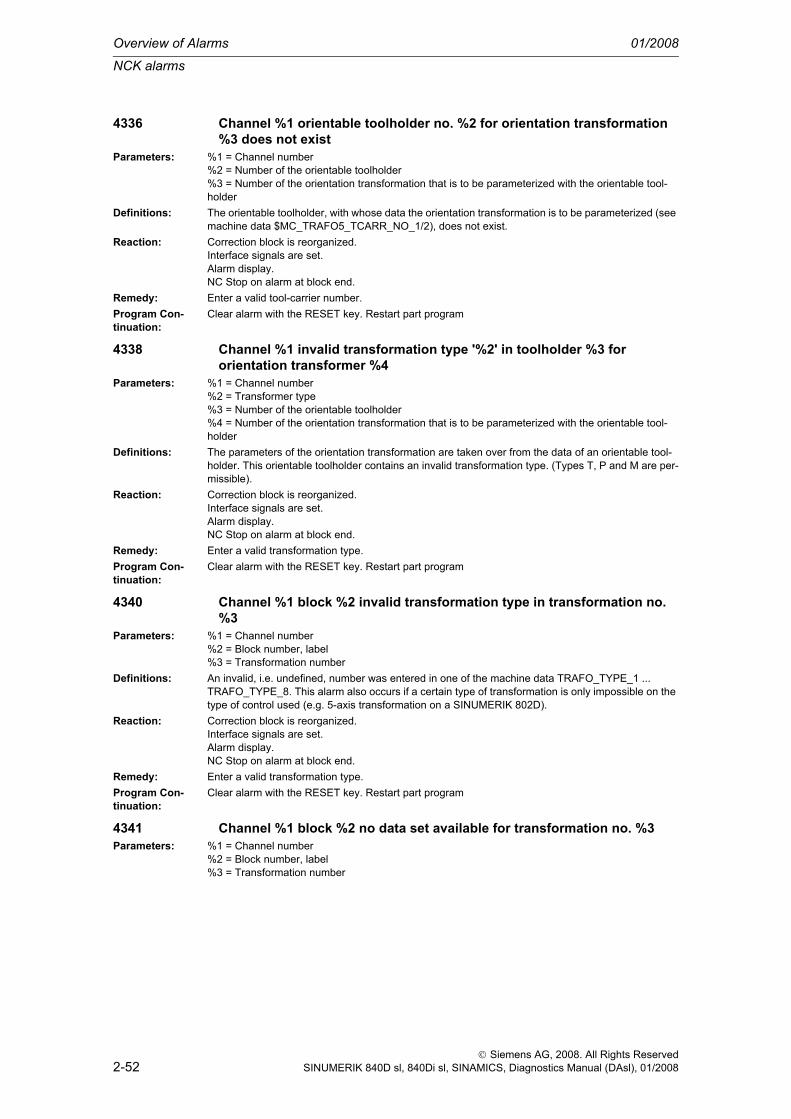
Overview of Alarms 01/2008
NCK alarms
2-52
© Siemens AG, 2008. All Rights ReservedSINUMERIK 840D sl, 840Di sl, SINAMICS, Diagnostics Manual (DAsl), 01/2008
4336 Channel %1 orientable toolholder no. %2 for orientation transformation %3 does not exist
Parameters: %1 = Channel number%2 = Number of the orientable toolholder%3 = Number of the orientation transformation that is to be parameterized with the orientable tool-holder
Definitions: The orientable toolholder, with whose data the orientation transformation is to be parameterized (see machine data $MC_TRAFO5_TCARR_NO_1/2), does not exist.
Reaction: Correction block is reorganized.Interface signals are set.Alarm display.NC Stop on alarm at block end.
Remedy: Enter a valid tool-carrier number.Program Con-tinuation:
Clear alarm with the RESET key. Restart part program
4338 Channel %1 invalid transformation type '%2' in toolholder %3 for orientation transformer %4
Parameters: %1 = Channel number%2 = Transformer type%3 = Number of the orientable toolholder%4 = Number of the orientation transformation that is to be parameterized with the orientable tool-holder
Definitions: The parameters of the orientation transformation are taken over from the data of an orientable tool-holder. This orientable toolholder contains an invalid transformation type. (Types T, P and M are per-missible).
Reaction: Correction block is reorganized.Interface signals are set.Alarm display.NC Stop on alarm at block end.
Remedy: Enter a valid transformation type.Program Con-tinuation:
Clear alarm with the RESET key. Restart part program
4340 Channel %1 block %2 invalid transformation type in transformation no. %3
Parameters: %1 = Channel number%2 = Block number, label%3 = Transformation number
Definitions: An invalid, i.e. undefined, number was entered in one of the machine data TRAFO_TYPE_1 ... TRAFO_TYPE_8. This alarm also occurs if a certain type of transformation is only impossible on the type of control used (e.g. 5-axis transformation on a SINUMERIK 802D).
Reaction: Correction block is reorganized.Interface signals are set.Alarm display.NC Stop on alarm at block end.
Remedy: Enter a valid transformation type.Program Con-tinuation:
Clear alarm with the RESET key. Restart part program
4341 Channel %1 block %2 no data set available for transformation no. %3Parameters: %1 = Channel number
%2 = Block number, label%3 = Transformation number

NCK alarms
01/2008 Overview of Alarms
2-53
© Siemens AG, 2008. All Rights ReservedSINUMERIK 840D sl, 840Di sl, SINAMICS, Diagnostics Manual (DAsl), 01/2008
Definitions: Only a limited number of machine data sets (usually 2) is available for each related group of transfor-mations (e.g. orientation transformations, Transmit, Tracyl, etc.). This alarm is output if an attempt is made to set more transformations from a group.Example:Two orientation transformations are allowed. The machine data contains e.g.:TRAFO_TYPE_1 = 16 ; 1st orientation transformationTRAFO_TYPE_2 = 33 ; 2nd orientation transformationTRAFO_TYPE_3 = 256 ; 1st transmit transformationTRAFO_TYPE_4 = 20 ; 3rd orientation transformation ==> This entry triggers alarm
Reaction: Correction block is reorganized.Interface signals are set.Alarm display.NC Stop on alarm at block end.
Remedy: Enter valid machine data.Program Con-tinuation:
Clear alarm with the RESET key. Restart part program
4342 Channel %1 invalid machine data for general 5-axis transformation error no. %2
Parameters: %1 = Channel number%2 = Error type
Definitions: The machine data which describe the axis directions and the basic orientation and the input axes for the general 5-axis transformation are invalid. The error parameter displayed specifies the cause of the alarm:- 1: The first axis (TRAFO5_AXIS1_*) is not defined (all three entries of the vector are 0)- 2: The second axis (TRAFO5_AXIS2_*) is not defined (all three entries of the vector are 0)- 3: The basic orientation (TRAFO5_BASE_ORIENT_*) is not defined (all three entries of the vector are 0)- 4: The first and second axis are (virtually) parallel- 5: On TRAFO_TYPE = 56 (rotatable tool and workpiece) there is no 4-axis transformation, i.e. 2 rotary axes must always be available. (See MD TRAFO_AXES_IN_X)- 6: The third axis (TRAFO5_AXIS3_*) is not defined (all three entries of the vector are 0) (6-axis trans-formation)- 7: The normal tool vector (TRAFO6_BASE_ORIENT_NORMAL_*) is not defined (all three entries of the vector are 0) (6-axis transformation)- 8: The basic tool orientation (TRAFO5_BASE_ORIENT_*) and the normal tool vector (TRAFO6_BASE_ORIENT_NORMAL_*) are (virtually) parallel (6-axis transformation)- 9: The first external axis (TRAFO7_EXT_AXIS1_*) has not been defined (all three vector entries are 0) (7-axis transformation)-10: Invalid transformation type (TRAFO_TYPE_*). A transformation type unequal to 24 has been entered for the generic 7-axis transformation.
Reaction: Correction block is reorganized.Interface signals are set.Alarm display.NC Stop on alarm at block end.
Remedy: Set valid machine data.Program Con-tinuation:
Clear alarm with the RESET key. Restart part program
4343 Channel %1 attempt made to change the machine data of an active transformation.
Parameters: %1 = Channel numberDefinitions: An attempt was made to change the machine data of an active transformation and to activate the
machine data with RESET or NEWCONFIG.Reaction: Interpreter stop
Interface signals are set.Alarm display.NC Stop on alarm at block end.
Remedy: Set valid machine data.Program Con-tinuation:
Clear alarm with the RESET key. Restart part program

Overview of Alarms 01/2008
NCK alarms
2-54
© Siemens AG, 2008. All Rights ReservedSINUMERIK 840D sl, 840Di sl, SINAMICS, Diagnostics Manual (DAsl), 01/2008
4345 Channel %1 invalid configuration in chained transformation no. %2Parameters: %1 = Channel number
%2 = Transformation numberDefinitions: A chained transformation is incorrectly configured (machine data $MC_TRACON_CHAIN_1 or
$MC_TRACON_CHAIN_2). The following causes for the error are possible:- The list of transformations to be chained starts with a 0 (at least one entry not equal to zero is required).- The list of transformations to be chained contains the number of a transformation which does not exist.- The number of a transformation in the list is greater than or equal to the number of the chained trans-formation. Example: The cascaded transformation is the fourth transformation in the system, i.e. $MC_TRAFO_TYPE_4 = 8192. In this case, only values 1, 2 or 3 may be entered in the associated list (e.g. $MC_TRACON_CHAIN_1[...]).- The chaining setting is invalid. The following restrictions currently apply. A maximum of two transfor-mations can be chained. The first transformation must be an orientation transformation, transmit, peripheral curve transformation or inclined axis. The second transformation must be the inclined axis transformation.
Reaction: Correction block is reorganized.Interface signals are set.Alarm display.NC Stop on alarm at block end.
Remedy: Set a valid transformation chain.Program Con-tinuation:
Clear alarm with the RESET key. Restart part program
4346 Channel %1 invalid geoaxis assignment in machine data %2[%3]Parameters: %1 = Channel number
%2 = Name of machine data%3 = Transformation number
Definitions: Machine data TRAFO_GEOAX_ASSIGN_TAB_X contains an invalid entry. The following causes for the error are possible:- The entry references a channel axis which does not exist.- The entry is zero (no axis) but the transformation needs the relevant axis as a geometry axis.
Reaction: Correction block is reorganized.Interface signals are set.Alarm display.NC Stop on alarm at block end.
Remedy: Correct the entry in TRAFO_GEOAX_ASSIGN_TAB_X or TRAFO_AXES_IN_X.Program Con-tinuation:
Clear alarm with the RESET key. Restart part program
4347 Channel %1 invalid channel axis assignment in machine data %2[%3]Parameters: %1 = Channel number
%2 = Name of machine data%3 = Transformation number
Definitions: Machine data TRAFO_AXIS_IN_X contains an invalid entry. The following causes for the error are possible:- The entry refers to a channel axis which does not exist.- The entry is zero (no axis) but the transformation needs the relevant axis as a channel axis.- More than one external axis has been entered in TRAFO_AXIS_IN_X for the 7-axis transformation.
Reaction: Correction block is reorganized.Interface signals are set.Alarm display.NC Stop on alarm at block end.
Remedy: Correct the entry in TRAFO_AXES_IN_X.Program Con-tinuation:
Clear alarm with the RESET key. Restart part program

NCK alarms
01/2008 Overview of Alarms
2-55
© Siemens AG, 2008. All Rights ReservedSINUMERIK 840D sl, 840Di sl, SINAMICS, Diagnostics Manual (DAsl), 01/2008
4350 Channel %1 axis identifier %2 machine data %3 not consistent with machine data %4
Parameters: %1 = Channel number%2 = String: Axis identifier%3 = String: MD identifier%4 = String: MD identifier
Definitions: MD 32410 JOG_AND_POS_JERK_ENABLE (jerk limitation) and MD 35240 ACCEL_TYPE_DRIVE (acceleration reduction) have been defined as the initial setting for an axis. However, the two functions cannot be activated at the same time for one axis.
Reaction: Mode group not ready.Channel not ready.NC Start disable in this channel.Interface signals are set.Alarm display.NC Stop on alarm.
Remedy: Please inform the authorized personnel/service department. Resetting of 32410 JOG_AND_POS_JERK_ENABLE or 35240 ACCEL_TYPE_DRIVE.
Program Con-tinuation:
Switch control OFF - ON.
4400 MD alteration will cause reorganisation of buffered memory (loss of data!)
Definitions: A machine data has been altered that configures the buffered memory. If the NCK powers up with the altered data, this will lead to reorganization of the buffered memory and thus to the loss of all buffered user data (part programs, tool data, GUD, leadscrew error compensation, ...)
Reaction: Alarm display.Remedy: Please inform the authorized personnel/service department. If the control includes user data that has
not yet been saved, then a data backup must be performed before the next NCK power-up. By man-ually resetting the altered MD to the value it had before the last power-up, reorganization of the mem-ory can be avoided.
Program Con-tinuation:
Alarm display showing cause of alarm disappears. No further operator action necessary.
4402 %1 causes a machine data resetParameters: %1 = Machine dataDefinitions: If this machine data is set, the current machine data values are overwritten by the default values at
the next ramp-up. Under certain circumstances, this may cause data loss (even in the buffered mem-ory).
Reaction: Alarm display.Remedy: Please inform the authorized personnel/service department. If the control includes user data that has
not yet been saved, then a data backup must be performed before the next NCK power-up. By man-ually resetting the altered MD to the value it had before the last power-up, reorganization of the mem-ory can be avoided.
Program Con-tinuation:
Alarm display showing cause of alarm disappears. No further operator action necessary.
4502 Channel %1 anachronism %2(%3) -> %4Parameters: %1 = Channel number
%2 = String: MD identifier%3 = String: MD identifier%4 = String: MD identifier
Definitions: Previously, in $MC_RESET_MODE_MASK Bit4 and Bit5, the reset behavior of the 6th or 8th G groupe was determined. This setting is now made in $MC_GCODE_RESET_MODE.In order to ensure compatible handling of "old" data backups, the "old" values are taken from $MC_RESET_MODE_MASK and entered in $MC_GCODE_RESET_MODE.
Reaction: Alarm display.Remedy: --Program Con-tinuation:
Clear alarm with the Delete key or NC START.

Overview of Alarms 01/2008
NCK alarms
2-56
© Siemens AG, 2008. All Rights ReservedSINUMERIK 840D sl, 840Di sl, SINAMICS, Diagnostics Manual (DAsl), 01/2008
4503 TO unit %1 H number %2 assigned more than once. H number linked again.
Parameters: %1 = TO unit%2 = H number
Definitions: This error can only occur when MD $MN_MM_EXTERN_CNC_SYSTEM= 1 or 2. The Power ON effective machine data bit 10890, $MN_EXTERN_TOOLPROG_MODE, bit 3 has been reset. On reconstructing data handling after Power ON, it has been found that different edges of the same TO unit have the same H number. They had been linked previously. They are linked again and MD bit $MN_EXTERN_TOOLPROG_MODE, bit 3 is set again.
Reaction: Alarm display.Remedy: H numbers must be assigned only once in a TO unit. Then, machine data bit 10890,
$MN_EXTERN_TOOLPROG_MODE, bit 3 can be set = 0 and a restart can be performed.Program Con-tinuation:
Clear alarm with the Delete key or NC START.
4600 Invalid handwheel type for handwheel %1Parameters: %1 = Handwheel numberDefinitions: The handwheel type (hardware segment) for handwheel %1 requested through machine data
$MN_HANDWHEEL_SEGMENT is invalid.Reaction: Interface signals are set.
Alarm display.Remedy: Configure a valid type for the corresponding handwheel through machine date
$MN_HANDWHEEL_SEGMENT.Program Con-tinuation:
Switch control OFF - ON.
4610 Invalid handwheel module for handwheel %1Parameters: %1 = Handwheel moduleDefinitions: For SINUMERIK 840D and SINUMERIK 840DI only:
The handwheel module for handwheel %1 requested through machine data $MN_HANDWHEEL_MODULE is not available for 840D systems. An 840D system is always regarded as a module. Therefore $MN_HANDWHEEL_MODULE = 1 must always be set for hand-wheels directly linked to 840D systems.
Reaction: Interface signals are set.Alarm display.
Remedy: Set machine date $MN_HANDWHEEL_MODULE = 1 for the corresponding handwheel.Program Con-tinuation:
Switch control OFF - ON.
4611 Invalid handwheel input for handwheel %1Parameters: %1 = Handwheel inputDefinitions: For SINUMERIK 840D and SINUMERIK 840Di only:
The handwheel input for handwheel %1 requested through machine data $MN_HANDWHEEL_INPUT is not available for 840D systems. A maximum of 2 or 3 handwheels can be linked directly to 840D systems:840D powerline: 1st and 2nd handwheels directly to the 840D hardware840Di: 1st and 2nd handwheels directly to the extension boardSIMODRIVE 611D only: 3rd handwheel via free encoder input.
Reaction: Interface signals are set.Alarm display.
Remedy: Configure machine date $MN_HANDWHEEL_INPUT for a valid input for the corresponding hand-wheel
Program Con-tinuation:
Switch control OFF - ON.

NCK alarms
01/2008 Overview of Alarms
2-57
© Siemens AG, 2008. All Rights ReservedSINUMERIK 840D sl, 840Di sl, SINAMICS, Diagnostics Manual (DAsl), 01/2008
4620 Invalid handwheel module for handwheel %1Parameters: %1 = Handwheel moduleDefinitions: For SINUMERIK 802D only:
The handwheel module for handwheel %1 requested through machine data $MN_HANDWHEEL_MODULE is not available for 802D systems. An 802D system is always regarded as a module. Therefore$MN_HANDWHEEL_MODULE = 1 must always be set for hand-wheels linked directly to 802D systems.
Reaction: Interface signals are set.Alarm display.
Remedy: Set machine date $MN_HANDWHEEL_MODULE = 1 for the corresponding handwheel.Program Con-tinuation:
Switch control OFF - ON.
4621 Invalid handwheel input for handwheel %1Parameters: %1 = Handwheel inputDefinitions: For SINUMERIK 802D only:
The handwheel input for handwheel %1 requested through machine data $MN_HANDWHEEL_INPUT is not available for 802D systems. A maximum of 2 handwheels can be directly linked to 802D system.
Reaction: Interface signals are set.Alarm display.
Remedy: Configure machine date $MN_HANDWHEEL_INPUT for a valid input for the corresponding hand-wheel
Program Con-tinuation:
Switch control OFF - ON.
4630 Invalid handwheel module for handwheel %1Parameters: %1 = Handwheel moduleDefinitions: For PROFIBUS/PROFINET only:
The reference in $MN_HANDWHEEL_MODULE to a corresponding entry in machine data array $MN_HANDWHEEL_LOGIC_ADDRESS[] which is required for configuring PROFIBUS handwheels is not available.
Reaction: Interface signals are set.Alarm display.
Remedy: Configure the machine data $MN_HANDWHEEL_MODULE for the corresponding PROFIBUS hand-wheel so that there is a valid reference to an entry in the machine data array $MN_HANDWHEEL_LOGIC_ADDRESS[].
Program Con-tinuation:
Switch control OFF - ON.
4631 Invalid handwheel slot for handwheel %1Parameters: %1 = Handwheel slotDefinitions: For PROFIBUS/PROFINET only:
The handwheel slot for handwheel %1 requested through machine data $MN_HANDWHEEL_INPUT is not available for PROFIBUS handwheels.
Reaction: Interface signals are set.Alarm display.
Remedy: Configure machine date $MN_HANDWHEEL_INPUT to a valid handwheel slot for the corresponding PROFIBUS handwheel.
Program Con-tinuation:
Switch control OFF - ON.
4632 Logical PROFIBUS handwheel slot base address for handwheel %1 not found
Parameters: %1 = Handwheel number

Overview of Alarms 01/2008
NCK alarms
2-58
© Siemens AG, 2008. All Rights ReservedSINUMERIK 840D sl, 840Di sl, SINAMICS, Diagnostics Manual (DAsl), 01/2008
Definitions: For PROFIBUS/PROFINET only:The logical basic address of the PROFIBUS handwheel slot in machine data array $MN_HANDWHEEL_LOGIC_ADDRESS[] indexed in machine data $MN_HANDWHEEL_MODULE was not found in the current STEP 7 hardware configuration.
Reaction: Interface signals are set.Alarm display.
Remedy: Check if $MN_HANDWHEEL_MODULE of the corresponding handwheel is correct. Check if indexed logical base address of PROFIBUS handwheel slot in machine date array $MN_HANDWHEEL_LOGIC_ADDRESS[] is correct.
Program Con-tinuation:
Switch control OFF - ON.
4640 Invalid handwheel module for handwheel %1Parameters: %1 = Handwheel moduleDefinitions: For ETHERNET only:
The handwheel module for handwheel %1 requested through machine data $MN_HANDWHEEL_MODULE is not available for ETHERNET handwheels. $MN_HANDWHEEL_MODULE = 1 must always be set when configuring ETHERNET handwheels.
Reaction: Interface signals are set.Alarm display.
Remedy: Set machine date $MN_HANDWHEEL_MODULE = 1 for the corresponding handwheel.Program Con-tinuation:
Switch control OFF - ON.
4641 Invalid handwheel input for handwheel %1Parameters: %1 = Handwheel inputDefinitions: For ETHERNET only:
The handwheel input for handwheel %1 requested through machine data $MN_HANDWHEEL_INPUT is not available for ETHERNET handwheels. A maximum of 6 hand-wheels can be configured.
Reaction: Interface signals are set.Alarm display.
Remedy: Configure machine date $MN_HANDWHEEL_INPUT for a valid input for the corresponding hand-wheel
Program Con-tinuation:
Switch control OFF - ON.
4700 PROFIBUS I/O: The logical slot / I/O area address %1 was not found.Parameters: %1 = Area addressDefinitions: For PROFIBUS/PROFINET only:
The logical slot / I/O area address was not found in machine data MD10500 $MN_DPIO_LOGIC_ADDRESS_IN with the stated slot / I/O area in the current STEP 7 hardware con-figuration.
Reaction: Interface signals are set.Alarm display.
Remedy: Check the slot / I/O area address in the configuration (STEP 7, HW Config).Program Con-tinuation:
Switch control OFF - ON.
4702 PROFIBUS I/O: The logical slot / I/O area address %1 was not found.Parameters: %1 = Area addressDefinitions: For PROFIBUS/PROFINET only:
The logical slot / I/O area address was not found in machine data MD10506 $MN_DPIO_LOGIC_ADDRESS_OUT with the stated slot / I/O area index in the current STEP 7 hard-ware configuration.
Reaction: Interface signals are set.Alarm display.
Remedy: Check the slot / I/O area address in the configuration (STEP 7, HW Config).Program Con-tinuation:
Switch control OFF - ON.
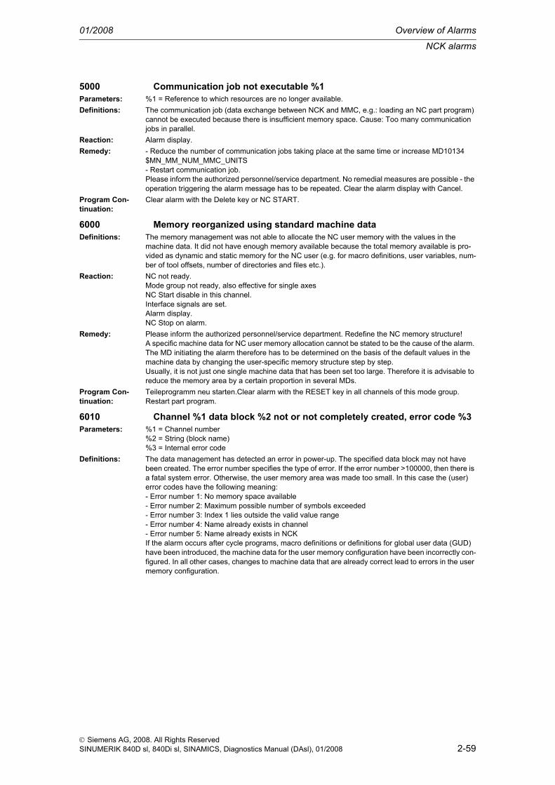
NCK alarms
01/2008 Overview of Alarms
2-59
© Siemens AG, 2008. All Rights ReservedSINUMERIK 840D sl, 840Di sl, SINAMICS, Diagnostics Manual (DAsl), 01/2008
5000 Communication job not executable %1Parameters: %1 = Reference to which resources are no longer available.Definitions: The communication job (data exchange between NCK and MMC, e.g.: loading an NC part program)
cannot be executed because there is insufficient memory space. Cause: Too many communication jobs in parallel.
Reaction: Alarm display.Remedy: - Reduce the number of communication jobs taking place at the same time or increase MD10134
$MN_MM_NUM_MMC_UNITS- Restart communication job.Please inform the authorized personnel/service department. No remedial measures are possible - the operation triggering the alarm message has to be repeated. Clear the alarm display with Cancel.
Program Con-tinuation:
Clear alarm with the Delete key or NC START.
6000 Memory reorganized using standard machine dataDefinitions: The memory management was not able to allocate the NC user memory with the values in the
machine data. It did not have enough memory available because the total memory available is pro-vided as dynamic and static memory for the NC user (e.g. for macro definitions, user variables, num-ber of tool offsets, number of directories and files etc.).
Reaction: NC not ready.Mode group not ready, also effective for single axesNC Start disable in this channel.Interface signals are set.Alarm display.NC Stop on alarm.
Remedy: Please inform the authorized personnel/service department. Redefine the NC memory structure!A specific machine data for NC user memory allocation cannot be stated to be the cause of the alarm. The MD initiating the alarm therefore has to be determined on the basis of the default values in the machine data by changing the user-specific memory structure step by step.Usually, it is not just one single machine data that has been set too large. Therefore it is advisable to reduce the memory area by a certain proportion in several MDs.
Program Con-tinuation:
Teileprogramm neu starten.Clear alarm with the RESET key in all channels of this mode group. Restart part program.
6010 Channel %1 data block %2 not or not completely created, error code %3Parameters: %1 = Channel number
%2 = String (block name)%3 = Internal error code
Definitions: The data management has detected an error in power-up. The specified data block may not have been created. The error number specifies the type of error. If the error number >100000, then there is a fatal system error. Otherwise, the user memory area was made too small. In this case the (user) error codes have the following meaning:- Error number 1: No memory space available- Error number 2: Maximum possible number of symbols exceeded- Error number 3: Index 1 lies outside the valid value range- Error number 4: Name already exists in channel- Error number 5: Name already exists in NCKIf the alarm occurs after cycle programs, macro definitions or definitions for global user data (GUD) have been introduced, the machine data for the user memory configuration have been incorrectly con-figured. In all other cases, changes to machine data that are already correct lead to errors in the user memory configuration.

Overview of Alarms 01/2008
NCK alarms
2-60
© Siemens AG, 2008. All Rights ReservedSINUMERIK 840D sl, 840Di sl, SINAMICS, Diagnostics Manual (DAsl), 01/2008
The following block names (2nd parameter) are known in the NCK (all system and user data blocks; in general, only problems in the user data blocks can be remedied by user intervention):- _N_NC_OPT - System internal: option data, NCK global- _N_NC_SEA - System internal: setting data, NCK global- _N_NC_TEA - System internal: machine data, NCK global- _N_NC_CEC - System internal: 'cross error compensation'- _N_NC_PRO - System internal: protection zones, NCK global- _N_NC_GD1 - User: 1st GUD block defined by _N_SGUD_DEF, NCK global- _N_NC_GD2 - User: 2nd GUD block defined by _N_MGUD_DEF, NCK global- _N_NC_GD3 - User: 3rd GUD block defined by _N_UGUD_DEF, NCK global- _N_NC_GD4 - User: 4th GUD block defined by _N_GUD4_DEF, NCK global- _N_NC_GD5 - User: 5th GUD block defined by _N_GUD5_DEF, NCK global- _N_NC_GD6 - User: 6th GUD block defined by _N_GUD6_DEF, NCK global- _N_NC_GD7 - User: 7th GUD block defined by _N_GUD7_DEF, NCK global- _N_NC_GD8 - User: 8th GUD block defined by _N_GUD8_DEF, NCK global- _N_NC_GD9 - User: 9th GUD block defined by _N_GUD9_DEF, NCK global- _N_NC_MAC - User: Macro definitions- _N_NC_FUN - User: Cycle programs- _N_CHc_OPT - System internal: option data, channel-specific- _N_CHc_SEA - System internal: setting data, channel-specific- _N_CHc_TEA - System internal: machine data, channel-specific- _N_CHc_PRO - System internal: protection zones, channel-specific- _N_CHc_UFR - System internal: frames, channel-specific- _N_CHc_RPA - System internal: arithmetic parameters, channel-specific- _N_CHc_GD1 - User: 1st GUD block defined by _N_SGUD_DEF, channel-specific- _N_CHc_GD2 - User: 2nd GUD block defined by _N_MGUD_DEF, channel-specific- _N_CHc_GD3 - User: 3rd GUD block defined by _N_UGUD_DEF, channel-specific- _N_CHc_GD4 - User: 4th GUD block defined by _N_GUD4_DEF, channel-specific- _N_CHc_GD5 - User: 5th GUD block defined by _N_GUD5_DEF, channel-specific- _N_CHc_GD6 - User: 6th GUD block defined by _N_GUD6_DEF, channel-specific- _N_CHc_GD7 - User: 7th GUD block defined by _N_GUD7_DEF, channel-specific- _N_CHc_GD8 - User: 8th GUD block defined by _N_GUD8_DEF, channel-specific- _N_CHc_GD9 - User: 9th GUD block defined by _N_GUD9_DEF, channel-specific- _N_AXa_OPT - System internal: option data, axial- _N_AXa_SEA - System internal: setting data, axial- _N_AXa_TEA - System internal: machine data, axial- _N_AXa_EEC - System internal: leadscrew error compensation data, axial- _N_AXa_QEC - System internal: quadrant error compensation data, axial- _N_TOt_TOC - System internal: toolholder data, TOA-specific- _N_TOt_TOA - System internal: tool data, TOA-specific- _N_TOt_TMA - System internal: magazine data, TOA-specific- _N_NC_KIN - System internal: data to describe kinematic chains, NCK-specific- _N_NC_NPA - System internal: data to describe 3D protection zones, NCK-specific- _N_NC_WAL - System internal: data to describe coordinate-specific working area limitationc = Channel numbera = Machine axis numbert = TOA unit numberThere are further internal system data blocks with identifiers.
Reaction: NC not ready.Channel not ready.NC Start disable in this channel.Interface signals are set.Alarm display.NC Stop on alarm.

NCK alarms
01/2008 Overview of Alarms
2-61
© Siemens AG, 2008. All Rights ReservedSINUMERIK 840D sl, 840Di sl, SINAMICS, Diagnostics Manual (DAsl), 01/2008
Remedy: Correct the machine data or undo the changes made.Please inform the authorized personnel/service department. There are two determining machine data for cycle programs:- $MN_MM_NUM_MAX_FUNC_NAMES = max. number of all cycle programs, error number = 2 shows that this value is too small.- $MN_MM_NUM_MAX_FUNC_PARAM = max. number of all parameters defined in the cycle pro-grams, error number = 2 shows that this value is too small(If these MDs are modified, the memory backup is retained)The following applies to macro definitions:$MN_MM_NUM_USER_MACROS = max. number of all macro definitions, error number = 2 shows that this value is too small.(If these MDs are modified, the memory backup is retained)The following applies to GUD variables:-- $MN_MM_NUM_GUD_NAMES_NCK = max. number of all NCK global GUD variables, error number = 2 shows that this value is too small.- $MN_MM_NUM_GUD_NAMES_CHAN = max. number of all channel-specific GUD variables in the channel, error number = 2 shows that this value is too small.- $MN_MM_GUD_VALUES_MEM = total value memory of all GUD variables together, error number = 1 shows that this value is too small.
Program Con-tinuation:
Switch control OFF - ON.
6020 Machine data have been changed - now memory is reorganizedDefinitions: Machine data have been changed that define the NC user memory allocation. Data management has
restructured the memory in accordance with the altered machine data.Reaction: Alarm display.Remedy: No remedial measures are required. Any user data that are required must be input again.Program Con-tinuation:
Clear alarm with the RESET key. Restart part program
6030 Limit of user memory has been adaptedDefinitions: Data management checks during power-up the actually available physical user memory (DRAM,
DPRAM and SRAM) with the values in the system-specific machine data 18210 MM_USER_MEM_DYNAMIC, MD 18220 MM_USER_MEM_DPR und MD 18230 MM_-USERMEM_BUFFERED.
Reaction: Alarm display.Remedy: No remedial measures are required. The new maximum permissible value can be read from the
reduced machine data.Program Con-tinuation:
Clear alarm with the RESET key. Restart part program
6035 Instead of %1 KB the system has only %2 KB of free user memory of type '%3'
Parameters: %1 = Free memory capacity in KB defined for the control model%2 = Actual maximum capacity of free memory in KB%3 = Type of memory, "D" =non-battery-backed, "S" =battery-backed
Definitions: The alarm can only occur after a 'cold start' (=NCK start-up with standard machine data). The alarm is only a notice. There is no interference with any NCK functions. It shows that the NCK has less free user memory available than specified by Siemens for this control variant. The value of the actually available free user memory can also be taken from the machine data $MN_INFO_FREE_MEM_DYNAMIC, $MN_INFO_FREE_MEM_STATIC. Siemens supplies NCK with default settings that, depending on the model, have certain (free) memory space available for the specific settings of the actual applications. The original factory setting of NCK systems is thus that the alarm does not occur with a cold start.
Reaction: Alarm display.

Overview of Alarms 01/2008
NCK alarms
2-62
© Siemens AG, 2008. All Rights ReservedSINUMERIK 840D sl, 840Di sl, SINAMICS, Diagnostics Manual (DAsl), 01/2008
Remedy: Reasons for the message:- The NCK contains compile cycle software, that uses so much memory space that the hardware can-not provide the required memory.- The NCK runs on hardware that is not intended for this NCK release (i.e. that has not enough mem-ory capacity).- If the application runs properly with the remaining free user memory (i.e. can be started up without any errors), the message can simply be ignored.- If the actual application cannot be configured because there is not enough memory capacity avail-able, either the existing compile cycle must be reduced or, if possible, the system must be upgraded with additional memory space.
Program Con-tinuation:
Clear alarm with the RESET key. Restart part program
6100 Error while creating %1, error number %2 %3Parameters: %1 = Symbolname
%2 = Error code%3 = If required, internal error identifier
Definitions: An error was detected while creating a compile cycle machine data. The error number specifies the type of error.- Error number 1: Insufficient memory available- Error number 2: Symbol in the NCK already exists- Error number 3: Maximum possible number of symbols exceeded- Error number 4: Invalid name prefix- Error number 5: Illegal array sizeNote: Other errors of this type could have occurred, but have not been displayed.
Reaction: NC not ready.Channel not ready.NC Start disable in this channel.Interface signals are set.Alarm display.NC Stop on alarm.
Remedy: - Error number 1: The memory reserved by machine data 12328 $MN_MM_CC_MD_MEM_SIZE has to be increased. If the error occurs while loading an archive, then the machine data must be increased "manually". To do this, either Edit the archive with 'arcedit' or Overwrite the MD in the MD picture and prevent the deletion of the machine data when writing the archive (MMC: Set Ask_for_CFG_RESET.INI = 1 in 'dino.ini'). Also refer to: Upgrade instructions P6.x.- Error number 2: Error in the combination or while reloading compile cycles: Do not activate compile cycle.- Error number 3: Error in the combination or while reloading compile cycles: Do not activate compile cycle.- Error number 4: Error in the compile cycle: Do not activate compile cycle.- Error number 5: Error in the compile cycle: Do not activate compile cycle.
Program Con-tinuation:
Switch control OFF - ON.
6200 Memory for CC MD full.Definitions: The memory reserved for storage of compile cycle machine data is full.
Some of these machine data could not be created correctly.Reaction: Alarm display.Remedy: Please inform the authorized personnel/service department.
If the alarm is displayed on start-up of compile cycles, this may be remedied by increasing $MN_MM_CC_MD_MEM_SIZE.
Program Con-tinuation:
Switch control OFF - ON.
6401 Channel %1 tool change not possible: Empty location for tool %2 on magazine %4 not available.
Parameters: %1 = Channel ID%2 = String (identifier)%3 = -Not used-%4 = Magazine number

NCK alarms
01/2008 Overview of Alarms
2-63
© Siemens AG, 2008. All Rights ReservedSINUMERIK 840D sl, 840Di sl, SINAMICS, Diagnostics Manual (DAsl), 01/2008
Definitions: The tool cannot be moved into the selected tool magazine. There is no appropriate location for this tool. A suitable location is mainly determined by the status. The status must indicate that this location is free, not disabled, not reserved and not co-occupied by a tool that is too large. Furthermore, it is important that the type of tool matches the type of any magazine location that may be free. (If, for example, all magazine locations are of the 'B' type and these are all free and the tool is of type 'A', then this tool cannot be put into this magazine).
Reaction: NC Start disable in this channel.Interface signals are set.Alarm display.NC Stop on alarm.
Remedy: - Check whether the magazine data have been defined correctly.- Check whether there is still room in the magazine to add another tool; there may not be due to oper-ating procedures.- Check whether a location type hierarchy is defined and whether it, for example, does not allow inser-tion of a type 'A' tool in a free location with type 'B'.
Program Con-tinuation:
Clear alarm with the RESET key. Restart part program
6402 Channel %1 tool change not possible. Magazine no. %2 not availableParameters: %1 = Channel ID
%2 = Magazine numberDefinitions: The desired tool change is not possible. The magazine with the specified number is not available.Reaction: NC Start disable in this channel.
Interface signals are set.Alarm display.NC Stop on alarm.
Remedy: - Check whether the magazine data have been defined correctly.- Check whether the magazine is connected to the desired tool holder/spindle via a distance relation.- The user PLC program may have sent wrong data to the NCK.
Program Con-tinuation:
Clear alarm with the RESET key. Restart part program
6403 Channel %1 tool change not possible. Magazine location number %2 on magazine %3 not available.
Parameters: %1 = Channel ID%2 = Magazine number%3 = Magazine location number
Definitions: The desired tool change is not possible. The specified magazine location is not contained in the spec-ified magazine.
Reaction: NC Start disable in this channel.Interface signals are set.Alarm display.NC Stop on alarm.
Remedy: Check whether the magazine data have been defined correctly.The user PLC program may have delivered incorrect data to the NCK.
Program Con-tinuation:
Clear alarm with the RESET key. Restart part program
6404 Channel %1 tool change not possible. Tool %2 not available or not usable
Parameters: %1 = Channel ID%2 = String (identifier)
Definitions: The desired tool change is not possible. The specified tool does not exist or cannot be inserted.Reaction: NC Start disable in this channel.
Interface signals are set.Alarm display.NC Stop on alarm.
Remedy: - Check whether the part program is written correctly.- Check whether the tool data are correctly defined.- Check whether there is a replacement tool which can be used for the specified tool.

Overview of Alarms 01/2008
NCK alarms
2-64
© Siemens AG, 2008. All Rights ReservedSINUMERIK 840D sl, 840Di sl, SINAMICS, Diagnostics Manual (DAsl), 01/2008
Program Con-tinuation:
Clear alarm with the RESET key. Restart part program
6405 Channel %1 command %2 has invalid PLC acknowledge parameter %3 - identifier %4
Parameters: %1 = Channel ID%2 = Command no.%3 = PLC acknowledge parameter%4 = Error code
Definitions: The specified command has been answered by the PLC with an invalid acknowledgement in the cur-rent context. The following assignments are defined for "command no.":1 Move tool, load or unload magazine2 Prepare tool change3 Execute tool change4 Prepare tool change and execute with T command5 Prepare tool change and execute with M command7 Terminate canceled tool command8 Check tool movement with reservation9 Check tool movement0 Transport acknowledgementParameters 2 and 3 designate the PLC command and the status number of the acknowledgement.Example: Parameter 4 of the alarm message is 10. It is not defined that a buffer location has to be reserved for asynchronous tool motion. In the example, the parameter is ignored by the NCK. Further possible causes for the alarm: The tool change defined by the command is not possible. The maga-zine location specified in the invalid parameter does not exist in the magazine.The 3rd parameter - error identification - gives a more detailed description of the alarm. Meanings:- 0 = not defined- 1 = status not allowed or undefined status received by PLC- 2 = source and/or target magazine no./location no. unknown- 3 = not defined- 4 = target magazine no. and/or location no. are not the end target in the tool motion command- 5 = not defined- 6 = source and/or target magazine no./location no. unknown during tool change- 7 = PLC comm. with inconsistent data: either inconsistent magazine addresses in VDI or NCK com-mand unequal to PLC acknowledgement or both- 8 = PLC comm. with inconsistent data: while rejecting a tool, the tool to be rejected was unloaded asynchronously. NCK cannot perform a new selection.- 9 = PLC comm. with inconsistent data: the command acknowledgement data wants to move a tool to a location that is occupied by another tool.- 10 = Asynchronous tool motion with reservation is only defined for the motion from a magazine to a buffer location.
Reaction: NC Start disable in this channel.Interface signals are set.Alarm display.NC Stop on alarm.
Remedy: Please inform the authorized personnel/service department. Erroneous PLC communication: Correct the PLC program.
Program Con-tinuation:
Clear alarm with the RESET key. Restart part program
6406 Channel %1 PLC acknowledge for command %2 is missingParameters: %1 = Channel ID
%2 = Command no.Definitions: There is still no acknowledgement from the PLC for the tool change. The NCK cannot continue pro-
cessing until it receives this acknowledgement for the specified command number. Possible command number values are described for alarm 6405.
Reaction: NC Start disable in this channel.Interface signals are set.Alarm display.

NCK alarms
01/2008 Overview of Alarms
2-65
© Siemens AG, 2008. All Rights ReservedSINUMERIK 840D sl, 840Di sl, SINAMICS, Diagnostics Manual (DAsl), 01/2008
Remedy: Please inform the authorized personnel/service department.- Erroneous PLC communication: Correct the PLC program.- It is possible to release NCK with the PLC command 7 from the wait condition.This aborts the waiting command.
Program Con-tinuation:
Clear alarm with the RESET key. Restart part program
6407 Channel %1 tool %2 cannot be placed in magazine %3 on location %4. Invalid definition of magazine!
Parameters: %1 = Channel ID%2 = String (identifier)%3 = Magazine number%4 = Magazine location number
Definitions: A tool change request or a verification request was issued to put the tool in a location which does not satisfy the prerequisites for filling.The following causes for the error are possible:- Location is blocked or not free!- Tool type does not match the location type!- Tool possibly too large, adjacent locations are not free!
Reaction: NC Start disable in this channel.Interface signals are set.Alarm display.NC Stop on alarm.
Remedy: - Check whether the magazine data are correctly defined (especially the location type).- Check whether the tool data are correctly defined (especially the location type).
Program Con-tinuation:
Clear alarm with the RESET key. Restart part program
6410 TO unit %1 tool %2 has reached its prewarning limit with D = %4Parameters: %1 = TO unit
%2 = Tool identifier (name)%3 = -Not used-%4 = D number
Definitions: Tool monitoring: This message informs that the specified D offset has reached its prewarning limit for a time-, quantity- or wear-monitored tool. If possible, the D number is displayed; if not, value 0 is assigned to the 4th parameter.If the function additive offset is being used, additive offset monitoring may be active instead of tool wear monitoring. The actual type of tool monitoring is a tool property (see $TC_TP9). If replacement tools are not being used, the duplo number specified has no meaning. The alarm is triggered through the MMC or PLC (=OPI interface). The channel context is not defined. The TO unit was specified for this reason (see $MC_MM_LINK_TOA_UNIT).
Reaction: Interface signals are set.Alarm display.
Remedy: For information only. The user must decide what to do.Program Con-tinuation:
Clear alarm with the Delete key or NC START.
6411 Channel %1 tool %2 has reached its prewarning limit with D = %4Parameters: %1 = Channel number
%2 = Tool identifier (name)%3 = -Not used-%4 = D number
Definitions: Tool monitoring: This message informs that the specified D offset has reached its prewarning limit for a time-, quantity- or wear-monitored tool. If possible, the D number is displayed; if not, value 0 is assigned to the 4th parameter.If the function additive offset is being used, additive offset monitoring may be active instead of tool wear monitoring. The actual type of tool monitoring is a tool property (see $TC_TP9).If replacement tools are not being used, the duplo number specified has no meaning.The alarm originates during NC program execution.
Reaction: Interface signals are set.Alarm display.

Overview of Alarms 01/2008
NCK alarms
2-66
© Siemens AG, 2008. All Rights ReservedSINUMERIK 840D sl, 840Di sl, SINAMICS, Diagnostics Manual (DAsl), 01/2008
Remedy: For information only. The user must decide what to do.Program Con-tinuation:
Clear alarm with the Delete key or NC START.
6412 TO unit %1 tool %2 has reached its monitoring limit with D = %4Parameters: %1 = TO unit
%2 = Tool identifier (name)%3 = -Not used-%4 = D number
Definitions: Tool monitoring: This message informs that the specified D offset has reached its prewarning limit for a time-, quantity- or wear-monitored tool. If possible, the D number is displayed; if not, value 0 is assigned to the 4th parameter.If the function additive offset is being used, additive offset monitoring may be active instead of tool wear monitoring.The actual type of tool monitoring is a tool property (see $TC_TP9).If replacement tools are not being used, the duplo number specified has no meaning.The alarm is triggered through the MMC or PLC (=OPI interface). The channel context is not defined. The TO unit was specified for this reason (see $MC_MM_LINK_TOA_UNIT).
Reaction: Interface signals are set.Alarm display.
Remedy: For information only. The user must decide what to do.Program Con-tinuation:
Clear alarm with the Delete key or NC START.
6413 Channel %1 tool %2 has reached its monitoring limit with D = %4Parameters: %1 = TO unit
%2 = Tool identifier (name)%3 = -Not used-%4 = D number
Definitions: Tool monitoring: This message informs that the specified D offset has reached its prewarning limit for a time-, quantity- or wear-monitored tool. If possible, the D number is displayed; if not, value 0 is assigned to the 4th parameter.If the function additive offset is being used, additive offset monitoring may be active instead of tool wear monitoring.The actual type of tool monitoring is a tool property (see $TC_TP9).If replacement tools are not being used, the duplo number specified has no meaning.The alarm originates during NC program execution.
Reaction: Interface signals are set.Alarm display.
Remedy: For information only. The user must decide what to do.Program Con-tinuation:
Clear alarm with the Delete key or NC START.
6415 TO unit %1 tool %2 with tool edge no. %3 has reached tool monitor warning limit
Parameters: %1 = TO unit%2 = Tool identifier%3 = Cutting edge number
Definitions: This message informs that at least one cutting edge of the time or quantity monitored tool has reached its monitoring limit. The alarm was triggered through the OPI interface (MMC, PLC). The channel con-text is not defined. The TO unit was specified for this reason.
Reaction: Interface signals are set.Alarm display.
Remedy: For information only. The user must decide what to do.Program Con-tinuation:
Clear alarm with the Delete key or NC START.

NCK alarms
01/2008 Overview of Alarms
2-67
© Siemens AG, 2008. All Rights ReservedSINUMERIK 840D sl, 840Di sl, SINAMICS, Diagnostics Manual (DAsl), 01/2008
6416 Channel %1 tool %2 with tool edge no. %3 has reached tool monitor warning limit
Parameters: %1 = Channel number%2 = Tool identifier%3 = Cutting edge number
Definitions: This message informs that at least one cutting edge of the time or quantity monitored tool has reached its monitoring limit. The limit was detected in the channel context. The alarm originated during NC pro-gram execution.
Reaction: Interface signals are set.Alarm display.
Remedy: For information only. The user must decide what to do.Program Con-tinuation:
Clear alarm with the Delete key or NC START.
6417 TO unit %1 tool %2 with tool edge no. %3 has reached tool monitoring limit
Parameters: %1 = TO unit%2 = Tool identifier%3 = Cutting edge number
Definitions: This message informs that at least one cutting edge of the time or quantity monitored tool has reached its monitoring limit. The alarm was triggered through the OPI interface (MMC, PLC). The channel con-text is not defined. The TO unit was specified for this reason.
Reaction: Interface signals are set.Alarm display.
Remedy: For information only. The user must decide what to do.Program Con-tinuation:
Clear alarm with the Delete key or NC START.
6418 Channel %1 tool %2 with tool edge no. %3 has reached tool monitoring limit
Parameters: %1 = Channel number%2 = Tool identifier%3 = Tool number
Definitions: This message informs that at least one cutting edge of the time or quantity monitored tool has reached its monitoring limit. The limit was detected in the channel context. The alarm originated during NC-program execution.
Reaction: Interface signals are set.Alarm display.
Remedy: For information only. The user must decide what to do.Program Con-tinuation:
Clear alarm with the Delete key or NC START.
6421 Channel %1 tool move not possible. Empty location for tool %2 on magazine %4 not available.
Parameters: %1 = Channel ID%2 = String (identifier)%3 = -Not used-%4 = Magazine number
Definitions: The desired tool motion command - triggered from the MMC or PLC - is not possible. The tool cannot be moved into the specified tool magazine. There is no appropriate location for this tool.
Reaction: NC Start disable in this channel.Interface signals are set.Alarm display.

Overview of Alarms 01/2008
NCK alarms
2-68
© Siemens AG, 2008. All Rights ReservedSINUMERIK 840D sl, 840Di sl, SINAMICS, Diagnostics Manual (DAsl), 01/2008
Remedy: - Check whether the magazine data have been defined correctly (e.g. the magazine must not be dis-abled).- Check whether the tool data are correctly defined (for example, the tool location type must match the location types allowed in the magazine).- Check whether the magazine has simply no more room to accept another tool thanks to operating procedures.- Check whether a location type hierarchy is defined and whether, for example, it does not allow inser-tion of a type 'A' tool in a free location with type 'B'.
Program Con-tinuation:
Clear alarm with the Delete key or NC START.
6422 Channel %1 tool move not possible. Magazine no. %2 not available.Parameters: %1 = Channel ID
%2 = Magazine numberDefinitions: The desired tool motion command - triggered from the MMC or PLC - is not possible. The magazine
with the specified number is not available.Reaction: NC Start disable in this channel.
Interface signals are set.Alarm display.
Remedy: - Check whether the magazine data have been defined correctly.- If the PLC issued the command for motion: check whether the PLC program is correct.- If the MMC issued the command for motion: check whether the MMC command was assigned correct parameters.
Program Con-tinuation:
Clear alarm with the Delete key or NC START.
6423 Channel %1 tool move not possible. Location %2 on magazine %3 not available.
Parameters: %1 = Channel ID%2 = Magazine location number%3 = Magazine number
Definitions: The desired tool motion command - triggered from the MMC or PLC - is not possible. The specified magazine location is not contained in the specified magazine.
Reaction: NC Start disable in this channel.Interface signals are set.Alarm display.
Remedy: Check whether the magazine data have been defined correctly.Program Con-tinuation:
Clear alarm with the Delete key or NC START.
6424 Channel %1 tool move not possible. Tool %2 not available/not usable.Parameters: %1 = Channel ID
%2 = String (identifier)Definitions: The desired tool motion command - triggered from the HMI or PLC - is not possible. The status of the
named tool does not allow movement of the tool. The named tool is not defined or not permitted for the command.
Reaction: NC Start disable in this channel.Interface signals are set.Alarm display.
Remedy: - Check whether the tool status 'is being changed' ('H20') is set. If yes, then the appropriate tool change command must first be completed by the PLC. Then the tool should be able to be moved.- Check whether the tool data are correctly defined. Has the correct T number been specified?- Check whether the move command has been correctly parameterized. Is the desired tool at the source location? Is the target location suitable for taking the tool?- Check whether the tool has already been loaded (if the alarm occurs while loading the tool).
Program Con-tinuation:
Clear alarm with the Delete key or NC START.

NCK alarms
01/2008 Overview of Alarms
2-69
© Siemens AG, 2008. All Rights ReservedSINUMERIK 840D sl, 840Di sl, SINAMICS, Diagnostics Manual (DAsl), 01/2008
6425 Channel %1 tool %2 cannot be placed in magazine %3 on location %4. Invalid definition of magazine!
Parameters: %1 = Channel ID%2 = String (identifier)%3 = Magazine number%4 = Magazine location number
Definitions: The desired tool motion command - triggered from the MMC or PLC - is not possible. A movement request was issued to put the tool in a location which does not satisfy the prerequisites for filling.The following causes for the error are possible:- Location is blocked or not free!- Tool type does not match the location type!- Tool possibly too large, adjacent locations are not free!- If a tool is to be loaded or unloaded, the load/unload position must be of 'load location' type.- If a tool is to be loaded or unloaded, is the magazine in question linked to the load/unload location?See $TC_MDP1, $TC_MDP2.
Reaction: NC Start disable in this channel.Interface signals are set.Alarm display.
Remedy: - Check whether the magazine data have been defined correctly.- Check whether there is still room in the magazine to add another tool; there may not be due to oper-ating procedures.- Check whether a location type hierarchy is defined and whether it, for example, does not allow inser-tion of a type 'A' tool in a free location with type 'B'.- Check whether the magazine in question is linked to the load/unload location or whether a distance has been defined.- Check whether the load/unload position is of 'load location' type.See also $TC_MPP1.
Program Con-tinuation:
Clear alarm with the Delete key or NC START.
6430 Workpiece counter: overflow in table of monitored cutting edges.Definitions: No more cutting edges can be entered in the piece counter table. As many cutting edges can be noted
for the workpiece counter as are possible in total in the NCK. This means that if for each tool each cutting edge in each TO unit is used precisely once for a workpiece then the limit is reached.If several workpieces are made on several toolholders/spindles simultaneously, it is possible to note 18100 MM_NUM_CUTTING_EDGES_IN_TOA cutting edges for the workpiece counter for all of the workpieces.If this alarm occurs, it means that cutting edges used subsequently are no longer quantity monitored until the table has been emptied again, e.g. by means of the NC language command SETPIECE or by the relevant job from MMC, PLC (PI service).
Reaction: NC Start disable in this channel.Interface signals are set.Alarm display.
Remedy: - Was decrementing of the piece counter forgotten? Then program SETPIECE in the part program, or add the correct command in the PLC program.- If the part program/PLC program is correct, then more memory should be set for tool cutting edges via the machine data $MN_MM_NUM_CUTTING_EDGES_IN_TOA (can only be performed with the necessary access rights!).
Program Con-tinuation:
Clear alarm with the Delete key or NC START.
6431 Channel %1 block %2 Function not allowed. Tool management/monitoring is not active.
Parameters: %1 = Channel ID%2 = Block number, label
Definitions: Occurs when a data management function is called which is not available because ToolMan is deac-tivated. For example, the language commands GETT, SETPIECE, GETSELT, NEWT, DELT.
Reaction: Correction block is reorganized.Interface signals are set.Alarm display.

Overview of Alarms 01/2008
NCK alarms
2-70
© Siemens AG, 2008. All Rights ReservedSINUMERIK 840D sl, 840Di sl, SINAMICS, Diagnostics Manual (DAsl), 01/2008
Remedy: - Please inform the authorized personnel/service department.- Make sure of how the NC is supposed to be configured! Is tool management or tool monitoring needed but not activated?- Are you using a part program that is meant for a numerical control with tool management/tool mon-itoring? It is not possible to start this program on the numerical control without tool management/tool monitoring. Either run the part program on the appropriate NC control or edit the part program.- Activate tool management/tool monitoring by setting the appropriate machine data. See $MN_MM_TOOL_MANAGEMENT_MASK, $MC_TOOL_MANAGEMENT_MASK- Check whether the required option is set accordingly.
Program Con-tinuation:
Clear alarm with NC START or RESET key and continue the program.
6432 Function not executable. No tool assigned to tool holder/spindleParameters: %1 = Channel IDDefinitions: When an attempt is made to perform an operation that requires a tool to be located on the spindle.
This can be the quantity monitoring function, for example.Reaction: Interface signals are set.
Alarm display.Remedy: Select another function, another toolholder/spindle, position tool on toolholder/spindle.Program Con-tinuation:
Clear alarm with the Delete key or NC START.
6433 Channel %1 block %2 %3 not available with tool managementParameters: %1 = Channel number
%2 = Block number, label%3 = Source symbol
Definitions: The symbol variable specified in %3 is not available with active tool management. The function GELSELT should be used with $P_TOOLP.
Reaction: Interpreter stopNC Start disable in this channel.Interface signals are set.Alarm display.
Remedy: Modify program. If $P_TOOLP has been programmed, the GETSELT function should be used instead.
Program Con-tinuation:
Clear alarm with the RESET key. Restart part program
6434 Channel %1 block %2 NC command SETMTH not allowed because tool holder function not active
Parameters: %1 = Channel number%2 = Block number, label
Definitions: No master toolholder has been defined for the initial state ($MC_TOOL_MANAGEMENT_TOOLHOLDER = 0), therefore no toolholder is available. The NC command SETMTH has neither been defined. In this setting, the tool change is carried out referring to the master spindle. The master spindle is set with SETMS.
Reaction: Correction block is reorganized.Local alarm reaction.Interface signals are set.Alarm display.
Remedy: Correct the NC program (delete or replace SETMHT) or enable toolholder function via machine data.Program Con-tinuation:
Clear alarm with NC START or RESET key and continue the program.
6441 Writing of $P_USEKT not allowed.Definitions: An attempt was made to write the value of $P_USEKT. This is not possible since programming T=
'location number' with automatic setting of $P_USEKT is active.Reaction: Interpreter stop
NC Start disable in this channel.Interface signals are set.Alarm display.

NCK alarms
01/2008 Overview of Alarms
2-71
© Siemens AG, 2008. All Rights ReservedSINUMERIK 840D sl, 840Di sl, SINAMICS, Diagnostics Manual (DAsl), 01/2008
Remedy: - Make sure of how the NC is supposed to be configured! (see bit16 and bit22 in $MC_TOOL_MANAGEMENT_MASK)- Tool change with "Reject tool" is configured. If you now try to start this program on NC control with T='location number' with automatic setting of $P_USEKT this will not be possible.- Either run the part program on the appropriate NC control or edit the part program.
Program Con-tinuation:
Clear alarm with the Delete key or NC START.
6442 Channel %1 function not executable. No tool assigned to desired magazine/magazine location %2.
Parameters: %1 = Channel ID%2 = Magazine/magazine location no.
Definitions: PLC logic is presumably incorrect. Tool change with reject tool is configured. Preparatory command is pending. Selected tool is (e.g. from PLC) unloaded from its location. PLC acknowledges preparatory command with 'Repeat tool selection' (e.g. status =7). NCK cannot find the tool at the magazine loca-tion specified in the PLC command.Or: Illegal operator intervention in an active tool selection (unloading of the tool to be selected) has occurred. Therefore the PLC acknowledgement fails.
Reaction: Interface signals are set.Alarm display.
Remedy: PLC programmer must note the following:- Ensure that the tool is not removed from the specified magazine location (e.g. incorrect PLC pro-gram).- Do not remove the tool from the programmed tool change before the final acknowledgement of the command (= unload).!! It is however permissible to change the location of the tool to be loaded. The NCK can deal with this situation.This alarm supplements Alarm 6405, if it contains the identifier 8. Therefore, the diagnostics should be easier.
Program Con-tinuation:
Clear alarm with the Delete key or NC START.
6450 Channel %1 block %2 tool change not possible. Invalid magazine location no. %3 in buffer magazine
Parameters: %1 = Channel ID%2 = Block number, label%3 = Magazine location number
Definitions: The desired tool change is not possible. The specified magazine location is either toolholder/spindle or empty.Only the numbers of the buffer that are not toolholder/spindle may be programmed with the NC com-mand TCI, i.e. the location number of a gripper is allowed.
Reaction: Correction block is reorganized.Interface signals are set.Alarm display.
Remedy: - Check whether the magazine data ($TC_MPP1) have been defined correctly.- Check whether the alarm-causing program command _ e.g. TCI _ has been programmed correctly.
Program Con-tinuation:
Clear alarm with NC START or RESET key and continue the program.
6451 Channel %1 block %2 tool change not possible. No buffer magazine defined.
Parameters: %1 = Channel ID%2 = Block number, label
Definitions: The desired tool change is not possible. No buffer magazine defined.Reaction: Correction block is reorganized.
Interface signals are set.Alarm display.
Remedy: Check whether the magazine data have been defined correctly.Program Con-tinuation:
Clear alarm with NC START or RESET key and continue the program.

Overview of Alarms 01/2008
NCK alarms
2-72
© Siemens AG, 2008. All Rights ReservedSINUMERIK 840D sl, 840Di sl, SINAMICS, Diagnostics Manual (DAsl), 01/2008
6452 Channel %1 block %2 tool change not possible. Tool holder/spindle number = %3 not defined.
Parameters: %1 = Channel ID%2 = Block number, label%3 = Tool holder/spindle number
Definitions: The desired tool change is not possible. The toolholder/spindle number has not been defined.Reaction: Correction block is reorganized.
Interface signals are set.Alarm display.
Remedy: General: The following must apply: 'maximum programmed address extension s (=spindle num-ber/toolholder number) of Ts=t, Ms=6 must be less than the value of $MN_MM_NUM_LOCS_WITH_DISTANCE.With magazine management: Check whether the toolholder number/spindle number and the maga-zine data have been defined correctly.(See also the system variables $TC_MPP1, $TC_MPP5 of the buffer magazine).
Program Con-tinuation:
Clear alarm with NC START or RESET key and continue the program.
6453 Channel %1 block %2 tool change not possible. No assignment between toolholder/spindle no. = %3 and buffer magazine location %4
Parameters: %1 = Channel ID%2 = Block number, label%3 = Spindle no.%4 = Location no.
Definitions: The desired tool change is not possible. No relation has been defined between the toolholder/spindle number and the buffer magazine location (Location No.)
Reaction: Correction block is reorganized.Interface signals are set.Alarm display.
Remedy: - Check whether the magazine data ($TC_MLSR) have been defined correctly.- Check whether the alarm-causing program command _ e.g. TCI _ has been programmed correctly.
Program Con-tinuation:
Clear alarm with NC START or RESET key and continue the program.
6454 Channel %1 block %2 tool change not possible. No distance relation available.
Parameters: %1 = Channel ID%2 = Block number, label
Definitions: The desired tool change is not possible. Neither the spindle nor the buffer magazine location have a distance relation.
Reaction: Correction block is reorganized.Interface signals are set.Alarm display.
Remedy: - Check whether the magazine data ($TC_MDP2) have been defined correctly.- Check whether the alarm-causing program command _ e.g. TCI _ has been programmed correctly.
Program Con-tinuation:
Clear alarm with NC START or RESET key and continue the program.
6455 Channel %1 block %2 tool change not possible. Magazine location no. %3 not available in magazine %4
Parameters: %1 = Channel ID%2 = Block number, label%3 = Magazine location number%4 = Magazine number
Definitions: The desired tool change is not possible. The indicated magazine location is not available in the indi-cated magazine.
Reaction: Correction block is reorganized.Interface signals are set.Alarm display.

NCK alarms
01/2008 Overview of Alarms
2-73
© Siemens AG, 2008. All Rights ReservedSINUMERIK 840D sl, 840Di sl, SINAMICS, Diagnostics Manual (DAsl), 01/2008
Remedy: - Check whether the causing program command - e.g. TCI - has been parameterized correctly.- Check whether magazine data have been defined correctly. ($TC_MAP6 and $TC_MAP7 of the intermediate location magazine)
Program Con-tinuation:
Clear alarm with NC START or RESET key and continue the program.
6500 NC memory fullDefinitions: The NCK file system is full.
The available buffered memory does not suffice. Note: At initial start-up, files of the NC file system may be affected such as drive data, MMC files, FIFO files, NC programs...
Reaction: Alarm display.Remedy: Adjust the size of the buffered memory ($MN_MM_USER_MEM_BUFFERED) or increase the space
available in the buffered memory, e.g. by unloading part programs that are no longer being used. Or decrease the size of the ring buffer (see $MC_RESU_RING_BUFFER_SIZE).
Program Con-tinuation:
Clear alarm with the Delete key or NC START.
6510 Too many part programs in the NC memoryDefinitions: The number of files in the file system (part of the NC memory) of the NC has reached the maximum
number possible. Note: During initial start-up, this can concern files from the NC file system, e.g. drive data, MMC files, FIFO files, NC programs, ...
Reaction: Alarm display.Remedy: Please inform the authorized personnel/service department.
- Delete or unload files (e.g. part programs), or- Increase $MM_NUM_FILES_IN_FILESYSTEM.
Program Con-tinuation:
Clear alarm with the Delete key or NC START.
6520 The value of the machine data %1%2 is too lowParameters: %1 = String: MD identifier
%2 = If required, index: MD arrayDefinitions: The machine data $MN_MM_PROTOC_NUM_FILES specifies the number of protocol files for the
protocol users. However, more types are used than configured.Reaction: Alarm display.Remedy: Increase machine data $MN_MM_PROTOC_NUM_FILES.Program Con-tinuation:
Clear alarm with the Delete key or NC START.
6530 Too many files in directoryDefinitions: The number of files in one directory of the NCK has reached the maximum limit.Reaction: Alarm display.Remedy: Please inform the authorized personnel/service department.
- Delete or unload files (e.g. part programs) in the respective directory, or- Increase $MM_NUM_FILES_PER_DIR.
Program Con-tinuation:
Clear alarm with the Delete key or NC START.
6540 Too many directories in the NC memoryDefinitions: The number of directories in the file system of the NCK has reached the maximum limit.Reaction: Alarm display.Remedy: - Delete or unload directory (e.g. workpiece), or
- Increase $MM_NUM_DIR_IN_FILESYSTEM.Program Con-tinuation:
Clear alarm with the Delete key or NC START.
6550 Too many subdirectoriesDefinitions: The number of subdirectories in a directory of the NCK has reached the maximum limit.Reaction: Alarm display.

Overview of Alarms 01/2008
NCK alarms
2-74
© Siemens AG, 2008. All Rights ReservedSINUMERIK 840D sl, 840Di sl, SINAMICS, Diagnostics Manual (DAsl), 01/2008
Remedy: Please inform the authorized personnel/service department.- Delete or empty subdirectories in the respective directory, or- Increase $MM_NUM_SUBDIR_PER_DIR.
Program Con-tinuation:
Clear alarm with the Delete key or NC START.
6560 Data format not allowedDefinitions: An attempt was made to write impermissible data in an NCK file. This error can occur in particular
when the attempt was made to load binary data in the NCK as ASCII file.The error can also occur during preprocessing of cycles (see $MN_PREPROCESSING_LEVEL) if the NC block is very long. In this case, subdivide the NC block.
Reaction: Alarm display.Remedy: Specify that the file concerned is a binary file (e.g. extension: .BIN).Program Con-tinuation:
Clear alarm with the Delete key or NC START.
6570 NC memory fullDefinitions: The NC card file system of the NCK is full. The task cannot be executed. Too many system files were
created in the DRAM.Reaction: Alarm display.Remedy: Start fewer "execute from external" processes.Program Con-tinuation:
Clear alarm with the Delete key or NC START.
6580 NC memory fullDefinitions: The NC card file system of the NCK is full. The task cannot be executed. To many files have been
loadedReaction: Alarm display.Remedy: Delete or empty files (e.g. part programs).Program Con-tinuation:
Clear alarm with the Delete key or NC START.
6581 NC user memory fullDefinitions: The DRAM file system of the user area is full. The order cannot be executed.Reaction: Alarm display.Remedy: Delete or unload files (e.g. parts programs)Program Con-tinuation:
Clear alarm with the Delete key or NC START.
6582 NC machine OEM memory fullDefinitions: The DRAM file system of the machine OEM area is full. The order cannot be executed.Reaction: Alarm display.Remedy: Delete or unload files (e.g. parts programs)Program Con-tinuation:
Clear alarm with the Delete key or NC START.
6583 NC system memory fullDefinitions: The DRAM file system of the system area (Siemens) is full. The order cannot be executed.Reaction: Alarm display.Remedy: Delete or unload files (e.g. parts programs)Program Con-tinuation:
Clear alarm with the Delete key or NC START.
6584 NC memory limit TMP reachedDefinitions: The DRAM file system of the TMP (temporary) area is full. The job cannot be executed.Reaction: Alarm display.Remedy: Increase machine date $MD_MM_DRAM_FILE_MEM_SIZE or switch off the precompilation of indi-
vidual or all cycles or, if need be, delete the files in the TMP area.

NCK alarms
01/2008 Overview of Alarms
2-75
© Siemens AG, 2008. All Rights ReservedSINUMERIK 840D sl, 840Di sl, SINAMICS, Diagnostics Manual (DAsl), 01/2008
Program Con-tinuation:
Clear alarm with the Delete key or NC START.
6585 NC external memory limit reachedDefinitions: The DRAM file system of the external area (execution of the external drive) is full.
The job cannot be executed.Reaction: Alarm display.Remedy: Load the files to be executed explicitly into the NCK.Program Con-tinuation:
Clear alarm with the Delete key or NC START.
6600 NC card memory is fullDefinitions: The NC card file system of the NCK is full. No more data can be stored on the NC card.Reaction: Alarm display.Remedy: Delete the data on the PCMCIA card.Program Con-tinuation:
Clear alarm with the Delete key or NC START.
6610 Too many files open on NC cardDefinitions: Too many files are being accessed simultaneously on the NC card.Reaction: Alarm display.Remedy: Repeat the action later.Program Con-tinuation:
Clear alarm with the Delete key or NC START.
6620 NC card has incorrect formatDefinitions: The NC card cannot be accessed because the format is incorrect.Reaction: Alarm display.Remedy: Replace the NC card.Program Con-tinuation:
Clear alarm with the Delete key or NC START.
6630 NC card hardware is defectiveDefinitions: The NC card cannot be accessed because the card is defective.Reaction: Alarm display.Remedy: Replace the PCMCIA card.Program Con-tinuation:
Clear alarm with the Delete key or NC START.
6640 NC card is not insertedDefinitions: The NC card cannot be accessed because the card is not plugged in.Reaction: Alarm display.Remedy: Plug in the NC card.Program Con-tinuation:
Clear alarm with the Delete key or NC START.
6650 Write protection of NC card is activeDefinitions: The NC card cannot be accessed because the write protection is active.Reaction: Alarm display.Remedy: Deactivate the write protection.Program Con-tinuation:
Clear alarm with the Delete key or NC START.
6660 'Flash File System' option is not setDefinitions: The NC card cannot be accessed because the option is not enabled.Reaction: Alarm display.Remedy: Buy option.Program Con-tinuation:
Clear alarm with the Delete key or NC START.

Overview of Alarms 01/2008
NCK alarms
2-76
© Siemens AG, 2008. All Rights ReservedSINUMERIK 840D sl, 840Di sl, SINAMICS, Diagnostics Manual (DAsl), 01/2008
6670 NC card read activeDefinitions: The alarm is active while the contents of the NC card are being read out. The FFS cannot be accessed
during this period.Reaction: Alarm display.Remedy: Wait until the read-out procedure is terminated.Program Con-tinuation:
Alarm display showing cause of alarm disappears. No further operator action necessary.
6671 NC card write activeDefinitions: The alarm is active while the contents of the NC card are being written. The FFS cannot be accessed
during this period. If the power is switched off while the alarm is active, the contents of the PCMCIA card are destroyed!
Reaction: Alarm display.Remedy: Wait until the write procedure is terminated.Program Con-tinuation:
Alarm display showing cause of alarm disappears. No further operator action necessary.
6690 Cycles from NC card cannot be copied to the passive file system.Definitions: There is not enough space in the file system that the directories specified in the
$PCMCIA_FUNCTION_MASK can be copied from the NC card to the passive file system.Reaction: Alarm display.Remedy: Delete data in the file system.Program Con-tinuation:
Clear alarm with the Delete key or NC START.
6691 Cycles from the passive file system cannot be saved on the NC cardDefinitions: There is not enough space on the NC card that the directories specified in the
$PCMCIA_FUNCTION_MASK can be saved. It is possible that cycles are lost during the next booting.Reaction: Alarm display.Remedy: Delete data on the NC card or delete cycles not required.Program Con-tinuation:
Clear alarm with the Delete key or NC START.
6692 Cycle %1 lostParameters: %1 = Name of cycleDefinitions: A cycle has been changed and due to a power failure, the backup on the PC card could not be termi-
nated properly. The cycle is lost.Reaction: NC not ready.
NC Start disable in this channel.Interface signals are set.Alarm display.
Remedy: Import the cycle again.Program Con-tinuation:
Switch control OFF - ON.
6693 File %1 lostParameters: %1 = Name of fileDefinitions: Due to a power failure, a file change could not be terminated properly. The file is lost.Reaction: NC not ready.
NC Start disable in this channel.Interface signals are set.Alarm display.
Remedy: Import the file again.Program Con-tinuation:
Switch control OFF - ON.
6698 Unknown NC card (%1/%2). Writing not possible.Parameters: %1 = actManufactorCode (manufacturer code read by the card)
%2 = actDeviceCode (memory code read by the card)

NCK alarms
01/2008 Overview of Alarms
2-77
© Siemens AG, 2008. All Rights ReservedSINUMERIK 840D sl, 840Di sl, SINAMICS, Diagnostics Manual (DAsl), 01/2008
Definitions: The NC card cannot be accessed because a valid write algorithm is not available for the flash memory.Reaction: Alarm display.Remedy: Use a compatible NC card or enter the new manufacturer code/device code in MD
$MN_PERMISSIVE_FLASH_TAB after consultation with SIEMENS.Program Con-tinuation:
Clear alarm with the Delete key or NC START.
6700 Channel %1 value of the machine data %2%3 is too lowParameters: %1 = Channel number
%2 = MD identifier%3 = If required, field index
Definitions: The machine data $MC_MM_PROTOC_NUM_ETP_STD_TYP specifies the number of default event types for the protocol users. However, more types are used than configured.
Reaction: Alarm display.Remedy: Increase machine data $MC_MM_PROTOC_NUM_ETP_STD_TYP.Program Con-tinuation:
Clear alarm with the Delete key or NC START.
7000 Too many compile cycle alarms definedDefinitions: Too many alarms are defined for the compile cycles. On powering up, the quantity was exceeded
when defining a new CC alarm.Reaction: Alarm display.Remedy: Apart from reducing the number of CC alarms, no remedial measures are possible at the present time.
(contact SIEMENS AG, System Support for A&D MC products, Hotline (Tel.: see alarm 1000)Program Con-tinuation:
Clear alarm with the Delete key or NC START.
7010 MMC number range exceededDefinitions: A fixed quantity of alarm numbers (100) is reserved for the compile cycles. This has been exceeded
when defining a new CC alarm. (The valid range is between 0 and 4999).Reaction: Alarm display.Remedy: Define the CC alarm numbers in the valid range from 0 to 4999.Program Con-tinuation:
Clear alarm with the Delete key or NC START.
7020 Compile cycle alarm number has not been definedDefinitions: The alarm ID used by the compile cycle manufacturer is not known to the system. This was not allo-
cated when the compile cycle alarms were generated.Reaction: Alarm display.Remedy: The alarm can have 2 possible causes:
- The alarm number has not been defined. A definition must still be made.- The call parameter used is not the same as the one transferred by the NCK.
Program Con-tinuation:
Clear alarm with the Delete key or NC START.
7100 Compile cycles VDI area: %1 byte for inputs and %2 byte for outputs. Maximum %3 bytes available.
Parameters: %1 = String (machine data)%2 = String (machine data)%3 = Max. length for interface
Definitions: The sum of the input and output bytes at the VDI user interface for the compile cycles exceeds the maximum quantity of 400 bytes.
Reaction: NC not ready.Channel not ready.NC Start disable in this channel.Interface signals are set.Alarm display.NC Stop on alarm.

Overview of Alarms 01/2008
NCK alarms
2-78
© Siemens AG, 2008. All Rights ReservedSINUMERIK 840D sl, 840Di sl, SINAMICS, Diagnostics Manual (DAsl), 01/2008
Remedy: Please inform the authorized personnel/service department. Set the machine data for dividing up the VDI user interface of the compile cycles (DB 9) into input and output bytes in accordance with the func-tions in the compile cycles. The maximum quantity of 400 bytes must not be exceeded. There are no restrictions concerning the division into input and output bytes.
Program Con-tinuation:
Switch control OFF - ON.
7200 Problem with externally linked compile cycle %1 %2Parameters: %1 = Description string
%2 = Additional informationDefinitions: Problem with loadable compile cycles
Example: "Version_conflict_with_CCNCKInterface_Version" Meaning: The interface version of the compile cycle is incompatible with the NCK version."Loader_problem_from_dFixup"Meaning: Unresolved references are left over after loading of all compile cycles, for example as an ELD file is missing.
Reaction: Alarm display.Remedy: See function description of the compile cycle!Program Con-tinuation:
Clear alarm with the Delete key or NC START.
7201 Assertion error in %1 line %2Parameters: %1 = String (path with program name)
%2 = String (line number)Definitions: This alarm is purely a development alarm. It only occurs with externally linked compile cycles.Reaction: NC not ready.
The NC switches to follow-up mode.Channel not ready.NC Start disable in this channel.Interface signals are set.Alarm display.NC Stop on alarm.Alarm reaction delay is cancelled.
Remedy: Consultation with CC developerProgram Con-tinuation:
Clear alarm with the RESET key in all channels. Restart part program.
7202 Missing option bit for %1: %2 <hex>Parameters: %1 = (string) name of the specific .elf file
%2 = (int) required option bit (hex)Definitions: Alarm for SIEMENS compile cycles. This alarm appears when the option bit required for a SIEMENS
compile cycle is not set.Reaction: NC not ready.
Channel not ready.Interface signals are set.Alarm display.Alarm reaction delay is cancelled.
Remedy: Set the required option bit or delete the .elf file from the Flash File System.Program Con-tinuation:
Clear alarm with the RESET key in all channels. Restart part program.
7205 Channel %1: incompatible OEM transformation version NCK %2 CC %3Parameters: %1 = (int) channel number
%2 = Transformer interface version NCK%3 = Transformer interface version OEM

NCK alarms
01/2008 Overview of Alarms
2-79
© Siemens AG, 2008. All Rights ReservedSINUMERIK 840D sl, 840Di sl, SINAMICS, Diagnostics Manual (DAsl), 01/2008
Definitions: The interface for OEM transformations has changed incompatibly in the system.Reaction: NC not ready.
Channel not ready.Interface signals are set.Alarm display.Alarm reaction delay is cancelled.
Remedy: Load the new compile cycle versionProgram Con-tinuation:
Clear alarm with the RESET key in all channels. Restart part program.
7300 Problem with externally linked COA application %1 Index: %2 Additional information: %3
Parameters: %1 = Name of the COA application%2 = Index describing the problem that occured in more detail%3 = Optional additional parameter
Definitions: A problem occurred while loading the COA application. This problem is described in more detail by the parameters "Index" and "Additional information":Index == 1: The interface version of the COA application is incompatible with the NCK version. The additional information contains the interface version of the COA application.Index == 2: The heap memory requested by the COA application is not available. The additional infor-mation contains the heap memory requested in KB.Index == 3: The $P_INCOAP parameters requested by the COA application cannot be created due to insufficient memory. The additional information contains the heap memory requested in KB.
Reaction: Alarm display.Remedy: Index == 1: The COA application is not executable in the current environment. Please inform the
authorized personnel/service department.Index == 2 or.3: The memory requested by the COA application will not become available until after another restart. This means that the alarm should no longer occur with a restart (NCK reset). Other-wise, there is a real memory problem, and the COA application is not executable (see Index == 1).
Program Con-tinuation:
Switch control OFF - ON.
7301 Assertion error in %1 line %2Parameters: %1 = File name
%2 = Line numberDefinitions: This alarm is purely a development alarm. It only occurs with externally linked COA applications.Reaction: NC not ready.
The NC switches to follow-up mode.Channel not ready.NC Start disable in this channel.Interface signals are set.Alarm display.NC Stop on alarm.Alarm reaction delay is cancelled.
Remedy: Query with COA developersProgram Con-tinuation:
Clear alarm with the RESET key in all channels. Restart part program.
7500 Block %1 invalid protection level for command %2 (protection level act.: %3 prog.: %4)
Parameters: %1 = Block number%2 = Programmed command%3 = Current protection level of the command%4 = Programmed protection level of the command

Overview of Alarms 01/2008
NCK alarms
2-80
© Siemens AG, 2008. All Rights ReservedSINUMERIK 840D sl, 840Di sl, SINAMICS, Diagnostics Manual (DAsl), 01/2008
Definitions: On assigning a protection level for a parts program command via REDEF command- an impermissible parts program command has been programmed- a protection level has been programmed that is logically smaller (larger in value) than the protection level currently applicable for this command.- the relevant definition file has not been protected sufficently against write access. The write protec-tion of the file must be at least as high as the highest protection level that has been assigned to a parts program command in this definition file.
Reaction: Alarm display.Remedy: Modify definition files /_N_DEF_DIR/_N_MACCESS_DEF or /_N_DEF_DIR/_N_UAC-CESS_ DEF.
Please see the Siemens Programming Guide or the OEM documentation for the language commands permissible for the relevant system configurations.
Program Con-tinuation:
Clear alarm with the RESET key. Restart part program
8000 Channel %1 option 'Interrupt routines' not setParameters: %1 = Channel numberDefinitions: Fast NCK inputs are required for the input signals in order to activate the interrupt routines and rapid
lift from contour. This function is not included in the basic version and must be retrofitted when needed.Reaction: Interpreter stop
NC Start disable in this channel.Interface signals are set.Alarm display.
Remedy: Please inform the authorized personnel/service department. Do not use rapid interrupt inputs or con-tact the machine manufacturer with a view to retrofitting this option!
Program Con-tinuation:
Clear alarm with the RESET key. Restart part program
8010 Option 'activation of more than %1 axes' not setParameters: %1 = Number of axesDefinitions: More machine axes have been defined through the channel-specific MD 20070
AXCONF_MACHAX_USED than are allowed in the system.Reaction: NC not ready.
Mode group not ready, also effective for single axesNC Start disable in this channel.Interface signals are set.Alarm display.NC Stop on alarm.
Remedy: Please inform the authorized personnel/service department. The sum of all axes that have been con-figured through the channel-specific MD 20070 AXCONF_MACHAX_USED, must not exceed the maximum number of axes (dependent on configuration -> option, basic version: 4 axes).
Program Con-tinuation:
Switch control OFF - ON.
8020 Option 'activation of more than %1 channels' not setParameters: %1 = Number of channelsDefinitions: A 2nd channel has been indicated but the corresponding option does not exist.Reaction: NC Start disable in this channel.
Interface signals are set.Alarm display.
Remedy: In the system-specific MD 10010 ASSIGN_CHAN_TO_MODE_GROUP, reduce the number of chan-nels to 1 or retrofit the option for a 2nd channel.
Program Con-tinuation:
Switch control OFF - ON.
8021 Option 'activation of more than %1 mode groups' not setParameters: %1 = Number of mode groupsDefinitions: The option for the number of mode groups is not compatible with the activated mode group.Reaction: NC Start disable in this channel.
Interface signals are set.Alarm display.

NCK alarms
01/2008 Overview of Alarms
2-81
© Siemens AG, 2008. All Rights ReservedSINUMERIK 840D sl, 840Di sl, SINAMICS, Diagnostics Manual (DAsl), 01/2008
Remedy: Add option for more mode groups. Activate fewer mode groups.Program Con-tinuation:
Switch control OFF - ON.
8022 Option 'activation of more than %1KB SRAM' not setParameters: %1 = Memory sizeDefinitions: The option for memory extension does not correspond to the active SRAM.Reaction: NC Start disable in this channel.
Interface signals are set.Alarm display.
Remedy: Please inform the authorized personnel/service department.- Buy option- Activate less SRAM
Program Con-tinuation:
Switch control OFF - ON.
8023 Option 'Activation of more than %1 KB PLC user memory' not setParameters: %1 = Memory sizeDefinitions: The option for the memory configuration does not correspond to the PLC user memory used.Reaction: NC Start disable in this channel.
Interface signals are set.Alarm display.
Remedy: Please inform the authorized personnel/service department.- Purchase option- Use less PLC user memory
Program Con-tinuation:
Switch control OFF - ON.
8024 Option 'Activation of more than %1 magazines' not setParameters: %1 = Number of permissible magazinesDefinitions: The option for activating multiple magazines is not setReaction: NC Start disable in this channel.
Interface signals are set.Alarm display.
Remedy: Please inform the authorized personnel/service department.- Buy option- Reduce the number of magazines (MD18084 $MN_MM_NUM_MAGAZINE)
Program Con-tinuation:
Switch control OFF - ON.
8030 Channel %1 block %2 option 'interpolation of more than %3 axes' not setParameters: %1 = Channel number
%2 = Block number, label%3 = Number of permissible axes
Definitions: The option for the number of interpolating axes does not correspond to the number of axes pro-grammed in the interpolation group.
Reaction: Interpreter stopNC Start disable in this channel.Interface signals are set.Alarm display.
Remedy: Option: "Interpolation of more than 4 axes" (the number of permitted axes can be set in this option) or program in the part program as many axes corresponding to the configuration of the control.
Program Con-tinuation:
Clear alarm with the RESET key. Restart part program
8031 Channel %1 block %2 axis %3: Axis has no IPO functionalityParameters: %1 = Channel number
%2 = Block number, label%3 = Axis, spindle number

Overview of Alarms 01/2008
NCK alarms
2-82
© Siemens AG, 2008. All Rights ReservedSINUMERIK 840D sl, 840Di sl, SINAMICS, Diagnostics Manual (DAsl), 01/2008
Definitions: An axis/spindle that has been defined as a special axis/auxiliary spindle (see $MA_BASE_FUNCTION_MASK bit8), should be operated as an interpolating axis.
Reaction: Interpreter stopNC Start disable in this channel.Interface signals are set.Alarm display.
Remedy: Define axis as interpolating axis (see $MA_BASE_FUNCTION_MASK bit8) or change part programProgram Con-tinuation:
Clear alarm with the RESET key. Restart part program
8032 Option 'activation of more than %1 link axes' not setParameters: %1 = Number of axesDefinitions: The option for the number of link axes does not match the number of axes programmed in MD
$MN_AXCONF_LOGIC_MACHAX_TAB.Reaction: Interpreter stop
NC Start disable in this channel.Interface signals are set.Alarm display.
Remedy: - Buy option- Configure fewer link axes
Program Con-tinuation:
Clear alarm with the RESET key. Restart part program
8034 Option 'activation of axis containers' not setDefinitions: The option for activating the axis container function in MD $MN_AXCONF_LOGIC_MACHAX_TAB is
not enabled.Reaction: Interpreter stop
NC Start disable in this channel.Interface signals are set.Alarm display.
Remedy: - Buy option- Do not configure any containers
Program Con-tinuation:
Clear alarm with the RESET key. Restart part program
8036 Option: it is not allowed to set different IPO cycles or position control cycles with NCU link.
Definitions: The option for activating the FAST_IPO_LINK has not been set. For NCU link, all Ipo or position con-trol cycles must then be equal (see FAST-IPO-LINK description).
Reaction: NC not ready.Channel not ready.NC Start disable in this channel.Interface signals are set.Alarm display.NC Stop on alarm.
Remedy: - Buy option- Do not activate different Ipo or position control cycles (see MN_IPO_SYSCLOCK_TIME_RATIO and MN_POSCTRL_SYSCLOCK_TIME_RATIO).
Program Con-tinuation:
Switch control OFF - ON.

NCK alarms
01/2008 Overview of Alarms
2-83
© Siemens AG, 2008. All Rights ReservedSINUMERIK 840D sl, 840Di sl, SINAMICS, Diagnostics Manual (DAsl), 01/2008
8037 'Activate APC/Number of current setpoint filters' option not set.Definitions: For SIMODRIVE 611D only:
The 'Advanced Positioning Control' (APC) function was activated in the drive, although the corre-sponding option had not been set.More than six current setpoint filters were activated in the drive, although the corresponding option had not been set.
Reaction: NC not ready.Channel not ready.NC Start disable in this channel.Interface signals are set.Alarm display.NC Stop on alarm.
Remedy: - Buy option- Deactivate the 'Advanced Positioning Control' (APC) function in the drive.- Set a maximum of six current setpoint filters in the drive.
Program Con-tinuation:
Switch control OFF - ON.
8038 Option 'activation of more than %1 lead link axes' not setParameters: %1 = Number of axesDefinitions: The option for the number of lead link axes does not match the number of configured axes in the MD
$MA_AXCONF_ASSIGN_MASTER_NCU.Reaction: Interpreter stop
NC Start disable in this channel.Interface signals are set.Alarm display.
Remedy: - Buy option- Configure fewer lead link axes
Program Con-tinuation:
Clear alarm with the RESET key. Restart part program
8040 Machine data %1 reset, corresponding option is not setParameters: %1 = String: MD identifierDefinitions: A machine data has been set that is locked by an option.Reaction: Alarm display.Remedy: Please inform the authorized personnel/service department. For retrofitting the option, please refer to
your machine manufacturer or to a sales representative of SIEMENS AG, A&D MC.Program Con-tinuation:
Clear alarm with the Delete key or NC START.
8041 Axis %1: MD %2 reset, corresponding option not sufficientParameters: %1 = Axis number
%2 = String: MD identifierDefinitions: All of the axes selected in the machine data of the assigned option are used. Safety functions have
been selected for too many axes in the axial machine data.The alarm can be reprogrammed in the MD ALARM_REACTION_CHAN_NOREADY (channel not ready).
Reaction: Mode group not ready.Channel not ready.NC Start disable in this channel.Interface signals are set.Alarm display.NC Stop on alarm.Channel not ready.
Remedy: --Program Con-tinuation:
Switch control OFF - ON.
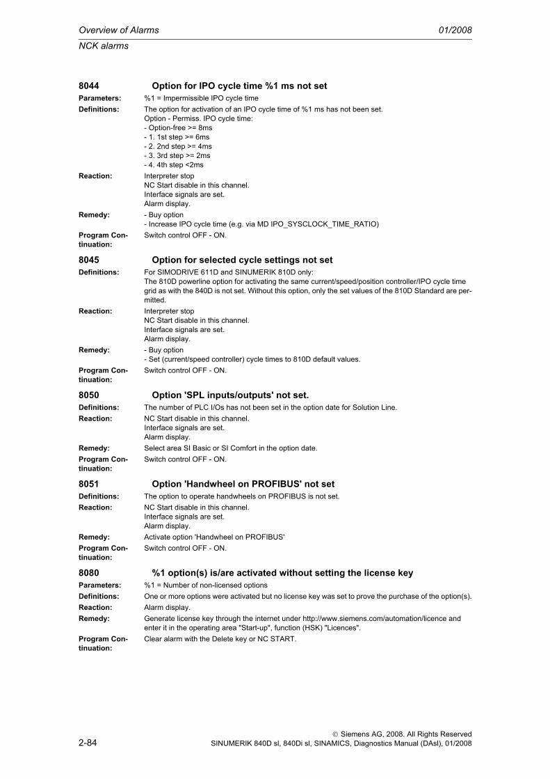
Overview of Alarms 01/2008
NCK alarms
2-84
© Siemens AG, 2008. All Rights ReservedSINUMERIK 840D sl, 840Di sl, SINAMICS, Diagnostics Manual (DAsl), 01/2008
8044 Option for IPO cycle time %1 ms not setParameters: %1 = Impermissible IPO cycle timeDefinitions: The option for activation of an IPO cycle time of %1 ms has not been set.
Option - Permiss. IPO cycle time:- Option-free >= 8ms- 1. 1st step >= 6ms- 2. 2nd step >= 4ms- 3. 3rd step >= 2ms- 4. 4th step <2ms
Reaction: Interpreter stopNC Start disable in this channel.Interface signals are set.Alarm display.
Remedy: - Buy option- Increase IPO cycle time (e.g. via MD IPO_SYSCLOCK_TIME_RATIO)
Program Con-tinuation:
Switch control OFF - ON.
8045 Option for selected cycle settings not setDefinitions: For SIMODRIVE 611D and SINUMERIK 810D only:
The 810D powerline option for activating the same current/speed/position controller/IPO cycle time grid as with the 840D is not set. Without this option, only the set values of the 810D Standard are per-mitted.
Reaction: Interpreter stopNC Start disable in this channel.Interface signals are set.Alarm display.
Remedy: - Buy option- Set (current/speed controller) cycle times to 810D default values.
Program Con-tinuation:
Switch control OFF - ON.
8050 Option 'SPL inputs/outputs' not set.Definitions: The number of PLC I/Os has not been set in the option date for Solution Line.Reaction: NC Start disable in this channel.
Interface signals are set.Alarm display.
Remedy: Select area SI Basic or SI Comfort in the option date.Program Con-tinuation:
Switch control OFF - ON.
8051 Option 'Handwheel on PROFIBUS' not setDefinitions: The option to operate handwheels on PROFIBUS is not set.Reaction: NC Start disable in this channel.
Interface signals are set.Alarm display.
Remedy: Activate option 'Handwheel on PROFIBUS' Program Con-tinuation:
Switch control OFF - ON.
8080 %1 option(s) is/are activated without setting the license keyParameters: %1 = Number of non-licensed optionsDefinitions: One or more options were activated but no license key was set to prove the purchase of the option(s).Reaction: Alarm display.Remedy: Generate license key through the internet under http://www.siemens.com/automation/licence and
enter it in the operating area "Start-up", function (HSK) "Licences".Program Con-tinuation:
Clear alarm with the Delete key or NC START.

NCK alarms
01/2008 Overview of Alarms
2-85
© Siemens AG, 2008. All Rights ReservedSINUMERIK 840D sl, 840Di sl, SINAMICS, Diagnostics Manual (DAsl), 01/2008
8081 %1 option(s) is/are activated that are not licensed by the license keyParameters: %1 = Number of non-licensed optionsDefinitions: One ore more options were activated, that are not licensed by the license key entered.Reaction: Alarm display.Remedy: Generate new license key through the internet under http://www.siemens.com/automation/licence
and enter it in the operating area "Start-up", function (HSK) "Licences".Program Con-tinuation:
Clear alarm with the Delete key or NC START.
8082 A wrong license key was entered three times, Power On required before next try.
Definitions: The license key was entered wrongly at least three times. Before the next input, a new power ON is required.
Reaction: Alarm display.Remedy: Execute NCK Power On and enter the license key (correctly).Program Con-tinuation:
Clear alarm with the Delete key or NC START.
8088 'Selection of non-grinding-specific tools' option not possibleDefinitions: The system version of the software only allows selection of grinding specific tools (i.e. tools of type
4xx).Reaction: Interpreter stop
NC Start disable in this channel.Interface signals are set.Alarm display.
Remedy: Select a tool of type 4xx (grinding tool)or install a standard version of the system software
Program Con-tinuation:
Clear alarm with the RESET key. Restart part program
8098 Invalid combination of options (%1)Parameters: %1 = Bit mask of optionsDefinitions: The following restrictions apply to this module for the combination of options:
The option "Two-channel" and the options "External language", "Nibbling", "Neural quadrant error compensation" and "Measurement level 2" exclude one another!Bit0 (LSB): NibblingBit1 : External languageBit2 : Neural quadrant error compensationBit3 : Measurement level 2
Reaction: Mode group not ready.Channel not ready.NC Start disable in this channel.Interface signals are set.Alarm display.NC Stop on alarm.
Remedy: Set the options accordingly.Program Con-tinuation:
Switch control OFF - ON.

Overview of Alarms 01/2008
NCK alarms
2-86
© Siemens AG, 2008. All Rights ReservedSINUMERIK 840D sl, 840Di sl, SINAMICS, Diagnostics Manual (DAsl), 01/2008
8100 Channel %1 block %2: function not possibleParameters: %1 = Channel number
%2 = Block number, labelDefinitions: - Impossible due to embargo regulations:
- 1. Synchronous actions: Writing of feed, override and axial offsets ($AA_VC, $AC_VC, $AA_OVR, $AA_VC and $AA_OFF) from synchronous actions as well as Continuous Dressing can be pro-grammed only once in a block.- 2. Extended measurement: 'Cyclic measurement' (MEAC) and 'Measurement from synchronous action' is not possible.- 3. Axis interpolation: The number of axes interpolating with one another must not exceed 4 (this also includes synchronous coupling of axes via synchronous actions "DO POS[X]=$A..." "DO FA[X]=$A...").
Reaction: Interpreter stopNC Start disable in this channel.Interface signals are set.Alarm display.NC Stop on alarm.
Remedy: Modify part program.Program Con-tinuation:
Clear alarm with the RESET key. Restart part program
8101 Option for collision avoidance is inadequateDefinitions: The option stage is inadequate for the desired function. Possible reasons:
1. More 3D protection zones have been created than is possible.2. A protection zone type was requested that is not permitted.
Reaction: Interpreter stopNC Start disable in this channel.Interface signals are set.Alarm display.
Remedy: 1. Buy an adequate option stage.2. Reduce the number of 3D protection zones.3. Avoid impermissible protection zone types.
Program Con-tinuation:
Clear alarm with the RESET key. Restart part program
8120 Channel %1 block %2 following axis/spindle %3 generic coupling %4 required
Parameters: %1 = Channel number%2 = Block number%3 = Slave axis%4 = String
Definitions: The option stage is inadequate for the desired function. Possible reasons:More couplings have been created than are permitted.The number of permissible leading axes has been exceeded for one or more couplings.The range of functions of one or more couplings has not been released.
Reaction: Interpreter stopNC Start disable in this channel.Interface signals are set.Alarm display.
Remedy: Buy an adequate option stage.Reduce the number of simultaneously active couplings.Reduce the number of leading axes per coupling or only use the released range of functions.
Program Con-tinuation:
Clear alarm with the RESET key. Restart part program

NCK alarms
01/2008 Overview of Alarms
2-87
© Siemens AG, 2008. All Rights ReservedSINUMERIK 840D sl, 840Di sl, SINAMICS, Diagnostics Manual (DAsl), 01/2008
9000 Handwheel %1 failedParameters: %1 = Handwheel numberDefinitions: For PROFIBUS/PROFINET only:
PROFIBUS handwheel has failedReaction: Interface signals are set.
Alarm display.Remedy: Restore connection to PROFIBUS handwheelProgram Con-tinuation:
Alarm display showing cause of alarm disappears. No further operator action necessary.
9050 PROFIBUS I/O: Sign of life failure, logical slot / I/O area address %1Parameters: %1 = Area addressDefinitions: For PROFIBUS/PROFINET only:
The sign of life of the slot / I/O area has failed. No data can currently be read from the PROFIBUS I/O devices.
Reaction: Interface signals are set.Alarm display.
Remedy: Check the communications link to the PROFIBUS I/O devices.Program Con-tinuation:
Alarm display showing cause of alarm disappears. No further operator action necessary.
9052 PROFIBUS I/O: Sign of life failure, logical slot / I/O area address %1Parameters: %1 = Area addressDefinitions: For PROFIBUS/PROFINET only:
The sign of life of the slot / I/O area has failed. No data can currently be written to the PROFIBUS I/O devices.
Reaction: Interface signals are set.Alarm display.
Remedy: Check the communications link to the PROFIBUS I/O devices.Program Con-tinuation:
Alarm display showing cause of alarm disappears. No further operator action necessary.
10203 Channel %1 NC start without reference point (action=%2<ALNX>)Parameters: %1 = Channel number
%2 = Action number/action nameDefinitions: NC start has been activated in the MDI or AUTOMATIC mode and at least one axis that needs to be
referenced has not reached its reference point.Reaction: Interface signals are set.
Alarm display.Remedy: Please inform the authorized personnel/service department. Via the channel-specific MD 20700:
REFP_NC_START_LOCK (NC Start without reference point) you can decide whether or not the axis has to be referenced before NC Start. The start of referencing can be enabled channel-specific or axis-specific.Channel-specific reference point approach: The rising edge of the NC/PLC interface signal DB21-30 DBX1.0 (Activate referencing) starts an automatic sequence which starts the axes of the channel in the same sequence as specified in the axis-specific MD 34110 REFP_CYCLE_NR (axis sequence channel-specific referencing). 0: The axis does not participate in channel-specific referencing, but it must be referenced for NC Start, -1: The axis does not participate in channel-specific referencing, but it need not be referenced for NC Start, 1- 8: Starting sequence for the channel-specific referencing (simultaneous start at the same no.), 1 - 31: CPU typeAxis-specific referencing: Press the direction key that corresponds to the approach direction in the axis-specific MD 34010 REFP_CAM_MDIR_IS_MINUS (reference point approach in minus direction).
Program Con-tinuation:
Clear alarm with NC START or RESET key and continue the program.
10207 Channel %1 error when selecting or deselecting the digitize functionParameters: %1 = Channel numberDefinitions: An error has occurred on activating/deactivating the digitizing module; e.g. not in channel ready state,
already activated, etc.Reaction: Alarm display.

Overview of Alarms 01/2008
NCK alarms
2-88
© Siemens AG, 2008. All Rights ReservedSINUMERIK 840D sl, 840Di sl, SINAMICS, Diagnostics Manual (DAsl), 01/2008
Remedy: Press RESET.Program Con-tinuation:
Clear alarm with the Delete key or NC START.
10208 Channel %1 continue program with NC startParameters: %1 = Channel numberDefinitions: After block search with calculation, the control is in the desired state. The program can now be started
with NC Start or the state can be changed for the time being with overstore/jog.Reaction: Interpreter stop
Alarm display.NC Stop on alarm.
Remedy: Press NC Start.Program Con-tinuation:
Clear alarm with NC START or RESET key and continue the program.
10209 Channel %1 internal NC stop after block searchParameters: %1 = Channel numberDefinitions: Internal alarm which only initiates the alarm response NC Stop.
The alarm is output in the following situations:- If $MN_SEARCH_RUN_MODE bit 0 ==1 and the last action block is loaded in the main run after block search. Alarm 10208 is then activated as a function of the NC/PLC interface signal DB21-30 DBX1.6 (PLC action finished).- Search alarm 10208 has been suppressed by the PI service _N_FINDBL (third decade of the param-eter supplied with "2"). Alarm 10209 is set as a function of whether or not a search ASUB has been configured ( $MN_SEARCHRUN_MODE bit 1) with the end of the search ASUB or the loading of the last action block in the main run.
Reaction: Interpreter stopNC Stop on alarm.
Remedy: NC-StartProgram Con-tinuation:
Clear alarm with NC START or RESET key and continue the program.
10222 Channel %1 inter-channel communication not possibleParameters: %1 = Channel numberDefinitions: This channel has received a negative acknowledgment from the inter-channel communication
because the destination channel number is not known, e.g.: START(x) or WAITE(x) but channel x has not been initialized
Reaction: Alarm display.Remedy: This is an indication of possible discrepancies. The program continues if no acknowledgment is called
for.Program Con-tinuation:
Clear alarm with the Delete key or NC START.
10223 Channel %1: Command %2 is already occupiedParameters: %1 = Channel number
%2 = Event nameDefinitions: This channel has received a negative acknowledgment from the inter-channel communication
because this command is already active or has not yet been terminated, e.g.: INIT(x,"ncprog") but a program select request is already active for channel x.
Reaction: Alarm display.Remedy: This is an indication of possible discrepancies. The program continues if no acknowledgment is called
for.Program Con-tinuation:
Clear alarm with the Delete key or NC START.
10225 Channel %1: command deniedParameters: %1 = Channel numberDefinitions: The channel has received a command. The command cannot be executed.Reaction: Alarm display.Remedy: Press RESET.

NCK alarms
01/2008 Overview of Alarms
2-89
© Siemens AG, 2008. All Rights ReservedSINUMERIK 840D sl, 840Di sl, SINAMICS, Diagnostics Manual (DAsl), 01/2008
Program Con-tinuation:
Clear alarm with the Delete key or NC START.Clear alarm with the RESET key. Restart part program
10261 Channel %1 communication overload for block preparationParameters: %1 = Channel numberDefinitions: The internal communication between the NCK modules that evaluate the channel-specific VDI signals
(START/STOP/RESET/DDTG/ASUBS/...) and the block preparation are overloaded. The block prep-aration modules are not being allocated enough computing time.
Reaction: NC not ready.Channel not ready.NC Start disable in this channel.Interface signals are set.Alarm display.NC Stop on alarm.
Remedy: More processor time must be allocated to the block preparation modules. Machine data $MN_IPO_SYSCLOCK_TIME_RATIO or $MN_SYSCLOCK_CYCLE_TIME can be increased for this purpose.
Program Con-tinuation:
Switch control OFF - ON.
10299 Channel %1 Auto-Repos function is not enabledParameters: %1 = Channel numberDefinitions: The Auto-Repos function (operating mode) was selected in the channel but is not implemented.Reaction: Alarm display.Remedy: This message is purely informational.Program Con-tinuation:
Clear alarm with the Delete key or NC START.
10600 Channel %1 block %2 auxiliary function during thread cutting activeParameters: %1 = Channel number
%2 = Block number, labelDefinitions: An auxiliary function output is programmed in a thread cutting block.Reaction: Alarm display.Remedy: Consequential errors can occur if the machining path of the thread block is too short and further blocks
(thread blocks) follow in which no machining stop may occur.Possible remedial measures:- Program a longer path and/or a lower traversing rate.- Output auxiliary function in another block (program section).
Program Con-tinuation:
Clear alarm with the Delete key or NC START.
10601 Channel %1 block %2 zero velocity at block end point during thread cutting
Parameters: %1 = Channel number%2 = Block number, label
Definitions: This alarm occurs only when several blocks with G33 follow in succession. The block end velocity in the specified block is zero, although a further thread cutting block follows. The reasons for this can be, for instance:- G9- Auxiliary function after motion- Auxiliary function output before the motion of the following block- Positioning axis in the block
Reaction: Interpreter stopNC Start disable in this channel.Interface signals are set.Alarm display.

Overview of Alarms 01/2008
NCK alarms
2-90
© Siemens AG, 2008. All Rights ReservedSINUMERIK 840D sl, 840Di sl, SINAMICS, Diagnostics Manual (DAsl), 01/2008
Remedy: Please inform the authorized personnel/service department. Modify the NC part program by removing any programmed "Stop at end of block" G09.Modify general machine data MD 11110 $MN_AUXFU_GROUP_SPEC [n] for selecting the output time of an auxiliary function group by changing "Auxiliary function output before/after the movement" to "Auxiliary function output during the movement".Bit 5 = 1: Auxiliary function output before movementBit 6 = 1: Auxiliary function output during movementBit 7 = 1: Auxiliary function output after movement
Program Con-tinuation:
Clear alarm with the RESET key. Restart part program
10602 Channel %1 block %2 velocity limitation during thread cuttingParameters: %1 = Channel number
%2 = Block number, labelDefinitions: In the displayed thread block, the axis would exceed its maximum velocity when the spindle override
is in the maximum position.Reaction: Local alarm reaction.
Alarm display.Remedy: If the axis velocity is not limited (faultless thread) no remedial measures are necessary. Otherwise, a
lower spindle speed must be programmed for the thread block.Program Con-tinuation:
Clear alarm with the Delete key or NC START.
10604 Channel %1 block %2 thread lead increase too highParameters: %1 = Channel number
%2 = Block number, labelDefinitions: The thread lead increase is causing an axis overload. A spindle override of 100% is assumed during
verification.Reaction: Correction block is reorganized.
Local alarm reaction.Interface signals are set.Alarm display.
Remedy: Reduce the spindle speed, thread lead increase or path length in the NC program.Program Con-tinuation:
Clear alarm with NC START or RESET key and continue the program.
10605 Channel %1 block %2 thread lead decrease too highParameters: %1 = Channel number
%2 = Block number, labelDefinitions: The thread lead decrease is causing an axis standstill in the thread block.Reaction: Correction block is reorganized.
Local alarm reaction.Interface signals are set.Alarm display.
Remedy: Reduce the thread lead decrease or path length in the NC program.Program Con-tinuation:
Clear alarm with NC START or RESET key and continue the program.
10607 Channel %1 block %2 thread with frame not executableParameters: %1 = Channel number
%2 = Block number, labelDefinitions: The current frame is corrupting the reference between the thread length and the thread lead.Reaction: Local alarm reaction.
NC Start disable in this channel.Interface signals are set.Alarm display.NC Stop on alarm at block end.
Remedy: - Perform thread cutting with G33, G34, G35 without a frame.- Use G63 or G331/G332.

NCK alarms
01/2008 Overview of Alarms
2-91
© Siemens AG, 2008. All Rights ReservedSINUMERIK 840D sl, 840Di sl, SINAMICS, Diagnostics Manual (DAsl), 01/2008
Program Con-tinuation:
Clear alarm with the RESET key. Restart part program
10610 Channel %1 axis %2 not stoppedParameters: %1 = Channel number
%2 = Block number, labelDefinitions: An axis/spindle has been positioned over several NC blocks using the POSA/SPOSA instruction. The
programmed target position had not yet been reached ("exact stop fine" window) when the axis/spin-dle was reprogrammed.Example:N100 POSA[U]=100:N125 X... Y... U... ; e.g.: U axis still travels from N100!
Reaction: NC Start disable in this channel.Interface signals are set.Alarm display.NC Stop on alarm.
Remedy: Check and correct the part program (analyze whether motion beyond block boundaries is appropriate here). Prevent block change by means of the keyword WAITP for axes or WAITS for spindles until the positioning axes or positioning spindles have also reached their target position.Example for axes:N100 POSA[U]=100:N125 WAITP(U)N130 X... Y... U...Example for spindles:N100 SPOSA[2]=77:N125 WAITS(2)N130 M6
Program Con-tinuation:
Clear alarm with the RESET key. Restart part program
10620 Channel %1 block %3 axis %2 at software limit switch %4Parameters: %1 = Channel number
%2 = Axis name, spindle number%3 = Block number, label%4 = String
Definitions: During the traversing motion, the system detected that the software limit switch would be traversed in the direction indicated. Exceeding the traversing range was not detected during block preparation because there has either been a motion overlay or a zero offset has been executed or a coordinate transformation is active.
Reaction: Local alarm reaction.NC Start disable in this channel.Interface signals are set.Alarm display.NC Stop on alarm at block end.
Remedy: Depending on the reason for this alarm being triggered, the following remedial measures should be undertaken:- Handwheel override: Cancel the motion overlay and avoid this or keep it smaller when the program is repeated.- Transformation: Check the preset/programmed zero offsets (current frame). If the values are correct, the tool holder (fixture) must be moved in order to avoid triggering the same alarm when the program is repeated, which would again cause the program to be aborted.
Program Con-tinuation:
Clear alarm with the RESET key. Restart part program
10621 Channel %1 axis %2 rests on software limit switch %3%4Parameters: %1 = Channel number
%2 = Axis name, spindle number%3 = String%4 = The axis of the software limit switch is only output if different from the traversing axis.

Overview of Alarms 01/2008
NCK alarms
2-92
© Siemens AG, 2008. All Rights ReservedSINUMERIK 840D sl, 840Di sl, SINAMICS, Diagnostics Manual (DAsl), 01/2008
Definitions: The specified axis is already positioned at the displayed software end delimiter.Reaction: Alarm display.Remedy: Please inform the authorized personnel/service department. Check machine data MD36110
$MA_POS_LIMIT_PLUS/MD36130 $MA_POS_LIMIT_PLUS2 and MD36100 $MA_POS_LIMIT_MINUS/MD36120 $MA_POS_LIMIT_MINUS2 for the software limit switches.Shut down in JOG mode from the software limit switch.Please inform the authorized personnel/service department.Machine data:Check whether the 2nd software limit switch has been selected in the.axis-specific interface signals: "DB31, ... DBX12.3 (2nd software limit switch plus) and DB31, ... DBX12.2 (2nd software limit switch minus).
Program Con-tinuation:
Alarm display showing cause of alarm disappears. No further operator action necessary.
10630 Channel %1 block %2 axis %3 at working area limit %4Parameters: %1 = Channel number
%2 = Block number, label%3 = Axis, spindle number%4 = String ( + or - )
Definitions: The specified axis violates the working area limitation. This is recognized only in the main run either because the minimum axis values could not be measured before the transformation or because there is a motion overlay.
Reaction: Local alarm reaction.NC Start disable in this channel.Interface signals are set.Alarm display.NC Stop on alarm at block end.
Remedy: Program other motion or do not perform overlaid motion.Program Con-tinuation:
Clear alarm with the RESET key. Restart part program
10631 Channel %1 axis %2 rests at working area limit %3%4Parameters: %1 = Channel number
%2 = Axis, spindle%3 = String ( + or - )%4 = The axis of the working area limitation is only output if different from the traversing axis.
Definitions: The specified axis reaches the working area limitation in JOG mode.Reaction: Alarm display.Remedy: Setting data: Check 43420 WORKAREA_LIMIT_PLUS and 43430 WORKAREA_LIMIT_MINUS for
the working area limitation.Program Con-tinuation:
Alarm display showing cause of alarm disappears. No further operator action necessary.
10632 Channel %1 block %2 axis %3 reaches the coordinate system-specific working area limit %4
Parameters: %1 = Channel number%2 = Block number, label%3 = Axis, spindle number%4 = String ( + or - )
Definitions: The specified axis violates the coordinate system-specific working area limitation. This is not detected until the main run, either because the minimum axis values could not be determined before the trans-formation or because there is an overlaid movement.
Reaction: Local alarm reaction.NC Start disable in this channel.Interface signals are set.Alarm display.NC Stop on alarm at block end.
Remedy: Program other motion or do not perform overlaid motion.Program Con-tinuation:
Clear alarm with the RESET key. Restart part program

NCK alarms
01/2008 Overview of Alarms
2-93
© Siemens AG, 2008. All Rights ReservedSINUMERIK 840D sl, 840Di sl, SINAMICS, Diagnostics Manual (DAsl), 01/2008
10633 Channel %1 axis %2 is at coordinate system-specific working area limit %3%4
Parameters: %1 = Channel number%2 = Axis, spindle%3 = String ( + or - )%4 = The axis of the coordinate system-specific working area limitation is only output if different from the traversing axis.
Definitions: The specified axis reaches the coordinate system-specific working area limitation in JOG mode.Reaction: Alarm display.Remedy: Check the system parameter $P_WORKAREA_CS_xx for the coordinate system-specific working
area limitation.Program Con-tinuation:
Alarm display showing cause of alarm disappears. No further operator action necessary.
10634 Channel %1 axis %2, tool radius compensation is inactive for type %3 working area limitation, reason: The tool is not oriented parallel to the axis.
Parameters: %1 = Channel number%2 = Axis, spindle%3 = 0: BCS, 1: WCS / SZS
Definitions: The tool radius compensation of the working area limitation of the stated axis is not taken into account.Reason: The tool is not oriented parallel to the axis (e.g. because toolcarrier or transformation is active).The alarm is reported in JOG mode.
Reaction: Alarm display.Remedy: The tool radius compensation for working area limitations in JOG mode can only be taken into account
if the tool is parallel to the axis.Active transformation and toolcarrier must be switched off for this function.
Program Con-tinuation:
Clear alarm with the Delete key or NC START.
10635 Channel %1 axis %2, tool radius compensation is inactive for type %3 working area limitation, reason: no milling or drilling tool.
Parameters: %1 = Channel number%2 = Axis, spindle%3 = 0: BCS, 1: WCS / SZS
Definitions: The tool radius compensation of the working area limitation of the stated axis is not taken into account.Reason: The tool must be of type milling cutter or drill.The alarm is reported in JOG mode.
Reaction: Alarm display.Remedy: The tool radius compensation for working area limitations in JOG mode can only be taken into account
for milling or drilling tools.Program Con-tinuation:
Clear alarm with the Delete key or NC START.
10636 Channel %1 axis %2, tool radius compensation is inactive for type %3 working area limitation, reason: Transformation is active.
Parameters: %1 = Channel number%2 = Axis, spindle%3 = 0: BCS, 1: WCS / SZS
Definitions: The tool radius compensation of the working area limitation of the stated axis is not taken into account.Reason: A transformation is active.The alarm is reported in JOG mode.
Reaction: Alarm display.Remedy: The tool radius compensation for working area limitations in JOG mode cannot be taken into account
if transfomation is active.Program Con-tinuation:
Clear alarm with the Delete key or NC START.

Overview of Alarms 01/2008
NCK alarms
2-94
© Siemens AG, 2008. All Rights ReservedSINUMERIK 840D sl, 840Di sl, SINAMICS, Diagnostics Manual (DAsl), 01/2008
10637 Channel %1 axis %2, tool radius compensation is inactive for type %3 working area limitation, reason: Tool not active.
Parameters: %1 = Channel number%2 = Axis, spindle%3 = 0: BCS, 1: WCS / SZS
Definitions: The tool radius compensation of the working area limitation of the stated axis is not taken into account.Reason: No tool is active.The alarm is reported in JOG mode.
Reaction: Alarm display.Remedy: The tool radius compensation for working area limitations in JOG mode cannot be taken into account
wihout an active tool.Program Con-tinuation:
Clear alarm with the Delete key or NC START.
10650 Channel %1 axis %2 incorrect gantry machine data, error code %3Parameters: %1 = Channel number
%2 = Axis%3 = Error no.
Definitions: An incorrect value was entered in the gantry-specific axial machine data. Further information can be derived from the error number.- Error no. = 1 => either an incorrect gantry unit has been entered or the designation of the following axis is incorrect.- Error no. = 2 => master axis has been specified more than once.
Reaction: NC not ready.Mode group not ready, also effective for single axesNC Start disable in this channel.Interface signals are set.Alarm display.NC Stop on alarm.
Remedy: Please inform the authorized personnel/service department. Correct the machine data:MD 37100 GANTRY_AXIS_TYPE0: No gantry axis 1: Master axis grouping 1 11: Slave axis grouping 1 2: Master axis grouping 2 12: Slave axis grouping 2 3: Master axis grouping 3 13: Slave axis grouping 3
Program Con-tinuation:
Switch control OFF - ON.
10651 Channel %1 gantry configuration error. Error code %2Parameters: %1 = Channel number
%2 = ReasonDefinitions: The gantry configuration set in the machine data is erroneous. Gantry unit and reason for objection
can be found in the transfer parameter.The transfer parameter is made up as follows.- %2 = error designation + gantry unit (XX).- %2 = 10XX => no master axis declared- %2 = 20XX => no slave axis declared- %2 = 30XX => different contents in MD 30550 slave axis and master axis- %2 = 40XX => different channel or NCU assignment of the gantry axes- %2 = 50XX => no slave axis declared in this channel- 2% = 60XX => different channel assignment of the master axis- %2 = 10000 => error: slave axis is geometry axis- %2 = 11000 => error: competing positioning axis as slave axis- %2 = 12000 => error: compile cycle axis as slave axis- %2 = 13000 => error: gantry axis is spindle- %2 = 14000 => error: gantry axis is Hirth gearede.g. error code 1001 = no master axis declared, gantry unit 1.
Reaction: NC not ready.Mode group not ready, also effective for single axesNC Start disable in this channel.Interface signals are set.Alarm display.NC Stop on alarm.

NCK alarms
01/2008 Overview of Alarms
2-95
© Siemens AG, 2008. All Rights ReservedSINUMERIK 840D sl, 840Di sl, SINAMICS, Diagnostics Manual (DAsl), 01/2008
Remedy: Please inform the authorized personnel/service department. Correct the machine data:MD 37100 GANTRY_AXIS_TYPE0: No gantry axis1: Master axis grouping 111: Slave axis grouping 12: Master axis grouping 212: Slave axis grouping 23: Master axis grouping 313: Slave axis grouping 3
Program Con-tinuation:
Switch control OFF - ON.
10652 Channel %1 axis %2 gantry warning threshold exceededParameters: %1 = Channel number
%2 = AxisDefinitions: The gantry following axis has exceeded the warning limit specified in MD 37110
GANTRY_POS_TOL_WARNING.Reaction: Alarm display.Remedy: Please inform the authorized personnel/service department.
1. Check axis (uneven mechanical movement?)2. MD not set correctly (MD 37110 GANTRY_POS_TOL_WARNING). Changes to this MD take effect after a RESET.
Program Con-tinuation:
Alarm display showing cause of alarm disappears. No further operator action necessary.
10653 Channel %1 axis %2 gantry error threshold exceededParameters: %1 = Channel number
%2 = AxisDefinitions: The gantry following axis has exceeded the error limit (actual value tolerance) specified in MD 37120
GANTRY_POS_TOL_ERROR.Reaction: NC Start disable in this channel.
Interface signals are set.Alarm display.NC Stop on alarm.
Remedy: Please inform the authorized personnel/service department.1. Check axis (uneven mechanical movement?)2. MD not set correctly (MD 37120 GANTRY_POS_TOL_ERROR). A POWER ON is necessary after modifying the MD.If the axes are not yet referenced, MD GANTRY_POS_TOL_REF is the trigger condition for the error message.
Program Con-tinuation:
Clear alarm with the RESET key. Restart part program
10654 Channel %1 waiting for synchronization start of gantry group %2Parameters: %1 = Channel number
%2 = Gantry unitDefinitions: The alarm message appears when the axes are ready for synchronization. The gantry grouping can
now be synchronized. The actual value difference between the master and slave axes is greater than the gantry warning limit MD 37110 $MA_GANTRY_POS_TOL_WARNING. The synchronization must be started explicitly with the NC/PLC interface signal DB31, ... DBX29.4 (Start gantry synchroniza-tion).
Reaction: Alarm display.Remedy: Please inform the authorized personnel/service department.
See Function Manual, Special Functions, Gantry Axes (G1)Program Con-tinuation:
Alarm display showing cause of alarm disappears. No further operator action necessary.
10655 Channel %1 synchronization of gantry group %2 in progressParameters: %1 = Channel number
%2 = Gantry unit

Overview of Alarms 01/2008
NCK alarms
2-96
© Siemens AG, 2008. All Rights ReservedSINUMERIK 840D sl, 840Di sl, SINAMICS, Diagnostics Manual (DAsl), 01/2008
Definitions: No further explanation.Reaction: Alarm display.Remedy: --Program Con-tinuation:
Alarm display showing cause of alarm disappears. No further operator action necessary.
10656 Channel %1 axis %2 gantry slave axis dynamically overloadedParameters: %1 = Channel number
%2 = AxisDefinitions: The indicated gantry slave axis is dynamically overloaded, i.e. the slave axis cannot follow the master
axis dynamicallyReaction: Mode group not ready.
Local alarm reaction.Channel not ready.Interface signals are set.Alarm display.
Remedy: Please inform the authorized personnel/service department. Compare the axial machine data of the gantry slave axis with the data of the gantry master axis
Program Con-tinuation:
Teileprogramm neu starten.Clear alarm with the RESET key in all channels of this mode group. Restart part program.
10657 Channel %1 axis %2 power OFF in the gantry error limit exceeded statusParameters: %1 = Channel number
%2 = AxisDefinitions: Gantry error limit exceeded status (alarm 10653) has been switched off.
The error can only be removed by deleting MD GANTRY_ACT_POS_TOL_ERROR or bydeactivating the extended monitoring (MD GANTRY_FUNCTION_MASK Bit0).
Reaction: NC Start disable in this channel.Interface signals are set.Alarm display.NC Stop on alarm.
Remedy: Please inform authorized personnel / the service department.1. Remove a mechanical misalignment2. Check axis (uneven mechanical movement?)3. Delete MD GANTRY_ACT_POS_TOL_ERROR or deactivate the extended monitoring4. MD 37120 GANTRY_POS_TOL_ERROR is set incorrectly If the MD is changed, a power ON will be required.
Program Con-tinuation:
Clear alarm with the RESET key. Restart part program
10658 Channel %1 axis %2 impermissible axis status %3.Parameters: %1 = Channel number
%2 = Axis number%3 = Error ID and gantry unit.
Definitions: Error ID and gantry unit- 30XX => Gantry group cannot be closed, as not all gantry axes are in one channel.- 40XX => Gantry group cannot be closed, as the gantry axes have different axis states, for example the axis is assigned to the PLC.- 50XX => Gantry group is to change channel due to a PLC request, not all gantry axes are known in the new channel.- 60XX => Gantry group is to be transferred to the channel due to an NC program request, but the channel does not know all the gantry axes.
Reaction: NC Start disable in this channel.Interface signals are set.Alarm display.NC Stop on alarm.

NCK alarms
01/2008 Overview of Alarms
2-97
© Siemens AG, 2008. All Rights ReservedSINUMERIK 840D sl, 840Di sl, SINAMICS, Diagnostics Manual (DAsl), 01/2008
Remedy: Error ID:- 30XX => assign all gantry axes to the current channel, for example via axis change.- 40XX => set all axes of the gantry group to the same axis state, for example assign all axes to the NC program, or assign all axes to the PLC.- 50XX => make all gantry axes known to the required channel.- 60XX => make all gantry axes known to the required channel.:end
Program Con-tinuation:
Clear alarm with the RESET key. Restart part program
10700 Channel %1 block %2 NCK protection zone %3 violated during automatic or MDI mode
Parameters: %1 = Channel number%2 = Block number%3 = Protection zone number
Definitions: The workpiece-related NCK protection zone has been violated. Note that another tool-related protec-tion zone is still active. The workpiece-related protected area can be traversed after a new NC Start.
Reaction: Local alarm reaction.Interface signals are set.Alarm display.NC Stop on alarm.
Remedy: Protection zone can be traversed after a new NC Start.Program Con-tinuation:
Clear alarm with NC START or RESET key and continue the program.
10701 Channel %1 block %2 channel-specific protection zone %3 violated during automatic or MDI mode
Parameters: %1 = Channel number%2 = Block number%3 = Protection zone number
Definitions: The workpiece-related channel-specific protection zone has been violated. Note that another tool-related protection zone is still active. The workpiece-related protected area can be traversed after a new NC Start.
Reaction: Local alarm reaction.Interface signals are set.Alarm display.NC Stop on alarm.
Remedy: Protection zone can be traversed after a new NC Start.Program Con-tinuation:
Clear alarm with NC START or RESET key and continue the program.
10702 Channel %1 NCK protection zone %2 violated during manual modeParameters: %1 = Channel number
%2 = Protection zone numberDefinitions: The workpiece-related NCK protection zone has been violated. Note that another tool-related protec-
tion zone is still active. The workpiece-related protected area can be traversed after a new NC Start.Reaction: Local alarm reaction.
Interface signals are set.Alarm display.
Remedy: Protection zone can be traversed after a new NC Start.Program Con-tinuation:
Alarm display showing cause of alarm disappears. No further operator action necessary.
10703 Channel %1 channel-specific protection zone %2 violated during manual mode
Parameters: %1 = Channel number%2 = Protection zone number
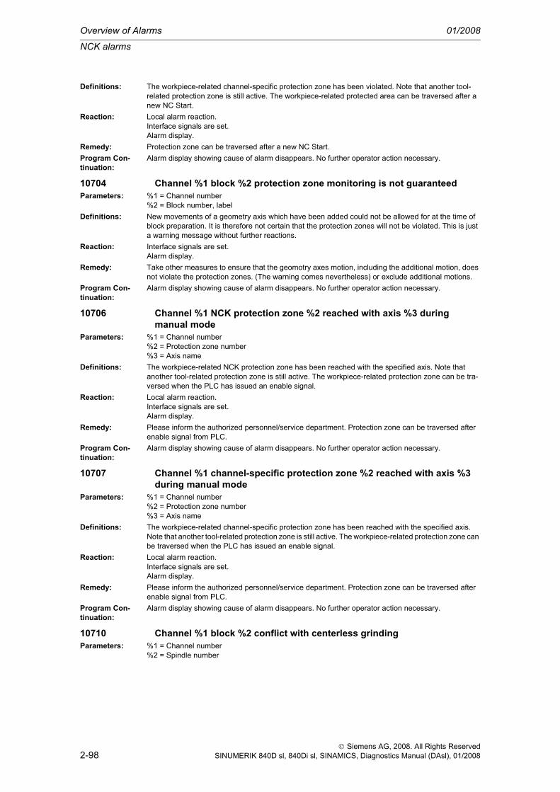
Overview of Alarms 01/2008
NCK alarms
2-98
© Siemens AG, 2008. All Rights ReservedSINUMERIK 840D sl, 840Di sl, SINAMICS, Diagnostics Manual (DAsl), 01/2008
Definitions: The workpiece-related channel-specific protection zone has been violated. Note that another tool-related protection zone is still active. The workpiece-related protected area can be traversed after a new NC Start.
Reaction: Local alarm reaction.Interface signals are set.Alarm display.
Remedy: Protection zone can be traversed after a new NC Start.Program Con-tinuation:
Alarm display showing cause of alarm disappears. No further operator action necessary.
10704 Channel %1 block %2 protection zone monitoring is not guaranteedParameters: %1 = Channel number
%2 = Block number, labelDefinitions: New movements of a geometry axis which have been added could not be allowed for at the time of
block preparation. It is therefore not certain that the protection zones will not be violated. This is just a warning message without further reactions.
Reaction: Interface signals are set.Alarm display.
Remedy: Take other measures to ensure that the geomotry axes motion, including the additional motion, does not violate the protection zones. (The warning comes nevertheless) or exclude additional motions.
Program Con-tinuation:
Alarm display showing cause of alarm disappears. No further operator action necessary.
10706 Channel %1 NCK protection zone %2 reached with axis %3 during manual mode
Parameters: %1 = Channel number%2 = Protection zone number%3 = Axis name
Definitions: The workpiece-related NCK protection zone has been reached with the specified axis. Note that another tool-related protection zone is still active. The workpiece-related protection zone can be tra-versed when the PLC has issued an enable signal.
Reaction: Local alarm reaction.Interface signals are set.Alarm display.
Remedy: Please inform the authorized personnel/service department. Protection zone can be traversed after enable signal from PLC.
Program Con-tinuation:
Alarm display showing cause of alarm disappears. No further operator action necessary.
10707 Channel %1 channel-specific protection zone %2 reached with axis %3 during manual mode
Parameters: %1 = Channel number%2 = Protection zone number%3 = Axis name
Definitions: The workpiece-related channel-specific protection zone has been reached with the specified axis. Note that another tool-related protection zone is still active. The workpiece-related protection zone can be traversed when the PLC has issued an enable signal.
Reaction: Local alarm reaction.Interface signals are set.Alarm display.
Remedy: Please inform the authorized personnel/service department. Protection zone can be traversed after enable signal from PLC.
Program Con-tinuation:
Alarm display showing cause of alarm disappears. No further operator action necessary.
10710 Channel %1 block %2 conflict with centerless grindingParameters: %1 = Channel number
%2 = Spindle number

NCK alarms
01/2008 Overview of Alarms
2-99
© Siemens AG, 2008. All Rights ReservedSINUMERIK 840D sl, 840Di sl, SINAMICS, Diagnostics Manual (DAsl), 01/2008
Definitions: Centerless grinding is active and a block has been processed that satisfies at least one of the following conditions:- G96 active and regulating spindle is master spindle.- Regulating spindle is in interdependent grouping.- Axes of centerless transformation overlap with an active transformation and a tool is active.- Constant wheel peripheral speed for the regulating spindle is active.
Reaction: Interpreter stopNC Start disable in this channel.Interface signals are set.Alarm display.
Remedy: Modify program.Program Con-tinuation:
Clear alarm with the RESET key. Restart part program
10720 Channel %1 block %3 axis %2 software limit switch %4Parameters: %1 = Channel number
%2 = Axis name, spindle number%3 = Block number, label%4 = String ( + or - )
Definitions: The path programmed for the axis violates the currently valid software limit switch. The alarm is acti-vated when preparing the part program block.If bit 11=0 in the machine data $MN_ENABLE_ALARM_MASK, this alarm is issued instead of alarm 10722. If bit 11 is set in the machine data $MN_ENABLE_ALARM_MASK, an expanded diagnostics option is offered for the software limit switch violation. The condition for activation is the presence of the ALUN* alarm file in the HMI.
Reaction: Correction block is reorganized.Local alarm reaction.Interface signals are set.Alarm display.
Remedy: Check and correct positions in the NC program.Please inform the authorized personnel/service department.Check machine data: 36100 POS_LIMIT_MINUS / 36120 POS_LIMIT_MINUS2 and 36110 POS_LIMIT_PLUS / 36130 POS_LIMIT_PLUS2 for the software limit switches.Check the axis-specific interface signals: DB31, ... DBX12.3 / 12.2 (2nd software limit switch plus/minus) to see whether the 2nd software limit switch is selected.Check the currently active work offsets via the current frame.Work offsets, overlaid movements ($AA_OFF), DRF and transformation components must also be checked.
Program Con-tinuation:
Clear alarm with NC START or RESET key and continue the program.
10721 Channel %1 block %3 axis %2 software limit switch %4Parameters: %1 = Channel number
%2 = Axis name, spindle number%3 = Block number, label%4 = String ( + or - )
Definitions: The motion planned for the axis violates the currently valid software limit switch.The alarm is activated during the preparation of approach or rest blocks for REPOS.This alarm is issued instead of alarm 10723 if bit11=0 in machine data $MN_ENABLE_ALARM_MASK. If bit11 is set in this machine data $MN_ENABLE_ALARM_MASK, an expanded diagnostics option is offered for the software limit switch violation. The condition for acti-vation is the presence of the ALUN* alarm file in the HMI. See also the diagnostics guide for alarm 10723.
Reaction: Local alarm reaction.Interface signals are set.Alarm display.

Overview of Alarms 01/2008
NCK alarms
2-100
© Siemens AG, 2008. All Rights ReservedSINUMERIK 840D sl, 840Di sl, SINAMICS, Diagnostics Manual (DAsl), 01/2008
Remedy: Determine the cause of the offset from the initial or target position. The REPOS command is executed at the end of an ASUB or system ASUB. See also cross reference from ASUBs.Check the axis-specific NC/PLC interface signals DB31, ... DBX12.3 / 12.2 (2nd software limit switch plus/minus) to see whether the 2nd software limit switch is selected.Check the currently active work offset via the current frame.Also check the external work offsets, overlaid movements ($AA_OFF), DRF and transformation com-ponents.Cancel the NC program with NC reset.
Program Con-tinuation:
Clear alarm with the RESET key. Restart part program
10722 Channel %1 block %5 axis %2 software limit switch %6 violated, residual distance: %7 %3<ALUN> violated
Parameters: %1 = Channel number%2 = Axis name, spindle number%3 = Unit of distance%4 = Block number, label|number+string(+/-)|residual distance
Definitions: The path programmed for the axis violates the currently valid software limit switch. The alarm is acti-vated when preparing the part program block.This alarm is issued instead of alarm 10720 if bit 11=1 in the machine data $MN_ENABLE_ALARM_MASK. Alarm 10722 offers an expanded diagnostics option for the software limit switch violation. The condition for activation is the presence of the ALUN* alarm file in the HMI.See also diagnostics guide for alarm 10720.
Reaction: Correction block is reorganized.Local alarm reaction.Interface signals are set.Alarm display.
Remedy: Check and correct positions in the NC program.Please inform the authorized personnel/service department.Machine data: 36100 POS_LIMIT_MINUS/36120 POS_LIMIT_MINUS2 and 36110 POS_LIMIT_PLUS/36130 POS_LIMIT_PLUS2 must be checked for the software limit switches.Check the axis-specific interface signals: DB31, ... DBX12.3 / 12.2 (2nd software limit switch plus/minus) to see whether the 2nd software limit switch is selected.Check currently active work offsets via the current frame.Work offsets, overlaid movements ($AA_OFF), DRF and transformation components must also be checked.
Program Con-tinuation:
Clear alarm with NC START or RESET key and continue the program.
10723 Channel %1 block %5 axis %2 software limit switch %6 violated, residual distance: %7 %3<ALUN>
Parameters: %1 = Channel number%2 = Axis name, spindle number%3 = Unit of distance%4 = Block number, label|number+string(+/-)|residual distance
Definitions: The motion planned for the axis violates the currently active software limit switch.The alarm is activated during the preparation of approach or rest blocks for REPOS.This alarm is issued instead of alarm 10721 if bit11=1 in machine data $MN_ENABLE_ALARM_MASK. Alarm 10723 offers an expanded diagnostics option for the software limit switch violation. The condition for activation is the presence of the ALUN* alarm file in the HMI. See also the Diagnostics Guide for alarm 10721.
Reaction: Local alarm reaction.Interface signals are set.Alarm display.

NCK alarms
01/2008 Overview of Alarms
2-101
© Siemens AG, 2008. All Rights ReservedSINUMERIK 840D sl, 840Di sl, SINAMICS, Diagnostics Manual (DAsl), 01/2008
Remedy: Determine the cause of the offset from the initial or target position. The REPOS command is executed at the end of an ASUB or system ASUB. See also cross reference from ASUBs.Please inform the authorized personnel/service department.Check the machine data: 36100 POS_LIMIT_MINUS / 36120 POS_LIMIT_MINUS2 and 36110 POS_LIMIT_PLUS / 36130 POS_LIMIT_PLUS2 for the software limit switches.Check the axis-specific interface signals DB31, ... DBX12.3 / 12.2 (2nd software limit switch plus/minus) to see whether the 2nd software limit switch is selected.Check the currently active work offset via the current frame.Also check the external work offsets, overlaid movements ($AA_OFF), DRF and transformation com-ponents.Cancel the NC program with NC reset.
Program Con-tinuation:
Clear alarm with the RESET key. Restart part program
10730 Channel %1 block %3 axis %2 working area limitation %4Parameters: %1 = Channel number
%2 = Axis name, spindle number%3 = Block number, label%4 = String ( + or - )
Definitions: This alarm is generated if it is determined during block preparation that the programmed path of the axis violates the working area limitation.If bit 11=0 in machine data $MN_ENABLE_ALARM_MASK, this alarm is issued instead of alarm 10732. If bit 11 is set in machine data $MN_ENABLE_ALARM_MASK, an expanded diagnostics option is offered for the software limit switch violation. The condition for activation is the presence of the ALUN* alarm file in the HMI.
Reaction: Correction block is reorganized.Local alarm reaction.Interface signals are set.Alarm display.
Remedy: a) Check NC program for correct positional data and, if necessary, make corrections.b) Check zero offsets (current frame)c) Correct working area limitation via G25/G26, ord) Correct working area limitation via setting data, ore) Deactivate working area limitation via setting data 43410 WORKAREA_MINUS_ENABLE=FALSE
Program Con-tinuation:
Clear alarm with NC START or RESET key and continue the program.
10731 Channel %1 block %3 axis %2 working area limitation %4Parameters: %1 = Channel number
%2 = Axis name, spindle number%3 = Block number, label%4 = String ( + or - )
Definitions: The motion planned for the axis violates the currently active working area limit.The alarm is activated during the preparation of approach or rest blocks for REPOS.This alarm is issued instead of alarm10733 if bit11 is not set in machine data $MN_ENABLE_ALARM_MASK.
Reaction: Local alarm reaction.Interface signals are set.Alarm display.
Remedy: Determine the cause of the offset from the initial or target position. The REPOS command is executed at the end of an ASUB or system ASUB. See also cross reference from ASUBs.Check the currently active work offset via the current frame.Also check the external work offsets, overlaid movements ($AA_OFF), DRF and transformation com-ponents.Cancel NC program with NC reset.
Program Con-tinuation:
Clear alarm with the RESET key. Restart part program

Overview of Alarms 01/2008
NCK alarms
2-102
© Siemens AG, 2008. All Rights ReservedSINUMERIK 840D sl, 840Di sl, SINAMICS, Diagnostics Manual (DAsl), 01/2008
10732 Channel %1 block %5 axis %2 working area limitation violated, residual distance: %6 %3<ALUN>
Parameters: %1 = Channel number%2 = Axis name, spindle number%3 = Unit of distance%4 = Block number, label|residual distance
Definitions: This alarm is generated if it is determined during block preparation that the programmed path of the stated axis violates the working area limitation.This alarm is issued instead of alarm 10730 if bit 11=1 in machine data $MN_ENABLE_ALARM_MASK. Alarm 10732 offers an expanded diagnostics option for the working area limitation violation. The condition for activation is the presence of the ALUN* alarm file in the HMI.
Reaction: Correction block is reorganized.Local alarm reaction.Interface signals are set.Alarm display.
Remedy: a) Check NC program for correct positional data and, if necessary, make corrections.b) Check zero offsets (current frame)c) Correct working area limitation via G25/G26, ord) Correct working area limitation via setting data, ore) Deactivate working area limitation via setting data 43410 WORKAREA_MINUS_ENABLE=FALSE
Program Con-tinuation:
Clear alarm with NC START or RESET key and continue the program.
10733 Channel %1 block %5 axis %2 working area limitation violated, residual distance: %6 %3<ALUN>
Parameters: %1 = Channel number%2 = Axis name, spindle number%3 = Unit of distance%4 = Block number, label|residual distance
Definitions: The motion planned for the axis violates the currently active working area limitation.The alarm is activated during the preparation of approach or rest blocks for REPOS.This alarm is issued instead of alarm 10731 if bit11=1 in machine data $MN_ENABLE_ALARM_MASK. Alarm 10733 offers an expanded diagnostics option for the working area limitation violation. The condition for activation is the presence of the ALUN* alarm file in the HMI.
Reaction: Local alarm reaction.Interface signals are set.Alarm display.
Remedy: Determine the cause of the offset from the initial or target position. The REPOS command is executed at the end of an ASUB or system ASUB. See also cross reference from ASUBs.Check the currently active work offset via the current frame.Also check the external work offsets, overlaid movements ($AA_OFF), DRF and transformation com-ponents.Cancel NC program with NC reset.
Program Con-tinuation:
Clear alarm with the RESET key. Restart part program
10735 Channel %1 block %5 axis %2 coordinate system-specific working area limitation violated, residual distance: %6 %3<ALUN>
Parameters: %1 = Channel number%2 = Axis name, spindle number%3 = Unit of distance%4 = Block number, label|residual distance
Definitions: This alarm is generated if it is determined during block preparation that the programmed path of the stated axis violates the coordinate system-specific working area limitation.
Reaction: Correction block is reorganized.Local alarm reaction.Interface signals are set.Alarm display.

NCK alarms
01/2008 Overview of Alarms
2-103
© Siemens AG, 2008. All Rights ReservedSINUMERIK 840D sl, 840Di sl, SINAMICS, Diagnostics Manual (DAsl), 01/2008
Remedy: a) Check NC program for correct positional data and, if necessary, make corrections.b) Check work offsets (current frame)c) Correct the working area limitation with WALCS1 ... WALCS9, ord) Correct the working area limitation in $P_WORKAREA_CS_LIMIT_PLUS or $P_WORKAREA_CS_LIMIT_MINUS, ore) Deactivate the working area limitation with $P_WORKAREA_CS_MINUS_ENABLE =FALSE or $P_WORKAREA_CS_PLUS_ENABLE.In cases d) and e), then reactivate the group of the selected coordinate system-specific working area limitation.
Program Con-tinuation:
Clear alarm with NC START or RESET key and continue the program.
10736 Channel %1 block %5 axis %2 coordinate system-specific working area limitation violated, residual distance: %6 %3<ALUN>
Parameters: %1 = Channel number%2 = Axis name, spindle number%3 = Unit of distance%4 = Block number, label|residual distance
Definitions: This alarm is generated if it is determined during block preparation that the programmed path of the stated axis violates the coordinate system-specific working area limitation.The alarm is activated during the preparation of approach or residual blocks for REPOS.
Reaction: Local alarm reaction.Interface signals are set.Alarm display.
Remedy: Determine the cause of the offset from the initial or target position. The REPOS command is executed at the end of an ASUB or system ASUB. See also cross reference from ASUBs.Check the currently active work offset via the current frame.Also check the external work offsets, overlaid movements ($AA_OFF), DRF and transformation com-ponents.Cancel NC program with NC reset.
Program Con-tinuation:
Clear alarm with the RESET key. Restart part program
10740 Channel %1 block %2 too many empty blocks in WAB programmingParameters: %1 = Channel number
%2 = Block number, labelDefinitions: It is not allowed to program more blocks than specified by machine data
MC_WAB_MAXNUM_DUMMY_BLOCKS between the WAB block and the block determining the approach and retraction tangent.
Reaction: Correction block is reorganized.Local alarm reaction.Interface signals are set.Alarm display.NC Stop on alarm at block end.
Remedy: Modify part program.Program Con-tinuation:
Clear alarm with NC START or RESET key and continue the program.
10741 Channel %1 block %2 direction reversal with WAB infeed motionParameters: %1 = Channel number
%2 = Block number, labelDefinitions: A safety distance which has been programmed is located perpendicular to the machining plane and
not between the start and end point of the WAB contour.Reaction: Correction block is reorganized.
Local alarm reaction.Interface signals are set.Alarm display.NC Stop on alarm at block end.
Remedy: Modify part program.Program Con-tinuation:
Clear alarm with NC START or RESET key and continue the program.

Overview of Alarms 01/2008
NCK alarms
2-104
© Siemens AG, 2008. All Rights ReservedSINUMERIK 840D sl, 840Di sl, SINAMICS, Diagnostics Manual (DAsl), 01/2008
10742 Channel %1 block %2 WAB distance invalid or not programmedParameters: %1 = Channel number
%2 = Block number, labelDefinitions: Possible causes:
- In a WAB block, the parameter DISR has not been specified or its value is less than or equal to 0.- During approach or retraction with circle and active tool radius, the radius of the internally generated - WAB contour is negative. The internally generated WAB contour is a circle with a radius which, when offset with the current offset radius (sum of tool radius and offset value OFFN), yields the tool center point path with the programmed radius DISR.
Reaction: Correction block is reorganized.Local alarm reaction.Interface signals are set.Alarm display.NC Stop on alarm at block end.
Remedy: Modify part program.Program Con-tinuation:
Clear alarm with NC START or RESET key and continue the program.
10743 Channel %1 block %2 WAB programmed several timesParameters: %1 = Channel number
%2 = Block number, labelDefinitions: An attempt has been made to activate a WAB motion before a previously activated WAB motion was
terminated.Reaction: Correction block is reorganized.
Local alarm reaction.Interface signals are set.Alarm display.NC Stop on alarm at block end.
Remedy: Modify part program.Program Con-tinuation:
Clear alarm with NC START or RESET key and continue the program.
10744 Channel %1 block %2 no valid WAB direction definedParameters: %1 = Channel number
%2 = Block number, labelDefinitions: The tangent direction for smooth approach or retraction is not defined.
Possible causes:- In the program, no block with travel information follows the approach block.- Before a retraction block, no block with travel information has been programmed in a program.- The tangent to be used for WAB motion is vertical to the current machining plane.
Reaction: Correction block is reorganized.Local alarm reaction.Interface signals are set.Alarm display.NC Stop on alarm at block end.
Remedy: Modify part program.Program Con-tinuation:
Clear alarm with NC START or RESET key and continue the program.
10745 Channel %1 block %2 WAB end position not clearParameters: %1 = Channel number
%2 = Block number, labelDefinitions: In the WAB block and in the following block, the position has been programmed perpendicular to the
machining direction. In the WAB block, no position has been indicated in the machining plane.Reaction: Correction block is reorganized.
Local alarm reaction.Interface signals are set.Alarm display.NC Stop on alarm at block end.

NCK alarms
01/2008 Overview of Alarms
2-105
© Siemens AG, 2008. All Rights ReservedSINUMERIK 840D sl, 840Di sl, SINAMICS, Diagnostics Manual (DAsl), 01/2008
Remedy: Modify part program. Either remove the position data for the infeed axis from the WAB block or the following block, or program a position in the machining plane in the WAB block as well.
Program Con-tinuation:
Clear alarm with NC START or RESET key and continue the program.
10746 Channel %1 block %2 block search stop for WABParameters: %1 = Channel number
%2 = Block number, labelDefinitions: A preprocessing stop has been inserted between an SAR approach block and the following block
defining the tangent direction or between an SAR retraction block and the following block defining the end position.
Reaction: Correction block is reorganized.Local alarm reaction.Interface signals are set.Alarm display.NC Stop on alarm at block end.
Remedy: Modify part program.Program Con-tinuation:
Clear alarm with NC START or RESET key and continue the program.
10747 Channel %1 block %2 retraction direction not defined for WABParameters: %1 = Channel number
%2 = Block number, labelDefinitions: In a WAB retraction block with quarter circle or semi-circle (G248 or G348), the end point in the
machining plane was not programmed, and either G143 or G140 without tool radius compensation is active.
Reaction: Correction block is reorganized.Local alarm reaction.Interface signals are set.Alarm display.NC Stop on alarm at block end.
Remedy: Modify part program. The following changes are possible:- Indicate end point in the machining plane in the WAB block.- Activate tool radius compensation (effective for G140 only, not for G143).- State retraction side explicitly with G141 or G142.- Perform retraction with a straight line instead of a circle.
Program Con-tinuation:
Clear alarm with NC START or RESET key and continue the program.
10748 Channel %1 block %2 illegal retract plane with WABParameters: %1 = Channel number
%2 = Block number, labelDefinitions: By means of DISRP a position of the retraction plane has been programmed which is not situated
between the safety distance (DISCL) and the starting point (during approach) and/or end point (during retraction) of the WAB movement.
Reaction: Correction block is reorganized.Local alarm reaction.Interface signals are set.Alarm display.NC Stop on alarm at block end.
Remedy: Modify part programProgram Con-tinuation:
Clear alarm with NC START or RESET key and continue the program.
10750 Channel %1 block %2 tool radius compensation activated without tool number
Parameters: %1 = Channel number%2 = Block number, label

Overview of Alarms 01/2008
NCK alarms
2-106
© Siemens AG, 2008. All Rights ReservedSINUMERIK 840D sl, 840Di sl, SINAMICS, Diagnostics Manual (DAsl), 01/2008
Definitions: A tool T... must be selected so that the control can make allowance for the associated compensation values.A correction data block (D1) containing the correction values (parameter P1 - P25) is automatically assigned to each tool (T number). Up to 9 correction data blocks can be assigned to a tool by speci-fying the required data block with the D number (D1 - D9).The cutter radius compensation (CRC) is allowed for if function G41 or G42 is programmed. The cor-rection values are contained in parameter P6 (geometry value) and P15 (wear value) of the active cor-rection data block Dx.
Reaction: Correction block is reorganized.Interpreter stopLocal alarm reaction.Interface signals are set.Alarm display.
Remedy: Before calling the CRC with G41/G42, program a tool number under the address T...Program Con-tinuation:
Clear alarm with NC START or RESET key and continue the program.
10751 Channel %1 block %2 danger of collision due to tool radius compensation
Parameters: %1 = Channel number%2 = Block number, label
Definitions: The "Bottleneck detection" (calculation of intersection for the following compensated traversing blocks) has not been able to calculate a point of intersection for the reviewed number of traversing blocks. It is therefore possible that one of the equidistant paths violates the workpiece contour.
Reaction: Correction block is reorganized.Local alarm reaction.Interface signals are set.Alarm display.NC Stop on alarm at block end.
Remedy: Please inform the authorized personnel/service department. Check the part program and, if possible, modify the programming so that inside corners with smaller paths than the correction value are avoided. (Outside corners are not critical because the equidistants are lengthened or intermediate blocks are inserted, so that there is always a point of intersection).Increase the number of reviewed traversing blocks via machine data MD20240 $MC_CUTCOM_MAXNUM_CHECK_BLOCKS (default: 3), this increases the amount of calculation and consequently also the block cycle time.
Program Con-tinuation:
Clear alarm with NC START or RESET key and continue the program.
10752 Channel %1 block %2 overflow of local block buffer with tool radius compensation
Parameters: %1 = Channel number%2 = Block number, label
Definitions: The cutter radius compensation must buffer a variable number of intermediate blocks in order to enable calculation of the equidistant tool path for each NC block. The size of the buffer cannot be determined by simple means. It depends on the number of blocks without traversing information in the compensation plane, the number of contour elements to be inserted and the shape of the curvature in spline and polynomial interpolation.The size of the buffer is fixed by the system and cannot be changed via the MDs.
Reaction: Correction block is reorganized.Local alarm reaction.Interface signals are set.Alarm display.NC Stop on alarm at block end.

NCK alarms
01/2008 Overview of Alarms
2-107
© Siemens AG, 2008. All Rights ReservedSINUMERIK 840D sl, 840Di sl, SINAMICS, Diagnostics Manual (DAsl), 01/2008
Remedy: Please inform the authorized personnel/service department.Reduce the size of the buffer that has been assigned by modifying the NC program.- By avoiding:- Blocks without traversing information in the compensation plane- Blocks with contour elements having a variable curvature (e.g. ellipses) and with curvature radii that are smaller than the compensation radius. (Such blocks are divided up into several subblocks).- Reduce the number of reviewed blocks for collision monitoring (MD20240 $MC_CUTCOM_MAXNUM_CHECK_BLOCKS).
Program Con-tinuation:
Clear alarm with NC START or RESET key and continue the program.
10753 Channel %1 block %2 selection of the tool radius compensation only possible in linear block
Parameters: %1 = Channel number%2 = Block number, label
Definitions: Selection of cutter radius compensation with G41/G42 may only be performed in blocks where the G function G00 (rapid traverse) or G01 (feed) is active.In the block with G41/G42, at least one axis in the plane G17 to G19 must be written. It is always advis-able to write both axes because, as a rule, both axes are traversed when selecting the compensation.
Reaction: Correction block is reorganized.Local alarm reaction.Interface signals are set.Alarm display.NC Stop on alarm at block end.
Remedy: Correct the NC program and put the compensation selection in a block with linear interpolation.Program Con-tinuation:
Clear alarm with NC START or RESET key and continue the program.
10754 Channel %1 block %2 deselection of the tool radius compensation only possible in linear block
Parameters: %1 = Channel number%2 = Block number, label
Definitions: Deselection of cutter radius compensation with G40 can only be performed in blocks where the G function G00 (rapid traverse) or G01 (feed) is active.In the block with G40, at least one axis in the plane G17 to G19 must be written. It is always advisable to write both axes because, as a rule, both axes are traversed when deselecting the compensation.
Reaction: Correction block is reorganized.Local alarm reaction.Interface signals are set.Alarm display.NC Stop on alarm at block end.
Remedy: Correct the NC program and put the compensation selection in a block with linear interpolation.Program Con-tinuation:
Clear alarm with NC START or RESET key and continue the program.
10755 Channel %1 block %2 selection of the tool radius compensation via KONT not possible at the current starting point
Parameters: %1 = Channel number%2 = Block number, label
Definitions: When activating the cutter radius compensation with KONT the starting point of the approach block is within the compensation circle and therefore already violates the contour.If the cutter radius compensation is selected with G41/G42, the approach behavior (NORM or KONT) determines the compensation movement if the present actual position is behind the contour. With KONT, a circle is drawn with the cutter radius around the programmed initial point (= end point of the approach block). The tangent that passes through the current actual position and does not violate the contour is the approach movement.If the start point is within the compensation circle around the target point, no tangent passes through this point.

Overview of Alarms 01/2008
NCK alarms
2-108
© Siemens AG, 2008. All Rights ReservedSINUMERIK 840D sl, 840Di sl, SINAMICS, Diagnostics Manual (DAsl), 01/2008
Reaction: Correction block is reorganized.Local alarm reaction.Interface signals are set.Alarm display.NC Stop on alarm at block end.
Remedy: Place selection of the CRC such that the starting point of the approach movements comes to rest out-side of the correction circle around the target point (programmed traversing movements > compensa-tion radius). The following possibilities are available:- Selection in the previous block- Insert intermediate block- Select approach behavior NORM
Program Con-tinuation:
Clear alarm with NC START or RESET key and continue the program.
10756 Channel %1 block %2 deselection of the tool radius compensation via KONT not possible at the programmed end point
Parameters: %1 = Channel number%2 = Block number, label
Definitions: On deselection of the cutter radius compensation, the programmed end point is within the compensa-tion circle. If this point were in fact to be approached without compensation, there would be a contour violation.If the cutter radius compensation is deselected via G40, the approach behavior (NORM or KONT) determines the compensation movement if the programmed end point is behind the contour. With KONT, a circle is drawn with the cutter radius about the last point at which the compensation is still active. The tangent passing through the programmed end position and not violating the contour is the retraction movement.If the start point is within the compensation circle around the target point, no tangent passes through this point.
Reaction: Correction block is reorganized.Local alarm reaction.Interface signals are set.Alarm display.NC Stop on alarm at block end.
Remedy: Place deselection of the CRC such that the programmed end point comes to rest outside the compen-sation circle around the last active compensation point. The following possibilities are available:- Deselection in the next block- Insert intermediate block- Select retract behavior NORM
Program Con-tinuation:
Clear alarm with NC START or RESET key and continue the program.
10757 Channel %1 block %2 changing the compensation plane while tool radius compensation is active not possible
Parameters: %1 = Channel number%2 = Block number, label
Definitions: In order to change the compensation plane (G17, G18 or G19) it is first necessary to deselect the cut-ter radius compensation with G40.
Reaction: Correction block is reorganized.Local alarm reaction.Interface signals are set.Alarm display.NC Stop on alarm at block end.
Remedy: Insert an intermediate block in the part program using the correction deselection. After the plane change, the cutter radius compensation is to be selected in an approach block with linear interpolation.
Program Con-tinuation:
Clear alarm with NC START or RESET key and continue the program.
10758 Channel %1 block %2 curvature radius with variable compensation value too small
Parameters: %1 = Channel number%2 = Block number, label

NCK alarms
01/2008 Overview of Alarms
2-109
© Siemens AG, 2008. All Rights ReservedSINUMERIK 840D sl, 840Di sl, SINAMICS, Diagnostics Manual (DAsl), 01/2008
Definitions: The current cutter radius compensation (the cutter used) is too large for the programmed path radius.In a block with variable tool radius compensation, a compensation must be possible either anywhere or nowhere on the contour with the smallest and the largest compensation value from the programmed range. There must be no point on the contour in which the curvature radius is within the variable com-pensation range.If the compensation value varies its sign within a block, both sides of the contour are checked, other-wise only the compensation side.
Reaction: Correction block is reorganized.Local alarm reaction.Interface signals are set.Alarm display.NC Stop on alarm at block end.
Remedy: Use smaller cutters or allow for a part of the cutter radius at the time of contour programming.Program Con-tinuation:
Clear alarm with NC START or RESET key and continue the program.
10759 Channel %1 block %2 path is parallel to tool orientationParameters: %1 = Channel number
%2 = Block number, labelDefinitions: In a block with spline or polynomial interpolation, the corrected path runs in at least one point parallel
to the tool orientation, i.e. the path has a tangent perpendicular to the compensation plane.The tangent at a point on a path is regarded as parallel to the tool orientation if the angle between the two directions is less than the limit value defined by machine data $MC_CUTCOM_PARALLEL_ORI_LIMIT.However, in circumferential milling, straight lines running parallel to the tool orientation are permissi-ble, as well as circles with a circle plane perpendicular to the compensation plane (application with smooth retraction from the groove).Straight lines in the direction of the tool orientation are not permissible in face milling (CUT3D, CUT3DF, CUT3DFS).
Reaction: Correction block is reorganized.Local alarm reaction.Interface signals are set.Alarm display.NC Stop on alarm at block end.
Remedy: Do not use splines or polynomials when writing the contour section, but straight lines and circles instead. Divide up the tool piece geometry and deselect the cutter radius compensation between the various sections.
Program Con-tinuation:
Clear alarm with NC START or RESET key and continue the program.
10760 Channel %1 block %2 helical axis is not parallel to tool orientationParameters: %1 = Channel number
%2 = Block number, labelDefinitions: With active tool radius compensation a helix is only permissible if the helix axis is parallel to the tool,
i.e. the circle plane and the compensation plane must be identical.Reaction: Correction block is reorganized.
Local alarm reaction.Interface signals are set.Alarm display.NC Stop on alarm at block end.
Remedy: Orient helix axis perpendicular to the machining plane.Program Con-tinuation:
Clear alarm with NC START or RESET key and continue the program.
10761 Channel %1 block %2 tool radius compensation for ellipse with more than one revolution not possible
Parameters: %1 = Channel number%2 = Block number, label
Overview of Alarms 01/2008
NCK alarms
2-110
© Siemens AG, 2008. All Rights ReservedSINUMERIK 840D sl, 840Di sl, SINAMICS, Diagnostics Manual (DAsl), 01/2008
Definitions: When machining the inside of an ellipse, in parts of the ellipse the curvature radii are greater than or smaller than the cutter radius compensation.In ellipses, in this case the block would be split up into 4 subblocks with curvature radii that are greater than and less than the compensation radius. Over several revolutions, there would be a tremendous increase in the amount of calculation required by the unlimited number of resulting subblocks, and therefore this situation is rejected by the error message.If compensation is possible everywhere or nowhere on the ellipse, then ellipses are also permissible that cover more than one full revolution.
Reaction: Correction block is reorganized.Local alarm reaction.Interface signals are set.Alarm display.NC Stop on alarm at block end.
Remedy: Use cutter with smaller radius or program motion block on blocks with no more than one revolution.Program Con-tinuation:
Clear alarm with NC START or RESET key and continue the program.
10762 Channel %1 block %2 too many empty blocks between two traversing blocks with active tool radius compensation
Parameters: %1 = Channel number%2 = Block number, label
Definitions: The maximum permissible number of empty blocks is limited by a machine data.Reaction: Correction block is reorganized.
Local alarm reaction.Interface signals are set.Alarm display.NC Stop on alarm at block end.
Remedy: - Modify part program- Modify machine data- Check whether SBL2 is activated. With SBL2, a block is generated from each part program line which can lead to exceeding the maximum permissible number of empty blocks between two traversing blocks.
Program Con-tinuation:
Clear alarm with NC START or RESET key and continue the program.
10763 Channel %1 block %2 path component of the block in the compensation plane becomes zero
Parameters: %1 = Channel number%2 = Block number, label
Definitions: Due to the collision monitoring with active tool radius compensation, the path component of the block in the compensation plane becomes zero. If the original block contains no motion information perpen-dicular to the compensation plane, it means that this block is excluded. The alarm can be suppressed with machine date 11410 SUPPRESS_ALARM_MASK Bit1 = 1.
Reaction: Alarm display.Remedy: - The behavior is correct at narrow locations that cannot be machined with the active tool.
- Modify the part program if necessary.- Use tool with smaller radius if necessary.- Program CDOF/CDOF2.
Program Con-tinuation:
Clear alarm with the Delete key or NC START.
10764 Channel %1 block %2 discontinuous path with active tool radius compensation
Parameters: %1 = Channel number%2 = Block number, label

NCK alarms
01/2008 Overview of Alarms
2-111
© Siemens AG, 2008. All Rights ReservedSINUMERIK 840D sl, 840Di sl, SINAMICS, Diagnostics Manual (DAsl), 01/2008
Definitions: This alarm occurs when, with active tool radius compensation, the starting point used for calculating the compensation is not identical to the end point of the preceding block. This situation can occur, for example, when a geometry axis is traversed between two positions as a positioning axis or when, with an active kinematic transformation (e.g. 5-axis transformation) the tool length compensation is altered.
Reaction: Correction block is reorganized.Local alarm reaction.Interface signals are set.Alarm display.NC Stop on alarm at block end.
Remedy: Modify part program.Program Con-tinuation:
Clear alarm with NC START or RESET key and continue the program.
10765 Channel %1 block %2 3D tool radius compensation not possibleParameters: %1 = Channel number
%2 = Block number, labelDefinitions: This alarm occurs when an attempt is made to activate the 3D tool radius compensation even though
the option required for this is not fitted in the control.Reaction: Correction block is reorganized.
Local alarm reaction.Interface signals are set.Alarm display.NC Stop on alarm at block end.
Remedy: Use another software version. The option cannot be activated by altering machine data because the necessary code is not physically available.
Program Con-tinuation:
Clear alarm with NC START or RESET key and continue the program.
10766 Channel %1 illegal change of surface orientation between block %2 and block %3
Parameters: %1 = Channel number%2 = Block number, label%3 = Block number, label
Definitions: This alarm occurs with 3D face milling when, at the time of block transition, the surface defined in the first block is continued in the second block with the rear side of the surface defined there. The block number in the alarm designates the second block.
Reaction: Correction block is reorganized.Local alarm reaction.Interface signals are set.Alarm display.NC Stop on alarm at block end.
Remedy: Modify part program.Program Con-tinuation:
Clear alarm with NC START or RESET key and continue the program.
10767 Channel %1 block %2 processing with tilt angle unequal 0 not possibleParameters: %1 = Channel number
%2 = Block number, labelDefinitions: When face milling with a torus milling cutter, the tilt angle must be 0 if the surface normal vector and
the tool orientation include an angle that is less than the limiting angle given by the machine data 21082 CUTCOM_PLANE_ORI_LIMIT, i.e. in this case only the lead angle may be unequal to 0.
Reaction: Correction block is reorganized.Local alarm reaction.Interface signals are set.Alarm display.NC Stop on alarm at block end.
Remedy: Modify part program. If necessary, use another tool (ball end mill).Program Con-tinuation:
Clear alarm with NC START or RESET key and continue the program.

Overview of Alarms 01/2008
NCK alarms
2-112
© Siemens AG, 2008. All Rights ReservedSINUMERIK 840D sl, 840Di sl, SINAMICS, Diagnostics Manual (DAsl), 01/2008
10768 Channel %1 block %2 illegal tool orientation with 3D tool radius compensation
Parameters: %1 = Channel number%2 = Block number, label
Definitions: This alarm can occur with 3D face milling: The angle between the surface normal vector of the surface to be machined and the extremal surface normal vector of the tool surface is smaller than the limit value given by the machine data 21080 CUTCOM_PARALLEL_ORI_LIMIT, or the tool is oriented such that machining would have to be performed from the rear side of the surface. In this case, the extremal surface normal vector is the vector whose direction deviates most from the direction in the tool point (i.e. parallel to the tool longitudinal axis).With cylindrical tools or tools which end in a cylindrical part (e.g. the standard torus milling cutter), this vector is positioned perpendicular to the tool vector. For this type of tool, the alarm indicates that the angle between the tool longitudinal axis of, for example a side line of the cylinder, and the surface to be machined is smaller than the minimum permissible value. With tools whose (valid) surface ends in a conical part instead of a cylindrical part (e.g. a beveled cutter or a torus milling cutter where the torus is defined to be smaller than 90 degrees), this alarm indicates that the angle between a side line of the taper and the surface to be machined is smaller than the minimum permissible value.
Reaction: Correction block is reorganized.Local alarm reaction.Interface signals are set.Alarm display.NC Stop on alarm at block end.
Remedy: Modify part program. If necessary, use another tool.Program Con-tinuation:
Clear alarm with NC START or RESET key and continue the program.
10769 Channel %1 block %2 Illegal surface normal vector with 3D tool radius compensation
Parameters: %1 = Channel number%2 = Block number, label
Definitions: In 3D face milling, surface normal vector and path tangent vector must theoretically be perpendicular to one another, i.e. they must be at 90° to one another. Since both vectors can be programmed inde-pendently of each other, deviations from this angle are possible and allowed. This alarm is generated when the angle between surface normal vector and path tangent vector becomes less than the limit angle given by the machine data 21084 CUTCOM_PLANE_PATH_LIMIT.
Reaction: Correction block is reorganized.Local alarm reaction.Interface signals are set.Alarm display.NC Stop on alarm at block end.
Remedy: Modify part program.Program Con-tinuation:
Clear alarm with NC START or RESET key and continue the program.
10770 Channel %1 block %2 change of corner type due to change of orientation with active tool radius compensation
Parameters: %1 = Channel number%2 = Block number, label
Definitions: The type of a corner (inside or outside corner) depends not only on the programmed path but also on the tool orientation. For this purpose, the programmed path is projected in the plane perpendicularly to the actual tool orientation and the corner type is determined there. If a change in orientation is pro-grammed (in one or several blocks) between two traversing blocks, resulting in the type of corner at the end of the first traversing block being different from that at the start point of the second block, the above error message is issued.
Reaction: Correction block is reorganized.Local alarm reaction.Interface signals are set.Alarm display.NC Stop on alarm at block end.
Remedy: Modify part program.

NCK alarms
01/2008 Overview of Alarms
2-113
© Siemens AG, 2008. All Rights ReservedSINUMERIK 840D sl, 840Di sl, SINAMICS, Diagnostics Manual (DAsl), 01/2008
Program Con-tinuation:
Clear alarm with NC START or RESET key and continue the program.
10771 Channel %1 block %2 overflow of local block buffer due to orientation smoothing
Parameters: %1 = Channel number%2 = Block number, label
Definitions: This error occurs when more blocks must be buffered than memory space is available.This error can only occur when the software has been incorrectly configured.
Reaction: Correction block is reorganized.Local alarm reaction.Interface signals are set.Alarm display.
Remedy: Increase size of local buffer area.Program Con-tinuation:
Clear alarm with NC START or RESET key and continue the program.
10772 Channel %1 block %2 illegal orientation change when activating or deactivating 3D face cutting
Parameters: %1 = Channel number%2 = Block number, label
Definitions: In face milling, no intermediate blocks with pure orientation change are allowed between the activation block and the first correction block or between the last correction block and the deactivation block (3D tool radius compensation).
Reaction: Correction block is reorganized.Local alarm reaction.Interface signals are set.Alarm display.NC Stop on alarm at block end.
Remedy: Modify part program.Program Con-tinuation:
Clear alarm with NC START or RESET key and continue the program.
10773 Channel %1 illegal tool orientation in block %2 at inside corner with block %3
Parameters: %1 = Channel number%2 = Block number, label%3 = Block number, label
Definitions: On inside corners, the path of the traversing blocks concerned is reduced but the orientation change originally programmed in the block is retained and is now carried out in synchronism with the short-ened path. Because of the ensuing changed relationship between path tangent, surface normal and tool orientation, singular points or points with impermissible side angle can occur in 3D face milling. This is not allowed.
Reaction: Correction block is reorganized.Local alarm reaction.Interface signals are set.Alarm display.NC Stop on alarm at block end.
Remedy: Modify part program.Program Con-tinuation:
Clear alarm with NC START or RESET key and continue the program.
10774 Channel %1 illegal tool dimensions with face cutting in block %2Parameters: %1 = Channel number
%2 = Block number, label

Overview of Alarms 01/2008
NCK alarms
2-114
© Siemens AG, 2008. All Rights ReservedSINUMERIK 840D sl, 840Di sl, SINAMICS, Diagnostics Manual (DAsl), 01/2008
Definitions: This alarm occurs when illegal tool dimensions are programmed for face milling, e.g. negative tool radius, rounding radius zero or negative for tool types that require a rounding radius, taper angle zero or negative for tapered tools.
Reaction: Correction block is reorganized.Local alarm reaction.Interface signals are set.Alarm display.NC Stop on alarm at block end.
Remedy: Modify part program.Program Con-tinuation:
Clear alarm with NC START or RESET key and continue the program.
10775 Channel %1 illegal tool change with face cutting in block %2Parameters: %1 = Channel number
%2 = Block number, labelDefinitions: This alarm occurs when a tool change has been programmed while 3D tool radius compensation is
active with the result that the tool type changes or, if the tool type remains unchanged, at least one relevant tool dimension has changed as compared with the deselected tool. Depending on the tool type, relevant tool dimensions can be the tool diameter, the rounding radius or the taper angle. Changes to the tool length are allowed.
Reaction: Correction block is reorganized.Local alarm reaction.Interface signals are set.Alarm display.NC Stop on alarm at block end.
Remedy: Modify part program.Program Con-tinuation:
Clear alarm with NC START or RESET key and continue the program.
10776 Channel %1 block%2 axis %3 must be geometry axis if tool radius compensation is active
Parameters: %1 = Channel number%2 = Block number, label%3 = Axis name
Definitions: This alarm occurs when an axis that is required for tool radius compensation is not a geometry axis. With CUT2DF, the axis can be a positioning axis perpendicular to the machining plane; with all other types of compensation (CUT2DF, CUT3DC, CUT3DF, CUT3DFF), all geometry axes must be oper-ated as such.
Reaction: Correction block is reorganized.Local alarm reaction.Interface signals are set.Alarm display.NC Stop on alarm at block end.
Remedy: Modify part program.On selection of G41/42, the axes involved must be known as GEOAX in the channel. It is possible by programming GEOAX() or G91 G0 X0 Y0 in the block prior to G41/42.
Program Con-tinuation:
Clear alarm with NC START or RESET key and continue the program.
10777 Channel %1 block %2 tool radius compensation: too many blocks with suppression of compensation
Parameters: %1 = Channel number%2 = Block number, label
Definitions: The maximum permissible number of blocks with active compensation suppression with tool radius compensation is limited by the machine data CUTCOM_MAXNUM_SUPPR_BLOCKS.
Reaction: Correction block is reorganized.Local alarm reaction.Interface signals are set.Alarm display.NC Stop on alarm at block end.

NCK alarms
01/2008 Overview of Alarms
2-115
© Siemens AG, 2008. All Rights ReservedSINUMERIK 840D sl, 840Di sl, SINAMICS, Diagnostics Manual (DAsl), 01/2008
Remedy: - Modify part program.- Modify machine data.- Check whether SBL2 is activated. With SBL2, a block is generated from each part program line which can lead to exceeding the maximum permissible number of empty blocks between two traversing blocks.
Program Con-tinuation:
Clear alarm with NC START or RESET key and continue the program.
10778 Channel %1 block %2 preprocessing stop with active tool radius compensation
Parameters: %1 = Channel number%2 = Block number, label
Definitions: If a preprocessing stop is detected with active tool radius compensation (either programmed by the user or generated internally) and the setting data $SC_STOP_CUTCOM_STOPRE is set, then this warning is issued because in this situation machine movements which were not intended by the user can occur (termination of radius compensation and new approach).
Reaction: Alarm display.NC Stop on alarm at block end.
Remedy: - Continue machining with CANCEL and Start.- Modify part program.- Set setting data $SC_STOP_CUTCOM_STOPRE to FALSE.
Program Con-tinuation:
Clear alarm with the Delete key or NC START.
10779 Channel %1 block %2 preprocessing stop with active tool radius compensation
Parameters: %1 = Channel number%2 = Block number, label
Definitions: If a preprocessing stop is detected with active tool radius compensation (either programmed by the user or generated internally) and the setting data $SC_STOP_CUTCOM_STOPRE is set, then this warning is issued because in this situation machine movements which were not intended by the user can occur (termination of radius compensation and new approach).To continue machining, activate the CANCEL key and perform a restart.
Reaction: Correction block is reorganized.Local alarm reaction.Interface signals are set.Alarm display.NC Stop on alarm at block end.
Remedy: - Continue machining with CANCEL and Start.- Modify part program.- Set setting data $SC_STOP_CUTCOM_STOPRE to FALSE.
Program Con-tinuation:
Clear alarm with NC START or RESET key and continue the program.
10780 Channel %1 block %2 impermissible change of a turning or grinding tool with active tool radius compensation
Parameters: %1 = Channel number%2 = Block number, label
Definitions: A tool change on which the edge offset (difference between edge center and edge reference point) changes, is only permissible in straight and polynomial blocks.It is impermissible in circular blocks, involute blocks and in blocks including rational polynomials with maximum permissible numerator and denominator degrees.
Reaction: Correction block is reorganized.Local alarm reaction.Interface signals are set.Alarm display.NC Stop on alarm at block end.
Remedy: - Continue machining with CANCEL and Start.- Modify part program.- Set setting data $SC_STOP_CUTCOM_STOPRE to FALSE.

Overview of Alarms 01/2008
NCK alarms
2-116
© Siemens AG, 2008. All Rights ReservedSINUMERIK 840D sl, 840Di sl, SINAMICS, Diagnostics Manual (DAsl), 01/2008
Program Con-tinuation:
Clear alarm with NC START or RESET key and continue the program.
10781 Channel %1 block %2 illegal orientation of involute with tool radius compensation
Parameters: %1 = Channel number%2 = Block number, label
Definitions: Tool radius compensation is possible for involutes only if the compensation plane matches the invo-lute plane.
Reaction: Correction block is reorganized.Local alarm reaction.Interface signals are set.Alarm display.NC Stop on alarm at block end.
Remedy: Modify part program.Program Con-tinuation:
Clear alarm with NC START or RESET key and continue the program.
10782 Channel %1 block %2 illegal curve type with tool radius compensationParameters: %1 = Channel number
%2 = Block number, labelDefinitions: This alarm occurs, if an attempt is made to apply the tool radius compensation to a curve type for
which this function is not implemented. The only cause at present: Involute with 3D tool radius com-pensation.
Reaction: Correction block is reorganized.Local alarm reaction.Interface signals are set.Alarm display.NC Stop on alarm at block end.
Remedy: Modify part program.Program Con-tinuation:
Clear alarm with NC START or RESET key and continue the program.
10783 Channel %1 block %2 tool radius compensation type requires orientation transformation
Parameters: %1 = Channel number%2 = Block number, label
Definitions: This alarm occurs, if an attempt is made to activate a tool radius compensation which must enable a tool orientation change and the _Orientation transformation_ option is not available. This alarm can only occur if one of the following G code is active in the G code group 22:- CUT3DC- CUT3DCC- CUT3DCCD
Reaction: Correction block is reorganized.Local alarm reaction.Interface signals are set.Alarm display.NC Stop on alarm at block end.
Remedy: - Modify part program- Install "Orientation transformation" option
Program Con-tinuation:
Clear alarm with NC START or RESET key and continue the program.
10784 Channel %1 block %2 illegal tool for tool radius compensation with constraint surface
Parameters: %1 = Channel number%2 = Block number, label

NCK alarms
01/2008 Overview of Alarms
2-117
© Siemens AG, 2008. All Rights ReservedSINUMERIK 840D sl, 840Di sl, SINAMICS, Diagnostics Manual (DAsl), 01/2008
Definitions: When activating the tool radius compensation with constraint surface, an illegal tool type is active.Only cutting tools of the tool types 1 to 399 are admitted with the following exceptions:- 111 ball end milling cutter- 155 torus milling cutter- 156 torus milling cutter- 157 torus milling cutter
Reaction: Correction block is reorganized.Local alarm reaction.Interface signals are set.Alarm display.NC Stop on alarm at block end.
Remedy: Use another tool.Program Con-tinuation:
Clear alarm with NC START or RESET key and continue the program.
10790 Channel %1 block %2 plane change during linear programming with angles
Parameters: %1 = Channel number%2 = Block number, label
Definitions: The active plane was changed between the first and second subblock when programming two straight lines with angle parameters.
Reaction: Correction block is reorganized.Local alarm reaction.Interface signals are set.Alarm display.NC Stop on alarm at block end.
Remedy: Modify part program.Program Con-tinuation:
Clear alarm with NC START or RESET key and continue the program.
10791 Channel %1 block %2 invalid angle during linear programmingParameters: %1 = Channel number
%2 = Block number, labelDefinitions: No intermediate point was found when programming a contour consisting of two straight lines and an
angle specification.Reaction: Correction block is reorganized.
Local alarm reaction.Interface signals are set.Alarm display.NC Stop on alarm at block end.
Remedy: Modify part program.Program Con-tinuation:
Clear alarm with NC START or RESET key and continue the program.
10792 Channel %1 block %2 illegal interpolation type during linear programming with angles
Parameters: %1 = Channel number%2 = Block number, label
Definitions: Only spline or linear interpolation is permitted for programming two straight lines with angle specifica-tion. Circular or polynomial interpolation is not allowed.
Reaction: Correction block is reorganized.Local alarm reaction.Interface signals are set.Alarm display.NC Stop on alarm at block end.
Remedy: Modify part program.Program Con-tinuation:
Clear alarm with NC START or RESET key and continue the program.

Overview of Alarms 01/2008
NCK alarms
2-118
© Siemens AG, 2008. All Rights ReservedSINUMERIK 840D sl, 840Di sl, SINAMICS, Diagnostics Manual (DAsl), 01/2008
10793 Channel %1 block %2 second block missing during linear programming with angles
Parameters: %1 = Channel number%2 = Block number, label
Definitions: The second block is missing during programming of two straight lines with angle specification. This situation only occurs if the first subblock is also the last block of a program, or if the first subblock is followed by a block with a preprocessor stop.
Reaction: Correction block is reorganized.Local alarm reaction.Interface signals are set.Alarm display.NC Stop on alarm at block end.
Remedy: Modify part program.Program Con-tinuation:
Clear alarm with NC START or RESET key and continue the program.
10794 Channel %1 block %2 angle specification missing in 2nd block during linear interpolation with angles
Parameters: %1 = Channel number%2 = Block number, label
Definitions: The angle is missing from the second block during programming of two straight lines with angle spec-ification. This error can only occur if an angle was programmed in the preceding block, but no axis of the active plane was programmed in that block. The cause of the error may therefore also have been the intention to program a single straight line with an angle in the previous block. In this case, exactly one axis of the active plane must be programmed.
Reaction: Correction block is reorganized.Local alarm reaction.Interface signals are set.Alarm display.NC Stop on alarm at block end.
Remedy: Modify part program.Program Con-tinuation:
Clear alarm with NC START or RESET key and continue the program.
10795 Channel %1 block %2 end point specification during angle programming contradictory
Parameters: %1 = Channel number%2 = Block number, label
Definitions: During programming of a straight line, both positions of the active plane and an angle were specified (the position of the end point is over-specified), or the position of the programmed coordinate cannot be reached with the specified angle. If a contour consisting of two straight lines is to be programmed with angles, it is possible to specify the two axis positions of the plane and an angle in the second block. The error can also occur if, due to a programming error, the preceding block cannot be inter-preted as the first subblock of such a contour. A block is interpreted as the first block of a two-block contour if an angle, but not an axis of the active plane, was programmed, and if the block is not already the second block of a contour.
Reaction: Correction block is reorganized.Local alarm reaction.Interface signals are set.Alarm display.NC Stop on alarm at block end.
Remedy: Modify part program.Program Con-tinuation:
Clear alarm with NC START or RESET key and continue the program.
10800 Channel %1 block %3 axis %2 is not a geometry axisParameters: %1 = Channel number
%2 = Axis name, spindle number%3 = Block number, label

NCK alarms
01/2008 Overview of Alarms
2-119
© Siemens AG, 2008. All Rights ReservedSINUMERIK 840D sl, 840Di sl, SINAMICS, Diagnostics Manual (DAsl), 01/2008
Definitions: With an active transformation or a frame with a rotation component the geometry axes are needed for block preparation. If a geometry axis has previously been traversed as positioning axis, it retains its status of "positioning axis" until it is again programmed as a geometry axis.Because of the POSA motion beyond block boundaries, it is not possible to identify in the preprocess-ing run whether the axis has already reached its target position when the block is executed. This is, however, an unconditional requirement for calculating the ROT component of the frame or of the trans-formation.If geometry axes are used as positioning axes, then:1. No rotation may be specified in the current overall frame.2. No transformation may be selected.
Reaction: Correction block is reorganized.Local alarm reaction.Interface signals are set.Alarm display.
Remedy: After selecting transformation or frame, reprogram the geometry axis now operating as positioning axis (e.g. with WAITP) in order to revert the status to "geometry axis.
Program Con-tinuation:
Clear alarm with NC START or RESET key and continue the program.
10805 Channel %1 block %2 repositioning after switch of geometry axes or transformation
Parameters: %1 = Channel number%2 = Block number, label
Definitions: In the asynchronous subroutine the assignment of geometry axes to channel axes was changed or the active transformation modified.
Reaction: Interpreter stopNC Start disable in this channel.Interface signals are set.Alarm display.
Remedy: Modify part program.Program Con-tinuation:
Clear alarm with the RESET key. Restart part program
10810 Channel %1 block %2 master spindle not definedParameters: %1 = Channel number
%2 = Block number, labelDefinitions: The function "Revolutional feedrate" (with G95 or G96), or "Rigid tapping" (with G331/G332) has been
programmed, although no master spindle is defined from which the speed could be derived. For the definition the MD 20090 SPIND_DEF_MASTER_SPIND is available for the default or the keyword SETMS in the part program, thus allowing each spindle of the channel to be redefined as master spin-dle.
Reaction: Correction block is reorganized.Local alarm reaction.Interface signals are set.Alarm display.
Remedy: Preset the master spindle with MD 20090 SPIND_DEF_MASTER_SPIND[n]=m (n ... channel index, m ... spindel no.) or define it with an identifier in an NC part program before a G function that requires a master spindle is programmed.The machine axis that is to be operated as a spindle must be equipped in MD 35000 SPIND_ASSIGN_TO_MACHAX[n]=m (n ... machine axis index, m ... spindle no.) with a spindle num-ber. Additionally, the MD 20070 AXCONF_MACHAX_USED[n]=m (n ... channel axis index, m ... machine axis index) must be used to assign it to a channel (channel axis index 1 or 2).
Program Con-tinuation:
Clear alarm with NC START or RESET key and continue the program.
10820 Channel %1 rotary axis/spindle %2 not definedParameters: %1 = Channel number
%2 = Axis name, spindle number

Overview of Alarms 01/2008
NCK alarms
2-120
© Siemens AG, 2008. All Rights ReservedSINUMERIK 840D sl, 840Di sl, SINAMICS, Diagnostics Manual (DAsl), 01/2008
Definitions: Revolutional feed has been programmed for contouring and synchronous axes or for an axis/spindle. However, the rotary axis/spindle from which the feed is to be deduced is not available.
Reaction: Correction block is reorganized.Local alarm reaction.Interface signals are set.Alarm display.
Remedy: Correct part program or set the setting data 43330 ASSIGN_FEED_PER_REV_SOURCE correctly.Program Con-tinuation:
Clear alarm with NC START or RESET key and continue the program.
10860 Channel %1 block %2 feedrate not programmedParameters: %1 = Channel number
%2 = Block number, labelDefinitions: Cause:
A traversing velocity has not been programmed for the displayed traversing block.Feed F:With the traversing velocity defined by feed F, F was not reprogrammed after the feed type changed, for example linear feed G94 after revolutional feedrate G95.Modal feed FRCM:With modal traversing velocity FRCM defined for rounding CHR and chamfering CHF, feed FRCM was not reprogrammed after the feed type changed, for example linear feed G94 after revolutional fee-drate G95.Note:Feed FRCM also has to be reprogrammed when the feed type changes if the current traversing block does not contain chamfering CHF or rounding CHR, but the feed FRCM was programmed active, that is unequal to 0, before the feed type changed.
Reaction: Correction block is reorganized.Local alarm reaction.Interface signals are set.Alarm display.
Remedy: Program feedrate in accordance with the interpolation type.- G93: The feedrate is specified as a time-reciprocal value under address F in [1/min].- G94 and G97: The feedrate is programmed under address F in [mm/min] or [m/min].- G95: The feedrate is programmed as revolutional feedrate under address F in [mm/revolution].- G96: The feedrate is programmed as cutting rate under address S in [m/min]. It is derived from the current spindle speed.
Program Con-tinuation:
Clear alarm with NC START or RESET key and continue the program.
10861 Channel %1 block %3 velocity of positioning axis %2 is zeroParameters: %1 = Channel number
%2 = Axis%3 = Block number, label
Definitions: No axis velocity has been programmed and the positioning velocity set in the machine data is zero.Reaction: Correction block is reorganized.
Local alarm reaction.Interface signals are set.Alarm display.
Remedy: Please inform the authorized personnel/service department. Enter a different velocity in machine data 32060 MA_POS_AX_VELO.
Program Con-tinuation:
Clear alarm with NC START or RESET key and continue the program.
10862 Channel %1 block %2 master spindle also used as path axisParameters: %1 = Channel number
%2 = Block number, label

NCK alarms
01/2008 Overview of Alarms
2-121
© Siemens AG, 2008. All Rights ReservedSINUMERIK 840D sl, 840Di sl, SINAMICS, Diagnostics Manual (DAsl), 01/2008
Definitions: A contour has been programmed that also includes the master spindle as contouring axis. However, the velocity of the contour is derived from the rotational speed of the master spindle (e.g. G95).
Reaction: Correction block is reorganized.Local alarm reaction.Interface signals are set.Alarm display.
Remedy: Modify the program so that no reference is possible to the program itself.Program Con-tinuation:
Clear alarm with NC START or RESET key and continue the program.
10870 Channel %1 block %2 facing axis for constant velocity not definedParameters: %1 = Channel number
%2 = Block number, labelDefinitions: Constant cutting speed was selected although no transverse axis was applied as reference axis for
constant cutting speed or assigned through SCC[AX].Constant cutting speed can be activated as follows:- Basic position G96, G961 or G962 of G group 29 during booting- Programming of G96, G961 or G962A reference axis for G96, G961 or G962 can be applied as a transverse axis in MD 20100 or defined through the instruction SCC[AX].
Reaction: Correction block is reorganized.Local alarm reaction.Interface signals are set.Alarm display.
Remedy: Please inform the authorized personnel/service department. Check machine date 20100. Before pro-gramming G96, G961 or G962 a transverse axis must be defined as a reference axis for constant cut-ting speed via machine date 20100 MC_DIAMETER_AX_DEF or SCC[AX].
Program Con-tinuation:
Clear alarm with NC START or RESET key and continue the program.
10880 Channel %1 block %2 too many empty blocks between two traversing blocks when inserting chamfers or radii
Parameters: %1 = Channel number%2 = Block number, label
Definitions: Between 2 blocks containing contour elements and which are to be joined with a chamfer or a radius (CHF, RND), more blocks without contour information have been programmed than provided for in the machine data 20200 CHFRND_MAXNUM_DUMMY_BLOCKS.
Reaction: Correction block is reorganized.Local alarm reaction.Interface signals are set.Alarm display.
Remedy: Please inform the authorized personnel/service department. Modify the part program in order that the permissible number of dummy blocks is not exceeded or adapt the channel-specific machine data 20200 CHFRND_MAXNUM_DUMMY_BLOCKS (dummy blocks with chamfers/radii) to the maximum number of dummy blocks.
Program Con-tinuation:
Clear alarm with NC START or RESET key and continue the program.
10881 Channel %1 block %2 overflow of local block buffer in the case of chamfers or radii
Parameters: %1 = Channel number%2 = Block number, label
Definitions: Between 2 blocks containing the contour elements and to be joined with a chamfer or a radius (CHF, RND), so many dummy blocks have been programmed without contour information that the internal buffer is too small.
Reaction: Correction block is reorganized.Local alarm reaction.Interface signals are set.Alarm display.
Remedy: Modify part program such that the number of dummy blocks is reduced.

Overview of Alarms 01/2008
NCK alarms
2-122
© Siemens AG, 2008. All Rights ReservedSINUMERIK 840D sl, 840Di sl, SINAMICS, Diagnostics Manual (DAsl), 01/2008
Program Con-tinuation:
Clear alarm with NC START or RESET key and continue the program.
10882 Channel %1 block %2 activation of chamfers or radii (non-modal) without traversing movement in the block
Parameters: %1 = Channel number%2 = Block number, label
Definitions: No chamfer or radius has been inserted between 2 linear or circle contours (edge breaking) because:- There is no straight line or circle contour in the plane- There is a movement outside the plane- A plane change has taken place- The permissible number of empty blocks without traversing information (dummy blocks) has been exceeded.
Reaction: Correction block is reorganized.Local alarm reaction.Interface signals are set.Alarm display.
Remedy: Please inform the authorized personnel/service department. Correct the part program according to the above error description or change the number of dummy blocks in the channel-specific MD CHFRND_MAXNUM_DUMMY_BLOCKS to comply with the maximum number allowed for in the pro-gram.
Program Con-tinuation:
Clear alarm with NC START or RESET key and continue the program.
10883 Channel %1 block %2 chamfer or fillet has to be reducedParameters: %1 = Channel number
%2 = Block number, labelDefinitions: This alarm is output, if at least one of the relevant blocks when inserting chamfers or radii is so short,
that the contour element to be inserted must be reduced against its originally programmed value. The alarm occurs only if bit 4 is set in the machine data $MN_ENABLE_ALARM_MASK. Otherwise, the chamfer or radius is adapted without an alarm being output.
Reaction: Local alarm reaction.Interface signals are set.Alarm display.NC Stop on alarm at block end.
Remedy: Modify NC program of continue program without modifications after CANCEL and Start or with Start alone.
Program Con-tinuation:
Clear alarm with the Delete key or NC START.
10890 Channel %1 block %2 overflow of local block buffer when calculating splines
Parameters: %1 = Channel number%2 = Block number, label
Definitions: The maximum permissible number of empty blocks is limited by a machine data.Reaction: Correction block is reorganized.
Local alarm reaction.Interface signals are set.Alarm display.
Remedy: - Modify part program- Modify machine data- Check whether SBL2 is activated. With SBL2, a block is generated from each part program line which can lead to exceeding the maximum permissible number of empty blocks between two traversing blocks.
Program Con-tinuation:
Clear alarm with NC START or RESET key and continue the program.

NCK alarms
01/2008 Overview of Alarms
2-123
© Siemens AG, 2008. All Rights ReservedSINUMERIK 840D sl, 840Di sl, SINAMICS, Diagnostics Manual (DAsl), 01/2008
10891 Channel %1 block %2 multiplicity of node is greater than its orderParameters: %1 = Channel number
%2 = Block number, labelDefinitions: In the B spline the distance between nodes PL (node = point on spline at which 2 polynomials meet)
has been programmed with zero too often in succession (i.e. the "multiplicity" of a node is too great).In the quadratic B spline the node distance may not be specified more than twice with 0 in succession, and in the cubic B spline not more than 3 times.
Reaction: Correction block is reorganized.Local alarm reaction.Interface signals are set.Alarm display.
Remedy: Program the node distance PL = 0 in succession no more than the degree of the B spline used.Program Con-tinuation:
Clear alarm with NC START or RESET key and continue the program.
10900 Channel %1 block %2 no S value programmed for constant cutting speedParameters: %1 = Channel number
%2 = Block number, labelDefinitions: If G96 is active, the constant cutting speed under address S is missing.Reaction: Correction block is reorganized.
Local alarm reaction.Interface signals are set.Alarm display.
Remedy: Program constant cutting speed under S in [m/min] or deselect the function G96. For example, with G97 the previous feed is retained but the spindle continues to rotate at the current speed.
Program Con-tinuation:
Clear alarm with NC START or RESET key and continue the program.
10910 Channel %1 block %2 irregular velocity waveform of one path axisParameters: %1 = Channel number
%2 = Block number, labelDefinitions: When the path axis waveforms were analyzed during block preparation, a large local deviation relative
to the path velocity was detected in the velocity waveform of one or more path axes.Such a situation can have the following causes:- The path runs close to singular positions of the machine kinematics.- The programmed contour characteristic is very uneven.- The FGROUP definition is unfavorable relative to the contour.- The setting MD28530 $MC_MM_PATH_VELO_SEGMENTS=0 is inadequate for curvature changes occurring within one block. This problem occurs more frequently with G643, G644 and COMPCAD.- A kinematic transformation has been implemented with insufficient numerical accuracy.The path velocity is generally reduced substantially in order to avoid axis overloads safely. An appar-ent machine standstill may occur. Severe axis movements occur suddenly as soon as the singular position is reached.
Reaction: Local alarm reaction.Alarm display.
Remedy: Dividing a block into several smaller ones often provides an improvement.If $MC_MM_PATH_VELO_SEGMENTS=0 is set, then the alarm may be avoidable by a value $MC_MM_PATH_VELO_SEGMENTS=3 or 5, as the blocks are then analyzed considerably more accurately.
Program Con-tinuation:
Clear alarm with the Delete key or NC START.
10911 Channel %1 block %2 transformation prohibits to traverse the poleParameters: %1 = Channel number
%2 = Block number, label

Overview of Alarms 01/2008
NCK alarms
2-124
© Siemens AG, 2008. All Rights ReservedSINUMERIK 840D sl, 840Di sl, SINAMICS, Diagnostics Manual (DAsl), 01/2008
Definitions: The given curve passes through the pole of the transformation.Reaction: Interpreter stop
Local alarm reaction.NC Start disable in this channel.Interface signals are set.Alarm display.
Remedy: Modify part program.Program Con-tinuation:
Clear alarm with the RESET key. Restart part program
10912 Channel %1 block %2 preprocessing and main run might not be synchronized
Parameters: %1 = Channel number%2 = Block number, label
Definitions: The preset positioning axis run cannot be accurately calculated beforehand. The reason for this is either that the axes involved in the transformation are traversed as positioning axes or that a transfor-mation pole is circumnavigated too frequently by the curve. The velocity check is performed starting from this block in the main run. It is more conservative than with anticipated calculation. The LookA-head function is deactivated. If it is not possible to take over the velocity check into the main run, part program processing is aborted.
Reaction: Alarm display.Remedy: No action is usually necessary. The velocity control operates more effectively, however, if the part pro-
gram is modified.- If a transformation pole is circumnavigated several times by the curve, it helps to split up the block into smaller parts.- If a positioning axis is the cause, you should check whether the axis can be traversed as a path axis. The Look Ahead function remains deactivated until preprocessing can be based on defined conditions again (e.g. as a result of change from JOG->AUTO, tool or tool edge change).
Program Con-tinuation:
Clear alarm with the Delete key or NC START.
10913 Channel %1 block %2 negative feed profile is ignoredParameters: %1 = Channel number
%2 = Block number, labelDefinitions: The given feed profile is in part negative. However, negative path feed is not allowed. The feed profile
is ignored. The specified feed block end value is taken when traversing over the entire block.Reaction: Local alarm reaction.
Alarm display.Remedy: No action is usually necessary. The alarm message indicates an error in the programming, however,
and this should be corrected.Program Con-tinuation:
Clear alarm with the Delete key or NC START.
10914 Channel %1, block %2: movement not possible while transformation active.
Parameters: %1 = Channel number%2 = Block number, label
Definitions: The machine kinematics does not allow the specified motion. Transformation-dependent error causes can be in: TRANSMIT: A (circular) area exists around the pole, where positioning is not possible. The area is caused by the fact that the tool reference point cannot be traversed as far as into the pole.The area is defined by:- the machine data ($MC_TRANSMIT_BASE_TOOL..)- the active tool length compensation (see $TC_DP..). Whether the tool length compensation is included in the calculation depends on the working plane selected (see G17,..).- The machine stops before the faulty block.
Reaction: Interpreter stopLocal alarm reaction.NC Start disable in this channel.Interface signals are set.Alarm display.

NCK alarms
01/2008 Overview of Alarms
2-125
© Siemens AG, 2008. All Rights ReservedSINUMERIK 840D sl, 840Di sl, SINAMICS, Diagnostics Manual (DAsl), 01/2008
Remedy: Modify part program. Change the incorrectly specified tool length compensation.Program Con-tinuation:
Clear alarm with the RESET key. Restart part program
10915 Channel %1 block %2 preparation problem in Look Ahead (module %3, identifier %4)
Parameters: %1 = Channel number%2 = Block number, label%3 = Module identifier%4 = Error code
Definitions: The parameterized memory is inadequate to run Look Ahead in expansion mode.Reaction: Interpreter stop
Local alarm reaction.NC Start disable in this channel.Interface signals are set.Alarm display.NC Stop on alarm.
Remedy: Change parameterization. Increase work memory. Use standard Look Ahead.Contact Siemens if necessary.
Program Con-tinuation:
Clear alarm with the RESET key. Restart part program
10916 Channel %1 block %2 preparation problem in Look Ahead (module %3, identifier %4)
Parameters: %1 = Channel number%2 = Block number, label%3 = Module identifier%4 = Error code
Definitions: The parameterized memory is inadequate to create an optimum path velocity profile. The profile cre-ated is not as smooth as it could be.
Reaction: Local alarm reaction.Alarm display.Warning display.
Remedy: Change parameterization, increase IPO buffer.Program Con-tinuation:
Clear alarm with the Delete key or NC START.
10930 Channel %1 block %2 interpolation type not allowed in stock removal contour
Parameters: %1 = Channel number%2 = Block number, label
Definitions: The following types of interpolation are allowed in the contour program for stock removal: G00, G01, G02, G03, CIP, CT
Reaction: Local alarm reaction.NC Start disable in this channel.Interface signals are set.Alarm display.
Remedy: In the contour subroutine, program only path elements that consist of straight lines and arcs.Program Con-tinuation:
Clear alarm with the RESET key. Restart part program
10931 Channel %1 block %2 incorrect stock removal contourParameters: %1 = Channel number
%2 = Block number, labelDefinitions: The following errors occurred in the subroutine for the contour during stock removal:
- Full circle- Overlapping contour elements- Wrong start position

Overview of Alarms 01/2008
NCK alarms
2-126
© Siemens AG, 2008. All Rights ReservedSINUMERIK 840D sl, 840Di sl, SINAMICS, Diagnostics Manual (DAsl), 01/2008
Reaction: Local alarm reaction.NC Start disable in this channel.Interface signals are set.Alarm display.
Remedy: The errors listed above must be corrected in the subroutine for the stock removal contour.Program Con-tinuation:
Clear alarm with the RESET key. Restart part program
10932 Channel %1 block %2 preparation of contour has been restartedParameters: %1 = Channel number
%2 = Block number, labelDefinitions: The first contour preparation/contour decoding run must be terminated with EXECUTE.Reaction: Local alarm reaction.
NC Start disable in this channel.Interface signals are set.Alarm display.
Remedy: Program the keyword EXECUTE to terminate the contour preparation in the part program before again calling up contour segmentation (keyword CONTPRON).
Program Con-tinuation:
Clear alarm with the RESET key. Restart part program
10933 Channel %1 block %2 contour programm does not contain enough contour blocks
Parameters: %1 = Channel number%2 = Block number, label
Definitions: The contour program contains:- Less than 3 contour blocks with CONTPRON- No contour blocks with CONTDCON
Reaction: Local alarm reaction.NC Start disable in this channel.Interface signals are set.Alarm display.
Remedy: Increase the size of the subroutine with the stock removal contour to include at least 3 NC blocks with movements in both axes of the current machining plane.
Program Con-tinuation:
Clear alarm with the RESET key. Restart part program
10934 Channel %1 block %2 array for contour segmentation is set too smallParameters: %1 = Channel number
%2 = Block number, labelDefinitions: During contour segmentation (activated with the keyword CONTPRON), the field for the contour table
has been detected as too small. For every permissible contour element (circle or straight line) there must be a row in the contour table.
Reaction: Local alarm reaction.NC Start disable in this channel.Interface signals are set.Alarm display.
Remedy: Base the definition of the field variables of the contour table on the contour elements to be expected. The contour segmentation divides some NC blocks into as many as 3 machining cuts. Example: N100 DEF TABNAME_1 [30, 11] Field variables for the contour table provide for 30 machining cuts. The number of columns (11) is a fixed quantity.
Program Con-tinuation:
Clear alarm with the RESET key. Restart part program
10940 Channel %1 block %2 curve table %3: delete/overwrite not possibleParameters: %1 = Channel number
%2 = Block number, label%3 = Number of curve table

NCK alarms
01/2008 Overview of Alarms
2-127
© Siemens AG, 2008. All Rights ReservedSINUMERIK 840D sl, 840Di sl, SINAMICS, Diagnostics Manual (DAsl), 01/2008
Definitions: The curve table can only be deleted if it is not active in a link.Reaction: Interpreter stop
NC Start disable in this channel.Interface signals are set.Alarm display.
Remedy: It is necessary to deactivate all links that are being used by the curve table to be deleted.Program Con-tinuation:
Clear alarm with the RESET key. Restart part program
10941 Channel %1 block %2: Curve table %3: NC SRAM memory full, type %4Parameters: %1 = Channel number
%2 = Block number, label%3 = Number of curve table%4 = Object type
Definitions: Insufficient free dynamic memory during curve table definition.The object type parameter specifies for which curve table objectthe memory will not suffice:1: Number of curve tables too small (MD $MN_MM_NUM_CURVE_TABS)2: Number of linear curve table segments too small (MD $MN_MM_NUM_CURVE_SEG_LIN)3: Number of polynomial curve table segments too small (MD $MN_MM_NUM_CURVE_SEGMENTS)4: Number of curve table polynomials too small (MD $MN_MM_NUM_CURVE_POLYNOMS)
Reaction: Interpreter stopNC Start disable in this channel.Interface signals are set.Alarm display.
Remedy: Please inform the authorized personnel / service department. Delete curve tables that are no longer required, or reconfigure the memory space for the curve tables. The curve table definition process now has to be repeated; see machine data:MN_MM_NUM_CURVE_TABS, MD MN_MM_NUM_CURVE_SEGMENTS, MN_MM_NUM_CURVE_SEG_LIN,MN_MM_NUM_CURVE_POLYNOMS.
Program Con-tinuation:
Clear alarm with the RESET key. Restart part program
10942 Channel %1 block %2 curve table %3: illegal instruction during definitionParameters: %1 = Channel number
%2 = Block number, label%3 = Number of curve table
Definitions: Various illegal command sequences cause the output of this alarm during the definition of the curve table. For example, it is impermissible to terminate definition of a curve table with M30 before program-ming the CTABEND command.
Reaction: Interpreter stopNC Start disable in this channel.Interface signals are set.Alarm display.
Remedy: Correct the part program and start it again.Program Con-tinuation:
Clear alarm with the RESET key. Restart part program
10943 Channel %1 block %2 curve table %3: direction reversal of lead value in the block not allowed
Parameters: %1 = Channel number%2 = Block number, label%3 = Number of curve table
Definitions: The conditions for converting a programmed contour to a curve table were not fulfilled in this block.Reaction: Interpreter stop
NC Start disable in this channel.Interface signals are set.Alarm display.
Remedy: Correct the part program and start it again.

Overview of Alarms 01/2008
NCK alarms
2-128
© Siemens AG, 2008. All Rights ReservedSINUMERIK 840D sl, 840Di sl, SINAMICS, Diagnostics Manual (DAsl), 01/2008
Program Con-tinuation:
Clear alarm with the RESET key. Restart part program
10944 Channel %1 block %2 curve table %3: illegal transformationParameters: %1 = Channel number
%2 = Block number, label%3 = Number of curve table
Definitions: It is impermissible to use a transformation in a curve table if the leading axis or following axis pro-grammed in CTABDEF is involved in the transformation. Exception: TRAANG.
Reaction: Interpreter stopNC Start disable in this channel.Interface signals are set.Alarm display.
Remedy: Correct NC part program.Program Con-tinuation:
Clear alarm with the RESET key. Restart part program
10945 Channel %1 block %2 curve table %3: illegal coupling of axesParameters: %1 = Channel number
%2 = Block number, label%3 = Number of curve table
Definitions: It is not possible to program axis links for the leading axes and following axis programmed in CTAB-DEF.
Reaction: Interpreter stopNC Start disable in this channel.Interface signals are set.Alarm display.
Remedy: Correct NC part program.Program Con-tinuation:
Clear alarm with the RESET key. Restart part program
10946 Channel %1 block %2 curve table %3: no contour definedParameters: %1 = Channel number
%2 = Block number, label%3 = Number of curve table
Definitions: No movement for the leading axis was programmed between CTABDEF and CTABEND. A curve table is not permitted without a contour.
Reaction: Interpreter stopNC Start disable in this channel.Interface signals are set.Alarm display.
Remedy: Correct the part program and start it again.Program Con-tinuation:
Clear alarm with the RESET key. Restart part program
10947 Channel %1 block %2 curve table %3: contour not continuousParameters: %1 = Channel number
%2 = Block number, label%3 = Number of curve table
Definitions: The contour in a curve table must be continuous. Incontinuity can occur, for example, as a result of activating a transformation.
Reaction: Interpreter stopNC Start disable in this channel.Interface signals are set.Alarm display.
Remedy: Correct the part program and start it again.Program Con-tinuation:
Clear alarm with the RESET key. Restart part program

NCK alarms
01/2008 Overview of Alarms
2-129
© Siemens AG, 2008. All Rights ReservedSINUMERIK 840D sl, 840Di sl, SINAMICS, Diagnostics Manual (DAsl), 01/2008
10948 Channel %1 block %2 curve table %3: position jump at end of periodParameters: %1 = Channel number
%2 = Block number, label%3 = Number of curve table
Definitions: A periodic curve table was defined in which the position of the following axis at the end of the table was different to the position at the start of the table.
Reaction: Interpreter stopNC Start disable in this channel.Interface signals are set.Alarm display.
Remedy: Correct the part program and start it again.Program Con-tinuation:
Clear alarm with the RESET key. Restart part program
10949 Channel %1 block %2 curve table %3: missing master axis motionParameters: %1 = Channel number
%2 = Block number, label%3 = Number of curve table
Definitions: A slave axis motion has been programmed without a master axis motion.Reaction: Interpreter stop
NC Start disable in this channel.Interface signals are set.Alarm display.
Remedy: Correct the part program and start it again.Program Con-tinuation:
Clear alarm with the RESET key. Restart part program
10950 Channel %1 calculation of arc length function too inaccurateParameters: %1 = Channel numberDefinitions: The calculation of the arc length function could not be performed to the required accuracy.Reaction: Alarm display.
Warning display.Remedy: The calculation of the arc length function could not be performed to the required accuracy during
active polynomial interpolation. Either increase MD SPLINE_FEED_PRECISION or reserve more memory for the representation of the arc length polynomials. MD MM_ARCLENGTH_SEGMENTS defines how many polynomial segments can be used per block in order to approximate the arc length function.
Program Con-tinuation:
Clear alarm with NC START or RESET key and continue the program.
10951 Channel %1 block %2 curve table %3: following value period is zeroParameters: %1 = Channel number
%2 = Block number, label%3 = Number of curve table
Definitions: --Reaction: Alarm display.Remedy: Ensure that the table specification is correct.Program Con-tinuation:
Clear alarm with the Delete key or NC START.
10955 Channel %1 block %2 curve table %3: missing master axis motionParameters: %1 = Channel number
%2 = Block number, label%3 = Number of curve table
Definitions: A slave axis motion has been programmed without a master axis motion. This can also occur if, with active radius compensation, a block is created in which the slave axis moves but not the master axis. The alarm is for information only and can be suppressed by setting MD $MC_CTAB_ENABLE_NO_LEADMOTION = 2.
Reaction: Alarm display.

Overview of Alarms 01/2008
NCK alarms
2-130
© Siemens AG, 2008. All Rights ReservedSINUMERIK 840D sl, 840Di sl, SINAMICS, Diagnostics Manual (DAsl), 01/2008
Remedy: Alarm can be switched off via MD $MC_CTAB_ENABLE_NO_LEADMOTION = 2.Program Con-tinuation:
Clear alarm with NC START or RESET key and continue the program.
10956 Channel %1 block %2 curve table %3: NC memory limit DRAM reached type %4.
Parameters: %1 = Channel number%2 = Block number, label%3 = Number of curve table%4 = Object type
Definitions: Insufficient memory in the DRAM while defining the curve table.The object type parameter specifies for which curve table objectthe memory will not suffice:1: Number of curve tables too small (MD $MN_MM_NUM_CURVE_TABS_DRAM)2: Number of linear curve table segments too small (MD $MN_MM_NUM_CURVE_SEG_LIN_DRAM)3: Number of polynomial curve table segments too small (MD $MN_MM_NUM_CURVE_SEGMENTS_DRAM)4: Number of curve table polynomials too small (MD $MN_MM_NUM_CURVE_POLYNOMS_DRAM)
Reaction: Interpreter stopNC Start disable in this channel.Interface signals are set.Alarm display.
Remedy: Delete the curve tables that are no longer required in DRAM or reconfigure the memory space for the curve tables. The curve table must then be redefined. Machine data for memory configuration of the curve tables in DRAM:MN_MM_NUM_CURVE_TABS_DRAM, MN_MM_NUM_CURVE_SEGMENTS_DRAM, MN_MM_NUM_CURVE_SEG_LIN_DRAM, MN_MM_NUM_CURVE_POLYNOMS_DRAM.
Program Con-tinuation:
Clear alarm with the RESET key. Restart part program
10958 Channel %1 lin. curve table %2, memory type %3 includes %4 polynomial segments.
Parameters: %1 = Channel number%2 = Number of curve table%3 = Memory type%4 = Number of polynomial segments
Definitions: On generating the curve table with the specified ID in the specified memory type(1 = SRAM, 2 = DRAM), polynomial segments were used instead of possible linear segments.By increasing the number of linear curve table segments by the indicated number, thecurve table can be saved in a better way.The following machine data are involved depending on the memory type:1 (SRAM): $MN_MM_NUM_CURVE_SEG_LIN2 (DRAM): $MN_MM_NUM_CURVE_SEG_LIN_DRAM
Reaction: Alarm display.Remedy: The indicated curve table can be created and optimized for the memory by increasing
MD $MN_MM_NUM_CURVE_SEG_LIN or $MN_MM_NUM_CURVE_SEG_LIN_DRAMand repeating table generation.
Program Con-tinuation:
Clear alarm with the Delete key or NC START.
10960 Channel %1 block %2 COMPCURV/COMPCAD and radius compensation can-notbe used simultaneously
Parameters: %1 = Channel number%2 = Block number, label
Definitions: Compressor types COMPCURV and COMPCAD cannot be used in combination with tool radius com-pensation. Only compressor type COMPON can be activated while tool radius compensation is active.
Reaction: Correction block is reorganized.Local alarm reaction.Interface signals are set.Alarm display.NC Stop on alarm at block end.

NCK alarms
01/2008 Overview of Alarms
2-131
© Siemens AG, 2008. All Rights ReservedSINUMERIK 840D sl, 840Di sl, SINAMICS, Diagnostics Manual (DAsl), 01/2008
Remedy: Modify part program.Program Con-tinuation:
Clear alarm with NC START or RESET key and continue the program.
10961 Channel %1 block %2 maximum cubic polynomials are allowed on active radius compensation.
Parameters: %1 = Channel number%2 = Block number, label
Definitions: With active radius compensation, only up to cubic polynomials are permissible for the geometry axes. In this case no 4th or 5th degree polynomials can be programmed.
Reaction: Correction block is reorganized.Local alarm reaction.Interface signals are set.Alarm display.NC Stop on alarm at block end.
Remedy: Modify part program.Program Con-tinuation:
Clear alarm with NC START or RESET key and continue the program.
10962 Channel %1 block %2 function %3 not possible with path correctionParameters: %1 = Channel number
%2 = Block number, label%3 = Funktionsname
Definitions: With this software release, the specified function can not yet be used together with tool radius com-pensation. Please modifiy the part program or obtain a higher software version.
Reaction: Correction block is reorganized.Local alarm reaction.Interface signals are set.Alarm display.NC Stop on alarm at block end.
Remedy: Modify part program.Program Con-tinuation:
Clear alarm with NC START or RESET key and continue the program.
10970 Channel %1 block %2 continuous-path mode active during punchingParameters: %1 = Channel number
%2 = Block numberDefinitions: The active continuous-path mode G64x is ignored during punching/nibbling.Reaction: Alarm display.Remedy: Disable continuous-path mode with G60 during punching/nibbling.Program Con-tinuation:
Clear alarm with NC START or RESET key and continue the program.
10980 Channel %1 block %2 orientation smoothing not possibleParameters: %1 = Channel number
%2 = Block number, labelDefinitions: This alarm can have the following causes:
1. Orientation smoothing cannot be activated with active path-relative orientation interpolation with ORIPATH. This means that in the 34th modal G code groupthe G code OSOF must be active.2. The path-relative orientation interpolation cannot be activated with ORIPATH and ORIPATH_MODE = 1because MD $MC_MM_ORIPATH_CONFIG = 0. This MD must have the value 1.3. Smoothing of the orientation cannot be activated with OSD or OSTbecause MD $MC_MM_ORIPATH_CONFIG = 0. This MD must have the value 1.
Reaction: Correction block is reorganized.Interpreter stopInterface signals are set.Alarm display.

Overview of Alarms 01/2008
NCK alarms
2-132
© Siemens AG, 2008. All Rights ReservedSINUMERIK 840D sl, 840Di sl, SINAMICS, Diagnostics Manual (DAsl), 01/2008
Remedy: Modify part program.Program Con-tinuation:
Clear alarm with NC START or RESET key and continue the program.
10982 Channel %1 block %2 orientation smoothing not possible with ORISONParameters: %1 = Channel number
%2 = Block number, labelDefinitions: This alarm has the following cause:
The smoothing of the orientation with ORISON is only possible if MD$MC_MM_ORISON_BLOCKS >= 4.
Reaction: Correction block is reorganized.Interpreter stopInterface signals are set.Alarm display.
Remedy: Modify part program or set MD $MC_MM_ORISON_BLOCKS >= 3.Program Con-tinuation:
Clear alarm with NC START or RESET key and continue the program.
12000 Channel %1 block %2 address %3 programmed repeatedlyParameters: %1 = Channel number
%2 = Block number, label%3 = Source string of the address
Definitions: Most addresses (address types) may only be programmed once in an NC block, so that the block infor-mation remains unambiguous (e.g. X... T... F... etc. - exception: G and M functions).
Reaction: Correction block is reorganized.Interface signals are set.Alarm display.
Remedy: Press the NC Stop key and select the function "Correction block" with the softkey PROGRAM COR-RECT. The correction pointer positions on the incorrect block.- Remove from the NC program addresses that occur more than once (except for those where multiple value assignments are allowed).- Check whether the address (e.g. the axis name) is specified via a user-defined variable (this may not be easy to see if allocation of the axis name to the variable is performed in the program through com-putational operations only).
Program Con-tinuation:
Clear alarm with NC START or RESET key and continue the program.
12010 Channel %1 block %2 address %3 address type programmed too oftenParameters: %1 = Channel number
%2 = Block number, label%3 = Source string of the address
Definitions: The number of times each address type may occur in a DIN block is defined internally (for instance, all axes together form one address type to which a block limit also applies).
Reaction: Correction block is reorganized.Interface signals are set.Alarm display.
Remedy: Press the NC Stop key and select the function "Correction block" with the softkey PROGRAM COR-RECT. The correction pointer positions on the incorrect block.The program information must be split up over several blocks (but make sure that the functions are of the non-modal type!).
Program Con-tinuation:
Clear alarm with NC START or RESET key and continue the program.
12020 Channel %1 block %2 illegal address modificationParameters: %1 = Channel number
%2 = Block number, label

NCK alarms
01/2008 Overview of Alarms
2-133
© Siemens AG, 2008. All Rights ReservedSINUMERIK 840D sl, 840Di sl, SINAMICS, Diagnostics Manual (DAsl), 01/2008
Definitions: Valid address types are 'IC', 'AC', 'DC', 'CIC', 'CAC', 'ACN', 'ACP', 'CACN', 'CACP'. Not each of these address modifications can be used for each address type. The Programming Guide specifies which of these can be used for the various address types. If this address modification is applied to address types that are not allowed, then the alarm is generated, e.g.:N10 G02 X50 Y60 I=DC(20) J30 F100interpolation parameters with DC.
Reaction: Correction block is reorganized.Interface signals are set.Alarm display.
Remedy: Key: Press the NC STOP key and select the function "Correction block" with the softkey PROGRAM CORRECT. The correction pointer is then positioned on the incorrect block.Apply non-modal address modifications only for permissible addresses, in accordance with the Pro-gramming Manual.
Program Con-tinuation:
Clear alarm with NC START or RESET key and continue the program.
12030 Channel %1 block %2 invalid parameter or data type in %3Parameters: %1 = Channel number
%2 = Block number, label%3 = Source string
Definitions: In polynomial interpolation, polynomials must not be greater than the 3rd degree (refer to Program-ming Guide).f(p) = a0 + a1 p + a2 p2 + a3 p3The coefficients a0 (the starting points) are identical to the end points of the preceding block and need not be programmed. In the polynomial block, a maximum of 3 coefficients per axis is therefore allowed (a1, a2, a3).
Reaction: Correction block is reorganized.Interface signals are set.Alarm display.
Remedy: Press the NC Stop key and select the function "Correction block" with the softkey PROGRAM COR-RECT. The correction pointer positions on the incorrect block.
Program Con-tinuation:
Clear alarm with NC START or RESET key and continue the program.
12040 Channel %1 block %2 expression %3 is not of data type 'AXIS'Parameters: %1 = Channel number
%2 = Block number, label%3 = Source string in the block
Definitions: Some keywords require that the data in their parameters be written in variables of the type "AXIS". For example, in the keyword PO the axis identifier must be specified in the parenthesized expression, and it must be defined as a variable of the AXIS type. With the following keywords only parameters of the AXIS type are possible:AX[..], FA[..], FD[..], FL[..], IP[..], OVRA[..], PO[..], POS[..], POSA[..]Example:N5 DEF INT ZUSTELL=Z1 incorrect, this does not specify an axis identifier but the number 26 161N5 DEF AXIS ZUSTELL=Z1 correct :N10 POLY PO[X]=(0.1,0.2,0.3) PO[Y]=(22,33,44) &PO[INFEED]=(1,2,3)
Reaction: Correction block is reorganized.Interface signals are set.Alarm display.
Remedy: Press the NC Stop key and select the function "Correction block" with the softkey PROGRAM COR-RECT. The correction pointer positions on the incorrect block.Correct the part program in accordance with the instructions given in the Programming Guide.
Program Con-tinuation:
Clear alarm with NC START or RESET key and continue the program.
12050 Channel %1 block %2 DIN address %3 not configuredParameters: %1 = Channel number
%2 = Block number, label%3 = DIN address in the source text block

Overview of Alarms 01/2008
NCK alarms
2-134
© Siemens AG, 2008. All Rights ReservedSINUMERIK 840D sl, 840Di sl, SINAMICS, Diagnostics Manual (DAsl), 01/2008
Definitions: The name of the DIN address (e.g. X, U, X1) is not defined in the control. In addition to the fixed DIN addresses, the control also has variable addresses. Refer to "Variable addresses" in the Programming Guide. The names of these addresses can be altered by machine data.e.g.: DIN identifier -> Configured identifierG01 -> LINE, G04 -> WAIT ...
Reaction: Correction block is reorganized.Interface signals are set.Alarm display.
Remedy: Study the Programming Guide and the machine data with respect to the addresses actually configured and their significance and correct the DIN block accordingly.
Program Con-tinuation:
Clear alarm with NC START or RESET key and continue the program.
12060 Channel %1 block %2 same G group programmed repeatedlyParameters: %1 = Channel number
%2 = Block number, labelDefinitions: The G functions that can be used in the part program are divided into groups that are syntax defining
or non-syntax defining. Only one G function may be programmed from each G group. The functions within a group are mutually preclusive.The alarm refers only to the non-syntax defining G functions. If several G functions from these groups are called in one NC block, the last of these in a group is active in each case (the previous ones are ignored).Syntax defining G functions: 1. to 4th G groupNon-syntax defining G functions: 5. to nth G group
Reaction: Correction block is reorganized.Interface signals are set.Alarm display.
Remedy: Press the NC Stop key and select the function "Correction block" with the softkey PROGRAM COR-RECT. The correction pointer positions on the incorrect block.No remedy is required. You should, however, check whether the G function last programmed really is the one required.
Program Con-tinuation:
Clear alarm with NC START or RESET key and continue the program.
12070 Channel %1 block %2 too many syntax-defining G functionsParameters: %1 = Channel number
%2 = Block number, labelDefinitions: Syntax defining G functions determine the structure of the part program block and the addresses con-
tained in it. Only one syntax defining G function may be programmed in each NC block. The G func-tions in the 1st to 4th G group are syntax defining.
Reaction: Correction block is reorganized.Interface signals are set.Alarm display.
Remedy: Press the NC Stop key and select the function "Correction block" with the softkey PROGRAM COR-RECT. The correction pointer positions on the incorrect block.Analyze NC block and distribute the G functions over several NC blocks.
Program Con-tinuation:
Clear alarm with NC START or RESET key and continue the program.
12080 Channel %1 block %2 syntax error in text %3Parameters: %1 = Channel number
%2 = Block number, label%3 = Source text area

NCK alarms
01/2008 Overview of Alarms
2-135
© Siemens AG, 2008. All Rights ReservedSINUMERIK 840D sl, 840Di sl, SINAMICS, Diagnostics Manual (DAsl), 01/2008
Definitions: At the text position shown, the grammar in the block is incorrect. The precise reason for this error can-not be specified in more detail because there are too many possibilities.Example 1:N10 IF GOTOF ... ; the condition for the jump is missing!Example 2:N10 DEF INT VARI=5N11 X VARI ; the operation is missing for the X and VARI variables
Reaction: Correction block is reorganized.Interface signals are set.Alarm display.
Remedy: Press the NC Stop key and select the function "Correction block" with the softkey PROGRAM COR-RECT. The correction pointer positions on the incorrect block.Analyze the block and correct it in accordance with the syntax rules given in the Programming Guide.
Program Con-tinuation:
Clear alarm with NC START or RESET key and continue the program.
12090 Channel %1 block %2 unexpected parameter %3Parameters: %1 = Channel number
%2 = Block number, label%3 = Disallowed parameters in the text
Definitions: The programmed function has been predefined; no parameters are allowed in its call. The first unex-pected parameter is displayed.Example: On calling the predefined subroutine TRAFOF (switching off a transformation) parameters have been transferred (one or more).
Reaction: Correction block is reorganized.Interface signals are set.Alarm display.
Remedy: Press the NC Stop key and select the function "Correction block" with the softkey PROGRAM COR-RECT. The correction pointer positions on the incorrect block.Program function without parameter transfer.
Program Con-tinuation:
Clear alarm with NC START or RESET key and continue the program.
12100 Channel %1 block %2 number of passes %3 not permissibleParameters: %1 = Channel number
%2 = Block number, label%3 = Number of passes
Definitions: The subroutines called with MCALL are modal, i.e. after each block with positional information a rou-tine run is automatically performed once. For this reason, programming of the number of passes under address P is not allowed.The modal call is effective until another MCALL is programmed, either with a new subroutine name or without (delete function).
Reaction: Correction block is reorganized.Interface signals are set.Alarm display.
Remedy: Press the NC Stop key and select the function "Correction block" with the softkey PROGRAM COR-RECT. The correction pointer positions on the incorrect block.Program the subroutine call MCALL without number of passes.
Program Con-tinuation:
Clear alarm with NC START or RESET key and continue the program.
12110 Channel %1 block %2 block syntax cannot be interpretedParameters: %1 = Channel number
%2 = Block number, labelDefinitions: The addresses programmed in the block are not permissible together with the valid syntax defining G
function, e.g. G1 I10 X20 Y30 F1000.An interpolation parameter must not be programmed in the linear block.
Reaction: Correction block is reorganized.Interface signals are set.Alarm display.

Overview of Alarms 01/2008
NCK alarms
2-136
© Siemens AG, 2008. All Rights ReservedSINUMERIK 840D sl, 840Di sl, SINAMICS, Diagnostics Manual (DAsl), 01/2008
Remedy: Press the NC Stop key and select the function "Correction block" with the softkey PROGRAM COR-RECT. The correction pointer positions on the incorrect block.Check the block structure and correct in accordance with the programming requirements.
Program Con-tinuation:
Clear alarm with NC START or RESET key and continue the program.
12120 Channel %1 block %2 G function not separately programmedParameters: %1 = Channel number
%2 = Block number, labelDefinitions: The G function programmed in this block must be alone in the block. No general addresses or syn-
chronous actions may occur in the same block. These G functions are:G25, G26: Working area and spindle speed limitationG110, G111, G112: Pole programming with polar coordinatesG92: Spindle speed limitation with v constantSTARTFIFO, STOPFIFO: Control of preprocessing bufferE.g. G4 F1000 M100: no M function allowed in the G4 block.
Reaction: Correction block is reorganized.Interface signals are set.Alarm display.
Remedy: Program G function by itself in the block.Program Con-tinuation:
Clear alarm with NC START or RESET key and continue the program.
12130 Channel %1 block %2 illegal tool orientationParameters: %1 = Channel number
%2 = Block number, labelDefinitions: The tool orientation may only be contained in a modal motion block or in a WAB block (repositioning).
It can be programmed via Euler angles (A1, B1, C1), normal vector components (A2, B2, C2), direction vectors (A3, B3, C3) or the axis end values. If the tool orientation is programmed in conjunction with the functions:G04 (dwell time), G33 (thread cutting with constant lead), G74 (approach reference points) or REPOSL, REPOSQ, REPOSH (repositioning)then an alarm is issued with Euler angles, direction vectors and normal vector components.
Reaction: Correction block is reorganized.Interface signals are set.Alarm display.
Remedy: Press the NC Stop key and select the function "Correction block" with the softkey PROGRAM COR-RECT. The correction pointer positions on the incorrect block.Program tool orientation with the axis end values or use a separate block for this.
Program Con-tinuation:
Clear alarm with NC START or RESET key and continue the program.
12140 Channel %1 block %2 functionality %3 not implementedParameters: %1 = Channel number
%2 = Block number, label%3 = Software construct in the source text
Definitions: In the full configuration of the control functions are possible that are not yet implemented in the current version.
Reaction: Correction block is reorganized.Interface signals are set.Alarm display.
Remedy: Press the NC Stop key and select the function "Correction block" with the softkey PROGRAM COR-RECT. The correction pointer positions on the incorrect block.The displayed function must be removed from the program.
Program Con-tinuation:
Clear alarm with NC START or RESET key and continue the program.
12150 Channel %1 block %2 operation %3 not compatible with data typeParameters: %1 = Channel number
%2 = Block number, label%3 = String (violating operator)

NCK alarms
01/2008 Overview of Alarms
2-137
© Siemens AG, 2008. All Rights ReservedSINUMERIK 840D sl, 840Di sl, SINAMICS, Diagnostics Manual (DAsl), 01/2008
Definitions: The data types are not compatible with the required operation (within an arithmetic expression or in a value assignment).Example 1:Arithmetic operationN10 DEF INT OTTON11 DEF STRING[17] ANNAN12 DEF INT MAX :N50 MAX = OTTO + ANNAExample 2:Value assignmentN10 DEF AXIS DRILL N11 DEF INT OTTO : N50 OTTO = DRILL
Reaction: Correction block is reorganized.Interface signals are set.Alarm display.
Remedy: Press the NC Stop key and select the function "Correction block" with the softkey PROGRAM COR-RECT. The correction pointer positions on the incorrect block.Alter the definition of the variables used such that the required operations can be executed.
Program Con-tinuation:
Clear alarm with NC START or RESET key and continue the program.
12160 Channel %1 block %2 range of values exceededParameters: %1 = Channel number
%2 = Block number, labelDefinitions: The programmed constant or the variable exceeds the value range that has previously been estab-
lished by the definition of data type.Reaction: Correction block is reorganized.
Interface signals are set.Alarm display.
Remedy: Press the NC Stop key and select the function "Correction block" with the softkey PROGRAM COR-RECT. The correction pointer positions on the incorrect block.Correct value of the constant or adapt data type. If the value for an integer constant is too great, it can be specified as real constant by adding a decimal point.Example:R1 = 9 876 543 210 Correct: R1 = 9 876 543 210.Value range INTEGER: 231 - 1 Value range REAL: 2-1022 to 2+1023
Program Con-tinuation:
Clear alarm with NC START or RESET key and continue the program.
12170 Channel %1 block %2 name %3 defined several timesParameters: %1 = Channel number
%2 = Block number, label%3 = Symbol in block
Definitions: The symbol shown in the error message has already been defined in the active part program. Note that user-defined identifiers may occur more than once if the multiple definition occurs in other (sub)programs, i.e. local variables may be redefined with the same name if the program has been exited (subprograms) or has already been concluded. This applies both to user-defined symbols (labels, variables) and to machine data (axes, DIN addresses and G functions).
Reaction: Correction block is reorganized.Interface signals are set.Alarm display.
Remedy: The symbol already known to data management is displayed. This symbol must be looked for in the definition part of the current program using the program editor. The 1st or 2nd symbol must be given a different name.
Program Con-tinuation:
Clear alarm with NC START or RESET key and continue the program.
12180 Channel %1 block %2 illegal chaining of operators %3Parameters: %1 = Channel number
%2 = Block number, label%3 = Chained operators

Overview of Alarms 01/2008
NCK alarms
2-138
© Siemens AG, 2008. All Rights ReservedSINUMERIK 840D sl, 840Di sl, SINAMICS, Diagnostics Manual (DAsl), 01/2008
Definitions: Operator chaining means the writing in sequence of binary and unary operators without using any form of parentheses.Example:N10 ERG = VARA - (- VARB) ; correct notationN10 ERG = VARA - - VARB ; error!
Reaction: Correction block is reorganized.Interface signals are set.Alarm display.
Remedy: Formulate the expression correctly and unambiguously making use of parentheses. This improves clarity and readability of the program.
Program Con-tinuation:
Clear alarm with NC START or RESET key and continue the program.
12185 Channel %1 block %2 a bit combination with %3 is not permittedParameters: %1 = Channel number
%2 = Block number, label%3 = Address name
Definitions: A bit combination is not possible with the assignment to this address. Bit combinations are permitted only for coupling adresses ( CPMBRAKE, CPMVDI and CPMAL ).
Reaction: Correction block is reorganized.Interface signals are set.Alarm display.
Remedy: Change the part rogram. If the data type of the address permits a bit combination, write the value of the address in a variable, make a bit combination with the variable, and assign the variable to the address.
Program Con-tinuation:
Clear alarm with NC START or RESET key and continue the program.
12190 Channel %1 block %2 variable of type ARRAY has too many dimensionsParameters: %1 = Channel number
%2 = Block number, labelDefinitions: Array with variables of type STRING may be no more than 1-dimensional, and with all other variables
no more than 2-dimensional.Reaction: Correction block is reorganized.
Interface signals are set.Alarm display.
Remedy: Press the NC Stop key and select the function "Correction block" with the softkey PROGRAM COR-RECT. The correction pointer positions on the incorrect block.Correct the array definition, with multi-dimensional arrays define a second 2-dimensional array if nec-essary and operate it with the same field index.
Program Con-tinuation:
Clear alarm with NC START or RESET key and continue the program.
12200 Channel %1 block %2 symbol %3 cannot be createdParameters: %1 = Channel number
%2 = Block number, label%3 = Symbol in the source block
Definitions: The symbol to be created with the DEF instruction cannot be created because:- it has already been defined (e.g. as variable or function)- the internal memory location is no longer sufficient (e.g. with large arrays)
Reaction: Correction block is reorganized.Interface signals are set.Alarm display.
Remedy: Make the following checks:- Check with the text editor whether the name to be allocated in the active program cycle (main pro-gram and called subprograms) has already been used.- Estimate the memory requirements for the symbols already defined and reduce these if necessary by using fewer global and more local variables.
Program Con-tinuation:
Clear alarm with NC START or RESET key and continue the program.

NCK alarms
01/2008 Overview of Alarms
2-139
© Siemens AG, 2008. All Rights ReservedSINUMERIK 840D sl, 840Di sl, SINAMICS, Diagnostics Manual (DAsl), 01/2008
12205 Channel %1 block %2 area specification missing for GUD areaParameters: %1 = Channel number
%2 = Block number, labelDefinitions: The area specification
(NCK or CHAN) was not programmed in the definition instruction for a GUD variable.Reaction: Correction block is reorganized.
Interface signals are set.Alarm display.
Remedy: Complete the area specification for the GUD variable definition in the GUD definition file.The definition of a GUD variable must conform to the following syntax:DEF <Area> <Data type> <Variable name> e.g.DEF NCK INT intVar1DEF CHAN REAL realVar1
Program Con-tinuation:
Clear alarm with NC START or RESET key and continue the program.
12210 Channel %1 block %2 string %3 too longParameters: %1 = Channel number
%2 = Block number, label%3 = String in the source block
Definitions: - In the definition of a variable of type STRING, it has been attempted to initialize more than 100 char-acters.- In an allocation, it has been found that the string does not fit in the given variable.
Reaction: Correction block is reorganized.Interface signals are set.Alarm display.
Remedy: Press the NC Stop key and select the function "Correction block" with the softkey PROGRAM COR-RECT. The correction pointer positions on the incorrect block.- Select shorter string or divide up the character string into 2 strings- Define larger string variable
Program Con-tinuation:
Clear alarm with NC START or RESET key and continue the program.
12220 Channel %1 block %2 binary constant %3 in string too longParameters: %1 = Channel number
%2 = Block number, label%3 = Binary constant
Definitions: When initializing or allocating the value of a variable of type STRING more than 8 bits have been found as binary constant.DEF STRING[8] OTTO = "ABC'H55''B000011111'DEF"
Reaction: Correction block is reorganized.Interface signals are set.Alarm display.
Remedy: Press the NC Stop key and select the function "Correction block" with the softkey PROGRAM COR-RECT. The correction pointer positions on the incorrect block.In the window for the alarm message, the first characters of the binary constant are always displayed although the surplus bit might not be located until further on. Therefore, the complete binary constant must always be checked for an incorrect value.
Program Con-tinuation:
Clear alarm with NC START or RESET key and continue the program.
12230 Channel %1 block %2 hexadecimal constant %3 in string too longParameters: %1 = Channel number
%2 = Block number, label%3 = Hexadecimal constant

Overview of Alarms 01/2008
NCK alarms
2-140
© Siemens AG, 2008. All Rights ReservedSINUMERIK 840D sl, 840Di sl, SINAMICS, Diagnostics Manual (DAsl), 01/2008
Definitions: A string can also contain bytes that do not correspond to a character that can be entered or one that is available on a keyboard with a minimized number of keys. These characters can be input as binary or hexadecimal constants. They may occupy up to 1 byte each only - therefore be < 256, e.g.N10 DEF STRING[2] OTTO=" 'HCA' 'HFE' "
Reaction: Correction block is reorganized.Interface signals are set.Alarm display.
Remedy: Press the NC Stop key and select the function "Correction block" with the softkey PROGRAM COR-RECT. The correction pointer positions on the incorrect block.In the window for the alarm message, the first characters of the hexadecimal constant are always dis-played although the surplus bit might not be located until further on. Therefore, the complete hexadec-imal constant must always be checked for an incorrect value.
Program Con-tinuation:
Clear alarm with NC START or RESET key and continue the program.
12240 Channel %1 block %2 tool orientation %3 defined repeatedlyParameters: %1 = Channel number
%2 = Block number, label%3 = Text
Definitions: Only 1 tool orientation can be programmed per DIN block. This can either be defined via the 3 Euler angles, or the end points of the axes, or through direction vectors.
Reaction: Correction block is reorganized.Interface signals are set.Alarm display.
Remedy: Press the NC Stop key and select the function "Correction block" with the softkey PROGRAM COR-RECT. The correction pointer positions on the incorrect block.Since the tool orientation can be set in 3 different ways, the most advantageous should be selected. For this type of specification, the addresses and value assignments must be programmed and all other orientation parameters must be removed.Axis end points (additional axes): A, B, C axis identifiers Euler angles: A2, B2, C2 Direction vectors: A3, B3, C3
Program Con-tinuation:
Clear alarm with NC START or RESET key and continue the program.
12250 Channel %1 block %2 nested macro %3 not possibleParameters: %1 = Channel number
%2 = Block number, label%3 = Source string
Definitions: The macro technique supplies a 1-line instruction or series of instructions with a new identifier by means of the keyword DEFINE. No further macro may be contained in the string of instructions (nest-ing). Example: N10 DEFINE MACRO1 AS G01 G91 X123 MACRO2 F100
Reaction: Correction block is reorganized.Interface signals are set.Alarm display.
Remedy: Press the NC Stop key and select the function "Correction block" with the softkey PROGRAM COR-RECT. The correction pointer positions on the incorrect block.Nested macros must be replaced by the full program information.
Program Con-tinuation:
Clear alarm with NC START or RESET key and continue the program.
12260 Channel %1 block %2 too many initialization values specified %3Parameters: %1 = Channel number
%2 = Block number, label%3 = Source string
Definitions: In the initialization of an array (array definition and value assignments to individual array elements) there are more initialization values than array elements. Example: N10 DEF INT OTTO[2,3]=(..., ..., {more than 6 values})
Reaction: Correction block is reorganized.Interface signals are set.Alarm display.

NCK alarms
01/2008 Overview of Alarms
2-141
© Siemens AG, 2008. All Rights ReservedSINUMERIK 840D sl, 840Di sl, SINAMICS, Diagnostics Manual (DAsl), 01/2008
Remedy: Press the NC Stop key and select the function "Correction block" with the softkey PROGRAM COR-RECT. The correction pointer positions on the incorrect block.Check the NC program to establish whether:1. During array definition the number of array elements (n,m) was indicated correctly (DEF INT FIELD-NAME[n,m] e.g. an array with 2 lines and 3 columns: n=2, m=3). 2. During initialization the value assignments have been made correctly (values of the individual field elements separated by comma, decimal point for variables of the type REAL).
Program Con-tinuation:
Clear alarm with NC START or RESET key and continue the program.
12261 Channel %1 block %2 initialization of %3 not allowedParameters: %1 = Channel number
%2 = Block number, label%3 = Source string
Definitions: Frame type variables cannot be initialized in the definition. Example: DEF FRAME LOCFRAME = CTRANS(X,200)Equally, no default values can be programmed for axes in the program run during field initialization via SET. A REDEF instruction with PRLOC is only permitted for setting data,but not for machine data or variables.
Reaction: Correction block is reorganized.Interface signals are set.Alarm display.
Remedy: IPerform initialization in separate block in the execution part of the program: DEF FRAME LOC-FRAME LOCFRAME = CTRANS(X,200)When using for axis variables:Replace DEF AXIS AXIS_VAR [10] AXIS_VAR [5] = SET (X, , Y) by: DEF AXIS AXIS_VAR [10] AXIS_VAR [5] = X AXIS_VAR [7] = YIf REDEF ... INIRE, INIPO, INICF, PRLOC changes the behavior of a GUD, LUD etc., then the machine data $MN_DEFAULT_VALUES_MEM_MASK must equal 1.
Program Con-tinuation:
Clear alarm with NC START or RESET key and continue the program.
12270 Channel %1 block %2 macro identifier %3 already definedParameters: %1 = Channel number
%2 = Block number, label%3 = Source string macro name
Definitions: The name of the macro to be selected by the instruction DEFINE is already defined in the control as:Macro nameKeywordVariableConfigured identifier.
Reaction: Correction block is reorganized.Interface signals are set.Alarm display.
Remedy: Press the NC Stop key and select the function "Correction block" with the softkey PROGRAM COR-RECT. The correction pointer positions on the incorrect block.Select DEFINE instruction with another macro name.
Program Con-tinuation:
Clear alarm with NC START or RESET key and continue the program.
12280 Channel %1 block %2 maximum macro length %3 exceededParameters: %1 = Channel number
%2 = Block number, label%3 = Source string

Overview of Alarms 01/2008
NCK alarms
2-142
© Siemens AG, 2008. All Rights ReservedSINUMERIK 840D sl, 840Di sl, SINAMICS, Diagnostics Manual (DAsl), 01/2008
Definitions: The string of instructions on the right side of the macro is limited to 256 characters. If an attempt is made to define a longer character string under one macro (possible only through V.24 input of NC blocks, because communication between operator panel and NCK is limited to a block length of 242 characters), an alarm is displayed.
Reaction: Correction block is reorganized.Interface signals are set.Alarm display.
Remedy: Press the NC Stop key and select the function "Correction block" with the softkey PROGRAM COR-RECT. The correction pointer positions on the incorrect block.Divide the functions defined under the macro into 2 macros.
Program Con-tinuation:
Clear alarm with NC START or RESET key and continue the program.
12290 Channel %1 block %2 arithmetic variable %3 not definedParameters: %1 = Channel number
%2 = Block number, label%3 = Source string arithmetic variable
Definitions: Only the R parameters are predefined as arithmetic variables. All other arithmetic variables must be defined with the DEF instruction before being used. The number of arithmetic parameters is defined via machine data. The names must be unambiguous and may not be repeated in the control (excep-tion: local variables).
Reaction: Correction block is reorganized.Interface signals are set.Alarm display.
Remedy: Press the NC Stop key and select the function "Correction block" with the softkey PROGRAM COR-RECT. The correction pointer positions on the incorrect block.Define the required variable in the definition part of the program (possibly in the calling program if it is to be a global variable).
Program Con-tinuation:
Clear alarm with NC START or RESET key and continue the program.
12300 Channel %1 block %2 call-by-reference parameter missing on subroutine call %3
Parameters: %1 = Channel number%2 = Block number, label%3 = Source string
Definitions: In the subroutine definition, a formal REF parameter (call-by-reference parameter) has been specified with no actual parameter assigned to it.The assignment takes place in the subroutine call on the basis of the position of the variable name and not on the basis of the name!Example:Subroutine:(2 call-by-value parameters X and Y, 1 call-by-reference parameter Z)PROC XYZ (INT X, INT Y, VAR INT Z) :M17ENDPROCMain program:N10 DEF INT XN11 DEF INT YN11 DEF INT Z :N50 XYZ (X, Y) ; REF parameter Z missingorN50 XYZ (X, Z) ; REF parameter Z missing!
Reaction: Correction block is reorganized.Interface signals are set.Alarm display.

NCK alarms
01/2008 Overview of Alarms
2-143
© Siemens AG, 2008. All Rights ReservedSINUMERIK 840D sl, 840Di sl, SINAMICS, Diagnostics Manual (DAsl), 01/2008
Remedy: Press the NC Stop key and select the function "Correction block" with the softkey PROGRAM COR-RECT. The correction pointer positions on the incorrect block.Assign a variable to all REF parameters (call-by-reference parameters) of the subroutine when calling. No variable must be assigned to "normal" formal parameters (call-by-value parameters), as these are defaulted with 0.
Program Con-tinuation:
Clear alarm with NC START or RESET key and continue the program.
12310 Channel %1 block %2 axis parameter missing on procedure call %3Parameters: %1 = Channel number
%2 = Block number, label%3 = Source string
Definitions: When calling the subroutine, an AXIS parameter is missing which, according to the EXTERN decla-ration, should be present.With the EXTERN instruction, user-defined subroutines (procedures) are made "known" that have a parameter transfer.Procedures without parameter transfer require no EXTERN declaration.Example:Subroutine XYZ (with the formal parameters):PROC XYZ (INT X, VAR INT Y, AXIS A, AXIS B)EXTERN instruction (with variable types):EXTERN XYZ (INT, VAR INT, AXIS, AXIS) Subroutine call (with actual parameters):N10 XYZ (, Y1, R_TABLE)Variable X is defaulted with value 0Variable Y is supplied with the value of the variable Y1 and returns the results to the calling program after the subroutine runVariable A is supplied with the axis in R_TABLEVariable B missing!
Reaction: Correction block is reorganized.Interface signals are set.Alarm display.
Remedy: Press the NC Stop key and select the function "Correction block" with the softkey PROGRAM COR-RECT. The correction pointer positions on the incorrect block.Program the missing AXIS parameter in the call.
Program Con-tinuation:
Clear alarm with NC START or RESET key and continue the program.
12320 Channel %1 block %2 parameter %3 is no variableParameters: %1 = Channel number
%2 = Block number, label%3 = Source string
Definitions: A constant or the result of a mathematical expression has been assigned to a REF parameter instead of a variable at the time of the subroutine call, even though only variable identifiers are allowed.Examples:N10 XYZ (NAME_1, 10, OTTO) orN10 XYZ (NAME_1, 5 + ANNA, OTTO)
Reaction: Correction block is reorganized.Interface signals are set.Alarm display.
Remedy: Press the NC Stop key and select the function "Correction block" with the softkey PROGRAM COR-RECT. The correction pointer positions on the incorrect block.Remove the constant or the mathematical expression from the NC block.
Program Con-tinuation:
Clear alarm with NC START or RESET key and continue the program.
12330 Channel %1 block %2 type of parameter %3 incorrectParameters: %1 = Channel number
%2 = Block number, label%3 = Source string

Overview of Alarms 01/2008
NCK alarms
2-144
© Siemens AG, 2008. All Rights ReservedSINUMERIK 840D sl, 840Di sl, SINAMICS, Diagnostics Manual (DAsl), 01/2008
Definitions: When calling a procedure (a subroutine) it is found that the type of the actual parameter cannot be converted into the type of the formal parameter. There are two possible cases:- Call-by-reference parameter: Actual parameter and formal parameter must be of precisely the same type, e.g. STRING, STRING.- Call-by-value parameter: Actual parameter and formal parameter can in principle be different provid-ing conversion is basically possible. In the present case, however, the types are generally not com-patible, e.g. STRING -> REAL.Overview of type conversions:- from REAL to: REAL: yes, INT: yes*, BOOL: yes1), CHAR: yes*, STRING: -, AXIS: -, FRAME: -- from INT to: REAL: yes, INT: yes, BOOL: yes1), CHAR: if value 0 ...255, STRING: -, AXIS: -, FRAME: -- from BOOL to: REAL: yes, INT: yes, BOOL: yes, CHAR: yes, STRING: -, AXIS: -, FRAME: -- from CHAR to: REAL: yes, INT: yes, BOOL: yes1), CHAR: yes, STRING: yes, AXIS: -, FRAME: -- from STRING to: REAL: -, INT: -, BOOL: yes2), CHAR: only if 1 character, STRING: yes, AXIS: -, FRAME: -- from AXIS to: REAL: -, INT: -, BOOL: -, CHAR: -, STRING: -, AXIS: yes, FRAME: -- from FRAME to: REAL: -, INT: -, BOOL: -, CHAR: -, STRING: -, AXIS: -, FRAME: yes1) Value <> 0 corresponds to TRUE, value ==0 corresponds to FALSE.2) String length 0 => FALSE, otherwise TRUE.*) At type conversion from REAL to INT fractional values that are >=0.5 are rounded up, others are rounded down.
Reaction: Correction block is reorganized.Interface signals are set.Alarm display.
Remedy: Press the NC Stop key and select the function "Correction block" with the softkey PROGRAM COR-RECT. The correction pointer positions on the incorrect block. Check transfer parameters of the sub-routine call and define the application accordingly as call-by-value or call-by-reference-parameter.
Program Con-tinuation:
Clear alarm with NC START or RESET key and continue the program.
12340 Channel %1 block %2 number of parameters too high %3Parameters: %1 = Channel number
%2 = Block number, label%3 = Source string
Definitions: When calling a function or a procedure (predefined or user-defined) more parameters were trans-ferred than defined.Predefined functions and procedures: The number of parameters has been set permanently in the NCK.User-defined functions and procedures: The number of parameters is established by type and name in the definition.
Reaction: Correction block is reorganized.Interface signals are set.Alarm display.
Remedy: Press the NC Stop key and select the function "Correction block" with the softkey PROGRAM COR-RECT. The correction pointer positions on the incorrect block. Check whether the correct proce-dure/function has been called. Program the number of parameters in accordance with the procedure/function.
Program Con-tinuation:
Clear alarm with NC START or RESET key and continue the program.
12350 Channel %1 block %2 parameter %3 no longer possibleParameters: %1 = Channel number
%2 = Block number, label%3 = Source string
Definitions: An attempt has been made to transfer actual parameters although axis parameters located before them have not been assigned. For procedure or function calls, assignment of parameters that are no longer required can be omitted, if subsequently no further parameters are to be transferred. Example: N10 FGROUP(X, Y, Z, A, B) ; max. 8 axes possible The following call-by-value parameters would then be initialized with zero because the space-dependent assignment has been lost on account of the omitted axis parameters.

NCK alarms
01/2008 Overview of Alarms
2-145
© Siemens AG, 2008. All Rights ReservedSINUMERIK 840D sl, 840Di sl, SINAMICS, Diagnostics Manual (DAsl), 01/2008
Axes that can be omitted and following parameters do not occur in the predefined procedures and functions.
Reaction: Correction block is reorganized.Interface signals are set.Alarm display.
Remedy: Press the NC Stop key and select the function "Correction block" with the softkey PROGRAM COR-RECT. The correction pointer positions on the incorrect block. In predefined procedures and functions either remove the following parameters or transfer any preceding axis parameters. In user-defined procedures and functions, parameter transfer must be programmed in accordance with the instruc-tions given in the machine manufacturer's programming guide.
Program Con-tinuation:
Clear alarm with NC START or RESET key and continue the program.
12360 Channel %1 block %2 dimension of parameter %3 incorrectParameters: %1 = Channel number
%2 = Block number, label%3 = Source string
Definitions: The following possibilities of error must be checked:- The current parameter is an array, but the formal parameter is a variable- The current parameter is a variable, but the formal parameter is an array-
Reaction: Correction block is reorganized.Interface signals are set.Alarm display.
Remedy: Press the NC Stop key and select the function "Correction block" with the softkey PROGRAM COR-RECT. The correction pointer positions on the incorrect block. Correct the NC part program in accor-dance with the cause of error as listed above.
Program Con-tinuation:
Clear alarm with NC START or RESET key and continue the program.
12370 Channel %1 block %2 range of values %3 not permissibleParameters: %1 = Channel number
%2 = Block number, label%3 = Source string
Definitions: A variable has been initialized with a value range outside an initialization block. The definition of pro-gram-global variables is allowed only in special initialization blocks. These variables can be initialized with a value range.
Reaction: Correction block is reorganized.Interface signals are set.Alarm display.
Remedy: Press the NC Stop key and select the function "Correction block" with the softkey PROGRAM COR-RECT. The correction pointer positions on the incorrect block.Remove the value range specification (begins with the keyword OF) or define the variable as a global variable in the initialization block and initialize it with a value range.
Program Con-tinuation:
Clear alarm with NC START or RESET key and continue the program.
12380 Channel %1 block %2 maximum memory capacity reachedParameters: %1 = Channel number
%2 = Block number, labelDefinitions: The data definitions in this block cannot be processed because the maximum available memory for
creating the data has been filled, or because the data block cannot accommodate any further data.The alarm can also occur if several subroutine calls are executed in sequence and no block with an effect on the machine is generated (motion, dwell, M function).
Reaction: Correction block is reorganized.Interface signals are set.Alarm display.

Overview of Alarms 01/2008
NCK alarms
2-146
© Siemens AG, 2008. All Rights ReservedSINUMERIK 840D sl, 840Di sl, SINAMICS, Diagnostics Manual (DAsl), 01/2008
Remedy: Please inform the authorized personnel/service department. Reduce the number of variables, reduce the size of arrays, or increase the capacity of the data management system.- If new macro definitions are to be introduced -> increase machine data 18160 MM_NUM_USER_MACROS- If new GUD definitions are to be introduced -> check machine data 18150 MM_GUD_VALUES_MEM, 18130 MM_NUM_GUD_NAMES_CHAN, 18120 MM_NUM_GUD_NAMES_NCK- If the error occurs while executing an NC part program with LUD definitions or when using cycle pro-grams (the parameters count as LUD variable of the cycle program), the following machine data must be checked:28040 MM_LUD_VALUES_MEM,18242 MM_MAX_SIZE_OF_LUD_VALUE,18260 MM_LUD_HASH_TABLE_SIZE,28020 MM_NUM_LUD_NAMES_TOTAL,28010 MM_NUM_REORG_LUD_MODULES
Program Con-tinuation:
Clear alarm with NC START or RESET key and continue the program.
12390 Channel %1 block %2 initialization value %3 cannot be convertedParameters: %1 = Channel number
%2 = Block number, label%3 = Source string
Definitions: During initialization, a value has been assigned to a variable that does not correspond to the type of the variable, nor can it be converted to the data type of the variable.Overview of type conversions:- from REAL to REAL: no, INT: yes1), BOOL: yes, CHAR: yes2), STRING: -- from INT to REAL: yes, INT: no, BOOL: yes, CHAR: yes2), STRING: -- from BOOL to REAL: yes, INT: yes, BOOL: no, CHAR: yes, STRING: -- from CHAR to REAL: yes, INT: yes, BOOL: yes, CHAR: no, STRING: yes- from STRING to REAL: -, INT: -, BOOL: yes, CHAR: yes3), STRING: no1) Value <> 0 corresponds to TRUE, value ==0 corresponds to FALSE.2) String length 0 => FALSE, otherwise TRUE.3) If only one character.It is not possible to convert from type AXIS and FRAME nor into type AXIS and FRAME.
Reaction: Correction block is reorganized.Interface signals are set.Alarm display.
Remedy: Press the NC Stop key and select the function "Correction block" with the softkey PROGRAM COR-RECT. The correction pointer positions on the incorrect block.- Define variable type such that the initialization value can be assigned, or- Select initialization value in accordance with the variable definition.
Program Con-tinuation:
Clear alarm with NC START or RESET key and continue the program.
12400 Channel %1 block %2 field %3 element does not existParameters: %1 = Channel number
%2 = Block number, label%3 = Source string
Definitions: The following causes are possible:- Impermissible index list; an axis index is missing- Array index does not match the definition of the variables- An attempt was made to access a variable at array initialization via SET or REP; this attempt did not correspond to the standard access. Single character access, partial frame access, omitted indices not possible.A non-existent element was addressed on initializing this array.
Reaction: Correction block is reorganized.Interface signals are set.Alarm display.

NCK alarms
01/2008 Overview of Alarms
2-147
© Siemens AG, 2008. All Rights ReservedSINUMERIK 840D sl, 840Di sl, SINAMICS, Diagnostics Manual (DAsl), 01/2008
Remedy: Press the NC Stop key and select the function "Correction block" with the softkey PROGRAM COR-RECT. The correction pointer positions on the incorrect block.Array initialization: Check the array index of the addressed element. The 1st array element is given the index [0,0], the 2nd array element [0,1] etc. The right array index (column index) is incremented first.In the 2nd row, the 4th element is also addressed with the index [1,3] (the indices start at zero).Array definition: Check the size of the array. The1st number indicates the number of elements in the 1st dimension (number of rows), the 2nd number indicates the number of elements in the 2nd dimen-sion (number of columns).An array with 2 rows and 3 columns must be defined by specifying [2,3].
Program Con-tinuation:
Clear alarm with NC START or RESET key and continue the program.
12410 Channel %1 block %2 incorrect index type for %3Parameters: %1 = Channel number
%2 = Block number, label%3 = Source string
Definitions: In assigning a value to an element of an array variable, the array index was specified in a way that is not allowed.Only the following are allowed as array index (in square brackets):- Axis identifier, provided the array variable was defined as data type FRAME.- Integer values for all other data types.
Reaction: Correction block is reorganized.Interface signals are set.Alarm display.
Remedy: Press the NC Stop key and select the function "Correction block" with the softkey PROGRAM COR-RECT. The correction pointer positions on the incorrect block. Correct indices of the array element with respect to variable definition or define the array variable differently.
Program Con-tinuation:
Clear alarm with NC START or RESET key and continue the program.
12420 Channel %1 block %2 identifier %3 too longParameters: %1 = Channel number
%2 = Block number, labelDefinitions: -Reaction: Correction block is reorganized.
Interface signals are set.Alarm display.
Remedy: Press the NC Stop key and select the function "Correction block" with the softkey PROGRAM COR-RECT. The correction pointer positions on the incorrect block. The symbol to be created or the target of program jumps (label) must conform to the system specifications, that means the name must begin with 2 letters (but the 1st sign must not be "$") and may be up to a maximum of 32 characters.
Program Con-tinuation:
Clear alarm with NC START or RESET key and continue the program.
12430 Channel %1 block %2 specified index is invalidParameters: %1 = Channel number
%2 = Block number, labelDefinitions: In specifying an array index (in the array definition) an index was used that is outside the permissible
range.Reaction: Correction block is reorganized.
Interface signals are set.Alarm display.
Remedy: Press the NC Stop key and select the function "Correction block" with the softkey PROGRAM COR-RECT. The correction pointer positions on the incorrect block. Specify array index within the permis-sible range. Value range per array dimension: 1 - 32 767.
Program Con-tinuation:
Clear alarm with NC START or RESET key and continue the program.

Overview of Alarms 01/2008
NCK alarms
2-148
© Siemens AG, 2008. All Rights ReservedSINUMERIK 840D sl, 840Di sl, SINAMICS, Diagnostics Manual (DAsl), 01/2008
12440 Channel %1 block %2 maximum number of formal arguments exceededParameters: %1 = Channel number
%2 = Block number, labelDefinitions: In the definition of a procedure (a subroutine) or in an EXTERN instruction, more than 127 formal
parameters have been specified.Example: PROC ABC (FORMPARA1, FORMPARA2, ... ... FORMPARA127, FORMPARA128, ...) EXTERN ABC (FORMPARA1, FORMPARA2, ... ... FORMPARA127, FORMPARA128, ...)
Reaction: Correction block is reorganized.Interface signals are set.Alarm display.
Remedy: Press the NC Stop key and select the function "Correction block" with the softkey PROGRAM COR-RECT. The correction pointer positions on the incorrect block. A check must be made to determine whether all parameters really have to be transferred. If so, the formal parameters can be reduced by using global variables or R parameters, or by grouping together parameters of the same type to form an array and transfer them in this form.
Program Con-tinuation:
Clear alarm with NC START or RESET key and continue the program.
12450 Channel %1 block %2 label defined twiceParameters: %1 = Channel number
%2 = Block number, labelDefinitions: The label of this block already exists.
If the NC program is compiled off-line, the entire program is compiled block for block. During this pro-cedure all multiple labels are recognized; this is not always the case with on-line compilation. (Only the actual program run is compiled here, i.e. program branches that are not passed through in this run are disregarded and could therefore contain programming errors).
Reaction: Correction block is reorganized.Interface signals are set.Alarm display.
Remedy: Press the NC Stop key and select the function "Correction block" with the softkey PROGRAM COR-RECT. The correction pointer is positioned on the block where the displayed label occurs for the 2nd time. Use the editor to search the part program where this label occurs for the 1st time, and change one of the names.
Program Con-tinuation:
Clear alarm with NC START or RESET key and continue the program.
12460 Channel %1 block %2 maximum number of symbols exceeded with %3Parameters: %1 = Channel number
%2 = Block number, label%3 = Source string
Definitions: The max. number of variable definitions (GUD, LUD), macro definitions, cycle programs and/or cycle parameters (PROC instruction) that the controller's data management system is able to handle has been exceeded.If this alarm occurs in conjunction with alarm 15175, not enough memory for the preprocessing of the cycle program definitions is available (PROC instruction).If this alarm occurs in conjunction with alarm 15180, then this alarm shows the name of the file (INI or DEF file) causing the error.(For a list of names of INI files and their meaning -> please refer to alarm 6010)
Reaction: Correction block is reorganized.Interface signals are set.Alarm display.

NCK alarms
01/2008 Overview of Alarms
2-149
© Siemens AG, 2008. All Rights ReservedSINUMERIK 840D sl, 840Di sl, SINAMICS, Diagnostics Manual (DAsl), 01/2008
Remedy: Generally reduce the number of symbols in the affected block (possibly by using the array technique or by using R parameters), or adapt the corresponding machine data (see below).$MC_MM_NUM_LUD_NAMES_TOTAL with error in LUD blocks (i.e. if more variable definitions were made in the active part program than allowed by the MD).GUD data blocks can cause errors as part of the 'initial.ini download' process (e.g. in the case of a series start-up) or by selective activation via PI service _N_F_COPY (activate GUD via HMI dialog). If alarm 15180 refers to a GUD definition file, then machine dates $MN_MM_NUM_GUD_NAMES_NCK and/or $MN_MM_NUM_GUD_NAMES_CHAN are set to a too small value.Macros are loaded during POWER ON/NCK-RESET or selectively via PI servicc _N_F_COPY (acti-vate Makro via HMI dialog). If alarm 15180 refers to a macro definition file, then machine date $MN_MM_NUM_USER_MACROS is set to a too small value.Cycle program definitions (PROC instruction) are reloaded at each POWER ON/NCK-RESET. In case of failure check parameter %3 to find out whether the name of the cycle program has caused the error - in this case the value of machine data $MN_MM_NUM_MAX_FUNC_NAMES should be increased, or whether the name of a cycle call parameter has caused the error - in this case the value of machine data $MN_MM_NUM_MAX_FUNC_PARAM should be increased.
Program Con-tinuation:
Clear alarm with NC START or RESET key and continue the program.
12470 Channel %1 block %2 G function %3 is unknownParameters: %1 = Channel number
%2 = Block number, label%3 = Source string
Definitions: With indirectly programmed G functions, an invalid or non-allowed group number has been pro-grammed. Allowed group number = 1. and 5 max. number of G groups. In the displayed block, a non-defined G function has been programmed. Only "real" G functions are checked, which begin with the address G, e.g. G555. "Named" G functions such as CSPLINE, BRISK etc. are interpreted as subrou-tine names.
Reaction: Correction block is reorganized.Interface signals are set.Alarm display.
Remedy: Press the NC Stop key and select the function "Correction block" with the softkey PROGRAM COR-RECT. The correction pointer positions on the incorrect block. You should decide on the basis of the machine manufacturer's programming guide whether or not the displayed G function exists or is avail-able, or whether a standard G function has been reconfigured (or introduced by an OEM). Remove G function from the part program or program function call in accordance with the machine manufac-turer's programming guide.
Program Con-tinuation:
Clear alarm with NC START or RESET key and continue the program.
12475 Channel %1 block %2 invalid G function number %3 programmedParameters: %1 = Channel number
%2 = Block number, label%3 = G code number
Definitions: A non-allowed G function number (parameter 3) has been programmed for a G group with indirect G code programming. Only the G function numbers indicated in the Programming Guide "Fundamen-tals", Section 12.3 "List of G functions/Path conditions" are allowed.
Reaction: Correction block is reorganized.Interface signals are set.Alarm display.
Remedy: Modify part program.Program Con-tinuation:
Clear alarm with NC START or RESET key and continue the program.
12480 Channel %1 block %2 subroutine %3 already definedParameters: %1 = Channel number
%2 = Block number, label%3 = Source string

Overview of Alarms 01/2008
NCK alarms
2-150
© Siemens AG, 2008. All Rights ReservedSINUMERIK 840D sl, 840Di sl, SINAMICS, Diagnostics Manual (DAsl), 01/2008
Definitions: The name used in the PROC or EXTERN instruction has already been defined in another call descrip-tion (e.g. for cycles).Example:EXTERN CYCLE85 (VAR TYP1, VAR TYP2, ...)
Reaction: Correction block is reorganized.Interface signals are set.Alarm display.
Remedy: Press the NC Stop key and select the function "Correction block" with the softkey PROGRAM COR-RECT. The correction pointer positions on the incorrect block. A program name must be selected that has not yet been used as identifier. (Theoretically, the parameter declaration of the EXTERN instruc-tion could also be adapted to the existing subroutine in order to avoid the alarm output. However, it would have been defined identically twice).
Program Con-tinuation:
Clear alarm with NC START or RESET key and continue the program.
12481 Channel %1 block %2 program attribute %3 not allowedParameters: %1 = Channel number
%2 = Block number, label%3 = Source string
Definitions: The attribute used in the PROC instruction is not permitted in the current operating mode.The attribute SAVE, for example, is not allowed in a technology cycle.
Reaction: Correction block is reorganized.Interface signals are set.Alarm display.
Remedy: Press button NC STOP and select the function "Compensation block" using softkey PROGAM COR-RECT. The cursor jumps to the incorrect block. Then delete the invalid program attribute.
Program Con-tinuation:
Clear alarm with NC START or RESET key and continue the program.
12490 Channel %1 block %2 access permission level %3 is not validParameters: %1 = Channel number
%2 = Block number, label%3 = Source string
Definitions: The desired access authorization, programmed with the keyword REDEF, has not been set. The desired protection level is either beyond the permitted value range or the protection level change is not allowed.(The REDEF instruction is only executable in INITIAL_INI blocks on SINUMERIK 840D, P1 (6/94)).The protection level may be changed only if:1. The current protection level is equal to or higher than the level originally defined, and2. The new protection level is to be below the level originally defined.The higher numerical values represent the lower protection levels. The lower 4 levels (from 7 to 4) correspond to the keyswitch positions, and the upper 4 levels are associated with 4 passwords.
Reaction: Correction block is reorganized.Interface signals are set.Alarm display.
Remedy: Press the NC Stop key and select the function "Correction block" with the softkey PROGRAM COR-RECT. The correction pointer positions on the incorrect block.- Use the REDEF instruction only in the INITIAL_INI block- Using the operator panel, set the current protection level to at least the same level as that of the vari-able with the highest level- Program protection level within the permissible value range- Only program new protection levels that are lower than the old values
Program Con-tinuation:
Clear alarm with NC START or RESET key and continue the program.
12500 Channel %1 block %2 in this module %3 is not possibleParameters: %1 = Channel number
%2 = Block number, label%3 = Source string

NCK alarms
01/2008 Overview of Alarms
2-151
© Siemens AG, 2008. All Rights ReservedSINUMERIK 840D sl, 840Di sl, SINAMICS, Diagnostics Manual (DAsl), 01/2008
Definitions: The displayed keyword may not be used in this type of block and at this location (all files in the NCK are designated as blocks).Block types:Program blockContains a main program or subroutineData blockContains macro or variable definitions and possibly an M, H or E functionInitialization blockContains only selected language elements for data initialization
Reaction: Correction block is reorganized.Interface signals are set.Alarm display.
Remedy: Press the NC Stop key and select the function "Correction block" with the softkey PROGRAM COR-RECT. The correction pointer positions on the incorrect block.Remove the displayed language elements (keyword) with its parameters from this block and insert in the block provided for this purpose.
Program Con-tinuation:
Clear alarm with NC START or RESET key and continue the program.
12510 Channel %1 block %2 too many machine data %3Parameters: %1 = Channel number
%2 = Block number, label%3 = Source symbol
Definitions: In the part program, in the machine data file (..._TEA) and in the initialization file (..._INI), no more than 5 machine data may be used per block.Example:N ...N 100 $MN_OVR_FACTOR_FEEDRATE [10] = 15, $MN_OVR_FACTOR_FEEDRATE [11] = 20N ...
Reaction: Correction block is reorganized.Interface signals are set.Alarm display.
Remedy: Press the NC Stop key and select the function "Correction block" with the softkey PROGRAM COR-RECT. The correction pointer positions on the incorrect block.- Divide up the part program block into several blocks.- If necessary, use the local variable for storing intermediate results.
Program Con-tinuation:
Clear alarm with NC START or RESET key and continue the program.
12520 Channel %1 block %2 too many tool parameters %3Parameters: %1 = Channel number
%2 = Block number, label%3 = Source symbol
Definitions: In the part program, in the tool offset file (..._TOA) and in the initialization file (..._INI), no more than 5 tool offset parameters may be used per block.Example:N ...N 100 $TC_DP1 [5,1] = 130, $TC_DP3 [5,1] = 150.123, $TC_DP4 [5,1] = 223.4, $TC_DP5 [5,1] = 200.12, $TC_DP6 [5,1] = 55.02N ...
Reaction: Correction block is reorganized.Interface signals are set.Alarm display.
Remedy: Press the NC Stop key and select the function "Correction block" with the softkey PROGRAM COR-RECT. The correction pointer positions on the incorrect block.- Divide up the part program block into several blocks.- If necessary, use the local variable for storing intermediate results.
Program Con-tinuation:
Clear alarm with NC START or RESET key and continue the program.

Overview of Alarms 01/2008
NCK alarms
2-152
© Siemens AG, 2008. All Rights ReservedSINUMERIK 840D sl, 840Di sl, SINAMICS, Diagnostics Manual (DAsl), 01/2008
12530 Channel %1 block %2 invalid index for %3Parameters: %1 = Channel number
%2 = Block number, label%3 = Source string
Definitions: In macro definitions, an attempt was made to define a G function with more than 3 decades or an M function with more than 2 decades as identifier of the macro.Example:_N_UMAC_DEF DEFINE G4444 AS G01 G91 G1234 DEFINE M333 AS M03 M50 M99 : M17
Reaction: Correction block is reorganized.Interface signals are set.Alarm display.
Remedy: Press the NC Stop key and select the function "Correction block" with the softkey PROGRAM COR-RECT. The correction pointer positions on the incorrect block.Modify the macro definition in accordance with the Programming Guide.
Program Con-tinuation:
Clear alarm with NC START or RESET key and continue the program.
12540 Channel %1 block %2 Block is too long or too complexParameters: %1 = Channel number
%2 = Block number, labelDefinitions: The maximum internal block length after translator processing must not exceed 256 characters. After
editing, for example, several macros in the block or a multiple nesting, this limit can be exceeded.Reaction: Correction block is reorganized.
Interface signals are set.Alarm display.
Remedy: Press the NC Stop key and select the function "Correction block" with the softkey PROGRAM COR-RECT. The correction pointer positions on the incorrect block.Divide up the program block into several subblocks.
Program Con-tinuation:
Clear alarm with NC START or RESET key and continue the program.
12550 Channel %1 block %2 name %3 not defined or option/function not activated
Parameters: %1 = Channel number%2 = Block number, label%3 = Source symbol
Definitions: The identifier displayed has not been defined before being used.-_N_SMAC_DEF_N_MMAC_DEF_N_UMAC_DEF_N_SGUD_DEF_N_MGUD_DEF_N_UGUD_DEFVariable: DEF statement is missingProgram: PROC declaration is missing
Reaction: Correction block is reorganized.Interface signals are set.Alarm display.
Remedy: Press the NC Stop key and select the function "Compensation block" with the softkey PROGRAM CORRECT. The cursor positions itself on the incorrect block.- Correct the name used (writing error)- Check definitions of variables, subroutines and macros- Declare subroutine with EXTERN, load subroutine to SPF-Dir- Check interface definition of subroutine- Check options. See also MD10711 $MN_NC_LANGUAGE_CONFIGURATION.
Program Con-tinuation:
Clear alarm with NC START or RESET key and continue the program.

NCK alarms
01/2008 Overview of Alarms
2-153
© Siemens AG, 2008. All Rights ReservedSINUMERIK 840D sl, 840Di sl, SINAMICS, Diagnostics Manual (DAsl), 01/2008
12552 Channel %1 block %2 tool/magazine OEM parameter not defined. Option not set. Option not set.
Parameters: %1 = Channel number%2 = Block number, label
Definitions: The programmed $TC_... Cx system variable is not known in the control.Reaction: Correction block is reorganized.
Interface signals are set.Alarm display.
Remedy: - Correct the name used (writing error)- $TC_DPCx, $TC_TPCx, $TC_MOPCx, $TC_MAPCx, $TC_MPPCx, $TC_DPCSx, $TC_TPCSx, $TC_MOPCSx, $TC_MAPCSx, $TC_MPPCSx; with x=1,...10- These are the OEM parameters of the tools magazines, The corresponding machine data value is set to < 10, or the option 'TM OEM parameters' has not been set.- Use correct parameter number, or - if the name cannot be changed - set machine data correction (see $MN_MM_NUM_CC_TOA_PARAM, ... $MN_MM_NUM_CCS_TOA_PARAM, ...). )- Check the option (machine data are only effective when the option is enabled).
Program Con-tinuation:
Clear alarm with NC START or RESET key and continue the program.
12553 Channel %1 block %2 name %3 option/function is not activeParameters: %1 = Channel number
%2 = Block number, label%3 = Source symbol
Definitions: The option (if $MN_NC_LANGUAGE_CONFIGURATION = 1) or the NC function (if $MN_NC_LANGUAGE_CONFIGURATION = 3) related to this language command is not active.But the name of the language command is known.Each programming of this language command is rejected with this alarm.
Reaction: Correction block is reorganized.Interface signals are set.Alarm display.
Remedy: Press the NC Stop key and select the "Compensation block" function by pressing the PROGRAM CORRECT softkey. The cursor positions itself on the incorrect block.- Correct the name used (in the case of a typing error).- Activate the NC function (if a language command of an inactive function has been programmed).- Enable the option required (if a language command of a function with a non-enabled option has been programmed).See also $MN_NC_LANGUAGE_CONFIGURATION.
Program Con-tinuation:
Clear alarm with NC START or RESET key and continue the program.
12554 Channel %1 block %2 replacement cycle %3 for the predefined procedure is missing.
Parameters: %1 = Channel number%2 = Block number, label%3 = Cycle name
Definitions: The replacement cycle that is to be called instead of the predefined procedureis not present / unknown in the control.
Reaction: Correction block is reorganized.Interface signals are set.Alarm display.
Remedy: Press the NC stop key and select the "Compensation block" function by pressing the PROGRAM CORRECT softkey. The cursor will position itself in the faulty block.- Correct the name used for the predefined procedure (write error)- Or load the replacement cycle into one of the cycle directories (+ restart)- Or set the machine data bit for the predefined procedure in $MN_COUPLE_CYCLE_MASK to 0 so that the predefined procedure is executed again.
Program Con-tinuation:
Clear alarm with NC START or RESET key and continue the program.

Overview of Alarms 01/2008
NCK alarms
2-154
© Siemens AG, 2008. All Rights ReservedSINUMERIK 840D sl, 840Di sl, SINAMICS, Diagnostics Manual (DAsl), 01/2008
12555 Channel %1 block %2 function not available (identification %3)Parameters: %1 = Channel number
%2 = Block number, label%3 = Fine ID
Definitions: The identifier has not been defined for this systemReaction: Correction block is reorganized.
Interface signals are set.Alarm display.
Remedy: Press the NC stop key and select the "Compensation block" function by pressing the "Program cor-rect" softkey. The correction indicator will position in the incorrect block.- Correct the name used (write error)- Use a better software system in case of malfunction- Check the definition of variables, subroutines and macros- Declare a subroutine with EXTERNAL; load the subroutine to SPF-Dir- Check the interface definition of the subroutine
Program Con-tinuation:
Clear alarm with NC START or RESET key and continue the program.
12556 Channel %1 block %2 name %3 Name is already knownParameters: %1 = Channel number
%2 = Block number, label%3 = Source symbol
Definitions: The name of the symbol created is part of theNC language scope and therefore already known. Although the NC functionis not active, this name can no longer be used for GUDs, macrosand PROC definitions.
Reaction: Correction block is reorganized.Interface signals are set.Alarm display.
Remedy: Press key NC Stop and select "Correction block" function by pressing softkey "Program correct". The correction indicator is set to the incorrect block.- Correct the name used (typing error)- With machine data $MN_NC_LANGUAGE_CONFIGURATION = 2 or 4, only those language com-mands are created, the option of which has been setor the function of which is active.
Program Con-tinuation:
Clear alarm with NC START or RESET key and continue the program.
12560 Channel %1 block %2 programmed value %3 exceeds allowed limitsParameters: %1 = Channel number
%2 = Block number, label%3 = Source string
Definitions: In a value assignment, the permissible value range of the data type has been exceeded.Reaction: Correction block is reorganized.
Interface signals are set.Alarm display.
Remedy: Press the NC Stop key and select the function "Correction block" with the softkey PROGRAM COR-RECT. The correction pointer positions on the incorrect block.Assign value within the value range of the various data types, or if necessary use another type in order to increase the size of the value range, e.g. INT ->REAL.Value ranges of the various variable types:- REAL: Property: Fractional number with dec. pt., value range: +/-(2-1022-2+1023)- INT: Property: Integers with signs, value range: +/-(231-1)- BOOL: Property: Truth value TRUE, FALSE, value range: 0,1- CHAR: Property: 1 ASCII character, value range: 0-255- STRING: Property: Character string (max. 100 values), value range: 0-255- AXIS: Property: Axis addresses, value range: Axis names only- FRAME: Property: Geometric information, value range: As for axis paths
Program Con-tinuation:
Clear alarm with NC START or RESET key and continue the program.

NCK alarms
01/2008 Overview of Alarms
2-155
© Siemens AG, 2008. All Rights ReservedSINUMERIK 840D sl, 840Di sl, SINAMICS, Diagnostics Manual (DAsl), 01/2008
12570 Channel %1 block %2 too many motion synchronous actions in %3Parameters: %1 = Channel number
%2 = Block number, label%3 = Source symbol
Definitions: No more than 16 actions are allowed in a block with motion synchronous action.Reaction: Correction block is reorganized.
Interface signals are set.Alarm display.
Remedy: Reduce the number of programmed actions.Program Con-tinuation:
Clear alarm with NC START or RESET key and continue the program.
12571 Channel %1 block %2 %3 not permissible for motion synchronous actionParameters: %1 = Channel number
%2 = Block number, label%3 = Source symbol
Definitions: The predefined subprogram %3 specified here is not allowed in a block with motion synchronous action. It may only be contained in a "normal" block.
Reaction: Correction block is reorganized.Interface signals are set.Alarm display.
Remedy: Modify program.Program Con-tinuation:
Clear alarm with NC START or RESET key and continue the program.
12572 Channel %1 block %2 %3 only permissible for motion synchronous action
Parameters: %1 = Channel number%2 = Block number, label%3 = Source symbol
Definitions: The predefined subprogram %3 specified here is only allowed in a block with motion synchronous action. It must not be contained alone in a "normal" block.
Reaction: Correction block is reorganized.Interface signals are set.Alarm display.
Remedy: Modify program.Program Con-tinuation:
Clear alarm with NC START or RESET key and continue the program.
12573 Channel %1 block %2 motion-synchronous action: Call by reference parameters not allowed %3
Parameters: %1 = Channel number%2 = Block number, label%3 = Source text area
Definitions: Call by reference parameters (keyword VAR) are not possible with technology cycles.Reaction: Correction block is reorganized.
Interface signals are set.Alarm display.
Remedy: Correct PROC instruction of technology cycle.Program Con-tinuation:
Clear alarm with NC START or RESET key and continue the program.
12580 Channel %1 block %2 %3 not permissible for assignment in motion synchronous action
Parameters: %1 = Channel number%2 = Block number, label%3 = Source symbol

Overview of Alarms 01/2008
NCK alarms
2-156
© Siemens AG, 2008. All Rights ReservedSINUMERIK 840D sl, 840Di sl, SINAMICS, Diagnostics Manual (DAsl), 01/2008
Definitions: The variable displayed must not be written in a motion synchronous action. Only selected variables are permitted here, e.g. DO $AA_IW[X]=10 is not allowed.
Reaction: Correction block is reorganized.Interface signals are set.Alarm display.
Remedy: Please inform the authorized personnel/service department.Modify part program.In a motion synchronous action, only certain variables are allowed.E.g. $AA_IM, $AC_DTGPB
Program Con-tinuation:
Clear alarm with NC START or RESET key and continue the program.
12581 Channel %1 block %2 invalid read access to %3 while in motion synchronous action
Parameters: %1 = Channel number%2 = Block number, label%3 = Source symbol
Definitions: In a motion synchronous action, the displayed variable must not be entered as a variable that is to be read online, i.e.1. The displayed variable must not be written to the left of the comparison in a motion synchronous action. Only selected variables are permissible, e.g. WHEN $AA_OVR == 100 DO ....2. In a motion synchronous action, the displayed variable must not be used as a $$ variable, e.g. WHEN $AA_IM[X] >= $$P_AD[1] DO ... DO $AC_VC = $$P_F3. The displayed variable must not be programmed as an online evaluated parameter of a synchro-nous procedure, e.g. DO SYNFCT(1, $AC_PARAM[0], $SA_OSCILL_REVERSE_POS2[Z])
Reaction: Correction block is reorganized.Interface signals are set.Alarm display.
Remedy: Modify program.Program Con-tinuation:
Clear alarm with NC START or RESET key and continue the program.
12582 Channel %1 block %2 field index %3 incorrectParameters: %1 = Channel number
%2 = Block number, label%3 = Source symbol
Definitions: $A or $V variables are assessed in real-time in motion synchronous actions, i.e. in the interpolation cycle. All other variables (e.g. user-defined variables) are still computed at block preparation. It is not permissible to index the index of a variable for block preparation with a real-time variable.Example:DEF INT INPUT[3]WHEN $A_IN[1] == INPUT[$A_INA[1]] DO ...The locally defined variable INPUT must not be indexed with a real-time variable.Program editing:WHEN $A_IN[1] == $AC_MARKER[$A_INA[1]] DO ...
Reaction: Correction block is reorganized.Interface signals are set.Alarm display.
Remedy: Modify program: Use real-time variables.Program Con-tinuation:
Clear alarm with NC START or RESET key and continue the program.
12583 Channel %1 block %2 variable %3 no system variableParameters: %1 = Channel number
%2 = Block number, label%3 = Source symbol

NCK alarms
01/2008 Overview of Alarms
2-157
© Siemens AG, 2008. All Rights ReservedSINUMERIK 840D sl, 840Di sl, SINAMICS, Diagnostics Manual (DAsl), 01/2008
Definitions: In motion synchronous actions, only special system variables are allowed on the left side of the com-pare operation for the assigned variable as input and result variable of SYNFCT and as input variable for PUTFTOCF. Real-time synchronous access is allowed here. The programmed variable is not a system variable.Example:DEF REAL OTTO, BERTA[2] DO SYNFCT(2,OTTO, $MN_...) ; Local variables or machine data are not allowed as parameter for SYNFCT.
Reaction: Correction block is reorganized.Interface signals are set.Alarm display.
Remedy: Modify part program. Local variables or machine data are not allowed as parameters for SYNFCT.Program Con-tinuation:
Clear alarm with NC START or RESET key and continue the program.
12584 Channel %1 block %2 variable %3 cannot be read synchronously with motion
Parameters: %1 = Channel number%2 = Block number, label%3 = Source symbol
Definitions: In motion synchronous actions on the left side of the compare operation, only special variables are allowed as input variables of SYNFCT and as input variables for PUTFTOCF. Motion synchronous access is possible here.Example:PUTFTOCF(1, $AA_OVR, 2, 1, 2)The variable $AA_OVR is not allowed here.
Reaction: Correction block is reorganized.Interface signals are set.Alarm display.
Remedy: Modify part program. For the functions SYNFCT and PUTFTOCF only certain variables are allowed, for example $AC_DTGPW.
Program Con-tinuation:
Clear alarm with NC START or RESET key and continue the program.
12585 Channel %1 block %2 variable %3 cannot be changed synchronously with motion
Parameters: %1 = Channel number%2 = Block number, label%3 = Source symbol
Definitions: When assigning SYNFCT in motion synchronous actions and result variables, only special variables are allowed. Real-time synchronous access is allowed here.Example:WHEN $AA_IM[AX1]>= 100 DO $AC_TIME=1000. The variable $AC_TIME (time from beginning of block) cannot be written
Reaction: Correction block is reorganized.Interface signals are set.Alarm display.
Remedy: Modify part program. Only certain variables are allowed for the function SYNFCT where real-time syn-chronous access is possible.
Program Con-tinuation:
Clear alarm with NC START or RESET key and continue the program.
12586 Channel %1 block %2 motion synchronous action: type conflict in variable %3
Parameters: %1 = Channel number%2 = Block number%3 = Source symbol

Overview of Alarms 01/2008
NCK alarms
2-158
© Siemens AG, 2008. All Rights ReservedSINUMERIK 840D sl, 840Di sl, SINAMICS, Diagnostics Manual (DAsl), 01/2008
Definitions: Type conversion is not possible for online variables $A.. or $V.., which are evaluated or written in the interpolation cycle. Only variables of the same type can be linked or assigned to one another.Example 1:WHENEVER $AA_IM[X] > $A_IN[1] DO ...An online variable of the REAL type (actual value) cannot be compared with a variable of the BOOL type (digital input)The operation is possible if the following change is made:WHENEVER $AA_IM[X] > $A_INA[1] DO ...Example 2:WHENEVER ... DO $AC_MARKER[1]=$AA_IM[X]-$AA_MM[X]Improvement:WHENEVER ... DO $AC_PARAM[1]=$AA_IM[X]-$AA_MM[X]
Reaction: Correction block is reorganized.Interface signals are set.Alarm display.
Remedy: Modify part program: Use variables of the same type.Program Con-tinuation:
Clear alarm with NC START or RESET key and continue the program.
12587 Channel %1 block %2 motion synchronous action: operation/function %3 not allowed
Parameters: %1 = Channel number%2 = Block number%3 = Operator/function
Definitions: The specified function / operator is not permissible for logic operations of real-time variables in motion synchronous actions. The following operators/functions are permissible:- == >= <= > < <> + - * /- DIV MOD- AND OR XOR NOT- B_AND B_OR B_XOR B_NOT- SIN COS TAN ATAN2 SQRT POT TRUNC ROUND ABS EXP LNX SPI
Reaction: Correction block is reorganized.Interface signals are set.Alarm display.
Remedy: Modify part program.Program Con-tinuation:
Clear alarm with NC START or RESET key and continue the program.
12588 Channel %1 block %2 motion synchronous action: address %3 not allowed
Parameters: %1 = Channel number%2 = Block number%3 = Address
Definitions: - The specified address cannot be programmed in motion synchronous action. Example: ID = 1 WHENEVER $A_IN[1]==1 DO D3- The cutting edge from motion synchronous actions cannot be changed.
Reaction: Correction block is reorganized.Interface signals are set.Alarm display.
Remedy: Modify part program.Program Con-tinuation:
Clear alarm with NC START or RESET key and continue the program.
12589 Channel %1 block %2 motion synchronous action: variable %3 not allowed with modal ID
Parameters: %1 = Channel number%2 = Block number%3 = Variable name

NCK alarms
01/2008 Overview of Alarms
2-159
© Siemens AG, 2008. All Rights ReservedSINUMERIK 840D sl, 840Di sl, SINAMICS, Diagnostics Manual (DAsl), 01/2008
Definitions: The modal ID in motion synchronous action must not be formed by means of an on-line variable.Examples:ID=$AC_MARKER[1] WHEN $a_in[1] == 1 DO $AC_MARKER[1] = $AC_MARKER[1]+1This can be corrected in the following way:R10 = $AC_MARKER[1]ID=R10 WHEN $a_in[1] == 1 DO $AC_MARKER[1] = $AC_MARKER[1]+1The ID in a synchronous action is always permanent, and cannot be changed in the interpolation cycle.
Reaction: Correction block is reorganized.Interface signals are set.Alarm display.
Remedy: Modify part program: Replace the on-line variable by an arithmetic variable.Program Con-tinuation:
Clear alarm with NC START or RESET key and continue the program.
12590 Channel %1 block %2 global user data cannot be createdParameters: %1 = Channel number
%2 = Block number, labelDefinitions: The number of global user data blocks is defined in machine data $MC_NUM_GUD_MODULES.
Here, _N_SGUD_DEF corresponds to block 1, _N_MGUD_DEF corresponds to block 2, _N_UGUD_DEF corresponds to block 3, _N_GUD4_DEF corresponds to block 4 etc.In the directory _N_DEF_DIR there is a file with definitions for global user data, the block number of which is greater than the number of blocks given in the MD.The alarm may, however, also be caused by value zero in one of MD $MN_MM_NUM_GUD_NAMES_NCK, $MN_MM_NUM_GUD_NAMES_CHAN and by the definition of a variable with NCK or CHAN in one of the GUD definition files.
Reaction: Correction block is reorganized.Interface signals are set.Alarm display.
Remedy: Please inform the authorized personnel/service department. Increase machine data 18118 MM_NUM_GUD_MODULES.Or, if it already has the correct value, check whether 18120 $MN_MM_NUM_GUD_NAMES_NCK (if a variable has been defined with attribute NCK) or 18130 $MN_MM_NUM_GUD_NAMES_CHAN (if a variable has been defined with attribute CHAN) is not zero.
Program Con-tinuation:
Clear alarm with NC START or RESET key and continue the program.
12600 Channel %1 block %2 invalid line checksumParameters: %1 = Channel number
%2 = Block numberDefinitions: On processing an INI file or when executing a TEA file, an invalid line checksum has been detected.Reaction: Interpreter stop
NC Start disable in this channel.Interface signals are set.Alarm display.
Remedy: Correct INI file or correct MD and create new INI file (via "upload").Program Con-tinuation:
Switch control OFF - ON.
12610 Channel %1 block %2 accessing single character with call-by-reference parameter not possible %3
Parameters: %1 = Channel number%2 = Block number, label%3 = Source string
Definitions: An attempt has been made to use a single character access for a call-by-reference parameter.Reaction: Correction block is reorganized.
Interface signals are set.Alarm display.
Remedy: Temporarily store single characters in user-defined CHAR variable and transfer this.

Overview of Alarms 01/2008
NCK alarms
2-160
© Siemens AG, 2008. All Rights ReservedSINUMERIK 840D sl, 840Di sl, SINAMICS, Diagnostics Manual (DAsl), 01/2008
Program Con-tinuation:
Clear alarm with NC START or RESET key and continue the program.
12620 Channel %1 block %2 accessing this variable as single character not possible %3
Parameters: %1 = Channel number%2 = Block number, label%3 = Source string
Definitions: The variable is not a user-defined variable. The single character access is only allowed for user-defined variables (LUD/GUD).
Reaction: Correction block is reorganized.Interface signals are set.Alarm display.
Remedy: Temporarily store variable in user-defined STRING, process this and put back into storage.Program Con-tinuation:
Clear alarm with NC START or RESET key and continue the program.
12630 Channel %1 block %2 skip ID/label in control structure not allowedParameters: %1 = Channel number
%2 = Block numberDefinitions: Blocks with control structures (FOR, ENDIF, etc.) cannot be concealed and must not contain any
labels.Reaction: Correction block is reorganized.
Interface signals are set.Alarm display.
Remedy: Modify part program: Reproduce skip ID via an IF query. Write the label alone in the block before the control structure block.
Program Con-tinuation:
Clear alarm with NC START or RESET key and continue the program.
12640 Channel %1 block %2 invalid nesting of control structuresParameters: %1 = Channel number
%2 = Block numberDefinitions: Error in program run: Opened control structures (IF-ELSE-ENDIF, LOOP-ENDLOOP etc.) are not ter-
minated or there is no beginning of loop for the programmed end of loop.Example:LOOP ENDIF ENDLOOP
Reaction: Interpreter stopNC Start disable in this channel.Interface signals are set.Alarm display.
Remedy: Correct part program in such a way that all opened control structures are also terminated.Program Con-tinuation:
Clear alarm with the RESET key. Restart part program
12641 Channel %1 block %2 maximum nesting depth of control structures exceeded
Parameters: %1 = Channel number%2 = Block number
Definitions: Max. nesting depth control structures (IF-ELSE-ENDIF, LOOP-ENDLOOP etc.) exceeded. At the present time, the max. nesting depth is 8.
Reaction: Interpreter stopNC Start disable in this channel.Interface signals are set.Alarm display.
Remedy: Correct part program. If necessary, move parts to a subroutine.Program Con-tinuation:
Clear alarm with the RESET key. Restart part program

NCK alarms
01/2008 Overview of Alarms
2-161
© Siemens AG, 2008. All Rights ReservedSINUMERIK 840D sl, 840Di sl, SINAMICS, Diagnostics Manual (DAsl), 01/2008
12650 Channel %1 block %2 axis identifier %3 different in channel %4Parameters: %1 = Channel number
%2 = Block number%3 = Source symbol%4 = Channel number with different axis definition
Definitions: In cycles that are preprocessed at Power On, only those geometry and channel axis identifiers may be used that exist in all channels with the same meaning. In different channels, different axis indices are assigned to the axis identifier.The axis identifiers are defined via machine data 20060 AXCONF_GEOAX_NAME_TAB and 20080 AXCONF_CHANAX_NAME_TAB. Example: C is the 4th channel axis in channel 1 and the 5th chan-nel axis in channel 2.If the axis identifier C is used in a cycle that is preprocessed at Power On, then this alarm is issued.
Reaction: Interpreter stopNC Start disable in this channel.Interface signals are set.Alarm display.
Remedy: Please inform the authorized personnel/service department.1. Modify machine data: Select the same identifiers for geometry and channel axes in all channels. Example: The geometry axes are called X, Y, Z in all channels. They can then also be programmed directly in preprocessed channels.2. Do not program the axis directly in the cycle but define it as a parameter of the axis type. Example: Cycle definition:PROC DRILL(AXIS DRILLAXIS) G1 AX[DRILLAXIS]=10 F1000 M17Call from the main program:DRILL(Z)
Program Con-tinuation:
Clear alarm with the RESET key. Restart part program
12660 Channel %1 block %2 motion synchronous action: variable %3 reserved formotion synchronous actions and technology cycles
Parameters: %1 = Channel number%2 = Block number%3 = Variable name
Definitions: The displayed variable may only be used in motion synchronous actions or in technology cycles. For example, '$R1' may only be used in motion synchronous actions. In standard part programs R param-eters are programmed with R1.
Reaction: Correction block is reorganized.Interface signals are set.Alarm display.
Remedy: Modify part program.Program Con-tinuation:
Clear alarm with NC START or RESET key and continue the program.
12661 Channel %1 block %2 technology cycle %3: no further subprogram call possible
Parameters: %1 = Channel number%2 = Block number%3 = Name of the technology cycle call
Definitions: In a technology cycle it is not possible to call a subroutine or another technology cycle.Reaction: Correction block is reorganized.
Interface signals are set.Alarm display.
Remedy: Modify part program.Program Con-tinuation:
Clear alarm with NC START or RESET key and continue the program.
12700 Channel %1 block %2 contour definition programming not allowed as modal sub-programis active
Parameters: %1 = Channel number%2 = Block number, label
Overview of Alarms 01/2008
NCK alarms
2-162
© Siemens AG, 2008. All Rights ReservedSINUMERIK 840D sl, 840Di sl, SINAMICS, Diagnostics Manual (DAsl), 01/2008
Definitions: In the external language mode, a block is programmed with contour definition and a modal cycle is active at the same time. Because of unclear address assignment (e.g. R = radius for contour definition or return plane for drilling cycle) contour definition programming must not be used when a modal cycle is active.
Reaction: Correction block is reorganized.Interface signals are set.Alarm display.
Remedy: Modify part program.Program Con-tinuation:
Clear alarm with NC START or RESET key and continue the program.
12701 Channel %1 block %2 illegal interpolation type for contour definition active
Parameters: %1 = Channel number%2 = Block number, label
Definitions: In one contour definition block, G01 is not active as interpolation function. In one contour definition block, the linear interpolation always has to be selected with G01. G00, G02, G03, G33 etc. are not permitted.
Reaction: Correction block is reorganized.Interface signals are set.Alarm display.
Remedy: Modify part program. Program linear interpolation G01.Program Con-tinuation:
Clear alarm with NC START or RESET key and continue the program.
12710 Channel %1 block %2 illegal language element in external language mode
Parameters: %1 = Channel number%2 = Block number, label
Definitions: The programmed language element is not allowed or unknown in external language mode. Only the language elements from Siemens mode which are used for subprogram calls (except for Lxx) and the language constructs for program repetition with REPEAT (UNTIL) are allowed.
Reaction: Correction block is reorganized.Interface signals are set.Alarm display.
Remedy: Modify part program.Check that the language command is available in Siemens mode. Switch to Siemens mode with G290. Program the command in the next block and switch back to the external language mode in the follow-ing block.
Program Con-tinuation:
Clear alarm with NC START or RESET key and continue the program.
12720 Channel %1 block %2 program number for macro call (G65/G66) missingParameters: %1 = Channel number
%2 = Block number, labelDefinitions: During macro call with G65/G66 no program number was defined. The program number must be pro-
grammed with address "P".Reaction: Correction block is reorganized.
Interface signals are set.Alarm display.
Remedy: Modify part program.Program Con-tinuation:
Clear alarm with NC START or RESET key and continue the program.
12722 Channel %1 block %2 multiple ISO_2/3 macro or cycle calls in the blockParameters: %1 = Channel number
%2 = Block number, label

NCK alarms
01/2008 Overview of Alarms
2-163
© Siemens AG, 2008. All Rights ReservedSINUMERIK 840D sl, 840Di sl, SINAMICS, Diagnostics Manual (DAsl), 01/2008
Definitions: A mixture of cycle and macro calls are programmed in a block, e.g. cycle calls with G81 - G89 together with an M macro in the block or a G65/G66 macro call together with M macros in the block.G05, G08, G22, G23, G27, G28, G29, G30, G50.1, G51.1, G72.1, G72.2 functions (ISO mode) also execute subroutine calls. Only one macro or cycle call can appear in an NC block.
Reaction: Correction block is reorganized.Interface signals are set.Alarm display.
Remedy: Deactivate modal cycles or modal macro calls if one of the above mentioned G functions has been programmed.
Program Con-tinuation:
Clear alarm with NC START or RESET key and continue the program.
12724 Channel %1 block %2 no radius programmed for cylinder interpolation activation/deactivation
Parameters: %1 = Channel number%2 = Block number, label
Definitions: When programming G07.1 (cylinder interpolation TRACYL), no cylinder radius has been pro-grammed. Selection of the cylinder interpolation (TRACYL) with G07.1 C <cylinder radius> deselect with G07.1 C0. For "C" the name of the rotary axis defined in the TRACYL machine data has to be programmed.
Reaction: Correction block is reorganized.Interface signals are set.Alarm display.
Remedy: G07.1 block, program the cylinder radius under the name of the rotary axis for the cylinder interpola-tion.
Program Con-tinuation:
Clear alarm with NC START or RESET key and continue the program.
12726 Channel %1 block %2 illegal plane selection with parallel axesParameters: %1 = Channel number
%2 = Block number, labelDefinitions: In a block with plane selection (G17 _ G19), a basic axis of the coordinate system must not be pro-
grammed together with the parallel axis assigned to it.Reaction: Correction block is reorganized.
Interface signals are set.Alarm display.
Remedy: For plane selection with G17, G18, G19 either program the basic axis of the coordinate system or the assigned parallel axis.
Program Con-tinuation:
Clear alarm with NC START or RESET key and continue the program.
12728 Channel %1 block %2 distance for double turret not setParameters: %1 = Channel number
%2 = Block number, labelDefinitions: The tool clearance for the double turret head in the setting data
$SC_EXTERN_DOUBLE_TURRET_DIST is 0.Reaction: Correction block is reorganized.
Interface signals are set.Alarm display.
Remedy: Enter tool clearance for the double turret head in the setting data $SC_EXTERN_DOUBLE_TURRET_DIST.
Program Con-tinuation:
Clear alarm with NC START or RESET key and continue the program.
12730 Channel %1 block %2 no valid transformation machine data parameterized
Parameters: %1 = Channel number%2 = Block number, label
Overview of Alarms 01/2008
NCK alarms
2-164
© Siemens AG, 2008. All Rights ReservedSINUMERIK 840D sl, 840Di sl, SINAMICS, Diagnostics Manual (DAsl), 01/2008
Definitions: The machine data $MC__TRAFO_TYPE_1, $MC_TRAFO_AXES_IN_1[1], $MC_TRAFO_AXES_IN_2[1] are incorrectly set for G07.1, G12.1.
Reaction: Correction block is reorganized.Interface signals are set.Alarm display.
Remedy: Enter valid transformation identifier for TRACYL in $MC__TRAFO_TYPE_1 and the rotary axis num-ber in $MC_TRAFO_AXES_IN_1[1] or $MC_TRAFO_AXES_IN_2[1].
Program Con-tinuation:
Clear alarm with NC START or RESET key and continue the program.
12740 Channel %1 block %2 modal macro call %3 not possibleParameters: %1 = Channel number
%2 = Block number, label%3 = Source string
Definitions: When calling a modal macro no other modal macro, modal cycle or modal subroutine may be active.Reaction: Correction block is reorganized.
Interface signals are set.Alarm display.
Remedy: Modify part programProgram Con-tinuation:
Clear alarm with NC START or RESET key and continue the program.
14000 Channel %1 block %2 illegal end of fileParameters: %1 = Channel number
%2 = Block number, labelDefinitions: Alarm 14000 is output in the following situations:
- Parts program was not terminated with M30, M02 or M17.- Executing from external: Download was aborted (e.g. because HMI was switched off).
Reaction: Interpreter stopNC Start disable in this channel.Interface signals are set.Alarm display.
Remedy: - End parts program with M30, M02 or M17 and start parts program.- Executing from external: If the download for the selected program was aborted, the default program _N_MPF0 is automatically selected with RESET The selection of the user program must be repeated after that.
Program Con-tinuation:
Clear alarm with the RESET key. Restart part program
14001 Channel %1 block %2 illegal end of blockParameters: %1 = Channel number
%2 = Block number, labelDefinitions: After system-internal data manipulation (e.g. when reloading from an external source) a part file can
end without having LF as the last character.Reaction: Interpreter stop
NC Start disable in this channel.Interface signals are set.Alarm display.
Remedy: Read out the part program, modify it with a text editor (e.g., insert blanks or comments before the dis-played block), so that after reading it in again the part program has a different structure in the memory.
Program Con-tinuation:
Clear alarm with the RESET key. Restart part program
14005 Channel %1 block %2 program %3 program-specific start disable has been set
Parameters: %1 = Channel number%2 = Block number, label%3 = Program name

NCK alarms
01/2008 Overview of Alarms
2-165
© Siemens AG, 2008. All Rights ReservedSINUMERIK 840D sl, 840Di sl, SINAMICS, Diagnostics Manual (DAsl), 01/2008
Definitions: Program %3 cannot be executed, as the program-specific start disable has been set for this file.Reaction: Correction block is reorganized.
Interface signals are set.Alarm display.
Remedy: Reset the program-specific start disable for file %3.Program Con-tinuation:
Clear alarm with NC START or RESET key and continue the program.
14006 Channel %1 block %2 invalid program name %3Parameters: %1 = Channel number
%2 = Block number, label%3 = Program name
Definitions: When selecting or calling an NC program it was found that the program name did not follow NC con-ventions:- The length of the program name, without prefix _N_ and Suffix _MPF / _SPF, must not exceed 24 characters, as otherwise the program name is truncated in the OPI variables.
Reaction: Alarm display.Remedy: - Shorten the name of the program.
- Suppress the alarm with MD 11415 / $MN_SUPPRESS_ALARM_MASK_2 bit 9.Program Con-tinuation:
Clear alarm with the Delete key or NC START.
14008 Channel %1 block %2 WRITE command writes in the temporary memory area in /_N_EXT_DIR
Parameters: %1 = Channel number%2 = Block number, label
Definitions: A workpiece is executed from an external data register (Execute from external drives function). The part programs are temporarily stored in the NCK directory /_N_EXT_DIR. An attempt is now made to write in this temporary directory with a WRITE command. The alarm is intended to indicate that this data is not stored in the original directory on the external data carrier, and will be lost at the next part program selection because the programs in the directory /_N_EXT_DIR will then be deleted.
Reaction: Alarm display.Remedy: State a directory that remains permanently loaded in the NCK as the target for the WRITE command
(e.g. MPF_DIR).The alarm can be suppressed with machine data 11415 / $MN_SUPPRESS_ALARM_MASK_2 bit 8.
Program Con-tinuation:
Clear alarm with the Delete key or NC START.
14009 Channel %1 block %2 illegal program path %3Parameters: %1 = Channel number
%2 = Block number, label%3 = Program path
Definitions: The part program command CALLPATH was called with a parameter (program path) referring to a directory which does not exist in the file system of the NCK.
Reaction: Correction block is reorganized.Interface signals are set.Alarm display.
Remedy: - Modify the CALLPATH instruction such that the parameter contains the complete path name of the loaded directory.- Load the programmed directory in the file system of the NCK.
Program Con-tinuation:
Clear alarm with NC START or RESET key and continue the program.
14010 Channel %1 block %2 invalid default parameter in subroutine callParameters: %1 = Channel number
%2 = Block number, label

Overview of Alarms 01/2008
NCK alarms
2-166
© Siemens AG, 2008. All Rights ReservedSINUMERIK 840D sl, 840Di sl, SINAMICS, Diagnostics Manual (DAsl), 01/2008
Definitions: In a subroutine call with parameter transfer, parameters have been omitted that cannot be replaced by default parameters (call-by-reference parameters or parameters of type AXIS. The other missing parameters are defaulted with the value 0 or with the unit frame in the case of frames).
Reaction: Correction block is reorganized.Interface signals are set.Alarm display.
Remedy: The missing parameters must be provided with values in the subroutine call.Program Con-tinuation:
Clear alarm with NC START or RESET key and continue the program.
14011 Channel %1 block %2 program %3 not existing or will be editedParameters: %1 = Channel number
%2 = Block number, label%3 = Program name
Definitions: A subroutine call was aborted because the called subroutine could not be opened.The subroutine call can be executed via- subroutine designator - CALL / PCALL / MCALL command- SETINT command- M/T function replacement- event-driven program calls (PROG_EVENT)- selection of a PLC ASUB via PI "_N_ASUP__" and/or FB-4- calling a PLC ASUB via interrupt interface (FC-9)There are various reasons for the alarm:- the subroutine is not in the parts program memory the subroutine- the subroutine is not in the search path (selected directory, _N_SPF_DIR or cycle directories _N_CUS_DIR, _N_CMA_DIR, _N_CST_DIR- the subroutine has not been released or is being edited- faulty absolute path name in subroutine call: Examples of complete path names: /_N_directoryName_DIR/_N_programmName_SPF or /_N_WKS_DIR/_N_wpdName_WPD/_N_programmName_SPF. directoryName: MPF, SPF, CUS, CMA, CST (predefined directories). wpdName: application-specific designator for workpiece directo-ries (max. of 24 signs). programmName: Name of subroutine (max. of 24 signs)- A reload buffer for executing from external was called as subroutine. Note: Unknown designators (string) found in the parts program line by themselves, are interpreted as subroutine calls.
Reaction: Correction block is reorganized.Interface signals are set.Alarm display.
Remedy: Ensure that the subroutine (alarm parameter %3)- is available in the parts program memory- has been released and is not being edited- is available in the search path if not being called via an absolute path name.
Program Con-tinuation:
Clear alarm with NC START or RESET key and continue the program.
14012 Channel %1 block %2 maximum subroutine level exceededParameters: %1 = Channel number
%2 = Block number, labelDefinitions: The maximum nesting depth of 8 program levels has been exceeded.
Subroutines can be called from the main program, and these in turn may have a nesting depth of 7.In interrupt routines the maximum number of levels is 4!
Reaction: Interpreter stopNC Start disable in this channel.Interface signals are set.Alarm display.
Remedy: Modify the machining program so that the nesting depth is reduced, e.g. using the editor copy a sub-routine of the next nesting level into the calling program and remove the call for this subroutine. This reduces the nesting depth by one program level.
Program Con-tinuation:
Clear alarm with the RESET key. Restart part program

NCK alarms
01/2008 Overview of Alarms
2-167
© Siemens AG, 2008. All Rights ReservedSINUMERIK 840D sl, 840Di sl, SINAMICS, Diagnostics Manual (DAsl), 01/2008
14013 Channel %1 block %2 number of subroutine passes invalidParameters: %1 = Channel number
%2 = Block number, labelDefinitions: In a subroutine call the programmed number of passes P is zero or negative.Reaction: Correction block is reorganized.
Interface signals are set.Alarm display.
Remedy: Program number of passes between 1 and 9 999.Program Con-tinuation:
Clear alarm with NC START or RESET key and continue the program.
14014 Channel %1 selected program %3 not available or will be editedParameters: %1 = Channel number
%2 = Block number, label%3 = Program name
Definitions: The selected parts program is not in the NCK memory or the access authorization for the program selection is from a higher level than the current control status.During creation, this program received the protection level of the NC control which was active at the time.In SW 5 or higher a program edited on HMI can no longer be started with NC Start.The alarm will also be issued, if a file other than the specified definition file has been selected for the GUD or macro definition.
Reaction: Alarm display.Remedy: Reload the program in the NCK memory or check and correct the name of the directory (workpiece
overview) and the program (program overview) and reselect.Program Con-tinuation:
Clear alarm with the Delete key or NC START.
14015 Channel %1 block %2 program %3 is not enabledParameters: %1 = Channel number
%2 = Block number, label%3 = Program name
Definitions: The execution right currently set in the control (e.g. key switch position 0) is inadequate to execute part program %3.
Reaction: Correction block is reorganized.Interface signals are set.Alarm display.
Remedy: - Raise the execution right to match the protection level of part program %3- Assign a lower protection level to part program %3 or release (key switch protection level 0)
Program Con-tinuation:
Clear alarm with NC START or RESET key and continue the program.
14016 Channel %1 block %2 error when calling the subroutine via M/T functionParameters: %1 = Channel number
%2 = Block number, labelDefinitions: The following conflict was detected in a subprogram call per M or T function:
In the block referenced by parameter %2:- An M or T function replacement has already been activated- A modal subprogram call is active- A subprogram return jump is programmed- An end of program is programmed- An M98 subprogram call is active (only in external language mode)- T function replacement by D function programming in the same part program line is not possible with active TLC (G43/G44) in ISO2 system.
Reaction: Correction block is reorganized.Interface signals are set.Alarm display.
Remedy: An M or T function replacement is only possible if a subprogram call or return jump has not already been performed as a result of other program constructs. The part program must be corrected accord-ingly.

Overview of Alarms 01/2008
NCK alarms
2-168
© Siemens AG, 2008. All Rights ReservedSINUMERIK 840D sl, 840Di sl, SINAMICS, Diagnostics Manual (DAsl), 01/2008
Program Con-tinuation:
Clear alarm with NC START or RESET key and continue the program.
14017 Channel %1 block %2 syntax error when calling the subroutine via M function
Parameters: %1 = Channel number%2 = Block number, label
Definitions: When calling M code subroutine with parameter transfer, an illegal syntax was detected:- Address extension not programmed as a constant.- M function value not programmed as a constant.Note: If a parameter transfer has been programmed via MD $MN_M_NO_FCT_CYCLE_PAR for an M function replacement, the following restriction applies to this M function: both the address extension and the M function value must be programmed for replacement as constants.
Reaction: Correction block is reorganized.Interface signals are set.Alarm display.
Remedy: Change the programming of the M function.Program Con-tinuation:
Clear alarm with NC START or RESET key and continue the program.
14018 Channel %1 block %2 parts program command %3 not executable (protection level setpoint value / actual value: %4)
Parameters: %1 = Channel number%2 = Block number, label%3 = Programmed command%4 = Protection level of the command / current protection level
Definitions: To parts program command %3, a protection level has been assigned that is logically higher (smaller in value) than the current access right, or the command does not exist in the current control configu-ration.
Reaction: Correction block is reorganized.Interface signals are set.Alarm display.
Remedy: Modify parts program. Please see the Siemens Progamming Guide or OEM documentation for the language commands permissible for the relevant system configuration.
Program Con-tinuation:
Clear alarm with NC START or RESET key and continue the program.
14020 Channel %1 block %2 wrong value or wrong number of parameters on function or procedure call
Parameters: %1 = Channel number%2 = Block number, label
Definitions: - An illegal parameter value was specified in a function or procedure call.- An illegal number of actual parameters was programmed in a function or procedure call.
Reaction: Correction block is reorganized.Interface signals are set.Alarm display.
Remedy: Modify part program.Program Con-tinuation:
Clear alarm with NC START or RESET key and continue the program.
14021 Channel %1 block %2 wrong value or wrong number of parameters on function or procedure call
Parameters: %1 = Channel number%2 = Block number, label
Definitions: - An illegal parameter value was specified in a function or procedure call.- An illegal number of actual parameters was programmed in a function or procedure call.
Reaction: Interpreter stopNC Start disable in this channel.Interface signals are set.Alarm display.

NCK alarms
01/2008 Overview of Alarms
2-169
© Siemens AG, 2008. All Rights ReservedSINUMERIK 840D sl, 840Di sl, SINAMICS, Diagnostics Manual (DAsl), 01/2008
Remedy: Modify part program.Program Con-tinuation:
Clear alarm with the RESET key. Restart part program
14022 Channel %1 block %2 error on function or procedure call, error code %3 Parameters: %1 = Channel number
%2 = Block number, label%3 = Error code
Definitions: An error occurred during a function or procedure call.The cause of the error is indicated more closely by an error code.The meaning of the error code can be found in the documentation of the function or procedure that caused the error.
Reaction: Correction block is reorganized.Interface signals are set.Alarm display.
Remedy: Modify part program.Program Con-tinuation:
Clear alarm with NC START or RESET key and continue the program.
14025 Channel %1 block %2 motion synchronous action: illegal modal IDParameters: %1 = Channel number
%2 = Block number, labelDefinitions: In modal motion synchronous actions an illegal ID number has been assigned.Reaction: Interpreter stop
NC Start disable in this channel.Interface signals are set.Alarm display.
Remedy: Modify part program.Program Con-tinuation:
Clear alarm with the RESET key. Restart part program
14026 Channel %1 block %2 motion synchronous action: invalid polynomial number in the FCTDEF command
Parameters: %1 = Channel number%2 = Block number, label
Definitions: An FCTDEF command was programmed with a polynomial number that exceeds the maximum value set in $MC_MM_NUM_FCTDEF_ELEMENTS.
Reaction: Interpreter stopNC Start disable in this channel.Interface signals are set.Alarm display.
Remedy: Modify part program.Program Con-tinuation:
Clear alarm with the RESET key. Restart part program
14027 Channel %1 block %2 motion-synchronous action: Too many technology cycles programmed.
Parameters: %1 = Channel number%2 = Block number, label
Definitions: You can call a maximum of eight technology cycles with one motion-synchronous action. You exceeded the upper limit.
Reaction: Correction block is reorganized.Interface signals are set.Alarm display.
Remedy: Modify part program.Program Con-tinuation:
Clear alarm with NC START or RESET key and continue the program.

Overview of Alarms 01/2008
NCK alarms
2-170
© Siemens AG, 2008. All Rights ReservedSINUMERIK 840D sl, 840Di sl, SINAMICS, Diagnostics Manual (DAsl), 01/2008
14028 Channel %1 block %2 motion-synchronous action: Technology cycle programmed with too many parameters
Parameters: %1 = Channel number%2 = Block number, label
Definitions: Maximum number of transfer parameters for one technology cycle exceeded.Reaction: Correction block is reorganized.
Interface signals are set.Alarm display.
Remedy: Change technology cycleProgram Con-tinuation:
Clear alarm with NC START or RESET key and continue the program.
14030 Channel %1 block %2 combine OSCILL and POSP during oscillation with infeedmotion
Parameters: %1 = Channel number%2 = Block number, label
Definitions: When oscillating controlled by synchronized actions, the assignment of oscillating and infeed axis (OSCILL) as well as the definition of the infeed (POSP) must be carried out in one NC block.
Reaction: Correction block is reorganized.Interface signals are set.Alarm display.
Remedy: Modify part program.Program Con-tinuation:
Clear alarm with NC START or RESET key and continue the program.
14033 Channel %1 block %2 involute: no end point programmedParameters: %1 = Channel number
%2 = Block number, labelDefinitions: No end point was programmed for the involute. This is either possible via direct programming with the
geometry axis identifiers or by specifying the angle between start and end vector.Reaction: Correction block is reorganized.
Interface signals are set.Alarm display.
Remedy: Modify part program.Program Con-tinuation:
Clear alarm with NC START or RESET key and continue the program.
14034 Channel %1 block %2 involute: angle of rotation too largeParameters: %1 = Channel number
%2 = Block number, labelDefinitions: With programming of the angle of rotation (with AR) for involute interpolation, the maximum program-
mable angle of rotation is limited if the involute is moving towards the basic circle. The maximum value is reached if the involute touches the basic circle. With MD_INVOLUTE_AUTO_ANGLE_RESTRICTION = TRUE, each angle is accepted without an alarm; if necessary, the angle is automatically limited during interpolation.
Reaction: Correction block is reorganized.Interface signals are set.Alarm display.
Remedy: Modify part program.Program Con-tinuation:
Clear alarm with NC START or RESET key and continue the program.
14035 Channel %1 block %2 involute: start point invalidParameters: %1 = Channel number
%2 = Block number, label

NCK alarms
01/2008 Overview of Alarms
2-171
© Siemens AG, 2008. All Rights ReservedSINUMERIK 840D sl, 840Di sl, SINAMICS, Diagnostics Manual (DAsl), 01/2008
Definitions: With involute interpolation, the start point of the involute must be outside the basic circle. The pro-grammed center point or radius must be adapted accordingly.
Reaction: Correction block is reorganized.Interface signals are set.Alarm display.
Remedy: Modify part program.Program Con-tinuation:
Clear alarm with NC START or RESET key and continue the program.
14036 Channel %1 block %2 involute: end point invalidParameters: %1 = Channel number
%2 = Block number, labelDefinitions: With involute interpolation, the end point of the involute must be outside the basic circle. The pro-
grammed center point / radius or end point must be adapted accordingly.Reaction: Correction block is reorganized.
Interface signals are set.Alarm display.
Remedy: Modify part program.Program Con-tinuation:
Clear alarm with NC START or RESET key and continue the program.
14037 Channel %1 block %2 involute: radius invalidParameters: %1 = Channel number
%2 = Block number, labelDefinitions: With involute interpolation, the programmed radius of the basic circle must be greater than zero.Reaction: Correction block is reorganized.
Interface signals are set.Alarm display.
Remedy: Modify part program.Program Con-tinuation:
Clear alarm with NC START or RESET key and continue the program.
14038 Channel %1 block %2 involute not definable: end point errorParameters: %1 = Channel number
%2 = Block number, labelDefinitions: The programmed end point does not lie on the involute defined by the start point, radius and center
point of the basic circle. The deviation of the effective end radius from the programmed value is greater than the permissible value specified in MD INVOLUTE_RADIUS_DELTA.
Reaction: Correction block is reorganized.Interface signals are set.Alarm display.
Remedy: Modify part program.Program Con-tinuation:
Clear alarm with NC START or RESET key and continue the program.
14039 Channel %1 block %2 involute: end point programmed several timesParameters: %1 = Channel number
%2 = Block number, labelDefinitions: With involute interpolation, either the end point with the geometry axis identifiers or the angle of rota-
tion with AR=value can be programmed. Simultaneous programming of end point and angle of rotation in one block is not allowed, since the end point can thus not be defined exactly.
Reaction: Correction block is reorganized.Interface signals are set.Alarm display.
Remedy: Modify part program.Program Con-tinuation:
Clear alarm with NC START or RESET key and continue the program.

Overview of Alarms 01/2008
NCK alarms
2-172
© Siemens AG, 2008. All Rights ReservedSINUMERIK 840D sl, 840Di sl, SINAMICS, Diagnostics Manual (DAsl), 01/2008
14040 Channel %1 block %2 error in end point of circleParameters: %1 = Channel number
%2 = Block number, labelDefinitions: In circular interpolation, either the circle radii for the initial point and the end point are further apart, or
the circle center points are further apart, than specified in the machine data.1. In circle radius programming the starting and end points are identical, thus the circle position is not determined by starting and end points.2. Radii: The NCK calculates from the present start point and the other programmed circle parameters the radii for the start and the end point.An alarm message is issued if the difference between the circle radii is either- greater than the value in the MD 21000 CIRCLE_ERROR_CONST (for small radii, if the programmed radius is smaller than the quotient of the machine data CIRCLE_ERROR_CONST divided by 21010 CIRCLE_ERROR_FACTOR), or- greater than the programmed radius multiplied by the MD CIRCLE_ERROR_FACTOR (for large radii, if the programmed radius is greater than the quotient of the machine data CIRCLE_ERROR_CONST divided by CIRCLE_ERROR_FACTOR).3. Center points: A new circle center is calculated using the circle radius at the starting position. It lies on the mid-perpendicular positioned on the connecting straight line from the starting point to the end point of the circle. The angle in the radian measure between both straight lines from the starting point to the center calculated/programmed as such must be lower than the root of 0.001 (corresponding to approx. 1.8 degrees).
Reaction: Correction block is reorganized.Interface signals are set.Alarm display.
Remedy: Please inform the authorized personnel/service department. Check MD 21000 CIRCLE_ERROR_CONST and 21010 CIRCLE_ERROR_FACTOR. If the values are within reason-able limits, the circle end point or the circle mid-point of the part program block must be programmed with greater accuracy.
Program Con-tinuation:
Clear alarm with NC START or RESET key and continue the program.
14045 Channel %1 block %2 error in tangential circle programmingParameters: %1 = Channel number
%2 = Block number, labelDefinitions: The alarm may have the following causes:
The tangent direction is not defined for tangent circle, e.g. because no other travel block has been programmed before the current block. No circle can be formed from start and end point as well as tan-gent direction because - seen from the start point - the end point is located in the opposite direction to that indicated by the tangent.It is not possible to form a tangent circle since the tangent is located perpendicular to the active plane.In the special case in which the tangent circle changes to a straight line, several complete circular rev-olutions were programmed with TURN.
Reaction: Correction block is reorganized.Local alarm reaction.Interface signals are set.Alarm display.NC Stop on alarm at block end.
Remedy: Modify part program.Program Con-tinuation:
Clear alarm with NC START or RESET key and continue the program.
14048 Channel %1 block %2 wrong number of revolutions in circle programming
Parameters: %1 = Channel number%2 = Block number, label
Definitions: In the circle programming, a negative number of full revolutions has been specified.Reaction: Interpreter stop
NC Start disable in this channel.Interface signals are set.Alarm display.
Remedy: Modify part program.

NCK alarms
01/2008 Overview of Alarms
2-173
© Siemens AG, 2008. All Rights ReservedSINUMERIK 840D sl, 840Di sl, SINAMICS, Diagnostics Manual (DAsl), 01/2008
Program Con-tinuation:
Clear alarm with the RESET key. Restart part program
14050 Channel %1 block %2 nesting depth for arithmetic operations exceededParameters: %1 = Channel number
%2 = Block number, labelDefinitions: For calculating arithmetic expressions in NC blocks, an operand stack with a fixed set size is used.
With very complex expressions, this stack can overflow. This may also occur with extensive expres-sions in synchronized actions.
Reaction: Correction block is reorganized.Interface signals are set.Alarm display.
Remedy: Divide up complex arithmetic expressions into several simpler arithmetic blocks.Program Con-tinuation:
Clear alarm with NC START or RESET key and continue the program.
14051 Channel %1 block %2 arithmetic error in part programParameters: %1 = Channel number
%2 = Block number, labelDefinitions: - In calculating an arithmetic expression, an overflow has occurred (e.g. division by zero)
- In a data type, the representable value range has been exceededReaction: Correction block is reorganized.
Interface signals are set.Alarm display.
Remedy: Analyze the program and correct the defective point in the program.Program Con-tinuation:
Clear alarm with NC START or RESET key and continue the program.
14055 Channel %1 block %2 impermissible NC language substitution, error code %3
Parameters: %1 = Channel number%2 = Block number, label%3 = Error code
Definitions: This alarm occurs in conjunction with an NC language substitution configured in $MA_AXIS_LANG_SUB_MASK. Error code %3 gives more detailed information about the cause of the problem:Error code:1: Several events had been programmed, causing the replacement cycle to be called. Only one sub-stitution is allowed per part program line.2: A non-modal synchronized action had also been programmed for the part program line with the NC language substitution.3: The system variables $P_SUB_SPOSIT and $P_SUB_SPOSMODE were called outside a replace-ment cycle.
Reaction: Correction block is reorganized.Interpreter stopInterface signals are set.Alarm display.
Remedy: Modify the NC programProgram Con-tinuation:
Clear alarm with NC START or RESET key and continue the program.
14060 Channel %1 block %2 invalid skip level with differential block skipParameters: %1 = Channel number
%2 = Block number, labelDefinitions: With "Differential block skip", a skip level greater than 7 has been specified. (In packet 1 specification
of a value for the skip level is rejected by the converter as a syntax error, i.e. the only possibility is a "Suppress block" ON/OFF on one level).
Reaction: Correction block is reorganized.Interface signals are set.Alarm display.

Overview of Alarms 01/2008
NCK alarms
2-174
© Siemens AG, 2008. All Rights ReservedSINUMERIK 840D sl, 840Di sl, SINAMICS, Diagnostics Manual (DAsl), 01/2008
Remedy: Enter a skip level (number behind the slash) less than 8.Program Con-tinuation:
Clear alarm with NC START or RESET key and continue the program.
14070 Channel %1 block %2 memory for variables not sufficient for subroutine call
Parameters: %1 = Channel number%2 = Block number, label
Definitions: A called subroutine cannot be processed (opened), either because the internal data memory to be cre-ated for general purposes is not large enough, or because the available memory for the local program variables is too small. The alarm can only occur in MDI mode.
Reaction: Interpreter stopNC Start disable in this channel.Interface signals are set.Alarm display.
Remedy: Analyze the part program section:1. Has the most useful data type always been selected in the variable definitions? (For example REAL for data bits is poor; BOOL would be better)2. Can local variables be replaced by global variables?
Program Con-tinuation:
Clear alarm with the RESET key. Restart part program
14080 Channel %1 block %2 jump destination %3 not foundParameters: %1 = Channel number
%2 = Block number, label%3 = Jump destination
Definitions: In conditional and unconditional jumps, the jump destination within the program must be a block with a label (symbolic name instead of block number). If no jump destination has been found with the given label when searching in the programmed direction, an alarm is output.
Reaction: Correction block is reorganized.Interface signals are set.Alarm display.
Remedy: Check NC part program for the following possible errors:1. Check whether the target designation is identical with the label.2. Is the jump direction correct?3. Has the label been terminated with a colon?
Program Con-tinuation:
Clear alarm with NC START or RESET key and continue the program.
14082 Channel %1 block %2 label %3 program section not foundParameters: %1 = Channel number
%2 = Block number, label%3 = Start or end label
Definitions: The start point for repetition of the program part with CALL <program name> BLOCK <start label> TO <end label> has not been found or the same program part repetition has been called recursively.
Reaction: Correction block is reorganized.Interface signals are set.Alarm display.
Remedy: Check the start and end labels for programming repetition in the user program.Program Con-tinuation:
Clear alarm with NC START or RESET key and continue the program.
14085 Channel %1 block %2 instruction not allowedParameters: %1 = Channel number
%2 = Block number, label

NCK alarms
01/2008 Overview of Alarms
2-175
© Siemens AG, 2008. All Rights ReservedSINUMERIK 840D sl, 840Di sl, SINAMICS, Diagnostics Manual (DAsl), 01/2008
Definitions: The instruction 'TML()' may only be used in the subprogram, which replaces the T command.Reaction: Correction block is reorganized.
Local alarm reaction.Interface signals are set.Alarm display.NC Stop on alarm at block end.
Remedy: Modify part program.Program Con-tinuation:
Clear alarm with NC START or RESET key and continue the program.
14088 Channel %1 block %2 axis %3 doubtful positionParameters: %1 = Channel number
%2 = Block number, label%3 = Axis name, spindle number
Definitions: An axis postion larger than 3.40e+38 increments has been programmed. This alarm can be sup-pressed with bit 11 in $MN_SUPPRESS_ALARM_MASK.
Reaction: Correction block is reorganized.Interface signals are set.Alarm display.
Remedy: Modify part program.Program Con-tinuation:
Clear alarm with NC START or RESET key and continue the program.
14090 Channel %1 block %2 invalid D numberParameters: %1 = Channel number
%2 = Block number, labelDefinitions: A value less than zero has been programmed under address D.
A set of parameters with 25 correction values has been automatically assigned to each active tool. Each tool can have 9 sets of parameters (D1 - D9, initial setting is D1). When the D number changes, the new parameter set is active (D0 is used for deselecting the correction values).N10 G.. X... Y... T15 ; Parameter set D1 of T15 activeN50 G.. X... D3 M.. ; Parameter set D3 of T15 activeN60 G.. X.. T20 ; Parameter set D1 of T20 active
Reaction: Correction block is reorganized.Interface signals are set.Alarm display.
Remedy: Program D numbers in the permissible value range (D0, D1 to D9).Program Con-tinuation:
Clear alarm with NC START or RESET key and continue the program.
14091 Channel %1 block %2 illegal function, index %3Parameters: %1 = Channel number
%2 = Block number, label%3 = Index
Definitions: A function was programmed or triggered which is not allowed in the current program context. The code of the function in question is encoded in the "index" parameter:Index == 1: "RET" command was programmed in the main program levelIndex == 2: Conflict between "Cancel level"/"Clear number of passes" and "Implicit GET"Index == 3: Conflict ASUB start immediately after selection of overstore (up to P3)Index == 4: MD MN_G53_TOOLCORR = 1 : SUPA/G153/G53 programmed in G75Index == 5: POSRANGE command not programmed in synchronized actionIndex == 6: SIRELAY command not programmed in synchronized actionIndex == 7: GOTOF/GOTOB/GOTO command programmed with string variable in synchronized action.Index == 8: COA application "cutting generator" not active
Reaction: Interpreter stopNC Start disable in this channel.Interface signals are set.Alarm display.

Overview of Alarms 01/2008
NCK alarms
2-176
© Siemens AG, 2008. All Rights ReservedSINUMERIK 840D sl, 840Di sl, SINAMICS, Diagnostics Manual (DAsl), 01/2008
Remedy: Index == 1: Substitute "RET" command with M17/M30Index == 2: Insert an auxiliary block (e.g. M99) after the subroutine call to which the "Cancel level"/"Clear number of passes" refersIndex == 3: Overstore an auxiliary block (e.g. M99), then start ASUB (up to P3)Index == 4: With MD MN_G53_TOOLCORR = 1: Do not activate SUPA/G53/G153 in the G75 blockIndex == 5: Program POSRANGE command in synchronized actionIndex == 6: Program SIRELAY command in synchronized actionIndex == 7: Program GOTOF/GOTOB/GOTO command with block number or labelIndex == 8: Load COA application "cutting generator"
Program Con-tinuation:
Clear alarm with the RESET key. Restart part program
14092 Channel %1 block %2 axis %3 is wrong axis typeParameters: %1 = Channel number
%2 = Block number, label%3 = Axis name, spindle number
Definitions: One of the following programming errors has occurred:1. The keyword WAITP(x) "Wait with block change until the specified positioning axis has reached its end point" has been used for an axis that is not a positioning axis.2. G74 "Reference point approach from the program" has been programmed for a spindle. (Only axis addresses are permitted).3. The keyword POS/POSA has been used for a spindle. (The keywords SPOS and SPOSA must be programmed for the spindle positions).4. If the alarm occurs with the rigid tapping function (G331),the following causes are conceivable:- The master spindle is not in position-controlled mode.- Incorrect master spindle- Master spindle without encoder5. An axis name was programmed which no longer exists (e.g. when using axial variables as an index). Or it was programmed as index NO_AXIS.
Reaction: Correction block is reorganized.Interface signals are set.Alarm display.
Remedy: - Correct the part program according to which of the above errors is involved.- Program SPOS.- Set the correct master spindle with SETMS.
Program Con-tinuation:
Clear alarm with NC START or RESET key and continue the program.
14093 Channel %1 block %2 path interval <= 0 with polynominal interpolationParameters: %1 = Channel number
%2 = Block number, labelDefinitions: In the polynomial interpolation POLY, a negative value or 0 has been programmed under the keyword
for the polynomial length PL=...Reaction: Correction block is reorganized.
Interface signals are set.Alarm display.
Remedy: Press the NC Stop key and select the function "Correction block" with the softkey PROGRAM COR-RECT. The correction pointer positions on the incorrect block.Correct the value given in PL = ...
Program Con-tinuation:
Clear alarm with NC START or RESET key and continue the program.
14094 Channel %1 block %2 polynominal degree greater than 3 programmed for polynominal interpolation
Parameters: %1 = Channel number%2 = Block number, label

NCK alarms
01/2008 Overview of Alarms
2-177
© Siemens AG, 2008. All Rights ReservedSINUMERIK 840D sl, 840Di sl, SINAMICS, Diagnostics Manual (DAsl), 01/2008
Definitions: The polynomial degree in the polynomial interpolation is based on the number of programmed coeffi-cients for an axis. The maximum possible polynomial degree is 3, i.e. the axes are according to the function:f(p) = a0 + a1 p + a2 p2 + a3 p3The coefficient a0 is the actual position at the start of interpolation and is not programmed!
Reaction: Correction block is reorganized.Interface signals are set.Alarm display.
Remedy: Reduce the number of coefficients. The polynomial block may have a form no greater than the follow-ing:N1 POLY PO[X]=(1.11, 2.22, 3.33) PO[Y]=(1.11, 2.22, 3.33)N1 PO[n]=... PL=44n ... n ... axis identifier, max. 8 path axes per block
Program Con-tinuation:
Clear alarm with NC START or RESET key and continue the program.
14095 Channel %1 block %2 radius for circle programming too smallParameters: %1 = Channel number
%2 = Block number, labelDefinitions: The radius entered for radius programming is too small, i.e. the programmed radius is smaller than
half of the distance between start and end point.Reaction: Correction block is reorganized.
Interface signals are set.Alarm display.
Remedy: Modify part program.Program Con-tinuation:
Clear alarm with NC START or RESET key and continue the program.
14096 Channel %1 block %2 illegal type conversionParameters: %1 = Channel number
%2 = Block number, labelDefinitions: During the program run, a variable value assignment or an arithmetic operation has caused data to
be processed in such a way that they have to be converted to another type. This would lead to the value range being exceeded.Value ranges of the various variable types:- REAL: Property: Fractional number with dec. pt., value range: +/-(2-1022-2+1023)- INT: Property: Integers with signs, value range: +/-(231-1)- BOOL: Property: Truth value TRUE, FALSE, value range: 0,1- CHAR: Property: 1 ASCII character, value range: 0-255- STRING: Property: Character string (max. 100 values), value range: 0-255- AXIS: Property: Axis addresses, value range: Axis names only- FRAME: Property: Geometric information, value range: As for axis pathsOverview of type conversions:- from REAL to: REAL: yes, INT: yes*, BOOL: yes1), CHAR: yes*, STRING: -, AXIS: -, FRAME: -- from INT to: REAL: yes, INT: yes, BOOL: yes1), CHAR: if value 0 ...255, STRING: -, AXIS: -, FRAME: -- from BOOL to: REAL: yes, INT: yes, BOOL: yes, CHAR: yes, STRING: -, AXIS: -, FRAME: -- from CHAR to: REAL: yes, INT: yes, BOOL: yes1), CHAR: yes, STRING: yes, AXIS: -, FRAME: -- from STRING to: REAL: -, INT: -, BOOL: yes2), CHAR: only if 1 character, STRING: yes, AXIS: -, FRAME: -- from AXIS to: REAL: -, INT: -, BOOL: -, CHAR: -, STRING: -, AXIS: yes, FRAME: -- from FRAME to: REAL: -, INT: -, BOOL: -, CHAR: -, STRING: -, AXIS: -, FRAME: yes1) Value <> 0 corresponds to TRUE, value ==0 corresponds to FALSE.2) String length 0 => FALSE, otherwise TRUE.3) If only 1 character.It is not possible to convert from type AXIS and FRAME nor into type AXIS and FRAME.
Reaction: Correction block is reorganized.Interface signals are set.Alarm display.
Remedy: Modify the program section such that the value range is not exceeded, e.g. by a modified variable def-inition.

Overview of Alarms 01/2008
NCK alarms
2-178
© Siemens AG, 2008. All Rights ReservedSINUMERIK 840D sl, 840Di sl, SINAMICS, Diagnostics Manual (DAsl), 01/2008
Program Con-tinuation:
Clear alarm with NC START or RESET key and continue the program.
14097 Channel %1 block %2 string cannot be converted to AXIS typeParameters: %1 = Channel number
%2 = Block number, labelDefinitions: The called function AXNAME - conversion of the transferred parameters of the STRING type to an
axis name (return value) of the AXIS type - has not found this axis identifier in the machine data.Reaction: Correction block is reorganized.
Interface signals are set.Alarm display.
Remedy: Please inform the authorized personnel/service department. Check the transferred parameter (axis name) of the function AXNAME to determine whether a geometry, channel or machine axis of this name has been configured by means of the machine data:MD10000 $MN_AXCONF_MACHAX_NAME_TABMD20070 $MC_AXCONF_GEOAX_NAME_TABMD20080 $MC_AXCONF_CHANAX_NAME_TAB Select the transfer string in accordance with the axis name, and change the axis name in the machine data if necessary. (If a change of name is to take place via the NC part program, this change must first be validated by means of a "POWER-ON").
Program Con-tinuation:
Clear alarm with NC START or RESET key and continue the program.
14098 Channel %1 block %2 conversion error: no valid number foundParameters: %1 = Channel number
%2 = Block number, labelDefinitions: The string is not a valid INT or REAL number.Reaction: Interpreter stop
NC Start disable in this channel.Interface signals are set.Alarm display.
Remedy: Modify part program. If it is an entry, then you can check whether the string is a number via the preset function ISNUMBER (with the same parameter).
Program Con-tinuation:
Clear alarm with the RESET key. Restart part program
14099 Channel %1 block %2 result in string concatenation too longParameters: %1 = Channel number
%2 = Block number, labelDefinitions: The result of string chaining returns a string which is greater than the maximum string length laid down
by the system.Reaction: Interpreter stop
NC Start disable in this channel.Interface signals are set.Alarm display.
Remedy: Adapt part program. With the function STRLEN, it is also possible to query the size of the sum string before executing the chaining operation.
Program Con-tinuation:
Clear alarm with the RESET key. Restart part program
14100 Channel %1 block %2 orientation transformation not availableParameters: %1 = Channel number
%2 = Block number, labelDefinitions: Up to 4 transformation groupings (transformation types) can be set for each channel via machine data.
If the keyword TRAORI(n) (n ... number of the transformation grouping) is used to address a transfor-mation grouping for which the machine data is not defaulted, the alarm message will be triggered.
Reaction: Correction block is reorganized.Interface signals are set.Alarm display.

NCK alarms
01/2008 Overview of Alarms
2-179
© Siemens AG, 2008. All Rights ReservedSINUMERIK 840D sl, 840Di sl, SINAMICS, Diagnostics Manual (DAsl), 01/2008
Remedy: Press the NC Stop key and select the function "Correction block" with the softkey PROGRAM COR-RECT. The correction pointer positions on the incorrect block.- Check the number of the transformation grouping when calling the part program with the keyword TRAORI(n) (n ... number of the transformation grouping).- Enter the machine data for this transformation grouping and then activate by "Power On".
Program Con-tinuation:
Clear alarm with NC START or RESET key and continue the program.
14101 Channel %1 block %2 orientation transformation not activeParameters: %1 = Channel number
%2 = Block number, labelDefinitions: Euler angles or a vector have been used in programming an orientation and no orientation transfor-
mation is active, i.e. the keyword TRAORI(n) (n ... number of transformation grouping) is missing.Example of correct transformation programming:N100 ... TRAORI(1)N110 G01 X... Y... ORIWKSN120 A3... B3... C3...N130 A3... B3... C3... :N200 TAFOOF
Reaction: Correction block is reorganized.Interface signals are set.Alarm display.
Remedy: Before the transformation is applied, the number of the transformation grouping must be specified with the keyword TRAORI(n) (n is between 1 and 4).
Program Con-tinuation:
Clear alarm with NC START or RESET key and continue the program.
14102 Channel %1 block %2 polynominal degree greater than 5 programmed for orientation vector angle
Parameters: %1 = Channel number%2 = Block number, label
Definitions: During polynomial interpolation for the orientation vector, a polynomial degree larger than 5 has been programmed.
Reaction: Correction block is reorganized.Interface signals are set.Alarm display.
Remedy: Modify part program.Program Con-tinuation:
Clear alarm with NC START or RESET key and continue the program.
14110 Channel %1 block %2 Euler angles and orientation vector components programmed
Parameters: %1 = Channel number%2 = Block number, label
Definitions: An orientation were programmed with Euler angles and the component of an orientation vector at the same time.Example:N50 TRAORI (1)N55 A2=10 B2=20 C3=50 ; alarm, because Euler angle and orientation vector
Reaction: Correction block is reorganized.Interface signals are set.Alarm display.
Remedy: Program only one type, in other words when transformation is switched on program either Euler angles only or orientation vectors (direction vectors) only.
Program Con-tinuation:
Clear alarm with NC START or RESET key and continue the program.

Overview of Alarms 01/2008
NCK alarms
2-180
© Siemens AG, 2008. All Rights ReservedSINUMERIK 840D sl, 840Di sl, SINAMICS, Diagnostics Manual (DAsl), 01/2008
14111 Channel %1 block %2 Euler angles, orientation vector and transformation axes programmed
Parameters: %1 = Channel number%2 = Block number, label
Definitions: An orientation has been programmed at the same time as Euler angles or components of an orienta-tion vector and the machine axis influenced by the orientation.Example:N50 TRAORI (1)N55 A2=70 B2=10 C2=0 X50 ; alarm, because Euler angle and axes were programmed
Reaction: Correction block is reorganized.Interface signals are set.Alarm display.
Remedy: Program only one type, in other words with transformation switched on program either Euler angles only or orientation vectors (direction vectors) only or deselect transformation (TRAFOOF) and set tool orientation by programming the auxiliary axes.
Program Con-tinuation:
Clear alarm with NC START or RESET key and continue the program.
14112 Channel %1 block %2 programmed orientation path not possibleParameters: %1 = Channel number
%2 = Block number, labelDefinitions: In 5-axis transformation, the two orientation axes place a coordinate system comprising lengths and
circles of latitude on a spherical surface.If the interpolation traverses the pole point, only the 5th axis will move and the 4th axis will retain its starting position. If a motion is programmed that does not traverse the pole point directly, but passes it very closely, the preset interpolation will be deviated from if the path forms a circle that is defined by the machine data: 24530 TRAFO5_NON_POLE_LIMIT_1 (changeover angle that refers to the 5th axis). The interpolated contour is then placed through the pole (in the immediate vicinity of the pole, the 4th axis would otherwise have to accelerate most rapidly and then decelerate again).For the 4th axis, the result is a position deviation as compared to the programmed value. The maxi-mum permissible angle which the programmed and the interpolated path may include is stored in the MD 24540 TRAFO5_POLE_LIMIT.
Reaction: Correction block is reorganized.Interface signals are set.Alarm display.
Remedy: In the vicinity of the pole, always make use of axis programming. Programming of tool orientations close to the pole should generally be avoided because this always leads to problems concerning dynamic response.
Program Con-tinuation:
Clear alarm with NC START or RESET key and continue the program.
14113 Channel %1 block %2 programmed lead angle too largeParameters: %1 = Channel number
%2 = Block number, labelDefinitions: No further explanation.Reaction: Correction block is reorganized.
Interface signals are set.Alarm display.
Remedy: Modify part program.Program Con-tinuation:
Clear alarm with NC START or RESET key and continue the program.
14114 Channel %1 block %2 programmed tilt angle too largeParameters: %1 = Channel number
%2 = Block number, labelDefinitions: No further explanation.Reaction: Correction block is reorganized.
Interface signals are set.Alarm display.
Remedy: Modify part program.

NCK alarms
01/2008 Overview of Alarms
2-181
© Siemens AG, 2008. All Rights ReservedSINUMERIK 840D sl, 840Di sl, SINAMICS, Diagnostics Manual (DAsl), 01/2008
Program Con-tinuation:
Clear alarm with NC START or RESET key and continue the program.
14115 Channel %1 block %2 illegal definition of workpiece surfaceParameters: %1 = Channel number
%2 = Block number, labelDefinitions: The surface normal vectors programmed at the beginning of block and at the end of block point in
opposite directions.Reaction: Correction block is reorganized.
Interface signals are set.Alarm display.
Remedy: Modify part program.Program Con-tinuation:
Clear alarm with NC START or RESET key and continue the program.
14116 Channel %1 block %2 absolute orientation programmed while ORIPATH/ORIPATHS is active
Parameters: %1 = Channel number%2 = Block number, label
Definitions: The orientation has been entered as an absolute value (e.g. by a direction vector or a rotation vector), although ORIPATH or ORIPATHS are active. When ORIPATH/ORIPATHS is active, the orientation is determined from the lead angle, tilt angle and angle of rotation relative to the path tangent and surface normal vector.
Reaction: Correction block is reorganized.Interface signals are set.Alarm display.
Remedy: Modify part program.Program Con-tinuation:
Clear alarm with NC START or RESET key and continue the program.
14117 Channel %1 block %2 no angle or direction of the cone programmmedParameters: %1 = Channel number
%2 = Block number, labelDefinitions: With taper circumference interpolation of orientation (ORICONCW and ORICONCC), either the open-
ing angle or the direction vector of the taper must be programmed. Otherwise, the change of orienta-tion is not clearly defined.
Reaction: Correction block is reorganized.Interface signals are set.Alarm display.
Remedy: Modify part program.Program Con-tinuation:
Clear alarm with NC START or RESET key and continue the program.
14118 Channel %1 block %2 no end orientation programmedParameters: %1 = Channel number
%2 = Block number, labelDefinitions: With taper circumference interpolation of orientation, no end orientation has been programmed. The
change of orientation is therefore not clearly defined.Reaction: Correction block is reorganized.
Interface signals are set.Alarm display.
Remedy: Modify part program.Program Con-tinuation:
Clear alarm with NC START or RESET key and continue the program.
14119 Channel %1 block %2 no intermediate orientation programmedParameters: %1 = Channel number
%2 = Block number, label

Overview of Alarms 01/2008
NCK alarms
2-182
© Siemens AG, 2008. All Rights ReservedSINUMERIK 840D sl, 840Di sl, SINAMICS, Diagnostics Manual (DAsl), 01/2008
Definitions: With taper circumference interpolation of orientation with ORICONIO, an intermediate orientation must also be programmed in addition to the end orientation.
Reaction: Correction block is reorganized.Interface signals are set.Alarm display.
Remedy: Modify part program.Program Con-tinuation:
Clear alarm with NC START or RESET key and continue the program.
14120 Channel %1 block %2 plane determination for programmed orientation not possible
Parameters: %1 = Channel number%2 = Block number, label
Definitions: The programmed orientation vectors (direction vectors) in the beginning of block and end of block point include an angle of 180 degrees. Therefore the interpolation plane cannot be determined.Example:N50 TRAORI (1)N55 A3=0 B3=0 C3=1N60 A3=0 B3=0 C3=-1 ; the vector of this block is precisely opposite to that in the preceding block.
Reaction: Correction block is reorganized.Interface signals are set.Alarm display.
Remedy: Modify the part program so that the orientation vectors of a block are not directly opposed to each other, for instance by dividing the block up into 2 subblocks.
Program Con-tinuation:
Clear alarm with NC START or RESET key and continue the program.
14121 Channel %1 block %2 no orientation defined (distance equals zero).Parameters: %1 = Channel number
%2 = Block number, labelDefinitions: The programmed coordinates for the 2nd space curve with XH, YH, ZH
do not define any tool orientation, as the distance of the curve to the TCP is becoming zero.Reaction: Correction block is reorganized.
Interface signals are set.Alarm display.
Remedy: Change the part program so that the distance between the two curves is not becoming zero andthat a tool orientation is defined.
Program Con-tinuation:
Clear alarm with NC START or RESET key and continue the program.
14122 Channel %1 block %2 angle and direction of the cone programmedParameters: %1 = Channel number
%2 = Block number, labelDefinitions: With taper circumference interpolation of orientation with ORICONCW and ORICC, only the opening
angle or the direction of the taper may be programmed. Programming of both in one single block is not allowed.
Reaction: Correction block is reorganized.Interface signals are set.Alarm display.
Remedy: Modify part program.Program Con-tinuation:
Clear alarm with NC START or RESET key and continue the program.
14123 Channel %1 block %2 nutation angle of the cone too smallParameters: %1 = Channel number
%2 = Block number, label

NCK alarms
01/2008 Overview of Alarms
2-183
© Siemens AG, 2008. All Rights ReservedSINUMERIK 840D sl, 840Di sl, SINAMICS, Diagnostics Manual (DAsl), 01/2008
Definitions: With taper circumference interpolation, the programmed opening angle of the taper must be greater than the half of the angle between the start and end orientation. Otherwise, a taper cannot be defined.
Reaction: Correction block is reorganized.Interface signals are set.Alarm display.
Remedy: Modify part program.Program Con-tinuation:
Clear alarm with NC START or RESET key and continue the program.
14124 Channel %1 block %2 start tangent for orientation is zeroParameters: %1 = Channel number
%2 = Block number, labelDefinitions: With taper circumference interpolation with tangential continuation (ORICONTO), the start tangent of
orientation must not be zero.Reaction: Correction block is reorganized.
Interface signals are set.Alarm display.
Remedy: Modify part program.Program Con-tinuation:
Clear alarm with NC START or RESET key and continue the program.
14125 Channel %1 block %2 programmed rotation is not possibleParameters: %1 = Channel number
%2 = Block number, labelDefinitions: The programmed rotation of tool orientation cannot be traversed.Reaction: Correction block is reorganized.
Interface signals are set.Alarm display.
Remedy: Modify part program.Program Con-tinuation:
Clear alarm with NC START or RESET key and continue the program.
14126 Channel %1 block %2 ORIPATH lift factor impermissible.Parameters: %1 = Channel number
%2 = Block number, labelDefinitions: The value programmed with ORIPLF = r is not within the permissible range. The relative retraction
factor must lie within interval 0 <= r < 1.Reaction: Correction block is reorganized.
Interpreter stopInterface signals are set.Alarm display.
Remedy: Modify part program.Program Con-tinuation:
Clear alarm with NC START or RESET key and continue the program.
14127 Channel %1 block %2 rotation programmed several timesParameters: %1 = Channel number
%2 = Block number, labelDefinitions: The rotation (3rd degree of freedom of orientation at 6-axis transformations) has been programmed
several times.The rotation is clearly defined by one of the following specifications:- Specification of the rotary axis positions included in the transformation- Specification of Euler or RPY angles (A2, B2, C2)- Specification of the normal orientation vector (AN3, BN3, CN3)- Specification of the THETA angle of rotation
Reaction: Correction block is reorganized.Interpreter stopInterface signals are set.Alarm display.
Remedy: Modify part program.

Overview of Alarms 01/2008
NCK alarms
2-184
© Siemens AG, 2008. All Rights ReservedSINUMERIK 840D sl, 840Di sl, SINAMICS, Diagnostics Manual (DAsl), 01/2008
Program Con-tinuation:
Clear alarm with NC START or RESET key and continue the program.
14128 Channel %1 block %2 absolute programming of the orienting rotation with active ORIROTC.
Parameters: %1 = Channel number%2 = Block number, label
Definitions: The rotation of orientation (3rd degree of freedom of orientation for 6-axis transformations) has been programmed with G code ORIROTC active. This is not possible, as the rotation of orientation is ori-ented relatively to the path tangent when ORIROTC is active.With ORIROTC, it is only possible to program the angle of rotation THETA that indicates the angleof the rotation vector to the path tangent.
Reaction: Correction block is reorganized.Interpreter stopInterface signals are set.Alarm display.
Remedy: Modify part program.Program Con-tinuation:
Clear alarm with NC START or RESET key and continue the program.
14129 Channel %1 block %2 orientation angles and orientation vector components programmed
Parameters: %1 = Channel number%2 = Block number, label
Definitions: An orientation angle and components of an orientation vector were programmed at the same time.Reaction: Correction block is reorganized.
Interface signals are set.Alarm display.
Remedy: Modify part program.Program Con-tinuation:
Clear alarm with NC START or RESET key and continue the program.
14130 Channel %1 block %2 too many initialization values givenParameters: %1 = Channel number
%2 = Block number, labelDefinitions: On assigning an array by means of SET, more initialization values than existing array elements have
been specified in the program run.Reaction: Interpreter stop
NC Start disable in this channel.Interface signals are set.Alarm display.
Remedy: Reduce the number of initialization values.Program Con-tinuation:
Clear alarm with the RESET key. Restart part program
14131 Channel %1 block %2 orientation axes and lead/tilt angles programmedParameters: %1 = Channel number
%2 = Block number, labelDefinitions: An orientation angle and a leading or sideways angle were programmed at the same time.Reaction: Correction block is reorganized.
Interface signals are set.Alarm display.
Remedy: Modify part program.Program Con-tinuation:
Clear alarm with NC START or RESET key and continue the program.
14132 Channel %1 block %2 orientation axes incorrectly configuredParameters: %1 = Channel number
%2 = Block number, label

NCK alarms
01/2008 Overview of Alarms
2-185
© Siemens AG, 2008. All Rights ReservedSINUMERIK 840D sl, 840Di sl, SINAMICS, Diagnostics Manual (DAsl), 01/2008
Definitions: The configuration of the orientation axes does not match the machine kinematics. Also, for example, when the position measuring system has not been set for the rotary axes.
Reaction: Interpreter stopNC Start disable in this channel.Interface signals are set.Alarm display.
Remedy: Adapt machine data.Program Con-tinuation:
Clear alarm with the RESET key. Restart part program
14133 Channel %1 block %2 G code for orientation definition not allowedParameters: %1 = Channel number
%2 = Block number, labelDefinitions: It is only possible to program a G code of the 50th G code group if machine data
ORI_DEF_WITH_G_CODE is set to TRUE.Reaction: Interpreter stop
NC Start disable in this channel.Interface signals are set.Alarm display.
Remedy: Adapt machine data.Program Con-tinuation:
Clear alarm with the RESET key. Restart part program
14134 Channel %1 block %2 G code for orientation interpolation not allowedParameters: %1 = Channel number
%2 = Block number, labelDefinitions: It will only be possible to program a G code of the 51st G code group, if machine data
ORI_IPO_WITH_G_CODE has been set to TRUE.Reaction: Interpreter stop
NC Start disable in this channel.Interface signals are set.Alarm display.
Remedy: Adapt machine data.Program Con-tinuation:
Clear alarm with the RESET key. Restart part program
14136 Channel %1 block %2 Orientation polynomial is not permittedParameters: %1 = Channel number
%2 = Block number, labelDefinitions: Programming of orientation polynomials both for the angles (PO[PHI], PO[PHI]) and for the coordi-
nates of a reference point on the tool (PO[XH], PO[YH], PO[ZH]) is not permitted. Orientation polyno-mials can only be programmed, if an orientation transformation is active and the orientation is changed by interpolating the vector (ORIVECT, ORICONxxx, ORICURVE), i.e. the orientation must not be changed by interpolating the axis (ORIAXES).
Reaction: Correction block is reorganized.Interpreter stopInterface signals are set.Alarm display.
Remedy: Modify the NC programProgram Con-tinuation:
Clear alarm with NC START or RESET key and continue the program.
14137 Channel %1 block %2 Polynomials PO[PHI] and PO[PSI] are not permitted
Parameters: %1 = Channel number%2 = Block number, label

Overview of Alarms 01/2008
NCK alarms
2-186
© Siemens AG, 2008. All Rights ReservedSINUMERIK 840D sl, 840Di sl, SINAMICS, Diagnostics Manual (DAsl), 01/2008
Definitions: A polynomial for the angles PHI and PSI can only be programmed, if the orientation is interpolated in the plane between start and end orientation (ORIVECT, ORIPLANE) or on a taper (ORICONxxx). If interpolation type ORICURVE is active, no polynomials can be programmed for angles PHI and PSI.
Reaction: Correction block is reorganized.Interpreter stopInterface signals are set.Alarm display.
Remedy: Modify the NC programProgram Con-tinuation:
Clear alarm with NC START or RESET key and continue the program.
14138 Channel %1 block %2 Polynomials PO[XH], PO[YH] and PO[ZH] are not permitted
Parameters: %1 = Channel number%2 = Block number, label
Definitions: Polynomials for the coordinates of a reference point on the tool (PO[XH], PO[YH], PO[ZH]) can only be programmed, if interpolation type ORICURVE is active. If ORIVECT, ORIPLANE, ORICONxxx is active, no polynomials can be programmed for coordinates XH, YH and ZH.
Reaction: Correction block is reorganized.Interpreter stopInterface signals are set.Alarm display.
Remedy: Modify the NC programProgram Con-tinuation:
Clear alarm with NC START or RESET key and continue the program.
14139 Channel %1 block %2 Polynomial for angle of rotation PO[THT] is not permitted
Parameters: %1 = Channel number%2 = Block number, label
Definitions: A polynomial for the angle of rotation of orientation (PO[THT]) can only be programmed, if the active transformation supports it.
Reaction: Correction block is reorganized.Interpreter stopInterface signals are set.Alarm display.
Remedy: Modify the NC programProgram Con-tinuation:
Clear alarm with NC START or RESET key and continue the program.
14140 Channel %1 block %2 position programming without transformation not allowed
Parameters: %1 = Channel number%2 = Block number, label
Definitions: Position information was programmed for an axis position but no transformation was active.Reaction: Interpreter stop
NC Start disable in this channel.Interface signals are set.Alarm display.
Remedy: Modify the program.Program Con-tinuation:
Clear alarm with the RESET key. Restart part program
14144 Channel %1 block %2 PTP movement not allowedParameters: %1 = Channel number
%2 = Block number, label

NCK alarms
01/2008 Overview of Alarms
2-187
© Siemens AG, 2008. All Rights ReservedSINUMERIK 840D sl, 840Di sl, SINAMICS, Diagnostics Manual (DAsl), 01/2008
Definitions: The PTP G code was programmed for a movement other than G0 or G1.Reaction: Interpreter stop
NC Start disable in this channel.Interface signals are set.Alarm display.
Remedy: Modify the program.Program Con-tinuation:
Clear alarm with the RESET key. Restart part program
14146 Channel %1 block %2 CP or PTP movement without transformation not allowed
Parameters: %1 = Channel number%2 = Block number, label
Definitions: The CP or PTP G code was programmed for a movement but no transformation was active.Reaction: Interpreter stop
NC Start disable in this channel.Interface signals are set.Alarm display.
Remedy: Modify the program.Program Con-tinuation:
Clear alarm with the RESET key. Restart part program
14147 Channel %1 block %2 spline for orientation not possible.Parameters: %1 = Channel number
%2 = Block number, labelDefinitions: If an orientation has been programmed while BSPLINE is active, the interpolation of
tool orientation must be interpolated via a 2nd space curve. This means that G code ORICURVEmust be active for the interpolation of the orientation.
Reaction: Correction block is reorganized.Interpreter stopInterface signals are set.Alarm display.
Remedy: Change the NC program.Program Con-tinuation:
Clear alarm with NC START or RESET key and continue the program.
14148 Channel %1 illegal reference system for Cartesian manual traverseParameters: %1 = Channel numberDefinitions: In the setting data SC_CART_JOG_MODE, an illegal value has been entered for the reference sys-
tem with Cartesian manual travel.Reaction: Alarm display.Remedy: Enter a permitted value in the setting data SC_CART_JOG_MODE.Program Con-tinuation:
Clear alarm with the RESET key. Restart part program
14150 Channel %1 block %2 illegal tool carrier number programmed or declared (MD)
Parameters: %1 = Channel number%2 = Block number, label
Definitions: A toolholder number was programmed which is negative or greater than the machine data MC_MM_NUM_TOOL_CARRIER.
Reaction: Correction block is reorganized.Interface signals are set.Alarm display.
Remedy: Please inform the authorized personnel/service department. Program valid toolholder number or adapt machine data MC_MM_NUM_TOOL_CARRIER.
Program Con-tinuation:
Clear alarm with NC START or RESET key and continue the program.

Overview of Alarms 01/2008
NCK alarms
2-188
© Siemens AG, 2008. All Rights ReservedSINUMERIK 840D sl, 840Di sl, SINAMICS, Diagnostics Manual (DAsl), 01/2008
14151 Channel %1 block %2 illegal tool carrier rotationParameters: %1 = Channel number
%2 = Block number, labelDefinitions: A toolholder was activated with an angle of rotation unequal to zero, although the associated axis is
not defined. A rotary axis is not defined when all three direction components are zero.Reaction: Correction block is reorganized.
Interface signals are set.Alarm display.
Remedy: Set angle of rotation to zero, or define the associated rotary axis.Program Con-tinuation:
Clear alarm with NC START or RESET key and continue the program.
14152 Channel %1 block %2 tool carrier: invalid orientation. Error code: %3Parameters: %1 = Channel number
%2 = Block number, label%3 = Error code
Definitions: An attempt was made to define a tool orientation by means of the active frame which cannot be reached with the current toolholder kinematics. This case can always occur when both rotary axes of the toolholder are not perpendicular to one another or when the toolholder has fewer than two rotary axes;or when rotary axis positions must be set that violate the corresponding axis limitations. Together with the alarm, an error code is displayed that specifies the cause in detail: The error code has the following meaning: 1: 1st rotary axis of the first solution violates the lower limit 2: 1st rotary axis of the first solution violates the upper limit 10: 2nd rotary axis of the first solution violates the lower limit 20: 2nd rotary axis of the first solution violates the upper limit 100: 1st rotary axis of the second solution violates the lower limit 200: 1st rotary axis of the second solution violates the upper limit 1000: 2nd rotary axis of the second solution violates the lower limit 2000: 2nd rotary axis of the second solution violates the upper limit 3: The required orientation cannot be set with the given axis configurationSeveral of the error codes that indicate a violation of the axis limits can occur simultaneouslyAs, when an axis limit is violated, an attempt is made to reach a valid position within the permissible axis limits by adding or substracting multiples of 360 degrees, it is - if this is not possible - not unequiv-ocally defined whether the lower or upper axis limit has been violated.
Reaction: Correction block is reorganized.Interface signals are set.Alarm display.
Remedy: Modify the part program (TOABS instead of TCOFR, activate another Frame. Change toolholder data. Change processing level G17-G19)
Program Con-tinuation:
Clear alarm with NC START or RESET key and continue the program.
14153 Channel %1 block %2 unknown tool carrier type: %3Parameters: %1 = Channel number
%2 = Block number, label%3 = Tool carrier type
Definitions: An invalid tool carrier type was specified in $TC_CARR23[]. Only the following are allowed: t, T, p, P, m, M.
Reaction: Correction block is reorganized.Interpreter stopInterface signals are set.Alarm display.
Remedy: Change the tool carrier data.Program Con-tinuation:
Clear alarm with NC START or RESET key and continue the program.
NCK alarms
01/2008 Overview of Alarms
2-189
© Siemens AG, 2008. All Rights ReservedSINUMERIK 840D sl, 840Di sl, SINAMICS, Diagnostics Manual (DAsl), 01/2008
14154 Channel %1 block %2 The amount of fine correction in parameter %3of the orientable toolholder %4 is too large
Parameters: %1 = Channel number%2 = Block number, label%3 = Invalid parameter of the orientable toolholder%4 = Number of the orientable toolholder
Definitions: The maximum permissible value of the fine correction in an orientable toolholder is limited by the machine data $MC_TOCARR_FINE_LIM_LIN for linear variables, and by the machine data $MC_TOCARR_FINE_LIM_ROT for rotary variables. The alarm can only occur if the setting data $SC_TOCARR_FINE_CORRECTION is not equal to zero.
Reaction: Correction block is reorganized.Interface signals are set.Alarm display.NC Stop on alarm at block end.
Remedy: Enter a valid fine correction value.Program Con-tinuation:
Clear alarm with NC START or RESET key and continue the program.
14155 Channel %1 block %2 invalid base frame definition for tool carrier offsetParameters: %1 = Channel number
%2 = Block number, labelDefinitions: If a tool carrier selection causes a change in the table offset, a valid base frame must be defined in
order to store this offset; for more information see machine data 20184 (TOCARR_BASE_FRAME_NUMBER).
Reaction: Correction block is reorganized.Interpreter stopInterface signals are set.Alarm display.
Remedy: Change the NC program or machine data 20184 (TOCARR_BASE_FRAME_NUMBER).Program Con-tinuation:
Clear alarm with NC START or RESET key and continue the program.
14156 Channel %1 toolholder selection error at resetParameters: %1 = Channel numberDefinitions: The settings in RESET_MODE_MASK require that an active orientable toolholder is maintained after
the reset. This is done by deselecting the old orientable toolholder and then reselecting it with data that may have been modified. If an error occurs during the reselection, this alarm is issued (as a warn-ing) and then an attempt is made to select the orientable toolholder in the initial setting. If this second attempt is successful, the reset cycle is continued without any further alarms.Typically, the alarm only occurs when the old orientable toolholder has been selected with TCOFR, and its axis directions have been changed in such a way before the reset that a setting suitable for the associated frame is no longer possible. If there is another cause for the alarm, this results in an alarm also being issued when attempting to select in the initial setting. This is then also displayed in plain text.
Reaction: Alarm display.Remedy: Check the program.Program Con-tinuation:
Clear alarm with NC START or RESET key and continue the program.
14157 Channel %1 block %2 illegal interpolation type with MOVTParameters: %1 = Channel number
%2 = Block number, labelDefinitions: Linear or spline interpolation must be active with MOVT (G0, G1, ASPLINE, BSPLINE, CSPLINE).Reaction: Correction block is reorganized.
Interpreter stopInterface signals are set.Alarm display.
Remedy: Modify program.Program Con-tinuation:
Clear alarm with NC START or RESET key and continue the program.

Overview of Alarms 01/2008
NCK alarms
2-190
© Siemens AG, 2008. All Rights ReservedSINUMERIK 840D sl, 840Di sl, SINAMICS, Diagnostics Manual (DAsl), 01/2008
14159 Channel %1 block %2 more than two angles programmed with ROTS or AROTS
Parameters: %1 = Channel number%2 = Block number, label
Definitions: Frame rotations are described using space angles with the language commands ROTS or AROTS. A maximum of two angles can be programmed.
Reaction: Correction block is reorganized.Interpreter stopInterface signals are set.Alarm display.
Remedy: Modify program.Program Con-tinuation:
Clear alarm with NC START or RESET key and continue the program.
14160 Channel %1 block %2 tool length selection without geometry axis specification
Parameters: %1 = Channel number%2 = Block number, label
Definitions: If variant C (tool length acts on the programmed axis) is activated by machine data $MC_TOOL_CORR_MODE for tool length compensation with H word and G43/G44 in ISO_2 mode, at least one geometry axis must be specified.
Reaction: Correction block is reorganized.Local alarm reaction.Interface signals are set.Alarm display.NC Stop on alarm at block end.
Remedy: Change machine data $MC_TOOL_CORR_MODE or the part program.Program Con-tinuation:
Clear alarm with NC START or RESET key and continue the program.
14162 Channel %1 block %2 error %3 on activation of the CUTMOD functionParameters: %1 = Channel number
%2 = Block number, label%3 = Error code
Definitions: An error occurred during the activation of the CUTMOD function. The type of error is more closely defined by the error code number:Error code1No valid cutting direction is defined for the active tool.2The edge angles (clearance angle and holder angle) of the active tool are both zero.3The clearance angle of the active tool has an impermissible value (less than 0 degrees or greater than 180 degrees).4The holder angle of the active tool has an impermissible value (less than 0 degrees or greater than 90 degrees).5The cutting tip angle of the active tool has an impermissible value (less than 0 degrees or greater than 90 degrees).6 The cutting edge position - holder angle combination of the active tool is impermissible (with cutting edge positions 1 through 4, the holder angle must be less than or equal to 90 degrees, with cutting edge positions 5 through 8, it must greater than or equal to 90 degrees).7 Impermissible rotation of the active tool (the tool was rotated through +/-90 degrees (with a tolerance of about 1 degree) out of the active machining plane. As a result, the cutting edge position is no longer defined in the machining plane.With the aid of machine data $MC_CUTMOD_ERR, it can be determined for each of the named errors whether the fault condition is to lead to the issue of an alarm, and whether the alarm is only to be dis-played or also trigger a program stop.
Reaction: Interpreter stopInterface signals are set.Alarm display.
Remedy: Correct the tool data of the active tool, or modify the part program in the case of error 7.Alternatively, suppress all error alarms with the aid of machine data $MC_CUTMOD_ERR.

NCK alarms
01/2008 Overview of Alarms
2-191
© Siemens AG, 2008. All Rights ReservedSINUMERIK 840D sl, 840Di sl, SINAMICS, Diagnostics Manual (DAsl), 01/2008
Program Con-tinuation:
Clear alarm with NC START or RESET key and continue the program.
14165 Channel %1 block %2 selected H number %3 does not match tool %4Parameters: %1 = Channel number
%2 = Block number, label%3 = H/D number of ISO mode%4 = Tool number
Definitions: When an H or D number is programmed in ISO_2 or ISO_3 mode, it must be available in the active tool. The active tool may also be the last tool loaded on the master spindle or master toolholder. This alarm is output if there is no H or D number on this tool.
Reaction: Correction block is reorganized.Local alarm reaction.Interface signals are set.Alarm display.NC Stop on alarm at block end.
Remedy: Set H number correctly.Program Con-tinuation:
Clear alarm with NC START or RESET key and continue the program.
14166 Channel %1 block %2 error %3 when programming a tool length offset with TOFF / TOFFL
Parameters: %1 = Channel number%2 = Block number, label%3 = Error code
Definitions: An error occurred while programming a tool length offset with TOFF or TOFFL. More information about the type of error is given by the error code number:Error code1At least one tool length offset component has been programmed twice in one block (with TOFF).2At least one tool length offset component has been programmed twice in one block (with TOFFL).3Tool length offset components have been programmed in one block with both TOFF and TOFFL.4An index must be declared when a tool length offset is programmed with TOFF, the form TOFF=.... is not permissible.5An illegal index was declared when programming TOFFL (permissible values 1..3).6An illegal axis was declared as the index when programming TOFF. Only geometry axes are permit-ted.
Reaction: Correction block is reorganized.Interface signals are set.Alarm display.
Remedy: Correct errors in program block.Program Con-tinuation:
Clear alarm with NC START or RESET key and continue the program.
14170 Channel %1 block %2 illegal interpolation type with tool length compensation
Parameters: %1 = Channel number%2 = Block number, label
Definitions: If tool compensation (G43/G44) is activated in language mode ISO_2, the linear type of interpolation must be active.
Reaction: Correction block is reorganized.Local alarm reaction.Interface signals are set.Alarm display.NC Stop on alarm at block end.
Remedy: Modify part program.Program Con-tinuation:
Clear alarm with NC START or RESET key and continue the program.

Overview of Alarms 01/2008
NCK alarms
2-192
© Siemens AG, 2008. All Rights ReservedSINUMERIK 840D sl, 840Di sl, SINAMICS, Diagnostics Manual (DAsl), 01/2008
14180 Channel %1 block %2 H number %3 is not definedParameters: %1 = Channel number
%2 = Block number, label%3 = H number of ISO mode
Definitions: The specified H number is not assigned to a tool (ISO_2).Reaction: Correction block is reorganized.
Local alarm reaction.Interface signals are set.Alarm display.NC Stop on alarm at block end.
Remedy: Modify part program.Program Con-tinuation:
Clear alarm with NC START or RESET key and continue the program.
14181 Channel %1 block %2 ISO tool offset %3 not presentParameters: %1 = Channel number
%2 = Block number, label%3 = Offset number
Definitions: Only relevant in ISO2 and ISO3 modes:When selecting the tool offset with H or D: Only tool offsets 1 - 98 are permissible in ISO2 and ISO3 modes. Exception: The structured cutting edge D1 of the active tool can also be selected with H99 in ISO2 mode or with the offset component in the tool selection in ISO3 mode.When writing the tool offset with G10: Only tool offsets 1 - 98 are permissible in ISO2 and ISO3 modes. Tool offset H99 can only be written in Siemens programming mode (G290) with $TC_DPx[y,z]=.
Reaction: Correction block is reorganized.Interface signals are set.Alarm display.NC Stop on alarm at block end.
Remedy: Correct NC block and select a permissible tool offset in the range 1 to 98.Program Con-tinuation:
Clear alarm with NC START or RESET key and continue the program.
14182 Channel %1 block %2 different values under H and D addressesParameters: %1 = Channel number
%2 = Block number, labelDefinitions: Only relevant in ISO2 mode:
Tool length and tool radius are programmed with H and D. The programming leads to contradictory offset numbers in the coupled offset memories.
Reaction: Correction block is reorganized.Interface signals are set.Alarm display.NC Stop on alarm at block end.
Remedy: Correct NC block. Only program H or D, or program the same value under H and D addresses.Set MD Bit $MN_EXTERN_TOOLPROG_MODE, Bit6=1. Different values can then be programmed in the H and D addresses.
Program Con-tinuation:
Clear alarm with NC START or RESET key and continue the program.
14183 Channel %1 block %2 H and D addresses must be programmed after Siemens offset
Parameters: %1 = Channel number%2 = Block number, label

NCK alarms
01/2008 Overview of Alarms
2-193
© Siemens AG, 2008. All Rights ReservedSINUMERIK 840D sl, 840Di sl, SINAMICS, Diagnostics Manual (DAsl), 01/2008
Definitions: Only relevant in ISO2 mode and if MD Bit $MN_EXTERN_TOOLPROG_MODE, Bit6=1:If the Siemens offset memory with H99 or a cutting edge has been selected in Siemens mode, both the tool length and tool radius offsets will have to be reselected the next time the ISO offset memory is selected.
Reaction: Correction block is reorganized.Interface signals are set.Alarm display.NC Stop on alarm at block end.
Remedy: Correct NC block. Only program H or D, or program the same value under H and D addresses.Set MD Bit $MN_EXTERN_TOOLPROG_MODE, Bit6=1. When H is programmed D will also be set, and vice versa.
Program Con-tinuation:
Clear alarm with NC START or RESET key and continue the program.
14184 Channel %1 block %2 G44 is not possible with tool offset H99Parameters: %1 = Channel number
%2 = Block number, labelDefinitions: Only relevant in ISO2 mode:
The structured D number D1 of the active tool has been selected with H99. These offset values cannot be calculated negatively with G44.
Reaction: Correction block is reorganized.Interface signals are set.Alarm display.NC Stop on alarm at block end.
Remedy: Correct NC block.Program Con-tinuation:
Clear alarm with NC START or RESET key and continue the program.
14185 Channel %1 block %2 D number %3 is not definedParameters: %1 = Channel number
%2 = Block number, label%3 = D number of ISO mode
Definitions: The specified D number is not assigned to a tool (language mode ISO_2).Reaction: Correction block is reorganized.
Local alarm reaction.Interface signals are set.Alarm display.NC Stop on alarm at block end.
Remedy: Modify part program.Program Con-tinuation:
Clear alarm with NC START or RESET key and continue the program.
14186 Channel %1 block %2 ISO2 mode, and toolcarrier or tool adapter are both active (identifier %3)
Parameters: %1 = Channel number%2 = Block number, label%3 = Identifier
Definitions: Only relevant in ISO2 mode:An attempt has been made to activate an ISO2 offset and toolcarrier or tool adapter together.Identifier 1: ISO2 offset is active (activated in ISO2 mode) and an attempt has been made to activate an additional toolcarrier in Siemens mode.Identifier 2: A toolcarrier has been activated in Siemens mode, and a tool offset is now activated in ISO2 mode.Identifier 3: A tool is active in the adapter in Siemens mode, and a tool offset is now activated in ISO2 mode.
Reaction: Correction block is reorganized.Interface signals are set.Alarm display.NC Stop on alarm at block end.

Overview of Alarms 01/2008
NCK alarms
2-194
© Siemens AG, 2008. All Rights ReservedSINUMERIK 840D sl, 840Di sl, SINAMICS, Diagnostics Manual (DAsl), 01/2008
Remedy: Correct NC block.For identifier 1: Select a Siemens offset before activating the toolcarrier.For identifier 2: Deactivate the toolcarrier before selecting a TLC in ISO2 mode.For identifier 3: Load a tool (T=0) or activate a tool without an adapter before selecting a TLC in ISO2 mode.
Program Con-tinuation:
Clear alarm with NC START or RESET key and continue the program.
14190 Channel %1 block %2 H number with G49Parameters: %1 = Channel number
%2 = Block number, labelDefinitions: G49 (select tool length compensation) and an H word not equal to H0 have been programmed simul-
taneously.Reaction: Correction block is reorganized.
Local alarm reaction.Interface signals are set.Alarm display.NC Stop on alarm at block end.
Remedy: Modify part program.Program Con-tinuation:
Clear alarm with NC START or RESET key and continue the program.
14195 Channel %1 block %2 D number with G49Parameters: %1 = Channel number
%2 = Block number, labelDefinitions: G49 (select tool length compensation) and an D word not equal to D0 have been programmed simul-
taneously.Reaction: Correction block is reorganized.
Local alarm reaction.Interface signals are set.Alarm display.NC Stop on alarm at block end.
Remedy: Modify part program.Program Con-tinuation:
Clear alarm with NC START or RESET key and continue the program.
14196 Channel %1 block %2 error %3 on interpreting the contents of $SC_CUTDIRMOD
Parameters: %1 = Channel number%2 = Block number, label%3 = Error code
Definitions: An error has occured during the interpretation of the strings contained in setting data $SC_CUTDIRMOD. This setting data is always read when a new edge is selected. The error code indicates the cause of the error: 1: The string only consists of blanks or a sign 2: Unknown frame name after $P_ 3: No colon after the first valid frame name 4: Insufficient memory space for creating a frame internally 5: Invalid frame index 6: Further characters found after complete string 7: Second frame name is missing after the colon 8: Impermissible frame rotation (surface normals are rotated against each other by 90 degrees or more)

NCK alarms
01/2008 Overview of Alarms
2-195
© Siemens AG, 2008. All Rights ReservedSINUMERIK 840D sl, 840Di sl, SINAMICS, Diagnostics Manual (DAsl), 01/2008
9: Invalid frame chain (the first frame must come before the second frame in the frame chain)10: Invalid axis name11: Axis is not a rotary axis12: Invalid string that cannot be assigned to any of the error types 1 to 1120: Invalid angle statement (numerical value)30: Invalid angle of rotation (not an integer multiple of 90 degrees)
Reaction: Interpreter stopNC Start disable in this channel.Interface signals are set.Alarm display.
Remedy: Enter valid string in setting data $SC_CUTDIRMOD.Program Con-tinuation:
Clear alarm with the RESET key. Restart part program
14197 Channel %1 block %2 D number and H number programmed simultaneously
Parameters: %1 = Channel number%2 = Block number, label
Definitions: A D word and H word have been programmed simultaneously.Reaction: Correction block is reorganized.
Local alarm reaction.Interface signals are set.Alarm display.NC Stop on alarm at block end.
Remedy: Modify part program.Program Con-tinuation:
Clear alarm with NC START or RESET key and continue the program.
14198 Channel %1 block %2 illegal change of tool direction with tool offsetParameters: %1 = Channel number
%2 = Block number, labelDefinitions: If an offset is active in the tool direction, block change is not possible if this would change the assign-
ment of the offset axes to the channel axes (plane change, tool change, cutter <=> turning tool, geom-etry axis replacement).
Reaction: Correction block is reorganized.Local alarm reaction.Interface signals are set.Alarm display.NC Stop on alarm at block end.
Remedy: - Modify part program.- Reduce the offset in tool direction to zero.
Program Con-tinuation:
Clear alarm with NC START or RESET key and continue the program.
14199 Channel %1 block %2 illegal plane change for tool with diameter component
Parameters: %1 = Channel number%2 = Block number, label
Definitions: If a tool has a wear or length component which is evaluated as a diameter for the facing axis (bit 0 and/or bit 1 in MD $MC_TOOL_PARAMETER_DEF_MASK is set) and bit 2 of this MD is also set, this tool may only be used in the plane active on tool selection. A plane change results in an alarm.
Reaction: Correction block is reorganized.Local alarm reaction.Interface signals are set.Alarm display.NC Stop on alarm at block end.
Remedy: - Modify part program.- Reset bit 2 in MD $MC_TOOL_PARAMETER_DEF_MASK.
Program Con-tinuation:
Clear alarm with NC START or RESET key and continue the program.

Overview of Alarms 01/2008
NCK alarms
2-196
© Siemens AG, 2008. All Rights ReservedSINUMERIK 840D sl, 840Di sl, SINAMICS, Diagnostics Manual (DAsl), 01/2008
14200 Channel %1 block %2 negative polar radiusParameters: %1 = Channel number
%2 = Block number, labelDefinitions: In the endpoint specification of a traversing block with G00, G01, G02 or G03 in polar coordinates, the
polar radius entered for the keyword RP=... is negative.Definition of terms:- Specification of end of block point with polar angle and polar radius, referring to the current pole (pre-paratory functions: G00/G01/G02/G03).- New definition of the pole with polar angle and pole radius, referring to the reference point selected with the G function. G110 ... last programmed point in the plane, G111 ... zero point of the current work, G112 ... last pole
Reaction: Correction block is reorganized.Interface signals are set.Alarm display.
Remedy: Correct NC part program - permissible inputs for the pole radius are only positive absolute values that specify the distance between the current pole and the block end point. (The direction is defined by the polar angle AP=...).
Program Con-tinuation:
Clear alarm with NC START or RESET key and continue the program.
14210 Channel %1 block %2 polar angle too largeParameters: %1 = Channel number
%2 = Block number, labelDefinitions: In specifying the endpoints in a traversing block with G00, G01, G02 or G03 in polar coordinates, the
value range of the polar angle programmed under the keyword AP=... has been exceeded. It covers the range from -360 to +360 degrees with a resolution of 0.001 degrees.Definition of terms:- Specification of end of block point with polar angle and polar radius, referring to the current pole (pre-paratory functions: G00/G01/G02/G03).- New definition of the pole with polar angle and pole radius, referring to the reference point selected with the G function. G110 ... referred to the last programmed point in the plane, G111 ... referred to the zero point of the current workpiece coordinate system (WCS), G112 ... referred to the last pole.
Reaction: Correction block is reorganized.Interface signals are set.Alarm display.
Remedy: Correct NC part program. The permissible input range for the polar angle is between the values -360 degrees and +360 degrees with a resolution of 0.001 degrees.
Program Con-tinuation:
Clear alarm with NC START or RESET key and continue the program.
14250 Channel %1 block %2 negative pole radiusParameters: %1 = Channel number
%2 = Block number, labelDefinitions: In redefining the pole with G110, G111 or G112 in polar coordinates, the pole radius specified under
keyword RP=... is negative. Only positive absolute values are permitted.Definition of terms:- Specification of end of block point with polar angle and polar radius, referring to the current pole (pre-paratory functions: G00/G01/G02/G03).- New definition of the pole with polar angle and pole radius, referring to the reference point selected with the G function. G110 ... last programmed point in the plane, G111 ... zero point of the current work, G112 ... last pole
Reaction: Correction block is reorganized.Interface signals are set.Alarm display.
Remedy: Correct the NC part program. Permissible inputs for the pole radius are only positive, absolute values that specify the distance between the reference point and the new pole. (The direction is defined with the pole angle AP=...).
Program Con-tinuation:
Clear alarm with NC START or RESET key and continue the program.

NCK alarms
01/2008 Overview of Alarms
2-197
© Siemens AG, 2008. All Rights ReservedSINUMERIK 840D sl, 840Di sl, SINAMICS, Diagnostics Manual (DAsl), 01/2008
14260 Channel %1 block %2 pole angle too largeParameters: %1 = Channel number
%2 = Block number, labelDefinitions: In redefining the pole with G110, G111 or G112 in polar coordinates, the value range of the pole angle
specified under keyword AP=... has been exceeded. It covers the range from -360 to +360 degrees with a resolution of 0.001 degrees.Definition of terms:- Specification of end of block point with polar angle and polar radius, referring to the current pole (pre-paratory functions: G00/G01/G02/G03).- New definition of the pole with polar angle and pole radius, referring to the reference point selected with the G function. G110 ... last programmed point in the plane, G111 ... zero point of the current work, G112 ... last pole
Reaction: Correction block is reorganized.Interface signals are set.Alarm display.
Remedy: Correct NC part program. The permissible input range for the polar angle is between the values -360 degrees and +360 degrees with a resolution of 0.001 degrees.
Program Con-tinuation:
Clear alarm with NC START or RESET key and continue the program.
14270 Channel %1 block %2 pole programmed incorrectlyParameters: %1 = Channel number
%2 = Block number, labelDefinitions: When defining the pole, an axis was programmed that does not belong to the selected processing
level. Programming in polar coordinates always refers to the plane activated with G17 to G19. This also applies to the definition of a new pole with G110, G111 or G112.
Reaction: Correction block is reorganized.Interface signals are set.Alarm display.
Remedy: Correct the NC part program. Only the two geometry axes may be programmed that establish the cur-rent machining plane.
Program Con-tinuation:
Clear alarm with NC START or RESET key and continue the program.
14280 Channel %1 block %2 polar coordinates programmed incorrectlyParameters: %1 = Channel number
%2 = Block number, labelDefinitions: The end point of the displayed block has been programmed both in the polar coordinate system (with
AP=..., RP=...) and in the Cartesian coordinate system (axis addresses X, Y,...).Reaction: Correction block is reorganized.
Interface signals are set.Alarm display.
Remedy: Correct the NC part program - the axis motion may be specified in one coordinate system only.Program Con-tinuation:
Clear alarm with NC START or RESET key and continue the program.
14290 Channel %1 block %2 polynominal degree greater than 5 programmed for polynominal interpolation
Parameters: %1 = Channel number%2 = Block number, label
Definitions: A polynominal degree greater than five was programmed for the polynominal interpolation. You can only program polynomials up to the 5th degree.
Reaction: Correction block is reorganized.Interface signals are set.Alarm display.
Remedy: Modify part program.Program Con-tinuation:
Clear alarm with NC START or RESET key and continue the program.

Overview of Alarms 01/2008
NCK alarms
2-198
© Siemens AG, 2008. All Rights ReservedSINUMERIK 840D sl, 840Di sl, SINAMICS, Diagnostics Manual (DAsl), 01/2008
14300 Channel %1 block %2 overlaid handwheel motion activated incorrectlyParameters: %1 = Channel number
%2 = Block number, labelDefinitions: Handwheel override has been called up incorrectly:
- 1st For positioning axes:- Handwheel override programmed for indexing axes,- No position programmed,- FA and FDA programmed for the same axis in the block.- 2nd For contouring axes:- No position programmed,- G60 not active,- 1st G group incorrect (only G01 to CIP).
Reaction: Correction block is reorganized.Interface signals are set.Alarm display.
Remedy: Modify part program.Program Con-tinuation:
Clear alarm with NC START or RESET key and continue the program.
14310 Handwheel %1 configuration incorrect or inactiveParameters: %1 = Handwheel numberDefinitions: For SIMODRIVE 611D only:
- The inputs are using a drive with a drive number that does not exist or- An inactive drive for assigning the handwheel (ENC_HANDWHEEL_MODULE_NR) or- An axis is using a measuring circuit which does not exist in the drive hardware.
Reaction: NC Start disable in this channel.Interface signals are set.Alarm display.
Remedy: Please inform the authorized personnel/service department. Check input configuration (machine data) and/or drive hardware. Power-up is interrupted.
Program Con-tinuation:
Switch control OFF - ON.
14320 Channel %3 axis %4: handwheel %1 used twice (%2)Parameters: %1 = Handwheel number
%2 = Use%3 = Channel%4 = Axis
Definitions: Informational alarm indicating that the mentioned handwheel is used twice:The second parameter provides the explanation:1: Block with axial handwheel override for this axis cannot be executed as the handwheel for this axis performs a DRF movement2: Block with velocity override of the path cannot be executed as the handwheel performs a DRF movement for this axis of the path3: Block with contour handwheel cannot be executed as the handwheel performs a DRF movement for this axis of the path4: PLC axis with axial handwheel override cannot be started immediately as the handwheel performs a DRF movement for this axis5: The axis is a reciprocating axis with axial handwheel override; the reciprocating movement cannot be started immediately as the handwheel performs a DRF movement for this axis6: The DRF movement for this axis cannot be executed as an axial handwheel override is active for this axis with the handwheel

NCK alarms
01/2008 Overview of Alarms
2-199
© Siemens AG, 2008. All Rights ReservedSINUMERIK 840D sl, 840Di sl, SINAMICS, Diagnostics Manual (DAsl), 01/2008
7: The DRF movement for this axis cannot be executed as a velocity override of the path with the handwheel is active and the axis belongs to the path8: The DRF movement for this axis cannot be executed as the contour handwheel is active with this handwheel and the axis belongs to the path9: The DRF movement for this axis cannot be executed as the axis is a PLC axis with handwheel override that is active with this handwheel10: The DRF movement for this axis cannot be executed as the axis is active as reciprocating axis with handwheel override with this handwheel
Reaction: Alarm display.Remedy: Use the handwheel for one purpose at a time only.Program Con-tinuation:
Alarm display showing cause of alarm disappears. No further operator action necessary.
14400 Channel %1 block %2 tool radius compensation active at transformation switchover
Parameters: %1 = Channel number%2 = Block number, label
Definitions: A change of transformation is not allowed when tool radius compensation is active.Reaction: Correction block is reorganized.
Interface signals are set.Alarm display.
Remedy: Perform tool radius compensation in the NC part program with G40 (in a block with G00 or G01) before performing a transformation change.
Program Con-tinuation:
Clear alarm with NC START or RESET key and continue the program.
14401 Channel %1 block %2 transformation not availableParameters: %1 = Channel number
%2 = Block number, labelDefinitions: The required transformation is not available.Reaction: Interpreter stop
NC Start disable in this channel.Interface signals are set.Alarm display.
Remedy: Please inform the authorized personnel/service department.- Modify part program; program defined transformations only.- Check MD 24100 TRAFO_TYPE_n (assigns the transformation to part program instruction).
Program Con-tinuation:
Clear alarm with the RESET key. Restart part program
14402 Channel %1 block %2 spline active at transformation changeParameters: %1 = Channel number
%2 = Block number, labelDefinitions: A change of transformation is not allowed in a spline curve section. A series of spline blocks must be
concluded.Reaction: Correction block is reorganized.
Interface signals are set.Alarm display.
Remedy: Modify part program.Program Con-tinuation:
Clear alarm with NC START or RESET key and continue the program.
14403 Channel %1 block %2 preprocessing and main run might not be synchronized
Parameters: %1 = Channel number%2 = Block number, label

Overview of Alarms 01/2008
NCK alarms
2-200
© Siemens AG, 2008. All Rights ReservedSINUMERIK 840D sl, 840Di sl, SINAMICS, Diagnostics Manual (DAsl), 01/2008
Definitions: Positioning axis runs cannot be accurately calculated beforehand. Consequently, the position in the MCS is not known exactly. It might therefore be possible that a change in the multiple significance of the transformation has been performed in the main run although no provision was made for this in the preprocessing run.
Reaction: Alarm display.Remedy: Modify part program. Synchronize preprocessing run and main run.Program Con-tinuation:
Clear alarm with the Delete key or NC START.
14404 Channel %1 block %2 illegal parameterization of transformationParameters: %1 = Channel number
%2 = Block number, labelDefinitions: Error has occurred when selecting transformation.
Possible causes of error:- An axis traversed by the transformation has not been enabled:- is being used by another channel (-> enable)- is in spindle mode (-> enable with SPOS)- is in POSA mode (-> enable with WAITP)- is concurrent Pos axis (-> enable with WAITP)- Parameterization via machine data has an error- Axis or geometry axis assignment to the transformation has an error,- Machine data has an error (-> modify machine data, restart)Please note: Any axes not enabled might be signaled via EXINAL_ILLEGAL_AXIS = 14092 or BSAL_SYSERRCHAN_RESET = 1011 instead of EXINAL_TRANSFORM_PARAMETER = 14404.Transformation-dependent error causes can be in: TRAORI: -TRANSMIT:- The current machine axis position is unsuitable for selection (e.g. selection in the pole) (-> change position slightly).- Parameterization via machine data has an error.- Special requirement with respect to the machine axis has not been fulfilled (e.g. rotary axis is not a modulo axis) (-> modify machine data, restart).TRACYL:The programmed parameter is not allowed when transformation is selected.TRAANG:- The programmed parameter is not allowed when transformation is selected.- Parameterization via machine data has an error.- Parameter is faulty (e.g. TRAANG: unfavorable angle value (-> modify machine data, restart)Persistent transformation:- Machine data for persistent transformation are wrong (-> consider dependencies, change machine data, restart)Only with active "OEM transformation" compile cycle:The axes included in the transformation must be referenced!
Reaction: Correction block is reorganized.Interface signals are set.Alarm display.
Remedy: Please inform the authorized personnel/service department. Modify part program or machine data.Only with active "OEM transformation" compile cycle:Reference the axes included in the transformation before selecting transformation.
Program Con-tinuation:
Clear alarm with NC START or RESET key and continue the program.
14410 Channel %1 block %2 spline active at geometry axis changeoverParameters: %1 = Channel number
%2 = Block number, labelDefinitions: It is not allowed to change the assignment of geometry axes to channel axes in a spline curve defini-
tion.Reaction: Correction block is reorganized.
Interface signals are set.Alarm display.
Remedy: Modify part program.

NCK alarms
01/2008 Overview of Alarms
2-201
© Siemens AG, 2008. All Rights ReservedSINUMERIK 840D sl, 840Di sl, SINAMICS, Diagnostics Manual (DAsl), 01/2008
Program Con-tinuation:
Clear alarm with NC START or RESET key and continue the program.
14411 Channel %1 block %2 tool radius compensation active at geometry axis changeover
Parameters: %1 = Channel number%2 = Block number, label
Definitions: It is not permissible to change the assignment of geometry axes to channel axes when tool radius compensation is active.
Reaction: Correction block is reorganized.Interface signals are set.Alarm display.
Remedy: Modify part program.Program Con-tinuation:
Clear alarm with NC START or RESET key and continue the program.
14412 Channel %1 block %2 transformation active at geometry axis changeoverParameters: %1 = Channel number
%2 = Block number, labelDefinitions: It is not permissible to change the assignment of geometry axes to channel axes when transformation
is active.Reaction: Correction block is reorganized.
Interface signals are set.Alarm display.
Remedy: Modify part program.Program Con-tinuation:
Clear alarm with NC START or RESET key and continue the program.
14413 Channel %1 block %2 fine tool correction: changeover geometry/channel axis not allowed
Parameters: %1 = Channel number%2 = Block number, label
Definitions: It is not permissible to change the assignment of geometry axes to channel axes during active tool fine compensation.
Reaction: Correction block is reorganized.Interface signals are set.Alarm display.
Remedy: Modify part program.Program Con-tinuation:
Clear alarm with NC START or RESET key and continue the program.
14414 Channel %1 block %2 GEOAX function: incorrect callParameters: %1 = Channel number
%2 = Block number, labelDefinitions: The parameters for calling the GEOAX(...) are incorrect. Possible causes:
- Uneven number of parameters.- More than 6 parameters were specified.- A geometry axis number was programmed which was less than 0 or greater than 3.- A geometry axis number was programmed more than once.- An axis identifier was programmed more than once.- An attempt was made to assign a channel axis to a geometry axis which has the same name as one of the channel axes.- An attempt was made to assign a channel axis to a geometry axis lacking IPO functionality (see $MA_BASE_FUNCTION_MASK Bit8).- An attempt was made to remove a geometry axis with the same name as one of the channel axes from the geometry axis grouping.
Reaction: Correction block is reorganized.Interface signals are set.Alarm display.
Remedy: Modify part program or correction block.

Overview of Alarms 01/2008
NCK alarms
2-202
© Siemens AG, 2008. All Rights ReservedSINUMERIK 840D sl, 840Di sl, SINAMICS, Diagnostics Manual (DAsl), 01/2008
Program Con-tinuation:
Clear alarm with NC START or RESET key and continue the program.
14415 Channel %1 block %2 tangent control: changeover geometry/channel axis not allowed
Parameters: %1 = Channel number%2 = Block number, label
Definitions: An assignment change of the geometry axes to channel axes is not permitted with active tangential control.
Reaction: Correction block is reorganized.Interface signals are set.Alarm display.
Remedy: Change part program and delete active tangential control with TANGDEL.Program Con-tinuation:
Clear alarm with NC START or RESET key and continue the program.
14420 Channel %1 block %2 index axis %3 frame not allowedParameters: %1 = Channel number
%2 = Block number, label%3 = Axis
Definitions: The axis is to be traversed as an indexing axis, but a frame is active. This is not allowed by machine data FRAME_FOR_CORRPOS_NOTALLOWED.
Reaction: Correction block is reorganized.Interface signals are set.Alarm display.
Remedy: Please inform the authorized personnel/service department. Modify part program. Change machine data CORR_OR_AXIS_NOT_ALLOWED.
Program Con-tinuation:
Clear alarm with NC START or RESET key and continue the program.
14430 Channel %1 block %2 tangential axis %3 must not be traversed as POS axis
Parameters: %1 = Channel number%2 = Block number, label%3 = Axis name
Definitions: A tangentially followed-up axis cannot be traversed as positioning axis.Reaction: Correction block is reorganized.
Interface signals are set.Alarm display.
Remedy: Change part program and delete active tangential control with TANGDEL.Program Con-tinuation:
Clear alarm with NC START or RESET key and continue the program.
14432 Channel %1 block %2 rounding length for tangential axis %3 is zero.Parameters: %1 = Channel number
%2 = Block number, label%3 = Axis name
Definitions: For a tangential axis that is coupled during preparation, a rounding length must be indicated with TANGON() on activating the tangential control, or possibly occuring discontinuities of the tangential axis cannot be smoothed.
Reaction: Correction block is reorganized.Interface signals are set.Alarm display.
Remedy: Modify part programProgram Con-tinuation:
Clear alarm with NC START or RESET key and continue the program.

NCK alarms
01/2008 Overview of Alarms
2-203
© Siemens AG, 2008. All Rights ReservedSINUMERIK 840D sl, 840Di sl, SINAMICS, Diagnostics Manual (DAsl), 01/2008
14434 Channel %1 block %2 rel. lift-off path for tangential axis %3 is invalidParameters: %1 = Channel number
%2 = Block number, label%3 = Axis name
Definitions: Factor r as programmed on TLIFT for the relative lift-off path must be within range 0 =< r < 1.Reaction: Correction block is reorganized.
Interface signals are set.Alarm display.
Remedy: Modify part programProgram Con-tinuation:
Clear alarm with NC START or RESET key and continue the program.
14500 Channel %1 block %2 illegal DEF or PROC instruction in the part program
Parameters: %1 = Channel number%2 = Block number, label
Definitions: NC part programs with high-level language elements are divided into a preceding definition part fol-lowed by a program part. The transition is not marked specifically; a definition statement is not allowed to follow the 1st program command.
Reaction: Correction block is reorganized.Interface signals are set.Alarm display.
Remedy: Put definition and PROFC statements at the beginning of the program.Program Con-tinuation:
Clear alarm with NC START or RESET key and continue the program.
14510 Channel %1 block %2 PROC instruction missing on subroutine callParameters: %1 = Channel number
%2 = Block number, labelDefinitions: In subroutine calls with parameter transfer ("call-by-value" or "call-by-reference") the called subroutine
must begin with a PROC statement.Reaction: Correction block is reorganized.
Interface signals are set.Alarm display.
Remedy: Define the subroutine in accordance with the type used.1. Conventional subroutine structure (without parameter transfer):% SPF 123456 :M172. Subroutine structure with keyword and subroutine name (without parameter transfer):PROC UPNAME :M17ENDPROC3. Subroutine structure with keyword and subroutine name (with parameter transfer "call-by-value"):PROC UPNAME (VARNAME1, VARNAME2, ...) :M17ENDPROC4. Subroutine structure with keyword and subroutine name (with parameter transfer "call-by-refer-ence"):PROC UPNAME (Typ1 VARNAME1, Typ2 VARNAME2, ...) :M17ENDPROC
Program Con-tinuation:
Clear alarm with NC START or RESET key and continue the program.

Overview of Alarms 01/2008
NCK alarms
2-204
© Siemens AG, 2008. All Rights ReservedSINUMERIK 840D sl, 840Di sl, SINAMICS, Diagnostics Manual (DAsl), 01/2008
14520 Channel %1 block %2 illegal PROC instruction in data definition sectionParameters: %1 = Channel number
%2 = Block number, labelDefinitions: The PROC statement may only be programmed at the beginning of the subroutine.Reaction: Correction block is reorganized.
Interface signals are set.Alarm display.
Remedy: Modify NC part program appropriately.Program Con-tinuation:
Clear alarm with NC START or RESET key and continue the program.
14530 Channel %1 block %2 EXTERN and PROC instruction do not correspondParameters: %1 = Channel number
%2 = Block number, labelDefinitions: Subroutines with parameter transfer must be known before they are called in the program. If the sub-
routines are always available (fixed cycles) the control establishes the call interfaces at the time of system power-up. Otherwise an EXTERN statement must be programmed in the calling program.Example:N123 EXTERN UPNAME (TYP1, TYP2, TYP3, ...)The type of the variable must match the type given in the definition (PROC statements) or it must be compatible with it. The name can be different.
Reaction: Interpreter stopNC Start disable in this channel.Interface signals are set.Alarm display.
Remedy: Check the variable types in the EXTERN and the PROC statements for correspondence and correct-ness.
Program Con-tinuation:
Clear alarm with the RESET key. Restart part program
14540 Channel %1 block %2 contour tool: the min. limit angle has been programmed more than once (edge D%3)
Parameters: %1 = Channel number%2 = Block number, label%3 = Edge number, label
Definitions: The limit angle of a contour tool must be equal zero in an involved edge only.Reaction: Correction block is reorganized.
Local alarm reaction.Interface signals are set.Alarm display.NC Stop on alarm at block end.
Remedy: Change tool definition.Program Con-tinuation:
Clear alarm with NC START or RESET key and continue the program.
14541 Channel %1 block %2 contour tool: the max. limit angle has been programmed more than once (edge D%3)
Parameters: %1 = Channel number%2 = Block number, label%3 = Edge number, label
Definitions: The limit angle of a contour tool must be equal zero in an involved edge only.Reaction: Correction block is reorganized.
Local alarm reaction.Interface signals are set.Alarm display.NC Stop on alarm at block end.
Remedy: Change tool definition.Program Con-tinuation:
Clear alarm with NC START or RESET key and continue the program.

NCK alarms
01/2008 Overview of Alarms
2-205
© Siemens AG, 2008. All Rights ReservedSINUMERIK 840D sl, 840Di sl, SINAMICS, Diagnostics Manual (DAsl), 01/2008
14542 Channel %1 block %2 contour tool: the min. limit angle has not been programmed
Parameters: %1 = Channel number%2 = Block number, label
Definitions: On defining a contour tool, either no limit angle must be indicated, or both the minimum and the max-imum limit angle must be programmed once for each.
Reaction: Correction block is reorganized.Local alarm reaction.Interface signals are set.Alarm display.NC Stop on alarm at block end.
Remedy: Change tool definition.Program Con-tinuation:
Clear alarm with NC START or RESET key and continue the program.
14543 Channel %1 block %2 contour tool: the max. limit angle has not been programmed
Parameters: %1 = Channel number%2 = Block number, label
Definitions: On defining a contour tool, either no limit angle must be indicated, or both the minimum and the max-imum limit angle must be programmed once for each.
Reaction: Correction block is reorganized.Local alarm reaction.Interface signals are set.Alarm display.NC Stop on alarm at block end.
Remedy: Change tool definition.Program Con-tinuation:
Clear alarm with NC START or RESET key and continue the program.
14544 Channel %1 block %2 contour tool: edge D%3 is not positioned between the two border edges
Parameters: %1 = Channel number%2 = Block number, label%3 = Edge number, label
Definitions: On defining a form tool with limit, all edges must be positioned between the edge with the minimum limit angle and the edge with the maximum limit angle when rotating counter-clockwise.
Reaction: Correction block is reorganized.Local alarm reaction.Interface signals are set.Alarm display.NC Stop on alarm at block end.
Remedy: Change tool definition.Program Con-tinuation:
Clear alarm with NC START or RESET key and continue the program.
14545 Channel %1 block %2 contour tool: edge D%3 completely encircles edge D%4
Parameters: %1 = Channel number%2 = Block number, label%3 = Edge number, label%4 = Edge number, label
Definitions: On defining a contour tool, tangents are placed on the adjacent circular edges. It will not be possible, if one edge is completely encircled by another one.
Reaction: Correction block is reorganized.Local alarm reaction.Interface signals are set.Alarm display.NC Stop on alarm at block end.

Overview of Alarms 01/2008
NCK alarms
2-206
© Siemens AG, 2008. All Rights ReservedSINUMERIK 840D sl, 840Di sl, SINAMICS, Diagnostics Manual (DAsl), 01/2008
Remedy: Change tool definition.Program Con-tinuation:
Clear alarm with NC START or RESET key and continue the program.
14546 Channel %1 block %2 contour tool: edge D%3 defines a concave cornerParameters: %1 = Channel number
%2 = Block number, label%3 = Edge number, label
Definitions: The contour of a contour tool must be convex throughout, i.e. there must not be any concave corners.Reaction: Correction block is reorganized.
Local alarm reaction.Interface signals are set.Alarm display.NC Stop on alarm at block end.
Remedy: Change tool definition.Program Con-tinuation:
Clear alarm with NC START or RESET key and continue the program.
14547 Channel %1 block %2 contour tool: checksum erroneous or not availableParameters: %1 = Channel number
%2 = Block number, labelDefinitions: When machine date $MC_SHAPED_TOOL_CHECKSUM was set, no edge was found for which the
tool length components and the tool radius equal the negative sum of the previous edges.Reaction: Correction block is reorganized.
Local alarm reaction.Interface signals are set.Alarm display.NC Stop on alarm at block end.
Remedy: Check tool definition. An edge must exist, the tool length components and tool radius of which equal the negative sum of the previous edges. This will not take the tool length components of the first edge into consideration. On comparing the components, the relevant sums of basic value and wear value are compared with each other, not the part components themselves.
Program Con-tinuation:
Clear alarm with NC START or RESET key and continue the program.
14548 Channel %1 block %2 contour tool: negative radius in edge D%3 is not allowed
Parameters: %1 = Channel number%2 = Block number, label%3 = Edge number, label
Definitions: No negative radii are permitted for contour tools, i.e. the sum of basic radius and wear value must be at least 0.
Reaction: Correction block is reorganized.Local alarm reaction.Interface signals are set.Alarm display.NC Stop on alarm at block end.
Remedy: Check tool definition. Change edge radius.Program Con-tinuation:
Clear alarm with NC START or RESET key and continue the program.
14549 Channel %1 block %2 contour tool: impermissible programming. Code no. %3
Parameters: %1 = Channel number%2 = Block number, label%3 = Error code

NCK alarms
01/2008 Overview of Alarms
2-207
© Siemens AG, 2008. All Rights ReservedSINUMERIK 840D sl, 840Di sl, SINAMICS, Diagnostics Manual (DAsl), 01/2008
Definitions: Impermissible programming has been found for contour tools on active tool radius compensation. The error cause is explained in detail by the error code. 1: In G code group 17, KONT is active during activation 2: In G code group 17, KONT is active during deactivation 9: In G code group 40, CUTCONOF is not active 10: Reprogramming of G41 / G42 in already active tool radius compensation not permissible 20: Circle with more than one rotation not permissible 21: Ellipse (circle not in compensation level) 23: Involute not permissible 24: Several polynomials not permitted in one block only. These blocks could be created by e.g. COM-PCAD or G643. 30: Preprocessing stop not permitted 41: Starting point of first compensation block cannot be reached by anyone of the defined cutting edges 42: End point of last compensation block cannot be reached by anyone of the defined cutting edges
Reaction: Correction block is reorganized.Local alarm reaction.Interface signals are set.Alarm display.NC Stop on alarm at block end.
Remedy: Change NC program.Program Con-tinuation:
Clear alarm with NC START or RESET key and continue the program.
14550 Channel %1 block %2 contour tool: impermissible tool contour change. Code no. %3
Parameters: %1 = Channel number%2 = Block number, label%3 = Error code
Definitions: A new tool with deviating tool contour was activated for contour tools on active tool radius compensa-tionThe error cause is explained further by an error code.If the error code is an integer, the lower-value three decimal places specify the number of the edge, in which the error was detected, while the thousandth digit explains the reason in more detail. -1: The tool was deleted. -2: The number of contour elements (edges) explaining the tool, has changed. 1000: The edge center has changed 2000: The edge radius has changed. 3000: The initial angle has changed. 4000: The final angle has changed.
Reaction: Correction block is reorganized.Local alarm reaction.Interface signals are set.Alarm display.NC Stop on alarm at block end.
Remedy: Change NC program.Program Con-tinuation:
Clear alarm with NC START or RESET key and continue the program.
14551 Channel %1 block %2 contour tool: angle area of edge D%3 larger than 359 degrees
Parameters: %1 = Channel number%2 = Block number, label%3 = Edge number, label
Definitions: A single edge must cover a max. angle area of 359 degrees.Reaction: Correction block is reorganized.
Local alarm reaction.Interface signals are set.Alarm display.NC Stop on alarm at block end.
Remedy: Check tool definition.

Overview of Alarms 01/2008
NCK alarms
2-208
© Siemens AG, 2008. All Rights ReservedSINUMERIK 840D sl, 840Di sl, SINAMICS, Diagnostics Manual (DAsl), 01/2008
Program Con-tinuation:
Clear alarm with NC START or RESET key and continue the program.
14600 Channel %1 block %2 reload buffer %3 cannot be establishedParameters: %1 = Channel number
%2 = Block number, label%3 = File name
Definitions: The download buffer for "execute from external" could not be created. Possible causes:- Not enough memory available (for minimum see MD $MN_MM_EXT_PROG_BUFFER_SIZE)- No resources available for MMC NCK communication (see MD $MN_MM_EXT_PROG_NUM)- The file already exists
Reaction: Interpreter stopNC Start disable in this channel.Interface signals are set.Alarm display.
Remedy: - Release memory, e.g. by deleting part programs- Modify MD $MN_MM_EXT_PROG_BUFFER_SIZE and/or $MN_MM_EXT_PROG_NUM.
Program Con-tinuation:
Clear alarm with the RESET key. Restart part program
14601 Channel %1 block %2 reload buffer could not be deletedParameters: %1 = Channel number
%2 = Block number, labelDefinitions: The reload buffer for "execute from external" could not be deleted. Possible cause: MMC/PLC com-
munication was not terminated.Reaction: Interpreter stop
NC Start disable in this channel.Interface signals are set.Alarm display.
Remedy: All reload buffers are cleared on POWER ON.Program Con-tinuation:
Clear alarm with the RESET key. Restart part program
14602 Channel %1 block %2 timeout while reloading from external.Parameters: %1 = Channel number
%2 = Block number, labelDefinitions: No connection could be made to the HMI while reloading external subprograms (EXTCALL) or exe-
cuting from external drives) within the monitoring time set in $MN_MMC_CMD_TIMEOUT.Reaction: Interpreter stop
NC Start disable in this channel.Interface signals are set.Alarm display.
Remedy: - Check the connection to the HMI- Increase $MN_MMC_CMD_TIMEOUT.
Program Con-tinuation:
Clear alarm with the RESET key. Restart part program
14603 Channel %1 block %2 timeout during execution from external source.Parameters: %1 = Channel number
%2 = Block number, labelDefinitions: If a program is selected for execution from external source, it will be expected that the first part pro-
gram line can be read from the reload buffer within 60s after part program start.Otherwise, part program processing will be aborted with alarm 14603 due to the assumption that the connection to the HMI or the external device is faulted.
Reaction: Interpreter stopNC Start disable in this channel.Interface signals are set.Alarm display.
Remedy: Check the connection to the HMI and repeat selection of the program that is to be executed from exter-nal source.

NCK alarms
01/2008 Overview of Alarms
2-209
© Siemens AG, 2008. All Rights ReservedSINUMERIK 840D sl, 840Di sl, SINAMICS, Diagnostics Manual (DAsl), 01/2008
Program Con-tinuation:
Clear alarm with the RESET key. Restart part program- Acknowledge the alarm by pressing the RESET key- Repeat program selection- Start the part program
14610 Channel %1 block %2 compensation block not possibleParameters: %1 = Channel number
%2 = Block number, labelDefinitions: An alarm was output which could be eliminated basically via program correction. Since the error
occurred in a program which is processed from external, a compensation block/program correction is not possible.
Reaction: Interpreter stopNC Start disable in this channel.Interface signals are set.Alarm display.
Remedy: - Abort program with reset.- Correct program on MMC or PC.- Restart reloading (possibly with block search and interrupt location).
Program Con-tinuation:
Clear alarm with the RESET key. Restart part program
14615 Channel %1 An error occurred while handling the function 'syntax check': identifier %3
Parameters: %1 = Channel number%2 = Is not used%3 = Error code
Definitions: An error occurred while handling the function syntax check via the PI services _N_CHKSEL, _N_CHKRUN, _N_CHKABO and _N_SEL_BL. Parameter %3 describes the error situation more closely:Value1: An invalid line number was transferred with the PI service _N_SEL_BL 2: An invalid line number for the range end was transferred with the PI service _N_CHKRUN3: PI service _N_CHKSEL was activated although a block selection (PI service _N_SEL_BL) was active for the selected program.
Reaction: Alarm display.Remedy: Value
1: Supply PI service _N_SEL_BL with the correct line number2: Supply PI service _N_CHKRUN with the correct line number for the range end3: Ensure that the channel is in reset status before activating the PI service _N_CHKSEL.
Program Con-tinuation:
Clear alarm with the Delete key or NC START.
14650 Channel %1 block %2 SETINT instruction with invalid ASUP inputParameters: %1 = Channel number
%2 = Block number, labelDefinitions: Asynchronous subroutines (ASUBs) are subroutines that are executed following a hardware input
(interrupt routine started by a rapid NCK input).The NCK input number must lie between 1 and 8. It is assigned a priority from 1 to 128 (1 is the highest priority) in the SETINT instruction with the keyword PRIO = ... .Example:If NCK input 5 changes to "1 signal", the subroutine AB-HEB_ Z should be started with the highest priority.N100 SETINT (5) PRIO = 1 ABHEB_ZRestriction for SW PLC2xx: The number of the NCK input must be 1 or 2.
Reaction: Correction block is reorganized.Interface signals are set.Alarm display.
Remedy: Program the NCK input of the SETINT statement with a value of not less than 1 or greater than 8.Program Con-tinuation:
Clear alarm with NC START or RESET key and continue the program.

Overview of Alarms 01/2008
NCK alarms
2-210
© Siemens AG, 2008. All Rights ReservedSINUMERIK 840D sl, 840Di sl, SINAMICS, Diagnostics Manual (DAsl), 01/2008
14660 Channel %1 block %2 SETINT instruction with invalid priorityParameters: %1 = Channel number
%2 = Block number, labelDefinitions: The NCK input number must lie between 1 and 8. It is assigned a priority from 0 to 128 (1 is the highest
priority) in the SETINT instruction with the keyword PRIO = ... .Example:If NCK input 5 changes to "1-signal" the subroutine ABHEB_ Z should be started with the highest pri-ority.N100 SETINT (5) PRIO = 1 ABHEB_ZRestriction for SW PLC2xx: The number of the NCK input must be 1 or 2.
Reaction: Correction block is reorganized.Interface signals are set.Alarm display.
Remedy: Program the priority of the NCK input with a value of not less than 1 or greater than 128.Program Con-tinuation:
Clear alarm with NC START or RESET key and continue the program.
14700 Channel %1 block %2 timeout during command to interpreterParameters: %1 = Channel number
%2 = Block number, labelDefinitions: A timeout has occurred in control-internal commands such as ANWAHL (part program selection),
RESET (channel reset), REORG (reorganization of the preprocessing buffer) and NEWCONFIG (change in the configuration-specific machine data = warm restart).
Reaction: Interpreter stopNC Start disable in this channel.Interface signals are set.Alarm display.
Remedy: Please inform the authorized personnel/service department. If the runtime error occurred as the result of a temporary excessive load on the system (e.g. in the MMC area or in OEM application) error-free execution is possible on repeating the program or operator action. Otherwise, the A&D MC system support should be contacted with a precise description of the error situation:(contact SIEMENS AG, System Support for A&D MC products, Hotline (Tel.:see alarm 1000)
Program Con-tinuation:
Switch control OFF - ON.
14701 Channel %1 block %2 number of available NC blocks reduced by %3Parameters: %1 = Channel number
%2 = Block number, label%3 = Number of non-available blocks
Definitions: After reset, it has been found that the number of available blocks has decreased compared with the last reset. This is due to a system error. Part program execution can be resumed after the alarm has been acknowledged. If the number of blocks no longer available is less than 28060 MM_IPO_BUFFER_SIZE, then the POWERON alarm 14700 is output.
Reaction: Interpreter stopNC Start disable in this channel.Interface signals are set.Alarm display.
Remedy: Proceed as in the case of a system error.Program Con-tinuation:
Clear alarm with the RESET key. Restart part program
14710 Channel %1 block %2 error in initialization sequence in function %3Parameters: %1 = Channel number
%2 = Block number, label%3 = Identifier of the function which caused the error

NCK alarms
01/2008 Overview of Alarms
2-211
© Siemens AG, 2008. All Rights ReservedSINUMERIK 840D sl, 840Di sl, SINAMICS, Diagnostics Manual (DAsl), 01/2008
Definitions: Initialization blocks are generated (or not) after control power-up, (program) RESET and (program) START, depending on the settings in machine data $MC_RESET_MODE_MASK and $MC_START_MODE_MASK.Errors can occur because of incorrect machine data settings. The errors are output with the same error messages as would appear if the function had been incorrectly programmed in the part program.This alarm is also generated in order to indicate that an error relates to the initialization sequence.Parameter %3 specifies which function triggers the alarm:Control power-up and (program) RESET:Value:0: Error during synchronization preprocessing/main run1: Error on selection of tool length compensation2: Error on selection of transformation3: Error on selection of work offsetThe macro definitions and cycle interfaces are also read in during the power-up procedure. If an error occurs here, this is indicated by value = 4, or value = 56: Error creating 2 1/2 D protection zones during power up.(Program) START:Value100: Error during synchronization preprocessing/main run101: Error on selection of tool length compensation102: Error on selection of transformation103: Error on selection of synchronized spindle104: Error on selection of work offsetParticularly when tool management is active, it is possible that a tool on the spindle or the toolholder is disabled but still needs to be activated.These tools are automatically activated on RESET. On START, machine data $MC_TOOL_CHANGE_ERROR_MODE can be used to specify whether an alarm is to be generated or an automatic bypass strategy selected.If the parameter contains 3 values from 200 to 203, this means that an insufficient number of NC blocks is available for NC block preparation on certain commands (ASUB start, overstore selection, teach-in).Remedy: Increase machine data $MC_MM_NUM_BLOCKS_IN_PREP.
Reaction: Interpreter stopChannel not ready.NC Start disable in this channel.Interface signals are set.Alarm display.
Remedy: Please inform the authorized personnel/service department.If parameter %3= 0 -3:If the alarm or alarms occur on RESET:Check the settings of machine data $MC_RESET_MODE_MASK,$MC_TOOL_RESET_VALUE, $MC_TOOL_PRESEL_RESET_VALUE,$MC_TOOL_RESET_NAME (only if tool management is active),$MC_CUTTING_EDGE_RESET_VALUE, $MC_SUMCORR_RESET_VALUE,$MC_TOOL_CARRIER_RESET_VALUE,$MC_GCODE_RESET_VALUES, $MC_EXTERN_GCODE_RESET_VALUES,$MC_TRAFO_RESET_VALUE,$MC_COUPLE_RESET_MODE_1,$MC_CHBFRAME_RESET_MASK If parameter %3= 100 - 104:Check the setting of machine data $MC_START_MODE_MASK and the machine data specified under '..._RESET_...'. If tool management is active, if necessary remove the tool stated in the associ-ated alarm from the toolholder/spindle and cancel the 'disabled' status.If parameter %3= 4 or 5:Check macro definitions in _N_DEF_DIRCheck cycle directories _N_CST_DIR and _N_CUS_DIRIf parameter %3= 6:Alarm 18002 or 18003 was also issued. This alarm contains the number of the incorrectly defined pro-tection zone and an identifier of what is incorrect about the protection zone. The system variables must be appropriately corrected.If Parameter %3= 200 bis 203:Increase machine data $MC_MM_NUM_BLOCKS_IN_PREP.

Overview of Alarms 01/2008
NCK alarms
2-212
© Siemens AG, 2008. All Rights ReservedSINUMERIK 840D sl, 840Di sl, SINAMICS, Diagnostics Manual (DAsl), 01/2008
Program Con-tinuation:
Clear alarm with the RESET key. Restart part program
14711 Channel %1 transformation selection not possible as axis %2 not available
Parameters: %1 = Channel number%2 = Axis name, spindle number
Definitions: Based on the configuration of machine data $MC_RESET_MODE_MASK and $MC_TRAFO_RESET_VALUE, a transformation shall be selected by performing a reset or control ramp-up. However, this is not possible as axis %2 required for this is not available. Possible reason: The axis was occupied by another channel or the PLC.
Reaction: Interface signals are set.Alarm display.
Remedy: - Use the GET command to get axis %2 in the channel in which the transformation is to be selected.- Select the transformation by means of the part program command.
Program Con-tinuation:
Clear alarm with the RESET key. Restart part program
14720 Channel %1 block %2 axes for centerless transformation not availableParameters: %1 = Channel number
%2 = Block number, labelDefinitions: In the channel not all of the axes/spindles are available that have been defined in machine data for
centerless grinding.Reaction: Interpreter stop
NC Start disable in this channel.Interface signals are set.Alarm display.
Remedy: Please inform the authorized personnel/service department.1. Modify part program.2. Modify machine data:24110 TRAFO_AXES_IN_n21522 TRACLG_GRINDSPI_NR21524 TRACLG_CTRLSPI_NR.
Program Con-tinuation:
Clear alarm with the RESET key. Restart part program
14730 Channel %1 block %2 conflict at activation of centerless transformationParameters: %1 = Channel number
%2 = Block number, labelDefinitions: - Centerless transformation may not be activated when:
- G96 is active and regulating spindle is also master spindle.- Regulating spindle is in interdependent grouping.- Axes of centerless transformation overlap with an active transformation and a tool is active.- For grinding or for regulating wheel spindle, tools are active that are not centerless tools (T1, T2).- Constant wheel peripheral speed for the regulating spindle is active.
Reaction: Interpreter stopNC Start disable in this channel.Interface signals are set.Alarm display.
Remedy: - Modify part program.- Check tool data.- Check machine data.
Program Con-tinuation:
Clear alarm with the RESET key. Restart part program
14740 Channel %1 block %2 no tool data available for centerless grindingParameters: %1 = Channel number
%2 = Block number, label

NCK alarms
01/2008 Overview of Alarms
2-213
© Siemens AG, 2008. All Rights ReservedSINUMERIK 840D sl, 840Di sl, SINAMICS, Diagnostics Manual (DAsl), 01/2008
Definitions: For centerless grinding, the tool data must be contained in T1, D1 (grinding wheel) or T2,D1 (regulat-ing wheel). An error has been found here.
Reaction: Interpreter stopNC Start disable in this channel.Interface signals are set.Alarm display.
Remedy: - Modify part program.- Check tool data.- Check machine data.
Program Con-tinuation:
Clear alarm with the RESET key. Restart part program
14745 Channel %1 block %2 centerless grinding not activeParameters: %1 = Channel number
%2 = Block number, labelDefinitions: An attempt has been made to switch off the centerless grinding function even though it was not active.Reaction: Interpreter stop
NC Start disable in this channel.Interface signals are set.Alarm display.
Remedy: Modify part program.Program Con-tinuation:
Clear alarm with the RESET key. Restart part program
14750 Channel %1 block %2 too many auxiliary functions programmedParameters: %1 = Channel number
%2 = Block number, labelDefinitions: More than 10 auxiliary functions have been programmed in an NC block.Reaction: Correction block is reorganized.
Interface signals are set.Alarm display.
Remedy: Check whether all auxiliary functions are necessary in one block - modal functions need not be repeated. Create separate auxiliary function block or divide the auxiliary functions over several blocks.
Program Con-tinuation:
Clear alarm with NC START or RESET key and continue the program.
14751 Channel %1 block %2 resources for motion synchronous actions not sufficient (code: %3)
Parameters: %1 = Channel number%2 = Block number, label%3 = Identifier
Definitions: Processing of motion synchronous actions requires resources that are configured via the machine data $MC_MM_IPO_BUFFER_SIZE, $MC_MM_NUM_BLOCKS_IN_PREP, $MC_MM_NUM_SAFE_SYNC_ELEMENTS and $MC_MM_NUM_SYNC_ELEMENTS. If these resources are insufficient for executing the part program, then this alarm is issued. Parameter %3 shows which resource has run out:Increase identifier <= 2: $MC_MM_IPO_BUFFER_SIZE or $MC_MM_NUM_BLOCKS_IN_PREP.Increase identifier > 2: $MC_MM_NUM_SYNC_ELEMENTS, $MC_MM_NUM_SAFE_SYNC_ELEMENTS.
Reaction: Correction block is reorganized.Interface signals are set.Alarm display.
Remedy: Correct part program or increase resources.Program Con-tinuation:
Clear alarm with NC START or RESET key and continue the program.

Overview of Alarms 01/2008
NCK alarms
2-214
© Siemens AG, 2008. All Rights ReservedSINUMERIK 840D sl, 840Di sl, SINAMICS, Diagnostics Manual (DAsl), 01/2008
14752 Channel %1 block %2 DELDTG | STOPREOF conflictParameters: %1 = Channel number
%2 = Block number, labelDefinitions: In a block of motion synchronous actions referring to a motion block, both DELDTG (delete distance-
to-go) and STOPREOF (preprocessing stop) have been programmed.Reaction: Correction block is reorganized.
Interface signals are set.Alarm display.
Remedy: The functions DELDTG and STOPREOF exclude each other in a block.Program Con-tinuation:
Clear alarm with NC START or RESET key and continue the program.
14753 Channel %1 block %2 motion synchronous actions with illegal interpolation type
Parameters: %1 = Channel number%2 = Block number, label
Definitions: The active interpolation type (e.g. 5-axis interpolation) is not allowed for the motion synchronous action or for the function "Several feeds".
Reaction: Correction block is reorganized.Interface signals are set.Alarm display.
Remedy: Modify part program.Program Con-tinuation:
Clear alarm with NC START or RESET key and continue the program.
14754 Channel %1 block %2 motion synchronous actions and wrong feed typeParameters: %1 = Channel number
%2 = Block number, labelDefinitions: The active feed type is not allowed for the motion synchronous action or for the function "Several
feeds".Reaction: Correction block is reorganized.
Interface signals are set.Alarm display.
Remedy: Modify part program.Program Con-tinuation:
Clear alarm with NC START or RESET key and continue the program.
14755 Channel %1 block %2 motion synchronous actions without traverse motion
Parameters: %1 = Channel number%2 = Block number, label
Definitions: The programmed motion synchronous action and the function "Several feeds" require a traversing motion or the value of the traversing motion is 0.This alarm is no longer used after P3.2.
Reaction: Correction block is reorganized.Interface signals are set.Alarm display.
Remedy: Modify part program.Program Con-tinuation:
Clear alarm with NC START or RESET key and continue the program.
14756 Channel %1 block %2 motion synchronous action and wrong valueParameters: %1 = Channel number
%2 = Block number, labelDefinitions: Value of the synchronous action or the function "Several feeds" is not allowed.Reaction: Correction block is reorganized.
Interface signals are set.Alarm display.
Remedy: Modify part program. Check whether a negative value was entered for a synchronous action.

NCK alarms
01/2008 Overview of Alarms
2-215
© Siemens AG, 2008. All Rights ReservedSINUMERIK 840D sl, 840Di sl, SINAMICS, Diagnostics Manual (DAsl), 01/2008
Program Con-tinuation:
Clear alarm with NC START or RESET key and continue the program.
14757 Channel %1 block %2 motion synchronous action and wrong typeParameters: %1 = Channel number
%2 = Block number, labelDefinitions: Programmed combination between action and type of motion synchronous action is not allowed.
- RET allowed in technology cycle only- Function "Several feeds" not allowed in technology cycle- H and M function outputs not allowed with WHENEVER, FROM and DO- MEASA / MEAWA / MEAC with WHENEVER, FROM and DO not allowed- DELDTG and STOPREOF allowed only in blockwise synchronous action with WHEN and EVERY
Reaction: Correction block is reorganized.Interface signals are set.Alarm display.
Remedy: Modify part program.Program Con-tinuation:
Clear alarm with NC START or RESET key and continue the program.
14758 Channel %1 block %2 programmed value not availableParameters: %1 = Channel number
%2 = Block number, labelDefinitions: The synchronous variables $AA_LOAD, $AA_TORQUE, $AA_POWER and $AA_CURR are avail-
able only for the SIMODRIVE611D drive. They are activated by the machine data MDC 36730 DRIVE_SIGNAL_TRACKING. The system variable $VA_IS: Safe Actual Position is available only if the machine data $MA_SAFE_FUNCTION_ENABLE has been set and the option $ON_NUM_SAFE_AXES has been set to a sufficient size.
Reaction: Correction block is reorganized.Interface signals are set.Alarm display.
Remedy: Modify program or machine data.Program Con-tinuation:
Clear alarm with NC START or RESET key and continue the program.
14759 Channel %1 block %2 motion synchronous action and wrong axis typeParameters: %1 = Channel number
%2 = Block number, labelDefinitions: When there are several feeds, a spark-out time, or a retraction stroke for path motions, at least one
GEO axis must be programmed. If the block also contains synchronous axes and there are several feeds, the feedrate for the synchronous axes is matched implicitly. No retraction stroke takes place for synchronous axes. However, after retraction stroke or spark-out time, the distance-to-go is also deleted in the block for the synchronous axes.The alarm is no longer used on P3.2.
Reaction: Correction block is reorganized.Interface signals are set.Alarm display.
Remedy: Program the axis as positioning axis with axial feed, return stroke or spark-out time.Program Con-tinuation:
Clear alarm with NC START or RESET key and continue the program.
14760 Channel %1 block %2 auxiliary function of a group programmed repeatedly
Parameters: %1 = Channel number%2 = Block number, label
Definitions: The M and H functions can be divided up as required over machine data in groups in any variation. Auxiliary functions are thus put into groups that mutually preclude several individual functions of one group. Within one group only one auxiliary function is advisable and permissible.
Reaction: Correction block is reorganized.Interface signals are set.Alarm display.

Overview of Alarms 01/2008
NCK alarms
2-216
© Siemens AG, 2008. All Rights ReservedSINUMERIK 840D sl, 840Di sl, SINAMICS, Diagnostics Manual (DAsl), 01/2008
Remedy: Please inform the authorized personnel/service department. Only program one help function per help function group. (For the group division, see the machine manufacturer's programming guide).
Program Con-tinuation:
Clear alarm with NC START or RESET key and continue the program.
14761 Channel %1 block %2 motion synchronous action: DELDTG function not allowed with active tool radius compensation
Parameters: %1 = Channel number%2 = Block number, label
Definitions: Rapid delete distance-to-go for synchronous actions is not allowed with DELDTG when tool radius compensation is active.
Reaction: Correction block is reorganized.Interface signals are set.Alarm display.
Remedy: Deactivate tool radius compensation before performing rapid delete distance-to-go and then reselectoras of SW 4.3: "Delete distance-to-go without preparation".
Program Con-tinuation:
Clear alarm with NC START or RESET key and continue the program.
14762 Channel %1 block %2 too many PLC variables programmedParameters: %1 = Channel number
%2 = Block number, labelDefinitions: The number of programmed PLC variables auxiliary functions has exceeded the maximum permissi-
ble number. The number is set in MD 28150 $MC_MM_NUM_VDIVAR_ELEMENTS.Reaction: Interpreter stop
NC Start disable in this channel.Interface signals are set.Alarm display.NC Stop on alarm.
Remedy: Modify part program or machine data.Program Con-tinuation:
Clear alarm with the RESET key. Restart part program
14763 Channel %1 block %2 too many link variables programmedParameters: %1 = Channel number
%2 = Block number, labelDefinitions: The number of NCU link variables programmed exceeds the maximum limit. The number is defined
in MD $MC_MM_NUM_LINKVAR_ELEMENTS.Reaction: Interpreter stop
NC Start disable in this channel.Interface signals are set.Alarm display.NC Stop on alarm.
Remedy: Modify part program or machine data.Program Con-tinuation:
Clear alarm with the RESET key. Restart part program

NCK alarms
01/2008 Overview of Alarms
2-217
© Siemens AG, 2008. All Rights ReservedSINUMERIK 840D sl, 840Di sl, SINAMICS, Diagnostics Manual (DAsl), 01/2008
14764 NCU link cannot transfer all link variables immediatelyDefinitions: Informational alarm for NC program developer.
A value assignment to a link variable (e.g. $a_dld[16]=19) is performed in the main run and transferred via NCU link to all NCUs in the link network. The bandwidth of this connection restricts the number of value assignments which can be transferred in one interpolation cycle.All value assignments are combined in the next main run block and performed immediately this block is executed. A main run block is the block at which you would stop in single block mode SLB1.Examples:Blocks with a real traversing movement (G0 X100), Stopre, G4, WAITM, WAITE,...The alarm occurs if the number of link variables set in any interpolation cycle exceeds the number that can be transferred. The link variables are not transferred until one of the next interpolation cycles. The assignment is not lost!
Reaction: Alarm display.Warning display.
Remedy: Insert main run blocks between the assignments if the program sequence allows. See also $A_LINK_TRANS_RATE.
Program Con-tinuation:
Clear alarm with the Delete key or NC START.
14765 NCU link cannot transfer all link variablesDefinitions: A value assignment to a link variable (e.g. $a_dld[16]=19) is performed in the main run and transferred
via NCU link to all NCUs in the link network. The bandwidth of this connection restricts the number of value assignments which can be transferred in one interpolation cycle. Assignment operations which are not transferred are stored in a buffer memory. This buffer is full!All value assignments are combined in the next main run block and performed immediately this block is executed.A main run block is the block at which you would stop in single block mode SLB1.Examples: Blocks with a real traversing movement (G0 X100), Stopre, G4, WAITM, WAITE,...Link variable scanning operations are not affected (e.g.: R100= $a_dld[16])
Reaction: NC Start disable in this channel.Interface signals are set.Alarm display.NC Stop on alarm.
Remedy: Insert main run blocks which require a sufficient number of interpolation cycles for execution (e.g. G4 F10) between the assignments. A block with an additional preprocessor stop does not improve the situation! See also $A_LINK_TRANS_RATE, for a variable which you can test before an assignment.
Program Con-tinuation:
Clear alarm with the RESET key. Restart part program
14766 NCU link is heavily loaded, impending memory shortageDefinitions: Informational alarm for NC program developer.
The capacity of the NCU link is not large enough to transfer all the data. This non-cyclic data includes link variable assignments, machine data write operations, values for container switches and setting data write operations.This type of data is buffered and is not lost. The buffer memory is now 70% full.
Reaction: Alarm display.Warning display.
Remedy: The timing of cyclic data should not be distorted in the NC program.Program Con-tinuation:
Clear alarm with the Delete key or NC START.
14767 Machine data matching via NCU link not completeDefinitions: A non-released option has been used in the block.Reaction: NC not ready.
NC Start disable in this channel.Interface signals are set.Alarm display.NC Stop on alarm.
Remedy: Change less setting or machine data at the same time.Program Con-tinuation:
Switch control OFF - ON.

Overview of Alarms 01/2008
NCK alarms
2-218
© Siemens AG, 2008. All Rights ReservedSINUMERIK 840D sl, 840Di sl, SINAMICS, Diagnostics Manual (DAsl), 01/2008
14768 Axial auxiliary function for the NCU link cannot be outputDefinitions: Informational alarm for the part program developer.
An axial auxiliary function transmitted via an NCU link cannot be output as the transmission buffer for thePLC is filled up to 100%.
Reaction: Alarm display.Warning display.
Remedy: In the part program, cyclic data - in this case the output of auxiliary functions for link axes on theinterpolating NCU - should be separated with regard to the time.
Program Con-tinuation:
Clear alarm with the Delete key or NC START.
14770 Channel %1 block %2 auxiliary function programmed incorrectlyParameters: %1 = Channel number
%2 = Block number, labelDefinitions: The permissible number of programmed auxiliary functions per NC block has been exceeded or more
than one auxiliary function of the same auxiliary function group has been programmed (M and S func-tion).In the user-defined auxiliary functions, the maximum number of auxiliary functions per group in the NCK system settings has been defined for all auxiliary functions by means of the machine data 11100 AUXFU_MAXNUM_GROUP_ASSIGN (default: 1)For each user-defined auxiliary function to be assigned to a group, the assignment is effected through 4 channel-specific machine data.Return jump from asynchronous subprogram with M02/M17/M30, whereby the M code is not alone in the block. This is impermissible if the asynchronous subprogram interrupts a block with WAITE, WAITM or WAITMC. Remedy: Program M02/M17/M30 alone in the block or replace via RET.22010 AUXFU_ASSIGN_TYPE: type of auxiliary function, e.g. M22000 AUXFU_ASSIGN_GROUP: required group22020 AUXFU_ASSIGN_EXTENSION: any required extension22030 AUXFU_ASSIGN_VALUE: function value
Reaction: Correction block is reorganized.Interface signals are set.Alarm display.
Remedy: Correct the part program - max. 16 auxiliary functions, max. 5 M functions per NC block, max. 1 aux-iliary function per group.
Program Con-tinuation:
Clear alarm with NC START or RESET key and continue the program.
14780 Channel %1 block %2 unreleased option used (identification %3)Parameters: %1 = Channel number
%2 = Block number, label%3 = Fine ID
Definitions: A non-released option has been used in the block.Identifier Brief description 1 LaserCtrl option 2 ClearCtrl option 3 FeedAdapt option 4 AaTOff option 5 Tang option 6 LeadCtab option 7 ELG option 8 Trafo5 option 9 Traoem option 10 Transmit option 11 Tracon option 12 Tracyl option

NCK alarms
01/2008 Overview of Alarms
2-219
© Siemens AG, 2008. All Rights ReservedSINUMERIK 840D sl, 840Di sl, SINAMICS, Diagnostics Manual (DAsl), 01/2008
13 Traang option 14 Oscill option 15 SynSpi option 16 Repos option 17 Spline option 18 Involute option 19 Poly option 20 Compress option 23 Masl option 24 ExtLang or ExtLanguage option not activated 25 TechCycle option 26 Liftfast option 27 ProgAccel option 33 AllAsupSynact option 34 CmdAxSpind option 35 Mea2 option 36 ProgAnaOut option 37 OptAaTOff option 41 MachineMaintenance option 42 PathFeedSAInput option 45 ElecTransfer option 46 Cut3D option 47 CDA option 48 Reserved: generic coupling option 49 Measuring cycles option 50 ForceControl option
Reaction: Correction block is reorganized.Interface signals are set.Alarm display.
Remedy: Modify part program, retrofit option.Program Con-tinuation:
Clear alarm with NC START or RESET key and continue the program.
14782 Channel %1 block %2 non-active function used (identification %3)Parameters: %1 = Channel number
%2 = Block number, label%3 = Fine ID
Definitions: A non-active function is used in the block Brief description of the identification 1 Transformation 2 H number of the tool
Reaction: Correction block is reorganized.Interface signals are set.Alarm display.
Remedy: - Modify part program.- Activate function.
Program Con-tinuation:
Clear alarm with NC START or RESET key and continue the program.
14783 Channel %1 block %2 coordinate system-specific working area limitation is not active
Parameters: %1 = Channel number%2 = Block number, label
Definitions: An attempt is made in the block to activate a group of the coordinate system-specific working area limitation.However, this group is not set up (see machine data $MC_MM_NUM_WORKAREA_CS_GROUPS).
Reaction: Correction block is reorganized.Interface signals are set.Alarm display.The NC program is stopped. The G code of the group WALCS01 - WALCS10 can be changed.

Overview of Alarms 01/2008
NCK alarms
2-220
© Siemens AG, 2008. All Rights ReservedSINUMERIK 840D sl, 840Di sl, SINAMICS, Diagnostics Manual (DAsl), 01/2008
Remedy: - Modify part programm.- Activate more coordinate system-specific working area limitations.
Program Con-tinuation:
Clear alarm with NC START or RESET key and continue the program.
14790 Channel %1 block %2 axis %3 programmed by PLCParameters: %1 = Channel number
%2 = Block number, label%3 = Axis
Definitions: In the NC block, an axis has been programmed that is already being traversed by the PLC.Reaction: Correction block is reorganized.
Interface signals are set.Alarm display.
Remedy: - Modify part program, do not use this axis.- Stop traversing motion of the axis by the PLC, modify part program (insert WAITP).
Program Con-tinuation:
Clear alarm with NC START or RESET key and continue the program.
14800 Channel %1 block %2 programmed path speed less or equal to zeroParameters: %1 = Channel number
%2 = Block number, labelDefinitions: A negative F value has been programmed in conjunction with the G functions G93, G94, G95 or G96.
The path velocity may be programmed in the range 0.001 to 999 999.999 [mm/min, mm/rev, deg/min, deg/rev] for the metric input system and 0.000 1 to 39 999.999 9 [inch/min, inch/rev] for the inch input system.
Reaction: Correction block is reorganized.Interface signals are set.Alarm display.
Remedy: Program the path velocity (geometric sum of the velocity components of the geometry axes involved) within the limits given above.
Program Con-tinuation:
Clear alarm with NC START or RESET key and continue the program.
14810 Channel %1 block %2 negative axis speed programmed for positioning axis %3
Parameters: %1 = Channel number%2 = Block number, label%3 = Axis
Definitions: A negative feed (FA value) has been programmed for the displayed axis presently operating as a posi-tioning axis. The positioning velocity may be programmed in the range 0.001 to 999 999.999 [mm/min, deg/min] for the metric input system and 0.000 1 to 39 999.999 9 [inch/min, inch/rev] for the inch input system.
Reaction: Correction block is reorganized.Interface signals are set.Alarm display.
Remedy: Program the positioning velocity within the limits given above.Program Con-tinuation:
Clear alarm with NC START or RESET key and continue the program.
14811 Channel %1 block %2 incorrect value range for acceleration of axis/spindle %3
Parameters: %1 = Channel number%2 = Block number, label%3 = Axis, spindle
Definitions: A value outside of the permissible input range of the programmed acceleration has been used. Values of between 1 and 200 % are possible.
Reaction: Correction block is reorganized.Interface signals are set.Alarm display.
Remedy: Adjust the value range in accordance with the Programming Guide. Values of 1 ... 200% are allowed.

NCK alarms
01/2008 Overview of Alarms
2-221
© Siemens AG, 2008. All Rights ReservedSINUMERIK 840D sl, 840Di sl, SINAMICS, Diagnostics Manual (DAsl), 01/2008
Program Con-tinuation:
Clear alarm with NC START or RESET key and continue the program.
14812 Channel %1 block %2 SOFTA not available for axis %3Parameters: %1 = Channel number
%2 = Block number, label%3 = Axis
Definitions: SOFT is to be set as type of motion control for an axis. This is not possible because a bent acceleration characteristic has been selected for this axis via machine data.
Reaction: Correction block is reorganized.Interface signals are set.Alarm display.
Remedy: Modify part program or machine data.Program Con-tinuation:
Clear alarm with NC START or RESET key and continue the program.
14815 Channel %1 block %2 negative thread lead change programmedParameters: %1 = Channel number
%2 = Block number, labelDefinitions: A negative thread lead change has been programmed.Reaction: Correction block is reorganized.
Interface signals are set.Alarm display.
Remedy: Correct the value assignment. The programmed F value should be greater than zero. Zero is allowed but has no effect.
Program Con-tinuation:
Clear alarm with NC START or RESET key and continue the program.
14820 Channel %1 block %2 negative value for maximum spindle speed programmed with constant cutting speed
Parameters: %1 = Channel number%2 = Block number, label
Definitions: For the function "Constant cutting speed G96" a maximum spindle speed can be programmed with the keyword LIMS=.... The values are in the range 0.1 - 999 999.9 [rev/min].
Reaction: Correction block is reorganized.Interface signals are set.Alarm display.
Remedy: Program the maximum spindle speed for the constant cutting speed within the limits given above. The keyword LIMS is modal and can either be placed in front of or within the block that selects the constant cutting speed.
Program Con-tinuation:
Clear alarm with NC START or RESET key and continue the program.
14821 Channel %1 block %2 error in selection or deselection of GWPSParameters: %1 = Channel number
%2 = Block number, labelDefinitions: On selecting GWPS programming (constant grinding wheel surface speed) with GWPSON, one of the
following errors occurred:- An attempt has been made to select the GWPS programming for a spindle that has already been assigned to another tool by TMON, GWPSON, CLGON or activation of the tool length compensation.- An attempt has been made to select a tool which has not been defined.- An attempt has been made to select an edge (implicitely) which has not been defined (implicit selec-tion: D1 of a tool, if no tool has been specified.)- Selection does not refer to a grinding-specific tool (400-499).

Overview of Alarms 01/2008
NCK alarms
2-222
© Siemens AG, 2008. All Rights ReservedSINUMERIK 840D sl, 840Di sl, SINAMICS, Diagnostics Manual (DAsl), 01/2008
- An attempt has been made to select GWPS for the active tool, although the TLC is not switched on.- Selection refers to an invalid spindle number.- A grinding wheel radius equal to zero has been specified.On deselecting GWPS programming with GWPSOFF, one of the following errors occurred:- Deselection does not refer to a grinding-specific tool (400-499).- An attempt has been made to deselect GWPS for the active tool, although the tool length compen-sation has not been activated.- Deselection refers to an invalid spindle number.
Reaction: Correction block is reorganized.Interface signals are set.Alarm display.
Remedy: - Check GWPSON and GWPSOF command.- Check tool compensation data:$TC_DP1 : 400 - 499;$TC_TGP1: Spindle number.
Program Con-tinuation:
Clear alarm with NC START or RESET key and continue the program.
14822 Channel %1 block %2 incorrect programming of GWPSParameters: %1 = Channel number
%2 = Block number, labelDefinitions: When selecting GWPS (constant grinding wheel peripheral speed) with GWPSON or programming
the GWPS with "S[spindle number] = value" one of the following errors has occurred:Invalid spindle number.Invalid parameter number for radius calculation in $TC_TPG9.The following values are valid:3 for $TC_DP3 (length 1)4 for $TC_DP4 (length 2)5 for $TC_DP5 (length 3)6 for $TC_DP6 (radius)Invalid angle in $TC_TPG8.The following values are valid: -90 <= $TC_TPG8 < +90.A grinding wheel radius equal to zero was specified.
Reaction: Correction block is reorganized.Interface signals are set.Alarm display.
Remedy: Check tool compensation data.- $TC_DP1 : 400 - 499.- $TC_TPG1: Spindle number.- $TC_TPG8: Inclination angle for slope grinding wheel.- $TC_TPG9: Compensation parameters for radius computation, e.g. 3 for $TC_GP3.
Program Con-tinuation:
Clear alarm with NC START or RESET key and continue the program.
14823 Channel %1 block %2 error on selection or deselection of tool monitoringParameters: %1 = Channel number
%2 = Block number, labelDefinitions: On selecting tool monitoring with TMON, one of the following errors occurred:
- Selection does not refer to a grinding-specific tool (400-499).- Selection refers to an invalid spindle number.- An attempt has been made to select tool monitoring for a spindle that is already assigned to another tool by TMON, GWPSON, CLGON or activation of tool length compensation.- An attempt has been made to select a tool that has not been defined.- An attempt has been made to select an edge (implicitely) that has not been defined. (Implicit selec-tion: D1 of a tool, if no edge has been specified.)- An attempt has been made to select tool monitoring for the active tool, although no tool length com-pensation has been activated.- Invalid parameter number for radius calculation in $TC_TPG9.

NCK alarms
01/2008 Overview of Alarms
2-223
© Siemens AG, 2008. All Rights ReservedSINUMERIK 840D sl, 840Di sl, SINAMICS, Diagnostics Manual (DAsl), 01/2008
The following values are valid:3 for $TC_DP3 (length 1)4 for $TC_DP4 (length 2)5 for $TC_DP5 (length 3)6 for $TC_DP6 (radius)A grinding wheel radius equal to zero has been specified.On deselecting tool monitoring with TMOF, one of the following errors occurred:- Deselection does not refer to a grinding-specific tool (400-499).- An attempt has been made to deselect tool monitoring for the active tool, although tool length com-pensation is not active.- Deselection refers to an invalid spindle number.
Reaction: Correction block is reorganized.Interface signals are set.Alarm display.
Remedy: Check TMON and TMOF command.Check tool compensation data.- $TC_DP1 : 400 - 499.- $TC_TPG1: Spindle number.- $TC_TPG8: Inclination angle for slope grinding wheel.- $TC_TPG9: Parameter number for radius computation, e.g. 3 for $TC_GP3.
Program Con-tinuation:
Clear alarm with NC START or RESET key and continue the program.
14824 Channel %1 block %2 conflict with GWPSParameters: %1 = Channel number
%2 = Block number, labelDefinitions: The functions of constant grinding wheel surface speed GWPS and constant cutting speed G96 S...
have been activated at the same time for a spindle.Reaction: Correction block is reorganized.
Interface signals are set.Alarm display.
Remedy: Modify part program.Program Con-tinuation:
Clear alarm with NC START or RESET key and continue the program.
14830 Channel %1 block %2 wrong feed type selectedParameters: %1 = Channel number
%2 = Block number, labelDefinitions: G97 has been programmed in the displayed block although G96 was not (or G97 already) active pre-
viously.Reaction: Correction block is reorganized.
Interface signals are set.Alarm display.
Remedy: Remove G97 from the displayed block and program the correct feed type (G93, G94, G95 or G96) for the machining section which follows.
Program Con-tinuation:
Clear alarm with NC START or RESET key and continue the program.
14840 Channel %1 block %2 incorrect value range for constant cutting speedParameters: %1 = Channel number
%2 = Block number, labelDefinitions: The programmed cutting speed is not within the input range
Input range metric: 0.01 to 9 999.99 [m/min]Input range inch: 0.1 to 99 999.99 [inch/min].
Reaction: Correction block is reorganized.Interface signals are set.Alarm display.
Remedy: Program cutting speed under address S within the permissible range of values.Program Con-tinuation:
Clear alarm with NC START or RESET key and continue the program.

Overview of Alarms 01/2008
NCK alarms
2-224
© Siemens AG, 2008. All Rights ReservedSINUMERIK 840D sl, 840Di sl, SINAMICS, Diagnostics Manual (DAsl), 01/2008
14850 Channel %1 block %2 changing the reference axis for a constant cutting speed not allowed
Parameters: %1 = Channel number%2 = Block number, label
Definitions: The attempt was made via the SCC[AX] instruction to change the referenceaxis for a constant cutting speed.This is not allowed if the indicated axis is no geometry axis.
Reaction: Correction block is reorganized.Local alarm reaction.Interface signals are set.Alarm display.
Remedy: Please inform authorized personnel/service.When programming SCC[AX] indicate a geometry axis known in the channel.
Program Con-tinuation:
Clear alarm with NC START or RESET key and continue the program.
14900 Channel %1 block %2 center point and end point programmed simultaneously
Parameters: %1 = Channel number%2 = Block number, label
Definitions: When programming a circle by means of the opening angle, the circle center point was programmed together with the circle end point. This is too much information for the circle. Only one of the two points is allowed.
Reaction: Correction block is reorganized.Interface signals are set.Alarm display.
Remedy: Select the programming variant guaranteeing that the dimensions are definitely taken over from the workpiece drawing (avoidance of calculation errors).
Program Con-tinuation:
Clear alarm with NC START or RESET key and continue the program.
14910 Channel %1 block %2 invalid angle of aperture for programmed circleParameters: %1 = Channel number
%2 = Block number, labelDefinitions: When programming a circle by means of the opening angle, a negative opening angle or an opening
angle greater than or equal to 360 degrees has been programmed.Reaction: Correction block is reorganized.
Interface signals are set.Alarm display.
Remedy: Program opening angle within the allowed range of values between 0.0001 and 359.9999 [degrees].Program Con-tinuation:
Clear alarm with NC START or RESET key and continue the program.
14920 Channel %1 block %2 intermediate point of circle incorrectParameters: %1 = Channel number
%2 = Block number, labelDefinitions: When programming a circle by means of an intermediate point (CIP) all 3 points (initial, end and inter-
mediate points) are on a straight line and the intermediate point (programmed by means of interpola-tion parameters I, J, K) is not located between the initial and end points.If the circle is the component of a helix, the specified number of turns (keyword TURN=...) determines further block processing:- TURN>0: alarm display because the circle radius is infinitely great.- TURN=0 and CIP specified between initial and end points. A straight line is generated between the initial and end points (without alarm message).
Reaction: Correction block is reorganized.Interface signals are set.Alarm display.
Remedy: Locate the position of the intermediate point with the parameters I, J and K in such a way that it actually is located between the initial and end points of the circle or do not make use of this type of circle pro-gramming and instead program the circle with radius or opening angle or center point parameters.

NCK alarms
01/2008 Overview of Alarms
2-225
© Siemens AG, 2008. All Rights ReservedSINUMERIK 840D sl, 840Di sl, SINAMICS, Diagnostics Manual (DAsl), 01/2008
Program Con-tinuation:
Clear alarm with NC START or RESET key and continue the program.
15000 Channel %1 block %2 channel-sync command using illegal markerParameters: %1 = Channel number
%2 = Block number, labelDefinitions: A WAITM/WAITMC/SETM/CLEARM instruction was programmed with a marker number of less than
1 or greater than the maximum number of markers. Exception: CLEARM(0) is allowed and clears all markers in the channel!
Reaction: Correction block is reorganized.Interface signals are set.Alarm display.
Remedy: Correct the instruction accordingly.Program Con-tinuation:
Clear alarm with NC START or RESET key and continue the program.
15010 Channel %1 block %2 program coordination instruction with invalid channel number
Parameters: %1 = Channel number%2 = Block number, label
Definitions: A WAITM, WAITMC,INIT or START instruction was programmed with an invalid channel number.Reaction: Correction block is reorganized.
Interface signals are set.Alarm display.
Remedy: Correct the instruction accordingly.Program Con-tinuation:
Clear alarm with NC START or RESET key and continue the program.
15020 Channel %1 block %2 CHANDATA instruction cannot be executed. Channel %3 is not active
Parameters: %1 = Channel number%2 = Block number, label%3 = String (CHANDATA parameter)
Definitions: With a CHANDATA instruction, the data input for a channel is selected that has not been activated. For structural reasons, the input of multi-channel data must take place twice.
Reaction: Interpreter stopNC Start disable in this channel.Interface signals are set.Alarm display.
Remedy: Please inform the authorized personnel/service department.- Activate the channel concerned by means of machine data or option data or- Delete the CHANDATA instruction and all following assignments to channel data. This error mes-sage occurs regularly when first reading in an INITIAL Init block with which a multi-channel system is to be installed. In this case:1. NCK Restart must be executed in order to activate the global machine data already input for the installation of the other channels.2. Input of the INITIAL Init block must be repeated.
Program Con-tinuation:
Switch control OFF - ON.
15021 Channel %1 block %2 CHANDATA instruction with invalid channel number
Parameters: %1 = Channel number%2 = Block number, label
Definitions: A CHANDATA instruction is used to enter data for an illegal channel, e. g. <1,> maximum number of channels, not the active channel.
Reaction: Interpreter stopNC Start disable in this channel.Interface signals are set.Alarm display.

Overview of Alarms 01/2008
NCK alarms
2-226
© Siemens AG, 2008. All Rights ReservedSINUMERIK 840D sl, 840Di sl, SINAMICS, Diagnostics Manual (DAsl), 01/2008
Remedy: Program CHANDATA instruction in accordance with the actual configuration.Program Con-tinuation:
Clear alarm with the RESET key. Restart part program
15025 CHANDATA(%2): channel is not active. Channel data will be ignored.Parameters: %1 = Channel number
%2 = CHANDATA parameterDefinitions: With a CHANDATA instruction, the data input for a channel is selected that has not been activated.Reaction: NC Start disable in this channel.
Interface signals are set.Alarm display.
Remedy: This is an informational alarm referring to the fact that the file loaded into the NCK contains data of an inactive channel. The number of the inactive channel is specified. Subsequently, the data of this chan-nel are not available in the NCK.The alarm may have two causes:(1) The channel is supposed to be activated by a following NCK RESET/POWER ON, i.e. the file must subsequently be reloaded.If the alarm occurs again, the reason is: (2) the specified channel is actually not supposed to be activated, however, the file contains the relevant data.For the 2nd reason, please check whether the system has correctly not activated the channel men-tioned.If the channel has been activated, operation may be continued after another NCK RESET/POWER ON without further measures, i.e. reloading the file is not required. If the channel has not been acti-vated, make sure that the channel inactivated by mistake is re-activated.If the settings of the channel activation are part of the file to be loaded (e.g. archive file), the file must either be modified with the relevant program or the file has to be created once more in the same sys-tem with the correct channel number.Similar alarms: 15020, 15021.
Program Con-tinuation:
Switch control OFF - ON.
15030 Channel %1 block %2 different measurement system settingsParameters: %1 = Channel number
%2 = Block number, labelDefinitions: The INCH or METRIC instruction describes the system of measurement in which the data blocks have
been read from the control. In order to prevent the incorrect interpretation of data intended for a par-ticular system of measurement, a data block is only accepted if the above instruction matches the active system of measurement.
Reaction: Interpreter stopNC Start disable in this channel.Interface signals are set.Alarm display.
Remedy: Change the system of measurement or load a data block which matches the system of measurement.Program Con-tinuation:
Clear alarm with the RESET key. Restart part program
15100 Channel %1 block %2 REORG abort caused by log file overflowParameters: %1 = Channel number
%2 = Block number, labelDefinitions: In order to synchronize the preprocessing run and the main run with REORG, the control accesses
modification data which are maintained in a logfile. The alarm indicates that no more capacity is avail-able in the logfile for the specified block in the channel.
Reaction: Interpreter stopNC Start disable in this channel.Interface signals are set.Alarm display.

NCK alarms
01/2008 Overview of Alarms
2-227
© Siemens AG, 2008. All Rights ReservedSINUMERIK 840D sl, 840Di sl, SINAMICS, Diagnostics Manual (DAsl), 01/2008
Remedy: Please inform the authorized personnel/service department. No remedial measures are available for the further execution of the current part program, however:1. Reduce log file size requirement by:Reducing the distance between the preprocessing and the main run via appropriate preprocessing stops STOPRE.2. Increase the size of the logfile by means of the channel-specific machine data:Modify MD28000 $MC_MM_REORG_LOG_FILE_MEM andModify MD 28010 $MC_MM_NUM_REORG_LUD_MODULES
Program Con-tinuation:
Clear alarm with the RESET key. Restart part program
15110 Channel %1 block %2 REORG not possibleParameters: %1 = Channel number
%2 = Block number, labelDefinitions: In order to synchronize the preprocessing run and the main run with REORG, the control accesses
modification data which are maintained in a logfile. The alarm indicates that no more capacity is avail-able in the logfile for the specified block in the channel.The alarm message means that the logfile has been deleted in order to obtain additional memory for program reorganization. Consequently, it is no longer possible to REORG the preprocessing memory up to the next coincidence point.
Reaction: Alarm display.Remedy: Please inform the authorized personnel/service department. No remedial measures are available for
the further execution of the current part program, however:1. Reduce log file size requirement by:Reducing the distance between the preprocessing and the main run via appropriate preprocessingstops STOPRE.2. Increase the size of the logfile by means of the channel-specific machine data:Modify MD28000 $MC_MM_REORG_LOG_FILE_MEM andModify MD MD28010 $MC_MM_NUM_REORG_LUD_MODULES
Program Con-tinuation:
Alarm display showing cause of alarm disappears. No further operator action necessary.
15120 If a power failure occurs now, the last data changed will be lost; index/buffer size = %1
Parameters: %1 = Index/buffer sizeDefinitions: Notification alarm. The alarm has no negative impact on the current machining.
One of the system-internal data buffers, in which the last changed, buffered data are stored, has overflowed because the current data change rate is too high.The alarm warns that a spontaneous power failure in this situation(mains fault, disconnect the system from the power supply) would cause a loss of the immediately previously changed buffered data (tool data, parts programs, R parameters, GUDs,...)If the system is operated in an environment in which a power failure cannot occur, then the output ofthis alarm can be prevented via machine data $MN_MM_ACTFILESYS_LOG_FILE_MEM[ index ] = 0.For information, parameter %1 specifies the index of the machine data, and the buffer size set there.
Reaction: Alarm display.Remedy: If the alarm is present only sporadically, it can simply be regarded as a notification.
The regular control behavior is not affected.If one does not want to or cannot eliminate the cause, then the alarm can be suppressed by setting$MN_SUPPRESS_ALARM_MASK_2; Bit3=1 ('H8').If the alarm is permanently present, please inform the authorized personnel/service department.The value of $MN_MM_ACTFILESYS_LOG_FILE_MEM[ index ] will then have to be increased.
Program Con-tinuation:
Alarm display showing cause of alarm disappears. No further operator action necessary.

Overview of Alarms 01/2008
NCK alarms
2-228
© Siemens AG, 2008. All Rights ReservedSINUMERIK 840D sl, 840Di sl, SINAMICS, Diagnostics Manual (DAsl), 01/2008
15122 Power ON after power failure: %1 data were restored, of which %2 machine data, %3 errors.
Parameters: %1 = Number of data%2 = Number of machine data%3 = Number of errors occurred
Definitions: Notification alarm. The alarm has no negative effect as long as %3 the number of errors occurred is zero.%1 indicates the number of elementary and complex data restoring steps which were taken after a power OFF during power ON orduring a power failure to restore the persistent NCK data.%2 indicates the number of restored machine data. If the value is larger than zero, another warm restart (NCK reset) may be necessary to make the - possibly configuring - machine data changes prior to the power failure effective.%3 indicates the number of errors occurred during data restoring.
Reaction: Alarm display.Remedy: As long as %3 number of errors occurred is zero, the alarm is only informative.
As long as %3 number of errors is larger than zero, the alarm indicates a software error.Continuing with the data is not recommended.Please install a suitable archive file before continuing to avoid follow-up problems.Please inform authorized personnel/service.
Program Con-tinuation:
Clear alarm with the RESET key. Restart part program
15150 Channel %1 block %2 reload from external abortedParameters: %1 = Channel number
%2 = Block number, labelDefinitions: Execution from external was aborted because the reload buffer does not have enough machine func-
tion blocks (traversing blocks, auxiliary function, dwell time etc.). Background: When already executed machine function blocks are released, memory becomes available in the reload buffer. If machine function blocks are no longer released, nothing can be reloaded - this results in a deadlock situation.Example: Definition of extremely long curve tables via execution from external.
Reaction: Interpreter stopNC Start disable in this channel.Interface signals are set.Alarm display.
Remedy: Insert machine function blocks in the part progam.- Increase the size of the reload buffer (MD18360 $MN_MM_EXT_PROG_BUFFER_SIZE).- Decrease the size of the curve table (Note: Blocks within CTABDEF/CTABEND are not machine function blocks).
Program Con-tinuation:
Clear alarm with the RESET key. Restart part program
15160 Channel %1 block %2 wrong preprocessing configurationParameters: %1 = Channel number
%2 = Block number, labelDefinitions: A block element is required, but the block element memory is empty.Reaction: Interpreter stop
NC Start disable in this channel.Interface signals are set.Alarm display.
Remedy: Please inform the authorized personnel/service department. Modify the block search configuration in machine data 28060 MM_IPO_BUFFER_SIZE (decrease size of IPO buffer if necessary) or 28070 MM_NUM_BLOCKS_IN_PREP.
Program Con-tinuation:
Clear alarm with the RESET key. Restart part program
15165 Channel %1 block %2 error when translating or interpreting Asup %3 Parameters: %1 = Channel number
%2 = Block number, label%3 = String

NCK alarms
01/2008 Overview of Alarms
2-229
© Siemens AG, 2008. All Rights ReservedSINUMERIK 840D sl, 840Di sl, SINAMICS, Diagnostics Manual (DAsl), 01/2008
Definitions: At part program start and at start of an ASUB under Reset condition, the relevant data of all the ASUBs that can be activated at that time are processed:- PLC ASUBs- With $MC_PROG_EVENT_MASK configured event-controlled program calls- ASUB after block search ($MN_SEARCH_RUN_MODE bit 1=1)- Editable system ASUB ($MN_ASUP_EDITABLE)If an error occurs (converter or interpreter), alarm 15165 will be output first and then a converter or interpreter alarm that describes more details of the error. Alarm 15165 will cause an interpreter stop. A compensation block will not be possible.
Reaction: Interpreter stopNC Start disable in this channel.Interface signals are set.Alarm display.
Remedy: Modify part program.Program Con-tinuation:
Clear alarm with the RESET key. Restart part program
15166 Channel %1 user system asup _N_ASUP_SPF not availableParameters: %1 = Channel numberDefinitions: By means of the machine data 11610 $MN_ASUP_EDITABLE the function "User-defined system
asup" has been activated. However, the relevant user program could not be found in the specified search path:- 1. /_N_CUS_DIR/_N_ASUP_SPF- 2. /_N_CMA_DIR/_N_ASUP_SPFThe default system asups are used.
Reaction: Interface signals are set.Alarm display.
Remedy: Load the user-defined system asup in /_N_CUS_DIR/_N_ASUP_SPF or /_N_CMA_DIR/_N_ASUP_SPF laden.
Program Con-tinuation:
Clear alarm with the RESET key. Restart part program
15170 Channel %1 block %2 program %3 could not be compiledParameters: %1 = Channel number
%2 = Block number, label%3 = String
Definitions: An error has occurred in compile mode. The (compiler) error message refers to the program specified here.
Reaction: Alarm display.Remedy: Modify part program.Program Con-tinuation:
Clear alarm with the Delete key or NC START.
15171 Channel %1 block %2 compiled program %3 older than the relevant subroutine
Parameters: %1 = Channel number%2 = Block number, label%3 = Compiled program file name
Definitions: When calling a precompiled subroutine, it was noticed that the compiled program is older than the rel-evant SPF file. The compiled program was deleted and during start the subroutine is executed instead of the compiled program.
Reaction: Correction block is reorganized.Interface signals are set.Alarm display.
Remedy: Perform another precompilation.Program Con-tinuation:
Clear alarm with NC START or RESET key and continue the program.

Overview of Alarms 01/2008
NCK alarms
2-230
© Siemens AG, 2008. All Rights ReservedSINUMERIK 840D sl, 840Di sl, SINAMICS, Diagnostics Manual (DAsl), 01/2008
15172 Channel %1 block %2 subroutine %3. No interface available at time of preprocessing.
Parameters: %1 = Channel number%2 = Block number, label%3 = Subroutine name
Definitions: In compilation mode no program interface of the subroutine to be called was available at the time of pre-compilation.
Reaction: Interpreter stopInterface signals are set.Alarm display.
Remedy: Modify parts program or recreate program interfaces and pre-compile programs again.Program Con-tinuation:
Clear alarm with the RESET key. Restart part program
15173 Channel %1 block %2 variable %3 was unknown at the time of preprocessing.
Parameters: %1 = Channel number%2 = Block number, label%3 = Variable
Definitions: At the time of program precompilation, variable %3 was not known to the control.Reaction: Interpreter stop
Interface signals are set.Alarm display.
Remedy: Correct the part program or introduce the variable at the time of precompilation, i.e. activate the new GUD variable prior to precompilation. Then restart precompilation.
Program Con-tinuation:
Clear alarm with the RESET key. Restart part program
15175 Channel %1 block %2 program %3. Interfaces could not be builtParameters: %1 = Channel number
%2 = Block number, label%3 = String
Definitions: An error has occurred in interface generation mode. The (compiler) error message refers to the pro-gram specified here. In particular when loading new cycle program on the NCK, problems can occur if the value settings in machine data $MN_MM_NUM_MAX_FUNC_NAMES and $MN_MM_NUM_MAX_FUNC_PARAM are too small.
Reaction: Alarm display.Remedy: - Modify part program.
- If new cycle programs have been loaded on the NCK, you will normally need to increase the values of $MN_MM_NUM_MAX_FUNC_NAMES and $MN_MM_NUM_MAX_FUNC_PARAM. See also the explanations for alarm 6010.
Program Con-tinuation:
Clear alarm with the Delete key or NC START.
15180 Channel %1 block %2: Error on editing program %3 as INI/DEF file.Parameters: %1 = Channel number
%2 = Block number, label%3 = String
Definitions: Errors were found when processing an initialization program (INI file), or a GUD or macro definition file (DEF file).The error message which is then displayed refers to the program specified here.
Reaction: Alarm display.Remedy: Correct the initialization program (INI file), or the GUD or macro definition file (DEF file).
In connection with Alarm 12380 or 12460, also change the memory configuration.Program Con-tinuation:
Clear alarm with the Delete key or NC START.
15185 Channel %1 %2 errors in INI fileParameters: %1 = Channel number
%2 = Number of detected errors

NCK alarms
01/2008 Overview of Alarms
2-231
© Siemens AG, 2008. All Rights ReservedSINUMERIK 840D sl, 840Di sl, SINAMICS, Diagnostics Manual (DAsl), 01/2008
Definitions: Errors were found when processing initialization program _N_INITIAL_INI.This alarm will also be output, if errors are found during editing of _N_INITIAL_INI in the GUD defini-tion files or if errors are found on ramp-up in the macro definition files.
Reaction: NC Start disable in this channel.Interface signals are set.Alarm display.
Remedy: Please inform the authorized personnel/service department. Correct the INI or DEF file or correct the MD and create a new INI file (via "Upload").
Program Con-tinuation:
Switch control OFF - ON.
15186 Channel %1 %2 errors in GUD, macro or INI fileParameters: %1 = Channel number
%2 = Number of detected errorsDefinitions: %2 errors were found when processing GUD/macro definition files (DEF files) or initialization files (INI
files)Alarm 15180 has already informed about the corresponding file.Prior to that the errors shown were reported by error-specific alarms, e.g. 12080 "syntax error".
Reaction: NC Start disable in this channel.Interface signals are set.Alarm display.
Remedy: Modify definition file or initialization fileProgram Con-tinuation:
Clear alarm with the RESET key. Restart part program
15187 Channel %1 error during execution of PROGEVENT file %3.Parameters: %1 = Channel number
%2 = Is not used%3 = PROGEVENT file name
Definitions: An error has occurred on executing PROGEVENT.With alarm 15187, the name of the program that was started as PROGEVENTis displayed. Alarm 15187 is displayed togetherwith the alarm that describes the error cause. Alarm 15187 is also outputwhen the alarm occurs in a subroutine started from PROGEVENT.
Reaction: Interface signals are set.Alarm display.
Remedy: Correct the PROGEVENT file (subroutine).Program Con-tinuation:
Clear alarm with the Delete key or NC START.
15188 Channel %1 error during execution of ASUB file %3.Parameters: %1 = Channel number
%2 = Is not used%3 = ASUB file name
Definitions: An error has occurred on executing an ASUB.Alarm 15188 displays the name of the program that was startedas ASUB. Alarm 15188 is output together with the alarm thatdescribes the error cause. Alarm 15188 is also output whenthe alarm occurs in a subroutine started from the ASUB.
Reaction: Interface signals are set.Alarm display.
Remedy: Correct the ASUB file (subroutine).Program Con-tinuation:
Clear alarm with the Delete key or NC START.
15190 Channel %1 block %2 not enough free memory for subroutine callParameters: %1 = Channel number
%2 = Block number, label

Overview of Alarms 01/2008
NCK alarms
2-232
© Siemens AG, 2008. All Rights ReservedSINUMERIK 840D sl, 840Di sl, SINAMICS, Diagnostics Manual (DAsl), 01/2008
Definitions: The following deadlock has been found in the interpreter: Memory is needed for calling a subroutine. The module memory is, however, empty and there is no prospect of module memory becoming free again by executing the preprocessing/main run queue, because this queue is empty.
Reaction: Correction block is reorganized.Interface signals are set.Alarm display.
Remedy: Please inform the authorized personnel/service department. Increase machine data 28010 MM_NUM_REORG_LUD_MODULES/28040 MM_LUD_VALUES_MEM / 18210 MM_USER_MEM_DYNAMIC or program a preprocessing stop STOPRE before calling the subrou-tine.
Program Con-tinuation:
Clear alarm with NC START or RESET key and continue the program.
15300 Channel %1 block %2 invalid number-of-passed-blocks during block search
Parameters: %1 = Channel number%2 = Block number, label
Definitions: In the function "Block search with calculation" a negative number of passes has been entered in col-umn P (number of passes). The permissible range of values is P 1 - P 9 999.
Reaction: Alarm display.Remedy: Enter only positive number of passes within the range of values.Program Con-tinuation:
Clear alarm with the Delete key or NC START.
15310 Channel %1 block %2 file requested during block search is not availableParameters: %1 = Channel number
%2 = Block number, labelDefinitions: During block search, a target has been specified with a program that has not been loaded.Reaction: Alarm display.Remedy: Correct the specified search target accordingly or reload the file.Program Con-tinuation:
Clear alarm with the Delete key or NC START.
15320 Channel %1 block %2 invalid block search commandParameters: %1 = Channel number
%2 = Block number, labelDefinitions: The block search command (type of search target) is smaller than 1 or greater than 5. It is entered in
column type of the block search window. The following block search orders are allowed.Type Meaning1 Search for block number2 Search for label3 Search for string4 Search for program name5 Search for line number in a file
Reaction: Alarm display.Remedy: Modify the block search command.Program Con-tinuation:
Clear alarm with the Delete key or NC START.
15330 Channel %1 block %2 invalid block number as search targetParameters: %1 = Channel number
%2 = Block number, labelDefinitions: Syntax error! Positive integers are allowed as block numbers. Block numbers must be preceded by ":"
and subblocks by an "N".Reaction: Alarm display.Remedy: Repeat the input with corrected block number.Program Con-tinuation:
Clear alarm with the Delete key or NC START.

NCK alarms
01/2008 Overview of Alarms
2-233
© Siemens AG, 2008. All Rights ReservedSINUMERIK 840D sl, 840Di sl, SINAMICS, Diagnostics Manual (DAsl), 01/2008
15340 Channel %1 block %2 invalid label as search targetParameters: %1 = Channel number
%2 = Block number, labelDefinitions: Syntax error! A label must have at least 2 but no more than 32 characters, and the first two characters
must be alphabetic or underscore characters. Labels must be concluded with a colon.Reaction: Alarm display.Remedy: Repeat the input with corrected label.Program Con-tinuation:
Clear alarm with the Delete key or NC START.
15350 Channel %1 block %2 search target not foundParameters: %1 = Channel number
%2 = Block number, labelDefinitions: The specified program has been searched to the end of the program without the selected search tar-
get having been found.Reaction: Interpreter stop
NC Start disable in this channel.Interface signals are set.Alarm display.
Remedy: Check the part program, change the block search (typing error in the part program) and restart the search.
Program Con-tinuation:
Clear alarm with the RESET key. Restart part program
15360 Channel %1 illegal target of block search (syntax error)Parameters: %1 = Channel numberDefinitions: The specified search target (block number, label or string) is not allowed in block search.Reaction: Alarm display.Remedy: Correct target of block search.Program Con-tinuation:
Clear alarm with the Delete key or NC START.
15370 Channel %1 target of block search not foundParameters: %1 = Channel numberDefinitions: In a block search, an impermissible search target has been specified (e.g. negative block number).Reaction: Alarm display.Remedy: Check the specified block number, label or character string. Repeat entry with correct search target.Program Con-tinuation:
Clear alarm with the Delete key or NC START.
15380 Channel %1 block %2 illegal incremental programming in axis %3Parameters: %1 = Channel number
%2 = Block number, label%3 = Axis
Definitions: The first axis programming after "search to block end point" is performed incrementally. This is not allowed in the following situations:- After searching the target a transformation change has taken place.- A frame with rotation component is active. The programmed axis is involved in the rotation.
Reaction: Interpreter stopNC Start disable in this channel.Interface signals are set.Alarm display.
Remedy: - Find search destination in which the axes are programmed using an absolute reference.- Deactivate adding of the accumulated search position with $SC_TARGET_BLOCK_INCR_PROG = FALSE.- Use search run with calculation "at contour".
Program Con-tinuation:
Clear alarm with the RESET key. Restart part program

Overview of Alarms 01/2008
NCK alarms
2-234
© Siemens AG, 2008. All Rights ReservedSINUMERIK 840D sl, 840Di sl, SINAMICS, Diagnostics Manual (DAsl), 01/2008
15390 Channel %1 block %2 %3 not executed during block searchParameters: %1 = Channel number
%2 = Block number, label%3 = Source symbol
Definitions: During block search, commands for switching, deleting and defining of the electronic gear are not exe-cuted and not gathered but simply skipped.
Reaction: NC Start disable in this channel.Interface signals are set.Alarm display.
Remedy: Set the desired gear status via asynchronous subprogram.Program Con-tinuation:
Clear alarm with the Delete key or NC START.
15395 Channel %1 master-slave not executable during block searchParameters: %1 = Channel numberDefinitions: A master-slave coupling is to be closed in the part program via the instruction MASLON. The position
offset $P_SEARCH_MASLD, however, cannot be correctly calculated during block search, as the axes to be coupled are located in different channels.
Reaction: Interpreter stopNC Start disable in this channel.Interface signals are set.Alarm display.
Remedy: Make sure that all relevant axes are in the same channel.Program Con-tinuation:
Clear alarm with the RESET key. Restart part program
15400 Channel %1 block %2 selected initial INIT block does not existParameters: %1 = Channel number
%2 = Block number, labelDefinitions: The operator has selected an INI block for a read, write or execution function which:
1. Does not exist in the NCK range or2. Does not have the necessary protection level required for performing the function.
Reaction: Alarm display.Remedy: Please inform the authorized personnel/service department. Check whether the selected INI block is
contained in the file system of the NCK. The present protection level must be selected to be at least equal to (or greater than) the protection level that has been defined for the read, write or execution function at the time of creating the file.
Program Con-tinuation:
Clear alarm with the RESET key. Restart part program
15410 Channel %1 block %2 initialization file contains invalid M functionParameters: %1 = Channel number
%2 = Block number, labelDefinitions: The only M function allowed in an Init block is the M02, M17 or M30 end-of-program function.Reaction: Interpreter stop
NC Start disable in this channel.Interface signals are set.Alarm display.
Remedy: Remove all M functions from the Init block except for the end identifier.An Init block may contain value assignments only (and global data definitions if they are not defined again in a program that can be executed later) but no motion or synchronous actions.
Program Con-tinuation:
Clear alarm with the RESET key. Restart part program
15420 Channel %1 block %2 instruction in current mode not allowedParameters: %1 = Channel number
%2 = Block number, label

NCK alarms
01/2008 Overview of Alarms
2-235
© Siemens AG, 2008. All Rights ReservedSINUMERIK 840D sl, 840Di sl, SINAMICS, Diagnostics Manual (DAsl), 01/2008
Definitions: The alarm is output in the following situation:The interpreter has detected an illegal instruction (e.g. a motion command) while processing an INI file or a definition file (macro or GUD).In a GUD file, the access security for a machine data is to be changed with REDEF, althoughan ACCESS file (_N_SACCESS_DEF, _N_MACCESS_DEF, _N_UACCESS_DEF) is available.Access rights for machine data can only be changed then via one of the ACCESS files with REDEF.
Reaction: Interpreter stopNC Start disable in this channel.Interface signals are set.Alarm display.
Remedy: - Correct the INI, GUD or macro file.- Correct part program.
Program Con-tinuation:
Clear alarm with the RESET key. Restart part program
15450 Channel %1 block %2 compiled program cannot be storedParameters: %1 = Channel number
%2 = Block number, labelDefinitions: In the compile mode, a compiled program could not be stored. One of the following reasons applies:
- Not enough memory- Intermediate code line (compilate) too large
Reaction: Alarm display.Remedy: Create space in work memory or modify part program (make it less complex).Program Con-tinuation:
Clear alarm with the Delete key or NC START.
15460 Channel %1 block %2 syntax error when lockingParameters: %1 = Channel number
%2 = Block number, labelDefinitions: The addresses programmed in the block are not compatible with the modal syntax-determining G
function.Example:N100 G01 ... I .. J.. K.. LF
Reaction: Correction block is reorganized.Interface signals are set.Alarm display.
Remedy: Correct the displayed block and ensure that the G functions and addresses in the block are in agree-ment.
Program Con-tinuation:
Clear alarm with NC START or RESET key and continue the program.
15500 Channel %1 block %2 illegal angle of shearParameters: %1 = Channel number
%2 = Block number, labelDefinitions: The function CSHEAR has been called with an illegal (impossible) angle of shear, e.g. when the sum
of angles between the axis vectors is greater than 360 degrees.Reaction: Interpreter stop
NC Start disable in this channel.Interface signals are set.Alarm display.
Remedy: Program the angle of shear in accordance with the geometrical conditions of the machine and work-piece system.
Program Con-tinuation:
Clear alarm with the RESET key. Restart part program
15700 Channel %1 block %2 illegal cycle alarm number %3Parameters: %1 = Channel number
%2 = Block number, label%3 = Cycle alarm number

Overview of Alarms 01/2008
NCK alarms
2-236
© Siemens AG, 2008. All Rights ReservedSINUMERIK 840D sl, 840Di sl, SINAMICS, Diagnostics Manual (DAsl), 01/2008
Definitions: A SETAL command has been programmed with a cycle alarm number less than 60 000 or greater than 67 999.Alarm reaction of Siemens standard cycles:Nos. 61,000 -61,999: Interpreter stop; delete with ResetNos. 62 000 - 62 999: Compensation block; delete with NC Start
Reaction: Interpreter stopNC Start disable in this channel.Interface signals are set.Alarm display.
Remedy: Program alarm number in the SETAL instruction in the correct range.Program Con-tinuation:
Clear alarm with the RESET key. Restart part program
15800 Channel %1 block %2 wrong starting conditions for CONTPRON/CONTDCON
Parameters: %1 = Channel number%2 = Block number, label
Definitions: There is an error in the start conditions for CONTPRON/CONDCON:- G40 not active- SPLINE or POLY active- Unknown machining type programmed- Transferred machining direction not defined- Definition of LUDs in incorrect subroutine level- Transferred circle coordinates
Reaction: Interpreter stopNC Start disable in this channel.Interface signals are set.Alarm display.
Remedy: Modify part program.Program Con-tinuation:
Clear alarm with the RESET key. Restart part program
15810 Channel %1 block %2 wrong array dimension for CONTPRON/CONTDCON
Parameters: %1 = Channel number%2 = Block number, label
Definitions: The number of columns for the array created for CONTPRON/CONTDCON does not conform to the current programming guide.
Reaction: Interpreter stopNC Start disable in this channel.Interface signals are set.Alarm display.
Remedy: Modify part program.Program Con-tinuation:
Clear alarm with the RESET key. Restart part program
15900 Channel %1 block %2 touch probe not allowedParameters: %1 = Channel number
%2 = Block number, labelDefinitions: Measure with deletion of distance-to-go
In the part program, an illegal probe has been programmed with the command MEAS (measure with deletion of distance-to-go). The probe numbers0 ... no probe1 ... probe 12 ... probe 2are allowed, whether the probe is actually connected or not.

NCK alarms
01/2008 Overview of Alarms
2-237
© Siemens AG, 2008. All Rights ReservedSINUMERIK 840D sl, 840Di sl, SINAMICS, Diagnostics Manual (DAsl), 01/2008
Example:N10 MEAS=2 G01 X100 Y200 Z300 F1000Probe 2 with deletion of distance-to-go
Reaction: Correction block is reorganized.Interface signals are set.Alarm display.
Remedy: Include a probe number within the limits given above in the keyword MEAS=... This must correspond to the hardware connection of the probe.
Program Con-tinuation:
Clear alarm with NC START or RESET key and continue the program.
15910 Channel %1 block %2 touch probe not allowedParameters: %1 = Channel number
%2 = Block number, labelDefinitions: Measure without deletion of distance-to-go
In the part program, an illegal probe has been programmed with the command MEAW (measure with-out distance-to-go). The probe numbers0 ... no probe1 ... probe 12 ... probe 2are allowed, whether the probe is actually connected or not.Example:N10 MEAW=2 G01 X100 Y200 Z300 F1000Probe 2 without deletion of distance-to-go
Reaction: Correction block is reorganized.Interface signals are set.Alarm display.
Remedy: Include a probe number within the limits given above in the keyword MEAW=... This must correspond to the hardware connection of the probe.
Program Con-tinuation:
Clear alarm with NC START or RESET key and continue the program.
15950 Channel %1 block %2 no traverse motion programmedParameters: %1 = Channel number
%2 = Block number, labelDefinitions: Measure with deletion of distance-to-go
In the part program, no axis or a traversing path of zero has been programmed with the command MEAS (measure with deletion of distance-to-go).
Reaction: Correction block is reorganized.Interface signals are set.Alarm display.
Remedy: Correct the part program and add the axis address or the traversing path to the measurements block.Program Con-tinuation:
Clear alarm with NC START or RESET key and continue the program.
15960 Channel %1 block %2 no traverse motion programmedParameters: %1 = Channel number
%2 = Block number, labelDefinitions: Measure without deletion of distance-to-go
In the part program, no axis or a traversing path of zero has been programmed with the command MEAW (measure without deletion of distance-to-go).
Reaction: Correction block is reorganized.Interface signals are set.Alarm display.
Remedy: Correct the part program and add the axis address or the traversing path to the measurements block.Program Con-tinuation:
Clear alarm with NC START or RESET key and continue the program.
16000 Channel %1 block %2 invalid value for lifting directionParameters: %1 = Channel number
%2 = Block number, label

Overview of Alarms 01/2008
NCK alarms
2-238
© Siemens AG, 2008. All Rights ReservedSINUMERIK 840D sl, 840Di sl, SINAMICS, Diagnostics Manual (DAsl), 01/2008
Definitions: During the "rapid lift from contour" (keyword: LIFTFAST), a code value for the lifting direction (key-word: ALF=...) which lies outside the permissible range (permissible value range: 0 to 8) was pro-grammed .With active cutter radius compensation:Code numbers 2, 3 and 4 cannot be used in G41Code numbers 6, 7 and 8 cannot be used in G42 because they code the direction to the contour.
Reaction: Correction block is reorganized.Interface signals are set.Alarm display.
Remedy: Program the lifting direction under ALF=... within the permissible limits.Program Con-tinuation:
Clear alarm with NC START or RESET key and continue the program.
16005 Channel %1 block %2 invalid value for lifting distanceParameters: %1 = Channel number
%2 = Block number, labelDefinitions: Mistake in programming: the value for the lifting path must not be negative.Reaction: Correction block is reorganized.
Interface signals are set.Alarm display.
Remedy: Modify part program.Program Con-tinuation:
Clear alarm with NC START or RESET key and continue the program.
16010 Channel %1 block %2 machining stop after lift fastParameters: %1 = Channel number
%2 = Block number, labelDefinitions: LIFTFAST without interrupt routine (Asup) has been programmed. The channel is stopped after the
lift motion has been carried out.Reaction: Interpreter stop
NC Start disable in this channel.Interface signals are set.Alarm display.
Remedy: After the channel stop, the axes must be retracted manually in JOG and the program aborted with Reset.
Program Con-tinuation:
Clear alarm with the RESET key. Restart part program
16015 Channel %1 block %2 wrong axis identifier %3Parameters: %1 = Channel number
%2 = Block number, label%3 = Axis name
Definitions: Axis names from different coordinate systems were used to program axes for LIFTFAST. The retrac-tion movement is no longer clear.
Reaction: Correction block is reorganized.Interface signals are set.Alarm display.
Remedy: Use axis names from one coordinate system.Program Con-tinuation:
Clear alarm with NC START or RESET key and continue the program.
16016 Channel %1 block %2 no retraction position programmed for axis %3Parameters: %1 = Channel number
%2 = Block number, label%3 = Axis name
Definitions: The retraction enable was programmed for LIFTFAST without defining a retraction position for the axis. The retraction movement is no longer clear.
Reaction: Correction block is reorganized.Interface signals are set.Alarm display.

NCK alarms
01/2008 Overview of Alarms
2-239
© Siemens AG, 2008. All Rights ReservedSINUMERIK 840D sl, 840Di sl, SINAMICS, Diagnostics Manual (DAsl), 01/2008
Remedy: Program a retraction position for the relevant axis.Program Con-tinuation:
Clear alarm with NC START or RESET key and continue the program.
16020 Channel %1 repositioning in block %2 is not possibleParameters: %1 = Channel number
%2 = Block number, labelDefinitions: Programming or operator action incorrect:
Repositioning via REPOS command is only possible in an asynchronous subprogram (interrupt rou-tine).If the REPOS command was programmed, e.g. in the main program or in a cycle, part program exe-cution is aborted with alarm 16020.In addition, the alarm is output in the following situations:- Access to $AC_RETPOINT (repositioning point) outside an ASUP (e.g. in the main program)- An axis to be repositioned was a oscillating axis with sychronous infeed (OSCILL) in the interrupted block and is now in a state that does not allow it to be traversed as a oscillating axis. Remedy: Change the axis to "neutral axis" state before repositioning with WAITP.- An axis to be repositioned was an infeed axis for a oscillating axis in the interrupted block; now it can no longer be traversed as one. Remedy: Change the axis back to "POS axis" state before reposition-ing.
Reaction: Interpreter stopNC Start disable in this channel.Interface signals are set.Alarm display.
Remedy: Modify the part program if necessary.Program Con-tinuation:
Clear alarm with the RESET key. Restart part program
16025 Channel %1 block %2 impermissible axis change in REPOS command by axis %3.
Parameters: %1 = Channel number%2 = Block number, label%3 = Axis identifier
Definitions: With the REPOS command, an axis or spindle was programmed that was in the NEUTRAL state at that time. As the REPOS command cannot execute any implicit GET, these axes/spindles cannot berepositioned. Part program editing is therefore aborted.
Reaction: Interpreter stopNC Start disable in this channel.Interface signals are set.Alarm display.
Remedy: Assign the axes/spindles that are to be repositioned to the channel via GET command prior to the REPOS command.Example:GET(A); assign the A axis to the channelREPOSL A; reposition the geometry axes and A axis
Program Con-tinuation:
Clear alarm with the RESET key. Restart part program
16100 Channel %1 block %2 spindle %3 not available in the channelParameters: %1 = Channel number
%2 = Block number, label%3 = String
Definitions: Mistake in programming: This channel does not recognize the spindle number. The alarm can occur together with a dwell or SPI function.
Reaction: Correction block is reorganized.Interface signals are set.Alarm display.

Overview of Alarms 01/2008
NCK alarms
2-240
© Siemens AG, 2008. All Rights ReservedSINUMERIK 840D sl, 840Di sl, SINAMICS, Diagnostics Manual (DAsl), 01/2008
Remedy: Please inform the authorized personnel/service department. Check the part program to determine whether the programmed spindle number is correct and whether the program is run in the correct channel.Check MD 35000 $MA_SPIND_ASSIGN_TO MACHAX for all machine axes to see whether one of them contains the programmed spindle number. This machine axis number must be entered in a chan-nel axis of the channel-specific machine data MD20070 $MC_AXCONF_MACHAX_USED.
Program Con-tinuation:
Clear alarm with NC START or RESET key and continue the program.
16105 Channel %1 block %2 spindle %3 cannot be assignedParameters: %1 = Channel number
%2 = Block number, label%3 = String
Definitions: Mistake in programming: The programmed spindle is not assigned a real spindle by the spindle num-ber converter. The alarm can be issued after improper use of $SC_SPIND_ASSIGN_TAB[].
Reaction: Interpreter stopNC Start disable in this channel.Interface signals are set.Alarm display.
Remedy: Correct setting data or modify part program.Program Con-tinuation:
Clear alarm with the RESET key. Restart part program
16110 Channel %1 block %2 spindle %3 for dwell time not in control modeParameters: %1 = Channel number
%2 = Block number, label%3 = Axis, spindle
Definitions: The spindle can be in the positioning mode, oscillating mode and control mode. With the M command M70 it can be changed from a spindle to an axis. The control mode is divided into the speed-controlled and position-controlled mode, and it is possible to alternate between these with the keywords SPCON and SPCOF.Positioning mode:Position control (spindle position under SPOS/SPOSA)Oscillating mode:Speed control (M41 - M45 or M40 and S...)Control mode:Speed control (spindle speed under S..., M3/M4/M5)Position control (SPCON/SPCOF, spindle speed under S..., M3/M4/M5)Axis mode:Position control (M70/M3, M4, M5, axis position under user-selectable axis name)
Reaction: Correction block is reorganized.Interface signals are set.Alarm display.
Remedy: Check part program for correct spindle number.With M3, M4 or M5 put the required spindle into control mode before calling the dwell time.
Program Con-tinuation:
Clear alarm with NC START or RESET key and continue the program.
16111 Channel %1 block %2 spindle %3 No speed programmedParameters: %1 = Channel number
%2 = Block number, label%3 = Spindle
Definitions: Programming of a speed is expected.Reaction: Correction block is reorganized.
Interface signals are set.Alarm display.
Remedy: Program speed with S[spindle number]=.. Program Con-tinuation:
Clear alarm with NC START or RESET key and continue the program.

NCK alarms
01/2008 Overview of Alarms
2-241
© Siemens AG, 2008. All Rights ReservedSINUMERIK 840D sl, 840Di sl, SINAMICS, Diagnostics Manual (DAsl), 01/2008
16112 Channel %1 block %2 following spindle %3 Impermissible programmingParameters: %1 = Channel number
%2 = Block number, label%3 = Spindle
Definitions: With synchronous spindle-VV-coupling an additional motion for the following spindle can only be pro-grammed with M3, M4, M5 and S... The paths created by specified positions cannot be maintained safely for a velocity coupling, especially if a position control is missing. If dimensional accuracy or reproducibility are not important, the alarm can be suppressed with machine data 11410 SUPPRESS_ALARM_MASK Bit27 = 1.
Reaction: Correction block is reorganized.Interface signals are set.Alarm display.
Remedy: Use synchronous spindle-DV-coupling or program direction of rotation and speed.Program Con-tinuation:
Clear alarm with NC START or RESET key and continue the program.
16120 Channel %1 block %2 invalid index for tool fine compensationParameters: %1 = Channel number
%2 = Block number, labelDefinitions: Mistake in programming: The 2nd parameter in the PUTFTOC command indicates for which tool
parameter the value is to be corrected (1 - 3 tool lengths, 4 tool radius). The programmed value is beyond the permitted range.Permissible values are 1 - 4 if on-line tool radius compensation is allowed (see MD20254 $MC_ONLINE_CUTCOM_ENABLE), otherwise values 1 - 3.
Reaction: Correction block is reorganized.Interface signals are set.Alarm display.
Remedy: Modify part program: Length 1 - 3 or 4 permissible for radius.Program Con-tinuation:
Clear alarm with NC START or RESET key and continue the program.
16130 Channel %1 block %2 command not allowed with FTOCONParameters: %1 = Channel number
%2 = Block number, labelDefinitions: - Case 1: A plane change is not allowed if the modal G function FTOCON: "fine tool compensation" is
active.- Case 2: Transformation selection is allowed only for zero transformation or transformation inclined axis, Transmit or Tracyl if FTOCON is active.- Case 3: Tool change is not allowed with M06 if FTOCON has been active since the last tool change.- Case 4: Orientable tool holder is active.
Reaction: Correction block is reorganized.Interface signals are set.Alarm display.
Remedy: Modify part program: Deselect fine tool compensation with FTOCOF.Program Con-tinuation:
Clear alarm with NC START or RESET key and continue the program.
16140 Channel %1 block %2 FTOCON not allowedParameters: %1 = Channel number
%2 = Block number, labelDefinitions: The tool fine compensation (FTOC) is not compatible with the currently active transformation.Reaction: Correction block is reorganized.
Interface signals are set.Alarm display.
Remedy: Modify part program: Deselect fine tool compensation with FTOCOF.Program Con-tinuation:
Clear alarm with NC START or RESET key and continue the program.
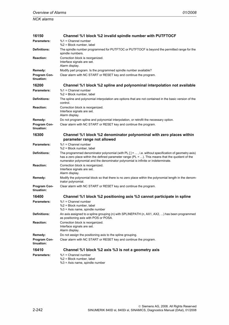
Overview of Alarms 01/2008
NCK alarms
2-242
© Siemens AG, 2008. All Rights ReservedSINUMERIK 840D sl, 840Di sl, SINAMICS, Diagnostics Manual (DAsl), 01/2008
16150 Channel %1 block %2 invalid spindle number with PUTFTOCFParameters: %1 = Channel number
%2 = Block number, labelDefinitions: The spindle number programmed for PUTFTOC or PUTFTOCF is beyond the permitted range for the
spindle numbers.Reaction: Correction block is reorganized.
Interface signals are set.Alarm display.
Remedy: Modify part program. Is the programmed spindle number available?Program Con-tinuation:
Clear alarm with NC START or RESET key and continue the program.
16200 Channel %1 block %2 spline and polynominal interpolation not availableParameters: %1 = Channel number
%2 = Block number, labelDefinitions: The spline and polynomial interpolation are options that are not contained in the basic version of the
control.Reaction: Correction block is reorganized.
Interface signals are set.Alarm display.
Remedy: Do not program spline and polynomial interpolation, or retrofit the necessary option.Program Con-tinuation:
Clear alarm with NC START or RESET key and continue the program.
16300 Channel %1 block %2 denominator polynominal with zero places within parameter range not allowed
Parameters: %1 = Channel number%2 = Block number, label
Definitions: The programmed denominator polynomial (with PL [ ] = ... , i.e. without specification of geometry axis) has a zero place within the defined parameter range (PL = ...). This means that the quotient of the numerator polynomial and the denominator polynomial is infinite or indeterminate.
Reaction: Correction block is reorganized.Interface signals are set.Alarm display.
Remedy: Modify the polynomial block so that there is no zero place within the polynomial length in the denom-inator polynomial.
Program Con-tinuation:
Clear alarm with NC START or RESET key and continue the program.
16400 Channel %1 block %2 positioning axis %3 cannot participate in splineParameters: %1 = Channel number
%2 = Block number, label%3 = Axis name, spindle number
Definitions: An axis assigned to a spline grouping (n) with SPLINEPATH (n, AX1, AX2, ...) has been programmed as positioning axis with POS or POSA.
Reaction: Correction block is reorganized.Interface signals are set.Alarm display.
Remedy: Do not assign the positioning axis to the spline grouping.Program Con-tinuation:
Clear alarm with NC START or RESET key and continue the program.
16410 Channel %1 block %2 axis %3 is not a geometry axisParameters: %1 = Channel number
%2 = Block number, label%3 = Axis name, spindle number
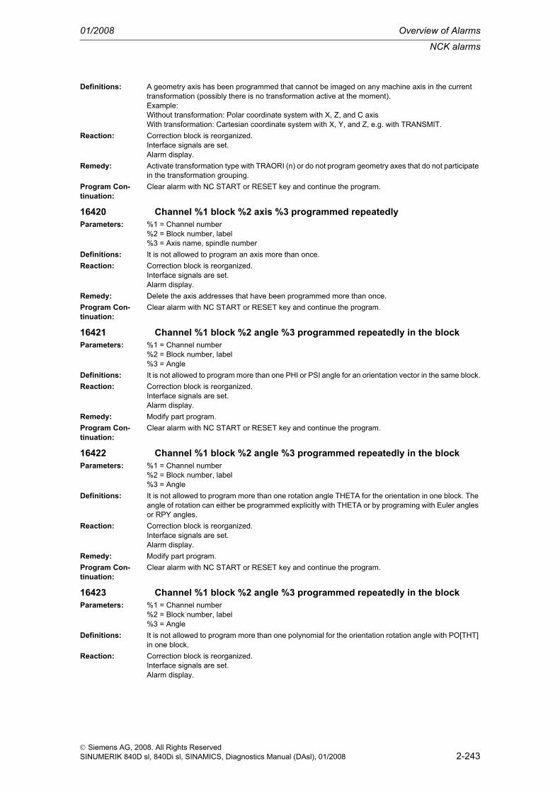
NCK alarms
01/2008 Overview of Alarms
2-243
© Siemens AG, 2008. All Rights ReservedSINUMERIK 840D sl, 840Di sl, SINAMICS, Diagnostics Manual (DAsl), 01/2008
Definitions: A geometry axis has been programmed that cannot be imaged on any machine axis in the current transformation (possibly there is no transformation active at the moment).Example:Without transformation: Polar coordinate system with X, Z, and C axisWith transformation: Cartesian coordinate system with X, Y, and Z, e.g. with TRANSMIT.
Reaction: Correction block is reorganized.Interface signals are set.Alarm display.
Remedy: Activate transformation type with TRAORI (n) or do not program geometry axes that do not participate in the transformation grouping.
Program Con-tinuation:
Clear alarm with NC START or RESET key and continue the program.
16420 Channel %1 block %2 axis %3 programmed repeatedlyParameters: %1 = Channel number
%2 = Block number, label%3 = Axis name, spindle number
Definitions: It is not allowed to program an axis more than once.Reaction: Correction block is reorganized.
Interface signals are set.Alarm display.
Remedy: Delete the axis addresses that have been programmed more than once.Program Con-tinuation:
Clear alarm with NC START or RESET key and continue the program.
16421 Channel %1 block %2 angle %3 programmed repeatedly in the blockParameters: %1 = Channel number
%2 = Block number, label%3 = Angle
Definitions: It is not allowed to program more than one PHI or PSI angle for an orientation vector in the same block.Reaction: Correction block is reorganized.
Interface signals are set.Alarm display.
Remedy: Modify part program.Program Con-tinuation:
Clear alarm with NC START or RESET key and continue the program.
16422 Channel %1 block %2 angle %3 programmed repeatedly in the blockParameters: %1 = Channel number
%2 = Block number, label%3 = Angle
Definitions: It is not allowed to program more than one rotation angle THETA for the orientation in one block. The angle of rotation can either be programmed explicitly with THETA or by programing with Euler angles or RPY angles.
Reaction: Correction block is reorganized.Interface signals are set.Alarm display.
Remedy: Modify part program.Program Con-tinuation:
Clear alarm with NC START or RESET key and continue the program.
16423 Channel %1 block %2 angle %3 programmed repeatedly in the blockParameters: %1 = Channel number
%2 = Block number, label%3 = Angle
Definitions: It is not allowed to program more than one polynomial for the orientation rotation angle with PO[THT] in one block.
Reaction: Correction block is reorganized.Interface signals are set.Alarm display.

Overview of Alarms 01/2008
NCK alarms
2-244
© Siemens AG, 2008. All Rights ReservedSINUMERIK 840D sl, 840Di sl, SINAMICS, Diagnostics Manual (DAsl), 01/2008
Remedy: Modify part program.Program Con-tinuation:
Clear alarm with NC START or RESET key and continue the program.
16424 Channel %1 block %2 coordinate %3 programmed repeatedly in the block
Parameters: %1 = Channel number%2 = Block number, label%3 = Coordinate
Definitions: It is not allowed to program a coordinate of the 2nd contact point of the tool for description of the tool orientation several times in one block.
Reaction: Correction block is reorganized.Interface signals are set.Alarm display.
Remedy: Modify part program.Program Con-tinuation:
Clear alarm with NC START or RESET key and continue the program.
16430 Channel %1 block %2 geometry axis %3 cannot traverse as positioning axis in rotated coordinate system
Parameters: %1 = Channel number%2 = Block number, label%3 = Axis name, spindle number
Definitions: In the rotated coordinate system, traversing of a geometry axis as positioning axis (i.e. along its axis vector in the rotated coordinate system) would mean traversing of several machine axes. This is in conflict with the positioning axis concept, however, in which one axis interpolator runs in addition to the path interpolator!
Reaction: Correction block is reorganized.Interface signals are set.Alarm display.
Remedy: Traverse geometry axes as positioning axes only with rotation deactivated.Deactivate rotation:Keyword ROT without further specification of axis and angle.Example: N100 ROT
Program Con-tinuation:
Clear alarm with NC START or RESET key and continue the program.
16440 Channel %1 block %2 rotation programmed for non-existent geometry axis
Parameters: %1 = Channel number%2 = Block number, label
Definitions: A rotation of a geometry axis which does not exist was programmed.Reaction: Correction block is reorganized.
Interface signals are set.Alarm display.
Remedy: Modify part program.Program Con-tinuation:
Clear alarm with NC START or RESET key and continue the program.
16500 Channel %1 block %2 chamfer or rounding negativeParameters: %1 = Channel number
%2 = Block number, labelDefinitions: A negative chamfer or rounding has been programmed under the keywords CHF= ..., RND=... or
RNDM=...Reaction: Correction block is reorganized.
Interface signals are set.Alarm display.
Remedy: Values for chamfers, roundings and modal roundings must be programmed with positive values only.Program Con-tinuation:
Clear alarm with NC START or RESET key and continue the program.

NCK alarms
01/2008 Overview of Alarms
2-245
© Siemens AG, 2008. All Rights ReservedSINUMERIK 840D sl, 840Di sl, SINAMICS, Diagnostics Manual (DAsl), 01/2008
16510 Channel %1 block %2 no facing axis for diameter programming availableParameters: %1 = Channel number
%2 = Block number, labelDefinitions: Diameter programming has been activated although no transverse axis with diameter programming
has been applied.Transverse axes can be applied with MD20100 or MD30460 bit2 for diameter programming.Diameter programming can be applied through:- basic position DIAMON or DIAM90 of the G 29 group during booting- programming of DIAMON or DIAM90- programming of DIAMONA[AX], DIAM90A[AX] or DAC, DIC, RAC, RIC
Reaction: Correction block is reorganized.Interface signals are set.Alarm display.
Remedy: Please inform the authorized personnel/service department.When programming DIAMON/DIAM90, a traverse axis must be configured via MD20100.When programming DIAMONA[AX], DIAM90A[AX] or DAC, DIC, RAC, RIC, the AX axis must be a transverse axis for diameter programming configured via MD30460 bit2.
Program Con-tinuation:
Clear alarm with NC START or RESET key and continue the program.
16520 Channel %1 axis %2, diameter programming active, function %3 is not executed
Parameters: %1 = Channel%2 = Axis, spindle%3 = NC function
Definitions: The function is not executed with diameter programming active for the stated axis.The following functions may be affected: 1 - Axis interchange 2 - Axis container rotation
Reaction: Interpreter stopLocal alarm reaction.NC Start disable in this channel.Interface signals are set.Alarm display.
Remedy: Disable diameter programming of the axis before activating the function.Program Con-tinuation:
Clear alarm with the RESET key. Restart part program
16600 Channel %1 block %2 spindle %3 gear stage change not possibleParameters: %1 = Channel number
%2 = Block number, label%3 = Spindle number
Definitions: The programmed speed is outside the speed range of the set gear stage. In order to execute the pro-grammed speed, the gear stage must be changed. In order to be able to execute the automatic gear stage change (M40 is active), the spindle must be in speed control operation.>The alarm will no longer be output after having set bit 30 (0x40000000) in MD 11410 SUPPRESS_ALARM_MASK. However, the function will not be affected by this.
Reaction: Correction block is reorganized.Interface signals are set.Alarm display.
Remedy: The changeover to speed control operation is performed by programming M3, M4 or M5. The M func-tions can be written together with the S word in the same block.
Program Con-tinuation:
Clear alarm with NC START or RESET key and continue the program.

Overview of Alarms 01/2008
NCK alarms
2-246
© Siemens AG, 2008. All Rights ReservedSINUMERIK 840D sl, 840Di sl, SINAMICS, Diagnostics Manual (DAsl), 01/2008
16670 Channel %1 block %2 following axis/spindle %3 maximum number of CP modules (%4) has been exceeded
Parameters: %1 = Channel number%2 = Block number, label%3 = Axis name, spindle number%4 = Max. number of CP modules
Definitions: An attempt was made to activate more generic couplings than are configured in MD18450.Reaction: Correction block is reorganized.
Interface signals are set.Alarm display.
Remedy: Reduce the number of defined or active couplings, or increase the number of coupling modules con-figured in MD18450.If necessary, buy another option stage of the generic coupling.
Program Con-tinuation:
Clear alarm with NC START or RESET key and continue the program.
16671 Channel %1 block %2 following axis/spindle %3 maximum number of CP modules (%4) has been exceeded
Parameters: %1 = Channel number%2 = Block number, label%3 = Axis name, spindle number%4 = Max. number of CP modules
Definitions: An attempt was made to activate more generic couplings than are configured in MD18450.Reaction: NC Start disable in this channel.
Interface signals are set.Alarm display.NC Stop on alarm.
Remedy: Reduce the number of defined or active couplings, or increase the number of coupling modules con-figured in MD18450.If necessary, buy another option stage of the generic coupling.
Program Con-tinuation:
Clear alarm with the RESET key in all channels. Restart part program.
16672 Channel %1 block %2 leading axis/spindle %3 maximum number of CP master values (%4) exceeded
Parameters: %1 = Channel number%2 = Block number, label%3 = Axis name, spindle number%4 = Max. number of CP master values
Definitions: An attempt was made to activate more master values of generic couplings than are configured in MD18452.
Reaction: Correction block is reorganized.Interface signals are set.Alarm display.
Remedy: Reduce the number of defined or active master values, or increase the total number of master values configured in MD18452.If necessary, buy another option stage of the generic coupling.
Program Con-tinuation:
Clear alarm with NC START or RESET key and continue the program.
16673 Channel %1 block %2 leading axis/spindle %3 maximum number of CP master values (%4) exceeded
Parameters: %1 = Channel number%2 = Block number, label%3 = Axis name, spindle number%4 = Max. number of CP master values

NCK alarms
01/2008 Overview of Alarms
2-247
© Siemens AG, 2008. All Rights ReservedSINUMERIK 840D sl, 840Di sl, SINAMICS, Diagnostics Manual (DAsl), 01/2008
Definitions: An attempt was made to activate more master values of generic couplings than are configured in MD18452.
Reaction: NC Start disable in this channel.Interface signals are set.Alarm display.NC Stop on alarm.
Remedy: Reduce the number of defined or active master values, or increase the total number of master values configured in MD18452.If necessary, buy another option stage of the generic coupling.
Program Con-tinuation:
Clear alarm with the RESET key in all channels. Restart part program.
16675 Channel %1 block %2 following axis/spindle %3 coupling module already defined in channel %4
Parameters: %1 = Channel number%2 = Block number, label%3 = Axis/spindle%4 = Channel number
Definitions: An attempt was made to define or activate a CP coupling, although a coupling had already been defined or activated on this following axis/spindle in another channel.
Reaction: NC Start disable in this channel.Interface signals are set.Alarm display.NC Stop on alarm.
Remedy: Change the part program: A CP coupling module must not be simultaneously defined in multiple chan-nels for the same following axis/spindle.
Program Con-tinuation:
Clear alarm with the RESET key. Restart part program
16678 Channel %1 block %2 following axis/spindle %3 status %4 impermissible traversing instruction
Parameters: %1 = Channel number%2 = Block number, label%3 = Axis name, spindle number%4 = Status
Definitions: An addtional traversing in the following axis/spindle is not permitted in the current status of the generic coupling.Example: CPOF=X G0 X100 is not permitted.
Reaction: Correction block is reorganized.Interface signals are set.Alarm display.
Remedy: Modify part program.A motion in the following axis/spindle can be programmed with CPFPOS, CPON or CPOF
Program Con-tinuation:
Clear alarm with NC START or RESET key and continue the program.
16680 Channel %1 block %2 following axis/spindle %4 instruction %3 programmed repeatedly
Parameters: %1 = Channel number%2 = Block number, label%3 = CP instruction%4 = Axis name, spindle number
Definitions: The stated instruction has been programmed repeatedly in the block for the same followingaxis/spindle of a generic coupling.
Reaction: Correction block is reorganized.Interface signals are set.Alarm display.
Remedy: Modify part program.Program Con-tinuation:
Clear alarm with NC START or RESET key and continue the program.

Overview of Alarms 01/2008
NCK alarms
2-248
© Siemens AG, 2008. All Rights ReservedSINUMERIK 840D sl, 840Di sl, SINAMICS, Diagnostics Manual (DAsl), 01/2008
16681 Channel %1 block %2 following axis/spindle %3 CPFPOS not permitted (reason %4)
Parameters: %1 = Channel number%2 = Block number, label%3 = Axis name, spindle number%4 = Reason
Definitions: CPFPOS must not be declared for a following axis/spindle of a generic coupling in the current status. The reasons for this may be:- Reason 1: The coupling does not completely switch off, at least one leading axis/spindle remains active in the coupling.
Reaction: Correction block is reorganized.Interface signals are set.Alarm display.
Remedy: The following remedies are available for the reasons stated below:- Reason 1: Only declare CPFPOS when switching off the coupling, if it is completely closed.
Program Con-tinuation:
Clear alarm with NC START or RESET key and continue the program.
16682 Channel %1 block %2 following axis/spindle %3 instructions %4 are not possible.
Parameters: %1 = Channel number%2 = Block number, label%3 = Axis name, spindle number%4 = CP instruction
Definitions: The stated instructions are not permitted together in one block for a following axis/spindle of a generic coupling.
Reaction: Correction block is reorganized.Interface signals are set.Alarm display.
Remedy: Modify part program.Program Con-tinuation:
Clear alarm with NC START or RESET key and continue the program.
16684 Channel %1 block %2 following axis/spindle %3 instructions %4 are not possible separately.
Parameters: %1 = Channel number%2 = Block number, label%3 = Axis name, spindle number%4 = CP instructions
Definitions: The stated instructions are only permitted together in one block for a following axis/spindle of a generic coupling.
Reaction: Correction block is reorganized.Interface signals are set.Alarm display.
Remedy: Modify part program.Program Con-tinuation:
Clear alarm with NC START or RESET key and continue the program.
16686 Channel %1 block %2 following axis/spindle %3 type of coupling/instruction %4 is not possible.
Parameters: %1 = Channel number%2 = Block number, label%3 = Axis name, spindle number%4 = CP instructions
Definitions: The stated instruction is not permitted for the stated type of generic coupling.Reaction: Correction block is reorganized.
Interface signals are set.Alarm display.
Remedy: Modify part program.

NCK alarms
01/2008 Overview of Alarms
2-249
© Siemens AG, 2008. All Rights ReservedSINUMERIK 840D sl, 840Di sl, SINAMICS, Diagnostics Manual (DAsl), 01/2008
Program Con-tinuation:
Clear alarm with NC START or RESET key and continue the program.
16687 Channel %1 block %2 following axis/spindle %3 type of coupling/instruction %4 is not possible.
Parameters: %1 = Channel number%2 = Block number, label%3 = Axis name, spindle number%4 = CP instructions
Definitions: The stated instruction is not permitted for the stated type of generic coupling.Reaction: NC Start disable in this channel.
Interface signals are set.Alarm display.NC Stop on alarm.
Remedy: Modify part program.Program Con-tinuation:
Clear alarm with NC START or RESET key and continue the program.
16688 Channel %1 block %2 following axis/spindle %3 coupling type %4 maximum number of master values exceeded
Parameters: %1 = Channel number%2 = Block number, label%3 = Axis name, spindle number%4 = Coupling type
Definitions: The maximum number of master values has been exceeded for the stated type of generic coupling.Reaction: Correction block is reorganized.
Interface signals are set.Alarm display.
Remedy: Modify part program, reduce number of master values or use a different type of coupling.Program Con-tinuation:
Clear alarm with NC START or RESET key and continue the program.
16689 Channel %1 block %2 following axis/spindle %3 coupling type %4 maximum number of master values exceeded
Parameters: %1 = Channel number%2 = Block number, label%3 = Axis name, spindle number%4 = Coupling type
Definitions: The maximum number of master values has been exceeded for the stated type of generic coupling.Reaction: NC Start disable in this channel.
Interface signals are set.Alarm display.NC Stop on alarm.
Remedy: Modify part program, reduce number of master values or use a different type of coupling.Program Con-tinuation:
Clear alarm with NC START or RESET key and continue the program.
16690 Channel %1 block %2 following axis/spindle %3 changing the reference system %4 is not possible.
Parameters: %1 = Channel number%2 = Block number, label%3 = Axis name, spindle number%4 = Reference system
Definitions: An attempt was made to change the reference system with generic coupling active.Reaction: Correction block is reorganized.
Interface signals are set.Alarm display.
Remedy: Modify part programm.End coupling and reactivate with desired reference system.

Overview of Alarms 01/2008
NCK alarms
2-250
© Siemens AG, 2008. All Rights ReservedSINUMERIK 840D sl, 840Di sl, SINAMICS, Diagnostics Manual (DAsl), 01/2008
Program Con-tinuation:
Clear alarm with NC START or RESET key and continue the program.
16691 Channel %1 block %2 following axis/spindle %3 changing the reference system %4 is not possible.
Parameters: %1 = Channel number%2 = Block number, label%3 = Axis name, spindle number%4 = Reference system
Definitions: An attempt was made to change the reference system with generic coupling active.Reaction: NC Start disable in this channel.
Interface signals are set.Alarm display.NC Stop on alarm.
Remedy: Modify part programm.End coupling and reactivate with desired reference system.
Program Con-tinuation:
Clear alarm with NC START or RESET key and continue the program.
16692 Channel %1 block %2 following axis/spindle %3 maximum number of couplings in the block %4 has been exceeded
Parameters: %1 = Channel number%2 = Block number, label%3 = Axis name, spindle number%4 = Maximum number of couplings
Definitions: The maximum number of generic couplings in the block has been exceeded.Reaction: Correction block is reorganized.
Interface signals are set.Alarm display.
Remedy: Modify part program.Reduce the number of generic couplings programmed in the block.
Program Con-tinuation:
Clear alarm with NC START or RESET key and continue the program.
16694 Channel %1 block %2 following axis/spindle %3 status/instruction %4 is not possible.
Parameters: %1 = Channel number%2 = Block number, label%3 = Axis name, spindle number%4 = Status, instruction
Definitions: The stated instruction is not permitted for the current status of the generic coupling.Reaction: Correction block is reorganized.
Interface signals are set.Alarm display.
Remedy: Modify part program.Program Con-tinuation:
Clear alarm with NC START or RESET key and continue the program.
16695 Channel %1 block %2 following axis/spindle %3 status/instruction %4 is not possible.
Parameters: %1 = Channel number%2 = Block number, label%3 = Axis name, spindle number%4 = Status, instruction
Definitions: The stated instruction is not permitted for the current status of the generic coupling.Reaction: NC Start disable in this channel.
Interface signals are set.Alarm display.NC Stop on alarm.
Remedy: Modify part program.

NCK alarms
01/2008 Overview of Alarms
2-251
© Siemens AG, 2008. All Rights ReservedSINUMERIK 840D sl, 840Di sl, SINAMICS, Diagnostics Manual (DAsl), 01/2008
Program Con-tinuation:
Clear alarm with NC START or RESET key and continue the program.
16696 Channel %1 block %2 following axis/spindle %3 coupling has not been defined.
Parameters: %1 = Channel number%2 = Block number, label%3 = Axis name, spindle number
Definitions: An instruction to an undefined coupling is to be executed.Reaction: Correction block is reorganized.
Interface signals are set.Alarm display.
Remedy: Modify part programm.Define the coupling and activate, if necessary, before the instruction.
Program Con-tinuation:
Clear alarm with NC START or RESET key and continue the program.
16697 Channel %1 block %2 following axis/spindle %3 coupling has not been defined.
Parameters: %1 = Channel number%2 = Block number, label%3 = Axis name, spindle number
Definitions: An instruction to an undefined coupling is to be executed.Reaction: NC Start disable in this channel.
Interface signals are set.Alarm display.NC Stop on alarm.
Remedy: Modify part programm.Define the coupling and activate, if necessary, before the instruction.
Program Con-tinuation:
Clear alarm with NC START or RESET key and continue the program.
16698 Channel %1 block %2 following axis/spindle %3 leading axis/spindle %4 has not been defined.
Parameters: %1 = Channel number%2 = Block number, label%3 = Axis name, spindle number%4 = Axis name, spindle number
Definitions: An instruction to an undefined leading axis/spindle of a coupling is to be executed.Reaction: Correction block is reorganized.
Interface signals are set.Alarm display.
Remedy: Modify part programm.Define the leading axis/spindle and activate, if necessary, before the instruction.
Program Con-tinuation:
Clear alarm with NC START or RESET key and continue the program.
16699 Channel %1 block %2 following axis/spindle %3 leading axis/spindle %4 has not been defined.
Parameters: %1 = Channel number%2 = Block number, label%3 = Axis name, spindle number%4 = Axis name, spindle number
Definitions: An instruction to an undefined leading axis/spindle of a coupling is to be executed.Reaction: NC Start disable in this channel.
Interface signals are set.Alarm display.NC Stop on alarm.
Remedy: Modify part programm.Define the leading axis/spindle and activate, if necessary, before the instruction.

Overview of Alarms 01/2008
NCK alarms
2-252
© Siemens AG, 2008. All Rights ReservedSINUMERIK 840D sl, 840Di sl, SINAMICS, Diagnostics Manual (DAsl), 01/2008
Program Con-tinuation:
Clear alarm with NC START or RESET key and continue the program.
16700 Channel %1 block %2 axis %3 invalid feed typeParameters: %1 = Channel number
%2 = Block number, label%3 = Axis name, spindle number
Definitions: In a thread cutting function, the feed has been programmed in a unit that is impermissible.1. G33 (thread with constant lead) and the feed have not been programmed with G94 or G95.2. G33 (thread with constant lead) is active (modal) and G63 is programmed additionally in a following block .conflict situation! (G63 is in the 2nd G group, G33, G331 and G332 are in the 1st G group).3. G331 or G332 (rigid tapping) and the feed have not been programmed with G94.
Reaction: Correction block is reorganized.Interface signals are set.Alarm display.
Remedy: Use only the feed type G94 or G95 in the thread cutting functions.After G33 and before G63, deselect the thread cutting function with G01.
Program Con-tinuation:
Clear alarm with NC START or RESET key and continue the program.
16710 Channel %1 block %2 axis %3 master spindle not programmedParameters: %1 = Channel number
%2 = Block number, label%3 = Axis name, spindle number
Definitions: A master spindle function has been programmed (G33, G331, G95, G96) but the speed or the direc-tion of rotation of the master spindle is missing.
Reaction: Interpreter stopNC Start disable in this channel.Interface signals are set.Alarm display.
Remedy: Add S value or direction of rotation for the master spindle in the displayed block.Program Con-tinuation:
Clear alarm with the RESET key. Restart part program
16715 Channel %1 block %2 axis %3 spindle not in standstillParameters: %1 = Channel number
%2 = Block number, label%3 = Spindle number
Definitions: In the applied function (G74, reference point approach), the spindle must be stationary.Reaction: Correction block is reorganized.
Interface signals are set.Alarm display.
Remedy: Program M5 or SPOS/SPOSA in front of the defective block in the part program.Program Con-tinuation:
Clear alarm with NC START or RESET key and continue the program.
16720 Channel %1 block %2 axis %3 thread lead is zeroParameters: %1 = Channel number
%2 = Block number, label%3 = Axis name, spindle number
Definitions: No lead was programmed in a thread block with G33 (thread with constant lead) or G331 (rigid tap-ping).
Reaction: Correction block is reorganized.Interface signals are set.Alarm display.
Remedy: The thread lead must be programmed for the specified geometry axis under the associated interpola-tion parameters.X -> IY -> JZ -> K

NCK alarms
01/2008 Overview of Alarms
2-253
© Siemens AG, 2008. All Rights ReservedSINUMERIK 840D sl, 840Di sl, SINAMICS, Diagnostics Manual (DAsl), 01/2008
Program Con-tinuation:
Clear alarm with NC START or RESET key and continue the program.
16730 Channel %1 block %2 axis %3 wrong parameterParameters: %1 = Channel number
%2 = Block number, label%3 = Axis name, spindle number
Definitions: In G33 (tapping with constant lead) the lead parameter was not assigned to the axis that determines the velocity.For longitudinal and face threads, the thread lead for the specified geometry axis must be pro-grammed under the associated interpolation parameter.X -> IY -> JZ -> KFor taper threads, the address I, J, K depends on the axis with the longer path (thread length). A 2nd lead for the other axis is, however, not specified.
Reaction: Correction block is reorganized.Interface signals are set.Alarm display.
Remedy: Assign lead parameters to the axis that determines the velocity.Program Con-tinuation:
Clear alarm with NC START or RESET key and continue the program.
16740 Channel %1 block %2 no geometry axis programmedParameters: %1 = Channel number
%2 = Block number, labelDefinitions: No geometry axis was programmed for tapping (G33) or for rigid tapping (G331, G332). The geometry
axis is, however, essential if an interpolation parameter has been specified.Example:N100 G33 Z400 K2 ; thread lead 2mm, thread end Z=400 mmN200 SPOS=0 ; position spindle in axis modeN201 G90 G331 Z-50 K-2 ; tapping to Z=-50, counterclockwiseN202 G332 Z5 ; retraction, direction reversal automaticN203 S500 M03 ; spindle again in spindle mode
Reaction: Correction block is reorganized.Interface signals are set.Alarm display.
Remedy: Specify geometry axis and corresponding interpolation parameters.Program Con-tinuation:
Clear alarm with NC START or RESET key and continue the program.
16746 Channel %1 block %2 spindle %3 selected gear stage %4 not installedParameters: %1 = Channel number
%2 = Block number, label%3 = Spindle number%4 = Gear stage
Definitions: The first gear stage data block is active. The required gear stage is not installed in the 1st gear stage data block. The number of gear stages installed is configured in machine data 35090 $MA_NUM_GEAR_STEPS.Examples of the occurrence of the alarm with 3 three gear stages installed (MD 35090 $MA_NUM_GEAR_STEPS = 3):* ... M44 or M45 has been programmed for the spindle concerned*...M70 has been programmed and machine data 35014 $MA_GEAR_STEP_USED_IN_AXISMODE is larger than 3.
Reaction: Correction block is reorganized.Interface signals are set.Alarm display.
Remedy: Modify part program: Only those valid gear stages can be entered which have also been installed according to machine data MA_NUM_GEAR_STEPS.Limit M70 configuration (MD 35014 $MA_GEAR_STEP_USED_IN_AXISMODE) to MD 35090 MA_NUM_GEAR_STEPS.

Overview of Alarms 01/2008
NCK alarms
2-254
© Siemens AG, 2008. All Rights ReservedSINUMERIK 840D sl, 840Di sl, SINAMICS, Diagnostics Manual (DAsl), 01/2008
Program Con-tinuation:
Clear alarm with NC START or RESET key and continue the program.
16747 Channel %1 block %2 spindle %3 inserted gear stage %4 for tapping not installed
Parameters: %1 = Channel number%2 = Block number, label%3 = Spindle number%4 = Gear stage
Definitions: The second gear stage data block has been activated for tapping with G331.However, the current gear stage has not been installed in the second gear stage data block. The num-ber of gear stages installed is configured in machine data 35092 NUM_GEAR_STEPS2. The gear stage cannot be changed in traversing blocks. The gear stage appropriate for the speed must be loaded before the traversing block.
Reaction: Correction block is reorganized.Interface signals are set.Alarm display.
Remedy: Procedure for automatically engaging the suitable gear stage prior to thread cutting:* Program the spindle speed (S) in a G331 block without axis motions and prior to thread cutting, e.g. G331 S1000.* Activate M40 for the spindle.
Program Con-tinuation:
Clear alarm with NC START or RESET key and continue the program.
16748 Channel %1 block %2 spindle %3 gear stage %4 expectedParameters: %1 = Channel number
%2 = Block number, label%3 = Spindle number%4 = Gear stage
Definitions: G331 activates the second gear stage data block for tapping.The programmed speed (S) of the master spindle lies outside the speed range of the active gear stage in the current traversing block.The gear stage cannot be changed in the traversing block. The gear stage appropriate for the speed must be loaded prior to the traversing block.
Reaction: Correction block is reorganized.Interface signals are set.Alarm display.
Remedy: Procedure for automatically engaging the suitable gear stage prior to thread cutting:* Program the spindle speed (S) in a G331 block without axis motions and prior to thread cutting, e.g. G331 S1000.* Activate M40 for the spindle.
Program Con-tinuation:
Clear alarm with NC START or RESET key and continue the program.
16750 Channel %1 block %2 axis %3 SPCON not programmedParameters: %1 = Channel number
%2 = Block number, label%3 = Axis name, spindle number
Definitions: For the programmed function (rotary axis, positioning axis), the spindle must be in position control mode.
Reaction: Correction block is reorganized.Interface signals are set.Alarm display.
Remedy: Program position control of the spindle with SPCON in the previous block.Program Con-tinuation:
Clear alarm with NC START or RESET key and continue the program.
16751 Channel %1 block %2 spindle/axis %3 SPCOF not executableParameters: %1 = Channel number
%2 = Block number, label%3 = Axis name, spindle number

NCK alarms
01/2008 Overview of Alarms
2-255
© Siemens AG, 2008. All Rights ReservedSINUMERIK 840D sl, 840Di sl, SINAMICS, Diagnostics Manual (DAsl), 01/2008
Definitions: For the programmed function, the spindle must be in the open-loop control mode. In the positioning or axis mode, the position control must not be deselected.
Reaction: Correction block is reorganized.Interface signals are set.Alarm display.
Remedy: Put the spindle into open-loop control mode in the preceding block. This can be done with M3, M4 or M5 for the relevant spindle.
Program Con-tinuation:
Clear alarm with NC START or RESET key and continue the program.
16755 Channel %1 block %2 no stop requiredParameters: %1 = Channel number
%2 = Block number, labelDefinitions: No Stop is needed for the programmed function. A Stop is necessary after SPOSA or after M5 if the
next block is to be loaded only after a spindle stop.Reaction: Correction block is reorganized.
Interface signals are set.Alarm display.
Remedy: Do not write instruction.Program Con-tinuation:
Clear alarm with NC START or RESET key and continue the program.
16757 Channel %1 block %2 for following spindle %3 coupling as leading spindle/axis already existing
Parameters: %1 = Channel number%2 = Block number, label%3 = Following spindle number
Definitions: A coupling has been switched on in which the following spindle/axis has already been active as lead-ing spindle/axis in another coupling. Chained couplings cannot be processed.
Reaction: Correction block is reorganized.Interface signals are set.Alarm display.
Remedy: Check in the parts program whether the following spindle/axis is already active as leading spindle/axis in another coupling.
Program Con-tinuation:
Clear alarm with NC START or RESET key and continue the program.
16758 Channel %1 block %2 for leading spindle %3 coupling as following spindle/axis already existing
Parameters: %1 = Channel number%2 = Block number, label%3 = Leading spindle number
Definitions: A coupling has been switched on in which the leading spindle/axis has already been active as follow-ing spindle/axis in another coupling. Chained couplings cannot be processed.
Reaction: Correction block is reorganized.Interface signals are set.Alarm display.
Remedy: Check in the parts program whether the leading spindle/axis is already active as following spindle/axis in another coupling.
Program Con-tinuation:
Clear alarm with NC START or RESET key and continue the program.
16760 Channel %1 block %2 axis %3 S value missingParameters: %1 = Channel number
%2 = Block number, label%3 = Axis name, spindle number
Definitions: No spindle speed has been given for rigid tapping (G331 or G332).Reaction: Correction block is reorganized.
Interface signals are set.Alarm display.

Overview of Alarms 01/2008
NCK alarms
2-256
© Siemens AG, 2008. All Rights ReservedSINUMERIK 840D sl, 840Di sl, SINAMICS, Diagnostics Manual (DAsl), 01/2008
Remedy: Program the spindle speed under address S in [rpm] (in spite of axis mode); the direction of rotation is given by the sign of the spindle lead:- Positive thread lead: Rotational direction as M03.- Negative thread lead: Rotational direction as M04 N2.
Program Con-tinuation:
Clear alarm with NC START or RESET key and continue the program.
16761 Channel %1 block %2 axis/spindle %3 not programmable in the channelParameters: %1 = Channel number
%2 = Block number, label%3 = Axis name, spindle number
Definitions: Mistake in programming: The axis/spindle cannot be programmed in the channel at this time. This alarm can occur when the axis/spindle is being used by another channel or by the PLC.
Reaction: Correction block is reorganized.Interface signals are set.Alarm display.
Remedy: Modify part program. Use "GET()".Program Con-tinuation:
Clear alarm with NC START or RESET key and continue the program.
16762 Channel %1 block %2 spindle %3 thread function is activeParameters: %1 = Channel number
%2 = Block number, label%3 = Spindle number
Definitions: Mistake in programming: The spindle function cannot be executed at the present time. This alarm occurs when the spindle (master spindle) is linked with the axes by an interpolation function.
Reaction: Correction block is reorganized.Interface signals are set.Alarm display.
Remedy: Modify part program. Deselect thread cutting or tapping.Program Con-tinuation:
Clear alarm with NC START or RESET key and continue the program.
16763 Channel %1 block %2 axis %3 programmed speed is illegal (zero or negative)
Parameters: %1 = Channel number%2 = Block number, label%3 = Axis name, spindle number
Definitions: A spindle speed (S value) was programmed with the value zero or with a negative value.Reaction: Correction block is reorganized.
Interface signals are set.Alarm display.
Remedy: The programmed spindle speed (S value) must be positive. Depending on the application case, the value zero can be accepted (e.g. G25 S0).
Program Con-tinuation:
Clear alarm with NC START or RESET key and continue the program.
16770 Channel %1 block %2 axis %3 no measuring system availableParameters: %1 = Channel number
%2 = Block number, label%3 = Axis name, spindle number
Definitions: One of the following spindle functions has been programmed, the position control requires:SPCON,SPOS, SPOSA,COUPON,G331/G332.

NCK alarms
01/2008 Overview of Alarms
2-257
© Siemens AG, 2008. All Rights ReservedSINUMERIK 840D sl, 840Di sl, SINAMICS, Diagnostics Manual (DAsl), 01/2008
The position control requires at least one measuring system.No measuring system has been configured in MD: 30200 NUM_ENCS of the programmed spindle.
Reaction: Interpreter stopNC Start disable in this channel.Interface signals are set.Alarm display.
Remedy: Please inform the authorized personnel/service department. Retrofit a measuring system.Program Con-tinuation:
Clear alarm with the RESET key. Restart part program
16771 Channel %1 block %3 following axis %2 overlaid movement not enabledParameters: %1 = Channel number
%2 = Axis name, spindle number%3 = Block number, label
Definitions: No gear synchronization and no overlay movement can be executed because this is not enabled at the VDI interface.
Reaction: Alarm display.Remedy: Set the "enable following axis overlay" VDI signal.Program Con-tinuation:
Alarm display showing cause of alarm disappears. No further operator action necessary.
16772 Channel %1 block %2 axis %3 is the slave axis, the coupling is being opened
Parameters: %1 = Channel number%2 = Block number, label%3 = Axis, spindle
Definitions: >The axis is active as a slave axis in a coupling. In the REF operation mode, the coupling is opened. The alarm can be suppressed by means of machine data 11410 SUPPRESS_ALARM_MASK Bit29 = 1.
Reaction: Alarm display.Remedy: The coupling will be closed again after having exited the REF operation mode.Program Con-tinuation:
Alarm display showing cause of alarm disappears. No further operator action necessary.
16773 Channel %1 axis %2 is the following axis. The axis/spindle disables of leading axes %3 and %4 differ from one another.
Parameters: %1 = Channel number%2 = Axis, spindle%3 = Axis, spindle%4 = Axis, spindle
Definitions: The axis is active in a coupling as a following axis. The master axes have different states regarding axis/spindle disable.The alarm can be suppressed with machine data 11415 SUPPRESS_ALARM_MASK_2 Bit0 =1.
Reaction: Alarm display.Remedy: Set the same axis/spindle disable for all master axes.Program Con-tinuation:
Alarm display showing cause of alarm disappears. No further operator action necessary.
16774 Channel %1 Synchronization aborted for slave axis/spindle %2Parameters: %1 = Channel number
%2 = Axis name, spindle numberDefinitions: For the indicated axis, the synchronization procedure (EGONSYN or EGONSYNE) was aborted.
There are several reasons for aborting the synchronization process: - RESET - End of program - Axis goes to follow-up mode

Overview of Alarms 01/2008
NCK alarms
2-258
© Siemens AG, 2008. All Rights ReservedSINUMERIK 840D sl, 840Di sl, SINAMICS, Diagnostics Manual (DAsl), 01/2008
- Rapid stop caused by an alarmReaction: NC Start disable in this channel.
Interface signals are set.Alarm display.NC Stop on alarm.Channel not ready.
Remedy: If the abort of the synchronization procedure can be tolerated or is intended, the alarm can be sup-pressed with machine data 11410 SUPPRESS_ALARM_MASK Bit31 = 1.Only applicable for electronic gear (EG):If it is not possible to abort the synchronization procedure, you can achieve it by specifying the block change criterion FINE in EGONSYN or EGONSYNE.
Program Con-tinuation:
Clear alarm with the RESET key. Restart part program
16776 Channel %1 block %2 curve table %3 does not exist for axis %4Parameters: %1 = Channel number
%2 = Block number, label%3 = Number of curve table%4 = Axis name, spindle number
Definitions: An attempt was made to couple axis %4 with curve table number %3, but no curve table of this number exists.
Reaction: NC Start disable in this channel.Interface signals are set.Alarm display.NC Stop on alarm.
Remedy: Modify the NC part program so that the required curve table exists when axis link is to be activated.Program Con-tinuation:
Clear alarm with the RESET key. Restart part program
16777 Channel %1 block %2 coupling: following axis %3 for lead axis %4 not available
Parameters: %1 = Channel number%2 = Block number, label%3 = Axis name, spindle number%4 = Axis name, spindle number
Definitions: A coupling has been switched on in which the slave spindle/axis is currently not available. Possible causes:- The spindle/axis is active in the other channel.- The spindle/axis has been accessed by the PLC and has not yet been released.
Reaction: NC Start disable in this channel.Interface signals are set.Alarm display.NC Stop on alarm.
Remedy: Please inform the authorized personnel/service department. Put the master spindle/axis with spin-dle/axis exchange into the necessary channel or release from the PLC.
Program Con-tinuation:
Clear alarm with the RESET key. Restart part program
16778 Channel %1 block %2 coupling: Ring coupling at following axis %3 and leading axis %4 impermissible
Parameters: %1 = Channel number%2 = Block number, label%3 = Axis name, spindle number%4 = Axis name, spindle number
Definitions: A coupling has been switched on which results in a cyclic coupling, allowance being made for further couplings. This cyclic coupling cannot be uniquely computed.
Reaction: NC Start disable in this channel.Interface signals are set.Alarm display.NC Stop on alarm.

NCK alarms
01/2008 Overview of Alarms
2-259
© Siemens AG, 2008. All Rights ReservedSINUMERIK 840D sl, 840Di sl, SINAMICS, Diagnostics Manual (DAsl), 01/2008
Remedy: Please inform the authorized personnel/service department. Configure link in accordance with the MD or correct NC part program (channel MD: COUPLE_AXIS_n).
Program Con-tinuation:
Clear alarm with the RESET key. Restart part program
16779 Channel %1 block %2 coupling: too many couplings for axis %3, see active leading axis %4
Parameters: %1 = Channel number%2 = Block number, label%3 = Axis name, spindle number%4 = Axis name, spindle number
Definitions: More leading axes and spindles were defined for the specified axis/spindle than are allowed. The last parameter to be specified is a leading value object/leading axis to which the specified axis/spindle is already linked.
Reaction: NC Start disable in this channel.Interface signals are set.Alarm display.NC Stop on alarm.
Remedy: Modify part program.Program Con-tinuation:
Clear alarm with the RESET key. Restart part program
16780 Channel %1 block %2 following spindle/axis missingParameters: %1 = Channel number
%2 = Block number, labelDefinitions: The following spindle/axis has not been written in the part program.Reaction: Correction block is reorganized.
Interface signals are set.Alarm display.
Remedy: Modify part program.Program Con-tinuation:
Clear alarm with NC START or RESET key and continue the program.
16781 Channel %1 block %2 master spindle/axis missingParameters: %1 = Channel number
%2 = Block number, labelDefinitions: The master spindle/axis has not been programmed in the part program.Reaction: Correction block is reorganized.
Interface signals are set.Alarm display.
Remedy: Modify part program.Program Con-tinuation:
Clear alarm with NC START or RESET key and continue the program.
16782 Channel %1 block %2 following spindle/axis %3 not availableParameters: %1 = Channel number
%2 = Block number, label%3 = Axis name, spindle number
Definitions: A coupling has been switched on in which the slave spindle/axis is currently not available. Possible causes:- The spindle/axis is active in the other channel.- The spindle/axis has been accessed by the PLC and has not yet been released.
Reaction: Correction block is reorganized.Interface signals are set.Alarm display.
Remedy: Please inform the authorized personnel/service department. Put the master spindle/axis with spin-dle/axis exchange into the necessary channel or release from the PLC.
Program Con-tinuation:
Clear alarm with NC START or RESET key and continue the program.

Overview of Alarms 01/2008
NCK alarms
2-260
© Siemens AG, 2008. All Rights ReservedSINUMERIK 840D sl, 840Di sl, SINAMICS, Diagnostics Manual (DAsl), 01/2008
16783 Channel %1 block %2 master spindle/axis %3 not availableParameters: %1 = Channel number
%2 = Block number, label%3 = Axis name, spindle number
Definitions: A coupling has been switched on in which the master spindle/axis is currently not available. Possible causes:- Setpoint linkage has been selected and spindle/axis is active in the other channel.- The spindle/axis has been accessed by the PLC and has not yet been released.
Reaction: Correction block is reorganized.Interface signals are set.Alarm display.
Remedy: Please inform the authorized personnel/service department. Put the master spindle/axis with spin-dle/axis exchange into the necessary channel or release from the PLC.
Program Con-tinuation:
Clear alarm with NC START or RESET key and continue the program.
16785 Channel %1 block %2 identical spindles/axes %3Parameters: %1 = Channel number
%2 = Block number, label%3 = Axis name, spindle number
Definitions: A coupling has been switched on in which the following spindle/axis is identical to the master spin-dle/axis.
Reaction: Correction block is reorganized.Interface signals are set.Alarm display.
Remedy: Please inform the authorized personnel/service department.- Configure link accordingly in MD (channel MD: COUPLE_AXIS_n)- or modify part program.
Program Con-tinuation:
Clear alarm with NC START or RESET key and continue the program.
16786 Channel %1 block %2 coupling to master spindle %3 already existsParameters: %1 = Channel number
%2 = Block number, label%3 = Leading spindle number
Definitions: A coupling is to be switched on, in which the slave axis is already actively coupled with the other mas-ter axis. Only one master spindle is allowed for the synchronous spindle function. The already active master spindle is displayed as last alarm parameter.
Reaction: Correction block is reorganized.Interface signals are set.Alarm display.
Remedy: Prior to switching on the new coupling, separate the existing coupling. If several master spindels/axes are required, the ELG function will have to be used.
Program Con-tinuation:
Clear alarm with NC START or RESET key and continue the program.
16787 Channel %1 block %2 coupling parameter not changeableParameters: %1 = Channel number
%2 = Block number, labelDefinitions: The specified coupling is write-protected. Therefore, the coupling parameters cannot be modified.Reaction: Interpreter stop
NC Start disable in this channel.Interface signals are set.Alarm display.
Remedy: Please inform the authorized personnel/service department.- Remove write protection. Channel MD: COUPLE_AXIS_IS_WRITE_PROT- or modify part program.
Program Con-tinuation:
Clear alarm with the RESET key. Restart part program

NCK alarms
01/2008 Overview of Alarms
2-261
© Siemens AG, 2008. All Rights ReservedSINUMERIK 840D sl, 840Di sl, SINAMICS, Diagnostics Manual (DAsl), 01/2008
16788 Channel %1 block %2 cyclic couplingParameters: %1 = Channel number
%2 = Block number, labelDefinitions: A coupling has been switched on which results in a cyclic coupling, allowance being made for further
couplings. This cyclic coupling cannot be uniquely computed.Reaction: Correction block is reorganized.
Interface signals are set.Alarm display.
Remedy: Please inform the authorized personnel/service department.- Configure link accordingly in MD (channel MD: 21300 COUPLE_AXIS_n)- or modify part program.
Program Con-tinuation:
Clear alarm with NC START or RESET key and continue the program.
16789 Channel %1 block %2 multiple linkParameters: %1 = Channel number
%2 = Block number, labelDefinitions: A coupling has been switched on in which the axes/spindles have already been assigned by another
coupling. Parallel couplings cannot be processed.Reaction: Correction block is reorganized.
Interface signals are set.Alarm display.
Remedy: Check in the part program whether another link already exists for the axes.Program Con-tinuation:
Clear alarm with NC START or RESET key and continue the program.
16790 Channel %1 block %2 Parameter is zero or missingParameters: %1 = Channel number
%2 = Block number, labelDefinitions: A coupling has been switched on in which a relevant parameter has been specified with zero or has
not been written (e.g. denominator in the transmission ratio, no slave axis).Reaction: Correction block is reorganized.
Interface signals are set.Alarm display.
Remedy: Please inform the authorized personnel/service department.- Configure link accordingly in MD (channel MD: 42300 COUPLE_RATIO_n)- or modify part program.
Program Con-tinuation:
Clear alarm with NC START or RESET key and continue the program.
16791 Channel %1 block %2 parameter is not relevantParameters: %1 = Channel number
%2 = Block number, labelDefinitions: A coupling has been switched on in which a non-relevant parameter has been written (e.g. parameter
for ELG).Reaction: Correction block is reorganized.
Interface signals are set.Alarm display.
Remedy: Modify part program.Program Con-tinuation:
Clear alarm with NC START or RESET key and continue the program.
16792 Channel %1 block %2 too many couplings for axis/spindle %3Parameters: %1 = Channel number
%2 = Block number, label%3 = Axis name, spindle number
Definitions: For the specified axis/spindle, more master axes/spindles have been defined than are allowed.Reaction: Correction block is reorganized.
Interface signals are set.Alarm display.

Overview of Alarms 01/2008
NCK alarms
2-262
© Siemens AG, 2008. All Rights ReservedSINUMERIK 840D sl, 840Di sl, SINAMICS, Diagnostics Manual (DAsl), 01/2008
Remedy: Modify part program.Program Con-tinuation:
Clear alarm with NC START or RESET key and continue the program.
16793 Channel %1 block %2 coupling of axis %3 prohibits transformation change
Parameters: %1 = Channel number%2 = Block number, label%3 = Axis name, spindle number
Definitions: The specified axis is a slave axis in a transformation grouping. When the coupling is switched on, the transformation cannot be changed to another one.
Reaction: Correction block is reorganized.Interface signals are set.Alarm display.
Remedy: Modify part program. Switch off coupling(s) of this axis before changing transformation or do not change the transformation.
Program Con-tinuation:
Clear alarm with NC START or RESET key and continue the program.
16794 Channel %1 block %2 coupling of axis/spindle %3 prohibits reference point approach
Parameters: %1 = Channel number%2 = Block number, label%3 = Axis name, spindle number
Definitions: The specified axis is a (gantry) slave axis and cannot therefore approach the reference point.Reaction: Correction block is reorganized.
Interface signals are set.Alarm display.
Remedy: Modify part program. Switch off coupling(s) of this axis before reference point approach or do not ref-erence. A gantry slave axis cannot reference for itself.
Program Con-tinuation:
Clear alarm with NC START or RESET key and continue the program.
16795 Channel %1 block %2 string cannot be interpretedParameters: %1 = Channel number
%2 = Block number, labelDefinitions: A coupling has been switched on in which a non-interpretable string has been written (e.g. block
change behavior).Reaction: Correction block is reorganized.
Interface signals are set.Alarm display.
Remedy: Modify part program.Program Con-tinuation:
Clear alarm with NC START or RESET key and continue the program.
16796 Channel %1 block %2 coupling not definedParameters: %1 = Channel number
%2 = Block number, labelDefinitions: A coupling is to be switched the parameters of which have neither been programmed nor configured.Reaction: Correction block is reorganized.
Interface signals are set.Alarm display.
Remedy: Please inform the authorized personnel/service department. Correct NC part program or MD, program the coupling with COUPDEF or configure by means of MD.
Program Con-tinuation:
Clear alarm with NC START or RESET key and continue the program.
16797 Channel %1 block %2 coupling is activeParameters: %1 = Channel number
%2 = Block number, label

NCK alarms
01/2008 Overview of Alarms
2-263
© Siemens AG, 2008. All Rights ReservedSINUMERIK 840D sl, 840Di sl, SINAMICS, Diagnostics Manual (DAsl), 01/2008
Definitions: An operation is to be performed in which no coupling may be active, e.g. COUPDEL or TANGDEL must not be used on active couplings.
Reaction: Correction block is reorganized.Interface signals are set.Alarm display.
Remedy: Correct NC part program, deselect the link with COUPOF or TANGOF.Program Con-tinuation:
Clear alarm with NC START or RESET key and continue the program.
16798 Channel %1 block %2 axis %3 is following axis and prohibits axis container rotation
Parameters: %1 = Channel number%2 = Block number, label%3 = Axis name, spindle number
Definitions: The programmed axis/spindle is active as a slave axis/spindle in a coupling. When the coupling is active, the axis container cannot be rotated.
Reaction: Correction block is reorganized.Interface signals are set.Alarm display.
Remedy: Modify part program. Deactivate the coupling(s) for this axis/spindle before rotating the axis container or execute the axis container rotation at a later time.
Program Con-tinuation:
Clear alarm with NC START or RESET key and continue the program.
16799 Channel %1 block %2 axis %3 is master axis and prohibits axis container rotation
Parameters: %1 = Channel number%2 = Block number, label%3 = Axis name, spindle number
Definitions: The programmed axis/spindle is active as a master axis/spindle in a coupling. When the coupling is active, the axis container cannot be rotated.
Reaction: Correction block is reorganized.Interface signals are set.Alarm display.
Remedy: Modify part program. Deactivate the coupling(s) for this axis/spindle before rotating the axis container or execute the axis container rotation at a later time.
Program Con-tinuation:
Clear alarm with NC START or RESET key and continue the program.
16800 Channel %1 block %2 traverse instruction DC/CDC for axis %3 not allowed
Parameters: %1 = Channel number%2 = Block number, label%3 = Axis name, spindle number
Definitions: The keyword DC (Direct Coordinate) can only be used for rotary axes. This causes approach of the programmed absolute position along the shortest path.Example:N100 C=DC(315)
Reaction: Correction block is reorganized.Interface signals are set.Alarm display.
Remedy: Please inform the authorized personnel/service department. Replace the keyword DC in the displayed NC block by specifying AC (Absolute Coordinate).If the alarm display is the result of an error in the axis definition, the axis can be declared as a rotary axis by means of the axis-specific MD 30300 IS_ROT_AX.Corresponding machine data:Modify MD 30310: ROT_IS_MODULOModify MD 30320: DISPLAY_IS_MODULO
Program Con-tinuation:
Clear alarm with NC START or RESET key and continue the program.

Overview of Alarms 01/2008
NCK alarms
2-264
© Siemens AG, 2008. All Rights ReservedSINUMERIK 840D sl, 840Di sl, SINAMICS, Diagnostics Manual (DAsl), 01/2008
16810 Channel %1 block %2 traverse instruction ACP for axis %3 not allowedParameters: %1 = Channel number
%2 = Block number, label%3 = Axis name, spindle number
Definitions: The keyword ACP (Absolute Coordinate Positive) is only allowed for "modulo axes". It causes approach of the programmed absolute position in the specified direction.
Reaction: Correction block is reorganized.Interface signals are set.Alarm display.
Remedy: Please inform the authorized personnel/service department. In the displayed NC block, replace the keyword ACP by specifying AC (Absolute Coordinate).If the alarm display is based on an incorrect axis definition, the axis with the axis-specific MD 30300: IS_ROT_AX and MD 30310: ROT_IS_MODULO can be declared a rotary axis with modulo change.Corresponding machine data:Modify MD 30320: DISPLAY_IS_MODULO
Program Con-tinuation:
Clear alarm with NC START or RESET key and continue the program.
16820 Channel %1 block %2 traverse instruction ACN for axis %3 not allowedParameters: %1 = Channel number
%2 = Block number, label%3 = Axis name, spindle number
Definitions: The keyword ACN (Absolute Coordinate Negative) is only allowed for "modulo axes". It causes approach of the programmed absolute position in the specified direction.
Reaction: Interpreter stopNC Start disable in this channel.Interface signals are set.Alarm display.
Remedy: Please inform the authorized personnel/service department. In the displayed NC block, replace the keyword ACN by specifying AC (Absolute Coordinate).If the alarm display is based on an incorrect axis definition, the axis with the axis-specific machine data MD30300: $MA_IS_ROT_AX and MD30310: $MA_ROT_IS_MODULO can be declared a rotary axis with modulo change.Corresponding machine data:MD30320: $MA_DISPLAY_IS_MODULO
Program Con-tinuation:
Clear alarm with the RESET key. Restart part program
16830 Channel %1 block %2 incorrect position programmed for axis/spindle %3Parameters: %1 = Channel number
%2 = Block number, label%3 = Axis name, spindle number
Definitions: A position beyond the range of 0 - 359.999 has been programmed for a modulo axis.Reaction: Correction block is reorganized.
Interface signals are set.Alarm display.
Remedy: Program position in the range 0 - 359.999.Program Con-tinuation:
Clear alarm with NC START or RESET key and continue the program.
16903 Channel %1 program control: action %2<ALNX> not allowed in the current state
Parameters: %1 = Channel number%2 = Action number/action name
Definitions: The relevant action cannot be processed now. This can occur, for instance, during read-in of machine data.
Reaction: Alarm display.Remedy: Wait until the procedure is terminated or abort with Reset and repeat the operation.Program Con-tinuation:
Clear alarm with the Delete key or NC START.

NCK alarms
01/2008 Overview of Alarms
2-265
© Siemens AG, 2008. All Rights ReservedSINUMERIK 840D sl, 840Di sl, SINAMICS, Diagnostics Manual (DAsl), 01/2008
16904 Channel %1 program control: action %2<ALNX> not allowed in the current state
Parameters: %1 = Channel number%2 = Action number/action name
Definitions: The operation (program, JOG, block search, reference point, etc.) cannot be started or continued in the current status.
Reaction: Alarm display.Remedy: Check the program status and channel status.Program Con-tinuation:
Clear alarm with the Delete key or NC START.
16905 Channel %1 program control: action %2<ALNX> not allowedParameters: %1 = Channel number
%2 = Action number/action nameDefinitions: Operation cannot be started or continued. A start is only accepted when an NCK function can be
started.Example: A start is accepted in JOG mode when, for example, the function generator is active or a JOG movement has first been stopped with the Stop key.
Reaction: Alarm reaction in Automatic mode.Remedy: Check the program status and channel status.Program Con-tinuation:
Clear alarm with the Delete key or NC START.
16906 Channel %1 program control: action %2<ALNX> is aborted due to an alarm
Parameters: %1 = Channel number%2 = Action number/action name
Definitions: The action was aborted due to an alarm.Reaction: Alarm display.Remedy: Eliminate the error and acknowledge the alarm. Then repeat the operation.Program Con-tinuation:
Clear alarm with the Delete key or NC START.
16907 Channel %1 action %2<ALNX> only possible in stop stateParameters: %1 = Channel number
%2 = Action number/action nameDefinitions: This action may only be performed in Stop state.Reaction: Alarm display.Remedy: Check the program status and channel status.Program Con-tinuation:
Clear alarm with the Delete key or NC START.
16908 Channel %1 action %2<ALNX> only possible in reset state or at the block end
Parameters: %1 = Channel number%2 = Action number/action name
Definitions: This action may only be performed in Reset state or at end of block.In JOG mode, no axis that is traversed as geometry axis in the switched coordinate system, must be active as PLC or command axis (started through static synchronized action) on mode change. This means that axes like that must be in the state 'neutral axis' again.
Reaction: Alarm display.Remedy: Check the program status and channel status.
Check in JOG mode whether the axes are PLC or command axes.Program Con-tinuation:
Clear alarm with the Delete key or NC START.
16909 Channel %1 action %2<ALNX> not allowed in current modeParameters: %1 = Channel number
%2 = Action number/action name

Overview of Alarms 01/2008
NCK alarms
2-266
© Siemens AG, 2008. All Rights ReservedSINUMERIK 840D sl, 840Di sl, SINAMICS, Diagnostics Manual (DAsl), 01/2008
Definitions: You have to activate a different operating mode for the function to be activated.Reaction: Alarm display.Remedy: Check operation and operating state.Program Con-tinuation:
Clear alarm with the Delete key or NC START.
16911 Channel %1 mode change is not allowedParameters: %1 = Channel numberDefinitions: The change from overstoring into another operating mode is not allowed.Reaction: Alarm display.Remedy: After overstoring is terminated, it is possible to change to another operating state again.Program Con-tinuation:
Clear alarm with the Delete key or NC START.
16912 Channel %1 program control: action %2<ALNX> only possible in reset state
Parameters: %1 = Channel number%2 = Action number/action name
Definitions: This action can only be performed in Reset state.Example: Program selection through MMC or channel communication (INIT) can only be performed in Reset state.
Reaction: Alarm display.Remedy: Reset or wait until processing is terminated.Program Con-tinuation:
Clear alarm with the Delete key or NC START.
16913 Mode group %1 channel %2 mode change: action %3<ALNX> not allowed
Parameters: %1 = Channel number%2 = Mode group number%3 = Action number/action name
Definitions: The change to the desired mode is not permitted. The change can only take place in the Reset state.Example: Program processing is halted in AUTO mode by NC Stop. Then there is a mode change to JOG mode (program status interrupted). From this operating mode it is only possible to change to AUTO mode and not to MDI mode!
Reaction: Alarm display.Remedy: Either activate the Reset key to reset program processing, or activate the mode in which the program
was being processed previously.Program Con-tinuation:
Clear alarm with the Delete key or NC START.
16914 Mode group %1 channel %2 mode change: action %3<ALNX> not allowed
Parameters: %1 = Channel number%2 = Mode group number%3 = Action number/action name
Definitions: Incorrect mode change, e.g.: Auto -> MDIREF.Reaction: Alarm display.Remedy: Check operation or selected mode.Program Con-tinuation:
Clear alarm with the Delete key or NC START.
16915 Channel %1 action %2<ALNX> not allowed in the current blockParameters: %1 = Channel number
%2 = Action number/action name

NCK alarms
01/2008 Overview of Alarms
2-267
© Siemens AG, 2008. All Rights ReservedSINUMERIK 840D sl, 840Di sl, SINAMICS, Diagnostics Manual (DAsl), 01/2008
Definitions: If traversing blocks are interrupted by asynchronous subroutines, then it must be possible for the inter-rupted program to continue (reorganization of block processing) after termination of the asynchronous subroutine.The 2nd parameter describes which action wanted to interrupt block processing.
Reaction: Alarm display.Remedy: Let the program continue to a reorganized NC block or modify part program.Program Con-tinuation:
Clear alarm with the Delete key or NC START.
16916 Channel %1 repositioning: action %2<ALNX> not allowed in the current state
Parameters: %1 = Channel number%2 = Action number/action name
Definitions: Repositioning of block processing presently not possible. In certain cases this can prevent a mode change from taking place.The 2nd parameter describes which action should be used to perform repositioning.
Reaction: Alarm display.Remedy: Let the program continue to a repositioned NC block or modify part program.Program Con-tinuation:
Clear alarm with the Delete key or NC START.
16918 Channel %1 for action %2<ALNX> all channels must be in reset stateParameters: %1 = Channel number
%2 = Action number/action nameDefinitions: All channels must be in the initial setting in order to carry out the action! (For example, for machine
data loading)Reaction: Alarm display.Remedy: Either wait until the channel status is aborted or press the Reset key.Program Con-tinuation:
Clear alarm with the Delete key or NC START.
16919 Channel %1 action %2<ALNX> is not allowed due to a pending alarmParameters: %1 = Channel number
%2 = Action number/action nameDefinitions: This action cannot be performed due to an alarm, or the channel is in fail.Reaction: Alarm display.Remedy: Press RESET key.Program Con-tinuation:
Clear alarm with the Delete key or NC START.
16920 Channel %1 action %2<ALNX> is already activeParameters: %1 = Channel number
%2 = Action number/action nameDefinitions: An identical action is still active.Reaction: Alarm display.Remedy: Wait until the existing procedure is terminated and then repeat the operation.Program Con-tinuation:
Clear alarm with the Delete key or NC START.
16921 Mode group %2 Channel %1 machine data: channel/mode group assignment not allowed or assigned twice
Parameters: %1 = Channel number%2 = Mode group number

Overview of Alarms 01/2008
NCK alarms
2-268
© Siemens AG, 2008. All Rights ReservedSINUMERIK 840D sl, 840Di sl, SINAMICS, Diagnostics Manual (DAsl), 01/2008
Definitions: On powering up, an illegal channel/mode group assignment was detected.Reaction: Mode group not ready.
Channel not ready.NC Start disable in this channel.Interface signals are set.Alarm display.NC Stop on alarm.
Remedy: Please inform the authorized personnel/service department. Check machine data ASSIGN_CHAN_TO_MODE_GROUP.
Program Con-tinuation:
Teileprogramm neu starten.Clear alarm with the RESET key in all channels of this mode group. Restart part program.
16922 Channel %1 subprograms: action %2<ALNX> maximum nesting depth exceeded
Parameters: %1 = Channel number%2 = Action number/action name
Definitions: Various actions can cause the current procedure to be interrupted. Depending on the action, asyn-chronous subroutines are activated. These asynchronous subroutines can be interrupted in the same manner as user programs. Unlimited nesting depth is not possible for asynchronous subroutines due to memory limitations.Example: An interrupt interrupts the current program processing. Other interrupts with higher priorities interrupt processing of the previously activated asynchronous subroutines.Possible actions are: DryRunOn/Off, DecodeSingleBlockOn, delete distance-to-go, interrupts .....
Reaction: NC Start disable in this channel.Interface signals are set.Alarm display.NC Stop on alarm.
Remedy: Do not trigger the event on this block.Program Con-tinuation:
Clear alarm with the RESET key. Restart part program
16923 Channel %1 program control: action %2<ALNX> not allowed in the current state
Parameters: %1 = Channel number%2 = Action number/action name
Definitions: The current processing cannot be stopped, due to an active preprocessing process. This applies to, for example, loading machine data and block searches until the search object is found.
Reaction: Interface signals are set.Alarm display.
Remedy: Abort by pressing Reset!Program Con-tinuation:
Clear alarm with the Delete key or NC START.
16924 Channel %1 caution: program test modifies tool management dataParameters: %1 = Channel numberDefinitions: Tool management data is changed during program testing. It is not possible to automatically rectify
the data after termination of the program testing.This error message prompts the user to make a backup copy of the data or to reimport the data after the operation is terminated.
Reaction: Alarm display.Remedy: Please inform the authorized personnel/service department. Save tool data on MMC and reimport
data after "ProgtestOff".Program Con-tinuation:
Clear alarm with the Delete key or NC START.
16925 Channel %1 program control: action %2<ALNX> not allowed in the current state, action %3<ALNX> active
Parameters: %1 = Channel number%2 = Action number/action name%3 = Action number/action name
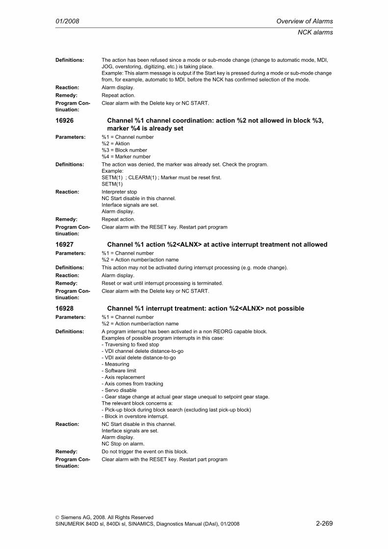
NCK alarms
01/2008 Overview of Alarms
2-269
© Siemens AG, 2008. All Rights ReservedSINUMERIK 840D sl, 840Di sl, SINAMICS, Diagnostics Manual (DAsl), 01/2008
Definitions: The action has been refused since a mode or sub-mode change (change to automatic mode, MDI, JOG, overstoring, digitizing, etc.) is taking place.Example: This alarm message is output if the Start key is pressed during a mode or sub-mode change from, for example, automatic to MDI, before the NCK has confirmed selection of the mode.
Reaction: Alarm display.Remedy: Repeat action.Program Con-tinuation:
Clear alarm with the Delete key or NC START.
16926 Channel %1 channel coordination: action %2 not allowed in block %3, marker %4 is already set
Parameters: %1 = Channel number%2 = Aktion%3 = Block number%4 = Marker number
Definitions: The action was denied, the marker was already set. Check the program.Example:SETM(1) ; CLEARM(1) ; Marker must be reset first.SETM(1)
Reaction: Interpreter stopNC Start disable in this channel.Interface signals are set.Alarm display.
Remedy: Repeat action.Program Con-tinuation:
Clear alarm with the RESET key. Restart part program
16927 Channel %1 action %2<ALNX> at active interrupt treatment not allowedParameters: %1 = Channel number
%2 = Action number/action nameDefinitions: This action may not be activated during interrupt processing (e.g. mode change).Reaction: Alarm display.Remedy: Reset or wait until interrupt processing is terminated.Program Con-tinuation:
Clear alarm with the Delete key or NC START.
16928 Channel %1 interrupt treatment: action %2<ALNX> not possibleParameters: %1 = Channel number
%2 = Action number/action nameDefinitions: A program interrupt has been activated in a non REORG capable block.
Examples of possible program interrupts in this case:- Traversing to fixed stop- VDI channel delete distance-to-go- VDI axial delete distance-to-go- Measuring- Software limit- Axis replacement- Axis comes from tracking- Servo disable- Gear stage change at actual gear stage unequal to setpoint gear stage.The relevant block concerns a:- Pick-up block during block search (excluding last pick-up block)- Block in overstore interrupt.
Reaction: NC Start disable in this channel.Interface signals are set.Alarm display.NC Stop on alarm.
Remedy: Do not trigger the event on this block.Program Con-tinuation:
Clear alarm with the RESET key. Restart part program

Overview of Alarms 01/2008
NCK alarms
2-270
© Siemens AG, 2008. All Rights ReservedSINUMERIK 840D sl, 840Di sl, SINAMICS, Diagnostics Manual (DAsl), 01/2008
16930 Channel %1: preceding block and current block %2 must be separated through an executable block
Parameters: %1 = Channel number%2 = Block number
Definitions: The language functions WAITMC, SETM, CLEARM and MSG must be packed in separate NC blocks due to the language definition. To avoid velocity drops, these blocks are attached to the next NC block internally in the NCK (for MSG only in path control mode, for WAITMC to the previous NC block). For this reason, there must always be an executable block (not a calculation block) between the NC blocks. An executable NC block always includes e.g. travel movements, a help function, Stopre, dwell time etc.
Reaction: Correction block is reorganized.Interpreter stopInterface signals are set.Alarm display.
Remedy: Program an executable NC block between the previous and the current NC block.Example:N10 SETM.N15 STOPRE ; insert executable NC block.N20 CLEARM.
Program Con-tinuation:
Clear alarm with NC START or RESET key and continue the program.
16931 Channel %1 subprograms: action %2<ALNX> maximum nesting depth exceeded
Parameters: %1 = Channel number%2 = Action number/action name
Definitions: Various actions can cause the current procedure to be interrupted. Depending on the action, asyn-chronous subroutines (ASUBs) are activated. These ASUBs can be interrupted in the same manner as the user program. Unlimited nesting depth is not possible for ASUBs due to memory limitations.Example: In the case of an approach block in a repositioning procedure do not interrupt repeatedly, instead wait until processing is completed.Possible actions are: mode change, SlashOn/Off, overstoring.
Reaction: Interface signals are set.Alarm display.NC Stop on alarm.
Remedy: Initiate a block change and repeat the action.Program Con-tinuation:
Clear alarm with the Delete key or NC START.
16932 Channel %1 conflict when activating user data type %2Parameters: %1 = Channel number
%2 = Data typeDefinitions: The "activate user data" function (PI service _N_SETUDT) modifies a data block (tool offset, settable
zero offset or base frame) which is also written by the NC blocks in preparation.In the event of a conflict, the value entered by the MMC is reset.Parameter %2 specifies which data block is affected:1: Active tool offset2: Base frame3: Active zero offset
Reaction: Alarm display.Remedy: Check the inputs on the MMC and repeat if necessary.Program Con-tinuation:
Clear alarm with the Delete key or NC START.
16933 Channel %1 interrupt treatment: action %2<ALNX> not allowed in the current state
Parameters: %1 = Channel ID%2 = Action number/action name

NCK alarms
01/2008 Overview of Alarms
2-271
© Siemens AG, 2008. All Rights ReservedSINUMERIK 840D sl, 840Di sl, SINAMICS, Diagnostics Manual (DAsl), 01/2008
Definitions: If a temporary standstill has occurred because of a Reorg event across block boundaries, it is possible that a block without Reorg capability has been loaded. In this situation, it is unfortunately necessary to abort the Reorg event handling! Reorg events are, e.g. abort subprogram, delete distance-to-go and interrupts.
Reaction: NC Start disable in this channel.Interface signals are set.Alarm display.NC Stop on alarm.
Remedy: Abort program with the RESET key.Program Con-tinuation:
Clear alarm with the RESET key. Restart part program
16934 Channel %1 interrupt treatment: action %2<ALNX> not possible due to stop
Parameters: %1 = Channel ID%2 = Action number/action name
Definitions: Reorg events are, e.g. abort subprogram, delete distance to go and interrupts, axis replacement, ter-mination of follow-up mode. Two Reorg events overlap in this situation. The 2nd Reorg event coin-cides with the 1st block generated by the previous event. (e.g. an axis replacement is induced twice in rapid succession). Axis replacement leads to Reorg in the channels in which an axis is removed without preparation. This block must be stopped in the above sequence in order to prevent the inter-polator buffer from overflowing. This can be achieved by pressing the Stop or StopAll key, configuring an alarm with INTERPRETERSTOP or by decode single block.
Reaction: NC Start disable in this channel.Interface signals are set.Alarm display.NC Stop on alarm.
Remedy: The program must be aborted with Reset.Program Con-tinuation:
Clear alarm with the RESET key. Restart part program
16935 Channel %1 action %2<ALNX> not possible due to search runParameters: %1 = Channel ID
%2 = Action number/action nameDefinitions: The action is not allowed as block search is currently running via program test. Block search via pro-
gram test: "PI Service _N_FINDBL with mode parameter 5_.With this block search type, it is not permissible to activate program test or dry run feedrate.
Reaction: Alarm display.Remedy: Activate the action after block search is terminated.Program Con-tinuation:
Clear alarm with the Delete key or NC START.
16936 Channel %1 action %2<ALNX> not possible due to active dry runParameters: %1 = Channel ID
%2 = Action number/action nameDefinitions: This action is not allowed as dry run feedrate is currently active.
Example: It is not permissible to activate block search via program test (PI service _N_FINDBL with mode parameter 5) when dry run feedrate is active.
Reaction: Alarm display.Remedy: Abort program with the RESET key.Program Con-tinuation:
Clear alarm with the Delete key or NC START.
16937 Channel %1 action %2<ALNX> not possible due to program testParameters: %1 = Channel ID
%2 = Action number/action nameDefinitions: This action is not allowed as program test is currently active.
Example: It is not permissible to activate block search via program test (PI service _N_FINDBL with mode parameter 5) when program test is active.
Reaction: Alarm display.

Overview of Alarms 01/2008
NCK alarms
2-272
© Siemens AG, 2008. All Rights ReservedSINUMERIK 840D sl, 840Di sl, SINAMICS, Diagnostics Manual (DAsl), 01/2008
Remedy: Deactivate program test.Program Con-tinuation:
Clear alarm with the Delete key or NC START.
16938 Channel %1 action %2<ALNX> aborted due to active gear changeParameters: %1 = Channel ID
%2 = Action number/action nameDefinitions: Reorganization events are, among others, subprogram abort, delete distance-to- go and interrupts,
axis replacement, exiting the correction state. These events wait for the end of a gear change. How-ever, the maximum waiting period has elapsed.
Reaction: NC Start disable in this channel.Interface signals are set.Alarm display.NC Stop on alarm.
Remedy: Program must be aborted with Reset and, if necessary, GEAR_CHANGE_WAIT_TIME must be increased.
Program Con-tinuation:
Clear alarm with the RESET key. Restart part program
16939 Channel %1 action %2<ALNX> rejected due to active gear changeParameters: %1 = Channel ID
%2 = Action number/action nameDefinitions: Reorganization events that are possible in Stop state, e.g mode change, are waiting for the end of the
gear change. However, the maximum waiting period has elapsed.Reaction: Interface signals are set.
Alarm display.Remedy: Repeat action or increase MD GEAR_CHANGE_WAIT_TIME.Program Con-tinuation:
Clear alarm with the Delete key or NC START.
16940 Channel %1 action %2<ALNX> wait for gear changeParameters: %1 = Channel ID
%2 = Action number/action nameDefinitions: Reorganization events are waiting for the end of a gear change. The alarm is displayed during the
waiting period.Reaction: Alarm display.
Warning display.Remedy: Alarm is suppressed by means of ENABLE_ALARM_MASK bit 1 == 0.Program Con-tinuation:
Alarm display showing cause of alarm disappears. No further operator action necessary.
16941 Channel %1 action %2<ALNX> rejected because no program event has been executed yet
Parameters: %1 = Channel ID%2 = Action number/action name
Definitions: The setting of the machine data $MC_PROG_EVENT_MASK forces an asynchronous subprogram to be triggered automatically on RESET or PowerOn. The implicitly triggered asynchronous subpro-grams are normally called "Event-triggered program call" or "Program event".In the alarm situation, this asynchronous subprogram could not yet be activated; that is why the action (normally start of part program) must be rejected.Reasons for the fact that the asynchronous subprogram could not be triggered:1. The asynchronous subprogram does not exist (/_N_CMA_DIR/_N_PROG_EVENT_SPF)2. The asynchronous subprogram is allowed to start in the referenced state only (see $MN_ASUP_START_MASK)3. READY is missing (because of alarm)
Reaction: Alarm display.Remedy: - Load program
- Check $MN_ASUP_START_MASK- Acknowledge alarm

NCK alarms
01/2008 Overview of Alarms
2-273
© Siemens AG, 2008. All Rights ReservedSINUMERIK 840D sl, 840Di sl, SINAMICS, Diagnostics Manual (DAsl), 01/2008
Program Con-tinuation:
Clear alarm with the Delete key or NC START.
16942 Channel %1 start program command action %2<ALNX> not possibleParameters: %1 = Channel ID
%2 = Action number/action nameDefinitions: Currently, the alarm occurs only in combination with the SERUPRO action. SERUPRO stands for
search via program test.SERUPRO is currently searching the search target and has therefore switched this channel to the pro-gram test mode. With the START program command in channel 1, another channel 2 would actually be started, which means that axes would really be started during the search action.If this alarm is switched off (see help), the user can make use of the above behavior by initially select-ing via PLC the program test mode in channel 2, leaving channel 2 executing until its natural end, stop-ping channel 2 in order to deselect program test again.
Reaction: NC Start disable in this channel.Interface signals are set.Alarm display.NC Stop on alarm.
Remedy: Alarm can be switched off with $MN_SERUPRO_MASK bit 1.Program Con-tinuation:
Clear alarm with the RESET key. Restart part program
16943 Channel %1 action %2<ALNX> not possible due to ASUPParameters: %1 = Channel ID
%2 = Action number/action nameDefinitions: The action in the 2nd parameter was rejected, since an asynchronous subprogram is currently active.
Currently, only the integrated search run is rejected with this alarm. The integrated search run is acti-vated, if search run is triggered in the Stop program state. In other words: Parts of a program have already been executed and a following program part is "skipped" with search run in order to continue the program afterwards.The event is not possible if the program is stopped within an asynchronous subprogram or if an asyn-chronous subprogram had been selected before the event. An asynchronous subprogram is selected, when the triggering asynchronous subprogram event arrives, but the asynchronous subprogram can-not be started (e.g. the asynchronous start program is not started because of a read-in disable or because the Stop key is active).In this case, it is irrelevant whether a user ASUP or a system ASUP has been triggered. User ASUPs are activated via FC-9 or via the fast inputs.The following events lead to system ASUPS:- Mode change- Overstore on- Aborting subprogram level- Switching on of single block, type 2- Setting machine data effective- Setting user data effective- Change skip levels- Dry run on/off- Program test off- Correction block alarms- Editing modi in Teach- External zero offset- Axis replacement- Delete distance-to-go- Measuring
Reaction: Alarm display.Remedy: Repeat the action after the end of the asynchronous subprogram.Program Con-tinuation:
Clear alarm with the Delete key or NC START.
16944 Channel %1 action %2<ALNX> not possible due to active search blocksParameters: %1 = Channel ID
%2 = Action number/action name

Overview of Alarms 01/2008
NCK alarms
2-274
© Siemens AG, 2008. All Rights ReservedSINUMERIK 840D sl, 840Di sl, SINAMICS, Diagnostics Manual (DAsl), 01/2008
Definitions: The NCK is currently processing either the action blocks of the search run or the approach motion after the search run.In this situation, the action (2nd parameter of the alarm) must be rejected.Currently, only the integrated search run is rejected with this alarm. The integrated search run is acti-vated, if search run is triggered in the Stop program state. In other words: Parts of a program have already been executed and a following program part is "skipped" with search run in order to continue the program afterwards.
Reaction: Alarm display.Remedy: Repeat the action after the approach motion of the search run.Program Con-tinuation:
Clear alarm with the Delete key or NC START.
16945 Channel %1 action %2<ALNX> delayed up to the block endParameters: %1 = Channel ID
%2 = Action number/action nameDefinitions: The currently executing action (e.g. dry run on/off, change skip levels, etc.) should be active immedi-
ately, but it can become active not earlier than at the end of the block, since a thread is currently being machined. The action is activated with a slight delay.Example: Dry run is started in the middle of the thread, then traversing at high speed does not start before the next block.
Reaction: Alarm display.Remedy: Alarm can be switched off via $MN_SUPPRESS_ALARM_MASK bit 17==1.Program Con-tinuation:
Clear alarm with the Delete key or NC START.
16946 Channel %1 start via START is not allowedParameters: %1 = Channel IDDefinitions: This alarm is active with "Group Serupro" only. _Group Serupro" is activated by means of
"$MC_SERUPRO_MODE BIT2" and enables the retrace support of entire channel groups during block search.The machine data $MC_DISABLE_PLC_START specifies which channel is generally started from the PLC and which channel is only allowed to be started from another channel via the START part pro-gram command.This alarm occurs if the channel was started via the START part programm command and $MC_DISABLE_PLC_START==FALSE was set.
Reaction: Alarm display.Remedy: Modify $MC_DISABLE_PLC_START of switch off "Group Serupro" (see $MC_SERUPRO_MODE).Program Con-tinuation:
Clear alarm with the Delete key or NC START.
16947 Channel %1 start via PLC is not allowedParameters: %1 = Channel IDDefinitions: This alarm is active with "Group Serupro" only. _Group Serupro" is activated by means of
"$MC_SERUPRO_MODE BIT2" and enables the retrace support of entire channel groups during block search.The machine data $MC_DISABLE_PLC_START specifies which channel is generally started from the PLC and which channel is only allowed to be started from another channel via the START part pro-gram command.This alarm occurs if the channel was started via the PLC and $MC_DISABLE_PLC_START==TRUE was set.
Reaction: Alarm display.Remedy: Modify $MC_DISABLE_PLC_START of switch off "Group Serupro" (see $MC_SERUPRO_MODE).Program Con-tinuation:
Clear alarm with the Delete key or NC START.

NCK alarms
01/2008 Overview of Alarms
2-275
© Siemens AG, 2008. All Rights ReservedSINUMERIK 840D sl, 840Di sl, SINAMICS, Diagnostics Manual (DAsl), 01/2008
16948 Channel %1 dependent channel %2 still activeParameters: %1 = Channel ID
%2 = Channel IDDefinitions: This alarm is active with "Group Serupro" only. _Group Serupro" is activated by means of
"$MC_SERUPRO_MODE BIT2" and enables the retrace support of entire channel groups during block search.A _dependent channel_ is a channel that had indirectly been started by the currently active channel. The currently active channel was started via PLC.This channel m_u_s_t be terminated (i.e. reached M30) before the current channel is terminated.This alarm occurs if the currently active channel is terminated before the dependent channel.
Reaction: Alarm display.Remedy: Switch off "Group Serupro" (see $MC_SERUPRO_MODE) or install WAITE.Program Con-tinuation:
Clear alarm with the Delete key or NC START.
16949 Correspondence between marker of channel %1 and channel %2 is invalid.
Parameters: %1 = Channel ID%2 = Channel ID
Definitions: This channel defines a WAIT marker with other channels, which on their part have no correspondence with this wait marker.This channel's WAIT marker has no explicit counterpart in the other channel; i.e. the channels do not mutually wait.============================================================ExampleCh 3Ch 5Ch 7WAITM(99,3,5) WAITM(99,3,5) WAITM(99,5,7)The wait markers in channels 3 and 5 mutually wait for each other and channel 7 only waits for channel 5. Therefore, channel 7 may continue when 5 and 7 have reached the wait marker, but channel 3 is still far in front of the wait marker.When it continues, channel 7 deletes its wait marker. When wait marker 99 is reached again, you can no longer determine the behavior precisely.============================================================
Reaction: Alarm display.Remedy: In each wait marker, list all channels with which you want to synchronize, or suppress the alarm with
$MN_SUPPRESS_ALARM_MASK, bit 23.============================================================Sample solution A:Ch 3Ch 5Ch 7WAITM(99,3,5,7) WAITM(99,3,5,7) WAITM(99,3,5,7)============================================================Sample solution B:Ch 3Ch 5Ch 7WAITM(99,3,5) WAITM(99,3,5) WAITM(88,5,7) WAITM(88,5,7)============================================================Sample solution C:Ch 3Ch 5Ch 7 WAITM(88,5,7) WAITM(88,5,7)WAITM(99,3,5) WAITM(99,3,5)
Program Con-tinuation:
Clear alarm with the Delete key or NC START.

Overview of Alarms 01/2008
NCK alarms
2-276
© Siemens AG, 2008. All Rights ReservedSINUMERIK 840D sl, 840Di sl, SINAMICS, Diagnostics Manual (DAsl), 01/2008
16950 Channel %1 search run with hold blockParameters: %1 = Channel IDDefinitions: Informational alarm.
The search run was not performed on the interruption block,instead, it touches down shortly before that. This so-called "hold block"is generated by the part program command IPTRLOCK, or implicitly defined by$MC_AUTO_IPTR_LOCK. This is to preventyou from performing a search run in critical program areas(e.g. gear hobbing).The alarm also displays that, instead of searching for theblock that actually was interrupted before, another block is being searched for.This behavior is desired and the alarm serves only informational purposes.
Reaction: Alarm display.Remedy: $MN_SUPPRESS_ALARM_MASK $MC_AUTO_IPTR_LOCK and language command IPTRLOCKProgram Con-tinuation:
Clear alarm with the Delete key or NC START.
16951 Channel %1 search run in a protected program section.Parameters: %1 = Channel IDDefinitions: A part programmer can define protected part program sections with the language commands
IPTRLOCK and IPTRUNLOCK,Every search run in these program sections will then be acknowledged with alarm 16951.In other words:When the alarm appears, the user has started a search run (Serupro type)and the search target lies in a protected area.A protected area can also be defined implicitly with the machine data$MC_AUTO_IPTR_LOCK.Note:The alarm can only be generated if the simulation has beencompleted during the search run. The alarm cannotbe output immediately at the start of the search run.
Reaction: NC Start disable in this channel.Interface signals are set.Alarm display.NC Stop on alarm.
Remedy: $MN_SUPPRESS_ALARM_MASK $MC_AUTO_IPTR_LOCK and language command IPTRLOCKProgram Con-tinuation:
Clear alarm with the RESET key. Restart part program
16952 Channel %1 start program command not possible due to MDIParameters: %1 = Channel IDDefinitions: NCK is currently executing an ASUB in MDI mode. In this constellation,
parts program command "Start" is not allowed for another channel. Attention: If an asup is started from JOG, the NCK can internally change to MDI,if the NCK was previously in MDI and not in RESET.Note: Without this alarm, the MDI buffer of the other channel would always be started.
Reaction: NC Start disable in this channel.Interface signals are set.Alarm display.NC Stop on alarm.
Remedy: Start ASUB in AUTO or ->JOG in AUTOProgram Con-tinuation:
Clear alarm with the RESET key. Restart part program
16953 Channel %1 For slave axis %2 SERUPRO not allowed, as master axis %3 not subject to axis/spindle disable
Parameters: %1 = Channel number%2 = Slave axis name, following spindle number%3 = Master axis name, master spindle number

NCK alarms
01/2008 Overview of Alarms
2-277
© Siemens AG, 2008. All Rights ReservedSINUMERIK 840D sl, 840Di sl, SINAMICS, Diagnostics Manual (DAsl), 01/2008
Definitions: Currently, the alarm occurs only in combination with the SERUPRO action. SERUPRO stands for search via program test.SERUPRO is possible only with an active coupling, if the axis/spindle disable is active for all master axes/spindles of the slave axis/spindle
Reaction: NC Start disable in this channel.Interface signals are set.Alarm display.NC Stop on alarm.
Remedy: Set axis/spindle disable of the master axisProgram Con-tinuation:
Clear alarm with the RESET key. Restart part program
16954 Channel %1 block %2 programmed stop prohibited in stop delay areaParameters: %1 = Channel ID
%2 = Block number, labelDefinitions: In a program area (stop delay area) that is bracketed with DELAYFSTON and DELAYFSTOF,
a program command was used that causes a stop.No commands other than G4 are permissible that might cause a stop even though only shortly.A stop delay area can also be defined by $MN_STOP_MODE_MASK.
Reaction: Interpreter stopNC Start disable in this channel.Interface signals are set.Alarm display.NC Stop on alarm.
Remedy: $MN_STOP_MODE_MASK and language command DELAYFSTON DELAYFSTOFProgram Con-tinuation:
Clear alarm with the RESET key. Restart part program
16955 Channel %1 stop in stop delay area is delayedParameters: %1 = Channel IDDefinitions: In a program area (stop delay area) that is bracketed by DELAYFSTON and DELAYFSTOF,
an event has been detected that causes a stop. The stop is delayedand executed after DELAYFSTOF. A stop delay area can also be defined by $MN_STOP_MODE_MASK.
Reaction: Interface signals are set.Alarm display.
Remedy: $MN_STOP_MODE_MASK and language command DELAYFSTON DELAYFSTOFProgram Con-tinuation:
Alarm display showing cause of alarm disappears. No further operator action necessary.
16956 Channel %1 program %2 cannot be started due to global start disable.Parameters: %1 = Channel ID
%2 = String (path with program name)Definitions: The program selected in this channel cannot be started as "Global start disable" had been set.
Note:PI "_N_STRTLK" sets the "Global start disable" and PI "_N_STRTUL"deletes the "Global start disable".The alarm is switched on with $MN_ENABLE_ALARM_MASK bit 6.
Reaction: Alarm display.Remedy: Delete the "Global start disable" and restart.Program Con-tinuation:
Clear alarm with the Delete key or NC START.

Overview of Alarms 01/2008
NCK alarms
2-278
© Siemens AG, 2008. All Rights ReservedSINUMERIK 840D sl, 840Di sl, SINAMICS, Diagnostics Manual (DAsl), 01/2008
16957 Channel %1 Stop-Delay area is suppressedParameters: %1 = Channel IDDefinitions: The program area (Stop-Delay area), which is put into brackets through DELAYFSTON and
DELAYFSTOF, could not be activated. Every stop therefore becomes effective immediatelyand is not delayed! This occurs every time, when braking into a stop Stop-Delay area, i.e. a braking processstarts before the Stop-Delay area and ends not earlier than in the Stop-Delay area.If the Stop-Delay area is entered with override 0, the Stop-Delay areacan also not be activated (example: a G4 before the Stop-Delay area allows the userto reduce the override to 0 and the next block in the Stop-Delay areathen starts with override 0 and the alarm situation described occurs.)$MN_ENABLE_ALARM_MASK Bit-7 switches on this alarm.
Reaction: Interface signals are set.Alarm display.
Remedy: $MN_STOP_MODE_MASK and language command DELAYFSTON DELAYFSTOFProgram Con-tinuation:
Alarm display showing cause of alarm disappears. No further operator action necessary.
16959 Channel %1 action %2<ALNX> prohibited during simulation block search.
Parameters: %1 = Channel number%2 = Action number/action name
Definitions: The function (2nd parameter) must not be activated during simulation search.Reaction: Alarm display.Remedy: Wait for search end.Program Con-tinuation:
Clear alarm with the Delete key or NC START.
16960 Channel %1 action %2<ALNX> prohibited during EXECUTE PROGRAM AREA.
Parameters: %1 = Channel number%2 = Action number/action name
Definitions: The function (2nd parameter) must not be activated during EXECUTE PROGRAM AREA.Reaction: Alarm display.Remedy: Wait for end of program area EXECUTE.Program Con-tinuation:
Clear alarm with the Delete key or NC START.
16961 Channel %1 action %2<ALNX> prohibited during syntax check.Parameters: %1 = Channel number
%2 = Action number/action nameDefinitions: The function (2nd parameter) must not be activated during the syntax check.
Comment: The syntax check is served by the following PI services:_N_CHKSEL _N_CHKRUN _N_CHKABO
Reaction: Alarm display.Remedy: Wait for the end of the syntax check, or
Cancel the syntax check with reset, orCancel the syntax check with PI _N_CHKABO.
Program Con-tinuation:
Clear alarm with the Delete key or NC START.
16962 Channel %1 NCK computing time reduced, start is not allowed.Parameters: %1 = Channel numberDefinitions: The computing time available to the NCK has been reduced, starts have therefore been locked. The
computer performance is inadequate for smooth program execution. The computing time of the NCK may have been reduced by the HMI because of an HMI part program simulation.
Reaction: Alarm display.Remedy: Wait for the simulation to end or press RESET in any channel.

NCK alarms
01/2008 Overview of Alarms
2-279
© Siemens AG, 2008. All Rights ReservedSINUMERIK 840D sl, 840Di sl, SINAMICS, Diagnostics Manual (DAsl), 01/2008
Program Con-tinuation:
Clear alarm with the Delete key or NC START.
17000 Channel %1 block %2 maximum number of symbols exceededParameters: %1 = Channel number
%2 = Block number, labelDefinitions: The maximum number of symbols defined by machine data 28020
$MC_MM_NUM_LUD_NAMES_TOTAL has been exceeded.Reaction: Interpreter stop
NC Start disable in this channel.Interface signals are set.Alarm display.
Remedy: Please inform the authorized personnel/service department.- Modify machine data- Reduce the number of symbols (variables, subroutines, parameters)
Program Con-tinuation:
Clear alarm with the RESET key. Restart part program
17001 Channel %1 block %2 no memory left for tool/magazine dataParameters: %1 = Channel number
%2 = Block number, labelDefinitions: The number of following tool/magazine data variables in the NC are given by machine data:
- Number of tools + number of grinding data blocks: MD18082 $MN_MM_NUM_TOOL- Number of cutting edges: MD18100 $MN_MM_NUM_CUTTING_EDGES_IN_TOATools, grinding data blocks, cutting edges can be used independently of the tool management.The memory for the following data is available only if the corresponding bit has been set in MD18080 $MN_MM_TOOL_MANAGEMENT_MASK.- Number of monitoring data blocks: MD18100 $MN_MM_NUM_CUTTING_EDGES_IN_TOA- Number of magazines: MD18084 $MN_MM_NUM_MAGAZINE- Number of magazine locations: MD18086 $MN_MM_NUM_MAGAZINE_LOCATIONThe following variable is determined by software configuration: Number of magazine spacing data blocks: P2 permits 32 such spacing data blocks.Definition:- 'Grinding data blocks': Grinding data can be defined for a tool from type 400 to 499. Such a data block occupies as much additional memory as that provided for a cutting edge.- 'Monitoring data blocks': Each cutting edge of a tool can be supplemented by monitoring data.- If the alarm occurs while writing from one of the parameters $TC_MDP1/$TC_MDP2/$TC_MLSR,check whether machine data MD18077 $MN_MM_NUM_DIST_REL_PER_MAGLOC / MD18076$MN_MM_NUM_LOCS_WITH_DISTANCE have been correctly set.MD18077 $MN_MM_NUM_DIST_REL_PER_MAGLOC defines the number of different Index1 state-ments that may be made for an Index2 value.MD18076 $MN_MM_NUM_LOCS_WITH_DISTANCE defines the number of different buffer storage locations that may be named in Index2.
Reaction: Correction block is reorganized.Interface signals are set.Alarm display.
Remedy: Please inform the authorized personnel/service department.- Modify machine data- Modify NC program, i.e. reduce number of rejected variable.
Program Con-tinuation:
Clear alarm with NC START or RESET key and continue the program.
17010 Channel %1 block %2 no memory leftParameters: %1 = Channel number
%2 = Block number, labelDefinitions: When executing/reading files from the active working memory, it was found that there is not enough
memory space (e.g. for large multidimensional arrays or when creating tool offset memory).Reaction: Interpreter stop
NC Start disable in this channel.Interface signals are set.Alarm display.

Overview of Alarms 01/2008
NCK alarms
2-280
© Siemens AG, 2008. All Rights ReservedSINUMERIK 840D sl, 840Di sl, SINAMICS, Diagnostics Manual (DAsl), 01/2008
Remedy: Please inform the authorized personnel/service department. Make arrays smaller or make more mem-ory space available for memory management of subroutine calls, tool offsets and user variables (machine data MM_...).See /FB/, S7 Memory Configuration
Program Con-tinuation:
Clear alarm with the RESET key. Restart part program
17018 Channel %1 block %2 incorrect value for parameter %3Parameters: %1 = Channel number
%2 = Block number, label%3 = Parameter name
Definitions: An incorrect value has been assigned to the stated parameter.Only the following values are permissible for the parameter $P_WORKAREA_CS_COORD_SYSTEM =1 for workpiece coordinate system =3 for settable zero system.
Reaction: Interpreter stopInterface signals are set.Alarm display.
Remedy: Assign another value.Program Con-tinuation:
Clear alarm with the RESET key. Restart part program
17020 Channel %1 block %2 illegal array index 1Parameters: %1 = Channel number
%2 = Block number, labelDefinitions: General:
A read or write access has been programmed to an array variable with an invalid 1st array index. The valid array indices must lie within the defined array size and the absolute limits (0 - 32,766).PROFIBUS I/O:An invalid slot / I/O area index was used while reading/writing data. Cause: 1.: Slot / I/O area index >= max. number of available slot / I/O areas. 2.: Slot / I/O area index references a slot / I/O area that has not been configured. 3.: Slot / I/O area index references a slot / I/O area that has not been released for a system variable.The following applies specifically: If the alarm occurs while writing from one of the parameters $TC_MDP1/$TC_MDP2/$TC_MLSR,check whether $MN_MM_NUM_DIST_REL_PER_MAGLOC has been set correctly. $MN_MM_NUM_DIST_REL_PER_MAGLOC defines the number of different Index1 statements that may be made for an Index2 value.
Reaction: Correction block is reorganized.Interface signals are set.Alarm display.
Remedy: Correct the specification of array elements in the access instruction to match the defined size. If an SPL is used in Safety Integrated, the field index via optional data may be subject to additional restric-tions.
Program Con-tinuation:
Clear alarm with NC START or RESET key and continue the program.
17030 Channel %1 block %2 illegal array index 2Parameters: %1 = Channel number
%2 = Block number, labelDefinitions: General:
A read or write access has been programmed to an array variable with an invalid 2nd array index. The valid array indices must lie within the defined array size and the absolute limits (0 - 32,766).PROFIBUS I/O:An attempt was made to read/write data outside the slot / I/O area limits of the stated slot / I/O area.

NCK alarms
01/2008 Overview of Alarms
2-281
© Siemens AG, 2008. All Rights ReservedSINUMERIK 840D sl, 840Di sl, SINAMICS, Diagnostics Manual (DAsl), 01/2008
The following applies specifically: If the alarm occurs while writing one of the parameters $TC_MDP1/$TC_MDP2/$TC_MLSR,check whether $MN_MM_NUM_LOCS_WITH_DISTANCE has been set correctly. $MN_MM_NUM_LOCS_WITH_DISTANCE defines the number of different buffer storage locations that may be named in Index2.
Reaction: Correction block is reorganized.Interface signals are set.Alarm display.
Remedy: Correct the specification of array elements in the access instruction to match the defined size.Program Con-tinuation:
Clear alarm with NC START or RESET key and continue the program.
17035 Channel %1 block %2 illegal array index 1Parameters: %1 = Channel number
%2 = Block number, labelDefinitions: General:
A read or write access has been programmed to an array variable with an invalid 3rd array index. The valid array indices must lie within the defined array size and the absolute limits (0 - 32,766).
Reaction: Correction block is reorganized.Interface signals are set.Alarm display.
Remedy: Correct the specification of array elements in the access instruction to match the defined size.Program Con-tinuation:
Clear alarm with NC START or RESET key and continue the program.
17040 Channel %1 block %2 illegal axis indexParameters: %1 = Channel number
%2 = Block number, labelDefinitions: A read or write access has been programmed to an axial variable in which the axis name cannot be
unambiguously imaged on a machine axis.Example:Writing of an axial machine data$MA_... [X]= ... ; but geometry axis X cannot be imaged on a machine axis because of a transforma-tion!
Reaction: Correction block is reorganized.Interface signals are set.Alarm display.
Remedy: Deselect transformation before writing into the axial data (keyword: TRAFOOF) or use the machine axis names as axis index.
Program Con-tinuation:
Clear alarm with NC START or RESET key and continue the program.
17050 Channel %1 block %2 illegal valueParameters: %1 = Channel number
%2 = Block number, labelDefinitions: On accessing an individual frame element, a frame component other than TRANS, ROT, SCALE or
MIRROR was addressed or the function CSCALE has been given a negative scale factor.Example:$P_UIFR[5] = CSCALE (X, -2.123)The frame components are either selected by means of the keywordsTR for translation (TRANS, internal 0)RT for rotation (ROT, internal 1)SC for scaling and (SCALE, internal 3)MI for mirroring (MIRROR, internal 4)or they are specified directly as an integral value 0, 1, 3, 4.

Overview of Alarms 01/2008
NCK alarms
2-282
© Siemens AG, 2008. All Rights ReservedSINUMERIK 840D sl, 840Di sl, SINAMICS, Diagnostics Manual (DAsl), 01/2008
Example: Access to the rotation around the X axis of the current settable frame.R10=$P_UIFR[$AC_IFRNUM, X, RT] can also be programmed as:R10=$P_UIFR[$AC_IFRNUM, X, 1]
Reaction: Interpreter stopNC Start disable in this channel.Interface signals are set.Alarm display.
Remedy: Address frame components only with the keywords provided; program the scale factor between the limits of 0.000 01 to 999.999 99.
Program Con-tinuation:
Clear alarm with the RESET key. Restart part program
17055 Channel %1 block %2 GUD variable not existingParameters: %1 = Channel number
%2 = Block number, labelDefinitions: The required GUD variable was not found for a MEACALC procedure during read or write access.Reaction: Interpreter stop
NC Start disable in this channel.Interface signals are set.Alarm display.
Remedy: Check whether all the GUDs were created for MEACALC.DEF CHAN INT _MVAR, _OVI[11]DEF CHAN REAL _OVR[32], _EV[20], _MV[20], _SPEED[4], _SM_R[10], _ISP[3]DEF NCK REAL _TP[3,10], _WP[3,11], _KB[3,7], _CM[8], _MFS[6]DEF NCK BOOL _CBIT[16]DEF NCK INT _CVAL[4].
Program Con-tinuation:
Clear alarm with the RESET key. Restart part program
17060 Channel %1 block %2 requested data area too largeParameters: %1 = Channel number
%2 = Block number, labelDefinitions: The maximum memory space of 8 KB available for a symbol has been exceeded.Reaction: Correction block is reorganized.
Interface signals are set.Alarm display.
Remedy: Reduce array dimensions.Program Con-tinuation:
Clear alarm with NC START or RESET key and continue the program.
17070 Channel %1 block %2 data is write-protectedParameters: %1 = Channel number
%2 = Block number, labelDefinitions: An attempt was made to write into a write-protected variable (e.g. a system variable). Safety Inte-
grated: Safety system variables can only be written into via the safety SPL program.Reaction: Correction block is reorganized.
Interface signals are set.Alarm display.
Remedy: Please inform the authorized personnel/service department. Modify part program.Program Con-tinuation:
Clear alarm with NC START or RESET key and continue the program.
17080 Channel %1 block %2 %3 value below lower limitParameters: %1 = Channel number
%2 = Block number, label%3 = MD
Definitions: An attempt was made to write into a machine date with a value smaller than the configured lower limit.Reaction: Correction block is reorganized.
Interface signals are set.Alarm display.

NCK alarms
01/2008 Overview of Alarms
2-283
© Siemens AG, 2008. All Rights ReservedSINUMERIK 840D sl, 840Di sl, SINAMICS, Diagnostics Manual (DAsl), 01/2008
Remedy: Please inform the authorized personnel/service department. Determine the input limits of the machine data and assign a value within these limits.
Program Con-tinuation:
Clear alarm with NC START or RESET key and continue the program.
17090 Channel %1 block %2 %3 value exceeds upper limitParameters: %1 = Channel number
%2 = Block number, label%3 = MD
Definitions: An attempt was made to write into a machine date with a value greater than the configured upper limit.Reaction: Correction block is reorganized.
Interface signals are set.Alarm display.
Remedy: Please inform the authorized personnel/service department. Determine the input limits of the machine data and assign a value within these limits.
Program Con-tinuation:
Clear alarm with NC START or RESET key and continue the program.
17095 Channel %1 block %2 invalid valueParameters: %1 = Channel number
%2 = Block number, labelDefinitions: An attempt was made to write an invalid value, e.g. zero, into a machine data.Reaction: Correction block is reorganized.
Interface signals are set.Alarm display.
Remedy: Correct the value assignment, e.g. a value within the value range not equal to zero.Program Con-tinuation:
Clear alarm with NC START or RESET key and continue the program.
17100 Channel %1 block %2 digital input/comparator no. %3 not activatedParameters: %1 = Channel number
%2 = Block number, label%3 = Input number
Definitions: Either an attempt was made to read a digital input n via the system variable $A_IN[n] and this input has not been activated via NCK machine data 10350 FASTIO_DIG_NUM_INPUTS; or to read a com-parator input via system variable $A_INCO[n] and this input belongs to a comparator which has not been activated.
Reaction: Correction block is reorganized.Interface signals are set.Alarm display.
Remedy: Please inform the authorized personnel/service department. Modify part program or machine data accordingly.
Program Con-tinuation:
Clear alarm with NC START or RESET key and continue the program.
17110 Channel %1 block %2 digital output no. %3 not activatedParameters: %1 = Channel number
%2 = Block number, label%3 = No. of output
Definitions: An attempt was made to read or set a digital NCK output (connector X 121) via the system variable $A_OUT [n] with the index [n] greater than the specified upper limit in the NCK machine data 10360 FASTIO_DIG_NUM_OUTPUTS.
Reaction: Correction block is reorganized.Interface signals are set.Alarm display.
Remedy: Program index [n] of the system variable $A_OUT [n] only between 0 and the value in the NCK machine data 10350 FASTIO_DIG_NUM_OUTPUTS.
Program Con-tinuation:
Clear alarm with NC START or RESET key and continue the program.

Overview of Alarms 01/2008
NCK alarms
2-284
© Siemens AG, 2008. All Rights ReservedSINUMERIK 840D sl, 840Di sl, SINAMICS, Diagnostics Manual (DAsl), 01/2008
17120 Channel %1 block %2 analog input no. %3 not activatedParameters: %1 = Channel number
%2 = Block number, label%3 = Input number
Definitions: An attempt has been made by means of the system variable $A_INA[n] to read an analog input n that has not been activated by the MD 10300 FASTIO_ANA_NUM_INPUTS.
Reaction: Correction block is reorganized.Interface signals are set.Alarm display.
Remedy: Please inform the authorized personnel/service department. Modify part program or machine data accordingly.
Program Con-tinuation:
Clear alarm with NC START or RESET key and continue the program.
17130 Channel %1 block %2 analog output no. %3 not activatedParameters: %1 = Channel number
%2 = Block number, label%3 = No. of output
Definitions: An attempt has been made by means of the system variable $A_OUTA[n] to write or read an analog output n that has not been activated by the MD 10310 FASTIO_ANA_NUM_OUTPUTS.
Reaction: Correction block is reorganized.Interface signals are set.Alarm display.
Remedy: Please inform the authorized personnel/service department. Modify part program or machine data accordingly.
Program Con-tinuation:
Clear alarm with NC START or RESET key and continue the program.
17140 Channel %1 block %2 NCK output %3 is assigned to a function via machine data
Parameters: %1 = Channel number%2 = Block number, label%3 = No. of output
Definitions: The programmed digital/analog output is assigned to an NC function (e.g. software cams).Reaction: Correction block is reorganized.
Interface signals are set.Alarm display.
Remedy: Please inform the authorized personnel/service department. Use another output or deactivate concur-rent NC function via MD.
Program Con-tinuation:
Clear alarm with NC START or RESET key and continue the program.
17150 Channel %1 block %2 maximum of %3 NCK outputs programmable in the block
Parameters: %1 = Channel number%2 = Block number, label%3 = Quantity
Definitions: No more than the specified number of outputs may be programmed in an NC block.The quantity of hardware outputs is defined in the MDs:10360 FASTIO_DIG_NUM_OUTPUTS and10310 FASTIO_ANA_NUM_OUTPUTS
Reaction: Correction block is reorganized.Interface signals are set.Alarm display.
Remedy: Program fewer digital/analog outputs in a block. The specified maximum number applies in each case separately for analog or digital outputs. If necessary, program two NC blocks.
Program Con-tinuation:
Clear alarm with NC START or RESET key and continue the program.

NCK alarms
01/2008 Overview of Alarms
2-285
© Siemens AG, 2008. All Rights ReservedSINUMERIK 840D sl, 840Di sl, SINAMICS, Diagnostics Manual (DAsl), 01/2008
17160 Channel %1 block %2 no tool selectedParameters: %1 = Channel number
%2 = Block number, labelDefinitions: An attempt has been made to access the current tool offset data via the system variables:
$P_AD [n]: Contents of the parameter (n: 1 - 25)$P_TOOL: Active D number (tool edge number)$P_TOOLL [n]: Active tool length (n: 1- 3)$P_TOOLR: Active tool radiusalthough no tool had been selected previously.
Reaction: Interpreter stopNC Start disable in this channel.Interface signals are set.Alarm display.
Remedy: Program or activate a tool offset in the NC program before using the system variables.Example:N100 G.. ... T5 D1 ... LFWith the channel-specific machine data:Modify MD 22550: TOOL_CHANGE_MODENew tool offset for M functionModify MD 22560: TOOL_CHANGE_M_CODEM function with tool changeIt is established whether a tool offset is activated in the block with the T word or whether the new offset values are allowed for only when the M word for tool change occurs.
Program Con-tinuation:
Clear alarm with the RESET key. Restart part program
17170 Channel %1 block %2 number of symbols too largeParameters: %1 = Channel number
%2 = Block number, labelDefinitions: The predefined symbols could not be read in during power-up.Reaction: Interpreter stop
NC Start disable in this channel.Interface signals are set.Alarm display.
Remedy: --Program Con-tinuation:
Clear alarm with the RESET key. Restart part program
17180 Channel %1 block %2 illegal D numberParameters: %1 = Channel number
%2 = Block number, labelDefinitions: In the displayed block, access is made to a D number that is not defined and therefore is not available.Reaction: Correction block is reorganized.
Interface signals are set.Alarm display.
Remedy: Check tool call in the NC parts program:- Correct tool correction number D programmed? If no D number is specified with the tool change com-mand, then the D number set by machine data $MC_CUTTING_EDGE_DEFAULT will be active auto-matically. It is D1 by default.- Tool parameters (tool type, length,...) defined? The dimensions of the tool edge must have been entered previously either through the operator panel or through a tool data file in NCK.Description of the system variables $TC_DPx[t, d] as included in a tool data file.x ... Correction parameter number Pt ... Associated tool number Td ... Tool correction number D
Program Con-tinuation:
Clear alarm with NC START or RESET key and continue the program.

Overview of Alarms 01/2008
NCK alarms
2-286
© Siemens AG, 2008. All Rights ReservedSINUMERIK 840D sl, 840Di sl, SINAMICS, Diagnostics Manual (DAsl), 01/2008
17181 Channel %1 block %2 T no.= %3, D no.= %4 not existingParameters: %1 = Channel number
%2 = Block number, label%3 = T number%4 = D number
Definitions: A programmed D number was not recognized by the NC. By default, the D number refers to the spec-ified T number. If the flat D number function is active, T= 1 is output.
Reaction: Correction block is reorganized.Interface signals are set.Alarm display.
Remedy: If the program is incorrect, remedy the error with a correction block and continue the program. If the data block is missing, download a data block for the specified T/D values onto the NCK (via MMC with overstore) and continue the program.
Program Con-tinuation:
Clear alarm with NC START or RESET key and continue the program.
17182 Channel %1 block %2 illegal sum correction numberParameters: %1 = Channel number
%2 = Block number, labelDefinitions: An attempt was made to access a non-defined total offset of the current tool edge.Reaction: Correction block is reorganized.
Interface signals are set.Alarm display.
Remedy: Access the total offset memory with $TC_SCP*, $TC_ECP*, check the total offset selection DLx or tool selection Ty or offset selection Dz.
Program Con-tinuation:
Clear alarm with NC START or RESET key and continue the program.
17183 Channel %1 block %2 H number already available in T no.= %3, D no.= %4
Parameters: %1 = Channel number%2 = Block number, label%3 = T number%4 = D number
Definitions: Each H number (except for H=0) must be assigned in a TO unit only once.The indicated edge already has the H number.If the H number shall be assigned more than once, machine date 10890, bit 3 must be set = 1.
Reaction: Correction block is reorganized.Interface signals are set.Alarm display.
Remedy: - Change program:- Select different H number
Program Con-tinuation:
Clear alarm with NC START or RESET key and continue the program.
17188 Channel %1 D number %2 defined in tool T no. %3 and %4Parameters: %1 = Channel number
%2 = Offset number D%3 = T number of first tool%4 = T number of second tool
Definitions: The specified D number %2 in the TO unit of channel %1 is not unique. The specified T numbers %3 and %4 each have an offset with number %2. If tool management is active: The specified T numbers belong to tool groups with different names.
Reaction: Interface signals are set.Alarm display.
Remedy: 1. Ensure that the D numbers within the TO unit are unique.2. If unique numbering is not necessary for subsequent operations, do not use the command.
Program Con-tinuation:
Clear alarm with the Delete key or NC START.

NCK alarms
01/2008 Overview of Alarms
2-287
© Siemens AG, 2008. All Rights ReservedSINUMERIK 840D sl, 840Di sl, SINAMICS, Diagnostics Manual (DAsl), 01/2008
17189 Channel %1 D number %2 of tools defined on magazine/location %3 and %4
Parameters: %1 = Channel number%2 = Offset number D%3 = Magazine/location number of first tool, '/' as separator%4 = Magazine/location number of second tool, '/' as separator
Definitions: The specified D number %2 in the TO unit of channel %1 is not unique. The specified T numbers %3 and %4 each have an offset with number %2.If tool management is active:The specified T numbers belong to tool groups with different names.
Reaction: Interface signals are set.Alarm display.
Remedy: 1. Ensure that the D numbers within the TO unit are unique, e.g. by renaming the D numbers.2. If unique numbering is not necessary for subsequent operations, do not use the command.
Program Con-tinuation:
Clear alarm with the Delete key or NC START.
17190 Channel %1 block %2 illegal T number %3Parameters: %1 = Channel number
%2 = Block number, label%3 = T number
Definitions: In the displayed block, access is made to a tool that is not defined and therefore not available. The tool has been named by its T number, its name or its name and duplo number.
Reaction: Correction block is reorganized.Interface signals are set.Alarm display.
Remedy: Check tool call in the NC part program:- Correct tool number T.. programmed?- Tool parameters P1 - P25 defined? The dimensions of the tool edge must have been entered previ-ously either through the operator panel or through the V.24 interface.Description of the system variables $P_DP x [n, m]n ... Associated tool number Tm ... Tool edge number Dx ... Parameter number P
Program Con-tinuation:
Clear alarm with NC START or RESET key and continue the program.
17191 Channel %1 block %2 T= %3 not existing, program %4Parameters: %1 = Channel number
%2 = Block number, label%3 = T number or T identifier%4 = Program name
Definitions: A tool identifier which the NCK does not recognize was programmed.Reaction: Correction block is reorganized.
Interface signals are set.Alarm display.
Remedy: If the program pointer is at an NC block which contains the specified T identifier: If the program is incor-rect, remedy the error with a correction block and continue the program. If the data block is missing, create one. You can do this by downloading a data block with all the defined D numbers onto the NCK (via MMC with overstore) and continue the program.If the program pointer is at an NC block which does not contain the specified T identifier: The error occurred at an earlier point in the program where the T command appeared, but the alarm was not output until the change command was detected.If the program is incorrect - T5 programmed instead of T55 - the current block can be corrected with a correction block; i.e. if only M06 is entered, you can correct the block with T55 M06. The incorrect T5 line remains in the program until it is terminated by a RESET or end of program.In complex program structures with indirect programming, it may not be possible to correct the pro-gram. In this case, you can only intervene locally with an overstore block - with T55 in the example. If the data block is missing, create one. You can do this by downloading the data block of the tool with all the defined D numbers onto the NCK (via MMC with overstore), program the T command with over-store, and continue the program.

Overview of Alarms 01/2008
NCK alarms
2-288
© Siemens AG, 2008. All Rights ReservedSINUMERIK 840D sl, 840Di sl, SINAMICS, Diagnostics Manual (DAsl), 01/2008
Program Con-tinuation:
Clear alarm with NC START or RESET key and continue the program.
17192 TO unit %1 invalid tool designation of '%2', duplo no. %3. No more replacement tools possible in '%4'.
Parameters: %1 = TO unit%2 = Tool identifier%3 = Duplonummer%4 = Group identifier
Definitions: The tool with the specified tool identifier, duplo number cannot accept the group identifier. Reason: The maximum number of replacement tools allowed has already been defined. The name allocation causes the tool to be reallocated to a tool group which already contains the maximum number of replacement tools allowed on this machine.
Reaction: Interface signals are set.Alarm display.
Remedy: Use fewer replacement tools or request a different maximum setting from the machine manufacturer.Program Con-tinuation:
Clear alarm with the Delete key or NC START.
17193 Channel %1 block %2 the active tool is no longer on toolholder no./spindle no. %3, program %4
Parameters: %1 = Channel number%2 = Block number, label%3 = Toolholder no., spindle no.%4 = Program name
Definitions: The tool at the specified toolholder/spindle at which the last tool change was carried out as master toolholder or master spindle, has been replaced.Example:N10 SETHTH(1)N20 T="Wz1" ; Tool change at master toolholder 1N30 SETMTH(2)N40 T1="Wz2" ; Toolholder 1 is only a secondary toolholder.Changing the tool does not result in correction deselection.N50 D5; New correction selection. At present, there is no active tool which D can refer to, i.e. D5 refers to T no. = 0, which results in zero correction.
Reaction: Interface signals are set.Alarm display.
Remedy: - Modify program:- Set desired spindle as master spindle or toolholder as master toolholder.- Then, if required, reset master spindle or master toolholder.
Program Con-tinuation:
Clear alarm with the Delete key or NC START.
17194 Channel %1 block %2 no suitable tool foundParameters: %1 = Channel number
%2 = Block number, labelDefinitions: - An attempt was made to access a tool which has not been defined.
- The specified tool does not permit access.- A tool with the desired properties is not available.
Reaction: Correction block is reorganized.Interface signals are set.Alarm display.
Remedy: Check access to tool:- Are the parameters of the command correctly programmed?- Does the status of the tool prevent access?
Program Con-tinuation:
Clear alarm with NC START or RESET key and continue the program.

NCK alarms
01/2008 Overview of Alarms
2-289
© Siemens AG, 2008. All Rights ReservedSINUMERIK 840D sl, 840Di sl, SINAMICS, Diagnostics Manual (DAsl), 01/2008
17200 Channel %1 block %2: Data of tool %3 cannot be deleted.Parameters: %1 = Channel number
%2 = Block number, label%3 = T number
Definitions: An attempt has been made to delete from the part program the tool data for a tool currently being pro-cessed. Tool data for tools involved in the current machining operation may not be deleted. This applies both for the tool preselected with T or that has been changed in place of another, and also for tools for which the constant grinding wheel peripheral speed or tool monitoring is active.
Reaction: Correction block is reorganized.Interface signals are set.Alarm display.
Remedy: Check access to tool offset memory by means of $TC_DP1[t,d] = 0 or deselect tool.Program Con-tinuation:
Clear alarm with NC START or RESET key and continue the program.
17202 Channel %1 block %2 deleting magazine data not possibleParameters: %1 = Channel number
%2 = Block number, labelDefinitions: An attempt was made to delete magazine data which cannot currently be deleted. A magazine with
the 'tool in motion' status active cannot be deleted. A tool adapter which is currently allocated to a magazine location cannot be deleted. A tool adapter cannot be deleted if machine data $MN_MM_NUM_TOOL_ADAPTER has the value -1.
Reaction: Correction block is reorganized.Interface signals are set.Alarm display.
Remedy: If an attempt to delete a magazine fails$TC_MAP1[ m ] = 0 ; Delete magazine with m=magazine no.$TC_MAP1[ 0 ] = 0 ; Delete all magazines$TC_MAP6[ m ] = 0 ; Delete magazines and all their tools you must ensure that the magazine does not have the 'tool in motion' status at the time of the call.If an attempt to delete a tool adapter fails$TC_ADPTT[ a ] = -1 ; Delete adapter with number a$TC_ADPTT[ 0 ] = -1 ; Delete all adaptersthen the data association with the magazine location or locations must first be canceled with $TC_MPP7[ m,p ] = 0 ; m = magazine no., p = no. of the location to which the adapter is assigned.
Program Con-tinuation:
Clear alarm with NC START or RESET key and continue the program.
17210 Channel %1 block %2 access to variable not possibleParameters: %1 = Channel number
%2 = Block number, labelDefinitions: The variable cannot be written/read directly from the part program. It is allowed only in motion syn-
chronous actions.Example for variable:$P_ACTID (which planes are active)$AA_DTEPB (axial distance-to-go for reciprocating infeed)$A_IN (test input)Safety Integrated: Safety PLC system variables can only be read during the safety SPL startup phase.
Reaction: Correction block is reorganized.Interface signals are set.Alarm display.
Remedy: Modify part program.Program Con-tinuation:
Clear alarm with NC START or RESET key and continue the program.
17212 Channel %1 tool management: Load manual tool %3, duplo no. %2 onto spindle/toolholder %4
Parameters: %1 = Channel number%2 = Duplo no.%3 = Tool identifier%4 = Toolholder number (spindle number)

Overview of Alarms 01/2008
NCK alarms
2-290
© Siemens AG, 2008. All Rights ReservedSINUMERIK 840D sl, 840Di sl, SINAMICS, Diagnostics Manual (DAsl), 01/2008
Definitions: Indicates that the specified manual tool must be loaded in the specified toolholder or spindle before the program is continued. A manual tool is a tool whose data are known to the NCK but which is not assigned to a magazine location and is thus not fully accessible to the NCK, and usually also to the machine, for an automatic tool change.
Reaction: Alarm display.Remedy: Make sure that the specified tool is loaded in the toolholder. The alarm is cleared automatically after
PLC acknowledgement of the tool change on command.Program Con-tinuation:
Alarm display showing cause of alarm disappears. No further operator action necessary.
17214 Channel %1 tool management: remove manual tool %3 from spindle/toolholder %2
Parameters: %1 = Channel number%2 = Toolholder number (spindle number)%3 = Tool identifier
Definitions: Indicates that the specified manual tool must be removed from the specified toolholder or spindle before the program is continued. A manual tool is a tool whose data are known to the NCK but which is not assigned to a magazine location and is thus not fully accessible to the NCK, and usually also to the machine, for an automatic tool change.
Reaction: Alarm display.Remedy: Make sure that the specified tool is removed from the toolholder. The alarm is cleared automatically
after PLC acknowledgement of the tool change on command. Manual tools can only be used efficiently if this is supported by the PLC program.
Program Con-tinuation:
Alarm display showing cause of alarm disappears. No further operator action necessary.
17216 Channel %1 remove manual tool from toolholder %4 and load manual tool %3 %2
Parameters: %1 = Channel number%2 = Duplo no.%3 = Tool identifier%4 = Toolholder number (spindle number)
Definitions: Indicates that the specified manual tool must be loaded in the specified toolholder or spindle before the program is continued and that the manual tool located there must be removed. A manual tool is a tool whose data are known to the NCK but which is not assigned to a magazine location and is thus not fully accessible to the NCK, and usually also to the machine, for an automatic tool change.
Reaction: Alarm display.Remedy: Make sure that the manual tools are exchanged. The alarm is cleared automatically after PLC
acknowledgement of the tool change on command. Manual tools can only be used efficiently if this is supported by the PLC program.
Program Con-tinuation:
Alarm display showing cause of alarm disappears. No further operator action necessary.
17220 Channel %1 block %2 tool not existingParameters: %1 = Channel number
%2 = Block number, labelDefinitions: If an attempt is made to access a tool that has not or not yet been defined, via T no., tool name, or tool
name and duplo number, e.g. if tools shall be positioned in magazine locations via programming of $TC_MPP6 = 'toolNo'. It will only be possible, if both the magazine location and the tool determined by 'toolNo' have been defined.
Reaction: Correction block is reorganized.Interface signals are set.Alarm display.
Remedy: Correct the NC program.Program Con-tinuation:
Clear alarm with NC START or RESET key and continue the program.

NCK alarms
01/2008 Overview of Alarms
2-291
© Siemens AG, 2008. All Rights ReservedSINUMERIK 840D sl, 840Di sl, SINAMICS, Diagnostics Manual (DAsl), 01/2008
17224 Channel %1 block %2 tool T/D= %3 - tool type %4 is not permittedParameters: %1 = Channel number
%2 = Block number, label%3 = Incorrect T no. / D no.%4 = Incorrect tool type
Definitions: On this system, it is not possible to select tool offsets of theindicated tool types.The variety of tool types can both be limited by the machine OEMand be reduced on individual control models.Only use tools of the tool types permitted for this system.Check whether an error has occurred on defining the tool.
Reaction: Correction block is reorganized.Interpreter stopInterface signals are set.Alarm display.
Remedy: Correct the NC program or correct the tool dataProgram Con-tinuation:
Clear alarm with NC START or RESET key and continue the program.
17230 Channel %1 block %2 Duplo no. already assignedParameters: %1 = Channel number
%2 = Block number, labelDefinitions: If an attempt is made to write a tool Duplo number to the name of which another tool (another T num-
ber) already exists with the same Duplo number.Reaction: Correction block is reorganized.
Interface signals are set.Alarm display.
Remedy: Correct the NC program.Program Con-tinuation:
Clear alarm with NC START or RESET key and continue the program.
17240 Channel %1 block %2 illegal tool definitionParameters: %1 = Channel number
%2 = Block number, labelDefinitions: If an attempt is made to modify a tool data that would subsequently damage the data consistency or
lead to a conflicting definition, this alarm will appear.Reaction: Correction block is reorganized.
Interface signals are set.Alarm display.
Remedy: Correct the NC program.Program Con-tinuation:
Clear alarm with NC START or RESET key and continue the program.
17250 Channel %1 block %2 illegal magazine definitionParameters: %1 = Channel number
%2 = Block number, labelDefinitions: If an attempt is made to modify a magazine data that would subsequently damage the data consis-
tency or lead to a conflicting definition, this alarm will appear.Reaction: Correction block is reorganized.
Interface signals are set.Alarm display.
Remedy: Correct the NC program.Program Con-tinuation:
Clear alarm with NC START or RESET key and continue the program.

Overview of Alarms 01/2008
NCK alarms
2-292
© Siemens AG, 2008. All Rights ReservedSINUMERIK 840D sl, 840Di sl, SINAMICS, Diagnostics Manual (DAsl), 01/2008
17260 Channel %1 block %2 illegal magazine location definitionParameters: %1 = Channel number
%2 = Block number, labelDefinitions: This alarm occurs if an attempt is made to change a magazine location data which would subsequently
damage the data consistency or lead to a conflicting definition.Example: If parameter $TC_MPP1 (= type of location) is described with 'spindle/toolholder location', then this may conflict with the limiting machine data $MN_MM_NUM_TOOLHOLDERS. The remedy is then either - if permitted by the control model - to increase the value of $MN_MM_NUM_TOOLHOLDERS or to correct the magazine definition.
Reaction: Correction block is reorganized.Interface signals are set.Alarm display.
Remedy: Correct the NC program.Program Con-tinuation:
Clear alarm with NC START or RESET key and continue the program.
17262 Channel %1 block %2 illegal tool adapter operationParameters: %1 = Channel number
%2 = Block number, labelDefinitions: If an attempt is made to define or cancel a tool adapter assignment with reference to a magazine loca-
tion and this magazine location already has another tool adapter and/or a tool is located in the adapter or - when canceling an assignment - a tool is still at the location, this alarm will appear. If machine data $MC_MM_NUM_SUMCORR has the value -1, adapters cannot be generated by a write operation to an adapter which is not already defined. While the machine data has this value, you can only write adapter data to adapters which have already been (automatically) assigned to magazine locations.
Reaction: Correction block is reorganized.Interface signals are set.Alarm display.
Remedy: - Assign max. one adapter to a magazine location.- The magazine location must not contain a tool.- Machine data $MC_MM_NUM_SUMCORR has value -1: If an alarm occurs when writing one of the system variables $TC_ADPTx (x=1,2,3,T), the write operation must be modified such that only adapter data which are already associated with the magazine locations are written.
Program Con-tinuation:
Clear alarm with NC START or RESET key and continue the program.
17270 Channel %1 block %2 call-by-reference: illegal variableParameters: %1 = Channel number
%2 = Block number, labelDefinitions: Machine data and system variables must not be transferred as call-by-reference parameters.Reaction: Correction block is reorganized.
Interface signals are set.Alarm display.
Remedy: Modify NC program: Assign the value of the machine data or of the system variable to a program-local variable and transfer this as parameter.
Program Con-tinuation:
Clear alarm with NC START or RESET key and continue the program.
17500 Channel %1 block %2 axis %3 is not an indexing axisParameters: %1 = Channel number
%2 = Block number, label%3 = Axis name, spindle number
Definitions: An indexing axis position has been programmed for an axis with the keywords CIC, CAC or CDC that has not been defined as indexing axis in the machine data.
Reaction: Correction block is reorganized.Interface signals are set.Alarm display.

NCK alarms
01/2008 Overview of Alarms
2-293
© Siemens AG, 2008. All Rights ReservedSINUMERIK 840D sl, 840Di sl, SINAMICS, Diagnostics Manual (DAsl), 01/2008
Remedy: Please inform the authorized personnel/service department. Remove programming instruction for indexing axis positions (CIC, CAC, CDC) from the NC part program or declare the relevant axis to be an indexing axis.Indexing axis declaration:Modify MD 30500: INDEX_AX_ASSIGN_POS_TAB(indexing axis assignment)The axis will become an indexing axis when an assignment to an indexing position table was made in the stated MD. 2 tables are possible (input value 1 or 2).Modify MD 10900: INDEX_AX_LENGTH_POS_TAB_1Modify MD 10920: INDEX_AX_LENGTH_POS_TAB_2(Number of positions for 1st/2nd indexing axis)Standard value: 0 Maximum value: 60Modify MD 10910: INDEX_AX_POS_TAB_1 [n]Modify MD 10930: INDEX_AX_POS_TAB_2 [n](Positions of the 1st indexing axis) The absolute axis positions are entered. (The list length is defined via MD 10900).
Program Con-tinuation:
Clear alarm with NC START or RESET key and continue the program.
17501 Channel %1 block %2 indexing axis %3 with Hirth tool system is activeParameters: %1 = Channel number
%2 = Block number, label%3 = Axis name
Definitions: The 'Hirth tooth system' function is activated for the indexing axis. This axis can therefore approach only indexing positions, another travel movement of the axis is not possible.
Reaction: Interpreter stopNC Start disable in this channel.Interface signals are set.Alarm display.NC Stop on alarm.
Remedy: Please inform the authorized personnel/service department.Correct part program.Correct FC16 or FC18 call.Deselect machine data $MA_HIRTH_IS_ACTIVE.
Program Con-tinuation:
Clear alarm with the RESET key. Restart part program
17502 Channel %1 block %2 indexing axis %3 with Hirth tooth system stop is delayed
Parameters: %1 = Channel number%2 = Block number, label%3 = Axis name
Definitions: For the indexing axis, the 'Hirth tooth system' function is activated and the override has been set to 0 or another stop condition (e.g. VDI interface signal) is active. Since it is possible to stop only on index-ing axes, the next possible indexing position is approached. The alarm is displayed until this position is reached or the stop condition is deactivated.
Reaction: Alarm display.Remedy: Wait until the next possible indexing position is reached or set override > 0 or deactivate another stop
condition.Program Con-tinuation:
Alarm display showing cause of alarm disappears. No further operator action necessary.
17503 Channel %1 block %2 indexing axis %3 with Hirth tooth system and axis not referenced
Parameters: %1 = Channel number%2 = Block number, label%3 = Axis name
Definitions: The 'Hirth tooth system' function is activated for the indexing axis and the axis is to be traversed although it is not referenced.
Reaction: Alarm display.Remedy: Reference axis.

Overview of Alarms 01/2008
NCK alarms
2-294
© Siemens AG, 2008. All Rights ReservedSINUMERIK 840D sl, 840Di sl, SINAMICS, Diagnostics Manual (DAsl), 01/2008
Program Con-tinuation:
Clear alarm with the Delete key or NC START.
17510 Channel %1 block %2 invalid index for indexing axis %3Parameters: %1 = Channel number
%2 = Block number, label%3 = Axis name, spindle number
Definitions: The programmed index for the indexing axis is beyond the position table range.Example:Perform an absolute approach of the 56th position in the list allocated via the axis-specific machine date 30500 INDEX_AX_ASSIGN_POS_TAB with the 1st positioning axis, the number of positions is e.g. only 40 (MD 10900 INDEX_AX_LENGTH_POS_TAB_1 = 40).N100 G.. U=CAC (56)Or, with equidistant distances, the programmed index is smaller or equal 0.Or, an attempt is made with a MOV movement to travel to a position outside the permitted area.
Reaction: Interpreter stopNC Start disable in this channel.Interface signals are set.Alarm display.
Remedy: Program the indexing axis position in the NC part program in accordance with the length of the current position table, or add the required value to the position table and adjust the length of the list.
Program Con-tinuation:
Clear alarm with the RESET key. Restart part program
17600 Channel %1 block %2 preset on transformed axis %3 not possibleParameters: %1 = Channel number
%2 = Block number, label%3 = Axis name, spindle number
Definitions: The programmed PRESET axis is involved in the current transformation. This means that setting the actual value memory (PRESET) is not possible for this axis.Example:Machine axis A should be set to the new actual value A 100 at the absolute position A 300. :N100 G90 G00 A=300N101 PRESETON A=100
Reaction: Correction block is reorganized.Interface signals are set.Alarm display.
Remedy: Avoid preset actual value memory for axes which are participating in a transformation or deselect the transformation with the keyword TRAFOOF.
Program Con-tinuation:
Clear alarm with NC START or RESET key and continue the program.
17605 Channel %1 block %2 axis %3 transformation active: inhibits rotation of axis container
Parameters: %1 = Channel number%2 = Block number, label%3 = Axis name, spindle number
Definitions: The programmed axis/spindle is active in a transformation and the axis container cannot be rotated for this reason.
Reaction: Correction block is reorganized.Interface signals are set.Alarm display.
Remedy: Modify part program. Deactivate the transformation for this axis/spindle before rotating the axis con-tainer or perform the axis container rotation later.
Program Con-tinuation:
Clear alarm with NC START or RESET key and continue the program.

NCK alarms
01/2008 Overview of Alarms
2-295
© Siemens AG, 2008. All Rights ReservedSINUMERIK 840D sl, 840Di sl, SINAMICS, Diagnostics Manual (DAsl), 01/2008
17610 Channel %1 block %2 axis %3 involved in the transformation, action cannot be carried out
Parameters: %1 = Channel number%2 = Block number, label%3 = Axis name, spindle number
Definitions: The axis is involved in the active transformation. It can therefore not execute the demanded action, traversing as positioning axis, enable for axis replacement.
Reaction: Correction block is reorganized.Interface signals are set.Alarm display.
Remedy: Deselect the transformation with TRAFOOF ahead of time or remove the action from the part program block
Program Con-tinuation:
Clear alarm with NC START or RESET key and continue the program.
17620 Channel %1 block %2 approaching fixed point for transformed axis %3 not possible
Parameters: %1 = Channel number%2 = Block number, label%3 = Axis name, spindle number
Definitions: In the displayed block, an axis is programmed for the fixed point approach (G75) that is involved in the active transformation. Fixed point approach is not performed with this axis!
Reaction: Correction block is reorganized.Interface signals are set.Alarm display.
Remedy: Remove G75 instruction from the part program block or previously deselect transformation with TRA-FOOF.
Program Con-tinuation:
Clear alarm with NC START or RESET key and continue the program.
17630 Channel %1 block %2 referencing for transformed axis %3 not possibleParameters: %1 = Channel number
%2 = Block number, label%3 = Axis name, spindle number
Definitions: In the displayed block, an axis is programmed for reference point approach (G74) that is involved in the active transformation. Reference point approach is not performed with this axis!
Reaction: Correction block is reorganized.Interface signals are set.Alarm display.
Remedy: Remove G74 instruction, or the machine axes involved in transformation, from the part program block or previously deselect the transformation with TRAFOOF.
Program Con-tinuation:
Clear alarm with NC START or RESET key and continue the program.
17640 Channel %1 block %2 spindle operation for transformed axis %3 not possible
Parameters: %1 = Channel number%2 = Block number, label%3 = Axis name, spindle number
Definitions: The axis programmed for the spindle operation is involved in the current transformation as geometry axis. This is not allowed.
Reaction: Correction block is reorganized.Interface signals are set.Alarm display.
Remedy: First switch off the transformation function.Program Con-tinuation:
Clear alarm with NC START or RESET key and continue the program.

Overview of Alarms 01/2008
NCK alarms
2-296
© Siemens AG, 2008. All Rights ReservedSINUMERIK 840D sl, 840Di sl, SINAMICS, Diagnostics Manual (DAsl), 01/2008
17650 Channel %1 block %2 machine axis %3 not programmableParameters: %1 = Channel number
%2 = Block number, label%3 = Axis name, spindle number
Definitions: The machine axis cannot be used in an active transformation. You may be able to program the func-tion in a different coordinate system. For example, it may be possible to specify the retraction position in the basic coordinate system or the workpiece coordinate system. The axis identifier is used to select the coordinate system.
Reaction: Correction block is reorganized.Interface signals are set.Alarm display.
Remedy: Deactivate the transformation or use another coordinate system.Program Con-tinuation:
Clear alarm with NC START or RESET key and continue the program.
17800 Channel %1 block %2 illegally coded position programmedParameters: %1 = Channel number
%2 = Block number, labelDefinitions: The position number n specified with the keyword FP=n is not permissible. 2 absolute axis positions
can be directly defined as fixed points by the axis-specific machine data MD30600 $MA_FIX_POINT_POS[n] (machine data MD36010 $MA_NUM_FIX_POINT_POS is zero).Or, if position numbers 3 and/or 4 are to be used, then machine data MD30610 $MA_NUM_FIX_POINT_POS must be set accordingly.
Reaction: Correction block is reorganized.Interface signals are set.Alarm display.
Remedy: Program keyword FP with machine fixed points 1 or 2.Example:Approach fixed point 2 with machine axes X1 and Z2.N100 G75 FP=2 X1=0 Z2=0Or modify MD30610 $MA_NUM_FIX_POINT_POS and, if necessary, MD30600 $MA_FIX_POINT_POS[].
Program Con-tinuation:
Clear alarm with NC START or RESET key and continue the program.
17810 Channel %1 axis %2 not referencedParameters: %1 = Channel number
%2 = Axis numberDefinitions: A function has been activated for the axis in JOG mode, e.g. fixed-point approach, JOG to position,
JOG in circles, but the axis has not been referenced.Reaction: Interface signals are set.
Alarm display.Remedy: Reference axis.Program Con-tinuation:
Clear alarm with the Delete key or NC START.
17811 Channel %1 fixed-point approach not possible for axis %2 in JOG, reason %3
Parameters: %1 = Channel number%2 = Axis name, spindle number%3 = Cause
Definitions: A 'fixed-point approach in JOG' has been requested for an axis. This is not possible because:Reason 1: The axis is involved in the active transformation.Reason 2: The axis is a following axis in an active coupling.The fixed point approach will therefore not be executed.
Reaction: Interface signals are set.Alarm display.
Remedy: Deselect fixed-point approach in JOG, or previously deselect the transformation with TRAFOOF or disband the coupling.

NCK alarms
01/2008 Overview of Alarms
2-297
© Siemens AG, 2008. All Rights ReservedSINUMERIK 840D sl, 840Di sl, SINAMICS, Diagnostics Manual (DAsl), 01/2008
Program Con-tinuation:
Clear alarm with the Delete key or NC START.
17812 Channel %1 axis %2 fixed-point approach in JOG: Fixed point %3 changed
Parameters: %1 = Channel number%2 = Axis name, spindle number%3 = Fixed-point number
Definitions: 'Fixed-point approach in JOG' is active for the axis, but another fixed point has been selected, or the fixed-point approach has been deactivated. The approach motion is canceled.
Reaction: Interface signals are set.Alarm display.
Remedy: Trigger JOG motion again.Program Con-tinuation:
Clear alarm with the Delete key or NC START.
17813 Channel %1 axis %2 fixed-point approach in JOG and override motion active
Parameters: %1 = Channel number%2 = Axis name, spindle number
Definitions: 'Fixed-point approach in JOG' is active for the axis, but another offset motion - for example a synchro-nization offset $AA_OFF - has been interpolated simultaneously.The position of the selected fixed-point is not reached if offset values are changed during the travers-ing motion.The target point then becomes "fixed-point position + change in offset value".The end point will be reached if the traversing motion is restarted after the offset value has been changed.(For example: incremental traversing in which the traversing motion stops intermittently).Reason:Restarting the motion takes the current offset value into account.
Reaction: Interface signals are set.Alarm display.
Remedy: Trigger JOG motion again.Program Con-tinuation:
Clear alarm with the Delete key or NC START.
17814 Channel %1 axis %2 fixed-point position not availableParameters: %1 = Channel number
%2 = Axis name, spindle number%3 = Number of fixed-point position
Definitions: No fixed-point position is available for the fixed point selected in JOG mode. See MD NUM_FIX_POINT_POS.
Reaction: Correction block is reorganized.Interface signals are set.Alarm display.
Remedy: Adapt MD NUM_FIX_POINT_POS and, if necessary, FIX_POINT_POS[].Deselect fixed-point approach or select a valid fixed point, and restart the JOG motion.
Program Con-tinuation:
Clear alarm with the Delete key or NC START.
17815 Indexing axis %1 fixed point %2 unequal indexing positionParameters: %1 = Axis number
%2 = Array index of machine dataDefinitions: The axis is a referenced indexing axis, and the fixed-point number %2 to be approached in JOG mode
(defined in MD $MA_FIX_POINT_POS) does not coincide with an indexing position. In JOG mode, referenced indexing axes approach indexing positions.

Overview of Alarms 01/2008
NCK alarms
2-298
© Siemens AG, 2008. All Rights ReservedSINUMERIK 840D sl, 840Di sl, SINAMICS, Diagnostics Manual (DAsl), 01/2008
Reaction: NC not ready.NC Start disable in this channel.Interface signals are set.Alarm display.NC Stop on alarm.
Remedy: MD FIX_POINT_POS[] or adapt the indexing positions.Program Con-tinuation:
Clear alarm with the RESET key. Restart part program
17820 Channel %1 JOG to position not possible for axis %2, reason %3Parameters: %1 = Channel number
%2 = Axis name, spindle number%3 = Cause
Definitions: A 'JOG to position' has been requested for an axis. This is not possible because:Reason 1: The axis is involved in the active transformation.Reason 2: The axis is a following axis in an active coupling.The JOG to position will therefore not be executed.
Reaction: Interface signals are set.Alarm display.
Remedy: Deselect 'JOG to position', or previously deselect the transformation with TRAFOOF or disband the coupling.
Program Con-tinuation:
Clear alarm with the Delete key or NC START.
17821 Channel %1 axis %2 JOG to position and override motion activeParameters: %1 = Channel number
%2 = Axis name, spindle numberDefinitions: 'JOG to position' is active for the axis, but an offset motion - for example a synchronization offset
$AA_OFF - has been interpolated simultaneously.The position of the setting data $SA_JOG_POSITION is not reached if offset values are changed dur-ing the traversing motion.The target point then becomes "Jog position + change in offset value".The position $SA_JOG_POSITION will be reached if the traversing motion is restarted after the offset value has been changed.(For example: incremental traversing in which the traversing motion stops intermittently).Reason:Restarting the motion takes the current offset value into account.
Reaction: Interface signals are set.Alarm display.
Remedy: Trigger JOG motion again.Program Con-tinuation:
Clear alarm with the Delete key or NC START.
17822 Channel %1 axis %2 JOG to position: Position changedParameters: %1 = Channel numberDefinitions: An axis motion is active for the axis with 'JOG to position' but the position, that is the content of setting
data $SA_JOG_POSITION, has been changed. The approach motion is canceled.Reaction: Interface signals are set.
Alarm display.Remedy: Trigger JOG motion again.Program Con-tinuation:
Clear alarm with the Delete key or NC START.
17823 Channel %1 axis %2 JOG to position deactivatedParameters: %1 = Channel numberDefinitions: An axis motion is active for the axis with 'JOG to position' but 'JOG to position' has been deactivated.
The approach motion is canceled.Reaction: Interface signals are set.
Alarm display.Remedy: Trigger JOG motion again.

NCK alarms
01/2008 Overview of Alarms
2-299
© Siemens AG, 2008. All Rights ReservedSINUMERIK 840D sl, 840Di sl, SINAMICS, Diagnostics Manual (DAsl), 01/2008
Program Con-tinuation:
Clear alarm with the Delete key or NC START.
17825 Indexing axis %1 $SA_JOG_POSITION unequal indexing positionParameters: %1 = Axis numberDefinitions: The axis is a referenced indexing axis and 'JOG to position' is activated in JOG mode, but
$SA_JOG_POSITION does not coincide with an indexing position. In JOG mode, referenced indexing axes approach indexing positions.
Reaction: NC not ready.NC Start disable in this channel.Interface signals are set.Alarm display.NC Stop on alarm.
Remedy: Modify SA_JOG_POSITION or indexing positions.Program Con-tinuation:
Clear alarm with the RESET key. Restart part program
17830 Channel %1 JOG in a circle is activated, but the axis %2 required for this is not a geometry axis.
Parameters: %1 = Channel number%2 = Axis name, spindle number
Definitions: The function JOG in circles has been activated, but the axis required for this has not been defined as a geometry axis.
Reaction: Interface signals are set.Alarm display.
Remedy: Define axis as geometry axis.Program Con-tinuation:
Clear alarm with the Delete key or NC START.
17831 Channel %1 JOG a circle is not possible, reason %2Parameters: %1 = Channel number
%2 = CauseDefinitions: The JOG in circles was activated, but this is not possible because:
1. The current positions of the axes involved lie outside the selected pitch circle.2. The current positions of the axes involved, with pitch circle selected and tool radius offset active, are too near to the center of the circle.3. The current positions of the axes involved, with tool radius offset active, are too near to the limiting circle during internal machining.4. The current positions of the axes involved, with tool radius offset active, are too near to the limiting circle during external machining.5. The current positions of the axes involved in internal machining are outside the defined circle.6. The current positions of the axes involved in external machining are inside the defined circle.10. A rotation is acting on the current plane, that is the current plane is inclined in space. This is not currently supported.
Reaction: Interface signals are set.Alarm display.
Remedy: Define axis as geometry axis.Program Con-tinuation:
Clear alarm with the Delete key or NC START.
17833 Channel %1 JOG a circle is active and JOG circles deactivatedParameters: %1 = Channel number
%2 = Axis name, spindle numberDefinitions: A circular motion is active but 'JOG in circles' has been deactivated. The circular motion is canceled.Reaction: Interface signals are set.
Alarm display.Remedy: Reactivate 'JOG circles' and trigger JOG motion again.Program Con-tinuation:
Clear alarm with the Delete key or NC START.

Overview of Alarms 01/2008
NCK alarms
2-300
© Siemens AG, 2008. All Rights ReservedSINUMERIK 840D sl, 840Di sl, SINAMICS, Diagnostics Manual (DAsl), 01/2008
17900 Channel %1 block %2 axis %3 is no machine axisParameters: %1 = Channel number
%2 = Block number, label%3 = Axis name, spindle number
Definitions: At this point, the block context calls for a machine axis. This is the case with:- G74 (reference point approach)- G75 (fixed point approach)If a geometry or additional axis identifier is used, then it must also be allowed as machine axis identifier (MD 10000 AXCONF_MACHAX_NAME_TAB).
Reaction: Interpreter stopNC Start disable in this channel.Interface signals are set.Alarm display.
Remedy: Use machine axis identifier when programming.Program Con-tinuation:
Clear alarm with the RESET key. Restart part program
18000 Channel %1 block %2 NCK-specific protection zone %3 wrong. Error code %4
Parameters: %1 = Channel number%2 = Block number, label%3 = Number of NCK protection zone%4 = Error specification
Definitions: There is an error in the definition of the protection zone. The error number gives the specific reason for the alarm:No.Meaning1: Incomplete or conflicting contour definition.2: Contour encompasses more than one surface area.3: Tool-related protection zone is not convex.4: If both boundaries are active in the 3rd dimension of the protection zone and both limits have the same value.5: The number of the protection zone does not exist (negative number, zero or greater than the max-imum number of protection zones).6: Protection zone definition consists of more than 10 contour elements.7: Tool-related protection zone is defined as inside protection zone.8: Incorrect parameter used.9: Protection zone to be activated is not defined.10: Incorrect modal G code used for protection zone definition.11: Contour definition incorrect or frame activated.12: Other, not further specified errors.
Reaction: Correction block is reorganized.Interface signals are set.Alarm display.
Remedy: Please inform the authorized personnel/service department. Modify definition of the protection zone and check MD.
Program Con-tinuation:
Clear alarm with NC START or RESET key and continue the program.
18001 Channel %1 block %2 channel-specific protection zone %3 incorrect. Error code %4
Parameters: %1 = Channel number%2 = Block number, label%3 = Number of the channel-specific protection zone%4 = Error specification
Definitions: There is an error in the definition of the protection zone. The error number gives the specific reason for the alarm.No.Meaning1: Incomplete or conflicting contour definition.2: Contour encompasses more than one surface area.3: Tool-related protection zone is not convex.

NCK alarms
01/2008 Overview of Alarms
2-301
© Siemens AG, 2008. All Rights ReservedSINUMERIK 840D sl, 840Di sl, SINAMICS, Diagnostics Manual (DAsl), 01/2008
4: If both boundaries are active in the 3rd dimension of the protection zone and both limits have the same value.5: The number of the protection zone does not exist (negative number, zero or greater than the max-imum number of protection zones).6: Protection zone definition consists of more than 10 contour elements.7: Tool-related protection zone is defined as inside protection zone.8: Incorrect parameter used.9: Protection zone to be activated is not defined.10: Incorrect modal G code used for protection zone definition.11: Contour definition incorrect or frame activated.12: Other, not further specified errors.
Reaction: Correction block is reorganized.Interface signals are set.Alarm display.
Remedy: Please inform the authorized personnel/service department. Modify definition of the protection zone and check MD.
Program Con-tinuation:
Clear alarm with NC START or RESET key and continue the program.
18002 Channel %1 block %2 NCK protection zone %3 cannot be activated. Error code %4
Parameters: %1 = Channel number%2 = Block number, label%3 = Number of NCK protection zone%4 = Error specification
Definitions: An error has occurred on activating the protection zone. The error number gives the specific reason for the alarm.No.Meaning1: Incomplete or conflicting contour definition.2: Contour encompasses more than one surface area.3: Tool-related protection zone is not convex.4: If both boundaries are active in the 3rd dimension of the protection zone and both limits have the same value.5: The number of the protection zone does not exist (negative number, zero or greater than the max-imum number of protection zones).6: Protection zone definition consists of more than 10 contour elements.7: Tool-related protection zone is defined as inside protection zone.8: Incorrect parameter used.9: Protection zone to be activated is not defined or number of contour element <2 or >MAXNUM_CONTOURNO_PROTECTAREA.10: Error in internal structure of the protection zones.11: Other, not further specified errors.12: The number of protection zones simultaneously active exceeds the maximum number (channel-specific machine data).13,14: Contour element for protection zones cannot be created.15,16: No more memory space for the protection zones.17: No more memory space for the contour elements.
Reaction: Correction block is reorganized.Interface signals are set.Alarm display.If the alarm is output on ramp-up (2nd parameter: "INIT" instead of block number), "Channel not ready to operate" will be set.
Remedy: Please inform the authorized personnel/service department.1. Reduce the number of simultaneously active protection zones (MD).2. Modify part program:- Delete other protection zones.- Preprocessing stop.When the alarm occurs during control ramp-up, the system variables $SN_PA_... have to be corrected for the specified protection zone. Afterwards perform a restart. If the erroneous data cannot be recog-nized, the protection zone's immediate activation can be removed, and the system variables of the protection zone can be written again by means of NPROTDEF.

Overview of Alarms 01/2008
NCK alarms
2-302
© Siemens AG, 2008. All Rights ReservedSINUMERIK 840D sl, 840Di sl, SINAMICS, Diagnostics Manual (DAsl), 01/2008
Program Con-tinuation:
Clear alarm with NC START or RESET key and continue the program.If the alarm occurs during NC program execution, the current block can be changed. This way, the NPROT parameters can also be adjusted. However, if there is an error in the definition of the protec-tion zone, the NC program must be aborted and the definition must be corrected under NPROTDEF.If the alarm occurs on control ramp-up, system variables $SN_PA_... must be corrected for the spec-ified protection zone. This can be done by downloading an Initial.ini file that includes the relevant cor-rected date. If afterwards a restart is performed again, the alarm will have been removed provided that the data are consistent.
18003 Channel %1 block %2 channel-specific protection zone %3 cannot be activated. Error code %4
Parameters: %1 = Channel number%2 = Block number, label%3 = Number of the channel-specific protection zone%4 = Error specification
Definitions: An error has occurred on activating the protection zone. The error number gives the specific reason for the alarm.No.Meaning1: Incomplete or conflicting contour definition.2: Contour encompasses more than one surface area.3: Tool-related protection zone is not convex.4: If both boundaries are active in the 3rd dimension of the protection zone and both limits have the same value.5: The number of the protection zone does not exist (negative number, zero or greater than the max-imum number of protection zones).6: Protection zone definition consists of more than 10 contour elements.7: Tool-related protection zone is defined as inside protection zone.8: Incorrect parameter used.9: Protection zone to be activated is not defined or number of the contour element <2 or >MAXNUM_CONTOURNO_PROTECTAREA.10: Error in internal structure of the protection zones.11: Other, not further specified errors.12: The number of protection zones simultaneously active exceeds the maximum number (channel-specific machine data).13,14: Contour element for protection zones cannot be created.15,16: No more memory space for the protection zones.17: No more memory space for the contour elements.
Reaction: Correction block is reorganized.Interface signals are set.Alarm display.If the alarm is output on ramp-up (2nd parameter: "INIT" instead of block number), "Channel not ready to operate" will be set.
Remedy: Please inform authorized personnel / the service department.1. Reduce the number of simultaneously active protection zones (MD).2. Modify part program:- Delete other protection zones.- Preprocessing stop.When the alarm occurs on control ramp-up, system variables $SC_PA_... must be corrected for the specified protection zone. Afterwards perform a restart. If the erroneous data cannot be recognized, the protection zone's immediate activation can be removed, and the system variables of the protec-tion zone can be written again by means of CPROTDEF.
Program Con-tinuation:
Clear alarm with NC START or RESET key and continue the program.The current block can be changed if the alarm occurs during NC program execution. The CPROT parameters can also be adjusted. However, if the error lies in the definition of the protection zone, the NC program must be aborted and the definition corrected under CPROTDEF.If the alarm occurs on control power-up, the system variables $SC_PA_... must be corrected for the specified protection zone. This can be done by downloading an Initial.ini file that includes the relevant corrected data. If another restart is then made, the alarm will have been eliminated provided that the data are now consistent.

NCK alarms
01/2008 Overview of Alarms
2-303
© Siemens AG, 2008. All Rights ReservedSINUMERIK 840D sl, 840Di sl, SINAMICS, Diagnostics Manual (DAsl), 01/2008
18004 Channel %1 block %2 orientation of workpiece-related protection zone %3 does not correspond to the orientation of tool-related protection zone %4
Parameters: %1 = Channel number%2 = Block number, label%3 = Number of workpiece-related protection zone
Definitions: The orientation of the workpiece-related protection zone and the orientation of the tool-related protec-tion zone differ. If the protection zone number is negative, then this is an NCK protection zone.
Reaction: Correction block is reorganized.Interface signals are set.Alarm display.
Remedy: - Modify the protection zone definition or do not simultaneously activate protection zones that have different orientations.- Check machine data and modify the protection zone definition if necessary.
Program Con-tinuation:
Clear alarm with NC START or RESET key and continue the program.
18005 Channel %1 block %2 serious error in definition of NCK-specific protection zone %3
Parameters: %1 = Channel number%2 = Block number, label%3 = Protection zone number
Definitions: The protection zone definition must be terminated with EXECUTE before a preprocessing stop is per-formed. This also applies to any that are initiated implicitly such as with G74, M30, M17.
Reaction: Correction block is reorganized.Local alarm reaction.Interface signals are set.Alarm display.
Remedy: Modify part program.Program Con-tinuation:
Clear alarm with NC START or RESET key and continue the program.
18006 Channel %1 block %2 serious error in definition of channel-specific protection zone %3
Parameters: %1 = Channel number%2 = Block number, label%3 = Protection zone number
Definitions: The protection zone definition must be terminated with EXECUTE before a preprocessing stop is per-formed. This also applies to any that are initiated implicitly such as with G74, M30, M17.
Reaction: Correction block is reorganized.Local alarm reaction.Interface signals are set.Alarm display.
Remedy: Modify part program.Program Con-tinuation:
Clear alarm with NC START or RESET key and continue the program.
18100 Channel %1 block %2 invalid value assigned to FXS[]Parameters: %1 = Channel number
%2 = Block number, labelDefinitions: The following values are valid at the present time:
0: "Deselect traverse against fixed stop"1: "Select traverse against fixed stop" valid.
Reaction: Correction block is reorganized.Interface signals are set.Alarm display.
Remedy: --Program Con-tinuation:
Clear alarm with NC START or RESET key and continue the program.

Overview of Alarms 01/2008
NCK alarms
2-304
© Siemens AG, 2008. All Rights ReservedSINUMERIK 840D sl, 840Di sl, SINAMICS, Diagnostics Manual (DAsl), 01/2008
18101 Channel %1 block %2 invalid value assigned to FXST[]Parameters: %1 = Channel number
%2 = Block number, labelDefinitions: Only the range 0.0 - 100.0 is valid at the present time.Reaction: Correction block is reorganized.
Interface signals are set.Alarm display.
Remedy: --Program Con-tinuation:
Clear alarm with NC START or RESET key and continue the program.
18102 Channel %1 block %2 invalid value assigned to FXSW[]Parameters: %1 = Channel number
%2 = Block number, labelDefinitions: Only positive values including zero are valid at the present time.Reaction: Correction block is reorganized.
Interface signals are set.Alarm display.
Remedy: --Program Con-tinuation:
Clear alarm with NC START or RESET key and continue the program.
18200 Channel %1 block %2 curve table: block search stop not allowed with definition CTABDEF
Parameters: %1 = Channel number%2 = Block number, label
Definitions: Program instructions that lead to a preprocessing stop are not allowed within a curve table definition. The system variable $P_CTABDEF can be queried to check whether a table definition is currently active.
Reaction: Interpreter stopNC Start disable in this channel.Interface signals are set.Alarm display.
Remedy: Put the block in parenthesis using "IF NOT($P_CTABDEF) ... ENDIF" or remove the instruction that causes the preprocessing stop. Then start the part program again.
Program Con-tinuation:
Clear alarm with the RESET key. Restart part program
18201 Channel %1 block %2 curve table: table %3 does not existParameters: %1 = Channel number
%2 = Block number, label%3 = Number of curve table
Definitions: An attempt was made to use a curve table whose table number is not known in the system \par.Reaction: Interpreter stop
NC Start disable in this channel.Interface signals are set.Alarm display.
Remedy: Change the table number in the program instruction or define the curve table with the desired table number.
Program Con-tinuation:
Clear alarm with the RESET key. Restart part program
18202 Channel %1 block %2 curve table: instruction CTABEND without CTABDEF not allowed
Parameters: %1 = Channel number%2 = Block number, label

NCK alarms
01/2008 Overview of Alarms
2-305
© Siemens AG, 2008. All Rights ReservedSINUMERIK 840D sl, 840Di sl, SINAMICS, Diagnostics Manual (DAsl), 01/2008
Definitions: The CTABEND instruction, which is used to terminate the definition, has been programmed in the pro-gram without starting a curve table definition with CTABDEF, or the CTABDEF and CTABEND instruc-tions were not programmed in the same program level.
Reaction: Interpreter stopNC Start disable in this channel.Interface signals are set.Alarm display.
Remedy: Remove the CTABEND command or add the CTABDEF( ..) command at the appropriate program location. The CTABDEF and CTABEND instructions must be programmed in the same program level (main or subprogram). Start the program again.
Program Con-tinuation:
Clear alarm with the RESET key. Restart part program
18203 Channel %1 block %2 curve table: instruction CTABDEF not within CTABDEF
Parameters: %1 = Channel number%2 = Block number, label
Definitions: In the program, the instruction CTABDEF that starts the definition of curve tables, is programmed within the definition part of a curve table. This is not allowed, as the current curve table must be com-pleted with CTABEND first.
Reaction: Interpreter stopNC Start disable in this channel.Interface signals are set.Alarm display.
Remedy: Remove command CTABEND from program or insert instruction CTABDEF ( ..) in the relevant pro-gram position. Instructions CTABDEF and CTABEND must be programmed in the same program level (main program or subroutine). Restart the program.
Program Con-tinuation:
Clear alarm with the RESET key. Restart part program
18204 Channel %1 block %2 curve table: instruction SUPA not within CTABDEFParameters: %1 = Channel number
%2 = Block number, labelDefinitions: G code SUPA is not allowed for the definition of a curve table, as it triggers a preprocessing stop.Reaction: Interpreter stop
NC Start disable in this channel.Interface signals are set.Alarm display.
Remedy: Remove G code SUPA from the curve table definition. If possible, use G codes G53 or G153 instead of SUPA.
Program Con-tinuation:
Clear alarm with the RESET key. Restart part program
18300 Channel %1 block %2 frame: fine shift not possibleParameters: %1 = Channel number
%2 = Block number, labelDefinitions: Allocation of a fine shift to settable frames or the basic frame is not possible since MD
$MN_FRAME_FINE_TRANS is not equal to 1.Reaction: Interpreter stop
Interface signals are set.Alarm display.
Remedy: Please inform the authorized personnel/service department. Modify program or set MD $MN_FRAME_FINE_TRANS to 1.
Program Con-tinuation:
Clear alarm with NC START or RESET key and continue the program.
18310 Channel %1 block %2 frame: illegal rotationParameters: %1 = Channel number
%2 = Block number, label

Overview of Alarms 01/2008
NCK alarms
2-306
© Siemens AG, 2008. All Rights ReservedSINUMERIK 840D sl, 840Di sl, SINAMICS, Diagnostics Manual (DAsl), 01/2008
Definitions: Rotations are not possible with NCU global frames.Reaction: Interpreter stop
NC Start disable in this channel.Interface signals are set.Alarm display.NC Stop on alarm.
Remedy: Modify part program.Program Con-tinuation:
Clear alarm with the RESET key. Restart part program
18311 Channel %1 block %2 frame: illegal instructionParameters: %1 = Channel number
%2 = Block number, labelDefinitions: An attempt was made to read or write a frame which does not exist.Reaction: Interpreter stop
NC Start disable in this channel.Interface signals are set.Alarm display.NC Stop on alarm.
Remedy: Modify part program.Program Con-tinuation:
Clear alarm with the RESET key. Restart part program
18312 Channel %1 block %2 frame: fine shift not configuredParameters: %1 = Channel number
%2 = Block number, labelDefinitions: Fine shift must be configurd with G58 and G59.Reaction: Interpreter stop
NC Start disable in this channel.Interface signals are set.Alarm display.NC Stop on alarm.
Remedy: Modify machine data.Program Con-tinuation:
Clear alarm with the RESET key. Restart part program
18313 Channel %1 block %2 frame: illegal switchover of geometry axesParameters: %1 = Channel number
%2 = Block number, labelDefinitions: It is not allowed to change the geometry axis assignment because the current frame contains rota-
tions.Reaction: Interpreter stop
NC Start disable in this channel.Interface signals are set.Alarm display.NC Stop on alarm.
Remedy: Change NC program or set other mode with $MN_FRAME_GEOAX_CHANGE_MODE.Program Con-tinuation:
Clear alarm with the RESET key. Restart part program
18314 Channel %1 block %2 frame: type conflictParameters: %1 = Channel number
%2 = Block number, labelDefinitions: It is not possible to chain global frames and channel-specific frames. The alarm occurs if a global
frame is programmed with a channel axis name and no machine axis on this NCU is assigned to the channel axis. Channel-specific frames cannot be programmed with machine axis names if there is no corresponding channel axis on this NCU.

NCK alarms
01/2008 Overview of Alarms
2-307
© Siemens AG, 2008. All Rights ReservedSINUMERIK 840D sl, 840Di sl, SINAMICS, Diagnostics Manual (DAsl), 01/2008
Reaction: Interpreter stopNC Start disable in this channel.Interface signals are set.Alarm display.NC Stop on alarm.
Remedy: Modify part program.Program Con-tinuation:
Clear alarm with the RESET key. Restart part program
18400 Channel %1 block %2 language change not possible:%3Parameters: %1 = Channel number
%2 = Block number, label%3 = Cause
Definitions: The selection of an external NC language is not possible due to the reason specified. The following reasons are possible (see parameter 3):1. Invalid machine data settings2. Active transformation
Reaction: Interpreter stopNC Start disable in this channel.Interface signals are set.Alarm display.
Remedy: Remedy the specified cause of the error before selecting the language.Program Con-tinuation:
Clear alarm with the RESET key. Restart part program
20000 Channel %1 axis %2 reference cam not reachedParameters: %1 = Channel number
%2 = Axis name, spindle numberDefinitions: After starting the reference point approach, the rising edge of the reduction cam must be reached
within the section defined in the MD 34030 REFP_MAX_CAM_DIST (phase 1 of referencing). (This error occurs only with incremental encoders).
Reaction: NC Start disable in this channel.Interface signals are set.Alarm display.NC Stop on alarm.
Remedy: Please inform the authorized personnel/service department. There are 3 possible causes of error:1. The value entered in MD 34030 REFP_MAX_CAM_DIST is too small. Determine the maximum possible distance from the beginning of reference motion up to the reduction cam and compare with the value in the MD: REFP_MAX_CAM_DIST, increase the value in the MD if necessary.2. The cam signal is not received by the PLC input module. Operate the reference point switch by hand and check the input signal on the NC/PLC interface (route: switch!connector!cable! PLC input!user program).3. The reference point switch is not operated by the cam. Check the vertical distance between reduc-tion cam and activating switch.
Program Con-tinuation:
Clear alarm with the RESET key. Restart part program
20001 Channel %1 axis %2 no cam signal presentParameters: %1 = Channel number
%2 = Axis name, spindle numberDefinitions: At the beginning of phase 2 of reference point approach, the signal from the reduction cam is no longer
available.Phase 2 of reference point approach begins when the axis remains stationary after deceleration to the reduction cam. The axis then starts in the opposite direction in order to select the next zero marker of the measuring system on leaving the reduction cam or approaching it again (negative/positive edge).
Reaction: NC Start disable in this channel.Interface signals are set.Alarm display.NC Stop on alarm.

Overview of Alarms 01/2008
NCK alarms
2-308
© Siemens AG, 2008. All Rights ReservedSINUMERIK 840D sl, 840Di sl, SINAMICS, Diagnostics Manual (DAsl), 01/2008
Remedy: Please inform the authorized personnel/service department. Check whether the deceleration path after the approach velocity is greater than the distance to the reference point cam - in which case the axis cannot stop until it is beyond the cam. Use a longer cam or reduce the approach velocity in machine data MD34020 $MA_REFP_VELO_SEARCH_CAM.When the axis has stopped at the cam, it must be checked whether the signal DB31, ... DBX12.7 (Deceleration reference point approach) is still available at the interface to the NCK.- Hardware: Wire break? Short circuit?- Software: User program?
Program Con-tinuation:
Clear alarm with the RESET key. Restart part program
20002 Channel %1 axis %2 zero mark not foundParameters: %1 = Channel number
%2 = Axis name, spindle numberDefinitions: The hardware zero mark of the incremental position encoder or the substitute zero mark of the abso-
lute position encoder is not within a defined section.Phase 2 of the reference point approach ends when the zero mark of the encoder has been detected after the rising/falling edge of the NC/PLC interface signal DB31, ... DBX12.7 (Deceleration reference point approach) has given the trigger start. The maximum distance between the trigger start and the zero mark that follows is defined in the machine data 34060 REFP_MAX_MARKER_DIST.The monitor prevents a zero mark signal from being overtraveled and the next being evaluated as ref-erence point signal. (Faulty cam adjustment or excessive delay by the PLC user program).
Reaction: NC Start disable in this channel.Interface signals are set.Alarm display.NC Stop on alarm.
Remedy: Please inform the authorized personnel/service department. Check the cam adjustment and make sure that the distance is sufficient between the end of the cam and the zero marker signal that follows. The path must be greater than the axis can cover in the PLC cycle time.Increase the machine data 34060 REFP_MAX_MARKER_DIST, but do not select a value greater than the distance between the 2 zero markers. This might result in the monitor being switched off.
Program Con-tinuation:
Clear alarm with the RESET key. Restart part program
20003 Channel %1 axis %2 measuring system errorParameters: %1 = Channel number
%2 = Axis name, spindle numberDefinitions: In a measuring system with distance-coded reference marks, the distance between two adjacent
markers has been found to be more than twice the distance entered in the machine data MD34300 $MA_ENC_REFP_MARKER_DIST.The control issues the alarm after having made a 2nd attempt in reverse direction with half the travers-ing velocity and detecting that the distance is too large again.
Reaction: NC Start disable in this channel.Interface signals are set.Alarm display.NC Stop on alarm.
Remedy: Determine the distance between 2 odd reference point markers (reference point marker interval). This value (which is 20.00 mm on Heidenhain scales) must be entered in the machine data MD34300 $MA_ENC_REFP_MARKER_DIST.Check the reference point track of the scale including the electronics for the evaluation.
Program Con-tinuation:
Clear alarm with the RESET key. Restart part program
20004 Channel %1 axis %2 reference mark missingParameters: %1 = Channel number
%2 = Axis name, spindle numberDefinitions: In the distance-coded length measurement system 2 reference marks were not found within the
defined searching distance (axis-specific MD: 34060 REFP_MAX_MARKER_DIST).

NCK alarms
01/2008 Overview of Alarms
2-309
© Siemens AG, 2008. All Rights ReservedSINUMERIK 840D sl, 840Di sl, SINAMICS, Diagnostics Manual (DAsl), 01/2008
No reduction cam is required for distance-coded scales (but an existing cam will be evaluated). The conventional direction key determines the direction of search. The searching distance 34060 REFP_MAX_MARKER_DIST, within which the two reference point markers are expected is counted commencing at the start point.
Reaction: NC Start disable in this channel.Interface signals are set.Alarm display.NC Stop on alarm.
Remedy: Please inform the authorized personnel/service department. Determine the distance between 2 odd reference point markers (reference point marker interval). This value (which is 20.00 mm on Heiden-hain scales) must be entered in the machine data 34060 REFP_MAX_MARKER_DIST.Check the reference point track of the scale including the electronics for the evaluation.
Program Con-tinuation:
Clear alarm with the RESET key. Restart part program
20005 Channel %1 axis %2 reference point approach abortedParameters: %1 = Channel number
%2 = Axis name, spindle numberDefinitions: Referencing could not be completed for all stated axes (e.g., abort caused by missing servo enable,
measuring system switchover, release of direction key, etc.).In distance-coded measuring systems, the alarm will also be displayed if the value 1 has been set in machine data MD34000 $MA_REFP_CAM_IS_ACTIV (reference cams) and one of the conditions stated in the remedy has been fulfilled.
Reaction: NC Start disable in this channel.Interface signals are set.Alarm display.NC Stop on alarm.
Remedy: Please inform the authorized personnel/service department. Check the possible reasons for termina-tion:- Servo enable missing: NC/PLC interface signal DB31, ... DBX2.1 (Servo enable)- Measuring system switchover: NC/PLC interface signal DB31, ... DBX1.5 / 1.6 (Position measuring system 1/2)- Traversing key + or - missing: NC/PLC interface signal DB31, ... DBX4.7 / 4.6 (Traversing keys plus/minus)- Feed override = 0- The feed disable is active- Exact stop not reached within MD36020 $MA_POSITIONING_TIME.The axis-specific MD34110 $MA_REFP_CYCLE_NR determines which axes are involved in the channel-specific referencing.ValueMeaning-1: No channel-specific referencing, NC Start without referencing.0: No channel-specific referencing, NC Start with referencing.1-8: Channel-specific referencing. The number entered here corresponds to the referencing sequence. (When all axes with contents 1 have reached the reference point, then the axes with con-tents 2 start, etc.).
Program Con-tinuation:
Clear alarm with the RESET key. Restart part program
20006 Channel %1 axis %2 reference point creep velocity not reachedParameters: %1 = Channel number
%2 = Axis name, spindle numberDefinitions: In phase 2 of reference point approach (wait for zero mark), the cam end was reached but the refer-
ence point approach velocity was not within the tolerance window. (This can occur when the axis is already at the end of the cam at the beginning of reference point approach. This means that phase 1 has already been concluded and will not be started.)

Overview of Alarms 01/2008
NCK alarms
2-310
© Siemens AG, 2008. All Rights ReservedSINUMERIK 840D sl, 840Di sl, SINAMICS, Diagnostics Manual (DAsl), 01/2008
Phase 2 has been interrupted (this time before the cam) and the reference point approach will be started once again automatically with phase 1. If the approach velocity is not attained at the 2nd attempt either, the referencing will be aborted with the alarm display.Approach velocity: MD34040 $MA_REFP_VELO_SEARCH_MARKERVelocity tolerance: MD35150 $MA_SPIND_DES_VELO_TOL.
Reaction: NC Start disable in this channel.Interface signals are set.Alarm display.NC Stop on alarm.
Remedy: Please inform the authorized personnel/service department. Reduce the MD for the approach velocity MD34040 $MA_REFP_VELO_SEARCH_MARKER and/or increase the MD for the velocity tolerance MD 35150 $MA_SPIND_DES_VELO_TOL.
Program Con-tinuation:
Clear alarm with the RESET key. Restart part program
20007 Channel %1 axis %2 reference point approach requires 2 measuring systems
Parameters: %1 = Channel number%2 = Axis name, spindle number
Definitions: 2 encoders are needed for setting 34200 ENC_REFP_MODE = 6!Reaction: NC Start disable in this channel.
Interface signals are set.Alarm display.NC Stop on alarm.
Remedy: Please inform the authorized personnel/service department. Modify reference mode 34200 ENC_REFP_MODE or install and configure a second encoder.
Program Con-tinuation:
Clear alarm with the RESET key. Restart part program
20008 Channel %1 axis %2 reference point approach requires second referenced measuring system
Parameters: %1 = Channel number%2 = Axis name, spindle number
Definitions: When setting 34200 ENC_REFP_MODE = 6 the 2nd encoder must first be referenced.Reaction: NC Start disable in this channel.
Interface signals are set.Alarm display.NC Stop on alarm.
Remedy: Modify referencing mode ENC_REFP_MODE or reference 2nd encoder.Program Con-tinuation:
Clear alarm with the RESET key. Restart part program
20050 Channel %1 axis %2 handwheel mode activeParameters: %1 = Channel number
%2 = Axis name, spindle numberDefinitions: The axes cannot be traversed in JOG mode using the traversing keys because traversing is still taking
place via the handwheel.Reaction: Alarm display.Remedy: Decide whether the axis is to be traversed by means of the direction keys or the handwheel. End hand-
wheel travel and delete the axial distance-to-go if necessary (NC/PLC interface signal DB31, ... DBX2.2 (Delete distance-to-go/Spindle reset)).
Program Con-tinuation:
Alarm display showing cause of alarm disappears. No further operator action necessary.
20051 Channel %1 axis %2 handwheel mode not possibleParameters: %1 = Channel number
%2 = Axis name, spindle numberDefinitions: The axis is already traveling via the traversing keys, so handwheel mode is no longer possible.Reaction: Alarm display.Remedy: Decide whether the axis is to be traversed by means of the jog keys or via the handwheel.

NCK alarms
01/2008 Overview of Alarms
2-311
© Siemens AG, 2008. All Rights ReservedSINUMERIK 840D sl, 840Di sl, SINAMICS, Diagnostics Manual (DAsl), 01/2008
Program Con-tinuation:
Alarm display showing cause of alarm disappears. No further operator action necessary.
20052 Channel %1 axis %2 already activeParameters: %1 = Channel number
%2 = Axis name, spindle numberDefinitions: The axis is to traverse as a machine axis in JOG mode using the direction keys on the machine control
panel. However, this is not possible because:1. It is already traversing as a geometry axis (through the channel-specific interface DB21-30 DBX12.6 / 12.7 (Traversing keys -/+) or DB21-30 DBX16.6 / 16.7 (Traversing keys -/+) or DB21-30 DBX20.6 / 20.7 (Traversing keys -/+)) or2. It is already traversing as a machine axis (through the axis-specific interface DB31, ... DBX4.7 / 4.6 (Traversing keys plus/minus)) or3. A frame is valid for a rotated coordinate system, and another geometry axis involved in this is already traversing in JOG mode by means of the direction keys.
Reaction: Alarm display.Remedy: Stop traversing through the channel or axis interface or stop the other geometry axis.Program Con-tinuation:
Clear alarm with the Delete key or NC START.
20053 Channel %1 axis %2 DRF, FTOCON, external zero point offset not possible
Parameters: %1 = Channel number%2 = Axis name, spindle number
Definitions: The axis is traversed in a mode (e.g. referencing) that allows no additional overlaid interpolation.Reaction: Alarm display.Remedy: Wait until the axis has reached its reference position or terminate reference point approach with
"Reset" and start DRF once again.Program Con-tinuation:
Clear alarm with the Delete key or NC START.
20054 Channel %1 axis %2 wrong index for indexing axis in JOG modeParameters: %1 = Channel number
%2 = Axis name, spindle numberDefinitions: 1. The displayed indexing axis is to be traversed incrementally in JOG mode (by 1 indexing position).
However, no further indexing position is available in the selected direction.2. The axis is stationary at the last indexing position. In incremental traversing the working area limi-tation or the software limit switch is reached without an indexing position being located in front of it at which a stop could be made.
Reaction: Alarm display.Remedy: Please inform the authorized personnel/service department.
Correct (add to) the list of indexing positions by means of the machine dataModify MD 10900: INDEX_AX_LENGTH_POS_TAB_1Modify MD 10910: INDEX_AX_POS_TAB_1Modify MD 10920: INDEX_AX_LENGTH_POS_TAB_2Modify MD 10930: INDEX_AX_POS_TAB_2or set the working area limits or the software limit switches to other values.
Program Con-tinuation:
Clear alarm with the Delete key or NC START.
20055 Channel %1 master spindle not present in JOG modeParameters: %1 = Channel numberDefinitions: The displayed axis is to be traversed as machine axis in JOG mode with revolutional feed, but no mas-
ter spindle has been defined from which the actual speed could have been derived.Reaction: Local alarm reaction.
Interface signals are set.Alarm display.

Overview of Alarms 01/2008
NCK alarms
2-312
© Siemens AG, 2008. All Rights ReservedSINUMERIK 840D sl, 840Di sl, SINAMICS, Diagnostics Manual (DAsl), 01/2008
Remedy: Please inform the authorized personnel/service department. If the revolutional feed is also to be active in JOG mode, then a master spindle must be declared via the channel-specific machine data 20090 SPIND_DEF_MASTER_SPIND. In this case you have to open a screen in the PARAMETER operat-ing area with the softkeys "SETTINGDATA" and "JOG DATA" and preselect the G function G95 there. The JOG feedrate can then be entered in [mm/rev]. (If 0 mm/rev is set as JOG feed, the control takes the value assigned in the axis-specific MD 32050 JOG_REV_VELO or in the case of rapid traverse overlay 32040 JOG_REV_VELO_RAPID).The revolutional feed in JOG mode is deactivated by changing the G function from G95 to G94.
Program Con-tinuation:
Clear alarm with the Delete key or NC START.
20056 Channel %1 axis %2 no revolutional feedrate possible. Axis/spindle %3 stationary
Parameters: %1 = Channel number%2 = Axis name, spindle number%3 = Axis name, spindle number
Definitions: An axis is to travel in JOG with revolutional feed, but the spindle/axis the feed is to be derived from is 0.Reaction: Alarm display.Remedy: Traverse the spindle/axis from which the feed is to be derived.Program Con-tinuation:
Alarm display showing cause of alarm disappears. No further operator action necessary.
20057 Channel %1 block %2 revolutional feedrate for axis/spindle %3 is <= zeroParameters: %1 = Channel number
%2 = Block number, label%3 = Axis name, spindle number
Definitions: Revolutional feed has been programmed for an axis/spindle, but the velocity was not programmed or the programmed value is smaller than or equal to zero.
Reaction: Correction block is reorganized.Local alarm reaction.Channel not ready.NC Start disable in this channel.Interface signals are set.Alarm display.NC Stop on alarm.
Remedy: Please inform the authorized personnel/service department.- Correct the part program or- Specify the correct feed for PLC axes at the VDI interface,- Specify feed for oscillating axes in the setting data $SA_OSCILL_VELO.
Program Con-tinuation:
Clear alarm with the RESET key. Restart part program
20058 Channel %1 axis %2 revolutional feedrate: illegal feed sourceParameters: %1 = Channel number
%2 = Axis name, spindle numberDefinitions: An axis/spindle is to be traversed at revolutional feedrate. The reference axis/spindle defined in SD
43300 ASSIGN_FEED_PER_REV_SOURCE refers to itself. The coupling caused cannot be exe-cuted.
Reaction: Alarm display.Remedy: The reference axis/spindle must be modified accordingly in SD 43300.Program Con-tinuation:
Alarm display showing cause of alarm disappears. No further operator action necessary.
20059 Channel %1 axis %2 already active due to %3Parameters: %1 = Channel number
%2 = Axis name, spindle number%3 = Cause

NCK alarms
01/2008 Overview of Alarms
2-313
© Siemens AG, 2008. All Rights ReservedSINUMERIK 840D sl, 840Di sl, SINAMICS, Diagnostics Manual (DAsl), 01/2008
Definitions: The axis (machine axis, geometry axis or orientation axis) is to be traversed in operation mode "Auto-matic&Jog" (see $MN_JOG_MODE_MASK) by using the direction keys or a handwheel. This is not possible, as (see parameter 3):1. the axis is active as a rotating spindle2. the axis is a PLC axis3. the axis is active as an asynchronous reciprocating axis4. the axis is active as a command axis5. the axis is active as a slave axis6. a frame applies for a rotated coordinate system and an axis involved in the required JOG movement of the geometry axis is not available for this7. an axis container rotation is activated via NCU linkNote: This alarm identifies an axis not capable of JOG which received a JOG order. In this case, the NCK will not proceed according to "Internal JOG".
Reaction: Alarm display.Remedy: Wait for the axis to traverse or abort with distance-to-go delete or RESET.Program Con-tinuation:
Clear alarm with the Delete key or NC START.
20060 Channel %1 axis %2 cannot be traversed as geometry axisParameters: %1 = Channel number
%2 = Axis nameDefinitions: The axis is currently not in "Geometry axis" state. Therefore, it cannot be traversed in JOG mode as
geometry axis.If the abbreviation WCS (workpiece coordinate system) is displayed in the "Position" screen, then only the geometry axes can be traversed by means of the direction keys! (MCS ... Machine coordinate system; all machine axes can now be traversed by using the direction keys on the machine control panel).
Reaction: Alarm display.Remedy: Check the operating steps to establish whether geometry axes really must be traversed, otherwise
switch over to the machine axes by activating the "WCS/MCS" key on the machine control panel.Program Con-tinuation:
Clear alarm with the Delete key or NC START.
20061 Channel %1 axis %2 cannot be traversed as orientation axisParameters: %1 = Channel number
%2 = Axis nameDefinitions: The axis is not an orientation axis and can therefore not be traversed as an orientation axis in JOG
mode.Reaction: Alarm display.Remedy: Register the axis as an orientation axis.Program Con-tinuation:
Clear alarm with the Delete key or NC START.
20062 Channel %1 axis %2 already activeParameters: %1 = Channel number
%2 = Axis name, spindle numberDefinitions: The displayed axis is already traversing as a machine axis. Therefore, it cannot be operated as a
geometry axis.Traversing an axis can take place in JOG mode through 2 different interfaces.1. As a geometry axis: via the channel-specific interface DB21-30 DBX12.6 / 12.7 (Traversing keys -/+)2. As a machine axis: via the axis-specific interface DB31, ... DBX4.7 / 4.6 (Traversing keys plus/minus)With the standard machine control panel, it is not possible to operate an axis as a machine axis and as a geometry axis at the same time.
Reaction: Alarm display.Remedy: Do not start the geometry axis until the traversing motion as machine axis has been concluded.Program Con-tinuation:
Clear alarm with the Delete key or NC START.

Overview of Alarms 01/2008
NCK alarms
2-314
© Siemens AG, 2008. All Rights ReservedSINUMERIK 840D sl, 840Di sl, SINAMICS, Diagnostics Manual (DAsl), 01/2008
20063 Channel %1 axis %2 orientation axes cannot be traversed without transformation
Parameters: %1 = Channel number%2 = Axis name
Definitions: An attempt was made to move an orientation axis in JOG mode without an active orientation transfor-mation.
Reaction: Alarm display.Remedy: Activate an orientation transformation.Program Con-tinuation:
Clear alarm with the Delete key or NC START.
20064 Channel %1 axis %2 selection of several axes with an active taper angle is not permitted.
Parameters: %1 = Channel number%2 = Axis name, spindle number
Definitions: With an active taper angle, only one geometry axis at the time can be traversed in JOG mode by press-ing traversing keys. Simultaneous traversing of a geometry axis as a machine axis is not permitted either.
Reaction: Interface signals are set.Alarm display.NC Stop on alarm.
Remedy: Starting the geometry axis only if traversing of the other geometry axis or machine axis completed. Program Con-tinuation:
Clear alarm with the RESET key in all channels. Restart part program.
20065 Channel %1 master spindle not defined for geometry axes in JOG modeParameters: %1 = Channel numberDefinitions: The displayed axis is to be traversed as geometry axis in JOG mode with rotary feed, but no master
spindle has been defined from which the actual speed could be derived.Reaction: Local alarm reaction.
Interface signals are set.Alarm display.
Remedy: If the revolutional feed is also to be active in JOG mode, then a master spindle must be declared in the channel-specific machine data MD20090 $MC_SPIND_DEF_MASTER_SPIND. In this case, you have to open a screen in the PARAMETER operating area with the softkeys "SETTINGDATA" and "JOG DATA", and preselect the G function G95 there. The JOG feedrate can then be entered in [mm/rev]. (If 0 mm/rev is set as JOG feed, the control takes the value assigned in the axis-specific machine data MD32050 $MA_JOG_REV_VELO or in the case of rapid traverse override MD32040 $MA_JOG_REV_VELO_RAPID).The revolutional feed in JOG mode is deactivated by changing the G function from G95 to G94.
Program Con-tinuation:
Clear alarm with the Delete key or NC START.
20070 Channel %1 axis %2 software limit switch %3Parameters: %1 = Channel number
%2 = Axis number%3 = "+" or "-"
Definitions: The axis is traversed by the PLC as a concurrent positioning axis and the corresponding software limit switch is violated for the axis. No traversing.With an additional message to alarm 20140, the axis is traversed as a command axis.
Reaction: Alarm display.Remedy: Please inform the authorized personnel/service department. Specify smaller target position. Modify
MD for SW limit switch. Possibly activate another SW limit switch. Retract axis via JOG.Program Con-tinuation:
Alarm display showing cause of alarm disappears. No further operator action necessary.
20071 Channel %1 axis %2 working area limit %3Parameters: %1 = Channel number
%2 = Axis number%3 = "+" or "-"

NCK alarms
01/2008 Overview of Alarms
2-315
© Siemens AG, 2008. All Rights ReservedSINUMERIK 840D sl, 840Di sl, SINAMICS, Diagnostics Manual (DAsl), 01/2008
Definitions: The displayed axis is operated as a "concurrent positioning axis" and the corresponding working area limitation active for the axis is violated. No traversing movement.With an additional message to alarm 20140, the axis is traversed as a command axis.
Reaction: Alarm display.Remedy: - Specify smaller target position.
- Deactivate working area limitation.- Set working area limitation differently.- Retract axis with JOG.
Program Con-tinuation:
Alarm display showing cause of alarm disappears. No further operator action necessary.
20072 Channel %1 axis %2 is not an indexing axisParameters: %1 = Channel number
%2 = Axis numberDefinitions: The displayed axis is operated as a concurrent positioning axis. Its target position is parameterized in
the FC INDEX-AXIS as indexing position number, but the axis is not an indexing axis.Reaction: Alarm display.Remedy: Please inform the authorized personnel/service department. The FC POS-AXIS for linear and rotary
axes should be used or the axis should be declared as an indexing axis. Corresponding machine data for indexing axis declaration:Modify MD 30500: INDEX_AX_ASSIGN_POS_TABModify MD 10900: INDEX_AX_LENGTH_POS_TAB_1Modify MD 10910: INDEX_AX_POS_TAB_1Modify MD 10920: INDEX_AX_LENGTH_POS_TAB_2Modify MD 10930: INDEX_AX_POS_TAB_2
Program Con-tinuation:
Alarm display showing cause of alarm disappears. No further operator action necessary.
20073 Channel %1 axis %2 cannot be repositionedParameters: %1 = Channel number
%2 = Axis numberDefinitions: The concurrent positioning axis cannot be positioned because it has already been restarted via the
VDI interface and is still active. No repositioning motion takes place and the motion initiated by the VDI interface is not affected.
Reaction: Alarm display.Remedy: None.Program Con-tinuation:
Clear alarm with the Delete key or NC START.
20074 Channel %1 axis %2 wrong index positionParameters: %1 = Channel number
%2 = Axis name, spindle numberDefinitions: For a concurrent positioning axis declared as indexing axis, the PLC has given an index number that
is not available in the table.Reaction: Alarm display.Remedy: Please inform the authorized personnel/service department. Check the indexing axis number given by
the PLC and correct this if necessary. If the indexing axis number is correct and the alarm results from an indexing position table that has been set too short, check the machine data for indexing axis dec-laration.Modify MD30500 $MA_INDEX_AX_ASSIGN_POS_TABModify MD10900 $MN_INDEX_AX_LENGTH_POS_TAB_1Modify MD10910 $MN_INDEX_AX_POS_TAB_1Modify MD10920 $MN_INDEX_AX_LENGTH_POS_TAB_2Modify MD10930 $MN_INDEX_AX_POS_TAB_2
Program Con-tinuation:
Alarm display showing cause of alarm disappears. No further operator action necessary.
20075 Channel %1 axis %2 can currently not oscillateParameters: %1 = Channel number
%2 = Axis number
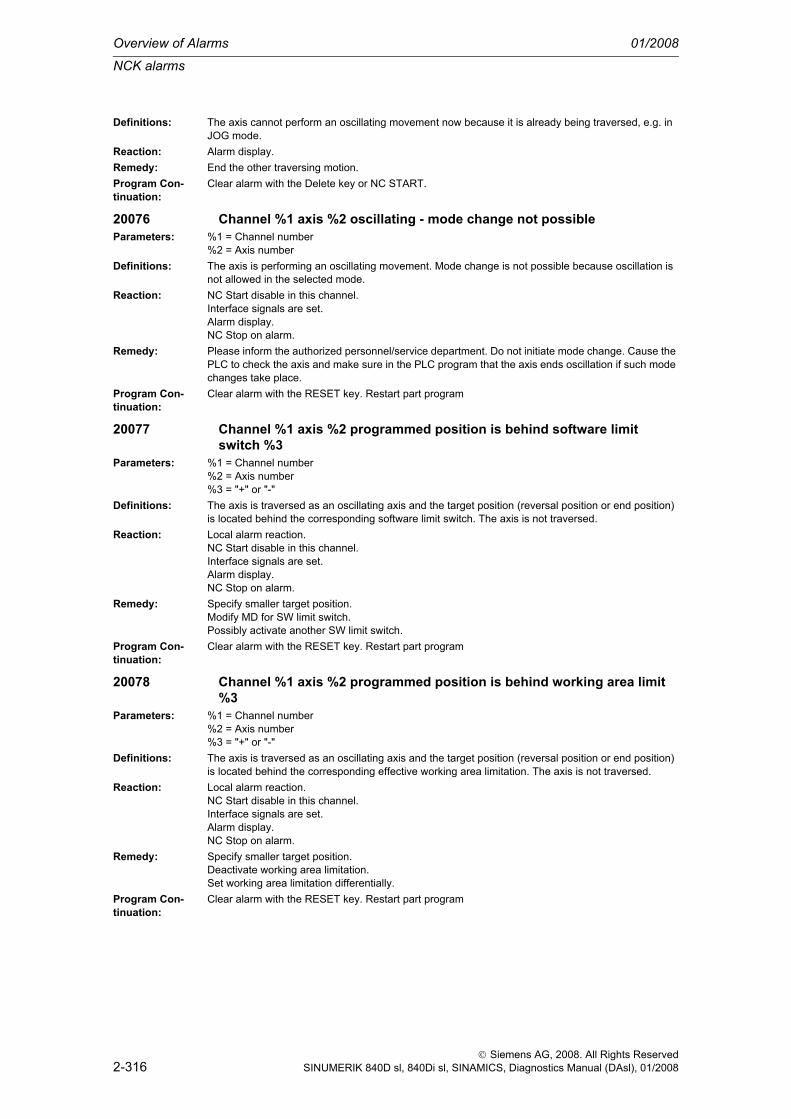
Overview of Alarms 01/2008
NCK alarms
2-316
© Siemens AG, 2008. All Rights ReservedSINUMERIK 840D sl, 840Di sl, SINAMICS, Diagnostics Manual (DAsl), 01/2008
Definitions: The axis cannot perform an oscillating movement now because it is already being traversed, e.g. in JOG mode.
Reaction: Alarm display.Remedy: End the other traversing motion.Program Con-tinuation:
Clear alarm with the Delete key or NC START.
20076 Channel %1 axis %2 oscillating - mode change not possibleParameters: %1 = Channel number
%2 = Axis numberDefinitions: The axis is performing an oscillating movement. Mode change is not possible because oscillation is
not allowed in the selected mode.Reaction: NC Start disable in this channel.
Interface signals are set.Alarm display.NC Stop on alarm.
Remedy: Please inform the authorized personnel/service department. Do not initiate mode change. Cause the PLC to check the axis and make sure in the PLC program that the axis ends oscillation if such mode changes take place.
Program Con-tinuation:
Clear alarm with the RESET key. Restart part program
20077 Channel %1 axis %2 programmed position is behind software limit switch %3
Parameters: %1 = Channel number%2 = Axis number%3 = "+" or "-"
Definitions: The axis is traversed as an oscillating axis and the target position (reversal position or end position) is located behind the corresponding software limit switch. The axis is not traversed.
Reaction: Local alarm reaction.NC Start disable in this channel.Interface signals are set.Alarm display.NC Stop on alarm.
Remedy: Specify smaller target position.Modify MD for SW limit switch.Possibly activate another SW limit switch.
Program Con-tinuation:
Clear alarm with the RESET key. Restart part program
20078 Channel %1 axis %2 programmed position is behind working area limit %3
Parameters: %1 = Channel number%2 = Axis number%3 = "+" or "-"
Definitions: The axis is traversed as an oscillating axis and the target position (reversal position or end position) is located behind the corresponding effective working area limitation. The axis is not traversed.
Reaction: Local alarm reaction.NC Start disable in this channel.Interface signals are set.Alarm display.NC Stop on alarm.
Remedy: Specify smaller target position.Deactivate working area limitation.Set working area limitation differentially.
Program Con-tinuation:
Clear alarm with the RESET key. Restart part program

NCK alarms
01/2008 Overview of Alarms
2-317
© Siemens AG, 2008. All Rights ReservedSINUMERIK 840D sl, 840Di sl, SINAMICS, Diagnostics Manual (DAsl), 01/2008
20079 Channel %1 axis %2 oscillation path %3 <= 0Parameters: %1 = Channel number
%2 = Axis number%3 = Length
Definitions: The axis is traversed as an oscillating axis and the distance to be traversed is smaller than or equal to zero. For example, both reversal points are situated on an identical position, one reversal point was shifted against the oscillating direction beyond the other reversal point. The axis is not traversed.
Reaction: Local alarm reaction.NC Start disable in this channel.Interface signals are set.Alarm display.NC Stop on alarm.
Remedy: Specify correct target position (reversal position, end position).Program Con-tinuation:
Clear alarm with the RESET key. Restart part program
20080 Channel %1 axis %2 no handwheel assigned for overrideParameters: %1 = Channel number
%2 = Axis numberDefinitions: No handwheel has been assigned for this specified axis after handwheel overlay has been started in
automatic mode. If the axis identifier is missing in the alarm with active velocity overlay FD > 0, then the 1st geometry axis has not been defined in the NC channel. In this case the block is executed with-out handwheel control.
Reaction: Alarm display.Remedy: If handwheel control is required, a handwheel must be activated.Program Con-tinuation:
Alarm display showing cause of alarm disappears. No further operator action necessary.
20081 Channel %1 axis %2 braking position cannot be accepted as a new reversing position
Parameters: %1 = Channel number%2 = Axis number
Definitions: On changing the reciprocation reversal from external sources, the braking positioncannot be accepted as a new reversing position, since changing the reversal point via handwheel or JOG key is active.
Reaction: Alarm display.Remedy: Deselect VDI signal "Change reversal point" and reselect it either
- with "Reciprocation reversal from external sources" or - by changing the reversal point by means of handwheel or- by changing the reversal point via JOG key.
Program Con-tinuation:
Alarm display showing cause of alarm disappears. No further operator action necessary.
20082 Channel %1 block %2 coordinate system-specific working area limit %3Parameters: %1 = Channel number
%2 = Axis number%3 = "+" or "-"
Definitions: The displayed axis is operated as a "concurrent positioning axis", and the corresponding active coor-dinate system-specific working area limitation for the axis is violated. No traversing movement.With an additional message to alarm 20140, the axis is traversed as a command axis.
Reaction: Alarm display.Remedy: - Specify smaller target position.
- Deactivate working area limitation.- Set working area limitation differently.- Retract axis with JOG.
Program Con-tinuation:
Alarm display showing cause of alarm disappears. No further operator action necessary.

Overview of Alarms 01/2008
NCK alarms
2-318
© Siemens AG, 2008. All Rights ReservedSINUMERIK 840D sl, 840Di sl, SINAMICS, Diagnostics Manual (DAsl), 01/2008
20083 Channel %1 axis %2 programmed position lies behind the coordinate system-specific working area limit %3
Parameters: %1 = Channel number%2 = Axis number%3 = "+" or "-"
Definitions: The axis is traversed as a reciprocating axis, and the target position (reversal position or end position) is located behind the corresponding, valid, coordinate system-specific working area limitation. The axis is not traversed.
Reaction: Local alarm reaction.NC Start disable in this channel.Interface signals are set.Alarm display.NC Stop on alarm.
Remedy: Specify smaller target position.Deactivate working area limitation.Set working area limitation differentially.
Program Con-tinuation:
Clear alarm with the RESET key. Restart part program
20085 Channel %1 contour handwheel: traverse direction or overtravel of beginning of block not allowed
Parameters: %1 = Channel numberDefinitions: Travel takes place on the path with the contour handwheel in the opposite direction to the programmed
travel direction and the starting point of the path has been reached at the start of the block.Reaction: Alarm display.Remedy: Turn the contour handwheel in the opposite direction.Program Con-tinuation:
Alarm display showing cause of alarm disappears. No further operator action necessary.
20090 Axis %1 travel to fixed stop not possible. Check programming and axis data.
Parameters: %1 = Axis name, spindle numberDefinitions: 1. The "Traverse against fixed stop" function has been programmed with FXS[AX]=1 but the axis does
not (yet) support this. Check MD 37000. This function is not available for gantry axes and simulated axes.2. On selection, no movement was programmed for axis AX. AX is a machine axis identifier.3. It is always necessary to program a traversing movement in the selection block for the axis/spindle for which the "Traverse against fixed stop" function is activated.The alarm can be reprogrammed in the MD ALARM_REACTION_CHAN_NOREADY (channel not ready).
Reaction: Mode group not ready.Channel not ready.NC Start disable in this channel.Interface signals are set.Alarm display.NC Stop on alarm.Channel not ready.
Remedy: Please inform the authorized personnel/service department.- Check the axis type.- Check MD 37000.- Is a machine axis movement missing in the approach block?
Program Con-tinuation:
Teileprogramm neu starten.Clear alarm with the RESET key in all channels of this mode group. Restart part program.

NCK alarms
01/2008 Overview of Alarms
2-319
© Siemens AG, 2008. All Rights ReservedSINUMERIK 840D sl, 840Di sl, SINAMICS, Diagnostics Manual (DAsl), 01/2008
20091 Axis %1 has not reached fixed stopParameters: %1 = Axis name, spindle numberDefinitions: On attempting to traverse against a fixed stop, the programmed end position has been reached or the
traversing movement has been aborted. The alarm can be concealed by means of the machine data $MA_FIXED_STOP_ALARM_MASK.The alarm can be reprogrammed in the MD ALARM_REACTION_CHAN_NOREADY (channel not ready).
Reaction: Mode group not ready.Channel not ready.NC Start disable in this channel.Interface signals are set.Alarm display.NC Stop on alarm.Channel not ready.
Remedy: Correct the part program and the settings:- Has the traversing block been aborted?- If the axis position does not correspond to the programmed end position, then correct the end posi-tion.- If the programmed end position is in the part, the triggering criterion must be checked.- Has the contour deviation leading to triggering been dimensioned too large? Has the torque limit been set too high?
Program Con-tinuation:
Teileprogramm neu starten.Clear alarm with the RESET key in all channels of this mode group. Restart part program.
20092 Axis %1 travel to fixed stop still activeParameters: %1 = Axis name, spindle numberDefinitions: An attempt has been made to move an axis while it is in fixed stop or while the deselection function
has not yet been completed.The alarm can be reprogrammed in the MD ALARM_REACTION_CHAN_NOREADY (channel not ready).
Reaction: Mode group not ready.Channel not ready.NC Start disable in this channel.Interface signals are set.Alarm display.NC Stop on alarm.Channel not ready.
Remedy: Please inform the authorized personnel/service department.Check the following:- Has the axis at the fixed stop also been moved by a traversing movement of geometry axes?- Is a selection carried out even though the axis is stationary at the stop?- Has the deselection process been interrupted by a RESET?- Has the PLC switched the acknowledgement signals?
Program Con-tinuation:
Teileprogramm neu starten.Clear alarm with the RESET key in all channels of this mode group. Restart part program.
20093 Axis %1 standstill monitoring at fixed-stop end point has been triggeredParameters: %1 = Axis name, spindle numberDefinitions: The position of the axis has been beyond the zero speed window ever since selection has been com-
pleted.The alarm can be reprogrammed in the MD ALARM_REACTION_CHAN_NOREADY (channel not ready).
Reaction: Mode group not ready.Channel not ready.NC Start disable in this channel.Interface signals are set.Alarm display.NC Stop on alarm.Channel not ready.

Overview of Alarms 01/2008
NCK alarms
2-320
© Siemens AG, 2008. All Rights ReservedSINUMERIK 840D sl, 840Di sl, SINAMICS, Diagnostics Manual (DAsl), 01/2008
Remedy: Please inform the authorized personnel/service department.- Check the mechanical components, e.g. has the stop broken away? Has the part to be clamped given way?- Position window for zero speed control too small (37020 MD: $MA_FIXED_STOP_WINDOW_DEF) (43520 setting data: $SA_FIXED_STOP_WINDOW). Default is 1 mm in each case.
Program Con-tinuation:
Teileprogramm neu starten.Clear alarm with the RESET key in all channels of this mode group. Restart part program.
20094 Axis %1 function has been abortedParameters: %1 = Axis name, spindle numberDefinitions: The function has been aborted. The possible reasons for this are:
- Because a pulse disable has occurred, the torque can no longer be provided.- The PLC has removed the acknowledgments.The alarm can be reprogrammed in the MD ALARM_REACTION_CHAN_NOREADY (channel not ready).
Reaction: Mode group not ready.Channel not ready.NC Start disable in this channel.Interface signals are set.Alarm display.NC Stop on alarm.Channel not ready.
Remedy: Check whether- there is a pulse disable from the infeed/regenerative-feedback unit or from the PLC?- the acknowledgement bits have been deleted by the PLC even though NCK has not requested dese-lection?
Program Con-tinuation:
Teileprogramm neu starten.Clear alarm with the RESET key in all channels of this mode group. Restart part program.
20095 Axis %1 illegal torque, current torque %2Parameters: %1 = Axis name, spindle number
%2 = Current holding torque when brake test selectedDefinitions: The current holding torque, when brake test selected, cannot be attained with the present parameter-
ization of the brake test.Reaction: Alarm display.Remedy: Check the parameterization for the brake test function check:
- The torque for the counterweight in the drive machine data 1192 should be nearly the same as the current holding torque. The current holding torque is displayed in the alarm text.- The torque set for the $MA_SAFE_BRAKETEST_TORQUE must be greater than the current holding torque.
Program Con-tinuation:
Clear alarm with the Delete key or NC START.
20096 Axis %1 brake test aborted, additional information %2Parameters: %1 = Axis name, spindle number
%2 = Error information based on $VA_FXS_INFODefinitions: The brake test has detected a problem. The additional info provides more detailed information on the
cause of the alarm. The explanation can be found in the $VA_FXS_INFO system variable documen-tation.Additional information:0: No additional information available.1: Axis type is not a PLC or command axis.2: End position reached, motion completed.3: Abort by NC RESET (key reset).4: Moved out of monitoring window.5: Torque reduction rejected by drive.6: PLC has cancelled enables.
Reaction: Interface signals are set.Alarm display.
Remedy: Note the supplementary conditions of the brake test, see additional info.

NCK alarms
01/2008 Overview of Alarms
2-321
© Siemens AG, 2008. All Rights ReservedSINUMERIK 840D sl, 840Di sl, SINAMICS, Diagnostics Manual (DAsl), 01/2008
Program Con-tinuation:
Clear alarm with the Delete key or NC START.
20097 Axis %1 incorrect travel direction brake testParameters: %1 = Axis name, spindle numberDefinitions: Due to the selected travel direction, the brake test for the current load torque is performed with an
incorrect torque.Reaction: Alarm display.Remedy: - Perform the brake test for the other travel direction
- Adjust drive MD 1192 better to the current weight ratio. The alarm will occur only if the current torque deviates from MD 1192 by more than 5% when the brake is released.- Activate the automatic determination of the load torque at the beginning of the brake test via MD $MA_SAFE_BRAKETEST_CONTROL, Bit 0 = 1.
Program Con-tinuation:
Clear alarm with the Delete key or NC START.
20100 Channel %1: invalid configuration for digitizingParameters: %1 = Channel numberDefinitions: - The digitizing function expects the definition of 3 geometry axes in the channel.
- At the available baud rate for a transmission of the actual positions and setpoint velocities between the NC and the digitizing device, the interpolation cycle must be set to a minimum of 5ms.
Reaction: Interface signals are set.Alarm display.
Remedy: Please inform authorized personnel / the service department.- Define 3 geometry axes for the digitizing channel by means of machine data.- Use an interpolation cycle greater than 5ms.
Program Con-tinuation:
Switch control OFF - ON.
20101 Timeout during initialization of communication with the digitizerDefinitions: The attempt to synchronize the communications link to the digitizing unit and to transfer the machine
parameters was aborted after the preset timeout limit of 15 seconds was exceeded.Reaction: Interface signals are set.
Alarm display.Remedy: Check the connection to the digitizing unit (RS422 cable, supply voltage) and whether the digitizing
unit is switched on.Program Con-tinuation:
Clear alarm with the Delete key or NC START.
20102 Channel %1: No or invalid trafo at digitizing activeParameters: %1 = Channel numberDefinitions: Prerequisite for the 3+2 axis digitizing is an active kinematic transformation. Permitted transformations
are the general 5-axis transformation and the universal inclinable head.Reaction: Interface signals are set.
Alarm display.Remedy: - Before digitizing, activate a permitted transformation.
- Select 3-axis mode for digitizing via machine data.Program Con-tinuation:
Clear alarm with the Delete key or NC START.
20103 Channel %1: Digitizing module does not support 3+2 axes digitizingParameters: %1 = Channel numberDefinitions: Prerequisite for 3+2 axis digitizing is that the NCU and the digitizing module both have the 3+2 axis
mode.Reaction: Interface signals are set.
Alarm display.Remedy: - SW update for the digitizing module.
- Select 3-axis mode for the digitizing via machine data.Program Con-tinuation:
Clear alarm with the Delete key or NC START.

Overview of Alarms 01/2008
NCK alarms
2-322
© Siemens AG, 2008. All Rights ReservedSINUMERIK 840D sl, 840Di sl, SINAMICS, Diagnostics Manual (DAsl), 01/2008
20105 Channel %1: axes stopped by digitizer. Error code: %2Parameters: %1 = Channel number
%2 = Error code of digitizing unitDefinitions: The digitizing unit has recognized an error in the communication and signaled this to the NC.Reaction: Channel not ready.
NC Start disable in this channel.Interface signals are set.Alarm display.NC Stop on alarm.
Remedy: Please inform the authorized personnel/service department. Error code 1: Check cable connection leading to the digitizing unit. Other error codes: See manual for digitizing unit.
Program Con-tinuation:
Clear alarm with the RESET key. Restart part program
20106 The digitizer has triggered an emergency stop.Definitions: The digitizing unit has recognized a serious error and triggered an emergency stop. Cause: See dis-
play on the digitizing unit.Reaction: Channel not ready.
NC Start disable in this channel.Interface signals are set.Alarm display.NC Stop on alarm.
Remedy: -Program Con-tinuation:
Clear alarm with the RESET key. Restart part program
20108 Invalid data package received from the digitizer. Error codes %1, %2Parameters: %1 = Error code of cyclic packet
%2 = Error code of out-of-band packetDefinitions: A data packet received by the digitizing unit could not be evaluated.Reaction: Channel not ready.
NC Start disable in this channel.Interface signals are set.Alarm display.NC Stop on alarm.
Remedy: Please inform the authorized personnel/service department. Error code: 0, 0: Check cable connection leading to the NC. Other error codes: e.g. wrong header, incorrect checksum (development documen-tation).
Program Con-tinuation:
Clear alarm with the RESET key. Restart part program
20109 Error in communication with the digitizer: status code of com-circuit: %1Parameters: %1 = Status byteDefinitions: The circuit for serial communication with the digitizing unit signals a transmission error via its status
byte (framing error, parity etc.).Reaction: Channel not ready.
NC Start disable in this channel.Interface signals are set.Alarm display.NC Stop on alarm.
Remedy: Please inform the authorized personnel/service department. Check connection cable leading to the digitizing unit: In particular screening.
Program Con-tinuation:
Clear alarm with the RESET key. Restart part program
20120 Axis %1: too many compensation relationsParameters: %1 = Axis name, spindle number

NCK alarms
01/2008 Overview of Alarms
2-323
© Siemens AG, 2008. All Rights ReservedSINUMERIK 840D sl, 840Di sl, SINAMICS, Diagnostics Manual (DAsl), 01/2008
Definitions: Interpolatory compensation with tables. For each axis, the maximum number of compensation rela-tionships defined may be no more than the number of axes in the system. In this alarm, the interpola-tory compensation in the axis is switched off automatically.
Reaction: Interface signals are set.Alarm display.
Remedy: Check table parameters $AN_CEC_OUTPUT_AXIS and correct and/or switch off one or more tables ($SN_CEC_TABLE_ENABLE).
Program Con-tinuation:
Clear alarm with the RESET key. Restart part program
20121 Axis %1: Configuration error in compensation table %2Parameters: %1 = Axis name, spindle number
%2 = Compensation tableDefinitions: Interpolatory compensation with tables. The settings for the specified table are not allowed.
$AN_CEC_MAX >= $AN_CEC_MIN and $AN_CEC_STEP != 0 apply to system variables. This table is switched off automatically.
Reaction: Interface signals are set.Alarm display.
Remedy: Please inform the authorized personnel/service department. Check and correct the characteristic data in the compensation table. If the error cannot be found, the alarm can be suppressed by switching off the table ($SN_CEC_TABLE_ENABLE) or switching off compensation in the axis ($MA_CEC_ENABLE).
Program Con-tinuation:
Clear alarm with the RESET key. Restart part program
20122 Compensation table %1: invalid axis assignmentParameters: %1 = Compensation tableDefinitions: Interpolatory compensation with tables. The input or output axes assignment in the given table is not
allowed. $AN_CEC_INPUT_AXIS and $AN_CEC_OUTPUT_AXIS != 0 apply to system variables. This table is automatically switched off.
Reaction: Interface signals are set.Alarm display.
Remedy: Please inform the authorized personnel/service department. Check and correct the axis assignment in the compensation table. If the error cannot be found, the alarm can be suppressed by switching off the table ($SN_CEC_TABLE_ENABLE) or switching off compensation in the axis ($MA_CEC_ENABLE).
Program Con-tinuation:
Clear alarm with the RESET key. Restart part program
20123 Axis %1: different output assignment of multiplied tablesParameters: %1 = Axis name, spindle numberDefinitions: Interpolatory compensation with tables. The two tables whose outputs are to be multiplied together
have different output axes assigned to them. The compensation in this axis is automatically switched off.
Reaction: Interface signals are set.Alarm display.
Remedy: Please inform the authorized personnel/service department. Check and correct the characteristic data in the compensation table ($AN_CEC_OUTPUT_AXIS and $AN_CEC_MULT_BY_TABLE).If the error cannot be found, the alarm can be suppressed by switching off the compensation in the axis ($MA_CEC_ENABLE) or the tables, ($SN_CEC_TABLE_ENABLE).
Program Con-tinuation:
Clear alarm with the RESET key. Restart part program
20124 Axis %1: sum of compensation values too largeParameters: %1 = Axis name, spindle numberDefinitions: The sum of the compensation values from all tables assigned to the axis had exceeded the limit value
$MA_CEC_MAX_SUM and had to be limited. Contour errors could have occurred as a result.Reaction: Interface signals are set.
Alarm display.

Overview of Alarms 01/2008
NCK alarms
2-324
© Siemens AG, 2008. All Rights ReservedSINUMERIK 840D sl, 840Di sl, SINAMICS, Diagnostics Manual (DAsl), 01/2008
Remedy: Check characteristic data of the compensation tables assigned to the axis.Check characteristic curves in the tables ($AN_CEC).
Program Con-tinuation:
Clear alarm with the RESET key. Restart part program
20125 Axis %1: change of compensation value is too rapidParameters: %1 = Axis name, spindle numberDefinitions: The compensation value has changed more rapidly than has been allowed for in 32730
CEC_MAX_VELO. It had to be limited temporarily. The missing section is repeated later but contour errors might have occurred.
Reaction: Interface signals are set.Alarm display.
Remedy: Check characteristic data of the compensation tables assigned to the axis.Check characteristic curves in the tables ($AN_CEC). Possibly one of the input axes has moved more rapidly than provided for.
Program Con-tinuation:
Alarm display showing cause of alarm disappears. No further operator action necessary.
20130 Channel %1 contour tunnel monitoringParameters: %1 = Channel numberDefinitions: The tool tip has exited the tunnel placed around the desired contour, i.e. the distance between tool tip
and desired contour was greater than specified in the MD 21050 CONTOUR_TUNNEL_TOL.The alarm can be reprogrammed in the MD ALARM_REACTION_CHAN_NOREADY (channel not ready).
Reaction: Mode group not ready.The NC switches to follow-up mode.Channel not ready.NC Start disable in this channel.Interface signals are set.Alarm display.NC Stop on alarm.Channel not ready.
Remedy: Please inform the authorized personnel/service department. Check the following points in turn:1. Is the machine in working order? That is, has the alarm been tripped by a sluggish axis, tool break-age or collision?2. If the machine is in working order, reduce the velocity or improve the controller setting.3. Possibly increase the size of the tunnel and monitor errors via analog output in order to ascertain the cause.
Program Con-tinuation:
Teileprogramm neu starten.Clear alarm with the RESET key in all channels of this mode group. Restart part program.
20139 Channel %1 block %2 motion-synchronous action: invalid markerParameters: %1 = Channel number
%2 = Block numberDefinitions: Setting or deleting of a marker in the motion-synchronous action is not possible.
Possible causes:SETM(): Maximum number of markers exceeded; marker has already been set.CLEARM(): Specified marker is not within permissible value range.
Reaction: NC Start disable in this channel.Interface signals are set.Alarm display.NC Stop on alarm.
Remedy: SETM(): use marker in valid value range; do not set the marker again.CLEARM(): use marker in valid value range.
Program Con-tinuation:
Clear alarm with the RESET key. Restart part program

NCK alarms
01/2008 Overview of Alarms
2-325
© Siemens AG, 2008. All Rights ReservedSINUMERIK 840D sl, 840Di sl, SINAMICS, Diagnostics Manual (DAsl), 01/2008
20140 Channel %1 motion synchronous action: traversing of command axis %2 see NC alarm %3
Parameters: %1 = Channel number%2 = Axis%3 = NC alarm
Definitions: An NC alarm was detected for a command axis which is to be traversed from a synchronous action. The NC alarm is indicated by an MMC alarm number in the 3rd parameter.
Reaction: NC Start disable in this channel.Interface signals are set.Alarm display.NC Stop on alarm.
Remedy: See help information for the additional alarms.Program Con-tinuation:
Clear alarm with the RESET key. Restart part program
20141 Channel %1 motion synchronous action: illegal axis typeParameters: %1 = Channel numberDefinitions: The requested command is not permissible in the current axis status for the command axis or spindle.
This alarm occurs with command axes (POS, MOV), spindle commands from motion synchronous actions (M3/M4/M5, SPOS), coupled motion (TRAILON, TRAILOF) and lead value coupling (LEA-DON, LEADOF).
Reaction: NC Start disable in this channel.Interface signals are set.Alarm display.NC Stop on alarm.
Remedy: First stop the axis or deactivate the coupling, then select a new status.Program Con-tinuation:
Clear alarm with the RESET key. Restart part program
20142 Channel %1 command axis %2: rotation of axis container already enabled
Parameters: %1 = Channel number%2 = Axis
Definitions: The synchronized action instruction is not allowed on a spindle enabled for the axis container rotation. The alarm only occurs if the spindle is handed to another NCU.
Reaction: NC Start disable in this channel.Interface signals are set.Alarm display.NC Stop on alarm.
Remedy: Initiate the synchronized action instruction before the axis container rotation enable or after the end of the rotation (depending on the application).
Program Con-tinuation:
Clear alarm with the RESET key. Restart part program
20143 Channel %1 axis %2 command axis cannot be started as it is controlled by the PLC
Parameters: %1 = Channel number%2 = Axis name, spindle number
Definitions: An attempt has been made to start a command axis by means of a block-related or modal synchro-nous action. This start is not possible as the axis is controlled by the PLC.
Reaction: Alarm display.Remedy: End control of the axis by the PLC and therefore return it to the channel or start the command axis
with a static synchronous action.Program Con-tinuation:
Clear alarm with the Delete key or NC START.

Overview of Alarms 01/2008
NCK alarms
2-326
© Siemens AG, 2008. All Rights ReservedSINUMERIK 840D sl, 840Di sl, SINAMICS, Diagnostics Manual (DAsl), 01/2008
20144 Channel %1 block %2 motion synchronous action: system variable access not possible
Parameters: %1 = Channel number%2 = Block number
Definitions: When using system variables, it is assumed that a read/write operation can access the required data successfully. In accesses to encoder actual values or digital I/Os, the result depends on the availability of the corresponding hardware components. If an access within synchronized actions does not return a valid value, alarm 20144 is output. Outside synchronized actions, such a read/write access causes block execution to be interrupted until the result is available. Block execution is subsequently contin-ued.
Reaction: NC Start disable in this channel.Interface signals are set.Alarm display.NC Stop on alarm.
Remedy: Before reading/writing system variables, ensure that it is possible to access the required hardware components.
Program Con-tinuation:
Clear alarm with the RESET key. Restart part program
20145 Channel %1 block %2 motion synchronous action: arithmetic errorParameters: %1 = Channel number
%2 = Block numberDefinitions: In calculating an arithmetic expression for a motion synchronous action, an overflow has occurred
(e.g. division by zero).Reaction: NC Start disable in this channel.
Interface signals are set.Alarm display.NC Stop on alarm.
Remedy: Correct error in expression.Program Con-tinuation:
Clear alarm with the RESET key. Restart part program
20146 Channel %1 block %2 motion synchronous action: nesting depth exceeded
Parameters: %1 = Channel number%2 = Block number
Definitions: For calculating arithmetic expressions in motion synchronous blocks, an operand stack with a fixed set size is used. With very complex expressions, this stack can overflow.
Reaction: NC Start disable in this channel.Interface signals are set.Alarm display.NC Stop on alarm.
Remedy: Correct error in expression.Program Con-tinuation:
Clear alarm with the RESET key. Restart part program
20147 Channel %1 block %2 motion synchronous action: command not executable
Parameters: %1 = Channel number%2 = Block number
Definitions: One of the commands for the synchronous action block cannot be executed, e.g. it is not possible to perform a Reset to the synchronous action.Measurement level 2- Embargo version does not allow measurement from a synchronized action- MEASA was programmed in a synchronized action- Measurement is already active- Programming error (see alarm 21701)

NCK alarms
01/2008 Overview of Alarms
2-327
© Siemens AG, 2008. All Rights ReservedSINUMERIK 840D sl, 840Di sl, SINAMICS, Diagnostics Manual (DAsl), 01/2008
Reaction: NC Start disable in this channel.Interface signals are set.Alarm display.NC Stop on alarm.
Remedy: Change synchronous action.Measurement level 2Execute the measurement task from an NC program first, in order to improve the error diagnostics. Only include it in the synchronized action when the first error-free run has been performed.
Program Con-tinuation:
Clear alarm with the RESET key. Restart part program
20148 Channel %1 block %2 motion synchronous action: internal error %3Parameters: %1 = Channel number
%2 = Block number%3 = Error code
Definitions: An internal error has occurred during processing of a synchronous action. The error code is for diag-nostics purposes. Please make a note and contact the manufacturer.
Reaction: NC Start disable in this channel.Interface signals are set.Alarm display.NC Stop on alarm.
Remedy: Change synchronous action.Program Con-tinuation:
Clear alarm with the RESET key. Restart part program
20149 Channel %1 block %2 motion synchronous action: illegal indexParameters: %1 = Channel number
%2 = Block numberDefinitions: An invalid index was used for accessing a variable in the motion-synchronous action.
Example: ... DO $R[$AC_MARKER[1]] = 100This error occurs if the value of marker 1 is greater than the maximum permissible R parameter num-ber.PROFIBUS/PROFINET I/O:An invalid slot / I/O area index was used while reading/writing data. Cause: 1.: Slot / I/O area index >= max. number of available slots / I/O areas. 2.: Slot / I/O area index references a slot / I/O area that has not been configured. 3.: Slot / I/O area index references a slot / I/O area that has not been released for a system variable.
Reaction: NC Start disable in this channel.Interface signals are set.Alarm display.NC Stop on alarm.
Remedy: Use a valid index.Program Con-tinuation:
Clear alarm with the RESET key. Restart part program
20150 Channel %1 tool management: PLC terminates interrupted commandParameters: %1 = Channel numberDefinitions: Indication that the PLC has terminated an interrupted command (with alarm output) from the tool man-
agement - tool change.Reaction: Interface signals are set.
Alarm display.Remedy: For information only.Program Con-tinuation:
Clear alarm with the Delete key or NC START.
20160 Channel %1 tool management: PLC can terminate only incorrectly aborted commands
Parameters: %1 = Channel number

Overview of Alarms 01/2008
NCK alarms
2-328
© Siemens AG, 2008. All Rights ReservedSINUMERIK 840D sl, 840Di sl, SINAMICS, Diagnostics Manual (DAsl), 01/2008
Definitions: Indication that the PLC wanted to interrupt an active command from the tool management (tool change); or that there is no command active for abort. NCK refuses because the channel status is either 'active' (abort is then not allowed), or 'reset' (then there is nothing to abort).
Reaction: Interface signals are set.Alarm display.
Remedy: For information only.Program Con-tinuation:
Clear alarm with the Delete key or NC START.
20170 Channel %1 machine data $AC_FIFO invalidParameters: %1 = Channel numberDefinitions: The structure of the FIFO variable $AC_FIFO1 - $AC_FIFO10 determined by the machine data
$MC_NUM_AC_FIFO, $MC_START_AC_FIFO, $MC_LEN_AC_FIFO and $MC_MODE_AC_FIFO cannot be stored in the R parameter field defined in $MC_MM_NUM_R_PARAM.
Reaction: NC Start disable in this channel.Interface signals are set.Alarm display.
Remedy: Please inform the authorized personnel/service department. Increase the number of the R parameters or reduce the FIFO elements.$MC_MM_NUM_R_PARAM = $MC_START_AC_FIFO + $MC_NUM_AC_FIFO x ($MC_LEN_AC_FIFO + 6)
Program Con-tinuation:
Switch control OFF - ON.
20200 Channel %1 invalid spindle number %2 with tool fine compensationParameters: %1 = Channel number target channel
%2 = Spindle numberDefinitions: There is no spindle/axis assignment in the target channel for the spindle specified in the PUTFTOC
command.Reaction: Interpreter stop
NC Start disable in this channel.Interface signals are set.Alarm display.NC Stop on alarm.
Remedy: Modify program in channel that writes the tool fine compensation.Program Con-tinuation:
Clear alarm with the RESET key. Restart part program
20201 Channel %1 spindle %2 no tool assignedParameters: %1 = Channel number
%2 = Spindle numberDefinitions: In order to make allowance for the fine tool compensation for the tool currently in the spindle, a spin-
dle/tool assignment must be active. This is not presently the case for the programmed spindle in the target channel of fine tool compensation.
Reaction: Interpreter stopNC Start disable in this channel.Interface signals are set.Alarm display.NC Stop on alarm.
Remedy: 1. Modify the part program (write the tool fine compensation).2. Establish spindle/tool assignment by programming:- TMON (tool monitoring)- GWPSON (tool selection)
Program Con-tinuation:
Clear alarm with the RESET key. Restart part program

NCK alarms
01/2008 Overview of Alarms
2-329
© Siemens AG, 2008. All Rights ReservedSINUMERIK 840D sl, 840Di sl, SINAMICS, Diagnostics Manual (DAsl), 01/2008
20203 Channel %1 no active toolParameters: %1 = Channel numberDefinitions: A tool fine compensation has been written for the active tool of channel %1 with PUTFTOC. No tool
is active in this channel. Therefore, the compensation cannot be assigned.Reaction: Interpreter stop
NC Start disable in this channel.Interface signals are set.Alarm display.NC Stop on alarm.
Remedy: Correct the program.Program Con-tinuation:
Clear alarm with the RESET key. Restart part program
20204 Channel %1 PUTFTOC command not allowed with FTOCOFParameters: %1 = Channel numberDefinitions: A tool fine compensation has been written for channel %1 with PUTFTOC. The tool fine compensation
is not active in this channel. FTOCON must be active in the target channel of the PUTFTOC com-mand.
Reaction: Interpreter stopNC Start disable in this channel.Interface signals are set.Alarm display.NC Stop on alarm.
Remedy: Correct the program in the machining channel: Select FTOCON so that the channel is ready to receive the PUTFTOC command.
Program Con-tinuation:
Clear alarm with the RESET key. Restart part program
20210 Channel %1 block %3 spindle %2 wrong values for centerless grindingParameters: %1 = Channel number
%2 = Spindle number%3 = Block number, label
Definitions: It was not possible to calculate a tool diameter (no speed specified for the spindle) for centerless grind-ing because it was not allowed by the input positions. The old S value still applies.
Reaction: Alarm display.Remedy: - Modify program
- Select new traversing positions for centerless axes- or suppress computation by G00.
Program Con-tinuation:
Alarm display showing cause of alarm disappears. No further operator action necessary.
20211 Channel %1 block %3 spindle %2 support point beyond range limitsParameters: %1 = Channel number
%2 = Spindle number%3 = Block number, label
Definitions: The support point calculated for centerless grinding is beyond the range limits.Machine data:Modify MD 21518: TRACLG_CONTACT_UPPER_LIMITModify MD 21520: TRACLG_CONTACT_LOWER_LIMIT
Reaction: Alarm display.Remedy: - Check centerless axis positions and machine data.
- Modify program.- Select new traversing positions for centerless axes- or suppress computation by G00.
Program Con-tinuation:
Alarm display showing cause of alarm disappears. No further operator action necessary.
20300 Channel %1 axis %2 orientation not possibleParameters: %1 = Channel number
%2 = Axis name, spindle number

Overview of Alarms 01/2008
NCK alarms
2-330
© Siemens AG, 2008. All Rights ReservedSINUMERIK 840D sl, 840Di sl, SINAMICS, Diagnostics Manual (DAsl), 01/2008
Definitions: On traversing the displayed (virtual) orientation axis, a tool orientation is to be setfor which the kinematics of this machine are not possible.
Reaction: Alarm display.Remedy: Abort the JOG movement and specify another (possible)
change of orientation.Program Con-tinuation:
Clear alarm with the Delete key or NC START.
21550 Channel %1 axis %2 Travel from hardware limit switch not possible. Reason: %3
Parameters: %1 = Channel number%2 = Axis name%3 = Cause
Definitions: It has been tried to retract a following axis of an axis coupling or an output axis of a transformation through the master axis or input axis of a transformation. This is not permitted in the current situation.Possible reasons:1 No permissible direction of retraction2 Coupling not synchronous3 Retraction not permitted for the active coupling4 Reserved5 Retraction not permitted for the active transformation
Reaction: NC Start disable in this channel.Alarm display.
Remedy: Remedy for error cause:1 Define another travel direction2 Deactivate the coupling and travel the axis/axes separately3 Deactivate the coupling and travel the axis/axes separately4 Reserved5 Deactivate the transformation and travel the axis/axes separately
Program Con-tinuation:
Clear alarm with the RESET key. Restart part program
21600 Monitoring for ESR activeDefinitions: -Reaction: NC not ready.
Alarm display.All alarm reactions are delayed by one IPO cycle with this alarm.
Remedy: The display can be suppressed with the machine data MD 11410: SUPPRESS_ALARM_MASK Bit 16 = 1
Program Con-tinuation:
Alarm display showing cause of alarm disappears. No further operator action necessary.
21610 Channel %1 axis %2 encoder %3 frequency exceededParameters: %1 = Channel number
%2 = Axis name, spindle number%3 = String (encoder number)
Definitions: The maximum permissible frequency of the currently active encoder (axis-specific interface signal DB31, ... DBX1.5 / 1.6 (position measuring system 1/2)) in the axis-specific machine data 36300 ENC_FREQ_LIMIT [n] (n ... encoder number, 1 or 2) has been exceeded. The reference of the actual value to the mechanical carriage position may have been lost.The alarm can be reprogrammed in the MD ALARM_REACTION_CHAN_NOREADY (channel not ready).
Reaction: Mode group not ready.Channel not ready.NC Start disable in this channel.Interface signals are set.Alarm display.NC Stop on alarm.Channel not ready.
Remedy: MD 36300: Check ENC_FREQ_LIMIT [n] and NC/PLC interface signal DB31, ... DBX1.5 / 1.6 (posi-tion measuring system 1/2).

NCK alarms
01/2008 Overview of Alarms
2-331
© Siemens AG, 2008. All Rights ReservedSINUMERIK 840D sl, 840Di sl, SINAMICS, Diagnostics Manual (DAsl), 01/2008
Program Con-tinuation:
Teileprogramm neu starten.Clear alarm with the RESET key in all channels of this mode group. Restart part program.
21611 Channel %1 NC-controlled Extended Stop/Retract triggeredParameters: %1 = Channel numberDefinitions: "NC-controlled Extended Stop/Retract" triggered.Reaction: The NC switches to follow-up mode.
Channel not ready.NC Start disable in this channel.Interface signals are set.Alarm display.NC Stop on alarm.All channel-specific alarm reactions are delayed with this alarm, alarm display.
Remedy: ResetProgram Con-tinuation:
Clear alarm with the RESET key. Restart part program
21612 Channel %1 axis %2: enable reset, cause %3Parameters: %1 = Channel number
%2 = Axis name, spindle number%3 = Cause of the alarm
Definitions: Causes of alarm: 0: The cause of the alarm cannot be preceisely determined. 1: The interface signal DB31, ... DBX2.1 (Servo enable) is missing 2: The interface signal DB31, ... DBX21.7 (Pulse enable) is missing 3: Drive signal DB31, ... DBX93.7 (Impulses enabled) is not set 4: Drive signal DB31, ... DBX93.5 (Drive ready) is not setOne of the motion-enabling signals (e.g. "Servo enable", "Pulse enable", parking/encoder selection (only for axes) or drive-specific enables (such as terminal 663 with SIMODRIVE 611D) has been reset for the displayed axis. The alarm can be reported with positioning axes, spindles and for axes from the geometry grouping.The axes entered in the channel-specific MD array 20050 AXCONF_GEOAX_ASSIGN_TAB are regarded as axes belonging to the geometry grouping. Servo enable must exist for all available geom-etry axes, regardless of whether or not they are currently in motion.Occurs in connection with SAFETY function: If a test stop is performed with linked axes, the alarm is issued if a motion command from the ELG grouping is pending during the test stop of the slave axis.
Reaction: The NC switches to follow-up mode.NC Start disable in this channel.Interface signals are set.Alarm display.NC Stop on alarm.
Remedy: Please inform the authorized personnel/service department. Check the interface signals DB31, ... DBX2.1 (Servo enable), DB31, ... DBX21.7 (Pulse enable), check the drive signals DB31, ... DBX93.7 (Pulses enabled), DB31, ... DBX93.5 (Drive ready) for example with the PLC status display in the DIAGNOSTICS operating area. Check the encoder selec-tion (for axes) as well as other signals enabling motion (such as SIMODRIVE 611D terminal 663 etc.) according to the drive type used.When the terminal enables of the drive have failed, trace back the wiring or hardware function (for example relay function) or proceed as stated in the relevant drive documentation.With SAFETY: With active actual-value linkage, output of the error message on the slave axis can be prevented by increasing MD 36060 $MA_STANDSTILL_VELO_TOL (default value is 5 mm).
Program Con-tinuation:
Clear alarm with the Delete key or NC START.
21613 Axis %1 measuring system changingParameters: %1 = Axis name, spindle numberDefinitions: The measuring system for this axis is changing.Reaction: Alarm display.Remedy: -Program Con-tinuation:
Alarm display showing cause of alarm disappears. No further operator action necessary.

Overview of Alarms 01/2008
NCK alarms
2-332
© Siemens AG, 2008. All Rights ReservedSINUMERIK 840D sl, 840Di sl, SINAMICS, Diagnostics Manual (DAsl), 01/2008
21614 Channel %1 axis %2 hardware limit switch %3Parameters: %1 = Channel number
%2 = Axis name, spindle number%3 = String (+, - or +/-)
Definitions: The signal DB31, ... DBX12.1 / 12.0 (Hardware limit switch plus/minus) has been set at the NC/PLC interface.
Reaction: NC Start disable in this channel.Alarm display.
Remedy: Please inform the authorized personnel/service department.1. With axes that have already been referenced, the software limit switch 1 or 2 should respond before the hardware limit switch is reached. Check MD 36110 POS_LIMIT_PLUS, 36100 POS_LIMIT_MINUS, 36130 POS_LIMIT_PLUS2 and 36120 POS_LIMIT_MINUS2 and the NC/PLC interface signal for selection of 1st/2nd software limit switch DB31, ... DBX12.3 / 12.2 (2nd software limit switch plus/minus) and correct if necessary (PLC user program).2. If the axis has not yet been moved to the reference point, it is possible to depart from the hardware limit switch in the opposite direction in JOG mode.3. Check PLC user program and the connection from the switch to the PLC input module, provided the axis has not yet reached the hardware limit switch.
Program Con-tinuation:
Clear alarm with the RESET key. Restart part program
21615 Channel %1 axis %2 taken from traverse mode to follow-up modeParameters: %1 = Channel number
%2 = Axis name, spindle numberDefinitions: This axis has been taken from traverse mode and put into "Follow-up" mode, for instance because the
pulse enable for the drive has been reset.Reaction: NC Start disable in this channel.
Interface signals are set.Alarm display.NC Stop on alarm.
Remedy: -Program Con-tinuation:
Clear alarm with the RESET key. Restart part program
21616 Channel %1 block %2 overlaid motion active at transformation switchover
Parameters: %1 = Channel number%2 = Block number, label
Definitions: The overlaid motion in the BCS changes its significance because of the transformation change and can therefore lead to undesired axis movements.
Reaction: Local alarm reaction.Interface signals are set.Alarm display.NC Stop on alarm.
Remedy: Take out the overlaid movement.Program Con-tinuation:
Clear alarm with NC START or RESET key and continue the program.
21617 Channel %1 block %2 transformation does not allow to traverse the poleParameters: %1 = Channel number
%2 = Block number, labelDefinitions: The preset curve passes through the pole or a forbidden area of the transformation.Reaction: Local alarm reaction.
NC Start disable in this channel.Interface signals are set.Alarm display.NC Stop on alarm.
Remedy: Modify part program (if alarm has occurred in AUTO mode).To escape from the alarm position, transformation must be deselected (it is not enough to try a RESET if the transformer remains active when RESET is applied).

NCK alarms
01/2008 Overview of Alarms
2-333
© Siemens AG, 2008. All Rights ReservedSINUMERIK 840D sl, 840Di sl, SINAMICS, Diagnostics Manual (DAsl), 01/2008
Program Con-tinuation:
Clear alarm with the RESET key. Restart part program
21618 Channel %1 as from block %2 transformation active: overlaid motion too great
Parameters: %1 = Channel number%2 = Block number, label
Definitions: The share of overlaid motion on the transformation-related axes is so high that the path movement planned by the preparation no longer sufficiently corresponds to the actual ratio for the interpolation. Strategy of singularities, monitoring of working range limitation and dynamic Look Ahead are possibly no longer correct.
Reaction: Alarm display.Remedy: With overlaid motion it is necessary to keep a sufficiently large path safety distance with regard to
poles and working range limitations.Program Con-tinuation:
Clear alarm with the Delete key or NC START.
21619 Channel %1 block %2 transformation active: motion not possibleParameters: %1 = Channel number
%2 = Block number, labelDefinitions: The machine kinematics does not allow the specified motion. Transformation-dependent error causes
can be in:TRANSMIT: A (circular) area exists around the pole, where positioning is not possible. The area is caused by the fact that the tool reference point cannot be traversed as far as into the pole. The area is defined by:- the machine data ($MC_TRANSMIT_BASE_TOOL..)- the active tool length compensation (see $TC_DP..).Whether the tool length compensation is included in the calculation depends on the working plane selected (see G17,..). The machine stops at the edge of the area where positioning is not possible.
Reaction: Local alarm reaction.NC Start disable in this channel.Interface signals are set.Alarm display.NC Stop on alarm.
Remedy: Modify part program. Change the incorrectly specified tool length compensation.Note: RESET alone is not enough if transformation also remains active during RESET.
Program Con-tinuation:
Clear alarm with the RESET key. Restart part program
21650 Channel %1 axis %2 overlaid motion not allowedParameters: %1 = Channel number
%2 = Axis name, spindle numberDefinitions: An overlaid motion was requested for the axis, however, this is not allowed due to the machine data
FRAME_OR_CORRPOS_NOTALLOWED.Reaction: Local alarm reaction.
NC Start disable in this channel.Interface signals are set.Alarm display.NC Stop on alarm.
Remedy: Please inform the authorized personnel/service department. Deselect the overlaid motion or change machine data FRAME_OR_CORRPOS_NOTALLOWED.
Program Con-tinuation:
Clear alarm with the RESET key. Restart part program
21660 Channel %1 block %2 axis %3 conflict between SYNACT: $AA_OFF and CORROF
Parameters: %1 = Channel number%2 = Block number, label%3 = Axis name

Overview of Alarms 01/2008
NCK alarms
2-334
© Siemens AG, 2008. All Rights ReservedSINUMERIK 840D sl, 840Di sl, SINAMICS, Diagnostics Manual (DAsl), 01/2008
Definitions: When deselecting the position offset ($AA_OFF) via the part program command CORROF (<axis>, "AA_OFF") an active synchronized action is detected that immediately sets $AA_OFF for the axis (DO_$AA_OFF [<axis>] =<value>). Deselection is executed and $AA_OFF not set again.
Reaction: Correction block is reorganized.Local alarm reaction.Interface signals are set.Alarm display.NC Stop on alarm at block end.
Remedy: Modify part program.Program Con-tinuation:
Clear alarm with NC START or RESET key and continue the program.
21665 Channel %1 $AA_TOFF clearedParameters: %1 = Channel numberDefinitions: If the tool position is changed with RESET and $AA_TOFF is active during RESET, the position offset
($AA_TOFF) is cleared.Reaction: Correction block is reorganized.
Local alarm reaction.Interface signals are set.Alarm display.NC Stop on alarm at block end.
Remedy: Modify the RESET setting in $AA_TOFF_MODE.Program Con-tinuation:
Clear alarm with NC START or RESET key and continue the program.
21670 Channel %1 block %2 illegal change of tool direction with $AA_TOFF active
Parameters: %1 = Channel number%2 = Block number, label
Definitions: If an offset has been activated in tool direction by means of $AA_TOFF[i], no block is allowed to be activated in which the offset axis assignment i is modified (plane change, tool change cutting tool <=> turning tool, transformation change, TRAFOOF, TCARR=0, geometry axis change)
Reaction: Correction block is reorganized.Local alarm reaction.Interface signals are set.Alarm display.NC Stop on alarm at block end.
Remedy: - Modify part program- Program TOFFOF()
Program Con-tinuation:
Clear alarm with NC START or RESET key and continue the program.
21700 Channel %1 block %3 axis %2 touch probe already deflected, edge polarity not possible
Parameters: %1 = Channel number%2 = Axis name, spindle number%3 = Block number
Definitions: The probe programmed under the keyword MEAS or MEAW is already deflected and has switched. For a further measuring operation, the probe signal must first be canceled (quiescent state of the probe).The axis display is of no significance at the present time but an axis-specific evaluation has been planned for later stages of development.
Reaction: Local alarm reaction.NC Start disable in this channel.Interface signals are set.Alarm display.NC Stop on alarm.
Remedy: Verify the starting position of the measuring operation or check the probe signals in the PLC interface DB10 DBX107.0 / 107.1 (Probe actuated key 1/key 2). Are the cables and connectors in good order?

NCK alarms
01/2008 Overview of Alarms
2-335
© Siemens AG, 2008. All Rights ReservedSINUMERIK 840D sl, 840Di sl, SINAMICS, Diagnostics Manual (DAsl), 01/2008
Program Con-tinuation:
Clear alarm with the RESET key. Restart part program
21701 Channel %1 block %3 axis %2 measurement not possibleParameters: %1 = Channel number
%2 = Axis name, spindle number%3 = Block number
Definitions: Measurement level 2 (MEASA, MEAWA, MEAC).There is an error in the programmed measurement task.Possible causes:- Invalid measurement mode- Invalid probe- Invalid encoder- Invalid number of measurement signal edges- Identical measurement signal edges are only programmable in mode 2- Invalid FIFO number- Mismatch between the number of FIFOs programmed and the number of probes used in the mea-surement task.Further causes:A measurement task is already active (e.g. from a synchronized action).
Reaction: Local alarm reaction.NC Start disable in this channel.Interface signals are set.Alarm display.NC Stop on alarm.
Remedy: Correct the measurement tasks.Program Con-tinuation:
Clear alarm with the RESET key. Restart part program
21702 Channel %1 block %3 axis %2 measurement abortedParameters: %1 = Channel number
%2 = Axis name, spindle number%3 = Block number
Definitions: The measurement block has ended (the programmed end position of the axis has been reached) but the activated touch probe has not yet responded.Measurement level 2 (MEAWA, MEASA, MEAC)Measured values cannot be converted to the workpiece coordinate system. The measured values of the GEO axes programmed in the measurement task are only available in the machine coordinate sys-tem.Causes:Not all GEO axes were programmed in the measurement task. At least one measured value is there-fore missing for conversion back into the workpiece coordinate system.Further causes:The measurement tasks programmed for all GEO axis are not identical.
Reaction: Alarm display.Remedy: Verify the traversing movement in the measurements block.
- Is it necessary in all cases for the activated probe to have switched up to the specified axis position?- Are the probe, cable, cable distributor, terminal connections in good order?Either program all GEO axes explicitly or program the traversing movement with the POS[axis] com-mand.
Program Con-tinuation:
Clear alarm with the Delete key or NC START.
21703 Channel %1 block %3 axis %2 touch probe not deflected, illegal edge polarity
Parameters: %1 = Channel number%2 = Axis name, spindle number%3 = Block number

Overview of Alarms 01/2008
NCK alarms
2-336
© Siemens AG, 2008. All Rights ReservedSINUMERIK 840D sl, 840Di sl, SINAMICS, Diagnostics Manual (DAsl), 01/2008
Definitions: The selected probe is not (!) deflected and therefore cannot record any measured value from the deflected to the non-deflected state.Measurement level 2 (MEAWA, MEASA, MEAC)The degree of deflection of the probe at the start of the measurement task is identical to the first pro-grammed measurement signal edge. The test is only performed in mode 2.
Reaction: Local alarm reaction.NC Start disable in this channel.Interface signals are set.Alarm display.NC Stop on alarm.
Remedy: - Check probe- Check start positioning for measuring- Check program
Program Con-tinuation:
Clear alarm with the RESET key. Restart part program
21740 Output value at analog output no. %1 has been limitedParameters: %1 = No. of outputDefinitions: The value range of the analog output n is limited by machine data 10330
FASTIO_ANA_OUTPUT_WEIGHT[n].Reaction: Alarm display.Remedy: With $A_OUTA[..] = x no greater values can be programmed than permitted in the respective machine
data.Program Con-tinuation:
Clear alarm with the Delete key or NC START.
21750 Error during output of cam switching signals via timerDefinitions: The signal output activated by the MD 10480 SW_CAM_TIMER_FASTOUT_MASK via the hardware
timer (independent of the clock grid) did not work. Cause: interpolation cycle is greater than 15 ms.The alarm can be reprogrammed in the MD ALARM_REACTION_CHAN_NOREADY (channel not ready).
Reaction: Mode group not ready.Channel not ready.NC Start disable in this channel.Interface signals are set.Alarm display.NC Stop on alarm.Channel not ready.
Remedy: Please inform the authorized personnel/service department. Shorten interpolation cycle (if at all pos-sible).
Program Con-tinuation:
Switch control OFF - ON.
21760 Channel %1 block %2 too many auxiliary functions programmedParameters: %1 = Channel number
%2 = Block number, labelDefinitions: The number of programmed auxiliary functions has exceeded the maximum permissible amount. This
alarm can occur in conjunction with motion synchronous actions: The maximum number of auxiliary functions must not be exceeded in motion block and motion synchronous actions.
Reaction: Interpreter stopNC Start disable in this channel.Interface signals are set.Alarm display.NC Stop on alarm.
Remedy: Modify part program.Program Con-tinuation:
Clear alarm with the RESET key. Restart part program
21800 Channel %1 workpiece setpoint %2 reachedParameters: %1 = Channel number
%2 = Workpiece setpoint

NCK alarms
01/2008 Overview of Alarms
2-337
© Siemens AG, 2008. All Rights ReservedSINUMERIK 840D sl, 840Di sl, SINAMICS, Diagnostics Manual (DAsl), 01/2008
Definitions: This alarm is activated via MD 27880 PART_COUNTER, bit 1:The number of counted workpieces ($AC_ACTUAL_PARTS or $AC_SPECIAL_PARTS) is equal or already greater than the programmed value for the number of required workpieces ($AC_REQUIRED_PARTS).At the same time, the channel VDI signal "Workpiece setpoint reached" is output.The value for the number of counted workpieces ($AC_ACTUAL_PARTS) is reset, while the value of $AC_SPECIAL_PARTS is retained.Note:The setpoint/actual comparisons of the workpieces are only made after an NC startunder the condition that $AC_REQUIRED_PARTS > 0. If $AC_REQUIRED_PARTS has a negative value, all workpiece counts activated through MD 27880 PART_COUNTERare frozen at the values they have reached, and the nominal/actual comparison is discontinued.
Reaction: NC not ready.Interface signals are set.Alarm display.
Remedy: No program interrupt. Delete alarm display.Program Con-tinuation:
Clear alarm with the Delete key or NC START.
22000 Channel %1 block %3 spindle %2 gear stage change not possibleParameters: %1 = Channel number
%2 = Spindle number%3 = Block number, label
Definitions: A gear stage change for the spindle will not be possible, if: - thread cutting (G33, G34, G35) is active - the spindle is active as master or slave spindle in a coupling - the spindle is being positioned
Reaction: Interpreter stopNC Start disable in this channel.Interface signals are set.Alarm display.
Remedy: The gear stage is to be set prior to the corresponding machining step.If it is necessary, however, to change the gear stage within one of the above mentioned functions, this function must be switched off for the time of the gear stage change. Thread cutting is deselected with G1; synchronous spindle coupling is switched off with COUPOF; the spindle positioning operation is exited with M3, M4 or M5.
Program Con-tinuation:
Clear alarm with the RESET key. Restart part program
22005 Channel %1 spindle %2 selected gear stage %3 not installedParameters: %1 = Channel number
%2 = Spindle number%3 = Gear stage
Definitions: The first gear stage data block is active. The required gear stage is not installed in the 1st gear stage data block. The number of installed gear stages is configured in machine data 35090 $MA_NUM_GEAR_STEPS.Examples for the occurrence of the alarm with 3 gear stages installed (MD 35090 $MA_NUM_GEAR_STEPS = 3):* ...DO M44 or DO 45 was programmed in synchronized action for the spindle concerned.* ...DO M70 was programmed and machine data 35014 $MA_GEAR_STEP_USED_IN_AXISMODE was larger than 3.
Reaction: NC Start disable in this channel.Interface signals are set.Alarm display.
Remedy: Modify part program: Only those valid gear stages can be entered which have also been installed according to machine data MA_NUM_GEAR_STEPS.Limit M70 configuration (MD 35014 $MA_GEAR_STEP_USED_IN_AXISMODE) to MD 35090 MA_NUM_GEAR_STEPS.
Program Con-tinuation:
Clear alarm with the RESET key. Restart part program

Overview of Alarms 01/2008
NCK alarms
2-338
© Siemens AG, 2008. All Rights ReservedSINUMERIK 840D sl, 840Di sl, SINAMICS, Diagnostics Manual (DAsl), 01/2008
22010 Channel %1 block %3 spindle %2 actual gear stage differs from requested gear stage
Parameters: %1 = Channel number%2 = Spindle number%3 = Block number, label
Definitions: The requested gear stage change has been concluded. The actual gear stage reported by the PLC as being engaged is not the same as the required gear stage called for by the NC. Note: Wherever possible, the requested gear stage should always be engaged.
Reaction: Alarm display.Remedy: Please inform the authorized personnel/service department. Correct the PLC program.Program Con-tinuation:
Clear alarm with the Delete key or NC START.
22011 Channel %1 block %3 spindle %2 change to programmed gear stage not possible
Parameters: %1 = Channel number%2 = Spindle number%3 = Block number, label
Definitions: With the 'DryRun', 'ProgramTest' and 'SearchRunByProgTest' functions deselected, it is not possible in the Repos module to carry out a gear stage change to a previously programmed gear stage. This is the case, if the spindle is in the deselection block not active in speed control mode, as a slave axis or in a transformation. Execution of a gear stage change is avoided if the above mentioned functions are deselected by resetting bit 2 of machine data 35035 SPIND_FUNCTION_MASK.
Reaction: Alarm display.Remedy: Change deselection block or block search target block to speed control mode (M3, M4, M5, SBCOF).
Set bit 2 of machine data 35035 SPIND_FUNCTION_MASK to 0.Program Con-tinuation:
Clear alarm with the Delete key or NC START.
22012 Channel %1 block %2 leading spindle %3 is in simulation.Parameters: %1 = Channel number
%2 = Block number, label%3 = Leading spindle number
Definitions: When coupling, no synchronism can be achieved if the lead spindle/axis is in simulation mode and the following spindle/axis is not.
Reaction: Alarm display.Remedy: Set the following spindle/axis to simulation mode, or do not simulate the lead spindle/axis
($MA_CTRLOUT_TYPE). If the differing settings have been selected on purpose, the alarm can be suppressed with the machine data 11410 SUPPRESS_ALARM_MASK Bit21 = 1.
Program Con-tinuation:
Clear alarm with the Delete key or NC START.
22013 Channel %1 block %2 dependent spindle %3 is in simulation.Parameters: %1 = Channel number
%2 = Block number, label%3 = Number of following spindle
Definitions: When coupling, no synchronism can be achieved if the following spindle/axis is in simulation mode and the lead spindle/axis is not.
Reaction: Alarm display.Remedy: Set the lead spindle/axis to simulation mode, or do not simulate the following spindle/axis
($MA_CTRLOUT_TYPE). If the differing settings have been selected on purpose, the alarm can be suppressed with the machine data 11410 SUPPRESS_ALARM_MASK Bit21 = 1.
Program Con-tinuation:
Clear alarm with the Delete key or NC START.

NCK alarms
01/2008 Overview of Alarms
2-339
© Siemens AG, 2008. All Rights ReservedSINUMERIK 840D sl, 840Di sl, SINAMICS, Diagnostics Manual (DAsl), 01/2008
22014 Channel %1 block %2. The dynamics of leading spindle %3 and dependent spindle %4 is too variably
Parameters: %1 = Channel number%2 = Block number, label%3 = Leading spindle number%4 = Number of following spindle
Definitions: If the spindles / axes differ strongly in their dynamic behavior during coupling, synchronism cannot be achieved. The dynamics are dependent on many settings: default feedforward control, parameter block data, first of all the servo gain factor, symmetrizing time, etc., feedforward control mode and feedforward setting parameter, FIPO mode, jerk filter and dynamic filter settings, DSC on/off. Among these are the following machine data: MA_FFW_MODE, MA_VELO_FFW_WEIGHT, MA_FIPO_TYPE, VEL_FFW_TIME, MA_EQUIV_SPEEDCTRL_TIME, MA_POSCTRL_GAIN, AX_JERK_TIME, STIFFNESS_DELAY_TIME, PROFIBUS_ACTVAL_LEAD_TIME, PROFIBUS_OUTVAL_DELAY_TIME, CTRLOUT_LEAD_TIME
Reaction: Alarm display.Remedy: Use spindles/axes with the same dynamics. If the differing settings have been selected on purpose,
the alarm can be suppressed with the machine data 11410 SUPPRESS_ALARM_MASK Bit21 = 1.Program Con-tinuation:
Clear alarm with the Delete key or NC START.
22015 Channel %1 block %2 following spindle %3 No dynamic response for supplementary motion
Parameters: %1 = Channel number%2 = Block number, label%3 = Number of following spindle
Definitions: The difference motion of the slave spindle cannot be executed due to a lack of available velocity. The coupling consumes the entire available dynamic response. The slave spindle is already rotating at maximum speed. In the part program a deadlock might occur. The alarm can be suppressed with machine data 11410 SUPPRESS_ALARM_MASK bit26 = 1.
Reaction: Alarm display.Remedy: Reduce the speed of the master spindleProgram Con-tinuation:
Clear alarm with the Delete key or NC START.
22016 Channel %1 block %2 following spindle %3 in the range of reduced acceleration capability
Parameters: %1 = Channel number%2 = Block number, label%3 = Number of following spindle
Definitions: The following spindle is driven with position control. Additional motion components of the following spindle shall not leave the linear range of the motor used. Otherwise deviations in the contour or servo alarms may occur. Monitoring refers to the configuration in machine data 35220 ACCEL_REDUCTION_SPEED_POINT. If the situation is mastered by the user, the alarm can be sup-pressed with machine data 11410 SUPPRESS_ALARM_MASK Bit25 = 1.
Reaction: Alarm display.Remedy: Use coupling type VV and safeguard SPCOF for master and following spindle.Program Con-tinuation:
Clear alarm with the Delete key or NC START.
22018 Channel %1 block %2 following axis/spindle %3 time monitoring: 'Synchronism fine' not reached
Parameters: %1 = Channel number%2 = Block number, label%3 = Following axis/spindle number
Definitions: After reaching the setpoint-side synchronism, the time until reaching the actual value-side synchro-nism is fine monitored.The tolerance is not reached within the time window defined in MD 37240 $MA_COUP_SYNC_DELAY_TIME[0]: MD 37210 $MA_COUPLE_POS_TOL_FINE and MD 37230 $COUPLE_VELO_TOL_FINE
Reaction: Alarm display.

Overview of Alarms 01/2008
NCK alarms
2-340
© Siemens AG, 2008. All Rights ReservedSINUMERIK 840D sl, 840Di sl, SINAMICS, Diagnostics Manual (DAsl), 01/2008
Remedy: Please inform the authorized personnel/service department.The interrelation between MD 37240 [0] and MD 37210 or MD 37230 must be adapted to the mechan-ical conditions.
Program Con-tinuation:
Clear alarm with the Delete key or NC START.
22019 Channel %1 block %2 following axis/spindle %3 time monitoring: 'Synchronism coarse' not reached
Parameters: %1 = Channel number%2 = Block number, label%3 = Following axis/spindle number
Definitions: After reaching the setpoint-side synchronism, the time until reaching the actual value-side synchro-nism is coarsely monitored.The tolerance is not reached within the time window defined in MD 37240 $MA_COUP_SYNC_DELAY_TIME[0]: MD 37200 $MA_COUPLE_POS_TOL_COARSE or MD 37220 $COUPLE_VELO_TOL_COARSE
Reaction: Alarm display.Remedy: Please inform the authorized personnel/service department.
The interrelation between MD 37240 [1] and MD 37200 or MD 37220 must be adapted to the mechan-ical conditions.
Program Con-tinuation:
Clear alarm with the Delete key or NC START.
22020 Channel %1 block %3 spindle %2 gear step change position not reachedParameters: %1 = Channel number
%2 = Spindle number%3 = Block number, label
Definitions: Through the configuration of MA_GEAR_STEP_CHANGE_ENABLE[AXn] = 2, the spindle is tra-versed to the position stored in MA_GEAR_STEP_CHANGE_POSITION[AXn] before the actual gear step change. The required gear step change position has not been reached.
Reaction: Channel not ready.NC Start disable in this channel.Interface signals are set.Alarm display.NC Stop on alarm.
Remedy: Correct sequence in the PLC.Program Con-tinuation:
Clear alarm with the RESET key. Restart part program
22022 Channel %1 block %2 spindle %3 gear stage %4 is expected for axis mode.
Parameters: %1 = Channel number%2 = Block number, label%3 = Spindle%4 = Gear stage
Definitions: The gear stage required for axis mode has not been installed.A gear stage has been configured in machine data 35014 GEAR_STEP_USED_IN_AXISMODE, in which the spindle is to be in axis mode. This gear stage is checked whenever the spindle is switched into axis mode. The configured gear stage is compared with the gear stage output by the PLC (NC/PLC interface signal DB31, ... DBX16.0. - .2 (Actual gear stage A through C)).This alarm will be output if the gear stages are not the same.
Reaction: Interface signals are set.Alarm display.
Remedy: Program M70 before the switch to axis mode. The gear stage configured in MD 35014 GEAR_STEP_USED_IN_AXISMODE is then automatically loaded.No gear stage change is required if the configured gear stage is aleady active. M40 remains active beyond the gear stage change.Consider MD 20094 SPIND_RIGID_TAPPING_M_NR.
Program Con-tinuation:
Clear alarm with the Delete key or NC START.

NCK alarms
01/2008 Overview of Alarms
2-341
© Siemens AG, 2008. All Rights ReservedSINUMERIK 840D sl, 840Di sl, SINAMICS, Diagnostics Manual (DAsl), 01/2008
22030 Channel %1 block %2 following spindle %3 Impermissible programmingParameters: %1 = Channel number
%2 = Block number, label%3 = Spindle
Definitions: With synchronous spindle-VV-coupling an additional motion for the following spindle can only be pro-grammed with M3, M4, M5 and S... The paths created by specified positions cannot be maintained safely for a velocity coupling, especially if a position control is missing. If dimensional accuracy or reproducibility are not important, the alarm can be suppressed with machine data 11410 SUPPRESS_ALARM_MASK Bit27 = 1.
Reaction: NC Start disable in this channel.Interface signals are set.Alarm display.NC Stop on alarm.
Remedy: Use synchronous spindle-DV-coupling or program direction of rotation and speed.Program Con-tinuation:
Clear alarm with the RESET key. Restart part program
22033 Channel %1 block %2 following axis/spindle %3 'Synchronism follow-up' diagnostics %4.
Parameters: %1 = Channel number%2 = Block number, label%3 = Following axis/spindle number%4 = Diagnostics
Definitions: The following situation has occurred during 'Correct synchronism':- Diagnosis 1: An existing override motion is terminated on key reset.- Diagnosis 2: The override motion has been deleted.- Diagnosis 3: Write override value impermissible. Override motion is stopped.- Diagnosis 4: Override motion is stopped temporarily (e.g. G74 reference point approach)- Diagnosis 5: Override motion delayed, acceleration capability has been used by other motions.- Diagnosis 6: Override motion delayed, velocity has been used by other motions.Machine data 11411 ENABLE_ALARM_MASK Bit9 = 1 activates this alarm.
Reaction: Alarm display.Remedy: Deactivation of the alarm with machine data 11411 ENABLE_ALARM_MASK Bit9 = 0.Program Con-tinuation:
Clear alarm with the Delete key or NC START.
22034 Channel %1 block %2 following spindle %3 PLC signal 'Enable override' has been set.
Parameters: %1 = Channel number%2 = Block number, label%3 = Number of following spindle
Definitions: PLC signals DB31..,DBX31.6 'Correct synchronism' and DB31.., DBX26.4 'Override enable' must not be set at the same time with CPSETTYPE="COUP". If an overlaid movement exists for the following spindle, override value $AA_COUP_CORR[Sn] cannot be calculated properly.
Reaction: Alarm display.Remedy: Set PLC signal DB31.., DBX26.4 'Override enable' to 0.Program Con-tinuation:
Clear alarm with the Delete key or NC START.
22035 Channel %1 block %2 following axis/spindle %3 unable to determine the offset value (reason %4).
Parameters: %1 = Channel number%2 = Block number, label%3 = Following axis/spindle number%4 = Reason

Overview of Alarms 01/2008
NCK alarms
2-342
© Siemens AG, 2008. All Rights ReservedSINUMERIK 840D sl, 840Di sl, SINAMICS, Diagnostics Manual (DAsl), 01/2008
Definitions: The determination of the override value ($AA_COUP_CORR[Sn]) intended by the NC/PLC signal DB31, ... DBX31.6 (Correct synchronism) cannot be executed. The override value cannot be calcu-lated properly. The reasons for this may be:- Reason 1: The following axis is not configured as a spindle.- Reason 2: The coupling has more than one active leading axis.- Reason 3: The leading axis is not configured as a spindle.- Reason 4: The coupling factor is neither 1 nor -1 (the quotient from CPLNUM and CPLDEN).- Reason 5: CPLSETVAL = "cmdvel".- Reason 6: An independent motion component of the following spindle is active (VDI interface signal DB31.., DBX98.4 = 1).- Reason 7: There is no following spindle synchronism on the setpoint side.- Reason 8: The synchronism on the setpoint side has decreased again.
Reaction: Alarm display.Remedy: The following remedies are available for the indicated reasons:
- Reasons 1 to 5: The coupling has to be reconfigured/reprogrammed.- Reasons 6 and 7: Wait until VDI interface signals DB31.., DBX99.4 'Synchronization running' = 0 and DB31.., DBX98.4 'Overlaid movement' = 0 before setting VDI interface signal DB31..,DBX31.6 'Correct synchronism'.- Reason 8: Wait until the following axle/spindle can follow the leading values before setting VDI inter-face signal DB31.., DBX31.6 'Correct synchronism'.
Program Con-tinuation:
Clear alarm with the Delete key or NC START.
22036 Channel %1 block %2 following axis/spindle %3 synchronism override not possible.
Parameters: %1 = Channel number%2 = Block number, label%3 = Following axis/spindle number
Definitions: The synchronism override intended by setting the VDI interface signal DB31..,DBX31.6 'Correct syn-chronism' or writing variable $AA_COUP_CORR[Sn] cannot currently be considered. The reasons may be:- Reference point approach or zero mark synchronization is active- NC reset is running
Reaction: Alarm display.Remedy: Wait until the conditions for override value processing are available again prior to setting VDI interface
signal DB31..,DBX31.6 'Correct synchronism' or writing variable $AA_COUP_CORR[Sn].Program Con-tinuation:
Clear alarm with the Delete key or NC START.
22040 Channel %1 block %3 spindle %2 is not referenced with zero markerParameters: %1 = Channel number
%2 = Axis name, spindle number%3 = Block number, label
Definitions: The current position is not referenced with the MS position although reference is made to it.Reaction: Alarm display.Remedy: Correct NC part program. Create the zero mark synchronization by positioning, by rotation (at least 1
revolution) in speed control mode or G74 before switching the alarm generating function on.If this has been intentionally programmed, the alarm can be suppressed in the cyclic check with posi-tion control already enabled by means of machine data 11410 SUPPRESS_ALARM_MASK Bit21 = 1.
Program Con-tinuation:
Clear alarm with the Delete key or NC START.
22045 Block %2 spindle/axis %3 not available in channel %1 because active in channel %4
Parameters: %1 = Channel number%2 = Block number, label%3 = Axis name, spindle number%4 = Number of the channel in which the spindle/axis is currently active.

NCK alarms
01/2008 Overview of Alarms
2-343
© Siemens AG, 2008. All Rights ReservedSINUMERIK 840D sl, 840Di sl, SINAMICS, Diagnostics Manual (DAsl), 01/2008
Definitions: The specified spindle/axis is required in channel %1 for the correct execution of a function. The spin-dle/axis is currently active in the %4 channel. The constellation can only occur with replacement axes.Problem case: A synchronized spindle coupling was programmed. The master spindle/axis is not con-tained in the channel programmed for the coupling at the time the coupling is activated. The master spindle/axis can be moved by FC18 or synchronized actions. When using FC18, please note that the master spindle/axis must be assigned to the channel which activates the coupling. When FC18 termi-nates, the master spindle/axis must not be assigned to another channel via PLC while the coupling is still active (VDI interface signals).
Reaction: Interface signals are set.Alarm display.NC Stop on alarm.
Remedy: - Program a GET for the master spindle/axis in the NC program before activating the coupling, or- Assign the master spindle/axis to the channel that activated the coupling via PLC.
Program Con-tinuation:
Clear alarm with the Delete key or NC START.
22050 Channel %1 block %3 spindle %2 no transition from speed control mode to position control mode
Parameters: %1 = Channel number%2 = Axis name, spindle number%3 = Block number, label
Definitions: - An oriented spindle stop (SPOS/SPOSA) has been programmed or the position control of the spindle was switched on with SPCON but no spindle encoder has been defined.- When switching on the position control, the spindle speed is greater than the limiting speed of the measuring system.
Reaction: NC Start disable in this channel.Interface signals are set.Alarm display.NC Stop on alarm.
Remedy: Spindle without attached encoder: Any NC language elements requiring the encoder signals must not be used.Spindle with attached encoder: Enter the number of spindle encoders used in the MD NUM_ENCS.
Program Con-tinuation:
Clear alarm with the RESET key. Restart part program
22051 Channel %1 block %3 spindle %2 reference mark not foundParameters: %1 = Channel number
%2 = Axis name, spindle number%3 = Block number, label
Definitions: When referencing, the spindle turned through a greater distance than given in the axis-specific machine data 34060 REFP_MAX_MARKER_DIST, without receiving a reference mark signal. The check is performed for spindle positioning with SPOS or SPOSA when the spindle has not previously run with speed control (S=...).
Reaction: NC Start disable in this channel.Interface signals are set.Alarm display.NC Stop on alarm.
Remedy: Please inform the authorized personnel/service department. Check and correct the machine data 34060 REFP_MAX_MARKER_DIST. The value entered states the distance in [mm] or [degrees] between 2 zero markers.
Program Con-tinuation:
Clear alarm with the RESET key. Restart part program
22052 Channel %1 block %3 spindle %2 no standstill on block changeParameters: %1 = Channel number
%2 = Axis name, spindle number%3 = Block number, label

Overview of Alarms 01/2008
NCK alarms
2-344
© Siemens AG, 2008. All Rights ReservedSINUMERIK 840D sl, 840Di sl, SINAMICS, Diagnostics Manual (DAsl), 01/2008
Definitions: The displayed spindle has been programmed as spindle or as axis even though a positioning opera-tion is still running from the previous block (with SPOSA ... spindle positioning beyond block limits).Example:N100 SPOSA [2] = 100 :N125 S2 = 1000 M2 = 04 ; Error, if spindle S2 from block N100 is still running!
Reaction: NC Start disable in this channel.Interface signals are set.Alarm display.NC Stop on alarm.
Remedy: Before programming the spindle/axis again using the SPOSA instruction, a WAITS command should be activated in order to wait for the programmed spindle position.Example:N100 SPOSA [2] = 100 :N125 WAITS (2)N126 S2 = 1000 M2 = 04
Program Con-tinuation:
Clear alarm with the RESET key. Restart part program
22053 Channel %1 block %3 spindle %2 reference mode not supportedParameters: %1 = Channel number
%2 = Axis name, spindle number%3 = Block number, label
Definitions: In the case of SPOS/SPOSA with an absolute encoder, only the referencing mode ENC_REFP_MODE = 2 is supported! SPOS/SPOSA does not support ENC_REFP_MODE = 6 at all!
Reaction: NC Start disable in this channel.Interface signals are set.Alarm display.NC Stop on alarm.
Remedy: Modify setting of ENC_REFP_MODE or change to JOG+REF and then reference.Program Con-tinuation:
Clear alarm with the RESET key. Restart part program
22054 Channel %1 block %3 spindle %2 improper punching signalParameters: %1 = Channel number
%2 = Axis name, spindle number%3 = Block number, label
Definitions: If the punching signal is irregular between the punching strokes, this alarm is generated according to a machine data.
Reaction: Alarm display.Remedy: Indicates poor condition of the punching hydraulics.Program Con-tinuation:
Clear alarm with the Delete key or NC START.
22055 Channel %1 block %3 spindle %2 configured positioning speed is too high
Parameters: %1 = Channel number%2 = Axis name, spindle number%3 = Block number, label
Definitions: The current position is not referenced with the MS position although reference is made to it.Reaction: Alarm display.Remedy: Correct NC part program. Create the zero mark synchronization by positioning, by rotation (at least 1
revolution) in speed control mode or G74 before switching the alarm generating function on.Program Con-tinuation:
Clear alarm with the Delete key or NC START.

NCK alarms
01/2008 Overview of Alarms
2-345
© Siemens AG, 2008. All Rights ReservedSINUMERIK 840D sl, 840Di sl, SINAMICS, Diagnostics Manual (DAsl), 01/2008
22057 Channel %1 block %2 for following spindle %3 coupling as leading spindle/axis already existing
Parameters: %1 = Channel number%2 = Block number, label%3 = Axis name, spindle number
Definitions: A coupling has been switched on in which the following spindle/axis has already been active as lead-ing spindle/axis in another coupling. Chained couplings cannot be processed.
Reaction: NC Start disable in this channel.Interface signals are set.Alarm display.NC Stop on alarm.
Remedy: Check in the parts program whether the following spindle/axis is already active as leading spindle/axis in another coupling.
Program Con-tinuation:
Clear alarm with the RESET key. Restart part program
22058 Channel %1 block %2 for leading spindle %3 coupling as following spindle/axis already existing
Parameters: %1 = Channel number%2 = Block number, label%3 = Axis name, spindle number
Definitions: A coupling has been switched on in which the leading spindle/axis has already been active as follow-ing spindle/axis in another coupling. Chained couplings cannot be processed.
Reaction: NC Start disable in this channel.Interface signals are set.Alarm display.NC Stop on alarm.
Remedy: Check in the parts program whether the leading spindle/axis is already active as following spindle/axis in another coupling.
Program Con-tinuation:
Clear alarm with the RESET key. Restart part program
22060 Channel %1 position control expected for axis/spindle %2Parameters: %1 = Channel number
%2 = Axis name, spindle numberDefinitions: The programmed coupling type (DV, AV) or the programmed function requires position control.Reaction: Alarm display.Remedy: Activate position control, e.g. by programming SPCON.Program Con-tinuation:
Alarm display showing cause of alarm disappears. No further operator action necessary.
22062 Channel %1 axis %2 reference point approach: zero marker search velocity (MD) is not reached
Parameters: %1 = Channel number%2 = Axis name, spindle number
Definitions: The configured zero marker search velocity is not reached.Reaction: NC Start disable in this channel.
Interface signals are set.Alarm display.NC Stop on alarm.
Remedy: Please inform the authorized personnel/service department. Check active spindle speed limitations. Configure a lower zero marker search velocity $MA_REFP_VELO_SEARCH_MARKER. Check the tolerance range for the actual velocity $MA_SPIND_DES_VELO_TOL. Set a different referencing mode $MA_ENC_REFP_MODE != 7.
Program Con-tinuation:
Clear alarm with the RESET key. Restart part program
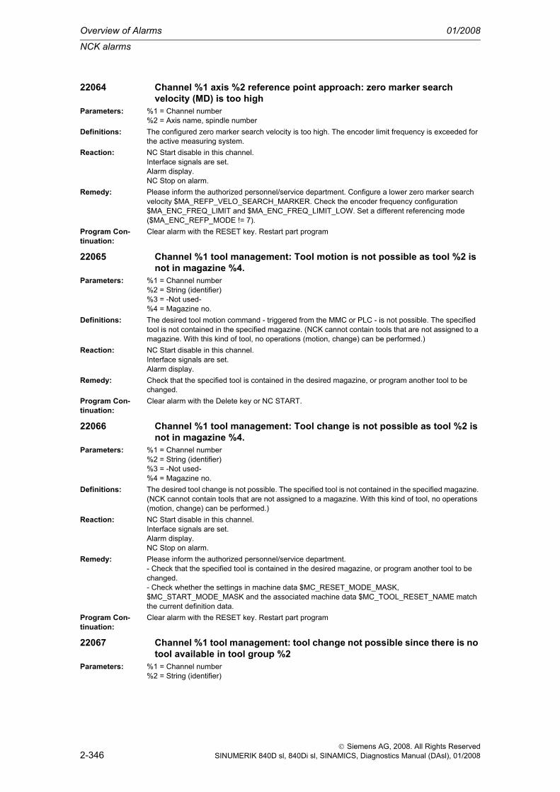
Overview of Alarms 01/2008
NCK alarms
2-346
© Siemens AG, 2008. All Rights ReservedSINUMERIK 840D sl, 840Di sl, SINAMICS, Diagnostics Manual (DAsl), 01/2008
22064 Channel %1 axis %2 reference point approach: zero marker search velocity (MD) is too high
Parameters: %1 = Channel number%2 = Axis name, spindle number
Definitions: The configured zero marker search velocity is too high. The encoder limit frequency is exceeded for the active measuring system.
Reaction: NC Start disable in this channel.Interface signals are set.Alarm display.NC Stop on alarm.
Remedy: Please inform the authorized personnel/service department. Configure a lower zero marker search velocity $MA_REFP_VELO_SEARCH_MARKER. Check the encoder frequency configuration $MA_ENC_FREQ_LIMIT and $MA_ENC_FREQ_LIMIT_LOW. Set a different referencing mode ($MA_ENC_REFP_MODE != 7).
Program Con-tinuation:
Clear alarm with the RESET key. Restart part program
22065 Channel %1 tool management: Tool motion is not possible as tool %2 is not in magazine %4.
Parameters: %1 = Channel number%2 = String (identifier)%3 = -Not used-%4 = Magazine no.
Definitions: The desired tool motion command - triggered from the MMC or PLC - is not possible. The specified tool is not contained in the specified magazine. (NCK cannot contain tools that are not assigned to a magazine. With this kind of tool, no operations (motion, change) can be performed.)
Reaction: NC Start disable in this channel.Interface signals are set.Alarm display.
Remedy: Check that the specified tool is contained in the desired magazine, or program another tool to be changed.
Program Con-tinuation:
Clear alarm with the Delete key or NC START.
22066 Channel %1 tool management: Tool change is not possible as tool %2 is not in magazine %4.
Parameters: %1 = Channel number%2 = String (identifier)%3 = -Not used-%4 = Magazine no.
Definitions: The desired tool change is not possible. The specified tool is not contained in the specified magazine. (NCK cannot contain tools that are not assigned to a magazine. With this kind of tool, no operations (motion, change) can be performed.)
Reaction: NC Start disable in this channel.Interface signals are set.Alarm display.NC Stop on alarm.
Remedy: Please inform the authorized personnel/service department.- Check that the specified tool is contained in the desired magazine, or program another tool to be changed.- Check whether the settings in machine data $MC_RESET_MODE_MASK, $MC_START_MODE_MASK and the associated machine data $MC_TOOL_RESET_NAME match the current definition data.
Program Con-tinuation:
Clear alarm with the RESET key. Restart part program
22067 Channel %1 tool management: tool change not possible since there is no tool available in tool group %2
Parameters: %1 = Channel number%2 = String (identifier)

NCK alarms
01/2008 Overview of Alarms
2-347
© Siemens AG, 2008. All Rights ReservedSINUMERIK 840D sl, 840Di sl, SINAMICS, Diagnostics Manual (DAsl), 01/2008
Definitions: The desired tool change is not possible. The specified tool group does not contain a tool which is ready for use and could be used for tool change. It is possible that all of the tools in question have been set to the 'Disabled' state by the tool monitoring function.
Reaction: NC Start disable in this channel.Interface signals are set.Alarm display.NC Stop on alarm at block end.
Remedy: - Ensure that the specified tool group contains a tool that is ready for use when tool change is requested.- This can be achieved, for example, by replacing disabled tools, or- by releasing a disabled tool manually.- Check whether the tool data are correctly defined. Have all intended tools in the group been defined with the specified identifier and loaded?
Program Con-tinuation:
Clear alarm with the RESET key. Restart part program
22068 Channel %1 block %2 tool management: no tool available in tool group %3
Parameters: %1 = Channel number%2 = Block number, label%3 = String (identifier)
Definitions: The specified tool group does not contain a tool which is ready for use and could be used for tool change. It is possible that all of the tools in question have been set to the 'Disabled' state by the tool monitoring function. The alarm can occur for example in conjunction with the alarm 14710 (error on INIT block generation). In this specific situation, NCK attempts to replace the disabled tool located on the spindle with an available replacement tool (which does not exist in this error condition).The user must resolve this conflict, for example, by removing the tool located on the spindle from the spindle by issuing a movement command (e.g. through MMC operation).
Reaction: Correction block is reorganized.Interface signals are set.Alarm display.
Remedy: - Ensure that the specified tool group contains a tool that is ready for use when tool change is requested.- This can be achieved, for example, by replacing disabled tools, or- by releasing a disabled tool manually.- If an alarm occurs on programming TCA: Has the duplo number been programmed >0?- Check whether the tool data are correctly defined. Have all intended tools in the group been defined/loaded with the specified identifier?
Program Con-tinuation:
Clear alarm with NC START or RESET key and continue the program.
22069 Channel %1 block %2 tool management: No tool available in tool group %3, program %4
Parameters: %1 = Channel number%2 = Block number, label%3 = String (identifier)%4 = Program name
Definitions: The specified tool group does not contain a tool which is ready for use and could be used for tool change. It is possible that all of the tools in question have been set to the 'Disabled' state by the tool monitoring function. Parameter %4 = program name facilitates the identification of the program con-taining the programming command (tool selection) that caused the error. This can be a subprogram or cycle, etc., which can no longer be identified from the display. If the parameter is not specified, it is the currently displayed program.
Reaction: Correction block is reorganized.Interface signals are set.Alarm display.

Overview of Alarms 01/2008
NCK alarms
2-348
© Siemens AG, 2008. All Rights ReservedSINUMERIK 840D sl, 840Di sl, SINAMICS, Diagnostics Manual (DAsl), 01/2008
Remedy: - Ensure that the specified tool group contains a tool that is ready for use when tool change is requested.- This can be achieved, for example, by replacing disabled tools, or- by releasing a disabled tool manually.- Check whether the tool data are correctly defined. Have all intended tools in the group been defined with the specified identifier and loaded?
Program Con-tinuation:
Clear alarm with NC START or RESET key and continue the program.
22070 TO unit %1 Please change tool %2 into magazine. Repeat data backupParameters: %1 = TO unit
%2 = T number of toolDefinitions: The alarm can only occur when the tool management function is active in the NCK. (TOOLMAN = tool
management) A data backup of the tool/magazine data has been started. During the backup, the sys-tem detected that tools are still located in the buffer magazine (= spindle, gripper, ...). During the backup, these tools will lose the information which defines the magazine and location to which they are allocated.It is therefore practical -assuming that the data are to be stored exactly as before - to ensure that all tools have been deposited in the magazine before the data backup!!If this is not the case, some magazine locations will have the 'reserved' status when the data are loaded again. This 'reserved' status must then be reset manually.For tools with fixed location coding, the loss of the information allocating their location in the magazine has the same effect as a general empty location search when they are returned to the magazine.
Reaction: Interface signals are set.Alarm display.
Remedy: Ensure that no tools are located in the buffer magazine before the data backup. Repeat the data backup after removing the tools from the buffer magazine.
Program Con-tinuation:
Clear alarm with the Delete key or NC START.
22071 TO unit %1 tool %2 is active, but not in the magazine area under consideration
Parameters: %1 = TO unit%2 = Tool identifier%3 = -Not used-
Definitions: The alarm can only occur when the tool management function is active in the NCK. Either the lan-guage command SETTA has been programmed or the corresponding operator action has been car-ried out via MMC, PLC, .... The alarm can also be triggered automatically by the NCK in the wear grouping function. It is detected that more than one tool from the tool group (tools with the same name/identifier) has the status "active".The specified tool is eitherfrom a non-considered magazine,from a non-considered wear grouping,or from a non-active wear groupingin a buffer location (is neither magazine nor wear grouping).
Reaction: Interface signals are set.Alarm display.
Remedy: The alarm is intended for information purposes. If only one tool in a group can be active at a time for technological reasons or for reasons of display, the "active" status must be canceled for the tool caus-ing the error.Otherwise, the alarm can be ignored or even suppressed via the machine data SUPPRESS_ALARM_MASK.Typical reasons of display are present, if the operator works with the function 'definite D numbers', which can be displayed on Siemens MMC in a definite form only, if exactly one tool from a tool group has the status 'active'.Before machining can be started or before the SETTA (or corresponding MMC operation, ...) language command is used, all tools of the magazine should have the status "not active".One option to achieve this is programming SETTIA (or corresponding MMC operation, ...).
Program Con-tinuation:
Clear alarm with the Delete key or NC START.

NCK alarms
01/2008 Overview of Alarms
2-349
© Siemens AG, 2008. All Rights ReservedSINUMERIK 840D sl, 840Di sl, SINAMICS, Diagnostics Manual (DAsl), 01/2008
22100 Channel %1 block %3 spindle %2 chuck speed exceededParameters: %1 = Channel number
%2 = Axis name, spindle number%3 = Block number, label
Definitions: The actual spindle speed is higher than the maximum speed configured in machine data 35100 $MA_SPIND_VELO_LIMIT plus a tolerance of 10 percent (fixed setting).The alarm should not occur after correct optimization of the drive actuator and gear configuration.This alarm can be reconfigured with MD 11412 $MN_ALARM_REACTION_CHAN_NOREADY (channel not ready to operate) to 'BAG not ready'.Note: Reconfiguring affects all alarms with alarm response 'Chan not ready'.
Reaction: Mode group not ready.Channel not ready.NC Start disable in this channel.Interface signals are set.Alarm display.NC Stop on alarm.Channel not ready.
Remedy: Please inform the authorized personnel/service department. Check the setup and optimization data of the drive actuator in accordance with the Installation and Start-up Guide and make corrections.Increase the tolerance window in machine data 35150 SPIND_DES_VELO_TOL.
Program Con-tinuation:
Teileprogramm neu starten.Clear alarm with the RESET key in all channels of this mode group. Restart part program.
22101 Channel %1 block %3 spindle %2 maximum speed for encoder resynchronization exceeded
Parameters: %1 = Channel number%2 = Axis name, spindle number%3 = Block number, label
Definitions: The maximum encoder speed was exceeded with G33, G95, G96 or G97. Reference to actual speed and actual position is no longer possible. The NC reduces the setpoint speed with the above functions until the active encoder is able to measure again. The alarm is issued if the encoder still reports the fault.
Reaction: NC Start disable in this channel.Interface signals are set.Alarm display.NC Stop on alarm.
Remedy: - Program speed limit with G26.- Reduce the maximum speed in the appropriate machine data.
Program Con-tinuation:
Clear alarm with the RESET key. Restart part program
22150 Channel %1 block %3 spindle %2 maximum speed for position control exceeded
Parameters: %1 = Channel number%2 = Axis name, spindle number%3 = Block number, label
Definitions: The maximum encoder speed was exceeded with SPCON. Position control is no longer possible. The NC reduces the setpoint speed with the above functions until the active encoder is able to measure again. The alarm is issued if the encoder still reports the fault.
Reaction: NC Start disable in this channel.Interface signals are set.Alarm display.NC Stop on alarm.
Remedy: - Program speed limit with G26.- Reduce the maximum speed in the appropriate machine data.
Program Con-tinuation:
Clear alarm with the RESET key. Restart part program

Overview of Alarms 01/2008
NCK alarms
2-350
© Siemens AG, 2008. All Rights ReservedSINUMERIK 840D sl, 840Di sl, SINAMICS, Diagnostics Manual (DAsl), 01/2008
22200 Channel %1 spindle %2 axis stopped during tappingParameters: %1 = Channel number
%2 = Axis name, spindle numberDefinitions: When tapping with compensating chuck (G63) the drilling axis was stopped via the NC/PLC interface
and the spindle continues to rotate. The thread and possibly also the tap were damaged as a result.Reaction: NC Start disable in this channel.
Interface signals are set.Alarm display.
Remedy: Please inform the authorized personnel/service department. Provide an interlock in the PLC user pro-gram so that no axis stop can be initiated when tapping is active. If the tapping operation is to be ter-minated under critical machine conditions, the spindle and the axis should be stopped simultaneously if at all possible. Slight differences are then accommodated by the compensating chuck.
Program Con-tinuation:
Clear alarm with the RESET key. Restart part program
22250 Channel %1 spindle %2 axis stopped during thread cuttingParameters: %1 = Channel number
%2 = Axis name, spindle numberDefinitions: The thread cutting axis has been stopped while a thread block was active.
The stop can be caused by VDI signals that cause the feed to be interrupted.Reaction: NC Start disable in this channel.
Interface signals are set.Alarm display.
Remedy: Please inform the authorized personnel/service department. Check the axis-specific/spindle-specific stop DB31, ... DBX4.3 (Spindle stop).
Program Con-tinuation:
Clear alarm with the RESET key. Restart part program
22260 Channel %1 spindle %2 thread might be damagedParameters: %1 = Channel number
%2 = Axis name%3 = Block number
Definitions: When DECODING SINGLE BLOCK has been selected and there is a chain of thread blocks, then machining pauses occur at the block limits until the next block is executed with the new NC Start.In normal single block mode, the program is stopped by a higher-level logic only at the block bound-aries at which no contour distortions or contour errors can occur. With chained thread blocks, this is the last thread block!
Reaction: Alarm display.Remedy: If only one thread block has been programmed, the alarm message can be ignored.
If there are several consecutive thread blocks, this machining section must not be executed in the automatic DECODING SINGLE BLOCK mode.
Program Con-tinuation:
Clear alarm with NC START or RESET key and continue the program.
22270 Channel %1 block %2 maximum tapping speed reachedParameters: %1 = Channel number
%2 = Block number, label%3 = Position
Definitions: The following additional parameters are output in order to ascertain the problem:1. 'Position' (without a preceding axis identifier): The maximum feed of the thread axis is reached at the displayed axis position.2. 'Master spindle': The position control for the spindle has been changed during thread cutting. This can lead to inaccurate thread cutting.3. 'Thread axis, velocity': The axis to which the lead refers is displayed. This cannot follow the spindle specifications. The maximum possible axis velocity is shown as a parameter.

NCK alarms
01/2008 Overview of Alarms
2-351
© Siemens AG, 2008. All Rights ReservedSINUMERIK 840D sl, 840Di sl, SINAMICS, Diagnostics Manual (DAsl), 01/2008
The velocity of the thread axis basically depends on:- The programmed thread lead- The programmed thread lead change and thread length (G34, G35)- The defined spindle speed (part program, FC18, synchronized action)- The spindle override (path and individual axis overrides are ineffective)
Reaction: Alarm display.Remedy: Reduce the spindle speed (lead, lead change).Program Con-tinuation:
Clear alarm with the Delete key or NC START.
22275 Channel %1 block %2 zero velocity of thread axis at position %3 reachedParameters: %1 = Channel number
%2 = Block number, label%3 = Position
Definitions: An axis standstill was reached at the specified position during thread cutting with G35 due to the linear decrease in the thread lead. The standstill position of the thread axis depends on:- Programmed thread lead decrease- Thread length
Reaction: Alarm display.Remedy: Change at least one of the above factors.Program Con-tinuation:
Clear alarm with the Delete key or NC START.
22280 Channel %1 in block %2: Prog. acceleration path too short %3, %4 required
Parameters: %1 = Channel number%2 = Block number, label%3 = Prog. acceleration path %4 = Required acceleration path
Definitions: In order to stay within the programmed acceleration path, the acceleration caused an overload on the thread axis. In order to accelerate the axis with the programmed dynamic response, the length of the acceleration path must be at least as large as the value in parameter %4.The alarm is of the technological type and is output whenever bit 2 in $MN_ENABLE_ALARM_MASK is enabled. The MMC softkey 'Technology support' sets and clears this bit in the MD.
Reaction: Alarm display.Remedy: Modify part program or reset MD $MN_ENABLE_ALARMMASK bit 2.Program Con-tinuation:
Clear alarm with the Delete key or NC START.
22290 Channel %1 spindle operation for transformed spindle/axis %2 not possible (reason: error code %3).
Parameters: %1 = Channel number%2 = Axis name, spindle number%3 = Error code
Definitions: It is impermissible to start a spindle as long as it is being used by a transformation. Reason: spindle usage in a transformation requires axis operation, which must not be exited.This alarm may have the following reasons:- Error code 1 : M3, M4 or M5 per synchronized action;- Error code 2 : M41 through M45 per synchronized action;- Error code 3 : SPOS, M19 per synchronized action;- Error code 11 : DB31, ... DBX30.0 (Spindle stop);- Error code 12 : DB31, ... DBX30.1 (Spindle start clockwise rotation);- Error code 13 : DB31, ... DBX30.2 (Spindle start counterclockwise rotation;- Error code 14 : DB31, ... DBX30.4 (Spindle positioning).
Reaction: NC Start disable in this channel.Interface signals are set.Alarm display.
Remedy: Resolve the conflict, for example by deactivating transformation prior to spindle start.Program Con-tinuation:
Clear alarm with the Delete key or NC START.

Overview of Alarms 01/2008
NCK alarms
2-352
© Siemens AG, 2008. All Rights ReservedSINUMERIK 840D sl, 840Di sl, SINAMICS, Diagnostics Manual (DAsl), 01/2008
22320 Channel %1 block %2 PUTFTOCF command could not be transferredParameters: %1 = Channel number
%2 = Block number, labelDefinitions: The cyclic transfer of the PUTFTOCF data block (fine tool compensation) could not be performed
because the transfer area is already occupied.Reaction: Interpreter stop
NC Start disable in this channel.Interface signals are set.Alarm display.NC Stop on alarm.
Remedy: Check the part program, in particular with regard to the other channels. Is a data block being trans-ferred by another channel?
Program Con-tinuation:
Clear alarm with the RESET key. Restart part program
22321 Channel %1 axis %2 PRESET not allowed during traverse motionParameters: %1 = Channel number
%2 = Block number, labelDefinitions: A preset command was given from MMC or PLC while an axis was traveling in JOG mode.Reaction: Interface signals are set.
Alarm display.Remedy: Wait until the axis is stationary.Program Con-tinuation:
Clear alarm with the Delete key or NC START.
22322 Channel %1 axis %2 PRESET: illegal valueParameters: %1 = Channel number
%2 = Axis name, spindle numberDefinitions: The entered Preset value is too large (number format overflow).Reaction: NC Start disable in this channel.
Interface signals are set.Alarm display.NC Stop on alarm.
Remedy: Use more realistic (smaller) Preset values.Program Con-tinuation:
Clear alarm with the RESET key. Restart part program
22400 Channel %1 option 'contour handwheel' not setParameters: %1 = Channel numberDefinitions: The function 'contour handwheel' was activated without the neccesary option.
If the alarm occurs- on selection of the contour handwheel via the PLC, then the contour handwheel has to be deselected in order to continue with the program- on account of programming FD=0, then the program can be corrected and continued with the com-pensation block and NCSTART.
Reaction: Alarm display.Remedy: Please inform the authorized personnel/service department.
- Set option- Cancel the activation of the function 'contour handwheel'- Modify part program.
Program Con-tinuation:
Clear alarm with the Delete key or NC START.
25000 Axis %1 hardware fault of active encoderParameters: %1 = Axis name, spindle numberDefinitions: The signals of the currently active position actual value encoder (NC/PLC interface signal DB31, ...
DBX1.5 = 1 (Position measuring system 1) orDB31, ... DBX1.6 = 1 (Position measuring system 2)) are missing, do not have the same phase, or exhibit grounding/short-circuit.The alarm can be reprogrammed in the MD ALARM_REACTION_CHAN_NOREADY (channel not ready).

NCK alarms
01/2008 Overview of Alarms
2-353
© Siemens AG, 2008. All Rights ReservedSINUMERIK 840D sl, 840Di sl, SINAMICS, Diagnostics Manual (DAsl), 01/2008
For PROFIdrive only:MD ENC_ZERO_MONITORING >100 replaces the existing PowerOn alarm by the Reset alarm 25010.
Reaction: Mode group not ready.The NC switches to follow-up mode.Channel not ready.NC Start disable in this channel.Axes of this channel must be re-referenced.Interface signals are set.Alarm display.NC Stop on alarm.Channel not ready.
Remedy: Please inform the authorized personnel/service department. Check measuring circuit connectors for correct contacting. Check encoder signals and replace the encoder if faults are found.Monitoring can be switched off by setting machine data MD36310 $MA_ENC_ZERO_MONITORING[n] to 100 (n = encoder number: 1,2).
Program Con-tinuation:
Switch control OFF - ON.
25001 Axis %1 hardware fault of passive encoderParameters: %1 = Axis name, spindle numberDefinitions: The signals from the currently inactive position actual value encoder are missing, or they are not of
the same phase, or they exhibit grounding/short-circuit.For PROFIdrive only:MD ENC_ZERO_MONITORING >100 replaces the existing PowerOn alarm by the Reset alarm 25011.MD ENC_ZERO_MONITORING >100 replaces the existing Reset alarm by the Cancel alarm 25011.
Reaction: Alarm display.Remedy: Please inform the authorized personnel/service department. Check measuring circuit connectors for
correct contacting. Check encoder signals and replace the encoder if faults are found. Switch off mon-itoring with the corresponding interface signal DB31, ... DBX1.5 / 1.6 = 0 (Position measuring system 1/2 ).Monitoring can be switched off by setting machine data MD36310 $MA_ENC_ZERO_MONITORING[n] to 100 (n = encoder number: 1,2).
Program Con-tinuation:
Clear alarm with the RESET key. Restart part program
25010 Axis %1 pollution of measuring systemParameters: %1 = Axis name, spindle numberDefinitions: The encoder used for position control sends a contamination signal (only in measuring systems with
contamination signal).The alarm can be reprogrammed in the MD ALARM_REACTION_CHAN_NOREADY (channel not ready).For PROFIdrive only:MD ENC_ZERO_MONITORING >100 returns the existing Reset alarm instead of the Power-on alarm 25000.
Reaction: Mode group not ready.The NC switches to follow-up mode.Channel not ready.NC Start disable in this channel.Axes of this channel must be re-referenced.Interface signals are set.Alarm display.NC Stop on alarm.Channel not ready.
Remedy: Please inform the authorized personnel/service department. Check the measuring system in accor-dance with the instructions given by the measuring device manufacturer.Monitoring can be switched off by setting machine data MD36310 $MA_ENC_ZERO_MONITORING[n] to 100 (n = encoder number: 1,2).
Program Con-tinuation:
Teileprogramm neu starten.Clear alarm with the RESET key in all channels of this mode group. Restart part program.
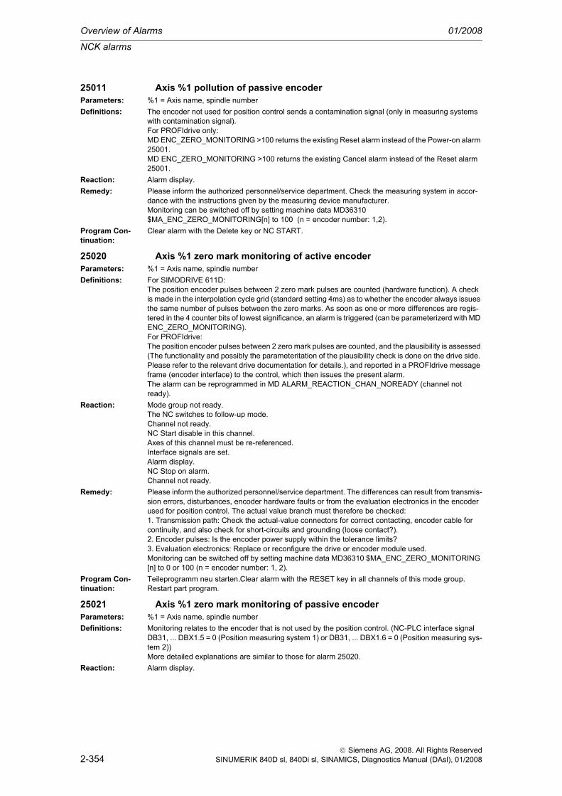
Overview of Alarms 01/2008
NCK alarms
2-354
© Siemens AG, 2008. All Rights ReservedSINUMERIK 840D sl, 840Di sl, SINAMICS, Diagnostics Manual (DAsl), 01/2008
25011 Axis %1 pollution of passive encoderParameters: %1 = Axis name, spindle numberDefinitions: The encoder not used for position control sends a contamination signal (only in measuring systems
with contamination signal).For PROFIdrive only:MD ENC_ZERO_MONITORING >100 returns the existing Reset alarm instead of the Power-on alarm 25001.MD ENC_ZERO_MONITORING >100 returns the existing Cancel alarm instead of the Reset alarm 25001.
Reaction: Alarm display.Remedy: Please inform the authorized personnel/service department. Check the measuring system in accor-
dance with the instructions given by the measuring device manufacturer.Monitoring can be switched off by setting machine data MD36310 $MA_ENC_ZERO_MONITORING[n] to 100 (n = encoder number: 1,2).
Program Con-tinuation:
Clear alarm with the Delete key or NC START.
25020 Axis %1 zero mark monitoring of active encoderParameters: %1 = Axis name, spindle numberDefinitions: For SIMODRIVE 611D:
The position encoder pulses between 2 zero mark pulses are counted (hardware function). A check is made in the interpolation cycle grid (standard setting 4ms) as to whether the encoder always issues the same number of pulses between the zero marks. As soon as one or more differences are regis-tered in the 4 counter bits of lowest significance, an alarm is triggered (can be parameterizerd with MD ENC_ZERO_MONITORING).For PROFIdrive:The position encoder pulses between 2 zero mark pulses are counted, and the plausibility is assessed (The functionality and possibly the parameteritation of the plausibility check is done on the drive side. Please refer to the relevant drive documentation for details.), and reported in a PROFIdrive message frame (encoder interface) to the control, which then issues the present alarm.The alarm can be reprogrammed in MD ALARM_REACTION_CHAN_NOREADY (channel not ready).
Reaction: Mode group not ready.The NC switches to follow-up mode.Channel not ready.NC Start disable in this channel.Axes of this channel must be re-referenced.Interface signals are set.Alarm display.NC Stop on alarm.Channel not ready.
Remedy: Please inform the authorized personnel/service department. The differences can result from transmis-sion errors, disturbances, encoder hardware faults or from the evaluation electronics in the encoder used for position control. The actual value branch must therefore be checked:1. Transmission path: Check the actual-value connectors for correct contacting, encoder cable for continuity, and also check for short-circuits and grounding (loose contact?).2. Encoder pulses: Is the encoder power supply within the tolerance limits?3. Evaluation electronics: Replace or reconfigure the drive or encoder module used.Monitoring can be switched off by setting machine data MD36310 $MA_ENC_ZERO_MONITORING [n] to 0 or 100 (n = encoder number: 1, 2).
Program Con-tinuation:
Teileprogramm neu starten.Clear alarm with the RESET key in all channels of this mode group. Restart part program.
25021 Axis %1 zero mark monitoring of passive encoderParameters: %1 = Axis name, spindle numberDefinitions: Monitoring relates to the encoder that is not used by the position control. (NC-PLC interface signal
DB31, ... DBX1.5 = 0 (Position measuring system 1) or DB31, ... DBX1.6 = 0 (Position measuring sys-tem 2))More detailed explanations are similar to those for alarm 25020.
Reaction: Alarm display.

NCK alarms
01/2008 Overview of Alarms
2-355
© Siemens AG, 2008. All Rights ReservedSINUMERIK 840D sl, 840Di sl, SINAMICS, Diagnostics Manual (DAsl), 01/2008
Remedy: Please inform the authorized personnel/service department. The differences can result from transmis-sion errors, disturbances, encoder hardware faults or from the evaluation electronics in the encoder not used for position control. The actual value branch must therefore be checked:1. Transmission path: Check the actual-value connectors for correct contacting, encoder cable for continuity, and also check for short-circuits and grounding (loose contact?).2. Encoder pulses: Is the encoder power supply within the tolerance limits?3. Evaluation electronics: Replace or reconfigure the drive or encoder module used.Monitoring can be switched off by setting machine data MD36310 $MA_ENC_ZERO_MONITORING[n] to 0 or 100 (n = encoder number: 1, 2).
Program Con-tinuation:
Clear alarm with the Delete key or NC START.
25022 Axis %1 encoder %2 warning %3Parameters: %1 = Axis name, spindle number
%2 = Encoder number%3 = Error fine coding
Definitions: This alarm only occurs with absolute encoders:a. Warning notice of missing absolute encoder adjustment (on the SIMODRIVE 611D or with PRO-FIdrive drives), that is if $MA_ENC_REFP_STATE equals 0. In this case, fine error code 0 is returned.b. If, on the SIMODRIVE 611D only, zero mark monitoring has been activated for the absolute encoder (see $MA_ENC_ZERO_MONITORING): In this case, the absolute position of the absolute encoder could not be read without error:Breakdown of fine error codes:(Bit 0 not used)Bit 1 Parity errorBit 2 Alarm bit of the encoderBit 3 CRC errorBit 4 Timeout - start bit for EnDat transfer is missingThis alarm is only displayed, as the absolute position itself is not required at this time for control/con-tour.A frequent occurrance of this alarm indicates that the absolute encoder transfer or the absolute encoder itself is faulty, and that an incorrect absolute value could be determined in one of the next encoder selection or power on situations.
Reaction: Alarm display.Remedy: a. Verify encoder adjustment (machine reference ) or readjust encoder.
b. Replace the encoder, replace or screen the encoder cable (or deactivate zero mark monitoring).Program Con-tinuation:
Clear alarm with the Delete key or NC START.
25030 Axis %1 actual velocity alarm limitParameters: %1 = Axis name, spindle numberDefinitions: If the axis has at least one active encoder, then the actual speed of the axis is cyclically checked in
the IPO cycle. If there are no errors, the actual velocity can never become greater than specified in the axis-specific machine data MD 36200 $MA_AX_VELO_LIMIT (threshold for velocity monitoring). This threshold value in [mm/min, rev/min] is input by an amount that is about 5 to 10% greater than that which can occur at maximum traversing velocity. Drive errors can result in the velocity being exceeded and the alarm is then triggered.The alarm can be reprogrammed in the MD11412 $MN_ALARM_REACTION_CHAN_NOREADY (channel not ready).
Reaction: Mode group not ready.The NC switches to follow-up mode.Channel not ready.NC Start disable in this channel.Interface signals are set.Alarm display.NC Stop on alarm.Channel not ready.
Remedy: Please inform the authorized personnel/service department. Check the speed setpoint cable (bus cable). Check the actual values and direction of position control. Change the position control direction if the axis rotates uncontrollably -> MD32110 $MA_ENC_FEEDBACK_POL [n] = < -1, 0, 1 >. Increase the monitoring limit value in MD 36200 $MA_AX_VELO_LIMIT.
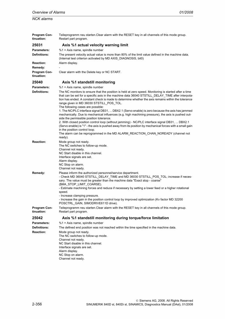
Overview of Alarms 01/2008
NCK alarms
2-356
© Siemens AG, 2008. All Rights ReservedSINUMERIK 840D sl, 840Di sl, SINAMICS, Diagnostics Manual (DAsl), 01/2008
Program Con-tinuation:
Teileprogramm neu starten.Clear alarm with the RESET key in all channels of this mode group. Restart part program.
25031 Axis %1 actual velocity warning limitParameters: %1 = Axis name, spindle numberDefinitions: The present velocity actual value is more than 80% of the limit value defined in the machine data.
(Internal test criterion activated by MD AXIS_DIAGNOSIS, bit0)Reaction: Alarm display.Remedy: -Program Con-tinuation:
Clear alarm with the Delete key or NC START.
25040 Axis %1 standstill monitoringParameters: %1 = Axis name, spindle numberDefinitions: The NC monitors to ensure that the position is held at zero speed. Monitoring is started after a time
that can be set for a specific axis in the machine data 36040 STSTILL_DELAY_TIME after interpola-tion has ended. A constant check is made to determine whether the axis remains within the tolerance range given in MD 36030 STSTILL_POS_TOL.The following cases are possible:1. The NC/PLC interface signal DB31, ... DBX2.1 (Servo enable) is zero because the axis has jammed mechanically. Due to mechanical influences (e.g. high machining pressure), the axis is pushed out-side the permissible position tolerance.2. With closed position control loop (without jamming) - NC/PLC interface signal DB31, ... DBX2.1 (Servo enable) is "1" - the axis is pushed away from its position by mechanical forces with a small gain in the position control loop.The alarm can be reprogrammed in the MD ALARM_REACTION_CHAN_NOREADY (channel not ready).
Reaction: Mode group not ready.The NC switches to follow-up mode.Channel not ready.NC Start disable in this channel.Interface signals are set.Alarm display.NC Stop on alarm.Channel not ready.
Remedy: Please inform the authorized personnel/service department.- Check MD 36040 STSTILL_DELAY_TIME and MD 36030 STSTILL_POS_TOL; increase if neces-sary. The value must be greater than the machine data "Exact stop - coarse" ($MA_STOP_LIMIT_COARSE).- Estimate machining forces and reduce if necessary by setting a lower feed or a higher rotational speed.- Increase clamping pressure.- Increase the gain in the position control loop by improved optimization (Kv factor MD 32200 POSCTRL_GAIN, SIMODRIVE611D drive).
Program Con-tinuation:
Teileprogramm neu starten.Clear alarm with the RESET key in all channels of this mode group. Restart part program.
25042 Axis %1 standstill monitoring during torque/force limitationParameters: %1 = Axis name, spindle numberDefinitions: The defined end position was not reached within the time specified in the machine data.Reaction: Mode group not ready.
The NC switches to follow-up mode.Channel not ready.NC Start disable in this channel.Interface signals are set.Alarm display.NC Stop on alarm.Channel not ready.

NCK alarms
01/2008 Overview of Alarms
2-357
© Siemens AG, 2008. All Rights ReservedSINUMERIK 840D sl, 840Di sl, SINAMICS, Diagnostics Manual (DAsl), 01/2008
Remedy: - If the drive torque (FXST) was set too low with the result that the force of the motor was not sufficient to reach the end position -> increase FXST.- If the machined part is slowly deformed, there may be a delay in reaching the end position -> increase MD 36042 FOC_STANDSTILL_DELAY_TIME.
Program Con-tinuation:
Teileprogramm neu starten.Clear alarm with the RESET key in all channels of this mode group. Restart part program.
25050 Axis %1 contour monitoringParameters: %1 = Axis name, spindle numberDefinitions: The NCK calculates for each interpolation point (setpoint) of an axis the actual value that should result
based on an internal model. If this calculated actual value and the true machine actual value differ by a larger amount than given in the machine data 36400 CONTOUR_TOL, then the program is aborted and the alarm message is issued.The alarm can be reprogrammed in the MD ALARM_REACTION_CHAN_NOREADY (channel not ready).
Reaction: Mode group not ready.The NC switches to follow-up mode.Channel not ready.NC Start disable in this channel.Interface signals are set.Alarm display.NC Stop on alarm.Channel not ready.
Remedy: Please inform the authorized personnel/service department.- Check whether the tolerance value set in MD 36400: CONTOUR_TOL is too small.- Check optimization of the position controller (Kv factor in the machine data 32200 POSCTRL_GAIN) to establish whether the axis follows the given setpoint without overshooting. Otherwise, the speed controller optimization must be improved or the Kv servo gain factor must be reduced.- Improvement of speed controller optimization- Check the mechanics (smooth running, inertial masses).
Program Con-tinuation:
Teileprogramm neu starten.Clear alarm with the RESET key in all channels of this mode group. Restart part program.
25060 Axis %1 speed setpoint limitationParameters: %1 = Axis name, spindle numberDefinitions: The speed setpoint has exceeded its upper limit for a longer period than allowed.
The maximum speed setpoint is limited to a certain percentage by the axis-specific machine data MD36210 $MA_CTRLOUT_LIMIT. The input value of 100% corresponds to the rated speed of the motor and hence the rapid traverse velocity (exemplary default value: 840D=110%).For SIMODRIVE 611D and SIMODRIVE 611U: Drive MD 1401 etc. also has a limiting effect.For SINAMICS: Drive parameter p1082 also has a limiting effect.If the values are exceeded for a short time, then this is tolerated provided they do not last longer than allowed for in the axis-specific machine data MD36220 $MA_CTRLOUT_LIMIT_TIME. The setpoint is limited during this time to the maximum value that has been set in (MD 36210).The alarm can be reprogrammed in the MD11412 $MN_ALARM_REACTION_CHAN_NOREADY (channel not ready).
Reaction: Mode group not ready.The NC switches to follow-up mode.Channel not ready.NC Start disable in this channel.Interface signals are set.Alarm display.NC Stop on alarm.Channel not ready.
Remedy: Please inform the authorized personnel/service department. This alarm should not occur if the drive controller has been set correctly and the machining conditions are those that normally prevail.- Check actual values: Local sluggishness of the carriage, speed dip by torque surge due to contact with workpiece/tool, travel against fixed obstacle, etc.- Check direction of position control: Does the axis continue to rotate without control (not on SIMO-DRIVE 611D drives)?- On SIMODRIVE 611D drives: Check the speed setpoint cable.

Overview of Alarms 01/2008
NCK alarms
2-358
© Siemens AG, 2008. All Rights ReservedSINUMERIK 840D sl, 840Di sl, SINAMICS, Diagnostics Manual (DAsl), 01/2008
Program Con-tinuation:
Teileprogramm neu starten.Clear alarm with the RESET key in all channels of this mode group. Restart part program.
25070 Axis %1 drift value too largeParameters: %1 = Axis name, spindle numberDefinitions: Only with analog drives!
The permissible maximum value of drift (internal, integrated drift value of automatic drift compensa-tion) was exceeded during the last compensation operation. The permissible maximum value is defined in the axis-specific machine data 36710 DRIFT_LIMIT. The drift value itself is not limited.Automatic drift compensation: MD 36700 DRIFT_ENABLE=1The difference between actual and setpoint position (drift) is checked cyclically in the IPO cycle when the axes are at zero speed. The difference is automatically compensated to zero by slowly integrating an internal drift value.Drift compensation by hand: MD 36700 DRIFT_ENABLE=0A static offset can be added to the speed setpoint in the machine data 36720 DRIFT_VALUE. This is not included in the drift monitoring because it acts like a voltage zero offset.
Reaction: Alarm display.Remedy: Please inform the authorized personnel/service department. Adjust the drift compensation with the
automatic drift compensation switched off at the drive until the position lag is approximately zero. Then reactivate the automatic drift compensation in order to balance out the dynamic drift changes (effects of heating up).
Program Con-tinuation:
Clear alarm with the Delete key or NC START.
25080 Axis %1 positioning monitoringParameters: %1 = Axis name, spindle numberDefinitions: For blocks in which "exact stop" is effective, the axis must have reached the exact stop window after
the positioning time given in the axis-specific MD 36020 POSITIONING_TIME.Exact stop coarse: MD 36000 STOP_LIMIT_COARSEExact stop fine: MD 36010 STOP_LIMIT_FINEThe alarm can be reprogrammed in the MD ALARM_REACTION_CHAN_NOREADY (channel not ready).
Reaction: Mode group not ready.The NC switches to follow-up mode.Channel not ready.NC Start disable in this channel.Interface signals are set.Alarm display.NC Stop on alarm.Channel not ready.
Remedy: Please inform the authorized personnel/service department. Check whether the exact stop limits (course and fine) correspond to the dynamic possibilities of the axis, otherwise increase them, if nec-essary in connection with the positioning time set in MD 36020 POSITIONING_TIME. Check speed controller/position controller optimization; select highest possible gains. Check setting of Kv factor (MD 32200 POSCTRL_GAIN) and increase if necessary.
Program Con-tinuation:
Teileprogramm neu starten.Clear alarm with the RESET key in all channels of this mode group. Restart part program.
25100 Axis %1 measuring system switchover not possibleParameters: %1 = Axis name, spindle numberDefinitions: The prerequisites are not satisfied for the required encoder switchover:
1. The newly selected encoder must be in the active state: (DB31, ... DBX1.5 / 1.6 = 1 (Position mea-suring system 1/2).2. The actual value difference between the two encoders is greater than the value in the axis-specific machine data MD36500 $MA_ENC_CHANGE_TOL ("Maximum tolerance for position actual value switchover").

NCK alarms
01/2008 Overview of Alarms
2-359
© Siemens AG, 2008. All Rights ReservedSINUMERIK 840D sl, 840Di sl, SINAMICS, Diagnostics Manual (DAsl), 01/2008
Activation of the measuring system concerned takes place in accordance with the NC/PLC interface signals DB31, ... DBX1.5 (Position measuring system 1) and DB31, ... DBX1.6 (Position measuring system 2), i.e. the position control is now operated with this measuring system. The other measuring system is switched over to follow-up mode. If both interface signals are set to "1", then only the 1st measuring system is active; if both interface signals are set to "0", the axis is parked.Changeover takes place as soon as the interface signals have changed, even if the axis is in motion.
Reaction: NC Start disable in this channel.Interface signals are set.Alarm display.NC Stop on alarm.
Remedy: Please inform the authorized personnel/service department. When referencing the active position actual value encoder, the actual value system of the inactive encoder is set to the same reference point value as soon as phase 3 has been concluded. A later positional difference between the two actual value systems can have occurred only as the result of an encoder defect or a mechanical dis-placement between the encoders.- Check the encoder signals, actual value cable, connectors.- Check the mechanical fastenings (displacement of the measuring head, mechanical twisting possi-ble).- Increase the axis-specific MD 36500 $MA_ENC_CHANGE_TOL.Program continuation is not possible. The program must be aborted with "RESET", then program exe-cution can be reinitiated with NC START, if necessary at the interruption point after "Block search with/without calculation".
Program Con-tinuation:
Clear alarm with the RESET key. Restart part program
25105 Axis %1 measuring systems differ considerablyParameters: %1 = Axis name, spindle numberDefinitions: The two measuring systems differ considerably, i.e. the cyclically monitored actual value difference
between the two measuring systems is greater than the associated tolerance value set in the machine data $MA_ENC_DIFF_TOL. This can only occur when both measuring systems are active ($MA_NUM_ENCS = 2) and referenced. The alarm can be reprogrammed in the MD ALARM_REACTION_CHAN_NOREADY (channel not ready).
Reaction: Mode group not ready.The NC switches to follow-up mode.Channel not ready.NC Start disable in this channel.Interface signals are set.Alarm display.NC Stop on alarm.Channel not ready.
Remedy: Please inform the authorized personnel/service department. Check machine data for the active, selected encoders. Check the machine data relating to encoder ($MA_ENC_DIFF_TOL) tolerance.
Program Con-tinuation:
Teileprogramm neu starten.Clear alarm with the RESET key in all channels of this mode group. Restart part program.
25110 Axis %1 selected encoder not availableParameters: %1 = Axis name, spindle numberDefinitions: The selected encoder does not correspond to the maximum number of encoders in the axis-specific
machine data 30200 NUM_ENCS, i.e. the 2nd encoder does not exist.Reaction: Alarm display.Remedy: Please inform the authorized personnel/service department. Enter the number of actual value encod-
ers used for this axis in the machine data 30200 NUM_ENCS ("Number of encoders").Input value 0: Axis without encoder -> e.g. spindleInput value 1: Axis with encoder -> default settingInput value 2: Axis with 2 encoders -> e.g. direct and indirect measuring system
Program Con-tinuation:
Clear alarm with the Delete key or NC START.
25200 Axis %1 requested set of parameters invalidParameters: %1 = Axis name, spindle number

Overview of Alarms 01/2008
NCK alarms
2-360
© Siemens AG, 2008. All Rights ReservedSINUMERIK 840D sl, 840Di sl, SINAMICS, Diagnostics Manual (DAsl), 01/2008
Definitions: A new parameter set has been requested for the positioning control. The number of this parameter set is beyond the permissible limit (8 parameter sets: 0 ... 7 available).
Reaction: NC Start disable in this channel.Interface signals are set.Alarm display.NC Stop on alarm.
Remedy: Please inform the authorized personnel/service department. Check the axis-specific/spindle-specific interface signals DB31, ... DBX9.0 - .2 (Select parameter set servo A, B, C).One parameter set includes the following machine data:- MD 31050: DRIVE_AX_RATIO_DENOM [n]- MD 31060: DRIVE_AX_RATIO_NUMERA [n]- MD 32200: POSCTRL_GAIN [n]- MD 32800: EQUIV_CURRCTRL_TIME [n]- MD 32810: EQUIV_SPEEDCTRL_TIME [n]- MD 32910: DYN_MATCH_TIME [n]- MD 36200: AX_VELO_LIMIT [n]
Program Con-tinuation:
Clear alarm with the RESET key. Restart part program
25201 Axis %1 drive faultParameters: %1 = Axis name, spindle numberDefinitions: For SIMODRIVE 611D:
The drive signals a serious fault of status class 1 (ZK1). The exact cause of the fault can be found by evaluating the following additionally output drive alarms:Alarm 300500, alarms 300502 - 300505, alarm 300508, alarm 300515, alarm 300608, alarm 300612, alarm 300614, alarms 300701 - 300761, alarm 300799.For PROFIdrive:The drive signals a serious fault which prevents the drive from being ready. The exact cause of the fault can be found by evaluating the additionally output drive alarms (It may be necessary to activate these diagnostic alarms by parameterizing the MDs DRIVE_FUNCTION_MASK, PROFIBUS_ALARM_ACCESS etc):Alarms 380500 and 380501 (or the corresponding alarm numbers implemented on the HMI side).The alarm can be reprogrammed in the MD11412 $MN_ALARM_REACTION_CHAN_NOREADY (channel not ready).
Reaction: Mode group not ready.The NC switches to follow-up mode.Channel not ready.NC Start disable in this channel.Interface signals are set.Alarm display.NC Stop on alarm.Channel not ready.
Remedy: Evaluation of the drive alarms listed above.Program Con-tinuation:
Teileprogramm neu starten.Clear alarm with the RESET key in all channels of this mode group. Restart part program.
25202 Axis %1 waiting for driveParameters: %1 = Axis name, spindle numberDefinitions: Drive group error (self-clearing).Reaction: Interface signals are set.
Alarm display.Remedy: For PROFIdrive only:
Wait for the drive. Alarm 25202 reveals similar problems to alarm 25201 (see that alarm). The alarm is continuously active during power-up if the drive does not communicate (e.g. if the PROFIBUS con-nector has fallen out). Otherwise, the alarm is active only briefly and is replaced by alarm 25201 after an internal timeout in the event of a permanent problem.
Program Con-tinuation:
Alarm display showing cause of alarm disappears. No further operator action necessary.

NCK alarms
01/2008 Overview of Alarms
2-361
© Siemens AG, 2008. All Rights ReservedSINUMERIK 840D sl, 840Di sl, SINAMICS, Diagnostics Manual (DAsl), 01/2008
26000 Axis %1 clamping monitoringParameters: %1 = Axis name, spindle numberDefinitions: The clamped axis has been pushed out of its setpoint position. The permissible difference is defined
in the axis-specific machine data 36050 CLAMP_POS_TOL.Clamping an axis is activated with the axis-specific interface signal DB31, ... DBX2.3 (Clamping pro-cess active).The alarm can be reprogrammed in the MD ALARM_REACTION_CHAN_NOREADY (channel not ready).
Reaction: Mode group not ready.The NC switches to follow-up mode.Channel not ready.NC Start disable in this channel.Interface signals are set.Alarm display.NC Stop on alarm.Channel not ready.
Remedy: Determine the position deviation to the setpoint position and, depending on the results, either increase the permissible tolerance in the MD or mechanically improve the clamping (e.g. increase clamping pressure).
Program Con-tinuation:
Teileprogramm neu starten.Clear alarm with the RESET key in all channels of this mode group. Restart part program.
26001 Axis %1 parameterization error: friction compensationParameters: %1 = Axis name, spindle numberDefinitions: The parameterization of the adaptation characteristic in the quadrant error compensation is not
allowed because acceleration value 2 (MD 32560 FRICT_COMP_ACCEL2 is not between accelera-tion value 1 (MD 32550 FRICT_COMP_ACCEL1) and acceleration value 3 (MD 32570 FRICT_COMP_ACCEL3).The alarm can be reprogrammed in the MD ALARM_REACTION_CHAN_NOREADY (channel not ready).
Reaction: Mode group not ready.The NC switches to follow-up mode.Channel not ready.NC Start disable in this channel.Interface signals are set.Alarm display.NC Stop on alarm.Channel not ready.
Remedy: Please inform the authorized personnel/service department. Check the setting parameters of the quadrant error compensation (friction compensation), if necessary switch off the compensation with MD 32500 FRICT_COMP_ENABLE.
Program Con-tinuation:
Teileprogramm neu starten.Clear alarm with the RESET key in all channels of this mode group. Restart part program.
26002 Axis %1 encoder %2 parameterization error: number of encoder marksParameters: %1 = Axis name, spindle number
%2 = Encoder numberDefinitions: 1. Rotary measuring system ($MA_ENC_IS_LINEAR[]==FALSE)
The number of encoder marks set in MD 31020 $MA_31020 $MA_ENC_RESOL[] does not corre-spond to the value in the drive machine data (SIMODRIVE 611D: MD1005; PROFIdrive: p979) or zero has been entered in one of the two machine data.2. Absolute measuring system with EnDat interface ($MA_ENC_TYPE[]==4)On absolute encoders, the resolution of the incremental and absolute tracks supplied by the drive is also checked for consistency.For SIMODRIVE 611D drives:- Motor measuring system: MD1005, MD1022- Direct measuring system: MD1007, MD1032

Overview of Alarms 01/2008
NCK alarms
2-362
© Siemens AG, 2008. All Rights ReservedSINUMERIK 840D sl, 840Di sl, SINAMICS, Diagnostics Manual (DAsl), 01/2008
The two drive machine data must have a defined relation to one another. An alarm is output if the con-ditions listed below are not fulfilled.2.1 Rotary measuring system ($MA_ENC_IS_LINEAR[] == FALSE)MD1022/MD1005 == 4 * n [n=1,2,3...] (motor measuring system)MD1032/MD1007 == 4 * n [n=1,2,3...] (direct measuring system)2.2 Linear measuring system ($MA_ENC_IS_LINEAR[] == TRUE)MD1005/MD1022 == 4 * n [n=1,2,3...] (motor measuring system)MD1007/MD1032 == 4 * n [n=1,2,3...] (direct measuring system)For PROFIdrive drives:Compare drive parameter p979 (and possibly other internal drive, manufacture-specific parameters stated in the relevant drive documentation)
Reaction: Mode group not ready.The NC switches to follow-up mode.Channel not ready.NC Start disable in this channel.Interface signals are set.Alarm display.NC Stop on alarm.Channel not ready.
Remedy: Please inform the authorized personnel/service department. Adjust machine data. For absolute encoders, pending drive alarms indicating encoder problems should be evaluated, if necessary. They could be the cause of incorrect entries for the absolute track resolution in the drive data which the drive reads out of the encoder itself.
Program Con-tinuation:
Switch control OFF - ON.
26003 Axis %1 parameterization error: lead screw pitchParameters: %1 = Axis name, spindle numberDefinitions: The pitch of the ballscrew/trapezoidal leadscrew set in the axis-specific machine data 31030
LEADSCREW_PITCH is zero.The alarm can be reprogrammed in the MD ALARM_REACTION_CHAN_NOREADY (channel not ready).
Reaction: Mode group not ready.The NC switches to follow-up mode.Channel not ready.NC Start disable in this channel.Interface signals are set.Alarm display.NC Stop on alarm.Channel not ready.
Remedy: Determine the leadscrew pitch (specify the machine manufacturer or pitch measurement with spindle cover removed) and enter it in the machine data 31030: LEADSCREW_PITCH (mostly 10 or 5 mm/rev.).
Program Con-tinuation:
Switch control OFF - ON.
26004 Axis %1 encoder %2 parameterization error: grid point distance with linear encoders
Parameters: %1 = Axis name, spindle number%2 = Encoder number
Definitions: The scale division of the linear scale set in the axis-specific MD 31010 ENC_GRID_POINT_DIST is zero or differs from the corresponding drive parameters. For a better understanding of the interrela-tions see the explanations for alarm 26002, which refer to rotatory encoders.The alarm can be reprogrammed in the MD ALARM_REACTION_CHAN_NOREADY (channel not ready).

NCK alarms
01/2008 Overview of Alarms
2-363
© Siemens AG, 2008. All Rights ReservedSINUMERIK 840D sl, 840Di sl, SINAMICS, Diagnostics Manual (DAsl), 01/2008
Reaction: Mode group not ready.The NC switches to follow-up mode.Channel not ready.NC Start disable in this channel.Interface signals are set.Alarm display.NC Stop on alarm.Channel not ready.
Remedy: Please inform the authorized personnel/service department. Enter the encoder grid point distance according to the data given by the machine (or measuring device) manufacturer in the machine data 31010 ENC_GRID_POINT_DIST.
Program Con-tinuation:
Switch control OFF - ON.
26005 Axis %1 parameterization error: output ratingParameters: %1 = Axis name, spindle numberDefinitions: For analog drives:
The output evaluation of the analog speed setpoint set in the machine data 32250 RATED_OUTVAL or in MD 32260 RATED_VELO is zero.For PROFIdrive drives: (ADI4, SIMODRIVE 611U, SINAMICS):The effective output evaluation of the speed setpoint interface is zero:-b. The corresponding drive-side standardizing parameter is zero, invalid or unreadable/unavailable although an automatic interface scaling adjustment has been selected on account of MD 32250 RATED_OUTVAL=0.The drive parameter defining the standard is not determined by PROFIdrive, but is specific to the man-ufacturer (see the relevant drive documentation: For SIMODRIVE 611U: p880; for SINAMICS: p2000).The alarm can be reprogrammed in the MD ALARM_REACTION_CHAN_NOREADY (channel not ready).
Reaction: Mode group not ready.The NC switches to follow-up mode.Channel not ready.NC Start disable in this channel.Interface signals are set.Alarm display.NC Stop on alarm.Channel not ready.
Remedy: Please inform the authorized personnel/service department. The nominal output voltage in [%] of the maximum setpoint value (10 V) is entered in the machine data 32250 RATED_OUTVAL, at which the rated motor speed in [degrees/s] is to be reached (machine data 32260 RATED_VELO).
Program Con-tinuation:
Teileprogramm neu starten.Clear alarm with the RESET key in all channels of this mode group. Restart part program.
26006 Axis %1 encoder %2 encoder type/output type %3 not possibleParameters: %1 = Axis name, spindle number
%2 = Encoder number%3 = Encoder type/output type
Definitions: Not every encoder type or output type can be used with every control or drive variant.Permissible settings:MD 30240 ENC_TYPE= 0 Simulation (always permissible)= 1 Raw signal incremental encoder (SIMODRIVE 611D and PROFIdrive)= 2 Square-wave incremental encoder (SIMODRIVE 611D only)= 4 Absolute encoder (EnDat with SIMODRIVE 611D; all drive-side absolute encoders supported by PROFIdrive)= 5 SSI absolute encoder (SIMODRIVE 611D only)MD 30130 CTRLOUT_TYPE= 0 Simulation= 1 Standard (SIMODRIVE 611D and PROFIdrive drives)The alarm can be reprogrammed in the MD ALARM_REACTION_CHAN_NOREADY (channel not ready).

Overview of Alarms 01/2008
NCK alarms
2-364
© Siemens AG, 2008. All Rights ReservedSINUMERIK 840D sl, 840Di sl, SINAMICS, Diagnostics Manual (DAsl), 01/2008
Reaction: Mode group not ready.The NC switches to follow-up mode.Channel not ready.NC Start disable in this channel.Interface signals are set.Alarm display.NC Stop on alarm.Channel not ready.
Remedy: Please inform the authorized personnel/service department. Check machine data MD 20240 ENC_TYPE and/or MD 30130 CTRLOUT_TYPE and make the necessary corrections.
Program Con-tinuation:
Switch control OFF - ON.
26007 Axis %1 QEC: invalid coarse step sizeParameters: %1 = Axis name, spindle numberDefinitions: The course step width for QEC must be within the range 1 <= course step width <= maximum value
of MD 18342 MM_QEC_MAX_POINTS (currently 1025), because a greater number of values would exceed the available memory space.
Reaction: Alarm display.Remedy: Modify the system variable $AA_QEC_COARSE_STEPS accordingly.Program Con-tinuation:
Clear alarm with the RESET key. Restart part program
26008 Axis %1 QEC: invalid fine step sizeParameters: %1 = Axis name, spindle numberDefinitions: The fine step size for quadrant error compensation $AA_QEC_FINE_STEPS must be in the range 1
<= fine step size <= 16 because this value has an influence on the computation time of the QEC.Reaction: Alarm display.Remedy: Modify the system variable $AA_QEC_FINE_STEPS accordingly.Program Con-tinuation:
Clear alarm with the RESET key. Restart part program
26009 Axis %1 QEC: memory overflowParameters: %1 = Axis name, spindle numberDefinitions: The product of the data $AA_QEC_COARSE_STEPS+1 and $AA_QEC_FINE_STEPS must not
exceed the maximum number of the characteristic curve points (MD $MA_MM_QEC_MAX_POINTS). With a direction-dependent characteristic, this criterion applies to 2 * ($AA_QEC_COARSE_STEPS+1) * $AA_QEC_FINE_STEPS!
Reaction: Alarm display.Remedy: Please inform the authorized personnel/service department. Either increase
$MA_MM_QEC_MAX_POINTS or reduce $AA_QEC_COARSE_STEPS and/or $AA_QEC_FINE_STEPS.
Program Con-tinuation:
Clear alarm with the RESET key. Restart part program
26010 Axis %1 QEC: invalid acceleration characteristicParameters: %1 = Axis name, spindle numberDefinitions: $AA_QEC_ACCEL_1/2/3: The acceleration characteristic is divided into three areas. In each area
there is a different quantization of the acceleration steps. The defaults should be changed only if com-pensation is inadequate in these acceleration areas.The defaults are as follows:- $AA_QEC_ACCEL_1 with approx. 2% of maximum acceleration ($AA_QEC_ACCEL_3),- $AA_QEC_ACCEL_2 with approx. 60% of maximum acceleration ($AA_QEC_ACCEL_3),- $AA_QEC_ACCEL_3 with maximum acceleration (MD32300 $MA_MAX_AX_ACCEL).
Reaction: Alarm display.Remedy: Please inform the authorized personnel/service department. Enter the values correctly:
0 < $AA_QEC_ACCEL_1 < $AA_QEC_ACCEL_2 < $AA_QEC_ACCEL_3.Program Con-tinuation:
Clear alarm with the RESET key. Restart part program

NCK alarms
01/2008 Overview of Alarms
2-365
© Siemens AG, 2008. All Rights ReservedSINUMERIK 840D sl, 840Di sl, SINAMICS, Diagnostics Manual (DAsl), 01/2008
26011 Axis %1 QEC: invalid measuring periodsParameters: %1 = Axis name, spindle numberDefinitions: $AA_QEC_MEAS_TIME_1/2/3: measuring time to determine the error criterion.
The measuring period begins when the criterion for activating the compensation value has been sat-isfied (the desired velocity changes the sign). The end is defined by the machine data values. In gen-eral, different measuring times are required for the three characteristic ranges. The presettings should be changed only if a problem occurs. The three data apply in each case for the three corresponding acceleration ranges.1. $AA_QEC_MEAS_TIME_1 specifies the measuring time (for determining the error criterion) for accelerations in the range between 0 and $AA_QEC_ACCEL_1.2. $AA_QEC_MEAS_TIME_2 specifies the measuring time in the range from $AA_QEC_ACCEL_1 to $AA_QEC_ACCEL_2.3. $AA_QEC_MEAS_TIME_3 specifies the measuring time in the range from $AA_QEC_ACCEL_2 to $AA_QEC_ACCEL_3 and beyond.
Reaction: Alarm display.Remedy: Please inform the authorized personnel/service department. Enter the values correctly: 0 <
$AA_QEC_MEAS_TIME_1 < $AA_QEC_MEAS_TIME_2 < $AA_QEC_MEAS_TIME_3.Program Con-tinuation:
Clear alarm with the RESET key. Restart part program
26012 Axis %1 QEC: feed forward control not activeParameters: %1 = Axis name, spindle numberDefinitions: The error criterion for determining the quadrant error necessitates a correctly set feedforward control.
The alarm can be reprogrammed in the MD ALARM_REACTION_CHAN_NOREADY (channel not ready).
Reaction: Mode group not ready.Channel not ready.NC Start disable in this channel.Alarm display.Channel not ready.
Remedy: Switch on feedforward control and set it correctly.Program Con-tinuation:
Teileprogramm neu starten.Clear alarm with the RESET key in all channels of this mode group. Restart part program.
26014 Axis %1 machine data %2 invalid valueParameters: %1 = Axis name, spindle number
%2 = String: MD identifierDefinitions: Machine data includes a value that is not valid.Reaction: NC not ready.
The NC switches to follow-up mode.Mode group not ready, also effective for single axesNC Start disable in this channel.Interface signals are set.Alarm display.NC Stop on alarm.
Remedy: Repeat entry with correct value and then Power On.Program Con-tinuation:
Switch control OFF - ON.
26015 Axis %1 machine data %2[%3] invalid valueParameters: %1 = Axis name, spindle number
%2 = String: MD identifier%3 = Index: MD array

Overview of Alarms 01/2008
NCK alarms
2-366
© Siemens AG, 2008. All Rights ReservedSINUMERIK 840D sl, 840Di sl, SINAMICS, Diagnostics Manual (DAsl), 01/2008
Definitions: Machine data includes a value that is not valid.Reaction: NC not ready.
The NC switches to follow-up mode.Mode group not ready, also effective for single axesNC Start disable in this channel.Interface signals are set.Alarm display.NC Stop on alarm.
Remedy: Repeat entry with correct value and then Power On.Program Con-tinuation:
Switch control OFF - ON.
26016 Axis %1 machine data %2 invalid valueParameters: %1 = Axis name, spindle number
%2 = String: MD identifierDefinitions: Machine data includes a value that is not valid.Reaction: NC not ready.
The NC switches to follow-up mode.Mode group not ready, also effective for single axesNC Start disable in this channel.Interface signals are set.Alarm display.NC Stop on alarm.
Remedy: Repeat entry with correct value and then Reset.Program Con-tinuation:
Teileprogramm neu starten.Clear alarm with the RESET key in all channels of this mode group. Restart part program.
26017 Axis %1 machine data %2[%3] invalid valueParameters: %1 = Axis name, spindle number
%2 = String: MD identifier%3 = Index: MD array
Definitions: Machine data includes a value that is not valid.Reaction: NC not ready.
The NC switches to follow-up mode.Mode group not ready, also effective for single axesNC Start disable in this channel.Interface signals are set.Alarm display.NC Stop on alarm.
Remedy: Repeat entry with correct value and then Reset.Program Con-tinuation:
Teileprogramm neu starten.Clear alarm with the RESET key in all channels of this mode group. Restart part program.
26018 Axis %1 setpoint output drive %2 used more than onceParameters: %1 = Axis name, spindle number
%2 = Drive numberDefinitions: The same setpoint assignment has been allocated more than once.
The machine data 30100 $MA_CTRLOUT_SEGMENT_NR, 30110 $MA_CTRLOUT_MODULE_NR and 30120 $MA_CTRLOUT_NR point to different axes on the same drive.SIMODRIVE 611D: The stated MDs contain the same values for different axes.PROFIdrive: The stated MDs contain the same values for different axes, or different entries in $MN_DRIVE_LOGIC_ADDRESS contain the same values.
Reaction: Mode group not ready.The NC switches to follow-up mode.Channel not ready.NC Start disable in this channel.Interface signals are set.Alarm display.NC Stop on alarm.
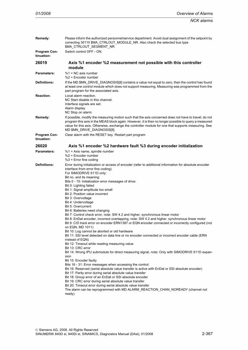
NCK alarms
01/2008 Overview of Alarms
2-367
© Siemens AG, 2008. All Rights ReservedSINUMERIK 840D sl, 840Di sl, SINAMICS, Diagnostics Manual (DAsl), 01/2008
Remedy: Please inform the authorized personnel/service department. Avoid dual assignment of the setpoint by correcting 30110 $MA_CTRLOUT_MODULE_NR. Also check the selected bus type $MA_CTRLOUT_SEGMENT_NR.
Program Con-tinuation:
Switch control OFF - ON.
26019 Axis %1 encoder %2 measurement not possible with this controller module
Parameters: %1 = NC axis number%2 = Encoder number
Definitions: If the MD $MN_DRIVE_DIAGNOSIS[8] contains a value not equal to zero, then the control has found at least one control module which does not support measuring. Measuring was programmed from the part program for the associated axis.
Reaction: Local alarm reaction.NC Start disable in this channel.Interface signals are set.Alarm display.NC Stop on alarm.
Remedy: If possible, modify the measuring motion such that the axis concerned does not have to travel; do not program this axis in the MEAS block again. However, it is then no longer possible to query a measured value for this axis. Otherwise, exchange the controller module for one that supports measuring. See MD $MN_DRIVE_DIAGNOSIS[8].
Program Con-tinuation:
Clear alarm with the RESET key. Restart part program
26020 Axis %1 encoder %2 hardware fault %3 during encoder initializationParameters: %1 = Axis name, spindle number
%2 = Encoder number%3 = Error fine coding
Definitions: Error during initialization or access of encoder (refer to additional information for absolute encoder interface from error fine coding).For SIMODRIVE 611D only:Bit no. and its meaning:Bits 0 - 15: Initialization error messages of drive:Bit 0: Lighting failedBit 1: Signal amplitude too smallBit 2: Position value incorrectBit 3: OvervoltageBit 4: UndervoltageBit 5: OvercurrentBit 6: Batteries need changingBit 7: Control check error, note: SW 4.2 and higher, synchronous linear motorBit 8: EnDat encoder, incorrect overlapping, note: SW 4.2 and higher, synchronous linear motorBit 9: C/D track error on encoder ERN1387 or EQN encoder connected or incorrectly configured (not on EQN, MD 1011)Bit 10: Log cannot be aborted or old hardwareBit 11: SSI level detected on data line or no encoder connected or incorrect encoder cable (ERN instead of EQN)Bit 12: Timeout while reading measuring valueBit 13: CRC errorBit 14: Wrong IPU submodule for direct measuring signal, note: Only with SIMODRIVE 611D expan-sionBit 15: Encoder faultyBits 16 - 31: Error messages when accessing the control:Bit 16: Reserved (serial absolute value transfer is active with EnDat or SSI absolute encoder)Bit 17: Parity error during serial absolute value transferBit 18: Group error of an EnDat or SSI absolute encoderBit 19: CRC error during serial absolute value transferBit 20: Timeout error during serial absolute value transferThe alarm can be reprogrammed with MD ALARM_REACTION_CHAN_NOREADY (channel not ready).

Overview of Alarms 01/2008
NCK alarms
2-368
© Siemens AG, 2008. All Rights ReservedSINUMERIK 840D sl, 840Di sl, SINAMICS, Diagnostics Manual (DAsl), 01/2008
Reaction: Mode group not ready.The NC switches to follow-up mode.Channel not ready.NC Start disable in this channel.Axes of this channel must be re-referenced.Interface signals are set.Alarm display.NC Stop on alarm.Channel not ready.
Remedy: Please inform the authorized personnel/service department. Rectify hardware error, replace encoder if necessary. For SIMODRIVE 611D: Make sure that a control module suitable for supporting this function and a suitable encoder cable are available with EnDat or SSI absolute encoders.Note: If an axis that is only connected to the second measuring system of a controller module SIMO-DRIVE 611D is driven by an absolute encoder, the axis with the first measuring system of this control-ler module will have to be switched to Parking Axis after the measuring system connector has been plugged in and prior to disabling the Parking Axis. After the Parking Axis of the first measuring system has been disabled, all measuring systems of the controller module will be initialized. The Parking Axis of the second measuring system can then be disabled without errors.
Program Con-tinuation:
Switch control OFF - ON.
26022 Axis %1 encoder %2 measurement with simulated encoder not possibleParameters: %1 = NC axis number
%2 = Encoder numberDefinitions: Alarm occurs on the control when a measurement was made without the encoder hardware (simulated
encoder).Reaction: Local alarm reaction.
NC Start disable in this channel.Interface signals are set.Alarm display.NC Stop on alarm.
Remedy: - Please inform the authorized personnel/service department. If possible, modify the measuring motion such that the axis concerned does not have to travel; do not program this axis in the MEAS block again. However, it is then no longer possible to query a measured value for this axis.- Ensure that measurement is not taking place with simulated encoders (MD $MA_ENC_TYPE).
Program Con-tinuation:
Clear alarm with the RESET key. Restart part program
26024 Axis %1 machine data %2 value changedParameters: %1 = Axis name, spindle number
%2 = String: MD identifierDefinitions: Machine data contains an invalid value and therefore has been changed by the software.Reaction: Alarm display.Remedy: Check MD.Program Con-tinuation:
Clear alarm with the RESET key. Restart part program
26025 Axis %1 machine data %2[%3] value changedParameters: %1 = Axis name, spindle number
%2 = String: MD identifier%3 = Index: MD array
Definitions: Machine data contains an invalid value and therefore has been changed by the software internally to a valid value.
Reaction: Alarm display.Remedy: Check MD.Program Con-tinuation:
Clear alarm with the RESET key. Restart part program

NCK alarms
01/2008 Overview of Alarms
2-369
© Siemens AG, 2008. All Rights ReservedSINUMERIK 840D sl, 840Di sl, SINAMICS, Diagnostics Manual (DAsl), 01/2008
26026 Axis %1 SINAMICS drive parameter P2038 value is not allowed.Parameters: %1 = Axis name, spindle numberDefinitions: For SINAMICS drives only:
The interface mode, which is set via drive parameter P2038, has not been set to SIMODRIVE 611 universal.The alarm can be disabled by $MN_DRIVE_FUNCTION_MASK - bit15.However, the following must be noted:- The device-specific assignment of the bits in the control and status words may be different.- The drive data sets can be created at will, and need not be subdivided into groups of 8. (For details see also SINAMICS Commissioning Manual). So the parameters of motors 2-4 may be incorrectly assigned.
Reaction: NC not ready.The NC switches to follow-up mode.Mode group not ready, also effective for single axesNC Start disable in this channel.Interface signals are set.Alarm display.NC Stop on alarm.
Remedy: - Set P2038 = 1 or- Set P0922 = 100...199 or - Set bit 15 of $MN_DRIVE_FUNCTION_MASK (note the boundary conditions, see above)and execute a Power ON in each case.
Program Con-tinuation:
Switch control OFF - ON.
26030 Axis %1 encoder %2 absolute position lostParameters: %1 = Axis name, spindle number
%2 = Encoder numberDefinitions: The absolute position of the absolute encoder has become invalid because
- on changing parameter block a changed gear stage ratio was identified between encoder and pro-cessing or- the encoder has been replaced (the absolute encoder's serial number has changed, see MD ENC_SERIAL_NUMBER, and drive-specific parameters).
Reaction: Mode group not ready.The NC switches to follow-up mode.Channel not ready.NC Start disable in this channel.Axes of this channel must be re-referenced.Interface signals are set.Alarm display.NC Stop on alarm.Channel not ready.
Remedy: Please inform the authorized personnel/service department. Rereferencing/resynchronization of the absolute encoder; attach absolute encoder on the load side and configure correctly (e.g. MD 31040 $MA_ENC_IS_DIRECT).For SIMODRIVE 611D only: If an absolute encoder with a serial number is replaced, the drive BOT file for this drive must be saved (because of the new serial number).
Program Con-tinuation:
Teileprogramm neu starten.Clear alarm with the RESET key in all channels of this mode group. Restart part program.
26031 Axis %1 configuration error master-slaveParameters: %1 = Axis name, spindle numberDefinitions: The alarm is output when the same machine axis has been configured as a master and a slave axis.
Each of the axes in the master/slave link can be operated either as master or slave.Reaction: Mode group not ready.
The NC switches to follow-up mode.Channel not ready.NC Start disable in this channel.Interface signals are set.Alarm display.NC Stop on alarm.

Overview of Alarms 01/2008
NCK alarms
2-370
© Siemens AG, 2008. All Rights ReservedSINUMERIK 840D sl, 840Di sl, SINAMICS, Diagnostics Manual (DAsl), 01/2008
Remedy: - Check machine data for all linked axes and correct if necessary:- MD 37250 $MA_MS_ASSIGN_MASTER_SPEED_CMD- MD 37252 $MA_MS_ASSIGN_MASTER_TORQUE_CTR.
Program Con-tinuation:
Clear alarm with the RESET key. Restart part program
26032 Channel %1 axis %2 master-slave not configuredParameters: %1 = Channel number
%2 = Axis name, spindle numberDefinitions: The master-slave coupling could not be activated because of incomplete configuration.Reaction: NC Start disable in this channel.
Interface signals are set.Alarm display.NC Stop on alarm.
Remedy: Check the current configuration of the master-slave coupling.The configuration can be modified via the MASLDEF instruction or the machine data MD37250 $MA_MS_ASSIGN_MASTER_SPEED_CMD and MD37252 $MA_MS_ASSIGN_MASTER_TORQUE_CTR.
Program Con-tinuation:
Clear alarm with the RESET key. Restart part program
26050 Axis %1 parameter set change from %2 to %3 not possibleParameters: %1 = Axis name, spindle number
%2 = Index: current parameter block%3 = Index: new parameter block
Definitions: The parameter block change cannot be performed without jumps. This is due to the content of the parameter block to be switched on, e.g. different load gear factors.
Reaction: The NC switches to follow-up mode.Local alarm reaction.NC Start disable in this channel.Interface signals are set.Alarm display.NC Stop on alarm.
Remedy: In following cases, the parameter block change is carried out via MD 31060 and MD 31050 without an alarm, even with different load gear ratio settings:1. In speed-controlled and follow-up mode.2. With position control with the direct encoder.3. With position control with the indirect encoder only within the position window (MD 36500 > actual position > MD 36500).
Program Con-tinuation:
Clear alarm with the RESET key. Restart part program
26051 Channel %1 in block %2 unanticipated stop crossed in continuous path mode
Parameters: %1 = Channel number%2 = Block number, label
Definitions: The path interpolation did not stop, as required, at the end of the block, but will only decelerate to a standstill in the next block. This error situation occurs if the stop at block change was not planned by the path interpolation or was not detected early enough. A possible cause is that the PLC changed the spindle speed when $MA_SPIND_ON_SPEED_AT_IPO_START > 0, and the machine has to wait until the spindle has returned to the setpoint range. Another possible cause is that a synchronized action needs to be finished before the path interpolation continues. The alarm is only output if $MN_TRACE_SELECT = 'H400'. The alarm output is normally suppressed. - $MN_TRACE_SELECT has SIEMENS password protection.
Reaction: Alarm display.Remedy: $MA_SPIND_ON_SPEED_AT_IPO_START = 1. Program G09 before the alarm output in the block
to allow the path interpolation to stop as planned.Program Con-tinuation:
Clear alarm with the Delete key or NC START.

NCK alarms
01/2008 Overview of Alarms
2-371
© Siemens AG, 2008. All Rights ReservedSINUMERIK 840D sl, 840Di sl, SINAMICS, Diagnostics Manual (DAsl), 01/2008
26052 Channel %1 in block %2: path velocity too high for auxiliary function output
Parameters: %1 = Channel number%2 = Block number, label
Definitions: This alarm usually occurs in a block with auxiliary function output during a movement. In this case, the wait for acknowledgement of the auxiliary function was longer than planned.The alarm occurs if internal control inconsistencies cause continuous path mode (G64, G641, ...) to be blocked unexpectedly.The path interpolation stops abruptly at the end of the block indicated in the message (regenerative stop). On the next block change, the path continues unless the abrupt stop has caused an error in the position controller (e.g. because the $MA_CONTOUR_TOL setting was over-sensitive).
Reaction: Alarm display.Remedy: - If the alarm occurred in a block with auxiliary function output during the movement: from SW 5.1 or
higher, increase machine $MN_PLC_CYCLE_TIME_AVERAGE or- Program G09 in the block indicated in the message to allow the path interpolation to stop as planned.
Program Con-tinuation:
Clear alarm with the Delete key or NC START.
26053 Channel %1 block %2 interpolation problem in Look Ahead (module %3, identifier %4)
Parameters: %1 = Channel number%2 = Block number, label%3 = Module identifier%4 = Error code
Definitions: Synchronism between interpolation and preparation is faulty.Reaction: Interpreter stop
Local alarm reaction.NC Start disable in this channel.Interface signals are set.Alarm display.NC Stop on alarm.
Remedy: Please contact Siemens.Program Con-tinuation:
Clear alarm with the RESET key. Restart part program
26054 Channel %1 block %2 interpolation warning in Look Ahead (module %3, problem %4)
Parameters: %1 = Channel number%2 = Block number, label%3 = Module identifier%4 = Error code
Definitions: The computer performance is inadequate to create a smooth path velocity profile. This can lead to drops in velocity.
Reaction: Local alarm reaction.Alarm display.Warning display.
Remedy: Change parameterization. Increase interpolation cycle.Program Con-tinuation:
Clear alarm with the Delete key or NC START.
26070 Channel %1 axis %2 cannot be controlled by the PLC, max. number exceeded
Parameters: %1 = Channel number%2 = Axis name, spindle number
Definitions: An attempt has been made to control more axes than allowed from the PLC.Reaction: Interface signals are set.
Alarm display.Remedy: Check the machine data MD_MAXNUM_PLC_CNTRL_AXES and correct if necessary or reduce the
number of PLC-controlled axes.

Overview of Alarms 01/2008
NCK alarms
2-372
© Siemens AG, 2008. All Rights ReservedSINUMERIK 840D sl, 840Di sl, SINAMICS, Diagnostics Manual (DAsl), 01/2008
Program Con-tinuation:
Clear alarm with the Delete key or NC START.
26072 Channel %1 axis %2 cannot be controlled by the PLCParameters: %1 = Channel number
%2 = Axis name, spindle numberDefinitions: Axis cannot be made a PLC-controlled axis. For the time being, the axis cannot be controlled at any
state from the PLC.Reaction: Interface signals are set.
Alarm display.Remedy: Use Release or Waitp to make the axis a neutral one.Program Con-tinuation:
Clear alarm with the Delete key or NC START.
26074 Channel %1 switching off PLC control of axis %2 not allowed in the current state
Parameters: %1 = Channel%2 = Axis, spindle
Definitions: The PLC can return the control rights for an axis to program processing only, if there is no alarm pend-ing for the axis.
Reaction: Interpreter stopNC Start disable in this channel.Interface signals are set.Alarm display.
Remedy: Reset VDI interface signal "PLC controls axis", then activate "Axial reset" and repeat process.Program Con-tinuation:
Clear alarm with the Delete key or NC START.
26075 Channel %1 axis %2 not available for the NC program, as exclusively controlled by the PLC
Parameters: %1 = Channel%2 = Axis, spindle
Definitions: The axis is exclusively controlled by the PLC. Therefore, the axis is not available for the NC program.Reaction: Interpreter stop
NC Start disable in this channel.Interface signals are set.Alarm display.
Remedy: Let the PLC control the axis not exclusively, but only temporarily. Change machine date $MA_BASE_FUNCTION_MASK bit 4.
Program Con-tinuation:
Clear alarm with the RESET key. Restart part program
26076 Channel %1 axis %2 not available for NC program, firmly assigned PLC axis
Parameters: %1 = Channel%2 = Axis, spindle
Definitions: The axis is a firmly assigned PLC axis. The axis is therefore not available for the NC program.Reaction: Interpreter stop
NC Start disable in this channel.Interface signals are set.Alarm display.
Remedy: Do not define axis as a firmly assigned PLC axis. Change of machine date $MA_BASE_FUNCTION_MASK bit5.
Program Con-tinuation:
Clear alarm with the RESET key. Restart part program
26080 Channel %1 retraction position of axis %2 not programmed or invalidParameters: %1 = Channel
%2 = Axis, spindle

NCK alarms
01/2008 Overview of Alarms
2-373
© Siemens AG, 2008. All Rights ReservedSINUMERIK 840D sl, 840Di sl, SINAMICS, Diagnostics Manual (DAsl), 01/2008
Definitions: No retraction position has been programmed for the axis trigger time or the position became invalid.Reaction: Alarm display.Remedy: Preset value by means of POLFA(Axis,Type,Pos), with type = 1 (absolut) or type = 2 (incremental);
type = 0 specifies the position as invalid.Program Con-tinuation:
Clear alarm with the Delete key or NC START.
26081 Channel %1 axis trigger of axis %2 was activated, but axis is not PLC-controlled
Parameters: %1 = Channel%2 = Axis, spindle
Definitions: The axis trigger for single axis was initiated. However, the axis is not PLC-controlled at the trigger time (therefore no single axis) or the position became invalid.
Reaction: Alarm display.Remedy: Preset axis PLC-controlled (declare single axis).Program Con-tinuation:
Clear alarm with the Delete key or NC START.
26082 Channel %1 ESR for PLC-controlled axis %2 has been triggeredParameters: %1 = Channel
%2 = Axis, spindleDefinitions: An axial ESR has been triggered for an individual axis (PLC-controlled axis):
The display can be suppressed by machine date MD 11410: SUPPRESS_ALARM_MASK bit28 = 1. Reaction: Alarm display.Remedy: The individual axis is in axial stop after the ESR movement.
If an axial reset is performed for the individual axis, the alarm will be deletedand the individual axis can be traversed again.
Program Con-tinuation:
Alarm display showing cause of alarm disappears. No further operator action necessary.The individual axis is in axial stop after the ESR movement.If an axial reset is performed for the individual axis, the alarm will be deletedand the individual axis can be traversed again.
26100 Axis %1 drive %2 sign of life missingParameters: %1 = Axis name, spindle number
%2 = Drive numberDefinitions: Special case: The output of drive number=0 indicates that a computing timeout occurred on the IPO
level (see also alarm 4240)For SIMODRIVE 611D only:The sign-of-life cell is no longer being updated by the drive.
Reaction: NC not ready.The NC switches to follow-up mode.Mode group not ready, also effective for single axesNC Start disable in this channel.Interface signals are set.Alarm display.NC Stop on alarm.
Remedy: Restart drive, check drive software.Program Con-tinuation:
Switch control OFF - ON.
26101 Axis %1 drive %2 communication failureParameters: %1 = Axis name, spindle number
%2 = Drive numberDefinitions: For PROFIdrive only:
The drive is not communicating.

Overview of Alarms 01/2008
NCK alarms
2-374
© Siemens AG, 2008. All Rights ReservedSINUMERIK 840D sl, 840Di sl, SINAMICS, Diagnostics Manual (DAsl), 01/2008
Reaction: Mode group not ready.The NC switches to follow-up mode.Channel not ready.NC Start disable in this channel.Axes of this channel must be re-referenced.Interface signals are set.Alarm display.NC Stop on alarm.
Remedy: - Check the bus configuration.- Check the interface (connector removed, option module inactive, etc.).
Program Con-tinuation:
Clear alarm with the RESET key. Restart part program
26102 Axis %1 drive %2 sign of life missingParameters: %1 = Axis name, spindle number
%2 = Drive numberDefinitions: For PROFIdrive only:
The sign-of-life cell is no longer being updated by the drive.Reaction: Mode group not ready.
The NC switches to follow-up mode.Channel not ready.NC Start disable in this channel.Axes of this channel must be re-referenced.Interface signals are set.Alarm display.NC Stop on alarm.
Remedy: - Check the cycle settings.- Increase the cycle time if necessary.- Power-up the drive again.- Check drive software.
Program Con-tinuation:
Clear alarm with the RESET key. Restart part program
26105 Drive of axis %1 not foundParameters: %1 = Axis name, spindle numberDefinitions: For PROFIdrive only:
The drive configured for the specified axis could not be found. For example, a PROFIBUS slave was configured on the NC but is not contained in SDB-Type-2000.
Reaction: Mode group not ready.The NC switches to follow-up mode.Channel not ready.NC Start disable in this channel.Interface signals are set.Alarm display.NC Stop on alarm.
Remedy: Possible causes:- $MA_CTRLOUT_TYPE not equal to 0 as a result of an oversight; the drive should actually be simu-lated (= 0).- $MA_CTRLOUT_MODULE_NR entered incorrectly, i.e. the logical drive numbers were exchanged and an invalid value is stored for this drive in $MN_DRIVE_LOGIC_ADDRESS (see 3.) or a drive num-ber which does not exist on the bus was entered (check the number for slaves, for example).- $MN_DRIVE_LOGIC_ADDRESS contains values which were not configured on the Profibus (i.e. the values are not in SDB-Type-2000) or different addresses were selected for the input and output slots of the drive in the Profibus configuration.
Program Con-tinuation:
Switch control OFF - ON.
26106 Encoder %2 of axis %1 not foundParameters: %1 = Axis name, spindle number
%2 = Encoder number

NCK alarms
01/2008 Overview of Alarms
2-375
© Siemens AG, 2008. All Rights ReservedSINUMERIK 840D sl, 840Di sl, SINAMICS, Diagnostics Manual (DAsl), 01/2008
Definitions: For PROFIdrive only:The encoder configured for the specified axis could not be found. For example, a PROFIBUS slave was configured on the NC but it is not contained in the SDB-Type-2000.
Reaction: Mode group not ready.The NC switches to follow-up mode.Channel not ready.NC Start disable in this channel.Interface signals are set.Alarm display.NC Stop on alarm.
Remedy: Possible causes:- $MA_ENC_TYPE not equal to 0 as a result of an oversight; the encoder should actually be simulated (= 0).- $MA_ENC_MODULE_NR entered incorrectly, i.e. the logical drive numbers were exchanged and an invalid value is stored for this drive in $MN_DRIVE_LOGIC_ADDRESS (see next paragraph) or a drive number which does not exist on the bus was entered (check the number for slaves, for example).- $MN_DRIVE_LOGIC_ADDRESS contains values which were not configured on the Profibus (i.e. the values are not in SDB-Type-2000) or different addresses were selected for the input and output slots of the drive in the Profibus configuration.
Program Con-tinuation:
Switch control OFF - ON.
26110 Independent drive stop/retract triggeredDefinitions: For SIMODRIVE 611D only:
Informational alarm: An "independent extended stop or retract" was triggered on the drive bus for at least one axis. The drive in question subsequently ignores NC travel commands. The bus has to be rebooted first (hardware reset).
Reaction: NC not ready.The NC switches to follow-up mode.NC Start disable in this channel.Interface signals are set.Alarm display.NC Stop on alarm.
Remedy: Reboot the drive, hardware reset.Program Con-tinuation:
Switch control OFF - ON.
26120 Channel %1 axis %2 $AA_ESR_ENABLE = 1 but axis should be set to NEUTRAL
Parameters: %1 = Channel%2 = Axis, spindle
Definitions: One axis with ESR configuration and $AA_ESR_ENABLE[Achse] = 1 should be set to NEUTRAL.However, neutral axes (apart from single axes) cannot execute an ESR.
Reaction: Alarm display.Remedy: Set $AA_ESR_ENABLE[Achse] = 0 before setting axis to NEUTRAL.
Alarm can be suppressed via $MN_ALARM_SUPPRESS_MASK_2 bit 6 = 1.Program Con-tinuation:
Clear alarm with the Delete key or NC START.
26121 Channel %1 axis %2 is NEUTRAL and $AA_ESR_ENABLE = 1 should be set
Parameters: %1 = Channel%2 = Axis, spindle
Definitions: $AA_ESR_ENABLE[Achse] = 1 should not be set to neutral axes (apart from single axes).Neutral axes (apart from single axes) cannot execute an ESR.
Reaction: Alarm display.Remedy: Do not apply $AA_ESR_ENABLE[Achse] = 1 to neutral axes (apart from single axes).
Alarm can be suppressed via $MN_ALARM_SUPPRESS_MASK_2 bit 6 = 1.Program Con-tinuation:
Clear alarm with the Delete key or NC START.

Overview of Alarms 01/2008
NCK alarms
2-376
© Siemens AG, 2008. All Rights ReservedSINUMERIK 840D sl, 840Di sl, SINAMICS, Diagnostics Manual (DAsl), 01/2008
26122 Channel %1 axis %2, $AA_ESR_ENABLE = 1, axis replacement not executed in this state
Parameters: %1 = Channel%2 = Axis, spindle
Definitions: With $AA_ESR_ENABLE[Achse] = 1 axis replacement not permitted.Reaction: Interpreter stop
NC Start disable in this channel.Interface signals are set.Alarm display.NC Stop on alarm.
Remedy: Set $AA_ESR_ENABLE[axis] = 0 before axis replacement.Program Con-tinuation:
Clear alarm with the RESET key. Restart part programSet $AA_ESR_ENABLE[axis] = 0
26123 Channel %1 axis %2, $AA_ESR_ENABLE = 1 should be set, but $MA_ESR_REACTION = 0
Parameters: %1 = Channel%2 = Axis, spindle
Definitions: $AA_ESR_ENABLE[axis] = 1 should only be set on axes with $MA_ESR_REACTION[Achse] > 0.The following example brings about the alarm: N100 $MA_ESR_REACTION[AX1] = 21 N110 $AA_ESR_ENABLE[AX1] = 1 N120 NEWCONFbecause $MA_ESR_REACTION[AX1] = 21 will become known to the NCK at the time of N120 NEW-CONF.Correct would be: N100 $MA_ESR_REACTION[AX1] = 21 N110 NEWCONF N120 $AA_ESR_ENABLE[AX1] = 1
Reaction: Alarm display.Remedy: Before setting $AA_ESR_ENABLE[axis] = 1, $MA_ESR_REACTION[axis] > 0 must be set.
When setting $MA_ESR_REACTION[axis] in the parts program, e.g. NEWCONF must be called before $AA_ESR_ENABLE[axis].Alarm can be suppressed via $MN_ALARM_SUPPRESS_MASK_2 bit 6 = 1.
Program Con-tinuation:
Clear alarm with the Delete key or NC START.
26124 Channel %1 axis %2, $AC_ESR_TRIGGER triggered but axis is NEUTRAL and cannot execute ESR
Parameters: %1 = Channel%2 = Axis, spindle
Definitions: Channel-specific ESR ($AC_ESR_TRIGGER) triggered, but one axis with ESR configuration is NEU-TRAL at the time of triggering.Neutral axes are ignored with ESR (apart from single axes which react only to $AA_ESR_TRIGGER[Ax]).
Reaction: Alarm display.Remedy: $AA_ESR_ENABLE[Achse] = 1 should not be set with neutral axes.
Alarm can be suppressed via $MN_ALARM_SUPPRESS_MASK_2 bit 6 = 1.Program Con-tinuation:
Clear alarm with the Delete key or NC START.
26200 Channel %1 block %2: The names of the kinematic chains $NK_CHAIN_NAME[%3] and $NK_CHAIN_NAME[%4] are the same]
Parameters: %1 = Channel number%2 = Block number, label%3 = Index of 1st chain%4 = Index of 2nd chain

NCK alarms
01/2008 Overview of Alarms
2-377
© Siemens AG, 2008. All Rights ReservedSINUMERIK 840D sl, 840Di sl, SINAMICS, Diagnostics Manual (DAsl), 01/2008
Definitions: There are (at least) two kinematic chains with the same name. The names of the kinematic chains must be clear and identifiable.
Reaction: Correction block is reorganized.Interface signals are set.Alarm display.
Remedy: - Change name of involved kinematic chainsProgram Con-tinuation:
Clear alarm with NC START or RESET key and continue the program.
26202 Channel %1 block %2: The names of the kinematic chain links $NK_NAME[%3] and $NK_NAME[%4] are the same]
Parameters: %1 = Channel number%2 = Block number, label%3 = Index of 1st chain element%4 = Index of 2nd chain element
Definitions: There are (at least) two kinematic chain links with the same name. The names of the kinematic chain links must be clear and identifiable.
Reaction: Correction block is reorganized.Interface signals are set.Alarm display.
Remedy: - Change the names of the kinematic chain links involvedProgram Con-tinuation:
Clear alarm with NC START or RESET key and continue the program.
26204 Channel %1 block %2: The chain element %3 referred to in $NK_NEXT[%4] is already contained in the chain
Parameters: %1 = Channel number%2 = Block number, label%3 = Name of the next chain link%4 = Index of the chain element
Definitions: In one chain link, the next link of the chain is indicated as a chain link already in existence in the chain. This allows you to define a not permitted closed chain.
Reaction: Correction block is reorganized.Interface signals are set.Alarm display.
Remedy: Define the kinematic chain in such a way that no closed chain results.Program Con-tinuation:
Clear alarm with NC START or RESET key and continue the program.
26206 Channel %1 block %2: The chain element %3, referred to in $NK_1ST_ELEM[%4], was not found
Parameters: %1 = Channel number%2 = Block number, label%3 = Name of first chain link%4 = Index of chain
Definitions: The chain link indicated as the first link in a kinematic chain was not found.Reaction: Correction block is reorganized.
Interface signals are set.Alarm display.
Remedy: Indicate in $NK_1ST_ELEM[...] the name of an existing chain link.Program Con-tinuation:
Clear alarm with NC START or RESET key and continue the program.
26208 Channel %1 block %2: Chain element %3, referred to in $NK_NEXT[%4], was not found
Parameters: %1 = Channel number%2 = Block number, label%3 = Name of the next chain link%4 = Index of chain link

Overview of Alarms 01/2008
NCK alarms
2-378
© Siemens AG, 2008. All Rights ReservedSINUMERIK 840D sl, 840Di sl, SINAMICS, Diagnostics Manual (DAsl), 01/2008
Definitions: The chain link indicated as the next link in a kinematic chain was not found.Reaction: Correction block is reorganized.
Interface signals are set.Alarm display.
Remedy: Indicate in $NK_1ST_NEXT[...] the name of an existing chain link.Program Con-tinuation:
Clear alarm with NC START or RESET key and continue the program.
26210 Channel %1 block %2: Chain %3, referred to in $NK_NEXTP[%4], was not found
Parameters: %1 = Channel number%2 = Block number, label%3 = Name of the next chain link%4 = Index of chain link
Definitions: The stated parallel chain was not found.Reaction: Correction block is reorganized.
Interface signals are set.Alarm display.
Remedy: Enter the name of an existing chain in $NK_NEXTP[...]Program Con-tinuation:
Clear alarm with NC START or RESET key and continue the program.
26212 Channel %1 block %2: Maximum number of %3 chain elements exceededParameters: %1 = Channel number
%2 = Block number, label%3 = Maximum number of chain links
Definitions: The maximum permitted number of chain links contained in all chains is too large.When determining the maximum number, a single chain link contained in several chains is counted several times.
Reaction: Correction block is reorganized.Interface signals are set.Alarm display.
Remedy: Reduce number of chain links contained in all chains.This can be achieved e.g. by deactivating individual and currently not required chains and by entering the zero string in the name of the chain.
Program Con-tinuation:
Clear alarm with NC START or RESET key and continue the program.
26218 Channel %1 block %2: Invalid name in %3[%4]Parameters: %1 = Channel number
%2 = Block number, label%3 = Name of the system variable%4 = Index of the system variable
Definitions: A system variable of type STRING contains an invalid name.Reaction: Correction block is reorganized.
Interface signals are set.Alarm display.
Remedy: Use a permissible name.The permissible names can be found in the documentation of the system variables involved.
Program Con-tinuation:
Clear alarm with NC START or RESET key and continue the program.
26222 Channel %1 block %2: The names of the protection areas $NP_PROT_NAME[%3] and $NP_PROT_NAME[%4] are the same
Parameters: %1 = Channel number%2 = Block number, label%3 = Index of 1st protection area%4 = Index of 2nd protection area

NCK alarms
01/2008 Overview of Alarms
2-379
© Siemens AG, 2008. All Rights ReservedSINUMERIK 840D sl, 840Di sl, SINAMICS, Diagnostics Manual (DAsl), 01/2008
Definitions: Two protection areas were assigned the same name. The names of the protection areas must be clear and identifiable.
Reaction: Correction block is reorganized.Interface signals are set.Alarm display.
Remedy: Rename one of the protection areas involved.Program Con-tinuation:
Clear alarm with NC START or RESET key and continue the program.
26224 Channel %1 block %2: The names of the protection area elements $NP_NAME[%3] and $NP_NAME[%4] are the same
Parameters: %1 = Channel number%2 = Block number, label%3 = Index of 1st protection area element%4 = Index of 2nd protection area element
Definitions: Two protection area elements were assigned the same name. The names of the protection area ele-ments must be clear and identifiable.
Reaction: Correction block is reorganized.Interface signals are set.Alarm display.
Remedy: Rename one of the protection area elements involved.Program Con-tinuation:
Clear alarm with NC START or RESET key and continue the program.
26226 Channel %1 block %2: Invalid protection area type in $NP_TYPE[%3]Parameters: %1 = Channel number
%2 = Block number, label%3 = Index of protection area element
Definitions: An invalid protection area type was indicated. The permitted protection area types are defined by the machine date $MN_3D_PROT_AREA_TYPE_NAME_TAB.
Reaction: Correction block is reorganized.Interface signals are set.Alarm display.
Remedy: Indicate valid protection area type.Program Con-tinuation:
Clear alarm with NC START or RESET key and continue the program.
26227 Channel %1 block %2: CAD file not found: %3Parameters: %1 = Channel number
%2 = Block number, label%3 = File name
Definitions: A CAD file referenced with $NP_TYPE was not found.Reaction: Correction block is reorganized.
Interface signals are set.Alarm display.
Remedy: Correct the name in $NP_TYPE or load the CAD file of this name into the control.Program Con-tinuation:
Clear alarm with NC START or RESET key and continue the program.
26228 Channel %1 block %2: The protection area element %3, referred to in $NP_1ST_PROT[%4], was not found
Parameters: %1 = Channel number%2 = Block number, label%3 = Name of next protection area element%4 = Index of protection area
Definitions: The protection area element indicated first in a protection area was not found.Reaction: Correction block is reorganized.
Interface signals are set.Alarm display.
Remedy: Indicate in $NP_1ST_PROT[...] the name of an existing protection area element.

Overview of Alarms 01/2008
NCK alarms
2-380
© Siemens AG, 2008. All Rights ReservedSINUMERIK 840D sl, 840Di sl, SINAMICS, Diagnostics Manual (DAsl), 01/2008
Program Con-tinuation:
Clear alarm with NC START or RESET key and continue the program.
26230 Channel %1 block %2: Protection area element %3, referred to in $NP_NEXT[%4], was not found
Parameters: %1 = Channel number%2 = Block number, label%3 = Name of next protection area element%4 = Index of protection area
Definitions: The protection area element indicated next in a protection area was not found.Reaction: Correction block is reorganized.
Interface signals are set.Alarm display.
Remedy: Indicate in $NP_NEXT[...] the name of an existing protection area element.Program Con-tinuation:
Clear alarm with NC START or RESET key and continue the program.
26231 Channel %1 block %2: The protection zone or the CAD file %3 referred to in $TC_TP_PROTA[%4] was not found.
Parameters: %1 = Channel number%2 = Block number, label%3 = Name of tool protection zone (element)%4 = T number of tool
Definitions: Tool parameter $TC_TP_PROTA refers to a protection zone and a CAD file. The protection zone and CAD file were not found.
Reaction: Correction block is reorganized.Interface signals are set.Alarm display.
Remedy: Enter in $TC_TP_PROTA[...] the name of an existing protection zone and the name of an existing CAD file.
Program Con-tinuation:
Clear alarm with NC START or RESET key and continue the program.
26232 Channel %1 bock %2: Maximum number of %3 protection area elements exceeded
Parameters: %1 = Channel number%2 = Block number, label%3 = Name of next protection area element
Definitions: The maximum number of permitted protection zone elements has been exceeded.Reaction: Correction block is reorganized.
Interface signals are set.Alarm display.
Remedy: Reduce number of protection areas or protection area elements.Program Con-tinuation:
Clear alarm with NC START or RESET key and continue the program.
26233 Channel %1 block %2: The maximum permissible number of tool protection zone elements has been exceeded.
Parameters: %1 = Channel number%2 = Block number, label
Definitions: The maximum permissible number of protection zone elements reserved for the tool has been exceeded.
Reaction: Correction block is reorganized.Interface signals are set.Alarm display.
Remedy: Increase the number of protection zone elements reserved for the tool (machine data $MN_MM_MAXNUM_3D_T_PROT_ELEM) or reduce the complexity of the tool descriptions.
Program Con-tinuation:
Clear alarm with NC START or RESET key and continue the program.

NCK alarms
01/2008 Overview of Alarms
2-381
© Siemens AG, 2008. All Rights ReservedSINUMERIK 840D sl, 840Di sl, SINAMICS, Diagnostics Manual (DAsl), 01/2008
26234 Channel %1 block %2: The protection area $NP_PROT_NAME[%3] does not contain any protection area elements
Parameters: %1 = Channel number%2 = Block number, label%3 = Index of protection area
Definitions: A protection area must contain at least one protection area element.Reaction: Correction block is reorganized.
Interface signals are set.Alarm display.
Remedy: Change definition of protection area or delete protection area.Program Con-tinuation:
Clear alarm with NC START or RESET key and continue the program.
26236 Channel %1 block %2: Protection area element %3, referred to in $NP_NEXT[%4], is already contained in the definition chain
Parameters: %1 = Channel number%2 = Block number, label%3 = Index of protection area element%4 = Index of protection area element
Definitions: A closed definition chain was found, i.e. a protection area element contains the protection area of which it is a part.
Reaction: Correction block is reorganized.Interface signals are set.Alarm display.
Remedy: Change definition of protection area or delete protection area.Program Con-tinuation:
Clear alarm with NC START or RESET key and continue the program.
26238 Channel %1 block %2: Protection area %3, referred to in $NP_ADD[%4], was not found
Parameters: %1 = Channel number%2 = Block number, label%3 = Name of the protection area to be added%4 = Index of protection area
Definitions: The protection area to be added to the current protection area element was not found.Reaction: Correction block is reorganized.
Interface signals are set.Alarm display.
Remedy: Indicate in $NP_ADD[...] the name of an existing protection area element, define a protection area with the name indicated or delete entry.
Program Con-tinuation:
Clear alarm with NC START or RESET key and continue the program.
26240 Channel %1 block %2: The protection area indicated in $NP_ADD[%3] is linked with a kinematic chain
Parameters: %1 = Channel number%2 = Block number%3 = Index of protection area element
Definitions: Protection areas added to an existing protection area via $NP_ADD[...], must not be linked to a kine-matic chain, e.g. $NP_CHAIN_NAME[...] and $NP_CHAIN_ELEM[...] must be empty.
Reaction: Correction block is reorganized.Interface signals are set.Alarm display.
Remedy: Enter in $NP_ADD[...] a protection area not linked with a kinematic chain or delete the reference to a kinematic chain in the protection area to be added or delete the entry in $NP_ADD[...].
Program Con-tinuation:
Clear alarm with NC START or RESET key and continue the program.

Overview of Alarms 01/2008
NCK alarms
2-382
© Siemens AG, 2008. All Rights ReservedSINUMERIK 840D sl, 840Di sl, SINAMICS, Diagnostics Manual (DAsl), 01/2008
26241 Channel %1 block %2: The tool protection zone %3 ($NP_PROT_NAME[%4]) contains a reference to a kinematic chain.
Parameters: %1 = Channel number%2 = Block number%3 = Name of 1st protection area%4 = Index of protection area
Definitions: Defined tool protection zones, which are referred to by the content of tool parameter $TC_TP_PROTA[T_NUMMER], must not contain any reference to a kinematic chain.
Reaction: Correction block is reorganized.Interface signals are set.Alarm display.
Remedy: Delete the entries in $NP_CHAIN_NAME und $NP_CHAIN_ELEM for the protection zone affected.In $TC_TP_PROTA, refer to a protection zone that is not attached to a kinematic chain.
Program Con-tinuation:
Clear alarm with NC START or RESET key and continue the program.
26242 Channel %1 block %2: Name of the kinematic chain in $NP_CHAIN_NAME[%3] not defined
Parameters: %1 = Channel number%2 = Block number%3 = Index of protection area
Definitions: The name of the element of a kinematic chain was indicated in the protection area in $NP_CHAIN_ELEM[...]. In this case, it is mandatory to indicate the name itself of the kinematic chain in $NP_CHAIN_NAME[...].
Reaction: Correction block is reorganized.Interface signals are set.Alarm display.
Remedy: Indicate in $NP_CHAIN_NAME[...] the name of a kinematic chain or delete the entry in $NP_CHAIN_ELEM[...].
Program Con-tinuation:
Clear alarm with NC START or RESET key and continue the program.
26244 Channel %1 block %2: Protection area %3, referred to in $NP_ADD[%4], is already contained in the definition chain
Parameters: %1 = Channel number%2 = Block number, label%3 = Index of protection area%4 = Index of protection area element
Definitions: A closed definition chain was found, i.e. a protection area element contains the protection area of which it is a part.
Reaction: Correction block is reorganized.Interface signals are set.Alarm display.
Remedy: Change definition of the protection area or delete protection area.Program Con-tinuation:
Clear alarm with NC START or RESET key and continue the program.
26246 Channel %1 block %2: Parameter $NP_PARA[%3,%4] is invalidParameters: %1 = Channel number
%2 = Block number, label%3 = Index of protection area element%4 = Index of parameters
Definitions: An invalid parameter value to define a protection area element was indicated.Parameter values must not be negative.
Reaction: Correction block is reorganized.Interface signals are set.Alarm display.
Remedy: Indicate valid parameter value.

NCK alarms
01/2008 Overview of Alarms
2-383
© Siemens AG, 2008. All Rights ReservedSINUMERIK 840D sl, 840Di sl, SINAMICS, Diagnostics Manual (DAsl), 01/2008
Program Con-tinuation:
Clear alarm with NC START or RESET key and continue the program.
26248 Channel %1 block %2: The contents (%4) of parameter $NP_BIT_NO[%3] are invalid
Parameters: %1 = Channel number%2 = Block number, label%3 = Programmed bit index%4 = Index of parameters
Definitions: Invalid bit number indicated for the switchover of a preactivated protection area between the states activated / deactivated.Bit number must have a value between -1 and 63.Whereby -1 means that no interface bit was assigned to the protection area.Values between 0 and 63 indicate the index of the interface bit through which the activation state of the protection area is switched over.
Reaction: Correction block is reorganized.Interface signals are set.Alarm display.
Remedy: Indicate valid indexProgram Con-tinuation:
Clear alarm with NC START or RESET key and continue the program.
26250 Channel %1 block %2: The names of the protection area groups $NP_NAME[%3] and $NP_NAME[%4] are the same
Parameters: %1 = Channel number%2 = Block number, label%3 = Index of 1st protection area group%4 = Index of 2nd protection area group
Definitions: Two protection area groups were assigned the same name. The names of the protection area groups must be clear and identifiable.
Reaction: Correction block is reorganized.Interface signals are set.Alarm display.
Remedy: Rename one of the protection area groups involved.Program Con-tinuation:
Clear alarm with NC START or RESET key and continue the program.
26252 Channel %1 block %2: Element %4 of the protection area group %3 is not linked with a kinematic chain
Parameters: %1 = Channel number%2 = Block number, label%3 = Index of 1st protection area group%4 = Index of 2nd protection area group
Definitions: Protection areas being elements of a protection area group must be linked with a kinematic chain.Reaction: Correction block is reorganized.
Interface signals are set.Alarm display.
Remedy: Defining the assignment of a protection area to a kinematic chain.Deleting the protection area from the protection area group.
Program Con-tinuation:
Clear alarm with NC START or RESET key and continue the program.
26254 Channel %1 block %2: The protection area referred to in element %4 of protection area group %3 was not found
Parameters: %1 = Channel number%2 = Block number, label%3 = Number of protection area group%4 = Number of the element of the protection area group
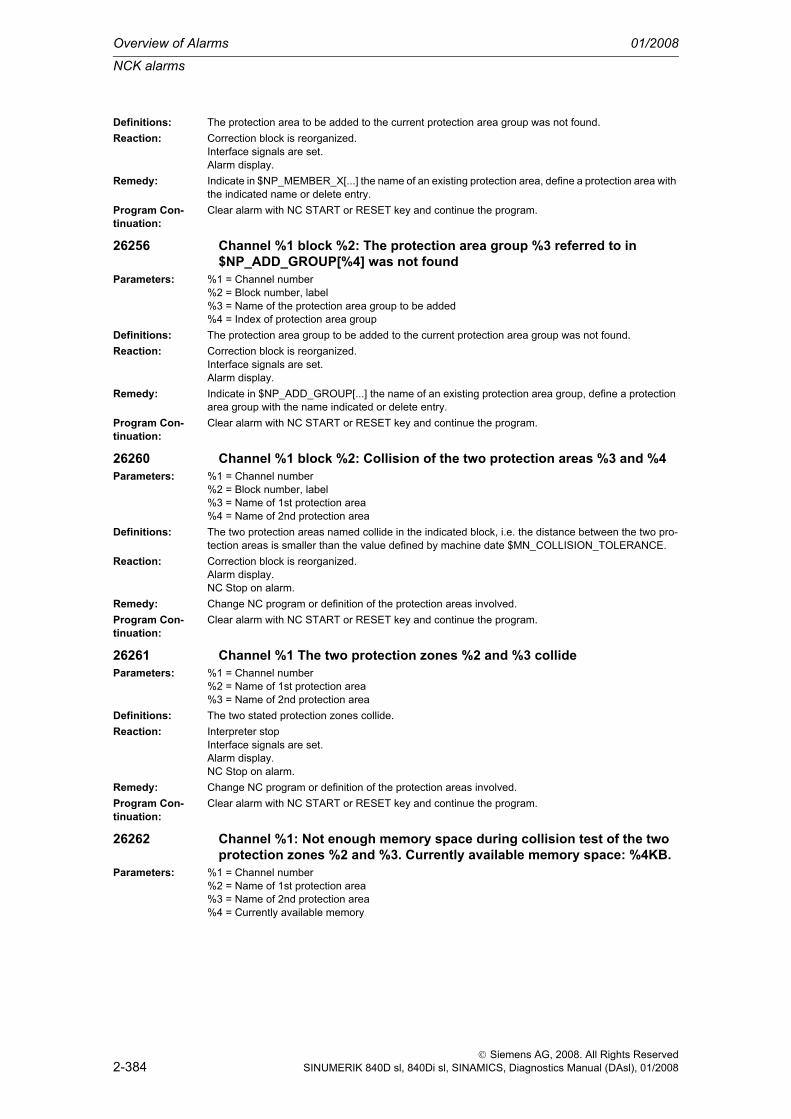
Overview of Alarms 01/2008
NCK alarms
2-384
© Siemens AG, 2008. All Rights ReservedSINUMERIK 840D sl, 840Di sl, SINAMICS, Diagnostics Manual (DAsl), 01/2008
Definitions: The protection area to be added to the current protection area group was not found. Reaction: Correction block is reorganized.
Interface signals are set.Alarm display.
Remedy: Indicate in $NP_MEMBER_X[...] the name of an existing protection area, define a protection area with the indicated name or delete entry.
Program Con-tinuation:
Clear alarm with NC START or RESET key and continue the program.
26256 Channel %1 block %2: The protection area group %3 referred to in $NP_ADD_GROUP[%4] was not found
Parameters: %1 = Channel number%2 = Block number, label%3 = Name of the protection area group to be added%4 = Index of protection area group
Definitions: The protection area group to be added to the current protection area group was not found.Reaction: Correction block is reorganized.
Interface signals are set.Alarm display.
Remedy: Indicate in $NP_ADD_GROUP[...] the name of an existing protection area group, define a protection area group with the name indicated or delete entry.
Program Con-tinuation:
Clear alarm with NC START or RESET key and continue the program.
26260 Channel %1 block %2: Collision of the two protection areas %3 and %4Parameters: %1 = Channel number
%2 = Block number, label%3 = Name of 1st protection area%4 = Name of 2nd protection area
Definitions: The two protection areas named collide in the indicated block, i.e. the distance between the two pro-tection areas is smaller than the value defined by machine date $MN_COLLISION_TOLERANCE.
Reaction: Correction block is reorganized.Alarm display.NC Stop on alarm.
Remedy: Change NC program or definition of the protection areas involved.Program Con-tinuation:
Clear alarm with NC START or RESET key and continue the program.
26261 Channel %1 The two protection zones %2 and %3 collideParameters: %1 = Channel number
%2 = Name of 1st protection area%3 = Name of 2nd protection area
Definitions: The two stated protection zones collide.Reaction: Interpreter stop
Interface signals are set.Alarm display.NC Stop on alarm.
Remedy: Change NC program or definition of the protection areas involved.Program Con-tinuation:
Clear alarm with NC START or RESET key and continue the program.
26262 Channel %1: Not enough memory space during collision test of the two protection zones %2 and %3. Currently available memory space: %4KB.
Parameters: %1 = Channel number%2 = Name of 1st protection area%3 = Name of 2nd protection area%4 = Currently available memory

NCK alarms
01/2008 Overview of Alarms
2-385
© Siemens AG, 2008. All Rights ReservedSINUMERIK 840D sl, 840Di sl, SINAMICS, Diagnostics Manual (DAsl), 01/2008
Definitions: The collision check of two protection zones requires temporary internal memory space, the size of which depends on the number of elements contained in the protection zones, the spacing of the pro-tection zones, and the number of machine axes.The size of the available memory space can be changed in machine data $MN_MM_MAXNUM_3D_COLLISION.
Reaction: Correction block is reorganized.Alarm display.NC Stop on alarm.
Remedy: Change NC program or definition of the protection areas involved.Adjust machine date $MN_MM_MAXNUM_3D_COLLISION.
Program Con-tinuation:
Clear alarm with NC START or RESET key and continue the program.
26263 Channel %1 block %2: Not enough memory space for determining the distance between two protection zones. Currently available memory space: %3KB.
Parameters: %1 = Channel number%2 = Block number, label%3 = Currently available memory
Definitions: The determination of the distance between two protection zones with the function PROTDFCT requires temporary internal memory space, the size of which depends on the number of elements con-tained in the protection zones, and their positions relative to one another.The size of the available memory space can be changed in machine data $MN_MM_MAXNUM_3D_COLLISION.
Reaction: Correction block is reorganized.Alarm display.NC Stop on alarm.
Remedy: Change NC program or definition of the protection areas involved.Adjust machine date $MN_MM_MAXNUM_3D_COLLISION.
Program Con-tinuation:
Clear alarm with NC START or RESET key and continue the program.
26264 Channel %1 block %2: The protection area with the name %3 was not found.
Parameters: %1 = Channel number%2 = Block number%3 = Name of protection area
Definitions: One protection area with the name indicated was not found (e.g. during function call PROTA).Reaction: Correction block is reorganized.
Alarm display.NC Stop on alarm.
Remedy: Indicate the name of an existing protection area or define the protection area with the name indicated.Program Con-tinuation:
Clear alarm with NC START or RESET key and continue the program.
26266 Channel %1 block %2: The protection area with the name %3 was programmed several times.
Parameters: %1 = Channel number%2 = Block number%3 = Name of protection area
Definitions: The name of a protection area was programmed several times (e.g, during the function call PROTA).Reaction: Correction block is reorganized.
Alarm display.NC Stop on alarm.
Remedy: Indicate each required name of a protection area only once.Program Con-tinuation:
Clear alarm with NC START or RESET key and continue the program.
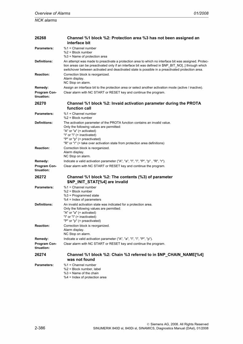
Overview of Alarms 01/2008
NCK alarms
2-386
© Siemens AG, 2008. All Rights ReservedSINUMERIK 840D sl, 840Di sl, SINAMICS, Diagnostics Manual (DAsl), 01/2008
26268 Channel %1 block %2: Protection area %3 has not been assigned an interface bit
Parameters: %1 = Channel number%2 = Block number%3 = Name of protection area
Definitions: An attempt was made to preactivate a protection area to which no interface bit was assigned. Protec-tion areas can be preactivated only if an interface bit was defined in $NP_BIT_NO[..] through which switchover between activated and deactivated state is possible in a preactivated protection area.
Reaction: Correction block is reorganized.Alarm display.NC Stop on alarm.
Remedy: Assign an interface bit to the protection area or select another activation mode (active / inactive).Program Con-tinuation:
Clear alarm with NC START or RESET key and continue the program.
26270 Channel %1 block %2: Invaid activation parameter during the PROTA function call
Parameters: %1 = Channel number%2 = Block number
Definitions: The activation parameter of the PROTA function contains an invalid value.Only the following values are permitted:"A" or "a" (= activated)"I" or "i" (= inactivated)"P" or "p" (= preactivated)"R" or "r" (= take over activation state from protection area definitions)
Reaction: Correction block is reorganized.Alarm display.NC Stop on alarm.
Remedy: Indicate a valid activation parameter ("A", "a", "I", "i", "P", "p" , "R", "r").Program Con-tinuation:
Clear alarm with NC START or RESET key and continue the program.
26272 Channel %1 block %2: The contents (%3) of parameter $NP_INIT_STAT[%4] are invalid
Parameters: %1 = Channel number%2 = Block number%3 = Programmed state%4 = Index of parameters
Definitions: An invalid activation state was indicated for a protection area. Only the following values are permitted:"A" or "a" (= activated)"I" or "i" (= inactivated)"P" or "p" (= preactivated)
Reaction: Correction block is reorganized.Alarm display.NC Stop on alarm.
Remedy: Indicate a valid activation parameter ("A", "a", "I", "i", "P", "p").Program Con-tinuation:
Clear alarm with NC START or RESET key and continue the program.
26274 Channel %1 block %2: Chain %3 referred to in $NP_CHAIN_NAME[%4] was not found
Parameters: %1 = Channel number%2 = Block number, label%3 = Name of the chain%4 = Index of protection area

NCK alarms
01/2008 Overview of Alarms
2-387
© Siemens AG, 2008. All Rights ReservedSINUMERIK 840D sl, 840Di sl, SINAMICS, Diagnostics Manual (DAsl), 01/2008
Definitions: The kinematic chain referred to in the protection area definition ($NP_CHAIN_NAME[...]) was not found.
Reaction: Correction block is reorganized.Interface signals are set.Alarm display.
Remedy: Indicate in $NP_CHAIN_NAME[...] the name of an existing kinematic chain or define a chain with the name indicated.
Program Con-tinuation:
Clear alarm with NC START or RESET key and continue the program.
26276 Channel %1 block %2: Chain element %3 referred to in $NP_CHAIN_ELEM[%4] was not found
Parameters: %1 = Channel number%2 = Block number, label%3 = Name of the chain element%4 = Index of protection area
Definitions: The kinematic chain element referred to in the protection area definition ($NP_CHAIN_ELEM[...]) was not found.
Reaction: Correction block is reorganized.Interface signals are set.Alarm display.
Remedy: Indicate in $NP_CHAIN_ELEM[...] the name of an existing chain element or define a chain element with the name indicated.
Program Con-tinuation:
Clear alarm with NC START or RESET key and continue the program.
26278 Channel %1 block %2: The axis or frame name %3 contained in $NK_AXIS[%4] is unknown
Parameters: %1 = Channel number%2 = Block number, label%3 = Axis or frame name%4 = Index of the chain element
Definitions: An unknown name was entered in the element of a kinematic chain in the component $NK_AXIS[...].The name entered must be either a machine axis identifier or the name of a variable made available by the OEM software.
Reaction: Correction block is reorganized.Interface signals are set.Alarm display.
Remedy: Enter a valid name in $NK_AXIS[...].In a regular case (without OEM software), that is a machine axis identifier.An empty string is also a valid name. That defines a constant chain link.
Program Con-tinuation:
Clear alarm with NC START or RESET key and continue the program.
26280 Channel %1 axis %2 risk of collision %3 %4Parameters: %1 = Channel number
%2 = Axis name, spindle number%3 = 1st protection zone%4 = 2nd protection zone
Definitions: The indicated axis was stopped due to the risk of collision.Reaction: Alarm display.Remedy: In JOG mode: Retract axis from danger zone.
In automatic mode: Determine reason for the risk of collision and eliminate. Possible reasons: wrong NC program, too large handwheel overrides, axis couplings and vice-versa impairing of two channels.
Program Con-tinuation:
Alarm display showing cause of alarm disappears. No further operator action necessary.

Overview of Alarms 01/2008
NCK alarms
2-388
© Siemens AG, 2008. All Rights ReservedSINUMERIK 840D sl, 840Di sl, SINAMICS, Diagnostics Manual (DAsl), 01/2008
26281 Channel %1 axis %2 risk of collision %3 %4Parameters: %1 = Channel number
%2 = Axis name, spindle number%3 = 1st protection zone%4 = 2nd protection zone
Definitions: The stated axis was stopped due to the risk of collision. The programmed path may have been left because it was not possible to stop in time on the path (exceptional situation).
Reaction: Local alarm reaction.NC Start disable in this channel.Interface signals are set.Alarm display.NC Stop on alarm at block end.
Remedy: In JOG mode: Retract axis from danger zone.In automatic mode: Determine reason for the risk of collision and eliminate. Possible reasons: wrong NC program, too large handwheel overrides, axis couplings and vice-versa impairing of two channels.
Program Con-tinuation:
Clear alarm with the RESET key. Restart part programThe stated axis was stopped due to the risk of collision. The programmed path may have been left because it was not possible to stop in time on the path (exceptional situation).
26282 Channel %1 block %2: Invalid definition of the protection zones or the kinematic chains.
Parameters: %1 = Channel number%2 = Block number, label
Definitions: There are no valid definitions of the protection zones and / or the kinematic chains.This alarm only occurs if an error occurred the last time the procedure PROTA was called, and its cause has not been eliminated.
Reaction: Correction block is reorganized.Alarm display.NC Stop on alarm.
Remedy: Protection zones and kinematic chains must be defined without errors.This is achieved by calling the procedure PROTA and closing it without errors.
Program Con-tinuation:
Clear alarm with NC START or RESET key and continue the program.
26284 Channel %1 block %2: The call of the function / procedure %3 is only permissible if the function 'Collision monitoring' is present.
Parameters: %1 = Channel number%2 = Block number, label%3 = Funktionsname
Definitions: The function or procedure stated in the alarm text (e.g. PROTA or PROTD) can only be called if the function "Collision avoidance" is present.
Reaction: Correction block is reorganized.Alarm display.NC Stop on alarm.
Remedy: The function "Collision avoidance" must be activated. For this, the machine data $MN_MM_MAXNUM_3D_PROT_AREAS must contain a value greater than zero.
Program Con-tinuation:
Clear alarm with NC START or RESET key and continue the program.
26286 Channel %1 axis %2 risk of collision preactivated protection zones interface signal(s) %3
Parameters: %1 = Channel number%2 = Axis name, spindle number%3 = Interface signal(s)

NCK alarms
01/2008 Overview of Alarms
2-389
© Siemens AG, 2008. All Rights ReservedSINUMERIK 840D sl, 840Di sl, SINAMICS, Diagnostics Manual (DAsl), 01/2008
Definitions: A collision was detected involving at least one preactivated protection zone.Such a collision can occur if the interface signal assigned to a preactivated protection zone has been activated. That is if a preactivated protection zone has become an active protection zone.Either a preactivated and a (static) active protection zone can be involved in the collision, or two pre-activated protection zones can be involved. The number(s) of the interface signals assigned to the preactivated protection zones involved are output in the alarm text.
Reaction: NC Start disable in this channel.Interface signals are set.Alarm display.Alarm reaction in Automatic mode.NC Stop on alarm.
Remedy: Reset activating interface signals.Redefine protection zones.Retract
Program Con-tinuation:
Clear alarm with NC START or RESET key and continue the program.
26290 Channel %1 block %2: Maximum number of %4 protection zone facets exceeded in CAD file %3
Parameters: %1 = Channel number%2 = Block number, label%3 = File name%4 = Maximum number of protection zone facets
Definitions: The maximum permissible number of protection zone facets has been exceeded.Reaction: Correction block is reorganized.
Interface signals are set.Alarm display.
Remedy: Increase the number of allowed Protection Area Facet elements (MD18895 $MN_MM_MAXNUM_3D_FACETS) or reduce the number of defined facets in the CAD file.
Program Con-tinuation:
Clear alarm with NC START or RESET key and continue the program.
26292 Channel %1 block %2: Maximum number of %4 input points exceeded in CAD file %3
Parameters: %1 = Channel number%2 = Block number, label%3 = File name%4 = Maximum number of input points
Definitions: The maximum permissible number of input points has been exceeded.Reaction: Correction block is reorganized.
Interface signals are set.Alarm display.
Remedy: Increase the number of allowed Protection Area Facet elements (MD18895 $MN_MM_MAXNUM_3D_FACETS) or reduce the number of defined facets in the CAD file.
Program Con-tinuation:
Clear alarm with NC START or RESET key and continue the program.
26294 Channel %1 block %2: CAD file %3 is not a valid VRML fileParameters: %1 = Channel number
%2 = Block number, label%3 = File name
Definitions: The CAD file does not contain valid VRML data.Reaction: Correction block is reorganized.
Interface signals are set.Alarm display.
Remedy: Check the format of the input CAD/VRML data.Program Con-tinuation:
Clear alarm with NC START or RESET key and continue the program.

Overview of Alarms 01/2008
NCK alarms
2-390
© Siemens AG, 2008. All Rights ReservedSINUMERIK 840D sl, 840Di sl, SINAMICS, Diagnostics Manual (DAsl), 01/2008
26296 Channel %1 block %2: CAD file %3 is not a valid STL fileParameters: %1 = Channel number
%2 = Block number, label%3 = File name
Definitions: The CAD file does not contain any valid STL dataReaction: Correction block is reorganized.
Interface signals are set.Alarm display.
Remedy: Check the format of the CAD/STL file.Program Con-tinuation:
Clear alarm with NC START or RESET key and continue the program.
27000 Axis %1 is not safely referencedParameters: %1 = Axis numberDefinitions: There are two reasons for this alarm:
- the machine position has not yet been acknowledged by the user,- the machine position has not yet been verified through follow-up referencing.Even if the axis is already referenced, there is no confirmation that referencing has supplied the cor-rect result. For example, wrong results can occur if the axis was moved after the control was switched off, with the result that the standstill position saved prior to switching off is no longer correct. To make sure that this does not happen, the user must acknowledge the displayed actual position after the first referencing process.When the user enable has first been set, follow-up referencing must be carried out each time the con-trol is booted (with absolute encoders, this follow-up referencing is executed automatically). This pro-cedure is carried out to verify the standstill position saved prior to switching off of the control.Via the MD $MN_SAFE_ALARM_SUPPRESS_LEVEL (MD>=3), the alarm display can be set in such a way that the group alarm 27100 is displayed for all SI axes.
Reaction: Alarm display.SGA "Axis safely referenced" is not set. SE will be switched off, if the actual safety position has not yet been confirmed by a user agreement. If the user agreement has been set, SE will remain active. The safe cams are calculated and output. However, their significance is limited as referencing has not been confirmed.
Remedy: Traverse the axis to a known position, change to operating mode "Referencing" and press softkey "Agreement". Check the positions displayed in the agreement screen on the machine. If they match the expected or known position, confirm this by using the toggle key. If the user agreement has already been set, reference the axis again.The user agreement can be changed only via keyswitch position 3 or after password entry.WARNING:If the axis is not referenced safely and the user agreement is not available, the following will apply:- the safe cams are not yet safe- the safe end positions are not yet active.
Program Con-tinuation:
Alarm display showing cause of alarm disappears. No further operator action necessary.
27001 Axis %1 error in a monitoring channel, code %2, values: NCK %3, drive %4
Parameters: %1 = Axis number%2 = Additional info cross-comparison index%3 = NCK comparison value extension%4 = Additional info comparison value drive
Definitions: The mutual comparison of the two monitoring channels has found a difference between input data or results of the monitoring operations. One of the monitors no longer functions reliably, i.e. safe opera-tion is no longer possible.The following error codes are possible on the NCK side:- 0 No error found in this channel; following alarm to drive alarm 300911.- 1 Result list 1: difference in SBH, SG, SBR or SE result, e.g. due to different activation of the moni-toring channels. For further information see drive MDs 1391, 1392.

NCK alarms
01/2008 Overview of Alarms
2-391
© Siemens AG, 2008. All Rights ReservedSINUMERIK 840D sl, 840Di sl, SINAMICS, Diagnostics Manual (DAsl), 01/2008
- 2 Result list 2: difference in SN, n_x result. For further information see drive MDs 1393, 1394.- 3 Actual value difference greater than setting in $MA_SAFE_POS_TOL.- 4 Not assigned.- 5 Function enables $MA_SAFE_FUNCTION_ENABLE.- 6 Velocity limit $MA_SAFE_VELO_LIMIT[0].- 7 Velocity limit $MA_SAFE_VELO_LIMIT[1].- 8 Velocity limit $MA_SAFE_VELO_LIMIT[2].- 9 Velocity limit $MA_SAFE_VELO_LIMIT[3].- 10 Tolerance for safe operational stop $MA_SAFE_STANDSTILL_TOL.- 11 Safe position limit $MA_SAFE_POS_LIMIT_PLUS[0].- 12 Safe position limit $MA_SAFE_POS_LIMIT_MINUS[0].- 13 Safe position limit $MA_SAFE_POS_LIMIT_PLUS[1].- 14 Safe position limit $MA_SAFE_POS_LIMIT_MINUS[1].- 15 Cam position $MA_SAFE_CAM_POS_PLUS[0] + $MA_SAFE_CAM_TOL.- 16 Cam position $MA_SAFE_CAM_POS_PLUS[0].- 17 Cam position $MA_SAFE_CAM_POS_MINUS[0] + $MA_SAFE_CAM_TOL.- 18 Cam position $MA_SAFE_CAM_POS_MINUS[0].- 19 Cam position $MA_SAFE_CAM_POS_PLUS[1] + $MA_SAFE_CAM_TOL.- 20 Cam position $MA_SAFE_CAM_POS_PLUS[1].- 21 Cam position $MA_SAFE_CAM_POS_MINUS[1] + $MA_SAFE_CAM_TOL.- 22 Cam position $MA_SAFE_CAM_POS_MINUS[1].- 23 Cam position $MA_SAFE_CAM_POS_PLUS[2] + $MA_SAFE_CAM_TOL.- 24 Cam position $MA_SAFE_CAM_POS_PLUS[2].- 25 Cam position $MA_SAFE_CAM_POS_MINUS[2] + $MA_SAFE_CAM_TOL.- 26 Cam position $MA_SAFE_CAM_POS_MINUS[2].- 27 Cam position $MA_SAFE_CAM_POS_PLUS[3] + $MA_SAFE_CAM_TOL.- 28 Cam position $MA_SAFE_CAM_POS_PLUS[3].- 29 Cam position $MA_SAFE_CAM_POS_MINUS[3] + $MA_SAFE_CAM_TOL.- 30 Cam position $MA_SAFE_CAM_POS_MINUS[3].- 31 Actual position tolerance $MA_SAFE_POS_TOL. $MA_SAFE_SLIP_VELO_TOL for active actual value synchronization (slippage)- 32 Ref. position tolerance $MA_SAFE_REFP_POS_TOL.- 33 Delay SG[x] -> SG[y] $MA_SAFE_VELO_SWITCH_DELAY.- 34 Delay cross-comparison $MA_SAFE_MODE_SWITCH_TIME.- 35 Delay pulse disable Stop B $MA_SAFE_PULSE_DISABLE_DELAY.- 36 Delay pulse disable test stop $MA_SAFE_PULSE_DIS_CHECK_TIME- 37 Delay Stop C -> SBH $MA_SAFE_STOP_SWITCH_TIME_C.- 38 Delay Stop D -> SBH $MA_SAFE_STOP_SWITCH_TIME_D.- 39 Delay Stop E -> SBH $MA_SAFE_STOP_SWITCH_TIME_E.- 40 Stop reaction on SG exceeded $MA_SAFE_VELO_STOP_MODE.- 41 Stop reaction on SE exceeded $MA_SAFE_POS_STOP_MODE.- 42 Standstill speed $MA_SAFE_STANDSTILL_VELO_TOL.- 43 Memory test, stop reaction.- 44 Actual position + SG[0] $MA_SAFE_VELO_LIMIT[0].- 45 Actual position - SG[0] $MA_SAFE_VELO_LIMIT[0].- 46 Actual position + SG[1] $MA_SAFE_VELO_LIMIT[1].- 47 Actual position - SG[1] $MA_SAFE_VELO_LIMIT[1].- 48 Actual position + SG[2] $MA_SAFE_VELO_LIMIT[2].- 49 Actual position - SG[2] $MA_SAFE_VELO_LIMIT[2].- 50 Actual position + SG[3] $MA_SAFE_VELO_LIMIT[3].- 51 Actual position - SG[3] $MA_SAFE_VELO_LIMIT[3].- 52 Standstill position + tolerance $MA_SAFE_STANDSTILL_TOL.- 53 Standstill position - tolerance $MA_SAFE_STANDSTILL_TOL.- 54 Actual postion + n_x + tolerance $MA_SAFE_VELO_X + $MA_SAFE_POS_TOL.- 55 Actual postion + n_x $MA_SAFE_VELO_X.- 56 Actual postion - n_x $MA_SAFE_VELO_X.- 57 Actual postion - n_x - tolerance $MA_SAFE_VELO_X - $MA_SAFE_POS_TOL- 58 Active external standstill request.- 59 SG override factor 1 $MA_SAFE_VELO_OVR_FACTOR[0].- 60 SG override factor 2 $MA_SAFE_VELO_OVR_FACTOR[1].- 61 SG override factor 3 $MA_SAFE_VELO_OVR_FACTOR[2].- 62 SG override factor 4 $MA_SAFE_VELO_OVR_FACTOR[3].- 63 SG override factor 5 $MA_SAFE_VELO_OVR_FACTOR[4].- 64 SG override factor 6 $MA_SAFE_VELO_OVR_FACTOR[5].

Overview of Alarms 01/2008
NCK alarms
2-392
© Siemens AG, 2008. All Rights ReservedSINUMERIK 840D sl, 840Di sl, SINAMICS, Diagnostics Manual (DAsl), 01/2008
- 65 SG override factor 7 $MA_SAFE_VELO_OVR_FACTOR[6].- 66 SG override factor 8 $MA_SAFE_VELO_OVR_FACTOR[7].- 67 SG override factor 9 $MA_SAFE_VELO_OVR_FACTOR[8].- 68 SG override factor 10 $MA_SAFE_VELO_OVR_FACTOR[9].- 69 SG override factor 11 $MA_SAFE_VELO_OVR_FACTOR[10].- 70 SG override factor 12 $MA_SAFE_VELO_OVR_FACTOR[11].- 71 SG override factor 13 $MA_SAFE_VELO_OVR_FACTOR[12].- 72 SG override factor 14 $MA_SAFE_VELO_OVR_FACTOR[13].- 73 SG override factor 15 $MA_SAFE_VELO_OVR_FACTOR[14].- 74 SG override factor 16 $MA_SAFE_VELO_OVR_FACTOR[15].- 75 Velocity limit n_x $MA_SAFE_VELO_X.- 76 Stop reaction SG1 $MA_SAFE_VELO_STOP_REACTION[0].- 77 Stop reaction SG2 $MA_SAFE_VELO_STOP_REACTION[1].- 78 Stop reaction SG3 $MA_SAFE_VELO_STOP_REACTION[2].- 79 Stop reaction SG4 $MA_SAFE_VELO_STOP_REACTION[3].- 80 Modulo value for safe cam $MA_SAFE_MODULO_RANGE.- 81 Actual velocity tolerance $MA_SAFE_STOP_VELO_TOL.- 82 SG override factor SGE 0...15 = active SGE position. -1 = SG override inactive (neither SG2 nor SG4 active, or function is not selected in $MA_SAFE_FUNCTION_ENABLE).- 83 Acceptance test time different $MA_SAFE_ACCEPTANCE_TST_TIMEOUT.- 84 Delay time Stop F -> Stop B $MA_SAFE_STOP_SWITCH_TIME_F.- 85 Delay time pulse disable bus failure $MN_SAFE_PULSE_DIS_TIME_BUSFAIL.- 86 Single encoder system $MA_SAFE_SINGLE_ENC.- 87 Encoder assignment $MA_SAFE_ENC_INPUT_NR.- 88 Cam enable $MA_SAFE_CAM_ENABLE.- 89 Encoder limit frequency $MA_SAFE_ENC_FREQ_LIMIT.- 90 Cam SGA outside $MA_SAFE_CAM_TOL different- 91 Cam position $MA_SAFE_CAM_POS_PLUS[4] + $MA_SAFE_CAM_TOL.- 92 Cam position $MA_SAFE_CAM_POS_PLUS[4].- 93 Cam position $MA_SAFE_CAM_POS_MINUS[4] + $MA_SAFE_CAM_TOL.- 94 Cam position $MA_SAFE_CAM_POS_MINUS[4].- 95 Cam position $MA_SAFE_CAM_POS_PLUS[5] + $MA_SAFE_CAM_TOL.- 96 Cam position $MA_SAFE_CAM_POS_PLUS[5].- 97 Cam position $MA_SAFE_CAM_POS_MINUS[5] + $MA_SAFE_CAM_TOL.- 98 Cam position $MA_SAFE_CAM_POS_MINUS[5].- 99 Cam position $MA_SAFE_CAM_POS_PLUS[6] + $MA_SAFE_CAM_TOL.- 100 Cam position $MA_SAFE_CAM_POS_PLUS[6].- 101 Cam position $MA_SAFE_CAM_POS_MINUS[6] + $MA_SAFE_CAM_TOL.- 102 Cam position $MA_SAFE_CAM_POS_MINUS[6].- 103 Cam position $MA_SAFE_CAM_POS_PLUS[7] + $MA_SAFE_CAM_TOL.- 104 Cam position $MA_SAFE_CAM_POS_PLUS[7].- 105 Cam position $MA_SAFE_CAM_POS_MINUS[7] + $MA_SAFE_CAM_TOL.- 106 Cam position $MA_SAFE_CAM_POS_MINUS[7].- 107 Cam position $MA_SAFE_CAM_POS_PLUS[8] + $MA_SAFE_CAM_TOL.- 108 Cam position $MA_SAFE_CAM_POS_PLUS[8].- 109 Cam position $MA_SAFE_CAM_POS_MINUS[8] + $MA_SAFE_CAM_TOL.- 110 Cam position $MA_SAFE_CAM_POS_MINUS[8].- 111 Cam position $MA_SAFE_CAM_POS_PLUS[9] + $MA_SAFE_CAM_TOL.- 112 Cam position $MA_SAFE_CAM_POS_PLUS[9].- 113 Cam position $MA_SAFE_CAM_POS_MINUS[9] + $MA_SAFE_CAM_TOL.- 114 Cam position $MA_SAFE_CAM_POS_MINUS[9].- 115 Cam position $MA_SAFE_CAM_POS_PLUS[10] + $MA_SAFE_CAM_TOL.- 116 Cam position $MA_SAFE_CAM_POS_PLUS[10].- 117 Cam position $MA_SAFE_CAM_POS_MINUS[10] + $MA_SAFE_CAM_TOL.- 118 Cam position $MA_SAFE_CAM_POS_MINUS[10].- 119 Cam position $MA_SAFE_CAM_POS_PLUS[11] + $MA_SAFE_CAM_TOL.- 120 Cam position $MA_SAFE_CAM_POS_PLUS[11].- 121 Cam position $MA_SAFE_CAM_POS_MINUS[11] + $MA_SAFE_CAM_TOL.- 122 Cam position $MA_SAFE_CAM_POS_MINUS[11].- 123 Cam position $MA_SAFE_CAM_POS_PLUS[12] + $MA_SAFE_CAM_TOL.- 124 Cam position $MA_SAFE_CAM_POS_PLUS[12].- 125 Cam position $MA_SAFE_CAM_POS_MINUS[12] + $MA_SAFE_CAM_TOL.- 126 Cam position $MA_SAFE_CAM_POS_MINUS[12].- 127 Cam position $MA_SAFE_CAM_POS_PLUS[13] + $MA_SAFE_CAM_TOL.

NCK alarms
01/2008 Overview of Alarms
2-393
© Siemens AG, 2008. All Rights ReservedSINUMERIK 840D sl, 840Di sl, SINAMICS, Diagnostics Manual (DAsl), 01/2008
- 128 Cam position $MA_SAFE_CAM_POS_PLUS[13].- 129 Cam position $MA_SAFE_CAM_POS_MINUS[13] + $MA_SAFE_CAM_TOL.- 130 Cam position $MA_SAFE_CAM_POS_MINUS[13].- 131 Cam position $MA_SAFE_CAM_POS_PLUS[14] + $MA_SAFE_CAM_TOL.- 132 Cam position $MA_SAFE_CAM_POS_PLUS[14].- 133 Cam position $MA_SAFE_CAM_POS_MINUS[14] + $MA_SAFE_CAM_TOL.- 134 Cam position $MA_SAFE_CAM_POS_MINUS[14].- 135 Cam position $MA_SAFE_CAM_POS_PLUS[15] + $MA_SAFE_CAM_TOL.- 136 Cam position $MA_SAFE_CAM_POS_PLUS[15].- 137 Cam position $MA_SAFE_CAM_POS_MINUS[15] + $MA_SAFE_CAM_TOL.- 138 Cam position $MA_SAFE_CAM_POS_MINUS[15].- 139 Cam position $MA_SAFE_CAM_POS_PLUS[16] + $MA_SAFE_CAM_TOL.- 140 Cam position $MA_SAFE_CAM_POS_PLUS[16].- 141 Cam position $MA_SAFE_CAM_POS_MINUS[16] + $MA_SAFE_CAM_TOL.- 142 Cam position $MA_SAFE_CAM_POS_MINUS[16].- 143 Cam position $MA_SAFE_CAM_POS_PLUS[17] + $MA_SAFE_CAM_TOL.- 144 Cam position $MA_SAFE_CAM_POS_PLUS[17].- 145 Cam position $MA_SAFE_CAM_POS_MINUS[17] + $MA_SAFE_CAM_TOL.- 146 Cam position $MA_SAFE_CAM_POS_MINUS[17].- 147 Cam position $MA_SAFE_CAM_POS_PLUS[18] + $MA_SAFE_CAM_TOL.- 148 Cam position $MA_SAFE_CAM_POS_PLUS[18].- 149 Cam position $MA_SAFE_CAM_POS_MINUS[18] + $MA_SAFE_CAM_TOL.- 150 Cam position $MA_SAFE_CAM_POS_MINUS[18].- 151 Cam position $MA_SAFE_CAM_POS_PLUS[19] + $MA_SAFE_CAM_TOL.- 152 Cam position $MA_SAFE_CAM_POS_PLUS[19].- 153 Cam position $MA_SAFE_CAM_POS_MINUS[19] + $MA_SAFE_CAM_TOL.- 154 Cam position $MA_SAFE_CAM_POS_MINUS[19].- 155 Cam position $MA_SAFE_CAM_POS_PLUS[20] + $MA_SAFE_CAM_TOL.- 156 Cam position $MA_SAFE_CAM_POS_PLUS[20].- 157 Cam position $MA_SAFE_CAM_POS_MINUS[20] + $MA_SAFE_CAM_TOL.- 158 Cam position $MA_SAFE_CAM_POS_MINUS[20].- 159 Cam position $MA_SAFE_CAM_POS_PLUS[21] + $MA_SAFE_CAM_TOL.- 160 Cam position $MA_SAFE_CAM_POS_PLUS[21].- 161 Cam position $MA_SAFE_CAM_POS_MINUS[21] + $MA_SAFE_CAM_TOL.- 162 Cam position $MA_SAFE_CAM_POS_MINUS[21].- 163 Cam position $MA_SAFE_CAM_POS_PLUS[22] + $MA_SAFE_CAM_TOL.- 164 Cam position $MA_SAFE_CAM_POS_PLUS[22].- 165 Cam position $MA_SAFE_CAM_POS_MINUS[22] + $MA_SAFE_CAM_TOL.- 166 Cam position $MA_SAFE_CAM_POS_MINUS[22].- 167 Cam position $MA_SAFE_CAM_POS_PLUS[23] + $MA_SAFE_CAM_TOL.- 168 Cam position $MA_SAFE_CAM_POS_PLUS[23].- 169 Cam position $MA_SAFE_CAM_POS_MINUS[23] + $MA_SAFE_CAM_TOL.- 170 Cam position $MA_SAFE_CAM_POS_MINUS[23].- 171 Cam position $MA_SAFE_CAM_POS_PLUS[24] + $MA_SAFE_CAM_TOL.- 172 Cam position $MA_SAFE_CAM_POS_PLUS[24].- 173 Cam position $MA_SAFE_CAM_POS_MINUS[24] + $MA_SAFE_CAM_TOL.- 174 Cam position $MA_SAFE_CAM_POS_MINUS[24].- 175 Cam position $MA_SAFE_CAM_POS_PLUS[25] + $MA_SAFE_CAM_TOL.- 176 Cam position $MA_SAFE_CAM_POS_PLUS[25].- 177 Cam position $MA_SAFE_CAM_POS_MINUS[25] + $MA_SAFE_CAM_TOL.- 178 Cam position $MA_SAFE_CAM_POS_MINUS[25].- 179 Cam position $MA_SAFE_CAM_POS_PLUS[26] + $MA_SAFE_CAM_TOL.- 180 Cam position $MA_SAFE_CAM_POS_PLUS[26].- 181 Cam position $MA_SAFE_CAM_POS_MINUS[26] + $MA_SAFE_CAM_TOL.- 182 Cam position $MA_SAFE_CAM_POS_MINUS[26].- 183 Cam position $MA_SAFE_CAM_POS_PLUS[27] + $MA_SAFE_CAM_TOL.- 184 Cam position $MA_SAFE_CAM_POS_PLUS[27].- 185 Cam position $MA_SAFE_CAM_POS_MINUS[27] + $MA_SAFE_CAM_TOL.- 186 Cam position $MA_SAFE_CAM_POS_MINUS[27].- 187 Cam position $MA_SAFE_CAM_POS_PLUS[28] + $MA_SAFE_CAM_TOL.- 188 Cam position $MA_SAFE_CAM_POS_PLUS[28].- 189 Cam position $MA_SAFE_CAM_POS_MINUS[28] + $MA_SAFE_CAM_TOL.- 190 Cam position $MA_SAFE_CAM_POS_MINUS[28].- 191 Cam position $MA_SAFE_CAM_POS_PLUS[29] + $MA_SAFE_CAM_TOL.

Overview of Alarms 01/2008
NCK alarms
2-394
© Siemens AG, 2008. All Rights ReservedSINUMERIK 840D sl, 840Di sl, SINAMICS, Diagnostics Manual (DAsl), 01/2008
- 192 Cam position $MA_SAFE_CAM_POS_PLUS[29].- 193 Cam position $MA_SAFE_CAM_POS_MINUS[29] + $MA_SAFE_CAM_TOL.- 194 Cam position $MA_SAFE_CAM_POS_MINUS[29].- 195 Cam track assignment SN1 $MA_SAFE_CAM_TRACK_ASSIGN[0].- 196 Cam track assignment SN2 $MA_SAFE_CAM_TRACK_ASSIGN[1].- 197 Cam track assignment SN3 $MA_SAFE_CAM_TRACK_ASSIGN[2].- 198 Cam track assignment SN4 $MA_SAFE_CAM_TRACK_ASSIGN[3].- 199 Cam track assignment SN5 $MA_SAFE_CAM_TRACK_ASSIGN[4].- 200 Cam track assignment SN6 $MA_SAFE_CAM_TRACK_ASSIGN[5].- 201 Cam track assignment SN7 $MA_SAFE_CAM_TRACK_ASSIGN[6].- 202 Cam track assignment SN8 $MA_SAFE_CAM_TRACK_ASSIGN[7].- 203 Cam track assignment SN9 $MA_SAFE_CAM_TRACK_ASSIGN[8].- 204 Cam track assignment SN10 $MA_SAFE_CAM_TRACK_ASSIGN[9].- 205 Cam track assignment SN11 $MA_SAFE_CAM_TRACK_ASSIGN[10].- 206 Cam track assignment SN12 $MA_SAFE_CAM_TRACK_ASSIGN[11].- 207 Cam track assignment SN13 $MA_SAFE_CAM_TRACK_ASSIGN[12].- 208 Cam track assignment SN14 $MA_SAFE_CAM_TRACK_ASSIGN[13].- 209 Cam track assignment SN15 $MA_SAFE_CAM_TRACK_ASSIGN[14].- 210 Cam track assignment SN16 $MA_SAFE_CAM_TRACK_ASSIGN[15].- 211 Cam track assignment SN17 $MA_SAFE_CAM_TRACK_ASSIGN[16].- 212 Cam track assignment SN18 $MA_SAFE_CAM_TRACK_ASSIGN[17].- 213 Cam track assignment SN19 $MA_SAFE_CAM_TRACK_ASSIGN[18].- 214 Cam track assignment SN20 $MA_SAFE_CAM_TRACK_ASSIGN[19].- 215 Cam track assignment SN21 $MA_SAFE_CAM_TRACK_ASSIGN[20].- 216 Cam track assignment SN22 $MA_SAFE_CAM_TRACK_ASSIGN[21].- 217 Cam track assignment SN23 $MA_SAFE_CAM_TRACK_ASSIGN[22].- 218 Cam track assignment SN24 $MA_SAFE_CAM_TRACK_ASSIGN[23].- 219 Cam track assignment SN25 $MA_SAFE_CAM_TRACK_ASSIGN[24].- 220 Cam track assignment SN26 $MA_SAFE_CAM_TRACK_ASSIGN[25].- 221 Cam track assignment SN27 $MA_SAFE_CAM_TRACK_ASSIGN[26].- 222 Cam track assignment SN28 $MA_SAFE_CAM_TRACK_ASSIGN[27].- 223 Cam track assignment SN29 $MA_SAFE_CAM_TRACK_ASSIGN[28].- 224 Cam track assignment SN30 $MA_SAFE_CAM_TRACK_ASSIGN[29].- 225 Result list 3: Differences in the results for "Safe cam track" for cams SN1..6.- 226 Result list 4: Differences in the results for "Safe cam track" for cams SN7..12.- 227 Result list 5: Differences in the results for "Safe cam track" for cams SN13..18.- 228 Result list 6: Differences in the results for "Safe cam track" for cams SN19..24.- 229 Result list 7: Differences in the results for "Safe cam track" for cams SN25.. 30.- 1000 Control timer expired: If one channel informs another of an SGE change, this control timer is used to check whether the update timer in the other channel has expired.- 1001 (only assigned on drive, see alarm 300911)- 1002 User confirmation inconsistent: Data for user confirmation different in both monitoring channels after 2 seconds.%3 = state of the NCK user acknowledgement.%4 = state of the 611D user acknowledgement.- 1003 Reference tolerance $MA_SAFE_REFP_POS_TOL exceeded.- 1004 Plausibility error in user confirmation.- 1005 Pulses already disabled on test stop selection.- 1006 (only assigned on drive, see alarm 300911).- 1007 (only assigned on drive, see alarm 300911).- 1008 (only assigned on drive, see alarm 300911).- 1009 Pulses not disabled after $MA_SAFE_PULSE_DIS_CHECK_TIME test stop time.- 1010 Pulses not disabled during test of the external pulse suppression after $MA_SAFE_PULSE_DIS_CHECK_TIME test stop time.- 1011 NCK/drive acceptance test states are different.- 1013 NCK user acknowledgement from PLC SRAM and NCK user acknowledgement from the NCK machine data are different.- 1014 NCK axis number from PLC SRAM and NCK axis number from the ramp up are different.- 1020 Communication disrupted between NCK monitoring channel and drive monitoring channel.- 1024 NCK standstill position from PLC SRAM and NCK standstill position from the NCK machine data are different.- 1025 Plausibility error in park selection: Encoder reports parking without user request.- 1026 Plausibility error in cam synchronisation between NCK and PLC ("Safe cam track" function).

NCK alarms
01/2008 Overview of Alarms
2-395
© Siemens AG, 2008. All Rights ReservedSINUMERIK 840D sl, 840Di sl, SINAMICS, Diagnostics Manual (DAsl), 01/2008
Reaction: NC Start disable in this channel.Alarm display.If safe monitoring was active, STOP B was also triggered automatically. In this case, a power OFF/ON of the control will be required.
Remedy: Find the difference between the monitoring channels. Error code %2 shows the cause of the alarm.It is possible that safety-relevant machine data are no longer the same (reload if required) orthat the safety-relevant inputs do not have the same level (check).If an error like that cannot be found, an error in the CPU may have occurred such as a memory cell that has "fallen over". This error may be temporary (remove with power ON) or permanent (replace hardware, if it is displayed again after power ON).Error codes for STOP F for 840D/SIMODRIVE 611D:0: No error in this channel. Look for the cause in the other channel.1: Results list 1. Unequal control of the functions via the SGEs; analyze precise error coding in SIMO-DRIVE 611D MD 1391 and 1392.2: Results list 2. Check cam tolerance, analyze precise error coding in the SIMODRIVE 611D MDs 1393 and 1394.3: Actual position. Incorrect encoder evaluation (check MDs). Differently stored standstill position.4: No cross-comparison. 5: Function enables. Enter equal MDs.6: Limit value for SG1. Enter equal MDs.7: Limit value for SG2. Enter equal MDs.8: Limit value for SG3. Enter equal MDs.9: Limit value for SG4. Enter equal MDs.10: Standstill tolerance. Enter equal MDs.11: Upper limit value SE1. Enter equal MDs.12: Lower limit value SE1. Enter equal MDs.13: Upper limit value SE2. Enter equal MDs.14: Lower limit value SE2. Enter equal MDs.15: Safe cam 1+ (+tolerance). Enter equal MDs.16: Safe cam 1+. Enter equal MDs.17: Safe cam 1- (+tolerance). Enter equal MDs.18: Safe cam 1-. Enter equal MDs.19: Safe cam 2+ (+tolerance). Enter equal MDs.20: Safe cam 2+. Enter equal MDs.21: Safe cam 2- (+tolerance). Enter equal MDs.22: Safe cam 2-. Enter equal MDs.23: Safe cam 3+ (+tolerance). Enter equal MDs.24: Safe cam 3+. Enter equal MDs.25: Safe cam 3- (+tolerance). Enter equal MDs.26: Safe cam 3-. Enter equal MDs.27: Safe cam 4+ (+tolerance). Enter equal MDs.28: Safe cam 4+. Enter equal MDs.29: Safe cam 4- (+tolerance). Enter equal MDs.30: Safe cam 4-. Enter equal MDs.31: Position tolerance. Enter equal MDs.32: Reference position tolerance. Enter equal MDs.

Overview of Alarms 01/2008
NCK alarms
2-396
© Siemens AG, 2008. All Rights ReservedSINUMERIK 840D sl, 840Di sl, SINAMICS, Diagnostics Manual (DAsl), 01/2008
33: Time velocity changeover. Enter equal MDs.34: Tolerance time SGE changeover. Enter equal MDs.35: Delay time pulse deletion. Enter equal MDs.36: Time for check of pulse suppression. Enter equal MDs.37: Transition time STOP C to SBH. Enter equal MDs.38: Transition time STOP D to SBH. Enter equal MDs.39: Transition time STOP E to SBH. Enter equal MDs.40: Stop reaction to SG. Enter equal MDs.41: Stop reaction to SE. Enter equal MDs.42: Creep speed pulse deletion. Enter equal MDs.43: Memory test stop reaction.44: Actual position value + limit value SG1. 45: Actual position value - limit value SG1. 46: Actual position value + limit value SG2. 47: Actual position value - limit value SG2.48: Actual position value + limit value SG3. 49: Actual position value - limit value SG3. 50: Actual position value + limit value SG4. 51: Actual position value - limit value SG4. 52: Standstill position + tolerance. 53: Standstill position - tolerance. 54: Actual position value "+ nx" + tolerance. 55: Actual position value "+ nx". 56: Actual position value "- nx". 57: Actual position value "- nx" + tolerance. 58: Current stop request. 59: SG override factor 1. Enter equal MDs.60: SG override factor 2. Enter equal MDs.61: SG override factor 3. Enter equal MDs.62: SG override factor 4. Enter equal MDs.63: SG override factor 5. Enter equal MDs.64: SG override factor 6. Enter equal MDs.65: SG override factor 7. Enter equal MDs.66: SG override factor 8. Enter equal MDs.67: SG override factor 9. Enter equal MDs.68: SG override factor 10. Enter equal MDs.69: SG override factor 11. Enter equal MDs.70: SG override factor 12. Enter equal MDs.71: SG override factor 13. Enter equal MDs.72: SG override factor 14. Enter equal MDs.73: SG override factor 15. Enter equal MDs.74: SG override factor 16. Enter equal MDs.75: Velocity limit "nx". Enter equal MDs.76: Stop reaction with SG1. Enter equal MDs.77: Stop reaction with SG2. Enter equal MDs.78: Stop reaction with SG3. Enter equal MDs.79: Stop reaction with SG4. Enter equal MDs.80: Modulo value for safe cams. Enter equal MDs.81: Velocity tolerance for safe braking ramp. Enter equal MDs.82: SG correction factor SGEs. Actuate equal SGEs.83: Acceptance test duration. Enter equal MDs.84: Stop F -> Stop B delay time. Enter equal MDs.85: Bus failure pulse suppression delay time. Enter equal MDs.89: Encoder limit frequency. Enter equal MDs.90: Check cam positions, $MA_SAFE_CAM_TOL91: Safe cam 5+ (+ tolerance). Enter equal MDs.92: Safe cam 5+. Enter equal MDs.93: Safe cam 5- (+ tolerance). Enter equal MDs.94: Safe cam 5-. Enter equal MDs.95: Safe cam 6+ (+ tolerance). Enter equal MDs.96: Safe cam 6+. Enter equal MDs.97: Safe cam 6- (+ tolerance). Enter equal MDs.98: Safe cam 6-. Enter equal MDs.99: Safe cam 7+ (+ tolerance). Enter equal MDs.

NCK alarms
01/2008 Overview of Alarms
2-397
© Siemens AG, 2008. All Rights ReservedSINUMERIK 840D sl, 840Di sl, SINAMICS, Diagnostics Manual (DAsl), 01/2008
100: Safe cam 7+. Enter equal MDs.101: Safe cam 7- (+ tolerance). Enter equal MDs.102: Safe cam 7-. Enter equal MDs.103: Safe cam 8+ (+ tolerance). Enter equal MDs.104: Safe cam 8+. Enter equal MDs.105: Safe cam 8- (+ tolerance). Enter equal MDs.106: Safe cam 8-. Enter equal MDs.107: Safe cam 9+ (+ tolerance). Enter equal MDs.108: Safe cam 9+. Enter equal MDs.109: Safe cam 9- (+ tolerance). Enter equal MDs.110: Safe cam 9-. Enter equal MDs.111: Safe cam 10+ (+ tolerance). Enter equal MDs.112: Safe cam 10+. Enter equal MDs.113: Safe cam 10- (+ tolerance). Enter equal MDs.114: Safe cam 10-. Enter equal MDs.115: Safe cam 11+ (+ tolerance). Enter equal MDs.116: Safe cam 11+. Enter equal MDs.117: Safe cam 11- (+ tolerance). Enter equal MDs.118: Safe cam 11-. Enter equal MDs.119: Safe cam 12+ (+ tolerance). Enter equal MDs.120: Safe cam 12+. Enter equal MDs.121: Safe cam 12- (+ tolerance). Enter equal MDs.122: Safe cam 12-. Enter equal MDs.123: Safe cam 13+ (+ tolerance). Enter equal MDs.124: Safe cam 13+. Enter equal MDs.125: Safe cam 13- (+ tolerance). Enter equal MDs.126: Safe cam 13-. Enter equal MDs.127: Safe cam 14+ (+ tolerance). Enter equal MDs.128: Safe cam 14+. Enter equal MDs.129: Safe cam 14- (+ tolerance). Enter equal MDs.130: Safe cam 14-. Enter equal MDs.131: Safe cam 15+ (+ tolerance). Enter equal MDs.132: Safe cam 15+. Enter equal MDs.133: Safe cam 15- (+ tolerance). Enter equal MDs.134: Safe cam 15-. Enter equal MDs.135: Safe cam 16+ (+ tolerance). Enter equal MDs.136: Safe cam 16+. Enter equal MDs.137: Safe cam 16- (+ tolerance). Enter equal MDs.138: Safe cam 16-. Enter equal MDs.139: Safe cam 17+ (+ tolerance). Enter equal MDs.140: Safe cam 17+. Enter equal MDs.141: Safe cam 17- (+ tolerance). Enter equal MDs.142: Safe cam 17-. Enter equal MDs.143: Safe cam 18+ (+ tolerance). Enter equal MDs.144: Safe cam 18+. Enter equal MDs.145: Safe cam 18- (+ tolerance). Enter equal MDs.146: Safe cam 18-. Enter equal MDs.147: Safe cam 19+ (+ tolerance). Enter equal MDs.148: Safe cam 19+. Enter equal MDs.149: Safe cam 19- (+ tolerance). Enter equal MDs.150: Safe cam 19-. Enter equal MDs.151: Safe cam 20+ (+ tolerance). Enter equal MDs.152: Safe cam 20+. Enter equal MDs.153: Safe cam 20- (+ tolerance). Enter equal MDs.154: Safe cam 20-. Enter equal MDs.155: Safe cam 21+ (+ tolerance). Enter equal MDs.156: Safe cam 21+. Enter equal MDs.157: Safe cam 21- (+ tolerance). Enter equal MDs.158: Safe cam 21-. Enter equal MDs.159: Safe cam 22+ (+ tolerance). Enter equal MDs.160: Safe cam 22+. Enter equal MDs.161: Safe cam 22- (+ tolerance). Enter equal MDs.162: Safe cam 22-. Enter equal MDs.163: Safe cam 23+ (+ tolerance). Enter equal MDs.

Overview of Alarms 01/2008
NCK alarms
2-398
© Siemens AG, 2008. All Rights ReservedSINUMERIK 840D sl, 840Di sl, SINAMICS, Diagnostics Manual (DAsl), 01/2008
164: Safe cam 23+. Enter equal MDs.165: Safe cam 23- (+ tolerance). Enter equal MDs.166: Safe cam 23-. Enter equal MDs.167: Safe cam 24+ (+ tolerance). Enter equal MDs.168: Safe cam 24+. Enter equal MDs.169: Safe cam 24- (+ tolerance). Enter equal MDs.170: Safe cam 24-. Enter equal MDs.171: Safe cam 25+ (+ tolerance). Enter equal MDs.172: Safe cam 25+. Enter equal MDs.173: Safe cam 25- (+ tolerance). Enter equal MDs.174: Safe cam 25-. Enter equal MDs.175: Safe cam 26+ (+ tolerance). Enter equal MDs.176: Safe cam 26+. Enter equal MDs.177: Safe cam 26- (+ tolerance). Enter equal MDs.178: Safe cam 26-. Enter equal MDs.179: Safe cam 27+ (+ tolerance). Enter equal MDs.180: Safe cam 27+. Enter equal MDs.181: Safe cam 27- (+ tolerance). Enter equal MDs.182: Safe cam 27-. Enter equal MDs.183: Safe cam 28+ (+ tolerance). Enter equal MDs.184: Safe cam 28+. Enter equal MDs.185: Safe cam 28- (+ tolerance). Enter equal MDs.186: Safe cam 28-. Enter equal MDs.187: Safe cam 29+ (+ tolerance). Enter equal MDs.188: Safe cam 29+. Enter equal MDs.189: Safe cam 29- (+ tolerance). Enter equal MDs.190: Safe cam 29-. Enter equal MDs.191: Safe cam 30+ (+ tolerance). Enter equal MDs.192: Safe cam 30+. Enter equal MDs.193: Safe cam 30- (+ tolerance). Enter equal MDs.194: Safe cam 30-. Enter equal MDs.195: Cam track assignment SN1. Enter equal MDs and check cam enable.196: Cam track assignment SN2. Enter equal MDs and check cam enable.197: Cam track assignment SN3. Enter equal MDs and check cam enable.198: Cam track assignment SN4. Enter equal MDs and check cam enable.199: Cam track assignment SN5. Enter equal MDs and check cam enable.200: Cam track assignment SN6. Enter equal MDs and check cam enable.201: Cam track assignment SN7. Enter equal MDs and check cam enable.202: Cam track assignment SN8. Enter equal MDs and check cam enable.203: Cam track assignment SN9. Enter equal MDs and check cam enable.204: Cam track assignment SN10. Enter equal MDs and check cam enable.205: Cam track assignment SN11. Enter equal MDs and check cam enable.206: Cam track assignment SN12. Enter equal MDs and check cam enable.207: Cam track assignment SN13. Enter equal MDs and check cam enable.208: Cam track assignment SN14. Enter equal MDs and check cam enable.209: Cam track assignment SN15. Enter equal MDs and check cam enable.210: Cam track assignment SN16. Enter equal MDs and check cam enable.211: Cam track assignment SN17. Enter equal MDs and check cam enable.212: Cam track assignment SN18. Enter equal MDs and check cam enable.213: Cam track assignment SN19. Enter equal MDs and check cam enable.214: Cam track assignment SN20. Enter equal MDs and check cam enable.215: Cam track assignment SN21. Enter equal MDs and check cam enable.216: Cam track assignment SN22. Enter equal MDs and check cam enable.217: Cam track assignment SN23. Enter equal MDs and check cam enable.218: Cam track assignment SN24. Enter equal MDs and check cam enable.219: Cam track assignment SN25. Enter equal MDs and check cam enable.220: Cam track assignment SN26. Enter equal MDs and check cam enable.221: Cam track assignment SN27. Enter equal MDs and check cam enable.222: Cam track assignment SN28. Enter equal MDs and check cam enable.223: Cam track assignment SN29. Enter equal MDs and check cam enable.224: Cam track assignment SN30. Enter equal MDs and check cam enable.225: Result list 3. Check cam tolerances, evaluate precise error coding in drive r9735[0,1].226: Result list 4. Check cam tolerances, evaluate precise error coding in drive r9736[0,1].227: Result list 5. Check cam tolerances, evaluate precise error coding in drive r9737[0,1].
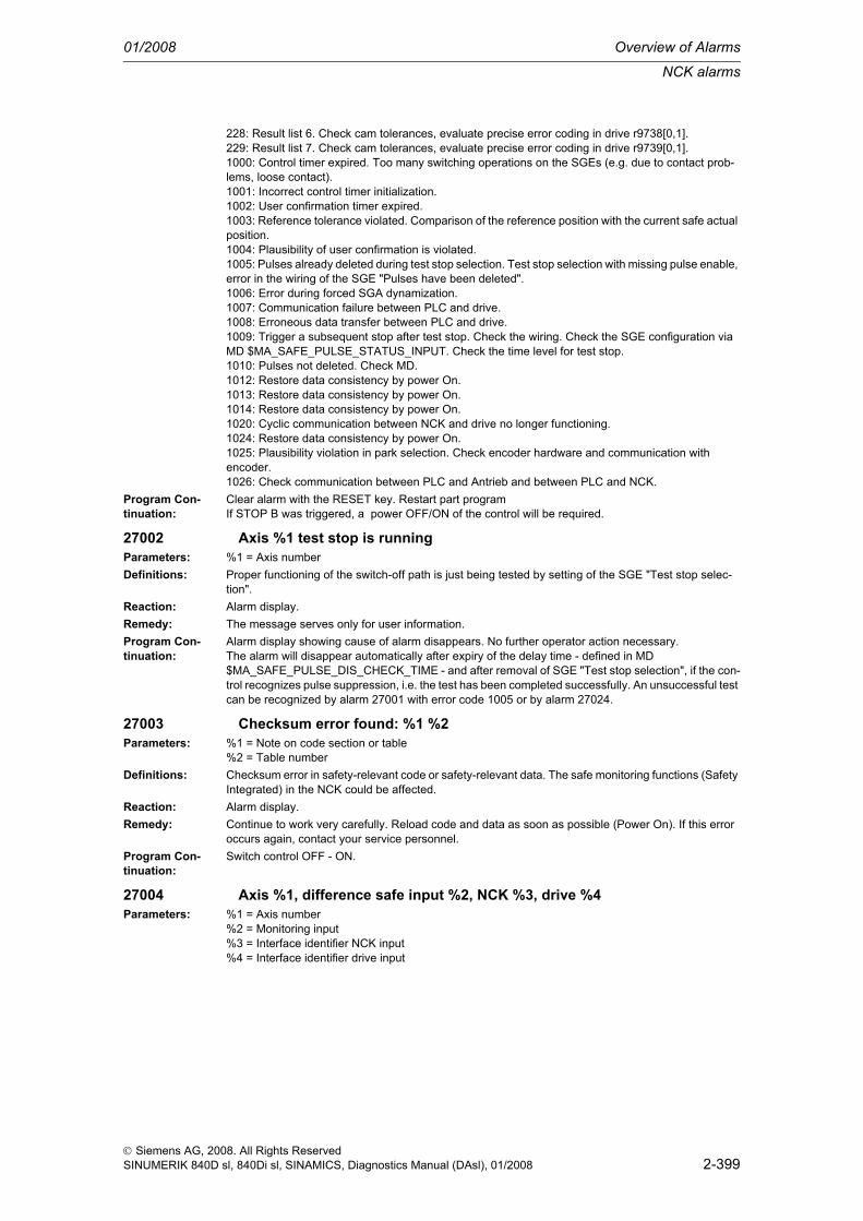
NCK alarms
01/2008 Overview of Alarms
2-399
© Siemens AG, 2008. All Rights ReservedSINUMERIK 840D sl, 840Di sl, SINAMICS, Diagnostics Manual (DAsl), 01/2008
228: Result list 6. Check cam tolerances, evaluate precise error coding in drive r9738[0,1].229: Result list 7. Check cam tolerances, evaluate precise error coding in drive r9739[0,1].1000: Control timer expired. Too many switching operations on the SGEs (e.g. due to contact prob-lems, loose contact).1001: Incorrect control timer initialization.1002: User confirmation timer expired. 1003: Reference tolerance violated. Comparison of the reference position with the current safe actual position.1004: Plausibility of user confirmation is violated.1005: Pulses already deleted during test stop selection. Test stop selection with missing pulse enable, error in the wiring of the SGE "Pulses have been deleted".1006: Error during forced SGA dynamization.1007: Communication failure between PLC and drive.1008: Erroneous data transfer between PLC and drive.1009: Trigger a subsequent stop after test stop. Check the wiring. Check the SGE configuration via MD $MA_SAFE_PULSE_STATUS_INPUT. Check the time level for test stop. 1010: Pulses not deleted. Check MD.1012: Restore data consistency by power On.1013: Restore data consistency by power On.1014: Restore data consistency by power On.1020: Cyclic communication between NCK and drive no longer functioning.1024: Restore data consistency by power On.1025: Plausibility violation in park selection. Check encoder hardware and communication with encoder.1026: Check communication between PLC and Antrieb and between PLC and NCK.
Program Con-tinuation:
Clear alarm with the RESET key. Restart part programIf STOP B was triggered, a power OFF/ON of the control will be required.
27002 Axis %1 test stop is runningParameters: %1 = Axis numberDefinitions: Proper functioning of the switch-off path is just being tested by setting of the SGE "Test stop selec-
tion".Reaction: Alarm display.Remedy: The message serves only for user information.Program Con-tinuation:
Alarm display showing cause of alarm disappears. No further operator action necessary.The alarm will disappear automatically after expiry of the delay time - defined in MD $MA_SAFE_PULSE_DIS_CHECK_TIME - and after removal of SGE "Test stop selection", if the con-trol recognizes pulse suppression, i.e. the test has been completed successfully. An unsuccessful test can be recognized by alarm 27001 with error code 1005 or by alarm 27024.
27003 Checksum error found: %1 %2Parameters: %1 = Note on code section or table
%2 = Table numberDefinitions: Checksum error in safety-relevant code or safety-relevant data. The safe monitoring functions (Safety
Integrated) in the NCK could be affected.Reaction: Alarm display.Remedy: Continue to work very carefully. Reload code and data as soon as possible (Power On). If this error
occurs again, contact your service personnel.Program Con-tinuation:
Switch control OFF - ON.
27004 Axis %1, difference safe input %2, NCK %3, drive %4Parameters: %1 = Axis number
%2 = Monitoring input%3 = Interface identifier NCK input%4 = Interface identifier drive input

Overview of Alarms 01/2008
NCK alarms
2-400
© Siemens AG, 2008. All Rights ReservedSINUMERIK 840D sl, 840Di sl, SINAMICS, Diagnostics Manual (DAsl), 01/2008
Definitions: A difference has been found on the specified safe input. The state of the specified input signal differed in the two monitoring channels NCK and SIMODRIVE611D during the duration set in $MA_SAFE_MODE_SWITCH_TIME.Monitoring in question (%2):SS/SV = Difference in SGE "Deselection of safe operating stop/Safe velocity"SS = Difference in SGE "Safe operating stop"SV = Difference in SGE "Selection safe velocity"SP = Difference in SGE "Selection safe limit position"SVOVR = Difference in SGEs "Selection SG correction"Interface identifier NCK input (%3):DMP<drv><mod><bit>=<value><drv> = Drive number of terminal block (1...31)<mod> = Submodule number (1...8)<bit> = Terminal number (1...16)<value> = Value of NCK SGE (0,1)SPL For when the SGE is parameterized at the SPL interface.<io> = Parameterizable system variable range (01=$A_INSID, 02=$A_INSED)<dword> = System variable double word (1,2)<bit> = Bit number in system variable double word (1...32)<value> = Value of NCK SGE (0,1)Onboard input For when the SGE is parameterized at an onboard input.<bit> = Input number = 01 ...04<value> = Value of NCK SGE = 0,1Interface identifier drive input (%4):DBX<byte><bit>=<value ><byte> = Byte number in axial DB (22, 23, 32, 33)<bit> = Bit number in byte (0...7)<value> = Value of drive SGE (0,1)This alarm can be hidden by setting MD $MN_SAFE_DIAGNOSIS_MASK, bit 0 = 0.
Reaction: Alarm display.Remedy: Check settings for safe input signals (NCK I/Os, PLC DB parameters).Program Con-tinuation:
Clear alarm with the RESET key. Restart part program
27005 Axis %1 error in data cross check: static actual value differenceParameters: %1 = Axis numberDefinitions: Via the data cross check between NCK and SIMODRIVE611D monitoring channel, a difference in
actual values was detected, which is greater than the maximum tolerance defined in MD $MA_SAFE_POS_TOL. This can be checked by means of the safe position values for the two moni-toring channels displayed in the service menu.The alarm is displayed only, if monitoring with absolute reference (SE/SN) has been enabled for the specified axis and if the user enable has been set. The alarm is cleared, as soon as the user enable is deleted or the actual value difference between the two monitoring channels falls again below the maximum permissible difference.
Reaction: Alarm display.Remedy: If the alarm is present statically, the user enable must be deleted. When the control is then rebooted,
the machine can be brought to the safe state again and operation resumed by a new referencing pro-cess and setting of the user enable. Prior to setting the user enable, the actual position of the axis displayed in the "User enable" screen must be compared with the current machine position. This is obligatory to ensure the proper functioning of the safe limit positions (SE) and safe cams (SN).A change of the user acknowledgement is only possible with key switch position 3 or after input of a password.
Program Con-tinuation:
Alarm display showing cause of alarm disappears. No further operator action necessary.
27006 Axis %1 Test ext. pulse deletion runningParameters: %1 = Axis numberDefinitions: The correct functioning of the external pulse disable is being checked now by setting the "Test stop of
external shutdown" SGE.Reaction: Alarm display.Remedy: Alarm disappears automatically when the test has been exited by deleting the "Test stop of external
shutdown" SGE.

NCK alarms
01/2008 Overview of Alarms
2-401
© Siemens AG, 2008. All Rights ReservedSINUMERIK 840D sl, 840Di sl, SINAMICS, Diagnostics Manual (DAsl), 01/2008
Program Con-tinuation:
Alarm display showing cause of alarm disappears. No further operator action necessary.
27007 Axis %1 acceptance test mode is activeParameters: %1 = Axis numberDefinitions: Via the operator panel, an SI acceptance test has been started for example with the acceptance test
wizard. The acceptance test mode is activated via the NCK and drive for the time of this acceptance test. In the acceptance test mode, SI PowerOn alarms can be acknowledged with the Reset key.
Reaction: Alarm display.Remedy: Deselect the acceptance test, for example with the acceptance test wizard or wait until completed
(acceptance test time can be parameterized via MD $MA_SAFE_ACCEPTANCE_TST_TIMEOUT).Program Con-tinuation:
Alarm display showing cause of alarm disappears. No further operator action necessary.
27008 Axis %1 SW limit switch deactivatedParameters: %1 = Axis numberDefinitions: Via the HMI, the SI acceptance test Safe limit position has been started, for example with the accep-
tance test wizard. For these acceptance tests, the single-channel software limit switches are deacti-vated for the axis/spindle, in order to assure that the safe limit positions can be approached.
Reaction: Alarm display.Deactivation of the single-channel software limit switch for the displayed axis/spindle.
Remedy: Deselect the acceptance test, for example with the acceptance test wizard, or wait until completed.Program Con-tinuation:
Alarm display showing cause of alarm disappears. No further operator action necessary.
27010 Axis %1 tolerance for safe standstill exceededParameters: %1 = Axis numberDefinitions: The axis has moved too far away from the setpoint position. It is further away than allowed in MD
$MA_SAFE_STANDSTILL_TOL.The alarm can be reprogrammed in the MD $MN_ALARM_REACTION_CHAN_NOREADY (channel not ready).
Reaction: Mode group not ready.Channel not ready.NC Start disable in this channel.Interface signals are set.Alarm display.NC Stop on alarm.Channel not ready.Stop of the axis with the setpoint speed value=0 (STOP B). As soon as the actual speed value is smaller than defined in MD $MA_SAFE_STANDSTILL_VELO_TOL, but the latest after time-out in MD $MA_SAFE_PULSE_DISABLE_DELAY, the pulses will be suppressed (STOP A).
Remedy: Check the tolerance of zero speed monitoring: does the value match the precision and control dynam-ics of the axis? If not, increase tolerance. If yes, check the machine for any damage and rectify it.
Program Con-tinuation:
Switch control OFF - ON.
27011 Axis %1 safe velocity exceededParameters: %1 = Axis numberDefinitions: The axis has moved too quickly and faster than allowed in MD $MA_SAFE_VELO_LIMIT. With active
SBH/SG and a 1-encoder system, the velocity which corresponds to an encoder limit frequency of MD SAFE_ENC_FREQ_LIMIT has been exceeded.
Reaction: NC Start disable in this channel.Interface signals are set.Alarm display.NC Stop on alarm.Axis stop with STOP A, C, D or E, depending on the configuration in MD $MA_SAFE_VELO_STOP_MODE or MD $MA_SAFE_VELO_STOP_REACTION.
Remedy: If no obvious operator error occurred: check the input value of the MD, check SGEs: was the correct safe velocity selected? If the MDs and SGEs are o.k., check the machine for any damage and rectify it.

Overview of Alarms 01/2008
NCK alarms
2-402
© Siemens AG, 2008. All Rights ReservedSINUMERIK 840D sl, 840Di sl, SINAMICS, Diagnostics Manual (DAsl), 01/2008
Program Con-tinuation:
Clear alarm with the RESET key. Restart part program
27012 Axis %1 safe end position exceededParameters: %1 = Axis numberDefinitions: The axis has exceeded the limit position entered in MD $MA_SAFE_POS_LIMT_PLUS or MD
$MA_SAFE_POS_LIMIT_MINUS.Reaction: NC Start disable in this channel.
Interface signals are set.Alarm display.NC Stop on alarm.Stop the axis with STOP C,D or E, depending on the configuration in MD $MA_SAFE_POS_STOP_MODE.
Remedy: If no obvious operator error occurred: Check the input value of the machine data and check the SGEs: was the correct one of 2 limit positions selected? If the MDs and SGEs are o.k., check the machine for any damage and rectify it.
Program Con-tinuation:
Clear alarm with the RESET key. Restart part programRemove the user agreement for this axis. Then press the RESET key causing the program to be aborted and the alarm to be deleted. Traverse the axis in JOG mode to the valid traversing range. After fault correction of the NC program and an axis position check, the user agreement can be set again and the program can be restarted.
27013 Axis %1 safe braking ramp exceededParameters: %1 = Axis numberDefinitions: After the initiation of STOP B or C, the velocity exceeded the tolerance value entered in MD
$MA_SAFE_STOP_VELO_TOL.Reaction: Mode group not ready.
Channel not ready.NC Start disable in this channel.Interface signals are set.Alarm display.NC Stop on alarm.Channel not ready.Pulse interlock by triggering a STOP A.
Remedy: Check MD $MA_SAFE_STOP_VELO_TOL. Check the braking behavior of the affected drive.Program Con-tinuation:
Switch control OFF - ON.
27020 Axis %1 stop E triggeredParameters: %1 = Axis numberDefinitions: This alarm is output together with alarms 27011 "Safe velocity exceeded" or 27012 "Safe limit position
exceeded" (when configured as such in MD $MA_SAFE_VELO_STOP_MODE, $MA_SAFE_VELO_STOP_REACTION or MD: $MA_SAFE_POS_STOP_MODE).
Reaction: NC Start disable in this channel.Interface signals are set.Alarm display.NC Stop on alarm.Trigger a LIFTFAST ASUB and internal activation of the safe operational stop (SBH) after expiry of the time set in MD $MA_SAFE_STOP_SWITCH_TIME_E.
Remedy: Eliminate causes of the alarms "Safe velocity exceeded" or "Safe limit position exceeded" (see description of these alarms).
Program Con-tinuation:
Clear alarm with the RESET key. Restart part program

NCK alarms
01/2008 Overview of Alarms
2-403
© Siemens AG, 2008. All Rights ReservedSINUMERIK 840D sl, 840Di sl, SINAMICS, Diagnostics Manual (DAsl), 01/2008
27021 Axis %1 stop D triggeredParameters: %1 = Axis numberDefinitions: This alarm is output together with alarms 27011 "Safe velocity exceeded" or 27012 "Safe limit position
exceeded" (when configured as such in $MA_SAFE_VELO_STOP_MODE, $MA_SAFE_VELO_STOP_REACTION or $MA_SAFE_POS_STOP_MODE).
Reaction: NC Start disable in this channel.Interface signals are set.Alarm display.NC Stop on alarm.Trigger a "Deceleration on the path" and internal activation of the safe operational stop (SBH) after expiry of the time set in MD $MA_SAFE_STOP_SWITCH_TIME_D.
Remedy: Eliminate causes of alarm "Safe velocity exceeded" or "Safe limit position exceeded" (see description of these alarms).
Program Con-tinuation:
Clear alarm with the RESET key. Restart part program
27022 Axis %1 stop C triggeredParameters: %1 = Axis numberDefinitions: This alarm is output together with alarms 27011 "Safe velocity exceeded" or 27012 "Safe limit position
exceeded" (when configured as such in $MA_SAFE_VELO_STOP_MODE, $MA_SAFE_VELO_STOP_REACTION or $MA_SAFE_POS_STOP_MODE).
Reaction: NC Start disable in this channel.Interface signals are set.Alarm display.NC Stop on alarm.Trigger a "Deceleration on the current limit" and internal activation of the safe operational stop (SBH) after expiry of the time set in MD $MA_SAFE_STOP_SWITCH_TIME_C.
Remedy: Eliminate causes of alarm "Safe velocity exceeded" or "Safe limit position exceeded" (see description of these alarms).
Program Con-tinuation:
Clear alarm with the RESET key. Restart part program
27023 Axis %1 stop B triggeredParameters: %1 = Axis numberDefinitions: This alarm is output together with alarm 27010 "Tolerance for safe operational stop exceeded" or after
alarm 27001 "STOP F triggered".The alarm can be reprogrammed in MD ALARM_REACTION_CHAN_NOREADY (channel not ready).
Reaction: Mode group not ready.Channel not ready.NC Start disable in this channel.Interface signals are set.Alarm display.NC Stop on alarm.Channel not ready.Trigger a "Deceleration on the current limit" and activation of the timer for a switchover after STOP A (see MD $MA_SAFE_PULSE_DISABLE_DELAY).
Remedy: Eliminate causes of alarm "Tolerance for safe standstill exceeded" or "STOP F triggered" (see description of these alarms).
Program Con-tinuation:
Switch control OFF - ON.

Overview of Alarms 01/2008
NCK alarms
2-404
© Siemens AG, 2008. All Rights ReservedSINUMERIK 840D sl, 840Di sl, SINAMICS, Diagnostics Manual (DAsl), 01/2008
27024 Axis %1 stop A triggeredParameters: %1 = Axis numberDefinitions: This alarm follows an
- Alarm 27011 "Safe velocity exceeded" (when configured as such in $MA_SAFE_VELO_STOP_MODE, $MA_SAFE_VELO_STOP_REACTION) - Alarm 27013 "Safe braking ramp exceeded",- Alarm 27023 "Stop B triggered"- unsuccessful test stop.The alarm can be reprogrammed in the MD ALARM_REACTION_CHAN_NOREADY (channel not ready).
Reaction: Mode group not ready.Channel not ready.NC Start disable in this channel.Interface signals are set.Alarm display.NC Stop on alarm.Channel not ready.Trigger a "Pulse suppression".
Remedy: Eliminate causes of- alarm "Save velocity exceeded",- alarm "Safe braking ramp exceeded",- alarm "Stop B triggered"- unsuccessful test stop(see description of these alarms).
Program Con-tinuation:
Switch control OFF - ON.
27030 Axis %1 function not supported on this SIMODRIVE611D moduleParameters: %1 = Axis numberDefinitions: SINUMERIK Safety Integrated can be used only with the SIMODRIVE611D Performance control mod-
ules with 2 measuring circuits per drive and cutoff relay. An attempt has been made to activate a safety function although no such module is plugged in.
Reaction: Mode group not ready.Channel not ready.NC Start disable in this channel.Interface signals are set.Alarm display.NC Stop on alarm.
Remedy: Replace module or switch off safety functions in MD $MA_SAFE_FUNCTION_ENABLE.Program Con-tinuation:
Switch control OFF - ON.
27031 Axis %1 limit value for safe velocity %2 at gear ratio %3 too large (max. %4)
Parameters: %1 = Axis number%2 = Limit value index%3 = Number of the transmission ratio%4 = Maximum velocity
Definitions: All limit values in MD $MA_SAFE_VELO_LIMIT have to be set in a way that the limit frequency of the amplitude monitoring in the measuring circuit hardware is not exceeded. The limit value which did not fulfil this condition is indicated as second parameter (1 for SG1, 2 for SG2, etc.). The third parameter indicates the gear stage, e.g. 1 for gear stage 1, 2 for gear stage 2, etc. The fourth parameter indicates the maximum velocity which can be entered to just maintain the limit frequency in safe operation.The alarm can be reprogrammed in the MD ALARM_REACTION_CHAN_NOREADY (channel not ready).
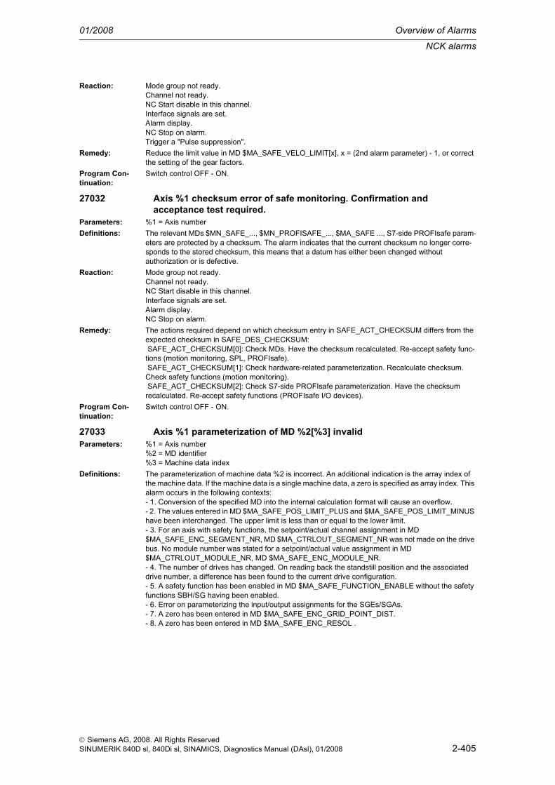
NCK alarms
01/2008 Overview of Alarms
2-405
© Siemens AG, 2008. All Rights ReservedSINUMERIK 840D sl, 840Di sl, SINAMICS, Diagnostics Manual (DAsl), 01/2008
Reaction: Mode group not ready.Channel not ready.NC Start disable in this channel.Interface signals are set.Alarm display.NC Stop on alarm.Trigger a "Pulse suppression".
Remedy: Reduce the limit value in MD $MA_SAFE_VELO_LIMIT[x], x = (2nd alarm parameter) - 1, or correct the setting of the gear factors.
Program Con-tinuation:
Switch control OFF - ON.
27032 Axis %1 checksum error of safe monitoring. Confirmation and acceptance test required.
Parameters: %1 = Axis numberDefinitions: The relevant MDs $MN_SAFE_..., $MN_PROFISAFE_..., $MA_SAFE ..., S7-side PROFIsafe param-
eters are protected by a checksum. The alarm indicates that the current checksum no longer corre-sponds to the stored checksum, this means that a datum has either been changed without authorization or is defective.
Reaction: Mode group not ready.Channel not ready.NC Start disable in this channel.Interface signals are set.Alarm display.NC Stop on alarm.
Remedy: The actions required depend on which checksum entry in SAFE_ACT_CHECKSUM differs from the expected checksum in SAFE_DES_CHECKSUM: SAFE_ACT_CHECKSUM[0]: Check MDs. Have the checksum recalculated. Re-accept safety func-tions (motion monitoring, SPL, PROFIsafe). SAFE_ACT_CHECKSUM[1]: Check hardware-related parameterization. Recalculate checksum. Check safety functions (motion monitoring). SAFE_ACT_CHECKSUM[2]: Check S7-side PROFIsafe parameterization. Have the checksum recalculated. Re-accept safety functions (PROFIsafe I/O devices).
Program Con-tinuation:
Switch control OFF - ON.
27033 Axis %1 parameterization of MD %2[%3] invalidParameters: %1 = Axis number
%2 = MD identifier%3 = Machine data index
Definitions: The parameterization of machine data %2 is incorrect. An additional indication is the array index of the machine data. If the machine data is a single machine data, a zero is specified as array index. This alarm occurs in the following contexts:- 1. Conversion of the specified MD into the internal calculation format will cause an overflow.- 2. The values entered in MD $MA_SAFE_POS_LIMIT_PLUS and $MA_SAFE_POS_LIMIT_MINUS have been interchanged. The upper limit is less than or equal to the lower limit.- 3. For an axis with safety functions, the setpoint/actual channel assignment in MD $MA_SAFE_ENC_SEGMENT_NR, MD $MA_CTRLOUT_SEGMENT_NR was not made on the drive bus. No module number was stated for a setpoint/actual value assignment in MD $MA_CTRLOUT_MODULE_NR, MD $MA_SAFE_ENC_MODULE_NR.- 4. The number of drives has changed. On reading back the standstill position and the associated drive number, a difference has been found to the current drive configuration.- 5. A safety function has been enabled in MD $MA_SAFE_FUNCTION_ENABLE without the safety functions SBH/SG having been enabled.- 6. Error on parameterizing the input/output assignments for the SGEs/SGAs.- 7. A zero has been entered in MD $MA_SAFE_ENC_GRID_POINT_DIST.- 8. A zero has been entered in MD $MA_SAFE_ENC_RESOL .

Overview of Alarms 01/2008
NCK alarms
2-406
© Siemens AG, 2008. All Rights ReservedSINUMERIK 840D sl, 840Di sl, SINAMICS, Diagnostics Manual (DAsl), 01/2008
- 9. Different settings have been made in MD $MA_IS_ROT_AX and MD $MA_SAFE_IS_ROT_AX.- 10. A non-existent measuring circuit has been parameterized in MD $MA_SAFE_ENC_INPUT_NR.- 11. In MD $MA_SAFE_ENC_MODULE_NR, the number of a drive has been entered that either does not exist or has been detected as inactive. With an inactive drive, MD $MA_SAFE_ENC_TYPE was not reset to 0.- 12. In MD $MA_SAFE_ENC_TYPE, an encoder type has been parameterized that does not match the physically present type.- 13. In MD $MA_SAFE_ENC_TYPE, an incorrect encoder type has been entered for an active drive ($MA_SAFE_ENC_TYPE = 0, 2, 3 or 5).- 14. When setting the parameters for the motor encoder in MD $MA_SAFE_ENC_INPUT_NR, the measuring circuit for the 2nd measuring system is also used to ensure double-redundancy. The 2nd measuring circuit of this drive module has also been parameterized in the data of another axis, there-fore there is a dual assignment. The 2nd measuring circuit connection cannot be used for the actual value acquisition in this parameterization.- 15. In MD $MA_SAFE_POS_TOL a value greater than 10mm was entered for a linear axis.- 16. In MD $MA_SAFE_REFP_POS_TOL, a value greater than 1mm was entered for a linear axis.- 17. The limit values for the "n<n_x" monitoring, calculated from MD $MA_SAFE_VELO_X and MD $MA_SAFE_POS_TOL, are of equal size.- 18. One of the activated cam positions is outside the actual value modulo range.- 19. The parameterized cam modulo range MD $MA_SAFE_MODULO_RANGE is not a multiple inte-ger of 360 degrees.- 20. The parameterized cam modulo range MD $MA_SAFE_MODULO_RANGE and the modulo range in MD $MA_MODULO_RANGE cannot be divided as integers into one another.- 21. The "Actual value synchronization 2-encoder system" function (slippage) is selected for a single-encoder system, or a function with an absolute reference (SE/SN) is active at the same time.- 22. Alarms 27000/300950 should be suppressed for parking (MD $MA_SAFE_PARK_ALARM_SUPPRESS!=0). The SGA "Axis safely referenced" must be configured in MD $MA_SAFE_REFP_STATUS_OUTPUT. - 23. An axial SGE/SGA was configured at the SPL interface (segment number = 4) and the function enable for the external stops (MD $MA_SAFE_FUNCTION_ENABLE, bit6) is missing.- 24. An axial SGE/SGA was parameterized at the SPL interface (segment number = 4) and the SGE "Deselect ext. Stop A" (assignment via MD $MA_SAFE_EXT_STOP_INPUT[0]) was parameterized inverted (bit31 = 1) or the SGE "Deselect ext. Stop A" was not parameterized at the SPL interface $A_OUTSI.- 25. The function "Save actual value with incremental encoder" is enabled via MD $MA_ENC_REFP_STATE for the parameterizable incremental encoder, and a monitoring function with absolute reference (SE/SN) is enabled via MD $MA_SAFE_FUNCTION_ENABLE. It is not per-missible to combine these functions.- 26. A value greater than 1000 mm/min was entered for a linear axis in MD $MA_SAFE_STANDSTILL_VELO_TOL.- 27. A value greater than 20000 mm/min was entered for a linear axis in MD $MA_SAFE_STOP_VELO_TOL.- 28. A value greater than 1000 mm/min was entered for a linear axis in MD $MA_SAFE_VELO_X.- 29. A value greater than 1000 mm/min was entered for a linear axis in $MA_SAFE_SLIP_VELO_TOL.- 30. A value greater than the maximum settable encoder limit frequency for the safe operation of a single-encoder system was set in MD $MA_SAFE_ENC_FREQ_LIMIT.- 31. A value greater than 300kHz for a Performance-1 or Standard-2 control module was set in MD $MA_SAFE_ENC_FREQ_LIMIT.- 32. MD $MA_SAFE_EXT_PULSE_ENAB_OUTPUT was not or not correctly parameterized. A parameterization of this MD is required if in MD $MA_SAFE_PULSE_ENABLE_OUTPUT, bit30 is set to 1, i.e. internal pulse suppression is being used.- 33. The MD $MN_SAFE_SPL_STOP_MODE has been parameterized to the value of 4 (Stop E) without having enabled the external Stop E in all the axes with SI function enables (MD $MA_SAFE_FUNCTION_ENABLE not equal to 0).- 34. Testing the mechanical system of the brakes was enabled in MD $MA_FIXED_STOP_MODE (bit1 = 1), without previously enabling the safe operation function for this axis in MD $MA_SAFE_FUNCTION_ENABLE. Testing the mechanical system of the brakes is permitted only with safety functions in this axis.- 35. Illegal values have been parameterized in MD $MA_SAFE_VELO_STOP_MODE or MD $MA_SAFE_VELO_STOP_REACTION.- 36. In MD $MA_SAFE_FUNCTION_ENABLE, the cam synchronization was activated via bit7 with-out enabling any cams via bit8...bit15.- 37. The cam is enabled both via $MA_SAFE_FUNCTION_ENABLE and via

NCK alarms
01/2008 Overview of Alarms
2-407
© Siemens AG, 2008. All Rights ReservedSINUMERIK 840D sl, 840Di sl, SINAMICS, Diagnostics Manual (DAsl), 01/2008
$MA_SAFE_CAM_ENABLE- 38. In MD $MA_SAFE_DRIVE_PS_ADDRESS an invalid value was parameterized or the same address was assigned to several axes.- 39. The internal default of MD $MA_SAFE_ENC_PULSE_SHIFT from drive parameterization could not be executed, as some values outside the specified range would have to be defaulted in this case. Adjust the encoder parameterization in the drive.- 40. The MD $MA_SAFE_VELO_OVR_FACTOR was parameterized with digits behind the decimal point.- 41. The logical basic address configured in the hardware configuration and that addressed via MDs $MA_SAFE_CTRLOUT_MODULE_NR, $MN_SAFE_DRIVE_LOGIC_ADDRESS are not the same or the slot addressed by them has the wrong length.- 42. The cam position $MA_SAFE_CAM_POS_PLUS[n] or $MA_SAFE_CAM_POS_MINUS[n] has been parameterized too close to the modulo limit.- 43. "Safe cams" are enabled in Bit 8...15 of $MA_SAFE_FUNCTION_ENABLE and at the same time the "Safe cam track" function is enabled in $MA_SAFE_CAM_ENABLE.- 44. The minus cam position $MA_SAFE_CAM_POS_MINUS[n] is greater than the plus cam position $MA_SAFE_CAM_POS_PLUS[n]. This is not permitted for the "Safe cam track" function.- 45. The distance between 2 cams on one cam track ($MA_SAFE_CAM_POS_MINUS[n] and $MA_SAFE_CAM_POS_PLUS[m]) is too small. ("Safe cam track" function)- 46. The cam length, that is the distance between a plus cam position ($MA_SAFE_CAM_POS_PLUS[n]) and a minus cam position ($MA_SAFE_CAM_POS_MINUS[n]), is too small. ("Safe cam track" function)- 47. Identical values have been entered in $MA_SAFE_CAM_TRACK_ASSIGN[n] for at least 2 cams enabled in $MA_SAFE_CAM_ENABLE. ("Safe cam track" function)- 48. The value parameterized in $MA_SAFE_CAM_TRACK_ASSIGN[n] for a cam enabled in $MA_SAFE_CAM_ENABLE is invalid. ("Safe cam track" function)- 49. More than 15 cams have been assigned to one cam track by $MA_SAFE_CAM_TRACK_ASSIGN[n]. ("Safe cam track" function)- 50. Cam modulo functionality has been selected in $MA_SAFE_MODULO_RANGE, however this is not suported for the "Safe cam track" function.- 51. Setting $MA_SAFE_FUNCTION_ENABLE Bit7 is not permitted if the "Safe cam track" function is enabled. The cam synchronization is implicitly enabled.
Reaction: Mode group not ready.Channel not ready.NC Start disable in this channel.Interface signals are set.Alarm display.NC Stop on alarm.
Remedy: Check and change the specified MD. Allow the checksum to be recalculated. Re-accept safety func-tions.
Program Con-tinuation:
Switch control OFF - ON.
27034 Parameterization of MD %1[%2] invalid.Parameters: %1 = MD identifier
%2 = Machine data indexDefinitions: The parameterization of machine data %1 is incorrect. This alarm occurs in the following contexts:
- An invalid value has been set for MD $MN_SAFE_ALARM_SUPPRESS_LEVEL.- An invalid value has been set for MD $MN_SAFE_RDP_CONNECTION_NR.- An invalid value has been set for MD $MN_SAFE_SDP_CONNECTION_NR.
Reaction: Mode group not ready.Channel not ready.NC Start disable in this channel.Interface signals are set.Alarm display.NC Stop on alarm.
Remedy: Check and correct the specified machine data.Program Con-tinuation:
Switch control OFF - ON.

Overview of Alarms 01/2008
NCK alarms
2-408
© Siemens AG, 2008. All Rights ReservedSINUMERIK 840D sl, 840Di sl, SINAMICS, Diagnostics Manual (DAsl), 01/2008
27035 Axis %1 new hardware component, confirmation and functional test required.
Parameters: %1 = Axis numberDefinitions: The IDs for the corresponding hardware components (encoder, motor module)
read out by the drive do not match the NCK parameterization.Reaction: Mode group not ready.
Channel not ready.NC Start disable in this channel.Interface signals are set.Alarm display.NC Stop on alarm.
Remedy: The following has to be done if the alarm occurs during the start-up:- Confirm the checksum SAFE_ACT_CHECKSUM[1] (key switch position 3 or password has to be entered). Continue the start-up.The following has to be done if the alarm occurs after an encoder module or a DRIVE-CLiQ motor has been replaced:- In the Diagnostics operating area, confirm the hardware checksum with softkey in SAFE_ACT_CHECKSUM[1] (key switch position 3 or password has to be entered)- Readjust the actual value encoder.- Check the SI actual value acquisition: velocities, traversing direction, absolute position (set user acknowledgement if necessary)- Document the new checksum value in SAFE_ACT_CHECKSUM[1] and the last entry in the change history in MD SAFE_CONFIG_CHANGE_DATE[0]- Document the hardware and software version data of the new component.
Program Con-tinuation:
Switch control OFF - ON.
27036 Axis %1 encoder parameterization MD %2[%3] has been adjusted.Parameters: %1 = Axis number
%2 = MD identifier%3 = Machine data index
Definitions: Encoder parameterization of the encoder read out by the drive for the SI monitoring functionsdoes not match NCK parameterization in the displayed MD. The relevant NCK MD has been adjusted.
Reaction: Mode group not ready.Channel not ready.NC Start disable in this channel.Interface signals are set.Alarm display.NC Stop on alarm.In addition, a Stop F is triggered that may cause follow-up alarm 27001 with error code 0 as well asalarms 27023 and 27024.Alarm 27001 with error code 0 can be avoided by alarm reduction($MA_SAFE_ALARM_SUPPRESS_LEVEL higher or equal to 1).
Remedy: Continue the start-up operation; correct the checksums.Program Con-tinuation:
Switch control OFF - ON.
27037 Axis %1 and %2 with the same PROFIsafe address %3.Parameters: %1 = Axis number
%2 = Axis number%3 = PROFIsafe address
Definitions: The PROFIsafe addresses of these two axes read out by the drive are identical.Reaction: Mode group not ready.
Channel not ready.NC Start disable in this channel.Interface signals are set.Alarm display.NC Stop on alarm.
Remedy: Set the correct PROFIsafe addresses of the drives.Program Con-tinuation:
Switch control OFF - ON.
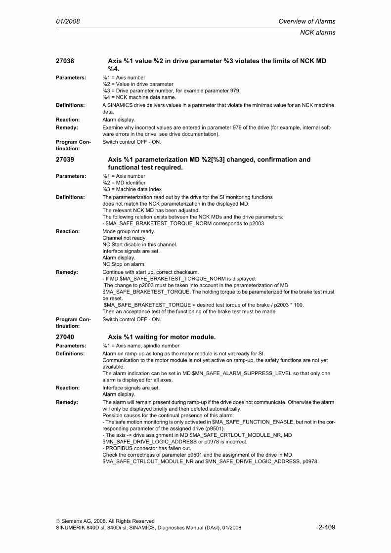
NCK alarms
01/2008 Overview of Alarms
2-409
© Siemens AG, 2008. All Rights ReservedSINUMERIK 840D sl, 840Di sl, SINAMICS, Diagnostics Manual (DAsl), 01/2008
27038 Axis %1 value %2 in drive parameter %3 violates the limits of NCK MD %4.
Parameters: %1 = Axis number%2 = Value in drive parameter%3 = Drive parameter number, for example parameter 979.%4 = NCK machine data name.
Definitions: A SINAMICS drive delivers values in a parameter that violate the min/max value for an NCK machine data.
Reaction: Alarm display.Remedy: Examine why incorrect values are entered in parameter 979 of the drive (for example, internal soft-
ware errors in the drive, see drive documentation).Program Con-tinuation:
Switch control OFF - ON.
27039 Axis %1 parameterization MD %2[%3] changed, confirmation and functional test required.
Parameters: %1 = Axis number%2 = MD identifier%3 = Machine data index
Definitions: The parameterization read out by the drive for the SI monitoring functionsdoes not match the NCK parameterization in the displayed MD.The relevant NCK MD has been adjusted.The following relation exists between the NCK MDs and the drive parameters:- $MA_SAFE_BRAKETEST_TORQUE_NORM corresponds to p2003
Reaction: Mode group not ready.Channel not ready.NC Start disable in this channel.Interface signals are set.Alarm display.NC Stop on alarm.
Remedy: Continue with start up, correct checksum.- If MD $MA_SAFE_BRAKETEST_TORQUE_NORM is displayed: The change to p2003 must be taken into account in the parameterization of MD $MA_SAFE_BRAKETEST_TORQUE. The holding torque to be parameterized for the brake test must be reset. $MA_SAFE_BRAKETEST_TORQUE = desired test torque of the brake / p2003 * 100.Then an acceptance test of the functioning of the brake test must be made.
Program Con-tinuation:
Switch control OFF - ON.
27040 Axis %1 waiting for motor module.Parameters: %1 = Axis name, spindle numberDefinitions: Alarm on ramp-up as long as the motor module is not yet ready for SI.
Communication to the motor module is not yet active on ramp-up, the safety functions are not yet available.The alarm indication can be set in MD $MN_SAFE_ALARM_SUPPRESS_LEVEL so that only one alarm is displayed for all axes.
Reaction: Interface signals are set.Alarm display.
Remedy: The alarm will remain present during ramp-up if the drive does not communicate. Otherwise the alarm will only be displayed briefly and then deleted automatically.Possible causes for the continual presence of this alarm:- The safe motion monitoring is only activated in $MA_SAFE_FUNCTION_ENABLE, but not in the cor-responding parameter of the assigned drive (p9501).- The axis -> drive assignment in MD $MA_SAFE_CRTLOUT_MODULE_NR, MD $MN_SAFE_DRIVE_LOGIC_ADDRESS or p0978 is incorrect.- PROFIBUS connector has fallen out.Check the correctness of parameter p9501 and the assignment of the drive in MD $MA_SAFE_CTRLOUT_MODULE_NR and $MN_SAFE_DRIVE_LOGIC_ADDRESS, p0978.

Overview of Alarms 01/2008
NCK alarms
2-410
© Siemens AG, 2008. All Rights ReservedSINUMERIK 840D sl, 840Di sl, SINAMICS, Diagnostics Manual (DAsl), 01/2008
Program Con-tinuation:
Alarm display showing cause of alarm disappears. No further operator action necessary.
27050 Axis %1 SI communication failure.Parameters: %1 = Axis numberDefinitions: Communication with the drive for Safety Integrated
motion monitoring is additionally monitored. This monitoringhas found an error.
Reaction: NC Start disable in this channel.Interface signals are set.Alarm display.NC Stop on alarm.
Remedy: Verification of the connections between NCK and drive.Check for compliance with the EMC requirements.
Program Con-tinuation:
Clear alarm with the RESET key. Restart part program
27090 Error in data cross check NCK-PLC, %1[%2], NCK: %3; %4<ALSI>Parameters: %1 = Name of system variable in which the error was detected
%2 = System variable array index extension%3 = NCK comparison value extension%4 = Cross-check array index extension
Definitions: Differences in the compared data have occured in a cyclic data cross check between NCK and PLC. Parameter %1 specifies the erroneous system variable ($A_INSI, $A_OUTSI, $A_INSE, $A_OUTSE or$A_MARKERSI) with array index %2.Special cases:- Display "Error in NCK-PLC data cross check, $MN_PREVENT_SYNACT_LOCK[0], ..." means that the SPL startup status has been set differently in the NCK and PLC.- Display "Error in NCK-PLC data cross check, $MN_SPL_STOP_MODE[0], ..." means that the SPL stop reaction (Stop D or E) has been set differently in the NCK and PLC.- Display "Error in NCK-PLC data cross check, TIMEOUT[0], NCK: 0" means that the communication between NCK and PLC is generally disturbed and that a data cross check can no longer be performed.With data cross-check errors on system variables $A_INSE, the hardware assignment parameterized in MD $MN_SAFE_IN_HW_ASSIGN[0...7] is displayed in addition to the affected system variables in alarm parameter %1, so that the affected hardware connection is shown directly by the specifications in the alarm line.Example: Error in NCK-PLC data cross-check, DMP 04.03 Bit 01=$A_INSE[2], NCK: 1;The specifications in the example (04.03) correspond to the entries made in the machine data $MN_SAFE_IN_HW_ASSIGN[0...7] for the stated system variable.They specify:DMP 04.xx The drive number of the affected terminal block (value range = 01...21).DMP xx.03 Module number of the input module (value range = 01...08).The stated numbers are shown as hexadecimal numbers as in MD $MN_SAFE_IN_HW_ASSIGN[0...7].The specification of the bit numbers begins with the value 0 (value range = 00...15), the same as the numbering of the inputs on the DMP modules.When assigning the SPL inputs to the NC onboard inputs, the extended alarm text is as follows:Error in NCK-PLC data cross-check, NC-Onboard-In 01=$A:INSE[1], NCK: 1; 2.

NCK alarms
01/2008 Overview of Alarms
2-411
© Siemens AG, 2008. All Rights ReservedSINUMERIK 840D sl, 840Di sl, SINAMICS, Diagnostics Manual (DAsl), 01/2008
With parameter %4, a specific alarm message can be configured on HMI for all listed system vari-ables: %4 = 0: Error SPL startup status ($MN_PREVENT_SYNACT_LOCK[0,1] - DB18 DBX36.0)or different stop reaction ($MN_SAFE_SPL_STOP_MODE - DB18 DBX36.1). %4 = 1.... 64: Error in system variable $A_INSE[1...64] %4 = 65...128: Error in system variable $A_OUTSE[1...64] %4 = 129...192: Error in system variable $A_INSI[1...64] %4 = 193...256: Error in system variable $A_OUTSI[1...64] %4 = 257...320: Error in system variable $A_MARKERSI[1...64] In order to parameterize alarm 27090, file ALSI_xx.com must be incorporated in the data management and declared in HMI via MBDDE.INI in the section[IndexTextFiles] ALSI=f:\dh\mb.dir\alsi_ . The machine manufacturer can redefine this file, in order to incorporate additional text passages in the alarm that make sense for their system. If the file is redefined, the newly created file has to be declared in the system via MBDDE.INI.The display of alarm 27090 can be modified via MD $MN_SAFE_ALARM_SUPPRESS_LEVEL: MD $MN_SAFE_ALARM_SUPPRESS_LEVEL = 2 : Alarm 27090 will now only displayed for the first data difference found.
Reaction: Alarm display.Trigger a STOP D/E (settable via MD $MN_SPL_STOP_MODE) on all axes with safety functionality, as soon as the SPL start-up phase (MD $MN_PREVENT_SYNACT_LOCK[0,1] unequal to 0) is com-pleted.
Remedy: Analyze the value displayed and evaluate DB18: SPL_DELTA on the PLC side.Find the difference between the monitoring channels. Possible causes:- Incorrect wiring- Incorrect SPL- Incorrect assignment of the axial SGEs to internal interface $A_OUTSI- Incorrect assignment of the axial SGAs to internal interface $A_INSI- Incorrect assignment of the SPL SGEs to external interface $A_INSE- Incorrect assignment of the SPL SGAs to external interface $A_OUTSE- Different SPL startup status set in NCK and PLC- Different SPL stop reaction set in NCK and PLC
Program Con-tinuation:
Clear alarm with the RESET key. Restart part program
27091 Error in data cross check NCK-PLC, stop of %1Parameters: %1 = Extension indicating the monitoring channel that triggered the stopDefinitions: The monitoring channel specified in %1 (NCK or PLC) has triggered a stop D or E (depending on the
parameterization in MD $MN_SAFE_SPL_STOP_MODE). The alarm 27090 provides further informa-tion about the cause for the stop D/E.
Reaction: Alarm display.Trigger a STOP D/E (settable via MD $MN_SPL_STOP_MODE) on all axes with safety functionality, as soon as the SPL start-up phase (MD $MN_PREVENT_SYNACT_LOCK[0,1] unequal to 0) is com-pleted.
Remedy: Evaluate the alarm parameters of alarm 27090 and amend the SPL, or check the I/O modules/wiring or the internal SPL interfaces to the safety monitoring channels in the NCK and drive SIMODRIVE611D.
Program Con-tinuation:
Clear alarm with the RESET key. Restart part program
27092 Communication broken off during NCK PLC data cross check, error detected by %1
Parameters: %1 = Extension indicating the monitoring channel that detected the errorDefinitions: The delay time (1s) for communication monitoring was exceeded in the monitoring channel specified
in %1 (NCK or PLC). The other monitoring channel did not send a new data packet within this time.Reaction: Alarm display.
A timer of 5 secs is started, after the expiry of which- the external NCK SPL outputs are deleted- the PLC changes to stop.
Remedy: Check the system components (the PLC must have the correct version of FB15 and DB18).Program Con-tinuation:
Switch control OFF - ON.

Overview of Alarms 01/2008
NCK alarms
2-412
© Siemens AG, 2008. All Rights ReservedSINUMERIK 840D sl, 840Di sl, SINAMICS, Diagnostics Manual (DAsl), 01/2008
27093 Checksum error NCK-SPL, %1, %2, %3Parameters: %1 = Extension indicating the type of error
%2 = Extension indicating the reference variable%3 = Extension indicating the actual variable
Definitions: A checksum error has occurred in the NCK SPL. The file /_N_CST_DIR/_N_SAFE_SPF was subse-quently modified. The safe programmable logic (SPL) in the NCK may be corrupted. Parameter %1 indicates the type of modification:- %1 = FILE_LENGTH: the file length has changed.- %1 = FILE_CONTENT: the file contents have changed.%2 specifies the reference variable (file length, checksum of file contents), %3 specifies the actual variable which is calculated cyclically.
Reaction: Alarm display.Remedy: Check the file and the time of the last modification to the file. Reload the original file and start the mon-
itoring system again with a Power On.Program Con-tinuation:
Switch control OFF - ON.
27094 Write access to system variable %1 only allowed from NCK-SPLParameters: %1 = Name of safety system variable concernedDefinitions: Write access to a safety system variable is only allowed from the part program
/_N_CST_DIR/_N_SAFE_SPF. If this error occurs, an instruction from another part program was detected.
Reaction: Alarm display.Remedy: Check the part programs you are using for write accesses to safety system variables.Program Con-tinuation:
Clear alarm with the RESET key. Restart part program
27095 %1 SPL protection not activatedParameters: %1 = Name of the component on which the protection is not activated (NCK or PLC)Definitions: The protection features are not activated for the SPL. The startup phase of the SPL is not yet com-
plete. No stop reaction (Stop D or E) was initiated on an error in data cross-comparison between NCK and PLC.
Reaction: Alarm display.Remedy: - Remedy for NCK: Activate the protection features with MD $MN_PREVENT_SYNACT_LOCK[0,1].
The number range of the synchronized action IDs used in the SPL must be entered in this MD.- Remedy for PLC: Activate the protection features by setting the appropriate data bit in DB18.
Program Con-tinuation:
Clear alarm with the RESET key. Restart part program
27096 SPL start not allowedDefinitions: To start the SPL in protected state (MD $MN_PREVENT_SYNACT_LOCK[0,1] not equal 0) Safety
Integrated functionality must first be activated for at least one axis (via MD $MA_SAFE_FUNCTION_ENABLE). Without this functionality it is only possible to operate SPL in start-up state.
Reaction: Mode group not ready.Channel not ready.NC Start disable in this channel.Interface signals are set.Alarm display.NC Stop on alarm.Channel not ready.
Remedy: Start up axial Safety Integrated functionality or remove the SPL protection via MD $MN_PREVENT_SYNACT_LOCK[0,1].
Program Con-tinuation:
Switch control OFF - ON.
27097 SPL start not executedDefinitions: SPL start not executed after predefined timeout in MD SAFE_SPL_START_TIMEOUT.Reaction: Alarm display.

NCK alarms
01/2008 Overview of Alarms
2-413
© Siemens AG, 2008. All Rights ReservedSINUMERIK 840D sl, 840Di sl, SINAMICS, Diagnostics Manual (DAsl), 01/2008
Remedy: Find the cause of the failure of the SPL to start. Possible causes may be:- There is an NC or drive error (e.g. after encoder replacement, EMERGENCY STOP, PROFIsafe alarms)- There is a syntax error in the SPL- Safety Integrated alarm present (e.g. "Safe limit position overrun")- Name or path of SPL for PROG_EVENT Start written incorrectly; make sure upper and lower cases are used correctly- Simultaneous start of an ASUB and PROG_EVENT, parameterization MD 11602 (stop causes e.g. read-in disable)- Problems when calling FB4/FC9This alarm can be masked via MD $MN_SAFE_DIAGNOSIS_MASK, Bit 1 = 1.
Program Con-tinuation:
Clear alarm with the RESET key. Restart part program
27099 Double assignment in SPL assignment MD %1[%2] - MD %3[%4]Parameters: %1 = MD name 1
%2 = MD array index for MD name 1%3 = MD name 2%4 = MD array index for MD name 2
Definitions: Different applications have double assigned SPL inputs ($A_INSE) in the displayed machine data.These could be: - PROFIsafe communication - F_DP communicationPossible values for alarm parameters %1 and %3: - $MN_PROFISAFE_IN_ASSIGN - $MN_SAFE_RDP_ASSIGN
Reaction: Alarm display.Remedy: Correct the MD.Program Con-tinuation:
Switch control OFF - ON.
27100 At least one axis is not safely referencedDefinitions: There are two reasons for this alarm:
- the machine position of at least one of the axes monitored with SI has not yet been acknowledged by the user, or- the machine position of at least one of the axes monitored with SI has not yet been verified through follow-up referencing.Even if the axis is already referenced, there is no confirmation that referencing has supplied the cor-rect result. For example, wrong results can occur if the axis was moved after the control was switched off, with the result that the standstill position saved prior to switching off is no longer correct. To make sure that this does not happen, the user must acknowledge the displayed actual position after the first referencing process.When the user enable has first been set, follow-up referencing must be carried out each time the con-trol is booted (with absolute encoders, this follow-up referencing is executed automatically). This pro-cedure is carried out to verify the standstill position saved prior to switching off of the control.Via the MD $MN_SAFE_ALARM_SUPPRESS_LEVEL (MD>=3), the alarm display can be set in such a way that an alarm is given for each axis individually which has not been safely referenced.
Reaction: Alarm display.SGA "Axis safely referenced" is not set. SE will be switched off, if the actual safety position has not yet been confirmed by a user agreement. If the user agreement has been set, SE will remain active. The safe cams are calculated and output. However, their significance is limited as referencing has not been confirmed.
Remedy: Move all SI axes to known positions and change to "Referencing" mode. Check the positions on the machine displayed in the user confirmation field and set "User confirmation" via the selection/toggle key. If the user confirmation for the axes has already been set, reference the axes again.Changing the user confirmation will be possible only in key switch position 3 or after password entry
Program Con-tinuation:
Alarm display showing cause of alarm disappears. No further operator action necessary.

Overview of Alarms 01/2008
NCK alarms
2-414
© Siemens AG, 2008. All Rights ReservedSINUMERIK 840D sl, 840Di sl, SINAMICS, Diagnostics Manual (DAsl), 01/2008
27101 Axis %1 difference in function safe operational stop, NCK: %2 drive: %3Parameters: %1 = Axis number
%2 = Monitoring status safe operating stop%3 = Monitoring status safe operating stop
Definitions: During cross-comparison of result list 1 a difference was detected between the NCK and drive moni-toring channels in the status of safe operating stop monitoring.Safe operating stop: Bit 0,1 in result list 1Monitoring status (%2, %3):- OFF = Monitoring is inactive in this monitoring channel- OK = Monitoring is active in this monitoring channel, limit values are not violated- L+ = Monitoring is active in this monitoring channel, upper limit exceeded- L- = Monitoring is active in this monitoring channel, lower limit exceeded
Reaction: Alarm display.If a safe monitoring was active, STOP B was also triggered automatically. In this case, a power OFF/ON of the control will be required.
Remedy: Check whether the safe inputs have switched to the same status in both monitoring channels within the permissible time tolerance.For further diagnostics, the drive machine data 1391, 1392 and the servo trace signals "Result list 1, NCK" and "Result list 1, drive" can be used.
Program Con-tinuation:
Clear alarm with the RESET key. Restart part program
27102 Axis %1 difference in function safe velocity %2, NCK: %3 drive: %4Parameters: %1 = Axis number
%2 = SG level for which the difference was determined%3 = Monitoring status safe velocity%4 = Monitoring status safe velocity
Definitions: During cross-comparison of result list 1 a difference was detected between the NCK and drive moni-toring channels in the status of safe velocity monitoring.- Safe velocity 1: Bit 6, 7 in result list 1- Safe velocity 2: Bit 8, 9 in result list 1- Safe velocity 3: Bit 10, 11 in result list 1- Safe velocity 4: Bit 12, 13 in result list 1Monitoring status (%3, %4):- OFF = Monitoring is inactive in this monitoring channel- OK = Monitoring is active in this monitoring channel, limit values are not violated- L+ = Monitoring is active in this monitoring channel, upper limit exceeded- L- = Monitoring is active in this monitoring channel, lower limit exceeded
Reaction: Alarm display.If a safe monitoring was active, STOP B was also triggered automatically. In this case, a power OFF/ON of the control will be required.
Remedy: Check whether the safe inputs have switched to the same status in both monitoring channels within the permissible time tolerance.For further diagnostics, the drive machine data 1391, 1392 and the servo trace signals "Result list 1, NCK" and "Result list 1, drive" can be used.
Program Con-tinuation:
Clear alarm with the RESET key. Restart part program
27103 Axis %1 difference in function safe limit position %2, NCK: %3 drive: %4Parameters: %1 = Axis number
%2 = Number of safe limit position%3 = Monitoring status safe limit position%4 = Monitoring status safe limit position
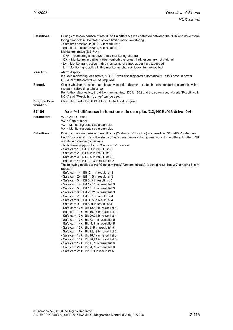
NCK alarms
01/2008 Overview of Alarms
2-415
© Siemens AG, 2008. All Rights ReservedSINUMERIK 840D sl, 840Di sl, SINAMICS, Diagnostics Manual (DAsl), 01/2008
Definitions: During cross-comparison of result list 1 a difference was detected between the NCK and drive moni-toring channels in the status of safe limit position monitoring.- Safe limit position 1: Bit 2, 3 in result list 1- Safe limit position 2: Bit 4, 5 in result list 1Monitoring status (%3, %4):- OFF = Monitoring is inactive in this monitoring channel- OK = Monitoring is active in this monitoring channel, limit values are not violated- L+ = Monitoring is active in this monitoring channel, upper limit exceeded- L- = Monitoring is active in this monitoring channel, lower limit exceeded
Reaction: Alarm display.If a safe monitoring was active, STOP B was also triggered automatically. In this case, a power OFF/ON of the control will be required.
Remedy: Check whether the safe inputs have switched to the same status in both monitoring channels within the permissible time tolerance.For further diagnostics, the drive machine data 1391, 1392 and the servo trace signals "Result list 1, NCK" and "Result list 1, drive" can be used.
Program Con-tinuation:
Clear alarm with the RESET key. Restart part program
27104 Axis %1 difference in function safe cam plus %2, NCK: %3 drive: %4Parameters: %1 = Axis number
%2 = Cam number%3 = Monitoring status safe cam plus%4 = Monitoring status safe cam plus
Definitions: During cross-comparison of result list 2 ("Safe cams" function) and result list 3/4/5/6/7 ("Safe cam track" function (sl only)), the status of safe cam plus monitoring was found to be different in the NCK and drive monitoring channels.The following applies to the "Safe cams" function:- Safe cam 1+: Bit 0, 1 in result list 2- Safe cam 2+: Bit 4, 5 in result list 2- Safe cam 3+: Bit 8, 9 in result list 2- Safe cam 4+: Bit 12,13 in result list 2The following applies to the "Safe cam track" function (sl only): (each of result lists 3-7 contains 6 cam results)- Safe cam 1+: Bit 0, 1 in result list 3- Safe cam 2+: Bit 4, 5 in result list 3- Safe cam 3+: Bit 8, 9 in result list 3- Safe cam 4+: Bit 12,13 in result list 3- Safe cam 5+: Bit 16,17 in result list 3- Safe cam 6+: Bit 20,21 in result list 3- Safe cam 7+: Bit 0, 1 in result list 4- Safe cam 8+: Bit 4, 5 in result list 4- Safe cam 9+: Bit 8, 9 in result list 4- Safe cam 10+: Bit 12,13 in result list 4- Safe cam 11+: Bit 16,17 in result list 4- Safe cam 12+: Bit 20,21 in result list 4- Safe cam 13+: Bit 0, 1 in result list 5- Safe cam 14+: Bit 4, 5 in result list 5- Safe cam 15+: Bit 8, 9 in result list 5- Safe cam 16+: Bit 12,13 in result list 5- Safe cam 17+: Bit 16,17 in result list 5- Safe cam 18+: Bit 20,21 in result list 5- Safe cam 19+: Bit 0, 1 in result list 6- Safe cam 20+: Bit 4, 5 in result list 6- Safe cam 21+: Bit 8, 9 in result list 6

Overview of Alarms 01/2008
NCK alarms
2-416
© Siemens AG, 2008. All Rights ReservedSINUMERIK 840D sl, 840Di sl, SINAMICS, Diagnostics Manual (DAsl), 01/2008
- Safe cam 22+: Bit 12,13 in result list 6- Safe cam 23+: Bit 16,17 in result list 6- Safe cam 24+: Bit 20,21 in result list 6- Safe cam 25+: Bit 0, 1 in result list 7- Safe cam 26+: Bit 4, 5 in result list 7- Safe cam 27+: Bit 8, 9 in result list 7- Safe cam 28+: Bit 12,13 in result list 7- Safe cam 29+: Bit 16,17 in result list 7- Safe cam 30+: Bit 20,21 in result list 7Monitoring status (%3, %4):- OFF = Monitoring is inactive in this monitoring channel- OK = Monitoring is active in this monitoring channel, limit values are not violated- L+ = Monitoring is active in this monitoring channel, upper limit exceeded- L- = Monitoring is active in this monitoring channel, lower limit exceeded
Reaction: Alarm display.If a safe monitoring was active, STOP B was also triggered automatically. In this case, a power OFF/ON of the control will be required.
Remedy: Check whether the safe actual values are the same in both monitoring channels.For pl, the drive machine data 1393, 1394, and for sl, the drive parameters r9711[0,1] (Diagnostics result list 2 [NCK, drive]) and r9735[0,1] / r9736[0,1] / r9737[0,1] / r9738[0,1] / r9739[0,1] (Diagnostics result lists 3/4/5/6/7 [NCK, drive]) drive" can be used for further diagnostics.A diagnosis is also possible using the servo trace signals "NCK result lists 2/3/4/5/6/7" and "Drive result lists 2/3/4/5/6/7".
Program Con-tinuation:
Clear alarm with the RESET key. Restart part program
27105 Axis %1 difference in function safe cam minus %2, NCK: %3 drive: %4Parameters: %1 = Axis number
%2 = Cam number%3 = Monitoring status safe cam minus%4 = Monitoring status safe cam minus
Definitions: During cross-comparison of result list 2 ("Safe cams" function) and result list 3/4/5/6/7 ("Safe cam track" function (sl only)), the status of safe cam minus monitoring was found to be different in the NCK and drive monitoring channels.The following applies to the "Safe cams" function:- Safe cam 1-: Bit 2, 3 in result list 2- Safe cam 2-: Bit 6, 7 in result list 2- Safe cam 3-: Bit 10, 11 in result list 2- Safe cam 4-: Bit 14, 15 in result list 2The following applies to the "Safe cam track" function (sl only): (each of result lists 3-7 contains 6 cam results)- Safe cam 1-: Bit 2, 3 in result list 3- Safe cam 2-: Bit 6, 7 in result list 3- Safe cam 3-: Bit 10,11 in result list 3- Safe cam 4-: Bit 14,15 in result list 3- Safe cam 5-: Bit 18,19 in result list 3- Safe cam 6-: Bit 22,23 in result list 3- Safe cam 7-: Bit 2, 3 in result list 4- Safe cam 8-: Bit 6, 7 in result list 4- Safe cam 9-: Bit 10,11 in result list 4- Safe cam 10-: Bit 14,15 in result list 4- Safe cam 11-: Bit 18,19 in result list 4- Safe cam 12-: Bit 22,23 in result list 4- Safe cam 13-: Bit 2, 3 in result list 5- Safe cam 14-: Bit 6, 7 in result list 5- Safe cam 15-: Bit 10,11 in result list 5
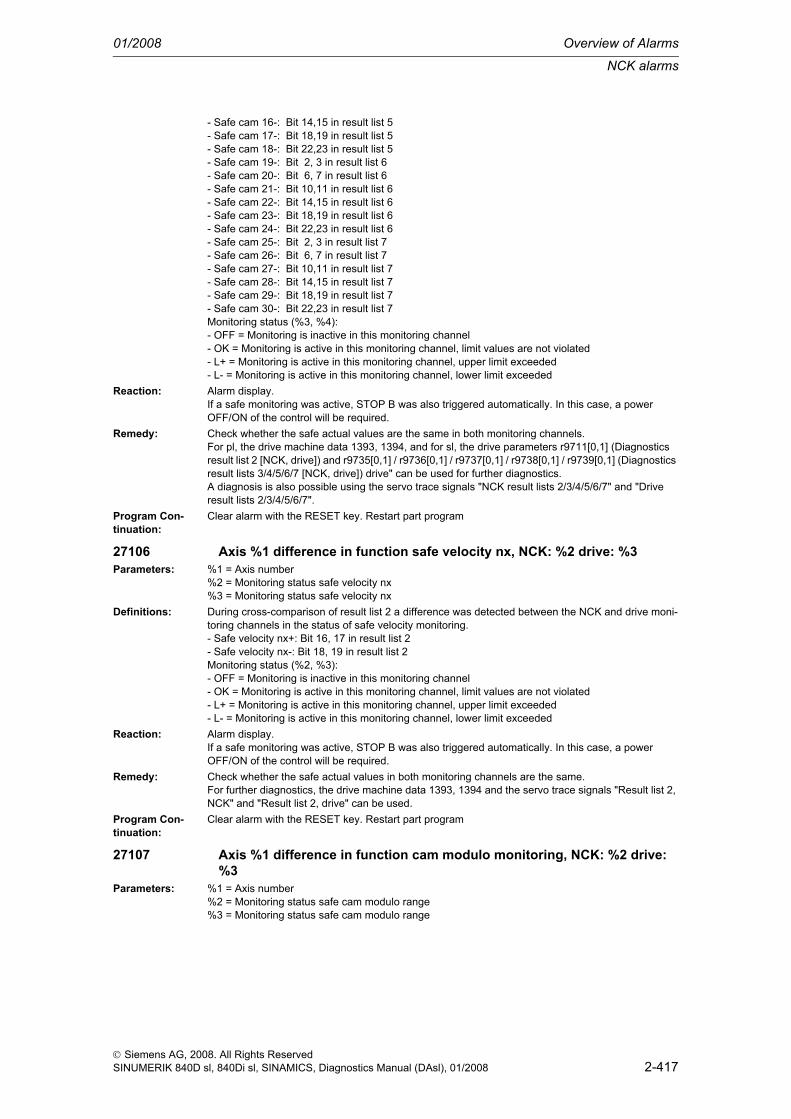
NCK alarms
01/2008 Overview of Alarms
2-417
© Siemens AG, 2008. All Rights ReservedSINUMERIK 840D sl, 840Di sl, SINAMICS, Diagnostics Manual (DAsl), 01/2008
- Safe cam 16-: Bit 14,15 in result list 5- Safe cam 17-: Bit 18,19 in result list 5- Safe cam 18-: Bit 22,23 in result list 5- Safe cam 19-: Bit 2, 3 in result list 6- Safe cam 20-: Bit 6, 7 in result list 6- Safe cam 21-: Bit 10,11 in result list 6- Safe cam 22-: Bit 14,15 in result list 6- Safe cam 23-: Bit 18,19 in result list 6- Safe cam 24-: Bit 22,23 in result list 6- Safe cam 25-: Bit 2, 3 in result list 7- Safe cam 26-: Bit 6, 7 in result list 7- Safe cam 27-: Bit 10,11 in result list 7- Safe cam 28-: Bit 14,15 in result list 7- Safe cam 29-: Bit 18,19 in result list 7- Safe cam 30-: Bit 22,23 in result list 7Monitoring status (%3, %4):- OFF = Monitoring is inactive in this monitoring channel- OK = Monitoring is active in this monitoring channel, limit values are not violated- L+ = Monitoring is active in this monitoring channel, upper limit exceeded- L- = Monitoring is active in this monitoring channel, lower limit exceeded
Reaction: Alarm display.If a safe monitoring was active, STOP B was also triggered automatically. In this case, a power OFF/ON of the control will be required.
Remedy: Check whether the safe actual values are the same in both monitoring channels.For pl, the drive machine data 1393, 1394, and for sl, the drive parameters r9711[0,1] (Diagnostics result list 2 [NCK, drive]) and r9735[0,1] / r9736[0,1] / r9737[0,1] / r9738[0,1] / r9739[0,1] (Diagnostics result lists 3/4/5/6/7 [NCK, drive]) drive" can be used for further diagnostics.A diagnosis is also possible using the servo trace signals "NCK result lists 2/3/4/5/6/7" and "Drive result lists 2/3/4/5/6/7".
Program Con-tinuation:
Clear alarm with the RESET key. Restart part program
27106 Axis %1 difference in function safe velocity nx, NCK: %2 drive: %3Parameters: %1 = Axis number
%2 = Monitoring status safe velocity nx%3 = Monitoring status safe velocity nx
Definitions: During cross-comparison of result list 2 a difference was detected between the NCK and drive moni-toring channels in the status of safe velocity monitoring.- Safe velocity nx+: Bit 16, 17 in result list 2- Safe velocity nx-: Bit 18, 19 in result list 2Monitoring status (%2, %3):- OFF = Monitoring is inactive in this monitoring channel- OK = Monitoring is active in this monitoring channel, limit values are not violated- L+ = Monitoring is active in this monitoring channel, upper limit exceeded- L- = Monitoring is active in this monitoring channel, lower limit exceeded
Reaction: Alarm display.If a safe monitoring was active, STOP B was also triggered automatically. In this case, a power OFF/ON of the control will be required.
Remedy: Check whether the safe actual values in both monitoring channels are the same.For further diagnostics, the drive machine data 1393, 1394 and the servo trace signals "Result list 2, NCK" and "Result list 2, drive" can be used.
Program Con-tinuation:
Clear alarm with the RESET key. Restart part program
27107 Axis %1 difference in function cam modulo monitoring, NCK: %2 drive: %3
Parameters: %1 = Axis number%2 = Monitoring status safe cam modulo range%3 = Monitoring status safe cam modulo range

Overview of Alarms 01/2008
NCK alarms
2-418
© Siemens AG, 2008. All Rights ReservedSINUMERIK 840D sl, 840Di sl, SINAMICS, Diagnostics Manual (DAsl), 01/2008
Definitions: During cross-comparison of result list 2 a difference was detected between the NCK and drive moni-toring channels in the status of cam modulo monitoring.Safe cam modulo range: Bit 20, 21 in result list 2Monitoring status (%2, %3):- OFF = Monitoring is inactive in this monitoring channel- OK = Monitoring is active in this monitoring channel, limit values are not violated- L+ = Monitoring is active in this monitoring channel, upper limit exceeded- L- = Monitoring is active in this monitoring channel, lower limit exceeded
Reaction: Alarm display.If a safe monitoring was active, STOP B was also triggered automatically. In this case, a power OFF/ON of the control will be required.
Remedy: Check whether the safe actual values in both monitoring channels are the same.For further diagnostics, the drive machine data 1393, 1394 and the servo trace signals "Result list 2, NCK" and "Result list 2, drive" can be used.
Program Con-tinuation:
Clear alarm with the RESET key. Restart part program
27110 Axis %1 fault during data transmission index%2.Parameters: %1 = Axis number
%2 = Index in data cross-check.Definitions: Faulty communication between NCK and drive caused that data cross-check
of data and indicated index could not be executed three times in a row.
Reaction: Alarm display.In addition, a Stop F is triggered that may cause follow-up alarm 27001 with error code 0 as well asalarms 27023 and 27024.Alarm 27001 with error code 0 can be avoided by alarm reduction($MA_SAFE_ALARM_SUPPRESS_LEVEL higher or equal to 1).
Remedy: Verification of compliance with the EMC regulations.Replace the hardware.
Program Con-tinuation:
Clear alarm with the RESET key. Restart part program
27111 Axis %1 fault during encoder evaluation of the safe actual value.Parameters: %1 = Axis numberDefinitions: The redundantly determined safe actual value does not match
the fine resolution actual value of the same encoder.Reaction: Alarm display.
In addition, a Stop F is triggered that may cause follow-up alarm 27001 with error code 0 as well asalarms 27023 and 27024.Alarm 27001 with error code 0 can be avoided by alarm reduction($MA_SAFE_ALARM_SUPPRESS_LEVEL higher or equal to 1).
Remedy: Verification of compliance with the EMC regulations.Replace the hardware.
Program Con-tinuation:
Clear alarm with the RESET key. Restart part program
27112 Axis %1 CRC error of the safe actual value.Parameters: %1 = Axis numberDefinitions: An error has been detected on verifying data consistency of the safe actual value (CRC).Reaction: Alarm display.
In addition, a Stop F is triggered that may cause follow-up alarm 27001 with error code 0 as well asalarms 27023 and 27024.Alarm 27001 with error code 0 can be avoided by alarm reduction($MA_SAFE_ALARM_SUPPRESS_LEVEL higher or equal to 1).

NCK alarms
01/2008 Overview of Alarms
2-419
© Siemens AG, 2008. All Rights ReservedSINUMERIK 840D sl, 840Di sl, SINAMICS, Diagnostics Manual (DAsl), 01/2008
Remedy: Possible causes of the continual presence of this alarm:- The NCK monitoring channel for safe motion monitoring is not communicating with the monitoring channel of the assigned drive but with that of another axis. Check the correctness of the assignment of the drive in the hardware configuration, $MA_SAFE_CTRLOUT_MODULE_NR, $MN_SAFE_DRIVE_LOGIC_ADDRESS, and p0978.- Interference in the communication between NCK and drive. Check compliance with the EMC guide-lines. Exchange hardware.
Program Con-tinuation:
Clear alarm with the RESET key. Restart part program
27113 Axis %1 hardware encoder error of the safe actual value.Parameters: %1 = Axis numberDefinitions: Encoder evaluation outputs a hardware error. The reasons may be pollution in
the visual encoder evaluation or problems during signal transmission.Reaction: Alarm display.
In addition, a Stop F is triggered that may cause follow-up alarm 27001 with error code 0 as well asalarms 27023 and 27024.Alarm 27001 with error code 0 can be avoided by alarm reduction($MA_SAFE_ALARM_SUPPRESS_LEVEL higher or equal to 1).
Remedy: Verification of compliance with the EMC regulations.Replace the encoder hardware.
Program Con-tinuation:
Clear alarm with the RESET key. Restart part program
27124 Stop A triggered at least in 1 axisDefinitions: This is only an informational alarm indicating that Stop A has been triggered in at least 1 axis and
Power On is required for alarm acknowledgment.This alarm occurs if the alarm priority function was activated in MD $MN_SAFE_ALARM_SUPPRESS_LEVEL.
Reaction: Interface signals are set.Alarm display.Trigger a "Pulse suppression" for the affected axis.
Remedy: Find the error cause by means of further alarm messages.Program Con-tinuation:
Switch control OFF - ON.
27140 Waiting for motor module of at least one axis.Definitions: Alarm during ramp-up as long as the motor module of at least one axis is not yet ready for SI.
Communication to the motor module during ramp-up has not yet been activated; the safety functions of at least one axis are not yet available.Via MD $MN_SAFE_ALARM_SUPPRESS_LEVEL (MD<3) the alarm display can be set to display for each axis individually whether communication has been activated.
Reaction: Interface signals are set.Alarm display.
Remedy: The alarm will remain present during ramp-up if at least one drive does not communicate. Otherwise, the alarm will only briefly be displayed, and then be deleted automatically.Possible causes of the continued presence of the alarm:- Safe motion monitoring has only been activated in $MA_SAFE_FUNCTION_ENABLE, but not in the corresponding parameter of the assigned drive (p9501).- The axis -> drive assignment is incorrect in MD $MA_SAFE_CRTLOUT_MODULE_NR, MD $MN_SAFE_DRIVE_LOGIC_ADDRESS or p0978.- PROFIBUS plug has fallen out.Check the correctness of parameter p9501 or the assignment of the drives in MD $MA_SAFE_CTRLOUT_MODULE_NR, $MN_SAFE_DRIVE_LOGIC_ADDRESS, p0978.
Program Con-tinuation:
Alarm display showing cause of alarm disappears. No further operator action necessary.

Overview of Alarms 01/2008
NCK alarms
2-420
© Siemens AG, 2008. All Rights ReservedSINUMERIK 840D sl, 840Di sl, SINAMICS, Diagnostics Manual (DAsl), 01/2008
27200 PROFIsafe: cycle time %1 [ms] too longParameters: %1 = Parameterized cycle timeDefinitions: The PROFIsafe communication cycle time resulting from MD $MN_PROFISAFE_IPO_TIME_RATIO
and MD $MN_IPO_CYCLE_TIME exceeds the permissible limit value (25 ms).Reaction: Mode group not ready.
Channel not ready.NC Start disable in this channel.Interface signals are set.Alarm display.NC Stop on alarm.
Remedy: Adapt cycle time via MD $MN_PROFISAFE_IPO_TIME_RATIO or correct the reduction of the IPO cycle.
Program Con-tinuation:
Switch control OFF - ON.
27201 PROFIsafe: MD %1[%2]: bus segment %3 errorParameters: %1 = MD name
%2 = MD array index%3 = Parameterized bus segment
Definitions: An incorrect bus segment was entered in the specified machine data. The value must be 5.Reaction: Mode group not ready.
Channel not ready.NC Start disable in this channel.Interface signals are set.Alarm display.NC Stop on alarm.
Remedy: Correct the MD.Program Con-tinuation:
Switch control OFF - ON.
27202 PROFIsafe: MD %1[%2]: address %3 errorParameters: %1 = MD name
%2 = MD array index%3 = Parameterized PROFIsafe address
Definitions: An incorrect PROFIsafe address was entered in the specified machine data. The value must be greater than 0.
Reaction: Mode group not ready.Channel not ready.NC Start disable in this channel.Interface signals are set.Alarm display.NC Stop on alarm.
Remedy: Correct the MD.Program Con-tinuation:
Switch control OFF - ON.
27203 PROFIsafe: MD %1[%2]: SPL assignment errorParameters: %1 = MD name
%2 = MD array indexDefinitions: The parameterization of the specified machine data for the link between the SPL interface and a
PROFIsafe module is incorrect because of the following reasons:- Bit values greater than definition of SPL interface (bit value > 64)- Number of bits too high for this PROFIsafe module (upper bit value - lower bit value + 1 > 8)- No SPL assignment parameterized (both bit values equal to zero)- Incorrect SPL assignment (bit value equals zero)

NCK alarms
01/2008 Overview of Alarms
2-421
© Siemens AG, 2008. All Rights ReservedSINUMERIK 840D sl, 840Di sl, SINAMICS, Diagnostics Manual (DAsl), 01/2008
Reaction: Mode group not ready.Channel not ready.NC Start disable in this channel.Interface signals are set.Alarm display.NC Stop on alarm.
Remedy: Correct the MD.Program Con-tinuation:
Switch control OFF - ON.
27204 PROFIsafe: double assignment MD %1[%2] - MD %3[%4]Parameters: %1 = MD name 1
%2 = MD array index for MD name 1%3 = MD name 2%4 = MD array index for MD name 2
Definitions: A double assignment has illegally been parameterized in the specified machine data:$A_INSE parameterized on DMP as well as PROFIsafe modules. Involved MDs:- MD $MN_SAFE_IN_HW_ASSIGN- MD $MN_PROFISAFE_IN_ASSIGN$A_INSE parameterized on several PROFIsafe modules. Involved MD:- MD $MN_PROFISAFE_IN_ASSIGN
Reaction: Mode group not ready.Channel not ready.NC Start disable in this channel.Interface signals are set.Alarm display.NC Stop on alarm.
Remedy: Correct the MD.Program Con-tinuation:
Switch control OFF - ON.
27205 PROFIsafe: number of signals in MD %1 [%2] <> MD %3[%4]Parameters: %1 = MD name 1
%2 = MD array index for MD name 1%3 = MD name 2%4 = MD array index for MD name 2
Definitions: The parameterized number or the signals used must be the same in both machine data.Reaction: Mode group not ready.
Channel not ready.NC Start disable in this channel.Interface signals are set.Alarm display.NC Stop on alarm.
Remedy: Correct the MD.Program Con-tinuation:
Switch control OFF - ON.
27206 PROFIsafe: MD %1[%2] maximum number of F user data (%3 bits) exceeded.
Parameters: %1 = MD name%2 = MD array index for MD name%3 = Maximum F user data bits.
Definitions: The parameterized data indicated in the machine data are outside the F user data range of the F mod-ule.NoteWhen machine data PROFISAFE_IN/OUT_ADDRESS is displayed, the sub slot addressparameterized in it will exceed the F user data range of the F module.

Overview of Alarms 01/2008
NCK alarms
2-422
© Siemens AG, 2008. All Rights ReservedSINUMERIK 840D sl, 840Di sl, SINAMICS, Diagnostics Manual (DAsl), 01/2008
Reaction: Mode group not ready.Channel not ready.NC Start disable in this channel.Interface signals are set.Alarm display.NC Stop on alarm.
Remedy: Correct the MD.Program Con-tinuation:
Switch control OFF - ON.
27207 PROFIsafe: MD %1[%2] max. sub slot number: %3 exceededParameters: %1 = MD name
%2 = MD array index for MD name%3 = Max. number of sub slots
Definitions: The sub slot parameterized in the indicated machine data exceeds the max. permissible number of sub slots per PROFIsafe module.
Reaction: Mode group not ready.Channel not ready.NC Start disable in this channel.Interface signals are set.Alarm display.NC Stop on alarm.
Remedy: Reduce the number of sub slots by changing the splitting of F user data of the PROFIsafe module.Program Con-tinuation:
Switch control OFF - ON.
27208 PROFIsafe: MD %1[%2]: max. sub-slot address %3 exceeded.Parameters: %1 = MD name
%2 = MD array index%3 = Maximum sub-slot address.
Definitions: A sub-slot address was entered in the MD that is too high. The entered value must not exceed the displayed maximum sub-slot address.
Reaction: Mode group not ready.Channel not ready.NC Start disable in this channel.Interface signals are set.Alarm display.NC Stop on alarm.
Remedy: Correct the MD.Program Con-tinuation:
Switch control OFF - ON.
27220 PROFIsafe: Number of NCK F modules (%1) <> Number of S7 F modules (%2)
Parameters: %1 = Number of parameterized NCK F modules%2 = Number of parameterized S7 F modules
Definitions: The number of F modules parameterized via the NCK machine data $MN_PROFISAFE_IN/OUT_ADDRESS is:- Greater than the number of PROFIBUS slaves in the S7 PROFIBUS configuration.- Smaller than the number of F modules in the S7 PROFIBUS configuration,- greater than the number of F modules known in the S7 PROFIBUS configuration.If alarm parameter %2 = 0, then none of the configured F modules were found in the S7 PROFIBUS configuration.In most cases, the reason for the alarm is an error in the parameterization of the PROFIsafe master address.
Reaction: Mode group not ready.Channel not ready.NC Start disable in this channel.Interface signals are set.Alarm display.NC Stop on alarm.

NCK alarms
01/2008 Overview of Alarms
2-423
© Siemens AG, 2008. All Rights ReservedSINUMERIK 840D sl, 840Di sl, SINAMICS, Diagnostics Manual (DAsl), 01/2008
Remedy: Check the F parameterization in MD $MN_PROFISAFE_IN/OUT_ADDRESS.Check the F configuration in the S7 PROFIBUS configuration.Check the parameterized PROFIsafe master address in MD $MN_PROFISAFE_MASTER_ADDRESS and in the S7 PROFIBUS configuration.
Program Con-tinuation:
Switch control OFF - ON.
27221 PROFIsafe: NCK F module MD %1[%2] unknownParameters: %1 = MD name
%2 = MD array indexDefinitions: The F module parameterized in the specified machine data is unknown under this PROFIsafe address
in the S7 PROFIBUS configuration.Reaction: Mode group not ready.
Channel not ready.NC Start disable in this channel.Interface signals are set.Alarm display.NC Stop on alarm.
Remedy: Check the PROFIsafe addresses in the NCK MD and S7 PROFIBUS configuration.Program Con-tinuation:
Switch control OFF - ON.
27222 PROFIsafe: S7 F module PROFIsafe address %1 unknownParameters: %1 = PROFIsafe addressDefinitions: The F module with the specified PROFIsafe address has not been parameterized as an F module in
the NCK MD.Reaction: Mode group not ready.
Channel not ready.NC Start disable in this channel.Interface signals are set.Alarm display.NC Stop on alarm.
Remedy: Check the S7 PROFIBUS configuration. Enter the module in the NCK MD.Program Con-tinuation:
Switch control OFF - ON.
27223 PROFIsafe: NCK F module MD %1[%2] is not a %3 moduleParameters: %1 = MD name
%2 = MD array index%3 = Module type
Definitions: The F module parameterized in the specified NCK MD has not been entered as input/output module in the S7 PROFIBUS configuration.- %3 = INPUT: NCK F parameterization expects INPUT module- %3 = OUTPUT: NCK F parameterization expects OUTPUT module- %3 = IN/OUT: NCK F parameterization expects INPUT or OUTPUT module
Reaction: Mode group not ready.Channel not ready.NC Start disable in this channel.Interface signals are set.Alarm display.NC Stop on alarm.
Remedy: Check the module in the S7 PROFIBUS configuration.Program Con-tinuation:
Switch control OFF - ON.
27224 PROFIsafe: F module MD %1[%2] - MD %3[%4]: double assignment of PROFIsafe address
Parameters: %1 = MD name 1%2 = MD array index 1%3 = MD name 2%4 = MD array index 2

Overview of Alarms 01/2008
NCK alarms
2-424
© Siemens AG, 2008. All Rights ReservedSINUMERIK 840D sl, 840Di sl, SINAMICS, Diagnostics Manual (DAsl), 01/2008
Definitions: In the NCK MD or in the S7 F parameters, the same PROFIsafe address has been parameterized for the F modules parameterized in the specified machine data. Therefore, no clear communication link is possible between F master and F slave.
Reaction: Mode group not ready.Channel not ready.NC Start disable in this channel.Interface signals are set.Alarm display.NC Stop on alarm.
Remedy: Check and correct the S7 F parameterization and NCK MD.Program Con-tinuation:
Switch control OFF - ON.
27225 PROFIsafe: slave %1, configuration error %2Parameters: %1 = PROFIBUS slave address
%2 = Configuration errorDefinitions: An error occurred during the evaluation of the S7 PROFIBUS configuration for the specified slave.
This is further specified in alarm parameter %2.%2 = PRM header: the PRM telegram for this slave could not clearly be interpreted.
Reaction: Mode group not ready.Channel not ready.NC Start disable in this channel.Interface signals are set.Alarm display.NC Stop on alarm.
Remedy: Check and correct the S7 PROFIBUS configuration.Program Con-tinuation:
Switch control OFF - ON.
27240 PROFIsafe: DP M not running up, DP info: %1Parameters: %1 = Current information from the DP interface NCK-PLCDefinitions: There is no DP configuration available to the NCK after the time specified via the MD
$MN_PLC_RUNNINGUP_TIMEOUT.Reaction: Mode group not ready.
Channel not ready.NC Start disable in this channel.Interface signals are set.Alarm display.NC Stop on alarm.
Remedy: - Increase MD $MN_PLC_RUNNINGUP_TIMEOUT- Check the PLC operating status.- Check the PLC operating system software version.- Delete the F parameterization in the NCK MD.
Program Con-tinuation:
Switch control OFF - ON.
27241 PROFIsafe: DP M version different, NCK: %1, PLC: %2Parameters: %1 = DP interface version of the NCK
%2 = DP interface version of the PLCDefinitions: The NCK and PLC components have different implementations of the DP interface. The F communi-
cation cannot be initialized.Reaction: Mode group not ready.
Channel not ready.NC Start disable in this channel.Interface signals are set.Alarm display.NC Stop on alarm.
Remedy: - Check the PLC operating system and NCK software versions.- Upgrade the PLC operating system.- Delete the NCK F parameterization.

NCK alarms
01/2008 Overview of Alarms
2-425
© Siemens AG, 2008. All Rights ReservedSINUMERIK 840D sl, 840Di sl, SINAMICS, Diagnostics Manual (DAsl), 01/2008
Program Con-tinuation:
Switch control OFF - ON.
27242 PROFIsafe: F module %1, %2 faultyParameters: %1 = PROFIsafe address
%2 = Incorrect F parameterDefinitions: An error was detected during the evaluation of the F parameters.
%2 = CRC1: CRC specified by F parameters faulty.%2 = F_WD_Timeout: The monitoring time parameterized in Step 7 is too small for the PROFIsafe cycle time defined by the MD $MN_PROFISAFE_IPO_TIME_RATIO.%2 = CRC2_Len: CRC message length faulty.%2 = F_Data_Len: the telegram length defined for the specified module is incorrect.
Reaction: Mode group not ready.Channel not ready.NC Start disable in this channel.Interface signals are set.Alarm display.NC Stop on alarm.
Remedy: %2 = CRC1: PLC overall reset, reload the S7 F configuration.%2 = F_WD_Timeout: reparameterize the PROFIsafe cycle time or F monitoring time.%2 = CRC2_Len: PLC overall reset, reload the S7 F configuration.%2 = F_Data_Len: PLC overall reset, reload the S7 F configuration.
Program Con-tinuation:
Switch control OFF - ON.
27250 PROFIsafe: configuration in DP M changed; error code %1 - %2Parameters: %1 = NCK project number
%2 = Current PLC project numberDefinitions: The DP master shows a modified S7 PROFIBUS configuration. Error-free operation can no longer be
guaranteed.Reaction: Mode group not ready.
Channel not ready.NC Start disable in this channel.Interface signals are set.Alarm display.NC Stop on alarm.Communication with F slaves is finished.A STOP D/E (settable via MD $MN_SPL_STOP_MODE) is triggered on all axes with safety function-ality.
Remedy: Restart the PLC/NCK.Program Con-tinuation:
Switch control OFF - ON.
27251 PROFIsafe: F module %1, %2 reports error %3Parameters: %1 = PROFIsafe address
%2 = Reporting component (master/slave)%3 = Error code
Definitions: An error occurred in the PROFIsafe communication between the F master and the specified F module which was detected by the component (master/slave) shown in parameter %2.The error code specifies the error type:- %3 = TO: The parameterized communication timeout was exceeded- %3 = CRC: A CRC error was detected- %3 = CN: An error in the time sequence of the F messages was detected- %3 = SF: F master error, NCK/PLC are no longer synchronous- %3 = EA: Communication error, slave sends empty messages
Reaction: Mode group not ready.NC Start disable in this channel.Interface signals are set.Alarm display.NC Stop on alarm.Trigger a STOP D/E (settable via MD $MN_SPL_STOP_MODE) on all axes with safety functionality.

Overview of Alarms 01/2008
NCK alarms
2-426
© Siemens AG, 2008. All Rights ReservedSINUMERIK 840D sl, 840Di sl, SINAMICS, Diagnostics Manual (DAsl), 01/2008
Remedy: Check the DP wiring. Restart F slave modules. Restart the NCK/PLC.Program Con-tinuation:
Clear alarm with the RESET key. Restart part program
27252 PROFIsafe: Slave %1, sign-of-life errorParameters: %1 = DP slave addressDefinitions: The specified DP slave no longer communicates with the master.Reaction: Mode group not ready.
NC Start disable in this channel.Interface signals are set.Alarm display.NC Stop on alarm.Trigger a STOP D/E (settable via MD $MN_SPL_STOP_MODE) on all axes with safety functionality.
Remedy: Check the DP wiring. Restart F slave modules. Restart the NCK/PLC.Program Con-tinuation:
Clear alarm with the RESET key. Restart part program
27253 PROFIsafe: communication fault F master component %1, error %2Parameters: %1 = Error component (NCK/PLC)
%2 = Error codeDefinitions: The F master signals that the communication between the NCK and PLC is no longer working.
The error code %1 specifies the cause:- %1 = NCK: Link between PROFIsafe and SPL interface is interrupted.- %1 = PLC: the PLC does no longer execute the OB40 request.- %1 = PLC-DPM: DP master is no longer in OPERATE status.Parameter %2 provides further information about the error's cause:- %2 = 0: NCK-internal sequence error (see %1=NCK).- %2 = 1,2,4: PLC processing of the OB40 not finished.
Reaction: Mode group not ready.NC Start disable in this channel.Interface signals are set.Alarm display.NC Stop on alarm.Trigger a STOP D/E (settable via MD $MN_SPL_STOP_MODE) on all axes with safety functionality.
Remedy: Extend the PROFIsafe cycle time via MD $MN_PROFISAFE_IPO_TIME_RATIO.Program Con-tinuation:
Clear alarm with the RESET key. Restart part program
27254 PROFIsafe: F module %1, error on channel %2; %3<ALSI>Parameters: %1 = PROFIsafe address
%2 = Channel type, channel number%3 = System variable array index extension
Definitions: The F module signals that an error occurred in the interface of the specified channel.This alarm is only triggered for ET200S F modules.The type of channel (input or output channel) is indicated by the abbreviations IN and OUT in %2.A specific alarm message can be programmed for each of the system variables on the HMI via param-eter %3:- %3 = 1....64: Error in system variables $A_INSE[1...64]- %3 = 65...128: Error in system variables $A_OUTSE[1...64]- %3 = -1: Error in an input or output channel for which there is no SPL assignment
Reaction: Mode group not ready.NC Start disable in this channel.Interface signals are set.Alarm display.NC Stop on alarm.Trigger a STOP D/E (settable via MD $MN_SPL_STOP_MODE) on all axes with safety functionality.
Remedy: Check wiring. Wiring OK: replace F module.Program Con-tinuation:
Clear alarm with the RESET key. Restart part program

NCK alarms
01/2008 Overview of Alarms
2-427
© Siemens AG, 2008. All Rights ReservedSINUMERIK 840D sl, 840Di sl, SINAMICS, Diagnostics Manual (DAsl), 01/2008
27255 PROFIsafe: F module %1, general errorParameters: %1 = PROFIsafe addressDefinitions: The specified PROFIsafe module signals an error. A more exact specification of the error's cause can-
not be made without further assistance.This alarm is triggered for all types of PROFIsafe slaves.
Reaction: Mode group not ready.NC Start disable in this channel.Interface signals are set.Alarm display.NC Stop on alarm.Trigger a STOP D/E (settable via MD $MN_SPL_STOP_MODE) on all axes with safety functionality.
Remedy: Check wiring.Program Con-tinuation:
Clear alarm with the RESET key. Restart part program
27256 PROFIsafe: Current cycle time %1 [ms]> parameterized cycle timeParameters: %1 = Current PROFIsafe communication cycle timeDefinitions: The current PROFIsafe communication cycle time is greater than the value set via MD
$MN_PROFISAFE_IPO_TIME_RATIO. The parameterized PROFIsafe communication cycle time is continually exceeded on the PLC side.
Reaction: Mode group not ready.NC Start disable in this channel.Interface signals are set.Alarm display.NC Stop on alarm.Trigger a STOP D/E (settable via MD $MN_SPL_STOP_MODE) on all axes with safety functionality.
Remedy: Adapt cycle time via MD $MN_PROFISAFE_IPO_TIME_RATIO.The value displayed in parameter %1 has to be set at least.The set cycle time affects the runtime load of the PLC module. This also has to be taken into consid-eration when making the setting.
Program Con-tinuation:
Clear alarm with the RESET key. Restart part program
27299 PROFIsafe: Diagnostics %1 %2 %3 %4Parameters: %1 = Error code 1
%2 = Error code 2%3 = Error code 3%4 = Error code 4
Definitions: Internal error in the NCK PROFIsafe implementation.Reaction: Alarm display.Remedy: Make a note of the error text and contact Siemens A&D MC, Hotline
- Tel 0180 / 5050 - 222 (Germany)- Fax 0180 / 5050 - 223- Tel +49-180 / 5050 - 222 (International)- Fax +49-180 / 5050 - 223- email [email protected]
Program Con-tinuation:
Clear alarm with the Delete key or NC START.
27300 F_DP: Cycle time %1 [ms] is too longParameters: %1 = Parameterized cycle timeDefinitions: The F_DP communication cycle time resulting from MD $MN_SAFE_SRDP_IPO_TIME_RATIO and
$MN_IPO_CYCLE_TIME exceeds the permissible limit value of 250ms.Reaction: Mode group not ready.
Channel not ready.NC Start disable in this channel.Interface signals are set.Alarm display.NC Stop on alarm.
Remedy: Correct cycle time via MD $MN_SAFE_SRDP_IPO_TIME_RATIO and/or $MN_IPO_CYCLE_TIME

Overview of Alarms 01/2008
NCK alarms
2-428
© Siemens AG, 2008. All Rights ReservedSINUMERIK 840D sl, 840Di sl, SINAMICS, Diagnostics Manual (DAsl), 01/2008
Program Con-tinuation:
Switch control OFF - ON.
27301 F_DP: MD %1[%2]: SPL interface faultyParameters: %1 = MD name
%2 = MD array indexDefinitions: The SPL interface in the displayed MD is incorrect: Possible causes:
- Bit values greater than definition of SPL interface (bit value > 64)- Number of bits too high (upper bit value - lower bit value > 16)- No SPL assignment parameterized (both bit values equal to zero)- Incorrect SPL assignment (bit value equals zero)
Reaction: Mode group not ready.Channel not ready.NC Start disable in this channel.Interface signals are set.Alarm display.NC Stop on alarm.
Remedy: Correct the MD.Program Con-tinuation:
Switch control OFF - ON.
27302 F_DP: Double assignment MD %1[%2] - MD %3[%4]Parameters: %1 = MD name 1
%2 = MD array index for MD name 1%3 = MD name 2%4 = MD array index for MD name 2
Definitions: An illegal double assignment has been parameterized in the stated MD:- %1 and %3 = $MN_SAFE_RDP_ASSIGN: SPL inputs ($A_INSE) are multiply occupied by F_DP communication.- %1 and %3 = $MN_SAFE_SDP_FILTER: F user data of an F_SENDDP are multiply occupied by sub-slots- %1 and %3 = $MN_SAFE_SDP_LADDR, $MN_SAFE_RDP_LADDR: Logical basic addresses are multiply occupied by SPL connections- %1 and %3 = $MN_SAFE_SDP_FILTER: System variable assignments are multiply occupied by SPL connections- %1 and %3 = $MN_SAFE_SDP_ID, $MN_SAFE_RDP_ID: Parameter DP_DP_ID is multiply occupied by different SPL connections%2 and %4: MD index of SPL connection
Reaction: Mode group not ready.Channel not ready.NC Start disable in this channel.Interface signals are set.Alarm display.NC Stop on alarm.
Remedy: Correct the MD.Program Con-tinuation:
Switch control OFF - ON.
27303 F_DP: Number of signals in MD %1 [%2] <> MD %3[%4]Parameters: %1 = MD name 1
%2 = MD array index for MD name 1%3 = MD name 2%4 = MD array index for MD name 2
Definitions: Different numbers of F user data signals have been parameterized in machine data $MN_SAFE_SDP/RDP_ASSIGN, $MN_SAFE_SDP/RDP_FILTER.
Reaction: Mode group not ready.Channel not ready.NC Start disable in this channel.Interface signals are set.Alarm display.NC Stop on alarm.

NCK alarms
01/2008 Overview of Alarms
2-429
© Siemens AG, 2008. All Rights ReservedSINUMERIK 840D sl, 840Di sl, SINAMICS, Diagnostics Manual (DAsl), 01/2008
Remedy: Correct the stated MD.Program Con-tinuation:
Switch control OFF - ON.
27305 F_DP: Parameter MD %1 [%2] <> MD %3[%4]Parameters: %1 = MD name 1
%2 = MD array index for MD name 1%3 = MD name 2%4 = MD array index for MD name 2
Definitions: An SPL connection has been parameterized with multiple SPL interfaces (sub-slots), in which different values have been entered in the F_DP communication parameters or the system variable assignment (%1 and %3). Note: SPL interfaces (sub-slots) of an SPL connection are characterized by equal values for: - F_DP communication parameter - System variable assignmentValues for %1 and %3: $MN_SAFE_SDP/RDP_LADDR or $MN_SAFE_SDP/RDP_TIMEOUT or $MN_SAFE_SDP/RDP_CONNECTION_NR $MN_SAFE_SDP/RDP_ERR_REAC $MN_SAFE_RDP_SUBS
Reaction: Mode group not ready.Channel not ready.NC Start disable in this channel.Interface signals are set.Alarm display.NC Stop on alarm.
Remedy: Correct the MD.Program Con-tinuation:
Switch control OFF - ON.
27306 F_DP: Maximum number of active SPL connections (%1) exceeded for %2.
Parameters: %1 = Maximum possible number of SPL connections%2 = F_SENDP/F_RECVDP
Definitions: More than the permissible number of SPL connections %1, marked by different identifiers ($MN_SAFE_SDP/RDP_ID), have been parameterized for %2 in the active parameter data records.
Reaction: Mode group not ready.Channel not ready.NC Start disable in this channel.Interface signals are set.Alarm display.NC Stop on alarm.
Remedy: Correct the identifiers of the active SPL connections or deactivate SPL connections ($MN_SAFE_SDP/RDP_ENABLE_MASK).
Program Con-tinuation:
Switch control OFF - ON.
27350 F_DP: %1 communication, connection %2 reports error %3Parameters: %1 = Type of communication
%2 = Name or DP_DP_ID of the communication relationship%3 = Error code
Definitions: The F_DP communication with the external communication partner is disturbed, and the programmed error reaction is $A_FSDP_/FRDP_ERR_REAC = 0 or 1.The affected component is displayed in %1:%1 = F_SENDDP%1 = F_RECVDP

Overview of Alarms 01/2008
NCK alarms
2-430
© Siemens AG, 2008. All Rights ReservedSINUMERIK 840D sl, 840Di sl, SINAMICS, Diagnostics Manual (DAsl), 01/2008
The name or the DP_DP_ID (identifier) of the F_DP communication relationship is displayed in %2.The detected cause of the error is displayed in %3.%3 = SN: An error has been detected in the message sequence.%3 = CRC: A CRC error has been detected.%3 = TO: The parameterized communication timeout was exceeded.%3 = SF: F_DP layer of the NCK detects a fault condition in the F_DP layer of the PLC.%3 = LS: F_DP layer of the NCK detects a faulty sign of life from the F_DP layer of the PLC.All values stated for %3 can also be displayed in combination according to the fault profile.
Reaction: Mode group not ready.NC Start disable in this channel.Interface signals are set.Alarm display.NC Stop on alarm.1. F_SENDDP/F_RECVDP: system variable $A_FSDP/FRDP_ERROR = TRUE2. F_SENDDP/F_RECVDP: system variable $A_FSDP/FRDP_DIAG <> 03. F_RECVDP: system variable $A_FRDP_ACK_REQ = TRUE4. F_RECVDP: Output of the substitute values defined in system variable $A_FRDP_SUBS5. An alarm and Stop D/E are also triggered with the programmed error reaction $A_FSDP_/FRDP_ERR_REAC = 0
Remedy: Check the PROFIBUS communication and the communication partner.Note: A user acknowledgment via DB18.FRDP_ACK_REI only acknowledges the F_DP communica-tion. The alarm is still displayed and must be acknowledged separately via NC RESET.Note to %3 = LS: Internal system error, can only be eliminated by PowerOn.
Program Con-tinuation:
Clear alarm with the RESET key. Restart part program
27351 F_DP: %1 communication, connection %2 reports error %3Parameters: %1 = Type of communication
%2 = Name or DP_DP_ID of the communication relationship%3 = Error code
Definitions: The F_DP communication with the external communication partner is disturbed, and the programmed error reaction is $A_FSDP_/FRDP_ERR_REAC = 2 (alarm, display only).The affected component is displayed in %1:%1 = F_SENDDP%1 = F_RECVDPThe name or the DP_DP_ID (identifier) of the F_DP communication relationship is displayed in %2.The detected cause of the error is displayed in %3.%3 = SN: An error has been detected in the message sequence.%3 = CRC: A CRC error has been detected.%3 = TO: The parameterized communication timeout was exceeded.%3 = SF: F_DP layer of the NCK detects a fault condition in the F_DP layer of the PLC.%3 = LS: F_DP layer of the NCK detects a faulty sign of life from the F_DP layer of the PLC.All values stated for %3 can also be displayed in combination according to the fault profile.
Reaction: Alarm display.1. F_SENDDP/F_RECVDP: system variable $A_FSDP/FRDP_ERROR = TRUE2. F_SENDDP/F_RECVDP: system variable $A_FSDP/FRDP_DIAG <> 03. F_RECVDP: system variable $A_FRDP_ACK_REQ = TRUE4. F_RECVDP: Output of the substitute values defined in system variable $A_FRDP_SUBS
Remedy: Check the PROFIBUS communication and the communication partnerUser acknowledgment via DB18.FRDP_ACK_REI or NC-RESETNote to %3 = LS: Internal system error, can only be eliminated by PowerOn.
Program Con-tinuation:
Alarm display showing cause of alarm disappears. No further operator action necessary.

NCK alarms
01/2008 Overview of Alarms
2-431
© Siemens AG, 2008. All Rights ReservedSINUMERIK 840D sl, 840Di sl, SINAMICS, Diagnostics Manual (DAsl), 01/2008
27352 F_DP: Communication error %1, error %2Parameters: %1 = Error component (NCK/PLC)
%2 = Error codeDefinitions: The communication is no longer working between the NCK and PLC.
Error code %1 specifies the cause:- %1 = NCK: Link is interrupted between F_DP communication and SPL interface.- %1 = PLC: The PLC is no longer executing the OB40 request.Parameter %2 provides further information about the cause of the error:- %2 = 0: NCK-internal sequence error (see %1=NCK).- %2 <> 0: PLC processing of the OB40 not finished.
Reaction: Mode group not ready.NC Start disable in this channel.Interface signals are set.Alarm display.NC Stop on alarm.Trigger a STOP D/E (settable via MD $MN_SPL_STOP_MODE) on all axes with safety functionality.
Remedy: Check whether the set F_DP cycle is too short.Program Con-tinuation:
Clear alarm with the RESET key. Restart part program
27353 F_DP: Current cycle time %1 [ms] > parameterized cycle timeParameters: %1 = Current F_DP communication cycle timeDefinitions: The current F_DP communication cycle time is greater than the value set via MD
$MN_SAFE_SRDP_IPO_TIME_RATIO. The parameterized communication cycle time is continually exceeded on the PLC side.
Reaction: Mode group not ready.NC Start disable in this channel.Interface signals are set.Alarm display.NC Stop on alarm.Trigger a STOP D/E (settable via MD $MN_SPL_STOP_MODE) on all axes with safety functionality.
Remedy: Adapt cycle time via MD $MN_SAFE_SRDP_IPO_TIME_RATIO.At least the value displayed in parameter %1 has to be set.The set cycle time affects the runtime load of the PLC module. This also has to be taken into consid-eration when making the setting.
Program Con-tinuation:
Clear alarm with the RESET key. Restart part program
27354 F_DP: %1 communication, connection %2 reports SFC%3 error %4Parameters: %1 = Type of communication
%2 = Name or DP_DP_ID of the communication relationship%3 = SFC block number%4 = Error code
Definitions: The F_DP communication with the external communication partner is disturbed. The PLC reports an error when trying to access via the parameterized interface.The affected component is displayed in %1:%1 = F_SENDDP%1 = F_RECVDPThe name or the DP_DP_ID (identifier) of the F_DP communication relationship is displayed in %2.The PLC block that detected an error is displayed in %3.The detected cause of the error is displayed in %4.This alarm can be masked with MD $MN_SAFE_DIAGNOSIS_MASK, bit 2 = 1.
Reaction: Alarm display.Remedy: Check the PROFIBUS communication and the communication partner
Check the parameterized, logical basic address in $MN_SAFE_SDP/RDP_LADDR.Program Con-tinuation:
Clear alarm with the RESET key. Restart part program

Overview of Alarms 01/2008
NCK alarms
2-432
© Siemens AG, 2008. All Rights ReservedSINUMERIK 840D sl, 840Di sl, SINAMICS, Diagnostics Manual (DAsl), 01/2008
27900 PROFIBUS DP: SI fault on axis %1, code %2, value %3, time %4.Parameters: %1 = Axis number
%2 = Fault code of the drive (r9747).%3 = Fault value of the drive (r9749)%4 = Fault time of drive (r9748).
Definitions: Error in a SINAMICS drive.Reaction: Alarm display.Remedy: See drive documentation for fault codes/fault values.Program Con-tinuation:
Alarm display showing cause of alarm disappears. No further operator action necessary.
27901 PROFIBUS DP: SI fault on axis %1, code %2, value %3, time %4.Parameters: %1 = Axis number
%2 = Fault code of the drive (r9747).%3 = Fault value of the drive (r9749)%4 = Fault time of drive (r9748).
Definitions: Error in a SINAMICS drive.Reaction: Alarm display.Remedy: See drive documentation for fault codes/fault values.Program Con-tinuation:
Clear alarm with the RESET key. Restart part program
28000 NCU link connection to all other NCUs of the link network has been aborted
Definitions: All NCUs in the NCU link network exchange data cyclically (sign-of-life). If this alarm occurs, sign-of-life signals have not been received from any other NCUs on the NCU network. This fault in the link can have various causes:- Defective hardware.- The machine data which configure the NCU link are not the same on all NCUs.- An identical interpolator cycle time has not been selected on all NCUs.
Reaction: NC not ready.Channel not ready.NC Start disable in this channel.Interface signals are set.Alarm display.NC Stop on alarm.
Remedy: Check the IPO cycle on all the NCUs.If necessary, check NCU link-specific alarms first.
Program Con-tinuation:
Switch control OFF - ON.
28001 NCU link connection to the NCU %1 of the link network has been abortedParameters: %1 = NCU numberDefinitions: All NCUs in the NCU link network exchange data cyclically (sign-of-life). If this alarm occurs, sign-of-
life signals have not been received from one other NCU on the NCU network. (see alarm parameters) This fault in the link can have various causes:- Defective hardware.- The machine data which configure the NCU link are not identical on all NCUs.- An identical interpolator cycle time has not been selected on all NCUs.
Reaction: NC not ready.Channel not ready.NC Start disable in this channel.Interface signals are set.Alarm display.NC Stop on alarm.
Remedy: - Check the IPO cycle on all the NCUs.- If necessary, check NCU link-specific alarms first.
Program Con-tinuation:
Switch control OFF - ON.

NCK alarms
01/2008 Overview of Alarms
2-433
© Siemens AG, 2008. All Rights ReservedSINUMERIK 840D sl, 840Di sl, SINAMICS, Diagnostics Manual (DAsl), 01/2008
28002 Error on activation of machine data, NCU network-wide machine data were modified by NCU %1
Parameters: %1 = NCU numberDefinitions: During the activation of machine data with NEWCONFIG or during an operator panel RESET, NCU
network-wide machine data were modified on another NCU. This alarm can only occur when a link connection is active.
Reaction: NC not ready.NC Start disable in this channel.Interface signals are set.Alarm display.NC Stop on alarm.
Remedy: Repeat the operator action or, if NEWCONFIG is activated by an NC program, terminate the program with Reset.
Program Con-tinuation:
Clear alarm with the RESET key. Restart part program
28004 NCU link: NCU %1 of the link network is not on the busParameters: %1 = NCU numberDefinitions: Error message of the NCU link module. When the NCU link was powered up, the local NCU (indicated
by the alarm) detected that the NCU with the number in the alarm parameter was not on the bus although it should be connected according to the MD settings.This fault in the link can have various causes:- Defective hardware.- The machine data which configure the NCU link are not identical on all NCUs.- An identical interpolator cycle time has not been selected on all NCUs.
Reaction: NC not ready.Channel not ready.NC Start disable in this channel.Interface signals are set.Alarm display.NC Stop on alarm.
Remedy: Check the machine data configuration and link hardware.Program Con-tinuation:
Switch control OFF - ON.
28005 NCU link: NCU %1 of the link network not running synchronouslyParameters: %1 = NCU numberDefinitions: Error message of the NCU link module. When the NCU link was powered up, the local NCU (indicated
by the alarm) detected that the NCU with the number in the alarm parameter was not running synchro-nously.This fault in the link can have various causes:- The machine data which configure the NCU link are not identical on all NCUs.- An identical interpolator cycle time has not been selected on all NCUs.
Reaction: NC not ready.Channel not ready.NC Start disable in this channel.Interface signals are set.Alarm display.NC Stop on alarm.
Remedy: Check machine data configuration.Program Con-tinuation:
Switch control OFF - ON.
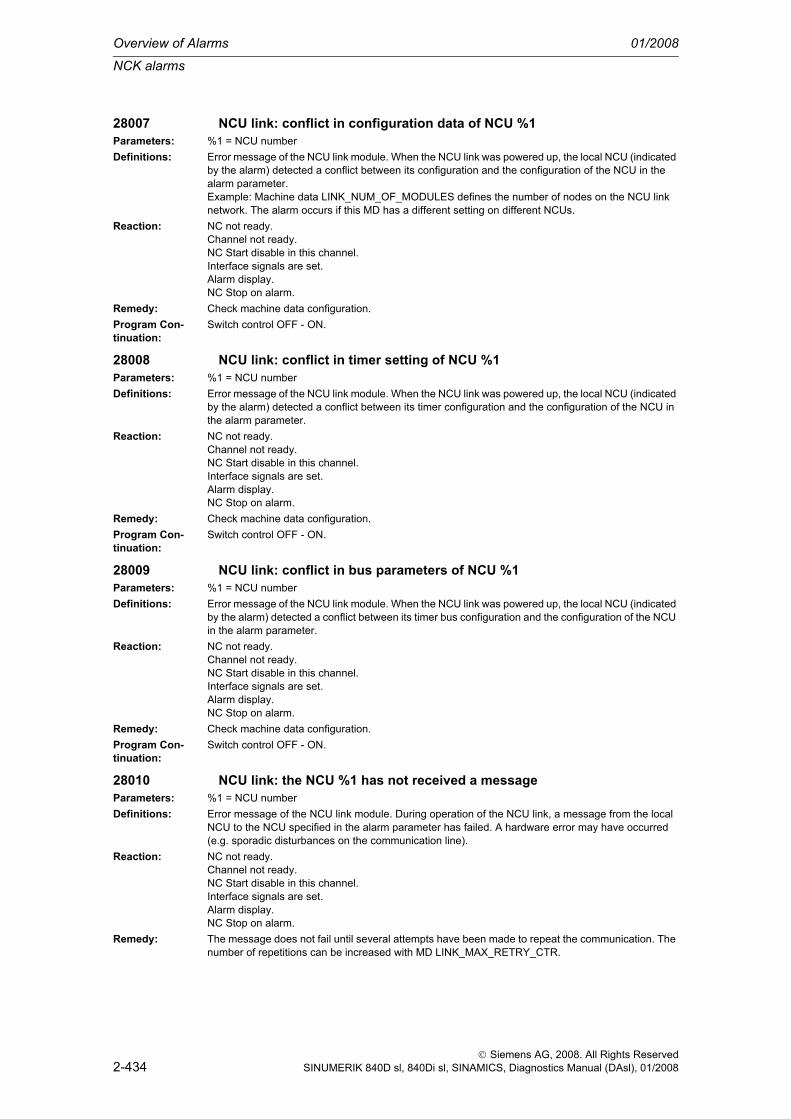
Overview of Alarms 01/2008
NCK alarms
2-434
© Siemens AG, 2008. All Rights ReservedSINUMERIK 840D sl, 840Di sl, SINAMICS, Diagnostics Manual (DAsl), 01/2008
28007 NCU link: conflict in configuration data of NCU %1Parameters: %1 = NCU numberDefinitions: Error message of the NCU link module. When the NCU link was powered up, the local NCU (indicated
by the alarm) detected a conflict between its configuration and the configuration of the NCU in the alarm parameter.Example: Machine data LINK_NUM_OF_MODULES defines the number of nodes on the NCU link network. The alarm occurs if this MD has a different setting on different NCUs.
Reaction: NC not ready.Channel not ready.NC Start disable in this channel.Interface signals are set.Alarm display.NC Stop on alarm.
Remedy: Check machine data configuration.Program Con-tinuation:
Switch control OFF - ON.
28008 NCU link: conflict in timer setting of NCU %1Parameters: %1 = NCU numberDefinitions: Error message of the NCU link module. When the NCU link was powered up, the local NCU (indicated
by the alarm) detected a conflict between its timer configuration and the configuration of the NCU in the alarm parameter.
Reaction: NC not ready.Channel not ready.NC Start disable in this channel.Interface signals are set.Alarm display.NC Stop on alarm.
Remedy: Check machine data configuration.Program Con-tinuation:
Switch control OFF - ON.
28009 NCU link: conflict in bus parameters of NCU %1Parameters: %1 = NCU numberDefinitions: Error message of the NCU link module. When the NCU link was powered up, the local NCU (indicated
by the alarm) detected a conflict between its timer bus configuration and the configuration of the NCU in the alarm parameter.
Reaction: NC not ready.Channel not ready.NC Start disable in this channel.Interface signals are set.Alarm display.NC Stop on alarm.
Remedy: Check machine data configuration.Program Con-tinuation:
Switch control OFF - ON.
28010 NCU link: the NCU %1 has not received a messageParameters: %1 = NCU numberDefinitions: Error message of the NCU link module. During operation of the NCU link, a message from the local
NCU to the NCU specified in the alarm parameter has failed. A hardware error may have occurred (e.g. sporadic disturbances on the communication line).
Reaction: NC not ready.Channel not ready.NC Start disable in this channel.Interface signals are set.Alarm display.NC Stop on alarm.
Remedy: The message does not fail until several attempts have been made to repeat the communication. The number of repetitions can be increased with MD LINK_MAX_RETRY_CTR.

NCK alarms
01/2008 Overview of Alarms
2-435
© Siemens AG, 2008. All Rights ReservedSINUMERIK 840D sl, 840Di sl, SINAMICS, Diagnostics Manual (DAsl), 01/2008
Program Con-tinuation:
Switch control OFF - ON.
28011 IPO time insufficient for NCU link. Link cycle time: %1Parameters: %1 = MicrosecondsDefinitions: Error message of the NCU link module. All messages must be transmitted within one interpolator
cycle. This applies particularly to message retries. The time was not sufficient! The parameter indi-cates how many microseconds the NCU link module needs in order to send the message.
Reaction: NC not ready.Channel not ready.NC Start disable in this channel.Interface signals are set.Alarm display.NC Stop on alarm.
Remedy: Increase the interpolator cycle time, i.e. modify one of the following MDs on all NCUs.IPO_SYSCLOCK_TIME_RATIOSYSCLOCK_CYCLE_TIME
Program Con-tinuation:
Switch control OFF - ON.
28012 NCU link: synchronization cycle signal failure %1 timesParameters: %1 = Number of cyclesDefinitions: Error message of the NCU link module that does not occur at NCU 1. The NCU's are synchronized
via their own NCU-link clock line. A large number of cycle signals are missing. The parameter indi-cates how many cycles have failed.
Reaction: NC not ready.Channel not ready.NC Start disable in this channel.Interface signals are set.Alarm display.NC Stop on alarm.
Remedy: Check the hardware.Program Con-tinuation:
Switch control OFF - ON.
28020 NCU link: too many link axes configured %1Parameters: %1 = Number of link axis connectionsDefinitions: Unfortunately, the communication capacity of the NCU link is insufficient for this link axis configuration.
The link axis configuration is determined by the following MDs:- $MN_AXCONF_LOGIC_MACHAX_TAB- $MN_AXCT_AXCONF_ASSIGN_TAB1 ... and all further container def.
Reaction: NC not ready.Channel not ready.NC Start disable in this channel.Interface signals are set.Alarm display.NC Stop on alarm.
Remedy: Connect a smaller number of axes across the link or combine the axes in fewer containers.Machine data to be changed:- $MN_AXCONF_LOGIC_MACHAX_TAB- $MN_AXCT_AXCONF_ASSIGN_TAB1 ... and all further container def.
Program Con-tinuation:
Switch control OFF - ON.

Overview of Alarms 01/2008
NCK alarms
2-436
© Siemens AG, 2008. All Rights ReservedSINUMERIK 840D sl, 840Di sl, SINAMICS, Diagnostics Manual (DAsl), 01/2008
28030 Serious alarm on NCU %1, axes in follow-up modeParameters: %1 = NCU numberDefinitions: All axes are trailing because of a serious alarm on another NCU.Reaction: NC not ready.
Mode group not ready, also effective for single axesNC Start disable in this channel.Interface signals are set.Alarm display.NC Stop on alarm.
Remedy: Acknowledge the alarm on the NCU.Program Con-tinuation:
Teileprogramm neu starten.Clear alarm with the RESET key in all channels of this mode group. Restart part program.
28031 Serious alarm on NCU %1 not yet acknowledged, axes still in follow-up mode
Parameters: %1 = NCU numberDefinitions: A serious alarm was not yet acknowledged on another NCU. Consequently, all the axes continue to
trail.Reaction: NC not ready.
Mode group not ready, also effective for single axesNC Start disable in this channel.Interface signals are set.Alarm display.NC Stop on alarm.
Remedy: Acknowledge the alarm on the NCU.Program Con-tinuation:
Alarm display showing cause of alarm disappears. No further operator action necessary.
28032 Emergency stop activated on NCU %1, axes in follow-up modeParameters: %1 = NCU numberDefinitions: The emergency stop request is active at the PLC-NCK interface on one NCU in the NCU group. Con-
sequently, all axes are following.Reaction: NC not ready.
Mode group not ready, also effective for single axesNC Start disable in this channel.Interface signals are set.Alarm display.NC Stop on alarm.
Remedy: Remedy the cause of the emergency stop on the NCU, and acknowledge the emergency stop via the PLC-NCK interface.
Program Con-tinuation:
Teileprogramm neu starten.Clear alarm with the RESET key in all channels of this mode group. Restart part program.
28033 Emergency stop on NCU %1, axes still in follow-up modeParameters: %1 = NCU numberDefinitions: The emergency stop request is active at the PLC-NCK interface on one NCU in the NCU group. Con-
sequently, all axes are following.Reaction: NC not ready.
Mode group not ready, also effective for single axesNC Start disable in this channel.Interface signals are set.Alarm display.NC Stop on alarm.
Remedy: Remedy the cause of the emergency stop on the NCU, and acknowledge the emergency stop via the PLC-NCK interface.
Program Con-tinuation:
Alarm display showing cause of alarm disappears. No further operator action necessary.

NCK alarms
01/2008 Overview of Alarms
2-437
© Siemens AG, 2008. All Rights ReservedSINUMERIK 840D sl, 840Di sl, SINAMICS, Diagnostics Manual (DAsl), 01/2008
29033 Channel %1 axis change of axis %2 not possible, PLC axis movement not yet completed
Parameters: %1 = Channel number%2 = Axis
Definitions: A PLC axis has not yet reached its end position and cannot be returned to a channel or neutralized. This alarm should not occur when PLC data block FC18 is used.
Reaction: NC Start disable in this channel.Interface signals are set.Alarm display.NC Stop on alarm.
Remedy: Wait until the axis has reached the end position or terminate the movement with delete distance to go.Program Con-tinuation:
Clear alarm with the RESET key. Restart part program
61000 Channel %1 block %2: No tool offset activeParameters: %1 = Channel number
%2 = Block number, labelDefinitions: Alarm triggered by following cycles: LONGHOLE, SLOT1, SLOT2, POCKET1 through POCKET4,
CYCLE71, CYCLE72, CYCLE90, CYCLE93 through CYCLE96.Reaction: Interpreter stop
NC Start disable in this channel.Interface signals are set.Alarm display.
Remedy: D-correction must be programmed before the cycle call.Program Con-tinuation:
Clear alarm with the RESET key. Restart part program
61001 Channel %1 block %2: Thread lead incorrectly definedParameters: %1 = Channel number
%2 = Block number, labelDefinitions: Alarm triggered by following cycles: CYCLE84, CYCLE840, CYCLE96, CYCLE97.Reaction: Interpreter stop
NC Start disable in this channel.Interface signals are set.Alarm display.
Remedy: Check parameter for the thread size or setting for the lead (contradict each other).Program Con-tinuation:
Clear alarm with the RESET key. Restart part program
61002 Channel %1 block %2: Type of machining incorrectly definedParameters: %1 = Channel number
%2 = Block number, labelDefinitions: The value of the VARI parameter for the machining has been incorrectly specified. Alarm triggered by
following cycles: SLOT1, SLOT2, POCKET1 to POCKET4, CYCLE71, CYCLE72, CYCLE76, CYCLE77, CYCLE93, CYCLE95, CYCLE97, CYCLE98.
Remedy: Modify VARI parameter.Program Con-tinuation:
Clear alarm with the RESET key. Restart part program
61003 Channel %1 Block %2: No feed programmed in cycleParameters: %1 = Channel number
%2 = Block number, labelDefinitions: The parameter for the feed has been incorrectly specified. Alarm triggered by following cycles:
CYCLE71, CYCLE72.Reaction: Interpreter stop
NC Start disable in this channel.Interface signals are set.Alarm display.
Remedy: Modify feed parameter.

Overview of Alarms 01/2008
NCK alarms
2-438
© Siemens AG, 2008. All Rights ReservedSINUMERIK 840D sl, 840Di sl, SINAMICS, Diagnostics Manual (DAsl), 01/2008
Program Con-tinuation:
Clear alarm with the RESET key. Restart part program
61004 Channel %1 Block %2: Incorrect configuration of geometry axesParameters: %1 = Channel number
%2 = Block number, labelDefinitions: The geometry-axes sequence is wrong. CYCLE328Reaction: Interpreter stop
NC Start disable in this channel.Interface signals are set.Alarm display.
Remedy: --Program Con-tinuation:
Internal
61005 Channel %1 Block %2: 3rd geometry axis not availableParameters: %1 = Channel number
%2 = Block number, labelDefinitions: With an application on the lathe with no Y-axis in the G18 plane. Alarm triggered by following cycle:
CYCLE86.Remedy: Check parameter on cycle call.
61006 Channel %1 Block %2: Tool radius too largeParameters: %1 = Channel number
%2 = Block number, labelDefinitions: The tool radius is too large for machining. Alarm triggered by following cycles: CYCLE930,
CYCLE951, E_CP_CE, E_CP_CO, E_CP_DR, E_PO_CIR, E_PO_REC, F_CP_CE, F_CP_CO, F_CP_DR, F_PO_CIR, F_PO_REC.
Reaction: Interpreter stopNC Start disable in this channel.Interface signals are set.Alarm display.
Remedy: Select a smaller tool.Program Con-tinuation:
Clear alarm with the RESET key. Restart part program
61007 Channel %1 Block %2: Tool radius too smallParameters: %1 = Channel number
%2 = Block number, labelDefinitions: The tool radius is too small for machining. Alarm triggered by following cycles: CYCLE92, E_CP_CO,
E_SL_CIR, F_CP_CO, F_PARTOF, F_SL_CIR.Reaction: Interpreter stop
NC Start disable in this channel.Interface signals are set.Alarm display.
Remedy: Select a larger tool.Program Con-tinuation:
Clear alarm with the RESET key. Restart part program
61008 Channel %1 Block %2: No tool activeParameters: %1 = Channel number
%2 = Block number, labelDefinitions: Alarm triggered by following cycles:Remedy: Select a tool.
61009 Channel %1 Block %2: Active tool number = 0Parameters: %1 = Channel number
%2 = Block number, label
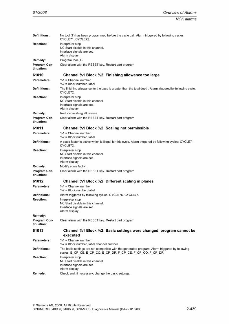
NCK alarms
01/2008 Overview of Alarms
2-439
© Siemens AG, 2008. All Rights ReservedSINUMERIK 840D sl, 840Di sl, SINAMICS, Diagnostics Manual (DAsl), 01/2008
Definitions: No tool (T) has been programmed before the cycle call. Alarm triggered by following cycles: CYCLE71, CYCLE72.
Reaction: Interpreter stopNC Start disable in this channel.Interface signals are set.Alarm display.
Remedy: Program tool (T).Program Con-tinuation:
Clear alarm with the RESET key. Restart part program
61010 Channel %1 Block %2: Finishing allowance too largeParameters: %1 = Channel number
%2 = Block number, labelDefinitions: The finishing allowance for the base is greater than the total depth. Alarm triggered by following cycle:
CYCLE72.Reaction: Interpreter stop
NC Start disable in this channel.Interface signals are set.Alarm display.
Remedy: Reduce finishing allowance.Program Con-tinuation:
Clear alarm with the RESET key. Restart part program
61011 Channel %1 Block %2: Scaling not permissibleParameters: %1 = Channel number
%2 = Block number, labelDefinitions: A scale factor is active which is illegal for this cycle. Alarm triggered by following cycles: CYCLE71,
CYCLE72.Reaction: Interpreter stop
NC Start disable in this channel.Interface signals are set.Alarm display.
Remedy: Modify scale factor.Program Con-tinuation:
Clear alarm with the RESET key. Restart part program
61012 Channel %1 Block %2: Different scaling in planesParameters: %1 = Channel number
%2 = Block number, labelDefinitions: Alarm triggered by following cycles: CYCLE76, CYCLE77.Reaction: Interpreter stop
NC Start disable in this channel.Interface signals are set.Alarm display.
Remedy: --Program Con-tinuation:
Clear alarm with the RESET key. Restart part program
61013 Channel %1 Block %2: Basic settings were changed, program cannot be executed
Parameters: %1 = Channel number%2 = Block number, label channel number
Definitions: The basic settings are not compatible with the generated program. Alarm triggered by following cycles: E_CP_CE, E_CP_CO, E_CP_DR, F_CP_CE, F_CP_CO, F_CP_DR.
Reaction: Interpreter stopNC Start disable in this channel.Interface signals are set.Alarm display.
Remedy: Check and, if necessary, change the basic settings.

Overview of Alarms 01/2008
NCK alarms
2-440
© Siemens AG, 2008. All Rights ReservedSINUMERIK 840D sl, 840Di sl, SINAMICS, Diagnostics Manual (DAsl), 01/2008
Program Con-tinuation:
Clear alarm with the RESET key. Restart part program
61014 Channel %1 Block %2: Return plane exceededParameters: %1 = Channel number
%2 = Block number, label channel numberDefinitions: Alarm triggered by following cycles: CYCLE72.Remedy: Check parameter RTP.
61015 Channel %1 Block %2: Contour is not definedParameters: %1 = Channel number
%2 = Block number, label channel numberDefinitions: Alarm triggered by following cycles: .Reaction: Interpreter stop
NC Start disable in this channel.Interface signals are set.Alarm display.
Remedy:Program Con-tinuation:
Clear alarm with the RESET key. Restart part program
61016 Channel %1 block %2: System frame for cycles missingParameters: %1 = Channel number
%2 = Block number, label channel numberDefinitions: All measuring cycles can trigger this alarm.Remedy: Set MD 28082: MM_SYSTEM_FRAME_MASK, Bit 5=1.
61017 Channel %1 block %2: function %4 not present in NCKParameters: %1 = Channel number
%2 = Block number, label channel numberDefinitions: Alarm triggered by following cycles: .Reaction: Interpreter stop
NC Start disable in this channel.Interface signals are set.Alarm display.
Remedy:Program Con-tinuation:
Clear alarm with the RESET key. Restart part program
61018 Channel %1 block %2: function %4 not executable with NCKParameters: %1 = Channel number
%2 = Block number, label channel numberDefinitions: Alarm triggered by following cycles: .Reaction: Interpreter stop
NC Start disable in this channel.Interface signals are set.Alarm display.
Remedy:Program Con-tinuation:
Clear alarm with the RESET key. Restart part program
61019 Channel %1 Block %2: Parameter %4 incorrectly definedParameters: %1 = Channel number
%2 = Block number, label channel numberDefinitions: Alarm triggered by following cycles: CYCLE60, CYCLE83.Reaction: Interpreter stop
NC Start disable in this channel.Interface signals are set.Alarm display.

NCK alarms
01/2008 Overview of Alarms
2-441
© Siemens AG, 2008. All Rights ReservedSINUMERIK 840D sl, 840Di sl, SINAMICS, Diagnostics Manual (DAsl), 01/2008
Remedy: Check the value of the parameter.Program Con-tinuation:
Clear alarm with the RESET key. Restart part program
61020 Channel %1 block %2: Machining not possible with active TRANSMIT/TRACYL
Parameters: %1 = Channel number%2 = Block number, label channel number
Definitions: Alarm triggered by following cycles: .Reaction: Interpreter stop
NC Start disable in this channel.Interface signals are set.Alarm display.
Remedy:Program Con-tinuation:
Clear alarm with the RESET key. Restart part program
61021 Channel %1 block %2: Parameter %4 value too highParameters: %1 = Channel number
%2 = Block number, label channel numberDefinitions: Alarm triggered by following cycles: .Reaction: Interpreter stop
NC Start disable in this channel.Interface signals are set.Alarm display.
Remedy:Program Con-tinuation:
Clear alarm with the RESET key. Restart part program
61022 Channel %1 block %2: Parameter %4 value too lowParameters: %1 = Channel number
%2 = Block number, label channel numberDefinitions: Alarm triggered by following cycles: .Reaction: Interpreter stop
NC Start disable in this channel.Interface signals are set.Alarm display.
Remedy:Program Con-tinuation:
Clear alarm with the RESET key. Restart part program
61023 Channel %1 block %2: Parameter %4 value must be unequal to zeroParameters: %1 = Channel number
%2 = Block number, label channel numberDefinitions: Alarm triggered by following cycles: .Reaction: Interpreter stop
NC Start disable in this channel.Interface signals are set.Alarm display.
Remedy:Program Con-tinuation:
Clear alarm with the RESET key. Restart part program
61024 Channel %1 bock %2: Parameter %4 check valueParameters: %1 = Channel number
%2 = Block number, label channel number

Overview of Alarms 01/2008
NCK alarms
2-442
© Siemens AG, 2008. All Rights ReservedSINUMERIK 840D sl, 840Di sl, SINAMICS, Diagnostics Manual (DAsl), 01/2008
Definitions: Alarm triggered by following cycles: .Reaction: Interpreter stop
NC Start disable in this channel.Interface signals are set.Alarm display.
Remedy:Program Con-tinuation:
Clear alarm with the RESET key. Restart part program
61025 Channel %1 block %2: Check tool carrier positionParameters: %1 = Channel number
%2 = Block number, label channel numberDefinitions: Alarm triggered by following cycles: .Reaction: Interpreter stop
NC Start disable in this channel.Interface signals are set.Alarm display.
Remedy:Program Con-tinuation:
Clear alarm with the RESET key. Restart part program
61026 Channel %1 block %2: Cycle cannot be executed with NC function %4.Parameters: %1 = Channel number
%2 = Block number, label channel numberDefinitions: Alarm triggered by following cycles: .Reaction: Interpreter stop
NC Start disable in this channel.Interface signals are set.Alarm display.
Remedy:Program Con-tinuation:
Clear alarm with the RESET key. Restart part program
61099 Channel %1 block %2: Internal cycle error (%4)Parameters: %1 = Channel number
%2 = Block number, label channel numberDefinitions: Alarm triggered by following cycles: .Reaction: Interpreter stop
NC Start disable in this channel.Interface signals are set.Alarm display.
Remedy:Program Con-tinuation:
Clear alarm with the RESET key. Restart part program
61101 Channel %1 block %2: Reference point defined incorrectlyParameters: %1 = Channel number
%2 = Block number, labelDefinitions: Alarm triggered by following cycles: CYCLE71, CYCLE72, CYCLE81 to CYCLE90, CYCLE840,
SLOT1, SLOT2, POCKET1 to POCKET4, LONGHOLE.Reaction: Interpreter stop
NC Start disable in this channel.Interface signals are set.Alarm display.
Remedy: With an incremental specification of the depth, either different values have to be selected for the ref-erence point (reference plane) and the retraction plane, or an absolute value must be specified for the depth.
Program Con-tinuation:
Clear alarm with the RESET key. Restart part program

NCK alarms
01/2008 Overview of Alarms
2-443
© Siemens AG, 2008. All Rights ReservedSINUMERIK 840D sl, 840Di sl, SINAMICS, Diagnostics Manual (DAsl), 01/2008
61102 Channel %1 block %2: No spindle direction programmedParameters: %1 = Channel number
%2 = Block number, labelDefinitions: Alarm triggered by following cycles: CYCLE86, CYCLE87, CYCLE88, CYCLE840, POCKET3,
POCKET4.Reaction: Interpreter stop
NC Start disable in this channel.Interface signals are set.Alarm display.
Remedy: Parameter SDIR (or SDR in CYCLE840) must be programmed.Program Con-tinuation:
Clear alarm with the RESET key. Restart part program
61103 Channel %1 block %2: Number of holes is zeroParameters: %1 = Channel number
%2 = Block number, labelDefinitions: No value for the number of holes has been programmed. Alarm triggered by following cycles:
HOLES1, HOLES2.Remedy: Check parameter NUM.Program Con-tinuation:
Clear alarm with the RESET key. Restart part program
61104 Channel %1 block %2: Contour violation of groovesParameters: %1 = Channel number
%2 = Block number, labelDefinitions: Incorrect parameterization of the milling pattern in the parameters which define the position of the
slots/elongated holes on the circle and their form. Alarm triggered by following cycles: SLOT1, SLOT2, LONGHOLE.
Reaction: Interpreter stopNC Start disable in this channel.Interface signals are set.Alarm display.
Remedy: --Program Con-tinuation:
Clear alarm with the RESET key. Restart part program
61105 Channel %1 block %2: Milling cutter radius too largeParameters: %1 = Channel number
%2 = Block number, labelDefinitions: The diameter of the cutter used is too large for the form to be machined. Alarm triggered by following
cycles: SLOT1, SLOT2, POCKET1 to POCKET4, LONGHOLE, CYCLE90.Reaction: Interpreter stop
NC Start disable in this channel.Interface signals are set.Alarm display.
Remedy: Either a tool with a smaller radius has to be used or the contour must be modified.Program Con-tinuation:
Clear alarm with the RESET key. Restart part program
61106 Channel %1 block %2: Number of or distance between circular elementsParameters: %1 = Channel number
%2 = Block number, labelDefinitions: Incorrect parameterization of NUM or INDA. The layout of the circle elements within a full circle is not
possible. Alarm triggered by following cycles: HOLES2, LONGHOLE, SLOT1, SLOT2.Reaction: Interpreter stop
NC Start disable in this channel.Interface signals are set.Alarm display.
Remedy: Correct parameterization.

Overview of Alarms 01/2008
NCK alarms
2-444
© Siemens AG, 2008. All Rights ReservedSINUMERIK 840D sl, 840Di sl, SINAMICS, Diagnostics Manual (DAsl), 01/2008
Program Con-tinuation:
Clear alarm with the RESET key. Restart part program
61107 Channel %1 block %2: First drilling depth incorrectly definedParameters: %1 = Channel number
%2 = Block number, labelDefinitions: First drilling depth is in the opposite direction to the total drilling depth. Alarm triggered by following
cycle: CYCLE83.Reaction: Interpreter stop
NC Start disable in this channel.Interface signals are set.Alarm display.
Remedy: Modify drilling depth.Program Con-tinuation:
Clear alarm with the RESET key. Restart part program
61108 Channel %1 block %2: Illegal values for radius and insertion depth parameters
Parameters: %1 = Channel number%2 = Block number, label
Definitions: The radius (_RAD1) and insertion depth (_DP1) parameters for defining the helix path for the depth infeed have been incorrectly specified. Alarm triggered by following cycles: POCKET3, POCKET4.
Reaction: Interpreter stopNC Start disable in this channel.Interface signals are set.Alarm display.
Remedy: Modify parameter.Program Con-tinuation:
Clear alarm with the RESET key. Restart part program
61109 Channel %1 block %2: Milling direction parameter incorrectly definedParameters: %1 = Channel number
%2 = Block number, labelDefinitions: The value of the parameter for the cutting direction _CDIR has been incorrectly defined. Alarm trig-
gered by following cycles: POCKET3, POCKET4.Remedy: Change milling direction.Program Con-tinuation:
Clear alarm with the RESET key. Restart part program
61110 Channel %1 Block %2: Finishing allowance at bottom > depth infeedParameters: %1 = Channel number
%2 = Block number, labelDefinitions: The finishing allowance at the base has been specified greater than the maximum depth infeed. Alarm
triggered by following cycles: POCKET3, POCKET4.Reaction: Interpreter stop
NC Start disable in this channel.Interface signals are set.Alarm display.
Remedy: Either reduce finishing allowance or increase depth infeed.Program Con-tinuation:
Clear alarm with the RESET key. Restart part program

NCK alarms
01/2008 Overview of Alarms
2-445
© Siemens AG, 2008. All Rights ReservedSINUMERIK 840D sl, 840Di sl, SINAMICS, Diagnostics Manual (DAsl), 01/2008
61111 Channel %1 Block %2: Infeed width > Tool diameterParameters: %1 = Channel number
%2 = Block number, labelDefinitions: The programmed infeed width is greater than the diameter of the active tool. Alarm triggered by fol-
lowing cycles: CYCLE71, POCKET3, POCKET4.Reaction: Interpreter stop
NC Start disable in this channel.Interface signals are set.Alarm display.
Remedy: Infeed width must be reduced.Program Con-tinuation:
Clear alarm with the RESET key. Restart part program
61112 Channel %1 Block %2: Tool radius negativeParameters: %1 = Channel number
%2 = Block number, labelDefinitions: The radius of the active tool is negative. This is illegal. Alarm triggered by following cycles: CYCLE72,
CYCLE76, CYCLE77, CYCLE90.Remedy: Change the tool radius.Program Con-tinuation:
Clear alarm with the RESET key. Restart part program
61113 Channel %1 block %2: Parameter for corner radius too largeParameters: %1 = Channel number
%2 = Block number, labelDefinitions: The parameter for the corner radius _CRAD has been specified too large. Alarm triggered by following
cycle: POCKET3.Reaction: Interpreter stop
NC Start disable in this channel.Interface signals are set.Alarm display.
Remedy: Reduce corner radiusProgram Con-tinuation:
Clear alarm with the RESET key. Restart part program
61114 Channel %1 Block %2: Machining direction G41/G42 incorrectly definedParameters: %1 = Channel number
%2 = Block number, labelDefinitions: The machining direction of the cutter radius compensation G41/G42 has been incorrectly selected.
Alarm triggered by following cycle: CYCLE72.Reaction: Interpreter stop
NC Start disable in this channel.Interface signals are set.Alarm display.
Remedy: Change machining direction.Program Con-tinuation:
Clear alarm with the RESET key. Restart part program
61115 Channel %1 Block %2: Approach or retract mode(straight / circle / plane / space) incorrectly defined
Parameters: %1 = Channel number%2 = Block number, label
Definitions: The approach or retract mode to/from the contour has been incorrectly defined. Alarm triggered by following cycle: CYCLE72.
Reaction: Interpreter stopNC Start disable in this channel.Interface signals are set.Alarm display.
Remedy: Check parameter _AS1 or _AS2.

Overview of Alarms 01/2008
NCK alarms
2-446
© Siemens AG, 2008. All Rights ReservedSINUMERIK 840D sl, 840Di sl, SINAMICS, Diagnostics Manual (DAsl), 01/2008
Program Con-tinuation:
Clear alarm with the RESET key. Restart part program
61116 Channel %1 Block %2: Approach or retract path = 0Parameters: %1 = Channel number
%2 = Block number, labelDefinitions: The approach or retract path has been specified with zero. Alarm triggered by following cycle:
CYCLE72.Reaction: Interpreter stop
NC Start disable in this channel.Interface signals are set.Alarm display.
Remedy: Check parameter _LP1 or _LP2.Program Con-tinuation:
Clear alarm with the RESET key. Restart part program
61117 Channel %1 Block %2: Active tool radius <= 0Parameters: %1 = Channel number
%2 = Block number, labelDefinitions: The radius of the acive tool is negative or zero. Alarm triggered by following cycles: CYCLE71,
POCKET3, POCKET4.Reaction: Interpreter stop
NC Start disable in this channel.Interface signals are set.Alarm display.
Remedy: Modify radius.Program Con-tinuation:
Clear alarm with the RESET key. Restart part program
61118 Channel %1 Block %2: Length or width = 0Parameters: %1 = Channel number
%2 = Block number, labelDefinitions: The length or width of the milling area is illegal. Alarm triggered by following cycle: CYCLE71.Reaction: Interpreter stop
NC Start disable in this channel.Interface signals are set.Alarm display.
Remedy: Check parameters _LENG and _WID.Program Con-tinuation:
Clear alarm with the RESET key. Restart part program
61119 Channel %1 Block %2: Nominal or core diameter programmed incorrectlyParameters: %1 = Channel number
%2 = Block number, labelDefinitions: The nominal or core diameter was incorrectly programmed. Alarm triggered by following cycles:
CYCLE70, E_MI_TR, F_MI_TR.Reaction: Interpreter stop
NC Start disable in this channel.Interface signals are set.Alarm display.
Remedy: Check thread geometry.Program Con-tinuation:
Clear alarm with the RESET key. Restart part program
61120 Channel %1 Block %2: Thread type inside / outside not definedParameters: %1 = Channel number
%2 = Block number, label

NCK alarms
01/2008 Overview of Alarms
2-447
© Siemens AG, 2008. All Rights ReservedSINUMERIK 840D sl, 840Di sl, SINAMICS, Diagnostics Manual (DAsl), 01/2008
Definitions: The thread type (internal/external) was not defined. Alarm triggered by following cycles: CYCLE70.Reaction: Interpreter stop
NC Start disable in this channel.Interface signals are set.Alarm display.
Remedy: The internal/external thread type must be entered.Program Con-tinuation:
Clear alarm with the RESET key. Restart part program
61121 Channel %1 Block %2: Number of teeth per cutting edge is missingParameters: %1 = Channel number
%2 = Block number, labelDefinitions: No value was entered for the number of teeth per cutting edge. Alarm triggered by following cycles:
CYCLE70.Reaction: Interpreter stop
NC Start disable in this channel.Interface signals are set.Alarm display.
Remedy: Enter the number of teeth/cutting edges for the active tool into the tool list.Program Con-tinuation:
Clear alarm with the RESET key. Restart part program
61122 Channel %1 Block %2: Safety distance incorrectly defined in planeParameters: %1 = Channel number
%2 = Block number, labelDefinitions: The safety clearance is negative or zero. This is not allowed.Reaction: Interpreter stop
NC Start disable in this channel.Interface signals are set.Alarm display.
Remedy: Define the safety clearance.Program Con-tinuation:
Clear alarm with the RESET key. Restart part program
61123 Channel %1 Block %2: CYCLE72 cannot be simulatedParameters: %1 = Channel number
%2 = Block number, labelDefinitions: Alarm triggered by following cycle: CYCLE72.Reaction: Interpreter stop
NC Start disable in this channel.Interface signals are set.Alarm display.
Remedy:Program Con-tinuation:
Clear alarm with the RESET key. Restart part program
61124 Channel %1 Block %2: Infeed width is not programmedParameters: %1 = Channel number
%2 = Block number, labelDefinitions: Alarm triggered by following cycle: CYCLE71.Reaction: Interpreter stop
NC Start disable in this channel.Interface signals are set.Alarm display.
Remedy: With active simulation without tool, a value for the infeed width _MIDA must always be programmed.Program Con-tinuation:
Clear alarm with the RESET key. Restart part program

Overview of Alarms 01/2008
NCK alarms
2-448
© Siemens AG, 2008. All Rights ReservedSINUMERIK 840D sl, 840Di sl, SINAMICS, Diagnostics Manual (DAsl), 01/2008
61125 Channel %1 block %2: Technology selection parameter incorrectly defined
Parameters: %1 = Channel number%2 = Block number, label
Definitions: Alarm triggered by following cycles: CYCLE84, CYCLE840.Reaction: Interpreter stop
NC Start disable in this channel.Interface signals are set.Alarm display.
Remedy: Check technology selection parameter (_TECHNO).Program Con-tinuation:
Clear alarm with the RESET key. Restart part program
61126 Channel %1 block %2: Thread length too shortParameters: %1 = Channel number
%2 = Block number, labelDefinitions: Alarm triggered by following cycle: CYCLE840.Reaction: Interpreter stop
NC Start disable in this channel.Interface signals are set.Alarm display.
Remedy: Program lower spindle speed or raise reference point (reference plane).Program Con-tinuation:
Clear alarm with the RESET key. Restart part program
61127 Channel %1 block %2: Wrong definition of tapping axis transformation ratio (machine data)
Parameters: %1 = Channel number%2 = Block number, label
Definitions: Alarm triggered by following cycles: CYCLE84, CYCLE840.Reaction: Interpreter stop
NC Start disable in this channel.Interface signals are set.Alarm display.
Remedy: Check machine data 31050 and 31060 in the appropriate gear stage of the drilling axis.Program Con-tinuation:
Clear alarm with the RESET key. Restart part program
61128 Channel %1 block %2: Insertion angle = 0 for insertion with oscillation or helix
Parameters: %1 = Channel number%2 = Block number, label
Definitions: Alarm triggered by following cycle: SLOT1.Reaction: Interpreter stop
NC Start disable in this channel.Interface signals are set.Alarm display.
Remedy: Check parameter _STA2.Program Con-tinuation:
Clear alarm with the RESET key. Restart part program
61129 Channel %1 block %2: perpendic. approach and retraction during contour milling only allowed with G40
Parameters: %1 = Channel number%2 = Block number, label

NCK alarms
01/2008 Overview of Alarms
2-449
© Siemens AG, 2008. All Rights ReservedSINUMERIK 840D sl, 840Di sl, SINAMICS, Diagnostics Manual (DAsl), 01/2008
Definitions: Alarm triggered by following cycle: CYCLE72.Reaction: Interpreter stop
NC Start disable in this channel.Interface signals are set.Alarm display.
Remedy:Program Con-tinuation:
Clear alarm with the RESET key. Restart part program
61130 Channel %1 block %2: positions of parallel axes cannot be compensated. No workpiece reference agreed.
Parameters: %1 = Channel number%2 = Block number, label
Definitions: Alarm triggered by following cycle: CYCLE69.Reaction: Interpreter stop
NC Start disable in this channel.Interface signals are set.Alarm display.
Remedy:Program Con-tinuation:
Clear alarm with the RESET key. Restart part program
61131 Channel %1 block %2: parameter _GEO incorrect, _GEO=%4Parameters: %1 = Channel number
%2 = Block number, labelDefinitions: Alarm triggered by following cycle: CYCLE69.Reaction: Interpreter stop
NC Start disable in this channel.Interface signals are set.Alarm display.
Remedy:Program Con-tinuation:
Clear alarm with the RESET key. Restart part program
61132 Channel %1 block %2: Parallel axis parameters incorrect, check values for parallel axis parameters ABS/INK
Parameters: %1 = Channel number%2 = Block number, label
Definitions: Alarm triggered by following cycle: CYCLE69.Reaction: Interpreter stop
NC Start disable in this channel.Interface signals are set.Alarm display.
Remedy:Program Con-tinuation:
Clear alarm with the RESET key. Restart part program
61133 Channel %1 block %2: 3rd parallel axis parameter incorrect, check axis name or GUD _SCW_N[]
Parameters: %1 = Channel number%2 = Block number, label
Definitions: Alarm triggered by following cycle: CYCLE69.Reaction: Interpreter stop
NC Start disable in this channel.Interface signals are set.Alarm display.
Remedy:

Overview of Alarms 01/2008
NCK alarms
2-450
© Siemens AG, 2008. All Rights ReservedSINUMERIK 840D sl, 840Di sl, SINAMICS, Diagnostics Manual (DAsl), 01/2008
Program Con-tinuation:
Clear alarm with the RESET key. Restart part program
61134 Channel %1 block %2: Rotary axis parameters incorrect, check values for rotary axis parameters ABS/INK
Parameters: %1 = Channel number%2 = Block number, label
Definitions: Alarm triggered by following cycle: CYCLE69.Reaction: Interpreter stop
NC Start disable in this channel.Interface signals are set.Alarm display.
Remedy:Program Con-tinuation:
Clear alarm with the RESET key. Restart part program
61135 Channel %1 block %2: incorrect parameter sequence for approaching target position: %4
Parameters: %1 = Channel number%2 = Block number, label
Definitions: Alarm triggered by following cycle: CYCLE69.Reaction: Interpreter stop
NC Start disable in this channel.Interface signals are set.Alarm display.
Remedy:Program Con-tinuation:
Clear alarm with the RESET key. Restart part program
61136 Channel %1 block %2: no 3rd geometry axis agreed in GUD _SCW_N[]Parameters: %1 = Channel number
%2 = Block number, labelDefinitions: Alarm triggered by following cycle: CYCLE69.Reaction: Interpreter stop
NC Start disable in this channel.Interface signals are set.Alarm display.
Remedy:Program Con-tinuation:
Clear alarm with the RESET key. Restart part program
61137 Channel %1 block %2: swiveling and parallel axes cycle are mutually exclusive because of workpiece reference $P_WPFRAME
Parameters: %1 = Channel number%2 = Block number, label
Definitions: Alarm triggered by following cycle: CYCLE69.Reaction: Interpreter stop
NC Start disable in this channel.Interface signals are set.Alarm display.
Remedy:Program Con-tinuation:
Clear alarm with the RESET key. Restart part program
61138 Channel %1 block %2: parameter %4 incorrectly defined for tool monitoring in cycles
Parameters: %1 = Channel number%2 = Block number, label

NCK alarms
01/2008 Overview of Alarms
2-451
© Siemens AG, 2008. All Rights ReservedSINUMERIK 840D sl, 840Di sl, SINAMICS, Diagnostics Manual (DAsl), 01/2008
Definitions:Reaction: Interpreter stop
NC Start disable in this channel.Interface signals are set.Alarm display.
Remedy:Program Con-tinuation:
Clear alarm with the RESET key. Restart part program
61139 Channel %1 block %2: error in function Tool monitoring in cyclesParameters: %1 = Channel number
%2 = Block number, labelDefinitions: Alarm triggered by following cycle: CYCLE69.Reaction: Interpreter stop
NC Start disable in this channel.Interface signals are set.Alarm display.
Remedy:Program Con-tinuation:
Clear alarm with the RESET key. Restart part program
61150 Channel %1 block %2: Tool cannot be aligned --> error code: %4Parameters: %1 = Channel number
%2 = Block number, labelDefinitions: Alarm triggered by following cycle: CYCLE800.Remedy: Causes of error:
1st error code = A -> only new swivel plane permitted, see parameter _ST
61151 Channel %1 block %2: Orientation of tool not possible --> error code: %4Parameters: %1 = Channel number
%2 = Block number, labelDefinitions: Alarm triggered by following cycle: CYCLE800.Remedy: Causes of error:
1st error code = A -> only additive swivel plane permitted, see parameter _ST
61152 Channel %1 block %2: B axis kinematics (turning technology) either not or incorrectly set up in Start-up of swivel cycle --> error code: %4
Parameters: %1 = Channel number%2 = Block number, label
Definitions: Alarm triggered by following cycle: CYCLE800.Remedy: Causes of error:
1st error code = A123 -> B axis not an automatic rotary axis under ShopTurn (123 corresponds to parameter _TCBA) 2nd error code = B123 -> B axis not activated in swiveling start-up (kinematics) (123 corresponds to $TC_CARR37[n], n ... number of the swivel data record)
61153 Channel %1 block %2: No 'Rotary axes direct' swivel mode possible --> error code: %4
Parameters: %1 = Channel number%2 = Block number, label
Definitions: Alarm triggered by following cycle: CYCLE800.Remedy: Causes of error:
1st error code = A -> No tool or cutting edge (D1..) active
61154 Channel %1 Block %2: Final depth wrongly programmedParameters: %1 = Channel number
%2 = Block number, label channel numberDefinitions: The alarm is triggered by the following cycle: CYCLE899Remedy: Input of end depth possible only absolutely or incrementally

Overview of Alarms 01/2008
NCK alarms
2-452
© Siemens AG, 2008. All Rights ReservedSINUMERIK 840D sl, 840Di sl, SINAMICS, Diagnostics Manual (DAsl), 01/2008
61155 Channel %1 block %2: Unit for plane infeed wrongly programmedParameters: %1 = Channel number
%2 = Block number, label channel numberDefinitions: The alarm is triggered by the following cycle: CYCLE899Remedy: Unit for plane infeed possible only in mm or % of tool diameter
61156 Channel %1 block %2: Depth calculation wrongly programmedParameters: %1 = Channel number
%2 = Block number, label channel numberDefinitions: The alarm is triggered by the following cycle: CYCLE899Remedy: Depth calculation possible only with or without SDIS
61157 Channel %1 block %2: Reference point wrongly programmedParameters: %1 = Channel number
%2 = Block number, label channel numberDefinitions: The alarm is triggered by the following cycle: CYCLE899Remedy: Check reference point in screen form, input only -X, centred or +X
61158 Channel %1 block %2: Machining plane wrongly programmedParameters: %1 = Channel number
%2 = Block number, label channel numberDefinitions: The alarm is triggered by the following cycle: CYCLE899Remedy: Check machining plane (G17, G18 or G19)
61159 Channel %1 block %2: Machining plane in cycle is different from the one in the position pattern
Parameters: %1 = Channel number%2 = Block number, label channel number
Definitions: The alarm is triggered by the following cycle: CYCLE899Remedy: Adjust machining plane in the cycle of the machining plane in the position pattern
61160 Channel %1 block %2: Residual material remains stationary, reduce plane infeed
Parameters: %1 = Channel number%2 = Block number, label channel number
Definitions: The alarm is triggered by the following cycle: CYCLE899Remedy: Reduce plane infeed or groove width, or use milling cutter with larger diameter
61161 Channel %1 block %2: Centering diameter or tool parameter diameter of tip angle incorrect
Parameters: %1 = Channel number%2 = Block number, label channel number
Definitions: The alarm is triggered by the following cycle: CYCLE81Remedy: - Diameter of centering with tip angle of active tool is impossible
- Input diameter, tool diameter or tip angle of tool is incorrect- Diameter of tool only has to be input if centering is to be on diameter.
Program Con-tinuation:
Clear alarm with the RESET key. Restart part program
61162 Channel %1 block %2: Tool parameter diameter or tip angle incorrectParameters: %1 = Channel number
%2 = Block number, label channel numberDefinitions: The alarm is triggered by the following cycle: CYCLE81Remedy: - The tool parameter diameter or tip angle must be greater than zero
- Tip angle must be less than 180°Program Con-tinuation:
Clear alarm with the RESET key. Restart part program

NCK alarms
01/2008 Overview of Alarms
2-453
© Siemens AG, 2008. All Rights ReservedSINUMERIK 840D sl, 840Di sl, SINAMICS, Diagnostics Manual (DAsl), 01/2008
61175 Channel %1 block %2: angle of aperture programmed too smallParameters: %1 = Channel number
%2 = Block number, labelDefinitions: The angle of aperture of the text (_DF) in the engraving cycle is too small. This means that the text for
engraving does not fit in the specified angle.Reaction: Interpreter stop
NC Start disable in this channel.Interface signals are set.Alarm display.
Remedy: Enter a larger angle of aperture.Program Con-tinuation:
Clear alarm with the RESET key. Restart part program
61176 Channel %1 block %2: text length programmed too smallParameters: %1 = Channel number
%2 = Block number, labelDefinitions: The text length (_DF) in the engraving cycle is too short. This means that the text for engraving is
longer than the specified text length.Reaction: Interpreter stop
NC Start disable in this channel.Interface signals are set.Alarm display.
Remedy: Enter longer text lengthProgram Con-tinuation:
Clear alarm with the RESET key. Restart part program
61177 Channel %1 block %2: polar text length > 360 degreesParameters: %1 = Channel number
%2 = Block number, labelDefinitions: In the engraving cycle, the polar text length must not exceed 360 degrees.Reaction: Interpreter stop
NC Start disable in this channel.Interface signals are set.Alarm display.
Remedy: Enter shorter text length.Program Con-tinuation:
Clear alarm with the RESET key. Restart part program
61178 Channel %1 block %2: code page not presentParameters: %1 = Channel number
%2 = Block number, labelDefinitions: The specified code page is not supported by the cycle.Reaction: Interpreter stop
NC Start disable in this channel.Interface signals are set.Alarm display.
Remedy: Use code page 1252.Program Con-tinuation:
Clear alarm with the RESET key. Restart part program
61179 Channel %1 block %2: character does not exist, no.: %4Parameters: %1 = Channel number
%2 = Block number, label%4 = Character number
Definitions: The character entered in the text for engraving cannot be milled.Reaction: Interpreter stop
NC Start disable in this channel.Interface signals are set.Alarm display.

Overview of Alarms 01/2008
NCK alarms
2-454
© Siemens AG, 2008. All Rights ReservedSINUMERIK 840D sl, 840Di sl, SINAMICS, Diagnostics Manual (DAsl), 01/2008
Remedy: Enter another character.Program Con-tinuation:
Clear alarm with the RESET key. Restart part program
61180 Channel %1 block %2: No name assigned to swivel data recordParameters: %1 = Channel number
%2 = Block number, labelDefinitions: Although there are several swivel data blocks, no unique names have been assigned. Alarm triggered
by following cycles: CYCLE800.Remedy: Assign unique name to swivel data block. Check machine data 18088
$MN_MM_NUM_TOOL_CARRIER.
61181 Channel %1 block %2: Insufficient NCK software version (TOOLCARRIER functionality missing)
Parameters: %1 = Channel number%2 = Block number, label
Definitions: Swivelling is not possible with the current NCK software version. Alarm triggered by following cycles: CYCLE800.
Remedy: Upgrade NCK software; functionality TOOLCARRIER available in NCU 6.3xx and higher.
61182 Channel %1 block %2: Name of swivel data record unknownParameters: %1 = Channel number
%2 = Block number, labelDefinitions: the specified name of the swivel data block is unknown. Alarm triggered by following cycles:
CYCLE800.Remedy: Check name of swivel data record.
61183 Channel %1 block %2: Swivel CYCLE800: Retraction mode parameter lies outside value range
Parameters: %1 = Channel number%2 = Block number, label
Definitions: The value of the retraction mode parameter (_FR) lies outside the valid range. Alarm triggered by fol-lowing cycles: CYCLE800.
Remedy: Check start-up swivel cycle CYCLE800 -> retractionor check transfer parameter _FR.
61184 Channel %1 block %2: No solution possible with current input angle values
Parameters: %1 = Channel number%2 = Block number, label
Definitions: The surface defined via the input angle cannot be processed with the machine. Alarm triggered by following cycles: CYCLE800.
Remedy: -Check the angle entered for swiveling the machining plane.-Parameter _MODE coding incorrect, e.g. rotation axis-wise YXY
61185 Channel %1 block %2: no or incorrect angular ranges agreed for rotary axes
Parameters: %1 = Channel number%2 = Block number, label
Definitions: The angular range of the rotary axes is invalild. Alarm triggered by following cycles: CYCLE800.Start-up swivel CYCL800, angular range of the rotary axes: left minimum value, right maximum value.Example: rotary axis modulo 360 degrees: angular range left: 0 right: 360.
Reaction: Interpreter stopNC Start disable in this channel.Interface signals are set.Alarm display.
Remedy: Check start-up swivel cycle CYCLE800.Program Con-tinuation:
Clear alarm with the RESET key. Restart part program

NCK alarms
01/2008 Overview of Alarms
2-455
© Siemens AG, 2008. All Rights ReservedSINUMERIK 840D sl, 840Di sl, SINAMICS, Diagnostics Manual (DAsl), 01/2008
61186 Channel %1 block %2: Invalid rotary axis vectors --> Check start-up swivel cycle CYCLE800
Parameters: %1 = Channel number%2 = Block number, label
Definitions: No or incorrect entry for rotary axis vector V1 or V2. Alarm triggered by following cycles: CYCLE800.Remedy: Check start-up swivel cycle CYCLE800.
Check rotary axis vectors V1 and V2.
61187 Channel %1 block %2: Check start-up swivel cycle CYCLE800 --> Error code: %4
Parameters: %1 = Channel number%2 = Block number, label
Definitions: The alarm is triggerd by the following cycles: CYCLE800.Reaction: Interpreter stop
NC Start disable in this channel.Interface signals are set.Alarm display.
Remedy: Error code: See current cycles software version notes in siemense.txtProgram Con-tinuation:
Clear alarm with the RESET key. Restart part program
61188 Channel %1 block %2: No axis name agreed for 1st rotary axis -> Check start-up swivel cycle CYCLE800
Parameters: %1 = Channel number%2 = Block number, label
Definitions: No axis name was specified for the 1st rotary axis. Alarm triggered by following cycles: CYCLE800.Remedy: Check start-up swivel cycle CYCLE800.
No entry under rotary axis 1 identifier.
61189 Channel %1 block %2: invalid rotary axis positionsParameters: %1 = Channel number
%2 = Block number, labelDefinitions: Alarm triggered by following cycles: CYCLE800.Remedy: Swivel in JOG, swivel mode direct, check position of rotary axes or start-up swivel cycle CYCLE800
rotary axes, check angular range.
61190 Channel %1 block %2: unable to retract in tool direction --> error code: %4
Parameters: %1 = Channel number%2 = Block number, label
Definitions: The alarm is triggered by the following cycles: CYCLE800.Remedy: Causes of error:
1st error code = A=0xxx -> Parameter CYCLE800 _FR incorrect or retraction variant not created in start-up CYCLE800. 2nd error code = A=1xxx -> No tool axis (applicates) available $P_AXN3 3rd error code = A=2xxx -> Maximum retraction path incorrect, see GUD _TC_P[8] 4th error code = A=3xxx -> Incremental retraction path incorrect, see GUD _TC_P[8] 5th error code = A=4xxx -> Retraction in tool direction, NC function CALCPOSI reports error No reference for tool axis (e.g. Z in G17) approached 6th error code = B -> Parameter _FR*100 7th error code = CD = Start-up CYCLE800: Parameter $P_TCARR37[] (7th, 8th decimal place) see Cycles Programming Manual CYCLE800: Coding retraction modes table.
61191 Channel %1 block %2: 5 axis transformation not set upParameters: %1 = Channel number
%2 = Block number, label

Overview of Alarms 01/2008
NCK alarms
2-456
© Siemens AG, 2008. All Rights ReservedSINUMERIK 840D sl, 840Di sl, SINAMICS, Diagnostics Manual (DAsl), 01/2008
Definitions: The alarm is triggerd by the following cycles: CYCLE832.Reaction: Interpreter stop
NC Start disable in this channel.Interface signals are set.Alarm display.
Remedy: --Program Con-tinuation:
Clear alarm with the RESET key. Restart part program
61192 Channel %1 block %2: second 5 axis transformation not set upParameters: %1 = Channel number
%2 = Block number, labelDefinitions: The alarm is triggerd by the following cycles: CYCLE832.Reaction: Interpreter stop
NC Start disable in this channel.Interface signals are set.Alarm display.
Remedy: --Program Con-tinuation:
Clear alarm with the RESET key. Restart part program
61193 Channel %1 block %2: compressor option not set upParameters: %1 = Channel number
%2 = Block number, labelDefinitions: The alarm is triggerd by the following cycles: CYCLE832.Reaction: Interpreter stop
NC Start disable in this channel.Interface signals are set.Alarm display.
Remedy: --Program Con-tinuation:
Clear alarm with the RESET key. Restart part program
61194 Channel %1 block %2: spline interpolation option not set upParameters: %1 = Channel number
%2 = Block number, labelDefinitions: The alarm is triggerd by the following cycles: CYCLE832.Reaction: Interpreter stop
NC Start disable in this channel.Interface signals are set.Alarm display.
Remedy: --Program Con-tinuation:
Clear alarm with the RESET key. Restart part program
61196 Channel %1 block %2: no swiveling in JOG --> 5 axis transformation and TCARR simultaneously activated
Parameters: %1 = Channel number%2 = Block number, label
Definitions: 5-axis transformation and TOOLCARRIER activated at the same time.Alarm triggered by following cycles: CYCLE800.
Remedy: 5-axis transformation and TOOLCARRIER activated at the same time.
61197 Channel %1 block %2: no swiveling in JOG --> active WO G%4 and basic frames contain rotations
Parameters: %1 = Channel number%2 = Block number, label

NCK alarms
01/2008 Overview of Alarms
2-457
© Siemens AG, 2008. All Rights ReservedSINUMERIK 840D sl, 840Di sl, SINAMICS, Diagnostics Manual (DAsl), 01/2008
Definitions: Alarm triggered by following cycles: CYCLE800.Reaction: Interpreter stop
NC Start disable in this channel.Interface signals are set.Alarm display.
Remedy: --Program Con-tinuation:
Clear alarm with the RESET key. Restart part program
61198 Channel %1 block %2: no swiveling in JOG --> several active basic frames(G500) contain rotations
Parameters: %1 = Channel number%2 = Block number, label
Definitions: Alarm triggered by following cycles: CYCLE800.Reaction: Interpreter stop
NC Start disable in this channel.Interface signals are set.Alarm display.
Remedy: --Program Con-tinuation:
Clear alarm with the RESET key. Restart part program
61199 Channel %1 block %2: approach of tool and swivel data record change (TOOLCARRIER) not allowed
Parameters: %1 = Channel number%2 = Block number, label
Definitions: Alarm triggered by following cycles: CYCLE800.Reaction: Interpreter stop
NC Start disable in this channel.Interface signals are set.Alarm display.
Remedy: --Program Con-tinuation:
Clear alarm with the RESET key. Restart part program
61200 Channel %1 block %2: Too many elements in machining blockParameters: %1 = Channel number
%2 = Block number, labelDefinitions: The machining block contains too many elements.
Alarm triggered by following cycles: CYCLE76, CYCLE77, E_CALL, E_DR, E_DR_BGF, E_DR_BOR, E_DR_O1, E_DR_PEC, E_DR_REA, E_DR_SIN, E_DR_TAP, E_MI_TR, E_PI_CIR, E_PI_REC, E_PO_CIR, E_PO_REC, E_PS_CIR, E_PS_FRA, E_PS_HIN, E_PS_MRX, E_PS_POL, E_PS_ROW, E_PS_SEQ, E_PS_XYA, E_SL_LON, F_DR, F_DR_PEC, F_DR_REA, F_DR_SIN, F_DR_TAP, F_MI_TR, F_PI_CIR, F_PI_REC, F_PO_CIR, F_PO_REC, F_PS_CIR, F_PS_MRX, F_PS_ROW, F_PS_SEQ, F_SL_LON
Remedy: Check the machining block, delete some elements if required.
61201 Channel %1 block %2: Wrong sequence in machining blockParameters: %1 = Channel number
%2 = Block number, labelDefinitions: The sequence of elements in the machining block is invalid.
Alarm triggered by following cycles: E_CP_CE, E_CP_DR, E_MANAGE, F_CP_CE, F_CP_DR, F_MANAGE.
Reaction: Interpreter stopNC Start disable in this channel.Interface signals are set.Alarm display.
Remedy: Sort the sequence in the machining block.Program Con-tinuation:
Clear alarm with the RESET key. Restart part program

Overview of Alarms 01/2008
NCK alarms
2-458
© Siemens AG, 2008. All Rights ReservedSINUMERIK 840D sl, 840Di sl, SINAMICS, Diagnostics Manual (DAsl), 01/2008
61202 Channel %1 block %2: No technology cycleParameters: %1 = Channel number
%2 = Block number, labelDefinitions: No technology cycle was programmed in the machining block.
Alarm triggered by following cycles: E_MANAGE, F_MANAGE.Reaction: Interpreter stop
NC Start disable in this channel.Interface signals are set.Alarm display.
Remedy: Program a technology block.Program Con-tinuation:
Clear alarm with the RESET key. Restart part program
61203 Channel %1 block %2: No position cycleParameters: %1 = Channel number
%2 = Block number, labelDefinitions: No positioning cycle was programmed in the machining block.
Alarm triggered by following cycles: E_MANAGE, F_MANAGE.Reaction: Interpreter stop
NC Start disable in this channel.Interface signals are set.Alarm display.
Remedy: Program positioning block.Program Con-tinuation:
Clear alarm with the RESET key. Restart part program
61204 Channel %1 block %2: Technology cycle unknownParameters: %1 = Channel number
%2 = Block number, labelDefinitions: The specified technology cycle in the machining block is unknown.
Alarm triggered by following cycles: E_MANAGE, F_MANAGE.Reaction: Interpreter stop
NC Start disable in this channel.Interface signals are set.Alarm display.
Remedy: Delete and reprogram the technology block.Program Con-tinuation:
Clear alarm with the RESET key. Restart part program
61205 Channel %1 block %2: Position cycle unknownParameters: %1 = Channel number
%2 = Block number, labelDefinitions: The specified positioning cycle in the machining block is unknown.
Alarm triggered by following cycles: E_MANAGE, F_MANAGE.Reaction: Interpreter stop
NC Start disable in this channel.Interface signals are set.Alarm display.
Remedy: Delete and reprogram the positioning block.Program Con-tinuation:
Clear alarm with the RESET key. Restart part program

NCK alarms
01/2008 Overview of Alarms
2-459
© Siemens AG, 2008. All Rights ReservedSINUMERIK 840D sl, 840Di sl, SINAMICS, Diagnostics Manual (DAsl), 01/2008
61210 Channel %1 block %2: Block search element not foundParameters: %1 = Channel number
%2 = Block number, labelDefinitions: The element specified for the block search does not exisit.
Alarm triggered by following cycles: E_MANAGE, E_PS_CIR, E_PS_MRX, E_PS_POL, E_PS_SEQ, E_PS_XYA, F_MANAGE, F_PS_CIR, F_PS_MRX, F_PS_SEQ
Reaction: Interpreter stopNC Start disable in this channel.Interface signals are set.Alarm display.
Remedy: Repeat block search.Program Con-tinuation:
Clear alarm with the RESET key. Restart part program
61211 Channel %1 block %2: Absolute reference missingParameters: %1 = Channel number
%2 = Block number, labelDefinitions: An incremental indication was made, but the absolute reference is unknown.
Alarm triggered by following cycles: E_MI_CON, E_MI_PL, E_PI_CIR, E_PI_REC, E_PO_CIR, E_PO_REC, E_PS_CIR, E_PS_HIN, E_PS_MRX, E_PS_POL, E_PS_SEQ, E_PS_XYA, E_SL_CIR, E_SL_LON, F_PS_CIR, F_PS_MRX, F_PS_SEQ
Reaction: Interpreter stopNC Start disable in this channel.Interface signals are set.Alarm display.
Remedy: Program an absolute position prior to using incremental indications.Program Con-tinuation:
Clear alarm with the RESET key. Restart part program
61212 Channel %1 block %2: Wrong tool typeParameters: %1 = Channel number
%2 = Block number, labelDefinitions: The tool type is not suitable for machining.
Alarm triggered by following cycles: CYCLE92, CYCLE951, E_DR, E_DR_O1, E_DR_PEC, E_DR_SIN, E_MI_TXT, F_DR, F_DR_PEC, F_DR_SIN, F_DRILL, F_DRILLC, F_DRILLD, F_DRM_DR, F_DRM_PE, F_DRM_SI, F_GROOV, F_MI_TXT, F_MT_LEN, F_PARTOF, F_ROU_Z, F_ROUGH, F_SP_EF, F_TAP, F_TR_CON, F_UCUT_T
Reaction: Interpreter stopNC Start disable in this channel.Interface signals are set.Alarm display.
Remedy: Select a new tool type.Program Con-tinuation:
Clear alarm with the RESET key. Restart part program
61213 Channel %1 block %2: Circle radius too smallParameters: %1 = Channel number
%2 = Block number, labelDefinitions: The programmed circle radius is too small.
Alarm triggered by following cycles: CYCLE77, E_CR_HEL, E_PI_CIR, E_PO_CIR, E_PO_REC, F_PI_CIR, F_PO_CIR, F_PO_REC
Remedy: Correct the circle radius, center point or end point.
61214 Channel %1 block %2: No lead programmedParameters: %1 = Channel number
%2 = Block number, label

Overview of Alarms 01/2008
NCK alarms
2-460
© Siemens AG, 2008. All Rights ReservedSINUMERIK 840D sl, 840Di sl, SINAMICS, Diagnostics Manual (DAsl), 01/2008
Definitions: No lead/helical lead has been entered. Alarm triggered by following cycles: E_CR_HEL, E_PO_CIR, E_PO_REC, F_PO_CIR, F_PO_REC.
Reaction: Interpreter stopNC Start disable in this channel.Interface signals are set.Alarm display.
Remedy: Program a lead.Program Con-tinuation:
Clear alarm with the RESET key. Restart part program
61215 Channel %1 Block %2: Unfinished dimension incorrectly programmedParameters: %1 = Channel number
%2 = Block number, labelDefinitions: Check the blank spigot dimensions. The blank spigot must be larger than the production part spigot.
Alarm triggered by following cycles: CYCLE76, CYCLE77, E_PI_CIR, E_PI_REC, E_PO_CIR, E_PO_REC, F_PI_CIR, F_PI_REC, F_PO_CIR, F_PO_REC
Remedy: Check parameters _AP1 and _AP2.
61216 Channel %1 Block %2: Feed/tooth only possible with cutting toolsParameters: %1 = Channel number
%2 = Block number, labelDefinitions: Feed per tooth is only possible with milling tools.
Alarm triggered by following cycles: E_TFS, F_TFS.Reaction: Interpreter stop
NC Start disable in this channel.Interface signals are set.Alarm display.
Remedy: As alternative, set a different feed type.Program Con-tinuation:
Clear alarm with the RESET key. Restart part program
61217 Channel %1 Block %2: Cutting speed programmed for tool radius 0Parameters: %1 = Channel number
%2 = Block number, labelDefinitions: To be able to work with cutting speed, the tool radius has to be specified.
Alarm triggered by following cycles: E_DR_SIN, E_DR_TAP, E_TFS, F_DR_SIN, F_DR_TAP, F_DRILLC, F_DRM_TA, F_TAP, F_TFS
Reaction: Interpreter stopNC Start disable in this channel.Interface signals are set.Alarm display.
Remedy: Enter a value for cutting speed.Program Con-tinuation:
Clear alarm with the RESET key. Restart part program
61218 Channel %1 Block %2: Feed/tooth programmed, but number of tools equals zero
Parameters: %1 = Channel number%2 = Block number, label
Definitions: For feed per tooth, the number of teeth has to be specified.Alarm triggered by following cycles: E_TFS, E_DR_BGF, F_TFS.
Reaction: Interpreter stopNC Start disable in this channel.Interface signals are set.Alarm display.
Remedy: Enter the number of teeth on the milling tool in the "Tool list" menu.Program Con-tinuation:
Clear alarm with the RESET key. Restart part program

NCK alarms
01/2008 Overview of Alarms
2-461
© Siemens AG, 2008. All Rights ReservedSINUMERIK 840D sl, 840Di sl, SINAMICS, Diagnostics Manual (DAsl), 01/2008
61219 Channel %1 Block %2: Tool radius too largeParameters: %1 = Channel number
%2 = Block number, labelDefinitions: The tool radius is too large for machining.Reaction: Interpreter stop
NC Start disable in this channel.Interface signals are set.Alarm display.
Remedy: Select a suitable tool.Program Con-tinuation:
Clear alarm with the RESET key. Restart part program
61220 Channel %1 Block %2: Tool radius too smallParameters: %1 = Channel number
%2 = Block number, labelDefinitions: The tool radius is too small for machining.
Alarm triggered by following cycles: CYCLE78.Reaction: Interpreter stop
NC Start disable in this channel.Interface signals are set.Alarm display.
Remedy: Select a suitable tool.Program Con-tinuation:
Clear alarm with the RESET key. Restart part program
61221 Channel %1 Block %2: No tool activeParameters: %1 = Channel number
%2 = Block number, labelDefinitions: No tool active.Reaction: Interpreter stop
NC Start disable in this channel.Interface signals are set.Alarm display.
Remedy: Select a suitable tool.Program Con-tinuation:
Clear alarm with the RESET key. Restart part program
61222 Channel %1 Block %2: Plane infeed greater than tool diameterParameters: %1 = Channel number
%2 = Block number, labelDefinitions: The plane infeed must not be greater than the tool diameter.
Alarm triggered by following cycles: CYCLE79, , E_MI_PL, E_PO_CIR, E_PO_REC, F_PO_CIR, F_PO_REC.
Reaction: Interpreter stopNC Start disable in this channel.Interface signals are set.Alarm display.
Remedy: Reduce plane infeed.Program Con-tinuation:
Clear alarm with the RESET key. Restart part program
61223 Channel %1 Block %2: Approach path too smallParameters: %1 = Channel number
%2 = Block number, labelDefinitions: The approach path must not be less than zero.
Alarm triggered by following cycles: E_MI_CON, F_MI_CON.Reaction: Interpreter stop
NC Start disable in this channel.Interface signals are set.Alarm display.

Overview of Alarms 01/2008
NCK alarms
2-462
© Siemens AG, 2008. All Rights ReservedSINUMERIK 840D sl, 840Di sl, SINAMICS, Diagnostics Manual (DAsl), 01/2008
Remedy: Enter a greater value for the approach path.Program Con-tinuation:
Clear alarm with the RESET key. Restart part program
61224 Channel %1 Block %2: Retract path too smallParameters: %1 = Channel number
%2 = Block number, labelDefinitions: The retract path must not be less than zero.
Alarm triggered by following cycles: E_MI_CON, F_MI_CON.Reaction: Interpreter stop
NC Start disable in this channel.Interface signals are set.Alarm display.
Remedy: Enter a greater value for the retract path.Program Con-tinuation:
Clear alarm with the RESET key. Restart part program
61225 Channel %1 block %2: Swivel data record unknownParameters: %1 = Channel number
%2 = Block number, labelDefinitions: An attempt was made to access a swivel data block which has not been defined.
Alarm triggered by following cycles: E_TCARR, F_TCARR.Reaction: Interpreter stop
NC Start disable in this channel.Interface signals are set.Alarm display.
Remedy: Select another swivel data block or define a new swivel data block.Program Con-tinuation:
Clear alarm with the RESET key. Restart part program
61226 Channel %1 block %2: Inclinable head cannot be exchangedParameters: %1 = Channel number
%2 = Block number, labelDefinitions: The parameter "Swivel data block" is set to "No". In spite of this, an attempt has been made to change
the swivel head.Alarm triggered by following functions: E_TCARR, F_TCARR.
Reaction: Interpreter stopNC Start disable in this channel.Interface signals are set.Alarm display.
Remedy: Set the parameter "Swivel data block" in the start-up screen "Rotary axes" to "Automatic" or "Manual".Program Con-tinuation:
Clear alarm with the RESET key. Restart part program
61230 Channel %1 Block %2: Tool probe diameter too smallParameters: %1 = Channel number
%2 = Block number, labelDefinitions: The tool probe has not been calibrated correctly.
Alarm triggered by following cycles: E_MT_CAL, E_MT_RAD, E_MT_LEN.Remedy: 840D:
Check the following variables in data block E_MESS_MT_DR[n] or E_MESS_MT_DL[n] for probe n+1 840D sl: Check the following machine data: 51778 $MNS_J_MEA_T_PROBE_DIAM_LENGTH[n] or 51780 $MNS_J_MEA_T_PROBE_DIAM_RAD[n] for probe n+1
61231 Channel %1 block %2: ShopMill program %4 not executable, as not tested by ShopMill
Parameters: %1 = Channel number%2 = Block number, label%4 = Program name

NCK alarms
01/2008 Overview of Alarms
2-463
© Siemens AG, 2008. All Rights ReservedSINUMERIK 840D sl, 840Di sl, SINAMICS, Diagnostics Manual (DAsl), 01/2008
Definitions: Before a ShopMill program can be executed, it has to be tested by ShopMill.Alarm triggered by following cycle: E_HEAD.
Reaction: Interpreter stopNC Start disable in this channel.Interface signals are set.Alarm display.
Remedy: The program first has to be simulated in ShopMill or loaded into the operating mode "Machine auto" by ShopMill.
Program Con-tinuation:
Clear alarm with the RESET key. Restart part program
61232 Channel %1 block %2: Impossible to load magazine toolParameters: %1 = Channel number
%2 = Block number, labelDefinitions: Only manual tools may be loaded into a swivel head in which only manual tools can be loaded.
The alarm is triggered by the following cycles: E_TD, E_TFS, F_TFSReaction: Interpreter stop
NC Start disable in this channel.Interface signals are set.Alarm display.
Remedy: Load a manual tool into the swivel head or set the parameter "Tool change" in the start-up screen form "Rotary axes" to "Automatic".
Program Con-tinuation:
Clear alarm with the RESET key. Restart part program
61233 Channel %1 block %2: Thread angle wrongly definedParameters: %1 = Channel number
%2 = Block number, labelDefinitions: The thread angles were specified too large or too small.
Alarm triggered by following cycles: E_TR_CON, F_TR_CONReaction: Interpreter stop
NC Start disable in this channel.Interface signals are set.Alarm display.
Remedy: Check thread geometry.Program Con-tinuation:
Clear alarm with the RESET key. Restart part program
61234 Channel %1 block %2: ShopMill subroutine %4 cannot be executed, as not tested by ShopMill
Parameters: %1 = Channel number%2 = Block number, label%4 = Subroutine name
Definitions: Before a ShopMill subroutine can be used, it has to be tested by ShopMill.Alarm triggered by following cycle: E_HEAD.
Reaction: Interpreter stopNC Start disable in this channel.Interface signals are set.Alarm display.
Remedy: The subroutine first has to be simulated in ShopMill or loaded into the ShopMill operating mode "Machine auto".
Program Con-tinuation:
Clear alarm with the RESET key. Restart part program
61235 Channel %1 block %2: ShopTurn program %4 cannot be executed as not tested by ShopTurn.
Parameters: %1 = Channel number%2 = Block number, label%4 = Program name

Overview of Alarms 01/2008
NCK alarms
2-464
© Siemens AG, 2008. All Rights ReservedSINUMERIK 840D sl, 840Di sl, SINAMICS, Diagnostics Manual (DAsl), 01/2008
Definitions: Before a ShopTurn program can be executed, it has to be tested by ShopTurn.Alarm triggered by following cycle: F_HEAD
Reaction: Interpreter stopNC Start disable in this channel.Interface signals are set.Alarm display.
Remedy: Simulate the subroutine first in ShopTurn or load it into the ShopTurn operating mode "Machine auto".Program Con-tinuation:
Clear alarm with the RESET key. Restart part program
61236 Channel %1 block %2: ShopTurn subroutine %4 cannot be executed as not tested by ShopTurn.
Parameters: %1 = Channel number%2 = Block number, label%4 = Subroutine name
Definitions: Before a ShopTurn subroutine can be used, it has to be tested by ShopTurn.Alarm triggered by following cycle: F_HEAD.
Reaction: Interpreter stopNC Start disable in this channel.Interface signals are set.Alarm display.
Remedy: Simulate the subroutine first in ShopTurn or load it into the ShopTurn operating mode "Machine auto".Program Con-tinuation:
Clear alarm with the RESET key. Restart part program
61237 Channel %1 Block %2: Retraction direction unknown. Withdraw tool manually!
Parameters: %1 = Channel number%2 = Block number, label
Definitions: The tool is in the retraction area and it is unknown in which direction it can be travelled out of it.Alarm triggered by following cycle: F_SP_RP
Reaction: Interpreter stopNC Start disable in this channel.Interface signals are set.Alarm display.
Remedy: Manually retract the tool from the retraction area defined in the program header and restart the pro-gram.
Program Con-tinuation:
Clear alarm with the RESET key. Restart part program
61238 Channel %1 Block %2: Machining direction unknown!Parameters: %1 = Channel number
%2 = Block number, labelDefinitions: The direction of the next machining is unknown.
Alarm triggered by following cycle: F_SP_RP.Reaction: Interpreter stop
NC Start disable in this channel.Interface signals are set.Alarm display.
Remedy: Please contact the responsible Siemens regional office.Program Con-tinuation:
Clear alarm with the RESET key. Restart part program
61239 Channel %1 Block %2: Tool change point lies within retraction area!Parameters: %1 = Channel number
%2 = Block number, label

NCK alarms
01/2008 Overview of Alarms
2-465
© Siemens AG, 2008. All Rights ReservedSINUMERIK 840D sl, 840Di sl, SINAMICS, Diagnostics Manual (DAsl), 01/2008
Definitions: The tool change point has to be far enough outside the retraction area so that when the revolver is swiveled, no tool extends into the retraction area.The alarm is triggered by the following cycle: F_SP_RP
Reaction: Interpreter stopNC Start disable in this channel.Interface signals are set.Alarm display.
Remedy: Specify another tool change point.Program Con-tinuation:
Clear alarm with the RESET key. Restart part program
61240 Channel %1 Block %2: Wrong feed typeParameters: %1 = Channel number
%2 = Block number, labelDefinitions: The feed type is not possible for this machining.
Alarm triggered by following cycles: F_DRM_DR, F_DRM_PE, F_DRM_RE, F_DRM_SI, F_GROOV, F_MIM_TR, F_ROUGH, F_SP_EF, F_UCUT_T
Reaction: Interpreter stopNC Start disable in this channel.Interface signals are set.Alarm display.
Remedy: Check feed typeProgram Con-tinuation:
Clear alarm with the RESET key. Restart part program
61241 Channel %1 Block %2: Retraction plane not defined for this machining direction
Parameters: %1 = Channel number%2 = Block number, label
Definitions: No retraction plane has been defined for the selected machining direction.Alarm triggered by following cycles: F_SP_RP, F_SP_RPT.
Reaction: Interpreter stopNC Start disable in this channel.Interface signals are set.Alarm display.
Remedy: Define the missing retraction plane.Program Con-tinuation:
Clear alarm with the RESET key. Restart part program
61242 Channel %1 block %2: Wrong machine directionParameters: %1 = Channel number
%2 = Block number, labelDefinitions: The machining direction has been specified incorrectly.
Alarm triggered by following cycles: F_DR, F_DR_PEC, F_DR_REA, F_DR_SIN, F_DR_TAP, F_DRILL, F_DRILLC, F_DRILLD, F_DRM_DR, F_DRM_PE, F_DRM_RE, F_DRM_SI, F_DRM_TA, F_MI_CON, F_MI_EDG, F_MI_TR, F_MI_TXT, F_MIM_TR, F_PI_CIR, F_PI_REC, F_PO_CIR, F_PO_REC, F_SL_CIR, F_SL_LON, F_TAP.
Reaction: Interpreter stopNC Start disable in this channel.Interface signals are set.Alarm display.
Remedy: Check the programmed machining direction.Program Con-tinuation:
Clear alarm with the RESET key. Restart part program
61243 Channel %1 block %2: Correct tool change point, tool tip inParameters: %1 = Channel number
%2 = Block number, label

Overview of Alarms 01/2008
NCK alarms
2-466
© Siemens AG, 2008. All Rights ReservedSINUMERIK 840D sl, 840Di sl, SINAMICS, Diagnostics Manual (DAsl), 01/2008
Definitions: The tool change point must be situated so far outside the retraction area that no tool protrudes into the retraction area on turret swivelling.Alarm triggered by following cycle: F_SP_RP
Reaction: Interpreter stopNC Start disable in this channel.Interface signals are set.Alarm display.
Remedy: Specify another tool change point.Program Con-tinuation:
Clear alarm with the RESET key. Restart part program
61244 Channel %1 block %2: Pitch change causingParameters: %1 = Channel number
%2 = Block number, labelDefinitions: The specified lead change causes a reversal of the thread direction.
Alarm triggered by following cycle: CYCLE99Reaction: Interpreter stop
NC Start disable in this channel.Interface signals are set.Alarm display.
Remedy: Check thread lead change and thread geometry.Program Con-tinuation:
Clear alarm with the RESET key. Restart part program
61245 Channel %1 block %2: Machining plane does not match modalParameters: %1 = Channel number
%2 = Block number, labelDefinitions: Machining plane does not match modal one.Reaction: Interpreter stop
NC Start disable in this channel.Interface signals are set.Alarm display.
Remedy: Check the machining plane.Program Con-tinuation:
Clear alarm with the RESET key. Restart part program
61246 Channel %1 block %2: Safety distance too smallParameters: %1 = Channel number
%2 = Block number, labelDefinitions: The safety clearance is too small for machining.
Alarm triggered by following cycle: CYCLE79.Reaction: Interpreter stop
NC Start disable in this channel.Interface signals are set.Alarm display.
Remedy: Increase safety clearance.Program Con-tinuation:
Clear alarm with the RESET key. Restart part program
61247 Channel %1 block %2: Blank radius too smallParameters: %1 = Channel number
%2 = Block number, labelDefinitions: The blank radius is too small for machining.
Alarm triggered by following cycle: CYCLE79.Reaction: Interpreter stop
NC Start disable in this channel.Interface signals are set.Alarm display.
Remedy: Increase blank radius.

NCK alarms
01/2008 Overview of Alarms
2-467
© Siemens AG, 2008. All Rights ReservedSINUMERIK 840D sl, 840Di sl, SINAMICS, Diagnostics Manual (DAsl), 01/2008
Program Con-tinuation:
Clear alarm with the RESET key. Restart part program
61248 Channel %1 block %2: Infeed too smallParameters: %1 = Channel number
%2 = Block number, labelDefinitions: The infeed is too small for machining.
Alarm triggered by following cycle: CYCLE79.Reaction: Interpreter stop
NC Start disable in this channel.Interface signals are set.Alarm display.
Remedy: Increase infeed.Program Con-tinuation:
Clear alarm with the RESET key. Restart part program
61249 Channel %1 block %2: Number of edges too smallParameters: %1 = Channel number
%2 = Block number, labelDefinitions: The number of edges is too small.
Alarm triggered by following cycle: CYCLE79.Reaction: Interpreter stop
NC Start disable in this channel.Interface signals are set.Alarm display.
Remedy: Increase number of edges.Program Con-tinuation:
Clear alarm with the RESET key. Restart part program
61250 Channel %1 block %2: Width across flats/edge length too smallParameters: %1 = Channel number
%2 = Block number, labelDefinitions: The width across flats/edge length is too small.
Alarm triggered by following cycle: CYCLE79.Reaction: Interpreter stop
NC Start disable in this channel.Interface signals are set.Alarm display.
Remedy: Increase key width/edge length.Program Con-tinuation:
Clear alarm with the RESET key. Restart part program
61251 Channel %1 block %2: Width across flats/edge length too largeParameters: %1 = Channel number
%2 = Block number, labelDefinitions: The width across flats/edge length is too large.
Alarm triggered by following cycle: CYCLE79.Reaction: Interpreter stop
NC Start disable in this channel.Interface signals are set.Alarm display.
Remedy: Decrease key width/edge length.Program Con-tinuation:
Clear alarm with the RESET key. Restart part program
61252 Channel %1 block %2: Chamfer/radius too largeParameters: %1 = Channel number
%2 = Block number, label

Overview of Alarms 01/2008
NCK alarms
2-468
© Siemens AG, 2008. All Rights ReservedSINUMERIK 840D sl, 840Di sl, SINAMICS, Diagnostics Manual (DAsl), 01/2008
Definitions: Chamfer/radius is too large.Alarm triggered by following cycle: CYCLE79.
Reaction: Interpreter stopNC Start disable in this channel.Interface signals are set.Alarm display.
Remedy: Decrease chamfer/radius.Program Con-tinuation:
Clear alarm with the RESET key. Restart part program
61253 Channel %1 Block %2: No finishing allowance programmedParameters: %1 = Channel number
%2 = Block number, labelDefinitions: No finishing allowance has been entered.
Alarm triggered by following cycles: E_PO_CIR, E_PO_REC, E_SL_CIR, E_SL_LON, F_PO_CIR, F_PO_REC, F_SL_CIR, F_SL_LON.
Reaction: Interpreter stopNC Start disable in this channel.Interface signals are set.Alarm display.
Remedy: Programm a finishing allowance.Program Con-tinuation:
Clear alarm with the RESET key. Restart part program
61254 Channel %1 Block %2: Error while traveling to fixed stopParameters: %1 = Channel number
%2 = Block number, labelDefinitions: Error on travelling to fixed stop.
Alarm triggered by following cycle: F_SUB_SP.Reaction: Interpreter stop
NC Start disable in this channel.Interface signals are set.Alarm display.
Remedy: specify another Z1 position for gripping the counterspindle.Program Con-tinuation:
Clear alarm with the RESET key. Restart part program
61255 Channel %1 block %2: Error during cut-off: Tool broken?Parameters: %1 = Channel number
%2 = Block number, labelDefinitions: Cut-off could not be completed. A tool breakage might have occurred.
Alarm triggered by following cycles: F_PARTOF, F_SUB_SP.Reaction: Interpreter stop
NC Start disable in this channel.Interface signals are set.Alarm display.
Remedy: Check the tool.Program Con-tinuation:
Clear alarm with the RESET key. Restart part program
61256 Channel %1 block %2: Mirroring not allowed at program start. Deselect work offset!
Parameters: %1 = Channel number%2 = Block number, label
Definitions: Mirroring impermissible at program start.Alarm triggered by following cycle: F_HEAD.
Reaction: Interpreter stopNC Start disable in this channel.Interface signals are set.Alarm display.

NCK alarms
01/2008 Overview of Alarms
2-469
© Siemens AG, 2008. All Rights ReservedSINUMERIK 840D sl, 840Di sl, SINAMICS, Diagnostics Manual (DAsl), 01/2008
Remedy: Deselect work offset.Program Con-tinuation:
Clear alarm with the RESET key. Restart part program
61257 Channel %1 block %2: incomplete installation of counterspindleParameters: %1 = Channel number
%2 = Block number, labelDefinitions: Start-up of the counterspindle is incomplete.
Alarm triggered by following cycle: F_SUB_SP.Reaction: Interpreter stop
NC Start disable in this channel.Interface signals are set.Alarm display.
Remedy: Check display machine data 9803, 9851, 9852, 9853 and 9854.Program Con-tinuation:
Clear alarm with the RESET key. Restart part program
61258 Channel %1 block %2: set parameters for counterspindle chuck in the spindle image
Parameters: %1 = Channel number%2 = Block number, label
Definitions: The parameters for the counterspindle chuck have not been set in the spindle view.Alarm triggered by following cycle: F_SUB_SP.
Reaction: Interpreter stopNC Start disable in this channel.Interface signals are set.Alarm display.
Remedy: Specify parameters "ZL1", "ZL2" and "ZL3" in mask "Tools work offset" > "Spindles". Program Con-tinuation:
Clear alarm with the RESET key. Restart part program
61259 Channel %1 block %2: program contains new machining steps from ShopMill %4
Parameters: %1 = Channel number%2 = Block number, label%4 = ShopMill version
Definitions: The program has been created with a ShopMill version that is higher than the existing one.Reaction: Interpreter stop
NC Start disable in this channel.Interface signals are set.Alarm display.
Remedy: Delete the machining step and reprogram machining if required.Program Con-tinuation:
Clear alarm with the RESET key. Restart part program
61260 Channel %1 block %2: program contains new machining steps from ShopTurn %4
Parameters: %1 = Channel number%2 = Block number, label%4 = ShopTurn version
Definitions: The program has been created with a ShopMill version that is higher than the existing one.Reaction: Interpreter stop
NC Start disable in this channel.Interface signals are set.Alarm display.
Remedy: Delete the machining step and reprogram machining if required.Program Con-tinuation:
Clear alarm with the RESET key. Restart part program

Overview of Alarms 01/2008
NCK alarms
2-470
© Siemens AG, 2008. All Rights ReservedSINUMERIK 840D sl, 840Di sl, SINAMICS, Diagnostics Manual (DAsl), 01/2008
61261 Channel %1 block %2: center offset too largeParameters: %1 = Channel number
%2 = Block number, labelDefinitions: The center offset on center drilling is larger than permissible.
Alarm triggered by following cycles: F_DRILL, F_DRILLD.Reaction: Interpreter stop
NC Start disable in this channel.Interface signals are set.Alarm display.
Remedy: Enter smaller center offset (see display machine data 9862).Program Con-tinuation:
Clear alarm with the RESET key. Restart part program
61262 Channel %1 block %2: lead not possible with selected toolParameters: %1 = Channel number
%2 = Block number, labelDefinitions: The lead of the tap does not match the programmed lead.
Alarm triggered by following cycles: F_DR_TAP, F_DRM_TA, F_TAP.Reaction: Interpreter stop
NC Start disable in this channel.Interface signals are set.Alarm display.
Remedy: Use a tap with the programmed lead.Program Con-tinuation:
Clear alarm with the RESET key. Restart part program
61263 Channel %1 Block %2: Chained ShopMill program blocks not permissible in subprogram on pos. pattern
Parameters: %1 = Channel number%2 = Block number, label
Definitions: If a subroutine is called from a position pattern, the subroutine itself must not include a position pattern.The alarm is triggered by the following cycle: E_MANAGE
Reaction: Interpreter stopNC Start disable in this channel.Interface signals are set.Alarm display.
Remedy: Reprogram machining.Program Con-tinuation:
Clear alarm with the RESET key. Restart part program
61264 Channel %1 Block %2: Chained ShopTurn program blocks not permissible in subprogram on pos. pattern
Parameters: %1 = Channel number%2 = Block number, label
Definitions: If a subroutine is called from a position pattern, the subroutine itself must not include a position pattern.Alarm triggered by following cycle: F_MANAGE.
Reaction: Interpreter stopNC Start disable in this channel.Interface signals are set.Alarm display.
Remedy: Reprogram machining.Program Con-tinuation:
Clear alarm with the RESET key. Restart part program

NCK alarms
01/2008 Overview of Alarms
2-471
© Siemens AG, 2008. All Rights ReservedSINUMERIK 840D sl, 840Di sl, SINAMICS, Diagnostics Manual (DAsl), 01/2008
61265 Channel %1 block %2: Too many restrictions, use rectangular pocketParameters: %1 = Channel number
%2 = Block number, labelDefinitions: In face milling a maximum of only 3 sides can be delimited.
Alarm triggered by following cycle: CYCLE61Reaction: Interpreter stop
NC Start disable in this channel.Interface signals are set.Alarm display.
Remedy: Use pocket cycle.Program Con-tinuation:
Clear alarm with the RESET key. Restart part program
61266 Channel %1 Block %2: Illegal machining directionParameters: %1 = Channel number
%2 = Block number, labelDefinitions: In face milling, the delimitations and the direction of machining do not match.
Alarm triggered by following cycle: CYCLE61Reaction: Interpreter stop
NC Start disable in this channel.Interface signals are set.Alarm display.
Remedy: Select another direction of machining.Program Con-tinuation:
Clear alarm with the RESET key. Restart part program
61267 Channel %1 Block %2: Plane infeed too large, residual corners remainParameters: %1 = Channel number
%2 = Block number, labelDefinitions: In face milling, the plane infeed must not exceed 85%.
Alarm triggered by following cycle: CYCLE61Reaction: Interpreter stop
NC Start disable in this channel.Interface signals are set.Alarm display.
Remedy: Select a smaller plane infeed, as otherwise residual corners will be left over.Program Con-tinuation:
Clear alarm with the RESET key. Restart part program
61268 Channel %1 block %2: Illegal machining direction, residual corners are left over.
Parameters: %1 = Channel number%2 = Block number, label
Definitions: In face milling, the machining direction does not match the selected delimitations.Alarm triggered by following cycle: CYCLE61.
Reaction: Interpreter stopNC Start disable in this channel.Interface signals are set.Alarm display.
Remedy: The machining direction must be selected to match the delimitations.Program Con-tinuation:
Clear alarm with the RESET key. Restart part program
61269 Channel %1 block %2: External tool diameter too smallParameters: %1 = Channel number
%2 = Block number, label

Overview of Alarms 01/2008
NCK alarms
2-472
© Siemens AG, 2008. All Rights ReservedSINUMERIK 840D sl, 840Di sl, SINAMICS, Diagnostics Manual (DAsl), 01/2008
Definitions: Incorrect tool definition.Alarm triggered by following cycle: CYCLE61.
Reaction: Interpreter stopNC Start disable in this channel.Interface signals are set.Alarm display.
Remedy: Check angle and diameter of the tool used.Program Con-tinuation:
Clear alarm with the RESET key. Restart part program
61270 Channel %1 block %2: Chamfer width too smallParameters: %1 = Channel number
%2 = Block number, labelDefinitions: Chamfer width selected too small.
Alarm triggered by the following cycles: E_SP_CHA, F_SP_CHA.Reaction: Interpreter stop
NC Start disable in this channel.Interface signals are set.Alarm display.
Remedy: Increase the chamfer width.Program Con-tinuation:
Clear alarm with the RESET key. Restart part program
61271 Channel %1 block %2: Chamfer width > tool radiusParameters: %1 = Channel number
%2 = Block number, labelDefinitions: Chamfer width larger than tool radius.
Alarm triggered by following cycles: E_SP_CHA, F_SP_CHA.Reaction: Interpreter stop
NC Start disable in this channel.Interface signals are set.Alarm display.
Remedy: Use a larger tool.Program Con-tinuation:
Clear alarm with the RESET key. Restart part program
61272 Channel %1 block %2: Insertion depth too smallParameters: %1 = Channel number
%2 = Block number, labelDefinitions: Insertion depth on chamfering too small.
Alarm triggered by following cycles: E_SP_CHA, F_SP_CHA.Reaction: Interpreter stop
NC Start disable in this channel.Interface signals are set.Alarm display.
Remedy: Increase the insertion depth.Program Con-tinuation:
Clear alarm with the RESET key. Restart part program
61273 Channel %1 block %2: Insertion depth too largeParameters: %1 = Channel number
%2 = Block number, labelDefinitions: Insertion depth on chamfering too large.
Alarm triggered by following cycles: E_SP_CHA, F_SP_CHA.Reaction: Interpreter stop
NC Start disable in this channel.Interface signals are set.Alarm display.
Remedy: Decrease the insertion depth.
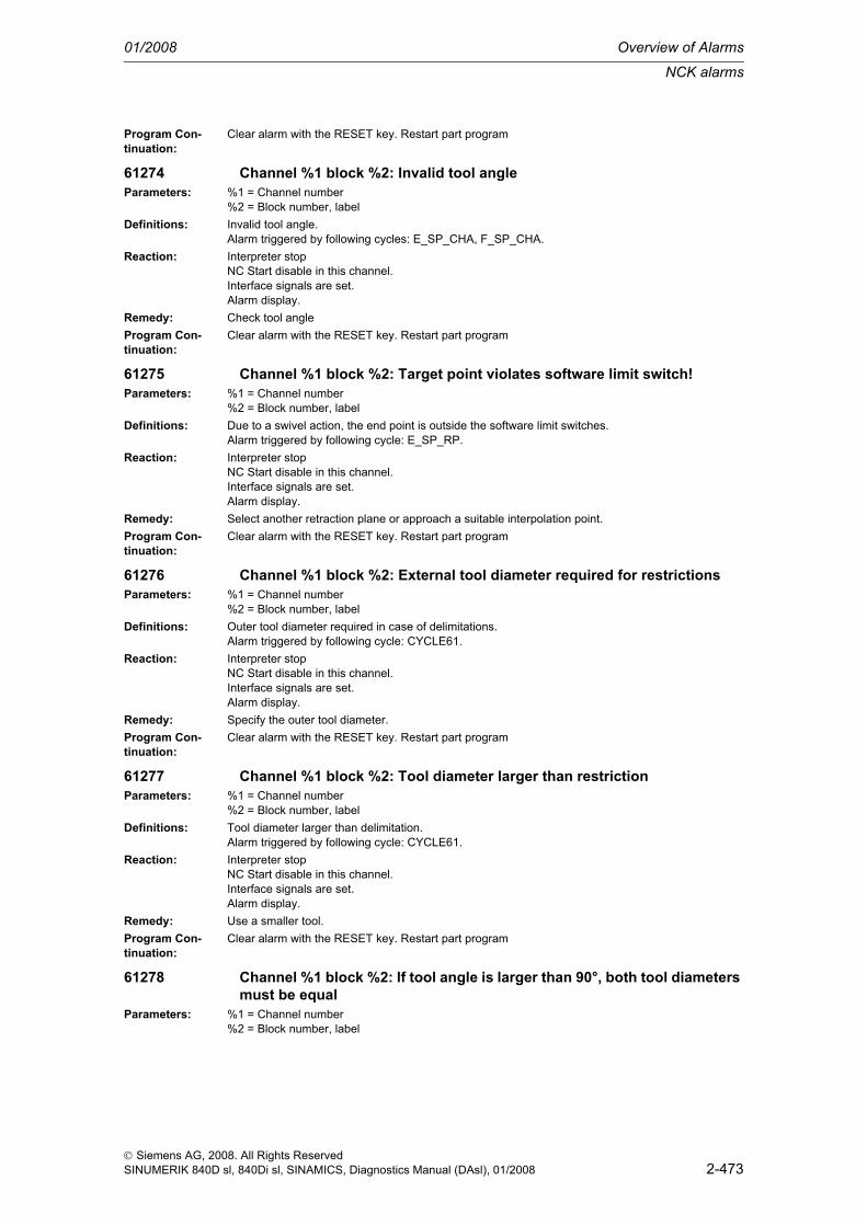
NCK alarms
01/2008 Overview of Alarms
2-473
© Siemens AG, 2008. All Rights ReservedSINUMERIK 840D sl, 840Di sl, SINAMICS, Diagnostics Manual (DAsl), 01/2008
Program Con-tinuation:
Clear alarm with the RESET key. Restart part program
61274 Channel %1 block %2: Invalid tool angleParameters: %1 = Channel number
%2 = Block number, labelDefinitions: Invalid tool angle.
Alarm triggered by following cycles: E_SP_CHA, F_SP_CHA.Reaction: Interpreter stop
NC Start disable in this channel.Interface signals are set.Alarm display.
Remedy: Check tool angleProgram Con-tinuation:
Clear alarm with the RESET key. Restart part program
61275 Channel %1 block %2: Target point violates software limit switch!Parameters: %1 = Channel number
%2 = Block number, labelDefinitions: Due to a swivel action, the end point is outside the software limit switches.
Alarm triggered by following cycle: E_SP_RP.Reaction: Interpreter stop
NC Start disable in this channel.Interface signals are set.Alarm display.
Remedy: Select another retraction plane or approach a suitable interpolation point.Program Con-tinuation:
Clear alarm with the RESET key. Restart part program
61276 Channel %1 block %2: External tool diameter required for restrictionsParameters: %1 = Channel number
%2 = Block number, labelDefinitions: Outer tool diameter required in case of delimitations.
Alarm triggered by following cycle: CYCLE61.Reaction: Interpreter stop
NC Start disable in this channel.Interface signals are set.Alarm display.
Remedy: Specify the outer tool diameter.Program Con-tinuation:
Clear alarm with the RESET key. Restart part program
61277 Channel %1 block %2: Tool diameter larger than restrictionParameters: %1 = Channel number
%2 = Block number, labelDefinitions: Tool diameter larger than delimitation.
Alarm triggered by following cycle: CYCLE61.Reaction: Interpreter stop
NC Start disable in this channel.Interface signals are set.Alarm display.
Remedy: Use a smaller tool.Program Con-tinuation:
Clear alarm with the RESET key. Restart part program
61278 Channel %1 block %2: If tool angle is larger than 90°, both tool diameters must be equal
Parameters: %1 = Channel number%2 = Block number, label

Overview of Alarms 01/2008
NCK alarms
2-474
© Siemens AG, 2008. All Rights ReservedSINUMERIK 840D sl, 840Di sl, SINAMICS, Diagnostics Manual (DAsl), 01/2008
Definitions: For tool angles larger than 90°, the two tool diameters must be identical.Alarm triggered by following cycle: CYCLE61.
Reaction: Interpreter stopNC Start disable in this channel.Interface signals are set.Alarm display.
Remedy: Correct the tool angle or the tool diameters.Program Con-tinuation:
Clear alarm with the RESET key. Restart part program
61279 Channel %1 block %2: If tool angle equals 90°, both tool diameters must be equal
Parameters: %1 = Channel number%2 = Block number, label
Definitions: For tool angles equal to 90°, the two tool diameters must be identical.Alarm triggered by following cycle: CYCLE61.
Reaction: Interpreter stopNC Start disable in this channel.Interface signals are set.Alarm display.
Remedy: Correct the tool angle or the tool diameters.Program Con-tinuation:
Clear alarm with the RESET key. Restart part program
61280 Channel %1 Block %2: Mirroring in WO %4 missingParameters: %1 = Channel number
%2 = Block number, labelDefinitions: If the program starts with a counterspindle movement, a work offset with mirroring will have to be
selected.Alarm triggered by following cycle: F_SUB_SP
Reaction: Interpreter stopNC Start disable in this channel.Interface signals are set.Alarm display.
Remedy: Select the mirroring for the work offset used.Program Con-tinuation:
Clear alarm with the RESET key. Restart part program
61281 Channel %1 block %2: starting point of machining outside retraction planes
Parameters: %1 = Channel number%2 = Block number, label
Definitions: The starting point of machining is outside the retraction planes.Alarm triggered by following cycle: F_SP_RP.
Reaction: Interpreter stopNC Start disable in this channel.Interface signals are set.Alarm display.
Remedy: Adjust the retraction planes.Program Con-tinuation:
Clear alarm with the RESET key. Restart part program
61282 Channel %1 block %2: end point of machining outside retraction planesParameters: %1 = Channel number
%2 = Block number, label

NCK alarms
01/2008 Overview of Alarms
2-475
© Siemens AG, 2008. All Rights ReservedSINUMERIK 840D sl, 840Di sl, SINAMICS, Diagnostics Manual (DAsl), 01/2008
Definitions: The end point of machining is outside the retraction planes.Alarm triggered by following cycle: F_SP_RP.
Reaction: Interpreter stopNC Start disable in this channel.Interface signals are set.Alarm display.
Remedy: Adjust the retraction planes.Program Con-tinuation:
Clear alarm with the RESET key. Restart part program
61283 Channel %1 block %2: direct approach not possible, as tool change required
Parameters: %1 = Channel number%2 = Block number, label
Definitions: After block search a position is to be reached by direct approach, but a tool change is required before.Alarm triggered by following cycle: F_TFS.
Reaction: Interpreter stopNC Start disable in this channel.Interface signals are set.Alarm display.
Remedy: First execute a manual tool change, then restart the block search.Program Con-tinuation:
Clear alarm with the RESET key. Restart part program
61284 Channel %1 block %2: starting point cannot be approached without collision. Pre-position tool manually
Parameters: %1 = Channel number%2 = Block number, label
Definitions: The starting point cannot be approached without collisions.Alarm triggered by following cycles: F_DRILL, F_DRILLC, F_DRILLD, F_DRM_DR, F_DRM_PE, F_DRM_RE, F_DRM_SI, F_DRM_TA, F_GROOV, F_MIM_TR, F_PARTOF, F_SP_EF, F_TAP, F_TR_CON, F_UCUT_T.
Reaction: Interpreter stopNC Start disable in this channel.Interface signals are set.Alarm display.
Remedy: Preposition the tool manually.Program Con-tinuation:
Clear alarm with the RESET key. Restart part program
61285 Channel %1 block %2: parking position is below return plane XRA.Parameters: %1 = Channel number
%2 = Block number, labelDefinitions: The parking position is below retraction plane XRA.
Alarm triggered by following cycle: F_SP_RP.Reaction: Interpreter stop
NC Start disable in this channel.Interface signals are set.Alarm display.
Remedy: Move the parking position above retraction plane XRA.Program Con-tinuation:
Clear alarm with the RESET key. Restart part program
61286 Channel %1 block %2: machining not possible, check tool angle.Parameters: %1 = Channel number
%2 = Block number, label

Overview of Alarms 01/2008
NCK alarms
2-476
© Siemens AG, 2008. All Rights ReservedSINUMERIK 840D sl, 840Di sl, SINAMICS, Diagnostics Manual (DAsl), 01/2008
Definitions: Machining not possible with the specified tool.Alarm triggered by following cycles: F_UCUT_T.
Reaction: Interpreter stopNC Start disable in this channel.Interface signals are set.Alarm display.
Remedy: Use a suitable tool.Program Con-tinuation:
Clear alarm with the RESET key. Restart part program
61287 Channel %1 block %2: no master spindle active.Parameters: %1 = Channel number
%2 = Block number, labelDefinitions: No master spindle active.
Alarm triggered by following cycle: F_TFS.Reaction: Interpreter stop
NC Start disable in this channel.Interface signals are set.Alarm display.
Remedy: Activate the master spindle (machine data 20090).Program Con-tinuation:
Clear alarm with the RESET key. Restart part program
61300 Channel %1 block %2: Probe defectiveParameters: %1 = Channel number
%2 = Block number, labelDefinitions:Reaction: Interpreter stop
NC Start disable in this channel.Interface signals are set.Alarm display.
Remedy:Program Con-tinuation:
Clear alarm with the RESET key. Restart part program
61301 Channel %1 block %2: Probe not switchingParameters: %1 = Channel number
%2 = Block number, labelDefinitions: The measuring distance was completely traversed, but no switching signal was generated at the mea-
suring input.Alarm can be triggered by following measuring cycles: all measuring cycles.
Remedy: -Check measuring input.-Check measuring distance.-Probe defective.
61302 Channel %1 block %2: Probe - collisionParameters: %1 = Channel number
%2 = Block number, labelDefinitions: The measuring probe collided with an obstacle when being positioned.
Alarm can be triggered by the following measuring cycles: all measuring cycles.Remedy: - Check spigot diameter (may be too small)
- Check measuring distance (may be too long)
61303 Channel %1 Block %2: Safety margin exceededParameters: %1 = Channel number
%2 = Block number, labelDefinitions: The measuring result differs greatly from the specified value.
Alarm can be triggered by following measuring cycles: all measuring cycles.Remedy: - Check setpoint value and parameter _TSA

NCK alarms
01/2008 Overview of Alarms
2-477
© Siemens AG, 2008. All Rights ReservedSINUMERIK 840D sl, 840Di sl, SINAMICS, Diagnostics Manual (DAsl), 01/2008
61304 Channel %1 Block %2: AllowanceParameters: %1 = Channel number
%2 = Block number, labelDefinitions:Reaction: Interpreter stop
NC Start disable in this channel.Interface signals are set.Alarm display.
Remedy:Program Con-tinuation:
Clear alarm with the RESET key. Restart part program
61305 Channel %1 Block %2: Dimension too smallParameters: %1 = Channel number
%2 = Block number, labelDefinitions:Reaction: Interpreter stop
NC Start disable in this channel.Interface signals are set.Alarm display.
Remedy:Program Con-tinuation:
Clear alarm with the RESET key. Restart part program
61306 Channel %1 Block %2: Permissible measuring difference exceededParameters: %1 = Channel number
%2 = Block number, label channel numberDefinitions: Alarm triggered by following cycles: CYCLE971, CYCLE972, CYCLE974, CYCLE977, CYCLE978,
CYCLE979, CYCLE982, CYCLE994.Remedy: - Check setpoint value and parameter _TDIF
61307 Channel %1 Block %2: Incorrect measuring variantParameters: %1 = Channel number
%2 = Block number, label channel numberDefinitions: Alarm can be triggered by following measuring cycles: all measuring cycles.Remedy: - The value of parameter _MVAR is impermissible.
61308 Channel %1 block %2: Check measuring pathParameters: %1 = Channel number
%2 = Block number, labelDefinitions: Alarm can be triggered by following measuring cycles: all measuring cycles.Remedy: A traversing path for measuring is generated with a size specified by parameter _FA (in 840D) or DFA
(in 840D sl). It describes the maximum distance before and after the expected switching position (workpiece edge) and must have a value greater than 0.For 840D: - Check parameter _FAFor 840D sl: - Check parameter DFA
61309 Channel %1 block %2: Check probe typeParameters: %1 = Channel number
%2 = Block number, labelDefinitions: Probe type: 3D probe inactive.
This alarm is generated by all cycles except CYCLE971, CYCLE972, CYCLE982.Remedy: The probe has to be of the "3D probe" type in the tool management.
Tool type of the workpiece probe in the TO memory is impermissible.For CYCLE971: no permissible tool probe type entered in _TP[x,8], or check the permissible working plane G17...G19 in the case of tool type "Wheel".

Overview of Alarms 01/2008
NCK alarms
2-478
© Siemens AG, 2008. All Rights ReservedSINUMERIK 840D sl, 840Di sl, SINAMICS, Diagnostics Manual (DAsl), 01/2008
61310 Channel %1 Block %2: Scale factor is activeParameters: %1 = Channel number
%2 = Block number, labelDefinitions: Scale factor = scaling is active.
Alarm can be triggered by following measuring cycles: all measuring cycles.Remedy: Switch off the active scale factor in the program. Measuring is not possible with an active scale factor.
61311 Channel %1 Block %2: No D number activeParameters: %1 = Channel number
%2 = Block number, labelDefinitions: No tool offset for the measuring probe (for workpiece measurement) or no tool offset for the active tool
(for tool measurement) is selected.Alarm can be triggered by the following measuring cycles: all measuring cycles.
Remedy: Select the tool's tool edge number D.
61312 Channel %1 block %2: Check measuring cycle numberParameters: %1 = Channel number
%2 = Block number, labelDefinitions: The alarm can be triggered by the following measuring cycles: all measuring cycles.Remedy: Measuring cycle called is impermissible...
61313 Channel %1 block %2: Check probe numberParameters: %1 = Channel number
%2 = Block number, labelDefinitions: Alarm can be triggered by following measuring cycles: all measuring cycles.Remedy: Check parameter _PRNUM in connection with the following data fields and machine data:
For 840D: - Create data field _WP[], _TP[] and _TPW[] for additional tool or workpiece probe and adjust _CVAL[0]/_CVAL[1] accordingly.Bei 840D sl: - Check the following machine data: 51600 $MNS_MEA_CAL_WP_NUM, 51602 $MNS_MEA_CAL_TP_NUM and 51603 $MNS_MEA_CAL_TPW_NUM
61314 Channel %1 block %2: Check selected tool typeParameters: %1 = Channel number
%2 = Block number, labelDefinitions: Alarm is triggered: CYCLE971, CYCLE972, CYCLE982.Remedy: Tool type impermissible for tool measurement/tool probe calibration.
61315 Channel %1 block %2: Check position of cutting edgeParameters: %1 = Channel number
%2 = Block number, labelDefinitions: Alarm is triggered: CYCLE972, CYCLE973, CYCLE974, CYCLE982, CYCLE994.Remedy: Check tool edge position (probe) in TO memory.
61316 Channel %1 Block %2: Center and radius cannot be determinedParameters: %1 = Channel number
%2 = Block number, labelDefinitions: No circle can be calculated from the measured points, as all measured points lie on a straight line.
The alarm is triggered by: CYCLE979Remedy: Program change
61317 Channel %1 block %2: Check number of circle calculation pointsParameters: %1 = Channel number
%2 = Block number, labelDefinitions: Parameterization faulty; requires 3 or 4 points to calculate the center point. Alarm is triggered:
CYCLE979.Remedy: Change parameterization of CYCLE116.

NCK alarms
01/2008 Overview of Alarms
2-479
© Siemens AG, 2008. All Rights ReservedSINUMERIK 840D sl, 840Di sl, SINAMICS, Diagnostics Manual (DAsl), 01/2008
61318 Channel %1 block %2: Check weighting factorParameters: %1 = Channel number
%2 = Block number, labelDefinitions: Alarm is triggered: CYCLE974, CYCLE977, CYCLE978, CYCLE979, CYCLE994, CYCLE998.Remedy: Check parameter (_K).
61319 Channel %1 block %2: Check call parameter CYCLE114Parameters: %1 = Channel number
%2 = Block number, labelDefinitions: Internal error in measuring cycles. Alarm is triggered: CYCLE974, CYCLE977, CYCLE978,
CYCLE979, CYCLE994, CYCLE998.Remedy: Check call parameter CYCLE114.
61320 Channel %1 block %2: Check tool numberParameters: %1 = Channel number
%2 = Block number, labelDefinitions: Alarm can be triggered by following measuring cycles: all measuring cycles.Remedy: For 840D:
- Check parameters _TNUM, _TNAME.Bei 840D sl: - Check parameter T.With active tool management, parameter T=0 (_TNUM=0 ), and parameter _TNAME is empty or the specified tool name is unknown to the tool management.
61321 Channel %1 block %2: Check WO memory numberParameters: %1 = Channel number
%2 = Block number, labelDefinitions: Alarm is triggered: CYCLE974, CYCLE977, CYCLE978, CYCLE979, CYCLE994, CYCLE998.Reaction: Interpreter stop
NC Start disable in this channel.Interface signals are set.Alarm display.
Remedy: For 840D: - Check parameter _KNUMFor 840D sl: - Check the the number entered for the work offset compensation
Program Con-tinuation:
Clear alarm with the RESET key. Restart part program
61322 Channel %1 block %2: Check 4th digit of _KNUMParameters: %1 = Channel number
%2 = Block number, labelDefinitions: The stated digit of _KNUM includes invalid values. Also check _MVAR.
Alarm is triggered: CYCLE974, CYCLE977, CYCLE978, CYCLE979, CYCLE994, CYCLE998, CYCLE114.
Remedy: Check parameter for tool offset target (_KNUM) and measurement variant (_MVAR)
61323 Channel %1 block %2: Check 5th digit of _KNUMParameters: %1 = Channel number
%2 = Block number, labelDefinitions: The stated digit of _KNUM includes invalid values. Also check _MVAR.
Alarm is triggered: CYCLE974, CYCLE977, CYCLE978, CYCLE979, CYCLE994, CYCLE998, CYCLE114.
Remedy: Check parameter for tool offset target (_KNUM) and measurement variant (_MVAR)
61324 Channel %1 block %2: Check 6th digit of _KNUMParameters: %1 = Channel number
%2 = Block number, label

Overview of Alarms 01/2008
NCK alarms
2-480
© Siemens AG, 2008. All Rights ReservedSINUMERIK 840D sl, 840Di sl, SINAMICS, Diagnostics Manual (DAsl), 01/2008
Definitions: The stated digit of _KNUM includes invalid values. Also check _MVAR.Alarm is triggered: CYCLE974, CYCLE977, CYCLE978, CYCLE979, CYCLE994, CYCLE998, CYCLE114.
Remedy: Check parameter for tool offset target (_KNUM) and measurement variant (_MVAR)
61325 Channel %1 block %2: Check measuring axis/offset axisParameters: %1 = Channel number
%2 = Block number, labelDefinitions: Alarm is triggered by: all measuring cycles except CYCLE979Remedy: For 840D:
- Check parameters for measuring axis _MAFor 840D sl:- Check parameters for measuring axis (X, Y, Z)
61326 Channel %1 block %2: Check measuring directionParameters: %1 = Channel number
%2 = Block number, labelDefinitions: Alarm triggered: CYCLE973, CYCLE976.Remedy: Parameter for measuring direction _MD has an incorrect value.
61327 Channel %1 Block %2: Program reset requiredParameters: %1 = Channel number
%2 = Block number, labelDefinitions: NC reset required.
Alarm is triggered: all measuring cycles except for CYCLE973, CYCLE976.Remedy: Execute NC reset.
61328 Channel %1 block %2: Check D numberParameters: %1 = Channel number
%2 = Block number, labelDefinitions: D number in parameter _KNUM is 0.
The alarm can be triggered by all measuring cycles.Remedy: Check parameter for tool offset target (_KNUM)
61329 Channel %1 block %2: Check rotary axisParameters: %1 = Channel number
%2 = Block number, labelDefinitions: Alarm triggered: CYCLE998Remedy: No name assigned to the axis number specified in the parameter of the rotary axis (_RA), or this axis
is not configured as a rotary axis.Check MD 20080 and MD 30300.
61330 Channel %1 Block %2: Coordinate rotation activeParameters: %1 = Channel number
%2 = Block number, labelDefinitions: No measuring possible in the rotated coordinate system. Alarm is triggered: CYCLE972, CYCLE973,
CYCLE974, CYCLE994.Remedy: Check the conditions for measuring.
61331 Channel %1 Block %2: Angle too large, change measuring axisParameters: %1 = Channel number
%2 = Block number, labelDefinitions: Parameter starting angle (_STA) is too large for the specified measuring axis. Alarm is triggered:
CYCLE998.Remedy: Select another metering axis.
61332 Channel %1 Block %2: Modify tool tip positionParameters: %1 = Channel number
%2 = Block number, label

NCK alarms
01/2008 Overview of Alarms
2-481
© Siemens AG, 2008. All Rights ReservedSINUMERIK 840D sl, 840Di sl, SINAMICS, Diagnostics Manual (DAsl), 01/2008
Definitions: The tool tip is below the measuring probe surface (e.g. for a ring gauge or cube). Alarm is triggered: CYCLE971, CYLCE972, CYCLE982, E_MT_CAL, E_MT_LEN, E_MT_RAD.
Remedy: Place the tool above the measuring probe surface.
61333 Channel %1 Block %2: Check calibration block numberParameters: %1 = Channel number
%2 = Block number, labelDefinitions: Alarm triggered: CYCLE973Remedy: Parameter _CALNUM is too large, reduce it to a permissible value
For 840D: - Increase the maximum value of _CVAL[2] in GUD6For 840D sl: - Check following machine data: 51601 $MNS_MEA_CAL_EDGE_NUM
61334 Channel %1 block %2: Check safety areaParameters: %1 = Channel number
%2 = Block number, labelDefinitions: Alarm triggered: CYCLE977Remedy: Check the parameters for the safety area
For 840D: _SZA or _SZOFor 840D sl: XS, YS or ZS
61336 Channel %1 Block %2: Geometry axes do not existParameters: %1 = Channel number
%2 = Block number, label channel numberDefinitions: No geometry axes configured. Alarm can be triggered by following measuring cycles: all measuring
cycles.Remedy: Machine data in MD 20060 must be changed.
61337 Channel %1 block %2: Check measuring inputParameters: %1 = Channel number
%2 = Block number, labelDefinitions:Reaction: Interpreter stop
NC Start disable in this channel.Interface signals are set.Alarm display.
Remedy:Program Con-tinuation:
Clear alarm with the RESET key. Restart part program
61338 Channel %1 Block %2: Positioning speed equal to zeroParameters: %1 = Channel number
%2 = Block number, labelDefinitions: Alarm can be triggered by following measuring cycles: all measuring cycles.Remedy: For some measuring versions, for example measuring spigots, in addition to the actual measuring
paths, intermediate paths are generated that are traversed with a specified feed.The values for the feed are specified: - For 840D: in parameters _SPEED[1] and _SPEED[2] in GUD6. - For 840D sl: in setting data 55631 $SCS_MEA_FEED_PLANE_VALUE and 55632 $SCS_MEA_FEED_FEEDAX_VALUE
61339 Channel %1 Block %2:Correction factor for rapid traverse speed = 0Parameters: %1 = Channel number
%2 = Block number, label channel numberDefinitions: Alarm can be triggered by following measuring cycles: all measuring cycles.Remedy: For 840D: Check parameter _SPEED[0] in GUD6
For 840D sl: Check setting data 55630 $SCS_MEA_FEED_RAPID_IN_PERCENT

Overview of Alarms 01/2008
NCK alarms
2-482
© Siemens AG, 2008. All Rights ReservedSINUMERIK 840D sl, 840Di sl, SINAMICS, Diagnostics Manual (DAsl), 01/2008
61340 Channel %1 Block %2: Incorrect alarm numberParameters: %1 = Channel number
%2 = Block number, label channel numberDefinitions: Alarm can be triggered by following measuring cycles: all measuring cycles.Remedy: Internal error in measuring cycles.
61341 Channel %1 block %2: Probe not calibrated in active plane.Parameters: %1 = Channel number
%2 = Block number, label channel numberDefinitions: The alarm is triggerd by the following cycles: CYCLE974, CYCLE977, CYCLE978, CYCLE979.Remedy: Calibrate the probe prior to calling a cycle.
61342 Channel %1 block %2: Upgrade NCK software versionParameters: %1 = Channel number
%2 = Block number, label channel numberDefinitions: Alarm can be triggered by following measuring cycles: all measuring cycles.Remedy: Up to measuring cycle software 6.2: _SI[1] in GUD6 has no value or a value < 3
As from measuring cycle software 6.3: Upgrade NCK software version.
61343 Channel %1 block %2: No tool available for specified tool nameParameters: %1 = Channel number
%2 = Block number, label channel numberDefinitions: Alarm can be triggered by following measuring cycles: all measuring cycles.Remedy: Check tool name.
61344 Channel %1 Block %2: Several tools are activeParameters: %1 = Channel number
%2 = Block number, label channel numberDefinitions: Alarm can be triggered by following measuring cycles: all measuring cycles.Remedy: Remove tool from another spindle.
61345 Channel %1 block %2: D number of tool offset, too many digitsParameters: %1 = Channel number
%2 = Block number, label channel numberDefinitions: Alarm can be triggered by following measuring cycles: all measuring cycles.Remedy: Reduce the D number in _KNUM, check software or MD of flat D number.
61346 Channel %1 block %2: Distance between starting point and measuring point <=0
Parameters: %1 = Channel number%2 = Block number, label channel number
Definitions: The alarm is triggerd by the following cycles: CYCLE961.Reaction: Interpreter stop
NC Start disable in this channel.Interface signals are set.Alarm display.
Remedy: 840D: - Parameter _SETV[0] or _SETV[1] is empty or less than 0.840D sl: - Parameter X1 or Y1 is empty or less than 0.
Program Con-tinuation:
Clear alarm with the RESET key. Restart part program
61347 Channel %1 Block %2: Angle 1st edge - 2nd edge equals 0Parameters: %1 = Channel number
%2 = Block number, label channel numberDefinitions: The alarm is triggerd by the following cycles: CYCLE961.Remedy: Parameter following angle (_INCA) equals 0.

NCK alarms
01/2008 Overview of Alarms
2-483
© Siemens AG, 2008. All Rights ReservedSINUMERIK 840D sl, 840Di sl, SINAMICS, Diagnostics Manual (DAsl), 01/2008
61348 Channel %1 Block %2: Angle rel. to reference edge equals 0Parameters: %1 = Channel number
%2 = Block number, label channel numberDefinitions:Reaction: Interpreter stop
NC Start disable in this channel.Interface signals are set.Alarm display.
Remedy:Program Con-tinuation:
Clear alarm with the RESET key. Restart part program
61349 Channel %1 Block %2: Distance upper probe edge - measuring position = 0 for tool radius measurement
Parameters: %1 = Channel number%2 = Block number, label channel number
Definitions: The alarm is triggerd by the following cycles: CYCLE971 Remedy: The distance between the upper and lower edges of the tool probe equals 0; relevant for radius mea-
surement.For 840D: Check parameter _TP[x,9]For 840D sl: Check setting data 54634 $SNS_MEA_TP_CAL_MEASURE_DEPTH
61350 Channel %1 block %2: Feed, speed not programmed for tool measurement with rotating spindle
Parameters: %1 = Channel number%2 = Block number, label channel number
Definitions: The alarm is triggered by the following cycles: CYCLE971.The measuring feed and/or spindle speed during tool measurement with rotating spindle is not spec-ified in the GUD variable _MFS.
Remedy: Check parameter _MFS[0]
61351 Channel %1 Block %2: Tool length or radius is 0Parameters: %1 = Channel number
%2 = Block number, label channel numberDefinitions: The alarm is triggerd by the following cycles: CYCLE971.
For the active tool, the length or radius equal zero.Remedy: Check length and radius of the active tool in the compensation data memory.
61352 Channel %1 Block %2: Path for logfile not permittedParameters: %1 = Channel number
%2 = Block number, label channel numberDefinitions: The alarm is triggerd by the following cycles: CYCLE106.
The specified path for the log file is incorrect.Remedy: Check parameter _PROTNAME[1]
61353 Channel %1 Block %2: Path for logfile not foundParameters: %1 = Channel number
%2 = Block number, label channel numberDefinitions: The alarm is triggerd by the following cycles: CYCLE106.
The specified directory does not exist or the specified path is incorrect.Remedy: Check parameter _PROTNAME[1]
61354 Channel %1 Block %2: File for logfile not foundParameters: %1 = Channel number
%2 = Block number, label channel numberDefinitions: The alarm is triggerd by the following cycles: CYCLE106.
No name specified for the log file.Remedy: Check parameter _PROTNAME[1]

Overview of Alarms 01/2008
NCK alarms
2-484
© Siemens AG, 2008. All Rights ReservedSINUMERIK 840D sl, 840Di sl, SINAMICS, Diagnostics Manual (DAsl), 01/2008
61355 Channel %1 Block %2: Incorrect file type for logfileParameters: %1 = Channel number
%2 = Block number, label channel numberDefinitions: The alarm is triggerd by the following cycles: CYCLE106.
The file extension for the log file is incorrect.Remedy: Check parameter _PROTNAME[1]
61356 Channel %1 Block %2: File for logfile is being usedParameters: %1 = Channel number
%2 = Block number, label channel numberDefinitions: The alarm is triggerd by the following cycles: CYCLE106.
The log file is already used by an NC program.Remedy: Check parameter _PROTNAME[1]
61357 Channel %1 Block %2: No resources freeParameters: %1 = Channel number
%2 = Block number, label channel numberDefinitions: The alarm is triggerd by the following cycles: CYCLE106.
Not enough NC memory space available.Reaction: Interpreter stop
NC Start disable in this channel.Interface signals are set.Alarm display.
Remedy: Delete the files.Program Con-tinuation:
Clear alarm with the RESET key. Restart part program
61358 Channel %1 Block %2: Error during recordingParameters: %1 = Channel number
%2 = Block number, label channel numberDefinitions: The alarm is triggerd by the following cycles: CYCLE106.
Internal errorRemedy: Call the hotline!
61359 Channel %1 Block %2: - continue with RESETParameters: %1 = Channel number
%2 = Block number, label channel numberDefinitions: The alarm is triggerd by the following cycles: CYCLE106.
Internal errorRemedy: Call the hotline!
61360 Channel %1 Block %2: Log job undefined - continue with RESETParameters: %1 = Channel number
%2 = Block number, label channel numberDefinitions: Alarm triggered by following cycle: CYCLE106.
Cycle CYCLE106 was called by an incorrect parameter.Remedy: Check cycle call for CYCLE106, specifically the call parameter.
61361 Channel %1 Block %2: Variable cannot be recordedParameters: %1 = Channel number
%2 = Block number, label channel numberDefinitions: The alarm is triggerd by the following cycles: CYCLE105.
The value specified in _PROTVAL[] cannot be logged. Remedy: Check parameter _PROTVAL[].
61362 Channel %1 Block %2: Cycle118: No. of values too largeParameters: %1 = Channel number
%2 = Block number, label channel numberDefinitions: The alarm is triggerd by the following cycles: CYCLE118.
4th parameter for CYCLE118 is larger than 10.
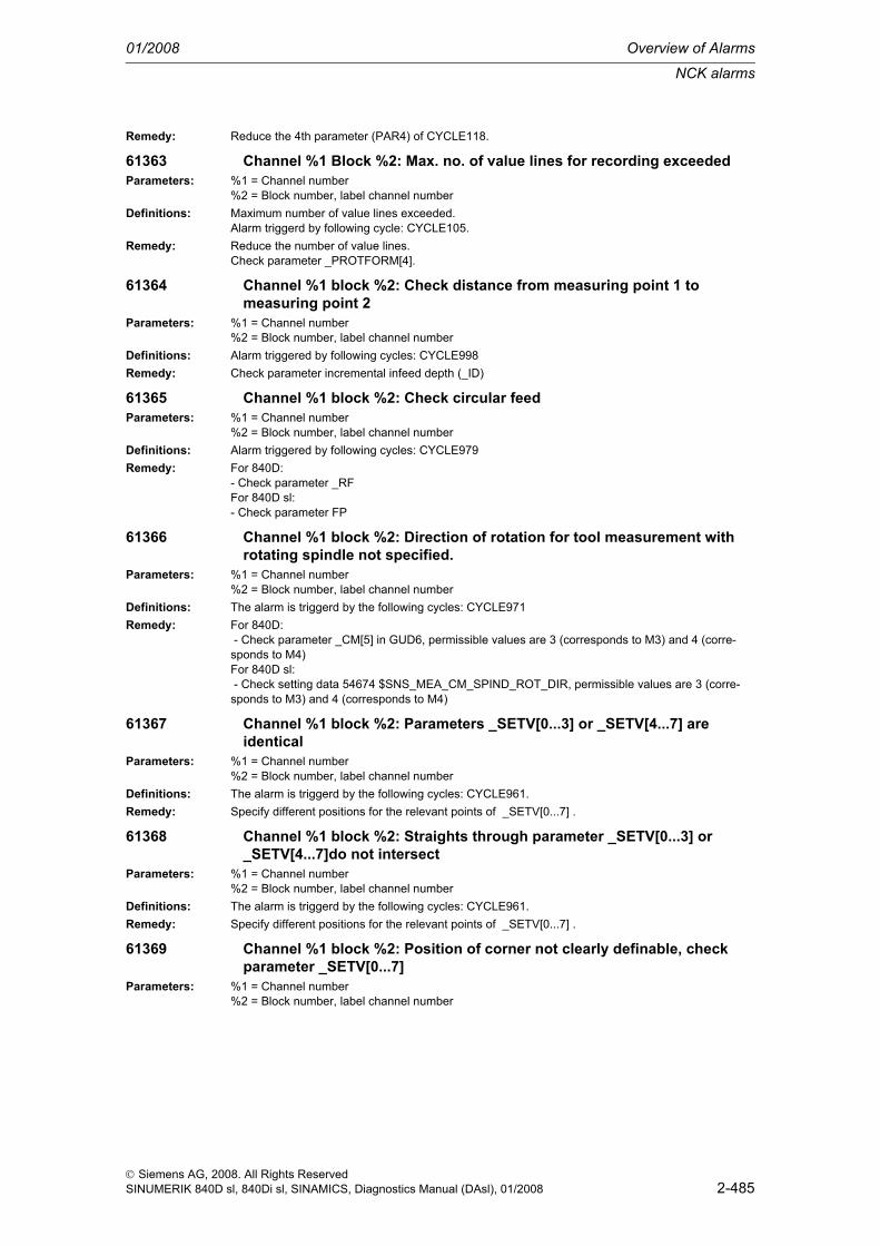
NCK alarms
01/2008 Overview of Alarms
2-485
© Siemens AG, 2008. All Rights ReservedSINUMERIK 840D sl, 840Di sl, SINAMICS, Diagnostics Manual (DAsl), 01/2008
Remedy: Reduce the 4th parameter (PAR4) of CYCLE118.
61363 Channel %1 Block %2: Max. no. of value lines for recording exceededParameters: %1 = Channel number
%2 = Block number, label channel numberDefinitions: Maximum number of value lines exceeded.
Alarm triggerd by following cycle: CYCLE105.Remedy: Reduce the number of value lines.
Check parameter _PROTFORM[4].
61364 Channel %1 block %2: Check distance from measuring point 1 to measuring point 2
Parameters: %1 = Channel number%2 = Block number, label channel number
Definitions: Alarm triggered by following cycles: CYCLE998Remedy: Check parameter incremental infeed depth (_ID)
61365 Channel %1 block %2: Check circular feedParameters: %1 = Channel number
%2 = Block number, label channel numberDefinitions: Alarm triggered by following cycles: CYCLE979Remedy: For 840D:
- Check parameter _RFFor 840D sl:- Check parameter FP
61366 Channel %1 block %2: Direction of rotation for tool measurement with rotating spindle not specified.
Parameters: %1 = Channel number%2 = Block number, label channel number
Definitions: The alarm is triggerd by the following cycles: CYCLE971Remedy: For 840D:
- Check parameter _CM[5] in GUD6, permissible values are 3 (corresponds to M3) and 4 (corre-sponds to M4)For 840D sl: - Check setting data 54674 $SNS_MEA_CM_SPIND_ROT_DIR, permissible values are 3 (corre-sponds to M3) and 4 (corresponds to M4)
61367 Channel %1 block %2: Parameters _SETV[0...3] or _SETV[4...7] are identical
Parameters: %1 = Channel number%2 = Block number, label channel number
Definitions: The alarm is triggerd by the following cycles: CYCLE961.Remedy: Specify different positions for the relevant points of _SETV[0...7] .
61368 Channel %1 block %2: Straights through parameter _SETV[0...3] or _SETV[4...7]do not intersect
Parameters: %1 = Channel number%2 = Block number, label channel number
Definitions: The alarm is triggerd by the following cycles: CYCLE961.Remedy: Specify different positions for the relevant points of _SETV[0...7] .
61369 Channel %1 block %2: Position of corner not clearly definable, check parameter _SETV[0...7]
Parameters: %1 = Channel number%2 = Block number, label channel number

Overview of Alarms 01/2008
NCK alarms
2-486
© Siemens AG, 2008. All Rights ReservedSINUMERIK 840D sl, 840Di sl, SINAMICS, Diagnostics Manual (DAsl), 01/2008
Definitions: The alarm is triggerd by the following cycles: CYCLE961.Reaction: Interpreter stop
NC Start disable in this channel.Interface signals are set.Alarm display.
Remedy: Define P1 and P2 or P3 and P4 in a way that the intersection of the straights determined by these points is outside the sections formed by P1 and P2 or P3 and P4.
Program Con-tinuation:
Clear alarm with the RESET key. Restart part program
61370 Channel %1 block %2: _PROTVAL[0] -_PROTVAL[5] do not have any entries
Parameters: %1 = Channel number%2 = Block number, label channel number
Definitions: The alarm is triggerd by the following cycles: CYCLE105.Remedy: Enter values in _PROTVAL[0...5].
61371 Channel %1 block %2: Product of column width and number of columns exceeds 200 characters per line
Parameters: %1 = Channel number%2 = Block number, label channel number
Definitions: The alarm is triggerd by the following cycles: CYCLE105.Remedy: Reduce the column width (_PROTFORM[4]) or number of columns (_PROTVAL[2...5]).
61372 Channel %1 block %2: selected meas.variant requires SPOS-capable spindle
Parameters: %1 = Channel number%2 = Block number, label channel number
Definitions: Alarm can be triggered by following measuring cycles: all measuring cycles.Remedy: Change measuring variant or check machine equipment.
61373 Channel %1 block %2: Mono-directional probe requires SPOS-capable spindle
Parameters: %1 = Channel number%2 = Block number, label channel number
Definitions: Alarm can be triggered by following measuring cycles: all measuring cycles.Remedy: Check machine equipment.
61401 Channel %1 block %2: Probe does not switch, traversing path limited by software limit position.
Parameters: %1 = Channel number%2 = Block number, label channel number
Definitions: The alarm is triggerd by the following cycles: CYCLE961, CYCLE971, CYCLE976, CYCLE977, CYCLE978, CYCLE998
Remedy: The position defined by a setpoint value cannot be reached as this would mean overrunning the soft-ware limit position.- Check specified setpoint value.
61402 Channel %1 block %2: Probe collision, traversing path limited by software limit position
Parameters: %1 = Channel number%2 = Block number, label channel number
Definitions: Alarm triggered by following cycles: CYCLE977Remedy: For the measuring variants Measure web/shaft, the position path in the plane was limited by the soft-
ware limit position. The probe switched in the following infeed along the infeed axis.Check programmed position of software limit position.

NCK alarms
01/2008 Overview of Alarms
2-487
© Siemens AG, 2008. All Rights ReservedSINUMERIK 840D sl, 840Di sl, SINAMICS, Diagnostics Manual (DAsl), 01/2008
61403 Channel %1 block %2: Work offset correction not executedParameters: %1 = Channel number
%2 = Block number, label channel numberDefinitions: Alarm can be triggered by following measuring cycles: all measuring cycles.Remedy: Call the SIEMENS hotline
61404 Channel %1 block %2: Tool correction not executedParameters: %1 = Channel number
%2 = Block number, label channel numberDefinitions: Alarm can be triggered by following measuring cycles: all measuring cycles.Remedy: Check the dependent tool specifications.
61405 Channel %1 block %2: Tool environment does not existParameters: %1 = Channel number
%2 = Block number, label channel numberDefinitions: Alarm can be triggered by following measuring cycles: all measuring cycles.Remedy: Correct the name of the tool environment (_TENV) or create this environment.
61406 Channel %1 block %2: Check DL numberParameters: %1 = Channel number
%2 = Block number, label channel numberDefinitions: Alarm can be triggered by following measuring cycles: all measuring cycles.Remedy: For 840D: Check parameter _DLNUM
For 840D sl: Check parameter DLCheck the number of the sum offset and that of the setup offset.
61407 Channel %1 block %2: Check 7th digit and higher of _KNUMParameters: %1 = Channel number
%2 = Block number, label channel numberDefinitions: Alarm can be triggered by following measuring cycles: all measuring cycles.Remedy: Check parameter _KNUM.
Check the the number of the sum offset and that of the setup offset.
61408 Channel %1 block %2: total offsets not presentParameters: %1 = Channel number
%2 = Block number, label channel numberDefinitions: Alarm can be triggered by following measuring cycles: all measuring cycles.Remedy: Set MD 18080, Bit 8=1
61409 Channel %1 block %2: set up offsets not presentParameters: %1 = Channel number
%2 = Block number, label channel numberDefinitions: Alarm can be triggered by following measuring cycles: all measuring cycles.Remedy: Set MD 18112, Bit 4=1
61410 Channel %1 block %2 access to nonexistent tool element or propertyParameters: %1 = Channel number
%2 = Block number, label channel numberDefinitions: Alarm can be triggered by following measuring cycles: all measuring cycles.Remedy: The variable to be corrected requires an option or an increase in MD values.
61411 Channel %1 block %2: Check the distribution of measuring points on the plane.
Parameters: %1 = Channel number%2 = Block number, label channel number
Definitions: The alarm is triggerd by the following cycles: CYCLE997, CYCLE119Remedy: Check the setpoint and actual values

Overview of Alarms 01/2008
NCK alarms
2-488
© Siemens AG, 2008. All Rights ReservedSINUMERIK 840D sl, 840Di sl, SINAMICS, Diagnostics Manual (DAsl), 01/2008
61412 Channel %1 block %2: channel basic frame not presentParameters: %1 = Channel number
%2 = Block number, label channel numberDefinitions: The alarm is triggerd by the following cycles: CYCLE997, CYCLE119Remedy: Set MD 28081>0, $P_CHBFRMASK>0
61413 Channel %1 block %2: check setpoint of ball diameter, _SETVAL<=0Parameters: %1 = Channel number
%2 = Block number, label channel numberDefinitions: The alarm is triggerd by the following cycles: CYCLE997Remedy: Check setpoint value of spherical diameter.
61414 Channel %1 block %2 : distortion of triangle over limitParameters: %1 = Channel number
%2 = Block number, label channel numberDefinitions: The alarm is triggerd by the following cycles: CYCLE997, CYCLE119Remedy: Check the setpoint and actual values
61415 Channel %1 block %2: Check probe / machining planeParameters: %1 = Channel number
%2 = Block number, label channel numberDefinitions: The alarm is triggerd by the following cycles: CYCLE971Remedy: Enter permissible probe for machining plane:
- For 840D: Check the variables _TP[x,8] and _TPW[x,8] in GUD6 - For 840D sl: Check the setting data 54633 $SNS_MEA_TP_TYPE and 54648 $SNS_MEA_TPW_TYPEor change the machining plane.
61416 Channel %1 block %2: adapt array size %4!Parameters: %1 = Channel number
%2 = Block number, label channel numberDefinitions: Alarm can be triggered by following measuring cycles: all measuring cycles.Remedy: For 840D:
Match _CVAL entry to the number of existing probe and calibration block data fields, that means: - Adapt _TP[ ]/_CVAL[0] field size, or - Adapt _WP[ ]/_CVAL[1] field size, or - Adapt _KP[ ]/_CVAL[2] field size, or - Adapt _TWP[ ]/_CVAL[3].For 840D sl:Check machine data for the number of probe and calibration block data fields, that means: - Workpiece probe 51600$MNS_MEA_CAL_WP_NUM or - Calibration block 51601$MNS_MEA_CAL_EDGE_NUM or - Workpiece probe in MCS 51602$MNS_MEA_CAL_TP_NUM or - Workpiece probe in WCS 51603$MNS_MEA_CAL_TPW_NUM
61417 Channel %1 block %2: Probe will collide with the carrier of the reference groove.
Parameters: %1 = Channel number%2 = Block number, label channel number
Definitions: The alarm can be triggered by the following measuring cycles: CYCLE973Remedy: Take up collision-free initial position of the axes involved in the measuring process.
61418 Channel %1 block %2: Protocol file too small, check MD11420: LEN_PROTOCOL_FILE.
Parameters: %1 = Channel number%2 = Block number, label channel number
Definitions: Alarm can be triggered by following measuring cycle: CYCLE106Remedy: Check MD11420: LEN_PROTOCOL_FILE.

NCK alarms
01/2008 Overview of Alarms
2-489
© Siemens AG, 2008. All Rights ReservedSINUMERIK 840D sl, 840Di sl, SINAMICS, Diagnostics Manual (DAsl), 01/2008
61419 Channel %1 block %2: Check probe calibration with reference to center of ball/circumference of ball.
Parameters: %1 = Channel number%2 = Block number, label channel number
Definitions: The alarm can be triggered by the following measuring cycles: CYCLE974, CYCLE994, CYCLE977, CYCLE978, CYCLE979, CYCLE997, CYCLE998
Remedy: The workpiece probe must be calibrated according to its use in the measuring cycles.
61420 Channel %1 block %2: Check calibration of multi/mono probes.Parameters: %1 = Channel number
%2 = Block number, label channel numberDefinitions: The alarm can be triggered by the following measuring cycles: CYCLE974, CYCLE994, CYCLE977,
CYCLE978, CYCLE979, CYCLE997, CYCLE998Remedy: The workpiece probe must be calibrated according to its type and use.
61421 Channel %1 block %2: Software release of measuring cycles or NCK inadequate or set up incorrectly --> error code %4
Parameters: %1 = Channel number%2 = Block number, label channel number
Definitions: The alarm can be triggered by the following measuring cycles: CYCLE996Remedy: Causes of error:
1. Error code = A -> _OVR[] - parameter field too small. Check GUD definition. DEF CHAN REAL _OVR[72] (up to MZ06.03.xx.xx =32)
61422 Channel %1 block %2: Parameter _MVAR incorrect --> Error code: %4Parameters: %1 = Channel number
%2 = Block number, label channel numberDefinitions: The alarm can be triggered by the following measuring cycles: CYCLE996Remedy: Causes of error:
1. Error code = A -> _MVAR = 9x identifier CYCLE996 measure kinematics2. Error code = B -> Parameter for normalizing (_MVAR) incorrect3. Error code = C -> Measurement variant "compute only" active, but rotary axis 1 or 2 not mea-sured (see also parameter _OVR[40])
61423 Channel %1 block %2: Parameter _TNUM not agreed or not createdParameters: %1 = Channel number
%2 = Block number, label channel numberDefinitions: The alarm can be triggered by the following measuring cycles: CYCLE996Remedy: Causes of error:
1. Parameter CYCLE996 _TNUM incorrect or equals zero2. No swivel data record created -> MD18088 = 0
61424 Channel %1 block %2: Parameter _SETVAL for diameter of calibration ball incorrect
Parameters: %1 = Channel number%2 = Block number, label channel number
Definitions: The alarm can be triggered by the following measuring cycles: CYCLE996Remedy: Check parameter _SETVAL.
61425 Channel %1 block %2: Parameter for measuring axis rotary axis 1 or 2 incorrect -> Error code: %4
Parameters: %1 = Channel number%2 = Block number, label channel number
Definitions: The alarm can be triggered by the following measuring cycles: CYCLE996
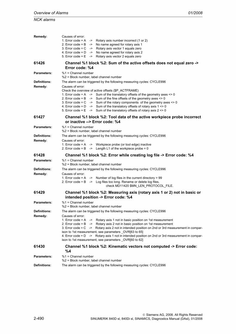
Overview of Alarms 01/2008
NCK alarms
2-490
© Siemens AG, 2008. All Rights ReservedSINUMERIK 840D sl, 840Di sl, SINAMICS, Diagnostics Manual (DAsl), 01/2008
Remedy: Causes of error:1. Error code = A -> Rotary axis number incorrect (1 or 2)2. Error code = B -> No name agreed for rotary axis 13. Error code = C -> Rotary axis vector 1 equals zero4. Error code = D -> No name agreed for rotary axis 25. Error code = E -> Rotary axis vector 2 equals zero
61426 Channel %1 block %2: Sum of the active offsets does not equal zero -> Error code: %4
Parameters: %1 = Channel number%2 = Block number, label channel number
Definitions: The alarm can be triggered by the following measuring cycles: CYCLE996Remedy: Causes of error:
Check the overview of active offsets ($P_ACTFRAME)1. Error code = A -> Sum of the translatory offsets of the geometry axes <> 02. Error code = B -> Sum of the fine offsets of the geometry axes <> 03. Error code = C -> Sum of the rotary components of the geometry axes <> 04. Error code = D -> Sum of the translatory offsets of rotary axis 1 <> 05. Error code = E -> Sum of the translatory offsets of rotary axis 2 <> 0
61427 Channel %1 block %2: Tool data of the active workpiece probe incorrect or inactive --> Error code: %4
Parameters: %1 = Channel number%2 = Block number, label channel number
Definitions: The alarm can be triggered by the following measuring cycles: CYCLE996Remedy: Causes of error:
1. Error code = A -> Workpiece probe (or tool edge) inactive2. Error code = B -> Length L1 of the workpiece probe = 0
61428 Channel %1 block %2: Error while creating log file -> Error code: %4Parameters: %1 = Channel number
%2 = Block number, label channel numberDefinitions: The alarm can be triggered by the following measuring cycles: CYCLE996Remedy: Causes of error:
1. Error code = A -> Number of log files in the current directory > 992. Error code = B -> Log files too long. Rename or delete log files, check MD11420 $MN_LEN_PROTOCOL_FILE.
61429 Channel %1 block %2: Measuring axis (rotary axis 1 or 2) not in basic or intended position -> Error code: %4
Parameters: %1 = Channel number%2 = Block number, label channel number
Definitions: The alarm can be triggered by the following measuring cycles: CYCLE996Remedy: Causes of error:
1. Error code = A -> Rotary axis 1 not in basic position on 1st measurement2. Error code = B -> Rotary axis 2 not in basic position on 1st measurement3. Error code = C -> Rotary axis 2 not in intended position on 2nd or 3rd measurement in compar-ison to 1st measurement, see parameters _OVR[63 to 65]4. Error code = D -> Rotary axis 1 not in intended position on 2nd or 3rd measurement in compar-ison to 1st measurement, see parameters _OVR[60 to 62]
61430 Channel %1 block %2: Kinematic vectors not computed -> Error code: %4
Parameters: %1 = Channel number%2 = Block number, label channel number
Definitions: The alarm can be triggered by the following measuring cycles: CYCLE996

NCK alarms
01/2008 Overview of Alarms
2-491
© Siemens AG, 2008. All Rights ReservedSINUMERIK 840D sl, 840Di sl, SINAMICS, Diagnostics Manual (DAsl), 01/2008
Remedy: Causes of error:1. Error code = A -> Plausibility of the input points PM1, PM2, PM3 not fulfilled, resulting side lengths must not be equal to zero (Notice: even in the case of side lengths not equal to zero, there is a risk of not being able to form a triangle, check => check PM1...3.)2. Error code = B -> Enclosed angle at PM1 between the spread vectors PM1PM2 and PM1PM3 is equal to zero 0. Starting points do not form a triangle.3. Error code = C -> Enclosed angle at PM2 between the spread vectors PM2PM1 and PM2PM3 is equal to 0. Starting points do not form a triangle.4. Error code = D -> Enclosed angle at PM3 between the spread vectors PM3PM1 and PM3PM2 is equal to 0. Starting points do not form a triangle.5. Error code = E -> Normalizing interpolation point: Invalid axis name defined for computation6. Error code = F -> Normalizing interpolation point: Invalid plane defined for computation
61440 Channel %1 block %2: Position of cutting edge cannot be determinedParameters: %1 = Channel number
%2 = Block number, label channel numberDefinitions: The alarm can be triggered by the following measuring cycle: CYCLE982Remedy: A turning tool with a cutting edge position between 1 and 8 must be used as the tool type.
Check the entered cutting edge position with reference to the basic position of the tool carrier.
61441 Channel %1 block %2: Position of cutting edge is not in the machining plane.
Parameters: %1 = Channel number%2 = Block number, label channel number
Definitions: The alarm can be triggered by the following measuring cycle: CYCLE982Remedy: The position of the cutting edge of the turning tool (cutting tip) is no longer in the machining plane
(interpolation plane), this can be caused, for example, by a tool carrier with orientation capability. Cor-rect the tool carrier position.
61442 Channel %1 block %2: Tool carrier not parallel to the geometry axesParameters: %1 = Channel number
%2 = Block number, label channel numberDefinitions: The alarm can be triggered by the following measuring cycle: CYCLE982Remedy: As a result of incorrect positioning of the orientable tool carrier, tool lengths L1,2,3 are not parallel to
the geometry axes. Optimize the axes of the tool carrier.
61443 Channel %1 block %2: Advance angle _INCA=0 or greater/less than +/-90° or +/-120°
Parameters: %1 = Channel number%2 = Block number, label channel number
Definitions: The alarm can be triggered by the following measuring cycle: CYCLE979Remedy: Check the value in the parameter advance angle _INCA.
If 3-point measurement is selected, _INCA must not be greater/less than +/-120°, and with 4-point measurement _INCA must not be greater/less than +/-90°.The advance angle _INCA must always be parameterized unequal to "zero".
61444 Channel %1 block %2: Current measuring speed is not identical to the calibration speed
Parameters: %1 = Channel number%2 = Block number, label channel number
Definitions: The alarm can be triggered by the following measuring cycles: CYCLE974, CYCLE994, CYCLE977, CYCLE978, CYCLE979, CYCLE997, CYCLE998E_MS_CAN, E_MS_HOL, E_MS_POC, E_MS_PIN, E_MS_SPI
Remedy: 1. Repeat the calibration on the basis of the desired measuring speed.2. Match the current measuring speed to the calibration speed. Note: In each case, the relevant calibration speed is stored in each calibration data record.

Overview of Alarms 01/2008
NCK alarms
2-492
© Siemens AG, 2008. All Rights ReservedSINUMERIK 840D sl, 840Di sl, SINAMICS, Diagnostics Manual (DAsl), 01/2008
61501 Channel %1 block %2: Simulation is activeParameters: %1 = Channel number
%2 = Block number, label channel numberDefinitions: The alarm can be triggered by the following grinding cycles: all grinding cyclesRemedy: Reset simulationProgram Con-tinuation:
Clear alarm with the RESET key. Restart part program
61502 Channel %1 block %2: No tool offset activeParameters: %1 = Channel number
%2 = Block number, label channel numberDefinitions: The alarm can be triggered by the following grinding cycles: all grinding cyclesRemedy: A tool number must be programmedProgram Con-tinuation:
Clear alarm with the RESET key. Restart part program
61503 Channel %1 block %2: tool nose radius compensation left or rightParameters: %1 = Channel number
%2 = Block number, label channel numberDefinitions: The alarm can be triggered by the following grinding cycles: CYCLE410, CYCLE411, CYCLE412,
CYCLE413, CYCLE414, CYCLE415, CYCLE416, CYCLE420Remedy: A tool offset value has to be programmedProgram Con-tinuation:
Clear alarm with the RESET key. Restart part program
61504 Channel %1 block %2: _KNG incorrect for setupParameters: %1 = Channel number
%2 = Block number, label channel numberDefinitions: The alarm can be triggered by the following grinding cycle: setup functionRemedy:Program Con-tinuation:
Clear alarm with the RESET key. Restart part program
61505 Channel %1 block %2: retraction path < 1mmParameters: %1 = Channel number
%2 = Block number, label channel numberDefinitions: The alarm can be triggered by the following grinding cycle: CYCLE420Remedy: Increase retraction pathProgram Con-tinuation:
Clear alarm with the RESET key. Restart part program
61506 Channel %1 block %2: infeed path < 1mmParameters: %1 = Channel number
%2 = Block number, label channel numberDefinitions: The alarm can be triggered by the following grinding cycle: CYCLE420Remedy: Increase infeed pathProgram Con-tinuation:
Clear alarm with the RESET key. Restart part program
61507 Channel %1 block %2: safety clearance < 1mmParameters: %1 = Channel number
%2 = Block number, label channel numberDefinitions: The alarm can be triggered by the following grinding cycle: setup functionRemedy:Program Con-tinuation:
Clear alarm with the RESET key. Restart part program

NCK alarms
01/2008 Overview of Alarms
2-493
© Siemens AG, 2008. All Rights ReservedSINUMERIK 840D sl, 840Di sl, SINAMICS, Diagnostics Manual (DAsl), 01/2008
61508 Channel %1 block %2: Incorrect default setting for shoulder positionParameters: %1 = Channel number
%2 = Block number, label channel numberDefinitions: The alarm can be triggered by the following grinding cycle: setup functionRemedy:Program Con-tinuation:
Clear alarm with the RESET key. Restart part program
61509 Channel %1 block %2: Incorrect default setting for dresser positionParameters: %1 = Channel number
%2 = Block number, label channel numberDefinitions: The alarm can be triggered by the following grinding cycle: setup functionRemedy:Program Con-tinuation:
Clear alarm with the RESET key. Restart part program
61510 Channel %1 block %2: Test run feed is activeParameters: %1 = Channel number
%2 = Block number, label channel numberDefinitions: The alarm can be triggered by the following grinding cycles: CYCLE410, CYCLE411, CYCLE413,
CYCLE415, CYCLE420Remedy: Switch off test run feedProgram Con-tinuation:
Clear alarm with the RESET key. Restart part program
61511 Channel %1 block %2: Incorrect shoulder position or tool edge D1/D2Parameters: %1 = Channel number
%2 = Block number, label channel numberDefinitions: The alarm can be triggered by the following grinding cycle: setup functionRemedy:Program Con-tinuation:
Clear alarm with the RESET key. Restart part program
61512 Channel %1 block %2: Incorrect longitudinal positionParameters: %1 = Channel number
%2 = Block number, label channel numberDefinitions: The alarm can be triggered by the following grinding cycle: setup functionRemedy:Program Con-tinuation:
Clear alarm with the RESET key. Restart part program
61513 Channel %1 block %2: Dresser left and inclined grinding wheelParameters: %1 = Channel number
%2 = Block number, label channel numberDefinitions: The alarm can be triggered by the following grinding cycle: setup functionRemedy:Program Con-tinuation:
Clear alarm with the RESET key. Restart part program
61514 Channel %1 block %2: Grinding wheel type missingParameters: %1 = Channel number
%2 = Block number, label channel numberDefinitions: The alarm can be triggered by the following grinding cycle: setup functionRemedy:Program Con-tinuation:
Clear alarm with the RESET key. Restart part program

Overview of Alarms 01/2008
NCK alarms
2-494
© Siemens AG, 2008. All Rights ReservedSINUMERIK 840D sl, 840Di sl, SINAMICS, Diagnostics Manual (DAsl), 01/2008
61515 Channel %1 block %2: Retraction path <= dressing amountParameters: %1 = Channel number
%2 = Block number, label channel numberDefinitions: The alarm can be triggered by the following grinding cycle: CYCLE416Remedy: Change retraction pathProgram Con-tinuation:
Clear alarm with the RESET key. Restart part program
61517 Channel %1 block %2: Angle of inclined grinding wheel missingParameters: %1 = Channel number
%2 = Block number, label channel numberDefinitions: The alarm can be triggered by the following grinding cycle: CYCLE416Remedy: Enter angle under $TC_TPG8Program Con-tinuation:
Clear alarm with the RESET key. Restart part program
61518 Channel %1 block %2: Shoulder height of grinding wheel must be > grinding wheel radius
Parameters: %1 = Channel number%2 = Block number, label channel number
Definitions: The alarm can be triggered by the following grinding cycle: CYCLE432Remedy: Change shoulder height or grinding wheel radiusProgram Con-tinuation:
Clear alarm with the RESET key. Restart part program
61519 Channel %1 block %2: Incorrect type of machiningParameters: %1 = Channel number
%2 = Block number, label channel numberDefinitions: The alarm can be triggered by the following grinding cycles: CYCLE410, CYCLE411, CYCLE412,
CYCLE413, CYCLE415Remedy: Assign a value between 1 and 3 to parameter B_ARTProgram Con-tinuation:
Clear alarm with the RESET key. Restart part program
61520 Channel %1 block %2: Additional offsets not setParameters: %1 = Channel number
%2 = Block number, label channel numberDefinitions: The alarm can be triggered by the following grinding cycles: CYCLE413, CYCLE420, CYCLE433Remedy: Set MD18094 MM_NUM_CC_TDA_PARAM=10Program Con-tinuation:
Clear alarm with the RESET key. Restart part program
61521 Channel %1 block %2: Current grinding wheel too wideParameters: %1 = Channel number
%2 = Block number, label channel numberDefinitions: The alarm can be triggered by the following grinding cycles: CYCLE411, CYCLE415Remedy: Reduce width of grinding wheelProgram Con-tinuation:
Clear alarm with the RESET key. Restart part program
61522 Channel %1 block %2: Overlap >= current grinding wheel widthParameters: %1 = Channel number
%2 = Block number, label channel numberDefinitions: The alarm can be triggered by the following grinding cycle: CYCLE411Remedy: Reduce overlapProgram Con-tinuation:
Clear alarm with the RESET key. Restart part program

NCK alarms
01/2008 Overview of Alarms
2-495
© Siemens AG, 2008. All Rights ReservedSINUMERIK 840D sl, 840Di sl, SINAMICS, Diagnostics Manual (DAsl), 01/2008
61523 Channel %1 block %2: Zero signal of calipers missingParameters: %1 = Channel number
%2 = Block number, label channel numberDefinitions: The alarm can be triggered by the following grinding cycles: CYCLE410, CYCLE411, CYCLE413Remedy: Check calipers signalProgram Con-tinuation:
Clear alarm with the RESET key. Restart part program
61524 Channel %1 block %2: Incorrect oblique angleParameters: %1 = Channel number
%2 = Block number, label channel numberDefinitions: The alarm can be triggered by the following grinding cycle: CYCLE413Remedy: Oblique plunge angles must be >-90° and <90°Program Con-tinuation:
Clear alarm with the RESET key. Restart part program
61525 Channel %1 block %2: Incorrect grinding wheel typeParameters: %1 = Channel number
%2 = Block number, label channel numberDefinitions: The alarm can be triggered by the following grinding cycle: CYCLE413Remedy: Change grinding wheel type $TC_TPC1Program Con-tinuation:
Clear alarm with the RESET key. Restart part program
61526 Channel %1 block %2: Workpiece radius = 0Parameters: %1 = Channel number
%2 = Block number, label channel numberDefinitions: The alarm can be triggered by the following grinding cycle: CYCLE414Remedy: Enter workpiece radius > 0Program Con-tinuation:
Clear alarm with the RESET key. Restart part program
61527 Channel %1 block %2: Grinding wheel radius >= workpiece radiusParameters: %1 = Channel number
%2 = Block number, label channel numberDefinitions: The alarm can be triggered by the following grinding cycle: CYCLE414Remedy: Change grinding wheel radius or workpiece radiusProgram Con-tinuation:
Clear alarm with the RESET key. Restart part program
61529 Channel %1 block %2: Dimensional notation INCH programmedParameters: %1 = Channel number
%2 = Block number, label channel numberDefinitions: The alarm can be triggered by the following grinding cycles: CYCLE410, CYCLE411, CYCLE412,
CYCLE413, CYCLE414, CYCLE415, CYCLE420Remedy: Basic system MD $MN_SCALING_SYSTEM_IS_METRIC does not correspond to programmed G
command (G group 13).Program Con-tinuation:
Clear alarm with the RESET key. Restart part program
61530 Channel %1 block %2: Default longitudinal position incorrectParameters: %1 = Channel number
%2 = Block number, label channel numberDefinitions: The alarm can be triggered by the following grinding cycles: CYCLE420Remedy: Check longitudinal position parameterProgram Con-tinuation:
Clear alarm with the RESET key. Restart part program

Overview of Alarms 01/2008
NCK alarms
2-496
© Siemens AG, 2008. All Rights ReservedSINUMERIK 840D sl, 840Di sl, SINAMICS, Diagnostics Manual (DAsl), 01/2008
61531 Channel %1 block %2: Longitudinal position not registered in ZParameters: %1 = Channel number
%2 = Block number, label channel numberDefinitions: The alarm can be triggered by the following grinding cycles: CYCLE420Remedy: Increase infeed path parameterProgram Con-tinuation:
Clear alarm with the RESET key. Restart part program
61532 Channel %1 block %2: Value for _LAGE is incorrectParameters: %1 = Channel number
%2 = Block number, label channel numberDefinitions: The alarm can be triggered by the following grinding cycle: CYCLE414Remedy: Correct parameter content for _LAGEProgram Con-tinuation:
Clear alarm with the RESET key. Restart part program
61533 Channel %1 block %2: No length L1 entered under D... Parameters: %1 = Channel number
%2 = Block number, label channel numberDefinitions: The alarm can be triggered by the following grinding cycles: CYCLE416, CYCLE420Remedy: Enter length L1 in the tool offset D of the grinding wheelProgram Con-tinuation:
Clear alarm with the RESET key. Restart part program
61540 Channel %1 block %2: Incorrect D number / dresser D field activeParameters: %1 = Channel number
%2 = Block number, label channel numberDefinitions: The alarm can be triggered by the following grinding cycles: CYCLE401, CYCLE402, CYCLE403,
CYCLE443Remedy: A tool D number must be programmed that is < _GC_DNUMProgram Con-tinuation:
Clear alarm with the RESET key. Restart part program
61541 Channel %1 block %2: Incorrect grinding wheel type enteredParameters: %1 = Channel number
%2 = Block number, label channel numberDefinitions: The alarm can be triggered by the following grinding cycles: CYCLE432, CYCLE434, CYCLE435,
CYCLE436, CYCLE438, CYCLE439, CYCLE444, CYCLE447Remedy: Select a valid grinding wheel type in tool managementProgram Con-tinuation:
Clear alarm with the RESET key. Restart part program
61542 Channel %1 block %2: Incorrect grinding wheel reference point selected when selecting the dresser coordinate system
Parameters: %1 = Channel number%2 = Block number, label channel number
Definitions: The alarm can be triggered by the following grinding cycles: CYCLE435, CYCLE441, CYCLE447Remedy: A tool D number must be programmed that is < _GC_DNUMProgram Con-tinuation:
Clear alarm with the RESET key. Restart part program
61543 Channel %1 block %2: Incorrect dresser selected when selecting the dresser coordinate system
Parameters: %1 = Channel number%2 = Block number, label channel number
Definitions: The alarm can be triggered by the following grinding cycles: CYCLE402, CYCLE435, CYCLE442, CYCLE447
Remedy: A dresser number >0 and <4 must be selected

NCK alarms
01/2008 Overview of Alarms
2-497
© Siemens AG, 2008. All Rights ReservedSINUMERIK 840D sl, 840Di sl, SINAMICS, Diagnostics Manual (DAsl), 01/2008
Program Con-tinuation:
Clear alarm with the RESET key. Restart part program
61544 Channel %1 block %2: Grinding wheel diameter worn downParameters: %1 = Channel number
%2 = Block number, label channel numberDefinitions: The alarm can be triggered by the following grinding cycle: CYCLE438Remedy: New grinding wheel required, or check limit values in the grinding wheel dataProgram Con-tinuation:
Clear alarm with the RESET key. Restart part program
61545 Channel %1 block %2: Width of grinding wheel worn downParameters: %1 = Channel number
%2 = Block number, label channel numberDefinitions: The alarm can be triggered by the following grinding cycle: CYCLE438Remedy: New grinding wheel required, or check limit values in the grinding wheel dataProgram Con-tinuation:
Clear alarm with the RESET key. Restart part program
61546 Channel %1 block %2: Dresser %4, wear limit length 1 reachedParameters: %1 = Channel number
%2 = Block number, label channel numberDefinitions: The alarm can be triggered by the following grinding cycle: CYCLE438Remedy: New dresser required, or check limit values of dresserProgram Con-tinuation:
Clear alarm with the RESET key. Restart part program
61547 Channel %1 block %2: Dresser %4, wear limit length 2 reachedParameters: %1 = Channel number
%2 = Block number, label channel numberDefinitions: The alarm can be triggered by the following grinding cycle: CYCLE438Remedy: New dresser required, or check limit values of dresserProgram Con-tinuation:
Clear alarm with the RESET key. Restart part program
61548 Channel %1 block %2: Dresser %4, wear limit length 3 reachedParameters: %1 = Channel number
%2 = Block number, label channel numberDefinitions: The alarm can be triggered by the following grinding cycle: CYCLE438Remedy: New dresser required, or check limit values of dresserProgram Con-tinuation:
Clear alarm with the RESET key. Restart part program
61549 Channel %1 block %2: Incorrect dresser type selectedParameters: %1 = Channel number
%2 = Block number, label channel numberDefinitions: The alarm can be triggered by the following grinding cycles: CYCLE402, CYCLE421, CYCLE422,
CYCLE423, CYCLE424Remedy: Check dresser type on inputProgram Con-tinuation:
Clear alarm with the RESET key. Restart part program
61555 Channel %1 block %2: Diameter of grinding wheel ==0, GWPS cannot be calculated
Parameters: %1 = Channel number%2 = Block number, label channel number
Definitions: The alarm can be triggered by the following grinding cycle: CYCLE446Remedy: Check diameter

Overview of Alarms 01/2008
NCK alarms
2-498
© Siemens AG, 2008. All Rights ReservedSINUMERIK 840D sl, 840Di sl, SINAMICS, Diagnostics Manual (DAsl), 01/2008
Program Con-tinuation:
Clear alarm with the RESET key. Restart part program
61556 Channel %1 block %2: Impossible chamfer and radius of left edge of wheel
Parameters: %1 = Channel number%2 = Block number, label channel number
Definitions: The alarm can be triggered by the following grinding cycle: CYCLE432Remedy: Check values in grinding wheel dataProgram Con-tinuation:
Clear alarm with the RESET key. Restart part program
61557 Channel %1 block %2: Impossible chamfer and radius of right edge of wheel
Parameters: %1 = Channel number%2 = Block number, label channel number
Definitions: The alarm can be triggered by the following grinding cycle: CYCLE432Remedy: Check values in grinding wheel dataProgram Con-tinuation:
Clear alarm with the RESET key. Restart part program
61558 Channel %1 block %2: Chamfer / radius + shoulder height are less than the retraction height of the left edge of the grinding wheel
Parameters: %1 = Channel number%2 = Block number, label channel number
Definitions: The alarm can be triggered by the following grinding cycle: CYCLE432Remedy: Check values in grinding wheel dataProgram Con-tinuation:
Clear alarm with the RESET key. Restart part program
61559 Channel %1 block %2: Chamfer / radius + shoulder height are less than the retraction height of the right edge of the grinding wheel
Parameters: %1 = Channel number%2 = Block number, label channel number
Definitions: The alarm can be triggered by the following grinding cycle: CYCLE432Remedy: Check values in grinding wheel dataProgram Con-tinuation:
Clear alarm with the RESET key. Restart part program
61560 Channel %1 Block %2: Infeed in Z direction too big per stroke, or wheel too narrow
Parameters: %1 = Channel number%2 = Block number, label channel number
Definitions: The alarm can be triggered by the following grinding cycles: CYCLE427, CYCLE428Remedy: Reduce infeed path parameter or use other toolProgram Con-tinuation:
Clear alarm with the RESET key. Restart part program
61561 Channel %1 Block %2: Feed left wheel edge <=0Parameters: %1 = Channel number
%2 = Block number, label channel numberDefinitions: The alarm can be triggered by the following grinding cycle: CYCLE432Remedy: Check values in grinding wheel dataProgram Con-tinuation:
Clear alarm with the RESET key. Restart part program
61562 Channel %1 Block %2: Feed right wheel edge <=0Parameters: %1 = Channel number
%2 = Block number, label channel number

NCK alarms
01/2008 Overview of Alarms
2-499
© Siemens AG, 2008. All Rights ReservedSINUMERIK 840D sl, 840Di sl, SINAMICS, Diagnostics Manual (DAsl), 01/2008
Definitions: The alarm can be triggered by the following grinding cycle: CYCLE432Remedy: Check values in grinding wheel dataProgram Con-tinuation:
Clear alarm with the RESET key. Restart part program
61563 Channel %1 Block %2: Feed on the diameter <=0Parameters: %1 = Channel number
%2 = Block number, label channel numberDefinitions: The alarm can be triggered by the following grinding cycle: CYCLE432Remedy: Check values in grinding wheel dataProgram Con-tinuation:
Clear alarm with the RESET key. Restart part program
61564 Channel %1 Block %2: Feed insertion <=0Parameters: %1 = Channel number
%2 = Block number, label channel numberDefinitions: The alarm can be triggered by the following grinding cycles: CYCLE434, CYCLE444Remedy: Check values in grinding wheel dataProgram Con-tinuation:
Clear alarm with the RESET key. Restart part program
61565 Channel %1 Block %2: Feed dressing <=0Parameters: %1 = Channel number
%2 = Block number, label channel numberDefinitions: The alarm can be triggered by the following grinding cycles: CYCLE434, CYCLE444Remedy: Check values in grinding wheel dataProgram Con-tinuation:
Clear alarm with the RESET key. Restart part program
61601 Channel %1 block %2: Finished part diameter too smallParameters: %1 = Channel number
%2 = Block number, labelDefinitions: The programmed radius of the machined part is too small. Alarm triggered by following cycles:
CYCLE94, CYCLE96.Remedy: Check parameter SPD or DIATH.Program Con-tinuation:
Clear alarm with the RESET key. Restart part program
61602 Channel %1 block %2: Tool width incorrectly definedParameters: %1 = Channel number
%2 = Block number, labelDefinitions: Plunge cutter is larger than the programmed groove width. Alarm triggered by following cycle:
CYCLE93.Remedy: Check tool or change program.Program Con-tinuation:
Clear alarm with the RESET key. Restart part program
61603 Channel %1 block %2: Recess type incorrectly definedParameters: %1 = Channel number
%2 = Block number, labelDefinitions: Radii/chamfers at the groove base do not match the groove width. Face groove on a contour element
running parallel to the longitudinal axis is not possible. Alarm triggered by following cycle: CYCLE93.Remedy: Check parameter VARI.Program Con-tinuation:
Clear alarm with the RESET key. Restart part program
61604 Channel %1 block %2: Active tool violates programmed contourParameters: %1 = Channel number
%2 = Block number, label

Overview of Alarms 01/2008
NCK alarms
2-500
© Siemens AG, 2008. All Rights ReservedSINUMERIK 840D sl, 840Di sl, SINAMICS, Diagnostics Manual (DAsl), 01/2008
Definitions: Contour violation in the relief cut elements due to the tool clearance angle of the tool used. Alarm trig-gered by following cycle: CYCLE95.
Reaction: Interpreter stopNC Start disable in this channel.Interface signals are set.Alarm display.
Remedy: Use a different tool or check the contour subroutine.Program Con-tinuation:
Clear alarm with the RESET key. Restart part program
61605 Channel %1 block %2: Contour incorrectly programmedParameters: %1 = Channel number
%2 = Block number, labelDefinitions: Illegal relief cut element detected. Alarm triggered by following cycles: CYCLE76, CYCLE77,
CYCLE95.Remedy: Check contour program.Program Con-tinuation:
Clear alarm with the RESET key. Restart part program
61606 Channel %1 block %2: Error during contour preparationParameters: %1 = Channel number
%2 = Block number, labelDefinitions: An error has been found on conditioning the contour. This alarm is always related to one of NCK
alarms 10930...10934, 15800 or 15810. Alarm triggered by following cycle: CYCLE95.Remedy: Check contour subroutine.Program Con-tinuation:
Clear alarm with the RESET key. Restart part program
61607 Channel %1 block %2: Starting point incorrectly programmedParameters: %1 = Channel number
%2 = Block number, labelDefinitions: The starting point reached before the cycle call does not lie outside the rectangle described by the
contour subroutine. Alarm triggered by following cycle: CYCLE95.Remedy: Check starting point prior to cycle call.Program Con-tinuation:
Clear alarm with the RESET key. Restart part program
61608 Channel %1 block %2: Incorrect tool point direction programmedParameters: %1 = Channel number
%2 = Block number, labelDefinitions: Alarm triggered by following cycles: CYCLE94, CYCLE96.Reaction: Interpreter stop
NC Start disable in this channel.Interface signals are set.Alarm display.
Remedy: A cutting edge position 1...4, matching the undercut form, must be programmed.Program Con-tinuation:
Clear alarm with the RESET key. Restart part program
61609 Channel %1 block %2: Shape incorrectly definedParameters: %1 = Channel number
%2 = Block number, labelDefinitions: Alarm triggered by following cycles: CYCLE94, CYCLE96, LONGHOLE, POCKET3, SLOT1.Remedy: Check parameter for the undercut form or groove form or pocket.Program Con-tinuation:
Clear alarm with the RESET key. Restart part program
61610 Channel %1 Block %2: No infeed depth programmedParameters: %1 = Channel number
%2 = Block number, label

NCK alarms
01/2008 Overview of Alarms
2-501
© Siemens AG, 2008. All Rights ReservedSINUMERIK 840D sl, 840Di sl, SINAMICS, Diagnostics Manual (DAsl), 01/2008
Definitions: Alarm triggered by following cycles: CYCLE76, CYCLE77, CYCLE96.Remedy: Check parameter MID.Program Con-tinuation:
Clear alarm with the RESET key. Restart part program
61611 Channel %1 Block %2: No point of intersection foundParameters: %1 = Channel number
%2 = Block number, labelDefinitions: No intersection could be calculated with the contour. Alarm triggered by following cycle: CYCLE95.Reaction: Interpreter stop
NC Start disable in this channel.Interface signals are set.Alarm display.
Remedy: Check contour programming or modify infeed depth.Program Con-tinuation:
Clear alarm with the RESET key. Restart part program
61612 Channel %1 block %2: Thread finishing not possibleParameters: %1 = Channel number
%2 = Block number, labelDefinitions: Alarm triggered by following cycles: CYCLE97, CYCLE98.Remedy: Check the conditions for thread finishing.
61613 Channel %1 block %2: Undercut position incorrectly definedParameters: %1 = Channel number
%2 = Block number, labelDefinitions: Alarm triggered by following cycles: CYCLE94, CYCLE96.Reaction: Interpreter stop
NC Start disable in this channel.Interface signals are set.Alarm display.
Remedy: Check value in parameter _VARI.Program Con-tinuation:
Clear alarm with the RESET key. Restart part program
61701 Channel %1 block %2: Error in finished part contour descriptionParameters: %1 = Channel number
%2 = Block number, labelDefinitions: Either none of parameters _NP1, _NP2 and _NP3 supplied or error in finished part contour program-
ming.Alarm triggered by following cycle: CYCLE950
Remedy: - Check parameters _NP1, _NP2 and _NP3.- Check finished-part contour programming.
61702 Channel %1 block %2: Error in blank contour descriptionParameters: %1 = Channel number
%2 = Block number, labelDefinitions: Either none of parameters _NP5, _NP6 and _NP7 supplied or error in blank contour programming.
The alarm is triggered by the following cycles: CYCLE950Remedy: - Check parameters _NP5, _NP6 and _NP7.
- Check blank contour programming
61703 Channel %1 block %2: Internal cycle error while deleting fileParameters: %1 = Channel number
%2 = Block number, labelDefinitions: Alarm triggered by following cycles: CYCLE950, CYCLE73, CYCLE74, CYCLE75.Remedy: --

Overview of Alarms 01/2008
NCK alarms
2-502
© Siemens AG, 2008. All Rights ReservedSINUMERIK 840D sl, 840Di sl, SINAMICS, Diagnostics Manual (DAsl), 01/2008
61704 Channel %1 block %2: Internal cycle error while writing to fileParameters: %1 = Channel number
%2 = Block number, labelDefinitions: Alarm triggered by following cycles: CYCLE950, CYCLE73, CYCLE74, CYCLE75.Remedy: --
61705 Channel %1 block %2: Internal cycle error while reading to fileParameters: %1 = Channel number
%2 = Block number, labelDefinitions: Alarm triggered by following cycles: CYCLE950, CYCLE73, CYCLE74, CYCLE75.Remedy: --
61706 Channel %1 block %2: Internal cycle error while generating checksumParameters: %1 = Channel number
%2 = Block number, labelDefinitions: Alarm triggered by following cycles: CYCLE950, CYCLE73, CYCLE74, CYCLE75.Remedy: --
61707 Channel %1 block %2: internal cycle error with ACTIVATE at HMIParameters: %1 = Channel number
%2 = Block number, labelDefinitions: Alarm triggered by following cycles: CYCLE950, CYCLE73, CYCLE74, CYCLE75.Remedy: --
61708 Channel %1 block %2: internal cycle error with READYPROG at HMIParameters: %1 = Channel number
%2 = Block number, labelDefinitions: Alarm triggered by following cycles: CYCLE950, CYCLE73, CYCLE74, CYCLE75.Remedy: --
61709 Channel %1 block %2: Timeout in contour calculationParameters: %1 = Channel number
%2 = Block number, labelDefinitions: Alarm triggered by following cycle: CYCLE950.Remedy: --
61710 Channel %1 block %2: Stock removal program not availableParameters: %1 = Channel number
%2 = Block number, labelDefinitions:Reaction: Interpreter stop
NC Start disable in this channel.Interface signals are set.Alarm display.
Remedy: --Program Con-tinuation:
Internal
61711 Channel %1 block %2: Name of stock removal program missingParameters: %1 = Channel number
%2 = Block number, labelDefinitions:Reaction: Interpreter stop
NC Start disable in this channel.Interface signals are set.Alarm display.
Remedy: --Program Con-tinuation:
Internal

NCK alarms
01/2008 Overview of Alarms
2-503
© Siemens AG, 2008. All Rights ReservedSINUMERIK 840D sl, 840Di sl, SINAMICS, Diagnostics Manual (DAsl), 01/2008
61712 Channel %1 block %2: Tool parameter for machining direction not defined
Parameters: %1 = Channel number%2 = Block number, label
Definitions:Reaction: Interpreter stop
NC Start disable in this channel.Interface signals are set.Alarm display.
Remedy: --Program Con-tinuation:
Internal
61720 Channel %1 block %2: Incorrect parameter input.Parameters: %1 = Channel number
%2 = Block number, labelDefinitions: Alarm triggered by following cycle: CYCLE950.Remedy: --
61721 Channel %1 block %2: Error contour direction cannot be determinedParameters: %1 = Channel number
%2 = Block number, labelDefinitions: Alarm triggered by following cycle: CYCLE950.Remedy: --
61722 Channel %1 block %2: System errorParameters: %1 = Channel number
%2 = Block number, labelDefinitions: Alarm triggered by following cycle: CYCLE950.Remedy: --
61723 Channel %1 block %2: Machining not possibleParameters: %1 = Channel number
%2 = Block number, labelDefinitions: Alarm triggered by following cycle: CYCLE950.Remedy: Use a tool with a larger clearance angle.
61724 Channel %1 block %2: Material not availableParameters: %1 = Channel number
%2 = Block number, labelDefinitions: Alarm triggered by following cycle: CYCLE950.Remedy: --
61725 Channel %1 block %2: Memory space problem, therefore error in contour generating
Parameters: %1 = Channel number%2 = Block number, label
Definitions: Alarm triggered by following cycle: CYCLE950.Remedy: --
61726 Channel %1 block %2: Internal error: Memory space problem _FILECTRL_INTERNAL_ERROR
Parameters: %1 = Channel number%2 = Block number, label
Definitions: Alarm triggered by following cycle: CYCLE950.Remedy: --

Overview of Alarms 01/2008
NCK alarms
2-504
© Siemens AG, 2008. All Rights ReservedSINUMERIK 840D sl, 840Di sl, SINAMICS, Diagnostics Manual (DAsl), 01/2008
61727 Channel %1 block %2: Internal error: Memory space problem _FILECTRL_EXTERNAL_ERROR
Parameters: %1 = Channel number%2 = Block number, label
Definitions: Alarm triggered by following cycle: CYCLE950.Remedy: --
61728 Channel %1 block %2: Internal error: Memory space problem _ALLOC_P_INTERNAL_ERROR
Parameters: %1 = Channel number%2 = Block number, label
Definitions: Alarm triggered by following cycle: CYCLE950.Remedy: --
61729 Channel %1 block %2: Internal error: Memory space problem _ALLOC_P_EXTERNAL_ERROR
Parameters: %1 = Channel number%2 = Block number, label
Definitions: Alarm triggered by following cycle: CYCLE950.Remedy: --
61730 Channel %1 block %2: Internal error: invalid memoryParameters: %1 = Channel number
%2 = Block number, labelDefinitions: Alarm triggered by following cycle: CYCLE950.Remedy: --
61731 Channel %1 block %2: Internal error: floating point exceptionParameters: %1 = Channel number
%2 = Block number, labelDefinitions: Alarm triggered by following cycle: CYCLE950.Remedy: --
61732 Channel %1 block %2: Internal error: invalid instructionParameters: %1 = Channel number
%2 = Block number, labelDefinitions: Alarm triggered by following cycle: CYCLE950.Remedy: --
61733 Channel %1 block %2: Internal error: Floating_Point_ErrorParameters: %1 = Channel number
%2 = Block number, labelDefinitions: Alarm triggered by following cycle: CYCLE950.Remedy: --
61734 Channel %1 block %2: Cutting edge not compatible with cutting directionParameters: %1 = Channel number
%2 = Block number, labelDefinitions: Alarm triggered by following cycle: CYCLE950.Remedy: --
61735 Channel %1 block %2: Finished part not within blank contourParameters: %1 = Channel number
%2 = Block number, labelDefinitions: Alarm triggered by following cycle: CYCLE950.Remedy: Check blank contour definition.

NCK alarms
01/2008 Overview of Alarms
2-505
© Siemens AG, 2008. All Rights ReservedSINUMERIK 840D sl, 840Di sl, SINAMICS, Diagnostics Manual (DAsl), 01/2008
61736 Channel %1 block %2: Insert length of tool < machining depthParameters: %1 = Channel number
%2 = Block number, labelDefinitions: Alarm triggered by following cycle: CYCLE950.Remedy: --
61737 Channel %1 block %2: Machining_cutting_depth > tool nose radiusParameters: %1 = Channel number
%2 = Block number, labelDefinitions: Alarm triggered by following cycle: CYCLE950.Remedy: --
61738 Channel %1 block %2: Machining_cutting_depth < tool nose radiusParameters: %1 = Channel number
%2 = Block number, labelDefinitions: Alarm triggered by following cycle: CYCLE950.Remedy: --
61739 Channel %1 block %2: Wrong insert position of tool for this machining operation
Parameters: %1 = Channel number%2 = Block number, label
Definitions: Alarm triggered by following cycle: CYCLE950.Remedy: --
61740 Channel %1 block %2: Blank must be closed contourParameters: %1 = Channel number
%2 = Block number, labelDefinitions: Alarm triggered by following cycle: CYCLE950.Remedy: Check whether blank contour is closed, i.e. starting point = end point.
61741 Channel %1 block %2: Abort due to insufficient memory spaceParameters: %1 = Channel number
%2 = Block number, labelDefinitions: Alarm triggered by following cycle: CYCLE950.Remedy: --
61742 Channel %1 block %2: Approach collision, correction not possibleParameters: %1 = Channel number
%2 = Block number, labelDefinitions: Alarm triggered by following cycle: CYCLE950.Remedy: --
61766 Channel %1 block %2: Error in blank programParameters: %1 = Channel number
%2 = Block number, labelDefinitions:Reaction: Interpreter stop
NC Start disable in this channel.Interface signals are set.Alarm display.
Remedy: --Program Con-tinuation:
Internal
61798 Channel %1 block %2: Acknowledgment error ACTIVATEParameters: %1 = Channel number
%2 = Block number, label

Overview of Alarms 01/2008
NCK alarms
2-506
© Siemens AG, 2008. All Rights ReservedSINUMERIK 840D sl, 840Di sl, SINAMICS, Diagnostics Manual (DAsl), 01/2008
Definitions:Reaction: Interpreter stop
NC Start disable in this channel.Interface signals are set.Alarm display.
Remedy: --Program Con-tinuation:
Internal
61799 Channel %1 block %2: Acknowledgment error READYPROGParameters: %1 = Channel number
%2 = Block number, labelDefinitions:Reaction: Interpreter stop
NC Start disable in this channel.Interface signals are set.Alarm display.
Remedy: --Program Con-tinuation:
Internal
61800 Channel %1 block %2: Ext. CNC system missingParameters: %1 = Channel number
%2 = Block number, labelDefinitions: Machine data for external language MD18800: $MN_MM_EXTERN_LANGUAGE or option bit 19800
$ON_EXTERN_LANGUAGE is not set.Reaction: Interpreter stop
NC Start disable in this channel.Interface signals are set.Alarm display.
Remedy: --Program Con-tinuation:
Internal
61801 Channel %1 block %2: Wrong G code selectedParameters: %1 = Channel number
%2 = Block number, labelDefinitions: In the program call CYCLE300<value> an impermissible numerical value was programmed for the
entered CNC System, or in the Cycles Setting Datum an incorrect value for the G Code System was set.
Reaction: Interpreter stopNC Start disable in this channel.Interface signals are set.Alarm display.
Remedy: --Program Con-tinuation:
Internal
61802 Channel %1 block %2: Wrong axis typeParameters: %1 = Channel number
%2 = Block number, labelDefinitions: The programmed axis is assigned to a spindleReaction: Interpreter stop
NC Start disable in this channel.Interface signals are set.Alarm display.
Remedy: --Program Con-tinuation:
Internal

NCK alarms
01/2008 Overview of Alarms
2-507
© Siemens AG, 2008. All Rights ReservedSINUMERIK 840D sl, 840Di sl, SINAMICS, Diagnostics Manual (DAsl), 01/2008
61803 Channel %1 block %2: Programmed axis not availableParameters: %1 = Channel number
%2 = Block number, labelDefinitions: The programmed axis is not in the system.
Alarm triggered by following cycles: CYCLE83, CYCLE84, CYCLE840.Reaction: Interpreter stop
NC Start disable in this channel.Interface signals are set.Alarm display.
Remedy: Check parameter _AXN.Check MD20050-20080.
Program Con-tinuation:
Clear alarm with the RESET key. Restart part program
61804 Channel %1 block %2: Progr. position exceeds reference pointParameters: %1 = Channel number
%2 = Block number, labelDefinitions: The programmed intermediate position or actual position is behind the reference point.Reaction: Interpreter stop
NC Start disable in this channel.Interface signals are set.Alarm display.
Remedy: --Program Con-tinuation:
Internal
61805 Channel %1 block %2: Value programmed absolute and incrementalParameters: %1 = Channel number
%2 = Block number, labelDefinitions: The programmed intermediate position is both absolutely as well as incrementally programmed.Reaction: Interpreter stop
NC Start disable in this channel.Interface signals are set.Alarm display.
Remedy: --Program Con-tinuation:
Internal
61806 Channel %1 block %2: Wrong axis assignmentParameters: %1 = Channel number
%2 = Block number, labelDefinitions: The axis-assignment sequence is wrong.Reaction: Interpreter stop
NC Start disable in this channel.Interface signals are set.Alarm display.
Remedy: --Program Con-tinuation:
Internal
61807 Channel %1 block %2: Wrong spindle direction programmed (active)Parameters: %1 = Channel number
%2 = Block number, labelDefinitions: Alarm triggered by following cycle: CYCLE840.
The programmed spindle direction contradicts the spindle direction planned for the cycle.Reaction: Interpreter stop
NC Start disable in this channel.Interface signals are set.Alarm display.

Overview of Alarms 01/2008
NCK alarms
2-508
© Siemens AG, 2008. All Rights ReservedSINUMERIK 840D sl, 840Di sl, SINAMICS, Diagnostics Manual (DAsl), 01/2008
Remedy: Check parameters SDR and SDAC.Program Con-tinuation:
Clear alarm with the RESET key. Restart part program
61808 Channel %1 block %2: Final drilling depth or single drilling depth missing
Parameters: %1 = Channel number%2 = Block number, label
Definitions: The total depth Z or individual drilling depth Q is missing from theG8xblock (initial cycle call).Reaction: Interpreter stop
NC Start disable in this channel.Interface signals are set.Alarm display.
Remedy: --Program Con-tinuation:
Internal
61809 Channel %1 Block %2: Drill position not permissibleParameters: %1 = Channel number
%2 = Block number, labelDefinitions: --Reaction: Interpreter stop
NC Start disable in this channel.Interface signals are set.Alarm display.
Remedy: --Program Con-tinuation:
Internal
61810 Channel %1 Block %2: ISO G code not possibleParameters: %1 = Channel number
%2 = Block number, labelDefinitions: In the call block an impermissible ISO axis name was programmed.Reaction: Interpreter stop
NC Start disable in this channel.Interface signals are set.Alarm display.
Remedy: --Program Con-tinuation:
Internal
61811 Channel %1 Block %2: ISO axis name illegalParameters: %1 = Channel number
%2 = Block number, labelDefinitions: In the call block an impermissible numerical value was programmed.Reaction: Interpreter stop
NC Start disable in this channel.Interface signals are set.Alarm display.
Remedy: --Program Con-tinuation:
Internal
61812 Channel %1 Block %2: Value(s) in external cycle call wrongly definedParameters: %1 = Channel number
%2 = Block number, label

NCK alarms
01/2008 Overview of Alarms
2-509
© Siemens AG, 2008. All Rights ReservedSINUMERIK 840D sl, 840Di sl, SINAMICS, Diagnostics Manual (DAsl), 01/2008
Definitions: In the call block an impermissible numerical value was programmed.Reaction: Interpreter stop
NC Start disable in this channel.Interface signals are set.Alarm display.
Remedy: --Program Con-tinuation:
Internal
61813 Channel %1 Block %2: GUD value wrongly definedDefinitions: An impermissible numerical value was
entered in the cycles-setting data.Reaction: Interpreter stop
NC Start disable in this channel.Interface signals are set.Alarm display.
Remedy: --Program Con-tinuation:
Internal
61814 Channel %1 block %2: Polar coordinates not possible with cycleParameters: %1 = Channel number
%2 = Block number, labelDefinitions: --Reaction: Interpreter stop
NC Start disable in this channel.Interface signals are set.Alarm display.
Remedy: --Program Con-tinuation:
Internal
61815 Channel %1 block %2: G40 not activeParameters: %1 = Channel number
%2 = Block numberDefinitions: G40 was inactive before the cycle call.Reaction: Interpreter stop
NC Start disable in this channel.Interface signals are set.Alarm display.
Remedy: --Program Con-tinuation:
Internal
61816 Channel %1 Block %2: Axes not on reference pointParameters: %1 = Channel number
%2 = Block number, labelDefinitions: --Reaction: Interpreter stop
NC Start disable in this channel.Interface signals are set.Alarm display.
Remedy: --Program Con-tinuation:
Internal
61817 Channel %1 Block %2: Axis coordinates within protection zoneParameters: %1 = Channel number
%2 = Block number, label

Overview of Alarms 01/2008
NCK alarms
2-510
© Siemens AG, 2008. All Rights ReservedSINUMERIK 840D sl, 840Di sl, SINAMICS, Diagnostics Manual (DAsl), 01/2008
Definitions: --Reaction: Interpreter stop
NC Start disable in this channel.Interface signals are set.Alarm display.
Remedy: --Program Con-tinuation:
Internal
61818 Channel %1 Block %2: Axis range limits are equalParameters: %1 = Channel number
%2 = Block number, labelDefinitions: --Reaction: Interpreter stop
NC Start disable in this channel.Interface signals are set.Alarm display.
Remedy: --Program Con-tinuation:
Internal
61900 Channel %1 block %2: No contour availableParameters: %1 = Channel number
%2 = Block number, labelDefinitions: Alarm triggered by following cycles: CYCLE73, CYCLE74, CYCLE75.Remedy: --
61901 Channel %1 block %2: Contour not closedParameters: %1 = Channel number
%2 = Block number, labelDefinitions: Alarm triggered by following cycles: CYCLE73, CYCLE74, CYCLE75.Remedy: --
61902 Channel %1 block %2: No more memory availableParameters: %1 = Channel number
%2 = Block number, labelDefinitions: Alarm triggered by following cycles: CYCLE73, CYCLE74, CYCLE75.Remedy: --
61903 Channel %1 block %2: Too many contour elementsParameters: %1 = Channel number
%2 = Block number, labelDefinitions: Alarm triggered by following cycles: CYCLE73, CYCLE74, CYCLE75.Remedy: --
61904 Channel %1 block %2: Too many intersectionsParameters: %1 = Channel number
%2 = Block number, labelDefinitions: Alarm triggered by following cycles: CYCLE73, CYCLE74, CYCLE75.Remedy: --
61905 Channel %1 block %2: Cutter radius too smallParameters: %1 = Channel number
%2 = Block number, labelDefinitions: The diameter of the cutter used is too small, residual material is left in the groove. Alarm triggered by
following cycles: SLOT2, CYCLE73, CYCLE74, CYCLE75.Remedy: Use a tool with a larger radius.

NCK alarms
01/2008 Overview of Alarms
2-511
© Siemens AG, 2008. All Rights ReservedSINUMERIK 840D sl, 840Di sl, SINAMICS, Diagnostics Manual (DAsl), 01/2008
61906 Channel %1 block %2: Too many contoursParameters: %1 = Channel number
%2 = Block number, labelDefinitions: Alarm triggered by following cycles: CYCLE73, CYCLE74, CYCLE75.Remedy: --
61907 Channel %1 block %2: No center point specified for circleParameters: %1 = Channel number
%2 = Block number, labelDefinitions: Alarm triggered by following cycles: CYCLE73, CYCLE74, CYCLE75.Remedy: --
61908 Channel %1 block %2: No starting point specifiedParameters: %1 = Channel number
%2 = Block number, labelDefinitions: Alarm triggered by following cycles: CYCLE73, CYCLE74, CYCLE75.Remedy: --
61909 Channel %1 block %2: Helix radius too smallParameters: %1 = Channel number
%2 = Block number, labelDefinitions: Alarm triggered by following cycles: CYCLE73, CYCLE74, CYCLE75.Remedy: --
61910 Channel %1 block %2: Helix violates contourParameters: %1 = Channel number
%2 = Block number, labelDefinitions: Alarm triggered by following cycles: CYCLE73, CYCLE74, CYCLE75.Remedy: --
61911 Channel %1 block %2: Several approach points requiredParameters: %1 = Channel number
%2 = Block number, labelDefinitions: Alarm triggered by following cycles: CYCLE73, CYCLE74, CYCLE75.Remedy: --
61912 Channel %1 block %2: No path to generateParameters: %1 = Channel number
%2 = Block number, labelDefinitions: --Reaction: Interpreter stop
NC Start disable in this channel.Interface signals are set.Alarm display.
Remedy: --Program Con-tinuation:
Internal
61913 Channel %1 block %2: No residual material generatedParameters: %1 = Channel number
%2 = Block number, labelDefinitions: Alarm triggered by following cycles: CYCLE73, CYCLE74, CYCLE75.Remedy: --
61914 Channel %1 block %2: Programmed helix violates contourParameters: %1 = Channel number
%2 = Block number, labelDefinitions: Alarm triggered by following cycles: CYCLE73, CYCLE74, CYCLE75.Remedy: --

Overview of Alarms 01/2008
NCK alarms
2-512
© Siemens AG, 2008. All Rights ReservedSINUMERIK 840D sl, 840Di sl, SINAMICS, Diagnostics Manual (DAsl), 01/2008
61915 Channel %1 block %2: Approach/retract motion violates contourParameters: %1 = Channel number
%2 = Block number, labelDefinitions: Alarm triggered by following cycles: CYCLE73, CYCLE74, CYCLE75.Remedy: --
61916 Channel %1 block %2: Ramp path too shortParameters: %1 = Channel number
%2 = Block number, labelDefinitions: Alarm triggered by following cycles: CYCLE73, CYCLE74, CYCLE75.Remedy: --
61917 Channel %1 block %2: Residual corners may remain with overlapping of less than 50%
Parameters: %1 = Channel number%2 = Block number, label
Definitions: Alarm triggered by following cycles: CYCLE73, CYCLE74, CYCLE75.Remedy: --
61918 Channel %1 block %2: Cutter radius for residual material too largeParameters: %1 = Channel number
%2 = Block number, labelDefinitions: Alarm triggered by following cycles: CYCLE73, CYCLE74, CYCLE75.Remedy: --
61980 Channel %1 block %2: Error in the island contourParameters: %1 = Channel number
%2 = Block number, labelDefinitions: Alarm triggered by following cycles: CYCLE73, CYCLE74, CYCLE75.Remedy: --
61981 Channel %1 block %2: Error in the edge contourParameters: %1 = Channel number
%2 = Block number, labelDefinitions: Alarm triggered by following cycles: CYCLE73, CYCLE74, CYCLE75.Remedy: --
61982 Channel %1 block %2: Infeed width in the plane too largeParameters: %1 = Channel number
%2 = Block number, labelDefinitions: Alarm triggered by following cycles: CYCLE73, CYCLE74, CYCLE75.Remedy: --
61983 Channel %1 block %2: Pocket edge contour missingParameters: %1 = Channel number
%2 = Block number, labelDefinitions: Alarm triggered by following cycles: CYCLE73, CYCLE74, CYCLE75.Remedy: --
61984 Channel %1 block %2: Tool parameter _TN not definedParameters: %1 = Channel number
%2 = Block number, labelDefinitions: Alarm triggered by following cycles: CYCLE73, CYCLE74, CYCLE75.Remedy: --
61985 Channel %1 block %2: Program name for drilling positions missingParameters: %1 = Channel number
%2 = Block number, labelDefinitions: Alarm triggered by following cycles: CYCLE73, CYCLE74, CYCLE75.

NCK alarms
01/2008 Overview of Alarms
2-513
© Siemens AG, 2008. All Rights ReservedSINUMERIK 840D sl, 840Di sl, SINAMICS, Diagnostics Manual (DAsl), 01/2008
Remedy: --
61986 Channel %1 block %2: Program pocket milling missingParameters: %1 = Channel number
%2 = Block number, labelDefinitions: Alarm triggered by following cycles: CYCLE73, CYCLE74, CYCLE75.Remedy: --
61987 Channel %1 block %2: Program drilling positions missingParameters: %1 = Channel number
%2 = Block number, labelDefinitions: Alarm triggered by following cycles: CYCLE73, CYCLE74, CYCLE75.Remedy: --
61988 Channel %1 block %2: Program name for pocket milling missingParameters: %1 = Channel number
%2 = Block number, labelDefinitions: Alarm triggered by following cycles: CYCLE73, CYCLE74, CYCLE75.Remedy: --
61989 Channel %1 block %2: D1 is not programmed as active tool cutting edgeParameters: %1 = Channel number
%2 = Block number, labelDefinitions: Alarm triggered by following cycles: CYCLE73, CYCLE74, CYCLE75.Remedy: --
62000 Channel %1 block %2: Insert new toolParameters: %1 = Channel number
%2 = Block number, labelDefinitions: Please load new tool.Remedy: --Program Con-tinuation:
Clear alarm with the Delete key or NC START.
62100 Channel %1 block %2: No drilling cycle activeParameters: %1 = Channel number
%2 = Block number, labelDefinitions: No modal drilling cycle has been called before the drilling pattern cycle call. Alarm triggered by follow-
ing cycles: HOLES1, HOLES2.Remedy: Check whether a drilling cycle was called prior to calling the drilling pattern cycle.Program Con-tinuation:
Clear alarm with the Delete key or NC START.
62101 Channel %1 Block %2: Milling direction incorrect - G3 is generatedParameters: %1 = Channel number
%2 = Block number, labelDefinitions: Synchronous or reverse rotation programmed. But the spindle does not rotate at a cycle call.Remedy: Check value in paramter CDIR.
62102 Channel %1 Block %2: pocket not completely solidly machined during finishing
Parameters: %1 = Channel number%2 = Block number, label
Definitions:Reaction: Alarm display.Remedy:Program Con-tinuation:
Clear alarm with the Delete key or NC START.

Overview of Alarms 01/2008
NCK alarms
2-514
© Siemens AG, 2008. All Rights ReservedSINUMERIK 840D sl, 840Di sl, SINAMICS, Diagnostics Manual (DAsl), 01/2008
62103 Channel %1 Block %2: No finishing allowance programmedParameters: %1 = Channel number
%2 = Block number, labelDefinitions: No finishing allowance is programmed, although it is necessary for this machining.Reaction: Alarm display.Remedy: Programm a finishing allowance.Program Con-tinuation:
Clear alarm with the Delete key or NC START.
62104 Channel %1 Block %2: Drilling cycle incorrectly definedParameters: %1 = Channel number
%2 = Block number, labelDefinitions:Reaction: Alarm display.Remedy:Program Con-tinuation:
Clear alarm with the Delete key or NC START.
62105 Channel %1 block %2: Number of columns or lines equals zeroParameters: %1 = Channel number
%2 = Block number, labelDefinitions: Alarm triggered by following cycle: CYCLE801.Remedy: Check parameters _NUM1 and _NUM2.
62106 Channel %1 block %2: incorrect value for monitoring status in tool monitoring
Parameters: %1 = Channel number%2 = Block number, label
Definitions:Reaction: Alarm display.Remedy:Program Con-tinuation:
Clear alarm with the Delete key or NC START.
62107 Channel %1 block %2: parameter %4 incorrectly defined for tool monitoring in cycles
Parameters: %1 = Channel number%2 = Block number, label
Definitions:Reaction: Alarm display.Remedy:Program Con-tinuation:
Clear alarm with the Delete key or NC START.
62108 Channel %1 block %2: error in function Tool monitoring in cyclesParameters: %1 = Channel number
%2 = Block number, labelDefinitions:Reaction: Alarm display.Remedy:Program Con-tinuation:
Clear alarm with the Delete key or NC START.
62180 Channel %1 block %2: Set rotary axes %4 [deg]Parameters: %1 = Channel number
%2 = Block number, label

NCK alarms
01/2008 Overview of Alarms
2-515
© Siemens AG, 2008. All Rights ReservedSINUMERIK 840D sl, 840Di sl, SINAMICS, Diagnostics Manual (DAsl), 01/2008
Definitions: Alarm triggered by following cycle: CYCLE800.Note on 62180 and 62181:Sample display of the swivel angle to be set for a manual rotary axis in CYCLE800: 62181 "Set rotary axis B: 32.5 [grd]"
Remedy: Settable angles for manual rotary axes.
62181 Channel %1 block %2: Set rotary axis %4 [deg]Parameters: %1 = Channel number
%2 = Block number, labelDefinitions: Alarm triggered by following cycle: CYCLE800.
Note on 62180 and 62181:Sample display of the swivel angle to be set for a manual rotary axis in CYCLE800: 62181 "Set rotary axis B: 32.5 [grd]"
Remedy: Settable angle for manual rotary axis.
62182 Channel %1 block %2 : load inclinable head: %4Parameters: %1 = Channel number
%2 = Block number, labelDefinitions: No swivel head is active. Alarm triggered by following cycles: E_TCARR, F_TCARR.Reaction: Alarm display.Remedy: Request to load a swivel head.Program Con-tinuation:
Clear alarm with the Delete key or NC START.
62183 Channel %1 block %2 : unload inclinable head: %4Parameters: %1 = Channel number
%2 = Block number, labelDefinitions: Alarm triggered by following cycle: CYCLE800.Reaction: Alarm display.Remedy: --Program Con-tinuation:
Clear alarm with the Delete key or NC START.
62184 Channel %1 block %2 : replace inclinable head: %4Parameters: %1 = Channel number
%2 = Block number, labelDefinitions: Alarm triggered by following cycle: CYCLE800.Reaction: Alarm display.Remedy: --Program Con-tinuation:
Clear alarm with the Delete key or NC START.
62185 Channel %1 block %2 : angle adapted to angle grid: %4Parameters: %1 = Channel number
%2 = Block number, labelDefinitions: %4 difference angle with Hirth tooth system
Alarm triggered by following cycle: CYCLE800.Remedy: Check start-up swivel cycle CYCLE800.
62186 Channel %1 block %2: Swiveling in JOG --> active work offset G%4 and base (basic reference) contain rotations
Parameters: %1 = Channel number%2 = Block number, label
Definitions: Alarm triggered by following cycle: CYCLE800.Check active work offsets (rotations)Error message can be masked -> see setting data 55410 MILL_SWIVEL_ALARM_MASK
Remedy: For %4 of the active work offset see notes for 62186 and 62187.

Overview of Alarms 01/2008
NCK alarms
2-516
© Siemens AG, 2008. All Rights ReservedSINUMERIK 840D sl, 840Di sl, SINAMICS, Diagnostics Manual (DAsl), 01/2008
62187 Channel %1 block %2: Swiveling in JOG --> active base, basic reference (G500) contains rotations
Parameters: %1 = Channel number%2 = Block number, label
Definitions: Active base, basic reference (G500) contains rotations.Alarm triggered by following cycle: CYCLE800.Note on 62186 and 62187:Check active work offsets (rotations)Error message can be masked -> see setting data 55410 MILL_SWIVEL_ALARM_MASK
Remedy: See notes for 62186 and 62187.
62200 Channel %1 Block %2: Start spindleParameters: %1 = Channel number
%2 = Block number, labelDefinitions: Stop prior to thread machining, as the spindle is in stop position.
Alarm triggered by following cycles: ASUP, E_TR_CON, F_TR_CON.Remedy: Start the tool spindle before machining the thread.
62201 Channel %1 block %2: Z offset does not influence the retraction planes.Parameters: %1 = Channel number
%2 = Block number, labelDefinitions: The retraction planes refer to the workpiece. Therefore, programmable offsets do not influence the
retraction planes.Alarm triggered by following cycle: F_SP_RP.
Remedy: Ensure that the offset will not cause a collision.Then start the NC.The alarm can be suppressed via display machine data 9898.
62202 Channel %1 block %2: NOTICE: tool travels directly to machining!Parameters: %1 = Channel number
%2 = Block number, labelDefinitions: After block search a position is to be reached by direct approach.
Alarm triggered by following cycle: F_TFS.Remedy: Check whether the desired position can be reached without collision.
Then execute an NC start.
62300 Channel %1 block %2: Check number of empirical value memoryParameters: %1 = Channel number
%2 = Block number, label channel numberDefinitions: --Reaction: Alarm display.Remedy: Check setpoint valueProgram Con-tinuation:
Clear alarm with the RESET key. Restart part program
62303 Channel %1 Block %2: Safety margin exceededParameters: %1 = Channel number
%2 = Block number, label channel numberDefinitions: Alarm can be triggered by following measuring cycles: all measuring cycles.Remedy: - Check setpoint value and parameter _TSA
62304 Channel %1 Block %2: AllowanceParameters: %1 = Channel number
%2 = Block number, label channel numberDefinitions: The alarm is triggerd by the following cycles: CYCLE974, CYCLE977, CYCLE978, CYCLE979,
CYCLE994.Reaction: Alarm display.Remedy: The difference between actual and setpoint value is larger than upper tolerance limit (parameter
_TUL).

NCK alarms
01/2008 Overview of Alarms
2-517
© Siemens AG, 2008. All Rights ReservedSINUMERIK 840D sl, 840Di sl, SINAMICS, Diagnostics Manual (DAsl), 01/2008
Program Con-tinuation:
Clear alarm with the RESET key. Restart part program
62305 Channel %1 Block %2: Dimension too smallParameters: %1 = Channel number
%2 = Block number, label channel numberDefinitions: The alarm is triggerd by the following cycles: CYCLE974, CYCLE977, CYCLE978, CYCLE979,
CYCLE994 Remedy: The difference between actual and setpoint value is smaller than lower tolerance limit (parameter
_TLL).
62306 Channel %1 Block %2: Permissible measuring difference exceededParameters: %1 = Channel number
%2 = Block number, label channel numberDefinitions: The alarm is triggerd by the following cycles: CYCLE971, CYCLE972, CYCLE974, CYCLE977,
CYCLE978, CYCLE979, CYCLE982, CYCLE994 Remedy: The difference between actual and setpoint value is larger than tolerance parameter _TDIF, tool data
are not corrected.
62307 Channel %1 block %2: Maximum number of characters per line exceeded.
Parameters: %1 = Channel number%2 = Block number, label channel number
Definitions: The alarm is triggerd by the following cycles: CYCLE105Insufficient number of characters per line.
Remedy: Increase the value in _PROTFORM[1]
62308 Channel %1 Block %2: Variable column width not possibleParameters: %1 = Channel number
%2 = Block number, label channel numberDefinitions: The alarm is triggerd by the following cycles: CYCLE105.
Unable to generate variable column widths, as no header available.A fixed column width of 12 characters is used.
Reaction: Alarm display.Remedy: Complete the header in _PROTVAL[0].Program Con-tinuation:
Clear alarm with the RESET key. Restart part program
62309 Channel %1 Block %2: Insufficient column widthParameters: %1 = Channel number
%2 = Block number, label channel numberDefinitions: The alarm is triggerd by the following cycles: CYCLE105.
The value to be logged is larger than the column width.Reaction: Alarm display.Remedy: Adjust _PROTFORM[5] or change the header at variable column width.Program Con-tinuation:
Clear alarm with the RESET key. Restart part program
62310 Channel %1 block %2: The max. number of characters per line is limited to 200 characters per line
Parameters: %1 = Channel number%2 = Block number, label channel number
Definitions: Alarm triggered by following cycles: CYCLE105.The maximum number of characters per line has been limited to 200 characters per line.
Remedy: --
62311 Channel %1 block %2: The maximum number of characters per line _PROTFORM[1] is adjusted.
Parameters: %1 = Channel number%2 = Block number, label channel number

Overview of Alarms 01/2008
NCK alarms
2-518
© Siemens AG, 2008. All Rights ReservedSINUMERIK 840D sl, 840Di sl, SINAMICS, Diagnostics Manual (DAsl), 01/2008
Definitions: The alarm is triggered by the following cycles: CYCLE105Max. number of characters per line _PROTFORM[1] has been adjusted.
Reaction: Alarm display.Remedy: --Program Con-tinuation:
Clear alarm with the RESET key. Restart part program
62312 Channel %1 block %2: probe is not perpendicular to plane!Parameters: %1 = Channel number
%2 = Block number, label channel numberDefinitions:Reaction: Alarm display.Remedy: --Program Con-tinuation:
Clear alarm with the RESET key. Restart part program
62313 Channel %1 block %2: The number of lines per page _PROTFORM[0] is incorrect and is automatically adjusted.
Parameters: %1 = Channel number%2 = Block number, label channel number
Definitions: Alarm triggered by following cycle: CYCLE106.Remedy: Check _PROTFORM[0] in the program.
62314 Channel %1 block %2: Traverse path limitation via software end position, collision detection activated, continue with NC START / cancel with RESET.
Parameters: %1 = Channel number%2 = Block number, label channel number
Definitions: The alarm is triggered by the following cycle: CYCLE977Remedy: Position the workpiece to be measured further away from the software end positions.
62315 Channel %1 block %2: Overwrite swivel data record TCARR = %4, yes -> NC start, no -> reset
Parameters: %1 = Channel number%2 = Block number, label channel number
Definitions: The alarm is triggered by the following cycle: CYCLE996Remedy:
62316 Channel %1 block %2: Overwrite TRAORIdata, yes -> NC start, no -> resetParameters: %1 = Channel number
%2 = Block number, label channel numberDefinitions: The alarm is triggered by the following cycle: CYCLE996Remedy:
62317 Channel %1 Block %2: Tolerance of the linear vector %4 exceededParameters: %1 = Channel number
%2 = Block number, label channel numberDefinitions: The alarm is triggered by the following cycle: CYCLE996Remedy:
62318 Channel %1 Block %2: Tolerance of the rotary axis vector %4 exceededParameters: %1 = Channel number
%2 = Block number, label channel numberDefinitions: The alarm is triggered by the following cycle: CYCLE996Remedy:

NCK alarms
01/2008 Overview of Alarms
2-519
© Siemens AG, 2008. All Rights ReservedSINUMERIK 840D sl, 840Di sl, SINAMICS, Diagnostics Manual (DAsl), 01/2008
62500 Channel %1 block %2: GWPS has been limitedParameters: %1 = Channel number
%2 = Block number, label channel numberDefinitions: The alarm can be triggered by the following grinding cycle: CYCLE446Remedy: Check limit value for GWPS and program a lower value in the NC program if necessaryProgram Con-tinuation:
Clear alarm with the Delete key or NC START.
62501 Channel %1 block %2: Speed has been limitedParameters: %1 = Channel number
%2 = Block number, label channel numberDefinitions: The alarm can be triggered by the following grinding cycle: CYCLE446Remedy: Check limit value for speed and program a lower value in the NC program if necessaryProgram Con-tinuation:
Clear alarm with the Delete key or NC START.
62502 Channel %1 block %2: Dresser %4, GWPS has been limitedParameters: %1 = Channel number
%2 = Block number, label channel numberDefinitions: The alarm can be triggered by the following grinding cycle: CYCLE421Remedy: Check limit value for GWPS and program a lower value in the NC program if necessaryProgram Con-tinuation:
Clear alarm with the Delete key or NC START.
62503 Channel %1 block %2: Dresser %4, speed has been limitedParameters: %1 = Channel number
%2 = Block number, label channel numberDefinitions: The alarm can be triggered by the following grinding cycle: CYCLE421Remedy: Check limit value for speed and program a lower value in the NC program if necessaryProgram Con-tinuation:
Clear alarm with the Delete key or NC START.
62900 Channel %1 block %2: Incorrect source fileParameters: %1 = Channel number
%2 = Block number, label channel numberDefinitions:Reaction: Alarm display.Remedy: --Program Con-tinuation:
Clear alarm with the RESET key. Restart part program
62901 Channel %1 block %2: Source file not availableParameters: %1 = Channel number
%2 = Block number, label channel numberDefinitions:Reaction: Alarm display.Remedy: --Program Con-tinuation:
Clear alarm with the RESET key. Restart part program
62902 Channel %1 block %2: Not yet implementedParameters: %1 = Channel number
%2 = Block number, label channel numberDefinitions:Reaction: Alarm display.Remedy: --Program Con-tinuation:
Clear alarm with the RESET key. Restart part program

Overview of Alarms 01/2008
NCK alarms
2-520
© Siemens AG, 2008. All Rights ReservedSINUMERIK 840D sl, 840Di sl, SINAMICS, Diagnostics Manual (DAsl), 01/2008
62903 Channel %1 block %2: Incorrect contourParameters: %1 = Channel number
%2 = Block number, label channel numberDefinitions:Reaction: Alarm display.Remedy: --Program Con-tinuation:
Clear alarm with the RESET key. Restart part program
62904 Channel %1 block %2: Inconsistent treeParameters: %1 = Channel number
%2 = Block number, label channel numberDefinitions:Reaction: Alarm display.Remedy: --Program Con-tinuation:
Clear alarm with the RESET key. Restart part program
62905 Channel %1 block %2: Inconsistent archiveParameters: %1 = Channel number
%2 = Block number, label channel numberDefinitions:Reaction: Alarm display.Remedy: --Program Con-tinuation:
Clear alarm with the RESET key. Restart part program
62906 Channel %1 block %2: Error while reading from input fileParameters: %1 = Channel number
%2 = Block number, label channel numberDefinitions:Reaction: Alarm display.Remedy: --Program Con-tinuation:
Clear alarm with the RESET key. Restart part program
62907 Channel %1 block %2: Error while writing to NC fileParameters: %1 = Channel number
%2 = Block number, label channel numberDefinitions:Reaction: Alarm display.Remedy: --Program Con-tinuation:
Clear alarm with the RESET key. Restart part program
62908 Channel %1 block %2: Selfcutting contourParameters: %1 = Channel number
%2 = Block number, label channel numberDefinitions:Reaction: Alarm display.Remedy: --Program Con-tinuation:
Clear alarm with the RESET key. Restart part program
62909 Channel %1 block %2: Internal error: selfcont_partParameters: %1 = Channel number
%2 = Block number, label channel number

NCK alarms
01/2008 Overview of Alarms
2-521
© Siemens AG, 2008. All Rights ReservedSINUMERIK 840D sl, 840Di sl, SINAMICS, Diagnostics Manual (DAsl), 01/2008
Definitions:Reaction: Alarm display.Remedy: --Program Con-tinuation:
Clear alarm with the RESET key. Restart part program
62910 Channel %1 block %2: Error while calculating the contour orientationParameters: %1 = Channel number
%2 = Block number, label channel numberDefinitions:Reaction: Alarm display.Remedy: --Program Con-tinuation:
Clear alarm with the RESET key. Restart part program
62911 Channel %1 block %2: Error on overwriting targetParameters: %1 = Channel number
%2 = Block number, label channel numberDefinitions:Reaction: Alarm display.Remedy: --Program Con-tinuation:
Clear alarm with the RESET key. Restart part program
62912 Channel %1 block %2: Plane cannot be specified hereParameters: %1 = Channel number
%2 = Block number, label channel numberDefinitions:Reaction: Alarm display.Remedy: --Program Con-tinuation:
Clear alarm with the RESET key. Restart part program
62913 Channel %1 block %2: Inch/metric indication not allowedParameters: %1 = Channel number
%2 = Block number, label channel numberDefinitions:Reaction: Alarm display.Remedy: --Program Con-tinuation:
Clear alarm with the RESET key. Restart part program
62914 Channel %1 block %2: Double contour pocket callParameters: %1 = Channel number
%2 = Block number, label channel numberDefinitions:Reaction: Alarm display.Remedy: --Program Con-tinuation:
Clear alarm with the RESET key. Restart part program
62915 Channel %1 block %2: Contour pocket call is missingParameters: %1 = Channel number
%2 = Block number, label channel numberDefinitions:Reaction: Alarm display.Remedy: --

Overview of Alarms 01/2008
NCK alarms
2-522
© Siemens AG, 2008. All Rights ReservedSINUMERIK 840D sl, 840Di sl, SINAMICS, Diagnostics Manual (DAsl), 01/2008
Program Con-tinuation:
Clear alarm with the RESET key. Restart part program
62916 Channel %1 block %2: Contour not finishedParameters: %1 = Channel number
%2 = Block number, label channel numberDefinitions:Reaction: Alarm display.Remedy: --Program Con-tinuation:
Clear alarm with the RESET key. Restart part program
62917 Channel %1 block %2: Contour end without specified startParameters: %1 = Channel number
%2 = Block number, label channel numberDefinitions:Reaction: Alarm display.Remedy: --Program Con-tinuation:
Clear alarm with the RESET key. Restart part program
62918 Channel %1 block %2: Rapid traverse within contour definitionParameters: %1 = Channel number
%2 = Block number, label channel numberDefinitions:Reaction: Alarm display.Remedy: --Program Con-tinuation:
Clear alarm with the RESET key. Restart part program
62919 Channel %1 block %2: Nominal radius parameter is missingParameters: %1 = Channel number
%2 = Block number, label channel numberDefinitions:Reaction: Alarm display.Remedy: --Program Con-tinuation:
Clear alarm with the RESET key. Restart part program
62920 Channel %1 block %2: Pocket surface not specifiedParameters: %1 = Channel number
%2 = Block number, label channel numberDefinitions:Reaction: Alarm display.Remedy: --Program Con-tinuation:
Clear alarm with the RESET key. Restart part program
62921 Channel %1 block %2: Pocket depth not specifiedParameters: %1 = Channel number
%2 = Block number, label channel numberDefinitions:Reaction: Alarm display.Remedy: --Program Con-tinuation:
Clear alarm with the RESET key. Restart part program

NCK alarms
01/2008 Overview of Alarms
2-523
© Siemens AG, 2008. All Rights ReservedSINUMERIK 840D sl, 840Di sl, SINAMICS, Diagnostics Manual (DAsl), 01/2008
62922 Channel %1 block %2: Output program not specifiedParameters: %1 = Channel number
%2 = Block number, label channel numberDefinitions:Reaction: Alarm display.Remedy: --Program Con-tinuation:
Clear alarm with the RESET key. Restart part program
62923 Channel %1 block %2: Starting point not specifiedParameters: %1 = Channel number
%2 = Block number, label channel numberDefinitions:Reaction: Alarm display.Remedy: --Program Con-tinuation:
Clear alarm with the RESET key. Restart part program
62924 Channel %1 block %2: Too many elements in the contourParameters: %1 = Channel number
%2 = Block number, label channel numberDefinitions:Reaction: Alarm display.Remedy: --Program Con-tinuation:
Clear alarm with the RESET key. Restart part program
62925 Channel %1 block %2: Radius specified together with center pointParameters: %1 = Channel number
%2 = Block number, label channel numberDefinitions:Reaction: Alarm display.Remedy: --Program Con-tinuation:
Clear alarm with the RESET key. Restart part program
62926 Channel %1 block %2: Wrong radius specifiedParameters: %1 = Channel number
%2 = Block number, label channel numberDefinitions:Reaction: Alarm display.Remedy: --Program Con-tinuation:
Clear alarm with the RESET key. Restart part program
62927 Channel %1 block %2: Error in filletParameters: %1 = Channel number
%2 = Block number, label channel numberDefinitions:Reaction: Alarm display.Remedy: --Program Con-tinuation:
Clear alarm with the RESET key. Restart part program
62928 Channel %1 block %2: Error in chamferParameters: %1 = Channel number
%2 = Block number, label channel number

Overview of Alarms 01/2008
NCK alarms
2-524
© Siemens AG, 2008. All Rights ReservedSINUMERIK 840D sl, 840Di sl, SINAMICS, Diagnostics Manual (DAsl), 01/2008
Definitions:Reaction: Alarm display.Remedy: --Program Con-tinuation:
Clear alarm with the RESET key. Restart part program
62929 Channel %1 block %2: Overlapping pocketsParameters: %1 = Channel number
%2 = Block number, label channel numberDefinitions:Reaction: Alarm display.Remedy: --Program Con-tinuation:
Clear alarm with the RESET key. Restart part program
62930 Channel %1 block %2: Contour not closedParameters: %1 = Channel number
%2 = Block number, label channel numberDefinitions:Reaction: Alarm display.Remedy: --Program Con-tinuation:
Clear alarm with the RESET key. Restart part program
62931 Channel %1 block %2: Residual material file errorParameters: %1 = Channel number
%2 = Block number, label channel numberDefinitions:Reaction: Alarm display.Remedy: --Program Con-tinuation:
Clear alarm with the RESET key. Restart part program
62932 Channel %1 block %2: error on reading RIF fileParameters: %1 = Channel number
%2 = Block number, label channel numberDefinitions:Reaction: Alarm display.Remedy: --Program Con-tinuation:
Clear alarm with the RESET key. Restart part program
62933 Channel %1 block %2: DEMO modeParameters: %1 = Channel number
%2 = Block number, label channel numberDefinitions:Reaction: Alarm display.Remedy: --Program Con-tinuation:
Clear alarm with the RESET key. Restart part program
62934 Channel %1 block %2: Incorrect finishing contour calculationParameters: %1 = Channel number
%2 = Block number, label channel numberDefinitions:Remedy: --

NCK alarms
01/2008 Overview of Alarms
2-525
© Siemens AG, 2008. All Rights ReservedSINUMERIK 840D sl, 840Di sl, SINAMICS, Diagnostics Manual (DAsl), 01/2008
70001 Channel %1 DTRA: Yf is larger than distance C1-CyParameters: %1 = Channel numberDefinitions: In JOG mode, the Yf axis is traversed. The value of the Yf axis is larger than the distance C1-CyReaction: Mode group not ready.
Channel not ready.NC Start disable in this channel.Interface signals are set.Alarm display.NC Stop on alarm.
Remedy: Traverse Yf axis in JOG mode in opposite traversing directionProgram Con-tinuation:
Teileprogramm neu starten.Clear alarm with the RESET key in all channels of this mode group. Restart part program.
70002 Channel %1 DTRA: block %2 Yf has been programmed larger than distance C1-Cy
Parameters: %1 = Channel number%2 = Block number
Definitions: In the part program, one position in the Yf axis has been programmed larger than the distance C1-CyReaction: Correction block is reorganized.
Local alarm reaction.Interface signals are set.Alarm display.
Remedy: Modify part program.Program Con-tinuation:
Teileprogramm neu starten.Clear alarm with the RESET key in all channels of this mode group. Restart part program.
70003 Channel %1 DTRA: Yf is larger than the effective arm lengthParameters: %1 = Channel numberDefinitions: In JOG mode, the Yf axis is traversed. The value of the Yf axis is larger than the sum of the arm lengths
and the current tool length in the Z direction.Reaction: Mode group not ready.
Channel not ready.NC Start disable in this channel.Interface signals are set.Alarm display.NC Stop on alarm.
Remedy: Traverse Yf axis in JOG mode in opposite traversing directionProgram Con-tinuation:
Teileprogramm neu starten.Clear alarm with the RESET key in all channels of this mode group. Restart part program.
70004 Channel %1 DTRA: block %2 Yf has been programmed larger than the effective arm length
Parameters: %1 = Channel number%2 = Block number
Definitions: In the part program, one position in the Yf axis has been programmed larger than the effective arm length
Reaction: Correction block is reorganized.Local alarm reaction.Interface signals are set.Alarm display.
Remedy: Modify part program.Program Con-tinuation:
Clear alarm with the RESET key. Restart part program
70010 Channel %1 PACO: block %2 unreachable point on selectionParameters: %1 = Channel number
%2 = Block number

Overview of Alarms 01/2008
NCK alarms
2-526
© Siemens AG, 2008. All Rights ReservedSINUMERIK 840D sl, 840Di sl, SINAMICS, Diagnostics Manual (DAsl), 01/2008
Definitions: On transformation selection, the machine axes are positioned with the joint rod not reaching the plat-form.This cannot happen with a machine that has been started up properly.If the joints have not yet been connected with the platform on start-up, this alarm will show an imper-missible position of the machine axes.
Reaction: Interpreter stopAlarm display.
Remedy: Modify machine data or approach other selection positionProgram Con-tinuation:
Clear alarm with the RESET key. Restart part program
70011 Channel %1 PACO: block %2 unreachable pointParameters: %1 = Channel number
%2 = Block numberDefinitions: The selected block includes a position outside the possible working range of the machine tool.Reaction: Local alarm reaction.
Alarm display.Remedy: Modify parts programProgram Con-tinuation:
Clear alarm with the RESET key. Restart part program
70012 Channel %1 PACO: unreachable pointParameters: %1 = Channel numberDefinitions: Failure in the cyclic backward transformation in the interpolator or in the forward transformation, e.g.
after RESET.Extreme distortions of the mechanical system in the current point may be the reasons.
Reaction: NC Start disable in this channel.Alarm display.NC Stop on alarm.
Remedy: Deselect transformation and relieve mechanismProgram Con-tinuation:
Clear alarm with the RESET key. Restart part program
70013 Channel %1 PACO: block %2 axis %3 reaches angle %4 on platformParameters: %1 = Channel number
%2 = Block number%3 = Channel axis%4 = Limit angle "+" or "-"
Definitions: The indicated block includes a position on which the limit angles on the platform are exceeded, see MD 62126 und 62127.
Reaction: Local alarm reaction.Interface signals are set.Alarm display.
Remedy: Modify parts program blockProgram Con-tinuation:
Clear alarm with the RESET key. Restart part program
70014 Channel %1 PACO: block %2 axis %3 reaches angle %4 on the driveParameters: %1 = Channel number
%2 = Block number%3 = Channel axis%4 = Limit angle "+" or "-"
Definitions: The indicated block includes a position on which the limit angles on the linear guides are exceeded, see MD 62128 and 62129.
Reaction: Local alarm reaction.Interface signals are set.Alarm display.
Remedy: Modify parts program blockProgram Con-tinuation:
Clear alarm with the RESET key. Restart part program

NCK alarms
01/2008 Overview of Alarms
2-527
© Siemens AG, 2008. All Rights ReservedSINUMERIK 840D sl, 840Di sl, SINAMICS, Diagnostics Manual (DAsl), 01/2008
70015 Channel %1 PACO: axis %2 reaches angle %3 on platformParameters: %1 = Channel number
%2 = Channel axis%3 = Limit angle "+" or "-"
Definitions: Cyclic monitoring of the cardanic angle on the platform detects a violation. The machine axes are decelerated after having reached their max. acceleration. The specified contour is left. %3 indicates the affected limit value.- : MD 62126 was not reached+ : MD 62127 was exceeded
Reaction: NC Start disable in this channel.Alarm display.NC Stop on alarm.
Remedy: Select another traversing directionProgram Con-tinuation:
Clear alarm with the RESET key. Restart part program
70016 Channel %1 PACO: axis %2 reaches angle %3 on the driveParameters: %1 = Channel number
%2 = Channel axis%3 = Limit angle "+" or "-"
Definitions: Cyclic monitoring of the angle between a rod and the associated linear guide detecs a violation. The machine axes are decelerated after having reached their max acceleration. The specified contour is left. %3 indicates the affected limit value.- : MD 62128 was not reached+ : MD 62129 was exceeded
Reaction: NC Start disable in this channel.Alarm display.NC Stop on alarm.
Remedy: Select another traversing directionProgram Con-tinuation:
Clear alarm with the RESET key. Restart part program
70017 Channel %1 PACO: incorrect MD configuration, error code: %2Parameters: %1 = Channel number
%2 = Error codeDefinitions: On ramp-up the following error was found in the machine data of the OEM transformation:
Error code = 3No channel axis defined. In MD 20070 at least 1 channel axis must be entered.Error code = 6Memory problem when creating the compile cycle machine data, modification of MD 18238 required (SW 6 and higher)Error code = 10One of the direction vectors in MD 62113-5 is too short.Error code = 12One rod length Li in MD 62120-2 equals zero.
Reaction: Interpreter stopNC Start disable in this channel.Alarm display.
Remedy: Correct machine dataProgram Con-tinuation:
Clear alarm with the RESET key. Restart part program

Overview of Alarms 01/2008
NCK alarms
2-528
© Siemens AG, 2008. All Rights ReservedSINUMERIK 840D sl, 840Di sl, SINAMICS, Diagnostics Manual (DAsl), 01/2008
70018 Channel %1 PACO: Transformation was selected with non-referenced axes
Parameters: %1 = Channel numberDefinitions: In order to guarantee proper operation of the transformation, the two linear axes involved in the trans-
formation have to be referenced prior to selection of the transformation. This alarm is output at the first traversing movement after selection of the transformation.
Reaction: NC Start disable in this channel.Alarm display.NC Stop on alarm.
Remedy: Reference the machine axes; deselect and reselect the transformationProgram Con-tinuation:
Clear alarm with the RESET key. Restart part program
75000 Channel %1 CLC: incorrect MD configuration, error code: %2Definitions: On ramp-up the following error was found in the clearance control machine data:
Error code = -1:The intermediate points of one of the two sensor characteristics are not rising or falling strictly monotonously.Error code = -2:One of the two sensor characteristics has less than 2 valid intermediate points.Error code = -3:One of the two sensor characteristics has more than 5 intermediate points with nega-tive velocity or more than 5 intermediate points with positive velocity.Error code = -4:The digital input for sensor collision monitoring as set in MD $MC_CLC_SENSOR_TOUCHED_INPUT has not been activated on the control ( 10350 $MN_FASTIO_DIG_NUM_INPUTS )Error code = -5:No rapid input was assigned to the special function "Fast retraction in the position con-troller" via MD $MC_CLC_SENSOR_TOUCHED_INPUT.Error code = -6:The axis selected for the clearance control in MD $MC_CLC_AXNO is not active in the channel.Error code = -7:The 5-axis transformation ( 24100 $MC_TRAFO_TYPE_x ) selected for the clearance control in MD $MC_CLC_AXNO is not configured in the channel.Error code = -8:More than one of the axes involved in the clearance control is the master axis of a gantry grouping 37100 $MA_GANTRY_AXIS_TYPEError code = -9:One of the axes involved in the clearance control is the slave axis of a gantry grouping 37100 $MA_GANTRY_AXIS_TYPEError code = -10: Export versions will only enable activation of an axial clearance control, if less than four simulataneously interpolating axes have been configured.Error code = -11: In MD $MC_CLC_PROG_ORI_AX_MASK, no or three axes exactly may be config-ured for CLC(3). When three axes are configured, these must be assigned to the channel with $MC_AXCONF_MACHAX_USED.
Reaction: Mode group not ready.Channel not ready.NC Start disable in this channel.Alarm display.
Remedy: Modify relevant machine dataProgram Con-tinuation:
Switch control OFF - ON.
75005 Channel %1 CLC: block %2 General programming errorParameters: %1 = Channel number
%2 = Block numberDefinitions: The activation / deactivation command for the clearance control "CLC(..)" accepts only the values 3,
2, 1, 0 and -1 as call parameters. This alarm signals that parameters are incorrect or missing. The activation command CLC(2) with monitoring of the sensor collision signal is accepted only if a valid digital input is configured for the monitoring signal in MD $MC_CLC_SENSOR_TOUCHED_INPUT.
Reaction: Interpreter stopAlarm display.
Remedy: Modify part program. Configure the digital input for the collision evaluation in MD if necessary.Program Con-tinuation:
Clear alarm with the RESET key. Restart part program

NCK alarms
01/2008 Overview of Alarms
2-529
© Siemens AG, 2008. All Rights ReservedSINUMERIK 840D sl, 840Di sl, SINAMICS, Diagnostics Manual (DAsl), 01/2008
75010 Channel %1 CLC: block %2 CLC_LIM value exceeds MD limitParameters: %1 = Channel number
%2 = Block numberDefinitions: One of the limits for the position offset of the clearance control programmed with CLC_LIM( ...,...) is
greater than the permissible limitation set in the associated MD. $MC_CLC_SENSOR_LOWER_LIMIT[ 1 ] or $MC_CLC_SENSOR_UPPER_LIMIT[ 1 ].
Reaction: Interpreter stopAlarm display.
Remedy: Modify parts program. Extend limitation in appropriate machine date.Program Con-tinuation:
Clear alarm with the RESET key. Restart part program
75015 Channel %1 CLC: block %2 CLC(0) with active TOCParameters: %1 = Channel number
%2 = Block numberDefinitions: The 3D clearance control has been switched off with CLC(0) while tool radius compensation is still
active (G41/G42). Since CLC(0) empties the internal block buffer and accepts the current traversed position offset of the clearance control as a "contour jump" in the interpreter, TRC must be deactivated when this command is issued.
Reaction: Interpreter stopAlarm display.
Remedy: Modify part program: Switch off active G41/G42 before CLC(0) or do not switch of clearance control, but just "freeze" temporarily (CLC_GAIN=0.0) or cancel the position offset mechanically with CLC(-1).
Program Con-tinuation:
Clear alarm with the RESET key. Restart part program
75016 Channel %1 CLC: block %2 orientation changed for TRAFOOFParameters: %1 = Channel number
%2 = Block numberDefinitions: 1. The 2D/3D clearance control has been switched off before the transformation. The tool direction
according to G17/G18/G19 has been applied as the control direction. Switching on the transformation with rotary axis settings that define a different tool orientation requires an orientation step change and is therefore rejected.2. The transformation has been switched off temporarily (TRAFOOF) while clearance control is still active. When the transformation is switched on again, the tool orientation must be the same as when it was switched off, i.e. the rotary axes must not be moved while the transformation is deactivated.
Reaction: NC Start disable in this channel.Alarm display.NC Stop on alarm.
Remedy: Modify part program: Do not switch on the clearance control until the transformation is already active or make sure that the required conditions relating to orientation are observed.
Program Con-tinuation:
Clear alarm with the RESET key. Restart part program
75018 Channel %1 CLC: block %2 in programmable direction, error ID: %3Parameters: %1 = Channel number
%2 = Block number%3 = Error ID
Definitions: The subfunction of the 3D clearance control programmed with CLC(3)"Closed-loop control in programmable direction" reports an error:Error ID:0:CLC(3) was programmed without having set the corresponding option bitor without having entered an axis screen with three validly configured, simulatedaxes in MD $MC_CLC_PROG_ORI_AX_MASK.1:The plane in which the closed-loop control direction is to be re-oriented, has notbeen defined. Probably, two directions programmed one after the other, are anti-parallel.
Reaction: Interpreter stopNC Start disable in this channel.Interface signals are set.Alarm display.

Overview of Alarms 01/2008
NCK alarms
2-530
© Siemens AG, 2008. All Rights ReservedSINUMERIK 840D sl, 840Di sl, SINAMICS, Diagnostics Manual (DAsl), 01/2008
Remedy: Modify MD or the part program.Program Con-tinuation:
Clear alarm with the RESET key in all channels. Restart part program.
75019 Channel %1 CLC: error ID: %2, angle %3Parameters: %1 = Channel number
%2 = Error ID%3 = Angle
Definitions: The subfunction of the 3D clearance control programmed with CLC(3)"Closed-loop control in programmable direction" reports an error:Error ID:1:The clearance control direction has not been defined. Probably, [ 0,0,0 ] has beenprogrammed for the three simulated axes specifying the direction components.In the "angle" parameter, zero is output.2:The max. permissible angle between the orientation of the blast tool andthe programmed control direction was exceeded.The permissible angle is set in machine data $MC_CLC_PROG_ORI_MAX_ANGLE. The angle triggering the alarm is output in the 3rd alarm parameter.
Reaction: NC Start disable in this channel.Interface signals are set.Alarm display.NC Stop on alarm.
Remedy: Enlarge the monitoring angle or modify the programming in the part program.Program Con-tinuation:
Clear alarm with the RESET key. Restart part program
75020 Channel %1 CLC: position offset at lower limit %2Parameters: %1 = Channel number
%2 = Limit valueDefinitions: The position offset generated by the overlaid motion has reached the limit set in MD
$MC_CLC_SENSOR_LOWER_LIMIT or programmed with CLC_LIM(...,...).Depending on the setting in bit 0 of MD $MC_CLC_SPECIAL_FEATURE_MASK the following cancel criterion applies:Bit 0 = 0: Cancel keyBit 0 = 1: Reset key
Reaction: NC Start disable in this channel.Alarm display.NC Stop on alarm.
Remedy: Check position and form of the workpiece. If necessary, program further limits.Program Con-tinuation:
Clear alarm with the Delete key or NC START.
75021 Channel %1 CLC: position offset at upper limit %2Parameters: %1 = Channel number
%2 = Limit valueDefinitions: The position offset generated by the overlaid motion has reached the limit set in MD
$MC_CLC_SENSOR_UPPER_LIMIT or programmed with CLC_LIM(...,...).Depending on the setting in bit 1 of MD $MC_CLC_SPECIAL_FEATURE_MASK the following cancel criterion is active:Bit 1 = 0: Cancel keyBit 1 = 1: Reset
Reaction: NC Start disable in this channel.Alarm display.NC Stop on alarm.
Remedy: Check position and form of the workpiece. If necessary, program further limits.Program Con-tinuation:
Clear alarm with the Delete key or NC START.
75025 Channel %1 CLC: stopped because sensor head has been touchedParameters: %1 = Channel number
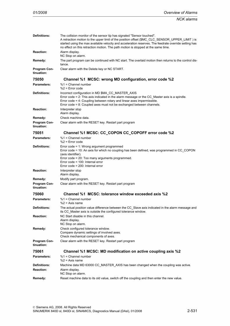
NCK alarms
01/2008 Overview of Alarms
2-531
© Siemens AG, 2008. All Rights ReservedSINUMERIK 840D sl, 840Di sl, SINAMICS, Diagnostics Manual (DAsl), 01/2008
Definitions: The collision monitor of the sensor tip has signaled "Sensor touched".A retraction motion to the upper limit of the position offset ($MC_CLC_SENSOR_UPPER_LIMIT ) is started using the max available velocity and acceleration reserves. The feedrate override setting has no effect on this retraction motion. The path motion is stopped at the same time.
Reaction: Alarm display.NC Stop on alarm.
Remedy: The part program can be continued with NC start. The overlaid motion then returns to the control dis-tance.
Program Con-tinuation:
Clear alarm with the Delete key or NC START.
75050 Channel %1 MCSC: wrong MD configuration, error code %2Parameters: %1 = Channel number
%2 = Error codeDefinitions: Incorrect configuration in MD $MA_CC_MASTER_AXIS
Error code = 2: This axis indicated in the alarm message or the CC_Master axis is a spindle.Error code = 4: Coupling between rotary and linear axes impermissible.Error code = 8: Coupled axes must not be exchanged between channels.
Reaction: Interpreter stopAlarm display.
Remedy: Check machine data.Program Con-tinuation:
Clear alarm with the RESET key. Restart part program
75051 Channel %1 MCSC: CC_COPON CC_COPOFF error code %2Parameters: %1 = Channel number
%2 = Error codeDefinitions: Error code = 1: Wrong argument programmed
Error code = 10: An axis for which no coupling has been defined, was programmed in CC_COPON (axis identifier).Error code = 20: Too many arguments programmed.Error code = 100: Internal errorError code = 200: Internal error
Reaction: Interpreter stopAlarm display.
Remedy: Modify part program.Program Con-tinuation:
Clear alarm with the RESET key. Restart part program
75060 Channel %1 MCSC: tolerance window exceeded axis %2Parameters: %1 = Channel number
%2 = Axis nameDefinitions: The actual position value difference between the CC_Slave axis indicated in the alarm message and
its CC_Master axis is outside the configured tolerance window.Reaction: NC Start disable in this channel.
Alarm display.NC Stop on alarm.
Remedy: Check configured tolerance window.Compare dynamic settings of involved axes.Check mechanical components of axes.
Program Con-tinuation:
Clear alarm with the RESET key. Restart part program
75061 Channel %1 MCSC: MD modification on active coupling axis %2Parameters: %1 = Channel number
%2 = Axis nameDefinitions: Machine data MD 63000 CC_MASTER_AXIS has been changed when the coupling was active.Reaction: Alarm display.
NC Stop on alarm.Remedy: Reset machine data to its old value, switch off the coupling and then enter the new value.

Overview of Alarms 01/2008
NCK alarms
2-532
© Siemens AG, 2008. All Rights ReservedSINUMERIK 840D sl, 840Di sl, SINAMICS, Diagnostics Manual (DAsl), 01/2008
Program Con-tinuation:
Clear alarm with the RESET key. Restart part program
75062 Channel %1 MCSC: axes to be coupled are not in standstill axis %2Parameters: %1 = Channel number
%2 = Axis nameDefinitions: The CC_Master and/or CC_Slave axes were not at standstill when the coupling was switched on.Reaction: Alarm display.
NC Stop on alarm.Remedy: Input G601 for path axes or program a stop preprocessor (STOPRE) before coupling with
CC_COPON.Program Con-tinuation:
Clear alarm with the RESET key. Restart part program
75070 Channel %1 MCSC: wrong machine data for collision protection axis %2Parameters: %1 = Channel number
%2 = Axis nameDefinitions: Incorrect machine data for collision protection.Reaction: Interpreter stop
Alarm display.Remedy: Correct machine data. The axes must be either both rotary axes or both linear axes!Program Con-tinuation:
Clear alarm with the RESET key. Restart part program
75071 Channel %1 MCSC: collision monitoring axis %2Parameters: %1 = Channel number
%2 = Axis nameDefinitions: The collision monitor has responded because the deceleration precomputation has detected that the
distance between the axes has fallen below the configured distance.Reaction: Alarm display.
NC Stop on alarm.Remedy: Traverse the axis out of the danger area in manual mode.Program Con-tinuation:
Clear alarm with the RESET key. Restart part program
75090 Axis %1 stopped by external process monitoring systemParameters: %1 = Axis numberDefinitions: An external process monitoring system has stopped the axis, as tool breakage is to be expected or
has already occured.Reaction: The NC switches to follow-up mode.
Channel not ready.NC Start disable in this channel.Interface signals are set.Alarm display.NC Stop on alarm.
Remedy: Change current tool, if required.Program Con-tinuation:
Clear alarm with the RESET key. Restart part program
75200 Channel %1 RCTR: incorrect MD configuration, error in MD: %2Parameters: %1 = Channel number
%2 = MD nameDefinitions: The following error was detected in the handling transformation machine data:
TRAFO6_IRORO: The orientation entered in MD TRAFO6_TIRORO_RPY is impermissible.TRAFO6_TFLWP: The orientation entered in MD TRAFO6_TFLWP_RPY is impermissible.TRAFO6_TX3P3: The orientation entered in MD TRAFO6_TX3P3_RPY is impermissible.TRAFO6_MAIN_LENGTH_AB: The value entered in MD TRAFO6_MAIN_LENGTH_AB is incorrect.
Reaction: Channel not ready.Alarm display.
Remedy: Correct machine data

NCK alarms
01/2008 Overview of Alarms
2-533
© Siemens AG, 2008. All Rights ReservedSINUMERIK 840D sl, 840Di sl, SINAMICS, Diagnostics Manual (DAsl), 01/2008
Program Con-tinuation:
Switch control OFF - ON.
75210 Channel %1 RCTR: number of axes/axis assignment inconsistentParameters: %1 = Channel numberDefinitions: On transformation selection an incorrect axis assignment is detected:
The axes entered in MD TRAFO_AXES_IN_1 do not match MD TRAFO6_NUM_AXES.Reaction: Interpreter stop
Alarm display.Remedy: Correct machine data.Program Con-tinuation:
Clear alarm with the RESET key. Restart part program
75212 Channel %1 RCTR: incorrect TRAFO_TYPE_ : use 4100Parameters: %1 = Channel numberDefinitions: The transformer type entered in MD TRAFO_TYPE_x is incorrect Reaction: Interpreter stop
Alarm display.Remedy: TRAFO_TYPE 4100 is to be usedProgram Con-tinuation:
Clear alarm with the RESET key. Restart part program
75214 Channel %1 RCTR: MD cannot be changed while transformation active.Parameters: %1 = Channel numberDefinitions: An attempt has been made to modify machine data of an active transformation via NEWCONF.
This is not permissible, because a change to the machine data directly affects the current axis posi-tion, which is transformed from the basic coordinate system into the machine coordinate system in real time. Changing the transformation data during an active transformation would cause the axis posi-tions to jump.
Reaction: Interpreter stopAlarm display.
Remedy: Switch off transformation with TRAFOOF before the machine data is taken over by means of NEW-CONF.
Program Con-tinuation:
Clear alarm with the RESET key. Restart part programThe changed machine data become effective after RESET.
75250 Channel %1 RCTR: tool parameters incorrect interpreterParameters: %1 = Channel numberDefinitions: On block interpretation incorrect tool parameters are detected:Reaction: Interpreter stop
Alarm display.Remedy: Correct tool parameters.Program Con-tinuation:
Clear alarm with the RESET key. Restart part program
75255 Channel %1 RCTR: unreachable position interpreterParameters: %1 = Channel numberDefinitions: On block interpretation a non-approachable position is detected:Reaction: Interpreter stop
Alarm display.Remedy: Modify part program.Program Con-tinuation:
Clear alarm with the RESET key. Restart part program
75260 Channel %1 RCTR: block: %2, tool parameters incorrect on block editingParameters: %1 = Channel number
%2 = Block number

Overview of Alarms 01/2008
NCK alarms
2-534
© Siemens AG, 2008. All Rights ReservedSINUMERIK 840D sl, 840Di sl, SINAMICS, Diagnostics Manual (DAsl), 01/2008
Definitions: On block editing incorrect tool parameters are detected:Reaction: Interpreter stop
Local alarm reaction.NC Start disable in this channel.Interface signals are set.Alarm display.
Remedy: Correct tool parameters.Program Con-tinuation:
Clear alarm with the RESET key. Restart part program
75265 Channel %1 RCTR: block: %2, unreachable position on block editingParameters: %1 = Channel number
%2 = Block numberDefinitions: On block editing a non-approachable position is detected:Reaction: Interpreter stop
Local alarm reaction.NC Start disable in this channel.Interface signals are set.Alarm display.
Remedy: Modify part program.Program Con-tinuation:
Clear alarm with the RESET key. Restart part program
75270 Channel %1 RCTR: tool parameters incorrect on interpolationParameters: %1 = Channel numberDefinitions: On interpolation incorrect tool parameters are detected:Reaction: NC Start disable in this channel.
Alarm display.NC Stop on alarm.
Remedy: Correct tool parameters.Program Con-tinuation:
Clear alarm with the RESET key. Restart part program
75273 Channel %1 RCTR: Transformation violates software limit switchParameters: %1 = Channel numberDefinitions: A violation of the software limit switch of an axis has been detected while traversing with transforma-
tion active in JOG mode.Reaction: NC Start disable in this channel.
Interface signals are set.Alarm display.NC Stop on alarm.
Remedy: JOG traverse in opposite direction.Program Con-tinuation:
Clear alarm with the RESET key. Restart part program
75274 Channel %1 RCTR: Excessive velocity near pole, error code %2Parameters: %1 = Channel number
%2 = Error codeDefinitions: Excessive velocity of the machine axes involved can oocur when traversing near the pole with active
transformation, especially in JOG mode. The alarm is triggered if excessive velocity or acceleration occurs for an output axis of the transformation (MCS).Error code:0: Position jump1: Excessive velocity2: Excessive acceleration
Reaction: NC Start disable in this channel.Interface signals are set.Alarm display.NC Stop on alarm.
Remedy: Reduce velocity. Avoid JOG traverse near pole.

NCK alarms
01/2008 Overview of Alarms
2-535
© Siemens AG, 2008. All Rights ReservedSINUMERIK 840D sl, 840Di sl, SINAMICS, Diagnostics Manual (DAsl), 01/2008
Program Con-tinuation:
Clear alarm with the RESET key. Restart part program
75275 Channel %1 RCTR: block: %2, unreachable position on interpolationParameters: %1 = Channel number
%2 = Block numberDefinitions: On block interpolation a non-approachable position is detected:Reaction: NC Start disable in this channel.
Alarm display.NC Stop on alarm.
Remedy: Modify part program.Program Con-tinuation:
Clear alarm with the RESET key. Restart part program
75500 Channel %1 HSLC: Configuration error ID=%2Parameters: %1 = Channel numberDefinitions: The function CC_FASTON or CC_FASTON_CONT cannot be executed because the following MD
configuration is incorrect:ID=2: The NCK system function "Timer-controlled cam signal output" (see Description of Functions "Software cams, Position switching signals (N3)" ) is configured with machine data MD 10480 $MN_SW_CAM_TIMER_FASTOUT_MASK > 0 at the same time as the function HSLC. As there is only one hardware timer on the NCU, only one of the two functions can be used.ID=4: Programming CC_FASTON and CC_FASTON_CONT requires internal block memory:In order to activate the compile cycle CCHSLC, the entries have to be increased in the following machine data:MD 28090 $MC_MM_NUM_CC_BLOCK_ELEMENTS by 1 elementMD 28100 $MC_MM_NUM_CC_BLOCK_USER_MEM by 2 [KB]
Reaction: Alarm display.Remedy: Modify the stated MD settingsProgram Con-tinuation:
Clear alarm with the RESET key. Restart part program
75501 Channel %1 HSLC: CC_FASTON_CONT velocity too highParameters: %1 = Channel numberDefinitions: The path-related switching signal output switched on by the part rogramm command
CC_FASTON_CONT( PATH_DISTANCE_ON, PATH_DISTANCE_OFF )cannot output all switching signals correctly at the current velocity.Reason:A maximum of one switching edge can be output per IPO cycle (see $MN_IPO_CYCLE_TIME ). The current path velocity is so high that there is more than one switching edge to be output within one path distance PATH_DISTANCE_ON or PATH_DISTANCE_OFF.Example:IPO cycle = 2ms ( position-control cycle = 1ms )PATH_DISTANCE_ON = 0.667PATH_DISTANCE_OFF = 0.667Maximum path velocity in which no switching edges are lost: 20000 mm/minWhen alarm 75501 occurs, the function skips the output of two successive switching edges. This does not affect the position of subsequent switching edges.Note: Whether the ommission of a signal from the previous switching signal leaves a high or low level present, is purely coincidental.
Reaction: Alarm display.Remedy: - Lengthen the operating travels programmed in the command CC_FASTON_CONT
- Program the path velocity or reduce it with the override switch- Set a shorter IPO cycle (machine manufacturer only)
Program Con-tinuation:
Clear alarm with the Delete key or NC START.

Overview of Alarms 01/2008
NCK alarms
2-536
© Siemens AG, 2008. All Rights ReservedSINUMERIK 840D sl, 840Di sl, SINAMICS, Diagnostics Manual (DAsl), 01/2008
75600 Channel %1 RESU: wrong MD configuration. Error code %2Parameters: %1 = Channel number
%2 = Error codeDefinitions: The following errors were detected in the machine data of the retrace support function when ramping
up:Error code = 4 : Machine date $MC_MM_NUM_CC_BLOCK_ELEMENTS or $MC_MM_NUM_CC_BLOCK_USER_MEM must be increased.Error code = 5 : Insufficient heap memory for compile cycles available. Adjust machine data $MC_RESU_RING_BUFFER_SIZE, $MC_RESU_SHARE_OF_CC_HEAP_MEM and $MC_MM_NUM_CC_HEAP_MEM.Error code = 6 : The machine data $MN_ASUP_START_MASK and $MN_ASUP_START_PRIO_LEVEL are not set correctly.Error code = 11: Machine data $MC_AXCONF_GEOAX_NAME_TAB[n], $MN_INTERMEDIATE_POINT_NAME_TAB[n] and $MN_IPO_PARAM_NAME_TAB[n] are not set correctly for RESU:Error code = 13: With bit 2 = 0 of MD $MC_RESU_SPECIAL_FEATURE_MASK it was specified that the retraction program cc_resu.mpf is to be stored in the DRAM parts program memory. However, no DRAM parts program memory was requested via MD $MN_MM_DRAM_FILE_MEM_SIZE. Remedy: Either set MD $MN_MM_DRAM_FILE_MEM_SIZE to a value inequal to zero or set bit 2 of MD $MC_RESU_SPECIAL_FEATURE_MASK equal to one.
Reaction: Mode group not ready.Channel not ready.NC Start disable in this channel.Interface signals are set.Alarm display.NC Stop on alarm.
Remedy: Correct machine data.Program Con-tinuation:
Switch control OFF - ON.
75601 Channel %1 RESU: block %2 invalid parameter in CC_PREPRE()Parameters: %1 = Channel number
%2 = Block number, labelDefinitions: Only the values <arg> = -1 0 or 1 are valid parameters for programming CC_STOPRE( <arg>).Reaction: Interpreter stop
Interface signals are set.Alarm display.
Remedy: Modify part program.Program Con-tinuation:
Clear alarm with the RESET key. Restart part program
75604 Channel %1 RESU: Return traveling not possible, error code %2Parameters: %1 = Channel number
%2 = Error codeDefinitions: Return traveling is not possible, as the following error was detected:
Error code = 1 : The current reverse block for return traveling is likely to be a block of cc_resu_ini.spf or cc_resu_end.spf programmed with a block number. It is impermissible to program block numbers in the subroutines cc_resu_ini.spf and cc_resu_end.spf, as they have an internal meaning.Error code = 2 : Unable to create cc_resu.mpf, as DRAM is insufficient.Error code = 4 : The selected continuation block is likely to be a block of cc_resu_ini.spf or cc_resu_end.spf programmed with block number. It is impermissible to program block numbers in the subroutines cc_resu_ini.spf and cc_resu_end.spf, as they have an internal meaning.
Reaction: NC Start disable in this channel.Interface signals are set.Alarm display.
Remedy: Error code = 1 or 4 : Remove all block numbers from cc_resu_ini.spf and cc_resu_end.spf and their subroutines.Error code = 2 : Assign a higher value to machine date $MN_MM_DRAM_FILE_MEM_SIZE.
Program Con-tinuation:
Clear alarm with the RESET key. Restart part program

NCK alarms
01/2008 Overview of Alarms
2-537
© Siemens AG, 2008. All Rights ReservedSINUMERIK 840D sl, 840Di sl, SINAMICS, Diagnostics Manual (DAsl), 01/2008
75605 Channel %1 RESU: internal error, error code %2Parameters: %1 = Channel number
%2 = Error codeDefinitions: With this alarm, RESU-internal error states are displayed which, together with the transferred error
number, provide information on the error cause and error location.Reaction: NC Start disable in this channel.
Interface signals are set.Alarm display.
Remedy: If this error occurs, please contact us on the SINUMERIK Hotline of the SIEMENS AG, specifying the error number.
Program Con-tinuation:
Clear alarm with the RESET key. Restart part program
75606 Channel %1 RESU: retraceable contour was shortenedParameters: %1 = Channel numberDefinitions: The block search buffer is full. Therefore the retraceable contour had to be shortened.Reaction: Alarm display.Remedy: This alarm has no effect on the current machining. If the alarm continues to occur frequently, the rea-
son should be eliminated: adjust machine data $MC_RESU_RING_BUFFER_SIZE, $MC_RESU_SHARE_OF_CC_HEAP_MEM and $MC_MM_NUM_CC_HEAP_MEM.
Program Con-tinuation:
Clear alarm with the Delete key or NC START.
75607 Channel %1 RESU: resynchronisation not possibleParameters: %1 = Channel numberDefinitions: The block search triggered by the compile cycle has been terminated with an error. It can have the
following cause: The control is not in the correct operating mode, e.g. in JOG_ AUTO instead of in AUTO.
Reaction: Interface signals are set.Alarm display.
Remedy: Switch the control to the AUTO operating mode and restart resynchronisation.Program Con-tinuation:
Clear alarm with the Delete key or NC START.
75608 Channel %1 RESU: NC memory limit reached, RAM type %2Definitions: A memory limit was reached on writing to file cc_resu.mpf. The possible area for return traveling is
shortened.RAM type = 1: File cc_resu.mpf is created in the buffer memory (SRAM). The buffer memory is there-fore full. If the buffer memory is used and if alarm 75608 with RAM type 1 is output, system alarm 6500 will be output simultaneously.RAM type = 2: The memory limit was reached on creating file cc_resu.mpf in the dynamic memory (DRAM part program memory).
Reaction: Alarm display.Remedy: RAM type = 1: Increase size of buffer memory ($MN_MM_USER_MEM_BUFFERED) or the available
space in the buffer memory, e.g. by unloading unused parts programs. Alternatively the ring buffer can be decreased via MD $MC_RESU_RING_BUFFER_SIZE.
Program Con-tinuation:
Clear alarm with the Delete key or NC START.
75609 Channel %1 RESU: POS axis not permitted, axis type %2, block no. %3Parameters: %1 = Channel number
%2 = Axis type%3 = Block number
Definitions: A geometry axis is traversed as a positioning axis with CC_PREPRE active. This programming is not permissible.
Reaction: Interpreter stopNC Start disable in this channel.Interface signals are set.Alarm display.NC Stop on alarm.

Overview of Alarms 01/2008
NCK alarms
2-538
© Siemens AG, 2008. All Rights ReservedSINUMERIK 840D sl, 840Di sl, SINAMICS, Diagnostics Manual (DAsl), 01/2008
Remedy: In order to traverse a geometry axis as positioning axis, RESU must be switched off temporarily (with CC_PREPRE(0) ) or completely. In order to make the internal axis state change from the geometry axis as positioning axis after traversing, a block without traveling motion must be programmed, if required: e.g. X=IC(0)
Program Con-tinuation:
Clear alarm with the RESET key. Restart part program
75610 Channel %1 RESU: NC start currently not possibleDefinitions: While RESU is active, no NC START must be performed in certain situations. If NC START is con-
firmed nevertheless, execution will be blocked and alarm 75610 will be displayed. This applies in the following situations:- On requesting return traveling: NC START is blocked when return traveling program cc_resu.mpf has been created and selected.- After having triggered continuation under NC STOP condition: as long as the internally started block search or the finally started Asup cc_resu_bs_asup.spf is running.
Reaction: Interface signals are set.Alarm display.
Remedy: Wait for completion of the current internal procedure. Then delete the alarm with NC START and con-tinue
Program Con-tinuation:
Clear alarm with NC START or RESET key and continue the program.
75651 Channel %1 PROT: Incorrect configuration no. %2Parameters: %1 = Channel number
%2 = Error codeDefinitions: Invalid configuration of the axis collision protection PROT
Significance of the displayed error numbers:1:The axes of one pair are not of the same axis type (linear / rotary axis)2:A selected axis pair includes an axis not activated in any channel8:In the assignment $MN_CC_PROTECT_PAIRS[ n ] only one axis was entered16:MD $MN_CC_PROTECT_SAFE_DIR[ n ] or $MN_CC_PROTECT_OFFSET[ n ] were changed in active collision monitoring32:The current position difference between the axes to be monitored is smaller than the monitoring window$MN_CC_PROTECT_WINDOW[ n ]
Reaction: Mode group not ready.Interface signals are set.Alarm display.
Remedy: Still missingProgram Con-tinuation:
Clear alarm with the RESET key. Restart part program
75653 Channel %1 PROT: Collision protection stops axis %2Parameters: %1 = Channel number
%2 = Axis numberDefinitions: The axis collision protection function PROT has detected a risk of collision, and stopped the critical
axes.Reaction: Interface signals are set.
Alarm display.NC Stop on alarm.
Remedy: Retract axis in JOG. Modify part program if necessary.Program Con-tinuation:
Clear alarm with the RESET key. Restart part program•

HMI-Alarms
01/2008 Overview of Alarms
2-539
© Siemens AG 2008 All Rights ReservedSINUMERIK 840D sl, 840Di sl, SINAMICS, Diagnostics Manual (DAsl), 01/2008
2.2 HMI-Alarms
100001 Function %1 not yet implemented!Parameters: %1 = --Definitions: --Remedy: --
100002 MS DOS test version !Definitions: --Remedy: --
100003 Test version only !Definitions: --Remedy: --
100004 Function %1 not yet finally implemented!Parameters: %1 = --Definitions: --Remedy: --
100006 Block storedDefinitions: --Remedy: --
100007 Program storedDefinitions: --Remedy: --
100008 Cannot saveDefinitions: --Reaction: Alarm display.Remedy: --
100009 Error in tk_getHandleDefinitions: --Remedy: --
100010 Error in task communicationDefinitions: --Remedy: --
100011 Incorrect NCK versionDefinitions: --Remedy: --
100012 Configuration error: %1, %2Parameters: %1 = --
%2 = --Definitions: --Remedy: --
100013 Selected program already opened by another applicationDefinitions: --Remedy: --
100014 No operating area configured for this access levelDefinitions: --Remedy: --

Overview of Alarms 01/2008
HMI-Alarms
2-540
© Siemens AG 2008 All Rights ReservedSINUMERIK 840D sl, 840Di sl, SINAMICS, Diagnostics Manual (DAsl), 01/2008
100015 Error in '%1' :%nlog file : %2Parameters: %1 = --
%2 = --Definitions: --Remedy: --
100099 Additional valueDefinitions: --Remedy: --
100100 Record length %1 reachedParameters: %1 = --Definitions: --Remedy: --
100101 No dynamic memory availableDefinitions: --Remedy: --
100102 Buffer limit for selection reachedDefinitions: --Remedy: --
100103 Area disabled for inputDefinitions: --Remedy: --
100104 Buffer is emptyDefinitions: --Remedy: --
100105 Search string '%1' not foundParameters: %1 = --Definitions: --Remedy: --
100106 Error on savingDefinitions: This message will be displayed on editing a file (part program), if a memory operation could not be
performed correctly. Reaction: Alarm display.Remedy: If there is no memory space left in the NCK, it will not be possible to save anything. Other contents
(files, programs) must be deleted.If the error occurs when the program is started immediately after the change, the changes will not become effective. The program should be stopped immediately. The change must be repeated and the program must be started after a small delay (approx. 1 sec.).If the error occurs when a program is changed during execution, only a program reset will help.
100107 Error on opening %1Parameters: %1 = --Definitions: --Remedy: --
100108 Write access not allowed in this stateDefinitions: --Remedy: --
100109 No block markedDefinitions: --Remedy: --

HMI-Alarms
01/2008 Overview of Alarms
2-541
© Siemens AG 2008 All Rights ReservedSINUMERIK 840D sl, 840Di sl, SINAMICS, Diagnostics Manual (DAsl), 01/2008
100110 Read access not allowed in this stateDefinitions: --Remedy: --
100111 Actual changes not yet effectiveDefinitions: --Remedy: --
100112 Search string '%1' foundParameters: %1 = --Definitions: --Remedy: --
100113 Search string '%1' replaced by '%2'Parameters: %1 = --
%2 = --Definitions: --Remedy: --
100114 Please wait, storing program (%1)!Parameters: %1 = --Definitions: --Remedy: --
100115 Please wait, flashing file %1 !!!Parameters: %1 = --Definitions: --Remedy: --
100116 Please wait, selected group is being copied!Definitions: --Remedy: --
100117 Please wait, selected group is being deleted!Definitions: --Remedy: --
100118 'Skip blocks' ignored for this file!Definitions: --Remedy: --
100119 Please wait, copied data is being inserted!Definitions: --Remedy: --
100120 Value is too large for%nfield %1Parameters: %1 = --Definitions: --Remedy: --
100121 Value is too small for%nfield %1Parameters: %1 = --Definitions: --Remedy: --
100122 No input rightsDefinitions: --Remedy: --

Overview of Alarms 01/2008
HMI-Alarms
2-542
© Siemens AG 2008 All Rights ReservedSINUMERIK 840D sl, 840Di sl, SINAMICS, Diagnostics Manual (DAsl), 01/2008
100123 Invalid character %1Parameters: %1 = --Definitions: --Remedy: --
100124 Above number range%n%1Parameters: %1 = --Definitions: --Remedy: --
100125 Below number range%n%1Parameters: %1 = --Definitions: --Remedy: --
100126 Division by 0Definitions: --Remedy: --
100130 Display editing suppressedDefinitions: --Remedy: --
100131 MACRO nesting > 10! MACRO (%1) is ignored.Parameters: %1 = --Definitions: --Remedy: --
100132 Pocket calculator mode active - see infoDefinitions: --Remedy: --
100133 Maximum input length reachedDefinitions: --Remedy: --
100134 Sign change - position of cursor changed!Definitions: --Remedy: --
100135 Value too large for display field ->input ignoredDefinitions: --Remedy: --
100136 Value too small for display field ->input ignoredDefinitions: --Remedy: --
100137 Tolerance not implemented: %1Parameters: %1 = --Definitions: --Remedy: --
100140 Please wait, reading file. (%1)Parameters: %1 = --Definitions: --Remedy: --

HMI-Alarms
01/2008 Overview of Alarms
2-543
© Siemens AG 2008 All Rights ReservedSINUMERIK 840D sl, 840Di sl, SINAMICS, Diagnostics Manual (DAsl), 01/2008
100141 Please wait, storing file. (%1)Parameters: %1 = --Definitions: --Remedy: --
100142 Error on opening the file!Definitions: --Remedy: --
100143 Error on reading the file!Definitions: --Remedy: --
100144 Error on saving the fileDefinitions: --Remedy: --
100145 File was stored without error!Definitions: --Remedy: --
100146 Block marking is active, no changes possible!Definitions: --Remedy: --
100150 Directory could not be readDefinitions: --Remedy: --
100151 Please wait, copying file %1Parameters: %1 = --Definitions: --Remedy: --
100152 Error on executing from externalDefinitions: --Remedy: --
100153 USB device no longer available,%nexecution from external source no longer possible.
Definitions: --Reaction: Alarm display.Remedy: --
100154 USB device no longer available,%nexecution of Extcall no longer possible.
Definitions: --Reaction: Alarm display.Remedy: --
100155 USB device no longer available, editing is%naborted. The last changes are lost.
Definitions: --Reaction: Alarm display.Remedy: --
100156 USB device no longer available,%ncopying was aborted.Definitions: --Reaction: Alarm display.

Overview of Alarms 01/2008
HMI-Alarms
2-544
© Siemens AG 2008 All Rights ReservedSINUMERIK 840D sl, 840Di sl, SINAMICS, Diagnostics Manual (DAsl), 01/2008
Remedy: --
100157 USB device no longer available.Definitions: --Reaction: Alarm display.Remedy: --
100160 Testing in block, please wait!Definitions: --Remedy: --
100161 The number of lines is being calculated, please wait!Definitions: --Remedy: --
100162 Caution: Marked line is write-protected!Definitions: --Remedy: --
100170 File is binary: editing and paging not possible!Definitions: --Remedy: --
100200 Error on reading NCK data: %1Parameters: %1 = --Definitions: --Remedy: --
100201 Error on writing NCK data: %1Parameters: %1 = --Definitions: --Remedy: --
100202 Channel group outside area (%1): %2Parameters: %1 = --
%2 = --Definitions: --Remedy: --
100203 Channel switchover key not effectiveDefinitions: --Remedy: --
100204 Channel on NCU does not exist or is not activeDefinitions: --Remedy: --
100300 '%1' not found, continue search without filter!Parameters: %1 = --Definitions: The search term entered in a list image (e.g. general machine data) was not found.Remedy: --
100301 Table cannot be fully generated!Definitions: The list image could not be generated due to insufficient memory.Remedy: System error, a rebooting may be necessary.
100302 No data available - or no access authorization!Definitions: The list image can not be generated, as this data is currently not available.
Example: Local user data is not defined.Remedy: --

HMI-Alarms
01/2008 Overview of Alarms
2-545
© Siemens AG 2008 All Rights ReservedSINUMERIK 840D sl, 840Di sl, SINAMICS, Diagnostics Manual (DAsl), 01/2008
100303 Paging not possibleDefinitions: You cannot page over, for example, axes, drives or channels, as more axes, drives or channels are
not configured.Remedy: --
100304 '%1' not found. Parameters: %1 = --Definitions: --Remedy: --
100350 Display MD savedDefinitions: - The display machine data is saved via the softkey "Save" in the operating
area start-up, image machine data - displaymachine data.- The display machine data is saved in the start-up basic display after pressing the softkey "LCD brighter" or "LCD darker" (this setting will remain at the next start-up).- As of SW 4.1: If the display options are changed in the machine data images,the change will be saved in the display machine data that is not visible to the user.
Remedy: --
100351 Display MD cannot be acceptedDefinitions: Saving the display machine data was rejected by the NCK.Remedy: --
100360 Logic drive data savedDefinitions: --Remedy: --
100361 Error on saving logic drive dataDefinitions: --Remedy: --
100362 Please wait, saving dataDefinitions: --Remedy: --
100363 Password has been changed, please confirm firstDefinitions: --Remedy: --
100402 Temporarily no access rights %1 !Parameters: %1 = --Definitions: --Remedy: --
100403 No access rights %1 !Parameters: %1 = --Definitions: --Remedy: --
100405 Error var. access: Variable address wrong %1Parameters: %1 = --Definitions: --Remedy: --
100406 Error var. access: Format unknown %1Parameters: %1 = --Definitions: --Remedy: --

Overview of Alarms 01/2008
HMI-Alarms
2-546
© Siemens AG 2008 All Rights ReservedSINUMERIK 840D sl, 840Di sl, SINAMICS, Diagnostics Manual (DAsl), 01/2008
100407 Error var. access: Format wrong %1Parameters: %1 = --Definitions: --Remedy: --
100410 Error var. access: Variable does not exist %1Parameters: %1 = --Definitions: --Remedy: --
100411 Error var. access: Value < minimum value %1Parameters: %1 = --Definitions: --Remedy: --
100412 Error var. access: Value > maximum value %1Parameters: %1 = --Definitions: --Remedy: --
100413 Error var. access: Value illegal %1Parameters: %1 = --Definitions: --Remedy: --
100414 Error on loading operating area notebooksDefinitions: --Remedy: --
100415 Error on saving operating area notebooksDefinitions: --Remedy: --
100500 COMIC: Syntax error in HMI()Definitions: --Remedy: --
100501 COMIC: Function not available HMI(.. %1 ..)Parameters: %1 = --Definitions: --Remedy: --
100511 Please wait, calculating stock removal program %1Parameters: %1 = --Definitions: --Remedy: --
100512 Please wait, copying stock removal program %1Parameters: %1 = --Definitions: --Remedy: --
100513 Stock removal DLL does not existDefinitions: --Remedy: --
100514 Stock removal DLL already startedDefinitions: --Remedy: --

HMI-Alarms
01/2008 Overview of Alarms
2-547
© Siemens AG 2008 All Rights ReservedSINUMERIK 840D sl, 840Di sl, SINAMICS, Diagnostics Manual (DAsl), 01/2008
100550 Error TA: Syntax error in %1 in line %2Parameters: %1 = --
%2 = --Definitions: --Remedy: --
100555 Error TA: Branch point not found in %1Parameters: %1 = --Definitions: --Remedy: --
100560 Automatic test machine startedDefinitions: --Remedy: --
100565 Automatic test machine stoppedDefinitions: --Remedy: --
100570 Error TA: %1 not foundParameters: %1 = --Definitions: --Remedy: --
100600 Error on trying to read text file %1Parameters: %1 = --Definitions: --Remedy: --
100620 Error on trying to open font file %1Parameters: %1 = --Definitions: --Remedy: --
100648 The selected language was not installed without errorDefinitions: --Remedy: --
100649 MMC0_TXV.INI file not foundDefinitions: --Remedy: --
100650 No NC/PLC found! NC/PLC being simulated!Definitions: --Remedy: --
100651 Network driver error!Definitions: --Remedy: --
100652 Network driver error! (network connection correct?)Definitions: --Remedy: --
100653 Network driver error! (DHCP/IP address correct?)Definitions: --Remedy: --
100850 Note : PCU 20 memory limit exceededDefinitions: --

Overview of Alarms 01/2008
HMI-Alarms
2-548
© Siemens AG 2008 All Rights ReservedSINUMERIK 840D sl, 840Di sl, SINAMICS, Diagnostics Manual (DAsl), 01/2008
Remedy: --
100851 Kernel error: No memory available any moreDefinitions: --Remedy: --
100852 Notice: Active memory statistics are reducing performanceDefinitions: --Remedy: --
100860 Max. 8 characters allowed for the name !Definitions: --Remedy: --
100900 Press Input key to selectDefinitions: --Remedy: --
100901 No data changedDefinitions: --Remedy: --
100910 Remote diagnostics: Error 00 -int4f_func(CREATE_SRV)-Definitions: --Remedy: --
100911 Remote diagnostics: Error 01 -int4f_func(ACCEPT)-Definitions: --Remedy: --
100912 Remote diagnostics: Error 02 -initTeleService()-Definitions: --Remedy: --
100913 Remote diagnostics: Error 03 -initTeleService()-Definitions: --Remedy: --
100914 Remote diagnostics: Error 04 -no free memory-Definitions: --Remedy: --
100915 Remote diagnostics: Error 05 -get_gosal_struk-Definitions: --Remedy: --
100916 Remote diagnostics: Error 06 -synchronizeRemote()-Definitions: --Remedy: --
100917 Remote diagnostics: Error 07 -socket(device/function %2):# %1Parameters: %1 = --
%2 = --Definitions: --Remedy: --
100918 Remote diagnostics: Error 08 -socket(device %2)-timeoutParameters: %1 = --Definitions: --Remedy: --

HMI-Alarms
01/2008 Overview of Alarms
2-549
© Siemens AG 2008 All Rights ReservedSINUMERIK 840D sl, 840Di sl, SINAMICS, Diagnostics Manual (DAsl), 01/2008
100921 Remote diagnostics: Waiting for connection to port:%1Parameters: %1 = --Definitions: --Remedy: --
100922 Remote diagnostics: No connection by remote PC, timeoutDefinitions: --Remedy: --
100923 Remote diagnostics: Connection aborted by remote PCDefinitions: --Remedy: --
100924 Remote diagnostics: SW option not setDefinitions: --Remedy: --
100925 Remote diagnostics:Connection to remote PC has been terminatedDefinitions: --Remedy: --
100930 No other settings relevant if no ping serverDefinitions: --Remedy: --
100931 Settings have been savedDefinitions: --Remedy: --
100932 !Error(file access): Cannot saveDefinitions: --Remedy: --
100933 Timeout: Semaphore not enabledDefinitions: --Remedy: --
100934 Remote diagnostics: Error 10 -SendFileToRemote()- %1Parameters: %1 = --Definitions: --Remedy: --
100935 Remote diagnostics: No response from remote PC (timeout)Definitions: --Remedy: --
100936 Remote diagnostics:Remote diag. port at default setting(5800)!Definitions: --Remedy: --
100937 Remote diagnostics: Connection established to %1Parameters: %1 = --Definitions: --Remedy: --
100938 Delete a connection in menu Start-up>>Log.drive>>Conn.Definitions: --Remedy: --

Overview of Alarms 01/2008
HMI-Alarms
2-550
© Siemens AG 2008 All Rights ReservedSINUMERIK 840D sl, 840Di sl, SINAMICS, Diagnostics Manual (DAsl), 01/2008
101000 No connection to PLC !Definitions: The connection to the PLC cannot be made while booting, e.g. wrong PLC basic program.Remedy: --
101001 Cannot read PLC system status list !Definitions: After the connection has been made, the system status list cannot be read.Remedy: Switch controller off/on
101002 Password is not valid !Definitions: The password entered is wrong.Remedy: Enter a valid password.
101003 Password has been set for %1 !Parameters: %1 = Access-level system, manufacturer, service or user.Definitions: The password for system, manufacturer, service or user was set successfully.Remedy: --
101004 Password has been changed for %1 !Parameters: %1 = Access-level system, manufacturer, service or user.Definitions: The password for system, manufacturer, service or user was changed successfully.Remedy: --
101005 Passwords do not correspond !Definitions: When the password was changed, the password entered first does not match the one entered second.Remedy: Enter valid passwords.
101006 Password has been deleted !Definitions: The password was deleted via the softkey "Delete password".Remedy: Enter password.
101007 Password has not been set !Definitions: To delete the password, a higher access authorization is required (at least user).Remedy: Set the password with a higher access level.
101008 Current access level: %1Parameters: %1 = Access-level system, manufacturer, service or user.Definitions: When selecting the alarm image, the current access level is displayed: system, manufacturer, service
or user or keyswitch positions 3/2/1/0.Remedy: --
101013 Input error - see Help key (i)Definitions: PLC status A syntax error occurred while entering a value in the PLC status.
The input syntax is explained in a help image.Remedy: --
101014 Error on reading PLC-data !Definitions: --Remedy: --
101015 Error on writing PLC-data !Definitions: --Remedy: --
101016 Error: Operand address greater than 65535 !!Definitions: The value range of the operand address was exceeded.Remedy: Use a smaller value range for the operand address.
101017 No PLC input masks found !Definitions: There are no *.plc input masks in the target system.Remedy: --

HMI-Alarms
01/2008 Overview of Alarms
2-551
© Siemens AG 2008 All Rights ReservedSINUMERIK 840D sl, 840Di sl, SINAMICS, Diagnostics Manual (DAsl), 01/2008
101018 Read-in possible only in active PLC status !Definitions: The current PLC status mode is not active, e.g. if the softkey "Change" was pressed.Remedy: Switch the PLC status to active.
101019 Not possible to initialize the HMI internal PLC status!Definitions: --Remedy: --
101020 Not possible to backup the HMI internal PLC status!Definitions: --Remedy: --
101100 No access rights !Definitions: The access level set is too low to open the selected window.Remedy: Enter a higher password.
101110 Error on overall resetDefinitions: --Remedy: --
101111 No axes configured !Definitions: Due to an incomplete start-up, the image "Service axis" or "Axis machine data" cannot be selected.Remedy: Complete start-up.
101112 No drives configured !Definitions: Due to an incomplete start-up, the image "Service drive" cannot be selected.
Remedy: Complete start-up.
101113 No channels configured !Definitions: Due to an incomplete start-up, the image "Channel machine data" cannot be selected.Remedy: Complete start-up.
101114 No MSD configured !Definitions: Due to an incomplete start-up or missing MSD drives, the image "MSD machine data" cannot be
selected.Remedy: --
101115 No FDD configured !Definitions: Due to an incomplete start-up or missing FDD/SLM drives, the image "FDD machine data" cannot be
selected.Remedy: --
101130 Error return value undefined: %1 %2Parameters: %1 = --
%2 = --Definitions: A function was called up in the start-up area that then, for unknown reasons, could not be executed.Remedy: When provided with the issued digits, the service may be able to help.
101131 No controller disable on PI StartDefinitions: --Remedy: --
101132 Impermissible value execution argumentDefinitions: --Remedy: --
101133 MDx120 CURRCTRL_GAIN could not be calculatedDefinitions: --Remedy: --

Overview of Alarms 01/2008
HMI-Alarms
2-552
© Siemens AG 2008 All Rights ReservedSINUMERIK 840D sl, 840Di sl, SINAMICS, Diagnostics Manual (DAsl), 01/2008
101134 MDx407 SPEEDCTRL_GAIN_1 could not be calculatedDefinitions: --Remedy: --
101135 MDx409 SPEEDCTRL_INTEGRATOR_TIME_1 could not be calculatedDefinitions: --Remedy: --
101136 MDx150 FIELDCTRL_GAIN could not be calculatedDefinitions: --Remedy: --
101137 MDx141 MAGNETIZING_REACTANCE = 0Definitions: --Remedy: --
101138 MDx139/MDx140 MD_STATOR-/ROTOR_LEAKAGE_REACTANCE = 0Definitions: --Remedy: --
101139 MDx134 MOTOR_NOMINAL_FREQUENCY = 0Definitions: --Remedy: --
101140 MDx138 ROTOR_COLD_RESISTANCE = 0Definitions: --Remedy: --
101141 MDx117 MOTOR_INERTIA = 0Definitions: --Remedy: --
101142 MDx146< MDx142 MOTOR_MAX_ALLOWED_SPEED<FIELD_WEAKENING_SPEED
Definitions: --Remedy: --
101143 MDx142 FIELD_WEAKENING_SPEED = 0Definitions: --Remedy: --
101144 MDx118 MOTOR_STANDSTILL_CURRENT = 0Definitions: --Remedy: --
101145 MD1104/1118 MOTOR_MAX_CURRENT/MOTOR_STANDSTILL_CURRENT > 900.0
Definitions: --Remedy: --
101146 Boot file(s) savedDefinitions: Saving the boot file in the start-up area, image drive machine data, was successful.Remedy: --
101147 Boot file(s) deletedDefinitions: Deleting the boot file in the start-up area, image drive machine data, was successful.Remedy: --
101148 Controller MD calculatedDefinitions: Calculating the controller data in the start-up area, image drive machine data, was successful.

HMI-Alarms
01/2008 Overview of Alarms
2-553
© Siemens AG 2008 All Rights ReservedSINUMERIK 840D sl, 840Di sl, SINAMICS, Diagnostics Manual (DAsl), 01/2008
Remedy: --
101149 Display MD acceptedDefinitions: --Remedy: --
101150 MD set to activeDefinitions: Activation of the machine data in the start-up area, machine data images, was successful.Remedy: --
101151 Start-up successfulDefinitions: In the start-up area, image NC start-up, one of the three functions
- normal booting- booting with default values- start of the software updatewas successfully initiated.
Remedy: --
101152 Error during communication with NCKDefinitions: --Remedy: --
101153 Erroneous HMI NCK communication %1 %2Parameters: %1 = Error class
%2 = Error codeDefinitions: In the start-up area the softkey "Calculate controller data", for example, was pressed.
An unspecific error message is sent from the NCK or drive as acknowledgement for this function call.By using the two hexadecimal values (error class, error code), the start-up engineer can perform an error diagnostics.
Remedy: --
101154 PI service refusedDefinitions: The current status of the NKC/drive does not permit the function that was selected.Remedy: See the Installation and Start-up Guide.
101155 Path %1 does not existParameters: %1 = PathDefinitions: During a file function, e.g.saving boot files, an attempt was made to access
a non-existent path.Remedy: Switch the control OFF/ON or see the Installation and Start-up Guide.
101156 Function impermissibleDefinitions: The selected function is impermissible.Remedy: See the Installation and Start-up Guide.
101157 File %1 does not existParameters: %1 = File nameDefinitions: In the start-up area the softkey "delete boot files", for example, was pressed, although no boot files
are yet available.Remedy: --
101158 Function in current operating mode not allowedDefinitions: The drive's current status does not permit this function.Remedy: --
101159 Remote block in incorrect stateDefinitions: The drive's current status does not permit this function.Remedy: --
101160 Date and time of PLC setDefinitions: In the PLC status, the time or date was changed.

Overview of Alarms 01/2008
HMI-Alarms
2-554
© Siemens AG 2008 All Rights ReservedSINUMERIK 840D sl, 840Di sl, SINAMICS, Diagnostics Manual (DAsl), 01/2008
Remedy: --
101161 The drive is not in cyclic mode!Definitions: The start-up is not completely carried out, therefore, the function "Calculate motor data" cannot be
selected.Remedy: --
101162 MDx134/MDx400 MOTOR_NOMINAL_FREQUENCY/MOTOR_RATED_SPEED illeg.
Definitions: --Remedy: --
101163 MDx130 MOTOR_NOMINAL_POWER <= 0Definitions: --Remedy: --
101164 MDx132 MOTOR_NOMINAL_VOLTAGE <= 0Definitions: --Remedy: --
101165 MDx103 MOTOR_NOMINAL_CURRENT <= 0Definitions: --Remedy: --
101166 MDx129 POWER_FACTOR_COS_PHI illegalDefinitions: --Remedy: --
101167 MDx134/MDx400 MOTOR_NOMINAL_FREQUENCY/MOTOR_RATED_SPEED illeg.
Definitions: --Remedy: --
101168 Warning MDx142 FIELD_WEAKENING_SPEED<MDx400 MOTOR_RATED_SPEED
Definitions: --Remedy: --
101169 Date and time could not be set!Definitions: --Remedy: --
101200 Safety Integrated data copiedDefinitions: The SI data copying function was successful.Remedy: --
101201 Safety Integrated data confirmedDefinitions: The SI data confirmation function was successfull.Remedy: --
101202 Copying SI data from axis %1 to drive %2Parameters: %1 = Axis name
%2 = Drive numberDefinitions: This message is output during the SI data copying function.Remedy: --
101203 SI data not copied completelyDefinitions: An error occurred during the SI data copying function; this caused the SI data to be copied incom-
pletely or not at all.Remedy: --

HMI-Alarms
01/2008 Overview of Alarms
2-555
© Siemens AG 2008 All Rights ReservedSINUMERIK 840D sl, 840Di sl, SINAMICS, Diagnostics Manual (DAsl), 01/2008
101204 SI data not confirmedDefinitions: The SI data confirmation function was not executed because an error occurred during the processing.Remedy: --
101205 Drive data changed? -> Don't forget to save bootfiles!Definitions: When exiting the drive machine data images, the operator is reminded to save the boot files so that
drive machine data that may have been changed is not lost.
Remedy: --
101206 Search operation in progress, please wait ...Definitions: The search function was initiated in the machine data images.Remedy: --
101207 Positioning to %1...Parameters: %1 = --Definitions: A list image, e.g. general machine data, has been selected.
The HMI is attempting to position at the last selected datum in this image.Remedy: --
101208 SI data are confirmed: axis %1Parameters: %1 = --Definitions: In the start-up area the function "Confirm Safety Integrated Data" has been started.
The message was output during this function in order to provied the user with an acknowledgement regarding the operation of the function.
Remedy: --
101209 SI data are confirmed: drive %1Parameters: %1 = --Definitions: In the start-up area the function "Confirm Safety Integrated Data" has been started.
The message was output during this function in order to provied the user with an acknowledgement regarding the operation of the function.
Remedy: --
101210 Machine data being prepared for displayDefinitions: A list image in the machine data was selected for which display options are active.
This image's machine data is individually checked to see whether it is permitted to be displayed.Remedy: --
101211 Address of NCK not changed!Definitions: An attempt was made to change the bus address of the NCK in the start-up area.
The change was rejected by the NCK; the reason is unknown.Remedy: --
101212 Address of NCK changedDefinitions: The NCK's bus address was set to the specified value.Remedy: --
101213 Invalid NCK address!Definitions: The value specified for the new NCK bus address is too large.Remedy: --
101214 Initialization of this window unsuccessful!Definitions: An attempt was made to select the image of the NCK address in the start-up area.
An error occured while determining the nodes on the bus.Due to inconsistent data, this image cannot be displayed.
Remedy: --

Overview of Alarms 01/2008
HMI-Alarms
2-556
© Siemens AG 2008 All Rights ReservedSINUMERIK 840D sl, 840Di sl, SINAMICS, Diagnostics Manual (DAsl), 01/2008
101300 Please wait - Language being changedDefinitions: In the start-up area the softkey "Change language" was pressed.
The screen content is being restructured.Remedy: --
101301 Versions saved -> output via %1Parameters: %1 = --Definitions: --Remedy: --
101310 Error in %1: line %2: error in XML structureDefinitions: --Remedy: Correct the error in the indicated line.
101311 Error in %1: line %2: path not found !Definitions: --Remedy: Correct the indicated line of the path.
101312 Error in %1: line %2: path incorrect !Definitions: --Remedy: Correct the indicated line of the path.
101400 License key set.Definitions: --Remedy: --
101401 License key NOT sufficient.Definitions: --Remedy: --
101402 Error on writing back the options.Definitions: --Remedy: --
101403 Please wait - licence screen is being prepared. (%1)Parameters: %1 = --Definitions: --Remedy: --
101500 No other drives possible; option not set.Definitions: --Remedy: --
101600 Unknown error code: %1Definitions: --Remedy: --
101601 Impermissible parameter numberDefinitions: --Remedy: --
101602 Parameter value cannot be changedDefinitions: --Remedy: --
101603 Low or high limit exceededDefinitions: --Remedy: --

HMI-Alarms
01/2008 Overview of Alarms
2-557
© Siemens AG 2008 All Rights ReservedSINUMERIK 840D sl, 840Di sl, SINAMICS, Diagnostics Manual (DAsl), 01/2008
101604 Faulty subindexDefinitions: --Remedy: --
101605 No arrayDefinitions: --Remedy: --
101606 Incorrect data typeDefinitions: --Remedy: --
101607 Setting not permitted (can only be reset)Definitions: --Remedy: --
101608 Description element cannot be changedDefinitions: --Remedy: --
101609 No description data availableDefinitions: --Remedy: --
101610 No operational priority.Definitions: --Remedy: --
101611 No text array availableDefinitions: --Remedy: --
101612 Request cannot be executed because of operating stateDefinitions: --Remedy: --
101613 Value impermissibleDefinitions: --Remedy: --
101614 Response too longDefinitions: --Remedy: --
101615 Parameter address impermissibleDefinitions: --Remedy: --
101616 Illegal formatDefinitions: --Remedy: --
101617 Number of values are not consistentDefinitions: --Remedy: --
101618 Drive object does not existDefinitions: --Remedy: --

Overview of Alarms 01/2008
HMI-Alarms
2-558
© Siemens AG 2008 All Rights ReservedSINUMERIK 840D sl, 840Di sl, SINAMICS, Diagnostics Manual (DAsl), 01/2008
101619 Parameter currently deactivated.Definitions: --Remedy: --
101620 Device buffer too small to answer the job.Definitions: --Remedy: --
101621 freeDefinitions: --Remedy: --
101622 Value impermissibleDefinitions: --Remedy: --
101623 Parameter is indexedDefinitions: --Remedy: --
101624 Request not supportedDefinitions: --Remedy: --
101625 No write access with active controller.Definitions: --Remedy: --
101626 Unknown unit.Definitions: --Remedy: --
101627 Write access only in start-up state Encoder (p10=4).Definitions: --Remedy: --
101628 Write access only in start-up state Motor (p10=3).Definitions: --Remedy: --
101629 Write access only in start-up state Power Section (p10=2).Definitions: --Remedy: --
101630 Write access only in rapid start-up state (p10=1).Definitions: --Remedy: --
101631 Write access only in start-up state Ready (p10=0).Definitions: --Remedy: --
101632 Write access only in start-up state Parameter Reset (p10=30).Definitions: --Remedy: --
101633 Write access only in start-up state Safety (p10=95).Definitions: --Remedy: --

HMI-Alarms
01/2008 Overview of Alarms
2-559
© Siemens AG 2008 All Rights ReservedSINUMERIK 840D sl, 840Di sl, SINAMICS, Diagnostics Manual (DAsl), 01/2008
101634 Write access only in start-up state Techn.Application/Units (p10=5).Definitions: --Remedy: --
101635 Write access only in start-up state (p10 unequal 0).Definitions: --Remedy: --
101636 Write access only in start-up state Download (p10=29).Definitions: --Remedy: --
101637 Parameter must not be written in download.Definitions: --Remedy: --
101638 Write access only in start-up state Drive Configuration (device: p9=3).Definitions: --Remedy: --
101639 Write access only in start-up state Drive Type Definition (device: p9=2).Definitions: --Remedy: --
101640 Write access only in start-up state Data Block Base Configuration (device: p9=4).
Definitions: --Remedy: --
101641 Write access only in start-up state Device Configuration (device: p9=1).Definitions: --Remedy: --
101642 Write access only in start-up state Device Download (device: p9=29).Definitions: --Remedy: --
101643 Write access only in start-up state Device Parameter Reset (device: p9=30).
Definitions: --Remedy: --
101644 Write access only in start-up state Device Ready (device: p9=0).Definitions: --Remedy: --
101645 Write access only in start-up state Device (device: p9 unequal 0).Definitions: --Remedy: --
101646 No parameterization enableDefinitions: --Remedy: --
101647 Parameter must not be written in download.Definitions: --Remedy: --
101648 Transfer of the control right is disabled via BI p806.Definitions: --

Overview of Alarms 01/2008
HMI-Alarms
2-560
© Siemens AG 2008 All Rights ReservedSINUMERIK 840D sl, 840Di sl, SINAMICS, Diagnostics Manual (DAsl), 01/2008
Remedy: --
101649 Desired BICO interconnection impossible, since BICO output does not supply float value
Definitions: --Remedy: --
101650 Free BICO interconnection disabled via p300,p400 oder p922.Definitions: --Remedy: --
101651 No access method defined.Definitions: --Remedy: --
101652 Below currently valid limitDefinitions: --Remedy: --
101653 Above currently valid limitDefinitions: --Remedy: --
101654 Parameter not accessible from BOP.Definitions: --Remedy: --
101655 Parameter not readable from BOP.Definitions: --Remedy: --
101656 Write access not permitted.Definitions: --Remedy: --
102000 Error %1 %2Parameters: %1 = --
%2 = --Definitions: --Remedy: --
102001 No data selectedDefinitions: --Remedy: --
102002 Write error on diskDefinitions: --Remedy: --
102003 No data found for archivingDefinitions: --Remedy: --
102004 No name enteredDefinitions: --Remedy: --
102005 Data cannot be created hereDefinitions: --Remedy: --
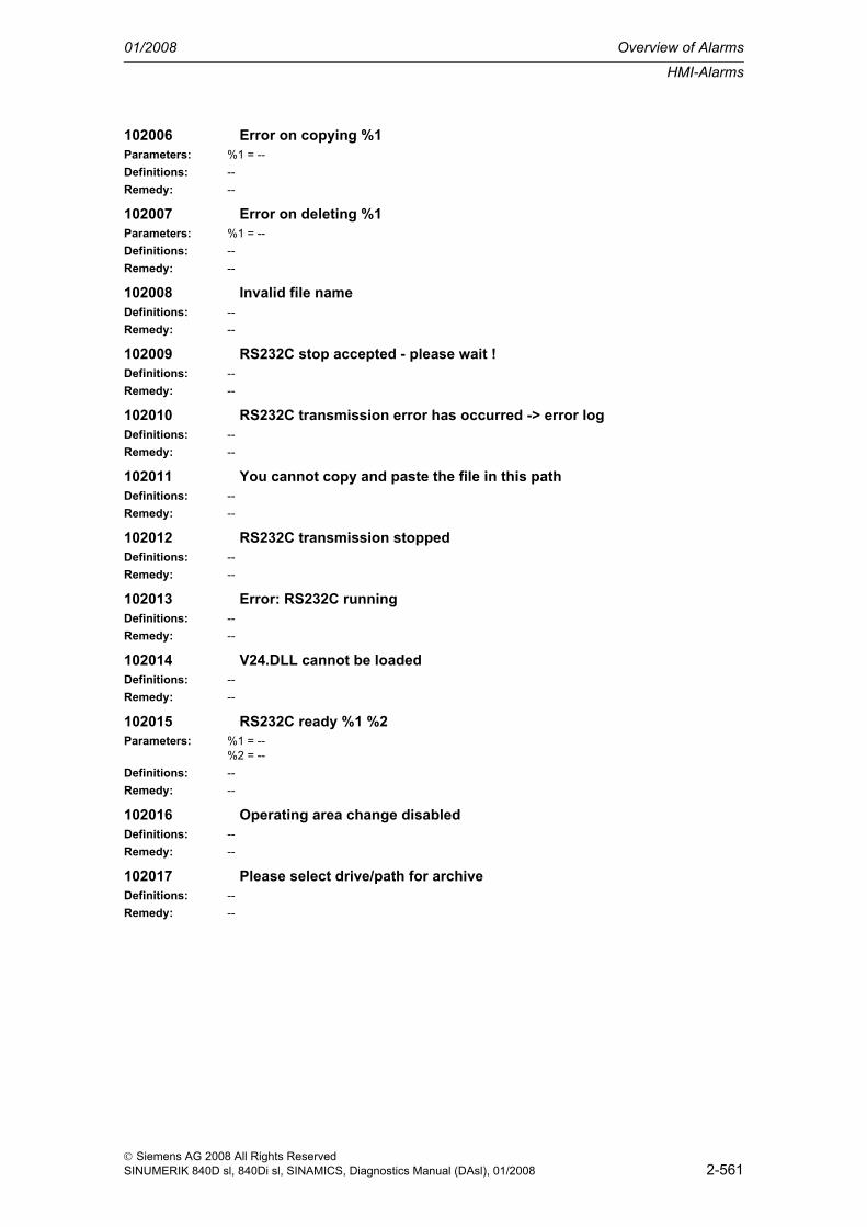
HMI-Alarms
01/2008 Overview of Alarms
2-561
© Siemens AG 2008 All Rights ReservedSINUMERIK 840D sl, 840Di sl, SINAMICS, Diagnostics Manual (DAsl), 01/2008
102006 Error on copying %1Parameters: %1 = --Definitions: --Remedy: --
102007 Error on deleting %1Parameters: %1 = --Definitions: --Remedy: --
102008 Invalid file nameDefinitions: --Remedy: --
102009 RS232C stop accepted - please wait !Definitions: --Remedy: --
102010 RS232C transmission error has occurred -> error logDefinitions: --Remedy: --
102011 You cannot copy and paste the file in this pathDefinitions: --Remedy: --
102012 RS232C transmission stoppedDefinitions: --Remedy: --
102013 Error: RS232C runningDefinitions: --Remedy: --
102014 V24.DLL cannot be loadedDefinitions: --Remedy: --
102015 RS232C ready %1 %2Parameters: %1 = --
%2 = --Definitions: --Remedy: --
102016 Operating area change disabledDefinitions: --Remedy: --
102017 Please select drive/path for archiveDefinitions: --Remedy: --

Overview of Alarms 01/2008
HMI-Alarms
2-562
© Siemens AG 2008 All Rights ReservedSINUMERIK 840D sl, 840Di sl, SINAMICS, Diagnostics Manual (DAsl), 01/2008
103000 No correction block in the NCKDefinitions: The following is valid up to SW 3.x:
The correction block window cannot be opened. No program correction is possible in the operating mode "Machine".The following is valid up to SW 4.1:The correction block window can be opened in the "Stop program" state.The program that is currently being executed is opened for editing.The program part that has not yet been recorded by the NCK'sprogram processing can be changed permanently.
Remedy: --
103001 Selection only possible after enable or in RESET stateDefinitions: In order to execute the desired function, the current channel has to be in the RESET state, e.g. "Pro-
gram selection".Remedy: Trigger reset.
103002 Copying to clipboard not possibleDefinitions: The NCK rejects a copy-action to the clipboard because, for example, no more memory is available
or the maximum manageable amount of programs has been exceeded.Remedy: Delete the programs not currently required.
103003 MDI buffer cannot be deletedDefinitions: The NCK rejects a deletion of the clipboard because the clipboard is currently being executed.Remedy: Wait until the MDI program has been executed or trigger an NC reset.
103004 Block search not possibleDefinitions: The search run cannot be started because the channel is active.Remedy: Wait until the program has been executed or trigger an NC reset.
103005 Block search backwards only possible without calculationDefinitions: --Remedy: --
103006 Block search without calculation possible on MP level onlyDefinitions: No subroutine calls can be processed during a block search without calculation.Remedy: If subroutines are to be processed, a search run with calculation has to be performed.
103007 You cannot terminate overstore in this channel stateDefinitions: Overstore cannot be ended because the channel is still active.Remedy: Wait until the overstore procedure has finished or trigger an NC reset.
103008 Block search started in channel %1 - please wait !Parameters: %1 = Channel numberDefinitions: The started block search is not yet finished.Remedy: Text is deleted automatically after the end of the block search.
Wait until the block search has finished or trigger an NC reset.
103009 Conflict between search type and search target !Definitions: The search target entered is not compatible with the search type:
The block number initial character "N" or ":" is missing,only the digits 0 to 9 are allowed.
Remedy: Correct the entry to correspond with the type.The following is valid up to SW 3.x: The faulty entry is deleted, and the cursor proceeds to the next field.As of SW 4.1: The faulty entry is retained, and the cursor remains at the field.

HMI-Alarms
01/2008 Overview of Alarms
2-563
© Siemens AG 2008 All Rights ReservedSINUMERIK 840D sl, 840Di sl, SINAMICS, Diagnostics Manual (DAsl), 01/2008
103010 Invalid file nameDefinitions: The file name entered:
Must not have more than 32 characters (letters, digits, underscore; including the block and program ID:_N_ and _MPF), amounts to 25 assignable characters.Cannot have any separators (e.g. /).Must have letters at the first and second position.
Remedy: --
103011 No program selected - block search endedDefinitions: At the moment, no program is selected, therefore, no search run is possible.Remedy: Select a program.
103012 Safety function not activeDefinitions: --Remedy: --
103013 No agreement could be givenDefinitions: --Remedy: --
103014 Please first reference axisDefinitions: The reference point approach was not yet performed or finished.Remedy: Perform reference point approach.
103015 NOTICE! Dimension system is changed from inch to metricDefinitions: --Remedy: --
103016 NOTICE! Dimension system is changed from metric to inchDefinitions: --Remedy: --
103017 Scratching impossible due to rotation in %1Parameters: %1 = --Definitions: --Remedy: --
103018 Swivel: Adjustment terminatedDefinitions: --Remedy: --
103019 Swivel: Adjustment not possibleDefinitions: --Remedy: --
104000 Actual tool not foundDefinitions: If the cursor in the window "Magazine list" is at a blank line, then no tool will be found after pressing
the softkey "Tool data".Remedy: Place the cursor on the tool.
104001 No additional tools availableDefinitions: After pressing the softkey "T No. +" or "T No. -" the next-highest or next-lowest tool number is
searched for.If no other tools are available, this message will be output.
Remedy: --
104002 No additional tool edges availableDefinitions: After pressing the softkey "D No. +" or "D No. -" the next-highest or next-lowest cutting edge is
searched for.If no other cutting edges are available,this message will be output.

Overview of Alarms 01/2008
HMI-Alarms
2-564
© Siemens AG 2008 All Rights ReservedSINUMERIK 840D sl, 840Di sl, SINAMICS, Diagnostics Manual (DAsl), 01/2008
Remedy: --
104003 There are no toolsDefinitions: No tools were set up.Remedy: Set up tools.
104004 No active workpiece availableDefinitions: After pressing the softkey "Current T+D No." in the "Tool overview" window, no tool was found
because no subroutine is active or in the active subrutine no tool is selected.Remedy: Select a tool.
104005 There is no active cutting edgeDefinitions: A tool has been selected, but not a cutting edge.Remedy: Select a cutting edge.
104006 No TO area available in current channelDefinitions: No TO area is assigned to the current channel.Remedy: Assign the current channel a TO area via the machine data, or switch channel.
104007 Error on creating toolDefinitions: The tool could not be created, as, for example, the maximum number of possible tools has already
been reached.Remedy: Extend the maximum number of tools via the machine data, or delete unnecessary tools.
104008 Error on creating tool edgeDefinitions: No new cutting edge could be created, as, for example, the maximum number of cutting edges has
already been reached.Remedy: Delete unnecessary cutting edges.
104009 Error while writing tool typeDefinitions: --Remedy: --
104010 Error while writing tool positionDefinitions: --Remedy: --
104011 Error on deleting toolDefinitions: The tool cannot be deleted. It may currently be active.Remedy: --
104012 No master spindle availableDefinitions: No master spindle was configured.Remedy: Configure a master spindle via the machine data.
104013 Error on deleting areaDefinitions: --Remedy: --
104014 Incorrect inputDefinitions: The entered value is impermissible, e.g., it lies outside the input limits.Remedy: Please observe the value range.
104015 Number of parameters per tool edge is zeroDefinitions: The number of parameters per cutting edge was not configured.Remedy: Configure the number of parameters per cutting edge via the machine data.
104016 No spindles availableDefinitions: No spindle was configured.Remedy: Configure a spindle via the machine data.

HMI-Alarms
01/2008 Overview of Alarms
2-565
© Siemens AG 2008 All Rights ReservedSINUMERIK 840D sl, 840Di sl, SINAMICS, Diagnostics Manual (DAsl), 01/2008
104017 No settable frame currently activeDefinitions: --Remedy: --
104018 Tool not availableDefinitions: The specified tool does not exist.Remedy: --
104019 Tool type not availableDefinitions: The specified tool type does not exist.Remedy: Specify a valid tool type.
104020 No empty location foundDefinitions: There is no empty location with the specified search parameters.Remedy: Correct search parameters.
104021 Error on searching for empty locationDefinitions: --Remedy: --
104022 Error in present location searchDefinitions: --Remedy: --
104023 Error in Tool LoadDefinitions: An error occurred while a tool was being loaded; the procedure has been aborted.Remedy: Check loader.
104024 Error in Tool UnloadDefinitions: An error occurred while a tool was being unloaded; the procedure has been aborted.Remedy: Check unloader.
104025 No magazine configuredDefinitions: No magazine was configured.Remedy: Configure a magazine via the machine data.
104026 NOTICE! Tool Load running!Definitions: Note regarding loading process.Remedy: Wait until the loading procedure is terminated.
104027 NOTICE! Tool Unload running!Definitions: Note regarding unloading process.Remedy: Wait until the unloading procedure is terminated.
104028 Error on accessing general tool dataDefinitions: --Remedy: --
104029 You cannot load into this locationDefinitions: The location may already be occupied.Remedy: Select another loading location.
104030 No more data foundDefinitions: All existing data was already displayed.Remedy: --
104031 There is no preselected toolDefinitions: --Remedy: --

Overview of Alarms 01/2008
HMI-Alarms
2-566
© Siemens AG 2008 All Rights ReservedSINUMERIK 840D sl, 840Di sl, SINAMICS, Diagnostics Manual (DAsl), 01/2008
104032 There is no preselected cutting edgeDefinitions: --Remedy: --
104033 Error on Delete cutting edgeDefinitions: --Remedy: --
104034 No work offset selectedDefinitions: --Remedy: --
104035 Position minus coarse offset was transferredDefinitions: --Remedy: --
104100 PA: Error on opening the menuDefinitions: --Remedy: --
104101 PA: Error on opening the windowDefinitions: --Remedy: --
104102 PA: Error on reading number of T numbersDefinitions: --Remedy: --
104103 PA: Error on reading number of params/cut-edgesDefinitions: --Remedy: --
104104 PA: Error on reading actual toolDefinitions: --Remedy: --
104105 PA: Error on reading actual D no.Definitions: --Remedy: --
104106 PA: No space in global memoryDefinitions: --Remedy: --
104107 PA: Error on reading notebookDefinitions: --Remedy: --
104108 PA: Error on reading cutting edge parametersDefinitions: --Remedy: --
104109 PA: Error on reading number of cutting edgesDefinitions: --Remedy: --
104110 PA: Error on reading toolDefinitions: --Remedy: --

HMI-Alarms
01/2008 Overview of Alarms
2-567
© Siemens AG 2008 All Rights ReservedSINUMERIK 840D sl, 840Di sl, SINAMICS, Diagnostics Manual (DAsl), 01/2008
104111 PA: Error on reading number of toolsDefinitions: --Remedy: --
104112 PA: Error on reading TO areaDefinitions: --Remedy: --
104113 PA: Error on reading tool numberDefinitions: --Remedy: --
104114 PA: Error on writing notebookDefinitions: --Remedy: --
104115 PA: Error on reading JOG feed unitDefinitions: --Remedy: --
104116 PA: JOG feed unit not G94 or G95Definitions: --Remedy: --
104117 PA: Error on writing JOG feed unitDefinitions: --Remedy: --
104118 PA: Error on reading JOG feedDefinitions: --Remedy: --
104119 PA: Feed value outside rangeDefinitions: --Remedy: --
104120 PA: Error on writing JOG feed valueDefinitions: --Remedy: --
104121 PA: Error on reading number of spindlesDefinitions: --Remedy: --
104122 PA: Error on reading spindle statusDefinitions: --Remedy: --
104123 PA: Error on reading spindle namesDefinitions: --Remedy: --
104124 PA: Error on reading tool typeDefinitions: --Remedy: --
104125 PA: Next tool has no cutting edgesDefinitions: --Remedy: --

Overview of Alarms 01/2008
HMI-Alarms
2-568
© Siemens AG 2008 All Rights ReservedSINUMERIK 840D sl, 840Di sl, SINAMICS, Diagnostics Manual (DAsl), 01/2008
104126 PA: Error on reading global basic unitDefinitions: --Remedy: --
104127 PA: Error on reading number of geometry axesDefinitions: --Remedy: --
104128 PA: Error on reading number of add. axesDefinitions: --Remedy: --
104129 PA: Error on reading number of mach. axesDefinitions: --Remedy: --
104130 PA: Error on reading number of spindlesDefinitions: --Remedy: --
104131 PA: Error on reading number of R variablesDefinitions: --Remedy: --
104132 PA: Error on reading number of user framesDefinitions: --Remedy: --
104133 PA: Error on reading cont./JOG modeDefinitions: --Remedy: --
104134 PA: Error on writing cont./JOG modeDefinitions: --Remedy: --
104135 PA: Error on activating the user frameDefinitions: --Remedy: --
104136 PA: Error in getting WO data Block %1 column index %2Parameters: %1 = --
%2 = --Definitions: --Remedy: --
104137 PA: Error in writing WO data Block %1 column index %2Parameters: %1 = --
%2 = --Definitions: --Remedy: --
104201 Error on setting/resetting semaphoresDefinitions: --Remedy: --
104202 Tool identifier not definedDefinitions: --Remedy: --

HMI-Alarms
01/2008 Overview of Alarms
2-569
© Siemens AG 2008 All Rights ReservedSINUMERIK 840D sl, 840Di sl, SINAMICS, Diagnostics Manual (DAsl), 01/2008
104203 Blank in tool identifier not allowedDefinitions: --Remedy: --
104204 No new tool createdDefinitions: --Remedy: --
104205 Tool exists alreadyDefinitions: --Remedy: --
104206 No magazine availableDefinitions: --Remedy: --
104207 The magazine is not definedDefinitions: --Remedy: --
104208 The tool size (L, R, T, B) must have a value between 1 and 7Definitions: --Remedy: --
104209 Dummy tool cannot be createdDefinitions: --Remedy: --
104210 Tool not availableDefinitions: --Remedy: --
104211 Tool number equals 0Definitions: --Remedy: --
104212 Tool already loadedDefinitions: --Remedy: --
104213 Location already loadedDefinitions: --Remedy: --
104214 Error on positioning magazineDefinitions: --Remedy: --
104215 Error on unloading toolsDefinitions: --Remedy: --
104216 Error on relocating toolsDefinitions: --Remedy: --
104217 Error on loading toolsDefinitions: --Remedy: --

Overview of Alarms 01/2008
HMI-Alarms
2-570
© Siemens AG 2008 All Rights ReservedSINUMERIK 840D sl, 840Di sl, SINAMICS, Diagnostics Manual (DAsl), 01/2008
104218 NOTICE! Tool Unload running!Definitions: --Remedy: --
104219 NOTICE! Tool Load running!Definitions: --Remedy: --
104220 NOTICE! Relocation of tool running!Definitions: --Remedy: --
104221 Error on creating toolDefinitions: --Remedy: --
104222 Illegal parametersDefinitions: --Remedy: --
104223 Error on reading TD blockDefinitions: --Remedy: --
104224 Illegal tool typeDefinitions: --Remedy: --
104225 No TO memory available in channelDefinitions: --Remedy: --
104226 Error on reading notebookDefinitions: --Remedy: --
104227 Error on writing notebookDefinitions: --Remedy: --
104228 Error on searching for empty locationDefinitions: --Remedy: --
104229 Empty location not foundDefinitions: --Remedy: --
104230 NOTICE!: Loaded tool cannot be deleted !Definitions: --Remedy: --
104231 Error on reading number of cutting edgesDefinitions: --Remedy: --
104232 Error on reading number of user cutting edgesDefinitions: --Remedy: --

HMI-Alarms
01/2008 Overview of Alarms
2-571
© Siemens AG 2008 All Rights ReservedSINUMERIK 840D sl, 840Di sl, SINAMICS, Diagnostics Manual (DAsl), 01/2008
104233 Load point not foundDefinitions: --Remedy: --
104234 Only memory block from 0..14 possible for NBDefinitions: --Remedy: --
104235 Only 1..15 lines allowed in tableDefinitions: --Remedy: --
104236 Load points: %1Parameters: %1 = --Definitions: --Remedy: --
104237 Current location (load point) of real magazine: %1Parameters: %1 = --Definitions: --Remedy: --
104238 Empty location %1 foundParameters: %1 = --Definitions: --Remedy: --
104239 Syntax error. Only these letters are allowed: %1Parameters: %1 = --Definitions: --Remedy: --
104240 Location %1 foundParameters: %1 = --Definitions: --Remedy: --
104241 Magazine %1 foundParameters: %1 = --Definitions: --Remedy: --
104242 Illegal location numberDefinitions: --Remedy: --
104243 Illegal magazine numberDefinitions: --Remedy: --
104244 Error on reading user cutting edge dataDefinitions: --Remedy: --
104245 Error on writing user cutting edge dataDefinitions: --Remedy: --

Overview of Alarms 01/2008
HMI-Alarms
2-572
© Siemens AG 2008 All Rights ReservedSINUMERIK 840D sl, 840Di sl, SINAMICS, Diagnostics Manual (DAsl), 01/2008
104246 Error on reading user tool dataDefinitions: --Remedy: --
104247 Error on writing user tool dataDefinitions: --Remedy: --
104248 Error on reading monitoring dataDefinitions: --Remedy: --
104249 Error on writing monitoring dataDefinitions: --Remedy: --
104250 Location not empty or not availableDefinitions: --Remedy: --
104251 Only one magazine available !Definitions: --Remedy: --
104252 Only 0 or 1 allowed for tool life/quantity monitoring !Definitions: --Remedy: --
104253 Only tool life or quantity monitoring possibleDefinitions: --Remedy: --
104254 Illegal magazine or location numberDefinitions: --Remedy: --
104255 Function Current location not valid for bufferDefinitions: --Remedy: --
105000 Error %1 ! %2Parameters: %1 = --
%2 = --Definitions: System-internal error.
A memory-access has failed - should not occur in normal operation.Remedy: --
105001 Cycles description '%1' not availableParameters: %1 = --Definitions: The cycle description sc.com was not found in the NCK file system.Remedy: --
105002 File %1 exists already !Parameters: %1 = --Definitions: The file name entered is already in this directory.Remedy: --
105003 Workpiece %1 exists alreadyParameters: %1 = --

HMI-Alarms
01/2008 Overview of Alarms
2-573
© Siemens AG 2008 All Rights ReservedSINUMERIK 840D sl, 840Di sl, SINAMICS, Diagnostics Manual (DAsl), 01/2008
Definitions: The workpiece name entered is already in this directory.Remedy: --
105004 Paste buffer is empty! First COPY then PASTEDefinitions: No file could be inserted, as no file was copied to the clipboard.Remedy: --
105005 Only tools can be inserted hereDefinitions: The file type of the previously copied file is not _wpd and cannot be inserted into
the workpiece directory.Remedy: --
105006 Only files can be inserted hereDefinitions: A file of the file type _wpd, i.e. a workpiece, was copied from the workpiece directory and an attempt
was made to insert it into a program directory.Remedy: --
105007 No name enteredDefinitions: --Remedy: Wait until the loading procedure is terminated.
105008 Write memory error on cycle callDefinitions: The resources of the HMI are exhausted.
No more dynamic memory is available.Remedy: --
105009 No write access to dataDefinitions: The file is write-protected.Remedy: --
105010 No data selectedDefinitions: The cursor is not placed on a valid file name.Remedy: --
105011 Cycles overview %1 not availableParameters: %1 = --Definitions: The cycle description sc.com was not found in the NCK file system.Remedy: --
105012 Program not or only partially editable (NC Reset)Definitions: The selected program is currently being executed.Remedy: --
105013 Copied data can be inserted with SK 'Paste'Definitions: The copied data is in the clipboard and can be inserted anywhere via the softkey "Paste".Remedy: --
105014 Error on copying ! %1Parameters: %1 = --Definitions: The file could not be copied.Remedy: --
105015 Error on renaming ! %1Parameters: %1 = --Definitions: The file could not be renamed.Remedy: --
105016 Error on deleting ! %1Parameters: %1 = --Definitions: The file could not be deleted.

Overview of Alarms 01/2008
HMI-Alarms
2-574
© Siemens AG 2008 All Rights ReservedSINUMERIK 840D sl, 840Di sl, SINAMICS, Diagnostics Manual (DAsl), 01/2008
Remedy: --
105017 Selection possible only after enable or in RESET state %1Parameters: %1 = --Definitions: The selected program is either being currently executed or was not yet enabled.Remedy: --
105018 Error on generating program ! %1Parameters: %1 = --Definitions: The program could not be created; there may no longer be sufficient memory.Remedy: --
105019 Error on opening window ! %1Parameters: %1 = --Definitions: The window could not be opened.
System error that should not occur in normal operation.Remedy: --
105020 Error on closing window ! %1Parameters: %1 = --Definitions: The window could not be closed.
System error that should not occur in normal operation.Remedy: --
105021 Error on generating workpiece ! %1Parameters: %1 = --Definitions: The workpiece could not be created.Remedy: --
105022 Error on enable ! %1Parameters: %1 = --Definitions: The program could not be enabled.Remedy: --
105023 File %1 exists already !Parameters: %1 = --Definitions: The file cannot be copied to this directory, as a file with the same name is already here.Remedy: --
105024 Check values! - At least 1 value not within input limits!Definitions: An invalild value was entered in the cycle parameter image.Remedy: --
105025 Please wait, structuring directory !Definitions: The data required for the display of the directory is being determined.Remedy: --
105026 NOTICE! Simulated program not identical to edited program!Definitions: The program being executed is not identical to the program opened in the editor.Remedy: --
105027 Selection is being madeDefinitions: --Remedy: --
105028 Selection is impossibleDefinitions: --Remedy: --

HMI-Alarms
01/2008 Overview of Alarms
2-575
© Siemens AG 2008 All Rights ReservedSINUMERIK 840D sl, 840Di sl, SINAMICS, Diagnostics Manual (DAsl), 01/2008
105030 Please wait, renumbering in progress (%1)!Parameters: %1 = --Definitions: The part program's blocks are serially numbered.Remedy: --
105031 Renumbering has been aborted !Definitions: Renumbering of the part program was aborted.
Insufficient part program memory may be the cause of the error.Remedy: --
105032 Renumbering finished !Definitions: Renumbering of the part program was completed without errors.Remedy: --
105033 Renumbering incomplete, max. block length exceeded (%1)Parameters: %1 = --Definitions: --Remedy: --
105041 Block number will be too large !Definitions: The set increment and the size of the program cause the block number to be greater than 999999.Remedy: --
105042 Block number not allowed !Definitions: The first block number is less than 0 or greater than 999999.Remedy: --
105043 Increment not allowed !Definitions: The increment was entered as a negative.Remedy: --
105050 Please wait: graphics being output !Definitions: The help displays are being prepared for display.Remedy: --
105051 %1Parameters: %1 = --Definitions: The dynamic long texts for the cycle parameterization are output here.Remedy: --
105052 Error in description of cycles of %1 !Parameters: %1 = --Definitions: The cycle description sc.com, uc.com contains a line that cannot be interpreted.
This line is output via <xxx>.Remedy: --
105053 No cycle available in current line !Definitions: The editor's cursor is in a line that does not contain a cycle.
A recompilation is not possible.Remedy: --
105054 Error on calling of description of cycles !Definitions: One of the sc.com, cov.com cycle description files contains a non-interpretable parameter.
Initilization of the cycles is aborted.Remedy: --
105060 Please wait: initialization of cycles supportDefinitions: The cycle description files are interpreted and prepared for display on the screen.Remedy: --

Overview of Alarms 01/2008
HMI-Alarms
2-576
© Siemens AG 2008 All Rights ReservedSINUMERIK 840D sl, 840Di sl, SINAMICS, Diagnostics Manual (DAsl), 01/2008
105061 Error on opening of file %1 !Parameters: %1 = --Definitions: The specified file could not be opened.
System-internal error that does not occur in normal operation.Remedy: --
105062 Error on closing of file %1 !Parameters: %1 = --Definitions: The specified file could not be closed.
System-internal error that does not occur in normal operation.Remedy: --
105063 Error on positioning in file %1 !Parameters: %1 = File nameDefinitions: No positioning could be done in the specified file.
System-internal error that does not occur in normal operation.Remedy: --
105064 Error on reading file %1 !Parameters: %1 = --Definitions: The specified file could not be read.
System-internal error that does not occur in normal operation.Remedy: --
105070 Please wait: initialization of simulation started !Definitions: The graphic travel path is being initialized.Remedy: --
105071 Simulation could not be loaded!Definitions: --Remedy: --
105072 Error while activating the file!Definitions: --Remedy: --
105075 Channel %1 not enough geo axes, contour definition not%npossible!Parameters: %1 = --Definitions: The default axis names for the required axes are used.Remedy: --
105076 Only 2 geo axes defined in channel %1-> working%nplane %2 fixed!Parameters: %1 = --
%2 = --Definitions: --Remedy: --
105080 File already selected: %1Parameters: %1 = --Definitions: --Remedy: --
105081 Contents were saved in %1.Parameters: %1 = --Definitions: --Remedy: --
105082 Selection of 2nd file not possible. Device was removed.Parameters: %1 = --

HMI-Alarms
01/2008 Overview of Alarms
2-577
© Siemens AG 2008 All Rights ReservedSINUMERIK 840D sl, 840Di sl, SINAMICS, Diagnostics Manual (DAsl), 01/2008
Definitions: --Remedy: --
107000 Error on reading a notebookDefinitions: --Remedy: --
107001 Error on reading MCU dataDefinitions: --Remedy: --
107002 Error on writing MCU dataDefinitions: --Remedy: --
107003 MCU: No memory availableDefinitions: --Remedy: --
107004 MCU: File not availableDefinitions: --Remedy: --
107010 MCU: Please wait. Data is being saved!Definitions: --Remedy: --
107011 MCU: Saving of data successfully carried out!Definitions: --Remedy: --
107021 MCU.INI: Number of axes incorrectDefinitions: --Remedy: --
107022 MCU.INI: File does not exist / contains error (%1)Parameters: %1 = --Definitions: --Remedy: --
107023 MCU.INI: Data for an axis contain errorDefinitions: --Remedy: --
107024 MCU.INI: Not all axes specifiedDefinitions: --Remedy: --
107031 MCU: Command unknownDefinitions: --Remedy: --
107032 MCU: Error in server management blockDefinitions: --Remedy: --
107033 MCU: No table management block availableDefinitions: --Remedy: --

Overview of Alarms 01/2008
HMI-Alarms
2-578
© Siemens AG 2008 All Rights ReservedSINUMERIK 840D sl, 840Di sl, SINAMICS, Diagnostics Manual (DAsl), 01/2008
107034 MCU: Error in table management blockDefinitions: --Remedy: --
107035 MCU: Tool data not savedDefinitions: --Remedy: --
107036 MCU: Tool data not stored on FEPROMDefinitions: --Remedy: --
107041 MCU: Incorrect value for work offsetDefinitions: --Remedy: --
107042 MCU: Incorrect value for feedrateDefinitions: --Remedy: --
107043 MCU: Value of traversing path / position incorrectDefinitions: --Remedy: --
107050 MCU: Program is running, cannot be selected !Definitions: --Remedy: --
107051 MCU: Please wait, reading traversing program !Definitions: --Remedy: --
107052 MCU: Please wait, transferring traversing program !Definitions: --Remedy: --
107053 MCU: Traversing program exists already !Definitions: --Remedy: --
107054 MCU: Traversing program not available !Definitions: --Remedy: --
107055 MCU: Active program cannot be changed !Definitions: --Remedy: --
107058 MCU: Transfer of traversing program terminated without errors!Definitions: --Remedy: --
107059 MCU: Transfer of traversing program aborted !Definitions: --Remedy: --
107061 MCU: Program number exists already!Definitions: --Remedy: --

HMI-Alarms
01/2008 Overview of Alarms
2-579
© Siemens AG 2008 All Rights ReservedSINUMERIK 840D sl, 840Di sl, SINAMICS, Diagnostics Manual (DAsl), 01/2008
107062 MCU: Program number not permissible (1 ... 199) !Definitions: --Remedy: --
107063 MCU: Block number not permissible %1 !Parameters: %1 = --Definitions: --Remedy: --
107064 MCU: G function not allowed !Definitions: --Remedy: --
107065 MCU: Tool offset number (D.) not permissible (0 ... 20) !Definitions: --Remedy: --
107066 MCU: During a dwell time, only M functions are permissible !Definitions: --Remedy: --
107067 MCU: Insertion of a block not possible !Definitions: --Remedy: --
107068 MCU: Subroutine call allowed only with quantity !Definitions: --Remedy: --
107069 MCU: Appending a block not possible !Definitions: --Remedy: --
107080 MCU: Unknown error at %1Parameters: %1 = --Definitions: --Remedy: --
107081 MCU: Command being processed (%1) !Parameters: %1 = --Definitions: --Remedy: --
107082 MCU: Command number unknown (%1) !Parameters: %1 = --Definitions: --Remedy: --
107083 MCU: Acknowledgment op code wrong (%1) !Parameters: %1 = --Definitions: --Remedy: --
107084 MCU: Drive not digital (%1) !Parameters: %1 = --Definitions: --Remedy: --
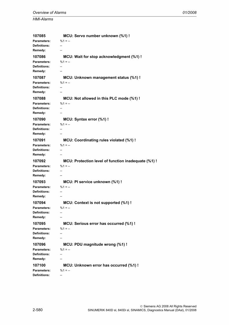
Overview of Alarms 01/2008
HMI-Alarms
2-580
© Siemens AG 2008 All Rights ReservedSINUMERIK 840D sl, 840Di sl, SINAMICS, Diagnostics Manual (DAsl), 01/2008
107085 MCU: Servo number unknown (%1) !Parameters: %1 = --Definitions: --Remedy: --
107086 MCU: Wait for stop acknowledgment (%1) !Parameters: %1 = --Definitions: --Remedy: --
107087 MCU: Unknown management status (%1) !Parameters: %1 = --Definitions: --Remedy: --
107088 MCU: Not allowed in this PLC mode (%1) !Parameters: %1 = --Definitions: --Remedy: --
107090 MCU: Syntax error (%1) !Parameters: %1 = --Definitions: --Remedy: --
107091 MCU: Coordinating rules violated (%1) !Parameters: %1 = --Definitions: --Remedy: --
107092 MCU: Protection level of function inadequate (%1) !Parameters: %1 = --Definitions: --Remedy: --
107093 MCU: PI service unknown (%1) !Parameters: %1 = --Definitions: --Remedy: --
107094 MCU: Context is not supported (%1) !Parameters: %1 = --Definitions: --Remedy: --
107095 MCU: Serious error has occurred (%1) !Parameters: %1 = --Definitions: --Remedy: --
107096 MCU: PDU magnitude wrong (%1) !Parameters: %1 = --Definitions: --Remedy: --
107100 MCU: Unknown error has occurred (%1) !Parameters: %1 = --Definitions: --

HMI-Alarms
01/2008 Overview of Alarms
2-581
© Siemens AG 2008 All Rights ReservedSINUMERIK 840D sl, 840Di sl, SINAMICS, Diagnostics Manual (DAsl), 01/2008
Remedy: --
108000 No dynamic memory availableDefinitions: --Remedy: --
108001 No entry in diagnostics fileDefinitions: --Remedy: --
108002 There are too many entries/errorsDefinitions: --Remedy: --
108003 Change of stateDefinitions: --Remedy: --
108004 Communications error to the HiGraph taskDefinitions: --Remedy: --
108005 Too many demands on HiGraph taskDefinitions: --Remedy: --
108006 No entries for HiGraph diagnostics (e.g. Z_FEHLER_ALT)Definitions: --Remedy: --
108007 Not possible to proceed to next transitionDefinitions: --Remedy: --
108008 Not possible to proceed to previous transitionDefinitions: --Remedy: --
108009 Switch on to next condition not possibleDefinitions: --Remedy: --
108010 Switch on to previous condition not possibleDefinitions: --Remedy: --
108011 No matching allocation foundDefinitions: --Remedy: --
108012 Zoom is emptyDefinitions: --Remedy: --
109000 New NCK address has been transferred to NCKDefinitions: --Remedy: --

Overview of Alarms 01/2008
HMI-Alarms
2-582
© Siemens AG 2008 All Rights ReservedSINUMERIK 840D sl, 840Di sl, SINAMICS, Diagnostics Manual (DAsl), 01/2008
109001 No switchover: Switchover disable set in current PLCDefinitions: HMI would like to go offline from this NCU.
The HMI switchover is disabled in the HMI PLC online interface in DB19.(MMCx_SHIFT_LOCK = TRUE, x = 1,2)
Remedy: --
109002 No switchover: Target PLC used, try againDefinitions: HMI would like to go online to this NCU.
HMI has called the target PLC and is waiting for an acknowledgement.The HMI does not receive an acknowledgement because the HMI parameter interface in DB19 is occupied by another HMI.
Remedy: Repeat the operation at a later point in time, as the HMI parameter interface in DB19 is only tempo-rarily occupied.
109003 No switchover: Switchover disable set in target PLCDefinitions: HMI would like to go online to this NCU.
The HMI switchover is disabled in the HMI PLC online interface in DB19.(MMCx_SHIFT_LOCK = TRUE, x = 1,2)
Remedy: The HMI switchover is disabled/enabled in the machine manufacturer'sPLC program.Reference to the machine manufacturer's documentation.
109004 No switchover: PLC occupied by higher-priority HMIsDefinitions: The HMI is attempting to switch to an NCU that is occupied by two higher-priority HMIs.Remedy: Switch one of the two higher-priority HMIs to another NCU.
109005 No switchover: No HMI displaceable on target PLCDefinitions: HMI would like to go online to this NCU.
At this NCU, two HMIs are online, on which uninterruptable processes are active (e.g. data transfer between HMI and NCU).
Remedy: Wait until at least one of the two HMIs can be displaced, and repeat the switchover.
109006 No switchover: Selected channel invalidDefinitions: The HMI was switched to a channel that does not exist on this NCU.Remedy: Set up the channel or adapt the parameterization of the NETNAMES.INI.
109007 Channel switchover runningDefinitions: The channel switchover has been initiated.
A different HMI may have to be displaced.Remedy: --
109008 Activation runningDefinitions: The switchover from the passive operating mode to the active operating mode has been initiated.Remedy: --
109009 Switchover: error in internal stateDefinitions: --Remedy: --
109010 Displacement: error in internal stateDefinitions: --Remedy: --
109011 Switchover: trace file cannot be createdDefinitions: --Remedy: --
109012 Operator units switchover, PLC timeout: 002Definitions: --Remedy: --

HMI-Alarms
01/2008 Overview of Alarms
2-583
© Siemens AG 2008 All Rights ReservedSINUMERIK 840D sl, 840Di sl, SINAMICS, Diagnostics Manual (DAsl), 01/2008
109013 Activation deniedDefinitions: --Remedy: --
110000 No data available for displayDefinitions: --Remedy: --
110001 Cannot read ACC variable:%1Parameters: %1 = --Definitions: --Remedy: --
110002 No memory availableDefinitions: --Remedy: --
110003 COM file not found: %1Parameters: %1 = --Definitions: --Remedy: --
110004 Screen not found: %1Parameters: %1 = --Definitions: --Remedy: --
112045 Several approach points requiredDefinitions: Several insertion points are required for machining the contour pocket. The machining breaks up into
several individual machinings.The program can be started.This alarm is only a warning.Residual material will remain.
Reaction: Alarm display.Remedy: By using a smaller milling cutter, the machining could be done with an insertion point.Program Con-tinuation:
Internal
112046 Main contour cannot be tracedDefinitions: The pocket contour cannot be bypassed with the specified milling cutter.
Residual material will remain.The program can be started.This alarm is only a warning.
Reaction: Alarm display.Remedy: By using a smaller milling cutter, the pocket contour could be bypassed.Program Con-tinuation:
Internal
112052 No residual material availableDefinitions: No residual material has been determined.Reaction: Alarm display.Remedy: Check parameters in the residual material cycle.Program Con-tinuation:
Clear alarm with the Delete key or NC START.

Overview of Alarms 01/2008
HMI-Alarms
2-584
© Siemens AG 2008 All Rights ReservedSINUMERIK 840D sl, 840Di sl, SINAMICS, Diagnostics Manual (DAsl), 01/2008
112057 Programmed helix violates contourDefinitions: The starting point for helical insertion was so selected, that the helix violates the programmed contour.
The program can be started.This alarm is only a warning.
Reaction: Alarm display.Remedy: Select another starting point; use a smaller helix radius.Program Con-tinuation:
Internal
112099 System error contour pocket %1Definitions: While the contour pocket was being calculated, an error occurred. The contour pocket cannot be cal-
culated.The program cannot be started.
Reaction: Alarm display.Remedy: Please contact the hotline of Siemens AG, A&D MC and provide with the error message.Program Con-tinuation:
Internal
112100 Error on renumbering.%nInitial state restored.Definitions: The softkey "Renumber" was pressed in the program editor. This caused an error during serial num-
bering that damaged the program in the memory, making it necessary to reload the initial program into the memory.The program was not renumbered.
Reaction: Alarm display.Remedy: Make room in the memory, e.g. by deleting an old program. Select "Renumber" again.Program Con-tinuation:
Internal
112200 The contour is a step in the current program%nsequence. Machining not enabled
Definitions: The contour is an element from a loaded program and cannot be deleted or renamed.Reaction: Alarm display.Remedy: Remove the contour from the loaded program.Program Con-tinuation:
Internal
112201 Contour is step in current automatic chain%nMachining not possible.Definitions: The contour is an element of a program loaded under "Machine auto" and cannot be deleted or
renamed.After the program has been started, the integrated contours cannot be changed under "Program" while the program is running.
Reaction: Alarm display.Remedy: Stop the program and load it under "Program". Remove the contour from the program.Program Con-tinuation:
Internal
112210 Tool axis cannot be changed. Not enough NC-%nmemory.Definitions: If the tool axis is reselected, the NC program has to be generated again. Hereby the old NC program
is saved first.Then the new program is generated. Here, the NC memory is insufficient to save the new program.The reselection of the tool axis was not carried out.
Reaction: Alarm display.Remedy: Free memory space must be created on the NC, and it must be enough for the program to be pro-
cessed (e.g. by deleting programs that are no longer required).Program Con-tinuation:
Internal

HMI-Alarms
01/2008 Overview of Alarms
2-585
© Siemens AG 2008 All Rights ReservedSINUMERIK 840D sl, 840Di sl, SINAMICS, Diagnostics Manual (DAsl), 01/2008
112211 Tool preselection cannot be processed.%nNot enough NC memory.Definitions: When tool preselection is processed, the NC program has to be generated again. Hereby the old NC
program is saved first.Then the new program is generated. Here, the NC memory is insufficient to save the new program.The tool preselection is not processed.
Reaction: Alarm display.Remedy: Free memory space must be created on the NC, and it must be enough for the program to be pro-
cessed (e.g. by deleting programs that are no longer required).Program Con-tinuation:
Internal
112300 Tool management concept 2 not possible%nMagazine not completely loaded.
Definitions: The magazine is not completely loaded with tools.In the magazine of tool management type 2, the number of tools specified in machine data 18082 has to be created.
Reaction: Alarm display.Remedy: Installation and start-up: Create the correct number of tools.Program Con-tinuation:
Internal
112301 Tool management concept 2 not possible%nMagazine not sorted like tool list.
Definitions: The magazine list sorting does not correspond to that of the tool list.-
Reaction: Alarm display.Remedy: Start-up: Assign tools according to their T numbers to the magazine locations.Program Con-tinuation:
Internal
112320 Replace manual tool:%n%1.Definitions: The operator is prompted to replace the indicated manual tool.Reaction: Alarm display.Remedy: Replace the manual tool.Program Con-tinuation:
Internal
112321 Load manual tool:%n%1.Definitions: The operator is prompted to load the specified manual tool.Reaction: Alarm display.Remedy: Load the manual tool.Program Con-tinuation:
Internal
112322 Exchange manual tool:%n%1 -> %2.Definitions: The operator is prompted to replace the specified manual tool by the new manual tool.Reaction: Alarm display.Remedy: Replace the manual tool.Program Con-tinuation:
Internal
112323 Replace inclinable head:%n%1Definitions: The operator is prompted to remove the specified swivel head from the spindle.Reaction: Alarm display.Remedy: Replace swivel head.
When doing this, please follow the machine manufacturer's instructions.Program Con-tinuation:
Internal

Overview of Alarms 01/2008
HMI-Alarms
2-586
© Siemens AG 2008 All Rights ReservedSINUMERIK 840D sl, 840Di sl, SINAMICS, Diagnostics Manual (DAsl), 01/2008
112324 Load inclinable head:%n%1Definitions: The operator is prompted to load the specified swivel head into the spindle.Reaction: Alarm display.Remedy: Load swivel head.
When doing this, please follow the machine manufacturer's instructions.Program Con-tinuation:
Internal
112325 Exchange inclinable head:%n%1 -> %2Definitions: The operator is prompted to replace the specified swivel head in the spindle with the new swivel head.Reaction: Alarm display.Remedy: Exchange swivel head.
When doing this, please follow the machine manufacturer's instructions.Program Con-tinuation:
Internal
112326 Set inclinable head%n%1%2Definitions: The operator is prompted to set the swivel head in accordance with the specified data.Reaction: Alarm display.Remedy: Set swivel head.
When doing this, please follow the machine manufacturer's instructions.Program Con-tinuation:
Internal
112327 Angle not in allowed area:%n%1%2Definitions: The programmed machining cannot be carried out with the swivel head.Reaction: Alarm display.Remedy: If necessary, clamp the workpiece differently.Program Con-tinuation:
Internal
112328 Angle adapted to angle grid:%n%1%2Definitions: Due to the angle grid, the swivel head could not be set exactly to the specified angle.Reaction: Alarm display.Remedy: Machining can be continued with the specified values, but it will not correspond exactly to the program-
ming.Program Con-tinuation:
Internal
112329 Set inclinable head/swivel table:%n%1%2Definitions: The operator is prompted to set the swivel head/table in accordance with the specified data.Reaction: Alarm display.Remedy: Set swivel head/table.
When doing this, please follow the machine manufacturer's instructions.Program Con-tinuation:
Internal
112330 Set swivel table:%n%1%2Definitions: The operator is prompted to set the swivel table in accordance with the specified data.Reaction: Alarm display.Remedy: Set swivel table.
When doing this, please follow the machine manufacturer's instructions.Program Con-tinuation:
Internal
112340 Approval not possible, as axes have not%nbeen referenced!Definitions: In Safety Integrated a user acknowledgement can only be made after the reference point has been
approached.Reaction: Alarm display.

HMI-Alarms
01/2008 Overview of Alarms
2-587
© Siemens AG 2008 All Rights ReservedSINUMERIK 840D sl, 840Di sl, SINAMICS, Diagnostics Manual (DAsl), 01/2008
Remedy: Approach reference point.Program Con-tinuation:
Clear alarm with the Delete key or NC START.
112350 No swivel data created!Definitions: There are no swivel data blocks.Reaction: Alarm display.Remedy: Set up swivel data blocks (see /FBSP/, ShopMill Description of Functions)Program Con-tinuation:
Internal
112360 Step was not transferred into program chain%nas program run active.Definitions: The program that you want to change is being executed in the operating mode "Machine auto". You
can only change programs that are not being executed in the operating mode "Machine auto".Reaction: Alarm display.Remedy: Stop the program run in the "Machine auto" operating mode.Program Con-tinuation:
Internal
112400 Not stored in the Tool Management:%n%1 Program: %2Definitions: The tool specified in the program does not exist.Reaction: Alarm display.Remedy: The tool must be created before the data is saved.Program Con-tinuation:
Internal
112401 Tool could not be set up:%n%1 Definitions: When reading in the tool data, a tool could not be created.Reaction: Alarm display.Remedy: Check tool management.Program Con-tinuation:
Internal
112402 Work offsets: error on writingDefinitions: Data could not be written to the NC.Reaction: Alarm display.Remedy: Should the alarm be displayed again after a new try, please contact the hotline of Siemens AG, A&D
MC.Program Con-tinuation:
Clear alarm with the Delete key or NC START.
112420 Error on changing over inch/metric!%nCheck all data!Definitions: The switchover of the data for the inch/metric conversion was not completed.
This alarm can only appear in the event of hardware defects.Reaction: NC Start disable in this channel.
Alarm display.

Overview of Alarms 01/2008
HMI-Alarms
2-588
© Siemens AG 2008 All Rights ReservedSINUMERIK 840D sl, 840Di sl, SINAMICS, Diagnostics Manual (DAsl), 01/2008
Remedy: The following data must be checked:Display MD's:MD9655: $MM_CMM_CYC_PECKING_DISTMD9656: $MM_CMM_CYC_DRILL_RELEASE_DISTMD9658: $MM_CMM_CYC_MIN_COUNT_PO_TO_RADMD9664: $MM_CMM_MAX_INP_FEED_P_MINMD9665: $MM_CMM_MAX_INP_FEED_P_ROTMD9666: $MM_CMM_MAX_INP_FEED_P_TOOTHMD9670: $MM_CMM_START_RAD_CONTOUR_POCKETMD9752: $MM_CMM_MEASURING_DISTANCEMD9753: $MM_CMM_MEAS_DIST_MANMD9754: $MM_CMM_MEAS_DIST_TOOL_LENGTHMD9755: $MM_CMM_MEAS_DIST_TOOL_RADIUSMD9756: $MM_CMM_MEASURING_FEEDMD9757: $MM_CMM_FEED_WITH_COLL_CTRLMD9758: $MM_CMM_POS_FEED_WITH_COLL_CTRLMD9759: $MM_CMM_MAX_CIRC_SPEED_ROT_SPMD9761: $MM_CMM_MIN_FEED_ROT_SPMD9762: $MM_CMM_MEAS_TOL_ROT_SPMD9765: $MM_CMM_T_PROBE_DIAM_LENGTH_MEASMD9766: $MM_CMM_T_PROBE_DIAM_RAD_MEASMD9767: $MM_CMM_T_PROBE_DIST_RAD_MEASMD10240: $MN_SCALING_SYSTEM_IS_METRICMD20150 [12]: $MC_GCODE_RESET_VALUESTool data for various cutting edges D: length Z, radius R, wear length radius Z and R.Zero offsets: Basic offset position in X, Y, Z , as well as A, C (if available) zero offset.Settings in operating mode MANUAL: Retraction plane, safety clearance.
Program Con-tinuation:
Internal
112500 Error in NC interpreter % module %1.Definitions: The ShopMill program cannot be opened.Reaction: Alarm display.Remedy: Alarm displayProgram Con-tinuation:
Internal
112501 Error in EASYSTEP chain:%nNon-interpretable step in line %1.Definitions: The ShopMill program cannot be opened.Reaction: Alarm display.Remedy: Correct the faulty line.Program Con-tinuation:
Internal
112502 Not enough memory space%nAbort in line %1.Parameters: %1 = Line numberDefinitions: The program cannot interpret a program block with contour programming. Contour not in the directory.
Program is not loaded.The program cannot interpret a program block with contour programming. Contour not in the directory.
Reaction: Alarm display.Remedy: Load contour into the directory.Program Con-tinuation:
Internal
112503 ShopMill: %1Definitions: A system error has occurred.Reaction: Alarm display.Remedy: Please contact the hotline of Siemens AG, A&D MC and provide with the error message.Program Con-tinuation:
Clear alarm with the Delete key or NC START.
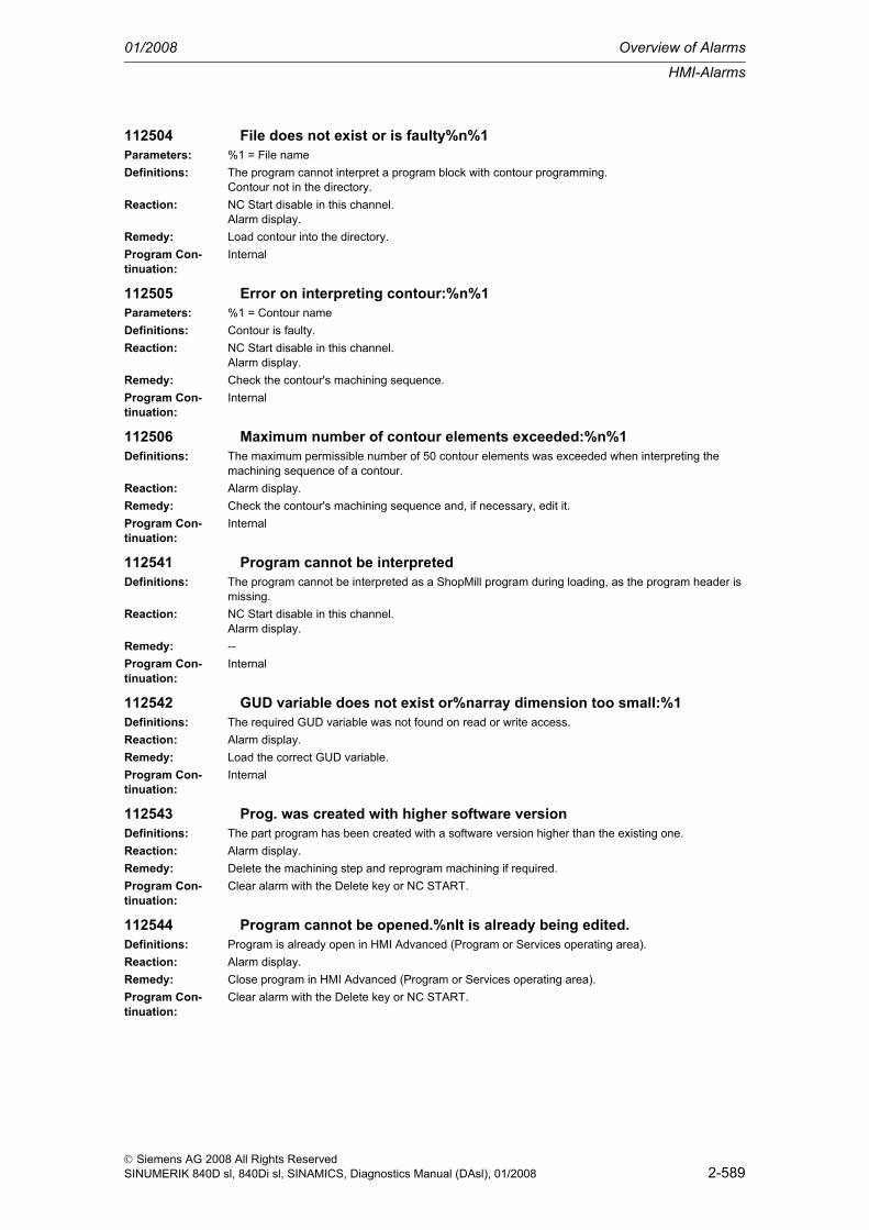
HMI-Alarms
01/2008 Overview of Alarms
2-589
© Siemens AG 2008 All Rights ReservedSINUMERIK 840D sl, 840Di sl, SINAMICS, Diagnostics Manual (DAsl), 01/2008
112504 File does not exist or is faulty%n%1Parameters: %1 = File nameDefinitions: The program cannot interpret a program block with contour programming.
Contour not in the directory.Reaction: NC Start disable in this channel.
Alarm display.Remedy: Load contour into the directory.Program Con-tinuation:
Internal
112505 Error on interpreting contour:%n%1Parameters: %1 = Contour nameDefinitions: Contour is faulty.Reaction: NC Start disable in this channel.
Alarm display.Remedy: Check the contour's machining sequence.Program Con-tinuation:
Internal
112506 Maximum number of contour elements exceeded:%n%1Definitions: The maximum permissible number of 50 contour elements was exceeded when interpreting the
machining sequence of a contour.Reaction: Alarm display.Remedy: Check the contour's machining sequence and, if necessary, edit it.Program Con-tinuation:
Internal
112541 Program cannot be interpretedDefinitions: The program cannot be interpreted as a ShopMill program during loading, as the program header is
missing.Reaction: NC Start disable in this channel.
Alarm display.Remedy: --Program Con-tinuation:
Internal
112542 GUD variable does not exist or%narray dimension too small:%1Definitions: The required GUD variable was not found on read or write access.Reaction: Alarm display.Remedy: Load the correct GUD variable.Program Con-tinuation:
Internal
112543 Prog. was created with higher software versionDefinitions: The part program has been created with a software version higher than the existing one.Reaction: Alarm display.Remedy: Delete the machining step and reprogram machining if required.Program Con-tinuation:
Clear alarm with the Delete key or NC START.
112544 Program cannot be opened.%nIt is already being edited.Definitions: Program is already open in HMI Advanced (Program or Services operating area).Reaction: Alarm display.Remedy: Close program in HMI Advanced (Program or Services operating area).Program Con-tinuation:
Clear alarm with the Delete key or NC START.

Overview of Alarms 01/2008
HMI-Alarms
2-590
© Siemens AG 2008 All Rights ReservedSINUMERIK 840D sl, 840Di sl, SINAMICS, Diagnostics Manual (DAsl), 01/2008
112546 Program cannot be opened.%nNo read access to the file.Definitions: The file has no write access for the current access level.Reaction: Alarm display.Remedy: Set read access with keyswitch or via password.Program Con-tinuation:
Internal
112550 Sequencer programming is not opened.Definitions: Option 'Sequencer programming' has not been set.Reaction: Alarm display.Remedy: The program is opened as G code.Program Con-tinuation:
Internal
112560 USB device no longer available, execution%nfrom external source no longer possible.
Definitions: --Reaction: Alarm display.Remedy: --
112561 USB device no longer available,%nexecution of Extcall no longer possible.
Definitions: --Reaction: Alarm display.Remedy: --
112562 USB device is no longer available, editing is%ncanceled. The last changes have been lost.
Definitions: --Reaction: Alarm display.Remedy: --
112563 USB device is not available, program editing%nis canceled. Last changes have been lost.
Definitions: --Reaction: Alarm display.Remedy: --
112564 USB device no longer available,%ncopying was aborted.Definitions: --Reaction: Alarm display.Remedy: --
112565 USB device no longer available.Definitions: --Reaction: Alarm display.Remedy: --
112600 Spindle not synchronizedDefinitions:Reaction: Alarm display.Remedy: Synchronize the spindle.Program Con-tinuation:
Internal
112601 ShopTurn: %1Definitions: A system error has occurred.Reaction: Alarm display.

HMI-Alarms
01/2008 Overview of Alarms
2-591
© Siemens AG 2008 All Rights ReservedSINUMERIK 840D sl, 840Di sl, SINAMICS, Diagnostics Manual (DAsl), 01/2008
Remedy: Please contact the hotline of Siemens AG, A&D MC and provide with the error message.Program Con-tinuation:
Clear alarm with the Delete key or NC START.
112604 Connection to the PLC broken offDefinitions: Acknowledgement to the PLC user program, that the connection with the PCU has been broken off.
ShopMill PLC is terminated.Reaction: Alarm display.Remedy: Check the PLC user program.Program Con-tinuation:
Internal
112605 Asynchronous subprogram was%nnot executedDefinitions: The input values could not be correctly processed by the NC.Reaction: Alarm display.Remedy: Perform an NCK resetProgram Con-tinuation:
Internal
112611 NC start not possible:%nDeselect single blockDefinitions: A program was activated with block search while a single block has been active.Reaction: Alarm display.Remedy: Deselect the single block.Program Con-tinuation:
Internal
112620 Language %1 not installed.Definitions: Language not installed.Reaction: Alarm display.Remedy: Install language.Program Con-tinuation:
Internal
112650 Unknown PLC errorDefinitions: The PLC has announced an error that is unknown in the operator panel.Reaction: NC Start disable in this channel.
Alarm display.Remedy: Press POWER ON, inform Siemens.Program Con-tinuation:
Internal
112999 Faulty graphic data. Exit graphic %nand restartDefinitions: More data was generated than can be read from the operator panel.
Stop the graphic.Remedy: Deselect the graphic and then select it again.
113000 Invalid value - value range: %1Parameters: %1 = --Definitions: --Remedy: --
113001 Incorrect configuration in line %1Parameters: %1 = --Definitions: --Remedy: --
113002 Insufficient access level!Definitions: --Remedy: --

Overview of Alarms 01/2008
HMI-Alarms
2-592
© Siemens AG 2008 All Rights ReservedSINUMERIK 840D sl, 840Di sl, SINAMICS, Diagnostics Manual (DAsl), 01/2008
113003 Error when writing variable %1Parameters: %1 = --Definitions: --Remedy: --
113004 Insufficient dynamic memoryDefinitions: --Remedy: --
113005 Incorrect NC file positioning: %1Parameters: %1 = --Definitions: --Remedy: --
113006 NC program is not open %1Parameters: %1 = --Definitions: --Remedy: --
113007 Cannot read NC block, no.: %1Parameters: %1 = --Definitions: --Remedy: --
113008 NC block cannot be written, no.: %1Parameters: %1 = --Definitions: --Remedy: --
113009 File name missing for copyDefinitions: --Remedy: --
113010 Cannot open file: %1Parameters: %1 = --Definitions: --Remedy: --
113011 Cannot write file: %1Parameters: %1 = --Definitions: --Remedy: --
113012 Cannot write NC file: %1Parameters: %1 = --Definitions: --Remedy: --
113013 Cannot read NC file: %1Parameters: %1 = --Definitions: --Remedy: --
113014 Invalid NC file name: %1Parameters: %1 = --Definitions: --Remedy: --

HMI-Alarms
01/2008 Overview of Alarms
2-593
© Siemens AG 2008 All Rights ReservedSINUMERIK 840D sl, 840Di sl, SINAMICS, Diagnostics Manual (DAsl), 01/2008
113015 DLL not loaded: %1Parameters: %1 = --Definitions: --Remedy: --
113016 No link to %1Parameters: %1 = --Definitions: --Remedy: --
113017 Incorrect DDE address: %1Parameters: %1 = --Definitions: --Remedy: --
113018 Invalid command: %1Parameters: %1 = --Definitions: --Remedy: --
113019 Invalid data format: %1Parameters: %1 = --Definitions: --Remedy: --
113020 Cursor data item cannot be writtenDefinitions: --Remedy: --
113021 Error on data access: %1Parameters: %1 = --Definitions: --Remedy: --
113022 No variables existDefinitions: --Remedy: --
113023 Impossible to enter code: %1Parameters: %1 = --Definitions: --Remedy: --
113024 Invalid mask property: %1Parameters: %1 = --Definitions: --Remedy: --
113025 Invalid action: %1Parameters: %1 = --Definitions: --Remedy: --
113026 Invalid type of action: %1Parameters: %1 = --Definitions: --Remedy: --

Overview of Alarms 01/2008
HMI-Alarms
2-594
© Siemens AG 2008 All Rights ReservedSINUMERIK 840D sl, 840Di sl, SINAMICS, Diagnostics Manual (DAsl), 01/2008
113027 No mask definedDefinitions: --Remedy: --
113028 You cannot insert hereDefinitions: --Remedy: --
113029 Mask '%1' being generated - please wait ...Parameters: %1 = --Definitions: --Remedy: --
113030 PLC connection '%1' not in 'common.com'Parameters: %1 = --Definitions: --Remedy: --
113031 PLC interpreter: %1 bytes not allocatedParameters: %1 = --Definitions: --Remedy: --
113032 Invalid PLC command: %1Parameters: %1 = --Definitions: --Remedy: --
113033 Block cannot be recompiledDefinitions: --Remedy: --
113034 No softkey is allowed in this state - ignoredDefinitions: --Remedy: --
113100 Internal error %1Parameters: %1 = --Definitions: --Remedy: --
120000 Area %1 cannot be loaded! Acknowledge alarm, press area switchover key!
Parameters: %1 = Operating area nameDefinitions: One of the applications listed in the REGIE.INI could not be started.Reaction: Alarm display.Remedy: Check whether the entry in REGIE.INI is correct.Program Con-tinuation:
Internal
120001 Area %1 cannot be selected. Please deactivate area %2Parameters: %1 = Operating area name
%2 = Operating area nameDefinitions: Within the scope of an area switchover, a different area is to be terminated (unloaded).
However, the area refuses this.The area switchover does not take place.
Reaction: Alarm display.Remedy: Try again and, if possible, close the reluctant area first.

HMI-Alarms
01/2008 Overview of Alarms
2-595
© Siemens AG 2008 All Rights ReservedSINUMERIK 840D sl, 840Di sl, SINAMICS, Diagnostics Manual (DAsl), 01/2008
Program Con-tinuation:
Internal
120002 Area %1 is still active. Please deactivate area %1Parameters: %1 = Operating area nameDefinitions: When the MMC system is closed (closing the master control), an area is to be terminated.
However, the area refuses this.The system was NOT closed.
Reaction: Alarm display.Remedy: Try again and, if possible, close the unwanted area first.Program Con-tinuation:
Internal
120003 Area %1 cannot be deactivated. Please try againParameters: %1 = Operating area nameDefinitions: Within the scope of an area switchover, an area is to be deselected.
However, the area refuses this.The area switchover does not take place.
Reaction: Alarm display.Remedy: Try again and, if possible, close the reluctant area first.Program Con-tinuation:
Internal
120005 Please acknowledge the dialog box in area %1Parameters: %1 = Operating area nameDefinitions: The area %1 could not be deselected, as in this area a dialog box is still open.Reaction: Alarm display.Remedy: Close the dialog box in area %1!Program Con-tinuation:
Internal
120006 The channel switchover is currently disabled by area %1.Parameters: %1 = Operating area nameDefinitions: The area %1 has disabled the channel switchover at the moment, as it is performing a critical opera-
tion (e.g. execution from external sources, etc.), during which no channel switchover may occur.Reaction: Alarm display.Remedy: Wait until the critical operation is finished or end the critical operation manually.Program Con-tinuation:
Internal
120007 The channel switchover is currently disabled.Definitions: The channel switchover is currently disabled, as a critical operation, during which no channel switcho-
ver may occur, is being carried out.Reaction: Alarm display.Remedy: Wait until the critical operation is finished or end the critical operation manually.
Program Con-tinuation:
Internal

Overview of Alarms 01/2008
HMI-Alarms
2-596
© Siemens AG 2008 All Rights ReservedSINUMERIK 840D sl, 840Di sl, SINAMICS, Diagnostics Manual (DAsl), 01/2008
120007 The channel switchover is currently disabled.Definitions: The channel switchover is currently disabled, as a critical operation, during which no channel switcho-
ver may occur, is being carried out.Reaction: Alarm display.Remedy: Wait until the critical operation is finished or end the critical operation manually.
Program Con-tinuation:
Internal
120008 Control unit switchover, PLC timeout: %1Parameters: %1 = --Definitions: 001: MMC would like to go offline from this NCU. MMC has made the offline request in the online PLC
and is waiting for the positive / negative acknowledgement from the PLC.002: MMC would like to go online to this NCU. MMC has called the target PLC and is waiting for the release to go online.003: MMC has requested the active operating mode and is waiting for acknowledgement from the PLC.
Remedy: Check whether the switchover blocks are loaded and started in the online PLC.
120010 PCU temperature alarmDefinitions: The temperature sensor on the PCU module has reached the response threshold.
Interface bit DB10.DB103.6 will be set.Remedy: Switch off the PCU and let it cool off.
Improve the ventilation of the PCU module.Check the function of the fan of the PCU module (fan defect).If the error is displayed again, please inform the authorized service personnel.
120011 Request for authority to operate from another station.%nTo retain authority to operate=>Recall key,%nto transfer authority to operate=>wait (no entry)
Definitions: The operator of another station requests authority to operate. This can be refused to him through Recall. After approx. 5 seconds, the authority to operate will automatically be transferred to the other station.
Reaction: Alarm display.Remedy: The alarm automatically disappears after approx. five seconds or if the Recall key is pressed within
this time limit.Program Con-tinuation:
Internal
120020 PCU fan monitoring CPU fanDefinitions: Low fan speed of CPU fan.
Interface bit DB10.DB103.4 is being set.Remedy: Switch off the PCU, let it cool off and have the function of the CPU fan of PCU module checked by
qualified service personnel (fan problem).Spare part description: Manual Operator Components SINUMERIK840D/840Di/810D section PCU 50 V3 spare parts, replacement of device fan.
120021 PCU fan monitoring housing fan 1Definitions: Low fan speed of PCU casing fan 1.
Interface bit DB10.DB103.4 is being set.
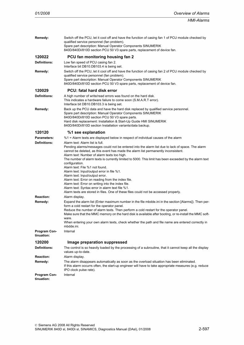
HMI-Alarms
01/2008 Overview of Alarms
2-597
© Siemens AG 2008 All Rights ReservedSINUMERIK 840D sl, 840Di sl, SINAMICS, Diagnostics Manual (DAsl), 01/2008
Remedy: Switch off the PCU, let it cool off and have the function of casing fan 1 of PCU module checked by qualified service personnel (fan problem).Spare part description: Manual Operator Components SINUMERIK840D/840Di/810D section PCU 50 V3 spare parts, replacement of device fan.
120022 PCU fan monitoring housing fan 2Definitions: Low fan speed of PCU casing fan 2.
Interface bit DB10.DB103.4 is being set.Remedy: Switch off the PCU, let it cool off and have the function of casing fan 2 of PCU module checked by
qualified service personnel (fan problem).Spare part description: Manual Operator Components SINUMERIK840D/840Di/810D section PCU 50 V3 spare parts, replacement of device fan.
120029 PCU: fatal hard disk errorDefinitions: A high number of write/read errors was found on the hard disk.
This indicates a hardware failure to come soon (S.M.A.R.T error).Interface bit DB10.DB103.3 is being set.
Remedy: Back up the PCU data and have the hard disk replaced by qualified service personnel.Spare part description: Manual Operator Components SINUMERIK840D/840Di/810D section PCU 50 V3 spare parts.Hard disk replacement: Installation & Start-Up Guide HMI SINUMERIK840D/840Di/810D section Installation variants/data backup.
120120 %1 see explanationParameters: %1 = Alarm texts are displayed below in respect of individual causes of the alarmDefinitions: Alarm text: Alarm list is full.
Pending alarms/messages could not be entered into the alarm list due to lack of space. The alarm cannot be deleted, as this event has made the alarm list permanently inconsistent.Alarm text: Number of alarm texts too high.The number of alarm texts is currently limited to 5000. This limit has been exceeded by the alarm text configuration.Alarm text: File %1 not found.Alarm text: Input/output error in file %1.Alarm text: Input/output error.Alarm text: Error on reading from the index file.Alarm text: Error on writing into the index file.Alarm text: Syntax error in alarm text file %1.Alarm texts are stored in files. One of these files could not be accessed properly.
Reaction: Alarm display.Remedy: Expand the alarm list (Enter maximum number in the file mbdde.ini in the section [Alarms]). Then per-
form a cold restart for the operator panel.Reduce the number of alarm texts. Then perform a cold restart for the operator panel.Make sure that the MMC memory on the hard disk is available after booting, or re-install the MMC soft-ware.When entering your own alarm texts, check whether the path and file name are entered correctly in mbdde.ini.
Program Con-tinuation:
Internal
120200 Image preparation suppressedDefinitions: The control is so heavily loaded by the processing of a subroutine, that it cannot keep all the display
values up-to-date.Reaction: Alarm display.Remedy: The alarm disappears automatically as soon as the overload situation has been eliminated.
If this alarm occurrs often, the start-up engineer will have to take appropriate measures (e.g. reduce IPO clock pulse rate).
Program Con-tinuation:
Internal

Overview of Alarms 01/2008
HMI-Alarms
2-598
© Siemens AG 2008 All Rights ReservedSINUMERIK 840D sl, 840Di sl, SINAMICS, Diagnostics Manual (DAsl), 01/2008
120200 Image preparation suppressedDefinitions: The control is so heavily loaded by the processing of a subroutine, that it cannot keep all the display
values up-to-date.Reaction: Alarm display.Remedy: The alarm disappears automatically as soon as the overload situation has been eliminated.
If this alarm occurrs often, the start-up engineer will have to take appropriate measures (e.g. reduce IPO clock pulse rate).
Program Con-tinuation:
Internal
120201 Communication failureDefinitions: The operator panel is connected with the NC and PLC via a serial bus.
This alarm occurs when the communication to these components is interrupted.In connection with this alarm, all display values connected with the NC/PLC become invalid.Such faults are normal while the controls are ramping up (e.g. after resetting).
Reaction: Alarm display.Remedy: The alarm disappears automatically as soon as the fault situation has ended.
If this alarm is continuously present, a wide variety of faults may be the cause. (e.g. wire breakage, NC/PLC not ramped up,faulty address/data transfer rate configuration of one of the bus nodes, etc.).
Program Con-tinuation:
Internal
120202 Waiting for a connection to the NC/PLCDefinitions: The operator panel is connected to the NC and PLC via a serial bus.
This alarm occurs if the MMC is started for the first time and the NC/PLC ramp-up is not yet finished or the communication to these components is faulty.In connection with this alarm, all display values connected with the NC/PLC become invalid.Such faults are normal while the controls are ramping up (e.g. after resetting).
Reaction: Alarm display.Remedy: The alarm disappears automatically as soon as the fault situation has ended.
If this alarm is continuously present, a wide variety of faults may be the cause. (e.g. wire breakage, NC/PLC not ramped up, faulty address/data transfer rate configuration of one of the bus nodes, etc.).
Program Con-tinuation:
Internal
120203 Communication failureDefinitions: The operator panel is connected to the NC and PLC via a serial bus.
This alarm occurs if the MMC is started for the first time and the NC/PLC ramp-up is not yet finished or the communication to these components is faulty.In connection with this alarm, all display values connected with the NC/PLC become invalid.Such faults are normal while the controls are ramping up (e.g. after resetting).
Reaction: Alarm display.Remedy: The alarm disappears automatically as soon as the fault situation has ended.
If this alarm is continuously present, a wide variety of faults may be the cause. (e.g. wire breakage, NC/PLC not ramped up, faulty address/data transfer rate configuration of one of the bus nodes, etc.).
Program Con-tinuation:
Internal
120301 Faulty entry for hardkey 'Program' in Keys.ini.Definitions: The configuration in Keys.ini is wrong.Reaction: Alarm display.Remedy: In Keys.ini, the parameter ChildTask:=26 has to be set in the line KEY2.0=.
The alarm can also be acknowledged manually via diagnostics.Program Con-tinuation:
Internal

HMI-Alarms
01/2008 Overview of Alarms
2-599
© Siemens AG 2008 All Rights ReservedSINUMERIK 840D sl, 840Di sl, SINAMICS, Diagnostics Manual (DAsl), 01/2008
120302 The selection is not possible. A program has to have been edited first via the area 'Program'.
Definitions: A program can only be selected via the hardkey program if a program has already been edited in the program area.
Reaction: Alarm display.Remedy: The alarm disappears automatically as soon as a program is edited or simulated in the program area.
The alarm can also be acknowledged manually via diagnostics.Program Con-tinuation:
Internal
120303 The selection is not possible. The edited file %1 no longer exists.Parameters: %1 = Program name with pathDefinitions: The file edited last in the program area has in the meantime been deleted.Reaction: Alarm display.Remedy: The alarm disappears automatically as soon as a program is edited or simulated in the program area.
The alarm can also be acknowledged manually via diagnostics.Program Con-tinuation:
Internal
120304 The selection is not possible. The file %1 has insufficient read rights.Parameters: %1 = Program name with pathDefinitions: The file has insufficient read rights for the current access level.Reaction: Alarm display.Remedy: Set the required read rights by means of keyswitch or password entry.
The alarm disappears automatically as soon as a program is edited or simulated in the program area.The alarm can also be acknowledged manually via diagnostics.
Program Con-tinuation:
Internal
120305 Selection is not possible. The file %1 is currently being edited.Parameters: %1 = Program name with pathDefinitions: The file is currently open in another application (e.g. services) with an editor.Reaction: Alarm display.Remedy: Change the program in the already open editor.
The alarm disappears automatically as soon as a program is edited or simulated in the program area.The alarm can also be acknowledged manually via diagnostics.
Program Con-tinuation:
Internal
120306 The selection is not possible. The file %1 is selected and active in channel %2.
Parameters: %1 = Program name with path%2 = Channel number
Definitions: --Reaction: Alarm display.Remedy: Stop the program with the NCU's channel reset and make the selection again.
The alarm disappears automatically as soon as a program is edited or simulated in the program area.The alarm can also be acknowledged manually via diagnostics.
Program Con-tinuation:
Internal
120307 File %1 cannot be opened for the editor because it is selected in channel %2 for execution by external sources.
Parameters: %1 = Program name with path%2 = Channel number
Definitions: --Reaction: Alarm display.

Overview of Alarms 01/2008
HMI-Alarms
2-600
© Siemens AG 2008 All Rights ReservedSINUMERIK 840D sl, 840Di sl, SINAMICS, Diagnostics Manual (DAsl), 01/2008
Remedy: A different program on the NCU or for execution from external sources has to be selected.The alarm disappears automatically as soon as a program is edited or simulated in the program area.The alarm can also be acknowledged manually via diagnostics.
Program Con-tinuation:
Internal
120308 In the event of an emergency stop, the program %1 can only be changed in the machine/program correction area.
Parameters: %1 = Program name with pathDefinitions: --Reaction: Alarm display.Remedy: Switch to the machine area and change the program with the program correction function.
The alarm disappears automatically as soon as a program is edited or simulated in the program area.The alarm can also be acknowledged manually via diagnostics.
Program Con-tinuation:
Internal
120309 The selection is not possible. Please close the simulation and repeat the selection.
Definitions: The simulation is currently active in the program area.A simultaneous editing is not possible.
Reaction: Alarm display.Remedy: Close the simulation and make the selection again.
The alarm disappears automatically as soon as a program is edited or simulated in the program area.The alarm can also be acknowledged manually via diagnostics.
Program Con-tinuation:
Internal
120310 The selection is not possible. Please wait for the pending action or terminate it, then repeat the selection.
Definitions: In the program area, programs are currently being copied, loaded or unloaded.A simultaneous editing is not possible.
Reaction: Alarm display.Remedy: Wait until the action is completed or terminate the action via the softkey "Cancel", and then repeat the
selection.The alarm disappears automatically as soon as a program is edited or simulated in the program area.The alarm can also be acknowledged manually via diagnostics.
Program Con-tinuation:
Internal
120400 Settings for communication links with drives not effective yet. Stop and restart HMI.
Definitions: Is triggered if someone tries to copy a file from / to the drive, and if the drive name in the mmc.ini is not yet valid.
Reaction: Alarm display.Remedy: Acknowledge alarmProgram Con-tinuation:
Internal
120401 SINAMICS: Write job for parameter %1, value %2, area %3: %4s timeoutParameters: %1 = Parameter number
%2 = Value that was written%3 = Area%4 = Time required for writing
Definitions: Will be activated if writing of parameters leads to timeout.Reaction: Alarm display.Remedy: Acknowledge alarmProgram Con-tinuation:
Internal

HMI-Alarms
01/2008 Overview of Alarms
2-601
© Siemens AG 2008 All Rights ReservedSINUMERIK 840D sl, 840Di sl, SINAMICS, Diagnostics Manual (DAsl), 01/2008
120402 DP%1.Slave%2: %3: Initial start-up requiredParameters: %1 = Bus number
%2 = Slave address%3 = Object name
Definitions: Will be activated if a CU is in ramp-up state r3988=200.Reaction: Alarm display.Remedy: Acknowledge alarmProgram Con-tinuation:
Internal
120403 DP%1.Slave%2: %3: Check / acknowledge topologyParameters: %1 = Bus number
%2 = Slave address%3 = Object name
Definitions: Will be activated if a CU is in ramp-up state r3988=250.Reaction: Alarm display.Remedy: Acknowledge alarmProgram Con-tinuation:
Internal
120404 Set-up of connection to %1 not possible. Load SDBs with HW Config in CP!
Parameters: %1 = Name of connectionDefinitions: Will be activated if subnet ID is different in PLC and in CP.Reaction: Alarm display.Remedy: Load drive project with same subnet ID with HW Config in PLC and CP, and restart HMI.
If error repeatedly occurs, call qualified service personnel.Program Con-tinuation:
Internal
120405 SINAMICS: The firmware of the DRIVE-CLiQ components is being updated.
Definitions: Is triggered when the value of parameter r3988 (power-up status) of at least one drive unit is equal to 670 (automatic FW update of DRIVE-CLiQ components).
Reaction: Alarm display.Remedy: This alarm will be automatically deleted when the firmware update has finished, whereupon alarm
120406 will be triggered.Program Con-tinuation:
Internal
120406 SINAMICS: The firmware update of the DRIVE-CLiQ components has finished. Switch the drive system off and then on again.
Definitions: Is triggered when the firmware update has finished.Reaction: Alarm display.Remedy: Switch the drive system off and then on again.Program Con-tinuation:
Internal
129900 Data of passive drives are not backed up!Definitions: This indicates that passive drives are not backed up as well when an upgrade is made.Reaction: Alarm display.Remedy: If the drive shall be backed up as well, it must be enabled. If the note shall not be displayed again, set
the drive to "0" in machine data 30240 ENC_TYPE and 30130 CTRLOUT_TYPE.Program Con-tinuation:
Internal

Overview of Alarms 01/2008
HMI-Alarms
2-602
© Siemens AG 2008 All Rights ReservedSINUMERIK 840D sl, 840Di sl, SINAMICS, Diagnostics Manual (DAsl), 01/2008
129901 Time determination is being initialized. Please wait...Definitions: This indicates that the time determination is being initialized and that the operator shall not yet press
NC Start or execute other operator actions.Reaction: Alarm display.Remedy: Not necessary. After completion of the initialization, the dialog box will be faded out again automati-
cally.Program Con-tinuation:
Internal
129902 Recorded data are being processed. Please wait...Definitions: This indicates that data recorded by time determination are currently processed and that the operator
shall not yet press NC Start or execute other operating actions.Reaction: Alarm display.Remedy: Not necessary. After completion of the initialization, the dialog box will be faded out again automati-
cally.Program Con-tinuation:
Internal
129903 Time determination is active.Definitions: This indicates that time determination is enabled and that the user can press NC Start.Reaction: Alarm display.Remedy: Not necessary. As soon as all channels viewed for time determination are in Reset again, this mes-
sage will be cancelled automatically.Program Con-tinuation:
Internal
129904 %1: Current NCK Version %2 is too low for time measurement. Version 500000 or higher will be required.
Parameters: %1 = Name of the NCU according to NETNAMES.INI%2 = Current NCU version
Definitions: The version of the specified NCU is too old (< 500000).Remedy: Upgrade or replace the relevant NCU for the required software version in order to use the time deter-
mination.
129905 %1: Unable to determine the NCK version for time measurement.Parameters: %1 = Name of the NCU according to NETNAMES.INIDefinitions: The version of the specified NCU could not be determined.Remedy: Connect to the NCU and restart the PCU if required.
129906 %1: Unable to determine the number of channels.Parameters: %1 = Name of the NCU according to NETNAMES.INIDefinitions: The number of channels of the specified NCU could not be determined.Remedy: Connect to the NCU and restart the PCU if required.
129907 %1:The max. number of channels could not be determined.Parameters: %1 = Name of the NCU according to NETNAMES.INIDefinitions: The maximum number of channels of the specified NCU could not be determined.Remedy: Connect to the NCU and restart the PCU if required.
129908 %1: Unable to determine active channels.Parameters: %1 = Name of the NCU according to NETNAMES.INIDefinitions: The active channels of the specified NCU could not be determined.Remedy: Connect to the NCU and restart the PCU if required.
129909 %1: Unable to determine the name of channel %2.Parameters: %1 = Name of the NCU according to NETNAMES.INI
%2 = Channel numberDefinitions: The channel name of the specified NCU could not be determined.Remedy: Connect to the NCU and restart the PCU if required.

HMI-Alarms
01/2008 Overview of Alarms
2-603
© Siemens AG 2008 All Rights ReservedSINUMERIK 840D sl, 840Di sl, SINAMICS, Diagnostics Manual (DAsl), 01/2008
129910 %1: Unable to determine general machine data.Parameters: %1 = Name of the NCU according to NETNAMES.INIDefinitions: The general machine data of the specified NCU could not be determined.Remedy: Connect to the NCU and restart the PCU if required.
129911 %1: Unable to determine machine data $MN_MM_PROTOC_NUM_FILES[1,10].
Parameters: %1 = Name of the NCU according to NETNAMES.INIDefinitions: Machine data MN_MM_PROTOC_NUM_FILES[1,10] of the specified NCU could not be determined.Remedy: Connect to the NCU and restart the PCU if required.
129912 %1: Unable to determine machine data $MN_MM_PROTOC_NUM_ETPD_STD_LIST[1,10].
Parameters: %1 = Name of the NCU according to NETNAMES.INIDefinitions: Machine data LINKITEM_MN_MM_PROTOC_NUM_ETPD_STD_LIST[1,10] of the specified NCU
could not be determined.Remedy: Connect to the NCU and restart the PCU if required.
129913 %1: Unable to determine machine data $MN_MM_PROTOC_NUM_ETPD_OEM_LIST[1,10].
Parameters: %1 = Name of the NCU according to NETNAMES.INIDefinitions: Machine data LINKITEM_MN_MM_PROTOC_NUM_ETPD_OEM_LIST[1,10] of the specified NCU
could not be determined.Remedy: Connect to the NCU and restart the PCU if required.
129914 %1: Unable to determine channel-specific machine data.Parameters: %1 = Name of the NCU according to NETNAMES.INIDefinitions: The channel-specific machine data of the specified NCU could not be determined.Remedy: Connect to the NCU and restart the PCU if required.
129915 %1: Unable to determine active user for channel %2.Parameters: %1 = Name of the NCU according to NETNAMES.INI
%2 = Channel numberDefinitions: The "active user" of the specified channel of the specified NCU could not be determined.Remedy: Connect to the NCU and restart the PCU if required.
129930 %1: Min. %2 log files are required for the requested time determination ($MN_MM_PROTOC_NUM_FILES[%3])
Parameters: %1 = Name of the NCU according to NETNAMES.INI%2 = Number of log files required%3 = User index
Definitions: Time measuring of the configured workpiece requires at least the specified number of log files.Remedy: Set general machine data $MN_MM_PROTOC_NUM_FILES[%3] of NCU %1 to value %2.
129931 %1: Min. %2 ETPD lists are required for the requested time determination ($MN_MM_PROTOC_NUM_ETPD_STD_LIST[%3])
Parameters: %1 = Name of the NCU according to NETNAMES.INI%2 = Number of ETPD lists required%3 = User index
Definitions: Time measuring of the configured workpiece requires at least the specified number of ETPD lists.Remedy: Set general machine data $MN_MM_PROTOC_NUM_ETPD_STD_LIST[%3] of NCU %1 to value
%2.
129932 DAT: The configured NCU (%1) for part program %2 in channel %3 is invalid.
Parameters: %1 = Name of the NCU according to NETNAMES.INI%2 = Name of the part program%3 = Channel number

Overview of Alarms 01/2008
HMI-Alarms
2-604
© Siemens AG 2008 All Rights ReservedSINUMERIK 840D sl, 840Di sl, SINAMICS, Diagnostics Manual (DAsl), 01/2008
Definitions: The specified combination of NCU, part program and channel is invalid for time measuring of the con-figured workpiece.
Remedy: Part program %2 can only be assigned to a channel in an NCU configured in NETNAMES.INI.
129933 DAT: The configured channel (%1) for part program %2 in NCU %3 is invalid.
Parameters: %1 = Channel number%2 = Name of the part program%3 = Name of the NCU according to NETNAMES.INI
Definitions: The specified combination of NCU, part program and channel is invalid for time measuring of the con-figured workpiece.
Remedy: Correct the corresponding entry in the DAT file belonging to the workpiece.
129934 DAT: Part program %1 has been configured more than once.Parameters: %1 = Name of the part programDefinitions: For time measuring of the configured workpiece, the specified part program is configured for several
channels.Remedy: Correct the corresponding entry in the DAT file belonging to the workpiece.
129935 NC configuration not yet determined.Definitions: Unable to determine the configuration of the NCs.Remedy: Ensure that communication to the NC has been activated and all machine data required for time mea-
suring have been set correctly.
129936 Initialization not yet executed.Definitions: An order has been sent to the ITS server although the server has not been initialized yet.Remedy: Execute your operation again later.
129937 Workpiece selection missing.Definitions: The ITS server has not yet received any DAT file for time measuring, or the contents of the DAT file
is faulty.Remedy: Select a workpiece for execution prior to executing a time measurement.
129938 Status of workpiece (%1) could not be determined.Parameters: %1 = Workpiece nameDefinitions: The state ?editable? of the DAT file or the workpiece could not be determined.Remedy: Restart communication to the NC, if required.
129939 Workpiece (%1) is currently being machined.Parameters: %1 = Workpiece nameDefinitions: The DAT file or workpiece is currently disabled.Remedy: Close the open DAT file or the corresponding workpiece in MCSE, if required.
129940 Error in workpiece (%1).Parameters: %1 = Workpiece nameDefinitions: The ITS server has not yet been initialized, it cannot, therefore, execute the order.Remedy: Execute your operation again later.
129941 Not all involved channels are in RESET.Definitions: At least one of the channels configured in the workpiece for time measuring is not in the "Reset" state.Remedy: Ensure that all channels configured in the workpiece for time measurement are in the "Reset" state.
129942 Not all involved channels are in AUTO.Definitions: At least one channel/mode group configured in the workpiece for time measurement is not in the
"AUTO" mode.Remedy: Ensure that all channels/mode groups configured in the workpiece for time measurement are in the
"AUTO" state.
129943 %1: Invalid configuration of $AN_TIMER.Parameters: %1 = NCU name

HMI-Alarms
01/2008 Overview of Alarms
2-605
© Siemens AG 2008 All Rights ReservedSINUMERIK 840D sl, 840Di sl, SINAMICS, Diagnostics Manual (DAsl), 01/2008
Definitions: Setting AN_TIMER_Nr of section [DAT] in ITS.INI is incompatible with the setting in machine data 18710 $MN_MM_NUM_AN_TIMER.
Remedy: The value in general machine data 18710 $MN_MM_NUM_AN_TIMER must be at least "1".The value set for AN_TIMER_Nr of section [DAT] in ITS.INI must be higher than "0" and smaller than or equal to the value of general machine data 18710 $MN_MM_NUM_AN_TIMER.The following rule applies: 0 < AN_TIMER_Nr <= $MN_MM_NUM_AN_TIMER
129944 %1: $AN_TIMER[%2] not running.Parameters: %1 = NCU name
%2 = Index of system variable $AN_TIMER used.Definitions: The $AN_TIMER[AN_TIMER_No] configured with setting AN_TIMER_Nr of section [DAT] in ITS.INI
has not been started.Remedy: Ensure that system variable $AN_TIMER[AN_TIMER_No] with value "0" is initialized and started on
NCU ramp-up; for example, with AN_TIMER_No = 1 the system variable must be initialized with NC instruction $AN_TIMER[1] = 0.
129945 %1: The current NCK version (%2) is too old for this type of time measuring.
Parameters: %1 = NCU name%2 = NCK software version of NCU %1.
Definitions: Measuring method "1" configured with setting MeasureMode of section [DAT] in ITS.INI cannot be used, as the current NCK version is too old.
Remedy: Either upgrade NCK software to at least 511300 or select measuring method "0".
129946 General error. See entry in log file ITSx.LOG.Definitions: A general error has occured that is specified in detail in log file "ITSx.LOG".
The files are stored in sub-directory "SEditor" of the "TMP" directory in HMI Advanced.Remedy: Follow the instructions in log file "ITSx.LOG" or contact the Siemens hotline.
142000 Operator at the machine is waiting for support via remote diagnostics! %1 %2 %3 %4
Parameters: %1 = IP address for existing Internet connection via modemDefinitions: Will be triggered in "User Controlled" mode, if user uses "Request Support" function.Reaction: Alarm display.Remedy: Acknowledge alarmProgram Con-tinuation:
Internal
142001 Operator at the machine is waiting for support via remote diagnostics! %1 %2 %3 %4
Parameters: %1 = IP address for existing Internet connection via modemDefinitions: Will be triggered in "User Controlled" mode, if user uses "Request Support" function.Reaction: Alarm display.Remedy: Acknowledge alarmProgram Con-tinuation:
Internal
142002 Operator at the machine is waiting for support via remote diagnostics! %1 %2 %3 %4
Parameters: %1 = IP address for existing Internet connection via modemDefinitions: Will be triggered in "User Controlled" mode, if user uses "Request Support" function.Reaction: Alarm display.Remedy: Acknowledge alarmProgram Con-tinuation:
Internal

Overview of Alarms 01/2008
HMI-Alarms
2-606
© Siemens AG 2008 All Rights ReservedSINUMERIK 840D sl, 840Di sl, SINAMICS, Diagnostics Manual (DAsl), 01/2008
142003 Operator at the machine is waiting for support via remote diagnostics! %1 %2 %3 %4
Parameters: %1 = IP address for existing Internet connection via modemDefinitions: Will be triggered in "User Controlled" mode, if user uses "Request Support" function.Reaction: Alarm display.Remedy: Acknowledge alarmProgram Con-tinuation:
Internal
142004 Operator at the machine is waiting for support via remote diagnostics! %1 %2 %3 %4
Parameters: %1 = IP address for existing Internet connection via modemDefinitions: Will be triggered in "User Controlled" mode, if user uses "Request Support" function.Reaction: Alarm display.Remedy: Acknowledge alarmProgram Con-tinuation:
Internal
142005 Machine ready for remote diagnostics! %1 %2 %3 %4Parameters: %1 = IP address for existing Internet connection via modemDefinitions: Are triggered in "PLC Controlled" modeReaction: Alarm display.Remedy: Acknowledge alarmProgram Con-tinuation:
Internal
142006 Machine ready for remote diagnostics! %1 %2 %3 %4Parameters: %1 = IP address for existing Internet connection via modemDefinitions: Are triggered in "PLC Controlled" modeReaction: Alarm display.Remedy: Acknowledge alarmProgram Con-tinuation:
Internal
142007 Machine ready for remote diagnostics! %1 %2 %3 %4Parameters: %1 = IP address for existing Internet connection via modemDefinitions: Are triggered in "PLC Controlled" modeReaction: Alarm display.Remedy: Acknowledge alarmProgram Con-tinuation:
Internal
142008 Machine ready for remote diagnostics! %1 %2 %3 %4Parameters: %1 = IP address for existing Internet connection via modemDefinitions: Are triggered in "PLC Controlled" modeReaction: Alarm display.Remedy: Acknowledge alarmProgram Con-tinuation:
Internal
142009 Machine ready for remote diagnostics! %1 %2 %3 %4Parameters: %1 = IP address for existing Internet connection via modemDefinitions: Are triggered in "PLC Controlled" modeReaction: Alarm display.Remedy: Acknowledge alarmProgram Con-tinuation:
Internal

HMI-Alarms
01/2008 Overview of Alarms
2-607
© Siemens AG 2008 All Rights ReservedSINUMERIK 840D sl, 840Di sl, SINAMICS, Diagnostics Manual (DAsl), 01/2008
142010 Operator at the machine is waiting for support via remote diagnostics! %1 %2 %3 %4
Parameters: %1 = IP address for existing Internet connection via modemDefinitions: Will be triggered in "User Controlled" mode, if user explicitely selects and starts a host object.Reaction: Alarm display.Remedy: Acknowledge alarmProgram Con-tinuation:
Internal
142011 Operator at the machine is waiting for support via remote diagnostics! %1 %2 %3 %4
Parameters: %1 = IP address for existing Internet connection via modemDefinitions: Will be triggered in "User Controlled" mode, if user uses "Request Support" function.Reaction: Alarm display.Remedy: Acknowledge alarmProgram Con-tinuation:
Internal
150201 Communication to %1 failedParameters: %1 = Source URL of the component involvedDefinitions: The operator panel is connected to the NC and PLC by a communications bus.
This alarm occurs when the communication to these components is interrupted.In connection with this alarm, all display values connected with the NC/PLC become invalid.Such faults are normal while the controls are ramping up (e.g. after resetting).
Reaction: Alarm display.Remedy: The alarm disappears automatically as soon as the fault situation has ended.
If this alarm is continuously present, a wide variety of faults may be the cause. (e.g. wire breakage, NC/PLC not ramped up,faulty address/data transfer rate configuration of one of the bus nodes, etc.).
Program Con-tinuation:
Internal
150202 Waiting for a connection to %1Parameters: %1 = Source URL of the component involvedDefinitions: The operator panel is connected to the NC and PLC by a communications bus.
This alarm occurs if the MMC is started for the first time and the NC/PLC ramp-up has not yet finished or the communication to these components is faulty.In conjuncction with this alarm, all display values connected with the NC/PLC become invalid.Such faults are normal while the controls are starting up (e.g. after resetting).
Reaction: Alarm display.Remedy: The alarm disappears automatically as soon as the fault situation has ended.
If this alarm is continuously present, a wide variety of faults may be the cause. (e.g. wire breakage, NC/PLC not ramped up, faulty address/data transfer rate configuration of one of the bus nodes, etc.).
Program Con-tinuation:
Internal
150204 ----- Start alarm acquisition -----Definitions: The alarm indicates the start or restart of alarm acquisition in the alarm log.
If the alarm log has been configured so that it is persistently written into the file system, a further alarm is written into the log at each new start. The alarm thus separates the individual time intervals during which alarm acquisition is active.The coming and going time stamps are identical, and correspond to the time of the start/restart of the alarm acquisition.The alarm is only visible in the alarm log.
Reaction: Alarm display.Remedy: The alarm can but need not be deleted as it is only visible in the alarm log.Program Con-tinuation:
Internal
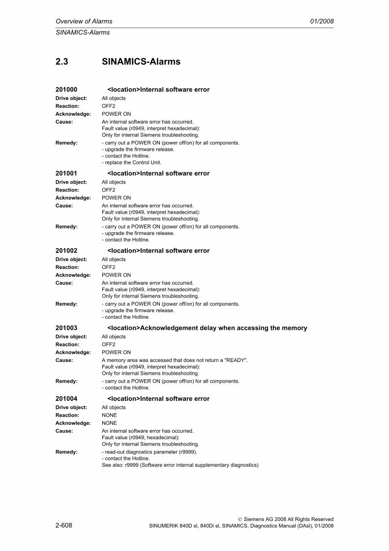
Overview of Alarms 01/2008
SINAMICS-Alarms
2-608
© Siemens AG 2008 All Rights ReservedSINUMERIK 840D sl, 840Di sl, SINAMICS, Diagnostics Manual (DAsl), 01/2008
2.3 SINAMICS-Alarms
201000 <location>Internal software errorDrive object: All objectsReaction: OFF2Acknowledge: POWER ONCause: An internal software error has occurred.
Fault value (r0949, interpret hexadecimal):Only for internal Siemens troubleshooting.
Remedy: - carry out a POWER ON (power off/on) for all components.- upgrade the firmware release.- contact the Hotline.- replace the Control Unit.
201001 <location>Internal software errorDrive object: All objectsReaction: OFF2Acknowledge: POWER ONCause: An internal software error has occurred.
Fault value (r0949, interpret hexadecimal):Only for internal Siemens troubleshooting.
Remedy: - carry out a POWER ON (power off/on) for all components.- upgrade the firmware release.- contact the Hotline.
201002 <location>Internal software errorDrive object: All objectsReaction: OFF2Acknowledge: POWER ONCause: An internal software error has occurred.
Fault value (r0949, interpret hexadecimal):Only for internal Siemens troubleshooting.
Remedy: - carry out a POWER ON (power off/on) for all components.- upgrade the firmware release.- contact the Hotline.
201003 <location>Acknowledgement delay when accessing the memoryDrive object: All objectsReaction: OFF2Acknowledge: POWER ONCause: A memory area was accessed that does not return a "READY".
Fault value (r0949, interpret hexadecimal):Only for internal Siemens troubleshooting.
Remedy: - carry out a POWER ON (power off/on) for all components.- contact the Hotline.
201004 <location>Internal software errorDrive object: All objectsReaction: NONEAcknowledge: NONECause: An internal software error has occurred.
Fault value (r0949, hexadecimal):Only for internal Siemens troubleshooting.
Remedy: - read-out diagnostics parameter (r9999).- contact the Hotline.See also: r9999 (Software error internal supplementary diagnostics)

SINAMICS-Alarms
01/2008 Overview of Alarms
2-609
© Siemens AG 2008 All Rights ReservedSINUMERIK 840D sl, 840Di sl, SINAMICS, Diagnostics Manual (DAsl), 01/2008
201005 <location>Firmware download for DRIVE-CLiQ component unsuccessfulDrive object: All objectsReaction: NONEAcknowledge: IMMEDIATELYCause: Firmware was not able to be downloaded into a DRIVE-CLiQ component.
Fault value (r0949, interpret hexadecimal):xxyyyy hex: xx = component number, yyyy = cause of the faultyyyy = 000B hex = 11 dec:DRIVE-CLiQ component has detected a checksum error.yyyy = 000F hex = 15 dec:The selected DRIVE-CLiQ component did not accept the contents of the firmware file.yyyy = 0012 hex = 18 dec:Firmware version is too old and is not accepted by the component.yyyy = 0013 hex = 19 dec:Firmware version is not suitable for the hardware release of the component.yyyy = 0065 hex = 101 dec:After several communication attempts, not response from the DRIVE-CLiQ component.yyyy = 008B hex = 139 dec:Initially, a new boot loader is loaded (must be repeated after POWER ON).yyyy = 008C hex = 140 dec:Firmware file for the DRIVE-CLiQ component not available on the CompactFlash card.yyyy = 008F hex = 142 dec:Component has not changed into the mode for firmware download.yyyy = 009C hex = 156 dec:Component with the specified component number is not available (p7828).yyyy = Additional values:Only for internal Siemens troubleshooting.
Remedy: - check the selected component number (p7828).- check the DRIVE-CLiQ connection.- save suitable firmware file for download in the directory /siemens/sinamics/code/sac/.- after POWER ON has been carried out again for the DRIVE-CLiQ component, download the firm-ware again.
201006 <location>Firmware update for DRIVE-CLiQ component requiredDrive object: All objectsReaction: NONEAcknowledge: NONECause: The firmware of a DRIVE-CLiQ component must be updated as there is no suitable firmware or firm-
ware version in the component for operation with the Control Unit.Alarm value (r2124, interpret decimal):Component number of the DRIVE-CLiQ component.
Remedy: Firmware update using the commissioning software:The firmware version of all of the components on the "Version overview" page can be read in the Project Navigator under "Configuration" of the associated drive unit and an appropriate firmware update can be carried out.Firmware update via parameter:- take the component number from the alarm value and enter into p7828.- start the firmware download with p7829 = 1.
201007 <location>POWER ON for DRIVE-CLiQ component requiredDrive object: All objectsReaction: NONEAcknowledge: NONECause: A DRIVE-CLiQ component must be powered-up again (POWER ON) as, for example, the firmware
was updated.Alarm value (r2124, interpret decimal):Component number of the DRIVE-CLiQ component.Note:For a component number = 1, a POWER ON of the Control Unit is required.
Remedy: Switch-out the power supply of the specified DRIVE-CLiQ component and switch-in again.

Overview of Alarms 01/2008
SINAMICS-Alarms
2-610
© Siemens AG 2008 All Rights ReservedSINUMERIK 840D sl, 840Di sl, SINAMICS, Diagnostics Manual (DAsl), 01/2008
201008 <location>Upload not possibleDrive object: All objectsReaction: NONEAcknowledge: IMMEDIATELYCause: It is neither possible to upload parameters nor the topology because this would lead to inconsistent
data sets due to the activation of certain drive functions.Fault value (r0949, interpret decimal):Number of active functions that result in the upload being canceled.
Remedy: For all vector drives, check the following functions and if required, de-activate:- rotating measurement (p1960).- record the friction characteristic (p3845).- synchronize line-drive (p3800).
201009 <location>CU: Control board overtemperatureDrive object: All objectsReaction: NONEAcknowledge: NONECause: The temperature (r0037[0]) of the control board (Control Unit) has exceeded the specified limit value.Remedy: - check the air intake for the Control Unit.
- check the fan for the Control Unit (only for CU310).Note:The alarm automatically disappears after the limit value has been fallen below.
201010 <location>Drive type unknownDrive object: All objectsReaction: NONEAcknowledge: IMMEDIATELYCause: An unknown drive type was found.
Fault value (r0949, interpret decimal):Drive object type (refer to p0101, p0107).
Remedy: - carry out a POWER ON (power off/on) for all components.- upgrade the firmware release.- contact the Hotline.
201011 <location>Download interruptedDrive object: All objectsReaction: NONEAcknowledge: IMMEDIATELYCause: The project download was interrupted.
- the user prematurely interrupted the project download.- the communication cable was interrupted (cable breakage, cable withdrawn).Note:The response to an interrupted download is the state "first commissioning".
Remedy: - check the communication cable.- download the project again.- boot from previously saved files (power-down/power-up or p0976).
201012 <location>Project conversion errorDrive object: SERVOReaction: OFF2 (NONE)Acknowledge: IMMEDIATELYCause: When converting the project of an older FW version, a fatal error occurred.
The fault value (r0949) specifies the number of the parameter that caused the error.Notice:For fault value 600, the motor temperature monitoring is no longer guaranteed.
Remedy: The parameter specified in fault value (r0949) must be checked.Notice: For fault value 600 the parameterization of p0600 (motor temperature sensor for monitoring) must be corrected (refer to the function diagram 8016 and parameter description for p0600).

SINAMICS-Alarms
01/2008 Overview of Alarms
2-611
© Siemens AG 2008 All Rights ReservedSINUMERIK 840D sl, 840Di sl, SINAMICS, Diagnostics Manual (DAsl), 01/2008
201015 <location>Internal software errorDrive object: All objectsReaction: OFF2Acknowledge: POWER ONCause: An internal software error has occurred.
Fault value (r0949, interpret decimal):Only for internal Siemens troubleshooting.
Remedy: - carry out a POWER ON (power off/on) for all components.- upgrade the firmware release.- contact the Hotline.
201016 <location>CompactFlash card changedDrive object: All objectsReaction: NONEAcknowledge: NONECause: On the CompactFlash card, at least one file in the directory /SIEMENS/SINAMICS/ has been illegally
changed with respect to that supplied from the factory. No changes are permitted in this directory.Alarm value (r2124, interpret decimal):0: Checksum of one file is incorrect.1: File missing.2: Too many files.3: Incorrect firmware version.4: Incorrect checksum of the back-up file.See also: r9925 (CompactFlash card file error)
Remedy: For the CompactFlash card, restore the status when originally supplied from the factory.Note:The file involved can be read-out using parameter r9925.See also: r9926 (CompactFlash card check status)
201017 <location>Component lists changedDrive object: All objectsReaction: NONEAcknowledge: NONECause: On the CompactFlash card, one file in the directory /SIEMENS/SINAMICS/DATA or
/ADDON/SINAMICS/DATA has been illegally changed with respect to that supplied from the factory. No changes are permitted in this directory.Alarm value (r2124, interpret decimal):The problem is indicated in the first digit of the alarm value:1: File does not exist.2: Firmware version of the file does not match-up with the software version.3: The file checksum is incorrect.The second digit of the alarm value indicates in which directory the file is located:0: Directory /SIEMENS/SINAMICS/DATA/1: Directory /ADDON/SINAMICS/DATA/The third digit of the alarm value indicates the file:0: File MOTARM.ACX1: File MOTSRM.ACX2: File MOTSLM.ACX3: File ENCDATA.ACX4: File FILTDATA.ACX5: File BRKDATA.ACX
Remedy: For the CompactFlash card file involved, restore the status when originally supplied from the factory.
201030 <location>Sign of life failure for master controlDrive object: A_INF, B_INF, SERVO, S_INF, TM41Reaction: A_INFEED: OFF1 (NONE, OFF2)
SERVO: OFF3 (ENCODER, IASC / DCBRAKE, NONE, OFF1, OFF2, STOP1, STOP2)Acknowledge: IMMEDIATELYCause: For active PC master control, no sign-of-life was received within the monitoring time.
The master control was returned to the active BICO interconnection.

Overview of Alarms 01/2008
SINAMICS-Alarms
2-612
© Siemens AG 2008 All Rights ReservedSINUMERIK 840D sl, 840Di sl, SINAMICS, Diagnostics Manual (DAsl), 01/2008
Remedy: Set the monitoring time higher at the PC or, if required, completely disable the monitoring function.For the commissioning software, the monitoring time is set as follows:<Drive> -> Commissioning -> Control panel -> Button "Fetch master control" -> A window is displayed to set the monitoring time in milliseconds.Notice:The monitoring time should be set as short as possible. A long monitoring time means a late response when the communications fail!
201031 <location>Sign of life failure for AOP off in remoteDrive object: A_INF, B_INF, SERVO, S_INFReaction: A_INFEED: OFF1 (NONE, OFF2)
SERVO: OFF3 (ENCODER, IASC / DCBRAKE, NONE, OFF1, OFF2, STOP1, STOP2)Acknowledge: IMMEDIATELYCause: With the off mode active in remove, no sign-of-life was received within the monitoring time.
The master control was returned to the active BICO interconnection.Remedy: Set the monitoring time higher at the AOP or disable completely.
Notice:The monitoring time should be set as short as possible. A long monitoring time means a late response when the communications fail!The monitoring time is set in milliseconds via the Main menu -> Settings -> Control settings -> Timeout monitoring
201033 <location>Units changeover: Reference parameter value invalidDrive object: A_INF, B_INF, SERVO, S_INF, TM41Reaction: NONEAcknowledge: IMMEDIATELYCause: When changing over the units into the referred representation type, it is not permissible that any of the
reference parameters required are equal to 0.0Fault value (r0949, parameter):Reference parameter, whose value is 0.0.See also: p0349 (System of units, motor equivalent circuit diagram data), p0505 (Selecting the system of units), p0595 (Selecting technological units)
Remedy: Set the value of the reference parameter to a number different than 0.0.See also: p0304, p0305, p0310, p0596, p2000, p2001, p2002, p2003, r2004
201034 <location>Units changeover: Calculation parameter values after reference value change unsuccessful
Drive object: A_INF, B_INF, SERVO, S_INF, TM41Reaction: NONEAcknowledge: IMMEDIATELYCause: The change of a reference parameter meant that for a parameter involved, the selected value was not
able to be recalculated in the per unit notation. The change was rejected and the original parameter value restored.Fault value (r0949, parameter):Parameter, whose value was not able to be re-calculated.See also: p0304, p0305, p0310, p0596, p2000, p2001, p2002, p2003, r2004
Remedy: Select the value of the reference parameters so that the parameter involved can be calculated in the per unit notation.See also: p0304, p0305, p0310, p0596, p2000, p2001, p2002, p2003, r2004
201035 <location>ACX: Boot from the back-up parameter back-up filesDrive object: All objectsReaction: NONEAcknowledge: NONECause: When the Control Unit booted, no complete data set was found from the parameter back-up files. The
last time that the parameterization was saved, it was not completely carried out. Instead, a back-up data set or a back-up parameter back-up file is downloaded.Alarm value (r2124, interpret hexadecimal):Only for internal Siemens troubleshooting.

SINAMICS-Alarms
01/2008 Overview of Alarms
2-613
© Siemens AG 2008 All Rights ReservedSINUMERIK 840D sl, 840Di sl, SINAMICS, Diagnostics Manual (DAsl), 01/2008
Remedy: If you have saved the project data using the commissioning software, carry out a new download for your project. Save using the function "Copy RAM to ROM" or with p0977 = 1 so that all of the param-eter files are again completely written into the CompactFlash card.
201036 <location>ACX: Parameter back-up file missingDrive object: All objectsReaction: A_INFEED: NONE (OFF2)
SERVO: NONE (OFF1, OFF2, OFF3)Acknowledge: IMMEDIATELYCause: When downloading the device parameterization, a parameter back-up file associated with a drive
object cannot be found. Neither a PSxxxyyy.ACX, a PSxxxyyy.NEW nor a PSxxxyyy.BAK parameter back-up file exists on the CompactFlash card for this drive object.Fault value (r0949, interpret hexadecimal):Byte 1: yyy in the file name PSxxxyyy.ACXyyy = 000 --> consistency back-up fileyyy = 001 ... 062 --> drive object numberyyy = 099 --> PROFIBUS parameter back-up fileByte 2, 3, 4:Only for internal Siemens troubleshooting.
Remedy: If you have saved your project data using the commissioning software, carry out a new download for your project. Save using the function "Copy RAM to ROM" or with p0977 = 1 so that all of the param-eter files are again completely written into the CompactFlash card.If you have not saved the project data, then the system must be again commissioned for the first time.
201037 <location>ACX: Re-naming the parameter back-up file not successfulDrive object: All objectsReaction: A_INFEED: NONE (OFF2)
SERVO: NONE (OFF1, OFF2, OFF3)Acknowledge: IMMEDIATELYCause: The re-naming after saving a parameter back-up file on the CompactFlash card or in the volatile mem-
ory was unsuccessful.One of the parameter back-up files to be re-named had the "read only" attribute. The parameter back-up files are saved on the CompactFlash card in the directory \USER\SINAMICS\DATA.It is possible that the CompactFlash card is defective.Fault value (r0949, interpret hexadecimal):Byte 1: yyy in the file names PSxxxyyy.* or CAxxxyyy.* or CCxxxyyy.*yyy = 000 --> consistency back-up fileyyy = 099 --> PROFIBUS parameter back-up file PSxxx099.*Byte 2: xxx in the file name PSxxxyyy.*xxx = 000 --> data save started with p0977 = 1xxx = 010 --> data save started with p0977 = 10xxx = 011 --> data save started with p0977 = 11xxx = 012 --> data save started with p0977 = 12Byte 4, 3:Only for internal Siemens troubleshooting.
Remedy: - check whether one of the files to be overwritten has the attribute "read only" and change this file attribute into "writable". Check all of the files (PSxxxyyy.*, CCxxxyyy.*, CAxxxyyy.*) that belong to drive yyy designated in the fault value.- replace the CompactFlash card.
201038 <location>ACX: Loading the parameter back-up file not successfulDrive object: All objectsReaction: A_INFEED: NONE (OFF2)
SERVO: NONE (OFF1, OFF2, OFF3)Acknowledge: IMMEDIATELY

Overview of Alarms 01/2008
SINAMICS-Alarms
2-614
© Siemens AG 2008 All Rights ReservedSINUMERIK 840D sl, 840Di sl, SINAMICS, Diagnostics Manual (DAsl), 01/2008
Cause: An error occurred when loading PSxxxyyy.ACX or PTxxxyyy.ACX files from the CompactFlash card or from the volatile memory of the Control Unit.Fault value (r0949, interpret hexadecimal):Byte 1: yyy in the file name PSxxxyyy.ACXyyy = 000 --> consistency back-up fileyyy = 001 ... 062 --> drive object numberyyy = 099 --> PROFIBUS parameter back-up fileByte 4, 3, 2:Only for internal Siemens troubleshooting.
Remedy: - if you have saved your project data using the commissioning software, carry out a new download for your project. Save using the function "Copy RAM to ROM" or with p0977 = 1 so that all of the param-eter files are again completely written into the CompactFlash card.- replace the CompactFlash card.
201039 <location>ACX: Writing to the parameter back-up file was unsuccessfulDrive object: All objectsReaction: A_INFEED: NONE (OFF2)
SERVO: NONE (OFF1, OFF2, OFF3)Acknowledge: IMMEDIATELYCause: Writing to at least one parameter-back-up file PSxxxyyy.NEW on the CompactFlash card was unsuc-
cessful.- on the CompactFlash card in the directory /USER/SINAMICS/DATA/ at least one parameter back-up file has the "read only" file attribute and cannot be overwritten.- there is not sufficient free memory space on the CompactFlash card.- the CompactFlash card is defective and cannot be written to.Fault value (r0949, interpret hexadecimal):Byte 1: yyy in the file name PSxxxyyy.NEWyyy = 000 --> consistency back-up fileyyy = 001 ... 062 --> drive object numberyyy = 099 --> PROFIBUS parameter back-up fileByte 2: xxx in the file name PSxxxyyy.NEWxxx = 000 --> data save started with p0977 = 1xxx = 010 --> data save started with p0977 = 10xxx = 011 --> data save started with p0977 = 11xxx = 012 --> data save started with p0977 = 12Byte 4, 3:Only for internal Siemens troubleshooting.
Remedy: - check the file attribute of the files (PSxxxyyy.*, CAxxxyyy.*, CCxxxyyy.*) and, if required, change from "read only" to "writeable".- check the free memory space on the CompactFlash card. Approx. 40 kbyte of free memory space is required for every drive object in the system.- replace the CompactFlash card.
201040 <location>Save parameter settings and carry out a POWER ONDrive object: All objectsReaction: OFF2Acknowledge: POWER ONCause: A parameter was changed in the drive system that means that it is necessary to save the parameters
and re-boot (e.g. p0110).Remedy: - save the parameters (p0971/p0977).
- carry out a POWER ON (power off/on) for all components.
201041 <location>Parameter save necessaryDrive object: All objectsReaction: NONEAcknowledge: IMMEDIATELY

SINAMICS-Alarms
01/2008 Overview of Alarms
2-615
© Siemens AG 2008 All Rights ReservedSINUMERIK 840D sl, 840Di sl, SINAMICS, Diagnostics Manual (DAsl), 01/2008
Cause: Defective or missing files were detected on the CompactFlash card when booting.Fault value (r0949, interpret decimal):-1: Source file cannot be opened.-2: Source file cannot be read.-3: Target directory cannot be set-up.-4: Target file cannot be set-up/opened.-5: Target file cannot be written into.Additional values:Only for internal Siemens troubleshooting.
Remedy: - save the parameters (p0977).- download the project again into the drive unit.- update the firmware- if required, replace the Control Unit and/or CompactFlash card.
201042 <location>Parameter error for a project downloadDrive object: All objectsReaction: A_INFEED: OFF2 (NONE, OFF1)
SERVO: OFF2 (NONE, OFF1, OFF3)Acknowledge: IMMEDIATELY

Overview of Alarms 01/2008
SINAMICS-Alarms
2-616
© Siemens AG 2008 All Rights ReservedSINUMERIK 840D sl, 840Di sl, SINAMICS, Diagnostics Manual (DAsl), 01/2008
Cause: An error was detected when downloading a project using the commissioning (start-up) software (e.g. incorrect parameter value).For the specified parameter, it was detected that dynamic limits were exceeded that could possibly depend on other parameters.Fault value (r0949, interpret decimal):Low word: Parameter number (16 bits without sign)Byte 3: Parameter indexByte 4: Error ID0: Parameter number illegal.1: Parameter value cannot be changed.2: Lower or upper value limit exceeded.3: Sub-index incorrect.4: No array, no sub-index.5: Data type incorrect.6: Setting not permitted (only resetting).7: Descriptive element cannot be changed.9: Descriptive data not available.11: No master control.15: No text array present.17: Task cannot be executed due to operating status.20: Illegal value.21: Response too long.22: Parameter address illegal.23: Format illegal.24: Number of values not consistent.25: Drive object does not exist.101: Presently de-activated.104: Illegal value.107: Write access not permitted when controller enabled.108: Units unknown.109: Write access only in the commissioning state, encoder (p0010 = 4).110: Write access only in the commissioning state, motor (p0010 = 3).111: Write access only in the commissioning state, power unit (p0010 = 2).112: Write access only in the quick commissioning mode (p0010 = 1).113: Write access only in the ready mode (p0010 = 0).114: Write access only in the commissioning state, parameter reset (p0010 = 30).115: Write access only in the Safety Integrated commissioning state (p0010 = 95).116: Write access only in the commissioning state, technological application/units (p0010 = 5).117: Write access only in the commissioning state (p0010 not equal to 0).118: Write access only in the commissioning state, download (p0010 = 29).119: Parameter may not be written into in download.120: Write access only in the commissioning state – drive basis configuration (device: p0009 = 3).121: Write access only in the commissioning state – define drive type (device: p0009 = 2).122: Write access only in the commissioning state – data set basis configuration (device: p0009 = 4).123: Write access only in the commissioning state – device configuration (device: p0009 = 1).124: Write access only in the commissioning state – device download (device: p0009 = 29).125: Write access only in the commissioning state – device parameter reset (device: p0009 = 30).126: Write access only in the commissioning state – device ready (device: p0009 = 0).127: Write access only in the commissioning state – device (device: p0009 not equal to 0).129: Parameter may not be written into in download.130: Transfer of the master control is inhibited via BI: p0806.131: Required BICO interconnection not possible, because BICO output does not supply floating value132: Free BICO interconnection inhibited via p0922.133: Access method not defined.200: Below the valid values.201: Above the valid values.202: Cannot be accessed from the Basic Operator Panel (BOP).203: Cannot be read from the Basic Operator Panel (BOP).204: Write access not permitted.
Remedy: - enter the correct value into the specified parameter.- identify the parameter that narrows (restricts) the limits of the specified parameter.
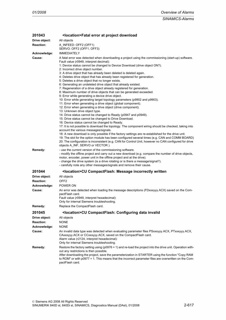
SINAMICS-Alarms
01/2008 Overview of Alarms
2-617
© Siemens AG 2008 All Rights ReservedSINUMERIK 840D sl, 840Di sl, SINAMICS, Diagnostics Manual (DAsl), 01/2008
201043 <location>Fatal error at project downloadDrive object: All objectsReaction: A_INFEED: OFF2 (OFF1)
SERVO: OFF2 (OFF1, OFF3)Acknowledge: IMMEDIATELYCause: A fatal error was detected when downloading a project using the commissioning (start-up) software.
Fault value (r0949, interpret decimal):1: Device status cannot be changed to Device Download (drive object ON?).2: Incorrect drive object number.3: A drive object that has already been deleted is deleted again.4: Deletes drive object that has already been registered for generation.5: Deletes a drive object that no longer exists.6: Generating an undeleted drive object that already existed.7: Regeneration of a drive object already registered for generation.8: Maximum number of drive objects that can be generated exceeded.9: Error while generating a device drive object.10: Error while generating target topology parameters (p9902 and p9903).11: Error when generating a drive object (global component).12: Error when generating a drive object (drive component).13: Unknown drive object type.14: Drive status cannot be changed to Ready (p0947 and p0949).15: Drive status cannot be changed to Drive Download.16: Device status cannot be changed to Ready.17: It is not possible to download the topology. The component wiring should be checked, taking into account the various messages/signals.18: A new download is only possible if the factory settings are re-established for the drive unit.19: The slot for the option module has been configured several times (e.g. CAN and COMM BOARD)20: The configuration is inconsistent (e.g. CAN for Control Unit, however no CAN configured for drive objects A_INF, SERVO or VECTOR ).
Remedy: - use the current version of the commissioning software.- modify the offline project and carry out a new download (e.g. compare the number of drive objects, motor, encoder, power unit in the offline project and at the drive).- change the drive system (is a drive rotating or is there a message/signal?).- carefully note any other messages/signals and remove their cause.
201044 <location>CU CompactFlash: Message incorrectly writtenDrive object: All objectsReaction: OFF2Acknowledge: POWER ONCause: An error was detected when loading the message descriptions (FDxxxyyy.ACX) saved on the Com-
pactFlash card.Fault value (r0949, interpret hexadecimal):Only for internal Siemens troubleshooting.
Remedy: Replace the CompactFlash card.
201045 <location>CU CompactFlash: Configuring data invalidDrive object: All objectsReaction: NONEAcknowledge: NONECause: An invalid data type was detected when evaluating parameter files PSxxxyyy.ACX, PTxxxyyy.ACX,
CAxxxyyy.ACX or CCxxxyyy.ACX, saved on the CompactFlash card.Alarm value (r2124, interpret hexadecimal):Only for internal Siemens troubleshooting.
Remedy: Restore the factory setting using (p0976 = 1) and re-load the project into the drive unit. Operation with-out any restrictions is then possible.After downloading the project, save the parameterization in STARTER using the function "Copy RAM to ROM" or with p0977 = 1. This means that the incorrect parameter files are overwritten on the Com-pactFlash card.

Overview of Alarms 01/2008
SINAMICS-Alarms
2-618
© Siemens AG 2008 All Rights ReservedSINUMERIK 840D sl, 840Di sl, SINAMICS, Diagnostics Manual (DAsl), 01/2008
201046 <location>CU CompactFlash: Configuring data invalidDrive object: All objectsReaction: NONEAcknowledge: NONECause: An invalid data type was detected when evaluating the parameter files PSxxxyyy.ACX, PTxxx-
yyy.ACX, CAxxxyyy.ACX or CCxxxyyy.ACX saved on the CompactFlash card.Alarm value (r2124, interpret hexadecimal):Only for internal Siemens troubleshooting.
Remedy: Restore the factory setting using (p0976 = 1) and re-load the project into the drive unit. Operation with-out any restrictions is then possible.After downloading the project, save the parameterization in STARTER using the function "Copy RAM to ROM" or with p0977 = 1, so that the incorrect parameter files are overwritten on the CompactFlash card.
201047 <location>ACX: Write to parameter errorDrive object: All objectsReaction: NONEAcknowledge: NONECause: When evaluating the parameters files PSxxxyyy.ACX, PTxxxyyy.ACX, CAxxxyyy.ACX or CCxxx-
yyy.ACX, saved on the CompactFlash card, a parameter value was not able to be transferred into the Control Unit memory.Alarm value (r2124, interpret hexadecimal):Only for internal Siemens troubleshooting.
Remedy: Restore the factory setting using (p0976 = 1) and re-load the project into the drive unit. Operation with-out any restrictions is then possible.After downloading the project, save the parameterization in STARTER using the function "Copy RAM to ROM" or with p0977 = 1. This means that the incorrect parameter files are overwritten on the Com-pactFlash card.
201049 <location>CU CompactFlash: It is not possible write to fileDrive object: All objectsReaction: NONEAcknowledge: NONECause: It is not possible to write into a write-protective file (PSxxxxxx.acx). The write request was interrupted.
Alarm value (r2124, interpret decimal):Drive object number.
Remedy: Check whether the "write protected" attribute has been set for the files on the CompactFlash card under .../USER/SINAMICS/DATA/... When required, remove write protection and save again (e.g. set p0971 to 1).
201050 <location>CompactFlash card and device not compatibleDrive object: All objectsReaction: A_INFEED: OFF2 (NONE, OFF1)
SERVO: OFF2 (NONE, OFF1, OFF3)Acknowledge: IMMEDIATELYCause: The CompactFlash card and the device type do not match (e.g. a CompactFlash card for SINAMICS
S is inserted in SINAMICS G).Remedy: - insert the matching CompactFlash card
- use the matching Control Unit or power unit.
201051 <location>Drive object type is not availableDrive object: All objectsReaction: NONEAcknowledge: IMMEDIATELYCause: The drive object type in conjunction with the selected application-specific perspective is not available.
The required descriptive file (PDxxxyyy.ACX) does not exist on the CompactFlash card.Fault value (r0949, interpret decimal):Index of p0103 and p0107.See also: p0103, r0103, p0107, r0107

SINAMICS-Alarms
01/2008 Overview of Alarms
2-619
© Siemens AG 2008 All Rights ReservedSINUMERIK 840D sl, 840Di sl, SINAMICS, Diagnostics Manual (DAsl), 01/2008
Remedy: - for this drive object type (p0107), select a valid application-specific perspective (p0103).- save the required descriptive file (PDxxxyyy.ACX) on the CompactFlash card.See also: p0103, r0103, p0107, r0107
201052 <location>CU: System overload calculated for the complete target topology
Drive object: All objectsReaction: NONEAcknowledge: NONECause: A system overload was calculated based on a complete active target topology.
Alarm value (r2124, interpret decimal):2: Computation time load too high.6: Cyclic computation time load too high.
Remedy: - reduce the sampling time.- only use one data set (CDS, DDS).- de-activate the function module.- de-activate the drive object.- remove the drive object from the target topology.Note:After executing the appropriate counter-measure, a new calculation must be initiated with p9974 = 1.
201053 <location>CU: System overload measuredDrive object: All objectsReaction: NONEAcknowledge: NONECause: A system overload was determined based on measured values.
Alarm value (r2124, interpret decimal):2: Computation time load too high.6: Cyclic computation time load too high.See also: r9976 (System load)
Remedy: - reduce the sampling time.- only use one data set (CDS, DDS).- de-activate the function module.- de-activate the drive object.- remove the drive object from the target topology.
201064 <location>CU: Internal error (CRC)Drive object: All objectsReaction: NONEAcknowledge: NONECause: CRC error in the Control Unit program memoryRemedy: - carry out a POWER ON (power off/on) for all components.
- upgrade the firmware release.- contact the Hotline.
201065 <location>Drive: Fault for non-active encoderDrive object: SERVOReaction: NONEAcknowledge: NONECause: On or several inactive encoders indicate an error.Remedy: Remove the error for the inactive encoder.
201099 <location>Tolerance window of the timer synchronization exitedDrive object: All objectsReaction: NONEAcknowledge: NONECause: The clock (time) master exited the selected tolerance window for clock synchronization.
See also: p3109 (RTC real time synchronization, tolerance window)

Overview of Alarms 01/2008
SINAMICS-Alarms
2-620
© Siemens AG 2008 All Rights ReservedSINUMERIK 840D sl, 840Di sl, SINAMICS, Diagnostics Manual (DAsl), 01/2008
Remedy: Select the re-synchronization interval so that the synchronization deviation between the clock master and drive system lies within the tolerance window.See also: r3108 (RTC last synchronization deviation)
201100 <location>CU: CompactFlash card withdrawnDrive object: All objectsReaction: NONEAcknowledge: NONECause: The CompactFlash card (non-volatile memory) was withdrawn in operation.
Notice:It is not permissible that the CompactFlash card is withdrawn or inserted under voltage.
Remedy: - power-down the drive system.- re-insert the CompactFlash card that was withdrawn - this card must match the drive system.- power-up the drive system again.
201105 <location>CU: Insufficient memoryDrive object: All objectsReaction: OFF1Acknowledge: IMMEDIATELY (POWER ON)Cause: Too many functions have been configured on this Control Unit e.g. too many drives, function modules,
data sets, OA applications, blocks, etc).Fault value (r0949, interpret decimal):Only for internal Siemens troubleshooting.
Remedy: - change the configuration on this Control Unit (e.g. fewer drive, function modules, data sets, OA appli-cations, blocks, etc).- use an additional Control Unit.
201107 <location>CU: Save to CompactFlash card unsuccessfulDrive object: All objectsReaction: NONEAcknowledge: IMMEDIATELYCause: A data save on the CompactFlash card was not able to be successfully carried out.
- CompactFlash card is defective.- CompactFlash card does not have sufficient memory space.Fault value (r0949, interpret decimal):-1: The file on the RAM was not able to be opened.-2: The file on the RAM was not able to be read.-3: A new directory was not able to be set-up on the CompactFlash card.-4: A new file was not able to be set-up on the CompactFlash card.-5: A new file was not able to be written onto the CompactFlash card.
Remedy: - try to save again.- use another CompactFlash card.
201110 <location>CU: More than one SINAMICS G on one Control UnitDrive object: All objectsReaction: NONEAcknowledge: IMMEDIATELYCause: More than one SINAMICS G power unit type is being operated from the Control Unit.
Fault value (r0949, interpret decimal):Number of the second drive with a SINAMICS G power unit type.
Remedy: Only one SINAMICS G drive type is permitted.
201111 <location>CU: SINAMICS S and G together on one Control UnitDrive object: All objectsReaction: NONEAcknowledge: IMMEDIATELYCause: SINAMICS S and G drive units are being operated together on one Control Unit.
Fault value (r0949, interpret decimal):Number of the first drive object with a different power unit type.
Remedy: Only power units of one particular drive type may be operated with one Control Unit.

SINAMICS-Alarms
01/2008 Overview of Alarms
2-621
© Siemens AG 2008 All Rights ReservedSINUMERIK 840D sl, 840Di sl, SINAMICS, Diagnostics Manual (DAsl), 01/2008
201112 <location>CU: Power unit not permissibleDrive object: All objectsReaction: NONEAcknowledge: IMMEDIATELYCause: The connected power unit cannot be used together with this Control Unit.
Fault value (r0949, interpret decimal):1: Power unit is not supported (e.g. PM240).2: DC/AC power unit connected to CU310 not permissible.
Remedy: Replace the power unit that is not permissible by a component that is permissible.
201120 <location>Terminal initialization has failedDrive object: All objectsReaction: OFF1 (OFF2)Acknowledge: IMMEDIATELY (POWER ON)Cause: An internal software error has occurred when initializing the terminal functions on the CU3xx, the TB30
or the TM31.Fault value (r0949, interpret hexadecimal):Only for internal Siemens troubleshooting.
Remedy: - carry out a POWER ON (power off/on) for all components.- upgrade the firmware release.- contact the Hotline.- replace the Control Unit.
201122 <location>Frequency at the measuring probe input too highDrive object: All objectsReaction: OFF1 (OFF2)Acknowledge: IMMEDIATELYCause: The frequency of the pulses at the measuring probe input is too high.
Fault value (r0949, interpret decimal):1: DI/DO 9 (X122.8)2: DI/DO 10 (X122.10)4: DI/DO 11 (X122.11)8: DI/DO 13 (X132.8)16: DI/DO 14 (X132.10)32: DI/DO 15 (X132.11)1001: DI/DO 9 (X122.8), initialization error1002: DI/DO 10 (X122.10), initialization error1004: DI/DO 11 (X122.11), initialization error1008: DI/DO 13 (X132.8), initialization error1016: DI/DO 14 (X132.10), initialization error1032: DI/DO 15 (X132.11), initialization error
Remedy: Reduce the frequency of the pulses at the measuring probe input.
201150 <location>CU: Number of instances of a drive object type exceededDrive object: All objectsReaction: NONEAcknowledge: IMMEDIATELYCause: The maximum permissible number of instances of a drive object type was exceeded.
Fault value (r0949, interpret decimal):Byte 1: Drive object type (p0107).Byte 2: Max. permissible number of instances for this drive object type.Byte 3: Actual number of instances for this drive object type.
Remedy: - power-down the unit.- suitably restrict the number of instances of a drive object type by reducing the number of inserted components.- re-commission the unit.

Overview of Alarms 01/2008
SINAMICS-Alarms
2-622
© Siemens AG 2008 All Rights ReservedSINUMERIK 840D sl, 840Di sl, SINAMICS, Diagnostics Manual (DAsl), 01/2008
201205 <location>CU: Time slice overflowDrive object: All objectsReaction: OFF2Acknowledge: POWER ONCause: Insufficient processing time is available for the existing topology.
Fault value (r0949, interpret hexadecimal):Only for internal Siemens troubleshooting.
Remedy: - reduce the number of drives.- increase the sampling times.
201210 <location>CU: Basic clock cycle selection and DRIVE-CLiQ clock cycles do not match
Drive object: All objectsReaction: NONEAcknowledge: IMMEDIATELYCause: The parameter to select the basic clock cycle does not match the drive topology. Drives connected to
the same DRIVE-CLiQ port of the Control Unit have been assigned different basic clock cycles.Fault value (r0949, interpret decimal):The fault value specifies the parameter involved.See also: r0111 (Basis sampling time selection)
Remedy: Only those drive objects may be connected to the same DRIVE-CLiQ socket of the Control Unit that should run with the same basic clock cycle.For example, Active Line Modules and Motor Modules should be inserted at different DRIVE-CLiQ sockets as their basic clock cycles and current controller clock cycles are generally different.See also: r0111 (Basis sampling time selection)
201220 <location>CU: Bas clk cyc too lowDrive object: All objectsReaction: NONEAcknowledge: IMMEDIATELYCause: The parameter for the basic clock cycle is set too short for the number of connected drives.
Fault value (r0949, interpret decimal):The fault value specifies the parameter involved.See also: r0110 (Basis sampling times)
Remedy: - increase the basic clock cycle.- reduce the number of connected drives and start to re-commission the unit.See also: r0110 (Basis sampling times)
201221 <location>CU: Bas clk cyc too lowDrive object: All objectsReaction: NONEAcknowledge: IMMEDIATELYCause: The closed-loop control / monitoring cannot maintain the intended clock cycle.
The runtime of the closed-loop control/monitoring is too long for the particular clock cycle or the com-putation time remaining in the system is not sufficient for the closed-loop control/monitoring.Fault value (r0949, interpret hexadecimal):Only for internal Siemens troubleshooting.
Remedy: Increase the basic clock cycle of DRIVE-CLiQ communications.See also: p0112 (Sampling times pre-setting p0115)
201223 <location>CU: Sampling time inconsistentDrive object: All objectsReaction: NONEAcknowledge: NONE

SINAMICS-Alarms
01/2008 Overview of Alarms
2-623
© Siemens AG 2008 All Rights ReservedSINUMERIK 840D sl, 840Di sl, SINAMICS, Diagnostics Manual (DAsl), 01/2008
Cause: When changing a sampling time (p0115[0], p0799 or p4099), inconsistency between the clock cycles has been identified.Alarm value (r2124, interpret decimal):1: Value, low minimal value.2: Value, high maximum value.3: Value not a multiple of 1.25 µs.4: Value does not match clock cycle synchronous PROFIBUS operation.5: Value not a multiple of 125 µs.6: Value not a multiple of 250 µs.7: Value not a multiple of 375 µs.8: Value not a multiple of 400 µs.10: Special restriction of the drive object violated.20: For a SERVO with a 62.5 µs sampling time, more than a maximum of two SERVO-type drive objects were detected on the DRIVE-CLiQ line (no other drive object is permitted on this line).21: Value can be a multiple of the current controller sampling time of a servo or vector drive in the system (e.g. for TB30, the values of all of the indices should be taken into account).30: Value less than 31.25 µs.31: Value less than 62.5 µs.32: Value less than 125 µs.40: Nodes (devices) have been identified on the DRIVE-CLiQ line whose highest common denomina-tor of the sampling times is less than 125 µs. Further, none of the nodes (devices) has a sampling tine of less than 125 µs.41: A chassis unit was identified on the DRIVE-CLiQ line. Further, the highest common denominator of the sampling times of the all of the nodes (devices) connected to the line is less than 250 µs.42: An Active Line Module was identified on the DRIVE-CLiQ line as device. Further, the highest com-mon denominator of the sampling times of the all of the nodes (devices) connected to the line is less than 125 µs.43: A Voltage Sensing Module (VSM) was identified on the DRIVE-CLiQ line as device. Further, the highest common denominator of the sampling times of the all of the nodes (devices) connected to the line is not equal to the current controller sampling time of the drive object of the VSM.44: The highest common denominator of the sampling times of all of the components connected to the DRIVE-CLiQ line is not the same for all components of this drive object (e.g. there are components on different DRIVE-CLiQ lines on which different highest common denominators are generated).52: Nodes (devices) have been identified on the DRIVE-CLiQ line whose highest common denomina-tor of the sampling times is less than 31.25 µs.54: Nodes (devices) have been identified on the DRIVE-CLiQ line whose highest common denomina-tor of the sampling times is less than 62.5 µs.56: Nodes (devices) have been identified on the DRIVE-CLiQ line whose highest common denomina-tor of the sampling times is less than 125 µs.58: Nodes (devices) have been identified on the DRIVE-CLiQ line whose highest common denomina-tor of the sampling times is less than 250 µs.99: Inconsistency identified cross drive objects.116: Recommended clock cycle in r0116[0...1].Note:The topology rules should be noted when connected-up DRIVE-CLiQ.The rules are, provided in the following document:SINAMICS S120 Function ManualThe parameters of the sampling times can also be changed with automatic calculations.
Remedy: - check the DRIVE-CLiQ cables.- set a valid sampling time.See also: p0115, p0799, p4099
201224 <location>CU: Pulse frequency inconsistentDrive object: All objectsReaction: NONEAcknowledge: NONE
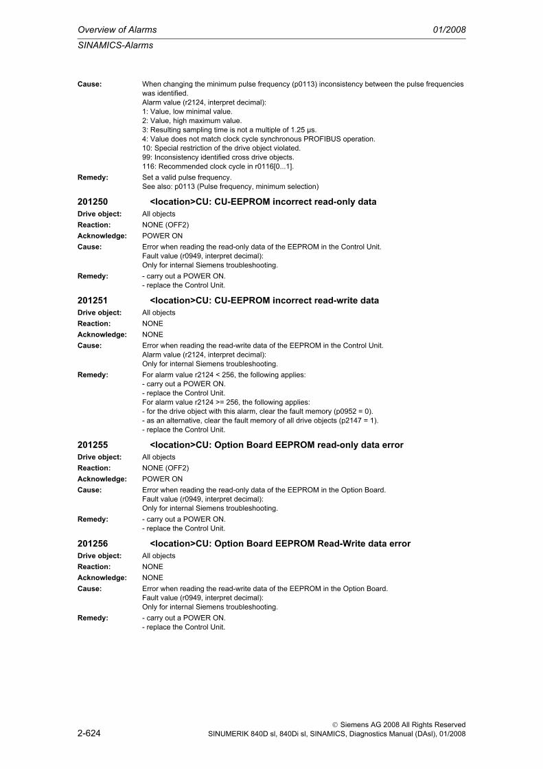
Overview of Alarms 01/2008
SINAMICS-Alarms
2-624
© Siemens AG 2008 All Rights ReservedSINUMERIK 840D sl, 840Di sl, SINAMICS, Diagnostics Manual (DAsl), 01/2008
Cause: When changing the minimum pulse frequency (p0113) inconsistency between the pulse frequencies was identified.Alarm value (r2124, interpret decimal):1: Value, low minimal value.2: Value, high maximum value.3: Resulting sampling time is not a multiple of 1.25 µs.4: Value does not match clock cycle synchronous PROFIBUS operation.10: Special restriction of the drive object violated.99: Inconsistency identified cross drive objects.116: Recommended clock cycle in r0116[0...1].
Remedy: Set a valid pulse frequency.See also: p0113 (Pulse frequency, minimum selection)
201250 <location>CU: CU-EEPROM incorrect read-only dataDrive object: All objectsReaction: NONE (OFF2)Acknowledge: POWER ONCause: Error when reading the read-only data of the EEPROM in the Control Unit.
Fault value (r0949, interpret decimal):Only for internal Siemens troubleshooting.
Remedy: - carry out a POWER ON.- replace the Control Unit.
201251 <location>CU: CU-EEPROM incorrect read-write dataDrive object: All objectsReaction: NONEAcknowledge: NONECause: Error when reading the read-write data of the EEPROM in the Control Unit.
Alarm value (r2124, interpret decimal):Only for internal Siemens troubleshooting.
Remedy: For alarm value r2124 < 256, the following applies:- carry out a POWER ON.- replace the Control Unit.For alarm value r2124 >= 256, the following applies:- for the drive object with this alarm, clear the fault memory (p0952 = 0).- as an alternative, clear the fault memory of all drive objects (p2147 = 1).- replace the Control Unit.
201255 <location>CU: Option Board EEPROM read-only data errorDrive object: All objectsReaction: NONE (OFF2)Acknowledge: POWER ONCause: Error when reading the read-only data of the EEPROM in the Option Board.
Fault value (r0949, interpret decimal):Only for internal Siemens troubleshooting.
Remedy: - carry out a POWER ON.- replace the Control Unit.
201256 <location>CU: Option Board EEPROM Read-Write data errorDrive object: All objectsReaction: NONEAcknowledge: NONECause: Error when reading the read-write data of the EEPROM in the Option Board.
Fault value (r0949, interpret decimal):Only for internal Siemens troubleshooting.
Remedy: - carry out a POWER ON.- replace the Control Unit.

SINAMICS-Alarms
01/2008 Overview of Alarms
2-625
© Siemens AG 2008 All Rights ReservedSINUMERIK 840D sl, 840Di sl, SINAMICS, Diagnostics Manual (DAsl), 01/2008
201303 <location>DRIVE-CLiQ component does not support the required function
Drive object: All objectsReaction: OFF2Acknowledge: IMMEDIATELYCause: A function requested by the Control Unit is not supported by a DRIVE-CLiQ component.
Fault value (r0949, interpret decimal):1: The component does not support the de-activation.101: The Motor Module does not support an internal armature short-circuit.102: The Motor Module does not support the de-activation.201: The Sensor Module does not support actual value inversion (p0410.0 = 1) when using a Hall sen-sor (p0404.6 = 1) for the commutation.202: The Sensor Module does not support parking/unparking.203: The Sensor Module does not support the de-activation.204: The firmware of this Terminal Module 15 (TM15) does not support the application TM15DI/DO.205: The Sensor Module does not support the selected temperature evaluation (r0458).206: The firmware of this Terminal Modules TM41/TM31/TM15 refers to an old firmware version. It is urgently necessary to upgrade the firmware to ensure disturbance-free operation.207: The infeed with this hardware version does not support operation with device supply voltages of less than 380 V.
Remedy: Upgrade the firmware of the DRIVE-CLiQ component involved.Re fault value = 205:Check parameter p0600 and p0601 and if required, adapt interpretation.Re fault value = 207:Replace the infeed or if required set the device supply voltage higher (p0210).
201304 <location>Firmware version of DRIVE-CLiQ component is not up-to-dateDrive object: All objectsReaction: NONEAcknowledge: NONECause: On the CompactFlash card, there is a later firmware version than in the connected DRIVE-CLiQ com-
ponent.Alarm value (r2124, interpret decimal):Component number of the DRIVE-CLiQ component involved.
Remedy: Update the firmware (p7828, p7829 and commissioning software).
201305 <location>Topology: Component number missingDrive object: All objectsReaction: NONEAcknowledge: IMMEDIATELYCause: The component number from the topology was not parameterized (p0121 (for power unit, refer to
p0107), p0131 (for servo/vector drives, refer to p0107), p0141, p0151, p0161).Fault value (r0949, interpret decimal):The fault value includes the particular data set number.The fault also occurs if speed encoders were configured (p0187 ... p0189), however, no component numbers exist for them.In this case, the fault value includes the drive data set number plus 100 * encoder number (e.g. 3xx, if a component number was not entered into p0141 for the third encoder (p0189)).See also: p0121, p0131, p0141, p0142, p0151, p0186, p0187, p0188, p0189
Remedy: Enter the missing component number or remove the component and restart commissioning.See also: p0121, p0131, p0141, p0142, p0151, p0186, p0187, p0188, p0189
201306 <location>Firmware of the DRIVE-CLiQ component being updatedDrive object: All objectsReaction: NONEAcknowledge: NONECause: Firmware update is active for at least one DRIVE-CLiQ component.
Alarm value (r2124, interpret decimal):Component number of the DRIVE-CLiQ component.

Overview of Alarms 01/2008
SINAMICS-Alarms
2-626
© Siemens AG 2008 All Rights ReservedSINUMERIK 840D sl, 840Di sl, SINAMICS, Diagnostics Manual (DAsl), 01/2008
Remedy: None necessary.This alarm automatically disappears after the firmware has been updated.
201314 <location>Topology: Component must not be presentDrive object: All objectsReaction: NONEAcknowledge: NONECause: For a component, "de-activate and not present" is set but this component is still in the topology.
Alarm value (r2124, interpret hexadecimal):Byte 1: Component numberByte 2: Component class of the componentByte 3: Connection numberNote: Component class and connection number are described in F01375.
Remedy: - remove the corresponding component.- change the setting "de-activat and not present".Note:Under "Topology --> Topology view" the commissioning software offers improved diagnostics capa-bility (e.g. setpoint/actual value comparison).See also: p0105, p0125, p0145
201315 <location>Drive object not ready for operationDrive object: All objectsReaction: NONEAcknowledge: NONECause: For the active drive object involved, at least one activated component is missing.
Note:All other active and operational drive objects can be in the "RUN" state.
Remedy: The alarm automatically disappears again with the following actions:- de-activate the drive object involved (p0105 = 0).- de-activate the components involved (p0125 = 0, p0145 = 0, p0155 = 0, p0165 = 0).- re-insert the components involved.See also: p0105, p0125, p0145
201316 <location>Drive object inactive and again ready for operationDrive object: All objectsReaction: NONEAcknowledge: NONECause: If, when inserting a component of the target topology, an inactive, non-operational drive object
becomes operational again. The associated parameter of the component is, in this case, set to "acti-vate" (p0125, p0145, p0155, p0165).Note:This is the only message, that is displayed for a de-activated drive object.
Remedy: The alarm automatically disappears again with the following actions:- activate the drive object involved (p0105 = 1).- again withdraw the components involved.See also: p0105 (Activate/de-activate drive object)
201317 <location>De-activated component again presentDrive object: All objectsReaction: NONEAcknowledge: NONECause: If a component of the target topology for an active drive object is inserted and the associated param-
eter of the component is set to "de-activate" (p0125, p0145, p0155, p0165).Note:This is the only message, that is displayed for a de-activated component.
Remedy: The alarm automatically disappears again with the following actions:- activate the components involved (p0125 = 1, p0145 = 1, p0155 = 1, p0165 = 1).- again withdraw the components involved.See also: p0125 (Activate/de-activate power unit components), p0145

SINAMICS-Alarms
01/2008 Overview of Alarms
2-627
© Siemens AG 2008 All Rights ReservedSINUMERIK 840D sl, 840Di sl, SINAMICS, Diagnostics Manual (DAsl), 01/2008
201318 <location>BICO: De-activated interconnections presentDrive object: All objectsReaction: NONEAcknowledge: NONECause: This alarm is output:
If an inactive/non-operational drive object is again active/ready for operationandr9498[] or r9499[] are not emptyandthe connections listed in r9498[] and r9499 have actually been changed
Remedy: Clear alarm:Set p9496 to 1 or 2orde-activate DO
201319 <location>Inserted component not initializedDrive object: A_INF, B_INF, CU_LINK, DMC20, SERVO, S_INF, TM15, TM15DI_DO, TM17, TM31, TM41,
TM54F_MA, TM54F_SLReaction: NONEAcknowledge: NONECause: The inserted component has still not been initiated, as the pulses are enabled.Remedy: Pulse inhibit
201320 <location>Topology: Drive object number does not exist in configurationDrive object: All objectsReaction: NONEAcknowledge: NONECause: A drive object number is missing in p0978
Alarm value (r2124, interpret decimal):Index of p0101 under which the missing drive object number can be determined.
Remedy: Set p0009 to 1 and change p0978:Rules:- p0978 must include all of the drive object numbers (p0101).- it is not permissible that a drive object number is repeated.- by entering a 0, the drive objects with PZD are separated from those without PZD.- only 2 partial lists are permitted. After the second 0, all values must be 0.- dummy drive object numbers (255) are only permitted in the first partial list.
201321 <location>Topology: Drive object number does not exist in configurationDrive object: All objectsReaction: NONEAcknowledge: NONECause: p0978 contains a drive object number that does not exist.
Alarm value (r2124, interpret decimal):Index of p0978 under which the drive object number can be determined.
Remedy: Set p0009 to 1 and change p0978:Rules:- p0978 must include all of the drive object numbers (p0101).- it is not permissible that a drive object number is repeated.- by entering a 0, the drive objects with PZD are separated from those without PZD.- only 2 partial lists are permitted. After the second 0, all values must be 0.- dummy drive object numbers (255) are only permitted in the first partial list.
201322 <location>Topology: Drive object number present twice in configurationDrive object: All objectsReaction: NONEAcknowledge: NONE

Overview of Alarms 01/2008
SINAMICS-Alarms
2-628
© Siemens AG 2008 All Rights ReservedSINUMERIK 840D sl, 840Di sl, SINAMICS, Diagnostics Manual (DAsl), 01/2008
Cause: A drive object number is present more than once in p0978.Alarm value (r2124, interpret decimal):Index of p0978 under which the involved drive object number is located.
Remedy: Set p0009 to 1 and change p0978:Rules:- p0978 must include all of the drive object numbers (p0101).- it is not permissible that a drive object number is repeated.- by entering a 0, the drive objects with PZD are separated from those without PZD.- only 2 partial lists are permitted. After the second 0, all values must be 0.- dummy drive object numbers (255) are only permitted in the first partial list.
201323 <location>Topology: More than two part lists set-upDrive object: All objectsReaction: NONEAcknowledge: NONECause: Partial lists are available more than twice in p0978. After the second 0, all must be 0.
Alarm value (r2124, interpret decimal):Index of p0978, under which the illegal value is located.
Remedy: Set p0009 to 1 and change p0978:Rules:- p0978 must include all of the drive object numbers (p0101).- it is not permissible that a drive object number is repeated.- by entering a 0, the drive objects with PZD are separated from those without PZD.- only 2 partial lists are permitted. After the second 0, all values must be 0.- dummy drive object numbers (255) are only permitted in the first partial list.
201324 <location>Topology: Dummy drive object number incorrectly set-upDrive object: All objectsReaction: NONEAcknowledge: NONECause: In p0978, dummy drive object numbers (255) are only permitted in the first partial list.
Alarm value (r2124, interpret decimal):Index of p0978, under which the illegal value is located.
Remedy: Set p0009 to 1 and change p0978:Rules:- p0978 must include all of the drive object numbers (p0101).- it is not permissible that a drive object number is repeated.- by entering a 0, the drive objects with PZD are separated from those without PZD.- only 2 partial lists are permitted. After the second 0, all values must be 0.- dummy drive object numbers (255) are only permitted in the first partial list.
201330 <location>Topology: Quick commissioning not possibleDrive object: All objectsReaction: NONEAcknowledge: NONE

SINAMICS-Alarms
01/2008 Overview of Alarms
2-629
© Siemens AG 2008 All Rights ReservedSINUMERIK 840D sl, 840Di sl, SINAMICS, Diagnostics Manual (DAsl), 01/2008
Cause: Unable to carry out a quick commissioning. The existing actual topology does not fulfill the require-ments.Alarm value (r2124, interpret hexadecimal):The cause is in byte 1 supplementary information is included in byte 2 and the high word.Byte 1 = 1:For a component, illegal connections were detected.- Byte 2 = 1: For a Motor Module, more than one motor with DRIVE-CLiQ was detected.- Byte 2 = 2: For a motor with DRIVE-CLiQ, the DRIVE-CLiQ cable is not connected to a Motor Module.- high word = preliminary component number of the component with illegal connection.Byte 1 = 2:The topology contains too many components of a particular type.- Byte 2 = 1: There is more than one Master Control Unit.- Byte 2 = 2: There is more than 1 infeed (8 for a parallel circuit configuration).- Byte 2 = 3: There are more than 10 Motor Modules (8 for a parallel circuit configuration).- Byte 2 = 4: There are more than 9 encoders.- Byte 2 = 5: There are more than 8 Terminal Modules.- Byte 2 = 7: Unknown component type.- Byte 2 = 8: There are more than 6 drive slaves.- Byte 2 = 9: Connection of a drive slave not permitted.- Byte 2 = 10: There is no Drive Master.- Byte 2 = 11: There is more than one motor with DRIVE-CLiQ for a parallel circuit.- high word = not used.Byte 1 = 3:More than 16 components are connected at a DRIVE-CLiQ socket of the Control Unit.- byte 2 = 0, 1, 2, 3 means e.g. detected at the DRIVE-CLiQ socket X100, X101, X102, X103.- high word = not used.Byte 1 = 4:The number of components connected one after the other is greater than 125.- byte 2 = not used.- high word = preliminary component number of the first component and component that resulted in the fault.Byte 1 = 5:The component is not permissible for SERVO.- Byte 2 = 1: SINAMICS G is being used.- Byte 2 = 2: Chassis is being used.- high word = preliminary component number of the first component and component that resulted in the fault.Byte 1 = 6:For a component, illegal EEPROM data was detected. These must be corrected before the system continues to boot.- Byte 2 = 1: The Order No. [MLFB] of the power unit that was replaced includes a space retainer. The space retainer (*) must be replaced by a correct character.- high word = preliminary component number of the component with illegal EEPROM data.Byte 1 = 7:The actual topology contains an illegal combination of components.- Byte 2 = 1: Active Line Module (ALM) and Basic Line Module (BLM).- Byte 2 = 2: Active Line Module (ALM) and Smart Line Module (SLM).- Byte 2 = 3: SIMOTION control (e.g. SIMOTION D445) and SINUMERIK component (e.g. NX15).- Byte 2 = 4: SINUMERIK control (e.g. SINUMERIK 730.net) and SIMOTION component (e.g. CX32).- high word = not used.Note:Connection type and connection number are described in F01375.See also: p0097 (Select drive object type), r0098 (Actual device topology), p0099 (Device target topol-ogy)
Remedy: - adapt the output topology to the permissible requirements.- carry out commissioning using the commissioning software.- for motors with DRIVE-CLiQ, connect the power and DRIVE-CLiQ cable to the same Motor Module (Single Motor Module: DRIVE-CLiQ at X202, Double Motor Module: DRIVE-CLiQ from motor 1 (X1) to X202, from motor 2 (X2) to X203).Re byte 1 = 6 and byte 2 = 1:Correct the order number when commissioning using the commissioning software.See also: p0097 (Select drive object type), r0098 (Actual device topology), p0099 (Device target topol-ogy)

Overview of Alarms 01/2008
SINAMICS-Alarms
2-630
© Siemens AG 2008 All Rights ReservedSINUMERIK 840D sl, 840Di sl, SINAMICS, Diagnostics Manual (DAsl), 01/2008
201331 <location>Topology: At least one component not assigned to a drive object
Drive object: All objectsReaction: NONEAcknowledge: NONECause: At least one component is not assigned to a drive object.
- when commissioning, a component was not able to be automatically assigned to a drive object.- the parameters for the data sets are not correctly set.Alarm value (r2124, interpret decimal):Component number of the unassigned component.
Remedy: This component is assigned to a drive object.Check the parameters for the data sets.Examples:- power unit (p0121).- motor (p0131, p0186).- encoder interface (p0140, p0141, p0187 ... p0189).- encoder (p0140, p0142, p0187 ... p0189).- Terminal Module (p0151).- option board (p0161).
201340 <location>Topology: Too many components on one lineDrive object: All objectsReaction: NONEAcknowledge: IMMEDIATELYCause: For the selected communications clock cycle, too many DRIVE-CLiQ components are connected to
one line of the Control Unit.Fault value (r0949, interpret hexadecimal):xyy hex: x = fault cause, yy = component number or connection number.1yy:The communications clock cycle of the DRIVE-CLiQ connection on the CU is not sufficient for all read transfers.2yy:The communications clock cycle of the DRIVE-CLiQ connection on the CU is not sufficient for all write transfers.3yy:Cyclic communications is fully utilized.4yy:The DRIVE-CLiQ cycle starts before the earliest end of the application. An additional dead time must be added to the control. Sign-of-life errors can be expected.5yy:Internal buffer overflow for net data of a DRIVE-CLiQ connection.6yy:Internal buffer overflow for receive data of a DRIVE-CLiQ connection.7yy:Internal buffer overflow for send data of a DRIVE-CLiQ connection.
Remedy: Check the DRIVE-CLiQ connection:Reduce the number of components on the DRIVE-CLiQ line involved and distribute these to other DRIVE-CLiQ connections of the Control Unit. This means that communication is uniformly distributed over several communication lines.Re fault value = 1yy - 4yy in addition:- increase the sampling times (p0112, p0115).
201354 <location>Topology: Actual topology indicates an illegal componentDrive object: All objectsReaction: OFF2Acknowledge: IMMEDIATELY

SINAMICS-Alarms
01/2008 Overview of Alarms
2-631
© Siemens AG 2008 All Rights ReservedSINUMERIK 840D sl, 840Di sl, SINAMICS, Diagnostics Manual (DAsl), 01/2008
Cause: The actual topology indicates at least one illegal component.Fault value (r0949, interpret hexadecimal):yyxx hex: yy = component number, xx = cause.xx = 1: Component at this Control Unit not permissible.xx = 2: Component in combination with another component not permissible.Note:Pulse enable is prevented.
Remedy: Remove the illegal components and restart the system.
201355 <location>Topology: Actual topology changedDrive object: All objectsReaction: NONEAcknowledge: IMMEDIATELYCause: The unit target topology (p0099) does not correspond to the unit actual topology (r0098).
The fault only occurs if the topology was commissioned using the automatic internal device mecha-nism and not using the commissioning software.Fault value (r0949, interpret decimal):Only for internal Siemens troubleshooting.See also: r0098 (Actual device topology), p0099 (Device target topology)
Remedy: One of the following counter-measures can be selected if no faults have occurred in the topology detection itself:If commissioning was still not completed:- carry out a self-commissioning routine (starting from p0009 = 1).General: Set p0099 to r0098, set p0009 to 0; for existing Motor Modules, this results in servo drives being automatically generated (p0107).Generating servo drives: Set p0097 to 1, set p0009 to 0.Generating vector drives: Set p0097 to 2, set p0009 to 0.Generating vector drives with parallel circuit: Set p0097 to 12, set p0009 to 0.In order to set configurations in p0108, before setting p0009 to 0, it is possible to first set p0009 to 2 and p0108 modified. The index corresponds to the drive object (p0107).If commissioning was already completed:- re-establish the original connections and re-connect power to the Control Unit.- restore the factory setting for the complete equipment (all of the drives) and allow automatic self-commissioning again.- change the device parameterization to match the connections (this is only possible using the com-missioning software).Notice:Topology changes, that result in this fault being generated, cannot be accepted by the automatic func-tion in the device, but must be transferred using the commissioning software and parameter down-load. The automatic function in the device only allows constant topology to be used. Otherwise, when the topology is changed, all of the previous parameter settings are lost and replaced by the factory setting.See also: r0098 (Actual device topology)
201360 <location>Topology: Actual topology is illegalDrive object: All objectsReaction: NONEAcknowledge: IMMEDIATELYCause: The detected actual topology is not permissible.
Fault value (r0949, interpret hexadecimal):Byte 1 (cause):1: Too many components were detected at the Control Unit. The maximum permissible number of components is 199.2: The component type of a component is not known. The preliminary component number is in the high word.Note:The drive system is no longer booted. In this state, the drive control (closed-loop) cannot be enabled.
Remedy: Re fault value = 1:Change the configuration. Connect less than 199 components to the Control Unit.Re fault value = 2:Remove the component with unknown component type.

Overview of Alarms 01/2008
SINAMICS-Alarms
2-632
© Siemens AG 2008 All Rights ReservedSINUMERIK 840D sl, 840Di sl, SINAMICS, Diagnostics Manual (DAsl), 01/2008
201361 <location>Topology: Actual topology contains SINUMERIK and SIMOTION components
Drive object: All objectsReaction: NONEAcknowledge: NONECause: The detected actual topology contains SINUMERIK and SIMOTION components.
Fault value (r0949, interpret hexadecimal):Byte 1: Component number of the component.Byte 2: Component class of the actual topology.Byte 3 (cause):1: An NX10 or NX15 was connected to a SIMOTION control.2: A CX32 was connected to a SINUMERIK control.The drive system is no longer booted. In this state, the drive control (closed-loop) cannot be enabled.
Remedy: Re fault value = 1:Replace all NX10 or NX15 by a CX32.Re fault value = 2:Replace all CX32 by an NX10 or NX15.
201375 <location>Topology: Actual topology, duplicate connection between two components
Drive object: All objectsReaction: NONEAcknowledge: IMMEDIATELYCause: When detecting the actual topology, a ring-type connection was detected.
Fault value (r0949, interpret hexadecimal):Low word: Preliminary component number of a component included in the ringByte 3: Component classByte 4: Connection numberExample:Fault value = 33751339 dec = 203012B hexByte 4 = 02 hex = 2 dec, byte 3 = 03 hex = 3 dec, low word = 012B hex = 299 decComponent class:1: Control unit2: Motor Module3: Line Module4: Sensor Module (SM)5: Voltage Sensing Module (VSM)6: Terminal Module (TM)7: DRIVE-CLiQ Module Cabinet (DMC)8: Controller Extension 32 (CX32)49: DRIVE-CLiQ components (non-listed components)50: Option slot (e.g. Terminal Board 30)60: Encoder (e.g. EnDat)70: Motor with DRIVE-CLiQComponent type:Precise designation within a component class (e.g. "SMC20").Connection number:Consecutive numbers, starting from zero, of the appropriate connection or slot (e.g. DRIVE-CLiQ con-nection X100 on the Control Unit has the connection number 0).
Remedy: Output the fault value and remove the specified connection.Note:Under "Topology --> Topology view" the commissioning software offers improved diagnostics capa-bility (e.g. setpoint/actual value comparison).
201380 <location>Topology: Actual topology, defective EEPROMDrive object: All objectsReaction: NONEAcknowledge: POWER ON

SINAMICS-Alarms
01/2008 Overview of Alarms
2-633
© Siemens AG 2008 All Rights ReservedSINUMERIK 840D sl, 840Di sl, SINAMICS, Diagnostics Manual (DAsl), 01/2008
Cause: When detecting the actual topology, a component with a defective EEPROM was detected.Fault value (r0949, interpret hexadecimal):Low word:Preliminary component number of the defective components.
Remedy: Output the fault value and remove the defected component.
201381 <location>Topology: Comparison power unit shiftedDrive object: All objectsReaction: NONEAcknowledge: NONECause: The topology comparison has detected a power unit in the actual topology that has been shifted with
respect to the target topology.Alarm value (r2124, interpret hexadecimal):Byte 1: Component number of the component shifted in the target topology.The connection in the actual topology where the shifted component was detected, is described in bytes 2, 3 and 4.Byte 2: Component classByte 3: Component numberByte 4: Connection numberNote:Component class and connection number are described in F01375.The drive system is no longer booted. In this state, the drive control (closed-loop) cannot be enabled.
Remedy: Adapting the topologies:- undo the change to the actual topology by changing-over the DRIVE-CLiQ cables.- commissioning software: Go online, upload the drive unit, adapt the topology offline and download the modified project.- automatically remove the topology error (p9904).Note:Under "Topology --> Topology view" the commissioning software offers improved diagnostics capa-bility (e.g. setpoint/actual value comparison).
201382 <location>Topology: Comparison Sensor Module shiftedDrive object: All objectsReaction: NONEAcknowledge: NONECause: The topology comparison has detected a Sensor Module in the actual topology that has been shifted
with respect to the target topology.Alarm value (r2124, interpret hexadecimal):Byte 1: Component number of the component shifted in the target topologyThe connection in the actual topology where the shifted component was detected, is described in bytes 2, 3 and 4.Byte 2: Component classByte 3: Component numberByte 4: Connection numberNote:Component class and connection number are described in F01375.The drive system is no longer booted. In this state, the drive control (closed-loop) cannot be enabled.
Remedy: Adapting the topologies:- undo the change to the actual topology by changing-over the DRIVE-CLiQ cables.- commissioning software: Go online, upload the drive unit, adapt the topology offline and download the modified project.- automatically remove the topology error (p9904).Note:Under "Topology --> Topology view" the commissioning software offers improved diagnostics capa-bility (e.g. setpoint/actual value comparison).
201383 <location>Topology: Comparison Terminal Module shiftedDrive object: All objectsReaction: NONEAcknowledge: NONE

Overview of Alarms 01/2008
SINAMICS-Alarms
2-634
© Siemens AG 2008 All Rights ReservedSINUMERIK 840D sl, 840Di sl, SINAMICS, Diagnostics Manual (DAsl), 01/2008
Cause: The topology comparison has detected a Terminal Module in the actual topology that has been shifted with respect to the target topology.Alarm value (r2124, interpret hexadecimal):Byte 1: Component number of the component shifted in the target topologyThe connection in the actual topology where the shifted component was detected, is described in bytes 2, 3 and 4.Byte 2: Component classByte 3: Component numberByte 4: Connection numberNote:Component class and connection number are described in F01375.The drive system is no longer booted. In this state, the drive control (closed-loop) cannot be enabled.
Remedy: Adapting the topologies:- undo the change to the actual topology by changing-over the DRIVE-CLiQ cables.- commissioning software: Go online, upload the drive unit, adapt the topology offline and download the modified project.- automatically remove the topology error (p9904).Note:Under "Topology --> Topology view" the commissioning software offers improved diagnostics capa-bility (e.g. setpoint/actual value comparison).
201384 <location>Topology: Comparison DMC shiftedDrive object: All objectsReaction: NONEAcknowledge: NONECause: The topology comparison has detected a DRIVE-CLiQ Hub Module Cabinet (DMC) in the actual topol-
ogy that has been shifted with respect to the target topology.Alarm value (r2124, interpret hexadecimal):Byte 1: Component number of the component shifted in the target topologyThe connection in the actual topology where the shifted component was detected, is described in bytes 2, 3 and 4.Byte 2: Component classByte 3: Component numberByte 4: Connection numberNote:Component class and connection number are described in F01375.The drive system is no longer booted. In this state, the drive control (closed-loop) cannot be enabled.
Remedy: Adapting the topologies:- undo the change to the actual topology by changing-over the DRIVE-CLiQ cables.- commissioning software: Go online, upload the drive unit, adapt the topology offline and download the modified project.- automatically remove the topology error (p9904).Note:Under "Topology --> Topology view" the commissioning software offers improved diagnostics capa-bility (e.g. setpoint/actual value comparison).
201385 <location>Topology: Comparison CX32 shiftedDrive object: All objectsReaction: NONEAcknowledge: NONECause: The topology comparison has detected a controller extension 32 (CX32) in the actual topology that
has been shifted with respect to the target topology.Alarm value (r2124, interpret hexadecimal):Byte 1: Component number of the component shifted in the target topologyThe connection in the actual topology where the shifted component was detected, is described in bytes 2, 3 and 4.Byte 2: Component classByte 3: Component numberByte 4: Connection numberNote:Component class and connection number are described in F01375.The drive system is no longer booted. In this state, the drive control (closed-loop) cannot be enabled.

SINAMICS-Alarms
01/2008 Overview of Alarms
2-635
© Siemens AG 2008 All Rights ReservedSINUMERIK 840D sl, 840Di sl, SINAMICS, Diagnostics Manual (DAsl), 01/2008
Remedy: Adapting the topologies:- undo the change to the actual topology by changing-over the DRIVE-CLiQ cables.- commissioning software: Go online, upload the drive unit, adapt the topology offline and download the modified project.- automatically remove the topology error (p9904).Note:Under "Topology --> Topology view" the commissioning software offers improved diagnostics capa-bility (e.g. setpoint/actual value comparison).
201386 <location>Topology: Comparison DRIVE-CLiQ component shiftedDrive object: All objectsReaction: NONEAcknowledge: NONECause: The topology comparison has detected a DRIVE-CLiQ component in the actual topology that has
been shifted with respect to the target topology.Alarm value (r2124, interpret hexadecimal):Byte 1: Component number of the component shifted in the target topologyThe connection in the actual topology where the shifted component was detected, is described in bytes 2, 3 and 4.Byte 2: Component classByte 3: Component numberByte 4: Connection numberNote:Component class and connection number are described in F01375.The drive system is no longer booted. In this state, the drive control (closed-loop) cannot be enabled.
Remedy: Adapting the topologies:- undo the change to the actual topology by changing-over the DRIVE-CLiQ cables.- commissioning software: Go online, upload the drive unit, adapt the topology offline and download the modified project.- automatically remove the topology error (p9904).Note:Under "Topology --> Topology view" the commissioning software offers improved diagnostics capa-bility (e.g. setpoint/actual value comparison).
201387 <location>Topology: Comparison option slot component shiftedDrive object: All objectsReaction: NONEAcknowledge: NONECause: The topology comparison has detected a option slot component in the actual topology that has been
shifted with respect to the target topology.Alarm value (r2124, interpret hexadecimal):Byte 1: Component number of the component shifted in the target topologyThe connection in the actual topology where the shifted component was detected, is described in bytes 2, 3 and 4.Byte 2: Component classByte 3: Component numberByte 4: Connection numberNote:Component class and connection number are described in F01375.The drive system is no longer booted. In this state, the drive control (closed-loop) cannot be enabled.
Remedy: Adapting the topologies:- undo the change to the actual topology by changing-over the DRIVE-CLiQ cables.- commissioning software: Go online, upload the drive unit, adapt the topology offline and download the modified project.- automatically remove the topology error (p9904).Note:Under "Topology --> Topology view" the commissioning software offers improved diagnostics capa-bility (e.g. setpoint/actual value comparison).

Overview of Alarms 01/2008
SINAMICS-Alarms
2-636
© Siemens AG 2008 All Rights ReservedSINUMERIK 840D sl, 840Di sl, SINAMICS, Diagnostics Manual (DAsl), 01/2008
201388 <location>Topology: Comparison EnDat encoder shiftedDrive object: All objectsReaction: NONEAcknowledge: NONECause: The topology comparison has detected an EnDat encoder in the actual topology that has been shifted
with respect to the target topology.Alarm value (r2124, interpret hexadecimal):Byte 1: Component number of the component shifted in the target topologyThe connection in the actual topology where the shifted component was detected, is described in bytes 2, 3 and 4.Byte 2: Component classByte 3: Component numberByte 4: Connection numberNote:Component class and connection number are described in F01375.The drive system is no longer booted. In this state, the drive control (closed-loop) cannot be enabled.
Remedy: Adapting the topologies:- undo the change to the actual topology by changing-over the DRIVE-CLiQ cables.- commissioning software: Go online, upload the drive unit, adapt the topology offline and download the modified project.- automatically remove the topology error (p9904).Note:Under "Topology --> Topology view" the commissioning software offers improved diagnostics capa-bility (e.g. setpoint/actual value comparison).
201389 <location>Topology: Comparison motor with DRIVE-CLiQ shiftedDrive object: All objectsReaction: NONEAcknowledge: NONECause: The topology comparison has detected a motor with DRIVE-CLiQ in the actual topology that has been
shifted with respect to the target topology.Alarm value (r2124, interpret hexadecimal):Byte 1: Component number of the component shifted in the target topologyThe connection in the actual topology where the shifted component was detected, is described in bytes 2, 3 and 4.Byte 2: Component classByte 3: Component numberByte 4: Connection numberNote:Component class and connection number are described in F01375.The drive system is no longer booted. In this state, the drive control (closed-loop) cannot be enabled.
Remedy: Adapting the topologies:- undo the change to the actual topology by changing-over the DRIVE-CLiQ cables.- commissioning software: Go online, upload the drive unit, adapt the topology offline and download the modified project.- automatically remove the topology error (p9904).Note:Under "Topology --> Topology view" the commissioning software offers improved diagnostics capa-bility (e.g. setpoint/actual value comparison).
201416 <location>Topology: Comparison additional component in actual topology
Drive object: All objectsReaction: NONEAcknowledge: NONE

SINAMICS-Alarms
01/2008 Overview of Alarms
2-637
© Siemens AG 2008 All Rights ReservedSINUMERIK 840D sl, 840Di sl, SINAMICS, Diagnostics Manual (DAsl), 01/2008
Cause: The topology comparison has found a component in the actual topology which is not specified in the target topology. The alarm value includes the component number and connection number of the com-ponent with which the additional component is connected.Alarm value (r2124, interpret hexadecimal):Byte 1: Component numberByte 2: Component class of the additional componentByte 3: Connection numberNote:Component class and connection number are described in F01375.
Remedy: Adapting the topologies:- remove the additional component in the actual topology.- download the target topology that matches the actual topology (commissioning software).Note:Under "Topology --> Topology view" the commissioning software offers improved diagnostics capa-bility (e.g. setpoint/actual value comparison).
201420 <location>Topology: Comparison a component is differentDrive object: All objectsReaction: NONEAcknowledge: NONECause: The topology comparison has detected differences in the actual and target topologies in relation to
one component. There are differences in the electronic rating plate.Alarm value (r2124, interpret hexadecimal):Byte 1: Component number of the componentByte 2: Component class of the target topologyByte 3: Component class of the actual topologyByte 4 (cause):1: Different component type.2: Different Order No.3: Different manufacturer.4: Connection changed-over for a multi-component slave (e.g. double Motor Module) or defective EEPROM data in the electronic rating plate.5: A CX32 was replaced by an NX10 or NX15.6: An NX10 or NX15 was replaced by a CX32.Note:Component class and component type are described in F01375.The drive system is no longer booted. In this state, the drive control (closed-loop) cannot be enabled.
Remedy: Adapting the topologies:- check the component soft-wired connections against the hardware configuration of the drive unit in the commissioning software and correct differences.- parameterize the topology comparison of all components (p9906).- parameterize the topology comparison of one components (p9907, p9908).Note:Under "Topology --> Topology view" the commissioning software offers improved diagnostics capa-bility (e.g. setpoint/actual value comparison).
201421 <location>Topology: Comparison different componentsDrive object: All objectsReaction: NONEAcknowledge: NONE

Overview of Alarms 01/2008
SINAMICS-Alarms
2-638
© Siemens AG 2008 All Rights ReservedSINUMERIK 840D sl, 840Di sl, SINAMICS, Diagnostics Manual (DAsl), 01/2008
Cause: The topology comparison has detected differences in the actual and target topologies in relation to one component. The component class, the component type or the number of connections differ.Alarm value (r2124, interpret hexadecimal):Byte 1: Component number of the componentByte 2: Component class of the target topologyByte 3: Component class of the actual topologyByte 4 (cause):1: Different component class2: Different component type3: Different order number4: Different number of connectionsNote:Component class, component type and connection number are described in F01375.The drive system is no longer booted. In this state, the drive control (closed-loop) cannot be enabled.
Remedy: Check the component soft-wired connections against the hardware configuration of the drive unit in the commissioning software and correct differences.Note:Under "Topology --> Topology view" the commissioning software offers improved diagnostics capa-bility (e.g. setpoint/actual value comparison).
201425 <location>Topology: Comparison serial number of a component is different
Drive object: All objectsReaction: NONEAcknowledge: NONECause: The topology comparison has detected differences in the actual and target topologies in relation to
one component. The serial number is different.Alarm value (r2124, interpret hexadecimal):Byte 1: Component number of the componentByte 2: Component classByte 3: Number of differencesNote:The component class is described in F01375.The drive system is no longer booted. In this state, the drive control (closed-loop) cannot be enabled.
Remedy: Adapting the topologies:- change over the actual topology to match the target topology.- download the target topology that matches the actual topology (commissioning software).Re byte 3:Byte 3 = 1 --> can be acknowledged using p9904 or p9905.Byte 3 > 1 --> can be acknowledged using p9905 and can be de-activated using p9906 or p9907/p9908.Note:Under "Topology --> Topology view" the commissioning software offers improved diagnostics capa-bility (e.g. setpoint/actual value comparison).See also: p9904, p9905, p9906, p9907, p9908
201428 <location>Topo: Comparison connection of a component is differentDrive object: All objectsReaction: NONEAcknowledge: NONECause: The topology comparison has detected differences in the actual and target topologies in relation to
one component. A component was connected to another connection.The different connections of a component are described in the alarm value:Alarm value (r2124, interpret hexadecimal):Byte 1: Component numberByte 2: Component classByte 3: Connection number of the actual topologyByte 4: Connection number of the target topologyNote:Component class and connection number are described in F01375.The drive system is no longer booted. In this state, the drive control (closed-loop) cannot be enabled.

SINAMICS-Alarms
01/2008 Overview of Alarms
2-639
© Siemens AG 2008 All Rights ReservedSINUMERIK 840D sl, 840Di sl, SINAMICS, Diagnostics Manual (DAsl), 01/2008
Remedy: Adapting the topologies:- change over the actual topology to match the target topology.- download the target topology that matches the actual topology (commissioning software).- automatically remove the topology error (p9904).Note:Under "Topology --> Topology view" the commissioning software offers improved diagnostics capa-bility (e.g. setpoint/actual value comparison).See also: p9904 (Topology comparison, acknowledge differences)
201429 <location>Topology: Comparison connection is different for more than component
Drive object: All objectsReaction: NONEAcknowledge: NONECause: A topology comparison has found differences between the actual and target topology for several com-
ponents. A component was connected to another connection.The different connections of a component are described in the alarm value:Alarm value (r2124, interpret hexadecimal):Byte 1: Component numberByte 2: Component classByte 3: Connection number of the actual topologyByte 4: Connection number of the target topologyNote:Component class and connection number are described in F01375.The drive system is no longer booted. In this state, the drive control (closed-loop) cannot be enabled.
Remedy: Adapting the topologies:- change over the actual topology to match the target topology.- download the target topology that matches the actual topology (commissioning software).Note:In the software, a double Motor Module behaves just like two separate DRIVE-CLiQ nodes. If a double Motor Module is re-inserted, this can result in several differences in the actual topology.Note:Under "Topology --> Topology view" the commissioning software offers improved diagnostics capa-bility (e.g. setpoint/actual value comparison).
201451 <location>Topology: Target topology is invalidDrive object: All objectsReaction: NONEAcknowledge: IMMEDIATELYCause: An error has occurred when writing into the target topology.
The write operation was interrupted due to an invalid target topology.Fault value (r0949, interpret hexadecimal):Only for internal Siemens troubleshooting.
Remedy: Reload the target topology using the commissioning software.
201470 <location>Topology: Target topology ring-type connectionDrive object: All objectsReaction: NONEAcknowledge: IMMEDIATELYCause: A ring-type connection was detected when writing into the target topology.
Fault value (r0949, interpret hexadecimal):Byte 1: Component number of a component included in the ringByte 2: Component classByte 3: Connection numberNote:Component class and connection number are described in F01375.
Remedy: Read-out the fault value and remove one of the specified connections.Then, download the target topology again using the commissioning software.Note:Under "Topology --> Topology view" the commissioning software offers improved diagnostics capa-bility (e.g. setpoint/actual value comparison).

Overview of Alarms 01/2008
SINAMICS-Alarms
2-640
© Siemens AG 2008 All Rights ReservedSINUMERIK 840D sl, 840Di sl, SINAMICS, Diagnostics Manual (DAsl), 01/2008
201475 <location>Topology: Target topology duplicate connection between two components
Drive object: All objectsReaction: NONEAcknowledge: IMMEDIATELYCause: When writing the target topology, a duplicate connection between two components was detected.
Fault value (r0949, interpret hexadecimal):Byte 1: Component number of one of the components connected twiceByte 2: Component classByte 3: Connection number 1 of the duplicate connectionByte 4: Connection number 2 of the duplicate connectionNote:Component class and connection number are described in F01375.
Remedy: Read-out the fault value and remove one of the two specified connections.Then, download the target topology again using the commissioning software.Note:Under "Topology --> Topology view" the commissioning software offers improved diagnostics capa-bility (e.g. setpoint/actual value comparison).
201481 <location>Topology: Comparison power unit missing in the actual topology
Drive object: All objectsReaction: NONEAcknowledge: NONECause: The topology comparison has detected a power unit in the target topology that is not available in the
actual topology.Alarm value (r2124, interpret decimal):Component number of the additional target components.Note:The drive system is no longer booted. In this state, the drive control (closed-loop) cannot be enabled.
Remedy: - delete the drive belonging to the power unit in the commissioning software project and download the new configuration into the drive unit.- check that the actual topology matches the target topology and if required, change over.- check DRIVE-CLiQ cables for interruption and contact problems.Note:Under "Topology --> Topology view" the commissioning software offers improved diagnostics capa-bility (e.g. setpoint/actual value comparison).
201482 <location>Topology: Comparison Sensor Module missing in the actual topology
Drive object: All objectsReaction: NONEAcknowledge: NONECause: The topology comparison has detected a Sensor Module in the target topology that is not available in
the actual topology.Alarm value (r2124, interpret decimal):Component number of the additional target components.Note:The drive system is no longer booted. In this state, the drive control (closed-loop) cannot be enabled.
Remedy: - re-configure the drive belonging to the Sensor Module in the commissioning software project (encoder configuration) and download the new configuration into the drive unit.- delete the drive belonging to the Sensor Module in the commissioning software project and download the new configuration into the drive unit.- check that the actual topology matches the target topology and if required, change over.- check DRIVE-CLiQ cables for interruption and contact problems.Note:Under "Topology --> Topology view" the commissioning software offers improved diagnostics capa-bility (e.g. setpoint/actual value comparison).

SINAMICS-Alarms
01/2008 Overview of Alarms
2-641
© Siemens AG 2008 All Rights ReservedSINUMERIK 840D sl, 840Di sl, SINAMICS, Diagnostics Manual (DAsl), 01/2008
201483 <location>Topology: Comparison Terminal Module missing in the actual topology
Drive object: All objectsReaction: NONEAcknowledge: NONECause: The topology comparison has detected a Terminal Module in the target topology that is not available
in the actual topology.Alarm value (r2124, interpret decimal):Component number of the additional target components.Note:The drive system is no longer booted. In this state, the drive control (closed-loop) cannot be enabled.
Remedy: - delete the Terminal Module in the commissioning software project and download the new configura-tion into the drive unit.- check that the actual topology matches the target topology and if required, change over.- check DRIVE-CLiQ cables for interruption and contact problems.Note:Under "Topology --> Topology view" the commissioning software offers improved diagnostics capa-bility (e.g. setpoint/actual value comparison).
201484 <location>Topology: Comparison DMC missing in the actual topologyDrive object: All objectsReaction: NONEAcknowledge: NONECause: The topology comparison has detected a DRIVE-CLiQ Hub Module Cabinet (DMC) in the target topol-
ogy that is not available in the actual topology.Alarm value (r2124, interpret decimal):Component number of the additional target components.Note:The drive system is no longer booted. In this state, the drive control (closed-loop) cannot be enabled.
Remedy: - delete the DRIVE-CLiQ Hub Module Cabinet (DMC) in the commissioning software project and download the new configuration into the drive unit.- check that the actual topology matches the target topology and if required, change over.- check DRIVE-CLiQ cables for interruption and contact problems.Note:Under "Topology --> Topology view" the commissioning software offers improved diagnostics capa-bility (e.g. setpoint/actual value comparison).
201485 <location>Topology: Comparison CX32 missing in the actual topologyDrive object: All objectsReaction: NONEAcknowledge: NONECause: The topology comparison has detected a controller extension 32 (CX32) in the target topology that is
not available in the actual topology.Alarm value (r2124, interpret decimal):Component number of the additional target components.Note:The drive system is no longer booted. In this state, the drive control (closed-loop) cannot be enabled.
Remedy: - delete the CX32 in the commissioning software project and download the new configuration into the drive unit.- check that the actual topology matches the target topology and if required, change over.- check DRIVE-CLiQ cables for interruption and contact problems.Note:Under "Topology --> Topology view" the commissioning software offers improved diagnostics capa-bility (e.g. setpoint/actual value comparison).
201486 <location>Topology: Comparison DRIVE-CLiQ components missing in the actual topology
Drive object: All objectsReaction: NONEAcknowledge: NONE

Overview of Alarms 01/2008
SINAMICS-Alarms
2-642
© Siemens AG 2008 All Rights ReservedSINUMERIK 840D sl, 840Di sl, SINAMICS, Diagnostics Manual (DAsl), 01/2008
Cause: The topology comparison has detected a DRIVE-CLiQ component in the target topology that is not available in the actual topology.Alarm value (r2124, interpret decimal):Component number of the additional target components.Note:The drive system is no longer booted. In this state, the drive control (closed-loop) cannot be enabled.
Remedy: - delete the drive belonging to this component in the commissioning software project and download the new configuration into the drive unit.- re-configure the drive belonging to this component in the commissioning software project and down-load the new configuration into the drive unit.- check that the actual topology matches the target topology and if required, change over.- check DRIVE-CLiQ cables for interruption and contact problems.Note:Under "Topology --> Topology view" the commissioning software offers improved diagnostics capa-bility (e.g. setpoint/actual value comparison).
201487 <location>Topology: Comparison option slot components missing in the actual topology
Drive object: All objectsReaction: NONEAcknowledge: NONECause: The topology comparison has detected an option slot module in the target topology that is not avail-
able in the actual topology.Alarm value (r2124, interpret decimal):Component number of the additional target components.Note:The drive system is no longer booted. In this state, the drive control (closed-loop) cannot be enabled.
Remedy: - delete the option board in the commissioning software project and download the new configuration into the drive unit.- re-configure the drive unit in the commissioning software project and download the new configuration into the drive unit.- check that the actual topology matches the target topology and if required, change over.Note:Under "Topology --> Topology view" the commissioning software offers improved diagnostics capa-bility (e.g. setpoint/actual value comparison).
201488 <location>Topology: Comparison EnDat encoder missing in the actual topology
Drive object: All objectsReaction: NONEAcknowledge: NONECause: The topology comparison has detected an EnDat encoder in the target topology that is not available
in the actual topology.Alarm value (r2124, interpret decimal):Component number of the additional target components.Note:The drive system is no longer booted. In this state, the drive control (closed-loop) cannot be enabled.
Remedy: - re-configure the drive belonging to the encoder in the commissioning software project (encoder con-figuration) and download the new configuration into the drive unit.- delete the drive belonging to the encoder in the commissioning software project and download the new configuration into the drive unit.- check that the actual topology matches the target topology and if required, change over.Note:Under "Topology --> Topology view" the commissioning software offers improved diagnostics capa-bility (e.g. setpoint/actual value comparison).
201489 <location>Topology: Comparison motor with DRIVE-CLiQ missing in the actual topology
Drive object: All objectsReaction: NONEAcknowledge: NONE

SINAMICS-Alarms
01/2008 Overview of Alarms
2-643
© Siemens AG 2008 All Rights ReservedSINUMERIK 840D sl, 840Di sl, SINAMICS, Diagnostics Manual (DAsl), 01/2008
Cause: The topology comparison has detected a motor with DRIVE-CLiQ in the target topology that is not available in the actual topology.Alarm value (r2124, interpret decimal):Component number of the additional target components.Note:The drive system is no longer booted. In this state, the drive control (closed-loop) cannot be enabled.
Remedy: - re-configure the drive belonging to this motor in the commissioning software project and download the new configuration into the drive unit.- delete the drive belonging to this motor in the commissioning software project and download the new configuration into the drive unit.- check that the actual topology matches the target topology and if required, change over.- check DRIVE-CLiQ cables for interruption and contact problems.Note:Under "Topology --> Topology view" the commissioning software offers improved diagnostics capa-bility (e.g. setpoint/actual value comparison).
201505 <location>BICO: Interconnection cannot be establishedDrive object: All objectsReaction: NONEAcknowledge: IMMEDIATELYCause: A PROFIdrive telegram has been set (p0922).
An interconnection contained in the telegram, was not able to be established.Fault value (r0949, interpret decimal):Parameter receiver that should be changed.
Remedy: Establish another interconnection.
201506 <location>BICO: No standard telegramDrive object: All objectsReaction: NONEAcknowledge: IMMEDIATELYCause: The standard telegram in p0922 is not maintained and therefore p0922 is set to 999.
Fault value (r0949, interpret decimal):BICO parameter for which the write attempt was unsuccessful.
Remedy: Again set the required standard telegram (p0922).
201507 <location>BICO: Interconnections to inactive objects presentDrive object: All objectsReaction: NONEAcknowledge: NONECause: There are BICO interconnections as signal drain from a drive object that is either inactive/not opera-
tional.The BI/CI parameters involved are listed in r9498.The associated BO/CO parameters are listed in r9499.The list of the BICO interconnections to other drive objects is displayed in r9491 and r9492 of the de-activated drive object.Note:r9498 and r9499 are only written into, if p9495 is not set to 0.Alarm value (r2124, interpret decimal):Number of BICO interconnections found to inactive drive objects.
Remedy: - set all open BICO interconnections centrally to the factory setting with p9495 = 2.- make the non-operational drive object active/operational again (re-insert or activate components).
201508 <location>BICO: Interconnections to inactive objects exceededDrive object: All objectsReaction: NONEAcknowledge: NONE

Overview of Alarms 01/2008
SINAMICS-Alarms
2-644
© Siemens AG 2008 All Rights ReservedSINUMERIK 840D sl, 840Di sl, SINAMICS, Diagnostics Manual (DAsl), 01/2008
Cause: The maximum number of BICO interconnections (signal drains) when de-activating a drive object was exceeded.When de-activating a drive object, all BICO interconnections (signal drains) are listed in the following parameters:- r9498[0...29]: List of the BI/CI parameters involved.- r9499[0...29]: List of the associated BO/CO parameters.
Remedy: The alarm automatically disappears as soon as no BICO interconnection (value = 0) is entered in r9498[29] and r9499[29].Notice:When re-activating the drive object, all BICO interconnections should be checked and if required, re-established.
201510 <location>BICO: Signal source is not float typeDrive object: All objectsReaction: NONEAcknowledge: IMMEDIATELYCause: The selected connector output does not have the correct data type. This interconnection is not estab-
lished.Fault value (r0949, interpret decimal):Parameter number to which an interconnection should be made (connector output).
Remedy: Interconnect this connector input with a connector output having a float data type.
201511 <location>BICO: Interconnection between various normalizationsDrive object: All objectsReaction: NONEAcknowledge: IMMEDIATELYCause: The requested interconnection was set up. However, a conversion is made between the BICO output
and BICO input using the reference values.- the BICO output has different normalized units than the BICO input.- message only for interconnections within a drive object.Example:The BICO output has, as normalized unit, voltage and the BICO input has current.This means that the factor p2002 (contains the reference value for current) / p2001 (contains the ref-erence value for voltage) is calculated between the BICO output and BICO input.Fault value (r0949, interpret decimal):Parameter number of the BICO input (signal receiver).
Remedy: No correction needed.
201512 <location>BICO: No normalization availableDrive object: All objectsReaction: A_INFEED: OFF2 (OFF1)
SERVO: OFF2Acknowledge: POWER ONCause: An attempt was made to determine a conversion factor for a normalization that does not exist.
Fault value (r0949, interpret decimal):Unit (e.g. corresponding to SPEED) for which an attempt was made to determine a factor.
Remedy: Apply normalization or check the transfer value.
201513 <location>BICO: Spanning DO between different normalizationsDrive object: All objectsReaction: NONEAcknowledge: IMMEDIATELY

SINAMICS-Alarms
01/2008 Overview of Alarms
2-645
© Siemens AG 2008 All Rights ReservedSINUMERIK 840D sl, 840Di sl, SINAMICS, Diagnostics Manual (DAsl), 01/2008
Cause: The requested interconnection was set up. However, a conversion is made between the BICO output and BICO input using the reference values.An interconnection is made between different drive objects and the BICO output has different normal-ized units than the BICO input or the normalized units are the same but the reference values are dif-ferent.Example:The BICO output has, as standard unit, voltage and the BICO input has current; both lie in different drive objects.This means that the factor p2002 (contains the reference value for current) / p2001 (contains the ref-erence value for voltage) is calculated between the BICO output and BICO input.Fault value (r0949, interpret decimal):Parameter number of the BICO input (signal receiver).
Remedy: No correction needed.
201514 <location>BICO: Error when writing during a reconnectDrive object: All objectsReaction: NONEAcknowledge: NONECause: During a reconnect operation (e.g. while booting or downloading - but cannot occur in normal opera-
tion) a parameter was not able to be written into.Example:When writing to a double word BICO input in the second index, the memory areas overlap (e.g. p8861). The parameter is then reset to the factory setting.Alarm value (r2124, interpret decimal):Parameter number of the BICO input (signal receiver).
Remedy: None necessary.
201515 <location>BICO: Writing to parameter not permitted as the master control is active
Drive object: A_INF, B_INF, SERVO, S_INFReaction: NONEAcknowledge: IMMEDIATELYCause: While changing the number of CDS or when copying from CDS, the master control was active.Remedy: None necessary.
201590 <location>Drive: Motor maintenance interval expiredDrive object: A_INF, B_INF, CU_LINK, DMC20, SERVO, S_INF, TM15, TM15DI_DO, TM17, TM31, TM41,
TM54F_MA, TM54F_SLReaction: NONEAcknowledge: NONECause: The selected service/maintenance interval for this motor was reached.
Alarm value (r2124, interpret decimal):Motor data set number.See also: p0650 (Actual motor operating hours), p0651 (Motor operating hours maintenance interval)
Remedy: carry out service/maintenance and reset the service/maintenance interval (p0651).
201600 <location>SI CU: STOP A initiatedDrive object: SERVOReaction: OFF2Acknowledge: IMMEDIATELY (POWER ON)Cause: The drive-based "Safety Integrated" function in the Control Unit (CU) has detected a fault and initiated
a STOP A (pulse cancelation via the safety shutdown path of the Control Unit).- forced checking procedure of the safety shutdown path of the Control Unit unsuccessful.- subsequent response to fault F01611 (defect in a monitoring channel).Fault value (r0949, interpret decimal):0: Stop request from the Motor Module.1005: Pulses canceled although STO not selected and there is no internal STOP A present.1010: Pulses enabled although STO is selected or an internal STOP A is present.1015: Feedback of the safe pulse cancelation for Motor Modules connected in parallel are different.9999: Subsequent response to fault F01611.

Overview of Alarms 01/2008
SINAMICS-Alarms
2-646
© Siemens AG 2008 All Rights ReservedSINUMERIK 840D sl, 840Di sl, SINAMICS, Diagnostics Manual (DAsl), 01/2008
Remedy: - select Safe Torque Off and de-select again.- replace the Motor Module involved.Re fault value = 9999:- carry out diagnostics for fault F01611.Note:CU: Control UnitMM: Motor ModuleSI: Safety IntegratedSTO: Safe Torque Off / SH: Safe standstill
201611 <location>SI CU: Defect in a monitoring channel".Drive object: SERVOReaction: NONE (OFF1, OFF2, OFF3)Acknowledge: IMMEDIATELY (POWER ON)Cause: The drive-based "Safety Integrated" function in the Control Unit (CU) has detected a fault in the data
cross-check between the CU and Motor Module (MM) and initiated a STOP F.As a result of this fault, after the parameterized transition has expired (p9658), fault F01600 (SI CU: STOP A initiated) is output.Fault value (r0949, interpret decimal):0: Stop request from the Motor Module.1 to 999:Number of the cross-checked data that resulted in this fault. This number is also displayed in r9795.1: SI monitoring clock cycle (r9780, r9880).2: SI enable safety functions (p9601, p9801). Crosswise data comparison is only carried out for the supported bits.3: SI SGE changeover tolerance time (p9650, p9850).4: SI transition period STOP F to STOP A (p9658, p9858).5: SI enable Safe Brake Control (p9602, p9802).6: SI motion enable, safety-relevant functions (p9501, internal value).7: SI pulse cancelation delay time for Safe Stop 1 (p9652, p9852).8: SI PROFIsafe address (p9610, p9810).1000: Watchdog timer has expired. Within the time of approx. 5 * p9650 too many switching operations have occurred at terminal EP of the Motor Module.1001, 1002: Initialization error, change timer / check timer.2000: Status of the STO terminals on the Control Unit and Motor Module are different.2001: Feedback signal for safe pulse cancelation on the Control Unit and Motor Module are different.2002: Status of the delay timer SS1 on the Control Unit and Motor Module are different.2004: Status of the STO selection for modules connected in parallel are different.2005: Feedback signal of the safe pulse cancelation on the Control Unit and Motor Modules connected in parallel are different.
SINAMICS-Alarms
01/2008 Overview of Alarms
2-647
© Siemens AG 2008 All Rights ReservedSINUMERIK 840D sl, 840Di sl, SINAMICS, Diagnostics Manual (DAsl), 01/2008
Remedy: Re fault value = 1 to 5 and 7 to 999:- check the cross-checked data that resulted in a STOP F.- carry out a POWER ON (power off/on) for all components.- upgrade the Motor Module software.- upgrade the Control Unit software.Re fault value = 6:- carry out a POWER ON (power off/on) for all components.- upgrade the Motor Module software.- upgrade the Control Unit software.Re fault value = 1000:- check the EP terminal at the Motor Module (contact problems).Re fault value = 1001, 1002:- carry out a POWER ON (power off/on) for all components.- upgrade the Motor Module software.- upgrade the Control Unit software.Re fault value = 2000, 2001, 2002, 2004, 2005:- check the tolerance time SGE changeover and if required, increase the value (p9650/p9850, p9652/p9852).- check the wiring of the safety-relevant inputs (SGE) (contact problems).- replace the Motor Module involved.Note:CU: Control UnitEP: Enable Pulses (pulse enable)MM: Motor ModuleF-DI: Failsafe Digital Input / SGE: Safety-relevant inputSI: Safety IntegratedSS1: Safe Stop 1 (corresponds to Stop Category 1 acc. to EN60204)STO: Safe Torque Off / SH: Safe standstill
201612 <location>SI CU: STO inputs for power units connected in parallel different
Drive object: SERVOReaction: NONE (OFF1, OFF2, OFF3)Acknowledge: IMMEDIATELY (POWER ON)Cause: The drive-based "Safety Integrated" function on the Control Unit (CU) has identified different states of
the AND'ed STO inputs for power units connected in parallel and has initiated a STOP F.As a result of this fault, after the parameterized transition has expired (p9658), fault F01600 (SI CU: STOP A initiated) is output.Fault value (r0949, interpret binary):Binary image of the digital inputs of the Control Unit that are used as signal source for the function "Safe Torque Off".
Remedy: - check the tolerance time SGE changeover and if required, increase the value (p9650).- check the wiring of the safety-relevant inputs (SGE) (contact problems).Note:CU: Control UnitF-DI: Failsafe Digital Input / SGE: Safety-relevant inputSI: Safety IntegratedSTO: Safe Torque Off / SH: Safe standstill
201620 <location>SI CU: Safe Torque Off activeDrive object: SERVOReaction: NONEAcknowledge: NONECause: The "Safe Torque Off" (STO) function has been selected on the Control Unit (CU) using the input ter-
minal and is active.Note:This message does not result in a safety stop response.
Remedy: None necessary.Note:CU: Control UnitSI: Safety IntegratedSTO: Safe Torque Off / SH: Safe standstill

Overview of Alarms 01/2008
SINAMICS-Alarms
2-648
© Siemens AG 2008 All Rights ReservedSINUMERIK 840D sl, 840Di sl, SINAMICS, Diagnostics Manual (DAsl), 01/2008
201621 <location>SI CU: Safe Stop 1 activeDrive object: SERVOReaction: NONEAcknowledge: NONECause: The "Safe Stop 1" (SS1) function has been selected on the Control Unit (CU) and is active.
Note:This message does not result in a safety stop response.
Remedy: None necessary.Note:CU: Control UnitSI: Safety IntegratedSS1: Safe Stop 1 (corresponds to Stop Category 1 acc. to EN60204)
201625 <location>SI CU: Sign-of-life error in safety dataDrive object: SERVOReaction: OFF2Acknowledge: IMMEDIATELY (POWER ON)Cause: The drive-based "Safety Integrated" function in the Control Unit (CU) has detected an error in the sign-
of-life of the safety data between the CU and Motor Module (MM) and initiated a STOP A.- there is either a DRIVE-CLiQ communications error or communications have failed.- a time slice overflow of the safety software has occurred.Fault value (r0949, interpret decimal):Only for internal Siemens troubleshooting.
Remedy: - select Safe Torque Off and de-select again.- carry out a POWER ON (power off/on) for all components.- check whether there is a DRIVE-CLiQ communications error between the Control Unit and the Motor Module involved and if required, carry out a diagnostics routine for the faults identified.- de-select all drive functions that are not absolutely necessary.- reduce the number of drives.- check the electrical cabinet design and cable routing for EMC complianceNote:CU: Control UnitMM: Motor ModuleSI: Safety Integrated
201630 <location>SI CU: Brake control errorDrive object: SERVOReaction: OFF2Acknowledge: IMMEDIATELY (POWER ON)Cause: The drive-based "Safety Integrated" function in the Control Unit (CU) has detected a brake control
error and initiated a STOP A.- no motor holding brake connected.- the motor holding brake control on the Motor Module is faulty.- a DRIVE-CLiQ communications error has occurred between the Control Unit and the Motor Module involved.Fault value (r0949, interpret decimal):10: No brake connected or fault in the Motor Module brake control circuit ("open brake" operation).11: Defect in the brake control circuit of the Motor Module ("brake open" operation).20: Short-circuit in the brake winding or fault in the brake control circuit of the Motor Module ("brake open" state).30: No brake connected, short-circuit in the brake winding or fault in the Motor Module brake control circuit ("close brake" operation).31: Defect in the brake control circuit of the Motor Module ("close brake" operation).40: Defect in the brake control circuit of the Motor Module ("brake closed" state).50: Defect in the brake control circuit of the Motor Module or communications fault between the Con-trol Unit and the Motor Module (brake control diagnostics).

SINAMICS-Alarms
01/2008 Overview of Alarms
2-649
© Siemens AG 2008 All Rights ReservedSINUMERIK 840D sl, 840Di sl, SINAMICS, Diagnostics Manual (DAsl), 01/2008
Remedy: - select Safe Torque Off and de-select again.- check the motor holding brake connection.- check the function of the motor holding brake.- check whether there is a DRIVE-CLiQ communications error between the Control Unit and the Motor Module involved and if required, carry out a diagnostics routine for the faults identified.- check the electrical cabinet design and cable routing for EMC compliance- replace the Motor Module involved.Operation with Safe Brake Module:- check the Safe Brake Modules connection.- replace the Safe Brake Module.Note:CU: Control UnitMM: Motor ModuleSI: Safety Integrated
201649 <location>SI CU: Internal software errorDrive object: SERVOReaction: OFF2Acknowledge: IMMEDIATELY (POWER ON)Cause: An internal error in the Safety Integrated software on the Control Unit has occurred.
Note:This fault results in a STOP A that cannot be acknowledged.Fault value (r0949, interpret hexadecimal):Only for internal Siemens troubleshooting.
Remedy: - carry out a POWER ON (power off/on) for all components.- re-commission the "Safety Integrated" function and carry out a POWER ON.- upgrade the Control Unit software.- contact the Hotline.- replace the Control Unit.Note:CU: Control UnitMM: Motor ModuleSI: Safety Integrated
201650 <location>SI CU: Acceptance test requiredDrive object: All objectsReaction: OFF2Acknowledge: IMMEDIATELY (POWER ON)

Overview of Alarms 01/2008
SINAMICS-Alarms
2-650
© Siemens AG 2008 All Rights ReservedSINUMERIK 840D sl, 840Di sl, SINAMICS, Diagnostics Manual (DAsl), 01/2008
Cause: The drive-based "Safety Integrated" function in the Control Unit requires an acceptance test.Note:This fault results in a STOP A that can be acknowledged.Fault value (r0949, interpret decimal):130: Safety parameters for the Motor Module not available.1000: Reference and actual checksum on the Control Unit are not identical (booting).- at least one checksum-checked piece of data is defective.2000: Reference and actual checksum on the Control Unit are not identical (commissioning mode).- reference checksum incorrectly entered into the Control Unit (p9799 not equal to r9798).- when de-activating the safety functions, p9501 or p9503 are not deleted.2001: Reference and actual checksum on the Motor Module are not identical (commissioning mode).- reference checksum incorrectly entered into the Motor Module (p9899 not equal to r9898).- when de-activating the safety functions, p9501 or p9503 are not deleted.2002: Enable of safety-related functions between the Control Unit and Motor Module differ (p9601 not equal to p9801).2003: Acceptance test is required as a safety parameter has been changed.2004: An acceptance test is required because a project with enabled safety-functions has been down-loaded.2005: The Safety LogBook has identified that a functional safety checksum has changed. An accep-tance test is required.2010: Safe Brake Control is enabled differently between the Control Unit and Motor Module (p9602 not equal to p9802).2020: Error when saving the safety parameters for the Motor Module.3005: The Safety LogBook has identified that a hardware-related safety checksum has changed. An acceptance test is required.9999: Subsequent response of another safety-related fault that occurred when booting that requires an acceptance test.
Remedy: Re fault value = 130:- carry out safety commissioning routine.Re fault value = 1000:- again carry out safety commissioning routine.- replace the CompactFlash card.Re fault value = 2000:- check the safety parameters in the Control Unit and adapt the reference checksum (p9799).Re fault value = 2001:- check the safety parameters in the Motor Module and adapt the reference checksum (p9899).Re fault value = 2002:- enable the safety-related functions in the Control Unit and check in the Motor Module (p9601 = p9801).Re fault value = 2003, 2004, 2005:- Carry out an acceptance test and generate an acceptance report. The procedure when carrying out an acceptance test as well as an example of the acceptance report are provided in the documentation for SINAMICS Safety Integrated. For fault value 2005, the alarm can be acknowledged if 'Safe Torque Off' (STO) has been deselectedRe fault value = 2010:- enable the safety-related brake control in the Control Unit and check in the Motor Module (p9602 = p9802).Re fault value = 2020:- again carry out safety commissioning routine.- replace the CompactFlash card.Re fault value = 3005:- carry out the function checks for the modified hardware and generate an acceptance report.For fault value 3005, the alarm can be acknowledged if 'Safe Torque Off' (STO) is deselected.Re fault value = 9999:- carry out diagnostics for the other safety-related fault that is present.Note:CU: Control UnitMM: Motor ModuleSI: Safety IntegratedSee also: p9799 (SI reference checksum SI parameters (Control Unit)), p9899 (SI reference check-sum SI parameters (Motor Module))

SINAMICS-Alarms
01/2008 Overview of Alarms
2-651
© Siemens AG 2008 All Rights ReservedSINUMERIK 840D sl, 840Di sl, SINAMICS, Diagnostics Manual (DAsl), 01/2008
201651 <location>SI CU: Synchronization safety time slices unsuccessfulDrive object: A_INF, B_INF, CU_LINK, DMC20, SERVO, S_INF, TM15, TM15DI_DO, TM17, TM31, TM41,
TM54F_MA, TM54F_SLReaction: OFF2Acknowledge: IMMEDIATELY (POWER ON)Cause: The "Safety Integrated" function requires a synchronization of the safety time slices between the Con-
trol Unit (CU) and Motor Module (MM) and between the Control Unit and the higher-level control. This synchronization routine was not successful.Note:This fault results in a STOP A that cannot be acknowledged.Fault value (r0949, interpret decimal):150: Fault in the synchronization to the PROFIBUS master.All other values: Only for internal Siemens troubleshooting.See also: p9510 (SI Motion clock-cycle synchronous PROFIBUS master)
Remedy: Re fault value = 150:- check the setting of p9510 (SI motion clock cycle synchronous PROFIBUS master) and if required, correct.General:- carry out a POWER ON (power off/on) for all components.- upgrade the Motor Module software.- upgrade the Control Unit software.- upgrade the software of the higher-level control.Note:CU: Control UnitMM: Motor ModuleSI: Safety Integrated
201652 <location>SI CU: Illegal monitoring clock cycleDrive object: SERVOReaction: OFF2Acknowledge: IMMEDIATELY (POWER ON)Cause: One of the Safety Integrated monitoring clock cycles is not permissible:
- the drive-based monitoring clock cycle cannot be maintained due to the communication conditions required in the system.- the monitoring clock cycle for safe motion monitoring functions with the higher-level control is not permissible (p9500).- The sampling time for the current controller (p0112, p0115) cannot be supported.Note:This fault results in a STOP A that cannot be acknowledged.Fault value (r0949, interpret decimal):- for enabled drive-based SI monitoring (p9601/p9801 > 0):Minimum setting for the monitoring clock cycle (in µs).- with the motion monitoring function enabled (p9501 > 0):100: No matching monitoring clock cycle was able to be found.101: The monitoring clock cycle is not an integer multiple of the position controller clock cycle and the DP clock cycle.102: An error has occurred when transferring the DP clock cycle to the Motor Module (MM).103: An error has occurred when transferring the DP clock cycle to the Sensor Module.104: Four times the sampling time of the current controller is greater than 1 ms.105: Four times the sampling time of the current controller is greater than the DP clock cycle when operating with a clock synchronous PROFIBUS. The DP clock cycle is not an integer multiple of the sampling time of the current controller.106: The monitoring clock cycle does not match the monitoring clock cycle of the TM54F.

Overview of Alarms 01/2008
SINAMICS-Alarms
2-652
© Siemens AG 2008 All Rights ReservedSINUMERIK 840D sl, 840Di sl, SINAMICS, Diagnostics Manual (DAsl), 01/2008
Remedy: For enabled drive-based SI monitoring (p9601/p9801 > 0):- upgrade the Control Unit software.For enabled motion monitoring function (p9501 > 0):- correct the monitoring clock cycle (p9500) and carry out POWER ON.Re fault value 104:- restrict operation to a maximum of two vector drives. For the standard settings in p0112, p0115, the current controller sampling time is automatically reduced to 250 µs. If the standard values were changed, then the current controller sampling time (p0112, p0115) should be appropriately set.Re fault value 105:- refer to the remedy for fault value 104.- increase the DP clock cycle for operation with a clock synchronous PROFIBUS so that there is a multiple clock cycle ratio of at least 4:1 between the DP clock cycle and the current controller sampling time.Re fault value 106:- set the parameters for the monitoring clock cycles the same (p10000 and p9500 / p9300).Note:CU: Control UnitMM: Motor ModuleSI: Safety Integrated
201653 <location>SI CU: PROFIBUS configuration errorDrive object: SERVOReaction: OFF2Acknowledge: IMMEDIATELY (POWER ON)Cause: There is a PROFIBUS configuration error for using Safety Integrated monitoring functions with a
higher-level control (SINUMERIK or F-PLC).Note:This fault results in a STOP A that cannot be acknowledged.Fault value (r0949, interpret decimal):200: A safety slot for receive data from the control has not been configured.210, 220: The configured safety slot for the receive data from the control has an unknown format.230: The configured safety slot for the receive data from the F-PLC has the incorrect length.240: The configured safety slot for the receive data from the SINUMERIK has the incorrect length.300: A safety slot for the send data to the control has not been configured.310, 320: The configured safety slot for the send data to the control has an unknown format.330: The configured safety slot for the send data to the F-PLC has the incorrect length.340: The configured safety slot for the send data to the SINUMERIK has the incorrect length.
Remedy: - check the PROFIBUS configuration of the safety slot on the master side and, if required, correct.- upgrade the Control Unit software.
201655 <location>SI CU: Align monitoring functionsDrive object: SERVOReaction: OFF2Acknowledge: IMMEDIATELY (POWER ON)Cause: An error has occurred when aligning the Safety Integrated monitoring functions on the Control Unit
(CU) and Motor Module (MM). Control unit and Motor Module were not able to determine a common set of supported SI monitoring functions.- there is either a DRIVE-CLiQ communications error or communications have failed.- Safety Integrated software releases on the Control Unit and Motor Module are not compatible with one another.Note:This fault results in a STOP A that cannot be acknowledged.Fault value (r0949, interpret hexadecimal):Only for internal Siemens troubleshooting.
Remedy: - carry out a POWER ON (power off/on) for all components.- upgrade the Motor Module software.- upgrade the Control Unit software.- check the electrical cabinet design and cable routing for EMC complianceNote:CU: Control UnitMM: Motor ModuleSI: Safety Integrated

SINAMICS-Alarms
01/2008 Overview of Alarms
2-653
© Siemens AG 2008 All Rights ReservedSINUMERIK 840D sl, 840Di sl, SINAMICS, Diagnostics Manual (DAsl), 01/2008
201656 <location>SI CU: Motor Module parameter errorDrive object: SERVOReaction: OFF2Acknowledge: IMMEDIATELY (POWER ON)Cause: When accessing the Safety Integrated parameters for the Motor Module (MM) on the CompactFlash
card, an error has occurred.Note:This fault results in a STOP A that can be acknowledged.Fault value (r0949, interpret decimal):129: Safety parameters for the Motor Module corrupted.131: Internal Motor Module software error.132: Communication errors when uploading or downloading the safety parameters for the Motor Mod-ule.255: Internal software error on the Control Unit.
Remedy: - re-commission the safety functions.- upgrade the Control Unit software.- upgrade the Motor Module software.- replace the CompactFlash card.Re fault value = 132:- check the electrical cabinet design and cable routing for EMC complianceNote:CU: Control UnitMM: Motor ModuleSI: Safety Integrated
201659 <location>SI CU: Write request for parameter rejectedDrive object: A_INF, B_INF, CU_LINK, DMC20, SERVO, S_INF, TM15, TM15DI_DO, TM17, TM31, TM41,
TM54F_MA, TM54F_SLReaction: OFF2Acknowledge: IMMEDIATELY (POWER ON)Cause: The write request for one or several Safety Integrated parameters on the Control Unit (CU) was
rejected.Note:This fault does not result in a safety stop response.Fault value (r0949, interpret decimal):1: The Safety Integrated password is not set.2: It was selected that the drive parameters are reset. However, the Safety Integrated parameters can-not be reset, as Safety Integrated is presently enabled.3: The interconnected STO input is in the simulation mode.10: An attempt was made to enable the STO function although this cannot be supported.11: An attempt was made to enable the SBC function although this cannot be supported.12: An attempt was made to enable the SBC function although this cannot be supported for a parallel circuit configuration.13: An attempt was made to enable the SS1 function although this cannot be supported.14: An attempt was made to enable the PROFIsafe communications although this cannot be sup-ported.15: An attempt was made to enable the motion monitoring functions integrated in the drive although these cannot be supported.16: An attempt was made to enable the STO function although this cannot be supported when the internal voltage protection (p1231) is enabled.See also: p0970, p3900, r9771, r9871

Overview of Alarms 01/2008
SINAMICS-Alarms
2-654
© Siemens AG 2008 All Rights ReservedSINUMERIK 840D sl, 840Di sl, SINAMICS, Diagnostics Manual (DAsl), 01/2008
Remedy: Re fault value = 1:- set the Safety Integrated password (p9761).Re fault value = 2:- inhibit Safety Integrated and again reset the drive parameters.Re fault value = 3:- end the simulation mode for the digital input (p0795).Re fault value = 10, 11, 12, 13, 14, 15:- check whether there are faults in the safety function alignment between the Control Unit and the Motor Module involved (F01655, F30655) and if required, carry out diagnostics for the faults involved.- use a Motor Module that supports the required function ("Safe Torque Off", "Safe Brake Control", "PROFIsafe", "motion monitoring functions integrated in the drive").- upgrade the Motor Module software.- upgrade the Control Unit software.Re fault value = 16:- inhibit the internal voltage protection (p1231).Note:CU: Control UnitSBC: Safe Brake ControlSI: Safety IntegratedSS1: Safe Stop 1 (corresponds to Stop Category 1 acc. to EN60204)STO: Safe Torque Off / SH: Safe standstillSee also: p9501 (SI motion enable safety functions (Control Unit)), p9601 (SI enable, functions inte-grated in the drive (Control Unit)), p9620 (SI signal source for STO (SH)/SBC/SS1 (Control Unit)), p9761 (SI password input), p9801 (SI enable, functions integrated in the drive (Motor Module))
201660 <location>SI CU: Safety-related functions not supportedDrive object: SERVOReaction: OFF2Acknowledge: IMMEDIATELY (POWER ON)Cause: The Motor Module (MM) does not support the safety-related functions (e.g. the Motor Module version
is not the correct one). Safety Integrated cannot be commissioned.Note:This fault does not result in a safety stop response.
Remedy: - use a Motor Module that supports the safety-related functions.- upgrade the Motor Module software.Note:CU: Control UnitMM: Motor ModuleSI: Safety Integrated
201670 <location>SI Motion: Invalid parameterization Sensor ModuleDrive object: SERVOReaction: OFF2Acknowledge: IMMEDIATELY (POWER ON)Cause: The parameterization of a Sensor Module used for Safety Integrated is not permissible.
Note:This fault results in a STOP A that cannot be acknowledged.Fault value (r0949, interpret decimal):1: No encoder was parameterized for Safety Integrated.2: An encoder was parameterized for Safety Integrated that does not have an A/B track (sinusoi-dal/cosinusoidal).3: The encoder data set selected for Safety Integrated is still not valid.4: A communications error to the encoder has occurred.10: For an encoder used for Safety Integrated, not all of the Drive Data Sets (DDS) are assigned to the same Encoder Data Set (EDS) (p0187 ... p0189).

SINAMICS-Alarms
01/2008 Overview of Alarms
2-655
© Siemens AG 2008 All Rights ReservedSINUMERIK 840D sl, 840Di sl, SINAMICS, Diagnostics Manual (DAsl), 01/2008
Remedy: Re fault value = 1, 2:- use and parameterize an encoder that Safety Integrated supports (encoder with track A/B sinusoidal, p0404.4 = 1).Re fault value = 3:- check whether the drive or drive commissioning function is active and if required, exit this (p0009 = p00010 = 0), save the parameters (p0971 = 1) and carry out a POWER ONRe fault value = 4:- check whether there is a DRIVE-CLiQ communications error between the Control Unit and the Sen-sor Module involved and if required, carry out a diagnostics routine for the faults identified.Re fault value = 10:- align the EDS assignment of all of the encoders used for safety integrated (p0187 ... p0189).Note:SI: Safety Integrated
201671 <location>SI Motion: Parameterization encoder errorDrive object: SERVOReaction: OFF2Acknowledge: IMMEDIATELY (POWER ON)Cause: The parameterization of the encoder used by Safety Integrated is different than the parameterization
of the standard encoder.Fault value (r0949, interpret decimal):Parameter number of the non-corresponding safety parameter.
Remedy: Align the encoder parameterization between the safety encoder and the standard encoder.Note:SI: Safety Integrated
201672 <location>SI Motion: Motor Module software incompatibleDrive object: SERVOReaction: OFF2Acknowledge: IMMEDIATELY (POWER ON)Cause: The existing Motor Module software does not support the safe motion monitoring function with the
higher-level control.Note:This fault results in a STOP A that cannot be acknowledged.Fault value (r0949, interpret decimal):Only for internal Siemens troubleshooting.
Remedy: - check whether there are faults in the safety function alignment between the Control Unit and the Motor Module involved(F01655, F30655) and if required, carry out the appropriate diagnostics routine for the particular faults.- use a Motor Module that supports safe motion monitoring- upgrade the Motor Module software.Note:SI: Safety Integrated
201673 <location>SI Motion: Sensor Module software/hardware incompatibleDrive object: SERVOReaction: OFF2Acknowledge: IMMEDIATELY (POWER ON)Cause: The existing Sensor Module software and/or hardware does not support the safe motion monitoring
function with the higher-level control.Note:This fault results in a STOP A that cannot be acknowledged.Fault value (r0949, interpret decimal):Only for internal Siemens troubleshooting.
Remedy: - upgrade the Sensor Module software.- use a Sensor Module that supports safe motion monitoring function.Note:SI: Safety Integrated

Overview of Alarms 01/2008
SINAMICS-Alarms
2-656
© Siemens AG 2008 All Rights ReservedSINUMERIK 840D sl, 840Di sl, SINAMICS, Diagnostics Manual (DAsl), 01/2008
201680 <location>SI Motion: Checksum error safety monitoring functionsDrive object: SERVOReaction: OFF2Acknowledge: IMMEDIATELY (POWER ON)Cause: The actual checksum calculated by the drive and entered in r9728 over the safety-relevant parameters
does not match the reference checksum saved in p9729 at the last machine acceptance.Safety-relevant parameters have been changed or a fault is present.Note:This fault results in a STOP A that cannot be acknowledged.Fault value (r0949, interpret decimal):0: Checksum error for SI parameters for motion monitoring.1: Checksum error for SI parameters for actual values.
Remedy: - Check the safety-relevant parameters and if required, correct.- carry out a POWER ON.- carry out an acceptance test.Note:SI: Safety Integrated
201681 <location>SI Motion: Incorrect parameter valueDrive object: SERVOReaction: NONEAcknowledge: IMMEDIATELY (POWER ON)Cause: The parameter cannot be parameterized with this value.
Fault value (r0949, interpret decimal):Parameter number with the incorrect value.
Remedy: Correct the parameter value.
201682 <location>SI Motion: Monitoring function not supportedDrive object: SERVOReaction: OFF2Acknowledge: IMMEDIATELY (POWER ON)Cause: The monitoring function enabled in p9501, p9601 or p9801 is not supported in this firmware version.
Note:This fault results in a STOP A that cannot be acknowledged.Fault value (r0949, interpret decimal):1: Monitoring function SLP not supported (p9501.1).2: Monitoring function SCA not supported (p9501.7 and p9501.8 ... 15 and p9503).3: Monitoring function SLS override not supported (p9501.5).10: Monitoring functions only supported for a SERVO drive object.20: Drive-based motion monitoring functions are only supported in conjunction with PROFIsafe (p9501 and p9601.1 ... 2 and p9801.1 ... 2).21: PROFIsafe only supported in conjunction with motion monitoring functions in the drive (p9501 and p9601.1 ... 2 and p9801.1 ... 2).
Remedy: De-select the monitoring function involved (p9501, p9503, p9601, p9801).Note:SCA: Safe Cam / SN: Safe software camSI: Safety IntegratedSLP: Safely-Limited Position / SE: Safe software limit switchesSLS: Safely-Limited Speed / SG: Safely reduced speedSee also: p9501 (SI motion enable safety functions (Control Unit)), p9503 (SI motion SCA (SN) enable (Control Unit))
201683 <location>SI Motion: SOS/SLS enable missingDrive object: SERVOReaction: OFF2Acknowledge: IMMEDIATELY (POWER ON)Cause: The safety-relevant basic function "SOS/SLS" is not enabled in p9501 although other safety-relevant
monitoring functions are enabled.Note:This fault results in a STOP A that cannot be acknowledged.

SINAMICS-Alarms
01/2008 Overview of Alarms
2-657
© Siemens AG 2008 All Rights ReservedSINUMERIK 840D sl, 840Di sl, SINAMICS, Diagnostics Manual (DAsl), 01/2008
Remedy: Enable the function "SOS/SLS" (p9501.0) and carry out a POWER ON.Note:SI: Safety IntegratedSLS: Safely-Limited Speed / SG: Safely reduced speedSOS: Safe Operating Stop / SBH: Safe operating stopSee also: p9501 (SI motion enable safety functions (Control Unit))
201684 <location>SI Motion: Safely limited position limit values interchangedDrive object: SERVOReaction: OFF2Acknowledge: IMMEDIATELY (POWER ON)Cause: For the function "Safely-Limited Position" (SE), a lower value is in p9534 as in p9535.
Note:This fault results in a STOP A that cannot be acknowledged.Fault value (r0949, interpret decimal):1: Limit values SLP1 interchanged.2: Limit values SLP2 interchanged.
Remedy: Correct the limit values in p9534 and p9535 and carry out a POWER ON.Note:SI: Safety IntegratedSLP: Safely-Limited Position / SE: Safe software limit switches
201685 <location>SI Motion: Safely-limited speed limit value too highDrive object: SERVOReaction: OFF2Acknowledge: IMMEDIATELY (POWER ON)Cause: The limit value for the function "Safely-Limited Speed" (SLS) is greater than the speed that corre-
sponds to an encoder limit frequency of 500 kHz.Fault value (r0949, interpret decimal):Maximum permissible speed.
Remedy: Correct the limit values for SLS and carry out a POWER ON.Note:SI: Safety IntegratedSLS: Safely-Limited Speed / SG: Safely reduced speedSee also: p9531 (SI motion SLS (SG) limit values (Control Unit))
201686 <location>SI Motion: Illegal parameterization cam positionDrive object: SERVOReaction: OFF2Acknowledge: IMMEDIATELY (POWER ON)Cause: At least one enabled "Safety Cam" (SCA) is parameterized in p9536 or p9537 too close at the toler-
ance range around the modulo position.The following conditions must be complied with to assign cams to a cam track:- the cam length of cam x = p9536[x]-p9537[x] must be greater or equal to the cam tolerance + the position tolerance (= p9540 + p9542). This also means that for cams on a cam track, the minus posi-tion value must be less than the plus position value.- the distance between 2 cams x and y (minus position value[y] - plus position value[x] = p9537[y] - p9536[x]) on a cam track must be greater than or equal to the cam tolerance + position tolerance (= p9540 + p9542).Fault value (r0949, interpret decimal):Number of the "Safe Cam" with an illegal position.See also: p9501 (SI motion enable safety functions (Control Unit))
Remedy: Correct the cam position and carry out a POWER ON.Note:SCA: Safe Cam / SN: Safe software camSI: Safety IntegratedSee also: p9536 (SI motion SCA (SN) plus cam position (Control Unit)), p9537 (SI motion SCA (SN) plus cam position (Control Unit))

Overview of Alarms 01/2008
SINAMICS-Alarms
2-658
© Siemens AG 2008 All Rights ReservedSINUMERIK 840D sl, 840Di sl, SINAMICS, Diagnostics Manual (DAsl), 01/2008
201687 <location>SI Motion: Illegal parameterization modulo value SCA (SN)Drive object: SERVOReaction: OFF2Acknowledge: IMMEDIATELY (POWER ON)Cause: The parameterized modulo value for the "Safe Cam" (SCA) function is not a multiple of 360 000 mDe-
grees.Remedy: Correct the modulo value for SCA and carry out a POWER ON.
Note:SCA: Safe Cam / SN: Safe software camSI: Safety IntegratedSee also: p9505 (SI motion SCA (SN) modulo value (Control Unit))
201688 <location>SI Motion: Actual value synchronization not permissibleDrive object: SERVOReaction: OFF2Acknowledge: IMMEDIATELY (POWER ON)Cause: It is not permissible to simultaneously enable the actual value synchronization and a monitoring func-
tion with absolute reference (SCA/SLP).Remedy: Either de-select the function "actual value synchronization" or the monitoring functions with absolute
reference (SCA/SLP) and carry out a POWER ON.Note:SCA: Safe Cam / SN: Safe software camSI: Safety IntegratedSLP: Safely-Limited Position / SE: Safe software limit switchesSee also: p9501 (SI motion enable safety functions (Control Unit))
201689 <location>SI Motion: Axis re-configuredDrive object: SERVOReaction: OFF2Acknowledge: POWER ONCause: The axis configuration was changed (e.g. changeover between linear axis and rotary axis).
Parameter p0108.13 is internally set to the correct value.Fault value (r0949, interpret decimal):Parameter number that initiated the change.See also: p9502 (SI motion axis type (Control Unit))
Remedy: The following should be carried out after the changeover:- exit the safety commissioning mode (p0010).- save the parameters.- carry out a POWER ON.Note:For the commissioning software, the units are only consistently displayed after a project upload.
201690 <location>SI Motion: Data save problem for the NVRAMDrive object: All objectsReaction: A_INFEED: NONE (OFF1, OFF2)
SERVO: NONE (OFF1, OFF2, OFF3)Acknowledge: POWER ONCause: For the safety functionality logbook when saving parameters p9781 and p9782, there was not enough
NVRAM available in the drive:0: There is no physical NVRAM available in the drive.1: There is no NVRAM free.
Remedy: 0: Use a drive with NVRAM or add NVRAM.1: By de-selecting functions that are not required, create sufficient space in the drive NVRAM.
201696 <location>SI Motion: Testing of the motion monitoring functions selected when booting
Drive object: SERVOReaction: NONEAcknowledge: NONE

SINAMICS-Alarms
01/2008 Overview of Alarms
2-659
© Siemens AG 2008 All Rights ReservedSINUMERIK 840D sl, 840Di sl, SINAMICS, Diagnostics Manual (DAsl), 01/2008
Cause: The test of the motion monitoring functions was already illegally active when booting.In order to avoid an incorrect alarm, the test is only carried out after again selecting the forced check-ing procedure parameterized in p9705.Note:This message does not result in a safety stop response.See also: p9705 (SI Motion: Test stop signal source)
Remedy: De-select the forced checking procedure of the safety motion monitoring functions and then select again.The signal source for initiation is parameterized in BI: p9705.Note:SI: Safety IntegratedSee also: p9705 (SI Motion: Test stop signal source)
201697 <location>SI Motion: Motion monitoring functions must be testedDrive object: SERVOReaction: NONEAcknowledge: NONECause: The time set in p9559 for the forced checking procedure of the safety motion monitoring functions has
been exceeded. A new test is required.After next selecting the forced checking procedure parameterized in p9705, the message is withdrawn and the monitoring time is reset.Note:This message does not result in a safety stop response.See also: p9559 (SI motion forced checking procedure timer (Control Unit)), p9705 (SI Motion: Test stop signal source)
Remedy: Carry out the forced checking procedure of the safety motion monitoring functions.The signal source for initiation is parameterized in BI: p9705.Note:SI: Safety IntegratedSee also: p9705 (SI Motion: Test stop signal source)
201698 <location>SI CU: Commissioning mode activeDrive object: A_INF, B_INF, CU_LINK, DMC20, SERVO, S_INF, TM15, TM15DI_DO, TM17, TM31, TM41,
TM54F_MA, TM54F_SLReaction: NONEAcknowledge: NONECause: The commissioning of the "Safety Integrated" function is selected.
This message is withdrawn after the safety functions have been commissioned.Note:This message does not result in a safety stop response.See also: p0010
Remedy: None necessary.Note:CU: Control UnitSI: Safety Integrated
201699 <location>SI CU: Shutdown path must be testedDrive object: SERVOReaction: NONEAcknowledge: NONECause: The time set in p9659 for the forced checking procedure of the safety shutdown paths has been
exceeded. The safety shutdown paths must be re-tested.After the next time that the "STO" function is de-selected, the message is withdrawn and the monitor-ing time is reset.Note:This message does not result in a safety stop response.See also: p9659 (SI forced checking procedure timer)

Overview of Alarms 01/2008
SINAMICS-Alarms
2-660
© Siemens AG 2008 All Rights ReservedSINUMERIK 840D sl, 840Di sl, SINAMICS, Diagnostics Manual (DAsl), 01/2008
Remedy: Select STO and then deselect again.Note:CU: Control UnitSI: Safety IntegratedSTO: Safe Torque Off / SH: Safe standstill
201700 <location>SI Motion CU: STOP A initiatedDrive object: SERVOReaction: OFF2Acknowledge: IMMEDIATELY (POWER ON)Cause: The drive is stopped via a STOP A (pulses are canceled via the safety shutdown path of the Control
Unit).Possible causes:- stop request from the higher-level control.- pulses not canceled after a parameterized time (p9557) after test stop selection.- subsequent response to the message C01706 "SI Motion: Safe Brake Ramp exceeded".- subsequent response to the message C01714 "SI Motion: Safely reduced speed exceeded".- subsequent response to the message C01701 "SI Motion: STOP B initiated".
Remedy: - remove the fault cause in the control and carry out a POWER ON.- check the value in p9557, if necessary, increase the value, and carry out POWER ON.- check the shutdown path of Control Unit (check DRIVE-CLiQ communications).- carry out a diagnostics routine for message C01706.- carry out a diagnostics routine for message C01714.- carry out a diagnostics routine for message C01701.- replace Motor Module.- replace Control Unit.This message can only be acknowledged as follows in the acceptance test mode without POWER ON:- motion monitoring functions integrated in the drive: Via Terminal Module 54F (TM54F) or PROFIsafe- motion monitoring functions with SINUMERIK: Via the machine control panel.Note:SI: Safety Integrated
201701 <location>SI Motion CU: STOP B initiatedDrive object: SERVOReaction: OFF3Acknowledge: IMMEDIATELY (POWER ON)Cause: The drive is stopped via a STOP B (braked along the current limit).
As a result of this fault, after the time, parameterized in p9556 has expired, or the speed threshold, parameterized in p9560 has been fallen below, message C01700 "STOP A initiated" is output.Possible causes:- stop request from the higher-level control.- subsequent response to the message C01714 "SI Motion: Safely reduced speed exceeded".- subsequent response to the message C01711 "SI Motion: Defect in a monitoring channel".
Remedy: - remove the fault cause in the control and carry out a POWER ON.- carry out a diagnostics routine for message C01714.- carry out a diagnostics routine for message C01711.This message can only be acknowledged as follows in the acceptance test mode without POWER ON:- motion monitoring functions integrated in the drive: Via Terminal Module 54F (TM54F) or PROFIsafe- motion monitoring functions with SINUMERIK: Via the machine control panel.Note:SI: Safety Integrated
201706 <location>SI Motion CU: Safe Acceleration Monitor limit exceededDrive object: SERVOReaction: NONEAcknowledge: IMMEDIATELY (POWER ON)Cause: After initiating STOP B or STOP C, the velocity has exceeded the selected tolerance.
The drive is shut down by the message C01700 "SI Motion: STOP A initiated".

SINAMICS-Alarms
01/2008 Overview of Alarms
2-661
© Siemens AG 2008 All Rights ReservedSINUMERIK 840D sl, 840Di sl, SINAMICS, Diagnostics Manual (DAsl), 01/2008
Remedy: Check the braking behavior, if required, adapt the tolerance for "Safe Acceleration Monitor".This message can only be acknowledged as follows in the acceptance test mode without POWER ON:- motion monitoring functions integrated in the drive: Via Terminal Module 54F (TM54F) or PROFIsafe- motion monitoring functions with SINUMERIK: Via the machine control panel.Note:SBR: Safe Acceleration MonitorSI: Safety IntegratedSee also: p9548 (SI motion SBR actual velocity tolerance (Control Unit))
201707 <location>SI Motion CU: Tolerance for safe operating stop exceededDrive object: SERVOReaction: NONEAcknowledge: IMMEDIATELY (POWER ON)Cause: The actual position has distanced itself further from the target position than the standstill tolerance.
The drive is shut down by the message C01701 "SI Motion: STOP B initiated".Remedy: - check whether safety faults are present and if required carry out the appropriate diagnostic routines
for the particular faults.- check whether the standstill tolerance matches the accuracy and control dynamic performance of the axis.- carry out a POWER ON.This message can only be acknowledged as follows in the acceptance test mode without POWER ON:- motion monitoring functions integrated in the drive: Via Terminal Module 54F (TM54F) or PROFIsafe- motion monitoring functions with SINUMERIK: Via the machine control panelNote:SI: Safety IntegratedSOS: Safe Operating Stop / SBH: Safe operating stopSee also: p9530 (SI motion standstill tolerance (Control Unit))
201708 <location>SI Motion CU: STOP C initiatedDrive object: SERVOReaction: STOP2Acknowledge: IMMEDIATELY (POWER ON)Cause: The drive is stopped via a STOP C (braked along the current limit).
"Safe Operating Stop" (SOS) is activated after the parameterized timer stage has expired.Possible causes:- stop request from the higher-level control.- subsequent response to the message C01714 "SI Motion: Safely reduced speed exceeded".- subsequent response to the message C01715 "SI Motion: Safe end stop exceeded".See also: p9552 (SI motion transition time STOP C to SOS (SBH) (Control Unit))
Remedy: - remove the cause of the fault at the control.- carry out a diagnostics routine for message C01714.This message can be acknowledged as follows:- motion monitoring functions integrated in the drive: Via Terminal Module 54F (TM54F) or PROFIsafe- motion monitoring functions with SINUMERIK: Via the machine control panelNote:SI: Safety IntegratedSOS: Safe Operating Stop / SBH: Safe operating stop
201709 <location>SI Motion CU: STOP D initiatedDrive object: SERVOReaction: NONEAcknowledge: IMMEDIATELY (POWER ON)Cause: The drive is stopped via a STOP D (braking along the path).
"Safe Operating Stop" (SOS) is activated after the parameterized timer stage has expired.Possible causes:- stop request from the higher-level control.- subsequent response to the message C01714 "SI Motion: Safely reduced speed exceeded".- subsequent response to the message C01715 "SI Motion: Safe end stop exceeded".See also: p9553 (SI motion transition time STOP D to SOS (SBH) (Control Unit))

Overview of Alarms 01/2008
SINAMICS-Alarms
2-662
© Siemens AG 2008 All Rights ReservedSINUMERIK 840D sl, 840Di sl, SINAMICS, Diagnostics Manual (DAsl), 01/2008
Remedy: - remove the cause of the fault at the control.- carry out a diagnostics routine for message C01714.This message can be acknowledged as follows:- motion monitoring functions integrated in the drive: Via Terminal Module 54F (TM54F) or PROFIsafe- motion monitoring functions with SINUMERIK: Via the machine control panelNote:SI: Safety IntegratedSOS: Safe Operating Stop / SBH: Safe operating stop
201710 <location>SI Motion CU: STOP E initiatedDrive object: SERVOReaction: NONEAcknowledge: IMMEDIATELY (POWER ON)Cause: The drive is stopped via a STOP E (retraction motion).
"Safe Operating Stop" (SOS) is activated after the parameterized timer stage has expired.Possible causes:- stop request from the higher-level control.- subsequent response to the message C01714 "SI Motion: Safely reduced speed exceeded".- subsequent response to the message C01715 "SI Motion: Safe end stop exceeded".See also: p9554 (SI motion transition time STOP E to SOS (SBH) (Control Unit))
Remedy: - remove the cause of the fault at the control.- carry out a diagnostics routine for message C01714.This message can be acknowledged as follows:- motion monitoring functions integrated in the drive: Via Terminal Module 54F (TM54F) or PROFIsafe- motion monitoring functions with SINUMERIK: Via the machine control panelNote:SI: Safety IntegratedSOS: Safe Operating Stop / SBH: Safe operating stop
201711 <location>SI Motion CU: Defect in a monitoring channel"Drive object: SERVOReaction: NONEAcknowledge: IMMEDIATELY (POWER ON)

SINAMICS-Alarms
01/2008 Overview of Alarms
2-663
© Siemens AG 2008 All Rights ReservedSINUMERIK 840D sl, 840Di sl, SINAMICS, Diagnostics Manual (DAsl), 01/2008
Cause: When cross-checking and comparing the two monitoring channels, the drive detected a difference between the input data or results of the monitoring functions and initiated a STOP F. One of the mon-itoring functions no longer reliably functions - i.e. safe operation is no longer possible.If at least one monitoring function is active, then after the parameterized timer stage has expired, the message C01701 "SI Motion: STOP B initiated" is output.The message value that resulted in a STOP F is displayed in r9725. The described message values involve the data cross-check between the Control Unit and Motor Module. If the drive is operated together with a SINUMERIK, the message values are described in message 27001 of SINUMERIK.Message value (r9749, interpret decimal):0 to 999: Number of the cross-checked data that resulted in this fault.0: Stop request from the other monitoring channel.1: Status image of monitoring functions SOS, SLS or SLP (result list 1) (r9710[0], r9710[1]).2: Status image of monitoring function SCA or n < nx (result list 2) (r9711[0], r9711[1]).3: Pos. act. val. (r9712).4: Error when synchronizing the crosswise data comparison between the two channels.5: Function enable signals (p9501, p9301).6: Limit value for SLS1 (p9531[0], p9331[0]).7: Limit value for SLS2 (p9531[1], p9331[1]).8: Limit value for SLS3 (p9531[2], p9331[2]).9: Limit value for SLS4 (p9531[3], p9331[3]).10: Standstill tol. (p9530, p9330).31: Pos. tol. (p9542, p9342).33: Time, velocity changeover (p9551, p9351).35: Delay time, pulse canc. (p9556, p9356).36: Checking time, pulse canc. (p9557, p9357).37: Trans. time, STOP C to SOS (p9552, p9352).38: Trans. time STOP D to SOS (p9553, p9353).40: Stop response for SLS.42: Shutdown speed, pulse canc. (p9560, p9360).43: Memory test, stop response (STOP A).44: Position actual value + limit value SLS1 / safety monitoring clock cycle.45: Pos. act. val. - limit value SLS1 / safety monitoring clock cycle.46: Pos. act. val. + limit value SLS2 / safety monitoring clock cycle.47: Pos. act. val. - limit value SLS2 / safety monitoring clock cycle.48: Pos. act. val. + limit value SLS3 / safety monitoring clock cycle.49: Pos. act. val. - limit value SLS3 / safety monitoring clock cycle.50: Pos. act. val. + limit value SLS4 / safety monitoring clock cycle.51: Pos. act. val. - limit value SLS4 / safety monitoring clock cycle.52: Standstill position + tolerance.53: Standstill position - tolerance54: Pos. act. val. + limit value nx / safety monit. clock cycle + tolerance.55: Pos. act. val. + limit value nx / safety monit. clock cycle.56: Pos. act. val. - limit value nx / safety monit. clock cycle.57: Pos. act. val. - limit value nx / safety monit. clock cycle - tolerance.58: Actual stop request.75: Velocity limit nx (p9546, p9346).76: Stop response for SLS1 (p9563[0], p9363[0]).77: Stop response for SLS2 (p9563[1], p9363[1]).78: Stop response for SLS3 (p9563[2], p9363[2]).79: Stop response for SLS4 (p9563[3], p9363[3]).81: Velocity tolerance for SBR (p9548, p9348).82: SGEs for SLS correction factor.83: Acceptance test timer (p9558, p9358).84: Trans. time STOP F (p9555, p9355).85: Trans. time bus failure (p9580, p9380).86: Ident. 1-encoder system.87: Encoder assignment, 2nd channel (p9526, p9326).89: Encoder limit freq.1000: Watchdog timer has expired. Too many signal changes have occurred at safety-relevant inputs.1001: Initialization error of watchdog timer.1005: Pulses already canceled for test stop selection.1011: Acceptance test status between the monitoring channels differ.1012: Plausibility violation of the actual value from the encoder.1020: Cyc. communication failure between the monit. cycles.

Overview of Alarms 01/2008
SINAMICS-Alarms
2-664
© Siemens AG 2008 All Rights ReservedSINUMERIK 840D sl, 840Di sl, SINAMICS, Diagnostics Manual (DAsl), 01/2008
1021: Cyc. communication failure between the monit. channel and Sensor Module.5000 ... 5140: PROFIsafe message values.Message values 5000, 5014, 5023, 5024, 5030 ... 5032, 5042, 5043, 5052, 5053, 5068, 5072, 5073, 5082 ... 5087, 5090, 5091, 5122 ... 5125, 5132 ... 5135, 5140:- an int. SW error has occurred. Only for int. Siemens troubleshooting.5012: Error when initializing the PROFIsafe driver.5013: The result of the initialization is different for the two controllers.5022: Error when evaluating the F parameters. The values of the transferred F parameters do not match the expected values in the PROFIsafe driver.5025: The result of the F parameterization is different for the two controllers.5026: CRC error for the F parameters. The transferred CRC value of the F parameters does not match the value calculated in the PST.5065: A communications error was identified when receiving the PROFIsafe telegram.5066: A time monitoring error (timeout) was identified when receiving the PROFIsafe telegram.See also: p9555 (SI motion transition time STOP F to STOP B (Control Unit)), r9725 (SI motion, diag-nostics STOP F)

SINAMICS-Alarms
01/2008 Overview of Alarms
2-665
© Siemens AG 2008 All Rights ReservedSINUMERIK 840D sl, 840Di sl, SINAMICS, Diagnostics Manual (DAsl), 01/2008
Remedy: The following generally applies:The monitoring clock cycles in both channels should be checked for equality and if required, set the same.Re fault value = 0:- no error was identified in this monitoring channel. Note the error message of the other monitoring channel (for MM: F30711).Re fault value = 4:The monitoring clock cycles in both channels should be checked for equality and if required, set the same.Re fault value = 1 ... 999:- check the cross-checked parameters that resulted in a STOP F, if required, copy the safety param-eters.- carry out a POWER ON (power off/on) for all components.- upgrade the Motor Module software.- upgrade the Control Unit software.- correction of the encoder evaluation. The actual values differ as a result of mechanical faults (V belts, travel to a mechanical endstop, wear and window setting that is to narrow, encoder fault, ...).Re fault value = 1000:- investigate the signal associated with the safety-relevant input (contact problems).Re fault value = 1001:- carry out a POWER ON (power off/on) for all components.- upgrade the Motor Module software.- upgrade the Control Unit software.Re fault value = 1005:- check the conditions for pulse enable.Re fault value = 1011:- for diagnostics, refer to parameter (r9571).Re fault value = 1012:- upgrade the Sensor Module software.Re fault value = 1020, 1021:- check the communication link.- carry out a POWER ON (power off/on) for all components.- replace the hardware.Re fault value = 5000, 5014, 5023, 5024, 5030, 5031, 5032, 5042, 5043, 5052, 5053, 5068, 5072, 5073, 5082 ... 5087, 5090, 5091, 5122 ... 5125, 5132 ... 5135, 5140:- carry out a POWER ON (power off/on) for all components.- check whether there is a DRIVE-CLiQ communications error between the Control Unit and the Motor Module involved and if required, carry out a diagnostics routine for the faults identified.- upgrade the firmware release.- contact the Hotline.- replace the Control Unit.Re fault value = 5012:- check the setting of the PROFIsafe address of the Control Unit (p9610) and that of the Motor Module (p9810). It is not permissible that the PROFIsafe address is 0 or FFFF!Re fault value = 5013, 5025:- carry out a POWER ON (power off/on) for all components.- check the setting of the PROFIsafe address of the Control Unit (p9610) and that of the Motor Module (p9810).- check whether there is a DRIVE-CLiQ communications error between the Control Unit and the Motor Module involved and if required, carry out a diagnostics routine for the faults identified.Re fault value = 5022:- check the setting of the values of the F parameters at the PROFIsafe slave (F_SIL, F_CRC_Length, F_Par_Version, F_Source_Add, F_Dest_add, F_WD_Time).Re fault value = 5026:- check the settings of the values of the F parameters and the F-parameter-CRC (CRC1) calculated from these at the PROFIsafe slave and update.Re fault value = 5065:- check the configuration and communication at the PROFIsafe slave (Cons. No. / CRC).- check whether there is a DRIVE-CLiQ communications error between the Control Unit and the Motor Module involved and if required, carry out a diagnostics routine for the faults identified.Re fault value = 5066:- check the setting of the F parameter value of the time monitoring at the PROFIsafe-slave and, if required, increase the timeout value (F_WD_Time).This message can be acknowledged as follows:

Overview of Alarms 01/2008
SINAMICS-Alarms
2-666
© Siemens AG 2008 All Rights ReservedSINUMERIK 840D sl, 840Di sl, SINAMICS, Diagnostics Manual (DAsl), 01/2008
- motion monitoring functions integrated in the drive: Via Terminal Module 54F (TM54F) or PROFIsafe- motion monitoring functions with SINUMERIK: Via the machine control panelSee also: p9500 (SI motion monitoring clock cycle (Control Unit))
201714 <location>SI Motion CU: Safely-Limited Speed exceededDrive object: SERVOReaction: NONEAcknowledge: IMMEDIATELY (POWER ON)Cause: The drive had moved faster than that specified by the velocity limit value (p9531). The drive is stopped
as a result of the configured stop response (p9563).Message value (r9749, interpret decimal):100: SLS1 exceeded.200: SLS2 exceeded.300: SLS3 exceeded.400: SLS4 exceeded.1000: Encoder limit frequency exceeded.
Remedy: - check the traversing/motion program in the control.- check the limits for "Safely-Limited Speed (SLS) and if required, adapt (p9531).This message can be acknowledged as follows:- motion monitoring functions integrated in the drive: Via Terminal Module 54F (TM54F) or PROFIsafe- motion monitoring functions with SINUMERIK: Via the machine control panelNote:SI: Safety IntegratedSLS: Safely-Limited Speed / SG: Safely reduced speedSee also: p9531 (SI motion SLS (SG) limit values (Control Unit)), p9563 (SI motion SLS (SG)-specific stop response (Control Unit))
201745 <location>SI Motion CU: Checking braking torque for the brake testDrive object: SERVOReaction: NONEAcknowledge: POWER ON (IMMEDIATELY)Cause: The normalization of the brake torque for the brake test can be changed using parameter p2003.
An acceptance test must be carried out again for the braking test. This determines whether the braking test is still carried out with the correct braking torque.
Remedy: - carry out a POWER ON (power off/on) for all components.- repeat the acceptance test for the safety brake test if the brake test is used.See also: p2003
201796 <location>SI Motion CU: Wait for communications to the controlDrive object: SERVOReaction: NONEAcknowledge: NONECause: The drive waits for communications to be established with the higher-level control to execute the
safety-relevant motion monitoring functions.Note:In this state, the pulses are safely deleted.
Remedy: If, after a longer period of time, the message is not automatically withdrawn, then the following checks are made:- correct assignment of the axes on the higher-level control to the drives in the drive unit.- enable signal of the safety-relevant motion monitoring functions for the corresponding axis on the higher-level control (SINUMERIK).- check the setting of p9510 (SI motion clock cycle synchronous PROFIBUS master) and if required, set p9510 to 1.
201798 <location>SI Motion CU: Test stop runningDrive object: SERVOReaction: NONEAcknowledge: IMMEDIATELY (POWER ON)Cause: The test stop is active.

SINAMICS-Alarms
01/2008 Overview of Alarms
2-667
© Siemens AG 2008 All Rights ReservedSINUMERIK 840D sl, 840Di sl, SINAMICS, Diagnostics Manual (DAsl), 01/2008
Remedy: None necessary.The message is withdrawn when the test stop is ended.Note:SI: Safety Integrated
201799 <location>SI Motion CU: Acceptance test mode activeDrive object: SERVOReaction: NONEAcknowledge: IMMEDIATELY (POWER ON)Cause: The acceptance test mode is active. The POWER ON signals of the safety-relevant motion monitoring
functions can be acknowledged during the acceptance test using the RESET button of the higher-level control.
Remedy: None necessary.The message is withdrawn when exiting the acceptance test mode.Note:SI: Safety Integrated
201800 <location>DRIVE-CLiQ: Hardware/configuration errorDrive object: All objectsReaction: A_INFEED: NONE (OFF1, OFF2)
SERVO: NONE (ENCODER, IASC / DCBRAKE, OFF1, OFF2, OFF3, STOP1, STOP2)Acknowledge: IMMEDIATELY (POWER ON)Cause: A DRIVE-CLiQ connection fault has occurred.
Fault value (r0949, interpret decimal):0 ... 7:Communications via DRIVE-CLiQ socket 0 ... 7 has not been switched to cyclic operation. The cause can be an incorrect structure or a configuration that results in an impossible bus timing.10:Loss of the DRIVE-CLiQ connection. The cause can be, for example, that the DRIVE-CLiQ cable was withdrawn from the Control Unit or as a result of a short-circuit for motors with DRIVE-CLiQ. This fault can only be acknowledged in cyclic communication.11:Repeated fault when detecting the connection. This fault can only be acknowledged in cyclic commu-nication.12:A connection was detected but the node ID exchange mechanism does not function. The reason is probably that the component is defective. This fault can only be acknowledged in cyclic communica-tion.
Remedy: Re fault value = 0 ... 7:- ensure that the DRIVE-CLiQ components have the same firmware releases.- avoid longer topologies for short current controller clock cycles.Re fault value = 10:- check the DRIVE-CLiQ cables at the Control Unit.- remove any short-circuit for motors with DRIVE-CLiQ.- carry out a POWER ON.Re fault value = 11:- check the electrical cabinet design and cable routing for EMC complianceRe fault value = 12:- replace the component involved.
201802 <location>CU DRIVE-CLiQ: POWER ON due to basis sampling timesDrive object: All objectsReaction: A_INFEED: OFF2 (OFF1)
SERVO: OFF2 (IASC / DCBRAKE, OFF1)Acknowledge: POWER ONCause: It is not possible to change the DRIVE-CLiQ basic sampling times p0110 in operation. POWER ON is
required.Fault value (r0949, interpret decimal):Index of p0110.
Remedy: - save (p0971 = 1).- carry out a POWER ON.

Overview of Alarms 01/2008
SINAMICS-Alarms
2-668
© Siemens AG 2008 All Rights ReservedSINUMERIK 840D sl, 840Di sl, SINAMICS, Diagnostics Manual (DAsl), 01/2008
201840 <location>SMI: Component found with changed dataDrive object: All objectsReaction: OFF2Acknowledge: POWER ONCause: Another Sensor Module Integrated (SMI) was found.
The reasons could be as follows:1. A motor with DRIVE-CLiQ (SMI) and another order No. were used as replacement.2. A Sensor Module Integrated was used as spare part where there is no encoder data and motor data of the incorrect data are present.Fault value (r0949, interpret hexadecimal):The value should be interpreted as follows as 8-digit hexadecimal number AAAABBBB:BBBB = Reserved.AAAA = Component number of the component involved.
Remedy: Re 1.- re-establish the factory setting.- carry out the first commissioning.Re 2.- download the SMI data from the back-up (p4690, p4691).- carry out a POWER ON (power off/on) for all components.
201900 <location>PROFIBUS: Configuration telegram errorDrive object: All objectsReaction: NONEAcknowledge: NONECause: A PROFIBUS master attempts to establish a connection using an incorrect configuring telegram.
Alarm value (r2124, interpret decimal):50: Syntax error.51: Connection established to more drive objects than configured in the device. The drive objects for process data exchange and their sequence was defined using p0978.52: Too many data words for input or output to a drive object. A maximum of 16 words is permitted for SERVO and VECTOR; maximum of 5 words, for A_INFEED, TB30, TM31 and CU320.53: Uneven number of bytes for input or output.
Remedy: Check the bus configuring on the master and slave sides.Re alarm value = 51:Check the list of the drive objects with process data exchange (p0978). With p0978[x] = 0, all of the following drive objects in the list are excluded from the process data exchange.
201901 <location>PROFIBUS: Parameterizing telegram errorDrive object: All objectsReaction: NONEAcknowledge: NONECause: A PROFIBUS master attempts to establish a connection using an incorrect parameterizing telegram.
Alarm value (r2124, interpret decimal):1: Incorrect parameterizing bits.10: Illegal length of an optional parameterizing block.11: Illegal ID of an optional parameterizing block.20: Double parameterizing block for clock synchronization.21: Incorrect parameterizing block for clock synchronization.22: Incorrect parameterizing bits for clock synchronization.23: Illegal clock synchronization for PZD interface 2.30: Double parameterizing block for peer-to-peer data transfer.31: Incorrect parameterizing block for peer-to-peer data transfer.
Remedy: Check the bus configuration:- bus addresses- slave configuring
SINAMICS-Alarms
01/2008 Overview of Alarms
2-669
© Siemens AG 2008 All Rights ReservedSINUMERIK 840D sl, 840Di sl, SINAMICS, Diagnostics Manual (DAsl), 01/2008
201902 <location>IF1: PB/PN clock cycle synchronous operation parameterization not permissible
Drive object: All objectsReaction: NONEAcknowledge: NONECause: Alarm value (r2124, interpret decimal):
0: Bus cycle time Tdp < 0.5 ms.1: Bus cycle time Tdp > 32 ms.2: Bus cycle time Tdp is not a integer multiple of the current controller clock cycle.3: Instant of the actual value sensing Ti > Bus cycle time Tdp or Ti = 0.4: Instant of the actual value sensing Ti is not an integer multiple of the current controller clock cycle.5: Instant of the setpoint acceptance Zo >= Bus cycle time Tdp or To = 0.6: Instant of the setpoint acceptance To is not an integer multiple of the current controller clock cycle.7: Master application cycle time Tmapc is not an integer multiple of the speed controller clock cycle.8: Bus reserve bus cycle time Tdp - data exchange time Tdx less than two current controller clock cycles.9: Bus cycle time Tdp has been modified with respect to the first time that the connection was estab-lished.10: Instant of the setpoint acceptance not To <= data exchange time Tdx + To_min.11: Master application cycle time Tmapc > 14 or Tmapc = 0.12: PLL tolerance window Tpll_w > Tpll_w_max.13: Bus cycle time Tdp is not a multiple of all basic clock cycles p0110[x].14: For COMM BOARD with the setting To - 1 = Tdp - Ti, the instant of the setpoint acceptance is not To <= Data Exchange time Tdx + 2 * To_min.15: This configuration is not permitted for Tdp < 1 ms.16: Instant of the actual value sensing Ti is less than the permitted value (COMM BOARD: Ti >= 2).17: The setting (To + Ti = Tdp + 2) is not permitted for COMM BOARD.
Remedy: - adapt the parameterizing telegram.- adapt the current and speed controller clock cycle.Re alarm value = 9:- carry out a POWER ON.Re alarm value = 15:- check the number of specific drive object types in the configuration.Note:IF1: Interface 1PB: PROFIBUSPN: PROFINET
201903 <location>COMM INT: Receive configuration data invalidDrive object: All objectsReaction: NONEAcknowledge: NONECause: The drive unit did not accept the receive-configuration data.
Alarm value (r2124, interpret decimal):Return value of the receive-configuration data check.0: Configuration accepted.1: Connection established to more drive objects than configured in the device. The drive objects for process data exchange and their sequence was defined using p0978.2: Too many data words for input or output to a drive object. A maximum of 16 words is permitted for SERVO and VECTOR; maximum of 5 words, for A_INFEED, TB30, TM31 and CU320.3: Uneven number of bytes for input or output.4: Setting data for synchronization not accepted.5: Drive still not in cyclic operation.6: Buffer system not accepted.7: Cyclic channel length too short for this setting.8: Cyclic channel address not initialized.9: 3-buffer system not permitted.10: DRIVE-CLiQ fault.11: CU-Link fault.12: CX32 not in cyclic operation.

Overview of Alarms 01/2008
SINAMICS-Alarms
2-670
© Siemens AG 2008 All Rights ReservedSINUMERIK 840D sl, 840Di sl, SINAMICS, Diagnostics Manual (DAsl), 01/2008
Remedy: Check the receive configuration data.Re alarm value = 1:Check the list of the drive objects with process data exchange (p0978). With p0978[x] = 0, all of the following drive objects in the list are excluded from the process data exchange.
201910 <location>PROFIBUS: Setpoint timeoutDrive object: All objectsReaction: A_INFEED: OFF2 (NONE, OFF1)
SERVO: OFF3 (IASC / DCBRAKE, NONE, OFF1, OFF2, STOP1, STOP2)Acknowledge: IMMEDIATELYCause: The receipt of setpoints from the PROFIBUS interface is interrupted because the bus connection is
interrupted or the PROFIBUS master is switched off or was set into the STOP state.See also: p2047 (PROFIBUS additional monitoring time)
Remedy: Restore the bus connection and set the PROFIBUS master to RUN.See also: p2047 (PROFIBUS additional monitoring time)
201911 <location>IF1: PB/PN clock cycle synchronous operation clock cycle failure
Drive object: All objectsReaction: OFF1Acknowledge: IMMEDIATELYCause: The global control telegram to synchronize the clock cycles has failed - in cyclic operation - for several
DP clock cycles or has violated the time grid specified in the parameterizing telegram over several consecutive DP clock cycles (refer to the bus cycle time, Tdp and Tdpllw).
Remedy: - check the PROFIBUS cables and connectors.- check whether communications were briefly or permanently interrupted.- check the bus and master for utilization level (e.g. bus cycle time Tdp was set too short).Note:IF1: Interface 1PB: PROFIBUSPN: PROFINET
201912 <location>IF1: PB/PN clock cycle synchronous operation sign-of-life failure
Drive object: All objectsReaction: OFF1Acknowledge: IMMEDIATELYCause: The maximum permissible number of errors in the master sign-of-life (clock synchronous operation)
has been exceeded in cyclic operation.Remedy: - check the physical bus configuration (terminating resistor, shielding, etc.).
- check the interconnection of the master sign-of-life (p2045).- check whether the master correctly sends the sign-of-life (e.g. set-up a trace with STW2.12 ... STW2.15 and trigger signal ZSW1.3).- check the permissible telegram failure rate (p0925).- check the bus and master for utilization level (e.g. bus cycle time Tdp was set too short).Note:IF1: Interface 1PB: PROFIBUSPN: PROFINET
201913 <location>COMM INT: Monitoring time sign-of-life expiredDrive object: All objectsReaction: A_INFEED: OFF1 (NONE, OFF2)
SERVO: OFF1 (NONE, OFF2, OFF3)Acknowledge: IMMEDIATELYCause: The monitoring time for the sign-of-life counter has expired.
The connection between the drive and the higher-level control (SIMOTION, SINUMERIK) has been interrupted for the following reasons:- the control was reset.- the data transfer to the control was interrupted.

SINAMICS-Alarms
01/2008 Overview of Alarms
2-671
© Siemens AG 2008 All Rights ReservedSINUMERIK 840D sl, 840Di sl, SINAMICS, Diagnostics Manual (DAsl), 01/2008
Remedy: - wait until the control has re-booted.- restore data transfer to the control.
201914 <location>COMM INT: Monitoring time configuration expiredDrive object: All objectsReaction: A_INFEED: OFF1 (NONE, OFF2)
SERVO: OFF1 (NONE, OFF2, OFF3)Acknowledge: IMMEDIATELYCause: The monitoring time for the configuration has expired.
Fault value (r0949, interpret decimal):0: The transfer of the send-configuration data has been exceeded (time).1: The transfer of the receive-configuration data has been exceeded (time).
Remedy: - acknowledge faults that are present.- carry out a POWER ON (power off/on) for all components.- upgrade the firmware release.- contact the Hotline.
201915 <location>IF1: PB/PN clock cycle synchronous operation sign-of-life failure drive object 1
Drive object: All objectsReaction: NONEAcknowledge: NONECause: Group display for problems with the sign-of-life of the master (PROFIBUS clock-cycle synchronous
[isochronous]) on the Drive Object 1 (Control Unit).For central measurements, synchronism with the master is lost.
Remedy: Note:IF1: Interface 1PB: PROFIBUSPN: PROFINET
201920 <location>PROFIBUS: Interruption cyclic connectionDrive object: All objectsReaction: NONEAcknowledge: NONECause: The cyclic connection to the PROFIBUS master is interrupted.Remedy: Set up the PROFIBUS connection and activate the PROFIBUS master in the cyclic mode.
201921 <location>PROFIBUS: Receive setpoints after ToDrive object: All objectsReaction: NONEAcknowledge: NONECause: Output data of PROFIBUS master (setpoints) received at the incorrect instant in time within the
PROFIBUS clock cycle.Remedy: - check bus configuration.
- check parameters for clock cycle synchronization (ensure To > Tdx).Note:Zo: Time of setpoint acceptanceTdx: Data exchange time
201930 <location>IF1: PB/PN current controller clock cycle clock cycle synchronous not equal
Drive object: All objectsReaction: NONEAcknowledge: NONECause: The current controller clock cycle of all drives must be set the same for the clock cycle synchronous
operation.Alarm value (r2124, interpret decimal):Number of the drive object with the different current controller clock cycle.

Overview of Alarms 01/2008
SINAMICS-Alarms
2-672
© Siemens AG 2008 All Rights ReservedSINUMERIK 840D sl, 840Di sl, SINAMICS, Diagnostics Manual (DAsl), 01/2008
Remedy: Set current controller clock cycles to identical values (p0115[0]).Note:IF1: Interface 1PB: PROFIBUSPN: PROFINETSee also: p0115
201931 <location>IF1: PB/PN speed controller clock cycle clock cycle synchronous not equal
Drive object: All objectsReaction: NONEAcknowledge: NONECause: The speed controller clock cycle of all drives must be set the same for the clock cycle synchronous
operation.Alarm value (r2124, interpret decimal):Number of the drive object with the different speed controller clock cycle.
Remedy: Set the speed controller clock cycles the same (p0115[1]).Note:IF1: Interface 1PB: PROFIBUSPN: PROFINETSee also: p0115
201932 <location>IF1: PB/PN clock cycle synchronization missing for DSCDrive object: SERVO, TM41Reaction: NONEAcknowledge: NONECause: There is not clock cycle synchronization and DSC is selected.
Note:DSC: Dynamic Servo Control
Remedy: Set the clock cycle synchronization when configuring the bus.
201940 <location>IF1: PB/PN clock cycle synchronism not reachedDrive object: All objectsReaction: NONEAcknowledge: NONECause: The bus is in the data exchange state and clock synchronous operation has been selected using the
parameterizing telegram. It was not possible to synchronize to the clock cycle specified by the master.- the master doesn't send a clock synchronous global control telegram although the clock synchronous operation was selected when configuring the bus.- the master is using another clock synchronous DP clock cycle than was transferred to the slave in the parameterizing telegram.- at least one drive object (that is not controlled from PROFIBUS/PROFINET) has a pulse enable.
Remedy: - check the master application and bus configuration.- check the consistency between the clock cycle input when configuring the slave and clock cycle set-ting at the master.- ensure that the pulses of drive objects, not controlled from PROFIBUS/PROFINET, are not enabled. Only enable the pulses after synchronizing the PROFIBUS/PROFINET drives.Note:IF1: Interface 1PB: PROFIBUSPN: PROFINET
201941 <location>IF1: PB/PN clock cycle signal missing when establishing the bus
Drive object: All objectsReaction: NONEAcknowledge: NONECause: The bus is in the data exchange state and clock synchronous operation has been selected using the
parameterizing telegram. The global control telegram for synchronization is not being received.

SINAMICS-Alarms
01/2008 Overview of Alarms
2-673
© Siemens AG 2008 All Rights ReservedSINUMERIK 840D sl, 840Di sl, SINAMICS, Diagnostics Manual (DAsl), 01/2008
Remedy: Check the master application and bus configuration.Note:IF1: Interface 1PB: PROFIBUSPN: PROFINET
201943 <location>IF1: PB/PN clock cycle signal faulted when establishing the bus
Drive object: All objectsReaction: NONEAcknowledge: NONECause: The bus is in the data exchange state and clock synchronous operation has been selected using the
parameterizing telegram. The global control telegram for synchronization is being irregularly received.-.the master is sending an irregular global control telegram.- the master is using another clock synchronous DP clock cycle than was transferred to the slave in the parameterizing telegram.
Remedy: - check the master application and bus configuration.- check the consistency between the clock cycle input when configuring the slave and clock cycle set-ting at the master.Note:IF1: Interface 1PB: PROFIBUSPN: PROFINET
201944 <location>IF1: PB/PN sign-of-life synchronism not reachedDrive object: All objectsReaction: NONEAcknowledge: NONECause: The bus is in the data exchange state and clock synchronous operation has been selected using the
parameterizing telegram. Synchronization with the master sign-of-life (STW2.12 ... STW2.15) could not be completed because the sign-of-life is changing differently than configured in the Tmapc time grid.
Remedy: - ensure that the master correctly increments the sign-of-life in the master application clock cycle.- check the interconnection of the master sign-of-life (p2045).Note:IF1: Interface 1PB: PROFIBUSPN: PROFINET
201945 <location>PROFIBUS: Connection to the Publisher faultedDrive object: A_INF, B_INF, CU_LINK, CU_S, DMC20, SERVO, S_INF, TM15, TM15DI_DO, TM17, TM31, TM41,
TM54F_MA, TM54F_SLReaction: NONEAcknowledge: NONECause: For PROFIBUS peer-to-peer data transfer, the connection to at least one Publisher is faulted.
Alarm value (r2124, interpret binary):Bit 0 = 1: Publisher with address in r2077[0], connection faulted....Bit 15 = 1: Publisher with address in r2077[15], connection faulted.
Remedy: - check the PROFIBUS cables.- carry out a first commissioning of the Publisher that has the faulted connection.See also: r2077 (PROFIBUS diagnostics peer-to-peer data transfer addresses)
201946 <location>PROFIBUS: Connection to the Publisher interruptedDrive object: A_INF, B_INF, CU_LINK, CU_S, DMC20, SERVO, S_INF, TM15, TM15DI_DO, TM17, TM31, TM41,
TM54F_MA, TM54F_SLReaction: A_INFEED: OFF1 (NONE, OFF2)
SERVO: OFF1 (NONE, OFF2, OFF3)Acknowledge: IMMEDIATELY (POWER ON)

Overview of Alarms 01/2008
SINAMICS-Alarms
2-674
© Siemens AG 2008 All Rights ReservedSINUMERIK 840D sl, 840Di sl, SINAMICS, Diagnostics Manual (DAsl), 01/2008
Cause: At this drive object, the connection to at least one Publisher for PROFIBUS peer-to-peer data transfer in cyclic operation was interrupted.Alarm value (r2124, interpret binary):Bit 0 = 1: Publisher with address in r2077[0], connection interrupted....Bit 15 = 1: Publisher with address in r2077[15], connection interrupted.
Remedy: - check the PROFIBUS cables.- check the state of the Publisher that has the interrupted connection.See also: r2077 (PROFIBUS diagnostics peer-to-peer data transfer addresses)
201950 <location>IF1: PB/PN clock cycle synchronous operation synchronization unsuccessful
Drive object: All objectsReaction: OFF1 (NONE)Acknowledge: IMMEDIATELY (POWER ON)Cause: Synchronization of the internal clock cycle to the global control telegram has failed. The internal clock
cycle exhibits an unexpected shift.Remedy: Siemens internal
Note:IF1: Interface 1PB: PROFIBUSPN: PROFINET
201951 <location>CU DRIVE-CLiQ: Synchronization application clock cycle missing
Drive object: All objectsReaction: OFF2 (NONE)Acknowledge: IMMEDIATELY (POWER ON)Cause: If DRIVE-CLiQ components with different application clock cycle are operated at a DRIVE-CLiQ port,
then this requires synchronization with the Control Unit.This synchronization routine was not successful.Fault value (r0949, interpret decimal):Only for internal Siemens troubleshooting.
Remedy: - carry out a POWER ON (power off/on) for all components.- upgrade the software of the DRIVE-CLiQ components.- upgrade the Control Unit software.
201952 <location>CU DRIVE-CLiQ: Synchronization of component not supported
Drive object: All objectsReaction: OFF2 (NONE)Acknowledge: IMMEDIATELY (POWER ON)Cause: The existing system configuration requires at the connected DRIVE-CLiQ components support the
synchronization between the basic clock cycle, DRIVE-CLiQ clock cycle and the application clock cycle.However, not all DRIVE-CLiQ components have this functionality.Fault value (r0949, interpret decimal):Component number of the first faulted DRIVE-CLiQ component.
Remedy: Upgrade the firmware of the component specified in the fault value.Note:If required, also upgrade additional components in the DRIVE-CLiQ line.
201953 <location>CU DRIVE-CLiQ: Synchronization not completedDrive object: All objectsReaction: NONEAcknowledge: NONE

SINAMICS-Alarms
01/2008 Overview of Alarms
2-675
© Siemens AG 2008 All Rights ReservedSINUMERIK 840D sl, 840Di sl, SINAMICS, Diagnostics Manual (DAsl), 01/2008
Cause: After the drive system is powered-up, the synchronization between the basic clock cycle, DRIVE-CLiQ clock cycle and application clock cycle was started but was not completed within the selected time (tolerance).Alarm value (r2124, interpret decimal):Only for internal Siemens troubleshooting.
Remedy: Carry out a POWER ON (power off/on) for all components.
201954 <location>CU DRIVE-CLiQ: Synchronization unsuccessfulDrive object: All objectsReaction: OFF2Acknowledge: IMMEDIATELY (POWER ON)Cause: After the drive system is powered-up, the synchronization between the basic clock cycle, DRIVE-CLiQ
clock cycle and application clock cycle was started and was not able to be successfully completed.Fault value (r0949, interpret decimal):Only for internal Siemens troubleshooting.
Remedy: 1. Ensure perfect functioning of the DRIVE-CLiQ.2. Initiate a new synchronization, e.g. by:- remove the PROFIBUS master and re-insert again.- restart the PROFIBUS master.- power-down the Control Unit and power-up again.- press the Control Unit reset button.- reset the parameter and download the saved parameters (p0009 = 30, p0976 = 2).
201955 <location>CU DRIVE-CLiQ: Synchronization DO not completedDrive object: All objectsReaction: NONEAcknowledge: NONECause: After the drive system is powered-up, the synchronization between the basic clock cycle, DRIVE-CLiQ
clock cycle and application clock cycle was started but was not completed within the selected time (tolerance).Alarm value (r2124, interpret decimal):Only for internal Siemens troubleshooting.
Remedy: Carry out a POWER ON (power off/on) for all components of the DO.
202000 <location>Function generator: Start not possibleDrive object: All objectsReaction: NONEAcknowledge: NONECause: The function generator has already been started.Remedy: Stop the function generator and restart again if necessary.
Note:The alarm is reset as follows:- remove the cause of this alarm.- restart the function generator.See also: p4800 (Function generator control)
202005 <location>Function generator: Drive does not existDrive object: All objectsReaction: NONEAcknowledge: NONECause: The drive object specified for connection does not exist.
See also: p4815 (Function generator drive number)Remedy: Use the existing drive object with the corresponding number.
Note:The alarm is reset as follows:- remove the cause of this alarm.- restart the function generator.See also: p4815 (Function generator drive number)

Overview of Alarms 01/2008
SINAMICS-Alarms
2-676
© Siemens AG 2008 All Rights ReservedSINUMERIK 840D sl, 840Di sl, SINAMICS, Diagnostics Manual (DAsl), 01/2008
202006 <location>Function generator: No drive specified for connectionDrive object: All objectsReaction: NONEAcknowledge: NONECause: No drive specified for connection in p4815.
See also: p4815 (Function generator drive number)Remedy: At least one drive to be connected must be specified in p4815.
Note:The alarm is reset as follows:- remove the cause of this alarm.- restart the function generator.See also: p4815 (Function generator drive number)
202007 <location>Function generator: Drive not SERVO / VECTORDrive object: All objectsReaction: NONEAcknowledge: NONECause: The drive object specified for connection is not a SERVO / VECTOR.
See also: p4815 (Function generator drive number)Remedy: Use a SERVO / VECTOR drive object with the corresponding number.
Note:The alarm is reset as follows:- remove the cause of this alarm.- restart the function generator.
202008 <location>Function generator: Drive specified a multiple number of times
Drive object: All objectsReaction: NONEAcknowledge: NONECause: The drive object specified for connection is already specified.
Alarm value (r2124, interpret decimal):Drive object number of the drive object that is specified a multiple number of times.
Remedy: Specify a different drive object.Note:The alarm is reset as follows:- remove the cause of this alarm.- restart the function generator.
202009 <location>Function generator: Illegal modeDrive object: All objectsReaction: NONEAcknowledge: NONECause: The selected operating mode (p1300) of the drive object is not permissible when using the function
generator.Alarm value (r2124, interpret decimal):Number of the drive object involved.
Remedy: Change the operating mode for this drive object to p1300 = 20 (sensorless speed control) or p1300 = 21 (speed control with encoder).Note:The alarm is reset as follows:- remove the cause of this alarm.- restart the function generator.
202010 <location>Function generator: Speed setpoint from the drive is not zeroDrive object: All objectsReaction: NONEAcknowledge: NONE

SINAMICS-Alarms
01/2008 Overview of Alarms
2-677
© Siemens AG 2008 All Rights ReservedSINUMERIK 840D sl, 840Di sl, SINAMICS, Diagnostics Manual (DAsl), 01/2008
Cause: The speed setpoint of a drive - selected to be connected to - is greater than the value for the standstill detection set using p1226.Alarm value (r2124, interpret decimal):Number of the drive object involved.
Remedy: For all of the drives specified for connection, set the speed setpoints to 0.Note:The alarm is reset as follows:- remove the cause of this alarm.- restart the function generator.
202011 <location>Function generator: The actual drive speed is not zeroDrive object: All objectsReaction: NONEAcknowledge: NONECause: The speed actual value of a drive - selected to be connected to - is greater than the value for the stand-
still detection set using p1226.Alarm value (r2124, interpret decimal):Number of the drive object involved.
Remedy: Set the relevant drives to zero speed before starting the function generator.Note:The alarm is reset as follows:- remove the cause of this alarm.- restart the function generator.
202015 <location>Function generator: Drive enable signals missingDrive object: All objectsReaction: NONEAcknowledge: NONECause: The master control and/or enable signals are missing to connect to the specified drive.
Alarm value (r2124, interpret decimal):Number of the drive object involved.See also: p4815 (Function generator drive number)
Remedy: Fetch the master control to the specified drive object and set all enable signals.Note:The alarm is reset as follows:- remove the cause of this alarm.- restart the function generator.
202020 <location>Function generator: Parameter cannot be changedDrive object: All objectsReaction: NONEAcknowledge: NONECause: This parameter setting cannot be changed when the function generator is active (p4800 = 1).
See also: p4810, p4812, p4813, p4815, p4820, p4821, p4822, p4823, p4824, p4825, p4826, p4827, p4828, p4829
Remedy: - stop before parameterizing the function generator (p4800 = 0).- if required, start the function generator (p4800 = 1).Note:The alarm is reset as follows:- remove the cause of this alarm.- restart the function generator.See also: p4800 (Function generator control)
202025 <location>Function generator: Period too shortDrive object: All objectsReaction: NONEAcknowledge: NONECause: The value for the period is too short.
See also: p4821 (Function generator period)

Overview of Alarms 01/2008
SINAMICS-Alarms
2-678
© Siemens AG 2008 All Rights ReservedSINUMERIK 840D sl, 840Di sl, SINAMICS, Diagnostics Manual (DAsl), 01/2008
Remedy: Check and adapt the value for the period.Note:The alarm is reset as follows:- remove the cause of this alarm.- restart the function generator.See also: p4821 (Function generator period)
202026 <location>Function generator: Pulse width too wideDrive object: All objectsReaction: NONEAcknowledge: NONECause: The selected pulse width is too high.
The pulse width must be less than the period duration.See also: p4822 (Function generator pulse width)
Remedy: Reduce pulse width.Note:The alarm is reset as follows:- remove the cause of this alarm.- restart the function generator.See also: p4821 (Function generator period), p4822 (Function generator pulse width)
202030 <location>Function generator: Physical address equals zeroDrive object: All objectsReaction: NONEAcknowledge: NONECause: The specified physical address is zero.
See also: p4812 (Function generator physical address)Remedy: Set a physical address with a value other than zero.
Note:The alarm is reset as follows:- remove the cause of this alarm.- restart the function generator.See also: p4812 (Function generator physical address)
202040 <location>Function generator: Impermissible value for offsetDrive object: All objectsReaction: NONEAcknowledge: NONECause: The value for the offset is higher than the value for the upper limit or lower than the value for the lower
limit.See also: p4826 (Function generator offset)
Remedy: Adjust the offset value accordingly.Note:The alarm is reset as follows:- remove the cause of this alarm.- restart the function generator.See also: p4826 (Function generator offset), p4828 (Function generator lower limit), p4829 (Function generator upper limit)
202041 <location>Function generator: Impermissible value for bandwidthDrive object: All objectsReaction: NONEAcknowledge: NONE

SINAMICS-Alarms
01/2008 Overview of Alarms
2-679
© Siemens AG 2008 All Rights ReservedSINUMERIK 840D sl, 840Di sl, SINAMICS, Diagnostics Manual (DAsl), 01/2008
Cause: The bandwidth, referred to the time slice clock cycle of the function generator has either been set too low or too high.Depending on the time slice clock cycle, the bandwidth is defined as follows:Bandwidth_max = 1 / (2 * time slice clock cycle)Bandwidth_min = Bandwidth_max / 100000Example:Assumption: p4830 = 125 µs--> Bandwidth_max = 1 / (2 * 125 µs) = 4000 Hz--> Bandwidth_min = 4000 Hz / 100000 = 0.04 HzNote:p4823: Function generator bandwidthp4830: Function generator time slice clock cycleSee also: p4823 (Function generator bandwidth), p4830 (Function generator time slice cycle)
Remedy: Check the value for the bandwidth and appropriately adapt.Note:The alarm is reset as follows:- remove the cause of this alarm.- restart the function generator.
202047 <location>Function generator: Time slice clock cycle invalidDrive object: All objectsReaction: NONEAcknowledge: NONECause: The time slice cycle selected does not match any of the existing time slices.
See also: p4830 (Function generator time slice cycle)Remedy: Input an existing time slice cycle. The existing time slices can be read out via p7901.
Note:The alarm is reset as follows:- remove the cause of this alarm.- restart the function generator.See also: r7901 (Time slice cycle times)
202050 <location>Trace: Start not possibleDrive object: All objectsReaction: NONEAcknowledge: NONECause: The trace has already been started.
See also: p4700 (Trace control)Remedy: Stop the trace and, if necessary, start again.
202055 <location>Trace: Recording time too shortDrive object: All objectsReaction: NONEAcknowledge: NONECause: The trace duration is too short.
The minimum is twice the value of the trace clock cycle.See also: p4721 (Trace recording time)
Remedy: Check the selected recording time and, if necessary, adjust.
202056 <location>Trace: Recording cycle too shortDrive object: All objectsReaction: NONEAcknowledge: NONECause: The selected recording cycle is shorter than the selected basis clock cycle 0 (p0110[0]).
See also: p4720 (Trace recording cycle)Remedy: Increase the value for the trace cycle.

Overview of Alarms 01/2008
SINAMICS-Alarms
2-680
© Siemens AG 2008 All Rights ReservedSINUMERIK 840D sl, 840Di sl, SINAMICS, Diagnostics Manual (DAsl), 01/2008
202057 <location>Trace: Time slice clock cycle invalidDrive object: All objectsReaction: NONEAcknowledge: NONECause: The time slice cycle selected does not match any of the existing time slices.
See also: p4723 (Time slice cycle for trace)Remedy: Input an existing time slice cycle. The existing time slices can be read out via p7901.
See also: r7901 (Time slice cycle times)
202058 <location>Trace: Time slice clock cycle for endless trace not validDrive object: All objectsReaction: NONEAcknowledge: NONECause: The selected time slice clock cycle cannot be used for the endless trace
See also: p4723 (Time slice cycle for trace)Remedy: Enter the clock cycle of an existing time slice with a cycle time >= 2 ms for up to 4 recording channels
or >= 4 ms from 5 recording channels per trace.The existing time slices can be read out via p7901.See also: r7901 (Time slice cycle times)
202059 <location>Trace: Time slice clock cycle for 2 x 8 recording channels not valid
Drive object: All objectsReaction: NONEAcknowledge: NONECause: The selected time slice clock cycle cannot be used for the setting p4702 = 1 (2 x 8 recording channels).
See also: p4723 (Time slice cycle for trace)Remedy: Enter the clock cycle of an existing time slice with a cycle time >= 4 ms or reduce the number of record-
ing channels to 4 per trace.The existing time slices can be read out via p7901.See also: p4702 (Trace recording channels count), r7901 (Time slice cycle times)
202060 <location>Trace: Signal to be traced missingDrive object: All objectsReaction: NONEAcknowledge: NONECause: - a signal to be traced was not specified.
- the specified signals are not valid.See also: p4730, p4731, p4732, p4733
Remedy: - specify the signal to be traced.- check whether the relevant signal can be traced.
202061 <location>Trace: Invalid signalDrive object: All objectsReaction: NONEAcknowledge: NONECause: - the specified signal does not exist.
- the specified signal can no longer be traced (recorded).See also: p4730, p4731, p4732, p4733
Remedy: - specify the signal to be traced.- check whether the relevant signal can be traced.
202062 <location>Trace: Invalid trigger signalDrive object: All objectsReaction: NONEAcknowledge: NONE

SINAMICS-Alarms
01/2008 Overview of Alarms
2-681
© Siemens AG 2008 All Rights ReservedSINUMERIK 840D sl, 840Di sl, SINAMICS, Diagnostics Manual (DAsl), 01/2008
Cause: - a trigger signal was not specified.- the specified signal does not exist.- the specified signal is not a fixed-point signal.- the specified signal cannot be used as trigger signal for the trace.See also: p4711 (Trace trigger signal)
Remedy: Specify a valid trigger signal.
202063 <location>Trace: Invalid data typeDrive object: All objectsReaction: NONEAcknowledge: NONECause: The specified data type to select a signal using a physical address is invalid.
See also: p4711, p4730, p4731, p4732, p4733Remedy: Use a valid data type.
202070 <location>Trace: Parameter cannot be changedDrive object: All objectsReaction: NONEAcknowledge: NONECause: The trace parameter settings cannot be changed when the trace is active.
See also: p4700, p4710, p4711, p4712, p4713, p4714, p4715, p4716, p4720, p4721, p4722, p4730, p4731, p4732, p4733, p4780, p4781, p4782, p4783, p4789, p4795
Remedy: - stop the trace before parameterization.- if required, start the trace.
202075 <location>Trace: Pretrigger time too longDrive object: All objectsReaction: NONEAcknowledge: NONECause: The selected pretrigger time must be shorter than the recording time.
See also: p4721 (Trace recording time), p4722 (Trace trigger delay)Remedy: Check the pretrigger time setting and change if necessary.
202080 <location>Trace: Delete trace because units changed overDrive object: All objectsReaction: NONEAcknowledge: IMMEDIATELYCause: The trace was cleared due to the fact that the units were changed over or the reference parameters
changed.Remedy:
202099 <location>Trace: Insufficient Control Unit memoryDrive object: All objectsReaction: NONEAcknowledge: NONECause: The memory space still available on the Control Unit is no longer sufficient for the trace function.Remedy: Reduce the memory required, e.g. as follows:
- reduce the trace (record) time.- increase the trace clock cycle.- reduce the number of signals to be traced (recorded).See also: r4708 (Trace memory space required), r4799 (Trace memory location free)
202100 <location>CU: Computation dead time current controller too shortDrive object: SERVOReaction: NONEAcknowledge: NONE
Overview of Alarms 01/2008
SINAMICS-Alarms
2-682
© Siemens AG 2008 All Rights ReservedSINUMERIK 840D sl, 840Di sl, SINAMICS, Diagnostics Manual (DAsl), 01/2008
Cause: The value in p0118 produces a dead time of one clock cycle because it lies before the setpoint becomes available. A possible cause could be, for example, that the system characteristics no longer match those parameterized after a component has been replaced.Alarm value (r2134, floating point):The minimum value for p0118 where a dead time no longer occurs.
Remedy: - set p0118 to a value greater than or equal to the alarm value.- set p0117 to an automatic setting.- check the firmware releases of the components involved.See also: p0117 (Current controller computation dead time mode), p0118 (Current controller compu-tation dead time)
202150 <location>OA: Application cannot be loadedDrive object: All objectsReaction: NONEAcknowledge: NONECause: The system was not able to load an OA application.
Alarm value (r2124, interpret hexadecimal):Only for internal Siemens troubleshooting.
Remedy: - carry out a POWER ON (power off/on) for all components.- upgrade the firmware release.- contact the Hotline.Note:OA: Open ArchitectureSee also: r4950, r4955, p4956, r4957
202151 <location>OA: Internal software errorDrive object: All objectsReaction: A_INFEED: OFF2 (NONE, OFF1)
SERVO: OFF2 (NONE, OFF1, OFF3)Acknowledge: IMMEDIATELY (POWER ON)Cause: An internal software error has occurred within an OA application.
Fault value (r0949, interpret hexadecimal):Only for internal Siemens troubleshooting.
Remedy: - carry out a POWER ON (power off/on) for all components.- upgrade the firmware release.- contact the Hotline.- replace the Control Unit.Note:OA: Open ArchitectureSee also: r4950, r4955, p4956, r4957
202152 <location>OA: Insufficient memoryDrive object: All objectsReaction: OFF1Acknowledge: IMMEDIATELY (POWER ON)Cause: Too many functions have been configured on this Control Unit (e.g. too many drives, function mod-
ules, data sets, OA applications, blocks, etc).Fault value (r0949, interpret decimal):Only for internal Siemens troubleshooting.
Remedy: - change the configuration on this Control Unit (e.g. fewer drive, function modules, data sets, OA appli-cations, blocks, etc).- use an additional Control Unit.Note:OA: Open Architecture
203500 <location>TM: InitializationDrive object: All objectsReaction: OFF1 (OFF2)Acknowledge: IMMEDIATELY (POWER ON)

SINAMICS-Alarms
01/2008 Overview of Alarms
2-683
© Siemens AG 2008 All Rights ReservedSINUMERIK 840D sl, 840Di sl, SINAMICS, Diagnostics Manual (DAsl), 01/2008
Cause: When initializing the Terminal Modules, the terminals of the Control Unit or the Terminal Board 30, an internal software error has occurred.Fault value (r0949, interpret decimal):The thousands location = 1 ... 3:The component number (p0151) of the module involved is specified at the ones, tens and hundreds position.
Remedy: - power-down the power supply for the Control Unit and power-up again.- check the DRIVE-CLiQ connection.- if required, replace the Terminal Module.The Terminal Module should be directly connected to a DRIVE-CLiQ socket of the Control Unit.If the fault occurs again, replace the Terminal Module.
203501 <location>TM: Sampling time changeDrive object: All objectsReaction: NONEAcknowledge: NONECause: The sampling times of the inputs/outputs were changed.
This change only becomes valid after the next boot.Remedy: Carry out a POWER ON.
203505 <location>TM: Analog input wire breakageDrive object: All objectsReaction: OFF1 (OFF2)Acknowledge: IMMEDIATELY (POWER ON)Cause: The input current of the Terminal Module analog input has exceeded the threshold value parameter-
ized in p4061[x].This fault can only occur, if p4056[x] = 3 (4 ... 20 mA with monitoring) is set.Index x = 0: Analog input 0 (X522.1 to .3)Index x = 1: Analog input 1 (X522.4 to .5)Fault value (r0949, interpret decimal):The component number (p0151) of the module involved is specified at the ones, tens and hundreds position.The thousands position specifies the analog input involved: 0: Analog input 0 (AI 0), 1: Analog input 1 (AI 1)
Remedy: Check the connection to the signal source for interruptions.Check the magnitude of the impressed current - it is possible that the impressed signal is too low.Please note that the input has a load resistor of 250 Ohm.The input current measured by the Terminal Module can be read-out of r4052[x].
203506 <location>24 V power supply missingDrive object: A_INF, B_INF, CU_I, CU_LINK, CU_S, DMC20, SERVO, S_INF, TM15, TM15DI_DO, TM17, TM31,
TM41, TM54F_MA, TM54F_SLReaction: NONEAcknowledge: NONECause: The 24 V power supply for the digital outputs (X124) is missing.Remedy: Check the terminals for the power supply voltage (X124, L1+, M).
203550 <location>TM: Speed setpoint filter natural frequency > Shannon frequency
Drive object: All objectsReaction: NONEAcknowledge: NONECause: The natural filter frequency of the speed setpoint filter (p1417) is greater than the Shannon frequency.
The Shannon frequency is calculated according to the following formula: 0.5 / p0115[0]See also: p1417
Remedy: Reduce the natural frequency of the speed setpoint filter (PT2 low pass) (p1417).

Overview of Alarms 01/2008
SINAMICS-Alarms
2-684
© Siemens AG 2008 All Rights ReservedSINUMERIK 840D sl, 840Di sl, SINAMICS, Diagnostics Manual (DAsl), 01/2008
203590 <location>TM: Module not readyDrive object: All objectsReaction: A_INFEED: OFF2 (NONE)
SERVO: NONE (ENCODER, IASC / DCBRAKE, OFF1, OFF2, OFF3, STOP1, STOP2)Acknowledge: IMMEDIATELY (POWER ON)Cause: The Terminal Module involved does not send a ready signal and no valid cyclic data.
Fault value (r0949, interpret decimal):Drive object number of the Terminal Module involved.
Remedy: - check the 24 V power supply.- check the DRIVE-CLiQ connection.- check whether the sampling time of the drive object involved is not equal to zero (p4099[0]).
205000 <location>Power unit: Heatsink overtemperatureDrive object: A_INF, B_INF, SERVO, S_INFReaction: NONEAcknowledge: NONECause: The alarm threshold for overtemperature at the inverter heatsink has been reached. The response is
set using p0290.If the temperature of the heatsink increases by an additional 5 K, then fault F30004 is initiated.
Remedy: Check the following:- is the ambient temperature within the defined limit values?- have the load conditions and the load duty cycle been appropriately dimensioned?- has the cooling failed?
205001 <location>Power unit: Chip overtemperatureDrive object: A_INF, B_INF, SERVO, S_INFReaction: NONEAcknowledge: NONECause: Alarm threshold for overtemperature of the power semiconductor in the AC converter has been
reached. The response is set using p0290.If the chip temperature increases by an additional 15 K, then fault F30025 is initiated.
Remedy: Check the following:- is the ambient temperature within the defined limit values?- have the load conditions and the load duty cycle been appropriately dimensioned?- has the cooling failed?- pulse frequency too high?See also: r0037, p0290 (Power unit overload response)
205002 <location>Power unit: Air intake overtemperatureDrive object: A_INF, B_INF, SERVO, S_INFReaction: NONEAcknowledge: NONECause: The alarm threshold for the air intake overtemperature has been reached. For air-cooled power units,
the threshold is 42 degrees Celcius (hysteresis 2 K). The response is set using p0290.If the air intake temperature increases by an additional 13 K, then fault F30035 is output.
Remedy: Check the following:- is the ambient temperature within the defined limit values?- has the fan failed? Check the direction of rotation.
205003 <location>Power unit: Electronics board overtemperatureDrive object: A_INF, B_INF, SERVO, S_INFReaction: NONEAcknowledge: NONECause: The alarm threshold for the overtemperature of the electronics module has been reached. The
response is set using p0290.If the temperature of the electronics module increases by an additional 5 K, then fault F30036 is initi-ated.

SINAMICS-Alarms
01/2008 Overview of Alarms
2-685
© Siemens AG 2008 All Rights ReservedSINUMERIK 840D sl, 840Di sl, SINAMICS, Diagnostics Manual (DAsl), 01/2008
Remedy: Check the following:- is the ambient temperature within the defined limit values?- has the fan failed? Check the direction of rotation.
205004 <location>Power unit: Rectifier overtemperatureDrive object: A_INF, B_INF, SERVO, S_INFReaction: NONEAcknowledge: NONECause: The alarm threshold for the overtemperature of the rectifier has been reached. The response is set
using p0290.If the temperature of the rectifier increases by an additional 5 K, then fault F30037 is initiated.
Remedy: Check the following:- is the ambient temperature within the defined limit values?- have the load conditions and the load duty cycle been appropriately dimensioned?- has the fan failed? Check the direction of rotation.- has a phase of the line supply failed?- is an arm of the supply (incoming) rectifier defective?
205005 <location>Cooling system: Cooling medium flow rate too lowDrive object: A_INF, B_INF, SERVO, S_INFReaction: NONEAcknowledge: NONECause: Cooling system: Alarm - flow rate has fallen below the alarm valueRemedy:
205006 <location>Power unit: Overtemperature chip to heatsinkDrive object: A_INF, SERVO, S_INFReaction: NONEAcknowledge: NONECause:Remedy: See also: r0037, p0290 (Power unit overload response)
205007 <location>Power unit: Overtemperature thermal model alarmDrive object: A_INF, SERVO, S_INFReaction: NONEAcknowledge: NONECause: The temperature difference between the heatsink and chip has exceeded the permissible limit value.
- the permissible load duty cycle was not maintained.- insufficient cooling, fan failure.- overload- ambient temperature too high.- pulse frequency too high.See also: r0037
Remedy: - adapt the load duty cycle.- check whether the fan is running.- check the fan elements- check whether the ambient temperature is in the permissible range.- check the motor load.- reduce the pulse frequency if this is higher than the rated pulse frequency.
205050 <location>Parallel circuit: Pulse enable in spite of pulse inhibitDrive object: A_INF, B_INF, S_INFReaction: OFF2 (NONE, OFF1)Acknowledge: IMMEDIATELYCause: A power unit signals that the pulses are enabled although the pulses are inhibited.
Fault value (r0949, interpret decimal):Number of the power unit involved.
Remedy: The power unit is defective and must be replaced.

Overview of Alarms 01/2008
SINAMICS-Alarms
2-686
© Siemens AG 2008 All Rights ReservedSINUMERIK 840D sl, 840Di sl, SINAMICS, Diagnostics Manual (DAsl), 01/2008
205051 <location>Parallel circuit: Power unit pulse enable missingDrive object: A_INF, B_INF, S_INFReaction: OFF2 (NONE, OFF1)Acknowledge: IMMEDIATELYCause: For one or several power units, the pulses were not able to be enabled.
Fault value (r0949, interpret decimal):Number of the power unit involved.
Remedy: - acknowledge power unit faults that are still present.- inhibit the pulses of the power unit involved (p7001).
205052 <location>Parallel circuit: Illegal current dissymmetryDrive object: A_INF, B_INF, S_INFReaction: NONEAcknowledge: NONECause: The deviation of the individual currents of the power units exceeds the alarm threshold specified in
p7010.Alarm value (r2124, interpret decimal):1: Phase U.2: Phase V.3: Phase W.
Remedy: - inhibit the pulses of the faulted power unit (p7001).- check the connecting cables. Loose contacts can cause current spikes.- the motor reactors are non-symmetrical or faulty and must be replaced.- the CTs must be calibrated or replaced.
205053 <location>Parallel circuit: Inadmissible DC link voltage dissymmetryDrive object: A_INF, B_INF, S_INFReaction: NONEAcknowledge: NONECause: The deviation of the DC link voltage measured values exceeds the alarm threshold specified in p7011.Remedy: - inhibit the pulses of the faulted power unit (p7001).
- check the DC link connecting cables.- the DC link voltage measurement is incorrect and must be calibrated or renewed.
205054 <location>Parallel circuit: Power unit de-activatedDrive object: A_INF, B_INF, SERVO, S_INFReaction: NONEAcknowledge: NONECause: For the drive object involved, fewer power unit components connected in parallel are active than exist
in the target topology. Operation is only possible at reduced power (power de-rating).Remedy: Re-activate the de-activated power unit components.
See also: p0125 (Activate/de-activate power unit components), p0895 (Activate/de-activate power unit components), p0897 (Parking axis selection)
205055 <location>Power circuit: Power units with different code numbersDrive object: A_INF, B_INF, SERVO, S_INFReaction: NONEAcknowledge: IMMEDIATELYCause: The code numbers of the power units do not match.
Fault value (r0949, interpret decimal):Parameter in which the first different power unit code number was detected.
Remedy: For parallel circuit configurations, only power units with identical power unit data may be used.
205056 <location>Parallel circuit: Power unit EPROM versions differDrive object: A_INF, B_INF, SERVO, S_INFReaction: NONEAcknowledge: IMMEDIATELY

SINAMICS-Alarms
01/2008 Overview of Alarms
2-687
© Siemens AG 2008 All Rights ReservedSINUMERIK 840D sl, 840Di sl, SINAMICS, Diagnostics Manual (DAsl), 01/2008
Cause: The EEPROM versions of the power units do not match.Fault value (r0949, interpret decimal):Parameter in which the first different version number was detected.
Remedy: For parallel circuit configurations, only power units with identical EEPROM versions may be used.
205057 <location>Parallel circuit: Power unit firmware versions differDrive object: A_INF, B_INF, SERVO, S_INFReaction: NONEAcknowledge: IMMEDIATELYCause: The firmware versions of the power modules connected in parallel do not match.
Fault value (r0949, interpret decimal):Parameter in which the first different version number was detected.
Remedy: For parallel circuit configurations, only power modules with identical firmware versions may be used.
205058 <location>Parallel circuit: VSM EEPROM versions differDrive object: A_INF, B_INF, SERVO, S_INFReaction: NONEAcknowledge: IMMEDIATELYCause: The EEPROM versions of the Voltage Sensing Modules (VSM) do not match.
Fault value (r0949, interpret decimal):Parameter in which the first different version number was detected.
Remedy: For parallel circuit configurations, only Voltage Sensing Modules (VSM) with identical EEPROM ver-sions may be used.
205059 <location>Parallel circuit: VSM firmware versions differDrive object: A_INF, B_INF, SERVO, S_INFReaction: NONEAcknowledge: IMMEDIATELYCause: The firmware versions of the Voltage Sensing Module (VSM) do not match.
Fault value (r0949, interpret decimal):Parameter in which the first different version number was detected.
Remedy: For parallel circuit configurations, only Voltage Sensing Modules (VSM) with identical firmware ver-sions may be used.
205060 <location>Parallel circuit: Power unit firmware version does not matchDrive object: A_INF, B_INF, SERVO, S_INFReaction: NONEAcknowledge: IMMEDIATELYCause: Firmware from version V02.30.01.00 is required when connecting the power units in parallel.Remedy: Update the firmware of the power units (at least V02.30.01.00).
205061 <location>Infeed, number of VSMDrive object: A_INF, B_INF, SERVO, S_INFReaction: NONEAcknowledge: IMMEDIATELYCause: The number of active Voltage Sensing Modules (VSM) for the drive object infeed with chassis power
units is not correct.For A_Infeed, each active power unit must be assigned an active VSM also for a parallel circuit con-figuration.For S_Infeed, the active drive object, must be assigned at least one active VSM.Fault value (r0949, interpret decimal):Number of VSMs that are currently assigned to the drive object.
Remedy: Adapts the number of active Voltage Sensing Modules (VSM).
206000 <location>Infeed: Precharging monitoring time expiredDrive object: A_INF, B_INF, S_INFReaction: OFF2 (OFF1)Acknowledge: IMMEDIATELY

Overview of Alarms 01/2008
SINAMICS-Alarms
2-688
© Siemens AG 2008 All Rights ReservedSINUMERIK 840D sl, 840Di sl, SINAMICS, Diagnostics Manual (DAsl), 01/2008
Cause: After the line contactor closes the power unit does not signal the READY state within the monitoring time (p0857).The end of the DC link pre-charging was not detected due to one of the following reasons:- there is not line supply voltage.- the line contactor is not closed.- the line supply voltage is too low.- the power unit has detected an internal fault.- there is a DC link short-circuit.- the DC link has a ground fault.- the pre-charging resistors are overheated as there were too many pre-charging operations per time unit.- the pre-charging resistors are overheated as the DC link capacitance is too high (maximum 20 mF).- line supply voltage incorrectly set.See also: p0857 (Power unit monitoring time)
Remedy: - check the line supply voltage- check or energize the line contactor.- check the monitoring time and, if required, increase (p0857).- if required, observe additional power unit messages/signals.- check the DC link regarding short-circuit or ground fault.- wait until the pre-charging resistors have cooled down.- reduce the DC link capacitance by removing the power units or supplementary modules.- check the line supply voltage setting (p0210).
206010 <location>Infeed: Power unit EP 24 V missing in operationDrive object: A_INF, B_INF, S_INFReaction: OFF2 (OFF1)Acknowledge: IMMEDIATELY (POWER ON)Cause: In operation, withdraw the pulse enable at terminal EP at the Line Module (X21.3, X21.4).Remedy: - do not open the Line Side Switch in operation - only when the pulses are inhibited.
- check the wiring of the DP input (X21.3, X21.4) at the Line Module to exclude any poor contacts.
206050 <location>Infeed: Smart Mode not supportedDrive object: A_INF, B_INF, S_INFReaction: OFF2Acknowledge: IMMEDIATELY (POWER ON)Cause: The power unit does not support the Smart Mode.Remedy: - set the suitable sampling time 250 µs <= p0115[0] <= 400 µs (e.g. by setting p0112 and p0115 to the
factory setting).- upgrade the power unit software and/or hardware for the Smart Mode. The availability of the Smart Mode function is displayed in r0192.- for A_INF the following applies: De-activate the Smart Mode with p3400.0 = 0 and activate the volt-age control with p3400.3 = 1. For booksize power units, it must be noted that for a supply voltage p0210 > 415 V only the Smart Mode is possible in the pre-setting. If DC link voltages above 660 V are permissible in the application, then voltage-controlled operation can be activated with p0280, p0210, p3400 and p3510. The information regarding p0210 should be carefully noted.See also: r0192 (Power unit firmware properties)
206052 <location>Infeed: Filter temperature evaluation not supportedDrive object: A_INF, S_INFReaction: OFF2 (NONE)Acknowledge: IMMEDIATELYCause: The power unit does not support filter temperature evaluation. This feature is required when using an
Active Interface Module as line filter.Remedy: Upgrade the power unit software.
See also: r0192 (Power unit firmware properties), p0220 (Infeed line filter type)
206100 <location>Infeed: Shutdown due to line supply undervoltage conditionDrive object: A_INF, B_INF, S_INFReaction: OFF2 (OFF1)Acknowledge: IMMEDIATELY (POWER ON)

SINAMICS-Alarms
01/2008 Overview of Alarms
2-689
© Siemens AG 2008 All Rights ReservedSINUMERIK 840D sl, 840Di sl, SINAMICS, Diagnostics Manual (DAsl), 01/2008
Cause: The filtered (steady-state) value of the line supply voltage is less than the fault threshold (p0283).Fault condition: Vrms < p0283 * p0210Fault value (r0949, floating point):Actual steady-state line supply voltage.See also: p0283 (Line supply undervoltage, shutdown (trip) threshold)
Remedy: - check the line supply.- check the line supply voltage (p0210).- check the fault threshold (p0283).
206105 <location>Infeed: Line supply undervoltageDrive object: A_INF, B_INF, S_INFReaction: NONEAcknowledge: NONECause: The filtered (steady-state) value of line supply voltage is lower than the alarm threshold (p0282).
Alarm condition: Vrms < p0282 * p0210Alarm value (r2124, floating point):Actual steady-state line supply voltage.See also: p0282 (Line supply undervoltage, alarm threshold)
Remedy: - check the line supply.- check the line supply voltage (p0210).- check the alarm threshold (p0282).
206200 <location>Infeed: Failure of one or several line phasesDrive object: A_INF, B_INF, S_INFReaction: OFF2 (OFF1)Acknowledge: IMMEDIATELY (POWER ON)Cause: Failure of one or several line phases.
The fault can be output in two operating states:1. During the power-on phase of the infeed unit.The measured line supply angle deviates from the regular characteristic for a 3-phase system - the PLL cannot be synchronized.The fault occurs immediately after power-up if, when operating with a VSM, the phase assignment L1, L2, L3 at the VSM differs from the phase assignment at the power unit.2. While the infeed is operational.After a voltage dip has been detected (note A06205) in one or several line phases a fault occurred within 100 ms (also refer to other relevant messages).Probable causes of the fault:- voltage dip on the line side or phase phase failure lasting longer than 10 ms.- overload condition on the load side with peak current.- commutating reactor missing.
Remedy: - check the line supply and fuses.- check the connection and size (rating) of the line commutating reactor.- check and correct the phase assignment at the VSM and at the power unit.- check the load.- if failed in operation, carefully note the previous alarm messages A6205 with alarm values.See also: p3463 (Infeed, line angle change, phase failure detection)
206205 <location>Infeed: Voltage dip in at least one line supply phaseDrive object: A_INF, B_INF, S_INFReaction: NONEAcknowledge: NONE

Overview of Alarms 01/2008
SINAMICS-Alarms
2-690
© Siemens AG 2008 All Rights ReservedSINUMERIK 840D sl, 840Di sl, SINAMICS, Diagnostics Manual (DAsl), 01/2008
Cause: Voltage dip or overvoltage in one or several line supply phases has been detected in operation.The pulses are then canceled for a time of at least 8 ms. The operating signal of the infeed unit in r0863.0 remains and the pulse inhibit due to the phase failure is displayed in r3405.2.Alarm value (r2124, bitwise coded cause of the alarm):Bit 0: Line angle deviation (limit value p3463) due to a line supply faultBit 2: Active current deviationBit 3: Line frequency deviation (limit values: 115 % * p0284, 85 % * p0285)Bit 4: Line overvoltage (limit value130 % * p0281)Bit 5: Line undervoltage (limit value 20 % * p0210)Bit 7: Peak current faultBit 8: Smart Mode without VSM (p3400.5 = 0): Line angle deviationBit 9: Smart Mode: DC link voltage dip
Remedy: Generally, the following applies when an alarm message is output:- check the line supply and fuses.- check the line supply quality and system fault level.- check the load.Dependent on the alarm value in r2124, the following applies:Bit 0 = 1: Line fault occurred or poor/incorrect controller setting. For poor line quality or frequent line supply changeover operations, when required, limit value p3463 can be increased until the alarm value no longer occurs.Bit 2 = 1: Line fault occurred or poor/incorrect controller setting. - check the controller setting and load.Bit 3 = 1: Line fault occurred. For poor line quality or frequent line changeover operations, when required, limit values p0284 and p0285 can be increased until the alarm value no longer occurs.Bit 4 = 1: Line interrupted or line overvoltage has occurred.Bit 5 = 1: Line interrupted or line undervoltage has occurred.Bit 7 = 1: Peak current trip due to line fault or overload. Check the load.Bit 8 = 1: Line fault occurred.Bit 9 = 1: Line undervoltage or overload. Check the load.See also: r3405 (Status word infeed), p3463 (Infeed, line angle change, phase failure detection)
206210 <location>Infeed: Summed current too highDrive object: A_INF, B_INF, S_INFReaction: OFF2 (OFF1)Acknowledge: IMMEDIATELY (POWER ON)Cause: The smoothed sum of the phase currents (i1 + i2 + i3) is greater than 4 % of the maximum power unit
current (r0209).Possible causes:- the DC link has a ground fault that results in a high summed current (r0069.6). The DC component in the line currents can damage/destroy the power unit, commutating reactor or line filter!- the zero point calibration of the current measurement was not carried out (p3491, A06602).- defective current measurement in the power unit.Fault value (r0949, floating point):Smoothed sum of the phase currents.
Remedy: - check the DC link for a low-ohmic or high-ohmic ground fault and if one is present, remove.- increase the monitoring time of the current-offset measurement (p3491).- if required, replace the power unit.
206215 <location>Infeed: Summed current too highDrive object: A_INF, B_INF, S_INFReaction: NONEAcknowledge: NONECause: The smoothed sum of the phase currents (i1 + i2 + i3) is greater than 3 % of the maximum power unit
current (r0209).Possible causes:- the DC link has a ground fault that results in a high summed current (r0069.6). The DC component in the line currents can damage/destroy the power unit, commutating reactor or line filter!- the zero point calibration of the current measurement was not carried out (p3491, A06602).- defective current measurement in the power unit.Alarm value (r2124, floating point):Smoothed sum of the phase currents.
SINAMICS-Alarms
01/2008 Overview of Alarms
2-691
© Siemens AG 2008 All Rights ReservedSINUMERIK 840D sl, 840Di sl, SINAMICS, Diagnostics Manual (DAsl), 01/2008
Remedy: - check the DC link for a low-ohmic or high-ohmic ground fault and if one is present, remove.- increase the monitoring time of the current-offset measurement (p3491).- if required, replace the power unit.
206250 <location>Infeed: Defective capacitor(s) in at least one phase of line filterDrive object: A_INF, B_INF, S_INFReaction: NONEAcknowledge: NONECause: A change in the line filter capacitance was detected in at least line phase.
The voltages and phase currents of the line filter, measured using a Voltage Sensing Module (VSM), indicated a deviation of the filter capacitances from the value parameterized in p0221.A change or a defect of the line filter capacitors results in a shift of the resonant frequencies and can result in severe damage to the drive system.Alarm value (r2124, floating point):The calculated actual capacitance in µF (rounded-off to an integer number).The 1st decimal point specifies the number of the phase (1, 2, 3) where the capacitance deviates from the specified value.
Remedy: - check the parameterized value of the filter capacitance (p0221).- check the correct wiring of the Voltage Sensing Module (VSM):Differential voltages u12 and u23 must be present at the 100 V/690 V inputs of the VSM; the phase currents of the line filter must be connected to the 10 V inputs through a current - voltage converter.- check the alarm limits for the permissible filter capacitance deviation (p3676).- check the normalization of the line supply voltage measurement using the VSM (p3660).- check the normalization of the filter current measurement using the VSM (p3670).- check the line filter capacitors and if required, replace the line filter.See also: p0221, p3660, p3670, p3676
206260 <location>Infeed: Temperature in the line filter too highDrive object: A_INF, S_INFReaction: NONEAcknowledge: NONECause: The temperature monitoring in the line filter has responded.
If the temperature remains too high during the complete monitoring time, this results in fault F06261.Note:The temperature monitoring is only available for an active interface module.
Remedy: - ensure the correct and reliable connection of the line filter temperature switch with input X21 of the infeed.- ensure the connection of the line filter specified for the infeed being used. Check the line filter type (p0220[0]).- reduce the ambient temperature of the line filter.- reduce the load on the infeed and the filter module.- check the magnitude of the line supply voltage.- the internal fan of the filter module is defective. If required, replace the fan.- defective temperature switch of the filter module. If required, replace the filter module.
206261 <location>Infeed: Temperature in the line filter permanently too highDrive object: A_INF, S_INFReaction: OFF2 (OFF1)Acknowledge: IMMEDIATELYCause: After the temperature monitoring responded, the temperature in the line filter was permanently
exceeded.Note:The temperature monitoring is only available for an active interface module.

Overview of Alarms 01/2008
SINAMICS-Alarms
2-692
© Siemens AG 2008 All Rights ReservedSINUMERIK 840D sl, 840Di sl, SINAMICS, Diagnostics Manual (DAsl), 01/2008
Remedy: - ensure the correct and reliable connection of the line filter temperature switch with input X21 of the infeed.- ensure the connection of the line filter specified for the infeed being used. Check the line filter type (p0220[0]).- reduce the ambient temperature of the line filter.- reduce the load on the infeed and the filter module.- check the magnitude of the line supply voltage.- the internal fan of the filter module is defective. If required, replace the fan.- defective temperature switch of the filter module. If required, replace the filter module.
206262 <location>Infeed: Temperature switch in the line filter open when powering-up
Drive object: A_INF, S_INFReaction: OFF2 (OFF1)Acknowledge: IMMEDIATELYCause: When powering-up the infeed, the temperature in the line filter is too high. Powering-up is prevented.Remedy: - ensure the correct and reliable connection of the line filter temperature switch with input X21 of the
infeed.- ensure the connection of the line filter specified for the infeed being used. Check the line filter type (p0220[0]).- the filter temperature is too high. Allow the system to cool down.- the internal fan of the filter module is defective. If required, replace the fan.- defective temperature switch of the filter module. If required, replace the filter module.
206300 <location>Infeed: Line voltage too high at power onDrive object: A_INF, B_INF, S_INFReaction: OFF2 (NONE, OFF1)Acknowledge: IMMEDIATELY (POWER ON)Cause: The RMS line supply voltage Vrms was so high when powering-up that controlled operation is not pos-
sible without exceeding the permissible maximum voltage in the DC link (p0280).Fault condition: Vrms * 1.5 > p0280.Fault value (r0949, floating point):Lowest possible controlled DC link voltage for the line supply voltage presently connected.See also: p0280 (DC link voltage maximum steady-state)
Remedy: - check the line supply voltage- check the maximum DC link voltage and if required, increase (p0280).- check the line supply voltage and compare with the actual line supply voltage (p0210).- check whether the power unit is dimensioned for the line supply voltage actually being used.See also: p0210 (Drive unit line supply voltage), p0280 (DC link voltage maximum steady-state)
206301 <location>Infeed: Line supply overvoltageDrive object: A_INF, B_INF, S_INFReaction: NONEAcknowledge: NONECause: The filtered (steady-state) value of the rms line supply voltage Vrms is higher than the alarm threshold
(p0281).Alarm condition: Vrms > p0281 * p0210.Alarm value (r2124, floating point):Actual steady-state line supply voltage.See also: p0281 (Line supply overvoltage, warning threshold)
Remedy: - check the line supply.- check the line supply voltage (p0210).- check the alarm threshold (p0281).See also: p0210 (Drive unit line supply voltage), p0281 (Line supply overvoltage, warning threshold)
206310 <location>Infeed: Supply voltage (p0210) incorrectly parameterizedDrive object: A_INF, B_INF, S_INFReaction: NONE (OFF1, OFF2)Acknowledge: IMMEDIATELY (POWER ON)

SINAMICS-Alarms
01/2008 Overview of Alarms
2-693
© Siemens AG 2008 All Rights ReservedSINUMERIK 840D sl, 840Di sl, SINAMICS, Diagnostics Manual (DAsl), 01/2008
Cause: After pre-charging was completed, the line supply voltage Vrms was calculated using the measured DC link voltage. This voltage Vrms is not within the tolerance range of the supply voltage.The following applies for the tolerance range: 85 % * p0210 < Vrms < 110 % * p0210.Alarm value (r2124, floating point):Line supply voltage Vrms present.See also: p0210 (Drive unit line supply voltage)
Remedy: - check the parameterized supply voltage and if required change (p0210).- check the line supply voltage.See also: p0210 (Drive unit line supply voltage)
206310 <location>Supply voltage (p0210) incorrectly parameterizedDrive object: SERVOReaction: NONE (OFF1, OFF2)Acknowledge: IMMEDIATELY (POWER ON)Cause: For AC/AC drive units, the measured DC voltage lies outside the tolerance range after pre-charging
has been completed. The following applies for the tolerance range: 1.16 * p0210 < r0070 < 1.6 * p0210.See also: p0210 (Drive unit line supply voltage)
Remedy: - check the parameterized supply voltage and if required change (p0210).- check the line supply voltage.See also: p0210 (Drive unit line supply voltage)
206311 <location>Infeed: Supply voltage (p0210) faultDrive object: A_INF, B_INF, S_INFReaction: OFF2 (OFF1)Acknowledge: IMMEDIATELY (POWER ON)Cause: After pre-charging was completed, the line supply voltage Vrms was calculated using the measured
DC link voltage. This voltage Vrms does not lie within the extended permissible tolerance range of the line supply voltage for 230 V applications.The following applies for the tolerance range: 75 % * p0210 < Vrms < 120 % * p0210.Alarm value (r2124, floating point):Line supply voltage Vrms present.See also: p0210 (Drive unit line supply voltage)
Remedy: - check the parameterized supply voltage and if required change (p0210).- check the line supply voltage.See also: p0210 (Drive unit line supply voltage)
206320 <location>Master/slave: Multiplexer control not validDrive object: A_INFReaction: NONEAcknowledge: IMMEDIATELYCause: Values 0, 1, 2 and 3 are valid to control the multiplexer via CI: 3572. In this case, an invalid value was
identified. The control remains effective with the previous value.Fault value (r0949, interpret decimal):Invalid value to control the multiplexer.See also: p3572 (Master/slave active current setpoint, multiplexer selection)
Remedy: - check the interconnection to control the multiplexer (CI: p3572).- check the signal source signal value of the BICO interconnection.See also: p3572 (Master/slave active current setpoint, multiplexer selection)
206350 <location>Infeed: Measured line frequency too highDrive object: A_INF, B_INF, S_INFReaction: NONEAcknowledge: NONE

Overview of Alarms 01/2008
SINAMICS-Alarms
2-694
© Siemens AG 2008 All Rights ReservedSINUMERIK 840D sl, 840Di sl, SINAMICS, Diagnostics Manual (DAsl), 01/2008
Cause: The actual line frequency f_line is higher than the parameterized alarm threshold (f_line > p0211 * p0284).The alarm can be output in two operating states:1. During the power-on phase of the infeed unit.Consequence:Synchronization of the infeed to the line supply is interrupted and is restarted.2. While the infeed is operational.Consequence:The infeed remains in the operating (run) state and alarm A6350 is output. This signifies a critical oper-ational fault.Alarm value (r2124, floating point):Actual line frequency determined.See also: p0284 (Line supply frequency exceeded, alarm threshold)
Remedy: - check the parameterized line frequency and if required change (p0211).- check the alarm threshold (p0284).- check the line supply.- check the line supply quality.See also: p0211 (Rated line freq), p0284 (Line supply frequency exceeded, alarm threshold)
206351 <location>Infeed: Measured line frequency too lowDrive object: A_INF, B_INF, S_INFReaction: NONEAcknowledge: NONECause: The actual line frequency f_line is lower than the parameterized alarm threshold (f_line < p0211 *
p0285).The alarm can be output in two operating states:1. During the power-on phase of the infeed unit.Consequence:Synchronization of the infeed to the line supply is interrupted and is restarted.2. While the infeed is operational.Consequence:The infeed remains in the operating (run) state and alarm A06351 is output. This signifies a critical operational fault.Alarm value (r2124, floating point):Actual line frequency determined.See also: p0285 (Line supply frequency fallen below, alarm threshold)
Remedy: - check the parameterized line frequency and if required change (p0211).- check the alarm threshold (p0285).- check the line supply.- check the line supply quality.See also: p0211 (Rated line freq), p0285 (Line supply frequency fallen below, alarm threshold)
206400 <location>Infeed: Line supply data identification selected/activeDrive object: A_INF, B_INF, S_INFReaction: NONEAcknowledge: NONECause: The line supply data identification is selected and active.
The line inductance and the DC link capacitance are measured at the next pulse enable.SM150:The Active Line Module is synchronized the next time that the pulses are enabled and the identification mode, selected in p3410 is carried out or the identification mode, displayed in r6442 is presently active. The INFEED_READY signal is not generated.See also: p3410 (Infeed identification method)
Remedy: No remedial action required.
206500 <location>Infeed: Line synchronization not possibleDrive object: A_INF, B_INF, S_INFReaction: OFF2 (OFF1)Acknowledge: IMMEDIATELY (POWER ON)

SINAMICS-Alarms
01/2008 Overview of Alarms
2-695
© Siemens AG 2008 All Rights ReservedSINUMERIK 840D sl, 840Di sl, SINAMICS, Diagnostics Manual (DAsl), 01/2008
Cause: The line synchronization is not possible within the monitoring time.The infeed was re-synchronized to the line supply because it was interrupted due to a line frequency that was determined to be either too low or too high.After 20 attempts, synchronization - and therefore also the power-on operation - were interrupted.
Remedy: - check the parameterized line frequency and if required change (p0211).- check the setting of the threshold values (p0284, p0285).- check the line supply.- check the line supply quality.See also: p0211 (Rated line freq), p0284 (Line supply frequency exceeded, alarm threshold), p0285 (Line supply frequency fallen below, alarm threshold)
206601 <location>Infeed: Current offset measurement interruptedDrive object: A_INF, B_INF, S_INFReaction: NONEAcknowledge: NONECause: Defective current measurement or a DC current is present during the offset measurement.
Alarm value (r2124, interpret decimal):1: Excessively high phase current has occurred during the current-offset calibration.2: The measured current - offset is greater than the 3% of the maximum permissible converter current (e.g. due to a ground fault in the DC link).
Remedy: Re alarm value = 1:- possible counter-measure if there is no line contactor: Power-up an adequately long time before OFF1 = 1.Re alarm value = 2:- defective current measurement or a DC current is present during the offset measurement.- check the DC link for a ground fault.
206602 <location>Infeed: Current offset measurement not possibleDrive object: A_INF, B_INF, S_INFReaction: NONEAcknowledge: NONECause: After an OFF1 = 1 no valid current offset measurement was able to be made within the monitoring time
(p3491) before closing the line contactor. The current offset is set to 0.See also: p3491 (Infeed I-offset measurement monitoring time)
Remedy: - check the DC link for a ground fault. A ground fault can destroy parts and components!- Check the monitoring time setting and if required increase (p3491). At least 100 ms is required for a valid measurement (p3491 > 100 ms).Notice:If there is no valid measurement, then under certain circumstances the quality of the DC link control will be reduced.See also: p3491 (Infeed I-offset measurement monitoring time)
206700 <location>Infeed: Switch line contactor for load conditionDrive object: A_INF, B_INF, S_INFReaction: NONE (OFF2)Acknowledge: IMMEDIATELYCause: For an ON command, the infeed line contactor should be switched under load.Remedy: - do not load the DC link if the infeed has not issued an operating signal (r0863.0 = 1).
- after the infeed has been powered-down, all power units connected to the DC link should be pow-ered-down. To realize this, the operating signal of the infeed (r0863.0) must be suitable intercon-nected.
206800 <location>Infeed: Maximum steady-state DC link voltage reachedDrive object: A_INF, B_INF, S_INFReaction: NONEAcknowledge: NONE

Overview of Alarms 01/2008
SINAMICS-Alarms
2-696
© Siemens AG 2008 All Rights ReservedSINUMERIK 840D sl, 840Di sl, SINAMICS, Diagnostics Manual (DAsl), 01/2008
Cause: The DC link voltage setpoint has reached the maximum steady-state voltage parameterized in p0280.The DC link voltage is increased by the modulation depth reserve controller for the following reasons:- modulation depth reserve is too low (p3480).- line supply voltage is too high.- supply voltage (p0210) parameterized to be too low.- excessively high setpoint for the reactive line current.
Remedy: - check the line supply voltage setting (p0210).- check the line supply for an overvoltage condition.- reduce the modulation depth reserve (p3480).- reduce the reactive current setpoint.See also: p0210 (Drive unit line supply voltage), p0280 (DC link voltage maximum steady-state), p3480 (Infeed modulation depth limit)
206810 <location>Infeed: DC link voltage alarm thresholdDrive object: A_INF, B_INF, S_INFReaction: NONEAcknowledge: NONECause: In operation, the DC link voltage has dropped to below the alarm threshold. The alarm threshold is
obtained from the sum of p0279 and r0296.Possible causes include:- line supply voltage dip or another line supply fault- overload of the infeed- for ALM: Incorrect controller parameterizationSee also: p0279 (DC link voltage offset alarm threshold), r0296 (DC link voltage undervoltage thresh-old)
Remedy: - check the line voltage and line supply quality.- reduce the power drawn, avoid step-like load changes- for ALM: Adapt the controller parameterization, e.g. using an automatic line supply identification (p3410=4, 5)
206900 <location>Braking Module: Fault (1 -> 0)Drive object: A_INF, B_INF, S_INFReaction: NONEAcknowledge: NONECause: The Braking Module signals "Fault (1 -> 0)" via terminal X21.4.
This signal is interconnected via binector input BI: p3866[0...7].See also: p3866 (Braking Module fault)
Remedy: - reduce the number of braking operations.- check binector input BI: p3866[0...7] and the wiring from terminal X21.4 of the particular braking mod-ule.
206901 <location>Braking Module: Pre-alarm I2t shutdownDrive object: A_INF, B_INF, S_INFReaction: NONEAcknowledge: NONECause: The Braking Module signals "Pre-alarm I2t shutdown" via terminal X21.3.
This signal is interconnected via binector input p3865[0...7].Note:The pre-alarm I2t shutdown is only possible for "booksize" formats. This function is not supported for "chassis" formats.
Remedy: - reduce the number of braking operations.- check binector input BI: p3865[0...7] and the wiring from terminal X21.3 of the particular Braking Module.
206904 <location>Braking Module internal is inhibitedDrive object: B_INFReaction: NONEAcknowledge: NONE

SINAMICS-Alarms
01/2008 Overview of Alarms
2-697
© Siemens AG 2008 All Rights ReservedSINUMERIK 840D sl, 840Di sl, SINAMICS, Diagnostics Manual (DAsl), 01/2008
Cause: The internal Braking Module was inhibited via the binector input BI: p3680 = 1 signal.In the inhibited state, energy cannot be dissipated using the braking resistor.See also: p3680 (Braking Module internal inhibit)
Remedy: Release the internal Braking Module (BI: p3680 = 0 signal).
206905 <location>Braking Module internal I2t shutdown alarmDrive object: B_INFReaction: NONEAcknowledge: NONECause: The internal Braking Module outputs an alarm due to the high I2t value.
80% of the maximum switch-on duration of the braking resistor has been reached.Note:This message is also displayed via BO: p3685.See also: r3685 (Digital Braking Module: Pre-alarm I2t shutdown)
Remedy: Reduce the number of braking operations.
206906 <location>Braking Module internal faultDrive object: B_INFReaction: NONEAcknowledge: IMMEDIATELYCause: The internal Braking Module outputs a fault due to overcurrent or an excessively high I2t value and is
therefore inhibited.Note:This message is also displayed via BO: p3686.Fault value (r0949, interpret bitwise binary):Bit 0 = 1: I2t exceededBit 1 = 1: overcurrentSee also: r3686 (Digital Braking Module Fault)
Remedy: Reduce the number of braking operations.
206907 <location>Braking Module internal overtemperatureDrive object: B_INFReaction: OFF2 (NONE, OFF1)Acknowledge: IMMEDIATELYCause: The temperature sensor connected to the braking resistor signals an overtemperature. The Braking
Module is still active. If the overtemperature continues for an additional 60s, the Braking Module is shut down (F6908).See also: r3687 (Digital Braking Module pre-alarm overtemperature)
Remedy: - reduce the temperature at the sensor.- check the temperature sensor connection.
206908 <location>Braking Module internal shutdown due to overtemperatureDrive object: B_INFReaction: OFF2 (OFF1)Acknowledge: IMMEDIATELYCause: Shutdown of the Braking Module due to overtemperature at the temperature sensor of the braking
resistor for more than 60s.See also: r3688 (Digital Braking Module fault overtemperature)
Remedy: - reduce the temperature at the sensor.- check the temperature sensor connection.
206909 <location>Braking Module internal Vce faultDrive object: B_INFReaction: OFF2Acknowledge: IMMEDIATELYCause: Trip due to Vce fault. Collector emitter voltage dip (Vce)
See also: r3689 (Digital Braking Module Vce fault)Remedy: - Power ON
- replace the unit.

Overview of Alarms 01/2008
SINAMICS-Alarms
2-698
© Siemens AG 2008 All Rights ReservedSINUMERIK 840D sl, 840Di sl, SINAMICS, Diagnostics Manual (DAsl), 01/2008
207011 <location>Drive: Motor overtemperatureDrive object: SERVOReaction: OFF2 (NONE, OFF1, OFF3, STOP1, STOP2)Acknowledge: IMMEDIATELYCause: KTY:
The motor temperature has exceeded the fault threshold (p0605) or the timer stage (p0606) after the alarm threshold was exceeded (p0604) has expired.VECTOR: The response parameterized in p0610 becomes active.PTC:The response threshold of 1650 Ohm was exceeded and the timer stage (p0606) has expired.VECTOR: The response parameterized in p0610 becomes active.Possible causes:- motor is overloaded.- motor ambient temperature too high.- wire breakage or sensor not connectedFault value (r0949, interpret decimal):For SME selected (p0601 = 10), number of the sensor channel leading to the message.See also: p0604 (Motor overtemperature alarm threshold), p0605 (Motor overtemperature fault threshold), p0606 (Motor overtemperature timer)
Remedy: - reduce the motor load.- check the ambient temperature.- check the wiring and sensor connector.See also: p0604 (Motor overtemperature alarm threshold), p0605 (Motor overtemperature fault threshold), p0606 (Motor overtemperature timer)
207015 <location>Drive: Motor temperature sensor alarmDrive object: SERVOReaction: NONEAcknowledge: NONECause: An error was detected when evaluating the temperature sensor set in p0600 and p0601.
With the fault, the time in p0607 is started. If the fault is still present after this time has expired, then fault F07016 is output; however, at the earliest, 1 s after alarm A07015.Possible causes:- wire breakage or sensor not connected (KTY: R > 1630 Ohm).- measured resistance too low (PTC: R < 20 Ohm, KTY: R < 50 Ohm).Alarm value (r2124, interpret decimal):For SME selected (p0601 = 10), number of the sensor channel leading to the message.
Remedy: - check that the sensor is connected correctly.- check the parameterization (p0600, p0601).See also: r0035, p0600, p0601, p0607
207016 <location>Drive: Motor temperature sensor faultDrive object: SERVOReaction: OFF1 (NONE, OFF2, OFF3, STOP1, STOP2)Acknowledge: IMMEDIATELYCause: An error was detected when evaluating the temperature sensor set in p0600 and p0601.
Possible causes:- wire breakage or sensor not connected (KTY: R > 1630 Ohm).- measured resistance too low (PTC: R < 20 Ohm, KTY: R < 50 Ohm).Note:If alarm A07015 is present, the time in p0607 is started. If the fault is still present after this time has expired, then fault F07016 is output; however, at the earliest, 1 s after alarm A07015.Fault value (r0949, interpret decimal):For SME selected (p0601 = 10), number of the sensor channel leading to the message.See also: p0607 (Temperature sensor fault timer)
Remedy: - check that the sensor is connected correctly.- check the parameterization (p0600, p0601).- induction motors: De-activate temperature sensor fault (p0607 = 0).See also: r0035, p0600, p0601, p0607

SINAMICS-Alarms
01/2008 Overview of Alarms
2-699
© Siemens AG 2008 All Rights ReservedSINUMERIK 840D sl, 840Di sl, SINAMICS, Diagnostics Manual (DAsl), 01/2008
207080 <location>Drive: Incorrect control parameterDrive object: A_INF, B_INF, SERVO, S_INFReaction: NONEAcknowledge: IMMEDIATELY (POWER ON)Cause: The closed-loop control parameters have been parameterized incorrectly (e.g. p0356 = L_spread = 0).
Fault value (r0949, interpret decimal):The fault value includes the parameter number involved.The following parameter numbers only occur as fault values for vector drives:p0310, for synchronous motors: p0341, p0344, p0350, p0357The following parameter numbers do not occur as fault values for synchronous motors:p0354, p0358, p0360See also: p0310, p0311, p0341, p0344, p0350, p0354, p0356, p0358, p0360, p0400, p0640, p1082, p1300
Remedy: Modify the parameter indicated in the fault value (r0949) (e.g. p0640 = current limit > 0).See also: p0311, p0341, p0344, p0350, p0354, p0356, p0358, p0360, p0400, p0640, p1082
207082 <location>Macro: Execution not possibleDrive object: All objectsReaction: NONEAcknowledge: IMMEDIATELYCause: The macro cannot be executed.
Fault value (r0949, interpret hexadecimal):The fault code is in byte 1, possibly supplementary information is in byte 2 and the high word contains the parameter number involved if this is available.Fault codes:Fault for the trigger parameter itself:-20: Called file is not valid for parameter 15.-21: Called file is not valid for parameter 700.-22: Called file is not valid for parameter 1000.-23: Called file is not valid for parameter 1500.-24: Data type of a TAG is incorrect (e.g.: Index, number or bit is not U16).Faults for the parameters to be set:-25: Error level has an undefined value.-26: Mode has an undefined value.-27: A value was entered as string in the tag value that is not "DEFAULT".-31: Entered drive object type unknown.-32: A device was not able to be found for the determined drive object number.-34: A trigger parameter was recursively called.-35: It is not permissible to write to the parameter via macro.-36: Check, writing to a parameter unsuccessful, parameter can only be read, not available, incorrect data type, value range or assignment incorrect.-37: Source parameter for a BICO interconnection was not able to be determined.-38: An index was set for a non-indexed parameter (or CDS-dependent).-39: No index was set for an indexed parameter.-41: A bit operation is only permissible for parameters with the parameter format DISPLAY_BIN.-42: A value not equal to 0 or 1 was set for a BitOperation.-43: Reading the parameter to be changed by the BitOperation was unsuccessful.-51: Factory setting for DEVICE may only be executed on the DEVICE.-61: The setting of a value was unsuccessful.
Remedy: - check the parameter involved.- check the macro file and BICO interconnection.See also: p0015, p0700, p1000, p1500
207083 <location>Macro: ACX file not foundDrive object: All objectsReaction: NONEAcknowledge: IMMEDIATELYCause: The ACX file (macro) to be executed was not able to be found in the appropriate directory.
Fault value (r0949, interpret decimal):Parameter number with which the execution was started.See also: p0015, p0700, p1000, p1500

Overview of Alarms 01/2008
SINAMICS-Alarms
2-700
© Siemens AG 2008 All Rights ReservedSINUMERIK 840D sl, 840Di sl, SINAMICS, Diagnostics Manual (DAsl), 01/2008
Remedy: - check whether the file is saved in the appropriate directory on the CompactFlash card.Example:If p0015 is set to 1501, then the selected ACX file must be located in the following directory:... /PMACROS/DEVICE/P15/PM001501.ACX
207084 <location>Macro: Condition for WaitUntil not fulfilledDrive object: All objectsReaction: NONEAcknowledge: IMMEDIATELYCause: The wait condition set in the macro was not fulfilled in a certain number of attempts.
Fault value (r0949, interpret decimal):Parameter number for which the condition was set.
Remedy: Check and correct the conditions for the WaitUntil loop.
207085 <location>Drive: Open-loop/closed-loop control parameters changedDrive object: A_INF, B_INF, SERVO, S_INFReaction: NONEAcknowledge: IMMEDIATELY (POWER ON)Cause: Parameters of the open-loop/closed-loop control had to be changed as they exceeded dynamic limits
as a result of other parameters.Fault value (r0949, interpret decimal):The fault value includes the modified parameter number.340: The motor and control parameters were automatically calculated (p0340 = 1), because the vector control was subsequently activated as configuration (r0108.2).See also: p0640 (Current limit), p1082, p1300 (Open-loop/closed-loop control operating mode), p1800 (Pulse frequency)
Remedy: It is not necessary to change the parameters as they have already been correctly limited.
207086 <location>Units changeover: Parameter limit violation due to reference value change
Drive object: A_INF, B_INF, SERVO, S_INF, TM41Reaction: NONEAcknowledge: IMMEDIATELYCause: A reference parameter was changed in the system. This resulted in the fact that for the parameters
involved, the selected value was not able to be written in the per unit notation (cause: e.g. the steady-state minimum/maximum limit or that defined in the application was violated). The values of the parameters were set to the corresponding violated minimum/maximum limit or to the factory setting.Fault value (r0949, parameter):Diagnostics parameter r9450 to display the parameters that were not able to be re-calculated.See also: p0304, p0305, p0310, p0596, p2000, p2001, p2002, p2003, r2004
Remedy: Check the adapted parameter value and if required correct.See also: r9450 (Displays para. that cannot be calc. after int. ref. value change)
207087 <location>Drive: Sensorless operation not possible for the selected pulse frequency
Drive object: SERVOReaction: NONEAcknowledge: IMMEDIATELYCause: Sensorless operation is not possible for the selected pulse frequency (p1800).
Sensorless operation is activated under the following conditions:- the changeover speed for sensorless operation (p1404) is less than the maximum speed (p0322).- a control type with sensorless operation has been selected (p1300).- encoder faults of the motor encoder result in a fault response with sensorless operation (p0491).See also: p0491 (Motor encoder fault response ENCODER), p1300 (Open-loop/closed-loop control operating mode), p1404, p1800 (Pulse frequency)
Remedy: Increase the pulse frequency (p1800).Note:In sensorless operation, the pulse frequency must be at least as high as half the current controller clock cycle (1/p0115[0]).

SINAMICS-Alarms
01/2008 Overview of Alarms
2-701
© Siemens AG 2008 All Rights ReservedSINUMERIK 840D sl, 840Di sl, SINAMICS, Diagnostics Manual (DAsl), 01/2008
207088 <location>Units changeover: Parameter limit violation due to units changeover
Drive object: A_INF, B_INF, SERVO, S_INF, TM41Reaction: NONEAcknowledge: IMMEDIATELYCause: A changeover of units was initiated.
Possible causes for the violation of a parameter limit are:- when rounding-off a parameter corresponding to its decimal places, the steady-state minimum or maximum limit was violated.- inaccuracies for the data type "Floating Point".In these cases, when the minimum limit is violated then the parameter value is rounded-up and when the maximum limited is violated the parameter value is rounded-down.Fault value (r0949, interpret decimal):Diagnostics parameter r9451 to display all parameters whose value had to be adapted.See also: p0100 (IEC/NEMA mot stds), p0349 (System of units, motor equivalent circuit diagram data), p0505 (Selecting the system of units), p0595 (Selecting technological units)
Remedy: Check the adapted parameter values and if required correct.See also: r9451 (Units changeover adapted parameters)
207089 <location>Changing over units: Adding a function module blocked if units changed over
Drive object: All objectsReaction: NONEAcknowledge: NONECause: An attempt was made to add a function module. This is not permissible if the units have already been
changed over.See also: p0100 (IEC/NEMA mot stds), p0349 (System of units, motor equivalent circuit diagram data), p0505 (Selecting the system of units)
Remedy: Restore units that have been changed over to the default value.
207090 <location>Drive: Upper torque limit less than the lower torque limitDrive object: SERVOReaction: OFF2 (NONE, OFF1, OFF3)Acknowledge: IMMEDIATELYCause: The upper torque limit is lower than the lower torque limit.Remedy: P1 must be >= P2 if parameter P1 is connected to p1522 and parameter P2 to p1523.
207100 <location>Drive: Sampling times cannot be resetDrive object: A_INF, B_INF, SERVO, S_INFReaction: NONEAcknowledge: IMMEDIATELYCause: When resetting drive parameter (p0976) sampling times cannot be reset using p0111, p0112, p0115.
Fault value (r0949, interpret decimal):Parameter whose setting prevents the sampling times being reset.See also: r0110 (Basis sampling times)
Remedy: - continue to work with the set sampling times.- before resetting the drive parameters, set the basic clock cycle p0110[0] to the original value.See also: r0110 (Basis sampling times)
207110 <location>Drive: Sampling times and basic clock cycle do not matchDrive object: All objectsReaction: NONEAcknowledge: IMMEDIATELYCause: The parameterized sampling times do not match the basic clock cycle.
Fault value (r0949, interpret decimal):The fault value specifies the parameter involved.See also: r0110, r0111, p0115

Overview of Alarms 01/2008
SINAMICS-Alarms
2-702
© Siemens AG 2008 All Rights ReservedSINUMERIK 840D sl, 840Di sl, SINAMICS, Diagnostics Manual (DAsl), 01/2008
Remedy: Enter the current controller sampling times so that they are identical to the basic clock cycle, e.g. by selecting p0112. Note which basic clock cycle is selected in p0111.The sampling times in p0115 can only be changed manually in the sampling times preset "Expert" (p0112).See also: r0110, r0111, p0112, p0115
207200 <location>Drive: Master control ON/OFF1 command presentDrive object: A_INF, B_INF, SERVO, S_INF, TM41Reaction: NONEAcknowledge: NONECause: The ON/OFF1 command is not 0, either via binector input p0840 (current CDS) or in control word
p3982 bit 0.Remedy: The signal at binector input p0840 (actual CDS) as well as p3982 bit 0 must be 0.
207210 <location>Master control PC/AOP inhibitedDrive object: A_INF, B_INF, SERVO, S_INF, TM41Reaction: NONEAcknowledge: IMMEDIATELYCause: The transfer of master control is disabled via binector input p3985.Remedy: Change the signal via binector input p3985.
207220 <location>Drive: Master control by PLC missingDrive object: A_INF, B_INF, SERVO, S_INFReaction: A_INFEED: OFF1 (NONE, OFF2)
SERVO: OFF1 (NONE, OFF2, OFF3, STOP1, STOP2)Acknowledge: IMMEDIATELYCause: The "master control by PLC" signal was missing in operation.
- interconnection of the binector input for "master control by PLC" is incorrect (p0854).- the higher-level control has withdrawn the "master control by PLC" signal.- data transfer via the fieldbus (master/drive) was interrupted.
Remedy: - check the interconnection of the binector input for "master control by PLC" (p0854).- check the "master control by PLC" signal and, if required, switch-in.- check the data transfer via the fieldbus (master/drive).Note:If the drive should continue to operate after withdrawing "master control by PLC" then fault response must be parameterized to NONE or the message type should be parameterized as alarm.
207300 <location>Drive: Line contactor feedback signal missingDrive object: A_INF, B_INF, SERVO, S_INFReaction: OFF2 (NONE)Acknowledge: IMMEDIATELYCause: - the line contactor was not able to be closed within the time in p0861.
- the line contactor was not able to be opened within the time in p0861.- the line contactor has dropped-out in operation.- the line contactor has closed although the drive converter is powered-down.
Remedy: - check the setting of p0860.- check the feedback circuit from the line contactor.- increase the monitoring time in p0861.See also: p0860 (Line cont. fdbk sig), p0861 (Line contactor monitoring time)
207311 <location>Bypass motor switchDrive object: SERVOReaction: OFF2Acknowledge: IMMEDIATELY

SINAMICS-Alarms
01/2008 Overview of Alarms
2-703
© Siemens AG 2008 All Rights ReservedSINUMERIK 840D sl, 840Di sl, SINAMICS, Diagnostics Manual (DAsl), 01/2008
Cause: Fault value: Bit field BYPASS_CONTACTOR_ERROR_STATEBit 1BYPASS_CONTACTOR_ERR_FBK_ON_MISSINGSwitch "Closed" feedback signal missingBit 2BYPASS_CONTACTOR_ERR_FBK_OFF_MISSINGSwitch "opened" feedback signal missingBit 3BYPASS_CONTACTOR_ERR_TOO_SLOWSwitch feedback signal too slow:After switching, the system waits for the positive feedback signal. If the feedback signal is received later than the specified time, then a fault trip (shutdown) is issued.Bit 6BYPASS_CONTACTOR_ERR_BYPASS_INCONSISTENCYDrive switch feedback signal is not consistent with the bypass state:When powering-up or for STAGING, the drive switch is closed.
Remedy: - check the transfer of the feedback signals.- check the switch
207312 <location>Bypass LSS:Drive object: SERVOReaction: OFF2Acknowledge: IMMEDIATELYCause: Fault value: Bit field BYPASS_CONTACTOR_ERROR_STATE
Bit 1BYPASS_CONTACTOR_ERR_FBK_ON_MISSINGSwitch "Closed" feedback signal missingBit 2BYPASS_CONTACTOR_ERR_FBK_OFF_MISSINGSwitch "opened" feedback signal missingBit 3BYPASS_CONTACTOR_ERR_TOO_SLOWSwitch feedback signal too slow:After switching, the system waits for the positive feedback signal. If the feedback signal is received later than the specified time, then a fault trip (shutdown) is issued.Bit 6BYPASS_CONTACTOR_ERR_BYPASS_INCONSISTENCYLine Side Switch feedback signal is not consistent with the bypass state:When powering-up or for STAGING, the Line Side Switch is closed without this having been requested from the bypass.
Remedy: - check the transfer of the feedback signals.- check the switch
207320 <location>Drive: Automatic restart interruptedDrive object: A_INF, B_INF, SERVO, S_INFReaction: OFF2Acknowledge: IMMEDIATELYCause: - The specified number of restart attempts (p1211) has been completely used up because within the
monitoring time (p1213) the faults were not able to be acknowledged. The number of restart attempts (p1211) is decremented at each new start attempt.- there is no active ON command.- the monitoring time for the power unit has expired (p0857).- when exiting commissioning or at the end of the motor identification routine or the speed controller optimization, the drive unit is not automatically powered-up again.Fault value (r0949, interpret hexadecimal):Only for internal Siemens troubleshooting.
Remedy: - increase the number of restart attempts (p1211). The actual number of starting attempts is displayed in r1214.- increase the delay time in p1212 and/or the monitoring time in p1213.- issue an ON command (p0840).- either increase or disable the monitoring time of the power unit (p0857).

Overview of Alarms 01/2008
SINAMICS-Alarms
2-704
© Siemens AG 2008 All Rights ReservedSINUMERIK 840D sl, 840Di sl, SINAMICS, Diagnostics Manual (DAsl), 01/2008
207321 <location>Drive: Automatic restart activeDrive object: A_INF, B_INF, SERVO, S_INFReaction: NONEAcknowledge: NONECause: The automatic restart (AR) is active. When the line supply returns and/or the causes of the existing
faults are removed the drive is automatically restarted. The pulses are enabled and the motor starts to rotate.
Remedy: - the automatic restart (AR) should, if required, be inhibited (p1210 = 0).- an automatic restart can be directly interrupted by withdrawing the power-on command (BI: p0840).
207329 <location>Drive: kT estimator, kT(iq) characteristic or voltage compensation does not function
Drive object: SERVOReaction: NONEAcknowledge: NONECause: A function of the function module "extended torque control" (r0108.1) was activated - however the
(complete) function is not available.Fault value (r0949, interpret decimal):1...3: The kT estimator is active (p1780.3 = 1) without a functioning compensation of the voltage emu-lation error in the drive converter. This means that the accuracy is severely restricted.1: The drive converter voltage emulation error "final value" is 0 (p1952).2: The drive converter voltage emulation error "current offset" is 0 (p1953).3: The compensation of the voltage emulation error is disabled (p1780.8 = 0).4: The kT estimator (p1780.3 = 1), the kT(iq) characteristic (p1780.9 = 1) or the compensation of the voltage emulation error (p1780.8 = 1) was activated without activating the function module "extended torque control" (when the function module is activated, the following must apply: r0108.1 = 1).
Remedy: Re fault value = 1, 2:- carry out an identification of the voltage emulation error in the drive converter (p1909.14 = 1, p1910 = 1).- set the parameter to compensation the voltage emulation error in the drive converter (p1952, p1953).Re fault value = 3:- enable the compensation of the voltage emulation error in the drive converter (p1780.8 = 1).Re fault value = 4:- activate the function module "extended torque control" (r0108.1 = 1) or de-activate the corresponding functions (p1780.3 = 0, p1780.8 = 0, p1780.9 = 0).
207350 <location>Drive: Measuring probe parameterized to a digital outputDrive object: All objectsReaction: NONEAcknowledge: NONECause: The measuring probe is connected to a bi-directional digital input/output and the terminal is set as out-
put.Alarm value (r2124, decimal):9: DI/DO 9 (X122.8)10: DI/DO 10 (X122.10)11: DI/DO 11 (X122.11)13: DI/DO 13 (X132.8)14: DI/DO 14 (X132.10)15: DI/DO 15 (X132.11)
Remedy: - set the terminal as input (p0728).- de-select the measuring probe (p0488, p0489, p0580).
207400 <location>Drive: DC link voltage maximum controller activeDrive object: SERVOReaction: NONEAcknowledge: NONE

SINAMICS-Alarms
01/2008 Overview of Alarms
2-705
© Siemens AG 2008 All Rights ReservedSINUMERIK 840D sl, 840Di sl, SINAMICS, Diagnostics Manual (DAsl), 01/2008
Cause: The DC link voltage controller has been activated because the upper switch-in threshold has been exceeded (r1242).The ramp-down times are automatically increased in order to maintain the DC link voltage (r0026) within the permissible limits. There is a system deviation between the setpoint and actual speeds.When the DC link voltage controller is switched-out (disabled), this is the reason that the ramp-function generator output is set to the speed actual value.See also: p1240 (Vdc controller or Vdc monitoring configuration)
Remedy: If the controller is not to intervene:- increase the ramp-down times.- disable the Vdc max controllerIf the ramp-down times are not to be changed:- use a chopper or regenerative feedback unit
207402 <location>Drive: DC link voltage minimum controller activeDrive object: SERVOReaction: NONEAcknowledge: NONECause: The DC link voltage controller has been activated as the lower switch-in threshold has been fallen
below (r1246).The kinetic energy of the motor is used in order to buffer the DC link. This brakes the drive.See also: p1240 (Vdc controller or Vdc monitoring configuration)
Remedy: The alarm disappears when power supply returns.
207403 <location>Drive: Lower DC link voltage threshold reachedDrive object: SERVOReaction: OFF1 (NONE, OFF2, OFF3)Acknowledge: IMMEDIATELYCause: The DC link voltage monitoring is active (p1240 = 2, 3) and the lower DC link voltage threshold (p1248)
was reached in the "Operation" state.Remedy: - check the line supply voltage.
- check the infeed module- reduce the lower DC link threshold (p1248).- switch-out (disable) the DC link voltage monitoring (p1240 = 0).
207404 <location>Drive: Upper DC link voltage threshold reachedDrive object: SERVOReaction: OFF2 (NONE, OFF1, OFF3)Acknowledge: IMMEDIATELYCause: The DC link voltage monitoring is active (p1240 = 1, 3) and the upper DC link voltage threshold
(p1244) was reached in the "Operation" state.Remedy: - check the line supply voltage.
- check the infeed module or the Braking Module.- increase the upper DC link voltage threshold (p1244).- switch-out (disable) the DC link voltage monitoring (p1240 = 0).
207410 <location>Drive: Current controller output limitedDrive object: SERVOReaction: OFF2 (NONE, OFF1)Acknowledge: IMMEDIATELYCause: The condition "I_act = 0 and Uq_set_1 longer than 16 ms at its limit" is present and can be caused by
the following:- motor not connected or motor contactor open.- no DC link voltage present.- Motor Module defective.- the "flying restart" function is not activated.
Remedy: - connect the motor or check the motor contactor.- check the DC link voltage (r0070).- check the Motor Module.- activate the "flying restart" function (p1200).

Overview of Alarms 01/2008
SINAMICS-Alarms
2-706
© Siemens AG 2008 All Rights ReservedSINUMERIK 840D sl, 840Di sl, SINAMICS, Diagnostics Manual (DAsl), 01/2008
207411 <location>Drive: Flux controller output limitedDrive object: SERVOReaction: OFF2 (NONE, OFF1)Acknowledge: IMMEDIATELYCause: The specified flux setpoint cannot be reached although 90% of the maximum current has been spec-
ified.- incorrect motor data.- motor data and motor configuration (star/delta) do not match.- the current limit has been set too low for the motor.- induction motor (sensorless, open-loop controlled) in I2t limiting.- the Motor Module is too small.
Remedy: - correct the motor data.- check the motor configuration.- correct the current limits (p0640, p0323).- reduce the induction motor load.- if required, use a larger Motor Module.
207412 <location>Drive: Commutation angle incorrect (motor model)Drive object: SERVOReaction: ENCODER (NONE, OFF2)Acknowledge: IMMEDIATELYCause: An incorrect commutation angle was detected, that can result in a positive coupling in the speed con-
troller.Possible causes:- the motor encoder is incorrectly adjusted with respect to the magnet position.- the motor encoder is damaged.- the angular commutation offset is incorrectly set (p0431).- data to calculate the motor model has been incorrectly set (p0356 (motor-stator leakage inductance) and/or p0350 (motor-stator resistance) and/or p0352 (cable resistance).- the changeover speed for the motor model is too low (p1752). The monitoring function only becomes effective above the changeover speed.- the motor encoder speed signal is faulted.- the control loop is instable due to incorrect parameterization.Fault value (r0949, interpret decimal):SERVO:0: The comparison of the pole position angle from the encoder and the motor model resulted in an excessively high value (> 80 ° electrical).1: -VECTOR:0: The comparison of the pole position angle from the encoder and the motor model resulted in an excessively high value (> 45 ° electrical).1: The change in the speed signal from the motor encoder has changed by > p0492 within a current controller clock cycle.
Remedy: - if the encoder mounting was changed - re-adjust the encoder.- replace the defective motor encoder.- correctly set the angular commutation offset (p0431).- correctly set the motor stator resistance, cable resistance and motor-stator leakage inductance (p0350, p0352, p0356).- increase the changeover speed for the motor model (p1752). The monitoring is completely de-acti-vated for p1752 > p1082 (maximum speed)Note:For High Dynamic Motors (1FK7xxx-7xxx), for applications with a higher current, if necessary, the monitoring should be disabled.
207413 <location>Drive: Commutation angle incorrect (pole position identification)
Drive object: SERVOReaction: ENCODER (NONE, OFF2)Acknowledge: IMMEDIATELY

SINAMICS-Alarms
01/2008 Overview of Alarms
2-707
© Siemens AG 2008 All Rights ReservedSINUMERIK 840D sl, 840Di sl, SINAMICS, Diagnostics Manual (DAsl), 01/2008
Cause: An incorrect commutation angle was detected, that can result in a positive coupling in the speed con-troller.- within the pole position identification routine (p1982 = 2):A difference of > 45° electrical to the encoder angle was determined.- for VECTOR, within the encoder adjustment (p1990 = 2):A difference of > 6 ° electrical to the encoder angle was determined.
Remedy: - correctly set the angular commutation offset (p0431).- re-adjust the motor encoder after the encoder has been replaced.- replace the defective motor encoder.- check the pole position identification routine. If the pole position identification routine is not suitable for this motor type, then disable the plausibility check (p1982 = 0).
207414 <location>Drive: Encoder serial number changedDrive object: SERVOReaction: ENCODER (NONE, OFF2)Acknowledge: IMMEDIATELYCause: The serial number of the motor encoder of a synchronous motor has changed. The change was only
checked for encoders with serial number (e.g. EnDat encoders) and build-in motors (e.g. p0300 = 401) or third-party motors (p0300 = 2).Cause 1:The encoder was replaced.Cause 2:A third-party, build-in or linear motor was re-commissioned.Cause 3:The motor with integrated and adjusted encoder was replaced.Cause 4:The firmware was updated to a version that checks the encoder serial number.
Remedy: Re causes 1, 2:Carry out an automatic adjustment using the pole position identification routine. First, accept the serial number with p0440 = 1. Acknowledge the fault. Initiate the pole position identification routine with p1990 = 1. Then check that the pole position identification routine is correctly executed.SERVO:If a pole position identification technique is selected in p1980, and if p0301 does not contain a motor type with an encoder adjusted in the factory, then p1990 is automatically activated.orSet the adjustment via p0431. In this case, the new serial number is automatically accepted.orMechanically adjust the encoder. Accept the new serial number with p0440 = 1.Re causes 3, 4:Accept the new serial number with p0440 = 1.
207415 <location>Drive: Angular commutation offset transfer runningDrive object: SERVOReaction: OFF2Acknowledge: NONECause: The angular commutation offset was automatically determined using p1990 = 1.
This fault causes the pulses to be canceled - this is necessary to transfer the angular commutation offset to p0431.See also: p1990 (Encoder adjustment, determine angular commutation offset)
Remedy: The fault can be acknowledged without any additional measures.
207420 <location>Drive: Current setpoint filter natural frequency > Shannon frequency
Drive object: SERVOReaction: NONE (OFF1, OFF2, OFF3)Acknowledge: IMMEDIATELY (POWER ON)

Overview of Alarms 01/2008
SINAMICS-Alarms
2-708
© Siemens AG 2008 All Rights ReservedSINUMERIK 840D sl, 840Di sl, SINAMICS, Diagnostics Manual (DAsl), 01/2008
Cause: One of the filter natural frequencies is greater than the Shannon frequency.The Shannon frequency is calculated according to the following formula: 0.5 / p0115[0]Fault value (r0949, interpret hexadecimal):Bit 0: Filter 1 (p1658, p1660)Bit 1: Filter 2 (p1663, p1665)Bit 2: Filter 3 (p1668, p1670)Bit 3: Filter 4 (p1673, p1675)Bit 8 ... 15: Data set number (starting from zero).
Remedy: - reduce the numerator or denominator natural frequency of the current setpoint filter involved.- reduce the current controller sampling time (p0115[0]).- switch-out the filter involved (p1656).
207421 <location>Drive: Speed setpoint filter natural frequency > Shannon frequency
Drive object: SERVOReaction: NONE (OFF1, OFF2, OFF3)Acknowledge: IMMEDIATELY (POWER ON)Cause: One of the filter natural frequencies is greater than the Shannon frequency.
The Shannon frequency is calculated according to the following formula: 0.5 / p0115[1]Fault value (r0949, interpret hexadecimal):Bit 0: Filter 1 (p1417, p1419)Bit 1: Filter 2 (p1423, p1425)Bit 8 ... 15: Data set number (starting from zero).
Remedy: - reduce the numerator or denominator natural frequency of the speed setpoint filter involved.- reduce the speed controller sampling time (p0115[1]).- switch-out the filter involved (p1414).
207422 <location>Drive: Reference model natural frequency > Shannon frequency
Drive object: SERVOReaction: NONE (OFF1, OFF2, OFF3)Acknowledge: IMMEDIATELY (POWER ON)Cause: The natural filter frequency of the PT2 element for the reference model (p1433) is greater than the
Shannon frequency.The Shannon frequency is calculated according to the following formula: 0.5 / p0115[1]
Remedy: - reduce the natural frequency of PT2 element for reference model (p1433).- reduce the speed controller sampling time (p0115[1]).
207423 <location>Drive: APC filter natural frequency > Shannon frequencyDrive object: SERVOReaction: NONE (OFF1, OFF2, OFF3)Acknowledge: IMMEDIATELY (POWER ON)Cause: One of the filter natural frequencies is greater than the Shannon frequency.
The Shannon frequency is calculated according to the following formula: 0.5 / (p0115[1] * x)Fault value (r0949, interpret hexadecimal):Bit 0: Filter 1.1 (p3711, p3713), x = 1Bit 4: Filter 2.1 (p3721, p3723), x = p3706Bit 5: Filter 2.2 (p3726, p3728), x = p3706Bit 8: Filter 3.1 (p3731, p3733), x = p3707Bit 9: Filter 3.2 (p3736, p3738), x = p3707Bit 16 ... 32: Data set number (starting from zero)
Remedy: - reduce the numerator or denominator natural frequency of the filter involved.- reduce the speed controller sampling time (p0115[1]) or the sub-sampling (p3706, p3707).- switch-out the filter involved (p3704).
207424 <location>Drive: Operating condition for APC not validDrive object: SERVOReaction: NONEAcknowledge: NONE

SINAMICS-Alarms
01/2008 Overview of Alarms
2-709
© Siemens AG 2008 All Rights ReservedSINUMERIK 840D sl, 840Di sl, SINAMICS, Diagnostics Manual (DAsl), 01/2008
Cause: The APC function (Advanced Positioning Control) has identified an invalid operating condition.Alarm value (r2124, interpret hexadecimal):Bit 0 = 1:APC is operating without encoder (sensorless).Bit 1 = 1:The load measuring system for APC, selected using p3701, has a fault. The APC function is disabled.Bit 2 = 1:The load measuring system for APC, selected using p3701, has a fault. The pulse de-coupling is dis-abled, i.e. the speed of the motor measuring system is used as speed for the closed-loop motor speed control.
Remedy: Re bit 0:Only use the APC function in operation with an encoder.Re Bit 1, 2:Check the load measuring system.
207429 <location>Drive: DSC without encoder not possibleDrive object: SERVOReaction: OFF2Acknowledge: IMMEDIATELY (POWER ON)Cause: The function DSC (Dynamic Servo Control) was activated although there is no encoder.
See also: p1191 (DSC position controller gain KPC)Remedy: If there is no encoder and CI: p1191 (DSC position controller gain) is interconnected, then connector
input CI: p1191 must have a 0 signal.
207430 <location>Drive: Changeover to open-loop torque controlled operation not possible
Drive object: SERVOReaction: OFF2 (NONE, OFF1, OFF3)Acknowledge: IMMEDIATELYCause: For sensorless operation, the converter cannot change over to closed-loop torque-controlled opera-
tion (BI: p1501).Remedy: Do not attempt to cover over to closed-loop torque-controlled operation.
207431 <location>Drive: Changeover to sensorless operation not possibleDrive object: SERVOReaction: OFF2 (OFF1)Acknowledge: IMMEDIATELYCause: For closed-loop torque control, the converter cannot change over to sensorless operation (p1404).Remedy: Do not attempt to change over to sensorless operation.
207432 <location>Drive: Synchronous motor without overvoltage protectionDrive object: SERVOReaction: OFF2 (OFF1)Acknowledge: IMMEDIATELYCause: Under voltage conditions, a synchronous motor can generate an overvoltage condition that can
destroy the drive system.Fault value (r0949, interpret hexadecimal):Associated Drive Data Set (DDS).

Overview of Alarms 01/2008
SINAMICS-Alarms
2-710
© Siemens AG 2008 All Rights ReservedSINUMERIK 840D sl, 840Di sl, SINAMICS, Diagnostics Manual (DAsl), 01/2008
Remedy: Overvoltage protection can be implemented in the following ways:- limit the maximum speed (p1082) without any additional protection.The maximum speed without protection is calculated as follows:Rotary motors: p1082 [rpm] <= 11.695 * p0297/p0316 [Nm/A]Linear motors: p1082 [m/min] <= 73.484 * p0297/p0316 [N/A]- use a voltage protection module (VPM) in conjunction with the function "Safe Torque Off" (p9601, p9801).When a fault condition exists, the VPM short-circuits the motors. During the short-circuit, the pulses must be canceled - this means that the terminals for the function "Safe Torque Off" must be connected to the VPM.When using a VPM, p0643 must be set to 1.- activating the internal voltage protection (IVP) with p1231 = 3.See also: p0643 (Overvoltage protection for synchronous motors), p1231 (Armature short-circuit / DC brake configuration)
207433 <location>Drive: Closed-loop control with encoder is not possible as the encoder has not been unparked
Drive object: SERVOReaction: NONE (OFF1, OFF2, OFF3)Acknowledge: IMMEDIATELYCause: The changeover to closed-loop control with encoder is not possible as the encoder has not been
unparked.Remedy: - check whether the encoder firmware supports the "parking" function (r0481.6 = 1).
- upgrade the firmware.Note:For long-stator motors (p3870.0 = 1), the following applies:The encoder must have completed the unparking procedure (r3875.0 = 1) before a changeover can be made to closed-loop control with encoder. The encoder is unparked with a 0/1 edge at BI: p3876 and remains unparked until a 0 signal is again present.
207434 <location>Drive: It is not possible to change the direction using p1821 with the pulses enabled
Drive object: SERVOReaction: OFF2Acknowledge: IMMEDIATELYCause: A drive data set was selected - with the pulses enabled - that has a different parameterized direction
(p1821). It is only possible to change the motor direction using p1821 when the pulses are inhibited.Remedy: - change over the drive data set with the pulses inhibited.
- ensure that the changeover to a drive data set does not result in the motor direction of rotation being reversed (i.e. for these drive data sets, the same value must be in p1821).See also: p1821 (Direction reversal rotating field)
207435 <location>Drive: Setting the ramp-function generator for sensorless vector control
Drive object: SERVOReaction: OFF2 (IASC / DCBRAKE, NONE, OFF1, OFF3)Acknowledge: IMMEDIATELYCause: During operation with sensorless vector control (r1407.1) the ramp-function generator was stopped
(p1141) or bypassed (p1122). An internal setting command of the ramp-function generator output caused the set setpoint speed to be frozen or was not able to be realized.
Remedy: - de-activate the holding command for the ramp-function generator (p1141).- do not bypass the ramp-function generator (p1122).- suppress the fault (p2101, p2119). This is necessary if the ramp-function generator is held using jog-ging and the speed setpoint is simultaneously inhibited (r0898.6).Note:For sensorless vector control it is not practical to read-in the main setpoint of the speed control via p1155 or p1160 (p0922). In this case, the main setpoint should be injected before the ramp-function generator (p1070). The reason for this is that the ramp-function generator output is automatically set when transitioning from closed-loop speed controlled into open-loop speed controlled operation.

SINAMICS-Alarms
01/2008 Overview of Alarms
2-711
© Siemens AG 2008 All Rights ReservedSINUMERIK 840D sl, 840Di sl, SINAMICS, Diagnostics Manual (DAsl), 01/2008
207440 <location>EPOS: Jerk time is limitedDrive object: SERVOReaction: NONEAcknowledge: NONECause: The calculation of the jerk time Tr = MAX(p2572, p2573) / p2574 resulted in an excessively high value
so that the jerk time is internally limited to 1000 ms.Note:The alarm is also output if jerk limiting is not active.
Remedy: - increase the jerk limiting (p2574).- reduce maximum acceleration or maximum deceleration (p2572, p2573).See also: p2572 (EPOS maximum acceleration), p2573 (EPOS maximum deceleration), p2574 (EPOS jerk limiting)
207441 <location>LR: Save the adjustment parametersDrive object: SERVOReaction: NONEAcknowledge: NONECause: The status of the absolute encoder adjustment has changed.
In order to permanently accept p2525 (encoder adjustment offset) it must be saved in a non-volatile fashion (p0971, p0977).
Remedy: None necessary.This alarm automatically disappears after the offset has been saved.See also: p2507 (LR absolute encoder adjustment status), p2525 (LR encoder adjustment, offset)
207442 <location>LR: Multiturn does not match the modulo rangeDrive object: SERVOReaction: OFF1 (OFF2, OFF3)Acknowledge: IMMEDIATELYCause: The ratio between the multiturn resolution and the modular range (p2576) is not an integer number.
This results in the adjustment being set back, as the position actual value cannot be reproduced after power-off/power-on.
Remedy: Make the ration between the multiturn resolution and the modulo range an integer number.The ratio v is calculated as follows:1. Motor encoder without position tracking:v = (p0421 * p2506 * p0433 * p2505) / (p0432 * p2504 * p2576)2. Motor encoder with position tracking for the measuring gearbox:v = (p0412 * p2506 * p2505) / (p2504 * p2576)3. Motor encoder with position tracking for the load gearbox:v = (p2721 * p2506 * p0433) / (p0432 * p2576)4. Motor encoder with position tracking for the load and measuring gearbox:v = (p2721 * p2506) / p25765. Direct encoder without position tracking:v = (p0421 * p2506 * p0433) / (p0432 * p2576)6. Direct encoder with position tracking for the measuring gearbox:v = (p0412 * p2506) / p2576Note:With position tracking, it is recommended that p0412 and p2721 are changedSee also: p0412, p0432, p0433, p2504, p2505, p2506, p2576, p2721
207443 <location>LR: Reference point coordinate not in the permissible rangeDrive object: SERVOReaction: OFF1 (OFF2, OFF3)Acknowledge: IMMEDIATELYCause: The reference point coordinate received when adjusting the encoder via connector input CI:p2599 lies
outside the half of the encoder range and cannot be set as actual axis position.Fault value (r0949, interpret decimal):Limit value (absolute value) for the reference point coordinate.
Remedy: Set the reference point coordinate less than the limit value specified in the fault value.See also: p2598 (EPOS reference point coordinate, signal source), p2599 (EPOS reference point coordinate value)

Overview of Alarms 01/2008
SINAMICS-Alarms
2-712
© Siemens AG 2008 All Rights ReservedSINUMERIK 840D sl, 840Di sl, SINAMICS, Diagnostics Manual (DAsl), 01/2008
207446 <location>Load gearbox: Position tracking cannot be resetDrive object: SERVOReaction: OFF1 (OFF2, OFF3)Acknowledge: IMMEDIATELYCause: The position tracking cannot be reset.Remedy:
207447 <location>Load gearbox: Position tracking, maximum actual value exceeded
Drive object: SERVOReaction: NONEAcknowledge: IMMEDIATELYCause: When the position tracking of the load gearbox is configured, the drive/encoder (motor encoder) iden-
tifies a maximum possible absolute position actual value (r2723) that can no longer be represented within 32 bits.Maximum value: p0408 * p2721 * 2^p0419See also: p0408 (Rotary encoder pulse No.), p0419 (Fine resolution absolute value Gx_XIST2 (in bits)), p2721 (Load gearbox, rotary absolute gearbox, revolutions, virtual)
Remedy: - reduce the fine resolution (p0419).- reduce the multiturn resolution (p2721).See also: p0419 (Fine resolution absolute value Gx_XIST2 (in bits)), p2721 (Load gearbox, rotary absolute gearbox, revolutions, virtual)
207448 <location>Load gearbox: Position tracking, linear axis has exceeded the maximum range
Drive object: SERVOReaction: OFF1 (NONE, OFF2, OFF3)Acknowledge: IMMEDIATELYCause: For a configured linear axis/no modulo axis, the drive/encoder has exceeded the maximum possible
traversing range.For the configured linear axis, the maximum traversing range is defined to be 64x (+/- 32x) of p0421. It should be read in p2721 and interpreted as the number of load revolutions.
Remedy: The fault should be resolved as follows:- select encoder commissioning (p0010 = 4).- reset position tracking, position (p2720.2 = 1).- de-select encoder commissioning (p0010 = 0).The fault should then be acknowledged and the absolute encoder adjusted.
207449 <location>Load gearbox: Position tracking, actual position outside tolerance window
Drive object: SERVOReaction: OFF1 (NONE, OFF2, OFF3)Acknowledge: IMMEDIATELYCause: When powered-down, the drive/encoder was moved through a distance greater than what was param-
eterized in the tolerance window. It is possible that there is no longer any reference between the mechanical system and encoder.Fault value (r0949, interpret decimal):Deviation (difference) to the last encoder position in increments of the absolute value after the mea-suring gearbox - if one is being used. The sign designates the traversing direction.Note:The deviation (difference) found is also displayed in r2724.See also: p2722 (Load gearbox, position tracking tolerance window), r2724 (Load gearbox position difference)
Remedy: Reset the position tracking as follows:- select encoder commissioning (p0010 = 4).- reset position tracking, position (p2720.2 = 1).- de-select encoder commissioning (p0010 = 0).The fault should then be acknowledged and, if necessary, the absolute encoder adjusted (p2507).See also: p0010, p2507

SINAMICS-Alarms
01/2008 Overview of Alarms
2-713
© Siemens AG 2008 All Rights ReservedSINUMERIK 840D sl, 840Di sl, SINAMICS, Diagnostics Manual (DAsl), 01/2008
207450 <location>LR: Standstill monitoring has respondedDrive object: SERVOReaction: OFF1 (OFF2, OFF3)Acknowledge: IMMEDIATELYCause: After the standstill monitoring time (p2543) expired, the drive left the standstill window (p2542).
- position actual value inversion incorrectly set (p0410).- standstill window set too small (p2542).- standstill monitoring time set too low (p2543).- position loop gain too low (p2538).- position loop gain too high (instability/oscillation, p2538).- mechanical overload.- check the connecting cable, motor/drive converter (phase missing, interchange).- when selecting motor identification, select tracking mode (BI: p2655[0] = 1 signal).- when selecting function generator, select tracking mode (BI: p2655[0] = 1 signal) and de-activate position control (BI:p2550 = 0 signal).
Remedy: Check the causes and resolve.
207451 <location>LR: Position monitoring has respondedDrive object: SERVOReaction: OFF1 (OFF2, OFF3)Acknowledge: IMMEDIATELYCause: When the position monitoring time (p2545) expired, the drive had still not reached the positioning win-
dow (p2544).- positioning window parameterized too small (p2544).- position monitoring time parameterized too short (p2545).- position loop gain too low (p2538).- position loop gain too high (instability/oscillation, p2538).- drive mechanically locked.
Remedy: Check the causes and resolve.
207452 <location>LR: Following error too highDrive object: SERVOReaction: OFF1 (OFF2, OFF3)Acknowledge: IMMEDIATELYCause: The difference between the position setpoint position actual value (following error dynamic model,
r2563) is greater than the tolerance (p2546).- the drive torque or accelerating capacity exceeded.- position measuring system fault.- position control sense incorrect.- mechanical system locked.- excessively high traversing velocity or excessively high position reference value (setpoint) differ-ences
Remedy: Check the causes and resolve.
207453 <location>LR: Position actual value preprocessing errorDrive object: SERVOReaction: OFF1 (OFF2, OFF3)Acknowledge: IMMEDIATELYCause: An error has occurred during the position actual value preprocessing.Remedy: Check the encoder for the position actual value preprocessing.
See also: p2502 (LR encoder assignment)
207454 <location>LR: Position actual value preprocessing does not have a valid encoder
Drive object: SERVOReaction: NONEAcknowledge: NONE

Overview of Alarms 01/2008
SINAMICS-Alarms
2-714
© Siemens AG 2008 All Rights ReservedSINUMERIK 840D sl, 840Di sl, SINAMICS, Diagnostics Manual (DAsl), 01/2008
Cause: One of the following problems has occurred with the position actual value preprocessing:- an encoder is not assigned for the position actual value preprocessing (p2502 = 0).- an encoder is assigned, but no encoder data set (p0187 = 99 or p0188 = 99 or p0189 = 99).- an encoder an an encoder data set have been assigned, however, the encoder data set does not contain any encoder data (p0400 = 0) or invalid data (e.g. p0408 = 0).
Remedy: Check the drive data sets, encoder data sets and encoder assignment.See also: p0187 (Encoder 1 encoder data set number), p0188 (Encoder 2 encoder data set number), p0189 (Encoder 3 encoder data set number), p0400 (Enc type selection), p2502 (LR encoder assign-ment)
207455 <location>EPOS: Maximum velocity limitedDrive object: SERVOReaction: NONEAcknowledge: NONECause: The maximum velocity (p2571) is too high to correctly calculate the modulo correction.
Within the sampling time for positioning (p0115[5]), with the maximum velocity, a maximum of the half modulo length must be moved through. p2571 was limited to this value.
Remedy: - reduce the maximum velocity (p2571).- increase the sampling time for positioning (p0115[5]).
207456 <location>EPOS: Setpoint velocity limitedDrive object: SERVOReaction: NONEAcknowledge: NONECause: The actual setpoint velocity is greater than the parameterized maximum velocity (p2571) and is there-
fore limited.Remedy: - check the entered setpoint velocity.
- reduce the velocity override (CI: p2646).- increase the maximum velocity (p2571).
207457 <location>EPOS: Combination of input signals illegalDrive object: SERVOReaction: NONEAcknowledge: NONECause: An illegal combination of input signals that are simultaneously set was identified.
Alarm value (r2124, interpret decimal):0: Jog 1 and jog 2 (p2589, p2590).1: Jog 1 or jog 2 and direct setpoint input/MDI (p2589, p2590, p2647).2: Jog 1 or jog 2 and start referencing (p2589, p2590, p2595).3: Jog 1 or jog 2 and activate traversing task (p2589, p2590, p2631).4: Direct setpoint input/MDI and starting referencing (p2647, p2595).5: Direct setpoint input/MDI and activate traversing task (p2647, p2631).6: Start referencing and activate traversing task (p2595, p2631).
Remedy: Check the appropriate input signals and correct.
207458 <location>EPOS: Reference cam not foundDrive object: SERVOReaction: OFF1 (OFF2, OFF3)Acknowledge: IMMEDIATELYCause: After starting the search for reference, the axis moved through the maximum permissible distance to
search for the reference cam without actually finding the reference cam.Remedy: - check the "reference cam" binector input (BI: p2612).
- check the maximum permissible distance to the reference cam (p2606).- if axis does not have any reference cam, then set p2607 to 0.See also: p2606 (EPOS search for reference, reference cam, maximum distance), p2607 (EPOS search for reference, reference cam present), p2612 (EPOS search for reference, reference cam)

SINAMICS-Alarms
01/2008 Overview of Alarms
2-715
© Siemens AG 2008 All Rights ReservedSINUMERIK 840D sl, 840Di sl, SINAMICS, Diagnostics Manual (DAsl), 01/2008
207459 <location>EPOS: No zero markDrive object: SERVOReaction: OFF1 (OFF2, OFF3)Acknowledge: IMMEDIATELYCause: After leaving the reference cam, the axis has traversed the maximum permissible distance between
the reference cam and zero mark without finding the zero mark.Remedy: - check the encoder regarding the zero mark
- check the maximum permissible distance between the reference cam and zero mark (p2609).- use an external encoder zero mark (equivalent zero mark) (p0495).See also: p0495 (Equivalent zero mark, input terminal), p2609 (EPOS search for reference, max. dis-tance ref. cam and zero mark)
207460 <location>EPOS: End of reference cam not foundDrive object: SERVOReaction: OFF1 (OFF2, OFF3)Acknowledge: IMMEDIATELYCause: During the search for reference, when the axis reached the zero mark it also reached the end of the
traversing range without detecting an edge at the binector input "reference cam" (BI: p2612).Maximum traversing range: -2147483648 [LU] ... -2147483647 [LU]
Remedy: - check the "reference cam" binector input (BI: p2612).- repeat the search for reference.See also: p2612 (EPOS search for reference, reference cam)
207461 <location>EPOS: Reference point not setDrive object: SERVOReaction: NONEAcknowledge: NONECause: When starting a traversing block/direct setpoint input, a reference point is not set (r2684.11 = 0).Remedy: Reference the system (search for reference, flying referencing, set reference point).
207462 <location>EPOS: Selected traversing block number does not existDrive object: SERVOReaction: NONEAcknowledge: NONECause: A traversing block selected via BI: p2625 to BI: p2630 was started via BI: p2631 = 0/1 edge "Activate
traversing task".- the number of the started traversing block is not contained in p2616[0...n].- the started traversing block is suppressed.Alarm value (r2124, interpret decimal):Number of the selected traversing block that is also not available.
Remedy: - correct the traversing program.- select an available traversing block number.
207463 <location>EPOS: External block change not requested in the traversing block
Drive object: SERVOReaction: NONEAcknowledge: NONECause: For a traversing block with the block change enable CONTINUE_EXTERNAL_ALARM, the external
block change was not requested.Alarm value (r2124, interpret decimal):Number of the traversing block.
Remedy: Resolve the reason as to why the edge is missing at binector input (BI: p2632).
207464 <location>EPOS: Traversing block is inconsistentDrive object: SERVOReaction: OFF1 (OFF2, OFF3)Acknowledge: IMMEDIATELY

Overview of Alarms 01/2008
SINAMICS-Alarms
2-716
© Siemens AG 2008 All Rights ReservedSINUMERIK 840D sl, 840Di sl, SINAMICS, Diagnostics Manual (DAsl), 01/2008
Cause: The traversing block does not contain valid information.Alarm value (r2124, interpret decimal):Number of the traversing block with invalid information.
Remedy: Check the traversing block and where relevant, take into consideration alarms that are present.
207465 <location>EPOS: Traversing block does not have a subsequent blockDrive object: SERVOReaction: NONEAcknowledge: NONECause: There is no subsequent block in the traversing block.
Alarm value (r2124, interpret decimal):Number of the traversing block with the missing subsequent block.
Remedy: - parameterize this traversing block with the block change enable END.- parameterize additional traversing blocks with a higher block number and for the last block, using the block change enable END.
207466 <location>EPOS: Traversing block number assigned a multiple number of times
Drive object: SERVOReaction: NONEAcknowledge: NONECause: The same traversing block number was assigned a multiple number of times.
Alarm value (r2124, interpret decimal):Number of the traversing block that was assigned a multiple number of times.
Remedy: Correct the traversing blocks.
207467 <location>EPOS: Traversing block has illegal task parametersDrive object: SERVOReaction: NONEAcknowledge: NONECause: The task parameter in the traversing block contains an illegal value.
Alarm value (r2124, interpret decimal):Number of the traversing block with an illegal task parameter.
Remedy: Correct the task parameter in the traversing block.
207468 <location>EPOS: Traversing block jump destination does not existDrive object: SERVOReaction: NONEAcknowledge: NONECause: In a traversing block, a jump was programmed to a non-existent block.
Alarm value (r2124, interpret decimal):Number of the traversing block with a jump destination that does not exist.
Remedy: - correct the traversing block.- add the missing traversing block.
207469 <location>EPOS: Traversing block < target position < software limit switch minus
Drive object: SERVOReaction: NONEAcknowledge: NONECause: In the traversing block the specified absolute target position lies outside the range limited by the soft-
ware limit switch minus.Alarm value (r2124, interpret decimal):Number of the traversing block with illegal target position.
Remedy: - correct the traversing block.- change software limit switch minus (CI: p2578, p2580).

SINAMICS-Alarms
01/2008 Overview of Alarms
2-717
© Siemens AG 2008 All Rights ReservedSINUMERIK 840D sl, 840Di sl, SINAMICS, Diagnostics Manual (DAsl), 01/2008
207470 <location>EPOS: Traversing block> target position > software limit switch plus
Drive object: SERVOReaction: NONEAcknowledge: NONECause: In the traversing block the specified absolute target position lies outside the range limited by the soft-
ware limit switch plus.Alarm value (r2124, interpret decimal):Number of the traversing block with illegal target position.
Remedy: - correct the traversing block.- change software limit switch plus (CI: p2579, p2581).
207471 <location>EPOS: Traversing block target position outside the modulo range
Drive object: SERVOReaction: NONEAcknowledge: NONECause: In the traversing block the target position lies outside the modulo range.
Alarm value (r2124, interpret decimal):Number of the traversing block with illegal target position.
Remedy: - in the traversing block, correct the target position.- change the modulo range (p2576).
207472 <location>EPOS: Traversing block ABS_POS/ABS_NEG not possibleDrive object: SERVOReaction: NONEAcknowledge: NONECause: In the traversing block the positioning mode ABS_POS or ABS_NEG were parameterized with the
modulo correction not activated.Alarm value (r2124, interpret decimal):Number of the traversing block with the illegal positioning mode.
Remedy: Correct the traversing block.
207473 <location>EPOS: Beginning of traversing range reachedDrive object: SERVOReaction: NONEAcknowledge: NONECause: When traversing, the axis has moved to the traversing range limit.Remedy: Move away in the positive direction.
207474 <location>EPOS: End of traversing range reachedDrive object: SERVOReaction: NONEAcknowledge: NONECause: When traversing, the axis has moved to the traversing range limit.Remedy: Move away in the negative direction.
207475 <location>EPOS: Target position < start of traversing rangeDrive object: SERVOReaction: OFF1 (OFF2, OFF3)Acknowledge: IMMEDIATELYCause: The target position for relative traversing lies outside the traversing range.Remedy: Correct the target position.
207476 <location>EPOS: Target position > end of the traversing rangeDrive object: SERVOReaction: OFF1 (OFF2, OFF3)Acknowledge: IMMEDIATELY

Overview of Alarms 01/2008
SINAMICS-Alarms
2-718
© Siemens AG 2008 All Rights ReservedSINUMERIK 840D sl, 840Di sl, SINAMICS, Diagnostics Manual (DAsl), 01/2008
Cause: The target position for relative traversing lies outside the traversing range.Remedy: Correct the target position.
207477 <location>EPOS: Target position < software limit switch minusDrive object: SERVOReaction: NONEAcknowledge: NONECause: In the actual traversing operation, the target position is less than the software limit switch minus.Remedy: - correct the target position.
- change software limit switch minus (CI: p2578, p2580).See also: p2578 (EPOS software limit switch minus signal source), p2580 (EPOS software limit switch minus), p2582 (EPOS software limit switch activation)
207478 <location>EPOS: Target position > software limit switch plusDrive object: SERVOReaction: NONEAcknowledge: NONECause: In the actual traversing operation, the target position is greater than the software limit switch plus.Remedy: - correct the target position.
- change software limit switch plus (CI: p2579, p2581).See also: p2579 (EPOS software limit switch plus signal source), p2581 (EPOS software limit switch plus), p2582 (EPOS software limit switch activation)
207479 <location>EPOS: Software limit switch minus reachedDrive object: SERVOReaction: NONEAcknowledge: NONECause: The axis is at the position of the software limit switch minus. An active traversing block was inter-
rupted.Remedy: - correct the target position.
- change software limit switch minus (CI: p2578, p2580).See also: p2578 (EPOS software limit switch minus signal source), p2580 (EPOS software limit switch minus), p2582 (EPOS software limit switch activation)
207480 <location>EPOS: Software limit switch plus reachedDrive object: SERVOReaction: NONEAcknowledge: NONECause: The axis is at the position of the software limit switch plus. An active traversing block was interrupted.Remedy: - correct the target position.
- change software limit switch plus (CI: p2579, p2581).See also: p2579 (EPOS software limit switch plus signal source), p2581 (EPOS software limit switch plus), p2582 (EPOS software limit switch activation)
207481 <location>EPOS: Axis position < software limit switch minusDrive object: SERVOReaction: OFF1 (OFF2, OFF3)Acknowledge: IMMEDIATELYCause: The actual position of the axis is less than the position of the software limit switch minus.Remedy: - correct the target position.
- change software limit switch minus (CI: p2578, p2580).See also: p2578 (EPOS software limit switch minus signal source), p2580 (EPOS software limit switch minus), p2582 (EPOS software limit switch activation)
207482 <location>EPOS: Axis position > software limit switch plusDrive object: SERVOReaction: OFF1 (OFF2, OFF3)Acknowledge: IMMEDIATELYCause: The actual position of the axis is greater than the position of the software limit switch plus.

SINAMICS-Alarms
01/2008 Overview of Alarms
2-719
© Siemens AG 2008 All Rights ReservedSINUMERIK 840D sl, 840Di sl, SINAMICS, Diagnostics Manual (DAsl), 01/2008
Remedy: - correct the target position.- change software limit switch plus (CI: p2579, p2581).See also: p2579 (EPOS software limit switch plus signal source), p2581 (EPOS software limit switch plus), p2582 (EPOS software limit switch activation)
207483 <location>EPOS: Travel to fixed stop clamping torque not reachedDrive object: SERVOReaction: NONEAcknowledge: NONECause: The fixed stop in the traversing block was reached without the clamping torque/clamping force having
been achieved.Remedy: - Check the maximum torque-generating current (r1533).
- check the torque limits (p1520, p1521).- check the power limits (p1530, p1531).- check the BICO interconnections of the torque limits (p1522, p1523, p1528, p1529).
207484 <location>EPOS: Fixed stop outside the monitoring windowDrive object: SERVOReaction: OFF3 (OFF1, OFF2)Acknowledge: IMMEDIATELYCause: In the "fixed stop reached" state, the axis has moved outside the defined monitoring window (p2635).Remedy: - check the monitoring window (p2635).
- check the mechanical system.
207485 <location>EPOS: Fixed stop not reachedDrive object: SERVOReaction: OFF1 (OFF2, OFF3)Acknowledge: IMMEDIATELYCause: In a traversing block with the task FIXED STOP, the end position was reached without detecting a
fixed stop.Remedy: - check the traversing block and locate the target position further into the workpiece.
- check the "fixed stop reached" control signal (p2637).- if required, reduce the maximum following error window to detect the fixed stop (p2634).
207486 <location>EPOS: Intermediate stop missingDrive object: SERVOReaction: NONEAcknowledge: NONECause: In the modes "traversing blocks" or "direct setpoint input/MDI" at the start of motion, the binector input
"no intermediate stop/intermediate stop" (BI: p2640) did not have a 1 signal.Remedy: Connect a 1 signal to the binector input "no intermediate stop/intermediate stop" (BI: p2640) and re-
start motion.See also: p2640 (EPOS intermediate stop (0 signal))
207487 <location>EPOS: Reject traversing task missingDrive object: SERVOReaction: NONEAcknowledge: NONECause: In the modes "traversing blocks" or "direct setpoint input/MDI" at the start of motion, the binector input
"do not reject traversing task/reject traversing task" (BI: p2641) does not have a 1 signal.Remedy: Connect a 1 signal to the binector input "do not reject traversing task/reject traversing task" (BI: p2641)
and re-start motion.See also: p2641 (EPOS reject traversing task (0 signal))
207488 <location>EPOS: Relative positioning not possibleDrive object: SERVOReaction: OFF1 (OFF2, OFF3)Acknowledge: IMMEDIATELY

Overview of Alarms 01/2008
SINAMICS-Alarms
2-720
© Siemens AG 2008 All Rights ReservedSINUMERIK 840D sl, 840Di sl, SINAMICS, Diagnostics Manual (DAsl), 01/2008
Cause: In the mode "direct setpoint input/MDI", for continuous transfer (p2649 = 1) relative positioning was selected (BI: p2648 = 0 signal).
Remedy: Check the control.
207489 <location>EPOS: Reference point correction outside the windowDrive object: SERVOReaction: NONEAcknowledge: NONECause: For the function "flying referencing" the difference between the measured position at the measuring
probe and the reference point coordinate lies outside the parameterized window.Remedy: - check the mechanical system.
- check the parameterization of the window (p2602).
207490 <location>EPOS: Enable signal withdrawn while traversingDrive object: SERVOReaction: OFF1 (OFF2, OFF3)Acknowledge: IMMEDIATELYCause: - for a standard assignment, another fault may have occurred as a result of withdrawing the enable
signals.- the drive is in the "power-on inhibit" state (for a standard assignment).
Remedy: - set the enable signals or check the cause of the fault that first occurred and then result (for a standard assignment).- check the assignment to enable the basic positioning function.
207491 <location>EPOS: STOP cam minus reachedDrive object: SERVOReaction: OFF3Acknowledge: IMMEDIATELYCause: A zero signal was detected at binector input BI: p2569, i.e. the STOP cam minus was reached.
For a positive traversing direction, the STOP cam minus was reached - i.e. the wiring of the STOP cam is incorrect.See also: p2569 (EPOS STOP cam minus)
Remedy: - leave the STOP cam minus in the positive traversing direction and return the axis to the valid travers-ing range.- check the wiring of the STOP cam.
207492 <location>EPOS: STOP cam plus reachedDrive object: SERVOReaction: OFF3Acknowledge: IMMEDIATELYCause: A zero signal was detected at binector input BI: p2570, i.e. the STOP cam plus was reached.
For a negative traversing direction, the STOP cam plus was reached - i.e. the wiring of the STOP cam is incorrect.See also: p2570 (EPOS STOP cam plus)
Remedy: - leave the STOP cam plus in the negative traversing direction and return the axis to the valid travers-ing range.- check the wiring of the STOP cam.
207493 <location>LR: Overflow of the value range for the position actual valueDrive object: SERVOReaction: OFF1 (OFF2, OFF3)Acknowledge: IMMEDIATELY

SINAMICS-Alarms
01/2008 Overview of Alarms
2-721
© Siemens AG 2008 All Rights ReservedSINUMERIK 840D sl, 840Di sl, SINAMICS, Diagnostics Manual (DAsl), 01/2008
Cause: The value range (-2147483648 ... 2147483647) for the position actual value representation was exceeded.When the overflow occurs, the status "referenced" or the status "adjustment absolute measuring sys-tem" is reset.Fault value (r0949, interpret decimal):1: r2521 has exceeded the value range for the position actual value display.2: r0483 and/or r2723 has exceeded the value range for the position actual value display.3. The factor to convert the absolute position (r0483 and/or r2723) from increments to LUs is greater than 1.0.
Remedy: If required, reduce the traversing range or position resolution (p2506).Increase the fine resolution of absolute position actual value p419.Reference to fault value 3:If the factor inc2lu to convert the absolute position (r0483 or r2723) from increments to LUs is greater than 1.0, then it is not possible to make an adjustment as an overflow can occur.The factor inc2lu is calculated as follows for rotary encoders:1. Motor encoder without position tracking:inc2lu = p2506 * p0433 * p2505 / (2^p0419 * p0408 * p0432 * p2504)2. Motor encoder with position tracking for the measuring gearbox:inc2lu = p2506 * p2505 / ( 2^p0419 * p0408 * p2504)3. Motor encoder with position tracking for the load gearbox:inc2lu = p2506 * p0433 / (2^p0419 * p0408 * p0432)4. Motor encoder with position tracking for the load and measuring gearbox:inc2lu = p2506 / (2^p0419 * p0408)5. Direct encoder without position tracking:inc2lu = p2506 * p0433 / (2^p0419 * p0408 * p0432)6. Direct encoder with position tracking for the measuring gearbox:inc2lu = p2506 / (2^p0419 * p0408)Example re 2:p2506 = 300000p0419 = 9p0408 = 2048p2505 = 7 LoadUp2504 = 2 MotUinc2lu = 1.001358032
207494 <location>LR: Drive Data Set changeover in operationDrive object: SERVOReaction: OFF1 (OFF2, OFF3)Acknowledge: IMMEDIATELYCause: A drive data set changeover (DDS changeover) when the mechanical relationships change (p2503 ..
2506), the direction of rotation (p1821) or the encoder assignment (p2502) were requested during operation.
Remedy: To changeover the drive data set, initially, exit the "operation" mode.
207495 <location>LR: Reference function interruptedDrive object: SERVOReaction: NONEAcknowledge: NONECause: An activated reference function (reference mark search or measuring probe evaluation) was inter-
rupted.- an encoder fault has occurred (Gn_ZSW.15 = 1).- position actual value was set during an activated reference function.- simultaneously activate reference mark search and measuring probe evaluation (BI: p2508 and BI: p2509 = 1 signal).- activated reference function (reference mark search or measuring probe evaluation) was de-acti-vated (BI: p2508 and BI: p2509 = 0 signal).
Remedy: - check the causes and resolve.- reset the control (BI: p2508 and BI: p2509 = 0 signal) and activate the requested function.

Overview of Alarms 01/2008
SINAMICS-Alarms
2-722
© Siemens AG 2008 All Rights ReservedSINUMERIK 840D sl, 840Di sl, SINAMICS, Diagnostics Manual (DAsl), 01/2008
207496 <location>EPOS: Enable not possibleDrive object: SERVOReaction: NONEAcknowledge: NONECause: It is not possible to enable the basic positioner because at least one signal is missing.
Alarm value (r2124, interpret decimal):1: EPOS enable missing (BI: p2656).2: Position actual value, valid feedback signal missing (BI: p2658).See also: p2656 (EPOS enable basic positioner), p2658 (EPOS pos. actual value valid, feedback sig-nal)
Remedy: Check the appropriate binector inputs and signals.
207497 <location>LR: Position setting value activatedDrive object: SERVOReaction: NONEAcknowledge: NONECause: The position actual value is set to the value received via CI: p2515while BI: p2514 = 1 signal. A pos-
sible system deviation cannot be corrected.Remedy: None necessary.
The alarm automatically disappears with BI: p2514 = 0 signal.
207498 <location>LR: Measuring probe evaluation not possibleDrive object: All objectsReaction: NONEAcknowledge: NONECause: When evaluating the measuring probe, an error occurred.
Alarm value (r2124, interpret decimal):6: The input terminal for the measuring probe is not set.4098: Error when initializing the measuring probe.4100: The measuring pulse frequency is too high.> 50000: The measuring clock cycle is not a multiple integer of the position controller clock cycle.
Remedy: De-activate the measuring probe evaluation (BI: p2509 = 0 signal).Re alarm value = 6:Set the input terminal for the measuring probe (p0488, p0489 or p2517, p2518).Re alarm value = 4098:Check the Control Unit hardware.Re alarm value = 4100:Reduce the frequency of the measuring pulses at the measuring probe.Re alarm value > 50000:Set the clock cycle ratio of the measuring clock cycle to the position controller clock cycle to an integer multiple.To do this, the currently effective measuring clock cycle can be determined from the alarm value as follows:Tmeas[125µs] = alarm value - 50000.With Profibus, the measuring clock cycle corresponds to the Profibus clock cycle r2064[1].Without Profibus, the measuring clock cycle is an internal cycle time that cannot be influenced.
207499 <location>EPOS: Reversing cam approached with the incorrect traversing direction
Drive object: SERVOReaction: OFF3Acknowledge: IMMEDIATELYCause: The reversing cam MINUS was approached in the positive traversing direction or the reversing cam
PLUS was approached in the negative traversing direction.See also: p2613 (EPOS search for reference reversing cam minus), p2614 (EPOS search for refer-ence reversing cam plus)
Remedy: - check the wiring of the reversing cam (BI: p2613, BI: p2614).- check the traversing direction to approach the reversing cam.
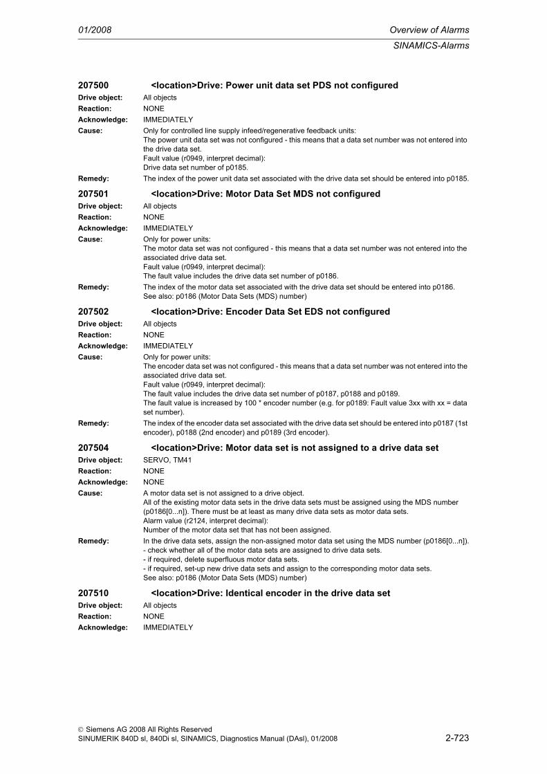
SINAMICS-Alarms
01/2008 Overview of Alarms
2-723
© Siemens AG 2008 All Rights ReservedSINUMERIK 840D sl, 840Di sl, SINAMICS, Diagnostics Manual (DAsl), 01/2008
207500 <location>Drive: Power unit data set PDS not configuredDrive object: All objectsReaction: NONEAcknowledge: IMMEDIATELYCause: Only for controlled line supply infeed/regenerative feedback units:
The power unit data set was not configured - this means that a data set number was not entered into the drive data set.Fault value (r0949, interpret decimal):Drive data set number of p0185.
Remedy: The index of the power unit data set associated with the drive data set should be entered into p0185.
207501 <location>Drive: Motor Data Set MDS not configuredDrive object: All objectsReaction: NONEAcknowledge: IMMEDIATELYCause: Only for power units:
The motor data set was not configured - this means that a data set number was not entered into the associated drive data set.Fault value (r0949, interpret decimal):The fault value includes the drive data set number of p0186.
Remedy: The index of the motor data set associated with the drive data set should be entered into p0186.See also: p0186 (Motor Data Sets (MDS) number)
207502 <location>Drive: Encoder Data Set EDS not configuredDrive object: All objectsReaction: NONEAcknowledge: IMMEDIATELYCause: Only for power units:
The encoder data set was not configured - this means that a data set number was not entered into the associated drive data set.Fault value (r0949, interpret decimal):The fault value includes the drive data set number of p0187, p0188 and p0189.The fault value is increased by 100 * encoder number (e.g. for p0189: Fault value 3xx with xx = data set number).
Remedy: The index of the encoder data set associated with the drive data set should be entered into p0187 (1st encoder), p0188 (2nd encoder) and p0189 (3rd encoder).
207504 <location>Drive: Motor data set is not assigned to a drive data setDrive object: SERVO, TM41Reaction: NONEAcknowledge: NONECause: A motor data set is not assigned to a drive object.
All of the existing motor data sets in the drive data sets must be assigned using the MDS number (p0186[0...n]). There must be at least as many drive data sets as motor data sets.Alarm value (r2124, interpret decimal):Number of the motor data set that has not been assigned.
Remedy: In the drive data sets, assign the non-assigned motor data set using the MDS number (p0186[0...n]).- check whether all of the motor data sets are assigned to drive data sets.- if required, delete superfluous motor data sets.- if required, set-up new drive data sets and assign to the corresponding motor data sets.See also: p0186 (Motor Data Sets (MDS) number)
207510 <location>Drive: Identical encoder in the drive data setDrive object: All objectsReaction: NONEAcknowledge: IMMEDIATELY

Overview of Alarms 01/2008
SINAMICS-Alarms
2-724
© Siemens AG 2008 All Rights ReservedSINUMERIK 840D sl, 840Di sl, SINAMICS, Diagnostics Manual (DAsl), 01/2008
Cause: More than one encoder with identical component number is assigned to a single drive data set. In one drive data set, it is not permissible that identical encoders are operated together.Fault value (r0949, interpret decimal):1000 * first identical encoder + 100 * second identical encoder + drive data set.Example:Fault value = 1203 means:In drive data set 3, the first (p0187[3]) and second encoder (p0188[3]) are identical.
Remedy: Assign the drive data set to different encoders.See also: p0141 (Encoder interface (Sensor Module) component number), p0187 (Encoder 1 encoder data set number), p0188 (Encoder 2 encoder data set number), p0189 (Encoder 3 encoder data set number)
207511 <location>Drive: Encoder used a multiple number of timesDrive object: All objectsReaction: NONEAcknowledge: IMMEDIATELYCause: Each encoder may only be assigned to one drive and within a drive must - in each drive data set -
either always be encoder 1, always encoder 2 or always encoder 3. This unique assignment has been violated.Fault value (r0949, interpret decimal):The two parameters in coded form, that refer to the same component number.First parameter:Index: First and second decimal place (99 for EDS, not assigned DDS)Parameter number: Third decimal place (1 for p0187, 2 for p0188, 3 for p0189, 4 for EDS not assigned DDS)Drive number: Fourth and fifth decimal placeSecond parameter:Index: Sixth and seventh decimal place (99 for EDS, not assigned DDS)Parameter number: Eighth decimal place (1 for p0187, 2 for p0188, 3 for p0189, 4 for EDS, not assigned DDS)Drive number: Ninth and tenth decimal placeSee also: p0141 (Encoder interface (Sensor Module) component number)
Remedy: Correct the double use of a component number using the two parameters coded in the fault value.
207512 <location>Drive: Encoder data set changeover cannot be parameterizedDrive object: SERVO, TM41Reaction: NONEAcknowledge: NONECause: Using p0141, a changeover of the encoder data set is prepared that is illegal. In this firmware release,
an encoder data set changeover is only permitted for the components in the actual topology. Commis-sioning can only be exited with the correct parameterization.Alarm value (r2124, interpret decimal):Incorrect EDS data set number.See also: p0187 (Encoder 1 encoder data set number), p0188 (Encoder 2 encoder data set number), p0189 (Encoder 3 encoder data set number)
Remedy: Every encoder data set must be assigned its own dedicated DRIVE-CLiQ socket. The component numbers of the encoder interfaces (p0141) must have different values within a drive object.The following must apply:p0141[0] not equal to p0141[1] not equal to ... not equal to p0141[n]
207514 <location>Drive: Data structure does not correspond to the interface module
Drive object: SERVO, TM41Reaction: NONEAcknowledge: NONE

SINAMICS-Alarms
01/2008 Overview of Alarms
2-725
© Siemens AG 2008 All Rights ReservedSINUMERIK 840D sl, 840Di sl, SINAMICS, Diagnostics Manual (DAsl), 01/2008
Cause: The interface mode "SIMODRIVE 611 universal" was set (p2038 = 1) and the data structure does not correspond to this mode.For the data structure, the following rule must be complied with.Within the group of 8 drive data sets, the assignment to the motor data set must be set the same:p0186[0] = p0186[1] = ... = p0186[7]p0186[8] = p0186[9] = ... = p0186[15]p0186[16] = p0186[17] = ... = p0186[23]p0186[24] = p0186[25] = ... = p0186[31]See also: p0180 (Number of Drive Data Sets (DDS)), p0186 (Motor Data Sets (MDS) number), p2038 (PROFIdrive STW/ZSW interface mode)
Remedy: - structure the data according to the rules of the "SIMODRIVE 611 universal" interface mode.- check the interface mode (p2038).
207515 <location>Drive: Power unit and motor incorrectly connectedDrive object: SERVO, TM41Reaction: NONEAcknowledge: NONECause: A power unit (via PDS) was assigned to a motor (via MDS) in a drive data set that is not connected in
the target topology.Alarm value (r2124, interpret decimal):Number of the incorrectly parameterized drive data set.
Remedy: - assign the drive data set to a combination of motor and power unit permitted by the target topology.- adapt the target topology.See also: p0121 (Power unit component number), p0131 (Motor component number), p0186 (Motor Data Sets (MDS) number)
207516 <location>Drive: Re-commission the data setDrive object: SERVO, TM41Reaction: NONEAcknowledge: IMMEDIATELYCause: The assignment between the drive data set and motor data set (p0186) or between the drive data set
and the encoder data set was modified (p0187). This is the reason that the drive data set must re-commissioned.Fault value (r0949, interpret decimal):Drive data set to be re-commissioned.
Remedy: Commission the drive data set specified in the fault value (r0949).
207517 <location>Drive: Encoder data set changeover incorrectly parameterizedDrive object: SERVO, TM41Reaction: NONEAcknowledge: NONECause: An MDS cannot have different motor encoders in two different DDS.
The following parameterization therefore results results in an error:p0186[0] = 0, p0187[0] = 0p0186[0] = 0, p0187[0] = 1Alarm value (r2124, interpret decimal):The lower 16 bits indicate the first DDS and the upper 16 bits indicate the second DDS.
Remedy: If you wish to operate a motor once with one motor encoder and then another time with the other motor encoder, then you must set-up two different MDSs, in which the motor data are the same.Example:p0186[0] = 0, p0187[0] = 0p0186[0] = 1, p0187[0] = 1
207518 <location>Drive: Motor data set changeover incorrectly parameterizedDrive object: SERVO, TM41Reaction: NONEAcknowledge: IMMEDIATELY

Overview of Alarms 01/2008
SINAMICS-Alarms
2-726
© Siemens AG 2008 All Rights ReservedSINUMERIK 840D sl, 840Di sl, SINAMICS, Diagnostics Manual (DAsl), 01/2008
Cause: The system has identified that two motor data sets were incorrectly parameterized.Parameter r0313 (calculated from p0314, p0310, p0311), r0315 and p1982 may only have different values if the motor data sets are assigned different motors. p0827 is used to assign the motors and/contactors.It is not possible to toggle between motor data sets.Alarm value (r2124, interpret hexadecimal):xxxxyyyy:xxxx: First DDS with assigned MDS, yyyy: Second DDS with assigned MDS
Remedy: Correct the parameterization of the motor data sets.
207519 <location>Drive: Motor cannot be changed overDrive object: SERVOReaction: NONEAcknowledge: NONECause: With the setting p0833.0, a motor changeover via the application is selected. This is the reason that
p0827 must have different values in the appropriate motor data set.Alarm value (r2124, interpret hexadecimal):xxxxyyyy:xxxx: First MDS, yyyy: Second MDS
Remedy: - parameterize the appropriate motor data sets differently (p0827).- select the setting p0833.0 = 0 (motor changeover via the drive).
207530 <location>Drive: Drive Data Set DDS not presentDrive object: SERVO, TM41Reaction: NONEAcknowledge: NONECause: The selected drive data set is not available (p0837 > p0180). The drive data set was not changed-over.
See also: p0180, p0820, p0821, p0822, p0823, p0824, r0837Remedy: - select the existing drive data set.
- set-up additional drive data sets.
207541 <location>Drive: Data set changeover not possibleDrive object: SERVO, TM41Reaction: NONEAcknowledge: NONECause: The selected drive data set changeover and the assigned motor changeover are not possible and are
not carried out.For synchronous motors, the motor contactor may only be switched for actual speeds less than the speed at the start of field weakening (r0063 < p0348).See also: r0063, p0348
Remedy: Reduce the speed below the speed at the start of field weakening.
207550 <location>Drive: Not possible to reset encoder parametersDrive object: SERVOReaction: NONEAcknowledge: NONECause: When carrying out a factory setting (e.g. using p0970 = 1), it was not possible to reset the encoder
parameters. The encoder parameters are directly read out of the encoder via DRIVE-CLiQ.Alarm value (r2124, interpret decimal):Component number of the encoder involved.
Remedy: - repeat the operation.- check the DRIVE-CLiQ connection.
207551 <location>Drive encoder: No commutation angle informationDrive object: SERVOReaction: OFF2 (IASC / DCBRAKE)Acknowledge: IMMEDIATELY (POWER ON)

SINAMICS-Alarms
01/2008 Overview of Alarms
2-727
© Siemens AG 2008 All Rights ReservedSINUMERIK 840D sl, 840Di sl, SINAMICS, Diagnostics Manual (DAsl), 01/2008
Cause: The angular commutation information is missing. This means that synchronous motors cannot be con-trolled (closed-loop control)Fault value (r0949, interpret decimal):Low word: Drive data set numberHigh word: Cause:1: The motor encoder used does not supply an absolute commutation angle.2: The selected ratio of the measuring gearbox does not match the motor pole pair number.
Remedy: Re cause 1:- check the encoder parameterization (p0404).- use an encoder with track C/D, EnDat interface of Hall sensors.- use an encoder with sinusoidal A/B track for which the motor pole pair number (p0313) is an integer multiple of the encoder pulse number (p0408).- activate the pole position identification routine (p1982 = 1).Re cause 2:- the quotient of the pole pair number divided by the measuring gearbox ratio must be an integer num-ber: (p0314 * p0433) / p0432, for operation with a C/D track, this quotient must be less than or equal to 8.See also: p0402 (Gearbox type selection), p0404 (Encoder configuration effective), p0432 (Gearbox factor, encoder revolutions), p0433 (Gearbox factor, motor/load revolutions)
207552 <location>Drive encoder: Encoder configuration not supportedDrive object: SERVOReaction: OFF2 (IASC / DCBRAKE, NONE, OFF1, OFF3, STOP1, STOP2)Acknowledge: IMMEDIATELY (POWER ON)Cause: The requested encoder configuration is not supported. Only bits may be requested in p0404 that are
signaled as being supported by the encoder evaluation in r0456.Fault value (r0949, interpret decimal):Low word low byte: Encoder data set numberLow word high byte: Component numberHigh word:The encoder evaluation does not support a function selected in p0404.1: sin/cos encoder with absolute track (this is supported by SME25).3: Squarewave encoder (this is supported by SMC30).4: sin/cos encoder (this is supported by SMC20, SMI20, SME20, SME25).12: sin/cos encoder with reference mark (this is supported by SME20).15: Commutation with zero mark for separately-excited synchronous motors with VECTORMV.23: Resolver (this is supported by SMC10, SMI10).65535: Other function (compare r0456 and p0404).See also: p0404 (Encoder configuration effective), r0456 (Encoder configuration supported)
Remedy: - check the encoder parameterization (p0400, p0404).- use the matching encoder evaluation (r0456).
207553 <location>Drive encoder: Sensor Module configuration not supportedDrive object: SERVOReaction: OFF2 (IASC / DCBRAKE, NONE, OFF1, OFF3, STOP1, STOP2)Acknowledge: IMMEDIATELY (POWER ON)Cause: The Sensor Module does not support the requested configuration.
Possible causes:- bits are set in p0430 (requested functions) that are not set in r0458 (supported functions). This does not apply for bit 19 (safety position actual value sensing), bit 29 (phase correction), bit 30 (amplitude correction) and bit 31 (offset correction).- p1982 > 0 (pole position identification requested), but r0458 bit 16 = 0 (pole position identification not supported).Fault value (r0949, interpret binary):DCBA:A: Encoder Data Set number.B: First incorrect bit.
Remedy: - check the encoder parameterization (p0430).- check the pole position identification routine (p1982).- use the matching encoder evaluation (r0458).

Overview of Alarms 01/2008
SINAMICS-Alarms
2-728
© Siemens AG 2008 All Rights ReservedSINUMERIK 840D sl, 840Di sl, SINAMICS, Diagnostics Manual (DAsl), 01/2008
207555 <location>Drive encoder: Configuration position trackingDrive object: SERVOReaction: OFF2 (IASC / DCBRAKE, NONE, OFF1, OFF3, STOP1, STOP2)Acknowledge: IMMEDIATELY (POWER ON)Cause: The configuration of the position tracking is not supported.
Position tracking can only be activated for absolute encoders.For linear axes, it is not possible to simultaneously activate the position tracking for load- and mea-suring gearboxes.Fault value (r0949, interpret decimal):Low word low byte: Encoder data set numberLow word high byte: Component numberHigh word low byte: Data set number (only load gearboxes)High word high byte: Cause0: An absolute encoder is not being used.1 : Position tracking cannot be activated because the internal NVRAM is full or the Control Unit does not have an NVRAM.2: For a linear axis, the position tracking was activated for the load and measuring gearbox.3: Position tracking cannot be activated because there is more than one data set (p0180).4: A linear encoder is being used.See also: p0404 (Encoder configuration effective), p0411 (Measuring gearbox, configuration)
Remedy: - use an absolute encoder.- if necessary, de-select the position tracking (p0411 for the measuring gearbox, p2720 for the load gearbox).- use a Control Unit with sufficient NVRAM.
207556 <location>Measuring gearbox: Position tracking, maximum actual value exceeded
Drive object: SERVOReaction: NONEAcknowledge: IMMEDIATELYCause: When the position tracking of the measuring gearbox is configured, the drive/encoder identifies a max-
imum possible absolute position actual value (r0483) that cannot be represented within 32 bits.Maximum value: p0408 * p0412 * 2^p0419Fault value (r0949, interpret decimal):Low word low byte: Encoder data set numberLow word high byte: Component numberSee also: p0408 (Rotary encoder pulse No.), p0412 (Measuring gearbox, rotary absolute gearbox, revolutions, virtual), p0419 (Fine resolution absolute value Gx_XIST2 (in bits))
Remedy: - reduce the fine resolution (p0419).- reduce the multiturn resolution (p0412).See also: p0412 (Measuring gearbox, rotary absolute gearbox, revolutions, virtual), p0419 (Fine res-olution absolute value Gx_XIST2 (in bits))
207557 <location>Encoder 1: Reference point coordinate not in the permissible range
Drive object: SERVOReaction: NONEAcknowledge: NONECause: The reference point coordinate received when adjusting the encoder via connector input CI:p2599 lies
outside the half of the encoder range and cannot be set as actual axis position.Fault value (r0949, interpret decimal):Limit value (absolute value) for the reference point coordinate.
Remedy: Set the reference point coordinate less than the limit value specified in the fault value.See also: p2598 (EPOS reference point coordinate, signal source)
207558 <location>Encoder 2: Reference point coordinate not in the permissible range
Drive object: SERVOReaction: NONEAcknowledge: NONE

SINAMICS-Alarms
01/2008 Overview of Alarms
2-729
© Siemens AG 2008 All Rights ReservedSINUMERIK 840D sl, 840Di sl, SINAMICS, Diagnostics Manual (DAsl), 01/2008
Cause: The reference point coordinate received when adjusting the encoder via connector input CI:p2599 lies outside the half of the encoder range and cannot be set as actual axis position.Fault value (r0949, interpret decimal):Limit value (absolute value) for the reference point coordinate.
Remedy: Set the reference point coordinate less than the limit value specified in the fault value.See also: p2598 (EPOS reference point coordinate, signal source)
207559 <location>Encoder 3: Reference point coordinate not in the permissible range
Drive object: SERVOReaction: NONEAcknowledge: NONECause: The reference point coordinate received when adjusting the encoder via connector input CI:p2599 lies
outside the half of the encoder range and cannot be set as actual axis position.Fault value (r0949, interpret decimal):Limit value (absolute value) for the reference point coordinate.
Remedy: Set the reference point coordinate less than the limit value specified in the fault value.See also: p2598 (EPOS reference point coordinate, signal source)
207560 <location>Drive encoder: Number of pulses is not to the power of twoDrive object: SERVOReaction: OFF2 (IASC / DCBRAKE, NONE, OFF1, OFF3, STOP1, STOP2)Acknowledge: IMMEDIATELY (POWER ON)Cause: For rotary absolute encoders, the pulse number in p0408 must be to the power of two.
Fault value (r0949, interpret decimal):The fault value includes the encoder data set number involved.
Remedy: - check the parameterization (p0408, p0404.1, r0458.5).- if required, upgrade the Sensor Module firmware.
207561 <location>Drive encoder: Number of multiturn pulses is not to the power of two
Drive object: SERVOReaction: OFF2 (IASC / DCBRAKE, NONE, OFF1, OFF3, STOP1, STOP2)Acknowledge: IMMEDIATELY (POWER ON)Cause: The multi-turn resolution in p0421 must be to the power of two.
Fault value (r0949, interpret decimal):The fault value includes the encoder data set number involved.
Remedy: - check the parameterization (p0421, p0404.1, r0458.5).- if required, upgrade the Sensor Module firmware.
207565 <location>Drive: Encoder error in PROFIdrive encoder interface 1Drive object: SERVOReaction: NONEAcknowledge: NONECause: An encoder error was signaled for encoder 1 via the PROFIdrive encoder interface (G1_ZSW.15).
Alarm value (r2124, interpret decimal):Error code from G1_XIST2, refer to the description regarding r0483.Note:This alarm is only output if p0480[0] is not equal to zero.
Remedy: Acknowledge the encoder error using the encoder control word (G1_STW.15 = 1).
207566 <location>Drive: Encoder error in PROFIdrive encoder interface 2Drive object: SERVOReaction: NONEAcknowledge: NONECause: An encoder error was signaled for encoder 2 via the PROFIdrive encoder interface (G2_ZSW.15).
Alarm value (r2124, interpret decimal):Error code from G2_XIST2, refer to the description regarding r0483.This alarm is only output if p0480[1] is not equal to zero.

Overview of Alarms 01/2008
SINAMICS-Alarms
2-730
© Siemens AG 2008 All Rights ReservedSINUMERIK 840D sl, 840Di sl, SINAMICS, Diagnostics Manual (DAsl), 01/2008
Remedy: Acknowledge the encoder error using the encoder control word (G2_STW.15 = 1).
207567 <location>Drive: Encoder error in PROFIdrive encoder interface 3Drive object: SERVOReaction: NONEAcknowledge: NONECause: An encoder error was signaled for encoder 3 via the PROFIdrive encoder interface (G3_ZSW.15).
Alarm value (r2124, interpret decimal):Error code from G3_XIST2, refer to the description regarding r0483.This alarm is only output if p0480[2] is not equal to zero.
Remedy: Acknowledge the encoder error using the encoder control word (G3_STW.15 = 1).
207575 <location>Drive: Motor encoder not readyDrive object: SERVO, TM41Reaction: OFF2 (ENCODER)Acknowledge: IMMEDIATELYCause: The motor encoder signals that it is not ready.
- initialization of encoder 1 (motor encoder) was unsuccessful.- the function "parking encoder" is active (selected using the encoder control word G1_STW.14 = 1).- the encoder interface (Sensor Module) is de-activated (p0145).- the Sensor Module is defective.
Remedy: Evaluate other queued faults via encoder 1.
207576 <location>Drive: Sensorless operation due to a fault activeDrive object: SERVOReaction: NONEAcknowledge: NONECause: Sensorless operation is active due to a fault (r1407.13).
The required response when an encoder fault occurs is parameterized in p0491.See also: p0491 (Motor encoder fault response ENCODER)
Remedy:
207577 <location>Encoder 1: Measuring probe evaluation not possibleDrive object: SERVOReaction: NONEAcknowledge: NONECause: When evaluating the measuring probe, an error occurred.
Alarm value (r2124, interpret decimal):6: The input terminal for the measuring probe is not set.4098: Error when initializing the measuring probe.4100: The measuring pulse frequency is too high.4200: The PROFIBUS clock cycle is not a multiple of integer of the position controller clock cycle.
Remedy: De-activate the measuring probe evaluation (BI: p2509 = 0 signal).Re alarm value = 6:Set the input terminal for the measuring probe (p0488, p0489 or p2517, p2518).Re alarm value = 4098:Check the Control Unit hardware.Re alarm value = 4100:Reduce the frequency of the measuring pulses at the measuring probe.Re alarm value = 4200:Set the clock cycle ratio between the PROFIBUS clock cycle and the position controller clock cycle to an integer multiple.
207578 <location>Encoder 2: Measuring probe evaluation not possibleDrive object: SERVOReaction: NONEAcknowledge: NONE

SINAMICS-Alarms
01/2008 Overview of Alarms
2-731
© Siemens AG 2008 All Rights ReservedSINUMERIK 840D sl, 840Di sl, SINAMICS, Diagnostics Manual (DAsl), 01/2008
Cause: When evaluating the measuring probe, an error occurred.Alarm value (r2124, interpret decimal):6: The input terminal for the measuring probe is not set.4098: Error when initializing the measuring probe.4100: The measuring pulse frequency is too high.4200: The PROFIBUS clock cycle is not a multiple of integer of the position controller clock cycle.
Remedy: De-activate the measuring probe evaluation (BI: p2509 = 0 signal).Re alarm value = 6:Set the input terminal for the measuring probe (p0488, p0489 or p2517, p2518).Re alarm value = 4098:Check the Control Unit hardware.Re alarm value = 4100:Reduce the frequency of the measuring pulses at the measuring probe.Re alarm value = 4200:Set the clock cycle ratio between the PROFIBUS clock cycle and the position controller clock cycle to an integer multiple.
207579 <location>Encoder 3: Measuring probe evaluation not possibleDrive object: SERVOReaction: NONEAcknowledge: NONECause: When evaluating the measuring probe, an error occurred.
Alarm value (r2124, interpret decimal):6: The input terminal for the measuring probe is not set.4098: Error when initializing the measuring probe.4100: The measuring pulse frequency is too high.4200: The PROFIBUS clock cycle is not a multiple of integer of the position controller clock cycle.
Remedy: De-activate the measuring probe evaluation (BI: p2509 = 0 signal).Re alarm value = 6:Set the input terminal for the measuring probe (p0488, p0489 or p2517, p2518).Re alarm value = 4098:Check the Control Unit hardware.Re alarm value = 4100:Reduce the frequency of the measuring pulses at the measuring probe.Re alarm value = 4200:Set the clock cycle ratio between the PROFIBUS clock cycle and the position controller clock cycle to an integer multiple.
207580 <location>Drive: No Sensor Module with matching component numberDrive object: SERVOReaction: NONEAcknowledge: NONECause: A Sensor Module with the component number specified in p0141 was not found.
Alarm value (r2124, interpret decimal):Encoder data set involved (index of p0141).
Remedy: Correct parameter p0141.
207581 <location>Encoder 1: Position actual value preprocessing errorDrive object: SERVOReaction: NONEAcknowledge: NONECause: An error has occurred during the position actual value preprocessing.Remedy: Check the encoder for the position actual value preprocessing.
See also: p2502 (LR encoder assignment)
207582 <location>Encoder 2: Position actual value preprocessing errorDrive object: SERVOReaction: NONEAcknowledge: NONECause: An error has occurred during the position actual value preprocessing.

Overview of Alarms 01/2008
SINAMICS-Alarms
2-732
© Siemens AG 2008 All Rights ReservedSINUMERIK 840D sl, 840Di sl, SINAMICS, Diagnostics Manual (DAsl), 01/2008
Remedy: Check the encoder for the position actual value preprocessing.See also: p2502 (LR encoder assignment)
207583 <location>Encoder 3: Position actual value preprocessing errorDrive object: SERVOReaction: NONEAcknowledge: NONECause: An error has occurred during the position actual value preprocessing.Remedy: Check the encoder for the position actual value preprocessing.
See also: p2502 (LR encoder assignment)
207584 <location>Encoder 1: Position setting value activatedDrive object: SERVOReaction: NONEAcknowledge: NONECause: The position actual value is set to the value received via CI: p2515while BI: p2514 = 1 signal. A pos-
sible system deviation cannot be corrected.Remedy: None necessary.
The alarm automatically disappears with BI: p2514 = 0 signal.
207585 <location>Encoder 2: Position setting value activatedDrive object: SERVOReaction: NONEAcknowledge: NONECause: The position actual value is set to the value received via CI: p2515while BI: p2514 = 1 signal. A pos-
sible system deviation cannot be corrected.Remedy: None necessary.
The alarm automatically disappears with BI: p2514 = 0 signal.
207586 <location>Encoder 3: Position setting value activatedDrive object: SERVOReaction: NONEAcknowledge: NONECause: The position actual value is set to the value received via CI: p2515while BI: p2514 = 1 signal. A pos-
sible system deviation cannot be corrected.Remedy: None necessary.
The alarm automatically disappears with BI: p2514 = 0 signal.
207587 <location>Encoder 1: Position actual value preprocessing does not have a valid encoder
Drive object: SERVOReaction: NONEAcknowledge: NONECause: The following problem has occurred during the position actual value preprocessing.
- an encoder data set has been assigned, however, the encoder data set does not contain any encoder data (p0400 = 0) or invalid data (e.g. p0408 = 0).
Remedy: Check the drive data sets, encoder data sets.See also: p0187 (Encoder 1 encoder data set number), p0188 (Encoder 2 encoder data set number), p0189 (Encoder 3 encoder data set number), p0400 (Enc type selection), p2502 (LR encoder assign-ment)
207588 <location>Encoder 2: Position actual value preprocessing does not have a valid encoder
Drive object: SERVOReaction: NONEAcknowledge: NONECause: The following problem has occurred during the position actual value preprocessing.
- an encoder data set has been assigned, however, the encoder data set does not contain any encoder data (p0400 = 0) or invalid data (e.g. p0408 = 0).

SINAMICS-Alarms
01/2008 Overview of Alarms
2-733
© Siemens AG 2008 All Rights ReservedSINUMERIK 840D sl, 840Di sl, SINAMICS, Diagnostics Manual (DAsl), 01/2008
Remedy: Check the drive data sets, encoder data sets.See also: p0187 (Encoder 1 encoder data set number), p0188 (Encoder 2 encoder data set number), p0189 (Encoder 3 encoder data set number), p0400 (Enc type selection), p2502 (LR encoder assign-ment)
207589 <location>Encoder 3: Position actual value preprocessing does not have a valid encoder
Drive object: SERVOReaction: NONEAcknowledge: NONECause: The following problem has occurred during the position actual value preprocessing.
- an encoder data set has been assigned, however, the encoder data set does not contain any encoder data (p0400 = 0) or invalid data (e.g. p0408 = 0).
Remedy: Check the drive data sets, encoder data sets.See also: p0187 (Encoder 1 encoder data set number), p0188 (Encoder 2 encoder data set number), p0189 (Encoder 3 encoder data set number), p0400 (Enc type selection), p2502 (LR encoder assign-ment)
207590 <location>Encoder 1: Drive Data Set changeover in operationDrive object: SERVOReaction: NONEAcknowledge: NONECause: A Drive Data Set changeover (DDS) with a change of the mechanical relationships and the encoder
assignment (p2502) was requested in operation.Remedy: To changeover the drive data set, initially, exit the "operation" mode.
207591 <location>Encoder 2: Drive Data Set changeover in operationDrive object: SERVOReaction: NONEAcknowledge: NONECause: A Drive Data Set changeover (DDS) with a change of the mechanical relationships and the encoder
assignment (p2502) was requested in operation.Remedy: To changeover the drive data set, initially, exit the "operation" mode.
207592 <location>Encoder 3: Drive Data Set changeover in operationDrive object: SERVOReaction: NONEAcknowledge: NONECause: A Drive Data Set changeover (DDS) with a change of the mechanical relationships and the encoder
assignment (p2502) was requested in operation.Remedy: To changeover the drive data set, initially, exit the "operation" mode.
207593 <location>Encoder 1: Overflow of the value range for the position actual value
Drive object: SERVOReaction: NONEAcknowledge: NONECause: The value range (-2147483648 ... 2147483647) for the position actual value representation was
exceeded.When the overflow occurs, the status "referenced" or the status "adjustment absolute measuring sys-tem" is reset.Fault value (r0949, interpret decimal):1: r2521 has exceeded the value range for the position actual value display.2: r0483 and/or r2723 has exceeded the value range for the position actual value display.3. The factor to convert the absolute position (r0483 and/or r2723) from increments to LUs is greater than 1.0.

Overview of Alarms 01/2008
SINAMICS-Alarms
2-734
© Siemens AG 2008 All Rights ReservedSINUMERIK 840D sl, 840Di sl, SINAMICS, Diagnostics Manual (DAsl), 01/2008
Remedy: If required, reduce the traversing range or position resolution.Reducing the position resolution and conversion factor (supplementary info 3):- reduce p2506 (LUs per load revolution for rotary encoders)- increase p419 (fine resolution of absolute position actual values).
207594 <location>Encoder 2: Overflow of the value range for the position actual value
Drive object: SERVOReaction: NONEAcknowledge: NONECause: The value range (-2147483648 ... 2147483647) for the position actual value representation was
exceeded.When the overflow occurs, the status "referenced" or the status "adjustment absolute measuring sys-tem" is reset.Fault value (r0949, interpret decimal):1: r2521 has exceeded the value range for the position actual value display.2: r0483 and/or r2723 has exceeded the value range for the position actual value display.3. The factor to convert the absolute position (r0483 and/or r2723) from increments to LUs is greater than 1.0.
Remedy: If required, reduce the traversing range or position resolution.Reducing the position resolution and conversion factor (supplementary info 3):- reduce p2506 (LUs per load revolution for rotary encoders)- increase p419 (fine resolution of absolute position actual values).
207595 <location>Encoder 3: Overflow of the value range for the position actual value
Drive object: SERVOReaction: NONEAcknowledge: NONECause: The value range (-2147483648 ... 2147483647) for the position actual value representation was
exceeded.When the overflow occurs, the status "referenced" or the status "adjustment absolute measuring sys-tem" is reset.Fault value (r0949, interpret decimal):1: r2521 has exceeded the value range for the position actual value display.2: r0483 and/or r2723 has exceeded the value range for the position actual value display.3. The factor to convert the absolute position (r0483 and/or r2723) from increments to LUs is greater than 1.0.
Remedy: If required, reduce the traversing range or position resolution.Reducing the position resolution and conversion factor (supplementary info 3):- reduce p2506 (LUs per load revolution for rotary encoders)- increase p419 (fine resolution of absolute position actual values).
207596 <location>Encoder 1: Reference function interruptedDrive object: SERVOReaction: NONEAcknowledge: NONECause: An activated reference function (reference mark search or measuring probe evaluation) was inter-
rupted.- an encoder fault has occurred (Gn_ZSW.15 = 1).- position actual value was set during an activated reference function.- simultaneously activate reference mark search and measuring probe evaluation (BI: p2508 and BI: p2509 = 1 signal).- activated reference function (reference mark search or measuring probe evaluation) was de-acti-vated (BI: p2508 and BI: p2509 = 0 signal).
Remedy: - check the causes and resolve.- reset the control (BI: p2508 and BI: p2509 = 0 signal) and activate the requested function.
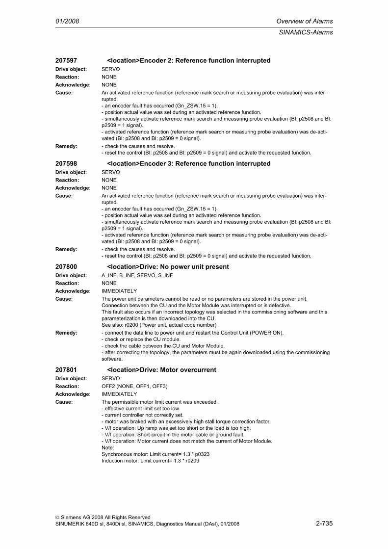
SINAMICS-Alarms
01/2008 Overview of Alarms
2-735
© Siemens AG 2008 All Rights ReservedSINUMERIK 840D sl, 840Di sl, SINAMICS, Diagnostics Manual (DAsl), 01/2008
207597 <location>Encoder 2: Reference function interruptedDrive object: SERVOReaction: NONEAcknowledge: NONECause: An activated reference function (reference mark search or measuring probe evaluation) was inter-
rupted.- an encoder fault has occurred (Gn_ZSW.15 = 1).- position actual value was set during an activated reference function.- simultaneously activate reference mark search and measuring probe evaluation (BI: p2508 and BI: p2509 = 1 signal).- activated reference function (reference mark search or measuring probe evaluation) was de-acti-vated (BI: p2508 and BI: p2509 = 0 signal).
Remedy: - check the causes and resolve.- reset the control (BI: p2508 and BI: p2509 = 0 signal) and activate the requested function.
207598 <location>Encoder 3: Reference function interruptedDrive object: SERVOReaction: NONEAcknowledge: NONECause: An activated reference function (reference mark search or measuring probe evaluation) was inter-
rupted.- an encoder fault has occurred (Gn_ZSW.15 = 1).- position actual value was set during an activated reference function.- simultaneously activate reference mark search and measuring probe evaluation (BI: p2508 and BI: p2509 = 1 signal).- activated reference function (reference mark search or measuring probe evaluation) was de-acti-vated (BI: p2508 and BI: p2509 = 0 signal).
Remedy: - check the causes and resolve.- reset the control (BI: p2508 and BI: p2509 = 0 signal) and activate the requested function.
207800 <location>Drive: No power unit presentDrive object: A_INF, B_INF, SERVO, S_INFReaction: NONEAcknowledge: IMMEDIATELYCause: The power unit parameters cannot be read or no parameters are stored in the power unit.
Connection between the CU and the Motor Module was interrupted or is defective.This fault also occurs if an incorrect topology was selected in the commissioning software and this parameterization is then downloaded into the CU.See also: r0200 (Power unit, actual code number)
Remedy: - connect the data line to power unit and restart the Control Unit (POWER ON).- check or replace the CU module.- check the cable between the CU and Motor Module.- after correcting the topology, the parameters must be again downloaded using the commissioning software.
207801 <location>Drive: Motor overcurrentDrive object: SERVOReaction: OFF2 (NONE, OFF1, OFF3)Acknowledge: IMMEDIATELYCause: The permissible motor limit current was exceeded.
- effective current limit set too low.- current controller not correctly set.- motor was braked with an excessively high stall torque correction factor.- V/f operation: Up ramp was set too short or the load is too high.- V/f operation: Short-circuit in the motor cable or ground fault.- V/f operation: Motor current does not match the current of Motor Module.Note:Synchronous motor: Limit current= 1.3 * p0323Induction motor: Limit current= 1.3 * r0209

Overview of Alarms 01/2008
SINAMICS-Alarms
2-736
© Siemens AG 2008 All Rights ReservedSINUMERIK 840D sl, 840Di sl, SINAMICS, Diagnostics Manual (DAsl), 01/2008
Remedy: - check the current limits (p0323, p0640).- check the current controller (p1715, p1717).- reduce the stall torque correction factor (p0326).- increase the up ramp (p1318) or reduce the load.- check the motor and motor cables for short-circuit and ground fault.- check the Motor Module and motor combination.
207802 <location>Drive: Infeed or power unit not readyDrive object: SERVOReaction: OFF2 (NONE)Acknowledge: IMMEDIATELYCause: After an internal power-on command, the infeed or drive does not signal ready.
- monitoring time is too short.- DC link voltage is not present.- associated infeed or drive of the signaling component is defective.- supply voltage incorrectly set.
Remedy: - increase the monitoring time (p0857).- ensure that there is a DC link voltage. Check the DC-link busbar. Enable the infeed.- replace the associated infeed or drive of the signaling component.- check the line supply voltage setting (p0210).See also: p0857 (Power unit monitoring time)
207805 <location>Infeed: Power unit overload I2tDrive object: A_INF, B_INF, S_INFReaction: NONEAcknowledge: NONECause: Alarm threshold for I2t overload (p0294) of the power unit exceeded.Remedy: - reduce the continuous load.
- adapt the load duty cycle.
207805 <location>Drive: Power unit overload I2tDrive object: SERVOReaction: NONEAcknowledge: NONECause: Alarm threshold for I2t overload (p0294) of the power unit exceeded.
The response parameterized in p0290 becomes active.See also: p0290 (Power unit overload response)
Remedy: - reduce the continuous load.- adapt the load duty cycle.- check the assignment of the rated currents of the motor and Motor Module.
207810 <location>Drive: Power unit EEPROM without rated dataDrive object: A_INF, B_INF, SERVO, S_INFReaction: NONEAcknowledge: IMMEDIATELYCause: No rated data are stored in the power unit EEPROM.
See also: r0206, r0207, r0208, r0209Remedy: Replace the power unit or inform Siemens Customer Service.
207815 <location>Drive: Power unit has been changedDrive object: A_INF, B_INF, SERVO, S_INFReaction: NONEAcknowledge: IMMEDIATELYCause: The code number of the actual power unit does not match the saved number.
Fault value (r0949, interpret decimal):Number of the incorrect parameter.See also: r0200 (Power unit, actual code number), p0201 (Power unit code number)

SINAMICS-Alarms
01/2008 Overview of Alarms
2-737
© Siemens AG 2008 All Rights ReservedSINUMERIK 840D sl, 840Di sl, SINAMICS, Diagnostics Manual (DAsl), 01/2008
Remedy: Connect the original power unit and power-up the Control Unit again (POWER ON) or set p0201 to r0200 and exit commissioning with p0010 = 0.For infeeds, the following applies:Commutating reactors or line filters must be used that are specified for the new power unit. A line sup-ply and DC link identification routine (p3410 = 5) must then be carried out. It is not possible to change the power unit without re-commissioning the system if the type of infeed (A_Infeed, B_Infeed, S_Infeed), the type of construction/design (booksize, chassis) or the voltage class differ between the old and new power units.For inverters, the following applies:If the new power module is accepted, then if required, the current limit p0640 can be reduced by a lower maximum current of the power module (r0209) (torque limits stay the same).If not only the power unit is changed, but also the motor, then the motor must be re-commissioning (e.g. using p0010 = 1). This is also necessary if motor data is still to be downloaded via DRIVE-CLiQ.See also: r0200 (Power unit, actual code number)
207820 <location>Drive: Temperature sensor not connectedDrive object: SERVOReaction: NONEAcknowledge: NONECause: The temperature sensor for motor temperature monitoring, specified in p0600, is not available.
- parameter download with "incorrect" setting.- module with sensor evaluation has been, in the meantime, been removed.- temperature sensor via Motor Module, not for CU310.
Remedy: - connect the module with temperature sensor.- set the available temperature sensor (p0600, p0601).See also: p0600 (Motor temperature sensor for monitoring), p0601
207840 <location>Drive: Infeed operation missingDrive object: SERVOReaction: OFF2 (NONE)Acknowledge: IMMEDIATELYCause: The signal "infeed operation" is not present although the enable signals for the drive have been
present for longer than the parameterized monitoring time (p0857).- infeed not operational.- interconnection of the binector input for the ready signal is either incorrect or missing (p0864).- infeed is presently carrying out a line supply identification routine.
Remedy: - bring the infeed into an operational state.- check the interconnection of the binector input for the signal "infeed operation" (p0864).- increase the monitoring time (p0857).- wait until the infeed has completed the line supply identification routine.See also: p0857 (Power unit monitoring time), p0864 (Infeed operation)
207841 <location>Drive: Infeed operation withdrawnDrive object: SERVOReaction: OFF2 (NONE, OFF1, OFF3)Acknowledge: IMMEDIATELYCause: The signal "infeed operation" was withdrawn in operation.
- interconnection of the binector input for the signal "infeed operation" is either incorrect or missing (p0864).- the enable signals of the infeed were disabled.- due to a fault, the infeed withdraws the signal "infeed operation".
Remedy: - check the interconnection of the binector input for the signal "infeed operation" (p0864).- check the enable signals of the infeed and if required, enable.- remove and acknowledge an infeed fault.Note:If this drive is intended to back-up the DC link regeneratively, then the fault response must be param-eterized for NONE so that the drive can continue to operate even after the infeed fails.
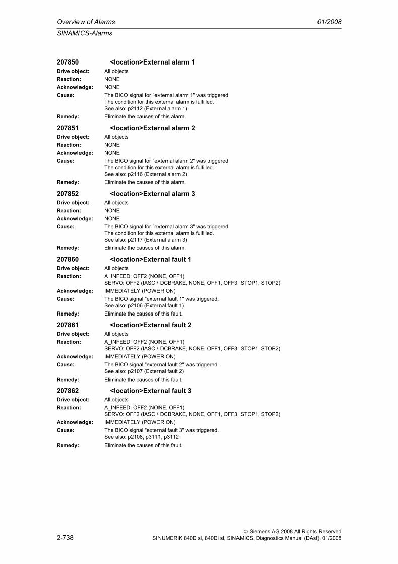
Overview of Alarms 01/2008
SINAMICS-Alarms
2-738
© Siemens AG 2008 All Rights ReservedSINUMERIK 840D sl, 840Di sl, SINAMICS, Diagnostics Manual (DAsl), 01/2008
207850 <location>External alarm 1Drive object: All objectsReaction: NONEAcknowledge: NONECause: The BICO signal for "external alarm 1" was triggered.
The condition for this external alarm is fulfilled.See also: p2112 (External alarm 1)
Remedy: Eliminate the causes of this alarm.
207851 <location>External alarm 2Drive object: All objectsReaction: NONEAcknowledge: NONECause: The BICO signal for "external alarm 2" was triggered.
The condition for this external alarm is fulfilled.See also: p2116 (External alarm 2)
Remedy: Eliminate the causes of this alarm.
207852 <location>External alarm 3Drive object: All objectsReaction: NONEAcknowledge: NONECause: The BICO signal for "external alarm 3" was triggered.
The condition for this external alarm is fulfilled.See also: p2117 (External alarm 3)
Remedy: Eliminate the causes of this alarm.
207860 <location>External fault 1Drive object: All objectsReaction: A_INFEED: OFF2 (NONE, OFF1)
SERVO: OFF2 (IASC / DCBRAKE, NONE, OFF1, OFF3, STOP1, STOP2)Acknowledge: IMMEDIATELY (POWER ON)Cause: The BICO signal "external fault 1" was triggered.
See also: p2106 (External fault 1)Remedy: Eliminate the causes of this fault.
207861 <location>External fault 2Drive object: All objectsReaction: A_INFEED: OFF2 (NONE, OFF1)
SERVO: OFF2 (IASC / DCBRAKE, NONE, OFF1, OFF3, STOP1, STOP2)Acknowledge: IMMEDIATELY (POWER ON)Cause: The BICO signal "external fault 2" was triggered.
See also: p2107 (External fault 2)Remedy: Eliminate the causes of this fault.
207862 <location>External fault 3Drive object: All objectsReaction: A_INFEED: OFF2 (NONE, OFF1)
SERVO: OFF2 (IASC / DCBRAKE, NONE, OFF1, OFF3, STOP1, STOP2)Acknowledge: IMMEDIATELY (POWER ON)Cause: The BICO signal "external fault 3" was triggered.
See also: p2108, p3111, p3112Remedy: Eliminate the causes of this fault.

SINAMICS-Alarms
01/2008 Overview of Alarms
2-739
© Siemens AG 2008 All Rights ReservedSINUMERIK 840D sl, 840Di sl, SINAMICS, Diagnostics Manual (DAsl), 01/2008
207890 <location>Internal voltage protection / internal armature short-circuit with Safe Torque Off active
Drive object: SERVOReaction: OFF2Acknowledge: IMMEDIATELYCause: The internal armature short-circuit (p1231=4) is not possible as Safe Torque Off is enabled. The
pulses cannot be enabled.Remedy: Switch-out the internal armature short-circuit (p1231=0) or de-activate Safe Torque Off (p9501 =
p9561 = 0).
207900 <location>Drive: Motor locked/speed controller at its limitDrive object: SERVOReaction: OFF2 (NONE, OFF1, OFF3, STOP1, STOP2)Acknowledge: IMMEDIATELYCause: Motor has been operating at the torque limit longer than the time specified in p2177 and below the
speed threshold set in p2175.This signal can also be initiated if the speed actual value is oscillating and the speed controller output repeatedly goes to its limit.See also: p2175, p2177 (Motor locked delay time)
Remedy: - check that the motor can freely rotate.- check the torque limit: For a positive direction of rotation r1538, for a negative direction of rotation r1539.- check the parameter, message "Motor locked" and if required, correct (p2175, p2177).- check the inversion of the actual value (p0410).- check the motor encoder connection.- check the encoder pulse number (p0408).- for SERVO with sensorless operation and motors with low power ratings (< 300 W), increase the pulse frequency (p1800).- after de-selecting basic positioning, check the torque limits when motoring (p1528) and when regen-erating (p1529).
207901 <location>Drive: Motor overspeedDrive object: SERVOReaction: OFF2Acknowledge: IMMEDIATELYCause: The maximum permissible speed was either positively or negatively exceeded.
The maximum permissible positive speed is formed as follows: Minimum(p1082, CI: p1085) + p2162. The maximum permissible negative speed is formed as follows: Maximum(-p1082, CI: 1088) - p2162.
Remedy: For a positive direction of rotation:- check r1084 and if required, correct p1082, CI:p1085 and p2162.For a negative direction of rotation:- check r1087 and if required, correct p1082, CI:p1088 and p2162.
207902 <location>Drive: Motor stalledDrive object: SERVOReaction: OFF2 (NONE, OFF1, OFF3, STOP1, STOP2)Acknowledge: IMMEDIATELYCause: For a vector drive the system has identified that the motor has stall for a time longer than is set in
p2178.Fault value (r0949, interpret decimal):1: Stall detection using r1408.11 (p1744 or p0492).2: Stall detection using r1408.12 (p1745).3: Stall detection using r0056.11 (only for separately excited synchronous motors).

Overview of Alarms 01/2008
SINAMICS-Alarms
2-740
© Siemens AG 2008 All Rights ReservedSINUMERIK 840D sl, 840Di sl, SINAMICS, Diagnostics Manual (DAsl), 01/2008
Remedy: For closed-loop speed and torque control with speed encoder, the following applies:- check the speed signal (interrupted cable, polarity, pulse number, broken encoder shaft).- check the speed encoder, if another speed encoder was selected using the data set changeover. This must be connected to the same motor that is controlled for the data set changeover.If there is no fault, then the fault tolerance (p1744 and p0492) can be increased.For closed-loop speed and torque control without speed encoder, the following applies:- check whether the drive in the open-loop controlled mode (r1750.0) stalls under load. If yes, then increase the current setpoint using p1610.- check whether the drive stalls due to the load if the speed setpoint is still zero. If yes, then increase the current setpoint using p1610.- if the motor excitation (magnetizing) time (r0346) was significantly reduced, then it should be increased again.- check the current limits (p0640, r0067). If the current limits are too low, then the drive cannot be mag-netized.- check the current controller (p1715, p1717) and the speed adaptation controller (p1764, p1767). If the dynamic response was significantly reduced, then this should be increased again.- check the speed encoder, if another speed encoder was selected using the data set changeover. This must be connected to the motor that is controlled for the data set changeover.If there is no fault, then the fault tolerance (p1745) or the delay time (p2178) can be increased.For separately-excited synchronous motors (closed-loop control with speed encoder), the following applies:- check the speed signal (interrupted cable, polarity, pulse number).- ensure the correct motor parameterization (rating plate and equivalent circuit diagram parameters).- check the excitation equipment and the interface to the closed-loop control.- encoder the highest possible dynamic response of the closed-loop excitation current control.- check the speed control for any tendency to oscillate and if resonance effects occur, use a bandstop filter.- do not exceed the maximum speed (p2162).If there is no fault, then the delay time can be increased (p2178).
207903 <location>Drive: Motor speed deviationDrive object: SERVOReaction: NONEAcknowledge: NONECause: The absolute value of the speed difference from the two setpoints (p2151, p2154) and the speed
actual value (r2169) exceeds the tolerance threshold (p2163) longer than tolerated (p2164, p2166).The alarm is only enabled for p2149.0 = 1.Possible causes could be:- the load torque is greater than the torque setpoint.- when accelerating, the torque/current/power limit is reached. If the limits are not sufficient, then it is possible that the drive has been dimensioned too small.- the speed controller is inhibited (refer to p0856; refer to Kp/Tn adaptation of the speed controller).- for closed-loop torque control, the speed setpoint does not track the speed actual value.- for active Vdc controller.- the encoder pulse number was incorrectly parameterized (p0408).The signal is not generated if the ramp-function generator tracking prevents the setpoint and actual speed from drifting (moving) apart.Only for vector drives:For V/f control, the overload condition is detected as the Imax controller is active.See also: p2149 (Monitoring configuration)
Remedy: - increase p2163 and/or p2166.- increase the torque/current/power limits.- enable the speed controller.- for closed-loop torque control: The speed setpoint should track the speed actual value.- correct the encoder pulse number in p0408 or mount the correct tachometer.
207904 <location>External armature short-circuit: Contactor feedback signal "Closed" missing
Drive object: A_INF, B_INF, SERVO, S_INFReaction: NONEAcknowledge: NONE

SINAMICS-Alarms
01/2008 Overview of Alarms
2-741
© Siemens AG 2008 All Rights ReservedSINUMERIK 840D sl, 840Di sl, SINAMICS, Diagnostics Manual (DAsl), 01/2008
Cause: When closing, the contactor feedback signal (p1235) did not issue the signal "Closed" (r1239.1 = 1) within the monitoring time (p1236).
Remedy: - check that the contactor feedback signal is correctly connected (p1235).- check the logic of the contactor feedback signal (r1239.1 = 1: "Closed", r1239.1 = 0: "Open").- increase the monitoring time (p1236).- if required, set the external armature short-circuit without contactor feedback signal (p1231=2).
207905 <location>External armature short-circuit: Contactor feedback signal "Open" missing
Drive object: A_INF, B_INF, SERVO, S_INFReaction: OFF2 (NONE)Acknowledge: IMMEDIATELYCause: When opening, the contactor feedback signal (p1235) did not issue the signal "Open" (r1239.1 = 0)
within the monitoring time (p1236).Remedy: - check that the contactor feedback signal is correctly connected (p1235).
- check the logic of the contactor feedback signal (r1239.1 = 1: "Closed", r1239.1 = 0: "Open").- increase the monitoring time (p1236).- if required, set the external armature short-circuit without contactor feedback signal (p1231=2).
207906 <location>Armature short-circuit / internal voltage protection: Parameterization error
Drive object: SERVOReaction: OFF2Acknowledge: IMMEDIATELYCause: The armature short-circuit is incorrectly parameterized.
Fault value (r0949, interpret decimal):Low word: Motor data set numberHigh word: Cause:1: A permanent-magnet synchronous motor has not been selected.101: External armature short-circuit: Output (r1239.0) not connected-up.102: External armature short-circuit with contactor feedback signal: No feedback signal connected (BI:p1235).103: External armature short-circuit without contactor feedback signal: Delay time when opening (p1237) is 0.201: Internal voltage protection: The maximum output current of the Motor Module (r0289) is less than 1.8 * motor short-circuit current (r0331).202: Internal voltage protection: A Motor Module in booksize format is not being used.203: Internal voltage protection: The motor short-circuit current (p0320) is greater than the maximum motor current (p0323).204: Internal voltage protection: The activation (p1231 = 4) is not given for all motor data sets with synchronous motors (p0300 = 2xx, 4xx).

Overview of Alarms 01/2008
SINAMICS-Alarms
2-742
© Siemens AG 2008 All Rights ReservedSINUMERIK 840D sl, 840Di sl, SINAMICS, Diagnostics Manual (DAsl), 01/2008
Remedy: Re cause 1:- an armature short-circuit / voltage protection is only permissible for permanent-magnetic synchro-nous motors. The highest position of the motor type in p0300 must either be 2 or 4.Re cause 101:- the contactor for the external armature short-circuit configuration should be controlled using output signal r1239.0. The signal can, e.g. be connected to an output terminal BI: p0738. Before this fault can be acknowledged, p1231 must be set again.Re cause 102:- if the external armature short-circuit with contactor feedback signal (p1231 = 1) is selected, this feed-back signal must be connected to an input terminal (e.g. r722.x) and then connected to BI: p1235.- alternatively, the external armature short-circuit without contactor feedback signal (p1231 = 2) can be selected.Re cause 103:- if the external armature short-circuit without contactor feedback signal (p1231 = 2) is selected, then a delay time must be parameterized in p1237. This time must always be greater than the actual con-tactor opening time, as otherwise the Motor Module would be short-circuited!Re cause 201:- a Motor Module with a higher maximum current or a motor with a lower short-circuit current must be used. The maximum Motor Module current must be higher than 1.8 * short-circuit current of the motor.Re cause 202:- for internal voltage protection, use a Motor Module in booksize format.Re cause 203:- for internal voltage protection, only use short-circuit proof motors.Re cause 204:- The internal voltage protection must either be activated for all motor data sets with synchronous motors (p0300 = 2xx, 4xx) (p1231 = 3) or it must be deactivated for all motor data sets (p1231 not equal to 3). This therefore ensures that the protection cannot be accidentally withdrawn as a result of a data set changeover. The fault can only be acknowledged if this condition is fulfilled.
207907 <location>Internal voltage protection: Motor terminals are not at zero potential after pulse cancelation
Drive object: SERVOReaction: NONEAcknowledge: IMMEDIATELYCause: The function "Internal voltage protection" (p1231 = 3) was activated. The following must be observed:
- when the internal voltage protection is active, after pulse cancelation, all of the motor terminals are at half of the DC link voltage (without an internal voltage protection, the motor terminals are at zero potential)!- it is only permissible to use motors that are short-circuit proof (p0320 < p0323).- the Motor Module must be able to continually conduct 180% short-circuit current (r0331) of the motor (r0289).- the internal voltage protection cannot be interrupted due to a fault response. If an overcurrent con-dition occurs during the active, internal voltage protection, then this can destroy the Motor Module and/or the motor.- if the Motor Module does not support the autonomous, internal voltage protection (r0192.10 = 0), in order to ensure safe, reliable functioning when the line supply fails, an external 24 V power supply (UPS) must be used for the components.- if the Motor Module does support the autonomous, internal voltage protection (r0192.10 = 1), in order to ensure safe, reliable functioning when the line supply fails, the 24 V power supply for the compo-nents must be provided through a Control Supply Module.- if the internal voltage protection is active, it is not permissible that the motor is driven by the load for a longer period of time (e.g. as a result of loads that move the motor or another coupled motor).
Remedy: None necessary.This a note for the user.
207908 <location>Internal voltage protection / internal armature short-circuit active
Drive object: SERVOReaction: NONEAcknowledge: NONECause: The Motor Module signals that the motor is short-circuited through the power semiconductors (r1239.5
= 1). The pulses cannot be enabled.

SINAMICS-Alarms
01/2008 Overview of Alarms
2-743
© Siemens AG 2008 All Rights ReservedSINUMERIK 840D sl, 840Di sl, SINAMICS, Diagnostics Manual (DAsl), 01/2008
Remedy: 1) The internal voltage protection is selected (p1231=3):If the Motor Module does not support the autonomous (independent) internal armature short-circuit (r0192.10 = 0) then none of the following activation criteria may apply.- the signal at BI: p1230 (armature short-circuit activation) is 1.- the drive is not in the state "S4: Operation" or in S5x.- the internal pulse enable is missing (r0046.19 = 0).If the Motor Module supports the autonomous internal voltage protection (r0192.10 = 1), then the Motor Module automatically decides - using the DC link voltage - as to whether the short-circuit should be activated. The short circuit is activated if the DC link voltage exceeds 800 V. If the DC link voltage falls below 450 V, then the short-circuit is withdrawn. If the autonomous (independent) internal voltage protection is active (r1239.5 = 1) and the line supply returns (450 V < DC link voltage < 800 V), the short-circuit is withdrawn after 3 minutes. If the motor is still in a critical speed range, the short-circuit is re-activated once the DC link voltage exceeds the threshold of 800 V.1) The internal armature short-circuit is selected (p1231=4):None of the following activation criteria may apply:- the signal at BI: p1230 (armature short-circuit activation) is 1.-
207909 <location>Internal voltage protection: The de-activation only becomes effective after a POWER ON.
Drive object: SERVOReaction: NONEAcknowledge: IMMEDIATELYCause: The de-activation of the internal voltage protection (p1231 not equal to 3) only becomes effective after
POWER ON.The status signal r1239.6 = 1 indicates that the internal voltage protection is ready.
Remedy: None necessary.This a note for the user.
207910 <location>Drive: Motor overtemperatureDrive object: SERVOReaction: NONEAcknowledge: NONECause: KTY:
The motor temperature has exceeded the fault threshold (p0604 or p0616).VECTOR: The response parameterized in p0610 becomes active.PTC:The response threshold of 1650 Ohm was exceeded.Alarm value (r2124, interpret decimal):SME not selected in p0601:1: No output current reduction.2: Output current reduction active.SME selected in p0601 (p0601 = 10):The number specifies the sensor channel that resulted in the alarm being output.See also: p0604 (Motor overtemperature alarm threshold)
Remedy: - check the motor load.- check the motor ambient temperature.- check KTY84.
207913 <location>Excitation current outside the tolerance rangeDrive object: SERVOReaction: OFF2Acknowledge: IMMEDIATELYCause: The difference between the excitation current actual value and setpoint has exceeded the tolerance:
abs(r1641 - r1626) > p3201 + p3202The cause of this fault is again reset for abs(r1641 - r1626) < p3201.
Remedy: - check the parameterization (p1640, p3201, p3202).- check the interfaces to the excitation equipment (r1626, p1640).- check the excitation equipment.

Overview of Alarms 01/2008
SINAMICS-Alarms
2-744
© Siemens AG 2008 All Rights ReservedSINUMERIK 840D sl, 840Di sl, SINAMICS, Diagnostics Manual (DAsl), 01/2008
207914 <location>Flux out of toleranceDrive object: SERVOReaction: OFF2Acknowledge: IMMEDIATELYCause: The difference between the flux actual value and setpoint has exceeded the tolerance:
abs(r0084 - r1598) > p3204 + p3205The cause of this fault is again reset for abs(r0084 - r1598) < p3204.The fault is only issued after the delay time p3206 has expired.
Remedy: - check the parameterization (p3204, p3205).- check the interfaces to the excitation equipment (r1626, p1640).- check the excitation equipment.- check the flux control (p1592, p1592, p1597).- check the control for oscillation and take the appropriate counter measures (e.g. optimize the speed control loop, parameterize a bandstop filter).
207918 <location>Three-phase setpoint generator operation selected/activeDrive object: A_INF, B_INF, SERVO, S_INFReaction: NONEAcknowledge: NONECause: Only for separately excited synchronous motors (p0300 = 5):
The actual open-loop/closed-loop control mode is I/f control (open-loop) with a fixed current (p1300 = 18).The speed is entered via the setpoint channel and the current setpoint is given by the minimum current (p1620).It must be ensured that in this mode, the control dynamic performance is very limited. This is the rea-son that longer ramp-up times should be set for the setpoint speed than for normal operation.
Remedy: Select another open-loop/closed-loop control modeSee also: p1300 (Open-loop/closed-loop control operating mode)
207920 <location>Drive: Torque too lowDrive object: SERVOReaction: NONEAcknowledge: NONECause: The torque deviates from the torque/speed envelope characteristic in the negative direction (too low).
See also: p2181 (Load monitoring response)Remedy: Adapt the load.
207921 <location>Drive: Torque too highDrive object: SERVOReaction: NONEAcknowledge: NONECause: The torque deviates from the torque/speed envelope characteristic in the positive direction (too high).Remedy: Adapt the load.
207922 <location>Drive: Torque outside the toleranceDrive object: SERVOReaction: NONEAcknowledge: NONECause: The torque deviates from the torque/speed envelope characteristic.Remedy: Adapt the load.
207923 <location>Drive: Torque too lowDrive object: SERVOReaction: OFF1 (NONE, OFF2, OFF3)Acknowledge: IMMEDIATELYCause: The torque deviates from the torque/speed envelope characteristic in the negative direction (too low).Remedy: Adapt the load.

SINAMICS-Alarms
01/2008 Overview of Alarms
2-745
© Siemens AG 2008 All Rights ReservedSINUMERIK 840D sl, 840Di sl, SINAMICS, Diagnostics Manual (DAsl), 01/2008
207924 <location>Drive: Torque too highDrive object: SERVOReaction: OFF1 (NONE, OFF2, OFF3)Acknowledge: IMMEDIATELYCause: The torque deviates from the torque/speed envelope characteristic in the positive direction (too high).Remedy: Adapt the load.
207925 <location>Drive: Torque outside the toleranceDrive object: SERVOReaction: OFF1 (NONE, OFF2, OFF3)Acknowledge: IMMEDIATELYCause: The torque deviates from the torque/speed envelope characteristic.Remedy: Adapt the load.
207926 <location>Drive: Envelope curve, parameter invalidDrive object: SERVOReaction: NONEAcknowledge: NONECause: Invalid parameter values were entered for the envelope characteristic of the load monitoring.
The following rules apply for the speed thresholds:p2182 < p2183 < p2184The following rules apply for the torque thresholds:p2185 > p2186p2187 > p2188p2189 > p2190Alarm value (r2124, interpret decimal):Number of the parameter with the invalid value.
Remedy: Set the parameters for the load monitoring according to the applicable rules.
207927 <location>DC brake activeDrive object: SERVOReaction: NONEAcknowledge: NONECause: The motor is braked using DC current - the DC current brake is active.Remedy: 1) An alarm with alarm response DC brake is active.
The motor is braked with the DC braking current p1232 for the duration in p1233. If the standstill threshold p1226 is fallen below, then braking is prematurely canceled.2) The DC braking function was activated at Bico input p1230 for a set DC brake p1230=4.Braking current p1232 should be impressed until the Bico activation is canceled again.
207930 <location>Drive: Brake control errorDrive object: SERVOReaction: OFF1 (NONE, OFF2, OFF3)Acknowledge: IMMEDIATELY

Overview of Alarms 01/2008
SINAMICS-Alarms
2-746
© Siemens AG 2008 All Rights ReservedSINUMERIK 840D sl, 840Di sl, SINAMICS, Diagnostics Manual (DAsl), 01/2008
Cause: The Control Unit has detected a brake control error.- no motor holding brake connected.- motor holding brake incorrectly parameterized (p1278).- the motor holding brake control on the Motor Module is faulty.- a DRIVE-CLiQ communications error has occurred between the Control Unit and the Motor Module involved.Fault value (r0949, interpret decimal):10: No brake connected or fault in the Motor Module brake control circuit ("open brake" operation).11: Defect in the brake control circuit of the Motor Module ("brake open" operation).20: Short-circuit in the brake winding or fault in the brake control circuit of the Motor Module ("brake open" state).30: No brake connected, short-circuit in the brake winding or fault in the Motor Module brake control circuit ("close brake" operation).31: Defect in the brake control circuit of the Motor Module ("close brake" operation).40: Defect in the brake control circuit of the Motor Module ("brake closed" state).50: Defect in the brake control circuit of the Motor Module or communications fault between the Con-trol Unit and the Motor Module (brake control diagnostics).See also: p1278 (Brake control, diagnostics evaluation)
Remedy: - check the motor holding brake connection. If there is not motor holding brake, set p1215 to 0.- check the parameterization of the motor holding brake (p1278).- check the function of the motor holding brake.- check whether there is a DRIVE-CLiQ communications error between the Control Unit and the Motor Module involved and if required, carry out a diagnostics routine for the faults identified.- check the electrical cabinet design and cable routing for EMC compliance- replace the Motor Module involved.- operation with Safe Brake Module: Check the connection of the Safe Brake Module.- operation with Safe Brake Module: Replace the Safe Brake Module.See also: p1215 (Motor holding brake configuration), p1278 (Brake control, diagnostics evaluation)
207931 <location>Brake does not openDrive object: SERVOReaction: NONEAcknowledge: NONECause: This alarm is output for r1229.4 = 1.
See also: p1216 (Motor holding brake, opening time), r1229 (Motor holding brake status word)Remedy: - check the functionality of the motor holding brake.
- check the feedback signal (p1223).
207932 <location>Brake does not closeDrive object: SERVOReaction: NONEAcknowledge: NONECause: This alarm is output for r1229.5 = 1.
For r1229.5 = 1, OFF/OFF3 are suppressed to prevent the drive accelerating by a load that drives the motor - whereby OFF2 remains effective.See also: p1217 (Motor holding brake closing time), r1229 (Motor holding brake status word)
Remedy: - check the functionality of the motor holding brake.- check the feedback signal (p1222).
207935 <location>Drv: Motor holding brake detectedDrive object: SERVOReaction: NONE (OFF1, OFF2, OFF3)Acknowledge: IMMEDIATELYCause: A motor with integrated motor holding brake was detected where the brake control has not been con-
figured (p1215 = 0). The brake control configuration was then set to "motor holding brake the same as sequence control" (p1215 = 1).
Remedy: None necessary.See also: p1215 (Motor holding brake configuration)

SINAMICS-Alarms
01/2008 Overview of Alarms
2-747
© Siemens AG 2008 All Rights ReservedSINUMERIK 840D sl, 840Di sl, SINAMICS, Diagnostics Manual (DAsl), 01/2008
207950 <location>Drive: Incorrect motor parameterDrive object: SERVOReaction: NONEAcknowledge: IMMEDIATELYCause: - the motor parameters were incorrectly entered while commissioning (e.g. p0300 = 0, no motor)
The braking resistor (p6811) has still not been parameterized - commissioning cannot be completed.Fault value (r0949, interpret decimal):The parameter number involved.See also: p0300, p0301, p0304, p0305, p0307, p0310, p0311, p0314, p0315, p0316, p0320, p0322, p0323
Remedy: Compare the motor data with the rating plate data and if required, correct.See also: p0300, p0301, p0304, p0305, p0307, p0310, p0311, p0314, p0316, p0320, p0322, p0323
207955 <location>Drive: Motor has been changedDrive object: SERVOReaction: NONEAcknowledge: IMMEDIATELYCause: The code number of the actual motor with DRIVE-CLiQ does not match the saved number.
Fault value (r0949, interpret decimal):Number of the incorrect parameter.See also: p0301 (Motor code number selection), r0302 (Motor code number of motor with DRIVE-CLiQ)
Remedy: Connect the original motor, power-up the Control Unit again (POWER ON) and exit the quick commis-sioning by setting p0010 to 0.Or set p0300 = 10000 (load the motor parameter with DRIVE-CLiQ) and re-commission.Quick commissioning (p0010 = 1) is automatically exited with p3900 > 0.If quick commissioning was exited by setting p0010 to 0, then an automatic controller calculation (p0340 = 1) is not carried out.
207956 <location>Drive: Motor code does not match the list (catalog) motorDrive object: SERVOReaction: NONEAcknowledge: IMMEDIATELYCause: The motor code of the actual motor with DRIVE-CLiQ does not match the possible list motor types
(refer to the selection, p0300).Fault value (r0949, interpret decimal):Motor code of the motor with DRIVE-CLiQ
Remedy: Use a motor with DRIVE-CLiQ and the matching motor code.The first three digits of the motor code generally correspond to the matching list motor type.
207960 <location>Drive: Incorrect friction characteristicDrive object: SERVOReaction: NONEAcknowledge: NONE

Overview of Alarms 01/2008
SINAMICS-Alarms
2-748
© Siemens AG 2008 All Rights ReservedSINUMERIK 840D sl, 840Di sl, SINAMICS, Diagnostics Manual (DAsl), 01/2008
Cause: The friction characteristic is incorrect.Alarm value (r2124, interpret decimal):1538:The friction torque is greater than the maximum from the upper effective torque limit (p1538) and zero. This is the reason that the output of the friction characteristic (r3841) is limited to this value.1539:The friction torque is less than the minimum from the lower effective torque limit (p1539) and zero. This is the reason that the output of the friction characteristic (r3841) is limited to this value.3820 ... 3829:Incorrect parameter number. The speeds entered in the parameters for the friction characteristic do not correspond to the following condition:0.0 < p3820 < p3821 < ... < p3829 <= p0322 or p1082, if p0322 = 0Therefore the output of the friction characteristic (r3841) is set to zero.3830 ... 3839:Incorrect parameter number. The torques entered in the parameters for the friction characteristic do not correspond to the following condition:0 <= p3830, p3831 ... p3839 <= p0333Therefore the output of the friction characteristic (r3841) is set to zero.See also: r3840 (Friction characteristic, status word)
Remedy: Fulfill the conditions for the friction characteristic.Re alarm value = 1538:Check the upper effective torque limit (e.g. in the field weakening range).Re alarm value = 1539:Check the lower effective torque limit (e.g. in the field weakening range).Re alarm value = 3820 ... 3839:Fulfill the conditions to set the parameters of the friction characteristic.If the motor data (e.g. the maximum speed p0322) are changed during commissioning (p0010 = 1, 3), then the technological limits and threshold values, dependent on this, must be re-calculated by select-ing p0340= 5).
207961 <location>Drive: Friction characteristic record activatedDrive object: SERVOReaction: NONEAcknowledge: NONECause: The automatic friction characteristic record is activated.
The friction characteristic is recorded at the next power-on command.Remedy: None necessary.
The alarm disappears automatically after the friction characteristic record has been successfully com-pleted or the record is de-activated (p3845 = 0).
207963 <location>Drive: Friction characteristic record interruptedDrive object: SERVOReaction: OFF1Acknowledge: IMMEDIATELY

SINAMICS-Alarms
01/2008 Overview of Alarms
2-749
© Siemens AG 2008 All Rights ReservedSINUMERIK 840D sl, 840Di sl, SINAMICS, Diagnostics Manual (DAsl), 01/2008
Cause: The conditions to record the friction characteristic are not fulfilled.Fault value (r0949, interpret decimal):0046: Missing enable signals (r0046).0840: OFF1 (p0840) is selected before the friction characteristic has been completely recorded.1082: The highest speed value to be approached (p3829) is greater than the maximum speed (p1082).1084: The highest speed value to be approached (p3829) is greater than the maximum speed (r1084, p1083, p1085).1087: The highest speed value to be approached (p3829) is greater than the maximum speed (r1087, p1086, p1088).1110: Friction characteristic record, negative direction of rotation has be selected (p3845) and the negative direction of rotation is inhibited (p1110).1111: Friction characteristic record, positive direction of rotation has be selected (p3845) and the pos-itive direction of rotation is inhibited (p1111).1198: Friction characteristic record selected (p3845 > 0) and the negative direction of rotation (p1110) and positive (p1111) are inhibited (r1198).1300: The control mode (p1300) has not been set to closed-loop speed control.1755: For sensorless closed-loop control (p1300 = 20), the lowest speed value to be approached (p3820) is less than or equal to the changeover speed, open-loop controlled operation (p1755).1910: Motor data identification activated.1960: Speed controller optimization activated.3820 - 3829: Speed (p382x) cannot be approached.3840: Friction characteristic incorrect.3845: Friction characteristic record de-selected.
Remedy: Fulfill the conditions to record the friction characteristic.Re fault value = 0046:Establish missing enable signals.Re fault value = 0840:Select OFF1 (p0840) only after the friction characteristic record has been completed.Re fault value = 1082, 1084, 1087:Select the highest speed value to be approached (p3829) less than or equal to the maximum speed (p1082, r1084, r1087).Re-calculate the speed points along the friction characteristic (p0340 = 5).Re fault value = 1110:Select the frequency characteristic record, positive direction of rotation (p3845).Re fault value = 1111:Select the frequency characteristic record, negative direction of rotation (p3845).Re fault value = 1198:Enable the permitted direction of rotation (p1110, p1111, r1198).Re fault value = 1300:Set the control mode (p1300) on the closed-loop speed control (p1300 = 20, 21).Re fault value = 1755:For sensorless closed-loop speed control (p1300 = 20) select the lowest speed value to be approached (p3820) greater than the changeover speed of open-loop controlled operation (p1755).Re-calculate the speed points along the friction characteristic (p0340 = 5).Re fault value = 1910:Exit the motor data identification routine (p1910).Re fault value = 1960:Exist the speed controller optimization routine (p1960).Re fault value 3820 - 3829:- check the load at speed p382x.- check the speed signal (r0063) for oscillation at speed p382x. If required, check the speed controller settings.Re fault value = 3840:Make the friction characteristic error-free (p3820 - p3829, p3830 - p3839, p3840).Re fault value = 3845:Activate the friction characteristic record (p3845).
207966 <location>Drive: Check the commutation angleDrive object: SERVOReaction: OFF2 (NONE)Acknowledge: IMMEDIATELY

Overview of Alarms 01/2008
SINAMICS-Alarms
2-750
© Siemens AG 2008 All Rights ReservedSINUMERIK 840D sl, 840Di sl, SINAMICS, Diagnostics Manual (DAsl), 01/2008
Cause: The speed actual value was inverted and the associated angular commutation offset is not equal to zero and is therefore possibly incorrect.
Remedy: Angular commutation offset after the actual value inversion or determine it again (p1990=1).
207971 <location>Drive: Angular commutation offset determination activatedDrive object: SERVOReaction: NONEAcknowledge: NONECause: The automatic determination of the angular commutation offset (encoder adjustment) is activated
(p1990 = 1).The automatic determination is carried out with the next power-on command.For SERVO and fault F07414 present, the following applies:The determination of the angular commutation offset is automatically activated (p1990 = 1), if a pole position identification technique is set in p1980.See also: p1990 (Encoder adjustment, determine angular commutation offset)
Remedy: None necessary.The alarm automatically disappears after determination or for the setting p1990 = 0.
207980 <location>Drive: Rotating measurement activatedDrive object: SERVOReaction: NONEAcknowledge: NONECause: The rotating measurement is activated. For the rotating measurement, the motor can accelerate up to
the maximum speed and with maximum torque. Only the parameterized current limit (p0640) and the maximum speed (p1082) are effective. The behavior of the motor can be influenced using the direction inhibit (p1959.14, p1959.15) and the ramp-up/ramp-down time (p1958).The rotating measurement is carried out at the next power-on command.See also: p1960
Remedy: None necessary.The alarm automatically disappears after the rotating measurement has been successfully completed or for the setting p1960 = 0.
207990 <location>Drive: Incorrect motor data identificationDrive object: SERVOReaction: OFF2 (NONE, OFF1)Acknowledge: IMMEDIATELY

SINAMICS-Alarms
01/2008 Overview of Alarms
2-751
© Siemens AG 2008 All Rights ReservedSINUMERIK 840D sl, 840Di sl, SINAMICS, Diagnostics Manual (DAsl), 01/2008
Cause: A fault has occurred during the identification routine.Fault value (r0949, interpret decimal):1: Current limit value reached.2: Identified stator resistance lies outside the expected range 0.1 ... 100 % of Zn.3: Identified rotor resistance lies outside the expected range 0.1 ... 100 % of Zn.4: Identified stator reactance lies outside the expected range 50 ... 500 % of Zn.5: Identified magnetizing reactance lies outside the expected range 50 ... 500 % of Zn.6: Identified rotor time constant lies outside the expected range 10 ms ... 5 s.7: Identified total leakage reactance lies outside the expected range 4 ... 50 % of Zn.8: Identified stator leakage reactance lies outside the expected range 2 ... 50 % of Zn.9: Identified rotor leakage reactance lies outside the expected range 2 ... 50 % of Zn.10: Motor has been incorrectly connected.11: Motor shaft rotates.20: Identified threshold voltage of the semiconductor devices lies outside the expected range 0 ... 10 V.30: Current controller in voltage limiting.40: At least one identification contains errors. The identified parameters are not saved to prevent inconsistencies.50: With the selected current controller sampling rate, the pulse frequency cannot be implemented.Note:Percentage values are referred to the rated motor impedance:Zn = Vmot.nom / sqrt(3) / Imot,nom101: Voltage amplitude even at 30% maximum current amplitude is too low to measure the induc-tance.102, 104: Voltage limiting while measuring the inductance.103: Maximum frequency exceeded during the rotating inductance measurement.110: Motor not finely synchronized before the rotating measurement.111: The zero mark is not received within 2 revolutions.112: Fine synchronization is not realized within 8 seconds after the zero mark has been passed.113: The power, torque or current limit is zero.120: Error when evaluating the magnetizing inductance.125: Cable resistance greater than the total resistance.126: Series inductance greater than the total leakage inductance.127: Identified leakage inductance negative.128: Identified stator resistance negative.129: Identified rotor resistance negative.130: Drive data set changeover during the motor data identification routine.140: The setpoint channel inhibits both directions of rotation.160: Accelerating when determining kT, moment of inertia or reluctance torque too short or the accel-erating time is too long.173: Internal problem.180: Identification speed (maximum speed, rated speed, 0.9 * p0348) less than p1755.190: Speed setpoint not equal to zero.191: An actual speed of zero is not reached.192: Speed setpoint not reached.193: Inadmissible motion of the motor when identifying the voltage emulation error.194: Supplementary torque (r1515) not equal to zero.195: Closed-loop torque control active.200, 201: Not possible to identify the voltage emulation error characteristic of the drive converter (p1952, p1953).

Overview of Alarms 01/2008
SINAMICS-Alarms
2-752
© Siemens AG 2008 All Rights ReservedSINUMERIK 840D sl, 840Di sl, SINAMICS, Diagnostics Manual (DAsl), 01/2008
Remedy: Re fault value = 0:Check whether motor is correctly connected. Observe config. (star-delta).Re fault value = 1 ... 40:- check whether motor data have been correctly entered into p0300, p0304 - p0311.- is there an appropriate relationship between the motor power rating and that of the Motor Module? The ratio of the Motor Module to the rated motor current should not be less than 0.5 and not be greater than 4.- check motor config. (star-delta).Re fault value = 2:For parallel circuits: Check the motor winding system in p7003.If, for power units connected in parallel, a motor is specified with a single-winding system (p7003 = 0), although a multi-winding system is being used, then a large proportion of the stator resistance is inter-preted as feeder cable resistance and entered in p0352.Re fault value = 4, 7:Check whether inductances are correctly entered in p0233 and p0353.Check whether motor was correctly connected (star/delta).Re fault value = 50:Reduce current controller sampling rate.Re fault value = 101:Increase current limit (p0640) or torque limit (p1520, p1521).Check current controller gain (p1715).Reduce current controller sampling time (p0115).It may be impossible to completely identify the L characteristic, as required current amplitude is too high.Suppress meas. (p1909, p1959).Re fault value = 102, 104:Reduce current limit (p0640).Check current controller P gain.Suppress meas. (p1909, p1959).Re fault value = 103:Increase external moment of inertia (if possible).Reduce current controller sampling time (p0115).Suppress meas. (p1909, p1959).Re fault value 110:Before rotating measurement, traverse motor over zero mark.Re fault value 111:It is possible that encoder does not have zero mark. Correct setting in p0404.Bit15.Encoder pulse number was incorrectly entered. Correct setting in p408.If zero mark signal is defective, replace encoder.Re fault value 112:Upgrade encoder software.Re fault value = 113:Check the limits (p0640, p1520, p1521, p1530, p1531), correct the zero values.Re fault value 120:Check current controller P gain (p1715) and if required, reduce.Increase pulse frequency (p1800).Re fault 125:Reduce cable resistance (p0352).Re fault 126:Reduce series inductance (p0353).Re fault 127, 128, 129:It is possible that current controller is oscillating. Reduce p1715 before next measurement.Re fault 130:Do not initiate a drive data set changeover during motor ident. routine.Re fault value 140:Before the measurement, enable at least one direction of rotation (value of p1110 = 0 or value of p1111 = 0 or p1959.14 = 1 or p1959.15 = 1).Re fault value = 160:- extend accelerating time when determining kT, moment of inertia and reluctance torque, e.g. by increasing max. speed (p1082), increasing moment of inertia or reducing max. current (p0640).- in sensorless operation with load moment of inertia, parameterize the load moment of inertia (p1498).- reduce the ramp-up time (p1958).- increase speed controller P-gain (p1460).- suppress meas. (p1959).

SINAMICS-Alarms
01/2008 Overview of Alarms
2-753
© Siemens AG 2008 All Rights ReservedSINUMERIK 840D sl, 840Di sl, SINAMICS, Diagnostics Manual (DAsl), 01/2008
Re fault value 173:-Re fault value 180:Increase max. speed (p1082).Reduce p1755.Suppress meas. (p1909, p1959).Re fault value 190:Set speed setpoint to zero.Re fault value 191:Do not start motor data ident. routine while motor is still rotating.Re fault value = 192:Check closed-loop speed control (motor rotor may be locked or closed-loop speed control is not func-tioning).For p1215 = 1, 3 (brake the same as the sequence control) check the control sense (p0410.0).Ensure that enable signals are present during measurement.Remove any pulling loads from motor.Increase max. current (p0640).Reduce max. speed (p1082).Suppress meas. (p1959).Re fault value 193:The motor has moved through more than 5° electrical (r0093). Lock motor rotor at one of these pole position angles (r0093): 90°, 210° or 330° (+- 5°) and then start identification.Re fault value 194:Switch-out all supplementary torques (e.g. CI:p1511).For hanging/suspended axes: Lock motor rotor at one of these pole position angles (r0093): 90°, 210° or 330° (+- 1°) and then start identification.Re fault value 195:De-select closed-loop torque control (p1300 = 21 or 20, or set the signal source in p1501 to a 0 signal).Re fault value = 200, 201:- set pulse frequency to 0.5 * current controller frequency (e.g. 4 kHz for a current controller clock cycle of 125 us).- reduce cable length between Motor Module and motor.- read-out measured values (r1950, r1951) and therefore determine suitable values for p1952, p1953 according to your own estimation.
207991 <location>Drive: Motor data identification activatedDrive object: SERVOReaction: NONEAcknowledge: NONECause: The motor data ident. routine is activated.
The motor data identification routine is carried out at the next power-on command.See also: p1910 (Motor data identification routine, stationary (standstill)), p1960
Remedy: None necessary.The alarm automatically disappears after the motor data identification routine has been successfully completed or for the setting p1910 = 0 or p1960 = 0.
207993 <location>Drive: Incorrect direction of rotation of the field or encoder actual value inversion
Drive object: SERVOReaction: OFF2 (NONE)Acknowledge: IMMEDIATELYCause: Either the direction of the rotating field or the encoder actual value has an incorrect sign. The motor
data identification automatically changed the actual value inversion (p0410) in order to correct the control sense. This can result in a direction of rotation change. To acknowledge this fault, the correct-ness of the direction of rotation must first be acknowledged with p1910 = -2.
Remedy: Check the direction of rotation, also for the position controller, if one is being used.If the direction of rotation is correct, the following applies:No additional measures are required (except p1910 = -2 and acknowledge fault).If the direction of rotation is incorrect, the following applies:To change the direction of rotation, two phases must be interchanged and the motor identification rou-tine must be repeated.

Overview of Alarms 01/2008
SINAMICS-Alarms
2-754
© Siemens AG 2008 All Rights ReservedSINUMERIK 840D sl, 840Di sl, SINAMICS, Diagnostics Manual (DAsl), 01/2008
207995 <location>Drive: Pole position identification not successfulDrive object: SERVOReaction: OFF2Acknowledge: IMMEDIATELYCause: The pole position identification routine was unsuccessful.
Fault value (r0949, interpret decimal):1: No current is established.2: The starting current is not zero.3: The selected max. distance was exceeded (p1981).4x: The measuring signal does not permit a clear evaluation.5: The max. current was exceeded during the measurement.6: The current measurement must be re-calibrated.7x: The Sensor Module does not support the pole position identification routine.70 ... 79: Only for internal Siemens troubleshooting.8: The pole position identification routine current required is greater than the max. current.9: The set pole position identification routine current is zero.10: Data set changeover during the pole position identification.11: The encoder adjustment to determine the commutation angle (p1990 = 1) and the encoder without zero mark is not finely synchronized or does not have any valid data.100: Motion-based pole position identification, 1st and 2nd measurement different. Motor locked or current (p1993) too low.101: Motion-based position position identification, insufficient motion, motor locked or current (p1993) too low.102: Motion-based pole position identification, brake is being used and is closed. The motion-based position position identification in conjunction with the brake is not permitted.103: Motion-based pole position identification without encoder.104: Motion-based pole position identification, speed actual value not zero after stabilizing time.Note: x = 0 ... 9

SINAMICS-Alarms
01/2008 Overview of Alarms
2-755
© Siemens AG 2008 All Rights ReservedSINUMERIK 840D sl, 840Di sl, SINAMICS, Diagnostics Manual (DAsl), 01/2008
Remedy: Re fault value = 1:Check the motor connection and DC link voltage.For the following parameters, set practical values that are not zero (p0325, p0329).Re fault value = 3:Increase the max. distance (p1981).Reduce the currents for the pole position identification routine (p0325, p0329).Stop the motor in order to carry out the pole position identification routine.Re fault value = 40 ... 49:Increase the currents for the pole position identification routine (p0325, p0329).Stop the motor in order to carry out the pole position identification routine.Select another technique for pole position identification routine (p1980).Use another motor, absolute encoder or Hall sensors.Re fault value = 5:Reduce the currents for the pole position identification routine (p0325, p0329).Re fault value = 6:Re-calibrate the Motor Module.Re fault value = 7x:Upgrade the software in the Sensor Module.Re fault value = 8:Reduce the currents for the pole position identification routine (p0329, p0325, p1993).The power unit cannot provide the necessary pole position identification routine current (p0209 < p0329, p0325, p1993), replace the power unit by a power unit with a higher max. current.Re fault value = 9:Enter a value not equal to zero in the pole position identification routine current (p0329, p0325, p1993).Re fault value = 10:Do not initiate a data set changeover during the pole position identification.Re fault value = 11:- for incremental encoders without commutation with zero mark (p0404.15 = 0), it does not make sense to adjust the encoder to determine the commutation angle (p1990 = 1). In this case, the function should be de-selected (p1990 = 0) or, for an encoder with suitable zero mark, commutation with zero mark should be selected (p0404.15 = 1).- for absolute encoders, only adjust the encoder to determine the commutation angle (p1990 = 1) if the encoder supplies commutation information and is finely synchronized (p1992.8 = 1 and p1992.10 = 1). The encoder is possibly parked, de-activated (p0145), not ready to operate or signals a fault con-dition.- deselect the encoder adjustment to determine the commutation angle (set p1990 to 0).Re fault value = 100, 101:Check and ensure that the motor is free to move.Increase the current for motion-based pole position identification (p1993).Re fault value = 102:If the motor is to be operated with a brake: Select a different technique to identify the pole position (p1980).If the motor can be operated without a brake: Open the brake (p1215 = 2).Re fault value = 103:The motion-based pole position identification can only be carried out using an encoder. Connect an encoder or select another technique for pole position identification routine (p1980).Re fault value = 104:Pole position identification, increase the smoothing time, motion-based (p1997).Pole position identification, increase the rise time, motion-based (p1994).Pole position identification, check the gain, motion-based (p1995).Pole position identification, check the integral time, motion-based (p1996).
207996 <location>Drive: Pole position identification routine not carried outDrive object: SERVOReaction: ENCODER (OFF2)Acknowledge: IMMEDIATELY

Overview of Alarms 01/2008
SINAMICS-Alarms
2-756
© Siemens AG 2008 All Rights ReservedSINUMERIK 840D sl, 840Di sl, SINAMICS, Diagnostics Manual (DAsl), 01/2008
Cause: In operation, the operating mode that requires a pole position identification was changed-over, which is not possible in this state:- the drive was changed over, flying, from sensorless operation to operation with encoder without hav-ing previously carried out a pole position identification for the encoder. p1404 is then at a value between zero and the max. speed and the pulses in the speed range above p1404 were enabled with-out a pole position ident. routine having been previously carried out in operation with encoder.- in operation, an EDS changeover was made to an encoder where it is necessary to carry out a pole position identification. However, this has still not been carried out (p1982 = 1 or 2 and p1992.7 = 0).
Remedy: - for a flying changeover between operation with and without encoder with pole position identification after POWER ON or commissioning (p0010 not equal to zero) enable the pulses once at zero speed. This means that the pole position identification routine is carried out and the result is available for oper-ation.- carry out the EDS changeover with the pulses inhibited, or, before the changeover, carry out a pole position identification using this data set.
207998 <location>Drive: Motor data identification active on another driveDrive object: SERVOReaction: NONEAcknowledge: NONECause: The motor data identification is activated on the drive object specified in the fault value and interlocks
the other drive objects so they cannot be powered-up.Fault value (r0949, interpret decimal):Drive object with the active motor data identification.See also: p1910 (Motor data identification routine, stationary (standstill)), p1960
Remedy: - wait for the complete execution of the motor data identification of the drive object designated in the fault value.- de-select the motor data identification for the drive object designated in the fault value (p1910 = 0 or p1960 = 0).
207999 <location>Drive: Motor data identification cannot be activatedDrive object: SERVOReaction: NONEAcknowledge: NONECause: Closed-loop control is enabled on a SERVO drive object type. To select motor data identification,
pulses must be canceled for all SERVO drive objects.Fault value (r0949, interpret decimal):Drive object with enabled closed-loop control.
Remedy: Withdraw the pulse enable on all drives and re-activate the motor data identification.
208000 <location>TB: +/-15 V power supply faultedDrive object: All objectsReaction: A_INFEED: NONE (OFF1, OFF2)
SERVO: NONE (IASC / DCBRAKE, OFF1, OFF2, OFF3, STOP1, STOP2)Acknowledge: IMMEDIATELY (POWER ON)Cause: Terminal Board 30 detects an incorrect internal power supply voltage.
Fault value (r0949, interpret decimal):0: Error when testing the monitoring circuit.1: Fault in normal operation.
Remedy: - replace Terminal Board 30.- replace Control Unit.
208010 <location>TB: Analog-digital converterDrive object: All objectsReaction: A_INFEED: NONE (OFF1, OFF2)
SERVO: NONE (IASC / DCBRAKE, OFF1, OFF2, OFF3, STOP1, STOP2)Acknowledge: IMMEDIATELY (POWER ON)Cause: The analog/digital converter on Terminal Board 30 has not supplied any converted data.Remedy: - check the power supply.
- replace Terminal Board 30.

SINAMICS-Alarms
01/2008 Overview of Alarms
2-757
© Siemens AG 2008 All Rights ReservedSINUMERIK 840D sl, 840Di sl, SINAMICS, Diagnostics Manual (DAsl), 01/2008
208500 <location>COMM BOARD: Monitoring time configuration expiredDrive object: A_INF, B_INF, CU_LINK, CU_S, DMC20, SERVO, S_INF, TM15, TM15DI_DO, TM17, TM31, TM41,
TM54F_MA, TM54F_SLReaction: A_INFEED: OFF1 (OFF2)
SERVO: OFF1 (OFF2, OFF3)Acknowledge: IMMEDIATELYCause: The monitoring time for the configuration has expired.
Fault value (r0949, interpret decimal):0: The transfer of the send-configuration data has been exceeded (time).1: The transfer of the receive-configuration data has been exceeded (time).
Remedy: Check communication line.
208501 <location>COMM BOARD: Monitoring time process data expiredDrive object: A_INF, B_INF, CU_LINK, CU_S, DMC20, SERVO, S_INF, TM15, TM15DI_DO, TM17, TM31, TM41,
TM54F_MA, TM54F_SLReaction: A_INFEED: OFF1 (OFF2)
SERVO: OFF1 (OFF2, OFF3)Acknowledge: IMMEDIATELYCause: The set monitoring time expired while transferring process data via COMM BOARD.
See also: p8840 (COMM BOARD monitoring time)Remedy: - check communications link.
- check the set monitoring time if the error persists.See also: p8840 (COMM BOARD monitoring time)
208502 <location>COMM BOARD: Monitoring time sign-of-life expiredDrive object: A_INF, B_INF, CU_LINK, CU_S, DMC20, SERVO, S_INF, TM15, TM15DI_DO, TM17, TM31, TM41,
TM54F_MA, TM54F_SLReaction: A_INFEED: OFF1 (OFF2)
SERVO: OFF1 (OFF2, OFF3)Acknowledge: IMMEDIATELYCause: The monitoring time for the sign-of-life counter has expired.
The connection to the COMM BOARD was interrupted.Remedy: - check communications link.
- check COMM BOARD.
208504 <location>COMM BOARD: Internal cyclic data transfer errorDrive object: A_INF, B_INF, CU_LINK, CU_S, DMC20, SERVO, S_INF, TM15, TM15DI_DO, TM17, TM31, TM41,
TM54F_MA, TM54F_SLReaction: NONEAcknowledge: NONECause: The cyclic actual and/or setpoint values were not transferred within the specified times.
Alarm value (r2124, interpret decimal):Only for internal Siemens troubleshooting.
Remedy: Check the parameterizing telegram (Ti, To, Tdp, etc.).
208510 <location>COMM BOARD: Send configuration data invalidDrive object: A_INF, B_INF, CU_LINK, CU_S, DMC20, SERVO, S_INF, TM15, TM15DI_DO, TM17, TM31, TM41,
TM54F_MA, TM54F_SLReaction: A_INFEED: OFF1 (OFF2)
SERVO: OFF1 (OFF2, OFF3)Acknowledge: IMMEDIATELYCause: COMM BOARD did not accept the send-configuration data.
Fault value (r0949, interpret decimal):Return value of the send-configuration data check.
Remedy: Check the send configuration data.

Overview of Alarms 01/2008
SINAMICS-Alarms
2-758
© Siemens AG 2008 All Rights ReservedSINUMERIK 840D sl, 840Di sl, SINAMICS, Diagnostics Manual (DAsl), 01/2008
208511 <location>COMM BOARD: Receive configuration data invalidDrive object: A_INF, B_INF, CU_LINK, CU_S, DMC20, SERVO, S_INF, TM15, TM15DI_DO, TM17, TM31, TM41,
TM54F_MA, TM54F_SLReaction: NONEAcknowledge: NONECause: The drive unit did not accept the receive-configuration data.
Alarm value (r2124, interpret decimal):Return value of the receive-configuration data check.0: Configuration accepted.1: Connection established to more drive objects than configured in the device. The drive objects for process data exchange and their sequence was defined using p0978.2: Too many data words for input or output to a drive object. A max. of 16 words is permitted for SERVO and VECTOR; a max. of 5 words for A_INF, TB30, TM31 and CU320.3: Uneven number of bytes for input or output.4: Setting data for synchronization not accepted.5: Drive still not in cyclic operation.6: Buffer system not accepted.7: Cyclic channel length too short for this setting.8: Cyclic channel address not initialized.9: 3-buffer system not permitted.10: DRIVE-CLiQ fault.11: CU-Link fault.12: CX32 not in cyclic operation.
Remedy: Check the receive configuration data.Re alarm value = 1:Check the list of the drive objects with process data exchange (p0978). With p0978[x] = 0, all of the following drive objects in the list are excluded from the process data exchange.
208520 <location>COMM BOARD: Non-cyclic channel errorDrive object: A_INF, B_INF, CU_LINK, CU_S, DMC20, SERVO, S_INF, TM15, TM15DI_DO, TM17, TM31, TM41,
TM54F_MA, TM54F_SLReaction: NONEAcknowledge: NONECause: The memory or the buffer status of the non-cyclic channel has an error.
Alarm value (r2124, interpret decimal):0: Error in the buffer status.1: Error in the memory.
Remedy: Check communication line.
208526 <location>COMM BOARD: No cyclic connectionDrive object: A_INF, B_INF, CU_LINK, CU_S, DMC20, SERVO, S_INF, TM15, TM15DI_DO, TM17, TM31, TM41,
TM54F_MA, TM54F_SLReaction: NONEAcknowledge: NONECause: There is no cyclic connection to the control.Remedy: Establish the cyclic connection and activate the control with cyclic operation.
For PROFINET, check the parameters "Name of Station" and "IP of Station" (r61000, r61001).
208530 <location>COMM BOARD: Message channel errorDrive object: A_INF, B_INF, CU_LINK, CU_S, DMC20, SERVO, S_INF, TM15, TM15DI_DO, TM17, TM31, TM41,
TM54F_MA, TM54F_SLReaction: NONEAcknowledge: NONECause: The memory or the buffer status of the message channel has an error.
Alarm value (r2124, interpret decimal):0: Error in the buffer status.1: Error in the memory.
Remedy: Check communication line.

SINAMICS-Alarms
01/2008 Overview of Alarms
2-759
© Siemens AG 2008 All Rights ReservedSINUMERIK 840D sl, 840Di sl, SINAMICS, Diagnostics Manual (DAsl), 01/2008
208550 <location>PZD Interface Hardware assignment errorDrive object: A_INF, B_INF, CU_LINK, CU_S, DMC20, SERVO, S_INF, TM15, TM15DI_DO, TM17, TM31, TM41,
TM54F_MA, TM54F_SLReaction: NONEAcknowledge: NONECause: The assignment of the hardware to the PZD interface has been incorrectly parameterized.
Alarm value (r2124, interpret decimal):1: Only one of the two indices is not equal to 99 (automatic).2: Both PZD interfaces are assigned to the same hardware.3: Assigned COMM BOARD missing.4: CBC10 is assigned to interface 1.See also: p8839 (PZD interface hardware assignment)
Remedy: Correct the parameterization (p8839).
208700 <location>CBC: Communications errorDrive object: CU_LINK, CU_S, DMC20, SERVO, TM15, TM15DI_DO, TM17, TM31, TM41, TM54F_MA,
TM54F_SLReaction: A_INFEED: NONE
SERVO: OFF3 (NONE, OFF1, OFF2)Acknowledge: IMMEDIATELYCause: A CAN communications error has occurred.
Fault value (r0949, interpret decimal):1: The error counter for the send telegrams has exceeded the BUS OFF value 255. The bus disables the CAN controller.- bus cable interrupted.- bus cable not connected.- incorrect baud rate.- incorrect bit timing.2: The master no longer interrogated the CAN node status longer than for its "life time". The "life time" is obtained from the "guard time" (p8604[0]) multiplied by the "life time factor" (p8604[1]).- bus cable interrupted.- bus cable not connected.- incorrect baud rate.- incorrect bit timing.- master fault.Note:The fault response can be set as required using p8641.See also: p8604 (CBC node guarding), p8641 (CBC abort connection option code)
Remedy: - check the bus cable- check the baud rate (p8622).- check the bit timing (p8623).- check the master.See also: p8622 (CBC baud rate), p8623 (CBC bit timing selection)
208700 <location>CBC: Communications errorDrive object: A_INF, B_INF, S_INFReaction: A_INFEED: NONE
SERVO: OFF3 (NONE, OFF1, OFF2)Acknowledge: IMMEDIATELY

Overview of Alarms 01/2008
SINAMICS-Alarms
2-760
© Siemens AG 2008 All Rights ReservedSINUMERIK 840D sl, 840Di sl, SINAMICS, Diagnostics Manual (DAsl), 01/2008
Cause: A CAN communications error has occurred.Fault value (r0949, interpret decimal):1: The error counter for the send telegrams has exceeded the BUS OFF value 255. The bus disables the CAN controller.- bus cable interrupted.- bus cable not connected.- incorrect baud rate.- incorrect bit timing.2: The master no longer interrogated the CAN node status longer than for its "life time". The "life time" is obtained from the "guard time" (p8604[0]) multiplied by the "life time factor" (p8604[1]).- bus cable interrupted.- bus cable not connected.- incorrect baud rate.- incorrect bit timing.- master fault.See also: p8604 (CBC node guarding), p8641 (CBC abort connection option code)
Remedy: - check the bus cable- check the baud rate (p8622).- check the bit timing (p8623).- check the master.See also: p8622 (CBC baud rate), p8623 (CBC bit timing selection)
208701 <location>CBC: NMT state changeDrive object: A_INF, B_INF, CU_LINK, CU_S, DMC20, SERVO, S_INF, TM15, TM15DI_DO, TM17, TM31, TM41,
TM54F_MA, TM54F_SLReaction: A_INFEED: OFF2
SERVO: OFF3Acknowledge: IMMEDIATELYCause: A CANopen NMT state transition from "operational" to "pre-operational" or after "stopped".
Fault value (r0949, interpret decimal):1: CANopen NMT state transition from "operational" to "pre-operational".2: CANopen NMT state transition from "operational" to "stopped".Note:In the NMT state "pre-operational", process data cannot be transferred and in the NMT state "stopped", no process data and no service data can be transferred.
Remedy: None necessary.Acknowledge the fault and continue operation.
208751 <location>CBC: Telegram lossDrive object: A_INF, B_INF, CU_LINK, CU_S, DMC20, SERVO, S_INF, TM15, TM15DI_DO, TM17, TM31, TM41,
TM54F_MA, TM54F_SLReaction: NONEAcknowledge: NONECause: The CAN controller has lost a receive message (telegram).Remedy: Reduce the cycle times of the receive messages.
208752 <location>CBC: Error counter for error passive exceededDrive object: A_INF, B_INF, CU_LINK, CU_S, DMC20, SERVO, S_INF, TM15, TM15DI_DO, TM17, TM31, TM41,
TM54F_MA, TM54F_SLReaction: NONEAcknowledge: NONECause: The error counter for the send or receive telegrams has exceeded the value 127.Remedy: - check the bus cable
- set a higher baud rate (p8622).- check the bit timing and if required optimize (p8623).See also: p8622 (CBC baud rate), p8623 (CBC bit timing selection)

SINAMICS-Alarms
01/2008 Overview of Alarms
2-761
© Siemens AG 2008 All Rights ReservedSINUMERIK 840D sl, 840Di sl, SINAMICS, Diagnostics Manual (DAsl), 01/2008
208753 <location>CBC: Message buffer overflowDrive object: A_INF, B_INF, CU_LINK, CU_S, DMC20, SERVO, S_INF, TM15, TM15DI_DO, TM17, TM31, TM41,
TM54F_MA, TM54F_SLReaction: NONEAcknowledge: NONECause: A message buffer overflow.
Alarm value (r2124, interpret decimal):1: Non-cyclic send buffer (SDO response buffer) overflow.2: Non-cyclic receive buffer (SDO receive buffer) overflow.3: Cyclic send buffer (PDO send buffer) overflow.
Remedy: Check the bus cable.Set a higher baud rate (p8622).Check the bit timing and if required optimize (p8623).Re alarm value = 2:- reduce the cycle times of the SDO receive messages.See also: p8622 (CBC baud rate), p8623 (CBC bit timing selection)
208754 <location>CBC: Incorrect communications modeDrive object: A_INF, B_INF, CU_LINK, CU_S, DMC20, SERVO, S_INF, TM15, TM15DI_DO, TM17, TM31, TM41,
TM54F_MA, TM54F_SLReaction: NONEAcknowledge: NONECause: In the "operational" mode, an attempt was made to change parameters p8700 ... p8737.Remedy: Change into the "pre-operational" or "stopped" mode.
208755 <location>CBC: Obj cannot be mappedDrive object: A_INF, B_INF, CU_LINK, CU_S, DMC20, SERVO, S_INF, TM15, TM15DI_DO, TM17, TM31, TM41,
TM54F_MA, TM54F_SLReaction: NONEAcknowledge: NONECause: The CANopen object is not provided for the Process Data Object (PDO) Mapping.Remedy: Use a CANopen object intended for the PDO mapping or enter 0.
The following objects can be mapped in the Receive Process Data Object (RPDO) or Transmit Pro-cess Data Object (TPDO):- RPDO: 6040 hex, 6060 hex, 60FF hex, 6071 hex; 5800 hex - 580F hex; 5820 hex - 5827 hex- TPDO: 6041 hex, 6061 hex, 6063 hex, 6069 hex, 606B hex, 606C hex, 6074 hex; 5810 hex - 581F hex; 5830 hex - 5837 hexOnly sub-index 0 of the specified objects can be mapped.Note:As long as A08755 is present, the COB-ID cannot be set to valid.
208756 <location>CBC: Number of mapped bytes exceededDrive object: A_INF, B_INF, CU_LINK, CU_S, DMC20, SERVO, S_INF, TM15, TM15DI_DO, TM17, TM31, TM41,
TM54F_MA, TM54F_SLReaction: NONEAcknowledge: NONECause: The number of bytes of the mapped objects exceeds the telegram size for net data. A max. of 8 bytes
is permissible.Remedy: Map fewer objects or objects with a smaller data type.
See also: p8710, p8711, p8712, p8713, p8714, p8715, p8716, p8717, p8730, p8731, p8732, p8733, p8734, p8735, p8736, p8737
208757 <location>CBC: Set COB-ID invalidDrive object: A_INF, B_INF, CU_LINK, CU_S, DMC20, SERVO, S_INF, TM15, TM15DI_DO, TM17, TM31, TM41,
TM54F_MA, TM54F_SLReaction: NONEAcknowledge: NONE

Overview of Alarms 01/2008
SINAMICS-Alarms
2-762
© Siemens AG 2008 All Rights ReservedSINUMERIK 840D sl, 840Di sl, SINAMICS, Diagnostics Manual (DAsl), 01/2008
Cause: For online operation, the appropriate COB-ID must be set invalid before mapping.Example:Mapping for RPDO 1 should be changed (p8710[0]).--> set p8700[0] = C00006E0 hex (invalid COB-ID)--> set p8710[0] as required.--> p8700[0] enter a valid COB-ID
Remedy: Set the COB-ID to invalid.
208758 <location>CBC: Number of PDO channels too lowDrive object: A_INF, B_INF, CU_LINK, CU_S, DMC20, SERVO, S_INF, TM15, TM15DI_DO, TM17, TM31, TM41,
TM54F_MA, TM54F_SLReaction: NONEAcknowledge: NONECause: The number of PDO channels in p8740 has either been set to 0 or too low.
See also: p8740 (CBC channel assignment)Remedy: The number of channels set in p8740 must be greater than or equal to the number of PDOs.
There are 2 possibilities:Increase the number of channels in p8740 and confirm the selection using p8741.Reduce the number of PDOs by setting the COB-ID to invalid.See also: p8740 (CBC channel assignment), p8741 (CBC PDO configuration acknowledgement)
208759 <location>CBC: PDO COB-ID already availableDrive object: A_INF, B_INF, CU_LINK, CU_S, DMC20, SERVO, S_INF, TM15, TM15DI_DO, TM17, TM31, TM41,
TM54F_MA, TM54F_SLReaction: NONEAcknowledge: NONECause: An existing PDO COB-ID was allocated.Remedy: Select another PDO COB-ID.
213000 <location>License not adequateDrive object: A_INF, B_INF, CU_LINK, CU_S, DMC20, SERVO, S_INF, TM15, TM15DI_DO, TM17, TM31, TM41,
TM54F_MA, TM54F_SLReaction: NONEAcknowledge: NONECause: - for the drive unit, the options that require a license are being used but the licenses are not sufficient.
- an error occurred when checking the existing licenses.Alarm value (r2124, interpret decimal):0:The existing license is not sufficient.1:An adequate license was not able to be determined as the CompactFlash card with the required licensing data was withdrawn in operation.2:An adequate license was not able to be determined, as an error occurred when reading-out the required licensing data from the CompactFlash card.3:An adequate license was not able to be determined as there is a checksum error in the license key.4:An internal error occurred when checking the license.
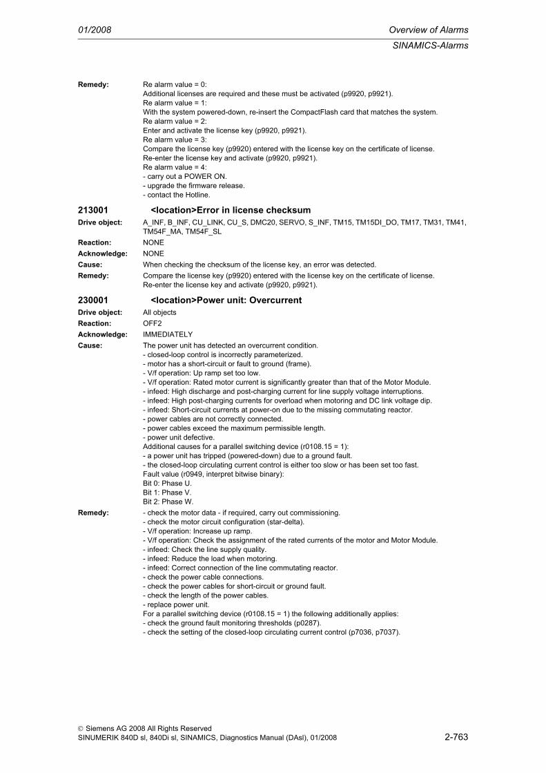
SINAMICS-Alarms
01/2008 Overview of Alarms
2-763
© Siemens AG 2008 All Rights ReservedSINUMERIK 840D sl, 840Di sl, SINAMICS, Diagnostics Manual (DAsl), 01/2008
Remedy: Re alarm value = 0:Additional licenses are required and these must be activated (p9920, p9921).Re alarm value = 1:With the system powered-down, re-insert the CompactFlash card that matches the system.Re alarm value = 2:Enter and activate the license key (p9920, p9921).Re alarm value = 3:Compare the license key (p9920) entered with the license key on the certificate of license.Re-enter the license key and activate (p9920, p9921).Re alarm value = 4:- carry out a POWER ON.- upgrade the firmware release.- contact the Hotline.
213001 <location>Error in license checksumDrive object: A_INF, B_INF, CU_LINK, CU_S, DMC20, SERVO, S_INF, TM15, TM15DI_DO, TM17, TM31, TM41,
TM54F_MA, TM54F_SLReaction: NONEAcknowledge: NONECause: When checking the checksum of the license key, an error was detected.Remedy: Compare the license key (p9920) entered with the license key on the certificate of license.
Re-enter the license key and activate (p9920, p9921).
230001 <location>Power unit: OvercurrentDrive object: All objectsReaction: OFF2Acknowledge: IMMEDIATELYCause: The power unit has detected an overcurrent condition.
- closed-loop control is incorrectly parameterized.- motor has a short-circuit or fault to ground (frame).- V/f operation: Up ramp set too low.- V/f operation: Rated motor current is significantly greater than that of the Motor Module.- infeed: High discharge and post-charging current for line supply voltage interruptions.- infeed: High post-charging currents for overload when motoring and DC link voltage dip.- infeed: Short-circuit currents at power-on due to the missing commutating reactor.- power cables are not correctly connected.- power cables exceed the maximum permissible length.- power unit defective.Additional causes for a parallel switching device (r0108.15 = 1):- a power unit has tripped (powered-down) due to a ground fault.- the closed-loop circulating current control is either too slow or has been set too fast.Fault value (r0949, interpret bitwise binary):Bit 0: Phase U.Bit 1: Phase V.Bit 2: Phase W.
Remedy: - check the motor data - if required, carry out commissioning.- check the motor circuit configuration (star-delta).- V/f operation: Increase up ramp.- V/f operation: Check the assignment of the rated currents of the motor and Motor Module.- infeed: Check the line supply quality.- infeed: Reduce the load when motoring.- infeed: Correct connection of the line commutating reactor.- check the power cable connections.- check the power cables for short-circuit or ground fault.- check the length of the power cables.- replace power unit.For a parallel switching device (r0108.15 = 1) the following additionally applies:- check the ground fault monitoring thresholds (p0287).- check the setting of the closed-loop circulating current control (p7036, p7037).

Overview of Alarms 01/2008
SINAMICS-Alarms
2-764
© Siemens AG 2008 All Rights ReservedSINUMERIK 840D sl, 840Di sl, SINAMICS, Diagnostics Manual (DAsl), 01/2008
230002 <location>Power unit: DC link voltage, overvoltageDrive object: All objectsReaction: OFF2Acknowledge: IMMEDIATELYCause: The power unit has detected an overvoltage condition in the DC link.
- motor regenerates too much energy.- line supply voltage too high.- when operating with a VSM, the phase assignment L1, L2, L3 at the VSM differs from the phase assignment at the power unit.Fault value (r0949, interpret decimal):DC link voltage [1 bit = 100 mV].For SINAMICS GM/SM, the following applies:Fault value (r0949, interpret decimal):32: Overvoltage in the negative partial DC link (VdcP)64: Overvoltage in the positive partial DC link (VdcN)96: Overvoltage in both partial -DC links
Remedy: - increase the ramp-down time.- activate the DC link voltage controller.- use a brake resistor or Active Line Module.- increase the current limit of the infeed or use a larger module (for the Active Line Module).- check the line supply voltage.- check and correct the phase assignment at the VSM and at the power unit.See also: p0210 (Drive unit line supply voltage), p1240 (Vdc controller or Vdc monitoring configura-tion)
230003 <location>Power unit: DC link voltage, undervoltageDrive object: All objectsReaction: OFF2Acknowledge: IMMEDIATELYCause: The power unit has detected an undervoltage condition in the DC link.
- line supply failure- line supply voltage below the permissible value.- line supply infeed failed or faulted.Note:The monitoring threshold for the DC link undervoltage is the minimum of the following values:- 85% of the unit supply voltage (p0210).- lowest permissible lower DC link voltage of the power units (descriptive data).
Remedy: - check the line supply voltage- check the line supply infeed and if necessary observe the fault messages of the line supply infeed.Note:The ready signal of the infeed r0863 must be connected to the associated inputs p0864 of the drives.See also: p0210 (Drive unit line supply voltage)
230004 <location>Power unit: Overtemperature heatsink AC inverterDrive object: All objectsReaction: OFF2Acknowledge: IMMEDIATELYCause: The temperature of the power unit heatsink has exceeded the permissible limit value.
- insufficient cooling, fan failure.- overload- ambient temperature too high.- pulse frequency too high.Fault value (r0949):Temperature [1 bit = 0.01 °C].

SINAMICS-Alarms
01/2008 Overview of Alarms
2-765
© Siemens AG 2008 All Rights ReservedSINUMERIK 840D sl, 840Di sl, SINAMICS, Diagnostics Manual (DAsl), 01/2008
Remedy: - check whether the fan is running.- check the fan elements- check whether the ambient temperature is in the permissible range.- check the motor load.- reduce the pulse frequency if this is higher than the rated pulse frequency.Notice:This fault can only be acknowledged after this alarm threshold for alarm A05000 has been fallen below.See also: p1800 (Pulse frequency)
230005 <location>Power unit: Overload I2tDrive object: All objectsReaction: OFF2Acknowledge: IMMEDIATELYCause: The power unit was overloaded (r0036 = 100 %).
- the permissible rated power unit current was exceeded for an inadmissibly long time.- the permissible load duty cycle was not maintained.Fault value (r0949, interpret decimal):I2t [100 % = 16384].
Remedy: - reduce the continuous load.- adapt the load duty cycle.- check the motor and power unit rated currents.See also: r0036 (Power unit overload I2t), r0206 (Rated power unit power), p0307 (Rated motor power)
230006 <location>Power unit: Thyristor Control BoardDrive object: All objectsReaction: OFF2Acknowledge: IMMEDIATELYCause: The Thyristor Control Board (TCB) of the Basic Line Module signals a fault.
- there is not line supply voltage.- the line contactor is not closed.- the line supply voltage is too low.- line supply frequency outside the permissible range (45 ... 66 Hz).- there is a DC link short-circuit.- there is a DC link short-circuit (during the pre-charging phase).- voltage supply for the Thyristor Control Board outside the nominal range (5 ... 18 V) and line voltage >30 V.- there is an internal fault in the Thyristor Control Board.
Remedy: The faults must be saved in the Thyristor Control Board and must be acknowledged. To do this, the supply voltage of the Thyristor Control Board must be switched-out for at least 10 s!- check the line supply voltage- check or energize the line contactor.- check the monitoring time and, if required, increase (p0857).- if required, observe additional power unit messages/signals.- check the DC link regarding short-circuit or ground fault.- evaluate diagnostic LEDs for the Thyristor Control Board.
230008 <location>Power unit: Sign-of-life error cyclic dataDrive object: All objectsReaction: A_INFEED: NONE (OFF1, OFF2)
SERVO: NONE (OFF1, OFF2, OFF3)Acknowledge: IMMEDIATELYCause: A DRIVE-CLiQ communications error has occurred between the Control Unit and the power unit
involved.The cyclic setpoint telegrams of the Control Unit were not received on time by the power unit for at least two clock cycles within a time interval of 20 ms.
Remedy: - check the electrical cabinet design and cable routing for EMC compliance

Overview of Alarms 01/2008
SINAMICS-Alarms
2-766
© Siemens AG 2008 All Rights ReservedSINUMERIK 840D sl, 840Di sl, SINAMICS, Diagnostics Manual (DAsl), 01/2008
230010 <location>Power unit: Sign-of-life error cyclic dataDrive object: All objectsReaction: NONEAcknowledge: NONECause: A DRIVE-CLiQ communications error has occurred between the Control Unit and the power unit
involved.The cyclic setpoint telegrams of the Control Unit were not received on time by the power unit for at least one clock cycle.
Remedy: - check the electrical cabinet design and cable routing for EMC compliance
230011 <location>Power unit: Line phase failure in main circuitDrive object: All objectsReaction: OFF2 (OFF1)Acknowledge: IMMEDIATELYCause: A line phase failure was detected at the power unit.
- the fuse of a phase of a main circuit has ruptured.- the DC link voltage ripple has exceeded the permissible limit value.
Remedy: Check the fuses in the main circuit.
230012 <location>Power unit: Temperature sensor heatsink wire breakageDrive object: All objectsReaction: OFF1 (OFF2)Acknowledge: IMMEDIATELYCause: The connection to one of the heatsink temperature sensors in the power unit is interrupted.
Fault value (r0949, interpret hexadecimal):Bit 0: Module slot (electronics slot)Bit 1: Air intakeBit 2: Inverter 1Bit 3: Inverter 2Bit 4: Inverter 3Bit 5: Inverter 4Bit 6: Inverter 5Bit 7: Inverter 6Bit 8: Rectifier 1Bit 9: Rectifier 2See also: r0949 (Fault value)
Remedy: Contact the manufacturer.
230013 <location>Power unit: Temperature sensor heatsink short-circuitDrive object: All objectsReaction: OFF1 (OFF2)Acknowledge: IMMEDIATELYCause: The heatsink temperature sensor in the Motor Module is short-circuited.
Fault value (r0949, interpret hexadecimal):Bit 0: Module slot (electronics slot)Bit 1: Air intakeBit 2: Inverter 1Bit 3: Inverter 2Bit 4: Inverter 3Bit 5: Inverter 4Bit 6: Inverter 5Bit 7: Inverter 6Bit 8: Rectifier 1Bit 9: Rectifier 2
Remedy: Contact the manufacturer.
230016 <location>Power unit: Load supply switched-outDrive object: SERVOReaction: NONEAcknowledge: NONE

SINAMICS-Alarms
01/2008 Overview of Alarms
2-767
© Siemens AG 2008 All Rights ReservedSINUMERIK 840D sl, 840Di sl, SINAMICS, Diagnostics Manual (DAsl), 01/2008
Cause: The following applies for CU31x and CUA31:The DC link voltage is too low.Fault value (r0949, interpret decimal):DC link voltage in [V].
Remedy: The following applies for CU31x and CUA31:Under certain circumstances, the AC line supply is not switched-in.
230017 <location>Power unit: Hardware current limit has responded too oftenDrive object: All objectsReaction: OFF2Acknowledge: IMMEDIATELYCause: The hardware current limitation in the relevant phase (see A30031, A30032, A30033) has responded
too often. The number of times the limit has been exceeded depends on the design and type of power unit.For infeed units, the following applies:- closed-loop control is incorrectly parameterized.- load on the infeed is too high.- Voltage Sensing Module incorrectly connected.- commutating reactor missing or the incorrect type.- power unit defective.The following applies to Motor Modules:- closed-loop control is incorrectly parameterized.- fault in the motor or in the power cables.- the power cables exceed the maximum permissible length.- motor load too high- power unit defective.Fault value (r0949, interpret binary):Bit 0: Phase UBit 1: Phase VBit 2: Phase W
Remedy: For infeed units, the following applies:- check the controller settings, if required, reset and identify the controller (p0340 = 2, p3410 = 5).- reduce the load, if required, increase the DC link capacitance or use a higher-rating infeed.- check the connection of the optional Voltage Sensing Module.- check the connection and technical data of the commutating reactor.- check the power cables for short-circuit or ground fault.- replace power unit.The following applies to Motor Modules:- check the motor data.- check the motor circuit configuration (star-delta).- check the motor load.- check the power cable connections.- check the power cables for short-circuit or ground fault.- check the length of the power cables.- replace power unit.
230021 <location>Power unit: Ground faultDrive object: All objectsReaction: OFF2Acknowledge: IMMEDIATELYCause: Power unit has detected a ground fault.
- ground fault in the power cables- winding fault or ground fault at the motor.- CT defective.Additional cause for CU310/CUA31:- when the brake is applied, this causes the hardware DC current monitoring to respond.Fault value (r0949, interpret decimal):Absolute value, summed current [32767 = 271 % rated current].Additional cause for parallel switching units (r0108 bit 15 = 1):- the closed-loop circulating current control is either too slow or has been set too fast.

Overview of Alarms 01/2008
SINAMICS-Alarms
2-768
© Siemens AG 2008 All Rights ReservedSINUMERIK 840D sl, 840Di sl, SINAMICS, Diagnostics Manual (DAsl), 01/2008
Remedy: - check the power cable connections.- check the motor.- check the CT.The following applies additionally for CU310 and CUA31:- check the cables and contacts of the brake connection (a wire is possibly broken).For parallel switching units (r0108 bit 15 = 1) the following also applies:- check the ground fault monitoring thresholds (p0287).- check the setting of the closed-loop circulating current control (p7036, p7037).See also: p0287 (Ground fault monitoring thresholds)
230022 <location>Power unit: Monitoring V_ceDrive object: All objectsReaction: OFF2Acknowledge: POWER ONCause: In the power unit, the monitoring of the collector-emitter voltage (V_ce) of the semiconductor has
responded.Possible causes:- fiber-optic cable interrupted.- power supply of the IGBT gating module missing.- short-circuit at the Motor Module output.- defective semiconductor in the power unit.Fault value (r0949, interpret binary):Bit 0: Short-circuit in phase UBit 1: Short circuit in phase VBit 2: Short-circuit in phase WBit 3: Light transmitter enable defectiveBit 4: V_ce group fault signal interruptedSee also: r0949 (Fault value)
Remedy: - check the fiber-optic cable and if required, replace.- check the power supply of the IGBT gating module (24 V).- check the power cable connections.- select the defective semiconductor and replace.
230023 <location>Power unit: Overtemperature thermal model alarmDrive object: All objectsReaction: NONEAcknowledge: NONECause: The temperature difference between the heatsink and chip has exceeded the permissible limit value.
- the permissible load duty cycle was not maintained.- insufficient cooling, fan failure.- overload- ambient temperature too high.- pulse frequency too high.See also: r0037
Remedy: - adapt the load duty cycle.- check whether the fan is running.- check the fan elements- check whether the ambient temperature is in the permissible range.- check the motor load.- reduce the pulse frequency if this is higher than the rated pulse frequency.
230024 <location>Power unit: Overtemperature thermal modelDrive object: All objectsReaction: OFF2Acknowledge: IMMEDIATELY

SINAMICS-Alarms
01/2008 Overview of Alarms
2-769
© Siemens AG 2008 All Rights ReservedSINUMERIK 840D sl, 840Di sl, SINAMICS, Diagnostics Manual (DAsl), 01/2008
Cause: The temperature difference between the heatsink and chip has exceeded the permissible limit value.- the permissible load duty cycle was not maintained.- insufficient cooling, fan failure.- overload- ambient temperature too high.- pulse frequency too high.See also: r0037
Remedy: - adapt the load duty cycle.- check whether the fan is running.- check the fan elements- check whether the ambient temperature is in the permissible range.- check the motor load.- reduce the pulse frequency if this is higher than the rated pulse frequency.
230025 <location>Power unit: Chip overtemperatureDrive object: All objectsReaction: OFF2Acknowledge: IMMEDIATELYCause: Chip temperature of the semiconductor has exceeded the permissible limit value.
- the permissible load duty cycle was not maintained.- insufficient cooling, fan failure.- overload- ambient temperature too high.- pulse frequency too high.Fault value (r0949):Temperature difference between the heatsink and chip [1 Bit = 0.01 °C].
Remedy: - adapt the load duty cycle.- check whether the fan is running.- check the fan elements- check whether the ambient temperature is in the permissible range.- check the motor load.- reduce the pulse frequency if this is higher than the rated pulse frequency.Notice:This fault can only be acknowledged after this alarm threshold for alarm A05001 has been fallen below.See also: r0037
230027 <location>Power unit: Precharging DC link time monitoringDrive object: All objectsReaction: OFF2Acknowledge: IMMEDIATELY

Overview of Alarms 01/2008
SINAMICS-Alarms
2-770
© Siemens AG 2008 All Rights ReservedSINUMERIK 840D sl, 840Di sl, SINAMICS, Diagnostics Manual (DAsl), 01/2008
Cause: The power unit DC link was not able to be pre-charged within the expected time.- line supply voltage too low.- line supply phase fault.- short-circuit or ground fault in the DC link.- pre-charging circuit defective.Fault value (r0949):Missing internal enable signals, power unit (lower 16 bit):(Inverted bit-coded notation FFFF hex -> all internal enable signals available)Bit 0: Power supply of the IGBT gating shut downBit 1: ReservedBit 2: ReservedBit 3: Ground fault detectedBit 4: Peak current interventionBit 5: I2t exceededBit 6. Thermal model overtemperature calculatedBit 7: (heatsink, gating module, power unit) overtemperature measuredBit 8: ReservedBit 9: Overvoltage detectedBit 10: Power unit has completed pre-charging, ready for pulse enableBit 11: STO terminal missingBit 12: Overcurrent detectedBit 13: Armature short-circuit activeBit 14: DRIVE-CLiQ fault activeBit 15: Uce fault detected, transistor de-saturated due to overcurrent/circuit-circuitStatus, power unit (upper 16 bit, hexadecimal number):0: Fault status (wait for OFF and fault acknowledgement)1: Restart inhibit (wait for OFF)2: Overvoltage condition detected -> change into the fault state3: Undervoltage condition detected -> change into the fault state4: Wait for bypass contactor to open -> change into the fault state5: Wait for bypass contactor to open -> change into restart inhibit6: Commissioning7: Ready for pre-charging8: Pre-charging started, DC link voltage lower than the minimum switch-on voltage9: Pre-charging, DC link voltage end of pre-charging still not detected10: Wait for the end of the de-bounce time of the main contactor after pre-charging has been com-pleted11: Pre-charging completed, ready for pulse enable12: It was detected that the STO terminal was energized at the power unitSee also: p0210 (Drive unit line supply voltage)
Remedy: - check the line supply voltage- check the line supply.- line contactor was closed during the DC link fast discharge by the braking module, the pre-charging resistor must cool down, check the interconnection of the external line contactor.See also: p0210 (Drive unit line supply voltage)
230031 <location>Power unit: Hardware current limiting, phase UDrive object: All objectsReaction: NONEAcknowledge: NONECause: Hardware current limit for phase U responded. The pulsing in this phase is inhibited for one pulse
period.- closed-loop control is incorrectly parameterized.- fault in the motor or in the power cables.- the power cables exceed the maximum permissible length.- motor load too high- power unit defective.
Remedy: - check the motor data.- check the motor circuit configuration (star-delta).- check the motor load.- check the power cable connections.- check the power cables for short-circuit or ground fault.- check the length of the power cables.

SINAMICS-Alarms
01/2008 Overview of Alarms
2-771
© Siemens AG 2008 All Rights ReservedSINUMERIK 840D sl, 840Di sl, SINAMICS, Diagnostics Manual (DAsl), 01/2008
230032 <location>Power unit: Hardware current limiting, phase VDrive object: All objectsReaction: NONEAcknowledge: NONECause: Hardware current limit for phase V responded. The pulsing in this phase is inhibited for one pulse
period.- closed-loop control is incorrectly parameterized.- fault in the motor or in the power cables.- the power cables exceed the maximum permissible length.- motor load too high- power unit defective.
Remedy: - check the motor data.- check the motor circuit configuration (star-delta).- check the motor load.- check the power cable connections.- check the power cables for short-circuit or ground fault.- check the length of the power cables.
230033 <location>Power unit: Hardware current limiting, phase WDrive object: All objectsReaction: NONEAcknowledge: NONECause: Hardware current limit for phase W responded. The pulsing in this phase is inhibited for one pulse
period.- closed-loop control is incorrectly parameterized.- fault in the motor or in the power cables.- the power cables exceed the maximum permissible length.- motor load too high- power unit defective.
Remedy: - check the motor data.- check the motor circuit configuration (star-delta).- check the motor load.- check the power cable connections.- check the power cables for short-circuit or ground fault.- check the length of the power cables.
230035 <location>Power unit: Air intake overtemperatureDrive object: All objectsReaction: OFF1 (OFF2)Acknowledge: IMMEDIATELYCause: Power unit air intake temperature has exceeded the permissible limit value. For air-cooled power
units, the limit is at 55 degrees Celsius.- ambient temperature too high.- insufficient cooling, fan failureFault value (r0949):Temperature [1 bit = 0.01 °C].
Remedy: - check whether the fan is running.- check the fan elements- check whether the ambient temperature is in the permissible range.Notice:This fault can only be acknowledged after this alarm threshold for alarm A05002 has been fallen below.
230036 <location>Power unit: Electronics board overtemperatureDrive object: All objectsReaction: OFF2Acknowledge: IMMEDIATELY

Overview of Alarms 01/2008
SINAMICS-Alarms
2-772
© Siemens AG 2008 All Rights ReservedSINUMERIK 840D sl, 840Di sl, SINAMICS, Diagnostics Manual (DAsl), 01/2008
Cause: Power unit temperature in the module slot of the drive converter has exceeded the permissible limit value.- insufficient cooling, fan failure.- overload- ambient temperature too high.Fault value (r0949):Temperature [1 bit = 0.01 °C].
Remedy: - check whether the fan is running.- check the fan elements- check whether the ambient temperature is in the permissible range.Notice:This fault can only be acknowledged after this alarm threshold for alarm A05003 has been fallen below.
230037 <location>Power unit: Rectifier overtemperatureDrive object: All objectsReaction: OFF2Acknowledge: IMMEDIATELYCause: Power unit rectifier temperature has exceeded the permissible limit value.
- insufficient cooling, fan failure.- overload- ambient temperature too high.- line supply phase failure.Fault value (r0949):Temperature [1 bit = 0.01 °C].
Remedy: - check whether the fan is running.- check the fan elements- check whether the ambient temperature is in the permissible range.- check the motor load.- check the line supply phases.Notice:This fault can only be acknowledged after this alarm threshold for alarm A05004 has been fallen below.
230038 <location>Power unit: Capacitor fan monitoringDrive object: B_INFReaction: NONEAcknowledge: NONECause: The capacitor fan signals a fault.Remedy: Replace the capacitor fan in the power unit.
230039 <location>Power unit: Failure capacitor fanDrive object: B_INFReaction: OFF1Acknowledge: IMMEDIATELYCause: The capacitor fan has failed.Remedy: Replace the capacitor fan in the power unit.
230040 <location>Power unit: Undervolt 24 VDrive object: All objectsReaction: OFF2Acknowledge: POWER ONCause: Failure of the 24 V power supply for the power unit.
- the 16 V threshold was fallen below for longer than 3 ms.Fault value (r0949):24 V voltage [1 bit = 0.1 V].
Remedy: Check the 24 V DC voltage supply to power unit.

SINAMICS-Alarms
01/2008 Overview of Alarms
2-773
© Siemens AG 2008 All Rights ReservedSINUMERIK 840D sl, 840Di sl, SINAMICS, Diagnostics Manual (DAsl), 01/2008
230041 <location>Power unit: Undervoltage 24 V alarmDrive object: All objectsReaction: NONEAcknowledge: NONECause: 24 V power supply fault for the power unit.
- the 16 V threshold was fallen below.Fault value (r0949):24 V voltage [1 bit = 0.1 V].
Remedy: Check the 24 V DC voltage supply to power unit.
230042 <location>Power unit: Fan operating time reached or exceededDrive object: All objectsReaction: NONEAcknowledge: NONECause: The maximum operating time of the fan in the power unit is set in p0252.
This message indicates the following:Fault value (r0949, interpret decimal):0: The maximum fan operating time is 500 hours.1: The maximum fan operating time has been exceeded.
Remedy: Replace the fan in the power unit and reset the operating hours counter to 0 (p0251 = 0).See also: p0251 (Operating hours counter power unit fan), p0252 (Maximum operating time power unit fan)
230043 <location>Power unit: Overvolt 24 VDrive object: All objectsReaction: OFF2Acknowledge: POWER ONCause: The following applies for CU31x:
Overvoltage of the 24 V power supply for the power unit.- the 31.5 V threshold was exceeded for more than 3 ms.Fault value (r0949):24 V voltage [1 bit = 0.1 V].
Remedy: Check the 24 V DC voltage supply to power unit.
230044 <location>Power unit: Overvoltage 24 V alarmDrive object: All objectsReaction: NONEAcknowledge: NONECause: The following applies for CU31x:
24 V power supply fault for the power unit.- the 32.0 V threshold was exceeded.Fault value (r0949):24 V voltage [1 bit = 0.1 V].
Remedy: Check the 24 V DC voltage supply to power unit.
230045 <location>Power unit: Supply undervoltageDrive object: All objectsReaction: OFF2Acknowledge: POWER ONCause: The following applies for CU31x:
Power supply fault in the power unit.- the voltage monitoring on the DAC board signals an undervoltage fault on the module.
Remedy: Check the 24 V DC power supply for the power unit and if required replace the module.
230046 <location>Power unit: Undervoltage, alarmDrive object: All objectsReaction: NONEAcknowledge: NONE

Overview of Alarms 01/2008
SINAMICS-Alarms
2-774
© Siemens AG 2008 All Rights ReservedSINUMERIK 840D sl, 840Di sl, SINAMICS, Diagnostics Manual (DAsl), 01/2008
Cause: Before the last new start, a problem occurred at the power unit power supply.- the voltage monitoring in the internal FPGA of the PSA signals an undervoltage fault on the module.Fault value (r0949):Register value of the voltage fault register.
Remedy: Check the 24 V DC power supply for the power unit and if required replace the module.
230047 <location>Cooling system: Cooling medium flow rate too lowDrive object: A_INF, B_INF, SERVO, S_INFReaction: OFF2Acknowledge: IMMEDIATELYCause: Cooling system: Fault - flow rate has fallen below the fault valueRemedy:
230050 <location>Power unit: Supply overvoltageDrive object: All objectsReaction: OFF2Acknowledge: POWER ONCause: The following applies for CU31x and CUA31:
- the voltage monitoring on the DAC board signals an overvoltage fault on the module.Remedy: - check the voltage supply for the Control Unit (24 V).
- if required, replace the module.
230052 <location>EEPROM data errorDrive object: All objectsReaction: NONEAcknowledge: POWER ONCause: EEPROM data error of the power unit module.
Fault value (r0949, interpret hexadecimal):0: The EEPROM data read-in from the power unit module is inconsistent.1: EEPROM data is not compatible to the firmware of the power unit application.
Remedy: Re fault value = 0:Replace the power unit module or update the EEPROM data.Re fault value = 1:The following applies for CU31x and CUA31:Update the firmware \SIEMENS\SINAMICS\CODE\SAC\cu31xi.ufw (cua31.ufw)
230070 <location>Cycle requested by the power unit module not supportedDrive object: All objectsReaction: OFF2Acknowledge: IMMEDIATELYCause: The following applies for CU31x and CUA31:
A cycle is requested that is not supported by the power unit.Fault value (r0949, interpret hexadecimal):The following applies for CU31x and CUA31:0: The current control cycle is not supported.1: The DRIVE-CLiQ cycle is not supported.2: Internal timing problem (clearance between RX and TX instants too low).3: Internal timing problem (TX instant too early).
Remedy: The following applies for CU31x and CUA31:The power unit only supports the following cycles:62.5 µs, 125 µs, 250 µs and 500 µsFault value (r0949, interpret hexadecimal):The following applies for CU31x and CUA31:0: Set a permitted current control cycle.1: Set a permitted DRIVE-CLiQ cycle.2/3: Contact the manufacturer (there is possibly an incompatible firmware release).

SINAMICS-Alarms
01/2008 Overview of Alarms
2-775
© Siemens AG 2008 All Rights ReservedSINUMERIK 840D sl, 840Di sl, SINAMICS, Diagnostics Manual (DAsl), 01/2008
230071 <location>No new actual values received from the power unit moduleDrive object: All objectsReaction: OFF2Acknowledge: IMMEDIATELYCause: The following applies for CU31x and CUA31:
More than one actual value telegram from the power unit has failed.Remedy: The following applies for CU31x and CUA31:
Check the interface (adjustment and locking) to the power unit.
230072 <location>Setpoints are no longer being transferred to the power unitDrive object: All objectsReaction: OFF2Acknowledge: IMMEDIATELYCause: The following applies for CU31x and CUA31:
More than one setpoint telegram was not able to be transferred to the power unit.Remedy: The following applies for CU31x and CUA31:
Check the interface (adjustment and locking) to the power unit.
230073 <location>Actual value/setpoint preprocessing no longer synchronous to DRIVE-CLiQ
Drive object: All objectsReaction: NONEAcknowledge: NONECause: The following applies for CU31x and CUA31:
Communications to the power unit module are no longer in synchronism with DRIVE-CLiQ.Remedy: The following applies for CU31x and CUA31:
Wait until synchronization is re-established.
230074 <location>Communications error to the power unit moduleDrive object: All objectsReaction: NONEAcknowledge: IMMEDIATELYCause: Communications is not possible to the power unit via the plug contact.Remedy: The following applies for CU31x and CUA31:
Either replace the CU board or the power unit. You must check which of the two components must be replaced by replacing one and then the other component; if neither are available then both compo-nents must be returned.
230105 <location>PU: Actual value sensing faultDrive object: All objectsReaction: OFF2Acknowledge: IMMEDIATELYCause: At least one incorrect actual value channel was detected on the Power Stack Adapter (PSA).
The incorrect actual value channels are displayed in the following diagnostic parameters.Remedy: Evaluate the diagnostic parameters.
If the actual value channel is incorrect, check the components and if required, replace.
230600 <location>SI MM: STOP A initiatedDrive object: All objectsReaction: OFF2Acknowledge: IMMEDIATELY (POWER ON)

Overview of Alarms 01/2008
SINAMICS-Alarms
2-776
© Siemens AG 2008 All Rights ReservedSINUMERIK 840D sl, 840Di sl, SINAMICS, Diagnostics Manual (DAsl), 01/2008
Cause: The drive-based "Safety Integrated" function in the Motor Module (MM) has detected a fault and initi-ated STOP A (pulse cancelation via the safety shutdown path of the Motor Module).- forced checking procedure of the safety shutdown path of the Motor Module unsuccessful.- subsequent response to fault F30611 (defect in a monitoring channel).Fault value (r0949, interpret decimal):0: Stop request from the Control Unit.1005: Pulses canceled although STO not selected and there is no internal STOP A present.1010: Pulses enabled although STO is selected or an internal STOP A is present.9999: Subsequent response to fault F30611.
Remedy: - select Safe Torque Off and de-select again.- replace the Motor Module involved.Re fault value = 9999:- carry out diagnostics for fault F30611.Note:CU: Control UnitMM: Motor ModuleSI: Safety IntegratedSTO: Safe Torque Off / SH: Safe standstill
230611 <location>SI MM: Defect in a monitoring channel".Drive object: All objectsReaction: A_INFEED: NONE (OFF1, OFF2)
SERVO: NONE (OFF1, OFF2, OFF3)Acknowledge: IMMEDIATELY (POWER ON)Cause: The drive-based "Safety Integrated" function in the Motor Module (MM) has detected a fault in the data
cross-check between the Control Unit (CU) and MM and initiated a STOP F.As a result of this fault, after the parameterized transition has expired (p9858), fault F30600 is output (SI MM: STOP A initiated).Fault value (r0949, interpret decimal):0: Stop request from the Control Unit.1 to 999:Number of the cross-checked data that resulted in this fault. This number is also displayed in r9895.1: SI monitoring clock cycle (r9780, r9880).2: SI enable safety functions (p9601, p9801). Crosswise data comparison is only carried out for the supported bits.3: SI SGE changeover tolerance time (p9650, p9850).4: SI transition period STOP F to STOP A (p9658, p9858).5: SI enable Safe Brake Control (p9602, p9802).6: SI motion enable, safety-relevant functions (p9501, internal value).7: SI pulse cancelation delay time for Safe Stop 1 (p9652, p9852).8: SI PROFIsafe address (p9610, p9810).1000: Watchdog timer has expired. Within the time of approx. 5 * p9850 too many switching operations have occurred at the safety-related inputs of the Control Unit.1001, 1002: Initialization error, change timer / check timer.2000: Status of the STO terminals on the Control Unit and Motor Module are different.2001: Feedback signal for safe pulse cancelation on the Control Unit and Motor Module are different.2002: Status of the delay timer SS1 on the Control Unit and Motor Module are different.

SINAMICS-Alarms
01/2008 Overview of Alarms
2-777
© Siemens AG 2008 All Rights ReservedSINUMERIK 840D sl, 840Di sl, SINAMICS, Diagnostics Manual (DAsl), 01/2008
Remedy: Re fault value = 1 to 5 and 7 to 999:- check the cross-checked data that resulted in a STOP F.- carry out a POWER ON (power off/on) for all components.- upgrade the Motor Module software.- upgrade the Control Unit software.Re fault value = 6:- carry out a POWER ON (power off/on) for all components.- upgrade the Motor Module software.- upgrade the Control Unit software.Re fault value = 1000:- check the wiring of the safety-relevant inputs (SGE) on the Control Unit (contact problems).Re fault value = 1001, 1002:- carry out a POWER ON (power off/on) for all components.- upgrade the Motor Module software.- upgrade the Control Unit software.Re fault value = 2000, 2001, 2002:- check the tolerance time SGE changeover and if required, increase the value (p9650/p9850, p9652/p9852).- check the wiring of the safety-relevant inputs (SGE) (contact problems).- replace the Motor Module involved.Note:CU: Control UnitMM: Motor ModuleSGE: Safety-relevant inputSI: Safety IntegratedSS1: Safe Stop 1 (corresponds to Stop Category 1 acc. to EN60204)STO: Safe Torque Off / SH: Safe standstill
230620 <location>SI MM: Safe Torque Off activeDrive object: All objectsReaction: NONEAcknowledge: NONECause: The "Safe Torque Off" function was selected on the Motor Module (MM) via the input terminal and is
active.Note:This message does not result in a safety stop response.
Remedy: None necessary.Note:MM: Motor ModuleSI: Safety IntegratedSTO: Safe Torque Off / SH: Safe standstill
230621 <location>SI MM: Safe Stop 1 activeDrive object: All objectsReaction: NONEAcknowledge: NONECause: The "Safe Stop 1" function (SS1) was selected on the Motor Module (MM) and is active.
Note:This message does not result in a safety stop response.
Remedy: None necessary.Note:MM: Motor ModuleSI: Safety IntegratedSS1: Safe Stop 1 (corresponds to Stop Category 1 acc. to EN60204)
230625 <location>SI MM: Sign-of-life error in safety dataDrive object: All objectsReaction: OFF2Acknowledge: IMMEDIATELY (POWER ON)

Overview of Alarms 01/2008
SINAMICS-Alarms
2-778
© Siemens AG 2008 All Rights ReservedSINUMERIK 840D sl, 840Di sl, SINAMICS, Diagnostics Manual (DAsl), 01/2008
Cause: The drive-based "Safety Integrated" function on the Motor Module (MM) has detected an error in the sign-of-life of the safety data between the Control Unit (CU) and MM and initiated a STOP A.- there is either a DRIVE-CLiQ communications error or communications have failed.- a time slice overflow of the safety software has occurred.Fault value (r0949, interpret decimal):Only for internal Siemens troubleshooting.
Remedy: - select Safe Torque Off and de-select again.- carry out a POWER ON (power off/on) for all components.- check whether there is a DRIVE-CLiQ communications error between the Control Unit and the Motor Module involved and if required, carry out a diagnostics routine for the faults identified.- de-select all drive functions that are not absolutely necessary.- reduce the number of drives.- check the electrical cabinet design and cable routing for EMC complianceNote:CU: Control UnitMM: Motor ModuleSI: Safety Integrated
230630 <location>SI MM: Brake control errorDrive object: All objectsReaction: OFF2Acknowledge: IMMEDIATELY (POWER ON)Cause: The drive-based "Safety Integrated" function on the Motor Module (MM) has detected a brake control
error and initiated a STOP A.- no motor holding brake connected.- the motor holding brake control on the Motor Module or the Control Unit is faulty.- a DRIVE-CLiQ communications error has occurred between the Control Unit and the Motor Module.Fault value (r0949, interpret decimal):10: No brake connected or fault in the Motor Module brake control circuit ("open brake" operation).30: Short-circuit in the brake winding or fault in the Motor Module brake control circuit ("close brake" operation).40: Defect in the brake control circuit of the Motor Module ("brake closed" state).60, 70: Fault in the brake control of the Control Unit or communications fault between the Control Unit and Motor Module (brake control).
Remedy: - select Safe Torque Off and de-select again.- check the motor holding brake connection.- check the function of the motor holding brake.- check whether there is a DRIVE-CLiQ communications error between the Control Unit and the Motor Module involved and if required, carry out a diagnostics routine for the faults identified.- check the electrical cabinet design and cable routing for EMC compliance- replace the Motor Module involved.Operation with Safe Brake Module:- check the Safe Brake Modules connection.- replace the Safe Brake Module.Note:CU: Control UnitMM: Motor ModuleSI: Safety Integrated
230640 <location>SI MM: Fault in the shutdown path of the second channelDrive object: All objectsReaction: OFF2Acknowledge: IMMEDIATELY (POWER ON)Cause: The Motor Module has detected a communications error with the higher-level control or the TM54F to
transfer the safety-relevant information.Note:This fault results in a STOP A that can be acknowledged.Fault value (r0949, interpret decimal):Only for internal Siemens troubleshooting.

SINAMICS-Alarms
01/2008 Overview of Alarms
2-779
© Siemens AG 2008 All Rights ReservedSINUMERIK 840D sl, 840Di sl, SINAMICS, Diagnostics Manual (DAsl), 01/2008
Remedy: For the higher-level control, the following applies:- check the PROFIsafe address in the higher-level control and Motor Modules and if required, align.- save all parameters (p0977 = 1).- carry out a POWER ON (power off/on) for all components.For TM54F, carry out the following steps:- start the copy function for the node identifier (p9700 = 1D hex).- acknowledge hardware CRC (p9701 = EC hex).- save all parameters (p0977 = 1).- carry out a POWER ON (power off/on) for all components.The following generally applies:- upgrade the Motor Module software.Note:MM: Motor ModuleSI: Safety IntegratedSee also: p9810 (SI PROFIsafe address (Motor Module))
230649 <location>SI MM: Internal software errorDrive object: All objectsReaction: OFF2Acknowledge: IMMEDIATELY (POWER ON)Cause: An internal error in the Safety Integrated software on the Motor Module has occurred.
Note:This fault results in a STOP A that cannot be acknowledged.Fault value (r0949, interpret hexadecimal):Only for internal Siemens troubleshooting.
Remedy: - carry out a POWER ON (power off/on) for all components.- re-commission the Safety Integrated function and carry out a POWER ON.- upgrade the Motor Module software.- contact the Hotline.- replace the Motor Module.Note:MM: Motor ModuleSI: Safety Integrated
230650 <location>SI MM: Acceptance test requiredDrive object: All objectsReaction: OFF2Acknowledge: IMMEDIATELY (POWER ON)Cause: The "Safety Integrated" function on the Motor Module requires an acceptance test.
Note:This fault results in a STOP A that can be acknowledged.Fault value (r0949, interpret decimal):130: Safety parameters for the Motor Module not available.1000: Reference and actual checksum in the Motor Module are not identical (booting).- at least one checksum-checked piece of data is defective.2000: Reference and actual checksum on the Motor Module are not identical (commissioning mode).- reference checksum incorrectly entered into the Motor Module (p9899 not equal to r9898).2003: Acceptance test is required as a safety parameter has been changed.2005: The safety logbook has identified that the safety checksums have changed. An acceptance test is required.3003: Acceptance test is required as a hardware-related safety parameter has been changed.9999: Subsequent response of another safety-related fault, which occurred when booting and requires an acceptance test.
Overview of Alarms 01/2008
SINAMICS-Alarms
2-780
© Siemens AG 2008 All Rights ReservedSINUMERIK 840D sl, 840Di sl, SINAMICS, Diagnostics Manual (DAsl), 01/2008
Remedy: Re fault value = 130:- carry out safety commissioning routine.Re fault value = 1000:- again carry out safety commissioning routine.- replace the CompactFlash card.Re fault value = 2000:- check the safety parameters in the Motor Module and adapt the reference checksum (p9899).Re fault value = 2003, 2005:- Carry out an acceptance test and generate an acceptance report.Re fault value 3003:- carry out the function checks for the modified hardware and generate an acceptance report.The procedure when carrying out an acceptance test as well as an example of the acceptance report are provided in the following literature:SINAMICS S120 Function Description Safety IntegratedRe fault value = 9999:- carry out diagnostics for the other safety-related fault that is present.Note:MM: Motor ModuleSI: Safety IntegratedSee also: p9799 (SI reference checksum SI parameters (Control Unit)), p9899 (SI reference check-sum SI parameters (Motor Module))
230651 <location>SI MM: Synchronization with Control Unit unsuccessfulDrive object: All objectsReaction: OFF2Acknowledge: IMMEDIATELY (POWER ON)Cause: The drive-based "Safety Integrated" function is requesting synchronization of the safety time slices on
the Control Unit and Motor Module. This synchronization routine was not successful.Note:This fault results in a STOP A that cannot be acknowledged.Fault value (r0949, interpret decimal):Only for internal Siemens troubleshooting.
Remedy: - carry out a POWER ON (power off/on) for all components.- upgrade the Motor Module software.- upgrade the Control Unit software.Note:MM: Motor ModuleSI: Safety Integrated
230652 <location>SI MM: Illegal monitoring clock cycleDrive object: All objectsReaction: OFF2Acknowledge: IMMEDIATELY (POWER ON)Cause: The Safety Integrated monitoring clock cycle cannot be maintained due to the communication condi-
tions requested in the system.Note:This fault results in a STOP A that cannot be acknowledged.Fault value (r0949, interpret decimal):Only for internal Siemens troubleshooting.
Remedy: Upgrade the Motor Module software.Note:MM: Motor ModuleSI: Safety Integrated
230655 <location>SI MM: Align monitoring functionsDrive object: All objectsReaction: OFF2Acknowledge: IMMEDIATELY (POWER ON)

SINAMICS-Alarms
01/2008 Overview of Alarms
2-781
© Siemens AG 2008 All Rights ReservedSINUMERIK 840D sl, 840Di sl, SINAMICS, Diagnostics Manual (DAsl), 01/2008
Cause: An error has occurred when aligning the Safety Integrated monitoring functions on the Control Unit (CU) and Motor Module (MM). Control unit and Motor Module were not able to determine a common set of supported SI monitoring functions.- there is either a DRIVE-CLiQ communications error or communications have failed.- Safety Integrated software releases on the Control Unit and Motor Module are not compatible with one another.Note:This fault results in a STOP A that cannot be acknowledged.Fault value (r0949, interpret hexadecimal):Only for internal Siemens troubleshooting.
Remedy: - carry out a POWER ON (power off/on) for all components.- upgrade the Motor Module software.- upgrade the Control Unit software.- check the electrical cabinet design and cable routing for EMC complianceNote:CU: Control UnitMM: Motor ModuleSI: Safety Integrated
230656 <location>SI MM: Motor Module parameter errorDrive object: All objectsReaction: OFF2Acknowledge: IMMEDIATELY (POWER ON)Cause: When accessing the Safety Integrated parameters for the Motor Module (MM) on the CompactFlash
card, an error has occurred.Note:This fault results in a STOP A that can be acknowledged.Fault value (r0949, interpret decimal):129: Safety parameters for the Motor Module corrupted.131: Internal software error on the Control Unit.255: Internal Motor Module software error.
Remedy: - re-commission the safety functions.- upgrade the Control Unit software.- upgrade the Motor Module software.- replace the CompactFlash card.Note:MM: Motor ModuleSI: Safety Integrated
230659 <location>SI MM: Write request for parameter rejectedDrive object: All objectsReaction: OFF2Acknowledge: IMMEDIATELY (POWER ON)Cause: The write request for one or several Safety Integrated parameters on the Motor Module (MM) was
rejected.Note:This fault does not result in a safety stop response.Fault value (r0949, interpret decimal):10: An attempt was made to enable the STO function although this cannot be supported.11: An attempt was made to enable the SBC function although this cannot be supported.13: An attempt was made to enable the SS1 function although this cannot be supported.14: An attempt was made to enable the safe motion monitoring function with the higher-level control, although this cannot be supported.See also: r9771 (SI common functions (Control Unit)), r9871 (SI common functions (Motor Module)

Overview of Alarms 01/2008
SINAMICS-Alarms
2-782
© Siemens AG 2008 All Rights ReservedSINUMERIK 840D sl, 840Di sl, SINAMICS, Diagnostics Manual (DAsl), 01/2008
Remedy: Re fault value = 10, 11:- check whether there are faults in the safety function alignment between the Control Unit and the Motor Module involved (F01655, F30655) and if required, carry out diagnostics for the faults involved.- use a Motor Module that supports the function "Safe Torque Off" or "Safe Brake Control".- upgrade the Motor Module software.- upgrade the Control Unit software.Note:MM: Motor ModuleSBC: Safe Brake ControlSI: Safety IntegratedSS1: Safe Stop 1 (corresponds to Stop Category 1 acc. to EN60204)STO: Safe Torque Off / SH: Safe standstill
230672 <location>SI Motion: Control Unit software incompatibleDrive object: SERVOReaction: OFF2Acknowledge: IMMEDIATELY (POWER ON)Cause: The existing Control Unit software does not support the safe drive-based motion monitoring function.
Note:This fault results in a STOP A that cannot be acknowledged.Fault value (r0949, interpret decimal):Only for internal Siemens troubleshooting.
Remedy: - check whether there are faults in the safety function alignment between the Control Unit and the Motor Module involved (F01655, F30655) and if required, carry out diagnostics for the faults involved.- use a Control Unit that supports the safe motion monitoring function.- upgrade the Control Unit software.Note:SI: Safety Integrated
230680 <location>SI Motion MM: Checksum error safety monitoring functionsDrive object: SERVOReaction: OFF2Acknowledge: IMMEDIATELY (POWER ON)Cause: The actual checksum calculated by the Motor Module and entered in r9398 over the safety-relevant
parameters does not match the reference checksum saved in p9399 at the last machine acceptance.Safety-relevant parameters have been changed or a fault is present.Note:This fault results in a STOP A that cannot be acknowledged.Fault value (r0949, interpret decimal):0: Checksum error for SI parameters for motion monitoring.1: Checksum error for SI parameters for component assignment.
Remedy: - Check the safety-relevant parameters and if required, correct.- set the reference checksum to the actual checksum.- carry out a POWER ON.- carry out an acceptance test.Note:SI: Safety Integrated
230681 <location>SI Motion MM: Incorrect parameter valueDrive object: SERVOReaction: NONEAcknowledge: IMMEDIATELY (POWER ON)Cause: The parameter value cannot be parameterized with this value.
Fault value (r0949, interpret decimal):Parameter number with the incorrect value.
Remedy: Correct the parameter value.
230682 <location>SI Motion MM: Monitoring function not supportedDrive object: SERVOReaction: OFF2Acknowledge: IMMEDIATELY (POWER ON)

SINAMICS-Alarms
01/2008 Overview of Alarms
2-783
© Siemens AG 2008 All Rights ReservedSINUMERIK 840D sl, 840Di sl, SINAMICS, Diagnostics Manual (DAsl), 01/2008
Cause: The monitoring function enabled in p9301, p9501, p9601 or p9801 is not supported in this firmware version.Note:This fault results in a STOP A that cannot be acknowledged.Fault value (r0949, interpret decimal):30: The firmware version of the Motor Module is older than the version of the Control Unit.
Remedy: De-select the monitoring function involved (p9301, p9301, p9303, p9601, p9801).Upgrade the Motor Module firmware.See also: p9501 (SI motion enable safety functions (Control Unit)), p9503 (SI motion SCA (SN) enable (Control Unit)), p9601 (SI enable, functions integrated in the drive (Control Unit)), p9801 (SI enable, functions integrated in the drive (Motor Module))
230683 <location>SI Motion MM: SOS/SLS enable missingDrive object: SERVOReaction: OFF2Acknowledge: IMMEDIATELY (POWER ON)Cause: The safety-relevant basic function "SOS/SLS" is not enabled in p9301 although other safety-relevant
monitoring functions are enabled.Note:This fault results in a STOP A that cannot be acknowledged.
Remedy: Enable the function "SOS/SLS" (p9301.0).Note:SI: Safety IntegratedSLS: Safely-Limited Speed / SG: Safely reduced speedSOS: Safe Operating Stop / SBH: Safe operating stop
230685 <location>SI Motion MM: Safely-Limited Speed limit value too highDrive object: SERVOReaction: OFF2Acknowledge: IMMEDIATELY (POWER ON)Cause: The limit value for the function "Safely-Limited Speed" (SLS) is greater than the speed that corre-
sponds to an encoder limit frequency of 500 kHz.Fault value (r0949, interpret decimal):Maximum permissible speed.
Remedy: Correct the limit values for SLS and carry out a POWER ON.Note:SI: Safety IntegratedSLS: Safely-Limited Speed / SG: Safely reduced speed
230688 <location>SI Motion MM: Actual value synchronization not permissibleDrive object: SERVOReaction: OFF2Acknowledge: IMMEDIATELY (POWER ON)Cause: It is not permissible to simultaneously enable the actual value synchronization and a monitoring func-
tion with absolute reference (SCA/SLP).Remedy: Either de-select the function "actual value synchronization" or the monitoring functions with absolute
reference (SCA/SLP) and carry out a POWER ON.Note:SCA: Safe Cam / SN: Safe software camSI: Safety IntegratedSLP: Safely-Limited Position / SE: Safe software limit switchesSee also: p9501 (SI motion enable safety functions (Control Unit))
230700 <location>SI Motion MM: STOP A initiatedDrive object: SERVOReaction: OFF2Acknowledge: IMMEDIATELY (POWER ON)

Overview of Alarms 01/2008
SINAMICS-Alarms
2-784
© Siemens AG 2008 All Rights ReservedSINUMERIK 840D sl, 840Di sl, SINAMICS, Diagnostics Manual (DAsl), 01/2008
Cause: The drive is stopped via a STOP A (pulses are canceled via the safety shutdown path of the Control Unit).Possible causes:- stop request from the Control Unit.- pulses not canceled after a parameterized time (p9357) after test stop selection.- subsequent response to the message C30706 "SI Motion: Safe brake ramp exceeded".- subsequent response to the message C30714 "SI Motion: Safely limited speed exceeded".- subsequent response to the message C30701 "SI Motion: STOP B initiated".
Remedy: - remove the cause to the fault on the Control Unit.- check the value in p9357, if required, increase the value.- check the shutdown path of Control Unit (check DRIVE-CLiQ communications).- carry out a diagnostics routine for message C30706.- carry out a diagnostics routine for message C30714.- carry out a diagnostics routine for message C30701.- replace Motor Module.- replace Control Unit.This message can only be acknowledged in the acceptance test mode without POWER ON via the Terminal Module 54F (TM54F) or PROFIsafe.Note:SI: Safety Integrated
230701 <location>SI Motion MM: STOP B initiatedDrive object: SERVOReaction: OFF3Acknowledge: IMMEDIATELY (POWER ON)Cause: The drive is stopped via a STOP B (braking along the OFF3 ramp).
As a result of this fault, after the time, parameterized in p9356 has expired, or the speed threshold, parameterized in p9360 has been fallen below, message C30700 "SI Motion MM: STOP A initiated" is output.Possible causes:- stop request from the Control Unit.- subsequent response to the message C30714 "SI Motion MM: Safely limited speed exceeded".- subsequent response to the message C30711 "SI Motion MM: Defect in a monitoring channel".
Remedy: - remove the fault cause in the control and carry out a POWER ON.- carry out a diagnostics routine for message C01714.- carry out a diagnostics routine for message C01711.This message can only be acknowledged in the acceptance test mode without POWER ON via the Terminal Module 54F (TM54F) or PROFIsafe.Note:SI: Safety Integrated
230706 <location>SI Motion MM: Safe Acceleration Monitor limit exceededDrive object: SERVOReaction: NONEAcknowledge: IMMEDIATELY (POWER ON)Cause: After initiating STOP B or STOP C, the velocity has exceeded the selected tolerance.
The drive is shut down by the message C30700 "SI Motion MM: STOP A initiated".Remedy: Check the braking behavior, if required, adapt the tolerance for "Safe Acceleration Monitor".
This message can only be acknowledged in the acceptance test mode without POWER ON via the Terminal Module 54F (TM54F) or PROFIsafe.Note:SBR: Safe Acceleration MonitorSI: Safety IntegratedSee also: p9548 (SI motion SBR actual velocity tolerance (Control Unit))
230707 <location>SI Motion MM: Tolerance for safe operating stop exceededDrive object: SERVOReaction: NONEAcknowledge: IMMEDIATELY (POWER ON)Cause: The actual position has distanced itself further from the target position than the standstill tolerance.
The drive is shut down by the message C30701 "SI Motion MM: STOP B initiated".

SINAMICS-Alarms
01/2008 Overview of Alarms
2-785
© Siemens AG 2008 All Rights ReservedSINUMERIK 840D sl, 840Di sl, SINAMICS, Diagnostics Manual (DAsl), 01/2008
Remedy: - check whether safety faults are present and if required carry out the appropriate diagnostic routines for the particular faults.- check whether the standstill tolerance matches the accuracy and control dynamic performance of the axis.- carry out a POWER ON.This message can only be acknowledged in the acceptance test mode without POWER ON via the Terminal Module 54F (TM54F) or PROFIsafe.Note:SI: Safety IntegratedSOS: Safe Operating Stop / SBH: Safe operating stopSee also: p9530 (SI motion standstill tolerance (Control Unit))
230708 <location>SI Motion MM: STOP C initiatedDrive object: SERVOReaction: STOP2Acknowledge: IMMEDIATELY (POWER ON)Cause: The drive is stopped via a STOP C (braking along the OFF3 ramp).
"Safe Operating Stop" (SOS) is activated after the parameterized timer stage has expired.Possible causes:- stop request from the higher-level control.- subsequent response to the message C30714 "SI Motion MM: Safely limited speed exceeded".See also: p9552 (SI motion transition time STOP C to SOS (SBH) (Control Unit))
Remedy: - remove the cause of the fault at the control.- carry out a diagnostics routine for message C30714.This message can only be acknowledged via the Terminal Module 54F (TM54F) or PROFIsafe.Note:SI: Safety IntegratedSOS: Safe Operating Stop / SBH: Safe operating stop
230709 <location>SI Motion MM: STOP D initiatedDrive object: SERVOReaction: NONEAcknowledge: IMMEDIATELY (POWER ON)Cause: The drive is stopped via a STOP D (braking along the path).
"Safe Operating Stop" (SOS) is activated after the parameterized timer stage has expired.Possible causes:- stop request from the Control Unit.- subsequent response to the message C30714 "SI Motion: Safely limited speed exceeded".See also: p9553 (SI motion transition time STOP D to SOS (SBH) (Control Unit))
Remedy: - remove the cause of the fault at the control.- carry out a diagnostics routine for message C30714.This message can only be acknowledged via the Terminal Module 54F (TM54F) or PROFIsafe.Note:SI: Safety IntegratedSOS: Safe Operating Stop / SBH: Safe operating stop
230711 <location>SI MM MM: Defect in a monitoring channelDrive object: SERVOReaction: NONEAcknowledge: IMMEDIATELY (POWER ON)

Overview of Alarms 01/2008
SINAMICS-Alarms
2-786
© Siemens AG 2008 All Rights ReservedSINUMERIK 840D sl, 840Di sl, SINAMICS, Diagnostics Manual (DAsl), 01/2008
Cause: When cross-checking and comparing the two monitoring channels, the drive detected a difference between the input data or results of the monitoring functions and initiated a STOP F. One of the mon-itoring functions no longer reliably functions - i.e. safe operation is no longer possible.If at least one monitoring function is active, then after the parameterized timer stage has expired, the message C30701 "SI Motion: STOP B initiated" is output. The alarm is output with message value 1031 when the Sensor Module hardware is replaced.Message value (r9749, interpret decimal):0 ... 999: Number of the cross-checked data that resulted in this fault.0: Stop request from the other monitoring channel.1: Status image of monitoring functions SOS, SLS or SLP (result list 1) (r9710[0], r9710[1]).2: Status image of monitoring function SCA or n < nx (result list 2) (r9711[0], r9711[1]).3: Position actual value.4: Error when synchronizing the crosswise data comparison between the two channels.5: Function enable signals (p9501, p9301).6: Limit value for SLS1 (p9531[0], p9331[0]).7: Limit value for SLS2 (p9531[1], p9331[1]).8: Limit value for SLS3 (p9531[2], p9331[2]).9: Limit value for SLS4 (p9531[3], p9331[3]).10: Standstill tol. (p9530, p9330).31: Pos. tol. (p9542, p9342).33: Time, velocity changeover (p9551, p9351).35: Delay time, pulse canc. (p9556, p9356).36: Checking time, pulse canc. (p9557, p9357).37: Trans. time, STOP C to SOS (p9552, p9352).38: Trans. time STOP D to SOS (p9553, p9353).40: Stop response for SLS.42: Shutdown speed, pulse canc. (p9560, p9360).43: Memory test, stop response (STOP A).44: Position actual value + limit value SLS1 / safety monitoring clock cycle.45: Pos. act. val. - limit value SLS1 / safety monitoring clock cycle.46: Pos. act. val. + limit value SLS2 / safety monitoring clock cycle.47: Pos. act. val. - limit value SLS2 / safety monitoring clock cycle.48: Pos. act. val. + limit value SLS3 / safety monitoring clock cycle.49: Pos. act. val. - limit value SLS3 / safety monitoring clock cycle.50: Pos. act. val. + limit value SLS4 / safety monitoring clock cycle.51: Pos. act. val. - limit value SLS4 / safety monitoring clock cycle.52: Standstill position + tolerance.53: Standstill position - tolerance54: Pos. act. val. + limit value nx / safety monit. clock cycle + tolerance.55: Pos. act. val. + limit value nx / safety monit. clock cycle.56: Pos. act. val. - limit value nx / safety monit. clock cycle.57: Pos. act. val. - limit value nx / safety monit. clock cycle - tolerance.58: Actual stop request.75: Velocity limit nx (p9546, p9346).76: Stop response for SLS1 (p9563[0], p9363[0]).77: Stop response for SLS2 (p9563[1], p9363[1]).78: Stop response for SLS3 (p9563[2], p9363[2]).79: Stop response for SLS4 (p9563[3], p9363[3]).81: Velocity tolerance for SBR (p9548, p9348).82: SGEs for SLS correction factor.83: Acceptance test timer (p9558, p9358).84: Trans. time STOP F (p9555, p9355).85: Trans. time bus failure (p9580, p9380).86: Ident. 1-encoder system.87: Encoder assignment, 2nd channel (p9526, p9326).89: Encoder limit freq.1000: Watchdog timer has expired. Too many signal changes have occurred at safety-relevant inputs.1001: Initialization error of watchdog timer.1005: Pulses already canceled for test stop selection.1011: Acceptance test status between the monitoring channels differ.1012: Plausibility violation of the actual value from the encoder.1020: Cyc. communication failure between the monit. cycles.1021: Cyc. communication failure between the monit. channel and Sensor Module.1030: Encoder fault detected from another monitoring channel.

SINAMICS-Alarms
01/2008 Overview of Alarms
2-787
© Siemens AG 2008 All Rights ReservedSINUMERIK 840D sl, 840Di sl, SINAMICS, Diagnostics Manual (DAsl), 01/2008
1031: Data transfer error between the monitoring channel and the Sensor Module.5000 ... 5140: PROFIsafe message values.Message values 5000, 5014, 5023, 5024, 5030 ... 5032, 5042, 5043, 5052, 5053, 5068, 5072, 5073, 5082 ... 5087, 5090, 5091, 5122 ... 5125, 5132 ... 5135, 5140:- an int. SW error has occurred. Only for int. Siemens troubleshooting.5012: Error when initializing the PROFIsafe driver.5013: The result of the initialization is different for the two controllers.5022: Error when evaluating the F parameters. The values of the transferred F parameters do not match the expected values in the PROFIsafe driver.5025: The result of the F parameterization is different for the two controllers.5026: CRC error for the F parameters. The transferred CRC value of the F parameters does not match the value calculated in the PST.5065: A communications error was identified when receiving the PROFIsafe telegram.5066: A time monitoring error (timeout) was identified when receiving the PROFIsafe telegram.See also: p9555 (SI motion transition time STOP F to STOP B (Control Unit)), r9725 (SI motion, diag-nostics STOP F)
Remedy: Re message value = 1030:- check the encoder connection.- if required, replace the encoder.Re message value = 1031:When replacing a Sensor Module, carry out the following steps:- start the copy function for the node identifier on the drive (p9700 = 1D hex).- acknowledge the hardware CRC on the drive (p9701 = EC hex).- save all parameters (p0977 = 1).- carry out a POWER ON (power off/on) for all components.The following always applies:- check the encoder connection.- if required, replace the encoder.Re other message values:- the significance of the message values is described in safety message C01711 of the Control Unit.Note:This message can only be acknowledged via the Terminal Module 54F (TM54F) or PROFIsafe.See also: p9500 (SI motion monitoring clock cycle (Control Unit))
230714 <location>SI Motion MM: Safely-Limited Speed exceededDrive object: SERVOReaction: NONEAcknowledge: IMMEDIATELY (POWER ON)Cause: The drive had moved faster than that specified by the velocity limit value (p9331). The drive is stopped
as a result of the configured stop response (p9363).Message value (r9749, interpret decimal):100: SLS1 exceeded.200: SLS2 exceeded.300: SLS3 exceeded.400: SLS4 exceeded.1000: Encoder limit frequency exceeded.
Remedy: - check the traversing/motion program in the control.- check the limits for "Safely-Limited Speed" (SLS) and if required, adapt (p9331).This message can only be acknowledged via the Terminal Module 54F (TM54F) or PROFIsafe.Note:SI: Safety IntegratedSLS: Safely-Limited Speed / SG: Safely reduced speed
230798 <location>SI Motion MM: Test stop runningDrive object: SERVOReaction: NONEAcknowledge: IMMEDIATELY (POWER ON)Cause: The test stop is active.Remedy: None necessary.
The message is withdrawn when the test stop is ended.Note:SI: Safety Integrated

Overview of Alarms 01/2008
SINAMICS-Alarms
2-788
© Siemens AG 2008 All Rights ReservedSINUMERIK 840D sl, 840Di sl, SINAMICS, Diagnostics Manual (DAsl), 01/2008
230799 <location>SI Motion MM: Acceptance test mode activeDrive object: SERVOReaction: NONEAcknowledge: IMMEDIATELY (POWER ON)Cause: The acceptance test mode is active. The POWER ON signals of the safety-relevant motion monitoring
functions can be acknowledged during the acceptance test using the acknowledgement functions of the higher-level control.
Remedy: None necessary.The message is withdrawn when exiting the acceptance test mode.Note:SI: Safety Integrated
230800 <location>Power unit: Group signalDrive object: All objectsReaction: OFF2Acknowledge: NONECause: The power unit has detected at least one fault.Remedy: Evaluates other actual messages.
230801 <location>Power unit DRIVE-CLiQ: Sign-of-life missingDrive object: All objectsReaction: OFF2Acknowledge: IMMEDIATELYCause: A DRIVE-CLiQ communications error has occurred between the Control Unit and the power unit
involved.The computation time load might be too high.Fault value (r0949, interpret hexadecimal):0A: The sign-of-life bit in the receive telegram is not set.
Remedy: - check the electrical cabinet design and cable routing for EMC compliance- remove DRIVE-CLiQ components that are not required.- de-select functions that are not required.- if required, increase the sampling times (p0112, p0115).- replace the component involved.
230802 <location>Power unit: Time slice overflowDrive object: All objectsReaction: OFF2Acknowledge: IMMEDIATELYCause: Time slide overflow.Remedy: - carry out a POWER ON (power off/on) for all components.
- upgrade the firmware release.- contact the Hotline.
230804 <location>Power unit: CRCDrive object: All objectsReaction: NONEAcknowledge: NONECause: CRC error actuatorRemedy: - carry out a POWER ON (power off/on) for all components.
- upgrade the firmware release.- contact the Hotline.
230805 <location>Power unit: EPROM checksum errorDrive object: All objectsReaction: OFF2Acknowledge: IMMEDIATELY
SINAMICS-Alarms
01/2008 Overview of Alarms
2-789
© Siemens AG 2008 All Rights ReservedSINUMERIK 840D sl, 840Di sl, SINAMICS, Diagnostics Manual (DAsl), 01/2008
Cause: Internal parameter data is corrupted.Fault value (r0949, interpret hexadecimal):01: EEPROM access error.02: Too many blocks in the EEPROM.
Remedy: Replace the module.
230809 <location>Power unit: Switching information not validDrive object: All objectsReaction: OFF2Acknowledge: IMMEDIATELYCause: For 3P gating unit:
The last switching status word in the setpoint telegram is identified by the end ID. Such an end ID was not found.
Remedy: - carry out a POWER ON (power off/on) for all components.- upgrade the firmware release.- contact the Hotline.
230810 <location>Power unit: Watchdog timerDrive object: All objectsReaction: NONEAcknowledge: NONECause: When booting it was detected that the cause of the previous reset was an SAC watchdog timer over-
flow.Remedy: - carry out a POWER ON (power off/on) for all components.
- upgrade the firmware release.- contact the Hotline.
230820 <location>Power unit DRIVE-CLiQ: Telegram errorDrive object: All objectsReaction: OFF2Acknowledge: IMMEDIATELYCause: A DRIVE-CLiQ communications error has occurred between the Control Unit and the power unit
involved.Fault value (r0949, interpret hexadecimal):01: CRC error.02: Telegram is shorter than specified in the length byte or in the receive list.03: Telegram is longer than specified in the length byte or in the receive list.04: The length of the receive telegram does not match the receive list.05: The type of the receive telegram does not match the receive list.06: The address of the component in the telegram and in the receive list do not match.07: A SYNC telegram is expected - but the received telegram is not a SYNC telegram.08: A SYNC telegram is not expected - but the received telegram is a SYNC telegram.09: The error bit in the receive telegram is set.10: The receive telegram is too early.
Remedy: - carry out a POWER ON.- check the electrical cabinet design and cable routing for EMC compliance- check the DRIVE-CLiQ wiring (interrupted cable, contacts, ...).See also: p9916 (DRIVE-CLiQ data transfer error shutdown threshold slave)
230835 <location>Power unit DRIVE-CLiQ: Cyclic data transfer errorDrive object: All objectsReaction: OFF2Acknowledge: IMMEDIATELYCause: A DRIVE-CLiQ communications error has occurred between the Control Unit and the power unit
involved. The nodes do not send and receive in synchronism.Fault value (r0949, interpret hexadecimal):21: The cyclic telegram has not been received.22: Timeout in the telegram receive list.40: Timeout in the telegram send list.

Overview of Alarms 01/2008
SINAMICS-Alarms
2-790
© Siemens AG 2008 All Rights ReservedSINUMERIK 840D sl, 840Di sl, SINAMICS, Diagnostics Manual (DAsl), 01/2008
Remedy: - carry out a POWER ON.- replace the component involved.See also: p9916 (DRIVE-CLiQ data transfer error shutdown threshold slave)
230836 <location>Power unit DRIVE-CLiQ: Send error for DRIVE-CLiQ dataDrive object: All objectsReaction: OFF2Acknowledge: IMMEDIATELYCause: A DRIVE-CLiQ communications error has occurred between the Control Unit and the power unit
involved. Data were not able to be sent.Fault value (r0949, interpret hexadecimal):41: Telegram type does not match send list.
Remedy: Carry out a POWER ON.
230837 <location>Power unit DRIVE-CLiQ: Component faultDrive object: All objectsReaction: OFF2Acknowledge: IMMEDIATELYCause: Fault detected on the DRIVE-CLiQ component involved. Faulty hardware cannot be excluded.
Fault value (r0949, interpret hexadecimal):20: Error in the telegram header.23: Receive error: The telegram buffer memory contains an error.42: Send error: The telegram buffer memory contains an error.43: Send error: The telegram buffer memory contains an error.
Remedy: - check the DRIVE-CLiQ wiring (interrupted cable, contacts, ...).- check the electrical cabinet design and cable routing for EMC compliance- if required, use another DRIVE-CLiQ socket (p9904).- replace the component involved.
230845 <location>Power unit DRIVE-CLiQ: Cyclic data transfer errorDrive object: All objectsReaction: OFF2Acknowledge: IMMEDIATELYCause: A DRIVE-CLiQ communications error has occurred between the Control Unit and the power unit
involved.Fault value (r0949, interpret hexadecimal):0B: Synchronization error during alternating cyclic data transfer.
Remedy: Carry out a POWER ON.See also: p9916 (DRIVE-CLiQ data transfer error shutdown threshold slave)
230850 <location>Power unit: Internal software errorDrive object: All objectsReaction: A_INFEED: OFF1 (NONE, OFF2)
SERVO: OFF1 (NONE, OFF2, OFF3)Acknowledge: POWER ONCause: An internal software error in the power unit has occurred.
Fault value (r0949, interpret decimal):Only for internal Siemens troubleshooting.
Remedy: - replace power unit.- if required, upgrade the firmware in the power unit.- contact the Hotline.
230851 <location>CU DRIVE-CLiQ: Sign-of-life missingDrive object: All objectsReaction: A_INFEED: OFF2 (NONE, OFF1)
SERVO: OFF2 (NONE, OFF1, OFF3)Acknowledge: IMMEDIATELY

SINAMICS-Alarms
01/2008 Overview of Alarms
2-791
© Siemens AG 2008 All Rights ReservedSINUMERIK 840D sl, 840Di sl, SINAMICS, Diagnostics Manual (DAsl), 01/2008
Cause: A DRIVE-CLiQ communications error has occurred between the Control Unit and the power unit involved. The DRIVE-CLiQ component did not set the sign of life to the Control Unit.Fault value (r0949, interpret hexadecimal):0A: The sign-of-life bit in the receive telegram is not set.
Remedy: Upgrade the firmware of the component involved.
230860 <location>CU DRIVE-CLiQ: Telegram errorDrive object: All objectsReaction: OFF2Acknowledge: IMMEDIATELYCause: A DRIVE-CLiQ communications error has occurred between the Control Unit and the power unit
involved.Fault value (r0949, interpret hexadecimal):11: CRC error and the receive telegram is too early.01: CRC error.12: The telegram is shorter than that specified in the length byte or in the receive list and the receive telegram is too early.02: Telegram is shorter than specified in the length byte or in the receive list.13: The telegram is longer than that specified in the length byte or in the receive list and the receive telegram is too early.03: Telegram is longer than specified in the length byte or in the receive list.14: The length of the receive telegram does not match the receive list and the receive telegram is too early.04: The length of the receive telegram does not match the receive list.15: The type of the receive telegram does not match the receive list and the receive telegram is too early.05: The type of the receive telegram does not match the receive list.16: The address of the power unit in the telegram and in the receive list does not match and the receive telegram is too early.06: The address of the power unit in the telegram and in the receive list do not match.19: The error bit in the receive telegram is set and the receive telegram is too early.09: The error bit in the receive telegram is set.10: The receive telegram is too early.
Remedy: - carry out a POWER ON.- check the electrical cabinet design and cable routing for EMC compliance- check the DRIVE-CLiQ wiring (interrupted cable, contacts, ...).See also: p9915 (DRIVE-CLiQ data transfer error shutdown threshold master)
230885 <location>CU DRIVE-CLiQ: Cyclic data transfer errorDrive object: All objectsReaction: OFF2Acknowledge: IMMEDIATELYCause: A DRIVE-CLiQ communications error has occurred between the Control Unit and the power unit
involved. The nodes do not send and receive in synchronism.Fault value (r0949, interpret hexadecimal):1A: Sign-of-life bit in the receive telegram not set and the receive telegram is too early.21: The cyclic telegram has not been received.22: Timeout in the telegram receive list.40: Timeout in the telegram send list.62: Error at the transition to cyclic operation.
Remedy: - check the power supply voltage of the component involved.- carry out a POWER ON.- replace the component involved.See also: p9915 (DRIVE-CLiQ data transfer error shutdown threshold master)
230886 <location>CU DRIVE-CLiQ: Error when sending DRIVE-CLiQ dataDrive object: All objectsReaction: OFF2Acknowledge: IMMEDIATELY

Overview of Alarms 01/2008
SINAMICS-Alarms
2-792
© Siemens AG 2008 All Rights ReservedSINUMERIK 840D sl, 840Di sl, SINAMICS, Diagnostics Manual (DAsl), 01/2008
Cause: A DRIVE-CLiQ communications error has occurred between the Control Unit and the power unit involved. Data were not able to be sent.Fault value (r0949, interpret hexadecimal):41: Telegram type does not match send list.
Remedy: Carry out a POWER ON.
230887 <location>CU DRIVE-CLiQ: Component faultDrive object: All objectsReaction: OFF2Acknowledge: IMMEDIATELYCause: Fault detected on the DRIVE-CLiQ component (power unit) involved. Faulty hardware cannot be
excluded.Fault value (r0949, interpret hexadecimal):20: Error in the telegram header.23: Receive error: The telegram buffer memory contains an error.42: Send error: The telegram buffer memory contains an error.43: Send error: The telegram buffer memory contains an error.60: Response received too late during runtime measurement.61: Time taken to exchange characteristic data too long.
Remedy: - check the DRIVE-CLiQ wiring (interrupted cable, contacts, ...).- check the electrical cabinet design and cable routing for EMC compliance- if required, use another DRIVE-CLiQ socket (p9904).- replace the component involved.
230895 <location>CU DRIVE-CLiQ: Cyclic data transfer errorDrive object: All objectsReaction: A_INFEED: OFF2 (NONE, OFF1)
SERVO: OFF2 (IASC / DCBRAKE, NONE, OFF1, OFF3, STOP1, STOP2)Acknowledge: IMMEDIATELYCause: A DRIVE-CLiQ communications error has occurred between the Control Unit and the power unit
involved.Fault value (r0949, interpret hexadecimal):0B: Synchronization error during alternating cyclic data transfer.
Remedy: Carry out a POWER ON.See also: p9915 (DRIVE-CLiQ data transfer error shutdown threshold master)
230896 <location>CU DRIVE-CLiQ: Inconsistent component characteristicsDrive object: All objectsReaction: A_INFEED: OFF2 (NONE, OFF1)
SERVO: OFF2 (IASC / DCBRAKE, NONE, OFF1, OFF3, STOP1, STOP2)Acknowledge: IMMEDIATELYCause: The properties of the DRIVE-CLiQ component (power unit), specified by the fault value, have changed
in an incompatible fashion with respect to the properties when booted. One cause can be, e.g. that a DRIVE-CLiQ cable or DRIVE-CLiQ component has been replaced.Fault value (r0949, interpret decimal):Component number.
Remedy: - when replacing cables, only use cables with the same length as the original cables.- when replacing components, use the same components and firmware releases.- carry out a POWER ON.
230897 <location>DRIVE-CLiQ: No communication to componentDrive object: All objectsReaction: A_INFEED: OFF2 (NONE, OFF1)
SERVO: OFF2 (ENCODER, IASC / DCBRAKE, NONE, OFF1, OFF3, STOP1, STOP2)Acknowledge: IMMEDIATELY (POWER ON)Cause: Communications with the DRIVE-CLiQ component (power unit) specified by the fault value is not pos-
sible.One cause can be, e.g. that a DRIVE-CLiQ cable has been withdrawn.Fault value (r0949, interpret decimal):Component ID.

SINAMICS-Alarms
01/2008 Overview of Alarms
2-793
© Siemens AG 2008 All Rights ReservedSINUMERIK 840D sl, 840Di sl, SINAMICS, Diagnostics Manual (DAsl), 01/2008
Remedy: - check the DRIVE-CLiQ connections.- carry out a POWER ON.
230899 <location>Power unit: Unknown faultDrive object: All objectsReaction: A_INFEED: NONE (OFF1, OFF2)
SERVO: NONE (IASC / DCBRAKE, OFF1, OFF2, OFF3, STOP1, STOP2)Acknowledge: IMMEDIATELY (POWER ON)Cause: A fault occurred on the power unit that cannot be interpreted by the Control Unit firmware.
This can occur if the firmware on the power unit is more recent than the firmware on the Control Unit.Fault value (r0949, interpret decimal):Fault number.If required, the significance of this new fault can be read about in a more recent description of the Con-trol Unit.
Remedy: - replace the firmware on the power unit by an older firmware version (r0128).- upgrade the firmware on the Control Unit (r0018).
230903 <location>Power unit: I2C bus error occurredDrive object: All objectsReaction: NONEAcknowledge: NONECause: Communications with EPROM not possible.
Fault value (r0949, interpret hexadecimal):Only for internal Siemens troubleshooting.
Remedy: Replace the module.
230907 <location>Power unit: FPGA configuration unsuccessfulDrive object: All objectsReaction: A_INFEED: OFF2 (NONE, OFF1)
SERVO: OFF2 (IASC / DCBRAKE, NONE, OFF1, OFF3, STOP1, STOP2)Acknowledge: IMMEDIATELYCause: For the initialization within the power unit, an internal software error has occurred.Remedy: - replace power unit.
- if required, upgrade the firmware in the power unit.- contact the Hotline.
230920 <location>Power unit: Temperature sensor faultDrive object: All objectsReaction: NONEAcknowledge: NONECause: When evaluating the temperature sensor, an error occurred.
Alarm value (r2124, interpret decimal):1: Wire breakage or sensor not connected (KTY: R > 1630 Ohm).2: Measured resistance too low (PTC: R < 20 Ohm, KTY: R < 50 Ohm).
Remedy: - check that the sensor is connected correctly.- replace sensor.
230999 <location>Power unit: Unknown alarmDrive object: All objectsReaction: NONEAcknowledge: NONECause: An alarm occurred on the power unit that cannot be interpreted by the Control Unit firmware.
This can occur if the firmware on the power unit is more recent than the firmware on the Control Unit.Alarm value (r2124, interpret decimal):Alarm number.If required, the significance of this new alarm can be read about in a more recent description of the Control Unit.
Remedy: - replace the firmware on the power unit by an older firmware version (r0128).- upgrade the firmware on the Control Unit (r0018).

Overview of Alarms 01/2008
SINAMICS-Alarms
2-794
© Siemens AG 2008 All Rights ReservedSINUMERIK 840D sl, 840Di sl, SINAMICS, Diagnostics Manual (DAsl), 01/2008
231100 <location>Encoder 1: Zero mark distance errorDrive object: All objectsReaction: A_INFEED: NONE (OFF1, OFF2)
SERVO: ENCODER (IASC / DCBRAKE, OFF1, OFF2, OFF3, STOP1, STOP2)Acknowledge: PULSE INHIBITCause: The measured zero mark distance does not correspond to the parameterized zero mark distance.
For distance-coded encoders, the zero mark distance is determined from zero marks detected pairs. This means that if a zero mark is missing, depending on the pair generation, this cannot result in a fault and also has no effect in the system.The zero mark distance for the zero mark monitoring is set in p0425 (rotary encoder) or p0424 (linear encoder).Fault value (r0949, interpret decimal):Last measured zero mark distance in increments (4 increments = 1 encoder pulse).The sign designates the direction of motion when detecting the zero mark distance.See also: p0491 (Motor encoder fault response ENCODER)
Remedy: - check that the encoder cables are routed in compliance with EMC.- check the plug connections.. check the encoder type (encoder with equidistant zero marks).- adapt the parameter for the distance between zero marks (p0424, p0425).- replace the encoder or encoder cable.
231101 <location>Encoder 1: Zero marked failedDrive object: All objectsReaction: A_INFEED: NONE (OFF1, OFF2)
SERVO: ENCODER (IASC / DCBRAKE, NONE, OFF1, OFF2, OFF3, STOP1, STOP2)Acknowledge: PULSE INHIBITCause: The 1.5 x parameterized zero mark distance was exceeded.
The zero mark distance for the zero mark monitoring is set in p0425 (rotary encoder) or p0424 (linear encoder).Fault value (r0949, interpret decimal):Number of increments after POWER ON or since the last zero mark that was detected (4 increments = 1 encoder pulse).See also: p0491 (Motor encoder fault response ENCODER)
Remedy: - check that the encoder cables are routed in compliance with EMC.- check the plug connections.. check the encoder type (encoder with equidistant zero marks).- adapt the parameter for the clearance between zero marks (p0425).- replace the encoder or encoder cable.
231110 <location>Encoder 1: Serial communications errorDrive object: All objectsReaction: A_INFEED: NONE
SERVO: ENCODER (IASC / DCBRAKE, NONE)Acknowledge: PULSE INHIBITCause: Serial communication protocol transfer error between the encoder and evaluation module.
Fault value (r0949, interpret binary):Bit 0: Alarm bit in the position protocol.Bit 1: Incorrect quiescent level on the data line.Bit 2: Encoder does not respond (does not supply a start bit within 50 ms).Bit 3: CRC error: The checksum in the protocol from the encoder does not match the data.Bit 4: Encoder acknowledgement error: The encoder incorrectly understood the task (request) or can-not execute it.Bit 5: Internal error in the serial driver: An illegal mode command was requested.Bit 6: Timeout when cyclically reading.Bit 8: Protocol is too long (e.g. > 64 bits).Bit 9: Receive buffer overflow.Bit 10: Frame error when reading twice.Bit 11: Parity error.Bit 12: Data line signal level error during the monoflop time.

SINAMICS-Alarms
01/2008 Overview of Alarms
2-795
© Siemens AG 2008 All Rights ReservedSINUMERIK 840D sl, 840Di sl, SINAMICS, Diagnostics Manual (DAsl), 01/2008
Remedy: Re fault value:Bit 0 = 1: Encoder defective. F31111 may provide additional details.Bit 1 = 1: Incorrect encoder type / replace the encoder or encoder cable.Bit 2 = 1: Incorrect encoder type / replace the encoder or encoder cable.Bit 3 = 1: EMC / connect the cable shield, replace the encoder or encoder cable.Bit 4 = 1: EMC / connect the cable shield, replace the encoder or encoder cable, replace the Sensor Module.Bit 5 = 1: EMC / connect the cable shield, replace the encoder or encoder cable, replace the Sensor Module.Bit 6 = 1: Update the Sensor Module firmware.Bit 8 = 1: Check the parameterization (p0429.2).Bit 9 = 1: EMC / connect the cable shield, replace the encoder or encoder cable, replace the Sensor Module.Bit 10 = 1: Check the parameterization (p0429.2, p0449).Bit 11 = 1: Check the parameterization (p0436).Bit 12 = 1: Check the parameterization (p0429.6).
231111 <location>Encoder 1: Absolute encoder EnDat, internal fault/errorDrive object: All objectsReaction: A_INFEED: NONE
SERVO: ENCODER (IASC / DCBRAKE, NONE)Acknowledge: PULSE INHIBITCause: The EnDat encoder fault word supplies fault bits that have been set.
Fault value (r0949, interpret binary):Bit 0: Lighting system failed.Bit 1: Signal amplitude too low.Bit 2: Position value incorrect.Bit 3: Encoder power supply overvoltage condition.Bit 4: Encoder power supply undervoltage condition.Bit 5: Encoder power supply overcurrent condition.Bit 6: The battery must be changed.See also: p0491 (Motor encoder fault response ENCODER)
Remedy: Re fault value, bit 0 = 1:Encoder is defective. Replace the encoder, where the motor encoder has a direct DRIVE-CLiQ socket: Replace the motor.Re fault value, bit 1 = 1:Encoder is defective. Replace the encoder, where the motor encoder has a direct DRIVE-CLiQ socket: Replace the motor.Re fault value, bit 2 = 1:Encoder is defective. Replace the encoder, where the motor encoder has a direct DRIVE-CLiQ socket: Replace the motor.Re fault value, bit 3 = 1:5 V power supply voltage fault.When using an SMC: Check the plug-in cable between the encoder and SMC or replace the SMC.When a motor encoder with a direct DRIVE-CLiQ connection is used: Replace the motor.Re fault value, bit 4 = 1:5 V power supply voltage fault.When using an SMC: Check the plug-in cable between the encoder and SMC or replace the SMC.When using a motor with DRIVE-CLiQ: Replace the motor.Re fault value, bit 5 = 1:Encoder is defective. Replace the encoder, where the motor encoder has a direct DRIVE-CLiQ socket: Replace the motor.Re fault value, bit 6 = 1:The battery must be changed (only for encoders with battery back-up).
231112 <location>Encoder 1: The error bit is set in the serial protocolDrive object: All objectsReaction: A_INFEED: NONE
SERVO: ENCODER (IASC / DCBRAKE, NONE)Acknowledge: PULSE INHIBITCause: Serial communication protocol transfer error between the encoder and evaluation module SMCxx.
Fault value (r0949, interpret binary):

Overview of Alarms 01/2008
SINAMICS-Alarms
2-796
© Siemens AG 2008 All Rights ReservedSINUMERIK 840D sl, 840Di sl, SINAMICS, Diagnostics Manual (DAsl), 01/2008
Remedy: Re fault value:
231115 <location>Encoder 1: Amplitude error track A or B (A^2 + B^2)Drive object: All objectsReaction: A_INFEED: NONE
SERVO: ENCODER (IASC / DCBRAKE, NONE)Acknowledge: PULSE INHIBITCause: The amplitude (A^2 + B^2) does not lie within the tolerance bandwidth (software monitoring function).
SMC20:The nominal signal level of the encoder must lie in the range 375 mV to 600 mV (500 mV -25 % / +20 %).On the other hand, the response threshold is < 230 mV (frequency characteristic).SMC10:The nominal signal level is at 2900 mV (2.0 Vrms). The response threshold is < 1070 mV.Fault value (r0949, interpret decimal):Low word:Signal level, track A (16 bits with sign).High word:Signal level, track B (16 bits with sign).SMC20:A signal level of 500 mV peak value corresponds to the numerical value 5333 hex = 21299 dec.SMC10:A signal level of 2900 mV peak value corresponds to the numerical value 6666 hex = 26214 dec.See also: p0491 (Motor encoder fault response ENCODER)
Remedy: - check that the encoder cables are routed in compliance with EMC.- check the plug connections.- replace the encoder or encoder cable.- check the Sensor Module (e.g. contacts).- with measuring systems without their own bearing system: Adjust the scanning head and check the bearing system of the measuring wheel.- for measuring systems with their own bearing system: Ensure that the encoder housing is not subject to any axial force.
231116 <location>Encoder 1: Amplitude error monitoring track A + BDrive object: All objectsReaction: A_INFEED: NONE
SERVO: ENCODER (IASC / DCBRAKE, NONE)Acknowledge: IMMEDIATELYCause: The amplitude of the rectified encoder signals A and B is not within the tolerance bandwidth (hardware
monitoring).The nominal signal level of the encoder must lie in the range 375 mV to 600 mV (500 mV -25 % / +20 %).On the other hand, the hardware response thresholds are at < 176 mV and > 1.35 V.Fault value (r0949, interpret decimal):Low word: Signal level, track A (16 bits with sign).High word: Signal level, track B (16 bits with sign).A signal level of 500 mV corresponds to the numerical value 5333 hex = 21299 dec.These analog values are not measured at the same time with the hardware fault output.See also: p0491 (Motor encoder fault response ENCODER)
Remedy: - check that the encoder cables are routed in compliance with EMC.- check the plug connections.- replace the encoder or encoder cable.- check the Sensor Module (e.g. contacts).
231117 <location>Encoder 1: Inversion error signals A and B and RDrive object: All objectsReaction: A_INFEED: NONE
SERVO: ENCODER (IASC / DCBRAKE, NONE)Acknowledge: IMMEDIATELY

SINAMICS-Alarms
01/2008 Overview of Alarms
2-797
© Siemens AG 2008 All Rights ReservedSINUMERIK 840D sl, 840Di sl, SINAMICS, Diagnostics Manual (DAsl), 01/2008
Cause: For a square-wave signal encoder (TTL. bipolar. double ended) the A* and B* and R* signals are not inverted with respect to signals A and B and R.See also: p0491 (Motor encoder fault response ENCODER)
Remedy: Check the setting of p0405: p0405.2 = 1 is only possible if the encoder is connected at X520.Check the encoder/cable: Does the encoder supply TTL signals and the associated inverted signals?
231118 <location>Encoder 1: Speed difference outside the tolerance rangeDrive object: All objectsReaction: A_INFEED: NONE
SERVO: ENCODER (IASC / DCBRAKE, NONE)Acknowledge: PULSE INHIBITCause: For an HTL/TTL encoder, the speed difference has exceeded the value in p0492 over several sam-
pling cycles.Encoder 1 is used as motor encoder and can be effective has fault response to change over to sen-sorless operation.Fault value (r0949, interpret decimal):Only for internal Siemens troubleshooting.See also: p0491 (Motor encoder fault response ENCODER)
Remedy: - check the tachometer feeder cable for interruptions.- check the grounding of the tachometer shielding.- if required, increase the maximum speed difference per sampling cycle (p0492).
231120 <location>Encoder 1: Power supply voltageDrive object: All objectsReaction: A_INFEED: NONE
SERVO: ENCODER (IASC / DCBRAKE, NONE)Acknowledge: PULSE INHIBITCause: Encoder power supply voltage fault.
Note:If the encoder cables 6FX2002-2EQ00-.... and 6FX2002-2CH00-.... are interchanged, this can result in the encoder being destroyed because the pins of the operating voltage are reversed.Fault value (r0949, interpret binary):Bit 0: Undervoltage condition on the sense line (threshold 4.75 V).Bit 1: Encoder power supply voltage overcurrent condition (threshold 450 mA).See also: p0491 (Motor encoder fault response ENCODER)
Remedy: For fault value, bit 0 = 1:- correct encoder cable connected?- check the plug connections of the encoder cable.- SMC30: Check the parameterization (p0404.22).For fault value, bit 1 = 1:- correct encoder cable connected?- replace the encoder or encoder cable.
231121 <location>Encoder 1: Coarse position errorDrive object: All objectsReaction: A_INFEED: NONE
SERVO: ENCODER (NONE)Acknowledge: PULSE INHIBITCause: For the actual value sensing, an error was detected on the module. As a result of this error, it must be
assumed that the actual value sensing supplies an incorrect coarse position.See also: p0491 (Motor encoder fault response ENCODER)
Remedy: Replace the motor with DRIVE-CLiQ or the appropriate Sensor Module.
231125 <location>Encoder 1: Amplitude error track A or B overcontrolledDrive object: All objectsReaction: A_INFEED: NONE
SERVO: ENCODER (IASC / DCBRAKE, NONE)Acknowledge: PULSE INHIBIT

Overview of Alarms 01/2008
SINAMICS-Alarms
2-798
© Siemens AG 2008 All Rights ReservedSINUMERIK 840D sl, 840Di sl, SINAMICS, Diagnostics Manual (DAsl), 01/2008
Cause: The amplitude (track A or B) does not lie within the tolerance bandwidth (software monitoring function).SMC20:The nominal signal level of the encoder must lie in the range 375 mV to 600 mV (500 mV -25 % / +20 %).On the other hand, the response threshold is > 760 mV (frequency characteristic).SMC10:The nominal signal level is at 2900 mV (2.0 Vrms). The response threshold is > 3582 mV.Fault value (r0949, interpret decimal):Low word:Signal level, track A (16 bits with sign).High word:Signal level, track B (16 bits with sign).SMC20:A signal level of 500 mV peak value corresponds to the numerical value 5333 hex = 21299 dec.SMC10:A signal level of 2900 mV peak value corresponds to the numerical value 6666 hex = 26214 dec.See also: p0491 (Motor encoder fault response ENCODER)
Remedy: - check that the encoder cables are routed in compliance with EMC.- replace the encoder or encoder cable.- with measuring systems without their own bearing system: Adjust the scanning head and check the bearing system of the measuring wheel.
231129 <location>Encoder 1: Position difference, hall sensor/track C/D and A/B too large
Drive object: All objectsReaction: A_INFEED: NONE
SERVO: ENCODER (IASC / DCBRAKE, NONE)Acknowledge: PULSE INHIBITCause: The error for track C/D is greater than +/-15 ° mechanical or +/-60 ° electrical or the error for the Hall
signals is greater than +/-60 ° electrical.One period of track C/D corresponds to 360 ° mechanical.One period of the Hall signal corresponds to 360 ° electrical.The monitoring responds if, for example, Hall sensors are connected as equivalent for the C/D tracks with the incorrect rotational sense or supply values that are not accurate enough.After the fine synchronization using one reference mark or 2 reference marks for distance-coded encoders, this fault is no longer initiated, but instead, Alarm A31429.Fault value (r0949, interpret decimal):For track C/D, the following applies:Measured deviation as mechanical angle (16 bits with sign, 182 dec corresponds to 1 °).For Hall signals, the following applies:Measured deviation as electrical angle (16 bits with sign, 182 dec corresponds to 1 °).See also: p0491 (Motor encoder fault response ENCODER)
Remedy: - track C or D not connected.- correct the direction of rotation of the Hall sensor possibly connected as equivalent for track C/D.- check that the encoder cables are routed in compliance with EMC.- check the adjustment of the Hall sensor.
231130 <location>Encoder 1: Zero mark and position error from the coarse synchronization
Drive object: All objectsReaction: A_INFEED: NONE
SERVO: ENCODER (IASC / DCBRAKE, NONE, OFF1, OFF2, OFF3, STOP1, STOP2)Acknowledge: PULSE INHIBIT

SINAMICS-Alarms
01/2008 Overview of Alarms
2-799
© Siemens AG 2008 All Rights ReservedSINUMERIK 840D sl, 840Di sl, SINAMICS, Diagnostics Manual (DAsl), 01/2008
Cause: After initializing the pole position using track C/D, Hall signals or pole position identification routine, the zero mark was detected outside the permissible range. For distance-coded encoders, the test is carried out after passing 2 zero marks. Fine synchronization was not carried out.When initializing via track C/D (p0404) then it is checked whether the zero mark occurs in an angular range of +/-18 ° mechanical.When initializing via Hall sensors (p0404) or pole position identification (p1982) it is checked as to whether the zero mark occurs in an angular range of +/-60 ° electrical.Fault value (r0949, interpret hexadecimal):yyyyxxxx hexyyyy: Determined mechanical zero mark position (can only be used for track C/D).xxxx: Deviation of the zero mark from the expected position as electrical angle.Normalization: 32768 dec = 180 °See also: p0491 (Motor encoder fault response ENCODER)
Remedy: - check p0431 and if required, correct.- check that the encoder cables are routed in compliance with EMC.- check the plug connections.- if the Hall sensor is used as an equivalent for track C/D, check the connection.- check the connection of track C or D.- replace the encoder or encoder cable.
231131 <location>Encoder 1: Deviation, position incremental/absolute too largeDrive object: All objectsReaction: A_INFEED: NONE
SERVO: ENCODER (IASC / DCBRAKE, NONE, OFF1, OFF2, OFF3, STOP1, STOP2)Acknowledge: PULSE INHIBITCause: Absolute encoder: When cyclically reading the absolute position, an excessively high difference to the
incremental position was detected. The absolute position that was read is rejected.Limit value for the deviation:- EnDat encoder: Is supplied from the encoder and is a minimum of 2 quadrants (e.g. EQI 1325 > 2 quadrants, EQN 1325 > 50 quadrants).- other encoders: 15 pulses = 60 quadrants.Fault value (r0949, interpret decimal):Deviation in quadrants (1 pulse = 4 quadrants).Incremental encoder: When the zero pulse is passed, a deviation in the incremental position was detected.See also: p0491 (Motor encoder fault response ENCODER)
Remedy: - check that the encoder cables are routed in compliance with EMC.- check the plug connections.- replace the encoder or encoder cable.- check whether the coding disk is dirty or there are strong ambient magnetic fields.
231150 <location>Encoder 1: Initialization errorDrive object: All objectsReaction: A_INFEED: NONE
SERVO: ENCODER (IASC / DCBRAKE, NONE, OFF1, OFF2, OFF3, STOP1, STOP2)Acknowledge: PULSE INHIBITCause: Encoder functionality selected in p0404 is not operating correctly.
Fault value (r0949, interpret hexadecimal):The fault value is a bit field. Every set bit indicates functionality that is faulted.The bit assignment corresponds to that of p0404 (e.g. bit 5 set: Error track C/D).See also: p0404 (Encoder configuration effective), p0491 (Motor encoder fault response ENCODER)
Remedy: - Check that p0404 is correctly set.- check the encoder type used (incremental/absolute value) and for SMCxx, the encoder cable.- if relevant, note additional fault/error messages that describe the fault in detail.
231400 <location>Encoder 1: Alarm threshold zero mark distance errorDrive object: All objectsReaction: NONEAcknowledge: NONE

Overview of Alarms 01/2008
SINAMICS-Alarms
2-800
© Siemens AG 2008 All Rights ReservedSINUMERIK 840D sl, 840Di sl, SINAMICS, Diagnostics Manual (DAsl), 01/2008
Cause: The measured zero mark distance does not correspond to the parameterized zero mark distance.For distance-coded encoders, the zero mark distance is determined from zero marks detected pairs. This means that if a zero mark is missing, depending on the pair generation, this cannot result in a fault and also has no effect in the system.The zero mark distance for the zero mark monitoring is set in p0425 (rotary encoder) or p0424 (linear encoder).Alarm value (r2124, interpret decimal):Last measured zero mark distance in increments (4 increments = 1 encoder pulse).The sign designates the direction of motion when detecting the zero mark distance.
Remedy: - check that the encoder cables are routed in compliance with EMC.- check the plug connections.. check the encoder type (encoder with equidistant zero marks).- adapt the parameter for the distance between zero marks (p0424, p0425).- replace the encoder or encoder cable.
231401 <location>Encoder 1: Alarm threshold zero marked failedDrive object: All objectsReaction: NONEAcknowledge: NONECause: The 1.5 x parameterized zero mark distance was exceeded.
The zero mark distance for the zero mark monitoring is set in p0425 (rotary encoder) or p0424 (linear encoder).Alarm value (r2124, interpret decimal):Number of increments after POWER ON or since the last zero mark that was detected (4 increments = 1 encoder pulse).
Remedy: - check that the encoder cables are routed in compliance with EMC.- check the plug connections.. check the encoder type (encoder with equidistant zero marks).- adapt the parameter for the clearance between zero marks (p0425).- replace the encoder or encoder cable.
231405 <location>Encoder 1: Encoder evaluation temperature too highDrive object: All objectsReaction: A_INFEED: NONE (OFF1, OFF2)
SERVO: NONE (IASC / DCBRAKE, OFF1, OFF2, OFF3, STOP1, STOP2)Acknowledge: IMMEDIATELY (POWER ON)Cause: The encoder evaluation for a motor with DRIVE-CLiQ has detected an excessively high temperature.
The fault threshold is 125 ° C.Alarm value (r2124, interpret decimal):Measured board/module temperature in 0.1 °C.
Remedy: Reduce the ambient temperature for the DRIVE-CLiQ connection of the motor.
231410 <location>Encoder 1: Serial communicationsDrive object: All objectsReaction: NONEAcknowledge: NONECause: Serial communication protocol transfer error between the encoder and evaluation module.
Alarm value (r2124, interpret binary):Bit 0: Alarm bit in the position protocol.Bit 1: Incorrect quiescent level on the data line.Bit 2: Encoder does not respond (does not supply a start bit within 50 ms).Bit 3: CRC error: The checksum in the protocol from the encoder does not match the data.Bit 4: Encoder acknowledgement error: The encoder incorrectly understood the task (request) or can-not execute it.Bit 5: Internal error in the serial driver: An illegal mode command was requested.Bit 6: Timeout when cyclically reading.Bit 8: Protocol is too long (e.g. > 64 bits).Bit 9: Receive buffer overflow.Bit 10: Frame error when reading twice.Bit 11: Parity error.Bit 12: Data line signal level error during the monoflop time.

SINAMICS-Alarms
01/2008 Overview of Alarms
2-801
© Siemens AG 2008 All Rights ReservedSINUMERIK 840D sl, 840Di sl, SINAMICS, Diagnostics Manual (DAsl), 01/2008
Remedy: - check that the encoder cables are routed in compliance with EMC.- check the plug connections.- replace the encoder.
231411 <location>Encoder 1: EnDat encoder signals alarmsDrive object: All objectsReaction: NONEAcknowledge: NONECause: The error word of the EnDat encoder has alarm bits that have been set.
Alarm value (r2124, interpret binary):Bit 0: Frequency exceeded (speed too high).Bit 1: Temperature exceeded.Bit 2: Control reserve, lighting system exceeded.Bit 3: Battery discharged.Bit 4: Reference point passed.See also: p0491 (Motor encoder fault response ENCODER)
Remedy: Replace encoder.
231414 <location>Encoder 1: Amplitude error track C or D (C^2 + D^2)Drive object: All objectsReaction: NONEAcknowledge: NONECause: The amplitude (C^2 + D^2) of track C or D of the encoder or from the Hall signals, is not within the
tolerance bandwidth.The nominal signal must be in the range 375 mV to 600 mV (500 mV -25 % / +20 %).On the other hand, the response thresholds are < 230 mV and > 750 mV (frequency characteristic).This fault also occurs if the A/D converter is overcontrolled.If the amplitude is not within the tolerance bandwidth, then it cannot be used to initialize the start posi-tion.Alarm value (r2124, interpret decimal):Low word: Signal level, track C (16 bits with sign).High word: Signal level, track D (16 bits with sign).A signal level of 500 mV corresponds to the numerical value 5333 hex = 21299 dec.See also: p0491 (Motor encoder fault response ENCODER)
Remedy: - check that the encoder cables are routed in compliance with EMC.- check the plug connections.- replace the encoder or encoder cable.- check the Sensor Module (e.g. contacts).- check the Hall sensor box
231415 <location>Encoder 1: Amplitude alarm track A or B (A^2 + B^2)Drive object: All objectsReaction: NONEAcknowledge: NONECause: The amplitude (A^2 + B^2) of track A or B is not within the tolerance bandwidth.
SMC20:The nominal signal level is at 500 mV (500 mV -25 % / +20 %). The response threshold is < 300 mV.SMC10:The nominal signal level is at 2900 mV (2.0 Vrms). The response threshold is < 1414 mV (1.0 Vrms).Alarm value (r2124, interpret decimal):Low word:Amplitude square root(A*A + B*B).SMC20:A signal level of 500 mV peak value corresponds to the numerical value 299A hex = 10650 dec.SMC10:A signal level of 2900 mV peak value corresponds to the numerical value 3333 hex = 13107 dec.High word:Angle 0 to 65535 corresponds to 0 to 360 degrees of the fine position. Zero degrees is at the negative zero crossover of track B.See also: p0491 (Motor encoder fault response ENCODER)

Overview of Alarms 01/2008
SINAMICS-Alarms
2-802
© Siemens AG 2008 All Rights ReservedSINUMERIK 840D sl, 840Di sl, SINAMICS, Diagnostics Manual (DAsl), 01/2008
Remedy: - check the speed range, frequency characteristic (amplitude characteristic) of the measuring equip-ment is not sufficient for the speed range.- check that the encoder cables are routed in compliance with EMC.- check the plug connections.- replace the encoder or encoder cable.- check the Sensor Module (e.g. contacts).- dirty code disk- aged lighting system.
231418 <location>Encoder 1: Speed difference per sampling rate exceededDrive object: All objectsReaction: NONEAcknowledge: NONECause: For an HTL/TTL encoder, the speed difference between two sampling cycles has exceeded the value
in p0492.Alarm value (r2124, interpret decimal):Only for internal Siemens troubleshooting.
Remedy: - check the tachometer feeder cable for interruptions.- check the grounding of the tachometer shielding.- if required, increase the setting of p0492.
231419 <location>Encoder 1: Track A or B outside the tolerance rangeDrive object: All objectsReaction: NONEAcknowledge: NONECause: The amplitude, phase or offset correction for track A or B is at the limit.
Amplitude error correction: Amplitude B / Amplitude A = 0.78 ... 1.27Phase: <84 degrees or >96 degreesSMC20: Offset correction: +/-140 mVSMC10: Offset correction: +/-650 mVAlarm value (r2124, interpret hexadecimal):xxx1: Minimum of the offset correction, track Bxxx2: Maximum of the offset correction, track Bxx1x: Minimum of the offset correction, track Axx2x: Maximum of the offset correction, track Ax1xx: Minimum of the amplitude correction, track B/Ax2xx: Maximum of the amplitude correction, track B/A1xxx: Minimum of the phase error correction2xxx: Maximum of the phase error correctionSee also: p0491 (Motor encoder fault response ENCODER)
Remedy: - check mechanical mounting tolerances for encoders without their own bearings (e.g. toothed-wheel encoders).- check the plug connections (also the transition resistance).- check the encoder signals.- replace the encoder or encoder cable.
231421 <location>Encoder 1: Coarse position errorDrive object: All objectsReaction: NONEAcknowledge: NONECause: For this encoder, this coarse position is incorrect.
Fault value (r0949, interpret decimal):3:The absolute position of the serial protocol and track A/B differ by half an encoder pulse. The absolute position must have its zero position in the quadrants in which both tracks are negative otherwise the position can be incorrect by one encoder pulse.

SINAMICS-Alarms
01/2008 Overview of Alarms
2-803
© Siemens AG 2008 All Rights ReservedSINUMERIK 840D sl, 840Di sl, SINAMICS, Diagnostics Manual (DAsl), 01/2008
Remedy: Re fault value = 3:For Sensor Module Cabinet (SMC) and Sensor Module External (SME), the following applies:- use an encoder cable from Siemens.- for encoder cables that you have fabricated yourself, interchange track A with A* and B with B*.For Sensor Module Integrated (SMI), the following applies:- replace the component.
231429 <location>Encoder 1: Position difference, hall sensor/track C/D and A/B too large
Drive object: All objectsReaction: NONEAcknowledge: NONECause: The error for track C/D is greater than +/-15 ° mechanical or +/-60 ° electrical or the error for the Hall
signals is greater than +/-60 ° electrical.One period of track C/D corresponds to 360 ° mechanical.One period of the Hall signal corresponds to 360 ° electrical.The monitoring responds if, for example, Hall sensors are connected as equivalent for the C/D tracks with the incorrect rotational sense or supply values that are not accurate enough.Alarm value (r2124, interpret decimal):For track C/D, the following applies:Measured deviation as mechanical angle (16 bits with sign, 182 dec corresponds to 1 °).For Hall signals, the following applies:Measured deviation as electrical angle (16 bits with sign, 182 dec corresponds to 1 °).See also: p0491 (Motor encoder fault response ENCODER)
Remedy: - track C or D not connected.- correct the direction of rotation of the Hall sensor possibly connected as equivalent for track C/D.- check that the encoder cables are routed in compliance with EMC.- check the adjustment of the Hall sensor.
231431 <location>Encoder 1: Deviation, position incremental/absolute too largeDrive object: All objectsReaction: NONEAcknowledge: NONECause: When the zero pulse is passed, a deviation in the incremental position was detected.
Alarm value (r2124, interpret decimal):Deviation in quadrants (1 pulse = 4 quadrants).See also: p0491 (Motor encoder fault response ENCODER)
Remedy: - check that the encoder cables are routed in compliance with EMC.- check the plug connections.- replace the encoder or encoder cable.- coding disk dirty or strong magnetic fields.
231432 <location>Encoder 1: Rotor position adaptation corrects deviationDrive object: All objectsReaction: NONEAcknowledge: NONECause: For track A/B, pulses have been lost or too many have been counted. These pulses are presently
being corrected.Alarm value (r2124, interpret decimal): Last measured deviation of the zero mark distance in incre-ments (4 increments = 1 encoder pulse). The sign designates the direction of motion when detecting the zero mark distance.
Remedy: - check that the encoder cables are routed in compliance with EMC.- check the plug connections.- replace the encoder or encoder cable.- check encoder limit frequency.- adapt the parameter for the distance between zero marks (p0424, p0425).
231500 <location>Encoder 1: Position tracking traversing range exceededDrive object: SERVOReaction: OFF1 (NONE, OFF2, OFF3)Acknowledge: IMMEDIATELY

Overview of Alarms 01/2008
SINAMICS-Alarms
2-804
© Siemens AG 2008 All Rights ReservedSINUMERIK 840D sl, 840Di sl, SINAMICS, Diagnostics Manual (DAsl), 01/2008
Cause: For a configured linear axis without modulo correction, the drive/encoder has exceeded the maximum possible traversing range.For the configured linear axis, the maximum traversing range is defined to be 64x (+/- 32x) of p0421. The value should be read in p0412 and interpreted as the number of motor revolutions.
Remedy: The fault should be resolved as follows:- select encoder commissioning (p0010 = 4).- reset the position tracking as follows (p0411.2 = 1).- de-select encoder commissioning (p0010 = 0).The fault should then be acknowledged and the absolute encoder adjusted.
231501 <location>Encoder 1: Position tracking encoder position outside tolerance window
Drive object: SERVOReaction: OFF1 (NONE, OFF2, OFF3)Acknowledge: IMMEDIATELYCause: When powered-down, the drive/encoder was moved through a distance greater than what was param-
eterized in the tolerance window. It is possible that there is no longer any reference between the mechanical system and encoder.Fault value (r0949, decimal):Deviation (difference) to the last encoder position in increments of the absolute value.The sign designates the traversing direction.Note:The deviation (difference) found is also displayed in r0477.See also: p0413 (Measuring gearbox, position tracking tolerance window), r0477 (Measuring gearbox, position difference)
Remedy: Reset the position tracking as follows:- select encoder commissioning (p0010 = 4).- reset the position tracking as follows (p0411.2 = 1).- de-select encoder commissioning (p0010 = 0).The fault should then be acknowledged and, if necessary, the absolute encoder adjusted (p2507).See also: p0010, p2507
231502 <location>Encoder 1: Encoder with measuring gearbox, without valid signals
Drive object: SERVOReaction: OFF1 (OFF2, OFF3)Acknowledge: IMMEDIATELYCause: The encoder with measuring gearbox no longer provides any valid signals.Remedy: It must be ensured that all of the encoders, with mounted measuring gearbox, provide valid actual val-
ues in operation.
231503 <location>Encoder 1: Position tracking cannot be resetDrive object: SERVOReaction: OFF1 (NONE, OFF2, OFF3)Acknowledge: IMMEDIATELYCause: The position tracking for the measuring gearbox cannot be reset.Remedy: The fault should be resolved as follows:
- select encoder commissioning (p0010 = 4).- reset the position tracking as follows (p0411.2 = 1).- de-select encoder commissioning (p0010 = 0).The fault should then be acknowledged and the absolute encoder adjusted.
231800 <location>Encoder 1: Group signalDrive object: All objectsReaction: A_INFEED: OFF2 (NONE)
SERVO: ENCODER (IASC / DCBRAKE, NONE)Acknowledge: NONECause: The motor encoder has detected at least one fault.
See also: p0491 (Motor encoder fault response ENCODER)Remedy: Evaluates other actual messages.

SINAMICS-Alarms
01/2008 Overview of Alarms
2-805
© Siemens AG 2008 All Rights ReservedSINUMERIK 840D sl, 840Di sl, SINAMICS, Diagnostics Manual (DAsl), 01/2008
231801 <location>Encoder 1 DRIVE-CLiQ: Sign-of-life missingDrive object: All objectsReaction: A_INFEED: OFF2 (NONE)
SERVO: ENCODER (IASC / DCBRAKE, NONE)Acknowledge: IMMEDIATELYCause: DRIVE-CLiQ communications error between the Control Unit and the encoder involved.
Fault value (r0949, interpret hexadecimal):0A: The sign-of-life bit in the receive telegram is not set.See also: p0491 (Motor encoder fault response ENCODER)
Remedy: - check the electrical cabinet design and cable routing for EMC compliance- replace the component involved.See also: p9916 (DRIVE-CLiQ data transfer error shutdown threshold slave)
231802 <location>Encoder 1: Time slice overflowDrive object: All objectsReaction: A_INFEED: OFF2 (NONE)
SERVO: ENCODER (IASC / DCBRAKE, NONE)Acknowledge: IMMEDIATELYCause: Time slice overflow, encoder 1.
Fault value (r0949, interpret decimal):9: Time slice overflow of the fast (current controller clock cycle) time slice.10: Time slice overflow of the average time slice.12: Time slice overflow of the slow time slice.999: Timeout when waiting for SYNO, e.g. unexpected return to non-cyclic operation.See also: p0491 (Motor encoder fault response ENCODER)
Remedy: Reduce the current controller frequency.
231804 <location>Encoder 1: Checksum errorDrive object: All objectsReaction: A_INFEED: OFF2 (NONE)
SERVO: ENCODER (IASC / DCBRAKE, NONE)Acknowledge: IMMEDIATELYCause: A checksum error has occurred when reading-out the program memory on the Sensor Module.
Fault value (r0949, interpret hexadecimal):yyyyxxxx hexyyyy: Memory area involved.xxxx: Difference between the checksum at POWER ON and the actual checksum.See also: p0491 (Motor encoder fault response ENCODER)
Remedy: - check whether the permissible ambient temperature for the component is maintained.- replace the Sensor Module.
231805 <location>Encoder 1: EPROM checksum errorDrive object: All objectsReaction: A_INFEED: OFF2 (NONE)
SERVO: ENCODER (IASC / DCBRAKE, NONE)Acknowledge: IMMEDIATELYCause: Internal parameter data is corrupted.
Fault value (r0949, interpret hexadecimal):01: EEPROM access error.02: Too many blocks in the EEPROM.See also: p0491 (Motor encoder fault response ENCODER)
Remedy: Replace the module.
231806 <location>Encoder 1: Initialization errorDrive object: All objectsReaction: A_INFEED: OFF2 (NONE)
SERVO: ENCODER (IASC / DCBRAKE, NONE)Acknowledge: PULSE INHIBIT

Overview of Alarms 01/2008
SINAMICS-Alarms
2-806
© Siemens AG 2008 All Rights ReservedSINUMERIK 840D sl, 840Di sl, SINAMICS, Diagnostics Manual (DAsl), 01/2008
Cause: The encoder was not successfully initialized.Fault value (r0949, interpret hexadecimal):1, 2, 3: Encoder initialization with the motor rotating.See also: p0491 (Motor encoder fault response ENCODER)
Remedy: Acknowledge the fault.
231811 <location>Encoder 1: Encoder serial number changedDrive object: All objectsReaction: NONEAcknowledge: NONECause: The serial number of the motor encoder of a synchronous motor has changed. The change was only
checked for encoders with serial number (e.g. EnDat encoders) and build-in motors (e.g. p0300 = 401) or third-party motors (p0300 = 2).Cause 1:The encoder was replaced.Cause 2:A third-party, build-in or linear motor was re-commissioned.Cause 3:The motor with integrated and adjusted encoder was replaced.Cause 4:The firmware was updated to a version that checks the encoder serial number.Note:With closed-loop position control, the serial number is accepted when starting the adjustment (p2507 = 2).When the encoder is adjusted (p2507 = 3), the serial number is checked for changes and if required, the adjustment is reset (p2507 = 1).See also: p0491 (Motor encoder fault response ENCODER)
Remedy: Re causes 1, 2:Carry out an automatic adjustment using the pole position identification routine. First, accept the serial number with p0440 = 1. Acknowledge the fault. Initiate the pole position identification routine with p1990 = 1. Then check that the pole position identification routine is correctly executed.SERVO:If a pole position identification technique is selected in p1980, and if p0301 does not contain a motor type with an encoder adjusted in the factory, then p1990 is automatically activated.orSet the adjustment via p0431. In this case, the new serial number is automatically accepted.orMechanically adjust the encoder. Accept the new serial number with p0440 = 1.Re causes 3, 4:Accept the new serial number with p0440 = 1.
231812 <location>Encoder 1: Requested cycle or RX-/TX timing not supportedDrive object: All objectsReaction: OFF2Acknowledge: IMMEDIATELYCause: A cycle requested from the Control Unit or RX/TX timing is not supported.
Alarm value (r2124, interpret decimal):0: Application cycle is not supported.1: DQ cycle is not supported.2: Clearance between RX and TX instants in time too low.3: TX instant in time too early.
Remedy:
231820 <location>Encoder 1 DRIVE-CLiQ: Telegram errorDrive object: All objectsReaction: A_INFEED: OFF2
SERVO: ENCODER (IASC / DCBRAKE, NONE)Acknowledge: IMMEDIATELY

SINAMICS-Alarms
01/2008 Overview of Alarms
2-807
© Siemens AG 2008 All Rights ReservedSINUMERIK 840D sl, 840Di sl, SINAMICS, Diagnostics Manual (DAsl), 01/2008
Cause: DRIVE-CLiQ communications error between the Control Unit and the encoder involved.Fault value (r0949, interpret hexadecimal):01: CRC error.02: Telegram is shorter than specified in the length byte or in the receive list.03: Telegram is longer than specified in the length byte or in the receive list.04: The length of the receive telegram does not match the receive list.05: The type of the receive telegram does not match the receive list.06: The address of the component in the telegram and in the receive list do not match.07: A SYNC telegram is expected - but the received telegram is not a SYNC telegram.08: A SYNC telegram is not expected - but the received telegram is a SYNC telegram.09: The error bit in the receive telegram is set.10: The receive telegram is too early.See also: p0491 (Motor encoder fault response ENCODER)
Remedy: - carry out a POWER ON.- check the electrical cabinet design and cable routing for EMC compliance- check the DRIVE-CLiQ wiring (interrupted cable, contacts, ...).See also: p9916 (DRIVE-CLiQ data transfer error shutdown threshold slave)
231835 <location>Encoder 1 DRIVE-CLiQ: Cyclic data transfer errorDrive object: All objectsReaction: A_INFEED: OFF2
SERVO: ENCODER (IASC / DCBRAKE, NONE)Acknowledge: IMMEDIATELYCause: DRIVE-CLiQ communications error between the Control Unit and the encoder involved. The nodes do
not send and receive in synchronism.Fault value (r0949, interpret hexadecimal):21: The cyclic telegram has not been received.22: Timeout in the telegram receive list.40: Timeout in the telegram send list.See also: p0491 (Motor encoder fault response ENCODER)
Remedy: - carry out a POWER ON.- replace the component involved.See also: p9916 (DRIVE-CLiQ data transfer error shutdown threshold slave)
231836 <location>Encoder 1 DRIVE-CLiQ: Send error for DRIVE-CLiQ dataDrive object: All objectsReaction: A_INFEED: OFF2
SERVO: ENCODER (IASC / DCBRAKE, NONE)Acknowledge: IMMEDIATELYCause: DRIVE-CLiQ communications error between the Control Unit and the encoder involved. Data were not
able to be sent.Fault value (r0949, interpret hexadecimal):41: Telegram type does not match send list.See also: p0491 (Motor encoder fault response ENCODER)
Remedy: Carry out a POWER ON.
231837 <location>Encoder 1 DRIVE-CLiQ: Component faultDrive object: All objectsReaction: A_INFEED: OFF2
SERVO: ENCODER (IASC / DCBRAKE, NONE)Acknowledge: IMMEDIATELYCause: Fault detected on the DRIVE-CLiQ component involved. Faulty hardware cannot be excluded.
Fault value (r0949, interpret hexadecimal):20: Error in the telegram header.23: Receive error: The telegram buffer memory contains an error.42: Send error: The telegram buffer memory contains an error.43: Send error: The telegram buffer memory contains an error.See also: p0491 (Motor encoder fault response ENCODER)

Overview of Alarms 01/2008
SINAMICS-Alarms
2-808
© Siemens AG 2008 All Rights ReservedSINUMERIK 840D sl, 840Di sl, SINAMICS, Diagnostics Manual (DAsl), 01/2008
Remedy: - check the DRIVE-CLiQ wiring (interrupted cable, contacts, ...).- check the electrical cabinet design and cable routing for EMC compliance- if required, use another DRIVE-CLiQ socket (p9904).- replace the component involved.
231845 <location>Encoder 1 DRIVE-CLiQ: Cyclic data transfer errorDrive object: All objectsReaction: A_INFEED: OFF2
SERVO: ENCODER (IASC / DCBRAKE, NONE)Acknowledge: IMMEDIATELYCause: DRIVE-CLiQ communications error between the Control Unit and the encoder involved.
Fault value (r0949, interpret hexadecimal):0B: Synchronization error during alternating cyclic data transfer.See also: p0491 (Motor encoder fault response ENCODER)
Remedy: Carry out a POWER ON.See also: p9916 (DRIVE-CLiQ data transfer error shutdown threshold slave)
231850 <location>Encoder 1: Sensor Module, internal software errorDrive object: All objectsReaction: A_INFEED: OFF2 (NONE)
SERVO: ENCODER (IASC / DCBRAKE, NONE)Acknowledge: POWER ONCause: Internal software error in the Sensor Module of encoder 1.
Fault value (r0949, interpret decimal):1: Background time slice is blocked.2: Checksum over the code memory is not OK.10000: OEM memory of the EnDat encoder contains data that cannot be interpreted.See also: p0491 (Motor encoder fault response ENCODER)
Remedy: - replace the Sensor Module.- if required, upgrade the firmware in the Sensor Module.- contact the Hotline.
231851 <location>CU DRIVE-CLiQ: Sign-of-life missingDrive object: All objectsReaction: A_INFEED: NONE (OFF1, OFF2)
SERVO: ENCODER (IASC / DCBRAKE, NONE)Acknowledge: IMMEDIATELYCause: A DRIVE-CLiQ communications error has occurred between the Control Unit and the Sensor Module
(encoder 1) involved. The DRIVE-CLiQ component did not set the sign of life to the Control Unit.Fault value (r0949, interpret hexadecimal):0A: The sign-of-life bit in the receive telegram is not set.
Remedy: Upgrade the firmware of the component involved.
231860 <location>CU DRIVE-CLiQ: Telegram errorDrive object: All objectsReaction: A_INFEED: NONE (OFF1, OFF2)
SERVO: ENCODER (IASC / DCBRAKE, NONE)Acknowledge: IMMEDIATELY

SINAMICS-Alarms
01/2008 Overview of Alarms
2-809
© Siemens AG 2008 All Rights ReservedSINUMERIK 840D sl, 840Di sl, SINAMICS, Diagnostics Manual (DAsl), 01/2008
Cause: DRIVE-CLiQ communications error between the Control Unit and the encoder involved (encoder 1).Fault value (r0949, interpret hexadecimal):11: CRC error and the receive telegram is too early.01: CRC error.12: The telegram is shorter than that specified in the length byte or in the receive list and the receive telegram is too early.02: Telegram is shorter than specified in the length byte or in the receive list.13: The telegram is longer than that specified in the length byte or in the receive list and the receive telegram is too early.03: Telegram is longer than specified in the length byte or in the receive list.14: The length of the receive telegram does not match the receive list and the receive telegram is too early.04: The length of the receive telegram does not match the receive list.15: The type of the receive telegram does not match the receive list and the receive telegram is too early.05: The type of the receive telegram does not match the receive list.16: The address of the encoder in the telegram and in the receive list does not match and the receive telegram is too early.06: The address of the encoder in the telegram and in the receive list do not match.19: The error bit in the receive telegram is set and the receive telegram is too early.09: The error bit in the receive telegram is set.10: The receive telegram is too early.
Remedy: - carry out a POWER ON.- check the electrical cabinet design and cable routing for EMC compliance- check the DRIVE-CLiQ wiring (interrupted cable, contacts, ...).See also: p9915 (DRIVE-CLiQ data transfer error shutdown threshold master)
231885 <location>CU DRIVE-CLiQ: Cyclic data transfer errorDrive object: All objectsReaction: A_INFEED: NONE (OFF1, OFF2)
SERVO: ENCODER (IASC / DCBRAKE, NONE)Acknowledge: IMMEDIATELYCause: DRIVE-CLiQ communications error between the Control Unit and the encoder involved (encoder 1).
The nodes do not send and receive in synchronism.Fault value (r0949, interpret hexadecimal):1A: Sign-of-life bit in the receive telegram not set and the receive telegram is too early.21: The cyclic telegram has not been received.22: Timeout in the telegram receive list.40: Timeout in the telegram send list.62: Error at the transition to cyclic operation.
Remedy: - check the power supply voltage of the component involved.- carry out a POWER ON.- replace the component involved.See also: p9915 (DRIVE-CLiQ data transfer error shutdown threshold master)
231886 <location>CU DRIVE-CLiQ: Error when sending DRIVE-CLiQ dataDrive object: All objectsReaction: A_INFEED: NONE (OFF1, OFF2)
SERVO: ENCODER (IASC / DCBRAKE, NONE)Acknowledge: IMMEDIATELYCause: DRIVE-CLiQ communications error between the Control Unit and the encoder involved (encoder 1).
Data were not able to be sent.Fault value (r0949, interpret hexadecimal):41: Telegram type does not match send list.
Remedy: - carry out a POWER ON.- check whether the firmware version of the encoder (r0148) matches the firmware version of Control Unit (r0018).

Overview of Alarms 01/2008
SINAMICS-Alarms
2-810
© Siemens AG 2008 All Rights ReservedSINUMERIK 840D sl, 840Di sl, SINAMICS, Diagnostics Manual (DAsl), 01/2008
231887 <location>CU DRIVE-CLiQ: Component faultDrive object: All objectsReaction: A_INFEED: NONE (OFF1, OFF2)
SERVO: ENCODER (IASC / DCBRAKE, NONE)Acknowledge: IMMEDIATELYCause: Fault detected on the DRIVE-CLiQ component involved (Sensor Module for encoder 1). Faulty hard-
ware cannot be excluded.Fault value (r0949, interpret hexadecimal):20: Error in the telegram header.23: Receive error: The telegram buffer memory contains an error.42: Send error: The telegram buffer memory contains an error.43: Send error: The telegram buffer memory contains an error.60: Response received too late during runtime measurement.61: Time taken to exchange characteristic data too long.
Remedy: - check the DRIVE-CLiQ wiring (interrupted cable, contacts, ...).- check the electrical cabinet design and cable routing for EMC compliance- if required, use another DRIVE-CLiQ socket (p9904).- replace the component involved.
231895 <location>CU DRIVE-CLiQ: Cyclic data transfer errorDrive object: All objectsReaction: A_INFEED: NONE (OFF1, OFF2)
SERVO: ENCODER (IASC / DCBRAKE, NONE)Acknowledge: IMMEDIATELYCause: DRIVE-CLiQ communications error between the Control Unit and the encoder involved (encoder 1).
Fault value (r0949, interpret hexadecimal):0B: Synchronization error during alternating cyclic data transfer.
Remedy: Carry out a POWER ON.See also: p9915 (DRIVE-CLiQ data transfer error shutdown threshold master)
231896 <location>CU DRIVE-CLiQ: Inconsistent component characteristicsDrive object: All objectsReaction: A_INFEED: NONE (OFF1, OFF2)
SERVO: OFF2 (ENCODER, IASC / DCBRAKE, NONE, OFF1, OFF3, STOP1, STOP2)Acknowledge: IMMEDIATELYCause: The properties of the DRIVE-CLiQ component (Sensor Module for encoder 1), specified by the fault
value, have changed in an incompatible fashion with respect to the properties when booted. One cause can be, e.g. that a DRIVE-CLiQ cable or DRIVE-CLiQ component has been replaced.Fault value (r0949, interpret decimal):Component number.
Remedy: - when replacing cables, only use cables with the same length as the original cables.- when replacing components, use the same components and firmware releases.- carry out a POWER ON.
231897 <location>DRIVE-CLiQ: No communication to componentDrive object: All objectsReaction: A_INFEED: NONE (OFF1, OFF2)
SERVO: ENCODER (IASC / DCBRAKE, NONE, OFF1, OFF2, OFF3, STOP1, STOP2)Acknowledge: IMMEDIATELY (POWER ON)Cause: Communications with the DRIVE-CLiQ component (Sensor Module for encoder 1) specified by the
fault value is not possible.One cause can be, e.g. that a DRIVE-CLiQ cable has been withdrawn.Fault value (r0949, interpret decimal):Component ID.
Remedy: - check the DRIVE-CLiQ connections.- carry out a POWER ON.

SINAMICS-Alarms
01/2008 Overview of Alarms
2-811
© Siemens AG 2008 All Rights ReservedSINUMERIK 840D sl, 840Di sl, SINAMICS, Diagnostics Manual (DAsl), 01/2008
231899 <location>Encoder 1: Unknown faultDrive object: All objectsReaction: A_INFEED: OFF2 (NONE, OFF1)
SERVO: ENCODER (IASC / DCBRAKE, NONE, OFF1, OFF2, OFF3, STOP1, STOP2)Acknowledge: IMMEDIATELY (POWER ON)Cause: A fault occurred on the Sensor Module for encoder 1 that cannot be interpreted by the Control Unit
firmware.This can occur if the firmware on the Sensor Module for encoder 1 is more recent than the firmware on the Control Unit.Fault value (r0949, interpret decimal):Fault number.If required, the significance of this new fault can be read about in a more recent description of the Con-trol Unit.See also: p0491 (Motor encoder fault response ENCODER)
Remedy: - replace the firmware on the Sensor Module by an older firmware version (r0148).- upgrade the firmware on the Control Unit (r0018).
231902 <location>Encoder 1: SPI-BUS error occurredDrive object: All objectsReaction: NONEAcknowledge: NONECause: Error when operating the internal SPI bus.
Fault value (r0949, interpret hexadecimal):Only for internal Siemens troubleshooting.
Remedy: - replace the Sensor Module.- if required, upgrade the firmware in the Sensor Module.- contact the Hotline.
231903 <location>Encoder 1: I2C-BUS error occurredDrive object: All objectsReaction: NONEAcknowledge: NONECause: Error when operating the internal I2C bus.
Fault value (r0949, interpret hexadecimal):Only for internal Siemens troubleshooting.
Remedy: - replace the Sensor Module.- if required, upgrade the firmware in the Sensor Module.- contact the Hotline.
231905 <location>Encoder 1: Parameterization errorDrive object: All objectsReaction: A_INFEED: OFF2 (NONE, OFF1)
SERVO: ENCODER (IASC / DCBRAKE, NONE, OFF1, OFF2, OFF3, STOP1, STOP2)Acknowledge: IMMEDIATELY

Overview of Alarms 01/2008
SINAMICS-Alarms
2-812
© Siemens AG 2008 All Rights ReservedSINUMERIK 840D sl, 840Di sl, SINAMICS, Diagnostics Manual (DAsl), 01/2008
Cause: A parameter of encoder 1 was detected as being incorrect.It is possible that the parameterized encoder type does not match the connected encoder.The parameter involved can be determined as follows:- determine the parameter number using the fault value (r0949).- determine the parameter index (p0187).Fault value (r0949, interpret decimal):High word - low word = information - parameter numberInfo = 0:No information available.Info = 1:The component does not support HTL level (p0405.1 = 0) combined with track monitoring A/B <> -A/B (p0405.2 = 1).Info = 2:A code number for an identified encoder has been entered into p0400, however, no identification was carried out. Please start a new encoder identification.Info = 3:A code number for an identified encoder has been entered into p0400, however, no identification was carried out. Please select a listed encoder in p0400 with a code number < 10000.Info = 4:This component does not support SSI encoders (p0404.9 = 1) without track A/B.See also: p0491 (Motor encoder fault response ENCODER)
Remedy: - check whether the connected encoder type matches the encoder that has been parameterized.- correct the parameter specified by the fault value (r0949) and p0187.- re parameter number 314: Check the pole pair number and measuring gearbox ratio. The quotient of the "pole pair number" divided by the "measuring gearbox ratio" must be less than or equal to 1000 ((r0313 * p0433) / p0432 <= 1000).
231920 <location>Encoder 1: Temperature sensor faultDrive object: All objectsReaction: NONEAcknowledge: NONECause: When evaluating the temperature sensor, an error occurred.
Alarm value (r2124, interpret decimal):Low word low byte: Cause:1: Wire breakage or sensor not connected (KTY: R > 1630 Ohm).2: Measured resistance too low (PTC: R < 20 Ohm, KTY: R < 50 Ohm).Additional values:Only for internal Siemens troubleshooting.Low word high byte: Channel number.See also: p0491 (Motor encoder fault response ENCODER)
Remedy: - check that the encoder cable is the correct type and is correctly connected.- check the temperature sensor selection in p0600 to p0603.- replace the Sensor Module (hardware defect or incorrect calibration data).
231999 <location>Encoder 1: Unknown alarmDrive object: All objectsReaction: NONEAcknowledge: NONECause: A alarm has occurred on the Sensor Module for encoder 1 that cannot be interpreted by the Control
Unit firmware.This can occur if the firmware on the Sensor Module for encoder 1 is more recent than the firmware on the Control Unit.Alarm value (r2124, interpret decimal):Alarm number.If required, the significance of this new alarm can be read about in a more recent description of the Control Unit.See also: p0491 (Motor encoder fault response ENCODER)
Remedy: - replace the firmware on the Sensor Module by an older firmware version (r0148).- upgrade the firmware on the Control Unit (r0018).

SINAMICS-Alarms
01/2008 Overview of Alarms
2-813
© Siemens AG 2008 All Rights ReservedSINUMERIK 840D sl, 840Di sl, SINAMICS, Diagnostics Manual (DAsl), 01/2008
232100 <location>Encoder 2: Zero mark clearance errorDrive object: All objectsReaction: A_INFEED: NONE (OFF1, OFF2)
SERVO: OFF1 (IASC / DCBRAKE, NONE, OFF2, OFF3, STOP1, STOP2)Acknowledge: PULSE INHIBITCause: The measured zero mark distance does not correspond to the parameterized zero mark distance.
For distance-coded encoders, the zero mark distance is determined from zero marks detected pairs. This means that if a zero mark is missing, depending on the pair generation, this cannot result in a fault and also has no effect in the system.The zero mark distance for the zero mark monitoring is set in p0425 (rotary encoder) or p0424 (linear encoder).Fault value (r0949, interpret decimal):Last measured zero mark distance in increments (4 increments = 1 encoder pulse).The sign designates the direction of motion when detecting the zero mark distance.
Remedy: - check that the encoder cables are routed in compliance with EMC.- check the plug connections.. check the encoder type (encoder with equidistant zero marks).- adapt the parameter for the distance between zero marks (p0424, p0425).- replace the encoder or encoder cable.
232101 <location>Encoder 2: Zero marked failedDrive object: All objectsReaction: A_INFEED: NONE (OFF1, OFF2)
SERVO: OFF1 (IASC / DCBRAKE, NONE, OFF2, OFF3, STOP1, STOP2)Acknowledge: PULSE INHIBITCause: The 1.5 x parameterized zero mark distance was exceeded.
The zero mark distance for the zero mark monitoring is set in p0425 (rotary encoder) or p0424 (linear encoder).Fault value (r0949, interpret decimal):Number of increments after POWER ON or since the last zero mark that was detected (4 increments = 1 encoder pulse).
Remedy: - check that the encoder cables are routed in compliance with EMC.- check the plug connections.. check the encoder type (encoder with equidistant zero marks).- adapt the parameter for the clearance between zero marks (p0425).- replace the encoder or encoder cable.
232110 <location>Encoder 2: Serial communications errorDrive object: All objectsReaction: A_INFEED: NONE
SERVO: OFF1 (IASC / DCBRAKE, NONE, OFF2, OFF3)Acknowledge: PULSE INHIBITCause: Serial communication protocol transfer error between the encoder and evaluation module.
Fault value (r0949, interpret binary):Bit 0: Alarm bit in the position protocol.Bit 1: Incorrect quiescent level on the data line.Bit 2: Encoder does not respond (does not supply a start bit within 50 ms).Bit 3: CRC error: The checksum in the protocol from the encoder does not match the data.Bit 4: Encoder acknowledgement error: The encoder incorrectly understood the task (request) or can-not execute it.Bit 5: Internal error in the serial driver: An illegal mode command was requested.Bit 6: Timeout when cyclically reading.Bit 8: Protocol is too long (e.g. > 64 bits).Bit 9: Receive buffer overflow.Bit 10: Frame error when reading twice.Bit 11: Parity error.Bit 12: Data line signal level error during the monoflop time.

Overview of Alarms 01/2008
SINAMICS-Alarms
2-814
© Siemens AG 2008 All Rights ReservedSINUMERIK 840D sl, 840Di sl, SINAMICS, Diagnostics Manual (DAsl), 01/2008
Remedy: Re fault value:Bit 0 = 1: Encoder defective. F31111 may provide additional details.Bit 1 = 1: Incorrect encoder type / replace the encoder or encoder cable.Bit 2 = 1: Incorrect encoder type / replace the encoder or encoder cable.Bit 3 = 1: EMC / connect the cable shield, replace the encoder or encoder cable.Bit 4 = 1: EMC / connect the cable shield, replace the encoder or encoder cable, replace the Sensor Module.Bit 5 = 1: EMC / connect the cable shield, replace the encoder or encoder cable, replace the Sensor Module.Bit 6 = 1: Update the Sensor Module firmware.Bit 8 = 1: Check the parameterization (p0429.2).Bit 9 = 1: EMC / connect the cable shield, replace the encoder or encoder cable, replace the Sensor Module.Bit 10 = 1: Check the parameterization (p0429.2, p0449).Bit 11 = 1: Check the parameterization (p0436).Bit 12 = 1: Check the parameterization (p0429.6).
232111 <location>Encoder 2: Absolute encoder EnDat, internal fault/errorDrive object: All objectsReaction: A_INFEED: NONE
SERVO: OFF1 (IASC / DCBRAKE, NONE, OFF2, OFF3)Acknowledge: PULSE INHIBITCause: The EnDat encoder fault word supplies fault bits that have been set.
Fault value (r0949, interpret binary):Bit 0: Lighting system failed.Bit 1: Signal amplitude too low.Bit 2: Position value incorrect.Bit 3: Encoder power supply overvoltage condition.Bit 4: Encoder power supply undervoltage condition.Bit 5: Encoder power supply overcurrent condition.Bit 6: The battery must be changed.
Remedy: Re fault value, bit 0 = 1:Encoder is defective. Replace the encoder, where the motor encoder has a direct DRIVE-CLiQ socket: Replace the motor.Re fault value, bit 1 = 1:Encoder is defective. Replace the encoder, where the motor encoder has a direct DRIVE-CLiQ socket: Replace the motor.Re fault value, bit 2 = 1:Encoder is defective. Replace the encoder, where the motor encoder has a direct DRIVE-CLiQ socket: Replace the motor.Re fault value, bit 3 = 1:5 V power supply voltage fault.When using an SMC: Check the plug-in cable between the encoder and SMC or replace the SMC.When a motor encoder with a direct DRIVE-CLiQ connection is used: Replace the motor.Re fault value, bit 4 = 1:5 V power supply voltage fault.When using an SMC: Check the plug-in cable between the encoder and SMC or replace the SMC.When using a motor with DRIVE-CLiQ: Replace the motor.Re fault value, bit 5 = 1:Encoder is defective. Replace the encoder, where the motor encoder has a direct DRIVE-CLiQ socket: Replace the motor.Re fault value, bit 6 = 1:The battery must be changed (only for encoders with battery back-up).
232112 <location>Encoder 2: The error bit is set in the serial protocolDrive object: All objectsReaction: A_INFEED: NONE
SERVO: OFF1 (IASC / DCBRAKE, NONE, OFF2, OFF3)Acknowledge: PULSE INHIBITCause: Serial communication protocol transfer error between the encoder and evaluation module SMCxx.
Fault value (r0949, interpret decimal):Remedy: Re fault value:

SINAMICS-Alarms
01/2008 Overview of Alarms
2-815
© Siemens AG 2008 All Rights ReservedSINUMERIK 840D sl, 840Di sl, SINAMICS, Diagnostics Manual (DAsl), 01/2008
232115 <location>Encoder 2: Amplitude error track A or B (A^2 + B^2)Drive object: All objectsReaction: A_INFEED: NONE
SERVO: OFF1 (IASC / DCBRAKE, NONE, OFF2, OFF3)Acknowledge: PULSE INHIBITCause: The amplitude (A^2 + B^2) does not lie within the tolerance bandwidth (software monitoring function).
SMC20:The nominal signal level of the encoder must lie in the range 375 mV to 600 mV (500 mV -25 % / +20 %).On the other hand, the response threshold is < 230 mV (frequency characteristic).SMC10:The nominal signal level is at 2900 mV (2.0 Vrms). The response threshold is < 1070 mV.Fault value (r0949, interpret decimal):Low word:Signal level, track A (16 bits with sign).High word:Signal level, track B (16 bits with sign).SMC20:A signal level of 500 mV peak value corresponds to the numerical value 5333 hex = 21299 dec.SMC10:A signal level of 2900 mV peak value corresponds to the numerical value 6666 hex = 26214 dec.
Remedy: - check that the encoder cables are routed in compliance with EMC.- check the plug connections.- replace the encoder or encoder cable.- check the Sensor Module (e.g. contacts).- with measuring systems without their own bearing system: Adjust the scanning head and check the bearing system of the measuring wheel.- for measuring systems with their own bearing system: Ensure that the encoder housing is not subject to any axial force.
232116 <location>Encoder 2: Amplitude error monitoring track A + BDrive object: All objectsReaction: A_INFEED: NONE
SERVO: OFF1 (IASC / DCBRAKE, NONE, OFF2, OFF3)Acknowledge: IMMEDIATELYCause: The amplitude of the rectified encoder signals A and B is not within the tolerance bandwidth (hardware
monitoring).The nominal signal level of the encoder must lie in the range 375 mV to 600 mV (500 mV -25 % / +20 %).On the other hand, the hardware response thresholds are at < 176 mV and > 1.35 V.Fault value (r0949, interpret decimal):Low word: Signal level, track A (16 bits with sign).High word: Signal level, track B (16 bits with sign).A signal level of 500 mV corresponds to the numerical value 5333 hex = 21299 dec.These analog values are not measured at the same time with the hardware fault output.
Remedy: - check that the encoder cables are routed in compliance with EMC.- check the plug connections.- replace the encoder or encoder cable.- check the Sensor Module (e.g. contacts).
232117 <location>Encoder 2: Inversion error signals A and B and RDrive object: All objectsReaction: A_INFEED: NONE
SERVO: OFF1 (IASC / DCBRAKE, NONE, OFF2, OFF3)Acknowledge: IMMEDIATELYCause: For a square-wave signal encoder (TTL. bipolar. double ended) the A* and B* and R* signals are not
inverted with respect to signals A and B and R.Remedy: Check the setting of p0405: p0405.2 = 1 is only possible if the encoder is connected at X520.
Check the encoder/cable: Does the encoder supply TTL signals and the associated inverted signals?

Overview of Alarms 01/2008
SINAMICS-Alarms
2-816
© Siemens AG 2008 All Rights ReservedSINUMERIK 840D sl, 840Di sl, SINAMICS, Diagnostics Manual (DAsl), 01/2008
232118 <location>Encoder 2: Speed difference outside the tolerance rangeDrive object: All objectsReaction: A_INFEED: NONE
SERVO: OFF1 (IASC / DCBRAKE, NONE, OFF2, OFF3)Acknowledge: PULSE INHIBITCause: For an HTL/TTL encoder, the speed difference has exceeded the value in p0492 over several sam-
pling cycles.Fault value (r0949, interpret decimal):Only for internal Siemens troubleshooting.
Remedy: - check the tachometer feeder cable for interruptions.- check the grounding of the tachometer shielding.- if required, increase the maximum speed difference per sampling cycle (p0492).
232120 <location>Encoder 2: Power supply voltageDrive object: All objectsReaction: A_INFEED: NONE
SERVO: OFF1 (IASC / DCBRAKE, NONE, OFF2, OFF3)Acknowledge: PULSE INHIBITCause: Encoder power supply voltage fault.
Note:If the encoder cables 6FX2002-2EQ00-.... and 6FX2002-2CH00-.... are interchanged, this can result in the encoder being destroyed because the pins of the operating voltage are reversed.Fault value (r0949, interpret binary):Bit 0: Undervoltage condition on the sense line (threshold 4.75 V).Bit 1: Encoder power supply voltage overcurrent condition (threshold 450 mA).
Remedy: For fault value, bit 0 = 1:- correct encoder cable connected?- check the plug connections of the encoder cable.- SMC30: Check the parameterization (p0404.22).For fault value, bit 1 = 1:- correct encoder cable connected?- replace the encoder or encoder cable.
232121 <location>Encoder 2: Coarse position errorDrive object: All objectsReaction: A_INFEED: NONE
SERVO: OFF1 (NONE, OFF2, OFF3)Acknowledge: PULSE INHIBITCause: For the actual value sensing, an error was detected on the module. As a result of this error, it must be
assumed that the actual value sensing supplies an incorrect coarse position.Remedy: Replace the motor with DRIVE-CLiQ or the appropriate Sensor Module.
232125 <location>Encoder 1: Amplitude error track A or B overcontrolledDrive object: All objectsReaction: A_INFEED: NONE
SERVO: ENCODER (IASC / DCBRAKE, NONE)Acknowledge: PULSE INHIBIT
SINAMICS-Alarms
01/2008 Overview of Alarms
2-817
© Siemens AG 2008 All Rights ReservedSINUMERIK 840D sl, 840Di sl, SINAMICS, Diagnostics Manual (DAsl), 01/2008
Cause: The amplitude (track A or B) does not lie within the tolerance bandwidth (software monitoring function).SMC20:The nominal signal level of the encoder must lie in the range 375 mV to 600 mV (500 mV -25 % / +20 %).On the other hand, the response threshold is > 760 mV (frequency characteristic).SMC10:The nominal signal level is at 2900 mV (2.0 Vrms). The response threshold is > 3582 mV.Fault value (r0949, interpret decimal):Low word:Signal level, track A (16 bits with sign).High word:Signal level, track B (16 bits with sign).SMC20:A signal level of 500 mV peak value corresponds to the numerical value 5333 hex = 21299 dec.SMC10:A signal level of 2900 mV peak value corresponds to the numerical value 6666 hex = 26214 dec.See also: p0491 (Motor encoder fault response ENCODER)
Remedy: - check that the encoder cables are routed in compliance with EMC.- replace the encoder or encoder cable.- with measuring systems without their own bearing system: Adjust the scanning head and check the bearing system of the measuring wheel.
232129 <location>Encoder 2: Position difference, hall sensor/track C/D and A/B too large
Drive object: All objectsReaction: A_INFEED: NONE
SERVO: OFF1 (IASC / DCBRAKE, NONE, OFF2, OFF3)Acknowledge: PULSE INHIBITCause: The error for track C/D is greater than +/-15 ° mechanical or +/-60 ° electrical or the error for the Hall
signals is greater than +/-60 ° electrical.One period of track C/D corresponds to 360 ° mechanical.One period of the Hall signal corresponds to 360 ° electrical.The monitoring responds if, for example, Hall sensors are connected as equivalent for the C/D tracks with the incorrect rotational sense or supply values that are not accurate enough.After the fine synchronization using one reference mark or 2 reference marks for distance-coded encoders, this fault is no longer initiated, but instead, Alarm A32429.Fault value (r0949, interpret decimal):For track C/D, the following applies:Measured deviation as mechanical angle (16 bits with sign, 182 dec corresponds to 1 °).For Hall signals, the following applies:Measured deviation as electrical angle (16 bits with sign, 182 dec corresponds to 1 °).
Remedy: - track C or D not connected.- correct the direction of rotation of the Hall sensor possibly connected as equivalent for track C/D.- check that the encoder cables are routed in compliance with EMC.- check the adjustment of the Hall sensor.
232130 <location>Encoder 2: Zero mark and position error from the coarse synchronization
Drive object: All objectsReaction: A_INFEED: NONE
SERVO: OFF1 (IASC / DCBRAKE, NONE, OFF2, OFF3, STOP1, STOP2)Acknowledge: PULSE INHIBIT

Overview of Alarms 01/2008
SINAMICS-Alarms
2-818
© Siemens AG 2008 All Rights ReservedSINUMERIK 840D sl, 840Di sl, SINAMICS, Diagnostics Manual (DAsl), 01/2008
Cause: After initializing the pole position using track C/D, Hall signals or pole position identification routine, the zero mark was detected outside the permissible range. For distance-coded encoders, the test is carried out after passing 2 zero marks. Fine synchronization was not carried out.When initializing via track C/D (p0404) then it is checked whether the zero mark occurs in an angular range of +/-18 ° mechanical.When initializing via Hall sensors (p0404) or pole position identification (p1982) it is checked as to whether the zero mark occurs in an angular range of +/-60 ° electrical.Fault value (r0949, interpret hexadecimal):yyyyxxxx hexyyyy: Determined mechanical zero mark position (can only be used for track C/D).xxxx: Deviation of the zero mark from the expected position as electrical angle.Normalization: 32768 dec = 180 °
Remedy: - check that the encoder cables are routed in compliance with EMC.- check the plug connections.- if the Hall sensor is used as an equivalent for track C/D, check the connection.- check the connection of track C or D.- replace the encoder or encoder cable.
232131 <location>Encoder 2: Deviation, position incremental/absolute too largeDrive object: All objectsReaction: A_INFEED: NONE
SERVO: OFF1 (IASC / DCBRAKE, NONE, OFF2, OFF3, STOP1, STOP2)Acknowledge: PULSE INHIBITCause: Absolute encoder: When cyclically reading the absolute position, an excessively high difference to the
incremental position was detected. The absolute position that was read is rejected.Limit value for the deviation:- EnDat encoder: Is supplied from the encoder and is a minimum of 2 quadrants (e.g. EQI 1325 > 2 quadrants, EQN 1325 > 50 quadrants).- other encoders: 15 pulses = 60 quadrants.Fault value (r0949, interpret decimal):Deviation in quadrants (1 pulse = 4 quadrants).Incremental encoder: When the zero pulse is passed, a deviation in the incremental position was detected.
Remedy: - check that the encoder cables are routed in compliance with EMC.- check the plug connections.- replace the encoder or encoder cable.- check whether the coding disk is dirty or there are strong ambient magnetic fields.
232150 <location>Encoder 2: Initialization errorDrive object: All objectsReaction: A_INFEED: NONE
SERVO: OFF1 (IASC / DCBRAKE, NONE, OFF2, OFF3, STOP1, STOP2)Acknowledge: PULSE INHIBITCause: Encoder functionality selected in p0404 is not operating correctly.
Fault value (r0949, interpret hexadecimal):The fault value is a bit field. Every set bit indicates functionality that is faulted.The bit assignment corresponds to that of p0404 (e.g. bit 5 set: Error track C/D).
Remedy: - Check that p0404 is correctly set.- check the encoder type used (incremental/absolute value) and for SMCxx, the encoder cable.- if relevant, note additional fault/error messages that describe the fault in detail.
232400 <location>Encoder 2: Alarm threshold zero mark distance errorDrive object: All objectsReaction: NONEAcknowledge: NONE

SINAMICS-Alarms
01/2008 Overview of Alarms
2-819
© Siemens AG 2008 All Rights ReservedSINUMERIK 840D sl, 840Di sl, SINAMICS, Diagnostics Manual (DAsl), 01/2008
Cause: The measured zero mark distance does not correspond to the parameterized zero mark distance.For distance-coded encoders, the zero mark distance is determined from zero marks detected pairs. This means that if a zero mark is missing, depending on the pair generation, this cannot result in a fault and also has no effect in the system.The zero mark distance for the zero mark monitoring is set in p0425 (rotary encoder) or p0424 (linear encoder).Alarm value (r2124, interpret decimal):Last measured zero mark distance in increments (4 increments = 1 encoder pulse).The sign designates the direction of motion when detecting the zero mark distance.
Remedy: - check that the encoder cables are routed in compliance with EMC.- check the plug connections.. check the encoder type (encoder with equidistant zero marks).- adapt the parameter for the distance between zero marks (p0424, p0425).- replace the encoder or encoder cable.
232401 <location>Encoder 2: Alarm threshold zero marked failedDrive object: All objectsReaction: NONEAcknowledge: NONECause: The 1.5 x parameterized zero mark distance was exceeded.
The zero mark distance for the zero mark monitoring is set in p0425 (rotary encoder) or p0424 (linear encoder).Alarm value (r2124, interpret decimal):Number of increments after POWER ON or since the last zero mark that was detected (4 increments = 1 encoder pulse).
Remedy: - check that the encoder cables are routed in compliance with EMC.- check the plug connections.. check the encoder type (encoder with equidistant zero marks).- adapt the parameter for the clearance between zero marks (p0425).- replace the encoder or encoder cable.
232405 <location>Encoder 2: Encoder evaluation temperature too highDrive object: All objectsReaction: A_INFEED: NONE (OFF1, OFF2)
SERVO: NONE (IASC / DCBRAKE, OFF1, OFF2, OFF3, STOP1, STOP2)Acknowledge: IMMEDIATELY (POWER ON)Cause: The encoder evaluation for a motor with DRIVE-CLiQ has detected an excessively high temperature.
The fault threshold is 125 ° C.Alarm value (r2124, interpret decimal):Measured board/module temperature in 0.1 °C.
Remedy: Reduce the ambient temperature for the DRIVE-CLiQ connection of the motor.
232410 <location>Encoder 2: Serial communicationsDrive object: All objectsReaction: NONEAcknowledge: NONECause: Serial communication protocol transfer error between the encoder and evaluation module.
Alarm value (r2124, interpret binary):Bit 0: Alarm bit in the position protocol.Bit 1: Incorrect quiescent level on the data line.Bit 2: Encoder does not respond (does not supply a start bit within 50 ms).Bit 3: CRC error: The checksum in the protocol from the encoder does not match the data.Bit 4: Encoder acknowledgement error: The encoder incorrectly understood the task (request) or can-not execute it.Bit 5: Internal error in the serial driver: An illegal mode command was requested.Bit 6: Timeout when cyclically reading.Bit 8: Protocol is too long (e.g. > 64 bits).Bit 9: Receive buffer overflow.Bit 10: Frame error when reading twice.Bit 11: Parity error.Bit 12: Data line signal level error during the monoflop time.

Overview of Alarms 01/2008
SINAMICS-Alarms
2-820
© Siemens AG 2008 All Rights ReservedSINUMERIK 840D sl, 840Di sl, SINAMICS, Diagnostics Manual (DAsl), 01/2008
Remedy: - check that the encoder cables are routed in compliance with EMC.- check the plug connections.- replace the encoder.
232411 <location>Encoder 2: EnDat encoder signals alarmsDrive object: All objectsReaction: NONEAcknowledge: NONECause: The error word of the EnDat encoder has alarm bits that have been set.
Alarm value (r2124, interpret binary):Bit 0: Frequency exceeded (speed too high).Bit 1: Temperature exceeded.Bit 2: Control reserve, lighting system exceeded.Bit 3: Battery discharged.Bit 4: Reference point passed.
Remedy: Replace encoder.
232414 <location>Encoder 2: Amplitude error track C or D (C^2 + D^2)Drive object: All objectsReaction: NONEAcknowledge: NONECause: The amplitude (C^2 + D^2) of track C or D of the encoder or from the Hall signals, is not within the
tolerance bandwidth.The nominal signal must be in the range 375 mV to 600 mV (500 mV -25 % / +20 %).On the other hand, the response thresholds are < 230 mV and > 750 mV (frequency characteristic).This fault also occurs if the A/D converter is overcontrolled.If the amplitude is not within the tolerance bandwidth, then it cannot be used to initialize the start posi-tion.Alarm value (r2124, interpret decimal):Low word: Signal level, track C (16 bits with sign).High word: Signal level, track D (16 bits with sign).A signal level of 500 mV corresponds to the numerical value 5333 hex = 21299 dec.
Remedy: - check that the encoder cables are routed in compliance with EMC.- check the plug connections.- replace the encoder or encoder cable.- check the Sensor Module (e.g. contacts).- check the Hall sensor box
232415 <location>Encoder 2: Amplitude alarm track A or B (A^2 + B^2)Drive object: All objectsReaction: NONEAcknowledge: NONECause: The amplitude (A^2 + B^2) of track A or B is not within the tolerance bandwidth.
SMC20:The nominal signal level is at 500 mV (500 mV -25 % / +20 %). The response threshold is < 300 mV.SMC10:The nominal signal level is at 2900 mV (2.0 Vrms). The response threshold is < 1414 mV (1.0 Vrms).Alarm value (r2124, interpret decimal):Low word:Amplitude square root(A*A + B*B).SMC20:A signal level of 500 mV peak value corresponds to the numerical value 299A hex = 10650 dec.SMC10:A signal level of 2900 mV peak value corresponds to the numerical value 3333 hex = 13107 dec.High word:Angle 0 to 65535 corresponds to 0 to 360 degrees of the fine position. Zero degrees is at the negative zero crossover of track B.

SINAMICS-Alarms
01/2008 Overview of Alarms
2-821
© Siemens AG 2008 All Rights ReservedSINUMERIK 840D sl, 840Di sl, SINAMICS, Diagnostics Manual (DAsl), 01/2008
Remedy: - check the speed range, frequency characteristic (amplitude characteristic) of the measuring equip-ment is not sufficient for the speed range.- check that the encoder cables are routed in compliance with EMC.- check the plug connections.- replace the encoder or encoder cable.- check the Sensor Module (e.g. contacts).- dirty code disk- aged lighting system.
232418 <location>Encoder 2: Speed difference per sampling rate exceededDrive object: All objectsReaction: NONEAcknowledge: NONECause: For an HTL/TTL encoder, the speed difference between two sampling cycles has exceeded the value
in p0492.Alarm value (r2124, interpret decimal):Only for internal Siemens troubleshooting.
Remedy: - check the tachometer feeder cable for interruptions.- check the grounding of the tachometer shielding.- if required, increase the setting of p0492.
232419 <location>Encoder 2: Track A or B outside the tolerance rangeDrive object: All objectsReaction: NONEAcknowledge: NONECause: The amplitude, phase or offset correction for track A or B is at the limit.
Amplitude error correction: Amplitude B / Amplitude A = 0.78 ... 1.27Phase: <84 degrees or >96 degreesSMC20: Offset correction: +/-140 mVSMC10: Offset correction: +/-650 mVAlarm value (r2124, interpret hexadecimal):xxx1: Minimum of the offset correction, track Bxxx2: Maximum of the offset correction, track Bxx1x: Minimum of the offset correction, track Axx2x: Maximum of the offset correction, track Ax1xx: Minimum of the amplitude correction, track B/Ax2xx: Maximum of the amplitude correction, track B/A1xxx: Minimum of the phase error correction2xxx: Maximum of the phase error correction
Remedy: - check mechanical mounting tolerances for encoders without their own bearings (e.g. toothed-wheel encoders).- check the plug connections (also the transition resistance).- check the encoder signals.- replace the encoder or encoder cable.
232421 <location>Encoder 2: Coarse position errorDrive object: All objectsReaction: NONEAcknowledge: NONECause: For this encoder, this coarse position is incorrect.
Fault value (r0949, interpret decimal):3:The absolute position of the serial protocol and track A/B differ by half an encoder pulse. The absolute position must have its zero position in the quadrants in which both tracks are negative otherwise the position can be incorrect by one encoder pulse.
Remedy: Re fault value = 3:For Sensor Module Cabinet (SMC) and Sensor Module External (SME), the following applies:- use an encoder cable from Siemens.- for encoder cables that you have fabricated yourself, interchange track A with A* and B with B*.For Sensor Module Integrated (SMI), the following applies:- replace the component.

Overview of Alarms 01/2008
SINAMICS-Alarms
2-822
© Siemens AG 2008 All Rights ReservedSINUMERIK 840D sl, 840Di sl, SINAMICS, Diagnostics Manual (DAsl), 01/2008
232429 <location>Encoder 2: Position difference, hall sensor/track C/D and A/B too large
Drive object: All objectsReaction: NONEAcknowledge: NONECause: The error for track C/D is greater than +/-15 ° mechanical or +/-60 ° electrical or the error for the Hall
signals is greater than +/-60 ° electrical.One period of track C/D corresponds to 360 ° mechanical.One period of the Hall signal corresponds to 360 ° electrical.The monitoring responds if, for example, Hall sensors are connected as equivalent for the C/D tracks with the incorrect rotational sense or supply values that are not accurate enough.Alarm value (r2124, interpret decimal):For track C/D, the following applies:Measured deviation as mechanical angle (16 bits with sign, 182 dec corresponds to 1 °).For Hall signals, the following applies:Measured deviation as electrical angle (16 bits with sign, 182 dec corresponds to 1 °).
Remedy: - track C or D not connected.- correct the direction of rotation of the Hall sensor possibly connected as equivalent for track C/D.- check that the encoder cables are routed in compliance with EMC.- check the adjustment of the Hall sensor.
232431 <location>Encoder 2: Deviation, position incremental/absolute too largeDrive object: All objectsReaction: NONEAcknowledge: NONECause: When the zero pulse is passed, a deviation in the incremental position was detected.
Alarm value (r2124, interpret decimal):Deviation in quadrants (1 pulse = 4 quadrants).
Remedy: - check that the encoder cables are routed in compliance with EMC.- check the plug connections.- replace the encoder or encoder cable.- coding disk dirty or strong magnetic fields.
232432 <location>Encoder 2: Rotor position adaptation corrects deviationDrive object: All objectsReaction: NONEAcknowledge: NONECause: For track A/B, pulses have been lost or too many have been counted. These pulses are presently
being corrected.Alarm value (r2124, interpret decimal): Last measured deviation of the zero mark distance in incre-ments (4 increments = 1 encoder pulse). The sign designates the direction of motion when detecting the zero mark distance.
Remedy: - check that the encoder cables are routed in compliance with EMC.- check the plug connections.- replace the encoder or encoder cable.- check encoder limit frequency.- adapt the parameter for the distance between zero marks (p0424, p0425).
232500 <location>Encoder 2: Position tracking traversing range exceededDrive object: SERVOReaction: OFF1 (NONE, OFF2, OFF3)Acknowledge: IMMEDIATELYCause: For a configured linear axis without modulo correction, the drive/encoder has exceeded the maximum
possible traversing range.For the configured linear axis, the maximum traversing range is defined to be 64x (+/- 32x) of p0421. The value should be read in p0412 and interpreted as the number of motor revolutions.

SINAMICS-Alarms
01/2008 Overview of Alarms
2-823
© Siemens AG 2008 All Rights ReservedSINUMERIK 840D sl, 840Di sl, SINAMICS, Diagnostics Manual (DAsl), 01/2008
Remedy: The fault should be resolved as follows:- select encoder commissioning (p0010 = 4).- reset the position tracking as follows (p0411.2 = 1).- de-select encoder commissioning (p0010 = 0).The fault should then be acknowledged and the absolute encoder adjusted.
232501 <location>Encoder 2: Position tracking encoder position outside tolerance window
Drive object: SERVOReaction: OFF1 (NONE, OFF2, OFF3)Acknowledge: IMMEDIATELYCause: When powered-down, the drive/encoder was moved through a distance greater than what was param-
eterized in the tolerance window. It is possible that there is no longer any reference between the mechanical system and encoder.Fault value (r0949, decimal):Deviation (difference) to the last encoder position in increments of the absolute value.The sign designates the traversing direction.Note:The deviation (difference) found is also displayed in r0477.See also: p0413 (Measuring gearbox, position tracking tolerance window), r0477 (Measuring gearbox, position difference)
Remedy: Reset the position tracking as follows:- select encoder commissioning (p0010 = 4).- reset the position tracking as follows (p0411.2 = 1).- de-select encoder commissioning (p0010 = 0).The fault should then be acknowledged and, if necessary, the absolute encoder adjusted (p2507).See also: p0010, p2507
232502 <location>Encoder 2: Encoder with measuring gearbox, without valid signals
Drive object: SERVOReaction: OFF1 (OFF2, OFF3)Acknowledge: IMMEDIATELYCause: The encoder with measuring gearbox no longer provides any valid signals.Remedy: It must be ensured that all of the encoders, with mounted measuring gearbox, provide valid actual val-
ues in operation.
232503 <location>Encoder 2: Position tracking cannot be resetDrive object: SERVOReaction: OFF1 (NONE, OFF2, OFF3)Acknowledge: IMMEDIATELYCause: The position tracking for the measuring gearbox cannot be reset.Remedy: The fault should be resolved as follows:
- select encoder commissioning (p0010 = 4).- reset the position tracking as follows (p0411.2 = 1).- de-select encoder commissioning (p0010 = 0).The fault should then be acknowledged and the absolute encoder adjusted.
232800 <location>Encoder 2: Group signalDrive object: All objectsReaction: A_INFEED: OFF2 (NONE)
SERVO: OFF1 (IASC / DCBRAKE, NONE, OFF2, OFF3)Acknowledge: NONECause: The motor encoder has detected at least one fault.Remedy: Evaluates other actual messages.

Overview of Alarms 01/2008
SINAMICS-Alarms
2-824
© Siemens AG 2008 All Rights ReservedSINUMERIK 840D sl, 840Di sl, SINAMICS, Diagnostics Manual (DAsl), 01/2008
232801 <location>Encoder 2 DRIVE-CLiQ: Sign-of-life missingDrive object: All objectsReaction: A_INFEED: OFF2 (NONE)
SERVO: OFF1 (IASC / DCBRAKE, NONE, OFF2, OFF3)Acknowledge: IMMEDIATELYCause: DRIVE-CLiQ communications error between the Control Unit and the encoder involved.
Fault value (r0949, interpret hexadecimal):0A: The sign-of-life bit in the receive telegram is not set.
Remedy: - check the electrical cabinet design and cable routing for EMC compliance- replace the component involved.See also: p9916 (DRIVE-CLiQ data transfer error shutdown threshold slave)
232802 <location>Encoder 2: Time slice overflowDrive object: All objectsReaction: A_INFEED: OFF2 (NONE)
SERVO: OFF1 (IASC / DCBRAKE, NONE, OFF2, OFF3)Acknowledge: IMMEDIATELYCause: Time slice overflow, encoder 2.
Fault value (r0949, interpret decimal):9: Time slice overflow of the fast (current controller clock cycle) time slice.10: Time slice overflow of the average time slice.12: Time slice overflow of the slow time slice.999: Timeout when waiting for SYNO, e.g. unexpected return to non-cyclic operation.
Remedy: Reduce the current controller frequency.
232804 <location>Encoder 2: Checksum errorDrive object: All objectsReaction: A_INFEED: OFF2 (NONE)
SERVO: OFF1 (IASC / DCBRAKE, NONE, OFF2, OFF3)Acknowledge: IMMEDIATELYCause: A checksum error has occurred when reading-out the program memory on the Sensor Module.
Fault value (r0949, interpret hexadecimal):yyyyxxxx hexyyyy: Memory area involved.xxxx: Difference between the checksum at POWER ON and the actual checksum.
Remedy: - check whether the permissible ambient temperature for the component is maintained.- replace the Sensor Module.
232805 <location>Encoder 2: EPROM checksum errorDrive object: All objectsReaction: A_INFEED: OFF2 (NONE)
SERVO: OFF1 (IASC / DCBRAKE, NONE, OFF2, OFF3)Acknowledge: IMMEDIATELYCause: Internal parameter data is corrupted.
Fault value (r0949, interpret hexadecimal):01: EEPROM access error.02: Too many blocks in the EEPROM.
Remedy: Replace the module.
232806 <location>Encoder 2: Initialization errorDrive object: All objectsReaction: A_INFEED: OFF2 (NONE)
SERVO: OFF1 (IASC / DCBRAKE, NONE, OFF2, OFF3)Acknowledge: PULSE INHIBITCause: The encoder was not successfully initialized.
Fault value (r0949, interpret hexadecimal):1, 2, 3: Encoder initialization with the motor rotating.
Remedy: Acknowledge the fault.
SINAMICS-Alarms
01/2008 Overview of Alarms
2-825
© Siemens AG 2008 All Rights ReservedSINUMERIK 840D sl, 840Di sl, SINAMICS, Diagnostics Manual (DAsl), 01/2008
232811 <location>Encoder 2: Encoder serial number changedDrive object: All objectsReaction: A_INFEED: OFF2 (NONE)
SERVO: OFF1 (NONE, OFF2, OFF3)Acknowledge: IMMEDIATELYCause: The encoder serial number has changed. The change is only checked for encoders with serial number
(e.g. EnDat encoders).Cause:The encoder was replaced.Note:With closed-loop position control, the serial number is accepted when starting the adjustment (p2507 = 2).When the encoder is adjusted (p2507 = 3), the serial number is checked for changes and if required, the adjustment is reset (p2507 = 1).
Remedy: Mechanically adjust the encoder. Accept the new serial number with p0440 = 1.
232812 <location>Encoder 2: Requested cycle or RX-/TX timing not supportedDrive object: All objectsReaction: OFF2Acknowledge: IMMEDIATELYCause: A cycle requested from the Control Unit or RX/TX timing is not supported.
Alarm value (r2124, interpret decimal):0: Application cycle is not supported.1: DQ cycle is not supported.2: Clearance between RX and TX instants in time too low.3: TX instant in time too early.
Remedy:
232820 <location>Encoder 2 DRIVE-CLiQ: Telegram errorDrive object: All objectsReaction: A_INFEED: OFF2
SERVO: OFF1 (IASC / DCBRAKE, NONE, OFF2, OFF3)Acknowledge: IMMEDIATELYCause: DRIVE-CLiQ communications error between the Control Unit and the encoder involved.
Fault value (r0949, interpret hexadecimal):01: CRC error.02: Telegram is shorter than specified in the length byte or in the receive list.03: Telegram is longer than specified in the length byte or in the receive list.04: The length of the receive telegram does not match the receive list.05: The type of the receive telegram does not match the receive list.06: The address of the component in the telegram and in the receive list do not match.07: A SYNC telegram is expected - but the received telegram is not a SYNC telegram.08: A SYNC telegram is not expected - but the received telegram is a SYNC telegram.09: The error bit in the receive telegram is set.10: The receive telegram is too early.
Remedy: - carry out a POWER ON.- check the electrical cabinet design and cable routing for EMC compliance- check the DRIVE-CLiQ wiring (interrupted cable, contacts, ...).See also: p9916 (DRIVE-CLiQ data transfer error shutdown threshold slave)
232835 <location>Encoder 2 DRIVE-CLiQ: Cyclic data transfer errorDrive object: All objectsReaction: A_INFEED: OFF2
SERVO: OFF1 (IASC / DCBRAKE, NONE, OFF2, OFF3)Acknowledge: IMMEDIATELY

Overview of Alarms 01/2008
SINAMICS-Alarms
2-826
© Siemens AG 2008 All Rights ReservedSINUMERIK 840D sl, 840Di sl, SINAMICS, Diagnostics Manual (DAsl), 01/2008
Cause: DRIVE-CLiQ communications error between the Control Unit and the encoder involved. The nodes do not send and receive in synchronism.Fault value (r0949, interpret hexadecimal):21: The cyclic telegram has not been received.22: Timeout in the telegram receive list.40: Timeout in the telegram send list.
Remedy: - carry out a POWER ON.- replace the component involved.See also: p9916 (DRIVE-CLiQ data transfer error shutdown threshold slave)
232836 <location>Encoder 2 DRIVE-CLiQ: Send error for DRIVE-CLiQ dataDrive object: All objectsReaction: A_INFEED: OFF2
SERVO: OFF1 (IASC / DCBRAKE, NONE, OFF2, OFF3)Acknowledge: IMMEDIATELYCause: DRIVE-CLiQ communications error between the Control Unit and the encoder involved. Data were not
able to be sent.Fault value (r0949, interpret hexadecimal):41: Telegram type does not match send list.
Remedy: Carry out a POWER ON.
232837 <location>Encoder 2 DRIVE-CLiQ: Component faultDrive object: All objectsReaction: A_INFEED: OFF2
SERVO: OFF1 (IASC / DCBRAKE, NONE, OFF2, OFF3)Acknowledge: IMMEDIATELYCause: Fault detected on the DRIVE-CLiQ component involved. Faulty hardware cannot be excluded.
Fault value (r0949, interpret hexadecimal):20: Error in the telegram header.23: Receive error: The telegram buffer memory contains an error.42: Send error: The telegram buffer memory contains an error.43: Send error: The telegram buffer memory contains an error.
Remedy: - check the DRIVE-CLiQ wiring (interrupted cable, contacts, ...).- check the electrical cabinet design and cable routing for EMC compliance- if required, use another DRIVE-CLiQ socket (p9904).- replace the component involved.
232845 <location>Encoder 2 DRIVE-CLiQ: Cyclic data transfer errorDrive object: All objectsReaction: A_INFEED: OFF2
SERVO: OFF1 (IASC / DCBRAKE, NONE, OFF2, OFF3)Acknowledge: IMMEDIATELYCause: DRIVE-CLiQ communications error between the Control Unit and the encoder involved.
Fault value (r0949, interpret hexadecimal):0B: Synchronization error during alternating cyclic data transfer.
Remedy: Carry out a POWER ON.See also: p9916 (DRIVE-CLiQ data transfer error shutdown threshold slave)
232850 <location>Encoder 2: Sensor Module, internal software errorDrive object: All objectsReaction: A_INFEED: OFF2 (NONE)
SERVO: OFF1 (IASC / DCBRAKE, NONE, OFF2, OFF3)Acknowledge: POWER ONCause: Internal software error in the Sensor Module of encoder 2.
Fault value (r0949, interpret decimal):1: Background time slice is blocked.2: Checksum over the code memory is not OK.10000: OEM memory of the EnDat encoder contains data that cannot be interpreted.

SINAMICS-Alarms
01/2008 Overview of Alarms
2-827
© Siemens AG 2008 All Rights ReservedSINUMERIK 840D sl, 840Di sl, SINAMICS, Diagnostics Manual (DAsl), 01/2008
Remedy: - replace the Sensor Module.- if required, upgrade the firmware in the Sensor Module.- contact the Hotline.
232851 <location>CU DRIVE-CLiQ: Sign-of-life missingDrive object: All objectsReaction: A_INFEED: NONE (OFF1, OFF2)
SERVO: OFF1 (IASC / DCBRAKE, NONE, OFF2, OFF3)Acknowledge: IMMEDIATELYCause: A DRIVE-CLiQ communications error has occurred between the Control Unit and the Sensor Module
(encoder 2) involved. The DRIVE-CLiQ component did not set the sign of life to the Control Unit.Fault value (r0949, interpret hexadecimal):0A: The sign-of-life bit in the receive telegram is not set.
Remedy: Upgrade the firmware of the component involved.
232860 <location>CU DRIVE-CLiQ: Telegram errorDrive object: All objectsReaction: A_INFEED: NONE (OFF1, OFF2)
SERVO: OFF1 (IASC / DCBRAKE, NONE, OFF2, OFF3)Acknowledge: IMMEDIATELYCause: DRIVE-CLiQ communications error between the Control Unit and the encoder involved (encoder 2).
Fault value (r0949, interpret hexadecimal):11: CRC error and the receive telegram is too early.01: CRC error.12: The telegram is shorter than that specified in the length byte or in the receive list and the receive telegram is too early.02: Telegram is shorter than specified in the length byte or in the receive list.13: The telegram is longer than that specified in the length byte or in the receive list and the receive telegram is too early.03: Telegram is longer than specified in the length byte or in the receive list.14: The length of the receive telegram does not match the receive list and the receive telegram is too early.04: The length of the receive telegram does not match the receive list.15: The type of the receive telegram does not match the receive list and the receive telegram is too early.05: The type of the receive telegram does not match the receive list.16: The address of the encoder in the telegram and in the receive list does not match and the receive telegram is too early.06: The address of the encoder in the telegram and in the receive list do not match.19: The error bit in the receive telegram is set and the receive telegram is too early.09: The error bit in the receive telegram is set.10: The receive telegram is too early.
Remedy: - carry out a POWER ON.- check the electrical cabinet design and cable routing for EMC compliance- check the DRIVE-CLiQ wiring (interrupted cable, contacts, ...).See also: p9915 (DRIVE-CLiQ data transfer error shutdown threshold master)
232885 <location>CU DRIVE-CLiQ: Cyclic data transfer errorDrive object: All objectsReaction: A_INFEED: NONE (OFF1, OFF2)
SERVO: OFF1 (IASC / DCBRAKE, NONE, OFF2, OFF3)Acknowledge: IMMEDIATELYCause: DRIVE-CLiQ communications error between the Control Unit and the encoder involved (encoder 2).
The nodes do not send and receive in synchronism.Fault value (r0949, interpret hexadecimal):1A: Sign-of-life bit in the receive telegram not set and the receive telegram is too early.21: The cyclic telegram has not been received.22: Timeout in the telegram receive list.40: Timeout in the telegram send list.62: Error at the transition to cyclic operation.

Overview of Alarms 01/2008
SINAMICS-Alarms
2-828
© Siemens AG 2008 All Rights ReservedSINUMERIK 840D sl, 840Di sl, SINAMICS, Diagnostics Manual (DAsl), 01/2008
Remedy: - check the power supply voltage of the component involved.- carry out a POWER ON.- replace the component involved.See also: p9915 (DRIVE-CLiQ data transfer error shutdown threshold master)
232886 <location>CU DRIVE-CLiQ: Error when sending DRIVE-CLiQ dataDrive object: All objectsReaction: A_INFEED: NONE (OFF1, OFF2)
SERVO: OFF1 (IASC / DCBRAKE, NONE, OFF2, OFF3)Acknowledge: IMMEDIATELYCause: DRIVE-CLiQ communications error between the Control Unit and the encoder involved (encoder 2).
Data were not able to be sent.Fault value (r0949, interpret hexadecimal):41: Telegram type does not match send list.
Remedy: Carry out a POWER ON.
232887 <location>CU DRIVE-CLiQ: Component faultDrive object: All objectsReaction: A_INFEED: NONE (OFF1, OFF2)
SERVO: OFF1 (IASC / DCBRAKE, NONE, OFF2, OFF3)Acknowledge: IMMEDIATELYCause: Fault detected on the DRIVE-CLiQ component involved (Sensor Module for encoder 2). Faulty hard-
ware cannot be excluded.Fault value (r0949, interpret hexadecimal):20: Error in the telegram header.23: Receive error: The telegram buffer memory contains an error.42: Send error: The telegram buffer memory contains an error.43: Send error: The telegram buffer memory contains an error.60: Response received too late during runtime measurement.61: Time taken to exchange characteristic data too long.
Remedy: - check the DRIVE-CLiQ wiring (interrupted cable, contacts, ...).- check the electrical cabinet design and cable routing for EMC compliance- if required, use another DRIVE-CLiQ socket (p9904).- replace the component involved.
232895 <location>CU DRIVE-CLiQ: Cyclic data transfer errorDrive object: All objectsReaction: A_INFEED: NONE (OFF1, OFF2)
SERVO: OFF1 (IASC / DCBRAKE, NONE, OFF2, OFF3)Acknowledge: IMMEDIATELYCause: DRIVE-CLiQ communications error between the Control Unit and the encoder involved (encoder 2).
Fault value (r0949, interpret hexadecimal):0B: Synchronization error during alternating cyclic data transfer.
Remedy: Carry out a POWER ON.See also: p9915 (DRIVE-CLiQ data transfer error shutdown threshold master)
232896 <location>CU DRIVE-CLiQ: Inconsistent component characteristicsDrive object: All objectsReaction: A_INFEED: NONE (OFF1, OFF2)
SERVO: OFF2 (IASC / DCBRAKE, NONE, OFF1, OFF3, STOP1, STOP2)Acknowledge: IMMEDIATELYCause: The properties of the DRIVE-CLiQ component (Sensor Module for encoder 2), specified by the fault
value, have changed in an incompatible fashion with respect to the properties when booted. One cause can be, e.g. that a DRIVE-CLiQ cable or DRIVE-CLiQ component has been replaced.Fault value (r0949, interpret decimal):Component number.
Remedy: - when replacing cables, only use cables with the same length as the original cables.- when replacing components, use the same components and firmware releases.- carry out a POWER ON.

SINAMICS-Alarms
01/2008 Overview of Alarms
2-829
© Siemens AG 2008 All Rights ReservedSINUMERIK 840D sl, 840Di sl, SINAMICS, Diagnostics Manual (DAsl), 01/2008
232897 <location>DRIVE-CLiQ: No communication to componentDrive object: All objectsReaction: A_INFEED: NONE (OFF1, OFF2)
SERVO: OFF1 (IASC / DCBRAKE, NONE, OFF2, OFF3, STOP1, STOP2)Acknowledge: IMMEDIATELY (POWER ON)Cause: Communications with the DRIVE-CLiQ component (Sensor Module for encoder 2) specified by the
fault value is not possible.One cause can be, e.g. that a DRIVE-CLiQ cable has been withdrawn.Fault value (r0949, interpret decimal):Component ID.
Remedy: - check the DRIVE-CLiQ connections.- carry out a POWER ON.
232899 <location>Encoder 2: Unknown faultDrive object: All objectsReaction: A_INFEED: OFF2 (NONE, OFF1)
SERVO: OFF1 (IASC / DCBRAKE, NONE, OFF2, OFF3, STOP1, STOP2)Acknowledge: IMMEDIATELY (POWER ON)Cause: A fault occurred on the Sensor Module for encoder 2 that cannot be interpreted by the Control Unit
firmware.This can occur if the firmware on the Sensor Module for encoder 2 is more recent than the firmware on the Control Unit.Fault value (r0949, interpret decimal):Fault number.If required, the significance of this new fault can be read about in a more recent description of the Con-trol Unit.
Remedy: - replace the firmware on the Sensor Module by an older firmware version (r0148).- upgrade the firmware on the Control Unit (r0018).
232902 <location>Encoder 2: SPI-BUS error occurredDrive object: All objectsReaction: NONEAcknowledge: NONECause: Error when operating the internal SPI bus.
Fault value (r0949, interpret hexadecimal):Only for internal Siemens troubleshooting.
Remedy: - replace the Sensor Module.- if required, upgrade the firmware in the Sensor Module.- contact the Hotline.
232903 <location>Encoder 2: I2C-BUS error occurredDrive object: All objectsReaction: NONEAcknowledge: NONECause: Error when operating the internal I2C bus.
Fault value (r0949, interpret hexadecimal):Only for internal Siemens troubleshooting.
Remedy: - replace the Sensor Module.- if required, upgrade the firmware in the Sensor Module.- contact the Hotline.
232905 <location>Encoder 2: Parameterization errorDrive object: All objectsReaction: A_INFEED: OFF2 (NONE, OFF1)
SERVO: OFF1 (IASC / DCBRAKE, NONE, OFF2, OFF3, STOP1, STOP2)Acknowledge: IMMEDIATELY

Overview of Alarms 01/2008
SINAMICS-Alarms
2-830
© Siemens AG 2008 All Rights ReservedSINUMERIK 840D sl, 840Di sl, SINAMICS, Diagnostics Manual (DAsl), 01/2008
Cause: A parameter of encoder 1 was detected as being incorrect.It is possible that the parameterized encoder type does not match the connected encoder.The parameter involved can be determined as follows:- determine the parameter number using the fault value (r0949).- determine the parameter index (p0187).Fault value (r0949, interpret decimal):High word - low word = information - parameter numberInfo = 0:No information available.Info = 1:The component does not support HTL level (p0405.1 = 0) combined with track monitoring A/B <> -A/B (p0405.2 = 1).Info = 2:A code number for an identified encoder has been entered into p0400, however, no identification was carried out. Please start a new encoder identification.Info = 3:A code number for an identified encoder has been entered into p0400, however, no identification was carried out. Please select a listed encoder in p0400 with a code number < 10000.Info = 4:This component does not support SSI encoders (p0404.9 = 1) without track A/B.
Remedy: - check whether the connected encoder type matches the encoder that has been parameterized.- correct the parameter specified by the fault value (r0949) and p0187.- re parameter number 314: Check the pole pair number and measuring gearbox ratio. The quotient of the "pole pair number" divided by the "measuring gearbox ratio" must be less than or equal to 1000 ((r0313 * p0433) / p0432 <= 1000).
232920 <location>Encoder 2: Temperature sensor faultDrive object: All objectsReaction: NONEAcknowledge: NONECause: When evaluating the temperature sensor, an error occurred.
Alarm value (r2124, interpret decimal):Low word low byte: Cause:1: Wire breakage or sensor not connected (KTY: R > 1630 Ohm).2: Measured resistance too low (PTC: R < 20 Ohm, KTY: R < 50 Ohm).Additional values:Only for internal Siemens troubleshooting.Low word high byte: Channel number.
Remedy: - check that the encoder cable is the correct type and is correctly connected.- check the temperature sensor selection in p0600 to p0603.- replace the Sensor Module (hardware defect or incorrect calibration data).
232999 <location>Encoder 2: Unknown alarmDrive object: All objectsReaction: NONEAcknowledge: NONECause: A alarm has occurred on the Sensor Module for encoder 2 that cannot be interpreted by the Control
Unit firmware.This can occur if the firmware on the Sensor Module for encoder 2 is more recent than the firmware on the Control Unit.Alarm value (r2124, interpret decimal):Alarm number.If required, the significance of this new alarm can be read about in a more recent description of the Control Unit.
Remedy: - replace the firmware on the Sensor Module by an older firmware version (r0148).- upgrade the firmware on the Control Unit (r0018).

SINAMICS-Alarms
01/2008 Overview of Alarms
2-831
© Siemens AG 2008 All Rights ReservedSINUMERIK 840D sl, 840Di sl, SINAMICS, Diagnostics Manual (DAsl), 01/2008
233100 <location>Encoder 3: Zero mark clearance errorDrive object: All objectsReaction: A_INFEED: NONE (OFF1, OFF2)
SERVO: OFF1 (IASC / DCBRAKE, NONE, OFF2, OFF3, STOP1, STOP2)Acknowledge: PULSE INHIBITCause: The measured zero mark distance does not correspond to the parameterized zero mark distance.
For distance-coded encoders, the zero mark distance is determined from zero marks detected pairs. This means that if a zero mark is missing, depending on the pair generation, this cannot result in a fault and also has no effect in the system.The zero mark distance for the zero mark monitoring is set in p0425 (rotary encoder) or p0424 (linear encoder).Fault value (r0949, interpret decimal):Last measured zero mark distance in increments (4 increments = 1 encoder pulse).The sign designates the direction of motion when detecting the zero mark distance.
Remedy: - check that the encoder cables are routed in compliance with EMC.- check the plug connections.. check the encoder type (encoder with equidistant zero marks).- adapt the parameter for the distance between zero marks (p0424, p0425).- replace the encoder or encoder cable.
233101 <location>Encoder 3: Zero marked failedDrive object: All objectsReaction: A_INFEED: NONE (OFF1, OFF2)
SERVO: OFF1 (IASC / DCBRAKE, NONE, OFF2, OFF3, STOP1, STOP2)Acknowledge: PULSE INHIBITCause: The 1.5 x parameterized zero mark distance was exceeded.
The zero mark distance for the zero mark monitoring is set in p0425 (rotary encoder) or p0424 (linear encoder).Fault value (r0949, interpret decimal):Number of increments after POWER ON or since the last zero mark that was detected (4 increments = 1 encoder pulse).
Remedy: - check that the encoder cables are routed in compliance with EMC.- check the plug connections.. check the encoder type (encoder with equidistant zero marks).- adapt the parameter for the clearance between zero marks (p0425).- replace the encoder or encoder cable.
233110 <location>Encoder 3: Serial communications errorDrive object: All objectsReaction: A_INFEED: NONE
SERVO: OFF1 (IASC / DCBRAKE, NONE, OFF2, OFF3)Acknowledge: PULSE INHIBITCause: Serial communication protocol transfer error between the encoder and evaluation module.
Fault value (r0949, interpret binary):Bit 0: Alarm bit in the position protocol.Bit 1: Incorrect quiescent level on the data line.Bit 2: Encoder does not respond (does not supply a start bit within 50 ms).Bit 3: CRC error: The checksum in the protocol from the encoder does not match the data.Bit 4: Encoder acknowledgement error: The encoder incorrectly understood the task (request) or can-not execute it.Bit 5: Internal error in the serial driver: An illegal mode command was requested.Bit 6: Timeout when cyclically reading.Bit 8: Protocol is too long (e.g. > 64 bits).Bit 9: Receive buffer overflow.Bit 10: Frame error when reading twice.Bit 11: Parity error.Bit 12: Data line signal level error during the monoflop time.

Overview of Alarms 01/2008
SINAMICS-Alarms
2-832
© Siemens AG 2008 All Rights ReservedSINUMERIK 840D sl, 840Di sl, SINAMICS, Diagnostics Manual (DAsl), 01/2008
Remedy: Re fault value:Bit 0 = 1: Encoder defective. F31111 may provide additional details.Bit 1 = 1: Incorrect encoder type / replace the encoder or encoder cable.Bit 2 = 1: Incorrect encoder type / replace the encoder or encoder cable.Bit 3 = 1: EMC / connect the cable shield, replace the encoder or encoder cable.Bit 4 = 1: EMC / connect the cable shield, replace the encoder or encoder cable, replace the Sensor Module.Bit 5 = 1: EMC / connect the cable shield, replace the encoder or encoder cable, replace the Sensor Module.Bit 6 = 1: Update the Sensor Module firmware.Bit 8 = 1: Check the parameterization (p0429.2).Bit 9 = 1: EMC / connect the cable shield, replace the encoder or encoder cable, replace the Sensor Module.Bit 10 = 1: Check the parameterization (p0429.2, p0449).Bit 11 = 1: Check the parameterization (p0436).Bit 12 = 1: Check the parameterization (p0429.6).
233111 <location>Encoder 3: Absolute encoder EnDat, internal fault/errorDrive object: All objectsReaction: A_INFEED: NONE
SERVO: OFF1 (IASC / DCBRAKE, NONE, OFF2, OFF3)Acknowledge: PULSE INHIBITCause: The EnDat encoder fault word supplies fault bits that have been set.
Fault value (r0949, interpret binary):Bit 0: Lighting system failed.Bit 1: Signal amplitude too low.Bit 2: Position value incorrect.Bit 3: Encoder power supply overvoltage condition.Bit 4: Encoder power supply undervoltage condition.Bit 5: Encoder power supply overcurrent condition.Bit 6: The battery must be changed.
Remedy: Re fault value, bit 0 = 1:Encoder is defective. Replace the encoder, where the motor encoder has a direct DRIVE-CLiQ socket: Replace the motor.Re fault value, bit 1 = 1:Encoder is defective. Replace the encoder, where the motor encoder has a direct DRIVE-CLiQ socket: Replace the motor.Re fault value, bit 2 = 1:Encoder is defective. Replace the encoder, where the motor encoder has a direct DRIVE-CLiQ socket: Replace the motor.Re fault value, bit 3 = 1:5 V power supply voltage fault.When using an SMC: Check the plug-in cable between the encoder and SMC or replace the SMC.When a motor encoder with a direct DRIVE-CLiQ connection is used: Replace the motor.Re fault value, bit 4 = 1:5 V power supply voltage fault.When using an SMC: Check the plug-in cable between the encoder and SMC or replace the SMC.When using a motor with DRIVE-CLiQ: Replace the motor.Re fault value, bit 5 = 1:Encoder is defective. Replace the encoder, where the motor encoder has a direct DRIVE-CLiQ socket: Replace the motor.Re fault value, bit 6 = 1:The battery must be changed (only for encoders with battery back-up).
233112 <location>Encoder 3: The error bit is set in the serial protocolDrive object: All objectsReaction: A_INFEED: NONE
SERVO: OFF1 (IASC / DCBRAKE, NONE, OFF2, OFF3)Acknowledge: PULSE INHIBITCause: Serial communication protocol transfer error between the encoder and evaluation module SMCxx.
Fault value (r0949, interpret decimal):Remedy: Re fault value:

SINAMICS-Alarms
01/2008 Overview of Alarms
2-833
© Siemens AG 2008 All Rights ReservedSINUMERIK 840D sl, 840Di sl, SINAMICS, Diagnostics Manual (DAsl), 01/2008
233115 <location>Encoder 3: Amplitude error track A or B (A^2 + B^2)Drive object: All objectsReaction: A_INFEED: NONE
SERVO: OFF1 (IASC / DCBRAKE, NONE, OFF2, OFF3)Acknowledge: PULSE INHIBITCause: The amplitude (A^2 + B^2) does not lie within the tolerance bandwidth (software monitoring function).
SMC20:The nominal signal level of the encoder must lie in the range 375 mV to 600 mV (500 mV -25 % / +20 %).On the other hand, the response threshold is < 230 mV (frequency characteristic).SMC10:The nominal signal level is at 2900 mV (2.0 Vrms). The response threshold is < 1070 mV.Fault value (r0949, interpret decimal):Low word:Signal level, track A (16 bits with sign).High word:Signal level, track B (16 bits with sign).SMC20:A signal level of 500 mV peak value corresponds to the numerical value 5333 hex = 21299 dec.SMC10:A signal level of 2900 mV peak value corresponds to the numerical value 6666 hex = 26214 dec.
Remedy: - check that the encoder cables are routed in compliance with EMC.- check the plug connections.- replace the encoder or encoder cable.- check the Sensor Module (e.g. contacts).- with measuring systems without their own bearing system: Adjust the scanning head and check the bearing system of the measuring wheel.- for measuring systems with their own bearing system: Ensure that the encoder housing is not subject to any axial force.
233116 <location>Encoder 3: Amplitude error monitoring track A + BDrive object: All objectsReaction: A_INFEED: NONE
SERVO: OFF1 (IASC / DCBRAKE, NONE, OFF2, OFF3)Acknowledge: IMMEDIATELYCause: The amplitude of the rectified encoder signals A and B is not within the tolerance bandwidth (hardware
monitoring).The nominal signal level of the encoder must lie in the range 375 mV to 600 mV (500 mV -25 % / +20 %).On the other hand, the hardware response thresholds are at < 176 mV and > 1.35 V.Fault value (r0949, interpret decimal):Low word: Signal level, track A (16 bits with sign).High word: Signal level, track B (16 bits with sign).A signal level of 500 mV corresponds to the numerical value 5333 hex = 21299 dec.These analog values are not measured at the same time with the hardware fault output.
Remedy: - check that the encoder cables are routed in compliance with EMC.- check the plug connections.- replace the encoder or encoder cable.- check the Sensor Module (e.g. contacts).
233117 <location>Encoder 3: Inversion error signals A and B and RDrive object: All objectsReaction: A_INFEED: NONE
SERVO: OFF1 (IASC / DCBRAKE, NONE, OFF2, OFF3)Acknowledge: IMMEDIATELYCause: For a square-wave signal encoder (TTL. bipolar. double ended) the A* and B* and R* signals are not
inverted with respect to signals A and B and R.Remedy: Check the setting of p0405: p0405.2 = 1 is only possible if the encoder is connected at X520.
Check the encoder/cable: Does the encoder supply TTL signals and the associated inverted signals?
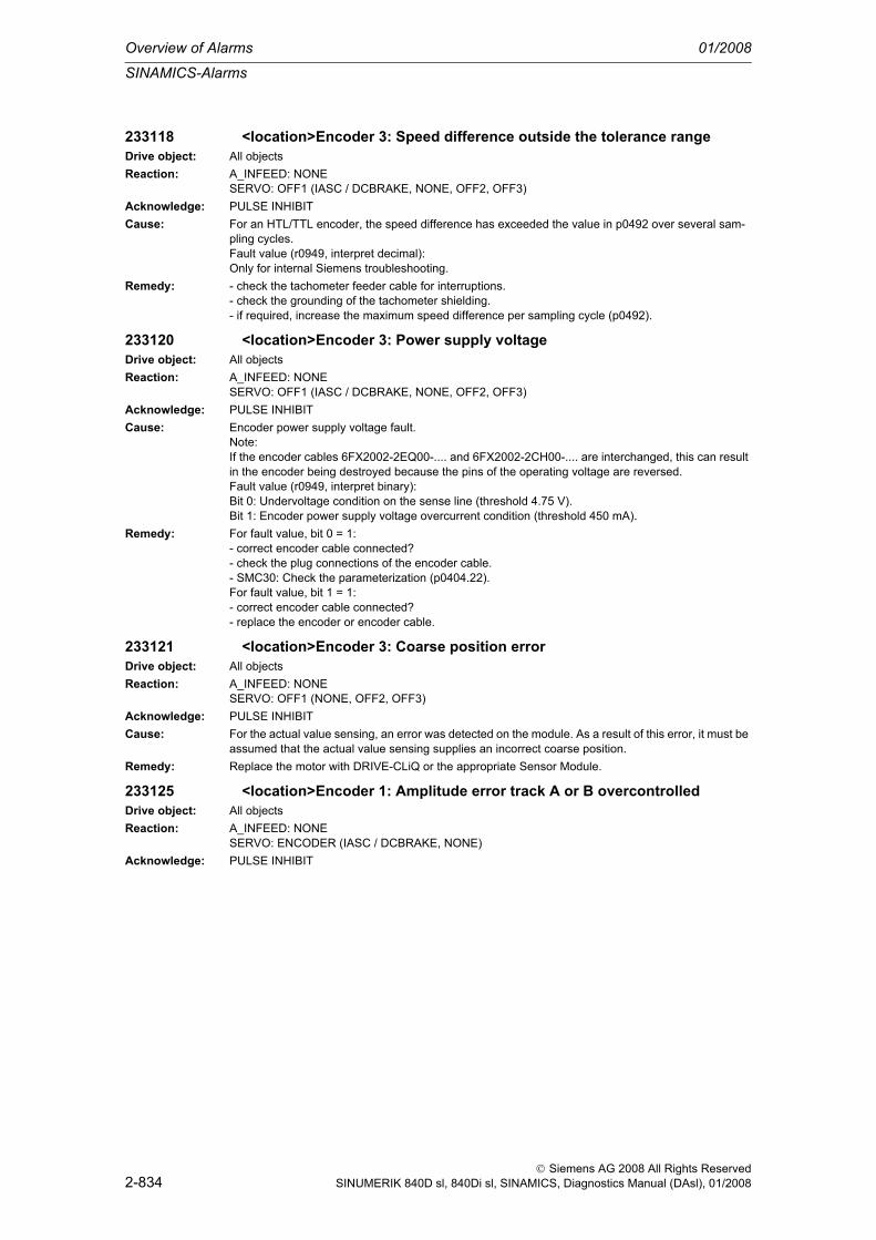
Overview of Alarms 01/2008
SINAMICS-Alarms
2-834
© Siemens AG 2008 All Rights ReservedSINUMERIK 840D sl, 840Di sl, SINAMICS, Diagnostics Manual (DAsl), 01/2008
233118 <location>Encoder 3: Speed difference outside the tolerance rangeDrive object: All objectsReaction: A_INFEED: NONE
SERVO: OFF1 (IASC / DCBRAKE, NONE, OFF2, OFF3)Acknowledge: PULSE INHIBITCause: For an HTL/TTL encoder, the speed difference has exceeded the value in p0492 over several sam-
pling cycles.Fault value (r0949, interpret decimal):Only for internal Siemens troubleshooting.
Remedy: - check the tachometer feeder cable for interruptions.- check the grounding of the tachometer shielding.- if required, increase the maximum speed difference per sampling cycle (p0492).
233120 <location>Encoder 3: Power supply voltageDrive object: All objectsReaction: A_INFEED: NONE
SERVO: OFF1 (IASC / DCBRAKE, NONE, OFF2, OFF3)Acknowledge: PULSE INHIBITCause: Encoder power supply voltage fault.
Note:If the encoder cables 6FX2002-2EQ00-.... and 6FX2002-2CH00-.... are interchanged, this can result in the encoder being destroyed because the pins of the operating voltage are reversed.Fault value (r0949, interpret binary):Bit 0: Undervoltage condition on the sense line (threshold 4.75 V).Bit 1: Encoder power supply voltage overcurrent condition (threshold 450 mA).
Remedy: For fault value, bit 0 = 1:- correct encoder cable connected?- check the plug connections of the encoder cable.- SMC30: Check the parameterization (p0404.22).For fault value, bit 1 = 1:- correct encoder cable connected?- replace the encoder or encoder cable.
233121 <location>Encoder 3: Coarse position errorDrive object: All objectsReaction: A_INFEED: NONE
SERVO: OFF1 (NONE, OFF2, OFF3)Acknowledge: PULSE INHIBITCause: For the actual value sensing, an error was detected on the module. As a result of this error, it must be
assumed that the actual value sensing supplies an incorrect coarse position.Remedy: Replace the motor with DRIVE-CLiQ or the appropriate Sensor Module.
233125 <location>Encoder 1: Amplitude error track A or B overcontrolledDrive object: All objectsReaction: A_INFEED: NONE
SERVO: ENCODER (IASC / DCBRAKE, NONE)Acknowledge: PULSE INHIBIT

SINAMICS-Alarms
01/2008 Overview of Alarms
2-835
© Siemens AG 2008 All Rights ReservedSINUMERIK 840D sl, 840Di sl, SINAMICS, Diagnostics Manual (DAsl), 01/2008
Cause: The amplitude (track A or B) does not lie within the tolerance bandwidth (software monitoring function).SMC20:The nominal signal level of the encoder must lie in the range 375 mV to 600 mV (500 mV -25 % / +20 %).On the other hand, the response threshold is > 760 mV (frequency characteristic).SMC10:The nominal signal level is at 2900 mV (2.0 Vrms). The response threshold is > 3582 mV.Fault value (r0949, interpret decimal):Low word:Signal level, track A (16 bits with sign).High word:Signal level, track B (16 bits with sign).SMC20:A signal level of 500 mV peak value corresponds to the numerical value 5333 hex = 21299 dec.SMC10:A signal level of 2900 mV peak value corresponds to the numerical value 6666 hex = 26214 dec.See also: p0491 (Motor encoder fault response ENCODER)
Remedy: - check that the encoder cables are routed in compliance with EMC.- replace the encoder or encoder cable.- with measuring systems without their own bearing system: Adjust the scanning head and check the bearing system of the measuring wheel.
233129 <location>Encoder 3: Position difference, hall sensor/track C/D and A/B too large
Drive object: All objectsReaction: A_INFEED: NONE
SERVO: OFF1 (IASC / DCBRAKE, NONE, OFF2, OFF3)Acknowledge: PULSE INHIBITCause: The error for track C/D is greater than +/-15 ° mechanical or +/-60 ° electrical or the error for the Hall
signals is greater than +/-60 ° electrical.One period of track C/D corresponds to 360 ° mechanical.One period of the Hall signal corresponds to 360 ° electrical.The monitoring responds if, for example, Hall sensors are connected as equivalent for the C/D tracks with the incorrect rotational sense or supply values that are not accurate enough.After the fine synchronization using one reference mark or 2 reference marks for distance-coded encoders, this fault is no longer initiated, but instead, Alarm A33429.Fault value (r0949, interpret decimal):For track C/D, the following applies:Measured deviation as mechanical angle (16 bits with sign, 182 dec corresponds to 1 °).For Hall signals, the following applies:Measured deviation as electrical angle (16 bits with sign, 182 dec corresponds to 1 °).
Remedy: - track C or D not connected.- correct the direction of rotation of the Hall sensor possibly connected as equivalent for track C/D.- check that the encoder cables are routed in compliance with EMC.- check the adjustment of the Hall sensor.
233130 <location>Encoder 3: Zero mark and position error from the coarse synchronization
Drive object: All objectsReaction: A_INFEED: NONE
SERVO: OFF1 (IASC / DCBRAKE, NONE, OFF2, OFF3, STOP1, STOP2)Acknowledge: PULSE INHIBIT

Overview of Alarms 01/2008
SINAMICS-Alarms
2-836
© Siemens AG 2008 All Rights ReservedSINUMERIK 840D sl, 840Di sl, SINAMICS, Diagnostics Manual (DAsl), 01/2008
Cause: After initializing the pole position using track C/D, Hall signals or pole position identification routine, the zero mark was detected outside the permissible range. For distance-coded encoders, the test is carried out after passing 2 zero marks. Fine synchronization was not carried out.When initializing via track C/D (p0404) then it is checked whether the zero mark occurs in an angular range of +/-18 ° mechanical.When initializing via Hall sensors (p0404) or pole position identification (p1982) it is checked as to whether the zero mark occurs in an angular range of +/-60 ° electrical.Fault value (r0949, interpret hexadecimal):yyyyxxxx hexyyyy: Determined mechanical zero mark position (can only be used for track C/D).xxxx: Deviation of the zero mark from the expected position as electrical angle.Normalization: 32768 dec = 180 °
Remedy: - check that the encoder cables are routed in compliance with EMC.- check the plug connections.- if the Hall sensor is used as an equivalent for track C/D, check the connection.- check the connection of track C or D.- replace the encoder or encoder cable.
233131 <location>Encoder 3: Deviation, position incremental/absolute too largeDrive object: All objectsReaction: A_INFEED: NONE
SERVO: OFF1 (IASC / DCBRAKE, NONE, OFF2, OFF3, STOP1, STOP2)Acknowledge: PULSE INHIBITCause: Absolute encoder: When cyclically reading the absolute position, an excessively high difference to the
incremental position was detected. The absolute position that was read is rejected.Limit value for the deviation:- EnDat encoder: Is supplied from the encoder and is a minimum of 2 quadrants (e.g. EQI 1325 > 2 quadrants, EQN 1325 > 50 quadrants).- other encoders: 15 pulses = 60 quadrants.Fault value (r0949, interpret decimal):Deviation in quadrants (1 pulse = 4 quadrants).Incremental encoder: When the zero pulse is passed, a deviation in the incremental position was detected.
Remedy: - check that the encoder cables are routed in compliance with EMC.- check the plug connections.- replace the encoder or encoder cable.- check whether the coding disk is dirty or there are strong ambient magnetic fields.
233150 <location>Encoder 3: Initialization errorDrive object: All objectsReaction: A_INFEED: NONE
SERVO: OFF1 (IASC / DCBRAKE, NONE, OFF2, OFF3, STOP1, STOP2)Acknowledge: PULSE INHIBITCause: Encoder functionality selected in p0404 is not operating correctly.
Fault value (r0949, interpret hexadecimal):The fault value is a bit field. Every set bit indicates functionality that is faulted.The bit assignment corresponds to that of p0404 (e.g. bit 5 set: Error track C/D).
Remedy: - Check that p0404 is correctly set.- check the encoder type used (incremental/absolute value) and for SMCxx, the encoder cable.- if relevant, note additional fault/error messages that describe the fault in detail.
233400 <location>Encoder 3: Alarm threshold zero mark distance errorDrive object: All objectsReaction: NONEAcknowledge: NONE

SINAMICS-Alarms
01/2008 Overview of Alarms
2-837
© Siemens AG 2008 All Rights ReservedSINUMERIK 840D sl, 840Di sl, SINAMICS, Diagnostics Manual (DAsl), 01/2008
Cause: The measured zero mark distance does not correspond to the parameterized zero mark distance.For distance-coded encoders, the zero mark distance is determined from zero marks detected pairs. This means that if a zero mark is missing, depending on the pair generation, this cannot result in a fault and also has no effect in the system.The zero mark distance for the zero mark monitoring is set in p0425 (rotary encoder) or p0424 (linear encoder).Alarm value (r2124, interpret decimal):Last measured zero mark distance in increments (4 increments = 1 encoder pulse).The sign designates the direction of motion when detecting the zero mark distance.
Remedy: - check that the encoder cables are routed in compliance with EMC.- check the plug connections.. check the encoder type (encoder with equidistant zero marks).- adapt the parameter for the distance between zero marks (p0424, p0425).- replace the encoder or encoder cable.
233401 <location>Encoder 3: Alarm threshold zero marked failedDrive object: All objectsReaction: NONEAcknowledge: NONECause: The 1.5 x parameterized zero mark distance was exceeded.
The zero mark distance for the zero mark monitoring is set in p0425 (rotary encoder) or p0424 (linear encoder).Alarm value (r2124, interpret decimal):Number of increments after POWER ON or since the last zero mark that was detected (4 increments = 1 encoder pulse).
Remedy: - check that the encoder cables are routed in compliance with EMC.- check the plug connections.. check the encoder type (encoder with equidistant zero marks).- adapt the parameter for the clearance between zero marks (p0425).- replace the encoder or encoder cable.
233405 <location>Encoder 3: Encoder evaluation temperature too highDrive object: All objectsReaction: A_INFEED: NONE (OFF1, OFF2)
SERVO: NONE (IASC / DCBRAKE, OFF1, OFF2, OFF3, STOP1, STOP2)Acknowledge: IMMEDIATELY (POWER ON)Cause: The encoder evaluation for a motor with DRIVE-CLiQ has detected an excessively high temperature.
The fault threshold is 125 ° C.Alarm value (r2124, interpret decimal):Measured board/module temperature in 0.1 °C.
Remedy: Reduce the ambient temperature for the DRIVE-CLiQ connection of the motor.
233410 <location>Encoder 3: Serial communicationsDrive object: All objectsReaction: NONEAcknowledge: NONECause: Serial communication protocol transfer error between the encoder and evaluation module.
Alarm value (r2124, interpret binary):Bit 0: Alarm bit in the position protocol.Bit 1: Incorrect quiescent level on the data line.Bit 2: Encoder does not respond (does not supply a start bit within 50 ms).Bit 3: CRC error: The checksum in the protocol from the encoder does not match the data.Bit 4: Encoder acknowledgement error: The encoder incorrectly understood the task (request) or can-not execute it.Bit 5: Internal error in the serial driver: An illegal mode command was requested.Bit 6: Timeout when cyclically reading.Bit 8: Protocol is too long (e.g. > 64 bits).Bit 9: Receive buffer overflow.Bit 10: Frame error when reading twice.Bit 11: Parity error.Bit 12: Data line signal level error during the monoflop time.

Overview of Alarms 01/2008
SINAMICS-Alarms
2-838
© Siemens AG 2008 All Rights ReservedSINUMERIK 840D sl, 840Di sl, SINAMICS, Diagnostics Manual (DAsl), 01/2008
Remedy: - check that the encoder cables are routed in compliance with EMC.- check the plug connections.- replace the encoder.
233411 <location>Encoder 3: EnDat encoder signals alarmsDrive object: All objectsReaction: NONEAcknowledge: NONECause: The error word of the EnDat encoder has alarm bits that have been set.
Alarm value (r2124, interpret binary):Bit 0: Frequency exceeded (speed too high).Bit 1: Temperature exceeded.Bit 2: Control reserve, lighting system exceeded.Bit 3: Battery discharged.Bit 4: Reference point passed.
Remedy: Replace encoder.
233414 <location>Encoder 3: Amplitude error track C or D (C^2 + D^2)Drive object: All objectsReaction: NONEAcknowledge: NONECause: The amplitude (C^2 + D^2) of track C or D of the encoder or from the Hall signals, is not within the
tolerance bandwidth.The nominal signal must be in the range 375 mV to 600 mV (500 mV -25 % / +20 %).On the other hand, the response thresholds are < 230 mV and > 750 mV (frequency characteristic).This fault also occurs if the A/D converter is overcontrolled.If the amplitude is not within the tolerance bandwidth, then it cannot be used to initialize the start posi-tion.Alarm value (r2124, interpret decimal):Low word: Signal level, track C (16 bits with sign).High word: Signal level, track D (16 bits with sign).A signal level of 500 mV corresponds to the numerical value 5333 hex = 21299 dec.
Remedy: - check that the encoder cables are routed in compliance with EMC.- check the plug connections.- replace the encoder or encoder cable.- check the Sensor Module (e.g. contacts).- check the Hall sensor box
233415 <location>Encoder 3: Amplitude alarm track A or B (A^2 + B^2)Drive object: All objectsReaction: NONEAcknowledge: NONECause: The amplitude (A^2 + B^2) of track A or B is not within the tolerance bandwidth.
SMC20:The nominal signal level is at 500 mV (500 mV -25 % / +20 %). The response threshold is < 300 mV.SMC10:The nominal signal level is at 2900 mV (2.0 Vrms). The response threshold is < 1414 mV (1.0 Vrms).Alarm value (r2124, interpret decimal):Low word:Amplitude square root(A*A + B*B).SMC20:A signal level of 500 mV peak value corresponds to the numerical value 299A hex = 10650 dec.SMC10:A signal level of 2900 mV peak value corresponds to the numerical value 3333 hex = 13107 dec.High word:Angle 0 to 65535 corresponds to 0 to 360 degrees of the fine position. Zero degrees is at the negative zero crossover of track B.

SINAMICS-Alarms
01/2008 Overview of Alarms
2-839
© Siemens AG 2008 All Rights ReservedSINUMERIK 840D sl, 840Di sl, SINAMICS, Diagnostics Manual (DAsl), 01/2008
Remedy: - check the speed range, frequency characteristic (amplitude characteristic) of the measuring equip-ment is not sufficient for the speed range.- check that the encoder cables are routed in compliance with EMC.- check the plug connections.- replace the encoder or encoder cable.- check the Sensor Module (e.g. contacts).- dirty code disk- aged lighting system.
233418 <location>Encoder 3: Speed difference per sampling rate exceededDrive object: All objectsReaction: NONEAcknowledge: NONECause: For an HTL/TTL encoder, the speed difference between two sampling cycles has exceeded the value
in p0492.Alarm value (r2124, interpret decimal):Only for internal Siemens troubleshooting.
Remedy: - check the tachometer feeder cable for interruptions.- check the grounding of the tachometer shielding.- if required, increase the setting of p0492.
233419 <location>Encoder 3: Track A or B outside the tolerance rangeDrive object: All objectsReaction: NONEAcknowledge: NONECause: The amplitude, phase or offset correction for track A or B is at the limit.
Amplitude error correction: Amplitude B / Amplitude A = 0.78 ... 1.27Phase: <84 degrees or >96 degreesSMC20: Offset correction: +/-140 mVSMC10: Offset correction: +/-650 mVAlarm value (r2124, interpret hexadecimal):xxx1: Minimum of the offset correction, track Bxxx2: Maximum of the offset correction, track Bxx1x: Minimum of the offset correction, track Axx2x: Maximum of the offset correction, track Ax1xx: Minimum of the amplitude correction, track B/Ax2xx: Maximum of the amplitude correction, track B/A1xxx: Minimum of the phase error correction2xxx: Maximum of the phase error correction
Remedy: - check mechanical mounting tolerances for encoders without their own bearings (e.g. toothed-wheel encoders).- check the plug connections (also the transition resistance).- check the encoder signals.- replace the encoder or encoder cable.
233421 <location>Encoder 3: Coarse position errorDrive object: All objectsReaction: NONEAcknowledge: NONECause: For this encoder, this coarse position is incorrect.
Fault value (r0949, interpret decimal):3:The absolute position of the serial protocol and track A/B differ by half an encoder pulse. The absolute position must have its zero position in the quadrants in which both tracks are negative otherwise the position can be incorrect by one encoder pulse.
Remedy: Re fault value = 3:For Sensor Module Cabinet (SMC) and Sensor Module External (SME), the following applies:- use an encoder cable from Siemens.- for encoder cables that you have fabricated yourself, interchange track A with A* and B with B*.For Sensor Module Integrated (SMI), the following applies:- replace the component.

Overview of Alarms 01/2008
SINAMICS-Alarms
2-840
© Siemens AG 2008 All Rights ReservedSINUMERIK 840D sl, 840Di sl, SINAMICS, Diagnostics Manual (DAsl), 01/2008
233429 <location>Encoder 3: Position difference, hall sensor/track C/D and A/B too large
Drive object: All objectsReaction: NONEAcknowledge: NONECause: The error for track C/D is greater than +/-15 ° mechanical or +/-60 ° electrical or the error for the Hall
signals is greater than +/-60 ° electrical.One period of track C/D corresponds to 360 ° mechanical.One period of the Hall signal corresponds to 360 ° electrical.The monitoring responds if, for example, Hall sensors are connected as equivalent for the C/D tracks with the incorrect rotational sense or supply values that are not accurate enough.Alarm value (r2124, interpret decimal):For track C/D, the following applies:Measured deviation as mechanical angle (16 bits with sign, 182 dec corresponds to 1 °).For Hall signals, the following applies:Measured deviation as electrical angle (16 bits with sign, 182 dec corresponds to 1 °).
Remedy: - track C or D not connected.- correct the direction of rotation of the Hall sensor possibly connected as equivalent for track C/D.- check that the encoder cables are routed in compliance with EMC.- check the adjustment of the Hall sensor.
233431 <location>Encoder 3: Deviation, position incremental/absolute too largeDrive object: All objectsReaction: NONEAcknowledge: NONECause: When the zero pulse is passed, a deviation in the incremental position was detected.
Alarm value (r2124, interpret decimal):Deviation in quadrants (1 pulse = 4 quadrants).
Remedy: - check that the encoder cables are routed in compliance with EMC.- check the plug connections.- replace the encoder or encoder cable.- coding disk dirty or strong magnetic fields.
233432 <location>Encoder 3: Rotor position adaptation corrects deviationDrive object: All objectsReaction: NONEAcknowledge: NONECause: For track A/B, pulses have been lost or too many have been counted. These pulses are presently
being corrected.Alarm value (r2124, interpret decimal): Last measured deviation of the zero mark distance in incre-ments (4 increments = 1 encoder pulse). The sign designates the direction of motion when detecting the zero mark distance.
Remedy: - check that the encoder cables are routed in compliance with EMC.- check the plug connections.- replace the encoder or encoder cable.- check encoder limit frequency.- adapt the parameter for the distance between zero marks (p0424, p0425).
233500 <location>Encoder 3: Position tracking traversing range exceededDrive object: SERVOReaction: OFF1 (NONE, OFF2, OFF3)Acknowledge: IMMEDIATELYCause: For a configured linear axis without modulo correction, the drive/encoder has exceeded the maximum
possible traversing range.For the configured linear axis, the maximum traversing range is defined to be 64x (+/- 32x) of p0421. The value should be read in p0412 and interpreted as the number of motor revolutions.

SINAMICS-Alarms
01/2008 Overview of Alarms
2-841
© Siemens AG 2008 All Rights ReservedSINUMERIK 840D sl, 840Di sl, SINAMICS, Diagnostics Manual (DAsl), 01/2008
Remedy: The fault should be resolved as follows:- select encoder commissioning (p0010 = 4).- reset the position tracking as follows (p0411.2 = 1).- de-select encoder commissioning (p0010 = 0).The fault should then be acknowledged and the absolute encoder adjusted.
233501 <location>Encoder 3: Position tracking encoder position outside tolerance window
Drive object: SERVOReaction: OFF1 (NONE, OFF2, OFF3)Acknowledge: IMMEDIATELYCause: When powered-down, the drive/encoder was moved through a distance greater than what was param-
eterized in the tolerance window. It is possible that there is no longer any reference between the mechanical system and encoder.Fault value (r0949, decimal):Deviation (difference) to the last encoder position in increments of the absolute value.The sign designates the traversing direction.Note:The deviation (difference) found is also displayed in r0477.See also: p0413 (Measuring gearbox, position tracking tolerance window), r0477 (Measuring gearbox, position difference)
Remedy: Reset the position tracking as follows:- select encoder commissioning (p0010 = 4).- reset the position tracking as follows (p0411.2 = 1).- de-select encoder commissioning (p0010 = 0).The fault should then be acknowledged and, if necessary, the absolute encoder adjusted (p2507).See also: p0010, p2507
233502 <location>Encoder 3: Encoder with measuring gearbox, without valid signals
Drive object: SERVOReaction: OFF1 (OFF2, OFF3)Acknowledge: IMMEDIATELYCause: The encoder with measuring gearbox no longer provides any valid signals.Remedy: It must be ensured that all of the encoders, with mounted measuring gearbox, provide valid actual val-
ues in operation.
233503 <location>Encoder 3: Position tracking cannot be resetDrive object: SERVOReaction: OFF1 (NONE, OFF2, OFF3)Acknowledge: IMMEDIATELYCause: The position tracking for the measuring gearbox cannot be reset.Remedy: The fault should be resolved as follows:
- select encoder commissioning (p0010 = 4).- reset the position tracking as follows (p0411.2 = 1).- de-select encoder commissioning (p0010 = 0).The fault should then be acknowledged and the absolute encoder adjusted.
233800 <location>Encoder 3: Group signalDrive object: All objectsReaction: A_INFEED: OFF2 (NONE)
SERVO: OFF1 (IASC / DCBRAKE, NONE, OFF2, OFF3)Acknowledge: NONECause: The motor encoder has detected at least one fault.Remedy: Evaluates other actual messages.

Overview of Alarms 01/2008
SINAMICS-Alarms
2-842
© Siemens AG 2008 All Rights ReservedSINUMERIK 840D sl, 840Di sl, SINAMICS, Diagnostics Manual (DAsl), 01/2008
233801 <location>Encoder 3 DRIVE-CLiQ: Sign-of-life missingDrive object: All objectsReaction: A_INFEED: OFF2 (NONE)
SERVO: OFF1 (IASC / DCBRAKE, NONE, OFF2, OFF3)Acknowledge: IMMEDIATELYCause: DRIVE-CLiQ communications error between the Control Unit and the encoder involved.
Fault value (r0949, interpret hexadecimal):0A: The sign-of-life bit in the receive telegram is not set.
Remedy: - check the electrical cabinet design and cable routing for EMC compliance- replace the component involved.See also: p9916 (DRIVE-CLiQ data transfer error shutdown threshold slave)
233802 <location>Encoder 3: Time slice overflowDrive object: All objectsReaction: A_INFEED: OFF2 (NONE)
SERVO: OFF1 (IASC / DCBRAKE, NONE, OFF2, OFF3)Acknowledge: IMMEDIATELYCause: Time slice overflow, encoder 3.
Fault value (r0949, interpret decimal):9: Time slice overflow of the fast (current controller clock cycle) time slice.10: Time slice overflow of the average time slice.12: Time slice overflow of the slow time slice.999: Timeout when waiting for SYNO, e.g. unexpected return to non-cyclic operation.
Remedy: Reduce the current controller frequency.
233804 <location>Encoder 3: Checksum errorDrive object: All objectsReaction: A_INFEED: OFF2 (NONE)
SERVO: OFF1 (IASC / DCBRAKE, NONE, OFF2, OFF3)Acknowledge: IMMEDIATELYCause: A checksum error has occurred when reading-out the program memory on the Sensor Module.
Fault value (r0949, interpret hexadecimal):yyyyxxxx hexyyyy: Memory area involved.xxxx: Difference between the checksum at POWER ON and the actual checksum.
Remedy: - check whether the permissible ambient temperature for the component is maintained.- replace the Sensor Module.
233805 <location>Encoder 3: EPROM checksum errorDrive object: All objectsReaction: A_INFEED: OFF2 (NONE)
SERVO: OFF1 (IASC / DCBRAKE, NONE, OFF2, OFF3)Acknowledge: IMMEDIATELYCause: Internal parameter data is corrupted.
Fault value (r0949, interpret hexadecimal):01: EEPROM access error.02: Too many blocks in the EEPROM.
Remedy: Replace the module.
233806 <location>Encoder 3: Initialization errorDrive object: All objectsReaction: A_INFEED: OFF2 (NONE)
SERVO: OFF1 (IASC / DCBRAKE, NONE, OFF2, OFF3)Acknowledge: PULSE INHIBITCause: The encoder was not successfully initialized.
Fault value (r0949, interpret hexadecimal):1, 2, 3: Encoder initialization with the motor rotating.
Remedy: Acknowledge the fault.

SINAMICS-Alarms
01/2008 Overview of Alarms
2-843
© Siemens AG 2008 All Rights ReservedSINUMERIK 840D sl, 840Di sl, SINAMICS, Diagnostics Manual (DAsl), 01/2008
233811 <location>Encoder 3: Encoder serial number changedDrive object: All objectsReaction: A_INFEED: OFF2 (NONE)
SERVO: OFF1 (NONE, OFF2, OFF3)Acknowledge: IMMEDIATELYCause: The encoder serial number has changed. The change is only checked for encoders with serial number
(e.g. EnDat encoders).Cause:The encoder was replaced.Note:With closed-loop position control, the serial number is accepted when starting the adjustment (p2507 = 2).When the encoder is adjusted (p2507 = 3), the serial number is checked for changes and if required, the adjustment is reset (p2507 = 1).
Remedy: Mechanically adjust the encoder. Accept the new serial number with p0440 = 1.
233812 <location>Encoder 3: Requested cycle or RX-/TX timing not supportedDrive object: All objectsReaction: OFF2Acknowledge: IMMEDIATELYCause: A cycle requested from the Control Unit or RX/TX timing is not supported.
Alarm value (r2124, interpret decimal):0: Application cycle is not supported.1: DQ cycle is not supported.2: Clearance between RX and TX instants in time too low.3: TX instant in time too early.
Remedy:
233820 <location>Encoder 3 DRIVE-CLiQ: Telegram errorDrive object: All objectsReaction: A_INFEED: OFF2
SERVO: OFF1 (IASC / DCBRAKE, NONE, OFF2, OFF3)Acknowledge: IMMEDIATELYCause: DRIVE-CLiQ communications error between the Control Unit and the encoder involved.
Fault value (r0949, interpret hexadecimal):01: CRC error.02: Telegram is shorter than specified in the length byte or in the receive list.03: Telegram is longer than specified in the length byte or in the receive list.04: The length of the receive telegram does not match the receive list.05: The type of the receive telegram does not match the receive list.06: The address of the component in the telegram and in the receive list do not match.07: A SYNC telegram is expected - but the received telegram is not a SYNC telegram.08: A SYNC telegram is not expected - but the received telegram is a SYNC telegram.09: The error bit in the receive telegram is set.10: The receive telegram is too early.
Remedy: - carry out a POWER ON.- check the electrical cabinet design and cable routing for EMC compliance- check the DRIVE-CLiQ wiring (interrupted cable, contacts, ...).See also: p9916 (DRIVE-CLiQ data transfer error shutdown threshold slave)
233835 <location>Encoder 3 DRIVE-CLiQ: Cyclic data transfer errorDrive object: All objectsReaction: A_INFEED: OFF2
SERVO: OFF1 (IASC / DCBRAKE, NONE, OFF2, OFF3)Acknowledge: IMMEDIATELY

Overview of Alarms 01/2008
SINAMICS-Alarms
2-844
© Siemens AG 2008 All Rights ReservedSINUMERIK 840D sl, 840Di sl, SINAMICS, Diagnostics Manual (DAsl), 01/2008
Cause: DRIVE-CLiQ communications error between the Control Unit and the encoder involved. The nodes do not send and receive in synchronism.Fault value (r0949, interpret hexadecimal):21: The cyclic telegram has not been received.22: Timeout in the telegram receive list.40: Timeout in the telegram send list.
Remedy: - carry out a POWER ON.- replace the component involved.See also: p9916 (DRIVE-CLiQ data transfer error shutdown threshold slave)
233836 <location>Encoder 3 DRIVE-CLiQ: Send error for DRIVE-CLiQ dataDrive object: All objectsReaction: A_INFEED: OFF2
SERVO: OFF1 (IASC / DCBRAKE, NONE, OFF2, OFF3)Acknowledge: IMMEDIATELYCause: DRIVE-CLiQ communications error between the Control Unit and the encoder involved. Data were not
able to be sent.Fault value (r0949, interpret hexadecimal):41: Telegram type does not match send list.
Remedy: Carry out a POWER ON.
233837 <location>Encoder 3 DRIVE-CLiQ: Component faultDrive object: All objectsReaction: A_INFEED: OFF2
SERVO: OFF1 (IASC / DCBRAKE, NONE, OFF2, OFF3)Acknowledge: IMMEDIATELYCause: Fault detected on the DRIVE-CLiQ component involved. Faulty hardware cannot be excluded.
Fault value (r0949, interpret hexadecimal):20: Error in the telegram header.23: Receive error: The telegram buffer memory contains an error.42: Send error: The telegram buffer memory contains an error.43: Send error: The telegram buffer memory contains an error.
Remedy: - check the DRIVE-CLiQ wiring (interrupted cable, contacts, ...).- check the electrical cabinet design and cable routing for EMC compliance- if required, use another DRIVE-CLiQ socket (p9904).- replace the component involved.
233845 <location>Encoder 3 DRIVE-CLiQ: Cyclic data transfer errorDrive object: All objectsReaction: A_INFEED: OFF2
SERVO: OFF1 (IASC / DCBRAKE, NONE, OFF2, OFF3)Acknowledge: IMMEDIATELYCause: DRIVE-CLiQ communications error between the Control Unit and the encoder involved.
Fault value (r0949, interpret hexadecimal):0B: Synchronization error during alternating cyclic data transfer.
Remedy: Carry out a POWER ON.See also: p9916 (DRIVE-CLiQ data transfer error shutdown threshold slave)
233850 <location>Encoder 3: Sensor Module, internal software errorDrive object: All objectsReaction: A_INFEED: OFF2 (NONE)
SERVO: OFF1 (IASC / DCBRAKE, NONE, OFF2, OFF3)Acknowledge: POWER ONCause: Internal software error in the Sensor Module of encoder 3.
Fault value (r0949, interpret decimal):1: Background time slice is blocked.2: Checksum over the code memory is not OK.10000: OEM memory of the EnDat encoder contains data that cannot be interpreted.

SINAMICS-Alarms
01/2008 Overview of Alarms
2-845
© Siemens AG 2008 All Rights ReservedSINUMERIK 840D sl, 840Di sl, SINAMICS, Diagnostics Manual (DAsl), 01/2008
Remedy: - replace the Sensor Module.- if required, upgrade the firmware in the Sensor Module.- contact the Hotline.
233851 <location>CU DRIVE-CLiQ: Sign-of-life missingDrive object: All objectsReaction: A_INFEED: NONE (OFF1, OFF2)
SERVO: OFF1 (IASC / DCBRAKE, NONE, OFF2, OFF3)Acknowledge: IMMEDIATELYCause: A DRIVE-CLiQ communications error has occurred between the Control Unit and the Sensor Module
(encoder 3) involved. The DRIVE-CLiQ component did not set the sign of life to the Control Unit.Fault value (r0949, interpret hexadecimal):0A: The sign-of-life bit in the receive telegram is not set.
Remedy: Upgrade the firmware of the component involved.
233860 <location>CU DRIVE-CLiQ: Telegram errorDrive object: All objectsReaction: A_INFEED: NONE (OFF1, OFF2)
SERVO: OFF1 (IASC / DCBRAKE, NONE, OFF2, OFF3)Acknowledge: IMMEDIATELYCause: DRIVE-CLiQ communications error between the Control Unit and the encoder involved (encoder 3).
Fault value (r0949, interpret hexadecimal):11: CRC error and the receive telegram is too early.01: CRC error.12: The telegram is shorter than that specified in the length byte or in the receive list and the receive telegram is too early.02: Telegram is shorter than specified in the length byte or in the receive list.13: The telegram is longer than that specified in the length byte or in the receive list and the receive telegram is too early.03: Telegram is longer than specified in the length byte or in the receive list.14: The length of the receive telegram does not match the receive list and the receive telegram is too early.04: The length of the receive telegram does not match the receive list.15: The type of the receive telegram does not match the receive list and the receive telegram is too early.05: The type of the receive telegram does not match the receive list.16: The address of the encoder in the telegram and in the receive list does not match and the receive telegram is too early.06: The address of the encoder in the telegram and in the receive list do not match.19: The error bit in the receive telegram is set and the receive telegram is too early.09: The error bit in the receive telegram is set.10: The receive telegram is too early.
Remedy: - carry out a POWER ON.- check the electrical cabinet design and cable routing for EMC compliance- check the DRIVE-CLiQ wiring (interrupted cable, contacts, ...).See also: p9915 (DRIVE-CLiQ data transfer error shutdown threshold master)
233885 <location>CU DRIVE-CLiQ: Cyclic data transfer errorDrive object: All objectsReaction: A_INFEED: NONE (OFF1, OFF2)
SERVO: OFF1 (IASC / DCBRAKE, NONE, OFF2, OFF3)Acknowledge: IMMEDIATELYCause: DRIVE-CLiQ communications error between the Control Unit and the encoder involved (encoder 3).
The nodes do not send and receive in synchronism.Fault value (r0949, interpret hexadecimal):1A: Sign-of-life bit in the receive telegram not set and the receive telegram is too early.21: The cyclic telegram has not been received.22: Timeout in the telegram receive list.40: Timeout in the telegram send list.62: Error at the transition to cyclic operation.

Overview of Alarms 01/2008
SINAMICS-Alarms
2-846
© Siemens AG 2008 All Rights ReservedSINUMERIK 840D sl, 840Di sl, SINAMICS, Diagnostics Manual (DAsl), 01/2008
Remedy: - check the power supply voltage of the component involved.- carry out a POWER ON.- replace the component involved.See also: p9915 (DRIVE-CLiQ data transfer error shutdown threshold master)
233886 <location>CU DRIVE-CLiQ: Error when sending DRIVE-CLiQ dataDrive object: All objectsReaction: A_INFEED: NONE (OFF1, OFF2)
SERVO: OFF1 (IASC / DCBRAKE, NONE, OFF2, OFF3)Acknowledge: IMMEDIATELYCause: DRIVE-CLiQ communications error between the Control Unit and the encoder involved (encoder 3).
Data were not able to be sent.Fault value (r0949, interpret hexadecimal):41: Telegram type does not match send list.
Remedy: Carry out a POWER ON.
233887 <location>CU DRIVE-CLiQ: Component faultDrive object: All objectsReaction: A_INFEED: NONE (OFF1, OFF2)
SERVO: OFF1 (IASC / DCBRAKE, NONE, OFF2, OFF3)Acknowledge: IMMEDIATELYCause: Fault detected on the DRIVE-CLiQ component involved (Sensor Module for encoder 3). Faulty hard-
ware cannot be excluded.Fault value (r0949, interpret hexadecimal):20: Error in the telegram header.23: Receive error: The telegram buffer memory contains an error.42: Send error: The telegram buffer memory contains an error.43: Send error: The telegram buffer memory contains an error.60: Response received too late during runtime measurement.61: Time taken to exchange characteristic data too long.
Remedy: - check the DRIVE-CLiQ wiring (interrupted cable, contacts, ...).- check the electrical cabinet design and cable routing for EMC compliance- if required, use another DRIVE-CLiQ socket (p9904).- replace the component involved.
233895 <location>CU DRIVE-CLiQ: Cyclic data transfer errorDrive object: All objectsReaction: A_INFEED: NONE (OFF1, OFF2)
SERVO: OFF1 (IASC / DCBRAKE, NONE, OFF2, OFF3)Acknowledge: IMMEDIATELYCause: DRIVE-CLiQ communications error between the Control Unit and the encoder involved (encoder 3).
Fault value (r0949, interpret hexadecimal):0B: Synchronization error during alternating cyclic data transfer.
Remedy: Carry out a POWER ON.See also: p9915 (DRIVE-CLiQ data transfer error shutdown threshold master)
233896 <location>CU DRIVE-CLiQ: Inconsistent component characteristicsDrive object: All objectsReaction: A_INFEED: NONE (OFF1, OFF2)
SERVO: OFF2 (IASC / DCBRAKE, NONE, OFF1, OFF3, STOP1, STOP2)Acknowledge: IMMEDIATELYCause: The properties of the DRIVE-CLiQ component (Sensor Module for encoder 3), specified by the fault
value, have changed in an incompatible fashion with respect to the properties when booted. One cause can be, e.g. that a DRIVE-CLiQ cable or DRIVE-CLiQ component has been replaced.Fault value (r0949, interpret decimal):Component number.
Remedy: - when replacing cables, only use cables with the same length as the original cables.- when replacing components, use the same components and firmware releases.- carry out a POWER ON.

SINAMICS-Alarms
01/2008 Overview of Alarms
2-847
© Siemens AG 2008 All Rights ReservedSINUMERIK 840D sl, 840Di sl, SINAMICS, Diagnostics Manual (DAsl), 01/2008
233897 <location>DRIVE-CLiQ: No communication to componentDrive object: All objectsReaction: A_INFEED: NONE (OFF1, OFF2)
SERVO: OFF1 (IASC / DCBRAKE, NONE, OFF2, OFF3, STOP1, STOP2)Acknowledge: IMMEDIATELY (POWER ON)Cause: Communications with the DRIVE-CLiQ component (Sensor Module for encoder 3) specified by the
fault value is not possible.One cause can be, e.g. that a DRIVE-CLiQ cable has been withdrawn.Fault value (r0949, interpret decimal):Component ID.
Remedy: - check the DRIVE-CLiQ connections.- carry out a POWER ON.
233899 <location>Encoder 3: Unknown faultDrive object: All objectsReaction: A_INFEED: OFF2 (NONE, OFF1)
SERVO: OFF1 (IASC / DCBRAKE, NONE, OFF2, OFF3, STOP1, STOP2)Acknowledge: IMMEDIATELY (POWER ON)Cause: A fault occurred on the Sensor Module for encoder 3 that cannot be interpreted by the Control Unit
firmware.This can occur if the firmware on the Sensor Module for encoder 3 is more recent than the firmware on the Control Unit.Fault value (r0949, interpret decimal):Fault number.If required, the significance of this new fault can be read about in a more recent description of the Con-trol Unit.
Remedy: - replace the firmware on the Sensor Module by an older firmware version (r0148).- upgrade the firmware on the Control Unit (r0018).
233902 <location>Encoder 3: SPI-BUS error occurredDrive object: All objectsReaction: NONEAcknowledge: NONECause: Error when operating the internal SPI bus.
Fault value (r0949, interpret hexadecimal):Only for internal Siemens troubleshooting.
Remedy: - replace the Sensor Module.- if required, upgrade the firmware in the Sensor Module.- contact the Hotline.
233903 <location>Encoder 3: I2C-BUS error occurredDrive object: All objectsReaction: NONEAcknowledge: NONECause: Error when operating the internal I2C bus.
Fault value (r0949, interpret hexadecimal):Only for internal Siemens troubleshooting.
Remedy: - replace the Sensor Module.- if required, upgrade the firmware in the Sensor Module.- contact the Hotline.
233905 <location>Encoder 3: Parameterization errorDrive object: All objectsReaction: A_INFEED: OFF2 (NONE, OFF1)
SERVO: OFF1 (IASC / DCBRAKE, NONE, OFF2, OFF3, STOP1, STOP2)Acknowledge: IMMEDIATELY

Overview of Alarms 01/2008
SINAMICS-Alarms
2-848
© Siemens AG 2008 All Rights ReservedSINUMERIK 840D sl, 840Di sl, SINAMICS, Diagnostics Manual (DAsl), 01/2008
Cause: A parameter of encoder 1 was detected as being incorrect.It is possible that the parameterized encoder type does not match the connected encoder.The parameter involved can be determined as follows:- determine the parameter number using the fault value (r0949).- determine the parameter index (p0187).Fault value (r0949, interpret decimal):High word - low word = information - parameter numberInfo = 0:No information available.Info = 1:The component does not support HTL level (p0405.1 = 0) combined with track monitoring A/B <> -A/B (p0405.2 = 1).Info = 2:A code number for an identified encoder has been entered into p0400, however, no identification was carried out. Please start a new encoder identification.Info = 3:A code number for an identified encoder has been entered into p0400, however, no identification was carried out. Please select a listed encoder in p0400 with a code number < 10000.Info = 4:This component does not support SSI encoders (p0404.9 = 1) without track A/B.
Remedy: - check whether the connected encoder type matches the encoder that has been parameterized.- correct the parameter specified by the fault value (r0949) and p0187.- re parameter number 314: Check the pole pair number and measuring gearbox ratio. The quotient of the "pole pair number" divided by the "measuring gearbox ratio" must be less than or equal to 1000 ((r0313 * p0433) / p0432 <= 1000).
233920 <location>Encoder 3: Temperature sensor faultDrive object: All objectsReaction: NONEAcknowledge: NONECause: When evaluating the temperature sensor, an error occurred.
Alarm value (r2124, interpret decimal):Low word low byte: Cause:1: Wire breakage or sensor not connected (KTY: R > 1630 Ohm).2: Measured resistance too low (PTC: R < 20 Ohm, KTY: R < 50 Ohm).Additional values:Only for internal Siemens troubleshooting.Low word high byte: Channel number.
Remedy: - check that the encoder cable is the correct type and is correctly connected.- check the temperature sensor selection in p0600 to p0603.- replace the Sensor Module (hardware defect or incorrect calibration data).
233999 <location>Encoder 3: Unknown alarmDrive object: All objectsReaction: NONEAcknowledge: NONECause: A alarm has occurred on the Sensor Module for encoder 3 that cannot be interpreted by the Control
Unit firmware.This can occur if the firmware on the Sensor Module for encoder 3 is more recent than the firmware on the Control Unit.Alarm value (r2124, interpret decimal):Alarm number.If required, the significance of this new alarm can be read about in a more recent description of the Control Unit.
Remedy: - replace the firmware on the Sensor Module by an older firmware version (r0148).- upgrade the firmware on the Control Unit (r0018).

SINAMICS-Alarms
01/2008 Overview of Alarms
2-849
© Siemens AG 2008 All Rights ReservedSINUMERIK 840D sl, 840Di sl, SINAMICS, Diagnostics Manual (DAsl), 01/2008
234207 <location>VSM: Temperature fault threshold exceededDrive object: All objectsReaction: A_INFEED: OFF2 (NONE, OFF1)
SERVO: NONEAcknowledge: IMMEDIATELY (POWER ON)Cause: The temperature (r3666) measured using the Voltage Sensing Module (VSM) has exceeded the
threshold value (p3668).This fault can only be initiated if the temperature evaluation was activated (p3665 = 2 for a KTY sensor or p3665 = 1 for a PTC sensor).Fault value (r0949, interpret decimal):The hundred thousands and ten thousands position specifies the component number of the VSM where the fault occurred.
Remedy: - check the fan.- reduce the power.
234211 <location>VSM: Temperature alarm threshold exceededDrive object: All objectsReaction: NONEAcknowledge: NONECause: The temperature (r3666) measured using the Voltage Sensing Module (VSM) has exceeded the
threshold value (p3667).Alarm value (r2124, interpret decimal):The hundred thousands and ten thousands position specifies the component number of the VSM where the fault occurred.
Remedy: - check the fan.- reduce the power.
234800 <location>VSM: Group signalDrive object: All objectsReaction: A_INFEED: OFF2 (NONE, OFF1)
SERVO: NONE (OFF1, OFF2, OFF3)Acknowledge: NONECause: The Voltage Sensing Module (VSM) has detected at least one fault.Remedy: Evaluates other actual messages.
234801 <location>VSM DRIVE-CLiQ: Sign-of-life missingDrive object: All objectsReaction: A_INFEED: OFF2 (NONE, OFF1)
SERVO: NONE (OFF1, OFF2, OFF3)Acknowledge: IMMEDIATELYCause: A DRIVE-CLiQ communications error has occurred between the Control Unit and the Voltage Sensing
Module (VSM).Fault value (r0949, interpret hexadecimal):0A: The sign-of-life bit in the receive telegram is not set.
Remedy: - check the DRIVE-CLiQ connection.- replace the Terminal Module.
234802 <location>VSM: Time slice overflowDrive object: All objectsReaction: A_INFEED: OFF2 (NONE, OFF1)
SERVO: NONE (OFF1, OFF2, OFF3)Acknowledge: IMMEDIATELYCause: Time slice overflow on the Voltage Sensing Module.Remedy: Replace the Voltage Sensing Module.

Overview of Alarms 01/2008
SINAMICS-Alarms
2-850
© Siemens AG 2008 All Rights ReservedSINUMERIK 840D sl, 840Di sl, SINAMICS, Diagnostics Manual (DAsl), 01/2008
234803 <location>VSM: Memory testDrive object: All objectsReaction: A_INFEED: OFF2 (NONE, OFF1)
SERVO: NONE (OFF1, OFF2, OFF3)Acknowledge: IMMEDIATELYCause: An error has occurred during the memory test on the Voltage Sensing Module.Remedy: - check whether the permissible ambient temperature for the Voltage Sensing Module is being main-
tained.- replace the Voltage Sensing Module.
234804 <location>VSM: CRCDrive object: All objectsReaction: A_INFEED: OFF2 (NONE, OFF1)
SERVO: NONE (OFF1, OFF2, OFF3)Acknowledge: IMMEDIATELYCause: A checksum error has occurred when reading-out the program memory on the Voltage Sensing Mod-
ule (VSM).Remedy: - check whether the permissible ambient temperature for the component is maintained.
- replace the Voltage Sensing Module.
234805 <location>VSM: EPROM checksum errorDrive object: All objectsReaction: A_INFEED: OFF2 (NONE, OFF1)
SERVO: NONE (OFF1, OFF2, OFF3)Acknowledge: IMMEDIATELYCause: Internal parameter data is corrupted.
Fault value (r0949, interpret hexadecimal):01: EEPROM access error.02: Too many blocks in the EEPROM.
Remedy: - check whether the permissible ambient temperature for the component is maintained.- replace the Voltage Sensing Module (VSM).
234806 <location>VSM: InitializationDrive object: All objectsReaction: A_INFEED: OFF2 (NONE, OFF1)
SERVO: NONE (OFF1, OFF2, OFF3)Acknowledge: IMMEDIATELYCause: For the Voltage Sensing Module (VSM), a fault has occurred while initializing.Remedy: Replace the Voltage Sensing Module.
234807 <location>VSM: Sequence control time monitoringDrive object: All objectsReaction: NONEAcknowledge: NONECause: Error, timeout in the sequence control on the Voltage Sensing Module (VSM).Remedy: Replace the Voltage Sensing Module.
234820 <location>VSM DRIVE-CLiQ: Telegram errorDrive object: All objectsReaction: A_INFEED: OFF2 (NONE, OFF1)
SERVO: NONE (OFF1, OFF2)Acknowledge: IMMEDIATELY

SINAMICS-Alarms
01/2008 Overview of Alarms
2-851
© Siemens AG 2008 All Rights ReservedSINUMERIK 840D sl, 840Di sl, SINAMICS, Diagnostics Manual (DAsl), 01/2008
Cause: A DRIVE-CLiQ communications error has occurred between the Control Unit and the Voltage Sensing Module.Fault value (r0949, interpret hexadecimal):01: CRC error.02: Telegram is shorter than specified in the length byte or in the receive list.03: Telegram is longer than specified in the length byte or in the receive list.04: The length of the receive telegram does not match the receive list.05: The type of the receive telegram does not match the receive list.06: The address of the component in the telegram and in the receive list do not match.07: A SYNC telegram is expected - but the received telegram is not a SYNC telegram.08: A SYNC telegram is not expected - but the received telegram is a SYNC telegram.09: The error bit in the receive telegram is set.10: The receive telegram is too early.
Remedy: - carry out a POWER ON.- check the electrical cabinet design and cable routing for EMC compliance- check the DRIVE-CLiQ wiring (interrupted cable, contacts, ...).See also: p9916 (DRIVE-CLiQ data transfer error shutdown threshold slave)
234835 <location>VSM DRIVE-CLiQ: Cyclic data transfer errorDrive object: All objectsReaction: A_INFEED: OFF2 (NONE, OFF1)
SERVO: NONE (OFF1, OFF2)Acknowledge: IMMEDIATELYCause: A DRIVE-CLiQ communications error has occurred between the Control Unit and the Voltage Sensing
Module. The nodes do not send and receive in synchronism.Fault value (r0949, interpret hexadecimal):21: The cyclic telegram has not been received.22: Timeout in the telegram receive list.40: Timeout in the telegram send list.
Remedy: - carry out a POWER ON.- replace the component involved.
234836 <location>VSM DRIVE-CLiQ: Send error for DRIVE-CLiQ dataDrive object: All objectsReaction: A_INFEED: OFF2 (NONE, OFF1)
SERVO: NONE (OFF1, OFF2)Acknowledge: IMMEDIATELYCause: A DRIVE-CLiQ communications error has occurred between the Control Unit and the Voltage Sensing
Module. Data were not able to be sent.Fault value (r0949, interpret hexadecimal):41: Telegram type does not match send list.
Remedy: Carry out a POWER ON.
234837 <location>VSM DRIVE-CLiQ: Component faultDrive object: All objectsReaction: A_INFEED: OFF2 (NONE, OFF1)
SERVO: NONE (OFF1, OFF2)Acknowledge: IMMEDIATELYCause: Fault detected on the DRIVE-CLiQ component involved. Faulty hardware cannot be excluded.
Fault value (r0949, interpret hexadecimal):20: Error in the telegram header.23: Receive error: The telegram buffer memory contains an error.42: Send error: The telegram buffer memory contains an error.43: Send error: The telegram buffer memory contains an error.
Remedy: - check the DRIVE-CLiQ wiring (interrupted cable, contacts, ...).- check the electrical cabinet design and cable routing for EMC compliance- if required, use another DRIVE-CLiQ socket (p9904).- replace the component involved.

Overview of Alarms 01/2008
SINAMICS-Alarms
2-852
© Siemens AG 2008 All Rights ReservedSINUMERIK 840D sl, 840Di sl, SINAMICS, Diagnostics Manual (DAsl), 01/2008
234845 <location>VSM DRIVE-CLiQ: Cyclic data transfer errorDrive object: All objectsReaction: A_INFEED: OFF2 (NONE, OFF1)
SERVO: NONE (OFF1, OFF2)Acknowledge: IMMEDIATELYCause: A DRIVE-CLiQ communications error has occurred between the Control Unit and the Voltage Sensing
Module (VSM).Fault value (r0949, interpret hexadecimal):0B: Synchronization error during alternating cyclic data transfer.
Remedy: Carry out a POWER ON.See also: p9916 (DRIVE-CLiQ data transfer error shutdown threshold slave)
234850 <location>VSM: Internal software errorDrive object: All objectsReaction: A_INFEED: OFF1 (NONE, OFF2)
SERVO: OFF1 (NONE, OFF2, OFF3)Acknowledge: POWER ONCause: An internal software error in the Voltage Sensing Module (VSM) has occurred.
Fault value (r0949, interpret decimal):1: Background time slice is blocked.2: Checksum over the code memory is not OK.
Remedy: - replace the Voltage Sensing Module (VSM).- if required, upgrade the firmware in the Voltage Sensing Module.- contact the Hotline.
234851 <location>CU DRIVE-CLiQ: Sign-of-life missingDrive object: All objectsReaction: A_INFEED: OFF2 (NONE, OFF1)
SERVO: NONE (OFF1, OFF2)Acknowledge: IMMEDIATELYCause: A DRIVE-CLiQ communications error has occurred between the Control Unit and the Voltage Sensing
Module (VSM). The DRIVE-CLiQ component did not set the sign of life to the Control Unit.Fault value (r0949, interpret hexadecimal):0A: The sign-of-life bit in the receive telegram is not set.
Remedy: Upgrade the firmware of the component involved.
234860 <location>CU DRIVE-CLiQ: Telegram errorDrive object: All objectsReaction: A_INFEED: OFF2 (NONE, OFF1)
SERVO: NONE (OFF1, OFF2)Acknowledge: IMMEDIATELY

SINAMICS-Alarms
01/2008 Overview of Alarms
2-853
© Siemens AG 2008 All Rights ReservedSINUMERIK 840D sl, 840Di sl, SINAMICS, Diagnostics Manual (DAsl), 01/2008
Cause: A DRIVE-CLiQ communications error has occurred between the Control Unit and the Voltage Sensing Module (VSM).Fault value (r0949, interpret hexadecimal):11: CRC error and the receive telegram is too early.01: CRC error.12: The telegram is shorter than that specified in the length byte or in the receive list and the receive telegram is too early.02: Telegram is shorter than specified in the length byte or in the receive list.13: The telegram is longer than that specified in the length byte or in the receive list and the receive telegram is too early.03: Telegram is longer than specified in the length byte or in the receive list.14: The length of the receive telegram does not match the receive list and the receive telegram is too early.04: The length of the receive telegram does not match the receive list.15: The type of the receive telegram does not match the receive list and the receive telegram is too early.05: The type of the receive telegram does not match the receive list.16: The address of the Voltage Sensing Module in the telegram and in the receive list does not match and the receive telegram is too early.06: The address of the Voltage Sensing Module in the telegram and in the receive list do not match.19: The error bit in the receive telegram is set and the receive telegram is too early.09: The error bit in the receive telegram is set.10: The receive telegram is too early.
Remedy: - carry out a POWER ON.- check the electrical cabinet design and cable routing for EMC compliance- check the DRIVE-CLiQ wiring (interrupted cable, contacts, ...).See also: p9915 (DRIVE-CLiQ data transfer error shutdown threshold master)
234885 <location>CU DRIVE-CLiQ: Cyclic data transfer errorDrive object: All objectsReaction: A_INFEED: OFF2 (NONE, OFF1)
SERVO: NONE (OFF1, OFF2)Acknowledge: IMMEDIATELYCause: A DRIVE-CLiQ communications error has occurred between the Control Unit and the Voltage Sensing
Module (VSM). The nodes do not send and receive in synchronism.Fault value (r0949, interpret hexadecimal):1A: Sign-of-life bit in the receive telegram not set and the receive telegram is too early.21: The cyclic telegram has not been received.22: Timeout in the telegram receive list.40: Timeout in the telegram send list.62: Error at the transition to cyclic operation.
Remedy: - check the power supply voltage of the component involved.- carry out a POWER ON.- replace the component involved.See also: p9915 (DRIVE-CLiQ data transfer error shutdown threshold master)
234886 <location>CU DRIVE-CLiQ: Error when sending DRIVE-CLiQ dataDrive object: All objectsReaction: A_INFEED: OFF2 (NONE, OFF1)
SERVO: NONE (OFF1, OFF2)Acknowledge: IMMEDIATELYCause: A DRIVE-CLiQ communications error has occurred between the Control Unit and the Voltage Sensing
Module (VSM). Data were not able to be sent.Fault value (r0949, interpret hexadecimal):41: Telegram type does not match send list.
Remedy: Carry out a POWER ON.

Overview of Alarms 01/2008
SINAMICS-Alarms
2-854
© Siemens AG 2008 All Rights ReservedSINUMERIK 840D sl, 840Di sl, SINAMICS, Diagnostics Manual (DAsl), 01/2008
234887 <location>CU DRIVE-CLiQ: Component faultDrive object: All objectsReaction: A_INFEED: OFF2 (NONE, OFF1)
SERVO: NONE (OFF1, OFF2)Acknowledge: IMMEDIATELYCause: Fault detected on the DRIVE-CLiQ component (Voltage Sensing Module) involved. Faulty hardware
cannot be excluded.Fault value (r0949, interpret hexadecimal):20: Error in the telegram header.23: Receive error: The telegram buffer memory contains an error.42: Send error: The telegram buffer memory contains an error.43: Send error: The telegram buffer memory contains an error.60: Response received too late during runtime measurement.61: Time taken to exchange characteristic data too long.
Remedy: - check the DRIVE-CLiQ wiring (interrupted cable, contacts, ...).- check the electrical cabinet design and cable routing for EMC compliance- if required, use another DRIVE-CLiQ socket (p9904).- replace the component involved.
234895 <location>CU DRIVE-CLiQ: Cyclic data transfer errorDrive object: All objectsReaction: A_INFEED: OFF2 (NONE, OFF1)
SERVO: NONE (OFF1, OFF2)Acknowledge: IMMEDIATELYCause: A DRIVE-CLiQ communications error has occurred between the Control Unit and the Voltage Sensing
Module (VSM).Fault value (r0949, interpret hexadecimal):0B: Synchronization error during alternating cyclic data transfer.
Remedy: Carry out a POWER ON.See also: p9915 (DRIVE-CLiQ data transfer error shutdown threshold master)
234896 <location>CU DRIVE-CLiQ: Inconsistent component characteristicsDrive object: All objectsReaction: A_INFEED: OFF2 (NONE, OFF1)
SERVO: OFF2 (IASC / DCBRAKE, NONE, OFF1, OFF3, STOP1, STOP2)Acknowledge: IMMEDIATELYCause: The properties of the DRIVE-CLiQ component (Voltage Sensing Module), specified by the fault value,
have changed in an incompatible fashion with respect to the properties when booted. One cause can be, e.g. that a DRIVE-CLiQ cable or DRIVE-CLiQ component has been replaced.Fault value (r0949, interpret decimal):Component number.
Remedy: - when replacing cables, only use cables with the same length as the original cables.- when replacing components, use the same components and firmware releases.- carry out a POWER ON.
234897 <location>DRIVE-CLiQ: No communication to componentDrive object: All objectsReaction: A_INFEED: OFF2 (NONE, OFF1)
SERVO: OFF2 (ENCODER, IASC / DCBRAKE, NONE, OFF1, OFF3, STOP1, STOP2)Acknowledge: IMMEDIATELY (POWER ON)Cause: Communications with the DRIVE-CLiQ component (Voltage Sensing Module) specified by the fault
value is not possible.One cause can be, e.g. that a DRIVE-CLiQ cable has been withdrawn.Fault value (r0949, interpret decimal):Component ID.
Remedy: - check the DRIVE-CLiQ connections.- carry out a POWER ON.

SINAMICS-Alarms
01/2008 Overview of Alarms
2-855
© Siemens AG 2008 All Rights ReservedSINUMERIK 840D sl, 840Di sl, SINAMICS, Diagnostics Manual (DAsl), 01/2008
234899 <location>VSM: Unknown faultDrive object: All objectsReaction: A_INFEED: NONE (OFF1, OFF2)
SERVO: NONE (OFF1, OFF2, OFF3)Acknowledge: IMMEDIATELY (POWER ON)Cause: A fault occurred on the Voltage Sensing Module that cannot be interpreted by the Control Unit firm-
ware.This can occur if the firmware on the Voltage Sensing Module is more recent than the firmware on the Control Unit.Fault value (r0949, interpret decimal):Fault number.If required, the significance of this new fault can be read about in a more recent description of the Con-trol Unit.
Remedy: - replace the firmware on the Voltage Sensing Module by an older firmware version (r0158).- upgrade the firmware on the Control Unit (r0018).
234903 <location>VSM: I2C bus error occurredDrive object: All objectsReaction: NONEAcknowledge: NONECause: An error has occurred in while accessing via the internal TM I2C bus.Remedy: Replace the Terminal Module.
234904 <location>VSM: EEPROMDrive object: All objectsReaction: NONEAcknowledge: NONECause: An error has occurred accessing the non-volatile memory on the Terminal Module.Remedy: Replace the Terminal Module.
234905 <location>VSM: Parameter accessDrive object: All objectsReaction: NONEAcknowledge: NONECause: The Control Unit attempted to write an illegal parameter value into the Voltage Sensing Module (VSM).Remedy: - check whether the firmware version of the VSM (r0158) matches the firmware version of Control Unit
(r0018).- if required, replace the Voltage Sensing Module.Note:The firmware versions that match each other are in the readme.txt file on the CompactFlash card.
234920 <location>VSM: Temperature sensor faultDrive object: All objectsReaction: NONEAcknowledge: NONECause: When evaluating the temperature sensor, an error occurred.
Alarm value (r2124, interpret decimal):1: Wire breakage or sensor not connected (KTY: R > 1630 Ohm).2: Measured resistance too low (PTC: R < 20 Ohm, KTY: R < 50 Ohm).
Remedy: - check that the sensor is connected correctly.- replace sensor.
234999 <location>VSM: Unknown alarmDrive object: All objectsReaction: NONEAcknowledge: NONE

Overview of Alarms 01/2008
SINAMICS-Alarms
2-856
© Siemens AG 2008 All Rights ReservedSINUMERIK 840D sl, 840Di sl, SINAMICS, Diagnostics Manual (DAsl), 01/2008
Cause: A fault occurred on the Voltage Sensing Module (VSM) an alarm has occurred that cannot be inter-preted by the Control Unit firmware.This can occur if the firmware on the module is more recent than the firmware on the Control Unit.Alarm value (r2124, interpret decimal):Alarm number.If required, the significance of this new alarm can be read about in a more recent description of the Control Unit.
Remedy: - replace the firmware on the Voltage Sensing Module by an older firmware version (r0148).- upgrade the firmware on the Control Unit (r0018).
235000 <location>TM54F: Sampling time invalidDrive object: A_INF, B_INF, CU_LINK, DMC20, SERVO, S_INF, TM15, TM15DI_DO, TM17, TM31, TM41,
TM54F_MA, TM54F_SLReaction: NONEAcknowledge: POWER ONCause: The set sampling time is invalid.
- not a multiple integer of the DP clock cycle.Fault value (r0949, floating point):Recommended valid sampling time.
Remedy: Adapt the sampling time (e.g. set the recommended valid sampling time).See also: p10000 (SI sampling time)
235001 <location>TM54F: Parameter value invalidDrive object: A_INF, B_INF, CU_LINK, DMC20, SERVO, S_INF, TM15, TM15DI_DO, TM17, TM31, TM41,
TM54F_MA, TM54F_SLReaction: NONEAcknowledge: IMMEDIATELY (POWER ON)Cause: The entered value is invalid.
Fault value (r0949, interpret decimal):Parameter number with the invalid value.
Remedy: Correct the parameter value.
235002 <location>TM54F: Commissioning not possibleDrive object: A_INF, B_INF, CU_LINK, DMC20, SERVO, S_INF, TM15, TM15DI_DO, TM17, TM31, TM41,
TM54F_MA, TM54F_SLReaction: NONEAcknowledge: IMMEDIATELYCause: The commissioning mode setting was rejected because for at least one drive belonging to the TM54F,
the pulses had not been canceled.Fault value (r0949, interpret decimal):Drive object number of the first drive found without pulse cancelation.
Remedy: Cancel the pulses for the drive specified in the fault value.
235011 <location>TM54F: Drive object number assignment illegalDrive object: A_INF, B_INF, CU_LINK, DMC20, SERVO, S_INF, TM15, TM15DI_DO, TM17, TM31, TM41,
TM54F_MA, TM54F_SLReaction: NONEAcknowledge: IMMEDIATELY (POWER ON)Cause: A drive object number was assigned twice. Each drive object number can be assigned only once.Remedy: Correct the assignment of the drive object numbers.
See also: p10010 (SI drive object assignment)
235012 <location>TM54F: Test stop activeDrive object: A_INF, B_INF, CU_LINK, DMC20, SERVO, S_INF, TM15, TM15DI_DO, TM17, TM31, TM41,
TM54F_MA, TM54F_SLReaction: NONEAcknowledge: NONECause: The test stop for the Terminal Module 54F (TM54F) is presently being executed.
F35013 is output when a error occurs during the test stop.

SINAMICS-Alarms
01/2008 Overview of Alarms
2-857
© Siemens AG 2008 All Rights ReservedSINUMERIK 840D sl, 840Di sl, SINAMICS, Diagnostics Manual (DAsl), 01/2008
Remedy: The alarm disappears automatically after successfully ending or canceling (when a fault condition occurs) the test stop.
235013 <location>TM54F: Test stop errorDrive object: A_INF, B_INF, CU_LINK, DMC20, SERVO, S_INF, TM15, TM15DI_DO, TM17, TM31, TM41,
TM54F_MA, TM54F_SLReaction: NONEAcknowledge: IMMEDIATELY (POWER ON)

Overview of Alarms 01/2008
SINAMICS-Alarms
2-858
© Siemens AG 2008 All Rights ReservedSINUMERIK 840D sl, 840Di sl, SINAMICS, Diagnostics Manual (DAsl), 01/2008
Cause: An error was detected when carrying out the test stop on the TM54F. As fault response, instead of the fail-safe input image, a logical 0 signal is transferred to the motion monitoring function.Fault value (r0949, interpret hexadecimal):0xaaaabbcc hexaaaa: Specifies the DOs or F-DIs (dependent on test step cc) for which the expected state was not assumed. The number is bit-coded (bit 0 = F-DI 0 or F-DO 0; bit 3 = F-DI 3 or F-DO 3).bb: Precise problem:0x01 = Internal error (error state on the opposite side).0x02 = Error when comparing the switching signals.0x03 = Internal error (delay time in the new state has still not expired).cc: Test step of the test stop in which the error has occurred.Test stop step cc for slave (hexadecimal):0x00: Action: L1+ switched-out, L2+ switched-in - error: Master not in initial state 0x00 and 0x0A.0x0A: Action: L1+ switched-out, L2+ switched-in - error: Master not in state 0x15.0x15: Action: L1+ switched-out, L2+ switched-out - error: F-DIs 0...4 of the master do not correspond to those of the slave (expected: level 0) or master not in state 0x20.0x20: Action: L1+ switched-out, L2+ switched-out - error: Master not in state 0x2B.0x2B: Action: L1+ switched-in, L2+ switched-in - error: F-DIs 5...9 of the master do not correspond to those of the slave (expected: level 0) or master not in state 0x36.0x36: Action: All slave DOs at OFF - error: Master not in state 0x41.0x41: Action: All slave DOs at OFF - error: Master not in state 0x4C.0x4C: Action: All slave-DOs at ON - error: State of DI 20...23 does not correspond to the expected state (24V) or the master not in state 0x57.0x57: Action: All slave DOs at ON - error: Master not in state 0x62.0x62: Action: All slave-DOs at OFF - error: State of DI 20...23 does not correspond to the expected state (0V) or the master not in state 0x6D.0x6D: Action: All slave DOs at OFF - error: Master not in state 0x78.0x78: Action: All slave-DOs at ON - error: State of DI 20...23 does not correspond to the expected state (0V) or the master not in state 0x83.0x83: Action: All slave DOs at ON - error: Master not in state 0x8E.0x8E: Action: All slave-DOs at OFF - error: State of DI 20...23 does not correspond to the expected state (0V) or the master not in state 0x99.0x99: Action: All slave DOs at OFF - error: Master not in state 0xA4.0xA4: Action: All slave-DOs at OFF - error: State of DI 20...23 do not correspond to the expected state 24V) or the master not in state 0xAF.0xAF: Action: All slave DOs at the original state - error: Master not in state 0xBA.0xBA: Action: All slave DOs at the original state - error: Master not in state 0xC5.0xC5: Action: Return to start state, test stop completed on the slave side. Error: Master not in state 0xD0.Test stop step cc for master (hexadecimal):0x0A: No actions - error: Slave not in initial state 0x00.0x15: No actions - error: Slave not in initial state 0x0A.0x20: No actions - error: F-DIs 0...4 of the slave do not correspond with those of the master (expected: level 0) or slave not in state 0x15.0x2B: No actions - error: Slave not in initial state 0x20.0x36: No actions - error: F-DIs 0...5 of the slave do not correspond with those of the master (expected: level 0) or slave not in state 0x2B.0x41: Action: All master DOs at OFF - error: Slave not in state 0x36.0x4C: Action: All master DOs at OFF - error: Slave not in state 0x41.0x57: Action: All master-DOs at ON - error: Status of DI 20...23 of the slave does not correspond to the expected state (24V) or the slave not in state 0x4C.0x62: Action: All master DOs at ON - error: Slave not in initial state 0x57.0x6D: Action: All master-DOs at ON - error: State of DI 20...23 of the slave does not correspond to the expected state (0V) or the slave not in state 0x62.0x78: Action: All master DOs at ON - error: Slave not in state 0x6D.0x83: Action: All master-DOs at OFF - error: State of DI 20...23 of the slave does not correspond to the expected state (0V) or the slave not in state 0x78.0x8E: Action: All master DOs at OFF - error: Slave not in state 0x83.0x99: Action: All master-DOs at OFF - error: State of DI 20...23 of the slave does not correspond to the expected state (0V) or the slave not in state 0x8E.0xA4: Action: All master DOs at OFF - error: Slave not in state 0x99.0xAF: Action: All master-DOs at OFF - error: Status of DI 20...23 of the slave does not correspond to the expected state (24V) or the slave not in state 0xA4.0xBA: Action: All master DOs at the original state - error: Slave not in state 0xAF.

SINAMICS-Alarms
01/2008 Overview of Alarms
2-859
© Siemens AG 2008 All Rights ReservedSINUMERIK 840D sl, 840Di sl, SINAMICS, Diagnostics Manual (DAsl), 01/2008
0xC5: Action: All master DOs at the original state - error: Slave not in state 0xBA.0xD0: Wait for the end of the test stop and return to the start stateNote: A check of the switching state of the F-DIs and DIs always refers to the switching operation of the previous state. The actions in one state are always only carried out after the actual state has been checked.
Remedy: Check the wiring of the F-DIs and F-DOs and restart the test stop. The fault is withdrawn if the test stop is successfully completed.
235014 <location>TM54F: Test stop requiredDrive object: A_INF, B_INF, CU_LINK, DMC20, SERVO, S_INF, TM15, TM15DI_DO, TM17, TM31, TM41,
TM54F_MA, TM54F_SLReaction: NONEAcknowledge: NONECause: - after powering-up the drive, a test stop has still not been carried out.
- a new test stop is required after commissioning.- the time to carry out the forced checking procedure (test stop) has expired (p10003).
Remedy: Initiate test stop (BI: p10007).
235015 <location>TM54F: Communication with drive not establishedDrive object: A_INF, B_INF, CU_LINK, DMC20, SERVO, S_INF, TM15, TM15DI_DO, TM17, TM31, TM41,
TM54F_MA, TM54F_SLReaction: NONEAcknowledge: NONECause: Cyclic communication of one or several drives with the Terminal Module 54F (TM54F) is not active.
Fault value (r0949, interpret binary):Bit 0 = 1: No communication with drive 1....Bit 5 = 1: No communication with drive 6.For fault value = 0, the following applies:The number of drive objects specified in p10010 is not equal to the number of drives that have drive-based motion monitoring functions that have been enabled.The drive object number for drive n is set in p10010[n-1].When this fault is present, none of the drives that have drive-based motion monitoring functions oper-ating with TM54F, are enabled.
Remedy: For all drive objects specified in p10010, check whether the drive-based motion monitoring functions with TM54F are enabled (p9601).
235016 <location>TM54F: Net data communication with drive not establishedDrive object: A_INF, B_INF, CU_LINK, DMC20, SERVO, S_INF, TM15, TM15DI_DO, TM17, TM31, TM41,
TM54F_MA, TM54F_SLReaction: NONEAcknowledge: NONECause: The cyclic net data communication within the Terminal Module 54F (TM54F) is still not active.
This message is output after the TM54F master and TM54F slave have booted and is automatically withdrawn as soon as communications have been established.If a drive does not communicate with the TM54F, then none of the drives parameterized in p10010 are enabled.
Remedy: When replacing a Motor Module, carry out the following steps:- start the copy function for the node identifier on the TM54F (p9700 = 1D hex).- acknowledge the hardware CRC on the TM54F (p9701 = EC hex).- save all parameters (p0977 = 1).- carry out a POWER ON (power off/on) for all components.The following always applies:- for all drive objects specified in p10010, check whether the drive-based motion monitoring functions with TM54F are enabled (p9601).- check whether fault F35150 is present and if required, remove the cause of the fault.See also: r10055 (SI TM54F communication status drive-specific)

Overview of Alarms 01/2008
SINAMICS-Alarms
2-860
© Siemens AG 2008 All Rights ReservedSINUMERIK 840D sl, 840Di sl, SINAMICS, Diagnostics Manual (DAsl), 01/2008
235040 <location>TM54F: 24V undervoltageDrive object: A_INF, B_INF, CU_LINK, DMC20, SERVO, S_INF, TM15, TM15DI_DO, TM17, TM31, TM41,
TM54F_MA, TM54F_SLReaction: NONEAcknowledge: POWER ONCause: For the 24 V power supply for the Terminal Module 54F (TM54F) an undervoltage condition was
detected.As fault response at the F-DIs involved, fail-safe signals are transferred to the motion monitoring func-tions instead of the actual terminal signals.Fault value (r0949, interpret binary):Bit 0 = 1: Power supply undervoltage at connection X524.Bit 1 = 1: Power supply undervoltage at connection X514.
Remedy: Check the 24 V DC power supply for the TM54F.
235043 <location>TM54F: 24V overvoltageDrive object: A_INF, B_INF, CU_LINK, DMC20, SERVO, S_INF, TM15, TM15DI_DO, TM17, TM31, TM41,
TM54F_MA, TM54F_SLReaction: NONEAcknowledge: POWER ONCause: For the 24 V power supply for the Terminal Module 54F (TM54F) an overvoltage condition was
detected.As fault response at the F-DIs involved, fail-safe signals are transferred to the motion monitoring func-tions instead of the actual terminal signals.
Remedy: Check the 24 V DC power supply for the TM54F.
235051 <location>TM54F: Defect in a monitoring channelDrive object: A_INF, B_INF, CU_LINK, DMC20, SERVO, S_INF, TM15, TM15DI_DO, TM17, TM31, TM41,
TM54F_MA, TM54F_SLReaction: NONEAcknowledge: IMMEDIATELY (POWER ON)

SINAMICS-Alarms
01/2008 Overview of Alarms
2-861
© Siemens AG 2008 All Rights ReservedSINUMERIK 840D sl, 840Di sl, SINAMICS, Diagnostics Manual (DAsl), 01/2008
Cause: The Terminal Module 54F (TM54F) has identified an error in the data cross check between the two control channels.As fault response, instead of the fail-safe input image, a logical 0 signal is transferred to the motion monitoring function.Fault value (r0949, interpret hexadecimal):aaaabbcc hexaaaa: A value greater than zero indicates an internal software error.bb: Data to be cross-checked that resulted in the error.bb = 00 hex: p10000bb = 01 hex: p10001bb = 02 hex: p10002bb = 03 hex: p10006bb = 04 hex: p10008bb = 05 hex: p10010bb = 06 hex: p10011bb = 07 hex: p10020bb = 08 hex: p10021bb = 09 hex: p10022bb = 0A hex: p10023bb = 0B hex: p10024bb = 0C hex: p10025bb = 0D hex: p10026bb = 0E hex: p10027bb = 0F hex: p10028bb = 10 hex: p10036bb = 11 hex: p10037bb = 12 hex: p10038bb = 13 hex: p10039bb = 14 hex: p10040bb = 15 hex: p10041bb = 16 hex: p10042bb = 17 hex: p10043bb = 18 hex: p10044bb = 19 hex: p10045bb = 1A hex: p10046cc: Index of the data to be cross-checked that resulted in the error.
Remedy: Carry out the following steps on the TM54F:- activate the safety commissioning mode (p0010 = 95).- start the copy function for SI parameters (p9700 = 57 hex).- acknowledge complete data change (p9701 = AC hex).- exit the safety commissioning mode (p0010 = 0).- save all parameters (p0977 = 1).- carry out a POWER ON (power off/on) for all components.For an internal software error (aaaa greater than zero):- upgrade the software on the TM54F.- contact the Hotline.- replace the TM54F.
235052 <location>TM54F: Internal hardware faultDrive object: A_INF, B_INF, CU_LINK, DMC20, SERVO, S_INF, TM15, TM15DI_DO, TM17, TM31, TM41,
TM54F_MA, TM54F_SLReaction: NONEAcknowledge: IMMEDIATELY (POWER ON)Cause: An internal software/hardware fault on the TM54F was identified.
Fault value (r0949, interpret decimal):Only for internal Siemens troubleshooting.
Remedy: - check the electrical cabinet design and cable routing for EMC compliance- upgrade the software on the TM54F.- contact the Hotline.- replace the TM54F.

Overview of Alarms 01/2008
SINAMICS-Alarms
2-862
© Siemens AG 2008 All Rights ReservedSINUMERIK 840D sl, 840Di sl, SINAMICS, Diagnostics Manual (DAsl), 01/2008
235053 <location>TM54F: Temperature fault threshold exceededDrive object: A_INF, B_INF, CU_LINK, DMC20, SERVO, S_INF, TM15, TM15DI_DO, TM17, TM31, TM41,
TM54F_MA, TM54F_SLReaction: NONEAcknowledge: IMMEDIATELY (POWER ON)Cause: The temperature measured using the temperature sensing on the TM54F has exceeded the threshold
value to initiate this fault.As fault response, instead of the fail-safe input image, a logical 0 signal is transferred to the motion monitoring function.Fault value (r0949, interpret decimal):Only for internal Siemens troubleshooting.
Remedy: - allow the TM54F to cool down.- carry out a POWER ON.
235075 <location>TM54F: Internal communicationsDrive object: A_INF, B_INF, CU_LINK, DMC20, SERVO, S_INF, TM15, TM15DI_DO, TM17, TM31, TM41,
TM54F_MA, TM54F_SLReaction: NONEAcknowledge: NONECause: An internal communications error has occurred in the Terminal Module 54F (TM54F).
Fault value (r0949, interpret decimal):Only for internal Siemens diagnostics.
Remedy: - check the electrical cabinet design and cable routing for EMC compliance- upgrade the software on the TM54F.- contact the Hotline.- replace the TM54F.
235080 <location>TM54F: Checksum error safety parametersDrive object: A_INF, B_INF, CU_LINK, DMC20, SERVO, S_INF, TM15, TM15DI_DO, TM17, TM31, TM41,
TM54F_MA, TM54F_SLReaction: NONEAcknowledge: NONECause: The calculated checksum entered in r10004 over the safety-relevant parameters does not match the
reference checksum saved in p10005 at the last machine acceptance.Fault value (r0949, interpret decimal):1: Checksum error for functional SI parameters.2: Checksum error for SI parameters for component assignment.
Remedy: - Check the safety-relevant parameters and if required, correct.- set the reference checksum to the actual checksum.- acknowledge that hardware was replaced- carry out a POWER ON.- carry out an acceptance test.
235150 <location>TM54F: Communication errorDrive object: A_INF, B_INF, CU_LINK, DMC20, SERVO, S_INF, TM15, TM15DI_DO, TM17, TM31, TM41,
TM54F_MA, TM54F_SLReaction: NONEAcknowledge: IMMEDIATELY (POWER ON)Cause: A communication error between the TM54F master and Control Unit or between the TM54F slave and
the Motor Module was detected.Fault value (r0949, interpret hexadecimal):Only for internal Siemens troubleshooting.

SINAMICS-Alarms
01/2008 Overview of Alarms
2-863
© Siemens AG 2008 All Rights ReservedSINUMERIK 840D sl, 840Di sl, SINAMICS, Diagnostics Manual (DAsl), 01/2008
Remedy: When replacing a Motor Module, carry out the following steps:- start the copy function for the node identifier on the TM54F (p9700 = 1D hex).- acknowledge the hardware CRC on the TM54F (p9701 = EC hex).- save all parameters (p0977 = 1).- carry out a POWER ON (power off/on) for all components.The following always applies:- check the electrical cabinet design and cable routing for EMC compliance- upgrade the software on the TM54F.- contact the Hotline.- replace the TM54F.
235151 <location>TM54F: Discrepancy errorDrive object: A_INF, B_INF, CU_LINK, DMC20, SERVO, S_INF, TM15, TM15DI_DO, TM17, TM31, TM41,
TM54F_MA, TM54F_SLReaction: NONEAcknowledge: IMMEDIATELY (POWER ON)Cause: The safety input terminals or output terminals show a different state longer than that parameterized in
p10002.Fault value (r0949, interpret hexadecimal):yyyyxxxx hexxxxx:The safety-relevant input terminals F-DI indicate a discrepancy.Bit 0: Discrepancy for F-DI 0...Bit 9: Discrepancy for F-DI 9yyyy:The safety-relevant output terminals F-DO indicate a discrepancy.Bit 0: Discrepancy for F-DO 0...Bit 3: Discrepancy for F-DO 3Note:If several discrepancy errors occur consecutively, then this fault is only signaled for the first error that occurs.The following possibilities exist of diagnosing all of the discrepancy errors:- in the commissioning software, evaluate the input states and output states of the TM54F. All discrep-ancy errors are displayed here.- compare parameters p10051 and p10052 from the TM54F master and TM54F slave for discrepancy.
Remedy: Check the wiring of the F-DI and F-DO (contact problems).Note:A discrepancy of the F-DO also occurs (in this special case, in conjunction with fault F35150 for the TM54F slave), if, after replacing a Motor Module, it was forgotten to acknowledge this.When replacing a Motor Module, carry out the following steps:- start the copy function for the node identifier on the TM54F (p9700 = 1D hex).- acknowledge the hardware CRC on the TM54F (p9701 = EC hex).- save all parameters (p0977 = 1).- carry out a POWER ON (power off/on) for all components.F-DI: Failsafe Digital InputF-DO: Failsafe Digital Output
235200 <location>TM: Calibration dataDrive object: All objectsReaction: NONEAcknowledge: NONECause: An error was detected in the calibration data of the Terminal Module.
Alarm value (r2124, interpret decimal):The hundred thousands and ten thousands location specifies the component Id of the Terminal Mod-ule where the fault occurred.The thousands location specifies whether the analog input 0 (=0) or analog output 1 (= 1) is involved.The hundreds location specifies the fault type:0: No calibration data available.1: Offset too high (> 100 mV).The tens and ones location specifies the number of the input involved.

Overview of Alarms 01/2008
SINAMICS-Alarms
2-864
© Siemens AG 2008 All Rights ReservedSINUMERIK 840D sl, 840Di sl, SINAMICS, Diagnostics Manual (DAsl), 01/2008
Remedy: Power-down the unit and power-up again.If the fault is still present, replace the module/board.
235207 <location>TM: Temperature fault threshold exceededDrive object: All objectsReaction: A_INFEED: OFF2 (NONE, OFF1)
SERVO: OFF2 (NONE, OFF1, OFF3)Acknowledge: IMMEDIATELY (POWER ON)Cause: The temperature measured using the temperature sensing of the Terminal Module (TM) (r4105) has
exceeded the threshold value to initiate this fault (p4102[1]).Please note that this fault can only be initiated if the temperature evaluation was activated (p4100 = 2 for KTY sensor or p4100 = 1 for PTC sensor).Fault value (r0949, interpret decimal):The hundred thousands and ten thousands location specifies the component number of the TMxx where the fault occurred.Alarm:Please note that Fault F35207 only causes the drive to be shut down if there is at least one BICO inter-connection between the drive and TM31.
Remedy: - allow the temperature sensor to cool down.- if required, set the fault response to NONE (p2100, p2101).
235211 <location>TM: Temperature alarm threshold exceededDrive object: All objectsReaction: NONEAcknowledge: NONECause: The temperature measured using the temperature sensing of the Terminal Module (TM) (r4105) has
exceeded the threshold value to initiate this alarm (p4102[0]).Alarm value (r2124, interpret decimal):The hundred thousands and ten thousands location specifies the component number of the TMxx where the fault occurred.
Remedy: Allow the temperature sensor to cool down.
235220 <location>TM: Frequency limit reached for signal outputDrive object: All objectsReaction: A_INFEED: OFF1 (NONE, OFF2)
SERVO: OFF1 (NONE, OFF2, OFF3)Acknowledge: IMMEDIATELY (POWER ON)Cause: The signals output from the Terminal Module 41 (TM41) for tracks A/B have reached the limit fre-
quency. The output signals are no longer in synchronism with the specified setpoint.Remedy: - enter a lower speed setpoint (p1155).
- reduce the encoder pulse number (p0408).
235221 <location>TM: Setpoint - actual value deviation, outside the tolerance range
Drive object: All objectsReaction: A_INFEED: OFF1 (NONE, OFF2)
SERVO: OFF1 (NONE, OFF2, OFF3)Acknowledge: IMMEDIATELY (POWER ON)Cause: The deviation between the setpoint and the output signals (track A/B) exceeds the tolerance of +/-3 %.Remedy: - reduce the basic clock cycle (p0110, p0111).
- replace the module.
235222 <location>TM: Encoder pulse number not permissibleDrive object: All objectsReaction: NONEAcknowledge: NONE

SINAMICS-Alarms
01/2008 Overview of Alarms
2-865
© Siemens AG 2008 All Rights ReservedSINUMERIK 840D sl, 840Di sl, SINAMICS, Diagnostics Manual (DAsl), 01/2008
Cause: The encoder pulse number entered does not match the permissible pulse number from a hardware perspective.Fault value (r0949, interpret decimal):1: Encoder pulse number is too high.2: Encoder pulse number is too low.4: Encoder pulse number is less than the zero mark offset (p4426).
Remedy: Enter the encoder pulse number in the permissible range (p0408).
235223 <location>TM: Zero mark offset not permissibleDrive object: All objectsReaction: NONEAcknowledge: NONECause: The entered zero mark offset is not permissible.
Fault value (r0949, interpret decimal):1: Zero mark offset is too high.See also: p4426 (Incremental encoder emulation, pulses for zero mark)
Remedy: Enter the zero mark offset in the permissible range (p4426).
235224 <location>TM: Zero mark synchronization interruptedDrive object: TM41Reaction: NONEAcknowledge: NONECause: The zero mark synchronization with the encoder to be emulated was interrupted.
Alarm value (r2124, interpret decimal):0: The encoder is not in the ready state (e.g. encoder parked)1: An absolute encoder was connected.2: The encoder r0479[0...2] interconnected with CI: p4420 is already communicating with another TM41 (precisely one TM41 can be interconnected with a specific r0479[0...2]).3: The BICO interconnection to Terminal Module 41 (TM41) was removed (CI: p4420 = 0 signal).4: The encoder connected with CI: p4420 has carried out an EDS changeover (this operation is not supported, set p4420 to 0 and interconnect again).5: The maximum number of revolutions of the encoder was exceeded.6: Encoder in an invalid state.7: Encoder in an invalid state.8: Encoder in an invalid state (the encoder is not parameterized or the interconnected signal source is not in the cyclic state).
Remedy: None necessary.- if the encoder changes into the ready state, then a synchronization operation that was previously interrupted is carried out again.- if the synchronization was interrupted due to the maximum permissible synchronization duration, then a new synchronization is not carried out.- for an absolute encoder, no synchronization is carried out, the zero mark is always output at the zero revolution of the TM41.
235225 <location>TM: Zero mark synchronization held - encoder not in the ready state
Drive object: TM41Reaction: NONEAcknowledge: NONECause: The zero mark synchronization with the encoder to be emulated was held.
The encoder is not in the "ready" state.Remedy: Bring the encoder into the "ready" state.
235226 <location>TM: Tracks A/B are de-activatedDrive object: TM41Reaction: NONEAcknowledge: NONE

Overview of Alarms 01/2008
SINAMICS-Alarms
2-866
© Siemens AG 2008 All Rights ReservedSINUMERIK 840D sl, 840Di sl, SINAMICS, Diagnostics Manual (DAsl), 01/2008
Cause: The output of tracks A/B of the Terminal Module 41 (TM41) has been held (frozen). This means:The encoder emulation of the TM41 hardware is enabled (this is necessary so that no TRI state of the AB tracks occurs). The hardware receives a setpoint of zero so that no motion occurs at the TM41 AB tracks.Reasons for Alarm 35226:- CI: p4420 was not interconnected (in this case, the encoder emulation of the hardware is de-acti-vated)- the encoder is not in the "ready" state (parking encoder or non-parameterized encoder data set).- for TM41 there is an additional fault.
Remedy: - establish an interconnection from CI: p4420.- bring the encoder into the "ready" state.- remove any TM41 faults.
235227 <location>TM: Zero mark synchronization interrupted - EDS changeover not supported
Drive object: TM41Reaction: NONEAcknowledge: NONECause: The interconnected encoder has carried out an EDS changeover.
Terminal Module 41 (TM41) does not support this particular application case.Remedy: Bring the encoder into the ready state, carry out RAM to ROM and then Power On.
235228 <location>TM: Sampling time p4099[3] invalidDrive object: TM41Reaction: NONEAcknowledge: IMMEDIATELYCause: The value of the cycle time for the incremental encoder emulation, specified in p4099[3] does not cor-
respond to a valid value.The system already changed the p4099[3] to a valid value.The parameters of the TM41 involved must be saved on the CompactFlash card and a POWER ON carried out.
Remedy:
235229 <location>TM time slice de-activatedDrive object: TM41Reaction: NONEAcknowledge: IMMEDIATELYCause: The required value of a cycle time in P4099 () is invalid.
The corresponding time slice was not activated.Alarm value:0 Digital input/outputs ( P4099(0) )1 Analog input ( P4099 (1) )3 Encoder emulation position setpoint ( P4099 (3) )4 Encoder emulation speed setpoint ( P4099 (3) )5 Encoder emulation speed setpoint ( P4099 (3) )6 Internal sequencer of the TM41 (internal error)
Remedy: The sampling time P4099 (0) may not be zero. Change the sampling time corresponding to the error code.
235230 <location>HW problem with the TM moduleDrive object: A_INF, B_INF, CU_LINK, DMC20, SERVO, S_INF, TM15, TM15DI_DO, TM17, TM31, TM41,
TM54F_MA, TM54F_SLReaction: A_INFEED: OFF1 (NONE, OFF2)
SERVO: NONEAcknowledge: POWER ONCause: The terminal module used has signaled an internal error. Signals of this module may not be evaluated
and are potentially incorrect.Remedy: The module must be replaced if no other alarms that refer to a communications error are present in
the system.

SINAMICS-Alarms
01/2008 Overview of Alarms
2-867
© Siemens AG 2008 All Rights ReservedSINUMERIK 840D sl, 840Di sl, SINAMICS, Diagnostics Manual (DAsl), 01/2008
235800 <location>TM: Group signalDrive object: All objectsReaction: A_INFEED: OFF2 (NONE, OFF1)
SERVO: OFF2 (IASC / DCBRAKE, NONE, OFF1, OFF3, STOP1, STOP2)Acknowledge: NONECause: The Terminal Module has detected at least one fault.Remedy: Evaluates other actual messages.
235801 <location>TM DRIVE-CLiQ: Sign-of-life missingDrive object: All objectsReaction: NONEAcknowledge: NONECause: A DRIVE-CLiQ communications error has occurred between the Control Unit and the Terminal Module
involved.Alarm value (r2124, interpret hexadecimal):0A: The sign-of-life bit in the receive telegram is not set.
Remedy: - check the DRIVE-CLiQ connection.- replace the component involved.See also: p9916 (DRIVE-CLiQ data transfer error shutdown threshold slave)
235802 <location>TM: Time slice overflowDrive object: All objectsReaction: NONEAcknowledge: NONECause: Time slice overflow on Terminal Module.Remedy: Replace the Terminal Module.
235803 <location>TM: Memory testDrive object: All objectsReaction: NONEAcknowledge: NONECause: An error has occurred during the memory test on the Terminal Module.Remedy: - check whether the permissible ambient temperature for the Terminal Module is being maintained.
- replace the Terminal Module.
235804 <location>TM: CRCDrive object: All objectsReaction: NONEAcknowledge: NONECause: A checksum error has occurred when reading-out the program memory on the Terminal Module.
Fault value (r0949, interpret hexadecimal):Difference between the checksum at POWER ON and the actual checksum.
Remedy: - check whether the permissible ambient temperature for the component is maintained.- replace the Terminal Module.
235805 <location>TM: EPROM checksum errorDrive object: All objectsReaction: NONEAcknowledge: NONECause: Internal parameter data is corrupted.
Alarm value (r2124, interpret hexadecimal):01: EEPROM access error.02: Too many blocks in the EEPROM.
Remedy: - check whether the permissible ambient temperature for the component is maintained.- replace the Terminal Module 31 (TM31).

Overview of Alarms 01/2008
SINAMICS-Alarms
2-868
© Siemens AG 2008 All Rights ReservedSINUMERIK 840D sl, 840Di sl, SINAMICS, Diagnostics Manual (DAsl), 01/2008
235807 <location>TM: Sequence control time monitoringDrive object: All objectsReaction: NONEAcknowledge: NONECause: Error, timeout, sequence control on the Terminal Module.Remedy: Replace the Terminal Module.
235820 <location>TM DRIVE-CLiQ: Telegram errorDrive object: All objectsReaction: OFF1 (OFF2)Acknowledge: IMMEDIATELYCause: A DRIVE-CLiQ communications error has occurred between the Control Unit and the Terminal Module
involved.Fault value (r0949, interpret hexadecimal):01: CRC error.02: Telegram is shorter than specified in the length byte or in the receive list.03: Telegram is longer than specified in the length byte or in the receive list.04: The length of the receive telegram does not match the receive list.05: The type of the receive telegram does not match the receive list.06: The address of the component in the telegram and in the receive list do not match.07: A SYNC telegram is expected - but the received telegram is not a SYNC telegram.08: A SYNC telegram is not expected - but the received telegram is a SYNC telegram.09: The error bit in the receive telegram is set.10: The receive telegram is too early.
Remedy: - carry out a POWER ON.- check the electrical cabinet design and cable routing for EMC compliance- check the DRIVE-CLiQ wiring (interrupted cable, contacts, ...).See also: p9916 (DRIVE-CLiQ data transfer error shutdown threshold slave)
235835 <location>TM DRIVE-CLiQ: Cyclic data transfer errorDrive object: All objectsReaction: OFF1 (OFF2)Acknowledge: IMMEDIATELYCause: A DRIVE-CLiQ communications error has occurred between the Control Unit and the Terminal Module
involved. The nodes do not send and receive in synchronism.Fault value (r0949, interpret hexadecimal):21: The cyclic telegram has not been received.22: Timeout in the telegram receive list.40: Timeout in the telegram send list.
Remedy: - carry out a POWER ON.- replace the component involved.See also: p9916 (DRIVE-CLiQ data transfer error shutdown threshold slave)
235836 <location>TM DRIVE-CLiQ: Send error for DRIVE-CLiQ dataDrive object: All objectsReaction: OFF1 (OFF2)Acknowledge: IMMEDIATELYCause: A DRIVE-CLiQ communications error has occurred between the Control Unit and the Terminal Module
involved. Data were not able to be sent.Fault value (r0949, interpret hexadecimal):41: Telegram type does not match send list.
Remedy: Carry out a POWER ON.
235837 <location>PTM DRIVE-CLiQ: Component faultDrive object: All objectsReaction: OFF1 (OFF2)Acknowledge: IMMEDIATELY

SINAMICS-Alarms
01/2008 Overview of Alarms
2-869
© Siemens AG 2008 All Rights ReservedSINUMERIK 840D sl, 840Di sl, SINAMICS, Diagnostics Manual (DAsl), 01/2008
Cause: Fault detected on the DRIVE-CLiQ component involved. Faulty hardware cannot be excluded.Fault value (r0949, interpret hexadecimal):20: Error in the telegram header.23: Receive error: The telegram buffer memory contains an error.42: Send error: The telegram buffer memory contains an error.43: Send error: The telegram buffer memory contains an error.
Remedy: - check the DRIVE-CLiQ wiring (interrupted cable, contacts, ...).- check the electrical cabinet design and cable routing for EMC compliance- if required, use another DRIVE-CLiQ socket (p9904).- replace the component involved.
235845 <location>TM DRIVE-CLiQ: Cyclic data transfer errorDrive object: All objectsReaction: OFF1 (OFF2)Acknowledge: IMMEDIATELYCause: A DRIVE-CLiQ communications error has occurred between the Control Unit and the Terminal Module
(TM) involved.Fault value (r0949, interpret hexadecimal):0B: Synchronization error during alternating cyclic data transfer.
Remedy: Carry out a POWER ON.See also: p9916 (DRIVE-CLiQ data transfer error shutdown threshold slave)
235850 <location>TM: Internal software errorDrive object: All objectsReaction: A_INFEED: OFF1 (NONE, OFF2)
SERVO: OFF1 (NONE, OFF2, OFF3)Acknowledge: POWER ONCause: An internal software error in the Terminal Module (TM) has occurred.
Fault value (r0949, interpret decimal):1: Background time slice is blocked.2: Checksum over the code memory is not OK.
Remedy: - replace the Terminal Module (TM).- if required, upgrade the firmware in the Terminal Module.- contact the Hotline.
235851 <location>CU DRIVE-CLiQ: Sign-of-life missingDrive object: All objectsReaction: OFF1 (OFF2)Acknowledge: IMMEDIATELYCause: A DRIVE-CLiQ communications error has occurred between the Control Unit and the Terminal Module
(TM) involved. The DRIVE-CLiQ component did not set the sign of life to the Control Unit.Fault value (r0949, interpret hexadecimal):0A: The sign-of-life bit in the receive telegram is not set.
Remedy: Upgrade the firmware of the component involved.
235860 <location>CU DRIVE-CLiQ: Telegram errorDrive object: All objectsReaction: OFF1 (OFF2)Acknowledge: IMMEDIATELY

Overview of Alarms 01/2008
SINAMICS-Alarms
2-870
© Siemens AG 2008 All Rights ReservedSINUMERIK 840D sl, 840Di sl, SINAMICS, Diagnostics Manual (DAsl), 01/2008
Cause: A DRIVE-CLiQ communications error has occurred between the Control Unit and the Terminal Module (TM) involved.Fault value (r0949, interpret hexadecimal):11: CRC error and the receive telegram is too early.01: CRC error.12: The telegram is shorter than that specified in the length byte or in the receive list and the receive telegram is too early.02: Telegram is shorter than specified in the length byte or in the receive list.13: The telegram is longer than that specified in the length byte or in the receive list and the receive telegram is too early.03: Telegram is longer than specified in the length byte or in the receive list.14: The length of the receive telegram does not match the receive list and the receive telegram is too early.04: The length of the receive telegram does not match the receive list.15: The type of the receive telegram does not match the receive list and the receive telegram is too early.05: The type of the receive telegram does not match the receive list.16: The address of the Terminal Module in the telegram and in the receive list does not match and the receive telegram is too early.06: The address of the Terminal Module in the telegram and in the receive list do not match.19: The error bit in the receive telegram is set and the receive telegram is too early.09: The error bit in the receive telegram is set.10: The receive telegram is too early.
Remedy: - carry out a POWER ON.- check the electrical cabinet design and cable routing for EMC compliance- check the DRIVE-CLiQ wiring (interrupted cable, contacts, ...).See also: p9915 (DRIVE-CLiQ data transfer error shutdown threshold master)
235885 <location>CU DRIVE-CLiQ: Cyclic data transfer errorDrive object: All objectsReaction: OFF1 (OFF2)Acknowledge: IMMEDIATELYCause: A DRIVE-CLiQ communications error has occurred between the Control Unit and the Terminal Module
(TM) involved. The nodes do not send and receive in synchronism.Fault value (r0949, interpret hexadecimal):1A: Sign-of-life bit in the receive telegram not set and the receive telegram is too early.21: The cyclic telegram has not been received.22: Timeout in the telegram receive list.40: Timeout in the telegram send list.62: Error at the transition to cyclic operation.
Remedy: - check the power supply voltage of the component involved.- carry out a POWER ON.- replace the component involved.See also: p9915 (DRIVE-CLiQ data transfer error shutdown threshold master)
235886 <location>CU DRIVE-CLiQ: Error when sending DRIVE-CLiQ dataDrive object: All objectsReaction: OFF1 (OFF2)Acknowledge: IMMEDIATELYCause: A DRIVE-CLiQ communications error has occurred between the Control Unit and the Terminal Module
(TM) involved. Data were not able to be sent.Fault value (r0949, interpret hexadecimal):41: Telegram type does not match send list.
Remedy: Carry out a POWER ON.
235887 <location>CU DRIVE-CLiQ: Component faultDrive object: All objectsReaction: OFF1 (OFF2)Acknowledge: IMMEDIATELY

SINAMICS-Alarms
01/2008 Overview of Alarms
2-871
© Siemens AG 2008 All Rights ReservedSINUMERIK 840D sl, 840Di sl, SINAMICS, Diagnostics Manual (DAsl), 01/2008
Cause: Fault detected on the DRIVE-CLiQ component (Terminal Module) involved. Faulty hardware cannot be excluded.Fault value (r0949, interpret hexadecimal):20: Error in the telegram header.23: Receive error: The telegram buffer memory contains an error.42: Send error: The telegram buffer memory contains an error.43: Send error: The telegram buffer memory contains an error.60: Response received too late during runtime measurement.61: Time taken to exchange characteristic data too long.
Remedy: - check the DRIVE-CLiQ wiring (interrupted cable, contacts, ...).- check the electrical cabinet design and cable routing for EMC compliance- if required, use another DRIVE-CLiQ socket (p9904).- replace the component involved.
235895 <location>CU DRIVE-CLiQ: Cyclic data transfer errorDrive object: All objectsReaction: OFF1 (OFF2)Acknowledge: IMMEDIATELYCause: A DRIVE-CLiQ communications error has occurred between the Control Unit and the Terminal Module
(TM) involved.Fault value (r0949, interpret hexadecimal):0B: Synchronization error during alternating cyclic data transfer.
Remedy: Carry out a POWER ON.See also: p9915 (DRIVE-CLiQ data transfer error shutdown threshold master)
235896 <location>CU DRIVE-CLiQ: Inconsistent component characteristicsDrive object: All objectsReaction: A_INFEED: OFF2 (NONE, OFF1)
SERVO: OFF2 (IASC / DCBRAKE, NONE, OFF1, OFF3, STOP1, STOP2)Acknowledge: IMMEDIATELYCause: The properties of the DRIVE-CLiQ component (Terminal Module), specified by the fault value, have
changed in an incompatible fashion with respect to the properties when booted. One cause can be, e.g. that a DRIVE-CLiQ cable or DRIVE-CLiQ component has been replaced.Fault value (r0949, interpret decimal):Component number.
Remedy: - when replacing cables, only use cables with the same length as the original cables.- when replacing components, use the same components and firmware releases.- carry out a POWER ON.
235897 <location>DRIVE-CLiQ: No communication to componentDrive object: All objectsReaction: A_INFEED: OFF2 (NONE, OFF1)
SERVO: OFF2 (ENCODER, IASC / DCBRAKE, NONE, OFF1, OFF3, STOP1, STOP2)Acknowledge: IMMEDIATELY (POWER ON)Cause: Communications with the DRIVE-CLiQ component (Terminal Module) specified by the fault value is
not possible.One cause can be, e.g. that a DRIVE-CLiQ cable has been withdrawn.Fault value (r0949, interpret decimal):Component ID.
Remedy: - check the DRIVE-CLiQ connections.- carry out a POWER ON.
235899 <location>TM: Unknown faultDrive object: All objectsReaction: A_INFEED: NONE (OFF1, OFF2)
SERVO: NONE (IASC / DCBRAKE, OFF1, OFF2, OFF3, STOP1, STOP2)Acknowledge: IMMEDIATELY (POWER ON)

Overview of Alarms 01/2008
SINAMICS-Alarms
2-872
© Siemens AG 2008 All Rights ReservedSINUMERIK 840D sl, 840Di sl, SINAMICS, Diagnostics Manual (DAsl), 01/2008
Cause: A fault has occurred on the Terminal Module that cannot be interpreted by the Control Unit firmware.This can occur if the firmware on the Terminal Module is more recent than the firmware on the Control Unit.Fault value (r0949, interpret decimal):Fault number.If required, the significance of this new fault can be read about in a more recent description of the Con-trol Unit.
Remedy: - replace the firmware on the Terminal Module by an older firmware version (r0158).- upgrade the firmware on the Control Unit (r0018).
235903 <location>TM: I2C bus error occurredDrive object: All objectsReaction: NONEAcknowledge: NONECause: An error has occurred while accessing the internal I2C bus of the Terminal Module.Remedy: Replace the Terminal Module.
235904 <location>TM: EEPROMDrive object: All objectsReaction: NONEAcknowledge: NONECause: An error has occurred accessing the non-volatile memory on the Terminal Module.Remedy: Replace the Terminal Module.
235905 <location>TM: Parameter accessDrive object: All objectsReaction: NONEAcknowledge: NONECause: The Control Unit attempted to write an illegal parameter value into the Terminal Module.Remedy: - check whether the firmware version of the Terminal Module (r0158) matches the firmware version of
Control Unit (r0018).- if required, replace the Terminal Module.Note:The firmware versions that match each other are in the readme.txt file on the CompactFlash card.
235906 <location>TM: 24 V power supply missingDrive object: All objectsReaction: NONEAcknowledge: NONECause: The 24 V power supply for the digital outputs is missing.
Alarm value (r2124, interpret hexadecimal):01: TM17 24 V power supply for DI/DO 0 ... 7 missing.02: TM17 24 V power supply for DI/DO 8 ... 15 missing.04: TM15 24 V power supply for DI/DO 0 ... 7 (X520) missing.08: TM15 24 V power supply for DI/DO 8 ... 15 (X521) missing.10: TM15 24 V power supply for DI/DO 16 ... 23 (X522) missing.20: TM41 24 V power supply for DI/DO 0 ... 3 missing.
Remedy: Check the terminals for the power supply voltage (L1+, L2+, L3+, M).
235907 <location>TM: Hardware initialization errorDrive object: All objectsReaction: NONEAcknowledge: NONECause: The Terminal Module was not successfully initialized.
Alarm value (r2124, interpret hexadecimal):01: TM17 or TM41 - incorrect configuration request.02: TM17 or TM41 - programming not successful.04: TM17 or TM41 - invalid time stamp
Remedy: Carry out a POWER ON.

SINAMICS-Alarms
01/2008 Overview of Alarms
2-873
© Siemens AG 2008 All Rights ReservedSINUMERIK 840D sl, 840Di sl, SINAMICS, Diagnostics Manual (DAsl), 01/2008
235910 <location>TM: Module overtemperatureDrive object: All objectsReaction: NONEAcknowledge: NONECause: The temperature in the module has exceeded the highest permissible limit.Remedy: - reduce the ambient temperature.
- replace the Terminal Module.
235911 <location>TM: Clock synchronous operation sign-of-life missingDrive object: All objectsReaction: NONEAcknowledge: NONECause: The maximum permissible number of errors in the master sign-of-life (clock synchronous operation)
has been exceeded in cyclic operation.When the alarm is output, the module outputs are reset up to the next synchronization.
Remedy: - check the physical bus configuration (terminating resistor, shielding, etc.).- check the interconnection of the master sign-of-life (r4201 via p0915).- check whether the master correctly sends the sign-of-life (e.g. set-up a trace with r4201.12 ... r4201.15 and trigger signal r4301.9).- check the bus and master for utilization level (e.g. bus cycle time Tdp was set too short).
235920 <location>TM: Temperature sensor faultDrive object: All objectsReaction: NONEAcknowledge: NONECause: When evaluating the temperature sensor, an error occurred.
Alarm value (r2124, interpret decimal):1: Wire breakage or sensor not connected (KTY: R > 1630 Ohm).2: Measured resistance too low (PTC: R < 20 Ohm, KTY: R < 50 Ohm).
Remedy: - check that the sensor is connected correctly.- replace sensor.
235999 <location>TM: Unknown alarmDrive object: All objectsReaction: NONEAcknowledge: NONECause: An alarm has occurred on the Terminal Module that cannot be interpreted by the Control Unit firm-
ware.This can occur if the firmware on the Terminal Module is more recent than the firmware on the Control Unit.Alarm value (r2124, interpret decimal):Alarm number.If required, the significance of this new alarm can be read about in a more recent description of the Control Unit.
Remedy: - replace the firmware on the Terminal Module by an older firmware version (r0158).- upgrade the firmware on the Control Unit (r0018).
236800 <location>DMC: Group signalDrive object: A_INF, B_INF, CU_LINK, DMC20, SERVO, S_INF, TM15, TM15DI_DO, TM17, TM31, TM41,
TM54F_MA, TM54F_SLReaction: NONEAcknowledge: NONECause: The DRIVE-CLiQ Hub Module Cabinet (DMC) has detected at least one fault.Remedy: Evaluates other actual messages.

Overview of Alarms 01/2008
SINAMICS-Alarms
2-874
© Siemens AG 2008 All Rights ReservedSINUMERIK 840D sl, 840Di sl, SINAMICS, Diagnostics Manual (DAsl), 01/2008
236801 <location>DMC DRIVE-CLiQ: Sign-of-life missingDrive object: A_INF, B_INF, CU_LINK, DMC20, SERVO, S_INF, TM15, TM15DI_DO, TM17, TM31, TM41,
TM54F_MA, TM54F_SLReaction: NONEAcknowledge: NONECause: A DRIVE-CLiQ communications error has occurred between the Control Unit and the DRIVE-CLiQ
Hub Module Cabinet (DMC) involved.Alarm value (r2124, interpret hexadecimal):0A: The sign-of-life bit in the receive telegram is not set.
Remedy: - check the DRIVE-CLiQ connection.- replace the component involved.See also: p9916 (DRIVE-CLiQ data transfer error shutdown threshold slave)
236804 <location>DMC: CRCDrive object: A_INF, B_INF, CU_LINK, DMC20, SERVO, S_INF, TM15, TM15DI_DO, TM17, TM31, TM41,
TM54F_MA, TM54F_SLReaction: NONEAcknowledge: NONECause: A checksum error has occurred when reading-out the program memory on the DRIVE-CLiQ Hub Mod-
ule Cabinet (DMC).Fault value (r0949, interpret hexadecimal):Difference between the checksum at POWER ON and the actual checksum.
Remedy: - check whether the permissible ambient temperature for the component is maintained.- replace the DRIVE-CLiQ Hub Module Cabinet (DMC).
236805 <location>DMC: EPROM checksum errorDrive object: A_INF, B_INF, CU_LINK, DMC20, SERVO, S_INF, TM15, TM15DI_DO, TM17, TM31, TM41,
TM54F_MA, TM54F_SLReaction: NONEAcknowledge: NONECause: Internal parameter data is corrupted.
Alarm value (r2124, interpret hexadecimal):01: EEPROM access error.02: Too many blocks in the EEPROM.
Remedy: - check whether the permissible ambient temperature for the component is maintained.- replace the DRIVE-CLiQ Hub Module Cabinet (DMC).
236820 <location>DMC DRIVE-CLiQ: Telegram errorDrive object: A_INF, B_INF, CU_LINK, DMC20, SERVO, S_INF, TM15, TM15DI_DO, TM17, TM31, TM41,
TM54F_MA, TM54F_SLReaction: NONEAcknowledge: IMMEDIATELYCause: A DRIVE-CLiQ communications error has occurred between the Control Unit and the DRIVE-CLiQ
Hub Module Cabinet (DMC) involved.Fault value (r0949, interpret hexadecimal):01. CRC error.02: Telegram is shorter than specified in the length byte or in the receive list.03: Telegram is longer than specified in the length byte or in the receive list.04: The length of the receive telegram does not match the receive list.05: The type of the receive telegram does not match the receive list.06: The address of the component in the telegram and in the receive list do not match.07: A SYNC telegram is expected - but the received telegram is not a SYNC telegram.08: A SYNC telegram is not expected - but the received telegram is a SYNC telegram.09: The error bit in the receive telegram is set.10: The receive telegram is too early.
Remedy: - carry out a POWER ON.- check the electrical cabinet design and cable routing for EMC compliance- check the DRIVE-CLiQ wiring (interrupted cable, contacts, ...).See also: p9916 (DRIVE-CLiQ data transfer error shutdown threshold slave)

SINAMICS-Alarms
01/2008 Overview of Alarms
2-875
© Siemens AG 2008 All Rights ReservedSINUMERIK 840D sl, 840Di sl, SINAMICS, Diagnostics Manual (DAsl), 01/2008
236835 <location>DMC DRIVE-CLiQ: Cyclic data transfer errorDrive object: A_INF, B_INF, CU_LINK, DMC20, SERVO, S_INF, TM15, TM15DI_DO, TM17, TM31, TM41,
TM54F_MA, TM54F_SLReaction: NONEAcknowledge: IMMEDIATELYCause: A DRIVE-CLiQ communications error has occurred between the Control Unit and the DRIVE-CLiQ
Hub Module Cabinet (DMC) involved. The nodes do not send and receive in synchronism.Fault value (r0949, interpret hexadecimal):21: The cyclic telegram has not been received.22: Timeout in the telegram receive list.40: Timeout in the telegram send list.
Remedy: - carry out a POWER ON.- replace the component involved.See also: p9916 (DRIVE-CLiQ data transfer error shutdown threshold slave)
236836 <location>DMC DRIVE-CLiQ: Send error for DRIVE-CLiQ dataDrive object: A_INF, B_INF, CU_LINK, DMC20, SERVO, S_INF, TM15, TM15DI_DO, TM17, TM31, TM41,
TM54F_MA, TM54F_SLReaction: NONEAcknowledge: IMMEDIATELYCause: A DRIVE-CLiQ communications error has occurred between the Control Unit and the DRIVE-CLiQ
Hub Module Cabinet (DMC) involved. Data were not able to be sent.Fault value (r0949, interpret hexadecimal):41: Telegram type does not match send list.
Remedy: Carry out a POWER ON.
236837 <location>DMC DRIVE-CLiQ: Component faultDrive object: A_INF, B_INF, CU_LINK, DMC20, SERVO, S_INF, TM15, TM15DI_DO, TM17, TM31, TM41,
TM54F_MA, TM54F_SLReaction: NONEAcknowledge: IMMEDIATELYCause: Fault detected on the DRIVE-CLiQ component involved. Faulty hardware cannot be excluded.
Fault value (r0949, interpret hexadecimal):20: Error in the telegram header.23: Receive error: The telegram buffer memory contains an error.42: Send error: The telegram buffer memory contains an error.43: Send error: The telegram buffer memory contains an error.
Remedy: - check the DRIVE-CLiQ wiring (interrupted cable, contacts, ...).- check the electrical cabinet design and cable routing for EMC compliance- if required, use another DRIVE-CLiQ socket (p9904).- replace the component involved.
236845 <location>DMC DRIVE-CLiQ: Cyclic data transfer errorDrive object: A_INF, B_INF, CU_LINK, DMC20, SERVO, S_INF, TM15, TM15DI_DO, TM17, TM31, TM41,
TM54F_MA, TM54F_SLReaction: NONEAcknowledge: IMMEDIATELYCause: A DRIVE-CLiQ communications error has occurred between the Control Unit and the DRIVE-CLiQ
Hub Module Cabinet (DMC) involved.Fault value (r0949, interpret hexadecimal):0B: Synchronization error during alternating cyclic data transfer.
Remedy: Carry out a POWER ON.See also: p9916 (DRIVE-CLiQ data transfer error shutdown threshold slave)
236851 <location>CU DRIVE-CLiQ: Sign-of-life missingDrive object: All objectsReaction: NONEAcknowledge: IMMEDIATELY

Overview of Alarms 01/2008
SINAMICS-Alarms
2-876
© Siemens AG 2008 All Rights ReservedSINUMERIK 840D sl, 840Di sl, SINAMICS, Diagnostics Manual (DAsl), 01/2008
Cause: A DRIVE-CLiQ communications error has occurred between the Control Unit and the DRIVE-CLiQ Hub Module Cabinet (DMC) involved. The DRIVE-CLiQ component did not set the sign of life to the Control Unit.Fault value (r0949, interpret hexadecimal):0A: The sign-of-life bit in the receive telegram is not set.
Remedy: Upgrade the firmware of the component involved.
236860 <location>CU DRIVE-CLiQ: Telegram errorDrive object: All objectsReaction: NONEAcknowledge: IMMEDIATELYCause: A DRIVE-CLiQ communications error has occurred between the Control Unit and the DRIVE-CLiQ
Hub Module Cabinet (DMC) involved.Fault value (r0949, interpret hexadecimal):11: CRC error and the receive telegram is too early.01: CRC error.12: The telegram is shorter than that specified in the length byte or in the receive list and the receive telegram is too early.02: Telegram is shorter than specified in the length byte or in the receive list.13: The telegram is longer than that specified in the length byte or in the receive list and the receive telegram is too early.03: Telegram is longer than specified in the length byte or in the receive list.14: The length of the receive telegram does not match the receive list and the receive telegram is too early.04: The length of the receive telegram does not match the receive list.15: The type of the receive telegram does not match the receive list and the receive telegram is too early.05: The type of the receive telegram does not match the receive list.16: The address of the Terminal Module in the telegram and in the receive list does not match and the receive telegram is too early.06: The address of the Terminal Module in the telegram and in the receive list do not match.19: The error bit in the receive telegram is set and the receive telegram is too early.09: The error bit in the receive telegram is set.10: The receive telegram is too early.
Remedy: - carry out a POWER ON.- check the electrical cabinet design and cable routing for EMC compliance- check the DRIVE-CLiQ wiring (interrupted cable, contacts, ...).
236885 <location>CU DRIVE-CLiQ: Cyclic data transfer errorDrive object: All objectsReaction: NONEAcknowledge: IMMEDIATELYCause: A DRIVE-CLiQ communications error has occurred between the Control Unit and the DRIVE-CLiQ
Hub Module Cabinet (DMC) involved. The nodes do not send and receive in synchronism.Fault value (r0949, interpret hexadecimal):1A: Sign-of-life bit in the receive telegram not set and the receive telegram is too early.21: The cyclic telegram has not been received.22: Timeout in the telegram receive list.40: Timeout in the telegram send list.62: Error at the transition to cyclic operation.
Remedy: - check the power supply voltage of the component involved.- carry out a POWER ON.- replace the component involved.
236886 <location>CU DRIVE-CLiQ: Error when sending DRIVE-CLiQ dataDrive object: All objectsReaction: NONEAcknowledge: IMMEDIATELY

SINAMICS-Alarms
01/2008 Overview of Alarms
2-877
© Siemens AG 2008 All Rights ReservedSINUMERIK 840D sl, 840Di sl, SINAMICS, Diagnostics Manual (DAsl), 01/2008
Cause: A DRIVE-CLiQ communications error has occurred between the Control Unit and the DRIVE-CLiQ Hub Module Cabinet (DMC) involved. Data were not able to be sent.Fault value (r0949, interpret hexadecimal):41: Telegram type does not match send list.
Remedy: Carry out a POWER ON.
236887 <location>CU DRIVE-CLiQ: Component faultDrive object: All objectsReaction: NONEAcknowledge: IMMEDIATELYCause: Fault detected on the DRIVE-CLiQ component (DRIVE-CLiQ Hub Module Cabinet) involved. Faulty
hardware cannot be excluded.Fault value (r0949, interpret hexadecimal):20: Error in the telegram header.23: Receive error: The telegram buffer memory contains an error.42: Send error: The telegram buffer memory contains an error.43: Send error: The telegram buffer memory contains an error.60: Response received too late during runtime measurement.61: Time taken to exchange characteristic data too long.
Remedy: - check the DRIVE-CLiQ wiring (interrupted cable, contacts, ...).- check the electrical cabinet design and cable routing for EMC compliance- if required, use another DRIVE-CLiQ socket (p9904).- replace the component involved.
236895 <location>CU DRIVE-CLiQ: Cyclic data transfer errorDrive object: All objectsReaction: NONEAcknowledge: IMMEDIATELYCause: A DRIVE-CLiQ communications error has occurred between the Control Unit and the DRIVE-CLiQ
Hub Module Cabinet (DMC) involved.Fault value (r0949, interpret hexadecimal):0B: Synchronization error during alternating cyclic data transfer.
Remedy: Carry out a POWER ON.See also: p9915 (DRIVE-CLiQ data transfer error shutdown threshold master)
236896 <location>CU DRIVE-CLiQ: Inconsistent component characteristicsDrive object: All objectsReaction: NONEAcknowledge: IMMEDIATELYCause: The properties of the DRIVE-CLiQ component (DRIVE-CLiQ Hub Module Cabinet), specified by the
fault value, have changed in an incompatible fashion with respect to the properties when booted. One cause can be, e.g. that a DRIVE-CLiQ cable or DRIVE-CLiQ component has been replaced.Fault value (r0949, interpret decimal):Component number.
Remedy: - when replacing cables, only use cables with the same length as the original cables.- when replacing components, use the same components and firmware releases.- carry out a POWER ON.
240000 <location>Fault at DRIVE-CLiQ socket X100Drive object: All objectsReaction: NONEAcknowledge: IMMEDIATELYCause: A fault has occurred at the drive object at the DRIVE-CLiQ socket X100.
Fault value (r0949, interpret decimal):First fault that has occurred for this drive object.
Remedy: Evaluate the fault buffer of the specified object.

Overview of Alarms 01/2008
SINAMICS-Alarms
2-878
© Siemens AG 2008 All Rights ReservedSINUMERIK 840D sl, 840Di sl, SINAMICS, Diagnostics Manual (DAsl), 01/2008
240001 <location>Fault at DRIVE-CLiQ socket X101Drive object: All objectsReaction: NONEAcknowledge: IMMEDIATELYCause: A fault has occurred at the drive object at the DRIVE-CLiQ socket X101.
Fault value (r0949, interpret decimal):First fault that has occurred for this drive object.
Remedy: Evaluate the fault buffer of the specified object.
240002 <location>Fault at DRIVE-CLiQ socket X102Drive object: All objectsReaction: NONEAcknowledge: IMMEDIATELYCause: A fault has occurred at the drive object at the DRIVE-CLiQ socket X102.
Fault value (r0949, interpret decimal):First fault that has occurred for this drive object.
Remedy: Evaluate the fault buffer of the specified object.
240003 <location>Fault at DRIVE-CLiQ socket X103Drive object: All objectsReaction: NONEAcknowledge: IMMEDIATELYCause: A fault has occurred at the drive object at the DRIVE-CLiQ socket X103.
Fault value (r0949, interpret decimal):First fault that has occurred for this drive object.
Remedy: Evaluate the fault buffer of the specified object.
240004 <location>Fault at DRIVE-CLiQ socket X104Drive object: All objectsReaction: NONEAcknowledge: IMMEDIATELYCause: A fault has occurred at the drive object at the DRIVE-CLiQ socket X104.
Fault value (r0949, interpret decimal):First fault that has occurred for this drive object.
Remedy: Evaluate the fault buffer of the specified object.
240005 <location>Fault at DRIVE-CLiQ socket X105Drive object: All objectsReaction: NONEAcknowledge: IMMEDIATELYCause: A fault has occurred at the drive object at the DRIVE-CLiQ socket X105.
Fault value (r0949, interpret decimal):First fault that has occurred for this drive object.
Remedy: Evaluate the fault buffer of the specified object.
240100 <location>Alarm at DRIVE-CLiQ socket X100Drive object: All objectsReaction: NONEAcknowledge: NONECause: An alarm has occurred at the drive object at the DRIVE-CLiQ socket X100.
Alarm value (r2124, interpret decimal):First alarm that has occurred for this drive object.
Remedy: Evaluate the alarm buffer of the specified object.
240101 <location>Alarm at DRIVE-CLiQ socket X101Drive object: All objectsReaction: NONEAcknowledge: NONE

SINAMICS-Alarms
01/2008 Overview of Alarms
2-879
© Siemens AG 2008 All Rights ReservedSINUMERIK 840D sl, 840Di sl, SINAMICS, Diagnostics Manual (DAsl), 01/2008
Cause: An alarm has occurred at the drive object at the DRIVE-CLiQ socket X101.Alarm value (r2124, interpret decimal):First alarm that has occurred for this drive object.
Remedy: Evaluate the alarm buffer of the specified object.
240102 <location>Alarm at DRIVE-CLiQ socket X102Drive object: All objectsReaction: NONEAcknowledge: NONECause: An alarm has occurred at the drive object at the DRIVE-CLiQ socket X102.
Alarm value (r2124, interpret decimal):First alarm that has occurred for this drive object.
Remedy: Evaluate the alarm buffer of the specified object.
240103 <location>Alarm at DRIVE-CLiQ socket X103Drive object: All objectsReaction: NONEAcknowledge: NONECause: An alarm has occurred at the drive object at the DRIVE-CLiQ socket X103.
Alarm value (r2124, interpret decimal):First alarm that has occurred for this drive object.
Remedy: Evaluate the alarm buffer of the specified object.
240104 <location>Alarm at DRIVE-CLiQ socket X104Drive object: All objectsReaction: NONEAcknowledge: NONECause: An alarm has occurred at the drive object at the DRIVE-CLiQ socket X104.
Alarm value (r2124, interpret decimal):First alarm that has occurred for this drive object.
Remedy: Evaluate the alarm buffer of the specified object.
240105 <location>Alarm at DRIVE-CLiQ socket X105Drive object: All objectsReaction: NONEAcknowledge: NONECause: An alarm has occurred at the drive object at the DRIVE-CLiQ socket X105.
Alarm value (r2124, interpret decimal):First alarm that has occurred for this drive object.
Remedy: Evaluate the alarm buffer of the specified object.
240799 <location>CU-Link: Configured transfer end time exceededDrive object: All objectsReaction: NONEAcknowledge: IMMEDIATELYCause: The configured transfer end time when transferring the cyclic actual values was exceeded.Remedy: - carry out a POWER ON (power off/on) for all components.
- contact the Hotline.
240801 <location>CX32 DRIVE-CLiQ: Sign-of-life missingDrive object: All objectsReaction: OFF2Acknowledge: IMMEDIATELYCause: A DRIVE-CLiQ communications error has occurred between the Control Unit and the controller exten-
sion involved. The nodes do not send and receive in synchronism.Fault value (r0949, interpret hexadecimal):0A: The sign-of-life bit in the receive telegram is not set.

Overview of Alarms 01/2008
SINAMICS-Alarms
2-880
© Siemens AG 2008 All Rights ReservedSINUMERIK 840D sl, 840Di sl, SINAMICS, Diagnostics Manual (DAsl), 01/2008
Remedy: - carry out a POWER ON.- replace the component involved.See also: p9916 (DRIVE-CLiQ data transfer error shutdown threshold slave)
240820 <location>CX32 DRIVE-CLiQ: Telegram errorDrive object: All objectsReaction: OFF2Acknowledge: IMMEDIATELYCause: A DRIVE-CLiQ communications error has occurred between the Control Unit and the controller exten-
sion involved.Fault value (r0949, interpret hexadecimal):01: CRC error.02: Telegram is shorter than specified in the length byte or in the receive list.03: Telegram is longer than specified in the length byte or in the receive list.04: The length of the receive telegram does not match the receive list.05: The type of the receive telegram does not match the receive list.06: The address of the component in the telegram and in the receive list do not match.07: A SYNC telegram is expected - but the received telegram is not a SYNC telegram.08: A SYNC telegram is not expected - but the received telegram is a SYNC telegram.09: The error bit in the receive telegram is set.10: The receive telegram is too early.
Remedy: - carry out a POWER ON.- check the electrical cabinet design and cable routing for EMC compliance- check the DRIVE-CLiQ wiring (interrupted cable, contacts, ...).See also: p9916 (DRIVE-CLiQ data transfer error shutdown threshold slave)
240835 <location>CX32 DRIVE-CLiQ: Cyclic data transfer errorDrive object: All objectsReaction: OFF2Acknowledge: IMMEDIATELYCause: A DRIVE-CLiQ communications error has occurred between the Control Unit and the controller exten-
sion involved. The nodes do not send and receive in synchronism.Fault value (r0949, interpret hexadecimal):21: The cyclic telegram has not been received.22: Timeout in the telegram receive list.40: Timeout in the telegram send list.
Remedy: - carry out a POWER ON.- replace the component involved.See also: p9916 (DRIVE-CLiQ data transfer error shutdown threshold slave)
240836 <location>CX32 DRIVE-CLiQ: Send error for DRIVE-CLiQ dataDrive object: All objectsReaction: OFF2Acknowledge: IMMEDIATELYCause: A DRIVE-CLiQ communications error has occurred between the Control Unit and the controller exten-
sion involved. Data were not able to be sent.Fault value (r0949, interpret hexadecimal):41: Telegram type does not match send list.
Remedy: Carry out a POWER ON.
240837 <location>CX32 DRIVE-CLiQ: Component faultDrive object: All objectsReaction: OFF2Acknowledge: IMMEDIATELYCause: Fault detected on the DRIVE-CLiQ component involved. Faulty hardware cannot be excluded.
Fault value (r0949, interpret hexadecimal):20: Error in the telegram header.23: Receive error: The telegram buffer memory contains an error.42: Send error: The telegram buffer memory contains an error.43: Send error: The telegram buffer memory contains an error.

SINAMICS-Alarms
01/2008 Overview of Alarms
2-881
© Siemens AG 2008 All Rights ReservedSINUMERIK 840D sl, 840Di sl, SINAMICS, Diagnostics Manual (DAsl), 01/2008
Remedy: - check the DRIVE-CLiQ wiring (interrupted cable, contacts, ...).- check the electrical cabinet design and cable routing for EMC compliance- if required, use another DRIVE-CLiQ socket (p9904).- replace the component involved.
240845 <location>CX32 DRIVE-CLiQ: Cyclic data transfer errorDrive object: All objectsReaction: OFF2Acknowledge: IMMEDIATELYCause: A DRIVE-CLiQ communications error has occurred between the Control Unit and the controller exten-
sion involved.Fault value (r0949, interpret hexadecimal):0B: Synchronization error during alternating cyclic data transfer.
Remedy: Carry out a POWER ON.See also: p9916 (DRIVE-CLiQ data transfer error shutdown threshold slave)
240851 <location>CU DRIVE-CLiQ: Sign-of-life missingDrive object: All objectsReaction: OFF2Acknowledge: IMMEDIATELYCause: A DRIVE-CLiQ communications error has occurred between the Control Unit and the controller exten-
sion involved. The DRIVE-CLiQ component did not set the sign of life to the Control Unit.Fault value (r0949, interpret hexadecimal):0A: The sign-of-life bit in the receive telegram is not set.
Remedy: Upgrade the firmware of the component involved.
240860 <location>CU DRIVE-CLiQ: Telegram errorDrive object: All objectsReaction: OFF2Acknowledge: IMMEDIATELYCause: A DRIVE-CLiQ communications error has occurred between the Control Unit and the controller exten-
sion involved.Fault value (r0949, interpret hexadecimal):11: CRC error and the receive telegram is too early.01: CRC error.12: The telegram is shorter than that specified in the length byte or in the receive list and the receive telegram is too early.02: Telegram is shorter than specified in the length byte or in the receive list.13: The telegram is longer than that specified in the length byte or in the receive list and the receive telegram is too early.03: Telegram is longer than specified in the length byte or in the receive list.14: The length of the receive telegram does not match the receive list and the receive telegram is too early.04: The length of the receive telegram does not match the receive list.15: The type of the receive telegram does not match the receive list and the receive telegram is too early.05: The type of the receive telegram does not match the receive list.16: The address of the controller extension in the telegram and in the receive list does not match and the receive telegram is too early.06: The address of the controller extension in the telegram and in the receive list do not match.19: The error bit in the receive telegram is set and the receive telegram is too early.09: The error bit in the receive telegram is set.10: The receive telegram is too early.
Remedy: - carry out a POWER ON.- check the electrical cabinet design and cable routing for EMC compliance- check the DRIVE-CLiQ wiring (interrupted cable, contacts, ...).See also: p9915 (DRIVE-CLiQ data transfer error shutdown threshold master)

Overview of Alarms 01/2008
SINAMICS-Alarms
2-882
© Siemens AG 2008 All Rights ReservedSINUMERIK 840D sl, 840Di sl, SINAMICS, Diagnostics Manual (DAsl), 01/2008
240885 <location>CU DRIVE-CLiQ: Cyclic data transfer errorDrive object: All objectsReaction: OFF2Acknowledge: IMMEDIATELYCause: A DRIVE-CLiQ communications error has occurred between the Control Unit and the controller exten-
sion involved. The nodes do not send and receive in synchronism.Fault value (r0949, interpret hexadecimal):0A: The sign-of-life bit in the receive telegram is not set.1A: Sign-of-life bit in the receive telegram not set and the receive telegram is too early.21: The cyclic telegram has not been received.22: Timeout in the telegram receive list.40: Timeout in the telegram send list.62: Error at the transition to cyclic operation.
Remedy: - check the power supply voltage of the component involved.- carry out a POWER ON.- replace the component involved.See also: p9915 (DRIVE-CLiQ data transfer error shutdown threshold master)
240886 <location>CU DRIVE-CLiQ: Error when sending DRIVE-CLiQ dataDrive object: All objectsReaction: OFF2Acknowledge: IMMEDIATELYCause: A DRIVE-CLiQ communications error has occurred between the Control Unit and the controller exten-
sion involved. Data were not able to be sent.Fault value (r0949, interpret hexadecimal):41: Telegram type does not match send list.
Remedy: Carry out a POWER ON.
240887 <location>CU DRIVE-CLiQ: Component faultDrive object: All objectsReaction: OFF2Acknowledge: IMMEDIATELYCause: Fault detected on the DRIVE-CLiQ component involved. Faulty hardware cannot be excluded.
Fault value (r0949, interpret hexadecimal):20: Error in the telegram header.23: Receive error: The telegram buffer memory contains an error.42: Send error: The telegram buffer memory contains an error.43: Send error: The telegram buffer memory contains an error.60: Response received too late during runtime measurement.61: Time taken to exchange characteristic data too long.
Remedy: - check the DRIVE-CLiQ wiring (interrupted cable, contacts, ...).- check the electrical cabinet design and cable routing for EMC compliance- if required, use another DRIVE-CLiQ socket (p9904).- replace the component involved.
240895 <location>CU DRIVE-CLiQ: Cyclic data transfer errorDrive object: All objectsReaction: OFF2Acknowledge: IMMEDIATELYCause: A DRIVE-CLiQ communications error has occurred between the Control Unit and the controller exten-
sion involved.Fault value (r0949, interpret hexadecimal):0B: Synchronization error during alternating cyclic data transfer.
Remedy: Carry out a POWER ON.See also: p9915 (DRIVE-CLiQ data transfer error shutdown threshold master)
249150 <location>Cooling system: Fault occurredDrive object: A_INF, B_INF, SERVO, S_INFReaction: OFF2Acknowledge: IMMEDIATELY

SINAMICS-Alarms
01/2008 Overview of Alarms
2-883
© Siemens AG 2008 All Rights ReservedSINUMERIK 840D sl, 840Di sl, SINAMICS, Diagnostics Manual (DAsl), 01/2008
Cause: The cooling system signals a general fault.Remedy: - check the wiring between the cooling system and the input terminal (Terminal Module).
- check the external Control Unit for the cooling system.See also: p0266 (Cooling system, feedback signals, signal source)
249151 <location>Cooling system: Conductivity has exceeded the fault threshold
Drive object: A_INF, B_INF, SERVO, S_INFReaction: OFF2Acknowledge: IMMEDIATELYCause: The conductivity of the cooling liquid has exceeded the selected fault threshold (p0269[2]).
See also: p0261 (Cooling system, starting time 2), p0262 (Cooling system, fault conductivity delay time), p0266 (Cooling system, feedback signals, signal source)
Remedy: Check the device to de-ionize the cooling liquid.
249152 <location>Cooling system: ON command feedback signal missingDrive object: A_INF, B_INF, SERVO, S_INFReaction: OFF2Acknowledge: IMMEDIATELYCause: The feedback signal of the ON command of the cooling system is missing.
- after the ON command, the feedback signal has not been received within the selected starting time (p0260).- the feedback signal has failed in operation.See also: p0260 (Cooling system, starting time 1), r0267 (Cooling system status word)
Remedy: - check the wiring between the cooling system and the input terminal (Terminal Module).- check the external Control Unit for the cooling system.
249153 <location>Cooling system: Liquid flow too lowDrive object: A_INF, B_INF, SERVO, S_INFReaction: OFF2Acknowledge: IMMEDIATELYCause: The drive converter cooling system signals that the cooling liquid flow is too low.
- after the ON command, the feedback signal has not been received within the selected starting time (p0260).- in operation, the feedback signal has failed for longer than the permitted failure time (p0263).See also: p0260 (Cooling system, starting time 1), p0263 (Cooling system fault liquid flow, delay time), r0267 (Cooling system status word)
Remedy: - check the wiring between the cooling system and the input terminal (Terminal Module).- check the external Control Unit for the cooling system.
249154 <location>Cooling system: Liquid leak is presentDrive object: A_INF, B_INF, SERVO, S_INFReaction: OFF2Acknowledge: IMMEDIATELYCause: The liquid leakage monitoring function has responded.
See also: r0267 (Cooling system status word)Remedy: - check the cooling system for leaks in the cooling circuit.
- check the wiring of the input terminal (Terminal Module) used to monitor leaking fluid.
249155 <location>Cooling system: Power Stack Adapter, firmware version too old
Drive object: A_INF, B_INF, SERVO, S_INFReaction: OFF2Acknowledge: POWER ONCause: The firmware version in the Power Stack Adapter (PSA) is too old and does not support the liquid cool-
ing.Remedy: Upgrade the firmware.
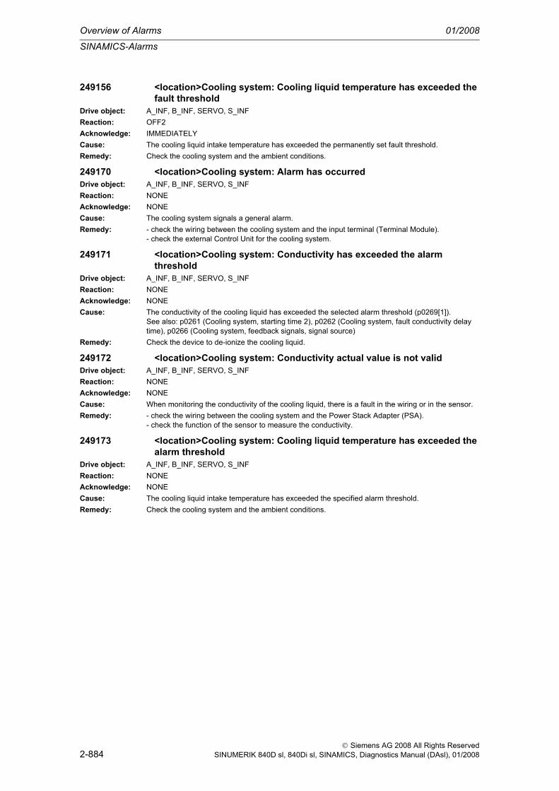
Overview of Alarms 01/2008
SINAMICS-Alarms
2-884
© Siemens AG 2008 All Rights ReservedSINUMERIK 840D sl, 840Di sl, SINAMICS, Diagnostics Manual (DAsl), 01/2008
249156 <location>Cooling system: Cooling liquid temperature has exceeded the fault threshold
Drive object: A_INF, B_INF, SERVO, S_INFReaction: OFF2Acknowledge: IMMEDIATELYCause: The cooling liquid intake temperature has exceeded the permanently set fault threshold.Remedy: Check the cooling system and the ambient conditions.
249170 <location>Cooling system: Alarm has occurredDrive object: A_INF, B_INF, SERVO, S_INFReaction: NONEAcknowledge: NONECause: The cooling system signals a general alarm.Remedy: - check the wiring between the cooling system and the input terminal (Terminal Module).
- check the external Control Unit for the cooling system.
249171 <location>Cooling system: Conductivity has exceeded the alarm threshold
Drive object: A_INF, B_INF, SERVO, S_INFReaction: NONEAcknowledge: NONECause: The conductivity of the cooling liquid has exceeded the selected alarm threshold (p0269[1]).
See also: p0261 (Cooling system, starting time 2), p0262 (Cooling system, fault conductivity delay time), p0266 (Cooling system, feedback signals, signal source)
Remedy: Check the device to de-ionize the cooling liquid.
249172 <location>Cooling system: Conductivity actual value is not validDrive object: A_INF, B_INF, SERVO, S_INFReaction: NONEAcknowledge: NONECause: When monitoring the conductivity of the cooling liquid, there is a fault in the wiring or in the sensor.Remedy: - check the wiring between the cooling system and the Power Stack Adapter (PSA).
- check the function of the sensor to measure the conductivity.
249173 <location>Cooling system: Cooling liquid temperature has exceeded the alarm threshold
Drive object: A_INF, B_INF, SERVO, S_INFReaction: NONEAcknowledge: NONECause: The cooling liquid intake temperature has exceeded the specified alarm threshold.Remedy: Check the cooling system and the ambient conditions.

Drives alarms
01/2008 Overview of Alarms
2-885
© Siemens AG 2008 All Rights ReservedSINUMERIK 840D sl, 840Di sl, SINAMICS, Diagnostics Manual (DAsl), 01/2008
2.4 Drives alarms
300000 Hardware drive bus: DCM not presentDefinitions: For SIMODRIVE 611D (and 840D powerline) only:
The DCM (Drive Communication Master, an ASIC on the NCU module that takes control of the drive bus) has not signaled during the powering up of the drive. There may be a hardware fault in the module
Reaction: NC not ready.The NC switches to follow-up mode.Channel not ready.NC Start disable in this channel.Interface signals are set.Alarm display.NC Stop on alarm.
Remedy: Please inform the authorized personnel/service department.Exchange the NCU module.
Program Con-tinuation:
Switch control OFF - ON.
300001 Axis %1 drive number %2 not possibleParameters: %1 = NC axis number
%2 = Drive numberDefinitions: For SIMODRIVE 611D only:
On powering up the drives, the NCK-specific machine data 13010 DRIVE_LOGIC_NR was checked for impermissible inputs. A logical drive number is entered in the MD that can be freely selected within the defined limits (drive number 0 = "no drive available"). Numbers greater than 15 and multiple use of the same number are not allowed. The MD array must be configured without gaps, i.e. as soon as the logical drive number 0 has been selected once, the logical drive number 0 must be entered in all MDs with a higher location index [p].
Reaction: NC not ready.The NC switches to follow-up mode.Channel not ready.NC Start disable in this channel.Interface signals are set.Alarm display.NC Stop on alarm.
Remedy: Please inform the authorized personnel/service department. Check MD DRIVE_LOGIC_NR for num-bers greater than 15 or for gaps in the machine axis indices.
Program Con-tinuation:
Switch control OFF - ON.
300002 Axis %1 drive number %2 assigned twiceParameters: %1 = NC axis number
%2 = Drive numberDefinitions: For SIMODRIVE 611D only:
The logical drive number has been assigned more than once in NCK MD 13010 DRIVE_LOGIC_NR .Reaction: NC not ready.
The NC switches to follow-up mode.Channel not ready.NC Start disable in this channel.Interface signals are set.Alarm display.NC Stop on alarm.
Remedy: Please inform the authorized personnel/service department. Check MD 13010 DRIVE_LOGIC_NR for identical drive logic numbers and assign another number in the range between 0 and 15 (0 corre-sponds to "No drive available" and is the only number that may occur more than once in the MD array) to each drive.
Program Con-tinuation:
Switch control OFF - ON.
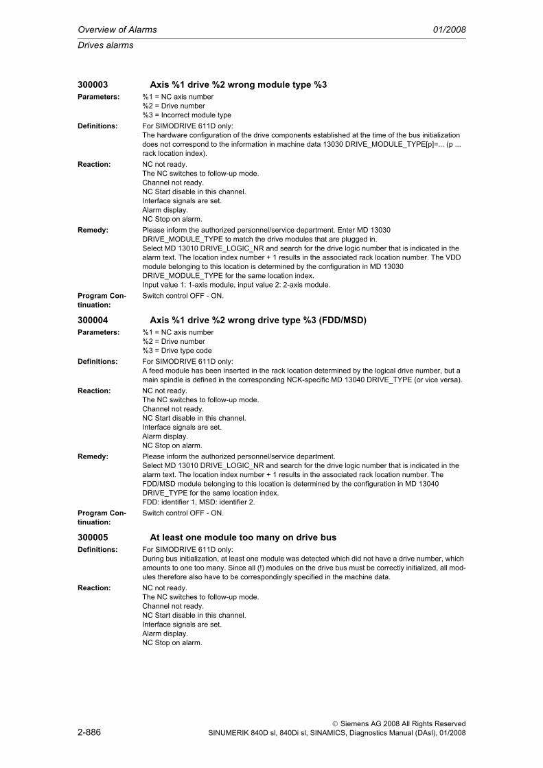
Overview of Alarms 01/2008
Drives alarms
2-886
© Siemens AG 2008 All Rights ReservedSINUMERIK 840D sl, 840Di sl, SINAMICS, Diagnostics Manual (DAsl), 01/2008
300003 Axis %1 drive %2 wrong module type %3Parameters: %1 = NC axis number
%2 = Drive number%3 = Incorrect module type
Definitions: For SIMODRIVE 611D only:The hardware configuration of the drive components established at the time of the bus initialization does not correspond to the information in machine data 13030 DRIVE_MODULE_TYPE[p]=... (p ... rack location index).
Reaction: NC not ready.The NC switches to follow-up mode.Channel not ready.NC Start disable in this channel.Interface signals are set.Alarm display.NC Stop on alarm.
Remedy: Please inform the authorized personnel/service department. Enter MD 13030 DRIVE_MODULE_TYPE to match the drive modules that are plugged in.Select MD 13010 DRIVE_LOGIC_NR and search for the drive logic number that is indicated in the alarm text. The location index number + 1 results in the associated rack location number. The VDD module belonging to this location is determined by the configuration in MD 13030 DRIVE_MODULE_TYPE for the same location index.Input value 1: 1-axis module, input value 2: 2-axis module.
Program Con-tinuation:
Switch control OFF - ON.
300004 Axis %1 drive %2 wrong drive type %3 (FDD/MSD)Parameters: %1 = NC axis number
%2 = Drive number%3 = Drive type code
Definitions: For SIMODRIVE 611D only:A feed module has been inserted in the rack location determined by the logical drive number, but a main spindle is defined in the corresponding NCK-specific MD 13040 DRIVE_TYPE (or vice versa).
Reaction: NC not ready.The NC switches to follow-up mode.Channel not ready.NC Start disable in this channel.Interface signals are set.Alarm display.NC Stop on alarm.
Remedy: Please inform the authorized personnel/service department.Select MD 13010 DRIVE_LOGIC_NR and search for the drive logic number that is indicated in the alarm text. The location index number + 1 results in the associated rack location number. The FDD/MSD module belonging to this location is determined by the configuration in MD 13040 DRIVE_TYPE for the same location index.FDD: identifier 1, MSD: identifier 2.
Program Con-tinuation:
Switch control OFF - ON.
300005 At least one module too many on drive busDefinitions: For SIMODRIVE 611D only:
During bus initialization, at least one module was detected which did not have a drive number, which amounts to one too many. Since all (!) modules on the drive bus must be correctly initialized, all mod-ules therefore also have to be correspondingly specified in the machine data.
Reaction: NC not ready.The NC switches to follow-up mode.Channel not ready.NC Start disable in this channel.Interface signals are set.Alarm display.NC Stop on alarm.

Drives alarms
01/2008 Overview of Alarms
2-887
© Siemens AG 2008 All Rights ReservedSINUMERIK 840D sl, 840Di sl, SINAMICS, Diagnostics Manual (DAsl), 01/2008
Remedy: Please inform the authorized personnel/service department. Check machine data; with the NCK MD 13000 DRIVE_IS_ACTIVE a drive that is not yet in use but exists on the bus can be declared as inac-tive. Inactive drives do not need installation and start-up or drive data.
Program Con-tinuation:
Switch control OFF - ON.
300006 Module with drive number %1 has not been found on drive busParameters: %1 = Drive numberDefinitions: For SIMODRIVE 611D only:
Not all of the drives stated in MD $MN_DRIVE_LOGIC_NR could be found on the drive bus. The asso-ciated module can be found in the configuration display via the displayed drive number.
Reaction: NC not ready.The NC switches to follow-up mode.Channel not ready.NC Start disable in this channel.Interface signals are set.Alarm display.NC Stop on alarm.
Remedy: Perform the following checks:1) Using the configuration display or the associated machine data, check whether the number and type (1-axis or 2-axis) of the modules match your bus setup.2) Check whether the red LED is illuminated on the displayed drive module. If this is not the case, then usually the module does not have any power.- Check the connections of the ribbon cable running from your I/RF or monitoring unit to the module.- If after switching on the I/RF or monitoring unit, no LED of a module which is connected to it is illu-minated, then check the I/RF or monitoring unit and, if required, replace the ribbon cable.- With a multi-tier installation where the power is switched on at different times, an error message can also mean that one tier has been switched on too late (current permissible time 10 seconds). If pos-sible, switch on the second tier at the same time.3) Check whether all drive bus connectors have correctly snapped into place and that the bus termi-nator is connected.4) If you have not been able to detect an error by now, the module is defective.- Replace the module.
Program Con-tinuation:
Switch control OFF - ON.
300007 Axis %1 drive %2 not present or inactiveParameters: %1 = NC axis number
%2 = Drive numberDefinitions: For SIMODRIVE 611D only:
In the axis-specific machine data 30110 CTRLOUT_MODULE_NR (allocation to which drive module the speed setpoint is output) and MD 30220 ENC_MODULE_NR (allocation from which drive module the encoder actual value for the position control is output) there is a logical drive number that does not occur in the NCK MD 13010 DRIVE_LOGIC_NR, and the machine data 30240 ENC_TYPE and MD 30130 CTRLOUT_TYPE are set to "1".
Reaction: NC not ready.The NC switches to follow-up mode.Channel not ready.NC Start disable in this channel.Interface signals are set.Alarm display.NC Stop on alarm.
Remedy: Please inform the authorized personnel/service department. Check the setpoint/actual value assign-ment in the axis-specific MD 30110 CTRLOUT_MODULE_NR and MD 30220 ENC_MODULE_NR and the drive logic number in the NCK MD 13010 DRIVE_LOGIC_NR and bring these into agreement.
Program Con-tinuation:
Switch control OFF - ON.
300008 Axis %1 drive %2 measuring circuit %3 is not availableParameters: %1 = NC axis number
%2 = Drive number%3 = Measuring circuit number

Overview of Alarms 01/2008
Drives alarms
2-888
© Siemens AG 2008 All Rights ReservedSINUMERIK 840D sl, 840Di sl, SINAMICS, Diagnostics Manual (DAsl), 01/2008
Definitions: For SIMODRIVE 611D only:In the axis-specific MD 30230 ENC_INPUT_NR [e]=E (e ... encoder index - the position control works with this encoder, E ... encoder number - encoder connector selection on the drive module), an encoder connector (1 or 2) was selected, to which no encoder was connected.
Reaction: NC not ready.The NC switches to follow-up mode.Channel not ready.NC Start disable in this channel.Interface signals are set.Alarm display.NC Stop on alarm.
Remedy: Please inform the authorized personnel/service department. Configure MD 30230 ENC_INPUT_NR [e] according to the encoder connector used or plug the encoder cable onto the other connector.If the encoder used corresponds to the input in the MD, there is a hardware fault on the drive module. Replace the module!
Program Con-tinuation:
Switch control OFF - ON.
300009 Axis %1 drive %2 measuring circuit %3 wrong measuring circuit type (type %4 used)
Parameters: %1 = NC axis number%2 = Drive number%3 = Measuring circuit number%4 = Measuring circuit type
Definitions: For SIMODRIVE 611D only:The available, displayed actual value module on the drive board cannot process the signal type that was stated in the axis-specific machine data 30240 ENC_TYPE [e]=S (e ... encoder index - the posi-tion control works with this encoder, S ... signal type of the actual value encoder - 0 ... simulation axis without hardware, 1 ... raw encoder signals, 2 ... square-wave signals).
Reaction: NC not ready.The NC switches to follow-up mode.Channel not ready.NC Start disable in this channel.Interface signals are set.Alarm display.NC Stop on alarm.
Remedy: Please inform the authorized personnel/service department.Set MD 30240 ENC_TYPE [e] to 1 (0 should only be entered for pure simulation axes which are to travel in the actual-value display only).
Program Con-tinuation:
Switch control OFF - ON.
300010 Axis %1 drive %2 active without NC axis assignmentParameters: %1 = NC axis number
%2 = Drive numberDefinitions: For SIMODRIVE 611D only:
A drive is active that is not used/addressed by any NC axis (actual value, setpoint).All active drives must be assigned to an axis with respect to the setpoint value or the actual value.
Reaction: NC not ready.The NC switches to follow-up mode.Channel not ready.NC Start disable in this channel.Interface signals are set.Alarm display.NC Stop on alarm.

Drives alarms
01/2008 Overview of Alarms
2-889
© Siemens AG 2008 All Rights ReservedSINUMERIK 840D sl, 840Di sl, SINAMICS, Diagnostics Manual (DAsl), 01/2008
Remedy: Please inform the authorized personnel/service department. Check the configuration data, the assign-ment of setpoints and actual values for the drive motor and the position encoder.MDs for the drive configuration:- Modify MD 13000: DRIVE_IS_ACTIVE- Modify MD 13010: DRIVE_LOGIC_NR- Modify MD 13020: DRIVE_INVERTER_CODE- Modify MD 13030: DRIVE_MODULE_TYPE- Modify MD 13040: DRIVE_TYPE- MDs for the setpoint/actual-value assignment:- Modify MD 30110: CTRLOUT_MODULE_NR- Modify MD 30130: CTRLOUT_TYPE- Modify MD 30220: ENC_MODULE_NR- Modify MD 30230: ENC_INPUT_NR- Modify MD 30240: ENC_TYPEIt might be necessary to first declare an NC axis in the channel for this drive (MD 20070 AXCONF_MACHAX_USED = K, [K ...channel axis no.]).
Program Con-tinuation:
Switch control OFF - ON.
300011 Axis %1 drive %2 hardware version of spindle not supportedParameters: %1 = NC axis number
%2 = Drive numberDefinitions: For SIMODRIVE 611D only:
An old spindle power section (so-called 186-HSA) is connected to the drive bus. These spindle drives are not supported by SINUMERIK 840D. Ramp-up is interrupted.
Reaction: NC not ready.The NC switches to follow-up mode.Channel not ready.NC Start disable in this channel.Interface signals are set.Alarm display.NC Stop on alarm.
Remedy: Please inform the authorized personnel/service department. An up-to-date DSP spindle module must be ordered and fitted.
Program Con-tinuation:
Switch control OFF - ON.
300012 Axis %1 drive %2 hardware version of control module not supportedParameters: %1 = NC axis number
%2 = Drive numberDefinitions: For SIMODRIVE 611D only:
There is a drive module with an "old" control module on the drive bus. 810D does not support these modules. Ramp-up is interrupted.
Reaction: NC not ready.The NC switches to follow-up mode.Channel not ready.NC Start disable in this channel.Interface signals are set.Alarm display.NC Stop on alarm.
Remedy: Please inform the authorized personnel/service department. Order standard or performance control module and exchange with "old".
Program Con-tinuation:
Switch control OFF - ON.
300020 Drive %1 removed for diagnosticsParameters: %1 = Drive number

Overview of Alarms 01/2008
Drives alarms
2-890
© Siemens AG 2008 All Rights ReservedSINUMERIK 840D sl, 840Di sl, SINAMICS, Diagnostics Manual (DAsl), 01/2008
Definitions: For SIMODRIVE 611D only:The alarm indicates that the drive bus configuration has been changed temporarily. The alarm is always output if MD 13030 $MN_DRIVE_MODULE_TYPE has value 0 (zero) for a configured drive.
Reaction: Mode group not ready.NC Start disable in this channel.Interface signals are set.Alarm display.NC Stop on alarm.
Remedy: Normal operation (full bus configuration): Integrate drive module into the bus again, enter the correct type in MD 13030 $MN_DRIVE_MODULE_TYPE.- Normal operation (module remains removed): Remove the module in the configuration screen. Remove all connections to outputs and inputs.- MD30110 $MA_CTRLOUT_MODULE_NR- MD30130 $MA_CTRLOUT_TYPE- MD30220 $MA_ENC_MODULE_NR- MD30240 $MA_ENC_TYPE- MD11342 $MA_ENC_HANDWHEEL_MODULE_NR
Program Con-tinuation:
Switch control OFF - ON.
300100 Drive power failureDefinitions: For SIMODRIVE 611D only:
There is a power failure in one or several (all) drive modules, although power was previously available. (The timeout is checked for write/read accesses. Timeouts are interpreted as power failures because this is the most probable case. The test takes place during cyclic mode only, not during system power-up.)As the drives and the NC-CPU have the same power supply in the SINUMERIK 840D, this error does not occur there because the NCU is also without a power supply.
Reaction: NC not ready.The NC switches to follow-up mode.Channel not ready.NC Start disable in this channel.Interface signals are set.Alarm display.NC Stop on alarm.
Remedy: Switch off the power to the system and switch on again - the drives start up again.Program Con-tinuation:
Clear alarm with the RESET key in all channels. Restart part program.
300101 Bus communications failureDefinitions: For SIMODRIVE 611D only:
This alarm indicates that there is still no power supply to the drives although the NC is already running. This message only appears if no drive module has signaled. (In theory, it could also be a bus error interrupting the connection to the 1st module).
Reaction: NC not ready.The NC switches to follow-up mode.Channel not ready.NC Start disable in this channel.Interface signals are set.Alarm display.NC Stop on alarm.

Drives alarms
01/2008 Overview of Alarms
2-891
© Siemens AG 2008 All Rights ReservedSINUMERIK 840D sl, 840Di sl, SINAMICS, Diagnostics Manual (DAsl), 01/2008
Remedy: 1) If the NCU has its own power supply, then the drives still have no power.- If possible, switch on the power supply for the drives at the same time as the NCU.2) If the NCU and the drives have the same power supply then not even the first module could be rec-ognized. Check whether the red LED on the first drive module is illuminated. If this is not the case, then usually the module does not have any power.- Check the connections of the ribbon cable running from your I/RF or monitoring unit to the module.- If after switching on the I/RF or monitoring unit, no LED of a module which is connected to it is illu-minated, then check the I/RF or monitoring unit and, if required, replace the ribbon cable.3) Check whether all drive bus connectors have correctly snapped into place and that the bus termi-naor is connected.4) If you have not been able to detect an error by now, the module is defective.- Replace the module.
Program Con-tinuation:
Clear alarm with the RESET key in all channels. Restart part program.
300200 Drive bus hardware faultDefinitions: For SIMODRIVE 611D only:
The drive bus has a fault. The following causes are possible:- The bus terminator is missing.- The drive bus is physically interrupted at some point.- Miscellaneous hardware fault.A check line is tested that runs over the entire bus, and returns from the last rack location (bus termi-nator) to the NCK.Note: If the drive ramps up correctly even though this message appeared, the error existed only at the beginning of the initialization. In spite of this, the drives can be capable of functioning.
Reaction: Mode group not ready.The NC switches to follow-up mode.Channel not ready.NC Start disable in this channel.Interface signals are set.Alarm display.
Remedy: Please inform the authorized personnel/service department.- Check the bus terminator.- Check all plug connections from the drive bus to the drive modules.- Other hardware faults.If the remedial measures given above do not lead to a change in the behaviour when starting, please contact the system support for the A&D MC products of SIEMENS AG through the Hotline (tel.: see alarm 1000).
Program Con-tinuation:
Switch control OFF - ON.
300201 Axis %1 drive %2 timeout during access, error location %3Parameters: %1 = NC axis number
%2 = Drive number%3 = Error location
Definitions: For SIMODRIVE 611D only:The read cycle of a drive address in the initialization phase or in cyclic operation did not end within the monitoring time (approx. 1ms) (timeout error).The error can occur in conjunction with a power failure in one or several drive modules. A hardware fault might also be the cause (ASICs, bus, drive modules).
Reaction: NC not ready.The NC switches to follow-up mode.Mode group not ready, also effective for single axesNC Start disable in this channel.Axes of this channel must be re-referenced.Interface signals are set.Alarm display.
Remedy: Please inform the authorized personnel/service department. If the alarm has occurred in conjunction with a power failure, this cause of failure must be eliminated. Otherwise, please contact the system support for A&D MC products, SIEMENS AG, through the Hotline (tel.: see alarm 1000).
Program Con-tinuation:
Switch control OFF - ON.

Overview of Alarms 01/2008
Drives alarms
2-892
© Siemens AG 2008 All Rights ReservedSINUMERIK 840D sl, 840Di sl, SINAMICS, Diagnostics Manual (DAsl), 01/2008
300202 Axis %1 drive %2 CRC error, error location %3Parameters: %1 = NC axis number
%2 = Drive number%3 = Error location
Definitions: For SIMODRIVE 611D only:The checksum test (CRC) has detected an access error in a write/read cycle. All bus accesses are not controlled directly by the processor but handled by special ASICs. They transfer not only the required data but also cheksum tests (cross-checks) for the write/read data and the addresses.The error can occur in conjunction with a power failure in one or several drive modules. A hardware fault might also be the cause (ASICs, bus, drive modules).
Reaction: NC not ready.The NC switches to follow-up mode.Mode group not ready, also effective for single axesNC Start disable in this channel.Axes of this channel must be re-referenced.Interface signals are set.Alarm display.
Remedy: Please inform the authorized personnel/service department. If the alarm has occurred in conjunction with a power failure, this cause of failure must be eliminated. Otherwise, please contact the system support for A&D MC products, SIEMENS AG, through the Hotline (tel.: see alarm 1000).
Program Con-tinuation:
Switch control OFF - ON.
300300 Axis %1 drive %2 boot error, error code %3Parameters: %1 = NC axis number
%2 = Drive number%3 = Error code
Definitions: For SIMODRIVE 611D only:An error occurred while starting up the status-controlled drive. (Example: Drive signals timeout).Meaning of the error codes:- 0..5: Timeout while waiting for the acknowledgement from the drive in the displayed state - 10: No signal from drive CPU (possibly defective module)Safety Integrated special case: If the axial machine data $MA_SAFE_FUNCTION_ENABLE is not zero for at least one axis , then the occurrence of this alarm with error code 5 can mean that the PLC, after the timeout PLC_RUNNINGUP_TIMEOUT, has not started cyclic operation. The drive and PLC components have to be synchronized, because data transmission between the PLC and the drive is monitored when the drive is in cyclic operation.
Reaction: Mode group not ready.The NC switches to follow-up mode.Channel not ready.NC Start disable in this channel.Interface signals are set.Alarm display.NC Stop on alarm.
Remedy: Please inform the authorized personnel/service department. You can try to power the system up again. The search for the precise cause of error can only be performed by the development team. The displayed status code is always needed for this.Contact SIEMENS AG, System Support for A&D MC products, Hotline (Tel.: see alarm 1000).Special case Safety Integrated: If the first NC axis is a simulation axis when the alarm occurs with error code 5, then the axial machine data $MA_SIMU_AX_VDI_OUTPUT must be set to 1.
Program Con-tinuation:
Switch control OFF - ON.
300400 Axis %1 drive %2 system error, error codes %3, %4Parameters: %1 = NC axis number
%2 = Drive number%3 = Error code 1%4 = Error code 2

Drives alarms
01/2008 Overview of Alarms
2-893
© Siemens AG 2008 All Rights ReservedSINUMERIK 840D sl, 840Di sl, SINAMICS, Diagnostics Manual (DAsl), 01/2008
Definitions: For SIMODRIVE 611D only:An internal software error or serious error condition has occurred which may be able to be cleared by a hardware reset. Troubleshooting can generally be performed only by Siemens AG, System Support for A&D MC Products, Hotline (tel.: see alarm 1000).In the case of error code combination (324,26), the calculation time allocated to the drive communi-cation subtask should be increased in MD 10140 $MN_TIME_LIMIT_NETTO_DRIVE_TASK (max. of 500ms).If the alarm continues to occur when the above-mentioned limit has been reached, MD 10150 $MN_PREP_DRIVE_TASK_CYCLE_RATIO=1 can also be set. Please note that reducing MD 10150 also reduces the time share of the block preparation on the non-cyclic time level. This may lead to longer block cycle times.The error code combination (257,n) indicates that n conflicts occurred during the conversion of the machine data. The data format of n machine data changed to the last backed-up version. This alarm occurs during the upgrading of SIMODRIVE 611D version 05.01.32 to a later version. Remedy: Back up the drive BOT file again for this drive.
Reaction: NC not ready.The NC switches to follow-up mode.Channel not ready.NC Start disable in this channel.Interface signals are set.Alarm display.NC Stop on alarm.Channel not ready.
Remedy: Please inform the authorized personnel/service department. You can try to power the system up again. The search for the precise cause of error can only be performed by the development team. The displayed error codes are always needed for this.(contact SIEMENS AG, System Support for A&D MC products, Hotline (Tel.: see alarm 1000).
Program Con-tinuation:
Switch control OFF - ON.
300401 Drive software for type %1, block %2 missing or incorrectParameters: %1 = Drive type
%2 = Block numberDefinitions: For SIMODRIVE 611D only:
Either there is no software for this drive type or it contains errors.Drive type- 1 = VSA (as in MD DRIVE_TYPE!)- 2 = HSA- 3 = SLM- 4 = HYD- 5 = ANABlock number- 1 = Drive software (code)- 2 = Data descriptions (ACC file)
Reaction: NC not ready.The NC switches to follow-up mode.Channel not ready.NC Start disable in this channel.Interface signals are set.Alarm display.NC Stop on alarm.
Remedy: Please inform the authorized personnel/service department. Check the data carrier (PCMCIA card), replace if necessary.
Program Con-tinuation:
Clear alarm with the RESET key in all channels. Restart part program.
300402 System error in drive link. Error codes %1, %2Parameters: %1 = Error code 1
%2 = Error code 2

Overview of Alarms 01/2008
Drives alarms
2-894
© Siemens AG 2008 All Rights ReservedSINUMERIK 840D sl, 840Di sl, SINAMICS, Diagnostics Manual (DAsl), 01/2008
Definitions: For SIMODRIVE 611D only:An internal software error or serious error condition has occurred which may be able to be cleared by a hardware reset. Troubleshooting can generally be performed only by Siemens AG, System Support for A&D MC Products, Hotline (tel.: see alarm 1000).In the case of error code combination (1077,X), the calculation time allocated to the drive communi-cation subtask should be increased in the MD 10140 $MN_TIME_LIMIT_NETTO_DRIVE_TASK (max. of 500ms).If the alarm continues to occur when the above-mentioned limit has been reached, MD 10150 $MN_PREP_DRIVE_TASK_CYCLE_RATIO=1 can also be set. Please note that reducing MD 10150 also reduces the time share of the preparation on the non-cyclic time level. This may lead to longer block cycle times.
Reaction: NC not ready.The NC switches to follow-up mode.Channel not ready.NC Start disable in this channel.Interface signals are set.Alarm display.NC Stop on alarm.
Remedy: Make a note of the error text and contact Siemens AG A&D MC, Hotline (tel./fax: see alarm 1000).Program Con-tinuation:
Switch control OFF - ON.
300403 Axis %1 drive %2 drive software and drive MD with different version numbers
Parameters: %1 = NC axis number%2 = Drive number
Definitions: For SIMODRIVE 611D only:The version number of the drive software (FDD/MSD) must correspond to the version number stored in the drive machine data because the MD files are not compatible with different software versions.
Reaction: NC not ready.The NC switches to follow-up mode.Channel not ready.NC Start disable in this channel.Interface signals are set.Alarm display.NC Stop on alarm.
Remedy: Please inform the authorized personnel/service department. After exchanging the drive software, the drives must be installed and started up again. Any MD files that were saved by the control running under the old version must no longer be used. The old data can be saved with the installation and start-up tool and this data can also be used again.
Program Con-tinuation:
Clear alarm with the RESET key in all channels. Restart part program.
300404 Axis %1 drive %2 drive MD contains different drive numberParameters: %1 = NC axis number
%2 = Drive numberDefinitions: For SIMODRIVE 611D only:
In the drive MD file loaded in a drive there is a drive number which does not correspond to this drive.Reaction: Mode group not ready.
The NC switches to follow-up mode.Channel not ready.NC Start disable in this channel.Interface signals are set.Alarm display.NC Stop on alarm.
Remedy: Files with drive data for a particular drive number must not be copied to another drive.Program Con-tinuation:
Teileprogramm neu starten.Clear alarm with the RESET key in all channels of this mode group. Restart part program.

Drives alarms
01/2008 Overview of Alarms
2-895
© Siemens AG 2008 All Rights ReservedSINUMERIK 840D sl, 840Di sl, SINAMICS, Diagnostics Manual (DAsl), 01/2008
300405 Axis %1 drive %2 unknown drive alarm, code %3Parameters: %1 = NC axis number
%2 = Drive number%3 = Service number
Definitions: For SIMODRIVE 611D only:The service number signaled by the drive is not implemented in the NCK. It cannot be assigned to any alarm number.
Reaction: Mode group not ready.The NC switches to follow-up mode.Channel not ready.NC Start disable in this channel.Interface signals are set.Alarm display.NC Stop on alarm.
Remedy: Please inform the authorized personnel/service department. Reinitialization of the drive required.The search for the precise cause of error can only be performed by the development team. The dis-played error codes are always needed for this. (contact SIEMENS AG, System Support for A&D MC products, Hotline (Tel.: see alarm 1000).
Program Con-tinuation:
Teileprogramm neu starten.Clear alarm with the RESET key in all channels of this mode group. Restart part program.
300406 Problem in the non-cyclic communication for basic address %1, additional information %2, %3, %4
Definitions: For PROFIdrive only:A problem has occured during the non-cyclic communication with the logical base address. The addi-tional information defines the location of the problem.
Reaction: Alarm display.Warning display.
Remedy: Please inform the authorized personnel/service department. The alarm can be suppressed with ENABLE_ALARM_MASK bit 1 == 0SIEMENS AG, System Support for A&D MC products, Hotline (Phone: see alarm 1000)
Program Con-tinuation:
Clear alarm with the Delete key or NC START.
300410 Axis %1 drive %2 error when storing a file (%3, %4)Parameters: %1 = NC axis number
%2 = Drive number%3 = Error code 1%4 = Error code 2
Definitions: An attempt to save a data block, e. g. the result of a measuring function, in the file system has failed.On error code 1 == 291: An error occurred during preparation of the ACC information. Basic informa-tion prepared on the drive contains an error or has an unknown format.On error code 1 == 292: Memory shortage during preparation of the ACC information.
Reaction: Interface signals are set.Alarm display.

Overview of Alarms 01/2008
Drives alarms
2-896
© Siemens AG 2008 All Rights ReservedSINUMERIK 840D sl, 840Di sl, SINAMICS, Diagnostics Manual (DAsl), 01/2008
Remedy: - Please inform the authorized personnel/service department.- Create more space in the file system. It is normally sufficient to delete 2 NC programs or to free 4 - 8 Kbytes of memory. If these remedies do not work, it will be necessary to increase the number of files per directory or the size of the file system itself (this will require a complete data backup).- Change settings of machine data- 18280 $MM_NUM_FILES_PER_DIR- 18320 $MM_NUM_FILES_IN_FILESYSTEM- 18350 $MM_USER_FILE_MEM_MINIMUM- and, if necessary, of- 18270 $MM_NUM_SUBDIR_PER_DIR,- 18310 $MM_NUM_DIR_IN_FILESYSTEM,- Power On- Reload saved data- On error code 1 == 291: Replace the drive software and use version with suitable ACC basic infor-mation.- On error code 1 == 292: Replace the drive software and use fewer different versions of the drive software.
Program Con-tinuation:
Clear alarm with the RESET key. Restart part program
300411 Axis %1 drive %2 error when reading a file (%3, %4)Parameters: %1 = NC axis number
%2 = Drive number%3 = Error code 1%4 = Error code 2
Definitions: An attempt to read a data block, e.g. a drive boot file, from the file system has failed. The data block or the file system is damaged.
Reaction: Interface signals are set.Alarm display.
Remedy: If the error occurred during power-up, i.e. it is probably connected to a drive boot file, delete all boot files and load them back into the control from the back-up copy.
Program Con-tinuation:
Clear alarm with the RESET key. Restart part program
300412 Error when storing a file (%1, %2)Parameters: %1 = Error code 1
%2 = Error code 2Definitions: An attempt to save a data block, e.g. the result of a measuring function, in the file system has failed.Reaction: Interface signals are set.
Alarm display.Remedy: Please inform the authorized personnel/service department. Create more space in the file system. It
is normally sufficient to delete 2 NC programs or to free 4 - 8 Kbytes of memory. If these remedies do not work, it will be necessary to increase the number of files per directory or the size of the file system itself. To do so, proceed as follows:- Save all data- Change settings of machine data- 18280 $MM_NUM_FILES_PER_DIR- 18320 $MM_NUM_FILES_IN_FILESYSTEM- 18350 $MM_USER_FILE_MEM_MINIMUM- and, if necessary, of- 18270 $MM_NUM_SUBDIR_PER_DIR- 18310 $MM_NUM_DIR_IN_FILESYSTEM- Power On- Reload saved data
Program Con-tinuation:
Clear alarm with the RESET key. Restart part program
300413 Error when reading a file (%1, %2)Parameters: %1 = Error code 1
%2 = Error code 2

Drives alarms
01/2008 Overview of Alarms
2-897
© Siemens AG 2008 All Rights ReservedSINUMERIK 840D sl, 840Di sl, SINAMICS, Diagnostics Manual (DAsl), 01/2008
Definitions: An attempt to read a data block, e.g. a drive boot file, from the file system has failed. The data block or the file system is damaged.
Reaction: Interface signals are set.Alarm display.
Remedy: If the error occurred during power-up, i.e. it is probably connected to a drive boot file, delete all boot files and load them back into the control from the back-up copy.
Program Con-tinuation:
Clear alarm with the RESET key. Restart part program
300423 Measuring result could not be read (%1)Parameters: %1 = Error codeDefinitions: An attempt to read a measurement result has failed:
- Error code = 4: Not enough space for test result- Error code = 16: Measurement not yet finished
Reaction: Interface signals are set.Alarm display.
Remedy: Repeat measurement. Alter measuring time if necessary.Program Con-tinuation:
Clear alarm with the RESET key. Restart part program
380001 PROFIBUS/PROFINET: Startup error, reason %1 parameter %2 %3 %4.Parameters: %1 = Cause of the error
%2 = Parameter 1%3 = Parameter 2%4 = Parameter 3
Definitions: An error occurred during startup of the PROFIBUS/PROFINET master.Overview: Cause of the error, Par 1, Par 2, Par 3:- 01 = DPM version, DPM version, DPA version, --- 02 = DPM ramp-up timeout, DPM actual value status, DPM setpoint value status, --- 03 = DPM ramp-up status, DPM actual value status, DPM setpoint value status, DPM error code- 04 = DPM ramp-up error, DPM actual value status, DPM setpoint value status, DPM error code- 05 = DPM-PLL sync error, --, --, --- 07 = Alarm queue too long, Actual number, Setpoint number, --- 08 = Unknown client, Client ID, --, --- 09 = Client version, Client ID, Client version, DPA version- 10 = Too many clients, Client number, max. number of clients, --- 11 = Log.basic address used several times; bus no.; slot no.; log.basic address --- 20 = Slave/device address used several times, slave/device address --- 21 = Slave/device address unknown, slave/device address, --- 22 = Erroneous configuration telegram, slave/device address, error code, --- 23 = OMI incompatible (data), drive version, CDA version, --, --- 24 = OMI incompatible (driver), drive version, CDA version, --, --- 25 = CPI initialization failed, error code, --, --, --- 26 = DMA not active- 27 = Reserved- 28 = Reserved- 29 = Reserved- The 1000s digit of the error cause = number of the affected busClients are the following components of the control system that use the PROFIBUS/PROFINET:Client ID = 1: PLCClient ID = 2: NCKPossible causes are:- Error in contents of SDB- Corruption of parts of the system program- Hardware defect on NC component
Reaction: Channel not ready.NC Start disable in this channel.Interface signals are set.Alarm display.

Overview of Alarms 01/2008
Drives alarms
2-898
© Siemens AG 2008 All Rights ReservedSINUMERIK 840D sl, 840Di sl, SINAMICS, Diagnostics Manual (DAsl), 01/2008
Remedy: Remedy for 1-111. Check the control project, check MD 11240, and reload it when using a user-specific SDB.2. If the error still occurs, back up data, and restart the control with the standard values as per the as-delivered condition.3. In case of correct ramp-up, reload the user data stage by stage.4. If the error still occurs during ramp-up with standard values, reboot the system from the PC card or update the software.5. If the error still occurs, replace the hardware.Remedy for 20-211. Check/correct the addresses of the connected slaves/devices.Remedy for 22See SINAMICS warning 1903 for a description of the meaning behind the error codes.1. Control the SDB- Check the type and length of the message frame- Match slot assignment with P9782. Evaluate the drive alarms/warningsRemedy for 23-241. Software replacement requiredRemedy for 251. Change the message frame type2. Reduce the number of slots3. Reduce the number of slaves/devices4. Create a new SDB5. Software must be replacedIf the error has still not been able to be rectified after this procedure, send the error text to the control manufacturer.
Program Con-tinuation:
Switch control OFF - ON.
380003 PROFIBUS/PROFINET: Operating error, reason %1 parameter %2 %3 %4.Parameters: %1 = Cause of the error
%2 = Parameter 1%3 = Parameter 2%4 = Parameter 3
Definitions: An operating error occurred on the PROFIBUS/PROFINET in cyclic mode.Overview: Cause of the error, Par 1, Par 2, Par 3:- 01 = unknown alarm, alarm class, logical address, --- 02 = DPM cycle timeout, DPM actual value status, DPM setpoint value status, --- 03 = DPM cycle status, DPM actual value status, DPM setpoint value status, DPM error code- 04 = DPM cycle error, DPM actual value status, DPM setpoint value status, DPM error code- 05 = Client not registered, client number, max. number of clients, --- 06 = Synchronisation error, number of sync violation, --, --- 07 = Spinlock timeout, PLC spinlock, NCK spinlock, --- 1000s digit of the error cause = number of the affected busAlarm class: (see alarm 380 060)The following can be primary causes:- For error cause 01: Data transfer error on the PROFIBUS/PROFINET- For error causes 02, 03, 04: Error in contents of SDB- For error causes 02, 03, 04, 05, 07: Corruption of parts of system program- For error cause 06: The PCI bus cycle does not match the expected rate, so synchronization is not possible. The correct PCI bus cycle must be entered. The error can also be caused by a hardware problem on the MCI module.
Reaction: Channel not ready.NC Start disable in this channel.Interface signals are set.Alarm display.

Drives alarms
01/2008 Overview of Alarms
2-899
© Siemens AG 2008 All Rights ReservedSINUMERIK 840D sl, 840Di sl, SINAMICS, Diagnostics Manual (DAsl), 01/2008
Remedy: - For error cause 01:- Check the electrical and fault-related specifications for PROFIBUS/PROFINET, assess the cable installation- Check the terminating resistors of the PROFIBUS connectors (ON setting at ends of cables, other-wise OFF setting required)- Check slave/device- For error causes 02, 03, 04:- Check SDB- For error causes 02, 03, 04, 05, 07:- Follow the procedure described for troubleshooting alarm 380 001- For error cause 06:- The correct PCI bus cycle must be entered.If the error cannot be eliminated by this procedure, send the error text to the control system manufac-turer.
Program Con-tinuation:
Clear alarm with the RESET key. Restart part program
380005 PROFIBUS/PROFINET: Bus %3 access conflict, type %1, counter %2Parameters: %1 = Conflict type
%2 = Serial number within a conflict sequence%3 = Number of the affected bus
Definitions: An access conflict occurred on the PROFIBUS/PROFINET in cyclic mode: An attempt has been made in the NCK to write data to the bus or to read from the bus while cyclic data transfer was active. This may lead to inconsistant data.Type 1: NCK attempts to read data before the cyclic transfer has finished on the bus.Type 2: The NCK has not finished writing its data when the cyclic transfer begins again. Counter %2 contains a serial number starting at 1. A maximum of 10 alarms are output in succession. If no conflicts occur in a DP cycle, the counter is reset and new alarms are output again on the next conflict.
Reaction: Alarm display.Remedy: - Check the timing again, in particular ensure that the settings in SYSCLOCK_CYCLE_TIME and
POSCTRL_CYCLE_DELAY are correct: POSCTRL_CYCLE_DELAY must be larger for type 1. POSCTRL_CYCLE_DELAY must be smaller for type 2.- If alarm-free operation cannot be achieved with any POSCTRL_CYCLE_DELAY setting, SYSCLOCK_CYCLE_TIME must be increased.- If the error cannot be eliminated by this procedure, please make a note of the error text and contact the control system manufacturer.
Program Con-tinuation:
Clear alarm with the Delete key or NC START.
380020 PROFIBUS/PROFINET: Bus %3 SDB %4 error %1 source %2Parameters: %1 = Error
%2 = SDB source%3 = Bus number%4 = SDB number

Overview of Alarms 01/2008
Drives alarms
2-900
© Siemens AG 2008 All Rights ReservedSINUMERIK 840D sl, 840Di sl, SINAMICS, Diagnostics Manual (DAsl), 01/2008
Definitions: Error in SDB for configuring PROFIBUS/PROFINET.Causes of the error:- 01 = SDB does not exist in source.- 02 = SDB from source is too large.- 03 = SDB from source cannot be activated.- 04 = Source is empty.- 05 = Source is not present.SDB source:- 99 = Passive file system: _N_SDB_DIR - 100 = CF card: /siemens/sinumerik/sdb/... - 101 = CF card: /addon/sinumerik/sdb/...- 102 = CF card: /oem/sinumerik/sdb/...- 103 = CF card: /user/sinumerik/sdb/...Reaction: PROFIBUS/PROFINET is inactive or working with the default SDB.
Reaction: Channel not ready.NC Start disable in this channel.Interface signals are set.Alarm display.
Remedy: - Check the setting of MD 11240.- If source = 100: Check directory _N_SDB_DIR in the passive file system.- If source = 103-106: Check directories on CF card
Program Con-tinuation:
Switch control OFF - ON.
380021 Profibus-DP: default SDB-Type-2000 was loadedDefinitions: No user-specific SDB-Type-2000 exists. The default SDB was loaded during startup. Without process
peripherals, the NC is ready for a start-up. The alarm is triggered the first time the NC is switched on or once if the SDB stored in the supported RAM is lost.
Reaction: Alarm display.Remedy: Create the user-specific SDB-Type-2000 and load it on the control system, or select and activate it via
MD 11240 standard SDB. Restart the NC. If the error occurs the next time the NC is switched on, the SDB which was loaded contains an error and must be created again.
Program Con-tinuation:
Clear alarm with the Delete key or NC START.
380022 PROFIBUS/PROFINET: Configuration of DP master bus %1 has been changed
Parameters: %1 = Number of the affected busDefinitions: The PROFIBUS configuration on the DP master was changed during operation, e.g. by downloading
a new hardware configuration via STEP 7. As the cycle data may also have changed, operation cannot be continued, and a warm start is required.If the master functionality is within the PLC (as on the 840Di), the PLC will have been stopped for the download, and alarm 2000 (PLC sign-of-life) output.
Reaction: Channel not ready.NC Start disable in this channel.Interface signals are set.Alarm display.
Remedy: NCK restartIf the error cannot be eliminated by this procedure, please make a note of the error text and contact the control system manufacturer.
Program Con-tinuation:
Switch control OFF - ON.
380040 PROFIBUS/PROFINET: Bus %3, configuration error %1, parameter %2Parameters: %1 = Cause of the error
%2 = Parameter%3 = Number of the affected bus

Drives alarms
01/2008 Overview of Alarms
2-901
© Siemens AG 2008 All Rights ReservedSINUMERIK 840D sl, 840Di sl, SINAMICS, Diagnostics Manual (DAsl), 01/2008
Definitions: The PROFIBUS/PROFINET was not generated in the SDB in accordance with the configuration spec-ifications of the NC in use.Overview: Cause of the error, Par 1:- 01 = SDB contains slave/device without diagnostics slot, slave/device address- 02 = SDB contains too many slot entries, identifier- 03 = SDB contains no equidistance data, no function.- 04 = PNIO: SDB contains different Tdp (also TDC) on a device- 05 = PNIO: SDB contains different Tmapc (also CACF) on a device- 06 = PNIO: SDB contains different TI on a device- 07 = PNIO: SDB contains different TO on a device- 20 = SDB contains too many slaves/devices, numbers of slaves/devices.- 21 = SDB missing or contains invalid data, error code.- 22 = SDB configuration data erroneous, slave/device address, error code- 23 = Reserved- 24 = Reserved- 25 = Reserved- 26 = Reserved- 27 = Reserved- 28 = Reserved- 29 = Reserved
Reaction: Channel not ready.NC Start disable in this channel.Interface signals are set.Alarm display.
Remedy: Check that the corresponding SDB- Contains a diagnostic slot for every slave/device, and- Contains only slave/device entries relevant to the application.In general, it is possible to include a superset of slaves/device in the SDB that are partially relevant for different end versions of the product. However, this overloads the NC memory and runtime capac-ity, and should therefore be avoided in general.If this alarm occurs, it is necessary to reduce the SDB to a minimum.If the code for the error cause is 03, check that equidistance is activated in the SDB (e.g. using STEP 7 HW config).If the alarm continues to occur, please send the error text to the control system manufacturer.
Program Con-tinuation:
Switch control OFF - ON.
380050 PROFIBUS/PROFINET: Multiple assignment of inputs on address %1Parameters: %1 = Logical addressDefinitions: Multiple assignments of input data have been detected in the logical address space. Logical address:
Base address of the address area defined several timesReaction: Channel not ready.
NC Start disable in this channel.Interface signals are set.Alarm display.
Remedy: The address partitioning should be checked as follows:Check for multiple assignments in the following machine data:- MD 13050[0] - MD 13050[n-1]: n = highest axis index on control system- MD 12970, 12971: PLC address area for digital inputs- MD 12978, 12979: PLC address area for analog inputsIf no inconsistencies can be found in the parameters, compare these machine data with the configu-ration in SDB (STEP 7 project). In particular, check that the lengths configured for the individual slots do not result in area overlaps. When you find the cause of the error, change the machine data and/or SDB.
Program Con-tinuation:
Switch control OFF - ON.
380051 PROFIBUS/PROFINET: Multiple assignment of outputs on address %1Parameters: %1 = Logical address

Overview of Alarms 01/2008
Drives alarms
2-902
© Siemens AG 2008 All Rights ReservedSINUMERIK 840D sl, 840Di sl, SINAMICS, Diagnostics Manual (DAsl), 01/2008
Definitions: Multiple assignments of input data have been detected in the logical address space. Logical address: Base address of the address area defined several times
Reaction: Channel not ready.NC Start disable in this channel.Interface signals are set.Alarm display.
Remedy: The address partitioning should be checked as follows:Check for multiple assignments in the following machine data:- MD 13050[0] - MD 13050[n-1]: n = highest axis index on control system- MD 12974, 12975: PLC address area for digital outputs- MD 12982, 12983: PLC address area for analog outputsIf no inconsistencies can be found in the parameters, compare these machine data with the configu-ration in the SDB (STEP 7 project). In particular, check that the lengths configured for the individual slots do not result in area overlaps. When you find the cause of the error, change the machine data and/or SDB.
Program Con-tinuation:
Switch control OFF - ON.
380060 PROFIBUS/PROFINET: Alarm %1 on logical address %2 from unassigned slave/device
Parameters: %1 = Alarm class%2 = Logical address
Definitions: SDB contains a slave/device which is not assigned in the NC via the MD parameters (see also alarm 380050/051). The slave/device is however connected to the PROFIBUS/PROFINET, and has reported an alarm.Alarm class:- 01 = Station return (or arrival)- 02 = Station failureDisplay alarm, further operation with the NC is possible.
Reaction: Alarm display.Remedy: - Enter machine data or
- Modify SDB or- Disconnect the slave/device from the PROFIBUS/PROFINET or- Acknowledge the alarm.
Program Con-tinuation:
Clear alarm with the Delete key or NC START.
380070 PROFIBUS/PROFINET: No input slot available for basic address %1 (length %2)
Parameters: %1 = Logical base address of the requested area%2 = Size of the area in bytes
Definitions: An incorrect logical base address was specified for a digital or analog input. Either no slot has been configured for this base address or the requested area extends beyond the end of the slot.Length=1 indicates a digital input.Length=2 indicates a analog input.
Reaction: Channel not ready.NC Start disable in this channel.Interface signals are set.Alarm display.
Remedy: Enter correct base addresses in the machine data:- For length=1: Correct machine data MN_HW_ASSIGN_DIG_FASTIN.- For length=2: Correct machine data MN_HW_ASSIGN_ANA_FASTIN.- NCK restartIf the error cannot be eliminated by this procedure, please make a note of the error text and contact the control system manufacturer.
Program Con-tinuation:
Switch control OFF - ON.

Drives alarms
01/2008 Overview of Alarms
2-903
© Siemens AG 2008 All Rights ReservedSINUMERIK 840D sl, 840Di sl, SINAMICS, Diagnostics Manual (DAsl), 01/2008
380071 PROFIBUS/PROFINET: No output slot available for basic address %1 (size %2)
Parameters: %1 = Logical base address of the requested area%2 = Size of the area in bytes
Definitions: An incorrect logical base address was specified for a digital or analog input. Either no slot has been configured for this base address or the requested area extends beyond the end of the slot.For length =1 it is a digital output,For length =2 it is an analog output.
Reaction: Channel not ready.NC Start disable in this channel.Interface signals are set.Alarm display.
Remedy: Enter correct base addresses in the machine data:- For length=1: Correct machine data MN_HW_ASSIGN_DIG_FASTOUT.- For length=2: Correct machine data MN_HW_ASSIGN_ANA_FASTOUT.- NCK restartIf the error cannot be eliminated by this procedure, please make a note of the error text and contact the control system manufacturer.
Program Con-tinuation:
Switch control OFF - ON.
380072 PROFIBUS/PROFINET: Output slot for basic address %1 (size %2) not allowed
Parameters: %1 = Logical base address of the requested area%2 = Size of the area in bytes
Definitions: An incorrect logical base address was set for a digital or analog output, the area is resides in the access range of the PLC (PIQ, base addresses < 256).For length =1 it is a digital output,For length =2 it is an analog output.
Reaction: Channel not ready.NC Start disable in this channel.Interface signals are set.Alarm display.
Remedy: Only use addresses outside the PLC process image (e.g. >= 256) for output slots.Enter correct basic addresses in the machine data:- For length=1: Correct machine data MN_HW_ASSIGN_DIG_FASTOUT.- For length=2: Correct machine data MN_HW_ASSIGN_ANA_FASTOUT.- NCK restartIf the error cannot be eliminated by this procedure, please make a note of the error text and contact the control system manufacturer.
Program Con-tinuation:
Switch control OFF - ON.
380075 PROFIBUS/PROFINET: DP I/O failure bus %2 slave/device %1Parameters: %1 = Slave/device address
%2 = Number of the affected busDefinitions: Failure of a PROFIBUS/PROFINET slot used by the NCK for digital or analog I/Os.Reaction: Alarm display.Remedy: Check that the slave/device is operating correctly (all slaves/devices must be included in the bus,
green LEDs).Program Con-tinuation:
Alarm display showing cause of alarm disappears. No further operator action necessary.
380076 PROFIBUS/PROFINET: No DO1 message frame: Bus %2 slave/device %1Parameters: %1 = Slave/device address
%2 = Number of the affected bus

Overview of Alarms 01/2008
Drives alarms
2-904
© Siemens AG 2008 All Rights ReservedSINUMERIK 840D sl, 840Di sl, SINAMICS, Diagnostics Manual (DAsl), 01/2008
Definitions: Note for the system startup engineer: A PROFIBUS slave/PROFINET device used as an NCK drive does not have a valid DO1 message frame assignment (see MD $MN_CONTROL_UNIT_LOGIC_ADDRESS with the STEP 7 configuration).This alarm is indicating, among other things, that the alarm time-of-day synchronization is not working between the controller and this slave/device.
Reaction: Alarm display.Remedy: Enter a valid value in MD $MN_CONTROL_UNIT_LOGIC_ADDRESS.Program Con-tinuation:
Alarm display showing cause of alarm disappears. No further operator action necessary.
380500 PROFIBUS/PROFINET: Fault on drive %1, code %2, value %3, time %4Parameters: %1 = Axis
%2 = Fault code of drive (P947(/945)/P824)%3 = Fault value of drive ((P949/P826)%4 = Fault time of drive (P948/P825)
Definitions: Contents of fault memory of assigned drive.Reaction: Alarm display.Remedy: See drive documentation for fault codes/fault values.Program Con-tinuation:
Alarm display showing cause of alarm disappears. No further operator action necessary.
380501 PROFIBUS/PROFINET: Fault on bus, slave/device, DO ID %1, code %2, value %3, time %4
Parameters: %1 = 8 bit bus number, 8 bit slave/device number, 16 bit DO ID%2 = Fault code of drive (P947)%3 = Fault value of the drive (P949)%4 = Fault time of the drive (P948)
Definitions: Contents of the fault memory of the assigned slave/device.Reaction: Alarm display.Remedy: See drive documentation for fault codes/fault values.Program Con-tinuation:
Alarm display showing cause of alarm disappears. No further operator action necessary.
380502 PROFIBUS/PROFINET: Bus %1, slave/device %2 configuration changedParameters: %1 = Bus number
%2 = Slave/device addressDefinitions: The bus configuration has changed.
Causes:- Initial start-up- New slave/device recognized on the bus
Reaction: Interface signals are set.Alarm display.
Remedy: In order to operate the bus with the new configuration, an additional restart will be required.Program Con-tinuation:
Switch control OFF - ON.
380503 PROFIBUS/PROFINET: Bus %1 configuration changedParameters: %1 = Bus numberDefinitions: A new SDB with a modified configuration has been provided.
The new settings will be activated only at the next bus power up.Reaction: Interface signals are set.
Alarm display.Remedy: In order to operate the bus with the new configuration, an additional restart will be required.Program Con-tinuation:
Switch control OFF - ON.
380598 do not useDefinitions: do not useReaction: Alarm display.

Drives alarms
01/2008 Overview of Alarms
2-905
© Siemens AG 2008 All Rights ReservedSINUMERIK 840D sl, 840Di sl, SINAMICS, Diagnostics Manual (DAsl), 01/2008
Remedy: do not useProgram Con-tinuation:
Alarm display showing cause of alarm disappears. No further operator action necessary.
380599 do not useDefinitions: do not useReaction: Alarm display.Remedy: do not useProgram Con-tinuation:
Alarm display showing cause of alarm disappears. No further operator action necessary.

Overview of Alarms 01/2008
PLC alarms
2-906
© Siemens AG 2008 All Rights ReservedSINUMERIK 840D sl, 840Di sl, SINAMICS, Diagnostics Manual (DAsl), 01/2008
2.5 PLC alarms
400102 Delete DB 2 in the PLC and restartDefinitions: The DB created by the basic program and the existing DB differ in size.Reaction: Alarm display.Remedy: Displayed DB must be deleted via STEP7. Possibly max. program size of the user program exceeded.Program Con-tinuation:
Internal
400103 Delete DB 3 in the PLC and restartDefinitions: The DB created by the basic program and the existing DB differ in size.Reaction: Alarm display.Remedy: Displayed DB must be deleted via STEP7. Possibly max. program size of the user program exceeded.Program Con-tinuation:
Internal
400106 Delete DB 6 in the PLC and restartDefinitions: The DB created by the basic program and the existing DB differ in size.Reaction: Alarm display.Remedy: Displayed DB must be deleted via STEP7. Possibly max. program size of the user program exceeded.Program Con-tinuation:
Internal
400109 Delete DB 9 in the PLC and restartDefinitions: The DB created by the basic program and the existing DB differ in size.Reaction: Alarm display.Remedy: Displayed DB must be deleted via STEP7. Possibly max. program size of the user program exceeded.Program Con-tinuation:
Internal
400110 Delete DB 10 in the PLC and restartDefinitions: The DB created by the basic program and the existing DB differ in size.Reaction: Alarm display.Remedy: Displayed DB must be deleted via STEP7. Possibly max. program size of the user program exceeded.Program Con-tinuation:
Internal
400111 Delete DB 11 in the PLC and restartDefinitions: The DB created by the basic program and the existing DB differ in size.Reaction: Alarm display.Remedy: Displayed DB must be deleted via STEP7. Possibly max. program size of the user program exceeded.Program Con-tinuation:
Internal
400120 Delete DB 20 in the PLC and restartDefinitions: The DB created by the basic program and the existing DB differ in size.Reaction: Alarm display.Remedy: Displayed DB must be deleted via STEP7. Possibly max. program size of the user program exceeded.Program Con-tinuation:
Internal
400121 Delete DB 21 in the PLC and restartDefinitions: The DB created by the basic program and the existing DB differ in size.Reaction: Alarm display.Remedy: Displayed DB must be deleted via STEP7. Possibly max. program size of the user program exceeded.Program Con-tinuation:
Internal

PLC alarms
01/2008 Overview of Alarms
2-907
© Siemens AG 2008 All Rights ReservedSINUMERIK 840D sl, 840Di sl, SINAMICS, Diagnostics Manual (DAsl), 01/2008
400122 Delete DB 22 in the PLC and restartDefinitions: The DB created by the basic program and the existing DB differ in size.Reaction: Alarm display.Remedy: Displayed DB must be deleted via STEP7. Possibly max. program size of the user program exceeded.Program Con-tinuation:
Internal
400123 Delete DB 23 in the PLC and restartDefinitions: The DB created by the basic program and the existing DB differ in size.Reaction: Alarm display.Remedy: Displayed DB must be deleted via STEP7. Possibly max. program size of the user program exceeded.Program Con-tinuation:
Internal
400124 Delete DB 24 in the PLC and restartDefinitions: The DB created by the basic program and the existing DB differ in size.Reaction: Alarm display.Remedy: Displayed DB must be deleted via STEP7. Possibly max. program size of the user program exceeded.Program Con-tinuation:
Internal
400125 Delete DB 25 in the PLC and restartDefinitions: The DB created by the basic program and the existing DB differ in size.Reaction: Alarm display.Remedy: Displayed DB must be deleted via STEP7. Possibly max. program size of the user program exceeded.Program Con-tinuation:
Internal
400126 Delete DB 26 in the PLC and restartDefinitions: The DB created by the basic program and the existing DB differ in size.Reaction: Alarm display.Remedy: Displayed DB must be deleted via STEP7. Possibly max. program size of the user program exceeded.Program Con-tinuation:
Internal
400127 Delete DB 27 in the PLC and restartDefinitions: The DB created by the basic program and the existing DB differ in size.Reaction: Alarm display.Remedy: Displayed DB must be deleted via STEP7. Possibly max. program size of the user program exceeded.Program Con-tinuation:
Internal
400128 Delete DB 28 in the PLC and restartDefinitions: The DB created by the basic program and the existing DB differ in size.Reaction: Alarm display.Remedy: Displayed DB must be deleted via STEP7. Possibly max. program size of the user program exceeded.Program Con-tinuation:
Internal
400129 Delete DB 29 in the PLC and restartDefinitions: The DB created by the basic program and the existing DB differ in size.Reaction: Alarm display.Remedy: Displayed DB must be deleted via STEP7. Possibly max. program size of the user program exceeded.Program Con-tinuation:
Internal

Overview of Alarms 01/2008
PLC alarms
2-908
© Siemens AG 2008 All Rights ReservedSINUMERIK 840D sl, 840Di sl, SINAMICS, Diagnostics Manual (DAsl), 01/2008
400130 Delete DB 30 in the PLC and restartDefinitions: The DB created by the basic program and the existing DB differ in size.Reaction: Alarm display.Remedy: Displayed DB must be deleted via STEP7. Possibly max. program size of the user program exceeded.Program Con-tinuation:
Internal
400131 Delete DB 31 in the PLC and restartDefinitions: The DB created by the basic program and the existing DB differ in size.Reaction: Alarm display.Remedy: Displayed DB must be deleted via STEP7. Possibly max. program size of the user program exceeded.Program Con-tinuation:
Internal
400132 Delete DB 32 in the PLC and restartDefinitions: The DB created by the basic program and the existing DB differ in size.Reaction: Alarm display.Remedy: Displayed DB must be deleted via STEP7. Possibly max. program size of the user program exceeded.Program Con-tinuation:
Internal
400133 Delete DB 33 in the PLC and restartDefinitions: The DB created by the basic program and the existing DB differ in size.Reaction: Alarm display.Remedy: Displayed DB must be deleted via STEP7. Possibly max. program size of the user program exceeded.Program Con-tinuation:
Internal
400134 Delete DB 34 in the PLC and restartDefinitions: The DB created by the basic program and the existing DB differ in size.Reaction: Alarm display.Remedy: Displayed DB must be deleted via STEP7. Possibly max. program size of the user program exceeded.Program Con-tinuation:
Internal
400135 Delete DB 35 in the PLC and restartDefinitions: The DB created by the basic program and the existing DB differ in size.Reaction: Alarm display.Remedy: Displayed DB must be deleted via STEP7. Possibly max. program size of the user program exceeded.Program Con-tinuation:
Internal
400136 Delete DB 36 in the PLC and restartDefinitions: The DB created by the basic program and the existing DB differ in size.Reaction: Alarm display.Remedy: Displayed DB must be deleted via STEP7. Possibly max. program size of the user program exceeded.Program Con-tinuation:
Internal
400137 Delete DB 37 in the PLC and restartDefinitions: The DB created by the basic program and the existing DB differ in size.Reaction: Alarm display.Remedy: Displayed DB must be deleted via STEP7. Possibly max. program size of the user program exceeded.Program Con-tinuation:
Internal

PLC alarms
01/2008 Overview of Alarms
2-909
© Siemens AG 2008 All Rights ReservedSINUMERIK 840D sl, 840Di sl, SINAMICS, Diagnostics Manual (DAsl), 01/2008
400138 Delete DB 38 in the PLC and restartDefinitions: The DB created by the basic program and the existing DB differ in size.Reaction: Alarm display.Remedy: Displayed DB must be deleted via STEP7. Possibly max. program size of the user program exceeded.Program Con-tinuation:
Internal
400139 Delete DB 39 in the PLC and restartDefinitions: The DB created by the basic program and the existing DB differ in size.Reaction: Alarm display.Remedy: Displayed DB must be deleted via STEP7. Possibly max. program size of the user program exceeded.Program Con-tinuation:
Internal
400140 Delete DB 40 in the PLC and restartDefinitions: The DB created by the basic program and the existing DB differ in size.Reaction: Alarm display.Remedy: Displayed DB must be deleted via STEP7. Possibly max. program size of the user program exceeded.Program Con-tinuation:
Internal
400141 Delete DB 41 in the PLC and restartDefinitions: The DB created by the basic program and the existing DB differ in size.Reaction: Alarm display.Remedy: Displayed DB must be deleted via STEP7. Possibly max. program size of the user program exceeded.Program Con-tinuation:
Internal
400142 Delete DB 42 in the PLC and restartDefinitions: The DB created by the basic program and the existing DB differ in size.Reaction: Alarm display.Remedy: Displayed DB must be deleted via STEP7. Possibly max. program size of the user program exceeded.Program Con-tinuation:
Internal
400143 Delete DB 43 in the PLC and restartDefinitions: The DB created by the basic program and the existing DB differ in size.Reaction: Alarm display.Remedy: Displayed DB must be deleted via STEP7. Possibly max. program size of the user program exceeded.Program Con-tinuation:
Internal
400144 Delete DB 44 in the PLC and restartDefinitions: The DB created by the basic program and the existing DB differ in size.Reaction: Alarm display.Remedy: Displayed DB must be deleted via STEP7. Possibly max. program size of the user program exceeded.Program Con-tinuation:
Internal
400145 Delete DB 45 in the PLC and restartDefinitions: The DB created by the basic program and the existing DB differ in size.Reaction: Alarm display.Remedy: Displayed DB must be deleted via STEP7. Possibly max. program size of the user program exceeded.Program Con-tinuation:
Internal

Overview of Alarms 01/2008
PLC alarms
2-910
© Siemens AG 2008 All Rights ReservedSINUMERIK 840D sl, 840Di sl, SINAMICS, Diagnostics Manual (DAsl), 01/2008
400146 Delete DB 46 in the PLC and restartDefinitions: The DB created by the basic program and the existing DB differ in size.Reaction: Alarm display.Remedy: Displayed DB must be deleted via STEP7. Possibly max. program size of the user program exceeded.Program Con-tinuation:
Internal
400147 Delete DB 47 in the PLC and restartDefinitions: The DB created by the basic program and the existing DB differ in size.Reaction: Alarm display.Remedy: Displayed DB must be deleted via STEP7. Possibly max. program size of the user program exceeded.Program Con-tinuation:
Internal
400148 Delete DB 48 in the PLC and restartDefinitions: The DB created by the basic program and the existing DB differ in size.Reaction: Alarm display.Remedy: Displayed DB must be deleted via STEP7. Possibly max. program size of the user program exceeded.Program Con-tinuation:
Internal
400149 Delete DB 49 in the PLC and restartDefinitions: The DB created by the basic program and the existing DB differ in size.Reaction: Alarm display.Remedy: Displayed DB must be deleted via STEP7. Possibly max. program size of the user program exceeded.Program Con-tinuation:
Internal
400150 Delete DB 50 in the PLC and restartDefinitions: The DB created by the basic program and the existing DB differ in size.Reaction: Alarm display.Remedy: Displayed DB must be deleted via STEP7. Possibly max. program size of the user program exceeded.Program Con-tinuation:
Internal
400151 Delete DB 51 in the PLC and restartDefinitions: The DB created by the basic program and the existing DB differ in size.Reaction: Alarm display.Remedy: Displayed DB must be deleted via STEP7. Possibly max. program size of the user program exceeded.Program Con-tinuation:
Internal
400152 Delete DB 52 in the PLC and restartDefinitions: The DB created by the basic program and the existing DB differ in size.Reaction: Alarm display.Remedy: Displayed DB must be deleted via STEP7. Possibly max. program size of the user program exceeded.Program Con-tinuation:
Internal
400153 Delete DB 53 in the PLC and restartDefinitions: The DB created by the basic program and the existing DB differ in size.Reaction: Alarm display.Remedy: Displayed DB must be deleted via STEP7. Possibly max. program size of the user program exceeded.Program Con-tinuation:
Internal

PLC alarms
01/2008 Overview of Alarms
2-911
© Siemens AG 2008 All Rights ReservedSINUMERIK 840D sl, 840Di sl, SINAMICS, Diagnostics Manual (DAsl), 01/2008
400154 Delete DB 54 in the PLC and restartDefinitions: The DB created by the basic program and the existing DB differ in size.Reaction: Alarm display.Remedy: Displayed DB must be deleted via STEP7. Possibly max. program size of the user program exceeded.Program Con-tinuation:
Internal
400155 Delete DB 55 in the PLC and restartDefinitions: The DB created by the basic program and the existing DB differ in size.Reaction: Alarm display.Remedy: Displayed DB must be deleted via STEP7. Possibly max. program size of the user program exceeded.Program Con-tinuation:
Internal
400156 Delete DB 56 in the PLC and restartDefinitions: The DB created by the basic program and the existing DB differ in size.Reaction: Alarm display.Remedy: Displayed DB must be deleted via STEP7. Possibly max. program size of the user program exceeded.Program Con-tinuation:
Internal
400157 Delete DB 57 in the PLC and restartDefinitions: The DB created by the basic program and the existing DB differ in size.Reaction: Alarm display.Remedy: Displayed DB must be deleted via STEP7. Possibly max. program size of the user program exceeded.Program Con-tinuation:
Internal
400158 Delete DB 58 in the PLC and restartDefinitions: The DB created by the basic program and the existing DB differ in size.Reaction: Alarm display.Remedy: Displayed DB must be deleted via STEP7. Possibly max. program size of the user program exceeded.Program Con-tinuation:
Internal
400159 Delete DB 59 in the PLC and restartDefinitions: The DB created by the basic program and the existing DB differ in size.Reaction: Alarm display.Remedy: Displayed DB must be deleted via STEP7. Possibly max. program size of the user program exceeded.Program Con-tinuation:
Internal
400160 Delete DB 60 in the PLC and restartDefinitions: The DB created by the basic program and the existing DB differ in size.Reaction: Alarm display.Remedy: Displayed DB must be deleted via STEP7. Possibly max. program size of the user program exceeded.Program Con-tinuation:
Internal
400161 Delete DB 61 in the PLC and restartDefinitions: The DB created by the basic program and the existing DB differ in size.Reaction: Alarm display.Remedy: Displayed DB must be deleted via STEP7. Possibly max. program size of the user program exceeded.Program Con-tinuation:
Internal

Overview of Alarms 01/2008
PLC alarms
2-912
© Siemens AG 2008 All Rights ReservedSINUMERIK 840D sl, 840Di sl, SINAMICS, Diagnostics Manual (DAsl), 01/2008
400171 Delete DB 71 in the PLC and restartDefinitions: The DB created by the basic program and the existing DB differ in size.Reaction: Alarm display.Remedy: Displayed DB must be deleted via STEP7. Possibly max. program size of the user program exceeded.Program Con-tinuation:
Internal
400172 Delete DB 72 in the PLC and restartDefinitions: --Reaction: Alarm display.Remedy: See the machine manufacturer's information.Program Con-tinuation:
Internal
400173 Delete DB 73 in the PLC and restartDefinitions: The DB created by the basic program and the existing DB differ in size.Reaction: Alarm display.Remedy: Displayed DB must be deleted via STEP7. Possibly max. program size of the user program exceeded.Program Con-tinuation:
Internal
400174 Delete DB 74 in the PLC and restartDefinitions: The DB created by the basic program and the existing DB differ in size.Reaction: Alarm display.Remedy: Displayed DB must be deleted via STEP7. Possibly max. program size of the user program exceeded.Program Con-tinuation:
Internal
400176 Delete DB 76 in the PLC and restartDefinitions: The DB created by the basic program and the existing DB differ in size.Reaction: Alarm display.Remedy: Displayed DB must be deleted via STEP7. Possibly max. program size of the user program exceeded.Program Con-tinuation:
Internal
400177 Delete DB 77 in the PLC and restartDefinitions: The DB created by the basic program and the existing DB differ in size.Reaction: Alarm display.Remedy: Displayed DB must be deleted via STEP7. Possibly max. program size of the user program exceeded.Program Con-tinuation:
Internal
400201 PLC STOP due to DB loading in the RUN state: DB%ZParameters: %Z = Data blockDefinitions: An existing DB was reloaded in the RUN state.Reaction: Alarm display.Remedy: Restart required.Program Con-tinuation:
Switch control OFF - ON.
400202 Access errorDefinitions: The data could not be accessed.Reaction: Alarm display.Remedy: System error, contact the Siemens AG A&D MC Hotline with the error text.Program Con-tinuation:
Switch control OFF - ON.

PLC alarms
01/2008 Overview of Alarms
2-913
© Siemens AG 2008 All Rights ReservedSINUMERIK 840D sl, 840Di sl, SINAMICS, Diagnostics Manual (DAsl), 01/2008
400203 DB acces error: DB%ZParameters: %Z = Data blockDefinitions: Data block is either not present or write-protected.Reaction: Alarm display.Remedy: The displayed DB has to be reloaded via STEP 7 or its write protection has to be removed. Restart
required.Program Con-tinuation:
Switch control OFF - ON.
400250 NCK sign-of-life monitoringDefinitions: NCK has not contacted the PLC during cyclic operation. Timer of FB1 parameter NCCyclTimeout was
executed without retrigger.Reaction: Alarm display.Remedy: NCK restartProgram Con-tinuation:
Internal
400251 NCK has not started upDefinitions: NCK has not contacted the PLC.
NCK has not ramped up.Acknowledgement error during ramp-up: the time limit entered in OB1 / FB1 under parameter address MCP1Cycl or MCP2Cycl has been exceeded.
Reaction: Alarm display.Remedy: Enter the default values in FB1 correctly.
Carry out a general NCK reset and restart.Increase the time values in FB1.
Program Con-tinuation:
Internal
400252 Error in internal communication with NCKDefinitions: An error has occured during data transmission between the PLC and the NCK (FM-NC only).Reaction: Alarm display.Remedy: NCK restartProgram Con-tinuation:
Internal
400253 PLC STOP because of SPL system errorDefinitions: After the interruption of the communication between the NCK and the PLC with regard to the SPL data
cross-check, the PLC was switched to STOP with a delay of 5 s.Reaction: Alarm display.Remedy: Do no longer start SPL. Check the system components (PLC must be provided with the correct version
of FB15 and with DB18).Program Con-tinuation:
Switch control OFF - ON.
400255 Sign of life monitoring NCK2Definitions: NCK2 has not contacted the PLC during cyclic operation. Timer of FB1 parameter NCCyclTimeout
was executed without retrigger. (FM-NC only). Reaction: Alarm display.Remedy: NCK restartProgram Con-tinuation:
Internal
400256 NCK2 has not run upDefinitions: NCK2 has not run up. NCK has not contacted the PLC. Timer of FB1 parameter NCRunupTimeout
has expired. (FM-NC only). Reaction: Alarm display.Remedy: General NCK reset and restart.

Overview of Alarms 01/2008
PLC alarms
2-914
© Siemens AG 2008 All Rights ReservedSINUMERIK 840D sl, 840Di sl, SINAMICS, Diagnostics Manual (DAsl), 01/2008
Program Con-tinuation:
Internal
400257 Error in internal communication with NCK2Definitions: An error has occured during data transmission between the PLC and the NCK. (FM-NC only)Reaction: Alarm display.Remedy: NCK restartProgram Con-tinuation:
Internal
400260 Failure of machine control panel 1Definitions: Machine control panel (MCP) at machine control panel interface 1 has failed. Timer of FB1 parameter
MCP1Timeout has expired. Incorrect address in DB7 parameter MCP1BusAdr. DB7 parameter MCP1NotSend=TRUE.
Reaction: Alarm display.Remedy: Check the connection to the MCP. Increase the value of the timer parameter MCP1Timeout. Set
MCP1Cycl to the default value. Correct the MCP1BusAdr in the DB7 parameter/compare with the selected address. Set DB7 parameter MCP1NotSend=FALSE.
Program Con-tinuation:
Internal
400261 Failure of machine control panel 2Definitions: Machine control panel (MCP) at machine control panel interface 2 has failed. Timer of FB1 parameter
MCP2Timeout has expired. Incorrect address in the DB7 parameter MCP2BusAdr. DB7 parameter MCP2NotSend=TRUE.
Reaction: Alarm display.Remedy: Check the connection to the MCP. Increase the value of the timer parameter MCP2Timeout. Set
MCP2Cycl to the default value. Correct the MCP2BusAdr in the DB7 parameter/compare with selected address. Set DB7 parameter MCP2NotSend=FALSE.
Program Con-tinuation:
Internal
400262 Failure of handheld unitDefinitions: Handheld unit (HHU) at handheld unit interface has failed. Timer of FB1 parameter HHUTimeout has
expired.Reaction: Alarm display.Remedy: Check the connection to the HHU. Increase the value of timer parameter HHUTimeout. Set HHUCycl
to the default value.Program Con-tinuation:
Internal
400264 Pointer parameter machine control panel 1 incorrectDefinitions: A pointer is incorrect in the MCP1 parameter range.Reaction: Alarm display.Remedy: Correct the PLC configuration in the FB1 parameters.Program Con-tinuation:
Switch control OFF - ON.
400265 Pointer parameter machine control panel 2 incorrectDefinitions: A pointer is incorrect in the MCP 2 parameter range.Reaction: Alarm display.Remedy: Correct the PLC configuration in the FB1 parameters.Program Con-tinuation:
Switch control OFF - ON.
400266 Pointer parameter handheld unit incorrectDefinitions: A pointer is incorrect in the HHU parameter range.Reaction: Alarm display.Remedy: Correct the PLC configuration in the FB1 parameters.

PLC alarms
01/2008 Overview of Alarms
2-915
© Siemens AG 2008 All Rights ReservedSINUMERIK 840D sl, 840Di sl, SINAMICS, Diagnostics Manual (DAsl), 01/2008
Program Con-tinuation:
Switch control OFF - ON.
400267 Access errorDefinitions: MCP or HHU data could not be accessedReaction: Alarm display.Remedy: Check the MCP or HHU parameters of the FB1.Program Con-tinuation:
Switch control OFF - ON.
400268 Error in internal communication with machine control panel 1, internal error code: %Z
Definitions: Communication error between CP and PLC.Reaction: Alarm display.Remedy: Check MCP parameter of FB1, MCP1Stop, switch TRUE->FALSEProgram Con-tinuation:
Switch control OFF - ON.
400269 Error in internal communication with machine control panel 2, internal error code: %Z
Definitions: Communication error between CP and PLC.Reaction: Alarm display.Remedy: Check MCP parameter of FB1, MCP2Stop, switch TRUE->FALSEProgram Con-tinuation:
Switch control OFF - ON.
400270 Error in internal communication with handheld unit, internal error code: %Z
Definitions: Communication error between CP and PLC.Reaction: Alarm display.Remedy: Check HHU parameter of FB1, HHUStop, switch TRUE->FALSEProgram Con-tinuation:
Switch control OFF - ON.
400271 Direct keys 1 communication error, internal error code: %ZDefinitions: Communication error between CP and PLC.Reaction: Alarm display.Remedy: Check OpKey parameterProgram Con-tinuation:
Internal
400272 Direct keys 2 communication error, internal error code: %ZDefinitions: Communication error between CP and PLC.Reaction: Alarm display.Remedy: Check OpKey parameterProgram Con-tinuation:
Internal
400274 Direct keys 1 failedDefinitions: Direct keys 1: internal timeout has expired. Reaction: Alarm display.Remedy: Check connection to direct key moduleProgram Con-tinuation:
Internal

Overview of Alarms 01/2008
PLC alarms
2-916
© Siemens AG 2008 All Rights ReservedSINUMERIK 840D sl, 840Di sl, SINAMICS, Diagnostics Manual (DAsl), 01/2008
400275 Direct keys 2 failedDefinitions: Direct keys 2: internal timeout has expired.Reaction: Alarm display.Remedy: Check connection to direct key moduleProgram Con-tinuation:
Internal
400276 Pointer parameter direct keys 1 incorrectDefinitions: Pointer incorrectly definedReaction: Alarm display.Remedy: Correct the pointerProgram Con-tinuation:
Switch control OFF - ON.
400277 Pointer parameter direct keys 2 incorrectDefinitions: Pointer incorrectly definedReaction: Alarm display.Remedy: Correct the pointerProgram Con-tinuation:
Switch control OFF - ON.
400551 Fault on MPI/DP busDefinitions: Error detected on I/O busReaction: Alarm display.Remedy: Check I/Os, rectify I/O faultProgram Con-tinuation:
Internal
400552 Fault on DP busDefinitions: Error detected on I/O busReaction: Alarm display.Remedy: Check I/Os, rectify I/O faultProgram Con-tinuation:
Internal
400553 Fault on PROFINET busDefinitions: Error detected on I/O busReaction: Alarm display.Remedy: Check I/Os, rectify I/O faultProgram Con-tinuation:
Internal
400601 Configuration loading points incorrectDefinitions: The PLC configuration in the DB4 does not match the NC configurationReaction: Alarm display.Remedy: Correct tool management start-upProgram Con-tinuation:
Switch control OFF - ON.
400602 Spindle configuration incorrectDefinitions: The PLC configuration in the DB4 does not match the NC configurationReaction: Alarm display.Remedy: Correct tool management start-upProgram Con-tinuation:
Switch control OFF - ON.

PLC alarms
01/2008 Overview of Alarms
2-917
© Siemens AG 2008 All Rights ReservedSINUMERIK 840D sl, 840Di sl, SINAMICS, Diagnostics Manual (DAsl), 01/2008
400603 Revolver configuration incorrectDefinitions: The PLC configuration in the DB4 does not match the NC configurationReaction: Alarm display.Remedy: Correct tool management start-upProgram Con-tinuation:
Switch control OFF - ON.
400604 Set change with M06 in the machine dataDefinitions: With the magazine type used (box magazine, chain), changing is possible only with M06. If necessary,
also check for impermissible settings at revolver magazines.Reaction: Alarm display.Remedy: Set the value in the channel-specific machine data TOOL_CHANGE_MODE (MD 22550) to 1.Program Con-tinuation:
Internal
400902 Parameter ChanNo impermissible in FC 9Definitions: The parameterized channel does not exist.Reaction: Alarm display.Remedy: Correct the parameter.Program Con-tinuation:
Switch control OFF - ON.
400903 Parameter IntNo impermissible in FC 9Definitions: The parameterized interrupt does not exist.Reaction: Alarm display.Remedy: Correct the parameter.Program Con-tinuation:
Switch control OFF - ON.
401003 FC 10 system error 0x8083Definitions: System error SFC52 has occurred.Reaction: Alarm display.Remedy: Restart, contact the Siemens AG A&D MC Hotline with the error text. Program Con-tinuation:
Switch control OFF - ON.
401004 FC 10 system error 0x8084Definitions: System error SFC52 has occurred.Reaction: Alarm display.Remedy: Restart, contact the Siemens AG A&D MC Hotline with the error text. Program Con-tinuation:
Switch control OFF - ON.
401005 FC 10 system error 0x8085Definitions: System error SFC52 has occurred.Reaction: Alarm display.Remedy: Restart, contact the Siemens AG A&D MC Hotline with the error text. Program Con-tinuation:
Switch control OFF - ON.
401006 FC 10 system error 0x8086Definitions: System error SFC52 has occurred.Reaction: Alarm display.Remedy: Restart, contact the Siemens AG A&D MC Hotline with the error text. Program Con-tinuation:
Switch control OFF - ON.

Overview of Alarms 01/2008
PLC alarms
2-918
© Siemens AG 2008 All Rights ReservedSINUMERIK 840D sl, 840Di sl, SINAMICS, Diagnostics Manual (DAsl), 01/2008
401007 FC 10 system error 0x8087Definitions: System error SFC52 has occurred.Reaction: Alarm display.Remedy: Restart, contact the Siemens AG A&D MC Hotline with the error text. Program Con-tinuation:
Switch control OFF - ON.
401502 Impermissible axis no. parameter in FC 15Definitions: The parameterized axis does not exist.Reaction: Alarm display.Remedy: Correct the parameter.Program Con-tinuation:
Switch control OFF - ON.
401602 Impermissible axis no. parameter in FC 16Definitions: The parameterized axis does not exist.Reaction: Alarm display.Remedy: Correct the parameter.Program Con-tinuation:
Switch control OFF - ON.
401702 Impermissible spindle IF no. parameter in FC 17Definitions: The parameterized spindle does not exist.Reaction: Alarm display.Remedy: Correct the parameter.Program Con-tinuation:
Switch control OFF - ON.
401805 Impermissible axis no. parameter in FC 18Definitions: The parameterized axis / spindle does not exist.Reaction: Alarm display.Remedy: Correct the parameter.Program Con-tinuation:
Switch control OFF - ON.
401901 Parameter BAGNo impermissible in FC19Definitions: The parameterized mode group, channel does not exist.Reaction: Alarm display.Remedy: Correct the parameter.Program Con-tinuation:
Switch control OFF - ON.
401902 Parameter ChanNo impermissible in FC19.Definitions: The parameterized channel does not exist.Reaction: Alarm display.Remedy: Correct the parameter.Program Con-tinuation:
Switch control OFF - ON.
402401 Parameter BAGNo impermissible in FC24Definitions: The parameterized mode group, channel does not exist.Reaction: Alarm display.Remedy: Correct the parameter.Program Con-tinuation:
Switch control OFF - ON.

PLC alarms
01/2008 Overview of Alarms
2-919
© Siemens AG 2008 All Rights ReservedSINUMERIK 840D sl, 840Di sl, SINAMICS, Diagnostics Manual (DAsl), 01/2008
402402 Parameter ChanNo impermissible in FC24.Definitions: The parameterized mode group, channel does not exist.Reaction: Alarm display.Remedy: Correct the parameter.Program Con-tinuation:
Switch control OFF - ON.
402501 Parameter BAGNo impermissible in FC25Definitions: The parameterized mode group, channel does not exist.Reaction: Alarm display.Remedy: Correct the parameter.Program Con-tinuation:
Switch control OFF - ON.
402502 Parameter ChanNo impermissible in FC25.Definitions: The parameterized mode group, channel does not exist.Reaction: Alarm display.Remedy: Correct the parameter.Program Con-tinuation:
Switch control OFF - ON.
402601 Parameter BAGNo impermissible in FC26Definitions: The parameterized mode group, channel does not exist.Reaction: Alarm display.Remedy: Correct the parameter.Program Con-tinuation:
Switch control OFF - ON.
402602 Parameter ChanNo impermissible in FC26Definitions: The parameterized mode group, channel does not exist.Reaction: Alarm display.Remedy: Correct the parameter.Program Con-tinuation:
Switch control OFF - ON.
410141 TM: Too many loading pointsDefinitions: The PLC configuration in the DB4 has more than 32 loading pointsReaction: Alarm display.Remedy: Correct tool management start-upProgram Con-tinuation:
Switch control OFF - ON.
410142 TM: Too many toolholdersDefinitions: The PLC configuration in the DB4 has more than 32 toolholdersReaction: Alarm display.Remedy: Correct tool management start-upProgram Con-tinuation:
Switch control OFF - ON.
410143 TM: Too many revolversDefinitions: The PLC configuration in the DB4 has more than 32 revolversReaction: Alarm display.Remedy: Correct tool management start-upProgram Con-tinuation:
Switch control OFF - ON.

Overview of Alarms 01/2008
PLC alarms
2-920
© Siemens AG 2008 All Rights ReservedSINUMERIK 840D sl, 840Di sl, SINAMICS, Diagnostics Manual (DAsl), 01/2008
410144 TOOLMAN: Multiple definition of magazine number %ZDefinitions: Multiple definition of the magazine numberReaction: Alarm display.Remedy: Magazines, spindles, loading points must be uniquely defined in different TO areasProgram Con-tinuation:
Switch control OFF - ON.
410150 Area in M group decoder list is too largeDefinitions: Number of M groups in PLC too large.Reaction: Alarm display.Remedy: Reduce the number of groupsProgram Con-tinuation:
Internal
410151 Magazine data for tool management missing in the PLCDefinitions: Magazine data are not available in the PLC. The start-up has not been completed, although the option
TOOLMAN has been activated.Reaction: Alarm display.Remedy: Softkey 'Create PLC Data' must be pressed during TOOLMAN start-up via HMI Advanced. Or create
the data in data block DB4 as from DBB64.Program Con-tinuation:
Internal
410160 PROFIBUS configuration is too large for DP1Definitions: Internal data area is too large for PROFIBUS configuration.Reaction: Alarm display.Remedy: Define and load a smaller PROFIBUS configurationProgram Con-tinuation:
Internal
410900 M:N: call waiting was not continuedDefinitions: The switchover sequence started was not completedReaction: Alarm display.Remedy: Reactuate channel menu on HMIProgram Con-tinuation:
Internal
410901 M:N: HMI 1 does not respond to displacementDefinitions: The HMI that is to be switched over does not respondReaction: Alarm display.Remedy: Reactuate channel menu on HMIProgram Con-tinuation:
Internal
410902 M:N: HMI 1 does not go offlineDefinitions: The HMI that is to be switched over does not respondReaction: Alarm display.Remedy: Reactuate channel menu on HMIProgram Con-tinuation:
Internal
410903 M:N: HMI 2 does not respond to displacementDefinitions: The HMI that is to be switched over does not respondReaction: Alarm display.Remedy: Reactuate channel menu on HMIProgram Con-tinuation:
Internal

PLC alarms
01/2008 Overview of Alarms
2-921
© Siemens AG 2008 All Rights ReservedSINUMERIK 840D sl, 840Di sl, SINAMICS, Diagnostics Manual (DAsl), 01/2008
410904 M:N: HMI 2 does not go offlinDefinitions: The HMI that is to be switched over does not respondReaction: Alarm display.Remedy: Reactuate channel menu on HMIProgram Con-tinuation:
Internal
410905 M:N: No HMI link to assigned interfaceDefinitions: The HMI to be switched over is not connecting to the NCReaction: Alarm display.Remedy: Reactuate channel menu on HMIProgram Con-tinuation:
Internal
410906 M:N: No sign of life of an HMIDefinitions: Link to NC disconnectedReaction: Alarm display.Remedy: Check connection to HMIProgram Con-tinuation:
Internal
411101 Impermissible Parameter Axis in FB11Definitions: Axis parameter not within the permissible range.Reaction: Alarm display.Remedy: Use permissible axis number.Program Con-tinuation:
Internal
411501 Incorrect version of FB 15, > general reset, do not transmit FB 15 from project
Definitions: FB 15 does not match the basic program used.Reaction: Alarm display.Remedy: General PLC reset. Use correct version of the basic program.Program Con-tinuation:
Internal
411502 Incorrect basic PLC program versionDefinitions: FB 15 does not match the basic program used.Reaction: Alarm display.Remedy: Load the basic program that matches the NCK version.Program Con-tinuation:
Internal
428201 Diagnostic alarmDefinitions: OB82 or OB86 has been triggered.Reaction: Alarm display.Remedy: Rectify the cause of the error displayedProgram Con-tinuation:
Switch control OFF - ON.
428221 Diagnostic alarm from diagnostics address %ZDefinitions: OB82 or OB86 has been triggered.Reaction: Alarm display.Remedy: Rectify the cause of the error displayedProgram Con-tinuation:
Switch control OFF - ON.

Overview of Alarms 01/2008
PLC alarms
2-922
© Siemens AG 2008 All Rights ReservedSINUMERIK 840D sl, 840Di sl, SINAMICS, Diagnostics Manual (DAsl), 01/2008
428601 Module failure of the expansion unitDefinitions: OB82 or OB86 has been triggered.Reaction: Alarm display.Remedy: Rectify the cause of the error displayedProgram Con-tinuation:
Switch control OFF - ON.
428602 Recurrence of module failure of the expansion unitDefinitions: OB82 or OB86 has been triggered.Reaction: Alarm display.Remedy: Rectify the cause of the error displayedProgram Con-tinuation:
Switch control OFF - ON.
428603 Module failure of the DP masterDefinitions: OB82 or OB86 has been triggered.Reaction: Alarm display.Remedy: Rectify the cause of the error displayedProgram Con-tinuation:
Switch control OFF - ON.
428604 Failure of a DP slaveDefinitions: OB82 or OB86 has been triggered.Reaction: Alarm display.Remedy: Rectify the cause of the error displayedProgram Con-tinuation:
Switch control OFF - ON.
428605 Fault in a DP slaveDefinitions: OB82 or OB86 has been triggered.Reaction: Alarm display.Remedy: Rectify the cause of the error displayedProgram Con-tinuation:
Switch control OFF - ON.
428606 Expansion unit recurrence, parameterization errorDefinitions: OB82 or OB86 has been triggered.Reaction: Alarm display.Remedy: Rectify the cause of the error displayedProgram Con-tinuation:
Switch control OFF - ON.
428607 DP slave recurrence, parameterization errorDefinitions: OB82 or OB86 has been triggered.Reaction: Alarm display.Remedy: Rectify the cause of the error displayedProgram Con-tinuation:
Switch control OFF - ON.
428608 DP slave recurrence, discrepancy between preset and actual configurations
Definitions: OB82 or OB86 has been triggered.Reaction: Alarm display.Remedy: Rectify the cause of the error displayedProgram Con-tinuation:
Switch control OFF - ON.

PLC alarms
01/2008 Overview of Alarms
2-923
© Siemens AG 2008 All Rights ReservedSINUMERIK 840D sl, 840Di sl, SINAMICS, Diagnostics Manual (DAsl), 01/2008
428621 Failure of expansion unitDefinitions: OB82 or OB86 has been triggered.Reaction: Alarm display.Remedy: Rectify the cause of the error displayedProgram Con-tinuation:
Switch control OFF - ON.
428622 Restoration of expansion unit, discrepancy between preset and actual configurations
Definitions: OB82 or OB86 has been triggered.Reaction: Alarm display.Remedy: Rectify the cause of the error displayedProgram Con-tinuation:
Switch control OFF - ON.
428623 Failure of a DP master system, bus: %2Definitions: OB82 or OB86 has been triggered.Reaction: Alarm display.Remedy: Rectify the cause of the error displayedProgram Con-tinuation:
Switch control OFF - ON.
428624 Failure of a DP slave, bus: %2, slave: %1Definitions: OB82 or OB86 has been triggered.Reaction: Alarm display.Remedy: Rectify the cause of the error displayedProgram Con-tinuation:
Switch control OFF - ON.
428625 Restoration of DP slave with fault, bus: %2, slave: %1Definitions: OB82 or OB86 has been triggered.Reaction: Alarm display.Remedy: Rectify the cause of the error displayedProgram Con-tinuation:
Switch control OFF - ON.
428626 Restoration of expansion unit, parameterization errorDefinitions: OB82 or OB86 has been triggered.Reaction: Alarm display.Remedy: Rectify the cause of the error displayedProgram Con-tinuation:
Switch control OFF - ON.
428627 Restoration of DP slave, parameterization error, bus: %2, slave: %1Definitions: OB82 or OB86 has been triggered.Reaction: Alarm display.Remedy: Rectify the cause of the error displayedProgram Con-tinuation:
Switch control OFF - ON.
428628 Restoration of DP slave, discrepancy between preset and actual configurations, bus: %2, slave: %1
Definitions: OB82 or OB86 has been triggered.Reaction: Alarm display.Remedy: Rectify the cause of the error displayedProgram Con-tinuation:
Switch control OFF - ON.

Overview of Alarms 01/2008
PLC alarms
2-924
© Siemens AG 2008 All Rights ReservedSINUMERIK 840D sl, 840Di sl, SINAMICS, Diagnostics Manual (DAsl), 01/2008
428630 Failure of the PROFINET IO systemDefinitions: OB82 or OB86 has been triggered.Reaction: Alarm display.Remedy: Rectify the cause of the error displayedProgram Con-tinuation:
Switch control OFF - ON.
428631 Failure of a PROFINET device, device: %ZDefinitions: OB82 or OB86 has been triggered.Reaction: Alarm display.Remedy: Rectify the cause of the error displayedProgram Con-tinuation:
Switch control OFF - ON.
428632 Restoration of PROFINET device with fault, device %ZDefinitions: OB82 or OB86 has been triggered.Reaction: Alarm display.Remedy: Rectify the cause of the error displayedProgram Con-tinuation:
Switch control OFF - ON.
428633 Restoration of PROFINET device, discrepancy between preset and actual configurations, device %Z
Definitions: OB82 or OB86 has been triggered.Reaction: Alarm display.Remedy: Rectify the cause of the error displayedProgram Con-tinuation:
Switch control OFF - ON.
428634 Restoration of PROFINET device, parameterization error, device %ZDefinitions: OB82 or OB86 has been triggered.Reaction: Alarm display.Remedy: Rectify the cause of the error displayedProgram Con-tinuation:
Switch control OFF - ON.
800000 Error: HiGraph group no. %A graph no. %N status %ZDefinitions: -Reaction: Alarm display.Remedy: -Program Con-tinuation:
Internal
810001 Error OB event, error analysis via STEP7 requiredDefinitions: Reduced PLC error message. STEP7 is required for exact analysis.Reaction: Alarm display.Remedy: Diagnose with STEP7.Program Con-tinuation:
Internal
810002 Synchronous error, error analysis via STEP7 requiredDefinitions: Reduced PLC error message. STEP7 is required for exact analysis.Reaction: Alarm display.Remedy: Diagnose with STEP7.Program Con-tinuation:
Internal

PLC alarms
01/2008 Overview of Alarms
2-925
© Siemens AG 2008 All Rights ReservedSINUMERIK 840D sl, 840Di sl, SINAMICS, Diagnostics Manual (DAsl), 01/2008
810003 Asynchronous error, error analysis via STEP7 requiredDefinitions: Reduced PLC error message. STEP7 is required for exact analysis.Reaction: Alarm display.Remedy: Diagnose with STEP7.Program Con-tinuation:
Internal
810004 Stop/abort event, error analysis via STEP7 requiredDefinitions: Reduced PLC error message. STEP7 is required for exact analysis.Reaction: Alarm display.Remedy: Diagnose with STEP7.Program Con-tinuation:
Internal
810005 Operational state sequence event, error analysis via STEP7 requiredDefinitions: Reduced PLC error message. STEP7 is required for exact analysis.Reaction: Alarm display.Remedy: Diagnose with STEP7.Program Con-tinuation:
Internal
810006 Error communication event, error analysis via STEP7 requiredDefinitions: Reduced PLC error message. STEP7 is required for exact analysis.Reaction: Alarm display.Remedy: Diagnose with STEP7.Program Con-tinuation:
Internal
810007 Error H/F system event, error analysis via STEP7 requiredDefinitions: Reduced PLC error message. STEP7 is required for exact analysis.Reaction: Alarm display.Remedy: Diagnose with STEP7.Program Con-tinuation:
Internal
810008 Error diagnostics data from modules, error analysis via STEP7 requiredDefinitions: Reduced PLC error message. STEP7 is required for exact analysis.Reaction: Alarm display.Remedy: Alarm display, PLC Stop if required.Program Con-tinuation:
Internal
810009 User diagnostics event, error analysis via STEP7 requiredDefinitions: Reduced PLC error message. STEP7 is required for exact analysis.Reaction: Alarm display.Remedy: Diagnose with STEP7.Program Con-tinuation:
Internal
810015 Module diagnositcs event, error analysis via STEP 7 requiredDefinitions: Reduced PLC error message. STEP7 is required for exact analysis.Reaction: Alarm display.Remedy: Diagnose with STEP7.Program Con-tinuation:
Internal

Overview of Alarms 01/2008
PLC alarms
2-926
© Siemens AG 2008 All Rights ReservedSINUMERIK 840D sl, 840Di sl, SINAMICS, Diagnostics Manual (DAsl), 01/2008
830000 Message: HiGraph group no. %A graph no. %N status %ZDefinitions: -Reaction: Alarm display.Remedy: -Program Con-tinuation:
Internal

3-927
© Siemens AG 2008 All Rights ReservedSINUMERIK 840D sl, 840Di sl, SINAMICS, Diagnostics Manual (DAsl), 01/2008
List of Action Numbers 3The following list describes the actions stated in the alarm texts under "Action %.." according to their numbers.
No. 1Definitions: Execute initialization phase (internal, after power on, initialization of tasks)
No. 2Definitions: Execute reset (VDI signal reset, mode group reset or after power on).
Should not occur in any alarm
No. 3Definitions: Activate reset INIT blocks.
(Is initiated by the VDI signal reset)Should not occur in any alarm
No. 4Definitions: Execute reset. Program end has been detected (NC block M30).
Should not occur in any alarm
No. 5Definitions: Change the mode to a program operation mode "MDA or automatic"
(VDI signal: mode group signals)Not permitted if: 1. The channel is active (program running, block search, loading machine data) 2. Has already been started in the other program operation mode. 3. A channel has left the mode group on account of an interrupt. 4. OverstoringPossible actions: 1. Cancel the program with the Reset button or stop the program (not with block search, loading machine data) 2. Cancel the program with the Reset button 3. Cancel the program with the Reset button or wait until the interrupt has finished. 4. Deselect overstore
No. 6Definitions: Automatic change from an internal mode
into the externally set mode.E.g: With teach-in: Internal mode = automatic or MDAShould not occur in any alarm

List of Action Numbers 01/2008
3-928
© Siemens AG 2008 All Rights ReservedSINUMERIK 840D sl, 840Di sl, SINAMICS, Diagnostics Manual (DAsl), 01/2008
No. 7Definitions: Change the mode to a manual mode
(VDI signal: mode group signals, JOG, TEACH_IN, RE)Not permitted if: 1. The nesting depth is too great The current processing procedure can be interrupted by various events. ASUB programs are activated according to the event. These ASUB programs can be interrupted in the same way as the user program. Free nesting depth of the ASUB programs is not possible for memory reasons. Example: An interrupt interrupts the current program execution. Other higher priority interrupts interrupt the previously activated ASUB program execution. 2. The channel is active (program running, block search, loading machine data) 3. A channel has left the mode group on account of an interrupt. 4. OverstoringPossible actions: 1. Cancel the program with the Reset button 2. Cancel the program with the Reset button or stop the program (not with block search, loading machine data) 3. Cancel the program with the Reset button or wait until the interrupt has finished. 4. Deselect overstore
No. 8Definitions: Select overstore (PI command)
Should not occur in any alarm
No. 9Definitions: Deselect overstore (PI command)
Should not occur in any alarm
No. 10Definitions: Execute an "ASUB" user interrupt.
(VDI signal, ASUB interface, digital-analog interface)Alarms can be switched on by machine data "HW_DEBUG_MASK" (for test purposes only).Not permitted if: 1. The channel is active on account of block search or loading machine data 2. The channel has stopped, and the ASUB "ASUP_START_MASK" has to be started, and the current block cannot be reorganized. 3. Reference point approach has not yet been madePossible actions: 1. Wait until block search or loading machine data has finished, or cancel the program with the Reset button. 2. Activate block change until NC block can be reorganized 3. Execute reference point approach, or this status can be ignored by means of machine data "ASUP_START_MASK".
No. 11Definitions: Execute an "ASUB" user interrupt with fast retraction.
(VDI signal, ASUB interface, digital-analog interface) as INTERRUPT
No. 12Definitions: Execute an "ASUB" user interrupt at the block boundary.
(VDI signal, ASUB interface, digital-analog interface)as INTERRUPT
No. 13Definitions: Execute a fast retraction
Should not occur in any alarm

01/2008 List of Action Numbers
3-929
©Siemens AG 2008 All Rights ReservedSINUMERIK 840D sl, 840Di sl, SINAMICS, Diagnostics Manual (DAsl), 01/2008
No. 14Definitions: Move tool (only with tool management) (PI command)
Should not occur in any alarm
No. 15Definitions: Execute delete distance-to-go or axis synchronization.
(VDI signal: delete distance-to-go or follow-up mode)Follow-up mode: e.g. on enabling axis controlNot permitted if: 1. The nesting depth is too great 2. If there is a reorganize brake errorPossible actions: 1. Cancel program 2. Cancel program
No. 16Definitions: Cancel the subprogram repetition.
(VDI signal: delete subprogram number of passes)Not permitted if: 1. The nesting depth is too great 2. If there is a reorganize brake errorPossible actions: 1. Cancel program 2. Cancel program
No. 17Definitions: Cancel the subprogram execution.
(VDI signal: program level cancel)Not permitted if: 1. The nesting depth is too great 2. If there is a reorganize brake errorPossible actions: 1. Cancel program 2. Cancel program
No. 18Definitions: Activate single block.
(VDI signal: activate single block)Should not occur in any alarm
No. 19Definitions: Disable single block.
(VDI signal: deactivate single block)Should not occur in any alarm
No. 20Definitions: Activate main run single block.
(OPI variable and VDI signal: activate single block)Should not occur in any alarm
No. 21Definitions: Activate decoding single block.
(OPI variable and VDI signal: activate single block)Not permitted if: 1. The nesting depth is too great 2. If there is a reorganize brake errorPossible actions: 1. Wait until previous ASUB has finished or cancel program 2. Cancel program

List of Action Numbers 01/2008
3-930
© Siemens AG 2008 All Rights ReservedSINUMERIK 840D sl, 840Di sl, SINAMICS, Diagnostics Manual (DAsl), 01/2008
No. 22Definitions: Activate main program single block.
(OPI variable and VDI signal: activate single block)Should not occur in any alarm
No. 23Definitions: Activate traversing single block.
(OPI variable and VDI signal: activate single block)Should not occur in any alarm
No. 24Definitions: Start program execution,
(VDI signal, NC start)Not permitted if: 1. Program status is active, 2. An alarm response is pending: which prevents a start, or compels braking. 3. Reference point approach not yet executedPossible actions: 1. None 2. Execute alarm clear condition. 3. Execute reference point approach
No. 25Definitions: Start program execution (Channel communication, NC block:START)
Not permitted if: 1. Program status is active, 2. An alarm response is pending: which prevents a start, or compels braking. 3. Reference point approach not yet executed. 4. An incorrect mode has been selected (automatic only).Possible actions: 1. Protect start with WAITE. 2. Execute alarm clear condition. 3. Execute reference point approach 4. Select program operation mode
No. 26Definitions: Start continue program execution,
(VDI signal, NC start)Not permitted if: 1. Program status is active, 2. An alarm response is pending: which prevents a start, or compels braking. 3. Reference point approach not yet executed.Possible actions: 1. None 2. Execute alarm clear condition. 3. Execute reference point approach

01/2008 List of Action Numbers
3-931
©Siemens AG 2008 All Rights ReservedSINUMERIK 840D sl, 840Di sl, SINAMICS, Diagnostics Manual (DAsl), 01/2008
No. 27Definitions: Start continue the selected processing,
(VDI signal, NC start)(JOG or reference point)Not permitted if: 1. JOG motion is active, 2. An alarm response is pending: which prevents a start, or compels braking. Possible actions: 1. None 2. Execute alarm clear condition.
No. 28Definitions: ! Digitize function removed !
Start processing in digitize submode(VDI signal, NC start)Not permitted if: 1. JOG motion is active, 2. An alarm response is pending: which prevents a start, or compels braking. 3. Reference point approach has not yet been executed.Possible actions: 1. None 2. Execute alarm clear condition. 3. Execute reference point approach
No. 29Definitions: Stop all axes
(VDI signal, stop all or by means of reset button)Should not occur in any alarm
No. 30Definitions: Execute a program stop (NC block M0)
Should not occur in any alarm
No. 31Definitions: Stop the JOG motion
Should not occur in any alarm
No. 32Definitions: ! Digitize function removed !
Stop the digitizer processing.(VDI signal, NC stop)Should not occur in any alarm
No. 33Definitions: Start the selected machining
(VDI signal, NC start)Not permitted if: 1. Process switch is active (mode change, enable and disable overstore) 2. An alarm response is pending: which prevents a start, or compels braking. 3. A process is running (NC program, block search, loading machine data)Possible actions: 1. None 2. Execute alarm clear condition. 3. None

List of Action Numbers 01/2008
3-932
© Siemens AG 2008 All Rights ReservedSINUMERIK 840D sl, 840Di sl, SINAMICS, Diagnostics Manual (DAsl), 01/2008
No. 34Definitions: Stop the active processing.
(VDI signal, NC stop)Should not occur in any alarm
No. 35Definitions: Start machine data processing (PI command)
(INI file is already in the NCK)Should not occur in any alarm
No. 36Definitions: Start machine data processing (PI command)
(INI file is located externally (e.g.) on MMC)Should not occur in any alarm
No. 37Definitions: Stop on account of mode group single block.
(VDI signal: single type A, after stop in another channel of this mode group)Should not occur in any alarm
No. 38Definitions: Stop on account of mode group single block.
(VDI signal: single type B, after stop at the block boundary in the other channel of this mode group)Should not occur in any alarm
No. 39Definitions: Stop because the end of the overstore buffer "_N_OSTOREXX_SYF" has been reached
Should not occur in any alarm
No. 40Definitions: Start the preprocessing (NC block, Stopre)
Should not occur in any alarm
No. 41Definitions: Stop the processing at the block boundary. (NC block, M00/M01)
Should not occur in any alarm
No. 42Definitions: Stop the processing at the block boundary.
(Alarm, VDI signal: NC stop at the block boundary)Should not occur in any alarm
No. 43Definitions: Stop at ASUB end if started from "stopped" (internal command)
Should not occur in any alarm
No. 44Definitions: Select program (PI command)
Should not occur in any alarm
No. 45Definitions: Select program that is still located internally (PI command)
Should not occur in any alarm
No. 46Definitions: Program selection from another channel (channel communication, NC block INIT)
Should not occur in any alarm
No. 47Definitions: Save definition of an activatable ASUB (PI command)
Should not occur in any alarm

01/2008 List of Action Numbers
3-933
©Siemens AG 2008 All Rights ReservedSINUMERIK 840D sl, 840Di sl, SINAMICS, Diagnostics Manual (DAsl), 01/2008
No. 48Definitions: Sets all machine data with the attribute (NEW_CONF) to active (PI command)
Should not occur in any alarm
No. 49Definitions: Clears all alarms with the clear condition CANCELCLEAR (PI command, Cancel key)
Should not occur in any alarm
No. 50Definitions: Continue block search (NC block: = Stopre)
Should not occur in any alarm
No. 51Definitions: Start block search (PI command)
Should not occur in any alarm
No. 52Definitions: Continue block search (PI command)
Should not occur in any alarm
No. 53Definitions: ! Digitize function removed !
Activate digitization (PI command)Should not occur in any alarm
No. 54Definitions: ! Digitize function removed !
Deactivate digitization (PI command)Should not occur in any alarm
No. 55Definitions: Enable the function generator (PI command)
Should not occur in any alarm
No. 56Definitions: 'Disable the function generator (PI command)
Should not occur in any alarm
No. 57Definitions: Wait for a program marker (channel communication, NC block, WAITM)
Should not occur in any alarm
No. 58Definitions: Wait for a program end (channel communication, NC block, WAITE)
Should not occur in any alarm
No. 59Definitions: Program selection from the other channel with synchronization
(Channel communication, NC block INIT + SYNC)Should not occur in any alarm
No. 60Definitions: Wait until acknowledgement arrives from MMC (NC block, MMC_CMD)
Should not occur in any alarm
No. 61Definitions: Activate skip slash blocks
(VDI signal: skip block)Not permitted if: 1. The nesting depth is too great Possible actions: 1. Wait until previous ASUB has finished or cancel program
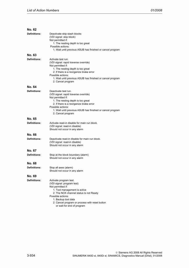
List of Action Numbers 01/2008
3-934
© Siemens AG 2008 All Rights ReservedSINUMERIK 840D sl, 840Di sl, SINAMICS, Diagnostics Manual (DAsl), 01/2008
No. 62Definitions: Deactivate skip slash blocks
(VDI signal: skip block)Not permitted if: 1. The nesting depth is too great Possible actions: 1. Wait until previous ASUB has finished or cancel program
No. 63Definitions: Activate test run.
(VDI signal: rapid traverse override)Not permitted if: 1. The nesting depth is too great 2. If there is a reorganize brake errorPossible actions: 1. Wait until previous ASUB has finished or cancel program 2. Cancel program
No. 64Definitions: Deactivate test run.
(VDI signal: rapid traverse override)Not permitted if: 1. The nesting depth is too great 2. If there is a reorganize brake errorPossible actions: 1. Wait until previous ASUB has finished or cancel program 2. Cancel program
No. 65Definitions: Activate read-in disable for main run block.
(VDI signal: read-in disable)Should not occur in any alarm
No. 66Definitions: Deactivate read-in disable for main run block.
(VDI signal: read-in disable)Should not occur in any alarm
No. 67Definitions: Stop at the block boundary (alarm)
Should not occur in any alarm
No. 68Definitions: Stop all axes (alarm)
Should not occur in any alarm
No. 69Definitions: Activate program test.
(VDI signal: program test)Not permitted if: 1. Tool management is active 2. The NCK channel status is not ReadyPossible actions: 1. Backup tool data 2. Cancel program or process with reset button or wait for end of program

01/2008 List of Action Numbers
3-935
©Siemens AG 2008 All Rights ReservedSINUMERIK 840D sl, 840Di sl, SINAMICS, Diagnostics Manual (DAsl), 01/2008
No. 70Definitions: Deactivate program test.
(VDI signal: program test)Not permitted if: 1. The NCK channel status is not ReadyPossible actions: 2. Cancel program or process with reset button or wait for end of program
No. 71Definitions: Stop at the end of block preparation (alarm)
Should not occur in any alarm
No. 72Definitions: Stop at end of block preparation (alarm)
followed by reorganization of the block preparation.Not permitted if: 1. The nesting depth is too great Possible actions: 1. Wait until previous ASUB has finished or cancel program
No. 73Definitions: Conditional stop at the block boundary. There is another stop if there is
still a stop reason "Stop at end of block" after continuation by an NC start.Should not occur in any alarm
No. 74Definitions: Conditional stop at the block boundary. Despite Start, the interpreter
or preprocessing does not bring any blocks into the main run.Should not occur in any alarm
No. 75Definitions: Stop the preprocessing (alarm)
Should not occur in any alarm
No. 76Definitions: Retraction motion with G33 and Stop
Should not occur in any alarm
No. 77Definitions: Conditional wait for a program marker (NC block, WAITMC)
Should not occur in any alarm
No. 78Definitions: Set marker (NC_block,SETM)
Should not occur in any alarm
No. 79Definitions: Delete marker (NC_block,CLEARM)
Should not occur in any alarm
No. 80Definitions: Select an NC block (PI command)
Should not occur in any alarm
No. 81Definitions: Block editing of the NC program
currently being processed (PI command)Should not occur in any alarm

List of Action Numbers 01/2008
3-936
© Siemens AG 2008 All Rights ReservedSINUMERIK 840D sl, 840Di sl, SINAMICS, Diagnostics Manual (DAsl), 01/2008
No. 82Definitions: Start a program in the teach-in submode.
(VDI signal, NC start)See STARTSIG and MODESWITCHTOAPROGMODE
No. 83Definitions: Continue a program in the teach-in submode.
(VDI signal, NC start)See STARTSIG and MODESWITCHTOAPROGMODE
No. 84Definitions: Reorganize block execution
Should not occur in any alarm
No. 85Definitions: Activate a user interrupt "ASUB" in a manual mode (JOG, REF,...).
(VDI signal, ASUB interface, digital-analog interface) See INTERRUPT
No. 86Definitions: Activate a user interrupt "ASUB".
Is only executed in channel status READY.(VDI signal, ASUB interface, digital-analog interface)See INTERRUPT
No. 87Definitions: Execute an "ASUB" user interrupt.
(VDI signal, ASUB interface, digital-analog interface)Collective event for all interrupt signals.This event decides which actual interrupt one would like to trigger.Possible candidates are: INTERRUPT INTERRUPTFASTLIFTOFF INTERRUPTBLSYNC INTERRUPT_TOPROG_NOEPOS INTERRUPT_STARTSee INTERRUPT
No. 88Definitions: Stop processing
(VDI signal, mode group stop)Should not occur in any alarm
No. 89Definitions: Set all machine data with the attribute (NEW_CONF) to active.
(NC_Satz, NEW_CONF)Should not occur in any alarm
No. 90Definitions: Set all machine data with the attribute (NEW_CONF) to active.
(NC_Satz, NEW_CONF with block search)Should not occur in any alarm
No. 91Definitions: Start the continuation of the interpreter processing (internal preprocessing stop)
Should not occur in any alarm
No. 92Definitions: Interlock for data recovery
Is not permitted if: The NCK channel status is not Stopped

01/2008 List of Action Numbers
3-937
©Siemens AG 2008 All Rights ReservedSINUMERIK 840D sl, 840Di sl, SINAMICS, Diagnostics Manual (DAsl), 01/2008
No. 93Definitions: Set all user data to active.
For example, that means tool lengths newly changed via MMC become active immediately in the current program.Not permitted if: 1. The NCK channel status is not Stopped 2. The channel has stopped, and the current block cannot be reorganized.Possible actions: 1. Press stop button/single block/reset/StopAtEnd button (in Auto). 2. Activate block change until NC block can be reorganized
No. 94Definitions: Write user PLC version in version file
Should not occur in any alarm
No. 95Definitions: Change over PI service measuring system
Should not occur in any alarm as, if necessary, the PI service is acknowledged negatively
No. 96Definitions: Switch off system
(VDI signal)Should not occur in any alarm
No. 97Definitions: Connect block search PI in mode 5.
Block search is simulated in this mode by executing the program under "program test mode" as far as the search target block.
No. 98Definitions: Extended Stop and Retract
No. 99Definitions: Block search (general) is being activated.
Should not occur in any alarm as, if necessary, the PI service is acknowledged negatively.
No. 100Definitions: Integrated block search, this means that a search run
is restarted after a stopped program.
No. 101Definitions: External work offset is activated via PLC.
To do this the path is stopped, REORG executed,the interpreter changed over, and then selected and continued automatically with REPOS.Not permitted if: 1. The channel is not in AUTO or MDA. 2. The channel has stopped, and the current block cannot be reorganized.Possible actions: 1. Select AUTO or MDA. 2. Activate block change until NC block can be reorganized.
No. 102Definitions: Single block type 3 is activated.
With single block type 3, there is a stop at all main blocks.In contrast to single block type 1, the part programm command SBLOF is ignored.

List of Action Numbers 01/2008
3-938
© Siemens AG 2008 All Rights ReservedSINUMERIK 840D sl, 840Di sl, SINAMICS, Diagnostics Manual (DAsl), 01/2008
No. 103Definitions: Stopping a single axis motion
(VDI signal)Not permitted if: The axis is not controlled by the PLC (Exception: "old" behavior in the case of a reciprocating axis)
No. 104Definitions: Stopping a single axis motion by an alarm
(alarm)Not permitted if: The axis is not controlled by the PLC (Exception: "old" behavior in the case of a reciprocating axis)
No. 105Definitions: Continuation of a single axis motion
(VDI signal)Not permitted if: The axis has not previously stoppedInitially, not for all types of axis
No. 106Definitions: Canceling a single axis motion
(VDI signal)Not permitted if: The axis is not controlled by the PLCInitially, not for all types of axis
No. 107Definitions: Delete distance-to-go of a single axis motion
(VDI signal)Not permitted if: The axis is not controlled by the PLCInitially, not for all types of axis
No. 108Definitions: Activate: The axis is now controlled by the PLC
(VDI signal)Not permitted if: The axis is not controlled by the PLCInitially, not for all types of axis
No. 109Definitions: Deactivate: The axis is now controlled by the PLC
(VDI signal)Not permitted if: The axis is a main run axis or neutral.Initially, not for all types of axis
No. 110Definitions: Available soon
No. 111Definitions: Available soon
No. 112Definitions: Available soon
No. 113Definitions: Available soon
No. 114Definitions: Available soon

01/2008 List of Action Numbers
3-939
©Siemens AG 2008 All Rights ReservedSINUMERIK 840D sl, 840Di sl, SINAMICS, Diagnostics Manual (DAsl), 01/2008
No. 115Definitions: The event is triggered by the positive PLC edge of the
signal "Repos mode edge".Not permitted if: 1. The channel is active (program running, block search, loading machine data)Possible actions: 1. Cancel the program with the Reset button or stop the program (not with block search, loading machine data)
No. 116Definitions: Enable the tool management commands.
(CH VDI signal)Not permitted if: 1. The NCK channel status is not ReadyPossible actions: 1. Cancel program or process with reset button or wait for end of program
No. 117Definitions: Disable the tool management commands.
(CH VDI signal)Not permitted if: 1. The NCK channel status is not ReadyPossible actions: 1. Cancel program or process with reset button or wait for end of program
No. 118Definitions: Switching over the desired safety limits (SGE)
is always permitted
No. 119Definitions: Stop run, that is the NCK stops automatically at a block
defined by the OPI.Not permitted if 1. Control is not in Automatic.
No. 120Definitions: Fast retraction with a single axis
Not permitted if: The axis is not controlled by the PLC
No. 121Definitions: Stop fast retraction with a single axis
Not permitted if: The axis is not controlled by the PLC and the single axis does not execute a fast retraction
No. 122Definitions: For test purposes only, and only in assert systems.
No. 123Definitions: PI _N_STRTLK Set global start disable
always permitted
No. 124Definitions: PI _N_STRTUL Reset global start disable
always permitted

List of Action Numbers 01/2008
3-940
© Siemens AG 2008 All Rights ReservedSINUMERIK 840D sl, 840Di sl, SINAMICS, Diagnostics Manual (DAsl), 01/2008
No. 125Definitions: Implicit change to JOG mode at the start of a "JOG motion" in Automatic
See also $MN_JOG_MODE_MASKNot permitted if: 1. A channel has left the mode group on account of an interrupt. 2. OverstoringPossible actions: 1. Cancel the program with the Reset button or wait until the interrupt has finished. 4. Deselect overstore
No. 126Definitions: Implicit mode change back at the end of a "JOG motion" started in automatic mode.
See also $MN_JOG_MODE_MASKNot permitted if: 1. A channel has left the mode group on account of an interrupt. 2. OverstoringPossible actions: 1. Cancel the program with the Reset button or wait until the interrupt has finished. 4. Deselect overstore
No. 127Definitions: Simulation block search is to be started, that means the results of the computation will only be dis-
played on the HMI,NO traverse after block search.Not permitted if: 1. The NCK channel is not in RESETPossible action: 1. Press reset
No. 128Definitions: Execute program area has been rejected.
Not permitted if: 1. The channel is not in RESET. 2. The channel is not in Automatic.Possible actions: 1. Press reset. 2. Switch to automatic.
No. 129Definitions: Selection of PI service syntax check "_N_CHKSEL" has been rejected.
Not permitted if: 1. The channel is not in RESETPossible action: 1. Press reset
No. 130Definitions: Starting of PI service syntax check "_N_CHKRUN" has been rejected.
Not permitted if: 1. The channel is not in RESETPossible action: 1. Press reset
No. 131Definitions: Starting of PI service syntax check "_N_CHKABO" has been rejected.
Not permitted if: Should not occur.
No. 132Definitions: PI service _N_NCKMOD (BIT-1) has been rejected.
Not permitted if: Should not occur.

01/2008 List of Action Numbers
3-941
©Siemens AG 2008 All Rights ReservedSINUMERIK 840D sl, 840Di sl, SINAMICS, Diagnostics Manual (DAsl), 01/2008
No. 133Definitions: PI service _N_NCKMOD (BIT-1) has been rejected.
Not permitted if: Should not occur.

List of Action Numbers 01/2008
3-942
© Siemens AG 2008 All Rights ReservedSINUMERIK 840D sl, 840Di sl, SINAMICS, Diagnostics Manual (DAsl), 01/2008

4-943
© Siemens AG 2008 All Rights ReservedSINUMERIK 840D sl, 840Di sl, SINAMICS, Diagnostics Manual (DAsl), 01/2008
System Reactions on Alarms 4Names COMPBLOCKWITHREORG
Effect Block preparation has detected an error, which can be rectified by modifying the pro-gram. Reorganization is performed after a program modification.
− Correction block with reorganization.
Names COMPENSATIONBLOCK
Effect Block preparation has detected an error, which can be rectified by modifying the pro-gram.
− Correction block
Names FOLLOWUP
Effect Follow-up of axes− NC switches to follow-up mode
Names INTERPRETER STOP
Effect Program execution is aborted after all the prepared blocks (interpolator buffer) have been processed.
− Interpreter stop
Names LOCALREACTION
Effect − Local alarm response
Names NOALARMREACTION
Effect − No alarm reaction
Names NOREADY | NCKREACTIONVIEW
Effect NCK ready off: Active rapid deceleration (i.e. with maximum braking current) of all drives Clearing of servo enable for all NC axes Release of NC ready relay
− NC not ready

System Reactions on Alarms 01/2008
4-944
© Siemens AG 2008 All Rights ReservedSINUMERIK 840D sl, 840Di sl, SINAMICS, Diagnostics Manual (DAsl), 01/2008
Names NOREADY | BAGREACTIONVIEW
Effect Mode group ready off: Active rapid deceleration (i.e. with maximum braking current) of the drives in this mode group Clearing of servo enable for the NC axes concerned.
− Mode group not ready
Names NOREADY
Effect Channel ready off: Active rapid deceleration (i.e. with maximum braking current) of the drives in this channel Clearing of servo enable for the NC axes concerned.
− Channel not ready
Names NONCSTART
Effect It is not possible to start a program in this channel.− NC start inhibit in this channel
Names NOREFMARK
Effect The axes in this channel have to be rereferenced.− Rereference axes in this channel.
Names SETVDI
Effect VDI interface signal alarm is set.− Interface signals are set
Names SHOWALARM
Effect Alarm is displayed on MMC.Alarm display
Names STOPBYALARM
Effect Ramp stop of all channel axes.− NC stop for alarm
Names STOPATENDBYALARM
Effect Stop at end of block.− NC Stop on alarm at end of block

01/2008 System Reactions on Alarms
4-945
© Siemens AG 2008 All Rights ReservedSINUMERIK 840D sl, 840Di sl, SINAMICS, Diagnostics Manual (DAsl), 01/2008
Names SHOWALARMAUTO
Effect The alarm is displayed whenever bit 0 of machine data ENABLE_ALARM_MASK is set. The reaction should be set whenever an alarm should only occur during automatic mode without manual operation by the user.
− Alarm reaction in automatic mode
Names SHOWWARNING
Effect The alarm is displayed whenever bit 1 of machine data ENABLE_ALARM_MASK is set. It is designed for warnings which should normally be suppressed.
− Alarm view
Names ALLBAGS_NOREADY
Effect The Ready is canceled in all mode groups. The reaction thus corresponds to an NCK-REACTIONVIEW|NOREADY, the difference being that the NC READY relay is not can-celed and the corresponding VDI bit is not set. This is desirable in the event of an emergency stop for example.
− Mode group not ready
Names DELAY_ALARM_REACTION
Effect If this alarm reaction is configured in the alarm handler, all alarm reactions for alarms, which occur at this point, are buffered channel-specifically and are, therefore, not active. The alarms are displayed on the MMC. Mode group and NC-wide reactions are trans-ferred. The reaction is cleared by activating the clearDelayReaction call or by an alarm, which has configured NO_DELAY_ALARM_REACTION. This activates all the delayed alarm reactions.
− All channel-specific alarm reactions delayed on alarm, alarm display
Names NO_DELAY_ALARM_REACTION
Effect The DELAY_ALARM_REACTION state is canceled.− The alarm reaction delay is canceled.
Names ONE_IPO_CLOCK_DELAY_ALARM_REACTION
Effect All alarm reactions are delayed by one cycle when an alarm is output. This functionality became necessary as part of ESR development.
− All alarm reactions are delayed by one IPO cycle on alarm.

System Reactions on Alarms 01/2008
Cancel criteria for alarms
4-946
© Siemens AG 2008 All Rights ReservedSINUMERIK 840D sl, 840Di sl, SINAMICS, Diagnostics Manual (DAsl), 01/2008
4.1 Cancel criteria for alarms
Names CANCELCLEAR
Effect The alarm is cleared by pressing the Cancel key in any channel. It is also cleared by the Start part program key.
− Clear the alarm with the Clear key or with NC START
Names CLEARHIMSELF
Effect Self-clearing alarm. The alarm is cleared not by an operator action but explicitly by a "clearAlarm" in programmed the NCK source code.
− Alarm display disappears with alarm cause. No further operator action necessary.
Names NCSTARTCLEAR
Effect The alarm is cleared by starting a program in the channel, in which the alarm occurred. The alarm is also cleared by an NC reset.
− Clear the alarm with NC START or the RESET key and continue the program.
Names POWERONCLEAR
Effect The alarm is canceled by turning off / turning on the control system (POWER ON).− Switch the control OFF - ON.
Names RESETCLEAR
Effect The alarm is cleared by pressing the Reset key in the channel in which the alarm occurred.
− Clear alarm with the RESET key. Restart part program.
Names BAGRESETCLEAR
Effect The alarm is cleared by a "BAGRESETCLEAR" command or by carrying out a reset in all channels of this mode group.
− Press the RESET key to clear the alarm in all channels of this mode group. Restart part program.
Names NCKRESETCLEAR
Effect The alarm is cleared by an "NCKRESETCLEAR" command or by carrying out a reset in all channels.
− Clear alarm in all channels with the RESET key. Restart part program.
Names NOCLEAR
Effect The clear information is only required for the internal pseudo alarm number EXBSAL_NOMOREALARMS.

System reactions on SINAMICS alarms
01/2008 System Reactions on Alarms
4-947
© Siemens AG 2008 All Rights ReservedSINUMERIK 840D sl, 840Di sl, SINAMICS, Diagnostics Manual (DAsl), 01/2008
4.2 System reactions on SINAMICS alarms
The errors and states detected by the individual components of the drive system are indicated by alarms.
These alarms are categorized into faults and warnings.
General information on faults (alarms)
The following happens when a fault occurs:
• The appropriate fault action is triggered.
• Status signal ZSW1.3 is set.
• The fault is entered in the fault buffer.
Clearing of a fault:
• Clear the cause of the fault
• Acknowledge the fault
General information on warnings (alarms)
The following happens when a warning occurs:
• Status signal ZSW1.7 is set.
• The warning is entered in the warning buffer.
Clearing of a warning:
• Warnings are self-acknowledging, i.e. if the cause has been removed, the warnings reset themselves automatically.
"Reaction" to faults (alarms)
The standard fault reaction specifies the reaction in the event of a fault. For an overview of parameters and function block diagram, please refer to the fol-lowing publication:
LIS1, Lists 1
Definition of fault reactions
Description NONE
Reaction None
Description No reaction when a fault occurs

System Reactions on Alarms 01/2008
System reactions on SINAMICS alarms
4-948
© Siemens AG 2008 All Rights ReservedSINUMERIK 840D sl, 840Di sl, SINAMICS, Diagnostics Manual (DAsl), 01/2008
Description OFF1
Reaction Brake along the ramp generator deceleration ramp followed by pulse disable
Description Closed-loop speed control (p1300 = 20, 21)• n_set=0 is input immediately to brake the drive along the deceleration ramp (p1121).• When zero speed is detected, the motor holding brake (if parameterized) is closed
(p1215). The pulses are suppressed when the brake application time (p1217) expires. Zero speed is detected if the actual speed drops below the threshold (p1226) or if the monitoring time (p1227) started when speed setpoint <= speed threshold (p1226) has expired.
Closed-loop torque control (p1300 = 23)• The following applies to closed-loop torque control mode: Reaction as for OFF2• On switchover to closed-loop torque control mode (p1501):
There is no special braking reaction. If the actual speed drops below the speed threshold (p1226), the motor holding brake will be closed if one is parameterized. The pulses are suppressed when the brake application time (p1217) expires.
Description OFF2
Reaction Internal/external pulse disable
Description Closed-loop speed and torque control• Instantaneous pulse suppression, the drive "coasts" to a standstill.• The motor holding brake (if parameterized) is closed immediately.• Power-on disable is activated.
Description OFF3
Reaction Brake along the OFF3 deceleration ramp followed by pulse disable
Description Closed-loop speed control (p1300 = 20, 21)• n_set=0 is input immediately to brake the drive along the OFF3 deceleration ramp
(p1135).• When zero speed is detected, the motor holding brake (if parameterized) is closed.
Pulses are suppressed when the brake application time (p1217) expires. Zero speed is detected if the actual speed drops below the threshold in p1226 or if the monitoring time (p1227) started when speed setpoint <= speed threshold (p1226) has expired.
• Power-on disable is activated.
Closed-loop torque control (p1300 = 23)• Switchover to speed-controlled operation and other reactions as described for speed-
controlled operation

System reactions on SINAMICS alarms
01/2008 System Reactions on Alarms
4-949
© Siemens AG 2008 All Rights ReservedSINUMERIK 840D sl, 840Di sl, SINAMICS, Diagnostics Manual (DAsl), 01/2008
Acknowledging faults (alarms)
Indicates the standard acknowledgement of the fault after removal of the cause. For an overview of parameters and function block diagram, please refer to the fol-lowing publication:
LIS1, Lists 1
Description STOP1
Reaction -
Description Available soon
Description STOP2
Reaction n_set = 0
Description • n_set=0 is input immediately to brake the drive along the OFF3 deceleration ramp (p1135).
• The drive remains in closed-loop speed control mode.
Description DCBRAKE
Reaction -
Description Available soon
Description ENCODER
Reaction Internal/external pulse disable (p0491)
Description The fault reaction ENCODER is applied as a function of the setting in p0491.Factory setting:p0491=0 --> Encoder fault results in OFF2
Description POWER ON
Description • The fault is acknowledged by a POWER ON process (switch drive unit off and on again).
Note:If this action has not eliminated the fault cause, the fault is displayed again immediately after power up.
Description IMMEDIATELY
Description After correction of the fault, the alarm can be cleared by pressing the RESET key: •

System Reactions on Alarms 01/2008
System reactions on SINAMICS alarms
4-950
© Siemens AG 2008 All Rights ReservedSINUMERIK 840D sl, 840Di sl, SINAMICS, Diagnostics Manual (DAsl), 01/2008
parameter "pxxxx"
With some alarms, reference is made to a SINAMICS parameter in the fields "cause" and "remedy".
The parameter number consists of a "p" or "r", followed by a 4-digit number (xxxx) and the index (optional), e.g. p0918[0...3].
A detailed description of the SINAMICS parameters is provided in the following publication:
LIS1, Parameter Manual 1 (brief description)
SINAMICS_S List Manual (detailed description)

A-951
© Siemens AG, 2008. All Rights ReservedSINUMERIK 840D sl, 840Di sl, SINAMICS, Diagnostics Manual (DAsl), 01/2008
Appendix AA.1 Abbreviations
ASCII American Standard Code for Information Interchange
AV Job planning
BA Operating mode
BB Ready to run
BCD Binary Coded Decimals: Decimals encrypted in binary code
CNC Computerized Numerical Control
CP Communications Processor
CPU Central Processing Unit
CR Carriage Return
CRC Cutter Radius Compensation
CSB Central Service Board: PLC module
CTS Clear To Send: Signal from serial data interfaces
DAC Digital-to-Analog Converter
DB Data Block
DIN German standard
DIO Data Input/Output: Data transfer display
DRF Differential Resolver Function: Handwheel jog
DRY Dry Run: Dry run feedrate
DSB Decoding Single Block
DSR Data Send Ready:Signal from serial data interfaces indicating that they are ready to send
DW Data Word
EIA code Special punched tape code, number of holes per character always odd
EPROM Erasable Programmable Read Only Memory
ETC ETC Key: Expansion of the softkey bar in the same menu
FDB Product database
FDD Feed Drive (spindle)
FIFO First In First Out: Memory, which works without address specification where data are read in the same order, in which they were stored.

Appendix 01/2008
Abbreviations
A-952
© Siemens AG, 2008. All Rights ReservedSINUMERIK 840D sl, 840Di sl, SINAMICS, Diagnostics Manual (DAsl), 01/2008
FM Function Module
FM-NC Function Module Numerical Control
FRA Frame block
FRAME Coordinate conversion with the components zero (work) offset, rotation, scaling, mirror-ing
FST Feed Stop
GUD Global User Data
HD Hard Disk
HHU Handheld unit
HMS High-resolution Measuring System
HW Hardware
I Input
IM Interface Module
IM S/R Interface Module (S=send/R=receive): Interface module for transmitting and receiving data
INC Increment
I/RF Infeed/Regenerative Feedback unit
ISO code Special punched tape code, number of holes per character always even
K1...K4 Channel 1 to channel 4
KUE Gear ratio
Kv Servo gain factor
LAD Ladder diagram
LCD Liquid Crystal Display: Opto-electronic display with liquid crystals
LEC Leadscrew Error Compensation
LED Light Emitting Diode
LUD Local User Data
MB MegaByte
MC Measuring Circuit
MCP Machine Control Panel
MD Machine Data
MDI Manual Data Input
MLFB Machine-readable product designation
MMC Man-Machine Communication: User interface on numerical control systems for operator control, programming and simulation
Mode group Mode groups
MPF Main Program File: NC part program (main program)
MPI Multi-Point Interface
MSD Main Spindle Drive

Abbreviations
01/2008 Appendix
A-953
© Siemens AG, 2008. All Rights ReservedSINUMERIK 840D sl, 840Di sl, SINAMICS, Diagnostics Manual (DAsl), 01/2008
NC Numerical Control
NCK Numerical Control Kernel: NC kernel with block preparation, travel range, etc.
NCU Numerical Control Unit
NURBS Non-Uniform Rational B Spline
O Output
OEM Original Equipment Manufacturer
OP Operator Panel
OPI Operator Panel Interface: Interface for connection to the operator panel
PC Personal Computer
PCMCIA Personal Computer Memory Card International Association: Interface standard
PG Programming device
PLC Programmable Logic Control
PRT Program test
RAM Random Access Memory (can be read and written)
RISC Reduced Instruction Set Computer: Type of processor with small instruction set and ability to process instructions at high speed
ROV Rapid Override
RPA R Parameter Active: Memory area on the NCK for R parameter numbers
RTS Request To Send: Activate transmitter, control signal from serial data interfaces
SBL Single Block
SD Setting Data
SEA Setting Data Active: Memory area for setting data on the NCK
SKP SKiP: Skip block
SM Signal Module
SPF SubProgram File: Subroutine
SSI Serial Synchronous Interface
SW Software
T Tool
TEA Testing Data Active: Refers to machine data
TNRC Tool Nose Radius Compensation
TO Tool Offset Tool Offset
TOA Tool Offset Active: Memory area for tool offsets
TRANSMIT TRANSform Milling Into Turning: Coordinate conversion on turning machines for milling operations
UI User interface
ZO Zero Offset
ZOA Zero Offset Active: Memory area

Appendix 01/2008
Abbreviations
A-954
© Siemens AG, 2008. All Rights ReservedSINUMERIK 840D sl, 840Di sl, SINAMICS, Diagnostics Manual (DAsl), 01/2008

© Siemens AG, 2008. All rights reservedSINUMERIK 840D sl, 840Di sl, SINAMICS, Diagnostics Manual (DAsl), 01/2008 Edition
Suggrestions and Corrections
Siemens AG
A&D MC MS 1
P. O. Box 3180
D-91050 Erlangen
Federal Republic of Germany
Fax +49 (0) 9131 / 98 - 63315 [Dokumentation]
mailto:[email protected]
http://www.siemens.com/automation/service&support
Suggestions
Corrections
for Publication/Manual
SINUMERIK 840D sl, 840Di sl, SINAMICS,
Manufacturer/Service documenta-tion
From
Name:
Company/Dept.
Address :
Telephone : /
Telefax : /
email :
Diagnostics Manual (DAsl)
Order No.: 6FC5398-6BP10-3BA0
01/2008 Edition
Should you come across any print-ing errors when reading this publica-tion, please notify us on this sheet. Suggestions for improvements are also welcome.

Overview