DIAGNOSTICS - PriusChat
870
DIAGNOSTICS ENGINE DI–1 . . . . . . . . . . . . . . . . . . . . . . . . . . . . . . . . HOW TO PROCEED WITH TROUBLESHOOTING DI–1 . . . . . . . . . . . . . . . . . . . . CUSTOMER PROBLEM ANALYSIS CHECK DI–2 . . . PRE–CHECK DI–3 . . . . . . . . . . . . . . . . . . . . . . . . . . . . . DIAGNOSTIC TROUBLE CODE CHART DI–14 . . . . . . PARTS LOCATION DI–17 . . . . . . . . . . . . . . . . . . . . . . . . . TERMINALS OF ECU DI–18 . . . . . . . . . . . . . . . . . . . . . . PROBLEM SYMPTOMS TABLE DI–20 . . . . . . . . . . . . . CIRCUIT INSPECTION DI–21 . . . . . . . . . . . . . . . . . . . . . HYBRID VEHICLE CONTROL SYSTEM DI–141 . . . . HOW TO PROCEED WITH TROUBLESHOOTING DI–141 . . . . . . . . . . . . . . . . . . . . CUSTOMER PROBLEM ANALYSIS CHECK DI–142 . . . PRE–CHECK DI–144 . . . . . . . . . . . . . . . . . . . . . . . . . . . . . DIAGNOSTIC TROUBLE CODE CHART DI–156 . . . . . . PARTS LOCATION DI–165 . . . . . . . . . . . . . . . . . . . . . . . . . TERMINALS OF ECU DI–166 . . . . . . . . . . . . . . . . . . . . . . CIRCUIT INSPECTION DI–169 . . . . . . . . . . . . . . . . . . . . . HV BATTERY CONTROL SYSTEM DI–265 . . . . . . . . HOW TO PROCEED WITH TROUBLESHOOTING DI–265 . . . . . . . . . . . . . . . . . . . . CUSTOMER PROBLEM ANALYSIS CHECK DI–266 . . . PRE–CHECK DI–268 . . . . . . . . . . . . . . . . . . . . . . . . . . . . . DIAGNOSTIC TROUBLE CODE CHART DI–272 . . . . . . PARTS LOCATION DI–273 . . . . . . . . . . . . . . . . . . . . . . . . . CIRCUIT INSPECTION DI–274 . . . . . . . . . . . . . . . . . . . . . ANTI–LOCK BRAKE SYSTEM WITH EBD & RBS DI–306 . . . . . . . . . . . . . . . . . . . . . . . . . . . . . . . . . . HOW TO PROCEED WITH TROUBLESHOOTING DI–306 . . . . . . . . . . . . . . . . . . . . CUSTOMER PROBLEM ANALYSIS CHECK DI–307 . . . PRE–CHECK DI–308 . . . . . . . . . . . . . . . . . . . . . . . . . . . . . DIAGNOSTIC TROUBLE CODE CHART DI–313 . . . . . . PARTS LOCATION DI–316 . . . . . . . . . . . . . . . . . . . . . . . . . TERMINALS OF ECU DI–318 . . . . . . . . . . . . . . . . . . . . . . PROBLEM SYMPTOMS TABLE DI–321 . . . . . . . . . . . . . CIRCUIT INSPECTION DI–322 . . . . . . . . . . . . . . . . . . . . . ELECTRIC MOTOR POWER STEERING DI–408 . . . HOW TO PROCEED WITH TROUBLESHOOTING DI–408 . . . . . . . . . . . . . . . . . . . . CUSTOMER PROBLEM ANALYSIS CHECK DI–409 . . . PRE–CHECK DI–410 . . . . . . . . . . . . . . . . . . . . . . . . . . . . . DIAGNOSTIC TROUBLE CODE CHART DI–416 . . . . . . PARTS LOCATION DI–418 . . . . . . . . . . . . . . . . . . . . . . . . . TERMINALS OF ECU DI–419 . . . . . . . . . . . . . . . . . . . . . . PROBLEM SYMPTOMS TABLE DI–420 . . . . . . . . . . . . . CIRCUIT INSPECTION DI–421 . . . . . . . . . . . . . . . . . . . . . SUPPLEMENTAL RESTRAINT SYSTEM DI–451 . . . HOW TO PROCEED WITH TROUBLESHOOTING DI–451 . . . . . . . . . . . . . . . . . . . . CUSTOMER PROBLEM ANALYSIS CHECK DI–452 . . . PRE–CHECK DI–453 . . . . . . . . . . . . . . . . . . . . . . . . . . . . . DIAGNOSTIC TROUBLE CODE CHART DI–459 . . . . . . PARTS LOCATION DI–461 . . . . . . . . . . . . . . . . . . . . . . . . . TERMINALS OF ECU DI–462 . . . . . . . . . . . . . . . . . . . . . . PROBLEM SYMPTOMS TABLE DI–463 . . . . . . . . . . . . . CIRCUIT INSPECTION DI–464 . . . . . . . . . . . . . . . . . . . . . THEFT DETERRENT SYSTEM DI–549 . . . . . . . . . . . . HOW TO PROCEED WITH TROUBLESHOOTING DI–549 . . . . . . . . . . . . . . . . . . . . CUSTOMER PROBLEM ANALYSIS CHECK DI–550 . . . PRE–CHECK DI–551 . . . . . . . . . . . . . . . . . . . . . . . . . . . . . PARTS LOCATION DI–554 . . . . . . . . . . . . . . . . . . . . . . . . . TERMINALS OF ECU DI–555 . . . . . . . . . . . . . . . . . . . . . . PROBLEM SYMPTOMS TABLE DI–556 . . . . . . . . . . . . . CIRCUIT INSPECTION DI–558 . . . . . . . . . . . . . . . . . . . . . CRUISE CONTROL SYSTEM DI–574 . . . . . . . . . . . . . HOW TO PROCEED WITH TROUBLESHOOTING DI–574 . . . . . . . . . . . . . . . . . . . . CUSTOMER PROBLEM ANALYSIS CHECK DI–575 . . . PRE–CHECK DI–576 . . . . . . . . . . . . . . . . . . . . . . . . . . . . . DIAGNOSTIC TROUBLE CODE CHART DI–579 . . . . . . PARTS LOCATION DI–580 . . . . . . . . . . . . . . . . . . . . . . . . . TERMINALS OF ECU DI–581 . . . . . . . . . . . . . . . . . . . . . . PROBLEM SYMPTOMS TABLE DI–582 . . . . . . . . . . . . . CIRCUIT INSPECTION DI–583 . . . . . . . . . . . . . . . . . . . . . COMBINATION METER SYSTEM DI–596 . . . . . . . . . . HOW TO PROCEED WITH TROUBLESHOOTING DI–596 . . . . . . . . . . . . . . . . . . . . CUSTOMER PROBLEM ANALYSIS CHECK DI–597 . . . PRE–CHECK DI–598 . . . . . . . . . . . . . . . . . . . . . . . . . . . . . PARTS LOCATION DI–599 . . . . . . . . . . . . . . . . . . . . . . . . . TERMINALS OF ECU DI–600 . . . . . . . . . . . . . . . . . . . . . . PROBLEM SYMPTOMS TABLE DI–602 . . . . . . . . . . . . . CIRCUIT INSPECTION DI–604 . . . . . . . . . . . . . . . . . . . . . BODY CONTROL SYSTEM DI–611 . . . . . . . . . . . . . . . HOW TO PROCEED WITH TROUBLESHOOTING DI–611 . . . . . . . . . . . . . . . . . . . . CUSTOMER PROBLEM ANALYSIS CHECK DI–612 . . .
-
Upload
khangminh22 -
Category
Documents
-
view
0 -
download
0
Transcript of DIAGNOSTICS - PriusChat

DIAGNOSTICS
ENGINE DI–1. . . . . . . . . . . . . . . . . . . . . . . . . . . . . . . . HOW TO PROCEED WITH
TROUBLESHOOTING DI–1. . . . . . . . . . . . . . . . . . . .
CUSTOMER PROBLEM ANALYSIS CHECK DI–2. . .
PRE–CHECK DI–3. . . . . . . . . . . . . . . . . . . . . . . . . . . . .
DIAGNOSTIC TROUBLE CODE CHART DI–14. . . . . .
PARTS LOCATION DI–17. . . . . . . . . . . . . . . . . . . . . . . . .
TERMINALS OF ECU DI–18. . . . . . . . . . . . . . . . . . . . . .
PROBLEM SYMPTOMS TABLE DI–20. . . . . . . . . . . . .
CIRCUIT INSPECTION DI–21. . . . . . . . . . . . . . . . . . . . .
HYBRID VEHICLE CONTROL SYSTEM DI–141. . . . HOW TO PROCEED WITH
TROUBLESHOOTING DI–141. . . . . . . . . . . . . . . . . . . .
CUSTOMER PROBLEM ANALYSIS CHECK DI–142. . .
PRE–CHECK DI–144. . . . . . . . . . . . . . . . . . . . . . . . . . . . .
DIAGNOSTIC TROUBLE CODE CHART DI–156. . . . . .
PARTS LOCATION DI–165. . . . . . . . . . . . . . . . . . . . . . . . .
TERMINALS OF ECU DI–166. . . . . . . . . . . . . . . . . . . . . .
CIRCUIT INSPECTION DI–169. . . . . . . . . . . . . . . . . . . . .
HV BATTERY CONTROL SYSTEM DI–265. . . . . . . . HOW TO PROCEED WITH
TROUBLESHOOTING DI–265. . . . . . . . . . . . . . . . . . . .
CUSTOMER PROBLEM ANALYSIS CHECK DI–266. . .
PRE–CHECK DI–268. . . . . . . . . . . . . . . . . . . . . . . . . . . . .
DIAGNOSTIC TROUBLE CODE CHART DI–272. . . . . .
PARTS LOCATION DI–273. . . . . . . . . . . . . . . . . . . . . . . . .
CIRCUIT INSPECTION DI–274. . . . . . . . . . . . . . . . . . . . .
ANTI–LOCK BRAKE SYSTEM WITH EBD &
RBS DI–306. . . . . . . . . . . . . . . . . . . . . . . . . . . . . . . . . . HOW TO PROCEED WITH
TROUBLESHOOTING DI–306. . . . . . . . . . . . . . . . . . . .
CUSTOMER PROBLEM ANALYSIS CHECK DI–307. . .
PRE–CHECK DI–308. . . . . . . . . . . . . . . . . . . . . . . . . . . . .
DIAGNOSTIC TROUBLE CODE CHART DI–313. . . . . .
PARTS LOCATION DI–316. . . . . . . . . . . . . . . . . . . . . . . . .
TERMINALS OF ECU DI–318. . . . . . . . . . . . . . . . . . . . . .
PROBLEM SYMPTOMS TABLE DI–321. . . . . . . . . . . . .
CIRCUIT INSPECTION DI–322. . . . . . . . . . . . . . . . . . . . .
ELECTRIC MOTOR POWER STEERING DI–408. . . HOW TO PROCEED WITH
TROUBLESHOOTING DI–408. . . . . . . . . . . . . . . . . . . .
CUSTOMER PROBLEM ANALYSIS CHECK DI–409. . .
PRE–CHECK DI–410. . . . . . . . . . . . . . . . . . . . . . . . . . . . .
DIAGNOSTIC TROUBLE CODE CHART DI–416. . . . . .
PARTS LOCATION DI–418. . . . . . . . . . . . . . . . . . . . . . . . .
TERMINALS OF ECU DI–419. . . . . . . . . . . . . . . . . . . . . .
PROBLEM SYMPTOMS TABLE DI–420. . . . . . . . . . . . .
CIRCUIT INSPECTION DI–421. . . . . . . . . . . . . . . . . . . . .
SUPPLEMENTAL RESTRAINT SYSTEM DI–451. . . HOW TO PROCEED WITH
TROUBLESHOOTING DI–451. . . . . . . . . . . . . . . . . . . .
CUSTOMER PROBLEM ANALYSIS CHECK DI–452. . .
PRE–CHECK DI–453. . . . . . . . . . . . . . . . . . . . . . . . . . . . .
DIAGNOSTIC TROUBLE CODE CHART DI–459. . . . . .
PARTS LOCATION DI–461. . . . . . . . . . . . . . . . . . . . . . . . .
TERMINALS OF ECU DI–462. . . . . . . . . . . . . . . . . . . . . .
PROBLEM SYMPTOMS TABLE DI–463. . . . . . . . . . . . .
CIRCUIT INSPECTION DI–464. . . . . . . . . . . . . . . . . . . . .
THEFT DETERRENT SYSTEM DI–549. . . . . . . . . . . . HOW TO PROCEED WITH
TROUBLESHOOTING DI–549. . . . . . . . . . . . . . . . . . . .
CUSTOMER PROBLEM ANALYSIS CHECK DI–550. . .
PRE–CHECK DI–551. . . . . . . . . . . . . . . . . . . . . . . . . . . . .
PARTS LOCATION DI–554. . . . . . . . . . . . . . . . . . . . . . . . .
TERMINALS OF ECU DI–555. . . . . . . . . . . . . . . . . . . . . .
PROBLEM SYMPTOMS TABLE DI–556. . . . . . . . . . . . .
CIRCUIT INSPECTION DI–558. . . . . . . . . . . . . . . . . . . . .
CRUISE CONTROL SYSTEM DI–574. . . . . . . . . . . . . HOW TO PROCEED WITH
TROUBLESHOOTING DI–574. . . . . . . . . . . . . . . . . . . .
CUSTOMER PROBLEM ANALYSIS CHECK DI–575. . .
PRE–CHECK DI–576. . . . . . . . . . . . . . . . . . . . . . . . . . . . .
DIAGNOSTIC TROUBLE CODE CHART DI–579. . . . . .
PARTS LOCATION DI–580. . . . . . . . . . . . . . . . . . . . . . . . .
TERMINALS OF ECU DI–581. . . . . . . . . . . . . . . . . . . . . .
PROBLEM SYMPTOMS TABLE DI–582. . . . . . . . . . . . .
CIRCUIT INSPECTION DI–583. . . . . . . . . . . . . . . . . . . . .
COMBINATION METER SYSTEM DI–596. . . . . . . . . . HOW TO PROCEED WITH
TROUBLESHOOTING DI–596. . . . . . . . . . . . . . . . . . . .
CUSTOMER PROBLEM ANALYSIS CHECK DI–597. . .
PRE–CHECK DI–598. . . . . . . . . . . . . . . . . . . . . . . . . . . . .
PARTS LOCATION DI–599. . . . . . . . . . . . . . . . . . . . . . . . .
TERMINALS OF ECU DI–600. . . . . . . . . . . . . . . . . . . . . .
PROBLEM SYMPTOMS TABLE DI–602. . . . . . . . . . . . .
CIRCUIT INSPECTION DI–604. . . . . . . . . . . . . . . . . . . . .
BODY CONTROL SYSTEM DI–611. . . . . . . . . . . . . . . HOW TO PROCEED WITH
TROUBLESHOOTING DI–611. . . . . . . . . . . . . . . . . . . .
CUSTOMER PROBLEM ANALYSIS CHECK DI–612. . .

PARTS LOCATION DI–613. . . . . . . . . . . . . . . . . . . . . . . . .
TERMINALS OF ECU DI–614. . . . . . . . . . . . . . . . . . . . . .
PROBLEM SYMPTOMS TABLE DI–615. . . . . . . . . . . . .
CIRCUIT INSPECTION DI–616. . . . . . . . . . . . . . . . . . . . .
DRIVER DOOR CONTROL SYSTEM DI–636. . . . . . . HOW TO PROCEED WITH
TROUBLESHOOTING DI–636. . . . . . . . . . . . . . . . . . . .
CUSTOMER PROBLEM ANALYSIS CHECK DI–637. . .
PARTS LOCATION DI–638. . . . . . . . . . . . . . . . . . . . . . . . .
TERMINALS OF ECU DI–639. . . . . . . . . . . . . . . . . . . . . .
PROBLEM SYMPTOMS TABLE DI–640. . . . . . . . . . . . .
CIRCUIT INSPECTION DI–641. . . . . . . . . . . . . . . . . . . . .
MULTIPLEX COMMUNICATION SYSTEM DI–656. . HOW TO PROCEED WITH
TROUBLESHOOTING DI–656. . . . . . . . . . . . . . . . . . . .
CUSTOMER PROBLEM ANALYSIS CHECK DI–657. . .
PRE–CHECK DI–658. . . . . . . . . . . . . . . . . . . . . . . . . . . . .
DIAGNOSTIC TROUBLE CODE CHART DI–663. . . . . .
PARTS LOCATION DI–664. . . . . . . . . . . . . . . . . . . . . . . . .
TERMINALS OF ECU DI–665. . . . . . . . . . . . . . . . . . . . . .
CIRCUIT INSPECTION DI–669. . . . . . . . . . . . . . . . . . . . .
NAVIGATION SYSTEM DI–702. . . . . . . . . . . . . . . . . . . HOW TO PROCEED WITH
TROUBLESHOOTING DI–702. . . . . . . . . . . . . . . . . . . .
CUSTOMER PROBLEM ANALYSIS CHECK DI–703. . .
PRE–CHECK DI–704. . . . . . . . . . . . . . . . . . . . . . . . . . . . .
DIAGNOSTIC TROUBLE CODE CHART DI–721. . . . . .
PARTS LOCATION DI–727. . . . . . . . . . . . . . . . . . . . . . . . .
TERMINALS OF ECU DI–728. . . . . . . . . . . . . . . . . . . . . .
PROBLEM SYMPTOMS TABLE DI–732. . . . . . . . . . . . .
CIRCUIT INSPECTION DI–733. . . . . . . . . . . . . . . . . . . . .
AIR CONDITIONING SYSTEM DI–777. . . . . . . . . . . . HOW TO PROCEED WITH
TROUBLESHOOTING DI–777. . . . . . . . . . . . . . . . . . . .
CUSTOMER PROBLEM ANALYSIS CHECK DI–778. . .
PRE–CHECK DI–779. . . . . . . . . . . . . . . . . . . . . . . . . . . . .
DIAGNOSTIC TROUBLE CODE CHART DI–782. . . . . .
TERMINALS OF ECU DI–784. . . . . . . . . . . . . . . . . . . . . .
PROBLEM SYMPTOMS TABLE DI–787. . . . . . . . . . . . .
CIRCUIT INSPECTION DI–789. . . . . . . . . . . . . . . . . . . . .

DI4DW–07
Vehicle Brought to Workshop
Customer Problem Analysis P. DI–2
Problem Symptom ConfirmationIf the engine does not start perform steps 10 and 12 first
Connect the hand–held tester to DLC3 P. DI–3If the display indicates a communication fault in the tool, inspect DLC3 P. DI–3
Check DTC and Freezed Frame Data (Precheck)
Record or Print DTC and Freezed Frame Data P. DI–3
Clear DTC and Freezed Frame Data P. DI–3
Visual Inspection
Setting the Check (Test) Mode Diagnosis P. DI–3
Symptom Simulation P IN–29.
Basic Inspection P. DI–3 DTC Chart P. DI–14
Problem Symptom Table P. DI–20
Circuit Inspection P. DI–21 – DI–138
Adjustment, Repair
DTC Check P. DI–3
Titles inside are titles of pages in
in the bottom portion. See the indicatedpages for detailed explanations.
this manual with the page number indicated
Malfunctionoccurs.
Malfunction does not occur.
Parts Inspection
Check for Intermittent Problems P. DI–3
Identification of Problem
Confirmation Test
End
1
2
3
4
5
6
7
10
8
9
11
12
13
15
14
16
Normal Malfunction code.
17
–DIAGNOSTICS ENGINEDI–1
PRIUS (RM771E)
ENGINEHOW TO PROCEED WITH TROUBLESHOOTINGWhen using hand–held tester, troubleshooting in accordance with the procedure on the following page.

DI4DX–02
ENGINE CONTROL SYSTEM Check Sheet
Customer’s Name
Driver’s Name
Data VehicleBrought in
License No.
Model and ModelYear
Frame No.
Engine Model
Odometer Readingkmmiles
Pro
ble
m S
ymp
tom
s
Engine doesnot Start
Difficult toStart
Poor Idling
PoorDrivability
Engine Stall
Others
Engine does not crank No initial combustion No complete combustion
Engine cranks slowlyOther
Incorrect first idle Idling rpm is abnormal High ( rpm) Low ( rpm)Rough idling Other
Hesitation Back fire Muffler explosion (after–fire) SurgingKnocking Other
Soon after starting After accelerator pedal depressedAfter accelerator pedal released During A/C operationShifting from N to D Other
Datas ProblemOccurred
Problem Frequency
Co
nd
itio
n W
hen
Pro
ble
m O
ccu
rs
Weather
Engine Operation
Engine Temp.
Place
OutdoorTemperature
Constant Sometimes ( times per day/month) Once onlyOther
Fine Cloudy Rainy Snowy Various/Other
Hot Warm Cool Cold (approx. F/ C)
Highway Suburbs Inner City Uphill DownhillRough road Other
Cold Warming up After Warming up Any temp. Other
Starting Just after starting ( min.) Idling RacingDriving Constant speed Acceleration DecelerationA/C switch ON/OFF Other
Condition of check engine warning light(CHK ENG)
Remains on Sometimes light up Does not light up
Normal Malfunction code(s) (code )Freezed frame data ( )
Normal Malfunction code(s) (code )Freezed frame data ( )
Normal mode(Precheck)
Check Mode
DTC Inspection
Inspector’sName
DI–2–DIAGNOSTICS ENGINE
PRIUS (RM771E)
CUSTOMER PROBLEM ANALYSIS CHECK

FI2547
DI7O5–01
I12054
Hand–Held Tester
DLC3
–DIAGNOSTICS ENGINEDI–3
PRIUS (RM771E)
PRE–CHECK1. DIAGNOSIS SYSTEM(a) Description
When troubleshooting Euro–OBD vehicles, theonly difference from the usual troubleshooting pro-cedure is that you connect to the vehicle the OBDscan tool complying with ISO 15031–4 or hand–held tester, and read off various data output fromthe vehicle’s engine ECU.
Euro–OBD regulations require that the vehicle’son–board computer lights up the check enginewarning light on the instrument panel when thecomputer detects a malfunction in the emissioncontrol system / components or in the power traincontrol components which affect vehicle emissions,or a malfunction in the computer. In addition to thecheck engine warning light lighting up when a mal-function is detected, the applicable DiagnosticTrouble Codes (DTC) prescribed by ISO 15031–4are recorded in the engine ECU memory (See pageDI–14). If the malfunction does not reoccur in 3 con-secutive trips, the check engine warning light goesoff automatically but the DTCs remain recorded inthe engine ECU memory.
When DTC P3190, P3191 are detected and the re-main of the fuel is little, the computer judges thecause as a fuel shortage, and after the next trip,when the supply of fuel is confirmed, it turns off MIL,but the memory of DTC still remains.
To check the DTCs, connect the OBD scan tool orhand–held tester to Data Link Connector 3 (DLC3)on the vehicle. The OBD scan tool or hand–heldtester also enables you to erase the DTCs andcheck freezed frame data and various forms of en-gine data. (For operating instructions, see the OBDscan tool’s instruction book.)DTCs include ISO controlled codes and manufac-turer controlled codes. ISO controlled codes mustbe set as prescribed by the ISO, while manufacturercontrolled codes can be set freely by the manufac-turer within the prescribed limits. (See DTC chart onpage DI–14)

DI–4–DIAGNOSTICS ENGINE
PRIUS (RM771E)
The diagnosis system operates in normal modeduring normal vehicle use. It also has a check modefor technicians to simulate malfunction symptomsand troubleshoot. Most DTCs use 2 trip detectionlogic* to prevent erroneous detection, and ensurethorough malfunction detection. By switching theengine ECU to check mode when troubleshooting,the technician can cause the check engine warninglight to light up for a malfunction that is only detectedonce or momentarily. (hand–held tester only) (Seestep 2)
*2 trip detection logic: When a malfunction is 1st de-tected, the malfunction is temporarily stored in theengine ECU memory. (1st trip) If the same malfunc-tion is detected again during the second drive test,this 2nd detection causes the check engine warninglight to light up. (2nd trip)(However, the IG switch must be turned OFF be-tween the 1st trip and the 2nd trip.)
Freeze frame data:Freeze frame data records the engine conditionwhen a misfire (DTCs P0300 – P0304) or fuel trimmalfunction (DTCs P0171, P0172) or other mal-function (first malfunction only), is detected.Because freeze frame data records the engineconditions (fuel system, calculated load, enginecoolant temperature, fuel trim, engine speed, ve-hicle speed, etc.) when the malfunction is detected,when troubleshooting it is useful for determiningwhether the vehicle was running or stopped, the en-gine warmed up or not, the air–fuel ratio lean or rich,etc. at the time of the malfunction.
Priorities for troubleshooting:If troubleshooting priorities for multiple DTCs are given in theapplicable DTC chart, these should be followed.If no instructions are given troubleshoot DTCs according to thefollowing priorities.
(1) DTCs other than fuel trim malfunction (DTCsP0171, P0172) and misfire (DTCs P0300 – P0304).
(2) Fuel trim malfunction (DTCs P0171, P0172).(3) Misfire (DTCs P0300 – P0304).

A04550
DLC3
1 2 3 4 5 6 7 8
9 10 1112 1314 15 16
FI2547
–DIAGNOSTICS ENGINEDI–5
PRIUS (RM771E)
(b) Check the DLC3.The vehicle’s engine ECU uses the ISO 9141–2 commu-nication protocol. The terminal arrangement of DLC3complies with ISO 15031–03 and matches the ISO9141–2 format.
Terminal No. Connection / Voltage or Resistance Condition
7 Bus Line / Pulse generation During transmission
4 Chassis Ground / ↔ Body Ground 1 Ω or less Always
16 Battery Positive / ↔ Body Ground 9 – 14 V Always
HINT:If your display shows ”UNABLE TO CONNECT TO VEHICLE”when you have connected the cable of the OBD scan tool orhand–held tester to DLC3, turned the ignition switch ON andoperated the hand–held tester, there is a problem on the vehicleside or tool side. If communication is normal when the tool is connected to
another vehicle, inspect DLC3 on the original vehicle. If communication is still not possible is when the tool is
connected to another vehicle, the problem is probably inthe tool itself, so consult the Service Debarment listed inthe tool,s instruction manual.
2. INSPECT DIAGNOSIS (Normal Mode)(a) Check the check engine warning light.
(1) The check engine warning (CHK ENG) comes onwhen the ignition switch is turned ON and the en-gine is not running.
HINT:If the check engine warning (CHK ENG) does not light up, trou-bleshoot the combination meter.
(2) When the engine is started, the check engine warn-ing light should go off. If the lamp remains on, thediagnosis system has detected a malfunction or ab-normality in the system
(b) Check the DTC, using hand–held tester.NOTICE:Hand–held tester only: When the diagnosis system is switched from normal modeto check (test) mode, it erases all DTCs and freezed framedata recorded in normal mode. So before switching modes,always check the DTCs and freezed frame data, and notethem down.

DI–6–DIAGNOSTICS ENGINE
PRIUS (RM771E)
(1) Prepare the hand–held tester.(2) Connect the hand–held tester to DLC3.(3) Turn the ignition switch ON and switch the hand–
held tester main switch ON.(4) Use the hand–held tester to check the DTCs and
freezed frame data; note them down. (For operatinginstructions, see the hand–held tester,s instructionbook.)
(5) See page DI–14 to confirm the details of the DTCs.
(c) Clear the DTC.The following actions will erase the DTCs and freezedframe data.
Operating the hand–held tester to erase thecodes. (See the hand–held tester’s instruc-tion book for operating instructions.)
Disconnecting the battery terminals or EFIfuse.
NOTICE:If the hand–held tester switches the engine ECU from nor-mal mode to check mode or vice–versa, or if the ignitionswitch is turned from ON to ACC or OFF during checkmode, the DTCs and freezed frame data will be erased.
3. INSPECT DIAGNOSIS (Check (Test) Mode)HINT:Hand–held tester only:Compared to the normal mode, the check mode has an in-creased sensitivity to detect malfunctions.Furthermore, the same diagnostic items which are detected inthe normal mode can also be detected in the check (test) mode.(a) Check the DTC.
(1) Initial conditions Battery positive voltage 11V or more. Throttle valve fully closed. Transmission in ”P” or ”N” position. Air conditioning switched OFF.
(2) Turn ignition switch OFF.(3) Prepare the hand–held tester.(4) Connect the hand–held tester to DLC3 on the at the
lower left of the instrument panel.(5) Turn the ignition switch ON and switch the push the
hand–held tester ON.

FI3605
ON
OFF
Flashing
0.13 Second
N09348
Interface BoxVehicle Harness
EngineECU
Break–Out–Box
–DIAGNOSTICS ENGINEDI–7
PRIUS (RM771E)
(6) Switch the hand–held tester normal mode to check(test) mode. (Check that the check engine warninglight (CHK ENG) flashes.)
(7) Start the engine. (The check engine warning (CHKENG) light goes out after the engine start.)
(8) Simulate the conditions of the malfunction de-scribed by the customer.
NOTICE:Leave the ignition switch ON until you have checked theDTC, etc.
(9) After simulating the malfunction conditions, use thehand–held tester diagnosis selector to check theDTCs and freezed frame data, etc.
HINT:Take care not to turn the ignition switch OFF. Turning the ignitionswitch OFF switches the diagnosis system from check (test)mode to normal mode. so all DTCs, etc. are erased.
(10) After checking the DTCs, inspect the applicable cir-cuit.
(b) Using break–out–box and hand–held tester(1) Hook up the break–out–box and hand–held tester
to the vehicle.(2) Read the engine ECU input/output values following
the prompts on the tester screen.HINT:Hand–held tester has a ”Snapshot” function. This records themeasured values and is effective in the diagnosis of intermittentproblems. Please refer to the hand–held tester/break–out–boxoperator,s manual for further details.
4. FAIL–SAFE CHARTIf any of the following codes is recorded, the engine ECU enters fail–safe mode.
DTC No. Fail–Safe Operation Fail–Safe Deactivation Conditions
P0105 Ignition timing fixed at 5 BTDC Returned to normal condition
P0110 Intake air temp. is fixed at 20C (68F) Returned to normal condition
P0115 Water temp. is fixed at 80 Returned to normal condition
P0120 VTA is fixed at 0
The following condition must be repeated at least 2 times
consecutively
When closed throttle position switch is ON:
0.1 V VTA and 0.95 V
P0325 Max. timing retardation IG switch OFF
P0500High RPM for cut is prohibited
ISC control prohibited
Returned to normal condition
P1300
P1305
P1310
P1315
Fuel cut Feturned to normal condition

DI–8–DIAGNOSTICS ENGINE
PRIUS (RM771E)
5. CHECK FOR INTERMITTENT PROBLEMSHAND–HELD TESTER only:By putting the vehicle’s engine ECU in check (test) mode, 1 trip detection logic is possible instead of 2 tripdetection logic and sensitivity to detect open circuits is increased. This makes it easier to detect intermittentproblems.
(1) Clear the DTC (See step 3.).(2) Set the check (test) mode (See step 3.).(3) Perform a simulation test (See page IN–29).(4) Check the connector and terminal (See page IN–40).(5) Check the visual check and contact pressure (See page IN–40).(6) Handle the connector (See page IN–40).
6. BASIC INSPECTIONWhen the malfunction code is not confirmed in the DTC check, troubleshooting should be carried out in theorder for all possible circuits to be considered as the causes of the problems. In many cases, by carryingout the basic engine check shown in the following flow chart, the location causing the problem can be foundquickly and efficiently. Therefore, use of this check is essential in engine troubleshooting.
1 Is battery positive voltage 11V or more when engine is stopped ?
NO Charge or replace battery.
YES
2 Is engine cranked ?
NO Proceed to problem table on page DI–20.
YES
3 Does engine start ?
NO Go to step 7.
YES

P00495
Outside
Inside
A09031
DLC3
SST
Tachometer
9 (TAC)
Battery
–DIAGNOSTICS ENGINEDI–9
PRIUS (RM771E)
4 Check air filter.
PREPARATION:Remove the air filter.CHECK:Visually check that the air filter is not excessively dirty or oily.HINT:If necessary, clean the filter with compressed air. First blow frominside thoroughly, then blow from outside of filter.
NG Repair or replace.
OK
5 Check engine idle speed.
PREPARATION:(a) Warm up engine to normal operating temperature.(b) Switch off all accessories.(c) Switch off air conditioning.(d) Shift transmission into the ”P” position.(e) Connect the hand–held tester to DLC3 on the vehicle.(f) If you have no hand–held tester, connect tachometer test
prove to terminal 9 (TAC) of DLC3.SST 09843–18030
(g) Transit to inspection mode.NOTICE:As some tachometer are not compatible with this ignitionsystem, we recommend that you confirm the compatibilityof your until before use.CHECK:Check the idle speed.OK:
A14466
TC
CG
DI–10–DIAGNOSTICS ENGINE
PRIUS (RM771E)
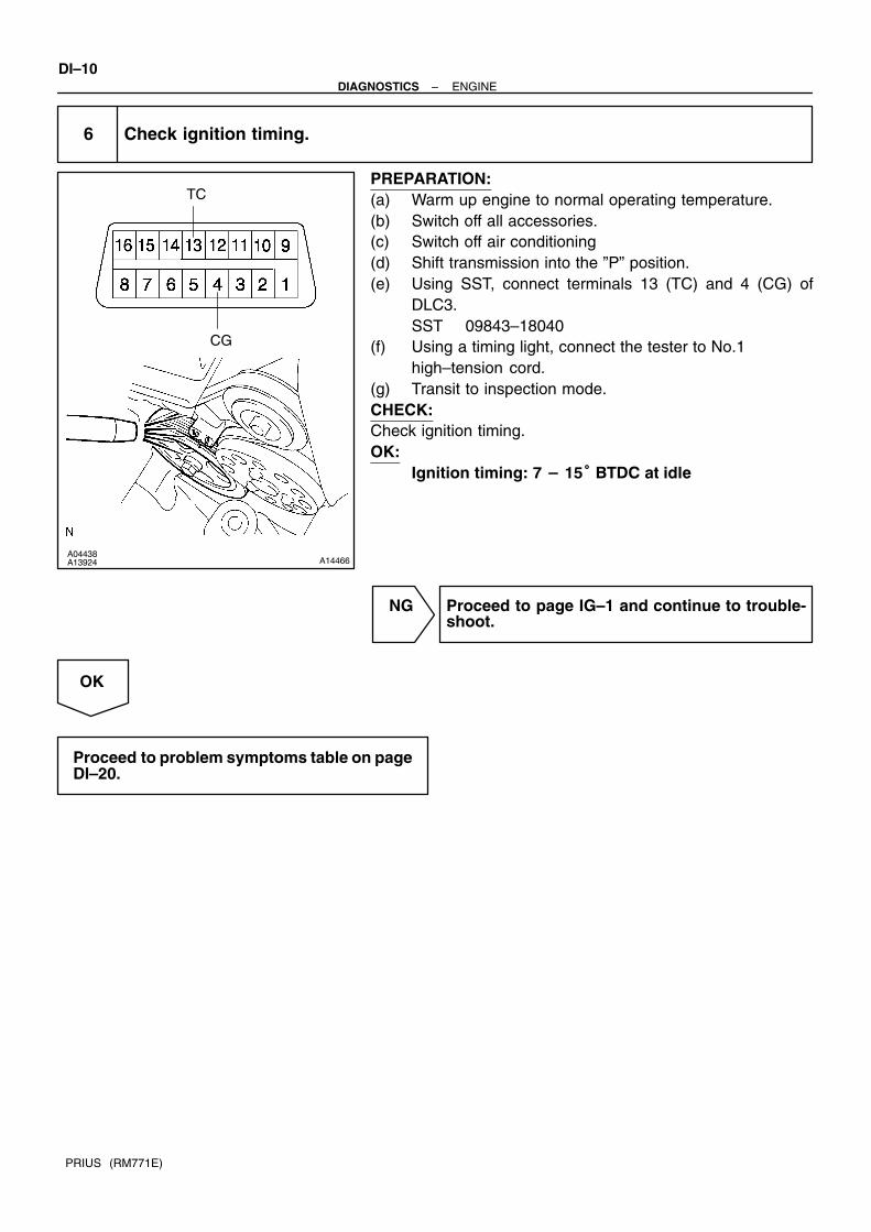
6 Check ignition timing.
PREPARATION:(a) Warm up engine to normal operating temperature.(b) Switch off all accessories.(c) Switch off air conditioning(d) Shift transmission into the ”P” position.(e) Using SST, connect terminals 13 (TC) and 4 (CG) of
DLC3.SST 09843–18040
(f) Using a timing light, connect the tester to No.1 high–tension cord.
(g) Transit to inspection mode.CHECK:Check ignition timing.OK:
Ignition timing:
NG Proceed to page IG–1 and continue to trouble-shoot.
OK
Proceed to problem symptoms table on pageDI–20.

A14060
–DIAGNOSTICS ENGINEDI–11
PRIUS (RM771E)
7 Check fuel pressure.
PREPARATION:(a) Be sure that enough fuel is in the tank.(b) Turn the ignition switch ON.(c) Connect the hand–held tester to the DLC3.(d) Use ACTIVE TEST mode to operate the fuel pump.(e) If you have no hand–held tester, connect the positive (+)
and negative (–) leads from the battery to the fuel pumpconnector (See page FI–6 ).
CHECK:Check that there is pressure in the fuel inlet pipe from the fuelline.
NG Proceed to page FI–6, and continue to trouble-shoot.
OK
8 Check for spark.
PREPARATION:(a) Remove ignition coil.(b) Remove the spark plug.(c) Install the spark plug to the ignition coil, and connect the ignition coil connector.(d) Disconnect the injector connector.(e) Be sure to ground the screw of the spark plug securely.CHECK:Check if spark occurs while engine is being cranked.NOTICE:To prevent excess fuel being injected from the injectors during this test, don’t crank the engine formore than 5 – 10 seconds at a time.
NG Proceed to page IG–1 and continue to trouble-shoot.
OK
Proceed to problem symptoms table on pageDI–20.

DI–12–DIAGNOSTICS ENGINE
PRIUS (RM771E)
7. ENGINE OPERATING CONDITIONNOTICE:The values given below for ”Normal Condition” are representative values, so a vehicle may still benormal even if its value from those listed here. So do not decide whether a part is faulty or not solelyaccording to the ”Normal Condition” here.(a) CARB mandated signal.
Hand–held tester display Measurement Item Normal Condition*
FUEL SYS #1
Fuel System Bank 1
OPEN: Air–fuel ratio feedback stopped
CLOSED: Air–fuel ratio feedback operating
Idling after warming up: CLOSED
CALC LOAD
Calculator Load:
Current intake air volume as a proportion of max.
intake air volume
Idling: 5.4 – 19.2 %
Racing without load (2,250rpm): 6.9 – 16.2 %
COOLANT TEMP/WATER TEMP. Water Temp. Sensor Value After warming up: 80 – 95C (176 – 203
SHORT FT #1 Short–term Fuel Trim Bank 1 0 20%
LONG FT #1 Long–term Fuel Trim Bank 1 0 20%
MAF/AFM Air Flow Rate Through Mass Flow Meter
Idling: 1.11 – 4.38 gm/sec.
Racing without load (2,250 rpm):
3.38 – 7.88 gm/sec.
ENGINE SPD Engine Speed Idling: 950 – 1,050 rpm
VEHICLE SPD Vehicle Speed Vehicle Stopped: 0 km/h (0 mph)
IGN ADVANCEIgnition Advance:
Ignition Timing of Cylinder No. 1Idling: BTDC 7 – 15
INTAKE AIR Intake Air Temp. Sensor Value Equivalent to Ambient Temp.
THROTTLE POS
Voltage Output of Throttle Position Sensor
Calculated as a percentage:
0 V → 0%, 5 V → 100%
Throttle Fully Closed: 6 – 16 %
Throttle Fully Open: 64 – 98 %
O2S B1, S1Voltage Output of Oxygen Sensor
Bank 1, Sensor 1Idling: 0.05 – 0.95 V
O2FT B1, S1Oxygen Sensor Fuel Trim Bank 1, Sensor 1
(Same as SHORT FT #1)0 20 %
O2S B1, S2Voltage Output of Oxygen Sensor Bank 1 Sensor
2Driving 50 km/h (31 mph): 0.05 – 0.95 V
(b) TOYOTA Enhanced Signals.
Hand–held tester display Measurement Item Normal Condition*1
MIL ON RUN DISTDistance since activation of check engine warn-
ing lightWhen there is no DTC: 0 km (0 mile)
INJECTOR Fuel injection time for cylinder No.1 Idling: 1.0 – 3.0 ms
IGNITIONTotal number of ignition for every 1,000 revolu-
tions0 – 2,000
CYL#1, CYL#2, CYL#3, CYL#4 Abnormal revolution variation for each cylinder 0 %
A/C CUT SIG A/C Cut Signal A/C S/W OFF: ON
FUEL PUMP Fuel Pump Signal Idling: ON
EVAP (PURGE) VSV EVAP VSV Signal VSV operation: Above 30 %
TOTAL FT B1Total Fuel Trim Bank 1: Average value for fuel
trim system of bank 1Idling: 0.8 – 1.2

–DIAGNOSTICS ENGINEDI–13
PRIUS (RM771E)
O2 LR B1 S1
Oxygen Sensor Lean Rich Bank 1 Sensor 1: Re-
sponse time for oxygen sensor output to switch
from lean to rich
Idling after warming up: 0 – 1,000 msec.
O2 RL B1 S1
Oxygen Sensor Rich Lean Bank 1 Sensor 1: Re-
sponse time for oxygen sensor output to switch
from rich to lean
Idling after warming up: 0 – 1,000 msec.
*: If no conditions are specifically stated for ”ldling”, it means the shift lever is at P position, the A/C switchis OFF and all accessory switches are OFF.

DI12C–17
DI–14–DIAGNOSTICS ENGINE
PRIUS (RM771E)
DIAGNOSTIC TROUBLE CODE CHARTSAE CONTROLLEDHINT: Parameters listed in the chart may not be exactly the same as your reading due to the type of instru-
ment or other factors.If a malfunction code is displayed during the DTC check in check mode, check the circuit for that codelisted in the table below. For details of each code, turn to the page referred to under the ’’See page’’ for the respective ’’DTC No.’’ in the DTC chart.
When the ignition switch is ON and ”READY” indicator light is OFF, the bulb check of the ”CHE ENG”warning light is performed (”CHE ENG” warning light is ON).When ”CHE ENG” warning light is ON, but the DTC of the engine is not memorized, it may be becauseof HV control system abnormality, so check HV control system beforehand.
DTC No.
(See Page)Detection Item Trouble Area CHK ENG* Memory
P0100
(DI–21)
Mass Air Flow Circuit Malfunc-
tion
Open or short in air flow meter circuit
Air flow meter
Engine ECU
P0101
(DI–26)
Mass Air Flow Circuit Range/
Performance ProblemAir flow meter
P0110
(DI–26)
Intake Air Temp. Circuit
Malfunction
Open or short in intake air temp. sensor circuit
Intake air temp. sensor (built into air flow meter)
Engine ECU
P0115
(DI–32)
Engine Coolant Temp. Circuit
Malfunction
Open or short in water temp. sensor circuit
Water temp. sensor
Engine ECU
P0116
(DI–36)
Engine Coolant Temp. Circuit
Range/Performance Probrem
Engine coolant temp. sensor
Cooling system
P0120
(DI–37)
Throttle/Pedal Position Sensor/
Switch ”A” Circuit Malfunction
Open or short in throttle position sensor circuit
Throttle position sensor
Engine ECU
P0121
(DI–43)
Throttle/Pedal Position Sensor/
Switch ”A” Circuit Range/Perfor-
mance Problem
Throttle position sensor
P0125
(DI–44)
Insufficient Coolant Temp. for
Closed Loop Fuel Control
Air induction system
Fuel pressure
Injector injection
Gas leakage on exhaust system
Open or short in heated oxygen sensor (bank 1 sensor 1)
circuit
Oxygen sensor (bank 1 sensor 1)
P0130
(DI–49)
Oxygen Sensor Circuit
Malfunction (Bank 1 Sensor 1)
Air induction system
EGR system
Fuel pressure
Injector injection
Open or short in heated oxygen sensor circuit
Heated oxygen sensor
P0133
(DI–53)
Oxygen Sensor Circuit
Slow Response
(Bank 1 Sensor 1)
Air induction system
EGR system
Fuel pressure
Injector injection
Open or short in heated oxygen sensor circuit
Heated oxygen sensor
Engine ECU

–DIAGNOSTICS ENGINEDI–15
PRIUS (RM771E)
P0135
(DI–56)
Oxygen Sensor Heater
Circuit Malfunction
(Bank 1 Sensor 1)
Open or short in heater circuit of oxygen sensor
Oxygen sensor heater
Engine ECU
P0136
(DI–58)
Oxygen Sensor Circuit Malfunc-
tion (Bank 1 Sensor 2)
Open or short in heater circuit of oxygen sensor
Oxygen sensor
P0141
(DI–56)
Oxygen Sensor Heater Circuit
Malfunction (Bank 1 Sensor 2)Same as DTC No. P0135
P0171
(DI–60)
Fuel Trim System too Lean
(Air–Fuel Ratio Lean Malfunc-
tion, Bank 1)
Air intake (hose loose)
Fuel line pressure
Injector blockage
Oxygen sensor malfunction
Air flow meter
Water temp. sensor
P0172
(DI–60)
System too Rich
(Fuel Trim)
Fuel line pressure
Injector leak, blockage
Heated oxygen sensor malfunction
Mass air flow meter
Engine coolant temp. sensor
Gas leakage on exhaust system
P0300
(DI–66)
Random/Multiple Cylinder
Misfire Detected
Ignition system
Injector
Fuel pressure
Compression pressure
P0301
P0302
P0303
P0304
(DI–66)
Misfire Detected
– Cylinder 1
– Cylinder 2
– Cylinder 3
– Cylinder 4
Com ression ressure
Valve clearance
Valve timing
Air flow meter
Water temp. sensor
Open or short in engine wire
Connector connection
Engine ECU
P0325
(DI–72)
Knock Sensor 1 Circuit
Malfunction
Open or short in knock sensor 1 circuit
Knock sensor 1 (looseness)
Engine ECU
P0335
(DI–75)
Crankshaft Position Sensor
”A” Circuit Malfunction
Open or short in crankshaft position sensor circuit
Crankshaft position sensor
Signal plate
Engine ECU
P0340
(DI–78)
Camshaft Position Sensor
Circuit Malfunction
Open or short in camshaft position sensor circuit
Camshaft position sensor
Engine ECU
P0420
(DI–80)
Catalyst System Efficiency
Below Threshould (Bank 1)
Gas leakage on exhaust system
Oxygen sensor
Three–way catalytic converter
P0443
(DI–83)
Evaporative Emission Control
System Purge Control Vent
Control Malfunction
Open or short in VSV circuit for EVAP
VSV for EVAP
Engine ECU
P0500
(DI–86)
Vehicle Speed Sensor
Malfunction
Combination meter
Open or short in No.1 vehicle speed sensor circuit
Engine ECU
No.1 vehicle speed sensor
P0505
(DI–88)
Idle Control System
Malfunction
Electric throttle control system
Air induction system
P1125
(DI–89)
Throttle Conrol Motor Circuit
Malfunction
Open or short in throttle control motor circuit
Throttle control motor
ECM

DI–16–DIAGNOSTICS ENGINE
PRIUS (RM771E)
P1127
(DI–91)
ETCS Actuator Power Source
Circuit Malfunction
Open in ETCS power source circuit
ECM
P1128
(DI–93)
Throttle Conrol Motor Lock
Malfunction
Throttle control motor
Throttle body assembly
ECM
P1129
(DI–94)
Electric Throttle Conrol
System Malfunction
Electric throttle control system
ECM
P1300
(DI–95)
Igniter Circuit Malfunction
(No.1)
Open or short in IGF and IGT1 circuit from ignition coil with
igniter to Engine ECU
No.1 ignition coil with igniter
Engine ECU
P1305
(DI–95)
Igniter Circuit Malfunction
(No.2)
Open or short in IGF or IGT2 circuit from No.2 ignition coil with
igniter to engine ECU
No.2 ignition coil with igniter
Engine ECU
P1310
(DI–95)
Igniter Circuit Malfunction
(No.3)
Open or short in IGF and IGT3 circuit from ignition coil with
igniter to Engine ECU
No.3 ignition coil with igniter
Engine ECU
P1315
(DI–95)
Igniter Circuit Malfunction
(No.4)
Open or short in IGF or IGT4 circuit from No.4 ignition coil with
igniter to engine ECU
No.4 ignition coil with igniter
Engine ECU
P1346
(DI–102)
VVT Sensor Circuit
Range/Performance Problem
Mechanical system (Jumping teeth of timing belt, belt
stretched)
Engine ECU
P1349
(DI–103)VVT System Malfunction
Valve timing
OCV
VVT controller assembly
Engine ECU
P1525
(DI–109)
Resolver Circuit
Malfunction
HV ECU
Engine ECU–
P1600
(DI–111)Engine ECU BATT Malfunction
Open in back up power source circuit
Engine ECU
P1633
(DI–113)ECU Malfunction (ETCS Circuit) ECM
P1636
(DI–114)HV ECU Malfunction
HV ECU
Engine ECU
P1637
(DI–116)EGSTP Signal Malfunction
HV ECU
Engine ECU–
P1656
(DI–118)OCV Circuit Malfunction
Open or short in OCV circuit (bank 1)
OCV
Engine ECU
P3190
(DI–121)Poor Engine Power
Air induction system
Throttle body
Fuel pressure
Engine
Mass air flow meter
P3191
(DI–121)Engine dose not Start
Mass air flow meter
Out of fuel
Engine coolant temp. sensor
Crankshaft position sensor
Camshaft position sensor
Engine ECU
*: – Check engine warning light does not light up. Check engine warning light lights up.

DI68L–08
A13617
Camshaft Oil Control Valve
Ignition Coil(with Igniter)
Knock Sensor
Crankshaft Position Sensor
Water TemperatureSensor
Oxygen Sensor(Bank1 Sensor1)
DLC3
Oxygen Sensor (Bank1 Sensor2)
Camshaft PositionSensor
Air Flow Meter
Engine ECU
InjectorVSV for EVAP
Throttle Body Throttle Motor Throttle PositionSensor
Fuel Pump
–DIAGNOSTICS ENGINEDI–17
PRIUS (RM771E)
PARTS LOCATION

DI7O6–01
F02094
E7 E8 E9 E10
DI–18–DIAGNOSTICS ENGINE
PRIUS (RM771E)
TERMINALS OF ECU
Symbols (Terminal No.) Wiring Color Condition STD Voltage (V)
BATT (E8 – 3) – E1 (E8 – 17) R–W ↔ BR Always 9 – 14
+B (E8 – 4) – E1 (E8 – 17) B ↔ BR IG switch ON 9 – 14
+BM (E7 – 6) – E1 (E8 – 17) GR ↔ BR Always 9 – 14
IGSW(E10 – 9) – E1(E8 – 17) B–W ↔ BR IG switch ON 9 – 14
MREL (E9 – 25)
– E1(E8 – 17)G–R ↔ BR IG switch ON 9 – 14
VC (E8 – 2) – E2 (E8 – 18) Y–R ↔ BR IG switch ON 4.5 – 5.5
VTA (E8 23) E2 (E8 18) P ↔ BR
IG switch ON
Throttle valve fully closed0.4 – 1.0
VTA (E8 – 23) – E2 (E8 – 18) P ↔ BRIG switch ON
Throttle valve fully open3.2 – 4.8
VTA2 (E8 21) E2 (E8 18) L ↔ BR
IG switch ON
Accelerator pedal released2.0 – 2.9
VTA2 (E8 – 21) – E2 (E8 – 18) L ↔ BRIG switch ON
Accelerator pedal depressed4.6 – 5.1
VG (E8 – 10) – EVG (E8 – 19) G ↔ R Idling, A/C switch OFF, Shift position in N or P position 0.5 – 3.0
THA (E8 – 22) – E2 (E8 – 18) R–B ↔ BR Idling, Intake air temp. 20C (68F) 0.5 – 3.4
THW (E8 – 14) – E2 (E8 – 18) W ↔ BR Idling, Engine coolant temp. 80 0.2 – 1.0
IG switch ON 9 – 14
#10 (E8 – 5) – E01 (E7 – 21) Y ↔ W–BIdling
Pulse generation
(See page DI–66)
IG switch ON 9 – 14
#20 (E8 – 6) – E01 (E7 – 21) B–R ↔ W–BIdling
Pulse generation
(See page DI–66)
IG switch ON 9 – 14
#30 (E7 – 1) – E01 (E7 – 21) L–W ↔ W–BIdling
Pulse generation
(See page DI–66)
IG switch ON 9 – 14
#40 (E7 – 2) – E01 (E7 – 21) R–W ↔ W–BIdling
Pulse generation
(See page DI–66)
IGT1 (E7 – 11) – E1 (E8 – 17) Y–G ↔ BR IdlingPulse generation
(See page DI–95)
IGT2 (E7 – 12) – E1 (E8 – 17) W ↔ BR IdlingPulse generation
(See page DI–95)
IGT3 (E7 – 13) – E1 (E8 – 17) G ↔ BR IdlingPulse generation
(See page DI–95)

–DIAGNOSTICS ENGINEDI–19
PRIUS (RM771E)
IGT4 (E7 – 14) – E1 (E8 – 17) Y ↔ BR IdlingPulse generation
(See page DI–95)
IG switch ON 4.5 – 5.5
IGF (E7 – 25) – E1 (E8 – 17) B–R ↔ BRIdling
Pulse generation
(See page DI–95)
G2 (E7 – 10) – NE (E8 – 24) R ↔ G IdlingPulse generation
(See page DI–75)
NE+ (E8 – 16) – NE– (E8 – 24) R ↔ G IdlingPulse generation
(See page DI–75)
FC (E8 – 9) – E01 (E7 – 21) G–R ↔ W–B IG switch ON 9 – 14
EVP1 (E7 – 29) – E1 (E8 – 17) R–L ↔ BR IG switch ON 9 – 14
OX1A (E10 – 12)
– E2 (E8 – 18)W ↔ BR
Maintain engine speed at 2,500 rpm for 2 min. after
warming up
Pulse generation
(See page DI–49)
OX1B (E10 – 11)
– E2 (E8 – 18)Y ↔ BR
Maintain engine speed at 2,500 rpm for 2 min. after
warming up
Pulse generation
(See page DI–49)
HT1A (E10 1) E1 (E8 17) P L ↔ BRIdling Below 3.0
HT1A (E10 – 1) – E1 (E8 – 17) P–L ↔ BRIG switch ON 9 – 14
HT1B (E10 7) E1 (E8 17) G Y ↔ BRIdling Below 3.0
HT1B (E10 – 7) – E1 (E8 – 17) G–Y ↔ BRIG switch ON 9 – 14
KNK1 (E7 – 28) – E2 (E8 – 18) B ↔ BR IdlingPulse generation
(See page DI–72)
SPD (E10 – 5)
– E1 (E8 – 17)V–W ↔ BR
IG switch ON
Rotate driving wheel slowlyPulse generation
SPHV (E9 – 10)
– E1 (E8 – 17)O ↔ BR
IG switch ON
Rotate driving wheel slowly
Pulse generation
(See page DI–109)
ESTP (E9 – 16) – E1 (E8 – 17) R–Y ↔ BR Idling 9 – 14
TAM (E9 – 23) – E2 (E8 – 18) W–G ↔ BR Outer air temp. –30 – 50C 0.7 – 3.2
W (E10 6) E1 (E8 17) G R ↔ BRIdling 9 – 14
W (E10 – 6) – E1 (E8 – 17) G–R ↔ BRIG switch ON Below 3.0
ACT (E10 5) E1 (E8 17) P G ↔ BRA/C switch OFF Below 2.0
ACT (E10 – 5) – E1 (E8 – 17) P–G ↔ BRA/C switch ON at idling 9 – 14
OCV+ (E7 – 23)Y R ↔ W G IG switch ON
Pulse generationOCV+ (E7 23)
– OCV – (E7 – 24)Y–R ↔ W–G IG switch ON
Pulse generation
(See page DI–103)
M+ (E7 – 8) – E1 (E8 – 17)
M– (E7 – 7) – E1 (E8 – 17)
L ↔ BR
P ↔ BRIdling
Pulse generation
(See page DI–89)
TC (E9 – 6) – E1 (E8 – 17) P–B ↔ BR IG switch ON 9 – 14

DI1IA–18
DI–20–DIAGNOSTICS ENGINE
PRIUS (RM771E)
PROBLEM SYMPTOMS TABLESymptom Suspect Area See page
Engine does not crank (Does not start)15.MG1
16.HV ECU
–
IN–40
No initial combustion (Does not start)
1. Engine immobiliser system
2. ECU power source circuit
3. Fuel pump control circuit
BE–2
DI–124
DI–129
No complete combustion (Does not start) 1. Fuel pump control circuit DI–129
Under normal condition (Difficult to start)1. Fuel pump control circuit
2. Compression
DI–129
EM–3
Cold engine (Difficult to start) 1. Fuel pump control circuit DI–129
Hot engine (Difficult to start) 1. Fuel pump control circuit DI–129
High engine idle speed (Poor idling)1. A/C signal circuit (Compressor circuit)
2. ECU power source circuit
DI–138
DI–124
Low engine idle speed (Poor idling)1. A/C signal circuit (Compressor circuit)
2. Fuel pump control circuit
DI–138
DI–129
Rough idling (Poor idling)1. Compression
2. Fuel pump control circuit
EM–3
DI–129
Hunting (Poor idling)1. ECU power source circuit
2. Fuel pump control circuit
DI–124
DI–129
Hesitation/Poor acceleration (Poor driveability) 1. Fuel pump control circuit DI–129
Surging (Poor driveability) 1. Fuel pump control circuit DI–129
Soon after starting (Engine stall)1. Engine immobiliser system
2. Fuel pump control circuit
BE–2
DI–129
During A/C operation (Engine stall)1. A/C signal circuit (Compressor circuit)
2. Engine ECU
DI–138
IN–29

DI7O7–01
A09707
Power Transistor
Platinum Hot Wire
OutputVoltage
Temparature sensor
A B
Platinum Hot Wire
Temparature sensor
B+
–DIAGNOSTICS ENGINEDI–21
PRIUS (RM771E)
CIRCUIT INSPECTION
DTC P0100 Mass Air Flow Circuit Malfunction
CIRCUIT DESCRIPTIONThe air flow meter uses a platinum hot wire. The hot wire air flow meter consists of a platinum hot wire, tempa-rature sensor and a control circuit installed in a plastic housing. The hot wire air flow meter works on theprinciple that the hot wire and temparature sensor located in the intake air bypass of the housing detect anychanges in the intake air temperature.The hot wire is maintained at the set temperature by controlling the current flow through the hot wire. Thiscurrent flow is then measured as the output voltage of the air flow meter.The circuit is constructed so that the platinum hot wire and temparature sensor provide a bridge circuit, withthe power transistor controlled so that the potential of A and B remains equal to maintain the set temperature.
DTC No. DTC Detecting Condition Trouble Area
P0100
Open or short in air flow meter circuit with more than 3 sec.
engine speed less than 3,000 rpm Open or short in air flow meter circuit
Ai fl tP0100Open or short in air flow meter circuit with more than 3 sec.
engine speed 3,000 rpm or more (2 trip detection logic)
Air flow meter
Engine ECU
HINT:After confirming DTC P0100 use the hand–held tester to confirm the air flow ratio from CURRENT DATA.
Air Flow Value (gm/sec.) Malfunction
Approx. 0.0Air flow meter power source circuit open
VG circuit open or short
271.0 or more EVG circuit open

A14023
Battery
MAIN
FL Block No. 1
(Shielded)
212
EFI
EVG
Air Flow Meter
B–R
4
1
1
EFI Relay
W–B
B–G
B
1 J8
3
A
A
E9
J/C
E8
25
10VG
MRELG–R
1B
IA2
A
Engine Room J/B19
52
2
3
A
A
B
F12
IE
G
3
1
A6
A
(LHD)
EB
3
Engine ECU
E8R
G–R
J9FL Block No. 2
J1 J/C
J7 J/C
1K 1F
1A
F13
W–B W–B
W–B
(RHD)
(LHD)
1
DI–22–DIAGNOSTICS ENGINE
PRIUS (RM771E)
WIRING DIAGRAM

A01588
ON
3 (+)
–DIAGNOSTICS ENGINEDI–23
PRIUS (RM771E)
INSPECTION PROCEDUREHINT:Read freeze frame data using hand–held tester. Because freeze frame records the engine conditions whenthe malfunction is detected, when troubleshooting it is useful for determining whether the vehicle was run-ning or stopped, the engine warmed up or not, the air–fuel ratio lean or rich, etc. at the time of the malfunction.
1 Connect hand–held tester, and read value of air flow rate.
PREPARATION:(a) Connect the hand–held tester to the DLC3.(b) Turn the ignition switch ON and push the hand–held tester main switch ON.(c) Start the engine.CHECK:Read air flow rate on the hand–held tester.RESULT:
Type I Type II
Air flow rata (gm/sec.) 0.0 271.0 or more
Type I Go to step 2.
Type II Go to step 5.
2 Check voltage of air flow meter power source.
PREPARATION:(a) Disconnect the air flow meter connector.(b) Turn the ignition switch ON.CHECK:Measure voltage between terminal 4 of the air flow meter con-nector and body ground.OK:
Voltage: 9 – 14 V
NG Check for open in harness and connector be-tween EFI main relay (Marking: EFI) and air flowmeter (See page IN–40).
OK

A13618
VG
START
(+) (–)
DI–24–DIAGNOSTICS ENGINE
PRIUS (RM771E)
3 Check voltage between terminals VG of engine ECU connector and body ground.
PREPARATION:(a) Remove the engine ECU with connector still connected
(See page FI–58).(b) Start the engine.CHECK:Measure voltage between terminal VG of the engine ECU con-nector and body ground while engine is idling.OK:
Voltage: 0.5 – 3.0 V (P or N position and A/C switch OFF)
OK Check and replace engine ECU (See page IN–40).
NG
4 Check for open and short in harness and connector between air flow meter andengine ECU (See page IN–40).
NG Repair or replace harness or connector.
OK
Replace air flow meter.

A13619
EVG
–DIAGNOSTICS ENGINEDI–25
PRIUS (RM771E)
5 Check continuity between terminal EVG of engine ECU connector and bodyground.
PREPARATION:Remove the engine ECU with connector still connected (Seepage FI–58).CHECK:Check continuity between terminal EVG of the engine ECUconnector and body ground.OK:
Continuity (1 Ω or less)
NG Check and replace engine ECU(See page IN–40).
OK
6 Check for open in harness and connector between air flow meter and engineECU (See page IN–40).
NG Repair or replace harness or connector.
OK
Replace air flow meter.

DI–26–DIAGNOSTICS ENGINE
PRIUS (RM771E)
DTC P0101 Mass Air Flow Circuit Range/PerformanceProblem
CIRCUIT DESCRIPTIONRefer to DTC P0100 on page DI–21.
DTC No. DTC Detecting Condition Trouble Area
P0101
After engine is warmed up, conditions (1) and (2) continue with
more than 10 sec. engine speed 1,500 rpm or less:
(2 trip detection logic)
1. 0.42 V VTA 0.86 V
2. Air flow meter output 2.91 VAir flow meterP0101
Conditions (1) and (2) continue with more than 10 sec.
engine speed 2,100 rpm or more:
(2 trip detection logic)
1. VTA 3.0 V
2. Air flow meter output 1.0 V
Air flow meter
INSPECTION PROCEDUREHINT:Read freeze frame data using hand–held tester. Because freeze frame records the engine conditions whenthe malfunction is detected, when troubleshooting it is useful for determining whether the vehicle was run-ning or stopped, the engine warmed up or not, the air–fuel ratio lean or rich, etc. at the time of the malfunction.
1 Are there any other codes (besides DTC P0101) being output?
NO Replace air flow meter.
YES
Go to relevant DTC chart (See page DI–14).
DI7O8–01

FI4741
(fig. 1)
Acceptable
Res
ista
nce
kΩ
– 20 0 20 40 60 80 100(– 4) 32 68 104 140 176 212
30
20
10
5
3
2
1
0.5
0.3
0.2
0.1
Temp. C (F)
–DIAGNOSTICS ENGINEDI–27
PRIUS (RM771E)
DTC P0110 Intake Air Temp. Circuit Malfunction
CIRCUIT DESCRIPTIONThe intake air temp. sensor is built into the air flow meter andsenses the intake air temperature.A thermistor built in the sensor changes the resistance valueaccording to the intake air temperature.The lower the intake air temperature, the greater the thermistorresistance value, and the higher the intake air temperature, thelower the thermistor resistance value (See fig. 1).The intake air temp. sensor is connected to the engine ECU(See below ). The 5 V power source voltage in the engine ECUis applied to the intake air temp. sensor from the terminal THA(THAR) via resistor R.That is, the resistor R and the intake air temp. sensor are con-nected in series. When the resistance value of the intake airtemp. sensor changes in accordance with changes in the intakeair temperature, the potential at terminal THA (THAR) alsochanges. Based on this signal, the engine ECU increases thefuel injection volume to improve driveability during cold engineoperation.
DTC No. DTC Detecting Condition Trouble Area
P0110 Open or short in intake air temp. sensor circuit
Open or short in intake air temp. sensor circuit
Intake air temp. sensor (inside air flow meter)
Engine ECU
HINT:After confirming DTC P0110 use the hand–held tester to confirm the intake air temperature from CURRENTDATA.
Temperature Displayed Malfunction
–40C (–40) Open circuit
140C ( 284 ) or more Short circuit
DI7O9–01

A00328
Engine ECUIntake Air Temp. Sensor(Inside air flow meter)
THA
5 V
R
E1
E2BR
R–B 22
E818
4
5
A6
E8
DI–28–DIAGNOSTICS ENGINE
PRIUS (RM771E)
WIRING DIAGRAM
INSPECTION PROCEDUREHINT: If DTC P0110 (Intake Air Temp. Circuit Malfunction), P0115 (Water Temp. Circuit Malfunction), P0120
(Throttle/Pedal Position Sensor/Switch ”A” Malfunction) are output simultaneously, E2 (SensorGround) may be open.
Read freeze frame data using hand–held tester. Because freeze frame records the engine conditionswhen the malfunction is detected, when troubleshooting it is useful for determining whether the vehiclewas running or stopped, the engine warmed up or not, the air–fuel ratio lean or rich, etc. at the timeof the malfunction.

A00348
ON
Engine ECUIntake AirTemp. Sensor
4
5
Connecting
–DIAGNOSTICS ENGINEDI–29
PRIUS (RM771E)
1 Connect hand–held tester, and read value of intake air temperature.
PREPARATION:(a) Connect the hand–held tester to the DLC3.(b) Turn the ignition switch ON and push the hand–held tester main switch ON.CHECK:Read temperature value on the hand–held tester.OK:
Same as actual intake air temperatureHINT: If there is open circuit, hand–held tester indicates –40C (–40F). If there is short circuit, hand–held tester indicates 140C (284F)
NG –40C (–40)...Go to step 2 140C (284) or more...Go to step 4.
OK
Check for intermittent problems (See page DI–3).
2 Check for open in harness or engine ECU.
PREPARATION:(a) Disconnect the air flow meter connector.(b) Connect the sensor wire harness terminals together.(c) Turn the ignition switch ON.CHECK:Read temperature value on the hand–held tester.OK:
Temperature value: 140°C (284°F) or more
OK Confirm good connection at sensor. If OK, re-place air flow meter.
NG

A13621
ON
Intake AirTemp. Sensor
5
4
THAE2
Engine ECU
5 V
E2
THA
E1
DI–30–DIAGNOSTICS ENGINE
PRIUS (RM771E)
3 Check for open in harness or engine ECU.
PREPARATION:(a) Remove the engine ECU with connector still connected
(See page FI–58).(b) Connect between terminals THA and E2 of the engine
ECU connector.HINT:Air flow meter connector is disconnected.Before checking, do a visual and contact pressure check for theengine ECU connector (See page IN–40).CHECK:Read temperature value on the hand–held tester.OK:
Temperature value: 140°C (284°F) or more
OK Open in harness between terminals E2 or THA,repair or replace harness.
NG
Confirm good connection at engine ECU.If OK, check and replace engine ECU.(See page IN–40)

A00363
ON
Intake AirTemp. Sensor
Engine ECU
4
5
3
9
A09091
ON
Intake Air Temp. Sensor
E8 Connector
Engine ECU
5 V
E2
THA
E1
–DIAGNOSTICS ENGINEDI–31
PRIUS (RM771E)
4 Check for short in harness and engine ECU.
PREPARATION:(a) Disconnect the air flow meter connector.(b) Turn the ignition switch ON.CHECK:Read temperature value on the hand–held tester.OK:
Temperature value: –40°C (–40°F)
OK Replace air flow meter.
NG
5 Check for short in harness or engine ECU.
PREPARATION:(a) Remove the engine ECU with connector still connected
(See page FI–58).(b) Disconnect the E8 connector of the engine ECU.HINT:Air flow meter connector is disconnected.(c) Turn the ignition switch ON.CHECK:Read temperature value on the hand–held tester.OK:
Temperature value: –40°C (–40°F)
OK Repair or replace harness or connector.
NG
Check and replace engine ECU (See page IN–40).

A00328
Engine ECUE2Engine Coolant Temp. Sensor
E8 THW
5 V
E2
E2BR
W 14
E818
2
1
DI–32–DIAGNOSTICS ENGINE
PRIUS (RM771E)
DTC P0115 Water Temp. Circuit Malfunction
CIRCUIT DESCRIPTIONA thermistor built into the water temp. sensor changes the resistance value according to the water tempera-ture.The structure of the sensor and connection to the engine ECU is the same as in the DTC P0110 shown onpage DI–27.
DTC No. DTC Detecting Condition Trouble Area
P0115 Open or short in water temp. sensor circuit
Open or short in water temp. sensor circuit
Water temp. sensor
Engine ECU
HINT:After confirming DTC P0115 use the hand–held tester to confirm the water temperature from CURRENTDATA.
Temperature Displayed Malfunction
–40C (–40F) Open circuit
140C (284 Short circuit
WIRING DIAGRAM
DI7OA–01

–DIAGNOSTICS ENGINEDI–33
PRIUS (RM771E)
INSPECTION PROCEDUREHINT: If DTC P0110 (Intake Air Temp. Circuit Malfunction), P0115 (Water Temp. Circuit Malfunction), P0120
(Throttle/Pedal Position Sensor/Switch ”A” Malfunction) are output simultaneously, E2 (SensorGround) may be open.
Read freeze frame data using hand–held tester. Because freeze frame records the engine conditionswhen the malfunction is detected, when troubleshooting it is useful for determining whether the vehiclewas running or stopped, the engine warmed up or not, the air–fuel ratio lean or rich, etc. at the timeof the malfunction.
1 Connect hand–held tester, and read value of water temperature.
PREPARATION:(a) Connect the hand–held tester to the DLC3.(b) Turn the ignition switch ON and switch the hand–held tester main switch ON.CHECK:Read temperature value on the hand–held tester.OK:
Same as actual water temperatureHINT: If there is open circuit, Hand–held tester indicates –40C (–40F). If there is short circuit, Hand–held tester indicates 140C (284F) or more.
NG –40C (–40F)...Go to step 2.140C (284F) or more...Go to step 4.
OK
Check for intermittent problems (See pageDI–3).

A00366
ON
Engine ECU
2
1
Water Temp. Sensor
Connecting
4
9
A13623
ON
Engine CoolantTemp. Sensor
1
2
THW E2
Engine ECU
5 V
E2
THW
E1
DI–34–DIAGNOSTICS ENGINE
PRIUS (RM771E)
2 Check for open in harness or engine ECU.
PREPARATION:(a) Disconnect the water temp. sensor connector.(b) Connect sensor wire harness terminals together.(c) Turn the ignition switch ON.CHECK:Read temperature value on the hand–held tester.OK:
Temperature value: 140°C (284°F) or more
OK Confirm good connection at sensor. If OK, re-place water temp. sensor.
NG
3 Check for open in harness or engine ECU.
PREPARATION:(a) Remove the engine ECU with connector still connected
(See page FI–58).(b) Connect between terminals THW, and E2 of the engine
ECU connector.HINT:Water temp. sensor connector is disconnected. Before checking, do a visual and contact pressure check for theengine ECU connector (See page IN–40).(c) Turn the ignition switch ON.CHECK:Read temperature value on the hand–held tester.OK:
Temperature value: 140°C (284°F) or more
OK Open in harness between terminals E2 or THW,repair or replace harness.
NG
Confirm good connection at engine ECU.If OK, check and replace engine ECU (Seepage IN–40).

A00373
ON
2
1
Engine ECUWater Temp. Sensor
A09091
ON
Engine CoolantTemp. Sensor
E8 Connector
Engine ECU
5 V
E2
THW
E1
–DIAGNOSTICS ENGINEDI–35
PRIUS (RM771E)
4 Check for short in harness and engine ECU.
PREPARATION:(a) Disconnect the water temp. sensor connector.(b) Turn the ignition switch ON.CHECK:Read temperature value on the hand–held tester.OK:
Temperature value: –40°C (–40°F)
OK Replace water temp. sensor.
NG
5 Check for short in harness or engine ECU.
PREPARATION:(a) Remove the engine ECU with connector still connected
(See page FI–58).(b) Disconnect the E8 connector of the engine ECU.HINT:Water temp. sensor connector is disconnected.(c) Turn the ignition switch ON.CHECK:Read temperature value on the hand–held tester.OK:
Temperature value: –40°C (–40°F)
OK Repair or replace harness or connector.
NG
Check and replace engine ECU (See pageIN–40).

DI–36–DIAGNOSTICS ENGINE
PRIUS (RM771E)
DTC P0116 Water Temp. Circuit Range/PerformanceProblem
CIRCUIT DESCRIPTION
!"# $
DTC No. DTC Detecting Condition Trouble Area
P0116
When the fluctuations in the engine coolant tempeerature are
within 3 C (37 F)before and afrer the follwing conditions are
met:
1. IDL OFF time 250 sec.
2. Vehicle speed change of 15 km/h (9 mph) or more occurs
10 times or more.
3. –10 C (14 F) Engine coolant temperature when the
ignition switch is turned ON < 60 C (140 F)
4. Intake air temperature after starting the engine –6.7 C
(20 F)
Engine coolant temp. sensor
Cooling system
INSPECTION PROCEDURE
HINT: If DTC P0115 and P0116 are output simultaneously, water temp. sensor circuit may be open. Perform
troubleshooting of DTC P0115 first. Read freeze frame data using hand–held tester or OBD scan tool. Because freeze frame records the
engine conditions when the malfunction is detected, when troubleshooting it is useful for determiningwhether the vehicle was running or stopped, the engine warmed up or not, the air–fuel ratio lean orrich, etc. at the time of the malfunction.
1 Are there any other codes (besides DTC P0116) being output?
YES Go to relevant DTC chart.
NO
2 Check thermostat (See page CO–10).
NG Replace thermostat.
OK
Replace engine coolant temp. sensor.
DI6UZ–02

A02624
Thr
ottle
Pos
ition
Sen
sor
Out
put V
olta
ge (V
)
0
1.5
Throttle Valve Opening Angle (deg)
70 125
VTA
VTA25
VTA2 VTAE2 VC
Movable Range
Usable Range
Usable Range*1 *2
*1
*2
Movable Range
UsableRange
*2
*1
*1: Throttle valve fully closed
*2: Throttle valve fully open
VTA2 line open or grand short
Accelerator pedal position expressed as percentage and voltage
Accelerator pedal released Accelerator pedal depressed
THROTTLE POS THROTTLE POS #2 THROTTLE POS THROTTLE POS #2
0 %
0 %
100 %
8 – 20 %
0 V
2.0 – 2.9 V
0 V
5 V
0 %
0 %
100 %
0 V
4.6 – 5.1 V
0 V
5 V
Trouble area
VC line open
VTA line open or grand short
E2 line open
64 – 96 %
–DIAGNOSTICS ENGINEDI–37
PRIUS (RM771E)
DTC P0120 Throttle/Pedal Position Sensor/Switch ”A”Circuit Malfunction
CIRCUIT DESCRIPTION
Throttle position sensor is mounted on the throttle body and it have the 2 sensors to detect the throttle open-ing angle and the malfunction of the throttle position sensor’s own.The voltage applied to the terminals VTA and VTA2 of the engine ECU changes between 0 V and 5 V inproportion to the opening angle of the throttle valve.The engine ECU judges the current opening angle of the throttle valve from these signals input from termi-nals VTA and VTA2, and the engine ECU controls the throttle motor to make the throttle valve angle properlyin response to driving condition.If this DTC is stored, the engine ECU shuts down the power for the throttle motor, and the throttle valve isfully closed by the return spring.
DTC No. DTC Detecting Condition Trouble Area
P0120
Condition (a), (b), (c), (d) or (e) continues for 2.0 seconds:
(a) VTA 0.2 V
(b) VTA2 0.625 V
(c) VTA 4.8 V
(d) When VTA 0.2 V and 2.0 V, and VTA2 4.97 V
(e) VTA–VTA2 0.02 V
Open or short in throttle position sensor circuit
Throttle position sensor
Engine ECU
Condition (a) or (b) continues for 0.4 seconds:
(a) VTA 0.2 V and VTA2 0.5 V
(b) VTA–VTA2 0.02 V
Engine ECU
HINT:After confirming DTC P0120 use the hand–held tester to confirm the throttle valve opening percentage .
DI2TV–03

A14024
Throttle Position Sensor
Engine ECU
2
3
4
BR
23
2
21
18
VTA
VC
VTA2
E2
E8
E8
E8
E8BR
BR
1
VTA1
VC
VTA2
E2
J9 J/C
T2
EB
AA
J8 J/CCC Y–RY–R
P
L
Shielded
DI–38–DIAGNOSTICS ENGINE
PRIUS (RM771E)
WIRING DIAGRAM
INSPECTION PROCEDURE
HINT: If DTC P0110 (Intake Air Temp. Circuit Malfunction), P0115 (Water Temp. Circuit Malfunction), P0120
(Throttle Position Sensor Circuit Malfunction) are output simultaneously, E2 (Sensor Ground) may beopen.
Read freeze frame data using hand–held tester. Because freeze frame records the engine conditionswhen the malfunction is detected, when troubleshooting it is useful for determining whether the vehiclewas running or stopped, the engine warmed up or not, the air–fuel ratio lean or rich, etc. at the timeof the malfunction.

FI7052
A13624
E2
VC
ON
(+) (–)
–DIAGNOSTICS ENGINEDI–39
PRIUS (RM771E)
Hand–held tester:
1 Connect hand–held tester, read throttle valve opening percentage.
PREPARATION:(a) Connect the hand–held tester to DLC3.(b) Turn the ignition switch ON and switch the hand–held tes-
ter main switch ON.CHECK:Read the throttle valve opening percentage for VTA circuit andread the voltage for VTA2 circuit.OK:
Accelerator pedal
Throttle valve opening
position expressed
as percentage (VTA)
Voltage
(VTA2)
Released 8 – 20 % 2.0 – 2.9 V
Depressed 64 – 96 % 4.6 – 5.1 V
OK Check and replace engine ECU(See page IN–40).
NG
2 Check voltage between terminals VC and E2 of engine ECU connector.
PREPARATION:(a) Remove the engine ECU with connector still connected
(See page FI–58).(b) Turn the ignition switch ON.CHECK:Measure voltage between terminals VC and E2 of the engineECU connector.OK:
Voltage: 4.5 – 5.5 V
NG Check and replace engine ECU(See page IN–40).
OK

A13625
ON
VTA2
E2VTA
DI–40–DIAGNOSTICS ENGINE
PRIUS (RM771E)
3 Check voltage between terminals VTA, VTA2 and E2 of engine ECU connector.
PREPARATION:(a) Remove the engine ECU with connector still connected
(See page FI–58).(b) Turn the ignition switch ON.CHECK:Measure voltage between terminals VTA, VTA2 and E2 of theengine ECU connector.OK:
A l t d lVoltage
Accelerator pedalVTA VTA2
Released 0.4 – 1.0 V 2.0 – 2.9 V
Depressed 3.2 – 4.8 V 4.6 – 5.1 V
NG Check and replace engine ECU(See page IN–40).
NG
4 Check throttle position sensor (See page FI–32).
NG Replace throttle position sensor (See page FI–32).
OK
Check for open and short in harness and connector between engine ECU and throttle positionsensor (VC, VTA, VTA2, E2 line) (See page IN–40).

A13624
E2
VC
ON
A13625
ON
VTA
E2VTA2
–DIAGNOSTICS ENGINEDI–41
PRIUS (RM771E)
When not using hand–held tester
1 Check voltage between terminals VC and E2 of engine ECU connector.
PREPARATION:(a) Remove the engine ECU with connector still connected
(See page FI–58).(b) Turn the ignition switch ON.CHECK:Measure voltage between terminals VC and E2 of the engineECU connector.OK:
Voltage: 4.5 – 5.5 V
NG Check and replace engine ECU(See page IN–40).
OK
2 Check voltage between terminals VTA, VTA2 and E2 of engine ECU connector.
PREPARATION:(a) Remove the engine ECU with connector still connected
(See page FI–58).(b) Turn the ignition switch ON.CHECK:Measure voltage between terminals VTA, VTA2 and E2 of theengine ECU connector.OK:
AcceleratorpedalVoltage
Accelerator pedalVTA VTA2
Released 0.4 – 1.0 V 2.0 – 2.9 V
Depressed 3.2 – 4.8 V 4.6 – 5.1 V
OK Check and replace engine ECU(See page IN–40).
NG

DI–42–DIAGNOSTICS ENGINE
PRIUS (RM771E)
3 Check throttle position sensor (See page FI–32).
NG Replace throttle position sensor (See page FI–32).
OK
Check for open and short in harness and connector between engine ECU and throttle positionsensor (VC, VTA, VTA2, E2 line) (See page IN–40).

–DIAGNOSTICS ENGINEDI–43
PRIUS (RM771E)
DTC P0121 Throttle/Pedal Position Sensor/Switch ”A”Circuit Range/Performance Problem
CIRCUIT DESCRIPTION !"# $
DTC No. DTC Detecting Condition Trouble Area
P0121
While vehicle speed drops from 30 km/h (19 mph) or more to 0
km/h (0 mph), output value of throttle position sensor is out of
applicable range. (2 trip detection logic)
Throttle position sensor
Engine ECU
INSPECTION PROCEDUREHINT:Read freeze frame data using hand–held tester. Because freeze frame records the engine conditions whenthe malfunction is detected, when troubleshooting it is useful for determining whether the vehicle was run-ning or stopped, the engine warmed up or not, the air–fuel ratio lean or rich, etc. at the time of the malfunction.
Replace throttle body (See page FI–34).
DI1LI–10

A00798
Atmosphere
Housing
Platinum Electrode
Solid Electrolyte(Zirconia Element)
Platinum ElectrodeHeaterCoating (Ceramic)
Exhaust Gas
Cover
Ideal Air–Fuel Mixture
Out
put
Vol
tage
Richer – Air–Fuel Ratio – Leaner
DI–44–DIAGNOSTICS ENGINE
PRIUS (RM771E)
DTC P0125 Insufficient Coolant Temp. for Closed LoopFuel Control
CIRCUIT DESCRIPTIONTo obtain a high purification rate for the CO, HC and NOx components of the exhaust gas, a three–way cata-lytic converter is used, but for the most efficient use of the three–way catalytic converter, the air–fuel ratiomust be precisely controlled so that it is always close to the stoichiometric air–fuel ratio.The oxygen sensor (bank 1 sensor 1) has the characteristic which its output voltage changes suddenly inthe vicinity of the stoichiometric air–fuel ratio. This characteristic is used to detect the oxygen concentrationin the exhaust gas and provide the engine ECU with feedback to control the air–fuel ratio.When the air–fuel ratio becomes LEAN, the oxygen concentration in the exhaust increases and the oxygensensor informs the engine ECU of the LEAN condition (small electromotive force: < 0.45 V).When the air–fuel ratio is RICHER than the stoichiometric air–fuel ratio the oxygen concentration in the ex-haust gas is reduced and the oxygen sensor informs the engine ECU of the RICH condition (large electromo-tive force: > 0.45 V). The engine ECU judges by the electromotive force from the oxygen sensor whetherthe air–fuel ratio is RICH or LEAN and controls the injection time accordingly. However, if malfunction of theoxygen sensor causes output of abnormal electromotive force, the engine ECU is unable to perform accu-rate air–fuel ratio control. The oxygen sensors include a heater which heats the zirconia element. The heateris controlled by the engine ECU. When the intake air volume is low (the temperature of the exhaust gas islow) current flows to the heater to heat the sensor for accurate oxygen concentration detection.
DTC No. DTC Detection Condition Trouble Area
P0125
After engine is warmed up, oxygen sensors (bank 1, 2 sensor
1) output does not indicate RICH (0.45 V) even once when
conditions (a), (b) and (c) continue for at least 50 sec.:
(a) Engine speed: 800 rpm or more
(b) Vehicle speed: 40 – 100 km/h (25 – 62 mph)
(c) 20 sec. or more after starting engine
Open or short in oxygen sensor (bank 1 sensor 1) circuit
Oxygen sensor (bank 1 sensor 1)
Air induction system
Fuel pressure
Injector
Gas leakage on exhaust system
Engine ECU
HINT: % && # ' () * *" +$*,+ ) % & -,"# (!( * ./# ) ) 0" 1
) ) *23 -,"# (!( * ./# ) ) &) ,)) *" 4' ./# ) )
%&%(& "/ 0 ! )*
DI7J3–02

A14025
Engine ECU
B
F13
P–L
G–Y
W
1
2 4
12
3
25
518
G–R
IE1
Engine Room J/B
(Shielded)
MREL
MT1A
OX1B
HT1B
OX1A
BatteryE10
E9
E8
E10
E2
E10
E1016ED
B
W–B (RHD)
BR
B–G
BR
J21
A
3
1
2 4
3
11
7
4
Y
MAIN
2
J1 J/C
1
2
1
1B
Fusible Link Block No. 1
BR
BR
BR
H13 Heated Oxygen Sensor(Bank 1 Sensor 2)
E10
J21J21
J20
EE
(Shielded)
(Shielded)(Shielded)
IK1
IE1IK1
IE1IK1
EFI
EFI Relay
H5 Heated Oxygen Sensor (Bank 1 Sensor 1)
G–R
W6
7
22
12
F18 Fusible Link Block No. 2
J7 J/C
J4 J/C
F1211 B
12
13
2
3
31K
1F
1F
1B
1A
1
A
A
A
BC
C
W–B (LHD)
IE1
IE
1
IA2
J/C
W–B
P–L P–L
W
BR
E11
–DIAGNOSTICS ENGINEDI–45
PRIUS (RM771E)
WIRING DIAGRAM
INSPECTION PROCEDUREHINT: If the vehicle runs out of fuel, the air–fuel ratio is LEAN and DTC P0125 will be recorded. The CHK
ENG warning light then comes on. There is a possibility that P0125 is detected because of abnormal fuel system, so, when P0125 is mem-
orized, check P0171 and P0172 even if P0171 and P0172 are memorized. Read freeze frame data using hand–held tester. Because freeze frame records the engine conditions
when the malfunction is detected. When troubleshooting, it is useful for determining whether the ve-hicle was running or stopped, the engine was warmed up or not, the air–fuel ratio was lean or rich, etc.at the time of the malfunction.

DI–46–DIAGNOSTICS ENGINE
PRIUS (RM771E)
1 Are there any other codes (besides DTC P0125) being output?
YES Go to relevant DTC chart (See page DI–14).
NO
2 Connect hand–held tester, and read value for voltage output of oxygen sensor(bank 1 sensor 1).
PREPARATION:(a) Connect the hand–held tester to the DLC3.(b) Warm up the engine to normal operating temperature (above 75C (169F)).CHECK:Read the voltage output of the oxygen sensors when the engine is suddenly raced.HINT:Perform quick racing to 4,000 rpm 3 times using the accelerator pedal.OK:
Oxygen sensor output a RICH signal (0.45 V or more) at least once.
OK Go to step 9.
NG
3 Check for open and short in harness and connector between engine ECU andoxygen sensor (bank 1 sensor 1) (See page IN–40).
NG Repair or replace harness or connector.
OK
4 Check whether misfire has occurred or not by monitoring DTC and data list.
NG Perform troubleshooting for misfire (See pageDI–20).
OK

–DIAGNOSTICS ENGINEDI–47
PRIUS (RM771E)
5 Check air induction system (See page FI–1).
NG Repair or replace.
OK
6 Check fuel pressure (See page FI–6).
NG Check and repair fuel pump, pressure regulator,fuel pipe line and filter.
OK
7 Check injector injection (See page FI–18).
NG Replace injector.
OK
8 Check gas leakage on exhaust system.
NG Repair or replace.
OK
Replace oxygen sensor (bank 1 sensor 1).
9 Perform confirmation driving pattern (See page DI–49).
GO

DI–48–DIAGNOSTICS ENGINE
PRIUS (RM771E)
10 Is there DTC P0125 being output again?
YES Check and replace engine ECU (See page IN–40).
NO
11 Did vehicle runs out of fuel in past?
NO Check for intermittent problems(See page DI–3).
YES
DTC P0125 is caused by shortage of fuel.

A14461
Vehicle speed
Constant speed
Start online
(c)
(d)
IG SW OFF 30 sec. 36 sec. Time
(a)(b)
–DIAGNOSTICS ENGINEDI–49
PRIUS (RM771E)
DTC P0130 Oxygen Sensor Circuit Malfunction(Bank 1 Sensor 1)
CIRCUIT DESCRIPTION !"# $
DTC No. DTC Detection Condition Trouble Area
P0130
Voltage output of oxygen sensor remains at 0.42 V or more, or
0.48 V or less, during idling after engine is warmed up (2 trip
detection logic)
Open or short in oxygen sensor circuit
Oxygen sensor
Air induction system
Fuel pressure
Injector
Engine ECU
HINT:* ./# ) )5) (!( -,"# " + * )*$ (, & -",( %" 0 "+ ()& # * *" +$*,+
)
WIRING DIAGRAM !"# $
CONFIRMATION DRIVING PATTERN
(a) Connect the hand–held tester to the DLC3.(b) Switch the hand–held tester from normal mode to check mode (See page DI–3).(c) Start the engine and pass 30 seconds or more.(d) Drive the vehicle at constant speed for 36 seconds or more.HINT:If a malfunction exists, the CHK ENG warning light will be indicated on the multi information display duringstep (d).NOTICE:If the conditions in this test are not strictly followed, detection of the malfunction will not be possible.If you do not have a hand–held tester, turn the ignition switch OFF after performing steps (c) to (f),then perform steps (c) to (d) again.
DI7OB–01

A00292
OK NG NG NG
1 V
0.48 V
0.42 V
0 V
DI–50–DIAGNOSTICS ENGINE
PRIUS (RM771E)
INSPECTION PROCEDUREHINT:Read freeze frame data using hand–held tester. Because freeze frame records the engine conditions whenthe malfunction is detected. When troubleshooting, it is useful for determining whether the vehicle was run-ning or stopped, the engine was warmed up or not, the air–fuel ratio was lean or rich, etc. at the time of themalfunction.
1 Are there any other codes (besides DTC P0130) being output?
YES Go to relevant DTC chart (See page DI–14).
NO
2 Check output voltage of oxygen sensor during idling.
PREPARATION:Warm up the oxygen sensor with the engine speed at 2,500 rpm for approx. 90 sec.CHECK:Use the hand–held tester to read the output voltage of the oxygen sensor during idling.OK:
Oxygen sensor output voltage:Alternates repeatedly between less than 0.4 V and more than 0.55 V (See the following table).
OK Go to step 7.
NG
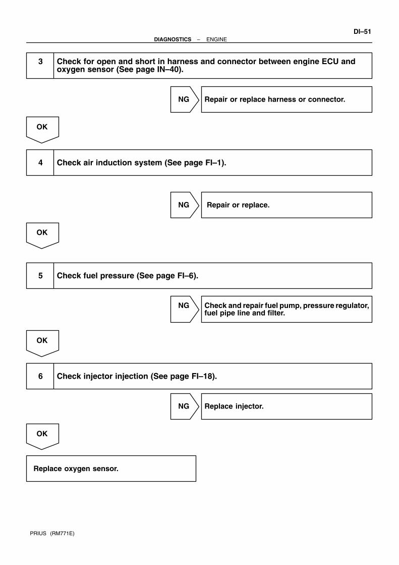
–DIAGNOSTICS ENGINEDI–51
PRIUS (RM771E)
3 Check for open and short in harness and connector between engine ECU andoxygen sensor (See page IN–40).
NG Repair or replace harness or connector.
OK
4 Check air induction system (See page FI–1).
NG Repair or replace.
OK
5 Check fuel pressure (See page FI–6).
NG Check and repair fuel pump, pressure regulator,fuel pipe line and filter.
OK
6 Check injector injection (See page FI–18).
NG Replace injector.
OK
Replace oxygen sensor.

DI–52–DIAGNOSTICS ENGINE
PRIUS (RM771E)
7 Perform confirmation driving pattern.
Go
8 Is there DTC P0130 being output again?
NO Check for intermittent problems (See page DI–3).
YES
Check and replace engine ECU (See page IN–40).

–DIAGNOSTICS ENGINEDI–53
PRIUS (RM771E)
DTC P0133 Oxygen Sensor Circuit Slow Response(Bank 1 Sensor 1)
CIRCUIT DESCRIPTIONRefer to DTC P0125 on page DI–44.
DTC No. DTC Detecting Condition Trouble Area
P0133
Response time for oxygen sensor voltage output to change
from rich to lean, or from lean to rich, is 0.4 sec. or more during
constant vehicle speed after engine is warmed up
(2 trip detection logic)
Air induction system
Fuel pressure
Injector injection
Open or short in heated oxygen sensor circuit
Oxygen sensor
Engine ECU
HINT:6 ) ) * ) ) %,) * #& 0+/
WIRING DIAGRAMRefer to DTC P0125 on page DI–44.
INSPECTION PROCEDUREHINT:Read freeze frame data using hand–held tester. Because freeze frame records the engine conditions whenthe malfunction is detected, when troubleshooting it is useful for determining whether the vehicle was run-ning or stopped, the engine warmed up or not, the air–fuel ratio lean or rich, etc. at the time of the malfunction.
1 Are there any other codes (besides DTC P0133) being output?
YES Go to relevant DTC chart (See page DI–14).
NO
DI57S–10

A00292
OK NG NG NG
1 V
0.48 V
0.42 V
0 V
DI–54–DIAGNOSTICS ENGINE
PRIUS (RM771E)
2 Check output voltage of oxygen sensor during idling.
PREPARATION:Warm up the oxygen sensor with the engine speed at 2,500 rpm for approx. 90 sec.CHECK:Use the hand–held tester to read the output voltage of the heated oxygen sensor during idling.OK:
Oxygen sensor output voltage:Alternates repeatedly between less than 0.42 V and more than 0.48 V (See the following table).
OK Go to step 7.
NG
3 Check for open and short in harness and connector between engine ECU andoxygen sensor (See page IN–40).
NG Repair or replace harness or connector.
OK
4 Check air induction system (See page FI–1).
NG Repair or replace.
OK

–DIAGNOSTICS ENGINEDI–55
PRIUS (RM771E)
5 Check fuel pressure (See page FI–6).
NG Check and repair fuel pump, pressure regulator,fuel pipe line and filter (See page FI–1).
OK
6 Check injector injection (See page FI–21).
NG Replace injector.
OK
Replace oxygen sensor.
7 Perform confirmation driving pattern (See page DI–49).
GO
8 Is there DTC P0133 being output again?
NO Check for intermittent problems(See page DI–3).
YES
Check and replace engine ECU (See page IN–40).

A13626
ONHT1A
(+)(–)
HT1B
DI–56–DIAGNOSTICS ENGINE
PRIUS (RM771E)
DTC P0135 Oxygen Sensor Heater Circuit Malfunction (Bank 1 Sensor 1)
DTC P0141 Oxygen Sensor Heater Circuit Malfunction (Bank 1 Sensor 2)
CIRCUIT DESCRIPTIONRefer to DTC P0125 on page DI–44.
DTC No. DTC Detecting Condition Trouble Area
P0135
When the heater operates, heater current exceeds 2 A
(2 trip detection logic) Open or short in heater circuit of oxygen sensor
O h tP0135
P0141 Heater current of 0.2 A or less when the heater operates
(2 trip detection logic)
Oxygen sensor heater
Engine ECU
WIRING DIAGRAMRefer to DTC P0125 on page DI–44.
INSPECTION PROCEDUREHINT:Read freeze frame data using hand–held tester. Because freeze frame records the engine conditions whenthe malfunction is detected, when troubleshooting it is useful for determining whether the vehicle was run-ning or stopped, the engine warmed up or not, the air–fuel ratio lean or rich, etc. at the time of the malfunction.
1 Check voltage between terminals HT1A, HT1B of engine ECU connector andbody ground.
PREPARATION:(a) Remove the engine ECU with connector still connected
(See page FI–58).(b) Turn the ignition switch ON.CHECK:Measure voltage between terminals HT1A, HT1B of the engineECU connector and body ground.HINT:OK:
Voltage: 9 – 14 V
OK Check and replace engine ECU(See page IN–40).
NG
DI2S8–10

–DIAGNOSTICS ENGINEDI–57
PRIUS (RM771E)
2 Check resistance of oxygen sensor heater (See page FI–54).
NG Replace oxygen sensor.
OK
Check and repair harness or connector between main relay and oxygen sensor and engine ECU (See page IN–40).

A09300
Vehicle speed
40 km/h(25 mph)
Idling(c)
(d)
(e)
(a)
IG SW OFF
(b)
(e)
60 sec.or more
(d) (d)
Once40 sec.or more
Twice40 sec.or more
Nine times40 sec.or more
10 sec. 10 sec.
(e)
10 sec.
DI–58–DIAGNOSTICS ENGINE
PRIUS (RM771E)
DTC P0136 Oxygen Sensor Circuit Malfunction (Bank 1Sensor 2)
CIRCUIT DESCRIPTIONRefer to DTC P0125 on page DI–44.
DTC No. DTC Detecting Condition Trouble Area
P0136
Voltage output of heated oxygen sensor remains at 0.45 V or
more or 0.55 V or less when vehicle is driven at 100 km/h (62
mph) or more after engine is warmed up (2 trip detection logic)
Open or short in heated oxygen sensor circuit
Oxygen sensor
HINT:6 ) ) * ) ) "* "7"/ * #& 0+/
WIRING DIAGRAMRefer to DTC P0125 on page DI–44.
CONFIRMATION DRIVING PATTERN
(a) Connect the hand–held tester to the DLC3.(b) Switch the hand–held tester from the Normal Mode to the Check (Test) Mode (See page DI–3).(c) Start the engine and let the engine idle for 60 seconds or more.(d) Drive the vehicle at 40 km/h (25 mph) or more for 40 seconds or more.(e) Let the engine idle for 10 seconds or more.(f) Preform steps (d) to (e) 9 times.HINT: During performing the step (d) to (e) 9 times, drive the vehicle at over 90 km (56 mile) and make the
fuel cut happen for over 3 sec. If a malfunction exists, the CHK ENG warning light will be indicated on the multi information display
during step (f).NOTICE:If the conditions in this test are not strictly followed, detection of the malfunction will not be possible.If you do not have a hand–held tester, turn the ignition switch OFF after performing steps (c) to (f),then perform steps (c) to (f) again.
DI68O–06

–DIAGNOSTICS ENGINEDI–59
PRIUS (RM771E)
INSPECTION PROCEDUREHINT:Read freeze frame data using hand–held tester. Because freeze frame records the engine conditions whenthe malfunction is detected, when troubleshooting it is useful for determining whether the vehicle was run-ning or stopped, the engine warmed up or not, the air–fuel ratio lean or rich, etc. at the time of the malfunction.
1 Are there any other codes (besides DTC P0136) being output?
YES Go to relevant DTC chart (See page DI–14).
NO
2 Check for open and short in harness and connector between engine ECU andoxygen sensor (See page IN–40).
NG Repair or replace harness or connector.
OK
3 Check output voltage of oxygen sensor.
PREPARATION:(a) Connect the hand–held tester to the DLC3.(b) Warm up the engine to normal operating temperature.CHECK:Read voltage output of the oxygen sensor when the engine suddenly raced.HINT:Perform quick racing to 4,000 rpm 3 min. using the accelerator pedal.OK:
Oxygen sensor output voltage: Alternates from 0.4 V or less to 0.5 V or more.
OK Check that each connector is properly con-nected.
NG
Replace oxygen sensor.

DI–60–DIAGNOSTICS ENGINE
PRIUS (RM771E)
DTC P0171 System too Lean (A/F Lean Malfunction,Bank 1)
DTC P0172 System too Rich (A/F Rich Malfunction,Bank 1)
CIRCUIT DESCRIPTIONFuel trim refers to the feedback compensation value compared to the basic injection time. Fuel trim includesshort–term fuel trim and long–term fuel trim.Short–term fuel trim is the short–term fuel compensation used to maintain the air–fuel ratio at its idealtheoretical value. The signal from the heated oxygen sensor indicates whether the air–fuel ratio is RICH orLEAN compared to the ideal theoretical value, triggering a reduction in fuel volume if the air–fuel ratio is rich,and an increase in fuel volume if it is lean.Long–term fuel trim is overall fuel compensation carried out long–term to compensate for continual deviationof the short–term fuel trim form the central value due to individual engine differences, wear overtime andchanges in the usage environment.If both the short–term fuel trim and long–term fuel trim are LEAN or RICH beyond a certain value, it is de-tected as a malfunction and the CHK ENG warning light on the multi information display.
DTC No. DTC Detecting Condition Trouble Area
P0171
When air–fuel ratio feedback is stable after engine warming up,
fuel trim is considerably in error on LEAN side
(2 trip detection logic)
Air induction system
Injector blockage
Vacuum sensor
Water temp. sensor
Fuel pressure
Gas leakage on exhaust system
Open or short in oxygen sensor (bank 1 sensor 1)
Oxygen sensor (bank 1 sensor 1)
Engine ECU
P0172
When air–fuel ratio feedback is stable after engine warming up,
fuel trim is considerably in error on RICH side
(2 trip detection logic)
Injector leak, blockage
Vacuum sensor
Water temp. sensor
Ignition system
Fuel pressure
Gas leakage on exhaust system
Open or short in oxygen sensor (bank 1 sensor 1)
Oxygen sensor (bank 1 sensor 1)
Engine ECU
HINT: When the DTC P0171 is recorded, the actual air–fuel ratio is on the LEAN side. When DTC P0172 is
recorded, the actual air–fuel ratio is on the RICH side. If the vehicle runs out of fuel, the air–fuel ratio is LEAN and DTC P0171 is recorded. The CHK ENG
warning light then comes on. If the total of the short–term fuel trim value and long–term fuel trim value is within 38 %, the system
is functioning normally. The oxygen sensor (bank 1 sensor 1) output voltage and the short–term fuel trim value can be read
using the hand–held tester.
DI63Y–02

–DIAGNOSTICS ENGINEDI–61
PRIUS (RM771E)
WIRING DIAGRAMRefer to DTC P0125 on page DI–44.
INSPECTION PROCEDUREHand–held tester:HINT:Read freeze frame data using hand–held tester. Because freeze frame records the engine conditions whenthe malfunction is detected. When troubleshooting it is useful for determining whether the vehicle was run-ning or stopped, the engine was warmed up or not, the air–fuel ratio was lean or rich, etc. at the time of themalfunction.
1 Check air induction system (See page FI–1).
NG Repair or replace.
OK
2 Check injector injection (See page FI–18).
NG Replace injector.
OK
3 Check air flow meter (See page FI–30) and water temperature sensor (See pageFI–50).
NG Repair or replace.
OK
4 Check for spark and ignition (See page IG–1).
NG Repair or replace.
OK

A00292
OK NG NG NG
1 V
0.55 V
0.4 V
0 V
DI–62–DIAGNOSTICS ENGINE
PRIUS (RM771E)
5 Check fuel pressure (See page FI–6).
NG Check and repair fuel pump, pressure regulator,fuel pipe line and filter.
OK
6 Check gas leakage on exhaust system.
NG Repair or replace.
OK
7 Check output voltage of oxygen sensor (bank 1 sensor 1) during idling.
PREPARATION:Warm up the oxygen sensor with the engine speed at 2,500 rpm for approx. 90 sec.CHECK:Used the hand–held tester to read the output voltage of the oxygen sensor during idling.OK:
Oxygen sensor output voltage:Alternates repeatedly between less than 0.4 V and more than 0.5 V (See the following table).
OK Go to step 9.
NG

–DIAGNOSTICS ENGINEDI–63
PRIUS (RM771E)
8 Check for open and short in harness and connector between engine ECU andoxygen sensor (bank 1 sensor 1) (See page IN–40).
NG Repair or replace harness or connector.
OK
Replace oxygen sensor.
9 Perform confirmation driving pattern (See page DI–49).
Go
10 Is there DTC P0171 or P0172 being output again?
YES Check and replace engine ECU (See page IN–40).
NO
11 Did vehicle runs out of fuel in past?
NO Check for intermittent problems (See page DI–20).
YES
DTC P0171 or P0172 is caused by running out of fuel.

DI–64–DIAGNOSTICS ENGINE
PRIUS (RM771E)
OBD scan tool (excluding hand–held tester):
1 Check air induction system (See page FI–1).
NG Repair or replace.
OK
2 Check fuel pressure (See page FI–6).
NG Check and repair fuel pump, fuel pipe line andfilter (See page FI–27).
OK
3 Check injector injection (See page FI–21).
NG Replace injector.
OK
4 Check air flow meter sensor (See page FI–30) and water temperature sensor (Seepage FI–50).
NG Repair or replace.
OK
5 Check for spark and ignition (See page IG–1).
NG Repair or replace.
OK

–DIAGNOSTICS ENGINEDI–65
PRIUS (RM771E)
6 Does malfunction disappear when a good oxygen sensor (bank 1 sensor 1)installed?
YES Repair oxygen sensor.
NO
Check and replace engine ECU (See pageIN–40).

DI–66–DIAGNOSTICS ENGINE
PRIUS (RM771E)
DTC P0300 Random/Multiple Cylinder Misfire Detected
DTC P0301 Cylinder 1 Misfire Detected
DTC P0302 Cylinder 2 Misfire Detected
DTC P0303 Cylinder 3 Misfire Detected
DTC P0304 Cylinder 4 Misfire Detected
CIRCUIT DESCRIPTIONMisfire: The engine ECU uses the crankshaft position sensor and camshaft position sensor to monitorchanges in the crankshaft rotation for each cylinder.The engine ECU counts the number of times the engine speed change rate indicates that misfire has oc-curred. And when the misfire rate equals or exceeds the count indicating that the engine condition has deteri-orated, the check engine warning light lights up.If the misfire rate is high enough and the driving conditions will cause catalyst overheating, the check enginewarning light blinks when misfiring occurs.
DTC No. DTC Detecting Condition Trouble Area
P0300Misfiring of random cylinders is detected during any particular
200 or 1,000 revolutions
Ignition system
Injector
F l
P0301
For any particular 200 revolutions for engine, misfiring is de-
tected which can cause catalyst overheating
(This causes MIL to blink) (2 trip detection logic)
Fuel pressure
Compression pressure
Valve clearance
Valve timingP0302
Valve timing
Air flow meterP0302
P0303Air flow meter
W t tP0303
P0304For any particular 1,000 revolutions of engine, misfiring is de- Water temp. sensor
P0304For any articular 1,000 revolutions of engine, misfiring is de
tected which causes a deterioration in emissions Open or short in engine wiretected which causes a deterioration in emissions
(2 trip detection logic)
O en or short in engine wire
Connectorconnection(2 trip detection logic) Connector connectiongEngine ECU
HINT: When the 2 or more codes for a misfiring cylinder are recorded repeatedly but no random misfire code
is recorded, it indicates that the misfires were detected and recorded at different times. There is a case where the cylinder other than memorized has an accidental fire (the cylinder which is
one ahead of fired cylinder), so. at the time of checking all the checking items and if there is no ab-normality, check the cylinder which is different from the recorded cylinder as fired.
DI12T–12

A14026
Battery
FL Block No. 1
F13
A
B
1K
1
AM2
Engine RoomJ/B W–R
7
1
1A
IE
5
6
Instrument Panel J/B
6
5
B–R
IG2
B–G
R–WB–W
B–W
W–B (LHD)
B–W
B–W
I5 Injector No. 1
1
2C
1
2
1 2
1
2
J1 J/C
B–W
L–W1
9
2G
2B
E8
E8
E7
E7
Engine ECU
#10
#20
#30
#40
Y
11
3
Ignition SW
W–B
1J
1
2
F12
A
MAIN
I6 Injector No. 2
I7 Injector No. 3
I8 Injector No. 4
FL Block No. 2
1J
1B
AM2
A
A
W–B (LHD)
W–B (RHD)
3
2G
2
2
2
J7 J/C
B–W
B–W
B–W
B–W
B–W
W–RIG2 Relay
2
2 1
3 5
–DIAGNOSTICS ENGINEDI–67
PRIUS (RM771E)
WIRING DIAGRAM

DI–68–DIAGNOSTICS ENGINE
PRIUS (RM771E)
CONFIRMATION DRIVING PATTERN(a) Connect the hand–held tester.(b) Record DTC and the freeze frame data.(c) Use the hand–held tester to set to Check Mode (See page DI–3).(d) Drive the vehicle several times with the engine speed, load and its surrounding range shown with EN-
GINE SPD, CALC LOAD in the freeze frame data or MISFIRE RPM, MISFIRE LOAD in the data list.If you have no hand–held tester, turn the ignition switch OFF after the symptom is simulated the first time.Then repeat the simulation process again.HINT:In order to memorize DTC of misfire, it is necessary to drive around MISFIRE RPM, MISFIRE LOAD in thedata list for the following period of time.
Engine Speed Time
1000 rpm 3 minutes or more
2000 rpm 1 minutes 30 seconds or more
3000 rpm 1 minutes or more
(e) Check whether there is misfire or not by monitoring DTC and the freeze frame data. After that, recordthem.
(f) Turn ignition switch OFF and least 5 seconds.
INSPECTION PROCEDUREHINT: If is the case that DTC besides misfire is memorized simultaneously, first perform the troubleshooting
for them. Read freeze frame data using hand–held tester. Because freeze frame data records the engine condi-
tions when the malfunction is detected, when troubleshooting it is useful for determining whether thevehicle was running or stopped, the engine warmed up or not, the air–fuel ratio lean or rich, etc. at thetime of the malfunction.
When the vehicle is brought to the workshop and the misfire is not occurred, misfire can be confirmedby reproducing the condition or freeze frame data. Also, after finishing the repair, confirm that thereis no misfire. (See the confirmation driving pattern)
When either of SHORT FT #1, LONG FT #1, SHORT FT #2 or LONG FT #2 in the freeze frame datais besides the range of 20 %, there is a possibility that the air–fuel ratio is inclining either to RICH(–20 % or less) or LEAN (+20 % or more).
When COOLANT TEMP in the freeze frame data is less than 80C (176F), there is a possibility ormisfire only during warning up.
In the case that misfire cannot be reproduced, the reason may be because of the driving with lack orfuel, the use of improper fuel, a stain of ignition plug, and etc.

P03792
–DIAGNOSTICS ENGINEDI–69
PRIUS (RM771E)
1 Check wire harness, connector and vacuum hose in engine room.
CHECK:(a) Check the connection conditions of wire harness and connector.(b) Check the disconnection, piping and break or vacuum hose.
NG Repair or replace, then confirm that there is nomisfire (See confirmation driving pattern).
OK
2 Check spark plug and spark of misfiring cylinder.
PREPARATION:Remove the spark plug (See page IG–1).CHECK:(a) Check the electrode of carbon deposits electrode.(b) Check the electrode gap.OK:
(a) No large carbon deposit present.Not wet with gasoline or oil.(b) Electrode gap: 1.0 – 1.2 mm (0.037 – 0.047 in.)
PREPARATION:(a) Install the spark plug to the ignition coil.(b) Disconnect the injector connector.(c) Ground the spark plug.CHECK:Check if spark occurs while the engine is being cracked.NOTICE:To prevent excess fuel being injected from the injectorsduring this test, don’t crank the engine for more than 5 – 10seconds at a time.OK:
Spark jumps across electrode gap.
NG Replace or check ignition system (See page IG–1).
OK

A13627
ON#10
(+) (–)
#20#30#40
FI6588 FI6538
A00064
10 V/Division
GND
10 V/Division
100 msec./Division (Idling)
GND
(Magnification)
1 msec./Division (Idling)Injection duration
Injector Signal Waveform
DI–70–DIAGNOSTICS ENGINE
PRIUS (RM771E)
3 Check voltage of engine ECU terminals for injector of failed cylinder.
PREPARATION:(a) Remove the engine ECU with connector still connected
(See page FI–58).(b) Turn the ignition switch ON.CHECK:Measure voltage between applicable terminal of the engineECU connector and body ground.OK:
Voltage: 9 – 14 V
Reference: INSPECTION USING OSCILLOSCOPEWith the engine idling, measure between terminals #10 – #40 and E01 of the engine ECU connector.HINT:The correct waveforms are as shown.
OK Go to step 4.
NG

–DIAGNOSTICS ENGINEDI–71
PRIUS (RM771E)
4 Check resistance of injector of misfiring cylinder (See page FI–18).
NG Replace injector.
OK
Check for open and short in harness and con-nector between injector and engine ECU (Seepage IN–40).
5 Check fuel pressure (See page FI–6).
NG Check and repair fuel pump, pressure regulator,fuel pipe line and filter (See page FI–1).
OK
6 Check injector injection (See page FI–21).
NG Replace injector.
OK
7 Check mass air flow meter and water temp. sensor (See pages FI–30 and FI–50).
NG Repair or replace.
OK
Check compression pressure, valve clear-ance and valve timing.

A14027
K1Knock Sensor
Engine ECU
KNK128E8
1B
BR
EB
(Shielded)
EA1
J8 J/C
1
ABR
A
B
DI–72–DIAGNOSTICS ENGINE
PRIUS (RM771E)
DTC P0325 Knock Sensor Circuit Malfunction
CIRCUIT DESCRIPTION
Knock sensor are fitted to the cylinder block to detect engine knocking. This sensor contains a piezoelectricelement which generates a voltage when it becomes deformed, which occurs when the cylinder block vi-brates due to knocking. If engine knocking occurs, ignition timing is retarded to suppress it.
DTC No. DTC Detecting Condition Trouble Area
P0325No knock sensor signal to engine ECU with engine speed
1,280 rpm or more
Open or short in knock sensor circuit
Knock sensor (looseness)
Engine ECU
WIRING DIAGRAM
DI4EA–09

A13628E8 Connector
KNK
LOCK
A00068
KNK Signal Waveform0.5 V/ Division
0.5 V/ Division
0 V
0 V
5 msec./Division
200 µsec./Division
–DIAGNOSTICS ENGINEDI–73
PRIUS (RM771E)
INSPECTION PROCEDURE
HINT:Read freed frame data using hand–held tester. Because freeze frame records the engine conditions whenthe malfunction is detected, when troubleshooting it is useful for determining whether the vehicle was run-ning or stopped, the engine warmed up or not, the air–fuel ratio lean or rich, etc. at the time of the malfunction.
1 Check continuity between terminal KNK1 of engine ECU connector and bodyground.
PREPARATION:(a) Remove the engine ECU with connector still connected
(See page FI–58).(b) Disconnect the E8 connector of engine ECU.CHECK:Measure resistance between terminal KNK1 of engine ECUconnector and body ground.OK:
Resistance: 1 MΩ or higher
Reference: INSPECTION USING OSCILLOSCOPE With the engine racing (4,000 rpm) measure between ter-
minal KNK1 of engine ECU and body ground.HINT:The correct waveform is as shown.
Spread the time on the horizontal axis, and confirm thatperiod of the wave is 151 µsec.(Normal mode vibration frequency of knock sensor:8.1 kHz).
HINT:If normal mode vibration frequency is not 8.1 kHz the sensor ismalfunctioning.
OK Go to step 3 .
NG

DI–74–DIAGNOSTICS ENGINE
PRIUS (RM771E)
2 Check knock sensor (See page FI–52).
NG Replace knock sensor.
OK
3 Check for open and short in harness and connector between engine ECU andknock sensor (See page IN–40).
NG Repair or replace harness or connector.
OK
4 Does malfunction disappear when a good knock sensor is installed?
YES Replace knock sensor.
NO
Check and replace engine ECU(See page IN–40).

A14028
1
2
RE7
J/C
J8
NE+
NE–
C1Camshaft Position Sensor
2
1C6 Crankshaft Position Sensor
E8
E8
BR
G
EB
Engine ECU
BR
BR
G2
J8
J9
R
G
AA
A
24
16
10(Shielded)
(Shielded)
G
–DIAGNOSTICS ENGINEDI–75
PRIUS (RM771E)
DTC P0335 Crankshaft Position Sensor Circuit Malfunction
CIRCUIT DESCRIPTION
Crankshaft position sensor (NE signal) consist of a signal plate and pick up coil.The NE signal plate has 34 teeth and is mounted on the crankshaft. The NE signal sensor generates 34signals of every engine revolution. The engine ECU detects the standard crankshaft angle based on the G2signals, and the actual crankshaft angle the engine speed by the NE signals.
DTC No. DTC Detecting Condition Trouble Area
No crankshaft position sensor signal to engine ECU during Open or short in crankshaft position sensor circuitNo crankshaft position sensor signal to engine ECU during
ki
O en or short in crankshaft osition sensor circuit
Crankshaft position sensorP0335 cranking Crankshaft position sensor
StarterOpen in NE– circuit
Starter
Engine ECU
WIRING DIAGRAM
DI4EB–09

A14463
G2+, NE Signal Waveforms
5 V/ DivisionG2
NE
20 msec./Division (Idling)
DI–76–DIAGNOSTICS ENGINE
PRIUS (RM771E)
INSPECTION PROCEDURE
HINT: Read freed frame data using hand–held tester. Because freeze frame records the engine conditions
when the malfunction is detected, when troubleshooting it is useful for determining whether the vehiclewas running or stopped, the engine warmed up or not, the air–fuel ratio lean or rich, etc. at the timeof the malfunction.
Perform troubleshooting of DTC P0335 first. If no trouble is found, troubleshoot the following mechani-cal system.
1 Check resistance of crankshaft position sensor (See page IG–13).
Reference: INSPECTION USING OSCILLOSCOPEDuring cranking or idling, check between terminals G2 andNE–, NE+ and NE– of engine ECU.HINT:The correct waveforms are as shown.
NG Replace crankshaft position sensor.
OK
2 Check for open and short in harness and connector between engine ECU and crankshaft position sensor (See page IN–40).
NG Repair or replace harness or connector.
OK

–DIAGNOSTICS ENGINEDI–77
PRIUS (RM771E)
3 Inspect sensor installation and teeth of signal plate.
NG Tighten the sensor. Replace signal plate.
OK
Check and replace engine ECU(See page IN–40).

A14463
G2+, NE Signal Waveforms
5 V/ DivisionG2
NE
20 msec./Division (Idling)
DI–78–DIAGNOSTICS ENGINE
PRIUS (RM771E)
DTC P0340 Camshaft Position Sensor CircuitMalfunction
CIRCUIT DESCRIPTION
Camshaft position sensor (G2 signal) consist of a signal plate and pick up coil. The G2 signal plate has onetooth on its outer circumference and is mounted on the camshaft.When the camshafts rotate, the protrusion on the signal plate and the air gap on the pick up coil change,causing fluctuations in the magnetic field and generating an electromotive force in the pick up coil.The NE signal plate has 34 teeth and is mounted on the crankshaft. The NE signal sensor generates 34signals for every engine revolution. The engine ECU detects the standard crankshaft angle based on theG2+ signals and the actual crankshaft angle and the engine speed by the NE signals.
DTC No. DTC Detecting Condition Trouble Area
P0340
No camshaft position sensor signal to engine ECU during
cranking
Open or short in camshaft position sensor circuit
Camshaft position sensorP0340
StarterOpen in NE circuit
StarterOpen in NE– circuit
Engine ECUO en in NE circuitEngine ECU
WIRING DIAGRAM
Refer to DTC P0335 on page DI–75.
INSPECTION PROCEDURE
HINT:Read freed frame data using hand–held tester. Because freeze frame records the engine conditions whenthe malfunction is detected, when troubleshooting it is useful for determining whether the vehicle was run-ning or stopped, the engine warmed up or not, the air–fuel ratio lean or rich, etc. at the time of the malfunction.
1 Check resistance of camshaft position sensor (Signal generator) (See page IG–1).
Reference: INSPECTION USING OSCILLOSCOPEDuring cranking or idling, check between terminals G2 andNE–, NE+ and NE– of engine ECU.HINT:The correct waveforms are as shown.
NG Replace camshaft position sensor.
OK
DI4EC–04

–DIAGNOSTICS ENGINEDI–79
PRIUS (RM771E)
2 Check for open and short in harness and connector between engine ECU andcamshaft position sensor (See page IN–40).
NG Repair or replace harness or connector.
OK
3 Inspect sensor installation.
NG Tighten the sensor.
OK
Check and replace engine ECU(See page IN–40).

FI7081
Waveform of Oxygen Sensorbefore Catalyst
Normal Catalyst Waveform of Oxygen Sensorafter Catalyst
FI7132
Vehicle Speed
89 km/h (55 mph)
OIG SW OFF
(1)
TimeWarmed up Check
(2)
(3) (4)
Warmed up5 min. or more
Idling
DI–80–DIAGNOSTICS ENGINE
PRIUS (RM771E)
DTC P0420 Catalyst System Efficiency Below Threshold(Bank 1)
CIRCUIT DESCRIPTIONThe engine ECU compares the waveform of the oxygen sensor located before the catalyst with the waveformof the oxygen sensor located after the catalyst to determine whether or not catalyst performance has deterio-rated.Air–fuel ratio feedback compensation keeps the waveform of the oxygen sensor before the catalyst repeat-edly changing back and forth from rich to lean.If the catalyst is functioning normally, the waveform of the oxygen sensor after the catalyst switches backand forth between rich and lean much more slowly than the waveform of the oxygen sensor before the cata-lyst.But when both waveform change at a similar rate, it indicates that catalyst performance has deteriorated.
DTC No. DTC Detecting Condition Trouble Area
P0420
After engine and catalyst are warmed up, and while vehicle is
driven within set vehicle and engine speed range, waveform of
oxygen sensors have same amplitude (2 trip detection logic)
Gas leakage on exhaust system
Oxygen sensor
Three–way catalytic converter
CONFIRMATION ENGINE RACING PATTERN
(1) Connect the hand–held tester to the DLC3, or connect the probe of the oscilloscope betweenterminals OX1A, OX1B, and E1 of the engine ECU connectors.
DI643–03

A14462
OX Signal Waveform (Oscilloscope)
1.0 V
0 V500 msec./Division
0 V
1.0 V
–DIAGNOSTICS ENGINEDI–81
PRIUS (RM771E)
(2) Start the engine and warm it up with all the accessories switched OFF until engine coolant tem-perature is stable.
(3) Drive the vehicle at 89 km/h (55 mph) or more for 5 min. or more.(4) After confirming that the waveform of the oxygen sensor (bank 1 sensor 1) (OX1A), oscillate
around 0.5 V during feedback to the engine ECU, check the waveform of the oxygen sensor(bank 1 sensor 2) (OX1B).
HINT:If there is a malfunction in the system, the waveform of the oxy-gen sensor (bank 1 sensor 2) (OX1B) is as shown on the left.There are some cases where, even though a malfunction ex-ists, the CHK ENG warning light may either light up or not lightup.
INSPECTION PROCEDUREHINT:Read freeze frame data using hand–held tester. Because freeze frame records the engine conditions whenthe malfunction is detected. When troubleshooting it is useful for determining whether the vehicle was run-ning or stopped, the engine was warmed up or not, the air–fuel ratio was lean or rich, etc. at the time of themalfunction.
1 Are there any other codes (besides P0420) being output?
YES Go to relevant DTC chart (See page DI–14).
NO
2 Check gas leakage on exhaust system.
NG Repair or replace.
OK

DI–82–DIAGNOSTICS ENGINE
PRIUS (RM771E)
3 Check oxygen sensor (bank 1 sensor 1) (See page FI–54).
NG Repair or replace.
OK
4 Check oxygen sensor (bank 1 sensor 2) (See page FI–54).
NG Repair or replace.
OK
Replace three–way catalytic converter.

A14029
Engine ECU
MREL
EVP1
25E9
E7
VSV (EVAP)
3
V1
29
G–R
1B
F18
W–B(LHD)
5 3 B
B–G
EFI
Battery
2
1K
1A
1F
1
EFI Relay
Engine Room J/B
1
IE
12
2
J7J/C
A
A
W–B
W–B(RHD)
A
Fusible Link Block No. 1
1B
R–L
J1J/C
A
3
Fusible Link Block No. 1
F13 F12
IA24
G–R
2 1
1
MAIN
W–B (LHD)
–DIAGNOSTICS ENGINEDI–83
PRIUS (RM771E)
DTC P0443 Evaporative Emission Control System PurgeControl Vent Control Malfunction
CIRCUIT DESCRIPTIONTo reduce HC emissions, evaporated fuel from the fuel tank is routed through the charcoal canister to theintake manifold for combustion in the cylinders.The engine ECU changes the duty signal to the VSV for the EVAP so that the intake quantity of HC emissionsis appropriate for the driving conditions (engine load, engine speed, vehicle speed, etc.) after the engine iswamed up.
DTC No. DTC Detecting Condition Trouble Area
P0443 Proper response to engine ECU command does not occur
Open or short in VSV circuit for EVAP
VSV for EVAP
Engine ECU
WIRING DIAGRAM
DI644–05

A12550
ON
F
E E
F
VSV is ON VSV is OFFAir Air
DI–84–DIAGNOSTICS ENGINE
PRIUS (RM771E)
INSPECTION PROCEDUREHand–held tester:HINT:Read freeze frame data using hand–held tester. Because freeze frame records the engine conditions whenthe malfunction is detected. When troubleshooting it is useful for determining whether the vehicle was run-ning or stopped, the engine was warmed up or not, the air–fuel ratio was lean or rich, etc. at the time of themalfunction.
1 Connect hand–held tester and check operation of VSV for EVAP.
PREPARATION:(a) Connect the hand–held tester to the DLC3.(b) Turn the ignition switch ON and push the hand–held tes-
ter main switch ON.(c) Select the ACTIVE TEST mode on the hand–held tester.CHECK:Check the operation of the VSV when the VSV is operated bythe hand–held tester.OK:
VSV is ON:Air from port E flows out through port F.VSV is OFF:Air from port E is flows out through the air filter.
OK Check for intermittent problems (See page DI–3).
NG
2 Check VSV for EVAP (See page FI–48).
NG Replace VSV for EVAP.
OK
3 Check for open and short in harness and connector between EFI main relay andengine ECU (See page IN–40).
NG Repair or replace harness or connector.
OK

A13629
ON
EVP1
(+) (–)
–DIAGNOSTICS ENGINEDI–85
PRIUS (RM771E)
Check and replace engine ECU (See pageIN–40).
OBD scan tool (excluding hand–held tester):
1 Check VSV for EVAP (See page FI–48).
NG Replace VSV for EVAP.
OK
2 Check voltage between terminal EVP1 of engine ECU connector and bodyground.
PREPARATION:(a) Remove the engine ECU with connector still connected
(See page FI–58).(b) Turn the ignition switch ON.CHECK:Measure the voltage between terminal EVP1 of the engineECU connector and body ground.OK:
Voltage: 9 – 14 V
NG Check for open and short in harness and con-nector between EFI main relay and engine ECU(See page IN–40).
OK
Check and replace engine ECU (See pageIN–40).

A00022
FromSpeed Sensor
4–Pulse 4–Pulse
Combination Meter
ABS ECU ECM
A14030
C10 Combination Meter
Engine ECU
GJ25 E102B2A SPD
5V–WV–W
Instrument Panel J/B
LJ26
G7613
J/C
DI–86–DIAGNOSTICS ENGINE
PRIUS (RM771E)
DTC P0500 Vehicle Speed Sensor Malfunction
CIRCUIT DESCRIPTIONThe vehicle speed sensor outputs a 4–pulse signal for every revolution of the rotor shaft, which is rotatedby the transmission output shaft via the driven gear. After this signal is converted into a more precise rectan-gular waveform by the waveform shaping circuit inside the combination meter, it is then transmitted to theEngine ECU. The EngineECU determines the vehicle speed based on the frequency of these pulse signals.
DTC No. DTC Detecting Condition Trouble Area
P0500
During vehicle is being driven, no vehicle speed sensor signal
to engine ECU
(2 trip detection logic)
Combination meter
Open or short in No. 1 vehicle speed sensor circuit
No. 1 vehicle speed sensor
Engine ECU
WIRING DIAGRAM
DI4ED–08

A14009
SPD
(+)(–)
A07133
4.5 – 5.5 V
0
–DIAGNOSTICS ENGINEDI–87
PRIUS (RM771E)
INSPECTION PROCEDURE
1 Check operation of speedometer.
CHECK:Drive the vehicle and check if the operation of the speedometer in the combination meter is normal.HINT:The ABS ECU is operating normally if the speedometer display is normal.
NG Check and replace combination meter (Seepage BE–46).
OK
2 Check voltage between terminal SPD of engine ECU connector and body ground.
PREPARATION:(a) Remove the engine ECU with connector still connected
(See page FI–58).(b) Drive the vehicle.CHECK:Measure voltage between terminal SPD of the engine ECUconnector and body ground.OK:
Voltage is generated intermittently.
NG Check and repair harness and connector be-tween combination meter and engine ECU.
OK
Check and replace engine ECU(See page IN–40).

DI–88–DIAGNOSTICS ENGINE
PRIUS (RM771E)
DTC P0505 Idle Control System Malfunction
CIRCUIT DESCRIPTIONThe idle speed is controlled by the Electric Throttle Control System (ETCS).ETCS is composed of the throttle motor to operate the throttle valve, the throttle position sensor to detectthe opening angle of the throttle valve, the accelerator pedal position sensor to detect the accelerator pedalposition, the engine ECU to control the ETCS and the one valve type throttle body.The engine ECU controls the throttle motor to make the throttle valve opening angle properly for the targetidle speed.
DTC No. DTC Detecting Condition Trouble Area
P0505Idle speed continues to vary greatly from target speed
(2 trip detection logic)
Air induction system
Electric throttle control system
INSPECTION PROCEDUREHINT:Read freeze frame data using hand–held tester or OBD scan tool. Because freeze frame records the engineconditions when the malfunction is detected. When troubleshooting, it is useful for determining whether thevehicle was running or stopped, the engine was warmed up or not, the air–fuel ratio was lean or rich, etc.at the time of the malfunction.
1 Are there any other codes (besides P0505) being output?
YES Go to relevant DTC chart (See page DI–14).
NO
2 Check air induction system (See page FI–1).
NG Repair or replace.
OK
Check electric throttle control system (Seepage FI–32).
DI2CR–04

A14031
Throttle Control Motorwith magnetic clutch
2
1 P
L8
7
M+
M–
GE01
30
Engine ECU
E7
E7
E7
(Shielded)
–DIAGNOSTICS ENGINEDI–89
PRIUS (RM771E)
DTC P1125 Throttle Control Motor Circuit Malfunction
CIRCUIT DESCRIPTIONThrottle motor is operated by the engine ECU and it opens and closes the throttle valve.The opening angle of the throttle valve is detected by the throttle position sensor which is mounted on thethrottle body and it provides feedback to the engine ECU to control the throttle motor in order to the throttlevalve opening angle properly in response to driving condition.If this DTC is stored, the engine ECU shuts down the power for the throttle motor, and the throttle valve isfully closed by the return spring.
DTC No. DTC Detecting Condition Trouble Area
Condition (a) and (b) continues for 0.5 seconds:
(a) Throttle control motor output duty 80 %
(b) Throttle control motor current < 0.5 A Open or short in throttle control motor circuitP1125
Throttle control motor current 16 AThrottle control motor
Engine ECUUnder condition continue for 0.6 seconds:
Throttle control motor current 7 A
Engine ECU
WIRING DIAGRAM
INSPECTION PROCEDUREHINT:Read freeze frame data using hand–held tester. Because freeze frame records the engine conditions whenthe malfunction is detected. When troubleshooting it is useful for determining whether the vehicle was run-ning or stopped, the engine was warmed up or not, the air–fuel ratio was lean or rich, etc. at the time of themalfunction.
DI7OC–01

A03675
M+ Signal Waveform
5V/
Division
GND
1 m sec./Division
M– Signal Waveform
GND
5V/
Division
1 msec./Division
DI–90–DIAGNOSTICS ENGINE
PRIUS (RM771E)
1 Check throttle control motor circuit.
PREPARATION:(a) Connect the oscilloscope between terminals M+ or M–
and E1 of the engine ECU connector.(b) Start the engine.CHECK:Check the waveform between terminals M+ or M– and E1 of theengine ECU when the engine is idling.OK:
The correct waveforms are as shown.HINT:The waveform frequency varies depending on the throttleopening.
OK Check and replace engine ECU (See page IN–40).
NG
2 Check throttle control motor (See page FI–32).
NG Replace throttle control motor (See page FI–37).
OK
3 Check for open and short in harness and connector between throttle control mo-tor and engine ECU (See page IN–40).
NG Repair or replace.
OK
Check and replace engine ECU (See pageIN–40).

A14032
Engine ECU
E7 +BM6
MAIN
1AB
B–G
Battery
2
1
Engine Room J/BFL Block No. 1
1BF12F131 1
FL Block No. 2
8THROGR
–DIAGNOSTICS ENGINEDI–91
PRIUS (RM771E)
DTC P1127 ETCS Actuator Power Source Circuit Mal-function
CIRCUIT DESCRIPTIONBattery positive voltage is supplied to terminal BM of the engine ECU even once when the ignition switchis OFF for the electric throttle control system.If this DTC is stored, the engine ECU shuts down the power for the throttle motor, and the throttle valve isfully closed by the return spring.
DTC No. DTC Detecting Condition Trouble Area
P1127 Open in ETCS power source circuitOpen in ETCS power source circuit
Engine ECU
WIRING DIAGRAM
INSPECTION PROCEDUREHINT:Read freeze frame data using hand–held tester. Because freeze frame records the engine conditions whenthe malfunction is detected. When troubleshooting it is useful for determining whether the vehicle was run-ning or stopped, the engine was warmed up or not, the air–fuel ratio was lean or rich, etc. at the time of themalfunction.
DI64A–02

A13630
Engine Room J/B
THRO Fuse
A13631
BMLOCK
(+) (–)
DI–92–DIAGNOSTICS ENGINE
PRIUS (RM771E)
1 Check THRO fuse.
PREPARATION:Remove the THRO fuse from the engine room J/B.CHECK:Check the continuity of the THRO fuse.OK:
Continuity
NG Check for short in all harness and componentsconnected to THRO fuse.
OK
2 Check voltage between terminal+ BM of engine ECU connector and bodyground.
PREPARATION:Remove the engine ECU with connector still connected (Seepage FI–58).CHECK:Measure the voltage between terminal+ BM of the engine ECUconnector and body ground.OK:
Voltage: 9 – 14 V
OK Check and replace engine ECU (See page IN–40).
NG
Check and repair harness or connector be-tween battery and ETCS fuse, and ETCS fuseand engine ECU (See page IN–40).

–DIAGNOSTICS ENGINEDI–93
PRIUS (RM771E)
DTC P1128 Throttle Control Motor Lock Malfunction
CIRCUIT DESCRIPTIONThrottle motor is operated by the ECU and it opens and closes the throttle valve. The opening angle of thethrottle valve is detected by the throttle position sensor which is mounted on the throttle body and it providesfeedback to the engine ECU to control the throttle motor in order the throttle valve opening angle properlyin response to driving condition. If this DTC is stored, the engine ECU shuts down the power for the throttlemotor, and the throttle valve is fully closed by the return spring.
DTC No. DTC Detecting Condition Trouble Area
P1128Lock throttle control motor during control throttle
control motor
Throttle control motor
Throttle body
INSPECTION PROCEDUREHINT:Read freeze frame data using hand–held tester. Because freeze frame records the engine conditions whenthe malfunction is detected. When troubleshooting it is useful for determining whether the vehicle was run-ning or stopped, the engine was warmed up or not, the air–fuel ratio was lean or rich, etc. at the time of themalfunction.
1 Check throttle control motor (See page FI–32).
NG Replace throttle control motor (See page FI–37).
OK
2 Visually check throttle valve.
PREPARATION:Remove the air cleaner.CHECK:Check whether or not a foreign body is caught between the throttle valve and the housing.
NG Remove a foreign body and clean throttle body.
OK
Replace throttle body.
DI7OD–01

DI–94–DIAGNOSTICS ENGINE
PRIUS (RM771E)
DTC P1129 Electric Throttle Control System Malfunction
CIRCUIT DESCRIPTIONElectric Throttle Control System (ETCS) is composed of the throttle motor to operate the throttle valve, thethrottle position sensor to detect the opening angle of the throttle valve, the accelerator pedal position sensorto detect the accelerator pedal position, the engIne ECU to control the ETCS and the one valve type throttlebody.The engIne ECU controls the throttle motor to make the throttle valve opening angle properly in responsedriving condition.The throttle position sensor which is mounted on the throttle body detects the opening angle of the throttlevalve, and it provides feedback to the engIne ECU to control the throttle motor.If the ETCS has a malfunction, the engIne ECU shuts down the power for the throttle motor, and the throttlevalve is fully closed by the return spring.
DTC No. DTC Detecting Condition Trouble Area
P1129Throttle opening angle continues to vary great from target
throttle opening angle
Electric throttle control system
EngIne ECU
WIRING DIAGRAMRefer to DTC P1125 on page DI–89.
INSPECTION PROCEDUREHINT:Read freeze frame data using hand–held tester. Because freeze frame records the engine conditions whenthe malfunction is detected. When troubleshooting it is useful for determining whether the vehicle was run-ning or stopped, the engine was warmed up or not, the air–fuel ratio was lean or rich, etc. at the time of themalfunction.
1 Are there any other codes (besides DTC P1129) being output?
YES Go to relevant DTC chart (See page DI–14).
NO
Replace engIne ECU, and clear DTC. If DTC P1129/89 is memorized again, and then replacethrottle body.
DI64C–02

–DIAGNOSTICS ENGINEDI–95
PRIUS (RM771E)
DTC P1300 Igniter Circuit Malfunction (No. 1)
DTC P1305 Igniter Circuit Malfunction (No. 2)
DTC P1310 Igniter Circuit Malfunction (No. 3)
DTC P1315 Igniter Circuit Malfunction (No. 4)
CIRCUIT DESCRIPTIONA Direct Ignition System (DIS) has been adopted. The DIS improves the ignition timing accuracy, reduceshigh–voltage loss, and enhances the the overall reliability of the ignition system by eliminating the distributor.The DIS is a 1–cylinder ignition system which ignites one cylinder with one ignition coil. In the 1–cylinderignition system, the one spark plug is connected to the end of the secondary winding. High voltage generatedin the secondary winding is applied directly to the spark plug. The spark of the spark plug pass from the centerelectode to the ground electrode.The engine ECU determines ignition timing and outputs the ignition signals (IGT) for each cylinder. Basedon IGT signals, the power transistors in the igniter cuts off the current to the primary coil in the ignition coilis supplied to the spark plug that are connected to the end of the secondary coil. At the same time, the igniteralso sends an ignition confirmation signal (IGF) as a fail–safe measure to the engine ECU.
DI68S–04

A09058
Engine ECUNo. 1 Ignition Coil with Igniter
Crankshaft Position Sensor
CamshaftPositionSensor
VariousSensor
No. 2 Ignition Coil with Igniter
No. 3 Ignition Coil with Igniter
No. 4 Ignition Coil with Igniter
TAC
To Tachometer
From Battery
Igniter
Ignition CoilSpark Plug
No. 1 Cylinder
No. 2 Cylinder
No. 3 Cylinder
No. 4 Cylinder
IGT1
IGF
IGT2
IGT3
IGT4
DI–96–DIAGNOSTICS ENGINE
PRIUS (RM771E)
DTC No. DTC Detecting Condition Trouble Area
P1300
P1305
P1310
P1315
No IGF signal to engine ECU while engine is running
Open or short in IGF and IGT1 – 4 circuit from
ignition coil with igniter
No. 1 – No. 4 ignition coil with igniter
Engine ECU
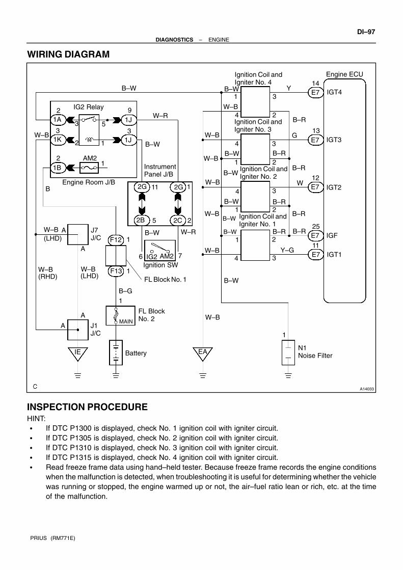
A14033
Ignition SW
Instrument Panel J/B
Engine Room J/B
FL Block No. 2
Battery
AM2
1
2
Engine ECU
N1 Noise Filter
MAIN
IGT4
IGT3
IGT2
IGF
IGT1
12
E7
3
25
E7
E7
E7
E7
EA
11
3
IE
1
11
1A
1K 1J
1B
B 1
7
B–R
B–R
B–R
B–R
B–R
B–W
B–W B–R
Y–G
W–B
B–G
W–B
W–B
W–B
1
1
1
1
B–R
Y
9
A
W
G
2
2
2
3
2
3
3
3
4
4
4
4
Ignition Coil andIgniter No. 1
Ignition Coil andIgniter No. 2
Ignition Coil andIgniter No. 3
Ignition Coil andIgniter No. 4
F13
(LHD)J7 J/C
W–B
W–R
F12
2
6
5
13
14
B–W
B–W
B–W
1J
IG2
IG2 Relay
2B 2C
2G2G
2
W–R
B–W
1
1
(RHD)
J1 J/C
W–B(LHD)
A
W–B
W–B
W–B
B–WB–W
FL Block No. 1
W–B
W–B
AM2
1
12
3 5
A
A
B–W
B–W
–DIAGNOSTICS ENGINEDI–97
PRIUS (RM771E)
WIRING DIAGRAM
INSPECTION PROCEDUREHINT: If DTC P1300 is displayed, check No. 1 ignition coil with igniter circuit. If DTC P1305 is displayed, check No. 2 ignition coil with igniter circuit. If DTC P1310 is displayed, check No. 3 ignition coil with igniter circuit. If DTC P1315 is displayed, check No. 4 ignition coil with igniter circuit. Read freeze frame data using hand–held tester. Because freeze frame records the engine conditions
when the malfunction is detected, when troubleshooting it is useful for determining whether the vehiclewas running or stopped, the engine warmed up or not, the air–fuel ratio lean or rich, etc. at the timeof the malfunction.

A13632
IGFON
(+) (–)
DI–98–DIAGNOSTICS ENGINE
PRIUS (RM771E)
1 Check spark plug and spark (See page IG–1).
NG Go to step 4.
OK
2 Check for open and short in harness and connector in IGF and IGT signal circuitbetween engine ECU and ignition coil with igniter (See page IN–40).
NG Repair or replace harness or connector.
OK
3 Disconnect ignition coil with igniter connector, and check voltage between terminals IGF of engine ECU connector and body ground.
PREPARATION:(a) Remove the engine ECU with connector still connected
(See page FI–58).(b) Disconnect the ignition coil with the igniter connector.(c) Turn the ignition switch ON.CHECK:Measure voltage between terminals IGF of the engine ECUconnector and body ground.OK:
Voltage: 4.5 – 5.5 V
OK Replace ignition coil with igniter.
NG
Check and replace engine ECU (See page IN–40).

A13633
ON
IGT1IGT4 IGT2IGT3
(+) (–)
A03401
IGT Signal Waveform2 V/Division
IGT
GNDIGF
GND
20 msec./Division
–DIAGNOSTICS ENGINEDI–99
PRIUS (RM771E)
4 Check for open and short in harness and connector in IGT signal circuit betweenengine ECU and ignition coil with igniter (See page IN–40).
NG Repair or replace harness or connector.
OK
5 Check voltage between terminals IGT1 – 4 of engine ECU connector and bodyground.
PREPARATION:Remove the engine ECU with connector still connected (Seepage FI–58).CHECK:Measure voltage between terminals IGT1 – 4 of the engineECU connector and body ground when the engine is cranked.OK:
Voltage: More than 0.1 V and less than 4.5 V
Reference: INSPECTION USING OSCILLOSCOPEDuring cranking or idling, check waveform between terminalsIGT1 – 4 and E1 of the engine ECU connector.HINT:Correct waveform appears as shown, with rectangle waves.
NG Check and replace engine ECU (See page IN–40).
OK

A13633
ON
IGT1IGT4 IGT2IGT3
(+) (–)
A09045
ON
START
1
(+) (–)
DI–100–DIAGNOSTICS ENGINE
PRIUS (RM771E)
6 Disconnect ignition coil with igniter connector, and check voltage between ter-minals IGT1 – 4 of engine ECU connector and body ground.
PREPARATION:(a) Remove the engine ECU with connector still connected
(See page FI–58).(b) Disconnect the ignition coil with the igniter connector.CHECK:Measure voltage between terminals IGT1 – 4 of the engineECU connector and body ground when the engine is cranked.OK:
Voltage: More than 0.1 V and less than 4.5 V
NG Check and replace engine ECU (See page IN–40).
OK
7 Check ignition coil with igniter power source circuit.
PREPARATION:Disconnect the ignition coil the with the igniter connector.CHECK:Measure voltage between terminal 1 of the ignition coil with theigniter connector and body ground when the ignition switch isturned to ON and START position.OK:
Voltage: 9 – 14 V
OK Repair ignition coil with igniter power sourcecircuit.
NG
8 Check for open and short in harness and connector between ignition switch andignition coil with igniter (See page IN–40).
NG Repair or replace harness or connector.
OK

–DIAGNOSTICS ENGINEDI–101
PRIUS (RM771E)
9 Check EFI main relay (Marking: EFI) (See page FI–45).
NG Replace EFI main relay.
OK
Replace ignition coil with igniter.

DI–102–DIAGNOSTICS ENGINE
PRIUS (RM771E)
DTC P1346 VVT Sensor (Camshaft Position Sensor) Cir-cuit Range/Performance Problem
CIRCUIT DESCRIPTIONVVT sensor (G2 signal) consist of a signal plate and pickup coil.The G2 signal plate has 1 tooth on its outer circumference and is mounted on the intake camshafts.When the camshafts rotate, the protrusion on the signal plate and the air gap on the pickup coil change,causing fluctuations in the magnetic field and generating an electromotive force in the pickup coil.The actual camshaft angle is detected by the VVT sensor and it provides feedback to the engine ECU tocontrol the intake valve timing in response to during condition.
DTC No. Detection Item Trouble Area
P1346Deviation in crankshaft position sensor signal and VVT sensor
signal (2 trip detection logic)
Mechanical system malfunction (Skipping teeth of timing
chain, chain stretched)
Engine ECU
WIRING DIAGRAMRefer to DTC P0335 on page DI–75.
INSPECTION PROCEDUREHINT:Read freeze frame data using hand–held tester. Because freeze frame records the engine conditions whenthe malfunction is detected, when troubleshooting it is useful for determining whether the vehicle was run-ning or stopped, the engine warmed up or not, the air–fuel ratio lean or rich, etc. at the time of the malfunction.
1 Check valve timing (Check for loose and jumping teeth of timing chain) (See page EM–21).
NG Adjust valve timing (Repair or replace timing chain).
OK
Check and replace engine ECU (See page IN–40).
DI1MB–09

A09060
Engine ECU
Oil ControlValve
2
1
W–G
Y–R 23E7
24E7
OCV+
OCV–
–DIAGNOSTICS ENGINEDI–103
PRIUS (RM771E)
DTC P1349 VVT System Malfunction
CIRCUIT DESCRIPTIONVVT system controls the intake valve timing to proper timing in response to driving condition.Engine ECU controls OCV (Oil Control Valve) to make the intake valve timing properly, and, oil pressure con-trolled with OCV is supplied to the VVT controller, and then, VVT controller changes relative position betweenthe camshaft and the crankshaft.
DTC No. DTC Detecting Condition Trouble Area
P1349
Condition (a) or (b) continues for after the engine is
warmed up and engine speed at 400 – 4,000 rpm:
(a) Valve timing does not change from of current valve timing
(b) Current valve timing is fixed
Valve timing
Oil control valve
VVT controller assembly
Engine ECU
WIRING DIAGRAM
INSPECTION PROCEDUREHINT:Read freeze frame data using hand–held tester. Because freeze frame records the engine conditions whenthe malfunction is detected, when troubleshooting it is useful for determining whether the vehicle was run-ning or stopped, the engine warmed up or not, the air–fuel ratio lean or rich, etc. at the time of the malfunction.
Hand–held tester:
1 Check valve timing (See page EM–21).
NG Repair valve timing.
OK
DI7I6–02

A02397
OCV Signal Waveform
1 m sec./Division
5 V/Division
GND
(A) (A) (A)
DI–104–DIAGNOSTICS ENGINE
PRIUS (RM771E)
2 Check operation of OCV.
PREPARATION:(a) Start the engine and warmed it up.(b) Connect the hand–held tester and select VVT from ACTIVE TEST menu.CHECK:Check the engine speed when operate the OCV by the hand–held tester.OK:
VVT system OFF to ON (OCV OFF to ON):Engine speed increases.VVT system ON to OFF (OCV ON to OFF):Engine is stalled.
OK VVT system is OK.*
*: DTC P1349 are also output after the foreign object is caughtin some part of the system in the engine oil and the system re-turns to normal in a short time. As engine ECU controls so thatforeign objects are ejected, there is no problem about VVT.There is also no problem since the oil filter should get the for-eign object in the engine oil.
NG
3 Check voltage between terminals OCV+ and OCV– of engine ECU connector.
Reference: INSPECTION USING OSCILLOSCOPETurn the ignition switch ON, and check waveform between ter-minals OCV+ and OCV– of the engine ECU connector.HINT: The correct waveform is as shown. The waveform frequency (A) is lengthened as the engine
speed becomes higher.
NG Check and replace engine ECU (See page IN–40).
OK

–DIAGNOSTICS ENGINEDI–105
PRIUS (RM771E)
4 Check valve timing controller assembly (See page EM–33).
NG Replace VVT controller assembly, and then go to step 5.
OK
5 Check oil control valve (See page FI–43).
NG Replace oil control valve, and then go to step 6.
OK
6 Check blockage of oil control valve, oil check valve and oil pipe.
NG Repair or replace.
OK
7 Check whether or not DTC P1349 is stored.
PREPARATION:(a) Clear the DTC (See page DI–3).(b) Perform simulation test.CHECK:Check whether or not DTC P1349 is stored (See page DI–3).OK:
DTC P1349 is not stored
OK VVT system is OK.*
*: DTC P1349 are also output after the foreign object is caughtin some part of the system in the engine oil and the system re-turns to normal in a short time. As engine ECU controls so thatforeign objects are ejected, there is no problem about VVT.There is also no problem since the oil filter should get the for-eign object in the engine oil.

A14465
OCV Connector
(a)
(b)
DI–106–DIAGNOSTICS ENGINE
PRIUS (RM771E)
NG
Replace engine ECU
OBD scan tool (excluding hand–held tester):
1 Check valve timing (See page EM–21).
NG Repair valve timing.
OK
2 Check operation of OCV.
PREPARATION:Start the engine.CHECK:(a) Check the engine speed when disconnecting the OCV
connector.(b) Check the engine speed when applying battery positive
voltage between terminals of OCV.RESULT:
Result Check (a) Check (b)
1 Normal engine speed Rough idle or engine stall
2 Except 1
2 Go to step 4.
1

A02397
OCV Signal Waveform
1 msec./Division
5 V/Division
GND
(A) (A) (A)
–DIAGNOSTICS ENGINEDI–107
PRIUS (RM771E)
3 Check voltage between terminals OCV+ and OCV– of engine ECU connector.
Reference: INSPECTION USING OSCILLOSCOPETurn the ignition switch ON, check waveform between terminalsOCV+ and OCV– of the engine ECU connector.HINT: The correct waveform is as shown. The waveform frequency (A) is lengthened as the engine
speed becomes higher.
OK VVT system is OK.*
*: DTCs P1349 are also output after the foreign object is caughtin some part of the system in the engine oil and the system re-turns to normal in a short time. As engine ECU controls so thatforeign objects are ejected, there is no problem about VVT.There is also no problem since the oil filter should get the for-eign object in the engine oil.
NG
Check and replace engine ECU (See pageIN–40).
4 Check valve timing controller assembly.
NG Replace VVT controller assembly, and then go to step 5.
OK
5 Check oil control valve (See page FI–43).
NG Replace oil control valve, and then go to step 6.
OK

DI–108–DIAGNOSTICS ENGINE
PRIUS (RM771E)
6 Check blockage of oil control valve, oil check valve and oil pipe No. 1.
NG Repair or replace.
OK
7 Check whether or not DTC P1349 is stored.
PREPARATION:(a) Clear the DTC (See page DI–3).(b) Perform simulation test.CHECK:Check whether or not DTC P1349 is stored (See page DI–3).OK:
DTC P1349 is not stored
OK VVT system is OK.*
*: DTCs P1349 are also output after the foreign object is caughtin some part of the system in the engine oil and the system re-turns to normal in a short time. As engine ECU controls so thatforeign objects are ejected, there is no problem about VVT.There is also no problem since the oil filter should get the for-eign object in the engine oil.
NG
Replace engine ECU.

F02660
HV ECU
H18SPDO
6O E9
10
Engine ECU
SPHV
–DIAGNOSTICS ENGINEDI–109
PRIUS (RM771E)
DTC P1525 Resolver Vehicle Malfunction
CIRCUIT DESCRIPTIONDTC No. DTC Detecting Condition Trouble Area
P1525When signals of vehicle speed is not input from the resolver for
16 sec. or more while rurining at a speed of 20 km/h or more
Engine ECU
Wire harness
HV ECU
WIRING DIAGRAM
DI7OE–01

A14010
SPHV
(+) (–)
A07133
4.5 – 5.5 V
0
DI–110–DIAGNOSTICS ENGINE
PRIUS (RM771E)
INSPECTION PROCEDURE
1 Check voltage between terminal SPHV of engine ECU and body ground.
PREPARATION:(a) Remove the engine ECU with connector still connected
(See page FI–58).(b) Drive the vehicle at 20 km/h (12 mph).CHECK:Measure the voltage between SPHV of engine ECU connectorand body ground.OK:
Voltage is generated intermitlently.
OK Replace engine ECU.
NG
2 Check for open and short in harness and connector between SPHV of engineECU and SPDO of HV ECU.
NG Repair or replace harness or connector.
OK
Replace HV ECU.

A14034
Battery
MAIN
FL Block No. 1
F131
B–G
Engine Room J/B
1B4 3
E8 BATT
Engine ECU
1 21AF12
R–WEFI
FL Block No. 2
B
1
–DIAGNOSTICS ENGINEDI–111
PRIUS (RM771E)
DTC P1600 ECM BATT Malfunction
CIRCUIT DESCRIPTIONBattery positive voltage is supplied to terminal BATT of the engine ECU even when the ignition switch is OFFfor use by the DTC memory and air–fuel ratio adaptive control value memory, etc.
DTC No. DTC Detecting Condition Trouble Area
P1600 Open in back up power source circuitOpen in back up power source circuit
Engine ECU
HINT:If DTC P1600 appear, the engine ECU does not store another DTC.
WIRING DIAGRAM
DI1ME–13

A13634
LOCK
BATT
(–)(+)
A13630
Engine Room J/B
EFI Fuse
DI–112–DIAGNOSTICS ENGINE
PRIUS (RM771E)
INSPECTION PROCEDUREHINT:Read freeze frame data using hand–held tester. Because freeze frame records the engine conditions whenthe malfunction is detected, when troubleshooting it is useful for determining whether the vehicle was run-ning or stopped, the engine warmed up or not, the air–fuel ratio lean or rich, etc. at the time of the malfunction.
1 Check voltage between terminal BATT of engine ECU connector and bodyground.
PREPARATION:Remove the engine ECU with connector still connected (Seepage FI–58).CHECK:Measure voltage between terminal BATT of the engine ECUconnector and body ground.OK:
Voltage: 9 – 14 V
OK Check and replace engine ECU (See page IN–40).
NG
2 Check EFI fuse of engine room J/B.
PREPARATION:Remove the EFI fuse from the engine room J/B.CHECK:Check continuity of the EFI fuse.OK:
Continuity
NG Check for short in all harness and componentsconnected to EFI fuse.
OK
Check and repair harness or connector be-tween battery and EFI fuse, and EFI fuse andengine ECU (See page IN–40).

–DIAGNOSTICS ENGINEDI–113
PRIUS (RM771E)
DTC P1633 Engine ECU Malfunction (ETCS Circuit)
CIRCUIT DESCRIPTIONRefer to DTC P1129 on page DI–94.
DTC No. DTC Detecting Condition Trouble Area
P1633 Engine ECU malfunction Engine ECU
INSPECTION PROCEDUREHINT:Read freeze frame data using hand–held tester or OBD scan tool. Because freeze frame records the engineconditions when the malfunction is detected. When troubleshooting, it is useful for determining whether thevehicle was running or stopped, the engine was warmed up or not, the air–fuel ratio was lean or rich, etc.at the time of the malfunction.
Replace engine ECU.
DI1MF–06

I06573
HV ECU
19H18HTE+
29HTE– BR
YE919
18HTE–
HTE+
Engine ECU
H18 E9
A14011
ON
HTE+
HTE– (+)(–)
A14012
GND
2 V/Div.
2 msec./Div.
DI–114–DIAGNOSTICS ENGINE
PRIUS (RM771E)
DTC P1636 HV ECU Malfunction
CIRCUIT DESCRIPTIONDTC No. DTC Detecting Condition Trouble Area
P1636When communication with HV ECU is interrupted for 1.5 sec.
or more
Wire harness
Engine ECU
HV ECU
WIRING DIAGRAM
INSPECTION PROCEDURE
1 Check voltage between terminal HTE+ and HTE– of engine ECU.
PREPARATION:(a) Remove the engine ECU with connector still connected
(See page FI–58).(b) Turn the ignition swith ON.CHECK:Measure voltage between terminal HTE+ and HTE– of the en-gine ECU.OK:
Reference: INSPECTION USING OSCILLOSCOPETurn the ignition swith ON, check waveform between terminalsHTE+ and HTE– of the engine ECU.HINT:The correct waveform is as shown.
DI7OF–01

–DIAGNOSTICS ENGINEDI–115
PRIUS (RM771E)
OK Replace engine ECU.
NG
2 Check for open and short in harness and connector between HTE+ and HTE– ofengine ECU and HTE+ and HTE– of HV ECU.
OK Replace HV ECU.
NG
Repair or replace harness or connector.

F02660
HV ECU Engine ECU
H19 ESTPESTP E108 16R–Y
A14013
ON
ESTP
(+)(–)
DI–116–DIAGNOSTICS ENGINE
PRIUS (RM771E)
DTC P1637 ESTP Signal Malfunction
CIRCUIT DESCRIPTIONDTC No. DTC Detecting Condition Trouble Area
P1637When signal of ESTP is not input from the HV ECU for 2 sec.
or more
Wire harness
HV ECU
Engine ECU
WIRING DIAGRAM
INSPECTION PROCEDURE
1 Check voltage between terminal ESTP of engine ECU and body ground.
PREPARATION:(a) Remove the engine ECU with connector still connected
(See page FI–58).(b) Start the engine.CHECK:Measure the voltage between terminal ESTP of engine ECUand body ground.OK:
Voltage: 9 – 14 V
OK Replace engine ECU.
NG
DI7OG–01

–DIAGNOSTICS ENGINEDI–117
PRIUS (RM771E)
2 Check for open and short in harness and connector between ESTP of engineECU and HV ECU (See page IN–40).
OK Replace HV ECU.
NG
Repair or replace harness or connector.

DI–118–DIAGNOSTICS ENGINE
PRIUS (RM771E)
DTC P1656 OCV Circuit Malfunction
CIRCUIT DESCRIPTIONRefer to DTC P1349 on page DI–103.
DTC No. DTC Detecting Condition Trouble Area
P1656/39 Open or short in oil control valve circuit
Open or short in oil control valve circuit
Oil control valve
Engine ECU
WIRING DIAGRAMRefer to DTCs P1349 on page DI–103.
INSPECTION PROCEDUREHINT:Read freeze frame data using hand–held tester. Because freeze frame records the engine conditions whenthe malfunction is detected, when troubleshooting it is useful for determining whether the vehicle was run-ning or stopped, the engine warmed up or not, the air–fuel ratio lean or rich, etc. at the time of the malfunction.
Hand–held tester:
1 Check OCV circuit.
PREPARATION:(a) Start the engine and warmed it up.(b) Connect the hand–held tester and select VVT from ACTIVE TEST menu.CHECK:Check the engine speed when operate the OCV by the hand–held tester.OK:
VVT system OFF to ON (OCV OFF to ON):Engine speed increases.VVT system ON to OFF (OCV ON to OFF):Engine is stalled
HINT:The change of engine speed lasts only few seconds.
OK Check for intermittent problems (See page DI–3).
NG
DI1MH–12

A14062
–DIAGNOSTICS ENGINEDI–119
PRIUS (RM771E)
2 Check operation of OCV.
PREPARATION:(a) Start the engine and warmed it up.(b) Disconnect the OCV connector.(c) Apply battery positive voltage between terminals of the
OCV.CHECK:Check the engine speed.OK:
Rough idle or engine stalled.
NG Replace OCV.
OK
3 Check voltage between terminals OCV+ and OCV– of engine ECU connector (See page DI–103).
NG Check and replace engine ECU(See page IN–40).
OK
4 Check for open and short in harness and connector between OCV and engineECU (See page IN–40).
NG Repair or replace.
OK
Check for intermittent problems (See page DI–3).

A14062
DI–120–DIAGNOSTICS ENGINE
PRIUS (RM771E)
OBD scan tool (excluding hand–held tester):
1 Check operation of OCV.
PREPARATION:(a) Start the engine and warmed it up.(b) Disconnect the OCV connector.(c) Apply battery positive voltage between terminals of the
OCV.CHECK:Check the engine speed.OK:
Rough idle or engine stalled
NG Replace OCV.
OK
2 Check voltage between terminals OCV+ and OCV– of engine ECU connector (See page DI–103).
NG Check and replace engine ECU (See page IN–40).
OK
3 Check for open and short in harness and connector between OCV and engineECU (See page IN–40).
NG Repair or replace.
OK
Check for intermittent problems (See page DI–3).

–DIAGNOSTICS ENGINEDI–121
PRIUS (RM771E)
DTC P3190 Poor Engine Power
DTC P3191 Engine dose not Start
CIRCUIT DESCRIPTIONFrom the HV ECU, the engine ECU receives data such as power output required for the engine (requiredoutput), estimated torque produced by the engine (estimated torque), engine RPM of control target (targetRPM), whether the engine is in start mode or not. Then, based on the required output and target RPM, theengine ECU calculates a target torque that is to be produced by the engine and compares it with the esti-mated torque.If the estimated torque is very low compared with the target torque, or the engine start mode continues atthe engine RPM or for the duration calculated by water temperature, an abnormal condition is detected.
DTC No. DTC Detecting Condition Trouble Area
P3190
Following condition (a) to (e) continues at a fixed engine RPM
or a fixed length of time:
(a) Communication with HV ECU is normal.
(b) Engine RPM is a fixed value or more.
(c) Engine star mode is not active.
(d) Target torque is a fixed value or more.
(e) Ratio of estimated torque against target torque is less than
20 %.
Air induction system
Throttle body
Fuel pressure
Engine
Air flow meter
Out of fuel
W t t
P3191
Following condition (a) to (c) continues at a fixed engine RPM
or for a fixed length of time:
(a) Vommunication with HV ECU is normal.
(b) Engine RPM is a fixed value or more.
(c) Engine start mode is active.
Water temp. sensor
Crankshaft position sensor
Camshaft position sensor
Engine ECU
HINT:When DTC P3190, P3191 are detected and the remain of the fuel is little, the computer judges the causeas a fuel shortage, and after the next trip, when the supply of fuel is confirmed, it turns off MIL, but the memoryof DTC still remains.
WIRING DIAGRAMRefer to DTC P1636 on page DI–114.
INSPECTION PROCEDURE
1 Are there any other codes begin output?
YES Go to relevant DTC chart.
NO
DI7OH–01
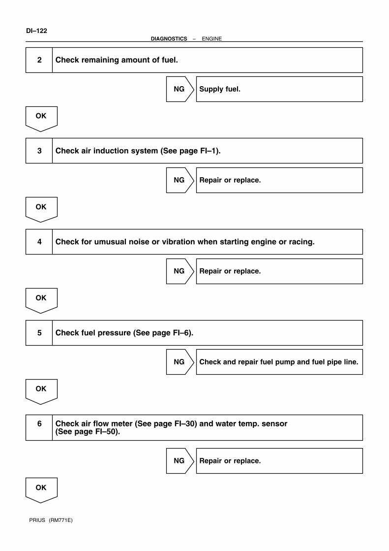
DI–122–DIAGNOSTICS ENGINE
PRIUS (RM771E)
2 Check remaining amount of fuel.
NG Supply fuel.
OK
3 Check air induction system (See page FI–1).
NG Repair or replace.
OK
4 Check for umusual noise or vibration when starting engine or racing.
NG Repair or replace.
OK
5 Check fuel pressure (See page FI–6).
NG Check and repair fuel pump and fuel pipe line.
OK
6 Check air flow meter (See page FI–30) and water temp. sensor (See page FI–50).
NG Repair or replace.
OK

–DIAGNOSTICS ENGINEDI–123
PRIUS (RM771E)
7 Check crankshaft position sensor and camshaft position sensor (See page IG–1).
NG Repair or replace.
OK
8 Check throttle control motor and throttle position sensor (See page FI–32).
NG Repair or replace.
OK
Chack and replace engine ECU (See page IN–40).

A14035
Engine ECU
+B4
E8
Battery
W–R
G–RMREL
25
EFI Relay
Ignition SW
EFI
IGSW6
IE
1B
3 5
AM2
(LHD)
E9
J22 J23
J1 J/C
E10
B
9
3
B
2C
1
2
2G
2
4
A
F12
1
31K 1F
12
1A
1J
2
7
1
W–B
W–B
W–R
B–W
B–G
Engine Room J/B
FL Block No. 2
IA2
FL Block No. 1
9
G–R
J7J/C
B–WAM2 IG2
J/C
Instrument Panel J/B
F131
A
A
A
W–B W–B(RHD) (LHD)
DI–124–DIAGNOSTICS ENGINE
PRIUS (RM771E)
Engine ECU Power Source Circuit
CIRCUIT DESCRIPTIONWhen the ignition switch is turned ON, battery positive voltage is applied to terminal IGSW of the engine ECUand the EFI main relay (Marking: EFI MAIN) control circuit in the engine ECU sends a signal to the terminalMREL of the engine ECU switching on the EFI main relay.This signal causes current to flow to the coil, closing the contacts of the EFI main relay and supplying powerto terminals +B of the engine ECU.
WIRING DIAGRAM
DI7OI–01

A13635
+B
E1(+) (–)
ON
A13636
(+)(–)
IGSWON
–DIAGNOSTICS ENGINEDI–125
PRIUS (RM771E)
INSPECTION PROCEDURE
1 Check voltage between terminals +B and E1 of engine ECU connectors.
PREPARATION:(a) Remove the engine ECU with connector still connected
(See page FI–58).(b) Turn the ignition switch ON.CHECK:Measure the voltage between terminals +B and E1 of the en-gine ECU connectors.OK:
Voltage: 9 – 14 V
OK Proceed to next circuit inspection shown onproblem symptoms table (See page DI–20).
NG
2 Check for open in harness and connector between terminal E1 of engine ECUand body ground (See page IN–40).
NG Repair or replace harness or connector.
OK
3 Check voltage between terminal IGSW of engine ECU connector and bodyground.
PREPARATION:(a) Remove the engine ECU with connector still connected
(See page FI–58).(b) Turn the ignition switch ON.CHECK:Measure the voltage between terminal IGSW of the engineECU connector and body ground.OK:
Voltage: 9 – 14 V

A13630
Engine Room J/B
AM2 Fuse
DI–126–DIAGNOSTICS ENGINE
PRIUS (RM771E)
OK Go to step 8.
NG
4 Check AM2 fuse.
PREPARATION:Remove the AM2 fuse from the engine room J/B.CHECK:Check the continuity of the AM2 fuse.OK:
Continuity
NG Replace AM2 fuse.
OK
5 Check ignition switch (See page BE–17).
NG Replace ignition switch.
OK
Check and repair harness and connector be-tween battery and ignition switch, and igni-tion switch and engine ECU.
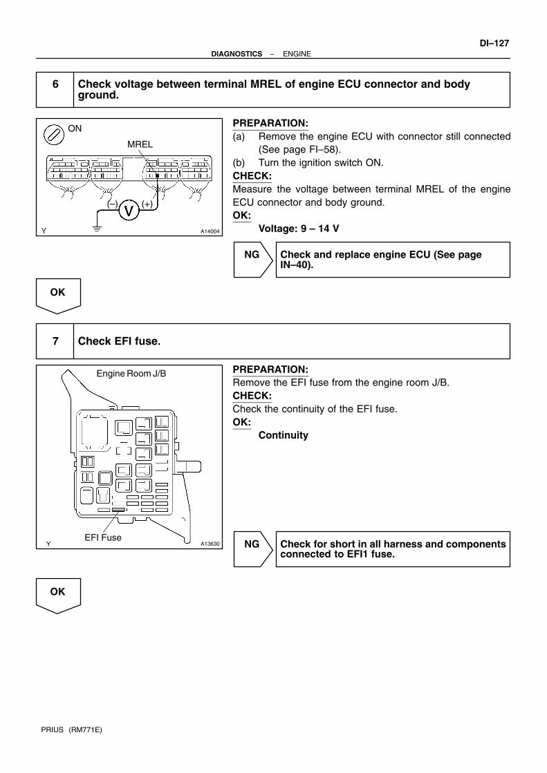
A14004
MREL
(+)(–)
ON
A13630
Engine Room J/B
EFI Fuse
–DIAGNOSTICS ENGINEDI–127
PRIUS (RM771E)
6 Check voltage between terminal MREL of engine ECU connector and bodyground.
PREPARATION:(a) Remove the engine ECU with connector still connected
(See page FI–58).(b) Turn the ignition switch ON.CHECK:Measure the voltage between terminal MREL of the engineECU connector and body ground.OK:
Voltage: 9 – 14 V
NG Check and replace engine ECU (See page IN–40).
OK
7 Check EFI fuse.
PREPARATION:Remove the EFI fuse from the engine room J/B.CHECK:Check the continuity of the EFI fuse.OK:
Continuity
NG Check for short in all harness and componentsconnected to EFI1 fuse.
OK

DI–128–DIAGNOSTICS ENGINE
PRIUS (RM771E)
8 Check EFI main relay (Marking: EFI MAIN) (See page FI–45).
NG Replace EFI main relay.
OK
9 Check for open and short in harness and connector between terminal MREL ofengine ECU and body ground (See page IN–40).
NG Repair and replace harness or connector.
OK
Check and repair harness or connector be-tween EFI fuse and battery.

A14036
B–G
EFI
Cir OPN Relay
MREL
G–R
Engine Room J/B
B–R
1A
B
A
Engine ECU
FC
F16 Fuel Pump
IE
(LHD)(RHD)5
Fusible Link Block No. 1
MAINF12
Battery
E8
E925
9
W–B
J17 J/C
J1 J/C
IG
J7 J/C
IA1
IA2
W–B
W–BW–B
AA
A
A
W–B
G–R
B–R
G–R
F18 Fusible Link Block No. 2
EFI Relay
1K
1F
1B
10
1F
2
12
1
321
34
1
1
1
5
21
3
F13
G–R
B–R
5
(LHD)
14
4
–DIAGNOSTICS ENGINEDI–129
PRIUS (RM771E)
Fuel Pump Control Circuit
CIRCUIT DESCRIPTIONWhen starting the engine with ignition switch:HV ECU receives ST signal and decides to start the engine, and send the signal of the engine start priorsignal to the engine ECU by the communicatio between the engine ECU and HV ECU.Engien ECU receives that signal and turns ON the circuit opening relay slightly earlier, then turns the fuelpump.When starting the engine in an intermittent operation:With the cranking by MG1, NE signal comes in immediately, so the engine ECU receives the generation ofNE signal and turns the fuel pump. (At this time, no refernce of the communication from HV ECU)When stopping the fuel pump:When the signal to stop the engine comes in to the engine ECU from HV ECU from HV ECU side, the fuelpump stops.At the time of the fuel cut opetation such as deceleration by the engine brake, the fuel pump stops.
WIRING DIAGRAM
DI7HB–02

A14006
ON
FC
ON
OFF
DI–130–DIAGNOSTICS ENGINE
PRIUS (RM771E)
INSPECTION PROCEDURE
1 Check fuel pump operation.
PREPARATION:(a) Connect the hand–held tester to the DLC3.(b) Turn the ignition switch ON and hand–held tester main
switch ON.(c) Select the active test mode on the hand–held tester.(d) If you have no hand–held tester, connect the terminal be-
tween FC of the engine ECU and body ground.CHECK:Check that the there is pressure in the fuel inlet tube from thefuel line.OK:
Pressure in the fuel inlet tube.
OK Proceed to next circuit inspection shown onproblem symptoms table (See page DI–20).
NG
2 Check for engine ECU power source circuit (See page DI–124).
NG Repair or replace.
OK

A05448
A14007
ONFC
(+) (–)
–DIAGNOSTICS ENGINEDI–131
PRIUS (RM771E)
3 Check circuit opening relay.
PREPARATION:Remove the circuit opening relay from the instrument panel J/B.CHECK:Check continuity between terminals of circuit opening relayshown below.OK:
Terminals 3 and 5 Open
Terminals 1 and 2Continuity
(Reference value 74 Ω)
CHECK:(a) Apply battery positive voltage between terminals 1 and 2.(b) Check continuity between terminals 3 and 5.OK:
Terminals 3 and 5 Continuity
NG Replace circuit opening relay.
OK
4 Check voltage between terminal FC of engine ECU and body ground.
PREPARATION:(a) Remove the engine ECU with connector still connected
(See page FI–58).(b) Turn ignition switch ON.CHECK:Measure voltage between terminal FC of engine ECU and bodyground.OK:
Voltage: 9 – 14 V
NG Check for open in harness and connector between EFI main relay and circuit opening relay, circuit opening relay and engine ECU.
OK

DI–132–DIAGNOSTICS ENGINE
PRIUS (RM771E)
5 Check fuel pump operation.
NG Repair or replace fuel pump.
OK
6 Check for open in harness and connector between circuit opening relay and fuelpump, and fuel pump and body ground (See page IN–40).
NG Repair or replace harness or connector.
OK
Check and replace engine ECU(See page IN–40).

A14037
Combination MeterEngine ECUInstrument Panel J/B
W
Battery
E10
IG1 Relay 6
J11 J/C
IG1
C11C10
ID
DC/DC
G–R2A
A
5W
W–B
F11
4
3
GAUGE
Ignition SW
22
2
3
B–Y2 1
1
11MAIN
L
AM1
B–G
4
FL Block No. 1 FL Block No. 2
F131
2D
2B
2K
2H
8 65
AM1W–G
Check Engine
–DIAGNOSTICS ENGINEDI–133
PRIUS (RM771E)
CHK ENG Warning Light Circuit Malfunction
CIRCUIT DESCRIPTIONIf the engine ECU detects trouble, the CHK ENG warning lights up. At this time, the engine ECU recordsa DTC in memory.HINT:When the ignition switch is ON and ”READY” indicator light is OFF, the bulb check of the ”CHE ENG” warninglight is performed (”CHE ENG” warning light is ON).When ”CHE ENG” warning light is ON, but the DTC of the engine is not memorized, it may be because ofHV control system abnormality, so check HV control system beforehand.
WIRING DIAGRAM
INSPECTION PROCEDUREHINT:Troubleshoot in accordance with the chart below for each trouble symptom.
CHK ENG does not light upStart inspection from step 1 in case of using hand–held tester and
start from step 2 in case of not using hand–held tester
CHK ENG remains on
After inspection of step 3, start inspection from step 4 in case of
using hand–held tester and start from step 5 in case of not using
hand–held tester
DI6QO–04

DI–134–DIAGNOSTICS ENGINE
PRIUS (RM771E)
1 Check operation of CHK ENG warning light.
PREPARATION:(a) Connect the hand–held tester to the DLC3.(b) Turn the ignition switch ON and push the hand–held tester main switch ON.(c) Switch the hand–held tester from the normal mode to the check mode.CHECK:Check if the CHK ENG warning light blinks.OK:
The CHK ENG warning light blinks.
OK Check and replace engine ECU (See page IN–40).
NG
2 Check CHK ENG warning light.
See combination meter troubleshooting (See page BE–2).
NG Repair or replace bulb or combination meter as-sembly.
OK
3 Check that engine ECU connectors are securely connected to engine ECU.
NO Connect connector to engine ECU.
YES
Check for open circuit in harness and connector between combination meter and engine ECU(See page IN–40).

–DIAGNOSTICS ENGINEDI–135
PRIUS (RM771E)
4 Check operation of CHK ENG (See step 1).
OK Check and replace engine ECU (See page IN–40).
NG
5 Is DTC output?
Check DTC on page DI–3.
YES Repair circuit indicated by output code.
NO
6 Check ignition relay (Marking: IG1).
OK Replace IG1 relay.
NG
Check for short circuit in harness and connector between DLC3 and engine ECU (See page IN–40).

A14038
W–B
13TCE9TC
CG
D5 DLC3
4
P–B
Instrument Panel J/B
62
2K2D
ID1
A
Engine ECU
ID
W–B A
J22J/C
E
W–B
P–B
J11J/C
J24 J/C
P–B
A
E
W–B88
P–BC C
J16 J/C
F08565
CG
(–)
(+)
ON
TC
DI–136–DIAGNOSTICS ENGINE
PRIUS (RM771E)
TC Terminal Circuit
CIRCUIT DESCRIPTIONTerminal TC and CG are located in the DLC3. When connecting these terminals, DTCs in normal mode ortest mode can be read through the check engine warning light in combination meter by flashing it.
WIRING DIAGRAM
INSPECTION PROCEDUREHINT: Even though terminal TC is not connected with terminal CG, the CHK ENG (MIL) blinks. For the above phenomenon, an open or short in the wire harness, or malfunction inside the engine
ECU is the likely cause.
1 Check voltage between terminals TC and CG of DLC3.
PREPARATION:Turn the ignition switch ON.CHECK:Measure the voltage between terminals TC and CG of theDLC3.OK:
Voltage: 9 – 14 V
OK Check and replace engine ECU (See page IN–40).
NG
DI6SV–06

–DIAGNOSTICS ENGINEDI–137
PRIUS (RM771E)
2 Check continuity between terminal CG of DLC3 and body ground.
NG Repair or replace harness or connector.
OK
3 Check for open and short circuit in harness and connector between engine ECUand DLC3, and DLC3 and body ground (See page IN–40).
NG Repair or replace harness or connector.
OK
Check and replace engine ECU (See page IN–40).

A11860
A/C Amplifier
Engine ECU
ACT
A9 E10
E1
225
B+
P–G
DI–138–DIAGNOSTICS ENGINE
PRIUS (RM771E)
A/C Cut Control Circuit
CIRCUIT DESCRIPTIONThis circuit cuts air conditioning operation during vehicle acceleration in order to increase acceleration per-formance. During acceleration with the vehicle speed at 25 km/h (16 mph) or less, engine speed at 1,600rpm or less and throttle valve opening angle at 60 or more, the A/C magnetic switch is turned OFF for severalseconds.
WIRING DIAGRAM
INSPECTION PROCEDUREHINT:Read freeze flame data using hand–held tester. Because freeze flame records the engine conditions whenthe malfunction is detected, when troubleshooting it is useful for determining whether the vehicle was run-ning or stopped, the engine warmed up or not, the air–fuel ratio lean or rich, etc. at the time of the malfunction.
Hand–held tester:
1 Connect the hand–held tester and check operation of air conditioning cut con-trol.
PREPARATION:(a) Connect the hand–held tester to the DLC3.(b) Turn the ignition switch ON and hand–held tester main switch ON.(c) Start the engine and air conditioner switch ON.HINT:A/C magnetic clutch is turned ON.(d) Select the active test mode on the hand–held tester.
DI70F–02

A14008
ONACT
(–) (+)
–DIAGNOSTICS ENGINEDI–139
PRIUS (RM771E)
CHECK:Check operation of A/C magnetic clutch cut when air conditioning cut control is operated by the hand–heldtester.OK:
A/C magnet clutch is turned OFF.
OK Proceed to next circuit inspection shown onproblem symptoms table (See page DI–20).
NG
2 Check for open and short in harness and connector between engine ECU andA/C control assembly (See page IN–40).
NG Repair or replace harness or connector.
OK
3 Check voltage between terminal ACT of engine ECU and body ground.
PREPARATION:(a) Remove the engine ECU with connector still connected
(See page FI–58).(b) Start the engine.CHECK:Measure voltage between terminal ACT of engine ECU con-nector and body ground when A/C switch is turned to ON andOFF.OK:
A/C switch condition Voltage
ON 9 – 14 V
OFF 0 – 2 V
NG Repair or replace engine ECU (See pageIN–40).
OK
Check and replace A/C control assembly.
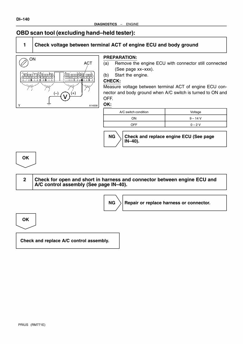
A14008
ONACT
(–) (+)
DI–140–DIAGNOSTICS ENGINE
PRIUS (RM771E)
OBD scan tool (excluding hand–held tester):
1 Check voltage between terminal ACT of engine ECU and body ground
PREPARATION:(a) Remove the engine ECU with connector still connected
(See page xx–xxx).(b) Start the engine.CHECK:Measure voltage between terminal ACT of engine ECU con-nector and body ground when A/C switch is turned to ON andOFF.OK:
A/C switch condition Voltage
ON 9 – 14 V
OFF 0 – 2 V
NG Check and replace engine ECU (See pageIN–40).
OK
2 Check for open and short in harness and connector between engine ECU andA/C control assembly (See page IN–40).
NG Repair or replace harness or connector.
OK
Check and replace A/C control assembly.

DI82I–01
Vehicle Brought to Workshop
Customer Problem Analysis P. DI–266
Connect the hand–held tester to DLC3 P. DI–268If the display indicates a communication fault in the tool, inspect DLC3 P. DI–268
Check DTC, INF. code and Freeze Frame Data (Precheck)
Record or Print DTC and Freeze Frame Data P. DI–268
DTC Chart P. DI–272
Circuit Inspection P. DI–274
Adjustment, Repair
DTC Check P. DI–268
Inside
See the indicated pages for details.in this manual.
Identification of Problem
Confirmation Test
End
1
2
3
4
7
5
6
8
Malfunction code.
are shown titles and page numbers
–DIAGNOSTICS HYBRID VEHICLE CONTROL SYSTEMDI–141
PRIUS (RM771E)
HYBRID VEHICLE CONTROL SYSTEMHOW TO PROCEED WITH TROUBLESHOOTING

DI82J–01
Prius Problem Check Sheet
Veh
icle
Sp
ecif
icat
ion
s
Please fill in the blanks within bold frame.
Name of Dealer Person in Charge at Headquarters
Person in Chargeat Dealer
Model Code
Office
Vehicle Delivery Date
Frame No.
Unit No. etc.
Option
. . . :
( ) Navigation (equipped by ( ) MOP ( ) dealer) ( ) Cold climate specification( ) others( )
Problem Occurrence Date
Service Entry Date
NHW11–
NHW11– . .
. .
Km–reading
Registration date
km
. .
Contents of complaint (Status when and before/after occurring inthe order of events as correct as possible)
Characteristics of Customer
Gender
Age
Occupation
Vehicle used before
Main use area
Frequency in use
Others
times/day orweek or month
Status of engine
Others
Inte
rvie
w R
esu
lts
( ) Male ( ) Female
suburbs ( ) %
Others ( ) ( ) %
city area ( ) %
mountain area ( ) %
Driving Condition Road Condition Vehicle Condition
Vehicle Speed km/h
( ) when starting
( ) when according
( ) When normal driving( ) when decelerating( ) when braking
( ) when shopping
( ) when parking
( ) when tuming
( ) when ABS actuating( ) others ( )
( ) flat road
( ) up hill ( ) down hill incline of /% distance km
( ) dry paved road
( ) wet paved road
( ) rough paved road
( ) unpaved road
( ) snowy/frozen road
( ) bump/curb
( ) others ( )
( ) when starting
( ) right after starting( ) until min. after starting( ) until min. after starting of driving
( ) when shopping system
( ) while shopping engine( ) when starting engine( ) when revolving engine
HV Battery indication
( ) 4/4 ( ) 3/4( ) 2/4 ( ) 1/4( ) unidentified
Shift position(indication)( ) P ( ) R ( ) N( ) D ( ) B( ) when operating →
Weather:
A/C status
( ) no indication( ) unidentified
( ) A/C ( ) FULL( ) OFF( ) unidentified
Warning light(MIL)
( ) ON ( ) OFF
( ) PS( ) main battery( ) HV!
( ) engine( ) charge( ) output control( ) brake( ) ABS
( ) others ( )
Temperature:
C
Brake operation( ) brake slowly( ) Brake suddenly( ) use two pedals system
Frequency in occurrence( ) always( ) sometimes( ) only once
DI–142–DIAGNOSTICS HYBRID VEHICLE CONTROL SYSTEM
PRIUS (RM771E)
CUSTOMER PROBLEM ANALYSIS CHECK

Verification Results of Warning Light
Engine
HV
INF. code
HV battery
Veh
icle
Ver
ific
atio
n R
esu
lts
( ) ON ( ) OFF
( ) engine ( ) HV
( ) HV battery
( ) output control warning light
( ) brake ( ) ABS
( ) charge ( ) PS
( ) others ( )
Verification Results of Diagnostic Code
Brake
PS
Vehicle Inspection Results (Verification items, reason to identify/presume the cause parts, etc.)
Replacemect Parts
problem parts: No/Yes (Sending date: . . )
Reproduction Status
( ) always( ) sometimes condition when occurring
( ) no reproduction
Confirmation Results After Repair
( ) Normal( ) reproduction( ) others ( )
–DIAGNOSTICS HYBRID VEHICLE CONTROL SYSTEMDI–143
PRIUS (RM771E)

B04757
DI82K–01
A14091
F12397
DLC3
Hand–held tester
DI–144–DIAGNOSTICS HYBRID VEHICLE CONTROL SYSTEM
PRIUS (RM771E)
PRE–CHECK1. PRECAUTION(a) When distinguishing trouble and replace the defective
part, take necessary preventive measures against anelectric shock (See page IN–4).
(b) Some portions of the wiring harness in the THS vehiclehave circuits to which a high voltage is applied. To preventan electrical shock, be sure to observe the following:(1) Wear insulated gloves during inspection.(2) Remove a service plug and do not start any repair
operation before 5 minutes have passed. Then,confirm that the voltage at the output terminals hasdropped down to 12 V or less.
(3) Use insulated tools during inspection.(4) When disengaging the wiring connectors, hold the
connector bodies to avoid pulling the wires. Whenengaging the wiring connectors, be sure to engagethem securely.
(c) Do not leave the tools or parts (bolts, nuts, etc.) inside thecabin.
(d) Do not carry metallic objects such as mechanical pencilsor scales.
2. DIAGNOSIS SYSTEM(a) Description
The HV control ECU has a self–diagnosis systemby which malfunction in the computer itself or inTHS components is detected and the Hybrid ve-hicle warning light in the multi–information displayare lighted up.
To check the Diagnostic Trouble Codes (DTC), con-nect the hand–held tester to the Data Link Connec-tor 3 (DLC3) on the vehicle. The hand–held testeralso enables you to erase the DTC and checkfreeze frame data and various forms of THS data.
Freeze frame data:As the freeze frame data records the driving condi-tion when a malfunction is detected, when trouble-shooting, it is useful for determining whether the ve-hicle was running, braked, stopped or reversed.

A04550
DLC3
9
1 2 3 4 5 6 7 8
16151413121110
A14089
–DIAGNOSTICS HYBRID VEHICLE CONTROL SYSTEMDI–145
PRIUS (RM771E)
(b) Check the DLC3.The HV control ECU conforms to ISO 14230 for commu-nication.The terminal arrangement of the DLC3 complies withSAEJ1962 and matches the ISO 14230 format.
Terminal No. Connection/Voltage or Resistance Condition
7 Bus Line/Pulse generation During transmission
4 Chassis Ground ↔ Body Ground/1 Ω or less Always
5 Signal Ground ↔ Body Ground/1 Ω or less Always
16 Battery Positive ↔ Body Ground/10 – 15 V Always
HINT:If your display shows UNABLE TO CONNECT TO VEHICLEwhen you have connected the cable of the hand–held tester tothe DLC3, turned the motor switch ON and operated the tester,there is a problem in the vehicle or tool. If communication is normal when the tool is connected to
another vehicle, inspect the DLC3 on the original vehicle. If communication is still not possible when the tool is con-
nected to another vehicle, the problem is probably in thetool itself, so consult the Service Department.
3. INSPECT DIAGNOSIS(a) Check the auxiliary battery.
(1) Measure the voltage of the auxiliary battery.Voltage: 10 – 15 V(2) Inspect the auxiliary battery, fuses, fusible links, wir-
ing harness, connectors and ground.
(b) Check the master warning light.(1) Turn the ignition switch ON and confirm that the
master warning light comes on.HINT:If the master warning light does not come on, suspect a burntfuse, burnt bulb, or open in wiring harness.

B12009
F12397
DLC3
Hand–held tester
F12397
DLC3
Hand–held tester
DI–146–DIAGNOSTICS HYBRID VEHICLE CONTROL SYSTEM
PRIUS (RM771E)
(2) When the ”READY” light is ON, the master warninglight should go off.
If the lamp remains on, the diagnosis system has detected amalfunction in the system or the meassage such as ”When youpark your care, make sure you shift to Park P.” and ”The batter-ies will not charge if the shifter is N” appears on the multi–in-formation display.
(c) Check the DTC.(1) Prepare a hand–held tester.(2) Connect the hand–held tester to the DLC3.(3) Turn the ignition switch ON and push the hand–held
tester main switch ON.(4) Use the hand–held tester to check the DTC, in-
formation code and freeze frame data and notethem down. (For operating instructions, see thehand–held tester operator’s manual).
(5) See a related page to confirm details of the DTC.(d) Clear the DTC.
(1) Connect the hand–held tester to the DLC3.(2) Operate the hand–held tester to erase the DTC
(See the hand–held tester operator’s manual.).
4. FAIL–SAFE CHARTIf any of the following codes is recorded, the HV ECU enters the fail safe mode.
DTC code INF. code Trouble are Driving condition
B2799 101 Immobilizer Malfunction Impossible to drive
C2692 102 Regenerative Brake Check –
C2693 103 Regenerative Brake Check –
104 Limited driving
105 Limited driving
106 Limited driving
107 Limited driving
108 Limited driving
P1120 109Accelerator Pedal Position
Sensor Circuit MalfunctionLimited driving
110Sensor Circuit Malfunction
Limited driving
111 Limited driving
112 Limited driving
113 Limited driving (Creep vehicle speed)
114 Limited driving (Creep vehicle speed)
P1520 115 Stop Light Switch Malfunction Cruise control driving impossible

–DIAGNOSTICS HYBRID VEHICLE CONTROL SYSTEMDI–147
PRIUS (RM771E)
P1566 116Cruise Control System Mal-
functionCruise control driving impossible
P1600 117 BATT Malfunction Normal driving
118 Impossible to drive/Normal driving when shift position is fixed
P1780119 Neutral Start Switch System Impossible to drive/Normal driving when shift position is fixed
P1780120
Neutral Start Switch System
Malfunction Impossible to drive
121 Impossible to drive/Normal driving when shift position is fixed
123 Limited driving
P3000125
HV B tt M lf tiLimited driving
P3000388
HV Battery MalfunctionLimited driving
389 Limited driving
P3001 129 HV Battery ECU Malfunction Limited driving
130 Limited driving
P3004131
Power Cable MalfunctionImpossible to drive
P3004132
Power Cable MalfunctionNormal driving
133 Limited driving
127 Limited driving
128 Limited driving
134 Impossible to drive
135 Impossible to drive
136 Normal driving
137 Normal driving
138 Limited driving
139 Normal driving
140 Impossible to drive
141 Impossible to drive
142 Impossible to drive
143 Impossible to drive
144 Impossible to drive
145 Impossible to drive
P3100147
HV ECU MalfunctionImpossible to drive
P3100148
HV ECU MalfunctionNormal driving
149 Normal driving
150 Impossible to drive
151 Impossible to drive
152 Impossible to drive
153 Impossible to drive
154 Impossible to drive
155 Impossible to drive
156 Impossible to drive
157 Impossible to drive
158 Impossible to drive
159 Impossible to drive
160 Impossible to drive
161 Impossible to drive
162 Impossible to drive

DI–148–DIAGNOSTICS HYBRID VEHICLE CONTROL SYSTEM
PRIUS (RM771E)
163 Impossible to drive
164 Impossible to drive
165 Limited driving
166 Normal driving
167 Limited driving
168 Limited driving
169 Limited driving
170 Limited driving
171 Impossible to drive
172 Impossible to drive
173 Impossible to drive
174 Normal driving
175 Normal driving
176 Normal driving
177 Impossible to drive
178 Impossible to drive
179 Impossible to drive
180 Impossible to drive
181 Impossible to drive
182 Impossible to drive
183 Impossible to drive
184 Impossible to drive
P3100 185 HV ECU Malfunction Impossible to drive
186 Impossible to drive
187 Impossible to drive
188 Limited driving
189 Limited driving
190 Limited driving
191 Limited driving
192 Limited driving
193 Limited driving
194 Limited driving
195 Limited driving
196 Limited driving
197 Limited driving
198 Normal driving
199 Limited driving
200 Limited driving
201 Limited driving
202 Limited driving
203 Limited driving
271 Normal driving
310 Limited driving
392 Impossible to drive
393 Impossible to drive

–DIAGNOSTICS HYBRID VEHICLE CONTROL SYSTEMDI–149
PRIUS (RM771E)
204 Limited driving
P3101 205 Engine System Malfunction Limited driving
238
g y
Limited driving
206 Limited driving
P3105 207Battery ECU Communication
CircuitMalfunctionLimited driving
208Circuit Malfunction
Limited driving
209 Limited driving
210 Limited driving
P3106 211Engine ECU Communication
CircuitMalfunctionLimited driving
212Circuit Malfunction
Limited driving
394 Limited driving
213 Normal driving
P3107 214Airbag ECU Communication
CircuitMalfunctionNormal driving
215Circuit Malfunction
Normal driving
P3108216 A/C Amplifier Communication Normal driving
P3108217
A/C Am lifier Communication
Circuit Malfunction Normal driving
218 Regenerative brake ineffective
219 Regenerative brake ineffective
P3109 220Battery ECU Communication
CircuitMalfunctionRegenerative brake ineffective
221Circuit Malfunction
Regenerative brake ineffective
222 Regenerative brake ineffective
P3110 223 IGCT Relay Malfunction Normal driving
P3115224 System Main Relay Malfunc- Normal driving
P3115225
System Main Relay Malfunc
tion Normal driving
226 Impossible to drive
227 Impossible to drive
228 Impossible to drive
P3115 229System Main Relay Malfunc-
tionImpossible to drive
231tion
Impossible to drive
232 Limited driving
233 Impossible to drive
234 Regenerative brake ineffective
235 Impossible to drive
236 Normal driving
237 Limited driving
239 Limited driving
240 Impossible to drive
241 Normal driving
P3120 242 HV Transaxle Malfunction Limited driving
243 Limited driving
244 Limited driving
245 Limited driving
246 Limited driving
247 Normal driving
248 Normal driving
249 Normal driving

DI–150–DIAGNOSTICS HYBRID VEHICLE CONTROL SYSTEM
PRIUS (RM771E)
250 Normal driving
253 Limited driving
254 Limited driving
255 Limited driving
P3120 256 HV Transaxle Malfunction Limited driving
257 Normal driving
258 Normal driving
259 Normal driving
260 Normal driving
263 Normal driving
264 Normal driving
265 Normal driving
266 Limited driving
267 Limited driving
268 Limited driving
269 Limited driving
270 Limited driving
272 Normal driving
273 Normal driving
274 Normal driving
275 Normal driving
276 Normal driving
277 Normal driving
278 Limited driving
279 Impossible to drive
280 Limited driving
281 Limited driving
P3125 282Converter & Inverter Assem-
blyMalfunctionLimited driving
283bly Malfunction
Limited driving
284 Impossible to drive
285 Limited driving
286 Limited driving
287 Limited driving
288 Limited driving
289 Limited driving
290 Limited driving
291 Limited driving
292 Limited driving
293 Limited driving
294 Limited driving
295 Limited driving
296 Limited driving
297 Limited driving
298 Limited driving
299 Limited driving
300 Limited driving

–DIAGNOSTICS HYBRID VEHICLE CONTROL SYSTEMDI–151
PRIUS (RM771E)
301 Limited driving
302 Limited driving
303 Limited driving
304 Limited driving
305 Limited driving
306 Limited driving
307 Limited driving
308 Impossible to drive
309 Limited driving
311 Normal driving
312 Normal driving
313 Normal driving
314 Normal driving
315 Normal driving
316 Limited driving
317 Limited driving
318 Limited driving
319 Limited driving
320 Limited driving
321 Limited driving
322 Limited driving
P3125323 Converter & Inverter Assem- Limited driving
P3125324
Converter & Inverter Assem
bly Malfunction Limited driving
325 Limited driving
326 Limited driving
327 Limited driving
328 Limited driving
329 Limited driving
330 Limited driving
331 Limited driving
332 Limited driving
333 Limited driving
334 Limited driving
335 Limited driving
336 Limited driving
337 Limited driving
338 Limited driving
339 Limited driving
340 Limited driving
341 Limited driving
342 Limited driving
343 Limited driving
344 Limited driving
345 Limited driving
P3130346 Inverter Cooling System Mal- Normal driving
P3130347
Inverter Cooling System Mal
function Normal driving

DI–152–DIAGNOSTICS HYBRID VEHICLE CONTROL SYSTEM
PRIUS (RM771E)
P3135348 Circuit Breaker Sensor Mal- Normal driving
P3135349
Circuit Breaker Sensor Mal
function Normal driving
P3140350
InterlockMalfunctionNormal driving
P3140351
Interlock MalfunctionNormal driving
P3145 352Vehicle Speed Sensor Circuit
MalfunctionCruise control driving impossible
5. CHECK FOR INTERMITTENT PROBLEMS(a) Perform a simulation test (See page IN–40).(b) Check the connector and terminal (See page IN–40).(c) Handle the connector (See page IN–40).6. HAND–HELD TESTER DISPLAY ITEMS
Hand–held tester display Measurement Item
1 BEF LATST OR Number of operation of 1 trip before last
1 BEF LATST TRP Number of trips bear last
2 BEF LATST OR Number of operation 2 trips before last
2 BEF LATST TRP Number of trips 2 bear last
ABNML CON BR–HV Communication malfunction between HV ECU and brake
ACC SENSOR MAIN Main accelerator sensor
ACC SENSOR SUB Sub accelerator sensor
ACC TENT TRBLE Tentative trouble of accelerator
ACC THROTTLE Accelerator throttle
ACCEL MODE History of acceleration and reduction
AIR CON REQUEST Air conditioner request
AUX. BATT LOW Auxiliary battery becomes week
AUX. BATT V Voltage of auxiliary battery
BATT HIGH TEMP Temperature of the battery is too high
BATT HIGH VOLT Voltage of the battery is too high
BATT LOW BOLT Voltage of the battery is low
BATT OVER LOAD Battery is overloaded
BATT SAVE RQST Request to save the main battery
BATTERY FULL Battery full
BRAKE TORQ Brake torque
CELL TEMP–MAX Highest temperature of all battery cells
CELL TEMP–MIN Lowest temperature of all battery cells
CHG RESTRICTION Charge restriction
COOLANT TEMP Water temperature
CRUISE CONTROL Condition of the cruise control
DC/DC CONV STOP DC/DC converter stop signal
DC/DC CONV STOP Factors causing DC/DC converter to stop
DC/DC STOP FACT DC/DC converter has stopped at least once
DC/DC V UNSET DC/DC voltage is unsettled
DCHG RQST SOC Discharge request to adjust SOC
DISCHAG INHIBIT Battery is inhibited to discharge
0: When engine is stopped
DRIVE CONDTION 1: When stopping engine
2: When starting engine

–DIAGNOSTICS HYBRID VEHICLE CONTROL SYSTEMDI–153
PRIUS (RM771E)
3: When cranking engine or engine is operating
DRIVE CONDITION4: While generating power or load driving
DRIVE CONDITION5: –
6: While racing engine in P range
DRIVING PATTEM1 History of driving pattern 1
DRIVING PATTEM2 History of driving pattern 2
DRIVING PATTEM3 History of driving pattern 3
DRIVING PATTERN HIstory of driving
ECU TYPE ECU type
ENG INDPDET RQ Factors causing engine to run independently
ENG STOP RQST Engine stop request
ENG SEP INHIBIT Engine stop inhibition
ENG WARM UP RQT Engine warming up request
ENGINE FUEL CUT Engine fuel cut
ENGINE SPD Engine speed
EXCLUSIVE INFO1 Exclusive information 1
EXCLUSIVE INFO2 Exclusive information 2
EXCLUSIVE INFO3 Exclusive information 3
EXCLUSIVE INFO4 Exclusive information 4
EXCLUSIVE INFO5 Exclusive information 5
EXCLUSIVE INFO6 Exclusive information 6
FUEL SHORTAGE Low fuel
HCAC ABSRT RQST HCAC OBD request
HV BATT CH RQST Request from HV ECU to charge the battery
HV ECU INTERMITTENT HV ECU intermittent problems
IDLING REQUEST Engine idling request
IG OFF IN DRVIN Turning IG OFF while driving the car
IG OFF TIME IG OFF time
ILK OPERATION Interlock operation
INFORMATION 1–5 Information code
INPUT V LOW Input voltage is too low
INPUT V OVER Input voltage is too high
INTAKE AIR Intake air temperature
INVERT TEMP–MG1 Temperature of MG1
INVERT TEMP–MG2 Temperature of MG2
LATEST OPER Latest number of operation
LATEST TRIP Latest number of trips (IG ON–OFF)
LOAD CONDITION Indicating which of MG1 or MG2 the vehicle uses more
MAIN BATT LOW SOC of main battery becomes low
MCYL CTRL POWER Torque for controlling oil pressure of master cylinder
MG1 TEMP HIGH Temperature MG1 is too high
MG2 TEMP HIGH Temperature MG2 is too high
MG1 CURRENT V Electric current of MG1 V phase
MG1 CURRENT W Electric current of MG1 W phase
MG1 INV TEMP HI Temperature of inverter MG1 is high
MG1 REV MG1 revolution
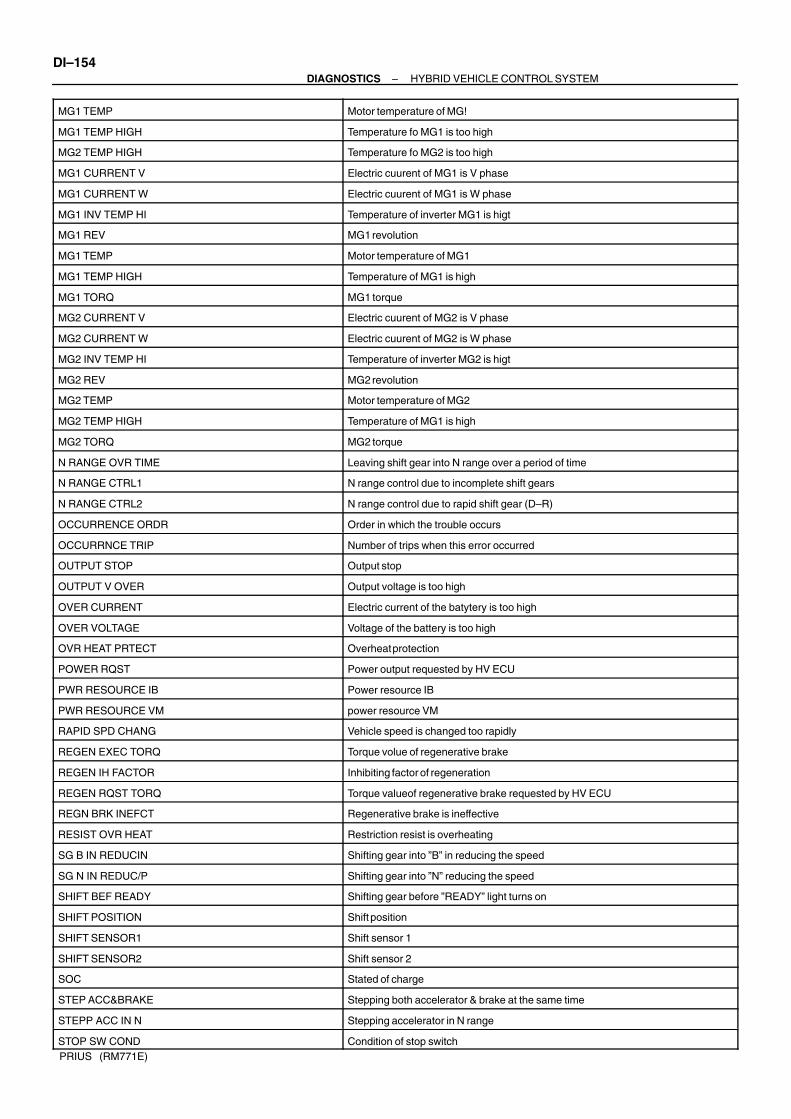
DI–154–DIAGNOSTICS HYBRID VEHICLE CONTROL SYSTEM
PRIUS (RM771E)
MG1 TEMP Motor temperature of MG!
MG1 TEMP HIGH Temperature fo MG1 is too high
MG2 TEMP HIGH Temperature fo MG2 is too high
MG1 CURRENT V Electric cuurent of MG1 is V phase
MG1 CURRENT W Electric cuurent of MG1 is W phase
MG1 INV TEMP HI Temperature of inverter MG1 is higt
MG1 REV MG1 revolution
MG1 TEMP Motor temperature of MG1
MG1 TEMP HIGH Temperature of MG1 is high
MG1 TORQ MG1 torque
MG2 CURRENT V Electric cuurent of MG2 is V phase
MG2 CURRENT W Electric cuurent of MG2 is W phase
MG2 INV TEMP HI Temperature of inverter MG2 is higt
MG2 REV MG2 revolution
MG2 TEMP Motor temperature of MG2
MG2 TEMP HIGH Temperature of MG1 is high
MG2 TORQ MG2 torque
N RANGE OVR TIME Leaving shift gear into N range over a period of time
N RANGE CTRL1 N range control due to incomplete shift gears
N RANGE CTRL2 N range control due to rapid shift gear (D–R)
OCCURRENCE ORDR Order in which the trouble occurs
OCCURRNCE TRIP Number of trips when this error occurred
OUTPUT STOP Output stop
OUTPUT V OVER Output voltage is too high
OVER CURRENT Electric current of the batytery is too high
OVER VOLTAGE Voltage of the battery is too high
OVR HEAT PRTECT Overheat protection
POWER RQST Power output requested by HV ECU
PWR RESOURCE IB Power resource IB
PWR RESOURCE VM power resource VM
RAPID SPD CHANG Vehicle speed is changed too rapidly
REGEN EXEC TORQ Torque volue of regenerative brake
REGEN IH FACTOR Inhibiting factor of regeneration
REGEN RQST TORQ Torque valueof regenerative brake requested by HV ECU
REGN BRK INEFCT Regenerative brake is ineffective
RESIST OVR HEAT Restriction resist is overheating
SG B IN REDUCIN Shifting gear into ”B” in reducing the speed
SG N IN REDUC/P Shifting gear into ”N” reducing the speed
SHIFT BEF READY Shifting gear before ”READY” light turns on
SHIFT POSITION Shift position
SHIFT SENSOR1 Shift sensor 1
SHIFT SENSOR2 Shift sensor 2
SOC Stated of charge
STEP ACC&BRAKE Stepping both accelerator & brake at the same time
STEPP ACC IN N Stepping accelerator in N range
STOP SW COND Condition of stop switch

–DIAGNOSTICS HYBRID VEHICLE CONTROL SYSTEMDI–155
PRIUS (RM771E)
STP CIRCIT OPEN STP circuit short
STP IN CIR MLF STP circuit malfunciton
TACHO METER Engine rpm
TARGET ENG SPD Target engine speed
TEMP TRBLE FACT Factors causing temporay trouble
VEHICLE SPD Vehicle speed
WIN CTRL POWER Power value of charge control
WOUT CTRL POWER Power value of discharge control

DI82L–01
DI–156–DIAGNOSTICS HYBRID VEHICLE CONTROL SYSTEM
PRIUS (RM771E)
DIAGNOSTIC TROUBLE CODE CHARTHINT:Parameters listed in the chart may not be exactly the same as your reading due to the type of instrumentor other factors.If a malfunction code is displayed during the DTC check in the check mode, check the circuit for that codelisted in the table below. For the details of each code, turn to the page referred to under the ’’See page’’ forthe respective ’’DTC No.’’ in the DTC chart.
DTC No.
(See page)Detection Item Trouble Area
Hybrid
System
Warning
Light*
Memory
B2799
(DI–169)Immobilizer Malfunction
Wire Harness
HV ECU
Transponder Key ECU
C2692
(DI–171)Regenerative Brake Check –
C2693
(DI–171)Regenerative Brake Check – X
P1120
(DI–172)
Accelerator Pedal Position
Sensor Circuit Malfunction
Accelerator Pedal Position Sensor
Wire Harness
P1520
(DI–174)
Stop Light Switch (Cruise Con-
trol System) Malfunction
Stop Light Switch
Wire Harness
HV ECU
X
P1566
(DI–176)
Cruise Control System Malfunc-
tion
HV ECU
Brake ECUX
P1600
(DI–177)BATT Malfunction
HV Fuse
Wire Harness
P1780
(DI–179)
Neutral Start Switch System Mal-
function
Neutral Start Switch
Wire Harness
P3000
(DI–181)HV Battery Malfunction
HV Battery
Fuse
Power Cable
HV Battery Cooling System
/X
P3001
(DI–182)HV Battery ECU Malfunction Battery ECU
P3004
(DI–183)Power Cable Malfunction
Power Cable
HV Battery System
Main Fuse
Service Plug
System Main Relay
/X
P3100
(DI–187)HV ECU Malfunction
Wire Harness
HV ECU
Engine ECU
Battery ECU
Ignition Switch
Converter & inverter Assembly
P3101
(DI–196)Engine System Malfunction
Engine
HV Transaxle
P3105
(DI–197)
Battery ECU Communication Cir-
cuit Malfunction
Battery ECU
Wire Harness
HV ECU

–DIAGNOSTICS HYBRID VEHICLE CONTROL SYSTEMDI–157
PRIUS (RM771E)
P3106
(DI–199)
Engine ECU Communication Cir-
cuit Malfunction
Engine ECU
Wire Harness
HV ECU
/X
P3107
(DI–202)
Airbag ECU Communication Cir-
cuit Malfunction
Airbag Sensor
Wire Harness
HV ECU
P3108
(DI–204)
A/C Amplifier Communication
Circuit Malfunction
A/C Amplifier
Wire Harness
HV ECU
X
P3109
(DI–205)
Brake ECU Communication Cir-
cuit Malfunction
Brake ECU
Wire Harness
HV ECU
P3110
(DI–207)IGCT Relay Malfunction
IGCT Relay
Wire Harness
HV ECU
P3115
(DI–209)System Main Relay Malfunction
System Main Relay
Wire Harness
P3120
(DI–212)HV Transaxle Malfunction
HV Transaxle
Wire Harness
HV ECU
P3125
(DI–222)
Converter & Inverter Assembly
Malfunction
Converter & Inverter Assembly
Wire Harness
HV ECU
P3130
(DI–255)
Inverter Cooling System Mal-
function
Inverter Water Pump
Electric Cooling Fun System
Wire Harness
IG2 Relay
P3135
(DI–258)
Circuit Breaker Sensor Malfunc-
tion
Circuit Breaker Sensor
Wire Harness
P3140
(DI–260)Interlock Switch Malfunction
Interlock Switch
Inverter Terminal Cover
Sensor Cover
Wire Harness
P3145
(DI–263)
Vehicle Speed Sensor Circuit
Malfunction
Combination Meter
Wire Harness
HV ECU
X
*: : Hybrid system warning light lights up. X: Hybrid system warning light does not light up.

DI–158–DIAGNOSTICS HYBRID VEHICLE CONTROL SYSTEM
PRIUS (RM771E)
INFORMATION CODE (Hand–held tester only)
DTC NO. INF. Code Detection Item Detecting Condition
B2799 101 Immobilizer Malfunction No input of signal from transponder key ECU
C2692 102 Regenerative Brake Check Regenerative brake check
C2693 103 Regenerative Brake Check Regenerative brake check
104 Open or short in main accelerator sensor circuit
105 +B short in main accelerator sensor circuit
106 Main sensor internal error
107 Open or short in sub accelerator sensor circuit
108 +B short in sub accelerator sensor circuit
P1120 109Accelerator Pedal Position
Sensor Circuit MalfunctionSub sensor internal error
110Sensor Circuit Malfunction
When difference between main sensor value and sub sensor value is large
111 When sub sensor value changes while main sensor value does not
112 When main sensor value changes while sub sensor value does not
113 When any of the information code 104 – 112 continues to appear
114 Accelerator pedal not smoothly returning to original position
P1520 115Cruise Control System
MalfunctionOpen or short in stop light switch circuit
P1566 116Cruise Control System
Malfunction
When STP signal of HV ECU is inconsistent with that of brake ECU, with
cruise control indicator ON
P1600 117 BATT Malfunction HV ECU back–up power source circuit malfunction
118 When more than 2 main signals are ON
119Neutral Start Switch System
When main signal is not turned ON even though sub signal has been input
P1780 120Neutral Start Switch System
Malfunction Open or short in sub sensor circuit
121
MalfunctionWhen shift position detected by main signal is different from that detected
by sub signal
123HV Battery Malfunction
Input of abnormal signal from battery ECU (HV battery system malfunction)
125HV Battery Malfunction
Input of abnormal signal from battery ECU (high voltage fuse blown out)
P3000388
Discharge Inhibition Control
Malfunction
Input of abnormal signal from battery ECU (discharge inhibition control
malfunction)
389 Drop of High Voltage Input of abnormal signal from battery ECU (drop of high voltage)
P3001 129 HV Battery ECU Malfunction Battery ECU malfunction
130 HV Battery Malfunction When HV battery voltage becomes lower than inverter voltage
P3004131
Power Cable Malfunction
When main fuse is blown out, service plug is disconnected or limiter resis-
tance is cut offP3004
132
Power Cable Malfunction
When voltage sensor is malfunctioning or limiter resistance is broken
133 HV Battery Malfunction Input of abnormal signal from battery ECU
134HV ECU Internal Error
HV ECU Internal Error
135HV ECU Internal Error
HV ECU Internal Error
136 GO Signal Error Open or short in GO signal circuit
P3100137
Engine Speed Sensor
MalfunctionEngine speed sensor malfunction
127 +B short in IB terminal circuit of HV ECU
128IB Circuit Malfunction
Open or short in IB terminal circuit of HV ECU
138
IB Circuit MalfunctionWhen the difference between battery current of HV ECU and current of
battery is more than 10A

–DIAGNOSTICS HYBRID VEHICLE CONTROL SYSTEMDI–159
PRIUS (RM771E)
DTC NO. INF. Code Detection Item Detecting Condition
139 IG Signal Circuit Malfunction HV EcU internal error
140 RAM Breaked HV ECU internal error
141 ROM Breaked HV ECU internal error
142 ST Signal Circuit Malfunction When ST signal of HV ECU is ON, with ignition switch turned OFF
143 Immobilizer Malfunction HV ECU internal error
144 HV ECU internal error
145Primary Check Malfunction
HV ECU internal error
146Primary Check Malfunction
HV ECU internal error
147 HV ECU internal error
391Motor CPU Malfunction
HV ECU internal error
392Motor CPU Malfunction
HV ECU internal error
393HV CPU Operation Malfunc-
tionHV ECU internal error
148HV CPU Malfunction
HV ECU internal error
149HV CPU Malfunction
HV ECU internal error
150 HV ECU internal error
151 HV ECU internal error
152 HV ECU internal error
153 Motor CPU Malfunction HV ECU internal error
154 HV ECU internal error
155 HV ECU internal error
156 HV ECU internal error
P3100 157Motor CPU Malfunction
HV ECU internal error
158Motor CPU Malfunction
HV ECU internal error
159 Motor ECU Communication HV ECU internal error
160
Motor ECU Communication
Circuit Malfunction HV ECU internal error
161 HV ECU internal error
162 HV ECU internal error
163Motor ECU Power Source
MalfunctionHV ECU internal error
164Malfunction
HV ECU internal error
165 HV ECU internal error
271Motor PWN Line Connection
MalfunctionOpen or short in inverter switching wiring (MUU, MVU, MWU)
166 HV ECU internal error
167 HV ECU internal error
168 Motor R/D Malfunction HV ECU internal error
169 HV ECU internal error
170 HV ECU internal error
171 HV ECU internal error
172 Motor REF Signal Malfunction HV ECU internal error
173
g
HV ECU internal error
174 Motor Inverter Current Sen- HV ECU internal error
175
Motor Inverter Current Sen
sor Malfunction HV ECU internal error
176Motor Gate Shutdown Signal
Line Connection MalfunctionHV ECU internal error
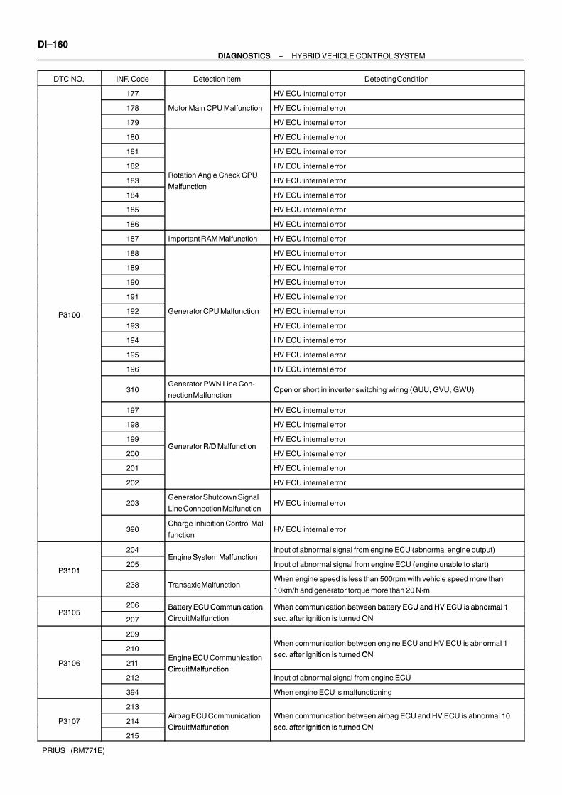
DI–160–DIAGNOSTICS HYBRID VEHICLE CONTROL SYSTEM
PRIUS (RM771E)
DTC NO. INF. Code Detection Item Detecting Condition
177 HV ECU internal error
178 Motor Main CPU Malfunction HV ECU internal error
179 HV ECU internal error
180 HV ECU internal error
181 HV ECU internal error
182 HV ECU internal error
183Rotation Angle Check CPU
MalfunctionHV ECU internal error
184Malfunction
HV ECU internal error
185 HV ECU internal error
186 HV ECU internal error
187 Important RAM Malfunction HV ECU internal error
188 HV ECU internal error
189 HV ECU internal error
190 HV ECU internal error
191 HV ECU internal error
P3100 192 Generator CPU Malfunction HV ECU internal errorP3100193 HV ECU internal error
194 HV ECU internal error
195 HV ECU internal error
196 HV ECU internal error
310Generator PWN Line Con-
nection MalfunctionOpen or short in inverter switching wiring (GUU, GVU, GWU)
197 HV ECU internal error
198 HV ECU internal error
199Generator R/D Malfunction
HV ECU internal error
200Generator R/D Malfunction
HV ECU internal error
201 HV ECU internal error
202 HV ECU internal error
203Generator Shutdown Signal
Line Connection MalfunctionHV ECU internal error
390Charge Inhibition Control Mal-
functionHV ECU internal error
204Engine System Malfunction
Input of abnormal signal from engine ECU (abnormal engine output)
P3101205
Engine System MalfunctionInput of abnormal signal from engine ECU (engine unable to start)
P3101
238 Transaxle MalfunctionWhen engine speed is less than 500rpm with vehicle speed more than
10km/h and generator torque more than 20 N·m
P3105206 Battery ECU Communication When communication between battery ECU and HV ECU is abnormal 1
P3105207
Battery ECU Communication
Circuit Malfunction
When communication between battery ECU and HV ECU is abnormal 1
sec. after ignition is turned ON
209
210When communication between engine ECU and HV ECU is abnormal 1
sec after ignition is turned ONP3106 211
Engine ECU Communication
CircuitMalfunction
sec. after ignition is turned ON
212Circuit Malfunction
Input of abnormal signal from engine ECU
394 When engine ECU is malfunctioning
213
P3107 214Airbag ECU Communication
CircuitMalfunction
When communication between airbag ECU and HV ECU is abnormal 10
sec after ignition is turned ON215
Circuit Malfunction sec. after ignition is turned ON

–DIAGNOSTICS HYBRID VEHICLE CONTROL SYSTEMDI–161
PRIUS (RM771E)
DTC NO. INF. Code Detection Item Detecting Condition
P3108216 A/C Amplifier Communication
When communication between A/C amplifier and HV ECU is abnormalP3108217
A/C Am lifier Communication
Circuit MalfunctionWhen communication between A/C amplifier and HV ECU is abnormal
218
219
P3109 220Brake ECU Communication
CircuitMalfunction
When communication between brake ECU and HV ECU is abnormal 1.5
sec after ignition is turned ON221
Circuit Malfunction sec. after ignition is turned ON
222
P3110 223 IG Circuit Malfunction When IGCT relay is always closed
224SMR C t1 M lf ti
+B short in system main relay NO. 1 circuit
225SMR Cont1 Malfunction
Open or short in system main relay No. 1 circuit
226SMR C t2 M lf ti
+B short in system main relay NO. 2 circuit
227SMR Cont2 Malfunction
Open or short in system main relay No. 2 circuit
P3115 228SMR C t3 M lf ti
+B short in system main relay NO. 3 circuit
229SMR Cont3 Malfunction
Open or short in system main relay No. 3 circuit
231 System main relay + terminal deposited
232 Deposit of SMR System main relay – terminal deposited
233 System main relay + & – terminal deposited
234 Small reduction of motor magnetism
235E B l M lf ti
Large reduction of motor magnetism
236Energy Balance Malfunction
Small reduction of generator magnetism
237 Large reduction of generator magnetism
239 Shaft damaged
240HV T l M lf ti
Generator locked
241HV Transaxle Malfunction
Torque limiter sliding
242 Planetary gear locked
243 Motor resolver inter–phase short
244
M t R l M lf ti
Motor resolver inter–phase short (When there is a history that the state of
malfunction continued during inverter fail safe mode)
245Motor Resolver Malfunction
Open or short in motor resolver circuit
P3120
246Open or short in motor resolver circuit (When there is a history that the
state of malfunction continued during inverter fail safe mode)P3120
247 GND short in motor temperature sensor
248 Motor Temperature Sensor Motor temperature sensor malfunction
249
Motor Tem erature Sensor
Malfunction Open or +B short in motor temperature sensor
250 Motor temperature sensor performance problem
253 Generator resolver inter–phase short
254Generator Resolver Malfunc-
Generator resolver inter–phase short (When there is a history that the
state of malfunction continued during inverter fail safe mode)
255
Generator Resolver Malfunc
tion Open or short in generator resolver circuit
256Open or short in generator resolver circuit (When there is a history that the
state of malfunction continued during inverter fail safe mode)
257 GND short in generator temperature sensor
258 Generator Temperature Sen- Generator temperature sensor malfunction
259
Generator Tem erature Sen
sor Malfunction Open or +B short in generator temperature sensor
260 Generator temperature sensor performance problem

DI–162–DIAGNOSTICS HYBRID VEHICLE CONTROL SYSTEM
PRIUS (RM771E)
DTC NO. INF. Code Detection Item Detecting Condition
263 +B short in DCDC converter NODD wiring
264 DCDC Converter Malfunction DCDC converter malfunction
265 Open or GND short in DCDC converter NODD wiring
266 Open or GND short in inverter voltage signal circuit
267 +B short in inverter voltage signal circuit
268 Inverter voltage signal is inconsistent with battery voltage
269 VM Malfunction Inverter voltage sensor malfunction
270
Abnormality of line connection of inverter voltage signal circuit (When there
is a history that the state of malfunction continued during inverter fail safe
mode)
272Motor PWN Line Connection
Malfunction
Abnormality of line connection of motor PWM (When there is a history that
the state of malfunction continued during inverter fail safe mode)
273Motor Inverter Gate Malfunc-
tionMotor inverter gate malfunction
274Motor Inverter Temperature
Open or +B short in motor inverter temperature sensor
275Motor Inverter Temperature
GND short in motor inverter temperature sensor
276SensorMalfunction
Motor inverter temperature sensor malfunction
277Sensor Malfunction
Motor inverter temperature sensor performance problem
278Motor Inverter Sinv
+B short in motor inverter stop signal circuit
279Motor Inverter Sinv
Over–voltage of inverter
280 Open or GND short in motor inverter stop signal circuit
281 Motor Inverter Sinv Voltage drop of inverter power source
282 Inverter circuit broken
P3125 283 +B short in motor inverter fail signal circuit
284 Inverter overheating
285 Motor Inverter Finv Open or GND short in motor inverter fail signal circuit
286 Inverter circuit broken
287 Inverter internal short
288 Motor inverter current sensor malfunction (V phase sub sensor)
289 Open in motor inverter current sensor (V phase sub sensor)
290 Motor inverter current sensor malfunction (V phase main sensor)
291(when there is a history that the state of malfunction continued during in-
verter fail safe mode)
292 Open in motor inverter current sensor (V phase main sensor)
293(when there is a history that the state of malfunction continued during in-
verter fail safe mode)
294Motor Inverter Current Sen
Motor inverter current sensor V phase performance problem
295
Motor Inverter Current Sen-
sor Malfunction (when there is a history that the state of malfunction continued during in-
verter fail safe mode)
296 Motor inverter current sensor malfunction (W phase sub sensor)
297 Open in motor inverter current sensor (W phase sub sensor)
298 Motor inverter current sensor malfunction (W phase main)
299(when there is a history that the state of malfunction continued during in-
verter fail safe mode)
300 Open in motor inverter current sensor (W phase main sensor)
301(when there is a history that the state of malfunction continued during in-
verter fail safe mode)

–DIAGNOSTICS HYBRID VEHICLE CONTROL SYSTEMDI–163
PRIUS (RM771E)
DTC NO. INF. Code Detection Item Detecting Condition
302Motor Inverter Current Sen
Motor inverter current sensor W phase performance problem
303
Motor Inverter Current Sen-
sor Malfunction (when there is a history that the state of malfunction continued during in-
verter fail safe mode)
304 Motor Gate Shutdown Signal +B short in motor gate shutdown signal circuit
305
Motor Gate Shutdown Signal
Line Connection Malfunction Open or GND short in motor gate shutdown signal circuit
306Failure in Monitoring Motor
Torque PerformanceFailure in monitoring motor torque performance
307Abnormal Current Value of
MotorAbnormal current value of motor
308 Detection of Collision Signal Input of collision signal from airbag or inverter
309Motor PWM Line Connection
Malfunction
Abnormality of generator PWM line connection (when there is a history that
the state of malfunction continued during fail safe mode)
311Generator Inverter Gate Mal-
functionGenerator inverter gate broken
312 Open or +B short in generator inverter temperature sensor
313 Generator Inverter Tempera- GND short in generator inverter temperature sensor
314
Generator Inverter Tem era
ture Sensor Malfunction Generator inverter temperature sensor malfunction
315 Generator inverter temperature sensor performance problem
316 +B short in generator inverter stop signal circuit
317 Over–voltage of inverter
318 Generator Inverter Sinv Open or GND short in generation inverter stop signal circuit
319 Voltage drop of inverter power source
320 Inverter circuit broken
P3125 321 +B short in generator inverter fail signal circuit
322 Inverter overheating
323 Generator Inverter Finv Open or GND short in generator inverter fail signal circuit
324 Inverter circuit broken
325 Inverter internal short
326 Generator inverter current sensor malfunction (V phase sub sensor)
327 Open in generator inverter current sensor (V phase sub sensor)
328 Generator inverter current sensor malfunction (V phase main sensor)
329(when there is a history that the state of malfunction continued during in-
verter fail safe mode)
330 Open in generator inverter current sensor (V phase main sensor)
331(when there is a history that the state of malfunction continued during in-
verter fail safe mode)
332Generator Inverter Current
Generator inverter current sensor V phase performance problem
333
Generator Inverter Current
Sensor Malfunction (when there is a history that the state of malfunction continued during in-
verter fail safe mode)
334 Generator inverter current sensor malfunction (W phase sub sensor)
335 Open in generator inverter current sensor (W phase sub sensor)
336 Generator inverter current sensor malfunction (W phase main sensor)
337(when there is a history that the state of malfunction continued during in-
verter fail safe mode)
338 Open in generator inverter current sensor (W phase main sensor)
339(when there is a history that the state of malfunction continued during in-
verter fail safe mode)

DI–164–DIAGNOSTICS HYBRID VEHICLE CONTROL SYSTEM
PRIUS (RM771E)
DTC NO. INF. Code Detection Item Detecting Condition
340Generator Inverter Current
Generator inverter current sensor W phase performance problem
341
Generator Inverter Current
Sensor Malfunction (when there is a history that the state of malfunction continued during in-
verter fail safe mode)
342 Motor Gate Shutdown Signal +B short in generator gate shutdown signal circuit
P3125 343
Motor Gate Shutdown Signal
Line Connection Open or GND short in generator gate shutdown signal circuit
344Failure in Monitoring Genera-
tor Torque PerformanceFailure in monitoring generator torque performance
345Abnormal Current Value of
GeneratorAbnormal current value of generator
P3130346 Inverter Cooling System Mal- Water pump system malfunction
P3130347
Inverter Cooling System Mal
function Radiator fan system malfunction
P3135348
Detection of Collision SignalGND short in circuit breaker sensor
P3135349
Detection of Collision SignalOpen or +B short in circuit breaker sensor
350Detection of Open in Interlock
Safety devices operating with vehicle speed less than 5 km/h
P3140351
Detection of Open in Interlock
Switch Open in interlock signal circuit while vehicle is running (with vehicle speed
more than 5 km/h)
P3145 352Cruise Control System Mal-
functionNo input of vehicle speed signal during cruise control driving

DI82M–01
A14129
Converter & Inverter Assembly
Engine Room R/B No.2IGCT Relay
Power Cable
Circuit Breaker Sensor
Service Plug
System Main Relay
Ignition Switch
Transponder Key ECU
Spot Light Switch
Airbag Sensor
HV ECU
Engine ECU
Battery ECU
–DIAGNOSTICS HYBRID VEHICLE CONTROL SYSTEMDI–165
PRIUS (RM771E)
PARTS LOCATION

DI82N–01
A04997
HV ECU Terminals
H16H17H18 H15 H14
12456789 3101112131416151920 17182122232425262728293031
12456 378910111213141615
1920 171821222324
12456 3789101112
1413151617
12346 57891011121314161519 171820212225262728 2324
123456789101112131415
1718 1619202122
DI–166–DIAGNOSTICS HYBRID VEHICLE CONTROL SYSTEM
PRIUS (RM771E)
TERMINALS OF ECU
Symbols (Terminals No.) Wiring Color Condition STD Voltage (V)
BATT (H18–3) –
GND1 (H18–31)G–Y ↔ W–B Always 9 – 14
+B1 (H18–4) – GND1 (H18–31) W–G ↔ W–B Ignition switch ON and ”READY” light ON 9 – 14
+B2 (H18–5) – GND1 (H18–31) W–G ↔ W–B Ignition switch ON and ”READY” light ON 9 – 14
IGSW (H17–7) – GND1
(H18–31)B–W ↔ W–B Ignition switch ON 9 – 14
ST2 (H17–6) – GND1 (H18–31) R–W ↔ W–B Ignition switch ST 9 – 14
ST1 (H18 2) GND1 (H18 31) B Y ↔ W BBrake pedal is depressed Below 0.5
ST1 (H18–2) – GND1 (H18–31) B–Y ↔ W–BBrake pedal is released 9 – 14
STP (H18 1) GND1 (H18 31) G W ↔ W BBrake pedal is depressed 9 – 14
STP (H18–1) – GND1 (H18–31) G–W ↔ W–BBrake pedal is released Below 0.5
VCP1 (H18–13) – GND1
(H18–31)Y ↔ W–B Ignition switch ON Approx. 5
VPA1 (H18–14) – GND1G ↔ W B
Ignition switch ON and accelerator pedal is released Approx. 1VPA1 (H18 14) GND1
(H18–31)G ↔ W–B
Ignition switch ON and accelerator pedal is fully depressed Approx. 4
EP1 (H18–12) – GND1
(H18–31)L ↔ W–B Ignition switch ON Below 0.5
VCP2 (H18–23) – GND1
(H18–31)B ↔ W–B Ignition switch ON Approx. 5
VPA2 (H18–15) – GND1W ↔ W B
Ignition switch ON and accelerator pedal is released Approx. 1VPA2 (H18 15) GND1
(H18–31)W ↔ W–B
Ignition switch ON and accelerator pedal is fully depressed Approx. 4
EP2 (H18–22) – GND1
(H18–31)R ↔ W–B Ignition switch ON Below 0.5
P (H17 15) GND1 (H18 31) L R ↔ W BShift lever is P range Below 1
P (H17–15) – GND1 (H18–31) L–R ↔ W–BExcept shift lever is P range 4 or more
R (H17 14) GND1 (H18 31) R B ↔ W BShift lever is R range Below 1
R (H17–14) – GND1 (H18–31) R–B ↔ W–BExcept shift lever is R range 4 or more
N (H17 13) GND1 (H18 31) L W ↔ W BShift lever is N range Below 1
N (H17–13) – GND1 (H18–31) L–W ↔ W–BExcept shift lever is N range 4 or more
D (H17 23) GND1 (H18 31) L B ↔ W BShift lever is D range Below 1
D (H17–23) – GND1 (H18–31) L–B ↔ W–BExcept shift lever is D range 4 or more
B (H17 22) GND1 (H18 31) LG R ↔ W BShift lever is B range Below 1
B (H17–22) – GND1 (H18–31) LG–R ↔ W–BExcept shift lever is B range 4 or more

–DIAGNOSTICS HYBRID VEHICLE CONTROL SYSTEMDI–167
PRIUS (RM771E)
Shift lever is P range Approx. 0.5
Shift lever is R range Approx. 2.8SFT (H17–11) – GSFT
(H17 21)B–R Shift lever is N range Approx. 3.4
(H17–21)Shift lever is D range Approx. 4.0
Shift lever is B range Approx. 4.5
VSFT (H17–12) – GSFT
(H17–21)W–R Ignition switch ON 4 or more
SPDI (H16–8) – GND1
(H18–31)V–W ↔ W–B Ignition switch ON and rotor driving wheel slowly Pulse generation
ESTP (H18–8) – GND1R Y W B
Engine stop is not required 9 – 14ESTP (H18 8) GND1
(H18–31)R–Y ↔ W–B
Engine stop is required Below 1
SPDO (H18–6) – GND1
(H18–31)O ↔ W–B Ignition switch ON and rotor driving wheel slowly Pulse generation
When converter is in normal operation 5 – 7NODD (H16–4) – GND1
(H18 31)L–O ↔ W–B When converter is improper 2 – 4
(H18–31)When converter is required to stop 0.1 – 0.5
ILK (H17 4) GND1 (H18 31) O ↔ W BIgnition switch ON and interlock switch ON Below 1
ILK (H17–4) – GND1 (H18–31) O ↔ W–BIgnition switch ON and interlock switch OFF 4 or more
AS1G (H16–14) – AS1
(H16–15)BR–B ↔ G–R Ignition switch ON 2.5 – 2.9
IB (H18 25) GB (H18 26) B L ↔ R WIgnition switch OFF Below 1
IB (H18–25) – GB (H18–26) B–L ↔ R–WIgnition switch from ON to ST (”READY” light ON) 0.5 – 4.5
ABFS (H17–3) – GND1
(H18–31)L ↔ W–B Ignition switch ON and ”READY” light ON 2.7 – 3.2
MREL (H16–7) – GND1
(H18–31)O ↔ W–B Ignition switch ON 9 – 14
Communication Line
Symbols (Terminals No.) Wiring Color Connecting Part or Symbol (Terminal No.)
GSNG (H14–11) G MG1, GSNG (M1–7)
GSN (H14–4) R MG1, GSN (M1–2)
GRF (H14–10) B MG1, GRF (M1–1)
GRFG (H14–17) W MG1, GRFG (M1–6)
GCS (H14–5) Y MG1, GCS (M1–3)
GCSG (H14–12) BR MG1, GCSG (M1–8)
GMTG (H14–8) G–W MG1, GMTG (M1–9)
GMT (H14–1) B–R MG1, GMT (M1–4)
MSNG (H14–20) G MG2, MSNG (M2–5)
MSN (H14–13) R MG2, MSN (M2–2)
MRF (H14–19) P MG2, MRF (M2–1)
MRFG (H14–18) L MG2, MRFG (M2–4)
MCS (H14–14) B MG2, MCS (M2–3)
MCSG (H14–21) W MG2, MCSG (M2–6)
MMTG (H14–9) R–W MG2, MMTG (M3–3)
MMT (H14–2) GR MG2, MMT (M3–1)
MSIV (H15–21) G Inverter, M–SINV (I10–7)
MSDN (H15–13) Y Inverter, M–SDOWN (I9–4)
MIT (H15–11) L Inverter, M–INVT (I9–5)

DI–168–DIAGNOSTICS HYBRID VEHICLE CONTROL SYSTEM
PRIUS (RM771E)
MWU (H15–6) G Inverter, M–WU (I9–3)
MUU (H15–4) R Inverter, M–UU (I9–1)
MVU (H15–5) W Inverter, M–VU (I9–2)
MIVG (H15–26) B Inverter, M–GINV (I9–6)
MIVA (H15–16) B Inverter, M–IVA (I10–1)
MIVB (H15–7) W Inverter, M–IVB (I10–3)
MIWB (H15–17) G Inverter, M–IWB (I10–4)
VB (H15–20) Y Inverter, VB (I10–5)
MIWA (H15–25) R Inverter, M–IWA (I10–2)
GIVA (H15–19) B Inverter, G–IVA (I12–1)
GIVB (H15–8) W Inverter, G–IVB (I12–4)
GIWB (H15–18) G Inverter, G–IWB (I12–4)
GIWA (H15–28) R Inverter, G–IWA (I12–2)
GSDN (H15–12) Y Inverter, G–SDOWN (I11–4)
GIT (H15–23) L Inverter, G–INVT (I11–5)
GWU (H15–3) G Inverter, G–WU (I11–3)
GVU (H15–2) W Inverter, G–VU (I11–2)
GUU (H15–1) R Inverter, G–UU (I11–1)
GIVG (H15–27) B Inverter, G–GINV (I11–6)
MFIV (H15–14) B Inverter, M–FINV (I10–8)
GSIV (H15–15) G Inverter, G–SINV (I12–7)
GFIV (H15–24) B Inverter, G–FINV (I12–8)
ETH+ (H18–28) P Engine ECU, ETH+ (E9–28)
ETH– (H18–27) L Engine ECU, ETH– (E9–27)
E TE+ (H18–19) Y Engine ECU, H TE+ (E9–19)
E–TE– (H18–29) BR Engine ECU, H TE– (E9–18)
HTB+ (H18–20) LG Brake ECU, HV+ (B10–24)
HTB– (H18–30) V Brake ECU, HV– (B10–16)
BTH+ (H18–18) G Brake ECU, HVO+ (B10–14)
BTH– (H18–17) R Brake ECU, HVO– (B10–22)
FCVC (H18–7) B–W Transponder Key ECU, HEVC (T5–8))
CON1 (H16–13) V System Main Relay (S6–3)
CON2 (H16–2) GR System Main Relay (S6–4)
CON3 (H17–1) P System Main Relay (S6–5)
HTD+ (H17–2) W Battery ECU, HTD+ (B16–6)
HTD– (H17–20) B Battery ECU, HTD– (B16–7)
DTD+ (H17–19) R Battery ECU, DTD+ (B16–18)
DTD– (H17–18) G Battery ECU, DTD– (B16–19)

DI82O–01
A14140
T4 Transponder Key ECU
HEVC8 B – W
7
H18 FCVC
Hybrid Vehicle Control ECU
–DIAGNOSTICS HYBRID VEHICLE CONTROL SYSTEMDI–169
PRIUS (RM771E)
CIRCUIT INSPECTION
DTC B2799 Immobilizer Malfunction
CIRCUIT DESCRIPTIONThe HV ECU checks the condition of the communication from the transponder key ECU.DTC B2799 – Information code 101
INF. code. Detecting Condition Trouble Area
101 No input of signal from transponder key ECU
Wire harness
HV ECU
Transponder key ECU
WIRING DIAGRAM

DI–170–DIAGNOSTICS HYBRID VEHICLE CONTROL SYSTEM
PRIUS (RM771E)
INSPECTION PROCEDURE
1 Check for open and short in wire harness between HV ECU FCVC terminal andtransponder key ECU HEVC terminal (See page IN–40).
NG Repair or replace wire harness.
OK
2 Check immobilizer system (See page BE–99).
NG Repair or replace immobilizer system.
OK
Replace HV ECU.

–DIAGNOSTICS HYBRID VEHICLE CONTROL SYSTEMDI–171
PRIUS (RM771E)
DTC C2692/C2693 Regenerative Brake Check
CIRCUIT DESCRIPTIONThese codes are used to check the regenerative brake at the manufacturing plant.DTC C2692 – Information code 102DTC C2693 – Information code 103
INF. code. Detecting Condition Trouble Area
102Regenerative brake check
103Regenerative brake check –
HINT:Since these are the codes that are used at the manufacturing plant, clear the DTC unless other DTC arerecorded.
DI82P–01

A14132
H18
Hybrid Vehicle Control ECU
VCP1
VPA1
EP1
VCP2
VPA2
EP2
A14 Accel Position Sensor
Y
6
5
3
4
2
1
VCP1
VPA1
EP1
VCP2
VPA2
EP2
H18
H18
H18
H18
H18
G
L
B
W
R
14
13
12
23
15
22
DI–172–DIAGNOSTICS HYBRID VEHICLE CONTROL SYSTEM
PRIUS (RM771E)
DTC P1120 Accelerator Pedal Position Sensor CircuitMalfunction
CIRCUIT DESCRIPTIONThe accelerator pedal position sensor mounted on the accelerator pedal has main and sub sensors and de-tects the accelerator pedal position and the malfunction of the accelerator position sensor itself.HINT: When using an OBD-6 scan tool other than hand–held tester, check all the steps. When using hand–held tester, confirm the information code and check it.
DTC P1120 – Information code 104, 105, 107, 108
INF. code. Detecting Condition Trouble Area
104 Open or short in main accelerator sensor circuit
105 +B short in main accelerator sensor circuitAccelerator pedal position sensor
107 Open or short in sub accelerator sensor circuit
Accelerator edal osition sensor
Wire harness
108 +B short in sub accelerator sensor circuit
WIRING DIAGRAM
DI82Q–01

–DIAGNOSTICS HYBRID VEHICLE CONTROL SYSTEMDI–173
PRIUS (RM771E)
INSPECTION PROCEDURE
1 Check for open, short and +B short in wire harness between HV ECU and accel-erator pedal position sensor (See page IN–40).
Terminals for checking open and short:
Accelerator pedal position sensor
TerminalsHV ECU Terminals
VCP1 VCP1
VPA1 VPA1
EP1 EP1
VCP2 VCP2
VPA2 VPA2
EP2 EP2
HINT:The acceleration pedal position sensor circuit has +B short if the voltage at the HV ECU VPA1 or VPA2 termi-nal is more than 5V with the ignition ON.
NG Repair or replace wire harness.
OK
Replace accelerator pedal position sensor.
DTC P1120 – Information code 106, 109, 110, 111, 112, 113, 114
INF. code. Detecting Condition Trouble Area
106 Main sensor internal error
109 Sub sensor internal error
110When difference between main sensor value and sub sensor
value is large
111When sub sensor value changes while main sensor value does
not Accelerator pedal position sensor
112When main sensor value changes while sub sensor value does
not
113When any of the information code 104 – 112 continues to ap-
pear
114 Accelerator pedal not smoothly returning to original position
INSPECTION PROCEDUREIf the information code 106 or 109 – 114 is output, replace the accelerator pedal position sensor.

A14147
H18
Hybrid Vehicle Control ECU
H18
Battery
MAIN B–G11
F18
1 1
1
1
1
1
F13
2
3
2 2
Engine Room J/B
STP
ST1–
G–WJ15E
2
J14D
J/C
G–W
S3 Stop Light SW
R–B
R–B
4B–YB–WB–W
B BJ22 J23 ID1
J/C
B–WI15 Ignition SW
W–R W–R6 7
9
IG2 AM2
Instrument Panel J/B
STOP
2C
2K 2H
2G91J 1B
AM2
B
W
F12F11
DC/DC
Fusible Link Block No. 1
Fusible Link Block No. 1
6
DI–174–DIAGNOSTICS HYBRID VEHICLE CONTROL SYSTEM
PRIUS (RM771E)
DTC P1520 Stop Light Switch (Cruise Control System)Malfunction
CIRCUIT DESCRIPTIONThe HV ECU detects the malfunction of the cruise control system and inhibits the operation of the cruisecontrol.HINT: When using an OBD-6 scan tool other than hand–held tester, check all the steps. When using hand–held tester, confirm the information code and check it.
DTC P1520 – Information code 115
INF. code. Detecting Condition Trouble Area
115 Open or short in stop light switch circuit
Stop light switch
Wire harness
HV ECU
WIRING DIAGRAM
DI82R–01

–DIAGNOSTICS HYBRID VEHICLE CONTROL SYSTEMDI–175
PRIUS (RM771E)
INSPECTION PROCEDURE
1 Is DTC of brake ECU being output?
YES Check DTC of brake ECU (See page DI–313).
NO
2 Check stop light switch (See page BE–36).
NG Replace stop light switch.
OK
3 Check for open and short in wire harness between stop light switch and HV ECU (See page IN–40).
NG Repair or replace wire harness.
OK
Replace HV ECU.

DI–176–DIAGNOSTICS HYBRID VEHICLE CONTROL SYSTEM
PRIUS (RM771E)
DTC P1566 Cruise Control System Malfunction
CIRCUIT DESCRIPTIONRefer to DTC P1520.HINT: When using an OBD-6 scan tool other than hand–held tester, check all the steps. When using hand–held tester, confirm the information code and check it.
DTC P1566 – Information code 116
INF. code. Detecting Condition Trouble Area
116When STP signal of HV ECU is inconsistent with that of brake
ECU, with cruise control indicator ON.
Brake ECU
HV ECU
WIRING DIAGRAMRefer to DTC P1520.
INSPECTION PROCEDURE
1 Is DTC of brake ECU being output (See page DI–306)?
NG Check DTC of brake ECU (See page DI–306).
OK
2 Check for +B short in wire harness between stop light switch and HV ECU (See page IN–40).
HINT:Under the normal condition, the voltage of the HV ECU STP terminal is 0V when the brake pedal is releasedwith the ignition OFF. If there is any output of voltage at this time, the stop light switch circuit has +B short.
NG Repair or replace wire harness.
OK
Replace HV ECU.
DI82S–01

A14146
Battery
B–G
11
F18
F13
Fusible Link Block No. 2
Hybrid Vehicle Control ECU
H18
Engine Room J/B
B BJ/C
1B
Fusible Link Block No. 1
F12B
1MAIN
1F
11 1HV
G–Y
J2 J3G–Y G–YIA1
4 3BATT
–DIAGNOSTICS HYBRID VEHICLE CONTROL SYSTEMDI–177
PRIUS (RM771E)
DTC P1600 BATT Malfunction
CIRCUIT DESCRIPTIONSince the ECU back–up power source is used for DTC and freeze frame data memory, the back–up powersource (BATT) continues to be supplied to the HV ECU even though the ignition switch is turned OFF.DTC P1600 – Information code 117
INF. code. Detecting Condition Trouble Area
117 HV ECU back–up power source circuit malfunctionWire harness
HV Fuse
WIRING DIAGRAM
DI82T–01

DI–178–DIAGNOSTICS HYBRID VEHICLE CONTROL SYSTEM
PRIUS (RM771E)
INSPECTION PROCEDURE
1 Check continuity of HV fuse of engine room J/B.
OK:Continuity
NG Check for short in all harness and parts con-nected to HV fuse.
OK
Repair or replace wire harness.

A14130
H17
Hybrid Vehicle Control ECU
N2 Neutral Start SW
P
6
5
3
4
2
8
VSFT
SFT
FSFT
L–R
L–W
L–B
N
D
B
R14
11
12
23
15
22
H17
H17
H17
H17
H17
H17
H17
13
21
9
7LG–R
R–B
W
B
R
–DIAGNOSTICS HYBRID VEHICLE CONTROL SYSTEMDI–179
PRIUS (RM771E)
DTC P1780 Neutral Start Switch System Malfunction
CIRCUIT DESCRIPTIONThe neutral start switch sends both main sensor signal (switch signal) and sub sensor signal (analogue val-ue) to the HV ECU. The HV ECU uses those signals to detect the shift lever position (P, R, N, D or B) andto control the forward and backward movement of the vehicle.HINT: When using an OBD-6 scan tool other than hand–held tester, check all the steps. When using hand–held tester, confirm the information code and check it.
DTC P1780 – Information code 118, 119, 120, 121
INF. code. Detecting Condition Trouble Area
118 When more than two main signals are ON
119When main signal is not turned ON even though sub signal has
been inputNeutral start switch
120 Open or short in sub sensor circuit
Neutral start switch
Wire harness
121When shift position detected by main signal is different from
that detected by sub signal
WIRING DIAGRAM
DI82U–01

DI–180–DIAGNOSTICS HYBRID VEHICLE CONTROL SYSTEM
PRIUS (RM771E)
INSPECTION PROCEDURE
1 Check for open and short in wire harness between neutral start switch and HVECU (See page IN–40).
Terminals for checking open and short:
Neutral Start Switch Terminals HV ECU Terminals
2 P
5 N
6 D
7 B
4 R
9 VSFT
8 SFT
3 GSFT
NG Repair or replace wire harness.
OK
Check and repair neutral start switch (See page HT–48).

–DIAGNOSTICS HYBRID VEHICLE CONTROL SYSTEMDI–181
PRIUS (RM771E)
DTC P3000 HV Battery Malfunction
CIRCUIT DESCRIPTIONThe HV ECU gives warning to the driver and performs the fail safe control, according to the abnormal signalreceived from the battery ECU.HINT: When using an OBD-6 scan tool other than hand–held tester, check all the steps. When using hand–held tester, confirm the information code and check it.
DTC P3000 – Information code 123, 125
INF. code. Detecting Condition Trouble Area
123Input of abnormal signal from battery ECU (HV battery system
malfunction)HV battery system
High voltage fuse
125Input of abnormal signal from battery ECU (high voltage fuse
blown out)
High voltage fuse
HV battery cooling system
Power Cable
INSPECTION PROCEDUREIf the information code 123 or 125 is output, after confirming the DTC of the HV battery system, check andrepair the applicable DTC. After repairing it, record the DTC of the HV ECU, freeze frame data and historyof operation. Then, clear the DTC and check it one more time after starting the system again (”READY” lightON).DTC P3000 – Information code 388
INF. code. Detecting Condition Trouble Area
388When charged battery is low due to leaving the vehicle in N
range, gas shortage or HV system malfunction–
INSPECTION PROCEDUREIf the information code 388 is output, check if other information codes are being output and then check andrepair the applicable code. After that, confirm the gas is affluent and it is OK if you can crank the engine again.DTC P3000 – Information code 388
INF. code. Detecting Condition Trouble Area
389When main battery is dead or main battery is dead due to HV
system malfunction–
INSPECTION PROCEDUREIf the information code 389 is output, check if other information codes are being output and then check repairthe applicable code. After that, replace the main battery and it is OK if you can crank the engine again.
DI82V–01

DI–182–DIAGNOSTICS HYBRID VEHICLE CONTROL SYSTEM
PRIUS (RM771E)
DTC P3001 HV Battery ECU Malfunction
CIRCUIT DESCRIPTIONDTC P3001 – Information code 129
INF. code. Detecting Condition Trouble Area
129 Battery ECU malfunction Battery ECU
INSPECTION PROCEDURE
1 Is DTC of battery ECU being output (See page DI–272)?
YES Check DTC of battery ECU.
NO
Replace the battery ECU.
DI82W–01

–DIAGNOSTICS HYBRID VEHICLE CONTROL SYSTEMDI–183
PRIUS (RM771E)
DTC P3004 Power Cable Malfunction
CIRCUIT DESCRIPTIONHINT: When using an OBD-6 scan tool other than hand–held tester, check all the steps. When using hand–held tester, confirm the information code and check it.
DTC P3004 – Information code 130
INF. Code. Detecting Condition Trouble Area
130 When HV battery voltage becomes lower than inverter voltage Converter & inverter assembly
INSPECTION PROCEDUREIf the above information code is output, replace the converter & inverter assembly.
DI82X–01

DI–184–DIAGNOSTICS HYBRID VEHICLE CONTROL SYSTEM
PRIUS (RM771E)
DTC P3004 – Information code 131
INF. Code. Detecting Condition Trouble Area
131
When condition (a), (b) or (c) is detected:
(d) Main fuse blown out
(e) Service plug disconnected
(f) Limiter resistance cut off
Main fuse
Service plug
Limiter resistance
INSPECTION PROCEDURE
1 Check continuity of main fuse in the service plug.
NG Check the cause of open circuit and replacemain fuse.
OK
2 Check the condition of service plug terminal (Loosened, poor contact, etc.).
NG Replace service plug.
OK
3 Check the continuity of power cable.
NG Replace the power cable.
OK
Replace the system main relay.

–DIAGNOSTICS HYBRID VEHICLE CONTROL SYSTEMDI–185
PRIUS (RM771E)
CIRCUIT DESCRIPTIONDTC P3004 – Information code 132
INF. Code. Detecting Condition Trouble Area
132When inverter voltage sensor is malfunctioning or limiter resis-
tance value increases.
Converter & inverter assembly
System main relay
INSPECTION PROCEDURE
1 Are other information codes recorded?
YES Check applicable information code (See pageDI–265).
NO
2 Check continuity of power cable.
OK:Continuity: Less than 1Ω
NG Replace power cable.
OK
Replace system main relay.

DI–186–DIAGNOSTICS HYBRID VEHICLE CONTROL SYSTEM
PRIUS (RM771E)
CIRCUIT DESCRIPTIONThe HV ECU gives warning to the driver and performs the fail safe control, according to the abnormal signalreceived from the battery ECU.DTC P3004 – Information code 133
INF. Code. Detecting Condition Trouble Area
133 Input of abnormal signal from battery ECU HV battery system
INSPECTION PROCEDUREIf the information code 133 output, after confirming the DTC of the HV ECU, check and repair the applicableDTC. After repairing it, record the DTC of the HV ECU, freeze frame data and history of operation. Then,clear the DTC and check it one more time after starting the system again (”READY” light ON).

A14150
H16
Hybrid Vehicle Control ECU
1021GO
G9IA2
GE9GO
Engine ECU
–DIAGNOSTICS HYBRID VEHICLE CONTROL SYSTEMDI–187
PRIUS (RM771E)
DTC P3100 HV ECU Malfunction
CIRCUIT DESCRIPTIONHINT: When using an OBD-6 scan tool other than hand–held tester, check all the steps. When using hand–held tester, confirm the information code and check it.
DTC P3100 – Information code 136, 137
INF. Code. Detecting Condition Trouble Area
136 Open or short in GO signal circuit Wire harness
HV ECU137 Engine speed sensor malfunction
HV ECU
Engine speed sensor
WIRING DIAGRAM
DI82Y–01

DI–188–DIAGNOSTICS HYBRID VEHICLE CONTROL SYSTEM
PRIUS (RM771E)
INSPECTION PROCEDURE
1 Is DTC of engine ECU being output (See page DI–1)?
Yes Check applicable DTC (See page DI–1).
NO
2 Check for open and short in wire harness between GO terminal of HV ECU andGO terminal of engine ECU (See page IN–40).
NG Repair or replace wire harness.
OK
Replace HV ECU.

A14734
Hybrid VehicleControl ECU
25H18 IB
B–L
R–W
Battery ECU
26H18 GB
B–L 6IB1
10IB1
R–W
16B16
17B16
IB
GB
–DIAGNOSTICS HYBRID VEHICLE CONTROL SYSTEMDI–189
PRIUS (RM771E)
CIRCUIT DESCRIPTIONThe HV ECU checks the current value of the battery and detects malfunction.DTC P3100 – Information code 127, 128
INF. Code. Detecting Condition Trouble Area
127 +B short in IB terminal circuit of HV ECU
128 Open or short in IB terminal circuit of HV ECUWire harness
HV ECU
138When the difference between battery current of HV ECU
and current of battery is large.
HV ECU
Battery ECU
WIRING DIAGRAM

DI–190–DIAGNOSTICS HYBRID VEHICLE CONTROL SYSTEM
PRIUS (RM771E)
INSPECTION PROCEDURE
1 Is DTC of battery ECU being output (See page DI–265)?
Yes Check applicable DTC (See page DI–265).
NO
2 Check for open, short and +B short in wire harness between HV ECU IB and GBterminals and battery ECU IB and GB terminals (See page IN–40).
HINT:The HV ECU IB terminal has +B short if there is no open in wire harness and the voltage of the IB or GBterminal is more than 5 V with the ignition ON.
NG Repair or replace wire harness.
OK
Replace HV ECU.

A14148
Hybrid Vehicle Control ECUInstrument Panel J/B I15
Ignition SW
Engine Room J/B Fusible Link Block No. 1
ST2R–W6
H172C
2W–R
2G
2W–R
1J
9 AM2B
B–G
MAIN
Battery
1B
2
F12
1
F131
B–GF181
Fusible Link Block No. 2
ST2AM27 8
–DIAGNOSTICS HYBRID VEHICLE CONTROL SYSTEMDI–191
PRIUS (RM771E)
CIRCUIT DESCRIPTIONThe HV ECU checks the ST signal and detects malfunction. If the ST signal has +B short, the ST will alwaysbe ON. Therefore, even with the IG ON when starting the THS, the system will start. To prevent this fromhappening, the HV ECU detects the malfunction of the ST signal.DTC P3100 – Information code 142
INF. Code. Detecting Condition Trouble Area
142When ST signal of HV ECU is ON, with ignition switch
turned OFF.
Wire harness
HV ECU
Ignition switch
WIRING DIAGRAM

DI–192–DIAGNOSTICS HYBRID VEHICLE CONTROL SYSTEM
PRIUS (RM771E)
INSPECTION PROCEDURE
1 Check ignition switch (See page BE–17).
NG Replace ignition switch (See page SR–11).
NO
2 Check for +B short in wire harness between ignition switch ST2 terminal and HVECU ST2 terminal (See page IN–40).
HINT:The HV ECU ST circuit has +B short if battery voltage is supplied to the ST2 terminal with the ignition ON.
NG Repair or replace wire harness.
OK
Replace HV ECU.

–DIAGNOSTICS HYBRID VEHICLE CONTROL SYSTEMDI–193
PRIUS (RM771E)
CIRCUIT DESCRIPTIONThe HV ECU checks the line connection of the inverter switching wiring (MUU, MVU and MWU) and detectsmalfunction.DTC P3100 – Information code 271
INF. Code. Detecting Condition Trouble Area
271 Motor PWM line connection malfunction Converter & inverter assembly
INSPECTION PROCEDUREIf any of these information codes is output, replace the converter & inverter.
CIRCUIT DESCRIPTIONThe HV ECU checks the line connection of the inverter switching wiring (GUU, GVU and GWU) and detectsmalfunction.DTC P3100 – Information code 310
INF. Code. Detecting Condition Trouble Area
310 Generator PWM line connection malfunction Converter & inverter assembly
INSPECTION PROCEDUREIf any of these information codes is output, replace the converter & inverter.

DI–194–DIAGNOSTICS HYBRID VEHICLE CONTROL SYSTEM
PRIUS (RM771E)
CIRCUIT DESCRIPTIONThe HV ECU checks the internal operation of the ECU and detects malfunction.DTC P3100 – Information code 134, 135, 139, 140, 141, 143, 144, 145, 146, 147, 148, 149, 150, 151, 152,153, 154, 155, 156, 157, 158, 159, 160, 161, 162, 163, 164, 165, 166, 167, 168, 169, 170, 171, 172, 173,174, 175, 176, 177, 178, 179, 180, 181, 182, 183, 184, 185, 186, 187, 188, 189, 190, 191, 192, 193, 194,195, 196, 197, 198, 199, 200, 201, 202, 203, 390, 391, 392, 393
INF. Code. Detecting Condition Trouble Area
134 HV ECU internal error HV ECU
135
139
140
141
143
144
145
146
147
148
149
150
151
152
153
154
155
156
157
158
159
160
161
162
163
164
165
166
167
168
169

–DIAGNOSTICS HYBRID VEHICLE CONTROL SYSTEMDI–195
PRIUS (RM771E)
INF. Code. Detecting Condition Trouble Area
170 HV ECU internal error HV ECU
171
172
173
174
175
176
177
178
179
180
181
182
183
184
185
186
187
188
189
190
191
192
193
194
195
196
197
198
199
200
201
202
203
390
391
392
393
INSPECTION PROCEDUREIf any of the above information codes is output, replace the HV ECU.

DI–196–DIAGNOSTICS HYBRID VEHICLE CONTROL SYSTEM
PRIUS (RM771E)
DTC P3101 Engine System Malfunction
CIRCUIT DESCRIPTIONThe HV ECU performs the fail safe control, according to the abnormal signal from the engine ECU.HINT: When using an OBD-6 scan tool other than hand–held tester, check all the steps. When using hand–held tester, confirm the information code and check it.
DTC P3101 – Information code 204, 205
INF. Code. Detecting Condition Trouble Area
204Input of abnormal signal from the engine ECU (abnormal
engine output)Engine
205Input of abnormal signal from the engine ECU (engine un-
able to start)
Engine
INSPECTION PROCEDUREIf any of the above information codes is output, after confirming the DTC of the engine ECU, check and repairthe applicable DTC. After repairing it, record the DTC of the HV ECU, freeze frame data and history of opera-tion. Then, clear the DTC and check it one more time after starting the system again (”READY” light ON).
CIRCUIT DESCRIPTIONThe HV ECU detects the seizure of the engine or transmission gear and a foreign material and performs thefail safe control.DTC P3101 – Information code 238
INF. Code. Detecting Condition Trouble Area
238 When engine does not start even though cranking it.Engine
HV transaxle
INSPECTION PROCEDUREIf the above information code is output, investigate what has caused the revolution resistance of the trans-axle and engine to become greater. Check the engine lubrication system and transaxle lubrication system. Check the engine coolant and transaxle coolant. Check for any breakdowns in engine itself and transaxle itself.
DI82Z–01

A14734
Hybrid Vehicle Control ECU
19
H17 DTH+
DTH–
R
G
Battery ECU
18
H17
4
IF2
3
IF2
R
G
18
B16
19
B16
BEH+
BEH–
–DIAGNOSTICS HYBRID VEHICLE CONTROL SYSTEMDI–197
PRIUS (RM771E)
DTC P3105 Battery ECU Communication Circuit Mal-function
CIRCUIT DESCRIPTIONThe HV ECU performs multiple checks to avoid any malfunction that may occur through the communicationwith the battery ECU due to a noise, etc.DTC P3105 – Information code 206, 207, 208
INF. Code. Detecting Condition Trouble Area
206Wire harness
207When communication between battery ECU and HV ECU is
abnormal 1 sec after ignition is turned ON
Wire harness
HV ECU
208abnormal 1 sec. after ignition is turned ON
Battery ECU
WIRING DIAGRAM
DI830–01

DI–198–DIAGNOSTICS HYBRID VEHICLE CONTROL SYSTEM
PRIUS (RM771E)
INSPECTION PROCEDURE
1 Check for open and short in wire harness between HV ECU terminals (DTH+,DTH–) and battery ECU terminals (BEH+, BEH–) (See page IN–40).
NG Repair or replace wire harness.
OK
2 Check battery ECU (See page DI–265).
NG Replace battery ECU circuit.
OK
Replace HV ECU.

A14738
Hybrid Vehicle Control ECU
28
H18 ETH+
ETH–
Engine ECU
27
H18
P
L
28E9
27
E9
ETH+
ETH–
–DIAGNOSTICS HYBRID VEHICLE CONTROL SYSTEMDI–199
PRIUS (RM771E)
DTC P3106 Engine ECU Communication Circuit Mal-function
CIRCUIT DESCRIPTIONThe HV ECU performs multiple checks to avoid any malfunction that may occur through the communicationwith the engine ECU due to a noise, etc.HINT: When using an OBD-6 scan tool other than hand–held tester, check all the steps. When using hand–held tester, confirm the information code and check it.
DTC P3106 – Information code 209, 210, 211
INF. Code. Detecting Condition Trouble Area
209Wire harness
210When communication between engine ECU and HV ECU is
abnormal 1 sec after ignition is turned ON
Wire harness
HV ECU
211abnormal 1 sec. after ignition is turned ON
Engine ECU
WIRING DIAGRAM
DI831–01

DI–200–DIAGNOSTICS HYBRID VEHICLE CONTROL SYSTEM
PRIUS (RM771E)
INSPECTION PROCEDURE
1 Check for open and short in wire harness between HV ECU terminals (ETH+,ETH–) and engine ECU terminals (ETH+, ETH–) (See page IN–40).
NG Repair or replace wire harness.
OK
2 Check engine ECU (See page DI–1).
NG Replace engine ECU circuit.
OK
Replace HV ECU.

–DIAGNOSTICS HYBRID VEHICLE CONTROL SYSTEMDI–201
PRIUS (RM771E)
CIRCUIT DESCRIPTIONDTC P3106 – Information code 212
INF. Code. Detecting Condition Trouble Area
212 Input of abnormal signal from engine ECU Engine ECU
INSPECTION PROCEDUREIf the information code 212 is output, after confirming the DTC of the engine ECU, check and repair the appli-cable DTC. After repairing it, record the DTC of the HV ECU, freeze frame data and history of operation.Then, clear the DTC and check it one more time after starting the system again (”READY” light ON).
CIRCUIT DESCRIPTIONDTC P3106 – Information code 394
INF. Code. Detecting Condition Trouble Area
394 When engine ECU does not operate Engine ECU
INSPECTION PROCEDUREIf the information code 394 is output, check and repair the engine ECU power source circuit. If there is noproblem in the power source circuit, replace the engine ECU. After the repair, record the DTC of the HV ECU,freeze frame data and history of operation and clear them. Then, start the system one more time (”READY”light ON) and check the DTC again.

A14139
Hybrid Vehicle Control ECU
3
H17 ABFSL23
A19GSW2
Airbag SensorAssembly
DI–202–DIAGNOSTICS HYBRID VEHICLE CONTROL SYSTEM
PRIUS (RM771E)
DTC P3107 Airbag ECU Communication Circuit Mal-function
CIRCUIT DESCRIPTIONThe HV ECU detects the malfunction of the collision signal circuit from the airbag and gives warning to thedriver.DTC P3107 – Information code 213, 214, 215
INF. Code. Detecting Condition Trouble Area
213Wire harness
214When communication between airbag ECU and HV ECU is
abnormal 10 sec after ignition is turned ON
Wire harness
HV ECU
215abnormal 10 sec. after ignition is turned ON
Airbag sensor
WIRING DIAGRAM
DI832–01
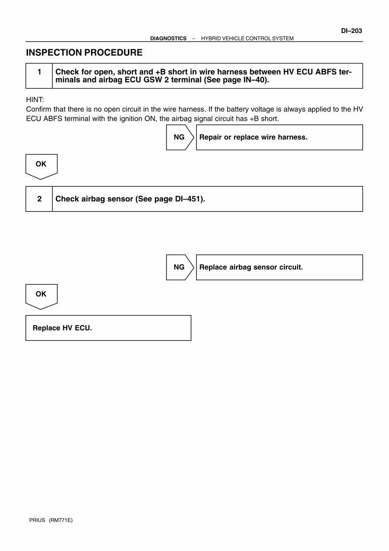
–DIAGNOSTICS HYBRID VEHICLE CONTROL SYSTEMDI–203
PRIUS (RM771E)
INSPECTION PROCEDURE
1 Check for open, short and +B short in wire harness between HV ECU ABFS ter-minals and airbag ECU GSW 2 terminal (See page IN–40).
HINT:Confirm that there is no open circuit in the wire harness. If the battery voltage is always applied to the HVECU ABFS terminal with the ignition ON, the airbag signal circuit has +B short.
NG Repair or replace wire harness.
OK
2 Check airbag sensor (See page DI–451).
NG Replace airbag sensor circuit.
OK
Replace HV ECU.

DI–204–DIAGNOSTICS HYBRID VEHICLE CONTROL SYSTEM
PRIUS (RM771E)
DTC P3108 A/C Amplifier Communication Circuit Mal-function
CIRCUIT DESCRIPTIONThe HV ECU detects the abnormal signal from the A/C amplifier and records it.DTC P3108 – Information code 216, 217
INF. Code. Detecting Condition Trouble Area
216 When communication between A/C amplifier and HV ECUWire harness
HV ECU217
When communication between A/C am lifier and HV ECU
is abnormal.HV ECU
A/C ECU
INSPECTION PROCEDUREIf the information code 216 or 217 is output, after confirming the DTC of the A/C amplifier, check and repairthe applicable DTC. After repairing it, record the DTC of the HV ECU, freeze frame data and history of opera-tion. Then, clear the DTC and check it one more time after starting the system again (”READY” light ON).
DI833–01

A14137
Hybrid Vehicle Control ECU
20
H18 HTB+
HTB–
BTH+
BTH–
Brake ECU
30
H18
18
H18
17
H18
LG
V
G
R
24B10
16
B10
14
B10
22
B10
HV1+
HV1–
HVO+
HVO–
–DIAGNOSTICS HYBRID VEHICLE CONTROL SYSTEMDI–205
PRIUS (RM771E)
DTC P3109 Brake ECU Communication Circuit Malfunc-tion
CIRCUIT DESCRIPTIONThe HV ECU performs multiple checks to avoid any malfunction that may occur through the communicationwith the brake ECU due to a noise, etc.DTC P3109 – Information code 218, 219, 220, 221, 222
INF. Code. Detecting Condition Trouble Area
218
219 When communication between brake ECU and HV ECU is Wire harness220
When communication between brake ECU and HV ECU is
abnormal 1.5 sec. after ignition is turned ON
Wire harness
HV ECU
221
g
Brake ECU
222
WIRING DIAGRAM
DI834–01

DI–206–DIAGNOSTICS HYBRID VEHICLE CONTROL SYSTEM
PRIUS (RM771E)
INSPECTION PROCEDURE
1 Check for open, short and +B short in wire harness between HV ECU terminals(HTB+, HTB–, BTH+, BTH–) and brake ECU terminals (HV1+, HV1–, HVO+, HVO–)(See page IN–40).
HINT:Confirm that there is no open circuit in the wire harness. If the voltage of each HV ECU terminals (HTB+,HTB–, BTH+ and BTH–) is always more than 5 V with the ignition ON, the brake ECU communication circuithas +B short.
NG Repair or replace wire harness.
OK
2 Check brake ECU (See page DI–306).
NG Replace brake ECU circuit.
OK
Replace HV ECU.

A14151
Hybrid Vehicle Control ECUEngine Room R/B No. 2
Fusible LinkBlock No. 1
Battery
+B1
MREL
4
H18
1F
G–Y W–G
O
2
7
H16
W–G12IA1
2
2
22 1
35
Engine Room J/B
11
HV
F12B–G MAIN
1B 1
B
F13
Fusible LinkBlock No. 2
1
F18
AJ7J/C
W–B
IE EC
W–B (RHD)
W–B (LHD)
W–B (LHD)
A
J1J/C
A A
IGCT Relay
–DIAGNOSTICS HYBRID VEHICLE CONTROL SYSTEMDI–207
PRIUS (RM771E)
DTC P3110 IGCT Relay Malfunction
CIRCUIT DESCRIPTIONThe HV ECU checks the IGCT relay and detects malfunction.DTC P3110 – Information code 223
INF. Code. Detecting Condition Trouble Area
223
When IGCT relay is always closed.Wire harness
IGCT relay
WIRING DIAGRAM
DI835–01

A14712
12
3
5
12
3
5
Ohmmeter
Battery
Continuity
Ohmmeter
Ohmmeter
Continuity
No Continuity
DI–208–DIAGNOSTICS HYBRID VEHICLE CONTROL SYSTEM
PRIUS (RM771E)
INSPECTION PROCEDURE
1 Check IGCT relay.
PREPARATION:Remove the IGCT relay from the engine room R/B No. 3.CHECK:(a) Using an ohmmeter, check that there is continuity be-
tween terminals 1 and 2.(b) Check that there is no continuity between terminals 3 and
5.(c) Apply battery voltage across terminals 1 and 2. Using an
ohmmeter, check that there is continuity between termi-nals 3 and 5.
OK:(a) Continuity(b) No continuity(c) Continuity
NG Replace IGCT relay.
OK
Check for +B short in wire harness between HV ECU and IGCT relay (See page IN–40)Repair or replace wire harness.
HINT:The HV ECU MREL terminal has +B short if the battery voltage is always applied to the HV ECU +B1 or MRELterminal with the ignition OFF.

A14143
Hybrid Vehicle Control ECU
13
H16 CON1
CON2
CON3
System Main Relay
2
H16
1
H17
V
GR
P
3S6
V
GR
P
8
IH1
9
IH1
11
IF1
4S6
5S6
–DIAGNOSTICS HYBRID VEHICLE CONTROL SYSTEMDI–209
PRIUS (RM771E)
DTC P3115 System Main Relay Malfunction
CIRCUIT DESCRIPTIONThe HV ECU checks that the system main relay (No. 1, No. 2, No. 3) is normally operating and detects mal-function.HINT: When using an OBD-6 scan tool other than hand–held tester, check all the steps. When using hand–held tester, confirm the information code and check it.
DTC P3115 – Information code 224, 225, 226, 227, 228, 229
INF. Code. Detecting Condition Trouble Area
224 Open or +B short in system main relay No. 1 circuit
225 Short in system main relay No. 1 circuit
226 Open or +B short in system main relay No. 2 circuit Wire harness
S t i l227 Short in system main relay No. 2 circuit
System main relay
HV ECU228 Open or +B short in system main relay No. 3 circuit
HV ECU
229 Short in system main relay No. 3 circuit
WIRING DIAGRAM
DI836–01

DI–210–DIAGNOSTICS HYBRID VEHICLE CONTROL SYSTEM
PRIUS (RM771E)
INSPECTION PROCEDURE
1 Check for open, short and +B short in wire harness between HV ECU terminals(Cont1, Cont2, Cont3) and system main relay terminals (See page IN–40).
HINT:Confirm that there is no open circuit in the wire harness. If the battery voltage is always applied to the HVECU Cont1, Cont2 and Cont3 terminals with the ignition ON (”READY” light OFF), the system main relayhas +B short.
NG Repair or replace wire harness.
OK
2 Is any of the information code 231, 232 or 233 recorded?
NO Replace HV ECU.
YES
Replace system main relay.

–DIAGNOSTICS HYBRID VEHICLE CONTROL SYSTEMDI–211
PRIUS (RM771E)
CIRCUIT DESCRIPTIONIf the system main relay is deposited, it might be impossible to shut down the high voltage system. Therefore,the HV ECU checks the system main relay and stops the system if malfunction is detected.DTC P3115 – Information code 231, 232, 233
INF. Code. Detecting Condition Trouble Area
231 System main relay + terminal deposited
232 System main relay – terminal depositedSystem main relay
HV ECU233 System main relay + & – terminal deposited
HV ECU
INSPECTION PROCEDUREIf any of these information codes is output, replace the system main relay.If one of the information codes above and any of the information codes 224 – 229 are recorded at the sametime, also replace the HV ECU.

DI–212–DIAGNOSTICS HYBRID VEHICLE CONTROL SYSTEM
PRIUS (RM771E)
DTC P3120 HV Transaxle Malfunction
CIRCUIT DESCRIPTIONThe HV ECU checks the energy balance and detects abnormality if the magnetism of the motor or generatorgreatly decreases.HINT: When using an OBD-6 scan tool other than hand–held tester, check all the steps. When using hand–held tester, confirm the information code and check it.
DTC P3120 – Information code 234, 235, 236, 237
INF. Code. Detecting Condition Trouble Area
234 Small reduction of motor magnetismHV transaxle (motor)
235 Large reduction of motor magnetismHV transaxle (motor)
236 Small reduction of generator magnetismHV transaxle (generator)
237 Large reduction of generator magnetismHV transaxle (generator)
INSPECTION PROCEDURE
1 Is DTC of HV battery ECU being output?
YES Check applicable DTC.
NO
DI837–01

–DIAGNOSTICS HYBRID VEHICLE CONTROL SYSTEMDI–213
PRIUS (RM771E)
2 Check main current sensor. (In SMR)
Measurement of Resistance between SMR S6 Connector Ter-minals
Terminal No. (Tester +) Terminal No. (Tester –) Resistance
7 2 30 – 50 kΩ
7 6 More than 10 MΩ
2 7 30 – 50 kΩ
2 6 More than 10 MΩ
6 7 300 – 400 kΩ
6 2 3 – 5 MΩ
NG Replace system main relay.
OK
Replace HV transaxle motor or generator.
CIRCUIT DESCRIPTIONThe HV ECU detects the malfunction of the transmission system. Judging from a malfunction symptom, itrecords one of the four information codes.DTC P3120 – Information code 239, 240, 241, 242
INF. Code. Detecting Condition Trouble Area
239 Shaft damaged
240 Generator lockedHV transaxle
241 Torque limiter slidingHV transaxle
242 Planetary gear locked
INSPECTION PROCEDUREIf any of these information codes is output, replace the defective part inside the HV transaxle.

A14122
Motor Generator No. 2Hybrid Vehicle Control ECU
MSNG
MSN
MCS
MCSG
MRF
MRFG
5
M2
2
M23
M2
6M2
1
M24
M2
G
R
MSNG
MSN
MCS
MCSG
MRF
MRFG
P
L
B
W
20
H14
13H14
14
H1421
H14
19H14
18H14
DI–214–DIAGNOSTICS HYBRID VEHICLE CONTROL SYSTEM
PRIUS (RM771E)
CIRCUIT DESCRIPTIONThe HV ECU checks the motor resolver and detects malfunction.DTC P3120 – Information code 243, 244, 245, 246
INF. Code. Detecting Condition Trouble Area
243 Motor resolver inter–phase short
244
Motor resolver inter–phase short (when there is a history
that the state of malfunction continued during inverter fail
safe mode)HV transaxle
245 Open or short in motor resolver circuit
HV transaxle
Wire harness
246
Open or short in motor resolver circuit (when there is a
history that the state of malfunction continued during invert-
er fail safe mode)
WIRING DIAGRAM

–DIAGNOSTICS HYBRID VEHICLE CONTROL SYSTEMDI–215
PRIUS (RM771E)
INSPECTION PROCEDURE
1 Check for open and short in wire harness between HV transaxle and HV ECU (See page IN–40).
Terminals for checking open and short:
MG2 Terminals HV ECU Terminals
MSNG MSNG
MSN MSN
MCS MCS
MCSG MCSG
MRF MRF
MRFG MRFG
NG Repair or replace wire harness.
OK
Check for open in motor resolver or inter–phase short and then replace HV transaxle motor.Check motor resolver (See page HV–40).

A14121
Motor Generator No. 2Hybrid Vehicle Control ECU
MMTG
MMT
3
M3
1M3
R–W MMTG
MMTGR
9
H14
2H14
DI–216–DIAGNOSTICS HYBRID VEHICLE CONTROL SYSTEM
PRIUS (RM771E)
CIRCUIT DESCRIPTIONThe HV ECU checks the motor temperature and controls the load limitation in order to prevent the motor fromoverheating. Also, it detects the abnormality of the line connection of the motor temperature sensor and mal-function of the sensor itself.DTC P3120 – Information code 247, 249
INF. Code. Detecting Condition Trouble Area
247 GND short in motor temperature sensorHV transaxle
249 Open or +B short in motor temperature sensor
HV transaxle
Wire harness
WIRING DIAGRAM

–DIAGNOSTICS HYBRID VEHICLE CONTROL SYSTEMDI–217
PRIUS (RM771E)
INSPECTION PROCEDURE
1 Check open, short and +B short in wire harness between HV transaxle motortemperature sensor MMT and MMTG terminals and HV ECU MMT and MMTG ter-minals (See page IN–40).
HINT:Confirm that there is no open circuit in the wire harness. If the voltage of the HV ECU MMT terminal is alwaysmore than 5V with the ignition ON, the motor temperature sensor circuit has +B short.
NG Repair or replace wire harness.
OK
Check for open in motor temperature sensor and then replace HV transaxle motor.Check motor temperature sensor (See page HV–40).
CIRCUIT DESCRIPTIONDTC P3120 – Information code 248, 250
INF. Code. Detecting Condition Trouble Area
248 Motor temperature sensor malfunctionHV transaxle motor
250 Motor temperature sensor performance problemHV transaxle motor
INSPECTION PROCEDUREIf the information code 248 or 250 is output, replace the HV transaxle motor.

A14122
Motor Generator No. 1Hybrid Vehicle Control ECU
7
M1
2
M11
M1
6M1
3
M18
M1
G
R
GSNG
GSN
GRF
GRFG
GCS
GCSG
B
W
Y
BR
11
H14
4
H14
10
H1417H14
5H14
12
H14
GSNG
GSN
GRF
GRFG
GCS
GCSG
DI–218–DIAGNOSTICS HYBRID VEHICLE CONTROL SYSTEM
PRIUS (RM771E)
CIRCUIT DESCRIPTIONThe HV ECU checks the generator resolver and detects malfunction.DTC P3120 – Information code 253, 254, 255, 256
INF. Code. Detecting Condition Trouble Area
253 Generator resolver inter–phase short
254
Generator resolver inter–phase short (when there is a histo-
ry that the state of malfunction continued during inverter fail
safe mode)HV transaxle (generator)
255 Open or short in generator resolver circuit
HV transaxle (generator)
Wire harness
256
Open or short in generator resolver circuit (when there is a
history that the state of malfunction contained during invert-
er fail safe mode)
WIRING DIAGRAM

–DIAGNOSTICS HYBRID VEHICLE CONTROL SYSTEMDI–219
PRIUS (RM771E)
INSPECTION PROCEDURE
1 Check for open and short in wire harness between HV transaxle and HV ECU (See page IN–40).
Terminals for checking open and short:
MG1 Terminals HV ECU Terminals
GSNG GSNG
GSN GSN
GCS GCS
GCSG GCSG
GRF GRF
GRFG GRFG
NG Repair or replace wire harness.
OK
Check for open in generator resolver or inter–phase short and then replace HV transaxle genera-tor.Check generator resolver (See page HV–40).

A14121
Motor Generator No. 1Hybrid Vehicle Control ECU
4
M1
9
M1
B–R GMT
GMTGG–W
1
H14
8H14
GMT
GMTG
DI–220–DIAGNOSTICS HYBRID VEHICLE CONTROL SYSTEM
PRIUS (RM771E)
CIRCUIT DESCRIPTIONThe HV ECU checks the generator temperature and controls the load limitation in order to prevent the gener-ator from overheating. Also, it detects the abnormality of the line connection of the generator temperaturesensor and the malfunction of the sensor itself.DTC P3120 – Information code 254, 259
INF. Code. Detecting Condition Trouble Area
257 GND short in generator temperature sensorHV transaxle
259 Open or +B short in generator temperature sensor
HV transaxle
Wire harness
WIRING DIAGRAM

–DIAGNOSTICS HYBRID VEHICLE CONTROL SYSTEMDI–221
PRIUS (RM771E)
INSPECTION PROCEDURE
1 Check for open, short and +B short in wire harness between HV transaxle gener-ator temperature sensor GMT and GMTG terminals and HV ECU GMT and GMTGterminals (See page IN–40).
HINT:Confirm that there is no open circuit in the wire harness. If the voltage of the HV ECU GMT terminal is alwaysmore than 5V with the ignition ON, the generator temperature sensor circuit has +B short.
NG Repair or replace wire harness.
OK
Check for open in generator temperature sensor and then replace HV transaxle generator.Check generator temperature sensor (See page HV–40).
CIRCUIT DESCRIPTIONDTC P3120 – Information code 258, 260
INF. Code. Detecting Condition Trouble Area
258 Generator temperature sensor malfunctionHV transaxle generator
260 Generator temperature sensor performance problemHV transaxle generator
INSPECTION PROCEDUREIf the information code 258 or 260 is output, replace the HV transaxle generator.

A14140
C4Converter
Hybrid Vehicle Control ECU
NODD4
L – ONODD
4
H16
DI–222–DIAGNOSTICS HYBRID VEHICLE CONTROL SYSTEM
PRIUS (RM771E)
DTC P3125 Converter & Inverter Assembly Malfunction
CIRCUIT DESCRIPTIONIf driving the vehicle with the DCDC converter malfunctioning, the voltage of the auxiliary battery will drop,which will make it impossible to keep driving the vehicle. Therefore, HV ECU checks the operation of theDCDC converter and gives warning to the driver if malfunction is detected.HINT: When using an OBD-6 scan tool other than hand–held tester, check all the steps. When using hand–held tester, confirm the information code and check it.
DTC P3125 – Information code 263, 265
INF. Code. Detecting Condition Trouble Area
263 +B short in DCDC converter NODD wiringConverter & inverter assembly
265 Open or GND short in DCDC converter NODD wiring
Converter & inverter assembly
Wire harness
WIRING DIAGRAM
DI838–01

–DIAGNOSTICS HYBRID VEHICLE CONTROL SYSTEMDI–223
PRIUS (RM771E)
INSPECTION PROCEDURE
1 Check for open, short and +B short in wire harness between HV ECU NODD ter-minal and converter & inverter NODD terminal (See page IN–40).
HINT:The converter has +B short if the battery voltage is always applied to the HV ECU NODD terminal with theignition ON.
NG Repair or replace wire harness.
OK
Replace converter & inverter.

A14121
InverterHybrid Vehicle Control ECU
VBY
5
I10
6
I9M–GINVB
20
H15
26
H15
VB
MIVG
DI–224–DIAGNOSTICS HYBRID VEHICLE CONTROL SYSTEM
PRIUS (RM771E)
CIRCUIT DESCRIPTIONDTC P3125 – Information code 264
INF. Code. Detecting Condition Trouble Area
264 DCDC converter malfunction Converter & inverter assembly
INSPECTION PROCEDUREIf any of the above information code is output, replace the converter & inverter assembly.
CIRCUIT DESCRIPTIONThe HV ECU checks the inverter voltage and detects malfunction.DTC P3125 – Information code 266, 267, 268, 269, 270
INF. Code. Detecting Condition Trouble Area
266 Open or GND short in inverter voltage signal circuit
267 +B short in inverter voltage signal circuit
268 Inverter voltage signal is inconsistent with battery voltageConverter & inverter assembly
269 Inverter voltage sensor malfunctionConverter & inverter assembly
Wire harness
270
Abnormality of line connection of inverter voltage signal
circuit (when there is a history that the state of malfunction
continued during inverter fail safe mode
Wire harness
WIRING DIAGRAM

–DIAGNOSTICS HYBRID VEHICLE CONTROL SYSTEMDI–225
PRIUS (RM771E)
INSPECTION PROCEDURE
1 Check for open, short and +B short in wire harness between HV ECU VB andMIVG terminals and converter & inverter assembly VB and M–GINV terminal (Seepage IN–40).
HINT:Confirm that there is no open circuit in the wire harness. If the voltage between the HV ECT VB or MIVGterminal and body ground is always more than 5V with the ignition ON, the inverter voltage signal circuit has+B short.
NG Repair or replace wire harness.
OK
Replace converter & inverter.

A14124
InverterHybrid Vehicle Control ECU
G3
I9
1
I9M–VUW
6
H15
5
H15
MWU
MVU
MUU
4
H15R
I9
2
M–UU
M–WU
DI–226–DIAGNOSTICS HYBRID VEHICLE CONTROL SYSTEM
PRIUS (RM771E)
CIRCUIT DESCRIPTIONDTC P3125 – Information code 272
INF. Code. Detecting Condition Trouble Area
272
Abnormality of line connection of motor PWM (when there
is a history that the state of malfunction continued during
inverter fail safe mode)
Wire harness
Converter & inverter assembly
HV ECU
WIRING DIAGRAM

–DIAGNOSTICS HYBRID VEHICLE CONTROL SYSTEMDI–227
PRIUS (RM771E)
INSPECTION PROCEDURE
1 Check open and short in wire harness between HV ECU terminals (MUU, MVU,MWU) and inverter terminals.
NG Repair or replace wire harness.
OK
2 Check voltage between inverter terminals (MUU, MVU, MWU) and body ground,with ignition turned ON.
OK:Standard voltage: 13 – 17 V
NG Replace inverter.
OK
Replace HV ECU.

A14121
InverterHybrid Vehicle Control ECU
M–INVTL
5
I9
6
I9M–GINVB
11
H15
26
H15
MIT
MIVG
DI–228–DIAGNOSTICS HYBRID VEHICLE CONTROL SYSTEM
PRIUS (RM771E)
CIRCUIT DESCRIPTIONDTC P3125 – Information code 273
INF. Code. Detecting Condition Trouble Area
273 Motor inverter malfunction Converter & inverter assembly
INSPECTION PROCEDUREIf any of the above information code is output, replace the converter & inverter assembly.
CIRCUIT DESCRIPTIONThe HV ECU checks the inverter temperature and controls the load limitation in order to prevent the inverterfrom overheating. Also, it detects the abnormality of the line connection of the inverter temperature sensorand the malfunction of the sensor itself.DTC P3125 – Information code 274, 275, 276, 277
INF. Code. Detecting Condition Trouble Area
274 Open or +B short in motor inverter temperature sensor
275 GND short in motor inverter temperature sensor Converter & inverter assembly
Wi h276 Motor inverter temperature sensor malfunction
Wire harness
HV ECU277 Motor inverter temperature sensor performance problem
HV ECU
WIRING DIAGRAM
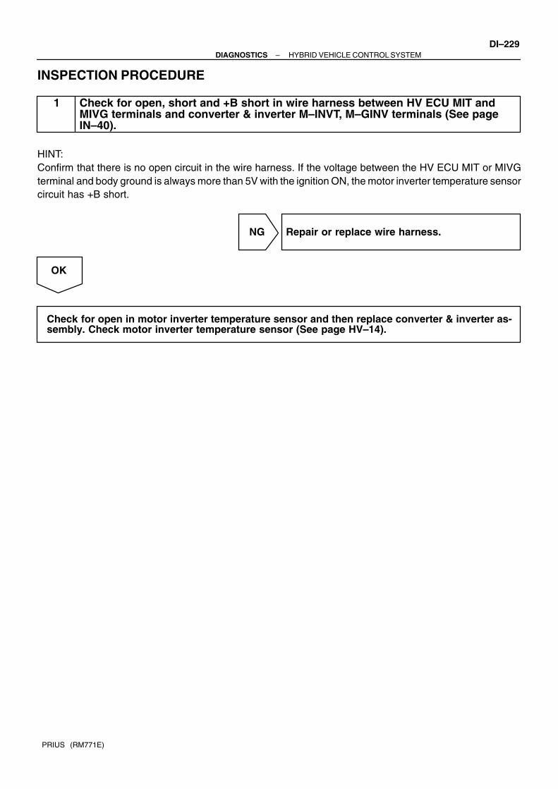
–DIAGNOSTICS HYBRID VEHICLE CONTROL SYSTEMDI–229
PRIUS (RM771E)
INSPECTION PROCEDURE
1 Check for open, short and +B short in wire harness between HV ECU MIT andMIVG terminals and converter & inverter M–INVT, M–GINV terminals (See pageIN–40).
HINT:Confirm that there is no open circuit in the wire harness. If the voltage between the HV ECU MIT or MIVGterminal and body ground is always more than 5V with the ignition ON, the motor inverter temperature sensorcircuit has +B short.
NG Repair or replace wire harness.
OK
Check for open in motor inverter temperature sensor and then replace converter & inverter as-sembly. Check motor inverter temperature sensor (See page HV–14).

A14121
Inverter Hybrid Vehicle Control ECU
M–SINVG
7
I10
6
I9M–GINVB
21MSIV
MIVG
26
H15
H15
DI–230–DIAGNOSTICS HYBRID VEHICLE CONTROL SYSTEM
PRIUS (RM771E)
CIRCUIT DESCRIPTIONThe HV ECU checks the line connection of the motor inverter stop signal circuit and enters the fail safe mode(limited output driving) if malfunction is detected.DTC P3125 – Information code 278, 280
INF. Code. Detecting Condition Trouble Area
278 +B short in motor inverter stop signal circuitConverter & inverter assembly
280 Open or GND short in motor inverter stop signal circuit
Converter & inverter assembly
Wire harness
WIRING DIAGRAM

–DIAGNOSTICS HYBRID VEHICLE CONTROL SYSTEMDI–231
PRIUS (RM771E)
INSPECTION PROCEDURE
1 Check for open, short and +B short in wire harness between HV ECU MSIV andMIVG terminals and converter & inverter assembly M–SINV and M–GIVN termi-nals (See page IN–40).
HINT:The motor inverter stop signal circuit has +B short if the voltage between the HV ECU MSIV or MIGV terminaland body ground is always more than 13 V with the ignition ON (”READY” light OFF).
NG Repair or replace wire harness.
OK
Replace converter & inverter assembly.

DI–232–DIAGNOSTICS HYBRID VEHICLE CONTROL SYSTEM
PRIUS (RM771E)
CIRCUIT DESCRIPTIONDTC P3125 – Information code 279, 281, 282
INF. Code. Detecting Condition Trouble Area
279 Over voltage of inverter
281 Voltage drop of inverter power source Converter & inverter assembly
282 Inverter circuit broken
y
INSPECTION PROCEDUREIf the information code 279 or 281 is output, check if other information codes are recorded. If they are re-corded, check and repair those codes first.If the information code 279 or 281 alone is recorded, replace the converter & inverter assembly.If the information code 282 is output, replace the converter & inverter assembly.

A14121
Inverter Hybrid Vehicle Control ECU
M–GINVB
6
I9
8
I10M–FINVB
26
MFIV14
H15
H15
MIVG
–DIAGNOSTICS HYBRID VEHICLE CONTROL SYSTEMDI–233
PRIUS (RM771E)
CIRCUIT DESCRIPTIONThe HV ECU checks the line connection of the motor inverter fail signal circuit and detects malfunction.DTC P3125 – Information code 283, 285
INF. Code. Detecting Condition Trouble Area
283 +B short in motor inverter fail signal circuitConverter & inverter assembly
285 Open or GND short in motor inverter fail signal circuit
Converter & inverter assembly
Wire harness
WIRING DIAGRAM
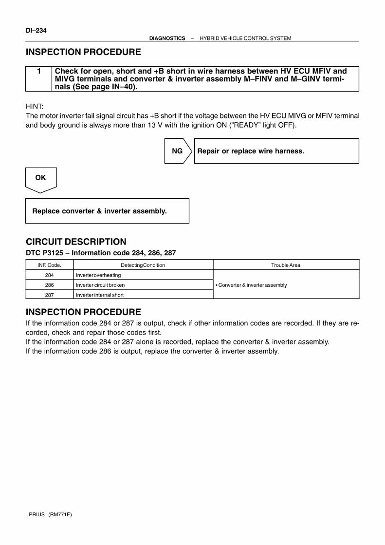
DI–234–DIAGNOSTICS HYBRID VEHICLE CONTROL SYSTEM
PRIUS (RM771E)
INSPECTION PROCEDURE
1 Check for open, short and +B short in wire harness between HV ECU MFIV andMIVG terminals and converter & inverter assembly M–FINV and M–GINV termi-nals (See page IN–40).
HINT:The motor inverter fail signal circuit has +B short if the voltage between the HV ECU MIVG or MFIV terminaland body ground is always more than 13 V with the ignition ON (”READY” light OFF).
NG Repair or replace wire harness.
OK
Replace converter & inverter assembly.
CIRCUIT DESCRIPTIONDTC P3125 – Information code 284, 286, 287
INF. Code. Detecting Condition Trouble Area
284 Inverter overheating
286 Inverter circuit broken Converter & inverter assembly
287 Inverter internal short
y
INSPECTION PROCEDUREIf the information code 284 or 287 is output, check if other information codes are recorded. If they are re-corded, check and repair those codes first.If the information code 284 or 287 alone is recorded, replace the converter & inverter assembly.If the information code 286 is output, replace the converter & inverter assembly.

–DIAGNOSTICS HYBRID VEHICLE CONTROL SYSTEMDI–235
PRIUS (RM771E)
CIRCUIT DESCRIPTIONThe HV ECU detects the malfunction of the motor inverter current sensor. It detects the malfunction of thesensor system, not of the high voltage system.DTC P3125 – Information code 288, 289, 290, 291, 292, 293, 294, 295, 296, 297, 298, 299, 300,301, 302,303
INF. Code. Detecting Condition Trouble Area
289 Open in motor inverter current sensor (V phase sub sensor)
292Open in motor inverter current sensor (V phase main sen-
sor)
297Open in motor inverter current sensor (W phase sub sen-
sor)
300Open in motor inverter current sensor (W phase main sen-
sor)
288Motor inverter current sensor malfunction (V phase sub
sensor)
290Motor inverter current sensor malfunction (V phase main
sensor)
294Motor inverter current sensor V phase performance prob-
lem Converter & inverter assembly
296Motor inverter current sensor malfunction (W phase sub
sensor)
Wire harness
298Motor inverter current sensor malfunction (W phase main
sensor)
302Motor inverter current sensor W phase performance prob-
lem
291
293
295 (when there is a history that the state of malfunction contin-
299
(when there is a history that the state of malfunction contin
ued during inverter fail safe mode)
301
303

A14123
Inverter Hybrid Vehicle Control ECU
M–GINVB
2
I10M–IWAR
B
W
G4
I10
3
I10
1
I10
6I9
M–IWB
M–IVB
M–IVA
MIVG
MIWA
MIWB
MIVB
MIVA
26
16
7
17
25
H15
H15
H15
H15
H15
DI–236–DIAGNOSTICS HYBRID VEHICLE CONTROL SYSTEM
PRIUS (RM771E)
WIRING DIAGRAM

–DIAGNOSTICS HYBRID VEHICLE CONTROL SYSTEMDI–237
PRIUS (RM771E)
INSPECTION PROCEDURE
1 Check continuity of wire harness between HV ECU and converter & inverter as-sembly (See page IN–40).
OK:Continuity: Less then 1 Ω
HV ECU Terminals Inverter Terminals
MIVA M–IVA
MIVB M–IVB
MIWA M–IWA
MIWB M–IWB
MIVG M–GINV
NG Repair or replace wire harness.
OK
Replace converter & inverter assembly.

DI–238–DIAGNOSTICS HYBRID VEHICLE CONTROL SYSTEM
PRIUS (RM771E)
CIRCUIT DESCRIPTIONThe HV ECU detects the malfunction of the motor inverter current sensor. It detects the malfunction of thesensor system, not of the high voltage system.DTC P3125 – Information code 306, 307
INF. Code. Detecting Condition Trouble Area
306 Failure in monitoring motor torque performanceConverter & inverter assembly
307 Abnormal current value of motorConverter & inverter assembly
INSPECTION PROCEDUREIf the information code 306 or 307 is output, check if other information codes are recorded. If they are re-corded, check and repair those codes first.If the information code 306 or 307 alone is recorded, replace the converter & inverter assembly.
CIRCUIT DESCRIPTIONIf the HV ECU detects the collision signal from the airbag or inverter, the HV ECU recognizes it as the destruc-tion of the vehicle and then shuts down the high voltage system to ensure safety.DTC P3125 – Information code 308
INF. Code. Detecting Condition Trouble Area
308 Input of collision signal from airbag or inverter –
HINT:When the vehicle collision occurs and the airbag is deployed, this information code will be recorded and thehigh voltage system will be shut down.

A14120
InverterHybrid Vehicle Control ECU
M–SDOWNY
4
I9
13
MSDNH15
–DIAGNOSTICS HYBRID VEHICLE CONTROL SYSTEMDI–239
PRIUS (RM771E)
CIRCUIT DESCRIPTIONThe HV ECU checks the line connection of the motor gate shutdown signal circuit and detects malfunction.DTC P3125 – Information code 304, 305
INF. Code. Detecting Condition Trouble Area
304 +B short in motor gate shutdown signal circuitConverter & inverter assembly
305 Open or GND short in motor gate shutdown signal circuit
Converter & inverter assembly
Wire harness
WIRING DIAGRAM

DI–240–DIAGNOSTICS HYBRID VEHICLE CONTROL SYSTEM
PRIUS (RM771E)
INSPECTION PROCEDURE
1 Check for open, short and +B short in wire harness between HV ECU MSDN ter-minal and converter & inverter assembly M–SDOWN terminals (See page IN–40).
HINT:Confirm that there is no open circuit in the wire harness. The motor gate shutdown signal circuit has +B shortif the battery voltage is always applied to the HV ECU MSDN terminal with the ignition ON.
NG Repair or replace wire harness.
OK
Replace converter & inverter assembly.

A14124
InverterHybrid Vehicle Control ECU
G3
I11
2
I11G–UUR
3
H15
1
H15
GWU
GUU
GVU
2
H15W
I11
1
G–VU
G–WU
–DIAGNOSTICS HYBRID VEHICLE CONTROL SYSTEMDI–241
PRIUS (RM771E)
CIRCUIT DESCRIPTIONDTC P3125 – Information code 309
INF. Code. Detecting Condition Trouble Area
309Open or short in generator inverter switching wiring (GUU,
GVU, GWU)
Wire harness
Converter & inverter assembly
HV ECU
WIRING DIAGRAM

DI–242–DIAGNOSTICS HYBRID VEHICLE CONTROL SYSTEM
PRIUS (RM771E)
INSPECTION PROCEDURE
1 Check for open and short in wire harness between HV ECU terminals (GUU, GVU,GWU) and inverter terminals.
NG Repair or replace wire harness.
OK
2 Check voltage between inverter terminals (GUU, GVU, GWU) and body ground,with ignition turned ON.
OK:Standard voltage: 13 – 17 V
NG Replace inverter.
OK
Replace HV ECU.

A14121
Inverter Hybrid Vehicle Control ECU
M–INVTL
5I11
6
I11M–GINVB
23GIT
GIVG
27
H15
H15
–DIAGNOSTICS HYBRID VEHICLE CONTROL SYSTEMDI–243
PRIUS (RM771E)
CIRCUIT DESCRIPTIONThe HV ECU checks the generator temperature and controls the load limitation in order to prevent the gener-ator from overheating. Also, it detects the abnormality of the line connection of the generator temperaturesensor and the malfunction of the sensor itself.DTC P3125 – Information code 312, 313, 314, 315
INF. Code. Detecting Condition Trouble Area
312 Open or +B short in generator inverter temperature sensor
313 GND short in generator inverter temperature sensorConverter & inverter assembly
314 Generator inverter temperature sensor malfunction
Converter & inverter assembly
Wire harness
315Generator inverter temperature sensor performance prob-
lem
HV ECU
WIRING DIAGRAM

DI–244–DIAGNOSTICS HYBRID VEHICLE CONTROL SYSTEM
PRIUS (RM771E)
INSPECTION PROCEDURE
1 Check for open, short and +B short in wire harness between HV ECU GIT andGIVG terminals and converter & inverter G–GINV or G–GINV terminals (See pageIN–40).
HINT:Confirm that there is no open circuit in the wire harness. The generator inverter temperature sensor circuithas +B short if the voltage between the HV ECU GIT or GIVG terminal and body ground is always more than5V with the ignition ON.
NG Repair or replace wire harness.
OK
Check for open in generator inverter temperature sensor and then replace converter & inverterassembly. Check generator inverter temperature sensor (See page HV–14).

A14121
Inverter Hybrid Vehicle Control ECU
G–GINVB
6
I11
7
I12G–SINVG
27GIVG
GSIV
15
H15
H15
–DIAGNOSTICS HYBRID VEHICLE CONTROL SYSTEMDI–245
PRIUS (RM771E)
CIRCUIT DESCRIPTIONThe HV ECU checks the line connection of the generator inverter stop signal circuit and enters the fail safemode (limited driving) if malfunction is detected.DTC P3125 – Information code 316, 318
INF. Code. Detecting Condition Trouble Area
316 +B short in generator inverter stop signal circuitConverter & inverter assembly
318 Open or GND short in generator inverter stop signal circuit
Converter & inverter assembly
Wire harness
WIRING DIAGRAM

DI–246–DIAGNOSTICS HYBRID VEHICLE CONTROL SYSTEM
PRIUS (RM771E)
INSPECTION PROCEDURE
1 Check for open, short and +B short in wire harness between HV ECU GSIV andGIVG terminals and converter & inverter assembly G–SINV and G–GINV termi-nals (See page IN–40).
HINT:The generator inverter stop signal circuit has +B short if the voltage between the HV ECU GSIV or GIVGterminal and body ground is always more than 13 V with the ignition ON (”READY” light OFF).
NG Repair or replace wire harness.
OK
Replace converter & inverter assembly.
CIRCUIT DESCRIPTIONDTC P3125 – Information code 317, 319, 320
INF. Code. Detecting Condition Trouble Area
317 Over voltage of inverter
319 Voltage drop of inverter power source Converter & inverter assembly
320 Inverter circuit broken
y
INSPECTION PROCEDUREIf the information code 317 or 319 is output, check if other information codes are recorded. If they are re-corded, check and repair those codes first.If the information code 317 or 319 alone is recorded, replace the converter & inverter assembly.If the information code 320 is output, replace the converter & inverter assembly.

A14121
Inverter Hybrid Vehicle Control ECU
G–GINVB
6I11
8
I12G–FINVB
27GIVG
GFIV
24
H15
H15
–DIAGNOSTICS HYBRID VEHICLE CONTROL SYSTEMDI–247
PRIUS (RM771E)
CIRCUIT DESCRIPTIONThe HV ECU checks the line connection of the generator inverter fail signal circuit and detects malfunction.DTC P3125 – Information code 321, 323
INF. Code. Detecting Condition Trouble Area
321 +B short in generator inverter fail signal circuitConverter & inverter assembly
323 Open or GND short in generator inverter fail signal circuit
Converter & inverter assembly
Wire harness
WIRING DIAGRAM

DI–248–DIAGNOSTICS HYBRID VEHICLE CONTROL SYSTEM
PRIUS (RM771E)
INSPECTION PROCEDURE
1 Check for open, short and +B short in wire harness between HV ECU GFIV andGIVG terminals and converter & inverter assembly G–FINV and G–GINV terminals(See page IN–40).
HINT:The generator inverter fail signal circuit has +B short if the voltage between the HV ECU GFIV or GIVG termi-nal and body ground is always more than 13 V with the ignition ON (”READY” light OFF).
NG Repair or replace wire harness.
OK
Replace converter & inverter assembly.
CIRCUIT DESCRIPTIONDTC P3125 – Information code 322, 324, 325
INF. Code. Detecting Condition Trouble Area
322 Inverter overheating
324 Inverter circuit broken Converter & inverter assembly
325 Inverter internal short
y
INSPECTION PROCEDUREIf the information code 322 or 325 is output, check if other information codes are recorded. If they are re-corded, check and repair those codes first.If the information code 322 or 325 alone is recorded, replace the converter & inverter assembly.If the information code 324 is output, replace the converter & inverter assembly.

–DIAGNOSTICS HYBRID VEHICLE CONTROL SYSTEMDI–249
PRIUS (RM771E)
CIRCUIT DESCRIPTIONThe HV ECU detects the malfunction of the generator inverter current sensor. It detects the malfunction ofthe sensor system, not of the high voltage system.DTC P3125 – Information code 326, 327, 328, 329, 330, 331, 332, 333, 334, 335, 336, 337, 338, 339, 340,341
INF. Code. Detecting Condition Trouble Area
327Open in generator inverter current sensor (V phase sub
sensor)
330Open in generator inverter current sensor (V phase main
sensor)
335Open in generator inverter current sensor (W phase sub
sensor)
338Open in generator inverter current sensor (W phase main
sensor)
326Generator inverter current sensor malfunction (V phase sub
sensor)
328Generator inverter current sensor malfunction (V phase
main sensor)
332Generator inverter current sensor V phase performance
problemConverter & inverter assembly
Wire harness
334Generator inverter current sensor malfunction (W phase
sub sensor)
Wire harness
336Generator inverter current sensor malfunction (W phase
main sensor)
340Generator inverter current sensor W phase performance
problem
329
331
333 (when there is a history that the state of malfunction contin-
337
(when there is a history that the state of malfunction contin
ued during inverter fail safe mode)
339
341

A14123
InverterHybrid Vehicle Control ECU
G–IVAB
5I11G–INVT
L
W
G
R2I12
4I12
3I12
1I12
G–IWA
G–IWB
G–IVB
GIVA
GIT
GIWA
GIWB
GIVB
19
8
18
28
23H15
H15
H15
H15
H15
DI–250–DIAGNOSTICS HYBRID VEHICLE CONTROL SYSTEM
PRIUS (RM771E)
WIRING DIAGRAM

–DIAGNOSTICS HYBRID VEHICLE CONTROL SYSTEMDI–251
PRIUS (RM771E)
INSPECTION PROCEDURE
1 Check continuity of wire harness between HV ECU and converter & inverter as-sembly (See page IN–40).
OK:Continuity: Less then 1 Ω
HV ECU Terminals Inverter Terminals
GIVA G–IVA
GIVB G–IVB
GIWA G–IWA
GIWB G–IWB
GIVG G–GINV
NG Repair or replace wire harness.
OK
Replace converter & inverter assembly.

DI–252–DIAGNOSTICS HYBRID VEHICLE CONTROL SYSTEM
PRIUS (RM771E)
CIRCUIT DESCRIPTIONThe HV ECU detects the malfunction of the generator inverter current sensor. It detects the malfunction ofthe sensor system, not of the high voltage system.DTC P3125 – Information code 344, 345
INF. Code. Detecting Condition Trouble Area
344 Failure in monitoring generator torque performanceConverter & inverter assembly
345 Abnormal current value of generatorConverter & inverter assembly
INSPECTION PROCEDUREIf the information code 344 or 345 is output, check if other information codes are recorded. If they are re-corded, check and repair those codes first.If the information code 344 or 345 alone is recorded, replace the converter & inverter assembly.

A14120
InverterHybrid Vehicle Control ECU
G–SDOWNY
4I11
12
GSDNH15
–DIAGNOSTICS HYBRID VEHICLE CONTROL SYSTEMDI–253
PRIUS (RM771E)
CIRCUIT DESCRIPTIONThe HV ECU checks the line connection of the generator gate shutdown signal circuit and detects malfunc-tion.DTC P3125 – Information code 342, 343
INF. Code. Detecting Condition Trouble Area
342 +B short in generator gate shutdown signal circuitConverter & inverter assembly
343Open or GND short in generator gate shutdown signal cir-
cuit
Converter & inverter assembly
Wire harness
WIRING DIAGRAM

DI–254–DIAGNOSTICS HYBRID VEHICLE CONTROL SYSTEM
PRIUS (RM771E)
INSPECTION PROCEDURE
1 Check for open, short and +B short in wire harness between HV ECU GSDN ter-minal and converter & inverter assembly G–SDOWN terminals (See page IN–40).
HINT:Confirm that there is no open circuit in the wire harness. The generator gate shutdown signal circuit has +Bshort if the battery voltage is always applied to the HV ECU GSDN terminal with the ignition ON.
NG Repair or replace wire harness.
OK
Replace converter & inverter assembly.

A14152
Battery
MAIN
B–G
1
1F18
1
1
51
F13
2
3
2
2
Engine Room J/B
W–B (LHD)
IK1
2 14
5
AM2
B–W
B–W
J7 J/C
B–WI15 Ignition SW
W–R
67
11
IG2AM2
Instrument Panel J/B
2C
1K
1A2G9
1J
1B
B
A
F12
IG2 Relay
Fusible Link Block No. 1
Fusible Link Block No. 2
1J
2G2B
W–R
1
3
3
IE
A
A
A
AA
B–W2
W–B (RHD)
W–BW–BW–B(LHD) (LHD)
W3 Water Pump Motor
W–B (LHD)
J1 J/C
–DIAGNOSTICS HYBRID VEHICLE CONTROL SYSTEMDI–255
PRIUS (RM771E)
DTC P3130 Inverter Cooling System Malfunction
CIRCUIT DESCRIPTIONThe HV ECU checks the operation of the inverter water pump and detects malfunction.HINT: When using an OBD-6 scan tool other than hand–held tester, check all the steps. When using hand–held tester, confirm the information code and check it.
DTC P3130 – Information code 346
INF. code. Detecting Condition Trouble Area
346 Water pump system malfunction
Water pump
IG2 relay
Wire harness
WIRING DIAGRAM
DI839–01

DI–256–DIAGNOSTICS HYBRID VEHICLE CONTROL SYSTEM
PRIUS (RM771E)
INSPECTION PROCEDURE
1 Check wire harness (See page IN–40).
HINT:After removing the IG2 relay, check the electrical condition of each terminal. No. 1 terminal: With the IG switch ON, 10 – 14 V No. 2 terminal : Continuity between the IG2 relay No. 2 terminal and body ground (less than 1 Ω ) No. 3 terminal: Continuity between the IG2 relay No. 3 terminal and water pump No. 2 terminal (less
than 1 Ω ) No. 5 terminal: Always 10 – 14 V
Continuity between the water pump No. 1 terminal and body ground (less than 1 Ω )
NG Repair or replace wire harness.
OK

A14712
Continuity
Ohmmeter Ohmmeter
No Continuity
2
1
5
3
Ohmmeter
Continuity
2
1
5
3Battery
–DIAGNOSTICS HYBRID VEHICLE CONTROL SYSTEMDI–257
PRIUS (RM771E)
2 Check IG2 relay.
PREPARATION:Remove the IG2 relay from the engine room J/B.CHECK:(a) Using an ohmmeter, check that there is continuity be-
tween terminals 1 and 2.(b) Check that there is no continuity between terminals 3 and
5.(c) Apply battery voltage across terminals 1 and 2. Using an
ohmmeter, check that there is continuity between termi-nals 3 and 5.
OK:(a) Continuity(b) No continuity(c) Continuity
NG Replace IG2 relay.
OK
Confirm that water pump is defective and then replace it.Check water pump (See page HV–26).
CIRCUIT DESCRIPTIONDTC P3130 – Information code 347
INF. code. Detecting Condition Trouble Area
347 Radiator fan system malfunction Radiator fan system
INSPECTION PROCEDUREIf this information code is output, check the radiator fan system (See page CO–21).

A14136
C3 Circuit Breaker Sensor
1
2
H16
AS1G
Hybrid Vehicle Control ECU
BR–B
G–R
H16
14
15
AS1
DI–258–DIAGNOSTICS HYBRID VEHICLE CONTROL SYSTEM
PRIUS (RM771E)
DTC P3135 Circuit Breaker Sensor Malfunction
CIRCUIT DESCRIPTIONThe HV ECU checks the line connection of the circuit breaker sensor (collision signal) and gives warningto the driver if malfunction is detected.DTC P3135 – Information code 348, 349
INF. code. Detecting Condition Trouble Area
348 GND short in circuit breaker sensor Circuit breaker sensor
Wi h349 Open or +B short in circuit breaker sensor
Wire harness
HV ECU
WIRING DIAGRAM
DI83A–01

–DIAGNOSTICS HYBRID VEHICLE CONTROL SYSTEMDI–259
PRIUS (RM771E)
INSPECTION PROCEDURE
1 Check for open, short and +B short in wire harness between circuit breaker sen-sor No. 1 and No. 2 terminals and HV ECU AS1G and AS1 terminals (See page IN–40).
HINT:Confirm that there is no open circuit in the wire harness. The circuit breaker sensor circuit has +B short ifthe voltage of the HV ECU AS1 terminal is more than 5V with the ignition ON.
NG Repair or replace wire harness.
OK
Check for open in resistance between circuit breaker sensor terminals and then replace circuitbreaker sensor (Circuit breaker sensor resistance: 820 82 Ω).

DI–260–DIAGNOSTICS HYBRID VEHICLE CONTROL SYSTEM
PRIUS (RM771E)
DTC P3140 Interlock Malfunction
CIRCUIT DESCRIPTIONIf the HV ECU detects the operation of the safety devices (removal of the service plug, inverter terminal coverand sensor cover) while the vehicle is not running (with the vehicle is stopped), it will shut down the systemmain relay. It the safety devices are correctly installed, it will resume the normal operation after the powersource is supplied again. If it does not, there is a possibility of an open circuit, so perform the same inspectionas the information code 351.HINT: When using an OBD-6 scan tool other than hand–held tester, check all the steps. When using hand–held tester, confirm the information code and check it.
DTC P3140 – Information code 350
INF. code. Detecting Condition Trouble Area
350Safety devices operating with vehicle is stopped (ILK signal
ON)–
DI83B–01

A14141
Inverter
12IH1CVRSW
Hybrid Vehicle Control ECU
V–RH17
10ILK
6 40 0
4
IF1V–R
I10
I17 Interlock SW
–DIAGNOSTICS HYBRID VEHICLE CONTROL SYSTEMDI–261
PRIUS (RM771E)
CIRCUIT DESCRIPTIONThe HV ECU records the information code 351 and gives warning to the driver when it detects an open circuitin the interlock signal circuit while the vehicle is running . In this case, it does not shut down the high voltagesystem.DTC P3140 – Information code 351
INF. code. Detecting Condition Trouble Area
351 Open circuit in interlock signal circuit while vehicle is running
Interlock switch
Inverter terminal cover
Sensor cover
Wire harness
HV ECU
WIRING DIAGRAM

DI–262–DIAGNOSTICS HYBRID VEHICLE CONTROL SYSTEM
PRIUS (RM771E)
INSPECTION PROCEDURE
1 Check installation condition of inverter terminal cover and sensor cover.
NG Install them correctly.
OK
2 Check continuity of wire harness between interlock switch No. 1 terminal and HVECU ILK terminal and interlock switch No. 2 terminal and inverter CVRSW termi-nal (See page IN–40).
OK:Continuity: Less than 1 Ω
NG Repair or replace wire harness.
OK
3 Check continuity between inverter CVRSW terminal and body ground (See page IN–40).
OK:Continuity: Less than 1 Ω
NG Replace converter & inverter assembly.
OK
Confirm that interlock switch is defective and replace it.Check interlock switch (See page HV–38)

A14138
2A
C10 Combination Meter
Hybrid Vehicle Control ECU
LH16
19SPDI
6 8
IE113
Instrument Panel J/B
7
2BV–W
J/CG
J25
G
J26V–W V–W
–DIAGNOSTICS HYBRID VEHICLE CONTROL SYSTEMDI–263
PRIUS (RM771E)
DTC P3145 Vehicle Speed Sensor Circuit Malfunction
CIRCUIT DESCRIPTIONDTC P3145 – Information code 352
INF. code. Detecting Condition Trouble Area
352 No input of vehicle speed during cruise control driving
Wire harness
Combination meter
HV ECU
WIRING DIAGRAM
DI83C–01

DI–264–DIAGNOSTICS HYBRID VEHICLE CONTROL SYSTEM
PRIUS (RM771E)
INSPECTION PROCEDURE
1 Is DTC P0500 of engine ECU being output?
NG Check DTC P0500.
OK
2 Check continuity of wire harness between J26 J/B G terminal and HV ECU SPDIterminal (See page IN–40).
OK:Continuity: Less than 1 Ω
NG Repair or replace wire harness.
OK
Replace HV ECU.

DI81G–01
Vehicle Brought to Workshop
Connect the hand–held tester to DLC3 P. DI–268If the display indicates a communication fault in the tool, inspect DLC3 P. DI–268
Check DTC and Freezed Frame Data (Precheck)
Record or Print DTC and Freezed Frame Data P. DI–268
DTC Chart P. DI–272
Circuit Inspection P. DI–274
Adjustment, Repair
DTC Check P. DI–268
Inside
See the indicated pages for details.in this manual.
Identification of Problem
Confirmation Test
End
1
2
3
4
7
5
6
8
shown titles and page numbers
Customer Problem Analysis P. DI–266
–DIAGNOSTICS HV BATTERY CONTROL SYSTEMDI–265
PRIUS (RM771E)
HV BATTERY CONTROL SYSTEMHOW TO PROCEED WITH TROUBLESHOOTING

DI81H–01
Prius Problem Check Sheet
Veh
icle
Sp
ecif
icat
ion
s
Please fill in the blanks within bold frame.
Name of Dealer Person in Charge at Headquarters
Person in Chargeat Dealer
Model Code
Office
Vehicle Delivery Date
Frame No.
Unit No. etc.
Option
. . . :
( ) Navigation (equipped by ( ) MOP ( ) dealer) ( ) Cold climate specification( ) others( )
Problem Occurrence Date
Service Entry Date
NHW11–
NHW11– . .
. .
Km–reading
Registration date
km
. .
Contents of complaint (Status when and before/after occurring inthe order of events as correct as possible)
Characteristics of Customer
Gender
Age
Occupation
Vehicle used before
Main use area
Frequency in use
Others
times/day orweek or month
Status of engine
Others
Inte
rvie
w R
esu
lts
( ) Male ( ) Female
suburbs ( ) %
Others ( ) ( ) %
city area ( ) %
mountain area ( ) %
Driving Condition Road Condition Vehicle Condition
Vehicle Speed km/h
( ) when starting
( ) when according
( ) When normal driving( ) when decelerating( ) when braking
( ) when shopping
( ) when parking
( ) when tuming
( ) when ABS actuating( ) others ( )
( ) flat road
( ) up hill ( ) down hill incline of /% distance km
( ) dry paved road
( ) wet paved road
( ) rough paved road
( ) unpaved road
( ) snowy/frozen road
( ) bump/curb
( ) others ( )
( ) when starting
( ) right after starting( ) until min. after starting( ) until min. after starting of driving
( ) when shopping system
( ) while shopping engine( ) when starting engine( ) when revolving engine
HV Battery indication
( ) 4/4 ( ) 3/4( ) 2/4 ( ) 1/4( ) unidentified
Shift position(indication)( ) P ( ) R ( ) N( ) D ( ) B( ) when operating →
Weather:
A/C status
( ) no indication( ) unidentified
( ) A/C ( ) FULL( ) OFF( ) unidentified
Warning light(MIL)
( ) ON ( ) OFF
( ) PS( ) main battery( ) HV!
( ) engine( ) charge( ) output control( ) brake( ) ABS
( ) others ( )
Temperature:
C
Brake operation( ) brake slowly( ) Brake suddenly( ) use two pedals system
Frequency in occurrence( ) always( ) sometimes( ) only once
DI–266–DIAGNOSTICS HV BATTERY CONTROL SYSTEM
PRIUS (RM771E)
CUSTOMER PROBLEM ANALYSIS CHECK

Verification Results of Warning Light
Engine
HV
INF. code
HV battery
Veh
icle
Ver
ific
atio
n R
esu
lts
( ) ON ( ) OFF
( ) engine ( ) HV
( ) HV battery
( ) output control warning light
( ) brake ( ) ABS
( ) charge ( ) PS
( ) others ( )
Verification Results of Diagnostic Code
Brake
PS
Vehicle Inspection Results (Verification items, reason to identify/presume the cause parts, etc.)
Replacemect Parts
problem parts: No/Yes (Sending date: . . )
Reproduction Status
( ) always( ) sometimes condition when occurring
( ) no reproduction
Confirmation Results After Repair
( ) Normal( ) reproduction( ) others ( )
–DIAGNOSTICS HV BATTERY CONTROL SYSTEMDI–267
PRIUS (RM771E)

B04757
DI81I–01
A14090
DI–268–DIAGNOSTICS HV BATTERY CONTROL SYSTEM
PRIUS (RM771E)
PRE–CHECK1. PRECAUTION(a) To distinguish a trouble and replace a defective part, take
necessary preventive measures against an electric shock(See page IN–4).
(b) Some portions of the wiring harness in the THS vehiclehave the circuits, to which a high voltage is applied. Toprevent an electrical shock, be sure to observe the follow-ing:(1) Wear insulated gloves during inspection.(2) Remove a service plug and do not start any repair
operation before 5 minutes have passed, then con-firm that the voltage at the output terminals hasdropped down to 12 V or less.
(3) Use insulated tools during inspection.(4) When disengaging wiring connectors, hold the con-
nector bodies to avoid pulling the wires. When en-gaging wiring connectors, be sure to engage themsecurely.
(c) Do not leave tools or parts (bolts, nuts, etc.) inside thecabin.
(d) Do not carry metallic objects such as mechanical pencilsor scales.
2. DIAGNOSIS SYSTEM(a) Description
The HV control ECU has a self–diagnosis systemby which malfunction in the computer itself or inTHS components is detected and the master warn-ing light in the combination meter and the HV bat-tery warning light in the multi–information displaylights up.

F12397
DLC3
Hand–held tester
A04550
DLC3
9
1 2 3 4 5 6 7 8
16151413121110
–DIAGNOSTICS HV BATTERY CONTROL SYSTEMDI–269
PRIUS (RM771E)
To check the Diagnostic Trouble Codes (DTC), con-nect the hand–held tester to the Data Link Connec-tor 3 (DLC3) on the vehicle. The hand–held testeralso enables you to erase the DTC and checkfreeze frame data and various forms of THS data.
Freeze frame data:Freeze frame data records the driving conditionwhen a malfunction is detected. When trouble-shooting it is useful to determine whether the ve-hicle was running, braked, stopped or reversed.
(b) Check the DLC3.The HV control ECU conforms to ISO 14230 for commu-nication.The terminal arrangement of the DLC3 complies withSAEJ1962 and matches the ISO 14230 format.
Terminal No. Connection/Voltage or Resistance Condition
7 Bus Line/Pulse generation During transmission
4 Chassis Ground ↔ Body Ground/1 Ω or less Always
5 Signal Ground ↔ Body Ground/1 Ω or less Always
16 Battery Positive ↔ Body Ground/10 – 15 V Always
HINT:If your display shows UNABLE TO CONNECT TO VEHICLEwhen you have connected the cable of the hand–held tester tothe DLC3, turned the motor switch ON and operated the tester,there is a problem in the vehicle or tool. If communication is normal when the tool is connected to
another vehicle, inspect the DLC3 on the original vehicle. If communication is still not possible when the tool is con-
nected to another vehicle, the problem is probably in thetool itself, so consult the Service Department.
3. INSPECT DIAGNOSIS(a) Check the auxiliary battery.
(1) Measure the voltage of the auxiliary battery.Voltage: 10 – 15 V(2) Inspect the auxiliary battery, fuses, fusible links, wir-
ing harness, connectors and ground.

A14089
B12009
F12397
DLC3
Hand–held tester
F12397
DLC3
Hand–held tester
DI–270–DIAGNOSTICS HV BATTERY CONTROL SYSTEM
PRIUS (RM771E)
(b) Check the master warning light.(1) Turn the ignition switch ON and confirm that the
master warning light comes on.HINT:If the master warning light does not come on, suspect a burntfuse, burnt bulb, or open in wiring harness.
(2) When the ”READY” light is ON, the master warninglight should go off.
If the lamp remains on, the diagnosis system has detected amalfunction or abnormality in the system.
(c) Check the DTC.(1) Prepare a hand–held tester.(2) Connect the hand–held tester to the DLC3.(3) Turn the ignition switch ON and push the hand–held
tester main switch ON.(4) Use the hand–held tester to check the DTC and
freeze frame data and note them down. (For operat-ing instructions, see the TOYOTA hand–held testeroperator ’s manual).
(5) See a related page to confirm details of the DTC.
(d) Clear the DTC.(1) Connect the hand–held tester to the DLC3.(2) Operate the hand–held tester to erase the DTC
(See the hand–held tester operator’s manual.).

–DIAGNOSTICS HV BATTERY CONTROL SYSTEMDI–271
PRIUS (RM771E)
4. CHECK FOR INTERMITTENT PROBLEMS(a) Perform a simulation test (See page IN–29).(b) Check the connector and terminal (See page IN–40).(c) Handle the connector (See page IN–40).5. HAND–HELD TESTER DISPLAY ITEMS
TOYOTA hand–held tester display Measurement Item
BATTERY SOC Battery capacity SOC
AVERAGE TEMP Average battery temperature
ONB CHARGE TIME Cumulative number of times of on–board uniform charging
BATERY LO TIME Cumulative number of times of low uniform charging
BC INHIBIT TIME Cumulative number of times of BC inhibition
IB MAIN BATTERY IB main battery current (with correction)
BATT BLOCK V# Battery block voltage #
BAT BLOCK MIN V Battery block minimum voltage
MIN BAT BLOCK # Minimum voltage battery block
BAT BLOCK MAX V Battery block maximum voltage
MAX BAT BLOCK # Maximum voltage battery block
BATT INSIDE AIR Ambient temperature inside battery pack
BATTERY TOO HI # Cumulative number of times of too–high battery voltage
VMF FAN VOLTAGE VMF fan voltage
AUX. BAT V Auxiliary battery voltage
WIN Charge restriction value
WOUT Discharge restriction value
DELTA SOC SOC
SBL FAN STP RQST SBL cooling fan stop request signal
COOLING FAN HI Cooling fan operation in high speed
COOLING FAN MID Cooling fan operation in middle speed
COOLING FAN LO Cooling fan operation in low
CCTL CFRS outer air intake request signal (changed by CCTL)
EQC0 DF RELAY EQC0 dead front relay
EQTR CHARGE ST EQTR uniform charging start signal
AX BATT CHARGE Auxiliary battery charging status
ONBORD CHARGE Outside uniform charging status
PRE ONBORDE CH Pre–On–board charging status
TEMPERATURE LO Stand–by status at low temperature
NORMAL STATUS Normal status
INSIDE RESIST # Inside resistance
BATT TEMP # Battery temperature
ECU CODE ECU code
IG OFF HOWR Average time of IG OFF
IG ON HOWR Average time of IG ON
ET OFF CHG HR Estimation of time to finish OFF BOARD
DTC The number of stored DTC

DI81J–01
DI–272–DIAGNOSTICS HV BATTERY CONTROL SYSTEM
PRIUS (RM771E)
DIAGNOSTIC TROUBLE CODE CHART
DTC No.
(See Page)Detection Item Trouble Area
Master
Warning
Light
Memory
P1600
(DI–278)BATT malfunction
Open in back up power source circuit
Battery ECU
P3001
(DI–280)Battery ECU malfunction Battery ECU
P3002
(DI–281)
HV serial communication mal-
function
Battery ECU
HV ECU
Communication bus
P3005
(DI–284)High voltage fuse snapped
High voltage fuse
Power cableX
P3006
(DI–285)Battery levels are unusually Battery pack
P3007
(DI–286)
Battery levels are becoming dif-
ferent– X
P3009
(DI–287)Leak detective
Battery cover
SMR
Power cable
Converter & inverter assembly
Battery temperature sensor
Battery ECU
HV transaxle
Busbar module
X
P3010
(DI–294)Battery becomes weak Battery pack
P3011–P3029
(DI–295)Battery block # becomes weak Battery pack
P3030
(DI–296)
Battery voltage detective line
snapped
Open in battery voltage detective line
Connector
Busbar module
P3060
(DI–298)
Battery temperature sensor mal-
functionBattery temperature sensor
P3076
(DI–299)
Abnormal air flow by battery
cooling fan
Duct
Blower fan
Battery ECU
P3077
(DI–301)Battery fan circuit malfunction
Battery fan relay
Battery fan blower controller
Blower fan
Wire harness
P3115
(DI–304)SMR malfunction
SMR
Wire harness
C2552
(DI–274)
Malfunction in external uniform
charging
HV battery conditioner
Wire harness
Adaptor for charger
Battery ECU
SMR
X
*: ··· Master warning light lights up. X ··· Master warning light does not lights up.

DI81K–01
A14088
HV ECU
Power Cable
Battery Fan BlowerController
Blower Motor
Battery Fan Relay
Battery ECU SMR
Service Plug
–DIAGNOSTICS HV BATTERY CONTROL SYSTEMDI–273
PRIUS (RM771E)
PARTS LOCATION

DI81L–01
DI–274–DIAGNOSTICS HV BATTERY CONTROL SYSTEM
PRIUS (RM771E)
CIRCUIT INSPECTION
DTC C2552 Malfunction in External Uniform Charging
CIRCUIT DESCRIPTIONWhen a HV battery is depleted and its charging rate is low, it can be recharged using an external uniformcharger.
DTC No. DTC Detecting Condition Trouble Area
c2552 Charged current is beyond a fixed range.
HV battery conditioner not applicable
Wire harness
Adaptor for charger
Battery ECU
SMR
INSPECTION PROCEDURE
1 Check that HV battery conditioner is applicable.
NG Replace the HV battery conditioner
OK
2 Check CCTL line.
PREPARATION:(a) Remove the adapter for charger.(b) Connect the hand–held tester to the DLC3.(c) Turn the ignition switch ON and push the hand–held tes-
ter main switch ON.(d) Set the CCTL line to HI in the active test.CHECK:Using a voltmeter, measure the voltage between terminal CCTLand body ground.OK:
Standard voltage: More than 5 V
OK Go to step 4
NG

–DIAGNOSTICS HV BATTERY CONTROL SYSTEMDI–275
PRIUS (RM771E)
3 Check that wire harness is open.
PREPARATION:Remove the wire harness between the battery ECU and HVbattery conditioner.CHECK:Using an ohmmeter, check the wire harness continuity.OK:
Continuity
NG Repair or replace the wire harness.
OK
Replace the battery ECU.
4 Check CCTL line.
PREPARATION:(a) Remove the adapter for charger.(b) Connect the hand–held tester to the DLC3.(c) Turn the ignition switch ON and push the hand–held tes-
ter main switch ON.(d) Set the CCTL line to LO in the active test.CHECK:Using a voltmeter, measure the voltage between terminal CCTLand body ground.OK:
Standard voltage: 1V or less
OK Go to step 6
NG

DI–276–DIAGNOSTICS HV BATTERY CONTROL SYSTEM
PRIUS (RM771E)
5 Check that wire harness is open.
PREPARATION:Remove the wire harness between the battery ECU and adapt-er for THS charger.CHECK:Check for short circuit between CCTL terminal and other termi-nals.OK:
Short circuit is not identified.
NG Repair or replace the wire harness.
OK
Replace the battery ECU.
6 Check high voltage connector for charge
CHECK:Using a voltmeter, measure the voltage between terminal CEZand CBZ.OK:
Standard voltage: 200V or more
OK HV battery conditioner malfunction.
NG

–DIAGNOSTICS HV BATTERY CONTROL SYSTEMDI–277
PRIUS (RM771E)
7 Check power cable for battery pack
PREPARATION:Remove the battery cover (See page HV–2).CHECK:Check the power cable inside the battery pack for damage.
NG Replace the power cable.
OK
Replace the SMR.

A14078
Engine Room J/B
Fusible Link Block No. 1
Fusible Link Block No. 2
Battery
Battery ECU
1
1B
B
MAIN
B–G
G–Y
J2 J/C1
1F
1
F121
F13
5IH1
1
B16
HV
1
F18
G–Y G–Y
B B
DI–278–DIAGNOSTICS HV BATTERY CONTROL SYSTEM
PRIUS (RM771E)
DTC P1600 BATT Malfunction
CIRCUIT DESCRIPTIONBattery positive voltage is supplied to terminal AM of the Battery ECU even when the ignition switch is OFFto read the DTC memory and freeze frame data adaptive control value memory, etc.
DTC No. DTC Detecting Condition Trouble Area
P1600 Open in back up power source circuitOpen in back up power source circuit
Battery ECU
HINT:If DTC P1600 appears, the Battery ECU does not store any other DTC.
WIRING DIAGRAM
DI81M–01

A14081
LOCK
AM
(+)
(–)
A14082
Engine Room J/B
HV Fuse
–DIAGNOSTICS HV BATTERY CONTROL SYSTEMDI–279
PRIUS (RM771E)
INSPECTION PROCEDUREHINT:Read freeze frame data using a hand–held tester. Because freeze frame records the engine conditions whenthe malfunction is detected, when troubleshooting, it is useful to determine whether the vehicle was runningor stopped, the engine was warmed up or not, the air–fuel ratio was lean or rich, etc. at the time of malfunc-tion.
1 Check voltage between terminal AM of Battery ECU connector and body ground.
PREPARATION:Remove the luggage trim.CHECK:Measure the voltage between terminal AM of the Battery ECUconnector and body ground.OK:
Voltage: 9 – 14 V
OK Check and replace Battery ECU(See page IN–40).
NG
2 Check HV fuse of engine room J/B.
PREPARATION:Remove the HV fuse from the engine room J/B.CHECK:Check the continuity of the HV fuse.OK:
Continuity
NG Check for short in all harness and componentsconnected to HV fuse.
OK
Check and repair harness or connector be-tween battery and HV fuse, and HV fuse andBattery ECU (See page IN–40).

DI–280–DIAGNOSTICS HV BATTERY CONTROL SYSTEM
PRIUS (RM771E)
DTC P3001 Battery ECU Abnormally
CIRCUIT DESCRIPTIONDTC No. DTC Detection Condition Trouble Area
P3001 Battery ECU Malfunction Battery ECU
INSPECTION PROCEDURECAUTION:To avoid receiving an electric shock, obseve the instructions written in PRECAUTION on pageDI–268.
Replace battery ECU.
DI81N–01

A14076
HV ECUBattery ECU
HTD+
HTD–
DTH+
DTH–
W
B
R
G
2H17
20H17
19H17
18H17
W
B
R
G
1IF2
2IF2
4IF2
3IF2
6B16
7B16
18B16
19B16
–DIAGNOSTICS HV BATTERY CONTROL SYSTEMDI–281
PRIUS (RM771E)
DTC P3002 HV ECU Communication Malfunction
CIRCUIT DESCRIPTIONThe battery ECU inputs information of the AC ECU, SMR connection signals, etc. sent from the HV ECU,and outputs information such as errors inside the battery pack, MIL Light lighting request, etc.
DTC No. DTC Detecting Condition Trouble Area
P3002 No serial signals transmitted from HV ECU
Communication bus line
Battery ECU
HV ECU
WIRING DIAGRAM
DI81O–01

A14083
HV ECU Side :
Battery ECU Side :
DI–282–DIAGNOSTICS HV BATTERY CONTROL SYSTEM
PRIUS (RM771E)
INSPECTION PROCEDURE
1 Inspect communication bus line.
PREPARATION:Disconnect the connector from the battery ECU and the HVECUCHECK:Check that the communication bus line is not short or open.OK:
No open or short.
NG Repair or replace the wire harness.
OK
2 Check if noise affect operation or not.
CHECK:Using an oscilloscope, inspect the communication signal between the battery ECU and the HV ECU.OK:
Communication signals of 0 – 5 V are transmitted from the HV ECU to the battery ECU.
NG Seek for a cause of the noise occurrence.
OK

–DIAGNOSTICS HV BATTERY CONTROL SYSTEMDI–283
PRIUS (RM771E)
3 Check communication signal.
Using an oscilloscope, check the communication signal between the battery ECU and the HV ECU.OK:
Communication signals of 0 – 5 V are transmitted from the HV ECU to the battery ECU.
NG Replace the HV ECU.
OK
Replace the battery ECU.

DI–284–DIAGNOSTICS HV BATTERY CONTROL SYSTEM
PRIUS (RM771E)
DTC P3005 High Voltage Fuse Snapped
CIRCUIT DESCRIPTIONA fuse is set in the service plug to protect high–voltage system parts.
DTC No. DTC Detecting Condition Trouble Area
P3005Although interlock switch is connected, voltage of battery bolck
No. 10 is less than specified.
High voltage fuse
Power cable
INSPECTION PROCEDURE
1 Are there any other codes (besides DTC P3005) being output?
NO Go to relevant DTC chart.
OK
2 Check continuity between fuse terminals in service plug.
NO Repair or replace the power cable.
OK
Replace the fuse.
DI81P–01

–DIAGNOSTICS HV BATTERY CONTROL SYSTEMDI–285
PRIUS (RM771E)
DTC P3006 Battery Levels Are Unusual
CIRCUIT DESCRIPTIONThrough the battery voltage detective line, charging rate of each battery is detected.
DTC No. DTC Detecting Condition Trouble Area
P3005
SOC becomes high (42 % or more)
Amount of scatter in charging rate becomes large.
(2 trip detection logic)
Battery pack
INSPECTION PROCEDURE
1 Are there any other codes (besides DTC P3006) being output?
NO Replace the battery pack assembly, and initial-ize the battery ECU by performing an active test.
YES
Go to relevant DTC chart.
DI81Q–01

DI–286–DIAGNOSTICS HV BATTERY CONTROL SYSTEM
PRIUS (RM771E)
DTC P3007 Battery Levels Are Becoming Different
CIRCUIT DESCRIPTIONThis code is output when charging rates are scattering after a vehicle has been left without driven for a longperiod. Therefore, it does not indicate any failure of the vehicle.
DTC No. DTC Detecting Condition Trouble Area
P3005
Scattering of charging rate identified after leaving vehicle
alone for long period.
SOC is 42 % or more.
–
INSPECTION PROCEDURE
1 Are there any other codes (besides DTC P3007) being output?
NO Replace the battery pack assembly, and initial-ize the battery ECU by performing an active test.
YES
Go to relevant DTC chart.
DI81R–01

–DIAGNOSTICS HV BATTERY CONTROL SYSTEMDI–287
PRIUS (RM771E)
DTC P3009 Leak Detected
CIRCUIT DESCRIPTIONElectric leak from the high–voltage system, which may seriously harm the human body, is detected by thiscode.
DTC No. DTC Detecting Condition Trouble Area
P3009Electric leak from high–voltage system
(Insulating resistance of power cable is 100 kΩ or less.)
Power cable
HV transaxle
Converter & inverter assembly
Battery cover
SMR
Battery temperature sensor
Battery ECU
Busbar module
INSPECTION PROCEDURE
1 Check that P3001 is not detected.
NG Troubleshoot against P3001.
OK
2 Check for recurrence
PREPARATION:(a) With the shift lever in P, delete this DTC using a hand–held tester.(b) Then, turn the ’’READY’’ light ON and wait for 1 min.CHECK:Check that P3009 is not detected again.OK:
No continuity.
NG Repeat this check.
HINT:When this DTC is not detected again, the following causes areplausible. Water or foreign matter in the battery pack assembly. Water or foreign matter in the inverter or converter. Failure inside the inverter, converter or battery ECU.
OK
DI81S–01

DI–288–DIAGNOSTICS HV BATTERY CONTROL SYSTEM
PRIUS (RM771E)
3 Check power cable
PREPARATION:(a) Turn the ignition switch OFF.(b) Remove the auxiliary battery negative terminal.(c) Remove the service plug.(d) Disconnect the power cable between the inverter and SMR.CHECK:Check the insulating resistance between the power cable and body.OK:
Standard resistance: 10 MΩ or more
NG Replace the power cable.
OK
4 Check HV transaxle
CHECK:(a) Check that the voltage between each of 6 connecting points of the power cable which connects the
inverter to HV transaxle, and body ground.(b) Check the resistance between each of the 6 terminals and HV transaxle itself.OK:
(a) Standard voltage: 0V(b) Standard resistance: 10 MΩ or more
NG Replace the HV transaxle.
OK

–DIAGNOSTICS HV BATTERY CONTROL SYSTEMDI–289
PRIUS (RM771E)
5 Check inverter
PREPARATION:Disconnect the power cable connector from the inverter and SMR.CHECK:Check the insulating resistance between each of the 8 contact points (including 6 points connecting the in-verter to HV transaxle and 2 points connecting the SMR to inverter) and the inverter itself.
NG Replace the Converter & inverter assembly.
OK
6 Check cover for high voltage contacting part
PREPARATION:(a) Remove the auxiliary battery negative terminal.(b) Remove the service plug.(c) Remove the battery carrier catch bracket (See page HV–4).(d) Connect the auxiliary battery negative terminal (with the service plug removed) and delete the DTC
with TOYOTA hand–held tester.(e) Then, turn the ignition switch ON–OFF–ON (Do not turn it to ST) and wait for 1 min.CHECK:Check if P3009 is detected or not.
NG Check for foreign matter or water inside the con-verter. Inspect the power cable. If necessary, re-place.
OK

DI–290–DIAGNOSTICS HV BATTERY CONTROL SYSTEM
PRIUS (RM771E)
7 Check battery cover
PREPARATION:(a) Remove the auxiliary battery negative terminal.(b) Remove the service plug.(c) Remove the battery cover (See page HV–5).(d) Connect the auxiliary battery negative terminal (with the service plug removed) and delete the DTC
with a hand–held tester.(e) Then, turn the ignition switch ON–OFF–ON (Do not turn it to ST) and wait for 1 min.CHECK:Check if P3009 is detected or not.
NG Check if the battery cover is contact with highvoltage part or not. If necessary, replace.
OK
8 Check high voltage cables in battery pack
PREPARATION:(a) Turn the ignition switch OFF.(b) Remove the auxiliary battery negative terminal.(c) Remove the service plug.(d) Disconnect the high voltage cables in the battery pack from the battery (both ends of the vehicle front
side, 2 places on the center of the rear side).CHECK:Check the insulating resistance between each of 4 cables and the body ground.OK:
Standard resistance: 10 MΩ or more
NG Replace the high voltage cable.
OK

–DIAGNOSTICS HV BATTERY CONTROL SYSTEMDI–291
PRIUS (RM771E)
9 Check SMR
CHECK:Check the insulating resistance between each of 4 connecting points (2 on the battery side and 2 on thevehicle side) of the high voltage cable for SMR and body ground.OK:
Standard resistance: 10 MΩ or more
NG Replace SMR.
OK
10 Check battery temperature sensor.
PREPARATION:Disconnect the connector for battery temperature sensor from the battery ECU (See page HV–5).CHECK:Check the insulating resistance between each terminal and the body ground.OK:
Standard resistance: 10 MΩ or more
NG Replace the battery temperature sensor.
OK

DI–292–DIAGNOSTICS HV BATTERY CONTROL SYSTEM
PRIUS (RM771E)
11 Check battery ECU
PREPARATION:(a) Remove the auxiliary battery negative terminal.(b) Remove the service plug.(c) Disconnect the connector for high voltage from the battery ECU (See page HV–5).(d) Connect the auxiliary battery negative terminal (with the service plug removed) and delete the DTC
with TOYOTA hand–held tester.(e) Then, turn the ignition switch ON–OFF–ON (Do not turn it to ST) and wait for 1 min.CHECK:Check if P3009 is detected or not.
NG Replace the battery ECU.
OK
12 Check busbar module
PREPARATION:(a) Turn the ignition switch OFF.(b) Remove the auxiliary battery negative terminal.(c) From the part connected to the battery module (on the vehicle front side), remove all of wire harness
used only for module voltage detection.(d)CHECK:Check the insulating resistance between each terminal of orange colored connector on the battery ECU con-necting side and the body ground.OK:
Standard resistance: 10 MΩ or more
NG Replace the busbar module.
OK

–DIAGNOSTICS HV BATTERY CONTROL SYSTEMDI–293
PRIUS (RM771E)
13 Check left half of battery module
CHECK:Check the insulating resistance between the terminal on the left end of the battery module and the bodyground.OK:
Standard resistance: 10 MΩ or more
NG Replace the busbar module.
OK
14 Check right half of battery module
CHECK:Check the insulating resistance between the terminal on the right end of the battery module and the bodyground.OK:
Standard resistance: 10 MΩ or more
NG Replace the busbar module.
OK
Repeatedly check and observe the result.

DI–294–DIAGNOSTICS HV BATTERY CONTROL SYSTEM
PRIUS (RM771E)
DTC P3010 Battery Becomes Weak
CIRCUIT DESCRIPTIONDepletion of the whole HV battery is detected from its internal resistance.
DTC No. DTC Detecting Condition Trouble Area
P3009 Total resistance of battery becomes large. Battery pack
INSPECTION PROCEDURE
1 Are there any other codes (besides DTC P3010) being outputs?
NO Replace the battery pack assembly, and initial-ize the battery ECU by performing an active test.
YES
Go to relevant DTC chart.
DI81T–01

–DIAGNOSTICS HV BATTERY CONTROL SYSTEMDI–295
PRIUS (RM771E)
DTC P3011–P3029 Battery Block # Becomes Weak
CIRCUIT DESCRIPTIONInternal resistance of each battery module is measured, detecting battery depletion for each module block,1 to 19.Nineteen block of battery modules are arranged in the order of 1 to 19 from the ECU side.
DTC No. DTC Detecting Condition Trouble Area
P3009 Battery internal resistance is abnormal. Battery pack
INSPECTION PROCEDURE
1 Are there any other codes (besides DTC P3011–P3029) being outputs?
NO Replace the battery pack assembly, and initial-ize the battery ECU by performing an active test.
YES
Go to relevant DTC chart.
DI81U–01

A14077
Battery ECU
GR – B
Busbar Module
14V – Y 2
GR 15O 3
LG – B 16L – O 4
LG 17P 5
Y – B 18L – W 6
L 7LG – R 20
Y 8P – L 21
G 9L – R 22
G – W 10R 23
W 11L – B 24
DI–296–DIAGNOSTICS HV BATTERY CONTROL SYSTEM
PRIUS (RM771E)
DTC P3030 Battery Voltage Detective line Snapped
CIRCUIT DESCRIPTIONA voltage sensor set in a busbar module circuit measures a voltage of a pair of battery packs and sendssignals to the battery ECU.
DTC No. DTC Detecting Condition Trouble Area
P3030 Open in battery voltage detective line
Open in battery voltage detective line
Connector
Busbar module
WIRING DIAGRAM
DI81V–01

–DIAGNOSTICS HV BATTERY CONTROL SYSTEMDI–297
PRIUS (RM771E)
INSPECTION PROCEDURE
1 Are there any other codes (besides DTC P3030) being outputs?
NO Go to relevant DTC chart.
OK
2 Check if connector is properly connected.
NG Connect properly, repair or replace.
OK
3 Check busbar module
CHECK:Check the tightening of the nuts of the busbar modules before and behind the battery block which voltageis 2 V or less.OK:
The nut is not loosened.
NG Tighten the nut.
OK
Replace the busbar module.

DI–298–DIAGNOSTICS HV BATTERY CONTROL SYSTEM
PRIUS (RM771E)
DTC P3060 Battery Temperature sensor Circuit Malfunc-tion
CIRCUIT DESCRIPTIONA thermistor in the sensor set in a battery pack changes its resistance according to battery bemperature.As the battery temperature falls or rises, the sesistance rises or falls accordingly.
DTC No. DTC Detecting Condition Trouble Area
P3030
Open or short in battery temperature sensor circuit
Battery temperature sensor circuit range/performance prob-
lem
Battery temperature sensor
Connector
INSPECTION PROCEDURE
1 Are there any other codes (besides DTC P3060) being output?
NO Go to relevant DTC chart.
OK
2 Check if connector is properly connected.
NG Connect properly, repair or replace.
OK
Replace the battery temperature sensor.
DI81W–01

–DIAGNOSTICS HV BATTERY CONTROL SYSTEMDI–299
PRIUS (RM771E)
DTC P3076 Abnormal Air Flow by Battery Cooling Fan
CIRCUIT DESCRIPTIONDTC No. DTC Detecting Condition Trouble Area
P3076 Rotating fan does not lower battery temperature.
Duct clogged or disconnected.
Mechanical failure of fan
Battery ECU
INSPECTION PROCEDURE
1 Connect hand–held tester, and perform active test.
PREPARATION:(a) Connect the hand–held tester to the DLC 3.(b) Turn the ignition switch ON and push the hand–held tester main switch ON.CHECK:Operating the fan forcibly, put your hand on the inlet to check that air is being inhaled by the fan.OK:
Air is inhaled.
OK Replace the battery ECU.
NG
2 Check if duct is correctly installed.
NG Repair or replace the duct.
OK
3 Check duct for clog.
NG Repair or replace the duct.
OK
DI81X–01

DI–300–DIAGNOSTICS HV BATTERY CONTROL SYSTEM
PRIUS (RM771E)
4 Check blower fan.
NG Repair or replace the blower fan.
OK
Replace the battery ECU.

A14079
Battery ECU
B18Battery Fan Relay B14
Battery Blower Motor
B15Battery Blower Motor Controller
Fusible Link Block No. 1
Fusible Link Block No. 2
BATT FAN
Engine Room J/B
Battery
BI
B
J31J/C
L – R
L – B
LG – R
L – BL – R
L – R
MAIN
W – B
W – B
B – G
BJ
J32B
J31C
1F18
1F13
1F12
21B
81J
7IH1
3
1
5
2
L 12
L 3 1
4 29
B17
2B17
8B17
W – B
W – B
B
13 J/C
–DIAGNOSTICS HV BATTERY CONTROL SYSTEMDI–301
PRIUS (RM771E)
DTC P3077 Battery Cooling Fan Motor Circuit Malfunc-tion
CIRCUIT DESCRIPTIONTo control rise in battery temperature during driving and charging, the battery fan operation is controlled in3 levels depending on battery temperature.
DTC No. DTC Detecting Condition Trouble Area
P3002
Electric error in battery cooling fan motor circuit continues for
10 sec.
(2 trip detection logic)
Battery blower motor
Battery fan relay
Battery fan blower controller
Wire harness
WIRING DIAGRAM
DI81Y–01

A14084
Engine Room J/B
FAN Fuse
DI–302–DIAGNOSTICS HV BATTERY CONTROL SYSTEM
PRIUS (RM771E)
INSPECTION PROCEDURE
1 Check FAN fuse of engine room J/B.
PREPARATION:Remove the FAN fuse from the engine room J/B.CHECK:Check the continuity of the FAN fuse.OK:
Continuity
NG Check for short in all harness and componentsconnected to FAN fuse. Check that the motor isnot locked. If locked, replace the motor.
OK
2 Check wire harness open or short (See page IN–40).
NG Repair or replace the wire harness.
OK
3 Check blower fan relay (See page HV–35).
NG Replace the blower fan relay.
OK

–DIAGNOSTICS HV BATTERY CONTROL SYSTEMDI–303
PRIUS (RM771E)
4 Check blower fan operation.
PREPARATION:Remove the blower fan (See page HV–32).CHECK:Apply battery voltage to the power supply terminal of the fan,and check the fan rotation.OK:
The fan rotates normally.
NG Replace the blower fan.
OK
Replace battery fan blower controller.

A14075
S6SMR
Battery ECU
7
2
6 Y – R
Y – B
Y 4B17
10B17
3B17
DI–304–DIAGNOSTICS HV BATTERY CONTROL SYSTEM
PRIUS (RM771E)
DTC P3115 SMR Assembly Malfunction
CIRCUIT DESCRIPTIONThe SMR connects or breaks electric power in high voltage circuit according to instructions from the HV ECU.The battery ECU inputs signals from a current sensor in the SMR and controls the output current.
DTC No. DTC Detecting Condition Trouble Area
P3115 Current sensor in SMR is defective.SMR
Wire harness
WIRING DIAGRAM
DI81Z–01

–DIAGNOSTICS HV BATTERY CONTROL SYSTEMDI–305
PRIUS (RM771E)
INSPECTION PROCEDURE
1 Are there any other codes (besides DTC P3115) being output?
NO Go to relevant DTC chart.
OK
2 Check if connector is properly connected
NG Connect properly, repair or replace.
OK
3 Check wire harness
PREPARATION:(a) Disconnect the connector from the battery ECU.(b) Disconnect the connector from the SMR.CHECK:Check that the wire harness between the battery ECU and the SMR is short and open.OK:
No short and open
NG Repair or replace the wire harness.
OK
Replace the SMR.
NOTICE: If the DTC, P3115 is output from the battery ECU, check the HV ECU for DTC. If the DTC, P3115 is also output from the HV ECU, replace the SMR. Erase the DTC from the HV
ECU and check the DTC.

DI7MJ–01
Vehicle Brought to Workshop
Customer Problem AnalysisP. DI–307
Check and Clear DTC (Precheck)P. DI–308
Items inside are titles of pages in this manual,with the page number in the bottom portion. Seethe pages for detailed explanations.
Problem Symptom Confirmation Symptom SimulationP. IN–29
Symptomdoes not occur
Symptomoccurs
DTC Check
Sensor CheckCircuit Inspection
P. DI–322 – DI–405
DTC ChartP. DI–313
Malfunction code
Problem Symptoms TableP. DI–321
Check for Fluid LeakageP. DI–407
Identification of Problem
Normal code
Repair
Confirmation Test
End
1
2
3 4
5
6 7
89
10
11
Step 2, 5, 8, 9, 11: Diagnostic steps permitting the use of thehand–held tester.
Fail safe function:When a failure occurs in the ABS & RBS system, the ABS warning light is lit and the ABS & RBS operation is prohibited.In addition to this, when the failure which disables the EBD operation occurs, the brake warning light is lit as well andthe EBD operation is prohibited.
P. DI–308
DI–306–DIAGNOSTICS ANTI–LOCK BRAKE SYSTEM WITH EBD & RBS
PRIUS (RM771E)
ANTI–LOCK BRAKE SYSTEM WITH EBD & RBSHOW TO PROCEED WITH TROUBLESHOOTINGTroubleshoot in accordance with the procedure on the following pages.

DI7MK–01
Inspector’sName :
Customer’s Name
Date VehicleBrought In
Registration Date
Registration No.
Frame No.
Odometer Reading
/ /
/ /
Date Problem First Occurred
Frequency Problem Occurs
/ /
Continuous Intermittent ( times a day)
Check Item
Normal Malfunction Code (Code )
Normal
Symptoms
kmmiles
ABS does not operate.
ABS does not operate intermittently.
ABS Check Sheet
Remains ON Does not Light UpABS Warning LightAbnormal
Brake WarningLight Abnormal Remains ON Does not Light Up
EBD does not operate.
RBS does not operate.
DTC Check1st Time
2nd Time
Normal Code Malfunction Code (Code )
Normal Code Malfunction Code (Code )
ABS Warning Light
Brake WarningLight Does not Light Up
–DIAGNOSTICS ANTI–LOCK BRAKE SYSTEM WITH EBD & RBSDI–307
PRIUS (RM771E)
CUSTOMER PROBLEM ANALYSIS CHECK

DI7ML–01
F12427
LHD:
RHD:
F09750
DLC3
CG
Tc
DI–308–DIAGNOSTICS ANTI–LOCK BRAKE SYSTEM WITH EBD & RBS
PRIUS (RM771E)
PRE–CHECK1. PRECAUTION(a) To distinguish trouble and repair it, perform necessary
electrical shock prevention operation (See page IN–4).
(b) Some portions of the wiring harness belong to the 288 Vcircuit, to which a high voltage is supplied. To avoid re-ceiving an electrical shock, be sure to observe the follow-ing:(1) Wear insulating gloves during inspection.(2) Before removing or installing parts and connectors,
remove the service plug and conform that the volt-age at the output terminals has dropped down to 0V.
(3) When disengaging wiring connectors, hold the con-nector bodies to avoid pulling the wires. When en-gaging wiring connectors, be sure to engage themsecurely.
2. DIAGNOSIS SYSTEM(a) Release the parking brake pedal.(b) Check the indicator.
When the ignition switch is turned ON, check that the ABSwarning light and brake warning light goes on for approx.3 seconds.
HINT: When the parking brake is applied or the level of the brake
fluid is low, the brake warning light is lit. If the indicator check result is not normal, proceed to trou-
bleshooting for the ABS warning light circuit or brakewarning light circuit (See page DI–394 or DI–398).
(c) Check the warning buzzer.When depressing the brake pedal repeatedly it may turnon the brake warning buzzer.
HINT:If the warning buzzer check result is not normal, proceed totroubleshooting for the brake warning buzzer circuit (See pageDI–401).
(d) In case of not using hand–held tester:Check the DTC.(1) Using SST, connect terminals Tc and CG of DLC3.SST 09843–18040(2) Turn the ignition switch ON.(3) Read the DTC from the ABS warning light on the
combination meter.HINT: If no code appears, inspect the diagnostic circuit or ABS
warning light circuit (See page DI–403 or DI–394).

R01346
Normal Code
0.25 sec.
0.25 sec.
2 sec.
ON
OFF
ON
OFF
0.5 sec. 0.5 sec.
Code 11 and 21
4 sec.
1.5 sec.
2.5 sec.
Code 11 Code 21
F12397
Hand–held Tester
DLC3
BR3890
–DIAGNOSTICS ANTI–LOCK BRAKE SYSTEM WITH EBD & RBSDI–309
PRIUS (RM771E)
As an example, the blinking patterns for normal code andcodes 11 and 21 are shown on the left.(4) Codes are explained in the code table on page
DI–313.(5) After completing the check, disconnect terminals Tc
and CG, and turn off the display.If 2 or more malfunctions are indicated at the same time the low-est numbered DTC will be displayed 1st.
(e) In case of using hand–held tester:Check the DTC.(1) Hook up the hand–held tester to the DLC3.(2) Turn the ignition switch ON.(3) Read the DTC by following the prompts on the tes-
ter screen.HINT:Please refer to the hand–held tester operator’s manual for fur-ther details.
(f) In case of not using hand–held tester:Clear the DTC.(1) Using SST, connect terminals Tc and CG of DLC3.SST 09843–18040(2) Turn the ignition switch ON.(3) Clear the DTC stored in ECU by depressing the
brake pedal 8 or more times within 5 seconds.(4) Check that the warning light shows the normal
code.(5) Remove the SST from the terminals of DLC3.SST 09843–18040

F12397
Hand–held Tester
DLC3
F09750
DLC3Tc
Ts
CG
BR3904
0.13 sec. 0.13 sec.
ON
OFF
DI–310–DIAGNOSTICS ANTI–LOCK BRAKE SYSTEM WITH EBD & RBS
PRIUS (RM771E)
(g) In case of using hand–held tester:Clear the DTC.(1) Hook up the hand–held tester to the DLC3.(2) Turn the ignition switch ON.(3) Operate the hand–held tester to erase the codes.
HINT:Please refer to the hand–held tester operator’s manual for fur-ther details.
3. SENSOR SIGNAL CHECK (TEST MODE)HINT:If the ignition switch is turned from ON to ACC or LOCK duringtest mode, DTC will be erased.(a) In case of not using hand–held tester:
Check the sensor signal.(1) Turn the ignition switch OFF.(2) Using SST, connect terminals Ts and CG of DLC3.SST 09843–18040(3) Start the engine.(4) Check that the ABS warning light blinks.
HINT:If the ABS warning light does not blink, inspect the ABS warninglight circuit and Ts terminal circuit (See page DI–394, DI–405).
(5) Keep the vehicle in the stationary condition and thebrake pedal in free condition for 1 sec. or more.
(6) Keeping the vehicle in the stationary condition, de-press the brake pedal with 98 N (10 kgf, 22 lbf) ormore for 1 sec. or more.
(7) Drive vehicle straight forward.When driving the vehicle at the speed faster than 45km/h (28 mph) for several seconds, check that theABS warning light comes off.
HINT:There is a case that the sensor check is not completed if the ve-hicle has its front wheels spun or its steering wheel steered dur-ing this check.

BR3893
Malfunction Code (Example Code 72, 76)
7 2 67
ON
OFF
0.5 sec.0.5 sec.0.5 sec.0.5 sec.
1.5 sec. 2.5 sec. 4 sec.
Repeat
F12397
Hand–held Tester
DLC3
–DIAGNOSTICS ANTI–LOCK BRAKE SYSTEM WITH EBD & RBSDI–311
PRIUS (RM771E)
(8) Stop the vehicle.(9) Using SST, connect terminals Tc and CG of DLC3.SST 09843–18040(10) Read the number of blinks of the ABS warning light.
HINT: See the list of DTC shown on the next page. If every sensor is normal, a normal code is output (A cycle
of 0.25 sec. ON and 0.25 sec. OFF is repeated). If 2 or more malfunctions are indicated at the same time,
the lowest numbered code will be displayed 1st.
(11) After doing the check, turn ignition switch OFF, anddisconnect the SST from terminals Ts and CG, Tcand CG of DLC3.
SST 09843–18040
(b) In case of using hand–held tester:Check the DTC.(1) Hook up the hand–held tester to the DLC3.(2) Do step (3) to (8) on the previous page and this
page.(3) Read the DTC by following the prompts on the tes-
ter screen.HINT:Please refer to the hand–held tester operator’s manual for fur-ther details.

DI–312–DIAGNOSTICS ANTI–LOCK BRAKE SYSTEM WITH EBD & RBS
PRIUS (RM771E)
DTC of sensor check function:
Code No. Diagnosis Trouble Area
C1271/71 Low output voltage of right front speed sensor
Right front speed sensor
Sensor installation
Right front speed sensor rotor
C1272/72 Low output voltage of left front speed sensor
Left front speed sensor
Sensor installation
Left front speed sensor rotor
C1273/73 Low output voltage of right rear speed sensor
Right rear speed sensor
Sensor installation
Right rear speed sensor rotor
C1274/74 Low output voltage of left rear speed sensor
Left rear speed sensor
Sensor installation
Left rear speed sensor rotor
C1275/75Abnormal change in output voltage of right front speed sen-
sorRight front speed sensor rotor
C1276/76Abnormal change in output voltage of left front speed
sensorLeft front speed sensor rotor
C1277/77Abnormal change in output voltage of right rear speed
sensorRight rear speed sensor rotor
C1278/78 Abnormal change in output voltage of left rear speed sensor Left rear speed sensor rotor
C1281/81Master cylinder (M/C) pressure sensor output signals is
faultyMaster cylinder (M/C) pressure sensor
C1282/82 Regulator (REG) pressure sensor output signal is faulty Regulator (REG) pressure sensor
C1283/83 Front (FR) pressure sensor output signal is faulty Front (FR) pressure sensor
C1284/84 Rear (RR) pressure sensor output signal is faulty Rear (RR) pressure sensor

DI7MM–01
–DIAGNOSTICS ANTI–LOCK BRAKE SYSTEM WITH EBD & RBSDI–313
PRIUS (RM771E)
DIAGNOSTIC TROUBLE CODE CHARTNOTICE:When removing the part, turn the ignition switch OFF.HINT: Using SST 09843–18040, connect the terminals Tc and CG of DLC3. If any abnormality is not found when inspecting parts, inspect the ECU. If a malfunction code is displayed during the DTC check, check the circuit listed that code. For details
of each code, turn to the page referred to under the ”See page” for respective ”DTC No.” in the DTCchart.
DTC No.
(See Page)Detection Item Trouble Area
C0200/31*1
(DI–322)Right front wheel speed sensor signal malfunction
C0205/32*1
(DI–322)Left front wheel speed sensor signal malfunction
Right front, left front, right rear and left rear speed sensor
E h d i itC0210/33*1
(DI–322)Right rear wheel speed sensor signal malfunction
Each speed sensor circuit
Sensor rotor
C0215/34*1
(DI–322)Left rear wheel speed sensor signal malfunction
C0226/21
(DI–329)Malfunction in ABS solenoid (SFR) circuit
SFRR or SFRH circuit
Brake actuator
C0236/22
(DI–329)Malfunction in ABS solenoid (SFL) circuit
SFLR or SFLH circuit
Brake actuator
C0246/23
(DI–329)Malfunction in ABS solenoid (SR) circuit
SRR or SRH circuit
Brake actuator
C0278/11
(DI–332)Open circuit in ABS solenoid relay circuit
ABS solenoid relay
C0279/12
(DI–332)Short circuit in ABS solenoid relay circuit
ABS solenoid relay
ABS solenoid relay circuit
C1202/58
(DI–336)
Brake fluid level low
Open circuit in brake fluid level warning switch circuit
Brake fluid level
Brake fluid level warning switch
Brake fluid level warning switch circuit
C1211/61
(DI–338)Malfunction in linear solenoid (SLA) circuit
SLA+ or SLA– circuit
Brake actuator
C1212/62
(DI–338)Malfunction in linear solenoid (SLR) circuit
SLR+ or SLR– circuit
Brake actuator
C1213/63
(DI–340)Malfunction in HV ECU communication circuit
HVI+ or HVI– circuit
HVO+ or HVO– circuit
HV ECU
C1214/64
(DI–342)Malfunction in hydraulic system
Each pressure sensor
Each pressure sensor circuit
Fluid leakage
C1215/15
(DI–343)Low voltage of linear solenoid
Battery
Ch i tC1216/16
(DI–343)High voltage of linear solenoid
Charging system
Power source circuit
C1217/25
(DI–329)Malfunction in regenerative solenoid (SMC1) circuit
Regenerative solenoid (SMC1) circuit
Brake actuator
C1218/26
(DI–329)Malfunction in regenerative solenoid (SMC2) circuit
Regenerative solenoid (SMC2) circuit
Brake actuator

DI–314–DIAGNOSTICS ANTI–LOCK BRAKE SYSTEM WITH EBD & RBS
PRIUS (RM771E)
C1219/27
(DI–329)Malfunction in regenerative solenoid (SS) circuit
Regenerative solenoid (SS) circuit
Brake actuator
C1220/46
(DI–348)Malfunction in regulator (REG) pressure sensor
C1221/46
(DI–348)Malfunction in front (FR) pressure sensor
Each pressure sensor
Each pressure sensor circuit
Brake actuatorC1222/46
(DI–348)Malfunction in rear (RR) pressure sensor
Brake actuator
C1241/41
(DI–353)Low or abnormally high battery positive voltage in IG1 circuit
Battery
Charging system
Power source circuit
C1242/42*2
(DI–356)Open circuit in IG2 circuit
Battery
Charging system
Power source circuit
C1246/46
(DI–348)Malfunction in master cylinder (M/C) pressure sensor
Master cylinder (M/C) pressure sensor
Master cylinder (M/C) pressure sensor circuit
C1249/49
(DI–359)Open circuit in stop light switch circuit
Stop light switch
Stop light switch circuit
C1251/51*2
(DI–362)Malfunction in hydraulic brake booster pump motor Hydraulic brake booster pump motor
C1252/52*2
(DI–366)Hydraulic brake booster pump motor ON time abnormally long
Hydraulic brake booster pump motor
Hydraulic brake booster pump motor circuit
Pressure switch (PH or PL)
C1253/53*2
(DI–373)Malfunction in hydro motor relay circuit
Hydro motor relay
Hydro motor relay circuit
C1254/54*2
(DI–378)Malfunction in pressure switch
Pressure switch (PH or PL)
Pressure switch circuit
C1256/56*2
(DI–381)Malfunction of accumulator low pressure
Accumulator
Pressure switch (PH or PL)
Hydraulic brake booster pump motor
C1257/57*2
(DI–387)Malfunction in power supply drive circuit
Battery
Power Source circuit
C1259/59
(DI–390)Malfunction in regenerative of HV ECU
HV control system
HV ECU
Always ON
(DI–391)Malfunction in brake ECU
Battery
Charging system
Power source circuit
Brake ECU
*1: As the DTC cannot be erased by replacing parts alone do either of the following operations.(1) Clear DTC (See page DI–308).(2) At the vehicle speed of 20 km/h (12 mph), drive the vehicle for 30 sec. or more.
*2: Using the following table, troubled parts can be specified.

ECU
Power source*
Hydraulic brake booster
Motor relay circuit
Accumulator malfunction
Pump motor circuit
Pressure switch PH
PL
Pump motor
MTT wire harness
MT+ wire harnessMT– wire harness
MR1 open circuit
MR2 open circuit
MR1 welded contact
MR2 welded contact
Pressure leaks
IG2 open circuit
Power suplly circuit
Light BuzzerLight Light Light Light Light LightBuzzer Buzzer Buzzer Buzzer Buzzer Buzzer
DTC
Brake warning light and buzzer
*: When IG1 circuit is open, ABS warning light and brake warning light come on.
C1242/42 C1251/51 C1252/52 C1253/53 C1254/54 C1256/56 C1257/57
–DIAGNOSTICS ANTI–LOCK BRAKE SYSTEM WITH EBD & RBSDI–315
PRIUS (RM771E)
Table of Trouble Part and DTC:

DI7MN–01
F12430
Engine Room R/B No. 3Engine Room R/B No. 2 Hydro Motor Relay No. 1
Hydro Motor Relay No. 2
ABS Solenoid Relay
Fluid Level Switch
Front Speed Sensor
Sensor Rotor
Hydraulic Brake BoosterBrake Actuator
Sensor Rotor
Front Speed Sensor
Rear Speed Sensor
ABS Warning Light Brake Warning Light
Brake ECU
Brake Warning Buzzer
Stop Light Switch
DLC3
Parking Brake Switch
LHD:
DI–316–DIAGNOSTICS ANTI–LOCK BRAKE SYSTEM WITH EBD & RBS
PRIUS (RM771E)
PARTS LOCATION

F12437
Engine Room R/B No. 3 Engine Room R/B No. 2 Hydro Motor Relay No. 1
Hydro Motor Relay No. 2
ABS Solenoid Relay
Fluid Level Switch
Front Speed Sensor
Sensor Rotor
Hydraulic Brake BoosterBrake Actuator
Sensor Rotor
Front Speed Sensor
Rear Speed Sensor
ABS Warning Light Brake Warning Light
Brake ECU
Brake Warning Buzzer
Stop Light Switch
DLC3
Parking Brake Switch
RHD:
–DIAGNOSTICS ANTI–LOCK BRAKE SYSTEM WITH EBD & RBSDI–317
PRIUS (RM771E)

DI7MO–01
F02094
B12B11B10B9
DI–318–DIAGNOSTICS ANTI–LOCK BRAKE SYSTEM WITH EBD & RBS
PRIUS (RM771E)
TERMINALS OF ECU
Symbols (Terminals No.) Wiring Color Condition STD Voltage (V)
SFRH (B9 – 1) – GND (B9 – 6,
31, B10 – 8, 17)R–B ↔ W–B IG switch ON, ABS warning light OFF 10 – 14
SFRR (B9 – 2) – GND (B9 – 6,
31, B10 – 8, 17)R–W ↔ W–B IG switch ON, ABS warning light OFF 10 – 14
SMC2 (B9 – 3) – GND (B9 – 6,
31, B10 – 8, 17)G–B ↔ W–B IG switch ON, ABS warning light OFF (Brake pedal released) 10 – 14
SMC1 (B9 – 4) – GND (B9 – 6,
31, B10 – 8, 17)G–W ↔ W–B IG switch ON, ABS warning light OFF (Brake pedal released) 10 – 14
SS (B9 – 5) – GND (B9 – 6, 31,
B10 – 8, 17)G–O ↔ W–B IG switch ON, ABS warning light OFF (Brake pedal released) 10 – 14
SFLR (B9 – 7) – GND (B9 – 6,
31, B10 – 8, 17)R–G ↔ W–B IG switch ON, ABS warning light OFF 10 – 14
SRRH (B9 – 8) – GND (B9 – 6,
31, B10 – 8, 17)R–Y ↔ W–B IG switch ON, ABS warning light OFF 10 – 14
SRRR (B9 – 9) – GND (B9 – 6,
31, B10 – 8, 17)R–L ↔ W–B IG switch ON, ABS warning light OFF 10 – 14
VCM (B9 – 10) – GND (B9 – 6,
31, B10 – 8, 17)B ↔ W–B IG switch ON 4.5 – 5.5
PH (B9 – 11) – GND (B9 – 6,GR ↔ W B
Vehicle stops, pump motor rotates 5 – 7PH (B9 11) GND (B9 6,
31, B10 – 8, 17)GR ↔ W–B
Vehicle stops, pump motor stops Below 1.0
SG1 (B9 – 12) – GND (B9 – 6,
31, B10 – 8, 17)Shielded ↔ W–B IG switch OFF Continuity
FR+ (B9 – 14) – FR– (B9 – 13) P ↔ L IG switch ON, slowly turn right front wheel Pulse generation
FL+ (B9 – 16) – FL– (B9 – 15) R ↔ G IG switch ON, slowly turn left front wheel Pulse generation
MT– (B9 – 18) – GND (B9 – 6,
31, B10 – 8, 17)Y ↔ W–B IG switch OFF Continuity
SR (B9 – 19) – GND (B9 – 6,
31, B10 – 8, 17)B–L ↔ W–B IG switch ON, ABS warning light OFF Below 1.5
SFLH (B9 – 21) – GND (B9 – 6,
31, B10 – 8, 17)Y–B ↔ W–B IG switch ON, ABS warning light OFF 10 – 14
PMC (B9 – 22) – GND (B9 – 6,
31, B10 – 8, 17)W ↔ W–B IG switch ON, stop light switch OFF Below 1.0
E2 (B9 – 23) – GND (B9 – 6,
31, B10 – 8, 17)R ↔ W–B IG switch OFF Continuity
FSS (B9 – 24) – GND (B9 – 6,
31, B10 – 8, 17)BR ↔ W–B IG switch OFF Continuity
MTT (B9 – 27) – GND (B9 – 6,W L ↔ W B
IG switch ON, pump motor rotates Above 8.0MTT (B9 27) GND (B9 6,
31, B10 – 8, 17)W–L ↔ W–B
IG switch ON, pump motor stops Below 1.5

–DIAGNOSTICS ANTI–LOCK BRAKE SYSTEM WITH EBD & RBSDI–319
PRIUS (RM771E)
MT+ (B9 – 28) – GND (B9 – 6,
31, B10 – 8, 17)Y–G ↔ W–B IG switch ON (Motor relay is OFF) Below 1.5
MR1 (B9 – 29) – GND (B9 – 6,
31, B10 – 8, 17)LG–R ↔ W–B IG switch ON, ABS motor stops 10 – 14
STP (B10 – 1) – GND (B9 – 6,G W W B
Stop light switch OFF Below 1.5STP (B10 1) GND (B9 6,
31, B10 – 8, 17)G–W ↔ W–B
Stop light switch ON 8 – 14
SP1 (B10 – 2) – GND (B9 – 6,
31, B10 – 8, 17)V–R ↔ W–B Vehicle driving at about 30 km/h (19 mph) Pulse generation
Tc (B10 – 3) – GND (B9 – 6, 31,
B10 – 8, 17)P–B ↔ W–B IG switch ON 10 – 14
Ts (B10 – 4) – GND (B9 – 6, 31,
B10 – 8, 17)GR–G ↔ W–B IG switch ON 10 – 14
BRL (B10 – 5) – GND (B9 – 6,
31, B10 – 8, 17)R–Y ↔ W–B IG switch OFF → ON (Parking brake switch OFF)
10 – 14 for about 3
sec., then Below 2
IG1 (B10 – 6) – GND (B9 – 6,
31, B10 – 8, 17)B–Y ↔ W–B IG switch ON 10 – 14
R1+ (B10 – 7) – GND (B9 – 6,
31, B10 – 8, 17)Y–B ↔ W–B IG switch ON 10 – 14
D/G (B10 – 10) – GND (B9 – 6,
31, B10 – 8, 17)W–L ↔ W–B IG switch ON 10 – 14
RR+ (B10 – 11) – RR– (B10 –
12)Y ↔ BR IG switch ON, slowly turn right rear wheel Pulse generation
HVO+ (B10 – 14) – GND (B9 –
6, 31, B10 – 8, 17)G ↔ W–B IG switch ON About 2.5
RLO (B10 – 15) – GND (B9 – 6,
31, B10 – 8, 17)W ↔ W–B Vehicle driving at about 30 km/h (19 mph) Pulse generation
HVI– (B10 – 16) – GND (B9 –
6, 31, B10 – 8, 17)V ↔ W–B IG switch ON About 2.5
WA (B10 – 18) – GND (B9 – 6,B W ↔ W B
IG switch ON, ABS warning light ON 10 – 14WA (B10 18) GND (B9 6,
31, B10 – 8, 17)B–W ↔ W–B
IG switch ON, ABS warning light OFF Below 2.0
RL+ (B10 – 19) – RL– (B10 –
20)P ↔ L IG switch ON, slowly turn left rear wheel Pulse generation
RSS (B10 – 21) – GND (B9 – 6,
31, B10 – 8, 17)BR–B ↔ W–B IG switch OFF Continuity
HVO– (B10 – 22) – GND (B9 –
6, 31, B10 – 8, 17)R ↔ W–B IG switch ON About 2.5
RRO (B10 – 23) – GND (B9 –
6, 31, B10 – 8, 17)B ↔ W–B Vehicle driving at about 30 km/h (19 mph) Pulse generation
HVI+ (B10 – 24) – GND (B9 –
6, 31, B10 – 8, 17)LG ↔ W–B IG switch ON About 2.5
IG2 (B11 – 1) – GND (B9 – 6,
31, B10 – 8, 17)B–W ↔ W–B IG switch ON 10 – 14
LBL (B11 – 7) – GND (B9 – 6,
31, B10 – 8, 17)LG–R ↔ W–B IG switch ON, fluid in master cylinder reservoir above MIN level 4.5 – 6.4
VFR (B11 – 9) – GND (B9 – 6,
31, B10 – 8, 17)B ↔ W–B IG switch ON 4.5 – 5.5
PKB (B11 – 13) – GND (B9 – 6,R Y ↔ W B
IG switch ON, parking brake switch ON Below 1.5PKB (B11 13) GND (B9 6,
31, B10 – 8, 17)R–Y ↔ W–B
IG switch ON, parking brake switch OFF 10 – 14
SG2 (B11 – 15) – GND (B9 – 6,
31, B10 – 8, 17)Shielded ↔ W–B IG switch OFF Continuity

DI–320–DIAGNOSTICS ANTI–LOCK BRAKE SYSTEM WITH EBD & RBS
PRIUS (RM771E)
VREG (B11 – 16) – GND (B9 –
6, 31, B10 – 8, 17)B ↔ W–B IG switch ON 4.5 – 5.5
SG3 (B11 – 18) – GND (B9 – 6,
31, B10 – 8, 17)Shielded ↔ W–B IG switch OFF Continuity
BZ (B11 – 20) – GND (B9 – 6,G W B
IG switch ON, buzzer sounds Below 1.5BZ (B11 20) GND (B9 6,
31, B10 – 8, 17)G ↔ W–B
IG switch ON, buzzer does not sound 10 – 14
EREG (B11 – 24) – GND (B9 –
6, 31, B10 – 8, 17)R ↔ W–B IG switch OFF Continuity
PREG (B11 – 25) – GND (B9 –
6, 31, B10 – 8, 17)W ↔ W–B IG switch ON, brake pedal released Below 1.0
EFR (B11 – 27) – GND (B9 – 6,
31, B10 – 8, 17)R ↔ W–B IG switch OFF Continuity
PFR (B11 – 28) – GND (B9 – 6,
31, B10 – 8, 17)W ↔ W–B IG switch ON, brake pedal released Below 1.0
SLA+ (B12 – 1) – GND (B9 – 6,
31, B10 – 8, 17)L ↔ W–B IG switch ON Pulse generation
MR2 (B12 – 2) – GND (B9 – 6,Y G ↔ W B
IG switch ON, pump motor rotates Below 1.0MR2 (B12 2) GND (B9 6,
31, B10 – 8, 17)Y–G ↔ W–B
IG switch ON, pump motor stops 10 –14
R2+ (B12 – 3) – GND (B9 – 6,
31, B10 – 8, 17)L–O ↔ W–B IG switch ON 10 – 14
VRR (B12 – 5) – GND (B9 – 6,
31, B10 – 8, 17)B ↔ W–B IG switch ON 4.5 – 5.5
AST (B12 – 6) – GND (B9 – 6,
31, B10 – 8, 17)B–O ↔ W–B IG switch ON, ABS warning light OFF 10 – 14
SLR– (B12 – 7) – GND (B9 – 6,
31, B10 – 8, 17)V ↔ W–B IG switch ON Below 1.5
SLA– (B12 – 8) – GND (B9 – 6,
31, B10 – 8, 17)LG ↔ W–B IG switch ON Below 1.5
PL (B12 – 9) – GND (B9 – 6,
31, B10 – 8, 17)Y–R ↔ W–B
IG switch OFF, depress brake pedal more than 40 times → IG
switch ON6.5 – 10 → 2.5 – 5.0
PRR (B12 – 13) – GND (B9 – 6,
31, B10 – 8, 17)W ↔ W–B IG switch ON, brake pedal released Below 1.0
SLR+ (B12 – 16) – GND (B9 –
6, 31, B10 – 8, 17)P ↔ W–B IG switch ON Pulse generation
SG4 (B12 – 19) – GND (B9 – 6,
31, B10 – 8, 17)Shielded ↔ W–B IG switch OFF Continuity
ERR (B12 – 20) – GND (B9 – 6,
31, B10 – 8, 17)R ↔ W–B IG switch OFF Continuity
+BS (B12 – 22) – GND (B9 – 6,
31, B10 – 8, 17)L ↔ W–B IG switch ON 10 – 14

DI7MP–01
–DIAGNOSTICS ANTI–LOCK BRAKE SYSTEM WITH EBD & RBSDI–321
PRIUS (RM771E)
PROBLEM SYMPTOMS TABLEIf a normal code is displayed during the DTC check but the problem still occurs, check the circuits for eachproblem symptom in the order given in the table below and proceed to the relevant troubleshooting page.NOTICE:When replacing brake ECU, sensor or etc., turn the IG switch OFF.
Symptom Suspect Area See page
ABS does not operate
Only when 1. to 4. are all normal and the problem is still
occurring, replace the brake ECU.
5. Check the DTC reconfirming that the normal code is
output.
6. IG power source circuit
7. Speed sensor circuit
8. Check the hydraulic brake booster with a hand–held
tester.
If abnormal, check the hydraulic circuit for leakage
(See page DI–407).
DI–308
DI–353
DI–322
BR–61
ABS does not operate efficiently
Only when 1. to 4. are all normal and the problem is still
occurring, replace the brake ECU.
1. Check the DTC reconfirming that the normal code is
output.
2. Speed sensor circuit
3. Stop light switch circuit
4. Check the hydraulic brake booster with a hand–held
tester.
If abnormal, check the hydraulic circuit for leakage
(See page DI–407).
DI–308
DI–322
DI–359
BR–61
RBS does not operate.
Only when 1. to 5. are all normal and problem is still occur-
ring, replace brake ECU.
1. Check the DTC reconfirming that the normal code is
output.
2. IG power source circuit
3. Master cylinder pressure sensor circuit
4. Wheel cylinder pressure sensor circuit
5. Check the hydraulic brake booster with a hand–held
tester.
If abnormal, check the hydraulic circuit for leakage
(See page DI–407).
DI–308
DI–353
DI–348
DI–348
BR–61
ABS warning light abnormal1. ABS warning light circuit
2. Brake ECU
DI–394
Brake warning light abnormal1. Brake warning light circuit
2. Brake ECU
DI–398
DTC check cannot be done
Only when 1. and 2. are all normal and the problem is still
occurring, replace the brake ECU.
1. ABS warning light circuit
2. Tc terminal circuit
DI–394
DI–403
Speed sensor signal check cannot be done1. Ts terminal circuit
2. Brake ECU
DI–405

DI7MQ–01
BR3583BR3582 F00010
RotorSpeed Sensor
Magnet
To ECU
+V
–V
High Speed
Low Speed
CoilN S
DI–322–DIAGNOSTICS ANTI–LOCK BRAKE SYSTEM WITH EBD & RBS
PRIUS (RM771E)
CIRCUIT INSPECTION
DTC C0200/31 – C0215/34 Speed Sensor Circuit
CIRCUIT DESCRIPTIONThe speed sensor detects wheel speed and sends the ap-propriate signals to the ECU. These signals are used for controlof both the ABS & EBD control system. The front and rear rotorseach have 48 serrations.When the rotors rotate, the magnetic field emitted by the perma-nent magnet in the speed sensor generates an AC voltage.Since the frequency of this AC voltage changes in direct propor-tion to the speed of the rotor, the frequency is used by the ECUto detect the speed of each wheel.
DTC No. DTC Detecting Condition Trouble Area
C0200/31
C0205/32
C0210/33
C0215/34
Detection of any of conditions 1. through 4.:
1. At vehicle speed of 10 km/h (6 mph) or more, pulses are
not input for 15 sec. or more.
2. While a vehicle is driven at a speed of 15 km/h (24 mph)
or more, pulse signals from the speed sensor are
instantly omitted 7 times or more.
3. While a vehicle is driven at a speed of 20 km/h (32 mph)
or more, error signals from the speed sensor are trans-
mitted consecutively 75 time or more within 5 min.
4. When the ignition switch is ON, an open circuit in the
speed sensor continues for 0.5 sec. or more.
Right front, left front, right rear and left rear speed sensor
Each speed sensor circuit
Sensor rotor
HINT:DTC No. C0200/31 is for the right front speed sensor.DTC No. C0205/32 is for the left front speed sensor.DTC No. C0210/33 is for the right rear speed sensor.DTC No. C0215/34 is for the left rear speed sensor.

F12670
Brake ECU
A21 Speed Sensor Rear RH
P
L
IB1
15
11
2
1
2
1
1
2
2
1
FR+
FL–
FR–
RR+
FL+
RR–
RL+
RL–
(Shielded)
BR
14
13
BR–B
5
19
20
12
Y
FSS
RSS
B10
B9
16
24
21
R
G
(Shielded)
IB1
IB1
1
2
P
L
(Shielded)
(Shielded)
P
L
(Shielded)
BR
(Shielded)
A20 Speed Sensor Rear LH
A5 Speed Sensor Front RH
A4 Speed Sensor Front LH B9
B9
B9
B9
B10
B10
B10
B10
–DIAGNOSTICS ANTI–LOCK BRAKE SYSTEM WITH EBD & RBSDI–323
PRIUS (RM771E)
WIRING DIAGRAM

R14205
1
2
DI–324–DIAGNOSTICS ANTI–LOCK BRAKE SYSTEM WITH EBD & RBS
PRIUS (RM771E)
INSPECTION PROCEDUREHINT:Start the inspection from step 1 in case of using the hand–held tester and start from step 2 in case of notusing the hand–held tester.
1 Check output value of speed sensor.
PREPARATION:(a) Connect the hand–held tester to the DLC3.(b) Turn the ignition switch ON, and push the hand–held tester main switch ON.(c) Select the DATALIST mode on the hand–held tester.CHECK:Check that there is no difference between the speed value output from the speed sensor displayed on thehand–held tester and the speed value displayed on the speedometer when driving the vehicle.OK:
There is almost no difference from the displayed speed value.HINT:There is tolerance of 10 % in the speedometer indication.
OK Check and replace brake ECU.
NG
2 Check speed sensor.
Front:PREPARATION:(a) Remove the front fender liner.(b) Make sure that there is no looseness at the connector
lock part and connecting part of the connector.(c) Disconnect the speed sensor connector.CHECK:Measure resistance between terminals 1 and 2 of speed sensorconnector.OK:
Resistance: 0.6 – 2.5 kΩCHECK:Measure resistance between terminals 1 and 2 of speed sensorconnector and body ground.OK:
Resistance: 10 MΩ or higher

F10179
1
2
F10180
Connector 1
1 2
Connector 2
12
–DIAGNOSTICS ANTI–LOCK BRAKE SYSTEM WITH EBD & RBSDI–325
PRIUS (RM771E)
Rear:PREPARATION:(a) Make sure that there is no looseness at the connector
lock part and connecting part of the connector.(b) Disconnect the speed sensor connector at hub bearing .CHECK:Measure resistance between terminals 1 and 2 of speed sensorconnector.OK:
Resistance: 0.7 – 2.2 kΩCHECK:Measure resistance between terminals 1 and 2 of speed sensorconnector and body ground.OK:
Resistance: 1 MΩ or higher
Rear speed sensor sub–wire harness:PREPARATION:(a) Remove the seat cushion and seatback.(b) Make sure that there is no looseness at the connector
lock part and connecting part of the connector.(c) Disconnect the speed sensor connector inside vehicle.CHECK:(a) Measure resistance between terminal 1 of connector 1
and terninal 2 of connector 2.(b) Measure resistance between terminal 2 of connector 1
and terninal 1 of connector 2.OK:
Resistance: below 1 ΩCHECK:Measure resistance between terminals 1 and 2 of speed sensorconnector 1 and body ground.OK:
Resistance: 10 MΩ or higher
NG Replace speed sensor or sub–wire harness.
NOTICE:Check the speed sensor signal last (See page DI–308).
OK

F10452
Front
Rear
OK
NGOK
NG
DI–326–DIAGNOSTICS ANTI–LOCK BRAKE SYSTEM WITH EBD & RBS
PRIUS (RM771E)
3 Check for open and short circuit in harness and connector between each speedsensor and brake ECU (See page IN–40).
NG Repair or replace harness or connector.
OK
4 Check speed sensor installation.
CHECK:Check the speed sensor installation.OK:
The installation bolt is tightened properly and there isno clearance between the sensor and steeringknuckle or rear axle carrier.Torque:Front speed sensor: 8.0 N·m (82 kgf·cm, 71 in.·lbf)
NG Replace speed sensor.
NOTICE:Check the speed sensor signal last (See page DI–308).
OK

W04200
Normal Signal Waveform
1 V / Division2 m/s / Division
GND
R00948
–DIAGNOSTICS ANTI–LOCK BRAKE SYSTEM WITH EBD & RBSDI–327
PRIUS (RM771E)
5 Check speed sensor and sensor rotor serrations.
REFERENCE: INSPECTION USING OSCILLOSCOPEPREPARATION:(a) Remove the brake ECU with connectors still connected.(b) Connect the oscilloscope to the terminals FR+, FL+, RR+
or RL+ and GND of the brake ECU.CHECK:Drive the vehicle with about 20 km/h (12 mph), and check thesignal waveform.HINT: As the vehicle speed (rpm of the wheels) increases, a
cycle of the waveform becomes shorter and the fluctua-tion in the output voltage becomes greater.
When noise is identified in the waveform on the oscillo-scope, error signals are generated due to the speed sen-sor rotor’s scratches, looseness or foreign matter depos-ited on it.
OK Check and replace brake ECU.
NG
6 Check sensor rotor and sensor tip.
Front:PREPARATION:Remove the front drive shaft (See page SA–17).CHECK:Check the sensor rotor serrations.OK:
No scratches or missing teeth or foreign objects.PREPARATION:Remove the front speed sensor (See page BR–73).CHECK:Check the sensor tip.OK:
No scratches or foreign objects on the sensor tip.HINT:If foreign matter (including that on the sensor rotor side) is iden-tified, remove it and after reassembling, check the output wave-form.

W04846
DI–328–DIAGNOSTICS ANTI–LOCK BRAKE SYSTEM WITH EBD & RBS
PRIUS (RM771E)
Rear:PREPARATION:Remove the rear speed sensor (See page BR–76).CHECK:Check the sensor rotor serrations.OK:
No scratches or missing teeth or foreign objects.HINT:If the sensor rotor is damaged or deformed, replace the hub as-sembly.CHECK:Check the sensor tip.OK:
No scratches or foreign objects on the sensor tip.HINT:If foreign matter (including that on the sensor rotor side) is iden-tified, remove it and after reassembling, check the output wave-form.
NG Replace sensor rotor or speed sensor.
NOTICE:Check the speed sensor signal last (See page DI–308).
OK
Check and replace brake ECU.

–DIAGNOSTICS ANTI–LOCK BRAKE SYSTEM WITH EBD & RBSDI–329
PRIUS (RM771E)
DTC C0226/21 – C0246/23 ABS Solenoid Circuit
DTC C1217/25 – C1219/27 Regenerative Solenoid Circuit
CIRCUIT DESCRIPTIONThis solenoid goes on when signals are received from the ECU and controls the pressure acting on the wheelcylinders thus controlling the braking force.
DTC No. DTC Detecting Condition Trouble Area
C0226/21Open or short circuit in SFRH or SFRR circuit continues for
0.05 sec. or more.
SFRH or SFRR circuit
Brake actuator
C0236/22Open or short circuit in SFLH or SFLR circuit continues for
0.05 sec. or more.
SFLH or SFLR circuit
Brake actuator
C0246/23Open or short circuit in SRR or SRH circuit continues for
0.05 sec. or more.
SRR or SRH circuit
Brake actuator
C1217/25Open or short circuit in SMC1 circuit continues for 0.05 sec.
or more.
SMC1 circuit
Brake actuator
C1218/26Open or short circuit in SMC2 circuit continues for 0.05 sec.
or more.
SMC2 circuit
Brake actuator
C1219/27Open or short circuit in SS circuit continues for 0.05 sec. or
more.
SS circuit
Brake actuator
DI7MR–01

F12695
Brake ECU
SFRH
SFRR
SFLH
SFLR
SRRH
SMC1
SS
Engine Room R/B No. 3
ABS No. 1
21
ABS Solenoid Relay
2
1
6
3
714
B–L
R1+
SR
Y–B
1F10 R–B
IA2
B2 1
4
FL Block No. 1
DC/DC
2
1
3
W–R
W
F13 1
1
Battery
B–G
FL Block No. 2
MAIN
IE
A
A
A
A
J1 J/C
W–B (LHD)
J7 J/C
W–B (LHD)
W–B (RHD)
W–B
3
3
3 3
33 Engine Room R/B No. 3
Y–B B10
SMC2
SRRR
B9
B9
B9
B9
B9
B9
B9
B9
B9
B919
1
2
7
9
4
3
5
R–W
Y–B
R–G
R–Y
R–L
G–W
G–B
G–OB3
B3
B3
B2
B3
B2
B3
B3
B39
5
10
2
12
3
4
11
3
SFRH
SFRR
SFLH
SFLR
SRRH
SMC1
SS
SMC2
SRRR
Brake Actuator
R
BS
8
DI–330–DIAGNOSTICS ANTI–LOCK BRAKE SYSTEM WITH EBD & RBS
PRIUS (RM771E)
WIRING DIAGRAM

F12666
SS
SFRH
SFRR
SMC1
SFLH SRRRSMC2
BS
SRRH
SFLR
–DIAGNOSTICS ANTI–LOCK BRAKE SYSTEM WITH EBD & RBSDI–331
PRIUS (RM771E)
INSPECTION PROCEDURE
1 Check brake actuator solenoid.
PREPARATION:Disconnect the 2 connectors from the brake actuator.CHECK:Check continuity between the terminal BS and each of termi-nals SFRH, SFRR, SFLH, SFLR, SRRH, SRRR, SMC1, SMC2and SS of brake actuator connector.OK:
ContinuityHINT:Resistance of each solenoid at 20 C (68 F)SFRH, SFLH, SRRH: approx. 6.6 ΩSFRR, SFLR, SRRR: approx. 2.2 ΩSMC1, SMC2, SS: approx. 16 Ω
NG Replace brake actuator.
OK
2 Check for open and short circuit in harness and connector between brake ECUand brake actuator (See page IN–40).
NG Repair or replace harness or connector.
OK
If the same code is still output after the DTC is deleted, check the contact condition of each con-nection. If the connections are normal, the ECU may be defective.

F12696
Brake ECU
AST
ABS Solenoid Relay
1
4
6
73
W–B
Y–B R1+
SR19
Engine Room R/B No. 31
1
1
ABS No. 1
AST
Battery
A
IE
B–G
J1J/C
B–L
B2
W–BW–B
W–R3W
F10
F13
FL Block No. 1
DC/DC
FL Block No. 2
MAIN AA
A
W–B (*1)
(*2) (*1)3
2
3 3
33
1
3
BS
B36
B–O B126
B9
B10
Brake Actuator
Y–BIA214
Brake ECUEngine Room R/B No. 3
J7J/C
1 2
R
*1: LHD *2: RHD
DI–332–DIAGNOSTICS ANTI–LOCK BRAKE SYSTEM WITH EBD & RBS
PRIUS (RM771E)
DTC C0278/11, C0279/12 ABS Solenoid Relay Circuit
CIRCUIT DESCRIPTIONThis relay supplies power to each ABS solenoid. After the ignition switch is turned ON, if the initial check isOK, the relay goes on.
DTC No. DTC Detecting Condition Trouble Area
C0278/11
When the terminal SR in brake ECU is 2 V or less, the ter-
minal AST in brake ECU continues to be in other than the
range from 10 – 14 V for 0.2 sec. more.ABS solenoid relay
C0279/12
When the voltage of the terminal SR in brake ECU is 10 –
14 V, the terminal AST in brake ECU continues to be in the
range from 10 – 14 V for 0.2 sec. more.
ABS solenoid relay
ABS solenoid relay circuit
WIRING DIAGRAM
DI7MS–01

F12662
LOCK
1
2
Engine Room R/B No. 3
–DIAGNOSTICS ANTI–LOCK BRAKE SYSTEM WITH EBD & RBSDI–333
PRIUS (RM771E)
INSPECTION PROCEDUREHINT:Start the inspection from step 1 in case of using the hand–held tester and start from step 2 in case of notusing the hand–held tester.
1 Check ABS solenoid relay operation.
PREPARATION:(a) Connect the hand–held tester to the DLC3.(b) Turn the ignition switch ON, and push the hand–held tester main switch ON.(c) Select the ACTIVE TEST mode on the hand–held tester.CHECK:Check the operation sound of the ABS solenoid relay when operating it with the hand–held tester.OK:
The operation sound of the ABS solenoid relay should be heard.
OK Go to step 4.
NG
2 Check voltage between terminals 1 and 2 of engine room R/B No. 3 (for ABS so-lenoid relay).
PREPARATION:Remove the ABS solenoid relay from engine room R/B No. 3.CHECK:Measure the voltage between terminals 1 and 2 of engine roomR/B No. 3 (for ABS solenoid relay).OK:
Voltage: 10 – 14 V
NG Check and repair harness or connector.
OK

F00042
13
4
6
Open
(+)
(–)
123
4
4
56
123
2
56
5
Continuity
Continuity
Continuity
Open
DI–334–DIAGNOSTICS ANTI–LOCK BRAKE SYSTEM WITH EBD & RBS
PRIUS (RM771E)
3 Check ABS solenoid relay.
CHECK:Check continuity between each terminal of ABS solenoid relay.OK:
Terminals 4 and 6Continuity
(Reference value 80 Ω)
Terminals 2 and 3 Continuity
Terminals 1 and 3 Open
CHECK:(a) Apply battery voltage between terminals 4 and 6.(b) Check continuity between each terminal of ABS solenoid
relay.OK:
Terminals 2 and 3 Open
Terminals 1 and 3 Continuity
NG Replace ABS solenoid relay.
OK

F12443
ABS Solenoid Relay
Engine Room R/B No. 3
BrakeActuator
Brake ECU
AST
BS
3
AST
AST
–DIAGNOSTICS ANTI–LOCK BRAKE SYSTEM WITH EBD & RBSDI–335
PRIUS (RM771E)
4 Check continuity between terminals 3 of engine room R/B No. 3 (for ABS sole-noid relay) and terminal AST of brake ECU.
CHECK:Check continuity between terminal 3 of engine room R/B No. 3(for ABS solenoid relay) and terminal AST of brake ECU.OK:
ContinuityHINT:There is a resistance of approx. 33 Ω between terminals BS andAST of the brake actuator.
NG Repair or replace harness or brake actuator.
OK
5 Check for open and short circuit in harness and connector between ABS sole-noid relay and brake ECU (See page IN–40).
NG Repair or replace harness or connector.
OK
If the same code is still output after the DTC is deleted, check the contact condition of each con-nection. If the connections are normal, the ECU may be defective.

F12673
B–GF111
L
4
Instrument Panel J/B
DC/DC
FL Block No. 1
3
Brake
Combination Meter
W–B
Brake Fluid Level Warning Switch
7
Brake ECU
LBL
C11
J7 J/C
AM1
11
2K
IE
2A
ID
22
B10
W
R–Y
MAIN
LG–R
1
2
14
A
W–GB–Y
IG1 Relay
BRL
B11
C11C10
C10
5Body ECU
B8 B810
BR
2
2W–BAA
J1 J/C
AW–B Instrument
Panel J/B
Battery
FL Block No. 2
1F13
Ignition Switch
2 4
2H2B2D
2K
2A
5136
51
32 7
8
GAUGE
L
Multiplex Communication Circuit
IH
2B 6
1
J11J/C
GR–B GR
DI–336–DIAGNOSTICS ANTI–LOCK BRAKE SYSTEM WITH EBD & RBS
PRIUS (RM771E)
DTC C1202/58 Brake Fluid Warning Switch Circuit
CIRCUIT DESCRIPTIONThe brake fluid level warning switch sends the appropriate signal to the ECU when the brake fluid level drops.HINT:Depressing the parking brake pedal also turns on the brake warning light but does not diagnose DTC No.C1202/58.
DTC No. DTC Detecting Condition Trouble Area
C1202/58
When any of the following 1. 2. or 3. is detected:
1. When the ignition switch is ON, an open condition in the
reservoir level switch circuit continues for 2 sec. or
more.
2. While a vehicle is driven at a speed of 3 km/h (5 mph) or
more, decrease in the reservoir level continues for 10
sec. or more.
3. While a vehicle is stopped, decrease in the reservoir
level continues for 5 sec. or more.
Brake fluid level
Brake fluid level warning switch
Brake fluid level warning switch circuit
WIRING DIAGRAM
DI7MT–01

–DIAGNOSTICS ANTI–LOCK BRAKE SYSTEM WITH EBD & RBSDI–337
PRIUS (RM771E)
INSPECTION PROCEDURE
1 Check brake fluid level.
CHECK:Check the amount of fluid in the brake reservoir.
NG Check and repair brake fluid leakage and addfluid.
OK
2 Check brake fluid level warning switch (See page BE–2).
NG Replace brake fluid level warning switch.
OK
3 Check for open circuit in all the harness and components connected to brakefluid level warning light (See page IN–40).
NG Repair or replace harness or connector.
OK
Check and replace brake ECU.

F12674
Brake Actuator
12
V
P
B12
7
B12
B12
B12
1
8
7
L
LG
B3
B3
B3
B3
8
16
SLA+
SLA–
SLR+
SLR–
Brake ECU
DI–338–DIAGNOSTICS ANTI–LOCK BRAKE SYSTEM WITH EBD & RBS
PRIUS (RM771E)
DTC C1211/61, C1212/62 Linear Solenoid Circuit
CIRCUIT DESCRIPTIONDTC No. DTC Detecting Condition Trouble Area
C1211/61When the ignition switch is ON, an open or short circuit of
SLA+ or SLA– circuit
Brake actuator
C1212/62
When the ignition switch is ON, an o en or short circuit of
solenoid continues for 0.1 sec. or more.SLR+ or SLR– circuit
Brake actuator
WIRING DIAGRAM
DI7MU–01

F10936
SLA+
SLR+SLR–
SLA–
B3
–DIAGNOSTICS ANTI–LOCK BRAKE SYSTEM WITH EBD & RBSDI–339
PRIUS (RM771E)
INSPECTION PROCEDURE
1 Check brake actuator solenoid.
PREPARATION:Disconnect the connector (B3) from the brake actuator.CHECK:Check continuity between each of terminals SLA+ and SLA–,and terminals SLR+ and SLR– of brake actuator.OK:
ContinuityHINT:Resistance of each solenoid approx. 2.3 Ω at 20 C (68 F).
NG Replace brake actuator.
OK
2 Check for open and short circuit in harness and connector between brake ECUand brake actuator (See page IN–40).
NG Repair or replace harness or connector.
OK
If the same code is still output after the DTC is deleted, check the contact condition of each con-nection. If the connections are normal, the ECU may be defective.

F12697
Brake ECU
HVI+B10
B10
B10
B10
HVI–
HVO+
HVO–
H18
H18
H18
H18
HTB+
HTB–
BTH+
BTH–
HV ECU20
30
18
17
(Shielded) (Shielded)
(Shielded) (Shielded)
(LHD)
(LHD) (RHD)
(RHD)
(LHD)
(LHD) (RHD)
(RHD)A A
J11 J/C
W–B W–B
J17 J/C
A
A
B
A B B
IGID
W–B W–B
J10 J/C
J27 J/C
R
G
V
LG24
16
14
22
DI–340–DIAGNOSTICS ANTI–LOCK BRAKE SYSTEM WITH EBD & RBS
PRIUS (RM771E)
DTC C1213/63 HV ECU Communication Circuit Malfunction
CIRCUIT DESCRIPTIONThe circuit is used to send RBS control information from the brake ECU to the HV ECU (HVI+, HVI–), andHV control information from the HV ECU to the brake ECU (HVO+, HVO–).
DTC No. DTC Detecting Condition Trouble Area
C1213/63When the ignition switch is ON, abnormal communication
with HV ECU continues for 0.5 sec. or more.
HVI+ or HVI– circuit
HVO+ or HVO– circuit
HV ECU
WIRING DIAGRAM
DI7MV–01

–DIAGNOSTICS ANTI–LOCK BRAKE SYSTEM WITH EBD & RBSDI–341
PRIUS (RM771E)
INSPECTION PROCEDURE
1 Check for open and short circuit in harness and connector between terminalsHVI+, HVI–, HVO+ and HVO– of brake ECU and HV ECU (See page IN–40).
NG Repair or replace harness or connector.
OK
Check and replace HV ECU or brake ECU.

DI–342–DIAGNOSTICS ANTI–LOCK BRAKE SYSTEM WITH EBD & RBS
PRIUS (RM771E)
DTC C1214/64 Hydraulic System Malfunction
CIRCUIT DESCRIPTIONDTC No. DTC Detecting Condition Trouble Area
C1214/64
While the brake pedal is depressed, the condition that out-
put values from each pressure sensor are not equal contin-
ues for 1 sec. or more.
Each pressure sensor
Each pressure sensor circuit
Fluid leakage
INSPECTION PROCEDURE
1 Check each pressure sensor (See page DI–348).
NG Replace brake actuator.
OK
2 Check for open and short circuit in harness and connector between each pres-sure sensor and brake ECU and brake actuator (See page IN–40).
NG Repair or replace harness or connector.
OK
3 Check for fluid leakage (See page DI–407).
NG Repair fluid leakage.
OK
Check and replace brake ECU.
DI7MW–01

F12676
B–GF101
3
Engine Room R/B No. 3
DC/DC
FL Block No. 1
7
Brake ECU
L
W 22
B12
8
ABS No. 41F13
Battery
2B3
1
8
1
7
B3
B3
B3
B12
B12
B12
B12
LG
P
V
1
16
L31 2
FL Block No. 2
Brake Actuator
+BS
SLA+
SLA–
SLR+
SLR–
MAIN
–DIAGNOSTICS ANTI–LOCK BRAKE SYSTEM WITH EBD & RBSDI–343
PRIUS (RM771E)
DTC C1215/15, C1216/16 Linear Solenoid Voltage Malfunction
CIRCUIT DESCRIPTIONDTC No. DTC Detecting Condition Trouble Area
C1215/15
When any of the following 1. or 2. is detected:
1. When the ignition switch is ON, the condition that the
voltage of the terminal +BS in brake ECU is 2.5 V or
less continues for 0.5 sec. or more.
2. While a vehicle is driven at a speed of 3 km/h (5 mph) or
more, the condition that the voltage of the terminal +BS
in brake ECU is 9 V or less continues for 10 sec. or
more.
Battery
Charging system
Power source circuit
C1216/16
When the ignition switch is ON, the condition that the volt-
age of the terminal +BS in brake ECU is 17 V or more con-
tinues for 1.2 sec. or more.
WIRING DIAGRAM
DI7MX–01

F12445
Engine Room R/B No. 3
ABS No. 4
DI–344–DIAGNOSTICS ANTI–LOCK BRAKE SYSTEM WITH EBD & RBS
PRIUS (RM771E)
INSPECTION PROCEDURE
1 Check ABS No. 4 fuse.
PREPARATION:Remove the ABS No. 4 fuse from engine room R/B No. 3.CHECK:Check continuity of ABS No. 4 fuse.OK:
Continuity
NG Check for short circuit in all the harness andcomponents connected to ABS No. 4 fuse (Seeattached wiring diagram).
OK
2 Check battery voltage.
OK:Voltage: 10 – 14 V
NG Check and repair the charging system (Seepage HV–39).
OK

F10937
GND +BS
–DIAGNOSTICS ANTI–LOCK BRAKE SYSTEM WITH EBD & RBSDI–345
PRIUS (RM771E)
3 Check voltage of the ECU +BS power source.
In case of using the hand–held tester:PREPARATION:(a) Connect the hand–held tester to the DLC3.(b) Turn the ignition switch ON, and push the hand–held tester main switch ON.(c) Select the DATALIST mode on the hand–held tester.CHECK:Check the voltage condition output from the ECU displayed on the hand–held tester.OK:
”Normal” is displayed.
In case of not using hand–held tester:PREPARATION:Remove the brake ECU with connectors still connected.CHECK:Measure voltage between terminals +BS and GND of brakeECU connector.OK:
Voltage: 10 – 14 V
OK Check and replace brake ECU.
NG
4 Check for open circuit (to +BS) in harness and connector between brake ECUand battery (See page IN–40).
NG Repair or replace harness or connector.
OK

F12406
LOCK
GND
B10
B9
F10936
SLA+
SLR+SLR–
SLA–
B3
DI–346–DIAGNOSTICS ANTI–LOCK BRAKE SYSTEM WITH EBD & RBS
PRIUS (RM771E)
5 Check continuity between terminal GND of brake ECU connector and bodyground.
PREPARATION:Disconnect the 2 connectors (B9, B10) from the brake ECU.CHECK:Measure resistance between terminals GND of brake ECU har-ness side connector and body ground.OK:
Resistance: 1 Ω or less
NG Repair or replace harness or connector.
OK
6 Check brake actuator solenoid.
PREPARATION:Disconnect the connector (B3) from the brake actuator.CHECK:Check continuity between each of terminals SLA+ and SLA–,and terminals SLR+ and SLR– of brake actuator.OK:
ContinuityHINT:Resistance of each solenoid approx. 2.3 Ω at 20 C (68 F).
NG Replace brake actuator.
OK

–DIAGNOSTICS ANTI–LOCK BRAKE SYSTEM WITH EBD & RBSDI–347
PRIUS (RM771E)
7 Check for short circuit in harness and connector between brake ECU and brakeactuator (See page IN–40).
NG Repair or replace harness or connector.
OK
Check and replace brake ECU.

DI–348–DIAGNOSTICS ANTI–LOCK BRAKE SYSTEM WITH EBD & RBS
PRIUS (RM771E)
DTC C1220–C1222/C1246/46 Each Hydraulic Pressure Sensor Cir-cuit
CIRCUIT DESCRIPTIONDTC No. DTC Detecting Condition Trouble Area
C1220/46
Either of the following 1. or 2. is detected:
1. When the ignition switch is ON, the condition that the
voltage of the terminal PREG in brake ECU is 0.14 V or
less or 4.85 V or more, or that of terminal VREG is 4.4 V
or less or 5.6 V or more continues for 1.2 sec. or more.
2. At a vehicle speed of 15 km/h (24 mph) or more, when
both the brake switch and hydro motor are OFF, the
voltage ratio of the terminal PREG to VREG of brake
ECU is 0.06 or less or 0.14 or more continues for 8 sec.
and this condition occurs consecutively 10 times.
Regulator (REG) pressure sensor
Regulator (REG) pressure sensor circuit
Brake actuator
C1221/46
Either of the following 1. or 2. is detected:
1. When the ignition switch is ON, the condition that the
voltage of the terminal PFR in brake ECU is 0.14 V or
less or 4.85 V or more, or that of terminal VFR is 4.4 V
or less or 5.6 V or more continues for 1.2 sec. or more.
2. At a vehicle speed of 15 km/h (24 mph) or more, when
both the brake switch and hydro motor are OFF, the
voltage ratio of the terminal PFR to VFR of brake ECU is
0.06 or less or 0.14 or more continues for 8 sec. and this
condition occurs consecutively 10 times.
Front (FR) pressure sensor
Front (FR) pressure sensor circuit
Brake actuator
C1222/46
Either of the following 1. or 2. is detected:
1. When the ignition switch is ON, the condition that the
voltage of the terminal PRR in brake ECU is 0.14 V or
less or 4.85 V or more, or that of terminal VRR is 4.4 V
or less or 5.6 V or more continues for 1.2 sec. or more.
2. At a vehicle speed of 15 km/h (24 mph) or more, when
both the brake switch and hydro motor are OFF, the
voltage ratio of the terminal PRR to VRR of brake ECU
is 0.06 or less or 0.14 or more continues for 8 sec. and
this condition occurs consecutively 10 times.
Rear (RR) pressure sensor
Rear (RR) pressure sensor circuit
Brake actuator
C1246/46
Either of the following 1. or 2. is detected:
1. When the ignition switch is ON, the condition that the
voltage of the terminal PMC in brake ECU is 0.14 V or
less or 4.85 V or more, or that of terminal VMC is 4.4 V
or less or 5.6 V or more continues for 1.2 sec. or more.
2. At a vehicle speed of 15 km/h (24 mph) or more, when
both the brake switch and hydro motor are OFF, the
voltage ratio of the terminal PMC to VMC of brake ECU
is 0.06 or less or 0.14 or more continues for 8 sec. and
this condition occurs consecutively 10 times.
Master cylinder (M/C) pressure sensor
Master cylinder (M/C) pressure sensor circuit
Brake actuator
DI7MY–01

F12677
(Shielded)
Brake ECU
SG1
E2
22PMC
10
1
2
3
24
VCM
VRR
B1
19(Shielded)
B
W
R
23
B9(Shielded)
(Shielded)
B
W
R
B
W
R
B
W
R
Brake Actuator
10
B1
B1
B1
B1
B1
B1
B1
B1
B1
B1
B1
B12
B9
B9
B9
B11
B11
B11
B11
B11
B11
B11
B11
B12
B12
B12
SG2
VREG
PREG
EREG
SG3
SG4
VFR
PFR
EFR
PRR
ERR20
13
5
27
28
9
18
25
16
15
12
6
7
11
4
8
12
5
9
–DIAGNOSTICS ANTI–LOCK BRAKE SYSTEM WITH EBD & RBSDI–349
PRIUS (RM771E)
WIRING DIAGRAM

DI–350–DIAGNOSTICS ANTI–LOCK BRAKE SYSTEM WITH EBD & RBS
PRIUS (RM771E)
INSPECTION PROCEDUREHINT:Start the inspection from step 1 in case of using the hand–held tester and start from step 2 in case of notusing the hand–held tester.
1 Check output value of the each pressure sensor.
PREPARATION:(a) Connect the hand–held tester to the DLC3.(b) Turn the ignition switch ON, and push the hand–held tester main switch ON.(c) Select the DATALIST mode on the hand–held tester.CHECK:Check that the brake fluid pressure value of the master cylinder pressure sensor, regulator pressure sensor,front pressure sensor and rear pressure sensor displayed on the hand–held tester is changing when de-pressing the brake pedal.OK:
Brake fluid pressure value must be changing.
OK Go to step 4.
NG

F12669
ON
E2
FRR
PREG
PFR
PMCEREG
ERREFR
–DIAGNOSTICS ANTI–LOCK BRAKE SYSTEM WITH EBD & RBSDI–351
PRIUS (RM771E)
2 Check each pressure sensor.
PREPARATION:(a) Install the LSPV gauge to the front caliper bleeder plug
portion, and bleed LSPV gauge.SST 09709–29018
(b) Remove the brake ECU with connectors still connected.CHECK:Turn the ignition switch ON and depress the brake pedal, thencheck the relation between the fluid pressure and voltage of ter-minals of each pressure sensor shown below with the connec-tor still connected.
Pressure sensor name Symbols
Master cylinder pressure sensor PMC – E2
Regulator pressure sensor PREG – EREG
Front pressure sensor PFR – EFR
Rear pressure sensor PRR – ERR
OK:
Front brake caliper fluid pressure Voltage
0 kPa (0 Kgf/cm2, 0 psi) 0.37 – 0.63 V
5,883 kPa (60 kgf/cm2, 853 psi) 1.57 – 1.83 V
11,768 kPa (120 kgf/cm2, 1,706 psi) 2.77 – 3.03 V
HINT:It should be taken into account that the difference in voltage be-tween terminals is caused by the slightly different pressure ap-plied to each pressure sensor.
OK Go to step 4.
NG
3 Check for open and short circuit in harness and connector between each pres-sure sensor and brake ECU (See page IN–40).
NG Repair or replace harness or connector.
OK
Replace brake actuator.

DI–352–DIAGNOSTICS ANTI–LOCK BRAKE SYSTEM WITH EBD & RBS
PRIUS (RM771E)
4 Check whether or not the brake ECU terminal STP input voltage is changedwhen the stop light switch is turned on and off.
NO Check the stop light switch circuit (See pageBE–2).
YES
Check and replace brake ECU.

F12678
Ignition Switch
FL Block No. 1
Battery
B–Y2
4
W–B
W–B
W–B
J15
6
1
IG1
GND3
GND1
GND4
DC/DC
AM1
ECU–IG
IE
J/C
A
A
A
W–B
GND2B9
F131
1
2
2B 1
B–G
ID
Brake ECU
8
17
W–G
W
Instrument Panel J/B
31
2H 2I2D
2K
F11
FL Block No. 2
MAIN
B10
B10
B10
B9
J1J/C
J11J/C
6
6
8
J14
2
1
3
3
5
IG1 Relay
B–Y B–Y
W–B
ED
–DIAGNOSTICS ANTI–LOCK BRAKE SYSTEM WITH EBD & RBSDI–353
PRIUS (RM771E)
DTC C1241/41 IG Power Source Circuit
CIRCUIT DESCRIPTIONDTC No. DTC Detecting Condition Trouble Area
C1241/41
Either of the following 1. 2. or 3. is detected:
1. While a vehicle is driven at a speed of 3 km/h (5 mph),
the condition that the voltage of the terminal IG1 in brake
ECU is 9 V or less continues for 10 sec. or more.
2. When the solenoid relay is ON, the contact point of the
relay becomes OFF for 0.2 sec. or more due to the volt-
age decrease of the terminal IG1 in brake ECU.
3. When ignition switch is ON, the voltage of terminal IG1
in brake ECU remains in 17 V or more for 1.2 sec. or
more.
Battery
Charging system
Power source circuit
WIRING DIAGRAM
DI7MZ–01

F12428
Instrument Panel J/B
ECU–IG
DI–354–DIAGNOSTICS ANTI–LOCK BRAKE SYSTEM WITH EBD & RBS
PRIUS (RM771E)
INSPECTION PROCEDURE
1 Check ECU–IG fuse.
PREPARATION:Remove the ECU–IG fuse from instrument panel J/B.CHECK:Check continuity of ECU–IG fuse.OK:
Continuity
NG Check for short circuit in all the harness andcomponents connected to ECU–IG fuse (Seeattached wiring diagram).
OK
2 Check battery voltage.
OK:Voltage: 10 – 14 V
NG Check and repair the charging system (Seepage HV–39).
OK

F12405
ONIG1
GND
F12406
LOCK
GND
B9
B10
–DIAGNOSTICS ANTI–LOCK BRAKE SYSTEM WITH EBD & RBSDI–355
PRIUS (RM771E)
3 Check voltage of the ECU IG power source.
In case of using the hand–held tester:PREPARATION:(a) Connect the hand–held tester to the DLC3.(b) Turn the ignition switch ON, and push the hand–held tester main switch ON.(c) Select the DATALIST mode on the hand–held tester.CHECK:Check the voltage condition output from the ECU displayed on the hand–held tester.OK:
”Normal” is displayed.In case of not using the hand–held tester:PREPARATION:Remove the brake ECU with connectors still connected.CHECK:Turn the ignition switch ON, measure voltage between termi-nals IG1 and GND of brake ECU connector.OK:
Voltage: 10 – 14 V
OK Check and replace brake ECU.
NG
4 Check continuity between terminal GND of brake ECU connector and bodyground.
PREPARATION:Disconnect the 2 connectors (B9, B10) from the brake ECU.CHECK:Measure resistance between terminal GND of brake ECU har-ness side connector and body ground.OK:
Resistance: 1 Ω or less
NG Repair or replace harness or connector.
OK
Check for open circuit in harness and connector between brake ECU and battery (See pageIN–40).

F12679
Ignition Switch
2W–B
W–B
6
1
IG2
GND3
GND1
GND4
AM2
W–B
GND2B9
F131
22B
7
1
B–G
Brake ECU
17
W–R
31
2G
IJ
2C
F12MAIN
B10
B11
B10
B9
1
6
8
12B–W
Battery
W–B
IE
AA
ID
Instrument Panel J/B
J1J/C
J11J/C
1
9
5
FL Block No. 2 FL Block No. 1
B–WW–R2G
IB
Instrument Panel J/B
Engine Room J/B
B
DI–356–DIAGNOSTICS ANTI–LOCK BRAKE SYSTEM WITH EBD & RBS
PRIUS (RM771E)
DTC C1242/42 IG2 Power Source Circuit
CIRCUIT DESCRIPTIONDTC No. DTC Detecting Condition Trouble Area
C1242/42
When the vehicle is driven at a speed of 3km/h (5 mph) or
more, an open condition in IG2 circuit in brake ECU contin-
ues for 7 sec. or more.
Battery
Charging system
Power source circuit
WIRING DIAGRAM
DI7N0–01

F10935
ONIG2
GND
–DIAGNOSTICS ANTI–LOCK BRAKE SYSTEM WITH EBD & RBSDI–357
PRIUS (RM771E)
INSPECTION PROCEDURE
1 Check battery voltage.
OK:Voltage: 10 – 14 V
NG Check and repair the charging system (Seepage HV–39).
OK
2 Check voltage of the ECU IG power source.
In case of using the hand–held tester:PREPARATION:(a) Connect the hand–held tester to the DLC3.(b) Turn the ignition switch ON, and push the hand–held tester main switch ON.(c) Select the DATALIST mode on the hand–held tester.CHECK:Check the voltage condition output from the ECU displayed on the hand–held tester.OK:
”Normal” is displayed.In case of not using the hand–held tester:PREPARATION:Remove the brake ECU with connectors still connected.CHECK:Turn the ignition switch ON, measure voltage between termi-nals IG2 and GND of brake ECU connector.OK:
Voltage: 10 – 14 V
OK Check and replace brake ECU.
NG

F12406
LOCK
GND
B9
B10
DI–358–DIAGNOSTICS ANTI–LOCK BRAKE SYSTEM WITH EBD & RBS
PRIUS (RM771E)
3 Check continuity between terminal GND of brake ECU connector and bodyground.
PREPARATION:Disconnect the 2 connectors (B9, B10) from the brake ECU.CHECK:Measure resistance between terminals GND of brake ECU har-ness side connector and body ground.OK:
Resistance: 1 Ω or less
NG Repair or replace harness or connector.
OK
Check for open circuit in harness and connector between brake ECU and battery (See pageIN–40).

F12680
Battery
B–G
F13 1
FL Block No. 2
MAIN
F11 1
H19 High Mounted Stop Light
2HR–B
STOP
C
Instrument Panel J/B
W
2
1Stop Light Switch
G–W
5
IB1
2K
2
G–W
A
A
J14J/C
G–W9
Brake ECU
STP
G–W
B10
2
1
W–B
9
12 E
BI
1
BK
R8 Stop Light RH
W–B
W–B
W–B
J29
5
E
R7 Stop Light LH G–W
J29J30
J30C
G–W
G–W
W–B
C
C
BJ31 J32
J32
J/CJ/C
1
FL Block No. 1
DC/DC
E
–DIAGNOSTICS ANTI–LOCK BRAKE SYSTEM WITH EBD & RBSDI–359
PRIUS (RM771E)
DTC C1249/49 Stop Light Switch Circuit
CIRCUIT DESCRIPTIONDTC No. DTC Detecting Condition Trouble Area
C1249/49
When the ignition switch is ON, the condition that the termi-
nal STP in brake ECU is 3 – 12 V continues for 1 sec. or
more.
Stop light switch
Stop light switch circuit
WIRING DIAGRAM
DI7N1–01

F12407
LOCKSTP
DI–360–DIAGNOSTICS ANTI–LOCK BRAKE SYSTEM WITH EBD & RBS
PRIUS (RM771E)
INSPECTION PROCEDURE
1 Check operation of the stop light switch.
CHECK:Check that the stop light lights up when brake pedal is depressed and turns off when the brake pedal is re-leased.
OK Go to step 3.
NG
2 Check stop light circuit (See page BE–2).
NG Repair or replace stop light circuit.
OK
3 Check voltage between terminal STP of brake ECU and body ground.
PREPARATION:Remove the brake ECU with connectors still connected.CHECK:Measure voltage between terminal STP of brake ECU and bodyground when brake pedal is depressed.OK:
Voltage: 8 – 14 V
OK Check and replace brake ECU.
NG

–DIAGNOSTICS ANTI–LOCK BRAKE SYSTEM WITH EBD & RBSDI–361
PRIUS (RM771E)
4 Check for open circuit in harness and connector between brake ECU and stoplight switch (See page IN–40).
NG Repair or replace harness or connector.
OK
Proceed to next circuit inspection on prob-lem symptoms table (See page DI–321).

F12698
Brake ECU
B
2
2
A
A
A
B–G
1
1
1
ABSNo. 2
Engine Room R/B No. 2
2 2
2
2
2
2
2
1 3
42
2
4
1
3
Hydro Motor Relay No. 1
2
2
L–O
LG–R
3R1+
R2+
Y–B
IE
B10
3
14
G–W 2
W–B
Battery
6
1
Hydraulic Brake Booster
7
5
W–L
Y
1K
MR2
MR1
MTT
MT+
MT–
29
27
28
18
W–L
1K
1B
ABSNo. 3
BEngine Room J/B
F12
F13
FL Block No. 1
FL Block No. 2
MAIN
Hydro Motor Relay No. 2
G
H9 H8
6
H8
H8
H8
H9
H9W–B
J7 J/C
W–B (LHD)(LHD)
W–B (LHD)
W–B (RHD)
W–B (RHD)
J1 J/C
A
B12
B9
B12
B9
B9
B9
Y–G
Y–G
1 3
42
Y–BIA2
W–BA A
A
DI–362–DIAGNOSTICS ANTI–LOCK BRAKE SYSTEM WITH EBD & RBS
PRIUS (RM771E)
DTC C1251/51 Hydraulic Brake Booster Pump MotorMalfunction
CIRCUIT DESCRIPTIONDTC No. DTC Detecting Condition Trouble Area
C1251/51
Either of the following 1. or 2. is detected:
1. After turning the ignition switch ON, the current of more
than 28A flows to the motor for more than 1 sec.
2. After turning the ignition switch ON, less than 7A
change in current is detected more than 3 times in a row
when the motor is ON.
Hydraulic brake booster pump motor
WIRING DIAGRAM
DI7N2–01

F12689
BM2BM1
GND2
GND1
LHD:
RHD:
BM1
GND1
GND2
BM2
–DIAGNOSTICS ANTI–LOCK BRAKE SYSTEM WITH EBD & RBSDI–363
PRIUS (RM771E)
INSPECTION PROCEDURE
1 Check operation of hydraulic brake booster pump motor.
PREPARATION:Disconnect the 2 connectors from the hydraulic brake booster.CHECK:Connect battery positive lead to BM1 or BM2 terminal andbattery negative lead to GND1 or GND2 terminal of the hy-draulic brake booster (pump motor) connector.OK:
The operation sound of the pump motor should beheard.
NG Go to step 4.
OK

F12690
BM1
MT+
GND1
LHD:
RHD:
MT– MTT
MT+ BM1GND2
MTT
GND1MT–
GND2
DI–364–DIAGNOSTICS ANTI–LOCK BRAKE SYSTEM WITH EBD & RBS
PRIUS (RM771E)
2 Check hydraulic brake booster resistance.
CHECK:Check resistance between terminals MT+ and MT–, BM1 andMTT, BM2 and MTT, GND1 and MT+, GND2 and MT+ of the hy-draulic brake booster connector.OK:
30 – 36 Ω
NG Replace the hydraulic brake booster assembly.
OK
3 Check for open circuit in harness and connector between hydraulic brake boost-er and brake ECU (See page IN–40).
NG Repair or replace harness or connector.
OK
Check and replace brake ECU.

–DIAGNOSTICS ANTI–LOCK BRAKE SYSTEM WITH EBD & RBSDI–365
PRIUS (RM771E)
4 Check for open or short circuit in harness and connector between hydraulicbrake booster pump motor and hydraulic brake booster (See page IN–40).
NG Replace wire harness.
OK
5 Check hydraulic brake booster pump motor (See page BR–57).
NG Replace hydraulic brake booster pump motor.
OK
Replace hydraulic brake booster.

F12698
Brake ECU
B
2
2
A
A
A
B–G
1
1
1
ABSNo. 2
Engine Room R/B No. 2
2 2
2
2
2
2
2
1 3
42
2
4
1
3
Hydro Motor Relay No. 1
2
2
L–O
LG–R
3R1+
R2+
Y–B
IE
B10
3
14
G–W 2
W–B
Battery
6
1
Hydraulic Brake Booster
7
5
W–L
Y
1K
MR2
MR1
MTT
MT+
MT–
29
27
28
18
W–L
1K
1B
ABSNo. 3
BEngine Room J/B
F12
F13
FL Block No. 1
FL Block No. 2
MAIN
Hydro Motor Relay No. 2
G
H9 H8
6
H8
H8
H8
H9
H9W–B
J7 J/C
W–B (LHD)(LHD)
W–B (LHD)
W–B (RHD)
W–B (RHD)
J1 J/C
A
B12
B9
B12
B9
B9
B9
Y–G
Y–G
1 3
42
Y–BIA2
W–BA A
A
DI–366–DIAGNOSTICS ANTI–LOCK BRAKE SYSTEM WITH EBD & RBS
PRIUS (RM771E)
DTC C1252/52 Hydraulic Brake Booster Pump MotorON Time Abnormally Long
CIRCUIT DESCRIPTIONDTC No. DTC Detecting Condition Trouble Area
C1252/52After turning the ignition switch ON, when the power is sup-
plied to the pump motor for more than 5 minutes.
Hydraulic brake booster pump motor
Hydraulic brake booster pump motor circuit
Pressure switch (PH or PL)
WIRING DIAGRAM
DI7N3–01

F12689
BM2BM1
GND2
GND1
LHD:
RHD:
BM1
GND1
GND2
BM2
–DIAGNOSTICS ANTI–LOCK BRAKE SYSTEM WITH EBD & RBSDI–367
PRIUS (RM771E)
INSPECTION PROCEDURE
1 Check operation of hydraulic brake booster pump motor.
PREPARATION:Disconnect the 2 connectors from the hydraulic brake booster.CHECK:Connect battery positive lead to BM1 or BM2 terminal andbattery negative lead to GND1 or GND2 terminal of the hy-draulic brake booster (pump motor) connector.OK:
The operation sound of the pump motor should beheard.
NG Go to step 9.
OK
2 Check for short circuit in harness and connector between BM1 or BM2 of hy-draulic brake booster and hydro motor relay (See page IN–40).
NG Repair or replace harness or connector.
OK
3 Check for short circuit in harness and connector between MTT of hydraulicbrake booster and brake ECU (See page IN–40).
NG Repair or replace harness or connector.
OK

F12691
LOCK ON PH PHG
ON
PH PHGRHD:
LHD:
LOCKH8
H8
DI–368–DIAGNOSTICS ANTI–LOCK BRAKE SYSTEM WITH EBD & RBS
PRIUS (RM771E)
4 Check pressure switch (PH).
In case of using the hand–held tester:PREPARATION:(a) Connect the hand–held tester to the DLC3.(b) Turn the ignition switch ON, and push the hand–held tester main switch ON.(c) Select the DATALIST mode on the hand–held tester.CHECK:Depress the brake pedal more than 40 times with the ignition switch OFF then turn the ignition switch ONand check the pressure switch (PH) condition.HINT:When a pressure in power supply system is released, reaction force becomes heavy and stroke becomesshorter.OK:
”OFF” turns to ”ON”.HINT:OFF: Low pressureON: High pressure
In case of not using the hand–held tester:PREPARATION:(a) Disconnect the connector (H8) from the hydraulic brake
booster.(b) With the ignition switch OFF, depress the brake pedal more than
40 times to decrease the accumulator pressure.HINT:When a pressure in power supply system is released, reactionforce becomes heavy and stroke becomes shorter.CHECK:Measure resistance between terminals PH and PHG of hydrau-lic brake booster connector.OK:
Resistance: 1.0 kΩPREPARATION:(a) Connect the connector (H8) to the hydraulic brake boost-
er.(b) Disconnect the connector (H8) after ignition switch has
been ON and the pump motor has stopped.CHECK:Measure resistance between terminals PH and PHG of hydrau-lic brake booster connector.OK:
Resistance: 0 ΩHINT:After inspection, connect the connector and clear the DTC (Seepage DI–308).
NG Replace hydraulic brake booster assembly.

F12692
LOCK ON
PL
PLG
LOCK ON
RHD:
LHD: PL
PLG
H9
H9
–DIAGNOSTICS ANTI–LOCK BRAKE SYSTEM WITH EBD & RBSDI–369
PRIUS (RM771E)
OK
5 Check pressure switch (PL).
In case of using hand–held tester:PREPARATION:(a) Connect the hand–held tester to the DLC3.(b) Turn the ignition switch ON, and push the hand–held tester main switch ON.(c) Select the DATALIST mode on the hand–held tester.CHECK:Depress the brake pedal more than 40 times with the ignition switch OFF then turn the ignition switch ONand check the pressure switch (PL) condition.HINT:When a pressure in power supply system is released, reaction force becomes heavy and stroke becomesshorter.OK:
”OFF” turns to ”ON”.HINT:OFF: Low pressureON: High pressure
In case of not using hand–held tester:PREPARATION:(a) Disconnect the connector (H9) from the hydraulic brake
booster.(b) With the ignition switch OFF, depress the brake pedal
more than 40 times to decrease the accumulator pres-sure.
HINT:When a pressure in power supply system is released, reactionforce becomes heavy and stroke becomes shorter.CHECK:Measure resistance between terminals PL and PLG of hydrau-lic brake booster connector.OK:
Resistance: 5.7 kΩPREPARATION:(a) Connect the connector (H9) to the hydraulic brake boost-
er.(b) Disconnect the connector (H9) after ignition switch has
been ON and the pump motor has stopped.CHECK:Measure resistance between terminals PL and PLG of hydrau-lic brake booster connector.OK:
Resistance: 1.0 kΩ

DI–370–DIAGNOSTICS ANTI–LOCK BRAKE SYSTEM WITH EBD & RBS
PRIUS (RM771E)
HINT:After inspection, connect the connector and clear the DTC (Seepage DI–308).
NG Replace hydraulic brake booster assembly.
OK
6 Check for short circuit in harness and connector between pressure switch andbrake ECU (See page IN–40).
NG Repair or replace harness or connector.
OK

F00044
1
2
34
(+)
(–)
Continuity
12
34
1
2
3
4
Open
Continuity
–DIAGNOSTICS ANTI–LOCK BRAKE SYSTEM WITH EBD & RBSDI–371
PRIUS (RM771E)
7 Check hydro motor relay No. 1 and No. 2.
PREPARATION:Remove the hydro motor relay No. 1 and No. 2 from the engineroom R/B No. 2.CHECK:Check continuity between each pair of terminal of motor relay.OK:
Terminals 3 and 4Continuity
(Reference value ∗)
Terminals 1 and 2 Open
* Reference value: Hydro motor relay No. 1 62 Ω Hydro motor relay No. 2 54 Ω
CHECK:(a) Apply battery voltage between terminals 3 and 4.(b) Check continuity between terminals.OK:
Terminals 1 and 2 Continuity
NG Replace hydro motor relay.
OK
8 Check for short circuit in harness and connector between hydro motor relay No.1, No. 2 and brake ECU (See page IN–40).
NG Repair or replace harness or connector.
OK
Check and replace brake ECU.

DI–372–DIAGNOSTICS ANTI–LOCK BRAKE SYSTEM WITH EBD & RBS
PRIUS (RM771E)
9 Check for open or short circuit in harness and connector between hydraulicbrake booster pump motor and hydraulic brake booster (See page IN–40).
NG Replace wire harness.
OK
10 Check hydraulic brake booster pump motor (See page BR–57).
NG Replace hydraulic brake booster pump motor.
OK
Replace hydraulic brake booster.

–DIAGNOSTICS ANTI–LOCK BRAKE SYSTEM WITH EBD & RBSDI–373
PRIUS (RM771E)
DTC C1253/53 Hydro Motor Relay Circuit
CIRCUIT DESCRIPTIONThe hydro motor relay supplies power to the hydraulic brake booster pump motor. While the ABS & EBD &RBS are activated, the ECU switches the motor relay ON and operates the hydraulic brake booster pumpmotor.
DTC No. DTC Detecting Condition Trouble Area
C1253/53
When any of the following 1. through 4. is detected:
1. After turning the ignition switch ON, open in the relay
coil is detected for more than 1 sec.
2. When the pressure switch does not control motor
driving, the status that the motor relay is always ON
continues for more than 1 sec. due to short circuit.
3. When the pressure switch (PH) detects the low
pressure or while the pump motor operates to increase
the pressure, the status that the motor relay does not
turn ON continues for more than 0.2 sec.
4. When pressure switch does not control motor driving,
the status that the motor relay is always ON due to the
welded contact continues for more than 2 sec.
Hydro motor relay
Hydro motor relay circuit
DI7N4–01

F12698
Brake ECU
B
2
2
A
A
A
B–G
1
1
1
ABSNo. 2
Engine Room R/B No. 2
2 2
2
2
2
2
2
1 3
42
2
4
1
3
Hydro Motor Relay No. 1
2
2
L–O
LG–R
3R1+
R2+
Y–B
IE
B10
3
14
G–W 2
W–B
Battery
6
1
Hydraulic Brake Booster
7
5
W–L
Y
1K
MR2
MR1
MTT
MT+
MT–
29
27
28
18
W–L
1K
1B
ABSNo. 3
BEngine Room J/B
F12
F13
FL Block No. 1
FL Block No. 2
MAIN
Hydro Motor Relay No. 2
G
H9 H8
6
H8
H8
H8
H9
H9W–B
J7 J/C
W–B (LHD)(LHD)
W–B (LHD)
W–B (RHD)
W–B (RHD)
J1 J/C
A
B12
B9
B12
B9
B9
B9
Y–G
Y–G
1 3
42
Y–BIA2
W–BA A
A
DI–374–DIAGNOSTICS ANTI–LOCK BRAKE SYSTEM WITH EBD & RBS
PRIUS (RM771E)
WIRING DIAGRAM

–DIAGNOSTICS ANTI–LOCK BRAKE SYSTEM WITH EBD & RBSDI–375
PRIUS (RM771E)
INSPECTION PROCEDUREHINT:Start the inspection from step 1, in case of using the hand–held tester and start from step 3, in case of notusing hand–held tester.
1 Check hydro motor relay operation.
PREPARATION:(a) Connect the hand–held tester to the DLC3.(b) Turn the ignition switch ON, and push the hand–held tester main switch ON.(c) Select the ACTIVE TEST mode on the hand–held tester.CHECK:Check the operation sound of the hydro motor relays individually when operating it with the hand–held tester.OK:
The operation sound of the hydro motor relay should be heard.
NG Go to step 3.
OK
2 Check for short circuit in harness and connector between MTT of hydraulicbrake booster and brake ECU (See page IN–40).
NG Repair or replace harness or connector.
OK
Check and replace brake ECU.

F12663
(+) (–)
Engine Room R/B No. 2
LOCK1
1
F00044
1
2
34
(+)
(–)
Continuity
12
34
1
2
3
4
Open
Continuity
DI–376–DIAGNOSTICS ANTI–LOCK BRAKE SYSTEM WITH EBD & RBS
PRIUS (RM771E)
3 Check voltage between terminal 1 of engine room R/B No. 2 (for hydro motor re-lays) and body ground.
PREPARATION:Remove the hydro motor relay No. 1 and No. 2 from the engineroom R/B No. 2.CHECK:Measure voltage between terminal 1 of engine room R/B No. 2(for hydro motor relays) and body ground.OK:
Voltage: 10 – 14 V
NG Check and repair harness or connector.
OK
4 Check hydro motor relay.
CHECK:Check continuity between each pair of terminal of motor relay.OK:
Terminals 3 and 4Continuity
(Reference value ∗)
Terminals 1 and 2 Open
* Reference value: Hydro motor relay No. 1 62 Ω Hydro motor relay No. 2 54 Ω
CHECK:(a) Apply battery voltage between terminals 3 and 4.(b) Check continuity between terminals.OK:
Terminals 1 and 2 Continuity
NG Replace hydro motor relay.
OK

F12412
RelayNo. 1
2
Brake ECU
MTT
Motor Relay
RelayNo. 2
Engine Room R/B No. 2
MTT
2
BM1 BM2
–DIAGNOSTICS ANTI–LOCK BRAKE SYSTEM WITH EBD & RBSDI–377
PRIUS (RM771E)
5 Check continuity between each terminal 2 of engine room R/B No. 2 (for hydromotor relay) and terminal MTT of brake ECU.
CHECK:(a) Check continuity betwee terminal 2 of engine room R/B
No. 2 (for hydro motor relay No. 1) and terminal MTT ofbrake ECU.
(b) Check continuity between terminal 2 of engine room R/BNo. 2 (for hydro motor relay No. 2) and terminal MTT ofbrake ECU.
OK:Continuity
HINT:There is resistance of 33 3 Ω between terminals BM1or BM2and MTT of the hydraulic brake booster.
NG Repair or replace harness, connector or hy-draulic brake booster.
OK
6 Check for open and short circuit in harness and connector between hydro motorrelay No. 1 and No. 2 and brake ECU (See page IN–40).
NG Repair or replace harness or connector.
OK
Check and replace brake ECU.

F12699
Hydraulic Brake Booster
W–B
GR
Brake ECU
PH
Y–R
4
H8 B9
High Pressure Switch
Low Pressure Switch
H8
H9
H9
5
1
4
B12
11
9PL
PH
PHG
PL
PLG W–B
W–B (RHD)
(LHD)W–B
(LHD)W–B
A A AA IE
J7 J/C
J1 J/C
DI–378–DIAGNOSTICS ANTI–LOCK BRAKE SYSTEM WITH EBD & RBS
PRIUS (RM771E)
DTC C1254/54 Pressure Switch Circuit
CIRCUIT DESCRIPTIONDTC No. DTC Detecting Condition Trouble Area
C1254/54
Either of the following 1. or 2. is detected:
1. After turning the ignition switch ON, short or open circuit
in pressure switch (PL) continued for more than 1 sec.
2. After turning the ignition switch ON open in pressure
switch (PH) continued for more than 1 sec.
Pressure switch (PH or PL)
Pressure switch circuit
WIRING DIAGRAM
DI7N5–01

F12693
LOCK PLG
PLLHD:
RHD:
PLG
PL
LOCK
H9
H9
–DIAGNOSTICS ANTI–LOCK BRAKE SYSTEM WITH EBD & RBSDI–379
PRIUS (RM771E)
INSPECTION PROCEDURE
1 Check pressure switch (PL) resistance.
PREPARATION:(a) Disconnect the connector (H9) from the hydraulic brake
booster.(b) With ignition switch OFF, depress the brake pedal more
than 40 times to decrease the accumulator pressure.HINT:When a pressure in power supply system is released, reactionforce becomes heavy and stroke becomes shorter.CHECK:Measure resistance between terminals PL and PLG of hydrau-lic brake booster connector.OK:
Resistance: 5.1 – 6.3 kΩHINT:After inspection, connect the connector and clear the DTC (Seepage DI–308).
NG Replace hydraulic brake booster assembly.
OK

F12694
LOCKPHGPH
LOCK PHGPH
LHD:
RHD:
H8
H8
DI–380–DIAGNOSTICS ANTI–LOCK BRAKE SYSTEM WITH EBD & RBS
PRIUS (RM771E)
2 Check pressure switch (PH) resistance.
PREPARATION:(a) Disconnect the connector (H8) from the hydraulic brake
booster.(b) With ignition switch OFF, depress the brake pedal more
than 40 times to decrease the accumulator pressure.HINT:When a pressure in power supply system is released, reactionforce becomes heavy and stroke becomes shorter.CHECK:Measure resistance between terminals PH and PHG of hydrau-lic brake booster connector.OK:
Resistance: 0.9 – 1.1 kΩHINT:After inspection, connect the connector and clear the DTC (Seepage DI–308).
NG Replace hydraulic brake booster assembly.
OK
3 Check for open and short circuit in harness and connector between each pres-sure switch and brake ECU (See page IN–40).
NG Repair or replace harness or connector.
OK
Check and replace brake ECU.

F12699
Hydraulic Brake Booster
W–B
GR
Brake ECU
PH
Y–R
4
H8 B9
High Pressure Switch
Low Pressure Switch
H8
H9
H9
5
1
4
B12
11
9PL
PH
PHG
PL
PLG W–B
W–B (RHD)
(LHD)W–B
(LHD)W–B
A A AA IE
J7 J/C
J1 J/C
–DIAGNOSTICS ANTI–LOCK BRAKE SYSTEM WITH EBD & RBSDI–381
PRIUS (RM771E)
DTC C1256/56 Accumulator Low Pressure Malfunc-tion
CIRCUIT DESCRIPTIONDTC No. DTC Detecting Condition Trouble Area
C1256/56
Either of the following 1. through 5. is detected:
1. With the vehicle running, when the pressure switch (PL)
detects high pressure, although ABS, EBD or RBS
does not control, the pressure switch (PL) detects low
pressure for more than 1.4 sec.
2. With the vehicle running, when the pressure switch
(PL) detects high pressure, although ABS, EBD or RBS
controls, the pressure switch (PL) detects low pressure
for more than 0.2 sec.
3. After the ignition switch is turned ON, the pressure
switch (PL) detects low pressure for more than 60 sec.
4. After the ignition switch is ON, PL (Low pressure switch)
turns ON while PH (High pressure switch) is stuck to
ON, or PL cannot turn OFF for 1.4 sec. or more when
running the vehicle without ABS, EBD or RBS control.
5. After the ignition switch is ON, PL turns ON while PH is
stuck to ON, or PL cannot turn OFF for 0.2 sec. or more
when running the vehicle under ABS, EBD or RBS con-
trol.
Accumulator
Pressure switch (PH or PL)
Hydraulic brake booster pump motor
WIRING DIAGRAM
DI7N6–01

DI–382–DIAGNOSTICS ANTI–LOCK BRAKE SYSTEM WITH EBD & RBS
PRIUS (RM771E)
INSPECTION PROCEDURE
1 Check accumulator operation.
PREPARATION:(a) Turn the ignition switch OFF, and depress the brake pedal 40 times or more.HINT:When a pressure in power supply system is released, reaction force becomes heavy and stroke becomesshorter.(b) Install the LSPV gauge (SST) to rear wheel cylinder and bleed air.
SST 09709–29018CHECK:Depress the brake pedal with force of more than 343 N (35 kgf, 77 lbf) and turn the ignition switch ON, thencheck the rear wheel cylinder pressure when an increase of pressure changes from acutely to mildly.OK:
5,099 – 8,924 kPa (52 – 91 kgf/cm2, 740 – 1,294 psi) at 20C (68F)HINT:If the value is not within the standard, cool the engine room and check it again.
NG Replace accumulator.
OK

F12689
BM2BM1
GND2
GND1
LHD:
RHD:
BM1
GND1
GND2
BM2
–DIAGNOSTICS ANTI–LOCK BRAKE SYSTEM WITH EBD & RBSDI–383
PRIUS (RM771E)
2 Check operation of hydraulic brake booster pump motor.
PREPARATION:Disconnect the 2 connectors from the hydraulic brake booster.CHECK:Connect battery positive lead to BM1 or BM2 terminal andbattery negative lead to GND1 or GND2 terminal of the hy-draulic brake booster (pump motor) connector.OK:
The operation sound of the pump motor should beheard.
NG Go to step 7.
OK

F12691
LOCK ON PHPHG
ON
PHGRHD:
LHD:
LOCK
PH
F12694
LOCKPHG
PH
LOCK PHGPH
LHD:
RHD:
DI–384–DIAGNOSTICS ANTI–LOCK BRAKE SYSTEM WITH EBD & RBS
PRIUS (RM771E)
3 Check pressure switch (PH) operation.
PREPARATION:(a) Turn the ignition switch OFF, and depress the brake pedal
40 times or more.HINT:When a pressure in power supply system is released, reactionforce becomes heavy and stroke becomes shorter.(b) Install the LSPV gauge (SST) to the rear brake caliper
and bleed air.SST 09709–29018
CHECK:While checking the voltage between terminals PH and PHG ofhydraulic brake booster, depress the brake pedal with force ofmore than 343 N (35 kgf, 77 lbf) and turn the ignition switch ON,then check the rear brake caliper pressure when voltagechanges from 6 V to 0 V.OK:
12,553 – 20,104 kpa (128 – 205 kgf·cm2, 1,820 – 2,916psi)
CHECK:While checking the resistance between terminals PH and PHG,depress the brake pedal changing the force in the range of 197N (20 kgf, 44 lbf) to 343 N (35 kgf, 77 lbf) and check the rearbrake caliper pressure when resistance changes from 0 kΩ to1 kΩ between PH and PHG.OK:
11,964 – 18,240 kpa (122 – 186 kgf·cm2, 1,735 – 2,645psi)
HINT:After inspection, connect the connector, fill brake reservoir withbrake fluid and clear the DTC (See page DI–308).
OK Go to step 5.
NG

F12692
LOCK ON
PLPLG
LOCK ON
RHD:
LHD: PL
PLG
–DIAGNOSTICS ANTI–LOCK BRAKE SYSTEM WITH EBD & RBSDI–385
PRIUS (RM771E)
4 Check for open circuit in harness and connector between pressure switch (PH)and brake ECU (See page IN–40).
NG Repair or replace harness or connector.
OK
Replace hydraulic brake booster assembly.
5 Check pressure switch (PL) operation.
PREPARATION:(a) Turn the motor switch OFF, and depress the brake pedal
40 times or more.HINT:When a pressure in power supply system is released, reactionforce becomes heavy and stroke becomes shorter.(b) Install the LSPV gauge (SST) to the rear brake caliper
and bleed air.SST 09709 –29018
CHECK:While checking the resistance between terminals PL and PLGof hydraulic brake booster, depress the brake pedal with forceof more than 343 N (35 kgf, 77 lbf) and turn the ignition switchON, then check the rear brake caliper pressure when the resis-tance changes from 5.7 kΩ to 1.0 kΩ.OK:
9,022 – 15,102 kpa (92 – 154 kgf·cm2, 1,308 – 2,190 psi)PREPARATION:Turn the ignition switch OFF and disconnect the connector (8P)from the hydraulic brake booster.CHECK:While checking the resistance between terminals PL and PLGof hydraulic brake booster, depress the brake pedal changingthe force in the range of 197 N (20 kgf, 44 lbf) to 343 N (35 kgf,77 lbf) and check the rear brake caliper pressure when resis-tance changes from 1.0 kΩ to 5.7 kΩ.OK:
8,532 – 13,337 kpa (87 – 136 kgf·cm2, 1,237 – 1,934 psi)HINT:After inspection, connect the connector, fill brake reservoir withbrake fluid and clear the DTC (See page DI–308).
NG Replace hydraulic brake booster assembly.

DI–386–DIAGNOSTICS ANTI–LOCK BRAKE SYSTEM WITH EBD & RBS
PRIUS (RM771E)
OK
6 Check pressure switch (PH) and pressure switch (PL).
CHECK:Compare the pressure value of the rear brake caliper measured in check pressure switch (PL) operation withthe one measured in check pressure switch (PH) operation.OK: Pressure when the voltage between PH and PHG becomes 6 to 0 V > pressure when the resis-
tance between PL and PLG becomes 5.7 kΩ to 1.0 kΩ. Pressure when the resistance between PH and PHG becomes 0 kΩ to 1 kΩ > pressure when
the resistance between PL and PLG becomes 1.0 kΩ to 5.7 kΩ.
NG Replace hydraulic brake booster assembly.
OK
Check and replace brake ECU.
7 Check for open or short circuit in harness and connector between hydraulicbrake booster pump motor and hydraulic brake booster (See page IN–40).
NG Replace wire harness.
OK
8 Check hydraulic brake booster pump motor (See page BR–57).
NG Replace hydraulic brake booster pump motor.
OK
Replace hydraulic brake booster.

F12678
Ignition Switch
FL Block No. 1
Battery
B–Y2
4
W–B
W–B
W–B
J15
6
1
IG1
GND3
GND1
GND4
DC/DC
AM1
ECU–IG
IE
J/C
A
A
A
W–B
GND2B9
F131
1
2
2B 1
B–G
ID
Brake ECU
8
17
W–G
W
Instrument Panel J/B
31
2H 2I2D
2K
F11
FL Block No. 2
MAIN
B10
B10
B10
B9
J1J/C
J11J/C
6
6
8
J14
2
1
3
3
5
IG1 Relay
B–Y B–Y
W–B
D E
–DIAGNOSTICS ANTI–LOCK BRAKE SYSTEM WITH EBD & RBSDI–387
PRIUS (RM771E)
DTC C1257/57 Power Supply Drive Circuit
CIRCUIT DESCRIPTIONDTC No. DTC Detecting Condition Trouble Area
C1257/57
After turning the ignition switch ON, open or short circuit in
circuit of power supply drive system inside ECU continues
for more than 1.5 sec.
Battery
Power source circuit
WIRING DIAGRAM
DI7N7–01

F12428
Instrument Panel J/B
ECU–IG
DI–388–DIAGNOSTICS ANTI–LOCK BRAKE SYSTEM WITH EBD & RBS
PRIUS (RM771E)
INSPECTION PROCEDURE
1 Check ECU–IG fuse.
PREPARATION:Remove the ECU–IG fuse from instrument panel J/B.CHECK:Check continuity of ECU–IG fuse.OK:
Continuity
NG Check for short circuit in all the harness andcomponents connected to ECU–IG fuse (Seeattached wiring diagram).
OK
2 Check battery voltage.
OK:Voltage: 10 – 14 V
NG Check and repair the charging system (Seepage HV–39).
OK

F12405
ONIG1
GND
F12406
LOCK
GND
B10
B9
–DIAGNOSTICS ANTI–LOCK BRAKE SYSTEM WITH EBD & RBSDI–389
PRIUS (RM771E)
3 Check voltage of the ECU IG power source.
In case of using the hand–held tester:PREPARATION:(a) Connect the hand–held tester to the DLC3.(b) Turn the ignition switch ON, and push the hand–held tester main switch ON.(c) Select the DATALIST mode on the hand–held tester.CHECK:Check the voltage condition output from the ECU displayed on the hand–held tester.OK:
”Normal” is displayed.In case of not using the hand–held tester:PREPARATION:Remove the brake ECU with connectors still connected.CHECK:Turn the ignition switch ON, measure voltage between termi-nals IG1 and GND of brake ECU connector.OK:
Voltage: 10 – 14 V
OK Check and replace brake ECU.
NG
4 Check continuity between terminal GND of brake ECU connector and bodyground.
PREPARATION:Disconnect the 2 connectors (B9, B10) from the brake ECU.CHECK:Measure resistance between terminal GND of brake ECU har-ness side connector and body ground.OK:
Resistance: 1 Ω or less
NG Repair or replace harness or connector.
OK
Check for open circuit in harness and connector between brake ECU and battery (See page IN–40).

DI–390–DIAGNOSTICS ANTI–LOCK BRAKE SYSTEM WITH EBD & RBS
PRIUS (RM771E)
DTC C1259/59 Malfunction in HV ECU
CIRCUIT DESCRIPTIONIf any trouble occurs in the HV control system, the ECU prohibits RBS control.
DTC No. DTC Detecting Condition Trouble Area
C1259/59
The conditions 1. to 3. continues for 0.02 sec.
1. The condition that the voltage of the terminal IG2 in
brake ECU is 10.5 V or more continues for 1.5 sec.
2. Regenerative malfunction occurs on HV ECU side.
3. Received data is accepted as valid.
HV control system
HV ECU
INSPECTION PROCEDURE
1 Check the DTC for the HV control system (See page DI–144).
*1 Repair HV control system according to the out-put code.
*2
Check that HV ECU is connected to malfunc-tion indicator light.
*1: Output NG code*2: Malfunction indicator light remains ON
DI7N8–01

F12678
Ignition Switch
FL Block No. 1
Battery
B–Y2
4
W–B
W–B
W–B
J15
6
1
IG1
GND3
GND1
GND4
DC/DC
AM1
ECU–IG
IE
J/C
A
A
A
W–B
GND2B9
F131
1
2
2B 1
B–G
ID
Brake ECU
8
17
W–G
W
Instrument Panel J/B
31
2H 2I2D
2K
F11
FL Block No. 2
MAIN
B10
B10
B10
B9
J1J/C
J11J/C
6
6
8
J14
2
1
3
3
5
IG1 Relay
B–Y B–Y
W–B
D E
–DIAGNOSTICS ANTI–LOCK BRAKE SYSTEM WITH EBD & RBSDI–391
PRIUS (RM771E)
DTC Always ON Malfunction in ECU
CIRCUIT DESCRIPTIONDTC No. DTC Detecting Condition Trouble Area
Always ON
Either of the following 1. or 2. is detected:
1. ECU connectors are disconnected from ECU
2. There is a malfunction in ECU internal circuit
Battery
Charging system
Power source circuit
Brake ECU
HINT:There is a case that hand–held tester cannot be used when ECU is abnormal.
WIRING DIAGRAM
DI7N9–01

DI–392–DIAGNOSTICS ANTI–LOCK BRAKE SYSTEM WITH EBD & RBS
PRIUS (RM771E)
INSPECTION PROCEDURE
1 Check that brake ECU connectors are securely connected to brake ECU.
NO Connect connectors to brake ECU.
YES
2 Is DTC output?
Check DTC on page DI–308.
YES Repair circuit indicated by output code.
NO
3 Is normal code displayed?
YES Check ABS solenoid relay. Check for short cir-cuit in harness and connector between ABS so-lenoid relay and DLC3 (See page IN–40).
NO
4 Does ABS warning light go off?
YES Check for open or short circuit in harness andconnector between ECU–IG fuse and brake ECU(See page IN–40).
NO

F12444
ON
WAB10
–DIAGNOSTICS ANTI–LOCK BRAKE SYSTEM WITH EBD & RBSDI–393
PRIUS (RM771E)
5 Check battery voltage.
CHECK:Check the battery voltage.OK:
Voltage: 10 – 14 V
NG Check and repair charging system (See page HV–39).
OK
6 Check operation of the ABS warning light.
In case of using the hand–held tester:PREPARATION:(a) Connect the hand–held tester to the DLC3.(b) Turn the ignition switch ON, and push the hand–held tester main switch ON.(c) Select the ACTIVE TEST mode on the hand–held tester.CHECK:Check that ”ON” and ”OFF” of the ABS warning light can be shown on the combination meter by the hand–held tester.
In case of not using the hand–held tester:(a) Disconnect the connector (B10) from the brake ECU.(b) Using service wire, connect terminal WA of brake ECU
harness side connector and body ground.(c) Turn the ignition switch ON.OK:
ABS warning light goes off.
OK Check and replace brake ECU.
NG
Check for short circuit in harness and connector between combination meter and brake ECU,combination meter and DLC3 (See page IN–40).Check ABS solenoid relay circuit (See page DI–332).

F12683
Brake ECU
Instrument Panel J/B
GAUGE
4
BR
LFL Block No. 1
1
Battery
Ignition Switch
2
2
2K
2A
18W
3
AM1
IP1
A
ABS
2A
14
2B
F11
C10
J11JC
B–W
5
WA
W–B
W–G
2H2D
DC/DC
B–Y
1FL Block No. 2
MAIN
B–GF13
1B10
1
C10 C10
L
2
1022
5136
8
7L
Commbination Mater
2B6
ID IH
IG1Relay
DI–394–DIAGNOSTICS ANTI–LOCK BRAKE SYSTEM WITH EBD & RBS
PRIUS (RM771E)
ABS Warning Light Circuit
CIRCUIT DESCRIPTIONIf the ECU detects trouble, it lights the ABS warning light while at the same time prohibiting ABS control. Atthis time, the ECU records a DTC in memory.Connect terminals Tc and CG of the DLC3 to make the ABS warning light blink and output the DTC.
WIRING DIAGRAM
DI7NA–01

–DIAGNOSTICS ANTI–LOCK BRAKE SYSTEM WITH EBD & RBSDI–395
PRIUS (RM771E)
INSPECTION PROCEDUREHINT:Troubleshoot in accordance with the chart below for each trouble symptom.
ABS warning light does not light up *1
ABS warning light remains on *2
*1: Start the inspection from step 1 in case of using the hand–held tester and start from step 2 in case of not using hand–held tester.*2: After inspection with step 4, start the inspection from step 5 in case of using the hand–held tester and start from step 6 in case of not using hand–held tester.
1 Check operation of the ABS warning light.
PREPARATION:(a) Connect the hand–held tester to the DLC3.(b) Turn the ignition switch ON, and push the hand–held tester main switch ON.(c) Select the ACTIVE TEST mode on the hand–held tester.CHECK:Check that ”ON” and ”OFF” of the ABS warning light can be shown on the combination meter on the hand–held tester.
OK Check and replace brake ECU.
NG
2 Check ABS warning light.
See combination meter troubleshooting on page BE–2.
NG Repair bulb or combination meter assembly.
OK

F00043
123
456
123
456
123
46 5
Open
Continuity
Continuity
Continuity
Open
(+)
(–)
(+)(–)
123
456
Continuity
DI–396–DIAGNOSTICS ANTI–LOCK BRAKE SYSTEM WITH EBD & RBS
PRIUS (RM771E)
3 Check ABS solenoid relay.
PREPARATION:Remove the ABS solenoid relay from engine room R/B No. 3.CHECK:Check continuity between each terminal of ABS solenoid relay.OK:
Terminals 4 and 6 Continuity (Reference value 80 Ω)
Terminals 2 and 3 Continuity
Terminals 1 and 3 Open
CHECK:(a) Apply battery voltage between terminals 4 and 6.(b) Check continuity between each terminal of ABS solenoid
relay.OK:
Terminals 2 and 3 Open
Terminals 1 and 3 Continuity
CHECK:Connect the test lead to terminal 5 and the lead to terminal3. Check continuity between the terminals.OK:
ContinuityIf there is no continuity, connect the test lead to terminal 5and the lead to terminal 3. Recheck continuity between ter-minals.
NG Replace ABS solenoid relay.
OK
Repair or replace and check for open circuit in harness and connector between DLC3 and ABSsolenoid relay and body ground (See page IN–40).

–DIAGNOSTICS ANTI–LOCK BRAKE SYSTEM WITH EBD & RBSDI–397
PRIUS (RM771E)
4 Check that the brake ECU connectors are securely connected to the brake ECU.
NO Connect the connector to the brake ECU.
YES
5 Check operation of the ABS warning light (See step 1).
OK Check and replace brake ECU.
NG
6 Is DTC output?
Check DTC on page DI–308.
YES Repair circuit indicated by the output code.
NO
7 Check ABS solenoid relay (See step 3).
NG Replace ABS solenoid relay.
OK
Check for short circuit in harness and connector between DLC3 and ABS solenoid relay (Seepage IN–40).

F12684
Brake Fluid Level Warning Switch
IG1 Relay
FL Block No. 2 Body ECU
Multiplex Communication Circuit
Combination Meter
R–Y
Brake
PKBE
8
3
GAUGE
5
W
J12 J/C
Parking Brake Switch
2
1
1
C10
2A
7
LG–R
A
4
BRL
Brake ECU
W–G
B11
6
Battery ID
LBLB11
B10
13R–YR–Y
R–Y
E
J7 J/C
J1 J/C
J11 J/C
2D 2B 2H
2K
2K
5
2 3
1 5
2A7
AM1
C10
C11 C11
14
3222
2
W–B
B–Y
L
Instrument Panel J/B
IE
A
A A
W–B
W–B
2 1
IA218
MAIN B–G
FL Block No. 1
1
1 1DC/DCF13 F11
B8 B810 11 4
Instrument Panel J/B
L
GR–B GR
IH
2B6
Ignition Switch
BR
DI–398–DIAGNOSTICS ANTI–LOCK BRAKE SYSTEM WITH EBD & RBS
PRIUS (RM771E)
Brake Warning Light Circuit
CIRCUIT DESCRIPTIONThe brake warning light lights up when the brake fluid is insufficient, the parking brake is applied or the EBDis defective.The brake warning light also lights up when DTC No. C1259/63 or C1213/13 is detected, however, the EBDis not inhibited in this case.
WIRING DIAGRAM
DI7NB–01

–DIAGNOSTICS ANTI–LOCK BRAKE SYSTEM WITH EBD & RBSDI–399
PRIUS (RM771E)
INSPECTION PROCEDUREHINT:Start the inspection from step 1 in case of using the hand–held tester and start from step 2 in case of notusing the hand–held tester.
1 Check operation of the brake warning light.
PREPARATION:(a) Release the parking brake pedal.(b) Connect the hand–held tester to the DLC3.(c) Turn the ignition switch ON, and push the hand–held tester main switch ON.(d) Select the ACTIVE TEST mode on the hand–held tester.CHECK:Check that ”ON” and ”OFF” of brake warning light can be shown on the combination meter by the hand–heldtester.
OK Check and replace brake ECU.
NG
2 Check parking brake switch circuit (See page BE–2).
NG Repair or replace parking brake switch circuit.
OK
3 Check brake fluid level warning switch circuit (See page BE–2).
NG Repair or replace brake fluid level warningswitch circuit.
OK
4 Is DTC output for ABS ?
Yes Repair circuit indicated by the output code.
No

DI–400–DIAGNOSTICS ANTI–LOCK BRAKE SYSTEM WITH EBD & RBS
PRIUS (RM771E)
5 Check brake warning light.
See combination meter troubleshooting on page BE–2.
NG Repair or replace combination meter.
OK
6 Check multiplex communication system (See page DI–658).
NG Repair or replace multiplex communication cir-cuit.
OK
Check and replace brake ECU.

F12685
ECU–IG
1 2
W–B
20
GND1IG1 Relay
FL Block No. 2
BUZZER
Ignition Switch
8
3
W
21
G
4
BZ
W–G
B10
6
Battery ID
B11
B9
13
B–YJ/C
J1 J/C
J11 J/C
2D 2B 2I
2K
2H
2 3
1 5
8AM1
31
2
W–B
B–Y
Instrument Panel J/B
IE
AA
W–B
17
MAIN B–G
FL Block No. 11 1
1DC/DC
F13 F11
J15
6
Brake Warning Buzzer
GND2
GND4
GND3B10
B9
IA2
W–B
W–B
D EJ14
G
B–Y
Brake ECU
A
–DIAGNOSTICS ANTI–LOCK BRAKE SYSTEM WITH EBD & RBSDI–401
PRIUS (RM771E)
Brake Warning Buzzer Circuit
CIRCUIT DESCRIPTIONThe brake warning buzzer sounds while the accumulator pressure is abnormally low.
WIRING DIAGRAM
DI7NC–01

F02192
12
(+) (–)
DI–402–DIAGNOSTICS ANTI–LOCK BRAKE SYSTEM WITH EBD & RBS
PRIUS (RM771E)
INSPECTION PROCEDUREHINT:Start the inspection from step 1 in case of using the hand–held tester and start from step 2 in case of notusing the hand–held tester.
1 Check operation of the brake warning buzzer.
PREPARATION:(a) Connect the hand–held tester to the DLC3.(b) Turn the ignition switch ON, and push the hand–held tester main switch ON.(c) Select the ACTIVE TEST mode on the hand–held tester.CHECK:Check that brake warning buzzer sounds ”ON” and ”OFF” with the hand–held tester.
OK Check and replace brake ECU.
NG
2 Check brake warning buzzer.
PREPARATION:Disconnect the brake warning buzzer connector.CHECK:Apply battery voltage to the terminals 1 and 2 of brake warningbuzzer connector, check that the brake warning buzzer sounds.
NG Replace brake warning buzzer.
OK
3 Check for open and short circuit in harness and connector between brake ECUand brake warning buzzer (See page IN–40).
NG Repair or replace harness or connector.
OK
Check and replace brake ECU.

F12686
DLC3
2D
Tc3
Tc
8
4CG
13ID1
P–B P–BB10
W–BAA
ID
C
Instrument Panel J/B
Brake ECU
P–BP–BEE C
W–BW–BA 2K
8
2
J11J/C
J16J/C
J24J/C
J22J/C
F09678
CG
TcDLC3
ON
(+) (–)
–DIAGNOSTICS ANTI–LOCK BRAKE SYSTEM WITH EBD & RBSDI–403
PRIUS (RM771E)
Tc Terminal Circuit
CIRCUIT DESCRIPTIONConnecting terminals Tc and CG of the DLC3 causes the ECU to display the DTC by flashing the ABS warn-ing light.
WIRING DIAGRAM
INSPECTION PROCEDURE
1 Check voltage between terminals Tc and CG of DLC3.
PREPARATION:Turn the ignition switch ON.CHECK:Measure voltage between terminal Tc and CG of DLC3.OK:
Voltage: 10 – 14 V
OK If ABS warning light does not blink even after Tcand CG are connected, the ECU may be defec-tive.
NG
DI7ND–01

DI–404–DIAGNOSTICS ANTI–LOCK BRAKE SYSTEM WITH EBD & RBS
PRIUS (RM771E)
2 Check for open and short circuit in harness and connector between brake ECUand DLC3, DLC3 and body ground (See page IN–40).
NG Repair or replace harness or connector.
OK
Check and replace brake ECU.

F12687
DLC3
2D
Ts4
Ts
8
4CG
14ID1
GR–GB10
W–BAA
ID
Instrument Panel J/B
Brake ECU
B
W–BW–BA 2K
8
3GR–GGR–G
B
J22J/C
J16J/C
J11J/C
–DIAGNOSTICS ANTI–LOCK BRAKE SYSTEM WITH EBD & RBSDI–405
PRIUS (RM771E)
Ts Terminal Circuit
CIRCUIT DESCRIPTIONThe sensor check circuit detects abnormalities in the speed sensor signal which cannot be detected by theDTC check.Connecting terminals Ts and CG of the DLC3 starts the check.
WIRING DIAGRAM
DI7NE–01

F09679
ONDLC3 (+) (–)
Ts
CG
DI–406–DIAGNOSTICS ANTI–LOCK BRAKE SYSTEM WITH EBD & RBS
PRIUS (RM771E)
INSPECTION PROCEDURE
1 Check voltage between terminals Ts and CG of DLC3.
CHECK:(a) Turn the ignition switch ON.(b) Measure voltage between terminals Ts and CG of DLC3.OK:
Voltage: 10 – 14 V
OK If ABS warning light does not blink even after Tsand CG are connected, the ECU may be defec-tive.
NG
2 Check for open and short circuit in harness and connector between brake ECUand DLC3, DLC3 and body ground (See page IN–40).
NG Repair or replace harness or connector.
OK
Check and replace brake ECU.

F12688
LHD:
RHD:
–DIAGNOSTICS ANTI–LOCK BRAKE SYSTEM WITH EBD & RBSDI–407
PRIUS (RM771E)
Check for Fluid Leakage
Check for fluid leakage from actuator or hydraulic lines.
DI7NF–01

DI7PM–01
Vehicle Brought to Workshop
Customer Problem AnalysisP. DI–409
Check and Clear DTC (Pre–check)P. DI–410
Items inside are titles of pages in this manual,with the page number in the bottom portion. Seethe indicated pages for detailed explanations.
Problem Symptom Confirmation Symptom SimulationP. IN–29
Symptomdoes not occur
Symptomoccurs
DTC CheckP. DI–410
Sensor CheckCircuit Inspection
P. DI–421 to DI–449
DTC ChartP. DI–416
Malfunction code
Problem Symptoms TableP. DI–420
Identification of Problem
Normal code
Repair
Confirmation Test
End
1
2
3 4
5
6 7
89
10
11
Step 2, 5, 8, 9, 11: Diagnostic steps permitting the use of the hand–held tester.
DI–408–DIAGNOSTICS ELECTRIC MOTOR POWER STEERING
PRIUS (RM771E)
ELECTRIC MOTOR POWER STEERINGHOW TO PROCEED WITH TROUBLESHOOTINGTroubleshooting in accordance with the procedure on the following pages.

DI7PN–01
Inspector’sName :
Customer’s Name
Date VehicleBrought In
Registration Year
Registration No.
Frame No.
Odometer Reading
/ /
/ /
Date Problem First Occurred
Frequency Problem Occurs
/ /
Continuous Intermittent ( times a day)
PS does not operate.
PS does not operate efficiently.
PS Warning LightAbnormal
Remains ON Does not Light Up
DTC Check1st Time
2nd Time
Normal Code Malfunction Code (Code )
Normal Code Malfunction Code (Code )
Symptoms
kmmiles
EMPS Check Sheet
At the time of idling, steering control force is great. (Rest swing is heavy).
Even if the vehicle speed is increased, steering effort does not become greater.
–DIAGNOSTICS ELECTRIC MOTOR POWER STEERINGDI–409
PRIUS (RM771E)
CUSTOMER PROBLEM ANALYSIS CHECK

DI7PO–01
F12845
F12874
F12846
Tc
CG
F12873
WLPGND
DI–410–DIAGNOSTICS ELECTRIC MOTOR POWER STEERING
PRIUS (RM771E)
PRE–CHECK1. DIAGNOSIS SYSTEM(a) Check the indicator.
When the ignition switch is turned ON, check that the PSwarning light goes on for 1.5 seconds.
HINT: If the indicator check result is not normal, proceed to trou-
bleshooting for the PS warning light circuit (See pageDI–442).
When the EMPS system is faulty, the master warning lightin the combination meter and the PS warning light in themultiinformation display lights up.
(b) In case of not using hand–held tester:Check the DTC.(1) Using SST, connect terminals Tc and CG of the
DLC3.SST 09843–18040
(2) Remove the EMPS ECU with connector still con-nected
(3) Connect the both terminals of the 1kΩ resistanceand LED (Light Emitting Diode) circuit to terminalsWL and PGND of the EMPS ECU.
(4) Turn the ignition switch ON.(5) Read the DTC from the PS warning light.

F12870
Normal Code
0.25 sec.
0.25 sec.
ON
OFF
ON
OFF
0.5 sec.
0.5 sec.
Codes 21 and 22
1.5 sec.2.5 sec.
Code 21 Code 22
4 sec.
0.5 sec.
F12397
Hand–held Tester
DLC3
F12861
Ts
CG
–DIAGNOSTICS ELECTRIC MOTOR POWER STEERINGDI–411
PRIUS (RM771E)
HINT: If no code appears, inspect the diagnostic circuit and PS
warning light circuit (See page DI–447 or DI–442). As an example, the blinking patterns for normal code and
codes 21 and 22 are shown on the left.(6) Codes are explained in the DTC chart on page
DI–416.(7) After completing the check, disconnect terminals Tc
and CG of the DLC3, and turn off the display.If 2 or more malfunctions are indicated at the sametime, the lowest numbered DTC will be displayedfirst.
(c) In case of using hand–held tester:Check the DTC.(1) Hook up the hand–held tester to the DLC3.(2) Turn the ignition switch ON.(3) Read the DTC by following the prompts on the tes-
ter screen.HINT:Please refer to the hand–held tester operator’s manual for fur-ther details.
(d) In case of not using hand–held tester:Clear the DTC.(1) Using SST, connect terminals Ts and CG of the
DLC3.SST 09843–18040(2) Turn the ignition switch ON.(3) ON and OFF the terminal CG of the DLC3 4 times
or more within 8 seconds, delete DTC of the EMPSECU.
(4) Check that the PS warning light shows the normalcode.
(5) Remove the SST from the DLC3.SST 09843–18040

F12397
Hand–held Tester
DLC3
F12827
Ts Tc
CG
F12871
Malfunction Code (Example Code 72)
7 2
ON
OFF
0.5 sec.0.5 sec.0.5 sec.
1.5 sec. 4 sec.
Repeat0.5 sec.
ON
OFF0.25 sec.
0.25 sec.
Normal Code
A Cycle
DI–412–DIAGNOSTICS ELECTRIC MOTOR POWER STEERING
PRIUS (RM771E)
(e) In case of using hand–held tester:Clear the DTC.(1) Hook up the hand–held tester to the DLC3.(2) Turn the ignition switch ON.(3) Operate the hand–held tester to erase the codes.
(See hand–held tester operator’s manual.)
2. INPUT SIGNAL CHECK (TEST MODE)(a) In case of not using hand–held tester:
Check the input signal.(1) Turn the ignition switch OFF.(2) Using SST, connect terminals Ts and CG of DLC3.(3) Check the warning light goes off with driving more
than 20 km/h (12 mph).HINT:If the warning light goes off during driving, the sensor can bejudged to normal.
(4) Stop the vehicle.(5) Using SST, connect terminals Tc and CG of DLC3.SST 09843–18040(6) Read the number of blinks of the PS warning light.(7) Remove the EMPS ECU with connected still con-
nected.(8) Connect the both terminals of the 1k Ω resistance
and LED circuit to terminals WL and PGND of theEMPS ECU.
HINT: See the list of DTC shown on the next page. Even a sensor is normal, it output codes 71 and 72 during
test mode.
(9) After doing check, disconnect the SST from the ter-minals Ts and CG, Tc and CG of DLC3, and turn theignition switch OFF.
SST 09843–18040

F12397
Hand–held Tester
DLC3
–DIAGNOSTICS ELECTRIC MOTOR POWER STEERINGDI–413
PRIUS (RM771E)
(b) In case of using hand–held tester:Check the input signal.(1) Hook up the hand–held tester to the DLC3.(2) Check the warning light goes off with driving more
than 20 km/h.(3) Read the DTC by following the prompts on the tes-
ter screen.HINT: Please refer to the hand–held tester operator’s manual
for further details. See the list of DTC shown on the bottom of this page. Even a sensor is normal, it output codes 71 and 72 during
test mode.
DTC of input signal check function:
Code No.
(See page)Diagnosis Trouble Area
C1515/15
(DI–424)Calibration of torque sensor zero point not performed –
C1516/16
(DI–425)Calibration of torque sensor zero point not completed –
C1571/71
C1572/72
(DI–430)
Speed sensor malfunction (Test mode)
Right rear or left rear speed sensor
Sensor installation
Right rear or left rear speed sensor rotor
Right rear or left rear speed sensor circuit
Brake ECU
EMPS ECU
3. CALIBRATION OF TORQUE SENSOR ZERO POINTHINT:Perform this operation in the following cases. When removing and installing ”steering wheel”, ”tilt steer-
ing column”and ”electric power steering gear”. When replacing EMPS ECU.
(a) Place front wheels and steering wheel facing straightahead.
(b) In case of using hand–held tester:Perform the torque sensor zero point initialization.
HINT:If the EMPS ECU is replaced, however, this operation is notnecessary.
(1) Stop the vehicle.

F12397
Hand–held Tester
F12827
Ts Tc
CG
F12864
Tc
CG
DI–414–DIAGNOSTICS ELECTRIC MOTOR POWER STEERING
PRIUS (RM771E)
(2) Hook up the hand–held tester to the DLC3.(3) Select the ”TRQ SENS ADJUST” mode on the
hand–held tester.(4) Select the ”ZERO POINT INITIALIZE”.(5) Following the screen instructions, perform the
torque sensor zero point initialization.HINT:Please refer to the hand–held tester operator’s manual for fur-ther details.
(c) In case of not using hand–held tester:Perform the torque sensor zero point initialization.
HINT:If the EMPS ECU is replaced, however, this operation is notnecessary.
(1) Stop the vehicle.(2) Using SST, connect terminals Ts and CG of DLC3.SST 09843–18040(3) Using SST, connect terminals Tc and CG of DLC3.SST 09843–18040(4) ON and OFF the terminal Tc of DLC3 20 times within
20 seconds.(5) Check that the DTC C1515/15.
(d) In case of using hand–held tester:Perform the torque sensor zero point calibration.
HINT:Don’t touch the steering wheel.
(1) Select the ”TRQ SENS ADJUST” mode on thehand–held tester.
(2) Select the ”ZERO POINT ADJUST”.(3) Following the screen instructions, perform the
torque sensor zero point calibration.HINT:Please refer to the hand–held tester operator’s manual for fur-ther details.(e) In case of not using hand–held tester:
Perform the torque sensor zero point calibration.HINT: Don’t touch the steering wheel. Check the DTC except C1515/15 is not output.
(1) Stop the vehicle and turn the ignition switch OFF.

F12848
Ts
CG
–DIAGNOSTICS ELECTRIC MOTOR POWER STEERINGDI–415
PRIUS (RM771E)
(2) Using SST, connect terminals Ts and CG of DLC3and ignition switch ON.
SST 09843–18040(3) Disconnect the SST.SST 09843–18040

DI7PP–01
DI–416–DIAGNOSTICS ELECTRIC MOTOR POWER STEERING
PRIUS (RM771E)
DIAGNOSTIC TROUBLE CODE CHARTHINT: Using SST 09843–18040, connect terminals Tc and CG of the DLC3. If a malfunction code is displayed during the DTC check, check the circuit listed for the code. For details
of each code, turn to the page referred to under the ”See page” for respective ”DTC No.” in the DTCchart.
DTC No.
(See page)Detection Item Trouble Area
C1511/11
(DI–421)
C1512/12
(DI–421)Torque sensor circuit malfunction
Torque sensor
C1513/13
(DI–421)
Torque sensor circuit malfunctionTorque sensor
EMPS ECU
C1514/14
(DI–421)
C1521/21
(DI–427)
C1522/22
(DI–427)Motor circuit malfunction
Power steering gear assembly with motor
C1523/23
(DI–427)
Motor circuit malfunctionPower steering gear assembly with motor
EMPS ECU
C1524/24
(DI–427)
C1531/31
(DI–429)
C1532/32
(DI–429)EMPS ECU malfunction EMPS ECU
C1533/33
(DI–429)
C1541/41
(DI–430)
C1542/42
(DI–430)Speed sensor malfunction
Speed sensor
Brake ECU
EMPS ECUC1543/43
(DI–430)
EMPS ECU
C1551/51
(DI–432)IG power source circuit malfunction
EMPS ECU
Power source circuit
Charging system
C1552/52
(DI–435)PIG power source drop voltage malfunction
EMPS ECU
Power source circuit
C1553/53
(DI–438)When resetting voltage, vehicle is being driven EMPS ECU
C1554/54
(DI–439)EMPS relay circuit malfunction
EMPS relay
EMPS ECU
EMPS relay circuit
C1555/55
(DI–429)EMPS ECU malfunction EMPS ECU
C1556/56
(DI–442)P/S warning light circuit
Multiinformation display
EMPS ECU

–DIAGNOSTICS ELECTRIC MOTOR POWER STEERINGDI–417
PRIUS (RM771E)
DTC No.
(See page)Detection Item Trouble Area
C1557/57
(DI–444)Memory of overheat prevention control –
C1558/58
(DI–444)Memory of voltage drop at motor power supply –
C1559/59
(DI–444)Memory of continuous control under high load –
Always ON
(DI–445)Malfunction in EMPS ECU
Power source circuit
EMPS ECU
PS warning light circuit

DI7PQ–01
F12831
EMPS Fuse
EMPS Relay
EMPS ECU
Multiinformation Display DLC3
Instrument Panel J/B
ECU–IG Fuse
Engine Room R/B No. 3
Electric Power Steering Gear
ECU–B Fuse
DI–418–DIAGNOSTICS ELECTRIC MOTOR POWER STEERING
PRIUS (RM771E)
PARTS LOCATION

DI7PR–01
F12872
E5 E6 E7 E4
–DIAGNOSTICS ELECTRIC MOTOR POWER STEERINGDI–419
PRIUS (RM771E)
TERMINALS OF ECU
Symbols (Terminal No.) Wiring Color Condition STD Voltage (V)
TRQV (E4–1) – PGND (E6–2) W – W–B IG switch ON 4.5 – 5.5
TRQ2 (E4–2) – PGND (E6–2) G – W–B IG switch ON, turn the steering wheel to left and right 0.3 – 4.7
TRQG (E4–3) – PGND (E6–2) B – W–B IG switch ON Below 1.0
TRQ1 (E4–4) – PGND (E6–2) R – W–B IG switch ON, turn the steering wheel to left and right 0.3 – 4.7
M1 (E5–1) – PGND (E6–2) Y – W–BIG switch ON, turn the steering wheel to left
IG switch ON, turn the steering wheel to right
9 – 14
Below 1.0
M2 (E5–2) – PGND (E6–2) B–Y – W–BIG switch ON, turn the steering wheel to left
IG switch ON, turn the steering wheel to right
Below 1.0
9 – 14
PIG (E6–1) – PGND (E6–2) B – W–B IG switch ON 9 – 14
PGND (E6–2) – Body GroundW–B – Body
GroundAlways Below 1.0
SIL (E7–1) – PGND (E6–2) W–L – W–B IG switch ON 9 – 14
RLY (E7–2) – PGND (E6–2) GR – W–B IG switch ON, After 1 sec. or more Below 1.0
Tc (E7–3) – PGND (E6–2) P–B – W–B IG switch ON 9 – 14
WRR (E7–4) – PGND (E6–2) B – W–B IG switch ON Below 1.5
IG (E7–5) – PGND (E6–2) B–Y – W–B IG switch ON 9 – 14
WL (E7–7) – PGND (E6–2) Y – W–BAfter IG switch ON and P/S warning light turns on for 1.5 sec.,
then it goes offBelow 1.0
Ts (E7–9) – PGND (E6–2) GR–G – W–B IG switch ON 9 – 14
WRL (E7–10) – PGND (E6–2) W – W–B IG switch ON Below 1.5

DI7PS–01
DI–420–DIAGNOSTICS ELECTRIC MOTOR POWER STEERING
PRIUS (RM771E)
PROBLEM SYMPTOMS TABLEIf a normal code is displayed during the DTC check but the problem still occurs, check the circuits for eachproblem symptom in the order given in the table below and proceed to the relevant troubleshooting page.
Symptom Suspected Area See page
At the time of idling, steering control force is great.
Only when 1. to 4. are all normal and the problem is still
occurring, replace the EMPS ECU.
1. Check the DTC reconfirming that the normal code is
output.
2. Power source circuit
3. Brake ECU
4. Power steering gear assembly with motor
DI–410
DI–435
DI–306
SR–18
Even if the vehicle speed is increased, appropriate steering resis-
tance cannot be felt.
Only when 1. to 3. are all normal and the problem is still
occurring, replace the EMPS ECU.
1. Check the DTC reconfirming that the normal code is
output.
2. Brake ECU
3. Power steering gear assembly with motor
DI–410
DI–306
SR–18
PS warning light abnormal.1. PS warning light circuit
2. EMPS ECU
DI–442
DTC check cannot be done.
Only when 1. and 2. are all normal and the problem is still
occurring, replace the EMPS ECU.
1. PS warning light circuit
2. Tc terminal circuit
DI–442
DI–447
Speed sensor signal check cannot be done.
1. Ts terminal circuit
2. EMPS ECU
3. Brake ECU
DI–449
DI–306
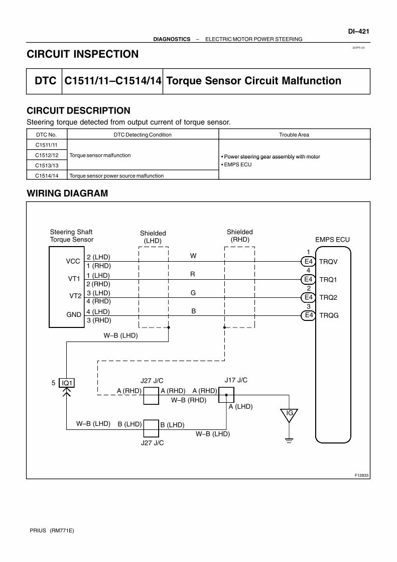
DI7PT–01
F12833
Steering ShaftTorque Sensor
2 (LHD)1 (RHD)
W
E4
1 (LHD)
3 (LHD)
4 (LHD)
2 (RHD)
4 (RHD)
3 (RHD)
R
G
B
VCC
VT1
VT2
GND
TRQV
TRQ1
TRQ2
TRQG
W–B (LHD)
EMPS ECU
E4
E4
E4
1
4
2
3
IQ15 J27 J/C
A (RHD)
A (LHD)
J17 J/C
IG
Shielded (LHD)
Shielded (RHD)
A (RHD) A (RHD)W–B (RHD)
W–B (LHD)
W–B (LHD) B (LHD) B (LHD)
J27 J/C
–DIAGNOSTICS ELECTRIC MOTOR POWER STEERINGDI–421
PRIUS (RM771E)
CIRCUIT INSPECTION
DTC C1511/11–C1514/14 Torque Sensor Circuit Malfunction
CIRCUIT DESCRIPTIONSteering torque detected from output current of torque sensor.
DTC No. DTC Detecting Condition Trouble Area
C1511/11
C1512/12 Torque sensor malfunctionPower steering gear assembly with motor
C1513/13
q Power steering gear assembly with motor
EMPS ECU
C1514/14 Torque sensor power source malfunction
WIRING DIAGRAM

F12270
ONTRQV
TRQG
F12271
VT1
VT2GND
DI–422–DIAGNOSTICS ELECTRIC MOTOR POWER STEERING
PRIUS (RM771E)
INSPECTION PROCEDURE
1 Check voltage between terminals TRQV and TRQG of EMPS ECU.
PREPARATION:Remove the EMPS ECU with connectors still connected.CHECK:Measure the voltage between terminals TRQV and TRQG ofEMPS ECU connector.OK:
Voltage: 4.5 – 5.5 V
NG Check and replace the EMPS ECU.
OK
2 Check for open and short circuit in harness and connector between terminalsTRQV and TRQG of EMPS ECU connector (See page IN–40).
NG Repair and replace harness or connector.
OK
3 Check voltage between terminals VT1 and GND, VT2 and GND of torque sensorconnector.
PREPARATION:Remove the torque sensor with connectors still connected.CHECK:Measure the voltage between terminals VT1 and GND, VT2 andGND of torque sensor connector.OK:
Steering Position VT1 VT2
Center position 2.1 – 2.9 V 2.1 – 2.9 V
Right turned 0.15 – 2.9 V 2.1 – 4.85 V
Left turned 2.1 – 4.85 V 0.15 – 2.9 V

–DIAGNOSTICS ELECTRIC MOTOR POWER STEERINGDI–423
PRIUS (RM771E)
NG Check and replace the power steering gear as-sembly with motor (See page SR–18).
OK
4 Check for open and short circuit in harness and connector between terminalsVT1 of torque sensor connector and TRQ1 of EMPS ECU connector, VT2 of torquesensor connector and TRQ2 of EMPS ECU connector (See page IN–40).
NG Repair and replace harness or connector.
OK
Check and replace the EMPS ECU.

DI–424–DIAGNOSTICS ELECTRIC MOTOR POWER STEERING
PRIUS (RM771E)
DTC C1515/15 Torque Sensor Zero Point Calibration NotPerformed
CIRCUIT DESCRIPTIONThis DTC does not indicate trouble. Perform calibration of torque sensor zero point to delete DTC.
DTC No. DTC Detecting Condition Trouble Area
C1515/15When torque sensor zero point calibration not performed,
this DTC is detected.–
INSPECTION PROCEDURE
1 Is DTC except C1515/15 output?
Check DTC on page DI–416.
YES Repair circuit indicated by code output.
NO
2 Perform calibration of torque sensor zero point (See page DI–410).
3 Is DTC C1516/16 output?
Check DTC on page DI–416.
NO No problem.
YES
Repair circuit indicated by DTC C1516/16 (See page DI–425).
DI7PU–01

–DIAGNOSTICS ELECTRIC MOTOR POWER STEERINGDI–425
PRIUS (RM771E)
DTC C1516/16 Calibration of Torque Sensor Zero Point NotCompleted
CIRCUIT DESCRIPTIONThis DTC does not indicated trouble. This is detected when the torque sensor zero point calibration is notcompleted normally.
DTC No. DTC Detecting Condition Trouble Area
C1516/16This is detected when the torque sensor zero point calibra-
tion is not completed normally.–
INSPECTION PROCEDURE
1 Perform calibration of torque sensor zero point (See page DI–410).
2 Is DTC C1516/16 output?
Check DTC on page DI–416.
NO No problem.
YES
3 Is DTC C1532/32 output ?
YES Check and replace EMPS ECU.
NO
4 Perform calibration of torque sensor zero point again (See page DI–410).
DI7PV–01

DI–426–DIAGNOSTICS ELECTRIC MOTOR POWER STEERING
PRIUS (RM771E)
5 Is DTC C1516/16 output after attempted 3 times or more ?
YES Replace the power steering gear assembly withmotor.
NO
No problem.

F12834
EMPS ECU
DC Motor
M1
M2
E5
1
2
E5
2
1
Y
B–Y
F12819
ONM1
M2
–DIAGNOSTICS ELECTRIC MOTOR POWER STEERINGDI–427
PRIUS (RM771E)
DTC C1521/21–C1524/24 Motor Circuit Malfunction
CIRCUIT DESCRIPTIONDTC No. DTC Detecting Condition Trouble Area
C1521/21
C1522/22 Short circuit of motor terminal or abnormal voltage or current in Power steering gear assembly with motor
C1523/23
Short circuit of motor terminal or abnormal voltage or current in
motor circuit.
Power steering gear assembly with motor
EMPS ECU
C1524/24
WIRING DIAGRAM
INSPECTION PROCEDURE
1 Check voltage between terminals M1 and M2 of EMPS ECU connector.
PREPARATION: Remove the EMPS ECU with connectors still connected. Turn the ignition switch ON.
CHECK:Turn the steering wheel to left and right and measure the volt-age between terminals M1 and M2 of EMPS ECU connector.OK:
Voltage: 9 – 14 V
DI7PW–01

F12820
M1M2
DI–428–DIAGNOSTICS ELECTRIC MOTOR POWER STEERING
PRIUS (RM771E)
NG Check and replace the EMPS ECU.
OK
2 Check for open and short circuit in harness and connector between terminals M1and M2 of EMPS ECU connector (See page IN–40).
NG Repair or replace harness or connector.
OK
3 Check continuity between terminal M1 and M2 of motor connector.
PREPARATION:Disconnect the connector from the motor.CHECK:Measure the resistance between terminals M1 and M2 of motorconnector.OK:
Resistance: 0.1 – 1 Ω
NG Check and replace the power steering gear as-sembly with motor (See page SR–27).
OK
Check and replace EMPS ECU.

–DIAGNOSTICS ELECTRIC MOTOR POWER STEERINGDI–429
PRIUS (RM771E)
DTC C1531/31–C1533/33, C1555/55 EMPS ECU Circuit Malfunction
CIRCUIT DESCRIPTIONDTC No. DTC Detecting Condition Trouble Area
C1531/31
C1532/32EMPS ECU internal malfunction is detected EMPS ECU
C1533/33EMPS ECU internal malfunction is detected EMPS ECU
C1555/55
INSPECTION PROCEDURE
1 Clear DTC (See page DI–410).
2 Recheck EMPS ECU Malfunction.
PREPARATION:Turn the ignition switch ON.CHECK:Turn the steering wheel repeatedly to the right and left.OK:DTC is not output.
NG Replace EMPS ECU.
OK
Check multiinformation display circuit (See page BE–92).
DI7PY–01

F12835
Brake ECU EMPS ECU
WRL
WRR
4
E710
Shielded
B10
23
15RLO
RRO
IG J17 J/C J27 J/C
E7
W
BB10
A (RHD)
B (LHD)
(W–B)
W–B (LHD)A (LHD)
A (RHD)J27 J/C
B (LHD)
A (RHD)
W–B (RHD)
DI–430–DIAGNOSTICS ELECTRIC MOTOR POWER STEERING
PRIUS (RM771E)
DTC C1541/41–C1543/43 Speed Sensor Malfunction
DTC C1571/71, C1572/72 Speed Sensor Malfunction (Test Mode)
CIRCUIT DESCRIPTIONDTC No. DTC Detecting Condition Trouble Area
C1541/41Speed sensor
C1542/42 Speed sensor malfunctionS eed sensor
Brake ECU
C1543/43 EMPS ECU
C1571/71
Speed sensor malfunction (Test mode)
Right rear or left rear speed sensor
Sensor installation
Right rear or left rear speed sensor rotor
C1572/72
Speed sensor malfunction (Test mode)Right rear or left rear s eed sensor rotor
Right rear or left rear speed sensor circuit
Brake ECU
EMPS ECU
WIRING DIAGRAM
DI7PZ–01

F12822
ON PGND
WRLWRR
PGND
–DIAGNOSTICS ELECTRIC MOTOR POWER STEERINGDI–431
PRIUS (RM771E)
INSPECTION PROCEDURE
1 Check continuity between terminals WRR and PGND, WRL and PGND of EMPSECU connector.
PREPARATION:Remove the EMPS ECU with connectors still connected.CHECK:Turn the ignition switch ON and measure the resistance be-tween terminals WRR and PGND, WRL and PGND of EMPSECU connector.OK:
Resistance: 1 MΩ or higher
NG Check and replace EMPS ECU.
OK
2 Check for open and short circuit in harness and connector between terminalsWRR of EMPS ECU connector and RRO of brake ECU connector, WRL of EMPSECU and RLO of brake ECU connector (See page IN–40).
NG Repair and replace harness or connector.
OK
3 Check the DTC for the ABS with EBD and RBS (See page DI–306).
*1 Repair ABS with EBD and RBS control systemaccording to the code output.
*1: Out put NG code

F12837
EMPS ECU
IGE75J/C ED B–YB–Y
22I
ECU–IG IG1 Relay
AM1
6
2H
2B
2D8
2K
IG S/W
F11
FL Block No. 1
F13
F18FL Block No. 2
PGNDE6
J17 J/C
IGBattery
ID
J11 J/C
J15J14
5
2
3
1
1
3
W
W–G
4B–Y
11B–G1
A
W–BA
2
2W–B
DC/DCMAIN
Instrument Panel J/B
DI–432–DIAGNOSTICS ELECTRIC MOTOR POWER STEERING
PRIUS (RM771E)
DTC C1551/51 IG Power Source Circuit Malfunction
CIRCUIT DESCRIPTIONThe EMPS ECU identifies ON or OFF status of ignition switch by this circuit.
DTC No. DTC Detecting Condition Trouble Area
Th b l IG lt l hi h i t ithi th ifiEMPS ECU
C1551/51The abnormal IG voltage value which is not within the specifi-
cation is input to EMPS ECU
EMPS ECU
Power source circuitC1551/51cation is input to EMPS ECU.
Power source circuit
Charging system
WIRING DIAGRAM
DI7Q0–01

F12823
ECU–IG Fuse
Instrument Panel J/B
–DIAGNOSTICS ELECTRIC MOTOR POWER STEERINGDI–433
PRIUS (RM771E)
INSPECTION PROCEDURE
1 Check ECU–IG fuse.
PREPARATION:Remove the ECU–IG fuse from the instrument panel J/B.CHECK:Check the continuity of the ECU–IG.OK:
Continuity
NG Check for short circuit in all harness and com-ponents connected to ECU–IG fuse (See at-tached wiring diagram).
OK
2 Check that the battery voltage when engine is stopped.
OK:Voltage: 9 – 14 V
NG Charge or replace battery.
OK

F12824
ON IG
PGND
F12825
LOCK PGND
DI–434–DIAGNOSTICS ELECTRIC MOTOR POWER STEERING
PRIUS (RM771E)
3 Check voltage between terminals IG and PGND of EMPS ECU connector.
PREPARATION:Remove the EMPS ECU with connectors still connected.CHECK:Turn the ignition switch ON and measure the voltage betweenterminals IG and PGND of EMPS ECU connector.OK:
Voltage: 9 – 14 V
NG Check and replace EMPS ECU.
OK
4 Check continuity between terminals PGND of EMPS ECU connector and bodyground.
CHECK:Measure the resistance between terminals PGND of EMPSECU connector and body ground.OK:
Resistance: 1 Ω or less
NG Repair or replace harness or connector.
OK
Check for open and short circuit harness and connector between EMPS ECU and ECU–IG fuse(See page IN–40).

F12838
EMPS ECUEngine Room R/B No. 3
PIG
RLY
PGND
J17 J/CW–B
Battery IG
R–GB–R Instrument Panel J/B
Engine Room R/B No. 3
E6
E6
E7
B
GR
IA1IM1
(LHD) 1
IA27
B
GR
3
33
3
2G 2H
16 ECU–B
F11
F10 F13
1
1 1
FL Block No. 1
DC/DC
3 312
EMPS
MAIN
FL Block No. 2
B–G
1
2A
W
W
3
1 2
51
2
(RHD) 7
EMPS Relay
(LHD)(RHD)
–DIAGNOSTICS ELECTRIC MOTOR POWER STEERINGDI–435
PRIUS (RM771E)
DTC C1552/52 PIG Power Source Circuit
CIRCUIT DESCRIPTIONWhen turning ignition switch ON, battery is supplied to terminal PIG of EMPS ECU by EMPS relay operation.
DTC No. DTC Detecting Condition Trouble Area
C1552/52The abnormal motor power source voltage value which is not
within the specification is input to EMPS ECU.
EMPS ECU
Power source circuit
WIRING DIAGRAM
DI7Q1–01

F12826
ON PIG
PGND
F12825
LOCK PGND
DI–436–DIAGNOSTICS ELECTRIC MOTOR POWER STEERING
PRIUS (RM771E)
INSPECTION PROCEDURE
1 Check voltage between terminals PIG and PGND of EMPS ECU connector.
PREPARATION:Remove the EMPS ECU with connectors still connected.CHECK:Turn the ignition switch ON and measure the voltage betweenterminals PIG and PGND of EMPS ECU connector.OK:
Voltage: 9 – 14 V
NG Check and replace EMPS ECU.
OK
2 Check continuity between terminals PGND of EMPS ECU connector and bodyground.
CHECK:Measure the resistance between terminals PGND of EMPSECU connector and body ground.OK:
Resistance: 1 Ω or less
NG Repair or replace harness or connector.
OK

F12862
EngineRoom R/BNo. 3
EMPSFuse
–DIAGNOSTICS ELECTRIC MOTOR POWER STEERINGDI–437
PRIUS (RM771E)
3 Check EMPS fuse.
PREPARATION:Remove the EMPS fuse from engine room R/B No. 3.CHECK:Check continuity of EMPS fuse.OK:
Continuity
NG Check for short circuit in harness and all com-ponents connected to EMPS fuse (See attachedwiring diagram).
OK
Check for open and short circuit in harness and connector between EMPS ECU and battery (Seepage IN–40).

DI–438–DIAGNOSTICS ELECTRIC MOTOR POWER STEERING
PRIUS (RM771E)
DTC C1553/53 When resetting voltage, vehicle is beingdriven
CIRCUIT DESCRIPTIONDTC No. DTC Detecting Condition Trouble Area
C1553/53 ECU internal malfunction EMPS ECU
Fail safe function: When this code is identified, stop the steering assist.
INSPECTION PROCEDUREHINT: In case the ECU detects that the ignition switch turns ON – OFF – ON while driving and starting the
system, DTC C1553/53 is output. Stop the vehicle and start the system by turning the ignition switch OFF – ON. Then DTC 1553/53 will
not be output.
1 Check output DTC C1553/53 when turning the ignition switch from OFF to ON(See page DI–410).
YES Check and replace the EMPS ECU.
NO
No problem.
DI7Q2–01

F12838
EMPS ECUEngine Room R/B No. 3
PIG
RLY
PGND
J17 J/CW–B
BatteryIG
R–GB–R Instrument Panel J/B
Engine Room R/B No. 3
E6
E6
E7
B
GR
IA1
(RHD) 7
IM1
(LHD) 1
IA17
B
GR
3
33
3
2G 2H
16 ECU–B
F11
F10 F13
1
1 1
FL Block No. 1
DC/DC
3 312
EMPS
MAIN
FL Block No. 2
B–G
1
2A
W
W
3
1 2
5
(LHD)(RHD)
1
2
EMPS Relay
–DIAGNOSTICS ELECTRIC MOTOR POWER STEERINGDI–439
PRIUS (RM771E)
DTC C1554/54 EMPS Relay Circuit
CIRCUIT DESCRIPTIONDTC No. DTC Detecting Condition Trouble Area
C1554/54 Open or short circuit of EMPS relay circuit is detected
EMPS relay
EMPS ECU
EMPS relay circuit
WIRING DIAGRAM
DI7Q3–01

F12828
ON RLY
PGND
F11788
5
1
3
2
Open
Continuity
5
2
1
3
5
2
1
3
Continuity
DI–440–DIAGNOSTICS ELECTRIC MOTOR POWER STEERING
PRIUS (RM771E)
INSPECTION PROCEDURE
1 Check voltage between terminals RLY and PGND of EMPS ECU connector.
PREPARATION:Remove the EMPS ECU with connectors still connected.CHECK:Turn the ignition switch ON and measure the voltage betweenterminals RLY and PGND of EMPS ECU connector.OK:
Voltage: 9 – 14 V
OK Check or replace the EMPS ECU.
NG
2 Check EMPS relay.
PREPARATION:Remove the EMPS relay from the engine room R/B No. 3.CHECK:Check the continuity between each terminal of the EMPS relay.OK:
Terminals 1 and 2 Continuity (Reference value 80 Ω)
Terminals 3 and 5 Open
CHECK:(a) Apply battery voltage between terminals 1 and 2.(b) Check the continuity between the terminals.OK:
Terminals 3 and 5 Continuity

F12863
Instrument Panel J/B
ECU–B Fuse
–DIAGNOSTICS ELECTRIC MOTOR POWER STEERINGDI–441
PRIUS (RM771E)
NG Replace EMPS relay.
OK
3 Check ECU–B fuse.
PREPARATION:Remove the ECU–B fuse from instrument panel J/B.CHECK:Check the continuity of ECU–B fuse.OK:
Continuity
NG Check for short circuit in harness and all com-ponents connected to ECU–B fuse (See at-tached wiring diagram).
OK
Check for open and short circuit harness and connector between EMPS ECU and battery (Seepage IN–40).

F12840
EMPS ECUMultiinformation Display
Instrument Panel J/B
FL Block No. 1F18FL Block No. 2
WLE77
YIP13
L1122
L
2A
IG1 Relay5 GAUGE
2H1
3 5
W
F111
F131
B–GMAIN
Battery
DC/DC1
DI–442–DIAGNOSTICS ELECTRIC MOTOR POWER STEERING
PRIUS (RM771E)
DTC C1556/56 PS Warning Light Circuit
CIRCUIT DESCRIPTIONDTC No. DTC Detecting Condition Trouble Area
C1556/56 There is a malfunction is PS warning light circuitMultiinformation display
EMPS ECU
WIRING DIAGRAM
DI7Q4–01
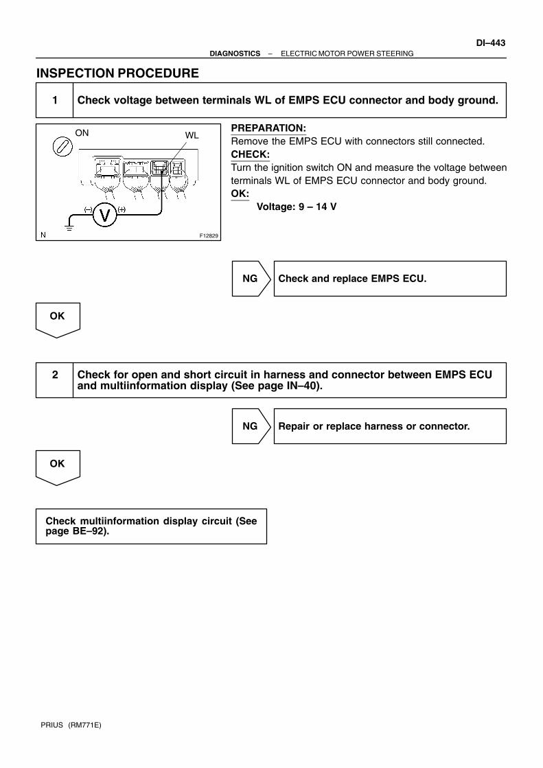
F12829
ON WL
–DIAGNOSTICS ELECTRIC MOTOR POWER STEERINGDI–443
PRIUS (RM771E)
INSPECTION PROCEDURE
1 Check voltage between terminals WL of EMPS ECU connector and body ground.
PREPARATION:Remove the EMPS ECU with connectors still connected.CHECK:Turn the ignition switch ON and measure the voltage betweenterminals WL of EMPS ECU connector and body ground.OK:
Voltage: 9 – 14 V
NG Check and replace EMPS ECU.
OK
2 Check for open and short circuit in harness and connector between EMPS ECUand multiinformation display (See page IN–40).
NG Repair or replace harness or connector.
OK
Check multiinformation display circuit (Seepage BE–92).

DI–444–DIAGNOSTICS ELECTRIC MOTOR POWER STEERING
PRIUS (RM771E)
DTC C1557/57 Memory of Overheat Prevention Control
DTC C1558/58 Memory of Voltage Drop at Motor Power Supply
DTC C1559/59 Memory of Continuous Control Under High Load
CIRCUIT DESCRIPTION These DTC do not indicated trouble. DTC C1557/57 and C1558/58 :
Steering wheel operation is felt hard to handle when this detected, it is not EMPS failure.Check the AUXILIARY BATTERY.
DTC C1559/59: EMPS ECU records this code in some case, for example, when steering wheel operation under highload is repeated, there is no failure in EMPS and it does not affect driving afterward.
DTC No Detection Item Trouble Area
C1557/57 Perform the overheat prevention control.
C1558/58 Drop the voltage of motor power source. –
C1559/59 Steering wheel operation under high load is repeated.
DI7Q5–01

–DIAGNOSTICS ELECTRIC MOTOR POWER STEERINGDI–445
PRIUS (RM771E)
DTC Always ON Malfunction in EMPS ECU
CIRCUIT DESCRIPTIONDTC No. DTC Detecting Condition Trouble Area
Always ON There is a malfunction in the EMPS ECU internal circuit.
Power source circuit
EMPS ECU
PS warning light circuit
1 Is DTC output?
Check DTC on page DI–416.
YES Repair circuit indicated by output code.
NO
2 Is normal code displayed?
YES Check and replace EMPS ECU.
NO
3 Does PS warning light goes off?
YES Check for open or short circuit in harness andconnector between ECU–IG fuse and EMPSECU (See page IN–40).
NO
DI7Q7–01

DI–446–DIAGNOSTICS ELECTRIC MOTOR POWER STEERING
PRIUS (RM771E)
4 Check battery voltage.
PREPARATION:Start the engine.CHECK:Check the battery voltage.OK:
Voltage: 9 – 14 V
NG Check and repair charging system.
OK
5 Check operation of PS warning light.
PREPARATION:(a) Turn the ignition switch OFF.(b) Disconnect the connector from the EMPS ECU.(c) Turn the ignition switch ON.CHECK:Check the PS warning light goes OFF.
OK Check and replace EMPS ECU.
NG
Check for short circuit in harness and connector between multiinformation display and EMPSECU,multiinformation display and DLC3 (See page IN–40).

F12841
EMPS ECU
TcE73
P–BCC
J16 J/C
P–BID12
P–BEE
J24 J/C
P–B13
DLC3
Tc
SG 5 BRID2
(LHD) 14
IE1
(RHD) 9
BRBR
EB
(LHD) (RHD)
(LHD) 14
(RHD)13
IO1 IK1(LHD) (RHD)
–DIAGNOSTICS ELECTRIC MOTOR POWER STEERINGDI–447
PRIUS (RM771E)
Tc Terminal Circuit
CIRCUIT DESCRIPTIONConnecting terminals Tc and CG of the DLC3 causes the EMPS ECU to display the DTC by flashing the PSwarning light.
WIRING DIAGRAM
DI7Q8–01

F09678
Tc
CG
ON
DI–448–DIAGNOSTICS ELECTRIC MOTOR POWER STEERING
PRIUS (RM771E)
INSPECTION PROCEDURE
1 Check voltage between terminals Tc and CG of DLC3.
CHECK:Turn the ignition switch ON and measure the voltage betweenterminals Tc and CG of the DLC3.OK:
Voltage: 9 – 14 V
OK If PS warning light does not blink even after Tcand CG are connected, EMPS ECU may be de-fective.
NG
2 Turn the ignition switch OFF, and check for open and short circuit in harnessand connector between EMPS ECU and DLC3, and DLC3 and body ground (Seepage IN–40).
NG Repair or replace harness or connector.
OK
Check and replace EMPS ECU.

F12843
EMPS ECU
TsE79
GR–GJ16 J/C
BBGR–GID1
3Ts GR–G14
DLC3
SGBR5
(LHD) 14
ID2 IE1
(RHD) 9
BRBR
EB
(LHD) 14
(RHD) 13
(LHD)(RHD)IO1 IK1
(LHD) (RHD)
–DIAGNOSTICS ELECTRIC MOTOR POWER STEERINGDI–449
PRIUS (RM771E)
Ts Terminal Circuit
CIRCUIT DESCRIPTIONThe sensor check circuit detects abnormalities in the speed sensor signal which cannot be detected by theDTC check.Connecting terminals Ts and CG of the DLC3 starts the check.
WIRING DIAGRAM
DI7Q9–01

F09679
Ts
CG
ON
DI–450–DIAGNOSTICS ELECTRIC MOTOR POWER STEERING
PRIUS (RM771E)
INSPECTION PROCEDURE
1 Check voltage between terminals Ts and CG of DLC3.
CHECK:Turn the ignition switch ON and measure the voltage betweenterminals Ts and CG of the DLC3.OK:
Voltage: 9 – 14 V
OK If PS warning light repeats turning ON and OFFeven after Ts and CG are connected, EMPS ECUmay be defective.
NG
2 Turn the ignition switch OFF, and check for open and short circuit in harnessand connector between EMPS ECU and DLC3, DLC3 and body ground (See page IN–40).
NG Repair or replace harness or connector.
OK
Check and replace EMPS ECU.

DI6OW–02
Warning Light Check
P. DI–453
END: Diagnostic steps permitting the useof the hand–held tester.
P. DI–452
P. DI–453
Symptom SimulationNormal
DTC Check
Warning Light ON
Malfunction Code Warning LightRemains OFF
Circuit Inspection
Identification of Problem
Repair
Warning Light CheckP. DI–453
DTC Check (Read Past DTC)
Confirmation Test
Remains ON
Remains OFF
Clear DTC (Present and Past DTC)
Items inside are titles of pages in this manual,with the page number in the bottom portion. See thepages for detailed explanations.1
2
43
5
7
8
9
10
DTC Chart
11
6
P. DI–459
P. IN–29P. DI–464 to DI–545
Remains OFF
Remains ON
Vehicle Brought to Workshop
Customer Problem Analysis
DTC Check (Read Present DTC)
Step 3, 4, 6, 8, 9, 11
P. DI–453DTC Check (Read Past DTC)
P. DI–453
P. DI–453
P. DI–453
–DIAGNOSTICS SUPPLEMENTAL RESTRAINT SYSTEMDI–451
PRIUS (RM771E)
SUPPLEMENTAL RESTRAINT SYSTEMHOW TO PROCEED WITH TROUBLESHOOTING

DI6OX–01
Supplemental Restraint System Check Sheet
Date Problem Occurred
Customer’s Name
Registration No.
Registration Year
Frame No.
Odometer Reading
Weather
Temperature
Vehicle Operation
Road Conditions
Details Of Problem
Vehicle Inspection, Repair Histo-ry Prior to Occurrence of Mal-function (Including Supplemen-tal Restraint System)
Diagnosis System Inspection
SRS Warning Light Inspection
DTC Inspection
1st Time
2nd Time
1st Time
2nd Time
Inspector’s Name
Fine Cloudy Rainy Snowy Other
Approx.
Starting Idling
Driving [ Constant speed Acceleration DecelerationOther ]
Remains ON Sometimes Lights Up Does Not Light Up
Remains ON Sometimes Lights Up Does Not Light Up
Normal Code Malfunction Code
Normal Code Malfunction Code
[ Code. ]
[ Code. ]
kmMiles
/ /
/ /
/ /
Date Vehicle Brought In
DI–452–DIAGNOSTICS SUPPLEMENTAL RESTRAINT SYSTEM
PRIUS (RM771E)
CUSTOMER PROBLEM ANALYSIS CHECK

DI6OY–06
H15701
LHD:
RHD:
H10658
DLC3
CG Tc
–DIAGNOSTICS SUPPLEMENTAL RESTRAINT SYSTEMDI–453
PRIUS (RM771E)
PRE–CHECK1. SRS WARNING LIGHT CHECK(a) Turn the ignition switch to the ON position and check that
the SRS warning light lights up.(b) Check that the SRS warning light goes out after approx.
6 seconds.HINT: When the ignition switch is at ON and the SRS warning
light remains on or flashes, the airbag sensor assemblyhas detected a malfunction code.
If, after approx. 6 seconds have elapsed, the SRS warn-ing light sometimes lights up or the SRS warning lightlights up even when the ignition switch is OFF, a short inthe SRS warning light circuit can be considered likely.Proceed to ”SRS warning light circuit malfunction” onpage .
2. DTC CHECK (Using diagnosis check wire)(a) Present troubles codes:
Output the DTC.(1) Turn the ignition switch to the ON position and wait
for approx. 20 seconds.(2) Using SST, connect terminals Tc and CG of the
DLC3.SST 09843–18020
NOTICE:Pay due attention to the terminal connecting position toavoid a malfunction.(b) Past troubles codes:
Output the DTC.(1) Using service wire, connect terminals Tc and CG of
the DLC3.SST 09843–18020(2) Turn the ignition switch to the ON position and wait
for approx. 20 seconds.NOTICE:Pay due attention to the terminal connecting position toavoid a malfunction.

H08231
Normal Code
ON
OFF
0.25
0.25
Code 11 and 31
ON
OFF
0.5 2.5 4.0
1.5 0.5
DTC 11 DTC 31
Repeat
F12397
Hand–held Tester
DLC3
DI–454–DIAGNOSTICS SUPPLEMENTAL RESTRAINT SYSTEM
PRIUS (RM771E)
(c) Read the DTC.Read the 2–digit DTC as indicated by the number of timesthe SRS warning light blinks. As an example, the blinkingpatterns, normal, 11 and 31 are shown in the illustration.
Normal code indication The light will blink 2 times per second.
Malfunction code indication The first blinking output indicates the first digitof a 2–digit DTC. After a 1.5–second pause,the second blinking output will indicate thesecond digit.
If there are 2 or more codes, there will be a 2.5–second pausebetween each code. After all the codes have been output, therewill be a 4.0–second pause and they will all be repeated.HINT: In the event of a number of trouble codes, indication will
start from the smallest numbered code. If a DTC is not output or a DTC is output without terminal
connection, proceed to the Tc terminal circuit inspectionon page DI–545.
3. DTC CHECK (Using hand–held tester)(a) Hook up the hand–held tester to the DLC3.(b) Read the DTCs by following the prompts on the tester
screen.HINT:Please refer to the hand–held tester operator’s manual for fur-ther details.4. DTC CLEARANCE (Not using service wire)When the ignition switch is turned off, the diagnostic troublecode is cleared.HINT:DTC might not be cleared by turning the ignition switch OFF. In this case, proceed to the next step.5. DTC CLEARANCE (Using service wire)(a) Connect the 2 service wires to terminals Tc and A/B of
DLC3.(b) Turn the ignition switch to ON and wait for approx. 6 se-
conds.

H15702
A/B
Terminal
Tc
A/B
OFF
Body Ground
OFF
ON
OFF
Several Seconds
50 m sec.
50 m sec.
1 second
0.5 sec.)
Tc
Body Ground
1 second0.5 sec.)
1
2
3
4
5
LHD:
RHD:
F12397
Hand–held Tester
DLC3
–DIAGNOSTICS SUPPLEMENTAL RESTRAINT SYSTEMDI–455
PRIUS (RM771E)
(c) Starting with the Tc terminal, ground alternately terminalTc and terminal A/B twice each in cycles of 1.0 second.Make sure that the terminals are grounded. Ensure theterminal Tc remain grounded.
HINT:When alternately grounding terminals Tc and A/B, releaseground from one terminal and immediately ground the other ter-minal within an interval of 0.2 seconds.If DTCs are not cleared, repeat the above procedure until thecodes are cleared.
(d) Several seconds after doing the clearing procedure, theSRS warning light will blink in a 50 – m sec. cycle to indi-cate the codes which have been cleared.
6. DTC CLEARANCE (Using hand–held tester)(a) Hook up the hand–held tester to the DLC3.(b) Clear the DTCs by following the prompts on the tester
screen.HINT:Please refer to the hand–held tester operation’s manual for fur-ther details.

DI–456–DIAGNOSTICS SUPPLEMENTAL RESTRAINT SYSTEM
PRIUS (RM771E)
7. RELEASE METHOD OF AIRBAG ACTIVATION PRE-VENTION MECHANISM
An airbag activation prevention mechanism is built into the con-nector for the squib circuit of the SRS. When release of the airbag activation prevention mechanism isdirected in the troubleshooting procedure, as shown in the il-lustration of the connectors on the next pages, insert paperwhich has the same thickness as the male terminal between theterminal and the short spring.CAUTION:Never release the airbag activation prevention mechanismon the squib connector.NOTICE: Do not release the airbag activation prevention mech-
anism unless specifically directed by the trouble-shooting procedure.
If the inserted paper is too thick the terminal and shortspring may be damaged, so always use paper withthe same thickness as the male terminal.

H14955
Airbag SensorAssembly
2
3
7
10 11
12
1
4 5
6
8 9
Seat Belt Pretensioner (RH)
Front Airbag Sensor (RH)
Front Passenger Airbag Assembly (Squib)
Spiral Cable
Steering Wheel Pad (Squib)
Front Airbag Sensor (LH)
Seat Belt Pretensioner (LH)
–DIAGNOSTICS SUPPLEMENTAL RESTRAINT SYSTEMDI–457
PRIUS (RM771E)

H11587
Airbag Sensor Assembly Connector
Short SpringShort Spring Short Spring
Before Release After Release
Connector Connector
Short SpringShort Spring
Before Release
Paper
After Release
Paper
4 7 12
Paper
2 1 3
DI–458–DIAGNOSTICS SUPPLEMENTAL RESTRAINT SYSTEM
PRIUS (RM771E)

DI6OZ–05
–DIAGNOSTICS SUPPLEMENTAL RESTRAINT SYSTEMDI–459
PRIUS (RM771E)
DIAGNOSTIC TROUBLE CODE CHARTIf a malfunction code is displayed during the DTC check, check the circuit listed for that code in the tablebelow (Proceed to the page given for that circuit.).
DTC No.
(See Page)Detection Item Trouble Area
SRS
Warning Light
B0100/13
(DI–464)
Short in D squib circuit Steering wheel pad (squib)
Spiral cable
Airbag sensor assembly
Wire harness
ON
B0101/14
(DI–469)
Open in D squib circuit Steering wheel pad (squib)
Spiral cable
Airbag sensor assembly
Wire harness
ON
B0102/11
(DI–473)
Short in D squib circuit (to ground) Steering wheel pad (squib)
Spiral cable
Airbag sensor assembly
Wire harness
ON
B0103/12
(DI–477)
Short in D squib circuit (to B+) Steering wheel pad (squib)
Spiral cable
Airbag sensor assembly
Wire harness
ON
B0105/53
(DI–481)
Short in P squib circuit Front passenger airbag assembly (squib)
Airbag sensor assembly
Wire harness
ON
B0106/54
(DI–485)
Open in P squib circuit Front passenger airbag assembly (squib)
Airbag sensor assembly
Wire harness
ON
B0107/51
(DI–488)
Short in P squib circuit (to ground) Front passenger airbag assembly (squib)
Airbag sensor assembly
Wire harness
ON
B0108/52
(DI–491)
Short in P squib circuit (to B+) Front passenger airbag assembly (squib)
Airbag sensor assembly
Wire harness
ON
B0130/63
(DI–494)
Short in P/T squib (RH) circuit Seat belt pretensioner RH (squib)
Airbag sensor assembly
Wire harness
Blink
B0131/64
(DI–498)
Open in P/T squib (RH) circuit Seat belt pretensioner RH (squib)
Airbag sensor assembly
Wire harness
Blink
B0132/61
(DI–501)
Short in P/T squib (RH) circuit
(to ground)
Seat belt pretensioner RH (squib)
Airbag sensor assembly
Wire harness
Blink
B0133/62
(DI–504)
Short in P/T squib (RH) circuit
(to B+)
Seat belt pretensioner RH (squib)
Airbag sensor assembly
Wire harness
Blink
B0135/73
(DI–507)
Short in P/T squib (LH) circuit Seat belt pretensioner LH (squib)
Airbag sensor assembly
Wire harness
Blink
B0136/74
(DI–511)
Open in P/T squib (LH) circuit Seat belt pretensioner LH (squib)
Airbag sensor assembly
Wire harness
Blink

DI–460–DIAGNOSTICS SUPPLEMENTAL RESTRAINT SYSTEM
PRIUS (RM771E)
DTC No.
(See Page)Detection Item Trouble Area
SRS
Warning Light
B0137/71
(DI–514)
Short in P/T squib (LH) circuit
(to ground)
Seat belt pretensioner LH (squib)
Airbag sensor assembly
Wire harness
Blink
B0138/72
(DI–517)
Short in P/T squib (LH) circuit
(to B+)
Seat belt pretensioner LH (squib)
Airbag sensor assembly
Wire harness
Blink
B1100/31
(DI–520)
Airbag sensor assembly malfunction Airbag sensor assemblyON
B1156/B1157/
15
(DI–522)
Front airbag sensor (RH) malfunction Front airbag sensor (RH)
Airbag sensor assembly
Instrument panel wire harness
Engine room No. 2 wire harness
ON
B1158/B1159/
16
(DI–530)
Front airbag sensor (LH) malfunction Front airbag sensor (LH)
Airbag sensor assembly
Instrument panel wire harness
Engine room main wire harness
ON
N lSystem normal – OFF
Normal
(DI–538) Voltage source drop Battery
Airbag sensor assemblyON
HINT: When the SRS warning light remains lit up and the DTC is the normal code, this means a voltage source
drops. This malfunction is not stored in memory by the airbag sensor assembly and if the power source volt-age returns to normal, the SRS warning light will automatically go out.
When 2 or more codes are indicated, the codes will be displayed in numeral order starting from thelowest numbered code.
If a code not listed on the chart is displayed, the airbag sensor assembly is faulty.

DI6P0–05
H15523
Front Passenger Airbag Assembly
Front Airbag Sensor (LH)
Front Airbag Sensor (RH)
Seat Belt Pretensioner (RH)
Seat BeltPretensioner (LH)
Spiral Cable
Steering Wheel Pad(with Airbag)
–DIAGNOSTICS SUPPLEMENTAL RESTRAINT SYSTEMDI–461
PRIUS (RM771E)
PARTS LOCATION

DI6P1–06
H01357
A19A18 A20
28
789101617
18
AB 123456
111215 14 13
A AB B
192021222324252627
123456
789101112
123456
789101112
DI–462–DIAGNOSTICS SUPPLEMENTAL RESTRAINT SYSTEM
PRIUS (RM771E)
TERMINALS OF ECU
No. Symbol Terminal Name
A – Electrical Connector Check Mechanism
B – Electrical Connector Check Mechanism
A19 – 3 LA SRS Warning Light
A19 – 5 IG2 Power Source
A19 – 6 ACC Power Source
A19 – 9 +SR Front Airbag Sensor (RH)
A19 – 10 P+ Squib (Passenger)
A19 – 11 P– Squib (Passenger)
A19 – 12 SIL Diagnosis
A19 – 13 D– Squib (Driver)
A19 – 14 D+ Squib (Driver)
A19 – 15 +SL Front Airbag Sensor (LH)
A19 – 19 Tc Diagnosis
A19 – 20 –SR Front Airbag Sensor (RH)
A19 – 23 GSW2 ECM
A19 – 26 –SL Front Airbag Sensor (LH)
A19 – 27 E1 Ground
A19 – 28 E2 Ground
A18 – 1 PL– Squib (Seat Belt Pretensioner, LH)
A18 – 2 PL+ Squib (Seat Belt Pretensioner, LH)
A20 – 5 PR+ Squib (Pretensioner, RH)
A20 – 6 PR– Squib (Pretensioner, RH)

DI6P2–01
–DIAGNOSTICS SUPPLEMENTAL RESTRAINT SYSTEMDI–463
PRIUS (RM771E)
PROBLEM SYMPTOMS TABLEProceed with troubleshooting of each circuit in the table below.
Symptom Suspect Area See page
With the ignition switch in ON position, the SRS warning light
sometimes lights up after approx. 6 seconds have elapsed.
SRS warning light is always lit up even when ignition switch is in
the LOCK position.SRS warning light circuit DI–541
With the ignition switch in ON position, the SRS warning light
does not light up.
DTC is not displayed.
SRS warning light is always lit up at the time of DTC check pro-
cedure.Tc terminal circuit DI–545
DTC is displayed without Tc and E1 terminal connection.

DI6P3–05
H01451
Y–BD+A19
14
Airbag Sensor Assembly
13
A19 D–Y
1
2
SpiralCable
D Squib
DI–464–DIAGNOSTICS SUPPLEMENTAL RESTRAINT SYSTEM
PRIUS (RM771E)
CIRCUIT INSPECTION
DTC B0100/13 Short in D Squib Circuit
CIRCUIT DESCRIPTIONThe D squib circuit consists of the airbag sensor assembly, spiral cable and steering wheel pad. It causes the airbag to deploy when the airbag deployment conditions are satisfied. For details of the function of each component, see OPERATION on page RS–2. DTC B0100/13 is recorded when a short is detected in the D squib circuit.
DTC No. DTC Detecting Condition Trouble Area
B0100/13
Short circuit between D+ wire harness and D– wire har-
ness of squib
D squib malfunction
Spiral cable malfunction
Airbag sensor assembly malfunction
Steering wheel pad (D squib)
Spiral cable
Airbag sensor assembly
Wire harness
WIRING DIAGRAM

H02193
D Squib
Spiral Cable
Airbag Sensor Assembly
D+
(–) (+)
D–
–DIAGNOSTICS SUPPLEMENTAL RESTRAINT SYSTEMDI–465
PRIUS (RM771E)
INSPECTION PROCEDURE
1 Prepare for inspection (See step 1 on page DI–538).
2 Check D squib circuit.
PREPARATION:Release the airbag activation prevention mechanism of theconnector (on the airbag sensor assembly side) between theairbag sensor assembly and the spiral cable (See page DI–453).CHECK:For the connector (on the spiral cable side) between the spiralcable and the steering wheel pad, measure the resistance be-tween D+ and D–.OK:
Resistance: 1 MΩ or Higher
NG Go to step 5.
OK

H10598
D Squib
SpiralCable
AirbagSensorAssembly
ON
DTC B0100/13DLC3
→ ←
TcCG
DI–466–DIAGNOSTICS SUPPLEMENTAL RESTRAINT SYSTEM
PRIUS (RM771E)
3 Check airbag sensor assembly.
PREPARATION:(a) Connect the connector to the airbag sensor assembly.(b) Connect negative (–) terminal cable to the battery, and
wait at least for 2 seconds.CHECK:(a) Turn the ignition switch to ON and wait at least for 20 se-
conds.(b) Clear the DTC stored in memory (See page DI–453).(c) Turn the ignition switch to LOCK, and wait at least for 20
seconds.(d) Turn the ignition switch to ON, and wait at least for 20 se-
conds.(e) Check the DTC (See page DI–453).OK:
DTC B0100/13 is not output.HINT:Codes other than code B0100/13 may be output at this time, butthey are not relevant to this check.
NG Replace airbag sensor assembly.
OK

H10599
D Squib
SpiralCable
AirbagSensorAssembly
ON
DTC B0100/13DLC3
→ ←
TcCG
–DIAGNOSTICS SUPPLEMENTAL RESTRAINT SYSTEMDI–467
PRIUS (RM771E)
4 Check D squib.
PREPARATION:(a) Turn the ignition switch to LOCK.(b) Disconnect negative (–) terminal cable from the battery,
and wait at least for 90 seconds.(c) Connect the steering wheel pad connector.(d) Connect negative (–) terminal cable to the battery, and
wait at least for 2 seconds.CHECK:(a) Turn the ignition switch to LOCK, and wait at least for 20
seconds.(b) Turn the ignition switch to ON, and wait at least for 20 se-
conds.(c) Clear the DTC stored in memory (See page DI–453).(d) Turn the ignition switch to LOCK, and wait at least for 20
seconds.(e) Turn the ignition switch to ON, and wait at least for 20 se-
conds.(f) Check the DTC (See page DI–453).OK:
DTC B0100/13 is not output.HINT:Codes other than code B0100/13 may be output at this time, butthey are not relevant to this check.
NG Replace steering wheel pad.
OK
From the results of the above inspection, the malfunctioning part can now be considered normal.To make sure of this, use the simulation method to check.

H02195
D Squib
Spiral Cable
Airbag Sensor Assembly
D+
← →
(–) (+)
D–
H01138
D Squib
SpiralCable
AirbagSensorAssembly
D+
(–) (+)
D–
DI–468–DIAGNOSTICS SUPPLEMENTAL RESTRAINT SYSTEM
PRIUS (RM771E)
5 Check spiral cable.
PREPARATION:(a) Disconnect the connector between the airbag sensor as-
sembly and the spiral cable.(b) Release the airbag activation prevention mechanism of
the spiral cable connector on the airbag sensor assemblyside (See page DI–453).
CHECK:For the connector (on the spiral cable side) between the spiralcable and the steering wheel pad, measure the resistance be-tween D+ and D–.OK:
Resistance: 1 MΩ or Higher
NG Repair or replace spiral cable.
OK
6 Check harness between airbag sensor assembly and spiral cable.
PREPARATION:Release the airbag activation prevention mechanism of theconnector (on the airbag sensor assembly side) between theairbag sensor assembly and the spiral cable (See page DI–453).CHECK:For the connector (on the spiral cable side) between the airbagsensor assembly and the spiral cable, measure the resistancebetween D+ and D–.OK:
Resistance: 1 MΩ or Higher
NG Repair or replace harness or connector be-tween airbag sensor assembly and spiral cable.
OK
From the results of the above inspection, the malfunctioning part can now be considered normal.To make sure of this, use the simulation method to check.

H02196
D Squib
Spiral Cable
Airbag Sensor Assembly
D+
(–) (+)
D–
← →
–DIAGNOSTICS SUPPLEMENTAL RESTRAINT SYSTEMDI–469
PRIUS (RM771E)
DTC B0101/14 Open in D Squib Circuit
CIRCUIT DESCRIPTIONThe D squib circuit consists of the airbag sensor assembly, spiral cable and steering wheel pad. It causes the airbag to deploy when the airbag deployment conditions are satisfied. For details of the function of each component, see OPERATION on page RS–2. DTC B0101/14 is recorded when an open is detected in the D squib circuit.
DTC No. DTC Detecting Condition Trouble Area
B0101/14
Open circuit in D+ wire harness or D– wire harness of
squib
D squib malfunction
Spiral cable malfunction
Airbag sensor assembly malfunction
Steering wheel pad (D squib)
Spiral cable
Airbag sensor assembly
Wire harness
WIRING DIAGRAMSee page DI–464.
INSPECTION PROCEDURE
1 Prepare for inspection (See step 1 on page DI–538).
2 Check D squib circuit.
CHECK:For the connector (on the spiral cable side) between the spiralcable and the steering wheel pad, measure the resistance be-tween D+ and D–.OK:
Resistance: Below 1 Ω
NG Go to step 5.
OK
DI6P4–03

H10602
D Squib
SpiralCable
AirbagSensorAssembly
ON
DTC B0101/14DLC3
→ ←
D+D–
TcCG
DI–470–DIAGNOSTICS SUPPLEMENTAL RESTRAINT SYSTEM
PRIUS (RM771E)
3 Check airbag sensor assembly.
PREPARATION:(a) Connect the connector to the airbag sensor assembly.(b) Using a service wire, connect D+ and D– of the connector
(on the spiral cable side) between the spiral cable and thesteering wheel pad.
(c) Connect negative (–) terminal cable to the battery, andwait at least for 2 seconds.
CHECK:(a) Turn the ignition switch to ON, and wait at least for 20 se-
conds.(b) Clear the DTC stored in memory (See page DI–453).(c) Turn the ignition switch to LOCK, and wait at least for 20
seconds.(d) Turn the ignition switch to ON, and wait at least for 20 se-
conds.(e) Check the DTC (See page DI–453).OK:
DTC B0101/14 is not output.HINT:Codes other than code B0101/14 may be output at this time, butthey are not relevant to this check.
NG Replace airbag sensor assembly.
OK

H10603
→ ←
D SquibSpiralCable
ON
DTC B0101/14DLC3
TcCG
AirbagSensorAssembly
–DIAGNOSTICS SUPPLEMENTAL RESTRAINT SYSTEMDI–471
PRIUS (RM771E)
4 Check D squib.
PREPARATION:(a) Turn the ignition switch to LOCK.(b) Disconnect negative (–) terminal cable from the battery,
and wait at least for 90 seconds.(c) Connect the steering wheel pad connector.(d) Connect negative (–) terminal cable to the battery, and
wait at least for 2 seconds.CHECK:(a) Turn the ignition switch to ON, and wait at least for 20 se-
conds.(b) Clear the DTC stored in memory (See page DI–453).(c) Turn the ignition switch to LOCK, and wait at least for 20
seconds.(d) Turn the ignition switch to ON, and wait at least for 20 se-
conds.(e) Check the DTC (See page DI–453).OK:
DTC B0101/14 is not output.HINT:Codes other than code B0101/14 may be output at this time, butthey are not relevant to this check.
NG Replace steering wheel pad.
OK
From the results of the above inspection, the malfunctioning part can now be considered normal.To make sure of this, use the simulation method to check.

H02195
D Squib ← →
Spiral Cable
D+
(–) (+)
D–
Airbag Sensor Assembly
H01138
D Squib
SpiralCable
AirbagSensorAssembly
D+
(–) (+)
D–
DI–472–DIAGNOSTICS SUPPLEMENTAL RESTRAINT SYSTEM
PRIUS (RM771E)
5 Check spiral cable.
PREPARATION:Disconnect the connector between the airbag sensor assemblyand the spiral cable.CHECK:For the connector (on the spiral cable side) between the spiralcable and the steering wheel pad, measure the resistance be-tween D+ and D–.OK:
Resistance: Below 1 Ω
NG Repair or replace spiral cable.
OK
6 Check harness between airbag sensor assembly and spiral cable.
CHECK:For the connector (on the spiral cable side) between the airbagsensor assembly and the spiral cable, measure the resistancebetween D+ and D–.OK:
Resistance: Below 1 Ω
NG Repair or replace harness or connector be-tween airbag sensor assembly and spiral cable.
OK
From the results of the above inspection, the malfunctioning part can now be considered normal.To make sure of this, use the simulation method to check.

H02198
D Squib
Spiral Cable
Airbag Sensor Assembly
D+
(–) (+)
–DIAGNOSTICS SUPPLEMENTAL RESTRAINT SYSTEMDI–473
PRIUS (RM771E)
DTC B0102/11 Short in D Squib Circuit (to Ground)
CIRCUIT DESCRIPTIONThe D squib circuit consists of the airbag sensor assembly, spiral cable and steering wheel pad. It causes the SRS to deploy when the SRS deployment conditions are satisfied. For details of the function of each component, see OPERATION on page RS–2. DTC B0102/11 is recorded when a ground short is detected in the D squib circuit.
DTC No. DTC Detecting Condition Trouble Area
B0102/11
Short circuit in D squib wire harness (to ground)
D squib malfunction
Spiral cable malfunction
Airbag sensor assembly malfunction
Steering wheel pad (D squib)
Spiral cable
Airbag sensor assembly
Wire harness
WIRING DIAGRAMSee page DI–464.
INSPECTION PROCEDURE
1 Prepare for inspection (See step 1 on page DI–538).
2 Check D squib circuit.
CHECK:For the connector (on the spiral cable side) between the spiralcable and the steering wheel pad, measure the resistance be-tween D+ and body ground.OK:
Resistance: 1 MΩ or Higher
NG Go to step 5.
OK
DI6P5–03

H10605
D Squib
SpiralCable
AirbagSensorAssembly
D+D– ON
DTC B0102/11DLC3
→ ←
TcCG
DI–474–DIAGNOSTICS SUPPLEMENTAL RESTRAINT SYSTEM
PRIUS (RM771E)
3 Check airbag sensor assembly.
PREPARATION:(a) Connect the connector to the airbag sensor assembly.(b) Using a service wire, connect D+ and D– of the connector
(on the spiral cable side) between the spiral cable and thesteering wheel pad.
(c) Connect negative (–) terminal cable to the battery, andwait at least for 2 seconds.
CHECK:(a) Turn the ignition switch to ON, and wait at least for 20 se-
conds.(b) Clear the DTC stored in memory (See step 5 on page
DI–453).(c) Turn the ignition switch to LOCK, and wait at least for 20
seconds.(d) Turn the ignition switch to ON, and wait at least for 20 se-
conds.(e) Check the DTC (See page DI–453).OK:
DTC B0102/11 is not output.HINT:Codes other than code B0102/11 may be output at this time, butthey are not relevant to this check.
NG Replace airbag sensor assembly.
OK

H10606
D Squib
SpiralCable
AirbagSensorAssembly
ON
DTC B0102/11DLC3
→ ←
TcCG
–DIAGNOSTICS SUPPLEMENTAL RESTRAINT SYSTEMDI–475
PRIUS (RM771E)
4 Check D squib.
PREPARATION:(a) Turn the ignition switch to LOCK.(b) Disconnect negative (–) terminal cable from the battery,
and wait at least for 90 seconds.(c) Connect the steering wheel pad connector.(d) Connect negative (–) terminal cable to the battery, and
wait at least for 2 seconds.CHECK:(a) Turn the ignition switch to ON, and wait at least for 20 se-
conds.(b) Clear the DTC stored in memory (See step 5 on page
DI–453).(c) Turn the ignition switch to LOCK, and wait at least for 20
seconds.(d) Turn the ignition switch to ON, and wait at least for 20 se-
conds.(e) Check the DTC (See page DI–453).OK:
DTC B0102/11 is not output.HINT:Codes other than code B0102/11 may be output at this time, butthey are not relevant to this check.
NG Replace steering wheel pad.
OK
From the results of the above inspection, the malfunctioning part can now be considered normal.To make sure of this, use the simulation method to check. If the malfunctioning part can not bedetected by the simulation method, replace all SRS components including the wire harness.

H02200
D Squib
Spiral Cable
Airbag Sensor Assembly
D+
← →
(–) (+)
H06304
D Squib
SpiralCable
(–) (+)
AirbagSensorAssembly
D+
DI–476–DIAGNOSTICS SUPPLEMENTAL RESTRAINT SYSTEM
PRIUS (RM771E)
5 Check spiral cable.
PREPARATION:Disconnect the connector between the airbag sensor assemblyand the spiral cable.CHECK:For the connector (on the spiral cable side) between the steer-ing wheel pad and the spiral cable, measure the resistance be-tween D+ and body ground.OK:
Resistance: 1 MΩ or Higher
NG Repair or replace spiral cable.
OK
6 Check harness between airbag sensor assembly and spiral cable.
CHECK:For the connector (on the spiral cable side) between the spiralcable and the airbag sensor assembly, measure the resistancebetween D+ and body ground.OK:
Resistance: 1 MΩ or Higher
NG Repair or replace harness between airbag sen-sor assembly and spiral cable.
OK
From the results of the above inspection, the malfunctioning part can now be considered normal.To make sure of this, use the simulation method to check. If the malfunctioning part can not bedetected by the simulation method, replace all SRS components including the wire harness.

H11570
D Squib
Spiral Cable
Airbag Sensor Assembly
D+
(–) (+)
ON
–DIAGNOSTICS SUPPLEMENTAL RESTRAINT SYSTEMDI–477
PRIUS (RM771E)
DTC B0103/12 Short in D Squib Circuit (to B+)
CIRCUIT DESCRIPTIONThe D squib circuit consists of the airbag sensor assembly, spiral cable and steering wheel pad. It causes the SRS to deploy when the SRS deployment conditions are satisfied. For details of the function of each component, see OPERATION on page RS–2. DTC B0103/12 is recorded when a B+ short is detected in the D squib circuit.
DTC No. DTC Detecting Condition Trouble Area
B0103/12
Short circuit in D squib wire harness (to B+)
D squib malfunction
Spiral cable malfunction
Airbag sensor assembly malfunction
Steering wheel pad (D squib)
Spiral cable
Airbag sensor assembly
Wire harness
WIRING DIAGRAMSee page DI–464.
INSPECTION PROCEDURE
1 Prepare for inspection (See step 1 on page DI–538).
2 Check D squib circuit.
CHECK:(a) Turn ignition switch to ON.(b) For the connector (on the spiral cable side) between the
spiral cable and the steering wheel pad, measure the volt-age between D+ and body ground.
OK:Voltage: 0 V
NG Go to step 5.
OK
DI6P6–03

H10608
D SquibSpiralCable
AirbagSensorAssembly
D+D– ON
DTC B0103/12DLC3
→ ←
TcCG
DI–478–DIAGNOSTICS SUPPLEMENTAL RESTRAINT SYSTEM
PRIUS (RM771E)
3 Check airbag sensor assembly.
PREPARATION:(a) Connect the connector to the airbag sensor assembly.(b) Using a service wire, connect D+ and D– of the connector
(on the spiral cable side) between the spiral cable and thesteering wheel pad.
(c) Connect negative (–) terminal cable to the battery, andwait at least for 2 seconds.
CHECK:(a) Turn the ignition switch to ON, and wait at least for 20 se-
conds.(b) Clear the DTC stored in memory (See step 5 on page
DI–453).(c) Turn the ignition switch to LOCK, and wait at least for 20
seconds.(d) Turn the ignition switch to ON, and wait at least for 20 se-
conds.(e) Check the DTC (See page DI–453).OK:
DTC B0103/12 is not output.HINT:Codes other than code B0103/12 may be output at this time, butthey are not relevant to this check.
NG Replace airbag sensor assembly.
OK

AB0019W02043
H10609
→ ←
SpiralCable
ON
DTC B0103/12DLC3
AirbagSensorAssembly
D Squib
TcCG
–DIAGNOSTICS SUPPLEMENTAL RESTRAINT SYSTEMDI–479
PRIUS (RM771E)
4 Check D squib.
PREPARATION:(a) Turn the ignition switch to LOCK.(b) Disconnect negative (–) terminal cable from the battery,
and wait at least for 90 seconds.(c) Connect the steering wheel pad connector.(d) Connect negative (–) terminal cable to the battery, and
wait at least for 2 seconds.CHECK:(a) Turn the ignition switch to ON, and wait at least for 20 se-
conds.(b) Clear the DTC stored in memory (See step 5 on page
DI–453).(c) Turn the ignition switch to LOCK, and wait at least for 20
seconds.(d) Turn the ignition switch to ON, and wait at least for 20 se-
conds.(e) Check the DTC (See page DI–453).OK:
DTC B0103/12 is not output.HINT:Codes other than code B0103/12 may be output at this time, butthey are not relevant to this check.
NG Replace steering wheel pad.
OK
From the results of the above inspection, the malfunctioning part can now be considered normal.To make sure of this, use the simulation method to check. If the malfunctioning part can not bedetected by the simulation method, replace all SRS components including the wire harness.

H02202
D Squib
Spiral Cable
Airbag Sensor Assembly
D+
← →
(–) (+)
ON
H08261
D Squib
SpiralCable
(–) (+)
D+
AirbagSensorAssembly
ON
DI–480–DIAGNOSTICS SUPPLEMENTAL RESTRAINT SYSTEM
PRIUS (RM771E)
5 Check spiral cable.
PREPARATION:(a) Turn the ignition switch to LOCK.(b) Disconnect the connector between the airbag sensor as-
sembly and the spiral cable.CHECK:(a) Turn the ignition switch to ON.(b) For the connector (on the spiral cable side) between the
spiral cable and the steering wheel pad, measure the volt-age between D+ and body ground.
OK:Voltage: 0 V
NG Repair or replace spiral cable.
OK
6 Check harness between airbag sensor assembly and spiral cable.
CHECK:(a) Turn the ignition switch to ON.(b) For the connector (on the spiral cable side) between the
spiral cable and airbag sensor assembly, measure thevoltage between D+ and body ground.
OK:Voltage: 0 V
NG Repair or replace harness between airbag sen-sor assembly and spiral cable.
OK
From the results of the above inspection, the malfunctioning part can now be considered normal.To make sure of this, use the simulation method to check. If the malfunctioning part can not bedetected by the simulation method, replace all SRS components including the wire harness.

H01454
P Squib
10
Airbag Sensor Assembly
2
Y–RA19
Y–G
1
11
A19
P+
P–
–DIAGNOSTICS SUPPLEMENTAL RESTRAINT SYSTEMDI–481
PRIUS (RM771E)
DTC B0105/53 Short in P Squib Circuit
CIRCUIT DESCRIPTIONThe P squib circuit consists of the airbag sensor assembly and front passenger airbag assembly. It causes the SRS to deploy when the SRS deployment conditions are satisfied. For details of the function of each component, see OPERATION on page RS–2. DTC B0105/53 is recorded when a short is detected in the P squib circuit.
DTC No. DTC Detecting Condition Trouble Area
B0105/53
Short circuit in P squib wire harness
P squib malfunction
Airbag sensor assembly malfunction
Front passenger airbag assembly (P squib)
Airbag sensor assembly
Wire harness
WIRING DIAGRAM
DI6P7–05

H02251
P SquibAirbag Sensor Assembly
P +P–
(–) (+)
DI–482–DIAGNOSTICS SUPPLEMENTAL RESTRAINT SYSTEM
PRIUS (RM771E)
INSPECTION PROCEDURE
1 Prepare for inspection (See step 1 on page DI–538).
2 Check P squib circuit.
PREPARATION:Release the airbag activation prevention mechanism of theconnector (on the airbag sensor assembly side) between thefront passenger airbag assembly and the airbag sensor assem-bly (See page DI–453).CHECK:For the connector (on the front passenger airbag assemblyside) between the front passenger airbag assembly and the air-bag sensor assembly, measure the resistance between P+ andP–.OK:
Resistance: 1 MΩ or Higher
NG Repair or replace harness or connector be-tween front passenger airbag assembly and air-bag sensor assembly.
OK

H10611
P Squib
AirbagSensorAssembly
DTC B0105/53DLC3
ON
→ ←
TcCG
–DIAGNOSTICS SUPPLEMENTAL RESTRAINT SYSTEMDI–483
PRIUS (RM771E)
3 Check airbag sensor assembly.
PREPARATION:(a) Connect the connector to the airbag sensor assembly.(b) Connect negative (–) terminal cable to the battery, and
wait at least for 2 seconds.CHECK:(a) Turn the ignition switch to ON and wait at least for 20 se-
conds.(b) Clear the DTC stored in memory (See page DI–453).(c) Turn the ignition switch to LOCK, and wait at least for 20
seconds.(d) Turn the ignition switch to ON, and wait at least for 20 se-
conds.(e) Check the DTC (See page DI–453).OK:
DTC B0105/53 is not output.HINT:Codes other than code B0105/53 may be output at this time, butthey are not relevant to this check.
NG Replace airbag sensor assembly.
OK

H10612
→ ←
ON
DTC B0105/53DLC3
AirbagSensorAssembly
P Squib
TcCG
DI–484–DIAGNOSTICS SUPPLEMENTAL RESTRAINT SYSTEM
PRIUS (RM771E)
4 Check P squib.
PREPARATION:(a) Turn the ignition switch to LOCK.(b) Disconnect negative (–) terminal cable from the battery,
and wait at least for 90 seconds.(c) Connect the front passenger airbag assembly connector.(d) Connect negative (–) terminal cable to the battery, and
wait at least for 2 seconds.CHECK:(a) Turn the ignition switch to LOOK, and wait at least for 20
seconds.(b) Turn the ignition switch to ON, and wait at least for 20 se-
conds.(c) Clear the DTC stored in memory (See page DI–453).(d) Turn the ignition switch to LOCK, and wait at least for 20
seconds.(e) Turn the ignition switch to ON, and wait at least for 20 se-
conds.(f) Check the DTC (See page DI–453).OK:
DTC B0105/53 is not output.HINT:Codes other than code B0105/53 may be output at this time, butthey are not relevant to this check.
NG Replace front passenger airbag assembly.
OK
From the results of the above inspection, the malfunctioning part can now be considered normal.To make sure of this, use the simulation method to check.

H02251
P SquibAirbag Sensor Assembly
P +P–
(–) (+)
–DIAGNOSTICS SUPPLEMENTAL RESTRAINT SYSTEMDI–485
PRIUS (RM771E)
DTC B0106/54 Open in P Squib Circuit
CIRCUIT DESCRIPTIONThe P squib circuit consists of the airbag sensor assembly and front passenger airbag assembly. It causes the SRS to deploy when the SRS deployment conditions are satisfied. For details of the function of each component, see OPERATION on page RS–2. DTC B0106/54 is recorded when an open is detected in the P squib circuit.
DTC No. DTC Detecting Condition Trouble Area
B0106/54
Open circuit in P+ wire harness or P– wire harness of
squib
P squib malfunction
Airbag sensor assembly malfunction
Front passenger airbag assembly (P squib)
Airbag sensor assembly
Wire harness
WIRING DIAGRAMSee page DI–481.
INSPECTION PROCEDURE
1 Prepare for inspection (See step 1 on page DI–538).
2 Check P squib circuit.
CHECK:For the connector (on the front passenger airbag assemblyside) between the front passenger airbag assembly and the air-bag sensor assembly, measure the resistance between P+ andP–.OK:
Resistance: Below 1 Ω
NG Repair or replace harness or connector be-tween front passenger airbag assembly and air-bag sensor assembly.
OK
DI6P8–01

H10613
P SquibAirbagSensorAssembly
P +P–
Code B0106/54DLC3
ON
→ ←
TcCG
DI–486–DIAGNOSTICS SUPPLEMENTAL RESTRAINT SYSTEM
PRIUS (RM771E)
3 Check airbag sensor assembly.
PREPARATION:(a) Connect the connector to the airbag sensor assembly.(b) Using a service wire, connect P+ and P– of the connector
(on the front passenger airbag assembly side) betweenthe front passenger airbag assembly and the airbag sen-sor assembly.
(c) Connect negative (–) terminal cable to the battery, andwait at least for 2 seconds.
CHECK:(a) Turn the ignition switch to ON and wait at least for 20 se-
conds.(b) Clear the DTC stored in memory (See page DI–453).(c) Turn the ignition switch to LOCK, and wait at least for 20
seconds.(d) Turn the ignition switch to ON, and wait at least for 20 se-
conds.(e) Check the DTC (See page DI–453).OK:
DTC B0106/54 is not output.HINT:Codes other than code B0106/54 may be output at this time, butthey are not relevant to this check.
NG Replace airbag sensor assembly.
OK

H10614
→ ←
ON
DTC B0106/54DLC3
AirbagSensorAssembly
P Squib
TcCG
–DIAGNOSTICS SUPPLEMENTAL RESTRAINT SYSTEMDI–487
PRIUS (RM771E)
4 Check P squib.
PREPARATION:(a) Turn the ignition switch to LOCK.(b) Disconnect negative (–) terminal cable from the battery,
and wait at least for 90 seconds.(c) Connect the front passenger airbag assembly connector.(d) Connect negative (–) terminal cable to the battery, and
wait at least for 2 seconds.CHECK:(a) Turn the ignition switch to ON, and wait at least for 20 se-
conds.(b) Clear the DTC stored in memory (See page DI–453).(c) Turn the ignition switch to LOCK, and wait at least for 20
seconds.(d) Turn the ignition switch to ON, and wait at least for 20 se-
conds.(e) Check the DTC (See page DI–453).OK:
DTC B0106/54 is not output.HINT:Codes other than code B0106/54 may be output at this time, butthey are not relevant to this check.
NG Replace front passenger airbag assembly.
OK
From the results of the above inspection, the malfunctioning part can now be considered normal.To make sure of this, use the simulation method to check.

H02254
P SquibAirbag Sensor Assembly
(+)(–)
P+
DI–488–DIAGNOSTICS SUPPLEMENTAL RESTRAINT SYSTEM
PRIUS (RM771E)
DTC B0107/51 Short in P Squib Circuit (to Ground)
CIRCUIT DESCRIPTIONThe P squib circuit consists of the airbag sensor assembly and front passenger airbag assembly. It causes the SRS to deploy when the SRS deployment conditions are satisfied. For details of the function of each component, see OPERATION on page RS–2. DTC B0107/51 is recorded when ground short is detected in the P squib circuit.
DTC No. DTC Detecting Condition Trouble Area
B0107/51
Short circuit in P squib wire harness (to ground)
P squib malfunction
Airbag sensor assembly malfunction
Front passenger airbag assembly (P squib)
Airbag sensor assembly
Wire harness
WIRING DIAGRAMSee page DI–481.
INSPECTION PROCEDURE
1 Prepare for inspection (See step 1 on page DI–538).
2 Check P squib circuit.
CHECK:For the connector (on the front passenger airbag assemblyside) between the front passenger airbag assembly and the air-bag sensor assembly, measure the resistance between P+ andbody ground.OK:
Resistance: 1 MΩ or Higher
NG Repair or replace harness or connector be-tween front passenger airbag assembly and air-bag sensor assembly.
OK
DI6P9–01

H10615
P Squib AirbagSensorAssembly
P+P–
DLC3
ON
→ ←
Code B0107/51
TcCG
–DIAGNOSTICS SUPPLEMENTAL RESTRAINT SYSTEMDI–489
PRIUS (RM771E)
3 Check airbag sensor assembly.
PREPARATION:(a) Connect the connector to the airbag sensor assembly.(b) Using a service wire, connect P+ and P– of the connector
(on the front passenger airbag assembly side) betweenthe front passenger airbag assembly and the airbag sen-sor assembly.
(c) Connect negative (–) terminal cable to the battery, andwait at least for 2 seconds.
CHECK:(a) Turn the ignition switch to ON and wait at least for 20 se-
conds.(b) Clear the DTC stored in memory (See step 5 on page
DI–453).(c) Turn the ignition switch to LOCK, and wait at least for 20
seconds.(d) Turn the ignition switch to ON, and wait at least for 20 se-
conds.(e) Check the DTC (See page DI–453).OK:
DTC B0107/51 is not output.HINT:Codes other than code B0107/51 may be output at this time, butthey are not relevant to this check.
NG Replace airbag sensor assembly.
OK

H10616
→ ←
ON
DTC B0107/51DLC3
AirbagSensorAssembly
P Squib
TcCG
DI–490–DIAGNOSTICS SUPPLEMENTAL RESTRAINT SYSTEM
PRIUS (RM771E)
4 Check P squib.
PREPARATION:(a) Turn the ignition switch to LOCK.(b) Disconnect negative (–) terminal cable from the battery,
and wait at least for 90 seconds.(c) Connect the front passenger airbag assembly connector.(d) Connect negative (–) terminal cable to the battery, and
wait at least for 2 seconds.CHECK:(a) Turn the ignition switch to ON, and wait at least for 20 se-
conds.(b) Clear the DTC stored in memory (See step 5 on page
DI–453).(c) Turn the ignition switch to LOCK, and wait at least for 20
seconds.(d) Turn the ignition switch to ON, and wait at least for 20 se-
conds.(e) Check the DTC (See page DI–453).OK:
DTC B0107/51 is not output.HINT:Codes other than code B0107/51 may be output at this time, butthey are not relevant to this check.
NG Replace front passenger airbag assembly.
OK
From the results of the above inspection, the malfunctioning part can now be considered normal.To make sure of this, use the simulation method to check. If the malfunctioning part can not bedetected by the simulation method, replace all SRS components including the wire harness.

H04524
P Squib
Airbag Sensor Assembly
(–) (+)
P+ON
–DIAGNOSTICS SUPPLEMENTAL RESTRAINT SYSTEMDI–491
PRIUS (RM771E)
DTC B0108/52 Short in P Squib Circuit (to B+)
CIRCUIT DESCRIPTIONThe P squib circuit consists of the airbag sensor assembly and front passenger airbag assembly. It causes the SRS to deploy when the SRS deployment conditions are satisfied. For details of the function of each component, see OPERATION on page RS–2. DTC B0108/52 is recorded when a B+ short is detected in the P squib circuit.
DTC No. DTC Detecting Condition Trouble Area
B0108/52
Short circuit in P squib wire harness (to B+)
P squib malfunction
Airbag sensor assembly malfunction
Front passenger airbag assembly (P squib)
Airbag sensor assembly
Wire harness
WIRING DIAGRAMSee page DI–481.
INSPECTION PROCEDURE
1 Prepare for inspection (See step 1 on page DI–538).
2 Check P squib circuit.
CHECK:(a) Turn the ignition switch to ON.(b) For the connector (on the front passenger airbag assem-
bly side) between the front passenger airbag assemblyand the airbag sensor assembly, measure the voltage be-tween the P+ and body ground.
OK:Voltage: 0 V
NG Repair or replace harness or connector be-tween front passenger airbag assembly and air-bag sensor assembly.
OK
DI6PA–01

H10617
P SquibAirbagSensorAssembly
P+P–
DTC B0108/52DLC3
ON
→ ←
TcCG
DI–492–DIAGNOSTICS SUPPLEMENTAL RESTRAINT SYSTEM
PRIUS (RM771E)
3 Check airbag sensor assembly.
PREPARATION:(a) Connect the connector to the airbag sensor assembly.(b) Using a service wire, connect P+ and P– of the connector
(on the front passenger airbag assembly side) betweenthe front passenger airbag assembly and the airbag sen-sor assembly.
(c) Connect negative (–) terminal cable to the battery, andwait at least for 2 seconds.
CHECK:(a) Turn the ignition switch to ON and wait at least for 20 se-
conds.(b) Clear the DTC stored in memory (See step 5 on page
DI–453).(c) Turn the ignition switch to LOCK, and wait at least for 20
seconds.(d) Turn the ignition switch to ON, and wait at least for 20 se-
conds.(e) Check the DTC (See page DI–453).OK:
DTC B0108/52 is not output.HINT:Codes other than code B0108/52 may be output at this time, butthey are not relevant to this check.
NG Replace airbag sensor assembly.
OK

H10618
→ ←
ON
DTC B0108/52DLC3
AirbagSensorAssembly
P Squib
TcCG
–DIAGNOSTICS SUPPLEMENTAL RESTRAINT SYSTEMDI–493
PRIUS (RM771E)
4 Check P squib.
PREPARATION:(a) Turn the ignition switch to LOCK.(b) Disconnect negative (–) terminal cable from the battery,
and wait at least for 90 seconds.(c) Connect the front passenger airbag assembly connector.(d) Connect negative (–) terminal cable to the battery, and
wait at least for 2 seconds.CHECK:(a) Turn the ignition switch to ON, and wait at least for 20 se-
conds.(b) Clear the DTC stored in memory (See step 5 on page
DI–453).(c) Turn the ignition switch to LOCK, and wait at least for 20
seconds.(d) Turn the ignition switch to ON, and wait at least for 20 se-
conds.(e) Check the DTC (See page DI–453).OK:
DTC B0108/52 is not output.HINT:Codes other than code B0108/52 may be output at this time, butthey are not relevant to this check.
NG Replace front passenger airbag assembly.
OK
From the results of the above inspection, the malfunctioning part can now be considered normal.To make sure of this, use the simulation method to check. If the malfunctioning part can not bedetected by the simulation method, replace all SRS components including the wire harness.

H01454
P/T Squib (RH)
Airbag Sensor Assembly
PR+
PR–
2
1 6
5A20
Y–B
YA20
DI–494–DIAGNOSTICS SUPPLEMENTAL RESTRAINT SYSTEM
PRIUS (RM771E)
DTC B0130/63 Short in P/T Squib (RH) Circuit
CIRCUIT DESCRIPTIONThe P/T squib (RH) circuit consists of the airbag sensor assembly and seat belt pretensioner (RH). It causes the SRS to deploy when the SRS deployment conditions are satisfied. For details of the function of each component, see OPERATION on page RS–2. DTC B0130/63 is recorded when a short is detected in the P/T squib (RH) circuit.
DTC No. DTC Detecting Condition Trouble Area
B0130/63
Short circuit between PR+ wire harness and PR– wire
harness of squib
P/T squib (RH) malfunction
Airbag sensor assembly malfunction
Seat belt pretensioner (RH)
Airbag sensor assembly
Wire harness
WIRING DIAGRAM
DI6PJ–05

H02203
P/T Squib (RH)Airbag Sensor Assembly
PR+ PR–
(+) (–)
–DIAGNOSTICS SUPPLEMENTAL RESTRAINT SYSTEMDI–495
PRIUS (RM771E)
INSPECTION PROCEDURE
1 Prepare for inspection (See step 1 on page DI–538).
2 Check P/T squib (RH) circuit.
PREPARATION:Release the airbag activation prevention mechanism of theconnector (on the airbag sensor assembly side) between theairbag sensor assembly and the seat belt pretensioner (RH) (See page DI–453).CHECK:For the connector (on the seat belt pretensioner side) betweenthe seat belt pretensioner (RH) and the airbag sensor assem-bly, measure the resistance between PR+ and PR–.OK:
Resistance: 1 MΩ or Higher
NG Repair or replace harness or connector be-tween seat belt pretensioner (RH) and airbagsensor assembly.
OK

H10619
P/T Squib (RH)AirbagSensorAssembly
DTC B0130/63
ON
→ ←
DLC3
TcCG
DI–496–DIAGNOSTICS SUPPLEMENTAL RESTRAINT SYSTEM
PRIUS (RM771E)
3 Check airbag sensor assembly.
PREPARATION:(a) Connect the connector to the airbag sensor assembly.(b) Connect negative (–) terminal cable to the battery, and
wait at least for 2 seconds.CHECK:(a) Turn the ignition switch to ON and wait at least for 20 se-
conds.(b) Clear the DTC stored in memory (See page DI–453).(c) Turn the ignition switch to LOCK, and wait at least for 20
seconds.(d) Turn the ignition switch to ON, and wait at least for 20 se-
conds.(e) Check the DTC (See page DI–453).OK:
DTC B0130/63 is not output.HINT:Codes other than code B0130/63 may be output at this time, butthey are not relevant to this check.
NG Replace airbag sensor assembly.
OK

H10620
→ ←
ON
AirbagSensorAssembly
P/T Squib (RH)
DTC B0130/63DLC3
TcCG
–DIAGNOSTICS SUPPLEMENTAL RESTRAINT SYSTEMDI–497
PRIUS (RM771E)
4 Check P/T squib (RH).
PREPARATION:(a) Turn the ignition switch to LOCK.(b) Disconnect negative (–) terminal cable from the battery,
and wait at least for 90 seconds.(c) Connect the seat belt pretensioner (RH) connector.(d) Connect negative (–) terminal cable to the battery, and
wait at least for 2 seconds.CHECK:(a) Turn the ignition switch to LOOK, and wait at least for 20
second.(b) Turn the ignition switch to ON, and wait at least for 20 se-
conds.(c) Clear the DTC stored in memory (See page DI–453).(d) Turn the ignition switch to LOCK, and wait at least for 20
seconds.(e) Turn the ignition switch to ON, and wait at least for 20 se-
conds.(f) Check the DTC (See page DI–453).OK:
DTC B0130/63 is not output.HINT:Codes other than code B0130/63 may be output at this time, butthey are not relevant to this check.
NG Replace seat belt pretensioner (RH).
OK
From the results of the above inspection, the malfunctioning part can now be considered normal.To make sure of this, use the simulation method to check.

H02205
P/T Squib (RH)Airbag Sensor Assembly
PR–
(+) (–)
PR+
DI–498–DIAGNOSTICS SUPPLEMENTAL RESTRAINT SYSTEM
PRIUS (RM771E)
DTC B0131/64 Open in P/T Squib (RH) Circuit
CIRCUIT DESCRIPTIONThe P/T squib circuit (RH) consists of the airbag sensor assembly and seat belt pretensioner (RH). It causes the SRS to deploy when the SRS deployment conditions are satisfied. For details of the function of each component, see OPERATION on page RS–2. DTC B0131/64 is recorded when an open is detected in the P/T squib (RH) circuit.
DTC No. DTC Detecting Condition Trouble Area
B0131/64
Open circuit in PR+ wire harness or PR– wire harness of
squib
P/T squib (RH) malfunction
Airbag sensor assembly malfunction
Seat belt pretensioner (RH)
Airbag sensor assembly
Wire harness
WIRING DIAGRAMSee page DI–494.
INSPECTION PROCEDURE
1 Prepare for inspection (See step 1 on page DI–538).
2 Check P/T squib (RH) circuit.
CHECK:For the connector (on the seat belt pretensioner side) betweenthe seat belt pretensioner (RH) and the airbag sensor assem-bly, measure the resistance between PR+ and PR–.OK:
Resistance: Below 1 Ω
NG Repair or replace harness or connector be-tween seat belt pretensioner (RH) and airbagsensor assembly.
OK
DI6PK–03

H10621
P/T Squib (RH)AirbagSensorAssembly
PR+ PR–
DTC B0131/64
→ ←
ON
DLC3
TcCG
–DIAGNOSTICS SUPPLEMENTAL RESTRAINT SYSTEMDI–499
PRIUS (RM771E)
3 Check airbag sensor assembly.
PREPARATION:(a) Connect the connector to the airbag sensor assembly.(b) Using a service wire, connect PR+ and PR– of the con-
nector (on the seat belt pretensioner side) between theseat belt pretensioner (RH) and the airbag sensor assem-bly.
(c) Connect negative (–) terminal cable to the battery, andwait at least for 2 seconds.
CHECK:(a) Turn the ignition switch to ON and wait at least for 20 se-
conds.(b) Clear the DTC stored in memory (See page DI–453).(c) Turn the ignition switch to LOCK, and wait at least for 20
seconds.(d) Turn the ignition switch to ON, and wait at least for 20 se-
conds.(e) Check the DTC (See page DI–453).OK:
DTC B0131/64 is not output.HINT:Codes other than code B0131/64 may be output at this time, butthey are not relevant to this check.
NG Replace airbag sensor assembly.
OK

H10622
→ ←
ON
AirbagSensorAssembly
P/T Squib (RH)
DTC B0131/64DLC3
TcCG
DI–500–DIAGNOSTICS SUPPLEMENTAL RESTRAINT SYSTEM
PRIUS (RM771E)
4 Check P/T squib (RH).
PREPARATION:(a) Turn the ignition switch to LOCK.(b) Disconnect negative (–) terminal cable from the battery,
and wait at least for 90 seconds.(c) Connect the seat belt pretensioner (RH) connector.(d) Connect negative (–) terminal cable to the battery, and
wait at least for 2 seconds.CHECK:(a) Turn the ignition switch to ON, and wait at least for 20 se-
conds.(b) Clear the DTC stored in memory (See page DI–453).(c) Turn the ignition switch to LOCK, and wait at least for 20
seconds.(d) Turn the ignition switch to ON, and wait at least for 20 se-
conds.(e) Check the DTC (See page DI–453).OK:
DTC B0131/64 is not output.HINT:Codes other than code B0131/64 may be output at this time, butthey are not relevant to this check.
NG Replace seat belt pretensioner (RH).
OK
From the results of the above inspection, the malfunctioning part can now be considered normal.To make sure of this, use the simulation method to check.

H08393
P/T Squib (RH)Airbag Sensor Assembly
(+)(–)PR+
–DIAGNOSTICS SUPPLEMENTAL RESTRAINT SYSTEMDI–501
PRIUS (RM771E)
DTC B0132/61 Short in P/T Squib (RH) Circuit (to Ground)
CIRCUIT DESCRIPTIONThe P/T squib (RH) circuit consists of the airbag sensor assembly and seat belt pretensioner (RH). It causes the SRS to deploy when the SRS deployment conditions are satisfied. For details of the function of each component, see OPERATION on page RS–2. DTC B0132/61 is recorded when a ground short is detected in the P/T squib (RH) circuit.
DTC No. DTC Detecting Condition Trouble Area
B0132/61
Short circuit in P/T squib (RH) wire harness (to ground)
P/T squib (RH) malfunction
Airbag sensor assembly malfunction
Seat belt pretensioner (RH)
Airbag sensor assembly
Wire harness
WIRING DIAGRAMSee page DI–494.
INSPECTION PROCEDURE
1 Prepare for inspection (See step 1 on page DI–538).
2 Check P/T squib (RH) circuit.
CHECK:For the connector (on the seat belt pretensioner side) betweenthe seat belt pretensioner (RH) and the airbag sensor assem-bly, measure the resistance between PR+ and body ground.OK:
Resistance: 1 MΩ or Higher
NG Repair or replace harness or connector be-tween seat belt pretensioner (RH) and airbagsensor assembly.
OK
DI6PL–03

H10623
P/T Squib (RH) AirbagSensorAssembly
PR+ PR–
DTC B0132/61
ON
→ ←
DLC3
TcCG
DI–502–DIAGNOSTICS SUPPLEMENTAL RESTRAINT SYSTEM
PRIUS (RM771E)
3 Check airbag sensor assembly.
PREPARATION:(a) Connect the connector to the airbag sensor assembly.(b) Using a service wire, connect PR+ and PR– of the con-
nector (on the seat belt pretensioner side) between theseat belt pretensioner (RH) and the airbag sensor assem-bly.
(c) Connect negative (–) terminal cable to the battery, andwait at least for 2 seconds.
CHECK:(a) Turn the ignition switch to ON and wait at least for 20 se-
conds.(b) Clear the DTC stored in memory (See step 5 on page
DI–453).(c) Turn the ignition switch to LOCK, and wait at least for 20
seconds.(d) Turn the ignition switch to ON, and wait at least for 20 se-
conds.(e) Check the DTC (See page DI–453).OK:
DTC B0132/61 is not output.HINT:Codes other than code B0132/61 may be output at this time, butthey are not relevant to this check.
NG Replace airbag sensor assembly.
OK

H10624
→ ←
ON
AirbagSensorAssembly
P/T Squib (RH)
DTC B0132/61DLC3
TcCG
–DIAGNOSTICS SUPPLEMENTAL RESTRAINT SYSTEMDI–503
PRIUS (RM771E)
4 Check P/T squib (RH).
PREPARATION:(a) Turn the ignition switch to LOCK.(b) Disconnect negative (–) terminal cable from the battery,
and wait at least for 90 seconds.(c) Connect the seat belt pretensioner (RH) connector.(d) Connect negative (–) terminal cable to the battery, and
wait at least for 2 seconds.CHECK:(a) Turn the ignition switch to ON, and wait at least for 20 se-
conds.(b) Clear the DTC stored in memory (See step 5 on page
DI–453).(c) Turn the ignition switch to LOCK, and wait at least for 20
seconds.(d) Turn the ignition switch to ON, and wait at least for 20 se-
conds.(e) Check the DTC (See page DI–453).OK:
DTC B0132/61 is not output.HINT:Codes other than code B0132/61 may be output at this time, butthey are not relevant to this check.
NG Replace seat belt pretensioner (RH).
OK
From the results of the above inspection, the malfunctioning part can now be considered normal.To make sure of this, use the simulation method to check. If the malfunctioning part can not bedetected by the simulation method, replace all SRS components including the wire harness.

H08268
P/T Squib (RH)
Airbag Sensor Assembly
PR+
(+)(–)
ON
DI–504–DIAGNOSTICS SUPPLEMENTAL RESTRAINT SYSTEM
PRIUS (RM771E)
DTC B0133/62 Short in P/T Squib (RH) Circuit (to B+)
CIRCUIT DESCRIPTIONThe P/T squib (RH) circuit consists of the airbag sensor assembly and seat belt pretensioner (RH).It causes the SRS to deploy when the SRS deployment conditions are satisfied.For details of the function of each component, see OPERATION on page RS–2.DTC B0133/62 is recorded when a B+ short is detected in the P/T squib (RH) circuit.
DTC No. DTC Detecting Condition Trouble Area
B0133/62
Short circuit in seat belt pretensioner (RH) wire harness
(to B+)
P/T squib (RH) malfunction
Airbag sensor assembly malfunction
Seat belt pretensioner (RH)
Airbag sensor assembly
Wire harness
WIRING DIAGRAMSee page DI–494.
INSPECTION PROCEDURE
1 Prepare for inspection (See step 1 on page DI–538).
2 Check P/T squib (RH) circuit.
CHECK:(a) Turn the ignition switch to ON.(b) For the connector (on the seat belt pretensioner side) be-
tween the seat belt pretensioner (RH) and the airbag sen-sor assembly, measure the voltage between PR+ andbody ground.
OK:Voltage: 0 V
NG Repair or replace harness or connector be-tween seat belt pretensioner (RH) and airbagsensor assembly.
OK
DI6PM–03

H10625
P/T Squib (RH) AirbagSensorAssembly
PR+ PR–
DTC B0133/62
ON
→ ←
DLC3
TcCG
–DIAGNOSTICS SUPPLEMENTAL RESTRAINT SYSTEMDI–505
PRIUS (RM771E)
3 Check airbag sensor assembly.
PREPARATION:(a) Connect the connector to the airbag sensor assembly.(b) Using a service wire, connect PR+ and PR– of the con-
nector (on the seat belt pretensioner side) between theseat belt pretensioner (RH) and the airbag sensor assem-bly.
(c) Connect negative (–) terminal cable to the battery, andwait at least for 2 seconds.
CHECK:(a) Turn the ignition switch to ON and wait at least for 20 se-
conds.(b) Clear the DTC stored in memory (See step 5 on page
DI–453).(c) Turn the ignition switch to LOCK, and wait at least for 20
seconds.(d) Turn the ignition switch to ON, and wait at least for 20 se-
conds.(e) Check the DTC (See page DI–453).OK:
DTC B0133/62 is not output.HINT:Codes other than code B0133/62 may be output at this time, butthey are not relevant to this check.
NG Replace airbag sensor assembly.
OK

H10626
→ ←
ON
AirbagSensorAssembly
P/T Squib (RH)
DTC B0133/62DLC3
TcCG
DI–506–DIAGNOSTICS SUPPLEMENTAL RESTRAINT SYSTEM
PRIUS (RM771E)
4 Check P/T squib (RH).
PREPARATION:(a) Turn ignition switch to LOCK.(b) Disconnect negative (–) terminal cable from the battery,
and wait at least for 90 seconds.(c) Connect the seat belt pretensioner (RH) connector.(d) Connect negative (–) terminal cable to the battery, and
wait at least for 2 seconds.CHECK:(a) Turn the ignition switch to ON, and wait at least for 20 se-
conds.(b) Clear the DTC stored in memory (See step 5 on page
DI–453).(c) Turn the ignition switch to LOCK, and wait at least for 20
seconds.(d) Turn the ignition switch to ON, and wait at least for 20 se-
conds.(e) Check the DTC (See page DI–453).OK:
DTC B0133/62 is not output.HINT:Codes other than code B0133/62 may be output at this time, butthey are not relevant to this check.
NG Replace seat belt pretensioner (RH).
OK
From the results of the above inspection, the malfunctioning part can now be considered normal.To make sure of this, use the simulation method to check. If the malfunctioning part can not bedetected by the simulation method, replace all SRS components including the wire harness.

H01454
P/T Squib (LH)
PL+
PL–
2
1 1
2A18
A18
Y–B
Y
Airbag Sensor Assembly
–DIAGNOSTICS SUPPLEMENTAL RESTRAINT SYSTEMDI–507
PRIUS (RM771E)
DTC B0135/73 Short in P/T Squib (LH) Circuit
CIRCUIT DESCRIPTIONThe P/T squib (LH) circuit consists of the airbag sensor assembly and seat belt pretensioner (LH). It causes the SRS to deploy when the SRS deployment conditions are satisfied. For details of the function of each component, see OPERATION on page RS–2. DTC B0135/73 is recorded when a short is detected in the P/T squib (LH) circuit.
DTC No. DTC Detecting Condition Trouble Area
B0135/73
Short circuit between PL+ wire harness and PL– wire har-
ness of squib
P/T squib (LH) malfunction
Airbag sensor assembly malfunction
Seat belt pretensioner (LH)
Airbag sensor assembly
Wire harness
WIRING DIAGRAM
DI6PN–05

H02211
P/T Squib (LH)Airbag Sensor Assembly
PL–PL+
(+) (–)
DI–508–DIAGNOSTICS SUPPLEMENTAL RESTRAINT SYSTEM
PRIUS (RM771E)
INSPECTION PROCEDURE
1 Prepare for inspection (See step 1 on page DI–538).
2 Check P/T squib (LH) circuit.
PREPARATION:Release the airbag activation prevention mechanism of theconnector (on the airbag sensor assembly side) between theairbag sensor assembly and the seat belt pretensioner (LH) (See page DI–453).CHECK:For the connector (on the seat belt pretensioner side) betweenthe seat belt pretensioner (LH) and the airbag sensor assembly,measure the resistance between PL+ and PL–.OK:
Resistance: 1 MΩ or Higher
NG Repair or replace harness or connector be-tween seat belt pretensioner (LH) and airbagsensor assembly.
OK

H10627
P/T Squib (LH)
AirbagSensorAssembly
DTC B0135/73
ON
→ ←
DLC3
TcCG
–DIAGNOSTICS SUPPLEMENTAL RESTRAINT SYSTEMDI–509
PRIUS (RM771E)
3 Check airbag sensor assembly.
PREPARATION:(a) Connect the connector to the airbag sensor assembly.(b) Connect negative (–) terminal cable to the battery, and
wait at least for 2 seconds.CHECK:(a) Turn the ignition switch to ON and wait at least for 20 se-
conds.(b) Clear the DTC stored in memory (See page DI–453).(c) Turn the ignition switch to LOCK, and wait at least for 20
seconds.(d) Turn the ignition switch to ON, and wait at least for 20 se-
conds.(e) Check the DTC (See page DI–453).OK:
DTC B0135/73 is not output.HINT:Codes other than code B0135/73 may be output at this time, butthey are not relevant to this check.
NG Replace airbag sensor assembly.
OK

H10628
→ ←
ON
AirbagSensorAssembly
P/T Squib (LH)
DTC B0135/73DLC3
TcCG
DI–510–DIAGNOSTICS SUPPLEMENTAL RESTRAINT SYSTEM
PRIUS (RM771E)
4 Check P/T squib (LH).
PREPARATION:(a) Turn the ignition switch to LOCK.(b) Disconnect negative (–) terminal cable from the battery,
and wait at least for 90 seconds.(c) Connect the seat belt pretensioner (LH) connector.(d) Connect negative (–) terminal cable to the battery, and
wait at least for 2 seconds.CHECK:(a) Turn the ignition switch to LOOK, and wait at least for 20
second.(b) Turn the ignition switch to ON, and wait at least for 20 se-
conds.(c) Clear the DTC stored in memory (See page DI–453).(d) Turn the ignition switch to LOCK, and wait at least for 20
seconds.(e) Turn the ignition switch to ON, and wait at least for 20 se-
conds.(f) Check the DTC (See page DI–453).OK:
DTC B0135/73 is not output.HINT:Codes other than code B0135/73 may be output at this time, butthey are not relevant to this check.
NG Replace seat belt pretensioner (LH).
OK
From the results of the above inspection, the malfunctioning part can now be considered normal.To make sure of this, use the simulation method to check.

H02213
P/T Squib (LH)Airbag Sensor Assembly
PL+ PL–
(+) (–)
–DIAGNOSTICS SUPPLEMENTAL RESTRAINT SYSTEMDI–511
PRIUS (RM771E)
DTC B0136/74 Open in P/T Squib (LH) Circuit
CIRCUIT DESCRIPTIONThe P/T squib circuit (LH) consists of the airbag sensor assembly and seat belt pretensioner (LH). It causes the SRS to deploy when the SRS deployment conditions are satisfied. For details of the function of each component, see OPERATION on page RS–2. DTC B0136/74 is recorded when an open is detected in the P/T squib (LH) circuit.
DTC No. DTC Detecting Condition Trouble Area
B0136/74
Open circuit in PL+ wire harness or PL– wire harness of
squib
P/T squib (LH) malfunction
Airbag sensor assembly malfunction
Seat belt pretensioner (LH)
Airbag sensor assembly
Wire harness
WIRING DIAGRAMSee page DI–507.
INSPECTION PROCEDURE
1 Prepare for inspection (See step 1 on page DI–538).
2 Check P/T squib (LH) circuit.
CHECK:For the connector (on the seat belt pretensioner side) betweenthe seat belt pretensioner (LH) and the airbag sensor assembly,measure the resistance between PL+ and PL–.OK:
Resistance: Below 1 Ω
NG Repair or replace harness or connector be-tween seat belt pretensioner (LH) and airbagsensor assembly.
OK
DI6PO–03

H10629
P/T Squib (LH)
AirbagSensorAssembly
PL+ PL–
DTC B0136/74
ON
DLC3
TcCG
DI–512–DIAGNOSTICS SUPPLEMENTAL RESTRAINT SYSTEM
PRIUS (RM771E)
3 Check airbag sensor assembly.
PREPARATION:(a) Connect the connector to the airbag sensor assembly.(b) Using a service wire, connect PL+ and PL– of the connec-
tor (on the seat belt pretensioner side) between the seatbelt pretensioner (LH) and the airbag sensor assembly.
(c) Connect negative (–) terminal cable to the battery, andwait at least for 2 seconds.
CHECK:(a) Turn the ignition switch to ON and wait at least for 20 se-
conds.(b) Clear the DTC stored in memory (See page DI–453).(c) Turn the ignition switch to LOCK, and wait at least for 20
seconds.(d) Turn the ignition switch to ON, and wait at least for 20 se-
conds.(e) Check the DTC (See page DI–453).OK:
DTC B0136/74 is not output.HINT:Codes other than code B0136/74 may be output at this time, butthey are not relevant to this check.
NG Replace airbag sensor assembly.
OK

H10630
→ ←
ON
AirbagSensorAssembly
P/T Squib (LH)
DTC B0136/74DLC3
TcCG
–DIAGNOSTICS SUPPLEMENTAL RESTRAINT SYSTEMDI–513
PRIUS (RM771E)
4 Check P/T squib (LH).
PREPARATION:(a) Turn the ignition switch to LOCK.(b) Disconnect negative (–) terminal cable from the battery,
and wait at least for 90 seconds.(c) Connect the seat belt pretensioner (LH) connector.(d) Connect negative (–) terminal cable to the battery, and
wait at least for 2 seconds.CHECK:(a) Turn the ignition switch to ON, and wait at least for 20 se-
conds.(b) Clear the DTC stored in memory (See page DI–453).(c) Turn the ignition switch to LOCK, and wait at least for 20
seconds.(d) Turn the ignition switch to ON, and wait at least for 20 se-
conds.(e) Check the DTC (See page DI–453).OK:
DTC B0136/74 is not output.HINT:Codes other than code B0136/74 may be output at this time, butthey are not relevant to this check.
NG Replace seat belt pretensioner (LH).
OK
From the results of the above inspection, the malfunctioning part can now be considered normal.To make sure of this, use the simulation method to check.

H08396
P/T Squib (LH)
Airbag Sensor Assembly
PL+
(+)(–)
DI–514–DIAGNOSTICS SUPPLEMENTAL RESTRAINT SYSTEM
PRIUS (RM771E)
DTC B0137/71 Short in P/T Squib (LH) Circuit (to Ground)
CIRCUIT DESCRIPTIONThe P/T squib (LH) circuit consists of the airbag sensor assembly and seat belt pretensioner (LH). It causes the SRS to deploy when the SRS deployment conditions are satisfied. For details of the function of each component, see OPERATION on page RS–2. DTC B0137/71 is recorded when a ground short is detected in the P/T squib (LH) circuit.
DTC No. DTC Detecting Condition Trouble Area
B0137/71
Short circuit in P/T squib (LH) wire harness (to ground)
P/T squib (LH) malfunction
Airbag sensor assembly malfunction
Seat belt pretensioner (LH)
Airbag sensor assembly
Wire harness
WIRING DIAGRAMSee page DI–507.
INSPECTION PROCEDURE
1 Prepare for inspection (See step 1 on page DI–538).
2 Check P/T squib (LH) circuit.
CHECK:For the connector (on the seat belt pretensioner side) betweenthe seat belt pretensioner (LH) and the airbag sensor assembly,measure the resistance between PL+ and body ground.OK:
Resistance: 1 MΩ or Higher
NG Repair or replace harness or connector be-tween seat belt pretensioner (LH) and airbagsensor assembly.
OK
DI6PP–03

H10631
P/T Squib (LH)
AirbagSensorAssembly
PL+ PL–
DTC B0137/71
ON
→ ←
DLC3
TcCG
–DIAGNOSTICS SUPPLEMENTAL RESTRAINT SYSTEMDI–515
PRIUS (RM771E)
3 Check airbag sensor assembly.
PREPARATION:(a) Connect the connector to the airbag sensor assembly.(b) Using a service wire, connect PL+ and PL– of the connec-
tor (on the seat belt pretensioner side) between the seatbelt pretensioner (LH) and the airbag sensor assembly.
(c) Connect negative (–) terminal cable to the battery, andwait at least for 2 seconds.
CHECK:(a) Turn the ignition switch to ON and wait at least for 20 se-
conds.(b) Clear the DTC stored in memory (See step 5 on page
DI–453).(c) Turn the ignition switch to LOCK, and wait at least for 20
seconds.(d) Turn the ignition switch to ON, and wait at least for 20 se-
conds.(e) Check the DTC (See page DI–453).OK:
DTC B0137/71 is not output.HINT:Codes other than code B0137/71 may be output at this time, butthey are not relevant to this check.
NG Replace airbag sensor assembly.
OK

H10632
→ ←
ON
AirbagSensorAssembly
P/T Squib (LH)
DTC B0137/71DLC3
TcCG
DI–516–DIAGNOSTICS SUPPLEMENTAL RESTRAINT SYSTEM
PRIUS (RM771E)
4 Check P/T squib (LH).
PREPARATION:(a) Turn the ignition switch to LOCK.(b) Disconnect negative (–) terminal cable from the battery,
and wait at least for 90 seconds.(c) Connect the seat belt pretensioner (LH) connector.(d) Connect negative (–) terminal cable to the battery, and
wait at least for 2 seconds.CHECK:(a) Turn the ignition switch to ON, and wait at least for 20 se-
conds.(b) Clear the DTC stored in memory (See step 5 on page
DI–453).(c) Turn the ignition switch to LOCK, and wait at least for 20
seconds.(d) Turn the ignition switch to ON, and wait at least for 20 se-
conds.(e) Check the DTC (See page DI–453).OK:
DTC B0137/71 is not output.HINT:Codes other than code B0137/71 may be output at this time, butthey are not relevant to this check.
NG Replace seat belt pretensioner (LH).
OK
From the results of the above inspection, the malfunctioning part can now be considered normal.To make sure of this, use the simulation method to check. If the malfunctioning part can not bedetected by the simulation method, replace all SRS components including the wire harness.

H08269
Airbag Sensor Assembly
P/T Squib (LH)
PL+
(–) (+)
ON
–DIAGNOSTICS SUPPLEMENTAL RESTRAINT SYSTEMDI–517
PRIUS (RM771E)
DTC B0138/72 Short in P/T Squib (LH) Circuit (to B+)
CIRCUIT DESCRIPTIONThe P/T squib (LH) circuit consists of the airbag sensor assembly and seat belt pretensioner (LH). It causes the SRS to deploy when the SRS deployment conditions are satisfied. For details of the function of each component, see OPERATION on page RS–2. DTC B0138/72 is recorded when a B+ short is detected in the P/T squib (LH) circuit.
DTC No. DTC Detecting Condition Trouble Area
B0138/72
Short circuit in seat belt pretensioner (LH) wire harness
(to B+)
P/T squib (LH) malfunction
Airbag sensor assembly malfunction
Seat belt pretensioner (LH)
Airbag sensor assembly
Wire harness
WIRING DIAGRAMSee page DI–507.
INSPECTION PROCEDURE
1 Prepare for inspection (See step 1 on page DI–538).
2 Check P/T squib (LH) circuit.
CHECK:(a) Turn the ignition switch to ON.(b) For the connector (on the seat belt pretensioner side) be-
tween the seat belt pretensioner (LH) and the airbag sen-sor assembly, measure the voltage between PL+ andbody ground.
OK:Voltage: 0 V
NG Repair or replace harness or connector be-tween seat belt pretensioner (LH) and airbagsensor assembly.
OK
DI6PQ–03

H10633
P/T Squib (LH)
AirbagSensorAssembly
PL+ PL–
DTC B0138/72
ON
→ ←
DLC3
TcCG
DI–518–DIAGNOSTICS SUPPLEMENTAL RESTRAINT SYSTEM
PRIUS (RM771E)
3 Check airbag sensor assembly.
PREPARATION:(a) Connect the connector to the airbag sensor assembly.(b) Using a service wire, connect PL+ and PL– of the connec-
tor (on the seat belt pretensioner side) between the seatbelt pretensioner (LH) and the airbag sensor assembly.
(c) Connect negative (–) terminal cable to the battery, andwait at least for 2 seconds.
CHECK:(a) Turn the ignition switch to ON and wait at least for 20 se-
conds.(b) Clear the DTC stored in memory (See step 5 on page
DI–453).(c) Turn the ignition switch to LOCK, and wait at least for 20
seconds.(d) Turn the ignition switch to ON, and wait at least for 20 se-
conds.(e) Check the DTC (See page DI–453).OK:
DTC B0138/72 is not output.HINT:Codes other than code B0138/72 may be output at this time, butthey are not relevant to this check.
NG Replace airbag sensor assembly.
OK

H10634
→ ←
ON
AirbagSensorAssembly
P/T Squib (LH)
DTC B0138/72DLC3
TcCG
–DIAGNOSTICS SUPPLEMENTAL RESTRAINT SYSTEMDI–519
PRIUS (RM771E)
4 Check P/T squib (LH).
PREPARATION:(a) Turn the ignition switch to LOCK.(b) Disconnect negative (–) terminal cable from the battery,
and wait at least for 90 seconds.(c) Connect the seat belt pretensioner (LH) connector.(d) Connect negative (–) terminal cable to the battery, and
wait at least for 2 seconds.CHECK:(a) Turn the ignition switch to ON, and wait at least for 20 se-
conds.(b) Clear the DTC stored in memory (See step 5 on page
DI–453).(c) Turn the ignition switch to LOCK, and wait at least for 20
seconds.(d) Turn the ignition switch to ON, and wait at least for 20 se-
conds.(e) Check the DTC (See page DI–453).OK:
DTC B0138/72 is not output.HINT:Codes other than code B0138/72 may be output at this time, butthey are not relevant to this check.
NG Replace seat belt pretensioner (LH).
OK
From the results of the above inspection, the malfunctioning part can now be considered normal.To make sure of this, use the simulation method to check. If the malfunctioning part can not bedetected by the simulation method, replace all SRS components including the wire harness.

H01299
(–) (+)
ONAirbag Sensor Assembly
ACC IG2
DI–520–DIAGNOSTICS SUPPLEMENTAL RESTRAINT SYSTEM
PRIUS (RM771E)
DTC B1100/31 Airbag Sensor Assembly Malfunction
CIRCUIT DESCRIPTIONThe airbag sensor assembly consists of a airbag sensor, safing sensor, drive circuit, diagnosis circuit andignition control, etc. It receives signals from the airbag sensor, judges whether or not the SRS must be activated, and detectsdiagnosis system malfunction. DTC B1100/31 is recorded when occurrence of a malfunction in the airbag sensor assembly is detected.
DTC No. DTC Detecting Condition Trouble Area
B1100/31 Airbag sensor assembly malfunction Airbag sensor assembly
INSPECTION PROCEDUREHINT:When a malfunction code other than code B1100/31 is displayed at the same time, first repair the malfunctionindicated by the malfunction code other than code B1100/31.
1 Prepare for inspection (See step 1 on page DI–538).
2 Check voltage at IG1 and IG2 of airbag sensor assembly.
CHECK:(a) Turn the ignition switch to ON.(b) Measure the voltage between body ground and each of
terminals ACC and IG2 of the airbag sensor assemblyconnector.
OK:Voltage: 10 – 14 V
NG Check that an abnormality occurs on the batteryand charging system.
OK
DI6PR–04

H10635
ON
DTC B1100/31DLC3
TcCG
–DIAGNOSTICS SUPPLEMENTAL RESTRAINT SYSTEMDI–521
PRIUS (RM771E)
3 Is DTC B1100/31 output again?
PREPARATION:Clear the DTC (See step 5 on page DI–453).CHECK:(a) Turn the ignition switch to LOCK, and wait at least for 20
seconds.(b) Turn the ignition switch to ON, and wait at least for 20 se-
conds.(c) Repeat operation in step (a) and (b) at least 5 times.(d) Check the DTC (See page DI–453).HINT:Codes other than code B1100/31 may be output at this time, butthey are not relevant to this check.
NO Using simulation method, reproduce malfunc-tion symptoms (See page IN–29).
YES
Replace airbag sensor assembly.

H16901
Airbag Sensor AssemblyFront Airbag Sensor (RH)
+SR
–SR
A19
A19
9
20
B–W
BR–W
IL13
4
B–W
BR–W
2
1
+SR
–SR IL1
DI–522–DIAGNOSTICS SUPPLEMENTAL RESTRAINT SYSTEM
PRIUS (RM771E)
DTC B1156/B1157/15 Front Airbag Sensor (RH) Malfunction
CIRCUIT DESCRIPTIONThe front airbag sensor (RH) circuit consists of the airbag sensor assembly and front airbag sensor (RH).For details of the function of each component, see OPERATION on page RS–2. DTC B1156/B1157/15 is recorded when a malfunction is detected in the front airbag sensor (RH) circuit.
DTC No. DTC Detecting Condition Trouble Area
B1156/B1157/15 Front airbag sensor (RH) malfunction
Front airbag sensor (RH)
Airbag sensor assembly
Wire harness
Engine room main wire harness
WIRING DIAGRAM
DI6PW–05

H03445
Airbag Sensor Assembly
Front Airbag Sensor (RH)
(+)+SR
(–) –SR
Airbag Sensor AssemblyON
H03443
Airbag Sensor Assembly
Front Airbag Sensor (RH)
(+) +SR
(–) –SR
Airbag Sensor Assembly
–DIAGNOSTICS SUPPLEMENTAL RESTRAINT SYSTEMDI–523
PRIUS (RM771E)
INSPECTION PROCEDURE
1 Prepare for inspection (See step 1 on page DI–538).
2 Check wire harness (to B+).
CHECK:(a) Turn the ignition switch to ON.(b) For the connector (on the airbag sensor assembly side)
between the front airbag sensor (RH) and the airbag sen-sor assembly, measure the voltage between body groundand each of +SR and –SR.
OK:Voltage: Below 1 V
NG Go to step 8.
OK
3 Check wire harness (to ground).
CHECK:For the connector (on the airbag sensor assembly side) be-tween the front airbag sensor (RH) and the airbag sensor as-sembly, measure the resistance between body ground andeach of +SR and –SR.OK:
Resistance: 1 MΩ or Higher
NG Go to step 9.
OK

H09518
Airbag Sensor Assembly
Front Airbag Sensor (RH)
(+) +SR
(–)–SR
Airbag Sensor Assembly
H16296
Front Airbag Sensor (RH)
Airbag Sensor Assembly
(+) +SR
Airbag Sensor Assembly
(–) –SR
+SR –SR
DI–524–DIAGNOSTICS SUPPLEMENTAL RESTRAINT SYSTEM
PRIUS (RM771E)
4 Check wire harness.
CHECK:For the connector (on the airbag sensor assembly side) be-tween the front airbag sensor (RH) and the airbag sensor as-sembly, measure the resistance between +SR and –SR.OK:
Resistance: 1 MΩ or Higher
NG Go to step 10.
OK
5 Check wire harness.
PREPARATION:Using a service wire, connect +SR and –SR of the connector(on the front airbag sensor (RH) side) between the airbag sen-sor assembly and the front airbag sensor (RH).CHECK:For the connector (on the airbag sensor assembly side) be-tween the front airbag sensor (RH) and the airbag sensor as-sembly, measure the resistance between +SR and –SR.OK:
Resistance: Below 1 Ω
NG Go to step 11.
OK

H08346
Airbag Sensor Assembly
Front Airbag Sensor (RH)
(+)
+SR
(–)
–SR
–DIAGNOSTICS SUPPLEMENTAL RESTRAINT SYSTEMDI–525
PRIUS (RM771E)
6 Check front airbag sensor (RH).
CHECK:For the connector of the front airbag sensor (RH), measure theresistance between +SR and –SR.OK:
Resistance: 300 – 1500 Ω
NG Replace front airbag sensor (RH).
OK

H10638
Front AirbagSensor (RH)
AirbagSensorAssembly
ON
DTC B1156/B1157/15
→ ←→ ←
DLC3
TcCG
DI–526–DIAGNOSTICS SUPPLEMENTAL RESTRAINT SYSTEM
PRIUS (RM771E)
7 Check airbag sensor assembly.
PREPARATION:(a) Turn the ignition switch to LOCK.(b) Disconnect negative (–) terminal cable from the battery,
and wait at least for 90 seconds.(c) Connect the front airbag sensor (RH) connector and air-
bag sensor assembly connector.(d) Connect negative (–) terminal cable to the battery, and
wait at least for 2 seconds.CHECK:(a) Turn the ignition switch to ON, and wait at least for 20 se-
conds.(b) Clear the DTC stored in memory (See page DI–453).(c) Turn the ignition switch to LOCK, and wait at least for 20
seconds.(d) Turn the ignition switch to ON, and wait at least for 20 se-
conds.(e) Check the DTC (See page DI–453).OK:
DTC B1156/B1157/15 is not output.HINT:Codes other than code B1156/B1157/15 may be output at thistime, but they are not relevant to this check.
NG Replace airbag sensor assembly.
OK
From the results of the above inspection, the malfunctioning part can now be considered normal.To make sure of this, use the simulation method to check.

H08272
Airbag Sensor Assembly
Front Airbag Sensor (RH)
(+)
+SR
(–)
–SR
ON
Engine Room MainWire Harness
← →
H08258
Airbag Sensor Assembly
Front Airbag Sensor (RH)
(+)
+SR
(–)
–SR
Engine Room MainWire Harness
–DIAGNOSTICS SUPPLEMENTAL RESTRAINT SYSTEMDI–527
PRIUS (RM771E)
8 Check engine room main wire harness (to B+).
PREPARATION:Disconnect the engine room main wire harness connector onthe airbag sensor assembly side.CHECK:(a) Turn the ignition switch to ON.(b) For the connector (on the RH front door wire harness
side) between the airbag sensor assembly and the en-gine room main wire harness, measure the voltage be-tween body ground and each of +SR and –SR.
OK:Voltage: Below 1 V
NG Repair or replace engine room main wire har-ness.
OK
Repair or replace harness or connector between airbag sensor assembly and engine room mainwire harness.
9 Check engine room main wire harness (to ground).
PREPARATION:Disconnect the engine room main wire harness connector onthe airbag sensor assembly side.CHECK:For the connector (on the engine room main wire harness side)between the airbag sensor assembly and the engine room mainwire harness, measure the resistance between body groundand each of +SR and –SR.OK:
Resistance: 1 MΩ or Higher
NG Repair or replace engine room main wire har-ness.
OK
Repair or replace harness or connector between airbag sensor assembly and engine room mainwire harness.

H09520
Airbag Sensor Assembly
Front Airbag Sensor (RH)
(–)
+SR –SR
Engine Room MainWire Harness
(+)
← →
DI–528–DIAGNOSTICS SUPPLEMENTAL RESTRAINT SYSTEM
PRIUS (RM771E)
10 Check engine room main wire harness.
PREPARATION:Disconnect the engine room main wire harness connector onthe airbag sensor assembly side.CHECK:For the connector (on the engine room main wire harness side)between the airbag sensor assembly and the engine room mainwire harness, measure the resistance between +SR and –SR.OK:
Resistance: 1 MΩ or Higher
NG Repair or replace engine room main wire har-ness.
OK
Repair or replace harness or connector between airbag sensor assembly and engine room mainwire harness.

H09522
Airbag Sensor Assembly
Front Airbag Sensor (RH)
(+)
+SR
(–)
–SR
Engine Room MainWire Harness
+SR –SR
← →
–DIAGNOSTICS SUPPLEMENTAL RESTRAINT SYSTEMDI–529
PRIUS (RM771E)
11 Check engine room main wire harness.
PREPARATION:(a) Disconnect the engine room main wire harness connector
on the airbag sensor assembly side.(b) Using a service wire, connect +SR and –SR of the con-
nector (on the engine room main wire harness side) be-tween the engine room main wire harness and the frontairbag sensor (RH).
CHECK:For the connector (on the engine room main wire harness side)between the airbag sensor assembly and the engine room mainwire harness, measure the resistance between +SR and –SR.OK:
Resistance: Below 1 Ω
NG Repair or replace engine room main wire har-ness.
OK
Repair or replace harness or connector between airbag sensor assembly and engine room mainwire harness.

H16901
Airbag Sensor AssemblyFront Airbag Sensor (LH)
+SL
–SL
A1915
26
2
1IL12
A19
W–R
BR BR
W–RIL11
+SL
–SL
DI–530–DIAGNOSTICS SUPPLEMENTAL RESTRAINT SYSTEM
PRIUS (RM771E)
DTC B1158/B1159/16 Front Airbag Sensor (LH) Malfunction
CIRCUIT DESCRIPTIONThe front airbag sensor (LH) circuit consists of the airbag sensor assembly and front airbag sensor (LH). For details of the function of each component, see OPERATION on page RS–2. DTC B1158/B1159/16 is recorded when malfunction is detected in the front airbag sensor (LH) circuit.
DTC No. DTC Detecting Condition Trouble Area
B1158/B1159/16 Front airbag sensor (LH) malfunction
Front airbag sensor (LH)
Airbag sensor assembly
Wire harness
Engine room main wire harness
WIRING DIAGRAM
DI6PX–05

H10972
Airbag Sensor Assembly
Front Airbag Sensor (LH)
(+) +SL
(–)–SL
Airbag Sensor Assembly
ON
H10973
Airbag Sensor Assembly
Front Airbag Sensor (LH)
(+)+SL
(–)–SL
Airbag Sensor Assembly
–DIAGNOSTICS SUPPLEMENTAL RESTRAINT SYSTEMDI–531
PRIUS (RM771E)
INSPECTION PROCEDURE
1 Prepare for inspection (See step 1 on page DI–538).
2 Check wire harness (to B+).
CHECK:(a) Turn the ignition switch to ON.(b) For the connector (on the airbag sensor assembly side)
between the front airbag sensor (LH) and the airbag sen-sor assembly, measure the voltage between body groundand each of +SL and –SL.
OK:Voltage: Below 1 V
NG Go to step 8.
OK
3 Check wire harness (to ground).
CHECK:For the connector (on the airbag sensor assembly side) be-tween the front airbag sensor (LH) and the airbag sensor as-sembly, measure the resistance between body ground andeach of +SL and –SL.OK:
Resistance: 1 MΩ or Higher
NG Go to step 9.
OK

H10974
Airbag Sensor Assembly
Front Airbag Sensor (LH)
(+) +SL
(–) –SL
Airbag Sensor Assembly
H16296
Front Airbag Sensor (LH)
Airbag Sensor Assembly
(+) +SL
Airbag Sensor Assembly
(–) –SL
+SL –SL
DI–532–DIAGNOSTICS SUPPLEMENTAL RESTRAINT SYSTEM
PRIUS (RM771E)
4 Check wire harness.
CHECK:For the connector (on the airbag sensor assembly side) be-tween the front airbag sensor (LH) and the airbag sensor as-sembly, measure the resistance between +SL and –SL.OK:
Resistance: 1 MΩ or Higher
NG Go to step 10.
OK
5 Check wire harness.
PREPARATION:Using a service wire, connect +SL and –SL of the connector (onthe front airbag sensor (LH) side) between the airbag sensorassembly and the front airbag sensor (LH).CHECK:For the connector (on the airbag sensor assembly side) be-tween the front airbag sensor (LH) and the airbag sensor as-sembly, measure the resistance between +SL and –SL.OK:
Resistance: Below 1 Ω
NG Go to step 11.
OK

H16297
Airbag Sensor Assembly
Front Airbag Sensor (LH)
(+)
+SL
(–)
–SL
–DIAGNOSTICS SUPPLEMENTAL RESTRAINT SYSTEMDI–533
PRIUS (RM771E)
6 Check front airbag sensor (LH).
CHECK:For the connector (on the front airbag sensor (LH)), measurethe resistance between +SL and –SL.OK:
Resistance: 300 – 1500 Ω
NG Replace front airbag sensor (LH).
OK

H10647
Front Airbag Sensor (LH)
Airbag Sensor Assembly
ON
DTC B1158/B1159/16DLC3
CG Tc
→ ←→ ←
DI–534–DIAGNOSTICS SUPPLEMENTAL RESTRAINT SYSTEM
PRIUS (RM771E)
7 Check airbag sensor assembly.
PREPARATION:(a) Turn the ignition switch to LOCK.(b) Disconnect negative (–) terminal cable from the battery,
and wait at least for 90 seconds.(c) Connect the front airbag sensor (LH) connector and air-
bag sensor assembly connector.(d) Connect negative (–) terminal cable to the battery, and
wait at least for 2 seconds.CHECK:(a) Turn the ignition switch to ON, and wait at least for 20 se-
conds.(b) Clear the DTC stored in memory (See page DI–453).(c) Turn the ignition switch to LOCK, and wait at least for 20
seconds.(d) Turn the ignition switch to ON, and wait at least for 20 se-
conds.(e) Check the DTC (See page DI–453).OK:
DTC B1158/B1159/16 is not output.HINT:Codes other than code B1158/B1159/16 may be output at thistime, but they are not relevant to this check.
NG Replace airbag sensor assembly.
OK
From the results of the above inspection, the malfunctioning part can now be considered normal.To make sure of this, use the simulation method to check.

H16902
Airbag Sensor Assembly
Front Airbag Sensor (LH)
(+)
+SL
(–)
–SL
ON
Engine Room MainWire Harness
← →
H16298
Airbag Sensor Assembly
Front Airbag Sensor (LH)
(+)
+SL
(–)
–SL
Engine Room MainWire Harness
–DIAGNOSTICS SUPPLEMENTAL RESTRAINT SYSTEMDI–535
PRIUS (RM771E)
8 Check engine room main wire harness (to B+).
PREPARATION:Disconnect the engine room main wire harness connector onthe airbag sensor assembly side.CHECK:(a) Turn the ignition switch to ON.(b) For the connector (on the LH front door wire harness side)
between the airbag sensor assembly and the engineroom main wire harness, measure the voltage betweenbody ground and each of +SL and –SL.
OK:Voltage: Below 1 V
NG Repair or replace engine room main wire har-ness.
OK
Repair or replace harness or connector between airbag sensor assembly and engine room mainwire harness.
9 Check engine room main wire harness (to ground).
PREPARATION:Disconnect the engine room main wire harness connector onthe airbag sensor assembly side.CHECK:For the connector (on the engine room main wire harness side)between the airbag sensor assembly and the engine room mainwire harness, measure the resistance between body groundand each of +SL and –SL.OK:
Resistance: 1 MΩ or Higher
NG Repair or replace engine room main wire har-ness.
OK
Repair or replace harness or connector between airbag sensor assembly and engine room mainwire harness.

H16299
Airbag Sensor Assembly
Front Airbag Sensor (LH)
(–)
+SL –SL
Engine Room MainWire Harness
(+)
← →
DI–536–DIAGNOSTICS SUPPLEMENTAL RESTRAINT SYSTEM
PRIUS (RM771E)
10 Check engine room main wire harness.
PREPARATION:Disconnect the engine room main wire harness connector onthe airbag sensor assembly side.CHECK:For the connector (on the engine room main wire harness side)between the airbag sensor assembly and the engine room mainwire harness, measure the resistance between +SL and –SL.OK:
Resistance: 1 MΩ or Higher
NG Repair or replace engine room main wire har-ness.
OK
Repair or replace harness or connector between airbag sensor assembly and engine room mainwire harness.

H16300
Airbag Sensor Assembly
Front Airbag Sensor (LH)
(+)
+SL
(–)
–SL
Engine Room MainWire Harness
+SL –SL
← →
–DIAGNOSTICS SUPPLEMENTAL RESTRAINT SYSTEMDI–537
PRIUS (RM771E)
11 Check engine room main wire harness.
PREPARATION:(a) Disconnect the engine room main wire harness connector
on the airbag sensor assembly side.(b) Using a service wire, connect +SL and –SL of the connec-
tor (on the engine room main wire harness side) betweenthe engine room main wire harness and the front airbagsensor (LH).
CHECK:For the connector (on the engine room main wire harness side)between the airbag sensor assembly and the engine room mainwire harness, measure the resistance between +SL and –SL.OK:
Resistance: Below 1 Ω
NG Repair or replace engine room main wire har-ness.
OK
Repair or replace harness or connector between airbag sensor assembly and engine room mainwire harness.

H15524
B–W
W
5
2BB–O
GR
W–B
ACC Relay 10A SRS ACC
Airbag SensorAssembly
5A AM1
I15 Ignition SW
FL Block No. 2FL Block No. 1
15A AM2
Battery100A DC/DC
B–G
W–R
ID
A
J11J/C
W–G
W–R
P–L
1
2H
82C
2
2E
4
2E
8
2K
2B
5
1 2
3
5
A19 IG2
120A
1
1
F13
1
F12
1
F11
1B
921J
B1
2G2
2C
ACC3 2
6 7
AM1
AM2IG2
MAIN
6
A19 ACC
3
Instrument Panel J/B
Instrument Panel J/BEngine Room J/B
DI–538–DIAGNOSTICS SUPPLEMENTAL RESTRAINT SYSTEM
PRIUS (RM771E)
DTC Normal Source Voltage Drop
CIRCUIT DESCRIPTIONThe SRS is equipped with a voltage–increase circuit (DC–DC converter) in the airbag sensor assembly incase the source voltage drops. When the battery voltage drops, the voltage–increase circuit (DC–DC converter) functions to increase thevoltage of the SRS to normal voltage. The diagnosis system malfunction display for this circuit is different from other circuits that is when the SRSwarning light remains lit up and the DTC is a normal code, source voltage drop is indicated. Malfunction in this circuit is not recorded in the airbag sensor assembly, and the source voltage returns tonormal, the SRS warning light automatically goes off.
DTC No. Diagnosis
(Normal) Source voltage drop
WIRING DIAGRAM
DI6PY–06
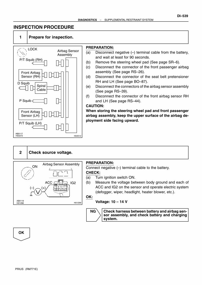
H04512
LOCK Airbag Sensor Assembly
P/T Squib (LH)
P Squib
D SquibSpiral Cable
Front Airbag Sensor (RH)
Front Airbag Sensor (LH)
P/T Squib (RH)
H01299
Airbag Sensor AssemblyON
ACC IG2(+)(–)
–DIAGNOSTICS SUPPLEMENTAL RESTRAINT SYSTEMDI–539
PRIUS (RM771E)
INSPECTION PROCEDURE
1 Prepare for inspection.
PREPARATION:(a) Disconnect negative (–) terminal cable from the battery,
and wait at least for 90 seconds.(b) Remove the steering wheel pad (See page SR–6).(c) Disconnect the connector of the front passenger airbag
assembly (See page RS–26).(d) Disconnect the connector of the seat belt pretensioner
RH and LH (See page BO–87).(e) Disconnect the connectors of the airbag sensor assembly
(See page RS–39).(f) Disconnect the connector of the front airbag sensor RH
and LH (See page RS–44).CAUTION:When storing the steering wheel pad and front passengerairbag assembly, keep the upper surface of the airbag de-ployment side facing upward.
2 Check source voltage.
PREPARATION:Connect negative (–) terminal cable to the battery.CHECK:(a) Turn ignition switch ON.(b) Measure the voltage between body ground and each of
ACC and IG2 on the sensor and operate electric system(defogger, wiper, headlight, heater blower, etc.).
OK:Voltage: 10 – 14 V
NG Check harness between battery and airbag sen-sor assembly, and check battery and chargingsystem.
OK

H01249
ON
DI–540–DIAGNOSTICS SUPPLEMENTAL RESTRAINT SYSTEM
PRIUS (RM771E)
3 Does SRS warning light turn off?
PREPARATION:(a) Turn the ignition switch to LOCK.(b) Connect the steering wheel pad connector.(c) Connect the front passenger airbag assembly connector.(d) Connect the seat belt pretensioner connectors.(e) Connect the airbag sensor assembly connectors.(f) Connect the front airbag sensor connectors.(g) Turn the ignition switch to ON.CHECK:Operate electric system (defogger, wiper, headlight, heaterblower, etc.) and check that SRS warning light goes off.
NO Check for DTCs. If a DTC is output, perform trou-bleshooting for the DTC. If a normal code is out-put, replace airbag sensor assembly.
YES
From the results of the above inspection, the malfunctioning part can now be considered normal.To make sure of this, use the simulation method to check.

H15525
Combination Meter
Instrument Panel J/B
Airbag SensorAssembly
10A ACC
ACC Relay
5A AM1
W–G
L15
C10
16
C10
5C11
J24J/C
GR–R GR–R
W–B
B–Y
B–Y9
2A
2
2D
8
2A
1
2H
8
2C
3
2B
5 3
1 2
8
2K
42B
1
2E
3A19 LA
1F11
C
J25
Fl Block No. 1
AM1 ACC2 3
P–L
W1F13
1
B–G
L
GR–R
B B
C
J26
D5
AB6
A
J11J/C
Battery
F18FL BlockNo. 2
DLC3
DC/DC
100A
J/C
Ignition Switch
100AMAIN
ID
–DIAGNOSTICS SUPPLEMENTAL RESTRAINT SYSTEMDI–541
PRIUS (RM771E)
SRS Warning Light Circuit Malfunction
CIRCUIT DESCRIPTIONThe SRS warning light is located on the combination meter. When the SRS is normal, the SRS warning light lights up for approx. 6 seconds after the ignition switch isturned from the LOCK position to ON position, and then turns off automatically. If there is a malfunction in the SRS, the SRS warning light lights up to inform the driver of the abnormality.When terminals Tc and CG of the DLC3 are connected, the DTC is displayed by blinking the SRS warninglight.
WIRING DIAGRAM
DI7QA–01

H01295
Airbag Sensor AssemblyLOCK
DI–542–DIAGNOSTICS SUPPLEMENTAL RESTRAINT SYSTEM
PRIUS (RM771E)
INSPECTION PROCEDUREAlways lights up, when ignition switch is in LOCK position
1 Prepare for inspection (See step 1 on page DI–538).
2 Does SRS warning light turn off?
PREPARATION:(a) Turn the ignition switch to LOCK.(b) Disconnect negative (–) terminal cable from the battery,
and wait at least for 90 seconds.(c) Disconnect the airbag sensor assembly connector.(d) Connect negative (–) terminal cable to the battery.CHECK:Check operation of SRS warning light.
NO Check SRS warning light circuit or terminal A/Bcircuit of DLC3.
YES
Replace airbag sensor assembly.
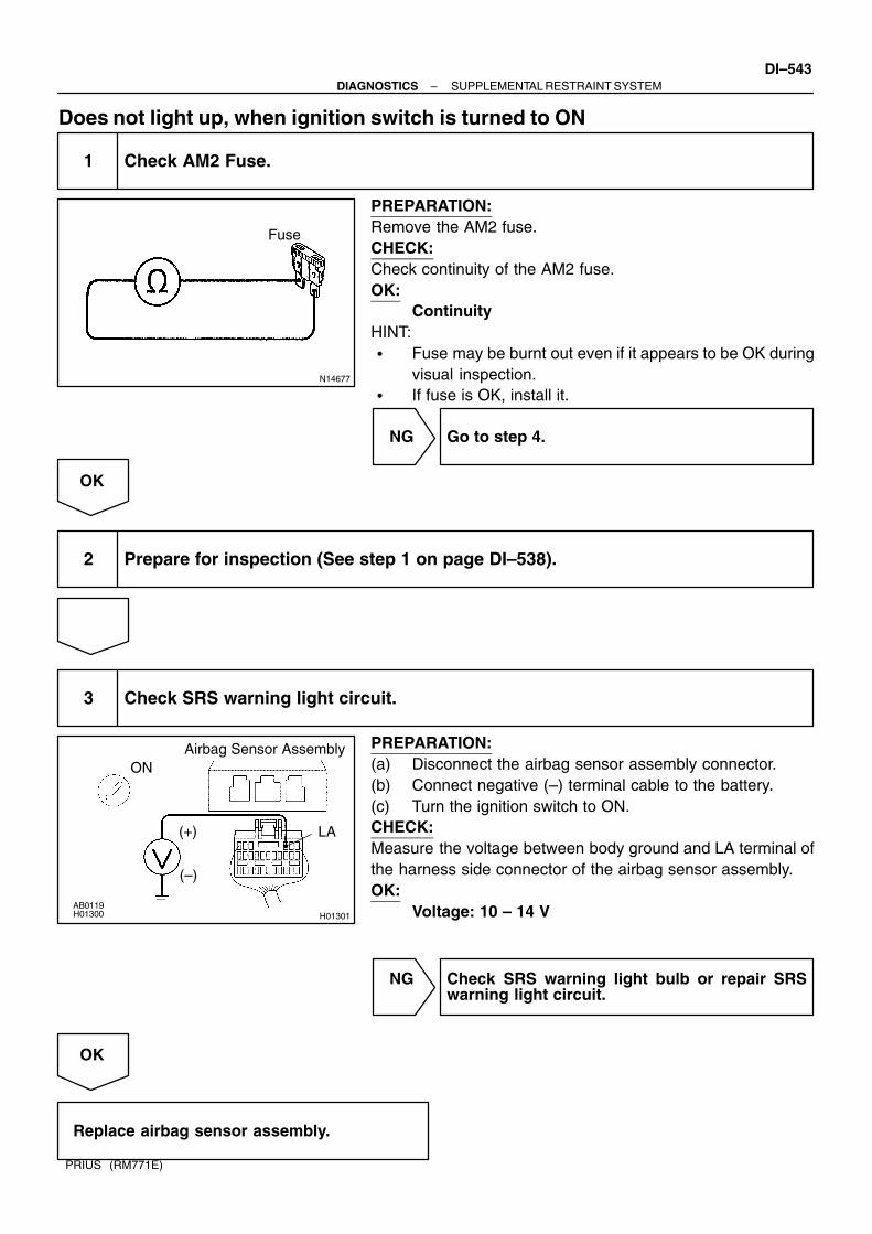
N14677
Fuse
H01301
Airbag Sensor AssemblyON
LA(+)
(–)
–DIAGNOSTICS SUPPLEMENTAL RESTRAINT SYSTEMDI–543
PRIUS (RM771E)
Does not light up, when ignition switch is turned to ON
1 Check AM2 Fuse.
PREPARATION:Remove the AM2 fuse.CHECK:Check continuity of the AM2 fuse.OK:
ContinuityHINT: Fuse may be burnt out even if it appears to be OK during
visual inspection. If fuse is OK, install it.
NG Go to step 4.
OK
2 Prepare for inspection (See step 1 on page DI–538).
3 Check SRS warning light circuit.
PREPARATION:(a) Disconnect the airbag sensor assembly connector.(b) Connect negative (–) terminal cable to the battery.(c) Turn the ignition switch to ON.CHECK:Measure the voltage between body ground and LA terminal ofthe harness side connector of the airbag sensor assembly.OK:
Voltage: 10 – 14 V
NG Check SRS warning light bulb or repair SRSwarning light circuit.
OK
Replace airbag sensor assembly.

DI–544–DIAGNOSTICS SUPPLEMENTAL RESTRAINT SYSTEM
PRIUS (RM771E)
4 Is new AM2 fuse burnt out again?
NO Using simulation method, reproduce malfunc-tion symptoms (See page IN–29).
YES
Check harness between AM2 fuse and SRSwarning light.
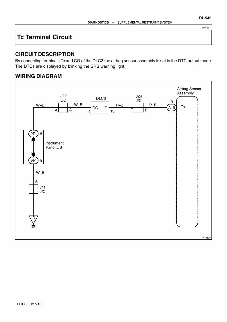
H15526
J11J/C
A
W–B
2K
W–B
J22J/C
W–B
DLC3
P–B
J24J/C
P–B Tc
8
2D 8
A A 4 13CG Tc E E
19
A19
Airbag Sensor Assembly
Instrument Panel J/B
ID
–DIAGNOSTICS SUPPLEMENTAL RESTRAINT SYSTEMDI–545
PRIUS (RM771E)
Tc Terminal Circuit
CIRCUIT DESCRIPTIONBy connecting terminals Tc and CG of the DLC3 the airbag sensor assembly is set in the DTC output mode.The DTCs are displayed by blinking the SRS warning light.
WIRING DIAGRAM
DI6Q0–05

H15704
LOCK ON
H10654
ON
CG
Tc(+)(–)
DI–546–DIAGNOSTICS SUPPLEMENTAL RESTRAINT SYSTEM
PRIUS (RM771E)
INSPECTION PROCEDUREIf the DTC is not displayed, do the following troubleshooting.
1 Does SRS warning light light up for approx. 6 seconds?
PREPARATION:Check operation of the SRS warning light after ignition switchis turned from LOCK position to ON position.
NO Check SRS warning light system (See page DI–541).
YES
2 Check voltage between terminals Tc and CG of DLC3.
PREPARATION:Turn the ignition switch to ON.CHECK:Measure the voltage between terminals Tc and CG of DLC3.OK:
Voltage: 10 – 14 V
OK Go to step 4.
NG

H10656
ON
Tc
(+)(–)
H12918
LOCK ON
Airbag Sensor Assembly
Tc
–DIAGNOSTICS SUPPLEMENTAL RESTRAINT SYSTEMDI–547
PRIUS (RM771E)
3 Check voltage between terminal Tc of DLC3 and body ground.
CHECK:Measure the voltage between terminal Tc of DLC3 and bodyground.OK:
Voltage: 10 – 14 V
OK Check harness between terminal E1 of DLC3and body ground.
NG
4 Check airbag sensor assembly.
PREPARATION:(a) Turn the ignition switch to LOCK.(b) Disconnect negative (–) terminal cable from the battery,
and wait at least for 90 seconds.(c) Disconnect the airbag sensor assembly connector.(d) Insert service wire into terminal Tc from back side as
shown in the illustration.(e) Connect the airbag sensor assembly connector with ser-
vice wire.(f) Connect negative (–) terminal cable to the battery.(g) Turn the ignition switch to ON and wait at least for 20 se-
conds.(h) Connect service wire of terminal Tc to body ground.CHECK:Check operation of the SRS warning light.OK:
SRS waning light comes on.NOTICE:Pay due attention to the terminal connecting position toavoid a malfunction.
OK Check harness between the airbag sensor as-sembly and DLC3.
NG
Replace airbag sensor assembly.

H01305
LOCK Airbag Sensor Assembly
Tc
(+)(–)
DI–548–DIAGNOSTICS SUPPLEMENTAL RESTRAINT SYSTEM
PRIUS (RM771E)
If the DTC is displayed without a DTC check procedure, perform the followingtroubleshooting.
1 Check resistance between terminal Tc of airbag sensor assembly and bodyground.
PREPARATION:(a) Turn the ignition switch to LOCK.(b) Disconnect negative (–) terminal cable from the battery,
and wait at least for 90 seconds.(c) Disconnect the airbag sensor assembly connector.CHECK:Check resistance between terminal Tc of the airbag sensor as-sembly connector and body ground.OK:
Resistance: 1 MΩ or Higher
NG Repair or replace harness or connector.
OK
Replace airbag sensor assembly.

DI611–02
Customer Problem Analysis
Vehicle Brought to Workshop
Problem Symptom ConfirmationSymptom SimulationSymptom does not occur
Problem Symptom Table
Circuit Inspection
Identification of Problem
Repair
Confirmation Test
End
Titles inside are titles of pages in thismanual with the page number indicated in thebottom portion. See the indicated pagesfor detailed explanations.1
23
4
5
7
Step 5, 7 : Diagnostic steps permitting the useof the hand–held tester and break–out–box.
P. DI–550
P. DI–556
P. IN–29
P. DI–572 ∼ DI–570
Symptom occur
6
–DIAGNOSTICS THEFT DETERRENT SYSTEMDI–549
PRIUS (RM771E)
THEFT DETERRENT SYSTEMHOW TO PROCEED WITH TROUBLESHOOTINGHINT:Troubleshooting of the theft deterrent system is based on the premise that the door lock control system isoperating normally. Accordingly, before troubleshooting the theft deterrent system, first make certain thatthe door lock control system is operating normally.For troubleshooting use a volt/ohm meter.Be sure to use troubleshooting procedure appropriate to the diagnostic tool being used.Perform troubleshooting in accordance with the procedure on the following page.

DI612–02
THEFT DETERRENT SYSTEM Check Sheet Inspector’s name:
Customer’s Name
Date Vehicle
Registration No.
Registration Year
Frame No.
Odometer Reading / / kmMile
Weather ConditionsWhen ProblemOccurred
Frequency Problem Occurs
Weather
Outdoor temperature
/ /
Constant Sometimes ( Times per day, month) Once only
Brought in
Theft deterrent system cannot be set.
Indicator light does not flash when the theft deterrent system is set. (It stays ON or does not light at all.)
Theft deterrent system does not operate.
When unlocked using the door lock knob. When the engine hood is opened.
System cannot be canceled once set.
When door is unlocked using key or wireless door lock control system.
System cannot be canceled during warning operation.
When door is unlocked using key or wireless door lock control system.
Others.
Date Problem First Occurred
Fine Cloudy Rainy Snowy Various/Others
Hot Warm Cool Cold (Approx. °F ( °C))
Pro
ble
m S
ymp
tom
Malfunction Horns only Interior light only Door lock operation only
DI–550–DIAGNOSTICS THEFT DETERRENT SYSTEM
PRIUS (RM771E)
CUSTOMER PROBLEM ANALYSIS CHECK

DI7PX–01
–DIAGNOSTICS THEFT DETERRENT SYSTEMDI–551
PRIUS (RM771E)
PRE–CHECK1. OUT LINE OF THEFT DETERRENT SYSTEMWhen the theft deterrent system detects any theft, it informspeople around with flashing lights and sound.This system is designed to be upgraded by featuring an option-al intrusion sensor and siren. (Dealer option)All initial setting are performed in active mode.HINT:There are 4 conditions in this system which are disarmed state,arming preparation, armed state and alarm sounding.
(1) Disarmed state When the alarming function does not oper-
ate. When theft deterrent function is not per-
formed.(2) Arming preparation
Time until transferring to armed state. Theft deterrent function is not performed.
(3) Armed stateWhen theft deterrent function is possible.
(4) Alarm sounding:In this condition, once theft is detected, it is in-formed using light and sound to people around thevehicle.Refer to the table for alarming method or time.
Horn
AlarmingmethodSiren (Dealer option)
Alarming methodHazard
Interior light
Alarming time 27.5 seconds
Alarming outputContinuous 0.25 secs. (ON)
0.25 secs. (OFF)
HINT:Alarming output for hazard is same as the one for the hazardon the vehicle.In the arming condition when either of doors is unlocked withkey not in the key cylinder, force lock signal is output.

Disarmed state
Perform any of the following and the system will go no to ”Arming preparation”: With all the doors, engine hood and luggage compartment door closed, lock all doors with the wireless remote.
Arming preparation
Perform the following and the system willgo on to ”Armed state”: Let 30 seconds elapse with all the doors,engine hood and luggage compartment doorclosed and locked.
Perform any of the following and the systemwill return to ”Disarmed state”: Open any of the doors, engine hood or luggagecompartment door. Unlock any of the doors. Put the key in the ignition. Reconnect the battery.
Armed statePerform any of the following and the systemwill return to ”Disarmed state”: Unlock any of the doors with the wireless remote.
Perform any of the following and the systemwill go on to ”Alarm sounding”: Unlock any of the doors with anything other thanthe wireless remote. Open the luggage compartment door (Including key operation). Open any of the doors. Lift the engine hood. Reconnect the battery. When input from optional intrusion sensor is de-tected. (Dealer option) Ignition switch is conneted directly.
(Key not inserted in ignition.)
Alarm sounding
Perform any of the following and the systemwill return to ”Disarmed state”: Unlock any of the doors with the wireless remote.
The vehicle’s horn and self–power siren* willsound, and the hazard and Interior lights flash for27.5 seconds.*: is optionalAfter the alarm has ended, the system willreturn to ”Armed state”.
DI–552–DIAGNOSTICS THEFT DETERRENT SYSTEM
PRIUS (RM771E)
2. ACTIVE ARMING MODE

N09348
ECU
TOYOTA hand–held tester
TOYOTA Break–out–box
–DIAGNOSTICS THEFT DETERRENT SYSTEMDI–553
PRIUS (RM771E)
Indicator light output:
Condition Indicator light
Disarmed state OFF
Arming preparation ON
Armed state OFF
Alarm sounding ON
HINT:Even in disarmed state, the indicator light flash. (Due to the sig-nal output form immobilizer system). The indicator alwaysflashes receiving the signal from the immobilizer system at anytime in the armed state.
Flashing frequency: 0.2 seconds (ON) 1.8 seconds (OFF)Answer back:The hazard lights flush as answer back under the followingconditions.
(1) When the system is set.When arming preparation is set from disarmed stateusing the wireless door lock, the hazard lights flushonce.
(2) When the system is released.When disarmed state is set from either arming prep-aration, armed state or alarm sounding using thewireless door lock, the hazard lights flush twice.
3. ECU TERMINAL VALUES MEASUREMENT BY USINGTOYOTA BREAK–OUT–BOX AND TOYOTA HAND–HELD TESTER
(a) Hook up the TOYOTA break–out–box and TOYOTAhand–held tester to the vehicle.
(b) Read the ECU input/output values by following theprompts on the tester screen.
(c) Please refer to the TOYOTA hand–held tester has a”Snapshot” function. This records the measured data andis effective in the diagnosis of intermittent problems.

DI614–02
I17857
Ignition Switch
Luggage Compartment DoorCoutesy Switch
Door Lock Assembly Door Lock Motor Door Unlock Detection Switch Door Key Lock and Unlock Switch
Horn
Engine Room Junction Block HORN Relay HORN Fuse
Instrument Panel Junction Block ECU–IG Fuse DOOR Fuse GAUGE Fuse
Theft Deterrent ECUEngine HoodCourtesy Switch
DI–554–DIAGNOSTICS THEFT DETERRENT SYSTEM
PRIUS (RM771E)
PARTS LOCATION

DI615–02
I01920Connector ”B” Connector ”A”
T4 T3
–DIAGNOSTICS THEFT DETERRENT SYSTEMDI–555
PRIUS (RM771E)
TERMINALS OF ECU
Symbols (Terminals No.) Wiring Color Condition STD Value
DSWH ↔ ER W ↔ W B
Engine hood courtesy switch position is ON.
(Engine hood opened)Below 1 V
DSWH ↔ E
(T3–4 ↔ T3–22)R–W ↔ W–B
Engine hood courtesy switch position is OFF.
(Engine hood closed)7 – 9 V
DSWL ↔ ER W ↔ W B
Luggage compartment door courtesy switch position is ON.
(Door closed)Below 1 V
DSWL ↔ E
(T3–12 ↔ T3–22)R–W ↔ W–B
Luggage compartment door courtesy switch position is OFF.
(Door opened)7 – 9 V
IG ↔ EB Y ↔ W B
Ignition switch position is LOCK or ACC. Below 1 VIG ↔ E
(T3–10 ↔ T3–22)B–Y ↔ W–B
Ignition switch position is ON. 10 – 14 V
+B1 ↔ E
(T3–11 ↔ T3–22)L–Y ↔ W–B Constant 10 – 14 V
KSW ↔ EL B ↔ W B
Key is inserted. Below 1 VKSW ↔ E
(T3–19 ↔ T3–22)L–B ↔ W–B
Key is not inserted. 10 – 14 V
E ↔ Body ground
(T3–22 ↔ Body ground)
W–B ↔ Body
groundConstant Below 1 V
HORN ↔ EB R ↔ W B
Horn switch position is ON. Below 1 VHORN ↔ E
(T4–4 ↔ T3–22)B–R ↔ W–B
Horn switch position is OFF. 10 – 14 V
IND ↔ E
(T4–12 ↔ T3–22)LG–B ↔ W–B During set preparation. 3 – 5 V

DI616–03
DI–556–DIAGNOSTICS THEFT DETERRENT SYSTEM
PRIUS (RM771E)
PROBLEM SYMPTOMS TABLEProceed to the reference page shown in the matrix chart below for each malfunction symptom and trouble-shoot for each circuit.HINT:Troubleshooting of the theft deterrent system is based on the premise that the door lock control system isoperating normally. Accordingly, before troubleshooting the theft deterrent system, first make certain thatthe door lock control system is operating normally.
Symptom Suspect Area See page
The theft deterrent system cannot be set
4. Indicator light circuit
5. ECU power source circuit
6. Key unlock warning switch circuit
7. Luggage compartment door courtesy switch circuit
8. Door key lock and unlock switch circuit
9. Door courtesy switch circuit
10.Door unlock detection switch circuit
11.Engine hood courtesy switch circuit
12.Theft deterrent ECU
DI–564
DI–558
DI–568
DI–572
DI–646
DI–628
DI–644
DI–570
IN–40
The indicator light does not blink when system is set.1. Indicator light circuit
2. Theft deterrent ECUDI–564
When the system is set
(The system does not operate when the rear door is unlocked).
1. Door unlock detection switch circuit
2. Theft deterrent ECUDI–644
When the system is set
(The system does not operate when the luggage compartment
door is opened by a method other than the key).
1. Luggage compartment door courtesy switch circuit
2. Theft deterrent ECUDI–572
When the system is set
(The system does not operate when the engine hood is lifted).
1. Engine hood courtesy switch circuit
2. Theft deterrent ECUDI–570
* When the system is set
(The system does not operate when after 30 seconds put your
hand through the window and shake it near the sensor).
1. * Radar sensor circuit
2. Theft deterrent ECU–
While the system is in warning operation
(Horns do not sound).
1. Horn relay circuit
2. Theft deterrent ECUDI–566
* While the system is in warning operation
(Siren does not sound).
1. * Self power siren circuit
2. Theft deterrent ECU–
* While the system is in warning operation
(When the siren does not sound or stops soon after it starts).
1. * Self power siren battery
2. Theft deterrent ECU–
While the system is in warning operation
(Interior light does not light).
1. Illumination circuit
2. Theft deterrent ECUDI–622
While the system is in warning operation
(Hazard lights do not flash).
1. Hazard switch circuit
2. Theft deterrent ECUDI–635
While the system is in warning operation
(The door lock is not locked).
1. Door unlock detection switch circuit
2. Theft deterrent ECUDI–644
System is still set even when a rear door is open1. Door courtesy switch circuit
2. Theft deterrent ECUDI–628
Even when the system is not set
(Horns sound).
1. Horn relay circuit
2. Theft deterrent ECUDI–566
* Even when the system is not set
(Siren sounds).
1. * Self power siren circuit
2. Theft deterrent ECU–
* Even when the system is not set
(when the siren does not sound or stops soon after it starts).
1. * Self power siren battery
2. Theft deterrent ECU–
Even when the system is not set
(Hazard lights do not flash).
1. Hazard switch circuit
2. Theft deterrent ECUDI–635

–DIAGNOSTICS THEFT DETERRENT SYSTEMDI–557
PRIUS (RM771E)
*: Dealer option

DI618–02
I15517
Theft Deterrent ECU
11
F13
+B1T3L–YB
72G 1J
41B
F12
2D
IP2
1 1B–G
Battery
1
2
Instrument Panel J/B Engine Room J/B
J23C
J22 L–Y
L–Y
L–Y215A DOME
120A MAIN
7J/C
FL Block No.2 FL Block No.1
DI–558–DIAGNOSTICS THEFT DETERRENT SYSTEM
PRIUS (RM771E)
CIRCUIT INSPECTION
ECU Power Source Circuit
CIRCUIT DESCRIPTIONThis circuit provides power to operate the theft deterrent ECU.
WIRING DIAGRAM

I19044
Engine room J/B
DOME Fuse
I11485E
(+)
+B2(–)
–DIAGNOSTICS THEFT DETERRENT SYSTEMDI–559
PRIUS (RM771E)
INSPECTION PROCEDURE
1 Check DOME.
PREPARATION:Remove DOME fuse from engine room junction block.CHECK:Check continuity of DOME fuse.OK:
Continuity
NG Check for short in all the harness and compo-nents connected to the DOME fuse (See at-tached wiring diagram).
OK
2 Check voltage between terminals +B and E of theft deterrent ECU connector.
PREPARATION:Disconnect the theft deterrent ECU connector.CHECK:Measure voltage between terminals +B and E of theft deterrentECU connector.OK:
Voltage: 10∼14V
OK Proceed to next circuit inspection shown inproblem symptom table (See page DI–556).
NG

DI–560–DIAGNOSTICS THEFT DETERRENT SYSTEM
PRIUS (RM771E)
3 Check for open in harness and connector between ECU and body ground(See page IN–40).
NG Repair or replace harness or connector.
OK
Check and repair harness and connector be-tween ECU and battery.

I15518
Theft Deterrent ECU
33
IDJ11 J/C
IG
5A AM15
10
B–Y
2ID2
AM1IG16
A
18
2 24
W–B
Instrument Panel J/B
5A ECU–IG
IG1 Relay
2D2K
2B
B–Y B–Y
DT3
J14J/C
W–G
Ignition Switch
–DIAGNOSTICS THEFT DETERRENT SYSTEMDI–561
PRIUS (RM771E)
Ignition Switch Circuit
CIRCUIT DESCRIPTIONWhen the ignition switch is turned to the ACC position, battery positive voltage is applied to the terminal ACCof the ECU. Also, if the ignition switch is turned to the ON position, battery positive voltage is applied to theterminals ACC and IG of the ECU. When the battery positive voltage is applied to the terminal ACC of theECU while the theft deterrent system is activated, the warning stops. Furthermore, power supplied from theterminals ACC and IG of the ECU is used as power for the door courtesy switch, and position switch, etc.
WIRING DIAGRAM
DI619–02

I19045
Instrument Panel J/B
AM1 Fuse
I11484IG
(+)
(–)
DI–562–DIAGNOSTICS THEFT DETERRENT SYSTEM
PRIUS (RM771E)
INSPECTION PROCEDURE
1 Check AM1 fuse.
PREPARATION:(a) Remove the fuse box opening cover.(b) Remove AM1 fuse from instrument panel junction block.CHECK:Check continuity of AM1 fuses.OK:
Continuity
NG Check for short in all the harness and compo-nents connected to the AM1 fuse(See attached wiring diagram).
OK
2 Check voltage between terminals IG of theft deterrent ECU and body ground.
PREPARATION:(a) Disconnect the theft deterrent ECU connectors.(b) Turn ignition switch ON.CHECK:Measure voltage between terminals IG of theft deterrent ECUconnector and body ground.OK:
Voltage: 10∼14V
NG Check and repair harness and connector be-tween theft deterrent ECU and battery(See page IN–40).
OK

–DIAGNOSTICS THEFT DETERRENT SYSTEMDI–563
PRIUS (RM771E)
Check and replace theft deterrent ECU.
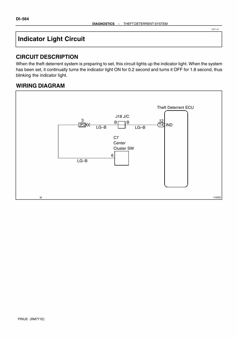
I15522
Theft Deterrent ECU
INDIP212
LG–B
J18 J/C
B T4B3
LG–B
LG–B6
C7 Center Cluster SW
DI–564–DIAGNOSTICS THEFT DETERRENT SYSTEM
PRIUS (RM771E)
Indicator Light Circuit
CIRCUIT DESCRIPTIONWhen the theft deterrent system is preparing to set, this circuit lights up the indicator light. When the systemhas been set, it continually turns the indicator light ON for 0.2 second and turns it OFF for 1.8 second, thusblinking the indicator light.
WIRING DIAGRAM
DI617–02

–DIAGNOSTICS THEFT DETERRENT SYSTEMDI–565
PRIUS (RM771E)
INSPECTION PROCEDURE
1 Check indicator light (center cluster module control) (See page DI–777).
NG Replace the bulb or meter wire harness.
OK
2 Check harness and connector between theft deterrent ECU and indicator light,indicator light and body ground (See page IN–40).
NG Repair or replace harness or connector.
OK
Check and replace theft deterrent ECU.*1
*1: When there is a malfunction that the theft deterrent systemcannot be set, proceed to the next numbered circuit inspectionshown in problem symptom table (See page DI–556).

I15521
Theft Deterrent ECU
Horn Relay
B–W
HORN
F18 FL Block No. 2
Battery H7Horn(Low)
F13
1
J16 J/C8IA2
19
9
4
22
T4A
1 1B–G
B–R
11
C14Horn SW (Comb SW)
Engine Room J/B
H6Horn(High)
120A MAINF12
B2
1B
1J
1F 53
10A Horn
B–W
B–R (LHD)
B–R (RHD)
B–R(RHD)
AA B–R
(RHD)
16
FL Block No. 1
DI–566–DIAGNOSTICS THEFT DETERRENT SYSTEM
PRIUS (RM771E)
Horn Relay Circuit
CIRCUIT DESCRIPTIONWhen the theft deterrent system is activated, it causes the transistor in the ECU to switch ON and OFF inapproximately 0.4 sec. cycles. This switches the horn relay ON and OFF, thus the horns blow (See the wiringdiagram below).In this condition, if any of the following operations is done, the transistor in the ECU goes OFF and the hornrelay switches OFF, thus stopping the horns from blowing:
(1) Unlock the doors with the wireless door lock control system.(2) Wait for approximately 27.5 seconds.
WIRING DIAGRAM
DI61A–02

I11488HORN
(+)
(–)
–DIAGNOSTICS THEFT DETERRENT SYSTEMDI–567
PRIUS (RM771E)
INSPECTION PROCEDUREHINT:The flow chart below is based on the premise that the horns blow normally whenever the horn switch is oper-ated. If horn operation is not normal when the horn switch is operated, check the horn switch.
1 Check voltage between terminal HORN of theft deterrent ECU connector andbody ground.
PREPARATION:Disconnect the theft deterrent ECU connectors.CHECK:Measure voltage between terminal HORN of theft deterrentECU connector and body ground.OK:
Voltage: 10∼14V
NG Check and repair harness and connector be-tween theft deterrent ECU and horn relay(See page IN–40).
OK
Check and replace theft deterrent ECU(See page IN–40).

I15519
Theft Deterrent System
W–B
KSW19
J18J/C
U1UnlockWarning SW
L–B
2 1
A A
2K8
2D
4
J11 J/C ID
B
IP2 L–B T3
L–B
DJ26 J25
L–B
AAJ22 J23W–B
8
A
W–B
Instrument Panel J/BJ/C
J/C
DI–568–DIAGNOSTICS THEFT DETERRENT SYSTEM
PRIUS (RM771E)
Key Unlock Warning Switch Circuit
CIRCUIT DESCRIPTIONThe key unlock warning switch goes ON when the ignition key is inserted in the key cylinder and goes OFFwhen the ignition key is removed.The ECU operates the key confinement prevention function while the key unlock warning switch is ON.
WIRING DIAGRAM
DI61F–02

2 1
e–4–2–B I11309
–DIAGNOSTICS THEFT DETERRENT SYSTEMDI–569
PRIUS (RM771E)
INSPECTION PROCEDURE
1 Check key unlock warning switch.
PREPARATION:Disconnect key unlock warning switch connector.CHECK:Check continuity between terminal 1 and 2 of key unlock warn-ing switch connector, when the key is inserted into the key cylin-der or removed.OK:
Switch position Tester connection Specified condition
ON (Key inserted) 1 – 2 Continuity
OFF (Key removed) – No continuity
NG Replace key unlock warning switch.
OK
2 Check harness and connectors between ECU and key unlock warning switch,key unlock warning switch and body ground (See page IN–40).
NG Repair or replace harness or connector.
OK
Check and replace theft deterrent ECU.*1
*1: When there is a malfunction that the theft deterrent systemcannot be set, proceed to the next numbered circuit inspectionshown in problem symptom table (See page DI–556).

I15523
Theft Deterrent ECU
DSWHT34
IE
1
E2Engine HoodCourtesy SW2
W–B
IA2
J1 J/C
R–W R–W1
A
DI–570–DIAGNOSTICS THEFT DETERRENT SYSTEM
PRIUS (RM771E)
Engine Hood Courtesy Switch Circuit
CIRCUIT DESCRIPTIONThe engine hood courtesy switch is built into the engine hood lock assembly and goes ON when the enginehood is opened and goes OFF when the engine hood is closed.
WIRING DIAGRAM
DI61H–02

N14878
1 (+) 2 (–)
–DIAGNOSTICS THEFT DETERRENT SYSTEMDI–571
PRIUS (RM771E)
INSPECTION PROCEDURE
1 Check engine hood courtesy switch.
PREPARATION:(a) Remove engine hood lock assembly.(b) Disconnect engine hood courtesy switch connector.CHECK:Check continuity between terminals 1 and 2 when engine hoodlock is locked and unlocked.OK:
Engine hood lock Tester connection Specified condition
LOCK – No continuity
UNLOCK 1 – 2 Continuity
NG Replace engine hood courtesy switch.
OK
2 Check harness and connector between theft deterrent ECU and switch, switchand body ground (See page IN–40).
NG Repair or replace harness or connector.
OK
Check and replace theft deterrent ECU (Seepage IN–40).

I15520
I15I15
Theft Deterrent ECU
DSWLT36
D
16
L4Luggage Compartment Light SW
IA2R–W R–W
1J29
R–W
R–WJ29D
12IH1
J/C
DI–572–DIAGNOSTICS THEFT DETERRENT SYSTEM
PRIUS (RM771E)
Luggage courtesy switch circuit
CIRCUIT DESCRIPTION
The luggage courtesy switch goes on when luggage compartment door is opened and goes off when lug-gage compartment door is closed.
WIRING DIAGRAM
DI7Q6–01

–DIAGNOSTICS THEFT DETERRENT SYSTEMDI–573
PRIUS (RM771E)
INSPECTION PROCEDURE
1 Check luggage courtesy switch (See page BE–31).
NG Replace the luggage courtesy switch.
OK
2 Check wire harness and connector between luggage courtesy switch and BodyECU. (See page IN–40)
NG Repair or replace wire harness or connector.
OK
Proceed to next circuit inspection shown onproblem symptoms table.(See page DI–615)

DI26R–15
Customer Problem Analysis
Check and Clear DTC (Precheck)
Vehicle Brought to Workshop
Problem Symptom ConfirmationSymptom SimulationSymptom does not occur
DTC Check Normal code
DTC Chart Problem Symptom Table
Circuit Inspection Input Signal CheckParts Inspection
Identification of Problem
Repair
Confirmation Test
End
Items inside are titles of pages in thismanual with the page number indicated in thebottom portion. See the indicated pagesfor detailed explanations.
1
2
34
5
6 7
89
10Step 2, 5, 8, 10: Diagnostic steps permitting the use
of the hand–held tester or break–out–box.
P. DI–575
P. DI–576
P. DI–576
P. DI–579
P. IN–29
P. DI–582
P. DI–583 – DI–594
OK
NG
Symptom occurs
Malfunction code
DI–574–DIAGNOSTICS CRUISE CONTROL SYSTEM
PRIUS (RM771E)
CRUISE CONTROL SYSTEMHOW TO PROCEED WITH TROUBLESHOOTINGTroubleshoot in accordance with the procedure on the following page.

DI26S–12
CRUISE CONTROL SYSTEM Check Sheet Inspector’s name:
Customer’s Name
Date of Vehicle
Registration No.
Registration Year
Frame No.
Odometer Reading / / kmMile
Condition ofProblem Occurrence
Date of Problem
Frequency
Occurrence
Problem Occurs?
Vehicle Speed whenProblem Occurred
/ /
"" Continuous "" Intermittent ( Times a day)
kmMile
Brought in
"" Auto cancel occurs
Driving condition City driving Freeway Up hill Down hill
After cancel occurred, did the driver activate cruise control again? Yes No
Cancel does not occur
With brake ON Except D position shift When control SW turns to CANCEL position
Cruise control malfunction
Slip to acceleration side Slip to deceleration side Hunting occurs O/D cut off does not occur O/D does not return
Switch malfunction SET ACCEL COAST RESUME CANCEL
Remains ON Does not light up Blinks
Symptoms
DTC Check1st Time
2nd Time
Normal Code Malfunction Code (Code )
Normal Code Malfunction Code (Code )
–DIAGNOSTICS CRUISE CONTROL SYSTEMDI–575
PRIUS (RM771E)
CUSTOMER PROBLEM ANALYSIS CHECK

DI7NG–02
N09348
Hand–held tester
Break–out–box
F12397DLC3
N17520
DI–576–DIAGNOSTICS CRUISE CONTROL SYSTEM
PRIUS (RM771E)
PRE–CHECK1. ECU TERMINAL VALUES MEASUREMENT BY USING
BREAK–OUT–BOX AND HAND–HELD TESTER(a) Hook up the break–out–box and hand–held tester to the
vehicle.(b) Read the ECU input/output values by following the
prompts on the tester screen.(c) Please refer to the hand–held tester has a ”Snapshot”
function. This records the measured data and is effectivein the diagnosis of intermittent problems.
2. USING HAND–HELD TESTER(a) Hook up the hand–held tester to the DLC3.(b) Monitor the ECU data by following the prompts on the tes-
ter screen.HINT:Hand–held tester has a ”Snapshot” function which records themonitored data.Please refer to the hand–held tester operator’s manual for fur-ther details.3. DTC CLEARANCEDTC can be deleted using a hand–held tester. If there is nohand–held tester or it cannot be used, disconnect the auxiliarybattery for 1 min. or more and connect it again.
4. PROBLEM SYMPTOM CONFIRMATION(ROAD TEST)
(a) Inspect the SET switch.(1) Push the main switch ON.(2) Drive at a desired speed (40 km/h (25 mph) or high-
er).(3) Press the control switch to the SET/COAST.(4) After releasing the switch, check that the vehicle
cruises at the desired speed.

N17520
N17520
N17520
–DIAGNOSTICS CRUISE CONTROL SYSTEMDI–577
PRIUS (RM771E)
(b) Inspect the ACCEL switch.(1) Push the main switch ON.(2) Drive at a desired speed (40 km/h (25 mph) or high-
er).(3) Check that the vehicle speed increases while the
control switch is turned to RES/ACC, and that thevehicle cruises at the set speed when the switch isreleased.
(4) Momentarily press the control switch upward in theRES/ACC and then immediately release it. Checkthat the vehicle speed increases by about 1.5 km/h(Tap–up function).
(c) Inspect the COAST switch.(1) Push the main switch ON.(2) Drive at a desired speed (40 km/h (25 mph) or high-
er).(3) Check that the vehicle speed decreases while the
control switch is turned to SET/COAST, and the ve-hicle cruises at the set speed when the switch is re-leased.
(4) Momentarily press the control switch is turned toSET/COAST, and then immediately release it.Check that the vehicle speed decreases by about1.5 km/h (Tap–down function).
(d) Inspect the CANCEL switch.(1) Push the main switch ON.(2) Drive at a desired speed (40 km/h (25 mph) or high-
er).(3) When operating one of the followings, check that
the cruise control system is cancelled and that thenormal driving mode is reset. Depress the brake pedal Shift to except D range (A/T) Push the main switch OFF

N17520
N17520
DI–578–DIAGNOSTICS CRUISE CONTROL SYSTEM
PRIUS (RM771E)
Pull the cruise control switch to CANCEL
(e) Inspect the RESUME switch.(1) Push the main switch ON.(2) Drive at a desired speed (40 km/h (25 mph) or high-
er).(3) When operating one of the followings, check that
the cruise control system is cancelled and that thenormal driving mode is reset. Depress the brake pedal Shift to except D range (A/T) Pull the cruise control switch to CANCEL
(4) After the control switch is turned to RES/ACC at thedriving speed of more than 40 km/h (25 mph), checkthat the vehicle restores the speed prior to the can-cellation.
5. INPUT SIGNAL CHECK(Using hand–held tester)
(a) Connect the hand–held tester to DLC3(b) Check the control switch (MAIN, CANCEL, SET/COAST,
RES/ACC)

DI26U–15
–DIAGNOSTICS CRUISE CONTROL SYSTEMDI–579
PRIUS (RM771E)
DIAGNOSTIC TROUBLE CODE CHARTIf a malfunction code is displayed during the DTC check, check the circuit listed for that code in the tablebelow and proceed to the appropriate page.
DTC No.
(See Page)Circuit Inspection Trouble Area
P1520
(DI–583)Stop Light Switch Circuit malfunction
Stop light switch
Harness or connector between hybrid vehicle control ECU
and stop light switch circuit
Hybrid vehicle control ECU
P1566
(DI–587)Input Signal Circuit Hybrid vehicle control ECU

DI7NH–02
I17812
Hybrid VehicleControl ECU
Stop Light Switch
Cruise Control Switch
Cruise Control Indicator (in Combination Meter)
DI–580–DIAGNOSTICS CRUISE CONTROL SYSTEM
PRIUS (RM771E)
PARTS LOCATION
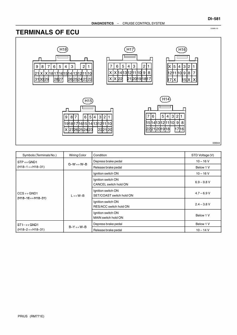
DI3MK–05
I09944
H15
H16
H14
H17H18
123456789
10111213141516171821
22232425262728293031
1234567
891011121314
171819202122
12345
789101112
1517
123456789
10111213141516171819
2021222324252627
1234567
89101112131415
16171819202122
X X XX
XX
X
XXX
X
–DIAGNOSTICS CRUISE CONTROL SYSTEMDI–581
PRIUS (RM771E)
TERMINALS OF ECU
Symbols (Terminals No.) Wiring Color Condition STD Voltage (V)
STP ↔ GND1G W ↔ W B
Depress brake pedal 10 – 16 VSTP ↔ GND1
(H18–1 ↔ H18–31)G–W ↔ W–B
Release brake pedal Below 1 V
Ignition switch ON 10 – 16 V
Ignition switch ON
CANCEL switch hold ON6.9 – 9.8 V
CCS ↔ GND1
(H18 16 ↔ H18 31)L ↔ W–B
Ignition switch ON
SET/COAST switch hold ON4.7 – 6.9 V
(H18–16 ↔ H18–31)Ignition switch ON
RES/ACC switch hold ON2.4 – 3.8 V
Ignition switch ON
MAIN switch hold ONBelow 1 V
ST1– ↔ GND1B Y ↔ W B
Depress brake pedal Below 1 VST1 ↔ GND1
(H18–2 ↔ H18–31)B–Y ↔ W–B
Release brake pedal 10 – 14 V

DI26X–15
DI–582–DIAGNOSTICS CRUISE CONTROL SYSTEM
PRIUS (RM771E)
PROBLEM SYMPTOMS TABLESymptom Suspect Area See page
SET not occurring or CANCEL occurring.
(DTC is Normal)
1. Input Signal Circuit
2. Vehicle Speed Sensor Circuit
3. Stop Light Switch Circuit
4. Park/Neutral Position Switch Circuit
5. Hybrid vehicle control ECU
DI–587
DI–86
DI–583
DI–179
IN–40
SET not occurring or CANCEL occurring.
(DTC is not output)1. Hybrid vehicle control ECU IN–40
Actual vehicle speed deviates above or below the set speed.1. Input Signal Circuit
2. Hybrid vehicle control ECU
DI–587
IN–40
Gear shifting occurs frequently between 3rd and O/D when driving
on uphill road. (Hurting)1. Hybrid vehicle control ECU IN–40
Cruise control not cancelled, even when brake pedal is de-
pressed.
1. Stop Light Switch Circuit
2. Hybrid vehicle control ECU
DI–583
IN–40
Cruise control not cancelled, even when transmission is shifted to
”N” position.
1. Park/Neutral Position SwitchCircuit
2. Hybrid vehicle control ECU
DI–179
IN–40
Control switch does not operate.
(SET/COAST, ACC/RES, CANCEL not possible)
1. Cruise Control Switch Circuit
2. Hybrid vehicle control ECU
DI–590
IN–40
SET possible at 40 km/h (25 mph) or less, or CANCEL does not
operate at 40 km/h (25 mph) or less.
1. Input Signal Circuit
2. Hybrid vehicle control ECU
DI–587
IN–40
Poor response is ACCEL and RESUME modes. 1. Hybrid vehicle control ECU IN–40
O/D does not resume, even though the road is not uphill. 1. Hybrid vehicle control ECU IN–40
DTC memory is erased. 1. Hybrid vehicle control ECU IN–40
DTC is not output, or is output when should not be.1. Diagnosis Circuit
2. Hybrid vehicle control ECU
–
IN–40
Cruise MAIN indicator light remains ON or falls to light up.1. Input Signal Circuit
2. Hybrid vehicle control ECU
DI–587
IN–40

–DIAGNOSTICS CRUISE CONTROL SYSTEMDI–583
PRIUS (RM771E)
CIRCUIT INSPECTION
DTC P1520 Stop light switch circuit
CIRCUIT DESCRIPTIONWhen the brake pedal is depressed, the stop light switch sends a signal to the hybrid vehicle control ECU.When the hybrid vehicle control ECU receives this signal, it cancels the cruise control.A fail–safe function is provided so that the cancel functions normally, even if there is a malfunction in the stoplight signal circuit.The cancel condition is that battery voltage is supplied to terminal STP.When the brake is on, battery voltage is normally applied through the STOP fuse and stop light switch toterminal STP of the hybrid vehicle control ECU, and the hybrid vehicle control ECU turns the cruise controlOFF.If the harness connected to terminal STP has an open circuit, terminal STP will have battery voltage andthe cruise control will be turned OFF.
DTC No. Detection Item Trouble Area
P1520 Stop light switch circuit.
Stop light switch
Harness or connector between hybrid vehicle control ECU
and stop light switch circuit
Hybrid vehicle control ECU
DI7NI–02

I15477
Instrument Panel J/B
FL Block No. 2
S3Stop Light SW
I15Ignition SW
Engine Room J/B
Hybrid Vehicle Control ECU
J23 ID1B–Y
ST1–IG2AM2
1G–W
2
R–B
2H18
STP1
H18
B–W3 4
6
B–WJ22
BC
B–WW–R7 6
2
2C
15A AM2
1
2GW–R
9
1J
2
1BB
1
F12B–G
120A MAIN
Battery
1
F13
1
F18
J15D
J14
E
G–W
Instrument Panel J/B
9
2K
15A STOPW
100A DC/DCF11
1
2H
FL Block No. 11
F13
1B–G
S3Stop Light SW
J/C
J/C
FL Block No. 1
DI–584–DIAGNOSTICS CRUISE CONTROL SYSTEM
PRIUS (RM771E)
WIRING DIAGRAM

I19096
ON
STP
(+) (–)
–DIAGNOSTICS CRUISE CONTROL SYSTEMDI–585
PRIUS (RM771E)
INSPECTION PROCEDURE
1 Check operation of stop light.
CHECK:Check that stop light comes on when brake pedal is depressed, and turns off when brake pedal is released.
NG Check stop light system (See page BE–2).
OK
2 Check voltage between terminal STP of hybrid vehicle control ECU connectorand body ground.
PREPARATION:(a) Remove the hybrid vehicle control ECU with connectors
still connected.(b) Turn ignition switch ON.CHECK:Measure voltage between terminal STP of hybrid vehicle con-trol ECU connector and body ground, when the brake pedal isdepressed and released.OK:
Depressed 10 – 14 V
Released Below 1 V
OK Proceed to next circuit inspection shown inproblem symptom table (See page DI–582).
NG

I19096
ON
ST1–
(+) (–)
DI–586–DIAGNOSTICS CRUISE CONTROL SYSTEM
PRIUS (RM771E)
3 Check voltage between terminal ST1– of hybrid vehicle control ECU connectorand body ground.
PREPARATION:(a) Remove the hybrid vehicle control ECU with connectors
still connected.(b) Turn ignition switch ON.CHECK:Measure voltage between terminal ST1– of hybrid vehicle con-trol ECU connector and body ground, when the brake pedal isdepressed and released.OK:
Depressed Below 1 V
Released 10 – 14 V
OK Proceed to next circuit inspection shown inproblem symptoms table (See page DI–582).
NG
4 Check wire harness and connector between terminal STP of hybrid vehicle con-trol ECU and stop light switch, and terminal ST1– of hybrid vehicle control ECUand stop light switch (See page IN–40).
NG Repair or replace harness or connector.
OK
Check and replace hybrid vehicle controlECU (See page DI–141).

–DIAGNOSTICS CRUISE CONTROL SYSTEMDI–587
PRIUS (RM771E)
DTC P1566 Input Signal Circuit abnormal
CIRCUIT DESCRIPTION
DTC No. Detection Item Trouble Area
P1566 Stop light switch input signal circuit abnormal. Hybrid vehicle control ECU
INSPECTION PROCEDURE
Check and replace hybrid vehicle controlECU (See page DI–141).
DI3CL–07

DI–588–DIAGNOSTICS CRUISE CONTROL SYSTEM
PRIUS (RM771E)
Power source circuit
CIRCUIT DESCRIPTIONThis circuit provides power to operate the hybrid vehicle control ECU.
WIRING DIAGRAMSee page DI–124.
INSPECTION PROCEDURE
1 Check IGN and EFI fuse.
CHECK:Check continuity of IGN and EFI fuse.OK:
Continuity
NG Replace the failure fuse.
OK
2 Check voltage between terminals IGSW, BATT and GND of hybrid vehicle controlECU connector (See page IN–40).
PREPARATION:(a) Turn ignition switch OFF.(b) Disconnect the hybrid vehicle control ECU connector.CHECK:Measure voltage between terminals IGSW, BATT and GNDOK:
Voltage: 10 – 14 V
OK Proceed to next circuit inspection shown inproblem symptoms table (See page DI–582).
NG
DI7NJ–02

–DIAGNOSTICS CRUISE CONTROL SYSTEMDI–589
PRIUS (RM771E)
3 Check wireharness and connector between hybrid vehicle control ECU and bodyground (See page IN–40).
NG Repair or replace wireharness or connector.
OK
Check and repair wireharness and connectorbetween hybrid vehicle control ECU and bat-tery (See page IN–40).

I15478
Hybrid VehicleControl ECU
C14Cruise Control SW (Comb. SW)
A
W–B
5
LCCS
16
H18
CRUISE
CCS
RES/ ACCSET/
COASTCANCEL
ECC
J17J/C
IG
A
W–BJ27
A
J274
J/C
DI–590–DIAGNOSTICS CRUISE CONTROL SYSTEM
PRIUS (RM771E)
Cruise Control Switch Circuit
CIRCUIT DESCRIPTION
This circuit carries the SET/COAST, RESUME/ACCEL and CANCEL signal (each voltage) to the ECU.
WIRING DIAGRAM
DI7NK–02

I19096
CCS
(+) (–)
ON
–DIAGNOSTICS CRUISE CONTROL SYSTEMDI–591
PRIUS (RM771E)
INSPECTION PROCEDURE
1 Check voltage between terminals CCS of hybrid vehicle control ECU connectorand body ground.
PREPARATION:(a) Remove the hybrid vehicle control ECU with connector
still connected.(b) Turn ignition switch ON.CHECK:Measure voltage between terminals CCS of hybrid vehicle con-trol ECU connector and body ground, when each of the SET/COAST, RESUME/ACCEL and CANCEL is turned ON.
Switch position Resistance (V)
Neutral 10 –16 V
RES/ACC 2.4 – 3.8 V
SET/COAST 4.7 – 6.9 V
CANCEL 6.9 – 9.8 V
NG Proceed to next circuit inspection shown inproblem symptoms table (See page DI–582).
OK

I05156
RES/ACC
CANCEL SET/COAST
4 3
I05126
CRUISE MAINSwitch
4 3
DI–592–DIAGNOSTICS CRUISE CONTROL SYSTEM
PRIUS (RM771E)
2 Check control switch continuity.
PREPARATION:(a) Remove steering wheel center pad.(b) Disconnect the control switch connector.CHECK:Measure resistance between terminals 4 and 5 of control switchconnector when control switch is operated.
Switch position Resistance (Ω)
Neutral ∞ (No continuity)
RES/ACC 220 – 260
SET/COAST 600 – 660
CANCEL 1,500 – 1,600
NG Replace control switch.
OK
3 Check main switch continuity.
PREPARATION:(a) Remove steering wheel center pad. (See page SR–6)(b) Disconnect the control switch connector.CHECK:Check continuity between terminals 4 and 5 of control switchconnector when main switch is held ON and OFF.OK:
Switch position Tester connection Specified condition
OFF – No continuity
Hold ON 4 – 5 Continuity
NG Replace control switch.

–DIAGNOSTICS CRUISE CONTROL SYSTEMDI–593
PRIUS (RM771E)
OK
4 Check harness and connector between hybrid vehicle control ECU and cruisecontrol switch, cruise control switch and body ground (See page IN–40).
NG Repair or replace harness or connector.
OK
Check and replace hybrid vehicle controlECU (See page IN–40).

I15479
Combination Meter
FL Block No. 1
Instrument Panel J/B
to Body ECU
5A AM1
IG1Relay
3
GR–B (RHD)
14C10
2ACRUISE
8
W–B
B–G
22C10
L
2K8
2C11
W–B
I15 Ignition SW
AM1 IG1
F11
BatteryID
10A GAUGE
5
A
J11J/C
21
2B6
2B3
2D6
W
W–G
B–Y
2 4 B–Y
1F131
F111
FL Block No. 2120A MAIN100A DC/DC
72A
12H
IH
BR
GR–B (LHD)
DI–594–DIAGNOSTICS CRUISE CONTROL SYSTEM
PRIUS (RM771E)
CRUISE MAIN Indicator Light Circuit
CIRCUIT DESCRIPTIONWhen the cruise control main switch is turned ON, CRUISE MAIN indicator light lights up.
WIRING DIAGRAM
DI7NL–02

–DIAGNOSTICS CRUISE CONTROL SYSTEMDI–595
PRIUS (RM771E)
INSPECTION PROCEDURE
1 Check combination meter (See page BE–2).
NG Replace combination meter.
OK
Check and replace hybrid vehicle controlECU (See page DI–141).

DI611–04
Customer Problem Analysis
Vehicle Brought to Workshop
Problem Symptom ConfirmationSymptom SimulationSymptom does not occur
Problem Symptom Table
Circuit Inspection
Identification of Problem
Repair
Confirmation Test
End
Titles inside are titles of pages in thismanual with the page number indicated in thebottom portion. See the indicated pagesfor detailed explanations.1
23
4
5
7
P. DI–597
P. DI–602
P. IN–29
P. DI–604 – DI–609
Symptom occur
6
DI–596–DIAGNOSTICS COMBINATION METER SYSTEM
PRIUS (RM771E)
COMBINATION METER SYSTEMHOW TO PROCEED WITH TROUBLESHOOTINGTroubleshooting in accordance with the procedure on the following page.

DI2BI–09
COMBINATION METER SYSTEM Check Sheet
Inspector’s name:
Customer’s Name
Date Vehicle
Registration No.
Registration Year
Frame No.
Odometer Reading / / kmMile
Weather ConditionsWhen ProblemOccurred
Date Problem First Occurred
Frequency Problem Occurs
Weather
/ /
"" Once only
Brought in
Outdoor Temperature
"" Fine "" Cloudy ""Rainy ""Snowy"" Various/ Others
"" Hot ""Warm "" Cool"" Cold (Approx. F ( C))
"" Constant "" Sometimes ( times per day, month)
–DIAGNOSTICS COMBINATION METER SYSTEMDI–597
PRIUS (RM771E)
CUSTOMER PROBLEM ANALYSIS CHECK

DI7XP–02
DI–598–DIAGNOSTICS COMBINATION METER SYSTEM
PRIUS (RM771E)
PRE–CHECK1. BEFORE CHECKSince a trouble symptom may result from multiple causes, check not only the part where a user complainsof but also the following items in order to be sure no other trouble is identified.
Fuse related parts Wire harness related parts Valve related parts
NOTICE: Setting the ignition switch to START temporarily stops all meter operation, however, this is not
an error. When replacing the combination meter ECU, carefully avoid any contact with the IC. Removing a battery terminal during engine operation may cause a reversed current and lead
to malfunction. When disconnecting any connector or terminal, be sure to disconnect the battery terminal.
2. FUEL GAUGE DIAGNOSIS CHECK(a) Fuel emergency displayHINT:If FR voltage input to the fuel sender gauge is abnormal (4.8 V or more, or 0.06 V or less) due to any error,an emergency will be displayed.(b) Display:
Immediately after the ignition switch is ON, all of the segments flash.
Diagnosis display Trouble Item Plausible Cause
All segments flashing
(Flashing pattern No. 1)
Cycle: 1.2 sec
Duty: 50 %
Multiple communication error Communication is cut off.
3. Body ECU faulty
4. Engine ECU faulty
5. Open or short in wire harness for communica-
tion
HINT:
Referring to the attached reference material 1 or
2, specify the main cause
All segments flashing
(Flashing pattern No. 2)
300 msec. ON
300 msec OFF x 2 + 1.2 sec. OFF
Sender gauge related trouble 1. Sender gauge faulty
2. Open or short in wire harness
Display segments and ”E” flashing.
(Flashing pattern No. 1)
Cycle: 1.2 sec
Duty: 50 %
Temperature sensor (located in the tank) related
trouble
1. Temperature sensor faulty
2. Open or short in wire harness
Display segments and ”E” flashing.
(Flashing pattern No. 2)
300 msec. ON
300 msec. OFF x 2 + 1.2 sec. OFF
Indication sensor (located in the meter ) trouble Combination meter faulty
Segment No. 1 flashing
(Flashing pattern No. 1)
Cycle: 1.2 sec
Duty: 50 %
This does not mean any failure.
When a battery is connected, it continues flash-
ing until the volume is confirmed.
This occurs when the battery is turned ON.
HINT:
Low fuel warning: Cycle: 0.6 sec.;
Duty: 50 %

DI7XZ–01
I17783
Brake Master Cylinder Brake Fluid Level Warning Switch
Combination Meter Assembly Meter Circuit Multi Display
Ignition Switch
Instrument Panel J/B Body ECU GAUGE Fuse
Stop Light Switch
Engine Room J/B DOME Fuse
–DIAGNOSTICS COMBINATION METER SYSTEMDI–599
PRIUS (RM771E)
PARTS LOCATION

DI7XR–02
I17804
Connector ”A” Connector ”B”
(LHD model)
COMBINATION METER
(RHD model)
DI–600–DIAGNOSTICS COMBINATION METER SYSTEM
PRIUS (RM771E)
TERMINALS OF ECUDisconnect connector ”A” and ”B” from the combination meter and inspect the connectors on the wire har-ness side as shown in the table.
Tester connection Condition Specified condition
A1 – Ground
(ILL – Body ground)
Ignition switch ON and tail cancel switch ON or
OFFBelow 1V or 4.5 – 5.5 V
A2 – Ground
(E – Body ground)Constant Continuity
A3 – Ground
(OPO – Body ground)
Ignition switch ON and trip reset switch ON or
OFFBelow 1V or 4.5 – 5.5 V
A9 – Ground
(SI – Body ground)Ignition switch ON and slowly turn drive wheel Below 1V or 10 – 14 V
A10 – Ground
(LP – Body ground)Ignition switch ON and ABS indicator ON or OFF Below 1V or 10 – 14 V
A11 – Ground
(L – Body ground)Ignition switch ON Pulse generation
A13 – GroundIgnition switch ON and slowly turn drive wheel
Below 1V or 10 – 14 VA13 Ground
(+S – Body ground)Ignition switch ON and slowly turn drive wheel
Below 1V or 4.5 – 5.5 V
A14 – Ground
(ES – Body ground)Constant Continuity
A15 – Ground
(EP – Body ground)Constant Continuity
A16 – Ground
(SW – Body ground)
Ignition switch ON and air bag indicator light ON
or OFFBelow 1V or 10 – 14 V
A17 – Ground
(S – Body ground)Headlight dimmer switch Hi or Low Below 1V or 10 – 14 V
A18 – Ground
(B – Body ground)Ignition switch ON and turn signal switch right Below 1V or 10 – 14 V
A19 – Ground
(B – Body ground)Ignition switch ON and turn signal switch left Below 1V or 10 – 14 V
A21 – Ground
(B – Body ground)Constant 10 – 14 V
A22 – Ground
(IG – Body ground)Ignition switch OFF or ON Below 1V or 10 – 14 V

–DIAGNOSTICS COMBINATION METER SYSTEMDI–601
PRIUS (RM771E)
B1 – Ground
(ROUT – Body ground)
Ignition switch ON and shift lever position is ”R”
or except ”R”Below 1V or 10 – 14 V
B2 – Ground
(MPX+ – Body ground)Ignition switch ON Pulse generation
B3 – Ground
(MPX – Body ground)Ignition switch ON Pulse generation
B5 – Ground
(ACC – Body ground)Ignition switch ACC 10 – 14 V

DI7XS–02
DI–602–DIAGNOSTICS COMBINATION METER SYSTEM
PRIUS (RM771E)
PROBLEM SYMPTOMS TABLEGeneral:
Symptom Suspect area
Meter display does not properly function. 1. Combination meter ECU
Entirely black screen appears. 1. Fuse
2. Wire harness and connector
3. Combination meter ECU
Turning the light control switch ON does not dim the light. 1. Illumination switch
2. Wire harness and connector
3. Combination meter ECU
Brightness cannot be changed by the illumination switch operation. 1. Illumination switch
2. Wire harness and connector
3. Combination meter ECU
Speedometer:
Symptom Suspect area
Improper display (Remained as 0 km/h) 1. Accessory that utilizes vehicle speed signals
2. Brake ECU
3. Combination meter ECU
4. Wire harness and connector
Speedometer only does not light up. 1. Combination meter ECU
Abnormal display (Incomplete numbers displayed) 1. Combination meter ECU
DIsplayed value changes frequently or sharply. 1. Accessory that utilizes vehicle speed signals
2. Brake ECU
3. Combination meter ECU
4. Wire harness and connector
Margin of error in speedometer is large. 1. Accessory that utilizes vehicle speed signals
2. Brake ECU
3. Combination meter ECU
4. Wire harness and connector
Fuel gauge:
Symptom Suspect area
Fuel gauge only does not light up. 1. Combination meter ECU
Some of segments remains ON or cannot light up. 1. Combination meter ECU
DIsplayed level is higher or lower than the actual level. 1. Fuel sender gauge
2. Combination meter ECU
3. Wire harness and connector
4. Multiplex communication circuit
Although the fuel level is full, it does not indicate as ”FULL”. 1. Refueling with the ignition switch ON
2. Fuel sender gauge
3. Combination meter ECU
4. Wire harness and connector
5. Multiplex communication circuit
Fuel gauge display is not stabilized. 1. Fuel sender gauge
2. Wire harness and connector
3. Combination meter ECU
4. Multiplex communication circuit
Fuel gauge warning does not light. 1. Combination meter ECU

–DIAGNOSTICS COMBINATION METER SYSTEMDI–603
PRIUS (RM771E)
Although 2 segments or more are ON, the fuel warning light remains ON. 1. Combination meter ECU
Flashing with the ignition switch ON and after 2 min., ”Empty” is displayed
(Fuel Emergency Display is ON).
1. Fuel sender gauge
2. Wire harness and connector
3. Combination meter ECU
4. Multiplex communication circuit
ODO/TRIP Meter:
Symptom Suspect area
ODO/TRIP only does not light up. 1. Combination meter ECU
Abnormal display (Incomplete number displayed) 1. Combination meter ECU
Both meters do not integrate values. (When speedometer is normal) 1. Combination meter ECU
Trip meter only does not integrate values. 1. ODO/TRIP switch
2. Combination meter ECU
Trip meter cannot be reset. 1. ODO/TRIP switch
2. Combination meter ECU
Display cannot be shifted among ODO, TRIPA and TRIPB. 1. ODO/TRIP switch
2. Combination meter ECU
Without resetting, the display returns to 0.0 km. 1. ODO/TRIP switch
2. +B wire harness
3. Combination meter ECU
Error of accumulated distance is large. 1. Accessory that utilizes vehicle speed signals.
2. GND wire harness
3. Brake ECU
4. Wire harness and connector
5. Combination meter ECU
Others:
Symptom Suspect area
Some indicators or warning lights are always ON. 1. Meter circuit plate
2. Corresponding switch and ECU
3. Combination meter ECU
4. Multiplex communication circuit
Some indicators or warning lights do not light up. 1. Bulb
2. Meter circuit plate
3. Corresponding switch and ECU
4. Combination meter ECU
5. Multiplex communication circuit
Buzzer does not stop. 1. Combination meter ECU
2. Corresponding switch and ECU
TROUBLESHOOTING:
Flow chart No. Symptom See page
1Check the communication between the combination meter and the multiplex com-
munication circuit.DI–604
2 The whole meter does not function DI–605
3 The margin of error in speedometer is large. Or it remains as 0 km/h. DI–606
4 Fuel receiver gauge is inoperative or improper. DI–607
5 Indicators or warning lights do not light up. DI–609

DI7XT–02
DI–604–DIAGNOSTICS COMBINATION METER SYSTEM
PRIUS (RM771E)
CIRCUIT INSPECTION
1. Check the communication between the combination meter andthe multiplex communication circuit.
INSPECTION PROCEDURE
1 Inspect indicator.
CHECK:Turn ON and OFF the switch corresponding to the following indicators and check if the indicator lights upor goes off accordingly.
Door indicator (Open/close operation of any of doors) Brake indicator (ON/OFF operation of the parking brake) Seat belt indicator (ON/OFF operation of the buckle switch)
NO
Yes Normal communication.
2 Any of them do not light.
NO
Yes Flow chart No. 5.
3 All of them do not light.
Communication error. Wire harness faulty.
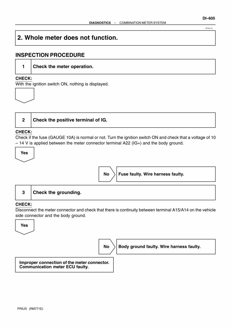
–DIAGNOSTICS COMBINATION METER SYSTEMDI–605
PRIUS (RM771E)
2. Whole meter does not function.
INSPECTION PROCEDURE
1 Check the meter operation.
CHECK:With the ignition switch ON, nothing is displayed.
2 Check the positive terminal of IG.
CHECK:Check if the fuse (GAUGE 10A) is normal or not. Turn the ignition switch ON and check that a voltage of 10– 14 V is applied between the meter connector terminal A22 (IG+) and the body ground.
Yes
No Fuse faulty. Wire harness faulty.
3 Check the grounding.
CHECK:Disconnect the meter connector and check that there is continuity between terminal A15/A14 on the vehicleside connector and the body ground.
Yes
No Body ground faulty. Wire harness faulty.
Improper connection of the meter connector.Communication meter ECU faulty.
DI7XU–01

DI–606–DIAGNOSTICS COMBINATION METER SYSTEM
PRIUS (RM771E)
3. Margin of error in speedometer is large, or it remains as 0 km/h
INSPECTION PROCEDURE
1 Check the brake ECU.
CHECK:Perform a diagnosis check of the brake system.Proceed to next circuit inspection shown in problem symptoms table (See page DI–306).
No
Yes Replace brake ECU.
2 Check the vehicle speed signal input.
PREPARATION:Turn the ignition switch ON.CHECK:Disconnect the meter connector, drive the vehicle at a speed of 2 – 4 km/h and check that continuity betweenterminal A9 on the vehicle side connector and the body ground is repeatedly turned ON and OFF.
Yes
No Wire harness faulty. Speed output terminal inbrake ECU faulty.
Combination meter ECU faulty.
DI7XV–01

–DIAGNOSTICS COMBINATION METER SYSTEMDI–607
PRIUS (RM771E)
4. Fuel receiver gauge is inoperative or improper
INSPECTION PROCEDURE
1 Fuel gauge diagnosis check (See page DI–602).
2 Communication check.
CHECK:Check if the communication between the combination meter and the multiplex communication circuit is nor-mal or not.
Yes
No Communication error. Wire harness faulty.
3 Check the fuel sender gauge.
CHECK:Check if the fuel sender gauge is normal or not.
Yes
No Fuel sender gauge faulty.
DI7XW–02

DI–608–DIAGNOSTICS COMBINATION METER SYSTEM
PRIUS (RM771E)
4 Check the fuel receiver gauge.
CHECK:Check if the fuel receiver gauge is normal or not.
Yes
No Fuel receiver gauge faulty.
5 Check the body ECU.
CHECK:With the fuel sender gauge connector connected, check if the voltage between each of terminal 1 (FV), 5(FR) and 6 (FE) of the vehicle side wire harness and connector and the body ground is normal or not.
Terminal 1 (FV): 4.5 – 5.5 V (When the ignition switch is ON) Terminal 5 (FR): 0.5 – 5.5 V (When the ignition switch is ON) Terminal 6 (FE): Continuity is always identified.
Yes
No Body ECU faulty.
Combination meter ECU faulty.

–DIAGNOSTICS COMBINATION METER SYSTEMDI–609
PRIUS (RM771E)
5. Indicators or warning lights do not light up. (*multiplex communication circuit inputindicator or warning)
INSPECTION PROCEDURE
1 Multiplex communication circuit input indicator or warning.
2 Communication check.
CHECK:Check if the communication between the combination meter and the multiplex communication circuit is nor-mal or not.
Yes
No Communication error. Wire harness faulty.
3 Check the bulb or circuit plate.
CHECK:Check if the bulb circuit plate is normal or not. Check open or short circuit in wire harness.
Yes
No Bulb or circuit plate faulty.
DI7XX–01

DI–610–DIAGNOSTICS COMBINATION METER SYSTEM
PRIUS (RM771E)
4 Check the corresponding switch or ECU.
CHECK:Check if the corresponding switch or ECU is normal or not.
Yes
No Corresponding switch or ECU faulty.
Combination meter ECU faulty.
*:
Multiplex communication input Single Communication Input
OPEN DOOR WARNING HI–BEAM INDICATOR
BRAKE WARNING TURN SIGNAL IND
OUTPUT CONTROL INDICATOR SRS WARNING
SHIFT POSITION INDICATOR ABS WARNING
SEAT BELT WARNING CHECK ENGINE WARNING
READY INDICATOR
WATER TEMPERATURE WARNING
OIL PRESSURE WARNING
CRUISE CONTROL INDICATOR
TAIL INDICATOR
DISCHARGE WARNING

DI7QE–01
Customer Problem Analysis
Vehicle Brought to Workshop
Problem Symptom Confirmation Symptom Simulation
Symptom does notoccur
Circuit Inspection
Identification of Problem
Repair
Confirmation Test
End
Titles inside are titles of pages in thismanual, with the page number indicated inthe bottom portion. See the indicated pagesfor detailed explanations.
1
23
6
5
P. IN–29
P.DI–612
P.DI–616 – DI–635
Symptomoccur
Step 6, 8 : Diagnostic steps permitting the use of the hand–held tester .
7
4Problem Symptoms Table
P. DI–615
–DIAGNOSTICS BODY CONTROL SYSTEMDI–611
PRIUS (RM771E)
BODY CONTROL SYSTEMHOW TO PROCEED WITH TROUBLESHOOTINGHINT:This ECU is connected to the multiplex communication system. Therefore, be sure to check that there is notroubles in the multiplex communication system before performing the trouble shooting.

DI7QF–01
"" Daytime Running Light System
"" Seat Belt Warning
BODY CONTROL SYSTEM Check Sheet
Inspector’s name:
Customer’s Name
Date Vehicle
Registration No.
Registration Year
Frame No.
Odometer Reading / / kmMile
Weather ConditionsWhen ProblemOccurred
Date Problem First Occurred
Frequency Problem Occurs
Weather
/ /
"" Once only
Brought in
"" Key Reminder System
MalfunctionSystem
Outdoor Temperature
"" Fine "" Cloudy ""Rainy ""Snowy"" Various/ Others
"" Hot ""Warm "" Cool"" Cold (Approx. F ( C))
"" Constant "" Sometimes ( times per day, month)
"" Illuminated Entry System
"" Theft Deterrent System
"" Combination Meter (Open door warning light)
"" Light–On Warning System
"" Power Window Control System
"" Power Door Lock Control System
"" Wireless Door Lock Control System
"" Others
DI–612–DIAGNOSTICS BODY CONTROL SYSTEM
PRIUS (RM771E)
CUSTOMER PROBLEM ANALYSIS CHECK

DI7QG–01
I17840
Door Lock Assembly Door Lock Motor Door Unlock Detection Switch Door Key Lock and Unlock Switch
Wireless Door Lock Receiver
Light Control Switch
Power Window Switch
Ignition Switch
Interior Light
Power Window Switch
Luggage Compartment Door Courtesy Switch
Licence Light
Power Window Master Switch
Instrument Panel J/B ECU–B Fuse Door Fuse GAUGE Fuse IG1 Relay
Door Lock Assembly Door Lock Motor Door Unlock Detection Switch Door Key Lock and Unlock Switch
Door Courtesy Switch
–DIAGNOSTICS BODY CONTROL SYSTEMDI–613
PRIUS (RM771E)
PARTS LOCATION

DI7QH–01
I17085
B8
DI–614–DIAGNOSTICS BODY CONTROL SYSTEM
PRIUS (RM771E)
TERMINALS OF ECUBODY ECU
Symbols (Terminals No.) Wiring Color Condition STD Voltage (V)
HAZ – EG R W B
Hazard warning light is not light Below 1 vHAZ E
(1 – 7)G–R – W–B
Hazard warning light is light 10 – 14 v
FLD – EG B W B
Power window (FR LH) is not operating Below 1 vFLD E
(3 – 7)G–B – W–B
Power window (FR LH) is operating downward 10 – 14 v
B – Body ground
(5 – Body ground)
R–G –
Body groundConstant 10 – 14 v
E – Body ground
(7 – Body ground)
W–B –
Body groundConstant Below 1 v
RX (9) Y AVC–LAN communication circuit –
MPX+ (10) GR–B Multiplex communication circuit –
MPX– (11) GR Multiplex communication circuit –
PRG (12) B–R Wireless door lock ECU communication circuit –
RDA (13) L Wireless door lock ECU communication circuit –
FLU – ER W W B
Power window (FR LH) is not operating Below 1 vFLU E
(14 – 7)R–W – W–B
Power window (FR LH) is operating upward 10 – 14 v

DI7QI–01
–DIAGNOSTICS BODY CONTROL SYSTEMDI–615
PRIUS (RM771E)
PROBLEM SYMPTOMS TABLEPOWER WINDOW CONTROL SYSTEM
Symptom Suspect Area See page
All the power windows does not operate. 1. Driver door ECU with master switch DI–636
Each power window does not operate. 1. Power window switch circuit DI–624
DOOR LOCK CONTROL
Symptom Suspect Area See page
Lock or unlock cannot be operated with door lock control S/W.
3. Door lock control switch circuit
(Master switch)
4. Body ECU
DI–630
IN–40
Door key linked function does not operate.1. Door key lock and unlock switch circuit
2. Body ECU
DI–630
IN–40
Key confinement prevention function does not operate.1. Key unlock switch circuit
2. Body ECU
DI–620
IN–40
Does not lock and unlock each door only.1. Door lock motor circuit
2. Body ECU
DI–632
IN–40
Luggage compartment door opener function does not operate.1. Luggage component door courtesy switch circuit
2. Body ECU
DI–572
IN–40
WIRELESS DOOR LOCK CONTROL
Symptom Suspect Area See page
All function of wireless door lock control system do not operate.
1. Transmitter
2. Wireless tuner circuit
3. Key unlock warning switch circuit
4. Body ECU
BE–78
DI–626
DI–620
IN–40
Lock (or unlock) function does not operate.
1. Door key lock and unlock switch circuit
2. Door unlock detection switch circuit
3. Body ECU
DI–630
DI–630
IN–40
Automatic lock function operates even if any door is opened within
30 seconds after all doors are unlocked by wireless door lock
control system .
1. Door courtesy switch circuit
2. Body ECU
DI–628
IN–40
ILLUMINATED ENTRY
Symptom Suspect Area See page
Illuminated entry does not operate.1. Illumination circuit
2. Body ECU
DI–622
IN–40
HEADLIGHT AND TAILLIGHT SYSTEM:
Symptom Suspect Area See page
Light–on warning system does not operate.1. Door courtesy switch circuit (Driver side)
2. Body ECU
DI–628
IN–40
OTHERS
Symptom Suspect Area See page
Body ECU does not operate.
1. Power source circuit
2. Ignition switch power source circuit
3. Body ECU
DI–616
DI–618
IN–40

DI7QJ–01
I17112
Body ECU
8
B8
B8
IG
5
7
15
5
8
8
21
353
1
62 4
11
1
F13F11
BF F
J25J/C
R–G
W–B
W–B
B–Y
B–G
W
R–G
2C
2D
2K
2B
2H
2D
10A GAUGEIG1 Relay
30A DOOR7.5A ECU–B
5A AM1
A
J11 J/C
IDBattery
100A DC/DC
I15 Ignition Switch
AM1 IG1
F18 FL Block No. 2
120A MAIN
E
B
FL Block No. 1
W–G
Instrument Panel J/B
DI–616–DIAGNOSTICS BODY CONTROL SYSTEM
PRIUS (RM771E)
CIRCUIT INSPECTION
Power Source Circuit
CIRCUIT DESCRIPTIONThis circuit provides power to operate the Body ECU.
WIRING DIAGRAM

–DIAGNOSTICS BODY CONTROL SYSTEMDI–617
PRIUS (RM771E)
INSPECTION PROCEDURE
1 Check ECU–B, DC/DC, GAUGE and DOOR fuse.
CHECK:Check continuity of ECU–B, DC/DC, GAUGE and DOOR fuse.OK:
Continuity
NG Replace the failure fuse.
OK
2 Check voltage between terminals B, BDR and E of body ECU connector.
PREPARATION:(a) Turn ignition switch OFF.(b) Disconnect the Body ECU connector.CHECK:Measure voltage between terminals B, BDR and E.OK:
Voltage: 10 – 14V
OK Proceed to next circuit inspection shown onproblem symptoms table (See page DI–615).
NG
3 Check wireharness and connector between body ECU and body ground (Seepage IN–40).
NG Repair or replace wireharness or connector.
OK
Check and repair wireharness and connectorbetween Body ECU and battery.

I17112
Body ECU
8
B8
B8
IG
5
7
15
5
8
8
21
353
1
62 4
11
1
F13F11
BF F
J25J/C
R–G
W–B
W–B
B–Y
B–G
W
R–G
2C
2D
2K
2B
2H
2D
10A GAUGEIG1 Relay
30A DOOR7.5A ECU–B
5A AM1
A
J11 J/C
IDBattery
100A DC/DC
I15 Ignition Switch
AM1 IG1
F18 FL Block No. 2
120A MAIN
E
B
FL Block No. 1
W–G
Instrument Panel J/B
DI–618–DIAGNOSTICS BODY CONTROL SYSTEM
PRIUS (RM771E)
Ignition Switch Power Source Circuit
CIRCUIT DESCRIPTIONWhen the ignition switch is turned to the ACC position, battery voltage is applied to the terminal ACC of theECU and when the ignition switch is turned to the ON position, battery voltage is applied to the terminal IGof the ECU.
WIRING DIAGRAM
DI7QK–01

–DIAGNOSTICS BODY CONTROL SYSTEMDI–619
PRIUS (RM771E)
INSPECTION PROCEDURE
1 Check AM1 fuse.
CHECK:Check continuity of AM1 fuse.OK:
Continuity
NG Replace the failure fuse.
OK
2 Check voltage between terminals 8, 15 and E of body ECU connector.
PREPARATION:Turn ignition switch ON.CHECK:Measure voltage between terminals 8, 15 and E.OK:
Voltage: 10 – 14V
OK Proceed to next circuit inspection shown onproblem symptoms table (See page DI–615).
NG
3 Check wireharness and connector between body ECU and body ground (Seepage IN–40).
NG Repair or replace wireharness or connector.
OK
Check and repair wireharness and connectorbetween body ECU and battery.
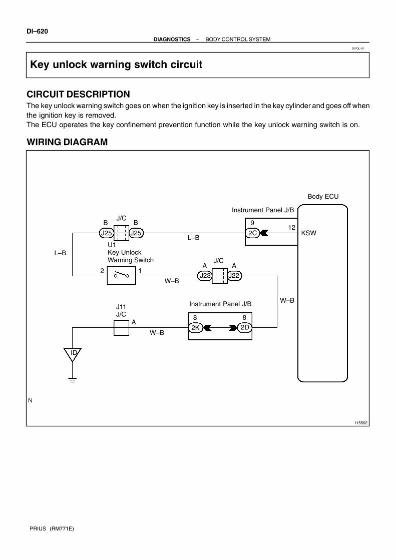
I15502
Body ECU
12J25
L–B2C KSW
9
J25
BB
L–B
12
U1 Key Unlock Warning Switch
A A
J22J23W–B
W–B
2D2K
88
W–B
A
J11 J/C
ID
Instrument Panel J/B
J/C
J/C
Instrument Panel J/B
DI–620–DIAGNOSTICS BODY CONTROL SYSTEM
PRIUS (RM771E)
Key unlock warning switch circuit
CIRCUIT DESCRIPTIONThe key unlock warning switch goes on when the ignition key is inserted in the key cylinder and goes off whenthe ignition key is removed. The ECU operates the key confinement prevention function while the key unlock warning switch is on.
WIRING DIAGRAM
DI7QL–01

–DIAGNOSTICS BODY CONTROL SYSTEMDI–621
PRIUS (RM771E)
INSPECTION PROCEDURE
1 Check key unlock warning switch (See page BE–17).
NG Replace the key unlock warning switch.
OK
2 Check wireharness and connector between key unlock warning switch and bodyECU (See page IN–40).
NG Repair or replace wireharness or connector.
OK
Proceed to next circuit inspection shown onproblem symptoms table(See page DI–615).

I17115
7
BI
Body ECU
J30
1B
B–G
I16 Interior Light
W–B
L–Y
J32 J/C
J291
2NR–B
12L–Y ED
DE
J30J29L–Y
L–Y
21
P4 Personal Light
B
2
1J7 15A DOME
L–Y
232G2N
11
F12F131120A MAIN
F18 FL Block No. 2BB
W–B
2
1
R–W
Battery
L4 Luggage Compartment Light Switch
LP
Instrument Panel J/B
Instrument Panel J/B Engine Room J/B
1
FL Block No. 1
L3 Luggage Compartment Light
J/C
R–W
R–W
(RHD)
(LHD)
EJ30
J29 D
J/C
DI–622–DIAGNOSTICS BODY CONTROL SYSTEM
PRIUS (RM771E)
Illumination Circuit
CIRCUIT DESCRIPTIONWhen the theft deterrent system is preparing to set, this circuit lights up the indicator light. When the systemhas been set, it continuously turns the indicator light on for 0.75 secs. and turns it off for 1.25 secs., thusblinking the indicator light.
WIRING DIAGRAM
DI7QS–01

–DIAGNOSTICS BODY CONTROL SYSTEMDI–623
PRIUS (RM771E)
INSPECTION PROCEDURE
1 Check illumination light (Interior light system)(See page BE–31).
NG Replace the failure light.
OK
2 Check harness and connector between body ECU and illumination light, illu-mination light and body ground (See page IN–40).
NG Repair or replace harness or connector.
OK
Check and replace body ECU.*1
*1: When there is a malfunction that the theft deterrent systemcannot be set, proceed to the next numbered circuit inspectionshown on problem symptom table (See page DI–556).

I15505
3
5
2
6
1
7 14
3
Y
G
U
D SD
5
2
5
2
1
Y
G
U
D SD
SU
5
2
6
12
1 Y
G
U
D SD
SU
4 2
1
5
10
1
1410
5
3 4
B8R–W
G–B
W
B–W
L–O
G–R
R–W
G–B
W
B–W
L–O
G–R
IN1
IN1
BB1
BA1
BA1
B8
2J
2K
2L
2L
FLU
FLD
Body ECU
P5 Power Window Control Switch Passenger Side
P7 Power Window Control Switch Rear RH
P6 Power Window Control Switch Rear LH
P10 Power Window Motor Passenger Side
P12 Power Window Motor Rear RH
P11 Power Window Motor Rear LH
Instrument Panel J/B
IG1SU6
IG1
5 5
BB2
BB2 BB1
4
RRU
RRD
RLU
RLD
BA2
BA2
4(RHD)(LHD)
5
2 (LHD)1 (RHD)
1 (LHD)2 (RHD)
6
1
(RHD)(LHD)
(RHD)(LHD)
(RHD)(LHD)
(RHD)(LHD)
(RHD)(LHD)
DI–624–DIAGNOSTICS BODY CONTROL SYSTEM
PRIUS (RM771E)
Power window switch circuit
CIRCUIT DESCRIPTIONPower window switch circuit can be checked using DTC check. (Refer to DI–672)
WIRING DIAGRAM
DI7QM–01

–DIAGNOSTICS BODY CONTROL SYSTEMDI–625
PRIUS (RM771E)
INSPECTION PROCEDURE
1 Check the power window switch (See page BE–60).
NG Replace the power window switch.
OK
2 Check wireharness and connector between power window switch and body ECU(See page IN–40).
NG Repair or replace wireharness or connector.
OK
3 Check wireharness and connector between power window switch and body ECU(See page IN–40).
NG Repair or replace wireharness or connector.
OK
Proceed to next circuit inspection shown onproblem symptoms table (See page DI–615).

I15506
2
312
Body ECU
B8
PRG
RDA
B–R
L
B8PRG
RDA
W5 Wireless Door Lock Control Receiver
13
DI–626–DIAGNOSTICS BODY CONTROL SYSTEM
PRIUS (RM771E)
Wireless door lock tuner circuit
CIRCUIT DESCRIPTIONThe signal from the transmitter will be input to the body ECU through RDA line. RDA line is diagnosed bythe body ECU, so check DTC also in case of the failure of the wireless function.
WIRING DIAGRAM
INSPECTION PROCEDURE
1 Check that DTC 42 is not output
NG Check the RDA line.
OK
DI7QN–01

–DIAGNOSTICS BODY CONTROL SYSTEMDI–627
PRIUS (RM771E)
2 Check wireharness
PREPARATION:Disconnect connectors of wireless door lock tuner and of body ECU.CHECK:Check continuity between terminals RCO of wireless door lock tuner and RCO of body ECU.OK:Continuity
NG Repair or replace wireharness
OK
3 Check the wireless door lock tuner
CHECK:Replace the wireless door lock tuner and check if it recovers normally.OK:Must be recovered normally.
NG Proceed to next circuit inspection shown onproblem symptoms table.(See page DI–615)
NG
Failure of the original wireless door lock tun-er.

I15507
7
3
3
2
11
A
A
4
1
66
3
Body ECU
J13
2LIB1
IB1
2L
2K
R
R–G
R
R–W
R–W
R–W
R–W
FDJ12
J16 J/C
D4DIODE (Door Courtesy No. 2)
D9Door Courtesy Switch Front RH
D8Door Courtesy Switch Front LH
D10Door Courtesy Switch Rear LH
D11Door Courtesy Switch Rear RH
2K
1 1
R–W
1
Instrument Panel J/B
R
DCTY
PCTY
J/C
DI–628–DIAGNOSTICS BODY CONTROL SYSTEM
PRIUS (RM771E)
Door Courtesy Switch Circuit
CIRCUIT DESCRIPTIONThe door courtesy switch goes on when the door is opened and goes off when door is closed.
WIRING DIAGRAM
DI7QO–01

–DIAGNOSTICS BODY CONTROL SYSTEMDI–629
PRIUS (RM771E)
INSPECTION PROCEDURE
1 Check courtesy switch (See page BE–31).
NG Replace the courtesy switch.
OK
2 Check that there is a grounding malfunction caused by looseness of the tightenscrew.
NG Install screw.
OK
3 Check wireharness and connector between courtesy switch and body ECU (Seepage IN–40).
NG Repair or replace wireharness or connector.
OK
Proceed to next circuit inspection shown onproblem symptoms table (See page DI–615).

I17113
5 918
Body ECU
YB8 RXIG1
P8 Power Window Master Switch
YMPX1
(LHD)
5IN1
(RHD)
DI–630–DIAGNOSTICS BODY CONTROL SYSTEM
PRIUS (RM771E)
Power window master switch circuit
CIRCUIT DESCRIPTIONPower window master switch circuit can be checked using DTC check. (See page DI–672)
WIRING DIAGRAM
DI7QP–01

–DIAGNOSTICS BODY CONTROL SYSTEMDI–631
PRIUS (RM771E)
INSPECTION PROCEDURE
1 Check the power window master switch circuit using DTC check. (See page DI–669)
OK Proceed to next circuit inspection shown onproblem symptom table (See page DI–615).
OK
2 Check the power window master switch (See page BE–60).
NG Replace the power window master switch.
OK
3 Check wireharness and connector between power window master switch andbody ECU (See page IN–40).
NG Repair or replace wireharness or connector.
OK
Proceed to next circuit inspection shown onproblem symptom table (See page DI–615).

I15504
9
16
4
6
5
1
2
8
9
3
2
1
6
3
6
2L
6
Body ECU
R
GG
R
G G
GG
G G
R R
R R
R R
ACT+2I
2J
IC1
IC1
IQ1
BB1
BA1
IQ1
BB1
BA1
A
B
J15
J14J15
C
D19 Door Lock Motor Front LH
D16 Door Lock Motor Front RH
D18 Door Lock Motor Rear RH
D17 Door Lock Motor Rear LH
B
J15 J14
5
1
2
1
2 J14CA
G
R
B BJ15 J14
2L
1 ACT–
LHD models
DI–632–DIAGNOSTICS BODY CONTROL SYSTEM
PRIUS (RM771E)
Door lock motor circuit
WIRING DIAGRAM
DI7QQ–01

I17114
9
16
4
6
5
4
5
8
9
2
1
2 6
2
6
2L
6
Body ECU
R
GG
R
G G
GG
G G
R R
R R
R
ACT+2I
2J
IQ1
IQ1
IC1
BB2
BA2
IC1
BB2
BA2
A
B
J15
J14J15
C
D13 Door Lock Motor Front LH
D12 Door Lock Motor Front RH
D15 Door Lock Motor Rear RH
D14 Door Lock Motor Rear LH
B
J15 J14
5
5
4
1
1 J14CA
G
R
B BJ15 J14
2L
2ACT–
RHD models
R
G
G
R
GR
R
–DIAGNOSTICS BODY CONTROL SYSTEMDI–633
PRIUS (RM771E)

DI–634–DIAGNOSTICS BODY CONTROL SYSTEM
PRIUS (RM771E)
INSPECTION PROCEDURE
1 Check door lock motor (See page BE–66).
NG Replace the door lock motor.
OK
2 Check wireharness and connector between door lock motor and body ECU(See page IN–40).
NG Repair or replace wireharness or connector.
OK
Proceed to next circuit inspection shown onproblem symptoms table (See page DI–615).

I15500
T6Turn Signal Flasher Relay Body ECU
HAZ8
G–RID1
4
G–RJ25
J/C
J26
A E
G–RB8
1
HAZ
–DIAGNOSTICS BODY CONTROL SYSTEMDI–635
PRIUS (RM771E)
Turn Signal Flasher Circuit
WIRING DIAGRAM
INSPECTION PROCEDURE
1 Check wireharness and connector between turn signal flasher and body ECU(See page IN–40).
NG Repair or replace wireharness or connector.
OK
Proceed to next circuit inspection shown onproblem symptoms table (See page DI–615).
DI7QR–01
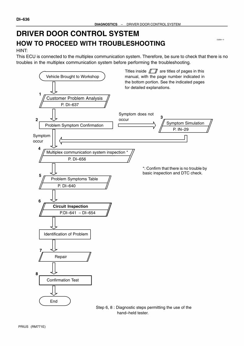
DI2BH–11
Customer Problem Analysis
Vehicle Brought to Workshop
Problem Symptom Confirmation Symptom Simulation
Symptom does notoccur
Circuit Inspection
Identification of Problem
Repair
Confirmation Test
End
Titles inside are titles of pages in thismanual, with the page number indicated inthe bottom portion. See the indicated pagesfor detailed explanations.
1
23
6
5
8
P. IN–29
P. DI–656
P. DI–637
P.DI–641 – DI–654
Symptomoccur
Step 6, 8 : Diagnostic steps permitting the use of the hand–held tester.
7
Multiplex communication system inspection *4
Problem Symptoms Table
P. DI–640
*: Confirm that there is no trouble bybasic inspection and DTC check.
DI–636–DIAGNOSTICS DRIVER DOOR CONTROL SYSTEM
PRIUS (RM771E)
DRIVER DOOR CONTROL SYSTEMHOW TO PROCEED WITH TROUBLESHOOTINGHINT:This ECU is connected to the multiplex communication system. Therefore, be sure to check that there is notroubles in the multiplex communication system before performing the troubleshooting.

DI2BI–08
DRIVER DOOR CONTROL SYSTEM Check Sheet
Inspector’s name:
Customer’s Name
Date Vehicle
Registration No.
Registration Year
Frame No.
Odometer Reading / / kmMile
Weather ConditionsWhen ProblemOccurred
Date Problem First Occurred
Frequency Problem Occurs
Weather
/ /
"" Once only
Brought in
MalfunctionSystem
Outdoor Temperature
"" Fine "" Cloudy ""Rainy ""Snowy"" Various/ Others
"" Hot ""Warm "" Cool"" Cold (Approx. F ( C))
"" Constant "" Sometimes ( times per day, month)
"" Power Window Control System
"" Power Door Lock Control System
"" Theft Deterrent System
"" Others
"" Jam Protection System
–DIAGNOSTICS DRIVER DOOR CONTROL SYSTEMDI–637
PRIUS (RM771E)
CUSTOMER PROBLEM ANALYSIS CHECK

DI2BJ–10
I17811
Door Lock Assembly Door Lock Motor Door Key Lock and Unlock Switch Door Unlock Detection Switch
Instrument Panel J/B PW1 Fuse AM1 Fuse GAUGE Fuse
Door Courtesy Switch
Driver Door ECU Power Window Master Switch
DI–638–DIAGNOSTICS DRIVER DOOR CONTROL SYSTEM
PRIUS (RM771E)
PARTS LOCATION

DI2BK–11
I15529
P8
DRIVER DOOR ECU
–DIAGNOSTICS DRIVER DOOR CONTROL SYSTEMDI–639
PRIUS (RM771E)
TERMINALS OF ECU
Symbols (Terminals No.) Wiring Color Condition STD Voltage (V)
DU ↔ E
(P8 8 P8 9) LHD Y ↔ W BIgnition switch ON and driver’s window switch OFF Below 1.0
(P8–8 ↔ P8–9) LHD
(P8–20 ↔ P8–9) RHD
Y ↔ W–BIgnition switch ON and driver’s window switch UP 10 – 14
KL ↔ E
(P8 6 P8 9) LHD G Y ↔ W BDoor key lock and unlock switch OFF or UNLOCK 10 – 14
(P8–6 ↔ P8–9) LHD
(P8–15 ↔ P8–9) RHD
G–Y ↔ W–BDoor key lock and unlock switch LOCK Below 1.0
LMT ↔ SGND P L ↔ O
Driver’s door window fully–closed position 10 – 14LMT ↔ SGND
(P8–13 ↔ P8–11)P–L ↔ O
Driver’s door window except fully–closed position Below 1.0
B ↔ E
(P8–1 ↔ P8–9)W–R ↔ W–B Constant 10 – 14
DON ↔ E
(P8 20 P8 9) LHD G ↔ W BIgnition switch ON and driver’s window switch OFF Below 1.0
(P8–20 ↔ P8–9) LHD
(P8–8 ↔ P8–9) RHD
G ↔ W–BIgnition switch ON and driver’s window switch DOWN 10 – 14
LSWD ↔ E W ↔ W B
Driver’s door is locked 10 – 14LSWD ↔ E
(P8–10 ↔ P8–9)W ↔ W–B
Driver’s door is unlocked Below 1.0
CPUB ↔ E
(P8–5 ↔ P8–9)L–Y ↔ W–B Constant 10 – 14
KUL ↔ E
(P8 15 P8 9) LHD L B ↔ L BDoor key lock and unlock switch OFF or LOCK 10 – 14
(P8–15 ↔ P8–9) LHD
(P8–6 ↔ P8–9) RHD
L–B ↔ L–BDoor key lock and unlock switch UNLOCK Below 1.0
During the driver’s door power window is operate. Pulse generationPLS ↔ SGND
(P8 12 ↔ P8 11)GR ↔ O Driver’s door power window not operate with switch ON Below 1.0
(P8–12 ↔ P8–11)Driver’s door power window not operate with switch OFF 10 – 14
DCTY ↔ E R Y ↔ W B
Driver’s door closed Below 1.0DCTY ↔ E
(P8–16 ↔ P8–9)R–Y ↔ W–B
Driver’s door open 10 – 14
*: Power window master switch

DI2BL–10
DI–640–DIAGNOSTICS DRIVER DOOR CONTROL SYSTEM
PRIUS (RM771E)
PROBLEM SYMPTOMS TABLEPOWER WINDOW CONTROL SYSTEM
Symptom Suspect Area See page
All the power windows does not operate. 1. Driver door ECU with master switch –
Power window does not operate. 1. Driver door ECU with master switch –
Auto up (or down) function does not operate. 1. Driver door ECU with master switch –
Jam protection function and auto up (or down) function does not
operate.
1. Jam protection limit switch circuit
2. Jam protection pulse switch circuit
3. Driver door ECU with master switch
DI–652
DI–654
–
OTHERS
Symptom Suspect Area See page
Parts of the door does not function.1. Power source circuit
2. Driver door ECU with master switch
DI–641
–

DI2BM–12
I17120
P9 Power Window Master SW
Instrument Panel J/B
J/C
5
1
IG
CPUB
B
L–Y
1
IN1
J134
W–R
R–L
3IQ1
8IQ1
L–YL–Y
C
J25
B
J24
4
2D
2
2G
W–R
R–LJ12
R–L
20A PWR1
5A AM1
I15 Ignition Switch
IG1 Relay
IG1AM1
B–YW–G
11
2J
12H
3
2B
2 4
L–Y
62D
1 2
3510A GAUGE 10
2K
W
15A DOME71J
8
2K
Engine Room J/B
21B
B
FL Block No. 1
1F11
100A DC/DC
B–GF18 FL Block No. 2
120A MAIN
1F12
1
F13
1
BatteryID
ID (LHD)IG (RHD)
A
J11 J/C
W–B
J11 J/C (LHD)J17 J/C (RHD)
W–B
1IQ1
W–B
9E
Instrument Panel J/B
A
J/C 1
IG1
3IC1
8IC1
RHDLHD
RHDLHD
RHDLHD
AA
1IC1
RHDLHD
J13 J/C (RHD only)AA
–DIAGNOSTICS DRIVER DOOR CONTROL SYSTEMDI–641
PRIUS (RM771E)
CIRCUIT INSPECTION
Power source circuit
CIRCUIT DESCRIPTIONThis circuit provides power to operate the driver door ECU.
WIRING DIAGRAM
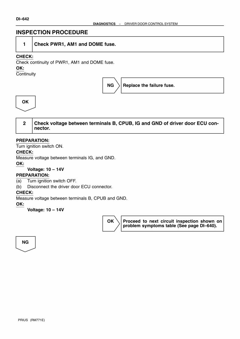
DI–642–DIAGNOSTICS DRIVER DOOR CONTROL SYSTEM
PRIUS (RM771E)
INSPECTION PROCEDURE
1 Check PWR1, AM1 and DOME fuse.
CHECK:Check continuity of PWR1, AM1 and DOME fuse.OK:Continuity
NG Replace the failure fuse.
OK
2 Check voltage between terminals B, CPUB, IG and GND of driver door ECU con-nector.
PREPARATION:Turn ignition switch ON.CHECK:Measure voltage between terminals IG, and GND.OK:
Voltage: 10 – 14VPREPARATION:(a) Turn ignition switch OFF.(b) Disconnect the driver door ECU connector.CHECK:Measure voltage between terminals B, CPUB and GND.OK:
Voltage: 10 – 14V
OK Proceed to next circuit inspection shown onproblem symptoms table (See page DI–640).
NG

–DIAGNOSTICS DRIVER DOOR CONTROL SYSTEMDI–643
PRIUS (RM771E)
3 Check wireharness and connector between ECU and body ground.
NG Repair or replace wireharness or connector
OK
Check and repair wireharness and connectorbetween ECU and battery.

I17117
LSWD
D13 (LHD)D19 (RHD)Door Unlock DetectionSwitch Front LH
4
W
103
W–BIN1
J22
2
P8 Power Window Master SW
W–B
A
Instrument Panel J/B
J11J/C
82D
W–B(RHD)
W–B
A
8
2K
J/C
ID
J22
A
J23
A
W–B(LHD)
IG1
2
(LHD) (RHD)
DI–644–DIAGNOSTICS DRIVER DOOR CONTROL SYSTEM
PRIUS (RM771E)
Door unlock detection switch circuit
CIRCUIT DESCRIPTIONThe door unlock detection switch is built in the door lock motor assembly. This switch is ON when the doorlock knob is in the unlock position and OFF when the lock knob is in the lock position. The ECU detects thedoor lock knob conditions is this circuit. It is used as one of the operating conditions for the key confinementprevention function.
WIRING DIAGRAM
DI2BP–09

–DIAGNOSTICS DRIVER DOOR CONTROL SYSTEMDI–645
PRIUS (RM771E)
INSPECTION PROCEDURE
1 Check door unlock detection switch (See page BE–66).
NG Replace the door lock motor.
OK
2 Check wireharness and connector between door unlock detection switch anddriver door ECU.
NG Repair or replace wireharness or connector.
OK
Proceed to next circuit inspection shown onproblem symptoms table(See page DI–640).

I17116
KUL
D13 (LHD)D19 (RHD)Door Key Lock and Unlock SwitchLH (LHD)RH(RHD)
6 (LHD)2 (RHD)
5 (LHD)11 (RHD) 6 (LHD)
15 (RHD)
3
W–B
A
IN12
P8 Power Window Master SW
J22
Instrument Panel J/B
J11J/CID
8
2D
W–B(LHD)
W–B
A
82K
KL
L–B
G–Y
UNLOCK
LOCK
J/C
W–B
W–B(RHD)
A
J22A
J23
IG12
(LHD) (RHD)15 (LHD)6 (RHD)
DI–646–DIAGNOSTICS DRIVER DOOR CONTROL SYSTEM
PRIUS (RM771E)
Door key lock and unlock switch circuit
CIRCUIT DESCRIPTIONThe door key lock and unlock switch is built in the door key cylinder. When the key is turned to the lock side,terminal 3 of the switch is grounded and when the key is turned to the unlock side, terminal 2 of the switchis grounded.Door key lock and unlock switch can be checked using DTC check. (Refer to DI–672)
WIRING DIAGRAM
DI2BQ–09
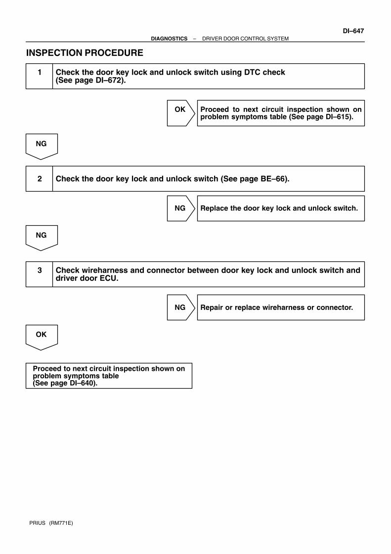
–DIAGNOSTICS DRIVER DOOR CONTROL SYSTEMDI–647
PRIUS (RM771E)
INSPECTION PROCEDURE
1 Check the door key lock and unlock switch using DTC check (See page DI–672).
OK Proceed to next circuit inspection shown onproblem symptoms table (See page DI–615).
NG
2 Check the door key lock and unlock switch (See page BE–66).
NG Replace the door key lock and unlock switch.
NG
3 Check wireharness and connector between door key lock and unlock switch anddriver door ECU.
NG Repair or replace wireharness or connector.
OK
Proceed to next circuit inspection shown onproblem symptoms table (See page DI–640).

I17119
DCTY
D9 (LHD)D8 (RHD)Door Courtesy SWFront RH (LHD)Front LH (RHD)
IC17
P8 Power Window Master SW
R–Y2
J16 (LHD)J33 (RHD)J/C
3
D3 DIODE(Door Courtesy)
R–W(LHD)
A A
R–W
16
R–Y
1
IQ17
(LHD) (RHD)
R(LHD)
R(LHD)
IA217
IH110
R(LHD)
DI–648–DIAGNOSTICS DRIVER DOOR CONTROL SYSTEM
PRIUS (RM771E)
Door courtesy light and courtesy switch circuit
CIRCUIT DESCRIPTIONThe door courtesy switch goes on when the door is opened and goes off when door is closed.
WIRING DIAGRAM
DI2BR–11

–DIAGNOSTICS DRIVER DOOR CONTROL SYSTEMDI–649
PRIUS (RM771E)
INSPECTION PROCEDURE
1 Check operation of door courtesy light.
CHECK:Check that door courtesy light comes on when door opened, and goes off when door is closed.OK:Must be operated normally.
OK Proceed to next circuit inspection shown onproblem symptom table (See page DI–640).
NG
2 Check courtesy light (See page BE–31).
NG Replace the courtesy light.
OK
3 Check courtesy switch (See page BE–31).
NG Replace the courtesy switch.
OK
4 Check wireharness and connector between courtesy light and driver door ECU,courtesy switch and driver door ECU.
NG Repair or replace wireharness or connector.
OK
Proceed to next circuit inspection shown onproblem symptoms table (See page DI–640).

I15516
P9Power Window Motor
Y
G
PLS
DU
DON
LMT
SGND
8 (LHD)20 (RHD)
11O
P–L
GR3
4
5
P8 Power Window Master SW
13
20(LHD)8 (RHD)
12
1 (LHD)2 (RHD)
2 (LHD)1 (RHD)
DI–650–DIAGNOSTICS DRIVER DOOR CONTROL SYSTEM
PRIUS (RM771E)
Power window motor circuit
WIRING DIAGRAM
DI2BS–11
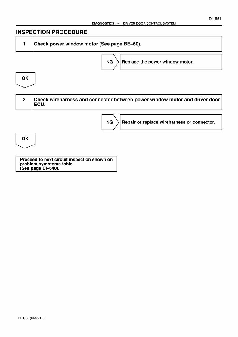
–DIAGNOSTICS DRIVER DOOR CONTROL SYSTEMDI–651
PRIUS (RM771E)
INSPECTION PROCEDURE
1 Check power window motor (See page BE–60).
NG Replace the power window motor.
OK
2 Check wireharness and connector between power window motor and driver doorECU.
NG Repair or replace wireharness or connector.
OK
Proceed to next circuit inspection shown onproblem symptoms table (See page DI–640).

I15516
P9Power Window Motor
Y
G
PLS
DU
DON
LMT
SGND
8 (LHD)20 (RHD)
11O
P–L
GR3
4
5
P8 Power Window Master SW
13
20(LHD)8 (RHD)
12
1 (LHD)2 (RHD)
2 (LHD)1 (RHD)
DI–652–DIAGNOSTICS DRIVER DOOR CONTROL SYSTEM
PRIUS (RM771E)
Jam protection limit switch circuit
CIRCUIT DESCRIPTIONJam protection limit switch is built–in the power window motor. This switch functions to turn ”OFF” before thetop dead center, and ECU reads this ”OFF” signal resulting in closing the window fully.
WIRING DIAGRAM
DI2BT–10

–DIAGNOSTICS DRIVER DOOR CONTROL SYSTEMDI–653
PRIUS (RM771E)
INSPECTION PROCEDURE
1 Check jam protection limit switch (See page BE–60).
NG Replace the power window motor.
OK
2 Check wireharness and connector between jam protection limit switch and driv-er door ECU.
NG Repair or replace wireharness or connector.
OK
Proceed to next circuit inspection shown onproblem symptoms table (See page DI–640).

I15516
P9Power Window Motor
Y
G
PLS
DU
DON
LMT
SGND
8 (LHD)20 (RHD)
11O
P–L
GR3
4
5
P8 Power Window Master SW
13
20(LHD)8 (RHD)
12
1 (LHD)2 (RHD)
2 (LHD)1 (RHD)
DI–654–DIAGNOSTICS DRIVER DOOR CONTROL SYSTEM
PRIUS (RM771E)
Jam protection pulse switch circuit
CIRCUIT DESCRIPTIONJam protection pulse switch is built–in the power window motor. Pulse switch outputs ON/OFF pulse whenthe motor rotates.
WIRING DIAGRAM
DI2BU–10

–DIAGNOSTICS DRIVER DOOR CONTROL SYSTEMDI–655
PRIUS (RM771E)
INSPECTION PROCEDURE
1 Check jam protection pulse switch (See page BE–60).
NG Replace the power window motor.
OK
2 Check wireharness and connector between jam protection pulse switch anddriver door ECU.
NG Repair or replace wireharness or connector.
OK
Proceed to next circuit inspection shown onproblem symptoms table (See page DI–640).

DI7RG–01
Customer Problem Analysis
Vehicle Brought to Workshop
Problem Symptom Confirmation Symptom Simulation
Problem does notoccur
Check DTC (Pre–check)
Normal code
Problem Symptoms Table
Identification of Problem
Repair
Confirmation Test
End
Titles inside are titles of pages in thismanual, with the page number indicated inthe bottom portion. See the indicated pagesfor detailed explanations.
1
23
4
6
8
P. IN–29
*
P. DI–657
P. DI–658
Malfunction code
Problemoccurs
Circuit InspectionP. DI–669 – DI–699
See page
Engine
Body Control System
Driver Door System
Air Conditioning System
Navigation System
System
DI–1
DI–611
DI–636
DI–777
DI–702
Step 4, 8 : Diagnostic steps permitting the use of the hand–held tester.
*
5
7DI–549Theft Deterrent System
DI–656–DIAGNOSTICS MULTIPLEX COMMUNICATION SYSTEM
PRIUS (RM771E)
MULTIPLEX COMMUNICATION SYSTEMHOW TO PROCEED WITH TROUBLESHOOTINGPerform troubleshooting in accordance with the procedure on the following page.

DI7RH–01
MULTIPLEX COMMUNICATION SYSTEM Check Sheet
Inspector’s name:
Customer’s Name
Date Vehicle
Registration No.
Registration Year
Frame No.
Odometer Reading / / kmMile
Weather ConditionsWhen ProblemOccurred
Date Problem First Occurred
Frequency Problem Occurs
Weather
/ /
"" Once only
Brought in
"" Engine
MalfunctionSystem
Outdoor Temperature
"" Fine "" Cloudy ""Rainy ""Snowy"" Various/ Others
"" Hot ""Warm "" Cool"" Cold (Approx. F ( C))
"" Constant "" Sometimes ( times per day, month)
"" Body Control System
"" Driver Door System
"" Air Conditioning System
""Navigation System
""Theft Deterrent System
–DIAGNOSTICS MULTIPLEX COMMUNICATION SYSTEMDI–657
PRIUS (RM771E)
CUSTOMER PROBLEM ANALYSIS CHECK

DI7RI–01
I15527
Theft Deterrent ECU
Body ECU
DLC3
Gateway ECU
Power Window Master Switch(Driver Door Control ECU) A/C AmplifierCombination Meter
Engine ECUDouble Locking Door Control Relay
DI–658–DIAGNOSTICS MULTIPLEX COMMUNICATION SYSTEM
PRIUS (RM771E)
PRE–CHECK1. DIAGNOSIS SYSTEM(a) As shown in the following illustration, each ECU of this ve-
hicle is connected by communication bus and it transmitseach signal by communication. This communication busis self–diagnosed by Body ECU and it memorizes DTCwhen it detects communication stop to ECU or commu-nication bus +B short or GND short. There is a possibilitythat Body ECU cannot self–diagnose accurately unlessit doesn’t work normal. So, please note that the trouble-shooting of Body Electrical System should be done afterconfirming if Body ECU and Open door indicator worksnormal by 2. ”BASIC INSPECTION” described later.

I03977
ECU
ECU
ECU
ECU
ECU
ECU
Open
Open
ECU
ECU
Open
ECU
Disconnection (DTC is detected)
Open (DTC is detected)
Open (DTC is not detected)
I03346
Body ECU
OpenOpen
Detect the DTC of commu-nication stop of the 3 ECUs.
Example
–DIAGNOSTICS MULTIPLEX COMMUNICATION SYSTEMDI–659
PRIUS (RM771E)
(b) If DTC of ECU communication stop is output, there is apossibility of connector disconnection or 2 communica-tion buses open. It will not become abnormal with only 1communication bus open.
(c) If 2 communication buses are open at the position asshown in the illustration, DTC of ECU communication stopbetween those 2 buses is output.

DI–660–DIAGNOSTICS MULTIPLEX COMMUNICATION SYSTEM
PRIUS (RM771E)
2. BASIC INSPECTION
INSPECT BODY ECU
1 Check room light operation.
HINT:With this inspection body ECU CPU can be diagnosed if it works normal or not.CHECK:Check if the room light works normal at DOOR position.
OK Go to next step”OPEN DOOR INDICATOR LIGHTINSPECTION”.
NG
2 Check interior light system (Except body ECU) (See page BE–31).
OK Replace the body ECU.
NG
Repair of replace malfunction part.

I15595
LHD models
RHD models
A04550
Tc
CGDLC3
–DIAGNOSTICS MULTIPLEX COMMUNICATION SYSTEMDI–661
PRIUS (RM771E)
INSPECT OPEN DOOR INDICATOR LIGHT
1 Check open door indicator light.
CHECK:Check if open door Indicator light is turned on when either dooropen.HINT:If open door Indicator light is not turned on, DTC will not be out-put.
OK Go to step 3. ”DTC CHECK”.
NG
Repair the open door indicator light(See page BE–46).
3. DTC CHECK (Using diagnosis check wire)(a) Using SST, connect terminals Tc and CG of DLC3.
SST 09843–18020(b) Turn the ignition switch ON.(c) Read the DTC on the open door indicator light.

N13628
Malfunction Code 12
Malfunction Code 11 and 12
0.25 sec.0.25 sec.
1.5 sec.
Normal Code
4.5 sec.
0.5 sec. 0.5 sec.
2.5 sec. 4.5 sec.
F12397
DLC3
DI–662–DIAGNOSTICS MULTIPLEX COMMUNICATION SYSTEM
PRIUS (RM771E)
As an example, the blinking patterns for codes; normal, 12, and11 and 12 are shown in the illustration.(d) Check for the problem using the DTC table on the next
page.(e) After completing the check, turn the ignition switch off,
and disconnect terminals Tc and E1.
4. DTC CHECK (Using hand–held tester)(a) Prepare the hand–held tester.(b) Connect the hand–held tester to DLC3.(c) Turn the ignition switch ON and switch the hand–held tes-
ter main switch ON.(d) Use the hand–held tester to check the DTCs, note them
down. (For opening instructions, see the hand–held tes-ter’s instruction book.)
(e) See page DI–663 to confirm the details of the DTCs.
5. DTC CLEARANCEDTC will be cleared when the trouble output to DTC is recov-ered normally.

DI7RJ–01
–DIAGNOSTICS MULTIPLEX COMMUNICATION SYSTEMDI–663
PRIUS (RM771E)
DIAGNOSTIC TROUBLE CODE CHARTIf a malfunction code is displayed during the DTC check, check the circuit listed for that code in the tablebelow (Proceed to the page given for that circuit).
DTC No.
(See Page)Detection Item Trouble Area
B1211/11
(DI–669)Driver door ECU communication stop
Wireharness
Driver door ECU
B1221/21
(DI–672)Power window switch circuit on driver door
Power window master switch
Wireharness
B1222/22
(DI–672)Door lock switch circuit on driver door
Door lock control switch
Door key lock and unlock switch
Wireharness
B1241/41
(DI–672)Body ECU switch circuit diagnosis
Stop light switch
Wireharness
B1242/42
(DI–673)Wireless door lock tuner circuit malfunction
Wireharness
Wireless door lock tuner
B1248/48
(DI–675)AVC–LAN circuit communication stop
Wireharness
Gateway ECU
B1249/49
(DI–677)Double locking ECU communication stop
Wireharness
Double locking ECU
B1261/61
(DI–679)Engine ECU communication stop
Wireharness
Engine ECU
B1262/62
(DI–682)A/C amplifier communication stop
Wireharness
A/C amplifier
B1266/66
B1267/67
Instrument panel system communication bus malfunction
(+B short)Wireharness
B1267/67
(DI–683)Instrument panel system communication bus malfunction
(GND short)
Wireharness
ECU (Instrument panel system)
B1269/69
(DI–691)Theft deterrent ECU communication stop
Wireharness
Theft deterrent ECU
B1271/71
(DI–693)Combination meter ECU communication stop
Wireharness
Combination meter ECU
B1274/74
(DI–695)Multi display communication stop
Wireharness
Multi display
B1293/93
(DI–697)
(DI–699)
Gateway ECU communication circuit
Wireharness
Power source circuit
Gateway ECU
HINT:DTC 21, 22, and 41 don’t mean switch abnormal but notify how switch works.If DTC is not output when operating switch, it means failure of switch contact.If DTC is output when not opening switch, it means stick of switch.

DI7RK–01
I17813
Engine ECU
A/C ECU
Instrument Panel J/B Body ECU
Gateway ECU
Driver Door ECU(Power Window Master Switch)
DI–664–DIAGNOSTICS MULTIPLEX COMMUNICATION SYSTEM
PRIUS (RM771E)
PARTS LOCATION

DI7RL–01
I17085
BODY ECU
B8
MPX1MPX2
I15529
DRIVER DOOR ECU
P8
MPX1
I15592
Engine ECU
MPX1 MPX2
E11E10E9E8
–DIAGNOSTICS MULTIPLEX COMMUNICATION SYSTEMDI–665
PRIUS (RM771E)
TERMINALS OF ECU

I15590
A/C amplifier
MP2+A9 A8 A7
MPX+
I15589
Combination Meter ECU
C10 C11 MP2+
MPX–
I15528
Multi Display
TX3+
M2 M4M3
TX1+
TX3–TX1–
DI–666–DIAGNOSTICS MULTIPLEX COMMUNICATION SYSTEM
PRIUS (RM771E)

I01920
Theft Deterrent ECU
T4 T3
MPX2 MPX1
I17093
Double Locking Relay
D8
MPX2 MPX1
–DIAGNOSTICS MULTIPLEX COMMUNICATION SYSTEMDI–667
PRIUS (RM771E)

I17261
Gateway ECU
G1GTX+ MPD1
GTX– MPD2
DI–668–DIAGNOSTICS MULTIPLEX COMMUNICATION SYSTEM
PRIUS (RM771E)
Symbols (Terminals No.) Wiring Color Condition STD Value (V)
IG ↔ GNDB Y ↔ W B
Ignition switch OFF or ACC Below 1 VIG ↔ GND
(2 ↔ 14)B–Y ↔ W–B
Ignition switch ON 10 – 14 V
MDP1 (4) GR–B A/C ECU communication circuit –
GTX+ (5) R AVC–LAN communication circuit –
CG ↔ Body ground
(7 ↔ Body ground)
W–B ↔
Body groundConstant Below 1 V
BATT ↔ GND
(8 ↔ 14)R–G ↔ W–B Constant 10 – 14 V
ACC ↔ GNDGR R ↔ W B
Ignition switch OFF Below 1 VACC ↔ GND
(9 ↔ 14)GR–R ↔ W–B
Ignition switch ACC or ON 10 – 14 V
MDP2 (11) GR–L Engine and ECT ECU communication circuit –
GTX– (12) G AVC–LAN communication circuit –
GND ↔ Body ground
(14 ↔ Body ground)
W–B ↔
Body groundConstant Below 1 V

DI7RM–01
I17113
5 918
Body ECU
YB8 RXIG1
P8 Power Window Master Switch
YMPX1
(LHD)
5IN1
(RHD)
–DIAGNOSTICS MULTIPLEX COMMUNICATION SYSTEMDI–669
PRIUS (RM771E)
CIRCUIT INSPECTION
DTC B1211 / 11 Driver door ECU communication stop
CIRCUIT DESCRIPTIONThis DTC is output when communication stops between driver door ECU and body ECU.
DTC No. DTC Detecting Condition Trouble Area
B1211/11No communication from driver door ECU more than 10 se- Driver door ECU
B1211/11No communication from driver door ECU more than 10 se
conds.
Driver door ECU
Wireharness
WIRING DIAGRAM

DI–670–DIAGNOSTICS MULTIPLEX COMMUNICATION SYSTEM
PRIUS (RM771E)
INSPECTION PROCEDURE
1 Check driver door ECU.
CHECK:Check if the driver door window glass auto up.HINT:With this inspection, the driver door ECU CPU can be diagnosed if it works normally or not.
NG Replace the driver door ECU.
OK

I15549
Body ECU
RX
MPX1
DriverDoorECU
–DIAGNOSTICS MULTIPLEX COMMUNICATION SYSTEMDI–671
PRIUS (RM771E)
2 Check wireharness.
PREPARATION:Disconnect connector ”B8” of body ECU and ”P9” of driver doorECU.CHECK:Check continuity between terminal RX of body ECU and MPX1of driver door ECU.OK:There is a continuity in wireharness.HINT:If there is OPEN in wireharness, please repair it.
NG Repair or replace wireharness.
OK
Replace the driver door ECU.

DI–672–DIAGNOSTICS MULTIPLEX COMMUNICATION SYSTEM
PRIUS (RM771E)
DTC B1221 / 21 Power window switch circuit on driverdoor
DTC B1222 / 22 Door lock switch circuit on driver door
DTC B1241 / 41 Body ECU switch circuit diagnosis
CIRCUIT DESCRIPTIONThese DTC notify how switch works as follows:If DTC is not output when operating switch, it means failure of switch contact. If DTC is output when not oper-ating switch, it means stick of switch. When something wrong is found by this diagnosis, inspect each switch.Then, replace the switch if there is a problem, or check the wireharness if there is no problem.
DTC No. DTC Detecting Condition Trouble Area
B1221/21Stick of either of the power window master switch
(except window lock switch)
Power window master switch
Wireharness
B1222/22 Stick of door key lock and unlock switch
Door lock control switch
Door key lock and unlock switch
Wireharness
B1241/41 Stick of switchStop light switch
Wireharness
HINT:Please refer to BE–2 for switch inspection, and to each door system of DI–636 for wireharness inspection.
DI7RN–01
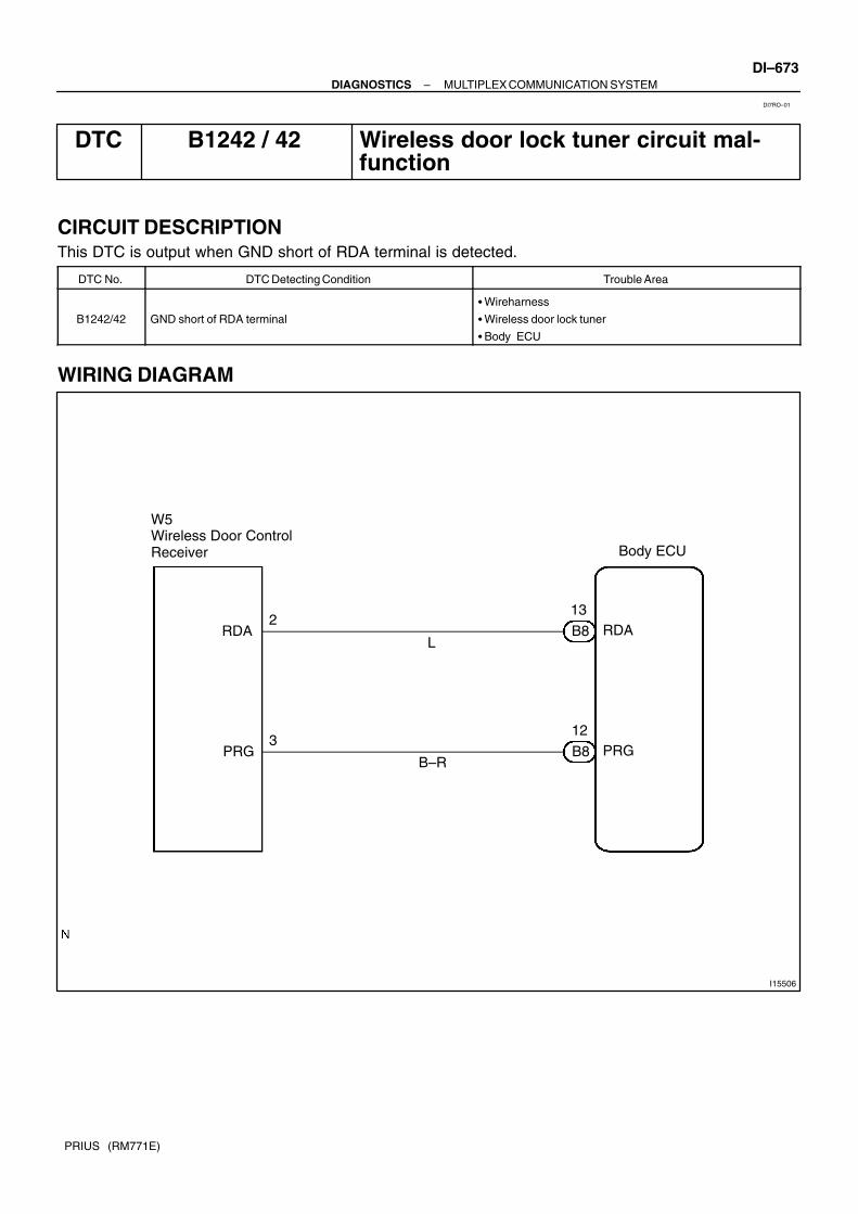
I15506
Body ECU
W5Wireless Door Control Receiver
12
B8
3
B–R
132
B8
L
PRG
RDA
PRG
RDA
–DIAGNOSTICS MULTIPLEX COMMUNICATION SYSTEMDI–673
PRIUS (RM771E)
DTC B1242 / 42 Wireless door lock tuner circuit mal-function
CIRCUIT DESCRIPTIONThis DTC is output when GND short of RDA terminal is detected.
DTC No. DTC Detecting Condition Trouble Area
B1242/42 GND short of RDA terminal
Wireharness
Wireless door lock tuner
Body ECU
WIRING DIAGRAM
DI7RO–01
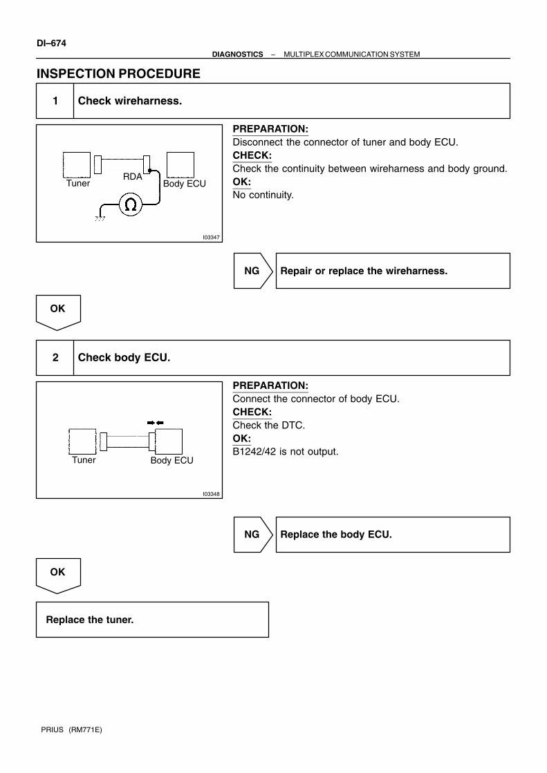
I03347
Tuner Body ECURDA
I03348
Tuner Body ECU
DI–674–DIAGNOSTICS MULTIPLEX COMMUNICATION SYSTEM
PRIUS (RM771E)
INSPECTION PROCEDURE
1 Check wireharness.
PREPARATION:Disconnect the connector of tuner and body ECU.CHECK:Check the continuity between wireharness and body ground.OK:No continuity.
NG Repair or replace the wireharness.
OK
2 Check body ECU.
PREPARATION:Connect the connector of body ECU.CHECK:Check the DTC.OK:B1242/42 is not output.
NG Replace the body ECU.
OK
Replace the tuner.

I15475
Multi DisplayG1Gateway ECU
4
M45
12
GTX+
GTX–
R
G
11
M4
TX3+
TX3–
–DIAGNOSTICS MULTIPLEX COMMUNICATION SYSTEMDI–675
PRIUS (RM771E)
DTC B1248/48 AVC–LAN circuit communication stop
CIRCUIT DESCRIPTIONThis DTC is output when communication stops between gateway ECU and AVC–LAN circuit.The body ECU performs the diagnosis check of the gateway ECU communication error to ”AVC–LAN”.The condition of registration can be checked by DTC of the body ECU.
DTC No. DTC Detecting Condition Trouble Area
B1248/48 Condition that the gateway ECU cannot register to AVC LANGateway ECU
B1248/48 Condition that the gateway ECU cannot register to AVC–LAN.Gateway ECU
Wireharness
WIRING DIAGRAM
DI7RP–01

I15538
Multi Display
TX3+
TX3–
Gateway ECU
GTX+
GTX–
DI–676–DIAGNOSTICS MULTIPLEX COMMUNICATION SYSTEM
PRIUS (RM771E)
INSPECTION PROCEDURE
1 Check ”Service check mode” of audio system. (AVC–LAN diagnosis check)(See page DI–704)
CHECK:Connection of the gateway ECU can be checked by AVC–LAN diagnosis. (”Servive check mode” of audiosystem)OK:DisplayG/W: OK (System is normal)G/W: NG (Communication error)G/W: None (Never registered)
NG Replace the gateway ECU.
OK
2 Check wireharness
PREPARATION:Disconnect connector ”G1” of gateway ECU and ”M2” of multidisplay.CHECK:(a) Check continuity between terminals GTX+ of gateway
ECU and TX3+ of multi display.(b) Check continuity between terminals GTX– of gateway
ECU and TX3– of multi display.OK:There is a continuity in wireharness of both (a) and (b), or either(a) or (b).HINT:If there is OPEN in wireharness of either (a) or (b), please repairit.
NG Repair or replace wireharness.
OK
Replace the gateway ECU.

–DIAGNOSTICS MULTIPLEX COMMUNICATION SYSTEMDI–677
PRIUS (RM771E)
DTC B1249/49 Double locking ECU communication stop
CIRCUIT DESCRIPTIONThis DTC is output when communication stops between double locking ECU and body ECU.
DTC No. DTC Detecting Condition Trouble Area
B1249/49No communication from double locking ECU more than 10 Double locking ECU
B1249/49No communication from double locking ECU more than 10
seconds.
Double locking ECU
Wireharness
WIRING DIAGRAMSee page DI–683.
INSPECTION PROCEDURE
1 Check double locking ECU.
CHECK:Check that the double locking system operate normally.HINT:With this inspection, the double locking ECU CPU can be diagnosed if it works normally or not.
NG Replace the double locking ECU.
OK
DI7RQ–01

I17094
Body ECU
RX
RX
Double Locking Relay
MPX1
MPX2
Double LockingRelayEngine ECU
DI–678–DIAGNOSTICS MULTIPLEX COMMUNICATION SYSTEM
PRIUS (RM771E)
2 Check wireharness
PREPARATION:Disconnect connector ”D8” of double locking ECU, ”E11” of en-gine ECU and ”B8” of body ECU.CHECK:(a) Check continuity between terminals MPX1 of double lock-
ing ECU and terminal RX of body ECU.(b) Check continuity between terminals MPX2 of double lock-
ing ECU and terminal RX of engine ECU.OK:There is a continuity in wireharness of both (a) and (b), or either(a) or (b).HINT:If there is OPEN in wireharness of either (a) or (b), please repairit.
NG Repair or replace wireharness.
OK
Replace the double locking ECU.

I15513
3
A8A/C Amplifier
C11Combination Meter
G1Gateway ECU
E10Engine ECU
IP2 MPX–
GR9
10
2
8
MPX+
(RHD)
MPX–
MPX2 MPX1
GR–B
4
13
GR
GR–L
1114GR(RHD)
10
(RHD)
GR
(RHD)
GR(LHD)
B8Body ECU
11MPX+
10
GR–B
(LHD)
(RHD)
IP2 12
GR–R (RHD)7
T4 Theft Deterrent ECU
(RHD)
GR–BIP211
GR–R
(RHD)
GR
11MPX+ MP2+
GR–B 4
IP29
D6Double Lock Door Control Relay
MPD2
MPD1
MPX2 MPX1
MPX2MPX1
–DIAGNOSTICS MULTIPLEX COMMUNICATION SYSTEMDI–679
PRIUS (RM771E)
DTC B1261 / 61 Engine ECU communication stop
CIRCUIT DESCRIPTIONThis DTC is output when communication stops between Engine ECU and body ECU.
DTC No. DTC Detecting Condition Trouble Area
B1261/61 No communication from Engine ECU more than 10 secondsEngine ECU
B1261/61 No communication from Engine ECU more than 10 seconds.Engine ECU
Wireharness
WIRING DIAGRAM
DI7RR–01

DI–680–DIAGNOSTICS MULTIPLEX COMMUNICATION SYSTEM
PRIUS (RM771E)
INSPECTION PROCEDURE
1 Check Engine ECU.
CHECK:Check that the engine starts normally.HINT:With this inspection, Engine ECU CPU can be diagnosed if it works normally or not.
NG Replace the Engine ECU.
OK

I15537
Body ECU
MPX– Engine ECU
MPX1
Gateway ECU
MPX1 MPX2
–DIAGNOSTICS MULTIPLEX COMMUNICATION SYSTEMDI–681
PRIUS (RM771E)
2 Check wireharness
PREPARATION:Disconnect connector ”B8” of body ECU, ”E11” of Engine ECUand ”G1” of gateway ECU.CHECK:(a) Check continuity between terminals MPX– of body ECU
and MPX2 of Engine ECU.(b) Check continuity between terminals MPX1 of Engine
ECU and MPX1 of gateway ECU.OK:There is a continuity in wireharness of both (1) and (2), or either(1) or (2).HINT:If there is OPEN in wireharness of either (1) or (2), please repairit.
NG Repair or replace wireharness.
OK
Replace the Engine ECU.

I15547
A/C amplifier
MPX+
Combination Meter A/C amplifier
Gateway ECU
MPX–
MP2+MPD1
DI–682–DIAGNOSTICS MULTIPLEX COMMUNICATION SYSTEM
PRIUS (RM771E)
DTC B1262 / 62 A/C amplifier communication stop
CIRCUIT DESCRIPTIONThis DTC is output when communication stops between A/C amplifier and body ECU.
DTC No. DTC Detecting Condition Trouble Area
B1262/62 No communication from A/C amplifier more than 10 secondsA/C amplifier
B1262/62 No communication from A/C amplifier more than 10 seconds.A/C am lifier
Wireharness
WIRING DIAGRAMSee page DI–682.
INSPECTION PROCEDURE
1 Check wireharness
PREPARATION:Disconnect connector ”G1” of gateway ECU, ”A7” of A/C ampli-fier and ”C11” of combination meter ECU.CHECK:(a) Check continuity between terminals MPD1 of gateway
ECU and MP2+ of A/C amplifier.(b) Check continuity between terminals MPX+ of A/C amplifi-
er and MPX– of combination meter ECU.OK:There is a continuity in wireharness of both (a) and (b) or (a) and(c), (a) or either (b) or (c).HINT:If there is OPEN in wireharness of either (a), (b) or (c), pleaserepair it.
NG Repair or replace wireharness.
OK
Replace the A/C amplifier.
DI7RS–01

I15513
3
A8A/C Amplifier
C11Combination Meter
G1Gateway ECU
E10Engine ECU
IP2 MPX–
GR9
10
2
8
MPX+
(RHD)
MPX–
MPX2 MPX1
GR–B
4
13
GR
GR–L
1114GR(RHD)
10
(RHD)
GR
(RHD)
GR(LHD)
B8Body ECU
11MPX+
10
GR–B
(LHD)
(RHD)
IP2 12
GR–R (RHD)7
T4 Theft Deterrent ECU
(RHD)
GR–BIP211
GR–R
(RHD)
GR
11MPX+ MP2+
GR–B 4
IP29
D6Double Lock Door Control Relay
MPD2
MPD1
MPX2 MPX1
MPX2MPX1
–DIAGNOSTICS MULTIPLEX COMMUNICATION SYSTEMDI–683
PRIUS (RM771E)
DTC B1266 / 66 Instrument panel system communica-tion bus malfunction (+B short)
DTC B1267 / 67 Instrument panel system communica-tion bus malfunction (GND short)
CIRCUIT DESCRIPTIONThis DTC is output when +B or GND short occurs on instrument panel system communication bus. If +B orGND short is detected on instrument panel system communication bus, separate it by bus cut relay in bodyECU to prevent while communication buses’ failure.
WIRING DIAGRAM
DI7RT–01

I17092
Double locking relay
D8
I15546
Engine ECU
E11
DI–684–DIAGNOSTICS MULTIPLEX COMMUNICATION SYSTEM
PRIUS (RM771E)
INSPECTION PROCEDUREHINT:On the system structure point of view, this DTC cannot display meter. In case of checking DTC, please usehand–held tester.
1 Check the communication circuit inside double locking relay. (RHD models)
PREPARATION:Disconnect the connector ”D8” of double locking relay.CHECK:Check the DTC.OK:Code B1266 or B1267 is not output
OK Replace the double locking relay.
NG
2 Check the communication circuit inside Engine ECU.
PREPARATION:Disconnect the connector ”E11” of Engine ECU.CHECK:Check the DTC.OK:Code B1266 or B1267 is not output
OK Replace the Engine ECU.
NG

I15545
Gateway ECU
G1
I15544
A/CAmplifier
A7
–DIAGNOSTICS MULTIPLEX COMMUNICATION SYSTEMDI–685
PRIUS (RM771E)
3 Check the communication circuit inside gateway ECU.
PREPARATION:(a) Connect the connector ”E11” of Engine ECU.(b) Disconnect the connector ”G1” of gateway ECU.CHECK:Check the DTC.OK:Code B1266 or B1267 is not output
OK Replace the gateway ECU.
NG
4 Check the communication circuit inside A/C amplifier.
PREPARATION:(a) Connect the connector of ”G1” of gateway ECU.(b) Disconnect the connector ”A7” of A/C amplifier.CHECK:Check the DTC.OK:Code B1266 or B1267 is not output
OK Replace the A/C amplifier.
NG

I15543
CombinationMeter
C11
I17090
Theft deterrent ECU
T4
DI–686–DIAGNOSTICS MULTIPLEX COMMUNICATION SYSTEM
PRIUS (RM771E)
5 Check the communication circuit inside combination meter ECU.
PREPARATION:(a) Connect the connector ”A7” of A/C amplifier.(b) Disconnect the connector ”C11” of combination meter
ECU.CHECK:Check the DTC.OK:Code B1266 or B1267 is not output
OK Replace the combination meter ECU.
NG
6 Check the communication circuit inside theft deterrent ECU. (RHD models)
PREPARATION:Disconnect the connector ”T4” of theft deterrent ECU.CHECK:Check the DTC.OK:Code B1266 or B1267 is not output
OK Replace the theft deterrent ECU.
NG

I15542
Body ECU
B8
I17092
Double locking relay
D8
–DIAGNOSTICS MULTIPLEX COMMUNICATION SYSTEMDI–687
PRIUS (RM771E)
7 Check for short circuit between combination meter ECU (LHD models) and body ECU.Check for short circuit between theft deterrent ECU (RHD models) and body ECU.
PREPARATION:Disconnect the connector ”B8” of body ECU.CHECK:Check the DTC.OK:Code B1266 or B1267 is not output
OK Repair or replace the wireharness betweencombination meter ECU and body ECU.
NG
8 Check for short circuit between double locking relay and body ECU. (RHD models)
PREPARATION:Connect the connector ”B8” of body ECU.Disconnect the connector ”D8” of double locking relay.CHECK:Check the DTC.OK:Code B1266 or B1267 is not output
OK Repair or replace the wireharness betweendouble locking relay and body ECU.
NG

I18344
Engine ECU
Body ECU
B8
I15545
Gateway ECU
G1
DI–688–DIAGNOSTICS MULTIPLEX COMMUNICATION SYSTEM
PRIUS (RM771E)
9 Check for short circuit between body ECU and Engine ECU. (LHD Models)
PREPARATION:Connect the connector ”B8” of body ECU.Disconnect the connector ”E11” of Engine ECU.CHECK:Check the DTC.OK:Code B1266 or B1267 is not output
OK Repair or replace the wireharness betweenbody ECU and Engine ECU.
NG
10 Check for short circuit between Engine ECU and gateway ECU.
PREPARATION:Connect the connector ”B8” of body ECU.Disconnect the connector ”G1” of gateway ECU.CHECK:Check the DTC.OK:Code B1266 or B1267 is not output
OK Repair or replace the wireharness between En-gine ECU and gateway ECU.
NG

I15544
A/CAmplifier
A7
I15543
CombinationMeter
C11
–DIAGNOSTICS MULTIPLEX COMMUNICATION SYSTEMDI–689
PRIUS (RM771E)
11 Check for short circuit between gateway ECU and A/C amplifier.
PREPARATION:Connect the connector ”E11” of Engine ECU.Disconnect the connector ”A7” of A/C amplifier.CHECK:Check the DTC.OK:Code B1266 or B1267 is not output
OK Repair or replace the wireharness between En-gine ECU and A/C amplifier.
NG
12 Check for short circuit between A/C amplifier and combination meter ECU. (LHD models)
PREPARATION:Connect the connector ”A7” of A/C amplifier.Disconnect the connector ”C11” of combination meter ECU.CHECK:Check the DTC.OK:Code B1266 or B1267 is not output
OK Repair or replace the wireharness between A/Camplifier and combination meter ECU.
NG

I17090
Theft deferrent ECU
T4
DI–690–DIAGNOSTICS MULTIPLEX COMMUNICATION SYSTEM
PRIUS (RM771E)
13 Check for short circuit between theft deterrent ECU and combination meter ECU.(RHD models)
PREPARATION:Disconnect the connector ”T4” of theft deterrent ECU.CHECK:Check the DTC.OK:Code B1266 or B1267 is not output
OK Replace the theft deterrent ECU.
NG
Replace the body ECU.

–DIAGNOSTICS MULTIPLEX COMMUNICATION SYSTEMDI–691
PRIUS (RM771E)
DTC B1269 / 69 Theft deterrent ECU communication stop
CIRCUIT INSPECTIONThis DTC is output when communication stops between theft deterrent ECU and body ECU.
DTC No. DTC Detecting Condition Trouble Area
B1249/49No communication from theft deterrent ECU more than 10 Theft deterrent ECU
B1249/49No communication from theft deterrent ECU more than 10
seconds.
Theft deterrent ECU
Wireharness
WIRING DIAGRAMSee page DI–691.
INSPECTION PROCEDURE
1 Check theft deterrent ECU.
CHECK:Check that the theft deterrent system operate normally.HINT:With this inspection, the theft deterrent ECU CPU can be diagnosed if it works normally or not.
NG Replace the theft deterrent ECU.
OK
DI7RU–01

I17091
Theft deferrent ECU
MPX1
Body ECU
MPX2
C11
MPX1
Theft deferrent ECUCombination meter
2
DI–692–DIAGNOSTICS MULTIPLEX COMMUNICATION SYSTEM
PRIUS (RM771E)
2 Check wireharness
PREPARATION:Disconnect connector ”T4” of theft deterrent ECU, ”C11” ofcombination meter ECU and ”B8” of body ECU.CHECK:(a) Check continuity between terminals MPX1 of theft deter-
rent ECU and terminal MPX1 of body ECU.(b) Check continuity between terminals MPX2 of theft deter-
rent ECU and terminal 2 of combination meter ECU.OK:There is a continuity in wireharness of both (a) and (b), or either(a) or (b).HINT:If there is OPEN in wireharness of either (a) or (b), please repairit.
NG Repair or replace wireharness.
OK
Replace the theft deterrent ECU.

–DIAGNOSTICS MULTIPLEX COMMUNICATION SYSTEMDI–693
PRIUS (RM771E)
DTC B1271 / 71 Combination meter ECU communica-tion stop
CIRCUIT DESCRIPTIONThis DTC is output when communication stops between combination meter ECU and body ECU.
DTC No. DTC Detecting Condition Trouble Area
B1271/71No communication from Combination meter ECU more than 10 Combination meter ECU
B1271/71No communication from Combination meter ECU more than 10
seconds.
Combination meter ECU
Wireharness
WIRING DIAGRAMSee page DI–683.
INSPECTION PROCEDURE
1 Check combination meter ECU.
CHECK:Start the engine and check that the speed meter and tacometer operate normally.HINT:With this inspection, the combination meter ECU CPU can be diagnosed if it works normally or not.
NG Replace the combination meter ECU.
OK
DI7RV–01

I15539
Combination Meter A/C amplifier
”C6”
MPX1MPX+
Combination Meter
Body ECU
MPX+
MPX–
DI–694–DIAGNOSTICS MULTIPLEX COMMUNICATION SYSTEM
PRIUS (RM771E)
2 Check wireharness
PREPARATION:Disconnect connector ”A7” of A/C amplifier, ”C11” of combina-tion meter ECU and ”B8” of body ECU.CHECK:(a) Check continuity between terminals MPX+ of A/C amplifi-
er and MPX– of combination meter ECU.(b) Check continuity between terminals MPX+ of combina-
tion meter ECU and MPX1 of body ECU.OK:There is a continuity in wireharness of both (a) and (b), or either(a) or (b).HINT:If there is OPEN in wireharness of either (a) or (b), please repairit.
NG Repair or replace wireharness.
OK
Replace the combination meter ECU.

–DIAGNOSTICS MULTIPLEX COMMUNICATION SYSTEMDI–695
PRIUS (RM771E)
DTC B1274/74 Multi display communication stop
CIRCUIT DESCRIPTION
This DTC is output when communication stops between multi display and body ECU.
DTC No. DTC Detecting Condition Trouble Area
B1274/74 No communication from multi display more than 10 secondsMulti display
B1274/74 No communication from multi display more than 10 seconds.Multi dis lay
Wireharness
WIRING DIAGRAM
See page DI–675.
INSPECTION PROCEDURE
1 Check multi display ECU.
CHECK:Check that the multi display operate normally.HINT:With this inspection, the multi display CPU can be diagnosed if it works normally or not.
NG Replace the multi display.
OK
DI7RW–01

I15538
Multi Display
Gateway ECU
TX3+
GTX+
GTX–
TX3–
DI–696–DIAGNOSTICS MULTIPLEX COMMUNICATION SYSTEM
PRIUS (RM771E)
2 Check wireharness.
PREPARATION:Disconnect connector ”M2” of multi display and ”G1” of gatewayECU.CHECK:(a) Check continuity between terminals TX3+ of multi display
and GTX+ of gateway ECU.(b) Check continuity between terminals TX3– of multi display
and GTX– of gateway ECU.OK:There is a continuity in wireharness.HINT:If there is OPEN in wireharness, please repair it.
NG Repair or replace wireharness.
OK
Replace the multi display.
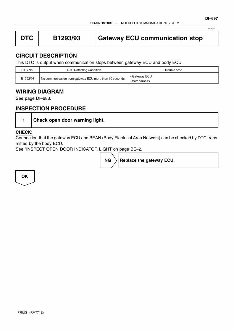
–DIAGNOSTICS MULTIPLEX COMMUNICATION SYSTEMDI–697
PRIUS (RM771E)
DTC B1293/93 Gateway ECU communication stop
CIRCUIT DESCRIPTIONThis DTC is output when communication stops between gateway ECU and body ECU.
DTC No. DTC Detecting Condition Trouble Area
B1293/93 No communication from gateway ECU more than 10 secondsGateway ECU
B1293/93 No communication from gateway ECU more than 10 seconds.Gateway ECU
Wireharness
WIRING DIAGRAMSee page DI–683.
INSPECTION PROCEDURE
1 Check open door warning light.
CHECK:Connection that the gateway ECU and BEAN (Body Electrical Area Network) can be checked by DTC trans-mitted by the body ECU.See ”INSPECT OPEN DOOR INDICATOR LIGHT¨on page BE–2.
NG Replace the gateway ECU.
OK
DI7RX–01

I15537MPX1
MPX–
Body ECU
Engine ECU
Gateway ECU
MPX1 MPX2
DI–698–DIAGNOSTICS MULTIPLEX COMMUNICATION SYSTEM
PRIUS (RM771E)
2 Check wireharness
PREPARATION:Disconnect connector ”B8” of body ECU, ”E11” of engine ECUand ”G1” of gateway ECU.CHECK:(a) Check continuity between terminals MPX– of body ECU
and MPX2 of engine ECU.(b) Check continuity between terminals MPX1 of engine ECU
and MPX1 of gateway ECU.OK:There is a continuity in wireharness of both (a) and (b), or either(a) or (b).HINT:If there is OPEN in wireharness of either (a) or (b), please repairit.
NG Repair or replace wireharness.
OK
Replace the gateway ECU.

–DIAGNOSTICS MULTIPLEX COMMUNICATION SYSTEMDI–699
PRIUS (RM771E)
Power Source Circuit
CIRCUIT DESCRIPTIONThis circuit provides power to operate the gateway ECU.
DI7RY–01

I17118
2C8
IG1 Relay
J26
7.5 A ECU–BH
R–G
Instrument Panel J/B
5A ECU–IG
BATT
IG
W–B
GND
G1Gateway ECU
J25F
R–G
2I25A AM1
2C
2H
J/C
D
2
B–Y
J21
Instrument Panel J/B
W–B
5
J19J/C
3
ID1
1
B–Y
2D2
E
J19J/C
W–BJ20
DE
A
AW–B
2K8
2D
8
W–B
A
J11J/C
ID
14
IG1 4
8
E 7CG
J/CAJ22
J/C
A
W–B
2B
2K8
2D6
D
Instrument Panel J/B
5
B–Y
D
J14J/C
D
35
21
ACC9
GR–R
GR–R
J26C
J25C J/C
10A ACCACC Relay
35
21
I15 Ignition Switch
AM1
ACC
2
3
Battery
F18 FL Block No.2
100A DC/DC 1
FL Block No.1
F13
1
F11
W
J11J/C
ID
120A MAIN FL
W–B
W–B
A
1
B–GB–Y
P–L
R–G
W
W–G
B–Y
DI–700–DIAGNOSTICS MULTIPLEX COMMUNICATION SYSTEM
PRIUS (RM771E)
WIRING DIAGRAM

–DIAGNOSTICS MULTIPLEX COMMUNICATION SYSTEMDI–701
PRIUS (RM771E)
INSPECTION PROCEDURE
1 Check ECU–B and ECU–IG fuse.
CHECK:Check continuity of ECU–B and ECU–IG fuse.OK:
Continuity
NG Replace the failure fuse.
OK
2 Check voltage between terminals BATT, IG and GND of body ECU connector.
PREPARATION:(a) Turn ignition switch OFF.(b) Disconnect the gateway ECU connector.CHECK:Measure voltage between terminals BATT and GND.OK:
Voltage: 10 – 14 V
OK Replace the gateway ECU.
NG
3 Check wireharness and connector between gateway ECU and body ground (Seepage IN–40).
NG Repair or replace wireharness or connector.
OK
Check and repair wireharness and connectorbetween gateway ECU and battery.

DI27W–06
Vehicle Brought to Workshop
Customer Problem Analysis
Check and Clear DTC (Pre check)
Items inside are titles of pages in this manual,with the page number in the bottom portion. Seethe pages for detailed explanations.
Problem Symptom Confirmation
Symptomdoes not occur
Symptomoccurs
DTC Check
DTC Chart
Malfunction code
Problem Symptoms Table
Identification of Problem
Normal code
Repair
Confirmation Test
End
1
2
3 4
5
6 7
8
9
10
P. DI–703
P. DI–704
P. IN–29
P. DI–732
P. DI–704
P. DI–721
P. DI–728Terminal of ECU
Symptom Simulation
DI–702–DIAGNOSTICS NAVIGATION SYSTEM
PRIUS (RM771E)
NAVIGATION SYSTEMHOW TO PROCEED WITH TROUBLESHOOTINGHINT:The ECU of this system is connected to the multiplex communication system. Therefore, before starting trou-bleshooting, make sure to check that there is no trouble in the multiplex communication system.

DI27X–06
–DIAGNOSTICS NAVIGATION SYSTEMDI–703
PRIUS (RM771E)
CUSTOMER PROBLEM ANALYSIS CHECK
NAVIGATION SYSTEM Check Sheet Inspector’s name:
Customer’s Name
Date of Vehicle
Registration No.
Registration Year
Frame No.
Odometer Reading / / kmMile
Frequency Problem Occurs
/ /
Constant Intermittent ( Times a day)
Brought in
Cursor movement is defective.
Date Problem First Occurred
Pro
ble
m S
ymp
tom
Cursor does not move.
GPS mark does not appear.
Map is not displayed.
Screen is dark.
Screen is white.
Color is not uniform.
Screen is in disorder.
Can not operate with panel switches.
Can not operate with touch switches.
Others ( )
Others ( )
Others ( )
Navigationmalfunction
Displaymalfunction
ControlSwitchmalfunction
Navigation ECU
Multi Display
Radio receiver assembly
DT
C C
hec
k
Parts name 1st time malfunction code. 2nd time malfunction code.

DI7OR–02
I17101
Navigation system normal operation
to 2. SYSTEM CHECK MODE SCREEN
to 4. DISPLAY CHECK MODE SCREEN
to 3. NAVIGATION CHECK MODE SCREEN
Diagnosis start–up. (refer to next page)
HINT:
When Diagnosis Sys-tem mode is started,system check is per-formed at first and thecheck result is dis-played.
DI–704–DIAGNOSTICS NAVIGATION SYSTEM
PRIUS (RM771E)
PRE–CHECK1. DIAGNOSIS SYSTEM MODEHINT:Diagnosis System Mode is operated as follows.

I15593
I17110
Concealed touch switch
–DIAGNOSTICS NAVIGATION SYSTEMDI–705
PRIUS (RM771E)
(a) DIAGNOSIS START–UPTo start the diagnosis menu, there are 2 ways: using adiagnosis check wire and using a switch.
(b) START–UP BY SWITCH OPERATION(1) Vehicle speed is 0 km/h (0 mph).(2) Parking brake switch is pressed.(3) Press the Display switch to display the Screen Ad-
justment screen.
(4) Repeatedly touch the upper and lower bottom partsof the left end of the screen 3 times.
(c) FINISHING DIAGNOSIS SYSTEM MODETurn the ignition switch from ACC to OFF to finish themode. If it is started by switch operation.

I15446
to 1. Diagnosis MENU screen
DTC memory and history clear
DTC memory clear
Recheck
DTC clear
When there are individual DTC data.Yes
No
DI–706–DIAGNOSTICS NAVIGATION SYSTEM
PRIUS (RM771E)
2. SERVICE CHECK MODEHINT:Service Check Mode is operated as follows.

I15447
Recheck
Memory clear switch
DTC clear switchCheck result
Components name
Diagnosis MENU screen switch
–DIAGNOSTICS NAVIGATION SYSTEMDI–707
PRIUS (RM771E)
(a) SERVICE CHECK SCREEN
(1) By performing system check and collecting data of diagnosis memory, this mode checks the cur-rent and past condition of the vehicle.
(2) List of all components name or physical addresses. It displays only the components that have been connected at least once.
(3) The check result is displayed for all components.(4) The check result is displayed by 6 abbreviations: ”OK”, ”EXCH”, ”CHEK”, ”NCON”, ”NRES” and
”Old”. (”EXCH”, ”CHEK” and ”Old” have a function as switches.)(5) Based on all information obtained from ”System Check Request”, ”Diagnosis Memory Request”
and ”Current Diagnosis Result” command, the following results are displayed:OK: No error is identified.EXCH: One or more error codes requesting for exchange are detected in any check result.CHEK: Except the conditions for ”EXCH”, one or more error codes requesting for check are de-tected in any check result.
(6) The other check results are as follows:NCON: No response to ”Diagnosis ON Instruction” command and it is not connected when thesystem is started.Old: One or more error codes are detected when responding to ”Diagnosis ON Instruction” com-mand because of the old version .NRES: No response to all commands of ”System Check Request”, ”Diagnosis Memory Request”and ”Current Diagnosis Result”. Or no error is detected by any one of ”System Check Request”or ”Diagnosis Memory Request” when no response to the other command.
(7) ”EXCH”, ”CHEK” and ”Old” are functioned as switches any by pressing these, LAN Check Modeand Unit Check Mode are activated.
(8) Memory Clear SwitchPressing this switch for 3 sec. deletes all information about master component registration anddiagnosis memory of all components.
(9) DTC Clear SwitchPressing this switch for 3 sec. deletes diagnosis memory of all components.
(10) Recheck SwitchPressing this switch rechecks the system.
(11) Menu SwitchPressing this switch activated the Diagnosis Menu Screen.

I15448
Service check modescreen switch
Unit check modescreen switch
DTC clear switch
Number of occurrence
Connection confirmation number
Related components partsDTCSegment
Components name
DI–708–DIAGNOSTICS NAVIGATION SYSTEM
PRIUS (RM771E)
(b) LAN CHECK MODE SCREEN
(1) As a detailed screen in the System Check Mode, LAN Check Mode is displayed.(2) Communication codes (logical address ”01”) are extracted from the diagnosis data obtained by
”Diagnosis Memory Request” and displayed.(3) Component Name
Names of the components to be checked are displayed.(4) Segment
Logical address codes corresponding to DTC are displayed.(5) DTC
DTC displayed.(6) Related components address
Physical address codes corresponding to DTC are displayed.(7) Connection Confirmation Number
Connection confirmation numbers corresponding to DTC is displayed.(8) Number of Occurrence
The number of occurrence of the same DTC is displayed.(9) DTC Clear Switch
Pressing this switch for 3 sec. deletes DTC memory of the selected diagnosis component. Whenreturning to the System Check Mode, the check result is shown as a blank.
(10) Unit Check Mode Screen SwitchPressing this switch activates the Unit Check Mode screen.
(11) System Check Mode Screen SwitchPressing this switch activates the System Check Mode screen.

I15449
System check modescreen switch
LAN check modescreen switch
DTCSegment
Components name
DTC clear switch
Segment
DTCYear/Month/Day
Hour/Minute/Second
–DIAGNOSTICS NAVIGATION SYSTEMDI–709
PRIUS (RM771E)
(c) UNIT CHECK MODE SCREEN
(1) As a detailed screen in the System Check Mode, the Unit Check Mode is displayed.(2) Up to 6 error codes detected by ”The DTC obtained during the system check (including when
starting the diagnosis mode)” can be displayed as ”Current”.(3) Up to 6 error codes detected by ”DTC stored in the past” can be displayed as ”Memory”.(4) Component Name
Names of the components are displayed.(5) Segment
Logical address numbers corresponding to DTC are displayed.(6) DTC
DTC is displayed.(7) Year/Month/Day/Hour/Minute/Second
The date and time stamped at the time of code occurrence is displayed in the order of year–month–day–hour–minute–second. (Year is shown in 2–digit number.) If the date and time datais invalid, it is displayed as a blank.
HINT:Time data is obtained after turning the ignition from ACC to ON. Until the valid time data is obtained, the datashown in the display shall be considered as invalid.If stored before a valid time data is obtained, the data shall not be displayed.
(8) DTC Clear SwitchPressing this switch for 3 sec. deletes all diagnosis memory of the component. When returningto the System Check Mode, the check result is displayed as a blank.
(9) Lan Check Mode Screen SwitchPressing this switch activates the LAN Check Mode screen.
(10) System Check Mode Screen .SwitchPressing this switch activates the System Check Mode screen.

I17108
to 1. Diagnosis MENU screen
DI–710–DIAGNOSTICS NAVIGATION SYSTEM
PRIUS (RM771E)
3. NAVIGATION CHECK MODEHINT:Navigation Check Mode is operated as follows.

I17105
Diagnosis MENUscreen switchGPS information
mode screen switch
Vehicle sensor modescreen switch
Color bar checkmode screen switch
–DIAGNOSTICS NAVIGATION SYSTEMDI–711
PRIUS (RM771E)
(a) NAVIGATION CHECK MODE SCREEN
(1) Various check screens for the Navigation ECU can be started from this menu screen.(2) GPS Information Mode Screen Switch
Pressing this switch activates GPS Information Mode Screen.(3) Vehicle Sensor Mode Screen Switch
Pressing this switch activates the Vehicle Signal Mode screen.(4) Color Bar Check Mode Screed Switch
Pressing this switch activates the Color Bar Check Mode screen.(5) Diagnosis Menu Screen Switch
Pressing this switch activates the Diagnosis Menu screen.

I17104
Navigation Check screen switch
Time data
Position dataMeasurement Status
Satellite Information
DI–712–DIAGNOSTICS NAVIGATION SYSTEM
PRIUS (RM771E)
(b) GPS INFORMATION MODE SCREEN
(1) This screen displays GPS related data.HINT:Data are updated every 1 sec.
(2) Satellite InformationThe angle of elevation of relevant satellite, azimuth signal level, and receiving condition of sig-nals are displayed.
HINT:The reception status shows receiving. ”T”: means in operation but measurement is not being used for positioning. ”P”: means measurement is being used for positioning. ”–”: means no data can be received.Display area for up to 8 satellites is ensured.Data shall be updated corresponding to change of information.
(3) Time data: The time data obtained from a GPS receiver is displayed in month, day, year, hourand minute.
(4) The displayed time is Greenwich Mean Time.(5) Position Data: The latitude and longitude of the current location are displayed in degree and min-
ute.(6) Measurement Status is displayed in the following 5 items.
2D: 2 dimensions.3D: 3 dimensions.NG: GPS information cannot be used.error: Receiving error occurs.–: Other than the above.
(7) Navigation Check Screen SwitchPressing this switch activates the Navigation Check screen.

I17106
Navigation check screen switch
–DIAGNOSTICS NAVIGATION SYSTEMDI–713
PRIUS (RM771E)
(c) VEHICLE SIGNAL CHECK MODE SCREEN
(1) Status of the vehicle sensor which are input to the Navigation ECU is checked in this screen.HINT:Data are updated every 1 sec.
(2) ACC signal status: Displayed as ON/OFF.(3) REV signal status: Displayed as ON/OFF.(4) SPD signal status: The following is displayed:
The cumulative value of the input pulse after displaying this screen. (shown in 5 digits) Vehicle speed (Unit: km/h, mph)
(5) Output condition of the gyro sensor: The following is displayed: Voltage (Unit: mV, LSB: 1mV) Relative azimuthal angle to the current point (0 degree).
Assuming the angle at a point when this screen is activated as 0 degree.(6) Navigation Check Menu Screen Switch
Pressing this switch displays the Navigation Check screen.

I17107
Navigation check screen switch
DI–714–DIAGNOSTICS NAVIGATION SYSTEM
PRIUS (RM771E)
(d) COLOR BAR CHECK MODE SCREEN
(1) Color display of the Navigation ECU is checked in this screen.(2) Color Bars:
Five colors of ”BLACK”, ”RED”, ”GREEN”, ”BLUE” and ”WHITE” are displayed as bars.(3) Navigation Check Screen Switch
Pressing this switch displays the Navigation Check screen.

I15454
to 1. Diagnosis MENUmode screen switch
–DIAGNOSTICS NAVIGATION SYSTEMDI–715
PRIUS (RM771E)
4. DISPLAY CHECK MODEHINT:Display Check Mode is operated as follows.

I15453
to 1. Diagnosis MENU screen switch
Color barcheck mode switch
Touch switchcheck mode switch
Touch pointcheck mode switch
Vehicle signalcheck mode switch
DI–716–DIAGNOSTICS NAVIGATION SYSTEM
PRIUS (RM771E)
(a) DISPLAY CHECK MENU SCREEN
(1) Various screens to check the display are started from this screen.(2) Color Bar Check Mode Switch
Pressing this switch activates the Color Bar Check Mode screen.(3) Touch Switch Check Mode Switch
Pressing this switch activates the Touch Switch Check Mode screen.(4) Touch Point Check Mode Switch
Pressing this switch activates the Touch Point Check Mode screen.(5) Vehicle Signal Check Mode Switch
Pressing this switch activates the Vehicle Signal Check Mode screen.(6) Diagnosis MENU Screen Switch
Pressing this switch activates the Diagnosis MENU screen.

I15456
to Display check screen switch
–DIAGNOSTICS NAVIGATION SYSTEMDI–717
PRIUS (RM771E)
(b) COLOR BAR CHECK MODE SCREEN
(1) Color display is checked in this screen.(2) Color Bar:
Black, Red, Green, Blue, White and Stripe is displayed in bars.If a bar is touched, color or stripe of the bar is appeared all over the screen. When touched again, it returnsto the previous screen.
(3) Display Check Screen SwitchPressing this switch activates the Display Check Mode screen.

I18203
Display check screen switch
Horizontal line check screen switch
DI–718–DIAGNOSTICS NAVIGATION SYSTEM
PRIUS (RM771E)
(c) TOUCH SWITCH CHECK MODE SCREEN
(1) Operating condition is checked line by line in the Touch Switch Check Mode screen.(2) Check Line:
Lines are displayed by using infrared beams in this screen.Once a beam is blocked off by touching the screen with a fingertip, the blocked part of the lineis deleted.
(3) Horizontal Line Check Screen Switch:Pressing this switch activates a screen in which beams of horizontal lines are checked.
(4) Display Check Mode SwitchPressing this switch activates the Display Check Mode screen.

I15462
Displaycheck screen switch
Press point
–DIAGNOSTICS NAVIGATION SYSTEMDI–719
PRIUS (RM771E)
(d) TOUCH POINT CHECK MODE SCREEN
(1) In this screen, the position detected by the pressure sensing touch switch is checked.(2) Press point:
The detected point is indicated by a cross–hair cursor.(3) Display Check Screen Switch
Pressing this switch activates the Display Check Mode screen.

I15461
Display check screen switch
DI–720–DIAGNOSTICS NAVIGATION SYSTEM
PRIUS (RM771E)
(e) VEHICLE SIGNAL CHECK MODE SCREEN
(1) Status of the Vehicle Signal which has been loaded into the display is checked in this screen.(2) Signal Description
Battery: Displays battery voltage in V.IG: Displays ON or OFF of the ignition switch.PKB: Displays ON (applied) or OFF (released) of the parking brake.SPEED: Displays the vehicle speed in km/h.TAIL: Displays ON or OFF of the tail light switch.
(3) Display Check Screen SwitchPressing this switch activates the Display Check Mode screen.

DI27Z–06
Physical address
Logical address
Meaning
Three–digit code (shown in hexadecimal) which is given to each component comprising the AVC – LANCorresponding to the function, individual symbols are specified..
Two–digit code (shown in hexadecimal) which is given to each function comprising the inner systemof the AVC – LAN.
Physical address: 110 Multi display
Diagnosis item
Panel Switch Error
Touch Switch Error
Diagnosis content Countermeasure andinspected parts
Error in panel switch input part is de-tected. (Error in switch control part, or inter-nal communication error with switchcontrol part is detected.)
Error in touch switch sensor is de-tected.
Inspect all switches on touchswitch test screen in display checkmode. If any of lines and point doesnot react, replace multi–display as-sembly. If all switches function withoutproblem, observe them for a while.
Inspect all touch switches ontouch switch test screen in displaycheck mode. If any of lines doesnot react, replace multi–display as-sembly. If all of vertical and horizontallines react normally, observe themfor a while.
Logical address
21 *1(Switch)
Replace multi–display assembly.
21(Switch)
34(Front passenger monitor)
DTC
11
10
Error in power supply system forpicture circuit (abnormal voltage) isdetected.
Error in Picture Circuit
10
Decline in power output from in-verter circuit for backlight.
Backlight Error (No current)
Replace multi–display assembly.34(Front passenger monitor)
11
Excess power output from invertercircuit for backlight.
Replace multi–display assembly.34(Front passenger monitor)
12 Backlight Error (Excess current)
Abnormal condition of ROM is de-tected.
Replace multi–display assembly.01(Communication control)
21 ROM Error
Abnormal condition of RAM is de-tected.
Replace multi–display assembly.01(Communication control)
22 RAM Error
Terms
*1: Check if the operation in Touch Point Check or Touch Switch Check screen is normal. If it operates without anyproblem, see how things go for a while. Although this code is defined as Panel Switch Error, there are touch switches only on the display. If the internal com-munication is erroneous, however, this code is stored.
–DIAGNOSTICS NAVIGATION SYSTEMDI–721
PRIUS (RM771E)
DIAGNOSTIC TROUBLE CODE CHART

Mode StatusError
DB01 *2(CommunicationControl)
Dual sound is detected. Check harness for power supplysystem of component shown byauxiliary code. Check harness for communica-tion system of component shown byauxiliary code.
TransmissionError
DC01 *4(CommunicationControl)
Transmission to component shownby auxiliary code has been failed.(This code does not necessarilymean actual failure.)
If same component shown by auxil-iary code is recorded in other com-ponent(s), check harness for powersupply and communication systemof components shown sub code.
Slave Reset(MomentaryInterruption)
DE01 *5(CommunicationControl)
After engine start, slave componenthas been disconnected. DB
Check harness for power supplysystem of component shown byauxiliary code. Check harness for communica-tion system of component shown byauxiliary code.
No response toconnection check
Component shown by auxiliarycode is or was disconnected fromsystem after engine is started.
Component operated (sound and/or image was provided) before en-gine stop is or was disconnectedwith ignition switch in ACC or ON.
Check harness for power supplyof component shown by auxiliarycode Check harness for communica-tion system of component shownby auxiliary code
D8
D9 Last ModeError
Check harness for power supplyof component shown by auxiliarycode Check harness for communica-tion system of component shownby auxiliary code
01 *3(CommunicationControl)
01 *2(CommunicationControl)
Multiple FrameAbort
E401 *1(CommunicationControl)
Since this DTC is provided for engi-neering, it may be detected whenno actual failure exists.
Multiple frame transmission isaborted.
Registeredcomponentdisconnected
Component shown by auxiliarycode is or was disconnected fromsystem with ignition switch in ACCor ON.Communication with componentshown by auxiliary code is not es-tablished when engine is started.
Check harness for power supplyof component shown by auxiliarycode Check harness for communica-tion system of component shown byauxiliary code
D501 *2(CommunicationControl)
No Response to ON/OFF Instruction
DA01 (CommunicationControl)
No response is identified whenchanging mode (audio and visualmode change). Detected whensound and picture does not changeby button operation.
Check harness for power supplyof component shown by auxiliarycode. Check harness for communica-tion system of component shown byauxiliary code. If error occurs again, replacecomponent shown by auxiliarycode.
*2: Even if no failure is detected, it may be stored depending on the battery condition or voltage for starting an engine.
*3: It is stored when 180 sec. has passed after the power supply connector is pulled out after engine start.
*4: It may be stored when the engine key is turned again 1 min. after engine start.
*5: It may be stored when the engine key is turned again after engine start.
DI–722–DIAGNOSTICS NAVIGATION SYSTEM
PRIUS (RM771E)

Physical address: 190 Radio receiver assembly
Diagnosis item
ROM Error
Absence of Master
Diagnosis content Countermeasure andinspected parts
Error is detected in internal ROM.
Logical address
01(CommunicationControl)
01 *2(CommunicationControl)
Component in which this code is re-corded has been disconnected fromsystem with ignition in ACC or ON.Or, when this code was recorded,multi–display assembly was discon-nected.
Check harness for power supplysystem of multi display. Check harness for communica-tion system of multi display. Check harness for power supplysystem of radio receiver assembly. Check harness for communica-tion system of radio receiver as-sembly.
DTC
21
D6
Replace radio receiver assembly.
RAM Error Error is detected in internal RAM.01(CommunicationControl)
22 Replace radio receiver assembly.
No Response to Connection Check
01 *3(CommunicationControl)
Component shown by auxiliary codeis or had been disconnected fromsystem after engine start. D9
Check harness for power supplysystem of component shown byauxiliary code. Check harness for communica-tion system of component shown byauxiliary code.
D8
Last Mode Error01 *2(CommunicationControl)
Component operated (sounds and/or images were provided) before en-gine stop is or has been discon-nected with ignition switch in ACC orON.
Check harness for power supplysystem of component shown byauxiliary code.Check harness for communicationsystem of component shown byauxiliary code.
D9
No Response to ON/OFF Instruction
Mode StatusError
No response is identified whenchanging mode (audio and visualmode change). Detected whensound and picture does not changeby button operation.
DA
DB
01(CommunicationControl)
01 *2(CommunicationControl)
Dual alarm is detected. Check harness for power supplyof component shown by auxiliarycode. Check harness for communica-tion system of component shown byauxiliary code.
Check harness for power supplyof component shown by auxiliarycode. Check harness for communica-tion system of component shown byauxiliary code. If error occurs again, replacecomponent shown by auxiliarycode.
TransmissionError
DC01 *4(CommunicationControl)
Transmission to component shownby auxiliary code has been failed.(Detecting this DTC does not nec-essary mean actual failure.)
If same auxiliary code is recordedin other component, check harnessfor power supply and communica-tion system of components shownsub code.
Master Reset(Momentary Interruption)
DD01 *5(CommunicationControl)
After engine is started, multi–dis-play assembly was disconnectedfrom system.
If this error occurs frequently, re-place multi–display assembly.
–DIAGNOSTICS NAVIGATION SYSTEMDI–723
PRIUS (RM771E)

Slave Reset(MomentaryInterruption)
DE01 *5(CommunicationControl)
After engine is started, slave com-ponent was disconnected from sys-tem.
Check harness for power supplyof component shown by auxiliarycode. Check harness for communica-tion system of component shown byauxiliary code.
Master ErrorDF01 *6(CommunicationControl)
Due to defective condition of multidisplay, master function is switchedto audio equipment.Error occurs in communication be-tween sub–master (audio) and mul-ti display.
Check harness for power supplyof multi–display assembly. Check harness for communica-tion system of multi–display assem-bly. Check harness for communica-tion system between multi–displayassembly and sub–master compo-nent.
RegistrationCompletionInstructionError
E001(CommunicationControl)
”Registration Completion Instruc-tion” command from multi displaycannot be received.
Since this DTC is provided for en-gineering purpose, it may be de-tected when no actual failure exists.
Audio processor ON error
E101 *2(CommunicationControl)
While source equipment is operat-ing, AMP output is stopped.
Check harness for power supplyof multi–display assembly. Check harness for communica-tion system of multi–display assem-bly.
ON/OFFInstructionParameterError
E201(CommunicationControl)
Error occurs in ON/OFF controllingcommand from multi–display as-sembly.
Replace multi–display assembly.
RegistrationRequestTransmission
E301(CommunicationControl)
Registration Request command isoutput from slave component.Receiving Connection CheckInstruction, Registration Requestcommand is output from sub–mas-ter component.
Since this DTC is provided for en-gineering purpose, it may be de-tected when no actual failure exists.
Plural FrameAbort
E401(CommunicationControl)
Since this DTC is provided for en-gineering purpose, it may be de-tected when no actual failure exists.
Plural frame transmission isaborted.
AM Tuner Error4360(Radio receiverassembly)
Replace radio receiver assembly.Abnormal condition is detected inAM tuner. Inspect radio receiver assembly.
FM Tuner Error4460(Radio receiverassembly)
Replace radio receiver assembly.Abnormal condition is detected inFM tuner.
Mechanical or Media Error
4061(Cassette switch)
Inspect cassette tape.Malfunction due to mechanical fail-ure is identified. Or, cassette tape iscut or entangled.
EJECT Malfunction
4161(Cassette switch)
Malfunction due to mechanical fail-ure.
Replace radio receiver assembly.
No Disc Readout
4262(CD player)
Disc cannot be read. Inspect CD.
CD Error4462(CD player)
Error is detected in CD player. Replace radio receiver assembly.
DI–724–DIAGNOSTICS NAVIGATION SYSTEM
PRIUS (RM771E)

EJECT Error4562(CD player)
Magazine cannot be ejected.
Scratched/ Reversed Disc
4662(CD player)
Scratches or dirt is found on CD sur-face or CD is set upside down.
Replace radio receiver assembly.
Inspect CD.
Physical address: 178 Navigation ECU
Gyro Error Error in gyro sensor is detected.(Abnormal value in voltage outputfrom sensor is detected for morethan specified time.)
Check the Gyro voltage in thediagnosis system mode.
1058(Navigation ECU)
Map Disc Error Data cannot be read for a specifiedtime due to scratches or dirt on discsurface or insertion of music CD.
Inspect disc and replace if neces-sary. (Visually check disc surfaceand wipe it with soft cloth.)
4258(Navigation ECU)
Vehicle speedsensor SignalError
Input error of vehicle speed sensorsignal is detected. (When no vehiclespeed sensor signal has been inputfor a specified time.)
Check the vehicle speed signal inthe diagnosis system mode. Inspect wire harness for vehiclespeed signal. If wire harness is normal, replacenavigation ECU.
4358(Navigation ECU)
Player Error Malfunction of player continues for aspecified length of time.
Check if disc can be inserted/tak-en out or not. If not , replace naviga-tion ECU. When the same code is detectedin recheck after deleting the DTCmemory.
4458(Navigation ECU)
GPS ReceiverError
Operation error of GPS receiver isdetected.
At an outdoor site with a clearview, operate to display the GPS in-formation screen of the diagnosissystem. If GPS time stamp is notproperly displayed after 15 min. ormore, replace navigation ECU.
1158(GPS receiver)
GPS AntennaError
Operation condition of GPS anten-na cable is detected. (Open circuit,connection failure of connectors,etc.)
Check if the GPS antenna is cor-rectly connected or positioned ornot. After replacing the antenna, ifthe error remains, replace the navi-gation ECU.
4058(GPS receiver)
Power SupplyError of GPSAntenna
Abnormal voltage of GPS antennacable or short circuit is detected.
Inspect GPS antenna and replaceif necessary. (When no continuity isidentified between connector’s coreand sealed part, GPS antenna isnormal.) If GPS antenna is normal, replacenavigation ECU.
4158(GPS receiver)
Player Temp. Too High
Readout cannot be done becausetemperature around player’s pickup(reading part) is too high.
With IG switch OFF, leave vehicle incool shaded place for a while andrecheck. After deleting the DTCmemory, If same code detected, re-place navigation ECU.
4558(Navigation ECU)
*2: Even if no failure is detected, it may be stored depending on the battery condition or voltage for starting an engine.
*3: It is stored when 180 sec. has passed after the power supply connector is pulled out after engine start.
*4: It may be stored when the engine key is turned again 1 min. after engine start.
*5: It may be stored when the engine key is turned again after engine start.
*6: When 210 sec. has passed after pulling out the power supply connector of the master component with the ignitionswitch in ACC or ON, this code is stored.
–DIAGNOSTICS NAVIGATION SYSTEMDI–725
PRIUS (RM771E)

Absence of Master
D601(CommunicationControl)
Component in which this code is re-corded has been disconnectedfrom system with ignition in ACC orON. Or, when this code was re-corded, multi–display assemblywas disconnected.
Check harness for power supplysystem of multi display. Check harness for communica-tion system of multi display. Check harness for power supplysystem of navigation ECU. Check harness for communica-tion system of navigation ECU.
Connection Check Error
D701 *6(CommunicationControl)
Component in which this code is re-corded has been disconnectedfrom system after engine start. Or, when this code was recorded,multi–display assembly was dis-connected. D6
Check harness for power supplysystem of multi display. Check harness for communica-tion system of multi display. Check harness for power supplysystem of navigation ECU. Check harness for communica-tion system of navigation ECU.
Transmission Error
DC01(CommunicationControl)
Transmission to component shownby auxiliary code has been failed. (This code does not necessarilymean actual failure.)
If same auxiliary code is recorded inother component(s), check harnessfor power supply and communica-tion system of components shownsub code.
Master Reset (Momentary Interruption)
DD01(CommunicationControl)
Check harness for power supplysystem of multi–display assembly. Check harness for communica-tion system of multi–display assem-bly. If error occurs frequently, replacemulti–display assembly.
Registration Completion InstructionError
E001(CommunicationControl)
”Registration Completion Instruc-tion” command from multi displaycannot be received.
Since this DTC is provided for engi-neering, it may be detected whenno actual failure exists.
ON/OFF InstructionParameter Error
E201(CommunicationControl)
Error is detected in ON/OFF controlcommand from multi–display as-sembly.
Replace multi–display assembly.
Registration Request Transmission
E301(CommunicationControl)
Since this DTC is provided for engi-neering, it may be detected whenno actual failure exists.
Registration Request commandis output from slave component. By reception of connection checkInstruction, Registration Requestcommand is output from sub–mas-ter component.
After engine is started, multi–dis-play assembly was disconnectedfrom system.
Master ErrorDF01(CommunicationControl)
Due to defective condition of com-ponent with a display, master func-tion is switched to audio equip-ment . Error occurs in communica-tion between sub–master (audio)and master component.
Check harness for power supplyof multi–display assembly. Check harness for communica-tion system of multi–display assem-bly. Check harness for communica-tion system between multi–displayassembly and sub–master compo-nent.
Plural Frame Abort
E401(CommunicationControl)
Since this DTC is provided for en-gineering purpose, it may be de-tected when no actual failure exists.
Plural frame transmission is aborted.
*6: When 210 sec. has passed after pulling out the power supply connector of the master component with the ignitionswitch in ACC or ON, this code is stored.
DI–726–DIAGNOSTICS NAVIGATION SYSTEM
PRIUS (RM771E)

DI7OS–02
I17807
Engine Room J/B DOME Fuse
Multi Display
Navigation Antenna
Navigation ECU
Radio AssemblyDriver Side J/B ACC Fuse ECU–B Fuse ECU–IG Fuse
–DIAGNOSTICS NAVIGATION SYSTEMDI–727
PRIUS (RM771E)
PARTS LOCATION

DI7OT–02
I15528
M5 M6 M7
DI–728–DIAGNOSTICS NAVIGATION SYSTEM
PRIUS (RM771E)
TERMINALS OF ECUMULTI DISPLAY
SymbolsCondition STD Voltage (V)
Problem symptom when
open circuit is detected.Symbols
(Terminals NO. )Condition STD Voltage (V)
Problem symptom when
short circuit is detected.
TX+ (M5–3) Ignition switch
ACC or ON
About 2.5 V Screen is in disorder.
TX3+ (M5–4) Ignition switch
ACC or ON
About 2.5 V Screen is in disorder.
SPD – GND
(M5–5 – M7–6)
Ignition switch ON, and driving
wheel rotated slowly
Repeatedly changes from below 1
to 9 V
Fuel efficiency cannot be calcu-
lated.
TX– (M5–10)Ignition switch
ACC or ON
About 2.5 V Screen is in disorder.
TX3– (M5–11)Ignition switch
ACC or ON
About 2.5 V Screen is in disorder.
PKB – GND
(M5–13 – M7–6)
Parking brake switch ON (parking
brake lever released)
5 V The system cannot enter Diagno-
sis System mode.
TC – GND Ignition switch OFF and connect Continuity Navigation system is normal.TC GND
(M5–14 – M7–6)
Ignition switch OFF and connect
thermals TC and E1 of diagnosis
check connector
Continuity
The system cannot exit Service
Check mode.
VR – VG
(M6–1 – M6–6)
Constant Continuity Screen noise or other types of
noise occur.
R – VG
(M6–2 – M6–6)
Diagnosis display check screen is
white (Using an oscilloscope)
0.7 V 0.1 V *2 Screen color turns to blue.
B – VG
(M6–3 – M6–6)
Diagnosis display check screen is
white (Using an oscilloscope)
0.7 V 0.1 V *2 Screen color turns to yellow.
TX1+ (M6–5) AVC–LAN
communication circuit
– Navigation system does not oper-
ate.
VG – GND
(M6–6 – M7–6)
Constant Continuity Screen noise or other types of
noise occur.(M6 6 M7 6)
Navigation system does not op-
eration.
G – VG
(M6–7 – M6–6)
Diagnosis display check screen is
white (Using an oscilloscope)
0.7 V 0.1 V *2 Screen color turns to red–purple.

–DIAGNOSTICS NAVIGATION SYSTEMDI–729
PRIUS (RM771E)
SYNC – VG
(M6–8 – M6–6)
Display ON
(Using an oscilloscope)
0.5 V – 1.3 V *1 Screen is in disorder
TX1– (M6–10)AVC–LAN
communication circuit
– Navigation system does not oper-
ate.
+B1 – GND
(M7–1 – M7–6)
Constant 10 – 14 V Navigation system does not oper-
ate.
IG – GND
(M7–2 – M7–6)
Ignition switch ON 10 – 14 V Navigation system does not oper-
ate.
DR – GND
(M7–3 – M7–6)
Light control switch TAIL or HEAD
and cover the top of automatic
light control sensor
9 V or more No problem is identified in the dis-
play.
ACC – GND
(M7–4 – M7–6)
Ignition switch ACC 10 – 14 V Navigation system does not oper-
ate.
GND – Body ground
(M7–6 – Body ground)
Constant Below 1 V Audio system is normal.
TAIL – GND
(M7–8 – M7–6)
Light control switch TAIL or HEAD 9 V or more Switching between Night and Day
mode cannot be done.

I15499
N2 N3
DI–730–DIAGNOSTICS NAVIGATION SYSTEM
PRIUS (RM771E)
NAVIGATION ECU
SymbolsCondition STD Voltage (V)
Problem symptom when
open circuit is detected.Symbols
(Terminals NO. )Condition STD Voltage (V)
Problem symptom when
short circuit is detected.
AUI+ – GND
(N2–1 – N2–17)
Radio switch ON 5 – 7 V Driver’s side speaker does not
sound.
AUO+ – GND
(N2–2 – N2–17)
Radio switch ON 5 – 7 V Driver’s side speaker does not
sound.
SPD – GND
(N2–5 – N2–17)
Ignition switch ON and driving
wheel rotated slowly
Repeatedly changes from below 1
to 9 V
Navigation operation is available
during, or a cursor on present site
does not move.
+B – GND
(N2–9 – N2–17)
Constant 10 – 14 V The set route can not be memo-
rized. (The route disappears by
turning the ignition switch OFF.)
Fuse is blown.
AUI– – GND
(N2–10 – N2–17)
Radio switch ON 5 – 7 V Driver’s side speaker does not
sound.
AUO– – GND
(N2–11 – N2–17)
Radio switch ON 5 – 7 V Driver’s side speaker does not
sound.
REV – GND
(N2–14 – N2–17)
A/T shift position R 5 VThe direction of advance of the ve-
hicle is different from that of the
cursor.
GND – Body ground
(N2–17 – Body ground)
Constant Below 1 V Audio system is normal.
ACC – GND
(N2–18 – N2–17)
Ignition switch ACC or ON 10 – 14 V Audio system does not sound.
VR – VG
(N3–1 – N3–6)
Constant Continuity Screen noise or other types of
noise occur.(N3 1 N3 6)
Navigation system does not op-
eration.
R – VG
(N3–2 – N3–6)
Diagnosis display check screen is
white (Using an oscilloscope)
0.7 V 0.1 V*1 Screen color turns to blue.

I15531
GND
Oscilloscope
*1: wave1
Measure terminal: SYNC ↔ GND1 Measure set: 500 mV/DIV 10 µs/DIV Condition: Navigation display is displayed
I15532
GND
*2: wave2
Measure terminal: R, G, B ↔ GND1 Measure set: 200 mV/DIV 10 µs/DIV Condition: Navigation map is switched
–DIAGNOSTICS NAVIGATION SYSTEMDI–731
PRIUS (RM771E)
+B – GND
(N3–3 – N2–17)
Constant 10 – 14 V The set route can not be memo-
rized. (The route disappears by
turning the ignition switch OFF.)
Fuse is blown.
B – VG
(N3–3 – N3–6)
Diagnosis display check screen is
white (Using an oscilloscope)
0.7 0.1 V*2 Screen color turns to yellow.
TX1+ – GND
(N3–5 – N2–17)
Ignition switch ACC or ON 2 – 3 V Navigation system does not oper-
ate.
VG – GND
(N3–6 – N2–17)
Constant Continuity Screen noise or other types of
noise occur.(N3 6 N2 17)
Navigation system does not op-
eration.
G – VG
(N3–7 – N3–6)
Diagnosis display check screen is
white (Using an oscilloscope)
0.7 0.1 V*2 Screen color turns to red–purple.
SYNC – VG
(N3–8 – N3–6)
Display ON
(Using an oscilloscope)
0.5 1.3 V*1 Screen is in disorder.
TX1– – GND
(N3–10 – N2–17)
Ignition switch ACC or ON 2 – 3 V Navigation system does not oper-
ate.

DI282–06
DI–732–DIAGNOSTICS NAVIGATION SYSTEM
PRIUS (RM771E)
PROBLEM SYMPTOMS TABLEFlow chart No. Symptom See page
1 Black screen (Nothing displayed) DI–733
2 No sound with POWER switch pressed. (”Audio OFF” on audio screen) DI–734
3No navigation screen displayed when ”MAP”, ”Menu”, or ”DEST” switch pressed.
(Screen cannot be switched.)DI–735
4 No corresponding screen displayed when ”Audio” or ”Information” switch pressed. DI–738
5 No navigation displayed, ”Audio OFF” on audio screen and no audio sound. DI–739
6 Screen cannot be dimmed in night time. DI–741
7 Navigation screen not stabilized. (Synchronous error) DI–743
8 Color on navigation screen is unusual (RGB signal error) DI–744
9 Black screen appears when ”MAP”, ”Menu” or ”DEST” switch pressed. DI–746
10 Sound of radio, cassette tape or CD only cannot be heard from speaker. DI–747
11No sound (radio, cassette tape, CD) can be heard from driver side door speaker
only.DI–748
12 Map DISC cannot be inserted. DI–750
13MAP screen display does not appear.
(Disc Caution screen does not change.)DI–752
14Map is displayed in white or blue screen. (Switches and vehicle position mark is
displayed.)DI–753
15 Touch switch does not function. (Navigation screen only) DI–754
16 The screen cannot change to the night mode color. DI–756
17 Vehicle position is deviated from correct point badly. DI–757
18 GPS mark does not appear. DI–760
19 No voice navigation. DI–762
20 Vehicle position rotates without control. (Map rotates without control) DI–763
21 Driving direction is opposite to moving direction of vehicle position mark. DI–765
22 Radio reception poor. DI–766
23 Cassette tape cannot be inserted. DI–767
24 Cassette tape cannot be eject. DI–768
25 CD cannot be inserted. DI–769
26 CD cannot be eject. DI–770
27 No AM. FM or CD screen is displayed. DI–771

DI7OU–02
–DIAGNOSTICS NAVIGATION SYSTEMDI–733
PRIUS (RM771E)
CIRCUIT INSPECTION
1. Black screen (Nothing displayed)
INSPECTION PROCEDURE
1 Check the ECU–IG fuse.
NG Replace the fuse.
OK
2 Check multi display.
PREPARATION:Disconnect the multi display connector.CHECK:Check voltage terminals +B.OK:
+B: 10 – 14 VCHECK:Check voltage terminal ACC when turn ignition switch ACC or ON position.OK:
ACC: 10 – 14 VCHECK:Check continuity terminal GND.OK:
GND: Continuity
NG Replace or repair wire harness or connector.
OK
Replace the multi display.

DI–734–DIAGNOSTICS NAVIGATION SYSTEM
PRIUS (RM771E)
2. No sound with POWER switch pressed. (”Audio OFF” on audioscreen)
INSPECTION PROCEDURE
1 Service check mode. (Check radio receiver assembly)
NG Troubleshoot for each diagnosis.
OK
2 Check the radio receiver assembly.
PREPARATION:Disconnect the radio receiver assembly connector.CHECK:Check voltage terminals +B.OK:
+B: 10 – 14 VCHECK:Check voltage terminal ACC when turn ignition switch ACC or ON position.OK:
ACC: 10 – 14 VCHECK:Check continuity terminal GND.OK:
GND: Continuity
NG Replace or repair wire harness or connector.
OK
Replace the radio receiver assembly.
DI7OV–02

–DIAGNOSTICS NAVIGATION SYSTEMDI–735
PRIUS (RM771E)
3. No navigation screen displayed when ”MAP”, ”Menu”, or ”DEST”switch pressed. (Screen cannot be switched.)
INSPECTION PROCEDURE
1 Service check mode. (Check the navigation ECU)
NG Troubleshoot for each diagnosis.
OK Go to step 6.
Ncon
2 Check the navigation ECU.
PREPARATION:Disconnect the navigation ECU connector.CHECK:Check voltage terminals +B.OK:
+B: 10 – 14 VCHECK:Check voltage terminal ACC when turn ignition switch ACC or ON position.OK:
ACC: 10 – 14 VCHECK:Check continuity terminal GND.OK:
GND: Continuity
NG Replace or repair wire harness or connector.
OK
DI7OW–02

DI–736–DIAGNOSTICS NAVIGATION SYSTEM
PRIUS (RM771E)
3 Check the navigation ECU.
CHECK:Check terminal R, G and B.OK:
R, G, B: See ”Naavigation ECU” of ”TERMINAL OF ECU”.
NG Replace the navigation ECU.
OK
4 Check the multi display.
PREPARATION:Disconnect the multi display connector.CHECK:Check voltage terminals +B.OK:
+B: 10 – 14 VCHECK:Check voltage terminal ACC when turn ignition switch ACC or ON position.OK:
ACC: 10 – 14 VCHECK:Check continuity terminal GND.OK:
GND: Continuity
NG Replace or repair wire harness or connector.
OK
5 Check the multi display.
CHECK:Check terminal R, G and B.OK:
R, G, B: See ”multi display” of ”TERMINAL OF ECU”.
NG Replace the multi display.
OK

–DIAGNOSTICS NAVIGATION SYSTEMDI–737
PRIUS (RM771E)
Replace the multi display.
6 All of the switches (MAP, Menu, DEST etc.) does not function.
No Replace the center cluster module control.
Yes
7 Check each switch (A/C switch e.t.c.) of the center cluster module control doesnot function.
No Replace the center cluster module control.
Yes
Replace the multi display.

DI–738–DIAGNOSTICS NAVIGATION SYSTEM
PRIUS (RM771E)
4. No corresponding screen displayed when ”Audio” or ”Informa-tion” switch pressed.
INSPECTION PROCEDURE
1 Check ”AVC–LAN communication circuit” (See page DI–773).
NG Replace or repair AVC–LAN circuit.
OK
2 ”Audio” and ”Information” switch does not function.
NG Replace the center cluster mudule control.
OK
3 Check each switch (A/C switch e.t.c.) of the center cluster module control doesnot function.
NG Replace the center cluster mudule control.
OK
Replace the multi display.
DI7OX–02

–DIAGNOSTICS NAVIGATION SYSTEMDI–739
PRIUS (RM771E)
5. No navigation displayed, ”Audio OFF” on audio screen and noaudio sound.
INSPECTION PROCEDURE
1 Service check mode.
NG Troubleshoot for each diagnosis.
OK
2 Check the radio receiver assembly.
PREPARATION:Disconnect the radio receiver assembly connector.CHECK:Check voltage terminals +B.OK:
+B: 10 – 14 VCHECK:Check voltage terminal ACC when turn ignition switch ACC or ON position.OK:
ACC: 10 – 14 VCHECK:Check continuity terminal GND.OK:
GND: Continuity
NG Replace or repair wire harness.
OK
3 Check ”AVC–LAN communication circuit” (See page DI–773).
NG Replace the AVC–LAN circuit or radio receiverassembly.
OK
DI7OY–02

DI–740–DIAGNOSTICS NAVIGATION SYSTEM
PRIUS (RM771E)
Replace the multi display.

–DIAGNOSTICS NAVIGATION SYSTEMDI–741
PRIUS (RM771E)
6. Screen cannot be dimmed in night time.
INSPECTION PROCEDURE
1 Check if the screen is dimmed at night. (With the light control switch ON), do allscreens except the navigation screen appear in Night Mode?)
NG Check the light control switch.
OK
2 Check the multi display.
CHECK:Check terminal TAIL.OK:
TAIL: See ”Multi display” of ”TERMINAL OF ECU”.
NG Replace or repair wire harness.
OK
3 Check the multi display.
PREPARATION:Disconnect the multi display connector.CHECK:Check voltage terminals +B.OK:
+B: 10 – 14 VCHECK:Check voltage terminal ACC when turn ignition switch ACC or ON position.OK:
ACC: 10 – 14 VCHECK:Check continuity terminal GND.OK:
GND: Continuity
NG Replace or repair wire harness.
DI7OZ–02

DI–742–DIAGNOSTICS NAVIGATION SYSTEM
PRIUS (RM771E)
OK
Replace the multi display.

–DIAGNOSTICS NAVIGATION SYSTEMDI–743
PRIUS (RM771E)
7. Navigation screen not stabilized (Synchronous error).
INSPECTION PROCEDURE
1 Check the navigation ECU.
CHECK:Check terminals +B.OK:
+B: 10 – 14 VCHECK:Check terminal ACC when turn ignition switch ACC or ON position.OK:
ACC: 10 – 14 VCHECK:Check terminal SYNC, VR or VG.OK:
SYNC, VR, VG: See ”Navigation ECU” of ”TERMINAL OF ECU”
NG Replace the wire harness when all terminals arefaulty. Replace the wire harness when the SYNCterminal is faulty.
OK
Replace the multi display.
DI7P0–02

DI–744–DIAGNOSTICS NAVIGATION SYSTEM
PRIUS (RM771E)
8. Color on navigation screen is unusual (RGB signal error).
INSPECTION PROCEDURE
1 Display check mode (Color bar check).
NG Replace the multi display.
2 Navigation check mode (Color bar check).
NG Go to step 4.
OK
3 Check the screen setting. (Day or Night mode)
OK Normal.
NG
4 Check the navigation ECU.
CHECK:Check terminals +B.OK:
+B: 10 – 14 VCHECK:Check terminal ACC when turn ignition switch ACC or ON position.OK:
ACC: 10 – 14 VCHECK:Check terminal R, G, B, VR or VG.OK:
R, G, B, VR or VG: See ”Navigation ECU” of ”TERMINAL OF ECU”
NG Replace the wire harness when all terminals arefaulty. Replace the wire harness when SYNC ter-minal is faulty.
DI7P1–02

–DIAGNOSTICS NAVIGATION SYSTEMDI–745
PRIUS (RM771E)
OK
Replace the multi display.

DI–746–DIAGNOSTICS NAVIGATION SYSTEM
PRIUS (RM771E)
9. Black screen appears when ”Present Location”, ”Menu” or ”SetDesignation” switch pressed.
INSPECTION PROCEDURE
1 Check the navigation ECU.
CHECK:Check terminals +B.OK:
+B: 10 – 14 VCHECK:Check terminal ACC when turn ignition switch ACC or ON position.OK:
ACC: 10 – 14 VCHECK:Check terminal R, G, B, VR or VG.OK:
R, G, B, VR or VG: See ”Navigation ECU” of ”TERMINAL OF ECU”
NG Replace the wire harness when all terminals arefaulty. Replace the wire harness when SYNC ter-minal is faulty.
OK
Replace the multi display.
DI7P2–02
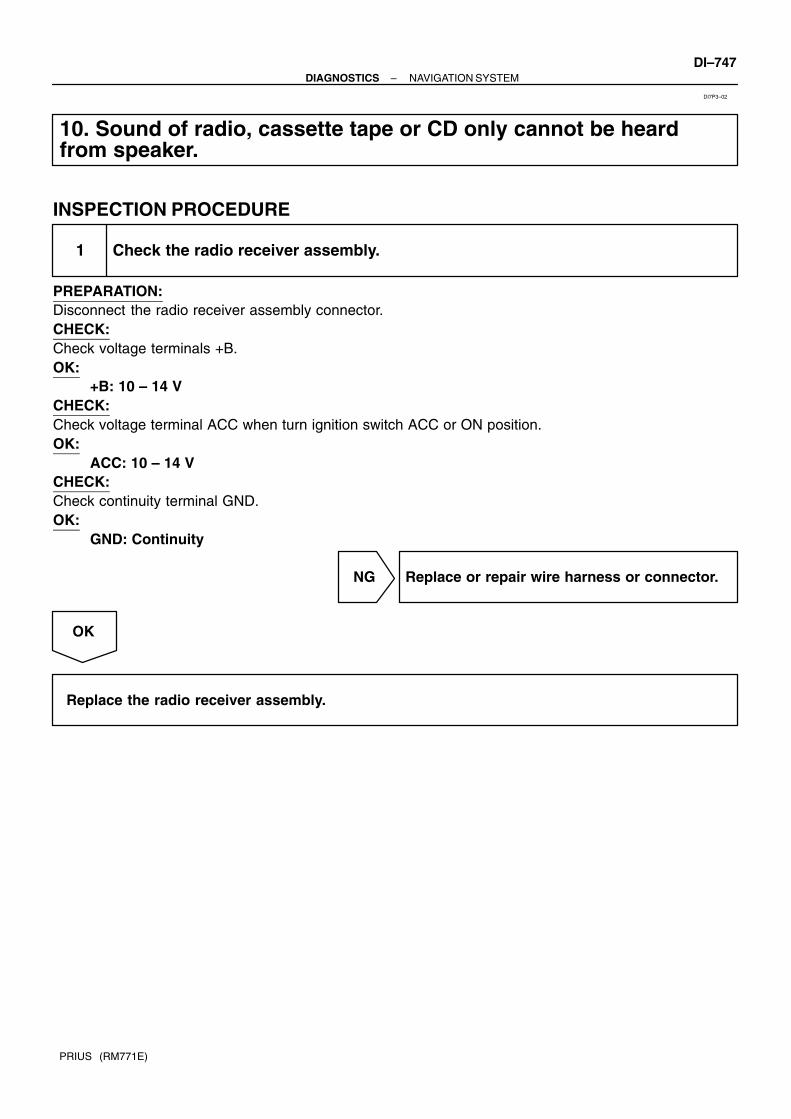
–DIAGNOSTICS NAVIGATION SYSTEMDI–747
PRIUS (RM771E)
10. Sound of radio, cassette tape or CD only cannot be heardfrom speaker.
INSPECTION PROCEDURE
1 Check the radio receiver assembly.
PREPARATION:Disconnect the radio receiver assembly connector.CHECK:Check voltage terminals +B.OK:
+B: 10 – 14 VCHECK:Check voltage terminal ACC when turn ignition switch ACC or ON position.OK:
ACC: 10 – 14 VCHECK:Check continuity terminal GND.OK:
GND: Continuity
NG Replace or repair wire harness or connector.
OK
Replace the radio receiver assembly.
DI7P3–02

DI–748–DIAGNOSTICS NAVIGATION SYSTEM
PRIUS (RM771E)
11. No sound (radio, cassette tape, CD) can be heard from driverside door speaker only.
INSPECTION PROCEDURE
1 Service check mode.
NG Troubleshoot for each diagnosis.
OK
2 Check wire harness (between navigation ECU and radio receiver assembly).
PREPARATION:Disconnect the navigation ECU and radio receiver assembly connector.CHECK:(a) Check continuity between terminal AUI+ of navigation ECU connector and terminal FL+ of radio receiv-
er assembly.(b) Check continuity between terminal AUI– of navigation ECU connector and terminal FL– of radio receiv-
er assembly.OK:
Continuity
NG Replace or repair wire harness.
OK
3 Check the navigation system voice.
OK Go to step 6.
NG
DI7P4–02

–DIAGNOSTICS NAVIGATION SYSTEMDI–749
PRIUS (RM771E)
4 Check wire harness (between navigation ECU and driver side door speaker).
PREPARATION:Disconnect the navigation ECU and driver side door speaker connector.CHECK:(a) Check continuity between terminal AUO+ of navigation ECU connector and terminal 1 of driver side
door speaker.(b) Check continuity between terminal AUO– of navigation ECU connector and terminal 2 of driver side
door speaker.OK:
Continuity
NG Replace or repair wire harness.
OK
5 Check the driver side door speaker.
NG Replace the speaker.
OK
Replace the navigation ECU.
6 Check the navigation ECU.
CHECK:Check terminal AUO+, AUO–, AUI+ and AUI–.OK:
AUO+, AUO–, AUI+ and AUI–: See ”Navigation ECU” of ”TERMINAL OF ECU”.
NG Replace the navigation ECU.
OK
Replace the radio receiver assembly.

DI–750–DIAGNOSTICS NAVIGATION SYSTEM
PRIUS (RM771E)
12. Map DISC cannot be inserted.
INSPECTION PROCEDURE
1 Check the MAP DISC.
NG Replace the MAP DISC.
OK
2 Insert a MAP DISC without tilt.
OK Normal.
NG
3 Check the navigation ECU.
PREPARATION:Disconnect the navigation ECU connector.CHECK:Check voltage terminals +B.OK:
+B: 10 – 14 VCHECK:Check voltage terminal ACC when turn ignition switch ACC or ON position.OK:
ACC: 10 – 14 VCHECK:Check continuity terminal GND.OK:
GND: Continuity
NG Replace or repair wire harness.
OK
DI7P5–02

–DIAGNOSTICS NAVIGATION SYSTEMDI–751
PRIUS (RM771E)
Replace the navigation ECU.

DI–752–DIAGNOSTICS NAVIGATION SYSTEM
PRIUS (RM771E)
13. MAP screen display does not appear. (Disc Caution screendoes not change)
INSPECTION PROCEDURE
1 Take appropriate measures according to the caution screen.
OK Normal.
NG
2 Check map DISC.
NG Replace the disc.
OK
Replace the navigation ECU.
CAUTION SCREENCAUTION MESSAGE CAUSE CORRECTIVE ACTION
Cover is open.
Close it.The cover of the map disk slot is open. Close the cover,
No disc is set.
Set a map disc.No map disk is inserted. Insert a proper map disc.
Data cannot be read properly.
Check it for scratches or dirt.
Data cannot be read because the map disc is
dirty or scratched.
Wipe off dirt on the both disc surface with soft
cloth.
Data cannot be read.
Check the correct map disc is set.Something other than map disc is inserted. Insert a correct map disc.
Due to high temperature of the player,
data cannot be read.
Pick–up part of the player is heated to a high
temperature.
Stop the vehicle at a shaded cool place and turn
the ignition switch OFF.
When confirming that the temperature of the navi-
gation ECU has been lowered, turn the ignition
switch ON.
Data cannot be read.
Contact your sales dealer.
The player cannot read data from the map disc
temporarily.Turn the ignition switch OFF and ON.*1
*1: If the same caution screen appears again after turning the ignition switch ON, replace the navigationECU.
DI7P6–02

–DIAGNOSTICS NAVIGATION SYSTEMDI–753
PRIUS (RM771E)
14. Map is displayed in white or blue screen. (Switches and ve-hicle position mark is displayed)
INSPECTION PROCEDURE
1 Set the map scale to the max.
OK Normal.
HINT:Correct the current position and check it again.
NG
2 Wipe the disc with a soft cloth, insert it again, and turn the ignition switch ONfrom OFF.
NG Replace the disc.
OK
Normal.
HINT:If the trouble still occurs, replace the navigation ECU.
DI7P7–02

DI–754–DIAGNOSTICS NAVIGATION SYSTEM
PRIUS (RM771E)
15. Navigation screen cannot change to the night mode color.
INSPECTION PROCEDURE
1 Check the setting. (Is it set to Day Mode in screen adjustment?)
Yes Normal.
No
2 Check if the screen is dimmed at night. (With the light control switch ON, do allscreens except the navigation screen appear in Night Mode?)
NG Go to step 5.
OK
3 Does the beep sound by operating switches on the navigation screen?
OK Replace the navigation ECU.
NG
4 Check ”AVC–LAN communication circuit” (See page DI–773).
NG Replace or repair AVC–LAN circuit.
OK
Replace the navigation ECU.
DI7P8–02

–DIAGNOSTICS NAVIGATION SYSTEMDI–755
PRIUS (RM771E)
5 Check the multi display.
CHECK:Check terminal TAIL.OK:
TAIL: See ”Multi Display” of ”TERMINAL OF ECU”.
OK Replace the multi display.
NG
Replace or repair wire harness.

DI–756–DIAGNOSTICS NAVIGATION SYSTEM
PRIUS (RM771E)
16. Touch switch does not function. (Navigation screen only)
INSPECTION PROCEDURE
1 Display check mode (Touch switch, Touch point screen).
NG Replace the multi display.
OK
2 Check ”AVC–LAN communication circuit” (See page DI–773).
NG Replace or repair AVC–LAN circuit.
OK
Replace the navigation ECU.
DI7P9–02

–DIAGNOSTICS NAVIGATION SYSTEMDI–757
PRIUS (RM771E)
17. Vehicle position is deviated from correct point badly.
INSPECTION PROCEDURE
1 Check the mark display. (At a place with a fine view, is GPS mark displayed ornot?)
No Go to step 7.
Yes
2 Does the trouble occur in the specific area or not?
Yes Normal. (If the vehicle is positioned in the placewhere it is difficult to be identified, the currentvehicle position may be incorrectly displayed.)
No
3 Check the setting (Color of the automatic calibration button on the calibrationscreen).
Green Normal. (Drive the vehicle (10 km or more) untilcalibration is completed.
Blue
4 Service check mode. (Is ”58–43” displayed in the unit check mode of the navigationECU?)
Yes Troubleshoot for each diagnosis.
No
DI7PA–02

DI–758–DIAGNOSTICS NAVIGATION SYSTEM
PRIUS (RM771E)
5 Navigation check mode (vehicle signal check mode: SPD).
NG Replace or repair speed sensor wire harness.
OK
6 Recurrence Test (Confirm the phenomenon) (Correct the current position anddrive the vehicle for a while with the GPS mark displayed).
OK Normal.
NG
Replace the navigation ECU.
7 Check if the harness is caught or sharply bent or not.
NG Navigation antenna is surely connected.
OK
8 Check optional components. (Does it become if the optionals such as the theftdeterrent system is removed?)
Yes Remove or change the position of the compo-nents.
HINT:Some optionals receive radio signals, and if this happens, GPSreception may be affected.
No

–DIAGNOSTICS NAVIGATION SYSTEMDI–759
PRIUS (RM771E)
9 Is there anything such as a film stuck to the window?
Yes Reception may be affected by a screen such asa film.
No
10 Service check mode. (Is ”80–40, 41” is displayed in the unit check mode of thenavigation ECU?)
Yes Troubleshoot for each diagnosis.
No
Replace the navigation antenna.
HINT:If the trouble still occurs, replace the navigation ECU.

DI–760–DIAGNOSTICS NAVIGATION SYSTEM
PRIUS (RM771E)
18. GPS mark does not appear.
INSPECTION PROCEDURE
1 Check the mark display. (At a place with a fine view, is GPS mark displayed ornot?)
Yes Normal.
No
2 Check if the harness is caught or sharply bent or not.
NG Navigation antenna is surely connected.
OK
3 Check optional components. (Does it become normal if the optionals such as thetheft deterrent system is removed?)
Yes Remove or change the position of the compo-nents.
HINT:Some optionals receive radio signals, and if this happens, GPSreception may be affected.
No
DI7PB–02

–DIAGNOSTICS NAVIGATION SYSTEMDI–761
PRIUS (RM771E)
4 Is there anything such as a film stuck to the window?
Yes Reception may be affected by a screen such asa film.
No
5 Service check mode. (Is ”80–40, 41” is displayed in the unit check mode of thenavigation ECU?)
Yes Troubleshoot for each diagnosis.
No
Replace the navigation antenna.
HINT:If the trouble still occurs, replace the navigation ECU.

DI–762–DIAGNOSTICS NAVIGATION SYSTEM
PRIUS (RM771E)
19. No voice navigation.
INSPECTION PROCEDURE
1 Set the volume to the max in the menu screen.
OK Normal. (Voice navigation is not available. Nodestination is set, or the vehicle is running offthe route.)
NG
2 Check wire harness (navigation ECU and driver side door speaker).
PREPARATION:Disconnect the navigation ECU connector and driver side door speaker connector.CHECK:(a) Check continuity between terminal AUO+ of navigation ECU connector and terminal 1 of driver side
door speaker.(b) Check continuity between terminal AUO– of navigation ECU connector and terminal 2 of driver side
door speaker.OK:Continuity
NG Replace or repair wire harness.
OK
3 Check the sound. (Check if the radio sound can be heard from the driver sidedoor speaker.)
OK Replace the navigation ECU.
NG
Replace the speaker.
DI7PC–02

–DIAGNOSTICS NAVIGATION SYSTEMDI–763
PRIUS (RM771E)
20. Vehicle position rotates without control. (Map rotates withoutcontrol)
INSPECTION PROCEDURE
1 Recheck. (While not rotating the vehicle, turn the ignition switch ON from OFFagain.)
OK Normal. (While the vehicle was turning, the igni-tion switch was turned ON.)
NG
2 System check mode. (Is ”58–10” is displayed in the unit check mode of the navi-gation ECU?)
Yes Replace the navigation ECU.
No
3 System check mode. (Is ”58–43” is displayed in the unit check mode of the navi-gation ECU?)
Yes Replace and repair SPD terminal wire harness.
No
4 Navigation check mode (vehicle signal check mode: SPD and gyro).
OK Replace the navigation ECU.
NG
DI7PD–02

DI–764–DIAGNOSTICS NAVIGATION SYSTEM
PRIUS (RM771E)
Replace or repair wire harness.

–DIAGNOSTICS NAVIGATION SYSTEMDI–765
PRIUS (RM771E)
21. Driving direction is opposite to moving direction of vehicleposition mark.
INSPECTION PROCEDURE
1 Navigation check mode (vehicle signal check mode REV).
OK Replace the navigation ECU.
NG
2 Check the navigation ECU.
CHECK:Check terminal REV.OK:
REV: See ”Navigation ECU” of ”TERMINAL OF ECU”.
OK Replace the navigation ECU.
NG
Replace or repair wire harness.
DI7PE–02

DI–766–DIAGNOSTICS NAVIGATION SYSTEM
PRIUS (RM771E)
22. Radio reception poor.
INSPECTION PROCEDURE
1 Check the reception. (Select an AM or FM station band which signals are strong)
Yes An electric wave environment is bad.
No
2 Are there any additional installation parts? (Telephone antenna, etc.)
Yes Does the condition get better if removing them?Influence of additional installation parts.
No
3 Is the contact of the plug jack of the radio OK?
NG Take a measure for contact.
OK
Is the antenna cord caught or broken?
DI7PF–02

–DIAGNOSTICS NAVIGATION SYSTEMDI–767
PRIUS (RM771E)
23. Cassette tape cannot be inserted.
INSPECTION PROCEDURE
1 Is there a foreign object inside tape player?
Yes Remove foreign object.
No
2 Is auto search button radio operating normally?
NG Radio assembly faulty.
OK
3 Check the cassette tape for deformation or peeling–off of the label.
NG Replace cassette.
OK
4 Is the tape slack?
NG Remove slack before using.
OK
Replace the radio receiver assembly.
DI7PG–02

DI–768–DIAGNOSTICS NAVIGATION SYSTEM
PRIUS (RM771E)
24. Cassette tape cannot be eject.
INSPECTION PROCEDURE
1 Check if ACC or DOME fuse is OK?
NG Replace fuse.
OK
2 Check the radio receiver assembly.
PREPARATION:Disconnect the radio receiver assembly connector.CHECK:Check voltage terminals +B.OK:
+B: 10 – 14 VCHECK:Check voltage terminal ACC when turn ignition switch ACC or ON position.OK:
ACC: 10 – 14 VCHECK:Check continuity terminal GND.OK:
GND: Continuity
NG Replace or repair wire harness.
HINT:When sending it for repair, leave as it is without attempting totake it out by force.
OK
Replace the radio receiver assembly.
DI7PH–02

–DIAGNOSTICS NAVIGATION SYSTEMDI–769
PRIUS (RM771E)
25. CD cannot be inserted.
INSPECTION PROCEDURE
1 Check that a proper CD is inserted. (Is it a music CD and free from scratches ordirt?)
NG Replace the CD.
OK
2 Check that the CD is not set upside down.
NG Use a proper CD.
OK
Replace the radio receiver assembly.
HINT:When sending it for repair, leave as it is without attempting to take it out by force.
DI7PI–02

DI–770–DIAGNOSTICS NAVIGATION SYSTEM
PRIUS (RM771E)
26. CD cannot be eject.
INSPECTION PROCEDURE
1 Check if ACC or DOME fuse is OK?
NG Replace fuse.
OK
2 Check the radio receiver assembly.
PREPARATION:Disconnect the radio receiver assembly connector.CHECK:Check voltage terminals +B.OK:
+B: 10 – 14 VCHECK:Check voltage terminal ACC when turn ignition switch ACC or ON position.OK:
ACC: 10 – 14 VCHECK:Check continuity terminal GND.OK:
GND: Continuity
NG Replace or repair wire harness.
OK
Replace the radio receiver assembly.
HINT:When sending it for repair, leave as it is without attempting to take it out by force.
DI7PJ–02

–DIAGNOSTICS NAVIGATION SYSTEMDI–771
PRIUS (RM771E)
27. No AM, FM or CD screen is displayed.
INSPECTION PROCEDURE
1 Check the sound. (Check if the sound of the radio, cassette or CD can be heard.)
OK System check mode. (Check radio receiver as-sembly)
NG
2 Check the radio receiver assembly.
PREPARATION:Disconnect the radio receiver assembly connector.CHECK:Check voltage terminals +B.OK:
+B: 10 – 14 VCHECK:Check voltage terminal ACC when turn ignition switch ACC or ON position.OK:
ACC: 10 – 14 VCHECK:Check continuity terminal GND.OK:
GND: Continuity
NG Replace or repair wire harness.
OK
DI7PK–02

DI–772–DIAGNOSTICS NAVIGATION SYSTEM
PRIUS (RM771E)
3 Check ”AVC–LAN communication circuit” (See page DI–773).
NG Replace or repair AVC–LAN circuit.
OK
Replace the radio receiver assembly.

I11572
Radio Receiver Assembly Multi Display Navigation ECU
Terminator
–DIAGNOSTICS NAVIGATION SYSTEMDI–773
PRIUS (RM771E)
AVC–LAN (Communication bus) Circuit
CIRCUIT DESCRIPTIONEach unit of navigation system connected with AVC–LAN (communication bus) transfers the signal of eachswitch by communication.When +B short and GND short occur in this AVC–LAN, navigation system will not function normally as thecommunication is discontinued.In this AVC–LAN, multi display becomes the master of the communication, and the radio receiver assemblyhas a terminator necessary for transmitting the communication.multi display is connected between navigation ECU and radio receiver assembly, navigation system has thestructure that makes communication impossible without navigation ECU, multi display or radio receiver as-sembly.
AVC–LAN
DI7PL–02

I17111
Navigation ECUMulti Display
Radio Receiver Assembly
R
GN4
10TX–
TX+
AUO+
AUO–
AUI–
G
7M5
N45
IJ16
R
G5
M5
TX1–
TX+
TX–
TX1+
10M4
3M4
R
G N32
GPIJ26
IN13
V
4
R
7
RN311
N3
1AUI+N3
109
IJ2
8
V (LHD)5
R32
F14 (LHD)F15 (RHD)Front Door SpeakerLH (LHD)RH (RHD)
2
FR–TX+R4
9
FL+TX–
10
10
R4
R
G
C
F
C
F
J24J/C
C7Center Cluster SW
7
8
C F
R
G
TX+
TX–
AVC–LAN circuit
P (LHD)
R3 IJ2
IJ2IN1
1
IJ1
IG13
4IG1
6FL– R3
R31
FR+
L (RHD)
LG (RHD)
V (LHD)L (RHD)
P (LHD)LG (RHD)
(RHD)(LHD)
(RHD)(LHD)
DI–774–DIAGNOSTICS NAVIGATION SYSTEM
PRIUS (RM771E)
WIRING DIAGRAM

–DIAGNOSTICS NAVIGATION SYSTEMDI–775
PRIUS (RM771E)
INSPECTION PROCEDURE
1 Check wire harness and connector between radio receiver assembly and naviga-tion ECU (See page IN–40).
NG Repair or replace wire harness or connector be-tween radio receiver assembly and navigationECU.
OK
2 Check wire harness and connector between multi display and navigation ECU(See page IN–40).
NG Repair or replace wire harness or connector be-tween multi display and navigation ECU.
OK

I12172
Navigation ECUMulti Display Radio Receiver
Assembly
SST
TX–TX+
TX–
TX+
Radio receiver assembly connector ”R4”
DI–776–DIAGNOSTICS NAVIGATION SYSTEM
PRIUS (RM771E)
3 Skip radio receiver assembly and check AVC–LAN.
PREPARATION:(a) Connect Multi Display connector.(b) Disconnect radio receiver assembly ”R” connector.(c) Using SST (Navigation Check Wire P/N 09843–18050),
connect the terminal TX+ to terminal TX– of ”R4” connec-tor of radio receiver assembly.
CHECK:Operate the panel switch and the touch switch of the displayand check that the navigation functions.(Check that AVC–LAN is recovered.)
OK Replace the radio receiver assembly.
NG
Replace the Navigation ECU.

DI1BX–06
Customer Problem Analysis
Check and Clear DTC (Pre–check)
Vehicle Brought to Workshop
Problem Symptom Confirmation Symptom Simulation
Symptom does notoccur
DTC Check Normal code
DTC Chart Problem Symptoms Table
Circuit Inspection Actuator CheckParts Inspection
Identification of Problem
Repair
Confirmation Test End
Items inside are titles of pages in thismanual with the page number indicated in thebottom portion. See the indicated pagesfor detailed explanations.
1
2
3 4
5
6 7
89
12
P. DI–779
P. IN–29
P. DI–782 P. DI–787
P. DI–789 – DI–863
P. DI–779
Malfunction code
P. DI–778
10
11
–DIAGNOSTICS AIR CONDITIONING SYSTEMDI–777
PRIUS (RM771E)
AIR CONDITIONING SYSTEMHOW TO PROCEED WITH TROUBLESHOOTINGPerform troubleshooting in accordance with the procedure on the fowling page.

DI1BY–01
Inspector’s name:
Customer’s Name
Registration No.
Registration Year
Frame No.
Odometer ReadingkmMiles
Date vehicleBrought In / /
Date of Problem Occurrence
How Often does Problem Occur?
Weather
Outdoor Temperature
/ /
Continuous Intermittent ( times a day)
Fine Cloudy Snowy Various / Other
Hot Warm Cool Cold (Approx. FC )
Symptoms
Blower motor does not operation Blower motor speed does not change (Always Hi, Always Med, Always Lo)
Air Flow Control isFaulty
Cabin temperature does not go down
Response is slow
Cannot change between FRS and REC(Always Fresh or always Recirculating)
Will not enter the desired mode
TemperatureControl is Faulty
Air Inlet Control isFaulty
Vent Control isFaulty
DTC Check1st Time
2nd Time
Normal Code Malfunction Code (Code )
Normal Code Malfunction Code (Code )
AIR CONDITIONING SYSTEM Check Sheet
Cabin temperature does not rise
Mode will not change
DI–778–DIAGNOSTICS AIR CONDITIONING SYSTEM
PRIUS (RM771E)
CUSTOMER PROBLEM ANALYSIS CHECK

DI7MA–01
AT0716
0.5 Seconds
0.5 Seconds
ON
OFF
With in 5 sec. after turning the ignition on,press the A/C switch 3 times and turn theblower switch from OFF to AUTO.
Indicator check (See step 3) Actuator check (See step 5)
Cancel check mode and can startA/C control.
If both A/C switch and blower switch are not operated.
: Indicates a blower switch operation
DTC check (See step 4) Actuator check (See step 5)
After indicators blink 4 times
Auto
Except Auto
Except AutoAuto
–DIAGNOSTICS AIR CONDITIONING SYSTEMDI–779
PRIUS (RM771E)
PRE–CHECK1. WARNING FOR A/C COMPRESSOR LOCKIf compressor lock occurs during A/C operation, the A/C switchindicator on the A/C control assembly starts blinking.When this occurs, check for compressor lock (DTC 22) usingdiagnosis trouble code check then proceed to inspect the circuitor the component.Compressor lock sensor circuit. → (See page DI–804)
2. LIST OF OPERATION METHODSBy operating each of the A/C control switches as shown in the diagram below, it is possible to enter the diag-nosis check mode.

I18151
Blower SwitchA/C Switch
I00339
Blinking Pattern
4 times
1 sec.1 sec.
ON
OFF
ON
OFF
ON
OFF
1 sec.
0.5 sec.
0.5 sec.
1.5 sec 2.5 sec. 1.5 sec.
No Malfunction
Malfunction Detected
← →4.5 sec.Repeat
DI–780–DIAGNOSTICS AIR CONDITIONING SYSTEM
PRIUS (RM771E)
3. INDICATOR CHECK(a) Within 5 sec. after turning the ignition switch on, press the
A/C switch 3 times and turn the blower switch from OFFto AUTO.
(b) Check that all the indicators light up and go off at 1 secondintervals 4 times in succession.
HINT: After the indicator check is ended, the system enters the
DTC begins automatically. Operate the blower switch from AUTO to except AUTO
position when desiring to cancel the check mode.
4. DTC CHECK (SENSOR CHECK)(a) Perform an indicator check. After the indicator check is
completed, the system enters the DTC check mode auto-matically.
(b) Read the DTC as indicated by the number of blinks of theA/C indicator.
HINT:The illustration shows the blinking pattern associated with theDTC 12 and 23. If 2 or more DTCs (abnormalities) are indicated,the lowest number (code) is output first.(c) Identify the problem using the chart of the DTC.

I18151
Blower Switch
Max. Cool ↔17.5
Step No.
Temp. setting C Blower Level
Air Mix Damper
*1 *2
50 % (Cool/Warm)
R/F (102.0 %)
ON
Air Inlet Damper
Air Outlet Damper Compressor
1
2
3
4
5
18.0 ↔ 20.5
21.0 ↔ 23.0
23.5 ↔ 26.0
26.5↔ Max. Warm
4
→→
17
31
→ →→→
50 % (Cool/Warm)
–10 % (Cool)
–10 % (Cool)
110 % (Warm)
100 % (Warm)
REC (–1 %)
R/F (82.0 %)
FRS (110.0 %)
FRS (110.0 %)
DEF (110 %)
FOOT (50 %)
F/D (90 %)
B/L (15 %)
FACE (–10 %)
OFF
→→
→
*2: LHD Standard heater*1: Except LHD Standard heater
–DIAGNOSTICS AIR CONDITIONING SYSTEMDI–781
PRIUS (RM771E)
5. ACTUATOR CHECK(a) Actuator check mode is started at the same time with DTC
check mode.(b) Check visually on by hand that the air flow, amount of
damper operating and operation of the compressorchanges according to the set temperature of the A/C con-trol panel, as shown in the chart.
HINT:To cancel the check mode, turn blower switch from AUTO to ex-cept AUTO.

DI7MB–01
DI–782–DIAGNOSTICS AIR CONDITIONING SYSTEM
PRIUS (RM771E)
DIAGNOSTIC TROUBLE CODE CHARTDTC No.
(See Page)Detection Item Trouble Area
11*1
(DI–789)Room temp. sensor circuit
Room temp. sensor
Harness or connector between room temp. sensor and A/C
amplifier
A/C amplifier
12*2
(DI–792)Ambient temp. sensor circuit
Ambient temp. sensor
Harness and connector between ambient temp. sensor and
engine ECU
Engine and ECT ECU
Harness and connector between engine ECU and A/C ampli-
fier
A/C amplifier
13
(DI–795)Evaporator temp. sensor circuit
Evaporator temp. sensor
Harness and connector between evaporator temp. sensor
and A/C amplifier
A/C amplifier
14
(DI–798)Water temp. sensor circuit
Water temp. sensor
Harness and connector between water temp. sensor and
engine ECU
Engine ECU
Harness and connector between engine ECU and A/C ampli-
fier
A/C amplifier
21*3
(DI–801)Solar sensor circuit
Solar sensor
Harness or connector between room temp. sensor and A/C
amplifier
A/C amplifier
22*4
(DI–804)
All conditions below are detected for 3 sec. or more
(g) Engine speed: 500 rpm or more
(h) Ratio between engine and compressor rpm deviates 20 %
or more in comparison to normal operation
Engine ECU
Harness and connector between engine ECU and A/C ampli-
fier
Compressor drive belt
Compressor lock sensor
Compressor
Harness and connector between compressor lock sensor and
A/C amplifier
23
(DI–807)
Open in pressure switch circuit
Abnormal refrigerant pressure
[below 196 kPa (2.0 kgf/cm2, 28 psi) over
3,140 kPa (32.0 kgf/cm2, 455 psi)]
Pressure switch
Harness or connector between pressure switch and A/C am-
plifier
A/C amplifier
31
(DI–810)Air mix damper position sensor circuit
Air mix control servomotor
Harness or connector between air mix control servomotor
and A/C amplifier
A/C amplifier
32
(DI–813)Air inlet damper position sensor circuit
Air inlet control servomotor
Harness or connector between air inlet control servomotor
and A/C amplifier
A/C amplifier
33
(DI–816)Air outlet damper position sensor circuit
Air outlet control servomotor
Harness or connector between air outlet control servomotor
and A/C amplifier
A/C amplifier

–DIAGNOSTICS AIR CONDITIONING SYSTEMDI–783
PRIUS (RM771E)
41
(DI–819)Air mix control servomotor circuit
Air mix control servomotor
Air mix damper position sensor
Harness or connector between air mix control servomotor
and A/C amplifier
A/C amplifier
42
(DI–823)Air inlet control servomotor circuit
Air inlet control servomotor
Air inlet damper position sensor
Harness or connector between air inlet control servomotor
and A/C amplifier
A/C amplifier
43
(DI–827)Air outlet control servomotor circuit
Air outlet control servomotor
Air outlet damper position sensor
Harness or connector between air outlet control servomotor
and A/C amplifier
A/C amplifier
HINT:
*1: If the room temp. is approx. –18.6C (–3.7F) or lower, trouble code 11 may be output even thoughthe system is normal.
*2: If the ambient temp. is approx. –52.9C (–61.4F) or lower, a malfunction code may be output eventhough the system is normal.
*3: If the check is being performed in a dark place, DTC 21 (solar sensor circuit abnormal) could bedisplayed.
*4: To confirm DTC 22, perform the following steps.(1) With the engine is running, enter the DTC check mode.(2) Enter actuator check mode and set the operation to step NO. 1.(3) Check that the DTC 22 is output.

DI7MD–01
I18176
A10 A9 A8
DI–784–DIAGNOSTICS AIR CONDITIONING SYSTEM
PRIUS (RM771E)
TERMINALS OF ECU
Symbols (Terminals No.) Wiring Color Condition STD Voltage (V)
IG ↔GND
(A8–1 ↔ A8–7)R ↔ W–B IG ON. 10 – 14
BLW ↔ GND
(A8–3 ↔ A8–7)V ↔ W–B IG ON. Blower motor: Operate Pulse generation
MP2+ ↔ GND
(A8–4 ↔ A8–7)GR–B ↔ W–B IG ON. Pulse generation
GND ↔ Body ground
(A8–7 ↔ Body ground)
W–B ↔
Body groundAlways Continuity
+B ↔ GND
(A8–8 ↔ A8–7)R–G ↔ W–B Always 10 – 14
IDH ↔ GND
(A8–10 ↔ A8–7)
Y ↔ W–B
IG ON. Head lamp: ON
Rear defogger: ON
Set temp.: MAX. WARM
10 – 14
Y ↔ W B
IG ON. Head lamp: OFF
Rear defogger: OFFBelow 1.0
MPX+ ↔ GND
(A8–11 ↔ A8–7)GR ↔ W–B IG ON. Pulse generation
RF ↔ GND
(A9–1 ↔ A8–7)R W ↔ W B
Start engine. Water temp.: Below 90C
Refrigerant pressure: Below 1,230 kPa10 – 14
(A9 1 ↔ A8 7)R–W ↔ W–B
Start engine. Water temp.: Approx. 90C
Refrigerant pressure: Above 1,520 kPaBelow 1.0
CF ↔ GNDV Y ↔ W B
Start engine. A/C compressor: ON Below 1.0CF ↔ GND
(A9–2 ↔ A8–7)V–Y ↔ W–B
Start engine. A/C compressor: OFF 10 – 14
WP ↔ GND
(A9–3 ↔ A8–7)
L–R ↔ W–B
Engine speed: Below 500 rpm
Set temp.: Max. WARM
Blower motor: Operate
Below 1.0
L R ↔ W B
Engine speed: Above 500 rpm
Blower motor: Not operate10 – 14
NE ↔ GND
(A9–4 ↔ A8–7)LG ↔ W–B Start engine A/C compressor: ON Pulse generation
ACT ↔ GND
(A9–5 ↔ A8–7)P–G ↔ W–B Engine speed: Idle speed 10 – 14
HTR0 ↔ GND(*)
(A9–6 ↔ A8–7)
P–B ↔ W–B
Start engine
Head lamp: OFF
Rear defogger: OFF
Set temp.: MAX. WARM
Blower switch: HI
Air flow selector: F/D
Water temp.: Below 50 C
Below 0.7

–DIAGNOSTICS AIR CONDITIONING SYSTEMDI–785
PRIUS (RM771E)
LOCk ↔ SGLOCK
(A9–9 ↔ A9–18)W–L ↔ BR–W Start engine. A/C compressor ON. Pulse generation
MGC ↔ GNDLG R ↔ W B
Start engine. A/C compressor: ON Below 1.0MGC ↔ GND
(A9–11 ↔ A8–7)LG–R ↔ W–B
Start engine. A/C compressor: OFF 10 – 14
PSW ↔ GND
(A9–11 ↔ A8–7)L Y ↔ W B
A/C refrigerant pressure: less than 0.19 Mpa (2.0 kgf/cm2) or
more than 3.14 Mpa (3,140 kgf/cm2)
From 10 – 14 to
Below 1.0(A9 11 ↔ A8 7)L–Y ↔ W–B
A/C refrigerant pressure: Except less than 0.19 Mpa (2.0 kgf/
cm2) or more than 3.14 Mpa (3,140 kgf/cm2)Below 1.0
HTR2 ↔ GND(*)
(A9–13 ↔ A8–7)
P ↔ W–B
Start engine
Head lamp: OFF
Rear defogger: OFF
Set temp.: MAX. WARM
Blower switch: HI
Air flow selector: F/D
Water temp.: C
Below 1.0
SGLOCK ↔ GND
(A9–18 ↔ A8–7)BR–W ↔ W–B Always Continuity
TE ↔ SGTEW ↔ W
IG ON. Ambient temp. 25C (77F) 1.35 – 1.75TE ↔ SGTE
(A10–1 ↔ A10–2)W ↔ W
IG ON. Ambient temp. 40C (104F) 0.85 – 1.25
SGTE ↔ GND
(A10–2 ↔ A8–7)W ↔ W–B Always Continuity
SGTR ↔ GND
(A10–3 ↔ A8–7)W ↔ W–B Always Continuity
TR ↔ SGTRW ↔ W
IG ON. Room temp. 25C (77F) 1.8 – 2.2TR ↔ SGTR
(A10–4 ↔ A10–3)W ↔ W
IG ON. Room temp. 40C (104F) 1.2 – 1.6
TS ↔ S5TSW ↔ W
IG ON. Solar sensor subject to electric light 1.0 or moreTS ↔ S5TS
(A10–5 ↔ A10–6)W ↔ W
IG ON. Solar sensor cover by a cloth Below 1.0
S5TS ↔ GND
(A10–6 ↔ A8–7)W ↔ W–B IG ON. 4.5 – 5.5
S5TPM ↔ SGTPM
(A10–7 ↔ A10–9)W ↔ W IG ON. 4.5 – 5.5
TPM ↔ SGTPMW ↔ W
IG ON. Air flow selector: FACE Above 4.0TPM ↔ SGTPM
(A10–8 ↔ A10–9)W ↔ W
IG ON. Air flow selector: DEF Below 1.0
SGTPM ↔ GND
(A10–9 ↔ A8–7)W ↔ W–B Always Continuity
AOF ↔ GNDW ↔ W B
IG ON. Air flow selector: FACE 10 – 14AOF ↔ GND
(A10–10 ↔ A8–7)W ↔ W–B
IG ON. Air flow selector: DEF Below 1.0
AOD ↔ GNDW ↔ W B
IG ON. Air flow selector: FACE Below 1.0AOD ↔ GND
(A10–11 ↔ A8–7)W ↔ W–B
IG ON. Air flow selector: DEF 10 – 14
AMH ↔ GNDW ↔ W B
IG ON. Set temp.: Max. COOL Below 1.0AMH ↔ GND
(A10–13 ↔ A8–7)W ↔ W–B
IG ON. Set temp.: Max. WARM 10 – 14
AMC ↔ GNDW ↔ W B
IG ON. Set temp.: Max. COOL 10 – 14AMC ↔ GND
(A10–14 ↔ A8–7)W ↔ W–B
IG ON. Set temp.: Max. WARM Below 1.0
SGTP ↔ GND
(A10–15 ↔ A8–7)W ↔ W–B Always Continuity
TP ↔ SGTPW ↔ W
IG ON. Set temp.: Max. COOL Above 4.0TP ↔ SGTP
(A10–16 ↔ A10–15)W ↔ W
IG ON. Set temp.: Max. WARM Below 1.0
S5TP ↔ SGTP
(A10–17 ↔ A10–15)W ↔ W IG ON. 4.5 – 5.5

DI–786–DIAGNOSTICS AIR CONDITIONING SYSTEM
PRIUS (RM771E)
S5TPI ↔ SGTPI
(A10–18 ↔ A10–20)W ↔ W IG ON. 4.5 – 5.5
TPI ↔ SGTPIW ↔ W
IG ON. Air intake selector: FRESH Below 1.0TPI ↔ SGTPI
(A10–19 ↔ A10–20)W ↔ W
IG ON. Air intake selector: RECIRCULATE 4.5 – 5.5
SGTPI ↔ GND
(A10–20 ↔ A8–7)W ↔ W–B Always Continuity
AIR ↔ GNDW W B
IG ON. Air intake selector: FRESH Below 1.0AIR ↔ GND
(A10–21 ↔ A8–7)W ↔ W–B
IG ON. Air intake selector: RECIRCULATE 10 – 14
AIF ↔ GNDW W B
IG ON. Air intake selector: FRESH 10 – 14AIF ↔ GND
(A10–22 ↔ A8–7)W ↔ W–B
IG ON. Air intake selector: RECIRCULATE Below 1.0
(*): Europe LHD cold area

DI7MC–01
–DIAGNOSTICS AIR CONDITIONING SYSTEMDI–787
PRIUS (RM771E)
PROBLEM SYMPTOMS TABLESymptom Suspect Area See page
Whole function of the does not operate 4. A/C amplifier
5. IG power source circuit
IN–40
DI–832
Air Flow Control: No blower operation 1. IG power source circuit
2. Heater main relay circuit
3. Blower motor circuit
4. A/C amplifier
DI–832
DI–837
DI–840
IN–40
Air Flow Control: No blower control 1. Heater main relay circuit
2. Blower motor circuit
3. A/C amplifier
DI–837
DI–840
IN–40
Air Flow Control: Insufficient air flow 1. Blower motor circuit DI–840
Temperature Control: No cool air comes out1. Refrigerant volume
2. Drive belt tension
3. Refrigeration system inspection with manifold gauge set
4. Compressor circuit
5. Pressure switch circuit
6. Compressor lock sensor circuit
7. Air mix damper position sensor circuit
8. Air mix damper control servomotor circuit
9. Room temperature sensor circuit
10.Ambient temperature sensor circuit
11.Evaporator temperature sensor circuit
12.A/C amplifier
AC–3
AC–15
AC–3
DI–843
DI–807
DI–804
DI–810
DI–819
DI–787
DI–792
DI–795
IN–40
Temperature Control: No warm air comes out 1. Air mix damper position sensor circuit
2. Air mix damper control servomotor circuit
3. DC/DC converter circuit
4. PTC heater circuit
5. Room temperature sensor circuit
6. Ambient temperature sensor circuit
7. Evaporator temperature sensor circuit
8. Water temperature sensor circuit
9. Water pump circuit
10.Engine ECU
11.A/C amplifier
DI–810
DI–819
DI–850
DI–853,
DI–858
DI–789
DI–792
DI–795
DI–798
DI–847
IN–40
IN–40
Temperature Control: Output air is warmer or cooler that the set
temperature or response is slow
1. Refrigerant volume
2. Drive belt tension
3. Refrigeration system inspection with manifold gauge set
4. Radiator fan and condenser fan circuit
5. Solar sensor circuit
6. Room temperature sensor circuit
7. Ambient temperature sensor circuit
8. Evaporator temperature sensor circuit
9. Air mix damper position sensor circuit
10.Air mix damper control servomotor circuit
11.Evaporator
12.Heater radiator
13.Expansion valve
14.Solar sensor circuit
15.Water temperature sensor circuit
16.A/C amplifier
AC–3
AC–15
AC–3
DI–863
DI–801
DI–789
DI–792
DI–795
DI–810
DI–819
AC–29
AC–29
AC–53
DI–801
DI–798
IN–40

DI–788–DIAGNOSTICS AIR CONDITIONING SYSTEM
PRIUS (RM771E)
Temperature Control: No temperature control (only Max. cool or
Max. warm)
1. Room temperature sensor circuit
2. Ambient temperature sensor circuit
3. Air mix damper position sensor circuit
4. Air mix damper control servomotor circuit
5. A/C amplifier
DI–789
DI–792
DI–810
DI–819
IN–40
No air inlet control 1. Air inlet damper position sensor circuit
2. Air inlet damper control servomotor circuit
3. A/C amplifier
DI–813
DI–823
IN–40
Engine idle up does not occur, or is continuous 1. Compressor circuit
2. A/C amplifier
DI–827
IN–40
Blinking of A/C indicator 1. Compressor lock sensor circuit
2. A/C amplifier
DI–804
IN–40

DI6S2–03
I18376
A/C Amplifier
W SGTR3
A10
2
1
A11A/C Room Temp.Sensor
W TR4
A10
–DIAGNOSTICS AIR CONDITIONING SYSTEMDI–789
PRIUS (RM771E)
CIRCUIT INSPECTION
DTC 11 Room Temperature Sensor Circuit
CIRCUIT DESCRIPTIONThis sensor detects the temperature inside the cabin and sends the appropriate signals to the A/C amplifier.
DTC No. Detection Item Trouble Area
Room temperature sensor.
11 Open or short in room temperature sensor circuit.Harness or connector between room temp. sensor and A/C
amplifieramplifier.
A/C amplifier.
WIRING DIAGRAM

I18162
ON SGTRTR
(–)(+)
I00317
DI–790–DIAGNOSTICS AIR CONDITIONING SYSTEM
PRIUS (RM771E)
INSPECTION PROCEDURE
1 Check voltage between terminals TR and SGTR of A/C amplifier connector.
PREPARATION:(a) Remove center cluster module control with connectors
still connected.(b) Turn the ignition switch ON.CHECK:Check voltage between terminals TR and SGTR of A/C amplifi-er connector at each temperature.OK:
at 25 C (77 F) : 1.8 – 2.2 Vat 40 C (104 F) : 1.2 – 1.6 V
HINT:As the temperature increases, the voltage decreases.
NG Go to step 2.
OK
Proceed to next circuit inspection shown on problem symptoms table (See page DI–787). Howev-er, if DTC 11 is output, check and replace A/C amplifier.
2 Check room temperature sensor.
PREPARATION:Remove room temperature sensor (See page AC–61).CHECK:Check resistance between terminals 1 and 2 of room tempera-ture sensor connector at each temperature.OK:
at 25 C (77 F) : 1.6 – 1.8 kΩat 40 C (104 F) : 0.5 – 1.7 kΩ
HINT:As the temperature increases, the resistance decreases.
NG Replace room temperature sensor.
OK

–DIAGNOSTICS AIR CONDITIONING SYSTEMDI–791
PRIUS (RM771E)
3 Check harness and connector between A/C amplifier and room temperature sen-sor (See page IN–40).
NG Repair or replace harness or connector.
OK
Check and replace A/C amplifier.

I18397
A/C amplifier
A7Ambient Temp.Sensor
MPX+A8
1
1
2
10
G–R
MP2+A8
4
32
C11Combination Meter
MPX+
MPX–
IP2IP2
1112GR–R
(*1)
(*2)
GR–B
GR–RGR–RGR–R
MPX1
MPX2
T4Theft Dterrent ECU
B8MPX+
MPX–11B8
Body ECU
(*1)
(*2)
GR
GR GR
GRIP210
IP29
GR
1MPX TAM
2MPX E2
14E10
13E10
23E8
18E8
Engine ECU
W–G
IA2
5
IK1
2
W–G
W–G
W–G
GR–L
11 4
G1 Gateway ECU
GR–B2MPD1MPD
(*1): LHD models(*2): RHD models
D6 Double Lock Door Control Relay
DI–792–DIAGNOSTICS AIR CONDITIONING SYSTEM
PRIUS (RM771E)
DTC 12 Ambient Temperature Sensor Circuit
CIRCUIT DESCRIPTIONThis sensor detects the ambient temperature and sends the appropriate signals to the A/C amplifier.
DTC No. Detection Item Trouble Area
Ambient temperature sensor.
Harness or connector between ambient temperature sensor
12 Open or short in ambient temperature sensor circuit.
and engine ECU.
Engine ECU.
Harness or connector between engine ECU and A/C amplifi-Harness or connector between engine ECU and A/C amplifi-
er.
A/C amplifier.
WIRING DIAGRAM
DI6S3–03

I18175
ON E2TAM
(–)(+)
–DIAGNOSTICS AIR CONDITIONING SYSTEMDI–793
PRIUS (RM771E)
INSPECTION PROCEDURE
1 Check voltage between terminals TAM and E2 of engine ECU connector.
PREPARATION:(a) Remove engine ECU with connectors still connected.(b) Turn ignition switch ON.CHECK:Check voltage between terminals TAM and E2 of engine ECUconnector at each temperature .OK:
Voltage at 25 C (77 F) : 1.35 – 1.75 V at 40 C (104 F) : 0.85 – 1.25 V
HINT:As the temperature increases, the voltage decreases.
NG Go to step 2.
OK
Proceed to the next circuit inspection shown on problem symptoms table (See page DI–787).However, if DTC 12 is displayed, check and replace A/C amplifier.

I05262
12
DI–794–DIAGNOSTICS AIR CONDITIONING SYSTEM
PRIUS (RM771E)
2 Check ambient temperature sensor.
PREPARATION:Disconnect ambient temperature sensor connector.CHECK:Check resistance between terminals 1 and 2 of ambient tem-perature sensor connector at each temperature.OK:
Resistance at 25 C (77 F) : 1.6 – 1.8 kΩ at 40 C (104 F) : 0.5 – 0.7 kΩ
HINT:As the temperature increases, the resistance decreases.
NG Replace ambient temperature sensor.
OK
Check multiplex communication system (See page DI–656).

I18376
A/C Amplifier
WSGTE
2A10
2
1
A13A/C Thermistor
W TE1
A10
–DIAGNOSTICS AIR CONDITIONING SYSTEMDI–795
PRIUS (RM771E)
DTC 13 Evaporator Temperature Sensor Circuit
CIRCUIT DESCRIPTIONThis sensor detects the temperature inside the cooling unit and sends the appropriate signals to the A/Camplifier.
DTC No. Detection Item Trouble Area
Evaporator temperature sensor.
13 Open or short in evaporator temperature sensor circuit.Harness or connector between evaporator temperature sen-
sor and A/C amplifiersor and A/C amplifier.
A/C amplifier.
WIRING DIAGRAM
DI6S4–03

I18161
ON SGTETE
(–)(+)
AC0175
Thermometer
Ice
Thermistor Ohmmeter
Morethan10 cm(3.94 in.)
DI–796–DIAGNOSTICS AIR CONDITIONING SYSTEM
PRIUS (RM771E)
1 Check voltage between terminals TE and SGTE of A/C amplifier connector.
PREPARATION:(a) Remove center cluster module control with connectors
still connected.(b) Turn ignition switch ON.CHECK:Measure voltage between terminals TE and SGTE of A/C am-plifier connector at each temperature.OK:
Voltage at 0 C (32 F) : 2.0 – 2.4 V at 15 C (59 F) : 1.4 – 1.8 V
HINT:As the temperature increases, the voltage decreases.
NG Go to step 2.
OK
Proceed to next circuit inspection shown on problem symptoms table (See page DI–787). Howev-er, if DTC 13 is displayed, check and replace A/C amplifier.
2 Check evaporator temperature sensor.
PREPARATION:Remove evaporator temperature sensor (See page AC–28).CHECK:Check resistance between terminals 1 and 2 of evaporator tem-perature sensor connector at each temperature.OK:
Resistance at 0 C (32 F) : 4.6. – 5.1 kΩ at 15 C (59 F) : 2.1 – 2.6 kΩ
HINT:As the temperature increases, the voltage decreases.
NG Replace evaporator temperature sensor.
OK

–DIAGNOSTICS AIR CONDITIONING SYSTEMDI–797
PRIUS (RM771E)
3 Check harness and connector between A/C amplifier and evaporator tempera-ture sensor (See page IN–40).
NG Repair or replace harness or connector.
OK
Check and replace A/C amplifier.

I18376
A/C Amplifier
E9 THW
14
E2
18
E2 Water Temp. Sensor
W
B–RE9
2
1
DI–798–DIAGNOSTICS AIR CONDITIONING SYSTEM
PRIUS (RM771E)
DTC 14 Water Temperature Sensor Circuit
CIRCUIT DESCRIPTIONThis sensor detects the water temperature and sends the appropriate signals to the A/C amplifier. Thesesignals are used for warm up control when the engine is cold.
DTC No. Detection Item Trouble Area
14 Open or short in water temperature sensor circuit
Water temperature sensor
Harness or connector between water temp. sensor and en-
gine ECU14 Open or short in water temperature sensor circuit. gine ECU
Harness or connector between engine ECU and A/C amplifier
A/C amplifier
WIRING DIAGRAM
DI7ME–01

S05502
–DIAGNOSTICS AIR CONDITIONING SYSTEMDI–799
PRIUS (RM771E)
INSPECTION PROCEDURE
1 Check water temp. sensor using hand–held tester.
PREPARATION:Connect the hand–held tester to the DLC3.CHECK:Check the water temp. sensor using DATA LIST.
OK Check or replace A/C amplifier.
NG
2 Check water temp. sensor.
PREPARATION:Disconnect the water temp. sensor connector.CHECK:Measure resistance between terminals.OK:Resistance is within acceptable zone on chart.
Water temperature Resistance
20C (68F) 2 – 3 kΩ
80C (176F) 0.2 – 0.4 kΩ
NG Replace water temp. sensor.
OK

DI–800–DIAGNOSTICS AIR CONDITIONING SYSTEM
PRIUS (RM771E)
3 Check for open and short in harness and connector between engine ECU andwater temp. sensor (See page IN–40).
NG Repair or replace harness or connector.
OK
Check multiplex communication system (See page DI–656).

Resistance of photodiode
Strength of solar radiationWeak Strong
High
Low
I18378
A/C Amplifier
A12A/C Solar Sensor
A10
A10
TS
S5TS
5
6
1
2
W
W
–DIAGNOSTICS AIR CONDITIONING SYSTEMDI–801
PRIUS (RM771E)
DTC 21 Solar Sensor Circuit
CIRCUIT DESCRIPTIONA photo diode in the solar sensor detects solar radiation andsends signals to the A/C amplifier.
DTC No. Detection Item Trouble Area
Open or short in solar sensor circuitSolar sensor
21Open or short in solar sensor circuit.
(Please note that display of DTC 21 is not abnormal when theHarness or connector between solar sensor and A/C amplifi-
er( y
sensor is not receiving solar radiation.)er.
A/C amplifier.
WIRING DIAGRAM
DI6S6–03

I18163
ON
(–)
TS
S5TS(+)
DI–802–DIAGNOSTICS AIR CONDITIONING SYSTEM
PRIUS (RM771E)
INSPECTION PROCEDURE
1 Check voltage between terminals S5TS and TS of A/C amplifier connector.
PREPARATION:(a) Remove center cluster module control with connectors
still connected.(b) Turn ignition switch ON.CHECK:Measure voltage between terminals S5TS and TS of A/C ampli-fier connector when the solar sensor is subjected to an electriclight, and when the sensor is covered by a cloth.OK:
Condition Voltage
Sensor subjected to electric light Below 4.0 V
Sensor covered by a cloth 4.0 – 4.5 V
HINT:As the inspection light is gradually moved away from the sen-sor, the voltage increases.
NG Go to step 2.
NG
Proceed to next circuit inspection shown on problem symptoms table (See page DI–787). Howev-er, if DTC 21 is displayed, check and replace A/C amplifier.

I00325
–DIAGNOSTICS AIR CONDITIONING SYSTEMDI–803
PRIUS (RM771E)
2 Check solar sensor.
PREPARATION:Remove solar sensor (See page AC–60).CHECK:(a) Cover the sensor by a cloth.(b) Measure resistance between terminals 1 and 2 of solar
sensor connector.HINT:Connect positive (+) lead of ohmmeter to terminal 2 and nega-tive (–) lead to terminal 1 of the solar sensor.OK:
Resistance : ∞ Ω (No continuity)PREPARATION:Remove the cloth from the solar sensor and subject the sensorto electric light.CHECK:Measure resistance.OK:
Resistance : Below 10 kΩ (Continuity)HINT:As the electric light is moved gradually away from the sensor,the resistance increases.
NG Replace solar sensor.
OK
3 Check harness and connector between A/C amplifier and solar sensor (See page IN–40).
NG Repair or replace harness or connector.
OK
Check and replace A/C amplifier.

I18379
CompressorLock Sensor
A/C Amplifier
4
2
9A9 LOCKW–L
18A9 SG LOCK
IE14
BR–W
W–L
W–L
IK14
IK15
BR–W BR–WIE15
DI–804–DIAGNOSTICS AIR CONDITIONING SYSTEM
PRIUS (RM771E)
DTC 22 Compressor Lock Sensor Circuit
CIRCUIT DESCRIPTION
This sensor sends 1 pulse par engine revolution to the A/C amplifier. If the number ratio of the compressorspeed divided by the engine speed is smaller than a predetermined value, the A/C amplifier turns the com-pressor off. And, the indicator flashes at about 1 sec. intervals.
DTC No. Detection Item Trouble Area
All diti b l d t t d f 3Compressor
All conditions below are detected for 3 secs. or more.
( ) E i d 450
Com ressor
Compressor drive belt
22(a) Engine speed : 450 rpm or more.
(b) Ratio between engine and compressor speed deviates
Com ressor drive belt
Compressor lock sensor22(b) Ratio between engine and compressor speed deviates
20 % or more in comparison to normal operation
Com ressor lock sensor
Harness or connector between compressor and A/C amplifier 20 % or more in comparison to normal operation.
Harness or connector between com ressor and A/C am lifier
A/C amplifier
WIRING DIAGRAM
DI7IG–02

I18005
2
4
N02774
0.2 V/Din.0 V
20 msec/Division (Idling)
LCK1
LOCK signal waveform
–DIAGNOSTICS AIR CONDITIONING SYSTEMDI–805
PRIUS (RM771E)
INSPECTION PROCEDURE
1 Check compressor.
PREPARATION:(a) Check compressor drive belt tension (See page AC–15).(b) Check if the compressor does not lock during operation with engine started and blower switch and A/C
switch ON.
NG Adjust drive belt tension or repair compressor.
OK
2 Check compressor lock sensor.
PREPARATION:Disconnect compressor lock sensor connector.CHECK:Measure resistance between terminals 2 and 4 of compressorlock sensor connector.OK:
Resistance : at 20 C (68 F) : 65 – 125 Ω
Reference : Inspection using oscilloscopeDuring cranking or idling, measure voltage between terminalsLOCK and SGLOCK of A/C amplifier.HINT:The correct waveform appears as shown in the illustration onthe left.
NG Replace compressor.
OK
DI–806–DIAGNOSTICS AIR CONDITIONING SYSTEM
PRIUS (RM771E)
3 Check harness and connector between A/C amplifier and compressor lock sen-sor (See page IN–40).
NG Repair or replace harness or connector.
OK
Proceed to next circuit inspection shown on problem symptoms table (See page DI–787). Howev-er, if DTC 22 is displayed, check and replace A/C amplifier.

I18382
(*1): LHD models(*2): RHD models
W–B
IE
A3A/C Dual Pressure SW
A/C Amplifier
(*2)A911
PSW
A
4
J1J/C
L–Y
1
L–YIE115
(*1)W–B
A
J7J/C
A A(*1) W–B
–DIAGNOSTICS AIR CONDITIONING SYSTEMDI–807
PRIUS (RM771E)
DTC 23 Pressure Switch Circuit
CIRCUIT DESCRIPTION
This pressure switch sends the appropriate signals to the A/C amplifier when the A/C refrigerant pressuredrops too low or rises too high. When the A/C amplifier receives these signals, if outputs signals via the A/Camplifier to switch off the compressor relay and turns the magnetic clutch off.
DTC No. Detection Item Trouble Area
Open in pressure sensor circuitPressure switch
23
Open in pressure sensor circuit.
Abnormal refrigerant pressure.Harness or connector between pressure switch and A/C am-
plifier23Abnormal refrigerant ressure.
below 196 kPa (2.0 kgf/cm2. 28 psi)
3 140 kP (32 0 k f/ 2 4 i)
plifier
Refrigerant pipe lineover 3,140 kPa (32.0 kgf/cm2. 455 psi)
Refrigerant i e line
A/C amplifier
WIRING DIAGRAM
DI7IH–02

I18170
ON PSW
(–)(+)
Low Pressure Cut Side Referaence : High Pressure Cut SIde
ON (0 V)
OFF (12V)
196 kPa
225 kPa
ON (0 V)
2,550 kPa
OFF (12V)
3,140 kPa
DI–808–DIAGNOSTICS AIR CONDITIONING SYSTEM
PRIUS (RM771E)
INSPECTION PROCEDURE
1 Check voltage between terminals PSW of A/C amplifier and body ground.
PREPARATION:(a) Install the manifold gauge set (See page AC–18).(b) Remove the center cluster module control with connec-
tors still connected.(c) Turn ignition switch ON.CHECK:Check voltage between terminals PSW of A/C amplifier con-nector and body ground when refrigerant pressure is changed.OK:
The voltage changes refrigerant pressure, as shownin the chart below.
OK Proceed to next circuit inspection shown onproblem symptoms table (See page DI–787).
NG

I18025
1
23
4 Low Pressure Cut Side
196 kPa
225 kPa 2,550 kPa3,140 kPa
OFF (No continuity)OFF (No continuity)
ON (Continuity)ON (Continuity)
Referaence : High Pressure Cut SIde
–DIAGNOSTICS AIR CONDITIONING SYSTEMDI–809
PRIUS (RM771E)
2 Check pressure switch.
PREPARATION:Disconnect pressure switch connector.CHECK:Check continuity between terminals 1 and 4 of pressure switchwhen refrigerant is changed.OK:
The continuity changes with refrigerant pressure asshown in the chart below.
NG Replace pressure switch.
OK
3 Check harness and connector between A/C amplifier and pressure switch, pres-sure switch and body ground (See page IN–40).
NG Repair or replace harness or connector.
OK
Check and replace A/C amplifier.

4
(V)
1
0 100%
TPI terminal voltage
Damper opening angle
I18402
A16Air Mix ControlServomotor A/C Amplifier
6S5TP
SGTP
TP
17
15
A1016
A10
A10II1
3 B
V
2
1WW–R
BR–W W8
II1
W7
II1Y–R
DI–810–DIAGNOSTICS AIR CONDITIONING SYSTEM
PRIUS (RM771E)
DTC 31, 41 Air Mix Damper Position Sensor Circuit
CIRCUIT DESCRIPTIONThis sensor detects the position of the air mix damper andsends the appropriate signals to the A/C amplifier. The positionsensor is built into the air mix control servomotor.
DTC No. Detection Item Trouble Area
31Short to ground or power source circuit in air mix damper posi-
tion sensor circuit.Air mix damper position sensor.
Harness of connector between air mix control servomotor and
41Air mix damper position sensor value does not change even if
A/C amplifier.
A/C lifi41Air mix dam er osition sensor value does not change even if
A/C amplifier operates air mix control servomotor.A/C amplifier.
WIRING DIAGRAM
DI6S8–03

I18165
SGTP
TP
ON
(+) (–)
–DIAGNOSTICS AIR CONDITIONING SYSTEMDI–811
PRIUS (RM771E)
INSPECTION PROCEDURE
1 Check voltage between terminals TP and SGTP of A/C amplifier connector.
PREPARATION:(a) Remove center cluster module control with connectors
still connected.(b) Turn ignition switch ON.CHECK:Change the set temperature to activate the air mix damper, andmeasure the voltage between terminals TP and SGTP of A/Camplifier connector each time when the set temperature ischanged.OK:
Set Temperature Voltage
Max. COOL 3.5 – 4.5 V
Max. WARM 0.5 – 1.8 V
HINT:As the set temperature increases, the voltage decreases grad-ually without interruption.
NG Go to step 2.
OK
Proceed to next circuit inspection shown on problem symptoms table (See page DI–787). However, if DTC 31 or 41 is displayed, check and replace A/C amplifier.

I18147
3
2
1
LHD models:
WARM
COOLRHD models:
WARM
COOL
DI–812–DIAGNOSTICS AIR CONDITIONING SYSTEM
PRIUS (RM771E)
2 Check air mix damper position sensor.
PREPARATION:Remove air mix control servomotor (See page AC–57).CHECK:Measure resistance between terminals 1 and 2 of air mix controlservomotor connector.OK:
Resistance : 4.2 – 7.8 kΩCHECK:While operating air mix control servomotor as shown in the pro-cedure on page DI–819, measure resistance between termi-nals 2 and 3 of air mix control servomotor connector.OK:
Position Resistance
Max. COOL 3.6 – 6.7 kΩ
Max. WARM 0.6 – 1.1 kΩ
HINT:As the air mix control servomotor moves from cool side to hotside, the resistance decreases gradually without interruption.
NG Replace air mix control servomotor.
OK
3 Check harness and connector between A/C amplifier and air mix control servo-motor (See page IN–40).
NG Repair or replace harness or connector.
OK
Check and replace A/C amplifier.

4
1
0100%Damper opening angle
0.7 V
TPI terminal voltage (V)
I14169
A/C Control Assembly
A15Air Inlet Control Servomotor
A10
S5TPI
19
SGTPIA10
2
118
18
TPI
A10
W3
W
W
–DIAGNOSTICS AIR CONDITIONING SYSTEMDI–813
PRIUS (RM771E)
DTC 32, 42 Air Inlet Damper Position Sensor Circuit
CIRCUIT DESCRIPTION
This sensor detects the position of the air inlet damper andsends the appropriate signals to the A/C amplifier. The positionsensor is built into the air inlet control servomotor.
DTC No. Detection Item Trouble Area
32Short to ground or power source circuit in air inlet damper posi-
Air inlet damper position sensor32Short to ground or ower source circuit in air inlet dam er osi
tion sensor circuit.Air inlet dam er osition sensor
Harness or connector between air inlet control servomotor
42Air inlet damper position sensor value does not change even if
A/C amplifier operates air inlet control servomotor.
Harness or connector between air inlet control servomotor
and A/C amplifier
A/C amplifier
WIRING DIAGRAM
DI7II–02

I18164
SGTPI
TPI
ON
(–)(+)
DI–814–DIAGNOSTICS AIR CONDITIONING SYSTEM
PRIUS (RM771E)
INSPECTION PROCEDURE
1 Check voltage between terminals TPI and SGTPI of A/C amplifier connector.
PREPARATION:(a) Remove center cluster module control with connectors
still connected.(b) Turn ignition switch ON.CHECK:Press REC/FRS switch to change air inlet between fresh andrecirculation air and measure voltage between terminals TPIand SGTPI of A/C amplifier when the air inlet servomotor oper-ates.OK:
REC/FRS Switch Voltage
REC 3.5 – 4.5 V
FRS 0.5 – 1.8 V
HINT:As the air inlet control servomotor is moved from REC side toFRS side, the voltage decreases gradually without interruption.
NG Go to step 2.
OK
Proceed to next circuit inspection shown on problem symptoms table (See page DI–787). Howev-er, if DTC 32 or 42 is displayed, check and replace A/C amplifier.

I18144
3
2
1
LHD models:
REC
FRS
RHD models:
REC
FRS
–DIAGNOSTICS AIR CONDITIONING SYSTEMDI–815
PRIUS (RM771E)
2 Check air inlet damper position sensor.
PREPARATION:Remove air inlet control servomotor (See page AC–34).CHECK:Measure resistance between terminals 1 and 2 of air inlet con-trol servomotor connector.OK:
Resistance : 4.2 – 7.8 kΩCHECK:While operating air inlet control servomotor as in the procedureon page DI–823, measure resistance between terminals 2 and3 of air inlet control servomotor connector.OK:
Resistance :
Damper Position Resistance
REC side 3.4 – 6.2 kΩ
FRS side 0.8 – 1.6 kΩ
HINT:As the air inlet control servomotor is moved from REC side toFRS side, the resistance decreases gradually without interrup-tion.
NG Replace air inlet control servomotor.
OK
3 Check harness and connector between A/C amplifier and air inlet control servo-motor (See page IN–40).
NG Repair or replace harness or connector.
OK
Check and replace A/C amplifier.

TPM terminal voltage(V)
4.3
0.7
0 100 %
Damper opening angle
I18402
A/C Amplifier
A17Air Outlet Control Servomotor
A10
S5TPM
8
SGTPMA10
3
1
9
7
TPM
A10W
5II1
3II1
4II1
W
W
W
BR–W2
GR–L
DI–816–DIAGNOSTICS AIR CONDITIONING SYSTEM
PRIUS (RM771E)
DTC 33, 43 Air Outlet Damper Position Sensor Circuit
CIRCUIT DESCRIPTIONThis sensor detects the position of the air outlet damper andsends the appropriate signals to the A/C amplifier.The position sensor is built into the air outlet damper control ser-vomotor assembly.
DTC No. Detection Item Trouble Area
33Short to ground or power source circuit in air outlet damper
position sensor circuit.Air outlet damper position sensor.
Harness or connector between air outlet damper control ser-
43Air outlet damper position sensor value does not change even
if A/C amplifier operates air outlet damper control servomotor.
Harness or connector between air outlet dam er control ser
vomotor assembly and A/C amplifier.
A/C amplifier.
WIRING DIAGRAM
DI6S9–03

I18166
ON
(+) (–)
SGTPM
TPM
–DIAGNOSTICS AIR CONDITIONING SYSTEMDI–817
PRIUS (RM771E)
1 Check voltage between terminals TPM and SGTPM of A/C amplifier connector.
PREPARATION:(a) Remove center cluster module control with connectors
still connected.(b) Turn ignition switch ON.CHECK:Measure the voltage between terminals TPM and SGTPM ofA/C amplifier.OK:
Air inlet selector Voltage
FACE 3.5 – 4.5 V
DEF 0.5 – 1.5 V
HINT:As the air outlet damper control servomotor is moved fromFACE side to DEF side, the voltage decreases gradually with-out interruption.
NG Go to step 2.
OK
Proceed to next circuit inspection shown on problem symptoms table (See page DI–787). Howev-er, if DTC 34 or 44 is displayed, check and replace A/C amplifier.

I18141
3
2
1
LHD models:DEF
FACE
RHD models:DEF
FACE
DI–818–DIAGNOSTICS AIR CONDITIONING SYSTEM
PRIUS (RM771E)
2 Check air outlet damper position sensor.
PREPARATION:Remove air outlet servomotor (See page AC–58).CHECK:Measure resistance between terminals 1 and 2 of air outlet ser-vomotor assembly connector.OK:
Resistance : 4.2 – 7.8 kΩCHECK:While operating air outlet damper control servomotor as in theprocedure on page DI–827, measure resistance between ter-minals 2 and 3 of air outlet damper control servomotor.OK:
Resistance:
Damper Position Resistance
DEF 3.6 – 6.7 kΩ
FACE 0.6 – 1.1 kΩ
HINT:As the air outlet servomotor moves from DEF side to FACE side,the resistance decreases gradually without interruption.
NG Replace air outlet control servomotor assem-bly.
OK
3 Check harness and connector between A/C amplifier and air outlet control servo-motor assembly (See page IN–40).
NG Repair or replace harness or connector.
OK
Check and replace A/C amplifier.

I18391
A/C Amplifier
AMCA10
14
WII19
AMHA10
13
IGA81
GNDA87
L
F18FL Block No. 2
Battery
A16Air Mix Control Servomotor
Instrument Panel J/B
I15Ignition SW
4
BR–R
J20J/C
C
5W
II110
C
RR2D3
2H1
2D6
2K8
2B3
8
2D
HTR
IG1 Relay
AM1
B–Y
J/C
3 5
2 1 4
W–G
IG1
AM12
W
W–BJ23
AJ22
A
W–BA
J11J/C
ID
MAINFL Block No. 1
F11
1
F13
11
DC/DC
–DIAGNOSTICS AIR CONDITIONING SYSTEMDI–819
PRIUS (RM771E)
DTC 41 Air Mix Control Servomotor Circuit
CIRCUIT DESCRIPTIONThis air mix control servomotor is controlled by the A/C amplifier and moves the air mix damper to the desiredposition.
DTC No. Detection Item Trouble Area
Air mix control servomotor.
41Air mix damper position sensor value does not change even if
Air mix damper position sensor.
Harness or connector between A/C amplifier and air mix con41Air mix dam er osition sensor value does not change even if
A/C amplifier operates air mix control servomotor.Harness or connector between A/C amplifier and air mix con-
trol servomotor, air mix damper position sensor.trol servomotor, air mix dam er osition sensor.
A/C amplifier.
WIRING DIAGRAM
DI7IJ–02

Max. COOL ↔ 17.5
18.0 ↔ 20.5
–10 % (Fully closed) –10 % (Fully closed) Cool air comes out
Temp. Setting CAir Mix Damper
*1 *2Condition
21.0 ↔ 23.0
23.5 ↔ 26.0
26.5 ↔ Max. WARM
→→
50 %
110 % (Fully opened) 100 % (Fully opened)
→→
50 %
→
Warm air comes out
*2: LHD standard heater*1: Except LHD standard heater
DI–820–DIAGNOSTICS AIR CONDITIONING SYSTEM
PRIUS (RM771E)
INSPECTION PROCEDURE
1 Actuator check.
PREPARATION:(a) Warm up the engine.(b) Set to the actuator check mode (See page DI–779).CHECK:Operate the temperatur control switch and check the operation of the air mix damper and the condition ofthe blower.OK:
OK Proceed to next circuit inspection shown onproblem symptoms table (See page DI–787).
NG

I18149
4
LHD models:
To COOL
RHD models:
(+) (–)
To COOL
5
I18148
4
LHD models:
To WARM
RHD models:
(+) (–)
To WARM
5
–DIAGNOSTICS AIR CONDITIONING SYSTEMDI–821
PRIUS (RM771E)
2 Check air mix control servomotor.
PREPARATION:Remove air mix control servomotor (See page AC–57).CHECK:Connect positive (+) lead to terminal 4 and the negative (–) leadto terminal 5.OK:
The lever turns smoothly to COOL side.
CHECK:Connect negative (–) lead to terminal 4 and positive (+) lead toterminal 5.OK:
The lever turns smoothly to WARM side.
NG Replace air mix control servomotor.
OK

DI–822–DIAGNOSTICS AIR CONDITIONING SYSTEM
PRIUS (RM771E)
3 Check harness and connector between A/C amplifier and air mix control servo-motor (See page IN–40).
NG Repair or replace harness or connector.
OK
Check and replace A/C amplifier.

I18403
A/C Amplifier
AIFA1022
W
AIRA10
21
IGA81
GNDA87
F18FL Block No. 2
Battery
A15Air Inlet Control Servomotor
Instrument Panel J/B
I15Ignition SW
4
J20J/C
C
5 W
C
RR2D3
2H1
2D6
2K
8
2B
3
8
2D
HTR
IG1 Relay
AM1
B–Y
J/C
3 5
2 1 4
W–G
IG1
AM12
W
W–BJ23
AJ22
A
W–B
A
J11J/C
ID
MAIN
FL Block No. 1
F11
1
F13
11 DC/DC
B–G
–DIAGNOSTICS AIR CONDITIONING SYSTEMDI–823
PRIUS (RM771E)
DTC 42 Air Inlet Control Servomotor Circuit
CIRCUIT DESCRIPTION
The air inlet control servomotor is controlled by the A/C amplifier and moves the air inlet damper to the de-sired position.
DTC No. Detection Item Trouble Area
Air inlet damper position sensor
42Air inlet damper position sensor value does not change even if
A/C amplifier operates air inlet control servomotor
Harness or connector between air inlet control servomotor
and A/C amplifierA/C amplifier operates air inlet control servomotor. and A/C amplifier
A/C amplifier
WIRING DIAGRAM
DI7IK–02

I18150
FRS REC
DI–824–DIAGNOSTICS AIR CONDITIONING SYSTEM
PRIUS (RM771E)
INSPECTION PROCEDURE
1 Actuator check.
PREPARATION:(a) Remove glove compartment door to see and check the air
inlet damper operation.(b) Set to the actuator check mode (See page DI–779).(c) Operate the temperature control switch and change it to
step operation.CHECK:Operate the temperature control switch and check the opera-tion air inlet damper.OK:
Temp. setting C Air Inlet Damper
Max. COOL ↔ 17.5 REC
18.0 ↔ 23.0 REC/FRS
23.5 ↔ Max. WARM FRS
OK Proceed to next circuit inspection shown onproblem symptoms table (See page DI–787).
NG

I18146
4
LHD models:
To FRS
RHD models:
5
4
5
To FRS
I18145
LHD models:
To REC
RHD models:To REC
4
5
4
5
(+)
(+) (–)
(–)
–DIAGNOSTICS AIR CONDITIONING SYSTEMDI–825
PRIUS (RM771E)
2 Check air inlet control servomotor.
PREPARATION:Remove air inlet control servomotor (See page AC–34).CHECK:Connect positive (+) lead from the battery to terminal 4 and neg-ative (–) lead to terminal 5.OK:
The lever moves smoothly to FRS position.
CHECK:Connect negative (+) lead from the battery to terminal 5 andpositive (–) lead to terminal 4.OK:
The lever moves smoothly to REC position.
NG Replace air inlet control servomotor assembly.
OK

DI–826–DIAGNOSTICS AIR CONDITIONING SYSTEM
PRIUS (RM771E)
3 Check harness and connector between A/C amplifier and air inlet control servo-motor (See page IN–40).
NG Repair or replace harness or connector.
OK
Check and replace A/C amplifier.

–DIAGNOSTICS AIR CONDITIONING SYSTEMDI–827
PRIUS (RM771E)
DTC 43 Air Outlet Damper Control Servomotor Cir-cuit
CIRCUIT DESCRIPTIONThis circuit turns the servomotor and changes each mode damper position by the signals from the A/C ampli-fier. When the AUTO switch is on, the A/C amplifier changes the mode automatically between (FACE), (BI–LEVEL) and (FOOT) according to the temperature setting.
DTC No. Detection Item Trouble Area
Air outlet damper control servomotor.
43Air outlet damper position sensor value does not change even
Air outlet damper position sensor.
Harness or connector between A/C amplifier air outlet damper43Air outlet dam er osition sensor value does not change even
if A/C amplifier operated air outlet damper control servomotor.Harness or connector between A/C amplifier air outlet damper
control servomotor, air outlet damper position sensor.control servomotor, air outlet dam er osition sensor.
A/C amplifier.
DI7IL–02

I18391
A/C Amplifier
AOFA10
10
WII12
AODA10
10
IGA81
GNDA87
L
F18FL Block No. 2
Battery
A13Air OutletServomotor
Instrument Panel J/B
I15Ignition SW
4
BR–R
J20J/C
C
5W
II11
C
RR2D3
2H1
2D6
2K8
2B3
8
2D
HTR
IG1 Relay
AM1
B–Y
J/C
3 5
2 1 4
W–G
IG1
AM12
W
W–BJ23
AJ22
A
W–BA
J11J/C
ID
MAINFL Block No. 1
F11
1
F13
11 DC/DC
DI–828–DIAGNOSTICS AIR CONDITIONING SYSTEM
PRIUS (RM771E)
WIRING DIAGRAM

Temp. setting C Air Flow
FACE
B/L
FOOT
FOOT/DEF
DEF
Max. COOL ↔ 17.5
18.0 ↔ 20.5
21.0 ↔ 23.0
23.5 ↔ 26.0
26.5 ↔ Max. WARM
–DIAGNOSTICS AIR CONDITIONING SYSTEMDI–829
PRIUS (RM771E)
INSPECTION PROCEDURE
1 Actuator check.
PREPARATION:(a) Set to the actuator check mode (See page DI–779).(b) Press the DEF switch and change to step operation.CHECK:Press the DEF switch in order and check the condition of air flowmode.OK:
The mode changes with the change in the tempera-ture setting as shown in the table.
OK Proceed to next circuit inspection shown onproblem symptoms table (See page DI–787).
NG

I18142
LHD models:
To FACE
RHD models:
4
5
To FACE
I18143
LHD models:
To DEF
RHD models:
4
(+) (–)5
To DEF
DI–830–DIAGNOSTICS AIR CONDITIONING SYSTEM
PRIUS (RM771E)
2 Check air outlet control servomotor.
PREPARATION:Remove air outlet control servomotor (See page AC–58).CHECK:Connect positive (+) lead to terminal 4 and negative (–) lead toterminal 5.OK:
The lever moves smoothly to FACE position.
CHECK:Connect positive (+) lead to terminal 5 and negative (–) lead toterminal 4.OK:
The lever moves smoothly to DEF position.
NG Replace air outlet servomotor.
OK

–DIAGNOSTICS AIR CONDITIONING SYSTEMDI–831
PRIUS (RM771E)
3 Check for open and short in harness and connector between A/C amplifier andair outlet servomotor (See page IN–40).
NG Repair or replace harness or connector.
OK
Check and replace A/C amplifier.

I18389
A/C Amplifier
IGA81
GNDA87
F18FL Block No. 2
Battery
Instrument Panel J/B
I15Ignition SW
J20J/C
C
R
CR
2D3
2H1
2D6
2K
8
2B
3
8
2D
HTR
IG1 Relay
AM1
B–Y
J/C
3 5
2 1 4IG1
AM12W
J23A
J22
A
A
J11J/C
ID
MAIN
FL Block No. 1
F11
1
F13
14 DC/DC
B–G
W–B
W–B
DI–832–DIAGNOSTICS AIR CONDITIONING SYSTEM
PRIUS (RM771E)
IG Power Source Circuit
CIRCUIT DESCRIPTIONThis is the power source for the A/C amplifier (contains the ECU) and servomotors, etc.
WIRING DIAGRAM
DI1CG–06

I18168
IG
(–) (+)
ON
I18167
GND
(–)(+)
–DIAGNOSTICS AIR CONDITIONING SYSTEMDI–833
PRIUS (RM771E)
INSPECTION PROCEDURE
1 Check voltage between terminals IG and GND of A/C amplifier connector.
PREPARATION:(a) Remove center cluster module control with connectors
still connected.(b) Turn ignition switch ON.CHECK:Measure voltage between terminals IG and GND of A/C amplifi-er.OK:
Voltage : 10 – 14 V
OK Proceed to next circuit inspection shown onproblem symptoms table (See page DI–787).
NG
2 Check continuity between terminal GND of A/C amplifier and body ground.
CHECK:Measure resistance between terminal GND of A/C amplifier andbody ground.OK:
Resistance : Below 1 Ω
NG Repair or replace harness or connector.
OK

I18410
Instrument Panel J/B
HTR Fuse
DI–834–DIAGNOSTICS AIR CONDITIONING SYSTEM
PRIUS (RM771E)
3 Check HTR fuse.
PREPARATION:Remove HTR fuse from instrument panel J/B.CHECK:Check continuity of HTR fuse.OK:
Continuity exists.
NG Check for shot in all the harness and compo-nents connected to the HTR fuse.
OK
Check and repair harness and connector between A/C amplifier and battery.

I18385
A/C Amplifier
A88ECU–B
F
1
W
F11
FL Block No. 1DC/DC
Battery
+B
Instrument Panel J/B
R–G
J25J/C
MAIN
R–GF2C
52H1
1 F13
B–G
F18FL Block No. 2
–DIAGNOSTICS AIR CONDITIONING SYSTEMDI–835
PRIUS (RM771E)
Back Up Power Source Circuit
CIRCUIT DESCRIPTIONThis is the back–up power source for the A/C amplifier. Power is supplied even when the ignition switch isoff.
WIRING DIAGRAM
DI1CH–06

I18172
+B
(+)(–)
I18410
ECU–B Fuse
Instrument Panel J/B
DI–836–DIAGNOSTICS AIR CONDITIONING SYSTEM
PRIUS (RM771E)
INSPECTION PROCEDURE
1 Check voltage between terminal +B of A/C amplifier connector and body ground.
PREPARATION:Remove A/C amplifier with connectors still connected.CHECK:Measure voltage between terminal +B of A/C amplifier connec-tor and body ground.OK:
Voltage : 10 – 14 V
OK Proceed to next circuit inspection shown onproblem symptoms table (See page DI–787).
NG
2 Check ECU–B fuse.
PREPARATION:Remove ECU–B fuse from instrument panel J/B.CHECK:Check continuity of ECU–B fuse.OK:
Continuity exists.
NG Check for short in all the harness and compo-nents connected to the ECU–B fuse (See pageIN–40).
OK
Check and repair harness and connector between A/C amplifier and battery.

I18400
A/C Amplifier11A8 MPX+
GR8MPX1
(*1)
B
J6J/C
HTR Relay
J/C
(*1): LHD models(*2): RHD models
Battery
4A8 MP2+
C11Combination Meter
T4Theft Deterrent ECU
D6 Door Control Relay MPX27
(*2)GR–B
GR–R11IP2
MPX1
MPX2
MPX1
MPX2
12IP2
GR–B
GR–B
10B8
GR–B
9IP2
10IP2
9 10
GR GRGR
GR
11B8
MPX+
MPX–13
MPD2
MPD1
MPD2
MPD1
14 11GR–L GR–B
C1Gateway ECU
4
Instrument Panel J/B
18HRLY
62F
L–O
Engine Room J/B
BRR
41F
5
1
3
2 2 14
HTR
131J
81K
31B
31K
To Blower Motor
W
13 IE1R
A J21
C J20
R
FL BlockNo. 1
DC/DC
B–G
F111
F131
1
MAIN
W–B
A
J7 J/C
F18FL BlockNo. 2
A
W–B(*1)
W
Instrument Panel J/B
12H
82K
IG1Relay
3
2
5
1
AM1W–G
I15Ignition SW
HTR
AM1
32B
62D3
2D
IG1
2
4B–Y
J11J/C
IDIE
W–B A
A J1J/C
–DIAGNOSTICS AIR CONDITIONING SYSTEMDI–837
PRIUS (RM771E)
Heater Main Relay Circuit
CIRCUIT DESCRIPTIONThe heater main relay is switched on by signals from the A/C amplifier. It supplies power to the blower motor.
WIRING DIAGRAM
DI7MF–01

I00312
1 2
5
3
1 2
5
3
4
4
I18394
Engine Room J/B
HTR Fuse
DI–838–DIAGNOSTICS AIR CONDITIONING SYSTEM
PRIUS (RM771E)
INSPECTION PROCEDURE
1 Check heater main relay.
PREPARATION:Remove heater main relay from engine room J/B.CHECK:Check continuity between each pair of terminals of heater mainrelay shown below.OK:
Tester connection Specified condition
1 – 4 No continuity
2 – 4 Continuity
3 – 5 62.5 – 90.9 Ω
PREPARATION:Apply battery positive voltage between terminals 3 and 5.CHECK:Check continuity between each pair of terminal shown below.OK:
Tester connection Specified condition
1 – 2 Continuity
2 – 4 No continuity
NG Replace hater main relay.
OK
2 Check HTR fuse
PREPARATION:Remove HTR fuse from engine room J/B.CHECK:Check continuity of HTR fuse.OK:
Continuity exists.
NG Check for short in all the harness and compo-nents connected to the HTR fuse (See pageIN–40).
OK

–DIAGNOSTICS AIR CONDITIONING SYSTEMDI–839
PRIUS (RM771E)
3 Check harness and connector between heater main relay and body ground, heat-er main relay and battery heater main relay and body ECU (See page IN–40).
NG Check and replace harness and connector.
OK
Check multiplex communication system (See page DI–656).

Duty Ratio =A + B
A x 100 (%)
ON
OFF
A
B1 cycle
Blower Level
0
Si duty (%)
LO
M1
M2
HI
30 43 67 100
I18383
B7Blower Motor Liner Controller
A/C Amplifier
B6 Blower Motor
J2
A
21C
A83
BLW
From HTR Relay
VIE1
VC
J6J/C
V
J2
ASI GND
+B
J/C
J3
A
VM
W–B
AJ1J/C
IE
DI–840–DIAGNOSTICS AIR CONDITIONING SYSTEM
PRIUS (RM771E)
Blower Motor Circuit
CIRCUIT DESCRIPTIONThe blower motor is operated by signals from the A/C amplifier.Blower motor speed signals are transmitted by changes in theDuty Ratio.Duty RatioThe duty ratio is the ratio of the period of continuity in one cycle.For example, if A is the period of continuity in one cycle, and Bis the period of non–continuity, then.
WIRING DIAGRAM
DI7IN–02

N16333
–DIAGNOSTICS AIR CONDITIONING SYSTEMDI–841
PRIUS (RM771E)
INSPECTION PROCEDURE
1 Check blower motor.
PREPARATION:Remove blower motor (See page AC–34).CHECK:Connect positive (+) lead connected to terminal 2 of blower mo-tor connector, negative (–) lead to terminal 1.OK:
Blower motor operates smoothly.
NG Replace blower motor.
OK
2 Check harness and connector between battery and blower motor, blower motorand body ground (See page IN–40).
NG Repair or replace harness or connector.
OK
3 Check harness and connector between blower motor linear controller and A/Camplifier (See page IN–40).
NG Repair or replace harness or connector.
OK

DI–842–DIAGNOSTICS AIR CONDITIONING SYSTEM
PRIUS (RM771E)
4 Check A/C amplifier (See page IN–40).
NG Replace A/C amplifier.
OK
Replace blower motor linear controller.

I18387
LG–RIE18
1
F18FL Block No. 2
Battery
Instrument Panel J/B
I15Ignition SW
J6J/C
A A
E10
22
1F3
1A5
2D
6
2K
8
3
2B
Engine Room J/B
IG1 Relay
ACT
B–Y
3 5
2 1 4
IG1
AM1
2
W
A
J11J/C
ID
MAIN
FL Block No. 1
F11
1
F13
11 DC/DC
B–G
W–B
A/C Amplifier
A2A/C Magnetic Clutch
W–G
AM1
2H1
2D3HTR
CLR MG Relay
1F4
1 2
5 3
A95
ACT
A910
MGCLG–R
B–L
IE113
R R
RJ/C
J21A
J20C
R
Engine ECU
–DIAGNOSTICS AIR CONDITIONING SYSTEMDI–843
PRIUS (RM771E)
Compressor Circuit
CIRCUIT DESCRIPTIONA/C amplifier switches the A/C magnetic clutch relay ON, thus turning the A/C compressor magnetic clutchON.
WIRING DIAGRAM
DI7MI–01

I18169
MGC
(+) (–)
ON
Z18060
1 5
2 3
1 2
35
DI–844–DIAGNOSTICS AIR CONDITIONING SYSTEM
PRIUS (RM771E)
INSPECTION PROCEDURE
1 Check voltage between terminal MGC of A/C amplifier and body ground.
CHECK:(a) Start engine.(b) Turn blower switch to AUTO.(c) Measure voltage between terminal MGC of A/C amplifier
connector and body ground when A/C switch is On andOFF.
OK:
A/C switch Voltage
ON Below 0.7 V
OFF 10 – 14 V
OK Go to step 5.
NG
2 Check magnetic clutch relay.
PREPARATION:Remove magnetic clutch relay from engine room J/B.CHECK:Check continuity between each pair of terminals shown belowof magnetic clutch relay.OK:
Tester connection Specified condition
1 – 2 62.5 – 90.9 Ω
3 – 5 No continuity
PREPARATION:Apply battery positive (+) voltage between terminals 1 and 2.CHECK:Check continuity between terminals 3 and 5.OK:
Continuity exists.
NG Replace magnetic clutch relay.
OK

I18006
1
I18156
ACT
–DIAGNOSTICS AIR CONDITIONING SYSTEMDI–845
PRIUS (RM771E)
3 Check A/C magnetic clutch.
PREPARATION:Disconnect magnetic clutch connector.CHECK:Connect positive (+) lead connected to battery to magneticclutch connector terminal 3 and negative (–) lead to bodyground.OK:
Magnetic clutch is energized.
NG Repair A/C magnetic clutch.
OK
4 Check harness and connector between magnetic clutch relay and A/C amplifier,A/C compressor and body ground (See page IN–40).
NG Repair or replace harness or connector.
OK
Proceed to next circuit inspection shown onproblem symptons table (See page DI–787).
5 Check voltage between terminal ACT of A/C amplifier connector side and bodyground.
PREPARATION:(a) Disconnect A/C amplifier connector.(b) Turn ignition switch ON.CHECK:Check voltage between terminal ACT of A/C amplifier harnessside connector.OK:
Voltage : 10 – 14 V
NG Check and replace engine ECU.
OK

I18157
ACT (–)(+)
ON
DI–846–DIAGNOSTICS AIR CONDITIONING SYSTEM
PRIUS (RM771E)
6 Check voltage between terminal ACT of A/C amplifier connector and bodyground.
PREPARATION:(a) Remove center cluster module control with connector still
connected.(b) Start the engine and turn blower switch to AUTO.CHECK:Check the voltage between terminal ACT of A/C amplifier con-nector and body ground when magnetic clutch is ON and OFFby A/C switch.OK:
Magnetic clutch Voltage
ON 10 – 14 V
OFF Below 1.0 V
NG Check and replace A/C amplifier.
OK
7 Check harness and connector between magnetic clutch relay and A/C amplifier(See page IN–40).
NG Repair or replace harness or connector.
OK
Proceed to next circuit inspection shown onproblem symptoms table (See page DI–787).

I18380
A/C Amplifier
WPA93
F18FL Block No. 2Battery
Instrument Panel J/B
C
R
R
2D3
J21
A
2D6
2K
82H1
B–Y
HTR
IG1 Relay
AM1 J11J/C
3 5
2 1W
A
IDMAIN
FL Block No. 1
F11
1
F13
11 DC/DC
B–G
A/C W/P RelayL–R
W2Water PumpMotor
(*1)
(*1): LHD models(*2): RHD models
IE
AA
J1J/C
AJ7J/C
A
W–B
IG1
42W–G
AM12B3
I15 Ignition SW
J20IE113
R
J6J/C
A A
R
R
Engine Room R/B No. 3
3
3
3
33 5
1 2IE120
L–R
L
1
2
(*2)
W–B
J/C
–DIAGNOSTICS AIR CONDITIONING SYSTEMDI–847
PRIUS (RM771E)
Water Pump Circuit
CIRCUIT DESCRIPTIONThis is hte power source for the water pump motor.
WIRING DIAGRAM
DI7MH–01

I18171
ON WP
(+) (–)
Z18060
1 5
2 3
1 2
35
DI–848–DIAGNOSTICS AIR CONDITIONING SYSTEM
PRIUS (RM771E)
INSPECTION PROCEDURE
1 Check voltage between terminal WP of A/C amplifier and body ground.
PREPARATION:(a) Remove the center cluster module control with connec-
tors still connected.(b) Start engine.(c) Operate blower motor.(d) Set temp. on MAX. WARM.CHECK:Measure voltage between terminal WP of A/C amplifier andbody ground when each condition as shown in the chart.OK:
condition Voltage
Engine running 10 – 14 V
Engine stop Below 1.0 V
OK Proceed to next circuit inspection shown onproblem symptoms table (See page DI–787).
NG
2 Check A/C water pump relay.
PREPARATION:Remove the A/C water pump relay from engine room R/B NO.3.CHECK:Check continuity between each pair of terminals shown belowof magnetic clutch relay.OK:
Tester connection Specified condition
1 – 2 62.5 – 90.9 Ω
3 – 5 No continuity
PREPARATION:Apply battery positive (+) voltage between terminals 1 and 2.CHECK:Check continuity between terminals 3 and 5.OK:
Continuity exists.
NG Replace magnetic clutch relay.
OK

I18018
6 Dry Cell Batteries
(–)
2 1
(+)
–DIAGNOSTICS AIR CONDITIONING SYSTEMDI–849
PRIUS (RM771E)
3 Check water pump motor.
PREPARATION:Remove the water pump (See page AC–56).CHECK:Connect the positive (+) lead from the 6 dry cell batteries (7 –10.5 V) to terminal 1 and negative (–) lead to terminal 2, thencheck that the motor operation.NOTICE: Do not apply battery voltage. Operate without water should be done within 10 sec.
OK:Motor operation smoothly.
NG Replace water pump.
OK
4 Check harness and connector between water pump motor and A/C amplifier, wa-ter pump motor and body ground (See page IN–40).
NG Repair or replace harness or connector.
OK
Check and replace A/C amplifier.

I18392
A/C Amplifier
A8
10IDHY
14Y2
IE1
C4Converter
DI–850–DIAGNOSTICS AIR CONDITIONING SYSTEM
PRIUS (RM771E)
Converter Circuit
WIRING DIAGRAM
DI7MG–01

I18158
ON
(+)(–)
IDH
I18398
ON
IDH
–DIAGNOSTICS AIR CONDITIONING SYSTEMDI–851
PRIUS (RM771E)
INSPECTION PROCEDURE
1 Check voltage between terminal IDH of A/C amplifier and body ground.
PREPARATION:Remove the center cluster module control with connectors stillconnected.CHECK:(a) Turn ignition switch ON.(b) Turn light control switch OFF.(c) Turn rear defogger switch OFF.(d) Measure voltage between terminal IDH of A/C amplifier.OK:
Voltage: Below 1.0 V
OK Proceed to next circuit inspection shown onproblem symptoms table (See page DI–787).
NG
2 Check voltage between terminal IDH of A/C amplifier and body ground.
PREPARATION:Disconnect the connector from A/C amplifier.CHECK:(a) Turn ignition switch ON.(b) Turn light control switch OFF.(c) Turn rear defogger switch OFF.(d) Measure voltage between terminal IDH of A/C amplifier
on wire harness side connector.OK:
Voltage: Below 1.0 V
OK Check and replace A/C amplifier.
NG

DI–852–DIAGNOSTICS AIR CONDITIONING SYSTEM
PRIUS (RM771E)
3 Check harness and connector between A/C amplifier and converter (See pageIN–40).
NG Repair and replace harness and connector.
OK
Check and replace converter.

–DIAGNOSTICS AIR CONDITIONING SYSTEMDI–853
PRIUS (RM771E)
PTC Heater Circuit (Quick Heater)
CIRCUIT DESCRIPTIONA/C amplifier switches the HTR3 relay ON by signal from the A/C amplifier. It supplies power to PTC heater(Quick heater).
DI7QB–01

I18386
A9
A913
6
HTR2
HTR0
A/C Amplifier
PP IE118
IE116L–R
P–B P–B
P–B
L–Y
G–R
1
2
3
4
1
2
P2
P2
P2
P2
P1
P1
PTC Heater
W–BW–B
W–B
W–B
W–B
J11J/C
J1J/C
A A
AA
IE ID
IA1
IA1
Engine Room R/B No.3
3
3
3
3
3
3
3
3
3
3
3
3
3
3
3
3
HTR3 Relay
HTR2 Relay
HTR1 Relay
1 2
53
1 2
53
1 2
53HTR1
HTR2
HTR3
R–L
G
R–L
G–W
R–L
B–R
W
Instrument Panel J/B
2G
2D
2H
2K
2B
8
6
1
8
3
GAUGE
IG1 Relay
53
2 1
AM1
B–YW–G 2 4
AM1 IG1
I15Ignition SW
DC/DCF13
F13
F13
1
1
1FL Block No.1F18 FL Block No.2
Battery
MAIN
W–B
W
1
5
DI–854–DIAGNOSTICS AIR CONDITIONING SYSTEM
PRIUS (RM771E)
WIRING DIAGRAM

I18174
ON
HTR2 (+) (–)
–DIAGNOSTICS AIR CONDITIONING SYSTEMDI–855
PRIUS (RM771E)
INSPECTION PROCEDURE
1 Check converter circuit (See page DI–850).
2 Check voltage between terminal HTR2 of A/C amplifier and body ground.
PREPARATION:Remove the center cluster module control with connectors stillconnected.CHECK:(a) Start engine.(b) Set temperature control switch on ”MAX. WARM” posi-
tion.(c) Set blower switch on ”HI” position.(d) Turn light control switch OFF.(e) Turn defogger switch OFF.(f) Check voltage between terminal HTR2 of A/C amplifier
and body ground at each conditions, as shown in thechart.
OK:
Condition Voltage
Air flow selector: FOOT
Water temp. : Below 65C (149F)Below 1.0 V
Air flow selector: FOOT/DEF
Water temp. : Below 60C (140F)Below 1.0 V
Air flow selector: DEF
Water temp. : 75C (167F)Below 1.0 V
OK Go to step 6.
NG

I18396
Engine Room R/B No. 3HTR3 Fuse
I05691
1
5
2
312
35
DI–856–DIAGNOSTICS AIR CONDITIONING SYSTEM
PRIUS (RM771E)
3 Check HTR3 fuses.
PREPARATION:Remove the HTR3 fuse from engine room R/B No. 3.CHECK:Check continuity of HTR1 and HTR2 fuses.OK:
Continuity exists.
NG Check for short in all the harness and compo-nents connected to the HTR1 and HTR2 fuses(See attached wiring diagram).
OK
4 Check HTR3 relay.
PREPARATION:Remove the HTR3 relay from engine room relay block No. 3.CHECK:Check continuity between each pair of terminals shown belowof magnetic clutch relay.OK:
Tester connection Specified condition
1 – 2 62.5 – 90.9 Ω
3 – 5 No continuity
PREPARATION:Apply battery positive (+) voltage between terminals 1 and 2.CHECK:Check continuity between terminals 3 and 5.OK:
Continuity exists.
NG Replace HTR3 relay.
OK

I18393
–DIAGNOSTICS AIR CONDITIONING SYSTEMDI–857
PRIUS (RM771E)
5 Check harness and connector between A/C amplifier and HTR1 and HTR2 fuses(See page IN–40).
NG Check and replace harness and connector.
OK
Check and replace A/C amplifier.
6 Check PTC heater.
PREPARATION:Remove the PTC heater (See page AC–28).CHECK:Check continuity between terminals of PTC heater connector,as shown in the chart.OK:
Tester connection Result
1 – 2 Continuity
3 – 4 Continuity
NG Replace heater radiator.
OK
Check harness and connector between PTC heater and HTR1, HT2 relays, PTC heater and bodyground (See page IN–40).

DI–858–DIAGNOSTICS AIR CONDITIONING SYSTEM
PRIUS (RM771E)
PTC Heater Circuit (Heater Radiator)
CIRCUIT DESCRIPTIONA/C amplifier switches the HTR1 relay and HTR2 relay ON by signal from the A/C amplifier. It supplies powerto PTC heater (Heater radiator).
DI7QC–01

I18386
A9
A913
6
HTR2
HTR0
A/C Amplifier
PP IE118
IE116L–R
P–B P–B
P–B
L–Y
G–R
1
2
3
4
1
2
P2
P2
P2
P2
P1
P1
PTC Heater
W–BW–B
W–B
W–B
W–B
J11J/C
J1J/C
A A
AA
IE ID
IA1
IA1
Engine Room R/B No.3
3
3
3
3
3
3
3
3
3
3
3
3
3
3
3
3
HTR3 Relay
HTR2 Relay
HTR1 Relay
1 2
53
1 2
53
1 2
53HTR1
HTR2
HTR3
R–L
G
R–L
G–W
R–L
B–R
W
Instrument Panel J/B
2G
2D
2H
2K
2B
8
6
1
8
3
GAUGE
IG1 Relay
53
2 1
AM1
B–YW–G 2 4
AM1 IG1
I15Ignition SW
DC/DCF13
F13
F13
1
1
1FL Block No.1F18 FL Block No.2
Battery
MAIN
W–B
W
1
5
–DIAGNOSTICS AIR CONDITIONING SYSTEMDI–859
PRIUS (RM771E)
WIRING DIAGRAM

I18152
ONHTR0
(+) (–)
DI–860–DIAGNOSTICS AIR CONDITIONING SYSTEM
PRIUS (RM771E)
INSPECTION PROCEDURE
1 Check converter circuit (See page DI–850).
2 Check voltage between terminal HTR0, of A/C amplifier and body ground.
PREPARATION:Remove the center cluster module control with connectors stillconnected.CHECK:(a) Start engine.(b) Set temperature control switch on ”MAX WARM” position.(c) Set blower switch on ”HI” position.(d) Turn light control switch to OFF.(e) Turn defogger switch OFF.(f) Check voltage between terminal HTR0 of A/C amplifier
and body ground at each conditions, as shown in thechart.
OK:
Condition Voltage
Air flow selector: FOOT
Water temp. : Below 60C (140F)Below 1.0 V
Air flow selector: FOOT/DEF
Water temp. : Below 50C (122F)Below 1.0 V
OK Go to step 6.
NG

I18396
Engine Room R/B No. 3HTR1 Fuse HTR2 Fuse
Z18060
1 5
2 3
1 2
35
–DIAGNOSTICS AIR CONDITIONING SYSTEMDI–861
PRIUS (RM771E)
3 Check HTR1 and HTR2 fuses.
PREPARATION:Remove the HTR1 and HTR2 fuses from engine room R/B NO.3.CHECK:Check continuity of HTR1 and HTR2 fuses.OK:
Continuity exists.
NG Check for short in all the harness and compo-nents connected to the HTR1 and HTR2 fuses(See attached wiring diagram).
OK
4 Check HTR1 and HTR2 relays.
PREPARATION:Remove the HTR1 and HTR2 relays from engine room relayblock NO. 3.CHECK:Check continuity between each pair of terminals shown belowof magnetic clutch relay.OK:
Tester connection Specified condition
1 – 2 62.5 – 90.9 Ω
3 – 5 No continuity
PREPARATION:Apply battery positive (+) voltage between terminals 1 and 2.CHECK:Check continuity between terminals 3 and 5.OK:
Continuity exists.
NG Replace HTR1 and (or) HTR2 relay.
OK

I18395
DI–862–DIAGNOSTICS AIR CONDITIONING SYSTEM
PRIUS (RM771E)
5 Check harness and connector between A/C amplifier and HTR1 and HTR2 fuses(See page IN–40).
NG Check and replace harness and connector.
OK
Check and replace A/C amplifier.
6 Check PTC heater (Heater Radiator).
PREPARATION:Remove the heater radiator (See page AC–28).CHECK:Check continuity between terminals of PTC heater connector.OK:
Continuity exists.
NG Replace heater radiator.
OK
Check harness and connector between PTC heater and HTR1, HTR2 relays, PTC heater and bodyground (See page IN–40).

–DIAGNOSTICS AIR CONDITIONING SYSTEMDI–863
PRIUS (RM771E)
Radiator Fan and Condenser Fan Circuit
CIRCUIT DESCRIPTIONThe electric fan speed is controlled as described below, in accordance with the following signals: ON/OFF signal of A/C switch ON/OFF signal detected by the pressure switch (that cut out at medium pressure) ON/OFF signal detected by water temperature switch
DI7QD–01

I18384
A/C Amplifier
CF
Engine Room J/B
Fan No.2 Relay
A9
A9
1
2
RFIE16
R–WR–W1J
1A
1J
1K
1J
1K
1B
1J
1K
1K
10
11
5
3
12
5
2
3
4
7
Fan No.1 Relay
Fan No.1 Relay
1 253
4
1 25 3
35
1 2
CDS FAN
RDI
IE17
V–Y V–Y
J25J25
J26
EE
E
J/C
L–W
To Engine ECU
W–B
A1A/C Condenser Fan Motor V–Y
V–Y
G–W
W–G
W From DC/DC Fuse
From ECU–IG Fuse
1 2
12
R1 Radiator Fan Motor
L–W
W4 Water Temp. Switch1 2W–B
W–B
A3 A/C Pressure Siwtch
23
W–B (*1)
(*2)
J1J/C
J7J/C
AA
A
AAA
A
W–B (*1) W–B (*1)
W–B (*2) W–B (*2)
W–B
(*1): LHD models
(*2): RHD models
W–B
W–B (*2)
IE
DI–864–DIAGNOSTICS AIR CONDITIONING SYSTEM
PRIUS (RM771E)
WIRING DIAGRAM

I18160
ON
(+)(–)
CF RF
Terminal Condition Voltage
10 – 14 V
Below 1.0 V
Below 1.0 V
10 – 14 V
Water temp.: Below 90C (194 F)Refrigerant pressure:Below 1,520 kPa (15.5 kgf/cm2, 220 psi)RF ↔ Body
ground
CF ↔ Bodyground
Water temp.: Above 90C (194 F)Refrigerant pressure:Above 1,520 kPa (15.5 kgf/cm2, 220 psi)
A/C switch: ON
A/C switch: OFF
–DIAGNOSTICS AIR CONDITIONING SYSTEMDI–865
PRIUS (RM771E)
INSPECTION PROCEDURE
1 Check voltage between terminals RF, CF of A/C amplifier and body ground.
PREPARATION:Remove the center cluster module control with connectors stillconnected.CHECK:(a) Start engine.(b) Turn A/C switch ON.(c) Measure voltage between terminal RF, CF of A/C amplifi-
er and body ground at each conditions as shown in thechart.
OK:
OK Go to step 4.
NG
2 Check Fan No. 1, No. 2 and No. 3 relays (See page AC–66).
NG Replace faulty relay
OK

I18394
Engine Room J/B
CDS FuseRDI Fuse
DI–866–DIAGNOSTICS AIR CONDITIONING SYSTEM
PRIUS (RM771E)
3 Check RDI fuse and CDS fuse.
PREPARATION:Remove RDI fuse and CDS fuse from engine room J/B.CHECK:Check continuity of RDI fuse and CDS fuse.OK:
Continuity exists.
NG Check for short in all the harness and compo-nents connected to the RDI fuse (See attachedwiring diagram).
OK
Check harness and connector between A/C control amplifier and battery (See page IN–40).
4 Check fan motor operation (See page AC–68).
NG Replace fan motor.
OK
5 Check pressure switch (See page AC–63).
NG Replace pressure switch.
OK

–DIAGNOSTICS AIR CONDITIONING SYSTEMDI–867
PRIUS (RM771E)
6 Check water temp. switch (See page AC–85).
NG Replace water temp. switch.
OK
7 Check harness and connector between A/C amplifier and pressure switch, pres-sure switch and body ground (See page IN–40).
NG Repair and replace harness and connector.
OK
8 Check harness and connector between A/C amplifier and water temp. switch, wa-ter temp. switch and body ground (See page IN–40).
NG Repair and replace harness and connector.
OK
Check and replace A/C amplifier.