
On the design of Doppler filters for next generation radio channel simulators
6
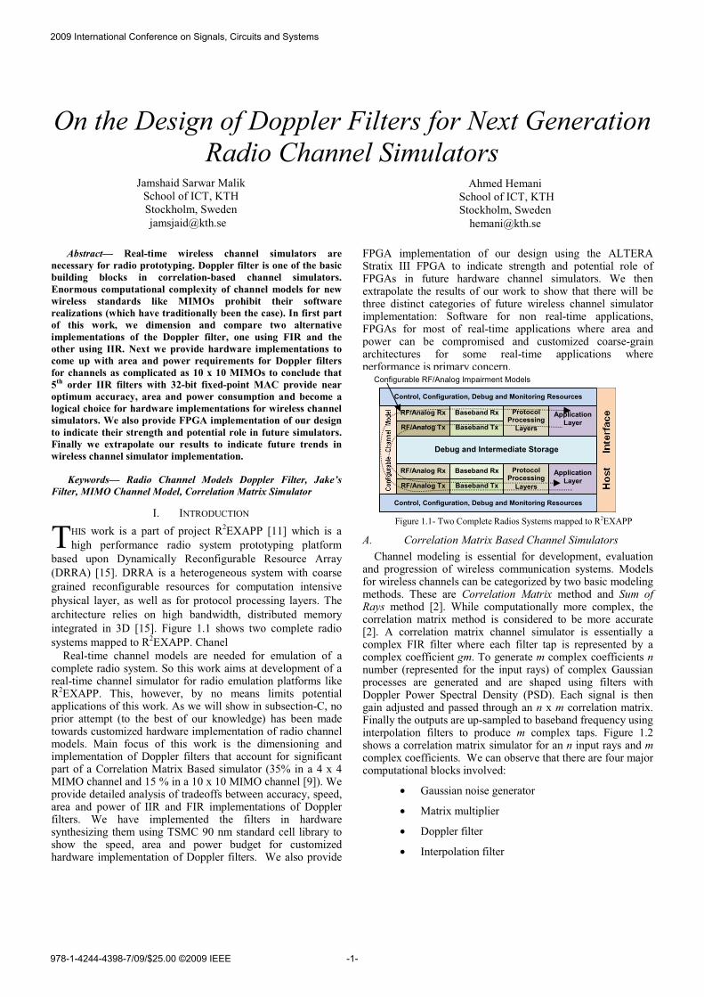
On the Design of Doppler Filters for Next Generation Radio Channel Simulators Abstract— Real-time wireless channel simulators are necessary for radio prototyping. Doppler filter is one of the basic building blocks in correlation-based channel simulators. Enormous computational complexity of channel models for new wireless standards like MIMOs prohibit their software realizations (which have traditionally been the case). In first part of this work, we dimension and compare two alternative implementations of the Doppler filter, one using FIR and the other using IIR. Next we provide hardware implementations to come up with area and power requirements for Doppler filters for channels as complicated as 10 x 10 MIMOs to conclude that 5 th order IIR filters with 32-bit fixed-point MAC provide near optimum accuracy, area and power consumption and become a logical choice for hardware implementations for wireless channel simulators. We also provide FPGA implementation of our design to indicate their strength and potential role in future simulators. Finally we extrapolate our results to indicate future trends in wireless channel simulator implementation. Keywords— Radio Channel Models Doppler Filter, Jake’s Filter, MIMO Channel Model, Correlation Matrix Simulator I. INTRODUCTION HIS work is a part of project R 2 EXAPP [11] which is a high performance radio system prototyping platform based upon Dynamically Reconfigurable Resource Array (DRRA) [15]. DRRA is a heterogeneous system with coarse grained reconfigurable resources for computation intensive physical layer, as well as for protocol processing layers. The architecture relies on high bandwidth, distributed memory integrated in 3D [15]. Figure 1.1 shows two complete radio systems mapped to R 2 EXAPP. Chanel Real-time channel models are needed for emulation of a complete radio system. So this work aims at development of a real-time channel simulator for radio emulation platforms like R 2 EXAPP. This, however, by no means limits potential applications of this work. As we will show in subsection-C, no prior attempt (to the best of our knowledge) has been made towards customized hardware implementation of radio channel models. Main focus of this work is the dimensioning and implementation of Doppler filters that account for significant part of a Correlation Matrix Based simulator (35% in a 4 x 4 MIMO channel and 15 % in a 10 x 10 MIMO channel [9]). We provide detailed analysis of tradeoffs between accuracy, speed, area and power of IIR and FIR implementations of Doppler filters. We have implemented the filters in hardware synthesizing them using TSMC 90 nm standard cell library to show the speed, area and power budget for customized hardware implementation of Doppler filters. We also provide FPGA implementation of our design using the ALTERA Stratix III FPGA to indicate strength and potential role of FPGAs in future hardware channel simulators. We then extrapolate the results of our work to show that there will be three distinct categories of future wireless channel simulator implementation: Software for non real-time applications, FPGAs for most of real-time applications where area and power can be compromised and customized coarse-grain architectures for some real-time applications where performance is primary concern. Figure 1.1- Two Complete Radios Systems mapped to R 2 EXAPP A. Correlation Matrix Based Channel Simulators Channel modeling is essential for development, evaluation and progression of wireless communication systems. Models for wireless channels can be categorized by two basic modeling methods. These are Correlation Matrix method and Sum of Rays method [2]. While computationally more complex, the correlation matrix method is considered to be more accurate [2]. A correlation matrix channel simulator is essentially a complex FIR filter where each filter tap is represented by a complex coefficient gm. To generate m complex coefficients n number (represented for the input rays) of complex Gaussian processes are generated and are shaped using filters with Doppler Power Spectral Density (PSD). Each signal is then gain adjusted and passed through an n x m correlation matrix. Finally the outputs are up-sampled to baseband frequency using interpolation filters to produce m complex taps. Figure 1.2 shows a correlation matrix simulator for an n input rays and m complex coefficients. We can observe that there are four major computational blocks involved: • Gaussian noise generator • Matrix multiplier • Doppler filter • Interpolation filter T Jamshaid Sarwar Malik School of ICT, KTH Stockholm, Sweden [email protected] Ahmed Hemani School of ICT, KTH Stockholm, Sweden [email protected] Configurable RF/Analog Impairment Models Control, Configuration, Debug and Monitoring Resources Control, Configuration, Debug and Monitoring Resources RF/Analog Rx Baseband Rx RF/Analog Tx Baseband Tx Protocol Processing Layers Application Layer RF/Analog Rx Baseband Rx RF/Analog Tx Baseband Tx Protocol Processing Layers Application Layer Debug and Intermediate Storage 2009 International Conference on Signals, Circuits and Systems -1- 978-1-4244-4398-7/09/$25.00 ©2009 IEEE
-
Upload
independent -
Category
Documents
-
view
5 -
download
0
Transcript of On the design of Doppler filters for next generation radio channel simulators
On the Design of Doppler Filters for Next Generation Radio Channel Simulators
Abstract— Real-time wireless channel simulators are necessary for radio prototyping. Doppler filter is one of the basic building blocks in correlation-based channel simulators. Enormous computational complexity of channel models for new wireless standards like MIMOs prohibit their software realizations (which have traditionally been the case). In first part of this work, we dimension and compare two alternative implementations of the Doppler filter, one using FIR and the other using IIR. Next we provide hardware implementations to come up with area and power requirements for Doppler filters for channels as complicated as 10 x 10 MIMOs to conclude that 5th order IIR filters with 32-bit fixed-point MAC provide near optimum accuracy, area and power consumption and become a logical choice for hardware implementations for wireless channel simulators. We also provide FPGA implementation of our design to indicate their strength and potential role in future simulators. Finally we extrapolate our results to indicate future trends in wireless channel simulator implementation.
Keywords— Radio Channel Models Doppler Filter, Jake’s Filter, MIMO Channel Model, Correlation Matrix Simulator
I. INTRODUCTION HIS work is a part of project R2EXAPP [11] which is a high performance radio system prototyping platform
based upon Dynamically Reconfigurable Resource Array (DRRA) [15]. DRRA is a heterogeneous system with coarse grained reconfigurable resources for computation intensive physical layer, as well as for protocol processing layers. The architecture relies on high bandwidth, distributed memory integrated in 3D [15]. Figure 1.1 shows two complete radio systems mapped to R2EXAPP. Chanel
Real-time channel models are needed for emulation of a complete radio system. So this work aims at development of a real-time channel simulator for radio emulation platforms like R2EXAPP. This, however, by no means limits potential applications of this work. As we will show in subsection-C, no prior attempt (to the best of our knowledge) has been made towards customized hardware implementation of radio channel models. Main focus of this work is the dimensioning and implementation of Doppler filters that account for significant part of a Correlation Matrix Based simulator (35% in a 4 x 4 MIMO channel and 15 % in a 10 x 10 MIMO channel [9]). We provide detailed analysis of tradeoffs between accuracy, speed, area and power of IIR and FIR implementations of Doppler filters. We have implemented the filters in hardware synthesizing them using TSMC 90 nm standard cell library to show the speed, area and power budget for customized hardware implementation of Doppler filters. We also provide
FPGA implementation of our design using the ALTERA Stratix III FPGA to indicate strength and potential role of FPGAs in future hardware channel simulators. We then extrapolate the results of our work to show that there will be three distinct categories of future wireless channel simulator implementation: Software for non real-time applications, FPGAs for most of real-time applications where area and power can be compromised and customized coarse-grain architectures for some real-time applications where performance is primary concern.
Figure 1.1- Two Complete Radios Systems mapped to R2EXAPP
A. Correlation Matrix Based Channel Simulators Channel modeling is essential for development, evaluation
and progression of wireless communication systems. Models for wireless channels can be categorized by two basic modeling methods. These are Correlation Matrix method and Sum of Rays method [2]. While computationally more complex, the correlation matrix method is considered to be more accurate [2]. A correlation matrix channel simulator is essentially a complex FIR filter where each filter tap is represented by a complex coefficient gm. To generate m complex coefficients n number (represented for the input rays) of complex Gaussian processes are generated and are shaped using filters with Doppler Power Spectral Density (PSD). Each signal is then gain adjusted and passed through an n x m correlation matrix. Finally the outputs are up-sampled to baseband frequency using interpolation filters to produce m complex taps. Figure 1.2 shows a correlation matrix simulator for an n input rays and m complex coefficients. We can observe that there are four major computational blocks involved:
• Gaussian noise generator
• Matrix multiplier
• Doppler filter
• Interpolation filter
T
Jamshaid Sarwar Malik School of ICT, KTH Stockholm, Sweden [email protected]
Ahmed Hemani School of ICT, KTH Stockholm, Sweden
Configurable RF/Analog Impairment Models
Control, Configuration, Debug and Monitoring Resources
Control, Configuration, Debug and Monitoring Resources
RF/Analog Rx Baseband Rx
RF/Analog Tx Baseband Tx
Protocol Processing
Layers
Application Layer
RF/Analog Rx Baseband Rx
RF/Analog Tx Baseband Tx
Protocol Processing
Layers
Application Layer
Debug and Intermediate Storage
2009 International Conference on Signals, Circuits and Systems
-1-978-1-4244-4398-7/09/$25.00 ©2009 IEEE
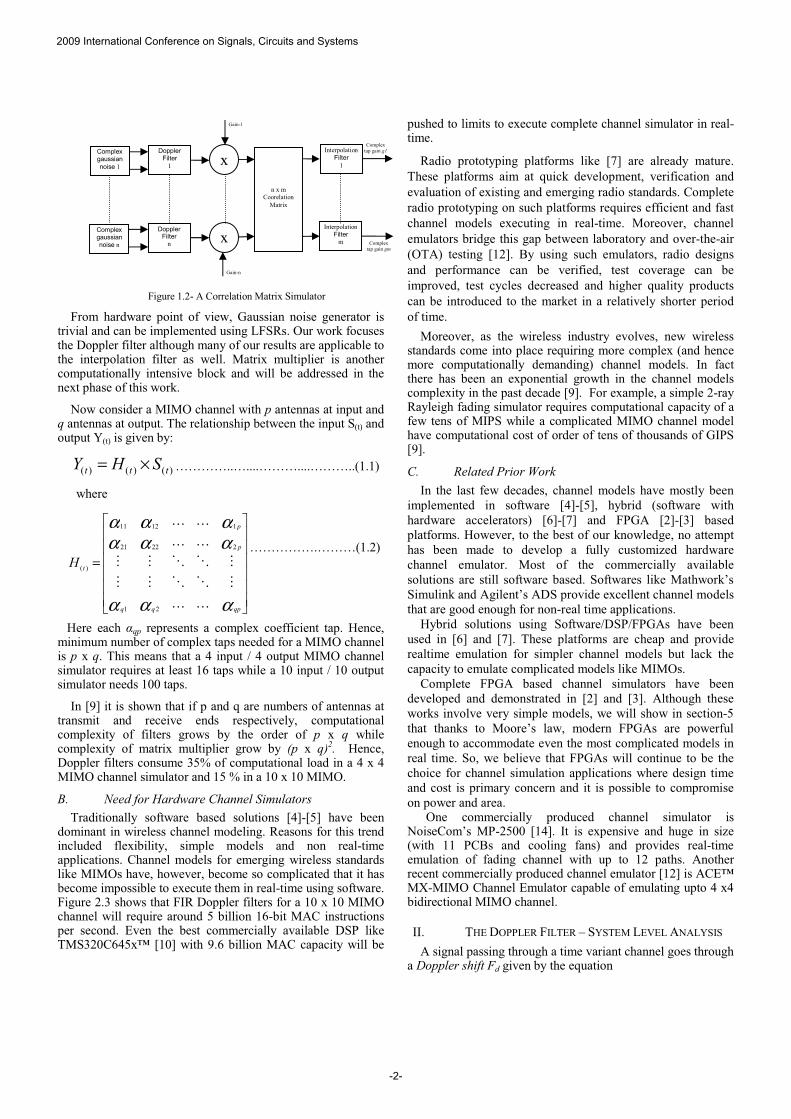
Figure 1.2- A Correlation Matrix Simulator
From hardware point of view, Gaussian noise generator is trivial and can be implemented using LFSRs. Our work focuses the Doppler filter although many of our results are applicable to the interpolation filter as well. Matrix multiplier is another computationally intensive block and will be addressed in the next phase of this work.
Now consider a MIMO channel with p antennas at input and q antennas at output. The relationship between the input S(t) and output Y(t) is given by:
)()()( ttt SHY ×= …………..…....………....………..(1.1)
where
������
�
�
������
�
�
=
ααα
αααααα
qpqq
p
p
tH
������������
����
21
22221
11211
)(
…………….………(1.2)
Here each �qp represents a complex coefficient tap. Hence, minimum number of complex taps needed for a MIMO channel is p x q. This means that a 4 input / 4 output MIMO channel simulator requires at least 16 taps while a 10 input / 10 output simulator needs 100 taps.
In [9] it is shown that if p and q are numbers of antennas at transmit and receive ends respectively, computational complexity of filters grows by the order of p x q while complexity of matrix multiplier grow by (p x q)2. Hence, Doppler filters consume 35% of computational load in a 4 x 4 MIMO channel simulator and 15 % in a 10 x 10 MIMO.
B. Need for Hardware Channel Simulators Traditionally software based solutions [4]-[5] have been
dominant in wireless channel modeling. Reasons for this trend included flexibility, simple models and non real-time applications. Channel models for emerging wireless standards like MIMOs have, however, become so complicated that it has become impossible to execute them in real-time using software. Figure 2.3 shows that FIR Doppler filters for a 10 x 10 MIMO channel will require around 5 billion 16-bit MAC instructions per second. Even the best commercially available DSP like TMS320C645x™ [10] with 9.6 billion MAC capacity will be
pushed to limits to execute complete channel simulator in real-time.
Radio prototyping platforms like [7] are already mature. These platforms aim at quick development, verification and evaluation of existing and emerging radio standards. Complete radio prototyping on such platforms requires efficient and fast channel models executing in real-time. Moreover, channel emulators bridge this gap between laboratory and over-the-air (OTA) testing [12]. By using such emulators, radio designs and performance can be verified, test coverage can be improved, test cycles decreased and higher quality products can be introduced to the market in a relatively shorter period of time.
Moreover, as the wireless industry evolves, new wireless standards come into place requiring more complex (and hence more computationally demanding) channel models. In fact there has been an exponential growth in the channel models complexity in the past decade [9]. For example, a simple 2-ray Rayleigh fading simulator requires computational capacity of a few tens of MIPS while a complicated MIMO channel model have computational cost of order of tens of thousands of GIPS [9].
C. Related Prior Work In the last few decades, channel models have mostly been
implemented in software [4]-[5], hybrid (software with hardware accelerators) [6]-[7] and FPGA [2]-[3] based platforms. However, to the best of our knowledge, no attempt has been made to develop a fully customized hardware channel emulator. Most of the commercially available solutions are still software based. Softwares like Mathwork’s Simulink and Agilent’s ADS provide excellent channel models that are good enough for non-real time applications.
Hybrid solutions using Software/DSP/FPGAs have been used in [6] and [7]. These platforms are cheap and provide realtime emulation for simpler channel models but lack the capacity to emulate complicated models like MIMOs.
Complete FPGA based channel simulators have been developed and demonstrated in [2] and [3]. Although these works involve very simple models, we will show in section-5 that thanks to Moore’s law, modern FPGAs are powerful enough to accommodate even the most complicated models in real time. So, we believe that FPGAs will continue to be the choice for channel simulation applications where design time and cost is primary concern and it is possible to compromise on power and area.
One commercially produced channel simulator is NoiseCom’s MP-2500 [14]. It is expensive and huge in size (with 11 PCBs and cooling fans) and provides real-time emulation of fading channel with up to 12 paths. Another recent commercially produced channel emulator [12] is ACE™ MX-MIMO Channel Emulator capable of emulating upto 4 x4 bidirectional MIMO channel.
II. THE DOPPLER FILTER – SYSTEM LEVEL ANALYSIS A signal passing through a time variant channel goes through
a Doppler shift Fd given by the equation
Complex tap gain gm
Complex tap gain g1
Gain-n
Gain-1
Complex gaussian noise 1
Doppler Filter
1
Complex gaussian noise n
Doppler Filter
n
x
x
n x m Coorelation
Matrix
InterpolationFilter
1
InterpolationFilter
m
2009 International Conference on Signals, Circuits and Systems
-2-
cFF c
d
×== νλν ……………...……………………....(1.3)
Where v is the relative velocity of the transmitter/receiver, � is the signal wavelength, Fc is the carrier frequency and c is the speed of light. As a result of Doppler shift, the received signal suffers a change in both its phase and magnitude. The rate of this change is directly proportional to Fd. [1]
-1 -0.8 -0.6 -0.4 -0.2 0 0.2 0.4 0.6 0.8 1
-40
-30
-20
-10
0
Jake's Filter PSD
0 20 40 60 80 100 120 140 160 180 200-20
0
20
40Jake's Filter Impulse Response
Figure 2.1- Frequency/Impulse response of Jake’s Filter
The effect of Doppler shift is modeled in a correlation simulator by shaping a complex white signal by a low-pass filter with so called Doppler Power Spectral Density (PSD). Such a filter is called Doppler shaping filter or simply Doppler filter. Depending upon the physical environment of the channel, Doppler filters with different PSD shapes are used. Most commonly used one is the Jake’s filter whose baseband normalized spectrum is given by:
d
dd
f FF
FFF
S ≤
��
� −
= ,
1
12)(
π
…….…………………....(1.4)
Where Fd is the Doppler shift. Figure 2.1 shows the PSD and impulse response of Jake’s filter. Other Doppler PSD include Flat, Gaussian and Asymmetrical Jake’s etc. For the rest of this text we will use only Jake’s filter since the analysis and results are equally applicable on the rest of filter types.
A. Challenges in Doppler Filter Design Designing Doppler filter is not a trivial task. For one, it
has a very sharp cut-off (infinite slope) which translates into a very high order filter. Secondly, if sampled at baseband frequency, the filter has an extremely narrow band which again translates to impractically high order filters Figure 2.2 shows how Fd changes with change in carrier frequency and relative speed. We can see that Fd can range from as few Hz (Walking speed with 400 MHz carrier) to few KHz (commercial jetliner cruise speed with 5 MHz carrier). Finally for complicated channel models multiple instances of filters are required for a complete simulator which is manifested in terms of huge chip area and power consumption.
These challenges are needed to be addressed individually. Since pass band of Doppler filter is extremely narrow as compared to baseband, sampling of Doppler filter is done at lower rate. A good approximation [2] is ten times Fd. To get
sampling at baseband, filter output is up sampled using interpolation [2]. So maximum Doppler shift of 5 KHz translates to upper limit of 50 KHz sampling rate. This low sampling rate is actually good news from hardware implementation view point as this makes it possible to have temporal reuse of the same instance to implement multiple filters. This also implies variable sampling rate for the filter as Fd is can vary for different channel models.
0100
200300 0 1 2 3 4 5 6
x 109
0
1000
2000
3000
4000
5000
6000
Signal Carrier Frequency
Doppler Shift vs carrier frequency and velocity
Vilocity (m/sec)
Dop
pler
Shi
ft (
Hz)
Figure 2.2
Previously, [2]-[7] correlation channel simulators have been implemented using both FIR and IIR Doppler filters. In this work, we have implemented both types in hardware and in sections 3 and 4 we will provide a detailed analysis of both types. Also number representation has not been an issue in software simulators since floating point numbers have been used almost universally. However, for hardware implementation floating point is not an optimum choice. So we will also investigate optimum number of bits for fixed point representation of Doppler filters.
Figure 2.3
Based upon the above discussion we have defined worst case scenario for our Doppler filter design. That is a 10 x 10 MIMO channel with 5 KHz Fd. This translates to 100 filters each operating at maximum sampling rate of 50 KHz. Figure 2.3 shows relative MMIPS (million MAC instructions per second) requirements for FIR and IIR implementations.
III. IIR IMPLEMENTATION IIR filters are prone to instability due to involved
feedback paths. Moreover, an increase in filter order also leads to more unstable filter. Finally, quantization errors and lower
Jetliner cruise speedWalking
speed
2009 International Conference on Signals, Circuits and Systems
-3-

dynamic range due to fix point arithmetic is more problem in IIR than their FIR counterparts. Figure 3.1 shows minimum number of bits required for a stable operation for an IIR Jake’s filter with changing filter order.
1 2 3 4 5 6 75
10
15
20
25
30
35
40Filter Order Vs fixed point bits
Filter order
Fix
ed p
oint
num
ber
of b
its
Figure 3.1
The figure indicates that we need less than 32-bits for a stable operation if filter order is less than six. Figures 3.2 shows the accuracy of same filter (in pass and stop bands) with changing filter orders.
1 2 3 4 5 6 70
1
2
3
4
5
6
7
Filter order
Ave
rage
Pas
s B
and
Acc
urac
y (d
B)
Ave
rage
Sto
p B
and
Rej
ectio
n (x
10
dB) Doppler IIR Filter order Vs accuracy
pass band accuracy
stop band rejection
Figure 3.2
From above analysis, we get an optimum filter order with corresponding minimum number of bits for stable operation. This comes out to be a fifth order filter (with pass band accuracy of more than 0.1 dB and stop band rejection of more than 50 dB) with 32-bit fix point operation. Designing a filter of order more than 5, results in fixed point operations of more than 32 bits which lead to sub-optimal hardware design while we don’t gain much in terms of accuracy (figure 3.3).
In light of above analysis, we now put following constraints on our IIR filter design: • Variable filter order with upper limit of 5th order • All datapaths and computational units should be 32-bit
fixed point • Possibility to change filter coefficients in runtime to
enable temporal reuse of same filter. • Variable clock speed
0 0.1 0.2 0.3 0.4 0.5
-60
-40
-20
0
IIR Filter - order vs accuracy
2nd order
5th order3rd order
ideal
Figure 3.3
Figure 3.4 shows datapath of the designed IIR filter. Direct Form II (DF-II) architecture has been used. Filter has three 32 x 11 bit memory blocks to store feed forward coefficients, feedback coefficients, and delayed feedback memory respectively. A clock divider skips variable clock cycles from 500MHz master clock to feed the filter a variable clock from 220 Hz to 250 MHz. The clock is further gated with Strobe_in signal to save dynamic power in idle mode. Only one 32-bit MAC is used to save resources. Filter samples the input data with active Strobe_in signal. Strobe_out signal is activated when 32-bit filter output is ready. Mimimum input (and output) sampling time can be calculated as
( )( )122 +≅ FOTT clksamp……………………(3.1)
Where Tsamp is filter effective sampling period, Tclk is the clock fed to filter from clock divider and Fo is the filter order. For example a 5th order filter with 1MHz (1μs) clock will have input/output sampling equal to 22μs.
Figure 3.4- Datapath of Designed IIR Filter
Figures 3.5 and 3.6 show the comparison of the designed
filter with similar filter implemented in software with 64-bit floating point filter. We see that both impulse and frequency response of our 32-bit fixed-point IIR filter is quite closed to similar 64-bit floating point filter.
-0.8 -0.6 -0.4 -0.2 0 0.2 0.4 0.6 0.8-80
-60
-40
-20
0
IIR Filter Frequency Response
Matlab floating point
32-bit fix point
Figure 3.5
1000 1100 1200 1300 1400 1500
-1
0
1
2
x 10-4 IIR Filter Impulse Response
matlab floating point
32-bit fix point
Figure 3.6
Filter Output (32 –bit)
Strobe in
Strobe out
Filter Input (32 –bit)
Filter Clk(220 Hz – 250 MHZ)
Master Clk(500 MHZ)
Clock divider
32 x 11 FB Coef. mem
32-bit MAC
32 x 11 delay FB mem
32 x 11 FF Coef. mem
2009 International Conference on Signals, Circuits and Systems
-4-

The designed filter has been synthesized using TSMC 90nm standard cell library and table 3.1 shows the post synthesis and optimization results. We need extra memory to save filter states for temporal re-usage of filter. Maximum memory density for 90nm technology is approximately 400 Kb/mm2 while power consumption is 7 nW/bit/MHz [13]. Power consumption for extra memory is comparatively small as it needs to be updated at very low rates.
TABLE 3.1 AREA AND POWER REQUIREMENTS FOR IIR FILTER
MIMO Channel
Clock MHz
Required Filters
Extra Memory
(Kb)
Filter Area
(mm2)
Memory Area
(mm2)
Power(mW)
4 x 4 40 16 5.63 0.039 0.014 5.06 10 x 10 250 100 35.2 0.039 0.088 29.22
IV. FIR IMPLEMENTATION FIR filter is inherently stable due to absence of any
feedback path. Fixed-point implementation of FIR filters may, however, impose some problems as quantization errors and shorter dynamic range can lead to filter inaccuracy. We have found that with appropriate selection of coefficients, fixed-point implementation using as low as 16-bits can lead to a fairly accurate filter whose time and frequency response matches with floating point implementations. Another important issue is filter order. Due to sharp cutoff of Jake’s spectrum, a very high filter order is required. Figure 4.1 shows how filter accuracy improves with the higher filter order. It is apparent that any decent accuracy requires filter order between 500 and 1000.
0 0.2 0.4 0.6 0.8
-80
-60
-40
-20
0
FIR jake's filter order vs accuracy
100 state
ideal
500 state
1000 state
Figure 4.1
Based upon the above discussion, we have put following constraints on our filter: • Variable filter state with upper limit of 500 states • All datapaths and computational units should be 16-bit
fixed-point • Re-configurability and temporal re-usage • Variable clock speed to allow different sampling rates
with changing Fd • Compact design to save area for multiple filter instances
Figure 4.2- Datapath of Designed FIR Filter
Figure 4.2 shows datapath of the designed FIR filter. Filter has two 16 x 500 bit memory blocks to store filter coefficients and delayed inputs. A clock divider skips variable clock cycles from 500MHz master clock to feed the filter a variable clock from 220 Hz to 250 MHz. The clock is further gated with Strobe_in signal to save dynamic power in idle mode. We use ten 16-bit parallel MAC units that provide a good compromise between power/area and net filter speed. Filter samples the input data with active Strobe_in signal. Strobe_out signal is activated when 16-bit filter output is ready. Maximum speed at which input (and output) can be sampled is
10FOTT clk
samp
×≅ ……..……………………….….…..(2.1)
Where Tsamp is filter effective sampling period, Tclk is the clock fed to filter from clock divider and FO is the filter order. For example a 100 state filter with 1MHz (1μs) clock will have input/output sampling equal to 10 μs.
Figures 4.3 and 4.4 show the comparison of the designed filter with similar filter implemented in software with 64-bit floating point. We see that both impulse and frequency response of our 16-bit filter is quite closed to similar 64-bit floating point filter.
50 100 150 200-0.4
-0.2
0
0.2
0.4
0.6
0.8
1FIR Filter Impulse Response
matlab floating point
16-bit fix point
Figure 4.3
TABLE 4.1
AREA AND POWER REQUIREMENTS FOR FIR FILTER MIMO
Channel ClockMHz
Required Filters
Extra Memory
(Kb)
Filter Area
(mm2)
Memory Area
(mm2)
Power(mW)
4 x 4 80 32 256 0.67 0.64 41.06 10 x 10 250 200 1600 1.34 4 258.3
The designed filter has been synthesized using TSMC 90nm standard cell library and table 4.1 shows post synthesis and optimization results. Figure 4.5 shows comparative chip area for FIR and IIR filter implementations.
2000 4000 6000 8000 10000 12000
-80
-60
-40
-20
0FIR Filter Frequency Response
Matlab floating point
16-bit fix point
Figure 4.4
Filter Output (16 –bit)
Strobe in
Strobe out
Filter Input (16 –bit)
Filter Clk (100 Hz – 250 MHZ)
Master Clk (500 MHZ)
Clock divider 16 x 500
Coef. mem
16 x 500 delay input. mem
16-bit MAC
2009 International Conference on Signals, Circuits and Systems
-5-

Figure 4.5- Filters comparative chip areas
V. IIR FILTER IMPLEMENTATION ON FPGA We have also synthesized the above IIR design using
ALTERA Stratix III FPGA. Minimum slack comes out to be 6.4 ns which translate to maximum possible clock of 150 MHz. This means a single instant can be reused for 120 filters. Table 5.1 shows that Doppler filters for a 10 x 10 MIMO channel simulator consume about 2% of the total FPGA resources.
Using the results of table 5.1 we can extrapolate our results
to show that a complete MIMO channel simulator will consume approximately 14% of the said FPGA resources. These figures will improve further if a better FPGA like Stratix IV is used. Hence, due to cheap cost factor and short design cycle, FPGAs will remain strong contenders for real-time channel simulators.
VI. CONCLUSION We wrap up this work with three important conclusions; Analysis in section-2 and results in sections 3 and 4 clearly
indicate that when number of taps is high IIR Doppler filters should be preferred over their FIR counterparts. 5th order IIR filters with 32-bit fixed-point MAC provide a good compromise between accuracy and area/power and become a logical choice for future hardware implementations of complicated channel simulators.
Although software based simulators will continue to be used in majority of applications, they fail to address real-time applications. FPGAs with benefits of lower cost, shorter design cycle and capability of parallel computation will be strong contenders for mainstream real-time channel simulators. As results in section-5 show, today’s FPGAs have enough computational muscle to incorporate most channel models.
For some applications, like radio emulation platforms and for some exotic channel models, even the best FPGAs in foreseeable future will fail to deliver required performance. In such cases, a customized coarse grained architecture will be
required which (although much costlier) will have enough computational power to execute the models in real-time.
ACKNOWLEDGMENT The authors of this work are extremely gratified to following for their
breed financial support: • ICT R&D Fund PTCL and SEECS, NUST Islamabad, Pakistan • Project MOSART, European Union (ref. FP7-215244 MOSART)
REFERENCES [1] Jeruchim, Michel C., Balaban, Philip, and Shanmugan, K. Sam,
“Simulation of Communication Systems”, Second edition, New York, Kluwer Academic/Plenum, 2000.
[2] Amir Hossein A, Bruce F. Cockburn, “Modeling and Hardware Implementation Aspects of Fading Channel Simulators”, IEEE transactions on Very Large Scale Integration (VLSI) systems, vol. 16, no. 5, May 2008.
[3] Ali Mohammad A. Khorasani M, Schlegel C, “A Compact and Accurate FPGA Based Nonisotropic Fading Channel Simulator”, CCECE 22-26 April 2007.
[4] Cyril-Daniel Iskander, “A MATLAB-based Object-Oriented Approach to Multipath Fading Channel Simulation”, MATLAB White Paper
[5] Komninakis, “A fast and accurate Rayleigh fading simulator” IEEE GLOBECOM, Volume 6, 1-5 Dec. 2003,
[6] J. F. An, A. M. D. Turkmani, J. D. Parsons, ‘‘Implementation of a DSP-based frequency non-selective fading simulator,’’ in Proc. Int. Conf. Radio Receivers Assoc. Syst., 1990, pp. 20–24.
[7] A. Verschoor, A. Kegel, and J. C. Arnbak, ‘‘Hardware fading simulator for a number of narrowband channels with controllable mutual correlation,’’ Electron. Lett., vol. 24, no. 22, pp. 1367---1369, Oct. 1988.
[8] Kimmo K, Chen C, M. Josephine, “Designing BEE: A Hardware Emulation Engine for Signal Processing in Low-PowerWireless Applications”, EURASIP Journal on Applied Signal Processing 2003.
[9] Kyosti, P, Jamsa T, “Complexity Comparison of MIMO Channel Modelling Methods”, ISWCS, 4th International Symposium on 17-19 Oct. 2007.
[10] “TMS320C6457Fixed-Point Digital Signal Processor Data Manual” http://focus.ti.com/lit/ds/symlink/tms320c6457.pdf
[11] “SDR Development using a Networks-On-Chip based Rapid Prototyping Platform”, http://www.graf-cefar.niit.edu.pk/pages/sdr.htm
[12] “Improving 4G Wireless Broadband Product Design through Effective Channel Emulation Testing”, White Paper Azimuth Systems, 2008.
[13] “ASIC 90nm TC300”, http://www.toshiba.com/taec/Catalog/Line.do?familyid=1&lineid=7231
[14] “NoiseCom MP-2500 Multipath Fading Emulator, Technical Manual”, NoiseCom, Paramus, NJ, 1996.
[15] Muhammed Ali Shami, Ahmed Hemani,.” Partially Reconfigurable Interconnection Network for Dynamically Reprogrammable Resource Array” n IEEE 8th International Conference on ASIC, October, 2009.
TABLE 5.1 FPGA RESOURCES CONSUMED FOR IIR DOPPLER FILTER
MIMO Channel
Required Filters
FPGA Memory (%)
FPGA Logic (%)
Power(W)
4 x 4 16 0.26 % 0.76% 1.13 10 x 10 100 1.3 % 2.1% 2.54
FIR (1000 states)
FIR (500 states)
IIR (5th order)
2009 International Conference on Signals, Circuits and Systems
-6-