OmniSeal ® Double Block & Bleed Expanding Plug Valve
24
OmniSeal ® Double Block & Bleed Expanding Plug Valve High integrity double block and bleed expanding plug valves for product isolation, blending, metering, custody transfer, terminal, storage and other land or offshore zero-leakage applications. © 2014 Omni Valve Company, LLC, | BRO-EPV Rev: 3.0 Global Energy Market Solutions Omni Valve ( 610 ) 270-2814 www.omnivalve.com
-
Upload
khangminh22 -
Category
Documents
-
view
1 -
download
0
Transcript of OmniSeal ® Double Block & Bleed Expanding Plug Valve

OmniSeal ® Double Block & Bleed Expanding Plug Valve
High integrity double block and bleed expanding plug valves for product isolation, blending, metering, custody transfer, terminal, storage and other land or offshore zero-leakage applications.
© 2014 Omni Valve Company, LLC, | BRO-EPV Rev: 3.0
Global Energy Market Solut ions
Omni Valve(610) 270-2814w w w. o m n i v a l v e . c o m

OmniSeal® DBB expanding plug valves are ideally suited for product blending & refining applications
OmniSeal® DBB expanding plug valves in service OmniSeal® DBB expanding plug valves during installation

Introduction
OmniSeal® expanding plug valves are designed for applications where positive shut-off, verifiable zero leakage and double block and bleed (DBB) capabilities are required. They meet API-6D definition of Double Isolation and Bleed valves (DIB) as defined in paragraph 4.8.
They are ideal for a variety of applications including leased automated custody transfer (LACT), product metering, aviation fueling, product isolation, blending, lockout/tagout (LOTO), multi-product manifolds, tank storage and other DBB applications.
The OmniSeal® is a single valve solution that simultaneously blocks both the upstream and downstream flow while allowing the user to verify seal integrity using a manual or automatic body bleed system. It replaces older double block and bleed systems that use two valves with a spool and bleed valve in-between. It also has significant design advantages when compared with some other single DBB valve designs.
All OmniSeal® DBB expanding plug valves are manufactured and monogrammed per API 6D and ISO 9001, fire tested per API 607 and API 6FA and have specific certifications such as CE/PED, CRN (Canadian Registration), TA-Luft or similar design or regional certifications where appropriate.
Omniseal® DBB expanding plug valves have been determined to be a “Product of the USA “ by the US Customs and Border Protection Agency (CBP). This applies to valve procurement for both commercial and US military installations.
Page 3
TABLE OF CONTENTS
Introduction 3
Applications 4
Single Valve DBB Solutions 5
Typical Valve Configuration 6
Size Range & Materials of Construction 7
Valve Operations 8-9
Design Features 10-11
Relief Systems 12-13
Dimension Tables 14-17
Automation 18
Torque and Turns Charts 19
Stem Extensions 20
Figure Numbers 21
Replacement Parts and Rebuild Kits 22
Manufacturer, Sales, Service & Distribution, Product Warranty 23

Some Copy Here....
Applications
Page 4
OmniSeal® expanding plug valves are ideal for applications that require positive shut-off, verifiable zero leakage and double block and bleed
(DBB) capability. Some of the more common applications include:
• BLENDING UNITS: Accurate blending of ethanol or other re-
gional fuel grades requires valves with exceptionally high seal
integrity to ensure accurate measurement of additives and blend-
ing stocks. The OmniSeal® DBB is specifically designed for ap-
plications of this type.
• PRODUCT ISOLATION: Secure isolation of Biofuels or other
process-sensitive fluids is critical for environmental and process
safety. The OmniSeal® DBB’s verifiable zero leakage and positive
shutoff capabilities make it an ideal solution for isolation and pro-
cess-sensitive applications.
• MULTI-PRODUCT MANIFOLDS: Pipeline, refinery and
transfer manifolds need to flow multiple products (e.g. diesel, jet
fuel, gasoline, blending stocks, etc.) reliably and without contam-
ination. The OmniSeal® DBB is an effective tool for preventing
product cross-contamination.
• PROVER LOOPS: Proper calibration of flow meters requires
that every valve in the prover loop system must have a zero leak
rate. Any leak could mean an error in calibration. OmniSeal® DBB
valves are used to ensure leak tight closure and accurate calibration.
• CUSTODY TRANSFER UNITS: Transfer of valuable media
relies on accurate measurement of product transfer quantity. The
OmniSeal® DBB provides positive shutoff and zero leak rate,
thereby ensuring accurate calculation of transfer quantity.
• OFFSHORE PLATFORMS: Valve leakage on an offshore
platform can result in damage to equipment and the environ-
ment. The OmniSeal® DBB has excellent low pressure positive shut-
off characteristics and is a great choice for use on offshore platforms.
• TERMINALS: Terminals used for loading and unloading tank-
ers require valves with positive sealing in order to prevent envi-
ronmental damage due to spillage. The OmniSeal® DBB pro-
vides positive sealing and zero leak rate in a reliable single
valve solution.
• TANK FARMS (OIL DEPOTS): Tank isolation valves, which
are operated frequently, require zero leak rate and a high de-
gree of reliability. The OmniSeal® DBB valve provides a reliable
high integrity seal designed for frequent and long-term use.
• AVIATION FUELING SYSTEMS: Airport fueling systems
require valves that close quickly and have verifiable seal integrity.
This allows for quick maintenance, repair, leak location and
testing. The OmniSeal® DBB valve’s verifiable zero leak rate
ensures that maintenance, repair, leak location and hydrant
testing can be done safely and quickly. Omniseal® DBB expanding
plug valves have been determined to be a “Product of the USA
“ by the US Customs and Border Protection Agency (CBP). This
applies to valve procurement for both commercial and US
military installations.

Single Valve DBB Solution
Page 5
The OmniSeal® replaces antiquated two-valve systems with a single DBB valve solution. The OmniSeal® has two seats (slips)
and provides a bubble tight seal.
Older double block & bleed systems (as shown above) used two valves and a spool piece with a bleed valve used to drain
the spool and verify seal integrity.
1. The upstream and downstream slip seals provide the same
function as the two block valves shown above.
2. The OmniSeal® body (serving as the spool piece shown above)
bleeds to verify seal integrity.
1
2 Body Drain
Some Copy Here....
Typical Valve Configuration
Page 6
Nuts
Gasket
Gasket
O-Ring
O-Ring
Studs
Packing Gland
Upper Stem
Lower Stem
Waterproof and Vented Indicator Cover
Body
Slip
Slip Seals
Stem Packing
Bevel Gear Operator
Stem Seal O-Rings
Stem Pin
Plug
Body Drain FittingBonnet / Lower Platewith Inverted Trunnion
GEAR OPERATED VALVE
HANDWHEEL OPERATED VALVE

Size Range & Materials of Construction
Page 7
OPTIONAL MATERIALS OF CONSTRUCTION & OTHER CUSTOMIZED FEATURES
OmniSeal® DBB Expanding Plug Valves are also available in a variety of alternate configurations or materials of construction depending on customer preferences, specifications, severe temp ranges and / or service conditions.
Some common options include valves as follows: • Constructed to meet requirements of NACE MR0175 / ISO 15156• With flanges drilled to DIN standard • Subjected to more rigorous customer-specified extended testing regimes• With application of special coatings based on customer specifications, service conditions or cosmetic preferences• Constructed to withstand extreme high or low temperatures - Please consult factory• With customer specified limit switches or other accessories• With special Automatic Body Bleed Valve (ABBV)
HW = Available Only as Handwheel Operated * These sizes have lifting lugsGO = Available Only as Gear OperatedHW/GO = Available as Handwheel or Gear Operated
STANDARD MATERIALS OF CONSTRUCTION
COMPONENT STANDARD TEMP. (-20º TO 200º F) LOW TEMP. (-40º TO 200º F)
BODY Cast ASTM A216 WCC * Cast ASTM A352 LCC *
BONNET/ LOWER PLATE Cast ASTM A216 WCC Cast ASTM A352 LCC
PLUG AND STEM Cast ASTM A216 WCC ** Cast ASTM A352 LCC **
SLIPS Cast Ductile Iron / Cast A395 GR 60-40-18 Cast ASTM A352 LCC
PACKING GLAND Cast ASTM A216 WCC Cast ASTM A352 LCC
STEM PACKING Pre-Formed Flexible Graphite Pre-Formed Flexible Graphite
GASKET Pre-Formed Flexible Graphite Pre-Formed Flexible Graphite
O-RINGS & SLIP SEALS Viton B *** Viton GFLT ***
BONNET TO BODY STUDS ASTM A193 Gr. B7 ASTM A320 Gr. L7
BONNET NUTS A 194 Gr. 2H A 194 Gr. 2H
RELIEF SYSTEM TUBING AISI 316 SS / AISI 304 SS AISI 316 SS / AISI 304 SS
RELIEF SYSTEM NEEDLE VALVES AISI 316 SS AISI 316 SS
RELIEF SYSTEM CHECK VALVE AISI 316 SS AISI 316 SS
* Electroless Nickel Plated - Entire Internal Surface** Electroless Nickel Plated - Entire Component*** All Omniseal® valves in class 300 & 600 are supplied with double reinforced Viton seals.
AVAILABLE SIZES AND PRESSURES SIZE (inches)
ANSI CLASS 2 3 4 6 8 10 12 14 16 18 20 24 26 28 30 36
150 HW/GO HW/GO HW/GO HW/GO GO* GO* GO* GO* GO* GO* GO* G0* GO* GO* GO* GO*
300 HW/GO HW/GO HW/GO GO* GO* GO* GO* GO* GO* GO* GO* GO* GO* GO* GO* N/A
600 HW/GO HW/GO GO GO* GO* GO* GO* GO* GO* GO* GO* GO* NA N/A N/A N/A

Valve Operation
Page 8
FULL OPEN POSITION
PARTIALLY CLOSED POSITION
In the fully open position, the resilient seals are positioned out of the flow path and protected within the body of the valve itself.
As the valve is cycled from the fully open to closed position, the plug begins a 90 degree rotation. During the entire rotation of the plug the resilient seals located on both slips are retracted away from the body. This ensures that there is no rubbing or scraping action on these resilient seals during rotation of the plug from the open to the closed position.

Valve Operation
Page 9
CLOSED POSITION PRIOR TO SEALING
FULLY CLOSED (SEALED) POSITION
After the plug has been rotated 90 degrees from the fully open to fully closed posi-tion, the resilient seals on both slips have not yet been forced outward and into the seating position. This expansion only occurs with continued rotation of the hand-wheel or actuator.
To fully close the valve and provide positive shut-off, the slips are expanded outward with continued rotation of the handwheel or actuator. This outward expansion is achieved by the tapered plug moving downward which causes the resilient seals on the slips to seal against the valve body.
With continued rotation of the handwheel, this small gap be-tween the slip seal and the valve body is closed by the slip moving in the outward direction. Once the slip seal is firmly seated against the valve body sealing surface, the valve achieves a positive, zero-leakage seal.

Some Copy Here....
Design Features
Page 10
1
2
3
4

Design Features
OmniSeal® DBB expanding plug valves have a number of design features that set it apart from competitive offerings.
Page 11
1. POLYCARBONATE PROTECTOR CAP
OmniSeal® DBB expanding plug valve has a robust clear acrylic indicator flag
protector. This keeps moisture and debris from infiltrating the operator housing.
The top of the indicator cap (shown above) is vented to ensure that air flow will
quickly evaporate any condensation that appears inside the clear housing.
Some competitive DBB valve offerings have the top port for the relief system located on the upper bonnet. Therefore, the relief system must be
disconnected whenever the upper bonnet needs to be removed for maintenance or repair. On the OmniSeal®, this port is located on the upper
section of the valve body. This eliminates any need to disassemble the relief system in order to remove the valve bonnet.
2. LOCATION OF RELIEF SYSTEM PORT
The lower trunnion of the OmniSeal® DBB valve is an integral part of the lower
bonnet and is not part of the plug. This design feature means that there is no cav-
ity present in the bottom of the valve body to collect dirt, scale, ice or other debris
that could make the valve hard to turn or otherwise interfere with valve function.
3. LOWER TRUNNION DESIGN
The interior cavity of the valve body and the entire plug are plated with electroless nickel to ensure a corrosion-free sealing surface for slip seals.
4. SURFACE TREATMENT OF BODY CAVITY AND PLUG
VENTS

Some Copy Here....
Relief Systems
Page 12
MANUAL BLEED WITH THERMAL RELIEF TO UPSTREAM
MANUAL BLEED WITH THERMAL RELIEF TO UPSTREAM - WITH GAUGE
THERMAL RELIEF TO ATMOSPHERE
MANUAL RELIEF TO ATMOSPHERE, THERMAL RELIEF FROM DOWN-
STREAM AND BODY TO UPSTREAM MANUAL BLEED TO ATMOSPHERE
Manual Relief Valve
Manual Relief Valve

Relief Systems
Page 13
The OmniSeal® DBB expanding plug valve can be delivered with a variety of relief systems. Some of the more common relief systems are:
STANDARD : MANUAL BLEED WITH THERMAL RELIEF TO UPSTREAM
This is the standard relief systems offered on the OmniSeal® DBB valve. It is designed to relieve excess pressure in the valve cavity due to thermal expansion when the valve is in the closed position. It is similar to a thermal relief to atmosphere system; however, it has a manual valve that provides both manual and automatic relief capabilities. The thermal relief system will relieve pressure to the upstream if differential pressure exceeds 25 psi.
IMPORTANT: In order for the automatic relief system to function properly, the valve that controls the upstream relief must be kept open and the valve that controls the manual bleed to atmosphere must be kept closed.
MANUAL BLEED WITH THERMAL RELIEF TO UPSTREAM - WITH GAUGE
This relief system is designed to relieve excess pressure in the valve cavity due to thermal expansion. It is similar to a thermal relief to up-stream system; however, it uses a gauge to measure the valve seal integrity. Using this system a positive seal can be verified at all times without dispersing any line media. The thermal relief system will relieve to upstream when differential pressure exceeds 25 psi.
THERMAL RELIEF TO ATMOSPHERE
This system is designed to relieve excess pressure in the valve cavity due to thermal expansion when the valve is in the closed position. This is an automatic system that relieves when trapped internal body pressure reaches the working pressure of the valve. The excess pressures will relieve to atmosphere or to a receptacle the customer has piped to the bleed port.
MANUAL RELIEF TO ATMOSPHERE, THERMAL RELIEF FROM DOWNSTREAM AND BODY TO UPSTREAM
This system is designed to relieve excess pressure in the valve cavity and downstream components due to thermal expansion when the valve is in the closed position. This system operates in the same manner as the standard relief system; however it also has a thermal relief from downstream to upstream. The thermal relief system will relieve to upstream if differential pressure exceeds 25 psi. The upstream and downstream relief systems operate independently.
IMPORTANT: In order for the automatic relief system to function properly, the valves that control the upstream and downstream relief must be kept open and the valve that controls the manual bleed to atmosphere must be kept closed.
MANUAL BLEED TO ATMOSPHERE
This system is operated manually. When the valve is in the closed position, the manual bleed valve can be opened to confirm seal integrity. The manual bleed valve should be closed before opening the valve bore.
CUSTOMER-SPECIFIED RELIEF SYSTEMS
The OmniSeal® DBB valve is also available with welded or other customized relief systems. Please contact Omni Valve for more details.

Some Copy Here....
Dimension Tables
Page 14
A
B
C
FH
D
G
(NUMBER) & SIZE
CLASS SIZE OPER. A B C D F G H Weight TAPPED HOLES CV
in. mm in. mm in. mm in. mm in. mm in. mm in. mm lbs kgs EACH FLANGE (GPM)
150
2 37H 18.0 457 10.6 269 4.0 102 10 254 7 178 6 152 3 76 46 21 none 2023 37H 18.0 457 10.6 269 4.0 102 10 254 8 203 7.5 191 3 76 59 27 none 2084 50H 27.5 699 16.0 406 6.0 152 20 508 9 229 9 229 4.5 114 132 60 none 5946 50H 32.6 828 18.0 457 7.5 191 20 508 10.5 267 11 279 8 203 196 89 (4) 3/4”-10 UNC 1438
3002 37H 18.0 457 10.6 269 4.0 102 10 254 8.5 216 6.5 165 3 76 52 24 none 2123 37H 18.0 457 10.6 269 4.0 102 10 254 11.1 282 8.25 210 3 76 73 33 none 2234 50H 28.3 719 16.0 406 5.5 140 20 508 12 305 10 254 5 127 158 72 none 624
6002 50H 26.0 660 15.5 394 4.0 102 20 508 11.5 292 6.5 165 2.5 64 100 45 none 2883 50H 26.0 660 16.0 406 5.0 127 20 508 14 356 8.3 211 3.5 89 142 64 none 300
Minimum clearance required to replace slips.

Dimension Tables
Page 15
A
B
C
H F
I
D E
G
Centerline of valveto centerline ofhandwheel
Minimum clearance required to replace slips.
(V) Designates a valve with a reduced face-to-face dimension versus the Omni standard pattern, except for the 16V
(NUMBER) & SIZE
CLASS SIZE OPER. A B C D E F G H I WEIGHT TAPPED HOLES CVin. mm in. mm in. mm in. mm in. mm in. mm in. mm in. mm in. mm LBS KGS EACH FLANGE (GPM)
150
2 37G 22.8 579 11.9 302 4.0 102 10 254 12.4 315 7 178 6 152 3 76 1.8 44 50 23 none 2023 37G 22.8 579 11.9 302 4.0 102 10 254 12.4 315 8 203 7.5 191 3 76 1.8 44 50 23 none 2084 55G 30.0 762 16.1 409 6.0 152 10 254 14.7 373 9 229 9 229 4.5 114 2.4 61 148 67 none 5946 55G 34.6 879 18.3 465 7.5 191 10 254 14.4 366 10.5 267 11 279 10 254 2.4 61 214 97 (4) 3/4”-10 UNC 14388 62G 42.5 1080 22.0 559 9.2 234 14 356 14.7 373 11.5 292 13.5 343 14 356 3 76 428 194 (4) 3/4”-10 UNC 2428
10 62G 46.0 1168 24.0 610 11.0 279 14 356 14.7 373 13 330 16 406 16 406 3 76 522 237 (4) 7/8” - 9 UNC 358812 75G 55.0 1397 31.0 787 12.5 318 20 508 14.7 373 14 356 19 483 26 660 3.5 89 832 377 (4) 7/8” - 9 UNC 401214 75G 58.0 1473 32.5 826 14.3 363 20 508 14.7 373 15 381 21 533 28 711 3.5 89 1074 487 (4) 1.0”- 8 UNC 550016 12G 65.0 1651 39.0 991 16.0 406 20 508 17.5 445 16 406 23.5 597 30 762 5 127 1472 668 (8) 1.0”- 8 UNC 7016
16V 75G 58.0 1473 32.5 826 14.3 363 20 508 14.7 373 16 406 23.5 597 28 711 3.5 89 1110 503 (8) 1.0”- 8 UNC 550018 12G 60.0 1524 36.0 914 14.0 356 20 508 17.5 445 34 864 25 635 30 762 5 127 2658 1206 none 10900
18V 12G 64.9 1648 38.7 983 16.0 406 20 508 17.5 445 17 432 25 635 30 762 5 127 1407 638 (8) 1-1/8 ”-8 UNC 700020 12G 63.0 1600 37.0 940 15.3 389 20 508 17.5 445 40 1016 27.5 699 27 686 5 127 3306 1500 none 15730
20V 12G 69.5 1765 40.3 1024 18.6 472 20 508 17.5 445 32 813 27.5 699 32 813 5 127 2860 1297 (4) 1-1/8”- 8 UNC 850024 12G 75.0 1905 44.0 1118 21.0 533 20 508 17.5 445 48 1219 32 813 32 813 5 127 6264 2841 none 24000
24V 12G 77.9 1979 45.6 1158 21.8 554 20 508 17.5 445 36 914 32 813 37 940 5 127 3830 1737 (8) 1-1/4”- 8 UNC 1125026 14G 99.0 2515 56.7 1441 29.5 748 32 813 26 660 42 1067 34.3 870 38 965 9 229 9680 4400 (16) 1-1/4”-8 UNC 2777828 14G 99.0 2515 56.7 1441 29.5 748 32 813 26 660 42 1067 36.4 925 38 965 9 229 10714 4870 (12) 1-1/4”-8 UNC 3167530 15G 97.3 2471 75.2 1910 27.4 696 32 813 26 660 60 1524 38.8 986 41 1041 9 229 13900 6305 (12) 1-1/4”-8 UNC 3300036 15G 119.2 3028 76.0 1930 30.0 762 32 813 26 660 78 1981 46 1168 41 1041 9 229 20600 9344 none 48000

Some Copy Here....
Dimension Tables
Page 16
A
B
C
H F
I
D E
G
Centerline of valveto centerline ofhandwheel
(NUMBER) & SIZE
CLASS SIZE OPER. A B C D E F G H I WEIGHT TAPPED HOLES CV
in. mm in. mm in. mm in. mm in. mm in. mm in. mm in. mm in. mm LBS KGS EACH FLANGE (GPM)
300
2 37G 22.8 579 11.9 302 4.0 102 10 254 12.4 315 8.5 216 6.5 165 3 76 1.8 46 65 29 none 212
3 37G 22.8 579 11.9 302 4.0 102 10 254 12.4 315 11.1 282 8.3 211 3 76 1.8 46 76 34 none 223
4 55G 30.0 762 16.2 411 5.5 140 10 254 14.7 373 12 305 10 254 5 127 2.4 61 171 78 none 624
6 62G 39.0 991 20.5 521 7.7 196 14 356 14.7 373 15.9 404 12.5 318 10 254 3 76 342 155 none 1776
8 75G 49.0 1245 28.0 711 9.5 241 20 508 14.7 373 16.5 419 15 381 14 356 3.5 89 658 298 (4) 7/8 " -9 UNC 3008
10 75G 51.8 1316 29.0 737 11.0 279 20 508 14.7 373 18 457 17.5 445 16 406 3.5 89 878 398 (4) 1.0" -8 UNC 3550
12 12G 61.0 1549 36.5 927 14.0 356 20 508 17.5 445 19.8 503 20.5 521 26 660 5 127 1402 636 (8) 1-1/8 "-8 UNC 4712
14 12G 60.9 1547 36.8 935 13.7 348 20 508 17.5 445 30 762 23 584 26 660 5 127 1990 903 none 6000
16 12G 60.3 1532 36.5 927 13.5 343 20 508 17.5 445 33 838 25.5 648 23 584 5 127 2662 1207 none 9400
16F 14G 81.4 2066 49.6 1260 18.9 481 32 813 26 660 35 889 25.5 648 27 686 9 229 5521 2504 (8) 1-1/4" -8 UNC 13400
18 12G 71.0 1803 40.5 1029 17.0 432 20 508 17.5 445 36 914 28 711 26 660 5 127 3550 1610 (12) 1-1/4”-8 UNC 11500
20 14G 81.4 2068 48.0 1219 20.0 508 32 813 26 660 39 991 30.5 775 29 737 9 229 4155 1885 (12) 1-1/4”-8 UNC 16300
24 14G 91.3 2319 54.1 1373 24.5 621 32 813 26 660 45 1143 36 914 38 965 9 229 8150 3697 none 27000
30 15G 120.0 3048 71.0 1803 32.5 826 32 813 26 660 65 1651 43 1092 41 1041 9 229 15300 6940 none 33500
Minimum clearance required to replace slips.

Dimension Tables
Page 17
A
B
C
H F
I
D E
G
Centerline of valveto centerline ofhandwheel
(NUMBER) & SIZE
CLASS SIZE OPER. A B C D E F G H I WEIGHT TAPPED HOLES CV
in. mm in. mm in. mm in. mm in. mm in. mm in. mm in. mm in. mm LBS KGS EACH FLANGE (GPM)
600
2 55G 28.0 711 15.5 394 4.0 102 10 254 14.5 368 11.5 292 6.5 165 2.5 64 2.4 61 108 49 none 288
3 55G 29.0 737 16.0 406 5.0 127 10 254 14.5 368 14 356 8.3 211 3.5 89 2.4 61 151 68 none 300
4 62G 36.0 914 19.0 483 6.2 157 14 356 14.7 373 17 432 10.8 274 3.5 89 3 76 275 125 none 850
6 75G 45.6 1158 26.0 660 8.0 203 20 508 14.7 373 22 559 14 356 10 254 3.5 89 700 318 none 2265
8 75G 48.2 1224 27.0 686 10.0 254 20 508 14.7 373 26 660 16.5 419 12 305 3.5 89 1100 499 none 3600
10 12G 58.4 1483 36.5 927 11.5 292 20 508 17.5 445 31 787 20 508 14 356 5 127 1975 896 none 5100
12 12G 61.0 1549 37.5 953 13.1 333 20 508 17.5 445 33 838 22 559 22 559 5 127 2532 1149 none 9300
14 14G 75.9 1928 47.0 1194 16.0 406 32 813 26 660 35 889 23.8 605 25 635 9 229 4100 1860 (4) 1-3/8"-8 UNC 9500
16 14G 75.7 1923 47.0 1194 15.8 401 32 813 26 660 39 991 27 686 25 635 9 229 4300 1950 (8) 1-1/2”-8 UNC 11000
18 14G 79.5 2019 48.8 1240 18.1 461 32 813 26 660 43 1092 29.3 743 25 635 9 229 7920 3600 (8) 1-5/8”-8 UNC 13457
20 15G 99.4 2525 69.5 1765 20.5 521 32 813 26 660 47 1194 32 813 25 635 9 229 9500 4309 none 16500
24 15G 107.8 2738 71.5 1816 23.5 597 32 813 26 660 55 1397 37 940 25 635 9 229 15000 6804 (8) 1-7/8"-8 UNC 27500
Minimum clearance required to replace slips.

Some Copy Here....
Automation
Page 18
OmniSeal® DBB expanding plug valves are available with Motor Adapter Kits (MAK’s) designed to accept most commercially
available electric actuators.
When OmniSeal® DBB valves are automated, it
is necessary to employ some type of body cavity
pressure relief system.
This is due to thermal expansion (see pages 12
and 13). If a relief system is not employed the
valve could be difficult to operate or could be-
come stuck in the closed position.
ACTUATOR SIZING
Valve choice and actuator sizing depend on a number of factors: • Service Conditions (Media Type, Temperature and Pressure) • Required Operating Speed • Access to the Handwheel • Available Power Source
Selection of the proper valve and electric actuator can be a highly specialized task and is the responsibility of the end-user.
STANDARD MOUNTING CONFIGURATIONS
Omniseal DBB valves with or without MAK’s can be configured with a variety of hand wheel/ actuator orientations. Some of the available mounting configurations are shown at the right.
• Model 37G/ 55G can be rotated in 90° increments
• Model 62G/75G/12G can be rotated in 45° increments
• Model 14G/15G can be rotated in 30° increments
Orientation “A” Upstream
Orientation “C” 90º from Upstream
Orientation “E” 180º from Upstream
Orientation “G” 270º from Upstream
(Standard)
UpstreamFlow
UpstreamFlow
UpstreamFlow
UpstreamFlow

Torque and Turns Chart
Page 19
CLA
SS A
NSI
150
CLA
SS A
NSI
300
CLA
SS A
NSI
600
(3) SSFT (Suggested Safety Factor Torque) values for each operator are the suggested maximum torques not to be exceeded in order to minimize possibility of damage to the operator or valve due to over-torque.
NOTES
HANDWHEEL GEAR OPERATORTorque Torque WORMSHAFT KEY WORMSHAFT
Size Model (ft-lbs) Turns Model (ft-lbs) SSFT(3) Turns DIA. (in.) Size (in.) EXT. (in.)2 37H 46 1.4 37G 2 23 18 .865 / .870 .3125 x .25 1.543 37H 114 1.5 37G 5 23 18 .865 / .870 .3125 x .25 1.544 50H 123 2.0 55G 7 75 17 1.000 / 1.002 .25 X .25 2.606 50H 163 2.9 55G 19 75 21 1.000 / 1.002 .25 X .25 2.608 62G 41 113 22 1.245 / 1.247 .3125 X .25 2.60
10 62G 52 113 20 1.245 / 1.247 .3125 X .25 2.6012 75G 70 225 27 1.245 / 1.247 .3125 X .25 2.6014 75G 92 225 26 1.245 / 1.247 .3125 X .25 2.6016 12G 104 338 46 1.245 / 1.247 .3125 X .25 3.66
16V 75G 92 225 26 1.245 / 1.247 .3125 X .25 2.6018 NA 12G 125 338 45 1.245 / 1.247 .3125 X .25 3.66
18V 12G 104 338 45 1.245 / 1.247 .3125 X .25 3.6620 12G 158 338 45 1.245 / 1.247 .3125 X .25 3.66
20V 12G 150 338 45 1.245 / 1.247 .3125 X .25 3.6624 12G 167 338 57 1.245 / 1.247 .3125 X .25 3.66
24V 12G 161 338 57 1.245 / 1.247 .3125 X .25 3.6626 14G 207 404 62 1.618 / 1.622 .375 X .3125 3.1428 14G 207 404 62 1.618 / 1.622 .375 X .3125 3.1430 15G 214 703 63 1.618 / 1.622 .375 X .3125 3.1436 15G 310 703 63 1.618 / 1.622 .375 X .3125 3.14
2 37H 120 1.8 37G 2 23 18 .865 / .870 .3125 x .25 2.603 37H 148 1.8 37G 5 23 18 .865 / .870 .3125 x .25 2.604 50H 175 2.3 55G 19 75 18 1.000 / 1.002 .25 X .25 2.606 62G 49 113 21 1.245 / 1.247 .3125 X .25 2.608 75G 105 225 29 1.245 / 1.247 .3125 X .25 2.60
10 75G 138 225 31 1.245 / 1.247 .3125 X .25 2.6012 12G 184 338 45 1.245 / 1.247 .3125 X .25 3.6614 NA 12G 209 338 46 1.245 / 1.247 .3125 X .25 3.6616 12G 250 338 40 1.245 / 1.247 .3125 X .25 3.6616F 14G 244 404 59 1.618 / 1.622 .375 X .3125 3.1418 12G 252 338 45 1.245 / 1.247 .3125 X .25 3.6620 14G 255 404 55 1.618 / 1.622 .375 X .3125 3.1424 14G 266 404 53 1.618 / 1.622 .375 X .3125 3.1430 15G 538 703 62 1.618 / 1.622 .375 X .3125 3.14
2 50H 161 1.5 55G 19 75 14 1.000 / 1.002 .25 X .25 2.603 50H 173 1.9 55G 28 75 14 1.000 / 1.002 .25 X .25 2.604 62G 38 113 18 1.245 / 1.247 .3125 X .25 2.606 75G 117 225 30 1.245 / 1.247 .3125 X .25 2.608 75G 129 225 30 1.245 / 1.247 .3125 X .25 2.60
10 12G 185 338 46 1.245 / 1.247 .3125 X .25 3.6612 N/A 12G 219 338 50 1.245 / 1.247 .3125 X .25 3.6614 14G 317 404 55 1.618 / 1.622 .375 X .3125 3.1416 14G 323 404 55 1.618 / 1.622 .375 X .3125 3.1418 15G 476 404 55 1.618 / 1.622 .375 X .3125 3.1420 15G 562 703 56 1.618 / 1.622 .375 X .3125 3.14
(1) Torque value to unseat valve at maximum ∆ P. There is no safety factor built in by Omni.(2) The OmniSeal DBB is a “lift & turn” valve. The components that allow the plug valve to operate by lifting the stem before it rotates
are built into the gear box. It will not function with other gear operators.
* These are the dimensions of the worm shaft diameter itself. Drive bushing bore should have between .004 and .006 clearance over shaft dimension.
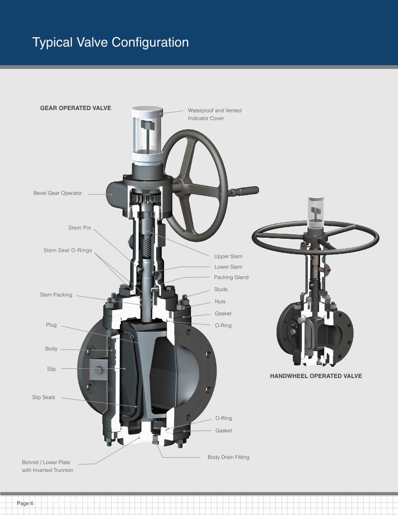
Stem Extensions
Page 20
OmniSeal® DBB expanding plug valves can be supplied with vertical or horizontal stem extensions (or a combination of both). It is
important to specify Dimension A when ordering vertical extensions and Dimension B when ordering horizontal extensions.
GEAR OPERATOREXTENSION-CLOSED
TYPE 1
HAND OPERATOREXTENSION-CLOSED
TYPE 1
HAND OPERATOREXTENSION-OPEN
TYPE 2
GEAR OPERATOREXTENSION-HORIZONTAL
TYPE 3
-OR-
NOTES
Type 1 extensions are suitable for underground burial
Type 2 extensions are exposed and not suitable for burial.
Type 3 extensions should be supported if dimension B is 36 inches (900 mm) or greater.
A
B
Figure Numbers
Page 21
OmniSeal® figure numbers provide an easy way to specify the valve you need and communicate with Omni Valve or its distributors.
Please use the following format to determine the appropriate figure number for any one of our valve sizes or configurations:
CLASS – SIZE / OPER / MAK (optional)
CLASS These digits refer to the ANSI class of the valve. 150 = ANSI Class 150, 300 = ANSI Class 300, 600 = ANSI Class 600
SIZE These digits refer to the valve size. 2 = ANSI 2”, 3,4,6,8,10,12,14,16,18,20,24,28,30,36, etc.
OPER These digits refer to the valve operator. Handhweel Operators Gear Operators 37H, 50H 37G, 55G, 62G, 75G, 12G, 14G, 15G
MAK These digits are only used if a MAK (Motor Adapter Kit) is required for the valve to be automated.
EXAMPLE: A) 8” ANSI 300 Gear Operated, with MAK 1) CLASS – 300 2) SIZE – Dash 8 3) OPERATOR – Slash 4) MAK Needed – Slash MAK
Figure number for above: 300-8/75G/MAK
B) 10” ANSI 150, Gear Operated: 150-10/62G
NOTE: If specifying a reduced face-to-face pattern valve (for 16,18, 20 and 24” Class 150 valves only) Then figure number is the same except that a “V” added to the number in the class section
Figure number: V150-18/12G
If MAK needed: V150-18/12G/MAK

Some Copy Here....
Replacement Parts and Rebuild Kits
Page 22
SPARE PARTS
Omni Valve stocks a complete line of replacement parts for the OmniSeal® DBB Expanding Plug Valve.
Please contact our exclusive global distributor for more information.
KITS
Omni Valve stocks various rebuild kits for the OmniSeal® DBB Expanding Plug Valve as follows.
Please contact our exclusive global distributor for more information.
NOTES (1) Stem packing is pre-formed flexible graphite.
(2) O-Rings are 75D Viton B unless otherwise specified.
(3) Gaskets are flexible graphite unless otherwise specified.
SLIPS
Slips for each plug valve size in standard Viton B trim are available off the shelf. Alternative seal materials are available upon request.
CLOSURE KIT (CK) (1) Body O-Ring and (1) Fire Seal Body Gasket. A closure kit is required for each of the upper and lower bonnets.
STEM KIT (SK) (1) Stem Packing Set, (1) Stem Seal ID O-Ring and (1) Stem Seal OD O-Ring.
REBUILD KIT (RK) (2) Closure Kits and (1) Stem Kit.
MOTOR ADAPTOR KIT (MAK) (1) Actuator Mounting Flange and (1) Stem Spacer Sleeve.
CLEAR ACRYLIC PROTECTOR CAPS
Clear acrylic protector caps and shipping caps for all sizes.
RELIEF SYSTEMS AND COMPONENTS
Standard relief systems and components for each valve size are available off the shelf. Custom relief systems available upon request.

Factory and Exclusive Distributor
Page 23
EXCLUSIVE MANUFACTURER FOR OMNISEAL® DBB EXPANDING PLUG VALVES
Q 6D-0364
www.GPI.co.in
All products manufactured or sold by Omni are warranted against defects of material and workmanship for a period of twelve (12) months from the date of installation or eighteen (18) months from date of shipment, whichever period first expires, when all such products are used in the service and within the pressure range for which they were manufactured.
In the case of products or parts not wholly of Omni’s manufacture, Omni’s liability shall be limited to the extent of Omni’s recovery from the original manufacturer of such products or parts under its warranty or liability to Omni.
Any repair work performed by Omni is warranted for one year from completion of such repairs and applies only to work performed. If, within these specified periods, Omni receives notice from Buyer of any alleged defect in or nonconformance of any product or repair and if in Omni’s sole judgment the product or repair does not conform or is found to be defective in material or workmanship, then, Buyer shall, at Omni’s request, return the part or product F.O.B. to Omni’s designated plant or service location.
Omni has no liability for removal or reinstallation of products or equipment. Omni, at its option and expense, shall repair or replace the defec-tive part or product, or repay to Buyer the full price paid by Buyer for such defective part, repair or product. Any repayment of purchase price shall be without interest.
Omni’s warranty liability, including defects caused by Omni’s negligence, shall be limited to such repair, replacement or refund, and shall not include claims for labor costs, expenses of Buyer resulting from such defects, recovery under general tort law or strict liability or for dam-ages resulting from delays, loss of use, or other direct, indirect, incidental or consequential damages of any kind.
Omni will not be responsible for failures of products which have been in any way tampered with or altered by anyone other than an authorized representative of Omni, failures due to lack of compliance with recommended maintenance procedures or products which have been re-paired or altered in such a way (in Omni’s judgment) as to affect the products adversely.
THIS WARRANTY IS EXPRESSLY IN LIEU OF ALL OTHER WARRANTIES, EXPRESS, STATUTORY OR IMPLIED, INCLUDING THE WARRANTY OF MERCHANTABILITY AND FITNESS FOR PARTICULAR PURPOSE WHICH EXCEED THE FOREGOING WARRANTY.
If you have questions regarding this warranty or if you would like information about other Omni products and services please contact us at the address and phone numbers below.
Limited Product Warranty
EXCLUSIVE GLOBAL SALESOne Schuylkill Pkwy. | Bridgeport, PA 19405 U.S.A. Phone (610) 270-2814 Fax (610) 270-0113Attention: Dan Bradley, Director Of [email protected]
ENGINEERING, SERVICE AND DISTRIBUTION 4520 Chandler Rd. | Muskogee, OK 74403 U.S.A. Phone (918) 687-6100 Fax (918) [email protected]

OmniSeal ® Double Block & Bleed Expanding Plug Valve
© 2014 Omni Valve Company, LLC, | BRO-EPV Rev: 3.0
Omni Valve(610) 270-2814w w w. o m n i v a l v e . c o m
Global Energy Market Solut ions
SCAN TO VIEW PDF