Evaluation of Bleed Valve Rate Requirements in Nonlinear ...
21
-
Upload
khangminh22 -
Category
Documents
-
view
1 -
download
0
Transcript of Evaluation of Bleed Valve Rate Requirements in Nonlinear ...
Evaluation of Bleed Valve Rate Requirements in Nonlinear Controlof Rotating Stall on Axial Flow Compressors �Simon [email protected] Yong [email protected] Richard M. [email protected] of Engineering and Applied ScienceCalifornia Institute of TechnologyPasadena, CA 91125CDS Technical Report 98-00117th February, 1998AbstractIn this paper we evaluate the actuator rate requirements for control of rotating stall using ableed valve and provide tools for predicting these requirements. Modi�cation of both the stableand unstable parts of the compressor characteristic via addition of continuous air injection servesto reduce the requirement of a bleed valve used for the purpose of rotating stall stabilization.Analytical tools based on low order models (2-3 states) and simulation tools based on a reducedorder model (37 states) are described. A bleed actuator rate limit study is presented to comparethe actuator requirements predicted by theory, simulation, and experiment. The comparisonsshow that the predictions obtained from theory and simulations share the same trend as theexperiments, with increasing accuracy as the complexity of the underlying model increases.Some insights on the design of a bleed-compressor pair are given.NomenclatureB, lc, m, � compressor model parameters; see [12]A amplitude of �rst Fourier modeAnom amplitude of �rst Fourier mode of fully developed stall cellCx axial ow velocity� noise level of the system expressed as a percentage of J throttle coe�cient, �T ( ) = p J squared amplitude of �rst Fourier mode, J = A2KX gain estimation from method XKRS gain for control of rotating stall in Liaw-Abed control lawKSU gain for control of surge in Eveker et al. [9] control lawRX rate estimation from method XU mean rotor speedu bleed valve control e�ortumag magnitude saturation of the bleed actuator as percentage of ��urate bleed valve rate limit in rotor revolutions for valve to open from fully closed�Funding for this research was provided in part by AFOSR grant F49620-95-1-0409.
� density of air�P pressure rise� nondimensionalized axial ow velocity, � = Cx=U�� � at peak of compressor characteristic�T ( ) nondimensionalized throttle characteristic as a function of nondimensionalized pressure rise, = �P=(�U2) � at peak of compressor characteristicc(�) nondimensionalized compressor characteristic as a function of �1 IntroductionRotating stall and surge are two types of instabilities that occur in axial ow compressor systemssuch as those in a gas turbine engine. Rotating stall refers to a non-axisymmetric ow perturbationthat travels around the annulus of the compressor (sometimes referred to as a stall cell), while surgeis a large axial oscillation of the ow. Typical e�ects of rotating stall and surge range from stress andwear on the compressor blades, to perturbation of the operation of the components downstream ofthe compressor in the engine, to destruction of the engine. Active control of rotating stall and surgecan lead to an increase in the stability of a compressor against various disturbances such as inletdistortions and power transients. As a result, a compressor with active controls can operate closer tothe current stall/surge line. The bene�ts can be realized in various ways including increased pointsof e�ciency, lower take-o� gross weight, lower speci�c fuel consumption, and stability/operabilityenhancement in maneuvers. Examples can be found in a set of reports prepared by Pratt andWhitney [15], General Electric Aircraft Engines [8], and Allison Gas Turbine [7] for the NationalTechnical Information Service of the U.S. Department of Commerce on an evaluation of controlconcepts applied to gas turbine engine operations for both civilian and military aircraft.Modeling and active control of rotating stall and surge has been investigated by a numberof researchers. A simpli�ed model was derived by Moore and Greitzer [12] for a compressionsystem that exhibits rotating stall and surge. Based on this model, Liaw and Abed [16] derived acontrol law using a bleed valve for rotating stall. Experimental evaluations and analysis of othercontrol laws using various types of actuators were investigated by other groups, including but notlimited to Badmus et al. [1, 2], Paduano et al. [20], Day [6], Gysling et al. [13], D'Andrea etal. [5], Freeman et al. [10], Eveker et al. [9], and Yeung and Murray [24, 25]. Eveker et al. [9] isthe �rst group to report successful experimental implementation of a bleed valve controller. Inparticular, the bleed valve actuation method tested by Eveker et al. [9] employs a 25 Hz (fullopen/full close) bleed valve and reports results on a compressor with a rotor frequency between22.5 and 26.7 Hz; D'Andrea et al. [5] proposed a pulsed air injection method which uses 200 Hzbinary injection actuators driven by solenoid valves on a compressor with a rotor frequency of100 Hz; and the recirculation study reported in Freeman et al. [10] uses 300 Hz sleeve valves on acompressor with a 106 Hz stall frequency. For industrial applications where the compressors may besigni�cantly more powerful (higher ow and pressure rise, higher rotor frequency, etc) than researchcompressors, obstacles such as control actuator magnitude and rate saturation can become crucialin these active control methods. Tools that predict and reduce the rate requirements of actuatorsfor purposes of control of rotating stall in compressors can be valuable in designing actuators andcircumventing possible actuator magnitude and rate limitations that may prevent successful activecontrol implementations.Attempts to control rotating stall on a single-stage, low-speed axial compressor at Caltech werecarried out initially with a high speed bleed actuator and results were unsuccessful due to the fastgrowth rate of the stall cell relative to the rate limit of the valve [24]. It has been shown by D'Andrea2
et al. [5] that air injection can be modeled as a shift of the compressor characteristic. By addingcontinuous air injection, the compressor characteristic is shifted favorably for bleed valve controlof rotating stall and demonstration of control is achieved only with the compressor characteristicactuation [24, 25]. On the Caltech rig, the amount of compressor characteristic shifting can bevaried by modifying the geometric features of the injection actuators setup [4], providing a familyof compressor characteristics. In this paper, investigation of the trade-o� between actuation of thecompressor characteristic and the bleed valve rate requirement is carried out, with the followinggoals:1. Identify possible functional dependence of the rate limit of a bleed valve in control of rotatingstall on the shape of the compressor characteristic.2. Provide a possible route to circumvent bleed valve rate limitation given the capability ofactuation or modi�cation of the compressor characteristic.3. Provide insights for designing a compressor-bleed pair for purposes of stabilization of rotatingstall.This paper is organized as follows. Section 2 describes the features of a low order model ofrotating stall and surge proposed by Moore and Greitzer [12]. The modeling of bleed actuationand continuous air injection is introduced as a modulation of the throttle [16] and compressorcharacteristic [5] respectively. The relevant control law will be given for the bleed valve. Analyticalformulas are presented as theoretical tools used for predicting the minimum gain in the control lawand rate limit of the bleed valve required for stabilization. A brief description of the simulation toolsusing a reduced order model proposed will end the section. Section 3 describes the experimentalsetup at Caltech including details of the sensing and actuation equipment. Section 4 presents theresults of control of rotating stall using bleed valve with continuous air injection. A comparisonstudy correlating the theory, simulation, and experiment in terms of the values of the gain and rateand the various features of the compressor characteristic is included to validate the theoretical andsimulation tools. Finally, we summarize the �ndings of the investigation in Section 5.2 Modeling and TheoryThis section �rst gives a brief review of the main features of a low order model proposed by Mooreand Greitzer [12]. Modeling of bleed actuation in the model is introduced and a review of a controllaw proposed by Liaw and Abed [16] is given. Expressions for the minimum gain and rate requiredfor peak stabilization of rotating stall are presented. The section then ends with a brief descriptionof the simulation tool using a high �delity model proposed by Mansoux et al. [18].2.1 Moore-Greitzer ModelTo describe the basic behavior of the compression system, we make use of a low order model derivedby Moore and Greitzer [12]. The model consists of three ordinary di�erential equations describingthe evolution of the nondimensionalized axial ow velocity �, nondimensionalized pressure rise ,3
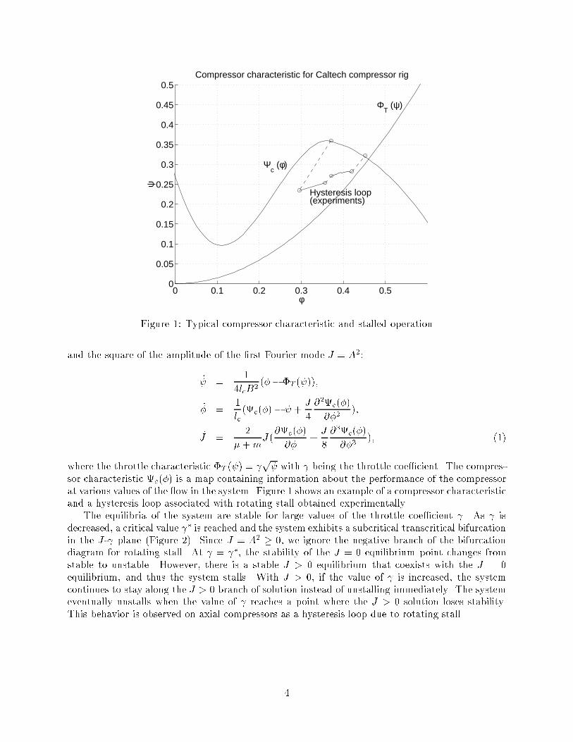
0 0.1 0.2 0.3 0.4 0.50
0.05
0.1
0.15
0.2
0.25
0.3
0.35
0.4
0.45
0.5Compressor characteristic for Caltech compressor rig
Ψc (φ)
Hysteresis loop(experiments)
ΦT (ψ)
φ
ψ
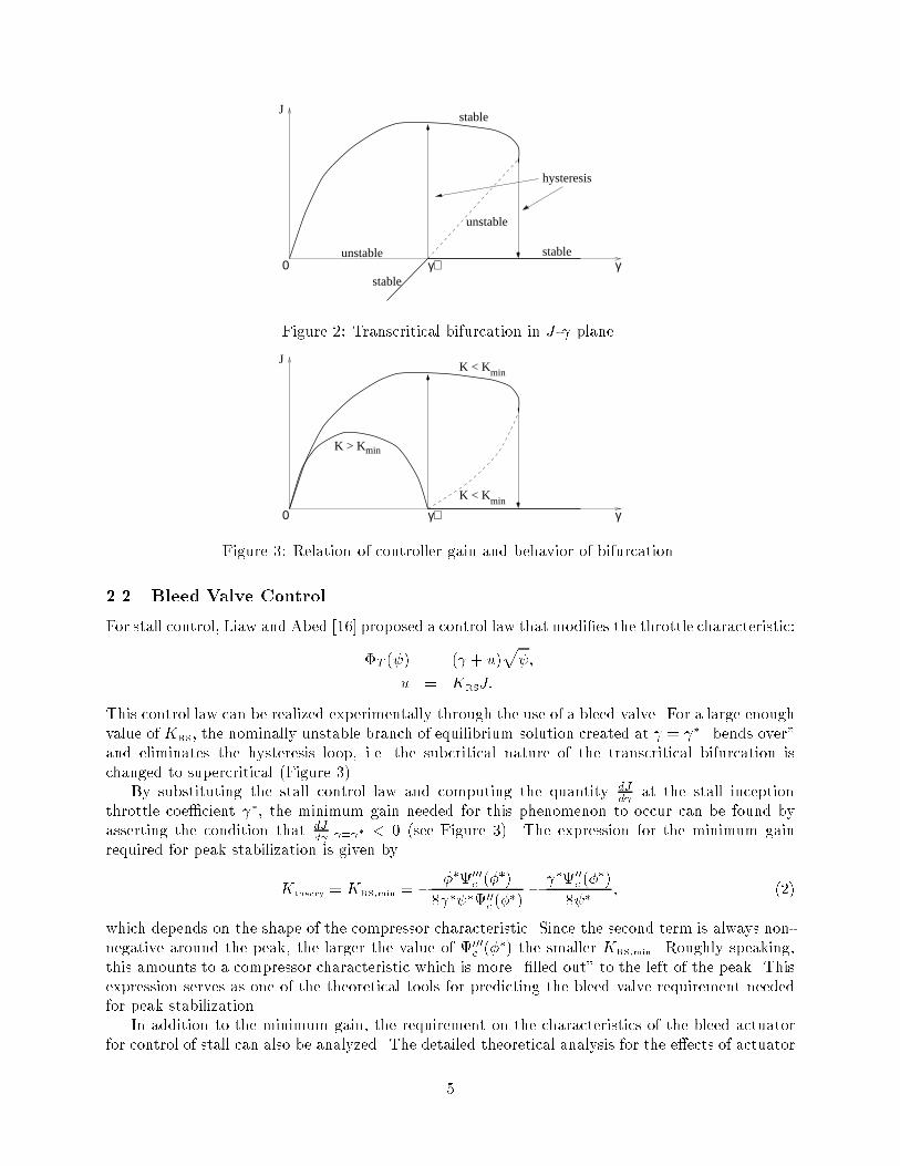
Figure 1: Typical compressor characteristic and stalled operationand the square of the amplitude of the �rst Fourier mode J = A2:_ = 14lcB2 (�� �T ( ));_� = 1lc (c(�)� + J4 @2c(�)@�2 );_J = 2� +mJ(@c(�)@� + J8 @3c(�)@�3 ); (1)where the throttle characteristic �T ( ) = p with being the throttle coe�cient. The compres-sor characteristic c(�) is a map containing information about the performance of the compressorat various values of the ow in the system. Figure 1 shows an example of a compressor characteristicand a hysteresis loop associated with rotating stall obtained experimentally.The equilibria of the system are stable for large values of the throttle coe�cient . As isdecreased, a critical value � is reached and the system exhibits a subcritical transcritical bifurcationin the J- plane (Figure 2). Since J = A2 � 0, we ignore the negative branch of the bifurcationdiagram for rotating stall. At = �, the stability of the J = 0 equilibrium point changes fromstable to unstable. However, there is a stable J > 0 equilibrium that coexists with the J = 0equilibrium, and thus the system stalls. With J > 0, if the value of is increased, the systemcontinues to stay along the J > 0 branch of solution instead of unstalling immediately. The systemeventually unstalls when the value of reaches a point where the J > 0 solution loses stability.This behavior is observed on axial compressors as a hysteresis loop due to rotating stall.4
γ
J
0stable
stable
unstable
stableγ∗
hysteresis
unstableFigure 2: Transcritical bifurcation in J- plane.K < Kmin
K > Kmin
K < Kmin
γ
J
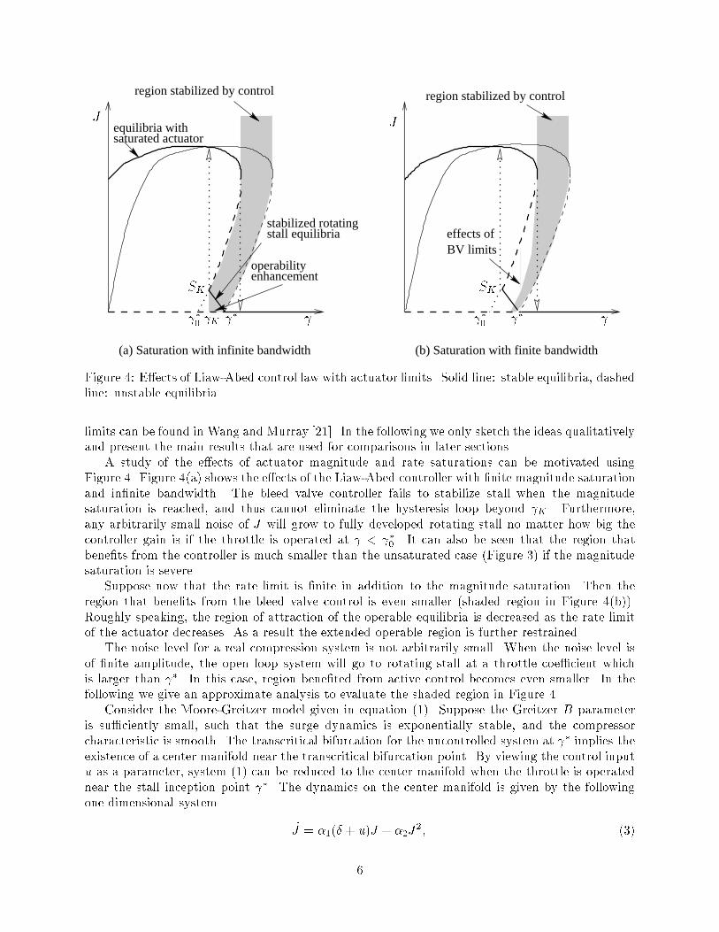
0 γ∗Figure 3: Relation of controller gain and behavior of bifurcation.2.2 Bleed Valve ControlFor stall control, Liaw and Abed [16] proposed a control law that modi�es the throttle characteristic:�T ( ) = ( + u)p ;u = KRSJ:This control law can be realized experimentally through the use of a bleed valve. For a large enoughvalue of KRS, the nominally unstable branch of equilibrium solution created at = � \bends over"and eliminates the hysteresis loop, i.e. the subcritical nature of the transcritical bifurcation ischanged to supercritical (Figure 3).By substituting the stall control law and computing the quantity dJd at the stall inceptionthrottle coe�cient �, the minimum gain needed for this phenomenon to occur can be found byasserting the condition that dJd j = � < 0 (see Figure 3). The expression for the minimum gainrequired for peak stabilization is given byKtheory = KRS;min = � ��000c (��)8 � �00c (��) � �00c (��)8 � ; (2)which depends on the shape of the compressor characteristic. Since the second term is always non-negative around the peak, the larger the value of 000c (��) the smaller KRS;min. Roughly speaking,this amounts to a compressor characteristic which is more \�lled out" to the left of the peak. Thisexpression serves as one of the theoretical tools for predicting the bleed valve requirement neededfor peak stabilization.In addition to the minimum gain, the requirement on the characteristics of the bleed actuatorfor control of stall can also be analyzed. The detailed theoretical analysis for the e�ects of actuator5
region stabilized by control
(b) Saturation with finite bandwidth
region stabilized by control
enhancementoperability
equilibria withsaturated actuator
stabilized rotatingstall equilibria effects of
BV limits
(a) Saturation with infinite bandwidth
�0SK SKJJ
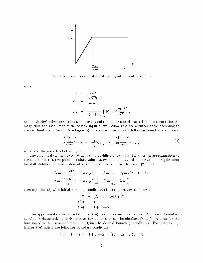
K �0 � � Figure 4: E�ects of Liaw-Abed control law with actuator limits. Solid line: stable equilibria, dashedline: unstable equilibria.limits can be found in Wang and Murray [21]. In the following we only sketch the ideas qualitativelyand present the main results that are used for comparisons in later sections.A study of the e�ects of actuator magnitude and rate saturations can be motivated usingFigure 4. Figure 4(a) shows the e�ects of the Liaw-Abed controller with �nite magnitude saturationand in�nite bandwidth. The bleed valve controller fails to stabilize stall when the magnitudesaturation is reached, and thus cannot eliminate the hysteresis loop beyond K . Furthermore,any arbitrarily small noise of J will grow to fully developed rotating stall no matter how big thecontroller gain is if the throttle is operated at < �0 . It can also be seen that the region thatbene�ts from the controller is much smaller than the unsaturated case (Figure 3) if the magnitudesaturation is severe.Suppose now that the rate limit is �nite in addition to the magnitude saturation. Then theregion that bene�ts from the bleed valve control is even smaller (shaded region in Figure 4(b)).Roughly speaking, the region of attraction of the operable equilibria is decreased as the rate limitof the actuator decreases. As a result the extended operable region is further restrained.The noise level for a real compression system is not arbitrarily small. When the noise level isof �nite amplitude, the open loop system will go to rotating stall at a throttle coe�cient whichis larger than �. In this case, region bene�ted from active control becomes even smaller. In thefollowing we give an approximate analysis to evaluate the shaded region in Figure 4.Consider the Moore-Greitzer model given in equation (1). Suppose the Greitzer B parameteris su�ciently small, such that the surge dynamics is exponentially stable, and the compressorcharacteristic is smooth. The transcritical bifurcation for the uncontrolled system at � implies theexistence of a center manifold near the transcritical bifurcation point. By viewing the control inputu as a parameter, system (1) can be reduced to the center manifold when the throttle is operatednear the stall inception point �. The dynamics on the center manifold is given by the followingone dimensional system _J = �1(� + u)J + �2J2; (3)6
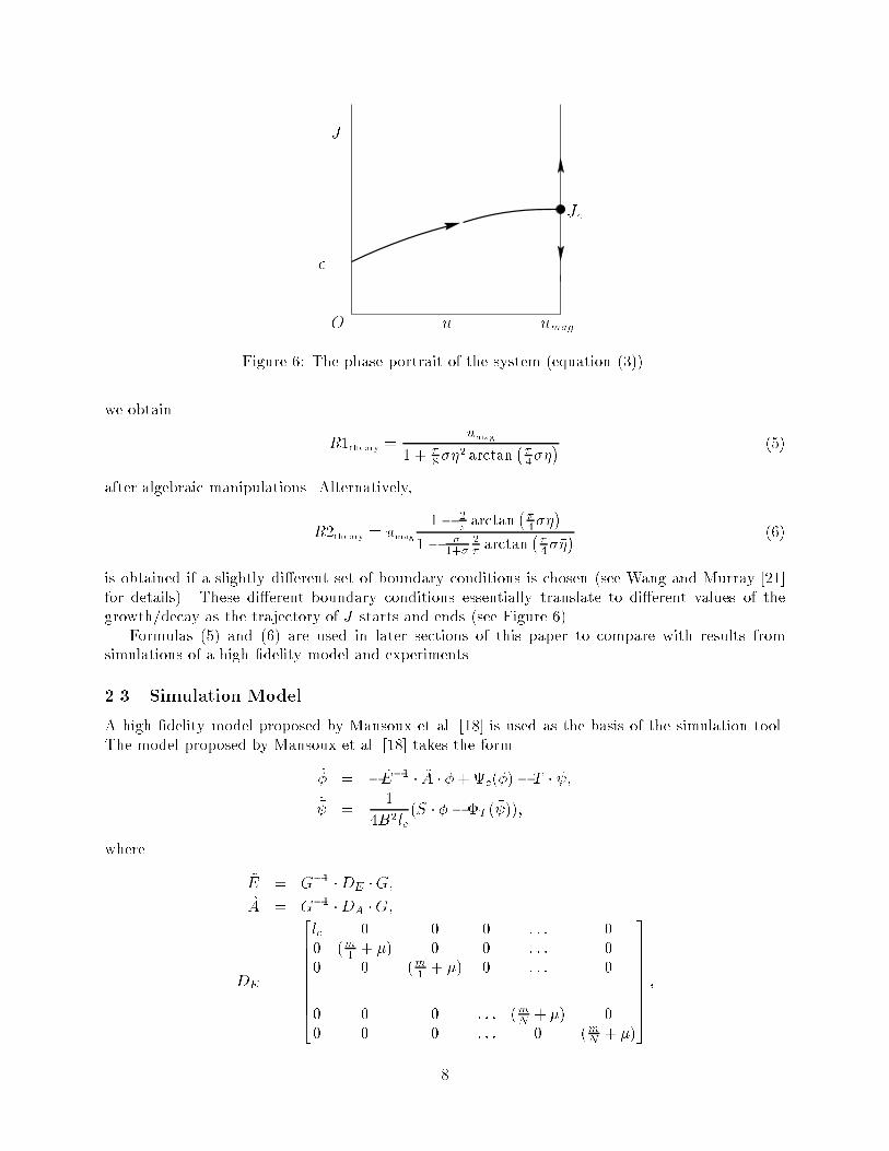
�uumag umagurateFigure 5: Controllers constrained by magnitude and rate limitswhere � = � �;�1 = 2p �00cm+ � ;�2 = 14(m+ �) 000c + �00c 2p � ! ;and all the derivatives are evaluated at the peak of the compressor characteristic. To account for themagnitude and rate limits of the control input u, we assume that the actuator opens according tothe rate limit and saturates (see Figure 5). The system then has the following boundary conditions.J(0) = �; u(0) = 0;J(umagurate ) = Jc = ��1�2 (umag + �); u(umagurate ) = umag; (4)where � is the noise level of the system.The analytical solution to equation (3) can be di�cult to obtain. However, an approximation tothe solution of this two-point boundary value system can be obtained. The rate limit requirementfor stall stabilization in a system of a given noise level can then be found [21]. Let� = 1 + �1��2� ; � = �2��; f = J� ; Jc = �(� + 1��);� = ��1umag�2� ; �� = �2�umagurate ; f 0 = dfd� ; � = ��� ;then equation (3) with initial and �nal conditions (4) can be written as follows:f 0 = (�� 1� ��)f + f2;f(0) = 1;f(��) = 1 + � ��:The approximation to the solution of f(��) can be obtained as follows. Additional boundaryconditions characterizing derivatives at the boundaries can be obtained from f 0. A form for thefunction f is then assumed while satisfying the desired boundary conditions. For instance, byletting f(�) satisfy the following boundary conditions,f(0) = 1; f(��) = 1 + � ��; f 0(0) = �; f 0(��) = 0:7
Jc� O u umagJ
Figure 6: The phase portrait of the system (equation (3)).we obtain R1theory = umag1 + �8���2 arctan ��4���� (5)after algebraic manipulations. Alternatively,R2theory = umag 1� 2� arctan ��4����1� �1+� 2� arctan ��4���� (6)is obtained if a slightly di�erent set of boundary conditions is chosen (see Wang and Murray [21]for details). These di�erent boundary conditions essentially translate to di�erent values of thegrowth/decay as the trajectory of J starts and ends (see Figure 6).Formulas (5) and (6) are used in later sections of this paper to compare with results fromsimulations of a high �delity model and experiments.2.3 Simulation ModelA high �delity model proposed by Mansoux et al. [18] is used as the basis of the simulation tool.The model proposed by Mansoux et al. [18] takes the form_� = � ~E�1 � ~A � �+c(�)� T � � ;_� = 14B2lc (S � � � �T ( � ));where ~E = G�1 �DE �G;~A = G�1 �DA �G;DE = 266666664lc 0 0 0 : : : 00 (m1 + �) 0 0 : : : 00 0 (m1 + �) 0 : : : 0...0 0 0 : : : (mN + �) 00 0 0 : : : 0 (mN + �)377777775 ;8
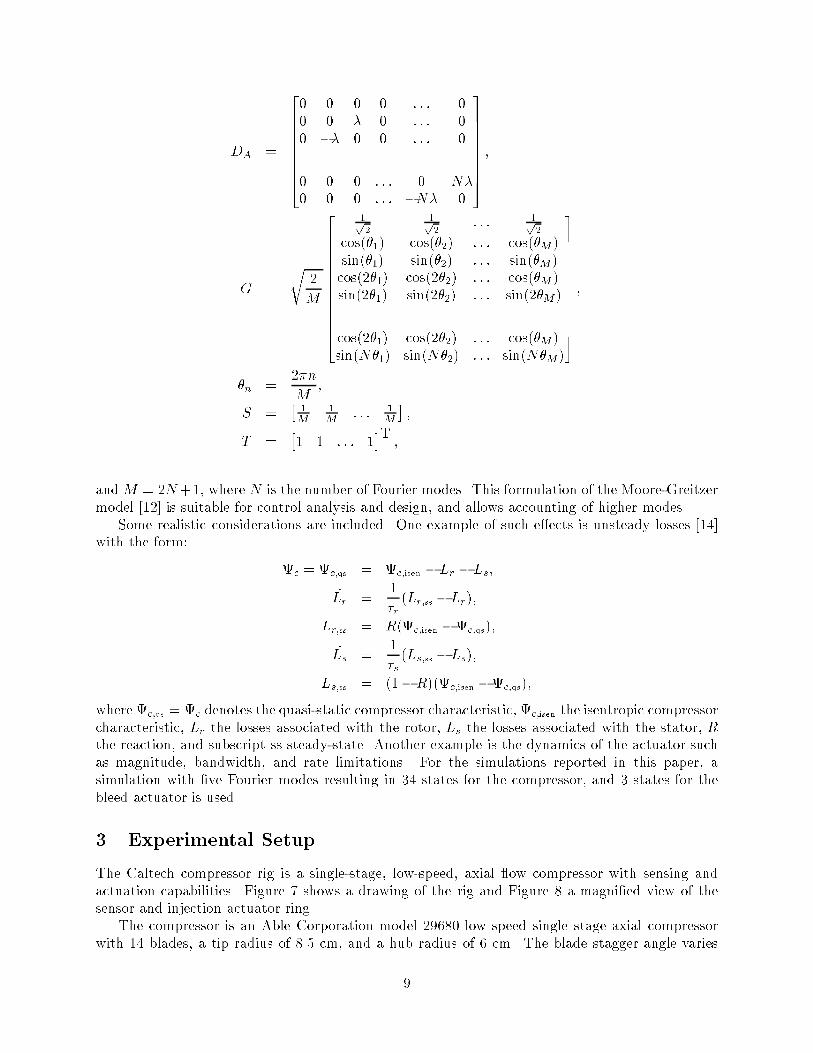
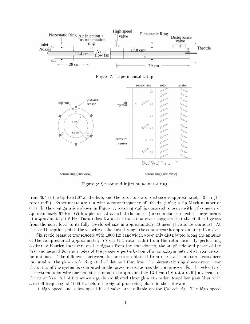
DA = 2666666640 0 0 0 : : : 00 0 � 0 : : : 00 �� 0 0 : : : 0...0 0 0 : : : 0 N�0 0 0 : : : �N� 0 377777775 ;G = r 2M 2666666666664 1p2 1p2 : : : 1p2cos(�1) cos(�2) : : : cos(�M )sin(�1) sin(�2) : : : sin(�M)cos(2�1) cos(2�2) : : : cos(�M )sin(2�1) sin(2�2) : : : sin(2�M )... ... ... ...cos(2�1) cos(2�2) : : : cos(�M )sin(N�1) sin(N�2) : : : sin(N�M)3777777777775 ;�n = 2�nM ;S = � 1M 1M : : : 1M � ;T = �1 1 : : : 1�T ;andM = 2N+1, where N is the number of Fourier modes. This formulation of the Moore-Greitzermodel [12] is suitable for control analysis and design, and allows accounting of higher modes.Some realistic considerations are included. One example of such e�ects is unsteady losses [14]with the form: c = c;qs = c;isen � Lr � Ls;_Lr = 1�r (Lr;ss � Lr);Lr;ss = R(c;isen � c;qs);_Ls = 1�s (Ls;ss � Ls);Ls;ss = (1� R)(c;isen �c;qs);where c;qs = c denotes the quasi-static compressor characteristic, c;isen the isentropic compressorcharacteristic, Lr the losses associated with the rotor, Ls the losses associated with the stator, Rthe reaction, and subscript ss steady-state. Another example is the dynamics of the actuator suchas magnitude, bandwidth, and rate limitations. For the simulations reported in this paper, asimulation with �ve Fourier modes resulting in 34 states for the compressor, and 3 states for thebleed actuator is used.3 Experimental SetupThe Caltech compressor rig is a single-stage, low-speed, axial ow compressor with sensing andactuation capabilities. Figure 7 shows a drawing of the rig and Figure 8 a magni�ed view of thesensor and injection actuator ring.The compressor is an Able Corporation model 29680 low speed single stage axial compressorwith 14 blades, a tip radius of 8.5 cm, and a hub radius of 6 cm. The blade stagger angle varies9
Inlet
79 cm
Nozzle
Piezostatic Ring
flow fanAxial-
Piezostatic Ring
Throttle
Disturbancevalvering
Instrumentation
High speedvalveAir injection +
17.8 cm11.4 cm
28 cm Figure 7: Experimental setup.pressuresensor
8.5 cm
injector
6 cm
injectorair
pressuresensor
sensor ring (end view) sensor ring (side view)
5.7 cm4.7 cm 12 cm
statorrotorsensor ring
Figure 8: Sensor and injection actuator ring.from 30� at the tip to 51:6� at the hub, and the rotor to stator distance is approximately 12 cm (1.4rotor radii). Experiments are run with a rotor frequency of 100 Hz, giving a tip Mach number of0.17. In the con�guration shown in Figure 7, rotating stall is observed to occur with a frequency ofapproximately 67 Hz. With a plenum attached at the outlet (for compliance e�ects), surge occursat approximately 1.8 Hz. Data taken for a stall transition event suggests that the stall cell growsfrom the noise level to its fully developed size in approximately 30 msec (3 rotor revolutions). Atthe stall inception point, the velocity of the ow through the compressor is approximately 16 m/sec.Six static pressure transducers with 1000 Hz bandwidth are evenly distributed along the annulusof the compressor at approximately 5.7 cm (1.1 rotor radii) from the rotor face. By performinga discrete Fourier transform on the signals from the transducers, the amplitude and phase of the�rst and second Fourier modes of the pressure perturbation of a nonaxisymmetric disturbance canbe obtained. The di�erence between the pressure obtained from one static pressure transducermounted at the piezostatic ring at the inlet and that from the piezostatic ring downstream nearthe outlet of the system is computed as the pressure rise across the compressor. For the velocity ofthe system, a hotwire anemometer is mounted approximately 13.4 cm (1.6 rotor radii) upstream ofthe rotor face. All of the sensor signals are �ltered through a 4th order Bessel low pass �lter witha cuto� frequency of 1000 Hz before the signal processing phase in the software.A high speed and a low speed bleed valve are available on the Caltech rig. The high speed10
bleed valve, used primarily for stall control, has a magnitude saturation of 12% (corresponding toan area of 11.4 cm2) of the ow at the stall inception point and is approximately 26 cm (3.1 rotorradii) downstream of the rotor. The low speed valve, used primarily for surge control and throttledisturbance generation, has a magnitude saturation of 30% of the ow of the system at the stallinception point and is estimated to have a small signal (�5� angle modulation) bandwidth of 50Hz and a large signal (�90� angle modulation) bandwidth of 15 Hz.The air injectors are on-o� type injectors driven by solenoid valves. For applications on theCaltech compressor rig, the injectors are fed with a pressure source supplying air at a maximumpressure of 80 psig. The injectors are located at approximately 10.4 cm (1.2 rotor radii) upstreamof the rotor. Due to signi�cant losses across the solenoid valves and between the valves and thepressure source, the injector back pressure reading does not represent an accurate indication of theactual velocity of the injected air on the rotor face. Using a hotwire anemometer, the maximumvelocity of the velocity pro�le produced by the injected air measured at a distance equivalent to therotor-injector distance for 50 and 60 psig injector back pressure are measured to be approximately30.2 and 33.8 m/sec respectively. At the stall inception point, each injector can add approximately1.7% mass, 2.4% momentum, and 1.3% energy to the system when turned on continuously at 60psig injector back pressure. The bandwidth associated with the injectors is approximately 200 Hzat 50% duty cycle. The angle of injection, injector back pressure, the axial location of the injectors,and the radial location of the injectors can all be varied.All experiments are run in real time using Sparrow [19] with a sampling frequency of 2000 Hzon a Pentium 100 MHz PC.4 ResultsIn this section, we present the results for axisymmetric bleed with continuous air injection. Controlof rotating stall is demonstrated �rst. A description of the procedure leading to the comparisonstudy is then given, followed by the results.4.1 Demonstration of ControlAt certain injector angles and locations, di�erent injector back pressure can reduce the size ofthe open-loop hysteresis loop by di�erent amounts on the Caltech rig. Addition of continuousair injection is conjectured to reduce rate and magnitude requirements for bleed valve controls ofrotating stall by changing the compressor characteristic.To validate the conjecture, the air injector angle is set at 27� (with positive angles implyingcounter-compressor-rotation) and 60 psig injector back pressure. With the plenum attached, surgecycle data is taken and the algorithm for identifying the unstable part of the compressor charac-teristic as described by Behnken [3]. Figure 9 shows the results.The identi�ed compressor characteristic is more \�lled out" on the left of the peak. The crossesin Figure 9 are experimental data points of the stable side of the compressor characteristic withcontinuous air injection, the right solid curve the polynomial �t of the experimental data points,the left solid curve the identi�ed unstable part of the characteristic in the presence of continuousair injection, the dashed the compressor characteristic with no air injection, and the shaded regionthe experimental surge cycles data for c(�) in the presence of air injection. As shown in the �gure,the shape of the compressor characteristic is shifted in the presence of continuous air injection.The shifting of the compressor characteristic serves to reduce the bandwidth and rate require-ment of the bleed valve for control of rotating stall. To observe this phenomenon, equation (2) canserve as an initial tool. Equation (2) gives a formula to the minimum gain required for stabilization11
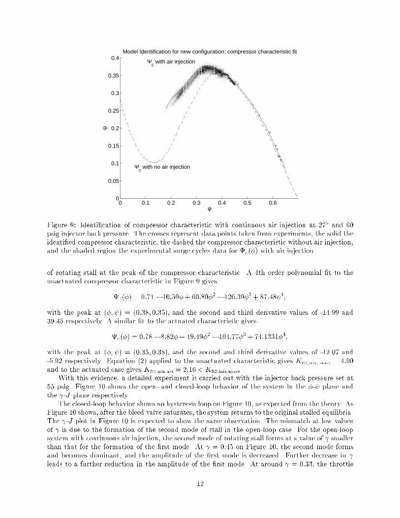
0 0.1 0.2 0.3 0.4 0.5 0.60
0.05
0.1
0.15
0.2
0.25
0.3
0.35
0.4Model Identification for new configuration: compressor characteristic fit
φ
Ψc with air injection
Ψc with no air injection
ψ
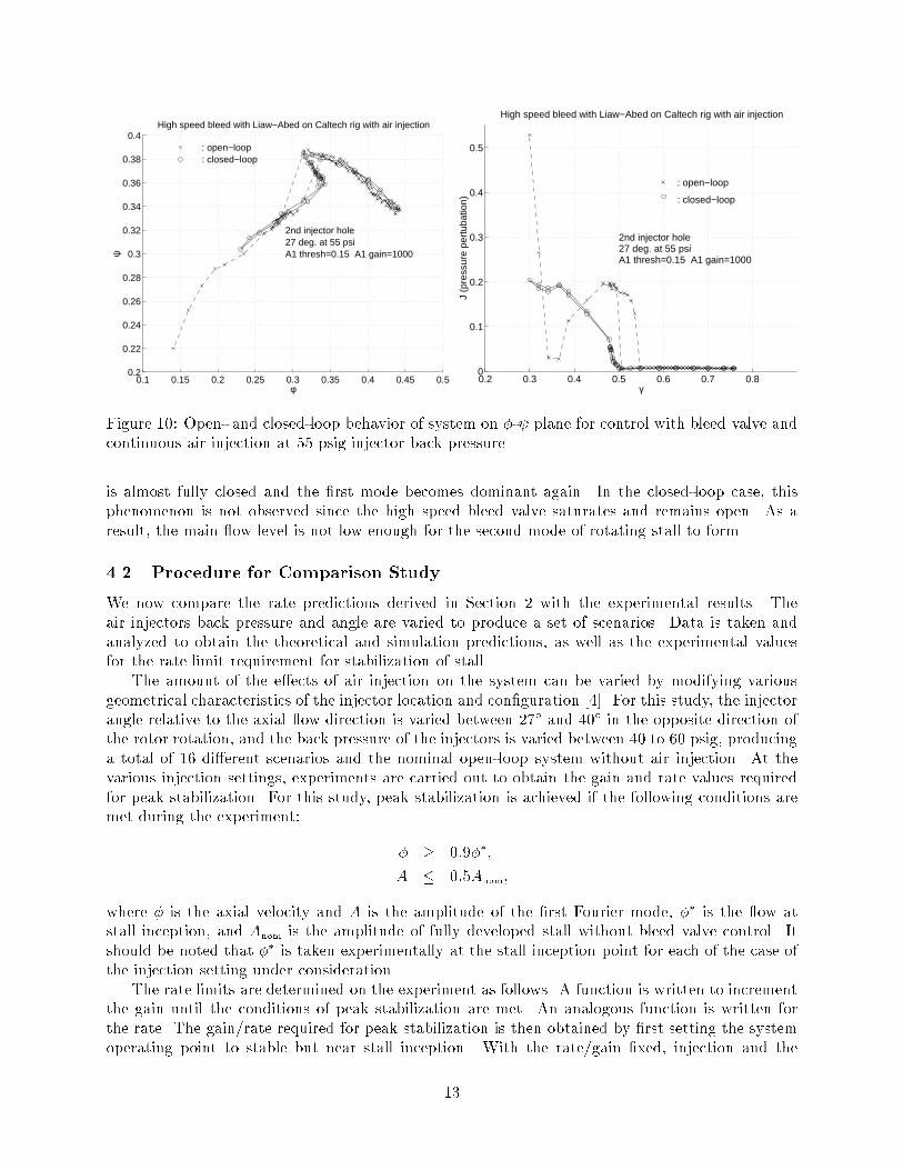
Figure 9: Identi�cation of compressor characteristic with continuous air injection at 27� and 60psig injector back pressure. The crosses represent data points taken from experiments, the solid theidenti�ed compressor characteristic, the dashed the compressor characteristic without air injection,and the shaded region the experimental surge cycles data for c(�) with air injection.of rotating stall at the peak of the compressor characteristic. A 4th order polynomial �t to theunactuated compressor characteristic in Figure 9 givesc(�) = 0:71� 10:59�+ 60:80�2� 126:39�3+ 87:48�4;with the peak at (�; ) = (0:38; 0:35), and the second and third derivative values of -14.99 and39.45 respectively. A similar �t to the actuated characteristic givesc(�) = 0:78� 8:82�+ 49:49�2� 104:77�3 + 74:1331�4;with the peak at (�; ) = (0:35; 0:38), and the second and third derivative values of -12.07 and-5.92 respectively. Equation (2) applied to the unactuated characteristic gives KRS,min,unact = 4:00and to the actuated case gives KRS,min,act = 2:16 < KRS,min,unact.With this evidence, a detailed experiment is carried out with the injector back pressure set at55 psig. Figure 10 shows the open- and closed-loop behavior of the system in the �- plane andthe -J plane respectively.The closed-loop behavior shows no hysteresis loop on Figure 10, as expected from the theory. AsFigure 10 shows, after the bleed valve saturates, the system returns to the original stalled equilibria.The -J plot in Figure 10 is expected to show the same observation. The mismatch at low valuesof is due to the formation of the second mode of stall in the open-loop case. For the open-loopsystem with continuous air injection, the second mode of rotating stall forms at a value of smallerthan that for the formation of the �rst mode. At = 0:45 on Figure 10, the second mode formsand becomes dominant, and the amplitude of the �rst mode is decreased. Further decrease in leads to a further reduction in the amplitude of the �rst mode. At around = 0:33, the throttle12
0.1 0.15 0.2 0.25 0.3 0.35 0.4 0.45 0.50.2
0.22
0.24
0.26
0.28
0.3
0.32
0.34
0.36
0.38
0.4High speed bleed with Liaw−Abed on Caltech rig with air injection
φ
ψ
2nd injector hole27 deg. at 55 psiA1 thresh=0.15 A1 gain=1000
: open−loop : closed−loop
0.2 0.3 0.4 0.5 0.6 0.7 0.80
0.1
0.2
0.3
0.4
0.5
High speed bleed with Liaw−Abed on Caltech rig with air injection
γ
J (p
ress
ure
pert
ubat
ion)
: open−loop
: closed−loop
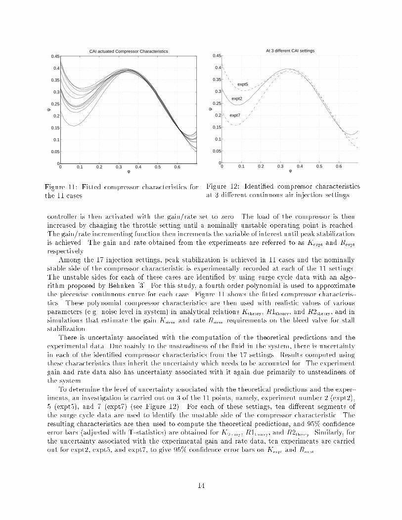
2nd injector hole27 deg. at 55 psiA1 thresh=0.15 A1 gain=1000Figure 10: Open- and closed-loop behavior of system on �- plane for control with bleed valve andcontinuous air injection at 55 psig injector back pressure.is almost fully closed and the �rst mode becomes dominant again. In the closed-loop case, thisphenomenon is not observed since the high speed bleed valve saturates and remains open. As aresult, the main ow level is not low enough for the second mode of rotating stall to form.4.2 Procedure for Comparison StudyWe now compare the rate predictions derived in Section 2 with the experimental results. Theair injectors back pressure and angle are varied to produce a set of scenarios. Data is taken andanalyzed to obtain the theoretical and simulation predictions, as well as the experimental valuesfor the rate limit requirement for stabilization of stall.The amount of the e�ects of air injection on the system can be varied by modifying variousgeometrical characteristics of the injector location and con�guration [4]. For this study, the injectorangle relative to the axial ow direction is varied between 27� and 40� in the opposite direction ofthe rotor rotation, and the back pressure of the injectors is varied between 40 to 60 psig, producinga total of 16 di�erent scenarios and the nominal open-loop system without air injection. At thevarious injection settings, experiments are carried out to obtain the gain and rate values requiredfor peak stabilization. For this study, peak stabilization is achieved if the following conditions aremet during the experiment: � � 0:9��;A � 0:5Anom;where � is the axial velocity and A is the amplitude of the �rst Fourier mode, �� is the ow atstall inception, and Anom is the amplitude of fully developed stall without bleed valve control. Itshould be noted that �� is taken experimentally at the stall inception point for each of the case ofthe injection setting under consideration.The rate limits are determined on the experiment as follows. A function is written to incrementthe gain until the conditions of peak stabilization are met. An analogous function is written forthe rate. The gain/rate required for peak stabilization is then obtained by �rst setting the systemoperating point to stable but near stall inception. With the rate/gain �xed, injection and the13
0 0.1 0.2 0.3 0.4 0.5 0.60
0.05
0.1
0.15
0.2
0.25
0.3
0.35
0.4
0.45
φ
ψCAI actuated Compressor Characteristics
Figure 11: Fitted compressor characteristics forthe 11 cases. 0 0.1 0.2 0.3 0.4 0.5 0.60
0.05
0.1
0.15
0.2
0.25
0.3
0.35
0.4
0.45
φ
ψ
At 3 different CAI settings
expt2
expt5
expt7Figure 12: Identi�ed compressor characteristicsat 3 di�erent continuous air injection settings.controller is then activated with the gain/rate set to zero. The load of the compressor is thenincreased by changing the throttle setting until a nominally unstable operating point is reached.The gain/rate incrementing function then increments the variable of interest until peak stabilizationis achieved. The gain and rate obtained from the experiments are referred to as Kexpt and Rexptrespectively.Among the 17 injection settings, peak stabilization is achieved in 11 cases and the nominallystable side of the compressor characteristic is experimentally recorded at each of the 11 settings.The unstable sides for each of these cases are identi�ed by using surge cycle data with an algo-rithm proposed by Behnken [3]. For this study, a fourth order polynomial is used to approximatethe piecewise continuous curve for each case. Figure 11 shows the �tted compressor characteris-tics. These polynomial compressor characteristics are then used with realistic values of variousparameters (e.g. noise level in system) in analytical relations Ktheory, R1theory, and R2theory, and insimulations that estimate the gain Ksimu and rate Rsimu requirements on the bleed valve for stallstabilization.There is uncertainty associated with the computation of the theoretical predictions and theexperimental data. Due mainly to the unsteadiness of the uid in the system, there is uncertaintyin each of the identi�ed compressor characteristics from the 17 settings. Results computed usingthese characteristics thus inherit the uncertainty which needs to be accounted for. The experimentgain and rate data also has uncertainty associated with it again due primarily to unsteadiness ofthe system.To determine the level of uncertainty associated with the theoretical predictions and the exper-iments, an investigation is carried out on 3 of the 11 points, namely, experiment number 2 (expt2),5 (expt5), and 7 (expt7) (see Figure 12). For each of these settings, ten di�erent segments ofthe surge cycle data are used to identify the unstable side of the compressor characteristic. Theresulting characteristics are then used to compute the theoretical predictions, and 95% con�denceerror bars (adjusted with T-statistics) are obtained for Ktheory, R1theory, and R2theory. Similarly, forthe uncertainty associated with the experimental gain and rate data, ten experiments are carriedout for expt2, expt5, and expt7, to give 95% con�dence error bars on Kexpt and Rexpt.14
40 60 80 100 120 1400
5
10
15
20
25
30
35
40
45
50
Experiment gain
MG
3 ga
in
Gain: MG3 vs. Experiment
expt5
expt7
expt2
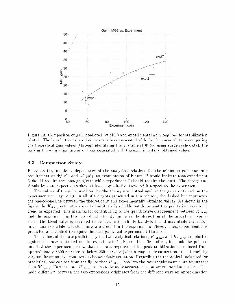
Figure 13: Comparison of gain predicted by MG3 and experimental gain required for stabilizationof stall. The bars in the x direction are error bars associated with the the uncertainty in computingthe theoretical gain values (through identifying the unstable of c(�) using surge cycle data); thebars in the y direction are error bars associated with the experimentally obtained values.4.3 Comparison StudyBased on the functional dependence of the analytical relations for the minimum gain and raterequirement on 00c (��) and 000c (��), an examination of Figure 12 would indicate that experiment5 should require the least gain/rate while experiment 7 should require the most. The theory andsimulations are expected to show at least a qualitative trend with respect to the experiment.The values of the gain predicted by the theory are plotted against the gains obtained on theexperiments in Figure 13. In all of the plots presented in this section, the dashed line representsthe one-to-one line between the theoretically and experimentally obtained values. As shown in the�gure, the Ktheory estimates are not quantitatively reliable but do present the qualitative monotonictrend as expected. The main factor contributing to the quantitative disagreement between Ktheoryand the experiment is the lack of actuator dynamics in the derivation of the analytical expres-sion. The bleed valve is assumed to be ideal with in�nite bandwidth and magnitude saturationin the analysis while actuator limits are present in the experiments. Nevertheless, experiment 5 ispredicted and veri�ed to require the least gain, and experiment 7 the most.The values of the rate predicted by the two analytical relations, R1theory and R2theory are plottedagainst the rates obtained on the experiments in Figure 14. First of all, it should be pointedout that the experiments show that the rate requirement for peak stabilization is reduced fromapproximately 3300 cm2/sec to below 230 cm2/sec (with a magnitude saturation at 11.4 cm2) byvarying the amount of compressor characteristic actuation. Regarding the theoretical tools used forprediction, one can see from the �gure that R1theory predicts the rate requirement more accuratelythan R2theory. Furthermore, R1theory seems to be more accurate at more severe rate limit values. Themain di�erence between the two expressions originates from the di�erent ways an approximation15

0 500 1000 1500 2000 2500 3000 35000
500
1000
1500
Experiment rate (cm2/sec)
1−D
For
mul
a ra
te
Rate: 1−D Formula vs. Experiment
expt7
expt2
expt5
formula 1
formula 2
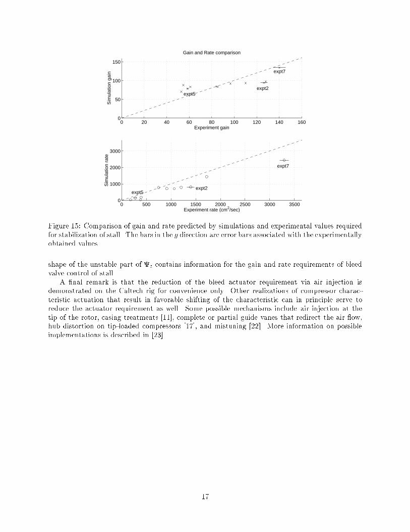
Figure 14: Comparison of rate predicted by theory and experimental rate required for stabilizationof stall. The bars in the x direction are error bars associated with the uncertainty in computingthe theoretical rate values (through identifying the unstable of c(�) using surge cycle data), andthe bars in the y direction the error bars associated with the experimentally obtained values.to the solution to the one-dimensional center manifold (eq. (3)) of the Moore-Greitzer equationsis made. Despite their quantitative di�erences, a monotonic trend similar to that observed in thetheoretical gain comparison is again displayed.The values of gain and rate predicted by simulations are plotted against the experimentalvalues in Figure 15. The gain and rate estimates of the simulations match with the experimentallyobtained counterpart more closely than the theoretical predictions. However, there are a numberof factors a�ecting the remaining di�erence. A possible explanation for this phenomenon is thatthe only di�erence in the 11 simulations are the compressor characteristics and the e�ective lengthparameter in the model lc. The e�ects of continuous air injection on the system in certain casesmay require modifying more parameters in order to accurate capture the reality. A more carefulidenti�cation of the system at each point should present a more reliable simulation.From the Ktheory expression,Ktheory = � ��000c (��)8 � �00c (��) � �00c (��)8 � ;it can be seen thatKtheory depends linearly on 000c (�) and nonlinearly on 00c (�). A similar conclusioncan be drawn for R1theory and R2theory with a closer examination of the expressions. The values ofthe gains from the theory, simulations, and experiments are plotted against 00c (�) and 000c (�) inFigure 16.The analogous plots for the rate expressions are shown in Figure 17. It can be seen from bothplots that the gain and rate values obtained from theory, simulations, and experiments share thesame trend on their dependence on 00c (�) and 000c (�). Since the values of the derivatives cannotbe obtained without identifying the unstable part of c(�), it is thus a natural conclusion that the16
0 20 40 60 80 100 120 140 1600
50
100
150
Sim
ulat
ion
gain
Experiment gain
Gain and Rate comparison
expt5expt2
expt7
0 500 1000 1500 2000 2500 3000 35000
1000
2000
3000
Experiment rate (cm2/sec)
Sim
ulat
ion
rate
expt5expt2
expt7Figure 15: Comparison of gain and rate predicted by simulations and experimental values requiredfor stabilization of stall. The bars in the y direction are error bars associated with the experimentallyobtained values.shape of the unstable part of c contains information for the gain and rate requirements of bleedvalve control of stall.A �nal remark is that the reduction of the bleed actuator requirement via air injection isdemonstrated on the Caltech rig for convenience only. Other realizations of compressor charac-teristic actuation that result in favorable shifting of the characteristic can in principle serve toreduce the actuator requirement as well. Some possible mechanisms include air injection at thetip of the rotor, casing treatments [11], complete or partial guide vanes that redirect the air ow,hub distortion on tip-loaded compressors [17], and mistuning [22]. More information on possibleimplementations is described in [23].17
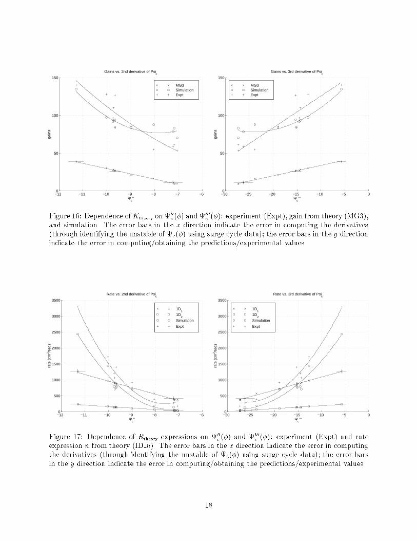
−12 −11 −10 −9 −8 −7 −60
50
100
150
Ψc’’
gain
s
Gains vs. 2nd derivative of Psic
MG3 SimulationExpt
−30 −25 −20 −15 −10 −5 00
50
100
150
Gains vs. 3rd derivative of Psic
Ψc’’’
gain
s
MG3 SimulationExpt
Figure 16: Dependence ofKtheory on 00c (�) and 000c (�): experiment (Expt), gain from theory (MG3),and simulation. The error bars in the x direction indicate the error in computing the derivatives(through identifying the unstable of c(�) using surge cycle data); the error bars in the y directionindicate the error in computing/obtaining the predictions/experimental values.−12 −11 −10 −9 −8 −7 −60
500
1000
1500
2000
2500
3000
3500
Rate vs. 2nd derivative of Psic
Ψc’’
rate
(cm
2 /sec
)
1D1
1D2
Simulation
Expt
−30 −25 −20 −15 −10 −5 00
500
1000
1500
2000
2500
3000
3500
Rate vs. 3rd derivative of Psic
Ψc’’’
rate
(cm
2 /sec
)
1D1
1D2
Simulation
Expt
Figure 17: Dependence of Rtheory expressions on 00c (�) and 000c (�): experiment (Expt) and rateexpression n from theory (ID n). The error bars in the x direction indicate the error in computingthe derivatives (through identifying the unstable of c(�) using surge cycle data); the error barsin the y direction indicate the error in computing/obtaining the predictions/experimental values.18
5 Conclusions and Future DirectionsTheoretical and simulation tools have been developed to analyze bleed valve requirements forcontrol of rotating stall and validated against experiments. Compressor characteristic actuationvia air injection is found to reduce the bleed valve rate requirement for stall control. Both the stableand unstable side of the compressor characteristic are changed by the addition of air injection andfound to be crucial in analyzing the closed-loop system.For the Caltech compression system, the compressor characteristic is more \�lled out" on the leftof the peak in the presence of air injection, and the peak location, second, and third derivative at thepeak are di�erent than those of the unactuated characteristic. This change of system characteristicsreduces the bandwidth and magnitude requirements of a bleed actuator in performing bleed valvecontrols of rotating stall. With a compressor rotor frequency of 100 Hz, active control of stall with ahigh speed bleed valve is achieved only when the compressor characteristic is actuated. Furthermore,the experiments show that the bleed valve rate requirement is reduced from approximately 3300cm2/sec to below 230 cm2/sec when the amount of compressor characteristic actuation is increased.This actuation is captured by a change of the shape and a shift in the peak of the compressorcharacteristic. Theoretical tools based on a low order model (2-3 states) and simulations based ona reduced order distributed model (37 states) have been developed to estimate the gain and raterequirements of the bleed controller. All of the proposed analytical formulas and simulations sharethe same qualitative trends with respect to 00c , 000c , and the experiment. The agreement impliesthat bleed valve control of rotating stall depends crucially on the rate limit of the bleed valve whichin turn depends on both the stable and the unstable part of the compressor characteristic.The e�ects of air injection are accounted for via a shift of the compressor characteristic inthis paper, whereas the actual e�ects are much more sophisticated. A more detailed uid dynamicmodel of the e�ects of air injection on compressors will provide a more accurate basis for theoreticalanalysis as well as simulations.Aside from rate limit, bandwidth and delay are also parts of actuator dynamics. A comparisonstudy between the theory, simulation, and experiments on various features of actuator limitationswill not only validate the model and the analysis, but also allow a more complete picture of howcontrol implementation is a�ected. The resulting sensitivity analysis can be used as a design guideline for compressor-bleed pair construction with intent of active control of stall implementations.AcknowledgmentThe authors would like to thank United Technologies Research Center (UTRC) for loan of the highspeed bleed valve that was used to achieve the results reported in this paper.References[1] O. O. Badmus, S. Chowdhury, K. M. Eveker, and C. N. Nett. Simpli�ed Approach for Controlof Rotating Stall 1 and 2. ASME Journal for Propulsion and Power, 11(6):1195{1223, 1995.[2] O. O. Badmus, S. Chowdhury, and C. N. Nett. Nonlinear Control of Surge in Axial-Compression Systems. Automatica, 32(1):59{70, 1996.[3] R. L. Behnken. Nonlinear Control and Modeling of Rotating Stall in an Axial Flow Compressor,September 1996. Ph.D thesis, California Institute of Technology.19
[4] R. L. Behnken, M. Leung, and R. M. Murray. Characterizing the E�ects of Air Injection onCompressor Performance for use in Active Control of Rotating Stall. In Proceedings of TheInternational Gas Turbine and Aeroengine Congress and Exhibition, 1997. ASME 97-GT-316.[5] R. D'Andrea, R.L. Behnken, and R.M. Murray. Active Control of an Axial Flow Compressorvia Pulsed Air Injection. ASME Journal of Turbomachinery, 119(4):742{752, 1998.[6] I.J. Day. Active Suppression of Rotating Stall and Surge in Axial Compressors. ASME Journalof Turbomachinery, 115:40{47, 1993.[7] Allison Engines. Advanced Control for Air Breathing Engines - Volume 3, Allison Gas Turbine,July 1993. N94-12272, U.S. Department of Commerce, National Technical Information Service.[8] General Electric Aircraft Engines. Advanced Control for Air Breathing Engines - Volume2, General Electric Aircraft Engines, July 1993. N94-12271, U.S. Department of Commerce,National Technical Information Service.[9] K.M. Eveker, D.L. Gysling, and C.N. Nett. Integrated Control of Rotating Stall and Surge inAeroengines. In Proceedings of The Internation Society for Optical Engineering, pages 21{35,April 1995.[10] C. Freeman, A. G. Wilson, I. J. Day, and M. A. Swinbanks. Experiments in Active Control ofStall on an Aeroengine Gas Turbine. In International Gas Turbine and Aeroengine Congressand Exhibition, 1997. ASME 97-GT-280.[11] E.M. Greitzer. Review - Axial Compressor Stall Phenomena. ASME Journal of Fluids Engi-neering, 102:134{151, 1980.[12] E.M. Greitzer and F.K. Moore. A Theory of Post-Stall Transients in Axial Compression Sys-tems: Part 1{Development of Equations, Part 2{Application. ASME Journal for Engineeringfor Power, 108:68{78, 231{239, 1986.[13] D.L. Gysling and E.M. Greitzer. Dynamic Control of Rotating Stall in Axial- ow Compressorsusing Aeromechanical Feedback. Journal of Turbomachinery, 117(3):307{319, 1995.[14] J. M. Haynes, G. J. Hendricks, and A. H. Epstein. Active Stabilization of Rotating Stall in aThree-Stage Axial Compressor. Journal of Turbomachinery, 116:226{239, 1994.[15] United Technologies Incorporated. Advanced Control for Air Breathing Engines - Volume 1,Pratt and Whitney, July 1993. N94-12270, U.S. Department of Commerce, National TechnicalInformation Service.[16] D. C. Liaw and E. H. Abed. Control of Compressor Stall Inception|A Bifurcation-theoreticApproach. Automatica, 32(1):109{115, 1996.[17] J.G. Lucas, H.B. Finger, and R.E. Filippi. E�ect of Inlet-Annulus Area Blockage on OverallPerformance and Stall Characteristics of an Experimental 15-Stage Axial-Flow Compressor.Technical Report R&M E53L28, NACA, 1958.[18] C. A. Mansoux, D. L. Gysling, J. D. Setiawan, and J. D. Paduano. Distributed NonlinearModeling and Stability Analysis of Axial Compressor Stall and Surge. In American ControlConference, pages 2305{2316, 1994. 20

[19] R.M. Murray, E.L. Wemho�, and Michael Kantner. Sparrow Reference Manual. CaliforniaInstitute of Technology, February 1995.[20] J.D. Paduano, A.H. Epstein, L. Valavani, J.P. Longley, E.M. Greitzer, and G.R. Guenette.Active Control of Rotating Stall in a Low-Speed Axial Compressor. ASME Journal of Turbo-machinery, 115:48{56, 1993.[21] Y. Wang and R. M. Murray. E�ects of Noise, Magnitude Saturation and Rate Limits onRotating Stall Control. In Proceedings of Conference on Decision and Control, pages 4682{4689, 1997.[22] D. S. Whitehead. Torsional Flutter of Unstalled Cascade Blades at Zero De ection. GreatBritain A.R.C., RM 3429, 1964.[23] S. Yeung and R. M. Murray. Actuator Bandwidth and Rate Limit Reduction for Control ofCompressor Rotating Stall. U. S. Patent Application, Serial No. 60/037,774, October, 1997.[24] S. Yeung and R. M. Murray. Nonlinear Control of Rotating Stall using 1-D Bleed Valve withContinuous Air Injection. In Proceedings of Joint Propulsion Conference and Exhibit, SeattleWashington, 1997. AIAA 97-2660.[25] S. Yeung and R. M. Murray. Reduction of Bleed Valve Rate Requirements for Control ofRotating Stall using Continuous Air Injection. In Proceedings of Conference on Control Ap-plications, pages 683{690, 1997.
21