OM KARIZMA ZMR-1.cdr - Hero MotoCorp
76
PREFACE Thank you for selecting a . We wish you many miles of Hero MotoCorp Karizma ZMR continued riding pleasure in the years ahead. Let us make this world a safer, healthier and more environment friendly place. This booklet is your guide to the basic operation and maintenance of your new . Please take time to read it carefully. As with any fine Hero MotoCorp Karizma ZMR machine, proper care and maintenance are essential for trouble-free operation and optimum performance. We at are committed to demonstrate excellence in our environment Hero MotoCorp, performance on a continual basis, as an intrinsic element of our corporate philosophy. To achieve this we commit ourselves to continue product innovations to improve environment compatibility, comply with and all applicable legislation including environment legislation strengthen the green supply chain. Your is conforming to latest (Bharat stage- norms) regulation for emission, safety & vehicle IV noise levels. We are also using non asbestos brake shoes/pads and engine gaskets which are environment friendly in nature. This vehicle is fitted with a lighting feature known as “Automatic Headlamp ON”. The feature is mandated for all 2 Wheelers by Ministry of Road Transport & Highways (Government of India) vide notification GSR 188 (E) dated 22nd February 2016. This feature helps in conspicuity for improving rider safety. The headlamp of this vehicle will always be lit ON when the engine gets ON. Your Authorised dealer will be glad to provide further information or Hero MotoCorp assistance and is equipped to handle your future service needs.
-
Upload
khangminh22 -
Category
Documents
-
view
1 -
download
0
Transcript of OM KARIZMA ZMR-1.cdr - Hero MotoCorp

PREFACEThank you for selecting a . We wish you many miles of Hero MotoCorp Karizma ZMRcontinued riding pleasure in the years ahead.
Let us make this world a safer, healthier and more environment friendly place.
This booklet is your guide to the basic operation and maintenance of your new . Please take time to read it carefully. As with any fine Hero MotoCorp Karizma ZMR
machine, proper care and maintenance are essential for trouble-free operation and optimum performance.
We at are committed to demonstrate excellence in our environment Hero MotoCorp,performance on a continual basis, as an intrinsic element of our corporate philosophy. To achieve this we commit ourselves to continue product innovations to improve environment compatibility, comply with and all applicable legislation including environment legislationstrengthen the green supply chain.
Your is conforming to latest (Bharat stage- norms) regulation for emission, safety & vehicle IVnoise levels. We are also using non asbestos brake shoes/pads and engine gaskets which are environment friendly in nature.
This vehicle is fitted with a lighting feature known as “Automatic Headlamp ON”. The feature is mandated for all 2 Wheelers by Ministry of Road Transport & Highways (Government of India) vide notification GSR 188 (E) dated 22nd February 2016. This feature helps in conspicuity for improving rider safety. The headlamp of this vehicle will always be lit ON when the engine gets ON.
Your Authorised dealer will be glad to provide further information or Hero MotoCorpassistance and is equipped to handle your future service needs.
ALL INFORMATION, ILLUSTRATION, PHOTOGRAPH, DIRECTIONS, SPECIFICATIONS AND OTHER CONTENTS COVERED IN THIS OWNER'S MANUAL ARE BASED ON THE LATEST PRODUCT INFORMATION AVAILABLE AT THE TIME OF ITS PRINTING APPROVAL, AND THE ACCURACY OR CORRECTNESS OF THE SAME IS NOT UNDERTAKEN OR GUARANTEED. Hero MotoCorp Ltd RESERVES THE RIGHT TO MAKE CHANGES IN ITS CONTENTS AT ANY TIME WITHOUT NOTICE AND/OR INCURRING ANY OBLIGATION, WHATSOEVER. NO ONE IS ALLOWED TO REPRODUCE ANY PART OF THIS PUBLICATION WITHOUT OBTAINING PRIOR WRITTEN PERMISSION FROM Hero MotoCorp Ltd.
NOTE
ACCESSORIES SHOWN MAY NOT BE THE PART OF STANDARD FITMENT. IT IS OUR ENDEAVOUR TO CONSTANTLY IMPROVE OUR PRODUCTS. THIS COULD LEAD TO CHANGE IN PRODUCT SPECIFICATIONS WITHOUT NOTICE. Hero
MotoCorp Ltd ‘KARIZMA ZMR’ COMPLIES WITH THE LATEST EMISSION NORMS.
Pg. No. Pg. No.
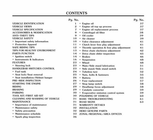
CONTENTS
• Safety precaution 32• Maintenance safety 32
• Spark plug inspection 36
• Instruments & Indicators 16FEATURES 23
• Fuel tank 24• Seat lock/Seat removal 25
HANDLEBAR SWITCHES CONTROL 23
• Seat installation/Helmet hanger 26
PARTS FUNCTION 14• Ignition switch 14
• Steering lock 23
TOOL KIT/FIRST AID KIT 30
PRE-RIDE INSPECTION 26
RIDING 29
PARKING 30
MAINTENANCE 31
BRAKING 29
• Importance of maintenance 31
STARTING THE ENGINE 27
CLEANING AND WASHING OF VEHICLE 31
VEHICLE IDENTIFICATION 1
VEHICLE SPECIFICATION 7ACCESSORIES & MODIFICATION 9
• Important safety information 10• Protective Apparel 11SAFE RIDING TIPS 12
ANTI-THEFT TIPS 9 VEHICLE SAFETY 10
VEHICLE VIEWS 2
TIPS FOR HEALTHY ENVIRONMENT 13
• Maintenance schedule 33
• Air cleaner 39
• Drive chain slider inspection 45• Brakes 46
• Main/Side stand lubrication 51
• Oil cooler 39
• Throttle operation & free play adjustment 41• Clutch lever free play adjustment 41
• Wheel 48
• Engine oil top up process 37
• Centrifugal oil filter 38
• Suspension 48
• Valve clearance adjustment 41
• Side stand/Side stand switch 51
• Engine oil replacement process 37
• Tubeless tyre 52• Nuts, bolts & fasteners 55
• Drive chain slackness adjustment 42
• Battery 55
• Stop lamp switch 58• Headlamp focus adjustment 58
ZONAL/REGIONAL/AREA OFFICES
BASIC TROUBLESHOOTING 61
• Evaporative emission control system 59
ROAD SIGNS 63
• Catalytic converter 59
• Fuse replacement 57
WARRANTY DETAILS
POLISHING OF VEHICLE 60
INSTALLATIONHERO GENUINE PARTS
• Engine oil 37
1
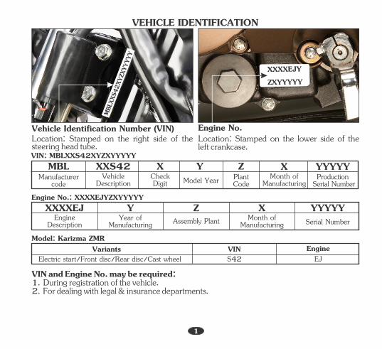
1. During registration of the vehicle.VIN and Engine No. may be required:
2. For dealing with legal & insurance departments.
Location: Stamped on the right side of the steering head tube.
Location: Stamped on the lower side of the left crankcase.
Engine No.: XXXXEJYZXYYYYY
Model: Karizma ZMRVIN EngineVariants
XXXXEJ Y Z X YYYYYEngine
DescriptionYear of
Manufacturing Assembly Plant Month of Manufacturing Serial Number
Vehicle Identification Number (VIN) Engine No.
Electric start/Front disc/Rear disc/Cast wheel S42 EJ
VIN: MBLXXS42XYZXYYYYYMBL XXS42 Y Z X YYYYY
Manufacturer code
Vehicle Description Model Year Plant
CodeMonth of
ManufacturingProduction
Serial Number
XCheckDigit
VEHICLE IDENTIFICATION
XXXXEJYZXYYYYY
MBLX
XS42
XYZX
YYYY
Y
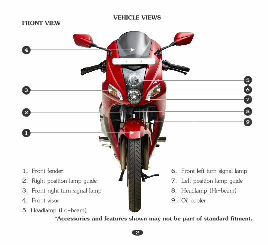
5. Headlamp (Lo-beam)
2. Right position lamp guide3. Front right turn signal lamp
1. Front fender
4. Front visor
1
7
6. Front left turn signal lamp
8. Headlamp (Hi-beam)7. Left position lamp guide
9. Oil cooler
*Accessories and features shown may not be part of standard fitment.
FRONT VIEWVEHICLE VIEWS
2
3
2
4
8
56
9

2. Tail/stop lamp1. Left rear turn signal lamp
4. Licence plate lamp3. Right rear turn signal lamp
1
2
*Accessories and features shown may not be part of standard fitment.
REAR VIEW
3
3
4
VEHICLE VIEWS
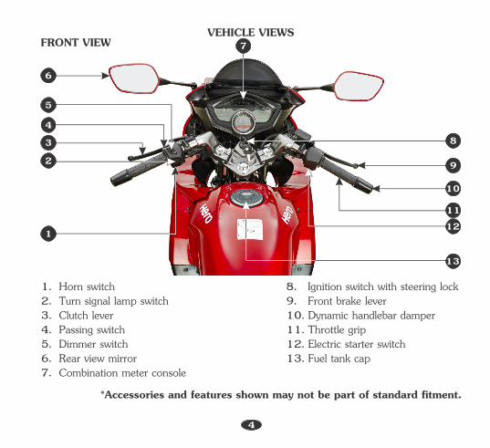
2. Turn signal lamp switch
7. Combination meter console
4. Passing switch
1. Horn switch
3. Clutch lever
5. Dimmer switch 6. Rear view mirror
8. Ignition switch with steering lock
13. Fuel tank cap
9. Front brake lever
12. Electric starter switch
10. Dynamic handlebar damper 11. Throttle grip
*Accessories and features shown may not be part of standard fitment.
FRONT VIEW
4
1
11
9
10
8
13
12
7
5
6
4
23
VEHICLE VIEWS
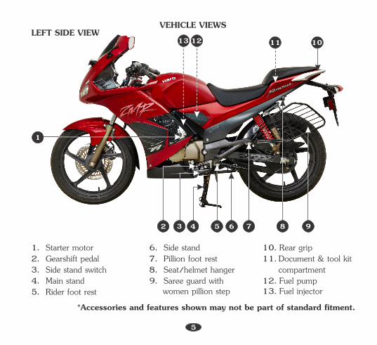
7. Pillion foot rest 8. Seat/helmet hanger 9. Saree guard with
women pillion step
6. Side stand 11. Document & tool kit 10. Rear grip
12. Fuel pump13. Fuel injector
compartment
1. Starter motor
3. Side stand switch4. Main stand
2. Gearshift pedal
5. Rider foot rest
5 7
5
LEFT SIDE VIEW
*Accessories and features shown may not be part of standard fitment.
1
2 3 4 6 8 9
1213 1011
VEHICLE VIEWS
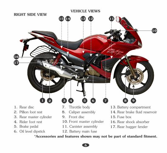
8. Caliper assembly 7. Throttle body
12. Battery main fuse
9. Front disc 10. Front master cylinder11. Canister assembly
13. Battery compartment 14. Rear brake fluid reservoir15. Fuse box16. Rear shock absorber17. Rear hugger fender
1. Rear disc
3. Rear master cylinder4. Rider foot rest 5. Brake pedal 6. Oil level dipstick
2. Pillion foot rest
5 7
RIGHT SIDE VIEW
6
*Accessories and features shown may not be part of standard fitment.
1214 1315
91 2 3 4 6 8
10
1716
VEHICLE VIEWS
11
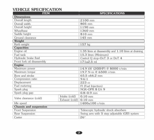
SPECIFICATIONSITEMDimensionsOverall lengthOverall widthOverall heightWheelbaseSaddle heightGround clearance
Kerb weight
2100 mm805 mm1190 mm1360 mm810 mm145 mm
157 kgWeight
Engine oilFuel tankHydraulic brake fluidFront fork oil disassembly
Maximum powerMaximum torqueBore and strokeCompression ratioDisplacement
1.35 litres at disassembly and 1.10 litres at draining15.3 litres (Minimum)Castrol Q stop-DoT 3 or DoT 4171±2.5 ml
14.9 kW (20BHP) @ 8000 r/min19. N-m @ 00 7 65 r/min65.5 x66.2 mm9.6:1223 cc
Capacities
Engine
Spark plug gapValve clearance (cold)Idle speed
Front SuspensionRear Suspension
0. -0. mm8 90. mm 100.1 mm01400 100 ± r/min
Telescopic hydraulic shock absorbersSwing arm with 5 step adjustable iGRS system
Intake (cold)Exhaust (cold)
Chassis and suspension
Fuel meteringSpark plug
FI (Fuel Injection)NGK-DPR 8 EA 9
7
Caster 26°
VEHICLE SPECIFICATION
8
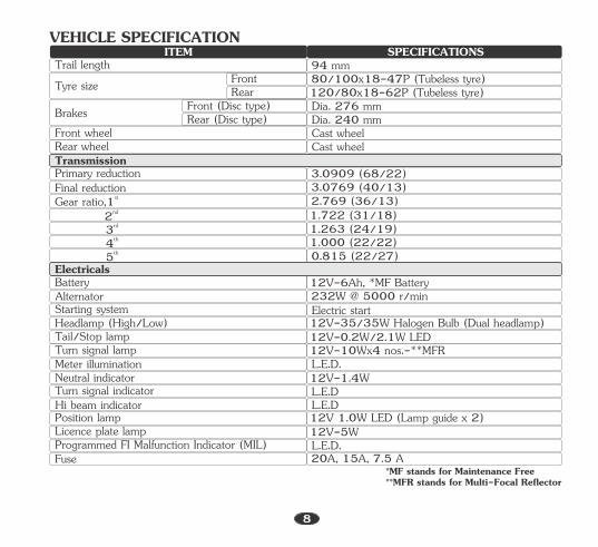
SPECIFICATIONSITEMTrail length 94 mmTyre size 80/100x18-47P (Tubeless tyre)
120/80x18-62P (Tubeless tyre)FrontRear
Brakes Dia. 276 mmDia. 240 mm
Front (Disc type)Rear (Disc type)
Primary reductionFinal reduction
stGear ratio, 1rd3th4
3.0909 (68/22)3.0769 (40/13)2.769 (36/13)1.722 (31/18)1.263 (24/19)1.000 (22/22)
Transmission
Cast wheel Cast wheel
Front wheelRear wheel
nd2
Battery 12V-6Ah, *MF BatteryElectricals
*MF stands for Maintenance Free**MFR stands for Multi-Focal Reflector
12V-0.2W/2.1W LED
AlternatorStarting systemHeadlamp (High/Low)Tail/Stop lampTurn signal lampMeter illuminationNeutral indicatorTurn signal indicator
Position lampLicence plate lampProgrammed FI Malfunction Indicator (MIL)Fuse
232W @ 5000 r/minElectric start
20A, 15A, 7.5 A
12V-35/35W Halogen Bulb (Dual headlamp)
L.E.D.12V-5W12V 1.0W LED (Lamp guide x 2)
L.E.D12V-1.4WL.E.D.12V-10Wx4 nos.-**MFR
th5 0.815 (22/27)
Hi beam indicator L.E.D
VEHICLE SPECIFICATION
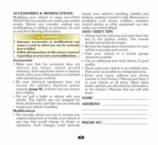
Modifying your vehicle or using non-Hero MotoCorp accessories can make your vehicle unsafe. Before you consider making any modifications or adding an accessory, be sure to read the following information.
ACCESSORIES & MODIFICATIONS
9
• Follow all instructions in this owner's manual regarding accessories and modifications.
• Improper accessories or modifications can cause a crash in which you can be seriously hurt or killed.
WARNING!!
• Never park your vehicle in an isolated area. Park as far as possible in a designated area.
_______________________________________________________
PHONE NO : _____________________________________
ADDRESS: _______________________________________
• Be sure the registration information for your vehicle is accurate and correct.
• Park your vehicle in a locked garage whenever possible.
NAME: _____________________________________________
ANTI-THEFT TIPS• Always lock the steering and never leave the
key in the ignition switch. This sounds simple but people do forgets.
impair your vehicle's handling, stability and braking, making it unsafe to ride. Removing or modifying your lamps, mufflers, emission control system or other equipment can also make your vehicle illegal.
• Use an additional anti-theft device of good quality.
• Enter your name, address and phone number in this Owner's Manual and keep it in your vehicle at all times. Many times stolen vehicles are identified by information in the Owner's Manuals that are still with them.
_______________________________________________________
_______________________________________________________
Modifications
• Do not pull a trailer or sidecar with your vehicle. This vehicle was not designed for these attachments, and their use can seriously impair your vehicle's handling.
• Make sure that the accessory does not obscure any lamps, reduce ground clearance, limit suspension travel or steering travel, affect your riding position or interfere with operating any controls.
• Be sure electrical equipment does not exceed the 's electrical system vehiclecapacity (page 8). A blown fuse can cause a loss of lights.
• We strongly advise you not to remove any original equipment or modify your vehicle in any way that would change its design or operation. Such changes could seriously
Accessories
It is a proven fact, Helmet significantly reduces the number and severity of head injuries. So always wear a helmet and make sure your pillion rider does the same. We also recommend that you wear eye protection, sturdy boots, gloves and other protective gear.
Important safety informationVEHICLE SAFETY
Your vehicle can provide many years of service and pleasure if you take responsibility for your own safety and understand the challenges you can meet on the road.There is much that you can do to protect yourself when you ride. You will find many helpful recommendations through out this manual. Following are a few that we consider most important.Always wear a helmet
Before riding your vehicleMake sure that you are physically fit, mentally focused and free of alcohol and drugs. Check that you and your pillion are both wearing an approved vehicle helmet and protective apparel. Instruct your pillion on holding onto the grab rail or your waist, leaning with you in turns, and keeping their feet on the footrest, even when the vehicle is stopped.Take time to learn & practice your vehicleEven if you have ridden other vehicles, practice riding in a safe area to become familiar with how this vehicle works and handles, and to become accustomed to the vehicle's size and weight.
Riding under the influence of alcohol or drugs is dangerous. Alcohol can reduce your ability to respond to changing conditions and reduce the reaction time. Do not drink and ride.
Ride within your limits
Do not drink and ride
Keep your vehicle in safe conditionFor safe riding, its important to inspect your vehicle before every ride and perform all recommended maintenance. Never exceed load limits, and use accessories that have been recommended by Hero MotoCorp for this vehicle.
Some drivers do not see because they vehiclesare not looking for them. To make yourself more visible, wear bright reflective clothing, position yourself so that others can see you, signal before turning or changing lanes, and use horn which will help others to notice you.
Pushing the limits is another major cause of vehicle accidents. Never ride beyond your personal abilities or faster than conditions demand. Remember that fatigue and negligence can significantly reduce your ability to make good judgements and ride safely.
Ride efensivelydAlways pay due attention to other vehicles around you, and do not assume that other drivers see you. Be prepared to stop quickly or perform an evasive maneuver.Make yourself easily visible
10
• Sturdy boots with non-slip soles to help protect your feet and ankles.
• Leather gloves to keep your hands warm and help prevent blisters, cuts, burns, and bruises.
Additional riding gear
An open-face helmet offers some protection, but a full-face helmet offers more. Always wear face shield or goggles to protect your eyes and help your vision.
In addition to a helmet and eye protection, we also recommend:
Your Helmet is your most important piece of riding gear because it offers the best protection against head injuries. A helmet should fit your head comfortably and securely. A bright coloured helmet can make you more noticeable in traffic, as can reflective strips.
• A two wheeler riding suit or jacket for comfort as well as protection. Bright coloured reflective clothing can help make you more noticeable in traffic. Be sure to avoid loose clothes that could get caught on any part of your vehicle.
Helmets and eye protection
Following are suggestions to help you choose proper riding gear.
Personal safety is your first priority. If you or anyone else has been injured, take time to assess the severity of the injuries and whether it is safe to continue riding. Call for emergency assistance if needed. Also follow applicable laws and regulations if another person or vehicle is involved in the crash.
If you are involved in a crash
If you decide to continue riding, first evaluate the condition of your vehicle. If the engine is still running, turn it off. Inspect for fluid leaks, check the tightness of critical nuts and bolts, and check the handlebar, brake levers, brakes, and wheels. Ride slowly and cautiously. Your vehicle may have suffered damage that is not immediately apparent. Have your vehicle thoroughly checked at a qualified service facility as soon as possible.
For your safety, we strongly recommend that you always wear an approved helmet (ISI marked), eye protection, boots, gloves, long pants and a long sleeve shirt or jacket whenever you ride. Take care of loose/ hanging clothes while solo/pillion riding. Although complete protection is not possible, wearing proper gear can reduce the chance of injury when you ride.
Protective apparel
• Be sure you and your pillion always wear a helmet, eye protection and other protective apparel when you ride.
• Not wearing a helmet increases the chance of serious injury or death in a crash.
WARNING!!
11

• Always conduct simple pre-ride inspection (page 27).
• Get your vehicle serviced regularly by the Authorised Hero MotoCorp workshop.
• While riding, sit in a comfortable position with your legs close to fuel tank.
• Respect road signs and obey traffic rules for your own safety and that of others on the road . (page 63)
• Give way to others on the road and signal before you make a turn.
• To make yourself more visible, wear bright reflective clothing that fits well.
• For stopping vehicle, use both brakes simultaneously, keeping throttle in the close position.
• During night time, dip headlamps of your vehicle for oncoming traffic, or when following another vehicle.
• Take care of loose/hanging clothes while solo/pillion riding.
• Ride defensively and at a steady speed (between 40-50 km/hr).
• Always wear a helmet (ISI marked) with chin strap securely fastened and insist on a helmet for your pillion rider.
• Do not cross the continuous white/yellow line in the center of the road, while overtaking.
• Do not attach large or heavy items to the handlebars, front forks, or fenders.
• Never take your hands off the steering handle while riding.
• Do not litter the road.
• Concentrate on the road and avoid talking to the pillion rider or others on the road.
• Never ride under the influence of alcohol or drugs.
• Never use cell phone while riding the vehicle.
• Avoid sudden acceleration, braking and turning of your vehicle.
• Never shift gears without disengaging the clutch and closing the throttle.
• Never touch any part of the hot exhaust system like muffler.
SAFE RIDING TIPS
Do's: Don't's:
12

• Genuine spares: Always insist on Hero MotoCorp genuine parts as spurious or incompatible spares and accessories can upset or deteriorate your vehicle’s running condition.
• Healthy engine: The engine is the lifeline of every vehicle. To keep it healthy, it should be tuned regularly, which will also help reduce pollution and improve vehicle performance & fuel efficiency.
The following tips shall ensure a healthy vehicle, healthy environment, and a healthy you.
• Genuine engine oil: Hero 4T Plus SAE 10W 30 SL grade (JASO MA2) engine oil recommended by Hero MotoCorp and make sure you change it every 6000 kms. (with top up every 3000 kilometres) to keep the engine fit and environment healthy.
• Noise pollution: Noise beyond a certain decibel is pollution. Whether it is from horns or defective mufflers, excessive noise will cause headaches and discomfort.
• Regular servicing: Get your vehicle serviced at an Authorised Hero MotoCorp workshop, as per the service schedule, for an optimum performance and keep the emission level under check.
• Emission pollution: Get emission of your vehicle checked by Authorised agencies atleast once every 3 months.
• Fuel saving & reduce pollution: Switch "OFF" the engine while waiting at traffic signal points to save fuel and reduce pollution, if the waiting period is long.
TIPS FOR HEALTHY ENVIRONMENT
13
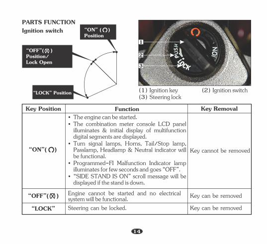
Key Position Function Key Removal
Key cannot be removed
(1) Ignition key (2) Ignition switch (3) Steering lock
• The engine can be started. • The combination meter console LCD panel
illuminates & initial display of multifunction digital segments are displayed.
• Turn signal lamps, Horns, Tail/Stop lamp, Passlamp, Headlamp & Neutral indicator will be functional.
• Programmed-FI Malfunction Indicator lamp illuminates for few seconds and goes “OFF”.
• “SIDE STAND IS ON” scroll message will be displayed if the stand is down.
Engine cannot be started and no electrical system will be functional. Key can be removed
Key can be removed“LOCK” Steering can be locked.
“LOCK” Position
PARTS FUNCTIONIgnition switch
1
2
3
14
“OFF”( ) Position/Lock Open
“ON” ( )Position
“ON”( )
“OFF”( )
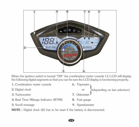
When the ignition switch is turned "ON" the combination meter console (1) LCD will display the following digital segments so that you can be sure the LCD display is functioning properly.
2. Digital clock 1. Combination meter console
3. Tachometer 4. Real Time Mileage Indicator (RTMI)5. Scroll message
or
9. Speedometer
6. Tripmeter
8. Fuel gauge 7. Odometer
NOTE : Digital clock (2) has to be reset if the battery is disconnected.
}(depending on last selection)
3
1
2
4
56789
15
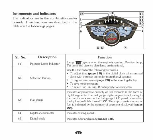
Instruments and IndicatorsThe indicators are in the combination meter console. Their functions are described in the tables on the followings pages.
Sl. No. (1) Position Lamp Indicator
(2) Selection Button
(3) Fuel gauge
• To save mode selection.
Use this button for the following purposes :• To adjust time (page 18) in the digital clock when pressed
along with the reset button for more than 2 seconds.• To register user name (page 20) in the scrolling display.
• To select Trip-A, Trip-B on tripmeter or odometer.
Lamp “ ” glows when the engine is running . Position lamp, Tail lamp and Licence plate lamp are functional.
Indicates approximate quantity of fuel available in the form of digital segments. The fuel gauge digital segments will swing to the maximum scale on the fuel gauge LCD panel once when the ignition switch is turned "ON". The approximate amount of fuel is indicated by the number of segments displayed (pages 22).
FunctionDescription
(5) Digital clock (4) Digital speedometer Indicates driving speed.
Indicates hour and minute (pages 18).
14
75 6
89
13121110
1234
15
16
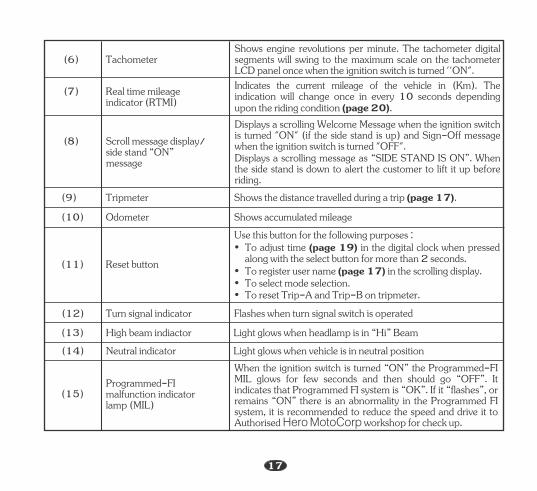
(9) Tripmeter Shows the distance travelled during a trip (page 17).(10) Odometer Shows accumulated mileage
(11) Reset button
(12) Turn signal indicator Flashes when turn signal switch is operated (13) High beam indiactor Light glows when headlamp is in “Hi” Beam(14) Neutral indicator Light glows when vehicle is in neutral position
(15) lamp (MIL)
Programmed-FI malfunction indicator
(6) Tachometer
side stand “ON” message
(8) Scroll message display/
indicator (RTMI) (7) Real time mileage
Shows engine revolutions per minute. The tachometer digital segments will swing to the maximum scale on the tachometer LCD panel once when the ignition switch is turned ''ON".Indicates the current mileage of the vehicle in (Km). The indication will change once in every 10 seconds depending upon the riding condition (page 20).Displays a scrolling Welcome Message when the ignition switch is turned "ON" (if the side stand is up) and Sign-Off message when the ignition switch is turned "OFF".Displays a scrolling message as “SIDE STAND IS ON”. When the side stand is down to alert the customer to lift it up before riding.
When the ignition switch is turned “ON” the Programmed-FI MIL glows for few seconds and then should go “OFF”. It indicates that Programmed FI system is “OK”. If it “flashes”, or remains “ON” there is an abnormality in the Programmed FI system, it is recommended to reduce the speed and drive it to Authorised Hero MotoCorp workshop for check up.
• To reset Trip-A and Trip-B on tripmeter.
• To adjust time (page 19) in the digital clock when pressed along with the select button for more than 2 seconds.
• To select mode selection.
Use this button for the following purposes :
• To register user name (page 17) in the scrolling display.
17
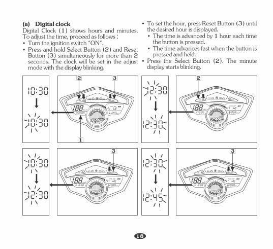
Digital Clock (1) shows hours and minutes. To adjust the time, proceed as follows :
• Press and hold Select Button (2) and Reset Button (3) simultaneously for more than 2 seconds. The clock will be set in the adjust mode with the display blinking.
(a) Digital clock
• Turn the ignition switch "ON".• The time is advanced by 1 hour each time
the button is pressed.• The time advances fast when the button is
pressed and held.
• To set the hour, press Reset Button (3) until the desired hour is displayed.
• Press the Select Button (2). The minute display starts blinking.
SEL RESET
km/h
AMPM
TOTAL TRIP
km/lAv
01
23
4 5 6 78
910
x1000r/minx1000r/min
SEL RESET
km/h
AMPM
TOTAL TRIP
km/lAv
01
23
4 5 6 78
910
x1000r/minx1000r/min
SEL RESET
km/h
AMPM
TOTAL TRIP
km/lAv
01
23
4 5 6 78
910
x1000r/minx1000r/min
2
SEL RESET
km/h
AMPM
TOTAL TRIP
km/lAv
01
23
4 5 6 78
910
x1000r/minx1000r/min
3
2 3
1
3
18
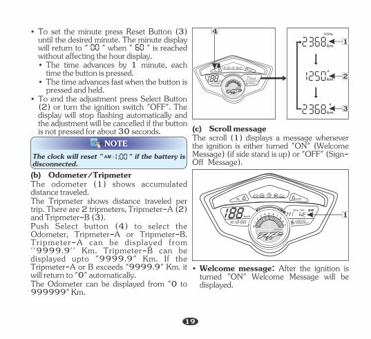
The odometer (1) shows accumulated distance traveled.The Tripmeter shows distance traveled per trip. There are 2 tripmeters, Tripmeter-A (2) and Tripmeter-B (3).Push Select button (4) to select the Odometer, Tripmeter-A or Tripmeter-B. Tripmeter-A can be displayed from ''9999.9'' Km. Tripmeter-B can be displayed upto "9999.9" Km. If the Tripmeter-A or B exceeds "9999.9" Km. it will return to "0" automatically.The Odometer can be displayed from "0 to 999999" Km.
(b) Odometer/Tripmeter
• The time advances fast when the button is pressed and held.
• The time advances by 1 minute, each time the button is pressed.
• To set the minute press Reset Button (3) until the desired minute. The minute display will return to " " when " " is reached without affecting the hour display.
• To end the adjustment press Select Button (2) or turn the ignition switch "OFF". The display will stop flashing automatically and the adjustment will be cancelled if the button is not pressed for about 30 seconds.
NOTEThe clock will reset " " if the battery is disconnected.
AM :
km.
TOTAL
km.
A
km.
B
SEL RESET
N
km/h
AMPM
TOTAL
km.
km/lAv
01
23
4 5 6 78
910
x1000r/minx1000r/min
1
3
The scroll (1) displays a message whenever the ignition is either turned "ON" (Welcome Message) (if side stand is up) or "OFF" (Sign-Off Message).
(c) Scroll message
SEL RESET
km/h
AMPM
TOTAL TRIP
km/lAv
01
23
4 5 6 78
910
x1000r/minx1000r/min
1
• Welcome message: After the ignition is turned "ON" Welcome Message will be displayed.
4
2
19
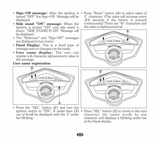
• The “Welcome” and “Sign-Off” messages are displayed in two forms;
• User name display: The user can register a 6 character alphanumeric value in the message.
• Sign-Off message: After the ignition is turned "OFF" the Sign-Off Message will be displayed.
• Side stand “ON” message: When the ignition is turned "ON" and side stand is down, “SIDE STAND IS ON” Message will be displayed.
• Fixed Display: This is a fixed type of message and no changes can be made.
User name registration
• Press the "SEL" button (2) and turn the ignition switch to "ON", 5 under bars (3) stout of 6will be displayed with the 1 under bar blinking.
SEL RESET
01
23
4 5 6 78
910
x1000r/minx1000r/min
• Press "Reset" button (4) to select value of st1 character. (The value will increase every
.25 seconds if the button is pressed continuously) There are "6" characters and the value is alphanumerical.
SEL RESET
01
23
4 5 6 78
910
x1000r/minx1000r/min
SEL RESET
01
23
4 5 6 78
910
x1000r/minx1000r/min
• Press "SEL" button (2) to move to the next character, the cursor scrolls by one character and displays a blinking under bar at the blank display.
22
3
4
20
NOTE
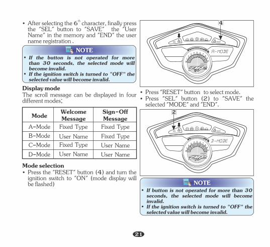
th• After selecting the 6 character, finally press the "SEL" button to "SAVE" the "User Name" in the memory and "END" the user name registration .
Display mode The scroll message can be displayed in four different modes;
Mode Welcome Message
Sign-Off Message
A-Mode B-ModeC-Mode D-Mode
Fixed Type User Name Fixed Type User Name
Fixed Type Fixed Type User Name User Name
Mode selection • Press the "RESET" button (4) and turn the
ignition switch to "ON" (mode display will be flashed)
• Press "RESET" button to select mode.• Press "SEL" button (2) to "SAVE" the
selected "MODE" and "END".
SEL RESET
01
23
4 5 6 78
910
x1000r/minx1000r/min
SEL RESET
01
23
4 5 6 78
910
x1000r/minx1000r/min
• If button is not operated for more than 30 seconds, the selected mode will become invalid.
• If the ignition switch is turned to "OFF" the selected value will become invalid.
NOTE• If the button is not operated for more
than 30 seconds, the selected mode will become invalid.
• If the ignition switch is turned to "OFF" the selected value will become invalid.
4
2
21
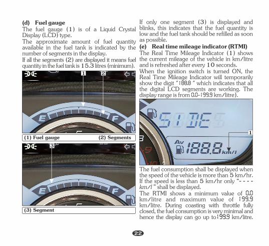
The fuel gauge (1) is of a Liquid Crystal Display (LCD) type.
If all the segments (2) are displayed it means fuel quantity in the fuel tank is litres . 15.3 (minimum)
(d) Fuel gauge
The approximate amount of fuel quantity available in the fuel tank is indicated by the number of segments in the display.
(1) Fuel gauge (2) Segments
(e) Real time mileage indicator (RTMI)
If only one segment (3) is displayed and blinks, this indicates that the fuel quantity is low and the fuel tank should be refilled as soon as possible.
When the ignition switch is turned ON, the Real Time Mileage Indicator will temporarily show the digit " " which indicates that all the digital LCD segments are working. The display range is from km/litre).
The Real Time Mileage Indicator (1) shows the current mileage of the vehicle in km/litre and is refreshed after every 10 seconds.
(3) Segment
The fuel consumption shall be displayed when the speed of the vehicle is more than 5 km/hr. If the speed is less than 5 km/hr only “- - - - km/l ” shall be displayed.The RTMI shows a minimum value of km/litre and maximum value of km/litre. During coasting with throttle fully closed, the fuel consumption is very minimal and hence the display can go up to km/litre.
3
1
1 2
22
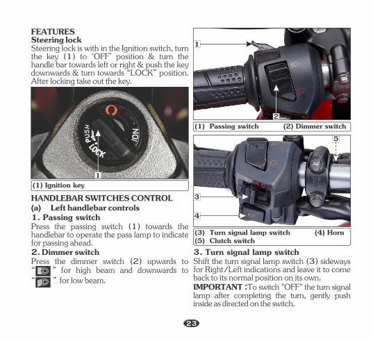
IMPORTANT :To switch "OFF" the turn signal lamp after completing the turn, gently push inside as directed on the switch.
Shift the turn signal lamp switch (3) sideways for Right/Left indications and leave it to come back to its normal position on its own.
3. Turn signal lamp switch
1
2
4
3
5
Steering lockSteering lock is with in the Ignition switch, turn the key (1) to ‘OFF’ position & turn the handle bar towards left or right & push the key downwards & turn towards “LOCK” position. After locking take out the key.
FEATURES
(1) Ignition key1
Press the passing switch (1) towards the handlebar to operate the pass lamp to indicate for passing ahead.
HANDLEBAR SWITCHES CONTROL
Press the dimmer switch (2) upwards to 2. Dimmer switch
“ ” for high beam and downwards to“ ” for low beam.
1. Passing switch ( ) Left handlebar controlsa
(1) Passing switch (2) Dimmer switch
( ) 3 Turn signal lamp switch (4) Horn(5) Clutch switch
23
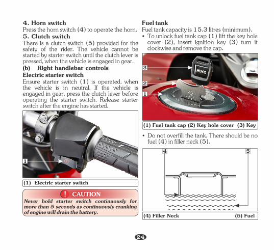
CAUTION!!Never hold starter switch continuously for more than 5 seconds as continuously cranking of engine will drain the battery.
1
(1) Electric starter switch
Fuel tankFuel tank capacity is 15.3 litres (minimum).• To unlock fuel tank cap (1) lift the key hole
cover (2), insert ignition key (3) turn it clockwise and remove the cap.
2
3
(1) Fuel tank cap (2) Key hole cover (3) Key
1
• Do not overfill the tank. There should be no fuel (4) in filler neck (5).
54
(4) Filler Neck (5) Fuel
4. Horn switchPress the horn switch (4) to operate the horn.5. Clutch switch There is a clutch switch (5) provided for the safety of the rider. The vehicle cannot be started by starter switch until the clutch lever is pressed, when the vehicle is engaged in gear.(b) Right handlebar controlsElectric starter switchEnsure starter switch (1) is operated. when the vehicle is in neutral. If the vehicle is engaged in gear, press the clutch lever before operating the starter switch. Release starter switch after the engine has started.
24
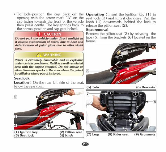
Location : On the rear left side of the seat, below the rear cowl.
Seat lock
WARNING!!
• To lock-position the cap back on the opening with the arrow mark "D" on the cap facing towards the front of the vehicle then press gently. The key springs back to the normal position and cap gets locked.
CAUTION!!Do not park the vehicle under direct sunlight as it causes evaporation of petrol due to heat and deterioration of paint gloss due to ultra violet rays.
Petrol is extremely flammable and is explosive under certain conditions. Refill in a well ventilated area with the engine stopped. Do not smoke or allow flames or sparks in the area where the petrol is refilled or where petrol is stored.
2
(1) Ignition key (2) Pillion seat(3) Seat lock (4) Knob
1
3
4
6
(5) Tabs (6) Brackets
5
Seat removal
Operation : Insert the ignition key (1) in seat lock (3) and turn it clockwise. Pull the knob (4) downwards, behind the lock to release the pillion seat (2).
Remove the pillion seat (2) by releasing the tabs (5) from the brackets (6) located on the frame.
7
8
(7) Lugs (8) Rider seat (9) Grommets9
25
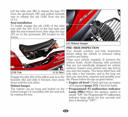
(10) Tab (11) Slot
10
11
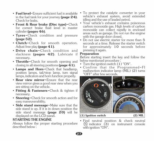
Helmet hanger
Engage the tabs (5) of the pillion seat in to the brackets (6) and slide it forward, then press down until the lock clicks.
The helmet can be hung and locked on the helmet hanger (1) provided with the seat lock by rotating the key.
Lift the rider seat (8) to release the lugs (7) from the grommets (9) and pullout towards rear to release the tab (10) from the slot (11).
To install, engage the tab (10) of the rider seat with the slot (11) of the fuel tank and slide the seat towards front, then align the lugs (7) on to the grommets (9) located on the frame.
Seat installation
(1) Helmet hanger
1
Clean your vehicle regularly. It protects the surface finish. Avoid cleaning with products that are not specifically designed for vehicle surfaces. Inspect your vehicle very day before you start the engine. The items listed here will only take a few minutes, and in the long run they can save time, expense and possibly your life. Please follow the tips as given below:
PRE-RIDE INSPECTION
• Engine oil level-Check and top up engine oil if required (page 37). Check for leaks.
• Programmed-FI malfunction indicator Lamp (MIL)-When the ignition switch is turned "ON" the Programmed-FI malfunction indicator lamp glows for few seconds and then it should go "OFF".
You should conduct pre-ride inspection before riding the vehicle to enhance riding comfort and safety.
26
• Fuel level-Ensure sufficient fuel is available in the fuel tank for your journey (page 24). Check for leaks.
• Front & Rear brake (Disc type)-Check for correct brake fluid level in master cylinder (pages 46).
• Tyres-Check condition and pressure (page 52).
• Clutch-Check for smooth operation. Adjust free play (page 41).
• Drive chain-Check condit ion and slackness (pages 42). Lubricate if necessary.
• Rear view mirror-Ensure that the rear view mirror gives a good rear view when you are sitting on the vehicle.
Always follow the proper starting procedure described below :
• Side stand message-Make sure that the side stand is up. If it is in down position the side stand message (page 20) will be displayed on the LCD panel.
• Lamps and Horn-Check that headlamp, position lamps, tail/stop lamp, turn signal lamps, indicators and horn function properly.
• Fitting & Fasteners-Check & tighten if necessary.
STARTING THE ENGINE
• Throttle-Check for smooth opening and closing in all steering positions (page 41).
• Steering-Check for smooth action and for easy maneuverability.
• Your vehicle's exhaust contains poisonous carbon monoxide gas. High levels of carbon monoxide can collect rapidly in enclosed areas such as garage. Do not run the engine with the garage door closed.
• Do not use electric starter for more than 5 seconds at a time. Release the starter switch for approximately 10 seconds before pressing it again.
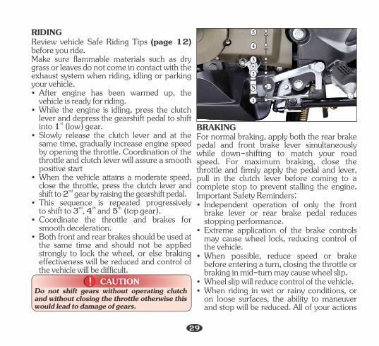
PreparationBefore starting insert the key and follow the below mentioned procedure :• Turn the ignition switch (1) "ON".• Conf i rm that the Programmed-FI
malfunction indicator lamp (MIL) (2) turns "OFF" after few seconds.
• To protect the catalytic converter in your vehicle's exhaust system, avoid extended idling and the use of leaded petrol.
(1) Ignition switch (2) MIL
1
2
• Find neutral position & check neutral N indicator (3) on instrument console with ignition "ON".
27

Any air temperature
• Press the starter switch.
Follow the procedure mentioned below :
Starting ProcedureThis vehicle has a Fuel-Injected engine with an Idle Air Control Valve (IACV).
• Press the starter switch with the throttle completely closed.
At any ambient temperature :
• Open the throttle fully.• Press the starter switch for 5 seconds.
With the throttle completely closed, press the starter switch. The engine will not start if the throttle is fully open because the Electronic control unit (ECU) cuts-off the fuel supply.Flooded engineIf the engine fails to start after repeated attempts, it may be flooded with excess fuel.
• Follow the normal starting procedure.
(3) Neutral indicator
3
these surfaces will wear in quickly. Running-in precautions till 1000 km will reduce initial wear of engine components and increase its service life.
• If the engine does not start wait for 10 seconds, then follow steps 1-3 again.
Your vehicle is designed to automatically stop the engine and fuel pump, if the vehicle is over-turned (Bank angle sensor cuts-off the ignition).
Running-In
Ignition cut-off
During initial running-in newly machined surfaces will be in contact with each other and
Bank Angle Sensor cuts-off the ignition system and fuel supply. Before restarting the engine you must turn the ignition switch to the "OFF" position and then back to "ON".
• If the engine starts with unstable idle, open the throttle slightly.
NOTE
• Do not open the throttle during starting the vehicle.
• To start the engine if any gear is engaged, press the clutch lever and press the starter switch.
WARNING!!Never run the engine in a closed area, the exhaust contains poisonous gases.
28
RIDINGReview vehicle Safe Riding Tips (page 12) before you ride.
• When the vehicle attains a moderate speed, close the throttle, press the clutch lever and
ndshift to 2 gear by raising the gearshift pedal.• This sequence is repeated progressively
rd th thto shift to 3 , 4 and 5 (top gear).
• Both front and rear brakes should be used at the same time and should not be applied strongly to lock the wheel, or else braking effectiveness will be reduced and control of the vehicle will be difficult.
• After engine has been warmed up, the vehicle is ready for riding.
• While the engine is idling, press the clutch lever and depress the gearshift pedal to shift
stinto 1 (low) gear.
• Coordinate the throttle and brakes for smooth deceleration.
• Slowly release the clutch lever and at the same time, gradually increase engine speed by opening the throttle. Coordination of the throttle and clutch lever will assure a smooth positive start
Make sure flammable materials such as dry grass or leaves do not come in contact with the exhaust system when riding, idling or parking your vehicle.
2
3
4
N
1
5
CAUTION!!Do not shift gears without operating clutch and without closing the throttle otherwise this would lead to damage of gears.
• Wheel slip will reduce control of the vehicle.
BRAKINGFor normal braking, apply both the rear brake pedal and front brake lever simultaneously while down-shifting to match your road speed. For maximum braking, close the throttle and firmly apply the pedal and lever, pull in the clutch lever before coming to a complete stop to prevent stalling the engine.
• Independent operation of only the front brake lever or rear brake pedal reduces stopping performance.
• Extreme application of the brake controls may cause wheel lock, reducing control of the vehicle.
• When possible, reduce speed or brake before entering a turn, closing the throttle or braking in mid-turn may cause wheel slip.
Important Safety Reminders:
• When riding in wet or rainy conditions, or on loose surfaces, the ability to maneuver and stop will be reduced. All of your actions
29
• When descending a long, steep grade, use engine compression braking by down-shifting, with intermittent use of both brakes.
should be smooth under these condition. Rapid acceleration, braking or turning may cause loss of control. For your safety, exercise extreme caution when braking, accelerating or turning.
• Continuous brake application can overheat the brakes and reduce their effectiveness.
After stopping the vehicle, shift the transmission into neutral and turn the ignition switch "OFF", park the vehicle on main stand, lock the steering and remove the key.
PARKING
• Riding with your foot resting on the brake pedal or your hand on the brake lever may actuate the brake lamp, giving a false indication to other drivers. It may also overheat and reduce effectiveness.
CAUTION!!• Park the vehicle on firm level ground to
prevent it from falling over.• While parking on side stand ensure the
vehicle is in first gear.
• Make sure flammable materials such as dry grass or leaves do not come in contact with the exhaust system when parking your vehicle. To avoid possible heat damage to your vehicle or personal belongings, do not cover the exhaust muffler with the protective cover or any clothing within 20 minutes after shutting “OFF” the engine.
• Lock the steering to prevent theft.
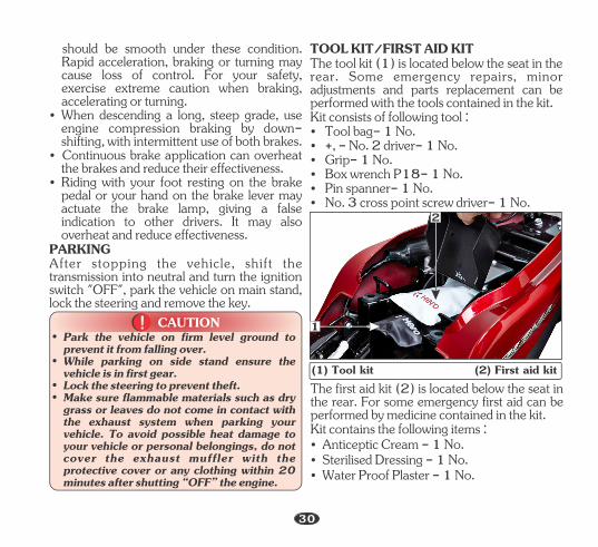
• Box wrench P18- 1 No.
TOOL KIT/FIRST AID KIT
• Tool bag- 1 No.Kit consists of following tool :
• +, - No. 2 driver- 1 No.
The tool kit (1) is located below the seat in the rear. Some emergency repairs, minor adjustments and parts replacement can be performed with the tools contained in the kit.
• No. 3 cross point screw driver- 1 No.
• Grip- 1 No.
• Pin spanner- 1 No.
1
2
(1) Tool kit (2) First aid kit
• Anticeptic Cream - 1 No.
• Water Proof Plaster - 1 No.
The first aid kit (2) is located below the seat in the rear. For some emergency first aid can be performed by medicine contained in the kit.Kit contains the following items :
• Sterilised Dressing - 1 No.
30
• After cleaning spray water thoroughly.
• Elastic Bandage - 1 No.
Follow the below mentioned steps for washing the vehicle.• Wet the vehicle with light water spray. Avoid
directing high pressure water spray onto muffler outlet, electrical/electronic parts, meter console and oil cooler.
• Gauze (Rolled Bandage) - 1 No.
• First Aid Bag - 1 No.
• Dry the vehicle by wiping with dry soft cloth.
• Sterilised Elastic Plaster - 1 No.
CLEANING AND WASHING OF VEHICLE
• Clean the headlamp lens and other plastic parts using a cloth or sponge dampened with a solution of mild detergent and water. Rub the soiled area gently rinsing it frequently with fresh water.
NOTEOur authorised dealership take all above mentioned precautions like recommended detergents and usage of muffler caps/plugs and oil cooler covers during wash to ensure quality wash.
WARNING!!Avoid direct high pressure water spray on any electrical, electronic components and oil cooler.
MAINTENANCE
A Well-maintained vehicle is essential for safe economical and trouble-free riding. It will also help in reducing air pollution.To help you, take proper care of your vehicle, the following pages include a Maintenance Schedule and a Maintenance Record for regular scheduled maintenance.These instructions are based on the assumption that the vehicle will be used exclusively for its designed purpose. Sustained high speed operation or operation in unusually
The Importance of Maintenance
wet or dusty conditions will require more frequent service than specified in the maintenance schedule.Consult your Authorised Hero MotoCorpworkshop for recommendation applicable to your individual needs and use.If your vehicle overturns or is involved in a crash, be sure that you visit your Authorised Hero MotoCorp workshop for detailed inspections.
WARNING!!• Improperly maintaining this vehicle or failing
to correct a problem before you ride can cause a crash in which you can be seriously hurt or killed.
• Always follow the inspection and maintenance recommendations and schedules in this owner’s manual.
31
WARNING!!
• Always fol low the procedures and precautions in this owner's manual.
• Failure to properly follow maintenance instructions and precautions can cause you to be seriously hurt.
Other tasks that are more difficult and require special tools are best performed by professionals. It is recommended that wheel removal should normally be handled by a Hero MotoCorp authorised workshop.
This section includes instruction on some important maintenance tasks. You can perform some of these tasks with the tools provided - if you have basic mechanical skills.
Some of the most important safety precautions follow. However, we cannot warn you of every conceivable hazard that can arise in performing maintenance. Only you can decide whether or not to perform a given task.
Maintenance Safety Safety precautions
Remember that your Authorised Hero MotoCorp workshop knows your vehicle best and is fully equipped to maintain and repair it. To ensure best quality and reliability, it is recommended to use Hero MotoCorp genuine parts for repair and replacement.
• Read the instruction before you begin and make sure you have the tools and skills required.
• Carbon monoxide poisoning from engine exhaust.
• Be sure there is adequate ventilation whenever you operate the engine.
• Do not run the engine unless instructed to do so.
• Let the engine and exhaust system cool before touching.
• Make sure the engine is “OFF” before you begin any maintenance or repair. This will help to eliminate several potential hazards:
• To help prevent the vehicle from falling over, park it on a firm, level surface on the main stand.
• To reduce the possibility of a fire or explosion, be careful when working around petrol or batteries. Use only nonflammable solvent, not petrol, to clean parts. Keep cigarettes, sparks and flames away from the battery and all fuel-related parts.
• Burns from hot parts.
• Injury from moving parts.
32
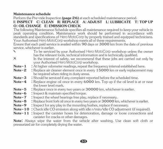
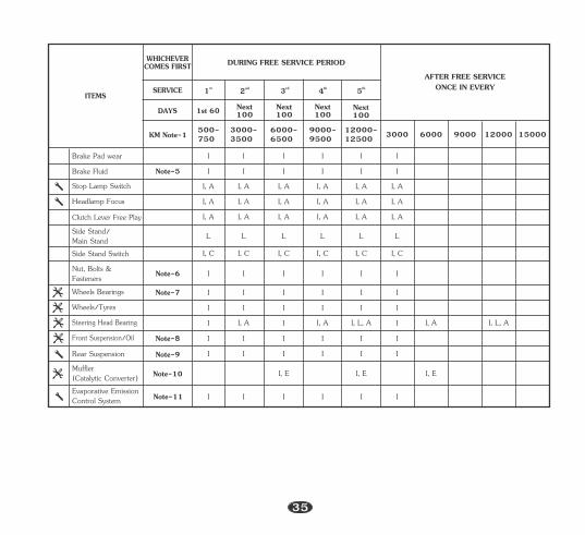
Note-1 : At higher odometer readings, repeat the frequency interval established here.
Maintenance schedule
I: INSPECT C: CLEAN R: REPLACE A: ADJUST L: LUBRICATE T: TOP UP O: OIL CHANGE E: EMISSION CHECK
Note-8 : Replace front fork oil once in every two years or 30000 km, whichever is earlier.
Note-10 : Check idle CO emission along with idle r/min/idle CO adjustment (if required).
Perform the Pre-ride Inspection (page 26) at each scheduled maintenance period.
The following Maintenance Schedule specifies all maintenance required to keep your vehicle in peak operating condition. Maintenance work should be performed in accordance with standards and specifications of Hero MotoCorp by properly trained and equipped technicians. Your Authorised Hero MotoCorp workshop meets all of these requirements.
To be serviced by your Authorised Hero MotoCorp workshop unless the owner has the relevant tools, technical information and is technically qualified.
In the interest of safety, we recommend that these jobs are carried out only by your Authorised Hero MotoCorp workshop.
Ensure that each paid service is availed within 90 days or 3000 km from the date of previous service, whichever is earlier.
Note-3 : Should be serviced if any complaint reported before the scheduled time.Note-4 : Replace engine oil once in every 6000 km. Top up if the oil level is at or near
the lower level mark.
Note-2 : Replace air cleaner element once in every 15000 km or early replacement may be required when riding in dusty areas.
Note-5 : Replace once in every two years or 30000 km, whichever is earlier.Note-6 : Inspect & maintain specified torque.Note-7 : Inspect the wheel bearings free play, replace if necessary.
Note-9 : Inspect for any play in the mounting bushes, replace if necessary.
Note: Always wipe the water from the vehicle after washing. Use clean soft cloth or pressurized air for completely drying the water.
Note-11 : Inspect the canister hoses for deterioration, damage or loose connections and canister for cracks or other damages.
33
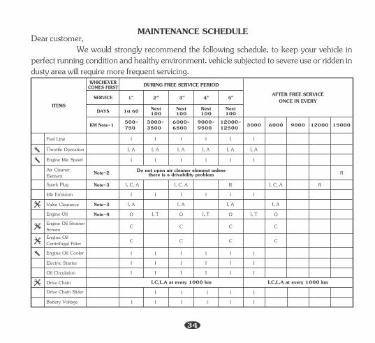
We would strongly recommend the following schedule, to keep your vehicle in perfect running condition and healthy environment. vehicle subjected to severe use or ridden in dusty area will require more frequent servicing.
Dear customer,MAINTENANCE SCHEDULE
3000-3500
6000-6500
9000-9500
12000-12500
I,C,L,A at every 1000 km I,C,L,A at every 1000 km
Air Cleaner Element
Fuel Line
Throttle Operation
Spark Plug
Valve Clearance
Engine Oil
Engine Oil StrainerScreenEngine Oil Centrifugal Filter
Oil Circulation
Electric Starter
WHICHEVERCOMES FIRST
ITEMS
DURING FREE SERVICE PERIOD
SERVICE st1 nd2 rd3 th4 th5 AFTER FREE SERVICEONCE IN EVERY
6000 9000 12000 15000
DAYS
500-750
R
R
O
C
C
Drive Chain
Battery Voltage I
I
I
I
I
I
I
I
I
I
I
I I I I I I
C C C
CCC
I, TOI, TOI, TO
I, A I, A I, A I, A
I, C, AI, C, A R
I, A I, A I, A I, A I, A
IIIIII
I, A
3000
Next 100
Next 100
Next 1001st 60 Next
100
I I I I I I
Drive Chain Slider
Do not open air cleaner element unless there is a drivability problem
KM Note-1
Engine Idle Speed IIIIII
Idle Emission IIIIII
Engine Oil Cooler I I I I I I
Note-2
Note-3
Note-3
Note-4
34
I, C, A
Next 100
Next 100
Next 100
3000-3500
6000-6500
9000-9500
12000-12500
WHICHEVERCOMES FIRST
ITEMS
DURING FREE SERVICE PERIOD
SERVICE st1 nd2 rd3 th4 th5AFTER FREE SERVICE
ONCE IN EVERY
6000 9000 12000 15000
DAYS
500-750
1st 60
3000
Next 100
Headlamp Focus
Brake Pad wear
I, A I, A I, A I, A I, A I, A
Clutch Lever Free Play
Nut, Bolts & Fasteners
Wheels/Tyres
Wheels Bearings
Steering Head Bearing
Front Suspension/Oil
I
I
I
I
I
I
I
I
I
I
I
I
I
I
I
I
I
I
I I I I I I
I, L, AI, AII, L, AI, AII, AI
I I I I I I
Side Stand/Main Stand L L L L L L
I, A I, A I, A I, A I, A I, A
Note-5
Muffler (Catalytic Converter) I, E I, E I, E
Brake Fluid
Rear Suspension
I
I
I
I
I
I
I
I
I
I
I
I
Stop Lamp Switch I, AI, AI, AI, AI, AI, A
Evaporative Emission Control System I I I I I I
KM Note-1
Note-8
Note-6
Note-7
Note-9
Note-10
Note-11
Side Stand Switch I, C I, C I, C I, C I, C I, C
35
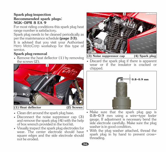
Spark plug removal• Remove the heat deflector (1) by removing
the screws (2).
It is advised that you visit your Authorised Hero MotoCorp workshop for this type of service.
Recommended spark plugs: NGK-DPR 8 EA 9
Spark plug inspection
Spark plug needs to be cleaned periodically as per the maintenance schedule (page 33).
For most riding conditions this spark plug heat range number is satisfactory.
• Visually inspect the spark plug electrodes for wear. The center electrode should have square edges and the side electrode should not be eroded.
• Disconnect the noise suppressor cap (3) and remove the spark plug (4) with the help of box wrench provided in the tool kit.
• Clean dirt around the spark plug base.
(3) Noise suppressor cap (4) Spark plug
3
4
(1) Heat deflector (2) Screws
1
2
• With the plug washer attached, thread the spark plug in by hand to prevent cross-threading.
• Make sure that the spark plug gap is 0.8-0.9 mm using a wire-type feeler gauge. If adjustment is necessary bend the side electrode carefully. Make sure the plug washer is in good condition.
• Discard the spark plug if there is apparent wear or if the insulator is cracked or chipped.
0.8-0.9 mm
36
36
(JASO MA ).2
Use hero genuine engine oil or recommended grade oil.
Manufactured by:
Engine oil
GRADE: SAE 10W 30 S Grade L
• Tighten a new spark-plug 1/2 turn after the plug seats, with a spark plug box wrench to compress the washer. If you are reusing a plug, it should only take 1/8-1/4 turn after the plug seats.
BRAND: Hero 4T plus
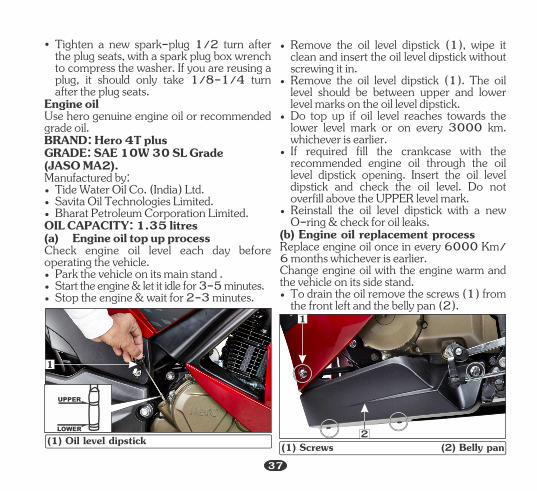
Check engine oil level each day beforeoperating the vehicle.
• Stop the engine & wait for 2-3 minutes.
• Tide Water Oil Co. (India) Ltd.• Savita Oil Technologies Limited.
• Start the engine & let it idle for 3-5 minutes.
OIL CAPACITY: 1. litres35
• Park the vehicle on its main stand .
(a) Engine oil top up process
• Bharat Petroleum Corporation Limited.
1
(1) Oil level dipstick
• To drain the oil remove the screws (1) from the front left and the belly pan (2).
• Reinstall the oil level dipstick with a new O-ring & check for oil leaks.
Replace engine oil once in every 6000 Km/ 6 months whichever is earlier.
• If required fill the crankcase with the recommended engine oil through the oil level dipstick opening. Insert the oil level dipstick and check the oil level. Do not overfill above the UPPER level mark.
• Remove the oil level dipstick (1). The oil level should be between upper and lower level marks on the oil level dipstick.
• Do top up if oil level reaches towards the lower level mark or on every 3000 km. whichever is earlier.
• Remove the oil level dipstick (1), wipe it clean and insert the oil level dipstick without screwing it in.
(b) Engine oil replacement process
Change engine oil with the engine warm and the vehicle on its side stand.
UPPER
LOWER
(1) Screws (2) Belly pan2
1
37
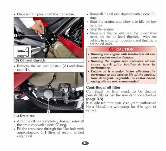
• Place a drain pan under the crankcase.
(3) Oil level dipstick
(4) Drain cap
• Start the engine and allow it to idle for few minutes.
• Make sure that oil level is at the upper level mark on the oil level dipstick with the vehicle in an upright position, and that there are no oil leaks.
• Reinstall the oil level dipstick with a new O-ring.
• Stop the engine.
UPPER
LOWER
3
• Remove the oil level dipstick (3) and drain cap (4).
CAUTION!!• Running the engine with insufficient oil can
cause serious engine damage.
• Engine oil is a major factor affecting the performance and service life of the engine. Non-detergent, vegetable, or castor based racing oils are not recommended.
• Running the engine with excessive oil can cause spark plug fouling & loss in performance.
• Fill the crankcase through the filler hole with approximately 1.1 litres of recommended engine oil.
• After the oil has completely drained, reinstall the drain cap with a new ‘O’ ring.
Centrifugal oil filter needs to be cleaned periodically as per the maintenance schedule (page 33).
Centrifugal oil filter
It is advised that you visit your Authorised Hero MotoCorp workshop for this type of service.
38
4
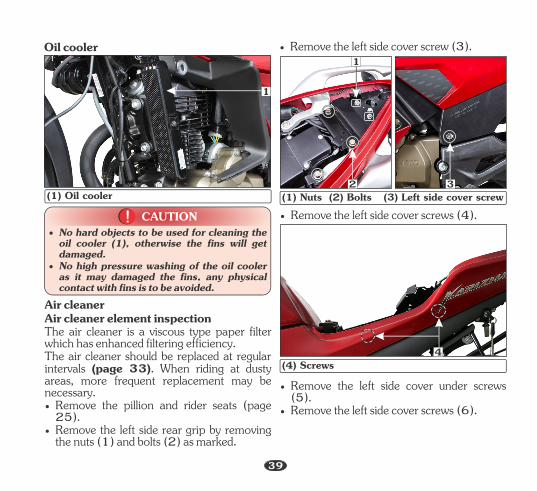
Oil cooler
(1) Oil cooler
CAUTION!!• No hard objects to be used for cleaning the
oil cooler (1), otherwise the fins will get damaged.
• No high pressure washing of the oil cooler as it may damaged the fins, any physical contact with fins is to be avoided.
1
Air cleanerAir cleaner element inspectionThe air cleaner is a viscous type paper filter which has enhanced filtering efficiency.
• Remove the pillion and rider seats (page 25).
• Remove the left side rear grip by removing the nuts (1) and bolts (2) as marked.
The air cleaner should be replaced at regular intervals (page 33). When riding at dusty areas, more frequent replacement may be necessary.
• Remove the left side cover screws (4).
• Remove the left side cover screws (6).
• Remove the left side cover under screws (5).
1
(1) Nuts (2) Bolts (3) Left side cover screw
4(4) Screws
2 3
• Remove the left side cover screw (3).
39
40
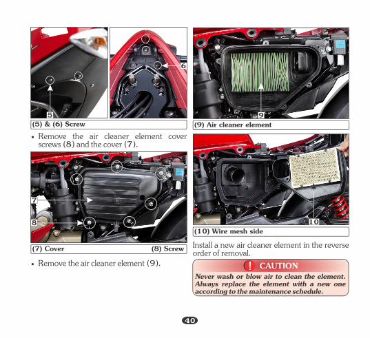
(5) & (6) Screw• Remove the air cleaner element cover
screws (8) and the cover (7).
• Remove the air cleaner element (9).(7) Cover (8) Screw
(9) Air cleaner element
Install a new air cleaner element in the reverse order of removal.
(10) Wire mesh side
5
6
9
7
8 10
CAUTION!!Never wash or blow air to clean the element. Always replace the element with a new one according to the maintenance schedule.
40

NOTEIf proper adjustment cannot be obtained or the clutch does not work properly, visit your Authorised Hero MotoCorp workshop.
Valve clearance adjustment
Refer to the safety precautions (page 32).
Replace paper filter element once in every 15000 Km.
Clutch lever free play adjustment
Excessive valve clearance will cause noise, and little or no clearance will prevent the valve from closing and cause valve damage and power loss. To ensure proper operation of the valves the valve clearance should be inspected and adjusted if necessary by your Authorised Hero MotoCorp workshop as per the maintenance schedule (page 33).
Clutch adjustment may be required if the vehicle stalls when shifting into gear or tends to creep or if the clutch slips, causing acceleration to lag behind engine speed. Normal clutch lever free play (1) is 10-20 mm at the clutch lever (2).
• Replace it earlier if it becomes very dirty, damaged on surface or on the sealing area.
(1) Free play 10-20 mm (2) Clutch lever(3) Dust cover (4) Lock nut (5) Adjuster
1 A
B
2 4
3
5
Cable inspection
• The standard free play should be approximately 2-6 mm of grip rotation.
Throttle operation & free play adjustment
Refer to the safety precautions on (page32).• Check for smooth rotation of the cable
inspection (sub head) throttle grip from the fully open to the fully closed position at both full steering positions.
• Measure the throttle grip free play (1) at the throttle grip flange.
• To adjust the free play move the clutch lever dust cover (3), loosen the lock nut (4). Turn the adjuster (5) to obtain the specified free play. To increase the clutch lever free play turn the adjuster in direction (A). To decrease the clutch lever free play turn the adjuster in direction (B).
• Start the engine, press the clutch lever and shift into gear. Make sure the engine does not stall and the vehicle does not creep. Gradually release the clutch lever and open the throttle. The vehicle should start smoothly and accelerate.
41

(1) Free play:2-6 mm
Free play adjustmentTo adjust the free play, slide the grommet (2), then loosen the lock nut (3). Turn the adjuster (4) to adjust free play. After adjustment, tighten the lock nut and reinstall the grommet securely.
• If the cable is kinked, chafed or improperly routed, it should be replaced or rerouted.
A
B
(2) Grommet (A) Decrease free play (3) Lock nut (B) Increase free play(4) Adjuster
43
2
The service life of the drive chain dependent upon proper lubrication and adjustment. Poor maintenance can cause premature wear or damage to the drive chain and sprockets. The drive chain (1) should be checked and lubricated as part of the Pre-ride inspection (page 26). Under severe usage, or when the vehicle is ridden in unusually dusty areas, more frequent maintenance will be necessary.
• Remove the lower chain guard by removing the bolts (2).
Drive chain slackness adjustment
• Turn the engine “OFF”, park the vehicle on its main stand and shift the gear to neutral.
Inspection
1 2(1) Drive chain (2) Bolts• Drive chain slack (3) should be checked in
the lower run midway between the sprockets. Move the drive chain up and down by hand and chain slack should be adjusted to 25 mm vertical movement by hand.
42
1
NOTE
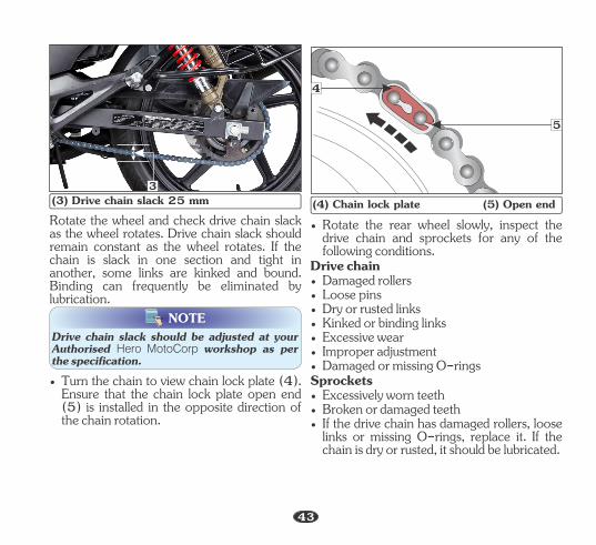
Rotate the wheel and check drive chain slack as the wheel rotates. Drive chain slack should remain constant as the wheel rotates. If the chain is slack in one section and tight in another, some links are kinked and bound. Binding can frequently be eliminated by lubrication.
3(3) Drive chain slack 25 mm
• Turn the chain to view chain lock plate (4). Ensure that the chain lock plate open end (5) is installed in the opposite direction of the chain rotation.
• Damaged rollers
• Excessive wear
• Rotate the rear wheel slowly, inspect the drive chain and sprockets for any of the following conditions.
Drive chain
• Damaged or missing O-rings
• If the drive chain has damaged rollers, loose links or missing O-rings, replace it. If the chain is dry or rusted, it should be lubricated.
Sprockets
• Improper adjustment
• Excessively worn teeth• Broken or damaged teeth
• Loose pins• Dry or rusted links• Kinked or binding links
(4) Chain lock plate (5) Open end
4
5
43
Drive chain slack should be adjusted at your Authorised Hero MotoCorp workshop as per the specification.
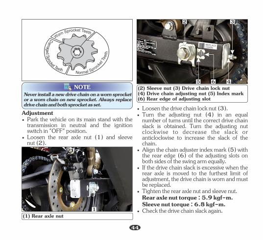
NOTENever install a new drive chain on a worn sprocket or a worn chain on new sprocket. Always replace drive chain and both sprocket as set.
Adjustment
• Loosen the rear axle nut (1) and sleeve nut (2).
• Park the vehicle on its main stand with the transmission in neutral and the ignition switch in "OFF" position.
Rear axle nut torque : 5.9 kgf-m.
• Loosen the drive chain lock nut (3).
• Align the chain adjuster index mark (5) with the rear edge (6) of the adjusting slots on both sides of the swing arm equally.
Sleeve nut torque : 6.8 kgf-m.
• If the drive chain slack is excessive when the rear axle is moved to the furthest limit of adjustment, the drive chain is worn and must be replaced.
• Tighten the rear axle nut and sleeve nut.
• Check the drive chain slack again.
• Turn the adjusting nut (4) in an equal number of turns until the correct drive chain slack is obtained. Turn the adjusting nut clockwise to decrease the slack or anticlockwise to increase the slack of the chain.
(1) Rear axle nut
5 6(2) Sleeve nut (3) Drive chain lock nut(4) Drive chain adjusting nut (5) Index mark(6) Rear edge of adjusting slot
1
2 3
4
co kr ep tS T enr
eo
thW
corpke
S
t
l
T
a
e
m
e
r
t
o
h
N
orp
cS
kd
ee
t
g
T
a
ee
m
t
a
h
D
44
CAUTION!!
NOTE
Cleaning
• Wait for approx 3-5 minutes to allow the mixture to penetrate in between bush and roller for proper cleaning of the drive chain. Repeat the process few times depending on the dirt accumulation on the drive chain.
• Finally wipe the chain with a dry shop towel to remove the oil + kerosene traces from it. Visibly inspect the chain after cleaning and ensure no mud or dust is left out.
• If the drive chain becomes extremely dirty, it should be removed and cleaned prior to lubrication.
• Dip a soft nylon brush in a mixture of kerosene and 10W30 engine oil (in the ratio of 1:1) and clean the dirt accumulated on the chain with the help of a soft brush.
Lubrication• Apply SAE 90 Grade oil on the inner side of
the entire length of the chain using the oil can.• Wait for 7-10 minutes for penetration of
the lubricant inside the bush & roller for better lubrication. Wipe the excess lubricant from the chain and nearby parts by using a dry shop towel.
• Regular adjustment and lubrication as per the maintenance schedule would ensure high performance and longer life.
• The drive chain is fitted with O-rings between the link plates. These O-rings retain grease inside the chain to improve its service life. However, special precautions must be taken when adjusting, lubricating, washing and replacing the chain.
• Steam cleaning, high pressure washers and certain solvents can damage the drive chain O-rings.
• While lubricating and cleaning hold the rear wheel with one hand to prevent the possibility of your finger being trapped between the chain and sprocket.
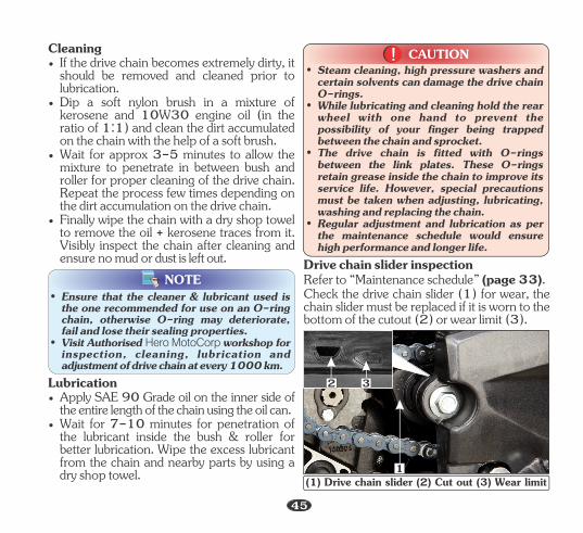
Drive chain slider inspection
Check the drive chain slider (1) for wear, the chain slider must be replaced if it is worn to the bottom of the cutout (2) or wear limit (3).
Refer to “Maintenance schedule” (page 33).
(1) Drive chain slider (2) Cut out (3) Wear limit1
2 3
45
• Ensure that the cleaner & lubricant used is the one recommended for use on an O-ring chain, otherwise O-ring may deteriorate, fail and lose their sealing properties.
• Visit Authorised Hero MotoCorp workshop for inspection, cleaning, lubrication and adjustment of drive chain at every 1000 km.
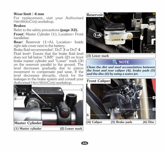
Fluid level- Ensure that the brake fluid level does not fall below "LWR'' mark (2) on front brake master cylinder and "Lower" mark (3) on the reservoir parallel to the ground. The level decreases gradually due to piston movement to compensate pad wear. If the level decreases abruptly, check for the leakages in the brake system and consult your Authorised Hero MotoCorp workshop.
Brake fluid recommended : DoT 3 or DoT 4
Front: Master Cylinder (1), Location- Front handlebar.Rear: Reservoir (1-A), Location- Inside right side cover next to the battery.
Wear limit : 4 mmFor replacement, visit your Authorised HeroMotoCorp workshop.BrakesRefer to the safety precautions (page 32).
Master Cylinder
UPPER
LOWER
Reservoir
3
Front Caliper
(4) Caliper (5) Brake pads (6) Disc
(1) Master cylinder (2) Lower mark
(3) Lower mark
1
2
6
4
5
1-A
NOTEClean the dirt and mud accumulation between the front and rear caliper (4), brake pads (5) and the disc (6) by using a water jet.
46
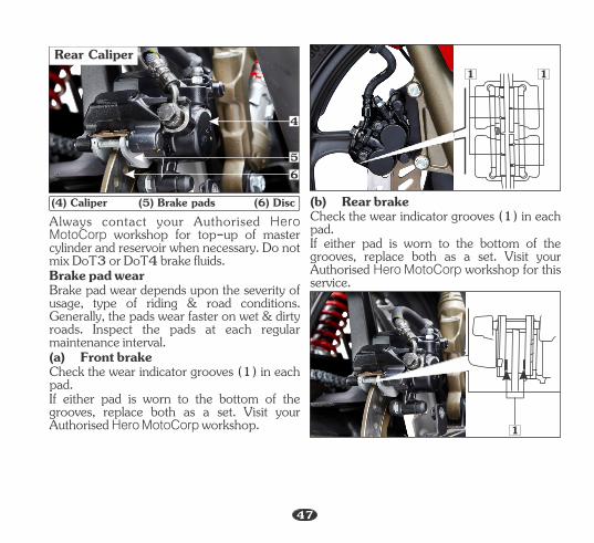
Check the wear indicator grooves (1) in each pad.
Brake pad wear
(a) Front brake
Always contact your Authorised Hero MotoCorp workshop for top-up of master cylinder and reservoir when necessary. Do not mix DoT3 or DoT4 brake fluids.
If either pad is worn to the bottom of the grooves, replace both as a set. Visit your Authorised Hero MotoCorp workshop.
Brake pad wear depends upon the severity of usage, type of riding & road conditions. Generally, the pads wear faster on wet & dirty roads. Inspect the pads at each regular maintenance interval.
(b) Rear brakeCheck the wear indicator grooves (1) in each pad. If either pad is worn to the bottom of the grooves, replace both as a set. Visit your Authorised Hero MotoCorp workshop for this service.
Rear Caliper
(4) Caliper (5) Brake pads (6) Disc
1 1
1
4
56
47
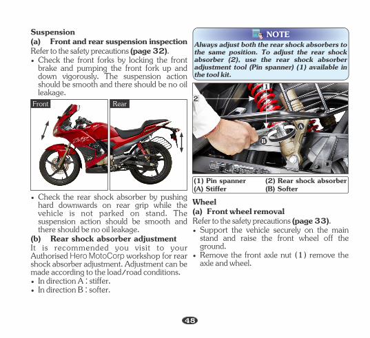
(a) Front and rear suspension inspectionRefer to the safety precautions (page 32).
Suspension
• Check the front forks by locking the front brake and pumping the front fork up and down vigorously. The suspension action should be smooth and there should be no oil leakage.
• In direction A : stiffer.• In direction B : softer.
(b) Rear shock absorber adjustmentIt is recommended you visit to your Authorised Hero MotoCorp workshop for rear shock absorber adjustment. Adjustment can be made according to the load/road conditions.
• Check the rear shock absorber by pushing hard downwards on rear grip while the vehicle is not parked on stand. The suspension action should be smooth and there should be no oil leakage.
NOTEAlways adjust both the rear shock absorbers to the same position. To adjust the rear shock absorber (2), use the rear shock absorber adjustment tool (Pin spanner) (1) available in the tool kit.
B
A
(1) Pin spanner (2) Rear shock absorber(A) Stiffer (B) Softer
1
Front Rear
• Support the vehicle securely on the main stand and raise the front wheel off the ground.
Wheel
Refer to the safety precautions (page 33).
• Remove the front axle nut (1) remove the axle and wheel.
(a) Front wheel removal
48
2
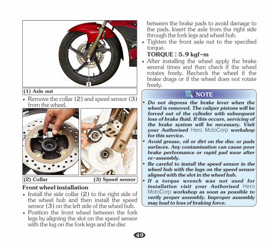
(1) Axle nut
(2) Collar (3) Speed sensorFront wheel installation• Install the side collar (2) to the right side of
the wheel hub and then install the speed sensor (3) on the left side of the wheel hub.
• Position the front wheel between the fork legs by aligning the slot on the speed sensor with the lug on the fork legs and the disc
1
23
• Remove the collar (2) and speed sensor (3) from the wheel.
between the brake pads to avoid damage to the pads. Insert the axle from the right side through the fork legs and wheel hub.
• Tighten the front axle nut to the specified torque.
• After installing the wheel apply the brake several times and then check if the wheel rotates freely. Recheck the wheel if the brake drags or if the wheel does not rotate freely.
TORQUE : 5.9 kgf-m
NOTE
49
• If a torque wrench was not used for installation visit your Authorised Hero MotoCorp workshop as soon as possible to verify proper assembly. Improper assembly may lead to loss of braking force.
• Do not depress the brake lever when the wheel is removed. The caliper pistons will be forced out of the cylinder with subsequent loss of brake fluid. If this occurs, servicing of the brake system will be necessary. Visit your Authorised Hero MotoCorp workshop for this service.
• Avoid grease, oil or dirt on the disc or pads surfaces. Any contamination can cause poor brake performance or rapid pad wear after re-assembly.
• Be careful to install the speed sensor in the wheel hub with the lugs on the speed sensor aligned with the slot in the wheel hub.
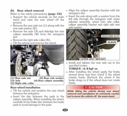
(1) Rear axle nut (2) Rear axle washer (3) Axle (4) Rear caliper assembly (5) Right side collar
• Align the caliper assembly bracket with the swingarm slot.
• Insert the axle along with a washer from the left side through the swingarm with chain adjuster assembly, wheel hub, side collar, caliper assembly bracket and right side rear axle washer.
4
2
1 3
5
• Remove the right side collar (5).
Refer to the safety precautions (page 32).
• Remove the axle (3) and dislodge the rear caliper assembly (4) from the swingarm slot.
(b) Rear wheel removal
• Support the vehicle securely on the main stand and raise the rear wheel off the ground.
• Remove the rear axle nut (1) along with the rear axle washer (2).
• Tilt the vehicle and remove the wheel.
• Tilt the vehicle and position the rear wheel between the swingarm.
• Insert the disc between the pads in the caliper assembly. When installing the wheel, carefully fit the brake disc between the brake pads to avoid damage to the pads.
Rear wheel installation
ALIGN
• After installing the wheel apply the brake several times and then check if the wheel rotates freely. Recheck the wheel if the brake drags or if the wheel does not rotate freely.
TORQUE : 6.8 kgf-m
• Install and tighten the rear axle nut to the specified torque.
CAUTION!!While tilting the vehicle during rear wheel removal and installation be extremely careful not to move the vehicle off the main stand.
SWINGARM SLOT
CALIPER ASSY. BRACKET
50
NOTE• Do not depress the brake pedal when the
wheel is removed. The caliper piston will be forced out of the cylinder with subsequent loss of brake fluid. If this occurs servicing of the brake system will be necessary. Visit your Authorised Hero MotoCorp workshop for this service.
• Avoid grease, oil or dirt on the disc or pads surfaces. Any contamination can cause poor brake performance or rapid pad wear after re-assembly.
• If a torque wrench was not used for installation visit your Authorised Hero MotoCorp workshop as soon as possible to verify proper assembly. Improper assembly may lead to loss of braking force.
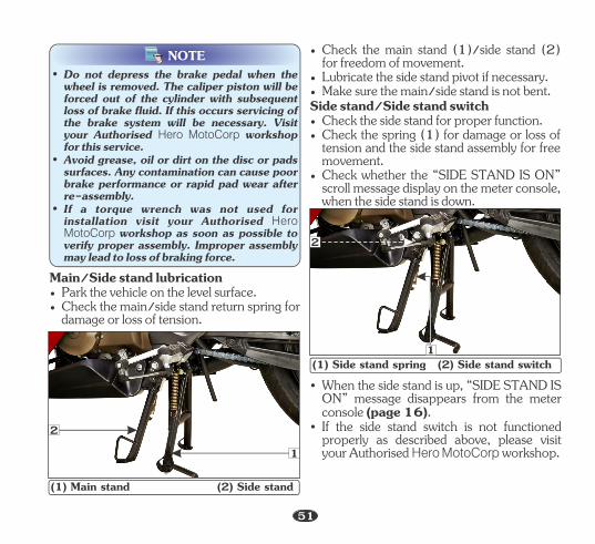
(1) Main stand (2) Side stand
• Park the vehicle on the level surface.• Check the main/side stand return spring for
damage or loss of tension.
Main/Side stand lubrication
2
1
• Check the side stand for proper function.
• Check whether the “SIDE STAND IS ON” scroll message display on the meter console, when the side stand is down.
• Check the spring (1) for damage or loss of tension and the side stand assembly for free movement.
• Make sure the main/side stand is not bent.• Lubricate the side stand pivot if necessary.
• Check the main stand (1)/side stand (2) for freedom of movement.
Side stand/Side stand switch
• If the side stand switch is not functioned properly as described above, please visit your Authorised Hero MotoCorp workshop.
• When the side stand is up, “SIDE STAND IS ON” message disappears from the meter console (page 16).
(1) Side stand spring (2) Side stand switch
2
1
51
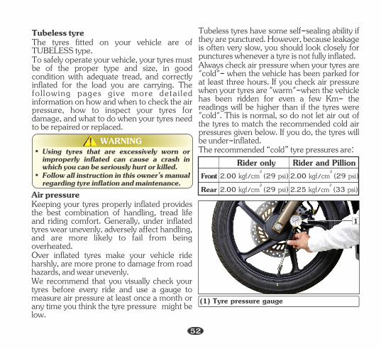
Tubeless tyreThe tyres fitted on your vehicle are of TUBELESS type.To safely operate your vehicle, your tyres must be of the proper type and size, in good condition with adequate tread, and correctly inflated for the load you are carrying. The fol lowing pages give more detai led information on how and when to check the air pressure, how to inspect your tyres for damage, and what to do when your tyres need to be repaired or replaced.
WARNING!!• Using tyres that are excessively worn or
improperly inflated can cause a crash in which you can be seriously hurt or killed.
• Follow all instruction in this owner’s manual regarding tyre inflation and maintenance.
Air pressureKeeping your tyres properly inflated provides the best combination of handling, tread life and riding comfort. Generally, under inflated tyres wear unevenly, adversely affect handling, and are more likely to fail from being overheated.
We recommend that you visually check your tyres before every ride and use a gauge to measure air pressure at least once a month or any time you think the tyre pressure might be low.
Over inflated tyres make your vehicle ride harshly, are more prone to damage from road hazards, and wear unevenly.
Tubeless tyres have some self-sealing ability if they are punctured. However, because leakage is often very slow, you should look closely for punctures whenever a tyre is not fully inflated.Always check air pressure when your tyres are "cold"- when the vehicle has been parked for at least three hours. If you check air pressure when your tyres are "warm"-when the vehicle has been ridden for even a few Km- the readings will be higher than if the tyres were "cold". This is normal, so do not let air out of the tyres to match the recommended cold air pressures given below. If you do, the tyres will be under-inflated.The recommended “cold” tyre pressures are:
FrontRear
2 2.00 kgf/cm (29 psi)2 2.00 kgf/cm (29 psi)
2 2.00 kgf/cm (29 psi)2 2.25 kgf/cm (33 psi)
Rider only Rider and Pillion
1
(1) Tyre pressure gauge
52
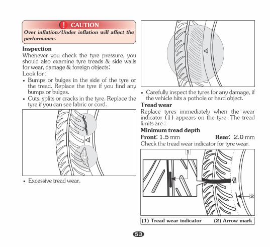
CAUTION!!Over inflation/Under inflation will affect the performance.
Inspection
• Bumps or bulges in the side of the tyre or the tread. Replace the tyre if you find any bumps or bulges.
Whenever you check the tyre pressure, you should also examine tyre treads & side walls for wear, damage & foreign objects:Look for :
• Cuts, splits or cracks in the tyre. Replace the tyre if you can see fabric or cord.
• Excessive tread wear.
• Carefully inspect the tyres for any damage, if the vehicle hits a pothole or hard object.
Tread wear
Minimum tread depth
Check the tread wear indicator for tyre wear.
Replace tyres immediately when the wear indicator (1) appears on the tyre. The tread limits are :
Front: 1.5 mm Rear: 2.0 mm
(1) Tread wear indicator (2) Arrow mark
1
2
53
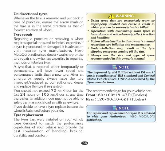
NOTEThe imported tyre(s) if fitted without ISI mark; are in compliance of BIS standard and Central Motor Vehicle Rules 1989, as declared by the Tyre manufacturer.
NOTEFor repair and replacement of tyre it is advised to visit your Authorised Hero MotoCorp workshop.
Tyre replacement
Tyre repair
Unidirectional tyresWhenever the tyre is removed and put back in case of puncture, ensure the arrow mark on the tyre is in the same direction as that of forward rotation of wheel.
Repairing a puncture or removing a wheel requires special tools and technical expertise. If a tyre is punctured or damaged, it is advised to visit nearest tyre manufacture, Hero MotoCorp authorised dealer/workshop or the tyre repair shop who has expertise in repairing methods of tubeless tyre. A tyre that is repaired either temporarily or permanently, will have lower speed and performance limits than a new tyre. After an emergency repair, always have the tyre inspected/replaced at our authorised dealer and replace the tyre if suggested. You should not exceed 70 km/hour for the 1st 24 hours or 105 km/hour at any time thereafter. In addition, you may not be able to safely carry as much load as with a new tyre. If you decide to have a tyre replace be sure the wheel is balanced before you ride.
durability and comfort.
The tyres that were installed on your vehicle were designed to match the performance capabilities of your vehicle and provide the best combination of handling, braking,
WARNING!!
• Under-inflation may result in the tyre slipping on or tyre coming off the rim.
• Always use the size and type of tyres recommended in this owner’s manual.
• Operation with excessively worn tyres is hazardous and will adversely affect traction and handling.
• Using tyres that are excessively worn or improperly inflated can cause a crash in which you can be seriously hurt or killed.
• Follow all instruction in this owner’s manual regarding tyre inflation and maintenance.
Front : 80/100x18-47 P (Tubeless)The recommended tyre for your vehicle are:
Rear : 120/80x18-62 P (Tubeless)
54
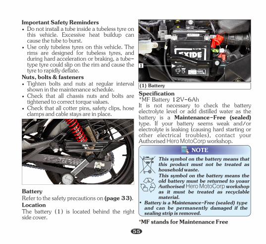
Important Safety Reminders• Do not install a tube inside a tubeless tyre on
this vehicle. Excessive heat buildup can cause the tube to burst.
• Use only tubeless tyres on this vehicle. The rims are designed for tubeless tyres, and during hard acceleration or braking, a tube-type tyre could slip on the rim and cause the tyre to rapidly deflate.
Nuts, bolts & fasteners
• Check that all chassis nuts and bolts are tightened to correct torque values.
• Tighten bolts and nuts at regular interval shown in the maintenance schedule.
• Check that all cotter pins, safety clips, hose clamps and cable stays are in place.
BatteryRefer to the safety precautions on (page 33).LocationThe battery (1) is located behind the rightside cover.
Specification*MF Battery 12V-6Ah It is not necessary to check the battery electrolyte level or add distilled water as the battery is a Maintenance-Free (sealed) type. If your battery seems weak and/or electrolyte is leaking (causing hard starting or other electrical troubles), contact your Authorised Hero MotoCorp workshop.
NOTE
This symbol on the battery means the old battery must be returned to yoaur Authorised Hero MotoCorp workshop as it must be treated as recyclable material.
This symbol on the battery means that this product must not be treated as household waste.
• Battery is a Maintenance-Free (sealed) type and can be permanently damaged if the sealing strip is removed.
(1) Battery
1
55*MF stands for Maintenance Free
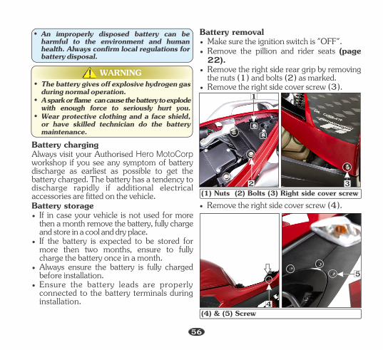
WARNING!!
• Wear protective clothing and a face shield, or have skilled technician do the battery maintenance.
• A spark or flame can cause the battery to explode with enough force to seriously hurt you.
• The battery gives off explosive hydrogen gas during normal operation.
• Ensure the battery leads are properly connected to the battery terminals during installation.
• Always ensure the battery is fully charged before installation.
• If the battery is expected to be stored for more then two months, ensure to fully charge the battery once in a month.
Battery charging Always visit your Authorised Hero MotoCorp workshop if you see any symptom of battery discharge as earliest as possible to get the battery charged. The battery has a tendency to discharge rapidly if additional electrical accessories are fitted on the vehicle.
• If in case your vehicle is not used for more then a month remove the battery, fully charge and store in a cool and dry place.
Battery storage
• An improperly disposed battery can be harmful to the environment and human health. Always confirm local regulations for battery disposal.
• Remove the right side cover screw (3).
• Make sure the ignition switch is "OFF". • Remove the pillion and rider seats (page
22).• Remove the right side rear grip by removing
the nuts (1) and bolts (2) as marked.
Battery removal
• Remove the right side cover screw (4).(1) Nuts (2) Bolts (3) Right side cover screw
1
2 3
5
(4) & (5) Screw4
56
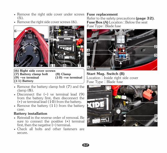
• Remove the battery clamp bolt (7) and the clamp (8).
• Disconnect the (-) ve terminal lead (9) from the battery first, then disconnect the (+) ve terminal lead (10) from the battery.
• Remove the battery (11) from the battery case.
Battery installation • Reinstall in the reverse order of removal. Be
sure to connect the positive (+) terminal first, then the negative (-) terminal.
• Check all bolts and other fasteners are secure.
6
11 8 7
109
• Remove the right side cover under screws (5).
• Remove the right side cover screws (6).
(6) Right side cover screws (7) Battery clamp bolt (8) Clamp (9) -ve terminal (10) +ve terminal (11) Battery
Fuse replacement
Fuse Type : Blade fuse
Refer to the safety precautions (page 32).Fuse Box (A) Location : Below the seat
Start Mag. Switch (B)Location : Inside right side cover Fuse Type : Blade fuse
A
54
1
2
3
7B
6
57
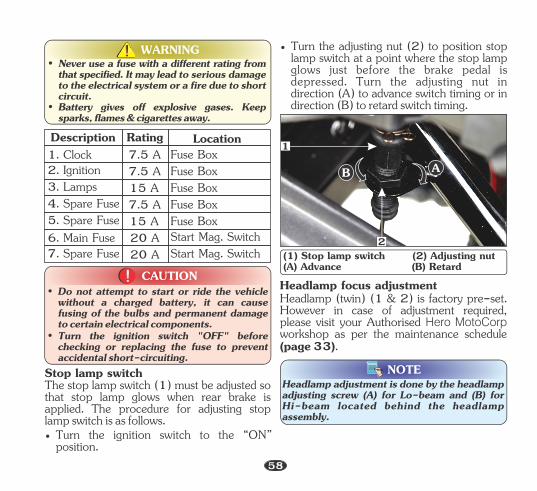
Description Rating Location 1. Clock 7.5 A Fuse Box 2. Ignition 7.5 A Fuse Box 3. Lamps 15 A Fuse Box 4. Spare Fuse 7.5 A Fuse Box 5. Spare Fuse 15 A Fuse Box 6. Main Fuse 20 A Start Mag. Switch 7. Spare Fuse 20 A Start Mag. Switch
WARNING!!
• Battery gives off explosive gases. Keep sparks, flames & cigarettes away.
• Never use a fuse with a different rating from that specified. It may lead to serious damage to the electrical system or a fire due to short circuit.
CAUTION!!• Do not attempt to start or ride the vehicle
without a charged battery, it can cause fusing of the bulbs and permanent damage to certain electrical components.
• Turn the ignition switch "OFF" before checking or replacing the fuse to prevent accidental short-circuiting.
Stop lamp switchThe stop lamp switch (1) must be adjusted so that stop lamp glows when rear brake is applied. The procedure for adjusting stop lamp switch is as follows.• Turn the ignition switch to the “ON”
position.
• Turn the adjusting nut (2) to position stop lamp switch at a point where the stop lamp glows just before the brake pedal is depressed. Turn the adjusting nut in direction (A) to advance switch timing or in direction (B) to retard switch timing.
(1) Stop lamp switch (2) Adjusting nut(A) Advance (B) Retard
B A
2
1
Headlamp focus adjustmentHeadlamp (twin) (1 & 2) is factory pre-set. However in case of adjustment required, please visit your Authorised Hero MotoCorp workshop as per the maintenance schedule (page 33).
NOTEHeadlamp adjustment is done by the headlamp adjusting screw (A) for Lo-beam and (B) for Hi-beam located behind the headlamp assembly.
58
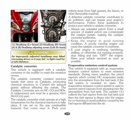
WARNING!!
(1) Headlamp (Lo-beam) (2) Headlamp (Hi-beam)(A) & (B) Headlamp adjusting screws (Lo& Hi-beam)
An improperly adjusted headlamp may blind oncoming driver or it may fail to light road for a safe distance.
2
1
B
A
B
Catalytic converterThis vehicle is equipped with a catalytic converter in the muffler to meet the emission norms.
The catalytic converter must operate at a high temperature for the chemical reactions to take place. It can set on fire any combustible material that come near it. Park your
The catalytic converter contains precious metals that serve as Catalysts, promoting chemical reactions to Convert the exhaust gasses without affecting the metals. The Catalytic Converter acts on HC, CO and NOx. A replacement unit must be a genuine Hero MotoCorp part.
• If your engine is misfiring, backfiring, stalling, or otherwise not running properly, stop riding and turn “OFF” the engine. Have your vehicle serviced as soon as possible.
A defective catalytic converter contributes to air pollution, and can impair your engine's performance. Follow these guidelines to protect your vehicle's catalytic converter.
• Keep the engine in good running condition. A poorly running engine can cause the catalytic converter to overheat.
vehicle away from high grasses, dry leaves, or other flammable material.
• Always use unleaded petrol. Even a small amount of leaded petrol can contaminate the catalyst metals, making the catalytic converter ineffective.
then the fuel vapour is drawn into the engine for re-burning to avoid pollution caused by the fuel vapour diffused into the air.
This vehicle is equipped with an evaporative emission control system to meet emission standards. During warm weather, the petrol vapours which contain HC evaporates easily into the atmosphere from the fuel tank, if the fuel system is unsealed or open. The evaporative emission control system is used to prevent petrol vapours from escaping into the atmosphere from fuel tank. The canister (1) collects the fuel vapour from the fuel tank and
Evaporative emission control system
59
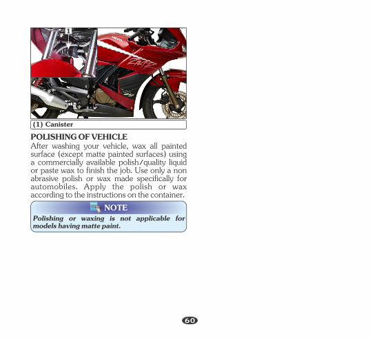
(1) CanisterPOLISHING OF VEHICLEAfter washing your vehicle, wax all painted surface (except matte painted surfaces) using a commercially available polish/quality liquid or paste wax to finish the job. Use only a non abrasive polish or wax made specifically for automobiles. Apply the polish or wax according to the instructions on the container.
NOTEPolishing or waxing is not applicable for models having matte paint.
1
60
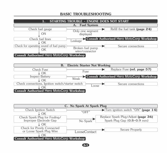
BASIC TROUBLESHOOTING
Check Fuse
Inspect Battery
Check connections, Ignition switch/starter switch
OK
OK
OK Loose
Replace Fuse (ref. page 57)
Secure connectionsWeak
Fuse
Consult Authorised Hero MotoCorp Workshop
B. Electric Starter Not Working
Check Ignition SwitchOK
OK
OK
Turn ignition switch “ON” (page 14)“OFF”
C. No Spark At Spark Plug
No Spark
Consult Authorised Hero MotoCorp Workshop
Check Spark Plug for Fouling/Improper Electrode Gap
Replace Spark Plug/Adjust (page 36)Spark Plug Gap (0.8-0.9 mm)
LooseContactCheck for Poorly Connectedor Loose Spark Plug Wire Secure Properly
Check fuel gaugeON
Check fuel linesOK
OKCheck for operating sound of fuel pump Broken fuel pump
wire/connector
Refill the fuel tank (page 24)
Secure connectionsLeakage
Only one segment displayed
A. Fuel System
Consult Authorised Hero MotoCorp Workshop
1. STARTING TROUBLE - ENGINE DOES NOT START
RefillConsult Authorised Hero MotoCorp Workshop
61
Consult Authorised Hero MotoCorp Workshop
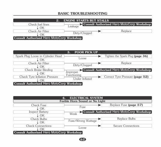
Spark Plug Loose in Cylinder HeadOK
Check Air FilterOK
OKCheck Brake Binding Improper
Functioning
Tighten the Spark Plug (page 36)
ReplaceDirty/Clogged
Loose3. POOR PICK UP
OKCheck Tyre Inflation Pressure Under Inflated Correct Tyre Pressure (page 52)
Consult Authorised Hero MotoCorp Workshop
Check FuseOK
Inspect BatteryOK
OKCheck Bulbs Fuse/Wrong Wattage
Replace Fuse (page 57)
Weak
FuseFeeble Horn Sound or No Light
Replace Bulbs
4. ELECTRICAL SYSTEM
OKCheck Connections Loose Secure Connections
Consult Authorised Hero MotoCorp Workshop
Consult Authorised Hero MotoCorp Workshop
Consult Authorised Hero MotoCorp Workshop
Consult Authorised Hero MotoCorp WorkshopCheck fuel linesOK
Check Air FilterOK
ReplaceDirty/Clogged
Leakage
Consult Authorised Hero MotoCorp Workshop
2. ENGINE STARTS BUT STALLS
BASIC TROUBLESHOOTING
62
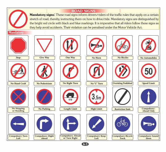
ROAD SIGNSMandatory signs: These road signs inform drivers/riders of the traffic rules that apply on a certain stretch of road, thereby instructing them on how to drive/ride. Mandatory signs are distinguished by the bright red circle with black and blue markings. It is imperative that all riders follow these signs as they help avoid accidents. Their violation can be penalised under the Motor Vehicle Act.
Mandatory
Speed LimitNo Hand Craft No Pedestrians No Right Turn No ‘U’ Turn Overtaking Prohibited
No Parking Length Limit High Limit Restriction EndsNo Stopping or Standing
Compulsory-Ahead Only
Compulsory-TurnLeft
Compulsory-RightAhead
Compulsory-Aheador Turn Right
Compulsory-Keep Left
Compulsory-BicycleTrack
Compulsory-SoundHorn
No AutomobilesStop Give Way One Way No Horn No Bicyles
63
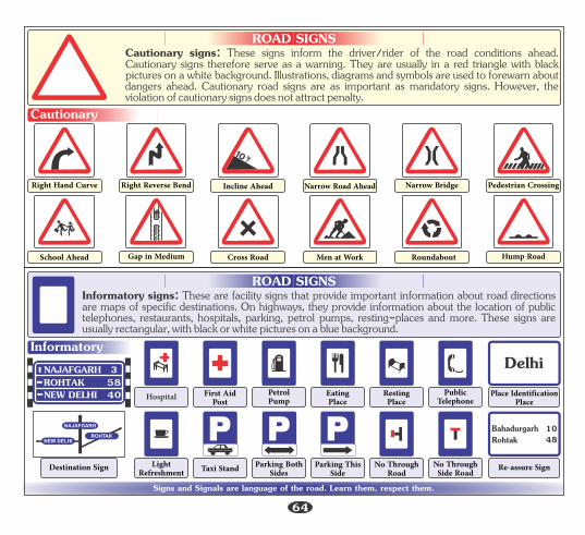
ROAD SIGNSCautionary signs: These signs inform the driver/rider of the road conditions ahead. Cautionary signs therefore serve as a warning. They are usually in a red triangle with black pictures on a white background. Illustrations, diagrams and symbols are used to forewarn about dangers ahead. Cautionary road signs are as important as mandatory signs. However, the violation of cautionary signs does not attract penalty.
Pedestrian CrossingRight Hand Curve Right Reverse Bend Incline Ahead Narrow Road Ahead Narrow Bridge
ROAD SIGNSInformatory signs: These are facility signs that provide important information about road directions are maps of specific destinations. On highways, they provide information about the location of public telephones, restaurants, hospitals, parking, petrol pumps, resting-places and more. These signs are usually rectangular, with black or white pictures on a blue background.
Signs and Signals are language of the road. Learn them, respect them.
Informatory
Cautionary
NEW DELHI 40ROHTAK 58NAJAFGARH 3
Hump RoadSchool Ahead Gap in Medium Cross Road Men at Work Roundabout
LightRefreshment
NEW DELHIROHTAK
NAJAFGARH
Destination Sign Taxi Stand Parking BothSides
Parking ThisSide
No ThroughRoad
No ThroughSide Road
RohtakBahadurgarh
4810
Re-assure Sign
DelhiPlace Identification
PlaceHospital First AidPost
PetrolPump
EatingPlace
RestingPlace
PublicTelephone
64
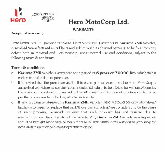
WARRANTYHero MotoCorp Ltd.
Scope of warranty
Hero MotoCorp Ltd. Hero MotoCorp Karizma ZMR (hereinafter called ‘ ') warrants its vehicles, assembled/manufactured in its to be free from any Plants and sold through its channel partners,defect-both in material and workmanship, under normal use and conditions, subject to the following terms & conditions.
a) vehicle is warranted for a period of , whichever is Karizma ZMR 5 years or 70000 Kmearlier, from the date of purchase.
Terms & conditions
b) It is advised that the purchaser avails all free and paid services from the Hero MotoCorp’s authorized workshop as per the recommended schedule, to be eligible for warranty benefits. Each paid service should be availed within 90 days from the date of previous service or as per the recommended schedule, whichever is earlier.
c) Karizma ZMR Hero MotoCorp'sIf any is observed in vehicle, only obligation/ problem liability is to repair or replace that part/those parts which is/are considered to be the cause of such , provided however that such has not resulted due to problem problemmisuse/improper handling etc. of the vehicle. Any vehicle needing repair Karizma ZMR should be brought along with owner's manual to authorized workshop for Hero MotoCorp's necessary inspection and carrying rectification job.
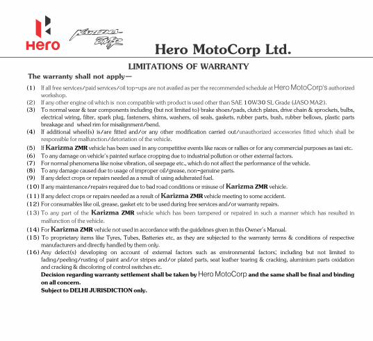
Hero MotoCorp Ltd.LIMITATIONS OF WARRANTY
The warranty shall not apply—
(4) If additional wheel(s) is/are fitted and/or any other modification carried out/unauthorized accessories fitted which shall be responsible for malfunction/detoriation of the vehicle.
(6) To any damage on 's painted surface cropping due to industrial pollution or other external factors.vehicle(7) For normal phenomena like noise vibration, oil seepage etc., which do not affect the performance of the .vehicle
(5) If has been used in any competitive events like races or rallies or for any commercial purposes as taxi etc.Karizma ZMR vehicle
(1) If all free services/paid services/oil top-ups are not availed as per the recommended schedule at authorized Hero MotoCorp'sworkshop.
(2) If any other engine oil which is non compatible with product is used other than SAE 10W30 S Grade (JASO M ).L A2(3) To normal wear & tear components including (but not limited to) brake shoes/pads, clutch plates, drive chain & sprockets, bulbs,
electrical wiring, filter, spark plug, fasteners, shims, washers, oil seals, gaskets, rubber parts, bush, rubber bellows, plastic parts breakage and wheel rim for misalignment/bend.
(10) If any maintenance/repairs required due to bad road conditions or misuse of . Karizma ZMR vehicle(11) If any defect crops or repairs needed as a result of meeting to some accident. Karizma ZMR vehicle
(9) If any defect crops or repairs needed as a result of using adulterated fuel.(8) To any damage caused due to usage of improper oil/grease, non-genuine parts.
(12) For consumables like oil, grease, gasket etc to be used during free services and/or warranty repairs.
(14) For not used in accordance with the guidelines given in this Owner's Manual.Karizma ZMR vehicle
(13) To any part of the vehicle which has been tampered or repaired in such a manner which has resulted in Karizma ZMRmalfunction of the vehicle.
(15) To proprietary items like Tyres, Tubes, Batteries etc, as they are subjected to the warranty terms & conditions of respective manufacturers and directly handled by them only.
Subject to DELHI JURISDICTION only.
(16) Any defect(s) developing on account of external factors such as environmental factors; including but not limited to fading/peeling/rusting of paint and/or stripes and/or plated parts, seat leather tearing & cracking, aluminium parts oxidation and cracking & discoloring of control switches etc.
Decision regarding warranty settlement shall be taken by and the same shall be final and binding Hero MotoCorpon all concern.

Hero MotoCorp Ltd.
5. All liabilities under this warranty will cease if the battery is used on the vehicle other than that on which the battery was originally fitted and on the expiry of the warranty period as mentioned above.
7 . This warranty does not cover damage to the battery caused by faulty electrical systems, incorrect charging and filling, improper handling of the battery by unauthorized dealers/auto electricians, maintenance, willfull abuse, destruction by fire, collusion, theft or recharging.
6 . Recharging is not covered under the purview of this warranty and shall be billed as extra. However, FOC battery replacement/ repair includes cost of charging.
8 . Breakage of container and cover do not come under the purview of this warranty.
3. 3 months idle period is allowed from the date of charging to date of sale on vehicle.Terms and condition of warranty1. Batteries are warranted against all defects in material and workmanship. Liability under this warranty is limited to making good of
defects rising solely from the use of faulty material or workmanship during manufacturing and developing under proper use.
2. 21 months from the date of charging (whichever is earlier).
1 . Customers are deemed to have read, understood and agreed to these conditions at the time of purchase of the vehicle.3 12. The leviable on the battery under repair or replacement will be borne by the customer.applicable taxes which is
9 . Adjudication and settlement of claim will take a couple of days as a battery has to be tested for the reported failure.
1 . If a battery which is not recommended is fitted on the vehicle then such battery will not carry any warranty.1 10. In case of tempering of the original wiring circuit in any manner whatsoever.
2. In the event of any complaint the battery is to be returned complete with electrolyte to nearest battery service station or any OEM dealer. On inspection, battery would be returned or replaced.
4. The right to determine whether a battery needs repair or totally replacement lies with the company. In case where the battery is replaced, the defective battery becomes the property of the company and no scrap rebate will be given for it. The warranty period on the battery being repaired/replaced shall commence from the date of sale of the original battery as stated in the original warranty card.
The warranty commences from the date of delivery to the original purchase of the vehicle.
3. This warranty card accompanies a battery sold as OEM fitment only. Claims should be supported with vehicle purchase invoice to enable processing.
BATTERY WARRANTY PERIOD1. 18 months from date of sale of vehicle or 20000 km. or
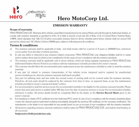
Hero MotoCorp Ltd.EMISSION WARRANTY
Scope of warranty
d) The customer should follow the recommended parts replacement as per the maintenance schedule in order to avail the emission warranty.
e) If any part (s) related to emission characteristics of the vehicles is/are tampered and/or repaired by unauthorised person/workshops etc, then the emission warranty shall stand cancelled.
c) The emission warranty shall be applicable only to those vehicles, which are being regularly maintained at Hero MotoCorpAuthorised Dealers/Service Points in accordance with the maintenance schedule provided in the owner's manual.
f) Any part (s) suffering wear and tear under the normal course of running shall not be covered under the emission warranty. Therefore, all such parts should be replaced by the customer from time to time, on payment basis, as per the maintenance schedule provided in owner's manual and dealer's advice.
b) In case any defect is observed in any emission-related component, only obligation/liability shall be to repair Hero MotoCorpand/or replace those part (s) which is/are considered to be the cause of non-compliance with the emission standards.
Hero MotoCorp Ltd. Warrants all its vehicles, assembled/manufactured at its various Plants and sold through its Authorised dealers, to comply with emission standards as specified in S.No. of table in item(i) of sub rule (2) of Rule 115 of Central Motor Vehicles Rules, 51989, which stipulates that "Idle CO (Carbon monoxide) emission limit for all two wheeled petrol driven vehicles shall not exceed 3. 0percent by volume and HC (Hydro Carbon) 00 ppm, subject to following terms & conditions.30
a) The emission warranty shall be applicable in India and shall remain valid for a period of 3 years or 30000 kms, whichever occurs earlier, from the date of vehicle purchase.
Terms & conditions
i Hero MotoCorp Ltd.) All decisions regarding emission warranty settlement shall be taken by and shall be final binding on all concerned.
h) It is mandatory to obtain a PUC certificate from the Authorised PUC center. In case of non-compliance with the emission standards please contact the immediately alongwith the previous OK certificate, for the necessary rectification. The channel partner/authorised workshopmanufacturer or the dealer is not responsible for any penalty levied on you on account of non-compliance with the emission standards.
Subjected to Delhi jurisdiction only.
g) Please It is recommended to avail the services as per the recommended schedule to be eligible for the emission warranty benefits.ensure that each paid service is availed within 90 days from the date of previous services or as per the recommended schedule, whichever is earlier. All service details should be completely filled by the dealer, in the given in the Service Record Sheetowner's manual.

• Explanation on collapsible visor mounted rear view mirrors.
• Function of Side Stand Switch.• Bank angle sensor activation and resetting of ignition switch.• Inspection and maintenance of Oil Cooler.• Brand and grade of engine oil used, top-up & replacement schedule.
• Minor clutch adjustment procedure.
• Engine oil level inspection, replacement and top-up procedure.
• Headlamp adjustment procedure.
• Function and operation of all digital display of multifunction meter console.
• Retractable rider foot rest.
• Function and operation of clutch switch.• Programmed-FI Malfunction Indicator Lamp (MIL).
• Warranty terms and conditions.
• Procedure of removing/installing seat, side covers and fuel tank lid.
• Tubeless tyre and importance of tyre pressure.
• Water wash precautions.
• Location of Tool Kit & First-Aid Kit.
• Maintenance Schedule.
• Inspection of brake fluid and pads.
• Inspection of tyre wear (TWI mark).
• Explain the service facilities available.
• Importance of availing all the free services.
• Location of Fuse Box and explanation/replacement procedure of various fuses.
• Explanation on Maintenance-Free Battery.
INSTALLATIONExplanation on important "Must know" points to customer during
delivery of vehicle by Dealer sales executive.
CUSTOMER SALES EXECUTIVE DEALER
Stamp & Signature :Signature :
Name :.....................................................................................
Signature :
Name :.....................................................................................
Hero MotoCorp Ltd.
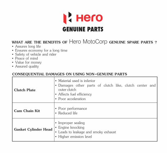
WHAT ARE THE BENEFITS OF Hero MotoCorp GENUINE SPARE PARTS ?
• Assured quality
• Safety of vehicle and rider• Ensures economy for a long time
• Peace of mind
• Assures long life
• Value for money
CONSEQUENTIAL DAMAGES ON USING NON-GENUINE PARTS
Clutch Plate• Affects fuel efficiency
• Material used is inferior
• Poor acceleration
• Damages other parts of clutch like, clutch center and outer clutch
• Reduced life• Poor performance
• Improper sealing• Engine knocking• Leads to leakage and smoky exhaust• Higher emission level
Cam Chain Kit
Gasket Cylinder Head
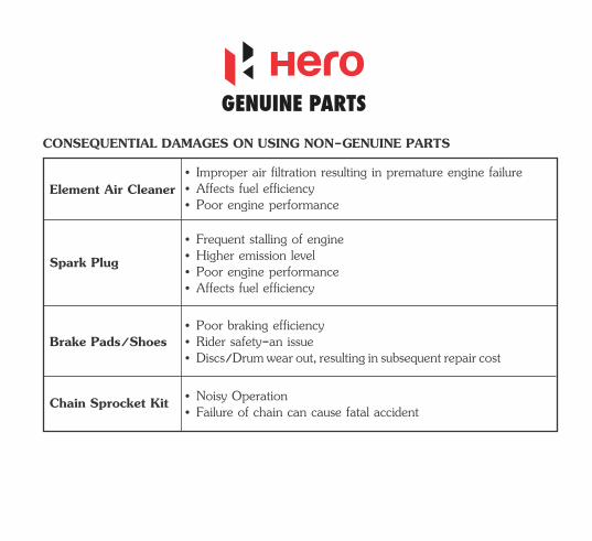
CONSEQUENTIAL DAMAGES ON USING NON-GENUINE PARTS
Element Air Cleaner• Improper air filtration resulting in premature engine failure
• Poor engine performance• Affects fuel efficiency
• Poor engine performance• Higher emission level• Frequent stalling of engine
• Affects fuel efficiency
• Poor braking efficiency• Rider safety-an issue• Discs/Drum wear out, resulting in subsequent repair cost
• Noisy Operation• Failure of chain can cause fatal accidentChain Sprocket Kit
Brake Pads/Shoes
Spark Plug
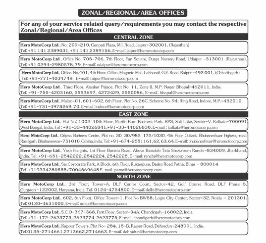
For any of your service related query/requirements you may contact the respective Zonal/Regional/Area Offices
Hero MotoCorp Ltd., Flat No: 1002. 10th Floor, Martin Burn Business Park, BP3, Salt Lake, Sector-V, Kolkata-700091, West Bengal, India. Tel : +91-33-44026841,+91-33-44026830, E-mail : [email protected] MotoCorp Ltd., Odyssa Business Centre, Plot no. 30, 30/982, 172/1030, 4th Floor Cuttack, Bhubaneshwar highway road, Rasulgarh, Bhubaneswar-751010, Odisha, India. Tel: +91-674-2581161, 62, 63, 64, E-mail: [email protected]
Hero MotoCorp Ltd., Yash Heights, 1st Floor Bariatu Road, Above Basudeb Tata Showroom Ranchi-834009, Jharkhand, India. Tel: +91-651-2542222, 2542224, 2542225, E-mail: [email protected] MotoCorp Ltd., Sai Corporate Park, A Block, 6th Floor, Rukanpura, Bailey Road Patna, Bihar – 800014Tel: +919334280555/7004569648 E-mail: [email protected]
EAST ZONE
Hero MotoCorp Ltd., 3rd Floor, Tower-A, DLF Centre Court, Sector-42, Golf Course Road, DLF Phase 5, Gurgaon -122002, Haryana, India. Tel: 0124-4754800, E-mail: [email protected]
Tel: +91-172-2623773, 2623774, 2623775, E-mail: [email protected] MotoCorp Ltd., S.C.O-367-368, First Floor, Sector-34A, Chandigarh-160022, India.
Tel:0135-2714661,2713662,2714663, E-mail: [email protected] MotoCorp Ltd., Kapoor Towers, Plot No- 284, 15-B, Rajpur Road, Dehradun-248001, India.
NORTH ZONE
Tel: +91 141 2389031, +91 141 2389156, E-mail: [email protected] MotoCorp Ltd., No. 209-210, Ganpati Plaza, M.I. Road, Jaipur-302001, (Rajasthan).
Tel: +91-755-4203160, 2553697, 4272429, 2550086, E-mail: [email protected] Hero MotoCorp Ltd., Third Floor, Alankar Palace, Plot No. 11, Zone II, M.P. Nagar Bhopal-462011, India.
Hero MotoCorp Ltd., Maloo-01, 601-602, 6th Floor, Plot No. 26C, Scheme No. 94, Ring Road, Indore, M.P.-452010,Tel: +91-731-4978269, 70, E-mail: [email protected]
CENTRAL ZONE
Hero MotoCorp Ltd., Office. No.401, 4th Floor, Offizo, Magneto Mall, Labhandi, G.E. Road, Raipur -492 001, (Chhattisgarh)Tel: +91-771-4034749, E-mail: [email protected]
Hero MotoCorp Ltd., Office No. 705-706, 7th Floor, Fun Square, Durga Nursery Road, Udaipur -313001 (Rajasthan). Tel: +91 0294-2980578, 79, E-mail: [email protected]
Hero MotoCorp Ltd., 602, 6th Floor, Office Tower-1, Plot No BW58, Logix City Center, Sector-32, Noida – 201301. Tel: 0120-4631000, E-mail: [email protected]
ZONAL/REGIONAL/AREA OFFICES
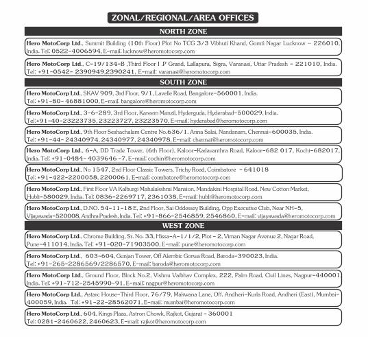
Hero MotoCorp Ltd., Chrome Building, Sr. No. 33, Hissa-A-1/1/2, Plot - 2, Viman Nagar Avenue 2, Nagar Road,Pune-411014, India. Tel: +91-020-71903500, E-mail: [email protected]
Hero MotoCorp Ltd., 603-604, Gunjan Tower, Off Alembic Gorwa Road, Baroda-390023, India.Tel: +91-265-2286569/2286570, E-mail: [email protected] MotoCorp Ltd., Ground Floor, Block No.2, Vishnu Vaibhav Complex, 222, Palm Road, Civil Lines, Nagpur-440001, India. Tel: +91-712-2545990-91, E-mail: [email protected]
WEST ZONE
Hero MotoCorp Ltd., Astarc House-Third Floor, 76/79, Makwana Lane, Off. Andheri-Kurla Road, Andheri (East), Mumbai-400059, India. Tel: +91-22-28562071, E-mail: [email protected]
Tel: 0281-2460622, 2460623, E-mail: [email protected] MotoCorp Ltd., 604, Kings Plaza, Astron Chowk, Rajkot, Gujarat - 360001
Hero MotoCorp Ltd., First Floor VA Kalburgi Mahalakshmi Mansion, Mandakini Hospital Road, New Cotton Market, Hubli-580029, India. Tel: 0836-2269717, 2361038, E-mail: [email protected]
Vijayawada-520008, Andhra Pradesh, India. Tel: +91-866-2546859, 2546860, E-mail: [email protected] MotoCorp Ltd., D.NO. 54-11-18 E, 2nd Floor, Sai Oddessey Building, Opp Executive Club, Near NH-5,
Hero MotoCorp Ltd., 3-6-289, 3rd Floor, Kareem Manzil, Hyderguda, Hyderabad-500029, India.Tel:+91-40-23223735, 23223727, 23223570, E-mail: [email protected]
SOUTH ZONE
Tel: +91-44- 24340974, 24340977, 24340978, E-mail: [email protected] MotoCorp Ltd., 9th Floor Seshachalam Centre No.636/1. Anna Salai, Nandanam, Chennai-600035, India.
Hero MotoCorp Ltd., No 1547, 2nd Floor Classic Towers, Trichy Road, Coimbatore - 641018Tel: +91-422-2200058, 2200061, E-mail: [email protected]
NORTH ZONE
Tel: +91- , E-mail: [email protected] 2390949,2390241Hero MotoCorp Ltd., , Varanasi, Uttar Pradesh - 221010, India.C-19/134-B ,Third Floor I .P Grand, Lallapura, Sigra
ZONAL/REGIONAL/AREA OFFICES
Hero MotoCorp Ltd., Summit Building (10th Floor) Plot No TCG 3/3 Vibhuti Khand, Gomti Nagar Lucknow – 226010, India. Tel: 0522-4006594, E-mail: [email protected]
Hero MotoCorp Ltd., 6-A, DD Trade Tower, (6th Floor), Kaloor-Kadavanthra Road, Kaloor , Kochi-682017, -682 017India. Tel: +91-0484- 4039646 -7, E-mail: [email protected]
Hero MotoCorp Ltd., SKAV 909, 3rd Floor, 9/1, Lavelle Road, Bangalore-560001, India. Tel: +91-80- 46881000, E-mail: [email protected]