Oil-Submersible Backup Fuses Full-Range CL Fuses External Backup Fuses Molded Fuse Products Product...
56
Oil-Submersible Backup Fuses Full-Range CL Fuses External Backup Fuses Molded Fuse Products Product Selection Guide PG-PC-H-0307 PROTECTION AND CONTROL
Transcript of Oil-Submersible Backup Fuses Full-Range CL Fuses External Backup Fuses Molded Fuse Products Product...

Oil-Submersible Backup FusesFull-Range CL Fuses
External Backup FusesMolded Fuse Products
Product Selection Guide
PG-PC-H-0307
PROTECTION AND CONTROL

Electric distribution systems demand high levels of reliability, and flexibility of operation. This is directly related to the ability to automatically sectionalize feeders and provide protection where it is most effective within the system.
Thomas & Betts’ protection and control products include a wide variety of backup and full-range current-limiting fuses for protection of overhead and underground systems. OS / OS Shorty backup current-limiting fuses, which are typically used in combination with bayonet or weak-link fuses inside distribution transformers, and EXT backup current-limiting fuses, which are used in overhead systems in series with cutout expulsion fuses, protect against high fault currents and limit the energy let-through during a fault to a value within the withstand rating of the affected equipment. FX full-range current-limiting fuses provide both overload and fault current protec-tion for distribution equipment in a single fuse body and can be installed in dry-well canisters, live-front switchgear, oil insulated equipment, overhead, or in a molded rubber housing for dead-front applications using the Elastimold fuse products.
This product guide details the application and char-acteristics of all the fuse products available from Thomas & Betts. Information on all other protection and control products such as switchgear, voltage and fault indicators, and arresters can be found in product guide PG-PC-E.
Introduction
PROTECTION AND CONTROL
�

�Thomas & Betts Corporation 8155 T&B Boulevard Memphis TN 38125 800.888.0211 www.tnb.com/utilityPG-PC-H-0307
Trans-Guard™ OS and OS Shorty Fuse 4-13
Trans-Guard™ FX Fuse 14-21
Trans-Guard™ SX Fuse 22-27
Trans-Guard™ EXT Fuse 28-31
Elastimold® Product Application 32-33
Fused Elbow 34-39
Molded Current-Limiting Fuse 40-46
Molded Canister Fuse 47-54
Molded Fuse Products
Current-Limiting Fuses
Contents

Highest current ratings available in a single fuse body
Durable design
Smaller physical size
Rigorous testing to meet ANSI/IEEE standards
Minimizes the costs and physical space associated with paralleling two fuses to achieve the desired current rating
Achieved particularly within line of OS Shorty fuse designs
Internal quality requirements including 100% physical inspection, resistance measurement, and helium mass spectrometer leak testing
For long life including machined brass end caps, filament-wound high temperature epoxy tubular bodies, sand filler and hermetic sealing system
FEatuRE BEnEFit/dESCRiPtiOn
High fault current interrupting capability 50,000 amperes symmetrical for most ratings
Broad range of fuse ratings Available with our Standard OS and OS Shorty lines (30 amps – 400 amps)
Elevated rated maximum voltages designs 10kV,17.2kV, and 25.5kV for many of the OS Shorty designs
OS
Bac
kup
Fuse
s
�
PROTECTION AND CONTROL
Thomas & Betts Corporation 8155 T&B Boulevard Memphis TN 38125 800.888.0211 www.tnb.com/utility PG-PC-H-0307
Trans-Guard™ OS and OS Shorty Fuses
the trans-Guard™ OS is a back-up type current-limiting fuse designed for application within distribution transformers. Its ability to significantly reduce fault energy and its very high interrupting capability (50,000 amperes symmetrical) provide state-of-the-art protection against today’s ever increasing available fault currents.
The newer OS Shorty fuses were specifically designed to be more compact in size and allow for easier installation in smaller distribution transformers.
As a back-up type current-limiting fuse (refer to ANSI C37.40 for fuse definitions), the Trans-Guard™ OS must always be applied in series with a properly-sized low current protective device. This device is typically an under-oil expulsion fuse (i.e. Bay-O-Net fault or load sensing link, terminal board weak link, etc.). The expulsion fuse and the current-limiting fuse are each selected to provide fault protection over a certain range of currents. The expulsion fuse is chosen to clear
the low magnitude currents such as those caused by faults that occur external to the transformer, high impedance faults within the transformer, and in the case of load sensing links, transformer overloads. Such currents are generally below the minimum interrupting current rating of the current-limiting fuse. The back-up type current-limiting fuse is selected so as to clear all other currents. In addition to interrupting the fault currents resulting from low impedance faults within the transformer, the back-up current-limiting fuse serves the very important function of limiting the amount of energy that is let through to the source of the fault to a value below the withstand capability of the transformer tank. By doing this, the current-limiting fuse
minimizes the likelihood of disruptive equipment failures (i.e. transformer tank ruptures, accessories being damaged or broken loose from their mountings, etc.). No other protective device is available to similarly reduce the risk of disruptive transformer failures.

taBLE 1 – diMEnSiOnaL inFORMatiOn FOR tRanS-GuaRd™ OS FuSES
CurrentRating(Amps)
NominalFuse
Voltage Rating(kV)
FuseCatalogNumber
OverallDiameter
(A)
OverallLength
(B)
BodyLength
(C)Fuse
Weight
8.3
35 HTDS232035
2.18-2.22” (55.4-56.4mm)
7.09-7.21” (180.0-183.1mm)
6.05-6.13” (153.7-155.7mm)
2.25lb.1.02kg
40 HTDS232040
10.89-11.01” (276.6-279.7mm)
9.85-9.93” (250.2-252.2mm)
3.25lb.1.47kg
50 HTDS232050
65 HTDS232065
80 HTDS232080
100 HTDS232100
125 HTDS332125
3.25-3.32” (82.5-84.3mm)
9.89-9.97” (251.2-253.2mm)
7.25lb.3.29kg
150 HTDS332150
165 HTDS332165
200 HTDS332200
15.5
35 HTDS242035
2.18-2.22” (55.4-56.4mm)
10.89-11.01” (276.6-279.7mm)
9.85-9.93” (250.2-252.2mm)
3.25lb.1.47kg
45 HTDS242045
40 HTDS242040
16.49-16.61” (418.8-421.9mm)
15.45-15.53”(392.4-394.5mm)
4.75lb.2.155kg
50 HTDS242050
65 HTDS242065
80 HTDS242080
100 HTDS242100
125 HTDS342125
3.25-3.32” (82.5-84.3mm)
15.49-15.57”(393.4-395.5mm)
10.75lb.4.87kg
150 HTDS242150
165 HTDS342165
200 HTDS342200
23.0
40 HTDS2520402.18-2.22”
(55.4-56.4mm)16.49-16.61”
(418.8-421.9mm)15.45-15.53”
(392.4-394.5mm)4.75lb.
2.155kg50 HTDS252050
65 HTDS252065
100 HTDS352100
3.25-3.32” (82.5-84.3mm)
19.29-19.41”(490.0-493.0mm)
18.29-18.37”(464.6-466.6mm)
12.0lb.5.44kg
125 HTDS352125
150 HTDS352150
175 HTDS352175
NOTE: Other hardware is available, consult the factory.
OS B
ackup Fuses
�
PROTECTION AND CONTROL
Thomas & Betts Corporation 8155 T&B Boulevard Memphis TN 38125 800.888.0211 www.tnb.com/utilityPG-PC-H-0307
Trans-Guard™ OS and OS Shorty Fuses
“A”
“B”
“C”
1/4”-20 threaded hole1/2” deep
(both ends)

8.3
40 HTSS232040
2.18-2.22” (55.4-56.4mm)
7.09-7.21” (180.0-183.1mm)
6.05-6.13” (153.7-155.7mm)
2.25lb.1.02kg
50 HTSS232050
7.68-7.80” (195.1-198.1mm)
6.64-6.72” (168.7-170.7mm)
2.5lb.1.13kg
65 HTSS232065
80 HTSS232080
100 HTSS232100
125 HTSS232125
10.89-11.01”(276.6-279.7mm)
9.85-9.93” (250.2-252.2mm)
3.25lb.1.45kg
150 HTSS232150
165 HTSS232165
200 HTSS232200
17.2
30 HTSS240030
2.18-2.22”
(55.4-56.4mm)
9.17-9.29” (232.9-236.0mm)
8.13-8.21”(206.5-208.5mm)
2.75lb.1.25kg40 HTSS240040
50 HTSS240050
65 HTSS24206512.01-12.13”
(305.1-308.1mm)10.97-11.05”
(278.6-280.7mm)3.75lb.1.70kg80 HTSS242080
100 HTSS242100
125 HTSS24212516.49-16.61”
(418.8-421.9mm)15.45-15.53”
(392.4-394.4mm)4.75lb.2.15kg150 HTSS242150
15.5 165 HTSS242165
23.0
30 HTSS252030
2.18-2.22” (55.4-56.4mm)
12.68-12.80”(322.1-325.1mm)
11.64-11.72”(295.7-297.7mm)
3.75lb.1.70kg40 HTSS252040
50 HTSS252050
65 HTSS25206516.29-16.41”
(413.8-416.8mm)15.25-15.33”
(387.4-389.4mm)4.75lb.2.15kg80 HTSS252080
100 HTSS252100
taBLE � – diMEnSiOnaL inFORMatiOn FOR tRanS-GuaRd™ OS ShORty FuSES
CurrentRating(Amps)
NominalFuse
Voltage Rating(kV)
FuseCatalogNumber
OverallDiameter
(A)
OverallLength
(B)
BodyLength
(C)Fuse
Weight
NOTE: Other hardware is available, consult the factory.
OS
Bac
kup
Fuse
s
�
PROTECTION AND CONTROL
Thomas & Betts Corporation 8155 T&B Boulevard Memphis TN 38125 800.888.0211 www.tnb.com/utility PG-PC-H-0307
Trans-Guard™ OS and OS Shorty Fuses

8.3
35 HTDS232035
8.3
26
415 3,140 10,000
40 HTDS232040 260 3,200 10,500
50 HTDS232050 320 5,000 16,000
65 HTDS232065 430 11,000 34,000
80 HTDS232080 600 17,000 45,000
100 HTDS232100 850 39,000 120,000
125 HTDS332125
22
450 29,000 90,000
150 HTDS332150 535 45,000 160,000
165 HTDS332165 1,250 67,300 230,000
200 HTDS332200 1,700 156,000 580,000
15.5
35 HTDS242035
15.5
49 380 3,140 10,000
40 HTDS242040 46 270 3,200 9,500
45 HTDS242045 49 450 4,340 14,500
50 HTDS242050 46 330 5,000 16,000
65 HTDS242065 46 450 11,000 34,000
80 HTDS242080 49 700 17,000 45,000
100 HTDS242100 49 1,000 39,000 120,000
125 HTDS342125
44
500 29,000 90,000
150 HTDS342150 600 45,000 160,000
165 HTDS342165 1,200 67,300 230,000
200 HTDS342200 1,530 156,000 580,000
23
40 HTDS252040
23
64 280 3,200 10,500
50 HTDS252050 65 340 5,000 17,000
65 HTDS252065 66 465 11,000 38,000
100 HTDS352100 69 600 20,100 70,000
125 HTDS352125 67 1,000 31,400 105,000
150 HTDS352150 65 1,300 66,900 220,000
175 HTDS352175 63 1,530 108,600 360,000
NominalFuse Voltage
Rating(kV)
CurrentRating(Amps)
FuseCatalogNumber
RatedMaximumVoltage
(kV)
Minimuml/C
(Amps)
Peak ArcVoltage
(kV)(3)
MinimumMelt l2t
(AMP2-SEC)
MaximumTotal l2t
(AMP2-SEC)(2)
taBLE � – ELECtRiCaL ChaRaCtERiStiCS OF tRanS-GuaRd™ OS FuSES (SinGLE FuSES)
NOTES:1. All fuses have a rated maximum interrupting current of 50,000 A rms symmetrical.2. Maximum total I2t values are reduced for currents below 50,000 A. For example, at 10,000 A, maximum total I2t
values are approximately 15% less than the published values.3. Peak arc voltages quoted are for 50,000 A currents at the rated maximum voltage listed. Reduced voltages and
currents will reduce the peak arc voltage. Consult the factory for information.
OS B
ackup Fuses
�
PROTECTION AND CONTROL
Thomas & Betts Corporation 8155 T&B Boulevard Memphis TN 38125 800.888.0211 www.tnb.com/utilityPG-PC-H-0307
Trans-Guard™ OS and OS Shorty Fuses

8.3
40 HTSS232040 8.3 26 415 3,140 10,000
50 HTSS232050
10.0 25
300 2,500 14,000
65 HTSS232065 350 3,700 18,000
80 HTSS232080 430 6,300 31,000
100 HTSS232100 570 12,800 66,000
125 HTSS232125
8.3
26 850 39,000 120,000
150 HTSS232150 24.5 900 23,000 110,000
165 HTSS23216524
1,020 39,500 175,000
200 HTSS232200 1,120 54,500 225,000
17.2
30 HTSS240030
17.2 49
240 1,260 6,800
40 HTSS240040 330 2,680 12,000
50 HTSS240050 440 4,440 17,000
65 HTSS242065 360 3,700 22,000
80 HTSS242080 440 6,300 36,000
100 HTSS242100 580 12,800 76,000
125(1) HTSS242125 540 14,800 66,000
150(1) HTSS242150 700 34,800 137,000
15.5 165(1) HTSS242165 15.5 48 780 51,200 195,000
23.0
30 HTSS252030
25.5
71
300 920 4,250
40 HTSS252040 390 1,580 9,750
50 HTSS252050 570 3,200 20,000
65 HTSS252065
70
360 3,700 17,000
80 HTSS252080 440 6,300 28,000
100 HTSS252100 575 12,800 70,000
taBLE � – ELECtRiCaL ChaRaCtERiStiCS OF tRanS-GuaRd™ OS ShORty FuSES (SinGLE FuSES)
NOTES:(1) These fuses have only been tested at a rated maximum interrupting current of 44,000 A rms symmetrical.
All other fuses have a rated maximum interrupting current of 50,000 A rms symmetrical.(2) Tabulated maximum total I2t values are at the nominal voltage of the fuse. Values for 17.2kV fuses at 15.5kV are
reduced by approximately 12%, while values for 8.3kV and 23kV fuses at 10kV and 25.5kV are increased by approximately 30% and13% respectively.
(3) Maximum total I2t values are reduced for currents below 50,000 A. For example, at 10,000 A, maximum total I2t values are approximately 15% less than the published values.
(4) Peak arc voltages quoted are for 50,000 A currents at the rated maximum voltage listed. Reduced voltages and currents will reduce the peak arc voltage. Consult the factory for information.
NominalFuse Voltage
Rating(kV)
CurrentRating(Amps)
FuseCatalogNumber
RatedMaximumVoltage
(kV)
MinimumI/C
(Amps)
Peak ArcVoltage
(kV)(4)
MinimumMelt l2t
(AMP2-SEC)
MaximumTotal l2t
(AMP2-SEC)(2) (3)
OS
Bac
kup
Fuse
s
�
PROTECTION AND CONTROL
Thomas & Betts Corporation 8155 T&B Boulevard Memphis TN 38125 800.888.0211 www.tnb.com/utility PG-PC-H-0307
Trans-Guard™ OS and OS Shorty Fuses

NOTES FOR TABLES 5 AND 6:(1) These fuses have only been tested at a rated maximum interrupting current of 44,000 A rms symmetrical due to test
station limitations. All other fuses have a rated maximum interrupting current of 50,000 A rms symmetrical.(2) Current ratings shown above are achieved by using a parallel combination of two fuses (order two fuses). To
facilitate equal sharing of the interrupting duty, the two fuses should be resistance matched (±2%) and be mounted such that current paths to and from each fuses are symmetrical.
(3) Tabulated maximum total I2t values are at the nominal voltage of the fuse. Values for 17.2kV fuses at 15.5kV are reduced by approximately 12%, while values for 23kV fuses at 25.5kV are increased by approximately 13%.
(4) Maximum total I2t values are reduced for currents below 50,000 A. For example, at 10,000 A, maximum total I2t values are approximately 15% less than the published values.
(5) Peak arc voltages quoted are for 50,000 A currents at the rated maximum voltage listed. Reduced voltages and currents will reduce the peak arc voltage. Consult the factory for information.
8.3
130 HTSS232065
8.3
25
420 14,800 65,000
160 HTSS232080 500 25,200 114,000
200 HTSS232100 630 51,200 240,000
300 HTSS232150 24.5 1,900 92,000 425,000
330 HTSS232165 24 2,150 158,000 675,000
400 HTSS232200 23.5 2,380 218,000 850,000
17.2
130 HTSS242065
17.247
420 14,800 92,000
160 HTSS242080 500 25,200 162,000
200 HTSS242100 630 51,200 310,000
250(1) HTSS242125 49 1,130 59,200 265,000
15.5300(1) HTSS242150
15.549 1,500 139,200 515,000
330 HTSS242165 46 1,670 204,800 733,000
23.0
130 HTSS25206525.5
69
360 14,800 68,000
160 HTSS252080 450 25,200 115,000
200 HTSS252100 23.0 560 51,200 280,000
NominalFuse Voltage
Rating(kV)
CurrentRating(Amps)
FuseCatalog Number
(Order Two Fuses)
RatedMaximumVoltage
(kV)
Minimuml/C
(Amps)
Peak ArcVoltage
(kV)(5)
MinimumMelt l2t
(AMP2-SEC)
MaximumTotal l2t
(AMP2-SEC)(3) (4)
taBLE � – ELECtRiCaL ChaRaCtERiStiCS OF tRanS-GuaRd™ OS ShORty FuSES (FuSES tEStEd FOR uSE in PaRaLLEL)
8.3250 HTDS332125
8.3 22850 116,000 350,000
300 HTDS332150 1,000 180,000 650,000
15.5250 HTDS342125
15.5 44850 116,000 350,000
300 HTDS342150 1,000 180,000 650,000
NominalFuse Voltage
Rating(kV)
CurrentRating(Amps)
FuseCatalog Number
(Order Two Fuses)
RatedMaximumVoltage
(kV)
Minimuml/C
(Amps)
Peak ArcVoltage
(kV)(5)
MinimumMelt l2t
(AMP2-SEC)
MaximumTotal l2t
(AMP2-SEC)(3) (4)
taBLE � – ELECtRiCaL ChaRaCtERiStiCS OF tRanS-GuaRd™ OS FuSES (FuSES tEStEd FOR uSE in PaRaLLEL)
OS B
ackup Fuses
�
PROTECTION AND CONTROL
Thomas & Betts Corporation 8155 T&B Boulevard Memphis TN 38125 800.888.0211 www.tnb.com/utilityPG-PC-H-0307
Trans-Guard™ OS and OS Shorty Fuses

5 1.90 –10 1.90 –15 1.90 –25 1.90 –
37.5 1.90 –45 – 1.6050 1.90 –75 1.90 1.60100 2.00 –
112.5 – 1.80150 – 2.00167 2.60 –225 – 3.00250 4.00 –300 – 3.50333 5.00 –500 5.00 4.00
750 and up 5.75 5.75
taBLE � – aSSuMEd tRanSFORMER iMPEdanCES uSEd FOR FuSES COORdinatiOn (taBLES �-11)
TransformerSize (kVA)
1ɸImpedances
(%)
3ɸImpedances
(%)
OS
Bac
kup
Fuse
s
10
PROTECTION AND CONTROL
Thomas & Betts Corporation 8155 T&B Boulevard Memphis TN 38125 800.888.0211 www.tnb.com/utility PG-PC-H-0307
Trans-Guard™ OS and OS Shorty Fuses
Fuse SelectionFor a detailed explanation on selecting the appropriate backup current limiting fuse for a given application, please refer to Hi-Tech Fuses Application Bulletin FS-10.
For a quicker method of selecting the proper Trans-Guard™ OS or OS Shorty fuse for applications involving coordination with Bay-O-Net expulsion fuses and transformers having impedances equal to, or higher, than those listed in Table 7, please refer to fuse coordination Tables 8-11. These tables include columns that specify both OS and OS Shorty fuses for each application. More comprehensive tables listing fusing alternatives for transformers having any impedance can be found at www.tnb.com/utility.

Trans-Guard™ OS/OS Shorty Fuse Voltage Rating (kV)
Transformer Voltage Rating (kV) Phase-to-Ground
kVA
FuseVoltage �.�kV 1�.�/1�.�kV ��kV
taBLE � – 1 tRanSFORMER COORdinatiOn taBLE FOR ExPuLSiOn & tRanS-GuaRd™ OS/OS ShORty FuSES
LINk OS SHORTy LINk OS SHORTy LINk OS SHORTy LINk OS SHORTy LINk OS SHORTy LINk OS SHORTy LINk OS SHORTy
2.4 4.16 - 4.8 7.2 - 7.96 12 - 12.47 13.2 - 14.4 16 19.9
dual Sensing Bay-O-net (�000���___)a,c and OS/OS Shorty Fuse CoordinationsC03 35 40 C03 35 40 C03 35 40 C03 35 30 C03 35 30 C03 – 30 C03 40 30
C05 35 40 C05 35 40 C03 35 40 C03 35 30 C03 35 30 C03 – 30 C03 40 30
C08 50 65 C05 35 40 C03 35 40 C03 35 30 C03 35 30 C03 – 30 C03 40 30
C10 100 100 C08 50 65 C05 35 40 C03 35 30 C03 35 30 C03 – 30 C03 40 30
C12 165 150 C10 80 100 C08 50 50 C05 35 30 C05 35 30 C03 – 30 C03 40 30
C12 200 165 C10 100 125 C08 65 65 C05 35 30 C05 35 30 C05 – 30 C05 40 30
C14 – 300 C12 165 150 C10 100 100 C08 50 65 C08 50 50 C08 – 50 C05 40 30
C14 – 330 C12 200 165 C10 100 125 C08 65 80 C08 65 65 C08 – 65 C05 40 40
– – – C14 – 300 C12 165 150 C10 100 100 C10 100 100 C10 – 100 C08 50 65
– – – C18 – 330 C14 250 200 C12 125 125 C12 125 125 C10 – 100 C10 65 80
– – – C18 – 330 C14 250 200 C12 125 125 C12 125 125 C12 – 125 C10 100 80
– – – – – – C18 – 330 C14 250 165 C14 250 165 C12 – 125 C12 100 130
5
10
15
25
37.5
50
75
100
167
250
333
500
Current Sensing Bay-O-net (�000���___)a,b and OS/OS Shorty Fuse CoordinationsC04 35 40 C04 35 40 C04 35 40 C04 35 30 C04 35 30 C04 – 30 C04 40 30
C06 35 40 C04 35 40 C04 35 40 C04 35 30 C04 35 30 C04 – 30 C04 40 30
C08 35 40 C06 35 40 C04 35 40 C04 35 30 C04 35 30 C04 – 30 C04 40 30
C10 65 80 C08 35 40 C06 35 40 C04 35 30 C04 35 30 C04 – 30 C04 40 30
C10 80 100 C08 50 65 C06 35 40 C06 35 30 C06 35 30 C04 – 30 C04 40 30
C12 100 125 C10 80 100 C08 35 40 C06 35 30 C06 35 30 C06 – 30 C04 40 30
C14 165 165 C12 100 125 C10 65 80 C08 35 40 C08 35 40 C06 – 30 C06 40 30
C14 200 200 C12 150 150 C10 80 100 C08 35 50 C08 35 40 C08 – 40 C06 40 30
C17 – 300 C14 165 165 C12 100 125 C10 65 80 C10 65 80 C10 – 65 C08 40 40
– – – C16 200 200 C14 150 150 C12 100 100 C12 80 100 C10 – 65 C10 50 65
– – – C17 300 300 C16 200 200 C14 150 150 C12 80 100 C12 – 100 C12 100 80
– – – – – – C17 300 300 C14 150 150 C14 150 150 C14 – 150 C12 100 100
5
10
15
25
37.5
50
75
100
167
250
333
500
dual Element Bay-O-net (�0��10�___)a,c and OS/OS Shorty Fuse CoordinationsC03 35 40 C03 35 40 C03 35 40 C03 35 30 C03 35 30 C03 – 30 C03 40 30
C05 35 40 C04 35 40 C03 35 40 C03 35 30 C03 35 30 C03 – 30 C03 40 30
C07 50 50 C05 35 40 C03 35 40 C03 35 30 C03 35 30 C03 – 30 C03 40 30
C09 80 100 C06 35 40 C04 35 40 C03 35 30 C03 35 30 C03 – 30 C03 40 30
C11 100 125 C09 65 80 C06 35 40 C05 35 30 C04 35 30 C03 – 30 C03 40 30
C12 100 125 C09 80 100 C07 50 50 C06 35 40 C05 35 30 C04 – 30 C03 40 30
– – – C12 100 125 C09 80 100 C07 45 50 C06 35 40 C06 – 40 C05 40 30
– – – C12 100 125 C09 80 100 C09 65 80 C07 50 65 C07 – 50 C06 40 40
– – – – – – C12 100 125 C11 80 100 C09 65 80 C07 – 65 C07 50 50
– – – – – – – – – C12 80 100 C11 80 100 C09 – 80 – – –
– – – – – – – – – C12 100 100 C12 80 100 C12 – 100 – – –
5
10
15
25
37.5
50
75
100
167
250
333
NOTES:
Bay-O-Net fuse selection is based on Cooper Power Systems recommendations.
Bay-O-Net fuses are selected to meet inrush criteria of 12 times transformer full load current for 0.1 second.
Backup OS / OS Shorty fuses are selected to melt only on internal transformer faults, where transformer impedance is equal to, or greater than, the value given in Table 7. If the impedance is higher, a smaller fuse can often be used.
Shaded areas indicate parallel fuse applications.
a Or equivalent Bay-O-Net link.
b Current Sensing Bay-O-Net fuses are selected to melt with 3 to 4 times transformer full load current at 300 seconds.
c Dual Sensing and Dual Element Bay-O-Net fuses are selected to limit transformer load to approximately 160% for 7 hours and 200% for 2 hours with the transformer initially carrying 75% of load at an ambient temperature of 35°C.
OS B
ackup Fuses
11
PROTECTION AND CONTROL
Thomas & Betts Corporation 8155 T&B Boulevard Memphis TN 38125 800.888.0211 www.tnb.com/utilityPG-PC-H-0307
Trans-Guard™ OS and OS Shorty Fuses

kVA
�.�kV 1�.�/1�.�kV ��kV
taBLE � – � tRanSFORMER COORdinatiOn taBLE FOR ExPuLSiOn & tRanS-GuaRd™ OS/OS ShORty FuSES
NOTES:Bay-O-Net fuse selection is based on Cooper Power Systems recommendations.Bay-O-Net fuses are selected to meet inrush criteria of 12 times transformer full load current for 0.1 second.Backup OS / OS Shorty fuses are selected to melt only on internal transformer faults, where transformer impedance is equal to, or greater than, the value given in Table 7. If the impedance is higher, a smaller fuse can often be used. Shaded areas indicate parallel fuse applications.a Or equivalent bayonet link.b Current Sensing Bay-O-Net fuses are selected to melt with 3 to 4 times transformer full load current at 300 secondsc Dual Sensing and Dual Element Bay-O-Net fuses are selected to limit transformer load to approximately 160% for 7 hours and 200% for 2 hours
with the transformer initially carrying 75% of load at ambient temperature of 35°C.d Applications are limited to gnd y-gnd y connected transformers with no more than 50% delta connected secondary load. Phase-to-ground rated
fuses are frequently recommended for gnd y-gnd y connected transformers.e Bay-O-Net assembly may be subjected to damage during fault clearing at currents above the Bay-O-Net’s Maximum I/C.
Trans-Guard™ OS/OS Shorty Fuse Voltage Rating (kV)
Transformer Voltage Rating (kV) Phase-to-Phase
2.4 4.16-4.8 7.2-7.96 12-12.47 13.2-14.4 20.8d 24.9d 23.0 27.6d 34.5d
LINk OS SHORTy LINk OS SHORTy LINk OS SHORTy LINk OS SHORTy LINk OS SHORTy LINk OS SHORTy LINk OS SHORTy LINk OS SHORTy LINk OS SHORTy LINk OS SHORTy
dual Sensing Bay-O-net (�000���___) a,c and OS / OS Shorty Fuse Coordinations45 C10 100 125 C08 65 65 C05 35 40 C03 35 30 C03 35 30 C03 35 30 C03 35 30 C03 40 30 C03 40 30 C03 40 30
75 C12 200 165 C10 100 125 C08 65 65 C05 35 30 C05 35 30 C03 35 30 C03 35 30 C03 40 30 C03 40 30 C03 40 30
112.5 C14 – 300 C12 165 150 C08 65 80 C08 50 50 C08 50 50 C05 35 30 C05 35 30 C05 40 30 C05 40 30 C03 40 30
150 C14 – 300 C12 200 165 C10 100 125 C08 65 65 C08 50 65 C05 35 30 C05 35 30 C05 40 30 C05 40 30 C05 40 30
225 C18 – 400 C14 300 300 C12 125 150 C10 80 100 C10 80 80 C08 40 50 C08 40 50 C08 40 65 C08 40 65 C05 40 30
300 C18 – 400 C14 300 300 C12 150 150 C10 80 100 C10 80 100 C08 40 50 C08 40 50 C08 40 65 C08 40 65 C05 40 30
500 – – – C18 – 400 C14 250 200 C12 125 125 C12 125 125 C10 80 80 C10 65 80 C10 65 80 C10 65 80 C08 40 65
750 – – – C18 – 400 C18 300 330 C14 250 150 C14 150 150 C12 125 125 C12 125 125 C12e 100 130 C10 65 80 C10 65 80
1000 – – – – – – C18 – 330 C14 250 165 C14 250 165 C12 125 125 C12 125 125 C12e 100 130 C12 100 130 C10 65 80
1500 – – – – – – – – – C18d – 300 C18d 300 300 C14 250 165 C14 250 150 C14e – 200 C14 – 200 C12 100 130
2000 – – – – – – – – – – – – – – – – – – C14 250 165 – – – C14 – 200 C14 – 200
Current Sensing Bay-O-net (�000���___) a,b and OS / OS Shorty Fuse Coordinations45 C10 80 100 C08 35 40 C06 35 40 C04 35 30 C04 35 30 C04 35 30 C04 35 30 C04 40 30 C04 40 30 C04 40 30
75 C12 100 125 C10 80 100 C06 35 40 C06 35 30 C06 35 30 C04 35 30 C04 35 30 C04 40 30 C04 40 30 C04 40 30
112.5 C12 165 165 C10 80 100 C08 50 65 C06 35 40 C06 35 30 C06 35 30 C04 35 30 C04 40 30 C04 40 30 C04 40 30
150 C14 165 165 C12 100 125 C10 80 100 C08 35 40 C08 35 40 C06 35 30 C06 35 30 C06 40 30 C06 40 30 C04 40 30
225 C16 200 200 C14 150 150 C10 80 100 C10 65 65 C10 50 65 C08 35 40 C08 35 30 C08 40 30 C06 40 30 C06 40 30
300 C17 300 300 C14 150 150 C12 100 125 C10 65 80 C10 65 65 C08 35 40 C08 35 30 C08 40 30 C08 40 30 C06 40 30
500 – – – C17 300 300 C14 150 150 C12 100 125 C12 100 100 C10 65 65 C10 50 65 C10 50 65 C10 50 65 C08 40 30
750 – – – C17 300 300 C16 200 200 C14 150 150 C14 150 150 C12 80 80 C12 80 80 C12 100 80 C10 50 65 C10 40 65
1000 – – – – – – C17 300 300 C14 150 150 C14 150 150 C12 80 100 C12 80 100 C12 100 100 C12 100 80 C12 100 80
1500 – – – – – – – – – C16 200 250 C16 200 250 C14 150 150 C14 150 150 C14e 125 160 C14 125 160 C12 100 100
2000 – – – – – – – – – – – – C17e 300 300 C16 200 250 C16 200 250 C16e – 200 C14 125 160 C14 125 160
2500 – – – – – – – – – – – – – – – C17e 300 300 C16 200 250 – – – – – – – – –
dual Element Bay-O-net (�0��10�___) a,c and OS / OS Shorty Fuse Coordinations45 C09 80 100 C07 50 65 C04 35 40 C03 35 30 C03 35 30 C03 35 30 C03 35 30 C03 40 30 C03 40 30 C03 40 30
75 C12 100 125 C09 80 100 C06 35 40 C04 35 30 C04 35 30 C03 35 30 C03 35 30 C03 40 30 C03 40 30 C03 40 30
112.5 – – – C11 100 125 C07 65 65 C06 35 40 C06 35 40 C05 35 30 C04 35 30 C04 40 30 C03 40 30 C03 40 30
150 – – – C12 100 125 C09 80 100 C07 50 50 C07 45 50 C06 35 40 C05 35 30 C05 40 30 C04 40 30 C03 40 30
225 – – – – – – C11 80 100 C09 65 65 C09 65 65 C07 35 50 C06 35 30 C06 40 40 C06 40 40 C05 40 30
300 – – – – – – C12 100 125 C09 65 80 C09 65 80 C09 50 65 C07 35 50 C07 40 50 C07 40 50 C06 40 40
500 – – – – – – – – – C12 100 100 C12 80 100 C11 65 80 C09 65 65 – – – – – – C07 40 50
750 – – – – – – – – – – – – – – – C12 80 100 C11 65 80 – – – – – – – – –
1000 – – – – – – – – – – – – – – – – – – C12 80 100 – – – – – – – – –
OS
Bac
kup
Fuse
s
1�
PROTECTION AND CONTROL
Thomas & Betts Corporation 8155 T&B Boulevard Memphis TN 38125 800.888.0211 www.tnb.com/utility PG-PC-H-0307
Trans-Guard™ OS and OS Shorty Fuses
PROTECTION AND CONTROL

FuseVoltage �.�kV 1�.�/1�.�kV
Trans-Guard™ OS/OS Shorty Fuse Voltage Rating (kV)
Transformer Voltage Rating (kV) Phase-to-PhasekVA
FuseVoltage �.�kV 1�.�/1�.�kV
taBLE 11 – � tRanSFORMER COORdinatiOn taBLE FOR COOPER hiGh aMPERE OVERLOad Bay-O-nEt (�0����1_CB) & tRanS-GuaRd™ OS/OS ShORty FuSES
LINk OS SHORTy LINk OS SHORTy LINk OS SHORTy LINk OS SHORTy LINk OS SHORTy LINk OS SHORTy LINk OS SHORTy
2.4 4.16 - 4.8 7.2 - 7.62 12 - 12.47 13.2 - 14.4 20.8a 24.9a
C03 165 165 – – – – – – – – – – – – – – – – – –
C03 165 165 – – – – – – – – – – – – – – – – – –
C04 200 200 – – – – – – – – – – – – – – – – – –
C04 200 300 C03 150 150 – – – – – – – – – – – – – – –
C05 – 300 C04 200 200 C03 150 150 – – – – – – – – – – – –
– – – C05 200 300 C04 165 150 C03 125 125 – – – – – – – – –
– – – – – – C05 200 200 C04 165 150 C03 125 125 – – – – – –
– – – – – – C05 300 300 C04 200 165 C04 165 165 C03 125 125 C03 125 125
– – – – – – – – – C05 200 250 C05 200 250 C04 165 150 C04 165 150
– – – – – – – – – C05b 300 300 C05b 300 300 C04 165 165 C04 165 150
112.5
150
225
300
500
750
1000
1500
2000
2500
NOTES:
Bay-O-Net fuse selection is based on Cooper Power Systems recommendations.
Bay-O-Net fuses are selected to meet inrush criteria of 12 times transformer full load current for 0.1 second.
Backup OS Shorty & OS fuses are selected to melt only on internal transformer faults, where transformer impedance is equal to, or greater than, the value given in Table 7. If the impedance is higher, a smaller fuse can often be used.
Shaded areas indicate parallel fuse applications.
High Ampere Overload Bay-O-Net fuses are selected to limit transformer load to approximately 160% for 7 hours and 200% for 2 hours with the transformer initially carrying 75% of load at ambient temperature of 35°C.
a Applications are limited to gnd y-gnd y connected transformers with no more than 50% delta connected secondary load. Phase-to-ground rated fuses are frequently recommended for gnd y-gnd y connected transformers.
b Bay-O-Net assembly may be subjected to damage during fault clearing at currents above the Bay-O-Net’s maximum I/C.
Trans-Guard™ OS/OS Shorty Fuse Voltage Rating (kV)
Transformer Voltage Rating (kV) Phase-to-Phase
2.4 4.16-4.8 7.2-7.96 12-12.47 13.2-14.4 20.8d 24.9d 23.0 27.6d 34.5d
LINk OS SHORTy LINk OS SHORTy LINk OS SHORTy LINk OS SHORTy LINk OS SHORTy LINk OS SHORTy LINk OS SHORTy LINk OS SHORTy LINk OS SHORTy LINk OS SHORTy
dual Sensing Bay-O-net (�000���___) a,c and OS / OS Shorty Fuse Coordinations45 C10 100 125 C08 65 65 C05 35 40 C03 35 30 C03 35 30 C03 35 30 C03 35 30 C03 40 30 C03 40 30 C03 40 30
75 C12 200 165 C10 100 125 C08 65 65 C05 35 30 C05 35 30 C03 35 30 C03 35 30 C03 40 30 C03 40 30 C03 40 30
112.5 C14 – 300 C12 165 150 C08 65 80 C08 50 50 C08 50 50 C05 35 30 C05 35 30 C05 40 30 C05 40 30 C03 40 30
150 C14 – 300 C12 200 165 C10 100 125 C08 65 65 C08 50 65 C05 35 30 C05 35 30 C05 40 30 C05 40 30 C05 40 30
225 C18 – 400 C14 300 300 C12 125 150 C10 80 100 C10 80 80 C08 40 50 C08 40 50 C08 40 65 C08 40 65 C05 40 30
300 C18 – 400 C14 300 300 C12 150 150 C10 80 100 C10 80 100 C08 40 50 C08 40 50 C08 40 65 C08 40 65 C05 40 30
500 – – – C18 – 400 C14 250 200 C12 125 125 C12 125 125 C10 80 80 C10 65 80 C10 65 80 C10 65 80 C08 40 65
750 – – – C18 – 400 C18 300 330 C14 250 150 C14 150 150 C12 125 125 C12 125 125 C12e 100 130 C10 65 80 C10 65 80
1000 – – – – – – C18 – 330 C14 250 165 C14 250 165 C12 125 125 C12 125 125 C12e 100 130 C12 100 130 C10 65 80
1500 – – – – – – – – – C18d – 300 C18d 300 300 C14 250 165 C14 250 150 C14e – 200 C14 – 200 C12 100 130
2000 – – – – – – – – – – – – – – – – – – C14 250 165 – – – C14 – 200 C14 – 200
Current Sensing Bay-O-net (�000���___) a,b and OS / OS Shorty Fuse Coordinations45 C10 80 100 C08 35 40 C06 35 40 C04 35 30 C04 35 30 C04 35 30 C04 35 30 C04 40 30 C04 40 30 C04 40 30
75 C12 100 125 C10 80 100 C06 35 40 C06 35 30 C06 35 30 C04 35 30 C04 35 30 C04 40 30 C04 40 30 C04 40 30
112.5 C12 165 165 C10 80 100 C08 50 65 C06 35 40 C06 35 30 C06 35 30 C04 35 30 C04 40 30 C04 40 30 C04 40 30
150 C14 165 165 C12 100 125 C10 80 100 C08 35 40 C08 35 40 C06 35 30 C06 35 30 C06 40 30 C06 40 30 C04 40 30
225 C16 200 200 C14 150 150 C10 80 100 C10 65 65 C10 50 65 C08 35 40 C08 35 30 C08 40 30 C06 40 30 C06 40 30
300 C17 300 300 C14 150 150 C12 100 125 C10 65 80 C10 65 65 C08 35 40 C08 35 30 C08 40 30 C08 40 30 C06 40 30
500 – – – C17 300 300 C14 150 150 C12 100 125 C12 100 100 C10 65 65 C10 50 65 C10 50 65 C10 50 65 C08 40 30
750 – – – C17 300 300 C16 200 200 C14 150 150 C14 150 150 C12 80 80 C12 80 80 C12 100 80 C10 50 65 C10 40 65
1000 – – – – – – C17 300 300 C14 150 150 C14 150 150 C12 80 100 C12 80 100 C12 100 100 C12 100 80 C12 100 80
1500 – – – – – – – – – C16 200 250 C16 200 250 C14 150 150 C14 150 150 C14e 125 160 C14 125 160 C12 100 100
2000 – – – – – – – – – – – – C17e 300 300 C16 200 250 C16 200 250 C16e – 200 C14 125 160 C14 125 160
2500 – – – – – – – – – – – – – – – C17e 300 300 C16 200 250 – – – – – – – – –
dual Element Bay-O-net (�0��10�___) a,c and OS / OS Shorty Fuse Coordinations45 C09 80 100 C07 50 65 C04 35 40 C03 35 30 C03 35 30 C03 35 30 C03 35 30 C03 40 30 C03 40 30 C03 40 30
75 C12 100 125 C09 80 100 C06 35 40 C04 35 30 C04 35 30 C03 35 30 C03 35 30 C03 40 30 C03 40 30 C03 40 30
112.5 – – – C11 100 125 C07 65 65 C06 35 40 C06 35 40 C05 35 30 C04 35 30 C04 40 30 C03 40 30 C03 40 30
150 – – – C12 100 125 C09 80 100 C07 50 50 C07 45 50 C06 35 40 C05 35 30 C05 40 30 C04 40 30 C03 40 30
225 – – – – – – C11 80 100 C09 65 65 C09 65 65 C07 35 50 C06 35 30 C06 40 40 C06 40 40 C05 40 30
300 – – – – – – C12 100 125 C09 65 80 C09 65 80 C09 50 65 C07 35 50 C07 40 50 C07 40 50 C06 40 40
500 – – – – – – – – – C12 100 100 C12 80 100 C11 65 80 C09 65 65 – – – – – – C07 40 50
750 – – – – – – – – – – – – – – – C12 80 100 C11 65 80 – – – – – – – – –
1000 – – – – – – – – – – – – – – – – – – C12 80 100 – – – – – – – – –
Trans-Guard™ OS/OS Shorty Fuse Voltage Rating (kV)
Transformer Voltage (kV) Phase-to-Ground
2.4 4.16-4.8 7.2-7.96 12-12.47 13.2-14.4Link OS Shorty Link OS Shorty Link OS Shorty Link OS Shorty Link OS Shorty
75 C03 200 165 – – – – – – – – – – – –
100 C03 200 200 – – – – – – – – – – – –
167 C04 200 300 C03 165 165 – – – – – – – – –
250 C05 300 300 C04 200 165 – – – – – – – – –
333 – – – C05 200 300 C03 150 150 – – – – – –
500 – – – C05 300 300 C04 200 165 C03 125 125 C03 125 125
833 – – – – – – C05 300 300 C04 165 165 C04 165 150
taBLE 10 – 1 tRanSFORMER COORdinatiOn taBLE FOR COOPER hiGh aMPERE OVERLOad Bay-O-nEt (�0����1_CB) & tRanS-GuaRd™ OS/OS ShORty FuSES
kVA
OS B
ackup Fuses
1�
PROTECTION AND CONTROL
Thomas & Betts Corporation 8155 T&B Boulevard Memphis TN 38125 800.888.0211 www.tnb.com/utilityPG-PC-H-0307
Trans-Guard™ OS and OS Shorty Fuses

Fx F
ull-R
ange
CL
Fuse
s
1�
PROTECTION AND CONTROL
Thomas & Betts Corporation 8155 T&B Boulevard Memphis TN 38125 800.888.0211 www.tnb.com/utility PG-PC-H-0307
Trans-Guard™ FX Fuses
• Installed in Elastimold MCAN rubber molded canister for dead-front/submersible applications (see page 47)
• Installed directly in oil (contact factory for more information)
Figure 1
Patented Damage Sensor
Rugged machined brass end caps
Hermetically sealed construction
Designed to significantly reduce the risk of fuse failure should the fuse be subjected to an element damaging current surge
Ensures that no gasses escape from the fuse during current interruption. All Trans-Guard™ FX fuses are helium mass spectrometer leak tested to ensure sealing system integrity
Used for greater ferrule strength resulting in less distortion and more secure fuse attachment in dry-well canisters
FEatuRE BEnEFit/dESCRiPtiOn
Tested in accordance with the most recent ANSI/IEEE standardsIncludes requirements for short circuit testing at the manufacturer’s specified rated maximum application temperature (RMAT)
the trans-Guard™ Fx full-range current-limiting fuse provides both overload and fault current protection for distribution equipment in a single fuse body. As a full-range fuse, it is capable of interrupting any continuous current between the minimum current that can cause melting of its elements and its rated maximum interrupting current (50,000 amps). The fuses are capable of interrupting
applications:Trans-Guard™ FX fuses are available in a broad range of ratings. For ease of application, all designs are compatible with the industry-recognized standard mounting codes. Common applications include the Trans-Guard™ FX:
• Installed in drywell canisters for distribution transformer protection (see Figure 1)
• Clip mounted in live-front switchgear (see Figure 2)
• Externally mounted on overhead distribution systems (several outdoor versions available – contact factory for more information)
Figure 2
in elevated ambient temperatures up to their rated maximum application temperature (RMAT). The Trans-Guard™ FX fuse is hermetically sealed and thus discharges no gasses during fuse operation. An additional design distinction is its Patented Damage Sensor that significantly reduces the potential for fuse failure in the event of element damaging current surges.
Optional blown fuse indicator (See Figure 3) Reliable indication of fuse operation with a unique designthat does not affect the fuse’s arcing performance

Nominal Fuse Voltage Rating (kV)
Current Rating(Amps)
Dimensions inches (mm) Standard Mounting CodeA B C
5.5 80-200 3.32-3.25”(84.4-82.5mm)
17.51-17.35”(444.8-440.7mm)
1.21-1.17”(30.7-29.7mm) 6
8.3
3-50 2.25-2.18”(57.0-55.3mm)
10.00-9.90”(254.0-251.5mm)
1.02-1.00”(25.9-25.4mm) 4
65-80 2.25-2.18”(57.0-55.3mm)
14.31-14.21”(363.5-360.9mm)
1.02-1.00”(25.9-25.4mm) 5
65-125 3.32-3.25”(84.4-82.5mm)
14.70-14.54”(373.4-369.3mm)
1.21-1.17”(30.7-29.7mm) 5
15.53-50 2.25-2.18”
(57.0-55.3mm)14.31-14.21”
(363.5-360.9mm)1.02-1.00”
(25.9-25.4mm) 5
65-100 3.32-3.25”(84.4-82.5mm)
17.51-17.35”(444.8-440.7mm)
1.21-1.17”(30.7-29.7mm) 6
23.0 6-50 2.25-2.18”(57.0-55.3mm)
17.12-17.02”(434.8-432.3mm)
1.02-1.00”(25.9-25.4mm) 6
taBLE 1� – diMEnSiOnaL inFORMatiOn FOR tRanS-GuaRd™ Fx FuSES
COnStRuCtiOn
Fx Full-Range
CL Fuses
1�
PROTECTION AND CONTROL
Thomas & Betts Corporation 8155 T&B Boulevard Memphis TN 38125 800.888.0211 www.tnb.com/utilityPG-PC-H-0307
Trans-Guard™ FX Fuses
BLOWn FuSE indiCatOR
Figure 3Before Operation After Operation

Nominal Fuse
VoltageRating(kV)
Fuse Diameter
(in)
Current Rating(Amps)
Fuse CatalogNumber
RatedMaximum Voltage
(kV)
Maximum Continuous Current (In Air)
(6)
Peak Arc Voltage
(5) (kV)
Minimum Melt I2t
(AMP2-SEC)
Maximum Melt I2t (3) (4)
(AMP2-SEC)
RMAT(8)
(°C)25°C 40°C 55°C
5.5 3.3
80 HTFX320080
5.5
99 96 94 15.0 22,100 110,000
71
100 HTFX320100 126 122 118 15.0 56,700 280,000
125 HTFX320125 142 138 134 15.0 78,300 380,000
150 HTFX320150 184 178 173 15.0 176,000 860,000
200 HTFX320200 208 202 196 15.0 259,000 1,270,000
8.3
2.2
3 HTFX230003
10.0
5.0 4.9 4.7 30 100 350
140
6 HTFX230006 11.0 10.5 10.0 32 620 2,700
8 HTFX230008 13.5 13.0 12.5 28 800 4,000
10 HTFX230010 16.0 15.5 15.0 28 800 4,000
12 HTFX230012 20.5 19.5 19.0 26 920 8,000
18 HTFX230018 23.5 22.5 22.0 26 1,310 9,500
20 HTFX230020 27.5 26.5 25.5 26 1,620 11,000
25 HTFX230025 37.0 35.5 34.5 26 3,660 22,000
30 HTFX230030 41.0 39.5 38.5 26 5,250 30,000
40 HTFX230040 50.0 48.5 47.0 26 8,700 50,000
50 HTFX230050 57.0 55.0 53.5 26 12,800 70,000
65 HTFX2300658.8
87.0 84.0 81.5 23 34,000 200,000
80 HTFX230080 100.0 98.0 95.0 22 51,200 280,000
713.3
65 HTFX330065
8.3
81.0 79.0 77.0 25 25,200 100,000
80 HTFX330080 95.0 92.0 89.0 25 47,200 185,000
100 HTFX330100 120.0 117.0 113.0 25 78,300 330,000
125 HTFX330125 135.0 131.0 127.0 25 115,150 480,000
15.5
2.2
3 HTFX240003
17.2
5.0 4.9 4.7 51 100 510
140
6 HTFX240006 11.0 10.5 10.0 54 620 2,600
8 HTFX240008 13.5 13.0 12.5 46 800 3,700
10 HTFX240010 16.0 15.5 15.0 46 800 3,700
12 HTFX240012 20.5 19.5 19.0 43 920 6,500
18 HTFX240018 23.5 22.5 22.0 45 1,310 8,000
20 HTFX240020 27.5 26.5 25.5 45 1,620 10,000
25 HTFX240025 37.0 35.5 34.5 45 3,660 22,000
30 HTFX240030 41.0 39.5 38.5 45 5,250 30,000
40 HTFX240040 50.0 48.5 47.0 45 8,700 50,000
50 HTFX240050 53.0 51.5 50.0 45 12,800 70,000
3.3
65 HTFX340065
15.5
78.0 75.0 73.0 40 25,200 110,000
7180 HTFX340080 88.0 85.0 82.0 40 39,400 185,000
100 HTFX340100 114.0 110.0 107.0 40 80,000 380,000
23.0 2.2
6 HTFX250006
23.0
11.0 10.5 10.0 67 620 3,100
140
8 HTFX250008 13.5 13.0 12.5 61 800 4,800
10 HTFX250010 16.0 15.5 15.0 61 800 4,800
12 HTFX250012 20.5 19.5 19.0 60 920 8,300
18 HTFX250018 23.5 22.5 22.0 60 1,310 11,200
20 HTFX250020 27.5 26.5 25.5 60 1,620 13,000
25 HTFX250025 37.0 35.5 34.5 60 3,660 28,000
30 HTFX250030 41.0 39.5 38.5 60 5,250 38,000
40 HTFX250040 48.0 46.5 45.0 60 8,700 61,000
50 HTFX250050 55.0 53.0 51.5 60 12,800 82,000
taBLE 1� – ELECtRiCaL ChaRaCtERiStiCS OF tRanS-GuaRd™ Fx FuSES (SinGLE FuSES)
Fx F
ull-R
ange
CL
Fuse
s
1�
PROTECTION AND CONTROL
Thomas & Betts Corporation 8155 T&B Boulevard Memphis TN 38125 800.888.0211 www.tnb.com/utility PG-PC-H-0307
Trans-Guard™ FX Fuses

Nominal Fuse
VoltageRating(kV)
Fuse Diameter
(in)
Current Rating(Amps)
Fuse CatalogNumber
RatedMaximum Voltage
(kV)
Maximum Continuous Current (In Air)
(6)
Peak Arc Voltage
(5) (kV)
Minimum Melt I2t
(AMP2-SEC)
Maximum Melt I2t (3) (4)
(AMP2-SEC)
RMAT(8)
(°C)25°C 40°C 55°C
8.3
2.2
60 HTFX230030 10.0
80.0 77.0 75.0 26 21,000 120,000
14080 HTFX230040 98.0 95.0 92.0 26 34,000 180,000
100 HTFX230050 8.3 111.0 108.0 105.0 24 51,200 250,000
130 HTFX2300658.8
170.0 165.0 160.0 22 136,000 670,000
160 HTFX230080 198.0 191.0 186.0 21 204,800 890,000 40
3.3
130 HTFX330065
8.3
158.0 154.0 151.0 24 100,800 400,000
71160 HTFX330080 186.0 180.0 175.0 24 189,000 740,000
200 HTFX330100 235.0 229.0 221.0 24 313,000 1,300,000
250 HTFX330125 265.0 256.0 249.0 24 460,500 1,800,000
15.5
2.2
60 HTFX240030
17.2
80.0 77.0 75.0 45 21,000 110,000
14080 HTFX240040 98.0 95.0 92.0 45 34,800 170,000
100 HTFX240050 104.0 101.0 98.0 45 51,200 310,000
3.3
130 HTFX340065
15.5
152.0 147.0 143.0 39 100,800 440,000
71160 HTFX340080 172.0 167.0 160.0 39 157,500 740,000
200 HTFX340100 222.0 214.0 208.0 39 320,000 1,520,000
taBLE 1� – ELECtRiCaL ChaRaCtERiStiCS OF tRanS-GuaRd™ Fx FuSES (PaRaLLEL FuSES)
NOTES FOR TABLES 13 AND 14:
1. Designs have a 50,000 Amps rms. Symmetrical Rating (except 3A 17.2 kV which was tested at 44 kA maximum).
2. Current ratings shown in Table 14 are achieved by using a parallel combination of two fuses (order two fuses). To facilitate equal shar-ing of the interrupting duty, the two fuses should be resistance matched (± 2%) and be mounted such that the current paths to and from each fuse are symmetrical.
3. Tabulated Maximum Total I2t values are for currents of 50,000 amperes at the nominal voltage of the fuse (except for fuses having a rated maximum voltage of 8.8kV, in which case the maximum total I2t values are at 8.8kV). Fuses that have a rated maximum voltage higher than their nominal voltage rating will have a higher I2t let-through when applied at voltages up to these higher values. For example, maxi-mum total I2t values are increased by approximately 30% when 8.3 kV fuses are applied at 10 kV and approximately 25% when 15.5 kV fuses are used at 17.2 kV.
4. Maximum total I2t values are reduced for currents below 50,000 A. For example, at 10,000 A, maximum total I2t values are approximately 15% less than the published values.
5. Peak arc voltages quoted are for 50,000 A currents at the rated maximum voltage listed. Reduced currents and voltages will reduce the peak arc voltage. Consult the factory for further information.
6. Maximum continuous currents at higher ambient temperatures, and in confining enclosures:
• These may be determined by derating the fuses by 0.2% per degree C over 25°C (for example at 85°C the derating would be 60 x .2 = 12%, making the maximum continuous current of a 30 A fuse 41 x .88 = 36.1 A).
• When fuses are applied in a confining enclosure, such as a drywell canister, additional derating of a fuse’s maximum continuous current is necessary. Specifically, the maximum continuous current for fuses used in a dry-well canister, with the canister completely submerged in oil, will be reduced by an additional 2% (3% for fuses having a rated maximum voltage of 8.8kV). When calculating the derating for temperature, as described above, the temperature of the oil surrounding the canister should be used. For other types of enclosures, please consult the factory.
7. Reduction in the long time melting current of the fuses (approximately one hour and longer) due to higher ambient temperatures and use in enclosures is the same as described above for “maximum continuous currents”. See time-current characteristics for melting characteristics in this time region.
8. The 2.2” dia. 80A and 160A (paralleled 80A) fuses have an RMAT of 140°C at a reduced rated maximum voltage of 5.5kV.
Fx Full-Range
CL Fuses
1�
PROTECTION AND CONTROL
Thomas & Betts Corporation 8155 T&B Boulevard Memphis TN 38125 800.888.0211 www.tnb.com/utilityPG-PC-H-0307
Trans-Guard™ FX Fuses

Recommended Fuse Current Ratings (Amperes)
1-Phase Transformer
kVA
Transformer 1-Phase Voltage Rating (kV) Phase-to-Ground2.4 4.16 4.8 7.2 7.62 12 14.4 16 19.9
A B A B A B A B A B A B A B A B A B10 6b 8 6a 3 3a 3a 3a 3a 3a 6a
15 8 12 6 6 3 3 3a 3a 3a 6a
25 18 20 8 12 8b 10 6 6 3 3 3 6a
37.5 20 30 12 18 12b 18 8 10 8 6 6a 6a 6a
50 30 40 18 20 18 20 10 12 10 12 6 6 6 6a
75 50 80 25 40 20 30 12 20 12 20 8 12 8 10 8 6
100 60 80 30 50 25 40 20 25 20 25 12b 18 10 12 10b 12 8
167 100 60 80 50 80 30 50 30 50 20 25 18 25 18 20 12 18
250 80 80 50 60 50 60 25 40 20 40 20 30 18 25
333 100 60 100 60 100 40 60 30 50 25 40 20 30
500 60 80 50 80 40 60 40 50
750 80 80 60 100
1000 100
FuseVoltage �.�kV 1�.�kV ��kV
taBLE 1� – RECOMMEndEd tRanS-GuaRd™ Fx MOuntEd in a StandaRd dRyWELL CaniStER in OiL (at a Max. OiL tEMP. OF 100°C)
NOTES FOR TABLES 15 AND 16:
Column A = 140-200% of transformer rating and Column B = 200-300% of transformer rating.
Fuses recommended in Table 16 must be mounted in a 15.5kV mounting code 5 drywell canister.
Recommended fuses meet inrush criteria of 12 times transformer full load current for 0.1 second and 25 times transformer full load current for 0.01 second. Fuses also meet cold load pickup criteria of 6 times transformer full load current for 1 second and 3 times transformer full load current for 10 seconds.
Shaded areas indicate parallel fuse applications.
a Fuse allows greater than 300% of transformer rating.
b. Fuse allows greater than 200% of transformer rating.
Recommended Fuse Current Ratings (Amperes)
1-Phase Transformer
kVA
Transformer 1-Phase Voltage Rating (kV) Phase-to-Ground2.4 4.16 4.8 7.2 7.62
A B A B A B A B A B75 80
100 65 80
167 X* 160 65 80 80
250 160 80 130 80 130 65 65
333 130 160 X* 160 65 X* 65 X*
500 160 160 130 130
FuseVoltage �.�kV
taBLE 1� – RECOMMEndEd �.�kV tRanS-GuaRd™ Fx MOuntEd in 1�.�kV dRyWELL CaniStER in OiL (at a Max. OiL tEMP. OF 100°C)
*X=Use an 8.3kV Drywell Canister. See Table 15 for fuse recommendations.
Fx F
ull-R
ange
CL
Fuse
s
1�
PROTECTION AND CONTROL
Thomas & Betts Corporation 8155 T&B Boulevard Memphis TN 38125 800.888.0211 www.tnb.com/utility PG-PC-H-0307
Trans-Guard™ FX Fuses

Recommended Fuse Current Ratings (Amperes)
3-Phase Transformer
kVA
Transformer 3-Phase Voltage Rating (kV) Phase-to-Phase2.4 4.16 4.8 7.2-7.96 8.32 12.47 13.2-14.4 20.8 22.9-24.9c 34.5c
A B A B A B A B A B A B A B A B A B A B15 6 3 3 3a 3a 3a 3a 6a 6a 6a
22.5 8 10 6 6a 3 3 3a 3a 6a 6a 6a
30 10 18 6 6 6a 3 3a 3a 6a 6a 6a
45 18 20 8 12 8b 10 6 6 3 3 6a 6a 6a
75 25 40 18 20 12 18 8 12 8b 10 6 6 6a 6a 6a
100 40 50 20 25 18 20 12b 18 10 12 8 6 8 6a 6a 6a
112.5 40 60 20 30 20 25 12 18 12b 18 8b 10 8 6 6a 6a
150 50 80 25 40 25 40 18 20 18 20 10 18 10b 12 6 6 6a
200 80 100 40 60 30 50 20 30 20 25 12 20 12b 18 8 10 8 6
225 80 40 60 40 60 25 40 20 30 18 20 12 20 8 12 8 10 6
300 60 80 50 80 30 50 30 40 20 25 20 25 12 18 12b 18 8
500 100 80 60 80 50 80 30 50 30 40 20 25 18 25 12 18
750 80 80 50 80 50 60 25 40 25 40 18 25
1000 60 100 60 80 40 40 20 30
1500 100 50 40
2000 50
taBLE 1� – RECOMMEndEd tRanS-GuaRd™ Fx MOuntEd in a StandaRd dRyWELL CaniStER in OiL (at a Max. OiL tEMP. OF 100°C)
NOTES FOR TABLES 17 AND 18:Column A = 140-200% of transformer rating and Column B = 200-300% of transformer rating. Fuses recommended in Table 18 must be mounted in a 15.5kV mounting code 5 drywell canister.Recommended fuses meet inrush criteria of 12 times transformer full load current for 0.1 second and 25 times transformer full load current for 0.01 second. Fuses also meet cold load pickup criteria of 6 times transformer full load current for 1 second and 3 times transformer full load current for 10 seconds. Shaded areas indicate parallel fuse applications.a Fuse allows greater than 300% of transformer rating.b Fuse allows greater than 200% of transformer rating.c Recommendations limited to gndy-gndy transformers with no more than 50% delta connected secondary load. Phase-to-ground rated fuses are frequently
recommended for gndy-gndy three phase transformers. In some cases, the fuses recommended in Table 18 may be suitable for use with transformers that are not gndy-gndy (contact the factory further information).
Recommended Fuse Current Ratings (Amperes)
3-Phase Transformer
kVA
Transformer 3-Phase Voltage Rating (kV) Phase-to-Phase2.4 4.16 4.8 7.2-7.96 8.32
A B A B A B A B A B112.5 65
150 80
200 80 X* 65
225 80 130 65 65
300 130b 160 65 80 80
500 160 X* 160 80 130 65 80c 80c
750 160 130 80c 130 80c 130
1000 160 130 160c 130b 160c
1500 160c 130
FuseVoltage �.�kV
taBLE 1� – RECOMMEndEd �.�kV tRanS-GuaRd™ Fx MOuntEd in 1�.�kV dRyWELL CaniStER in OiL (at a Max. OiL tEMP. OF 100°C)
*X=Use an 8.3kV Drywell Canister. See Table 17 for fuse recommendations.
FuseVoltage �.�kV 1�.�kV ��kV
Fx Full-Range
CL Fuses
1�
PROTECTION AND CONTROL
Thomas & Betts Corporation 8155 T&B Boulevard Memphis TN 38125 800.888.0211 www.tnb.com/utilityPG-PC-H-0307
Trans-Guard™ FX Fuses

Recommended Fuse Current Ratings (Amperes)
3-Phase Transformer
kVA
Transformer 3-Phase Voltage Rating (kV) Phase-to-Phase2.4 4.16 4.8 7.2-7.96 8.32 12.47 13.2-14.4 20.8 22.9-24.9c 34.5c
A B A B A B A B A B A B A B A B A B A B15 6 3 3 3a 3a 3a 3a 6a 6a 6a
22.5 8 6a 6a 3a 3a 3a 3a 6a 6a 6a
30 10b 12 6 6 6a 3 3a 3a 6a 6a 6a
45 12 18 8 8 6a 6a 3 3 6a 6a 6a
75 20 40 12 18 12b 18 8 8 6 6a 6a 6a 6a
100 25 40 18 20 18 20 12 10b 12 8 6 6a 6a 6a
112.5 30 50 20 25 18 20 12b 18 12 8 8 6a 6a 6a
150 40 (65) 25 30 20 25 18 20 12 18 10b 12 8b 10 6 6 6a
200 (65) (80) 30 50 25 40 20 25 18 20 12b 18 12b 18 8 8 6a
225 (65) 100 40 (65) 40 50 25 30 20 30 12 18 12b 18 8 10 8 6
300 (80) (130) 50 (80) 40 (65) 25 40 25 30 18 20 18 20 12 10 12 8
500 (160) 250 (80) (130) (80) 125 50 (65) 40 (65) 25 40 25 40 18 25 18 25 12b 18
750 250 (130) 200 125 (160) (65) 100 (65) (80) 40 65 40 65 25 40 20 40 18 25
1000 200 250 (160) 250 100 (130) (80) (130) 65 100 65 80 30 50 30 50 20 25
1500 250 (160) 200 (130) 200c 100 130 80 130 50 50 25 50
2000 200 200c 250c 130 200 100 160 40
2500 160 200 130 200 50
3000 200 200
taBLE 1� – RECOMMEndEd tRanS-GuaRd™ Fx MOuntEd in aiR at �0°C aMBiEnt tEMPERatuRE
NOTES:
Column A = 140-200% of transformer rating and Column B = 200-300% of transformer rating.
Recommended fuses meet inrush criteria of 12 times transformer full load current for 0.1 second and 25 times transformer full load current for 0.01 second. Fuses also meet cold load pickup criteria of 6 times transformer full load current for 1 second and 3 times transformer full load current for 10 seconds.
Shaded areas indicate parallel fuse applications.
Ratings in parenthesis are 2.2” dia. fuses (model numbers HTFX230065 and HTFX230080).
a Fuse allows greater than 300% of transformer rating.
b Fuse allows greater than 200% of transformer rating.
c Recommendations limited to gndy-gndy transformers with no more than 50% delta connected secondary load. Phase-to-ground rated fuses are frequently recommended for gndy-gndy three phase transformers.
FuseVoltage �.�kV 1�.�kV ��kV
Fx F
ull-R
ange
CL
Fuse
s
�0
PROTECTION AND CONTROL
Thomas & Betts Corporation 8155 T&B Boulevard Memphis TN 38125 800.888.0211 www.tnb.com/utility PG-PC-H-0307
Trans-Guard™ FX Fuses

Current Rating (Amps)
Fuse Diameter (in)
Catalog Number5.5kV 8.3kV 15.5kV 23.0kV
3
2.2
– HTFX230003 HTFX240003 -6 – HTFX230006 HTFX240006 HTFX2500068 – HTFX230008 HTFX240008 HTFX25000810 – HTFX230010 HTFX240010 HTFX25001012 – HTFX230012 HTFX240012 HTFX25001218 – HTFX230018 HTFX240018 HTFX25001820 – HTFX230020 HTFX240020 HTFX25002025 – HTFX230025 HTFX240025 HTFX25002530 – HTFX230030 HTFX240030 HTFX25003040 – HTFX230040 HTFX240040 HTFX25004050 – HTFX230050 HTFX240050 HTFX25005060 – HTFX230030 HTFX240030 –65 – HTFX230065 – –80 – HTFX230080 – –80 – HTFX230040 HTFX240040 –100 – HTFX230050 HTFX240050 –130 – HTFX230065 – –160 – HTFX230080 – –65
3.3
– HTFX330065 HTFX340065 –80 HTFX320080 HTFX330080 HTFX340080 –100 HTFX320100 HTFX330100 HTFX340100 –125 HTFX320125 HTFX330125 – –130 – HTFX330065 HTFX340065 –150 HTFX320150 – – –160 – HTFX330080 HTFX340080 –200 HTFX320200 – – –200 – HTFX330100 HTFX340100 –250 – HTFX330125 – –
FuSE ORdERinG inFORMatiOn
taBLE �0 – FuSE CataLOG nuMBERS
To order the proper fuse for a particular application, first determine the correct fuse voltage and current rating using either the appropriate application table (Tables 15-19) or the published performance data (Tables 13-14, the applicable TCC’s and Peak Let-through Characteristics). Then refer to Table 20 to determine the appropriate catalog number.
NOTES:
1. To order a fuse having a blown fuse indicator, replace the 7th character (“0”) in the catalog number with a “1” (EXAMPLE: HTFX241040). Please note that indicator fuses are not suitable for use in drywell canister applications. Also, an indicator option is not available on 3A fuses.
2. Contact factory for ordering information concerning available outdoor and under-oil fuse versions.
3. Shaded current ratings shown are achieved by using a parallel combination of two fuses (order two fuses).
Fx Full-Range
CL Fuses
�1
PROTECTION AND CONTROL
Thomas & Betts Corporation 8155 T&B Boulevard Memphis TN 38125 800.888.0211 www.tnb.com/utilityPG-PC-H-0307
Trans-Guard™ FX Fuses

PROTECTION AND CONTROL
�� Thomas & Betts Corporation 8155 T&B Boulevard Memphis TN 38125 800.888.0211 www.tnb.com/utility
Sx F
ull-R
ange
CL
Fuse
s
PG-PC-H-0307
Patented Damage Sensor
Rugged machined brass end caps
Hermetically sealed construction
Designed to significantly reduce the risk of fuse failure should the fuse be subjected to an element damaging current surge
Ensures that no gasses escape from the fuse during current interruption. All Trans-Guard™ SX fuses are helium mass spectrometer leak tested to ensure sealing system integrity
Used for greater ferrule strength resulting in less distortion and more secure fuse attachment in wet-well fuse holders
FEatuRE BEnEFit/dESCRiPtiOn
Tested in accordance with the most recent ANSI/IEEE standardsIncludes requirements for short circuit testing at the manufacturer’s specified rated maximum application temperature (140°C and 71°C for 2.2 inch and 3.3 inch diameter Trans-Guard™ SX designs, respectively)
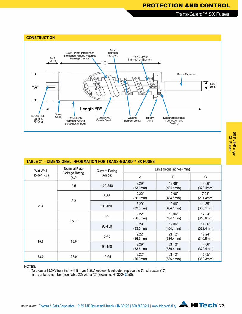
the trans-Guard™ Sx full-range current-limiting fuse provides both overload and fault current protection for distribution equipment in a single fuse body. As a full-range fuse, it is capable of interrupting any continuous current between the minimum current that can cause melting of its elements and its rated maximum interrupting current (50,000 amps). The fuses are capable of interrupting in elevated ambient temperatures up to their rated maximum
application:Trans-Guard™ SX fuses are specifically designed to be installed in “wet-well” fuse holders for oil-filled padmounted switchgear and transformer applications (only 2.2 inch diameter designs are suitable for wet-well fuses holders mounted directly in transformers).
application temperature, which is 140°C and 71°C for the 2.2 inch and 3.3 inch diameter designs, respectively. The Trans-Guard™ SX fuse is hermetically sealed and thus discharges no gasses during fuse operation. An additional design distinction is its Patented Damage Sensor that significantly reduces the potential for fuse failure in the event of element damaging current surges.
CAUTION: Trans-Guard™ SX fuses are NOT designed for any type of live switching operation.
!
Trans-Guard™ SX Fuses
Wet Well Holder (kV)
Nominal Fuse Voltage Rating
(kV)
Current Rating(Amps)
Dimensions inches (mm)
A B C
8.3
5.5 100-250 3.29”(83.6mm)
19.06”(484.1mm)
14.66”(372.4mm)
8.35-75 2.22”
(56.3mm)19.06”
(484.1mm)7.93”
(201.4mm)
90-160 3.29”(83.6mm)
19.06”(484.1mm)
11.85”(300.1mm)
15.51
5-75 2.22”(56.3mm)
19.06”(484.1mm)
12.24”(310.9mm)
90-150 3.29”(83.6mm)
19.06”(484.1mm)
14.66”(372.4mm)
15.5 15.55-75 2.22”
(56.3mm)21.12”
(536.4mm)12.24”
(310.9mm)
90-150 3.29”(83.6mm)
21.12”(536.4mm)
14.66”(372.4mm)
23.0 23.0 10-65 2.22”(56.3mm)
21.12”(536.4mm)
15.05”(382.3mm)
taBLE �1 – diMEnSiOnaL inFORMatiOn FOR tRanS-GuaRd™ Sx FuSES
COnStRuCtiOn
PROTECTION AND CONTROL
��Thomas & Betts Corporation 8155 T&B Boulevard Memphis TN 38125 800.888.0211 www.tnb.com/utility
Sx Full-Range
CL Fuses
PG-PC-H-0307
Trans-Guard™ SX Fuses
NOTES: 1. To order a 15.5kV fuse that will fit in an 8.3kV wet-well fuseholder, replace the 7th character (“0”)
in the catalog number (see Table 22) with a “2” (Example: HTSX24�050).

Nominal Fuse VoltageRating (kV)
Current Rating(Amps)
Fuse CatalogNumber
RatedMaximum
Voltage (kV)
Maximum Continuous Current (in Oil @ 60°C)
(5)
Peak Arc Voltage (6) (kV)
Minimum Melt I2t
(AMP2-SEC)
Maximum Melt I2t (3) (4)
(AMP2-SEC)
5.5
100 HTSX320100
5.5
114.0
15
22,100 110,000150 HTSX320150 147.0 56,700 280,000175 HTSX320175 172.0 78,300 380,000225 HTSX320225 230.0 176,000 860,000250 HTSX320250 253.0 259,000 1,270,000
8.3
5 HTSX230005
10.0
5.0 30 100 35010 HTSX230010 11.5 32 620 2,70012 HTSX230012 14.0 28 800 4,00015 HTSX230015 17.0 28 800 4,00020 HTSX230020 22.5 26 920 8,00025 HTSX230025 25.0 26 1,310 9,50030 HTSX230030 30.0 26 1,620 11,00040 HTSX230040 43.0 26 3,660 22,00050 HTSX230050 53.0 26 5,250 30,00065 HTSX230065 65.0 26 8,700 50,00075 HTSX230075 75.0 26 12,800 70,00090 HTSX330090
8.3
92.0
25
25,200 100,000100 HTSX330100 105.0 47,500 185,000150 HTSX330150 150.0 78,300 330,000160 HTSX330160 163.0 115,150 480,000
15.5
5 HTSX240005
17.2
5.0 51 100 51010 HTSX240010 11.5 54 620 2,60012 HTSX240012 14.0 46 800 3,70015 HTSX240015 17.0 46 800 3,70020 HTSX240020 22.5 43 920 6,50025 HTSX240025 25.0 45 1,310 8,00030 HTSX240030 30.0 45 1,620 10,00040 HTSX240040 43.0 45 3,660 22,00050 HTSX240050 53.0 45 5,250 30,00065 HTSX240065 65.0 45 8,700 50,00075 HTSX240075 75.0 45 12,800 70,00090 HTSX340090
15.5
98.0
40
25,200 110,000100 HTSX340100 117.0 39,400 185,000150 HTSX340150 150.0 80,000 380,000
23.0
10 HTSX250010
23.0
11.5 67 620 3,10012 HTSX250012 14.0 61 800 4,80015 HTSX250015 17.0 61 800 4,80020 HTSX250020 22.5 60 920 8,30025 HTSX250025 25.0 60 1,310 11,20030 HTSX250030 30.0 60 1,620 13,00040 HTSX250040 42.0 60 3,660 28,00050 HTSX250050 51.0 60 5,250 38,00065 HTSX250065 65.0 60 8,700 61,000
taBLE �� – ELECtRiCaL ChaRaCtERiStiCS OF tRanS-GuaRd™ Sx FuSES
NOTES:1. Designs have a 50,000 Amps rms. Symmetrical Rating (except 5A 17.2kV which was tested at 44kA maximum).2. Fuses rated 75A and below are 2.25” in diameter. Higher ratings are 3.3” in diameter.3. Tabulated Maximum Total I2t values are for currents of 50,000 amperes at the nominal voltage of the fuse. Fuses which have a Rated Maximum Voltage higher
than their Nominal Voltage Rating will have a higher I2t let-through when applied at voltages up to these higher values. For example, Maximum Total I2t values are increased by approximately 30% when 8.3kV fuses are applied at 10 kV and approximately 25% when 15.5kV fuses are used at 17.2 kV.
4. Maximum total I2t values are reduced for currents below 50,000 A. For example, at 10,000 A, I2t values are approximately 15% less than the published values.5. Maximum continuous currents at different ambient temperatures: These may be determined by derating the fuses by 0.2% per degree C over 60°C (for example at
80°C the derating would be 20 x .2 = 4%, making the maximum continuous current of a 20 A fuse 22.5 x .96 = 21.6A) or rerating the fuses by .2 % per degree C under 60°C (for example at 40°C the rerating would be 20 x .2 = 4 %, making the maximum continuous current of a 20 A fuse 22.5 / .96 = 23.4A). The long time melting current of the fuses (approximately one hour and longer) due to different ambient temperatures is the same as described above for “maximum continuous currents”. See time current characteristics for melting characteristics in this time region.
6. Peak arc voltages quoted are for 50,000 A currents at the rated maximum voltage listed. Reduced currents and voltages will reduce the peak arc voltage. Consult the factory for further information.
PROTECTION AND CONTROL
�� Thomas & Betts Corporation 8155 T&B Boulevard Memphis TN 38125 800.888.0211 www.tnb.com/utility
Sx F
ull-R
ange
CL
Fuse
s
PG-PC-H-0307
Trans-Guard™ SX Fuses

Recommended Fuse Current Ratings (Amperes)
1-Phase Transformer
kVA
Transformer 1-Phase Voltage Rating (kV) Phase-to-Ground2.4 4.16 4.8 7.2 7.62 12 14.4 16 19.9
A B A B A B A B A B A B A B A B A B10 10 10a 5 5a 5a 5a 5a 5a 10a
15 12 10a 10a 5 5 5a 5a 5a 10a
25 20b 25 12 12 10a 10a 5 5a 5a 10a
37.5 30b 40 20 20a 12 12a 10a 10a 10a 10a
50 40b 50 25b 30 20b 25 15 15 10 10a 10a 10a
75 50 65 30 40 30b 40 20b 25 20 15 12 12a 10a
100 65 (100) 40 50 40b 50 25 30 25 30 20 15 15 12
167 (150)b (175) 65 (100) 50 75 40 50 40b 50 25 30 25b 30 20b 25 20
250 (150) (225) (100) (150) 75 (100) 50 75 50 65 40b 50 30 40 30b 40 25b 30
333 (225) (150) (175) (150)b (175) 75 90 65 90 50 65 40 50 40b 50 30 40
500 (250)c (175) (250) (150) (225) 100 150 100 150 65 90 50 75 50 65 40 50
833 (250)c (250) 160 160 100 150 90 100 75 65
1000 (250)c 160c 150 100 150
1500 150c 150
FuseVoltage (�.�kV) �.�kV 1�.�kV ��kV
taBLE �� – RECOMMEndEd tRanS-GuaRd™ Sx FOR SWitChGEaR (MOuntEd in a WEt WELL FuSEhOLdER With a Max. OiL tEMP. OF �0°C)
NOTE: Column A = 140-200% of transformer rating and Column B = 200-300% of transformer rating. See additional notes on page 26.
Recommended Fuse Current Ratings (Amperes)
3-Phase Transformer
kVA
Transformer 3-Phase Voltage Rating (kV) Phase-to-Phase2.4 4.16 4.8 7.2-7.96 8.32 12.47 13.2-14.4 20.8
A B A B A B A B A B A B A B A B15 10a 5 5 5a 5a 5a 5a 10a
22.5 12 10a 10a 5 5a 5a 5a 10a
30 15 10 10a 10a 5 5a 5a 10a
45 20b 25 15 12 10 10a 5 5 10a
75 30 40 20b 25 20 12 12 10a 10a 10a
100 40 50 25 30 25b 30 20 15 12a 10a 10a
112.5 40 65 30b 40 25 30 20 20a 12 12a 10a
150 65 75 40b 50 30 40 25b 30 20b 25 15 15 10
200 75 (100) 50 65 40 50 30 40 25 30 20 20 12
225 75 (100) 50 75 40 65 30 40 30b 40 20b 25 20 15
300 (150)b (175) 65 (100) 65 75 40 50 40b 50 25 30 25 30 20
500 (175) (250) (150)b (175) (100) (150) 65 90 50 75 40 50 40b 50 25 30
750 (250) (150) (225) (150) (225) 90 150 75 100d 50 75 50 65 40b 50
1000 (225) (175) (250) 150 160 100d 150d 75 90 65 90 50 65
1500 (250)c (250) 160 150d 100 150 100 150 65
2000 150 150
2500 150c 150
3000 150c
FuseVoltage (�.�kV) �.�kV 1�.�kV ��kV
taBLE �� – RECOMMEndEd tRanS-GuaRd™ Sx FOR SWitChGEaR: PROtECtinG dELta COnnECtEd tRanSFORMERS (MOuntEd in a WEt WELL FuSEhOLdER With a Max. OiL tEMP. OF �0°C)
NOTE: Column A = 140-200% of transformer rating and Column B = 200-300% of transformer rating. See additional notes on page 26.
PROTECTION AND CONTROL
��Thomas & Betts Corporation 8155 T&B Boulevard Memphis TN 38125 800.888.0211 www.tnb.com/utility
Sx Full-Range
CL Fuses
PG-PC-H-0307
Trans-Guard™ SX Fuses

PROTECTION AND CONTROL
Recommended Fuse Current Ratings (Amperes)
3-Phase Transformer
kVA
Transformer 3-Phase Voltage Rating (kV) Phase-to-Phase2.4 4.16 4.8 7.2-7.96 8.32 12.47 13.2-14.4 20.8 22.9-24.9 34.5
A B A B A B A B A B A B A B A B A B A B15 10a 5 5 5a 5a 5a 5a 5a 5a 10a
22.5 12 10a 10a 5 5a 5a 5a 5a 5a 10a
30 15 10 10a 10a 5 5a 5a 5a 5a 10a
45 20b 25 15 12 10 10a 5 5 5a 5a 10a
75 30 40 20b 25 20 12 12 10a 10a 5 5 10a
100 40 50 25 30 25b 30 20 15 12a 10a 10a 10a 10a
112.5 40 65 30b 40 25 30 20 20a 12 12a 10a 10a 10a
150 65 75 40b 50 30 40 25b 30 20b 25 15 15 10 10a 10a
200 75 (100) 50 65 40 50 30 40 25 30 20 20 12 12 10a
225 75 (100) 50 75 40 65 30 40 30b 40 20b 25 20 15 12 10a
300 (150)b (175) 65 (100) 65 75 40 50 40b 50 25 30 25 30 20 20a 12
500 (175) (250) (150)b (175) (100) (150) 65 (100) 50 75 40 50 40b 50 25 30 25b 30 20
750 (250) (150) (225) (150) (225) (100) (150) 75 (100) 50 75 50 65 40b 50 40b 50 25b 30
1000 (225) (175) (250) (150) (175) (150)b (175) 75 90 65 90d 50 65 40 50 30 40
1500 (250)c (250) (175) (250) (150) (225) 100 150 100d 150d 65 90 65 75 40 50
2000 (225) (225) 150 150d 75 100 75 90 50
2500 (250)c (250) 160 150d 100 150 90 150 65
3000 160c 150 100 150
taBLE �� – RECOMMEndEd tRanS-GuaRd™ Sx FOR SWitChGEaR: PROtECtinG Gndy-Gndy* COnnECtEd tRanSFORMERS With LESS than �0% dELta COnnECtEd SECOndaRy LOad (MOuntEd in a WEt WELL FuSEhOLdER With a Max. OiL tEMP. OF �0°C)
NOTES FOR TABLES 23, 24 AND 25:
Column A = 140-200% of transformer rating and Column B = 200-300% of transformer rating. • Recommended fuses meet inrush criteria of 12 times transformer full load current for 0.1 second and 25 times transformer full load current
for 0.01 second. Fuses also meet cold load pickup criteria of 6 times transformer full load current for 1 second and 3 times transformer full load current for 10 seconds.
• Ratings in parentheses are 5.5 kV rated fuses.
a Fuse allows more than 300% of transformer rating.
b Fuse allows more than 200% of transformer rating.
c Fuse allows at least 125% of transformer rating.
d 15.5kV fuse must be used for voltages over 8.32 kV for delta configurations or 13.8kV Gndy/8.32kV.
*Phase-to-Ground rated fuses are commonly used for Gndy/Gndy connected transformers having no more than 50% Delta connected secondary load.
FuseVoltage (�.�kV) �.�kV 1�.�kV ��kV
�� Thomas & Betts Corporation 8155 T&B Boulevard Memphis TN 38125 800.888.0211 www.tnb.com/utility
Sx F
ull-R
ange
CL
Fuse
s
PG-PC-H-0307
Trans-Guard™ SX Fuses

Continuous Current Rating
(Amps)
Catalog Number
5.5kV 8.3kV 15.5kV 23.0kV
5 – HTSX230005 HTSX240005 –10 – HTSX230010 HTSX240010 HTSX25001012 – HTSX230012 HTSX240012 HTSX25001215 – HTSX230015 HTSX240015 HTSX25001520 – HTSX230020 HTSX240020 HTSX25002025 – HTSX230025 HTSX240025 HTSX25002530 – HTSX230030 HTSX240030 HTSX25003040 – HTSX230040 HTSX240040 HTSX25004050 – HTSX230050 HTSX240050 HTSX25005065 – HTSX230065 HTSX240065 HTSX25006575 – HTSX230075 HTSX240075 –90 – HTSX330090 HTSX340090 –100 HTSX320100 HTSX330100 HTSX340100 –150 HTSX320150 HTSX330150 HTSX340150 –160 – HTSX330160 – –175 HTSX320175 – – –225 HTSX320225 – – –250 HTSX320250 – – –
taBLE �� – ORdERinG inFORMatiOn FOR tRanS-GuaRd™ Sx FuSES
NOTES: To order a 15.5kV fuse that will fit in an 8.3kV Wet-well fuseholder, replace the 7th character (“0”) in the catalog number with a “2” (EXAMPLE: HTSX24�050).
Ordering information:To order the proper fuse for a particular application, first determine the correct fuse voltage and current rating using the published performance data (Table 22 and the applicable TCC). Then refer to Table 26 to determine the appropriate catalog number. Alternatively, fuse selection can be determined using the accompanying application Tables 23-25.
PROTECTION AND CONTROL
When replacing the obsolete AB Chance SL fuse with a Hi-Tech Fuses Trans-Guard™ SX fuse, it is important to recognize that the SX fuse designs should not be used on distribution systems where the primary line-to-line voltage exceeds the rated maximum voltage of the fuse as shown in the chart to the right:
This should be considered when choosing a proper replacement for the AB Chance SL fuse as they were, in some cases, used on systems having line-to-line voltages greater than that of the current-limiting fuse component of the assembly.
Again, when choosing the appropriate Hi-Tech SX fuse to replace the AB Chance SL fuse, care must be taken to ensure that the rated maximum voltage of the SX fuse exceeds the system line-to-line voltage. The only exception to this require-ment is when all the transformers that are downstream from the switches where the SX fuses are to be installed are Gndy-Gndy connected with less than 50% delta connected secondary load. In that case, a fuse having a rated maximum voltage exceeding the system line-to-neutral voltage may often be used.
tRanS-GuaRd™ SxNominal
Fuse Voltage Rating (kV)
CurrentRating(Amps)
Rated Maximum
Voltage (kV)5.5 100-250 5.5kV
8.35-75 10.0kV
90-160 8.3kV
15.55-75 17.2kV
90-150 15.5kV23.0 10-65 23.0kV
Important Notice When Using Trans-Guard™ SX Fuses
��Thomas & Betts Corporation 8155 T&B Boulevard Memphis TN 38125 800.888.0211 www.tnb.com/utility
Sx Full-Range
CL Fuses
PG-PC-H-0307
Trans-Guard™ SX Fuses

SOuRCE SidE CutOut inStaLLatiOn
LOad SidE CutOut inStaLLatiOn
hOt-LinE/BaiL inStaLLatiOn
BuShinG MOunt inStaLLatiOn
��
PROTECTION AND CONTROL
Thomas & Betts Corporation 8155 T&B Boulevard Memphis TN 38125 800.888.0211 www.tnb.com/utility
Ext
Bac
kup
CL
Fuse
s
PG-PC-H-0307
Trans-Guard™ EXT Fuses
the trans-Guard™ Ext is a back-up type current-limiting fuse designed for application on overhead distribution systems. Its ability to significantly reduce fault energy and its very high interrupting capability (50,000 amperes symmetrical) provide state-of-the-art protection against today’s ever increasing available fault currents.
As a back-up type current-limiting fuse (refer to ANSI C37.40 for fuse definitions), the Trans-Guard™ EXT must always be applied in series with a properly-sized low current protective device. This device is typically an expulsion fuse (i.e. cutout fuse link transformer internal weak link, etc.). The expulsion fuse and the current limiting fuse are each selected to provide fault protection over a certain range of currents. The expulsion fuse is chosen to clear the low magnitude currents such as those produced by overloads and high impedance faults. Such currents are generally below the minimum interrupting current rating of the current-limiting fuse. The back-up type current-limiting fuse is selected so as to clear all other currents. In addition to interrupting the fault current, the back-up current-limiting fuse serves the very important function of limiting the amount of energy that is let through to the source of the fault to a value below the withstand capability of the equipment being protected. By doing this, the current-limiting fuse minimizes the likelihood of disruptive equipment failures (i.e. transformer covers being blown off or capacitor casings rupturing) resulting from high magnitude fault currents. No other protective device is available to similarly reduce the risk of disruptive equipment failures.
applicationsAlthough Trans-Guard™ EXT fuses are used primarily to protect single-phase distribution transformers, they are also used to provide fault protection for distribution capacitor banks and three-phase distribution transformers. The selection of the proper Trans-Guard™ EXT for a particular application should be based upon matching it with the low current interrupter that is being used. The procedures to be followed in selecting the correct Trans-Guard™ EXT are discussed in Bulletin FS-10.
The Trans-Guard™ EXT is designed to be easily retrofittable to equipment already in service. It can be installed in a variety of ways. These include attaching the fuse to the terminal of a cutout, mounting it in the terminal of a transformer’s HV bushing, suspending it in a drop lead, and using the fuse with a hot line connector.

Nominal Fuse Voltage Rating (kV)
k-Link Coordin-
ation
Rated Maximum Voltage
(kV)
System Voltage Class (kV)
Peak Arc Volts (kV)
Maximum Continuous
Current (Amps)
Minimum Interrupting
Current (Amps)
Minimum Melt I2t
(AMP2-SEC)
Maximum Total I2t
(AMP2-SEC)(2)
Recommended Maximum Size of
Series-Connected Expulsion Fuses
k T QA
8.3
12
8.3 15
26 30 415 3,200 10,000 12 8 1525 26 50 500 11,000 33,000 25 15 3040 26 70 750 28,000 80,000 40 20 5050 26 80 850 39,000 120,000 50 25 6065 22 125 1,250 67,300 230,000 65 30 6080 22 160 1,700 156,000 580,000 80 50 125
100 23.5 195 2,380 218,000 850,000 100 65 125
15.5
12 (1)
17.2
27
49 30 440 3,200 10,000 12 8 15 25 (1) 49 50 580 11,000 33,000 25 15 30 40 (1) 49 65 850 28,000 80,000 40 20 50
50
15.5
49 75 1,000 39,000 120,000 50 25 6065 44 125 1,200 67,300 230,000 65 30 6080 44 160 1,530 156,000 580,000 80 50 125
100 46 190 1,670 204,000 733,000 100 65 125
23.0
12
23 35
64 30 280 3,200 10,500 12 8 1525 66 45 465 11,000 38,000 25 15 3030 69 80 800 20,100 70,000 30 20 4040 67 85 1,000 31,400 105,000 40 25 5050 65 100 1,300 66,900 220,000 50 30 6080 63 120 1,530 108,600 360,000 80 40 100
NOTES:1. These fuses have been tested at a Rated Maximum Interrupting Current of 43kA at 17.2kV due to test station
limitations and 50kA at 15.5kV.2. Tabulated Maximum Total I2t values are at the Nominal Voltage of the fuse. Values for 15.5kV fuses at 17.2kV are
approx. 25% higher.
taBLE �� – ELECtRiCaL ChaRaCtERiStiCS OF tRanS-GuaRd™ Ext FuSES
��
PROTECTION AND CONTROL
Thomas & Betts Corporation 8155 T&B Boulevard Memphis TN 38125 800.888.0211 www.tnb.com/utility
Ext Backup
CL Fuses
PG-PC-H-0307
Trans-Guard™ EXT Fuses
Lowest total I2t (energy let-through)
Broadest range of current ratings available
Higher melt l2t to total l2t ratios
High fault current interrupting capability
Lowest values available in the industry
Makes fuses less susceptible to damage from current surges
50,000 amperes symmetrical at the Nominal Voltage Rating of each fuse
Available up to 100k at 8.3kV and 15.5kV, and 80k at 23kV
FEatuRE BEnEFit/dESCRiPtiOn
Durable designFor extended life outdoors including brass end caps and filament wound epoxy tubular bodies which are centerless-ground and coated with an oven baked acrylic paint
Current-limiting action with high fault currents Reduces the magnitude of flame discharge and loud operation of the series-connected cutout
Hardware options Wide wariety of mounting and connection hardware options

taBLE �� – ORdERinG & diMEnSiOnaL inFORMatiOn FOR �” diaMEtER tRanS-GuaRd™ Ext FuSES
Nominal Fuse Voltage Rating (kV)
Fuse Catalog Number
k-Link Coordination
Dimensions (in)
A B
8.3
HTDE23(X)012 12 6.13-6.05 10.07-9.75
HTDE23(X)025 25
9.93-9.85 13.87-13.55HTDE23(X)040 40HTDE23(X)050 50
15.5
HTDE24(X)012 12HTDE24(X)025 25
15.73-15.65 19.67-19.35HTDE24(X)040 40HTDE24(X)050 50
23.0HTDE25(X)012 12HTDE25(X)025 25
Instructions: Replace (X) in the above model numbers by one of the following end cap configuration codes.
(X) Spade Cap
Stud Cap
Integral Eyebolt
Loose HardwareSpecial Features
Eyebolt Parallel Groove
Universal Adapter
0 2 1 11 1 12 23 1 1 14 2 15 1 1 16 2 17 2 1 18 1 19 2 1A 2x1/2-13 THREADED STUDSC 1 1 1F 2H 1 1J 1 1 1R 1 1 OFFSET STUD CAP
NOTES: Fuse diameter = 2.22” – 2.18”, knurled stud diameter = 0.29” and spade hole diameter = 0.42”.Eyebolt is suitable for conductors of AWG 8 SOL. – 2/0 STR. Parallel-Groove connector is suitable for conductors of 6 SOL. – 2/0 STR.Other hardware options are available, please consult the factory.
�0
PROTECTION AND CONTROL
Thomas & Betts Corporation 8155 T&B Boulevard Memphis TN 38125 800.888.0211 www.tnb.com/utility
Ext
Bac
kup
CL
Fuse
s
PG-PC-H-0307
Trans-Guard™ EXT Fuses
Eyebolt – Offset Stud
Type “R”
BA
Stud – Eyebolt
Type “8”
A
Spade – Stud
Type “1”
BA
Spade – Spade
Type “0”
BA
B
1.95”
1.375”
2.05”
1.55”
2.30”
0.295”
UNIVERSAL ADAPTER
3.32”

�1
PROTECTION AND CONTROL
Thomas & Betts Corporation 8155 T&B Boulevard Memphis TN 38125 800.888.0211 www.tnb.com/utility
Ext Backup
CL Fuses
PG-PC-H-0307
Trans-Guard™ EXT Fuses
taBLE �0 – ORdERinG & diMEnSiOnaL inFORMatiOn FOR 100k tRanS-GuaRd™ Ext FuSES (PaRaLLEL �” dia. FuSES)
Rated Maximum Voltage
(kV)
FuseCatalog Number
Dimension (in)
A B C
8.3 HTDE23E100 11.9 14.0 4.9 15.5 HTDE24E100 17.5 19.6 4.9
NOTES: Eyebolt is suitable for conductors of 8 Sol. – 2/0 Str.Stud is 1.8” long and 0.46” in diameter.Other hardware options are available, contact the factory.
Rated Maximum
Voltage (kV)Fuse Catalog
Numberk-Link
Coordination
Dimensions (in)
A BType “A”
BType “E”
BType “F”
BType “U”
8.3HTDE33(X)065 65
10.0-9.9 13.9-13.5 14.2-13.8 14.0-13.6 14.6-14.2HTDE33(X)080 80
15.5HTDE34(X)065 65
15.6-15.5 19.5-19.1 19.8-19.4 19.6-19.2 20.2-19.8HTDE34(X)080 80
23.0
HTDE35(X)030 30
18.4-18.3 22.3-21.9 22.6-22.2 22.4-22.0 23.0-22.6HTDE35(X)040 40HTDE35(X)050 50HTDE35(X)080 80
taBLE �� – ORdERinG & diMEnSiOnaL inFORMatiOn FOR �” diaMEtER tRanS-GuaRd™ Ext FuSES
NOTES: Replace (X) in the above model numbers with “A”, “E”, “F” or “U” (see below).Other hardware options are available, please consult the factory.Fuse dia. = 3.32” – 3.25”, spade hole dia. = 0.42” and knurled stud dia. = 0.46”.Eyebolt is suitable for conductors of AWG 8 SOL. – 2/0 STR
Eyebolt – SpadeWith Universal Adapter
Type “U”
1.95
BA
Eyebolt – Knurled Stud
Type “E”
BA
Eyebolt – Eyebolt
Type “F”
BA
1.751.95
1/2” – 13 Threaded Stud/Stud
Type “A”
BA
1.5
A
B
C
Eyebolt – Stud Type “E”

MCLFMOLdEd CuRREnt-LiMitinG FuSE
MCanMOLdEd CaniStER FuSE
FLRFuSEd LOadBREak ELBOW
FxCuRREnt-LiMitinG FuSE
thomas & Betts’ Elastimold® Fused Products cover a wide range of applications and ratings. Molded Current-Limiting Fuses (MCLF), Molded Canister Fuses (MCAN), and Fused Elbows (FLR) provide full-range protec-tion through 50 kA using Hi-Tech™ full-range fuses. The fuses in these products can easily be replaced with minimal down time. MCAN and MCLF are suitable for single-phase tap/load protection and can be used in vault, subsurface, or padmount installations. Fused loadbreak elbows provide low cost, convenient protec-tion for radial taps, junctions, transformers and other equipment. They combine the advantages of full-range current-limiting fusing with the convenience of 15/25kV, 200 Amp hotstick oper-able, loadbreak elbow switching.
In this guide you will find a description and basic features for Elastimold® fused products, as well as information on how to order.
hi-tech™ Fuses provide the benefits of current-limiting protection with fault clearing occurring in less than one half cycle, thereby limiting the let-through fault current and dramatically reducing stresses on equipment. They also provide both overload and fault current protection for distribution equipment in a single fuse body. As full-range fuses, they are capable of interrupting any continuous current between the minimum current that can cause melting of the elements and its rated maximum interrupting current (50,000 amps). All fuses are capable of interrupting in elevated ambient temperature. Hi-Tech™ design features include:
• Patented Damage Sensor designed to significantly reduce the risk of fuse failure should the fuse be subjected to an element damaging current surge. (e.g. lightning)
• Hermetically sealed construction ensures that no gasses escape from the fuse during current interruption. All fuses are helium mass spectrometer leak tested to ensure sealing system integrity.
• Rugged machined brass end caps used for greater ferrule strength resulting in less distortion and more secure fuse attachment.
��
PROTECTION AND CONTROL
Thomas & Betts Corporation 8155 T&B Boulevard Memphis TN 38125 800.888.0211 www.tnb.com/utility
Mol
ded
Fuse
Pro
duct
s
PG-PC-H-0307
Product Application

Breaker Locks OutJunction Cabinet
3-WayUnit
Loop system without tap protection: A fault on the tap will lock out the substation breaker and generate an outage for all customers to the open point.
B1 B�
S�i�B�
nC nC
nC
nO
Breaker ClosedJunction Cabinet
3-WayUnit
Loop system with tap protection: A fault on the tap will be isolated by the FUSES. This reduces the number of customers affected by the outage, thus improving the system’s System Average Interruption Frequency Index (SAIFI).
B1 B�
S�i�B�
nC nC
nC
nO
FAULT
FUSE ISOLATES FAULT
Full-Range Current-Limiting Fuse
Tin Plated Brass Caps
Low Current Interruption Element (Includes Patented Damage Sensor)
Compacted Quartz Sand
High Current Interruption Element
EpoxyJoint
Elastimold® FLR, MCAN, and MCLF fused products constitute some of the fastest and easiest ways to improve system reliability. As an example, loads that branch out along underground loops can be protected by installing any of these fuses into existing junction cabinets.
��
PROTECTION AND CONTROL
Thomas & Betts Corporation 8155 T&B Boulevard Memphis TN 38125 800.888.0211 www.tnb.com/utility
Molded Fuse Products
PG-PC-H-0307
Production Application
thE FOLLOWinG ExaMPLE ShOWS hOW MuCh iMPROVEMEnt in RELiaBiLity iS aChiEVEd By addinG PROtECtiOn tO a taP.

EPDM Molded Rubber Deadfront Construction
Full-range current-limiting fusing with 50kA interrupting capability
Rated 5kV Ungrounded to 25kV Grounded Wye
15/25kV hot stick operable, loadbreak elbow switching
Split Center Section
Built-in Voltage test points or direct test ports
Fully sealed and submersibleInsulate, shield and eliminate exposed live parts
Easy fuse replacement
Quick and convenient blown fuse indication
Facilitates fusing of light duty underground distribution systems including sub-loops, radial taps, junctions, transformers, and other equipment
��
PROTECTION AND CONTROL
Thomas & Betts Corporation 8155 T&B Boulevard Memphis TN 38125 800.888.0211 www.tnb.com/utility
Mol
ded
Fuse
Pro
duct
s
PG-PC-H-0307
Fused Elbow
FEatuRE BEnEFit/dESCRiPtiOn
Elastimold® Fused Elbows combine the advantages of Full-Range Current-Limiting Fusing with the convenience of 15/25kV hot stick operable, loadbreak elbow switching.
This is the fastest, most cost effective way to improve the distribution system’s reliability without adding a separate piece of switchgear or replacing existing sectionalizing cabinets. Simply replace existing 200 Amp tap elbows with Elastimold® Fused Elbows to protect light duty underground distribution systems including sub-loops, and radial taps.

Construction: Submersible, non-venting, deadfront, corrosion resistant.Ambient Temperature Range: – 30 to +65 degrees centigrade.Fuses are only suitable for the system voltage class shown if the recovery voltage across the fuse will not exceed its rated maximum voltage. For three-phase applications, this generally requires that protected transformers be gndy-gndy and have at least 50% grounded load.* The 15.5kV L-G rated fuse requires 75% grounded load to be applied on a 25kV system. The 17.2kV L-G rated fuse requires at least 75% grounded load to be applied on a 28kV system.Fuse replacement requires the elbow to be de-energized.
System Voltage Class (kV) 15 25* 25/28*Nominal Fuse Voltage (kV) 8.3 15.5 17.2Rated Maximum Fuse Voltage (kV) 10 15.5 17.2Frequency (Hz) 50/60 50/60 50/60BIL Impulse Withstand (kV) 95 125 140One Minute AC Withstand (kV) 34 40 45Fifteen Minute DC Withstand (kV) 53 78 78Corona Extinction (kV) 11 19 21.5Symmetrical Interrupting Capability (Amp) 50,000 50,000 50,000Current Rating (Amp) 3-80 6-20 3-45
aPPLiCatiOn inFORMatiOn
RatinGS
Elastimold® fused elbows have been designed and tested per applicable portions of IEEE, ANSI, and other industry standards including:
anSi C��.�0 Standard for Current-Limiting Fuse Service Conditions.
anSi C��.�1 Standard for Current-Limiting Fuse Design & Testing.
anSi C��.�� Standard for Current-Limiting Fuse Ratings & Specifications.
iEEE ��� Standard for Separable Connectors.
CERtiFiEd tEStS & PERFORManCE
��
PROTECTION AND CONTROL
Thomas & Betts Corporation 8155 T&B Boulevard Memphis TN 38125 800.888.0211 www.tnb.com/utility
Molded Fuse Products
PG-PC-H-0307
Fused Elbow
Upper elbow half
Probe lug
Fuse
Crimplug
Hose clamp
Lower elbow half
Probe

NOTES:1. Designs have a 50,000 Amps rms. Symmetrical Rating (except 3A 17.2kV which was tested at 44kA maximum).2. Fuses have a Rated Maximum Application Temperature of 65ºC (RMAT is the maximum temperature of the air, in contact with the elbow
housing, at which they have been shown to be suitable for use).3. Tabulated Maximum Total I2t values are for currents of 50,000 amperes at the nominal voltage of the fuse. Values for 8.3kV fuses at
10kV are approximately 30% higher. Values for 17.2kV fuses at 15.5kV are approximately 20% lower. 4. Maximum total I2t values are reduced for currents below 50,000 A. For example, at 10,000 A, maximum total I2t values are approximately
15% less than the published values.5. Peak arc voltages quoted are for 50,000 A currents at the rated maximum voltage listed. Reduced currents and voltages will reduce the
peak arc voltage. Consult the factory for further information.6. Maximum continuous currents at ambient temperatures other than those listed may be determined by derating the fuses by 0.2% per
degree C over 25º C. For example: At 40º C the derating would be 15 x .2 = 3%, making the maximum continuous current of a 17.2kV 25A fuse 31.5 x .97 = 30.5A.
7. Time-current characteristic curves are published at 25ºC. Reduction in the long time melting current of the fuses (approximately one hour and longer) due to higher ambient temperatures is the same as described above for “maximum continuous currents”.
NominalFuse
VoltageRating(kV)
3 EFX083003-E 4.3 4.2 3.9 30 100 3506 EFX083006-E 9.5 9.0 8.5 32 620 2,7008 EFX083008-E 11.5 11.0 10.5 28 800 4,00010 EFX083010-E 14.0 13.5 13.0 28 800 4,00012 EFX083012-E 19.0 18.5 17.5 26 920 8,00018 EFX083018-E
10.021.0 20.0 19.0 26 1,310 9,500
20 EFX083020-E 26.0 25.0 24.0 26 1,620 11,00025 EFX083025-E 34.0 33.0 31.0 26 3,660 22,00030 EFX083030-E 37.5 36.5 34.5 26 5,250 30,00040 EFX083040-E 43.0 42.0 40.0 26 8,700 50,00045 EFX083045-E 49.0 47.0 45.0 26 12,800 70,00065 EFX083065-E
8.870.0 68.0 64.5 23 34,000 200,000
80 EFX083080-E 80.0 77.5 73.5 22 51,200 280,0006 EFX155006-E 8.5 8.0 7.7 52 620 3,0008 EFX155008-E 10.5 10.0 9.5 40 800 4,30010 EFX155010-E
15.513.0 12.5 12.0 40 800 4,300
12 EFX155012-E 16.0 15.5 15.0 38 920 8,00018 EFX155018-E 20.0 19.5 18.5 38 1,620 13,00020 EFX155020-E 23.5 22.5 21.5 38 2,200 16,5003 EFX172003-E 4.3 4.2 3.9 51 100 5106 EFX172006-E 9.5 9.0 8.5 54 620 3,2508 EFX172008-E 11.5 11.0 10.5 46 800 4,60010 EFX172010-E 14.0 13.5 13.0 46 800 4,60012 EFX172012-E 18.0 17.5 16.5 43 920 8,50018 EFX172018-E 17.2 20.0 19.5 18.5 45 1,310 10,00020 EFX172020-E 24.0 23.0 22.0 45 1,620 12,50025 EFX172025-E 31.5 30.5 29.0 45 3,660 27,50030 EFX172030-E 35.5 34.5 32.5 45 5,250 37,50040 EFX172040-E 41.0 40.0 38.0 45 8,700 62,50045 EFX172045-E 46.0 45.0 42.5 45 12,800 87,500
SystemVoltageClass(kV)
CurrentRating(Amps)
FuseCatalogNumber
RatedMaximumVoltage
(kV)
MaximumContinuous Current
(2) (6)
Peak ArcVoltage
(kV)(5)
MinimumMelt l
2t
(AMP2-SEC)
MaximumTotal l
2t
(3) (4)(AMP
2-SEC)
25oC 40oC 65oC
10.0
8.8
15.5
17.2
8.3
15.5
17.2
15
25
25/28
t aBLE �1 – ELECtRiCaL ChaRaCtERiStiCS OF EFx-ELBOW FuSES
��
PROTECTION AND CONTROL
Thomas & Betts Corporation 8155 T&B Boulevard Memphis TN 38125 800.888.0211 www.tnb.com/utility
Mol
ded
Fuse
Pro
duct
s
PG-PC-H-0307
Fused Elbow

Recommended Fuse Current Ratings (Amperes)
1-Phase Transformer
kVA
Transformer 1-Phase Voltage Rating (kV) Phase-to-Ground2.4 4.16 4.8 7.2 7.62 12 14.4 16
A B A B A B A B A B A B A B A B10 6 6a 3 3 3 6a 6a (3)a
15 10 6 6a 3 3 6a 6a (3)a
25 12 20 8 8 6 6 6a 6a (3)
37.5 20 25 12 12 8 8 6 6a (6)a
50 25 40 18 20 12 20 10 12 10 6 6 (6)a
75 45 65 20 30 20 25 12 20 12 18 10 8 (8)
100 65 80 30 45 25 40 18 25 18 25 12 18 10 12 (10)
167 65 80 45 65 25 45 25 45 18 (25) 18 20 (12) (20)
250 80 80 45 65 45 65 (25) (45) 20 (30) (20) (30)
333 65 80 (40) (30) (45) (25) (45)
500 (45) (45)
FuseVoltage �.�kV 1�.�kV (1�.�kV)
taBLE �� – RECOMMEndEd EFx–E: ELBOW FuSE at �0°C aMBiEnt tEMPERatuRE
NOTES FOR TABLES 32 AND 33:
Column A = 140-200% of transformer rating and Column B = 200-300% of transformer rating.
• Ratings in parenthesis are 17.2kV fuses.
• 8.3kV 3-45A fuses and 15.5kV 6-20A fuses are used in the small elbow housing. 8.3kV 65-80A fuses and 17.2kV 3-45A fuses are used in the large elbow fuse housing.
• Recommended fuses meet inrush criteria of 12 times transformer full load current for 0.1 second and 25 times transformer full load current for 0.01 second. Fuses also meet cold load pickup criteria of 6 times transformer full load current for 1 second and 3 times transformer full load current for 10 seconds.
a Fuse allows greater than 300% of transformer rating.
b Recommendations limited to gndy-gndy transformers with no more than 50% delta connected secondary load, and involve certain assumptions. Phase-to-ground rated fuses are frequently recommended for gndy-gndy three phase transformers.
Recommended Fuse Current Ratings (Amperes)
3-Phase Transformer
kVA
Transformer 3-Phase Voltage Rating (kV) Phase-to-Phase2.4 4.16 4.8 7.2-7.96 8.32 12.47 13.2-14.4 20.8b 22.9-24.9b
A B A B A B A B A B A B A B A B A B15 6 3 3 3a 3a 6a 6a 6a (3)a
22.5 8 6a 6a 3 3 6a 6a 6a (3)a
30 10 12 6 6 6a 3 6a 6a 6a (3)a
45 12 20 10 8 6 6a 6a 6a 6a (3)a
75 20 30 12 20 12 8 8 6 6 6a (3)
100 30 45 18 25 18 20 12 10 8 8 6a (6)a
112.5 40 65 20 25 18 25 12 12 8 8 6 (6)a
150 45 80 25 40 20 30 18 20 12 20 10 12 10 12 6 (6)
200 65 80 40 65 30 45 20 25 18 25 12 18 12 18 8 10 (8)
225 80 45 65 40 65 20 30 20 25 12 20 12 18 8 10 (10)
300 65 80 45 80 30 45 25 40 18 (25) 18 (25) 12 18 (12)
500 80 65 80 45 80 (30) (45) (30) (45) 18 (25) (18) (25)
750 80 80 (45) (25) (45) (25) (40)
1000 (40) (40)
FuseVoltage �.�kV 1�.�kV (1�.�kV)
taBLE �� – RECOMMEndEd EFx–E: ELBOW FuSE at �0°C aMBiEnt tEMPERatuRE
��
PROTECTION AND CONTROL
Thomas & Betts Corporation 8155 T&B Boulevard Memphis TN 38125 800.888.0211 www.tnb.com/utility
Molded Fuse Products
PG-PC-H-0307
Fused Elbow
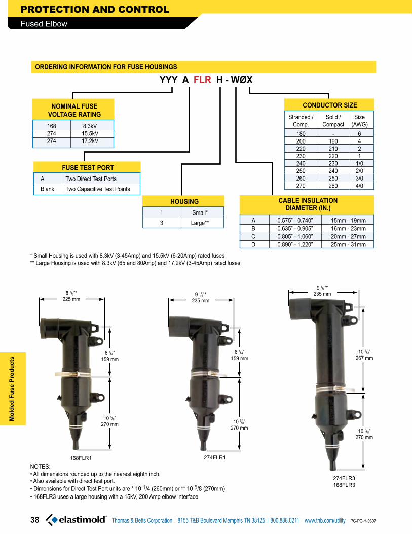
168FLR1 274FLR1
274FLR3168FLR3
9 1/4”*235 mm
10 1/2”267 mm
10 5/8”270 mm
9 1/4”*235 mm
6 1/4”159 mm
10 5/8”270 mm
6 1/4”159 mm
10 5/8”270 mm
8 7/8”*225 mm
��
PROTECTION AND CONTROL
Thomas & Betts Corporation 8155 T&B Boulevard Memphis TN 38125 800.888.0211 www.tnb.com/utility
Mol
ded
Fuse
Pro
duct
s
PG-PC-H-0307
Fused Elbow
hOuSinG
1 Small* 3 Large**
nOMinaL FuSEVOLtaGE RatinG
168 8.3kV 274 15.5kV 274 17.2kV
yyy a FLR h - WOx
* Small Housing is used with 8.3kV (3-45Amp) and 15.5kV (6-20Amp) rated fuses** Large Housing is used with 8.3kV (65 and 80Amp) and 17.2kV (3-45Amp) rated fuses
• Also available with direct test port.
NOTES: • All dimensions rounded up to the nearest eighth inch.
• Dimensions for Direct Test Port units are * 10 1/4 (260mm) or ** 10 5/8 (270mm) • 168FLR3 uses a large housing with a 15kV, 200 Amp elbow interface
FuSE tESt PORt
A Two Direct Test Ports Blank Two Capacitive Test Points
COnduCtOR SizE Stranded / Solid / Size Comp. Compact (AWG) 180 - 6 200 190 4 220 210 2 230 220 1 240 230 1/0 250 240 2/0 260 250 3/0 270 260 4/0
ORdERinG inFORMatiOn FOR FuSE hOuSinGS
CaBLE inSuLatiOndiaMEtER (in.)
A 0.575” - 0.740” 15mm - 19mm B 0.635” - 0.905” 16mm - 23mm C 0.805” - 1.060” 20mm - 27mm D 0.890” - 1.220” 25mm - 31mm

��
PROTECTION AND CONTROL
Thomas & Betts Corporation 8155 T&B Boulevard Memphis TN 38125 800.888.0211 www.tnb.com/utility
Molded Fuse Products
PG-PC-H-0307
Fused Elbow
ORdERinG inFORMatiOn FOR FuLL-RanGE CuRREnt-LiMitinG FuSES
EFx yyy aaa - E
8.3/15.5 kV Fuse
8.3/17.2kV Fuse
NOTE: • All dimensions rounded up to the nearest eighth inch.
9 1/4”235 mm
VOLtaGE RatinG 083 8.3kV 155 15.5kV 172 17.2kV
aMPERaGE RatinG 003 3 Amps 8.3 / 17.2kV 006 6 Amps 8.3 / 15.5 / 17.2kV 008 8 Amps 8.3 / 15.5 / 17.2kV 010 10 Amps 8.3 / 15.5 / 17.2kV 012 12 Amps 8.3 / 15.5 / 17.2kV 018 18 Amps 8.3 / 15.5 / 17.2kV 020 20 Amps 8.3 / 15.5 / 17.2kV 025 25 Amps 8.3 / 17.2kV 030 30 Amps 8.3 / 17.2kV 040 40 Amps 8.3 / 17.2kV 045 45 Amps 8.3 / 17.2kV 065 65 Amps 8.3kV 080 80 Amps 8.3kV
2 1/4”54 mm
2 1/4”54 mm
13 1/2”343 mm

EPDM Molded Rubber Deadfront Construction
Specially designed fuse elements with built-in low and high current interrupting capability
Current-limiting protection. Fault clearing occurs in less than one half cycle
Modular construction with a center replaceable fuse section and interchangeable end fittings
Compact
304 stainless steel brackets and hold down straps available
Fully sealed and submersibleLight weightInsulate, shield and eliminate exposed live parts
Full-Range fault current protection through 50kA
Limits the system available fault current and dramatically reduces stresses on equipment
Allow elbow connection or direct attachment to equipment mounted bushingsFlexibility of installation on junctions, transformers, cable runs, taps
Suitable for padmount, subsurface or vault installations
Accommodate a wide variety of mounting arrangements
�0
PROTECTION AND CONTROL
Thomas & Betts Corporation 8155 T&B Boulevard Memphis TN 38125 800.888.0211 www.tnb.com/utility
Mol
ded
Fuse
Pro
duct
s
PG-PC-H-0307
Molded Current-Limiting Fuse
Molded Current-Limiting Fuses provide full-range fault current protection through 50kA interrupting current.
Construction is modular with a center replaceable fuse section and interchangeable end fittings for elbow connection or direct attachment to equipment mounted bushings. The various end fittings allow fuses to be applied throughout the system including switchgear, junctions, transformers, cable runs and taps.
Elastimold® Molded Current-Limiting Fuses are available in:
• 80 thru 180 Amp ratings for applications on 5kV systems
• 6 thru 115 Amp ratings for applications on 8.7/15kV grounded Wye systems
• 6 thru 100 Amp ratings for applications on 15/25kV grounded Wye systems
• 6 thru 50 Amp ratings for applications on 20/35kV grounded Wye systems
FEatuRE BEnEFit/dESCRiPtiOn

Replaceable Molded Rubber Current-Limiting Fuse
Interchangeable Molded Rubber End
Fittings
Assembled Fuse Unit
Assembled Fuse Unit with Optional Wall Mounting
Bracket
CERtiFiEd tEStS & PERFORManCESystem Voltage Class (kV) 5 15 25/28+ 35Rated Maximum Fuse Voltage (kV) 5.5 10* 17.2* 23Frequency (Hz) 50/60 50/60 50/60 50/60BIL Impulse Withstand (kV) 60 95 125/140 150One Minute AC Withstand (kV) 34 34 40-45 50Fifteen Minute DC Withstand (kV) 53 53 78 103Corona Extinction (kV) 11 11 19/21.5 26Symmetrical Interrupting Capability (Amp) 50,000 50,000 50,000 50,000Current Rating (Amp) 80-180 10-115 10-100 10-50
Construction: Submersible, non-venting, deadfront, corrosion resistant.Ambient Temperature Range:– 30 to +65 degrees centigrade for 6-50 Amp fuses; – 30 to +40 degrees centigrade for >50 Amp fuses. Fuses are only suitable for the system voltage class shown if the recovery voltage across the fuse will not exceed its rated maximum voltage. For three-phase applications, this generally requires that protected transformers be gndy-gndy and have at least 50% grounded load.* These maximum design voltages apply to fuses rated between 6-50 Amp; for fuses with higher amperage rating the maximum design voltage is 8.3 kV for 15 kV systems and 15.5 kV for 25/28 kV systems.+15.5kV L-G rated fuses require 75% grounded load to be applied on a 25kV system. The 17.2kV L-G rated fuses require at least 75% grounded load to be applied on a 28kV system.Fuse replacement requires the MCLF to be de-energized.
aPPLiCatiOn inFORMatiOn
RatinGS
�1
PROTECTION AND CONTROL
Thomas & Betts Corporation 8155 T&B Boulevard Memphis TN 38125 800.888.0211 www.tnb.com/utility
Molded Fuse Products
PG-PC-H-0307
Molded Current-Limiting Fuse
Elastimold® Molded Current-Limiting Fuses have been designed and tested per applicable portions of IEEE, ANSI, NEMA and other industry standards including:
anSi C��.�0 Standard for Current-Limiting Fuse Service Conditions.
anSi C��.�1 Standard for Current-Limiting Fuse Design and Testing.
anSi C��.�� Standard for Current-Limiting Fuse Ratings and Specifications.
anSi/iEEE ��� Standard for Separable Connectors & Bushing Interfaces.

NOTES:
1. Designs have a 50,000 Amps rms. Symmetrical Rating.2. 10-50A fuses have a Rated Maximum Application Temperature of 65°C, and 65-180A fuses have a Rated Maximum
Application Temperature of 40°C (RMAT is the maximum temperature of the air in contact with the MCLF housing, at which the fuses have been shown suitable for use).
3. Tabulated Maximum Total I2t values are for currents of 50,000A at the nominal voltage of the fuse. Fuses that have a Rated Maximum Voltage higher than their Nominal Voltage Rating will have a higher I2t let-through when applied at voltages up to these higher values. For example, Maximum Total I2t values are increased by approximately 30% when 8.3kV fuses are applied at 10kV and approximately 25% when 15.5kV fuses are used at 17.2kV.
4. Maximum total l2t values are reduced for currents below 50,000A. For example, at 10,000A, l2t values are approximately 15% less than the published values.
5. Peak arc voltages quoted are for 50,000A currents at the rated maximum voltage listed. Reduced currents and voltages will reduce the peak arc voltage. Consult the factory for further information.
6. Maximum continuous currents at higher ambient temperatures may be determined by derating the fuses by 0.2% per degree C over 25°C. For example: At 40°C the derating would be 15 x .2 = 3%, making the maximum continuous current of a 20A fuse 23 x .97 = 22A.
Nominal Fuse
VoltageRating(kV)
80 M05CLF080 86 84 15 22,100 110,000100 M05CLF100 108 105 15 56,700 280,000125 M05CLF125 137 133 15 109,200 530,000150 M05CLF150 159 154 15 176,000 860,000180 M05CLF180
10.0185 180 15 259,000 1,270,000
10 M15CLF010 14 13 28 800 4,00020 M15CLF020 23 22 26 1,620 11,00030 M15CLF030 35 33 26 5,250 30,00040 M15CLF040 43 41 26 8,700 50,00050 M15CLF050 50 47 26 12,800 70,00065 M15CLF065
8.873 71 25 25,200 100,000
80 M15CLF080 87 84 25 47,000 185,000100 M15CLF100 106 103 25 78,300 330,000115 M15CLF115 120 116 25 115,150 480,00010 M25CLF010
15.514 13 46 800 3,700
20 M25CLF020 23 22 45 1,620 10,00030 M25CLF030 35 33 45 5,250 30,00040 M25CLF040 43 41 45 8,700 50,00050 M25CLF050 47 45 45 12,800 70,00065 M25CLF065 68 66 40 25,200 110,00080 M25CLF080 88 85 40 54,400 255,000100 M25CLF100 100 100 40 80,000 380,00010 M35CLF010 17.2 14 13 61 800 4,80020 M35CLF020 23 22 60 1,620 13,00030 M35CLF030 35 33 60 5,250 38,00040 M35CLF040 41 40 60 8,700 61,00050 M35CLF050 47 46 60 12,800 82,000
CurrentRating
(Amps)
FuseCatalogNumber
RatedMaximumVoltage
(kV)
MaximumContinuous
Current(2) (6)
Peak ArcVoltage
(kV)(5)
MinimumMelt l
2t
(AMP2-SEC)
MaximumTotal l
2t
(3) (4) (AMP
2-SEC)
25oC 40oC
5.5
10.0
17.2
23.0
5.5
8.3
15.5
taBLE �� – ELECtRiCaL ChaRaCtERiStiCS OF EnCaPSuLatEd FuSES uSEd in MCLF
23.0
8.3
15.5
��
PROTECTION AND CONTROL
Thomas & Betts Corporation 8155 T&B Boulevard Memphis TN 38125 800.888.0211 www.tnb.com/utility
Mol
ded
Fuse
Pro
duct
s
PG-PC-H-0307
Molded Current-Limiting Fuse

Recommended Fuse Current Ratings (Amperes)
1-Phase Transformer
kVA
Transformer 1-Phase Voltage Rating (kV) Phase-to-Ground2.4 4.16 4.8 7.2 7.62 12 14.4 16 19.9
A B A B A B A B A B A B A B A B A B10 10a 10a 10a 10a 10a 10a 10a 10a 10a
15 10 10a 10a 10a 10a 10a 10a 10a 10a
25 20 10 10 10a 10a 10a 10a 10a 10a
37.5 20 30 20 20 10 10 10a 10a 10a 10a
50 30 40 20 30 20 10 10 10a 10a 10a 10a
75 50 65 30 40 20 30 20 20 10 10 10 10a
100 65 (80) 40 50 30 50 20 30 20 30 20 10 10 10
167 (100) (150) 65 (80) 50 65 30 50 30 50 20 30 20 30 20 20
250 (150) (100) (125) (80) (100) 50 65 50 65 30 50 30 40 20 30 20 30
333 (180) (125) (180) (100) (150) 65 100 65 100 50 65 30 50 30 50 20 40
500 (180) (150) 115 115 65 100 65 80 50 40
750 100 80 100
1000 100
FuseVoltage (�.�kV) �.�kV 1�.�kV ��kV
taBLE �� – RECOMMEndEd MCLF at �0°C aMBiEnt tEMPERatuRE
Recommended Fuse Current Ratings (Amperes)
3-Phase Transformer
kVA
Transformer 3-Phase Voltage Rating (kV) Phase-to-Phase2.4 4.16 4.8 7.2-7.96 8.32 12.47 13.2-14.4 22.9-24.9b 20.8 34.5b
A B A B A B A B A B A B A B A B A B A B15 10a 10a 10a 10a 10a 10a 10a 10a 10a 10a
22.5 10 10a 10a 10a 10a 10a 10a 10a 10a 10a
30 10 10a 10a 10a 10a 10a 10a 10a 10a 10a
45 20 10 10 10a 10a 10a 10a 10a 10a 10a
75 30 40 20 20 10 10 10a 10a 10a 10a 10a
100 40 50 20 30 20 30 20 10 10 10 10a 10a 10a
112.5 40 65 20 30 20 30 20 20 10 10 10a 10a 10a
150 50 (80) 30 50 30 40 20 30 20 10 10 10a 10a 10a
200 65 (100) 40 65 40 50 20 30 20 30 20 20 10 10 10a
225 (80) (125) 50 65 40 65 30 40 30 50 20 20 10 10 10a
300 (100) (150) 65 (100) 65 (80) 40 50 30 50 20 30 20 30 10 20 20 10
500 (180) (100) (150) (100) (125) 65 80 50 30 50 30 50 20 30 20 30 20
750 (180) (125) (180) 80 115 65 80 50 65 30 40 30 50 20 30
1000 (180) 115 65 100 65 100 40 50 30 40
1500 100 100 40
taBLE �� – RECOMMEndEd MCLF at �0°C aMBiEnt tEMPERatuRE
FuseVoltage (�.�kV) �.�kV 1�.�kV ��kV
NOTES FOR TABLES 35 AND 36:Column A = 140-200% of transformer rating and Column B = 200-300% of transformer rating.
• Ratings in parenthesis are 5.5kV fuses.• Recommended fuses meet inrush criteria of 12 times transformer full load current for 0.1 second and 25 times transformer full load current
for 0.01 second. Fuses also meet cold load pickup criteria of 6 times transformer full load current for 1 second and 3 times transformer full load current for 10 seconds.
a Fuse allows greater than 300% of transformer rating.b Recommendations limited to gndy-gndy transformers with no more than 50% delta connected secondary load.
Phase-to-ground rated fuses are frequently recommended for gndy-gndy three phase transformers.
��
PROTECTION AND CONTROL
Thomas & Betts Corporation 8155 T&B Boulevard Memphis TN 38125 800.888.0211 www.tnb.com/utility
Molded Fuse Products
PG-PC-H-0307
Molded Current-Limiting Fuse

FuSE ORdERinG inFORMatiOn
taBLE �� – FuSE End FittinG aRRanGEMEntS
Approx. Weight 30 lbs. / 13.6 kg.
Approx. Weight 35 lbs. / 15.8 kg.
DescriptionOutlineModel
No.
200 Amp Deepwell on both ends.
200 Amp Deepwell on one end and two 200 Amp Deepwells on
the other end.
22
222
19 1/2” 343 mm16 5/8” 422 mm
5 1/8”130 mm
8 3/16”208 mm
8 3/16”208 mm5 1/8”
130 mm4”
102 mm
23 5/8” 343 mm16 5/8” 422 mm
Approx. Weight 40 lbs. / 18.1 kg.
Approx. Weight 30 lbs. / 13.6 kg.
Two 200 Amp Deepwell on both ends.
600 Amp Bushing on both ends.
2222
66
27 5/8” 702 mm16 5/8” 422 mm
5 1/8” 130 mm
4” 102 mm
4” 102 mm
8 3/16” 208 mm
9 3/16” 233 mm5 1/8”
130 mm
19 5/8” 498 mm16 5/8” 422 mm
��
PROTECTION AND CONTROL
Thomas & Betts Corporation 8155 T&B Boulevard Memphis TN 38125 800.888.0211 www.tnb.com/utility
Mol
ded
Fuse
Pro
duct
s
PG-PC-H-0307
Molded Current-Limiting Fuse
PROTECTION AND CONTROL
To completely specify and order a Molded Current-Limiting Fuse:
1. Select the Fuse Catalog Number from Table 34 based on the amperage and system voltage. This table is also used to order spare or replacement fuses.
2. From Table 37 select a suffix for the Model Number based on the required fuse end fittings. If end fittings are to be ordered and shipped separately from the fuse, use Table 39.
3. Select Mounting Options (if required) from Table 38.
ExaMPLE:To order a fuse for application in a 25kV gndy-gndy system (17.2 line-to-ground), rated 50 Amp with factory assembled 200 Amp Deepwell end fittings and no mounting provision, specify: CataLOG nO. M��CLF0�0-��
Mounting Options (See Table 38)

taBLE �� – FuSE End FittinG aRRanGEMEntS (COntinuEd)
Approx. Weight 30 lbs. / 13.6 kg.
Approx. Weight 30 lbs. / 13.6 kg.
NOTE: Other models are available such as 26.
600 Amp Elbow Connector on one end for attachment to equipment and a 200 Amp Deepwell on the other end.
This arrangement is not available at 20/35kV
600 Amp Elbow Connector on one end for attachment to equipment and a 600 Amp bushing on the other end.
This arrangement is not available at 20/35kV
DescriptionOutlineModel
No.
6E2
6E6
5 1/8” 130 mm
22 1/2” 572 mm
18 5/8” 473 mm
3/4” 19 mm
6 3/8” 162 mm
11 1/8” 283 mm
2 3/4” 70 mm
9/16” 14 mm x 1” 25 mmMounting Slots on
5 1/2” 140 mm Centers
Lifting Eye
9/16” 14 mm x 1” 25 mmMounting Slots on
5 1/2” 140 mm Centers
Lifting Eye
11 1/8” 283 mm
6 3/8” 162 mm
2 3/4” 70 mm
1/2” 13 mm
22 1/2” 572 mm
18 5/8” 473 mm
5 1/8” 130 mm
��
PROTECTION AND CONTROL
Thomas & Betts Corporation 8155 T&B Boulevard Memphis TN 38125 800.888.0211 www.tnb.com/utility
Molded Fuse Products
PG-PC-H-0307
Molded Current-Limiting Fuse

HDS Bolted Style Hold Down Strap (Qty: 1 required per end fitting)QRS Quick Release Style Hold Down Strap (Qty: 1 required per end fitting)WMB Wall Mounting Bracket with Parking Stands and Bolted Style Hold Down Straps (HDS)
WMBQ Wall Mounting Bracket with Parking Stands and Quick Release Style Hold Down Straps (QRS)
SMB Support Mounting Bracket for use with Models 6E2 or 6E6 endfitting arrangements. Includes Bolted Style Hold Down Strap (HDS).
TMA-EM Tilt Mounting Adapter. Bolts to bottom of Wall Mounting Bracket WMB or WMBQ to allow up to 60º angle mounting. (Qty 2 required per installation)
taBLE �� – FuSE MOuntinG OPtiOnS
NOTE: The Option number should be added as a suffix to the MCLF catalog number.
Option Number
Description
System Voltage Class
IEEE 386-1995 Interface Reference
CatalogNumber
NOTE: EF6E is equipped with a standard thru hole spade lug (Type 03700).
Description
taBLE �� – End FittinG CataLOG nuMBERS Use this table only if end fittings are to be ordered and shipped separately from the fuse.Use Table 37 for assembled units.
EF2 200 Amp Deepwell End Fitting (kV) 5,15,25 & 35 Figure 3
EF22 Double 200 Amp Deepwell End Fitting (kV) 5,15,25 & 35 Figure 3
EF6 600 Amp Bushing End Fitting(kV) 5, 15, 25 & 35 Figures 11 & 13
EF6E 600 Amp Elbow Connector End Fitting (kV) 5,15 & 25 Figure 11
OPtiOnaL MOuntinG BRaCkEt With adJuStaBLE PaRkinG StandS FOR VERtiCaL MOuntinG and
FuSE hOLd dOWn StRaPS
OPtiOnaL uniVERSaL MOuntinG tiLt
adaPtERS
Approx. Weight 8 lbs./3.6 kg.
3/16
3/8
(Assembly/Disassembly Tool)Hex Wrench for set screw removal and replacement when disassembling end fittings. Supplied as standard with replacement fuses.
Catalog Number Description
OthER OPtiOnS
MCLF-ADT
32 3/4” 832 mm
29 3/4” 756 mm
5 1/2” 140 mm
6 3/4” 171 mm
9/16” 14 mm X 1” 25 mm Mounting Slots
10mmSq. Drive
”
5mm Hex”
��
PROTECTION AND CONTROL
Thomas & Betts Corporation 8155 T&B Boulevard Memphis TN 38125 800.888.0211 www.tnb.com/utility
Mol
ded
Fuse
Pro
duct
s
PG-PC-H-0307
Molded Current-Limiting Fuse

MCan Molded Canister Fuse is a compact, lightweight EPDM Molded Rubber Fuse Enclosure Package. MCAN fuse canisters are maintenance-free, completely sealed and submersible. Designs are deadfront using molded rubber to insulate, shield and eliminate exposed live parts. Units are ideally suited for padmount, subsurface or vault applications, for systems through 35kV gndy-gndy.
The MCAN Molded Canister Fuse will accomm-odate and has been thoroughly tested with Hi-Tech Trans-Guard™ FX fuses. Contact the factory before using fuses from other manufacturers.
EPDM Molded Rubber Deadfront Construction
Compact
Modular construction
Various end fittings and bushings
Replaceable fuse section
Current-limiting protection. Fault clearing occurs in less than one half cycle
304 series stainless steel mounting brackets, and wall mounted parking stands available
Fully sealed and submersible
Insulate, shield and eliminate exposed live parts
Suitable for padmount, subsurface or vault installations
Allow elbow connection or direct attachment to equipment- mounted bushings
Neon voltage indicators (V2) attached to elbow test points, allow quick and convenient blown fuse indication
Flexibility of installation on switchgear, junctions, transformers, cable runs, taps
Ease of fuse replacement without full removal from installation
Limits the system available fault current and dramatically reduces stresses on equipment
Accommodate a wide variety of mounting arrangements
FEatuRE BEnEFit/dESCRiPtiOn
��
PROTECTION AND CONTROL
Thomas & Betts Corporation 8155 T&B Boulevard Memphis TN 38125 800.888.0211 www.tnb.com/utility
Molded Fuse Products
PG-PC-H-0307
Molded Canister Fuse

200 AmpBushing Well
200 AmpBushing Well
600 AmpBushing
200 AmpBushing Well
600 AmpElbow
200 AmpBushing Well
CERtiFiEd tEStS & PERFORManCE
Fuses are only suitable for the system voltage class shown if the recovery voltage across the fuse will not exceed its rated maximum voltage. For three-phase applications, this generally requires that protected transformers be gndy-gndy and have at least 50% grounded load.+The 17.2 kV L-G rated fuse requires at least 75% grounded load to be applied on a 28kV system.++3 Amp Fuse was Tested @ 44kAFuse replacement requires the MCAN to be de-energized.
FuSE CaniStER RatinGSSystem Voltage Class (kV) 15 25/28+ 35Maximum Line to Ground Voltage (kV) 8.8/10.0 17.2 23BIL Impulse Withstand (kV) 95 125-140 150One Minute AC Withstand (kV) 34 40-45 50Fifteen Minute DC Withstand (kV) 53 78 103Corona Extinction (kV) 11 19-21.5 26Maximum Continuous Current (Amps) 200* 200* 200*Momentary Current (kA) 10* 10* 10*Construction: Submersible, corrosion resistant, fully shielded.Ambient Temperature Range: – 30 to +65°*without fuse
FuSE RatinGSNominal Voltage Rating (kV) 8.3 15.5 23.0Rated Maximum Voltage (kV) 8.8/10.0 17.2+ 23.0Frequency (Hz) 50-60 50-60 50-60Current Rating (Amp) 3-80 3-50 6-50Rated Maximum Interrupting Current (Sym. Amperes)
50,000 50,000++ 50,000
End Plug with Eye
Elastimold® Molded Canister Fuses have been designed and tested per applicable portions of IEEE, ANSI, NEMA and other industry standards including:
anSi C��.�0 Standard for Current-Limiting Fuse Service Conditions.
anSi C��.�1 Standard for Current-Limiting Fuse Design & Testing.
anSi C��.�� Standard for Current-Limiting Fuse Ratings & Specifications.
anSi/iEEE ��� Standard for Separable Connectors & Bushing Interfaces.
FX Full-Range
Current-Limiting Fuse
Latching Lever
Mounting Feet
Molded EPDMRubber Insulation
and Shielding
Cable ConnectionBushings or Wells
Cable ConnectionBushings or Wells
��
PROTECTION AND CONTROL
Thomas & Betts Corporation 8155 T&B Boulevard Memphis TN 38125 800.888.0211 www.tnb.com/utility
Mol
ded
Fuse
Pro
duct
s
PG-PC-H-0307
Molded Canister Fuse

Fx Current-Limiting Fuse
Tin Plated Brass Caps
Low Current Interruption Element (Includes Patented Damage Sensor)
Compacted Quartz Sand
High Current Interruption Element
EpoxyJoint
NOTES:Column A = 140-200% of transformer rating and Column B = 200-300% of transformer rating.• 8.3kV 3-50A fuses are used in mounting code 4 canisters, 8.3kV 65-80A fuses and 15.5kV 3-50A fuses are used in mounting code 5
canisters, and 23kV 6-50A fuses are used in mounting code 6 canisters.• Recommended fuses meet inrush criteria of 12 times transformer full load current for 0.1 second and 25 times transformer full load current for 0.01 second.
Fuses also meet cold load pickup criteria of 6 times transformer full load current for 1 second and 3 times transformer full load current for 10 seconds.a Fuse allows greater than 300% of transformer rating.b Recommendations limited to gndy-gndy transformers with no more than 50% delta connected secondary load.
Phase-to-ground rated fuses are frequently recommended for gndy-gndy three phase transformers.
Recommended Fuse Current Ratings (Amperes)
3-Phase Transformer
kVA
Transformer 3-Phase Voltage Rating (kV) Phase-to-Phase2.4 4.16 4.8 7.2-7.96 8.32 12.47 13.2-14.4 22.9-24.9b 20.8 34.5b
A B A B A B A B A B A B A B A B A B A B15 6 3 3 3a 3a 3a 3a 3a 6a 6a
22.5 8 6a 6a 3 3 3a 3a 3a 6a 6a
30 10 12 6 6 6a 3 3a 3a 3a 6a 6a
45 12 20 10 8 6 6a 3 3 3a 6a 6a
75 25 40 12 20 12 18 8 8 6 6 3 6a 6a
100 30 50 18 25 18 25 12 10 8 8 6a 6a 6a
112.5 40 65 20 30 18 25 12 18 12 8 8 6a 6a 6a
150 65 80 25 50 25 40 18 25 12 18 10 10 6 6 6a
200 80 40 65 30 50 20 30 18 25 12 18 12 8 8 6225 50 65 40 65 25 40 20 30 12 20 12 20 8 10 6300 65 80 65 80 30 50 25 50 18 25 18 25 12 12 8500 65 80 65 80 30 30 50 18 25 18 25 12750 80 25 40 25 50 18 251000 40 40 25 301500 40
Recommended Fuse Current Ratings (Amperes)
1-Phase Transformer
kVA
Transformer 1-Phase Voltage Rating (kV) Phase-to-Ground2.4 4.16 4.8 7.2 7.62 12 14.4 16 19.9
A B A B A B A B A B A B A B A B A B10 6 6a 3 3a 3a 3a 3a 3a 6a
15 10 6 6a 3 3 3a 3a 3a 6a
25 12 20 8 10 8 6 6 3 3 3 6a
37.5 20 30 12 18 12 8 8 6a 6a 6a 6a
50 25 50 18 25 12 20 10 12 10 6 6 6a 6a
75 50 65 25 40 20 30 12 20 12 20 10 8 8 6100 65 80 30 50 25 50 18 25 18 25 12 10 12 10 8167 65 80 65 80 30 50 30 50 18 25 18 25 12 20 12250 80 65 80 50 65 25 50 25 40 20 30 18 25333 80 65 50 30 25 50 20 30500 50 40
FuseVoltage �.�kV 1�.�kV ��kV
taBLE �0 – RECOMMEndEd Fx: in MCan at �0°C aMBiEnt tEMPERatuRE
taBLE �1 – RECOMMEndEd Fx: in MCan at �0°C aMBiEnt tEMPERatuRE
FuseVoltage �.�kV 1�.�kV ��kV
��
PROTECTION AND CONTROL
Thomas & Betts Corporation 8155 T&B Boulevard Memphis TN 38125 800.888.0211 www.tnb.com/utility
Molded Fuse Products
PG-PC-H-0307
Molded Canister Fuse

NOTES:1. Designs have a 50,000 Amps rms. Symmetrical Rating (except 3A 15.5 kV which was tested at 44 kA maximum).2. Fuses have a Rated Maximum Application Temperature of 65°C (RMAT is the maximum temperature of the air, in contact with the MCAN housing, at
which they have been shown to be suitable for use).3. Tabulated Maximum Total I2t values are for currents of 50,000 amperes at the nominal voltage of the fuse. Fuses that have a Rated Maximum Voltage
higher than their Nominal Voltage Rating will have a higher I2t let-through when applied at voltages up to these higher values. For example, Maximum Total I2t values are increased by approximately 30% when 8.3 kV fuses are applied at 10 kV and approximately 25% when 15.5 kV fuses are used at 17.2 kV.
4. Maximum total I2t values are reduced for currents below 50,000 A. For example, at 10,000 A, maximum total I2t values are approximately 15% less than the published values.
5. Peak arc voltages quoted are for 50,000 A currents at the rated maximum voltage listed. Reduced currents and voltages will reduce the peak arc voltage. Consult the factory for further information.
6. Maximum continuous currents at higher ambient temperatures may be determined by derating the fuses by 0.2% per degree C over 25°C. For example: At 65°C the derating would be 40 x .2 = 8%, making the maximum continuous current of a 30 A fuse 34 x .92 = 31 A.
7. Reduction in the long time melting current of the fuses (approximately one hour and longer) due to higher ambient temperatures is the same as described above “Maximum continuous currents…”. See time-current characteristics for melting characteristics in this time region.
NominalFuse
VoltageRating(kV)
3 HTFX230003 4.3 4.2 3.9 30 100 3506 HTFX230006 9.5 9.0 8.5 32 620 2,7008 HTFX230008 11.5 11.0 10.5 28 800 4,00010 HTFX230010 13.5 13.0 12.5 28 800 4,00012 HTFX230012
10.017.5 17.0 16.0 26 920 8,000
18 HTFX230018 19.5 19.0 18.0 26 1,310 9,50020 HTFX230020 24.0 23.0 21.5 26 1,620 11,00025 HTFX230025 29.5 28.5 27.0 26 3,660 22,00030 HTFX230030 34.0 33.0 31.0 26 5,250 30,00040 HTFX230040 40.0 39.0 36.5 26 8,700 50,00050 HTFX230050
8.845.5 44.0 42.0 26 12,800 70,000
65 HTFX230065 70.0 68.0 64.5 23 34,000 200,00080 HTFX230080 80.0 77.5 73.5 22 51,200 280,0003 HTFX240003 4.3 4.2 3.9 51 100 5106 HTFX240006
15.59.5 9.0 8.5 54 620 2,600
8 HTFX240008 11.5 11.0 10.5 46 800 3,70010 HTFX240010 13.5 13.0 12.5 46 800 3,70012 HTFX240012 17.5 17.0 16.0 43 920 6,50018 HTFX240018 19.5 19.0 18.0 45 1,310 8,00020 HTFX240020 24.0 23.0 21.5 45 1,620 10,00025 HTFX240025 29.5 28.5 27.0 45 3,660 22,00030 HTFX240030 34.0 33.0 31.0 45 5,250 30,00040 HTFX240040 17.2 40.0 39.0 36.5 45 8,700 50,00050 HTFX240050 44.5 43.0 40.0 45 12,800 70,0006 HTFX250006 9.5 9.0 8.5 67 620 3,1008 HTFX250008 11.5 11.0 10.5 61 800 4,80010 HTFX250010 13.5 13.0 12.5 61 800 4,80012 HTFX250012 17.5 17.0 16.0 60 920 8,30018 HTFX250018 19.5 19.0 18.0 60 1,310 11,20020 HTFX250020 24.0 23.0 21.5 60 1,620 13,00025 HTFX250025 29.5 28.5 27.0 60 3,660 28,00030 HTFX250030 34.0 33.0 31.0 60 5,250 38,00040 HTFX250040 38.5 37.0 35.0 60 8,700 61,00050 HTFX250050 44.5 43.0 40.0 60 12,800 82,000
CurrentRating(Amps)
FuseCatalogNumber
RatedMaximumVoltage
(kV)
MaximumContinuous Current
(2) (6)
Peak ArcVoltage
(kV)(5)
MinimumMelt l
2t
(AMP2-SEC)
MaximumTotal l
2t
(3) (4)(AMP
2-SEC)
25oC 40oC 65oC
10.0
8.8
17.2
23.0
8.3
15.5
23.0
taBLE �� – ELECtRiCaL ChaRaCtERiStiCS OF hi-tECh Fx FuSES inSidE MCan CaniStERS
�0
PROTECTION AND CONTROL
Thomas & Betts Corporation 8155 T&B Boulevard Memphis TN 38125 800.888.0211 www.tnb.com/utility
Mol
ded
Fuse
Pro
duct
s
PG-PC-H-0307
Molded Canister Fuse

“A”
“B”
“D”“C”
ORdERinG inFORMatiOn
Mounting Code
Maximum Fuse Overall Length
Diameter Code
Maximum Fuse Overall Diameter
4 10” 254 mm B 2.25” 57 mm5 14.31” 363 mm B 2.25” 57 mm6 17.12” 435 mm B 2.25” 57 mm
MCan FuSE COdinG SyStEM
NOTE: Lower Mounting Codes (shorter) fuses may be applied in canisters of higher Mounting Codes by using an adapter. See Mounting Code Adapters table 45.
�1
PROTECTION AND CONTROL
Thomas & Betts Corporation 8155 T&B Boulevard Memphis TN 38125 800.888.0211 www.tnb.com/utility
Molded Fuse Products
PG-PC-H-0307
Molded Canister Fuse
To specify and order an FX fuse and an MCAN fuse canister:
1. Select the Fuse Catalog Number from Table 42 based on the amperage and “Rated Max Voltage (kV)” column.
2. Based on selected fuse, select canister from the “Canister Catalog Number” column of Table 43. See Table 44 for additional MCAN Fuse Canister infor-mation (Make sure that the Canister Mounting Code and Diameter Code correspond to the Fuse selected).
3. Select Options and accessories (if required) from Table 45.
ExaMPLE: To order a 15.5kV, 50 Amp fuse, a fuse canister for this fuse with 200 Amp bushing well and no options or accessories specify: CataLOG nO. htFx��00�0 and MCan-�B��-��

For 5kV systems, use the 8.3 kV rated fuses
4.39.511.513.517.519.524.029.534.040.045.570.080.04.39.511.513.517.519.524.029.534.0
30322828262626262626262322515446464345454545
3.98.510.512.516.018.021.527.031.036.542.064.573.53.98.510.512.516.018.021.527.031.0
3502,7004,0004,0008,0009,50011,00022,00030,00050,00070,000200,000280,000
5102,6003,7003,7006,5008,00010,00022,00030,000
100620800800920
1,3101,6203,6605,2508,70012,80034,00051,200
100620800800920
1,3101,6203,6605,250
3681012182025304050681012182025304050
HTFX240003HTFX240006HTFX240008HTFX240010HTFX240012HTFX240018HTFX240020HTFX240025HTFX240030HTFX240040HTFX240050HTFX250006HTFX250008HTFX250010HTFX250012HTFX250018HTFX250020HTFX250025HTFX250030HTFX250040HTFX250050
17.2
23.0
15.5
23.0
2.25”57mm
2.25”57mm
B
B
5
6
14.31”363mm
17.12”435mm
1.02”26mm
1.02”26mm
12.27”312mm
15.09”383mm
MCAN-5B25-22MCAN-5B25-66MCAN-5B25-6E2MCAN-5B25-6E6
MCAN-6B35-66
4.25lb1.9kg
4.75lb2.2kg
taBLE �� – ORdERinG inFORMatiOn FOR Fx FuSES uSEd With MCan
CurrentRating(Amps)
Nominal FuseVoltage Rating
(kV)
FuseCatalogNumber
Rated MaximumVoltage
(kV)Mounting
CodeDiameter
Code
OverallDiameter
(A)
OverallLength
(B)
ContactLength
(C)
BodyLength
(D)
CanisterCatalogNumber
FuseWeight
3681012182025304050
HTFX230003HTFX230006HTFX230008HTFX230010HTFX230012HTFX230018HTFX230020HTFX230025HTFX230030HTFX230040HTFX230050
10.0
8.8
8.3
2.25”57mm
2.25”57mm
B
B
4
5
10.0”254mm
14.31”363mm
1.02”26mm
1.02”26mm
7.96”202mm
12.27”312mm
MCAN-4B15-22MCAN-4B15-66MCAN-4B15-6E2MCAN-4B15-6E6
3.00lb.1.3kg
4.25lb.1.9kg
HTFX230065
HTFX230080
65
80
MCAN-5B15-22MCAN-5B15-66MCAN-5B15-6E2MCAN-5B15-6E6
��
PROTECTION AND CONTROL
Thomas & Betts Corporation 8155 T&B Boulevard Memphis TN 38125 800.888.0211 www.tnb.com/utility
Mol
ded
Fuse
Pro
duct
s
PG-PC-H-0307
Molded Canister Fuse

��
PROTECTION AND CONTROL
Thomas & Betts Corporation 8155 T&B Boulevard Memphis TN 38125 800.888.0211 www.tnb.com/utility
Molded Fuse Products
PG-PC-H-0307
Molded Canister Fuse
600 AmpElbow
Connector
200 AmpBushing
Well
600 AmpElbow
Connector
600 AmpBushing
Approx.Weight
EndBushing*
MainBushing*
200 AmpBushing
Well
200 AmpBushing
Well
600 AmpBushing
600 AmpBushing
MCAN-4B15-22 21.49” 10.06” 10.91” 19lb.546mm 256mm 277mm 8.6kg
MCAN-4B15-66 21.49” 10.06” 10.91” 21lb.546mm 256mm 277mm 9.5kg
MCAN-5B25-66 25.80” 14.37” 15.22” 23lb.655mm 365mm 387mm 10.4kg
MCAN-6B35-66 28.68” 17.25” 18.10” 24lb.728mm 438mm 460mm 10.8kg
MCAN-4B15-6E2 23.90” 10.06” 12.91” 20lb.607mm 256mm 328mm 9kg
MCAN-5B25-6E2 28.21” 14.37” 17.22” 22lb.717mm 365mm 437mm 10kg
MCAN-4B15-6E6 23.90” 10.06” 12.91” 20lb.607mm 256mm 328mm 9kg
MCAN-5B25-6E6 28.21” 14.37” 17.22” 22lb.717mm 365mm 437mm 10kg
taBLE �� – WEiGhtS and diMEnSiOnS Outline Catalog Number (A) (B) (C)
MCAN-5B25-22 25.80” 14.37” 15.22” 21lb.MCAN-5B15-22 655mm 365mm 387mm 9.5kg
MCAN-5B15-66
MCAN-5B15-6E2
MCAN-5B15-6E6
5 27/32” 148 mm
8 1/32” 204 mm 31/64”
25 mm 2 3/4” 70 mm
5 1/2” 140 mm
6 7/16” 164 mm
3 7/32” 82 mm
2 3/4” 70 mm
5 1/2” 140 mm
6 7/16” 164 mm
31/64” 25 mm
3 7/32” 82 mm
8 15/16” 227 mm
5 53/64” 152 mm
5 1/2” 140 mm
6 7/16” 164 mm
31/64” 25 mm 2 3/4”
70 mm
3 7/32” 82 mm
5 53/64” 152 mm
8 1/32” 204 mm
2 3/4” 70 mm
5 1/2” 140 mm
6 7/16” 164 mm
31/64” 25 mm5 53/64”
152 mm
8 15/16” 227 mm
3 7/32” 82 mm

taBLE �� – MCan MOLdEd CaniStER FuSE OPtiOnS and aCCESSORiES
Mounting Code adaptersA mounting code adapter is used to extend the fuse end cap ferrule so that a shorter fuse may be used in a longer code canister. Example: A code 4B size fuse can be used in a code 5B Canister with an MCAN-4-5 adapter.
Parking StandsParking stands can be mounted adjacent to MCAN Fuse Can-ister allowing attachment of additional accessories to ground, isolate and test the elbow cable connectors.
Switchgear assembliesElastimold® multi-point junctions shown in catalog PG-CA can be utilized to create custom switchgear lineups consisting of MVS switches, MVI fault interrupters, MCLF current-limiting fuses, MCAN fuse canisters, fused elbows, elbow arresters and other molded products. The junction allows easy assembly and interconnection of components into fully shielded, submersible, compact arrangements.
MCAN-4-5
CataLOG nuMBER dESCRiPtiOn
Code 4B size fuse to a code 5B canister
MCAN-4-6 Code 4B size fuse to a code 6B canister
MCAN-5-6 Code 5B size fuse to a code 6B canister
V2
CataLOG nuMBER dESCRiPtiOn
Capacitive test point, voltage indicator
160WMPS
CataLOG nuMBER dESCRiPtiOn
Wall Mount Parking Stand
-PS
SuFFix nuMBER dESCRiPtiOn
Parking Stand between bushings
��
PROTECTION AND CONTROL
Thomas & Betts Corporation 8155 T&B Boulevard Memphis TN 38125 800.888.0211 www.tnb.com/utility
Mol
ded
Fuse
Pro
duct
s
PG-PC-H-0307
Molded Canister Fuse
Voltage indicatorsNeon voltage indicators mounted to the test point provision on the MCAN elbow connectors provide quick and convenient indication of an energized circuit. The voltage indicator will illuminate with a flashing neon light when the elbow connector is energized. If the fuse opens/clears the neon lights on the load side elbows will stop flashing, indicating that the fuse has blown. Refer to operation instructions for additional detail.


Thomas & Betts Corporation8155 T&B Blvd.Memphis, TN 38125Tel: (800) 888-0211Fax: (800) 888-0690www.tnb.com/utility
PG-PC-H-0307©2007 Thomas & Betts