OPERATION BACKUP RESTORE For Windows
55
-
Upload
khangminh22 -
Category
Documents
-
view
6 -
download
0
Transcript of OPERATION BACKUP RESTORE For Windows


ii
NOTE A l l in format ion in th is manual is based on the la test product in format ion avai lab le at the t ime of pr in t ing. Hi tach i has reviewed the accuracy of th is manual , but assumes no responsib i l i ty for any omiss ions or er ro rs which may appear . The des ign of the product is under constant review and, whi le every ef for t is made to keep th is manual up to date, the r ight is reserved to change speci f icat ions and equipment a t any t ime wi thout pr ior not ice.
PROHIBITION These products should not be used for medica l , power supply, nuc lear , water supply, dra inage p lants , t ra f f ic cont ro l , mi l i tary, space, nor d isaster prevent ion equipment . Divers ion and/or resale of these products wi thout th is manual is prohib i ted. Reproduct ion of the contents of th is manual in whole or in par t , wi thout wr i t ten permiss ion of Hi tach i , is proh ib i ted.
TRADEMARKS HITACHI-S10/2α, S10/4α and PSEα are registered trademarks of Hitachi, Ltd.
FIRST EDITION, JUNE, 1997, SAE - 3 - 127 (A) (out of print) SECOND EDITION, AUGUST, 1998, SAE - 3 - 127 (B) (out of print) THIRD EDITION, OCTOBER, 2000, SAE - 3 - 127 (D) (out of print) FOURTH EDITION, MARCH, 2001, SAE - 3 - 127 (E) (out of print)
FIFTH EDITION, SEPTEMBER, 2003, SAE - 3 - 127 (F) All Rights Reserved, Copyright © 1997, 2003, Hitachi, Ltd.
BI-KB-SK<IC-NS> (FL-MW20)

iii
Hi tach i , L td . , warrants i ts products to be manufactured in accordance wi th publ ished speci f icat ions and f ree f rom defects in mater ia ls and/or workmanship. Hi tach i , L td . , warrants i ts products against defects in par ts and workmanship for one fu l l year f rom date of purchase. HITACHI, LTD., MAKES NO W ARRANTIES, EITHER EXPRESS OR IMPLIED EXCEPT AS PROVIDED HEREIN, INCLUDING W ITHOUT LIMITATION THEREOF, W ARRANTIES AS TO MARKETABILITY FOR A PARTICULAR PURPOSE OF USE, OR AGAINST INFRINGEMENT OF ANY PATENT. IN NO EVENT SHALL HITACHI BE LIABLE FOR ANY DIRECT, INCIDENTAL OR CONSEQUENTIAL DAMAGES OF ANY NATURE, OR COSTS, CHARGES, LOSSES OR EXPENSES RESULTING FROM ANY DEFECTIVE PRODUCT OR THE USE OF ANY PRODUCT.
LIMITED WARRANTY
SOFTWARE UP–TO DATE POLICY Hitachi, Ltd., constantly reviews its software so as to incorporate the latest technology. Hitachi reservesthe right to make changes to any software to improve reliability, function, or design. Hitachi cannot beheld responsible for any errors in its software.

iv
SAFETY PRECAUTIONS
Read this manual thoroughly and follow all the safety precautions and instructions given in this manual before operations such as system configuration and program creation. Keep this manual handy so that you can refer to it any time you want. If you have any question concerning any part of this manual, contact your nearest Hitachi branch office or service engineer. Hitachi will not be responsible for any accident or failure resulting from your operation in any manner not described in this manual. Hitachi will not be responsible for any accident or failure resulting from modification of software provided by Hitachi. Hitachi will not be responsible for reliability of software not provided by Hitachi. Make it a rule to back up every file. Any trouble on the file unit, power failure during file access or incorrect operation may destroy some of the files you have stored. To prevent data destruction and loss, make file backup a routine task. Furnish protective circuits externally and make a system design in a way that ensures safety in system operations and provides adequate safeguards to prevent personal injury and death and serious property damage even if the product should become faulty or malfunction or if an employed program is defective. If an emergency stop circuit, interlock circuit, or similar circuit is to be formulated, it must be positioned external to the programmable controller. If you do not observe this precaution, equipment damage or accident may occur when the programmable controller becomes defective. Before changing the program, generating a forced output, or performing the RUN, STOP, or like procedure during an operation, thoroughly verify the safety because the use of an incorrect procedure may cause equipment damage or other accident.
“RUN/STOP” SWITCH CAUTION
The “RUN/STOP” switch only stops execution of the ladder logic program or HI-FLOW program. Digital and analog outputs are left in the active state when execution stops, unless the optional rungs described in the CPU manual have been added. The “RUN/STOP” switch does not affect the operation of C-language or FA-BASIC language programs. Outputs can still be produced in response to C-language or FA-BASIC programs, or by the action of programmers typing in commands in these languages, while the “RUN/STOP” switch is in the “STOP” position. DO NOT DEPEND ON THE STOP SWITCH TO STOP MOVING PARTS OR TO PREVENT UNEXPECTED MOTION OR ENERGIZATION. USE HARDWIRED SAFETY DISCONNECT AND LOCK OUT POWER AND CONTROL VOLTAGES BEFORE WORKING ON ELECTRICAL CIRCUITS OR PARTS THAT CAN MOVE.

v
PREFACE
We greatly appreciate your purchase of this backup restore system.
This manual describes the operation of the backup restore system. This manual is applicable to the following system versions.
System name/version BACKUP RESTORE SYSTEM For Windows® 08-01
System versions 05-00 and earlier do not support the Microsoft® Windows® 98 operating system. They support the Microsoft® Windows® 95 operating system only.
See the following list when you use the NESP (Nissan Electronic Sequence Processor) series.
【HITACHI-S10α series】 【NESP series】 HITACHI-S10/2α HITACHI-S10/2αE HITACHI-S10/2αH HITACHI-S10/2αHf
………
………
………
………
NESP-S25E NESP-2αE NESP-2αH NESP-2αHf
<Trademarks> • Microsoft® Windows® operating system, Microsoft® Windows® 95 operating system,
Microsoft® Windows® 98 operating system, Microsoft® Windows® 2000 operating system, Microsoft® Windows® XP operating system are registered trademarks of Microsoft Corporation in the United States and/or other countries.
• Ethernet is a registered trademark of Xerox Corp. Other product names written in this manual are the trademarks of each manufacturer.
This system operates on a personal computer. It can backup the system programs used on the existing programmable controllers (PCs) and the contents of a specified memory area all at one to a specified floppy disk or hard disk. It can also restore the files previously created by backup all at once into the CPU.

vi
Systems Supported by Windows® 2000 and Windows® XP The systems supported by Microsoft® Windows® 2000 operating system (hereafter abbreviated as Windows® 2000) and Microsoft® Windows® XP operating system (hereafter abbreviated as Windows® XP) are shown in the following table. Systems of earlier versions than those shown in the following table are not supported by Windows® 2000 and Windows® XP but supported by only Microsoft® Windows® 95 operating system (hereafter abbreviated as Windows® 95) and Microsoft® Windows® 98 operating system (hereafter abbreviated as Windows® 98). (The system names in the following table are hereafter abbreviated as each system.) <Table of Systems Supported by Windows® 2000 and Windows® XP>
No. System name Type Version Windows® 2000 Windows® XP1 S10Tools SYSTEM S-7890-01 07-05 √ √ 2 LADDER CHART SYSTEM S-7890-02 07-05 √ √ 3 HI-FLOW SYSTEM S-7890-03 07-02 √ √ 4 CPMS LOADING SYSTEM S-7890-04 07-04 √ √ 5 CPMSE LOADING SYSTEM S-7890-05 07-04 √ √ 6 CPMS DEBUGGER SYSTEM S-7890-06 07-02 √ √ 7 CPMSE DEBUGGER SYSTEM S-7890-07 07-02 √ √ 8 GP-IB LOADING SYSTEM S-7890-08 07-01 √ √ 9 BACKUP RESTORE SYSTEM S-7890-09 08-01 √ √ 10 RPDP/S10 SYSTEM S-7891-10 03-03 √ (*2) ns (*1) 11 NX/Tools-S10 SYSTEM S-7890-13 07-02 √ √ 12 4α LADDER CHART SYSTEM S-7890-17 07-05 √ √ 13 4αH LADDER CHART SYSTEM S-7890-18 07-05 √ √ 14 LADDER COMMENT CONVERTER SYS S-7890-19 06-01 √ √ 15 HIGH SPEED REMOTE I/O SYSTEM S-7890-21 07-01 √ √ 16 CPU LINK SYSTEM S-7890-22 07-01 √ √ 17 4ch ANALOG PULSE COUNTER SYS S-7890-23 07-01 √ √ 18 EXTERNAL SERIAL LINK SYSTEM S-7890-24 07-02 √ √ 19 S10ET LINK SYSTEM S-7890-25 07-02 √ √ 20 J.NET SYSTEM S-7890-27 07-02 √ √ 21 OD.RING/SD.LINK SYSTEM S-7890-28 07-03 √ √ 22 ET.NET SYSTEM S-7890-29 07-01 √ √ 23 FL.NET SYSTEM S-7890-30 07-03 √ √ 24 D.NET SYSTEM S-7890-31 07-04 √ √ 25 LADDER CHART MONITOR SYSTEM S-7890-34 07-04 √ √ 26 HI-FLOW MONITOR SYSTEM S-7890-35 07-01 √ √ 27 IR.LINK SYSTEM S-7890-36 07-02 √ √ 28 Crossing C compiler
(manufactured by Mentor graphics company)MCP68K 5.3 √ (*2) ns (*1)
√: Supported ns: Not supported (*1) Crossing C compiler (No.28) is not supported by Windows® XP. Use it on Windows® 2000. (*2) Crossing C compiler (No.28) must be a version supported by Windows® 2000 (later than version 5.3) as
a premise.

vii
<Definitions of Terms> N coil: A ladder program converted into a form that can be run on the PCs by pasting a symbol on
the sheet displayed on a PC. Process: A HI-FLOW program converted into a form that can be run on the PCs by pasting a
symbol on the sheet displayed on a PC. Compile: To convert an application program such as a ladder chart and HI-FLOW into a form (N
coil, process, etc.) that can be run on the PCs. Build: To compile only a corrected application program. Rebuild: To compile every existing application program. Sheet: Paper to prepare an application program of ladder chart and HI-FLOW, etc. This paper is
controlled on a PC. PCs: An abbreviation of Programmable Controllers.
This is a general term for PLC such as the S10α and S10mini series. PLC: An abbreviation of Programmable Logic Controller.
This is an industrial electronic device to exert sequence control, having an incorporated program. The S10α and S10mini series come under this PLC.
<Note for storage capacity calculations> Memory capacities and requirements, file size and storage requirements, etc. must be calculated according to the formula 2n. The following examples show the results of such calculations by 2n (to the right of the equals signs). 1 KB (kilobyte) = 1024 bytes 1 MB (megabyte) = 1,048,576 bytes 1 GB (gigabyte) = 1,073,741,824 bytes As for disk capacities, they must be calculated using the formula 10n. Listed below are the results of calculating the above example capacities using 10n in place of 2n. 1 KB (kilobyte) = 1000 bytes 1 MB (megabyte) = 10002 bytes 1 GB (gigabyte) = 10003 bytes

viii
CONTENTS
1 BEFORE USE....................................................................................................................... 1 1.1 System Overview .............................................................................................................. 2 1.2 Hardware and Software Requirements.............................................................................. 2 1.3 Backup Area...................................................................................................................... 4 1.4 Backup/Restore Precautions ............................................................................................. 5 1.5 Compatibility with the Existing Backup Restore System ................................................. 8 2 INSTALLATION.................................................................................................................. 9 2.1 Installing the System ......................................................................................................... 10 2.2 Uninstalling the System .................................................................................................... 11 2.3 Starting Up the System...................................................................................................... 12 2.4 Terminating the System .................................................................................................... 13 3 COMMANDS....................................................................................................................... 15 3.1 Command System ............................................................................................................. 16 3.2 Backup .............................................................................................................................. 16 3.3 Restore .............................................................................................................................. 23 3.4 Load User Application ...................................................................................................... 30 3.5 Compare User Application................................................................................................ 31 3.6 Backup File Display.......................................................................................................... 32 3.7 Change Connection ........................................................................................................... 36 APPENDIXES........................................................................................................................... 39 APPENDIX A BACKUP FILE LIST..................................................................................... 40 APPENDIX B BACKUP AREAS ......................................................................................... 42

ix
FIGURES
Figure 2-1 [BACKUP RESTORE SYSTEM] Window ....................................................... 13 Figure 3-1 [Backup] Window ............................................................................................... 16 Figure 3-2 [Reference] Window ........................................................................................... 18 Figure 3-3 [BACKUP RESTORE SYSTEM] Dialog Box (All Tasks ABORT Confirmation)...................................................................................................... 19 Figure 3-4 [BACKUP RESTORE SYSTEM] Dialog Box (When the Debugger System Is Not Installed) ...................................................................................... 19 Figure 3-5 [BACKUP RESTORE SYSTEM] Dialog Box (OS Stop Confirmation) ........... 20 Figure 3-6 [Backup] Window (Backup Progress Status)...................................................... 20 Figure 3-7 [Option] Window (Save Area Size Changing).................................................... 21 Figure 3-8 [Restore] Window (File Selection) ..................................................................... 23 Figure 3-9 [PCs No. Check] Window (PCs No. Disagreement Error Message) .................. 24 Figure 3-10 [Reset PCs] Dialog Box ...................................................................................... 24 Figure 3-11 [Restore] Window (Memory Clear Confirmation).............................................. 25 Figure 3-12 [Restore] Window (Memory Clear Progress Status)........................................... 25 Figure 3-13 [BACKUP RESTORE SYSTEM] Window (Keep Coil and Counter Value Information Recovery Confirmation) ....................................................... 26 Figure 3-14 [Restore] window (Restore Progress Status)....................................................... 27 Figure 3-15 [Extended memory address disagreement] Window........................................... 28 Figure 3-16 [BACKUP RESTORE SYSTEM] Window (F.LINK Information Loading Permit Confirmation) ............................................................................ 28 Figure 3-17 [BACKUP RESTORE SYSTEM] Window (HDLC Information Loading Permit Confirmation) ............................................................................ 28 Figure 3-18 [BACKUP RESTORE SYSTEM] Window (H-7338 Information Loading Permit Confirmation) ............................................................................ 29 Figure 3-19 [BACKUP RESTORE SYSTEM] Window (BSC Module Information Loading Permit Confirmation) ............................................................................ 29 Figure 3-20 [BACKUP RESTORE SYSTEM] Window (External Serial Link Module Information Loading Permit Confirmation)........................................... 29 Figure 3-21 [Load user application] Window......................................................................... 30 Figure 3-22 [Compare user application] Window .................................................................. 31 Figure 3-23 [Backup file selection] Window.......................................................................... 32 Figure 3-24 [Backup File Display] Window........................................................................... 33 Figure 3-25 [Communicaton type] Window (Change Connection)........................................ 36 Figure 3-26 [Communicaton type] Window (RS-232C Port Selection)................................. 36

x
Figure 3-27 [Communication type] Window (Ethernet Connection)..................................... 37 Figure 3-28 [Communication type] Window (GP-IB Connection) ........................................ 37

xi
TABLES
Table 1-1 Relationship between Memory Extension Sizes and Extension Area Addresses for Backup..................................................................................... 4 Table 1-2 Relationship between Installed Extension Memory Card Count and Extension Area Address for Backup (When the LWM414 or LWM424 [1 MB] Is Used as 2α extension memory) ............................................. 4 Table 1-3 Restore .................................................................................................................... 8 Table 1-4 Backup File Display................................................................................................ 8 Table A-1 Backup File List ...................................................................................................... 40 Table B-1 OS Areas To Be Backed Up When “A program and a parameter.” Is Specified.............................................................................................................. 42 Table B-2 Option Module Areas To Be Backed Up When “A program and a parameter.” Is Specified ................................................................................ 43 Table B-3 Option Module Areas To Be Backed Up When “RAM whole.” Is Specified ........ 43

THIS PAGE INTENTIONALLY LEFT BLANK.

1 BEFORE USE

1 BEFORE USE
- 2 -
This manual is intended for users who use Windows® personal computer programming. 1.1 System Overview
The backup restore system for Windows® (hereinafter simply called the backup restore system) saves or loads the programs for the HITACHI-S10a and S10mini series all at once through operations as done on general Windows applications.
1.2 Hardware and Software Requirements
Using each system requires the following hardware and software. <Personal Computers (hereafter abbreviated as PC)>
OS Item
Windows® 95 (*1) Windows® 98 (*1)
Windows® 2000 (*1) Windows® XP (*1)(*2)
CPU Pentium 133 MHz or more Pentium 300 MHz or more Memory (RAM) 32 MB or more 64 MB or more 128 MB or more Free hard disk capacity (*3)
20 MB or more/system (However, 10 MB or more/system for OS loading and option module support software)
Floppy disk drive 1 unit or more (required to install software by FD) CD-ROM drive 1 unit or more (required to install software by CD-ROM) Ethernet (10BASE-T) 1 port or more (required to connect a PC with the ET.NET module) Serial (D-sub 9-pin) 1 port or more (required to connect the PCs with a PC by RS-232C or set
an IP address for the ET.NET module) PC card (conforming to the PC Card Standard (JEITA V4.2) TYPE II or TYPE III)
1 slot or more (required to connect a PC with the parallel interface module (LWZ400). At this time, the following GP-IB card is also required.) GP-IB card: PCMCIA-GPIB (Model: 777438-02)
(manufactured by National Instruments Corporation) Display Resolution of 800 × 600 pixels or more Microsoft® Internet Explorer
Version 4.01 or later
(*1) For the OS service pack, refer to the attached reference materials for software. (*2) No.10 and No.28 in <Table of Systems Supported by Windows® 2000 and Windows® XP> in
“PREFACE” are excepted. (*3) This is a capacity required to install each system. A free capacity to save user programs is also
required.

1 BEFORE USE
- 3 -
<Hardware other than PC> • CPU for HITACHI-S10 series (2α, 2αE, 2αH, 2αHf) or S10mini series • Power supply for HITACHI-S10 series or S10mini series • Backboard for HITACHI-S10 series or S10mini series • Connection cable between the personal computer and PCs • Remote I/O stations, other power supplies and backboards, cards, and wiring as required
NOTICE
Users to this product require knowledge of the Windows® environment and user interface. The backup restore system conforms to the Windows® standard. This manual is intended for users who have mastered the basic usage of Windows®.
NOTE FOR PERSONAL COMPUTER SETTING
When you use a personal computer with the suspend function, disable the function. The personal computer may malfunction if the suspend function remains enabled during execution of the backup restore system.

1 BEFORE USE
- 4 -
1.3 Backup Area The backup command saves the following areas.
(1) System area and ladder program area
The following areas are automatically saved by the backup command. • OS (work area included) • Ladder program and DW register • FW and BD registers • Timer setting and keep-relay status values For the addresses of these areas, see “APPENDIX B BACKUP AREAS.”
(2) Installed optional-module areas
The installed optional-module areas are also saved automatically by the backup command, but where they are saved depends on the optional module used. For the addresses of these areas, see “APPENDIX B BACKUP AREAS.” Some optional modules include a sub-OS and other software coding in the extension memory. At backup time, the user is advised to save all the installed extension memory areas. For the installed extension memory and addresses, see Tables 1-1 and 1-2.
Table 1-1 Relationship between Memory Extension Sizes and
Extension Area Addresses for Backup
Memory extension size Extension area addresses to be specified for backup 1 MB /100000 to /1FFFFE 2 MB /100000 to /2FFFFE 3 MB /100000 to /3FFFFE 4 MB /100000 to /4FFFFE
Table 1-2 Relationship between Installed Extension Memory Card Count and Extension Area
Address for Backup (When the LWM414 or LWM424 [1 MB] Is Used as 2α extension memory)
Number of installed extension
memory cards Model
1 2 3 4
2α 2α /100000 to /1FFFFE /100000 to /2FFFFE Unacceptable Unacceptable 2αE /100000 to /1FFFFE /100000 to /2FFFFE /100000 to /3FFFFE /100000 to /4FFFFE 2αH /100000 to /2FFFFE /100000 to /3FFFFE /100000 to /4FFFFE Unacceptable 2αHf /100000 to /3FFFFE /100000 to /4FFFFE Unacceptable Unacceptable S10mini Model S /100000 to /1FFFFE /100000 to /2FFFFE /100000 to /3FFFFE /100000 to /4FFFFE Model H /100000 to /2FFFFE /100000 to /3FFFFE /100000 to /4FFFFE Unacceptable Model F /100000 to /2FFFFE /100000 to /3FFFFE /100000 to /4FFFFE Unacceptable Model D /100000 to /3FFFFE /100000 to /4FFFFE Unacceptable Unacceptable

1 BEFORE USE
- 5 -
1.4 Backup/Restore Precautions When executing the backup command with optional modules installed, you must observe precautions (1) through (7) below. If you specify a backup area for each installed module, an incomplete backup may result. When extension memory cards are installed, therefore, you should execute the backup command so as to cover all the extension memory areas (e.g., specify addresses /100000 through /1FFFFE as the extension area addresses when 1 MB of extension memory is installed).
(1) External serial link/RS-232C link module
If you execute the backup command while the external serial link module (Model: LWE046) or RS-232C link module (Model: LWE450 or LQE060) is used with the task system, the handler program and reception task registration table will not automatically be backed up. To back up such items, specify the extension area address range so as to include the following addresses.
Name Address
Reception task registration module /107000 to /107FFE
When the RS-232C link module (LWE450) of the 2α Series is used as a higher-level link (H-7338), the sub-OS will not automatically be backed up. To backup the sub-OS, specify the extension area address range so as to include the addresses shown below. For the S10mini series, however, there is no need to make such a backup.
Name Address
Higher-level link sub-OS /170000 to /170FFE
(2) ET.LINK module
The handler program and HOSTS table for the ET.LINK module (Model: LWE400) will not automatically be backed up. To back up such items, specify the extension area address range so as to include the following addresses.
Name Address
Handler program and HOSTS table /160000 to /16FFFE

1 BEFORE USE
- 6 -
(3) CPU link module (when used as CV-NETα) When the CPU link module (Model: LWE020) is used as CV-NETα, the sub-OS will not automatically be backed up. To back up the sub-OS, specify the extension area address range so as to include the following addresses.
Name Address
Sub-OS /104000 to /1047FE /140000 to /15FFFE
(4) BSC module
The sub-OS for the BSC module (LWE430/LWE530) will not automatically be backed up. To back up the sub-OS, specify the extension area address range so as to include the following addresses.
Name Address
Sub-OS /105000 to /105FFE
(5) HDLC module
The handler program for the HDLC module (LWE240) will not automatically be backed up. To back up the handler program, specify the extension area address range so as to include the following addresses.
Name Address
Handler program /110000 to /111FFE
(6) Inability to back up/restore data between differing models
Files backed up by the S10mini must not be restored into the S10/2α series or vice versa. Performing a backup/restore operation between different models may cause a malfunction.

1 BEFORE USE
- 7 -
(7) Duplication of module setup switch If a module setup switch is duplicated for optional modules of the same type, the backup/restore process cannot be guaranteed. To perform a backup/restore operation successfully, check that the module setup switch is not duplicated.
Regarding the following modules, special care is needed.
① When an F.LINK module(s) and an HDLC module coexist
• If only one F.LINK module (Main) is installed, use No. 1, 2, or 3 as the module setup switch for the HDLC module.
• If two F.LINK modules (Main and Sub) are installed, use No. 2 or 3 as the module setup switch for the HDLC module.
② When an external serial link module, RS-232C module, and a BSC module coexist
• The module setup switches must not be duplicated among the external serial link module, RS-232C module, and BSC module.
③ Others
• When any of the F.LINK module, external serial link module, RS-232C module, and BSC module is installed, do not use No. 3 as the module setup switch for the external serial link module, RS-232C module, or BSC module.

1 BEFORE USE
- 8 -
1.5 Compatibility with the Existing Backup Restore System In the backup restore system of version/revision 08-00, the following functions are extended.
Backup/restore target module extension Backup file display
Tables 1-3 and 1-4 show the relationships between the backup restore system, version/revision 70-00 or earlier and the backup restore system, version/revision 08-00.
Table 1-3 Restore
Version/revision Restore
Backup Restore by 07-00 or earlier Restore by 08-00 or later Backup by 07-00 or earlier √ √ Backup by 08-00 or later △ √
√ : Backup is possible. △: Backup is possible though its functionality is somewhat limited.
With the modules supported by 08-00, restore is not possible.
In the existing backup restore system (08-00 or earlier), backed-up files can be restored by the backup restore system of 08-00 or later. In the backup restore system of 08-00, backed-up information can be restored though there are some limitations imposed by the existing backup restore system.
Table 1-4 Backup File Display
Version/revision Display
Backup Display by 07-00 or earlier Display by 08-00 or later Backup by 07-00 or earlier ─ √ Backup by 08-00 or later ─ √
√ : Backup file display is possible. ─: Backup file display is not possible.
In the existing backup restore system (08-00 or earlier), backed-up files can be displayed using the backup file display function of the backup restore system of 08-00 or later.

2 INSTALLATION

2 INSTALLATION
- 10 -
2.1 Installing the System (*) First, check if your CD is correct. To install each system, double-click the Setup.exe file saved in the DISK1 folder of the system CD. After installing it, an installed program window is not displayed. To install each system, install Microsoft® Internet Explorer 4.01 or later. If it is not installed, install each system after installing it.
NOTE
To operate each system, install Microsoft® Internet Explorer 4.01 or later. If it is not installed, each system does not operate normally. Before installing each system, be sure to terminate such a program residing in the memory as virus monitoring software. If each system is installed without terminating the program, an error may occur. In this case, uninstall the system by referring to “2.2 Uninstalling the System” and terminate all Windows® programs. Then, install each system once again. To install and uninstall each system by using Windows® 2000, set “Administrator” or “Member of Administrators” as the user account to be logged on. To install and uninstall each system by using Windows® XP, set “Computer administrator” as the user account to be logged on. If “Account with limitations” is set, each system does not operate normally.
(*) No.10 and No.28 in <Table of Systems Supported by Windows® 2000 and Windows® XP>
in “PREFACE” are excepted.

2 INSTALLATION
- 11 -
2.2 Uninstalling the System (*) To uninstall each system for version-up, observe the following procedure.
(1) Uninstalling from Windows® 95 or Windows® 98
Open [Settings] in the [Start] menu – [Control Panel]. Double-click [Add/Remove Programs], select “Each System” by the [Install/Uninstall] tab, and click the Change/Remove button. When the [Confirm File Deletion] window is displayed, click the Yes button.
(2) Uninstalling from Windows® 2000
Open [Settings] in the [Start] menu – [Control Panel]. Double-click [Add/Remove Programs], click [Change or Remove Programs], select “Each System,” and click the Change/Remove button. When the [Confirm File Deletion] window is displayed, click the Yes button.
(3) Uninstalling from Windows® XP
Open ([Settings] – ) [Control Panel] in the [Start] menu. Double-click [Add or Remove Programs], click [Change or Remove Programs], select “Each System,” and click the Change/Remove button. When the [Confirm File Deletion] window is displayed, click the Yes button. When a shortcut of each system executable file has been created on the desktop, etc. delete this shortcut.
NOTE
When the [Remove Shared File?] window is displayed while each system is uninstalled on Windows®, click No not to delete the shared file. To install and uninstall each system by using Windows® 2000, set “Administrator” or “Member of Administrators” as the user account to be logged on. To install and uninstall each system by using Windows® XP, set “Computer administrator” as the user account to be logged on. If the [Add/Remove Programs] window is locked (inoperable) when each system is uninstalled by using Windows® 2000, log off from [Shut Down] in the [Start] menu of Windows®, and then log on again on the [Log On to Windows] window.
(*) No.10 and No.28 in <Table of Systems Supported by Windows® 2000 and Windows® XP>
in “PREFACE” are excepted.

2 INSTALLATION
- 12 -
2.3 Starting Up the System (1) The system to be installed by each system is automatically registered in the [Start] menu of
Windows®. From this [Start] menu, select [Programs (All Programs)] – [Hitachi S10] – “Each System” to start the system. If the logged-on user name in installing each system is different from the user name in starting each system, each system is not displayed in the [Start] menu. In this case, create a shortcut of the executable file (extension .exe) for each system shown below and then double-click this shortcut to start each system.
<Executable File Storage Directory Table> No. System name Type Executable file storage directory (*1) Executable file name
S10Ladder.exe 1 S10Tools SYSTEM S-7890-01 C:\Hitachi\S10 S10Tool.exe
2 LADDER CHART SYSTEM S-7890-02 C:\Hitachi\S10\2ALDC S10Ladder.exe 3 HI-FLOW SYSTEM S-7890-03 C:\Hitachi\S10\HF S10Tool.exe 4 CPMS LOADING SYSTEM S-7890-04 C:\Hitachi\S10\CPMS Cpms.exe 5 CPMSE LOADING SYSTEM S-7890-05 C:\Hitachi\S10\CPMSE Cpmse.exe 6 CPMS DEBUGGER SYSTEM S-7890-06 C:\Hitachi\S10\DEBUG Debugger.exe 7 CPMSE DEBUGGER SYSTEM S-7890-07 C:\Hitachi\S10\DEBUGE DebuggerE.exe 8 GP-IB LOADING SYSTEM S-7890-08 C:\Hitachi\S10\GPIB Gpib.exe 9 BACKUP RESTORE SYSTEM S-7890-09 C:\Hitachi\S10\BACKUP SysAllSaveLoad.exe
10 NX/Tools-S10 SYSTEM S-7890-13 C:\Hitachi\S10\NX NXTool.exe 11 4α LADDER CHART SYSTEM S-7890-17 C:\Hitachi\S10\4ALDC S10Ladder_4A.exe 12 4αH LADDER CHART SYSTEM S-7890-18 C:\Hitachi\S10\4AHLDC S10Ladder_4AH.exe13 LADDER COMMENT CONVERTER SYS S-7890-19 C:\Hitachi\S10\CFCONV Cfconv.exe 14 HIGH SPEED REMOTE I/O SYSTEM S-7890-21 C:\Hitachi\S10\HISRIO HiSpeedRIO.exe 15 CPU LINK SYSTEM S-7890-22 C:\Hitachi\S10\CPULINK CpuLink.exe 16 4ch ANALOG PULSE COUNTER SYS S-7890-23 C:\Hitachi\S10\ANALOG AnalogPuls.exe 17 EXTERNAL SERIAL LINK SYSTEM S-7890-24 C:\Hitachi\S10\EXLINK ExLink.exe 18 S10ET LINK SYSTEM S-7890-25 C:\Hitachi\S10\ETLINK EtherNet.exe 19 J.NET SYSTEM S-7890-27 C:\Hitachi\S10\JNET JNet.exe 20 OD.RING/SD.LINK SYSTEM S-7890-28 C:\Hitachi\S10\ODRING-SDLINK ODRing.exe 21 ET.NET SYSTEM S-7890-29 C:\Hitachi\S10\ETNET Et_Net.exe 22 FL.NET SYSTEM S-7890-30 C:\Hitachi\S10\FLNET FLnet.exe 23 D.NET SYSTEM S-7890-31 C:\Hitachi\S10\DNET DNet.exe 24 LADDER CHART MONITOR SYSTEM S-7890-34 C:\Hitachi\S10\2ALDCM S10LadderM.exe 25 HI-FLOW MONITOR SYSTEM S-7890-35 C:\Hitachi\S10\HFM S10ToolM.exe 26 IR.LINK SYSTEM S-7890-36 C:\Hitachi\S10\IRLINK IrLink.exe
(*1) Directory name when “C” is the drive name of installing destination. (*) No.10 and No.28 in <Table of Systems Supported by Windows® 2000 and Windows® XP> in “PREFACE” are excepted.

2 INSTALLATION
- 13 -
(2) The [BACKUP RESTORE SYSTEM] window is displayed. In this state, the backup restore system has been started up. Then, click the button of the desired command.
Figure 2-1 [BACKUP RESTORE SYSTEM] Window 2.4 Terminating the System
Click the × or Close button on the [BACKUP RESTORE SYSTEM] window shown in Figure 2-1.

THIS PAGE INTENTIONALLY LEFT BLANK.

3 COMMANDS

3 COMMANDS
- 16 -
3.1 Command System The backup restore command system is shown below. Each of these commands is described in Section 3.2 and later. For details on each command, refer to Help.
Commands Backup Restore Load user application Compare user application Backup File Display Change connection
3.2 Backup
Function: Saves the programs used on the PCs all at once Operation: See the operation procedure below.
(1) Click the Backup button on the [BACKUP RESTORE SYSTEM] window (Figure 2-1).
The [Backup] window is displayed.
Figure 3-1 [Backup] Window

3 COMMANDS
- 17 -
(2) The [Backup] window is displayed. Enter the “Name”, “Position”, “PCs number”, and the “Top address of extended area” and “Last addresses of extended area” for the folder to be backed up. Enter a “Comment” as required. Regarding the extension memory area, the top address and last address of the installed extension memory are displayed as the default settings. You are advised to back up this area without changing them. If 0s are specified for both of the top address and last address of the extended area, the extension memory will not be backed up.
The input items and button operations on the [Backup] window are described below. Name: Specify the folder name of the folder in which to save the backup file. The backup file is
saved directly in it. For the types of files backed up, see, “APPENDIX A BACKUP FILE LIST.” There is no default name for this item, which is displayed as a blank space on the window.
Position: Specify the directory path from root up to “Name”. To specify the position, directly enter
the directory path from the drive name in the text box, or click the Refer button to select the directory path. The default position is the directory where the backup/restore system is installed.
PCs number: Specify the PCs number effective at backup time. Usually, use the PCs number
displayed as the default. If backup is made with a changed PCs number, the information cannot be restored to the same PCs. However, if backup is done with the PCs number 9999, the information can be restored to an optional set of PCs. The default PCs number is the PCs number of the PCs to which the backup/restore system is connected.
Top address of extended area: Specify the starting address of the extension memory area for which
backup is to be made. (This item can only be entered in hexadecimal format.) The default is the top address of the installed extension memory (including the internal extension memory).
Last address of extended area: Specify the end address of the extension memory area for which backup
is to be made. (This item can only be entered in hexadecimal format.) The default is the last address of the installed extension memory (including the internal extension memory). If 0s are specified for both of the top and last addresses of the extended area, the extension memory will not be backed up.
Comment: Optional. Comment text can be entered in single-byte characters. The maximum
number of characters to be entered is 256 single-byte characters.

3 COMMANDS
- 18 -
OK button: To perform backup, click this button. When the OK button is clicked, each input value is first checked. The input values are checked as follows: Name: If the “Name” box is made blank, it results in an error and the error message
dialog is displayed. Position: If the “Position” box is made blank or an invalid drive name is entered, it
results in an error and the error message dialog is displayed. PCs number: If an invalid PCs number (i.e., not within the range 0 to 9999) or
characters other than the decimal digits are entered, it results in an error and the error message dialog is displayed.
Top address of extended area: If a hexadecimal value smaller than 100000 (hexadecimal) is entered, it
results in an error and the input focus moves to the “Top address of extended area” box. No error message is output.
Last address of extended area: If a hexadecimal value smaller than the top address of extended area or
larger than the largest permissible address (4FFFFF) in the extended area is entered, it results in an error and the input focus moves to the “Last address of extended area” box. No error message is displayed.
When the input values are found normal through checking, the backup process starts. Cancel button: Click this button when you want to return to the [BACKUP RESTORE System]
window without performing backup. Option button: Click this button when you want to change the area for backup processing. For
details, see the description under the title “Changing the save area size” below. Refer button: Click this button when you want to change “Position”. Clicking the Refer
button displays the position [Reference] window.
Figure 3-2 [Reference] Window

3 COMMANDS
- 19 -
Select a folder and click the OK button, and then the [Reference] window disappears, returning to the [Backup] window. The folder selected on the [Reference] window has its full pathname (beginning with the drive name) entered into the “Position” input text box on the [Backup] window. If the Cancel button is clicked, the [Reference] window disappears, returning to the [Backup] window. The folder selected on the [Reference] window is not entered in the “Position” input box on the [Backup] window.
(3) After completing the entry, click the OK button. When the OK button is clicked,
backup is started. If you do not want to perform backup, click the Cancel button. When the Cancel button is clicked, the [Backup] window disappears, returning to the [BACKUP RESTORE SYSTEM] window.
(4) When backup is started, the message dialog box “Do you ABORT all tasks?” is displayed.
Figure 3-3 [BACKUP RESTORE SYSTEM] Dialog Box (All Tasks ABORT Confirmation)
Click the Yes button to abort (stop) all tasks. If the debugger system (*) is not installed in the PCs of backup destination, the error message dialog box (Figure 3-4) is displayed without aborting tasks. In this case, click the OK button in the error message dialog and install the debugger system; or click the No button in the all tasks ABORT confirmation dialog box (in this case, the error message dialog box is not displayed). If the No button is clicked, the tasks are not aborted. If the Cancel button is clicked, the [Backup] window reappears without performing backup.
Figure 3-4 [BACKUP RESTORE SYSTEM] Dialog Box (When the Debugger System Is Not Installed)
(*) The debugger system here is either the CPMS debugger system (P.P. type: S7890-06) or the
CPMSE debugger system (P.P. type: S7890-07). The former is used when the PCs to be acted on is S10/2α. The latter is used when the PCs to be acted on is S10/2αE, S10/2αH, S10/2αHf, or S10mini.

3 COMMANDS
- 20 -
<Aborting (stopping) all tasks> To stop the equipment, abort all tasks.
(5) Then, the message dialog box “Do you save after stop OS.” is displayed (Figure 3-5).
Figure 3-5 [BACKUP RESTORE SYSTEM] Dialog Box (OS Stop Confirmation)
If the Yes button is clicked, the OS currently in operation is temporarily stopped and backup is started. If the No button is clicked, backup is started without stopping the OS.
<Stopping the OS>
To cease the operation of the equipment, stop the OS. If the OS is not stopped, backup is performed in the situation where the work registers are dynamically changing. In this case, the work register values may be unstable and an error may occur at restore time.
(6) The window indicating the backup in process (Figure 3-6) is displayed.
Figure 3-6 [Backup] Window (Backup Progress Status)

3 COMMANDS
- 21 -
If the OK button is clicked (when backup is completed), the [Backup] window reappears. The OK button cannot be clicked until the backup operation is completed. If the Cancel button is clicked, the backup in process is stopped, returning to the [Backup] window. In this case, the save information file that was saved before the clicking of the Cancel button is not deleted. Do not perform the restore process using this file. Otherwise, a malfunction will result.
<Changing the save area size>
If the Option button is clicked on the [Backup] window, the [Option] window as shown in the figure below is displayed. When the Close button is clicked on the [Option] window, the [Option] window disappears, returning to the [Backup] window. On the [Option] window, the changed condition (“A program and a parameter” or “RAM whole”) is retained until the backup restore system exits (or its window is closed).
Figure 3-7 [Option] Window (Save Area Size Changing)
To change the save area size, choose one from the following. • A program and a parameter (default) • RAM whole If “A program and a parameter.” is selected, the save area size is the same as the area size previously saved by the backup restore system (version 07-00 or earlier). If “RAM whole.” is selected, the whole RAM of each installed module is saved.
<Limitation>
The save area size cannot be changed for each individual module.
Click the Close button.
Click the Option button.

3 COMMANDS
- 22 -
NOTE
The confirmation message below appears during the backup process to ask whether you want to abort all tasks. (This message does not appear when the GPIB system is not loaded in cases where the GPIB connection is made.)
All tasks can be aborted in this manner only when the system program for the CPMS debugger (2α) or CPMSE debugger (2αE/H/Hf or S10mini series) is loaded. If the debugger system program is not loaded, be sure to click No button. If either of the messages below appears in situations where the debugger system program is loaded, cancel the backup process, load the system program from the debugger system, and execute the backup command again.

3 COMMANDS
- 23 -
3.3 Restore Function: Loads the batch-saved programs all at once into the PCs. Operation: See the operation procedure below.
(1) Click the Restore button on the [BACKUP RESTORE SYSTEM] window (Figure 2-1). (2) The [Restore] window (file selection) is displayed.
Figure 3-8 [Restore] Window (File Selection)
Select a folder to be restored and click the OK button to start the restore process(*). If the selected folder is not a folder containing restore files, the OK button cannot be clicked. If the restore files are saved on a floppy disk, select the floppy disk on “Drive”. If you do not want to perform the restore process, click the Cancel button. The [Restore] window disappears without performing the restore process, returning to the [BACKUP RESTORE SYSTEM] window. The “Comment” field on the [Restore] window is displayed but cannot be edited. The “comment” is displayed only when a backup file is already selected in cases where any comment was entered at the backup time. (*) In this process, if the PCs number for the backup files disagrees with the PCs number of the
restore destination, the [PCs No. Check] window is displayed (Figure 3-9). At this window, select the desired radio button and click the OK button. If the PCs number in the backup file header is 9999, the PCs number is not checked. Note that the PCs number of the restore destination is rewritten with the PCs number for the backup file’s main part.

3 COMMANDS
- 24 -
Figure 3-9 [PCs No. Check] Window (PCs No. Disagreement Error Message) Restore. It rewrites by PCsNo of the pse file header.:
Rewrites the PCs No. of the restore destination with the PCs No. of the backup file header to perform the restore process. The PCs No. of the backup file header can be specified at backup time. For details, see “3.2 Backup.”
Restore. It rewrites by PCsNo of the psc file main part.:
Rewires the PCs No. of the restore destination with the PCs No. for the backup file’s main part to perform the restore process. The PCs No. for the backup file’s main part is the PCs No. defined in the PCs of the backup destination.
Restore. PCsNo is not rewritten.:
Performs the restore process without changing the PCs No. of the restore destination. No restore.: Do not perform the restore process. The default is “No restore.” (3) When restore is started, the message dialog box “Please Reset or Power OFF/ON PCs.” (Figure
3-10) is displayed. Reset or power off/on the PCs according to the message.
Figure 3-10 [Reset PCs] Dialog Box
3 COMMANDS
- 25 -
When the PCs is reset or powered off and then back on again, the message dialog box “Please Reset or Power OFF/ON PCs.” disappears.
(4) When the PCs is reset or powered off and then back on again, a window to query whether or not
to clear the memory before starting the restore process (Figure 3-11) is displayed.
Figure 3-11 [Restore] Window (Memory Clear Confirmation) <Memory clear>
Clear whole memory.: If this option is selected, the basic memory and the installed extension memory are cleared before restore.
Clear basic memory only.: If this option is selected, the basic memory (sequence memory, PI/O memory, and OS-RAM) is cleared.
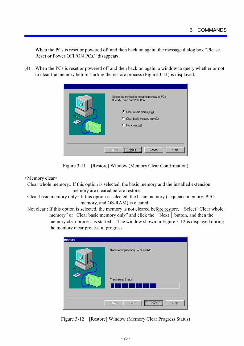
Not clear.: If this option is selected, the memory is not cleared before restore. Select “Clear whole memory” or “Clear basic memory only” and click the Next button, and then the memory clear process is started. The window shown in Figure 3-12 is displayed during the memory clear process in progress.
Figure 3-12 [Restore] Window (Memory Clear Progress Status)

3 COMMANDS
- 26 -
If the Cancel button is clicked on the [Restore] window (memory clear confirmation), the [Restore] window (memory clear confirmation) disappears, returning to the [Restore] window (file selection). If the Help button is clicked on the [Restore] window (memory clear confirmation), the help window appears.
(5) When the memory clear process is completed, you can click the Finish button on the
[Restore] window (memory clear progress status) to finish the process. If the Cancel button is clicked during the memory clear process, the process is aborted halfway (i.e., the memory is cleared partially) and the [Restore] window (memory clear progress status) disappears, returning to the [Restore] window (file selection).
(6) Upon completion of the memory clear process, the message displayed in Step (3) (Figure 3-10)
appears. Reset or power off or on the PCs according to the message. When the window shown in Figure 3-10 disappears, the [BACKUP RESTORE SYSTEM] window (keep coil and counter value information recovery confirmation) is displayed. This window is also displayed when “Not clear” is selected in Step (4).
Figure 3-13 [BACKUP RESTORE SYSTEM] Window (Keep Coil and Counter Value Information Recovery Confirmation)
If the Yes button is clicked, the measurement values of keep coils and counters are recovered at restore time. If the No button is clicked, the measurement values of keep coils and counters are not recovered. Keep coil: Keep relay (blackout hold latch type); one of KW000 through KWFFF. Counter: Up/down counter (counter value); one of CC000 through CC0FF.
(7) When the Yes or No button is clicked on the [BACKUP RESTORE SYSTEM] window
(keep coil and counter value information recovery confirmation) (Figure 3-13), this window disappears and the [Restore] window (restore progress status) (Figure 3-14) is displayed.

3 COMMANDS
- 27 -
Figure 3-14 [Restore] Window (Restore Progress Status)
If the Cancel button is clicked during the restore process, the [Restore] window (restore progress status) disappears, returning to the [Restore] window (file selection) (Figure 3-8). In this case, the restore process is completed halfway and system operations in this status will lead to a malfunction. Retry restore from the beginning. Upon completion of the restore process, the message dialog “Please Reset or Power OFF/ON PCs.” (Figure 3-10) is displayed. If the restore destination is S10mini and the target module is RS-232C, however, the message changes to the message “Reset PCs.”. According to this message, reset the PCs. If the PCs is powered off and then back on again, the LGB table information for RS-232C is not reflected in the system. When the PCs is reset or powered off and then back on again (powering off/on is prohibited for the above RS-232C module), the message dialog box “Please Reset or Power OFF/ON PCs.” disappears and the Finish button is made clickable. Click the Finish button. When the Finish button is clicked, the [Restore] window (restore progress status) disappears, returning to the [Restore] window (file selection).
<NOTICE>
(1) If the error message window shown in Figure 3-15 is displayed during the restore process, the extension memory information is not loaded. The [Extended memory address disagreement] window is displayed when one of the following conditions is met: The top address of extended memory at backup time is smaller than the top address of extended memory installed in the PCs (including the internal extension memory) of restore destination. The last address of extended memory at backup time is smaller than the last address of extended memory installed in the PCs (including the internal extension memory) of restore destination.
The address pairs (top and last) of extension memory should be matched between the backup destination and the restore destination if possible.

3 COMMANDS
- 28 -
Figure 3-15 [Extended memory address disagreement] Window
(2) If one of the message dialogs box shown below is displayed, check the option module installed at the restore destination. These message dialogs may be displayed when the restore destination is S10/2α, S10/2αE, S10/2αH, or S10/2αHf.
Where the F.LINK module is installed at the restore destination, clicking the Yes button loads the F.LINK module information, and clicking the No button does not load it.
Figure 3-16 [BACKUP RESTORE SYSTEM] Window (F.LINK Information Loading Permit Confirmation)
Where the HDLC module is installed at the restore destination, clicking the Yes button loads the HDLC module information, and clicking the No button does not load it.
Figure 3-17 [BACKUP RESTORE SYSTEM] Window (HDLC Information Loading Permit Confirmation)

3 COMMANDS
- 29 -
Where the external serial link module is installed at the restore destination and is used by the H-7338, clicking the Yes button loads the H-7338 information, and clicking the No button does not load it.
Figure 3-18 [BACKUP RESTORE SYSTEM] Window (H-7338 Information Loading Permit Confirmation)
Where the BSC module is installed at the restore destination, clicking the Yes button loads the BSC module information, and clicking the No button does not load the BSC module information.
Figure 3-19 [BACKUP RESTORE SYSTEM] Window (BSC Module Information Loading Permit Confirmation)
Where the external serial link module is installed at the restore destination, clicking the
Yes button loads the external serial link module information, and clicking the No button does not load it.
Figure 3-20 [BACKUP RESTORE SYSTEM] Window (External Serial Link Module Information Loading Permit Confirmation)
(3) Loading of the CPU link information onto the S10mini loads only the PCs edition
information.
(4) Loading of the RS-232C information onto the S10mini loads only the LGB table information.

3 COMMANDS
- 30 -
3.4 Load User Application Function: Loads the specified user application programs into the PCs. Operation: See the operation procedure below.
(1) Click the Load user application button on the [BACKUP RESTORE SYSTEM] window. (2) The [Load user application] window is displayed.
Figure 3-21 [Load user application] Window (3) Select the file to be loaded, and click the Add button. More than one file can be selected
for loading. When the selected file is to be deleted, click the Delete button. After the setting ends, click the OK button. Then, user application loading is started.

3 COMMANDS
- 31 -
3.5 Compare User Application Function: Compares the specified user application programs with its copy in memory of the
PCs. Operation: See the operation procedure below.
(1) Click the Compare user application button on the [BACKUP RESTORE SYSTEM] window. (2) The [Compare user application] window is displayed.
Figure 3-22 [Compare user application] Window (3) Select the file to be compared with its copy in memory of the PCs, and click the Add button.
More than one file can be selected for comparison. When the selected file is to be deleted, click the Delete button. After the setting ends, click the OK button. Then, file comparison is started.

3 COMMANDS
- 32 -
3.6 Backup File Display Function: Displays the contents of a file backed up by the backup/restore system. Operation: See the operaton procedure below.
(1) Click the Backup file display button on the [BACKUP RESTORE SYSTEM] window, and then the [Backup file selection] window is displayed.
Figure 3-23 [Backup file selection] Window
Select the folder containing a backup file you want to display and click the OK button. The [Backup File Display] window (Figure 3-24) is displayed. If any folder other than the backup file folder is selected, the OK button cannot be clicked. If the selected folder is a backup folder, any comment is displayed which was entered at backup time. The comment cannot be edited.

3 COMMANDS
- 33 -
Figure 3-24 [Backup File Display] Window
The [Backup File Display] window presents information when an address specification or PI/O value specification is given. If no information exists for the specified address or PI/O value in the backed up file, however, an error will occur. The display/input/operation items are described below.
<Display items>
PI/O: PI/O value into which an address is translated. If the translation fails, “-----” is displayed.
Address: Address of display data (always in hexadecimal). If no information exists for the
specified address, “000000” is displayed.
File contents: The contents of the 128-byte data read from the specified top address are displayed. The display format (decimal/hexadecimal or Long/Word format) can be selected. For details, see the description under <Operation items>. The contents of this file cannot be rewritten.
ASCII code: The contents of display data are converted into ASCII and displayed as character
strings. If the conversion fails, dots (“.”) are displayed.

3 COMMANDS
- 34 -
<Input items> Top address/PI/O value specification: The beginning of the backup file to be displayed is
specified by an address or IP/O value. Either a top address or a PI/O value is selected in the “Method to specify” group box.
<Operation items>
Method to specify: Select a method to specify a top address. The default is “Specify address.” If the “Specify address” radio button is selected, the entry is a top address specification. If the “Specify symbol” radio button is selected, the entry is a PI/O value specification.
DEC/HEX: Select a display format (decimal or hexadecimal) for display data. The default is
“HEX. .” If the “DEC.” radio button is selected, the display data is displayed in decimal format. If the “HEX.” radio button is selected, the display data is displayed in hexadecimal format. When this radio button is selected, the “SIGN” group box is unselectable.
WORD/LONG: Select a display format for display data. The default is “WORD.” If the
“WORD” radio button is selected, the display data is displayed in WORD format. If the “LONG” radio button is selected, the display data is displayed in LONG format.
SIGN: Select a display format for display data. The default is “SIGNED.” If the “SIGNED”
radio button is selected, the display data is displayed in the signed format. If the “UNSIGNED” radio button is selected, the display data is displayed in the UNSIGNED format.
Close button: The [Backup File Display] window is closed.
Read button: The contents of the 128-byte backup file are read from the specified top
address. However, if a nonexistent top address is specified, a warning message is displayed.

3 COMMANDS
- 35 -
scroll button: The display is moved one row up toward the smallest address from the currently displayed address. A total of 128 bytes of data is displayed from the address obtained by subtracting 8 bytes from the currently displayed address.
scroll button: The display is moved one page up toward the smallest address. A total of
128 bytes of data is displayed from the address obtained by subtracting 128 bytes from the currently displayed address.
scroll button: The display is moved one raw down toward the largest address. A total of
128 bytes of data is displayed from the address obtained by adding 8 bytes to the currently displayed address.
scroll button: The display is moved one page down toward the largest address. A total of
128 bytes of data is displayed from the address obtained by adding 128 bytes to the currently displayed address.
<NOTICE on backup file display>
For backup file display, select only a file that has undergone a backup operation. For any file that has been prepared in any other way, the success of a display operation cannot be guaranteed.

3 COMMANDS
- 36 -
3.7 Change Connection Function: Sets the communication type for the PCs and personal computer. Operation: See the operation procedure below.
(1) Click the Change connection button on the [BACKUP RESTORE SYSTEM] window. (2) The [Communication type] window is displayed.
Figure 3-25 [Communicaton type] Window (Change Connection) (3) When the communication type is RS-232C, click the “RS-232C” radio button and select a
“Communication port.”
Figure 3-26 [Communicaton type] Window (RS-232C Port Selection)

3 COMMANDS
- 37 -
(4) When the communication type is Ethernet, click the “Ethernet” radio button and enter the “IP address” of the destination station to connect with.
Figure 3-27 [Communication type] Window (Ethernet Connection) (5) When the communication type is GP-IB, click the “GPIB” radio button.
Figure 3-28 [Communication type] Window (GP-IB Connection)
NOTE
When connecting a personal computer to the S10mini series, select RS-232C or Ethernet because the S10mini series does not support GP-IB.
(6) After the setting ends, click the OK button. When no setting is to be made, click the
Cancel button.

THIS PAGE INTENTIONALLY LEFT BLANK.

APPENDIXES

APPENDIXES
- 40 -
APPENDIX A BACKUP FILE LIST The following table shows a list of files to be created through backup operations. Some of them may not be created if a module is not installed or under some backup conditions. Files of ET.NET and later are not created through backup operations done by the backup/restore system earlier than its version/revision 08-00.
Table A-1 Backup File List (1/2)
Target module for
backup Backup file name File capacity
(KB) Remarks
F.LINK Backup1.pse 159 to 317 (321 to 641)
ET.LINK Backup2.pse 101 to 201 (513 to 1025)
CRT Backup3.pse 129 to 513 (257 to 1025)
CPU link Backup4.pse 17 to 33 (25 to 49)
Backup5.pse 33 to 65 (33 to 65)
External serial link
Backup6.pse 33 to 65 (33 to 65)
198 (641)
For S10/2α CPU (OS) Backup7.pse
262 (641)
For S10/2αE, S10/2αH, S10/2αHf, S10mini
Backup8.pse Backup9.pse Backup10.pse
Extension memory
Backup11.pse
1 to 1025 (1 to 1025)
The allowable extension memory range to be backed up is /100000 to /4FFFFE. For one single file, data of up to 1 MB can be saved.
ET.NET Backup12.pse ─ (257 to 513)
J.NET Backup13.pse 33 to 65 (257 to 513)
OD.RING Backup14.pse 1 (257 to 513)
FL.NET Backup15.pse 8 to 16 (257 to 513)
Backup16.pse 24 to 47 (81 to 161)
D.NET
Backup17.pse 24 to 47 (81 to 161)

APPENDIXES
- 41 -
Table A-1 Backup File List (2/2)
Target module for backup
Backup file name File capacity(KB)
Remarks
HDLC Backup18.pse 33 to 129 (65 to 257)
1 KB = 1024 bytes. Before listing in this table, any figure with a fraction is changed into a whole number through rounding. The file capacity varies with the number of modules installed. The values in parentheses indicate the capacity range when backup is performed by specifying RAM whole.

APPENDIXES
- 42 -
APPENDIX B BACKUP AREAS Tables B-1, B-2 and B-3 show the memory addresses of each module to be backed up. If “A program and a parameter” is selected by a backup request as an option, the data is saved in accordance with the address ranges listed in Tables B-1 and B-2. If “RAM whole.” is selected, the data is saved in accordance with the address ranges listed in Table B-3. For information on the backup conditions “A program and a parameter.” and “RAM whole.”, see the description under <Changing the save area size> in “3.2 Backup.”
Table B-1 OS Areas To Be Backed Up When “A program and a parameter.” Is Specified
S10/2α S10/2αE, 2αH, 2αHf, S10mini /60000 to /7FFFE /60000 to /7FFFE /E1000 to /E11FE /E1000 to /E11FE /E2000 to /E3FFE /E2000 to /E3FFE /F0600 to /F07FE /F0600 to /F07FE /F1004 to /FFFFE /81000 to /90FFE
─ /91004 to /9FFFE
When “RAM whole.” is specified, the areas from /60000 to /FFFFE are all saved regardless of the above models.

APPENDIXES
- 43 -
Table B-2 Option Module Areas To Be Backed Up When “A program and a parameter.” Is Specified
Module name Module 0 Module 1 Module 2 Module 3
/B00000 to /B177FE /B40000 to /B577FE ─ ─ F.LINK
/F70000 to /F7FFFE /F80000 to /F8FFFE ─ ─
ET.LINK /C00000 to /C18FFE /C80000 to /C98FFE ─ ─
CRT /D00000 to /D1FFFE /D40000 to /D5FFFE /D80000 to /D9FFFE /DC0000 to /DDFFFE
CPU LINK /F08000 to /F0BFFE /F18000 to /F1BFFE ─ ─
EXTERNAL SERIAL LINK
/F48000 to /F4FFE /F58000 to /F5FFFE /F68000 to /F6FFFE /F78000 to /F7FFFE
ET.NET ─ ─ ─ ─
J.NET /A78008 to /A7FFFE /AF8008 to /AFFFFE ─ ─
OD.RING /978002 to /978012 /9F8002 to /9F8012 ─ ─
FL.NET (*) (*) ─ ─
/E30000 to /E35AFE /E70000 to /E75AFE /EB0000 to /EB5AFE /EF0000 to /EF5AFED.NET
/E36000 to /E3608E /E76000 to /E7608E /EB6000 to /EB608E /EF6000 to /EF608E
HDLC /B00000 to /B07FFE /B40000 to /B47FFE /B80000 to /B87FFE /BC0000 to /BC7FFE
(*) The FL.NET addresses are variable.
Table B-3 Option Module Areas To Be Backed Up When “RAM whole.” Is Specified
Module name Module 0 Module 1 Module 2 Module 3
/B00000 to /B3FFFE /B40000 to /B7FFFE ─ ─ F. LINK
/F70000 to /F7FFFE /F80000 to /F8FFFE ─ ─
ET. LINK /C00000 to /C7FFFE /C80000 to /CFFFFE ─ ─
CRT /D00000 to /D3FFFE /D40000 to /D7FFFE /D80000 to /DBFFFE /DC0000 to /DFFFFE
/F04000 to /F05FFE /F14000 to /F15FFE ─ ─ CPU LINK
/F08000 to /F0BFFE /F18000 to /F1BFFE
EXTERNAL SERIAL LINK
/F48000 to /F4FFE /F58000 to /F5FFFE /F68000 to /F6FFFE /F78000 to /F7FFFE
ET.NET /840000 to /87FFFE /8C0000 to /8FFFFE ─ ─
J.NET /A40000 to /A7FFFE /AC0000 to /AFFFFE ─ ─
OD.RING /940000 to /97FFFE /9C0000 to /9FFFFE ─ ─
FL.NET /D40000 to /D7FFFE /DC0000 to /DFFFFE ─ ─
/E00000 to /E03FFE /E40000 to /E43FFE /E80000 to /E83FFE /EC0000 to /EF3FFED.NET
/E30000 to /E3FFFE /E70000 to /E7FFFE /EB0000 to /EBFFFE /EF0000 to /EFFFFE
HDLC /B00000 to /B0FFFE /B40000 to /B4FFFE /B80000 to /B8FFFE /BC0000 to /BCFFFE