Oil-Air Cooler for Splash or Bath Lubrication /OAC1
224
*26609398_1020* Drive Technology \ Drive Automation \ System Integration \ Services Assembly and Operating Instructions Industrial Gear Units Oil-Air Cooler for Splash or Bath Lubrication /OAC1 Edition 10/2020 26609398/EN
-
Upload
khangminh22 -
Category
Documents
-
view
0 -
download
0
Transcript of Oil-Air Cooler for Splash or Bath Lubrication /OAC1

*26609398_1020*Drive Technology \ Drive Automation \ System Integration \ Services
Assembly and OperatingInstructions
Industrial Gear UnitsOil-Air Cooler for Splash or Bath Lubrication /OAC1
Edition 10/2020 26609398/EN

SEW-EURODRIVE—Driving the world
Table of contents
Assembly and Operating Instructions – Oil-Air Cooler for Splash or Bath Lubrication /OAC1 3
Table of contents1 General information.................................................................................................................. 5
1.1 About this documentation ............................................................................................... 51.2 Structure of the safety notes ........................................................................................... 51.3 Rights to claim under limited warranty ............................................................................ 61.4 Decimal separator in numerical values ........................................................................... 71.5 Product names and trademarks...................................................................................... 71.6 Copyright notice .............................................................................................................. 7
2 Safety notes .............................................................................................................................. 82.1 Preliminary information ................................................................................................... 82.2 Duties of the user............................................................................................................ 82.3 Target group ................................................................................................................... 92.4 Designated use ............................................................................................................... 92.5 Other applicable documentation ................................................................................... 102.6 Safety symbols.............................................................................................................. 102.7 Storage and transport conditions .................................................................................. 112.8 Transportation............................................................................................................... 13
3 Oil-air cooler /OAC1................................................................................................................ 143.1 Functional description ................................................................................................... 143.2 Structure ....................................................................................................................... 143.3 Scope of delivery .......................................................................................................... 173.4 Function ........................................................................................................................ 183.5 Nameplate..................................................................................................................... 193.6 Type designation........................................................................................................... 203.7 Hydraulics plan ............................................................................................................. 213.8 Technical data............................................................................................................... 243.9 Dimension sheets ......................................................................................................... 253.10 Interlocking specifications ............................................................................................. 27
4 Installation/assembly ............................................................................................................. 284.1 Mechanical connection ................................................................................................. 284.2 Separate installation ..................................................................................................... 284.3 Electrical connection ..................................................................................................... 314.4 Wiring diagram (schematic illustration) ......................................................................... 324.5 Electrical/optical contamination indicator ...................................................................... 344.6 Limit temperature for startup of the oil cooling system ................................................. 354.7 Notes on checking the oil level ..................................................................................... 35
5 Startup ..................................................................................................................................... 365.1 Notes............................................................................................................................. 365.2 Venting the oil pump ..................................................................................................... 365.3 Flow switch ................................................................................................................... 37
6 Inspection/maintenance......................................................................................................... 386.1 Inspection and maintenance intervals........................................................................... 386.2 Notes............................................................................................................................. 386.3 Checking hose pipes..................................................................................................... 39
2660
9398
/EN
– 1
0/20
20

Table of contents
Assembly and Operating Instructions – Oil-Air Cooler for Splash or Bath Lubrication /OAC14
7 Permitted lubricants............................................................................................................... 407.1 Structure of the tables and abbreviations ..................................................................... 407.2 Explanation of the various lubricants ............................................................................ 417.3 Explanation of the oil supply systems and the oil viscosity........................................... 417.4 Lubricant tables............................................................................................................. 42
8 Malfunctions/remedy.............................................................................................................. 458.1 Notes............................................................................................................................. 458.2 Possible failures/remedy............................................................................................... 458.3 Service .......................................................................................................................... 468.4 Waste disposal.............................................................................................................. 47
9 Supplier documentation......................................................................................................... 489.1 Oil-air-heater LKI - Technical data ................................................................................ 499.2 Transfer Gear Pumps - Operating and Maintenance Instructions ................................ 619.3 Transfer Gear Pumps - Technical data....................................................................... 1269.4 Bimetal thermometer - data sheet............................................................................... 1589.5 Flow switch - Operating instructions ........................................................................... 1649.6 Flow switch - data sheet ............................................................................................. 1779.7 Bourdon tube pressure gauge - data sheet ................................................................ 1809.8 Contamination indicator, operating instructions .......................................................... 1839.9 Single Filter - Operating instructions........................................................................... 1939.10 Duplex filter, operating instructions............................................................................. 2019.11 Pressure sensors - Installation instructions ................................................................ 2119.12 Pressure sensors - data sheet .................................................................................... 218
2660
9398
/EN
– 1
0/20
20
1General informationAbout this documentation
Assembly and Operating Instructions – Oil-Air Cooler for Splash or Bath Lubrication /OAC1 5
1 General information1.1 About this documentation
The documentation at hand is the original.This documentation is an integral part of the product. The documentation is intendedfor all employees who perform work on the product.Make sure this documentation is accessible and legible. Ensure that persons respon-sible for the systems and their operation as well as persons who work on the productindependently have read through the documentation carefully and understood it. If youare unclear about any of the information in this documentation or if you require furtherinformation, contact SEW‑EURODRIVE.
1.2 Structure of the safety notes1.2.1 Meaning of signal words
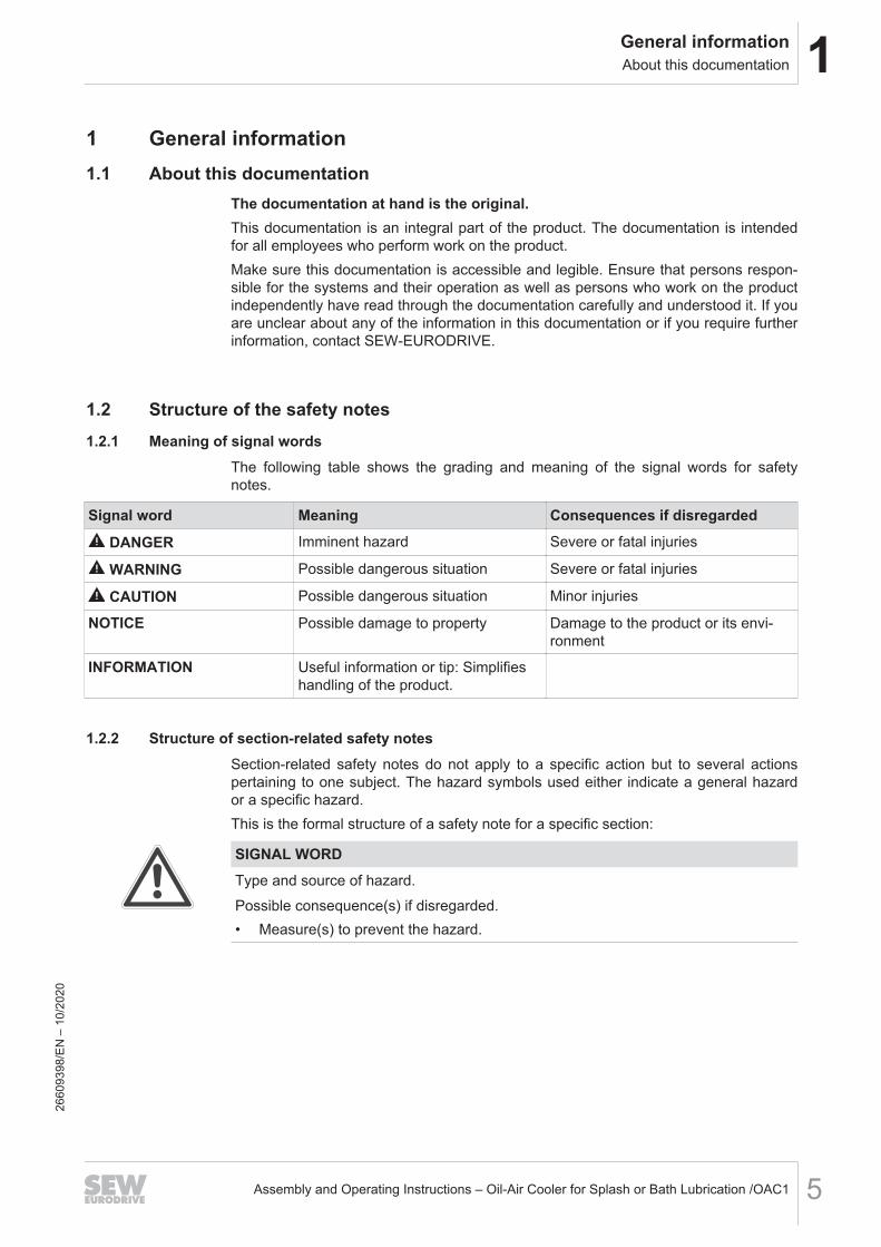
The following table shows the grading and meaning of the signal words for safetynotes.
Signal word Meaning Consequences if disregarded
DANGER Imminent hazard Severe or fatal injuries
WARNING Possible dangerous situation Severe or fatal injuries
CAUTION Possible dangerous situation Minor injuries
NOTICE Possible damage to property Damage to the product or its envi-ronment
INFORMATION Useful information or tip: Simplifieshandling of the product.
1.2.2 Structure of section-related safety notesSection-related safety notes do not apply to a specific action but to several actionspertaining to one subject. The hazard symbols used either indicate a general hazardor a specific hazard.This is the formal structure of a safety note for a specific section:
SIGNAL WORDType and source of hazard.Possible consequence(s) if disregarded.• Measure(s) to prevent the hazard.
2660
9398
/EN
– 1
0/20
20

1 General informationRights to claim under limited warranty
Assembly and Operating Instructions – Oil-Air Cooler for Splash or Bath Lubrication /OAC16
Meaning of the hazard symbolsThe hazard symbols in the safety notes have the following meaning:
Hazard symbol MeaningGeneral hazard
Warning of hot surfaces
Warning about suspended load
Warning of automatic restart
1.2.3 Structure of embedded safety notesEmbedded safety notes are directly integrated into the instructions just before the de-scription of the dangerous action.This is the formal structure of an embedded safety note:
SIGNAL WORD! Type and source of hazard. Possible consequence(s) if disregar-ded. Measure(s) to prevent the hazard.
1.3 Rights to claim under limited warrantyRead the information in this documentation. This is essential for fault-free operationand fulfillment of any rights to claim under limited warranty. Read the documentationbefore you start working with the product.
2660
9398
/EN
– 1
0/20
20

1General informationDecimal separator in numerical values
Assembly and Operating Instructions – Oil-Air Cooler for Splash or Bath Lubrication /OAC1 7
1.4 Decimal separator in numerical values
In this document, a period is used to indicate the decimal separator.Example: 30.5 kg
1.5 Product names and trademarks
The brands and product names in this documentation are trademarks or registeredtrademarks of their respective titleholders.
1.6 Copyright notice
© 2020 SEW‑EURODRIVE. All rights reserved. Unauthorized reproduction, modifica-tion, distribution or any other use of the whole or any part of this documentation isstrictly prohibited.
2660
9398
/EN
– 1
0/20
20
2 Safety notesPreliminary information
Assembly and Operating Instructions – Oil-Air Cooler for Splash or Bath Lubrication /OAC18
2 Safety notes
2.1 Preliminary informationThe following general safety notes serve the purpose of preventing injury to personsand damage to property. They primarily apply to the use of products described in thisdocumentation. If you use additional components, also observe the relevant warningand safety notes.
2.2 Duties of the userAs the user, you must ensure that the basic safety notes are observed and compliedwith. Make sure that persons responsible for the machinery and its operation as wellas persons who work on the device independently have read through the documenta-tion carefully and understood it.As the user, you must ensure that all of the work listed in the following may be carriedout only by qualified specialists:• Setup and installation• Installation and connection• Startup• Maintenance and repairs• Shutdown• DisassemblyEnsure that the persons who work on the product pay attention to the following regula-tions, conditions, documentation, and information:• National and regional safety and accident prevention regulations• Warning and safety signs on the product• All other relevant project planning documents, installation and startup instructions,
and wiring diagrams• Do not assemble, install or operate damaged products• All system-specific specifications and conditionsEnsure that systems in which the product is installed are equipped with additionalmonitoring and protection devices. Observe the applicable safety regulations and leg-islation governing technical work equipment and accident prevention regulations.
2660
9398
/EN
– 1
0/20
20
2Safety notesTarget group
Assembly and Operating Instructions – Oil-Air Cooler for Splash or Bath Lubrication /OAC1 9
2.3 Target group
Specialist for me-chanical work
Any mechanical work may be performed only by adequately qualified specialists. Spe-cialists in the context of this documentation are persons who are familiar with thedesign, mechanical installation, troubleshooting, and maintenance of the product whopossess the following qualifications:• Qualifications in the field of mechanics in accordance with the national regulations• Familiarity with this documentation
Specialist for elec-trotechnical work
Any electrotechnical work may be performed only by electrically skilled persons with asuitable education. Electrically skilled persons in the context of this documentation arepersons who are familiar with electrical installation, startup, troubleshooting, and main-tenance of the product who possess the following qualifications:• Qualifications in the field of electrical engineering in accordance with the national
regulations• Familiarity with this documentation
Additional qualific-ations
In addition to that, these persons must be familiar with the valid safety regulations andlaws, as well as with the requirements of the standards, directives, and laws specifiedin this documentation.The persons must have the express authorization of the company to operate, pro-gram, parameterize, label, and ground devices, systems, and circuits in accordancewith the standards of safety technology.
Instructed persons All work in the areas of transportation, storage, operation and waste disposal must becarried out by persons who are trained appropriately. The purpose of the training is togive persons the ability to perform the required tasks and work steps in a safe and cor-rect manner.
2.4 Designated useThe oil-air cooler /OAC1 is used for conveying and air-cooling the gear unit oil in thelubrication circuit of the gear unit. Adhere to the permitted technical data on the name-plate.Using these products in potentially explosive atmospheres is prohibited, unless spe-cifically designated otherwise.In compliance with the EC Machinery Directive 2006/42/EC, the oil cooling system isan incomplete machine for installation in machinery and systems. In the scope of theEU Directive, you must not take the machinery into operation in the designated fash-ion until you have established that the end product complies with Machinery Directive2006/42/EC.
2660
9398
/EN
– 1
0/20
20

2 Safety notesOther applicable documentation
Assembly and Operating Instructions – Oil-Air Cooler for Splash or Bath Lubrication /OAC110
2.5 Other applicable documentationNote also the following documentation:• "Helical and Bevel-Helical X.. Series Gear Units" operating instructions• Order documents, e.g. dimension sheet, order confirmation, etc.• If required, the operating instructions of the mounted components
2.6 Safety symbols
CAUTIONSafety/caution signs and safety symbols can become dirty or illegible over time.Risk of injury due to illegible symbols.• Always make sure that safety, warning, and operating notes are legible.• Replace damaged safety/caution signs and safety symbols.
The safety symbols on the oil cooling system must be observed. They have the follow-ing meaning:
Safety symbol Meaning
Oil
in
Indicates the oil supply and serves to locate the connection op-tion.
Oil
out
Indicates the oil return and serves to locate the connection op-tion.
2660
9398
/EN
– 1
0/20
20
2Safety notesStorage and transport conditions
Assembly and Operating Instructions – Oil-Air Cooler for Splash or Bath Lubrication /OAC1 11
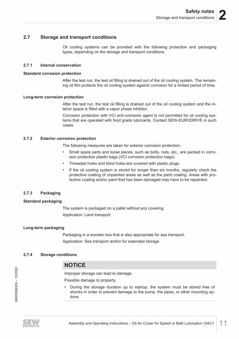
2.7 Storage and transport conditions
Oil cooling systems can be provided with the following protection and packagingtypes, depending on the storage and transport conditions.
2.7.1 Internal conservation
Standard corrosion protectionAfter the test run, the test oil filling is drained out of the oil cooling system. The remain-ing oil film protects the oil cooling system against corrosion for a limited period of time.
Long-term corrosion protectionAfter the test run, the test oil filling is drained out of the oil cooling system and the in-terior space is filled with a vapor phase inhibitor.Corrosion protection with VCI anti-corrosion agent is not permitted for oil cooling sys-tems that are operated with food grade lubricants. Contact SEW‑EURODRIVE in suchcases.
2.7.2 Exterior corrosion protectionThe following measures are taken for exterior corrosion protection:• Small spare parts and loose pieces, such as bolts, nuts, etc., are packed in corro-
sion protection plastic bags (VCI corrosion protection bags).• Threaded holes and blind holes are covered with plastic plugs.• If the oil cooling system is stored for longer than six months, regularly check the
protective coating of unpainted areas as well as the paint coating. Areas with pro-tective coating and/or paint that has been damaged may have to be repainted.
2.7.3 Packaging
Standard packagingThe system is packaged on a pallet without any covering.Application: Land transport
Long-term packagingPackaging in a wooden box that is also appropriate for sea transport.Application: Sea transport and/or for extended storage
2.7.4 Storage conditions
NOTICEImproper storage can lead to damage.Possible damage to property.• During the storage duration up to startup, the system must be stored free of
shocks in order to prevent damage to the pump, the pipes, or other mounting op-tions.
2660
9398
/EN
– 1
0/20
20

2 Safety notesStorage and transport conditions
Assembly and Operating Instructions – Oil-Air Cooler for Splash or Bath Lubrication /OAC112
INFORMATIONThe oil cooling system is delivered without any oil filling as standard; different protec-tion systems are required depending on the storage period and storage conditions asshown in the following table.
Corrosion protection+
packaging
Storage location Storage duration
Standard corrosion pro-tection
+standard packaging
Under a roof and enclosed at constant temperatureand atmospheric humidity (5 °C < ϑ < 60 °C,
< 50% relative humidity).No sudden temperature fluctuations. Controlledventilation with filter (free from dust and dirt). No
aggressive vapors and no shocks.
Max. 6 months with intactsurface protection.
Long-term corrosionprotection
+standard packaging
Under a roof and enclosed at constant temperatureand atmospheric humidity (5 °C < ϑ < 60 °C,
< 50% relative humidity).No sudden temperature fluctuations. Controlledventilation of the storage location with filter (freefrom dust and dirt). No aggressive vapors and no
shocks.
Max. 3 years with regular in-spection and checking for
intactness.
Long-term corrosionprotection
+long-term packaging
Under a roof, protected against rain and free fromshocks.
Max. 3 years with regular in-spection and checking for
intactness.
INFORMATIONIf stored in tropical zones, provide for sufficient protection against insect damage.Contact SEW-EURODRIVE in the case of differing requirements.
2660
9398
/EN
– 1
0/20
20

2Safety notesTransportation
Assembly and Operating Instructions – Oil-Air Cooler for Splash or Bath Lubrication /OAC1 13
2.8 TransportationIf the oil-air cooler is delivered on a base frame, observe the following informationabout transport.If the oil-air cooler is mounted on the gear unit, observe the information about trans-port in the "Helical and Bevel-Helical X.. Series Gear Units" operating instructions.
WARNINGSuspended loads can fall.Severe or fatal injuries.• Do not stand under the suspended load.• Secure the danger zone.• Use suitable, sufficiently rated, and undamaged handling equipment.• Consider the dimensions, the center of gravity, and the weight that has to be
moved when selecting lifting equipment or crane (see dimension drawing).
NOTICEImproper transport may result in damage to the oil-air cooler.Possible damage to property.• Observe the following information.
• Inspect the shipment for any possible transport damage as soon as you receivethe delivery. Inform the shipping company immediately about any damage. In theevent of damage, do not start up the gear unit.
• The oil-air cooler must only be transported in its original packaging or in a suitablereplacement. Ensure that the shipment is securely fastened and tied down.
• The weight of the oil-air cooler (without oil) is indicated on the nameplate or on thedimension sheet. Observe the specified loads and regulations.
• Do not transport the oil-air cooler on the piping.• For transport purposes, the oil-air cooler is suspended at the following four points
[1].
[1]
32364708491
2660
9398
/EN
– 1
0/20
20

3 Oil-air cooler /OAC1Functional description
Assembly and Operating Instructions – Oil-Air Cooler for Splash or Bath Lubrication /OAC114
3 Oil-air cooler /OAC13.1 Functional description
An oil-air cooler /OAC1 is used if the thermal rating of a naturally cooled gear unit orthe cooling via a fan on the input shaft is not sufficient.The motor pump pumps the gear unit oil out of the gear unit and to the oil-air heat ex-changer. The oil is cooled down there and is returned to the gear unit via a returncable.The oil-air coolers /OAC1 are used in gear units with splash or bath lubrication.
3.2 Structure3.2.1 Gear unit in mounting position M1 – mounting surface: Oil-air heat exchanger F2/oil pump
F6The following figures show the gear units in mounting position M1 with the standardmounting surfaces for the oil pump and oil-air heat exchanger.Mounting surfaces deviating from the standard require a new design. This may affectthe minimum oil viscosity. A comprehensive individual check is required. ContactSEW‑EURODRIVE.The oil cooling system is a complete unit mounted directly on the gear unit. The oilcooling system is delivered without any electrical wiring but with piping to the gearunit.
Oil-air cooler /OAC1 without oilfilter
[2]
[3]
[4]
[5]
[1]
[6]
18014419341386379
[1] Oil-air heat exchanger [4] Oil pump
[2] Pressure pipe [5] Suction pipe
[3] Pump motor [6] Fan motor
2660
9398
/EN
– 1
0/20
20

3Oil-air cooler /OAC1Structure
Assembly and Operating Instructions – Oil-Air Cooler for Splash or Bath Lubrication /OAC1 15
Oil-air cooler /OAC1 with oil filter
[2]
[3]
[6a]
[4]
[5]
[1]
[2]
[3]
[4]
[5]
[1]
[7]
[8] [8]
[6b][7]
18014423379869195
[1] Oil-air heat exchanger [6a] Duplex filter
[2] Pressure pipe [6b] Single filter
[3] Pump motor [7] Contamination indicator
[4] Oil pump [8] Fan motor
[5] Suction pipe
2660
9398
/EN
– 1
0/20
20
3 Oil-air cooler /OAC1Structure
Assembly and Operating Instructions – Oil-Air Cooler for Splash or Bath Lubrication /OAC116
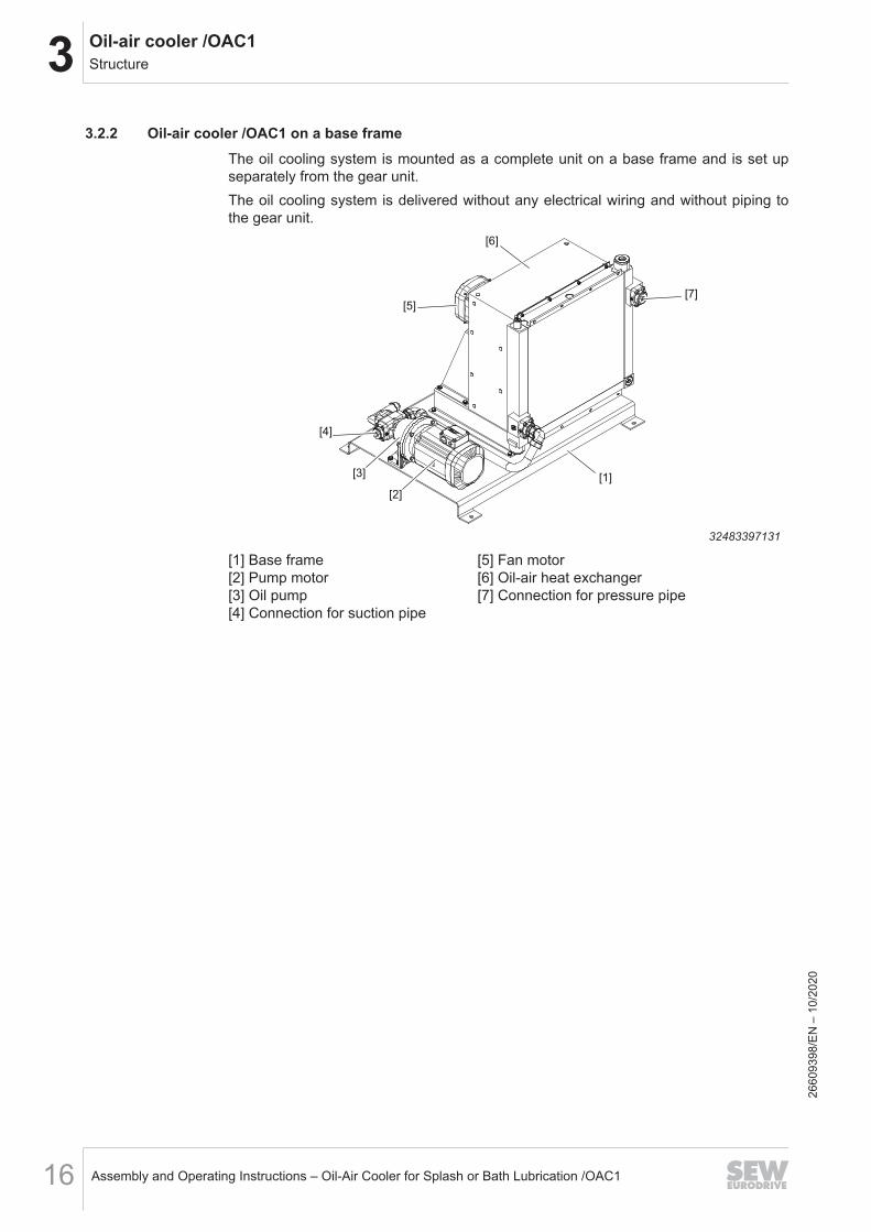
3.2.2 Oil-air cooler /OAC1 on a base frameThe oil cooling system is mounted as a complete unit on a base frame and is set upseparately from the gear unit.The oil cooling system is delivered without any electrical wiring and without piping tothe gear unit.
[1]
[4]
[3]
[2]
[5]
[6]
[7]
32483397131
[1] Base frame [5] Fan motor[2] Pump motor [6] Oil-air heat exchanger[3] Oil pump [7] Connection for pressure pipe[4] Connection for suction pipe
2660
9398
/EN
– 1
0/20
20

3Oil-air cooler /OAC1Scope of delivery
Assembly and Operating Instructions – Oil-Air Cooler for Splash or Bath Lubrication /OAC1 17
3.3 Scope of delivery
3.3.1 Standard designThe scope of delivery consists of the following:• Oil pump with directly mounted asynchronous motor• Fan with directly mounted asynchronous motor• Oil-air heat exchanger• Temperature switch /TSK2 with 2 switching points for
– Controlled start of the oil pump motor and oil-air heat exchanger motors at anoil temperature > 60 °C.
– Monitoring of the oil-air cooler, i.e. warning or gear unit shutdown at an oil tem-perature > 90 °C.
The temperature switch /TSK2 is mounted in the gear unit's oil sump.
3.3.2 Optional accessoriesThe oil cooling system can be equipped with the following components as an option:• PT100 temperature sensor• Oil filter with electrical/optical contamination indicator
– Single filter– Duplex filter
• Gauge mounting block; for installation on the gauge mounting block, the followingare available:– Flow switch– Manometer– Thermometer– Pressure sensor
2660
9398
/EN
– 1
0/20
20

3 Oil-air cooler /OAC1Function
Assembly and Operating Instructions – Oil-Air Cooler for Splash or Bath Lubrication /OAC118
3.4 Function3.4.1 Oil pump/Oil-air heat exchanger
The drive motor of the oil pump and the oil-air heat exchanger is switched on and offdepending on the temperature.When the oil pump is operated, a pressure control valve integrated in the oil-air heatexchanger limits the plant pressure.
INFORMATIONDo not change the default setting of the pressure control valve at the oil pump.
3.4.2 Temperature monitoringThe temperature of the oil cooling system is monitored via a temperature switch /TSK2with defined switching points.Optionally, a PT100 temperature sensor can be used instead of a temperature switch /TSK2 to control the oil cooling system. The evaluation of the temperature signal andthe controlling of the operator's switching devices are performed by the operator's con-troller.Observe the following switching points:• At TOil > 60 °C → Motors of the oil-air cooler – ON• At TOil < 50 °C → Motors of the oil-air cooler – OFF• At TOil > 90 °C → GEAR UNIT STOP/WARNING
3.4.3 Filter (optional)The filter is monitored visually by a pressure deviation indicator, and electrically by apressure deviation monitoring device.When m p > 2.2 bar → WARNING (clean filter)
2660
9398
/EN
– 1
0/20
20

3Oil-air cooler /OAC1Nameplate
Assembly and Operating Instructions – Oil-Air Cooler for Splash or Bath Lubrication /OAC1 19
3.5 NameplateThe following example shows the structure of the nameplate.
76646 Bruchsal/Germany
CLP HC 220 - synthetic oil
Made in Bruchsal / Germany
+10...+40 °C
Type OAC1 16/320-020/M
No. 01.78159301.0001-0002.20
Q-oil
MassTa [°C]
50/60 Hz[l/min] 121/126
9,4 [KW]
[Kg] 1200
m asl. [m] 1000
Year 2020
10,3 [KW]
nom. cooling capacity cal. cooling capacity
[1]
[2]
[3]
[4]
[5]
[7]
[8]
[9]
[10]
[6]
32250765195
[1] Type designation[2] Serial number[3] Oil grade and viscosity class[4] Volume flow 50/60 Hz[5] Cooling capacity:
Nominal cooling capacity at an ambient temperature of 40 °Cand an oil temperature of 70 °C.
[6] Cooling capacity: Calculated cooling capacity with deviating temperatures
[7] Ambient temperature range[8] Installation altitude[9] Mass[10] Year of manufacture
2660
9398
/EN
– 1
0/20
20
3 Oil-air cooler /OAC1Type designation
Assembly and Operating Instructions – Oil-Air Cooler for Splash or Bath Lubrication /OAC120
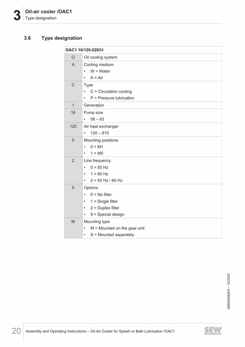
3.6 Type designation
OAC1 16/120-020/MO Oil cooling system
A Cooling medium• W = Water• A = Air
C Type• C = Circulation cooling• P = Pressure lubrication
1 Generation
16 Pump size• 06 – 63
120 Air heat exchanger• 120 – 810
0 Mounting positions• 0 = M1• 1 = M5
2 Line frequency• 0 = 50 Hz• 1 = 60 Hz• 2 = 50 Hz / 60 Hz
0 Options• 0 = No filter• 1 = Single filter• 2 = Duplex filter• 9 = Special design
M Mounting type• M = Mounted on the gear unit• S = Mounted separately
2660
9398
/EN
– 1
0/20
20

3Oil-air cooler /OAC1Hydraulics plan
Assembly and Operating Instructions – Oil-Air Cooler for Splash or Bath Lubrication /OAC1 21
3.7 Hydraulics plan3.7.1 Oil cooling system with duplex filter
The following figure shows an example of the standard device structure of the oil cool-ing system.
M
[1]
[2]
[3]
[6]
M
[5][4]
36028817842783755
[1] Pump motor [4] Fan motor
[2] Oil pump [5] Oil-air heat exchanger
[3] Duplex filter [6] Gear unit
The following figure shows at a glance the possible options that can be installed.
[1] [2]
[3]
[4]
22845975563
[1] Thermometer
[2] Manometer
[3] Flow switch
[4] Pressure sensor
2660
9398
/EN
– 1
0/20
20
3 Oil-air cooler /OAC1Hydraulics plan
Assembly and Operating Instructions – Oil-Air Cooler for Splash or Bath Lubrication /OAC122
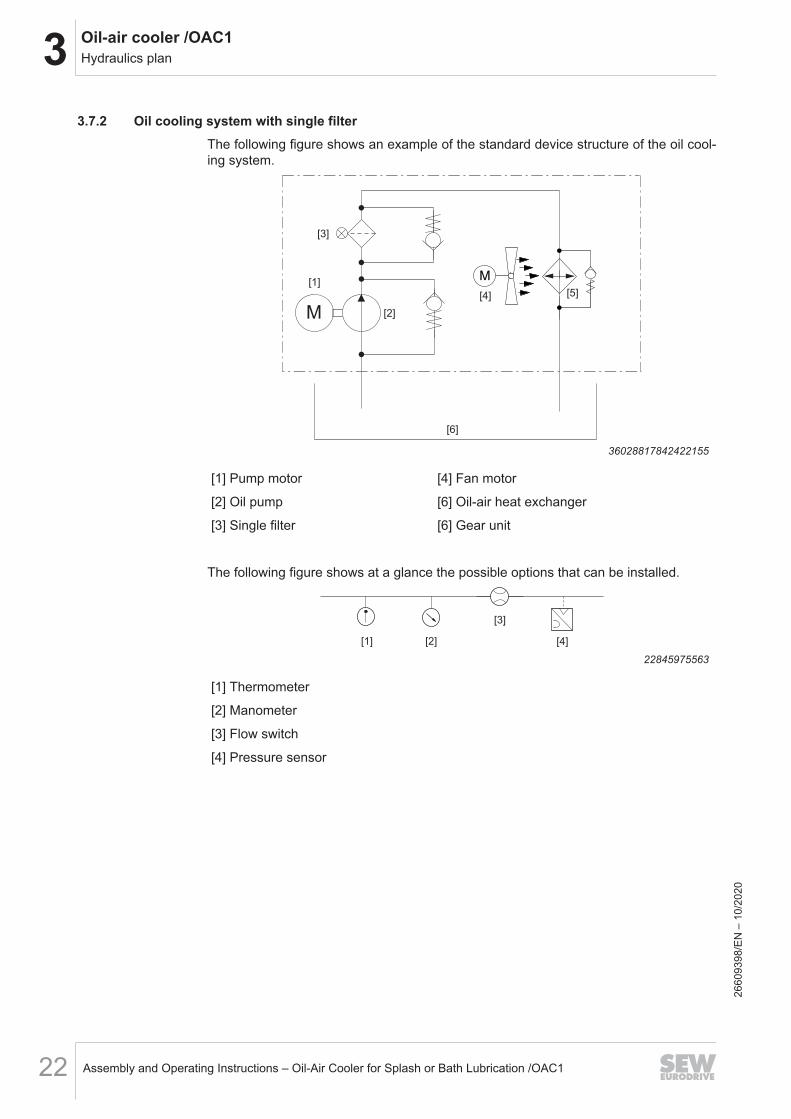
3.7.2 Oil cooling system with single filterThe following figure shows an example of the standard device structure of the oil cool-ing system.
M
[1]
[2]
[3]
[6]
M
[5][4]
36028817842422155
[1] Pump motor [4] Fan motor
[2] Oil pump [6] Oil-air heat exchanger
[3] Single filter [6] Gear unit
The following figure shows at a glance the possible options that can be installed.
[1] [2]
[3]
[4]
22845975563
[1] Thermometer
[2] Manometer
[3] Flow switch
[4] Pressure sensor26
6093
98/E
N –
10/
2020
3Oil-air cooler /OAC1Hydraulics plan
Assembly and Operating Instructions – Oil-Air Cooler for Splash or Bath Lubrication /OAC1 23
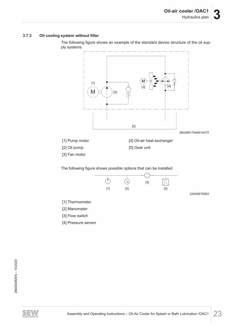
3.7.3 Oil cooling system without filterThe following figure shows an example of the standard device structure of the oil sup-ply systems.
M
[1]
[2]
[5]
M
[4][3]
36028817946814475
[1] Pump motor [4] Oil-air heat exchanger
[2] Oil pump [5] Gear unit
[3] Fan motor
The following figure shows possible options that can be installed.
[1] [2]
[3]
[4]
22845975563
[1] Thermometer
[2] Manometer
[3] Flow switch
[4] Pressure sensor
2660
9398
/EN
– 1
0/20
20

3 Oil-air cooler /OAC1Technical data
Assembly and Operating Instructions – Oil-Air Cooler for Splash or Bath Lubrication /OAC124
3.8 Technical data
The performance data of the standardized oil pump and oil-air heat exchanger is sum-marized in the following tables.
Motor data: Oil pump
Size Oil pumpsize Motor type IEC stan-
dardNumber of
polesMotor power
kWPump capacity at
1500 1/minGlobal motor
HzOAC1 06-120 KF 6 DRN 80MK 4 0.55 8.4
50/60
OAC1 10-220 KF 10 DRN 80M 4 0.75 13.7OAC1 16-320 KF 16 DRN 90S 4 1.1 21.8OAC1 20-420 KF 20 DRN 90L 4 1.5 27.1OAC1 32-420 KF 32 DRN 100ML 4 2.2 43.8OAC1 32-520 KF 32 DRN 100ML 4 2.2 43.8OAC1 50-710 KF 50 DRN 100L 4 4.0 68.2OAC1 63-810 KF 63 DRN 132S 4 5.5 86.2
Motor data: Oil-air heat exchanger
Size Oil-air heat exchanger Motor type IEC standard Number ofpoles
Motor powerkW
Global motorHz
OAC1 06-120 LKI-120 DRN 63M 4 0.18
50/60
OAC1 10-220 LKI-220 DRN 63M 4 0.18OAC1 16-320 LKI-320 DRN 71M 4 0.37OAC1 20-420 LKI-420 DRN 80M 4 0.75OAC1 32-420 LKI-420 DRN 80M 4 0.75OAC1 32-520 LKI-520 DRN 90S 4 1.1OAC1 50-710 LKI-710 DRN 112M 6 1.1OAC1 63-810 LKI-810 DRN 132S 6 2.2
Performancedata: Oil-aircooler /OAC1
The cooling capacity values given in the table apply to an air temperature of 40 °C, anoil temperature of 70 °C, equivalent volume flow of oil and cooling water, mineral oilCLP-CC-320, and 50 Hz line frequency.
SizeCooling capacity
at 40 °C air/70 °C oilkW
Specific cooling capacityat 40 °C air/70 °C oil
kW/°CNoise dB(A)
OAC1 06-120 4.0 0.13 64OAC1 10-220 4.8 0.16 64OAC1 16-320 9.4 0.31 73OAC1 20-420 10.8 0.36 75OAC1 32-420 13.0 0.43 75OAC1 32-520 20.3 0.68 80OAC1 50-710 27.7 0.92 77OAC1 63-810 40.4 1.35 79
2660
9398
/EN
– 1
0/20
20
3Oil-air cooler /OAC1Dimension sheets
Assembly and Operating Instructions – Oil-Air Cooler for Splash or Bath Lubrication /OAC1 25
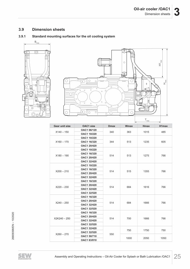
3.9 Dimension sheets3.9.1 Standard mounting surfaces for the oil cooling system
Bmax
Tmax
Hmax
H1max
Gear unit size OAC1 size Dmax Wmax Hmax H1max
X140 – 150OAC1 06/120
340 363 1015 485OAC1 10/220
X160 – 170OAC1 10/220
344 513 1235 605OAC1 16/320OAC1 20/420
X180 – 190
OAC1 10/220
514 513 1275 766OAC1 16/320OAC1 20/420OAC1 32/420
X200 – 210
OAC1 10/220
514 515 1355 766OAC1 16/320OAC1 20/420OAC1 32/420
X220 – 230
OAC1 16/320
514 684 1616 766OAC1 20/420OAC1 32/420OAC1 32/520
X240 – 250
OAC1 16/320
514 684 1666 766OAC1 20/420OAC1 32/420OAC1 32/520
X2K240 – 250
OAC1 16/320
514 700 1666 766OAC1 20/420OAC1 32/420OAC1 32/520
X260 – 270
OAC1 32/420
550750 1750 750
OAC1 32/520OAC1 50/710
1000 2050 1050OAC1 63/81026
6093
98/E
N –
10/
2020
3 Oil-air cooler /OAC1Dimension sheets
Assembly and Operating Instructions – Oil-Air Cooler for Splash or Bath Lubrication /OAC126
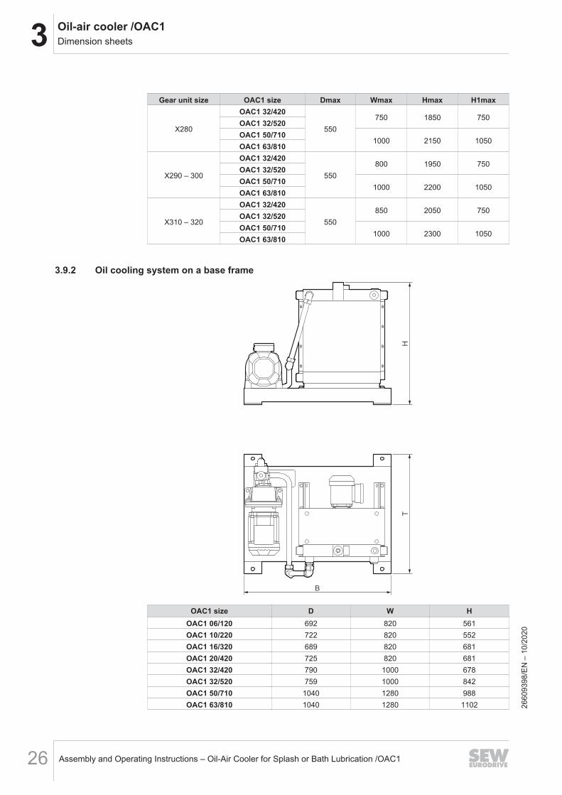
Gear unit size OAC1 size Dmax Wmax Hmax H1max
X280
OAC1 32/420
550750 1850 750
OAC1 32/520OAC1 50/710
1000 2150 1050OAC1 63/810
X290 – 300
OAC1 32/420
550800 1950 750
OAC1 32/520OAC1 50/710
1000 2200 1050OAC1 63/810
X310 – 320
OAC1 32/420
550850 2050 750
OAC1 32/520OAC1 50/710
1000 2300 1050OAC1 63/810
3.9.2 Oil cooling system on a base frame
HT
B
OAC1 size D W HOAC1 06/120 692 820 561OAC1 10/220 722 820 552OAC1 16/320 689 820 681OAC1 20/420 725 820 681OAC1 32/420 790 1000 678OAC1 32/520 759 1000 842OAC1 50/710 1040 1280 988OAC1 63/810 1040 1280 1102 26
6093
98/E
N –
10/
2020
3Oil-air cooler /OAC1Interlocking specifications
Assembly and Operating Instructions – Oil-Air Cooler for Splash or Bath Lubrication /OAC1 27
3.10 Interlocking specifications3.10.1 Enabling of the gear unit
The gear unit is enabled if the following condition is met:• Oil temperature T < 90 °C
3.10.2 STOP gear unit/warningSTOP gear unit/warning if the following condition is met:• Oil temperature T > 90 °C
2660
9398
/EN
– 1
0/20
20

4 Installation/assemblyMechanical connection
Assembly and Operating Instructions – Oil-Air Cooler for Splash or Bath Lubrication /OAC128
4 Installation/assembly4.1 Mechanical connection
Connect the oil cooling system to the gear unit according to the identifying markingsand local regulations.In this respect, observe the following:• Do not reduce the specified pipe cross sections.• It is important that you choose the correct wall thickness and material when select-
ing pipes, hoses and screw fittings. Preferably use screw fittings with non-metallicgaskets.
4.2 Separate installation4.2.1 Notes
Optionally, the oil-air heat exchanger and the gear unit can be installed separately. Inthis case, the oil cooling system is delivered without piping and without electrical wir-ing.Provide for a low-vibration installation site. Install the oil cooling system at the samelevel as the gear unit or lower. If this is not possible, contact SEW‑EURODRIVE.Install the oil cooling system in such a way that input and output air can flow withoutany obstruction. Provide for sufficient ventilation and protection against dirt.
INFORMATIONFor the dimensions of the cooler and detailed technical data, refer to the order docu-ments.
SEW‑EURODRIVE differentiates between the following designs for separate installa-tion.
2660
9398
/EN
– 1
0/20
20
4Installation/assemblySeparate installation
Assembly and Operating Instructions – Oil-Air Cooler for Splash or Bath Lubrication /OAC1 29
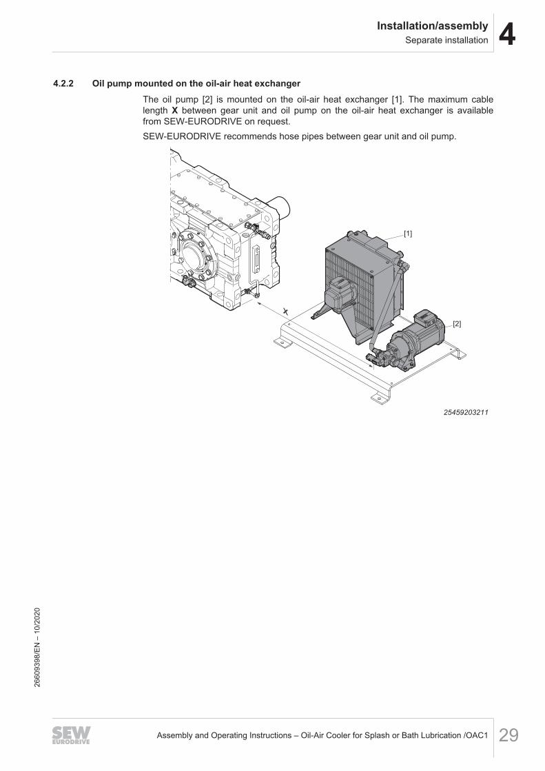
4.2.2 Oil pump mounted on the oil-air heat exchangerThe oil pump [2] is mounted on the oil-air heat exchanger [1]. The maximum cablelength X between gear unit and oil pump on the oil-air heat exchanger is availablefrom SEW‑EURODRIVE on request.SEW‑EURODRIVE recommends hose pipes between gear unit and oil pump.
X
[1]
[2]
25459203211
2660
9398
/EN
– 1
0/20
20
4 Installation/assemblySeparate installation
Assembly and Operating Instructions – Oil-Air Cooler for Splash or Bath Lubrication /OAC130
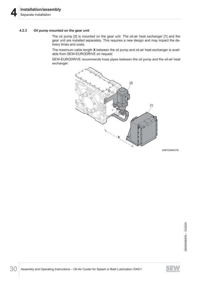
4.2.3 Oil pump mounted on the gear unitThe oil pump [2] is mounted on the gear unit. The oil-air heat exchanger [1] and thegear unit are installed separately. This requires a new design and may impact the de-livery times and costs.The maximum cable length X between the oil pump and oil-air heat exchanger is avail-able from SEW‑EURODRIVE on requestSEW‑EURODRIVE recommends hose pipes between the oil pump and the oil-air heatexchanger.
x
[1]
[2]
24870394379
2660
9398
/EN
– 1
0/20
20
4Installation/assemblyElectrical connection
Assembly and Operating Instructions – Oil-Air Cooler for Splash or Bath Lubrication /OAC1 31
4.3 Electrical connectionObserve country-specific regulations during the electrical connection.With the standard design, connect the following components:• Fan motor• Pump motor• Temperature switch/temperature sensor
Observe the following information.• Make sure that the oil pump and the oil-air heat exchanger rotate in the correct di-
rection.• Observe the motor data sheet.• If a temperature switch /TSK2 is used, it must be integrated in the controller in
such a way that:– The oil pump and oil-air heat exchanger are switched on at the first switching
point (at 60 °C oil temperature).– Either a warning signal is activated or the main drive is switched off at the
second switching point (at 90 °C oil temperature).• If a PT100 temperature sensor is used, it must be integrated in the controller in
such a way that:– The oil pump and the oil-air heat exchanger are switched on at an oil tempera-
ture of 60 °C.– The oil pump and the oil-air heat exchanger are switched off if the oil tempera-
ture drops below 50 °C.– Either a warning signal is issued or the main drive is switched off when the oil
temperature reaches 90 °C.• The contamination indicator of the oil filter indicates when a dirty filter element
needs to be replaced.When using options:• Connect the flow rate sensor to the customer-provided control.
2660
9398
/EN
– 1
0/20
20
4 Installation/assemblyWiring diagram (schematic illustration)
Assembly and Operating Instructions – Oil-Air Cooler for Splash or Bath Lubrication /OAC132
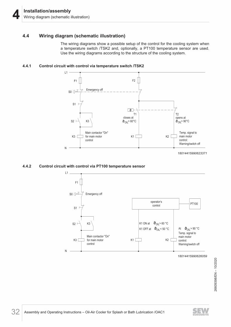
4.4 Wiring diagram (schematic illustration)The wiring diagrams show a possible setup of the control for the cooling system whena temperature switch /TSK2 and, optionally, a PT100 temperature sensor are used.Use the wiring diagrams according to the structure of the cooling system.
4.4.1 Control circuit with control via temperature switch /TSK2
F2F1
L1
N
K1 K2K3
S1
S2 K3
Temp. signal to
main motor
control:
Warning/switch off
Main contactor "On"
for main motor
control
S0Emergency off
T1 T2closes at
> 60°Copens at
OIL > 90°COILϑ ϑ
ϑ
18014415990623371
4.4.2 Control circuit with control via PT100 temperature sensor
K1 ON at
K1 K2
> 60 °C
OIL > 90 °C
Temp. signal to
main motor
control:
Warning/switch off
OILϑ
K1 OFF at < 50 °COILϑ ϑ
operator‘s
control
At
PT100
F1
L1
N
K3
S1
S2 K3
Main contactor "On"
for main motor
control
Emergency offS0
18014415990626059
2660
9398
/EN
– 1
0/20
20

4Installation/assemblyWiring diagram (schematic illustration)
Assembly and Operating Instructions – Oil-Air Cooler for Splash or Bath Lubrication /OAC1 33
4.4.3 Main circuit with separate motors for pump and fan
F4
Switch on at
> 60°C
L1
F3
Main motor
control
L2
L3
M3
PE
K3 K1
Main motor
M1
OIL
Pump motor Fan motor
ϑ
MM2 MM33 3
Signal of contactor K2
or PT100 temperature sensor
Warning/switch-off
via TSK2 temperature switch
18014415990631435
2660
9398
/EN
– 1
0/20
20
4 Installation/assemblyElectrical/optical contamination indicator
Assembly and Operating Instructions – Oil-Air Cooler for Splash or Bath Lubrication /OAC134
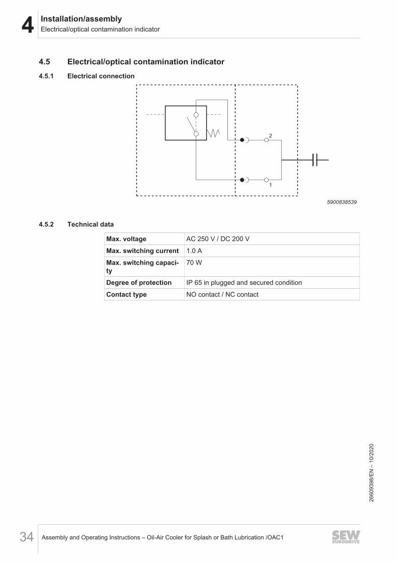
4.5 Electrical/optical contamination indicator4.5.1 Electrical connection
2
1
5900838539
4.5.2 Technical data
Max. voltage AC 250 V / DC 200 V
Max. switching current 1.0 A
Max. switching capaci-ty
70 W
Degree of protection IP 65 in plugged and secured condition
Contact type NO contact / NC contact
2660
9398
/EN
– 1
0/20
20
4Installation/assemblyLimit temperature for startup of the oil cooling system
Assembly and Operating Instructions – Oil-Air Cooler for Splash or Bath Lubrication /OAC1 35
4.6 Limit temperature for startup of the oil cooling systemTo ensure a correct function of the oil cooling system, the gear unit oil must not ex-ceed a maximum oil viscosity. The viscosity depends on the used oil, and on the oiltemperature in the oil pipes/hoses and in the oil pump. Observe chapter "Permitted lu-bricants" (→ 2 40).When the oil cooling system is used at low ambient temperatures, it may be requiredto adjust the cooling system. Contact SEW‑EURODRIVE, if required.
4.7 Notes on checking the oil level
Using an oil cooling system might influence the oil level. The fill quantities specified onthe nameplate are guide values and refer only to the gear unit. The mark on the oildipstick, oil level glass or oil sight glass is the decisive indicator of the correct oil quan-tity.Observe the chapter "Checking the oil level" in the operating instructions for the gearunit.
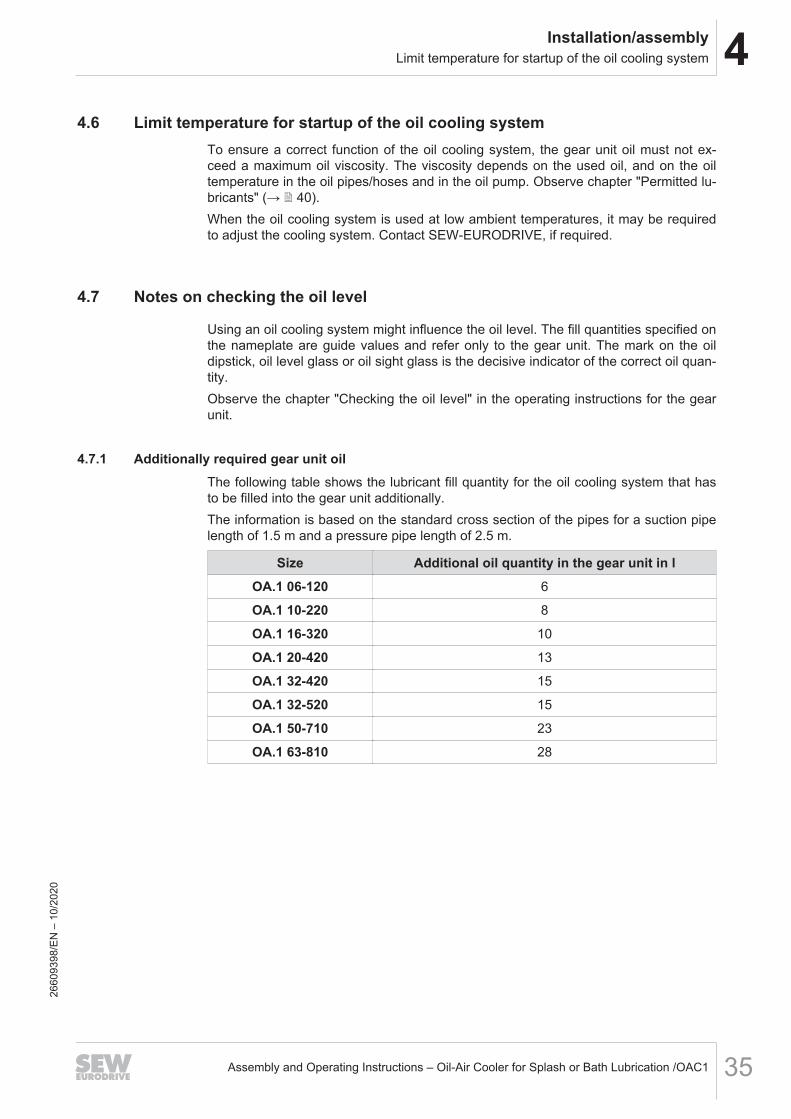
4.7.1 Additionally required gear unit oilThe following table shows the lubricant fill quantity for the oil cooling system that hasto be filled into the gear unit additionally.The information is based on the standard cross section of the pipes for a suction pipelength of 1.5 m and a pressure pipe length of 2.5 m.
Size Additional oil quantity in the gear unit in lOA.1 06-120 6
OA.1 10-220 8
OA.1 16-320 10
OA.1 20-420 13
OA.1 32-420 15
OA.1 32-520 15
OA.1 50-710 23
OA.1 63-810 28
2660
9398
/EN
– 1
0/20
20

5 StartupNotes
Assembly and Operating Instructions – Oil-Air Cooler for Splash or Bath Lubrication /OAC136
5 Startup5.1 Notes
NOTICEImproper startup may result in damage to the gear unit or the oil cooling system.Possible damage to property.• Observe the following information.
• Before startup, check the functionality of the monitoring devices. (Depending onthe types of pressure switch, flow monitor, temperature switch/temperature sensor,contamination indicator, etc.)
• Before starting up the gear unit for the first time and after each oil change, run theoil pump for at least 10 minutes to ensure that all oil chambers are filled with oil.Then switch the oil pump off again and check the oil level within a short period oftime. If necessary, correct the oil level.
• Note that an oil heater is mandatory when operating the oil cooling system at rela-tively low ambient temperatures. For further information, refer to chapter "Limittemperature for startup of the oil cooling system" (→ 2 35).
5.2 Venting the oil pump
WARNINGDanger due to leaking and squirting gear unit oil.Serious injury.• You must wear safety goggles.• Be very careful when you vent the oil pump.
If the oil pump does not supply oil immediately after the start, do the following:• Fill the oil pump with oil.• Vent the oil supply system on the pressure side during start, if possible at the
highest point.26
6093
98/E
N –
10/
2020

5StartupFlow switch
Assembly and Operating Instructions – Oil-Air Cooler for Splash or Bath Lubrication /OAC1 37
5.3 Flow switchObserve the following procedure:1. Connect the flow switch.2. Start up the oil pump.3. Perform the high-flow adjustment and observe the notes in the manufacturer docu-
mentation (see attachment).4. Set the switch-off point of the flow switch to LED 4 or 5 and observe the notes in
the manufacturer documentation.5. Integrate the switching point into the controller in such a way that the gear unit is
switched off if the set switching point (see point 4) is not reached.
2660
9398
/EN
– 1
0/20
20
6 Inspection/maintenanceInspection and maintenance intervals
Assembly and Operating Instructions – Oil-Air Cooler for Splash or Bath Lubrication /OAC138
6 Inspection/maintenance6.1 Inspection and maintenance intervals
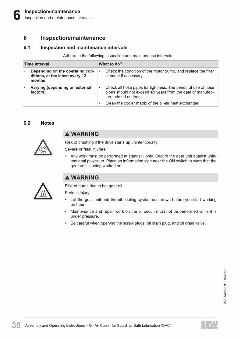
Adhere to the following inspection and maintenance intervals.
Time interval What to do?• Depending on the operating con-
ditions, at the latest every 12months
• Check the condition of the motor pump, and replace the filterelement if necessary.
• Varying (depending on externalfactors)
• Check all hose pipes for tightness. The period of use of hosepipes should not exceed six years from the date of manufac-ture printed on them.
• Clean the cooler matrix of the oil-air heat exchanger.
6.2 Notes
WARNINGRisk of crushing if the drive starts up unintentionally.Severe or fatal injuries.• Any work must be performed at standstill only. Secure the gear unit against unin-
tentional power-up. Place an information sign near the ON switch to warn that thegear unit is being worked on.
WARNINGRisk of burns due to hot gear oil.Serious injury.• Let the gear unit and the oil cooling system cool down before you start working
on them.• Maintenance and repair work on the oil circuit must not be performed while it is
under pressure.• Be careful when opening the screw plugs, oil drain plug, and oil drain valve.
2660
9398
/EN
– 1
0/20
20

6Inspection/maintenanceChecking hose pipes
Assembly and Operating Instructions – Oil-Air Cooler for Splash or Bath Lubrication /OAC1 39
6.3 Checking hose pipes
NOTICEHoses and hose pipes are subject to natural aging even if they are properly storedand used. This is why the period of use is limited.
• The period of use of hose pipes should not exceed 6 years from the date of manu-facture printed on them.
• The operator of the plant is responsible for making sure that hose pipes are re-placed at adequate intervals even if they do not show any signs of safety-relateddefects.
• Have hose pipes checked by a specialist at least once a year to ensure opera-tional safety.
2660
9398
/EN
– 1
0/20
20

7 Permitted lubricantsStructure of the tables and abbreviations
Assembly and Operating Instructions – Oil-Air Cooler for Splash or Bath Lubrication /OAC140
7 Permitted lubricantsThis chapter describes the permitted lubricants and the permitted temperatures for in-dustrial gear units from SEW‑EURODRIVE.
INFORMATION• The standard for viscosity and oil grade is the type of oil that is specified by
SEW‑EURODRIVE in the order (see order confirmation and nameplate).• Contact SEW‑EURODRIVE if you use bio and food grade lubricants or polyglycol
oils.• Check the compatibility of the greases and oils used.• The tables contain the lubricants approved by SEW‑EURODRIVE.• Oils of the same viscosity class from different manufacturers do not have the
same characteristics. In particular, the minimum permitted oil bath temperaturesare manufacturer-specific. These temperatures are specified in the lubricanttables.
• The minimum permitted oil bath temperatures depend on the lubrication typeused. These temperatures are specified in the lubricant tables. The values corres-pond to the maximum viscosity of the individual lubricants.
• The values specified in the lubricant tables apply as of the time of printing of thisdocument. The data of the lubricants are subject to dynamic change on the part ofthe lubricant manufacturers. For the latest information about the lubricants, visit:www.sew-eurodrive.de/lubricants
7.1 Structure of the tables and abbreviations
S0 S0
S0 S0
S0 S0
Optigear
BM 150
Alpha
SP 150
VG 150 1)
VG 320
DIN (ISO)
API
ISO,SAE
NLGI
CLP
VG 220Alpha
SP 220Optigear
BM 220
Alpha
SP 320Optigear
BM 320
-10
+5
+15
+85
-15
0
+10
+75
-20
-5
+5
+65
-20
-5
+5
+65
-15
0
+10
+75
-10
+5
+15
+80
[2]
[1]
18014416429328523
[1] Lubricant type[2] Viscosity class
2660
9398
/EN
– 1
0/20
20

7Permitted lubricantsExplanation of the various lubricants
Assembly and Operating Instructions – Oil-Air Cooler for Splash or Bath Lubrication /OAC1 41
Abbreviations
Icons DesignationCLP = Mineral oil
CLP HC = Synthetic polyalphaolefin (PAO)
E = Ester-based oil
= Mineral lubricant
= Synthetic lubricant
= Lubricant for the food industry (NSF H1-compliant)
OilOil
= Biodegradable oil (lubricant for agriculture, forestry, and water man-agement)
1) = Lubricants may only be used if service factor Fs ≥ 1.3
7.2 Explanation of the various lubricants
SEW070040013
-20
-5
+5
xyz
+65
[5]
[1]
[2]
[3]
[4]
[6]
[7]
18014416413363467
[1] Lowest cold start temperature in °C for splash lubrication1)
[2] Lowest cold start temperature in °C for drives with pumps up to a max. oil vis-cosity of 5000 cSt1)
[3] Lowest cold start temperature in °C for drives with pumps up to a max. oil vis-cosity of 2000 cSt1)
[4] Trade name[5] Manufacturer[6] Highest oil bath temperature in °C2)
[7] Approvals
1) In the case of low temperatures, the oil must be heated to the specified minimum temperature, for ex-ample by using an oil heater. For the maximum permitted oil viscosity per pump type, refer to the follow-ing chapter.
2) Service life is significantly reduced when exceeded. Observe chapter "Lubricant change intervals".
7.3 Explanation of the oil supply systems and the oil viscosityThe motor pump is designed for an oil viscosity of 5000 cSt.
2660
9398
/EN
– 1
0/20
20

7 Permitted lubricantsLubricant tables
Assembly and Operating Instructions – Oil-Air Cooler for Splash or Bath Lubrication /OAC142
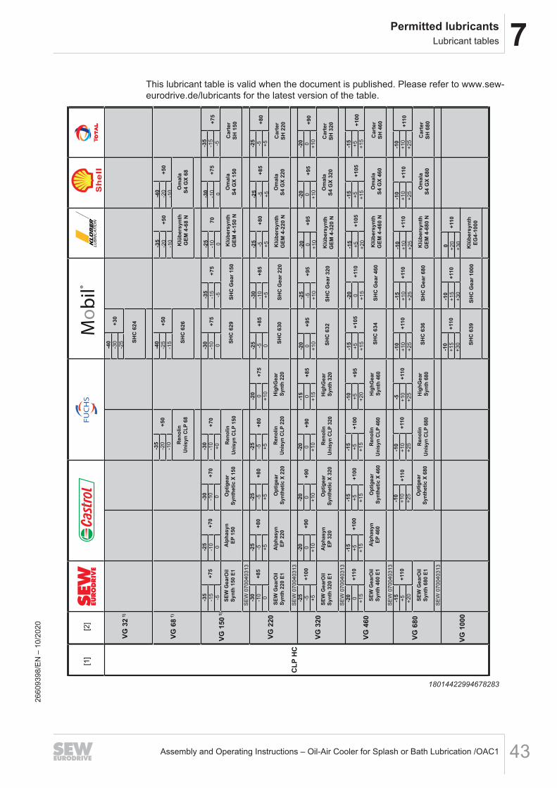
7.4 Lubricant tablesThis lubricant table is valid when the document is published. Please refer to www.sew-eurodrive.de/lubricants for the latest version of the table.
Klü
be
roil
GE
M 1
-15
0 N
Klü
be
roil
GE
M 1
-22
0 N
Klü
be
roil
GE
M 1
-32
0 N
Klü
be
roil
GE
M 1
-46
0 N
Klü
be
roil
GE
M 1
-68
0 N
SEW070030013
Op
tige
ar
BM
15
0
Alp
ha
SP
15
0
VG
15
0 1
)
VG
32
0
CL
P
VG
22
0
VG
46
0
VG
10
00
VG
68
0
0
+15
+25
0
+15
+25
0
+15
+25
0
+15
+25
0
+15
+25
+9
0+
90
Alp
ha
SP
22
0O
ptig
ea
r
BM
22
0
Alp
ha
SP
32
0O
ptig
ea
r
BM
32
0
Alp
ha
SP
68
0
+5
+20
+30
+9
0
Op
tige
ar
BM
10
00
Op
tige
ar
BM
68
0
-5
+10
+20
+9
0
-10
+5
+15
+8
5
-150
+10
+7
5
-20
-5
+5
+6
5
-20
-5
+5
+6
5
-20
-5
+5
+65
-20
-5
+5
+6
5
-20
-5
+5
+6
5
-20
-5
+5
+6
5
-150
+10
+7
5
-150
+10
+75
-150
+10
+7
5
-150
+10
+7
5
-150
+10
+7
5
-150
+10
+75
-150
+10
+7
5
-10
+5
+15
+80
-10
+5
+15
+80
-10
+5
+15
+80
-10
+5
+15
+8
0
-10
+5
+15
+8
0
-10
+5
+15
+80
Op
tige
ar
BM
46
0
-5
+10
+20
+9
0
-5
+10
+20
+9
0
-5
+10
+20
+90
-5
+10
+20
+9
0
-5
+10
+20
+9
0
-5
+10
+20
+90
-5
+10
+20
+9
0
Alp
ha
SP
46
0
+90
+90
Re
no
lin
CL
P 1
50
Plu
s
Re
no
lin
CL
P 2
20
Plu
s
Re
no
lin
CL
P 3
20
Plu
s
Re
no
lin
Hig
hG
ea
r 15
0
Re
no
lin
Hig
hG
ea
r 22
0
Re
no
lin
Hig
hG
ea
r 32
0
Re
no
lin
Hig
hG
ea
r 46
0
Re
no
lin
CL
P 4
60
Plu
s
Re
no
lin
Hig
hG
ea
r 68
0
SEW070040013
SEW070040013
SEW070040013
SEW070040013
SEW070040013
0
+15
+25
-20
-5
+5
+6
5
-150
+10
+7
5
-10
+5
+15
+85
-5
+10
+20
+90
+90
SE
W G
ea
rOil
Ba
se
15
0 E
1
SE
W G
ea
rOil
Ba
se
22
0 E
1
SE
W G
ea
rOil
Ba
se
32
0 E
1
SE
W G
ea
rOil
Ba
se
48
0 E
1
SE
W G
ea
rOil
Ba
se
68
0 E
1
Mo
bilg
ea
r 60
0
XP
68
0
SEW070030013
Mo
bilg
ea
r 60
0
XP
46
0
Re
no
lin
CL
P 6
80
Plu
s
+9
00
+15
+25
+9
00
+15
+25
+9
0
SEW070030013
SEW070030013
SEW070030013
Mo
bilg
ea
r 60
0
XP
15
0
Mo
bilg
ea
r 60
0
XP
22
0
Mo
bilg
ea
r 60
0
XP
32
0
Sh
ell O
ma
la
Oil F
22
0
-10
+5
+15
+8
0
Sh
ell O
ma
la
Oil F
32
0
Sh
ell O
ma
la
Oil F
46
0
Ca
rter E
P 2
20
Ca
rter E
P 3
20
Ca
rter E
P 4
60
Ca
rter E
P 6
80
Mobil®
TO
T A
LS
hll
e
FUCHS
LUBRICATION
[1]
[1]
[2]
SEW070030013
SEW070030013
SEW070030013
SEW070030013
9007223746196107
2660
9398
/EN
– 1
0/20
20
7Permitted lubricantsLubricant tables
Assembly and Operating Instructions – Oil-Air Cooler for Splash or Bath Lubrication /OAC1 43
This lubricant table is valid when the document is published. Please refer to www.sew-eurodrive.de/lubricants for the latest version of the table.
Klü
be
rsy
nth
GE
M 4
-15
0 N
Klü
be
rsy
nth
GE
M 4
-22
0 N
Klü
be
rsy
nth
GE
M 4
-32
0 N
Klü
be
rsy
nth
GE
M 4
-46
0 N
Klü
be
rsy
nth
GE
M 4
-68
0 N
Om
ala
S4
GX
68
0
Alp
ha
sy
n
EP
15
0O
pti
ge
ar
Syn
the
tic
X 1
50
VG
15
0 1
)
VG
68
1)
VG
32
1)
VG
32
0
CL
P H
C
VG
22
0
VG
46
0
VG
10
00
VG
68
0
-10
+1
0
+2
5
-10
+1
0
+2
5
-5 +1
0
+2
5
-10
+1
0
+2
5
+11
0
Op
tig
ear
Syn
the
tic
X 2
20
Alp
ha
sy
n
EP
22
0
Op
tig
ea
rS
yn
the
tic
X 3
20
Alp
ha
sy
n
EP
32
0
Op
tig
ear
Syn
the
tic
X 6
80
-15
+5
+1
5
+1
00
-20
0
+1
0
+9
0
-25
-5 +5
+8
0
-25
-10
0
+7
0-3
0-1
0
0
+7
0-3
0
-10
+0
+7
0-3
0
-10
0
+7
5-2
5
-10
0
70
Klü
be
rsy
nth
GE
M 4
-68
N
-35
-20
-10
+5
0
-25
-5 +5
+8
0-2
5
-5 +5
+8
0-2
0
0
+1
0
+7
5-2
5
-5 0
+8
5-2
5
-5 +5
+8
0
-25
-5 +5
+8
0
-25
-5 +5
+8
5
-20
0
+1
0
+9
0-2
0
0
+1
0
+9
0-1
5
0
+1
5
+8
5-2
0
0
+1
0
+9
5-2
0
0
+1
0
+9
5
-20
0
+1
0+
90
Alp
ha
sy
n
EP
46
0
SE
W G
ea
rOil
Sy
nth
15
0 E
1
SE
W G
ea
rOil
Sy
nth
22
0 E
1
SE
W G
ea
rOil
Sy
nth
32
0 E
1
-20
0
+1
5
+11
0
-25
-5 +5
+1
00
-30
-10
0
+8
5
-35
-15
-5
SE
W 0
70
04
03
13
SE
W 0
70
04
03
13
SE
W 0
70
04
03
13
SE
W 0
70
04
03
13
+7
5
SE
W G
ea
rOil
Syn
th 4
60
E1
-15
+5
+2
0
+11
0
SE
W 0
70
04
03
13
SE
W G
ea
rOil
Syn
th 6
80
E1
-15
+5
+1
5
+1
00
-15
+5
+1
5
+1
00
-10
+5
+2
0
+9
5-1
5
+5
+1
5
+1
05
-15
+5
+2
0
+1
05
-15
+5
+1
5+
10
0
-15
+5
+1
5+
10
5
Op
tig
ear
Syn
the
tic
X 4
60
+11
0+
11
0
Re
no
lin
Un
isy
n C
LP
15
0
-35
-20
-10
+5
0
Re
no
lin
Un
isy
n C
LP
68
Re
no
lin
Un
isy
n C
LP
22
0
Re
no
lin
Un
isy
n C
LP
32
0
Hig
hG
ea
r
Sy
nth
22
0
Hig
hG
ea
r
Sy
nth
32
0
Hig
hG
ea
r
Sy
nth
46
0
Re
no
lin
Un
isy
n C
LP
46
0
Hig
hG
ea
r
Sy
nth
68
0
-20
0
+1
5
+11
0
Re
no
lin
Un
isy
n C
LP
68
0
+11
0
-10
+1
5
+3
0
+11
0-1
0
+1
5
+3
0
+11
00
+2
0
+3
0
Klü
be
rsy
nth
EG
4-1
00
0
+11
0
-15
+1
0
+2
5
+11
0-1
0
+1
0
+2
5
+11
0
-10
+1
0
+2
5+
11
0
-10
+1
0
+2
5+
11
0
-35
-15
-5
+7
5
-40
-25
-15
+5
0
-40
-30
-25
+3
0
-30
-10
+5
+8
5
-25
-5 +1
0
+9
5
Om
ala
S4
GX
22
0
-30
-10
0
+7
5
Om
ala
S4
GX
15
0
-40
-20
-10
+5
0
Om
ala
S4
GX
68
-20
0
+1
0+
95
Om
ala
S4
GX
32
0
Om
ala
S4
GX
46
0
Ca
rte
r
SH
68
0
Ca
rte
r
SH
22
0
Ca
rte
r
SH
15
0
Ca
rte
r
SH
32
0
Ca
rte
r
SH
46
0
-35
-15
-5+
75
SH
C 6
30
SH
C 6
29
SH
C 6
26
SH
C 6
24
SH
C 6
32
SH
C 6
34
SH
C 6
36
SH
C 6
39
SH
C G
ea
r 2
20
SH
C G
ea
r 1
50
SH
C G
ea
r 3
20
SH
C G
ea
r 4
60
SH
C G
ea
r 6
80
SH
C G
ea
r 1
00
0
Mobil
®
TO
T A
LS
hll
e
FUCHS
LUBRICATION
[1]
[2]
18014422994678283
2660
9398
/EN
– 1
0/20
20

7 Permitted lubricantsLubricant tables
Assembly and Operating Instructions – Oil-Air Cooler for Splash or Bath Lubrication /OAC144
This lubricant table is valid when the document is published. Please refer to www.sew-eurodrive.de/lubricants for the latest version of the table.
Klü
be
roil
4U
H1
-68
N
Klü
be
roil
4U
H1
-22
0 N
Klü
be
roil
4U
H1
-46
0 N
Klü
be
rbio
CA
2-4
60
S2
S2
SE
W 0
70
04
03
13
SE
W 0
70
04
02
13
SE
W 0
70
04
03
13
SE
W 0
70
04
03
13
Op
tileb
HY
68
VG
68
1)
VG
46
0 1
)
CL
P H
C
NS
F H
1
E
VG
22
0 1
)
VG
46
0
Op
tileb
GT
22
0
Op
tileb
GT
46
0
-15
+5
+2
0
+9
5
-25
-5
+5
+7
5
-40
-25
-15
+4
5
-35
-20
-10
+4
5
-25
-5
+5
+7
5
-15
+5
+1
5
+9
5
Ca
ss
ida
Flu
id H
F 6
8
Ca
ss
ida
Flu
id G
L 2
20
Ca
ss
ida
Flu
id G
L 4
60
-15
+5
+2
0
+9
0
-20
-5
+5
+7
5
-35
-20
-10
+4
5
-15
+5
+1
5
+9
5
-15
+5
+1
5
+9
5
Pla
nto
ge
ar
46
0 S
FUCHS
LUBRICATION
SE
W G
ea
rOil
Sy
nth
22
0 H
1 E
1
SE
W G
ea
rOil
Sy
nth
46
0 H
1 E
1
-200
+1
5
+1
00
-30
-50
+8
0
Oil
Oil
[2]
[3]
[1]
Ca
ss
ida
Flu
id H
F 6
8
Ca
ss
ida
Flu
id G
L 2
20
Ca
ss
ida
Flu
id G
L 4
60
-15
+5
+2
0
+9
0
-20
-5
+5
+7
5
-35
-20
-10
+4
5
18014423000953611
2660
9398
/EN
– 1
0/20
20

8Malfunctions/remedyNotes
Assembly and Operating Instructions – Oil-Air Cooler for Splash or Bath Lubrication /OAC1 45
8 Malfunctions/remedy8.1 Notes
WARNINGRisk of crushing if the drive starts up unintentionally.Severe or fatal injuries.• Any work must be performed at standstill only. Secure the gear unit against unin-
tentional power-up. Place an information sign near the ON switch to warn that thegear unit is being worked on.
WARNINGRisk of burns due to hot gear oil.Serious injury.• Let the gear unit and the oil cooling system cool down before you start working
on them.• Maintenance and repair work on the oil circuit must not be performed while it is
under pressure.• Be careful when opening the screw plugs, oil drain plug, and oil drain valve.
8.2 Possible failures/remedy
Fault Possible cause MeasureNo oil pump suction • Air in the pipes • Fill the suction line and oil pump with oil
• Vent pressure pipe on startup
• Not enough oil in the gear unit • Check oil level in gear unit
• Wrong oil grade in the gear unit • Check oil grade (in particular whentemperatures are low)
• Motor not running • Check electrical connections
• Wrong direction of rotation of themotor
• Change the direction of rotation
Delivery rate of oilpump not sufficient
• Oil circulation clogged • Open valves and plugs
• Wrong oil grade • Check oil grade (in particular whentemperatures are low)
• Wrong motor speed • Check pump motor speed
• Negative pressure at pump suc-tion side too high
• Increase cross section of suction line• Decrease suction lift
Oil pump very loud • Negative pressure at pump suc-tion side too high
• Increase cross section of suction line
• Decrease suction lift
• Avoid distortion of the suction line
• Avoid reductions in the suction pipes
2660
9398
/EN
– 1
0/20
20

8 Malfunctions/remedyService
Assembly and Operating Instructions – Oil-Air Cooler for Splash or Bath Lubrication /OAC146
Fault Possible cause MeasureOil pump delivers froth • Not enough oil in the gear unit • Check oil level in gear unit
• Suction line leaking • Check screw fittings for leaks
Oil leakage at oil pump • Wear on the oil seal • Renew oil seal
• Wrong direction of rotation• Wrong sealing material
• Check direction of rotation• Check operating conditions
Cooling capacity is notreached
• Air temperature higher than di-mensioned
• Use larger cooler
Insufficient air flow • Lamella blocked • Clean cooler matrix
• Obstacles in the vicinity • Adhere to minimum clearance
8.3 Service
Please have the following information available if you require customer serviceassistance:• Complete nameplate data• Type and extent of the malfunction• Time the problem occurred and any accompanying circumstances• Assumed cause• If possible video and audio recordings
2660
9398
/EN
– 1
0/20
20

8Malfunctions/remedyWaste disposal
Assembly and Operating Instructions – Oil-Air Cooler for Splash or Bath Lubrication /OAC1 47
8.4 Waste disposalDispose of the product and all parts separately in accordance with their material struc-ture and the national regulations. Put the product through a recycling process or con-tact a specialist waste disposal company. If possible, divide the product into the follow-ing categories:• Iron, steel or cast iron• Stainless steel• Aluminum• Copper• PlasticsThe following materials are hazardous to health and the environment. These materialsmust be collected and disposed of separately.• Oil and grease
Collect used oil and grease separately according to type. Ensure that the used oilis not mixed with solvent. Dispose of used oil and grease correctly.
2660
9398
/EN
– 1
0/20
20
9 Supplier documentation
Assembly and Operating Instructions – Oil-Air Cooler for Splash or Bath Lubrication /OAC148
9 Supplier documentation
Table of Contents2 Oil-air-heater LKI - Technical data ....................................................................... 492 Transfer Gear Pumps - Operating and Maintenance Instructions........................ 612 Transfer Gear Pumps - Technical data .............................................................. 1262 Bimetal thermometer - data sheet ...................................................................... 1582 Flow switch - Operating instructions................................................................... 1642 Flow switch - data sheet..................................................................................... 1772 Bourdon tube pressure gauge - data sheet........................................................ 1802 Contamination indicator, operating instructions ................................................. 1832 Single Filter - Operating instructions .................................................................. 1932 Duplex filter, operating instructions .................................................................... 2012 Pressure sensors - Installation instructions........................................................ 2112 Pressure sensors - data sheet ........................................................................... 218
2660
9398
/ EN
– 1
0/20
20
9Supplier documentation
Assembly and Operating Instructions – Oil-Air Cooler for Splash or Bath Lubrication /OAC1 49
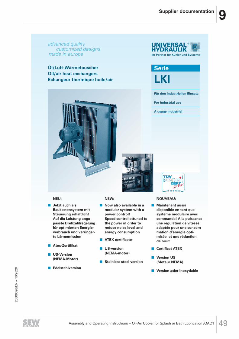
made in europe
advanced qualitycustomized designs
Ihr Partner für Kühler und Systeme
NEU:
Jetzt auch als Baukastensystem mit Steuerung erhältlich!Auf die Leistung ange-passte Drehzahlregelung für optimierten Energie-verbrauch und verringer-te Lärmemission
Atex-Zertifikat
US-Version (NEMA-Motor)
Edelstahlversion
NEW:
Now also available in a modular system with a power control!Speed control attuned tothe power in order to reduce noise level and energy consumption
ATEX certificate
US-version (NEMA-motor)
Stainless steel version
NOUVEAU:
Maintenant aussi disponible en tant que système modulaire avec commande! A la puissance une régulation de vitesse adaptée pour une consommation d‘énergie opti-misée et une réduction de bruit
Certificat ATEX
Version US(Moteur NEMA)
Version acier inoxydable
Öl/Luft-WärmetauscherOil/air heat exchangersEchangeur thermique huile/air
Serie
LKIFür den industriellen Einsatz
For industrial use
A usage industriel
2660
9398
/EN
– 1
0/20
20
9 Supplier documentation
Assembly and Operating Instructions – Oil-Air Cooler for Splash or Bath Lubrication /OAC150
Ihr Partner für Kühler und Systeme
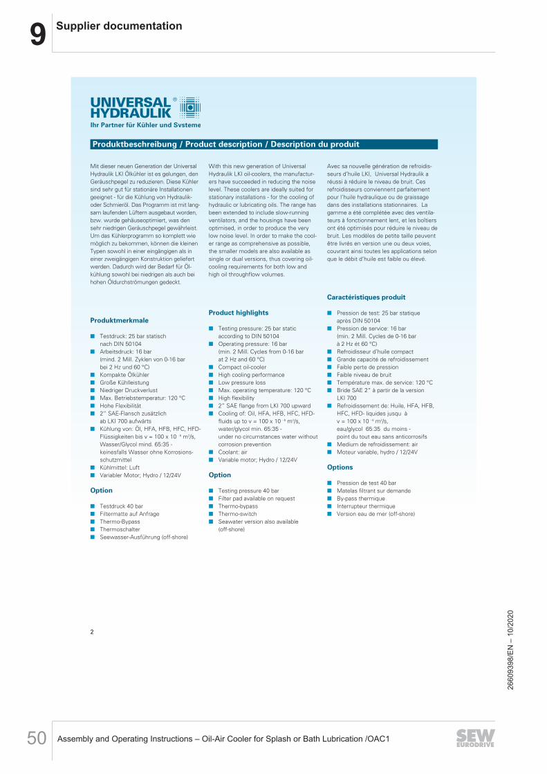
Mit dieser neuen Generation der UniversalHydraulik LKI Ölkühler ist es gelungen, denGeräuschpegel zu reduzieren. Diese Kühlersind sehr gut für stationäre Installationengeeignet - für die Kühlung von Hydraulik-oder Schmieröl. Das Programm ist mit lang-sam laufenden Lüftern ausgebaut worden,bzw. wurde gehäuseoptimiert, was densehr niedrigen Geräuschpegel gewährleist.Um das Kühlerprogramm so komplett wiemöglich zu bekommen, können die kleinenTypen sowohl in einer eingängigen als ineiner zweigängigen Konstruktion geliefertwerden. Dadurch wird der Bedarf für Öl -kühlung sowohl bei niedrigen als auch beihohen Öldurchströmungen gedeckt.
Produktmerkmale
Testdruck: 25 bar statisch nach DIN 50104
Arbeitsdruck: 16 bar(mind. 2 Mill. Zyklen von 0-16 bar bei 2 Hz und 60 °C)
Kompakte Ölkühler Große Kühlleistung Niedriger Druckverlust Max. Betriebstemperatur: 120 °C Hohe Flexibilität 2“ SAE-Flansch zusätzlich
ab LKI 700 aufwärts Kühlung von: Öl, HFA, HFB, HFC, HFD-
Flüssigkeiten bis v = 100 x 10 - 6 m2/s, Wasser/Glycol mind. 65:35 - keinesfalls Wasser ohne Korrosions-schutzmittel
Kühlmittel: Luft Variabler Motor; Hydro / 12/24V
Option
Testdruck 40 bar Filtermatte auf Anfrage Thermo-Bypass Thermoschalter Seewasser-Ausführung (off-shore)
With this new generation of UniversalHydraulik LKI oil-coolers, the manufactur-ers have succeeded in reducing the noiselevel. These coolers are ideally suited forstationary installations - for the cooling ofhydraulic or lubricating oils. The range hasbeen extended to include slow-runningventilators, and the housings have beenoptimised, in order to produce the verylow noise level. In order to make the cool-er range as comprehensive as possible,the smaller models are also available assingle or dual versions, thus covering oil-cooling requirements for both low and high oil throughflow volumes.
Product highlights
Testing pressure: 25 bar staticaccording to DIN 50104
Operating pressure: 16 bar(min. 2 Mill. Cycles from 0-16 bar at 2 Hz and 60 °C)
Compact oil-cooler High cooling performance Low pressure loss Max. operating temperature: 120 °C High flexibility 2” SAE flange from LKI 700 upward Cooling of: Oil, HFA, HFB, HFC, HFD-
fluids up to v = 100 x 10 - 6 m2/s, water/glycol min. 65:35 - under no circumstances water without corrosion prevention
Coolant: air Variable motor; Hydro / 12/24V
Option
Testing pressure 40 bar Filter pad available on request Thermo-bypass Thermo-switch Seawater version also available
(off-shore)
Avec sa nouvelle génération de refroidis-seurs d’huile LKI, Universal Hydraulik aréussi à réduire le niveau de bruit. Cesrefroidisseurs conviennent parfaitementpour l’huile hydraulique ou de graissagedans des installations stationnaires. Lagamme a été complétée avec des ventila-teurs à fonctionnement lent, et les boîtiersont été optimisés pour réduire le niveau debruit. Les modèles de petite taille peuventêtre livrés en version une ou deux voies,couvrant ainsi toutes les applications selonque le débit d’huile est faible ou élevé.
Caractéristiques produit
Pression de test: 25 bar statiqueaprès DIN 50104
Pression de service: 16 bar(min. 2 Mill. Cycles de 0-16 bar à 2 Hz ét 60 °C)
Refroidisseur d’huile compact Grande capacité de refroidissement Faible perte de pression Faible niveau de bruit Température max. de service: 120 °C Bride SAE 2“ à partir de la version
LKI 700 Refroidissement de: Huile, HFA, HFB,
HFC, HFD- liquides jusqu à v = 100 x 10 - 6 m2/s, eau/glycol 65:35 du moins - point du tout eau sans anticorrosifs
Medium de refroidissement: air Moteur variable, hydro / 12/24V
Options
Pression de test 40 bar Matelas filtrant sur demande By-pass thermique Interrupteur thermique Version eau de mer (off-shore)
Produktbeschreibung / Product description / Description du produit
2
2660
9398
/EN
– 1
0/20
20

9Supplier documentation
Assembly and Operating Instructions – Oil-Air Cooler for Splash or Bath Lubrication /OAC1 51
Ihr Partner für Kühler und Systeme
36 x QV Öl
36 x 935
Berechnungsbeispiel / Example calculation / Exemple de calcul
Beispiel 1:(wenn die Kühlleistung bekannt ist)Kühlleistung = 65 kWMax. Öltemperatur = 70°CUmgebungstemperatur = 30°CÖldurchströmung = 250 l/minSpez. Kühlleistung:
= 1,63 kW/°C
Wahl: LKI-710-400-6 oder LKI 810-400-8.Die Wahl hängt von eventuellen Geräusch-begrenzungen ab.
Beispiel 2:(wenn die Kühlleistung nicht bekannt ist)Normalerweise gibt es eine Wärmeabgabezum Öl von 25-30% der Motorleistung(Dieselmotor oder E-Motor)Motorleistung = 30 kWKühlleistung (0,3 x 30kW) = 9,0 kWMax. Öltemperatur = 60°CUmgebungstemperatur = 30°CÖldurchströmung = 250 l/minSpez. Kühlleistung:
= 0,3 kW/°C
Wahl: LKI-210-400-2 oder LKI 310-400-6.Die Wahl hängt von eventuellen Geräusch-begrenzungen ab.
Ölabkühlung:
Δt Öl = = = 9,26 °C
Q = Kühlleistung [ kW ]T Öl = max. Öltemperatur [ °C ]T umg = Umgebungstemperatur [ °C ]V Öl = Öldurchströmung [ l/min ]
QTÖl - Tumg
6570 - 30
QTÖl - Tumg
960 - 30
36 x QV Öl
36 x 935
Example 1:(if required cooling performance is known)Cooling performance = 65 kWMax. oil temperature = 70°CAmbient temperature = 30°COil throughflow = 250 l/minSpecial cooling performance:
= 1,63 kW/°C
Options: LKI-710-400-6 or LKI 810-400-8.The choice depends on any possible noiserestrictions.
Example 2:(if the required cooling performance is notknown). Normally there is a heat transferto the oil of 25-30% of the motor perfor-mance (diesel motor or electric motor)Motor performance = 30 kWCooling performance(0,3 x 30kW) = 9,0 kWMax. oil temperature = 60°CAmbient temperature = 30°COil throughflow = 250 l/minSpecial cooling performance:
= 0,3 kW/°C
Options: LKI-210-400-2 or LKI 310-400-6.The choice depends on any possible noiserestrictions.
Oil cooling:
Δt Öl = = = 9,26 °C
Q = Cooling performance [ kW ]T Öl = max. oil temperature [ °C ]T umg = Ambient temperature [ °C ]V Öl = Oil throughflow [ l/min ]
QTÖl - Tumg
6570 - 30
QTÖl - Tumg
960 - 30
36 x QV Öl
36 x 935
Exemple 1:(la capacité de refroidissement est connue)Capacité de refroidissement = 65 kWTempérature d’huile max. = 70 °CTempérature ambiante = 30 °CDébit d’huile = 250 l/minCapacité de refroidissement spéc.:
= 1,63 kW/°C
Modèle: LKI-710-400-6 ou LKI 810-400-8.Le choix dépend du niveau de bruit requis.
Exemple 2:(la capacité de refroidissement n’est pasconnue). En règle générale, le dégagementde chaleur vers l’huile est de 25-30% durendement du moteur (moteur diesel oumoteur électrique)
Rendement moteur = 30 kWCapacité de refroidissement(0,3 x 30 kW) = 9,0 kWTempérature d’huile max. = 60 °CTempérature ambiante = 30 °CDébit d’huile = 250 l/minCapacité de refroidissement speciale:
= 0,3 kW/°C
Modèle: LKI-210-400-2 ou LKI 310-400-6.Le choix dépend du niveau de bruit requis.
Refroidissement d’huile:
Δt Öl = = = 9,26 °C
Q = Refroidissement de l’huile [ kW ]T Öl = Température d’huile max. [ °C ]T umg = Température ambiante [ °C ]V Öl = Débit d’huile [ l/min ]
QTÖl - Tumg
6570 - 30
QTÖl - Tumg
960 - 30
Korrekturfaktor für den Druckverlust bei anderen Viskositäten:
Δ p Öl = Δ p 30cSt x f
Correction factor for the pressure loss for other viscosities:
Δ p Öl = Δ p 30cSt x f
Facteur de correction de la perte de pression pour d’autres viscosités:
Δ p Öl = Δ p 30cSt x f
3
2660
9398
/EN
– 1
0/20
20

9 Supplier documentation
Assembly and Operating Instructions – Oil-Air Cooler for Splash or Bath Lubrication /OAC152
Ihr Partner für Kühler und Systeme
Kennlinien / Performance Data / Courbes caractéristiques LKI 110 - 1010
Die Berechnung der spezifischen Kühllei-stungen gründet auf einer Öltemperaturvon 60°C, einer Umgebungs temperaturvon 20°C – und damit einem Temperatur-unterschied von 40°C. Die Werte geltenfür Hydrauliköl ISO VG32 mit 30 cSt. FürAbweichungen wird Δp mit dem Korrektur-faktor f aus dem Diagramm auf Seite 3multipliziert.
The calculation of the specific cooling per-formance is based on an oil temperature of60°C, an ambient temperature of 20°C –and therefore a temperature difference of40°C. The figures apply to ISO VG32hydraulic oil with 30 cSt. For variances, Δpis multiplied by the correction factor f fromthe diagram on Page 3.
Le calcul des capacités de refroidissementest basé sur une température d’huile de60° C et une température ambiante de 20°C, soit une différence de température de40°C. Les valeurs correspondent à l’utilisa-tion d’huile hydraulique ISO VG32 , visco-sité 30 cSt. Pour d’autres valeurs, on multi-plie Δp par le facteur de correction f du dia-gramme de la page 3.
4
2660
9398
/EN
– 1
0/20
20

9Supplier documentation
Assembly and Operating Instructions – Oil-Air Cooler for Splash or Bath Lubrication /OAC1 53
Ihr Partner für Kühler und Systeme
LKI-100/200
Technische Daten / Technical data / Données techniques
94 (LKI 210/220)
63 (LKI 110/120) 175 208 (Motor 0,37 kW; 2-polig)
183 (Motor 0,18 kW; 4-polig)
Anhebe- undTransportpunkte (M8)
1818350
345
G 1"
G 1"
G 1"
310
336
11
11
360
430
Ölausgangalle Kühler
ÖleingangLKI 120/220
ÖleingangLKI 110/210
Typmodelmodele
LKI-110-400V-2
LKI-120-400V-2
LKI-110-400V-4
LKI-120-400V-4
LKI-210-400V-2
LKI-220-400V-2
LKI-210-400V-4
LKI-220-400V-4
MotorleistungMotor performanceMoteur puissance
kW
0,37
0,37
0,18
0,18
0,37
0,37
0,18
0,18
StromaufnahmePower consumptionPuissance absorbée
A
0,88
0,88
0,58
0,58
0,88
0,88
0,58
0,58
DrehzahlRevolutionsVitesse rotation
min-1
3000
3000
1500
1500
3000
3000
1500
1500
LuftdurchsatzAir throughflowDébit d`air
m3/s
1,29
1,29
0,49
0,49
1,18
1,18
0,50
0,50
Schallpegel*Noise level*Niveau acoustique*
1m/7m (dBA)
77/62
77/62
64/50
64/50
79/64
79/64
64/50
64/50
GewichtWeightPoids
kg
17
17
17
17
20
20
20
20
Abmessungen / Dimensions
Kühlleistung / Cooling performance / Puissance de refroidissement Druckabfall / Pressure loss / Baisse de pression
LKI 100 - 600: Öl-Anschlusse Innengewinde seitlich / lateral internal-thread oil connections / Raccordements d’huile à filetage intérieur latéral
5
* kann aufgrund von Raumcharakteristik, Eigenfrequenzen, Öl-Verbindungen, Viskositäten etc. um ±3 dB(A) variieren.* may vary by ±3 dB(A) due to room characteristics, own frequencies, oil connections, viscosities etc.* en raison des caractéristiques spatiales, des résonances propres, des composés d`huile, des viscosités etc., peut varier de ±3 dB(A).
2660
9398
/EN
– 1
0/20
20

9 Supplier documentation
Assembly and Operating Instructions – Oil-Air Cooler for Splash or Bath Lubrication /OAC154
Ihr Partner für Kühler und Systeme
Kühlleistung / Cooling performance / Puissance de refroidissement
Technische Daten / Technical data / Données techniquesTypmodelmodelekW
LKI-310-400V-4
LKI-320-400V-4
LKI-310-400V-6
LKI-320-400V-6
LKI-410-400V-4
LKI-420-400V-4
LKI-410-400V-6
LKI-420-400V-6
MotorleistungMotor performanceMoteur puissance
kW
0,37
0,37
0,12
0,12
0,37
0,37
0,12
0,12
StromaufnahmePower consumptionPuissance absorbée
A
0,89
0,89
0,48
0,48
0,48
0,48
0,48
0,48
DrehzahlRevolutionsVitesse rotation
min-1
1500
1500
1000
1000
1500
1500
1000
1000
LuftdurchsatzAir throughflowDébit d`air
m3/s
0,74
0,74
0,59
0,59
0,76
0,76
0,55
0,55
Schallpegel*Noise level*Niveau acoustique*
1m/7m (dBA)
73/58
73/58
65/51
65/51
75/63
75/63
67/53
67/53
GewichtWeightPoids
kg
25
25
26
26
32
32
33
33
LKI-300/400
Anhebe- undTransportpunkte (M8)
Ölausgangalle Kühler
ÖleingangLKI 320/420
ÖleingangLKI 310/410
1818350
11
205490
G 1"
G 1"
G 1"
450476
550
460
94 (LKI 410/420)
63 (LKI 310/320)
208 (Motor 0,37 kW; 4-polig)
183 (Motor 0,12 kW; 6-polig)
Abmessungen / Dimensions
LKI 100 - 600: Öl-Anschlusse Innengewinde seitlich / lateral internal-thread oil connections / Raccordements d’huile à filetage intérieur latéral
6
Druckabfall / Pressure loss / Baisse de pression
* kann aufgrund von Raumcharakteristik, Eigenfrequenzen, Öl-Verbindungen, Viskositäten etc. um ±3 dB(A) variieren.* may vary by ±3 dB(A) due to room characteristics, own frequencies, oil connections, viscosities etc.* en raison des caractéristiques spatiales, des résonances propres, des composés d`huile, des viscosités etc., peut varier de ±3 dB(A).
2660
9398
/EN
– 1
0/20
20
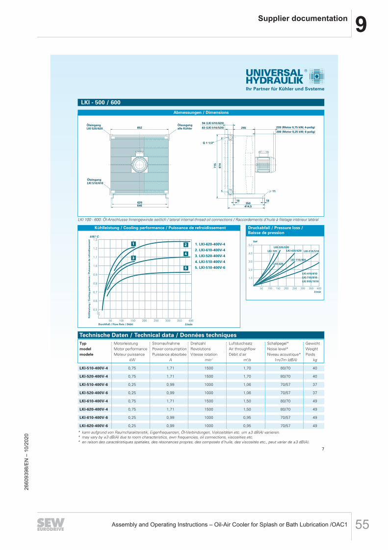
9Supplier documentation
Assembly and Operating Instructions – Oil-Air Cooler for Splash or Bath Lubrication /OAC1 55
Ihr Partner für Kühler und Systeme
Technische Daten / Technical data / Données techniquesTypmodelmodele
LKI-510-400V-4
LKI-520-400V-4
LKI-510-400V-6
LKI-520-400V-6
LKI-610-400V-4
LKI-620-400V-4
LKI-610-400V-6
LKI-620-400V-6
MotorleistungMotor performanceMoteur puissance
kW
0,75
0,75
0,25
0,25
0,75
0,75
0,25
0,25
StromaufnahmePower consumptionPuissance absorbée
A
1,71
1,71
0,99
0,99
1,71
1,71
0,99
0,99
DrehzahlRevolutionsVitesse rotation
min-1
1500
1500
1000
1000
1500
1500
1000
1000
LuftdurchsatzAir throughflowDébit d`air
m3/s
1,70
1,70
1,06
1,06
1,50
1,50
0,95
0,95
Schallpegel*Noise level*Niveau acoustique*
1m/7m (dBA)
80/70
80/70
70/57
70/57
80/70
80/70
70/57
70/57
GewichtWeightPoids
kg
40
40
37
37
49
49
49
49
LKI - 500 / 600
652
620646
94 (LKI 610/620)
63 (LKI 510/520)
11
1818350
414,5
245
G 1 1/2"
614
715
228 (Motor 0,75 kW; 4-polig)
208 (Motor 0,25 kW; 6-polig)
Ölausgangalle Kühler
ÖleingangLKI 520/620
ÖleingangLKI 510/610
Kühlleistung / Cooling performance / Puissance de refroidissement
Abmessungen / Dimensions
LKI 100 - 600: Öl-Anschlusse Innengewinde seitlich / lateral internal-thread oil connections / Raccordements d’huile à filetage intérieur latéral
7
Druckabfall / Pressure loss / Baisse de pression
* kann aufgrund von Raumcharakteristik, Eigenfrequenzen, Öl-Verbindungen, Viskositäten etc. um ±3 dB(A) variieren.* may vary by ±3 dB(A) due to room characteristics, own frequencies, oil connections, viscosities etc.* en raison des caractéristiques spatiales, des résonances propres, des composés d`huile, des viscosités etc., peut varier de ±3 dB(A).
2660
9398
/EN
– 1
0/20
20

9 Supplier documentation
Assembly and Operating Instructions – Oil-Air Cooler for Splash or Bath Lubrication /OAC156
Ihr Partner für Kühler und Systeme
Technische Daten / Technical data / Données techniquesTypmodelmodelekW
LKI-710-400V-6
LKI-710-400V-8
MotorleistungMotor performanceMoteur puissance
kW
1,1
0,55
StromaufnahmePower consumptionPuissance absorbée
A
2,56
2,56
DrehzahlRevolutionsVitesse rotation
min-1
1000
750
LuftdurchsatzAir throughflowDébit d`air
m3/s
2,14
1,56
Schallpegel*Noise level*Niveau acoustique*1m/7m (dBA)
77/64
69/56
LKI-700
804 900 698
590
94 340810760
735
765
424
G 2"
G 2" G 2"
G 1/2"
Kühlelement um 90° gedreht dargestellt Anhebe- und Transportpunkte (M10)
Öleingang (alternativ)
Ölausgang (alternativ)
Ölausgang (alternativ)
934
7981
0
424
886
272
2" SAE3000 PSI
2" SAE3000 PSI
11
77
18 18
264 (Motor 1,1 kW; 6-polig)
264 (Motor 0,55 kW; 8-polig)
Abmessungen / Dimensions
Kühlleistung / Cooling performance / Puissance de refroidissement
GewichtWeightPoids
kg
91
91
LKI 700 - 1000: Öl-Anschlusse Innengewinde seitlich und SAE -Flansch hinten oder vorne / lateral internal-thread oil connections and SAE flangeat front or rear / Raccordements d’huile à filetage intérieur latéral et bride SAE avant ou arrière
8
Druckabfall / Pressure loss / Baisse de pression
* kann aufgrund von Raumcharakteristik, Eigenfrequenzen, Öl-Verbindungen, Viskositäten etc. um ±3 dB(A) variieren.* may vary by ±3 dB(A) due to room characteristics, own frequencies, oil connections, viscosities etc.* en raison des caractéristiques spatiales, des résonances propres, des composés d`huile, des viscosités etc., peut varier de ±3 dB(A).
2660
9398
/EN
– 1
0/20
20

9Supplier documentation
Assembly and Operating Instructions – Oil-Air Cooler for Splash or Bath Lubrication /OAC1 57
Ihr Partner für Kühler und Systeme
Technische Daten / Technical data / Données techniquesTypmodelmodelekW
LKI-810-400V-6
LKI-810-400V-8
MotorleistungMotor performanceMoteur puissance
kW
1,5
0,75
StromaufnahmePower consumptionPuissance absorbée
A
3,78
2,42
DrehzahlRevolutionsVitesse rotation
min-1
1000
750
LuftdurchsatzAir throughflowDébit d`air
m3/s
3,38
2,64
Schallpegel*Noise level*Niveau acoustique*
1m/7m (dBA)
79/68
72/60
GewichtWeightPoids
kg
111
111
LKI-800
Kühlelement um 90° gedreht dargestellt
G 1/2"
2" SAE3000 PSI
G 2"
G 2"
918538
910
538
1000
272
8610
41
1000
910
860
835
865 590
2" SAE3000 PSI
11
735
34094
77
18 18
Anhebe- und Transportpunkte (M10)
301 (Motor 1,5 kW; 6-polig)
301 (Motor 0,75 kW; 8-polig)
Öleingang (alternativ)
Ölausgang (alternativ)
Ölausgang (alternativ)
Abmessungen / Dimensions
Kühlleistung / Cooling performance / Puissance de refroidissement
LKI 700 - 1000: Öl-Anschlusse Innengewinde seitlich und SAE -Flansch hinten oder vorne / lateral internal-thread oil connections and SAE flangeat front or rear / Raccordements d’huile à filetage intérieur latéral et bride SAE avant ou arrière
9
Druckabfall / Pressure loss / Baisse de pression
* kann aufgrund von Raumcharakteristik, Eigenfrequenzen, Öl-Verbindungen, Viskositäten etc. um ±3 dB(A) variieren.* may vary by ±3 dB(A) due to room characteristics, own frequencies, oil connections, viscosities etc.* en raison des caractéristiques spatiales, des résonances propres, des composés d`huile, des viscosités etc., peut varier de ±3 dB(A).
2660
9398
/EN
– 1
0/20
20
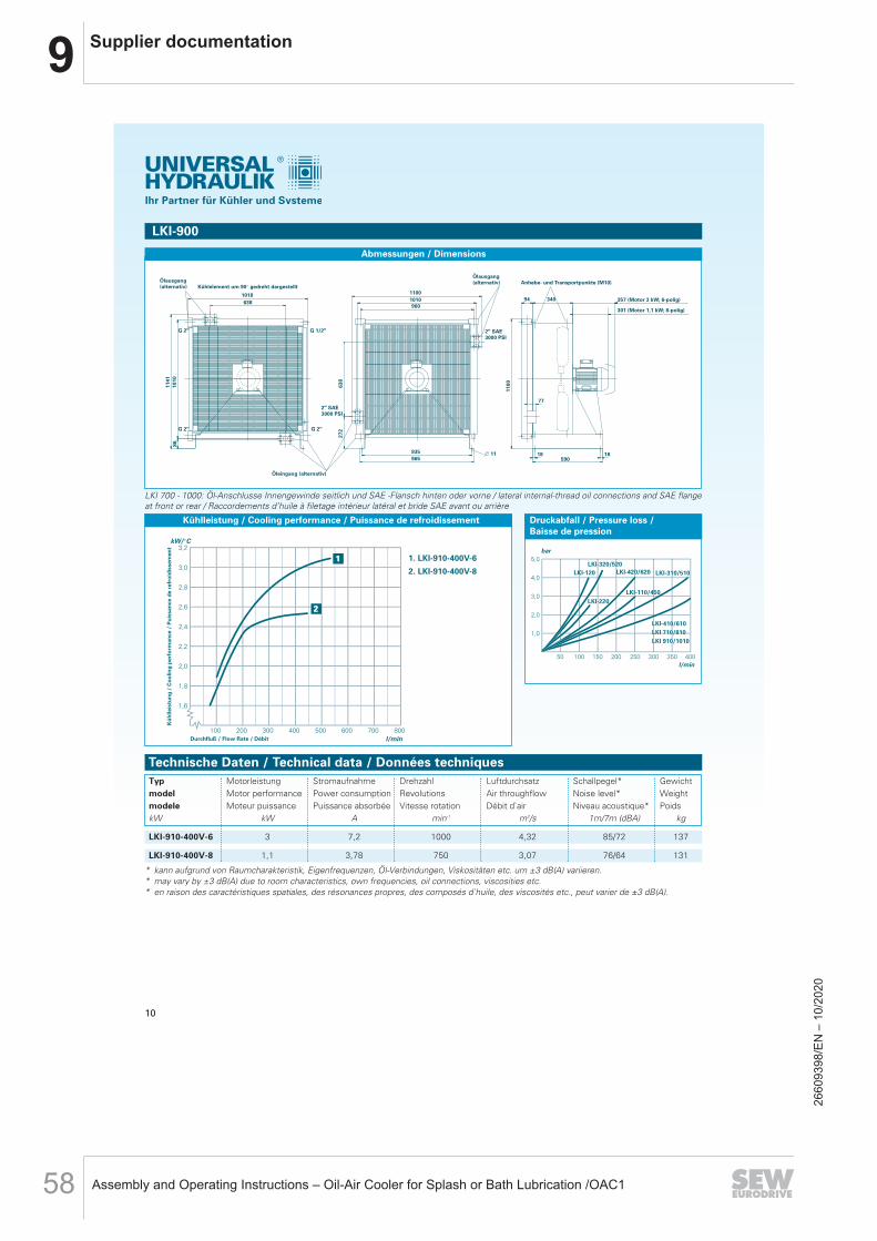
9 Supplier documentation
Assembly and Operating Instructions – Oil-Air Cooler for Splash or Bath Lubrication /OAC158
Ihr Partner für Kühler und Systeme
Technische Daten / Technical data / Données techniquesTypmodelmodelekW
LKI-910-400V-6
LKI-910-400V-8
MotorleistungMotor performanceMoteur puissance
kW
3
1,1
StromaufnahmePower consumptionPuissance absorbée
A
7,2
3,78
DrehzahlRevolutionsVitesse rotation
min-1
1000
750
LuftdurchsatzAir throughflowDébit d`air
m3/s
4,32
3,07
Schallpegel*Noise level*Niveau acoustique*
1m/7m (dBA)
85/72
76/64
GewichtWeightPoids
kg
137
131
LKI-900
Kühlelement um 90° gedreht dargestellt
1018 11001010960
340
590
94
77
18 18935965
638
1141
638
272
1010
G 2"G 2"
G 2" G 1/2"
86
2" SAE3000 PSI
2" SAE3000 PSI
11
1100
Anhebe- und Transportpunkte (M10)
357 (Motor 3 kW; 6-polig)
301 (Motor 1,1 kW; 8-polig)
Ölausgang (alternativ)
Öleingang (alternativ)
Ölausgang (alternativ)
Abmessungen / Dimensions
Kühlleistung / Cooling performance / Puissance de refroidissement
LKI 700 - 1000: Öl-Anschlusse Innengewinde seitlich und SAE -Flansch hinten oder vorne / lateral internal-thread oil connections and SAE flangeat front or rear / Raccordements d’huile à filetage intérieur latéral et bride SAE avant ou arrière
10
Druckabfall / Pressure loss / Baisse de pression
* kann aufgrund von Raumcharakteristik, Eigenfrequenzen, Öl-Verbindungen, Viskositäten etc. um ±3 dB(A) variieren.* may vary by ±3 dB(A) due to room characteristics, own frequencies, oil connections, viscosities etc.* en raison des caractéristiques spatiales, des résonances propres, des composés d`huile, des viscosités etc., peut varier de ±3 dB(A).
2660
9398
/EN
– 1
0/20
20
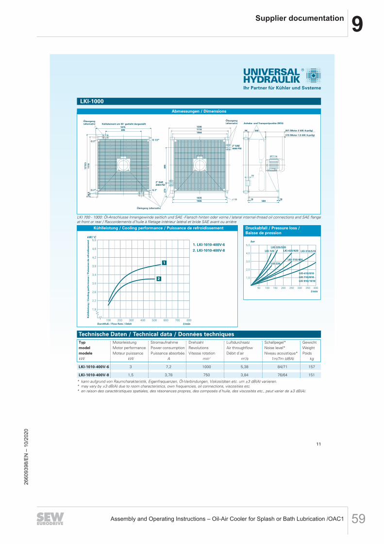
9Supplier documentation
Assembly and Operating Instructions – Oil-Air Cooler for Splash or Bath Lubrication /OAC1 59
Ihr Partner für Kühler und Systeme
Technische Daten / Technical data / Données techniquesTypmodelmodelekW
LKI-1010-400V-6
LKI-1010-400V-8
MotorleistungMotor performanceMoteur puissance
kW
3
1,5
StromaufnahmePower consumptionPuissance absorbée
A
7,2
3,78
DrehzahlRevolutionsVitesse rotation
min-1
1000
750
LuftdurchsatzAir throughflowDébit d`air
m3/s
5,38
3,84
Schallpegel*Noise level*Niveau acoustique*
1m/7m (dBA)
84/71
76/64
GewichtWeightPoids
kg
157
151
LKI-1000
Kühlelement um 90° gedreht dargestellt1075 1200
340
590
94
77
18 18
11101064
10351065
695
G 2"
G 2" G 2"
G 1/2"
1219
,511
10
695
272
64,5
2" SAE3000 PSI
2" SAE3000 PSI
11
Anhebe- und Transportpunkte (M10)
357 (Motor 3 kW; 6-polig)
319 (Motor 1,5 kW; 8-polig)
Ölausgang (alternativ)
Öleingang (alternativ)
Ölausgang (alternativ)
Abmessungen / Dimensions
Kühlleistung / Cooling performance / Puissance de refroidissement
LKI 700 - 1000: Öl-Anschlusse Innengewinde seitlich und SAE -Flansch hinten oder vorne / lateral internal-thread oil connections and SAE flangeat front or rear / Raccordements d’huile à filetage intérieur latéral et bride SAE avant ou arrière
11
Druckabfall / Pressure loss / Baisse de pression
* kann aufgrund von Raumcharakteristik, Eigenfrequenzen, Öl-Verbindungen, Viskositäten etc. um ±3 dB(A) variieren.* may vary by ±3 dB(A) due to room characteristics, own frequencies, oil connections, viscosities etc.* en raison des caractéristiques spatiales, des résonances propres, des composés d`huile, des viscosités etc., peut varier de ±3 dB(A).
2660
9398
/EN
– 1
0/20
20
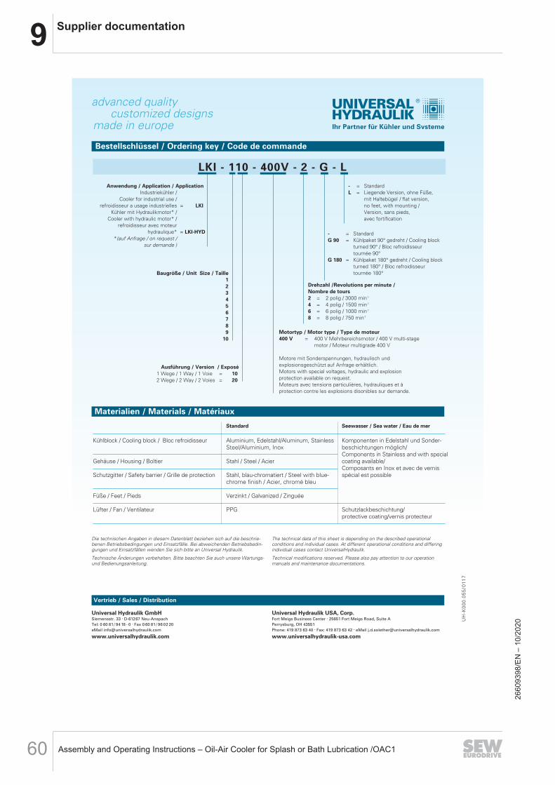
9 Supplier documentation
Assembly and Operating Instructions – Oil-Air Cooler for Splash or Bath Lubrication /OAC160
made in europe
advanced qualitycustomized designs
Ihr Partner für Kühler und Systeme
UH-K
000.055/0
117
Bestellschlüssel / Ordering key / Code de commande
LKI - 110 - 400V - 2 - G - L
Baugröße / Unit Size / Taille12345678910
Drehzahl /Revolutions per minute / Nombre de tours2 = 2 polig / 3000 min-1
4 = 4 polig / 1500 min-1
6 = 6 polig / 1000 min-1
8 = 8 polig / 750 min-1
Vertrieb / Sales / Distribution
Motortyp / Motor type / Type de moteur400 V = 400 V Mehrbereichsmotor / 400 V multi-stage
motor / Moteur multigrade 400 V
Motore mit Sonderspannungen, hydraulisch und explosionsgeschützt auf Anfrage erhältlich.Motors with special voltages, hydraulic and explosion protection available on request.Moteurs avec tensions particulières, hydrauliques et à protection contre les explosions disonibles sur demande.
Ausführung / Version / Exposé1 Wege / 1 Way / 1 Voie = 102 Wege / 2 Way / 2 Voies = 20
Anwendung / Application / Application Industriekühler /
Cooler for industrial use / refroidisseur a usage industrielles = LKI
Kühler mit Hydraulikmotor* / Cooler with hydraulic motor* /
refroidisseur avec moteur hydraulique* = LKI-HYD
*(auf Anfrage / on request / sur demande )
- = StandardG 90 = Kühlpaket 90° gedreht / Cooling block
turned 90° / Bloc refroidisseur tournée 90°
G 180 = Kühlpaket 180° gedreht / Cooling block turned 180° / Bloc refroidisseur tournée 180°
- = StandardL = Liegende Version, ohne Füße,
mit Haltebügel / flat version, no feet, with mounting / Version, sans pieds, avec fortification
Standard Seewasser / Sea water / Eau de mer
Kühlblock / Cooling block / Bloc refroidisseur Aluminium, Edelstahl/Aluminum, Stainless Komponenten in Edelstahl und Sonder-Steel/Aluminium, Inox beschichtungen möglich/
Components in Stainless and with special Gehäuse / Housing / Boîtier Stahl / Steel / Acier coating available/
Composants en Inox et avec de vernisSchutzgitter / Safety barrier / Grille de protection Stahl, blau-chromatiert / Steel with blue- spécial est possible
chrome finish / Acier, chromé bleu
Füße / Feet / Pieds Verzinkt / Galvanized / Zinguée
Lüfter / Fan / Ventilateur PPG Schutzlackbeschichtung/protective coating/vernis protecteur
Materialien / Materials / Matériaux
Universal Hydraulik GmbHSiemensstr. 33 . D-61267 Neu-AnspachTel: 0 60 81/ 94 18 - 0 . Fax 0 60 81/ 96 02 20eMail [email protected]
www.universalhydraulik.com
Die technischen Angaben in diesem Datenblatt beziehen sich auf die beschrie-benen Betriebsbedingungen und Einsatzfälle. Bei abweichenden Betriebsbedin-gungen und Einsatzfällen wenden Sie sich bitte an Universal Hydraulik.
Technische Änderungen vorbehalten. Bitte beachten Sie auch unsere Wartungs-und Bedienungsanleitung.
The technical data of this sheet is depending on the described operational conditions and individual cases. At different operational conditions and differingindividual cases contact UniversalHydraulik.
Technical modifications reserved. Please also pay attention to our operationmanuals and maintenance documentations.
Universal Hydraulik USA, Corp.Fort Meigs Business Center . 25651 Fort Meigs Road, Suite APerrysburg, OH 43551Phone: 419 873 63 40 . Fax: 419 873 63 42 . eMail [email protected]
www.universalhydraulik-usa.com
2660
9398
/EN
– 1
0/20
20

9Supplier documentation
Assembly and Operating Instructions – Oil-Air Cooler for Splash or Bath Lubrication /OAC1 61
D.0024710002Operating instructions (Translation)
Gear pump KF 2.5 - 630
88024710002-26
Englisch
2017-09-12
2660
9398
/EN
– 1
0/20
20
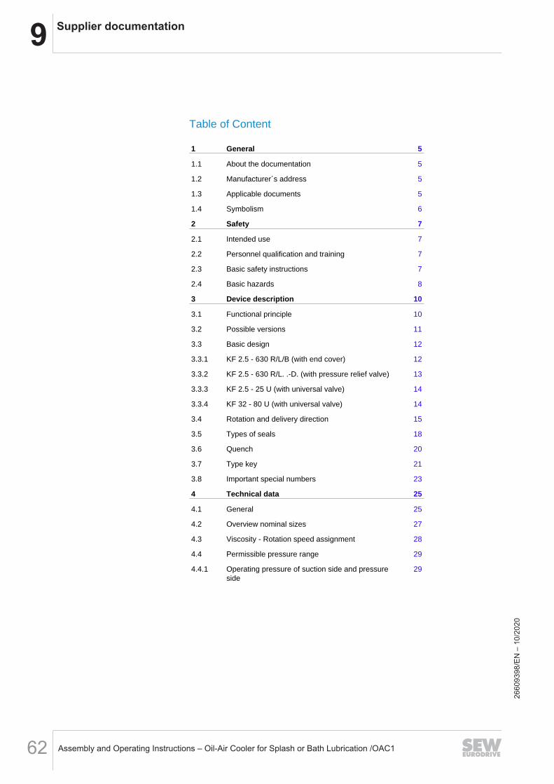
9 Supplier documentation
Assembly and Operating Instructions – Oil-Air Cooler for Splash or Bath Lubrication /OAC162
Table of Content
1 General 5
1.1 About the documentation 5
1.2 Manufacturer´s address 5
1.3 Applicable documents 5
1.4 Symbolism 6
2 Safety 7
2.1 Intended use 7
2.2 Personnel qualification and training 7
2.3 Basic safety instructions 7
2.4 Basic hazards 8
3 Device description 10
3.1 Functional principle 10
3.2 Possible versions 11
3.3 Basic design 12
3.3.1 KF 2.5 - 630 R/L/B (with end cover) 12
3.3.2 KF 2.5 - 630 R/L. .-D. (with pressure relief valve) 13
3.3.3 KF 2.5 - 25 U (with universal valve) 14
3.3.4 KF 32 - 80 U (with universal valve) 14
3.4 Rotation and delivery direction 15
3.5 Types of seals 18
3.6 Quench 20
3.7 Type key 21
3.8 Important special numbers 23
4 Technical data 25
4.1 General 25
4.2 Overview nominal sizes 27
4.3 Viscosity - Rotation speed assignment 28
4.4 Permissible pressure range 29
4.4.1 Operating pressure of suction side and pressureside
29
2660
9398
/EN
– 1
0/20
20

9Supplier documentation
Assembly and Operating Instructions – Oil-Air Cooler for Splash or Bath Lubrication /OAC1 63
4.4.2 Max. suction side operating pressure for sealingtype 1, 2, 7 and 19
30
4.4.3 Differential pressure - viscosity assignment 31
4.5 Permissible temperature range 31
4.6 Material data 32
4.7 Weight 34
4.8 Dimensions 34
5 Transport and storage 35
5.1 General 35
5.2 Transport 35
5.3 Storage 36
6 Installation 38
6.1 Safety instructions for installation 38
6.2 Noise reduction 39
6.3 Mechanical installation 39
6.3.1 Preparation 39
6.3.2 Pumps with free shaft end 39
6.3.3 Coupling Type "R." 41
6.4 Connection lines 45
6.4.1 General 45
6.4.2 Suction line 46
6.4.3 Pressure line 47
6.4.4 Mounting Connection lines 47
6.5 Change of the direction of rotation 48
7 Operation start-up 50
7.1 Safety instructions for start-up 50
7.2 Preparation 50
7.3 Filling the quench chamber 51
7.4 Pressure relief valve adjustment 52
7.5 Further operation start-up 53
8 Removal 54
8.1 Safety instructions for removal 54
2660
9398
/EN
– 1
0/20
20
9 Supplier documentation
Assembly and Operating Instructions – Oil-Air Cooler for Splash or Bath Lubrication /OAC164
8.2 Removal 55
9 Maintenance 56
9.1 Safety instructions for maintenance 56
9.2 Maintenance work 56
9.3 Maintenance instructions 57
10 Repairs 59
10.1 Safety instructions for repair 59
10.2 General 60
10.3 Detecting and eliminating failures 61
2660
9398
/EN
– 1
0/20
20

9Supplier documentation
Assembly and Operating Instructions – Oil-Air Cooler for Splash or Bath Lubrication /OAC1 65
1 General
1.1 About the documentation
These operating instructions describe the installation, operation and mainte-nance of the following device:
Gear pump KF 2.5 - 630The device is manufactured in different versions. Information about the ver-sion concerned in the individual case can be found on the device's type plate.
These operating instructions are a component of the device and must be keptaccessible for the personnel near the device at all times.
If you have any questions about these operating instructions, please contactthe manufacturer.
1.2 Manufacturer´s address
KRACHT GmbH
Gewerbestraße 20
DE 58791 Werdohl
phone: +49 2392 935-0
fax: +49 2392 935-209
email: [email protected]
web: www.kracht.eu
1.3 Applicable documents
1. KTR Kupplungstechnik GmbH, DE 48407 Rheine KTR-N 40210: Coupling operating/assembly instruction Rotex
Excerpts from these documents are included in these operating instructions.
If required, the original documents can be requested from the respectivemanufacturer.
Gear pump KF 2.5 - 630
88024710002-26 2017-09-12 5
2660
9398
/EN
– 1
0/20
20
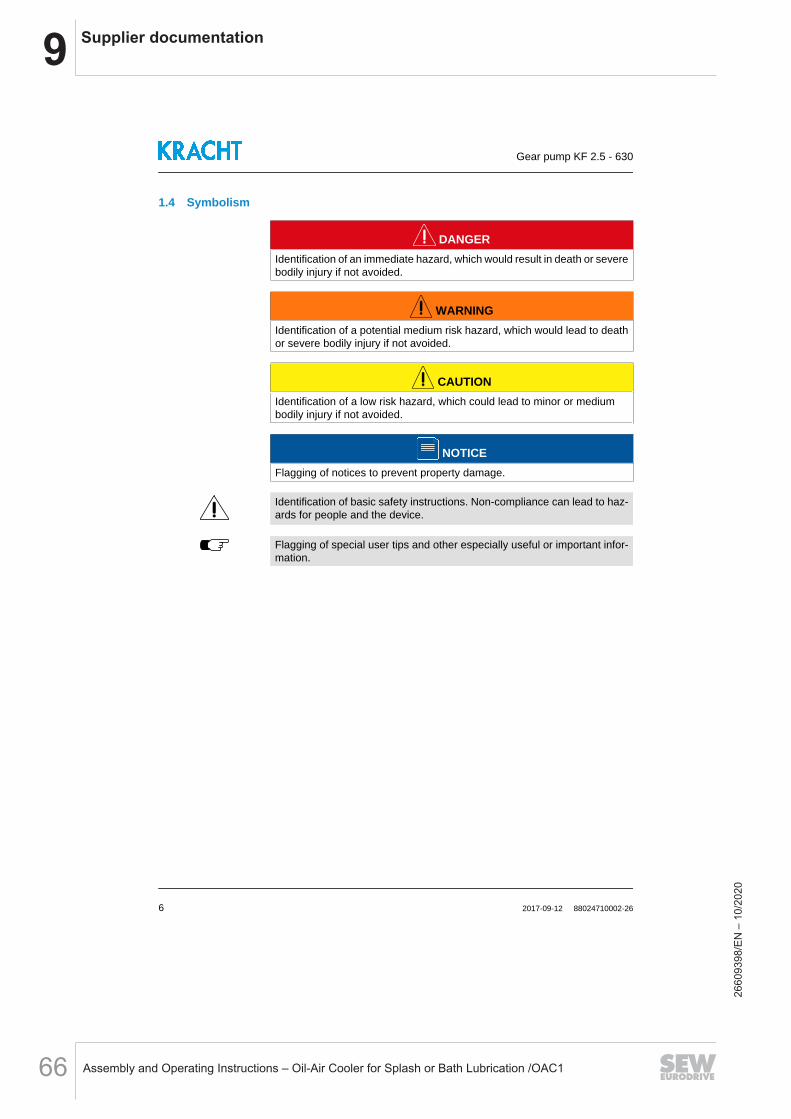
9 Supplier documentation
Assembly and Operating Instructions – Oil-Air Cooler for Splash or Bath Lubrication /OAC166
1.4 Symbolism
DANGERIdentification of an immediate hazard, which would result in death or severebodily injury if not avoided.
WARNINGIdentification of a potential medium risk hazard, which would lead to deathor severe bodily injury if not avoided.
CAUTIONIdentification of a low risk hazard, which could lead to minor or mediumbodily injury if not avoided.
NOTICEFlagging of notices to prevent property damage.
Identification of basic safety instructions. Non-compliance can lead to haz-ards for people and the device.
Flagging of special user tips and other especially useful or important infor-mation.
Gear pump KF 2.5 - 630
6 2017-09-12 88024710002-26
2660
9398
/EN
– 1
0/20
20
9Supplier documentation
Assembly and Operating Instructions – Oil-Air Cooler for Splash or Bath Lubrication /OAC1 67
2 Safety
2.1 Intended use
1. The device has been designed for operation with fluid. Dry operation isnot permitted.
2. The device may be operated in filled condition only.The medium must be compatible with the materials used in the device.The chemical competence is necessary for this. Be careful with ethyleneoxide or other cathalytic or exothermic or self-decomposing materials.Please consult the manufacturer in cases of doubt.
3. The device may be operated only in usual industrial atmospheres. If thereare any aggressive substances in the air, always ask the manufacturer.
4. Operation of the device is only permissible when complying with the op-erating instructions and applicable documents.Deviating operating conditions require the express approval of the man-ufacturer.
5. In case of any use of the device not according to specification, any war-ranty is voided.
2.2 Personnel qualification and training
The staff designated to assemble, operate and service the device must beproperly qualified. This can be through training or specific instruction. Per-sonnel must be familiar with the contents of this operating instructions.
Read the operating instructions thoroughly before use.
2.3 Basic safety instructions
1. Comply with existing regulations on accident prevention and safety atwork along with any possible internal operator regulations.
2. Pay attention to the greatest possible cleanliness.3. Wear suitable personal protection equipment.4. Do not remove, make illegible or obliterate type plates or other referen-
ces on the device.5. Do not make any technical changes on the device.6. Maintain and clean the device regularly.7. Use spare parts approved by the manufacturer only.
Gear pump KF 2.5 - 630
88024710002-26 2017-09-12 7
2660
9398
/EN
– 1
0/20
20

9 Supplier documentation
Assembly and Operating Instructions – Oil-Air Cooler for Splash or Bath Lubrication /OAC168
2.4 Basic hazards
DANGERHazardous fluids!Danger of death when handling hazardous fluids.1. Comply with the safety data sheets and regulations on handling haz-
ardous fluids.2. Collect and dispose of hazardous fluids so that no hazards arise for
people or the environment.
DANGERRotating parts!Danger of death due to body parts, hair or clothing getting trapped or en-tangled.1. Before all work, ensure that existing drives are voltage-free and pres-
sure-free.2. Securely prevent restarting during all work.
DANGERRotating parts!Danger of death due to body parts, hair or clothing getting trapped or en-tangled.1. Take measures against accidental touching of rotating parts.
WARNINGRotating parts!Danger of injury from flying parts.1. Enclose rotating parts so as to avoid any danger from flying parts in the
event of breakage or malfunction.
WARNINGFailure of load-carrying parts due to overload!Danger of injury from flying parts.Danger of injury from spurting fluids.1. Depressurise the device and all connection lines before doing any work.2. Securely prevent the restoration of pressure while working on the de-
vice.
Gear pump KF 2.5 - 630
8 2017-09-12 88024710002-26
2660
9398
/EN
– 1
0/20
20
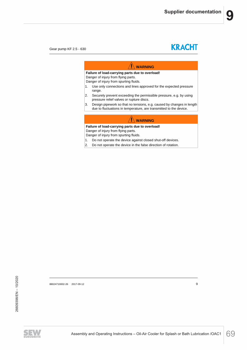
9Supplier documentation
Assembly and Operating Instructions – Oil-Air Cooler for Splash or Bath Lubrication /OAC1 69
WARNINGFailure of load-carrying parts due to overload!Danger of injury from flying parts.Danger of injury from spurting fluids.1. Use only connections and lines approved for the expected pressure
range.2. Securely prevent exceeding the permissible pressure, e.g. by using
pressure relief valves or rupture discs.3. Design pipework so that no tensions, e.g. caused by changes in length
due to fluctuations in temperature, are transmitted to the device.
WARNINGFailure of load-carrying parts due to overload!Danger of injury from flying parts.Danger of injury from spurting fluids.1. Do not operate the device against closed shut-off devices.2. Do not operate the device in the false direction of rotation.
Gear pump KF 2.5 - 630
88024710002-26 2017-09-12 9
2660
9398
/EN
– 1
0/20
20

9 Supplier documentation
Assembly and Operating Instructions – Oil-Air Cooler for Splash or Bath Lubrication /OAC170
3 Device description
3.1 Functional principle
KF/KFF series pumps are external gear pump types that work according tothe positive displacement principle.
S = Suction connectionP = Pressure connection
When rotated, two gearwheels meshing together produce a volume enlarge-ment as a result of the opening of the tooth spaces on the suction side (S),so that medium can flow in and so that a corresponding volume is displacedsimultaneously by immersion of the teeth into the filled tooth spaces on thepressure side (P). Fluid transport takes place through entrainment in the toothgaps along the wall of the wheel chamber. The so-called geometric flow rateVg is being displaced per wheel rotation. A value that is stated in technicaldocuments as rated volume Vgn to specify the pump size.
The actually delivered amount of liquid does not correspond with the theo-retical value, it is being reduced through losses due to the necessary toler-ances. The losses are less the lower the operating pressure and the higherthe viscosity of the medium.
Gear pumps are self-priming within wide limits. The displacement cycle de-scribe initially takes place without exhibiting appreciable pressure build-up.Only after setting external loads, for example, through delivery heights, flowresistances, line elements, etc. will the required working pressure arise toovercome these resistances.
As usual with non-axial play compensated pumps, the lateral clearance be-tween gear and front face has been set in such a way that the maximumallowable operating pressure is managed in an adequate and secure way.
Bearing and shaft seal of the device are lubricated by the media. The device'soperating life will be reduced if the medium contains abrasive ingredients.
The shaft seal chamber is connected to the device's suction side. The pres-sure occurring at the shaft seal therefore corresponds to the pressure at the
Gear pump KF 2.5 - 630
10 2017-09-12 88024710002-26
2660
9398
/EN
– 1
0/20
20

9Supplier documentation
Assembly and Operating Instructions – Oil-Air Cooler for Splash or Bath Lubrication /OAC1 71
suction connection of the device. The permissible pressure is determined bythe type of sealing.
3.2 Possible versions
Gear pump with end cover
Standard
Gear pump with pressure relief valve
Directly attached pressure relief valves ofthe series "D" are used exclusively for pro-tection of the gear pumps and may re-spond on a short-term basis only. Con-stant triggering of the valve can destroythe gear pump due to overheating.
Gear pump with universal valveKF 2.5 - 25 U
KF 32 - 80 U
Pumps with universal valve pump to thesame pressure connection even when thedirection of rotation of the drive shaftchanges. Because of the operating prin-ciple, the pressure and suction connec-tions remain the same under any directionof rotation. Select the mounting positionso that the piston is in a horizontal positionand the pressure port is at the top.
Gear pump KF 2.5 - 630
88024710002-26 2017-09-12 11
2660
9398
/EN
– 1
0/20
20

9 Supplier documentation
Assembly and Operating Instructions – Oil-Air Cooler for Splash or Bath Lubrication /OAC172
3.3 Basic design
3.3.1 KF 2.5 - 630 R/L/B (with end cover)
Explanation1. End cover 7. Shaft seal2. O-Ring (see "Section: Seal types")3. Housing 8. Outbord bearing4. Driven shaft (Mounting only: G; X)5. Driving shaft 9. Valve6. Plain bearing bush (Direction of rotation only: B)
Gear pump KF 2.5 - 630
12 2017-09-12 88024710002-26
2660
9398
/EN
– 1
0/20
20
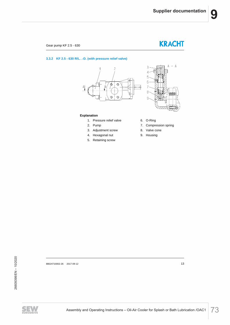
9Supplier documentation
Assembly and Operating Instructions – Oil-Air Cooler for Splash or Bath Lubrication /OAC1 73
3.3.2 KF 2.5 - 630 R/L. .-D. (with pressure relief valve)
Explanation1. Pressure relief valve 6. O-Ring2. Pump 7. Compression spring3. Adjustment screw 8. Valve cone4. Hexagonal nut 9. Housing5. Retaining screw
Gear pump KF 2.5 - 630
88024710002-26 2017-09-12 13
2660
9398
/EN
– 1
0/20
20
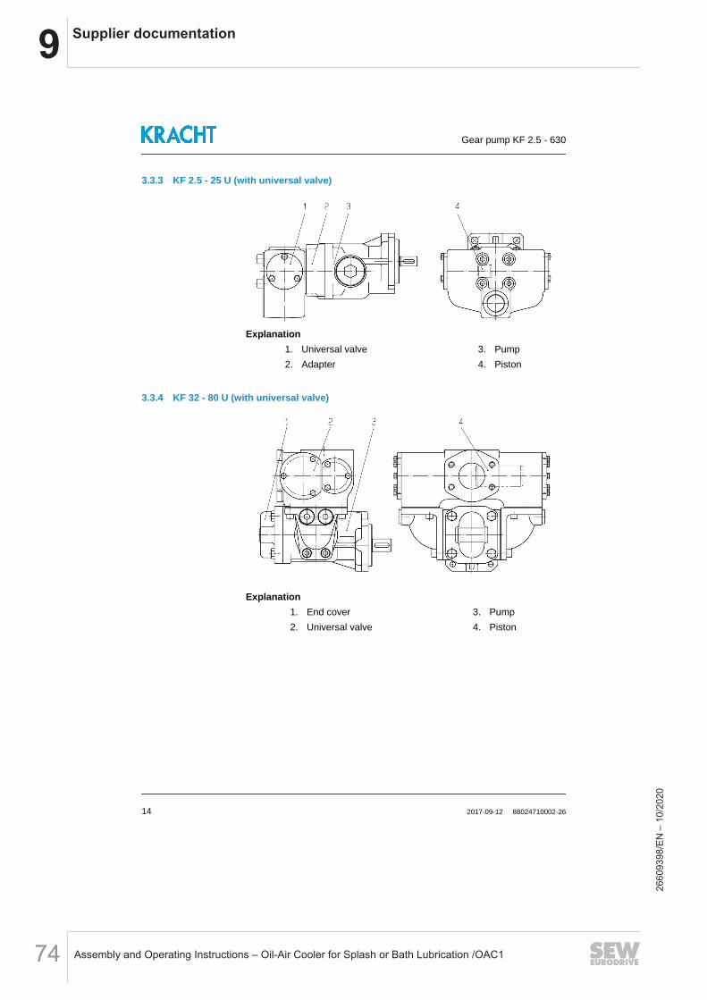
9 Supplier documentation
Assembly and Operating Instructions – Oil-Air Cooler for Splash or Bath Lubrication /OAC174
3.3.3 KF 2.5 - 25 U (with universal valve)
Explanation1. Universal valve 3. Pump2. Adapter 4. Piston
3.3.4 KF 32 - 80 U (with universal valve)
Explanation1. End cover 3. Pump2. Universal valve 4. Piston
Gear pump KF 2.5 - 630
14 2017-09-12 88024710002-26
2660
9398
/EN
– 1
0/20
20

9Supplier documentation
Assembly and Operating Instructions – Oil-Air Cooler for Splash or Bath Lubrication /OAC1 75
3.4 Rotation and delivery direction
The following definition applies with respect to the rotation and delivery di-rection of external gear pumps for pump connections positioned below thedrive shaft:Looking at the pump shaft end, thepumping flow is from left to right whenthe shaft is moving clockwise.
Looking at the pump shaft end, thepumping flow is from right to leftwhen the shaft is moving counter-clockwise.
Gear pump with end cover
S = Suction connectionP = Pressure connection
Gear pump with pressure relief valve
S = Suction connectionP = Pressure connection
The direction of rotation is indicated by the bent arrow.
The flow direction is indicated by the straight arrows.
Gear pump KF 2.5 - 630
88024710002-26 2017-09-12 15
2660
9398
/EN
– 1
0/20
20
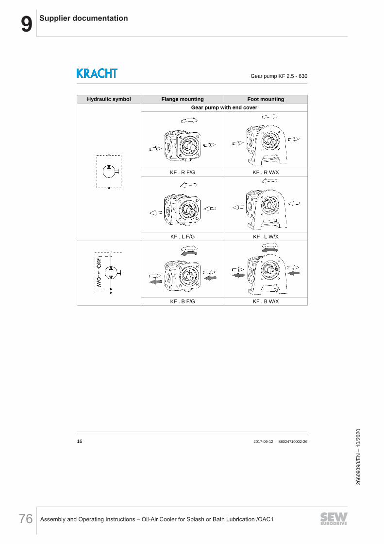
9 Supplier documentation
Assembly and Operating Instructions – Oil-Air Cooler for Splash or Bath Lubrication /OAC176
Hydraulic symbol Flange mounting Foot mountingGear pump with end cover
KF . R F/G KF . R W/X
KF . L F/G KF . L W/X
KF . B F/G KF . B W/X
Gear pump KF 2.5 - 630
16 2017-09-12 88024710002-26
2660
9398
/EN
– 1
0/20
20

9Supplier documentation
Assembly and Operating Instructions – Oil-Air Cooler for Splash or Bath Lubrication /OAC1 77
Hydraulic symbol Flange mounting Foot mountingGear pump with pressure relief valve
KF . R F/G. .-D. KF . R W/X. .-D.
KF . L F/G. .-D. KF . L W/X. .-D.Gear pump with universal valve
KF 2.5 - 25 U F/G -
KF 32 - 80 U F/G -
Gear pump KF 2.5 - 630
88024710002-26 2017-09-12 17
2660
9398
/EN
– 1
0/20
20

9 Supplier documentation
Assembly and Operating Instructions – Oil-Air Cooler for Splash or Bath Lubrication /OAC178
3.5 Types of seals
Rotary shaft sealSeal type: 1; 2; 3; 9; 18; 31
Rotary shaft sealSeal type: 23
Rotary shaft sealwith outboard bearingSeal type: 1; 2; 3; 9; 18; 31
Double rotary shaft sealConnection borehole G1/8 (forQuench) (1)
Seal type: 4; 7; 19; 32
Double rotary shaft seal (for vac-uum operation)Connection borehole G1/8 (forQuench) (1)
Seal type: 4; 7; 19; 32Special number 74
Triple rotary shaft seal (for vac-uum operation + for normal oper-ation)Connection borehole G1/8 (forQuench) (1)
Seal type: 7Special number 322(only KF 32 - 80)
Gear pump KF 2.5 - 630
18 2017-09-12 88024710002-26
2660
9398
/EN
– 1
0/20
20

9Supplier documentation
Assembly and Operating Instructions – Oil-Air Cooler for Splash or Bath Lubrication /OAC1 79
Mechanical sealSeal type: 5; 40
Mechanical sealSeal type: 6
Mechanical seal with Quench (1)
KF 2.5 - 25: Connection boreholeG1/8 (for Quench) (1)
KF 32 - 80: Connection boreholeG1/4 (for Quench) (1)
Seal type: 5Special number 198
without shaft seal(Leak oil drain through shaft seal-ing chamber)Seal type: 30; 36(1) See section 3.6 “Quench”
Gear pump KF 2.5 - 630
88024710002-26 2017-09-12 19
2660
9398
/EN
– 1
0/20
20

9 Supplier documentation
Assembly and Operating Instructions – Oil-Air Cooler for Splash or Bath Lubrication /OAC180
3.6 Quench
Versions with quench are used when absolute leak tightness is required onthe shaft seal, e.g. when pumping media
which cures upon contact with air. which crystallises upon contact with air humidity. the leakage of which must not be released into the environment. are under vacuum and their seal shall be gastight.
Select the mounting position so that the connection for the quench faces up.
Gear pump KF 2.5 - 630
20 2017-09-12 88024710002-26
2660
9398
/EN
– 1
0/20
20
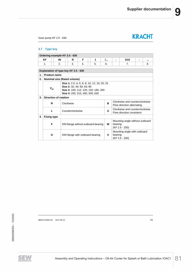
9Supplier documentation
Assembly and Operating Instructions – Oil-Air Cooler for Splash or Bath Lubrication /OAC1 81
3.7 Type key
Ordering example KF 2.5 - 630KF 40 R F 1 /... - D15 - ...1. 2. 3. 4. 5. 6. 7. 8.
Explanation of type key KF 2.5 - 6301. Product name2. Nominal size (Rated volume)
Vgn
Size 1: 2.5; 4; 5; 6; 8; 10; 12; 16; 20; 25Size 2: 32; 40; 50; 63; 80Size 3: 100; 112; 125; 150; 180; 200Size 4: 250; 315; 400; 500; 630
3. Direction of rotation
R Clockwise B Clockwise and counterclockwiseFlow direction alternating
L Counterclockwise U Clockwise and counterclockwiseFlow direction consistent
4. Fixing type
F DIN flange without outboard bearing WMounting angle without outboardbearing(KF 2.5 - 200)
G DIN flange with outboard bearing XMounting angle with outboardbearing(KF 2.5 - 200)
Gear pump KF 2.5 - 630
88024710002-26 2017-09-12 21
2660
9398
/EN
– 1
0/20
20

9 Supplier documentation
Assembly and Operating Instructions – Oil-Air Cooler for Splash or Bath Lubrication /OAC182
Explanation of type key KF 2.5 - 6305. Seal type
1 Rotary shaft sealNBR (BABSL) 18 Rotary shaft seal
FKM (BAUMX7)
2 Rotary shaft sealFKM (BABSL) 19 Double rotary shaft seal
NBR (BABSL)
3 Rotary shaft sealPTFE (HN2390) 23
Rotary shaft sealFKM (MSS1) (Low temperature)(KF 2.5 - 80)
4 Double rotary shaft sealPTFE (HN2390) 30 without shaft seal
O-Ring FKM
5
Mechanical seal with FKM secon-dary seals (AX15)C2S2V1G3G1 (KF 2.5 - 200)B10SV1G3G1 (KF 250 - 630)
31Rotary shaft sealFKM (BABSL) (Low temperature)(KF 32 - 200)
6
Mechanical contact seal with FFKMsecondary seals (AX30)Q2Q2K1G3 (KF 2.5 - 25)Q2B2K1G3 (KF 32 - 200)
32Double rotary shaft sealEPDM (R02-R)(not resistant to mineral oil)
7 Double rotary shaft sealFKM (BABSL) 36 without shaft seal
O-Ring NBR
9Rotary shaft sealEPDM (R02-R)(not resistant to mineral oil)
40Mechanical seal with FKM secon-dary seals (L4)AQ2VFF
6. Special number for special versionsSee section 3.8 “Important special numbers”
7. Pressure relief valve (only for direction of rotation R or L)D15 Adjustable from 0 - 15 bar D25 Adjustable from 15 - 25 barD30 Adjustable from 15 - 30 bar
8. Housing and cover materialNo specifi-
cation EN-GJL-250 (GG-25)
GJS EN-GJS-400-15 (GGG-40)
Gear pump KF 2.5 - 630
22 2017-09-12 88024710002-26
2660
9398
/EN
– 1
0/20
20
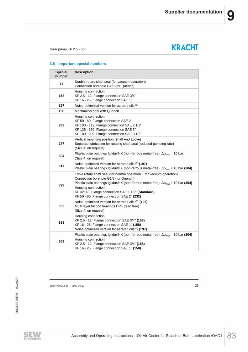
9Supplier documentation
Assembly and Operating Instructions – Oil-Air Cooler for Splash or Bath Lubrication /OAC1 83
3.8 Important special numbers
Specialnumber
Description
74 Double rotary shaft seal (for vacuum operation)Connection borehole G1/8 (for Quench)
158Housing connection:KF 2.5 - 12: Flange connection SAE 3/4"KF 16 - 25: Flange connection SAE 1"
197 Noise-optimized version for aerated oils (1)
198 Mechanical seal with Quench
232
Housing connection:KF 50 - 80: Flange connection SAE 2"KF 100 - 112: Flange connection SAE 2 1/2"KF 125 - 150: Flange connection SAE 3"KF 180 - 200: Flange connection SAE 3 1/2"
277Vertical mounting position (shaft end above)Separate lubrication for rotating shaft seal (reduced pumping rate)(Size 4: on request)
304 Plastic plain bearings Iglidur® X (non-ferrous metal-free), Δpmax = 10 bar(Size 4: on request)
317 Noise-optimized version for aerated oils (1) (197)Plastic plain bearings Iglidur® X (non-ferrous metal-free), Δpmax = 10 bar (304)
322
Triple rotary shaft seal (for normal operation + for vacuum operation)Connection borehole G1/8 (for Quench)Plastic plain bearings Iglidur® X (non-ferrous metal-free), Δpmax = 10 bar (304)Housing connection:KF 32; 40: Flange connection SAE 1 1/2" (Standard)KF 50 - 80: Flange connection SAE 2" (232)
353Noise-optimized version for aerated oils (1) (197)Multi layer friction bearings DP4 (lead free)(Size 4: on request)
359
Housing connection:KF 2.5 - 12: Flange connection SAE 3/4" (158)KF 16 - 25: Flange connection SAE 1" (158)Noise-optimized version for aerated oils (1) (197)
363
Plastic plain bearings Iglidur® X (non-ferrous metal-free), Δpmax = 10 bar (304)Housing connection:KF 2.5 - 12: Flange connection SAE 3/4" (158)KF 16 - 25: Flange connection SAE 1" (158)
Gear pump KF 2.5 - 630
88024710002-26 2017-09-12 23
2660
9398
/EN
– 1
0/20
20

9 Supplier documentation
Assembly and Operating Instructions – Oil-Air Cooler for Splash or Bath Lubrication /OAC184
Specialnumber
Description
391
Noise-optimized version for aerated oils (1) (197)Housing connection:KF 50 - 80: Flange connection SAE 2" (232)KF 100 - 112: Flange connection SAE 2 1/2" (232)KF 125 - 150: Flange connection SAE 3" (232)KF 180 - 200: Flange connection SAE 3 1/2" (232)
402
Double rotary shaft seal (for vacuum operation) (74)Connection borehole G1/8 (for Quench) (74)Housing connection:KF 2.5 - 12: Flange connection SAE 3/4" (158)KF 16 - 25: Flange connection SAE 1" (158)KF 50 - 80: Flange connection SAE 2" (232)KF 100 - 112: Flange connection SAE 2 1/2" (232)KF 125 - 150: Flange connection SAE 3" (232)KF 180 - 200: Flange connection SAE 3 1/2" (232)
455Noise-optimized version for aerated oils (1) (197)Vertical mounting position (shaft end above)Separate lubrication for rotating shaft seal (reduced pumping rate) (277)
459
Double rotary shaft seal (for vacuum operation) (74)Connection borehole G1/8 (for Quench) (74)Noise-optimized version for aerated oils (1) (197)Housing connection:KF 2.5 - 12: Flange connection SAE 3/4" (158)KF 16 - 25: Flange connection SAE 1" (158)KF 50 - 80: Flange connection SAE 2" (232)KF 100 - 112: Flange connection SAE 2 1/2" (232)KF 125 - 150: Flange connection SAE 3" (232)KF 180 - 200: Flange connection SAE 3 1/2" (232)
(1) Measures for noise optimisation are only possible for one rotational direction and only effectivefor aerated oils or vacuum (only in connection with seal versions that are suitable for vacuum op-eration). Can lead to a reduction of delivery rate.
Gear pump KF 2.5 - 630
24 2017-09-12 88024710002-26
2660
9398
/EN
– 1
0/20
20

9Supplier documentation
Assembly and Operating Instructions – Oil-Air Cooler for Splash or Bath Lubrication /OAC1 85
4 Technical data
4.1 General
General information KF 2.5 - 630Design External gear pumpFixing type Flange similar DIN ISO 3019 or Foot mountingEnd of drive shaft ISO R 775 short-cylindrical
Housing connection (1)
KF 2.5 - 12 Whitworth pipe thread G3/4KF 2.5 - 12 .. ./158 Flange connection SAE 3/4"KF 16 - 25 Whitworth pipe thread G1KF 16 - 25 .. ./158 Flange connection SAE 1"KF 32 - 80 Flange connection SAE 1 1/2"KF 50 - 80 .. ./232
Flange connection SAE 2"KF 100 - 112KF 100 - 112 .. ./232
Flange connection SAE 2 1/2"KF 125 - 150KF 125 - 150 .. ./232
Flange connection SAE 3"KF 180 - 200KF 180 - 200 .. ./232 Flange connection SAE 3 1/2"KF 250 - 315 Flange connection SAE 3"KF 400 - 630 Flange connection SAE 4"
KF 2.5 - 25 U
Suction connection:Whitworth pipe thread G3/4Pressure connection:Whitworth pipe thread G1/2
KF 32 - 80 U
Suction connection:Flange connection SAE 2"Pressure connection:Flange connection SAE 2"
Mounting position
KF . R/L/B without fluid buffer Any (2)
KF . R/L/B with fluid buffer Shaft end horizontal, fluid bufferconnection top
KF . U Piston horizontalPressure connection on top
External loads on shaft end See section 4.2 “Overview nominal sizes”
Speed n See section 4.2 “Overview nominal sizes” + section 4.3 “Viscosity- Rotation speed assignment”
Gear pump KF 2.5 - 630
88024710002-26 2017-09-12 25
2660
9398
/EN
– 1
0/20
20

9 Supplier documentation
Assembly and Operating Instructions – Oil-Air Cooler for Splash or Bath Lubrication /OAC186
General information KF 2.5 - 630
Operating pressurepe
pbSee section 4.4 “Permissible pressure range”
Viscosityνmin See section 4.4.3 “Differential pressure - viscosity assignment”νmax 20000 mm2/s
Fluid temperature ϑmSee section 4.5 “Permissible temperature range”
Ambient temperature ϑu
Material See section 4.6 “Material data”Filtering Filter porosity ≤ 60 µm
Permissible media Lubricating fluids without abrasive components.(Petrols, solvents, etc. are not permissible.)
(1) Pipe thread: ISO 228-1; Flange connection: ISO 6162-1 (SAE J518)(2) A reduced service life must be expected for the shaft seal in the case of vertical installation (shaftend top).
Gear pump KF 2.5 - 630
26 2017-09-12 88024710002-26
2660
9398
/EN
– 1
0/20
20

9Supplier documentation
Assembly and Operating Instructions – Oil-Air Cooler for Splash or Bath Lubrication /OAC1 87
4.2 Overview nominal sizes
NominalsizeVgn
Geom. dis-placement
Vg [cm³/rev.]
Speed n Perm. ra-dial force
(1)
Fradial [N](n = 1500
rpm)
Permis-sible ax-ial forceFaxial [N]
(n = 1500rpm)
Soundpressurelevel (2)
LpA [dBA]
Mass in-ertiax10-6
J [kg m2]
nmin
[rpm]nmax
[rpm] (3)
2,5 2.55
200
3600
700
-
≤ 67
14.04 4.03 15.95 5.05 17.86 6.38 20.58 8.05 24.0
10 10.11 28.412 12.58 33.716 16.09 42.320 20.1 50.825 25.1 61.732 32.12
1500
≤ 68
21740 40.21 25450 50.2 29963 63.18 36880 80.5
3000
443100 101.5
≤ 69741
112 113.5 806125 129.4
≤ 65
1418150 155.6 1637180 186.6 1911200 206.2 2500 2072250 245.1
2000 2500
≤ 754133
315 312.9 5011400 399.5
≤ 776618
500 496.5 7830630 622.5 ≤ 80 9591
(1) Outside forces are only permissible in combination with an outboard bearing. Fradial on centralshaft end.(2) n = 1500 rpm ; v = 34 mm2/s ; p = 5 - 25 bar.(3) Pay attention to the viscosity.
Gear pump KF 2.5 - 630
88024710002-26 2017-09-12 27
2660
9398
/EN
– 1
0/20
20

9 Supplier documentation
Assembly and Operating Instructions – Oil-Air Cooler for Splash or Bath Lubrication /OAC188
4.3 Viscosity - Rotation speed assignment
Kinematic viscosity ν [mm2/s]100 200 300 500 1000 2000 3000 6000 10000 20000
3600 2900 2300 1800 1200 800 650 450 300 200Recommended rpm n [rpm]
Select the speed of rotation so that complete filling of the pump is ensured.This is given if the pressure on the suction side does not fall below thepermissible pressure pe min.
Gear pump KF 2.5 - 630
28 2017-09-12 88024710002-26
2660
9398
/EN
– 1
0/20
20

9Supplier documentation
Assembly and Operating Instructions – Oil-Air Cooler for Splash or Bath Lubrication /OAC1 89
4.4 Permissible pressure range
4.4.1 Operating pressure of suction side and pressure side
Seal type (1) Specialnumber
Operating pressure (2)
Suction side Pressure sidepe min [barabs.] (3)
pe max [bar] pb [bar](perm. conti-nous pres-
sure)
pb max [bar](Pressure
peaks)
1 WDR(BABSL) -
0.6 (4)
See section 4.4.2“Max. suctionside operating
pressure for seal-ing type 1, 2, 7
and 19”
25 40
2 WDR(BABSL) -
3 WDR(HN2390) -
2
4 DRWDR(HN2390)
-74 0.1 0.2
5 GLRD(AX15) -
0.6 (4)
106 GLRD
(AX30) -
7 DRWDR(BABSL)
-
See section 4.4.2“Max. suctionside operating
pressure for seal-ing type 1, 2, 7
and 19”74 0.1 0.2
9 WDR(R02-R) -
0.6 (4)
0.518 WDR
(BAUMX7) -
19 DRWDR(BABSL)
-
See section 4.4.2“Max. suctionside operating
pressure for seal-ing type 1, 2, 7
and 19”74 0.1 0.2
Gear pump KF 2.5 - 630
88024710002-26 2017-09-12 29
2660
9398
/EN
– 1
0/20
20

9 Supplier documentation
Assembly and Operating Instructions – Oil-Air Cooler for Splash or Bath Lubrication /OAC190
Seal type (1) Specialnumber
Operating pressure (2)
Suction side Pressure sidepe min [barabs.] (3)
pe max [bar] pb [bar](perm. conti-nous pres-
sure)
pb max [bar](Pressure
peaks)
23 WDR(MSS1) -
0.6 (4)
0.5 25 (5) -
30 - - 25 25 40
31 WDR(BABSL) - 0.5 25 (5) -
32 DRWDR(R02-R)
- 0.5
25 4074 0.2
36 - - 25
40 GLRD(L4) - 10
(1) WDR: Rotary shaft seal, DRWDR: Double rotary shaft seal, GLRD: Mechanical seal(2) bar abs.: absolute pressure, bar: relative pressure(3) KF . U: pe min = 0.65 bar abs.(4) Start-up condition: 0.4 bar absolute (max. 30 minutes).(5) ϑm < -20 °C: 16 bar (Housing material GJL).
4.4.2 Max. suction side operating pressure for sealing type 1, 2, 7 and 19
Speed n [rpm] pe max [bar]KF 2.5 - 63 KF 80 KF 100 - 180 KF 200 KF 250 - 315 KF 400 - 630
≤ 750 6 6 6 6 5.5 5≤ 1000 5 5 5 5 4.5 4≤ 1500 4 4 3.5 3.5 3 2.5≤ 2000 3 3 2.5 2.5 2 1.5≤ 2500 2.5 2.5 2 2 - -≤ 3000 2 2 1.5 - - -≤ 3600 1.5 - - - - -
Gear pump KF 2.5 - 630
30 2017-09-12 88024710002-26
2660
9398
/EN
– 1
0/20
20

9Supplier documentation
Assembly and Operating Instructions – Oil-Air Cooler for Splash or Bath Lubrication /OAC1 91
4.4.3 Differential pressure - viscosity assignment
Bearing Δpmax [bar]ν ≥ 1.4 mm2/s ν ≥ 6 mm2/s ν ≥ 12 mm2/s
Multi layer friction bearings contains lead(Standard)DU, P10 3 12 25Multi layer friction bearings lead freeDP4Plastic plain bearingsIglidur® G; X; H370
- 6 10White-metalled bearingTEGO® V738
4.5 Permissible temperature range
Sealing material Fluid temperature ϑm (1)
ϑm min [°C] ϑm max [°C]NBR
-20
90PTFE / FEP with FKM-core 200
EPDM 120FKM 150
FFKM / FEP with FKM-core 200FKM
(Low temperature) -30 150
(1) Comply with media-specific properties.
Sealing material Ambient temperature ϑu
ϑu min. [°C] ϑu max. [°C]NBR
-2060
PTFE / FEP with FKM-coreEPDMFKM
FFKM / FEP with FKM-coreFKM
(Low temperature) -30
Gear pump KF 2.5 - 630
88024710002-26 2017-09-12 31
2660
9398
/EN
– 1
0/20
20

9 Supplier documentation
Assembly and Operating Instructions – Oil-Air Cooler for Splash or Bath Lubrication /OAC192
4.6 Material data
Seal type (1) MaterialShaft seal O-
ringsHousing/End
coverGears Bearing
1 WDR(BABSL) NBR NBR
EN-GJL-250(GG-25)
- - -EN-
GJS-400-15(GGG-40)
Case-hardened
steel(1.7139)
Multi layer frictionbearings containslead (Standard)
DU, P10(Steel, CuSn, PTFE,
Pb)- - -
Plastic plain bearingsnon-ferrous metal-
freeIglidur® X
- - -Multi layer frictionbearings lead free
DP4(Steel, CuSn, PTFE)
- - -White-metalled bear-
ingTEGO® V738
(Steel, Cu, Sn, Sb,Cd, Ni, As)
(only KF 2.5 - 80)
2 WDR(BABSL) FKM FKM
3 WDR(HN2390) PTFE
FEPwith
FKM-core
4 DRWDR(HN2390) PTFE
FEPwith
FKM-core
5
GLRDwith FKM
secondaryseals
(AX15)
C2S2V1G3G1(2)
(KF 2.5 - 200)FKM
B10SV1G3G1(3)
(KF 250 - 630)
6
GLRDwith FFKMsecondary
seals(AX30)
Q2Q2K1G3 (4)
(KF 2.5 - 25) FEPwith
FKM-core
Q2B2K1G3 (5)
(KF 32 - 200)
7 DRWDR(BABSL) FKM FKM
9 WDR(R02-R) EPDM EPDM
18 WDR(BAUMX7) FKM FKM
19 DRWDR(BABSL) NBR NBR
23 WDR(MSS1)
FKM(Low tempera-
ture)
FKM(Lowtem-pera-ture)
Gear pump KF 2.5 - 630
32 2017-09-12 88024710002-26
2660
9398
/EN
– 1
0/20
20

9Supplier documentation
Assembly and Operating Instructions – Oil-Air Cooler for Splash or Bath Lubrication /OAC1 93
Seal type (1) MaterialShaft seal O-
ringsHousing/End
coverGears Bearing
30 - - FKM
EN-GJL-250(GG-25)
- - -EN-
GJS-400-15(GGG-40)
Case-hardened
steel(1.7139)
Multi layer frictionbearings containslead (Standard)
DU, P10(Steel, CuSn, PTFE,
Pb)- - -
Plastic plain bearingsnon-ferrous metal-
freeIglidur® X
- - -Multi layer frictionbearings lead free
DP4(Steel, CuSn, PTFE)
- - -White-metalled bear-
ingTEGO® V738
(Steel, Cu, Sn, Sb,Cd, Ni, As)
(only KF 2.5 - 80)
31 WDR(BABSL)
FKM(Low tempera-
ture)
FKM(Lowtem-pera-ture)
32 DRWDR(R02-R) EPDM EPDM
36 - - NBR
40
GLRDwith FKM
secondaryseals(L4)
AQ2VFF (6) FKM
(1) WDR: Rotary shaft seal, DRWDR: Double rotary shaft seal, GLRD: Mechanical seal(2) Metal-impregnated carbon /CrMo-Steel, FKM, CrNiMo-Steel(3) Resin-impregnated carbon , Cr-casting, FKM, CrNiMo-Steel(4) SiC/SiC, FFKM, CrNiMo-Steel(5) SiC/Resin-impregnated carbon , FFKM, CrNiMo-Steel(6) Metal-impregnated carbon /SiC, FKM, CrNi-Steel
Gear pump KF 2.5 - 630
88024710002-26 2017-09-12 33
2660
9398
/EN
– 1
0/20
20
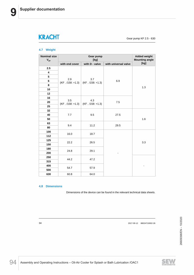
9 Supplier documentation
Assembly and Operating Instructions – Oil-Air Cooler for Splash or Bath Lubrication /OAC194
4.7 Weight
Nominal sizeVgn
Gear pump[kg]
Added weightMounting angle
[kg]with end cover with D - valve with universal valve2.5
2.9(KF . /158: +1.3)
3.7(KF . /158: +1.3) 6.9
1.3
4568
101216
3.5(KF . /158: +1.3)
4.3(KF . /158: +1.3) 7.520
2532
7.7 9.5 27.51.6
405063
9.4 11.2 29.580
10016.0 18.7
-
3.3
112125
22.2 26.5150180
24.8 29.1200250
44.2 47.2
-315400
54.7 57.9500630 60.8 64.0
4.8 Dimensions
Dimensions of the device can be found in the relevant technical data sheets.
Gear pump KF 2.5 - 630
34 2017-09-12 88024710002-26
2660
9398
/EN
– 1
0/20
20
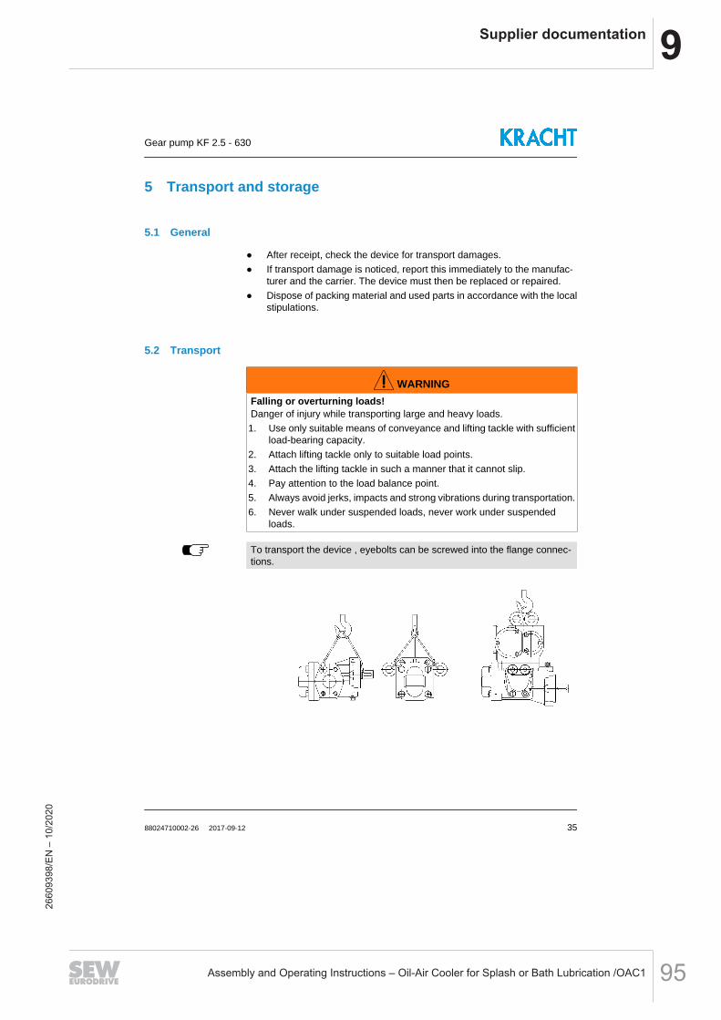
9Supplier documentation
Assembly and Operating Instructions – Oil-Air Cooler for Splash or Bath Lubrication /OAC1 95
5 Transport and storage
5.1 General
After receipt, check the device for transport damages. If transport damage is noticed, report this immediately to the manufac-
turer and the carrier. The device must then be replaced or repaired. Dispose of packing material and used parts in accordance with the local
stipulations.
5.2 Transport
WARNINGFalling or overturning loads!Danger of injury while transporting large and heavy loads.1. Use only suitable means of conveyance and lifting tackle with sufficient
load-bearing capacity.2. Attach lifting tackle only to suitable load points.3. Attach the lifting tackle in such a manner that it cannot slip.4. Pay attention to the load balance point.5. Always avoid jerks, impacts and strong vibrations during transportation.6. Never walk under suspended loads, never work under suspended
loads.
To transport the device , eyebolts can be screwed into the flange connec-tions.
Gear pump KF 2.5 - 630
88024710002-26 2017-09-12 35
2660
9398
/EN
– 1
0/20
20
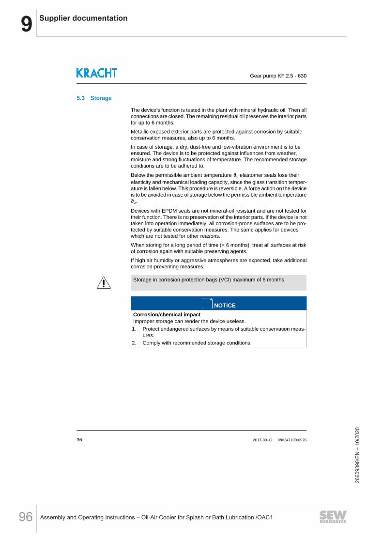
9 Supplier documentation
Assembly and Operating Instructions – Oil-Air Cooler for Splash or Bath Lubrication /OAC196
5.3 Storage
The device's function is tested in the plant with mineral hydraulic oil. Then allconnections are closed. The remaining residual oil preserves the interior partsfor up to 6 months.
Metallic exposed exterior parts are protected against corrosion by suitableconservation measures, also up to 6 months.
In case of storage, a dry, dust-free and low-vibration environment is to beensured. The device is to be protected against influences from weather,moisture and strong fluctuations of temperature. The recommended storageconditions are to be adhered to.
Below the permissible ambient temperature ϑu elastomer seals lose theirelasticity and mechanical loading capacity, since the glass transition temper-ature is fallen below. This procedure is reversible. A force action on the deviceis to be avoided in case of storage below the permissible ambient temperatureϑu.
Devices with EPDM seals are not mineral-oil resistant and are not tested fortheir function. There is no preservation of the interior parts. If the device is nottaken into operation immediately, all corrosion-prone surfaces are to be pro-tected by suitable conservation measures. The same applies for deviceswhich are not tested for other reasons.
When storing for a long period of time (> 6 months), treat all surfaces at riskof corrosion again with suitable preserving agents.
If high air humidity or aggressive atmospheres are expected, take additionalcorrosion-preventing measures.
Storage in corrosion protection bags (VCI) maximum of 6 months.
NOTICECorrosion/chemical impactImproper storage can render the device useless.1. Protect endangered surfaces by means of suitable conservation meas-
ures.2. Comply with recommended storage conditions.
Gear pump KF 2.5 - 630
36 2017-09-12 88024710002-26
2660
9398
/EN
– 1
0/20
20

9Supplier documentation
Assembly and Operating Instructions – Oil-Air Cooler for Splash or Bath Lubrication /OAC1 97
Recommended storage conditions1. Storage temperature: 5 °C - 25 °C2. Relative air humidity: < 70 %3. Protect elastomer parts from light, especially direct sunlight.4. Protect elastomer parts from oxygen and ozone.5. Comply with maximum storage times of elastomeric parts:
5 Years: AU (Polyurethane rubber) 7 Years: NBR, HNBR, CR 10 Years: EPM, EPDM, FEP/PTFE, FEPM, FKM, FFKM, VMQ,
FVMQ
Gear pump KF 2.5 - 630
88024710002-26 2017-09-12 37
2660
9398
/EN
– 1
0/20
20
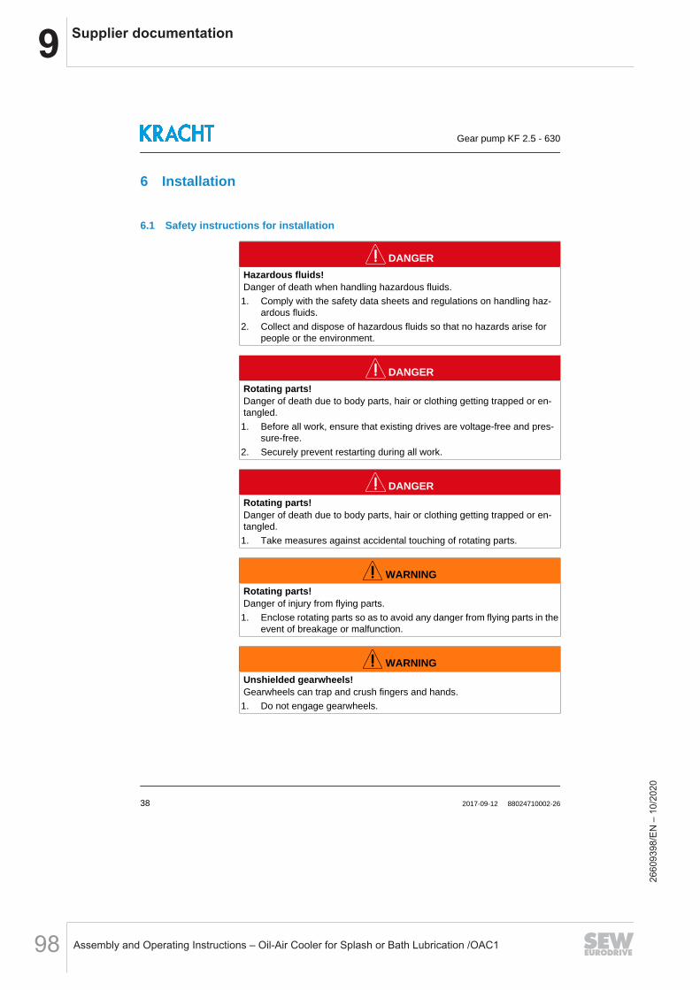
9 Supplier documentation
Assembly and Operating Instructions – Oil-Air Cooler for Splash or Bath Lubrication /OAC198
6 Installation
6.1 Safety instructions for installation
DANGERHazardous fluids!Danger of death when handling hazardous fluids.1. Comply with the safety data sheets and regulations on handling haz-
ardous fluids.2. Collect and dispose of hazardous fluids so that no hazards arise for
people or the environment.
DANGERRotating parts!Danger of death due to body parts, hair or clothing getting trapped or en-tangled.1. Before all work, ensure that existing drives are voltage-free and pres-
sure-free.2. Securely prevent restarting during all work.
DANGERRotating parts!Danger of death due to body parts, hair or clothing getting trapped or en-tangled.1. Take measures against accidental touching of rotating parts.
WARNINGRotating parts!Danger of injury from flying parts.1. Enclose rotating parts so as to avoid any danger from flying parts in the
event of breakage or malfunction.
WARNINGUnshielded gearwheels!Gearwheels can trap and crush fingers and hands.1. Do not engage gearwheels.
Gear pump KF 2.5 - 630
38 2017-09-12 88024710002-26
2660
9398
/EN
– 1
0/20
20

9Supplier documentation
Assembly and Operating Instructions – Oil-Air Cooler for Splash or Bath Lubrication /OAC1 99
WARNINGFailure of load-carrying parts due to overload!Danger of injury from flying parts.Danger of injury from spurting fluids.1. Depressurise the device and all connection lines before doing any work.2. Securely prevent the restoration of pressure while working on the de-
vice.
6.2 Noise reduction
Measures for noise reduction1. Use suction and pressure hoses.2. Use bell housings with high damping properties (plastic or cast iron).3. Use of damping rings and damping rods for separation of structure-
borne noise.
6.3 Mechanical installation
6.3.1 Preparation
Check the device for transport damage and dirt. Check the device for freedom of movement. Remove existing preservatives.
Use only those cleaning agents that are compatible with the mate-rials used in the device.
Do not use cleaning wool. Compare the environmental and ambient conditions at the place of in-
stallation to the permissible conditions. Ensure a sufficiently stable and level foundation. Expose the device only to small vibrations, see IEC 60034-14. Secure sufficient access for maintenance and repair.
6.3.2 Pumps with free shaft end
The prerequisite for trouble-free operation is suitable load transmission be-tween the pump and the drive. By default a torsionally flexible claw couplingType "R" is used for this.
Pre-mount coupling parts as per manufacturer's specifications.
Torsionally flexible claw coupling type "R.": See section 6.3.3 “CouplingType "R."”
Gear pump KF 2.5 - 630
88024710002-26 2017-09-12 39
2660
9398
/EN
– 1
0/20
20

9 Supplier documentation
Assembly and Operating Instructions – Oil-Air Cooler for Splash or Bath Lubrication /OAC1100
Position the pumps and the drive with respect to each other. Comply with the permissible mounting position. Comply with the permissible direction of rotation.
Rotation and delivery direction: See chapter 3 “Device description”
Tighten all fastening screws with the specified torque. Keep to the permissible displacement values of the coupling. Rule out any distortion of the device. Pay attention to sufficient screw-in depth of the fastening screws.
Tightening torques [Nm]Thread size (1) M6 M8 M10 M12 M16 M20 M24Counter-threadAluminium 4.6 11 22 39 95 184 315
Counter-threadCast iron/Steel 10 25 49 85 210 425 730
(1) Screws/Nuts with min. strength class 8.8/8
For devices without shaft seals, ensure that the leak oil from the shaftsealing chamber is specifically drained off and cannot get into the envi-ronment.
Make sure no foreign bodies can get into the device. Take measures against accidental touching of rotating parts. Take measures against accidental touching of hot surfaces (> 60 °C). On devices with quench, mount a tank for the liquid seal.
Mount the tank above the device. The connection on the device must point upward. Checking the fluid level must be possible at any time.
A second port on the unit enables purging of the quench chamber anddraining of the liquid seal.
Gear pump KF 2.5 - 630
40 2017-09-12 88024710002-26
2660
9398
/EN
– 1
0/20
20

9Supplier documentation
Assembly and Operating Instructions – Oil-Air Cooler for Splash or Bath Lubrication /OAC1 101
6.3.3 Coupling Type "R."
Claw couplings Type "R." are torsionally flexible and transmit the torque pos-itive. They are fail-safe. The vibrations and impacts that occur during opera-tion are effectively dampened and reduced.
Claw coupling Type "R."
NOTICECoupling breakage or increased wearAn overload can lead to premature failure of the coupling.1. Ensure safe dimensioning when designing the coupling. Take vibra-
tions, torque peaks and temperatures into account.
Gear pump KF 2.5 - 630
88024710002-26 2017-09-12 41
2660
9398
/EN
– 1
0/20
20
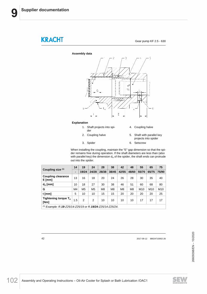
9 Supplier documentation
Assembly and Operating Instructions – Oil-Air Cooler for Splash or Bath Lubrication /OAC1102
Assembly data
Explanation1. Shaft projects into spi-
der4. Coupling halve
2. Coupling halve 5. Shaft with parallel keyprojects into spider
3. Spider 6. Setscrew
When installing the coupling, maintain the "E" gap dimension so that the spi-der remains free during operation. If the shaft diameters are less than (alsowith parallel key) the dimension dH of the spider, the shaft ends can protrudeout into the spider.
Coupling size (1)14 19 24 28 38 42 48 55 65 75- 19/24 24/28 28/38 38/45 42/55 48/60 55/70 65/75 75/90
Coupling clearanceE [mm] 13 16 18 20 24 26 28 30 35 40
dH [mm] 10 18 27 30 38 46 51 60 68 80G M4 M5 M5 M8 M8 M8 M8 M10 M10 M10t [mm] 5 10 10 15 15 20 20 20 20 25Tightening torque TA
[Nm] 1.5 2 2 10 10 10 10 17 17 17
(1) Example: R.19-Z25/14-Z25/19 or R.19/24-Z25/14-Z25/24.
Gear pump KF 2.5 - 630
42 2017-09-12 88024710002-26
2660
9398
/EN
– 1
0/20
20
9Supplier documentation
Assembly and Operating Instructions – Oil-Air Cooler for Splash or Bath Lubrication /OAC1 103
For assembly, the coupling halves can be heated to approx. 80 °C andpushed onto the shaft ends while warm.
CAUTIONHot surfaces!Burn injury to skin if touched.1. Wear protective gloves at temperatures ≥48°C.
Mount the coupling halves on the shaft ends but avoid impacts on thecomponents.
Position the coupling halves on the shaft ends so that in later operationthe "E" gap dimension is maintained.
Secure the coupling halves by tightening the setscrews. Insert the spider in a coupling half.
Gear pump KF 2.5 - 630
88024710002-26 2017-09-12 43
2660
9398
/EN
– 1
0/20
20

9 Supplier documentation
Assembly and Operating Instructions – Oil-Air Cooler for Splash or Bath Lubrication /OAC1104
Displacement valuesAxial displacement
ΔKa
Radial displacementΔKr
Angular displacementΔKw/ΔKL
ΔKL ≙ Lmax - Lmin
Coupling size14 19 24 28 38 42 48 55 65 75- 19/24 24/28 28/38 38/45 42/55 48/60 55/70 65/75 75/90
Coupling clearanceE [mm] 13 16 18 20 24 26 28 30 35 40
ΔKa [mm]+1.0 +1.2 +1.4 +1.5 +1.8 +2.0 +2.1 +2.2 +2.6 +3.0-0.5 -0.5 -0.5 -0.7 -0.7 -1.0 -1.0 -1-0 -1.0 -1.5
ΔKr [mm]
1500rpm 0.11 0.13 0.15 0.18 0.21 0.23 0.25 0.27 0.30 0.34
3000rpm 0.08 0.09 0.1 0.13 0.15 0.16 0.18 0.19 0.21 0.24
ΔKw [De-gree]
1500rpm 1.1 1.1 0.8 0.8 0.9 0.9 1.0 1.0 1.1 1.1
3000rpm 1.0 1.0 0.7 0.7 0.8 0.8 0.9 0.9 1.0 1.0
ΔKL [mm]
1500rpm 0.57 0.77 0.77 0.90 1.25 1.40 1.80 2.00 2.50 3.00
3000rpm 0.52 0.7 0.67 0.80 1.00 1.30 1.60 1.80 2.20 2.70
Gear pump KF 2.5 - 630
44 2017-09-12 88024710002-26
2660
9398
/EN
– 1
0/20
20
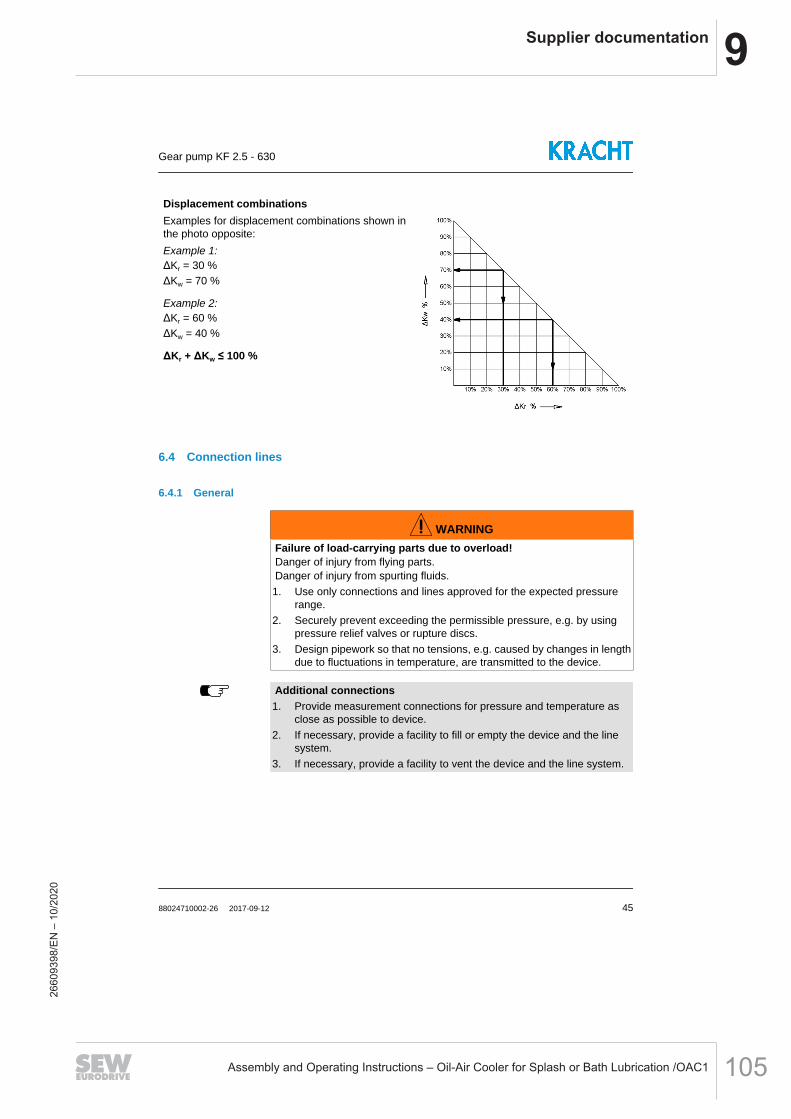
9Supplier documentation
Assembly and Operating Instructions – Oil-Air Cooler for Splash or Bath Lubrication /OAC1 105
Displacement combinationsExamples for displacement combinations shown inthe photo opposite:Example 1:ΔKr = 30 %ΔKw = 70 %
Example 2:ΔKr = 60 %ΔKw = 40 %
ΔKr + ΔKw ≤ 100 %
6.4 Connection lines
6.4.1 General
WARNINGFailure of load-carrying parts due to overload!Danger of injury from flying parts.Danger of injury from spurting fluids.1. Use only connections and lines approved for the expected pressure
range.2. Securely prevent exceeding the permissible pressure, e.g. by using
pressure relief valves or rupture discs.3. Design pipework so that no tensions, e.g. caused by changes in length
due to fluctuations in temperature, are transmitted to the device.
Additional connections1. Provide measurement connections for pressure and temperature as
close as possible to device.2. If necessary, provide a facility to fill or empty the device and the line
system.3. If necessary, provide a facility to vent the device and the line system.
Gear pump KF 2.5 - 630
88024710002-26 2017-09-12 45
2660
9398
/EN
– 1
0/20
20
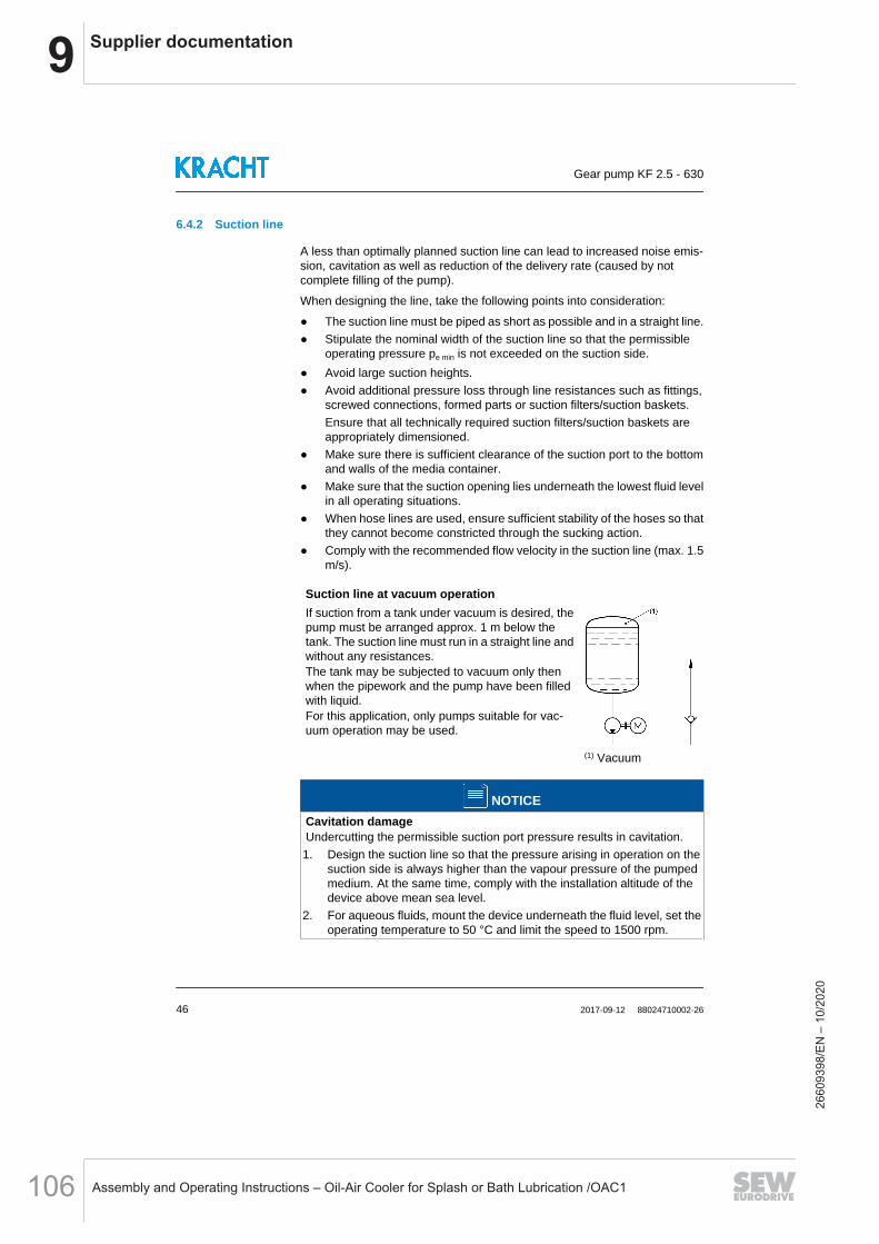
9 Supplier documentation
Assembly and Operating Instructions – Oil-Air Cooler for Splash or Bath Lubrication /OAC1106
6.4.2 Suction line
A less than optimally planned suction line can lead to increased noise emis-sion, cavitation as well as reduction of the delivery rate (caused by notcomplete filling of the pump).
When designing the line, take the following points into consideration:
The suction line must be piped as short as possible and in a straight line. Stipulate the nominal width of the suction line so that the permissible
operating pressure pe min is not exceeded on the suction side. Avoid large suction heights. Avoid additional pressure loss through line resistances such as fittings,
screwed connections, formed parts or suction filters/suction baskets.Ensure that all technically required suction filters/suction baskets areappropriately dimensioned.
Make sure there is sufficient clearance of the suction port to the bottomand walls of the media container.
Make sure that the suction opening lies underneath the lowest fluid levelin all operating situations.
When hose lines are used, ensure sufficient stability of the hoses so thatthey cannot become constricted through the sucking action.
Comply with the recommended flow velocity in the suction line (max. 1.5m/s).
Suction line at vacuum operationIf suction from a tank under vacuum is desired, thepump must be arranged approx. 1 m below thetank. The suction line must run in a straight line andwithout any resistances.The tank may be subjected to vacuum only thenwhen the pipework and the pump have been filledwith liquid.For this application, only pumps suitable for vac-uum operation may be used.
(1) Vacuum
NOTICECavitation damageUndercutting the permissible suction port pressure results in cavitation.1. Design the suction line so that the pressure arising in operation on the
suction side is always higher than the vapour pressure of the pumpedmedium. At the same time, comply with the installation altitude of thedevice above mean sea level.
2. For aqueous fluids, mount the device underneath the fluid level, set theoperating temperature to 50 °C and limit the speed to 1500 rpm.
Gear pump KF 2.5 - 630
46 2017-09-12 88024710002-26
2660
9398
/EN
– 1
0/20
20

9Supplier documentation
Assembly and Operating Instructions – Oil-Air Cooler for Splash or Bath Lubrication /OAC1 107
Prevention of suction problemsIf there is a possibility that the suction line can rundry if the pump stops, piping the suction line as si-phon is an option to avoid suction problems. Thisway, the pump will remain permanently filled afterinitial commissioning.
It is appropriate to employ a foot valve or a non-return valvein case of longer suction lines that can run dry while thepump is at rest. These must have been designed for use insuction lines and should offer as low a flow resistance aspossible.
During operation of a pump that has to pump mediavia a non-return valve in a pressurized circuit (e.g. re-serve pump in a lubricant circuit), suction problems canoccur if the suction line is filled with air.In this case the pressure pipe must be bled directlyupstream of the non-return valve.If no vent nozzle is used, the volume of the pressurepipe between the pump and the non-return valve mustbe at least 75 % of the suction line volume.
6.4.3 Pressure line
When designing the line, take the following points into consideration:
Select the nominal width of the pressure line so that the maximum per-missible pressures are not exceeded.
If necessary, provide a vent nozzle to prevent suction problems.
6.4.4 Mounting Connection lines
Position of the device connections: See chapter 3 “Device description”
Clean all lines. Do not use cleaning wool. Pickle and flush welded pipes.
Remove the protective plugs. Mount the lines.
Comply with the manufacturer's information. Do not use any sealing materials such as hemp, Teflon tape or putty.
Gear pump KF 2.5 - 630
88024710002-26 2017-09-12 47
2660
9398
/EN
– 1
0/20
20

9 Supplier documentation
Assembly and Operating Instructions – Oil-Air Cooler for Splash or Bath Lubrication /OAC1108
6.5 Change of the direction of rotation
For pump types KF . R and KF . L, a change of the direction of rotation is onlypossible by converting.
The manufacturer normally carries out the conversion work and the customershould do this only in exceptional cases. Please consult the manufacturerabout this.
Gear pumps in noise-optimized version cannot be converted. (e.g. specialnumber 197)
DANGERRotating parts!Danger of death due to body parts, hair or clothing getting trapped or en-tangled.1. Before all work, ensure that existing drives are voltage-free and pres-
sure-free.2. Securely prevent restarting during all work.
WARNINGFailure of load-carrying parts due to overload!Danger of injury from flying parts.Danger of injury from spurting fluids.1. Depressurise the device and all connection lines before doing any work.2. Securely prevent the restoration of pressure while working on the de-
vice.
NOTICELeaks or increased wearDamaged sealing surfaces or supports lead to lack of sealing and/or faultsin later operation.1. When assembling or disassembling housing components, be sure not
to damage the bearings, e.g. by tilting.2. When disassembling housing components, do not use screwdrivers or
the like as a lever to separate the joints.3. Do not remove, damage or jam seals.
Gear pump KF 2.5 - 630
48 2017-09-12 88024710002-26
2660
9398
/EN
– 1
0/20
20

9Supplier documentation
Assembly and Operating Instructions – Oil-Air Cooler for Splash or Bath Lubrication /OAC1 109
S = Suction connection 1. Fastening screwsP = Pressure connection 2. Leak oil hole
To change the direction of rotation of the gear pump, turn the end cover orthe pressure relief valve 180°.
Loose fastening screws. Unscrew the end cover or the pressure relief valve of the pump housing
and replace it rotated 180°. Tighten the fastening screws with the stated torque.
Fastening screws KF 2.5 - 630Gear pump KF 2.5 - 25 KF 32 - 80 KF 100 - 200 KF 250 - 630Tightening tor-ques [Nm] 25 49 85 215
For pumps with sealing type 6, the lip-type seal must be replaced in addition.During this process, the spring coiling direction must be observed.
When checking, pay attention to the following points:1. For gear pumps without pressure relief valve, the leak oil hole in the end
cover must be placed at the pump's suction side.2. Gear pumps with pressure relief valve must have their pressure relief
valve adjusting screw point toward the pump's pressure side.
Gear pump KF 2.5 - 630
88024710002-26 2017-09-12 49
2660
9398
/EN
– 1
0/20
20
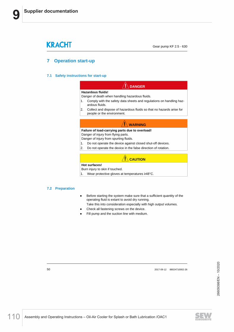
9 Supplier documentation
Assembly and Operating Instructions – Oil-Air Cooler for Splash or Bath Lubrication /OAC1110
7 Operation start-up
7.1 Safety instructions for start-up
DANGERHazardous fluids!Danger of death when handling hazardous fluids.1. Comply with the safety data sheets and regulations on handling haz-
ardous fluids.2. Collect and dispose of hazardous fluids so that no hazards arise for
people or the environment.
WARNINGFailure of load-carrying parts due to overload!Danger of injury from flying parts.Danger of injury from spurting fluids.1. Do not operate the device against closed shut-off devices.2. Do not operate the device in the false direction of rotation.
CAUTIONHot surfaces!Burn injury to skin if touched.1. Wear protective gloves at temperatures ≥48°C.
7.2 Preparation
Before starting the system make sure that a sufficient quantity of theoperating fluid is extant to avoid dry running.Take this into consideration especially with high output volumes.
Check all fastening screws on the device. Fill pump and the suction line with medium.
Gear pump KF 2.5 - 630
50 2017-09-12 88024710002-26
2660
9398
/EN
– 1
0/20
20

9Supplier documentation
Assembly and Operating Instructions – Oil-Air Cooler for Splash or Bath Lubrication /OAC1 111
7.3 Filling the quench chamber
1. Quench chamber2. Container for quench-liquid (Accessories)
For versions with quench, fill the quench chamber with a suitable quenchliquid. The filling is implemented through the tank provided for that. Fill fluid until the quench chamber is completely full and the tank is
half full. Do not apply pressure or vacuum to the quench chamber.
NOTICESeal failure due to dry runA lack of quench liquid can lead to a failure of the seal.1. Do not put pumps without quench liquid into operation.
A second port on the unit enables purging of the quench chamber anddraining of the liquid seal.
Gear pump KF 2.5 - 630
88024710002-26 2017-09-12 51
2660
9398
/EN
– 1
0/20
20

9 Supplier documentation
Assembly and Operating Instructions – Oil-Air Cooler for Splash or Bath Lubrication /OAC1112
7.4 Pressure relief valve adjustment
Directly attached pressure relief valves of the series "D" are used exclusivelyfor protection of the gear pumps and may respond on a short-term basis only.
The valves are factory set to the rated pressure of each pressure stage. Set-ting pressures that deviate from this are stated on the rating plate.
NOTICEFailure of the pumpLong triggering of the valve can cause the pump to overheat.1. Only allow intermittent triggering of the valve.
- Lower response pressure 1. Hexagonal nut+ Higher response pressure 2. Adjustment screw
Pressure setting:
Remove hexagon nut Set the response pressure using the adjusting screw Secure the adjusting screw with hexagon nut
WARNINGFailure of load-carrying parts due to overload!Danger of injury from flying parts.Danger of injury from spurting fluids.1. Consider the permissible pressure setting range of the valve.2. Check the pressure setting (the valve must not block).
Gear pump KF 2.5 - 630
52 2017-09-12 88024710002-26
2660
9398
/EN
– 1
0/20
20

9Supplier documentation
Assembly and Operating Instructions – Oil-Air Cooler for Splash or Bath Lubrication /OAC1 113
7.5 Further operation start-up
Open existing shut-off elements upstream and downstream of the de-vice.
Adjust pressure relief valves in the system installed for lowest openingpressure.
Allow the device start without or with a low pressure load (jog mode). Flow should have developed after 30 s at the latest.
Run the device for a few minutes depressurised or with low pressure. Vent the system at the highest possible point. Gradually increase the pressure load up to the desired operating pres-
sure. Operate the system for so long until the final operating state is achieved. Check the operating data such as:
Discharge flow Operating pressure (as close as possible to device) Fluid temperature (as close as possible to device) Device temperature (in particular in the area of the bearing points) ...
Document the operating data of the initial start-up for later comparison. Check the level of the operating medium in the system. Check the filling level of the liquid seal (if existing). Check the device for leaks. Check all threaded connections for leaks and retighten if necessary.
In order to ensure a constant and reliable function of the device, an initialmaintenance of the device is recommended after several hours warm-uptime (max. 24 h). Faults can thus be identified at an early stage.
Gear pump KF 2.5 - 630
88024710002-26 2017-09-12 53
2660
9398
/EN
– 1
0/20
20
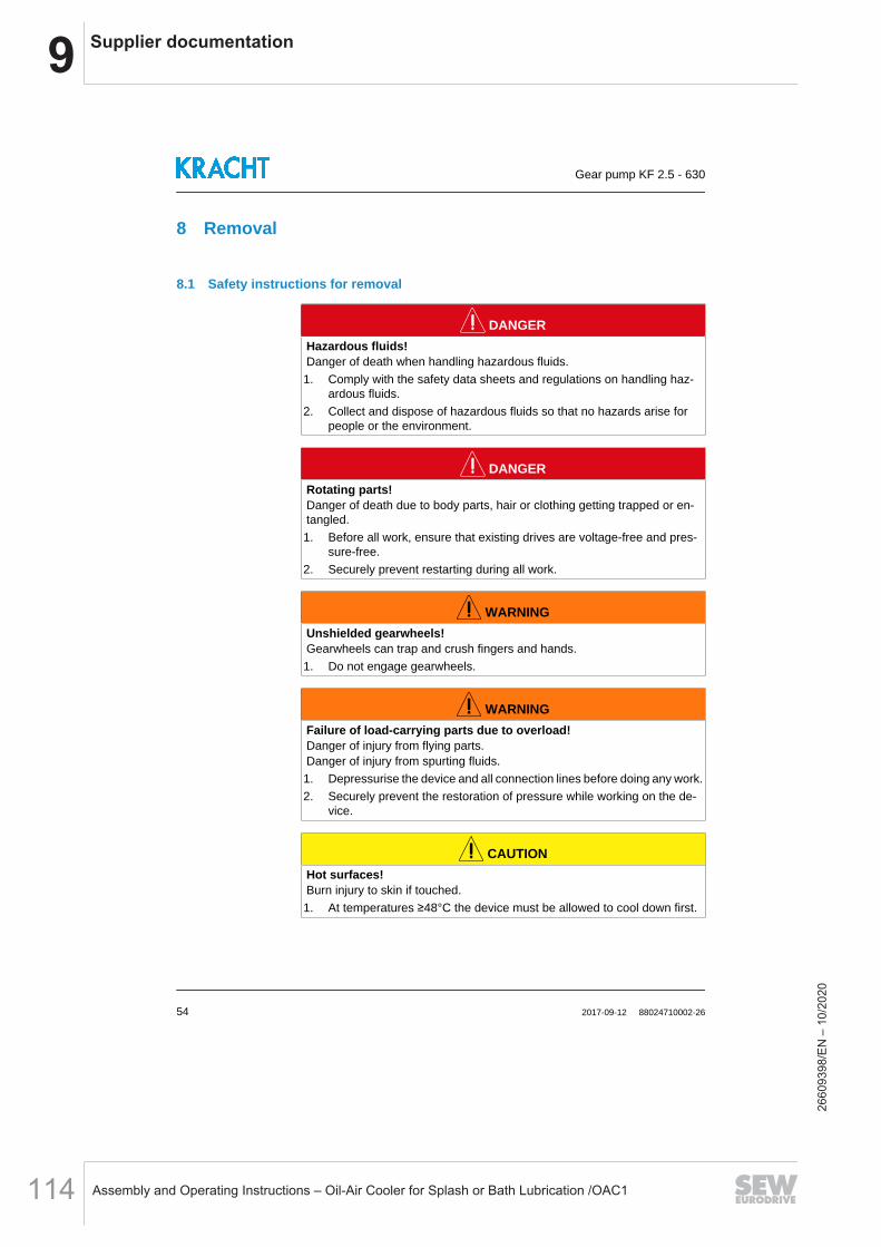
9 Supplier documentation
Assembly and Operating Instructions – Oil-Air Cooler for Splash or Bath Lubrication /OAC1114
8 Removal
8.1 Safety instructions for removal
DANGERHazardous fluids!Danger of death when handling hazardous fluids.1. Comply with the safety data sheets and regulations on handling haz-
ardous fluids.2. Collect and dispose of hazardous fluids so that no hazards arise for
people or the environment.
DANGERRotating parts!Danger of death due to body parts, hair or clothing getting trapped or en-tangled.1. Before all work, ensure that existing drives are voltage-free and pres-
sure-free.2. Securely prevent restarting during all work.
WARNINGUnshielded gearwheels!Gearwheels can trap and crush fingers and hands.1. Do not engage gearwheels.
WARNINGFailure of load-carrying parts due to overload!Danger of injury from flying parts.Danger of injury from spurting fluids.1. Depressurise the device and all connection lines before doing any work.2. Securely prevent the restoration of pressure while working on the de-
vice.
CAUTIONHot surfaces!Burn injury to skin if touched.1. At temperatures ≥48°C the device must be allowed to cool down first.
Gear pump KF 2.5 - 630
54 2017-09-12 88024710002-26
2660
9398
/EN
– 1
0/20
20

9Supplier documentation
Assembly and Operating Instructions – Oil-Air Cooler for Splash or Bath Lubrication /OAC1 115
NOTICEBlocking of the device through hardening mediumHardening medium can mechanically jam the device and make it unusable.1. Clean device immediately after operting with a hardening medium.
8.2 Removal
Depressurise and de-energize the system. Close existing shut-off elements upstream and downstream of the de-
vice. Open existing drain elements and loosen connection lines. Collect and
dispose of discharging medium so that no hazard arises for persons orenvironment.
Dismantle the device. Clean the device. Close the device connections and lines to prevent dirt penetration.
Gear pump KF 2.5 - 630
88024710002-26 2017-09-12 55
2660
9398
/EN
– 1
0/20
20
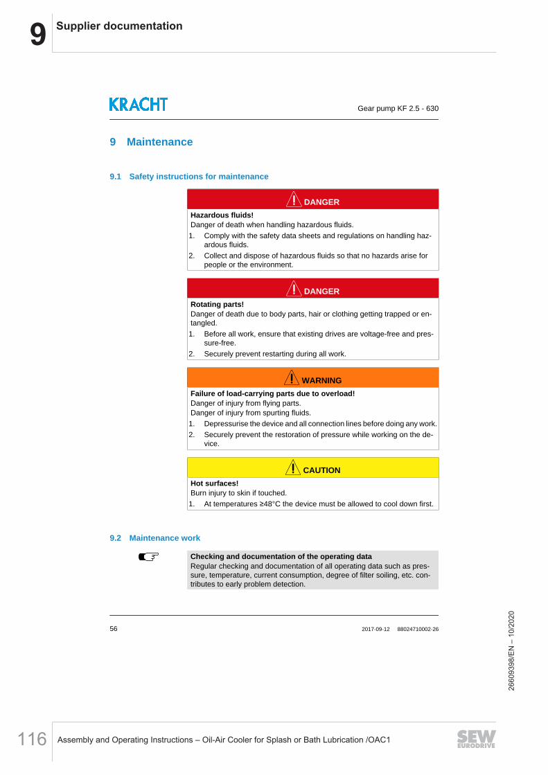
9 Supplier documentation
Assembly and Operating Instructions – Oil-Air Cooler for Splash or Bath Lubrication /OAC1116
9 Maintenance
9.1 Safety instructions for maintenance
DANGERHazardous fluids!Danger of death when handling hazardous fluids.1. Comply with the safety data sheets and regulations on handling haz-
ardous fluids.2. Collect and dispose of hazardous fluids so that no hazards arise for
people or the environment.
DANGERRotating parts!Danger of death due to body parts, hair or clothing getting trapped or en-tangled.1. Before all work, ensure that existing drives are voltage-free and pres-
sure-free.2. Securely prevent restarting during all work.
WARNINGFailure of load-carrying parts due to overload!Danger of injury from flying parts.Danger of injury from spurting fluids.1. Depressurise the device and all connection lines before doing any work.2. Securely prevent the restoration of pressure while working on the de-
vice.
CAUTIONHot surfaces!Burn injury to skin if touched.1. At temperatures ≥48°C the device must be allowed to cool down first.
9.2 Maintenance work
Checking and documentation of the operating dataRegular checking and documentation of all operating data such as pres-sure, temperature, current consumption, degree of filter soiling, etc. con-tributes to early problem detection.
Gear pump KF 2.5 - 630
56 2017-09-12 88024710002-26
2660
9398
/EN
– 1
0/20
20

9Supplier documentation
Assembly and Operating Instructions – Oil-Air Cooler for Splash or Bath Lubrication /OAC1 117
Perform maintenance according to specification. Replace defective and worn components. If required, request spare parts lists and assembly drawings from the
manufacturer. Document the type and scope of the maintenance work along with the
operating data. Compare the operating data with the values of the first commissioning.
Determine the cause in case of major non-compliances (> 10 %). Dispose of packing material and used parts in accordance with the local
stipulations.
Barriers and instructionsAll barriers and warning signs removed during this must be attached to theiroriginal position on completing maintenance and/or repairs.
9.3 Maintenance instructions
The following information provides recommendations on maintenance workand maintenance intervals for the device being used.
Depending on the actually occurring loads in operation, the type, scope andinterval of the maintenance work can deviate from the recommendations. Theequipment builder/operator shall write an obligatory maintenance plan.
Within the framework of preventive maintenance, it is appropriate to replacewear parts before reaching the wear limit.
With corresponding expertise and sufficient equipment, the replacement canbe carried out by the equipment builder/operator. Please consult the manu-facturer about this.
WarrantyIn case of improper implementation, any warranty is voided.
Gear pump KF 2.5 - 630
88024710002-26 2017-09-12 57
2660
9398
/EN
– 1
0/20
20

9 Supplier documentation
Assembly and Operating Instructions – Oil-Air Cooler for Splash or Bath Lubrication /OAC1118
Maintenance recommendations Gear pumpInterval Maintenance work Employ-
eesDurationapprox.[h]
Firstly:after max. 24 h
Inspection: Discharge flow
1 1
Inspection: Operating pressureInspection: Fluid temperatureInspection: Device temperatureInspection: Add-on valve function (if existing)Inspection: Check potential equalisation forfirm seating and functionality (if existing)Inspection: Condition of operating fluid
Daily
Audiometric monitoring: Unusual noise
1 0.1
Cleaning: Remove dust deposits and dirt witha moist clothVisual inspection: LeakagesVisual inspection: Filling level of liquid seal (ifexisting)
3000 Operating hours
Inspection: Discharge flow
1 1
Inspection: Operating pressureInspection: Fluid temperatureInspection: Device temperatureInspection: Add-on valve function (if existing)Inspection: Check potential equalisation forfirm seating and functionality (if existing)Inspection: Condition of operating fluid
6000 Operating hours
Visual inspection: Condition of gears
1 2
Visual inspection: Condition of housing partsVisual inspection: Condition of plain bearingsVisual inspection: Condition of shaft sealVisual inspection: Condition of outboard bear-ings (if existing)
As required
Replace: Plain bearings (only by manufacturer)
1 2Replace: Outbord bearing (if existing)Replace: Shaft sealReplace: Other seals
Gear pump KF 2.5 - 630
58 2017-09-12 88024710002-26
2660
9398
/EN
– 1
0/20
20
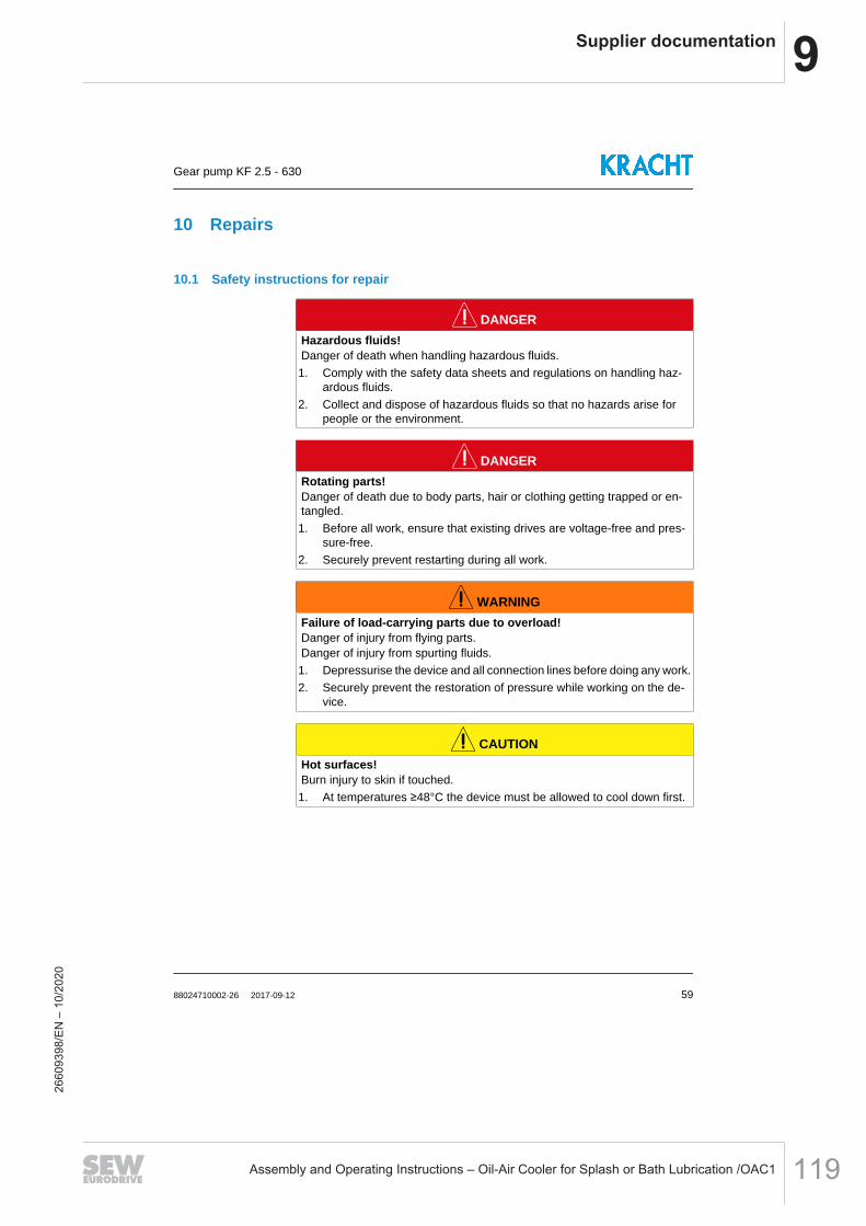
9Supplier documentation
Assembly and Operating Instructions – Oil-Air Cooler for Splash or Bath Lubrication /OAC1 119
10 Repairs
10.1 Safety instructions for repair
DANGERHazardous fluids!Danger of death when handling hazardous fluids.1. Comply with the safety data sheets and regulations on handling haz-
ardous fluids.2. Collect and dispose of hazardous fluids so that no hazards arise for
people or the environment.
DANGERRotating parts!Danger of death due to body parts, hair or clothing getting trapped or en-tangled.1. Before all work, ensure that existing drives are voltage-free and pres-
sure-free.2. Securely prevent restarting during all work.
WARNINGFailure of load-carrying parts due to overload!Danger of injury from flying parts.Danger of injury from spurting fluids.1. Depressurise the device and all connection lines before doing any work.2. Securely prevent the restoration of pressure while working on the de-
vice.
CAUTIONHot surfaces!Burn injury to skin if touched.1. At temperatures ≥48°C the device must be allowed to cool down first.
Gear pump KF 2.5 - 630
88024710002-26 2017-09-12 59
2660
9398
/EN
– 1
0/20
20
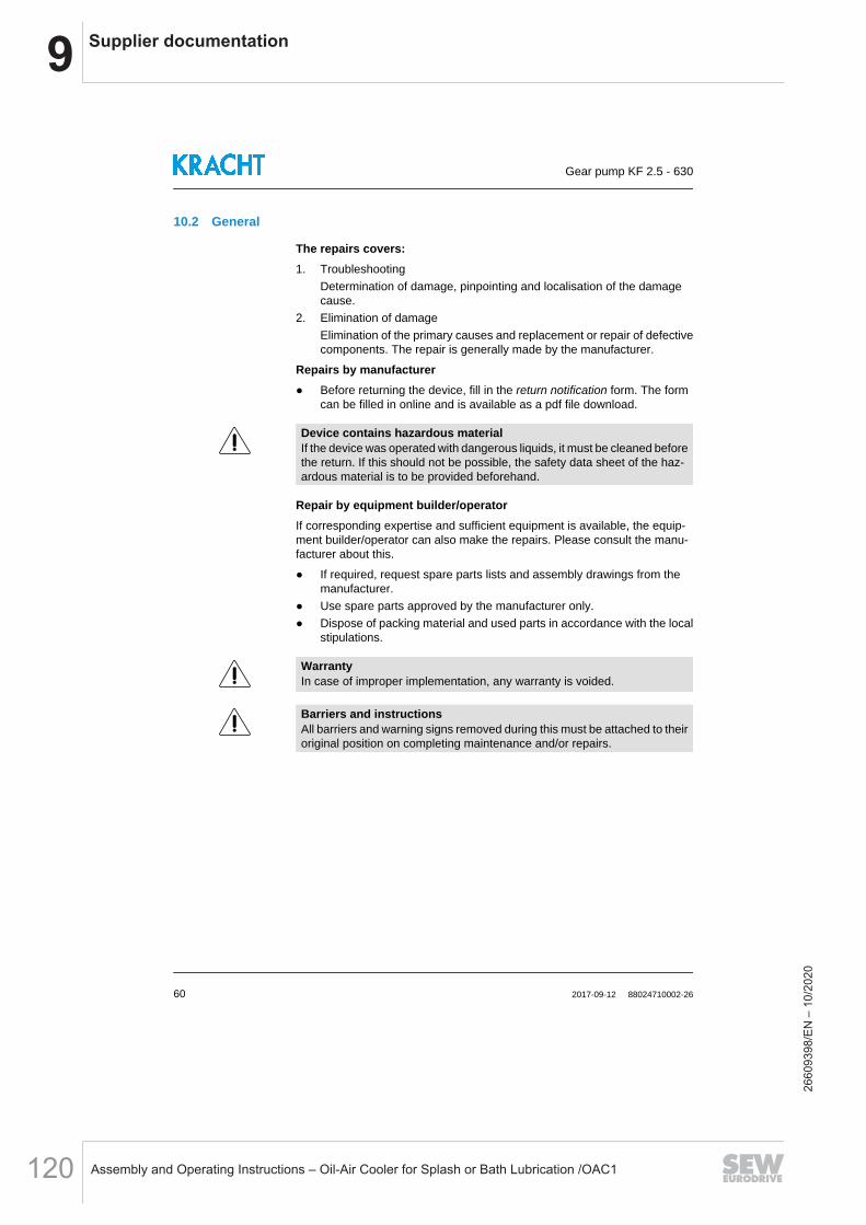
9 Supplier documentation
Assembly and Operating Instructions – Oil-Air Cooler for Splash or Bath Lubrication /OAC1120
10.2 General
The repairs covers:1. Troubleshooting
Determination of damage, pinpointing and localisation of the damagecause.
2. Elimination of damageElimination of the primary causes and replacement or repair of defectivecomponents. The repair is generally made by the manufacturer.
Repairs by manufacturer Before returning the device, fill in the return notification form. The form
can be filled in online and is available as a pdf file download.
Device contains hazardous materialIf the device was operated with dangerous liquids, it must be cleaned beforethe return. If this should not be possible, the safety data sheet of the haz-ardous material is to be provided beforehand.
Repair by equipment builder/operatorIf corresponding expertise and sufficient equipment is available, the equip-ment builder/operator can also make the repairs. Please consult the manu-facturer about this.
If required, request spare parts lists and assembly drawings from themanufacturer.
Use spare parts approved by the manufacturer only. Dispose of packing material and used parts in accordance with the local
stipulations.
WarrantyIn case of improper implementation, any warranty is voided.
Barriers and instructionsAll barriers and warning signs removed during this must be attached to theiroriginal position on completing maintenance and/or repairs.
Gear pump KF 2.5 - 630
60 2017-09-12 88024710002-26
2660
9398
/EN
– 1
0/20
20
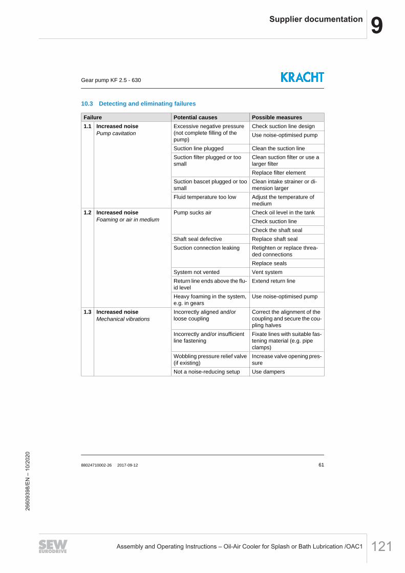
9Supplier documentation
Assembly and Operating Instructions – Oil-Air Cooler for Splash or Bath Lubrication /OAC1 121
10.3 Detecting and eliminating failures
Failure Potential causes Possible measures1.1 Increased noise
Pump cavitationExcessive negative pressure(not complete filling of thepump)
Check suction line designUse noise-optimised pump
Suction line plugged Clean the suction lineSuction filter plugged or toosmall
Clean suction filter or use alarger filterReplace filter element
Suction bascet plugged or toosmall
Clean intake strainer or di-mension larger
Fluid temperature too low Adjust the temperature ofmedium
1.2 Increased noiseFoaming or air in medium
Pump sucks air Check oil level in the tankCheck suction lineCheck the shaft seal
Shaft seal defective Replace shaft sealSuction connection leaking Retighten or replace threa-
ded connectionsReplace seals
System not vented Vent systemReturn line ends above the flu-id level
Extend return line
Heavy foaming in the system,e.g. in gears
Use noise-optimised pump
1.3 Increased noiseMechanical vibrations
Incorrectly aligned and/orloose coupling
Correct the alignment of thecoupling and secure the cou-pling halves
Incorrectly and/or insufficientline fastening
Fixate lines with suitable fas-tening material (e.g. pipeclamps)
Wobbling pressure relief valve(if existing)
Increase valve opening pres-sure
Not a noise-reducing setup Use dampers
Gear pump KF 2.5 - 630
88024710002-26 2017-09-12 61
2660
9398
/EN
– 1
0/20
20
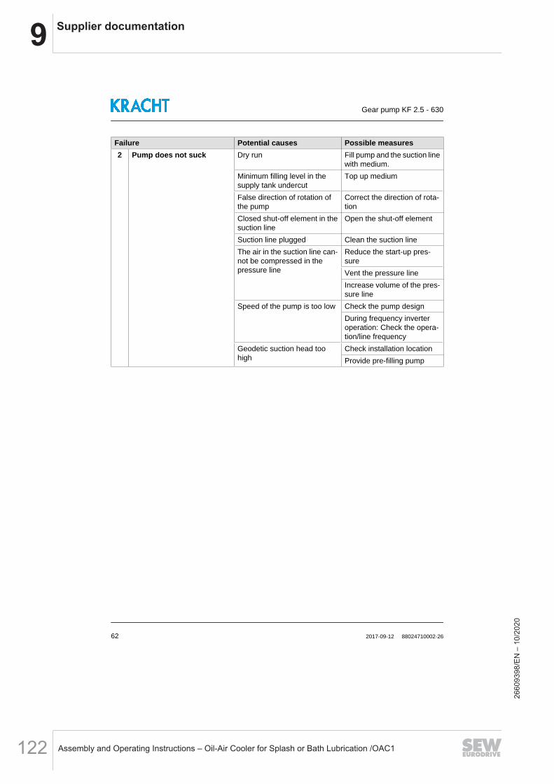
9 Supplier documentation
Assembly and Operating Instructions – Oil-Air Cooler for Splash or Bath Lubrication /OAC1122
Failure Potential causes Possible measures2 Pump does not suck Dry run Fill pump and the suction line
with medium.Minimum filling level in thesupply tank undercut
Top up medium
False direction of rotation ofthe pump
Correct the direction of rota-tion
Closed shut-off element in thesuction line
Open the shut-off element
Suction line plugged Clean the suction lineThe air in the suction line can-not be compressed in thepressure line
Reduce the start-up pres-sureVent the pressure lineIncrease volume of the pres-sure line
Speed of the pump is too low Check the pump designDuring frequency inverteroperation: Check the opera-tion/line frequency
Geodetic suction head toohigh
Check installation locationProvide pre-filling pump
Gear pump KF 2.5 - 630
62 2017-09-12 88024710002-26
2660
9398
/EN
– 1
0/20
20
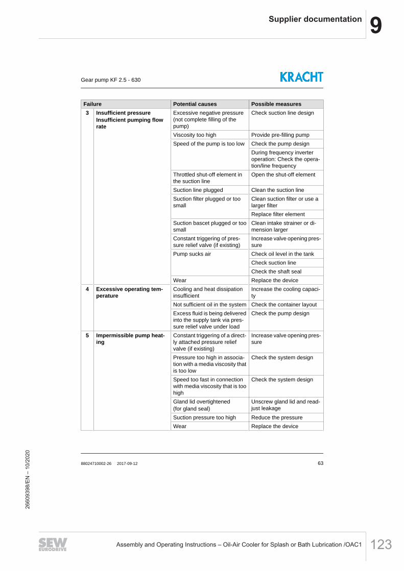
9Supplier documentation
Assembly and Operating Instructions – Oil-Air Cooler for Splash or Bath Lubrication /OAC1 123
Failure Potential causes Possible measures3 Insufficient pressure
Insufficient pumping flowrate
Excessive negative pressure(not complete filling of thepump)
Check suction line design
Viscosity too high Provide pre-filling pumpSpeed of the pump is too low Check the pump design
During frequency inverteroperation: Check the opera-tion/line frequency
Throttled shut-off element inthe suction line
Open the shut-off element
Suction line plugged Clean the suction lineSuction filter plugged or toosmall
Clean suction filter or use alarger filterReplace filter element
Suction bascet plugged or toosmall
Clean intake strainer or di-mension larger
Constant triggering of pres-sure relief valve (if existing)
Increase valve opening pres-sure
Pump sucks air Check oil level in the tankCheck suction lineCheck the shaft seal
Wear Replace the device4 Excessive operating tem-
peratureCooling and heat dissipationinsufficient
Increase the cooling capaci-ty
Not sufficient oil in the system Check the container layoutExcess fluid is being deliveredinto the supply tank via pres-sure relief valve under load
Check the pump design
5 Impermissible pump heat-ing
Constant triggering of a direct-ly attached pressure reliefvalve (if existing)
Increase valve opening pres-sure
Pressure too high in associa-tion with a media viscosity thatis too low
Check the system design
Speed too fast in connectionwith media viscosity that is toohigh
Check the system design
Gland lid overtightened(for gland seal)
Unscrew gland lid and read-just leakage
Suction pressure too high Reduce the pressureWear Replace the device
Gear pump KF 2.5 - 630
88024710002-26 2017-09-12 63
2660
9398
/EN
– 1
0/20
20

9 Supplier documentation
Assembly and Operating Instructions – Oil-Air Cooler for Splash or Bath Lubrication /OAC1124
Failure Potential causes Possible measures6 Leakages
Seal failurePoor maintenance Comply with maintenance
planReplace seals
Mechanical damage Replace sealsThermal overload Check the operating datas
Replace sealsPressure too high Check the operating datas
Replace sealsGas content in medium toohigh
Check the operating datasReplace seals
Corrosion/chemical impact Check the material compati-bilityReplace seals
Wrong direction of rotation Correct the direction of rota-tionReplace seals
Contaminated medium Provide filtrationReplace seals
Gland lid not sufficiently tight-ened(for gland seal)
Retighten gland lid
Loose threaded connections Retighten or replace threa-ded connections
7.1 CouplingCoupling wear
Alignment error Correct the alignment of thecoupling and secure the cou-pling halves
Spider overloaded Check the operating datasUse harder spider
7.2 CouplingCam break
Spider wearTorque transmission due tometal contact
Adapt maintenance intervalsReplace coupling
7.3 CouplingPremature spider wear
Alignment error Correct the alignment of thecoupling and secure the cou-pling halvesReplace spider
Spider failure due to chemicalcorrosion
Check the material compati-bilityReplace spider
Gear pump KF 2.5 - 630
64 2017-09-12 88024710002-26
2660
9398
/EN
– 1
0/20
20
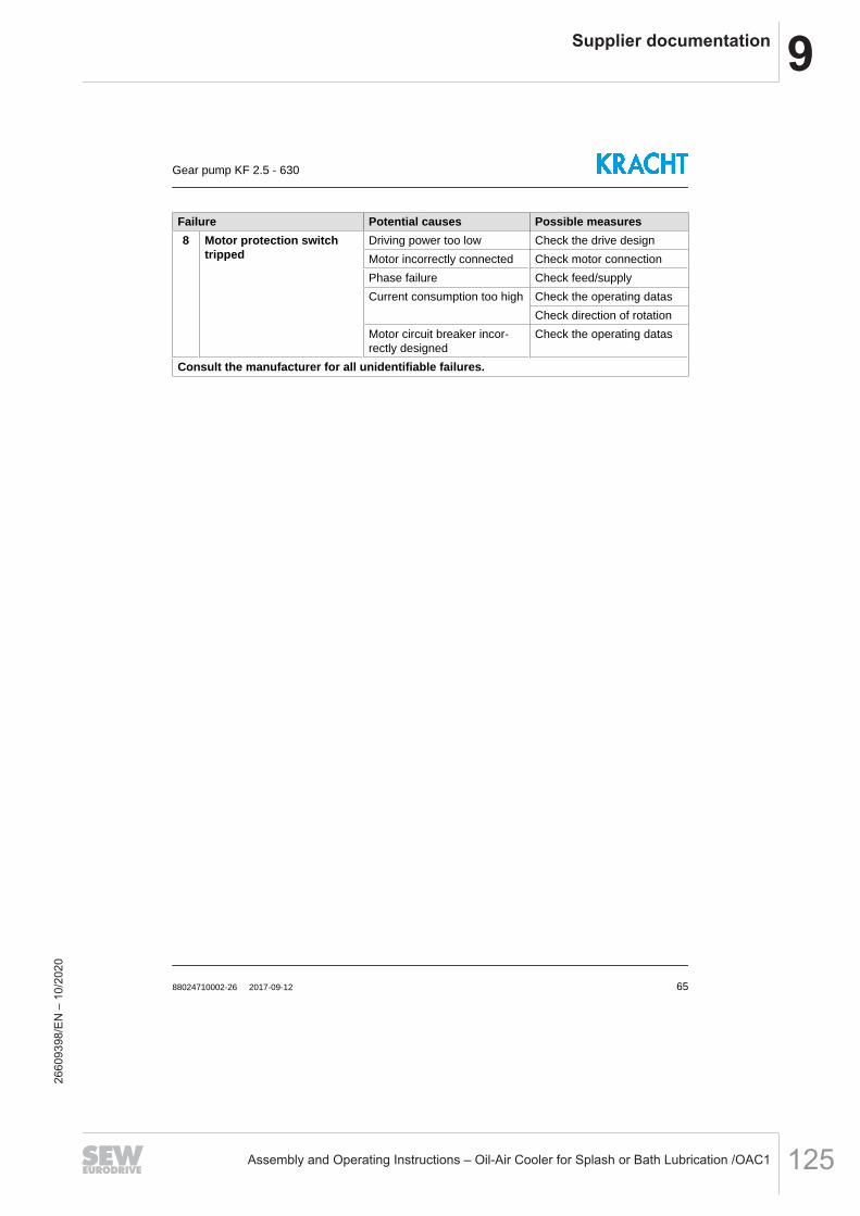
9Supplier documentation
Assembly and Operating Instructions – Oil-Air Cooler for Splash or Bath Lubrication /OAC1 125
Failure Potential causes Possible measures8 Motor protection switch
trippedDriving power too low Check the drive designMotor incorrectly connected Check motor connectionPhase failure Check feed/supplyCurrent consumption too high Check the operating datas
Check direction of rotationMotor circuit breaker incor-rectly designed
Check the operating datas
Consult the manufacturer for all unidentifiable failures.
Gear pump KF 2.5 - 630
88024710002-26 2017-09-12 65
2660
9398
/EN
– 1
0/20
20
9 Supplier documentation
Assembly and Operating Instructions – Oil-Air Cooler for Splash or Bath Lubrication /OAC1126
Transfer Gear Pumps
KF 2.5...200
2660
9398
/EN
– 1
0/20
20

9Supplier documentation
Assembly and Operating Instructions – Oil-Air Cooler for Splash or Bath Lubrication /OAC1 127
Transfer Gear Pumps KF 2.5...200
KRACHT GmbH · Gewerbestr. 20 · 58791 Werdohl, Germany · fon +49(0)23 92/935-0 · fax +49(0)23 92/935 209 · mail [email protected] · web www.kracht.eu2
2660
9398
/EN
– 1
0/20
20
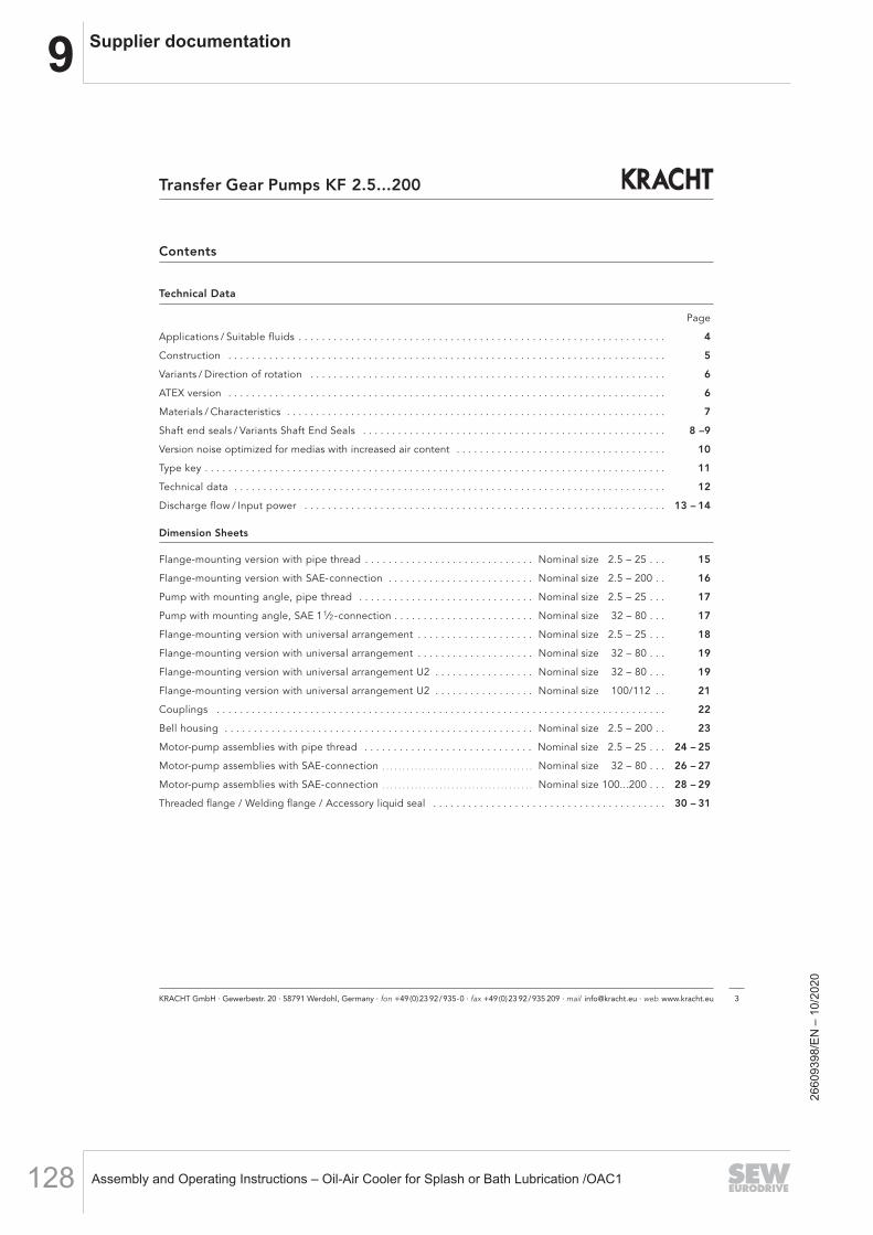
9 Supplier documentation
Assembly and Operating Instructions – Oil-Air Cooler for Splash or Bath Lubrication /OAC1128
KRACHT GmbH · Gewerbestr. 20 · 58791 Werdohl, Germany · fon +49(0)23 92/935-0 · fax +49(0)23 92/935 209 · mail [email protected] · web www.kracht.eu 3
Transfer Gear Pumps KF 2.5...200
Contents
Technical Data
Page
Applications / Suitable fluids . . . . . . . . . . . . . . . . . . . . . . . . . . . . . . . . . . . . . . . . . . . . . . . . . . . . . . . . . . . . . . . 4
Construction . . . . . . . . . . . . . . . . . . . . . . . . . . . . . . . . . . . . . . . . . . . . . . . . . . . . . . . . . . . . . . . . . . . . . . . . . . . 5
Variants / Direction of rotation . . . . . . . . . . . . . . . . . . . . . . . . . . . . . . . . . . . . . . . . . . . . . . . . . . . . . . . . . . . . . 6
ATEX version . . . . . . . . . . . . . . . . . . . . . . . . . . . . . . . . . . . . . . . . . . . . . . . . . . . . . . . . . . . . . . . . . . . . . . . . . . . 6
Materials / Characteristics . . . . . . . . . . . . . . . . . . . . . . . . . . . . . . . . . . . . . . . . . . . . . . . . . . . . . . . . . . . . . . . . . 7
Shaft end seals / Variants Shaft End Seals . . . . . . . . . . . . . . . . . . . . . . . . . . . . . . . . . . . . . . . . . . . . . . . . . . . . 8 –9
Version noise optimized for medias with increased air content . . . . . . . . . . . . . . . . . . . . . . . . . . . . . . . . . . . . 10
Type key . . . . . . . . . . . . . . . . . . . . . . . . . . . . . . . . . . . . . . . . . . . . . . . . . . . . . . . . . . . . . . . . . . . . . . . . . . . . . . . 11
Technical data . . . . . . . . . . . . . . . . . . . . . . . . . . . . . . . . . . . . . . . . . . . . . . . . . . . . . . . . . . . . . . . . . . . . . . . . . . 12
Discharge flow / Input power . . . . . . . . . . . . . . . . . . . . . . . . . . . . . . . . . . . . . . . . . . . . . . . . . . . . . . . . . . . . . . 13 – 14
Dimension Sheets
Flange-mounting version with pipe thread . . . . . . . . . . . . . . . . . . . . . . . . . . . . . Nominal size 2.5 – 25 . . . 15
Flange-mounting version with SAE-connection . . . . . . . . . . . . . . . . . . . . . . . . . Nominal size 2.5 – 200 . . 16
Pump with mounting angle, pipe thread . . . . . . . . . . . . . . . . . . . . . . . . . . . . . . Nominal size 2.5 – 25 . . . 17
Pump with mounting angle, SAE 11⁄2-connection . . . . . . . . . . . . . . . . . . . . . . . . Nominal size 32 – 80 . . . 17
Flange-mounting version with universal arrangement . . . . . . . . . . . . . . . . . . . . Nominal size 2.5 – 25 . . . 18
Flange-mounting version with universal arrangement . . . . . . . . . . . . . . . . . . . . Nominal size 32 – 80 . . . 19
Flange-mounting version with universal arrangement U2 . . . . . . . . . . . . . . . . . Nominal size 32 – 80 . . . 19
Flange-mounting version with universal arrangement U2 . . . . . . . . . . . . . . . . . Nominal size 100/112 . . 21
Couplings . . . . . . . . . . . . . . . . . . . . . . . . . . . . . . . . . . . . . . . . . . . . . . . . . . . . . . . . . . . . . . . . . . . . . . . . . . . . . 22
Bell housing . . . . . . . . . . . . . . . . . . . . . . . . . . . . . . . . . . . . . . . . . . . . . . . . . . . . . Nominal size 2.5 – 200 . . 23
Motor-pump assemblies with pipe thread . . . . . . . . . . . . . . . . . . . . . . . . . . . . . Nominal size 2.5 – 25 . . . 24 – 25
Motor-pump assemblies with SAE-connection . . . . . . . . . . . . . . . . . . . . . . . . . . . . . . . . . . . . . Nominal size 32 – 80 . . . 26 – 27
Motor-pump assemblies with SAE-connection . . . . . . . . . . . . . . . . . . . . . . . . . . . . . . . . . . . . . Nominal size 100...200 . . . 28 – 29
Threaded flange / Welding flange / Accessory liquid seal . . . . . . . . . . . . . . . . . . . . . . . . . . . . . . . . . . . . . . . . 30 – 3126
6093
98/E
N –
10/
2020
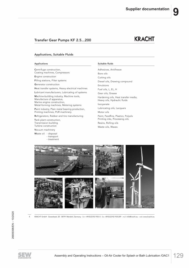
9Supplier documentation
Assembly and Operating Instructions – Oil-Air Cooler for Splash or Bath Lubrication /OAC1 129
Applications, Suitable Fluids
Applications
Centrifuge construction,Coating machines, Compressors
Engine construction
Filling stations, Filter systems
Generator construction
Heat transfer systems, Heavy electrical machines
Lubricant manufacturers, Lubricating oil systems
Machine-building industry, Machine tools,Manufacture of apparatus,Marine engine construction,Metal-forming machines, Metering systems
Paint industry, Plain metal bearing production,Printing machines, PUR machinery
Refrigerators, Rubber and tire manufacturing
Tank plant construction,Transmission buildingTurbine construction
Vacuum machinery
Waste oil - disposal- transport- treatment
Suitable fluids
Adhesives, Antifreeze
Bore oils
Cutting oils
Diesel oils, Drawing compound
Emulsions
Fuel oils, L, EL, H
Gear oils, Grease
Hardening oils, Heat transfer media,Heavy oils, Hydraulic fluids
Isocyanate
Lubricating oils, Lacquers
Motor oils
Paint, Paraffins, Plastics, PolyolsPrinting inks, Processing oils
Resins, Rolling oils
Waste oils, Waxes
KRACHT GmbH · Gewerbestr. 20 · 58791 Werdohl, Germany · fon +49(0)23 92/935-0 · fax +49(0)23 92/935 209 · mail [email protected] · web www.kracht.eu4
Transfer Gear Pumps KF 2.5...200
2660
9398
/EN
– 1
0/20
20
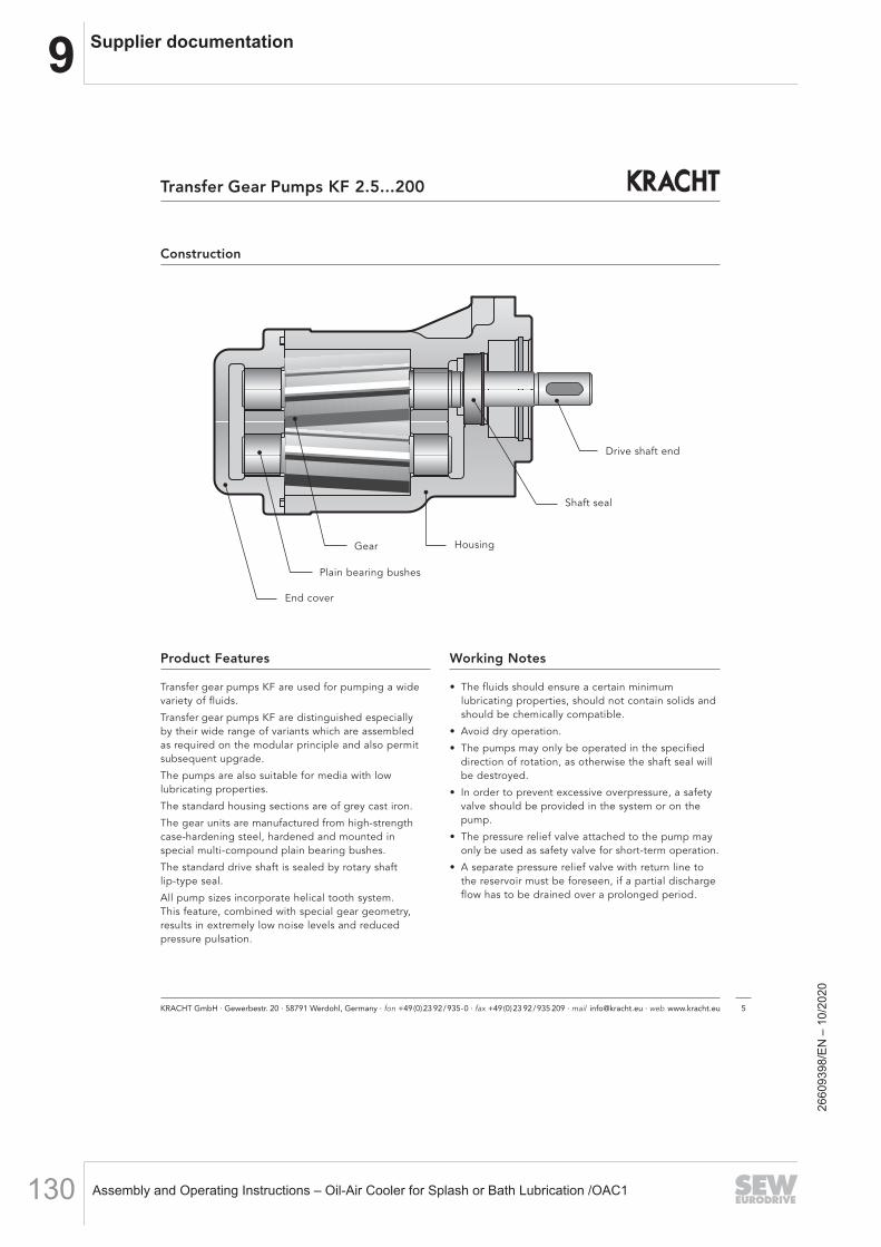
9 Supplier documentation
Assembly and Operating Instructions – Oil-Air Cooler for Splash or Bath Lubrication /OAC1130
KRACHT GmbH · Gewerbestr. 20 · 58791 Werdohl, Germany · fon +49(0)23 92/935-0 · fax +49(0)23 92/935 209 · mail [email protected] · web www.kracht.eu 5
Transfer Gear Pumps KF 2.5...200
Getriebe
Lagerbuchse
Lagerdeckel
Gehäuse
Antriebswellenende
Wellendichtung
Construction
Product Features
Transfer gear pumps KF are used for pumping a widevariety of fluids.
Transfer gear pumps KF are distinguished especially by their wide range of variants which are assembled as required on the modular principle and also permitsubsequent upgrade.
The pumps are also suitable for media with low lubricating properties.
The standard housing sections are of grey cast iron.
The gear units are manufactured from high-strength case-hardening steel, hardened and mounted in special multi-compound plain bearing bushes.
The standard drive shaft is sealed by rotary shaft lip-type seal.
All pump sizes incorporate helical tooth system. This feature, combined with special gear geometry, results in extremely low noise levels and reduced pressure pulsation.
Working Notes
• The fluids should ensure a certain minimum lubricating properties, should not contain solids andshould be chemically compatible.
• Avoid dry operation.
• The pumps may only be operated in the specified direction of rotation, as otherwise the shaft seal will be destroyed.
• In order to prevent excessive overpressure, a safetyvalve should be provided in the system or on thepump.
• The pressure relief valve attached to the pump mayonly be used as safety valve for short-term operation.
• A separate pressure relief valve with return line tothe reservoir must be foreseen, if a partial dischargeflow has to be drained over a prolonged period.
Drive shaft end
Shaft seal
HousingGear
Plain bearing bushes
End cover
2660
9398
/EN
– 1
0/20
20

9Supplier documentation
Assembly and Operating Instructions – Oil-Air Cooler for Splash or Bath Lubrication /OAC1 131
Variants
• Sealing of the drive shaft:– Rotary shaft lip-type seal– Double rotary shaft lip-type seal (Quench)– Mechanical seal
• Outboard bearing to take up input drive-side radial load
• Pressure relief valve for pump and system
• Uniform discharge flow direction with changingdirection of rotation by means of flange-mountingvalve combi nation (universal device).
Special Design
Various shafts ends and gear units, as well as flange mounted versions, bearing alternatives, multi-stagepump combinations for your special application areavailable on request.
Our Sales engineers will be pleased to advise you.
Accessories
• Connecting flanges• Couplings• Bell housing• Quench tank• Attenuation elements
Direction of Rotation
The following should be note for direction of rotation:
• when looking at thepump shaft end, thedirection of pumping isfrom left to right if theshaft rotates clockwise.
pump running cwsuction side pressure side pressure side suction side
pump running ccw
pump running cwsuction side pressure side pressure side suction side
pump running ccw
Without pressure relief valve
With pressure relief valve
KRACHT GmbH · Gewerbestr. 20 · 58791 Werdohl, Germany · fon +49(0)23 92/935-0 · fax +49(0)23 92/935 209 · mail [email protected] · web www.kracht.eu6
Transfer Gear Pumps KF 2.5...200
ATEX-VersionKF 2,5...112 KF 2,5...112
with lip-type seal with double lip-type seal
In Ex-area max. EX II 2G T4 EX II 2G T4suitable for category EX II 2D T135 °CPerm. working pressure – 0.4 ... + 0.5 – 0.4 ... + 0.5inlet port in bar
Perm. working pressure 25 25outlet port in bar
Perm. viscosity in mm2/s 12 … 20 000 12 … 20 000Max. speed in 1/min 3 000 3 000(viscosity dependent))
Perm. mounting position Horizontal or shaft end toward bottom Horizontal quencher upPerm. media – 10 ... + 80 – 10 ... + 80temperatures in °C
Perm. ambient – 20 ... + 60 – 20 ... + 60temperatures in °C
Comments
Additional products available on request.
Vertical mounting with shaft end up on request.
In executing with outboard bearing max. speed 1500 1/min.
In dust Ex-area, permissible only with non-conductive dusts. Dust-proof capsuling
of pump shaft and coupling required.
Not suitablefor dust-Ex.
Execution with quench feed and quencher.
• when looking at thepump shaft end, the direction of pum-ping is from right to leftif the shaft rotates counterclockwise.
With universal deviceDirection of rotation right and leftDirection of rotation consistent,see dimension sheets page 18 to 21.
2660
9398
/EN
– 1
0/20
20

9 Supplier documentation
Assembly and Operating Instructions – Oil-Air Cooler for Splash or Bath Lubrication /OAC1132
Materials
Housing and cover EN-GJL-250 (GG 25)EN-GJS-400-15 (GGG 40) on request
Gear Steel 1.7139
Plain bearing bushes DU (multi-layer friction-type bearings P 10, DP 4)Bearings free of nonferrous metal on request
Shaft end seals NBR, FKM, PTFE, EPDM(other sealing materials on request. E.g. HNBR / CR)
O-ring NBR, FKM, PTFE, EPDM(other sealing materials on request. E.g. HNBR / CR)
Characteristics
Nominal sizes 2.5...200 cm3 Vg = 2.5 / 4 / 5 / 6 / 8 /10 /12 /16 / 20 / 25 / 32 / 40 / 50 / 63 / 80 /100 /112 /125 / 150 / 180 / 200
Mounting position KF... R/L/B ... without Quench optionalKF... R/L/B ... with Quench horizontal, Quench connection aboveKF... U ... horizontal, Pressure connection aboveKF... U2...optional
Direction of rotation right or leftright and left
Fixing type flange
Pipe connection KF 2.5...25 Whitworth pipe thread, SAE flangeKF 32...200 SAE flange
Drive shaft end ISO R 775 short-cylindrical
Working pressure suction side see chart page 8
Working pressure pressure side Pn 25 bar (higher pressures on request)
Speed KF 2.5...63 200 … 3 600 1/minKF 80...180 200 ... 3 000 1/minKF 200 200 ... 2 500 1/min
Recommended speed The speed of the pump must be chosen in such a way that complete pump fillingis guaranteed. This is given if the relative pressure at the pump inlet does not fallbelow -0.4 bar (-0.6 bar briefly e.g. during cold start).
Viscosity (dependent on Vmin 1.4... 12 mm²/s (see table "permissible differential pressure")pressure and rotational speed) Vmax 20 000 mm2/s
Fluid temperature see chart page 8
Ambient temperature u = -- 20 °C … 60 °C (-- 4 °F…140 °F)– 30 °C... 60 °C Sealing type 23 (KF 2.5...80) – 30 °C... 60 °C Sealing type 31 (KF 32...200)
KRACHT GmbH · Gewerbestr. 20 · 58791 Werdohl, Germany · fon +49(0)23 92/935-0 · fax +49(0)23 92/935 209 · mail [email protected] · web www.kracht.eu 7
Transfer Gear Pumps KF 2.5...200
Permissible Differential Pressure
Bearing Δpmax [bar]
≥ 1.4 mm²/s ≥ 6 mm²/s ≥ 12 mm²/s
Multi-layer plain bearing containing lead (1): DU®, P103 12 25
Multi-layer plain bearing lead-free (2): DP4
Polymer plain bearing (2): Iglidur® X– 3 10
White metal plain bearing (2)
(1) Standard (2) Is defined in the special number
2660
9398
/EN
– 1
0/20
20

9Supplier documentation
Assembly and Operating Instructions – Oil-Air Cooler for Splash or Bath Lubrication /OAC1 133
KRACHT GmbH · Gewerbestr. 20 · 58791 Werdohl, Germany · fon +49(0)23 92/935-0 · fax +49(0)23 92/935 209 · mail [email protected] · web www.kracht.eu8
Transfer Gear Pumps KF 2.5...200
Shaft End Seals
Sealing material Pressure suction Fluid temperatureside * (bar) °C °FKF 2,5...80 KF 100...200
Pump with single rotary shaft lip max. 750 1/min -- 0.4...6.0 -- 0.4...6.0 --10...90-NBR 14...194-NBRmax. 1000 1/min -- 0.4...5.0 -- 0.4...5.0max. 1500 1/min -- 0.4...4.0 -- 0.4...3.5 --10...150-FKM 14...302-FKMmax. 2000 1/min -- 0.4...3.0 -- 0.4...2.5max. 3000 1/min -- 0.4...2.0 -- 0.4...1.5
FKM (low temperature) -- 0.4...0.5 -- 30**...150 -- 22**...302
EPDM -- 0.4...0.5 -- 10...120 14...248
PTFE -- 0.4...2.0 -- 10...200 14...392
Pump with outboard bearing max. 750 1/min -- 0.4...6.0 -- 0.4...6.0 --10...90-NBR 14...194-NBRand single rotary shaft lip max. 1000 1/min -- 0.4...5.0 -- 0.4...5.0
max. 1500 1/min -- 0.4...4.0 -- 0.4...3.5 --10...150-FKM 14...302-FKMmax. 2000 1/min -- 0.4...3.0 -- 0.4...5.5max. 3000 1/min -- 0.4...2.0 -- 0.4...1.5
PTFE -- 0.4...2.0 -- 10...200 14...392
max. 750 1/min -- 0.4...6.0 -- 0.4...6.0 --10...90-NBR 14...194-NBRmax. 1000 1/min -- 0.4...5.0 -- 0.4...5.0max. 1500 1/min -- 0.4...4.0 -- 0.4...3.5 --10...150-FKM 14...302-FKMmax. 2000 1/min -- 0.4...3.0 -- 0.4...2.5max. 3000 1/min -- 0.4...2.0 -- 0.4...1.5
PTFE -- 0.4...2.0 -- 10...200 14...392
NBR -- 0.9...0.2 -- 10...90 14...194
FKM -- 0.9...0.2 -- 10...150 14...302
PTFE -- 0.9...0.2 -- 10...200 14...392
max. 750 1/min -- 0.9...6.0 -- 0.9...6.0 --10...90-NBR 14...194-NBRmax. 1000 1/min -- 0.9...5.0 -- 0.9...5.0max. 1500 1/min -- 0.9...4.0 -- 0.9...3.5 --10...150-FKM 14...302-FKMmax. 2000 1/min -- 0.9...3.0 -- 0.9...2.5max. 3000 1/min -- 0.9...2.0 -- 0.9...1.5
Pump with mechanical seal FKM -- 0.4...10.0 -- 10...150 14...302
PTFE -- 0.4...10.0 -- 10...200 14...392
EPDM -- 0.4...10.0 -- 10...120 14...248
Pump with mechanical seal and FKM -- 0.4...10.0 -- 10...150 14...302connection borehole for liquid seal(quench)
Pump with double rotary shaft sealfor vacuum operation with connection borehole for liquid seal(quench)
Pump with triple rotary shaft sealfor vacuum and normal operationwith connection borehole for liquid seal (quench)
Pump with double rotary shaft sealwith connection borehole for liquid seal (quench)
Speed: KF 2.5... 63 200 … 3 600 1/minKF 80... 180 200 ... 3 000 1/minKF 200 200 ... 2 500 1/min
The indicated maximum values are dependent upon the remaining working conditions.
In case of universal devices, pay attention to limitation of Pe min.
Other sealing materials on request.
** short term during start-up status: -- 0.6 bar** only in connection with housing and
cover material EN-GJS-400 (GGG 40)
NBR/FKM
NBR/FKM
NBR/FKM
NBR/FKM
2660
9398
/EN
– 1
0/20
20

9 Supplier documentation
Assembly and Operating Instructions – Oil-Air Cooler for Splash or Bath Lubrication /OAC1134
Variants Shaft End Seals
Pump with single rotary shaft lip
Fixing type: F/W
Sealing materials:NBR = sealing type 1FKM = sealing type 2PTFE = sealing type 3EPDM = sealing type 9FKM low temperature
= sealing type 23/31
Pump with double rotaryshaft seal with connectionborehole for liquid seal(quench)
Fixing type: F/W
Sealing materials:NBR = sealing type 19FKM = sealing type 7PTFE = sealing type 4EPDM = sealing type 32
Pump with double rotaryshaft seal for vacuum operation with connectionborehole for liquid seal(quench)
Fixing type: F/W
Sealing materials:NBR = sealing type 19FKM = sealing type 7PTFE = sealing type 4EPDM = sealing type 32
Special number: 74
Pump with mechanical seal
Fixing type: F/W
Sealing materials:FKM = sealing type 5PTFE = sealing type 6mechanical seal
= sealing type 40
Pump with triple rotaryshaft seal for vacuum and normal operation with connection boreholefor liquid seal (quench)
Fixing type: F/W
Sealing materials:NBR = on requestFKM = on request
Pump with mechanical sealand connection boreholefor liquid seal (quench)
Fixing type: F/W
Sealing materials:FKM = sealing type 5
Special number: 198
Pump with outboard bearing and single rotary shaft lip
Fixing type: G/X
Sealing materials:NBR = sealing type 1FKM = sealing type 2PTFE = sealing type 3
Pump without shaft sealing
Fixing type: F/W
Sealing material:FKM o-ring
= sealing type 30
KRACHT GmbH · Gewerbestr. 20 · 58791 Werdohl, Germany · fon +49(0)23 92/935-0 · fax +49(0)23 92/935 209 · mail [email protected] · web www.kracht.eu 9
Transfer Gear Pumps KF 2.5...200
2660
9398
/EN
– 1
0/20
20

9Supplier documentation
Assembly and Operating Instructions – Oil-Air Cooler for Splash or Bath Lubrication /OAC1 135
KRACHT GmbH · Gewerbestr. 20 · 58791 Werdohl, Germany · fon +49(0)23 92/935-0 · fax +49(0)23 92/935 209 · mail [email protected] · web www.kracht.eu10
Transfer Gear Pumps KF 2.5...200
The noise optimized pumps in the KF series are designedfor conveying for medias with increased air content,predominantly for use as lubricating oil pumps in trans-missions. Special measures prevent the otherwisenormally increased noise present in auriferous transmissionoil. The noise levels do not exceed or only barelyexceed the measurements with non-auriferous oils.Also, there is no noise spectrum shift to higher, unplea-sant frequencies. In applications without auriferousportions in the media, it is not recommended to usethis version as it will not bring about noise reductioneffects there.
The noise optimized version of the KF pump is markedwith the special number 197 at the end of the type key.
Pumps with the special number 197 are built as pumpsin combination with an electric motor or as mountedpumps. The pump in combination with an electricmotor (Fig. 1) does not have an outboard bearing, so ithas to be driven via an elastic coupling. The mountedpump (Fig. 2) comes equipped with an outboard bearingto absorb the centrifugal forces such as those whicharise when using a flying pinion. Pumps for electricmotor drives and mounted pumps are sealed at theshaft end using a lip-type shaft seal.
Pump with single rotary shaft lip
Fixing type: F/W
Sealing materials:NBR = sealing type 1FKM = sealing type 2
Special number: 197
Fig. 1 Fig. 2
Pump with outboard bearingand single rotary shaft lip
Fixing type: G/X
Sealing materials:NBR = sealing type 1FKM = sealing type 2
Special number: 197
The noise optimized version is also available in a ductilecast iron version. We can supply these pumps in theATEX version also.
Note
Dimensions conformable standard pumps
KF 2.5...200 noise optimized for medias with increased air content
2660
9398
/EN
– 1
0/20
20

9 Supplier documentation
Assembly and Operating Instructions – Oil-Air Cooler for Splash or Bath Lubrication /OAC1136
KRACHT GmbH · Gewerbestr. 20 · 58791 Werdohl, Germany · fon +49(0)23 92/935-0 · fax +49(0)23 92/935 209 · mail [email protected] · web www.kracht.eu 11
Transfer Gear Pumps KF 2.5...200
Type Key (Ordering example)
KF 40 R F 1 - /... - D15 ·
Type of seal 1 Rotary shaft seal BABSL NBR2 Rotary shaft seal BABSL FKM3 Rotary shaft seal PTFE4 Double rotary shaft seal PTFE5 Mechanical seal with FKM secondary seals (C2S2V1G3G1)6 Mechanical seal with FFKM secondary seals
Q2Q2K1G3 (KF 2.5... 25) Q2B2K1G3 (KF 32... 200)7 Double rotary shaft seal BABSL FKM9 Rotary shaft seal EPDM (not resistant to mineral oils)
19 Double rotary shaft seal BABSL NBR23 Rotary shaft seal MSS-1 FKM
(low temperature) (KF 2.5... 80)30 Without shaft seal (1) O-ring FKM31 Rotary shaft seal BABSL FKM
(low temperature) (KF 32... 200)32 Double rotary shaft seal EPDM
(not resistant to mineral oils)36 Without shaft seal (1) O-ring NBR40 Mechanical seal with FKM secondary seals (AQ2VFF)
(1) Leak oil discharged through the gland pocket
Mounting F DIN flange without outboard bearingG DIN flange with outboard bearingW Mounting angle without outboard bearingX Mounting angle with outboard bearing
Direction of rotation R rightL leftB right and leftU universal Note direction of rotation right and left,
direction of discharge consistentProduct nameNominal size 2.5...200
Housing and cover materialnot specified EN-GJL-250 (GG 25)GJS EN-GJS-400 (GGG 40)
Valve type D 15 adjustable from 0 –15 barD 25 adjustable from 15 – 25 bar(only for one direction of rotation)
Special No.74 Double rotary shaft seal (for vacuum operation)
Connection bore G 1/8" (for liquid seal)158 KF 2.5… 12: Flange connection SAE ¾“
KF 16… 25: Flange connection SAE 1“197 Noise-optimized version for aerated oils and vacuum(1)
198 Mechanical seal KF 2.5… 25: Connection bore G 1/8" (for liquid seal) KF 32… 80: Connection bore G ¼" (for liquid seal)
232 KF 50...80: Flange connection SAE 2“KF100…112: Flange connection SAE 2 ½“KF125…150: Flange connection SAE 3“KF180…200: Flange connection SAE 3 ½“
304 Polymer plain bearing iglidur® X(free from non-ferrous metals), Δpmax = 10 bar
317 Noise-optimized version for aerated oils and vacuum (1)
Polymer plain bearing iglidur®X(free from non-ferrous metals), Δpmax = 10 bar
322 Triple rotary shaft seal (for normal operation + for vacuum operation) Connection bore G 1/8" (for liquid seal) Polymer plain bearing iglidur®X(free from non-ferrous metals), Δpmax = 10 barKF 50… 80: Flange connection SAE 2“
353 Noise-optimized version for aerated oils and vacuum (1)
Multi-layer plain bearing DP4 (lead-free)355 Polymer plain bearing iglidur®X
(free from non-ferrous metals), Δpmax = 10 barHousing connection: KF 2.5… 25: as special number 158
363 Version for low-viscous media (housing and cover material = GJS) Polymer plain bearing iglidur®X(free from non-ferrous metals), Δpmax = 10 barHousing connection: KF 2.5… 25: as special number 158KF 50… 200: as special number 232
391 Noise-optimized version for aerated oils and vacuum (1)
Housing connection: KF 50… 200: as special number 232425 Shaft end with centre hole DIN 322-D
Outboard bearing with steel cage(1) There can be a reduction in pumping capacity. Measures for noise optimisation are
only feasible for one rotational direction and only effective for aerated oils or vacuum.
Type of sealsee below
Special No.see below
2660
9398
/EN
– 1
0/20
20

9Supplier documentation
Assembly and Operating Instructions – Oil-Air Cooler for Splash or Bath Lubrication /OAC1 137
KRACHT GmbH · Gewerbestr. 20 · 58791 Werdohl, Germany · fon +49(0)23 92/935-0 · fax +49(0)23 92/935 209 · mail [email protected] · web www.kracht.eu12
Transfer Gear Pumps KF 2.5...200
Technical Data
Nominal geom. Working Maximum Speed range Permissible Sound levelsize displace- pressure* pressure load ** dB (A)
ment (pressure (n = 1500 1/min)peaks)
Vg pb pmax nmin nmax Fradial p = p = p =
cm3/r bar bar 1/min 1/min N 5 bar 15 bar 25 bar
2.5 2.55
4 4.03
5 5.05
6 6.38
8 8.05 700 ≤ 65 ≤ 66 ≤ 67
10 10.11
12 12.58
16 16.09
20 20.10
25 25.10
32 32.12 25 40 200 3600
40 40.21
≤ 67 ≤ 68 ≤ 6850 50.20
63 63.18
80 80.503000 1500
≤ 67 ≤ 68 ≤ 691000 101.500
1120 113.500
1250 129.400
1500 155.600 ≤ 65 ≤ 65 ≤ 65
1800 186.600
2000 206.200 2500
Remark
** Working pressure pb = perm. sustained pressure(higher pressures on request)
** Permissible load only for version with outboard bearing. Fradial at centre of shaft end.
For certain working condi tions, the minimum or maximum characteristics should not be used.
For example, the max. working pressure is not permissible in combination with low speed and low viscosity.
In such limit ranges, please consult us.
Sound level measured in dB(A) at 1 m distance
Sound level measured with drive motor,installation site:Works hall, quiet sound level = 40 dB(A)
Pump assembly on rigid fastening angle,Suction and pressure conduits: HoseMeasured with transmission oil, Oil viscosity ν = 34 mm2⁄s, Speed n = 1500 1/min.
2660
9398
/EN
– 1
0/20
20
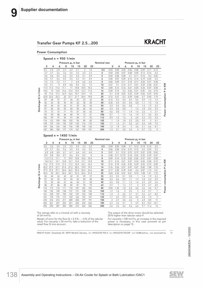
9 Supplier documentation
Assembly and Operating Instructions – Oil-Air Cooler for Splash or Bath Lubrication /OAC1138
Power Consumption
The ratings refer to a mineral oil with a viscosity of 34 mm2/s.Margin of error for the flow Q + 2.5 % ... -- 5 % of the tabularvalue. For viscosity < 30 mm2/s, take a reduction of therated flow Q into account.
The output of the drive motor should be selected20 % higher than tabular value P.For viscosity > 100 mm2/s, an increase in the requiredpower is necessary, in this case proceed as perdescription on page 15.
KRACHT GmbH · Gewerbestr. 20 · 58791 Werdohl, Germany · fon +49(0)23 92/935-0 · fax +49(0)23 92/935 209 · mail [email protected] · web www.kracht.eu 13
Transfer Gear Pumps KF 2.5...200D
isch
arg
e Q
in
l/m
in
Po
we
r co
nsu
mp
tio
nP
in K
W
Pressure pb in bar Nominal size Pressure pb in bar
2 4 6 8 10 15 20 25 2 4 6 8 10 15 20 252.5 2.4 2.4 2.3 2.2 2.1 2 1.8 2.5 0.03 0.04 0.05 0.06 0.08 0.09 0.11 0.133.7 3.7 3.6 3.6 3.6 3.5 3.4 3.3 4 0.04 0.05 0.07 0.08 0.09 0.13 0.16 0.24.6 4.6 4.5 4.5 4.4 4.2 4.1 3.9 5 0.04 0.06 0.08 0.1 0.11 0.16 0.2 0.255.8 5.7 5.6 5.5 5.5 5.3 5.1 4.9 6 0.05 0.07 0.09 0.12 0.14 0.19 0.25 0.37.3 7.3 7.2 7.1 7 6.8 6.6 6.4 8 0.06 0.09 0.11 0.14 0.17 0.24 0.31 0.389.2 9.1 9 8.9 8.8 8.5 8.2 7.9 10 0.07 0.1 0.14 0.17 0.21 0.29 0.38 0.47
11.4 11.3 11.2 11.1 11 10.8 10.5 10.3 12 0.08 0.12 0.16 0.21 0.25 0.36 0.47 0.5814.2 14 13.8 13.6 13.4 12.9 12.3 11.8 16 0.09 0.15 0.2 0.26 0.31 0.45 0.6 0.7418 17.6 17.3 16.9 16.6 15.7 14.9 14 20 0.1 0.18 0.25 0.32 0.39 0.56 0.74 0.92
22.8 22.5 22.3 22 21.7 21.1 20.4 19.8 25 0.12 0.21 0.3 0.39 0.48 0.7 0.92 1.1429 28 27 27 26 25 23 22 32 0.16 0.3 0.4 0.5 0.6 0.9 1.2 1.536 36 35 34 34 32 30 28 40 0.25 0.4 0.5 0.6 0.8 1.1 1.5 1.845 44 43 42 41 39 36 34 50 0.3 0.5 0.6 0.8 1 1.4 1.9 2.357 56 54 53 52 50 46 43 63 0.4 0.6 0.8 1 1.2 1.8 2.4 2.974 73 72 71 70 67 65 62 80 0.6 0.8 1.1 1.4 1.6 2.3 3 3.792 90 88 86 84 79 73 67 100 0.7 1 1.3 1.6 1.9 2.7 3.6 4.5
102 99 97 94 91 84 77 70 112 0.9 1.2 1.6 2 2.4 3.3 4.3 5.2114 112 109 106 103 96 89 82 125 1 1.4 1.8 2.3 2.8 3.9 5 6.1139 137 134 132 129 123 116 110 150 1.1 1.6 2.1 2.6 3.2 4.5 5.8 7.2169 166 163 160 156 148 140 132 180 1.2 1.8 2.4 3 3.6 5.1 6.6 8.1187 184 180 177 174 167 159 151 200 1.4 2.1 2.8 3.4 4 5.7 7.3 9
Speed n = 950 1/min
Speed n = 1450 1/min
Dis
char
ge
Q i
n l
/min
Po
we
r co
nsu
mp
tio
n P
in
KW
Pressure pb in bar Nominal size Pressure pb in bar
2 4 6 8 10 15 20 25 2 4 6 8 10 15 20 253.6 3.6 3.5 3.5 3.5 3.4 3.3 3.2 2.5 0.04 0.05 0.08 0.1 0.12 0.14 0.16 0.2
5.7 5.7 5.6 5.6 5.5 5.4 5.4 5.3 4 0.06 0.08 0.16 0.12 0.15 0.2 0.25 0.36.9 6.8 6.8 6.7 6.7 6.6 6.5 6.4 5 0.07 0.1 0.12 0.15 0.19 0.27 0.35 0.43
8.9 8.8 8.8 8.7 8.6 8.4 8.2 8 6 0.08 0.11 0.115 0.18 0.22 0.32 0.39 0.4711.3 11.2 11.1 11 10.9 10.8 10.6 10.4 8 0.09 0.14 0.18 0.22 0.26 0.37 0.47 0.5814.2 14.1 14.1 13.8 13.7 13.4 13.1 12.8 10 0.11 0.16 0.21 0.27 0.32 0.45 0.58 0.72
17.6 17.5 17.4 17.3 17.2 16.9 16.7 16.5 12 0.12 0.19 0.26 0.32 0.39 0.55 0.72 0.8922.2 21.9 21.7 21.4 21.2 20.5 19.9 19.3 16 0.16 0.26 0.37 0.47 0.57 0.82 1.08 1.3327.9 27.5 27.1 26.8 26.4 25.5 24.5 23.6 20 0.17 0.28 0.39 0.49 0.6 0.87 1.14 1.4135.3 35 34.7 34.4 34.1 33.3 32.6 31.8 25 0.24 0.34 0.47 0.61 0.74 1.08 1.41 1.7545 44 43 43 42 41 39 37 32 0.3 0.5 0.7 0.8 1 1.4 1.9 2.357 56 55 55 54 52 50 48 40 0.4 0.6 0.9 1.1 1.3 1.8 2.3 2.970 69 68 67 66 64 61 58 50 0.5 0.8 1.1 1.3 1.6 2.3 2.9 3.688 87 86 85 84 81 78 75 63 0.7 1 1.3 1.7 2 2.9 3.7 4.5
114 113 112 111 110 107 105 103 80 0.94 1.35 1.8 2.2 2.6 3.6 4.6 5.7144 142 140 138 137 131 128 126 100 1.2 1.6 2 2.5 3 4.3 5.7 7161 159 157 154 152 147 142 138 112 1.4 2 2.6 3.1 3.7 5.2 6.7 8.2181 178 175 172 169 162 155 147 125 1.7 2.3 2.9 3.6 4.2 5.8 7.4 9218 216 213 211 209 203 197 191 150 2 2.7 3.5 4.2 5 6.9 8.9 11264 261 257 254 251 242 234 226 180 2.3 3.2 4.1 5 5.9 8.2 10.4 12.7293 290 287 283 280 272 264 256 200 2.6 3.6 4.6 5.6 6.6 9.1 11.6 14
2660
9398
/EN
– 1
0/20
20

9Supplier documentation
Assembly and Operating Instructions – Oil-Air Cooler for Splash or Bath Lubrication /OAC1 139
KRACHT GmbH · Gewerbestr. 20 · 58791 Werdohl, Germany · fon +49(0)23 92/935-0 · fax +49(0)23 92/935 209 · mail [email protected] · web www.kracht.eu14
Transfer Gear Pumps KF 2.5...200
Discharge Flow / Input Power
Conversion factors
1 bar = 14.5 = 14.5 psi
1 = 0.220 = [U.K.]
1 = 0.264 = [US]
lbin2
galmin
galmin
lmin
lmin
Calculation
P1Pu = Ptab · + fν · Q
P1Pu = pump power consumption (kW)
Ptab = power consumption per table (kW) at 1450 1/min
n = speed (1/min)dependent on viscosity!(see speed recommendation)
fν = viscosity factor(see diagram)
Q = discharge flow (l/min) with Q =
Vg = geometricaldisplacement (cm3/r)
kWl/min[ ]
n1450
Example: Pump type KF 80
Viscosity ν = 3000 mm2/sWorking pressure p = 15 barat Ptab = 3.6 kW
n = 500 1/min
fν = 0.017
Q = = 40 l/min
becomes
P1Pu =
P1Pu = 1.92 kWMotorpower output: P2Mot = 1.2 · P1Pu = 2.3 kWSelect helicalgeared motor with P = 3.0 kW
n = 500 1/min
kWl/min
(3.6 · + 0.017 · 40) kW 5001450Vg · n
1000
80.5 · 5001000
Input Power
Diagramm: n, fν = f (ν)
Note:To determine the power consumption, always take the max. working viscosity at starting state into consideration.The power of the drive motor should be selected 20 % higher than the valuedetermined.
ν
ν
2660
9398
/EN
– 1
0/20
20
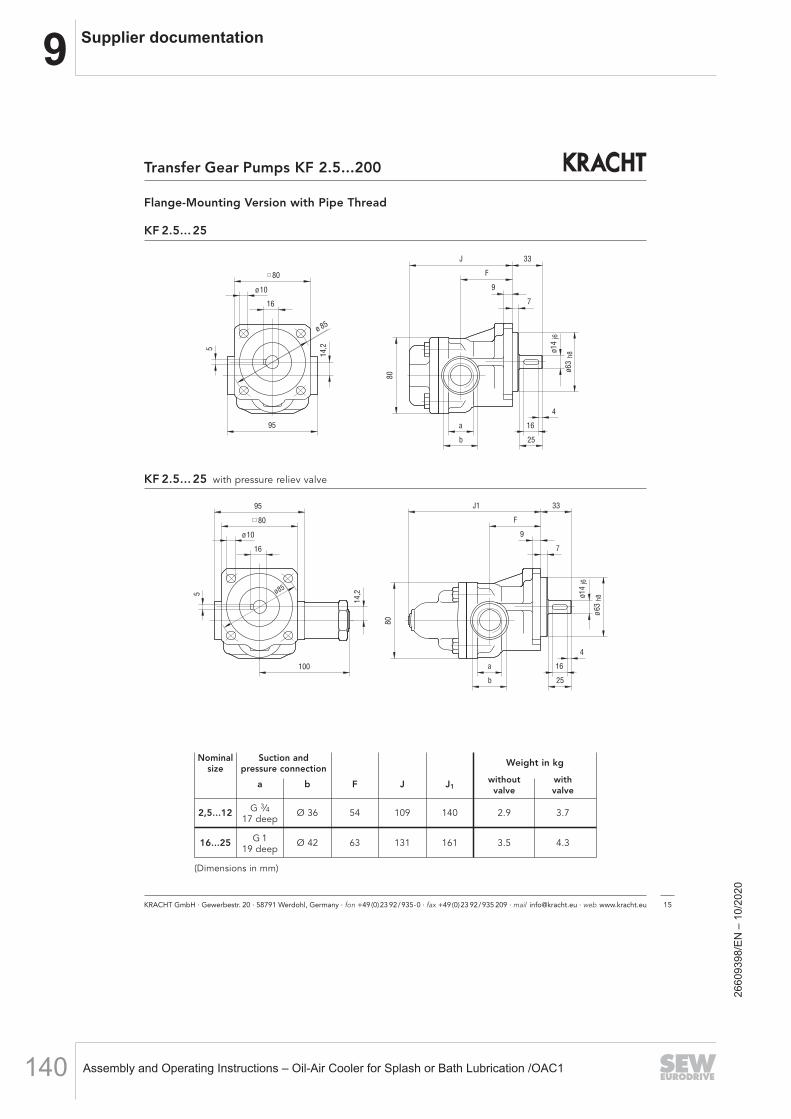
9 Supplier documentation
Assembly and Operating Instructions – Oil-Air Cooler for Splash or Bath Lubrication /OAC1140
F
33
9
7
J
ø63
ø14
25
16
4
a
b
80
16
ø10
ø 85
5
95
14,2
j6
h8
80
F
33
9
716
ø10
ø85
5
80
100
J195
14,2
ø63
ø14
80
j6
h8
25
16
4
a
b
KF 2.5... 25 with pressure reliev valve
Flange-Mounting Version with Pipe Thread
Nominal Suction and Weight in kgsize pressure connection
a b F J J1without with
valve valve
2,5...12 G 3⁄4 Ø 36 54 109 140 2.9 3.717 deep
16...25 G 1 Ø 42 63 131 161 3.5 4.319 deep
(Dimensions in mm)
KF 2.5... 25
Transfer Gear Pumps KF 2.5...200
KRACHT GmbH · Gewerbestr. 20 · 58791 Werdohl, Germany · fon +49(0)23 92/935-0 · fax +49(0)23 92/935 209 · mail [email protected] · web www.kracht.eu 15
2660
9398
/EN
– 1
0/20
20

9Supplier documentation
Assembly and Operating Instructions – Oil-Air Cooler for Splash or Bath Lubrication /OAC1 141
KRACHT GmbH · Gewerbestr. 20 · 58791 Werdohl, Germany · fon +49(0)23 92/935-0 · fax +49(0)23 92/935 209 · mail [email protected] · web www.kracht.eu16
Transfer Gear Pumps KF 2.5...200
KF 2.5...200 with pressure reliev valve
Flange-Mounting Version with SAE-Connection
KF 2.5...200
Nominal Sp.- SAE Seal Suction- and Pump sizes Shaft end Weight in kgsize No. pressure connectionwithout with
a b e f C D E F G J J1 K L M R Sh8 i Y dj6 l m n t u valve valve
2.5…12 158 3⁄4" – 47.6 22.2 19.5 M10- 54 109 140 4.2 5.015deep 85 80 10 100 9 33 7 80 63 14,2 100 14 25 16 4 16 5
16…25 158 1" – 52.4 26.2 25.0 M10- 63 131 162 4.8 5.617deep
32…50 – 11⁄2" – 84 110 173 212 7.7 9.569.9 35.7 38.0
63/80 – 11⁄2" – 103 100 10 100 208 247 13 44 7 110 80 20 153 24 36 28 4 27 8 9.4 11.2
50 232 2" –50.0
84 173 212 7.7 9.5
63/80 232 2" –77.8 42.9 M12- 100 208 247 9.4 11.2
100/112 – 2" –50.8
20deep 60 28 50 40 5 31
100/112 – 2" 31102 130 220.5 262.5 17
46128.0
24 36 28 4 2716.0 18.7
100/112 232 21⁄2" – 60 28 50 40 5 31
100/112 232 21⁄2" 31 88.9 50.8 63.5 468 110 23.7 170.5
24 36 28 4 27
125/150 – 21⁄2" – 60 28 50 40 5 31
125/150 – 21⁄2" 31145 135 14 120
46 24 36 28 4 27
125/150 232 3" –245.0 282.0
60 28 50 40 5 3122.2 24.9
125/150 232 3" 31 150 18 46 159 24 36 28 4 27
180/200 – 3" –106.4 61.9 76.2
M16-28 31
180/200 – 3" 3132deep 130
2450 40 5
27
180/200 232 31⁄2" –120.7 69.9 88.9
262 299 6028 31
24.8 27.5
180/200 232 31⁄2" 31 24 27
(Dimensions in mm)
2660
9398
/EN
– 1
0/20
20

9 Supplier documentation
Assembly and Operating Instructions – Oil-Air Cooler for Splash or Bath Lubrication /OAC1142
KRACHT GmbH · Gewerbestr. 20 · 58791 Werdohl, Germany · fon +49(0)23 92/935-0 · fax +49(0)23 92/935 209 · mail [email protected] · web www.kracht.eu 17
Transfer Gear Pumps KF 2.5...200
Pump with Mounting Angle, Pipe Thread
Nominal Suction andsize pressure connection Weight in kg
a b F J
2,5...12 G 3⁄4 Ø 36 54 109 4,217 deep
16...25 G 1 Ø 42 63 131 4,819 deep
(Dimensions in mm)
KF 2,5...25
95
14,2
12
120
135
80
R 55
9 0
F
33J
ø63
ø14
ab
80
j6
h8
ø11
9 0
8 5
16
7
25
16
4
1 6
5
110
20
120
150
165
R 65
100
12
110
8 0
J
M 12-20 tief
38
F
44
69,9
h8
941 8
ø24
j6
35,7
ø11
ø80
7
36
28
4
2 7
8
Pump with Mounting Angle, Pipe Thread, SAE 11⁄2-connection
KF 32 ... 80
Nominal-size F J Weight in kg
32...50 SAE 11⁄2 84 173 9.5
63 / 80 SAE 11⁄2 100 208 11.2
(Dimensions in mm)
2660
9398
/EN
– 1
0/20
20
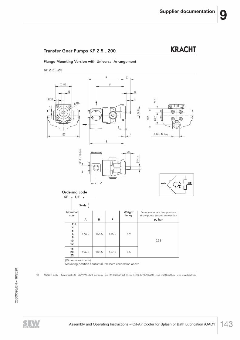
9Supplier documentation
Assembly and Operating Instructions – Oil-Air Cooler for Splash or Bath Lubrication /OAC1 143
Flange-Mounting Version with Universal Arrangement
KF 2.5...25
Ordering codeKF . UF .
Seals 12
Nominal Weight Perm. manometr. low pressuresize in kg at the pump suction connection
A B F p e bar
2.5456 174.5 166.5 135.5 6.98
10 0.3512
1620 196.5 188.5 157.5 7.525
(Dimensions in mm)Mounting position horizontal, Pressure connection above
Transfer Gear Pumps KF 2.5...200
KRACHT GmbH · Gewerbestr. 20 · 58791 Werdohl, Germany · fon +49(0)23 92/935-0 · fax +49(0)23 92/935 209 · mail [email protected] · web www.kracht.eu18
157
Ø 85
5
Ø 10
G 1/
2-15
tief 25
Ø 14
j6
7
9
Ø 63
h8
102
60.2
A
F
33
16
80
4
20.8
G 3/4-17 tief
B
16
G 3/4 – 17 deep
G1/
2 –
15 d
eep
2660
9398
/EN
– 1
0/20
20
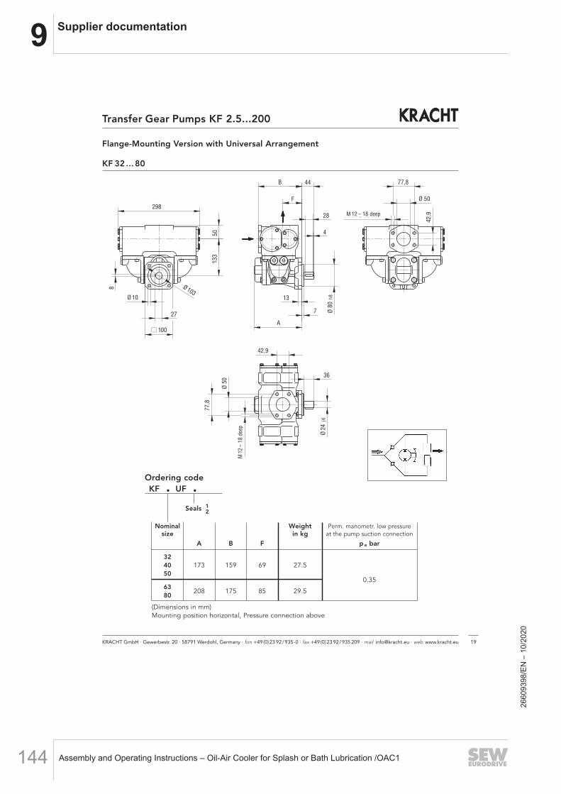
9 Supplier documentation
Assembly and Operating Instructions – Oil-Air Cooler for Splash or Bath Lubrication /OAC1144
A
7
13
Ø 80
h8
M12-18 tief
77,8
Ø 50
42,9
4
28
F
B 44
42,9
36
Ø 24
j6
Ø 50
77,8
M12
-18
tief
29850
133
Ø 103
27
8
Ø 10
100
KRACHT GmbH · Gewerbestr. 20 · 58791 Werdohl, Germany · fon +49(0)23 92/935-0 · fax +49(0)23 92/935 209 · mail [email protected] · web www.kracht.eu 19
Transfer Gear Pumps KF 2.5...200
Flange-Mounting Version with Universal Arrangement
KF 32 ... 80
Nominal Weight Perm. manometr. low pressuresize in kg at the pump suction connection
A B F p e bar
3240 173 159 69 27.550
0.356380
208 175 85 29.5
(Dimensions in mm)Mounting position horizontal, Pressure connection above
Ordering codeKF . UF .
Seals 12
M 12 – 18 deep
M12
– 18
deep
2660
9398
/EN
– 1
0/20
20

9Supplier documentation
Assembly and Operating Instructions – Oil-Air Cooler for Splash or Bath Lubrication /OAC1 145
Flange-Mounting Version with Universal Arrangement U2
KF 32…80
Nominaldisplacement A B Weight in kg
3240 256 216 15.550
63291 251 17.5
80
(Dimensions in mm)
Mounting position optional
Suction and pressure portequally sized
KRACHT GmbH · Gewerbestr. 20 · 58791 Werdohl, Germany · fon +49(0)23 92/935-0 · fax +49(0)23 92/935 209 · mail [email protected] · web www.kracht.eu20
Transfer Gear Pumps KF 2.5...200
2660
9398
/EN
– 1
0/20
20

9 Supplier documentation
Assembly and Operating Instructions – Oil-Air Cooler for Splash or Bath Lubrication /OAC1146
Flange-Mounting Version with Universal Arrangement U2
KF 100/112
Nominaldisplacement A B Weight in kg
100112
312,5 247,5 21.6
(Dimensions in mm)
Mounting position optional
Suction and pressure portequally sized
KRACHT GmbH · Gewerbestr. 20 · 58791 Werdohl, Germany · fon +49(0)23 92/935-0 · fax +49(0)23 92/935 209 · mail [email protected] · web www.kracht.eu 21
Transfer Gear Pumps KF 2.5...200
2660
9398
/EN
– 1
0/20
20

9Supplier documentation
Assembly and Operating Instructions – Oil-Air Cooler for Splash or Bath Lubrication /OAC1 147
Version A Version B
Ordering code Coupling Weight Moment Pre Finished Dimensions (in mm)size of bore bore
inertia min. max.
kg kgm2 part part part part part part1 2 1 2 1 2 l E s b L M DH D D1 dh
RA 19-Z25/..-Z25/.. 19 00.117 0.00003 4 – 6 – 19 – 25 16 2 12 66 20 40 32 – 18
RA 24-Z30/..-Z30/.. 24 0.24 0.00008 6 – 8 – 24 – 30 18 2 14 78 24 55 40 – 27
RA 28-Z30/..-Z30/.. 28 0.39 0.0002 8 – 10 – 28 – 30 20 2.5 15 80 28 65 48 – 30
RA 19/24-Z25/..-Z25/.. 19/24 00.129 0.00004 4 17 6 19 19 24 25 16 2 12 66 20 40 32 – 18
RA 24/28-Z30/..-Z30/.. 24/28 0.26 0.0001 6 22 8 24 24 28 30 18 2 14 78 24 55 40 – 27
RA 28/38-Z35/..-Z35/.. 28/38 0.46 0.0003 8 26 10 28 28 38 35 20 2.5 15 90 28 65 48 – 30
RA 38/45-Z45/..-Z45/.. 38/45 0.89 0.0008 10 36 12 38 38 45 45 24 3 18 114 37 80 66 – 38
RA 42/55-Z50/..-Z50/.. 42/55 1.39 0.0018 12 40 14 42 42 55 50 26 3 20 126 40 95 75 – 46
RG 42/55-Z50/..-Z75/.. 42/55 3.57 0.005 12 40 14 42 42 55 50/ 26 3 20 151 40 95 75 – 4675/
Ver
sio
n A
Ver
sio
n B
Accessory Couplings
Gear rim
Type Key KF Coupling
Working temperature:--20 °C to +80 °C (-- 4 °F to 176 °F)(short duration temperature peaks up to 120 °C / 248 °F are permissible).
Ordering example
coupling hub lengt and hub bore
Pump sidecylindrical
Motor sidecylindrical
R .* 38 - Z 45/38 - Z 45/38
Coupling size
.* Hub material
A AL
G GG
Weights and mass moments of inertia refer to max. finish machined bore without slot.Finish-machined bores to ISO Fit H7,parallel key slots in accordance with DIN 6886 Sh.1.
KRACHT GmbH · Gewerbestr. 20 · 58791 Werdohl, Germany · fon +49(0)23 92/935-0 · fax +49(0)23 92/935 209 · mail [email protected] · web www.kracht.eu22
Transfer Gear Pumps KF 2.5...200
2660
9398
/EN
– 1
0/20
20

9 Supplier documentation
Assembly and Operating Instructions – Oil-Air Cooler for Splash or Bath Lubrication /OAC1148
KRACHT GmbH · Gewerbestr. 20 · 58791 Werdohl, Germany · fon +49(0)23 92/935-0 · fax +49(0)23 92/935 209 · mail [email protected] · web www.kracht.eu
23
Transfer Gear Pumps KF 2.5...200
Bell Housing
KF 2,5 ... 25 Aluminum bell housing
Motorsize Bell housing Coupling Dimensions (in mm) Weight
A B C D E F G K L M N P kg71 S
PT160-A-063-80 RA19-Z25/14-Z25/14 160 110 130 110 63 7 85 9 80 M8 13 M8 1.017180 S
PT200-A-063-100 RA19-Z25/14-Z25/19 200 130 165 145 63 7 85 11 100 M8 16 M10 1.068090 S
PT200-A-063-100 RA19/24-Z25/14-Z25/24 200 130 165 145 63 7 85 11 100 M8 16 M10 1.0690 L
100 LS100 L PT250-A-063-120 RA24/28-Z30/14-Z30/28 250 180 215 190 63 7 85 14 120 M8 19 M12 1.75112 M
80 SPT200-A-080-100 RA19/24-Z25/24-Z25/19 200 130 165 145 80 7 103 11 100 M8 16 M10 1.41
8090 S
PT200-A-080-110 RA24-Z30/24-Z30/24 200 130 165 145 80 7 103 11 110 M8 16 M10 1.1990 L
100 LS100 L PT250-A-080-124 RA24/28-Z30/24-Z30/28 250 180 215 190 80 7 103 14 124 M8 19 M12 1.42112 M132 S
PT300-A-080-144 RA28/38-Z35/24-Z35/38 300 230 265 234 80 7 103 14 144 M8 20 M12 2.10132 M160 M
PT350-A-080-188 RA38/45-Z45/24-Z45/42 350 250 300 260 80 7 103 18 188 M8 26 M16 3.05160 L
100 LPT250-A-110-135
RA24/28-Z30/28-Z30/28250 180 215 190 110 7 145 14 135 M12 18 M12 1.4
112 M * RS24/28-Z30/24-Z30/28132 S PT300-A-110-168 RA28/38-Z35/28-Z35/38
300 230 265 234 110 7 145 14168
M12 20 M122.0
132 M * PT300-A-110-144 * RS28/38-Z35/24-Z35/38 * 144 * 1.6132 ** PT300-A-110-168 ** RS28-Z35/24-Z60/38 160 M
PT350-A-110-188RA38/45-Z45/28-Z45/42
350 250 300 260 110 7 145 18 188 M12 26 M16 2.9160 L * RS38/45-Z45/24-Z45/42180 M
PT350-A-110-204RA42/55-Z50/28-Z50/48
350 250 300 260 110 7 145 18 204 M12 26 M16 3.0180 L * RG42/55-Z50/24-Z75/48180 ** RG42/55-Z50/24-Z50/48
* Version seal 31 (KF 100... 150) ** Version seal 31 (KF 180... 200)
KF
2,5…
25K
F 32
…80
KF
100…
200
2660
9398
/EN
– 1
0/20
20

9Supplier documentation
Assembly and Operating Instructions – Oil-Air Cooler for Splash or Bath Lubrication /OAC1 149
Motor-Pump Assemblies with Pipe Thread
KF 2.5 ... 25
with pressure relief valve
KF 2.5 ... 25 Pump sizes (in mm)
NominalPump sizessize
F J J1
2.5 ...12 54 109 140
16...25 63 131 162
Transfer Gear Pumps KF 2.5...200
KRACHT GmbH · Gewerbestr. 20 · 58791 Werdohl, Germany · fon +49(0)23 92/935-0 · fax +49(0)23 92/935 209 · mail [email protected] · web www.kracht.eu24
2660
9398
/EN
– 1
0/20
20
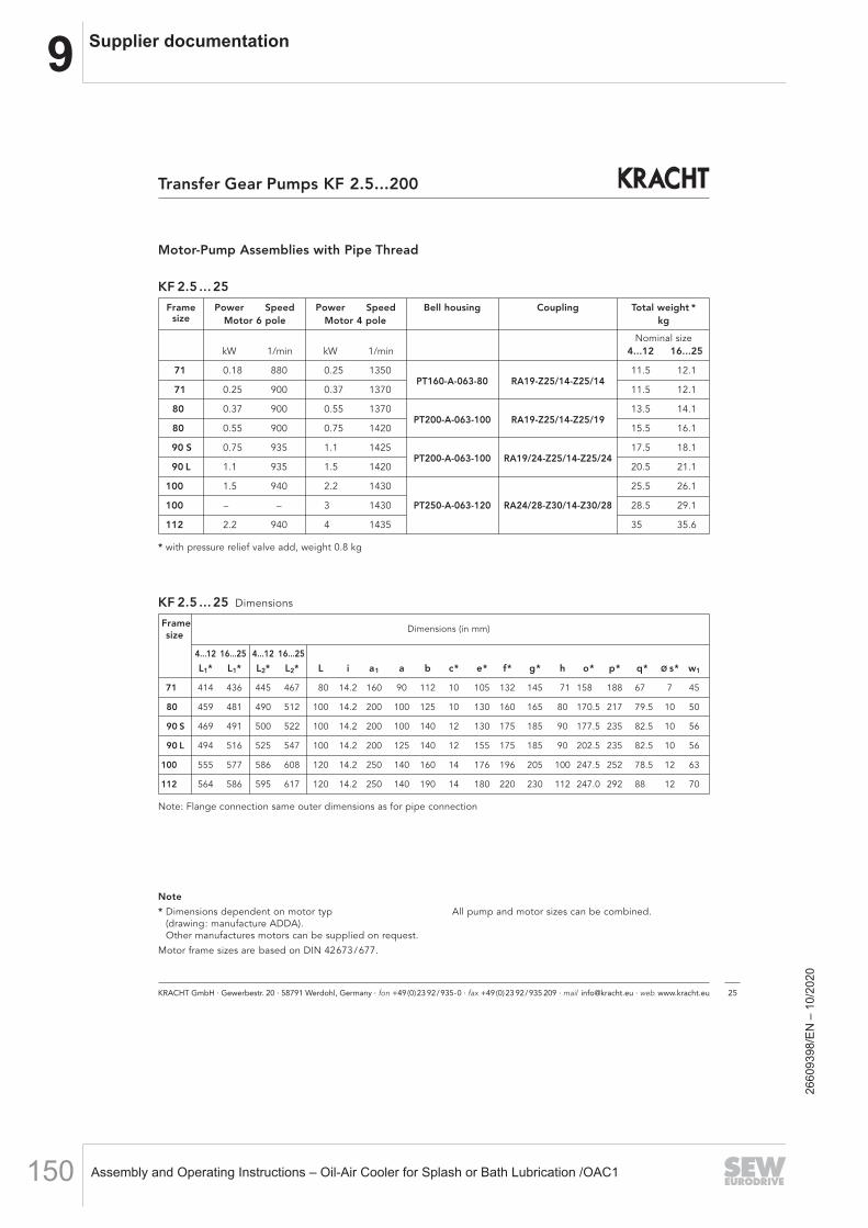
9 Supplier documentation
Assembly and Operating Instructions – Oil-Air Cooler for Splash or Bath Lubrication /OAC1150
KRACHT GmbH · Gewerbestr. 20 · 58791 Werdohl, Germany · fon +49(0)23 92/935-0 · fax +49(0)23 92/935 209 · mail [email protected] · web www.kracht.eu 25
Transfer Gear Pumps KF 2.5...200
Frame Power Speed Power Speed Bell housing Coupling Total weight *size Motor 6 pole Motor 4 pole kg
Nominal sizekW 1/min kW 1/min 4...12 16...25
71 0.18 880 0.25 1350PT160-A-063-80 RA19-Z25/14-Z25/14
11.5 12.1
71 0.25 900 0.37 1370 11.5 12.1
80 0.37 900 0.55 1370PT200-A-063-100 RA19-Z25/14-Z25/19
13.5 14.1
80 0.55 900 0.75 1420 15.5 16.1
90 S 0.75 935 1.1 1425PT200-A-063-100 RA19/24-Z25/14-Z25/24
17.5 18.1
90 L 1.1 935 1.5 1420 20.5 21.1
100 1.5 940 2.2 1430 25.5 26.1
100 – – 3 1430 PT250-A-063-120 RA24/28-Z30/14-Z30/28 28.5 29.1
112 2.2 940 4 1435 35 35.6
* with pressure relief valve add, weight 0.8 kg
Motor-Pump Assemblies with Pipe Thread
KF 2.5 ... 25
Frame Dimensions (in mm)size
4...12 16...25 4...12 16...25
L1* L1* L2* L2* L i a1 a b c* e* f* g* h o* p* q* ø s* w1
71 414 436 445 467 80 14.2 160 90 112 10 105 132 145 71 158.0 188 67 7 45
80 459 481 490 512 100 14.2 200 100 125 10 130 160 165 80 170.5 217 79.5 10 50
90 S 469 491 500 522 100 14.2 200 100 140 12 130 175 185 90 177.5 235 82.5 10 56
90 L 494 516 525 547 100 14.2 200 125 140 12 155 175 185 90 202.5 235 82.5 10 56
100 555 577 586 608 120 14.2 250 140 160 14 176 196 205 100 247.5 252 78.5 12 63
112 564 586 595 617 120 14.2 250 140 190 14 180 220 230 112 247.0 292 88 12 70
Note: Flange connection same outer dimensions as for pipe connection
KF 2.5 ... 25 Dimensions
Note
* Dimensions dependent on motor typ(drawing: manufacture ADDA).Other manufactures motors can be supplied on request.
Motor frame sizes are based on DIN 42673/677.
All pump and motor sizes can be combined.
2660
9398
/EN
– 1
0/20
20

9Supplier documentation
Assembly and Operating Instructions – Oil-Air Cooler for Splash or Bath Lubrication /OAC1 151
Motor-Pump Assemblies with SAE-Connection
KF 32 ... 80
with pressure relief valve
KF 32 ... 80 Pump sizes (in mm)
Nominalsize
F J J1
32...50 84 173 212
63 / 80 100 208 247
KRACHT GmbH · Gewerbestr. 20 · 58791 Werdohl, Germany · fon +49(0)23 92/935-0 · fax +49(0)23 92/935 209 · mail [email protected] · web www.kracht.eu26
Transfer Gear Pumps KF 2.5...200
2660
9398
/EN
– 1
0/20
20
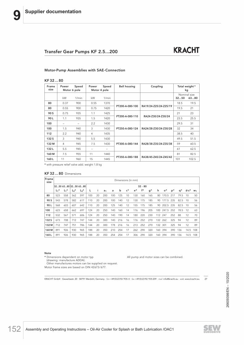
9 Supplier documentation
Assembly and Operating Instructions – Oil-Air Cooler for Splash or Bath Lubrication /OAC1152
KRACHT GmbH · Gewerbestr. 20 · 58791 Werdohl, Germany · fon +49(0)23 92/935-0 · fax +49(0)23 92/935 209 · mail [email protected] · web www.kracht.eu 27
Transfer Gear Pumps KF 2.5...200
Motor-Pump Assemblies with SAE-Connection
KF 32 ... 80
KF 32 ... 80 Dimensions
Frame Dimensions (in mm)size
32...50 63...80 32...50 63...80 32 - 80
L1* L1* L2* L2* L i a1 a b c* e* f* g* h o* p* q* ø s* w1
80 523 558 562 597 100 20 200 100 125 10 130 160 165 80 170.5 217 79.5 10.0 50
90 S 543 578 582 617 110 20 200 100 140 12 130 175 185 90 177.5 235 82.5 10.0 56
90 L 568 603 607 642 110 20 200 125 140 12 155 175 185 90 202.5 235 82.5 10.0 56
100 623 658 662 697 124 20 250 140 160 14 176 196 205 100 247.5 252 78.5 12.0 63
112 532 567 571 606 124 20 250 140 190 14 180 220 230 112 247.0 252 88.0 12.0 70
132 S 673 708 712 747 144 20 300 140 216 16 176 252 270 132 262.0 325 94.0 12.0 89
132 M 712 747 751 786 144 20 300 178 216 16 213 252 270 132 301.0 325 94.0 12.0 89
160 M 891 926 930 965 188 20 350 210 254 17 262 290 320 160 394.0 390 136.0 14.5 108
160 L 891 926 930 965 188 20 350 254 254 17 306 290 320 160 394.0 390 136.0 14.5 108
Frame Power Speed Power Speed Bell housing Coupling Total weight *size Motor 6 pole Motor 4 pole kg
Nominal sizekW 1/min kW 1/min 32...50 63...80
80 0.37 900 0.55 1370PT200-A-080-100 RA19/24-Z25/24-Z25/19
18.5 19.5
80 0.55 900 0.75 1420 19.5 21
90 S 0.75 935 1.1 1425PT200-A-080-110 RA24-Z30/24-Z30/24
21 23
90 L 1.1 935 1.5 1420 23.5 25.5
100 – – 2.2 1430 29.5 31
100 1.5 940 3 1430 PT250-A-080-124 RA24/28-Z30/24-Z30/28 32 34
112 2.2 940 4 1435 38.5 40
132 S 3 940 5.5 1430 49.5 51.5
132 M 4 945 7.5 1430 PT300-A-080-144 RA28/38-Z35/24-Z35/38 59 60.5
132 L 5.5 945 – – 61 62.5
160 M 7.5 955 11 1440PT350-A-080-188 RA38/45-Z45/24-Z45/42
81 82.5
160 L 11 960 15 1445 101 102.5
* with pressure relief valve add. weight 1.8 kg
Note* Dimensions dependent on motor typ
(drawing: manufacture ADDA).Other manufactures motors can be supplied on request.
Motor frame sizes are based on DIN 42673/677.
All pump and motor sizes can be combined.
2660
9398
/EN
– 1
0/20
20
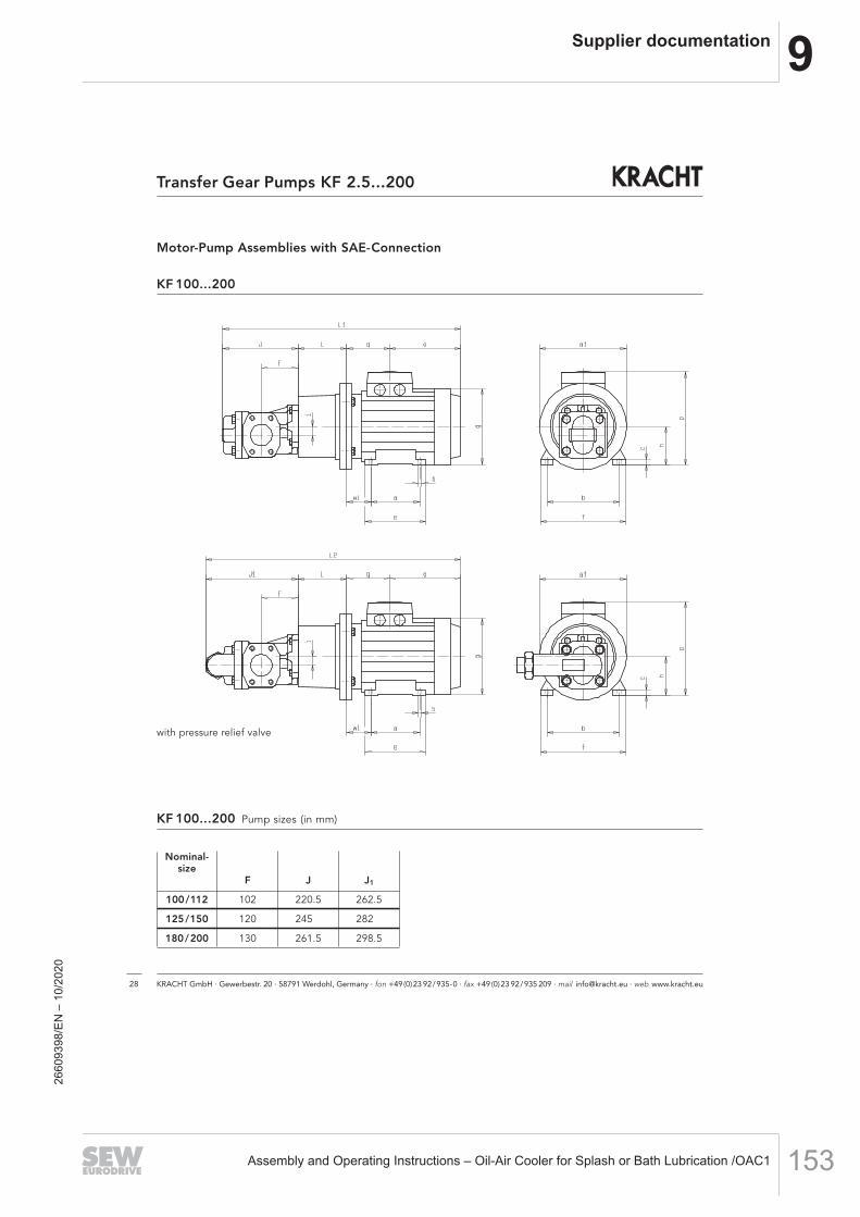
9Supplier documentation
Assembly and Operating Instructions – Oil-Air Cooler for Splash or Bath Lubrication /OAC1 153
Motor-Pump Assemblies with SAE-Connection
KF 100...200
KF 100...200 Pump sizes (in mm)
with pressure relief valve
Nominal-size
F J J1
100/112 102 220.5 262.5
125/150 120 245.0 282.0
180/200 130 261.5 298.5
KRACHT GmbH · Gewerbestr. 20 · 58791 Werdohl, Germany · fon +49(0)23 92/935-0 · fax +49(0)23 92/935 209 · mail [email protected] · web www.kracht.eu28
Transfer Gear Pumps KF 2.5...200
2660
9398
/EN
– 1
0/20
20
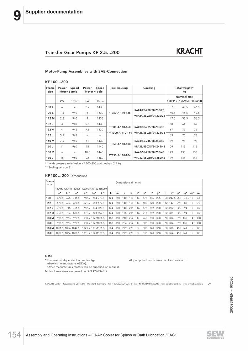
9 Supplier documentation
Assembly and Operating Instructions – Oil-Air Cooler for Splash or Bath Lubrication /OAC1154
KRACHT GmbH · Gewerbestr. 20 · 58791 Werdohl, Germany · fon +49(0)23 92/935-0 · fax +49(0)23 92/935 209 · mail [email protected] · web www.kracht.eu 29
Transfer Gear Pumps KF 2.5...200
Frame Power Speed Power Speed Bell housing Coupling Total weight *size Motor 6 pole Motor 4 pole kg
Nominal size
kW 1/min kW 1/min 100/112 125/150 180/200
100 L – – 2.2 1430RA24/28-Z30/28-Z30/28
37.5 43.5 46.5
100 L 1.5 940 3 1430 PT250-A-110-135**RA24/28-Z30/24-Z30/28
40.5 46.5 49.5
112 M 2.2 940 4 1435 47.5 53.5 56.5
132 S 3 940 5.5 1430PT300-A-110-168 RA28/38-Z35/28-Z35/38
58 64 67
132 M 4 945 7.5 1430**PT300-A-110-144 **RA28/38-Z35/24-Z35/38
67 73 76
132 L 5.5 945 – – 69 75 78
160 M 7.5 955 11 1430PT350-A-110-188
RA38/45-Z45/28-Z45/42 89 95 98
160 L 11 960 15 1140 **RA38/45-Z45/24-Z45/42 109 115 118
180 M – – 18.5 1445PT350-A-110-204
RA42/55-Z50/28-Z50/48 129 135 138
180 L 15 960 22 1460 **RG42/55-Z50/24-Z50/48 139 145 148
* * with pressure relief valve KF 100-200 add. weight 2.7 kg** Sealing version 31
Motor-Pump Assemblies with SAE-Connection
KF 100...200
KF 100 ... 200 Dimensions
Frame Dimensions (in mm)size
100/112 125/150 180/200 100/112 125/150 180/200
L1* L1* L1* L2* L2* L2* L a1 a b c* e* f* g* h o* p* q* ø s* w1
100 670.5 695 711.5 712.5 754 770.5 124 250 140 160 14 176 196 205 100 247.5 252 78.5 12 63
112 579.5 604 620.5 621.5 663 679.5 124 250 140 190 14 180 220 230 112 147 292 88 12 70
132 S 720.5 745 761.5 762.5 804 820.5 144 300 140 216 16 176 252 270 132 262 325 94 12 89
132 M 759.5 784 800.5 801.5 843 859.5 144 300 178 216 16 213 252 270 132 301 325 94 12 89
160 M 938.5 963 979.5 980.5 10221038.5 188 350 210 254 17 262 290 320 160 394 390 136 14.5 108
160 L 938.5 963 979.5 980.5 10221038.5 188 350 254 254 17 306 290 320 160 394 390 136 14.5 108
180 M 1001.5 1026 1042.5 1043.5 10851101.5 204 350 279 279 27 300 348 360 180 336 450 241 15 121
180 L 1039.5 1064 1080.5 1081.5 11231139.5 204 350 279 279 27 338 348 360 180 354 450 261 15 121
Note
* Dimensions dependent on motor typ(drawing: manufacture ADDA).Other manufactures motors can be supplied on request.
Motor frame sizes are based on DIN 42673/677.
All pump and motor sizes can be combined.
2660
9398
/EN
– 1
0/20
20

9Supplier documentation
Assembly and Operating Instructions – Oil-Air Cooler for Splash or Bath Lubrication /OAC1 155
Accessory Connections
SAE-Threaded Flange
SAE-Threaded Flange Dimensions (in mm)
SAE-Welding Flange
SAE-Welding Flange Dimensions (in mm)
KRACHT GmbH · Gewerbestr. 20 · 58791 Werdohl, Germany · fon +49(0)23 92/935-0 · fax +49(0)23 92/935 209 · mail [email protected] · web www.kracht.eu30
Transfer Gear Pumps KF 2.5...200
Nominal size A* B C D* E F* G H* Screws O-ring Working pressure Weight
SAE DN max. 10.9 max.** ca. [kg]
3/4" 19 28.0 19 47.63 65 22.23 50 36 18 M 10 x 35 24.99 x 3.53 350 0.51
1" 25 34.0 25 52.37 70 26.19 55 38 18 M 10 x 35 32.92 x 3.53 315 0.58
1 1/4" 32 42.8 32 58.72 79 30.18 68 41 21 M 10 x 40 37.69 x 3.53 250 0.79
1 1/2" 38 48.6
38
69.85
93 35.71
78
44
25
M 12 x 45 47.22 x 3.53 200 1.25
2" 51 61.0 51 77.77 102 42.88 90 45 25 M 12 x 45 56.74 x 3.53 200 1.39
2 1/2" 64 77.0 63 88.90 114 50.80 105 50 25 M 12 x 45 69.44 x 3.53 160 1.60
3" 76 92.0 73 106.38 134 61.93 124 50
27
M 16 x 50 85.32 x 3.53 138 2.58
3 1/2" 89 103.0 89 120.65 152 69.85 136 48 27 M 16 x 50 98.02 x 3.53 35 2.83
Nominal size A B C D* E F* G H* L Screws O-ring Working pressure Weight SAE DN max. min. 10.9 max.** ca. [kg]
3/4" 13 G 1/2" 13
47.63 65 22.23 50 36 1814
M 10 x 35 24.99 x 3.53 350 0.54
19 G 3/4" 19 16 0.51
1" 13 G 1/2" 13
52.37 70 26.19 55 38 1814
M 10 x 35 32.92 x 3.53 315 0.64
19 G 3/4" 19 16 0.61 25 G 1" 25 18 0.58
1 1/4" 19 G 3/4" 19
58.72 79 30.18 68 41 21 16
M 10 x 40 37.69 x 3.53 250 0.92
25 G 1" 25 42 25 18 0.88 32 G 1 1/4" 32 41 21 20 0.79
1 1/2" 25 G 1 " 25
69.85 93 35.71 78 45
25 18 M 12 x 45 47.22 x 3.53 200
1.36 32 G 1 1/4" 32 27 20 1.30 38 G 1 1/2" 38 25 22 1.25
2"
25 G1" 25
77.77 102 42.88 90 45 25
18
M 12 x 45 56.74 x 3.53 200
1.64 32 G1 1/4" 32 20 1.60 38 G 1 1/2" 38 22 1.45 51 G 2" 51 26 1.39
2 1/2" 51 G 2" 51
88.90 114 50.80 105 50 25 26
M 12 x 45 69.44 x 3.53 160 1.65
64 G 2 1/2" 63 30 1.60
3" 64 G 2 1/2" 63
106.38 134 61.93 124 50 27 30 M 16 x 50 85.32 x 3.53 138 2.68
76 G 3" 73 2.58
3 1/2" 76 G 3" 73
120.65 152 69.85 136 48 27 30 M 16 x 50 98.02 x 3.53 35 2.93
89 G 3 1/2" 89 2.83
* Dimensions depending on the manufacturer ** O-ring material with hardness 90 Shore AMaterial: Steel S355J2G3 or equivalent Stainless steel 1.4404 or equivalent 316L
Screw Screw
O-ring
O-ring
2660
9398
/EN
– 1
0/20
20

9 Supplier documentation
Assembly and Operating Instructions – Oil-Air Cooler for Splash or Bath Lubrication /OAC1156
KRACHT GmbH · Gewerbestr. 20 · 58791 Werdohl, Germany · fon +49(0)23 92/935-0 · fax +49(0)23 92/935 209 · mail [email protected] · web www.kracht.eu 31
Transfer Gear Pumps KF 2.5...200
Accessory Quench Chamber
Quench tank Adapter for screw size tap G 1⁄8
2660
9398
/EN
– 1
0/20
20

9Supplier documentation
Assembly and Operating Instructions – Oil-Air Cooler for Splash or Bath Lubrication /OAC1 157
KF2.5...200/GB/06.14
KRACHT GmbH · Gewerbestraße 20 · 58791 Werdohl, Germany · fon +49 (0) 23 92 / 935-0 · fax +49 (0) 23 92 / 935 209
mail [email protected] · web www.kracht.eu
Transfer PumpsTransfer pumps for lubricating oil supply equipment, low pressure filling and feed systems, dosing and mixing systems.
Mobile HydraulicsSingle and multistage high pressure gear pumps, hydraulic motors and valves for construction machinery, vehicle-mounted machines.
Flow MeasurementGear and turbine flow meters and electronics for volume and flow metering techno logy in hydraulics, processing and laquering technology.
Industrial Hydraulics /Test Bench ConstructionCetop directional control and proportional valves, hydraulic cylinders, pressure, quantity and stop valves for pipe and slab construction, hydraulic accessories for industrial hydraulics (mobile and stationary use).
Technology Test benches / Fluid Test benches.
Product Portfolio
2660
9398
/EN
– 1
0/20
20

9 Supplier documentation
Assembly and Operating Instructions – Oil-Air Cooler for Splash or Bath Lubrication /OAC1158
Mechanical temperature measurement
Bimetal thermometerModel 52, industrial series
Applications
A wide range of applications in machine building, vessel, piping and apparatus construction
Heating technology
Special features
Scale ranges from -30 ... +500 °C Large choice of nominal sizes from 25 ... 160 mm Case and stem from stainless steel 5 different connection designs
Description
The model 52 bimetal thermometer is the entry-level model among process thermometers. The target markets of this thermometer are air-conditioning and machine building.
Model 52 is manufactured in accordance with EN 13190 and already offers a stainless steel case and accuracy class 1 for nominal sizes > 60 mm.
Especially noteworthy is the large number of stem lengths and nominal sizes. This enables the individual adaptation to the target applications.
WIKA data sheet TM 52.01
Page 1 of 6WIKA data sheet TM 52.01 ∙ 01/2016
for further approvals see page 6
Fig. left: model A52.100, back mountFig. right: model R52.100, lower mount
2660
9398
/EN
– 1
0/20
20
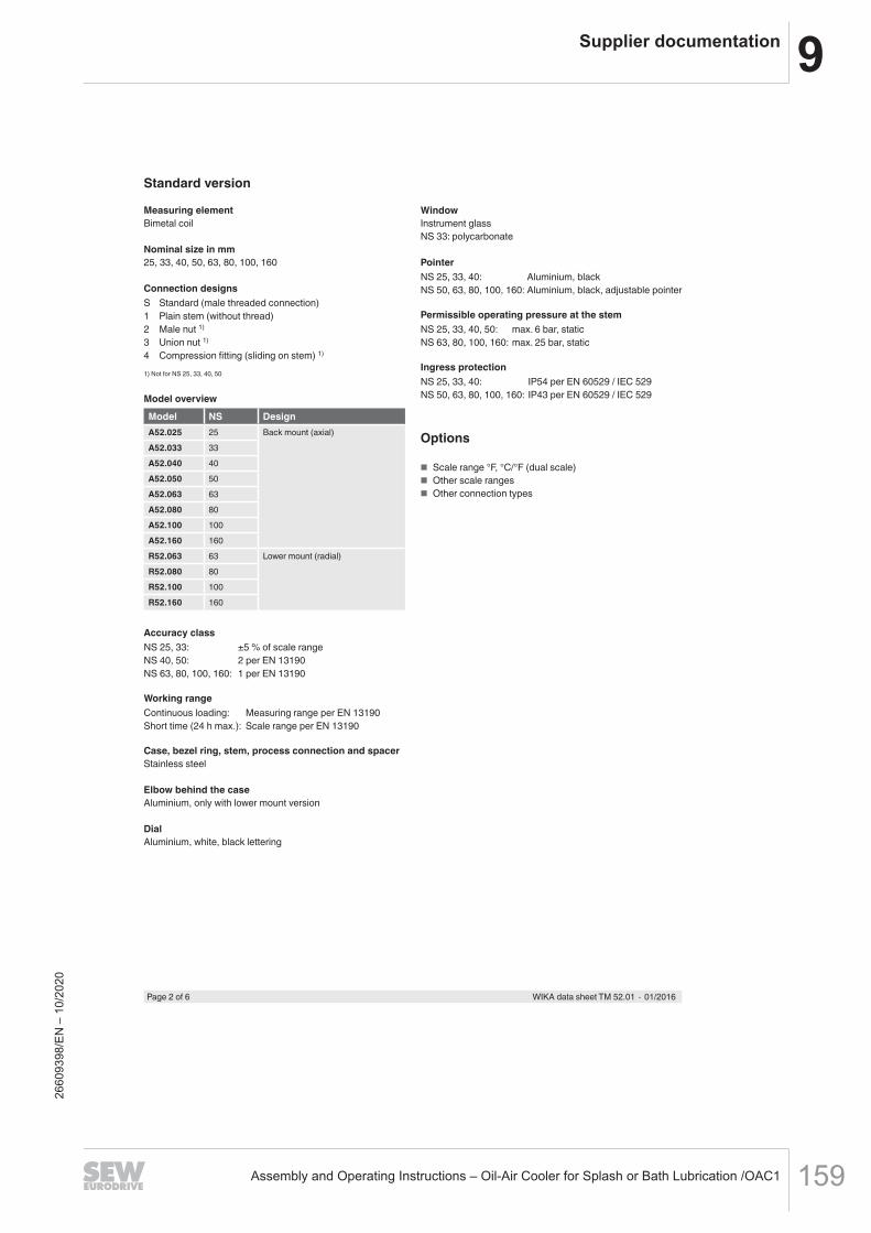
9Supplier documentation
Assembly and Operating Instructions – Oil-Air Cooler for Splash or Bath Lubrication /OAC1 159
Page 2 of 6 WIKA data sheet TM 52.01 ∙ 01/2016
Standard version
Measuring elementBimetal coil
Nominal size in mm25, 33, 40, 50, 63, 80, 100, 160
Connection designsS Standard (male threaded connection)1 Plain stem (without thread)2 Male nut 1)
3 Union nut 1)
4 Compression fitting (sliding on stem) 1)
1) Not for NS 25, 33, 40, 50
Model overview
Model NS DesignA52.025 25 Back mount (axial)A52.033 33A52.040 40A52.050 50A52.063 63A52.080 80A52.100 100A52.160 160R52.063 63 Lower mount (radial)R52.080 80R52.100 100R52.160 160
Accuracy classNS 25, 33: ±5 % of scale rangeNS 40, 50: 2 per EN 13190NS 63, 80, 100, 160: 1 per EN 13190
Working rangeContinuous loading: Measuring range per EN 13190Short time (24 h max.): Scale range per EN 13190
Case, bezel ring, stem, process connection and spacerStainless steel
Elbow behind the caseAluminium, only with lower mount version
DialAluminium, white, black lettering
WindowInstrument glassNS 33: polycarbonate
PointerNS 25, 33, 40: Aluminium, blackNS 50, 63, 80, 100, 160: Aluminium, black, adjustable pointer
Permissible operating pressure at the stemNS 25, 33, 40, 50: max. 6 bar, staticNS 63, 80, 100, 160: max. 25 bar, static
Ingress protectionNS 25, 33, 40: IP54 per EN 60529 / IEC 529NS 50, 63, 80, 100, 160: IP43 per EN 60529 / IEC 529
Options
Scale range °F, °C/°F (dual scale) Other scale ranges Other connection types
2660
9398
/EN
– 1
0/20
20

9 Supplier documentation
Assembly and Operating Instructions – Oil-Air Cooler for Splash or Bath Lubrication /OAC1160
Page 3 of 6WIKA data sheet TM 52.01 ∙ 01/2016
Scale range in °C Measuring range in °C Scale spacing in °C Error limit ±°Cup to NS 63 from NS 80 up to NS 50 from NS 63
-30 ... +50 -20 ... +40 1 1 2 1-20 ... +60 -10 ... +50 1 1 2 10 ... 60 10 ... 50 1 1 2 10 ... 80 10 ... 70 1 1 2 10 ... 100 10 ... 90 2 1 2 10 ... 120 10 ... 110 2 1 4 20 ... 160 20 ... 140 2 2 4 20 ... 200 3) 20 ... 180 5 2 4 20 ... 250 3) 30 ... 220 5 2 5 2.50 ... 300 4) 30 ... 270 5 2 - 50 ... 400 4) 50 ... 350 5 5 - 50 ... 500 4) 50 ... 450 5 5 - 5
Scale ranges, measuring ranges 2), error limit (EN 13190)Scale graduation per WIKA standard
2) The limits of the measuring range are indicated on the dial by two triangular marks.Only within this range is the stated error limit valid per EN 13190.
3) Not for NS 334) Not for NS 25 to NS 50
Nominal size
Process connection
Dimensions in mm
NS G i SW Ø d4 Ø d25, 33 M8 x 1.25 8 12 - 4
G ⅛ B 8 12 - 4G ¼ B 8 17 - 4
40, 50 M8 x 1.25 8 12 - 4G ⅛ B 8 17 - 4G ¼ B 8 17 - 4G ½ B 12 22 - 4
63, 80, 100, 160
G ¼ B 12 19 18 6 or 8G ½ B 14 27 26 6 or 8M18 x 1.5 12 24 23 6 or 8½ NPT 19 22 - 6 or 8
Nominal size Dimensions in mmNS d1 Ø d25, 33 8 440, 50 12 463, 80, 100, 160 18 6 or 8
Connection designs
Standard design (male thread connection)Standard insertion length l1 = 63, 100, 160, 200, 250 mm
Bauform 1, Anschluss glatt (ohne Gewinde)Standard-Einbaulänge I1 = 45, 63, 100, 140, 160, 200, 240, 290 mm
3073
050.
0530
7305
0.05
Legend:G Male threadi Thread lengthØ d4 Diameter of the sealing collar
Legend:Ø d1 BunddurchmesserØ d Stem diameter
SW Spanner widthØ d Stem diameterl2 Active length
l2 Active length
2660
9398
/EN
– 1
0/20
20
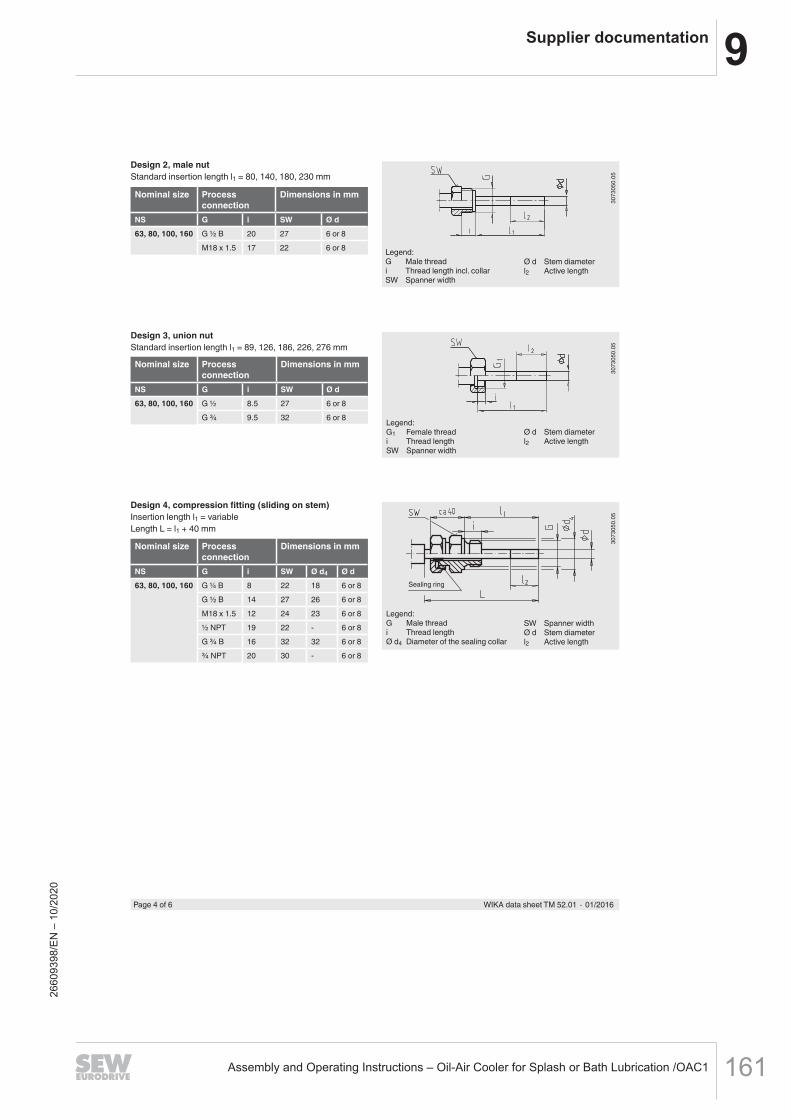
9Supplier documentation
Assembly and Operating Instructions – Oil-Air Cooler for Splash or Bath Lubrication /OAC1 161
Page 4 of 6 WIKA data sheet TM 52.01 ∙ 01/2016
Nominal size Process connection
Dimensions in mm
NS G i SW Ø d63, 80, 100, 160 G ½ B 20 27 6 or 8
M18 x 1.5 17 22 6 or 8
Nominal size Process connection
Dimensions in mm
NS G i SW Ø d63, 80, 100, 160 G ½ 8.5 27 6 or 8
G ¾ 9.5 32 6 or 8
Design 2, male nutStandard insertion length l1 = 80, 140, 180, 230 mm
3073
050.
05
Legend:G Male threadi Thread length incl. collarSW Spanner width
Ø d Stem diameterl2 Active length
Design 3, union nutStandard insertion length l1 = 89, 126, 186, 226, 276 mm
3073
050.
05
Legend:G1 Female threadi Thread lengthSW Spanner width
Ø d Stem diameterl2 Active length
Nominal size Process connection
Dimensions in mm
NS G i SW Ø d4 Ø d63, 80, 100, 160 G ¼ B 8 22 18 6 or 8
G ½ B 14 27 26 6 or 8M18 x 1.5 12 24 23 6 or 8½ NPT 19 22 - 6 or 8G ¾ B 16 32 32 6 or 8¾ NPT 20 30 - 6 or 8
Design 4, compression fitting (sliding on stem)Insertion length l1 = variableLength L = l1 + 40 mm
Legend:G Male threadi Thread lengthØ d4 Diameter of the sealing collar
3073
050.
05
Sealing ring
SW Spanner widthØ d Stem diameterl2 Active length
2660
9398
/EN
– 1
0/20
20

9 Supplier documentation
Assembly and Operating Instructions – Oil-Air Cooler for Splash or Bath Lubrication /OAC1162
Page 5 of 6WIKA data sheet TM 52.01 ∙ 01/2016
NS Dimensions in mm Weight in kgb1 b2 b3 b4 b5 Ø D F R RD U
25 16 - - - 6 25 - 0.035 - -33 16 - - - 6 33 - 0.040 - -40 21 - - - 8 40 - 0.050 - -50 21 - - - 8 50 - 0.060 - -63 29 30 1) 46 34 13 63 47 0.160 0.200 0.22080 30 30 1) 47 36 13 80 56 0.200 0.240 0.270100 35 30 1) 52 40 13 100 66 0.250 0.290 0.330160 39 30 1) 57 42,5 13 160 96 0.450 0.490 0.560
3072
991.
01
3073
009.
01
3190
307.
01
1) from 300 °C or on requestR Back mount (BM)RD Back mount with spacerU Lower mount (LM)
Dimensions in mm
Back mount (BM)(up to 250 °C)
Back mount with spacer(from 300 °C or on request)
Lower mount (LM)
Thermowell
In principle, the operation of a mechanical thermometer without a thermowell with low process-side loading (low pressure, low viscosity and low flow velocities) is possible.
However, in order to enable exchanging the thermometer during operation (e.g. instrument replacement or calibration) and to ensure a better protection of the instrument and also the plant and the environment, it is advisable to use a thermowell from the extensive WIKA thermowell portfolio.
For further information on the calculation of the thermowell, see Technical information IN 00.15.
2660
9398
/EN
– 1
0/20
20

9Supplier documentation
Assembly and Operating Instructions – Oil-Air Cooler for Splash or Bath Lubrication /OAC1 163
WIKA Alexander Wiegand SE & Co. KGAlexander-Wiegand-Straße 3063911 Klingenberg/GermanyTel. +49 9372 132-0Fax +49 9372 [email protected]
© 2004 WIKA Alexander Wiegand SE & Co. KG, all rights reserved.The specifications given in this document represent the state of engineering at the time of publishing.We reserve the right to make modifications to the specifications and materials.
Ordering informationModel / Connection design / Scale range / Process connection / Stem diameter, material / Insertion length / Options
Approvals
Logo Description CountryGOST (option)Metrology, measurement technology
Russia
- CRN (option)Safety (e.g. electr. safety, overpressure, ...)
Canada
Certificates (option)
2.2 test report
Approvals and certificates, see website
Page 6 of 6 WIKA data sheet TM 52.01 ∙ 01/2016
01/2
016
EN
2660
9398
/EN
– 1
0/20
20

9 Supplier documentation
Assembly and Operating Instructions – Oil-Air Cooler for Splash or Bath Lubrication /OAC1164
Operating instructions Flow monitors
SI5000 SI5001
7040
56 /
03
08 /
2010
UK
2660
9398
/EN
– 1
0/20
20

9Supplier documentation
Assembly and Operating Instructions – Oil-Air Cooler for Splash or Bath Lubrication /OAC1 165
2
Contents1 Safety instructions 32 Functions and features 421 Application area 422 Operating principle flow monitoring 43 Installation 531 Installation location 532 Sources of interference in the pipe system 633 Mounting operation 64 Electrical connection 75 Operating and display elements 76 Set-up and settings for water 861 Change the switch point (optional) 862 High flow adjustment (optional) 97 Additional settings (optional) 971 Low flow adjustment 972 Configure the switching output 973 Restore the factory setting (reset) 1074 Lock / unlock the unit 108 Error during adjustment 109 Operation 1110 Maintenance 1111 Scale drawing 1212 Technical data 12
2660
9398
/EN
– 1
0/20
20

9 Supplier documentation
Assembly and Operating Instructions – Oil-Air Cooler for Splash or Bath Lubrication /OAC1166
3
UK
Preliminary note• An instruction is indicated by “”:
Example: Check whether the unit operates correctly• A reaction to the action is indicated by ">":
Example: > LED 9 lights
1 Safety instructions• Please read the product description prior to set-up of the unit Ensure that the
product is suitable for your application without any restrictions• The unit conforms to the relevant regulations and EC directives • Improper or non-intended use may lead to malfunctions of the unit or to un-
wanted effects in your application • That is why installation, electrical connection, set-up, operation and mainte-
nance of the unit must only be carried out by qualified personnel authorised by the machine operator
For the scope of validity cULus:The device shall be supplied from an isolating transformer having a secondary Listed fuse rated as noted in the following table
Overcurrent protectionControl-circuit wire size Maximum protective device rating
AmpereAWG (mm2)26 (013) 124 (020) 222 (032) 320 (052) 518 (082) 716 (13) 10
2660
9398
/EN
– 1
0/20
20

9Supplier documentation
Assembly and Operating Instructions – Oil-Air Cooler for Splash or Bath Lubrication /OAC1 167
4
2 Functions and features2.1 Application area The unit monitors the flow of liquid and gaseous media
2.2 Operating principle flow monitoring• The unit detects the flow speed to the calorimetric measuring principle and
switches the output: - output closed if medium is flowing / output open if no medium is flowingThis applies to the unit on delivery: output = normally open In case of need you can change the output to normally closed (→ 72) It then applies: output open if medium is flowing
• If the flow speed increases, the switching status changes when the switch point is reached
• If the flow speed falls again, the switching status changes if the value "SP minus hysteresis" is reachedThe hysteresis changes with the flow speed and it is essentially influenced by the set monitoring range It is 25 cm/s for the setting 5100 cm/s (= factory setting), it increases with higher flow speeds
• The typical response time of the unit is 110 s It can be influenced by the setting of the switch point: - Low switch point = quick reaction with rising flow - High switch point = quick reaction with falling flow
2660
9398
/EN
– 1
0/20
20
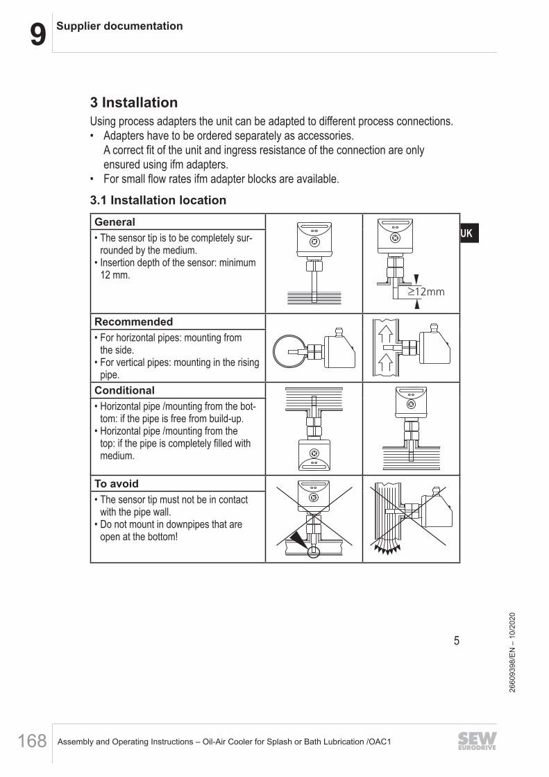
9 Supplier documentation
Assembly and Operating Instructions – Oil-Air Cooler for Splash or Bath Lubrication /OAC1168
5
UK
3 InstallationUsing process adapters the unit can be adapted to different process connections • Adapters have to be ordered separately as accessories
A correct fit of the unit and ingress resistance of the connection are only ensured using ifm adapters
• For small flow rates ifm adapter blocks are available
3.1 Installation locationGeneral
• The sensor tip is to be completely sur-rounded by the medium
• Insertion depth of the sensor: minimum 12 mm
Recommended• For horizontal pipes: mounting from
the side• For vertical pipes: mounting in the rising
pipeConditional• Horizontal pipe /mounting from the bot-
tom: if the pipe is free from build-up• Horizontal pipe /mounting from the
top: if the pipe is completely filled with medium
To avoid• The sensor tip must not be in contact
with the pipe wall• Do not mount in downpipes that are
open at the bottom!
2660
9398
/EN
– 1
0/20
20
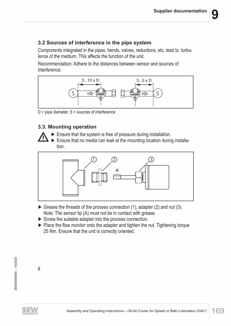
9Supplier documentation
Assembly and Operating Instructions – Oil-Air Cooler for Splash or Bath Lubrication /OAC1 169
6
3.2 Sources of interference in the pipe systemComponents integrated in the pipes, bends, valves, reductions, etc lead to turbu-lence of the medium This affects the function of the unitRecommendation: Adhere to the distances between sensor and sources of interference:
D = pipe diameter; S = sources of interference
3.3. Mounting operation Ensure that the system is free of pressure during installation Ensure that no media can leak at the mounting location during installa-tion
Grease the threads of the process connection (1), adapter (2) and nut (3)Note: The sensor tip (A) must not be in contact with grease
Screw the suitable adapter into the process connection Place the flow monitor onto the adapter and tighten the nut Tightening torque 25 Nm Ensure that the unit is correctly oriented
2660
9398
/EN
– 1
0/20
20

9 Supplier documentation
Assembly and Operating Instructions – Oil-Air Cooler for Splash or Bath Lubrication /OAC1170
7
UK
4 Electrical connectionThe unit must be connected by a qualified electricianThe national and international regulations for the installation of electrical equipment must be adhered to Voltage supply to EN 50178, SELV, PELV
Disconnect power Connect the unit as follows:
A: SI5000 (positive switching); B: SI5001 (negative switching)Core colours of ifm sockets:1 = BN (brown), 3 = BU (blue), 4 = BK (black)
5 Operating and display elements
1: Operation display• The green LEDs indicate the current flow (the LEDs 0 to 9 represent the range between
no flow and maximum flow)• A lighting LED indicates the position of the switch point (orange = output closed, red =
output open)2, 3: Setting buttons for adjustment and configuration
2660
9398
/EN
– 1
0/20
20

9Supplier documentation
Assembly and Operating Instructions – Oil-Air Cooler for Splash or Bath Lubrication /OAC1 171
8
6 Set-up and settings for water(For media other than water → 71: Low flow adjustment)
Switch on the supply voltage > All LEDs light and go out again step by step During this time the output is
closed (if configured as normally open) The unit is in the operating mode Let the normal flow circulate in the installation Check the display and determine further actions
1
The factory setting is suitable for the applica-tion
No further settings are required
2
Your normal flow is below the representation range of the display2 setting options:
Change the switch point (→ 61) Carry out high flow adjustment (→ 62)
3
Your normal flow exceeds the representation range of the display (LED 9 flashes)
Carry out high flow adjustment (→ 62)
You can restore the factory setting any time (→ 73)
6.1 Change the switch point (optional)For the factory setting the switch point is at LED 7 A change makes sense if:• the display shows example 2• the flow fluctuates much or pulsates• if a faster response time of the unit is requested (low switch point = fast re-
sponse with rising flow, high switch point = fast response with falling flow) Briefly press the pushbutton or
> The switch point LED flashes Press the pushbutton or as often as required Each press of the push-button shifts the LED by one position in the indicated direction
Note: If no pushbutton is pressed for 2 s, the unit returns to the operating mode with the newly set value
2660
9398
/EN
– 1
0/20
20
9 Supplier documentation
Assembly and Operating Instructions – Oil-Air Cooler for Splash or Bath Lubrication /OAC1172
9
UK
6.2 High flow adjustment (optional)The unit determines the existing flow as normal flow and adapts the display repre-sentation (all LEDs except the switch point LED light green)
Let the normal flow circulate in the installation Press the pushbutton and keep it pressed
> LED 9 lights, after approx 5 s it flashes Release the pushbutton
The unit is now adapted to your flow conditions It passes into the operating mode, the display should now show example 1Note: The adjustment affects the switch point: It is increased proportionally (maximum up to LED 7)
7 Additional settings (optional)7.1 Low flow adjustmentIf the unit is used in media other than water, you should additionally adapt the unit to the minimum flow Note: The following adjustment must only be carried out after the high flow adjust-ment
Let the minimum flow circulate in the installation or ensure flow standstill Press the pushbutton and keep it pressed
> LED 0 lights, after approx 5 s it flashes Release the pushbutton The unit adopts the new value and passes into the operating mode
7.2 Configure the switching outputThe unit is delivered as normally open In case of need you can change the output to normally closed:
Press the pushbutton for at least 15 s > LED 0 lights, after approx 5 s it flashes > After 10 s the current setting is displayed: LEDs 59 light orange (= output
normally open) > After approx 15 s LEDs 04 flash orange Release the pushbutton The output is changed to normally closed operation
For a new changeover repeat the operation
2660
9398
/EN
– 1
0/20
20
9Supplier documentation
Assembly and Operating Instructions – Oil-Air Cooler for Splash or Bath Lubrication /OAC1 173
10
7.3 Restore the factory setting (reset) Press the pushbutton for at least 15 s
> LED 9 lights, after approx 5 s it flashes > After approx 15 s LEDs 09 flash orange Release the pushbutton All settings are reset to the factory setting: - operating area: 5 100 cm/s for water - switch point: LED 7 - output function: NO - unlocked
7.4 Lock / unlock the unitThe unit can be locked electronically to prevent unintentional settings
Press both setting pushbuttons simultaneously for at least 10 s in the operating mode
> The indication goes out, the unit locks or unlocks On delivery: unlocked
8 Error during adjustmentIf no adjustment is possible, all LEDs flash red The unit then passes into the operating mode with unchanged valuesPossible cause /aid:
Error during installation Read chapter 3 Installation Check whether all requirements have been met
The difference between maximum flow and minimum flow is too small
Increase the flow difference and carry out the adjustment once again
The sequence high flow /low flow adjust-ment was not adhered to
Carry out the two adjustment operations again in the right sequence
2660
9398
/EN
– 1
0/20
20

9 Supplier documentation
Assembly and Operating Instructions – Oil-Air Cooler for Splash or Bath Lubrication /OAC1174
11
UK
9 OperationAfter every power on all LEDs light and go out again step by step (during this time the output is closed if configured as normally open) The unit is then ready for operationIn case of power failure or interruption all settings remain
Operating indicators
Green LED bar: Current flow within the representa-tion rangeIndication of the switch point (SP):- LED orange: output closed- LED red: output open
LED 9 flashes: current flow above therepresentation range
LED 0 flashes: current flow far below the represen-tation range
Interference indicators
Short circuit at the switching output:The operating indicator and red LEDs light alternately If the short circuit has been rectified, the unit im-mediately passes into the normal operating stateThe current operating state is displayed
Display OFF(no LED lights):
Operating voltage too low (< 19 V) or failedEnsure a correct voltage supply
10 MaintenanceRecommended maintenance:
Check the sensor tip for build-up from time to time Clean it using a soft cloth Stubborn build-up (eg lime) can be removed using a common vinegar cleaning agent
2660
9398
/EN
– 1
0/20
20
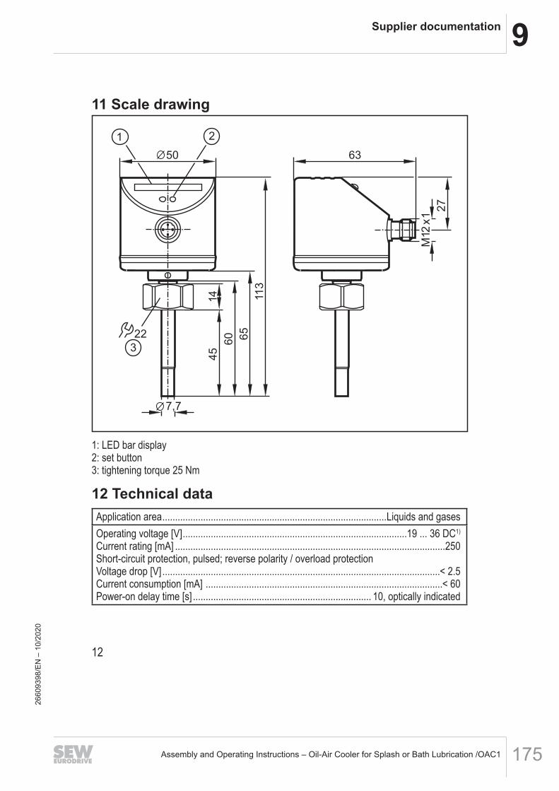
9Supplier documentation
Assembly and Operating Instructions – Oil-Air Cooler for Splash or Bath Lubrication /OAC1 175
12
11 Scale drawing
22
1 2
3
113
60 65
14
7,7
45
50
27
63
M12x1
1: LED bar display2: set button3: tightening torque 25 Nm
12 Technical dataApplication area Liquids and gasesOperating voltage [V] 19 36 DC1)
Current rating [mA] 250 Short-circuit protection, pulsed; reverse polarity / overload protectionVoltage drop [V] < 25Current consumption [mA] < 60Power-on delay time [s] 10, optically indicated
2660
9398
/EN
– 1
0/20
20

9 Supplier documentation
Assembly and Operating Instructions – Oil-Air Cooler for Splash or Bath Lubrication /OAC1176
13
UK
LiquidsMedium temperature [°C] .................................................................................... -25 ... +80Setting range [cm/s]..................................................................................................3 ... 300Greatest sensitivity [cm/s] ..........................................................................................3...100Temperature gradient [K/min] .........................................................................................300GasesMedium temperature [°C] .................................................................................... -25 ... +80Setting range [cm/s]............................................................................................200 ... 3000Greatest sensitivity [cm/s].....................................................................................200 ... 800Switch point accuracy [cm/s] ................................................................................± 2...± 102)
Hysteresis [cm/s] ..........................................................................................................2...52)
Repeatability [cm/s] ......................................................................................................1...52)
Temperature drift [cm/s x 1/K].........................................................................................0.13)
Response time [s] .......................................................................................................1 ... 10Pressure resistance [bar]...................................................................................................30Operating temperature [°C] .................................................................................. -25 ... +80Protection rating ........................................................................................................... IP 67Protection class ..................................................................................................................IIIShock resistance [g] .............................................................. 50 (DIN / IEC 68-2-27, 11 ms)Vibration resistance [g] ................................................... 20 (DIN / IEC 68-2-6, 55-2000 Hz)Housing materials ......................stainless steel 316L / 1.4404; stainless steel 304 / 1.4301;
PC (Makrolon); PBT-GF 20; EPDM/X (Santoprene)Materials (wetted parts) .......................................................... stainless steel 316L / 1.4404; O-ring: FPM 8x1.5 gr 80° Shore AEMCEN 61000-4-2 ESD: ................................................................................ 4 kV CD / 8 kV ADEN 61000-4-3 HF radiated: ...................................................................................... 10 V/m EN 61000-4-4 Burst: ..................................................................................................... 2 kV EN 61000-4-6 HF conducted: ....................................................................................... 10 V1) to EN50178, SELV, PELV;2) for water; 5...100 cm/s; 25°C (factory setting)3) for water; 5...100 cm/s; 10...70°CThe sensor conforms to the standard EN 61000-6-2
More information at www.ifm.com
2660
9398
/EN
– 1
0/20
20

9Supplier documentation
Assembly and Operating Instructions – Oil-Air Cooler for Splash or Bath Lubrication /OAC1 177
1: LED display2: setting pushbutton3: tightening torque 25 Nm
Product characteristicsFlow monitor
Compact type for adapter
Process connection: internal thread M18 x 1.5 for adapter
Probe length: 45 mm
Setting range: 3...300 cm/s (liquids)
Applicationliquids and gasesApplication
30Pressure rating [bar]
-25...80Medium temperature [°C]
Electrical dataDC PNPElectrical design
19...36 DCOperating voltage [V]
< 60Current consumption [mA]
IIIProtection class
yesReverse polarity protection
Outputsnormally open / closed programmableOutput function
250Current rating [mA]
< 2.5Voltage drop [V]
pulsedShort-circuit protection
yesOverload protection
Measuring / setting rangeLiquids
3...300Setting range [cm/s]
3...100Greatest sensitivity [cm/s]
Gases
200...3000Setting range [cm/s]
200...800Greatest sensitivity [cm/s]
SI5000Flow sensorsSID10ABBFPKG/US-100
2660
9398
/EN
– 1
0/20
20

9 Supplier documentation
Assembly and Operating Instructions – Oil-Air Cooler for Splash or Bath Lubrication /OAC1178
Accuracy / deviations± 2...± 10 *)Switch point accuracy [cm/s]
2...5 *)Hysteresis [cm/s]
1...5 *)Repeatability [cm/s]
0.1 **)Temperature drift [cm/s x 1/K]
300Max. temperature gradient ofmedium [K/min]
Reaction times10Power-on delay time [s]
1...10Response time [s]
Software / programmingpushbuttonsAdjustment of the switch point
Environment-25...80Ambient temperature [°C]
-25...100Storage temperature [°C]
IP 67Protection
Tests / approvalsEMC 4 kV CD / 8 kV ADEN 61000-4-2 ESD:
10 V/mEN 61000-4-3 HF radiated:2 kVEN 61000-4-4 Burst:10 VEN 61000-4-6 HF conducted:
Shock resistance 50 g (11 ms)DIN IEC 68-2-27:
Vibration resistance 20 g (55...2000 Hz)DIN EN 60068-2-6
298MTTF [Years]
Mechanical datainternal thread M18 x 1.5 for adapterProcess connection
stainless steel 316L / 1.4404; O-ring: FKM 8 x 1.5 gr 80° Shore AMaterials (wetted parts)
stainless steel 316L / 1.4404; stainless steel / 301 / 1.4310; PC (polycarbonate);PBT-GF 20; EPDM/X
Housing materials
45Probe length L [mm]
0.235Weight [kg]
Displays / operating elements10 LEDs, three-colourFunction display LED
Electrical connectionM12 connectorConnection
Wiring
RemarksRemarks *) for water; 5...100 cm/s; 25°C (factory setting)
**) for water; 5...100 cm/s; 10...70°C
1Pack quantity [piece]
SI5000Flow sensorsSID10ABBFPKG/US-100
2660
9398
/EN
– 1
0/20
20

9Supplier documentation
Assembly and Operating Instructions – Oil-Air Cooler for Splash or Bath Lubrication /OAC1 179
ifm electronic gmbh • Friedrichstraße 1 • 45128 Essen — We reserve the right to make technical alterations without prior notice. — GB — SI5000 — 09.07.2013
SI5000Flow sensorsSID10ABBFPKG/US-100
2660
9398
/EN
– 1
0/20
20

9 Supplier documentation
Assembly and Operating Instructions – Oil-Air Cooler for Splash or Bath Lubrication /OAC1180
for further approvals see page 2
Bourdon tube pressure gauge, model 213.53.100, lower mount
Description
DesignEN 837-1
Nominal size in mm50, 63, 100
Accuracy classNS 50, 63: 1.6 NS 100: 1.0
Scale rangesNS 50: 0 ... 1 to 0 ... 400 barNS 63, 100: 0 ... 0.6 to 0 ... 1,000 baror all other equivalent vacuum or combined pressure and vacuum ranges
Pressure limitationNS 50, 63: Steady: 3/4 x full scale value Fluctuating: 2/3 x full scale value Short time: Full scale valueNS 100: Steady: Full scale value Fluctuating: 0.9 x full scale value Short time: 1.3 x full scale value
Permissible temperatureAmbient: -20 ... +60 °CMedium: +60 °C maximum
Temperature effectWhen the temperature of the measuring system deviates from the reference temperature (+20 °C): Max. ±0.4 %/10 K of the span
Ingress protectionIP 65 per EN 60529 / lEC 60529
WIKA data sheet PM 02.12
WIKA data sheet PM 02.12 ∙ 03/2015 Page 1 of 3
Bourdon tube pressure gaugeModel 213.53, liquid filling, stainless steel case
Data sheets showing similar products:Standard version with liquid filling; model 113.53; see data sheet PM 01.08
Mechanical pressure measurement
Applications
For measuring points with high dynamic pressure loads or vibrations
For gaseous and liquid media that are not highly viscous or crystallising and will not attack copper alloy parts
Hydraulics Compressors, shipbuilding
Special features
Vibration and shock resistant Especially sturdy design NS 63 and 100 with German Lloyd and Gosstandart
approval Scale ranges up to 0 ... 1,000 bar
2660
9398
/EN
– 1
0/20
20

9Supplier documentation
Assembly and Operating Instructions – Oil-Air Cooler for Splash or Bath Lubrication /OAC1 181
Standard version
Process connectionCopper alloy,lower mount (LM) or back mount (BM),NS 50, 63: G ¼ B (male), 14 mm flatsNS 100: G ½ B (male), 22 mm flats
Pressure elementNS 50:Copper alloy, C-type or helical type
NS 63:≤ 400 bar: Copper alloy, C-type or helical type> 400 bar: Stainless steel 316L, helical type
NS 100:< 100 bar: Copper alloy, C-type≥ 100 bar: Stainless steel 316L, helical type
Movement Copper alloy
DialNS 50, 63: Plastic ABS, white, with pointer stop pinNS 100: Aluminium, white, black lettering
PointerNS 50, 63: Plastic, blackNS 100: Aluminium, black
WindowPlastic, crystal-clear
CaseNatural finish stainless steel, with blow-out device with NS 50: in case back, 12 o‘clockNS 63, 100: at case circumference, 12 o‘clockO-ring seal between case and connection.Scale ranges ≤ 0 ... 16 bar with compensating valve to vent case.
Bezel ringCrimp ring, glossy finish stainless steel, triangular bezel
Filling liquidGlycerine
Page 2 of 3 WIKA data sheet PM 02.12 ∙ 03/2015
CE conformity
Pressure equipment directive97/23/EC, PS > 200 bar, module A, pressure accessory
Approvals
GL, ships, shipbuilding (e.g. offshore), Germany EAC, import certificate, customs union Russia/Belarus/
Kazakhstan GOST, metrology/measurement technology, Russia KBA, automotive, European Community CRN, safety (e.g. electr. safety, overpressure, ...), Canada
Certificates 1)
2.2 test report per EN 10204 (e.g. state-of-the-art manufacturing, material proof, indication accuracy)
3.1 inspection certificate per EN 10204 (e.g. indication accuracy)
1) Option
Approvals and certificates, see website
Options
Other process connection Sealings (model 910.17, see data sheet AC 09.08) Measuring system and movement from stainless steel
(model 233.53) NS 100: Zero adjustment (in front) Increased medium temperature with special soft solder
- NS 50, 63: 100 °C - NS 100: 150 °C
Ambient temperature resistant -40 ... +60 °C with silicone oil filling
NS 50: Higher scale ranges up to 0 ... 1,000 bar Panel mounting flange, stainless steel, for back connection Surface mounting flange, stainless steel (not NS 50) Mounting clamp (for back connection)
2660
9398
/EN
– 1
0/20
20

9 Supplier documentation
Assembly and Operating Instructions – Oil-Air Cooler for Splash or Bath Lubrication /OAC1182
WIKA Alexander Wiegand SE & Co. KGAlexander-Wiegand-Straße 3063911 Klingenberg/GermanyTel. +49 9372 132-0Fax +49 9372 [email protected]
NS Dimensions in mm Weight in kga b ±0.5 b2 ±0.5 D1 D2 e f G h ±1 SW
50 12 30 55 55 50 5.5 - G ¼ B 48 14 0.1563 13 32 56 68 62 6.5 - G ¼ B 54 14 0.21100 15.5 48 81.5 107 100 8 30 G ½ B 87 22 0.80
1224
557.
0131
0591
55.0
1
1108
1163
.01
Process connection per EN 837-1 / 7.3
Lower mount (LM)
NS 50, 63, centre back mount (CBM)
Dimensions in mmStandard version
1224
557.
0131
0591
55.0
1NS 100, lower back mount (LBM)
Page 3 of 3WIKA data sheet PM 02.12 ∙ 03/2015
03/2
015
EN
Ordering informationModel / Nominal size / Scale range / Connection size / Connection location / Options
© 2008 WIKA Alexander Wiegand SE & Co. KG, all rights reserved.The specifications given in this document represent the state of engineering at the time of publishing.We reserve the right to make modifications to the specifications and materials.
2660
9398
/EN
– 1
0/20
20

9Supplier documentation
Assembly and Operating Instructions – Oil-Air Cooler for Splash or Bath Lubrication /OAC1 183
Contamination Indicator
1. Features-_Filter elements are economically used only if their dirt holding ca-pacity is fully exploited. This is achieved by using filter housingswith a contamination indicator.MAHLE manufactures contamination indicators of the followingdesigns:
Differential pressure indicators
Pressure indicators/Pressure switches
Vacuum switches/manometers-
With any filter element the collection of dirt particles continouslyreduces the number of open pores or, in other words: The opencross section for allowing the liquid to flow continously redu-ced.Thus the pressure on the upstream side of the element (dirtside) increases continously.-With pressure filters, the pressure is measured upstream anddownstream of the filter element (differential pressure). With returnline filters the pressure is measured only on the upstream side be-cause, depending on the tank design, atmospheric pressure exitson the downstream side of the filter element is measured analog.-A piston with attached magnet is moved against the force of aspring, with which the indicating point is determined by the pistionsurface.A homopolar poled magnet is fitted in the outer part in the indica-ting button.The closer the pole-springs move towards each other, the stron-ger is the force with the magnet mutually repel, until finally the redbutton on the indicator pops out.
-_This red button remains visible until it is pushed in during dailycheck which is to be performed while the plant is at operating tem-perature. If the red button pops out immediately after being pu-shed in, the filter element must be replaced after the end of theshift.This optical function may also be used for generating contactlesselectrical signals. For this purpose an electrical upper part incor-porates all electrical switching elements.-
Optical and electrical indicator with standard check function
Normally open/normally closed combination - standard feature
Electrical function, easy to install at a later time
Two-step indication, at 75 % and 100 % optional
Signal lock out up to approx. 30 °C optional
Pressure resistance, up to 10 bar (pressure/differential pressu-re), up to 160 bar (differential pressure), up to 450 bar(differential pressure)
Rugged, non-bypass design
Optimal element exploitation-Worldwide distribution
2660
9398
/EN
– 1
0/20
20

9 Supplier documentation
Assembly and Operating Instructions – Oil-Air Cooler for Splash or Bath Lubrication /OAC1184
2. Differential pressure indicator
Differential pressure indicator
Operatingpressure
Tempera-ture
resistance TypeOrder
number
Indicatorsetting[bar] Indication
Contacttype* Fig.
Materiallower
section
Materialupper
section
10- 10 to+ 120 ° C
PiS 3087 77738990
1.2
opt. - 1
AI PA 6PiS 3086 77737513 opt./electr. 1 1 + 1a
PiS 3104 78236994 opt./electr. 4 1 + 3a
160- 10 to+ 120 °C
PiS 3098 77669971
2.2
opt. - 2 + 2a
AI PA 6
PiS 3097 77669948 opt./electr. 1 2 + 2a
PiS 3116 78308074 opt./electr. 3 2 + 2a
PiS 3119 78309122
1.7/2.2
opt./electr. 2 2 + 2a
PiS 3012 78308454 opt./electr. 4 3 + 3a
PiS 3124 78383655 opt./electr. 5 3 + 3a
PiS 3098 779385823.5
opt. - 2
PiS 3097 78236648 opt./electr. 1 2 + 2a
PiS 3098 77669989
5.0
opt. - 2 + 2a
PiS 3097 77669955 opt./electr. 1 2 + 2a
PiS 3116 78308082 opt./electr. 3 2 + 2a
PiS 3119 78309130
3.7/5.0
opt./electr. 2 2 + 2a
PiS 3012 78308447 opt./electr. 4 2 + 2a
PiS 3124 78383663 opt./electr. 5 2 + 2a
400- 10 to+ 120 °C
PiS 3093 77669898
2.2
opt. - 2 +2a
CuZn PA 6
PiS 3092 77669856 opt./electr. 1 3 + 3a
PiS 3115 78308041 opt./electr. 3 3 + 3a
PiS 3105 77970387
1.7/2.2
opt./electr. 2 3 + 3a
PiS 3102 77942139 opt./electr. 4 3 + 3a
PiS 3122 78383630 opt./electr. 5 3 + 3a
PiS 3093 77669914
5.0
opt. - 2
PiS 3092 77669864 opt./electr. 1 2 + 2a
PiS 3115 78308058 opt./electr. 3 2 + 2a
PiS 3105 77970395
3.7/5.0
opt./electr. 2 2 + 2a
PiS 3102 77942147 opt./electr. 4 3 + 3a
PiS 3122 78383648 opt./electr. 5 3 + 3a
PiS 3093 77669880
8.0
opt. - 2
PiS 3092 77669872 opt./electr. 1 2 + 2a
PiS 3115 78308066 opt./electr. 3 2 + 2a
450- 10 to+ 120 °C
PiS 3193 778440612.2
opt. - 2
1.4301 PA 6PiS 3192 78308488 opt./electr. 1 2 + 2a
PiS 3193 783085385.0
opt. - 2
PiS 3192 78308546 opt./electr. 1 2 + 2a
* Contact type:1) Normally open/normally closed, wiring box DIN EN 175301-803, max. 250 V AC/200 V DC, max. 1 A2) Normally closed, 2 setting points (75 %/100 %); wiring box DIN EN 175301-803, max. 150 V, max. 1 A3) Change over contact; wiring box DIN EN 175301-803, max. 150 V, max. 1 A4) Change over contact; 2 setting points; LED; Mercedes-Benz-Norm DBL 9666 EA; wiring box DIN EN 175201-804, max. 150 V, max. 1 A5) Normally closed; 2 setting points, signal surpression; wiring box DIN EN 175201-804, max. 10-30 V, max. 1 A
Contamination Indicator 2
2660
9398
/EN
– 1
0/20
20
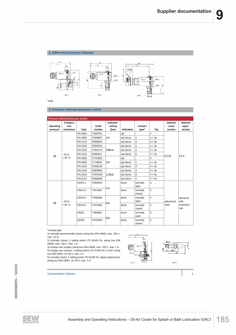
9Supplier documentation
Assembly and Operating Instructions – Oil-Air Cooler for Splash or Bath Lubrication /OAC1 185
2. Differential pressure indicator
*wide
3. Pressure indicator/pressure switch
Pressure indicator/pressure switch
Operatingpressure
Tempera-ture
resistance TypeOrder
number
Indicatorsetting[bar] Indication
Contacttype* Fig.
MaterialLowersection
Materialuppersection
10- 10 to+ 80 °C
PiS 3084 77669781
1.2
opt. - 4
PA 66 PA 6
PiS 3085 77669807 opt./electr. 1 4 + 4a
PiS 3125 78308033 opt./electr. 3 4 + 4a
PiS 3106 78309155
0.9/1.2
opt./electr. 2 4 + 4a
PiS 3103 77942170 opt./electr. 4 4 + 3a
PiS 3123 78383671 opt./electr. 5 4 + 3a
PiS 3084 77737802
2.2
opt. - 4
PiS 3085 77738032 opt./electr. 1 4 + 4a
PiS 3125 78308108 opt./electr. 3 4 + 4a
PiS 3106 78308850
1.7/2.2
opt./electr. 2 4 + 4a
PiS 3103 77970429 opt./electr. 4 4 + 3a
PiS 3123 78383689 opt./electr. 5 4 + 3a
10- 25 to+ 85 °C
DSS/1.2 77863814
1.2
electr. normallyopen
5
galvanizedsteel
deliveredwithprotectioncap
DSO/1.2 77870587 electr. normallyclosed
5
DSS/2.2 77845845
2.2
electr. normallyopen
5
DSO/2.2 77870595 electr. normallyclosed
5
DSS/5 77863822
5.0
electr. normallyopen
5
DSO/5 77870603 electr. normallyclosed
5
*Contact type:1) normally open/normally closed, wiring box DIN 43650, max. 230 V,max. 2.5 A2) normally closed, 2 setting points (75 %/100 %); wiring box DIN43650, max. 150 V, max. 1 A3) change over contact; wiring box DIN 43650, max. 150 V, max. 1 A4) change over contact; 2 setting points (75 %/100 %); 3 LED; wiringbox DIN 43651, 10–30 V, max. 1 A5) normally closed, 2 setting points (75 %/100 %), signal suppression;wiring box DIN 43651, 10–30 V, max. 1 A
Contamination Indicator 3
2660
9398
/EN
– 1
0/20
20

9 Supplier documentation
Assembly and Operating Instructions – Oil-Air Cooler for Splash or Bath Lubrication /OAC1186
4. Vacuum meter/manometer
Vacuum meter/manometer
Nominalsize(NG)[mm]
Specifi-cation
Indicatingrange[bar] Fig.
Connectionsize
Order-number Class Dial face
40Vacuummeter
- 1 to + 1.5
6
R 1/8 (conical) 76388714
min 2.5
white
- 1 to + 0.6 G 1/8 77545908Red/Green area,sep. line 0.25 bar
50 Manometer
0 to - 1 7
R 1/4 (conical)
77617558 white
0 to 6 878381998 Red/Green area,
sep. line 0.25 bar
5. Vacuum switch
Vacuum switch
Permissibleover-
pressuremax.
Tempera-ture
resistanceIndicator
settingContact
type Fig.Connection
size TypeOrder
Number
Materiallower
section
Materialupper
section
0.5 bar
- 10 to+ 70 °C
- 10 to - 80 mbar single poledouble-throwcut-outswitch
9
G 1/4
PiS 3070
77669690 GD-AI PA 6
1 bar - 50 to - 600 mbar G 1/8
77669724
GD-AI PA 6
0.1 bar- 20 to+ 80 °C,120 °C
- 200 mbar ± 10 normallyopen
10
G 1/8(outside)
HES 2200BP
78308892 GD-ZnAI Polycarbo-nat
- 200 mbar ± 10 normallyclosed
HEO 2200BP
78308900 GD-ZnAI Polycarbo-nat
- 50 mbar ± 4 normallyopen M 10 x 1
(inside)
LES 250 I 78308918 GD-ZnAI Polycarbo-nat
- 50 mbar ± 4 normallyclosed
LEO 250 I 78308926 GD-ZnAI Polycarbo-nat
* connection GTypes HES/HEO for hydraulic application, Types LES/LEO for air application
Contamination Indicator 4
2660
9398
/EN
– 1
0/20
20

9Supplier documentation
Assembly and Operating Instructions – Oil-Air Cooler for Splash or Bath Lubrication /OAC1 187
6. Vacuum indicator/air filter
Vacuum inidcator/air filter
Indicatorsetting± 10 %
Temperatureresistance Fig. Execution Type
Order-number Indication
- 50 mbar- 40 to + 110 °C
1 TB 745 78309056 optical indication- self locking -
11 2TB 745/1 78309064
- 65 mbar TB 746/1 78309049
*1 Execution 2*2 Execution 1*3 Indication: Position of display at nominal value in mbarStandard sealing material: NBRSealing material types LES/LEO: Silicone rubber
7. Accessories
7.1 Seal kits
Type
Ordernumber
NBR
Ordernumber
FPM
OrdernumberEPDM
PiS 3092, 3093, 3102,3105, 3115, 3122, 3192,3193
77760275 77760283 77760291
PiS 3012, 3019, 3024,3097, 3098, 3116
77760309 77760317 77760325
PiS 3084, 3085, 3103,3106, 3123, 3125
78383382 78383390 78383408
PiS 3086, 3087, 3104 77760242 77760259
7.2 Electrical upper sections
SpecificationOrder
number
Electrical upper sectionnormally open/ normally closedfor PiS 3084, 3087, 3093, 3098, 3193(Contact type 1)
7536550
Wiring box with lamp insert 12 - 230 Vfor electrical upper sectionnormally open (according to DIN EN 175301-803)
8307548
Electrical upper sectionChange over contactfor PiS 3084, 3087, 3093, 3098, 3193(Contact type 3)
8308017
Wiring box with 2 LEDs 10 - 30 Vfor electrical upper sectionChange over contact(according to DIN EN 175301-803)
8308025
Electrical upper sectionnormally closed with signalsuppression PiS 3003
7765357
Contamination Indicator 5
2660
9398
/EN
– 1
0/20
20
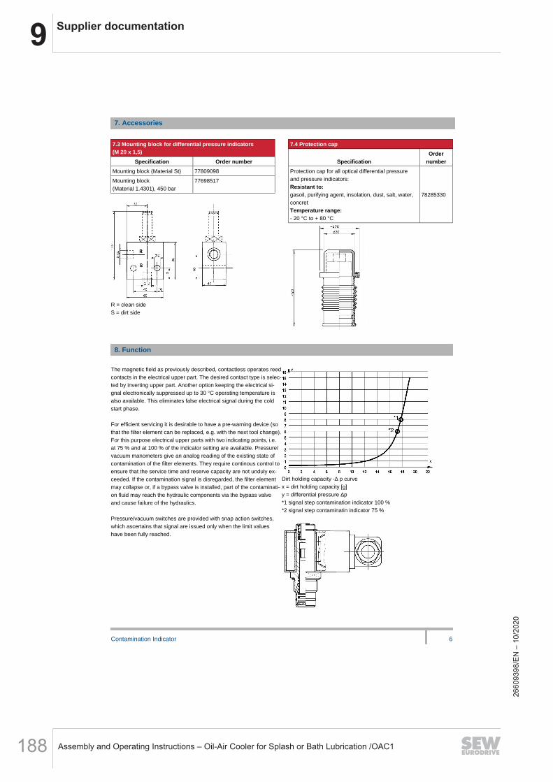
9 Supplier documentation
Assembly and Operating Instructions – Oil-Air Cooler for Splash or Bath Lubrication /OAC1188
7. Accessories
7.3 Mounting block for differential pressure indicators(M 20 x 1,5)
Specification Order number
Mounting block (Material St) 77809098
Mounting block(Material 1.4301), 450 bar
77698517
R = clean sideS = dirt side
7.4 Protection cap
SpecificationOrder
number
Protection cap for all optical differential pressureand pressure indicators:Resistant to:gasoil, purifying agent, insolation, dust, salt, water,concretTemperature range:- 20 °C to + 80 °C
78285330
8. Function
The magnetic field as previously described, contactless operates reedcontacts in the electrical upper part. The desired contact type is selec-ted by inverting upper part. Another option keeping the electrical si-gnal electronically suppressed up to 30 °C operating temperature isalso available. This eliminates false electrical signal during the coldstart phase.-For efficient servicing it is desirable to have a pre-warning device (sothat the filter element can be replaced, e.g. with the next tool change).For this purpose electrical upper parts with two indicating points, i.e.at 75 % and at 100 % of the indicator setting are available. Pressure/vacuum manometers give an analog reading of the existing state ofcontamination of the filter elements. They require continous control toensure that the service time and reserve capacity are not unduly ex-ceeded. If the contamination signal is disregarded, the filter elementmay collapse or, if a bypass valve is installed, part of the contaminati-on fluid may reach the hydraulic components via the bypass valveand cause failure of the hydraulics.-Pressure/vacuum switches are provided with snap action switches,which ascertains that signal are issued only when the limit valueshave been fully reached.
Dirt holding capacity -∆ p curvex = dirt holding capacity [g]y = differential pressure ∆p*1 signal step contamination indicator 100 %*2 signal step contaminatin indicator 75 %
Contamination Indicator 6
2660
9398
/EN
– 1
0/20
20

9Supplier documentation
Assembly and Operating Instructions – Oil-Air Cooler for Splash or Bath Lubrication /OAC1 189
9. Specifications
9.1 Contact type normally open/normally closedTypes PiS 3085, 3086, 3092, 3097,3192Maximum voltage:
250 V AC/200 V DC
Maximum current on contact: 1 AMaximum contact load: 70 WProtection type: IP 65 when inserted
and securedContact type: normally open/
normally closedCable connection: M 20 x 1,5-The switching function can be changed by turning the electric up-per part by 180° (normally open contact or normally closed con-tact). The state on delivery is a normally closed contact. The use ofquenching circuits must be checked in case of inductivity in the DCcurrent circuit. Electrical parts are isolated (plastic casing).-9.2 Contact type normally closed/signal lock-outType PiS 3003-Signal lock-out by thermorelay,Signal is released at + 30 °C,for further technical detail see 9.1--_-9.3. Contact type normallyclosed 2 stepTypes PiS 3105, 3106, 31991. Indicating at 75 %2. Indicating at 100 % of the indica-ting pressureMaximum voltage: 150 V AC/DCMaximum current on contact: 1 AMaximum contact load: 20 VA/20 Wfor further technical details see 9.1----9.4 Contact type normally closed2 step/signal lock-outTypes PiS 3122, 3123, 3124-Maximum voltage: 10 - 30 V AC/DCMaximum current on contact: 1 AMaximum contact load: 20 WSignal lock-out by thermorelaySignal is released at + 30 °CReset at + 20 °C1. Indicating at 75 %2. Indicating at 100 % of the indica-ting pressure
for further details see 9.1
-----
-_
Contamination Indicator 7
2660
9398
/EN
– 1
0/20
20

9 Supplier documentation
Assembly and Operating Instructions – Oil-Air Cooler for Splash or Bath Lubrication /OAC1190
9. Technische Daten
9.5 Contact type change-over contactTypes PiS 3115, 3116, 3125
Maximum voltage:Maximum current on contact:Maximum contact load:
150 V AC/DC1 A
20 VA/20 W
for further details see 9.1
9.6 Contact type change-over contact/2step LEDTypes PiS 3012, 3102, 3103
Maximum voltage:Maximum current on contact:Maximum contact load:1. Indicating at 75 %2. Indicating at 100 % of the indica-ting pressurefor further details see 9.1
*1 switch over *2 connector*3 indicator setting 100 % LED red*4 indicator setting 75 % LED red*5 stand-by indication LED green
9.7 Wiring boxwith lamp insertWill be supplied instead of standardconnection.Voltage:Not to combine with indicators with 2setting points
*1 switch cover*2 connector
9.8 Wiring boxwith lamp insertWill be supplied instead of standardconnection plug.Voltage:To combine with PiS 3115, 3116,3125
10 - 30 V DC1 A
20 VA/20 W
12 - 230 V AC/DC
10 - 30 V DC
*1 switch cover*2 connector*3 green*4 yellow*5 screw clamp
Contamination Indicator 8
2660
9398
/EN
– 1
0/20
20
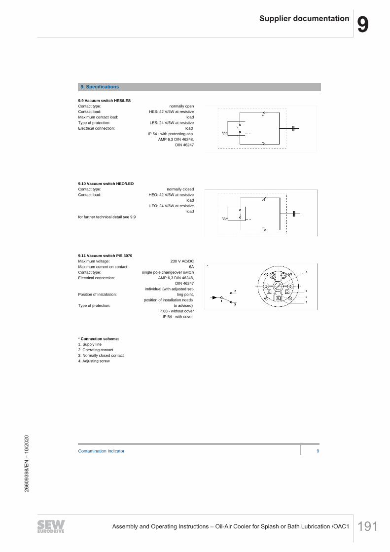
9Supplier documentation
Assembly and Operating Instructions – Oil-Air Cooler for Splash or Bath Lubrication /OAC1 191
9. Specifications
9.9 Vacuum switch HES/LESContact type:Contact load:Maximum contact load:Type of protection:Electrical connection:
normally openHES: 42 V/6W at resistive
loadLES: 24 V/6W at resistive
loadIP 54 - with protecting cap
AMP 6.3 DIN 46248,DIN 46247
9.10 Vacuum switch HEO/LEOContact type:Contact load:
for further technical detail see 9.9
9.11 Vacuum switch PiS 3070Maximum voltage:Maximum current on contact.:Contact type:Electrical connection:
Position of installation:
Type of protection:
normally closedHEO: 42 V/6W at resistive
loadLEO: 24 V/6W at resistive
load
230 V AC/DC6A
single pole changeover switchAMP 6,3 DIN 46248,
DIN 46247individual (with adjusted set-
ting point,position of installation needs
to adviced)IP 00 - without cover
IP 54 - with cover
* Connection scheme:1. Supply line2. Operating contact3. Normally closed contact4. Adjusting screw
Contamination Indicator 9
2660
9398
/EN
– 1
0/20
20

9 Supplier documentation
Assembly and Operating Instructions – Oil-Air Cooler for Splash or Bath Lubrication /OAC1192
9. Specification
9.12 Pressure switch DSS
Contact type:Maximum voltage:Maximum current on contact:Contact load:Duty classification:Type of protection:Electrical connections:
9. 13 Pressure switch DSOContact type:for further information see 9.12
normally open42 V
2 A100 VA
200 / minIP 65 - with protecting cap
AMP 6,3 DIN 46248for attachable sleeve
according to DIN 46247,(switching mode bi-pole)
normally closed
Contamination indicators PiS 3084, 3087, 3093, 3098, 3193 can be mounted in 45°.-We draw attention to the fact that all values indicated are average values which do not always occur in specific cases of application: Ourproducts are continually being further developed. Values, dimensions and weights can change as a result of this. Our specialized departe-ment will be pleased to offer you advice.-When using our filters in areas which are to be classified according to EU directive 94/9 EG (ATEX), we recommend prior discussion withus. The standard version can be used for liquids based on mineral oil /corresponding to the fluids in Group 2 of Directive 97/23 EG Articlel9). Please consult with us if using other media.--Subject to technical alterations without prior notice.
--MAHLE Filtersysteme GmbHIndustriefiltrationSchleifbachweg 45D-74613 ÖhringenPhone +49 (0) 7941/67-0Fax +49 (0) 7941/67-23429industriefiltration@mahle.comwww.mahle-industriafiltration.com78357428.11/2006
Contamination Indicator 10
2660
9398
/EN
– 1
0/20
20

9Supplier documentation
Assembly and Operating Instructions – Oil-Air Cooler for Splash or Bath Lubrication /OAC1 193
Low Pressure FilterPi 200
Nominal pressure 32/63 bar (460/910 psi), nominal size up to 600
1. Features
.-
_
High performance filters for modern hydraulic systems
-
Provided for pipe installation
Modular system
Compact design
Minimal pressure drop through optimal flow design
Visual/electrical/electronic maintenance indicator
Threaded connections
.
-.
-
Quality filters, easy to service
Equipped with highly efficient glass fibre PS filter elements
Beta rated elements according to ISO 16889 multipass test
Elements with high differential pressure stability and dirt holding
capacity
Other connections on request
Worldwide distribution
2660
9398
/EN
– 1
0/20
20
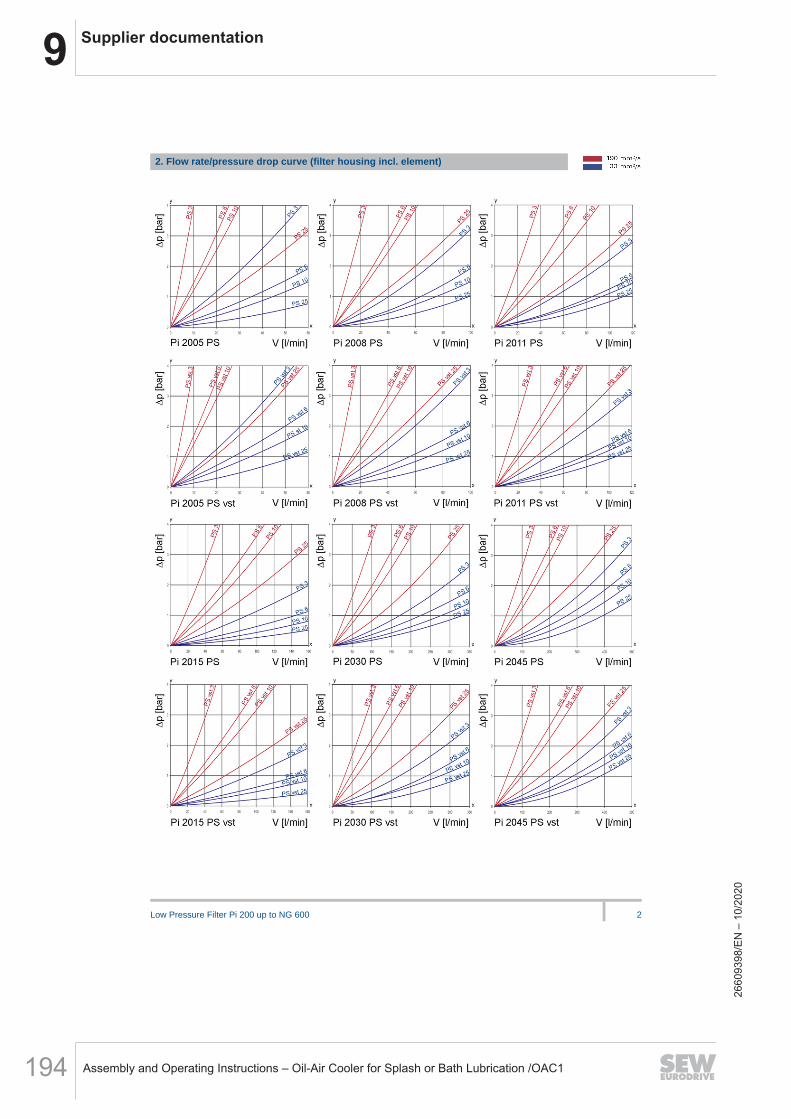
9 Supplier documentation
Assembly and Operating Instructions – Oil-Air Cooler for Splash or Bath Lubrication /OAC1194
Low Pressure Filter Pi 200 up to NG 600 2
2. Flow rate/pressure drop curve (filter housing incl. element)
2660
9398
/EN
– 1
0/20
20

9Supplier documentation
Assembly and Operating Instructions – Oil-Air Cooler for Splash or Bath Lubrication /OAC1 195
Low Pressure Filter Pi 200 up to NG 600 3
y = differential pressure ∆ p [bar]
x = flow rate V [l/min]
LEER
Calculation of individual filter under www.industrialfiltration-catalogue.mahle.com
LEER
3. Separation grade characteristics 4. Filter performance dataLEER
tested according to ISO 16889 (multipass test)
LEER
PS elements with
max. ∆ p 20 bar
PS vst elements with
max. ∆ p 210 bar
PS 3 β5(C) ≥ 200 PS vst 3 β5(C) ≥200
PS 6 β7(C) ≥ 200 PS vst 6 β7(C) ≥200
PS 10 β10(C) ≥ 200 PS vst 10 β10(C) ≥200
PS 25 β20(C) ≥ 200 PS vst 25 β20(C) ≥200
LEER
values guaranteed up to values guaranteed up to
10 bar differential pressure 20 bar differential pressure
LEER
y = beta-value
x = particle size [µm]
LEER
determined by multipass tests (ISO 16889)
calibration according to (NIST)
5. Quality assurance
MAHLE filters and filter elements are produced according to the following international standards:
Norm Designation
DIN ISO 2941 Hydraulic fluid power filter elements; verification of collapse/burst resistance
DIN ISO 2942 Hydraulic fluid power filter elements; verification of fabrication integrity
DIN ISO 2943 Hydraulic fluid power filter elements; verification of material compatibility with fluids
DIN ISO 3723 Hydraulic fluid power filter elements; method for end load test
DIN ISO 3724 Hydraulic fluid power filter elements; verification of flow fatigue characteristics
ISO 3968 Hydraulic fluid power-filters-evaluation of pressure drop versus flow characteristics
ISO 10771.1 Fatigue pressure testing of metal containing envelopes in hydraulic fluid applications
ISO 16889 Hydraulic fluid power filters-multipass method for evaluation filtration performance of a filter element
2660
9398
/EN
– 1
0/20
20

9 Supplier documentation
Assembly and Operating Instructions – Oil-Air Cooler for Splash or Bath Lubrication /OAC1196
Low Pressure Filter Pi 200 up to NG 600 4
6. Symbols
7. Order numbers
Example for ordering filters:
1. Filter housing 2. Filter element
V = 80 l/min and visual/electrical maintenance indicator
Type: Pi 2008-069
Order number: 77665284
PS vst 3
Type: Pi 2208 PS vst 3
Order number: 77680200
7.1 Housing design
Nominal size
NG [l/min]
Order
number Type no options
with
bypass valve
with bypass
valve and
visual
indicator
with bypass
valve and
electrical
indicator
with
visual
indicator
with
electrical
indicator
77665144 Pi 2005-060
77665110 Pi 2005-056
77665128 Pi 2005-057
77665136 Pi 2005-058
77665169 Pi 2005-068
50
77665177 Pi 2005-069
77665235 Pi 2008-060
77665201 Pi 2008-056
77665219 Pi 2008-057
77665227 Pi 2008-058
77665276 Pi 2008-068
80
77665284 Pi 2008-069
78205114 Pi 2011-060
78205122 Pi 2011-056
78205130 Pi 2011-057
78205148 Pi 2011-058
78205155 Pi 2011-068
110
78205163 Pi 2011-069
77840580 Pi 2015-060
76165203 Pi 2015-056
76165211 Pi 2015-057
79320748 Pi 2015-058
76165229 Pi 2015-068
150
78396616 Pi 2015-069
77665474 Pi 2030-060
77665441 Pi 2030-056
77665458 Pi 2030-057
77665466 Pi 2030-058
77665516 Pi 2030-068
300
77665532 Pi 2030-069
2660
9398
/EN
– 1
0/20
20
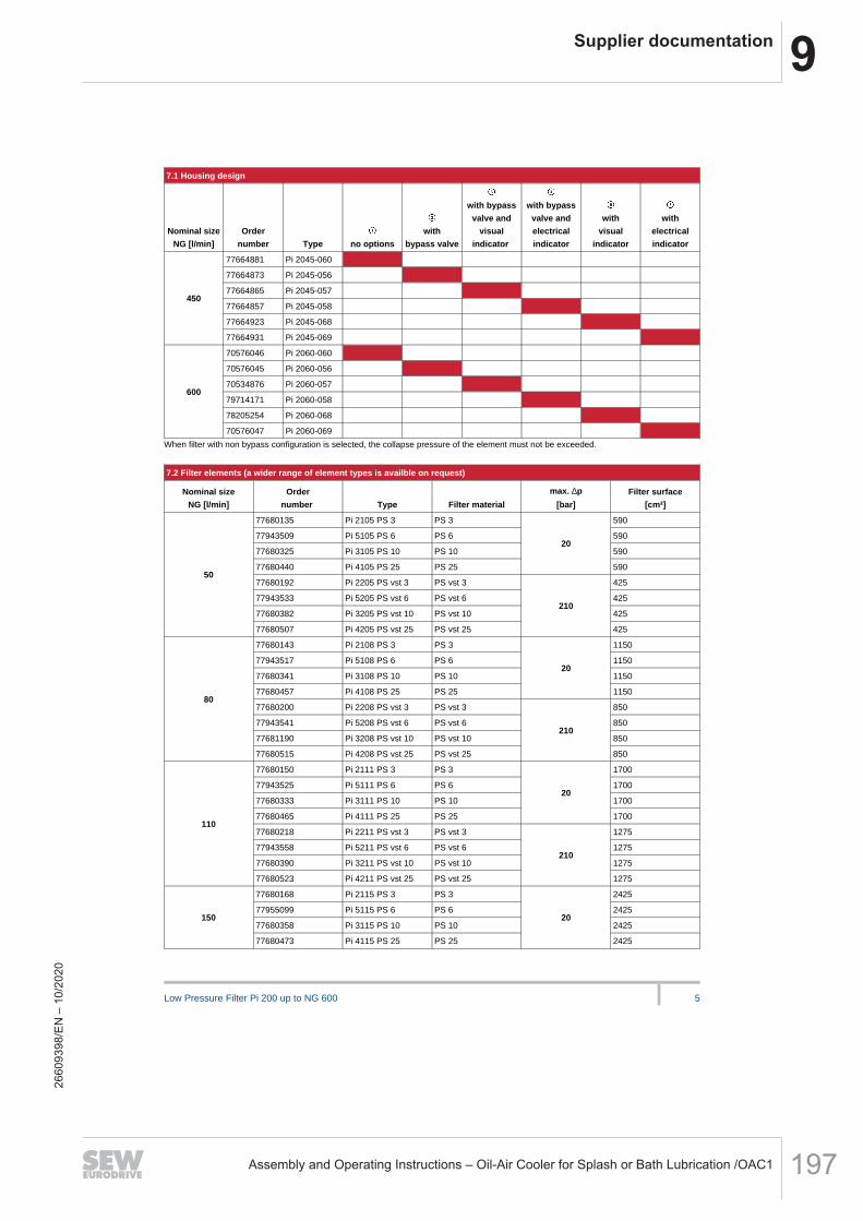
9Supplier documentation
Assembly and Operating Instructions – Oil-Air Cooler for Splash or Bath Lubrication /OAC1 197
Low Pressure Filter Pi 200 up to NG 600 5
7.1 Housing design
Nominal size
NG [l/min]
Order
number Type no options
with
bypass valve
with bypass
valve and
visual
indicator
with bypass
valve and
electrical
indicator
with
visual
indicator
with
electrical
indicator
77664881 Pi 2045-060
77664873 Pi 2045-056
77664865 Pi 2045-057
77664857 Pi 2045-058
77664923 Pi 2045-068
450
77664931 Pi 2045-069
70576046 Pi 2060-060
70576045 Pi 2060-056
70534876 Pi 2060-057
79714171 Pi 2060-058
78205254 Pi 2060-068
600
70576047 Pi 2060-069
When filter with non bypass configuration is selected, the collapse pressure of the element must not be exceeded.
LEER
7.2 Filter elements (a wider range of element types is availble on request)
Nominal size
NG [l/min]
Order
number Type Filter material
max. ∆p
[bar]
Filter surface
[cm²]
77680135 Pi 2105 PS 3 PS 3 590
77943509 Pi 5105 PS 6 PS 6 590
77680325 Pi 3105 PS 10 PS 10 590
77680440 Pi 4105 PS 25 PS 25
20
590
77680192 Pi 2205 PS vst 3 PS vst 3 425
77943533 Pi 5205 PS vst 6 PS vst 6 425
77680382 Pi 3205 PS vst 10 PS vst 10 425
50
77680507 Pi 4205 PS vst 25 PS vst 25
210
425
77680143 Pi 2108 PS 3 PS 3 1150
77943517 Pi 5108 PS 6 PS 6 1150
77680341 Pi 3108 PS 10 PS 10 1150
77680457 Pi 4108 PS 25 PS 25
20
1150
77680200 Pi 2208 PS vst 3 PS vst 3 850
77943541 Pi 5208 PS vst 6 PS vst 6 850
77681190 Pi 3208 PS vst 10 PS vst 10 850
80
77680515 Pi 4208 PS vst 25 PS vst 25
210
850
77680150 Pi 2111 PS 3 PS 3 1700
77943525 Pi 5111 PS 6 PS 6 1700
77680333 Pi 3111 PS 10 PS 10 1700
77680465 Pi 4111 PS 25 PS 25
20
1700
77680218 Pi 2211 PS vst 3 PS vst 3 1275
77943558 Pi 5211 PS vst 6 PS vst 6 1275
77680390 Pi 3211 PS vst 10 PS vst 10 1275
110
77680523 Pi 4211 PS vst 25 PS vst 25
210
1275
77680168 Pi 2115 PS 3 PS 3 2425
77955099 Pi 5115 PS 6 PS 6 2425
77680358 Pi 3115 PS 10 PS 10 2425150
77680473 Pi 4115 PS 25 PS 25
20
2425
2660
9398
/EN
– 1
0/20
20
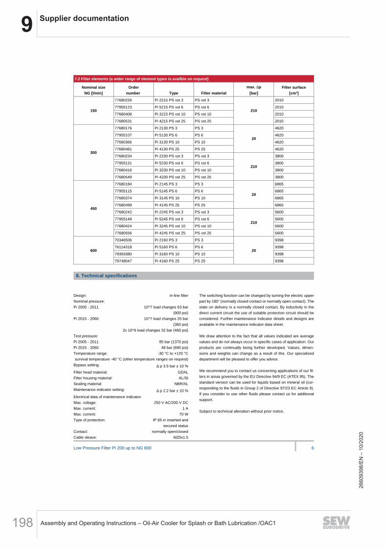
9 Supplier documentation
Assembly and Operating Instructions – Oil-Air Cooler for Splash or Bath Lubrication /OAC1198
Low Pressure Filter Pi 200 up to NG 600 6
7.2 Filter elements (a wider range of element types is availble on request)
Nominal size
NG [l/min]
Order
number Type Filter material
max. ∆p
[bar]
Filter surface
[cm²]
77680226 Pi 2215 PS vst 3 PS vst 3 2010
77955123 Pi 5215 PS vst 6 PS vst 6 2010
77680408 Pi 3215 PS vst 10 PS vst 10 2010150
77680531 Pi 4215 PS vst 25 PS vst 25
210
2010
77680176 Pi 2130 PS 3 PS 3 4620
77955107 Pi 5130 PS 6 PS 6 4620
77680366 Pi 3130 PS 10 PS 10 4620
77680481 Pi 4130 PS 25 PS 25
20
4620
77680234 Pi 2230 PS vst 3 PS vst 3 3800
77955131 Pi 5230 PS vst 6 PS vst 6 3800
77680416 Pi 3230 PS vst 10 PS vst 10 3800
300
77680549 Pi 4230 PS vst 25 PS vst 25
210
3800
77680184 Pi 2145 PS 3 PS 3 6865
77955115 Pi 5145 PS 6 PS 6 6865
77680374 Pi 3145 PS 10 PS 10 6865
77680499 Pi 4145 PS 25 PS 25
20
6865
77680242 Pi 2245 PS vst 3 PS vst 3 5600
77955149 Pi 5245 PS vst 6 PS vst 6 5600
77680424 Pi 3245 PS vst 10 PS vst 10 5600
450
77680556 Pi 4245 PS vst 25 PS vst 25
210
5600
70346506 Pi 2160 PS 3 PS 3 9398
76114318 Pi 5160 PS 6 PS 6 9398
79393380 Pi 3160 PS 10 PS 10 9398600
79748047 Pi 4160 PS 25 PS 25
20
9398
8. Technical specifications
LEER
Design: in-line filter
Nominal pressure:
Pi 2005 - 2011 10^7 load changes 63 bar
(900 psi)
Pi 2015 - 2060 10^7 load changes 25 bar
(360 psi)
2x 10^6 load changes 32 bar (460 psi)
Test pressure:
Pi 2005 - 2011 95 bar (1370 psi)
Pi 2015 - 2060 48 bar (690 psi)
Temperature range: -30 °C to +120 °C
survival temperature -40 °C (other temperature ranges on request)
Bypass setting: ∆ p 3.5 bar ± 10 %
Filter head material: GDAL
Filter housing material: AL/St
Sealing material: NBR/AL
Maintenance indicator setting: ∆ p 2.2 bar ± 10 %
Electrical data of maintenance indicator:
Max. voltage: 250 V AC/200 V DC
Max. current: 1 A
Max. current: 70 W
Type of protection: IP 65 in inserted and
secured status
Contact: normally open/closed
Cable sleave: M20x1.5
The switching function can be changed by turning the electric upper
part by 180° (normally closed contact or normally open contact). The
state on delivery is a normally closed contact. By inductivity in the
direct current circuit the use of suitable protection circuit should be
considered. Further maintenance indicator details and designs are
available in the maintenance indicator data sheet.
-
We draw attention to the fact that all values indicated are average
values and do not always occur in specific cases of application. Our
products are continually being further developed. Values, dimen-
sions and weights can change as a result of this. Our specialized
department will be pleased to offer you advice.
-
We recommend you to contact us concerning applications of our fil-
ters in areas governed by the EU Directive 94/9 EC (ATEX 95). The
standard version can be used for liquids based on mineral oil (cor-
responding to the fluids in Group 2 of Directive 97/23 EC Article 9).
If you consider to use other fluids please contact us for additional
support.
LEER
Subject to technical alteration without prior notice.
2660
9398
/EN
– 1
0/20
20

9Supplier documentation
Assembly and Operating Instructions – Oil-Air Cooler for Splash or Bath Lubrication /OAC1 199
Low Pressure Filter Pi 200 up to NG 600 7
9. Dimensions
In Inlet
Out Outlet
*1 Housing design for NG 600
LEER
All dimensions except “C” in mm.
Type A B C* D E F
G
SW H I K M N O P Weight [kg]
Pi 2005 78 19 G½ 186 240 80 27 66 80 95 45 13.0 M8x10 37.5 0.9
Pi 2008 78 19 G¾ 243 300 80 27 66 80 95 45 13.0 M8x10 37.5 1.0
Pi 2011 78 19 G¾ 333 393 80 27 66 80 95 45 13.0 M8x10 37.5 1.1
Pi 2015 78 30 G1¼ 268 326 110 32 109 128 150 60 24.5 M12x15 43.5 2.3
Pi 2030 78 30 G1¼ 363 421 110 32 109 128 150 60 24.5 M12x15 43.5 2.5
Pi 2045 78 30 G1¼ 509 566 110 32 109 128 150 60 24.5 M12x15 43.5 7.4
Pi 2060 78 30 G1¼ 615 672 110 32 109 128 150 60 24.5 M12x15 43.5 5.5
* NPT and SAE connections on request
2660
9398
/EN
– 1
0/20
20

9 Supplier documentation
Assembly and Operating Instructions – Oil-Air Cooler for Splash or Bath Lubrication /OAC1200
Low Pressure Filter Pi 200 up to NG 600 8
10. Installation, operating and maintenance instructions
10.1 Filter installation
When installing the filter make sure that sufficient space is available
to remove filter element and filter housing.
Preferably the filter should be installed with the filter housing pointing
downwards.
The maintenance indicator must be visible.
LEER
10.2 Connecting the electrical maintenance indicator
The electrical indicator is connected via a 2-pole appliance plug ac-
cording to DlN EN 175301-803 with poles marked 1 and 2. The elec-
trical section can be inverted to change from normally open position
to normally closed position or vice versa.
The state on delivery is a normally closed contact
.
LEER
10.3 When should the filter element be replaced?
1 . Filters equipped with visual and electrical maintenance
indicator:
During cold starts, the indicator may give a warning signal.
Press the red button of the visual indicator once again only after
operating temperature has been reached. lf the red button im-
mediately pops up again and/or the electrical signal has not
switched off after reaching operating temperature, the filter ele-
ment must be replaced after the end of the shift.
2 . Filters without maintenance indicator:
The filter element should be replaced after the trial run or flush-
ing of the system. Afterwards follow instructions of the manu-
facturer.
3 . Please always ensure that you have original MAHLE spare ele-
ments in stock: Disposable elements cannot be cleaned.
EER
_
10.4 Element replacement
1 . Stop system and relieve filter from pressure.
2 . Unscrew the filter housing by turning counter-clockwise. Clean
the housing using a suitable cleaning solvent.
3 . Remove element by pulling down carefully.
4 . Check O-ring on the filter housing for damage. Replace, if ne-
cessary.
5 . Make sure that the order number on the spare element corres-
ponds to the order number of the filter name-plate.
To ensure no contamination occurs during the exchange of the
element first open the plastic bag and push the element over
the spigot in the filter head. Now remove plastic bag.
6 . Lightly lubricate the threads of the filter housing a little bit and
screw into the filter head. Maximum tightening torque for NG 50
to 110 = 60 Nm, for NG 150 to 600 = 100 Nm.
LEER
LEER
LEER
LEER
MAHLE Industriefiltration GmbH
Schleifbachweg 45
D-74613 Öhringen
Phone +49 7941 67-0
Fax +49 7941 67-23429
www.mahle.com
78356446.04/2015
11. Spare parts list
Order numbers of spare parts
Position Type Order number
Seal kit for filter
Pi 2005 - Pi 2011
NBR 77550213
FPM 77845795
EPDM 77845803
Pi 2015 - Pi 2060
NBR 77550221
FPM 77845811
-
EPDM 77845829
Maintenance indicator
Visual PiS 3098/2,2 77669971
Electrical PiS 3097/2,2 77669948
Electrical upper section only 77536550
Seal kit for maintenance indicator
NBR 77760309
FPM 77760317
EPDM 77760325
2660
9398
/EN
– 1
0/20
20
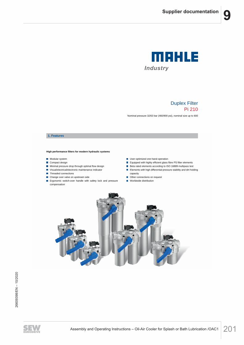
9Supplier documentation
Assembly and Operating Instructions – Oil-Air Cooler for Splash or Bath Lubrication /OAC1 201
Duplex FilterPi 210
Nominal pressure 32/63 bar (460/900 psi), nominal size up to 600
1. Features
.-
-
High performance filters for modern hydraulic systems
-
Modular system
Compact design
Minimal pressure drop through optimal flow design
Visual/electrical/electronic maintenance indicator
Threaded connections
Change over valve on upstream side
Ergonomic switch-over handle with safety lock and pressure
compensation
.-
-
_
-
User-optimized one-hand-operation
Equipped with highly efficient glass fibre PS filter elements
Beta rated elements according to ISO 16889 multipass test
Elements with high differential pressure stability and dirt holding
capacity
Other connections on request
Worldwide distribution
2660
9398
/EN
– 1
0/20
20
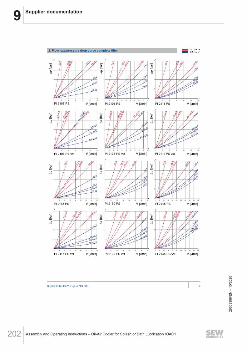
9 Supplier documentation
Assembly and Operating Instructions – Oil-Air Cooler for Splash or Bath Lubrication /OAC1202
Duplex Filter Pi 210 up to NG 600 2
2. Flow rate/pressure drop curve complete filter
LEER
2660
9398
/EN
– 1
0/20
20

9Supplier documentation
Assembly and Operating Instructions – Oil-Air Cooler for Splash or Bath Lubrication /OAC1 203
Duplex Filter Pi 210 up to NG 600 3
y = differential pressure ∆ p [bar]
x = flow rate V [l/min]
LEER
Calculation of individual filter under www.industrialfiltration-catalogue.mahle.com
LEER
3. Separation grade characteristics 4. Filter performance dataLEER
tested according to ISO 16889 (multipass test)
LEER
PS elements with
max. ∆ p 20 bar
PS vst elements with
max. ∆ p 210 bar
PS 3 β5(C) ≥ 200 PS vst 3 β5(C) ≥200
PS 6 β7(C) ≥ 200 PS vst 6 β7(C) ≥200
PS 10 β10(C) ≥ 200 PS vst 10 β10(C) ≥200
PS 25 β20(C) ≥ 200 PS vst 25 β20(C) ≥200
LEER
values guaranteed up to values guaranteed up to
10 bar differential pressure 20 bar differential pressure
LEER
y = beta-value
x = particle size [µm]
LEER
determined by multipass tests (ISO 16889)
calibration according to (NIST)
5. Quality assurance
MAHLE filters and filter elements are produced according to the following international standards:
Norm Designation
DIN ISO 2941 Hydraulic fluid power filter elements; verification of collapse/burst resistance
DIN ISO 2942 Hydraulic fluid power filter elements; verification of fabrication integrity
DIN ISO 2943 Hydraulic fluid power filter elements; verification of material compatibility with fluids
DIN ISO 3723 Hydraulic fluid power filter elements; method for end load test
DIN ISO 3724 Hydraulic fluid power filter elements; verification of flow fatigue characteristics
ISO 3968 Hydraulic fluid power-filters-evaluation of pressure drop versus flow characteristics
ISO 10771.1 Fatigue pressure testing of metal containing envelopes in hydraulic fluid applications
ISO 16889 Hydraulic fluid power filters-multipass method for evaluation filtration performance of a filter element
2660
9398
/EN
– 1
0/20
20

9 Supplier documentation
Assembly and Operating Instructions – Oil-Air Cooler for Splash or Bath Lubrication /OAC1204
Duplex Filter Pi 210 up to NG 600 4
6. Symbols
7. Order numbers
Example for ordering filters:
1. Housing design 2. Filter element
V = 80 l/min and visual/electrical indicator
Type: Pi 2108-069
Order number: 77810286
PS vst 3
Type: Pi 2208 PS vst 3
Order number: 77680200
7.1 Housing design
Nominal size
NG [l/min]
Order
number Type
with bypass
valve and
visual indicator
with bypass
valve and
electrical
indicator
with
visual
indicator
with
electrical
indicator
77810211 Pi 2105-057
77810229 Pi 2105-058
77810237 Pi 2105-06850
77810245 Pi 2105-069
77810252 Pi 2108-057
77810260 Pi 2108-058
77810278 Pi 2108-06880
77810286 Pi 2108-069
78204083 Pi 2111-057
78204091 Pi 2111-058
78204109 Pi 2111-068110
78204117 Pi 2111-069
77774573 Pi 2115-057
77774565 Pi 2115-058
77774557 Pi 2115-068150
77774540 Pi 2115-069
77774532 Pi 2130-057
77774524 Pi 2130-058
77774516 Pi 2130-068300
77774508 Pi 2130-069
77774490 Pi 2145-057
77774482 Pi 2145-058
77774474 Pi 2145-068450
77774466 Pi 2145-069
70574769 Pi 2160-057
70574768 Pi 2160-058
70574767 Pi 2160-068600
70574766 Pi 2160-069
When filter with non bypass configuration is selected, the collapse pressure of the element must not be exceeded.
2660
9398
/EN
– 1
0/20
20

9Supplier documentation
Assembly and Operating Instructions – Oil-Air Cooler for Splash or Bath Lubrication /OAC1 205
Duplex Filter Pi 210 up to NG 600 5
7.2 Filter elements*
Nominal size
NG [l/min]
Order
number Type Filter material
max. ∆p
[bar]
Filter surface
[cm²]
77680135 Pi 2105 PS 3 PS 3 590
77943509 Pi 5105 PS 6 PS 6 590
77680325 Pi 3105 PS 10 PS 10 590
77680440 Pi 4105 PS 25 PS 25
20
590
77680192 Pi 2205 PS vst 3 PS vst 3 425
77943533 Pi 5205 PS vst 6 PS vst 6 425
77680382 Pi 3205 PS vst 10 PS vst 10 425
50
77680507 Pi 4205 PS vst 25 PS vst 25
210
425
77680143 Pi 2108 PS 3 PS 3 1150
77943517 Pi 5108 PS 6 PS 6 1150
77680341 Pi 3108 PS 10 PS 10 1150
77680457 Pi 4108 PS 25 PS 25
20
1150
77680200 Pi 2208 PS vst 3 PS vst 3 850
77943541 Pi 5208 PS vst 6 PS vst 6 850
77681190 Pi 3208 PS vst 10 PS vst 10 850
80
77680515 Pi 4208 PS vst 25 PS vst 25
210
850
77680150 Pi 2111 PS 3 PS 3 1700
77943525 Pi 5111 PS 6 PS 6 1700
77680333 Pi 3111 PS 10 PS 10 1700
77680465 Pi 4111 PS 25 PS 25
20
1700
77680218 Pi 2211 PS vst 3 PS vst 3 1275
77943558 Pi 5211 PS vst 6 PS vst 6 1275
77680390 Pi 3211 PS vst 10 PS vst 10 1275
110
77680523 Pi 4211 PS vst 25 PS vst 25
210
1275
77680168 Pi 2115 PS 3 PS 3 2425
77955099 Pi 5115 PS 6 PS 6 2425
77680358 Pi 3115 PS 10 PS 10 2425
77680473 Pi 4115 PS 25 PS 25
20
2425
77680226 Pi 2215 PS vst 3 PS vst 3 2010
77955123 Pi 5215 PS vst 6 PS vst 6 2010
77680408 Pi 3215 PS vst 10 PS vst 10 2010
150
77680531 Pi 4215 PS vst 25 PS vst 25
210
2010
77680176 Pi 2130 PS 3 PS 3 4620
77955107 Pi 5130 PS 6 PS 6 4620
77680366 Pi 3130 PS 10 PS 10 4620
77680481 Pi 4130 PS 25 PS 25
20
4620
77680234 Pi 2230 PS vst 3 PS vst 3 3800
77955131 Pi 5230 PS vst 6 PS vst 6 3800
77680416 Pi 3230 PS vst 10 PS vst 10 3800
300
77680549 Pi 4230 PS vst 25 PS vst 25
210
3800
77680184 Pi 2145 PS 3 PS 3 6865
77955115 Pi 5145 PS 6 PS 6 6865
77680374 Pi 3145 PS 10 PS 10 6865
77680499 Pi 4145 PS 25 PS 25
20
6865
77680242 Pi 2245 PS vst 3 PS vst 3 5600
77955149 Pi 5245 PS vst 6 PS vst 6 5600
77680424 Pi 3245 PS vst 10 PS vst 10 5600
450
77680556 Pi 4245 PS vst 25 PS vst 25
210
5600
*a wider range of element types is availble on request
2660
9398
/EN
– 1
0/20
20
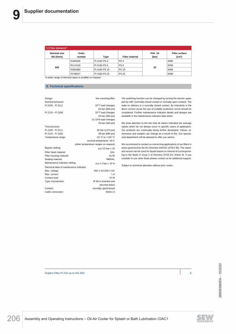
9 Supplier documentation
Assembly and Operating Instructions – Oil-Air Cooler for Splash or Bath Lubrication /OAC1206
Duplex Filter Pi 210 up to NG 600 6
7.2 Filter elements*
Nominal size
NG [l/min]
Order
number Type Filter material
max. ∆p
[bar]
Filter surface
[cm²]
70346506 Pi 2160 PS 3 PS 3 9398
76114318 Pi 5160 PS 6 PS 6 9398
79393380 Pi 3160 PS 10 PS 10 9398600
79748047 Pi 4160 PS 25 PS 25
20
9398
*a wider range of element types is availble on request
8. Technical specifications
LEER
Design: line mounting filter
Nominal pressure:
Pi 2105 - Pi 2111 10^7 load changes
63 bar (900 psi)
Pi 2115 - Pi 2160 10^7 load changes
25 bar (360 psi)
2x 10^6 load changes
32 bar (460 psi)
Test pressure:
Pi 2105 - Pi 2111 95 bar (1370 psi)
Pi 2115 - Pi 2160 48 bar (690 psi)
Temperature range: -10 °C to +120 °C
survival temperature -40 C
(other temperature ranges on request)
Bypass setting: ∆ p 3.5 bar ± 10
Filter head material: GAL
Filter housing material: AL/St
Sealing material: NBR/AL
Maintenance indicator setting: ∆ p 2.2 bar ± 10 %
Electrical data of maintenance indicator:
Max. voltage: 250 V AC/200 V DC
Max. current: 1 A
Contact load: 70 W
Type of protection: IP 65 in inserted and
secured status
Contact: normally open/closed
Cable connection: M20x1.5
The switching function can be changed by turning the electric upper
part by 180° (normally closed contact or normally open contact). The
state on delivery is a normally closed contact. By inductivity in the
direct current circuit the use of suitable protection circuit should be
considered. Further maintenance indicator details and designs are
available in the maintenance indicator data sheet.
-
We draw attention to the fact that all values indicated are average
values which do not always occur in specific cases of application.
Our products are continually being further developed. Values, di-
mensions and weights can change as a result of this. Our special-
ized department will be pleased to offer you advice.
-
We recommend to contact us concerning applications of our filters in
areas governed by the EU Directive 94/9 EC (ATEX 95). The stand-
ard version can be used for liquids based on mineral oil (correspond-
ing to the fluids in Goup 2 of Directive 97/23 EC Article 9). If you
consider to use other fluids please contact us for additional support.
LEER
Subject to technical alteration without prior notice.
2660
9398
/EN
– 1
0/20
20

9Supplier documentation
Assembly and Operating Instructions – Oil-Air Cooler for Splash or Bath Lubrication /OAC1 207
Duplex Filter Pi 210 up to NG 600 7
9. Dimensions
In Inlet *1 Lever locking and arresting
Out Outlet *2 Venting screws
*H Minimum clearance required for element change *3 Optional fixing for NG 150 to 600
*4 Housing version NG 600
All dimensions except "J" in mm
Type øA B C D E F G H øI J* K L
M
SW
Wt.
[kg]
Pi 2105 66 172 100 52 M8x16 189 130 80 47 G1 85 203 27 2.60
Pi 2108 66 172 100 52 M8x16 189 130 80 47 G1 85 261 27 2.90
Pi 2111 66 172 100 52 M8x16 189 130 80 47 G1 85 351 27 3.30
Pi 2115 109 283 210 62 M10x20 252 194 110 65 G1½ 140 264 32 8.50
Pi 2130 109 283 210 62 M10x20 252 194 110 65 G1½ 140 385 32 9.50
Pi 2145 109 283 210 62 M10x20 252 194 110 65 G1½ 140 497 32 17.25
Pi 2160 109 283 210 62 M10x20 252 194 110 65 G1½ 140 636 32 15.50
* SAE flange connections (3000 psi), NPT and SAE connections on request
2660
9398
/EN
– 1
0/20
20
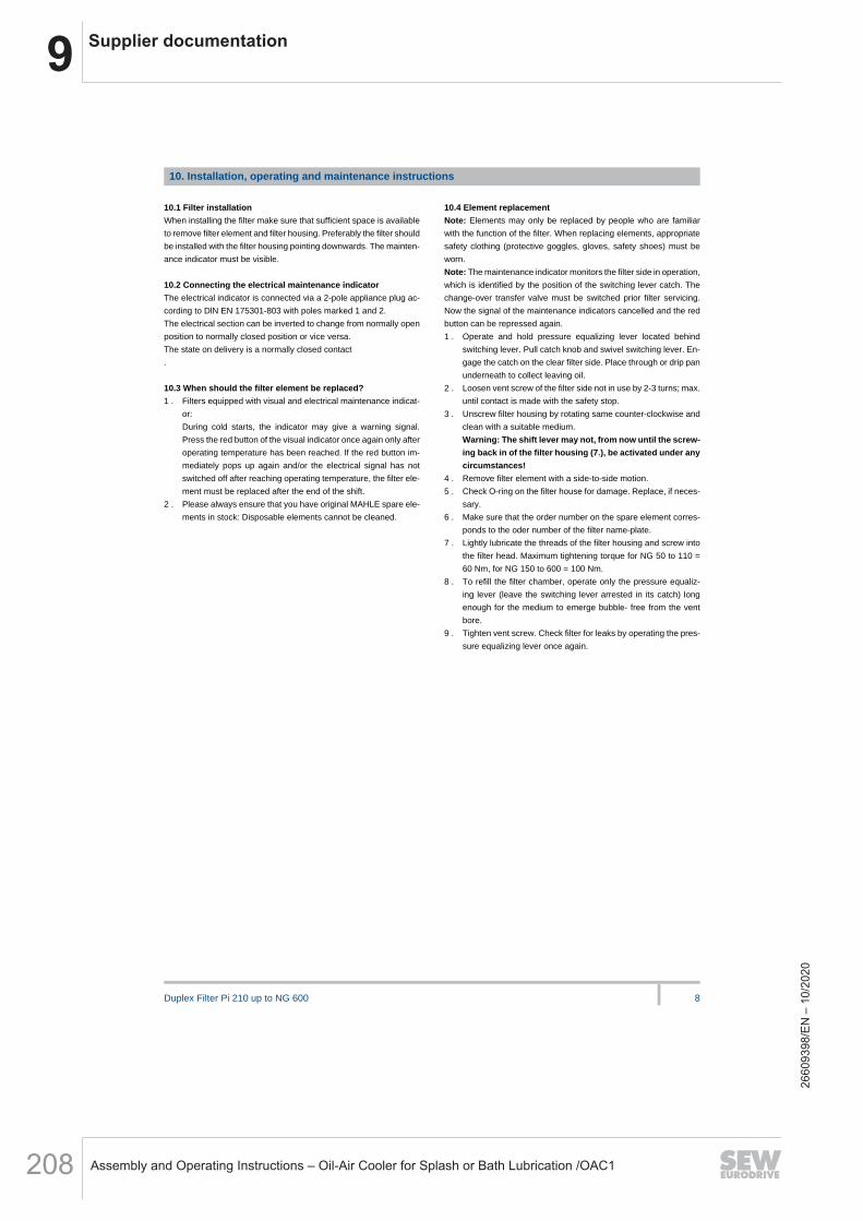
9 Supplier documentation
Assembly and Operating Instructions – Oil-Air Cooler for Splash or Bath Lubrication /OAC1208
Duplex Filter Pi 210 up to NG 600 8
10. Installation, operating and maintenance instructions
10.1 Filter installation
When installing the filter make sure that sufficient space is available
to remove filter element and filter housing. Preferably the filter should
be installed with the filter housing pointing downwards. The mainten-
ance indicator must be visible.
-
10.2 Connecting the electrical maintenance indicator
The electrical indicator is connected via a 2-pole appliance plug ac-
cording to DlN EN 175301-803 with poles marked 1 and 2.
The electrical section can be inverted to change from normally open
position to normally closed position or vice versa.
The state on delivery is a normally closed contact
.
-
10.3 When should the filter element be replaced?
1 . Filters equipped with visual and electrical maintenance indicat-
or:
During cold starts, the indicator may give a warning signal.
Press the red button of the visual indicator once again only after
operating temperature has been reached. lf the red button im-
mediately pops up again and/or the electrical signal has not
switched off after reaching operating temperature, the filter ele-
ment must be replaced after the end of the shift.
2 . Please always ensure that you have original MAHLE spare ele-
ments in stock: Disposable elements cannot be cleaned.
10.4 Element replacement
Note: Elements may only be replaced by people who are familiar
with the function of the filter. When replacing elements, appropriate
safety clothing (protective goggles, gloves, safety shoes) must be
worn.
Note: The maintenance indicator monitors the filter side in operation,
which is identified by the position of the switching lever catch. The
change-over transfer valve must be switched prior filter servicing.
Now the signal of the maintenance indicators cancelled and the red
button can be repressed again.
1 . Operate and hold pressure equalizing lever located behind
switching lever. Pull catch knob and swivel switching lever. En-
gage the catch on the clear filter side. Place through or drip pan
underneath to collect leaving oil.
2 . Loosen vent screw of the filter side not in use by 2-3 turns; max.
until contact is made with the safety stop.
3 . Unscrew filter housing by rotating same counter-clockwise and
clean with a suitable medium.
Warning: The shift lever may not, from now until the screw-
ing back in of the filter housing (7.), be activated under any
circumstances!
4 . Remove filter element with a side-to-side motion.
5 . Check O-ring on the filter house for damage. Replace, if neces-
sary.
6 . Make sure that the order number on the spare element corres-
ponds to the oder number of the filter name-plate.
7 . Lightly lubricate the threads of the filter housing and screw into
the filter head. Maximum tightening torque for NG 50 to 110 =
60 Nm, for NG 150 to 600 = 100 Nm.
8 . To refill the filter chamber, operate only the pressure equaliz-
ing lever (leave the switching lever arrested in its catch) long
enough for the medium to emerge bubble- free from the vent
bore.
9 . Tighten vent screw. Check filter for leaks by operating the pres-
sure equalizing lever once again.
2660
9398
/EN
– 1
0/20
20

9Supplier documentation
Assembly and Operating Instructions – Oil-Air Cooler for Splash or Bath Lubrication /OAC1 209
Duplex Filter Pi 210 up to NG 600 9
11. Spare parts list
Order number for spare parts
Position Type Order number
Seal kit for housing
Pi 2105 - Pi 2111
NBR 79761271
FPM 79761289
EPDM 79761297
Pi 2115 - Pi 2160
NBR 79761230
FPM 79761248
-
EPDM 79761255
Seal kit for maintenance indicator
NBR 77760309
FPM 77760317 -
EPDM 77760325
Maintenance indicator
Visual PiS 3098/2.2 77669971
Electrical PiS 3097/2.2 77669948
Electrical upper section only 77536550
2660
9398
/EN
– 1
0/20
20

9 Supplier documentation
Assembly and Operating Instructions – Oil-Air Cooler for Splash or Bath Lubrication /OAC1210
Duplex Filter Pi 210 up to NG 600 10
LEER
LEER
LEER
LEER
LEER
LEER
LEER
LEER
LEER
LEER
LEER
LEER
LEER
LEER
LEER
LEER
LEER
LEER
LEER
LEER
LEER
LEER
LEER
LEER
LEER
LEER
LEER
LEER
LEER
LEER
LEER
LEER
LEER
LEER
LEER
LEER
LEER
LEER
LEER
LEER
LEER
LEER
LEER
LEER
LEER
LEER
LEER
LEER
LEER
MAHLE Industriefiltration GmbH
Schleifbachweg 45
D-74613 Öhringen
Phone +49 7941 67-0
Fax +49 7941 67-23429
www.mahle-industry.com
78356552.12/2013
2660
9398
/EN
– 1
0/20
20

9Supplier documentation
Assembly and Operating Instructions – Oil-Air Cooler for Splash or Bath Lubrication /OAC1 211
Installation instructions Electronic pressure sensor
for industrial applicationsPT54xx/PU54xx
8028
0889
/ 00
12
/ 20
18
UK
2660
9398
/EN
– 1
0/20
20
9 Supplier documentation
Assembly and Operating Instructions – Oil-Air Cooler for Splash or Bath Lubrication /OAC1212
2
1 Preliminary noteSymbols used Instructions→ Cross-reference
Important note Non-compliance can result in malfunction or interference.Information Supplementary note.
2 Safety instructions• Read this document before setting up the product and keep it during the entire
service life.• The product must be suitable for the corresponding applications and
environmental conditions without any restrictions.• Only use the product for its intended purpose ( → Functions and features).• Only use the product for permissible media ( → Applications). • If the operating instructions or the technical data are not adhered to, personal
injury and/or damage to property may occur.• The manufacturer assumes no liability or warranty for any consequences
caused by tampering with the product or incorrect use by the operator.
Contents1 Preliminary note ...................................................................................................22 Safety instructions ...............................................................................................23 Functions and features ........................................................................................3
3.1 Applications ...................................................................................................34 Functions .............................................................................................................55 Installation............................................................................................................56 Electrical connection ............................................................................................67 Technical data ......................................................................................................7
2660
9398
/EN
– 1
0/20
20
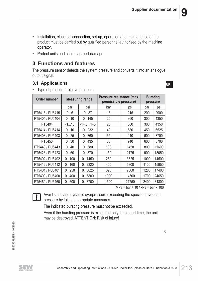
9Supplier documentation
Assembly and Operating Instructions – Oil-Air Cooler for Splash or Bath Lubrication /OAC1 213
3
UK
• Installation, electrical connection, set-up, operation and maintenance of the product must be carried out by qualified personnel authorised by the machine operator.
• Protect units and cables against damage.
3 Functions and featuresThe pressure sensor detects the system pressure and converts it into an analogue output signal.
3.1 Applications• Type of pressure: relative pressure
Order number Measuring range Pressure resistance (max. permissible pressure)
Bursting pressure
bar psi bar psi bar psiPT5415 / PU5415 0...6 0...87 15 215 200 2900PT5404 / PU5404 0...10 0...145 25 360 300 4350
PT5494 -1...10 -14.5...145 25 360 300 4350PT5414 / PU5414 0...16 0...232 40 580 450 6525PT5403 / PU5403 0...25 0...360 65 940 600 8700
PT5453 0...30 0...435 65 940 600 8700PT5443 / PU5443 0...40 0...580 100 1450 800 11600PT5423 / PU5423 0...60 0...870 150 2175 900 13050PT5402 / PU5402 0...100 0...1450 250 3625 1000 14500PT5412 / PU5412 0...160 0...2320 400 5800 1100 15950PT5401 / PU5401 0...250 0...3625 625 9060 1200 17400PT5400 / PU5400 0...400 0...5800 1000 14500 1700 24650PT5460 / PU5460 0...600 0...8700 1500 21750 2400 34800
MPa = bar ÷ 10 / kPa = bar × 100
Avoid static and dynamic overpressure exceeding the specified overload pressure by taking appropriate measures.The indicated bursting pressure must not be exceeded.Even if the bursting pressure is exceeded only for a short time, the unit may be destroyed. ATTENTION: Risk of injury!
2660
9398
/EN
– 1
0/20
20
9 Supplier documentation
Assembly and Operating Instructions – Oil-Air Cooler for Splash or Bath Lubrication /OAC1214
4
For units with a final value of the measuring range of 600 bar the limits of the pressure cycles across the lifetime apply. (→ Technical data).
Pressure Equipment Directive (PED):Units with a final value of the measuring range of 6...400 bar comply with the Pressure Equipment Directive and are designed and manufactured for group 2 fluids in accordance with the sound engineering practice. Use of group 1 fluids on request!Pressure Equipment Directive (PED):The units with a final value of the measuring range of 600 bar comply with the Pressure Equipment Directive. They are designed for group 2 fluids and manufactured and tested according to Module A. Use of group 1 fluids on request!
The units are vacuum resistant.
2660
9398
/EN
– 1
0/20
20

9Supplier documentation
Assembly and Operating Instructions – Oil-Air Cooler for Splash or Bath Lubrication /OAC1 215
5
UK
4 FunctionsCurrent output 4...20 mA (PT54xx) Voltage output 0...10 V (PU54xx)
MEWMAW MAW MEW
P = system pressure, MAW = Initial value of the measuring range, MEW = final value of the measuring rangeIn the measuring range the output signal is between 4 and 20 mA.If the system pressure is above or below the measuring range, the analogue output behaves, without achieving the accuracy, as follows:• System pressure above the measuring
range: 20...25 mA.• System pressure below the measuring
range: 4...3 mA.
In the measuring range the output signal is between 0 and 10 V.If the system pressure is above the measuring range, the analogue output behaves, without achieving the accuracy, as follows:• System pressure above the measuring
range: 10...11.5 V.
5 InstallationBefore installing and removing the unit: make sure that no pressure is applied to the system.
Insert the unit in a G ¼ process connection. Tighten firmly. Recommended tightening torque:
Pressure range in bar Tightening torque in Nm 6...400 25...35
600 30...50Depends on lubrication, seal and pressure load!
2660
9398
/EN
– 1
0/20
20

9 Supplier documentation
Assembly and Operating Instructions – Oil-Air Cooler for Splash or Bath Lubrication /OAC1216
6
6 Electrical connectionThe unit must be connected by a qualified electrician.The national and international regulations for the installation of electrical equipment must be adhered to.Voltage supply to EN 50178, SELV, PELV.For marine applications (if approval available for the device), additional surge protection is required.
Disconnect power. Connect the unit as follows:
PT54xx (4...20 mA analogue)Core colours
Original Scale Drawing (MTD)
EPS SourceFrame Size: 15 mm x 15 mm
PIN_0180
2 1
2 1
L+BN1
WH2 OUT
BN brownWH white
OUT: analogue output 4...20 mAColours to DIN EN 60947-5-2
Example circuit
L
1 L+
2
BN
WH
2660
9398
/EN
– 1
0/20
20

9Supplier documentation
Assembly and Operating Instructions – Oil-Air Cooler for Splash or Bath Lubrication /OAC1 217
7
UK
PU54xx (0...10 V analogue)Core colours
Original Scale Drawing (MTD)
EPS SourceFrame Size: 15 mm x 15 mm
PIN_0174
1
3
2
1
3
2
BN1
WH2
BU3
L+
L
OUT
BN brownWH whiteBU blue
OUT: analogue output 0...10 VColours to DIN EN 60947-5-2
Example circuit
L+
L
1 BN
2 WH
3 BU
7 Technical dataDirective 97/23/EC (pressure equipment directive) stipulates that the following technical data must be provided for units with a final value of the measuring range of 600 bar.
PT5460Operating voltage [V] .......................................................................................... 8.5...36 DCAnalogue output ................................................................................................... 4...20 mAPU5460Operating voltage [V] ........................................................................................... 16...36 DCAnalogue output ...................................................................................................... 0...10 VMedium temperature [°C] ......................................................................................... -40...90Ambient temperature [°C] ......................................................................................... -40...90Storage temperature [°C]........................................................................................ -40...100Pressure cycles (min.) across lifetime .........................60 million for 1.2 x nominal pressureShock resistance [g] ........................................................... 50 (DIN EN 60068-2-27, 11 ms)Vibration resistance [g] .............................................. 20 (DIN EN 60068-2-6, 10...2000 Hz)
More information at www.ifm.com
2660
9398
/EN
– 1
0/20
20
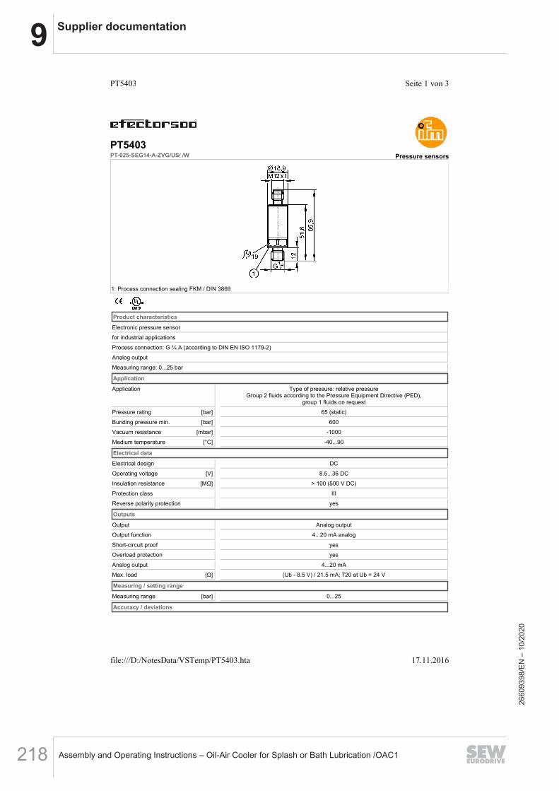
9 Supplier documentation
Assembly and Operating Instructions – Oil-Air Cooler for Splash or Bath Lubrication /OAC1218
[bar]
[bar]
[mbar]
[°C]
[V]
[MΩ]
[Ω]
[bar]
PT5403PT-025-SEG14-A-ZVG/US/ /W Pressure sensors
1: Process connection sealing FKM / DIN 3869
Product characteristics
Electronic pressure sensor
for industrial applications
Process connection: G ¼ A (according to DIN EN ISO 1179-2)
Analog output
Measuring range: 0...25 bar
Application
Application Type of pressure: relative pressureGroup 2 fluids according to the Pressure Equipment Directive (PED),
group 1 fluids on request
Pressure rating 65 (static)
Bursting pressure min. 600
Vacuum resistance -1000
Medium temperature -40...90
Electrical data
Electrical design DC
Operating voltage 8.5...36 DC
Insulation resistance > 100 (500 V DC)
Protection class III
Reverse polarity protection yes
Outputs
Output Analog output
Output function 4...20 mA analog
Short-circuit proof yes
Overload protection yes
Analog output 4...20 mA
Max. load (Ub - 8.5 V) / 21.5 mA; 720 at Ub = 24 V
Measuring / setting range
Measuring range 0...25
Accuracy / deviations
Seite 1 von 3PT5403
17.11.2016file:///D:/NotesData/VSTemp/PT5403.hta
2660
9398
/EN
– 1
0/20
20

9Supplier documentation
Assembly and Operating Instructions – Oil-Air Cooler for Splash or Bath Lubrication /OAC1 219
[ms]
[°C]
[°C]
[Years]
[Nm]
[kg]
Accuracy / deviations(in % of the span)
Characteristics deviation *) < ± 0.5
Linearity < ± 0.1 (BFSL) / < ± 0.2 (LS)
Hysteresis < ± 0.2
Repeatability **) < ± 0.05
Long-term stability ***) < ± 0.1
Temperature coefficients (TEMPCO) in the temperature range -40...90° C (in % of the span per 10 K)
Greatest TEMPCO of the zero point + span < 0.1 (-25...90 °C) / < 0.2 (-40...-25 °C)
Reaction times
Step response time analogue output 1
Environment
Ambient temperature -40...90
Storage temperature -40...100
Protection IP 67 / IP 69K
Tests / approvals
Pressure equipment directive sound engineering practice
EMC DIN EN 61000-6-2
DIN EN 61000-6-3
Shock resistance DIN EN 60068-2-27 50 g (11 ms)
Vibration resistance DIN EN 60068-2-6 20 g (10...2000 Hz)
MTTF 686
Mechanical data
Process connection G ¼ A (according to DIN EN ISO 1179-2)
Process connection sealing FKM (to DIN 3869)
Materials (wetted parts) 1.4542 (17-4 PH / 630)²
Housing materials 1.4542 (17-4 PH / 630)²; stainless steel (316L / 1.4404); PEI
Min. pressure cycles 60 millions in the course of the lifetime (at 1.2 times the nominal pressure)
Tightening torque 25...35 (recommended tightening torque¹)
Restrictor element integrated no
Weight 0.056
Electrical connection
Connection M12 connector
Wiring
Core colors
BN brown
WH white
OUT: 4...20 mA
The following pin connection is available on request:
pin 1: L+, pin 3: OUT
Colours to DIN EN 60947-5-2
Remarks
Remarks *) incl. drift when overtightened, zero point and span error, non-linearity, hysteresis
**) with temperature fluctuations < 10 K
***) in% of the span / 6 months
Seite 2 von 3PT5403
17.11.2016file:///D:/NotesData/VSTemp/PT5403.hta
2660
9398
/EN
– 1
0/20
20

9 Supplier documentation
Assembly and Operating Instructions – Oil-Air Cooler for Splash or Bath Lubrication /OAC1220
[piece]
¹) Depends on lubrication, seal and pressure rating
²) Characteristics similar to stainless steel (e.g. 304/1.4301) but higher strength.
BFSL = Best Fit Straight Line / LS = Limit Value Setting
Pack quantity 1
ifm efector, inc. • 1100 Atwater Drive • Malvern • PA 19355 — We reserve the right to make technical alterations without prior notice. — US — PT5403-01 — 07.09.2015
Seite 3 von 3PT5403
17.11.2016file:///D:/NotesData/VSTemp/PT5403.hta
2660
9398
/EN
– 1
0/20
20


SEW-EURODRIVE—Driving the world
SEW-EURODRIVE GmbH & Co KGErnst-Blickle-Str. 4276646 BRUCHSALGERMANYTel. +49 7251 75-0Fax +49 7251 [email protected]