SKF Maintenance and Lubrication Products - Epidor
196
Extending the Bearing Life Cycle SKF Maintenance and Lubrication Products Alignment Lubrication Mounting Buy a bearing Basic condition monitoring Dismounting
-
Upload
khangminh22 -
Category
Documents
-
view
0 -
download
0
Transcript of SKF Maintenance and Lubrication Products - Epidor
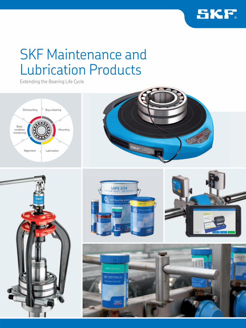
Extending the Bearing Life Cycle
SKF Maintenance and Lubrication Products
Alignment Lubrication
Mounting
Buy a bearing
Basic condition
monitoring
Dismounting

Instruments
Mounting and dismounting
Lubrication
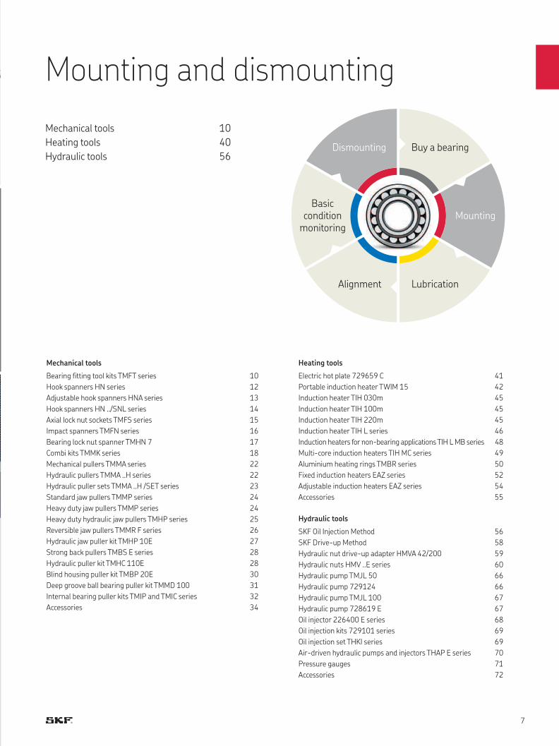
Mechanical tools 10
Heating tools 40
Hydraulic tools 56
Alignment 80
Basic condition monitoring 100
Lubricants 128
Automatic grease dispensing tools 158
Manual grease dispensing tools 172
Accessories 180
Oil inspection and dispensing 181
Storage tools 184
Lubrication analysis tools 186
Lubrication software 188
SKF Maintenance and Lubrication Products
Our mission is to maximize our customer bearing
performance through effective lubrication and
maintenance solutions.
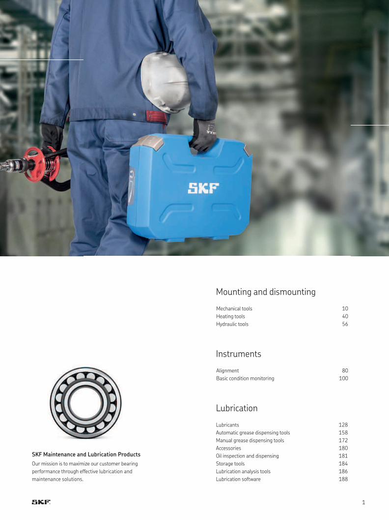
Help your bearing achieve its maximum service life
After the bearing has been mounted in an application such as a motor
connected to a pump, the application should be aligned. If the application
is not properly aligned, the misalignment can cause the bearing to suffer
additional load, friction and vibration. These can accelerate fatigue and
reduce the bearing’s, as well as other machine components, service life.
Furthermore, increased vibration and friction can significantly increase
energy consumption and the risk of premature failures.
Alignment
Includes shaft and belt alignment tools
and machinery shims
During operation, it is important to regularly inspect the condition of
the bearing by performing basic condition monitoring measurements.
These regular inspections will allow the detection of potential problems
and help to prevent unexpected machine stops. Consequently, the
machine maintenance can be planned to suit the production schedule,
increasing the plant’s productivity and efficiency.
Basic condition monitoring
Includes temperature, sound, visual
inspection, speed, electrical discharge
and vibration measuring instruments
Lubrication
Includes bearing greases, manual and
automatic lubricators and lubrication
accessories
Correct bearing lubrication is an essential step in reaching the bearing’s
service lifetime. It is important to select grease suitable for the bearing’s
application, and to apply the correct quantity before commissioning the
bearing. During operation, the bearing will require periodic relubrication.
The right quantity of the right grease applied at the right intervals is
essential to achieving optimum bearing performance and maximum
service life. Using manual relubrication methods is common practice;
however, continuous relubrication offers many advantages. Continuous
relubrication can be performed by using automatic lubricators, which
provide a more consistent, correct and contamination-free grease supply.
Mounting
Includes mechanical fitting tools,
induction heaters and hydraulic
equipment
Mounting is one of the critical stages of the bearing’s lifecycle. If the
bearing is not mounted properly using the correct method and tools, the
bearing’s service lifetime will be reduced. Individual applications may
require mechanical, heat or hydraulic mounting methods for correct
and efficient bearing mounting. Selecting the correct mounting
technique for your application will help you extend your bearing’s
service life and reduce costs resulting from premature bearing failure,
as well as potential damage to the application.
The SKF Bearing Life Cycle
Every bearing has a certain service life potential. However, research has shown that, for
various reasons, not every bearing achieves it. Important stages which have a major impact
on a bearing service life can be recognised during the bearing’s lifecycle. These stages are
mounting, lubrication, alignment, basic condition monitoring and dismounting.
The stages in a bearing life cycle are extremely important for achieving the maximum service
life of the bearing. By applying the right maintenance practices and using the correct tools,
you can considerably extend your bearing’s service life and increase plant productivity and
efficiency.
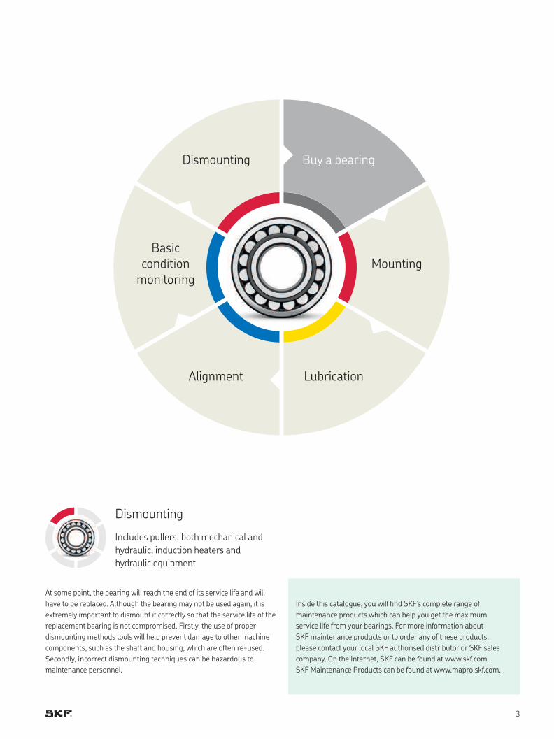
At some point, the bearing will reach the end of its service life and will
have to be replaced. Although the bearing may not be used again, it is
extremely important to dismount it correctly so that the service life of the
replacement bearing is not compromised. Firstly, the use of proper
dismounting methods tools will help prevent damage to other machine
components, such as the shaft and housing, which are often re-used.
Secondly, incorrect dismounting techniques can be hazardous to
maintenance personnel.
Dismounting
Includes pullers, both mechanical and
hydraulic, induction heaters and
hydraulic equipment
Inside this catalogue, you will find SKF’s complete range of
maintenance products which can help you get the maximum
service life from your bearings. For more information about
SKF maintenance products or to order any of these products,
please contact your local SKF authorised distributor or SKF sales
company. On the Internet, SKF can be found at www.skf.com.
SKF Maintenance Products can be found at www.mapro.skf.com.
Alignment Lubrication
Mounting
Buy a bearing
Basic condition
monitoring
Dismounting
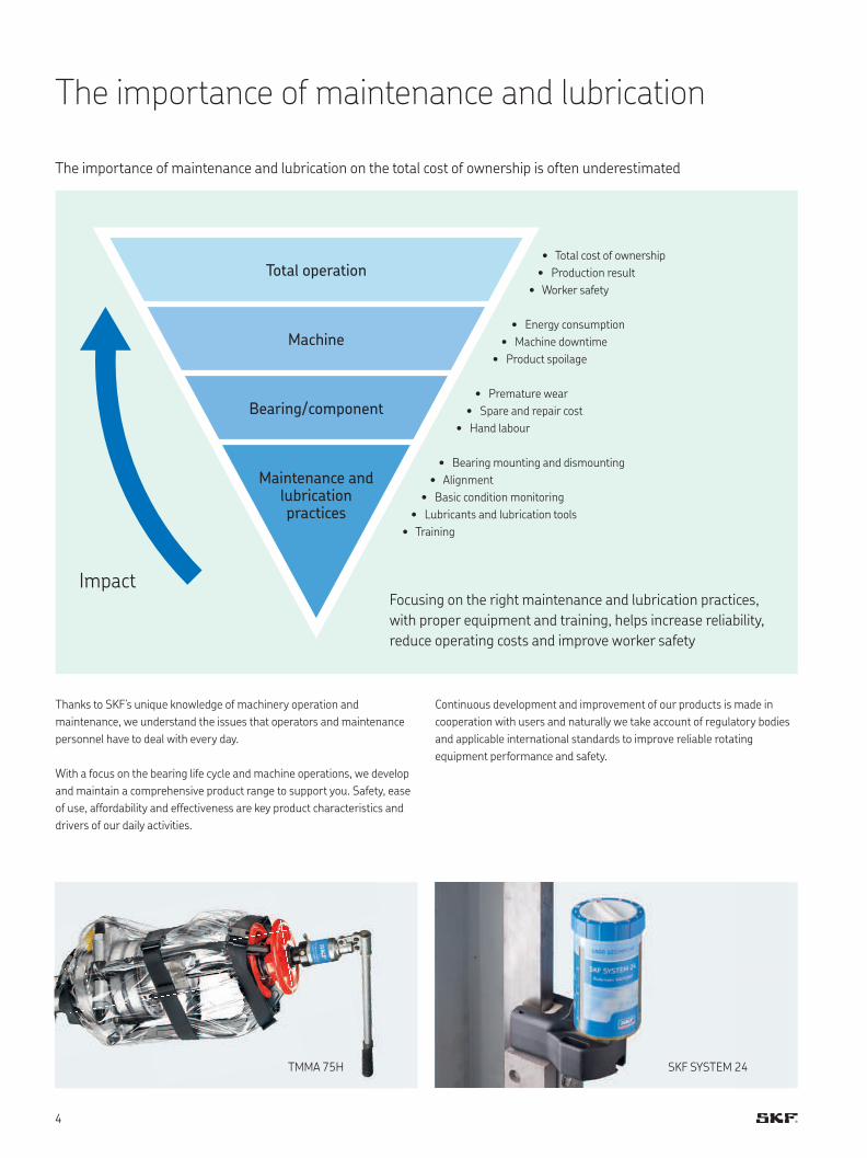
The importance of maintenance and lubrication
The importance of maintenance and lubrication on the total cost of ownership is often underestimated
Focusing on the right maintenance and lubrication practices,
with proper equipment and training, helps increase reliability,
reduce operating costs and improve worker safety
Thanks to SKF’s unique knowledge of machinery operation and
maintenance, we understand the issues that operators and maintenance
personnel have to deal with every day.
With a focus on the bearing life cycle and machine operations, we develop
and maintain a comprehensive product range to support you. Safety, ease
of use, affordability and effectiveness are key product characteristics and
drivers of our daily activities.
Continuous development and improvement of our products is made in
cooperation with users and naturally we take account of regulatory bodies
and applicable international standards to improve reliable rotating
equipment performance and safety.
• Total cost of ownership
• Production result
• Worker safety
• Energy consumption
• Machine downtime
• Product spoilage
• Premature wear
• Spare and repair cost
• Hand labour
• Bearing mounting and dismounting
• Alignment
• Basic condition monitoring
• Lubricants and lubrication tools
• Training
Total operation
Machine
Bearing / component
Maintenance and lubrication practices
Impact
SKF SYSTEM 24TMMA 75H
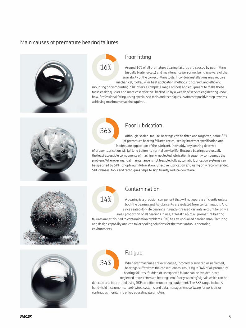
36%
14%
16%
34%
Poor fitting
Around 16% of all premature bearing failures are caused by poor fitting
(usually brute force...) and maintenance personnel being unaware of the
availability of the correct fitting tools. Individual installations may require
mechanical, hydraulic or heat application methods for correct and efficient
mounting or dismounting. SKF offers a complete range of tools and equipment to make these
tasks easier, quicker and more cost effective, backed up by a wealth of service engineering know-
how. Professional fitting, using specialised tools and techniques, is another positive step towards
achieving maximum machine uptime.
Poor lubrication
Although ‘sealed-for-life’ bearings can be fitted and forgotten, some 36%
of premature bearing failures are caused by incorrect specification and
inadequate application of the lubricant. Inevitably, any bearing deprived
of proper lubrication will fail long before its normal service life. Because bearings are usually
the least accessible components of machinery, neglected lubrication frequently compounds the
problem. Wherever manual maintenance is not feasible, fully automatic lubrication systems can
be specified by SKF for optimum lubrication. Effective lubrication and using only recommended
SKF greases, tools and techniques helps to significantly reduce downtime.
Contamination
A bearing is a precision component that will not operate efficiently unless
both the bearing and its lubricants are isolated from contamination. And,
since sealed-for-life bearings in ready-greased variants account for only a
small proportion of all bearings in use, at least 14% of all premature bearing
failures are attributed to contamination problems. SKF has an unrivalled bearing manufacturing
and design capability and can tailor sealing solutions for the most arduous operating
environments.
Fatigue
Whenever machines are overloaded, incorrectly serviced or neglected,
bearings suffer from the consequences, resulting in 34% of all premature
bearing failures. Sudden or unexpected failure can be avoided, since
neglected or overstressed bearings emit ‘early warning’ signals which can be
detected and interpreted using SKF condition monitoring equipment. The SKF range includes
hand-held instruments, hard-wired systems and data management software for periodic or
continuous monitoring of key operating parameters.
Main causes of premature bearing failures
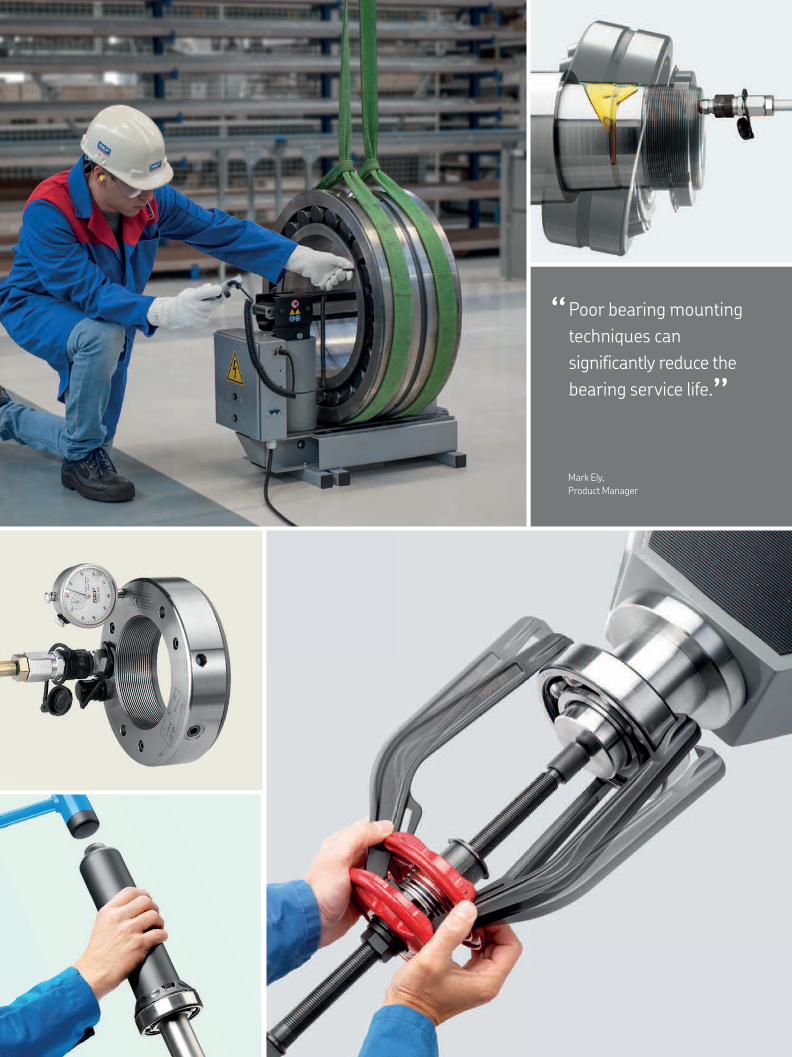
Poor bearing mounting
techniques can
significantly reduce the
bearing service life.
“ “
Mark Ely,
Product Manager
Mechanical tools
Bearing fitting tool kits TMFT series 10
Hook spanners HN series 12
Adjustable hook spanners HNA series 13
Hook spanners HN ../SNL series 14
Axial lock nut sockets TMFS series 15
Impact spanners TMFN series 16
Bearing lock nut spanner TMHN 7 17
Combi kits TMMK series 18
Mechanical pullers TMMA series 22
Hydraulic pullers TMMA ..H series 22
Hydraulic puller sets TMMA ..H /SET series 23
Standard jaw pullers TMMP series 24
Heavy duty jaw pullers TMMP series 24
Heavy duty hydraulic jaw pullers TMHP series 25
Reversible jaw pullers TMMR F series 26
Hydraulic jaw puller kit TMHP 10E 27
Strong back pullers TMBS E series 28
Hydraulic puller kit TMHC 110E 28
Blind housing puller kit TMBP 20E 30
Deep groove ball bearing puller kit TMMD 100 31
Internal bearing puller kits TMIP and TMIC series 32
Accessories 34
Heating tools
Electric hot plate 729659 C 41
Portable induction heater TWIM 15 42
Induction heater TIH 030m 45
Induction heater TIH 100m 45
Induction heater TIH 220m 45
Induction heater TIH L series 46
Induction heaters for non-bearing applications TIH L MB series 48
Multi-core induction heaters TIH MC series 49
Aluminium heating rings TMBR series 50
Fixed induction heaters EAZ series 52
Adjustable induction heaters EAZ series 54
Accessories 55
Hydraulic tools
SKF Oil Injection Method 56
SKF Drive-up Method 58
Hydraulic nut drive-up adapter HMVA 42/200 59
Hydraulic nuts HMV ..E series 60
Hydraulic pump TMJL 50 66
Hydraulic pump 729124 66
Hydraulic pump TMJL 100 67
Hydraulic pump 728619 E 67
Oil injector 226400 E series 68
Oil injection kits 729101 series 69
Oil injection set THKI series 69
Air-driven hydraulic pumps and injectors THAP E series 70
Pressure gauges 71
Accessories 72
Mounting and dismounting
Mechanical tools 10
Heating tools 40
Hydraulic tools 56
Alignment Lubrication
Mounting
Buy a bearing
Basic condition
monitoring
Dismounting
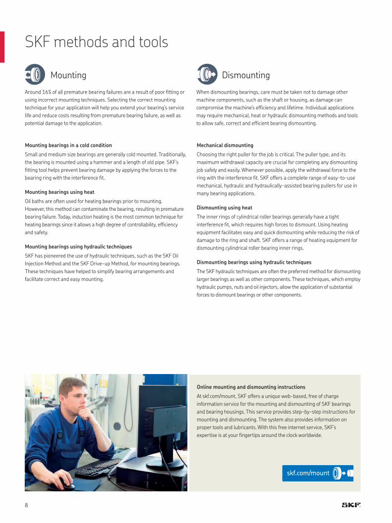
Mounting
Around 16% of all premature bearing failures are a result of poor fitting or
using incorrect mounting techniques. Selecting the correct mounting
technique for your application will help you extend your bearing’s service
life and reduce costs resulting from premature bearing failure, as well as
potential damage to the application.
Mounting bearings in a cold condition
Small and medium size bearings are generally cold mounted. Traditionally,
the bearing is mounted using a hammer and a length of old pipe. SKF’s
fitting tool helps prevent bearing damage by applying the forces to the
bearing ring with the interference fit.
Mounting bearings using heat
Oil baths are often used for heating bearings prior to mounting.
However, this method can contaminate the bearing, resulting in premature
bearing failure. Today, induction heating is the most common technique for
heating bearings since it allows a high degree of controllability, efficiency
and safety.
Mounting bearings using hydraulic techniques
SKF has pioneered the use of hydraulic techniques, such as the SKF Oil
Injection Method and the SKF Drive-up Method, for mounting bearings.
These techniques have helped to simplify bearing arrangements and
facilitate correct and easy mounting.
Dismounting
When dismounting bearings, care must be taken not to damage other
machine components, such as the shaft or housing, as damage can
compromise the machine’s efficiency and lifetime. Individual applications
may require mechanical, heat or hydraulic dismounting methods and tools
to allow safe, correct and efficient bearing dismounting.
Mechanical dismounting
Choosing the right puller for the job is critical. The puller type, and its
maximum withdrawal capacity are crucial for completing any dismounting
job safely and easily. Whenever possible, apply the withdrawal force to the
ring with the interference fit. SKF offers a complete range of easy-to-use
mechanical, hydraulic and hydraulically-assisted bearing pullers for use in
many bearing applications.
Dismounting using heat
The inner rings of cylindrical roller bearings generally have a tight
interference fit, which requires high forces to dismount. Using heating
equipment facilitates easy and quick dismounting while reducing the risk of
damage to the ring and shaft. SKF offers a range of heating equipment for
dismounting cylindrical roller bearing inner rings.
Dismounting bearings using hydraulic techniques
The SKF hydraulic techniques are often the preferred method for dismounting
larger bearings as well as other components. These techniques, which employ
hydraulic pumps, nuts and oil injectors, allow the application of substantial
forces to dismount bearings or other components.
SKF methods and tools
Online mounting and dismounting instructions
At skf.com/mount, SKF offers a unique web-based, free of charge
information service for the mounting and dismounting of SKF bearings
and bearing housings. This service provides step-by-step instructions for
mounting and dismounting. The system also provides information on
proper tools and lubricants. With this free internet service, SKF’s
expertise is at your fingertips around the clock worldwide.
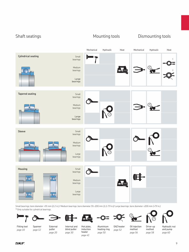
Shaft seatings Mounting tools Dismounting tools
Small bearings: bore diameter <55 mm (2.2 in.) / Medium bearings: bore diameter 55–200 mm (2.2-7.9 in.)/ Large bearings: bore diameter >200 mm (>7.9 in.)1) Only suitable for cylindrical bearings.
Fitting tool
page 10
Spanner
page 12
External puller
page 20
Internal and blind puller
page 30
Hot plate, induction heater
page 41
Aluminium heating ring
page 50
EAZ heater
page 52
Oil injection method
page 56
Drive-up method
page 58
Hydraulic nut and pump
page 60
Tapered seating
Cylindrical seating
Sleeve
Housing
Small
bearings
Small
bearings
Small
bearings
Small
bearings
Medium
bearings
Medium
bearings
Medium
bearings
Medium
bearings
Large bearings
Large bearings
Large
bearings
Large
bearings
1)
1)
Mechanical MechanicalHeat HeatHydraulic Hydraulic
1)
1)
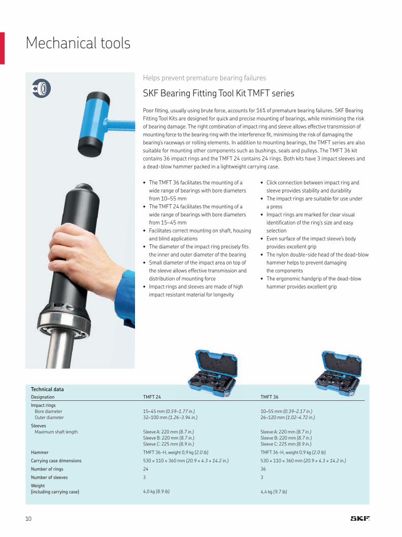
Mechanical tools
Helps prevent premature bearing failures
SKF Bearing Fitting Tool Kit TMFT series
Poor fitting, usually using brute force, accounts for 16% of premature bearing failures. SKF Bearing
Fitting Tool Kits are designed for quick and precise mounting of bearings, while minimising the risk
of bearing damage. The right combination of impact ring and sleeve allows effective transmission of
mounting force to the bearing ring with the interference fit, minimising the risk of damaging the
bearing’s raceways or rolling elements. In addition to mounting bearings, the TMFT series are also
suitable for mounting other components such as bushings, seals and pulleys. The TMFT 36 kit
contains 36 impact rings and the TMFT 24 contains 24 rings. Both kits have 3 impact sleeves and
a dead-blow hammer packed in a lightweight carrying case.
• The TMFT 36 facilitates the mounting of a
wide range of bearings with bore diameters
from 10–55 mm
• The TMFT 24 facilitates the mounting of a
wide range of bearings with bore diameters
from 15–45 mm
• Facilitates correct mounting on shaft, housing
and blind applications
• The diameter of the impact ring precisely fits
the inner and outer diameter of the bearing
• Small diameter of the impact area on top of
the sleeve allows effective transmission and
distribution of mounting force
• Impact rings and sleeves are made of high
impact resistant material for longevity
Designation TMFT 24 TMFT 36
Impact rings
Bore diameter
Outer diameter
15–45 mm (0.59–1.77 in.)
32–100 mm (1.26–3.94 in.)
10–55 mm (0.39–2.17 in.)
26–120 mm (1.02–4.72 in.)
Sleeves
Maximum shaft length Sleeve A: 220 mm (8.7 in.)
Sleeve B: 220 mm (8.7 in.)
Sleeve C: 225 mm (8.9 in.)
Sleeve A: 220 mm (8.7 in.)
Sleeve B: 220 mm (8.7 in.)
Sleeve C: 225 mm (8.9 in.)
Hammer TMFT 36-H, weight 0,9 kg (2.0 lb) TMFT 36-H, weight 0,9 kg (2.0 lb)
Carrying case dimensions 530 × 110 × 360 mm (20.9 × 4.3 × 14.2 in.) 530 × 110 × 360 mm (20.9 × 4.3 × 14.2 in.)
Number of rings 24 36
Number of sleeves 3 3
Weight
(including carrying case) 4,0 kg (8.9 lb) 4,4 kg (9.7 lb)
Technical data
• Click connection between impact ring and
sleeve provides stability and durability
• The impact rings are suitable for use under
a press
• Impact rings are marked for clear visual
identification of the ring’s size and easy
selection
• Even surface of the impact sleeve’s body
provides excellent grip
• The nylon double-side head of the dead-blow
hammer helps to prevent damaging
the components
• The ergonomic handgrip of the dead-blow
hammer provides excellent grip
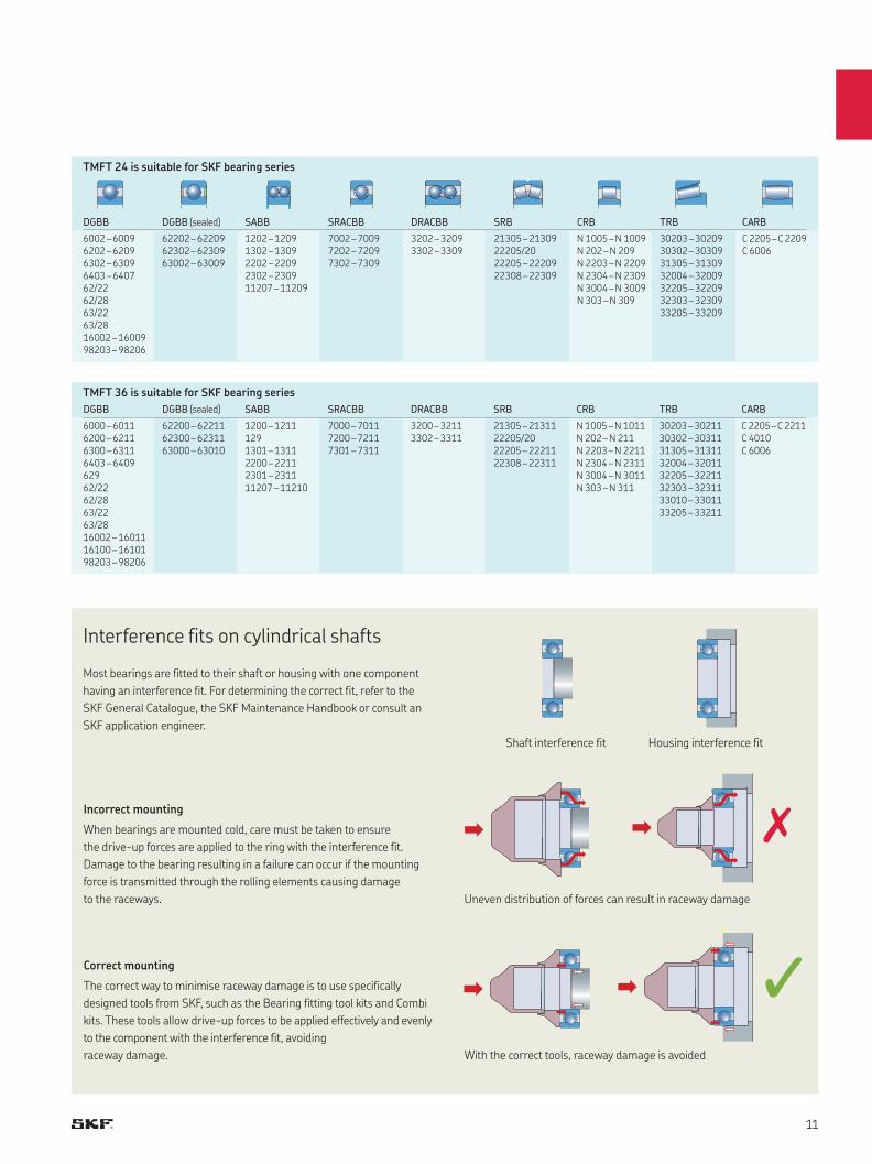
Interference fits on cylindrical shafts
Most bearings are fitted to their shaft or housing with one component
having an interference fit. For determining the correct fit, refer to the
SKF General Catalogue, the SKF Maintenance Handbook or consult an
SKF application engineer.
Incorrect mounting
When bearings are mounted cold, care must be taken to ensure
the drive-up forces are applied to the ring with the interference fit.
Damage to the bearing resulting in a failure can occur if the mounting
force is transmitted through the rolling elements causing damage
to the raceways.
Correct mounting
The correct way to minimise raceway damage is to use specifically
designed tools from SKF, such as the Bearing fitting tool kits and Combi
kits. These tools allow drive-up forces to be applied effectively and evenly
to the component with the interference fit, avoiding
raceway damage.
Shaft interference fit Housing interference fit
Uneven distribution of forces can result in raceway damage
With the correct tools, raceway damage is avoided
TMFT 24 is suitable for SKF bearing series
TMFT 36 is suitable for SKF bearing series
DGBB DGBB (sealed) SABB SRACBB DRACBB SRB CRB TRB CARB
6000 – 6011 62200 – 62211 1200 – 1211 7000 – 7011 3200 – 3211 21305 – 21311 N 1005 – N 1011 30203 – 30211 C 2205 – C 22116200 – 6211 62300 – 62311 129 7200 – 7211 3302 – 3311 22205/20 N 202 – N 211 30302 – 30311 C 40106300 – 6311 63000 – 63010 1301 – 1311 7301 – 7311 22205 – 22211 N 2203 – N 2211 31305 – 31311 C 60066403 – 6409 2200 – 2211 22308 – 22311 N 2304 – N 2311 32004 – 32011629 2301 – 2311 N 3004 – N 3011 32205 – 3221162/22 11207 – 11210 N 303 – N 311 32303 – 3231162/28 33010 – 3301163/22 33205 – 3321163/2816002 – 1601116100 – 1610198203 – 98206
DGBB DGBB (sealed) SABB SRACBB DRACBB SRB CRB TRB CARB
6002 – 6009 62202 – 62209 1202 – 1209 7002 – 7009 3202 – 3209 21305 – 21309 N 1005 – N 1009 30203 – 30209 C 2205 – C 22096202 – 6209 62302 – 62309 1302 – 1309 7202 – 7209 3302 – 3309 22205/20 N 202 – N 209 30302 – 30309 C 60066302 – 6309 63002 – 63009 2202 – 2209 7302 – 7309 22205 – 22209 N 2203 – N 2209 31305 – 313096403 – 6407 2302 – 2309 22308 – 22309 N 2304 – N 2309 32004 – 3200962/22 11207 – 11209 N 3004 – N 3009 32205 – 3220962/28 N 303 – N 309 32303 – 3230963/22 33205 – 3320963/2816002 – 1600998203 – 98206
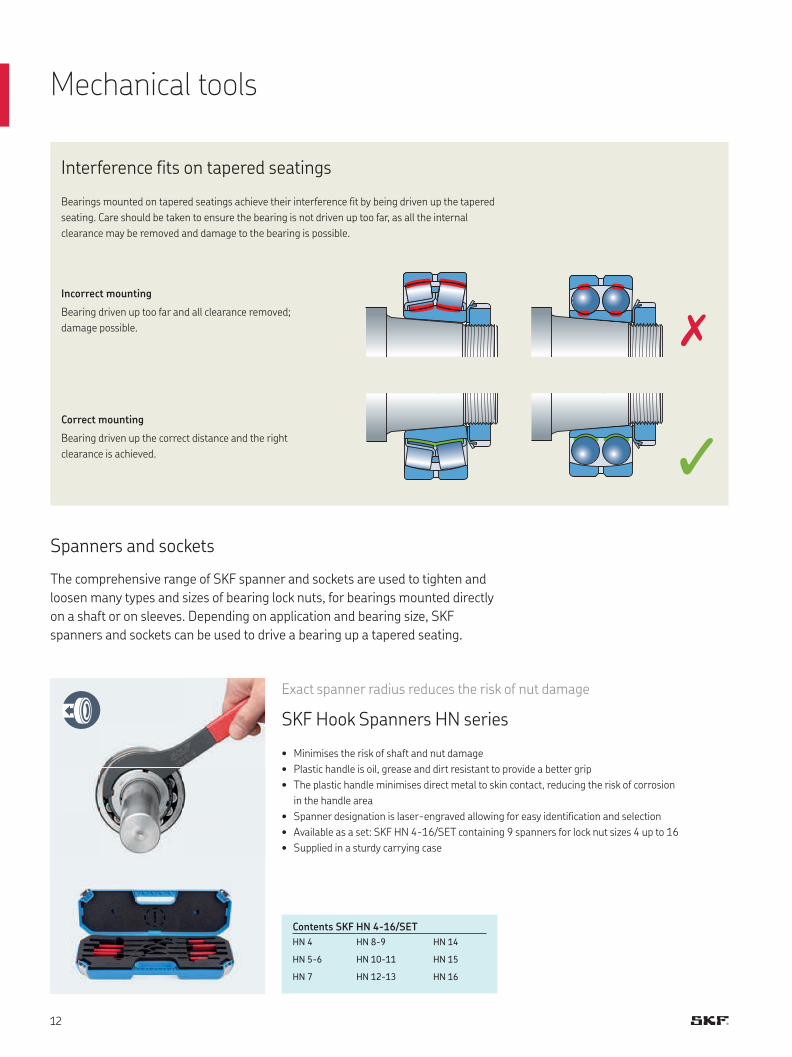
Spanners and sockets
The comprehensive range of SKF spanner and sockets are used to tighten and
loosen many types and sizes of bearing lock nuts, for bearings mounted directly
on a shaft or on sleeves. Depending on application and bearing size, SKF
spanners and sockets can be used to drive a bearing up a tapered seating.
• Minimises the risk of shaft and nut damage
• Plastic handle is oil, grease and dirt resistant to provide a better grip
• The plastic handle minimises direct metal to skin contact, reducing the risk of corrosion
in the handle area
• Spanner designation is laser-engraved allowing for easy identification and selection
• Available as a set: SKF HN 4-16/SET containing 9 spanners for lock nut sizes 4 up to 16
• Supplied in a sturdy carrying case
Exact spanner radius reduces the risk of nut damage
SKF Hook Spanners HN series
Contents SKF HN 4-16/SET
HN 4 HN 8-9 HN 14
HN 5-6 HN 10-11 HN 15
HN 7 HN 12-13 HN 16
Interference fits on tapered seatings
Bearings mounted on tapered seatings achieve their interference fit by being driven up the tapered
seating. Care should be taken to ensure the bearing is not driven up too far, as all the internal
clearance may be removed and damage to the bearing is possible.
Incorrect mounting
Bearing driven up too far and all clearance removed;
damage possible.
Correct mounting
Bearing driven up the correct distance and the right
clearance is achieved.
Mechanical tools
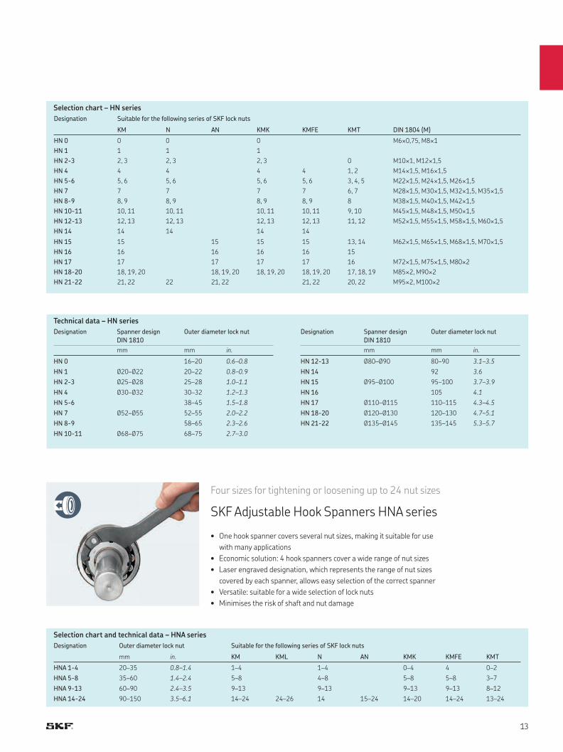
Technical data – HN series
Designation Spanner design
DIN 1810
Outer diameter lock nut
mm mm in.
HN 0 16–20 0.6–0.8
HN 1 Ø20–Ø22 20–22 0.8–0.9
HN 2-3 Ø25–Ø28 25–28 1.0–1.1
HN 4 Ø30–Ø32 30–32 1.2–1.3
HN 5-6 38–45 1.5–1.8
HN 7 Ø52–Ø55 52–55 2.0–2.2
HN 8-9 58–65 2.3–2.6
HN 10-11 Ø68–Ø75 68–75 2.7–3.0
Designation Spanner design
DIN 1810
Outer diameter lock nut
mm mm in.
HN 12-13 Ø80–Ø90 80–90 3.1–3.5
HN 14 92 3.6
HN 15 Ø95–Ø100 95–100 3.7–3.9
HN 16 105 4.1
HN 17 Ø110–Ø115 110–115 4.3–4.5
HN 18-20 Ø120–Ø130 120–130 4.7–5.1
HN 21-22 Ø135–Ø145 135–145 5.3–5.7
Four sizes for tightening or loosening up to 24 nut sizes
SKF Adjustable Hook Spanners HNA series
• One hook spanner covers several nut sizes, making it suitable for use
with many applications
• Economic solution: 4 hook spanners cover a wide range of nut sizes
• Laser engraved designation, which represents the range of nut sizes
covered by each spanner, allows easy selection of the correct spanner
• Versatile: suitable for a wide selection of lock nuts
• Minimises the risk of shaft and nut damage
Designation Suitable for the following series of SKF lock nuts
KM N AN KMK KMFE KMT DIN 1804 (M)
HN 0 0 0 0 M6×0,75, M8×1
HN 1 1 1 1
HN 2-3 2, 3 2, 3 2, 3 0 M10×1, M12×1,5
HN 4 4 4 4 4 1, 2 M14×1,5, M16×1,5
HN 5-6 5, 6 5, 6 5, 6 5, 6 3, 4, 5 M22×1,5, M24×1,5, M26×1,5
HN 7 7 7 7 7 6, 7 M28×1,5, M30×1,5, M32×1,5, M35×1,5
HN 8-9 8, 9 8, 9 8, 9 8, 9 8 M38×1,5, M40×1,5, M42×1,5
HN 10-11 10, 11 10, 11 10, 11 10, 11 9, 10 M45×1,5, M48×1,5, M50×1,5
HN 12-13 12, 13 12, 13 12, 13 12, 13 11, 12 M52×1,5, M55×1,5, M58×1,5, M60×1,5
HN 14 14 14 14 14
HN 15 15 15 15 15 13, 14 M62×1,5, M65×1,5, M68×1,5, M70×1,5
HN 16 16 16 16 16 15
HN 17 17 17 17 17 16 M72×1,5, M75×1,5, M80×2
HN 18-20 18, 19, 20 18, 19, 20 18, 19, 20 18, 19, 20 17, 18, 19 M85×2, M90×2
HN 21-22 21, 22 22 21, 22 21, 22 20, 22 M95×2, M100×2
Selection chart – HN series
Designation Outer diameter lock nut Suitable for the following series of SKF lock nuts
mm in. KM KML N AN KMK KMFE KMT
HNA 1-4 20–35 0.8–1.4 1–4 1–4 0–4 4 0–2
HNA 5-8 35–60 1.4–2.4 5–8 4–8 5–8 5–8 3–7
HNA 9-13 60–90 2.4–3.5 9–13 9–13 9–13 9–13 8–12
HNA 14-24 90–150 3.5–6.1 14–24 24–26 14 15–24 14–20 14–24 13–24
Selection chart and technical data – HNA series
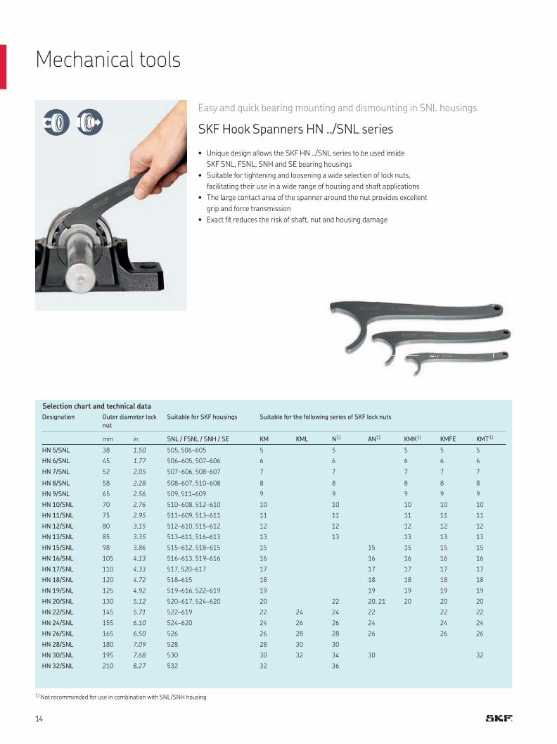
Easy and quick bearing mounting and dismounting in SNL housings
SKF Hook Spanners HN ../SNL series
• Unique design allows the SKF HN ../SNL series to be used inside
SKF SNL, FSNL, SNH and SE bearing housings
• Suitable for tightening and loosening a wide selection of lock nuts,
facilitating their use in a wide range of housing and shaft applications
• The large contact area of the spanner around the nut provides excellent
grip and force transmission
• Exact fit reduces the risk of shaft, nut and housing damage
Selection chart and technical data
1) Not recommended for use in combination with SNL/SNH housing
Designation Outer diameter lock
nut
Suitable for SKF housings Suitable for the following series of SKF lock nuts
mm in. SNL / FSNL / SNH / SE KM KML N1) AN1) KMK1) KMFE KMT1)
HN 5/SNL 38 1.50 505, 506–605 5 5 5 5 5
HN 6/SNL 45 1.77 506–605, 507–606 6 6 6 6 6
HN 7/SNL 52 2.05 507–606, 508–607 7 7 7 7 7
HN 8/SNL 58 2.28 508–607, 510–608 8 8 8 8 8
HN 9/SNL 65 2.56 509, 511–609 9 9 9 9 9
HN 10/SNL 70 2.76 510–608, 512–610 10 10 10 10 10
HN 11/SNL 75 2.95 511–609, 513–611 11 11 11 11 11
HN 12/SNL 80 3.15 512–610, 515–612 12 12 12 12 12
HN 13/SNL 85 3.35 513–611, 516–613 13 13 13 13 13
HN 15/SNL 98 3.86 515–612, 518–615 15 15 15 15 15
HN 16/SNL 105 4.13 516–613, 519–616 16 16 16 16 16
HN 17/SNL 110 4.33 517, 520–617 17 17 17 17 17
HN 18/SNL 120 4.72 518–615 18 18 18 18 18
HN 19/SNL 125 4.92 519–616, 522–619 19 19 19 19 19
HN 20/SNL 130 5.12 520–617, 524–620 20 22 20, 21 20 20 20
HN 22/SNL 145 5.71 522–619 22 24 24 22 22 22
HN 24/SNL 155 6.10 524–620 24 26 26 24 24 24
HN 26/SNL 165 6.50 526 26 28 28 26 26 26
HN 28/SNL 180 7.09 528 28 30 30
HN 30/SNL 195 7.68 530 30 32 34 30 32
HN 32/SNL 210 8.27 532 32 36
Mechanical tools
1) KM 0 only
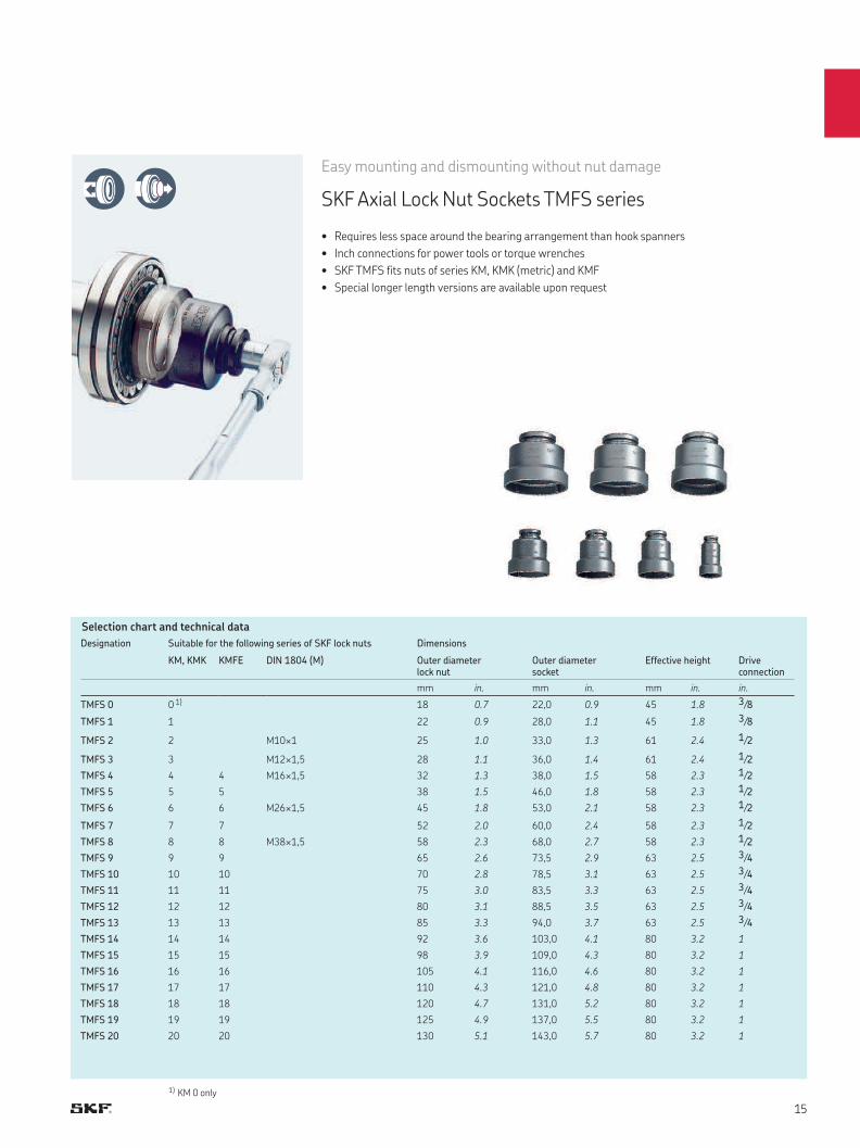
Easy mounting and dismounting without nut damage
SKF Axial Lock Nut Sockets TMFS series
• Requires less space around the bearing arrangement than hook spanners
• Inch connections for power tools or torque wrenches
• SKF TMFS fits nuts of series KM, KMK (metric) and KMF
• Special longer length versions are available upon request
Selection chart and technical data
Designation Suitable for the following series of SKF lock nuts Dimensions
KM, KMK KMFE DIN 1804 (M) Outer diameter lock nut
Outer diameter socket
Effective height Driveconnection
mm in. mm in. mm in. in.
TMFS 0 0 1) 18 0.7 22,0 0.9 45 1.8 3/8
TMFS 1 1 22 0.9 28,0 1.1 45 1.8 3/8
TMFS 2 2 M10×1 25 1.0 33,0 1.3 61 2.4 1/2
TMFS 3 3 M12×1,5 28 1.1 36,0 1.4 61 2.4 1/2
TMFS 4 4 4 M16×1,5 32 1.3 38,0 1.5 58 2.3 1/2
TMFS 5 5 5 38 1.5 46,0 1.8 58 2.3 1/2
TMFS 6 6 6 M26×1,5 45 1.8 53,0 2.1 58 2.3 1/2
TMFS 7 7 7 52 2.0 60,0 2.4 58 2.3 1/2
TMFS 8 8 8 M38×1,5 58 2.3 68,0 2.7 58 2.3 1/2
TMFS 9 9 9 65 2.6 73,5 2.9 63 2.5 3/4
TMFS 10 10 10 70 2.8 78,5 3.1 63 2.5 3/4
TMFS 11 11 11 75 3.0 83,5 3.3 63 2.5 3/4
TMFS 12 12 12 80 3.1 88,5 3.5 63 2.5 3/4
TMFS 13 13 13 85 3.3 94,0 3.7 63 2.5 3/4
TMFS 14 14 14 92 3.6 103,0 4.1 80 3.2 1
TMFS 15 15 15 98 3.9 109,0 4.3 80 3.2 1
TMFS 16 16 16 105 4.1 116,0 4.6 80 3.2 1
TMFS 17 17 17 110 4.3 121,0 4.8 80 3.2 1
TMFS 18 18 18 120 4.7 131,0 5.2 80 3.2 1
TMFS 19 19 19 125 4.9 137,0 5.5 80 3.2 1
TMFS 20 20 20 130 5.1 143,0 5.7 80 3.2 1
h
f
∅d
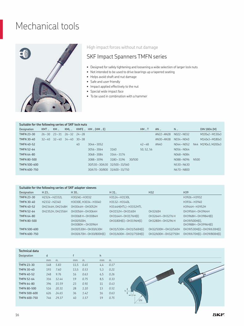
High impact forces without nut damage
SKF Impact Spanners TMFN series
• Designed for safely tightening and loosening a wide selection of larger lock nuts
• Not intended to be used to drive bearings up a tapered seating
• Helps avoid shaft and nut damage
• Safe and user friendly
• Impact applied effectively to the nut
• Special wide impact face
• To be used in combination with a hammer
Designation KMT .. KM .. KML .. KMFE .. HM .. (HM .. E) HM .. T AN .. N .. DIN 1804 (M)
TMFN 23-30 26 – 30 23 – 31 26 – 32 24 – 28 AN22 – AN28 N022 – N032 M105x2 – M130x3
TMFN 30-40 32 – 40 32 – 40 34 – 40 30 – 38 AN30 – AN38 N034 – N040 M140x3 – M180x3
TMFN 40-52 40 3044 – 3052 42 – 48 AN40 N044 – N052 N44 M190x3, M200x3
TMFN 52-64 3056 – 3064 3160 50, 52, 56 N056 – N064
TMFN 64-80 3068 – 3084 3164 – 3176 N068 – N084
TMFN 80-500 3088 – 3096 3180 – 3196 30/500 N088 – N096 N500
TMFN 500-600 30/530 – 30/630 31/500 – 31/560 N530 – N630
TMFN 600-750 30/670 – 30/800 31/600 – 31/750 N670 – N800
Designation H 23.. H 30.. H 31.. H32 H39
TMFN 23-30 H2324 – H2332L H3024E – H3032 H3124 – H3130L H3926 – H3932
TMFN 30-40 H2332 – H2340 H3030E, H3034 – H3040 H3132 – H3140L H3934 – H3940
TMFN 40-52 OH2344H, OH2348H OH3044H – OH3052H H3144H(HTL) – H3152HTL H3944H – H3952H
TMFN 52-64 OH2352H, OH2356H OH3056H – OH3064H OH3152H – OH3160H OH3260H OH3956H – OH3964H
TMFN 64-80 OH3068 H – OH3084H OH3164H – OH3176H(E) OH3264H – OH3276 H OH3968H – OH3984H(E)
TMFN 80-500 OH30/500H,
OH3080H – OH3096H
OH3180H(E) – OH3196H(E) OH3280H – OH3296 H OH39/500H(E),
OH3988H – OH3996H(E)
TMFN 500-600 OH30/530H – OH30/630H OH31/530H – OH31/560H(E) OH32/500H – OH32/560H OH39/530H(E) – OH39/630H(E)
TMFN 600-750 OH30/670H – OH30/800H(E) OH31/600H – OH31/750H(E) OH32/600H – OH32/750H OH39/670H(E) – OH39/800H(E)
Suitable for the following series of SKF lock nuts
Suitable for the following series of SKF adapter sleeves
Technical data
Designation d f h
mm in. mm in. mm in.
TMFN 23-30 148 5.83 11,5 0.45 4,4 0.17
TMFN 30-40 193 7.60 13,5 0.53 5,3 0.21
TMFN 40-52 248 9.76 16 0.63 6,5 0.26
TMFN 52-64 316 12.44 19 0.75 8,5 0.33
TMFN 64-80 396 15.59 23 0.91 11 0.43
TMFN 80-500 516 20.31 28 1.10 13 0.51
TMFN 500-600 626 24.65 36 1.42 16 0.63
TMFN 600-750 746 29.37 40 1.57 19 0.75
Mechanical tools
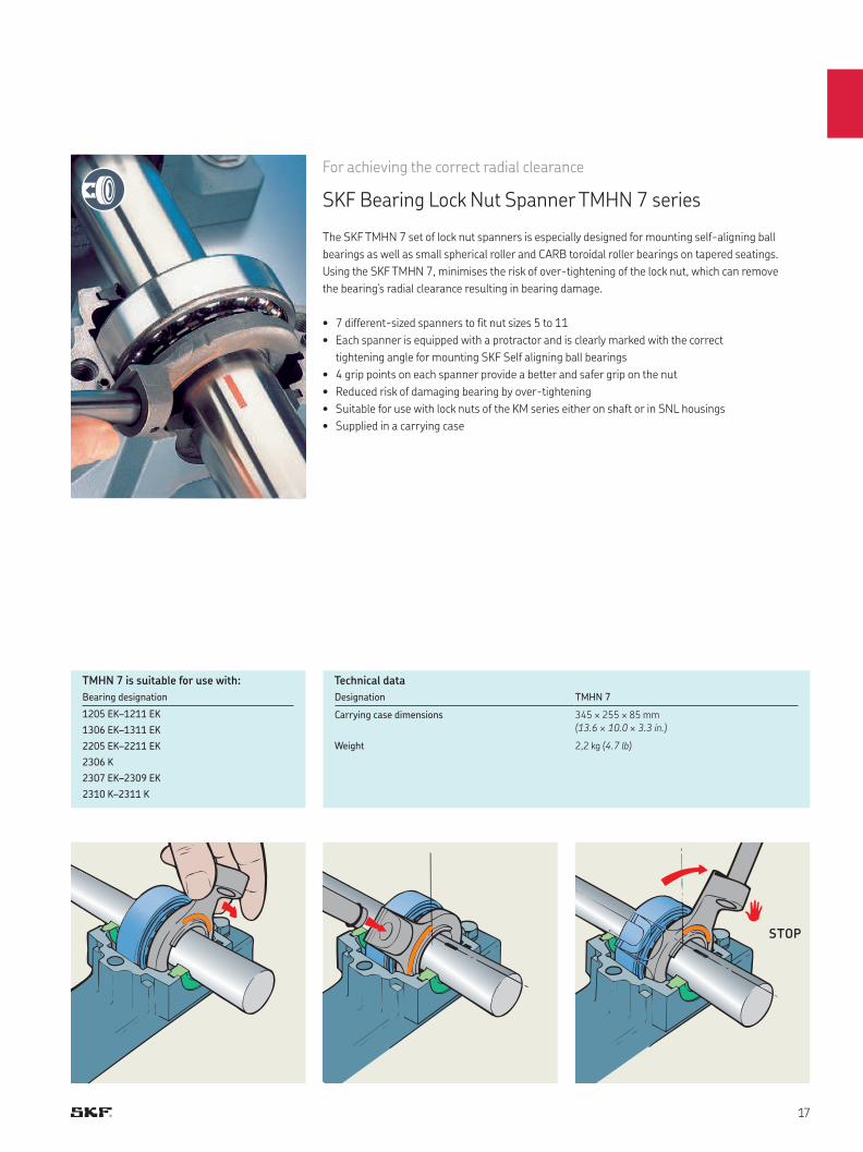
For achieving the correct radial clearance
SKF Bearing Lock Nut Spanner TMHN 7 series
The SKF TMHN 7 set of lock nut spanners is especially designed for mounting self-aligning ball
bearings as well as small spherical roller and CARB toroidal roller bearings on tapered seatings.
Using the SKF TMHN 7, minimises the risk of over-tightening of the lock nut, which can remove
the bearing’s radial clearance resulting in bearing damage.
• 7 different-sized spanners to fit nut sizes 5 to 11
• Each spanner is equipped with a protractor and is clearly marked with the correct
tightening angle for mounting SKF Self aligning ball bearings
• 4 grip points on each spanner provide a better and safer grip on the nut
• Reduced risk of damaging bearing by over-tightening
• Suitable for use with lock nuts of the KM series either on shaft or in SNL housings
• Supplied in a carrying case
Bearing designation
1205 EK–1211 EK
1306 EK–1311 EK
2205 EK–2211 EK
2306 K
2307 EK–2309 EK
2310 K–2311 K
TMHN 7 is suitable for use with: Technical data
Designation TMHN 7
Carrying case dimensions 345 × 255 × 85 mm
(13.6 × 10.0 × 3.3 in.)
Weight 2,2 kg (4.7 lb)
STOP
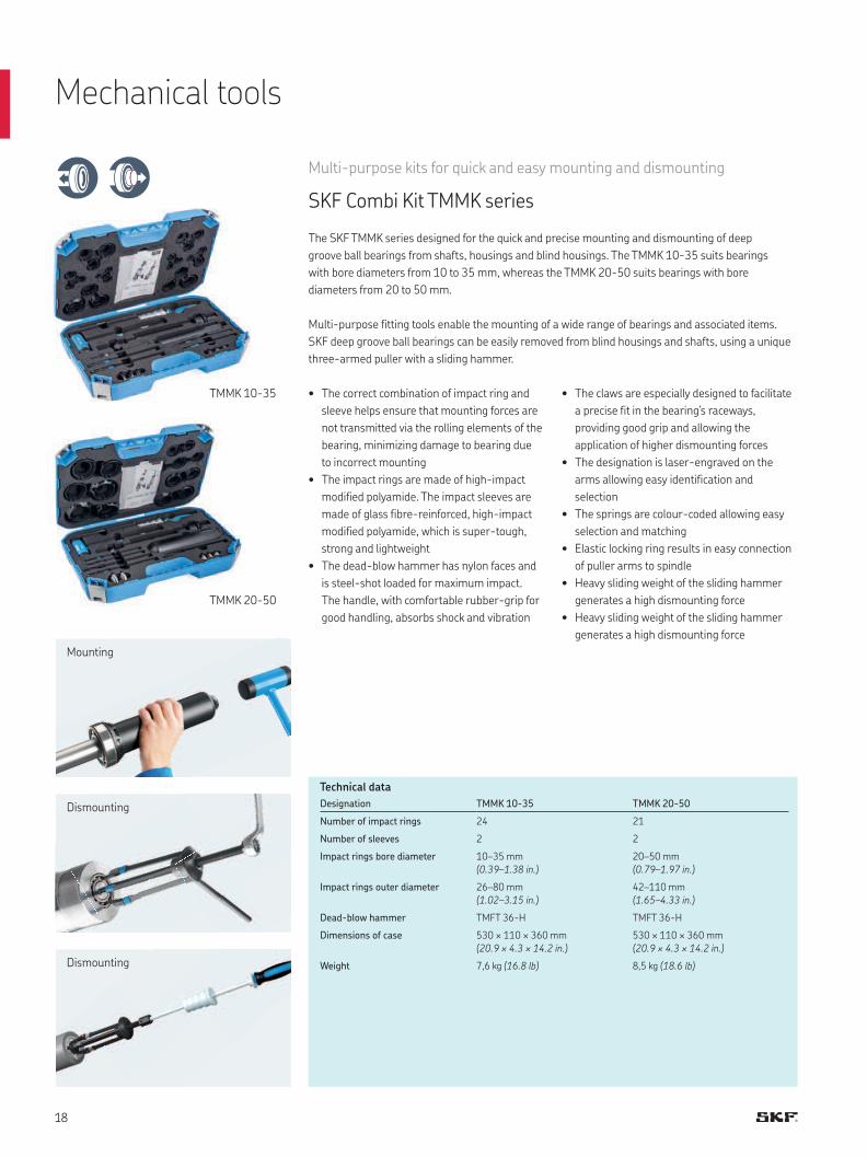
TMMK 20-50
TMMK 10-35
Multi-purpose kits for quick and easy mounting and dismounting
SKF Combi Kit TMMK series
The SKF TMMK series designed for the quick and precise mounting and dismounting of deep
groove ball bearings from shafts, housings and blind housings. The TMMK 10-35 suits bearings
with bore diameters from 10 to 35 mm, whereas the TMMK 20-50 suits bearings with bore
diameters from 20 to 50 mm.
Multi-purpose fitting tools enable the mounting of a wide range of bearings and associated items.
SKF deep groove ball bearings can be easily removed from blind housings and shafts, using a unique
three-armed puller with a sliding hammer.
Mounting
Dismounting
Dismounting
Technical data
Designation TMMK 10-35 TMMK 20-50
Number of impact rings 24 21
Number of sleeves 2 2
Impact rings bore diameter 10–35 mm
(0.39–1.38 in.)
20–50 mm
(0.79–1.97 in.)
Impact rings outer diameter 26–80 mm
(1.02–3.15 in.)
42–110 mm
(1.65–4.33 in.)
Dead-blow hammer TMFT 36-H TMFT 36-H
Dimensions of case 530 × 110 × 360 mm
(20.9 × 4.3 × 14.2 in.)
530 × 110 × 360 mm
(20.9 × 4.3 × 14.2 in.)
Weight 7,6 kg (16.8 lb) 8,5 kg (18.6 lb)
• The correct combination of impact ring and
sleeve helps ensure that mounting forces are
not transmitted via the rolling elements of the
bearing, minimizing damage to bearing due
to incorrect mounting
• The impact rings are made of high-impact
modified polyamide. The impact sleeves are
made of glass fibre-reinforced, high-impact
modified polyamide, which is super-tough,
strong and lightweight
• The dead-blow hammer has nylon faces and
is steel-shot loaded for maximum impact.
The handle, with comfortable rubber-grip for
good handling, absorbs shock and vibration
• The claws are especially designed to facilitate
a precise fit in the bearing’s raceways,
providing good grip and allowing the
application of higher dismounting forces
• The designation is laser-engraved on the
arms allowing easy identification and
selection
• The springs are colour-coded allowing easy
selection and matching
• Elastic locking ring results in easy connection
of puller arms to spindle
• Heavy sliding weight of the sliding hammer
generates a high dismounting force
• Heavy sliding weight of the sliding hammer
generates a high dismounting force
Mechanical tools
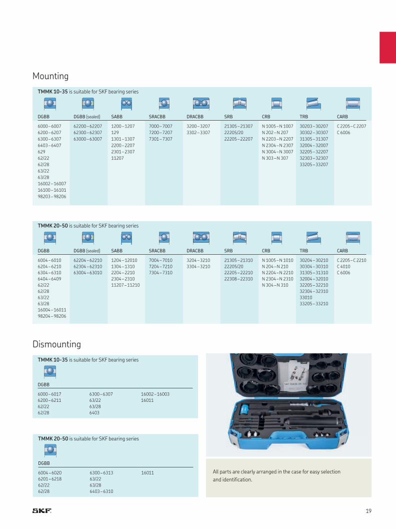
TMMK 10-35 is suitable for SKF bearing series
TMMK 20-50 is suitable for SKF bearing series
TMMK 10-35 is suitable for SKF bearing series
TMMK 20-50 is suitable for SKF bearing series
DGBB DGBB (sealed) SABB SRACBB DRACBB SRB CRB TRB CARB
6000 – 6007 62200 – 62207 1200 – 1207 7000 – 7007 3200 – 3207 21305 – 21307 N 1005 – N 1007 30203 – 30207 C 2205 – C 2207
6200 – 6207 62300 – 62307 129 7200 – 7207 3302 – 3307 22205/20 N 202 – N 207 30302 – 30307 C 6006
6300 – 6307 63000 – 63007 1301 – 1307 7301 – 7307 22205 – 22207 N 2203 – N 2207 31305 – 31307
6403 – 6407 2200 – 2207 N 2304 – N 2307 32004 – 32007
629 2301 – 2307 N 3004 – N 3007 32205 – 32207
62/22 11207 N 303 – N 307 32303 – 32307
62/28 33205 – 33207
63/22
63/28
16002 – 16007
16100 – 16101
98203 – 98206
DGBB DGBB (sealed) SABB SRACBB DRACBB SRB CRB TRB CARB
6004 – 6010 62204 – 62210 1204 – 12010 7004 – 7010 3204 – 3210 21305 – 21310 N 1005 – N 1010 30204 – 30210 C 2205 – C 2210
6204 – 6210 62304 – 62310 1304 – 1310 7204 – 7210 3304 – 3210 22205/20 N 204 – N 210 30304 – 30310 C 4010
6304 – 6310 63004 – 63010 2204 – 2210 7304 – 7310 22205 – 22210 N 2204 – N 2210 31305 – 31310 C 6006
6404 – 6409 2304 – 2310 22308 – 22310 N 2304 – N 2310 32004 – 32010
62/22 11207 – 11210 N 304 – N 310 32205 – 32210
62/28 32304 – 32310
63/22 33010
63/28 33205 – 33210
16004 – 16011
98204 – 98206
DGBB
6000 – 6017 6300 – 6307 16002 – 16003
6200 – 6211 63/22 16011
62/22 63/28
62/28 6403
DGBB
6004 – 6020 6300 – 6313 16011
6201 – 6218 63/22
62/22 63/28
62/28 6403 – 6310
Mounting
Dismounting
All parts are clearly arranged in the case for easy selection
and identification.
24
26
24
22
27, 28
25
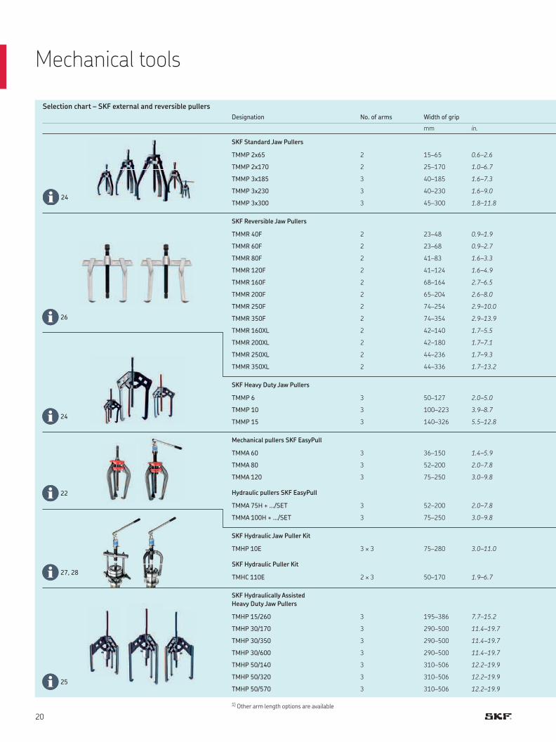
Designation No. of arms Width of grip
mm in.
SKF Standard Jaw Pullers
TMMP 2x65 2 15–65 0.6–2.6
TMMP 2x170 2 25–170 1.0–6.7
TMMP 3x185 3 40–185 1.6–7.3
TMMP 3x230 3 40–230 1.6–9.0
TMMP 3x300 3 45–300 1.8–11.8
SKF Reversible Jaw Pullers
TMMR 40F 2 23–48 0.9–1.9
TMMR 60F 2 23–68 0.9–2.7
TMMR 80F 2 41–83 1.6–3.3
TMMR 120F 2 41–124 1.6–4.9
TMMR 160F 2 68–164 2.7–6.5
TMMR 200F 2 65–204 2.6–8.0
TMMR 250F 2 74–254 2.9–10.0
TMMR 350F 2 74–354 2.9–13.9
TMMR 160XL 2 42–140 1.7–5.5
TMMR 200XL 2 42–180 1.7–7.1
TMMR 250XL 2 44–236 1.7–9.3
TMMR 350XL 2 44–336 1.7–13.2
SKF Heavy Duty Jaw Pullers
TMMP 6 3 50–127 2.0–5.0
TMMP 10 3 100–223 3.9–8.7
TMMP 15 3 140–326 5.5–12.8
Mechanical pullers SKF EasyPull
TMMA 60 3 36–150 1.4–5.9
TMMA 80 3 52–200 2.0–7.8
TMMA 120 3 75–250 3.0–9.8
Hydraulic pullers SKF EasyPull
TMMA 75H + .../SET 3 52–200 2.0–7.8
TMMA 100H + .../SET 3 75–250 3.0–9.8
SKF Hydraulic Jaw Puller Kit
TMHP 10E 3 × 3 75–280 3.0–11.0
SKF Hydraulic Puller Kit
TMHC 110E 2 × 3 50–170 1.9–6.7
SKF Hydraulically Assisted
Heavy Duty Jaw Pullers
TMHP 15/260 3 195–386 7.7–15.2
TMHP 30/170 3 290–500 11.4–19.7
TMHP 30/350 3 290–500 11.4–19.7
TMHP 30/600 3 290–500 11.4–19.7
TMHP 50/140 3 310–506 12.2–19.9
TMHP 50/320 3 310–506 12.2–19.9
TMHP 50/570 3 310–506 12.2–19.9
Selection chart – SKF external and reversible pullers
1) Other arm length options are available
Mechanical tools
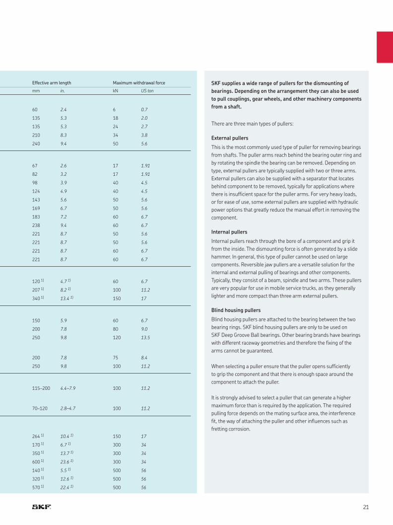
Effective arm length Maximum withdrawal force
mm in. kN US ton
60 2.4 6 0.7
135 5.3 18 2.0
135 5.3 24 2.7
210 8.3 34 3.8
240 9.4 50 5.6
67 2.6 17 1.91
82 3.2 17 1.91
98 3.9 40 4.5
124 4.9 40 4.5
143 5.6 50 5.6
169 6.7 50 5.6
183 7.2 60 6.7
238 9.4 60 6.7
221 8.7 50 5.6
221 8.7 50 5.6
221 8.7 60 6.7
221 8.7 60 6.7
120 1) 4.7 1) 60 6.7
207 1) 8.2 1) 100 11.2
340 1) 13.4 1) 150 17
150 5.9 60 6.7
200 7.8 80 9.0
250 9.8 120 13.5
200 7.8 75 8.4
250 9.8 100 11.2
115–200 4.4–7.9 100 11.2
70–120 2.8–4.7 100 11.2
264 1) 10.4 1) 150 17
170 1) 6.7 1) 300 34
350 1) 13.7 1) 300 34
600 1) 23.6 1) 300 34
140 1) 5.5 1) 500 56
320 1) 12.6 1) 500 56
570 1) 22.4 1) 500 56
SKF supplies a wide range of pullers for the dismounting of
bearings. Depending on the arrangement they can also be used
to pull couplings, gear wheels, and other machinery components
from a shaft.
There are three main types of pullers:
External pullers
This is the most commonly used type of puller for removing bearings
from shafts. The puller arms reach behind the bearing outer ring and
by rotating the spindle the bearing can be removed. Depending on
type, external pullers are typically supplied with two or three arms.
External pullers can also be supplied with a separator that locates
behind component to be removed, typically for applications where
there is insufficient space for the puller arms. For very heavy loads,
or for ease of use, some external pullers are supplied with hydraulic
power options that greatly reduce the manual effort in removing the
component.
Internal pullers
Internal pullers reach through the bore of a component and grip it
from the inside. The dismounting force is often generated by a slide
hammer. In general, this type of puller cannot be used on large
components. Reversible jaw pullers are a versatile solution for the
internal and external pulling of bearings and other components.
Typically, they consist of a beam, spindle and two arms. These pullers
are very popular for use in mobile service trucks, as they generally
lighter and more compact than three arm external pullers.
Blind housing pullers
Blind housing pullers are attached to the bearing between the two
bearing rings. SKF blind housing pullers are only to be used on
SKF Deep Groove Ball bearings. Other bearing brands have bearings
with different raceway geometries and therefore the fixing of the
arms cannot be guaranteed.
When selecting a puller ensure that the puller opens sufficiently
to grip the component and that there is enough space around the
component to attach the puller.
It is strongly advised to select a puller that can generate a higher
maximum force than is required by the application. The required
pulling force depends on the mating surface area, the interference
fit, the way of attaching the puller and other influences such as
fretting corrosion.
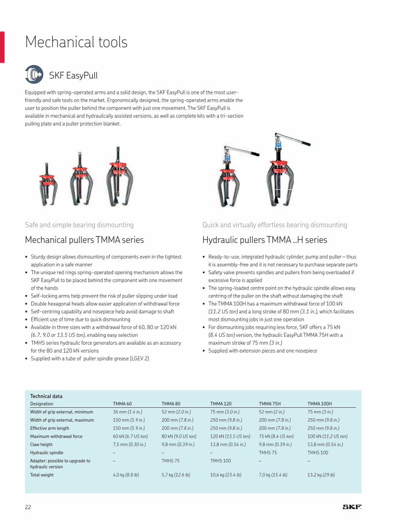
Safe and simple bearing dismounting
Mechanical pullers TMMA series
• Sturdy design allows dismounting of components even in the tightest
application in a safe manner
• The unique red rings spring-operated opening mechanism allows the
SKF EasyPull to be placed behind the component with one movement
of the hands
• Self-locking arms help prevent the risk of puller slipping under load
• Double hexagonal heads allow easier application of withdrawal force
• Self-centring capability and nosepiece help avoid damage to shaft
• Efficient use of time due to quick dismounting
• Available in three sizes with a withdrawal force of 60, 80 or 120 kN
(6.7, 9.0 or 13.5 US ton), enabling easy selection
• TMHS series hydraulic force generators are available as an accessory
for the 80 and 120 kN versions
• Supplied with a tube of puller spindle grease (LGEV 2)
Quick and virtually effortless bearing dismounting
Hydraulic pullers TMMA ..H series
• Ready-to-use, integrated hydraulic cylinder, pump and puller – thus
it is assembly-free and it is not necessary to purchase separate parts
• Safety valve prevents spindles and pullers from being overloaded if
excessive force is applied
• The spring-loaded centre point on the hydraulic spindle allows easy
centring of the puller on the shaft without damaging the shaft
• The TMMA 100H has a maximum withdrawal force of 100 kN
(11.2 US ton) and a long stroke of 80 mm (3.1 in.), which facilitates
most dismounting jobs in just one operation
• For dismounting jobs requiring less force, SKF offers a 75 kN
(8.4 US ton) version, the hydraulic EasyPull TMMA 75H with a
maximum stroke of 75 mm (3 in.)
• Supplied with extension pieces and one nosepiece
Technical data
Designation TMMA 60 TMMA 80 TMMA 120 TMMA 75H TMMA 100H
Width of grip external, minimum 36 mm (1.4 in.) 52 mm (2.0 in.) 75 mm (3.0 in.) 52 mm (2 in.) 75 mm (3 in.)
Width of grip external, maximum 150 mm (5.9 in.) 200 mm (7.8 in.) 250 mm (9.8 in.) 200 mm (7.8 in.) 250 mm (9.8 in.)
Effective arm length 150 mm (5.9 in.) 200 mm (7.8 in.) 250 mm (9.8 in.) 200 mm (7.8 in.) 250 mm (9.8 in.)
Maximum withdrawal force 60 kN (6.7 US ton) 80 kN (9.0 US ton) 120 kN (13.5 US ton) 75 kN (8.4 US ton) 100 kN (11.2 US ton)
Claw height 7,5 mm (0.30 in.) 9,8 mm (0.39 in.) 13,8 mm (0.54 in.) 9,8 mm (0.39 in.) 13,8 mm (0.54 in.)
Hydraulic spindle – – – TMHS 75 TMHS 100
Adapter: possible to upgrade to
hydraulic version
– TMHS 75 TMHS 100 – –
Total weight 4,0 kg (8.8 lb) 5,7 kg (12.6 lb) 10,6 kg (23.4 lb) 7,0 kg (15.4 lb) 13,2 kg (29 lb)
SKF EasyPull
Equipped with spring-operated arms and a solid design, the SKF EasyPull is one of the most user-
friendly and safe tools on the market. Ergonomically designed, the spring-operated arms enable the
user to position the puller behind the component with just one movement. The SKF EasyPull is
available in mechanical and hydraulically assisted versions, as well as complete kits with a tri-section
pulling plate and a puller protection blanket.
Mechanical tools
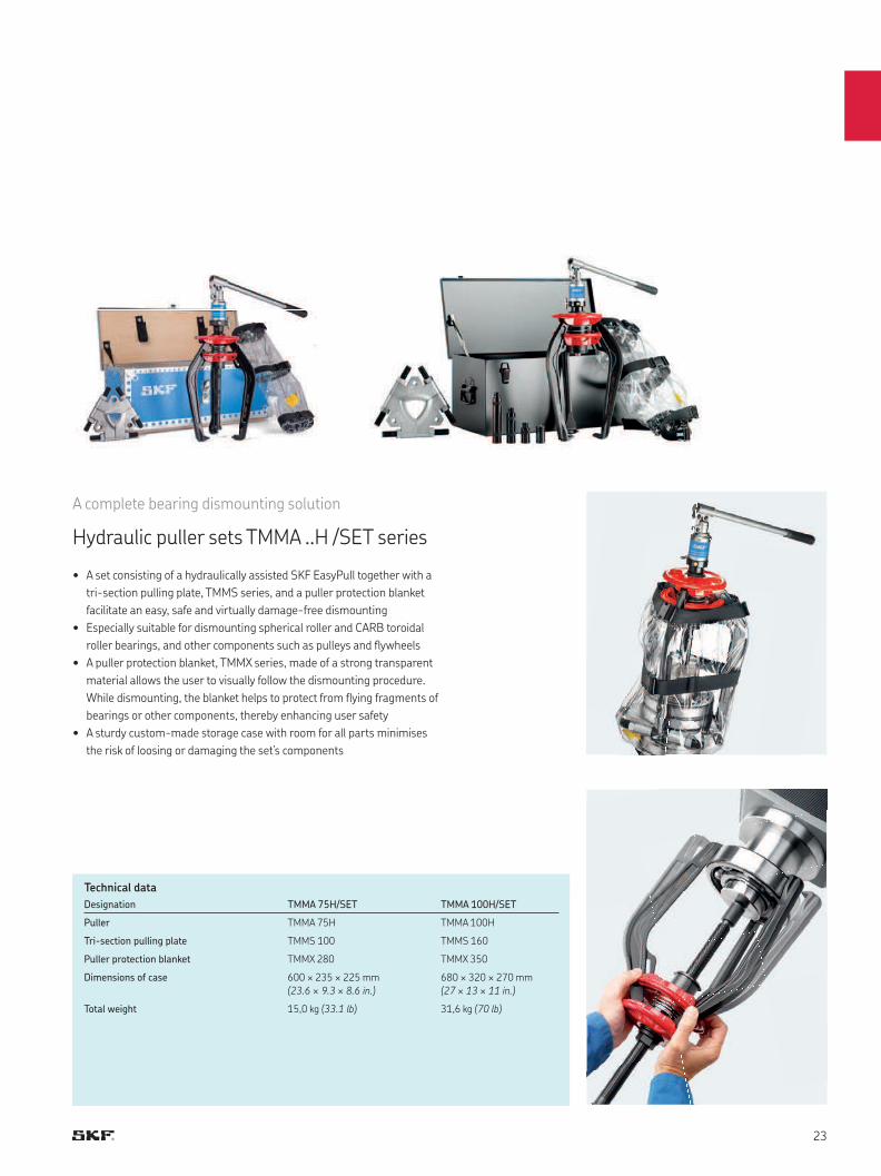
A complete bearing dismounting solution
Hydraulic puller sets TMMA ..H /SET series
Designation TMMA 75H/SET TMMA 100H/SET
Puller TMMA 75H TMMA 100H
Tri-section pulling plate TMMS 100 TMMS 160
Puller protection blanket TMMX 280 TMMX 350
Dimensions of case 600 × 235 × 225 mm
(23.6 × 9.3 × 8.6 in.)
680 × 320 × 270 mm
(27 × 13 × 11 in.)
Total weight 15,0 kg (33.1 lb) 31,6 kg (70 lb)
Technical data
• A set consisting of a hydraulically assisted SKF EasyPull together with a
tri-section pulling plate, TMMS series, and a puller protection blanket
facilitate an easy, safe and virtually damage-free dismounting
• Especially suitable for dismounting spherical roller and CARB toroidal
roller bearings, and other components such as pulleys and flywheels
• A puller protection blanket, TMMX series, made of a strong transparent
material allows the user to visually follow the dismounting procedure.
While dismounting, the blanket helps to protect from flying fragments of
bearings or other components, thereby enhancing user safety
• A sturdy custom-made storage case with room for all parts minimises
the risk of loosing or damaging the set’s components
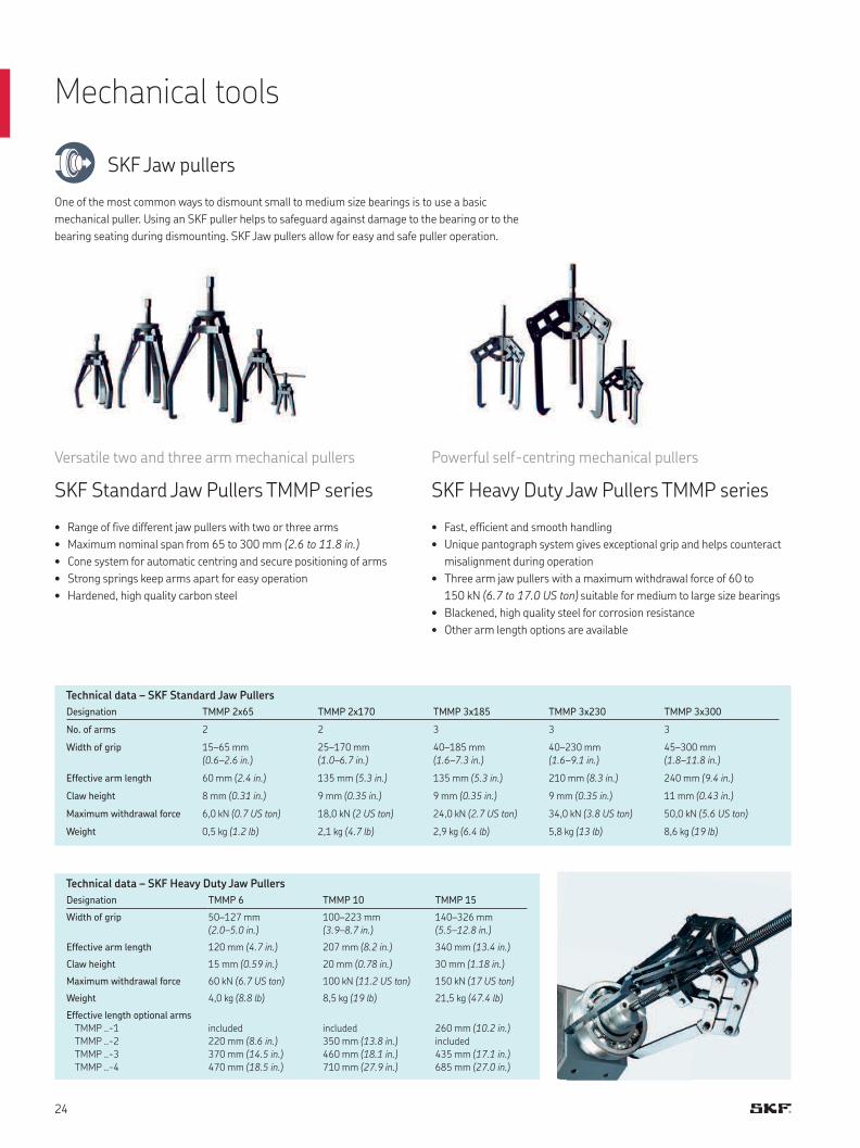
SKF Jaw pullers
One of the most common ways to dismount small to medium size bearings is to use a basic
mechanical puller. Using an SKF puller helps to safeguard against damage to the bearing or to the
bearing seating during dismounting. SKF Jaw pullers allow for easy and safe puller operation.
Versatile two and three arm mechanical pullers
SKF Standard Jaw Pullers TMMP series
• Range of five different jaw pullers with two or three arms
• Maximum nominal span from 65 to 300 mm (2.6 to 11.8 in.)
• Cone system for automatic centring and secure positioning of arms
• Strong springs keep arms apart for easy operation
• Hardened, high quality carbon steel
Powerful self-centring mechanical pullers
SKF Heavy Duty Jaw Pullers TMMP series
• Fast, efficient and smooth handling
• Unique pantograph system gives exceptional grip and helps counteract
misalignment during operation
• Three arm jaw pullers with a maximum withdrawal force of 60 to
150 kN (6.7 to 17.0 US ton) suitable for medium to large size bearings
• Blackened, high quality steel for corrosion resistance
• Other arm length options are available
Designation TMMP 2x65 TMMP 2x170 TMMP 3x185 TMMP 3x230 TMMP 3x300
No. of arms 2 2 3 3 3
Width of grip 15–65 mm
(0.6–2.6 in.)
25–170 mm
(1.0–6.7 in.)
40–185 mm
(1.6–7.3 in.)
40–230 mm
(1.6–9.1 in.)
45–300 mm
(1.8–11.8 in.)
Effective arm length 60 mm (2.4 in.) 135 mm (5.3 in.) 135 mm (5.3 in.) 210 mm (8.3 in.) 240 mm (9.4 in.)
Claw height 8 mm (0.31 in.) 9 mm (0.35 in.) 9 mm (0.35 in.) 9 mm (0.35 in.) 11 mm (0.43 in.)
Maximum withdrawal force 6,0 kN (0.7 US ton) 18,0 kN (2 US ton) 24,0 kN (2.7 US ton) 34,0 kN (3.8 US ton) 50,0 kN (5.6 US ton)
Weight 0,5 kg (1.2 lb) 2,1 kg (4.7 lb) 2,9 kg (6.4 lb) 5,8 kg (13 lb) 8,6 kg (19 lb)
Designation TMMP 6 TMMP 10 TMMP 15
Width of grip 50–127 mm
(2.0–5.0 in.)
100–223 mm
(3.9–8.7 in.)
140–326 mm
(5.5–12.8 in.)
Effective arm length 120 mm (4.7 in.) 207 mm (8.2 in.) 340 mm (13.4 in.)
Claw height 15 mm (0.59 in.) 20 mm (0.78 in.) 30 mm (1.18 in.)
Maximum withdrawal force 60 kN (6.7 US ton) 100 kN (11.2 US ton) 150 kN (17 US ton)
Weight 4,0 kg (8.8 lb) 8,5 kg (19 lb) 21,5 kg (47.4 lb)
Effective length optional arms
TMMP ..-1
TMMP ..-2
TMMP ..-3
TMMP ..-4
included
220 mm (8.6 in.)
370 mm (14.5 in.)
470 mm (18.5 in.)
included
350 mm (13.8 in.)
460 mm (18.1 in.)
710 mm (27.9 in.)
260 mm (10.2 in.)
included
435 mm (17.1 in.)
685 mm (27.0 in.)
Technical data – SKF Standard Jaw Pullers
Technical data – SKF Heavy Duty Jaw Pullers
Mechanical tools
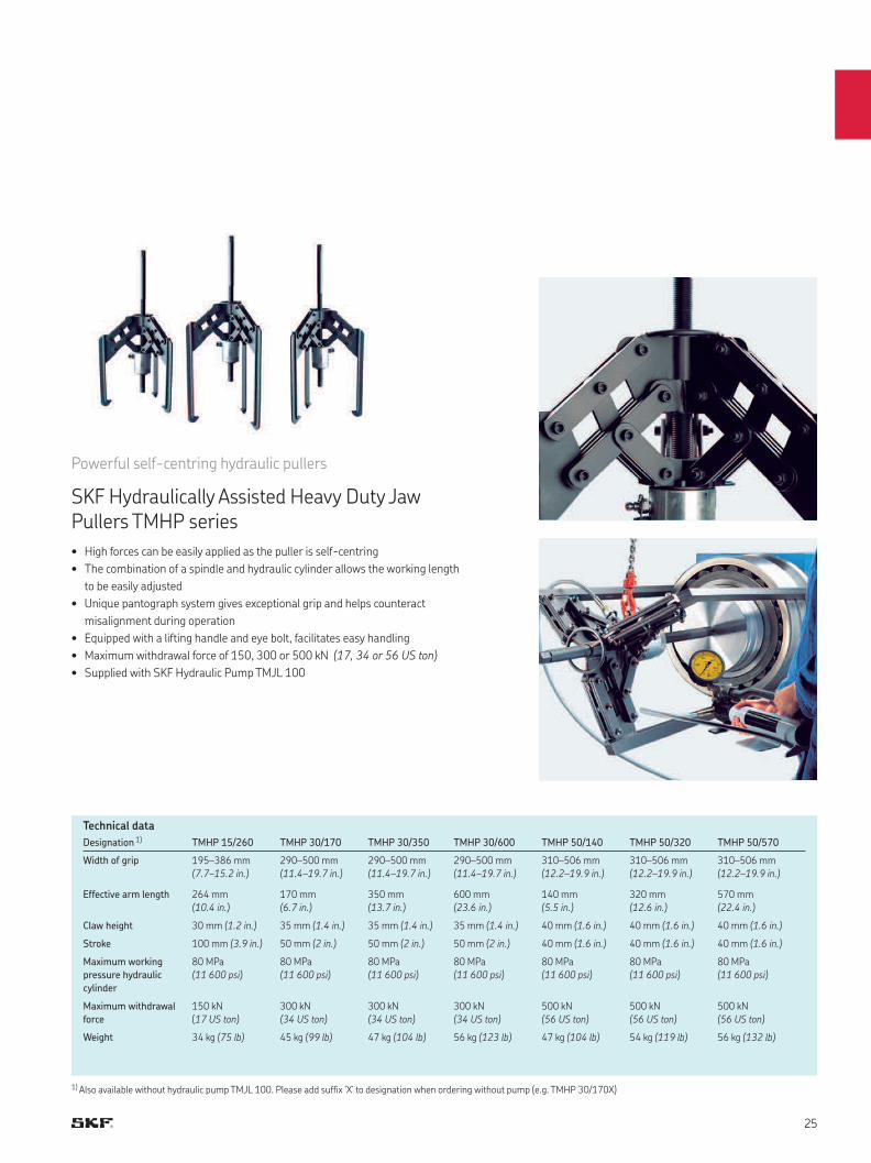
Powerful self-centring hydraulic pullers
SKF Hydraulically Assisted Heavy Duty Jaw Pullers TMHP series
• High forces can be easily applied as the puller is self-centring
• The combination of a spindle and hydraulic cylinder allows the working length
to be easily adjusted
• Unique pantograph system gives exceptional grip and helps counteract
misalignment during operation
• Equipped with a lifting handle and eye bolt, facilitates easy handling
• Maximum withdrawal force of 150, 300 or 500 kN (17, 34 or 56 US ton)
• Supplied with SKF Hydraulic Pump TMJL 100
Designation 1) TMHP 15/260 TMHP 30/170 TMHP 30/350 TMHP 30/600 TMHP 50/140 TMHP 50/320 TMHP 50/570
Width of grip 195–386 mm
(7.7–15.2 in.)
290–500 mm
(11.4–19.7 in.)
290–500 mm
(11.4–19.7 in.)
290–500 mm
(11.4–19.7 in.)
310–506 mm
(12.2–19.9 in.)
310–506 mm
(12.2–19.9 in.)
310–506 mm
(12.2–19.9 in.)
Effective arm length 264 mm
(10.4 in.)
170 mm
(6.7 in.)
350 mm
(13.7 in.)
600 mm
(23.6 in.)
140 mm
(5.5 in.)
320 mm
(12.6 in.)
570 mm
(22.4 in.)
Claw height 30 mm (1.2 in.) 35 mm (1.4 in.) 35 mm (1.4 in.) 35 mm (1.4 in.) 40 mm (1.6 in.) 40 mm (1.6 in.) 40 mm (1.6 in.)
Stroke 100 mm (3.9 in.) 50 mm (2 in.) 50 mm (2 in.) 50 mm (2 in.) 40 mm (1.6 in.) 40 mm (1.6 in.) 40 mm (1.6 in.)
Maximum working
pressure hydraulic
cylinder
80 MPa
(11 600 psi)
80 MPa
(11 600 psi)
80 MPa
(11 600 psi)
80 MPa
(11 600 psi)
80 MPa
(11 600 psi)
80 MPa
(11 600 psi)
80 MPa
(11 600 psi)
Maximum withdrawal
force
150 kN
(17 US ton)
300 kN
(34 US ton)
300 kN
(34 US ton)
300 kN
(34 US ton)
500 kN
(56 US ton)
500 kN
(56 US ton)
500 kN
(56 US ton)
Weight 34 kg (75 lb) 45 kg (99 lb) 47 kg (104 lb) 56 kg (123 lb) 47 kg (104 lb) 54 kg (119 lb) 56 kg (132 lb)
Technical data
1) Also available without hydraulic pump TMJL 100. Please add suffix ‘X’ to designation when ordering without pump (e.g. TMHP 30/170X)
D
L
D
L
d
L
d
L
TMMR.. XL
with 2 optional
extension pieces
Designation Width of
grip external
pull (D)
Width of
grip internal
pull (d)
Effective
arm length
(L)
Maximum
withdrawal
force
mm in. mm in. mm in. kN US ton
TMMR 40F 23–48 0.9–1.9 59–67 2.3–2.6 67 2.6 17 1.9
TMMR 60F 23–68 0.9–2.7 62–87 2.4–3.4 82 3.2 17 1.9
TMMR 80F 41–83 1.6–3.3 95–97 3.7–3.8 98 3.9 40 4.5
TMMR 120F 41–124 1.6–4.9 95–139 3.7–5.5 124 4.9 40 4.5
TMMR 160F 68–164 2.7–6.5 114–163 4.5–6.4 143 5.6 50 5.6
TMMR 200F 65–204 2.6–8.0 114–204 4.5–8.0 169 6.7 50 5.6
TMMR 250F 74–254 2.9–10.0 132–254 5.2–9.9 183 7.2 60 6.7
TMMR 350F 74–354 2.9–13.9 135–354 5.3–13.8 238 9.4 60 6.7
TMMR 160XL 42–140 1.7–5.5 121–188 4.8–7.4 221 8.7 50 5.6
TMMR 200XL 42–180 1.7–7.1 121–228 4.8–9.0 221 8.7 50 5.6
TMMR 250XL 44–236 1.7–9.3 123–284 4.8–11.2 221 8.7 60 6.7
TMMR 350XL 44–336 1.7–13.2 123–384 4.8–15.1 221 8.7 60 6.7
External pull Internal pull
Technical data
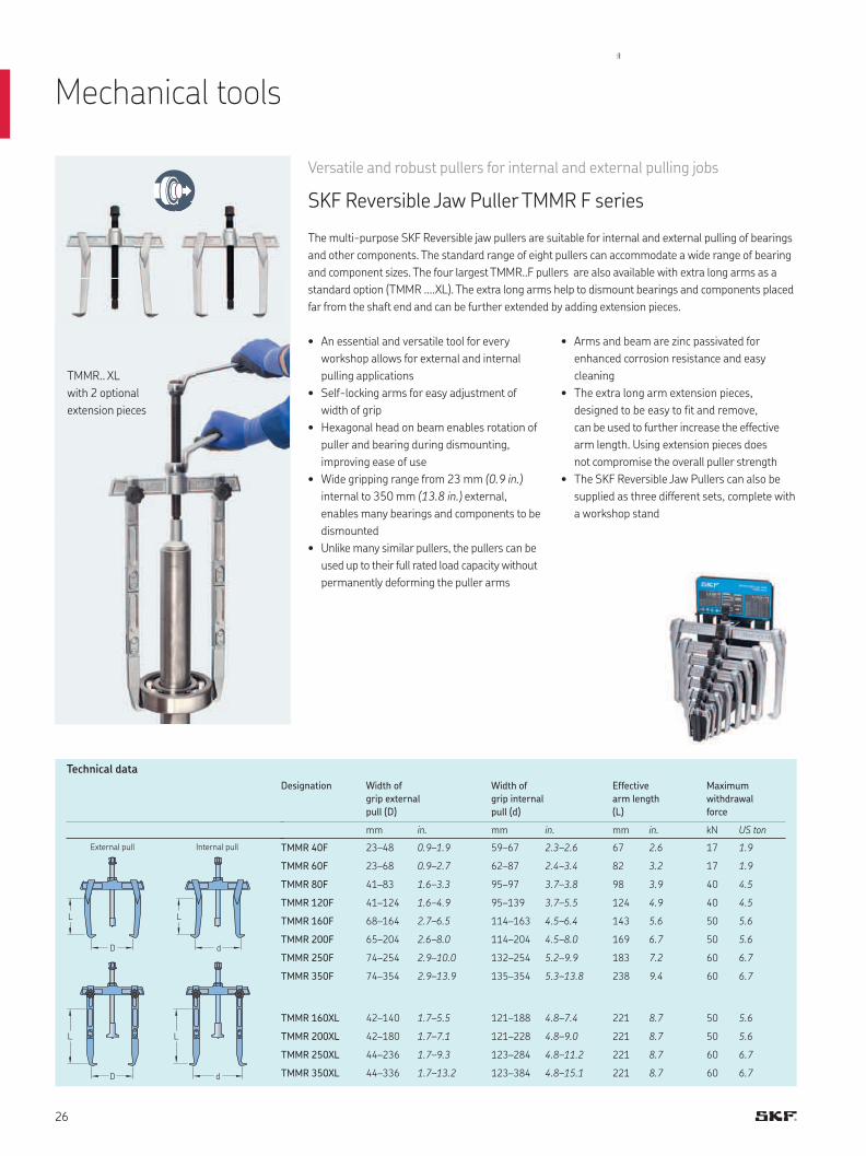
Versatile and robust pullers for internal and external pulling jobs
SKF Reversible Jaw Puller TMMR F series
The multi-purpose SKF Reversible jaw pullers are suitable for internal and external pulling of bearings
and other components. The standard range of eight pullers can accommodate a wide range of bearing
and component sizes. The four largest TMMR..F pullers are also available with extra long arms as a
standard option (TMMR ….XL). The extra long arms help to dismount bearings and components placed
far from the shaft end and can be further extended by adding extension pieces.
• An essential and versatile tool for every
workshop allows for external and internal
pulling applications
• Self-locking arms for easy adjustment of
width of grip
• Hexagonal head on beam enables rotation of
puller and bearing during dismounting,
improving ease of use
• Wide gripping range from 23 mm (0.9 in.)
internal to 350 mm (13.8 in.) external,
enables many bearings and components to be
dismounted
• Unlike many similar pullers, the pullers can be
used up to their full rated load capacity without
permanently deforming the puller arms
• Arms and beam are zinc passivated for
enhanced corrosion resistance and easy
cleaning
• The extra long arm extension pieces,
designed to be easy to fit and remove,
can be used to further increase the effective
arm length. Using extension pieces does
not compromise the overall puller strength
• The SKF Reversible Jaw Pullers can also be
supplied as three different sets, complete with
a workshop stand
Mechanical tools
TMMR 16/35XL-5
TMMR 25/35XL-1
TMMR 16/20XL-1TMMR.. F
TMMR 16/35XL-4
Technical data
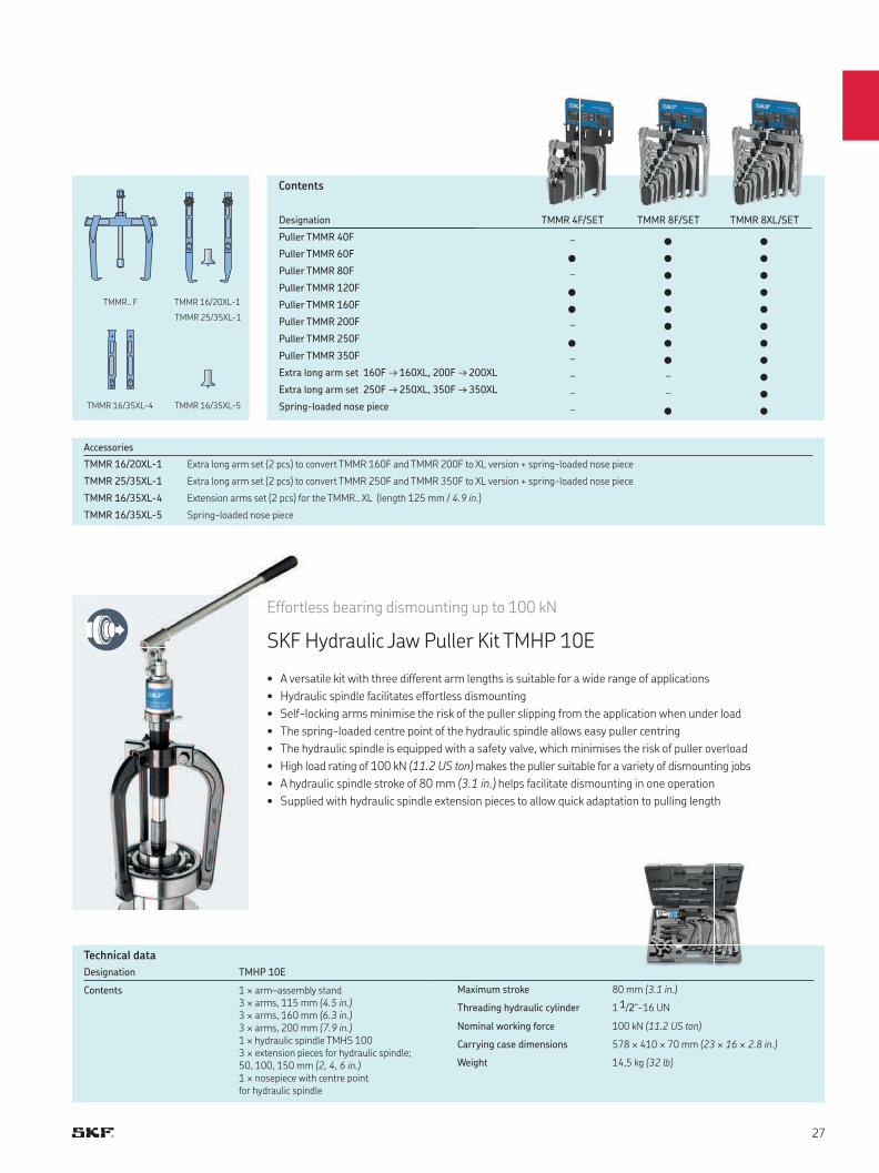
Designation TMHP 10E
Contents 1 × arm–assembly stand3 × arms, 115 mm (4.5 in.)3 × arms, 160 mm (6.3 in.)3 × arms, 200 mm (7.9 in.)1 × hydraulic spindle TMHS 1003 × extension pieces for hydraulic spindle; 50, 100, 150 mm (2, 4, 6 in.)1 × nosepiece with centre point for hydraulic spindle
Maximum stroke 80 mm (3.1 in.)
Threading hydraulic cylinder 1 1/2"-16 UN
Nominal working force 100 kN (11.2 US ton)
Carrying case dimensions 578 × 410 × 70 mm (23 × 16 × 2.8 in.)
Weight 14,5 kg (32 lb)
• A versatile kit with three different arm lengths is suitable for a wide range of applications
• Hydraulic spindle facilitates effortless dismounting
• Self-locking arms minimise the risk of the puller slipping from the application when under load
• The spring-loaded centre point of the hydraulic spindle allows easy puller centring
• The hydraulic spindle is equipped with a safety valve, which minimises the risk of puller overload
• High load rating of 100 kN (11.2 US ton) makes the puller suitable for a variety of dismounting jobs
• A hydraulic spindle stroke of 80 mm (3.1 in.) helps facilitate dismounting in one operation
• Supplied with hydraulic spindle extension pieces to allow quick adaptation to pulling length
Effortless bearing dismounting up to 100 kN
SKF Hydraulic Jaw Puller Kit TMHP 10E
Accessories
TMMR 16/20XL-1 Extra long arm set (2 pcs) to convert TMMR 160F and TMMR 200F to XL version + spring-loaded nose piece
TMMR 25/35XL-1 Extra long arm set (2 pcs) to convert TMMR 250F and TMMR 350F to XL version + spring-loaded nose piece
TMMR 16/35XL-4 Extension arms set (2 pcs) for the TMMR.. XL (length 125 mm / 4.9 in.)
TMMR 16/35XL-5 Spring-loaded nose piece
Designation TMMR 4F/SET TMMR 8F/SET TMMR 8XL/SET
Puller TMMR 40F – • •Puller TMMR 60F • • •Puller TMMR 80F – • •Puller TMMR 120F • • •Puller TMMR 160F • • •Puller TMMR 200F – • •Puller TMMR 250F • • •Puller TMMR 350F – • •Extra long arm set 160F → 160XL, 200F → 200XL – – •Extra long arm set 250F → 250XL, 350F → 350XL – – •Spring-loaded nose piece – • •
Contents
Designation Shaft diameter Maximum bearing outer diameter Maximum reach
mm in. mm in. mm in.
TMBS 50E 7–50 0.3–1.9 85 3.3 110 4.3
TMBS 100E 20–100 0.8–3.9 160 6.3 120–816 4.7–32.1
TMBS 150E 35–150 1.4–5.9 215 8.5 120–816 4.7–32.1
TMHC 110E 20–100 0.8–3.9 160 6.3 120–245 4.7–9.6
Selection chart
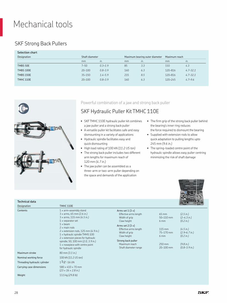
Powerful combination of a jaw and strong back puller
SKF Hydraulic Puller Kit TMHC 110E
SKF Strong Back Pullers
• SKF TMHC 110E hydraulic puller kit combines
a jaw puller and a strong back puller
• A versatile puller kit facilitates safe and easy
dismounting in a variety of applications
• Hydraulic spindle facilitates easy and
quick dismounting
• High load rating of 100 kN (11.2 US ton)
• The strong back puller includes two different
arm lengths for maximum reach of
120 mm (4.7 in.)
• The jaw puller can be assembled as a
three-arm or two-arm puller depending on
the space and demands of the application
• The firm grip of the strong back puller behind
the bearing’s inner ring reduces
the force required to dismount the bearing
• Supplied with extension rods to allow
quick adaptation to pulling lengths upto
245 mm (9.6 in.)
• The spring-loaded centre point of the
hydraulic spindle allows easy puller centring
minimizing the risk of shaft damage
Technical data
Designation TMHC 110E
Contents 1 × arm–assembly stand
3 × arms, 65 mm (2.6 in.)
3 × arms, 115 mm (4.5 in.)
1 × separator set
1 × beam
2 × main rods
2 × extension rods, 125 mm (4.9 in.)
1 × hydraulic spindle TMHS 100
2 × extension pieces for hydraulic
spindle; 50, 100 mm (2.0, 3.9 in.)
1 × nosepiece with centre point
for hydraulic spindle
Maximum stroke 80 mm (3.1 in.)
Nominal working force 100 kN (11.2 US ton)
Threading hydraulic cylinder 1 1/2"-16 UN
Carrying case dimensions 580 × 410 × 70 mm
(23 × 16 × 2.8 in.)
Weight 13,5 kg (29.8 lb)
Arms set 1 (3 ×)
Effective arms length
Width of grip
Claw height
65 mm
50–110 mm
6 mm
(2.5 in.)
(2–4.3 in.)
(0.2 in.)
Arms set 2 (3 ×)
Effective arms length
Width of grip
Claw height
115 mm
75–170 mm
6 mm
(4.5 in.)
(2.9–6.7 in.)
(0.2 in.)
Strong back puller
Maximum reach
Shaft diameter range
250 mm
20–100 mm
(9.8 in.)
(0.8–3.9 in.)
Mechanical tools
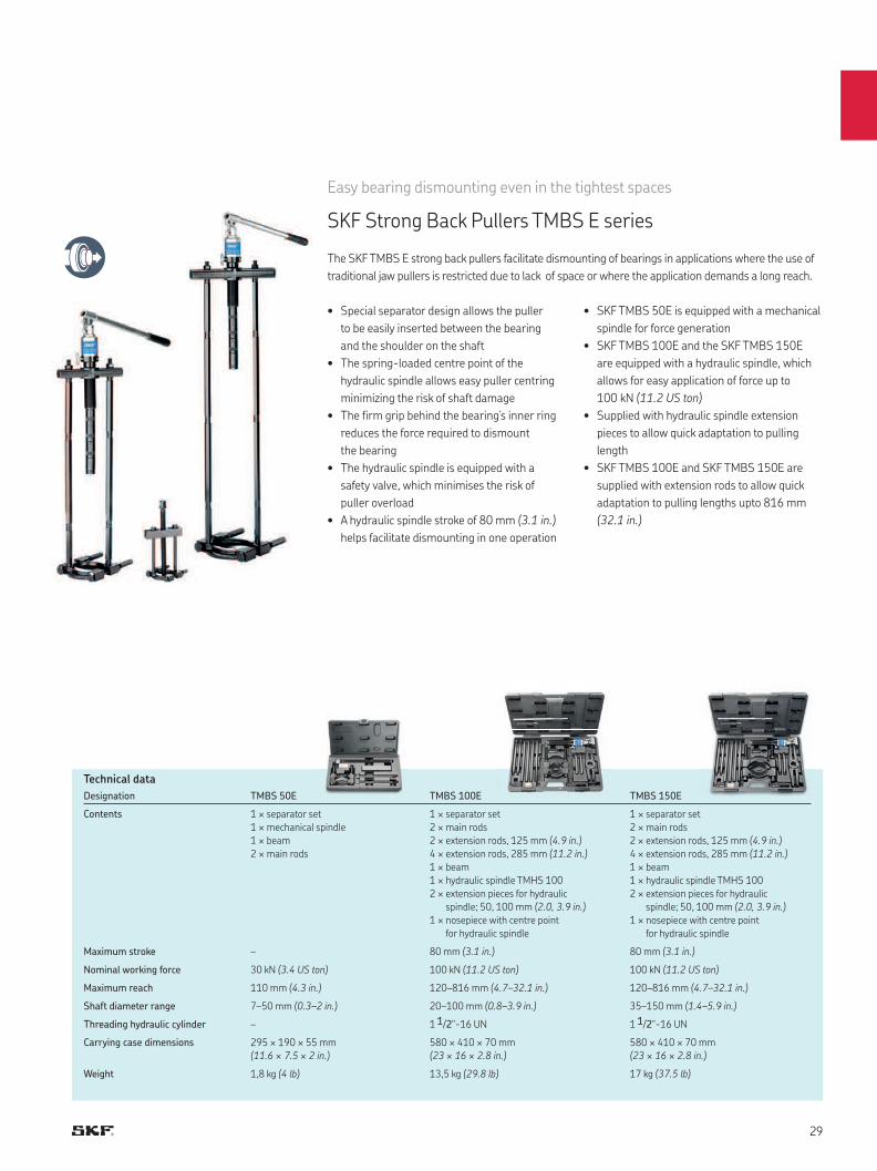
Easy bearing dismounting even in the tightest spaces
SKF Strong Back Pullers TMBS E series
The SKF TMBS E strong back pullers facilitate dismounting of bearings in applications where the use of
traditional jaw pullers is restricted due to lack of space or where the application demands a long reach.
• Special separator design allows the puller
to be easily inserted between the bearing
and the shoulder on the shaft
• The spring-loaded centre point of the
hydraulic spindle allows easy puller centring
minimizing the risk of shaft damage
• The firm grip behind the bearing’s inner ring
reduces the force required to dismount
the bearing
• The hydraulic spindle is equipped with a
safety valve, which minimises the risk of
puller overload
• A hydraulic spindle stroke of 80 mm (3.1 in.)
helps facilitate dismounting in one operation
• SKF TMBS 50E is equipped with a mechanical
spindle for force generation
• SKF TMBS 100E and the SKF TMBS 150E
are equipped with a hydraulic spindle, which
allows for easy application of force up to
100 kN (11.2 US ton)
• Supplied with hydraulic spindle extension
pieces to allow quick adaptation to pulling
length
• SKF TMBS 100E and SKF TMBS 150E are
supplied with extension rods to allow quick
adaptation to pulling lengths upto 816 mm
(32.1 in.)
Technical data
Designation TMBS 50E TMBS 100E TMBS 150E
Contents 1 × separator set
1 × mechanical spindle
1 × beam
2 × main rods
1 × separator set
2 × main rods
2 × extension rods, 125 mm (4.9 in.)
4 × extension rods, 285 mm (11.2 in.)
1 × beam
1 × hydraulic spindle TMHS 100
2 × extension pieces for hydraulic
spindle; 50, 100 mm (2.0, 3.9 in.)
1 × nosepiece with centre point
for hydraulic spindle
1 × separator set
2 × main rods
2 × extension rods, 125 mm (4.9 in.)
4 × extension rods, 285 mm (11.2 in.)
1 × beam
1 × hydraulic spindle TMHS 100
2 × extension pieces for hydraulic
spindle; 50, 100 mm (2.0, 3.9 in.)
1 × nosepiece with centre point
for hydraulic spindle
Maximum stroke – 80 mm (3.1 in.) 80 mm (3.1 in.)
Nominal working force 30 kN (3.4 US ton) 100 kN (11.2 US ton) 100 kN (11.2 US ton)
Maximum reach 110 mm (4.3 in.) 120–816 mm (4.7–32.1 in.) 120–816 mm (4.7–32.1 in.)
Shaft diameter range 7–50 mm (0.3–2 in.) 20–100 mm (0.8–3.9 in.) 35–150 mm (1.4–5.9 in.)
Threading hydraulic cylinder – 1 1/2"-16 UN 1 1/2"-16 UN
Carrying case dimensions 295 × 190 × 55 mm
(11.6 × 7.5 × 2 in.)
580 × 410 × 70 mm
(23 × 16 × 2.8 in.)
580 × 410 × 70 mm
(23 × 16 × 2.8 in.)
Weight 1,8 kg (4 lb) 13,5 kg (29.8 lb) 17 kg (37.5 lb)
SKF Blind housing pullersSelection chart
Designation Bearing bore
diameter (d)
Effective arm
length
TMBP 20E 30–160 mm
(1.2–6.3 in.)
547 mm
(21.5 in.)
TMMD 100 10–100 mm
(0.4–3.9 in.)
135–170 mm
(5.3–6.7 in.)
The SKF Deep Groove Ball Bearing Puller Kit TMMD 100 allows quick and easy dismounting of
SKF Deep Groove Ball Bearings with an interference fit on both rings.
The SKF Blind Housing Puller Kit TMBP 20E is an adapter type puller for dismounting deep groove
ball bearings in blind housings with shaft dimensions between 30 mm and 160 mm (1.18–6.3 in.).
The use of extension rods allows a long reach of up to 547 mm (21.5 in.).
60.. series 62.. series 63.. series 64.. series 16… series
6021–6032 6213–6230 6309–6320 6406–6418 16026–16032
Suitability chart
SKF TMBP 20E is suitable for dismounting the following deep groove ball bearings
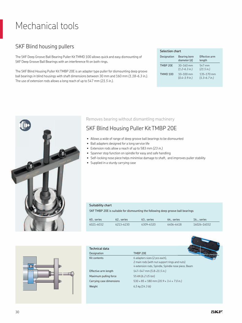
Removes bearing without dismantling machinery
SKF Blind Housing Puller Kit TMBP 20E
• Allows a wide of range of deep groove ball bearings to be dismounted
• Ball adapters designed for a long service life
• Extension rods allow a reach of up to 583 mm (23 in.)
• Spanner stop function on spindle for easy and safe handling
• Self-locking nose piece helps minimise damage to shaft, and improves puller stability
• Supplied in a sturdy carrying case
Mechanical tools
Designation TMBP 20E
Kit contents 6 adapters sizes (2 pcs each),
2 main rods (with nut support rings and nuts)
4 extension rods, Spindle, Spindle nose piece, Beam
Effective arm length 147–547 mm (5.8–21.5 in.)
Maximum pulling force 55 kN (6.2 US ton)
Carrying case dimensions 530 × 85 × 180 mm (20.9 × 3.4 × 7.0 in.)
Weight 6,5 kg (14.3 lb)
Technical data
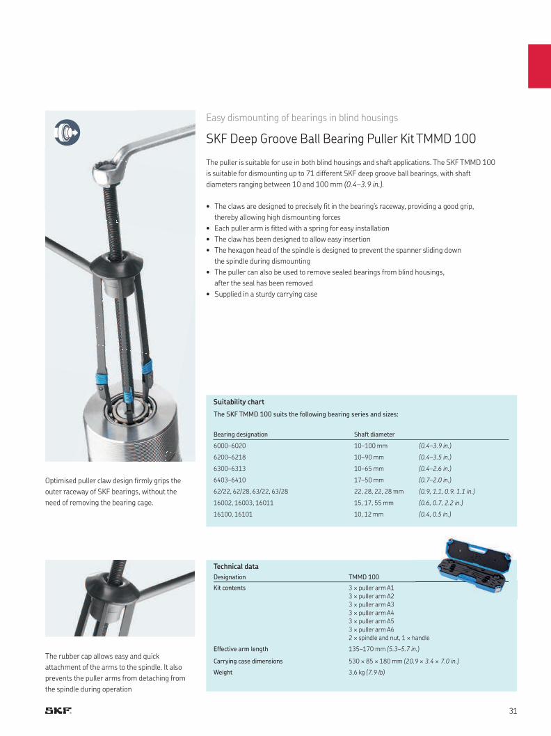
Easy dismounting of bearings in blind housings
SKF Deep Groove Ball Bearing Puller Kit TMMD 100
The puller is suitable for use in both blind housings and shaft applications. The SKF TMMD 100
is suitable for dismounting up to 71 different SKF deep groove ball bearings, with shaft
diameters ranging between 10 and 100 mm (0.4–3.9 in.).
• The claws are designed to precisely fit in the bearing’s raceway, providing a good grip,
thereby allowing high dismounting forces
• Each puller arm is fitted with a spring for easy installation
• The claw has been designed to allow easy insertion
• The hexagon head of the spindle is designed to prevent the spanner sliding down
the spindle during dismounting
• The puller can also be used to remove sealed bearings from blind housings,
after the seal has been removed
• Supplied in a sturdy carrying case
The rubber cap allows easy and quick
attachment of the arms to the spindle. It also
prevents the puller arms from detaching from
the spindle during operation
Optimised puller claw design firmly grips the
outer raceway of SKF bearings, without the
need of removing the bearing cage.
Bearing designation Shaft diameter
6000–6020 10–100 mm (0.4–3.9 in.)
6200–6218 10–90 mm (0.4–3.5 in.)
6300–6313 10–65 mm (0.4–2.6 in.)
6403–6410 17–50 mm (0.7–2.0 in.)
62/22, 62/28, 63/22, 63/28 22, 28, 22, 28 mm (0.9, 1.1, 0.9, 1.1 in.)
16002, 16003, 16011 15, 17, 55 mm (0.6, 0.7, 2.2 in.)
16100, 16101 10, 12 mm (0.4, 0.5 in.)
Suitability chart
The SKF TMMD 100 suits the following bearing series and sizes:
Technical data
Designation TMMD 100
Kit contents 3 × puller arm A1
3 × puller arm A2
3 × puller arm A3
3 × puller arm A4
3 × puller arm A5
3 × puller arm A6
2 × spindle and nut, 1 × handle
Effective arm length 135–170 mm (5.3–5.7 in.)
Carrying case dimensions 530 × 85 × 180 mm (20.9 × 3.4 × 7.0 in.)
Weight 3,6 kg (7.9 lb)
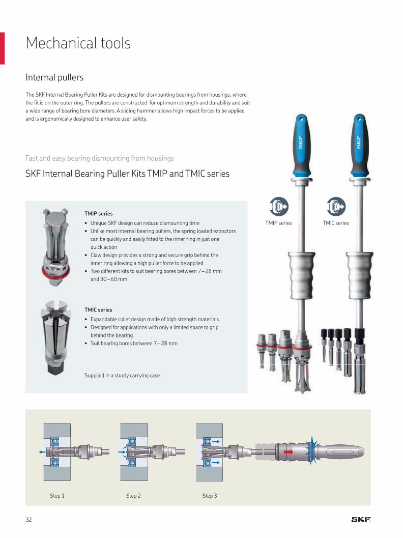
Fast and easy bearing dismounting from housings
SKF Internal Bearing Puller Kits TMIP and TMIC series
TMIP series
• Unique SKF design can reduce dismounting time
• Unlike most internal bearing pullers, the spring loaded extractors
can be quickly and easily fitted to the inner ring in just one
quick action
• Claw design provides a strong and secure grip behind the
inner ring allowing a high puller force to be applied
• Two different kits to suit bearing bores between 7 – 28 mm
and 30 – 60 mm
TMIC series
• Expandable collet design made of high strength materials
• Designed for applications with only a limited space to grip
behind the bearing
• Suit bearing bores between 7 – 28 mm
TMIP series TMIC series
Mechanical tools
Internal pullers
The SKF Internal Bearing Puller Kits are designed for dismounting bearings from housings, where
the fit is on the outer ring. The pullers are constructed for optimum strength and durability and suit
a wide range of bearing bore diameters. A sliding hammer allows high impact forces to be applied
and is ergonomically designed to enhance user safety.
Step 1 Step 2 Step 3
Supplied in a sturdy carrying case
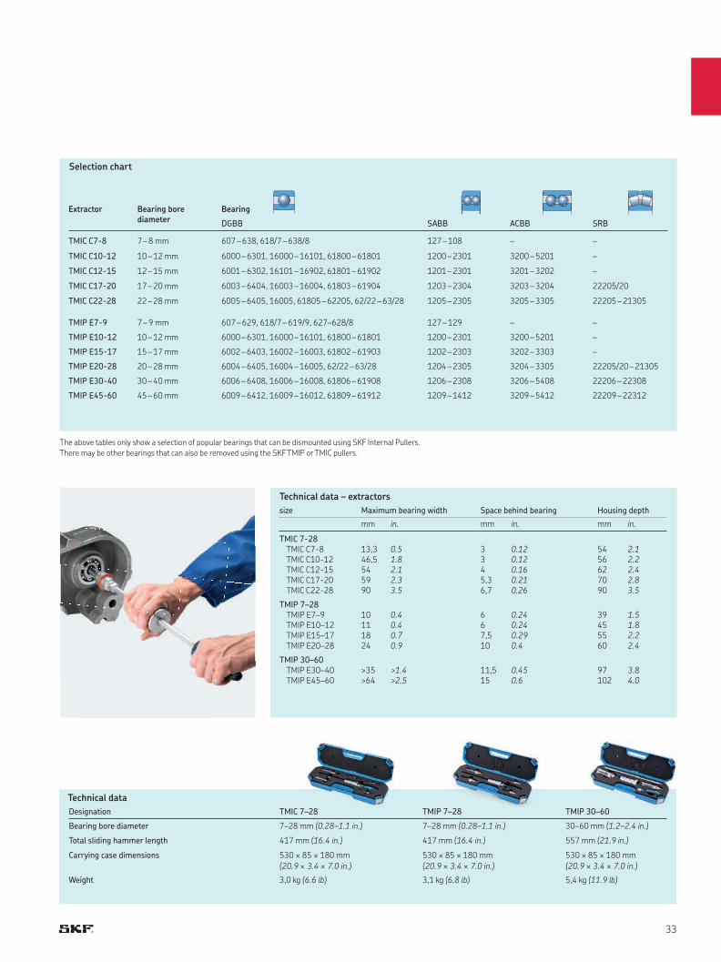
Technical data – extractors
size Maximum bearing width Space behind bearing Housing depth
mm in. mm in. mm in.
TMIC 7-28TMIC C7-8TMIC C10-12TMIC C12-15TMIC C17-20TMIC C22-28
13,346,5545990
0.51.82.12.33.5
3345,36,7
0.120.120.160.210.26
5456627090
2.12.22.42.83.5
TMIP 7–28TMIP E7–9TMIP E10–12TMIP E15–17TMIP E20–28
10111824
0.40.40.70.9
667,510
0.240.240.290.4
39455560
1.51.82.22.4
TMIP 30–60TMIP E30–40TMIP E45–60
>35>64
>1.4>2.5
11,515
0.450.6
97102
3.84.0
Technical data
Designation TMIC 7–28 TMIP 7–28 TMIP 30–60
Bearing bore diameter 7–28 mm (0.28–1.1 in.) 7–28 mm (0.28–1.1 in.) 30–60 mm (1.2–2.4 in.)
Total sliding hammer length 417 mm (16.4 in.) 417 mm (16.4 in.) 557 mm (21.9 in.)
Carrying case dimensions 530 × 85 × 180 mm
(20.9 × 3.4 × 7.0 in.)
530 × 85 × 180 mm
(20.9 × 3.4 × 7.0 in.)
530 × 85 × 180 mm
(20.9 × 3.4 × 7.0 in.)
Weight 3,0 kg (6.6 lb) 3,1 kg (6.8 lb) 5,4 kg (11.9 lb)
Selection chart
The above tables only show a selection of popular bearings that can be dismounted using SKF Internal Pullers.
There may be other bearings that can also be removed using the SKF TMIP or TMIC pullers.
Extractor Bearing bore diameter
Bearing
DGBB SABB ACBB SRB
TMIC C7-8 7–8 mm 607 – 638, 618/7 – 638/8 127 – 108 – –
TMIC C10-12 10–12 mm 6000 – 6301, 16000 – 16101, 61800 – 61801 1200 – 2301 3200 – 5201 –
TMIC C12-15 12–15 mm 6001 – 6302, 16101 – 16902, 61801 – 61902 1201 – 2301 3201 – 3202 –
TMIC C17-20 17–20 mm 6003 – 6404, 16003 – 16004, 61803 – 61904 1203 – 2304 3203 – 3204 22205/20
TMIC C22-28 22–28 mm 6005 – 6405, 16005, 61805 – 62205, 62/22 – 63/28 1205 – 2305 3205 – 3305 22205 – 21305
TMIP E7-9 7–9 mm 607–629, 618/7–619/9, 627–628/8 127–129 – –
TMIP E10-12 10–12 mm 6000–6301, 16000–16101, 61800–61801 1200–2301 3200–5201 –
TMIP E15-17 15–17 mm 6002–6403, 16002–16003, 61802–61903 1202–2303 3202–3303 –
TMIP E20-28 20–28 mm 6004–6405, 16004–16005, 62/22–63/28 1204–2305 3204–3305 22205/20–21305
TMIP E30-40 30–40 mm 6006–6408, 16006–16008, 61806–61908 1206–2308 3206–5408 22206–22308
TMIP E45-60 45–60 mm 6009–6412, 16009–16012, 61809–61912 1209–1412 3209–5412 22209–22312
24
26
22
27, 28
25
30, 31
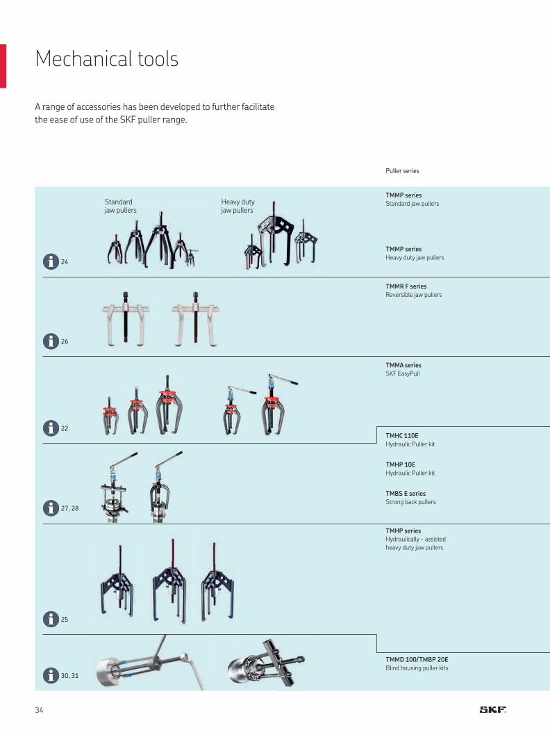
Puller series
TMMP series
Standard jaw pullers
TMMP series
Heavy duty jaw pullers
TMMR F series
Reversible jaw pullers
TMMA series
SKF EasyPull
TMHC 110E
Hydraulic Puller kit
TMHP 10E
Hydraulic Puller kit
TMBS E series
Strong back pullers
TMHP series
Hydraulically - assisted
heavy duty jaw pullers
TMMD 100/TMBP 20E
Blind housing puller kits
A range of accessories has been developed to further facilitate
the ease of use of the SKF puller range.
Standard jaw pullers
Heavy duty jaw pullers
Mechanical tools
38 36 37
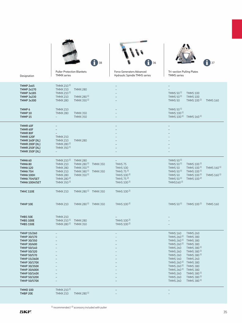
Designation
Puller Protection Blankets
TMMX series
Force Generators Advanced
Hydraulic Spindle TMHS series
Tri-section Pulling Plates
TMMS series
TMMP 2x65
TMMP 2x170
TMMP 3x185
TMMP 3x230
TMMP 3x300
TMMX 210 1)
TMMX 210
TMMX 210 1)
TMMX 210
TMMX 280
TMMX 280
TMMX 280 1)
TMMX 350 1)
–
–
–
–
–
–
–
TMMS 50 1)
TMMS 50 1)
TMMS 50
TMMS 100
TMMS 100
TMMS 100 1) TMMS 160
TMMP 6
TMMP 10
TMMP 15
TMMX 210
TMMX 280
–
TMMX 350
TMMX 350
–
–
–
TMMS 50 1)
TMMS 100 1)
TMMS 100 1) TMMS 160 1)
TMMR 40F
TMMR 60F
TMMR 80F
TMMR 120F
TMMR 160F (XL)
TMMR 200F (XL)
TMMR 250F (XL)
TMMR 350F (XL)
–
–
–
TMMX 210
TMMX 210
TMMX 280 1)
TMMX 350 1)
–
TMMX 280
–
–
–
–
–
–
–
–
–
–
–
–
–
–
–
–
TMMA 60
TMMA 80
TMMA 120
TMMA 75H
TMMA 100H
TMMA 75H/SET
TMMA 100H/SET
TMMX 210 1)
TMMX 210
TMMX 280
TMMX 210
TMMX 280
TMMX 280 2)
TMMX 350 2)
TMMX 280
TMMX 280 1)
TMMX 350 1)
TMMX 380 1)
TMMX 350 1)
TMMX 350
TMMX 350
–
TMHS 75
TMHS 100
TMHS 75 2)
TMHS 100 2)
TMHS 75 2)
TMHS 100 2)
TMMS 50 1)
TMMS 50 1)
TMMS 50
TMMS 50 1)
TMMS 50
TMMS 50 1)
TMMS160 2)
TMMS 100 1)
TMMS 100 1)
TMMS 100 1)
TMMS 100 1)
TMMS 100 2)
TMMS 160 1)
TMMS 160 1)
TMHC 110E TMMX 210 TMMX 280 1) TMMX 350 TMHS 100 2)
TMHP 10E TMMX 210 TMMX 280 1) TMMX 350 TMHS 100 2) TMMS 50 1) TMMS 100 1) TMMS 160
TMBS 50E
TMBS 100E
TMBS 150E
TMMX 210
TMMX 210 1)
TMMX 280 1)TMMX 280
TMMX 350
–
TMHS 100 2)
TMHS 100 2)
–
–
–
TMHP 15/260
TMHP 30/170
TMHP 30/350
TMHP 30/600
TMHP 50/140
TMHP 50/320
TMHP 50/570
TMHP 15/260X
TMHP 30/170X
TMHP 30/350X
TMHP 30/600X
TMHP 50/140X
TMHP 50/320X
TMHP 50/570X
–
–
–
–
–
–
–
–
–
–
–
–
–
–
–
–
–
–
–
–
–
–
–
–
–
–
–
–
TMMS 160
TMMS 260 1)
TMMS 260 1)
TMMS 260 1)
TMMS 260
TMMS 260
TMMS 260
TMMS 160
TMMS 260 1)
TMMS 260 1)
TMMS 260 1)
TMMS 260
TMMS 260
TMMS 260
TMMS 260
TMMS 380
TMMS 380
TMMS 380
TMMS 380 1)
TMMS 380 1)
TMMS 380 1)
TMMS 260
TMMS 380
TMMS 380
TMMS 380
TMMS 380 1)
TMMS 380 1)
TMMS 380 1)
TMMD 100
TMBP 20E
TMMX 210 1)
TMMX 210 TMMX 280 1) –
–
–
–
1) recommended / 2) accessory included with puller
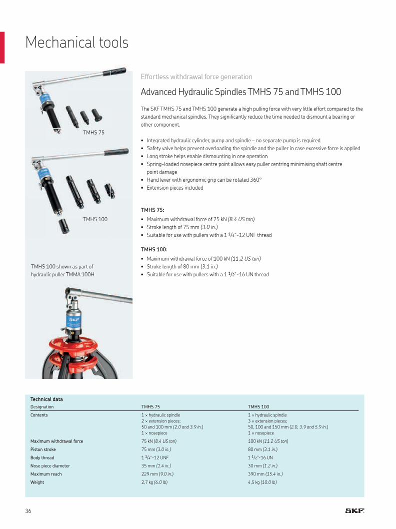
Effortless withdrawal force generation
Advanced Hydraulic Spindles TMHS 75 and TMHS 100
The SKF TMHS 75 and TMHS 100 generate a high pulling force with very little effort compared to the
standard mechanical spindles. They significantly reduce the time needed to dismount a bearing or
other component.
• Integrated hydraulic cylinder, pump and spindle – no separate pump is required
• Safety valve helps prevent overloading the spindle and the puller in case excessive force is applied
• Long stroke helps enable dismounting in one operation
• Spring-loaded nosepiece centre point allows easy puller centring minimising shaft centre
point damage
• Hand lever with ergonomic grip can be rotated 360°
• Extension pieces included
TMHS 75:
• Maximum withdrawal force of 75 kN (8.4 US ton)
• Stroke length of 75 mm (3.0 in.)
• Suitable for use with pullers with a 1 1/4"-12 UNF thread
TMHS 100:
• Maximum withdrawal force of 100 kN (11.2 US ton)
• Stroke length of 80 mm (3.1 in.)
• Suitable for use with pullers with a 1 1/2"-16 UN thread
TMHS 100
TMHS 75
Designation TMHS 75 TMHS 100
Contents 1 × hydraulic spindle
2 × extension pieces;
50 and 100 mm (2.0 and 3.9 in.)
1 × nosepiece
1 × hydraulic spindle
3 × extension pieces;
50, 100 and 150 mm (2.0, 3.9 and 5.9 in.)
1 × nosepiece
Maximum withdrawal force 75 kN (8.4 US ton) 100 kN (11.2 US ton)
Piston stroke 75 mm (3.0 in.) 80 mm (3.1 in.)
Body thread 1 1/4"-12 UNF 1 1/2"-16 UN
Nose piece diameter 35 mm (1.4 in.) 30 mm (1.2 in.)
Maximum reach 229 mm (9.0 in.) 390 mm (15.4 in.)
Weight 2,7 kg (6.0 lb) 4,5 kg (10.0 lb)
Technical data
TMHS 100 shown as part of
hydraulic puller TMMA 100H
Mechanical tools
H
A
dmin dmax
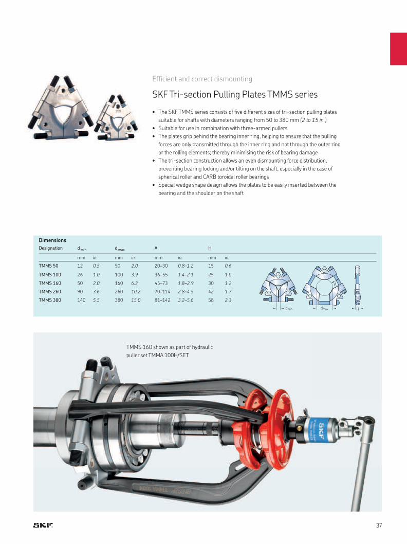
Efficient and correct dismounting
SKF Tri-section Pulling Plates TMMS series
• The SKF TMMS series consists of five different sizes of tri-section pulling plates
suitable for shafts with diameters ranging from 50 to 380 mm (2 to 15 in.)
• Suitable for use in combination with three-armed pullers
• The plates grip behind the bearing inner ring, helping to ensure that the pulling
forces are only transmitted through the inner ring and not through the outer ring
or the rolling elements; thereby minimising the risk of bearing damage
• The tri-section construction allows an even dismounting force distribution,
preventing bearing locking and/or tilting on the shaft, especially in the case of
spherical roller and CARB toroidal roller bearings
• Special wedge shape design allows the plates to be easily inserted between the
bearing and the shoulder on the shaft
TMMS 160 shown as part of hydraulic
puller set TMMA 100H/SET
Dimensions
Designation d min d max A H
mm in. mm in. mm in. mm in.
TMMS 50 12 0.5 50 2.0 20–30 0.8–1.2 15 0.6
TMMS 100 26 1.0 100 3.9 36–55 1.4–2.1 25 1.0
TMMS 160 50 2.0 160 6.3 45–73 1.8–2.9 30 1.2
TMMS 260 90 3.6 260 10.2 70–114 2.8–4.5 42 1.7
TMMS 380 140 5.5 380 15.0 81–142 3.2–5.6 58 2.3
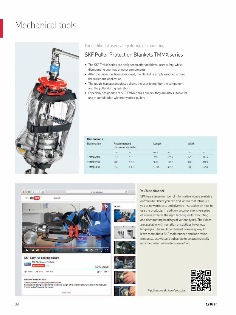
Dimensions
Designation Recommended
maximum diameter
Length Width
mm in. mm in. mm in.
TMMX 210 210 8.3 750 29.5 420 16.5
TMMX 280 280 11.0 970 38.2 480 18.9
TMMX 350 350 13.8 1 200 47.2 580 22.8
For additional user safety during dismounting
SKF Puller Protection Blankets TMMX series
• The SKF TMMX series are designed to offer additional user safety, while
dismounting bearings or other components
• After the puller has been positioned, the blanket is simply wrapped around
the puller and application
• The tough, transparent plastic allows the user to monitor the component
and the puller during operation
• Especially designed to fit SKF TMMA series pullers, they are also suitable for
use in combination with many other pullers
YouTube channel
SKF has a large number of informative videos available
on YouTube. There you can find videos that introduce
you to new products and give you instruction on how to
use the products. In addition, a comprehensive series
of videos explains the right techniques for mounting
and dismounting bearings of various types. The videos
are available with narration or subtitles in various
languages. The YouTube channel is an easy way to
learn more about SKF maintenance and lubrication
products. Just visit and subscribe to be automatically
informed when new videos are added.
http://mapro.skf.com/youtube
Mechanical tools
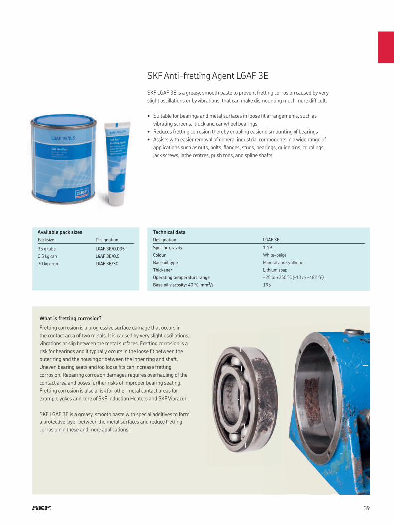
SKF Anti-fretting Agent LGAF 3E
SKF LGAF 3E is a greasy, smooth paste to prevent fretting corrosion caused by very
slight oscillations or by vibrations, that can make dismounting much more difficult.
• Suitable for bearings and metal surfaces in loose fit arrangements, such as
vibrating screens, truck and car wheel bearings
• Reduces fretting corrosion thereby enabling easier dismounting of bearings
• Assists with easier removal of general industrial components in a wide range of
applications such as nuts, bolts, flanges, studs, bearings, guide pins, couplings,
jack screws, lathe centres, push rods, and spline shafts
Designation LGAF 3E
Specific gravity 1,19
Colour White–beige
Base oil type Mineral and synthetic
Thickener Lithium soap
Operating temperature range –25 to +250 °C (–13 to +482 °F)
Base oil viscosity: 40 °C, mm2/s 195
Technical data
What is fretting corrosion?
Fretting corrosion is a progressive surface damage that occurs in
the contact area of two metals. It is caused by very slight oscillations,
vibrations or slip between the metal surfaces. Fretting corrosion is a
risk for bearings and it typically occurs in the loose fit between the
outer ring and the housing or between the inner ring and shaft.
Uneven bearing seats and too loose fits can increase fretting
corrosion. Repairing corrosion damages requires overhauling of the
contact area and poses further risks of improper bearing seating.
Fretting corrosion is also a risk for other metal contact areas for
example yokes and core of SKF Induction Heaters and SKF Vibracon.
SKF LGAF 3E is a greasy, smooth paste with special additives to form
a protective layer between the metal surfaces and reduce fretting
corrosion in these and more applications.
Available pack sizes
Packsize Designation
35 g tube LGAF 3E/0.035
0,5 kg can LGAF 3E/0.5
30 kg drum LGAF 3E/30
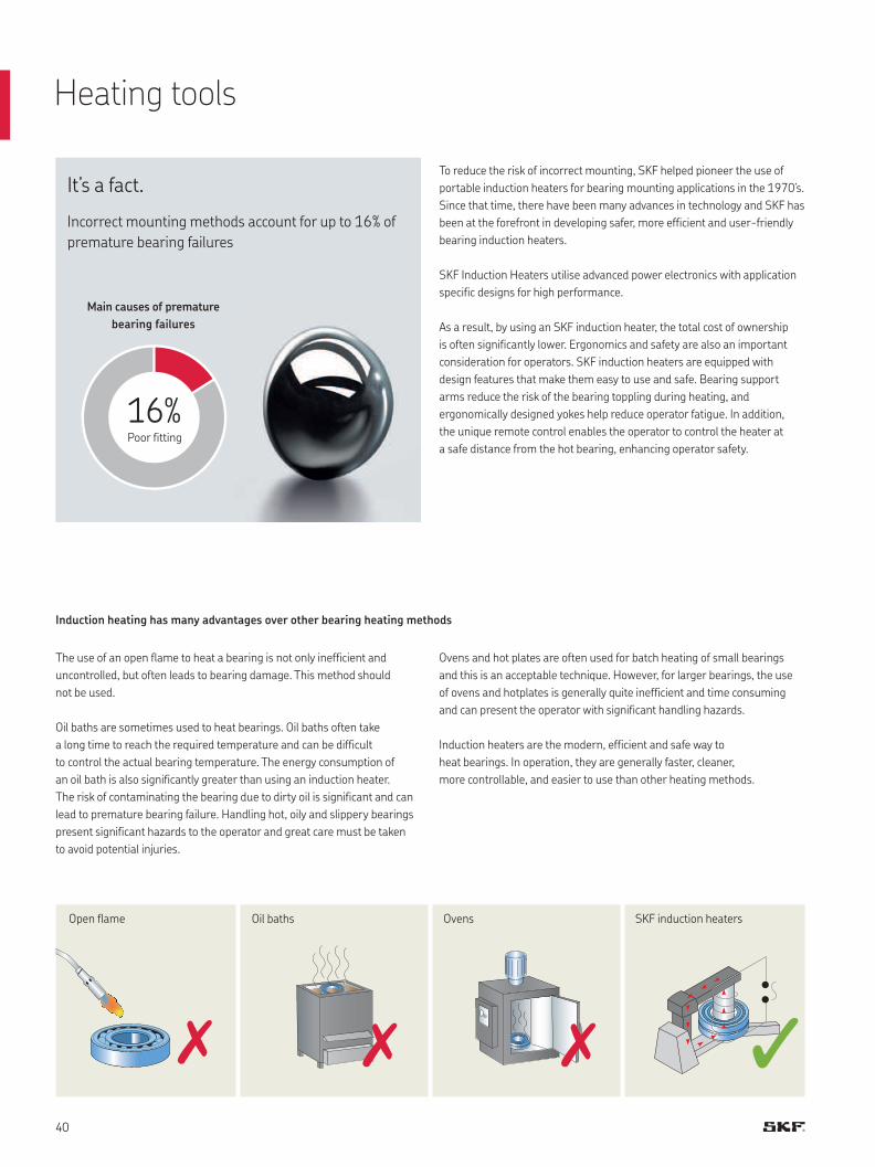
The use of an open flame to heat a bearing is not only inefficient and
uncontrolled, but often leads to bearing damage. This method should
not be used.
Oil baths are sometimes used to heat bearings. Oil baths often take
a long time to reach the required temperature and can be difficult
to control the actual bearing temperature. The energy consumption of
an oil bath is also significantly greater than using an induction heater.
The risk of contaminating the bearing due to dirty oil is significant and can
lead to premature bearing failure. Handling hot, oily and slippery bearings
present significant hazards to the operator and great care must be taken
to avoid potential injuries.
Open flame Oil baths Ovens SKF induction heaters
Heating tools
Ovens and hot plates are often used for batch heating of small bearings
and this is an acceptable technique. However, for larger bearings, the use
of ovens and hotplates is generally quite inefficient and time consuming
and can present the operator with significant handling hazards.
Induction heaters are the modern, efficient and safe way to
heat bearings. In operation, they are generally faster, cleaner,
more controllable, and easier to use than other heating methods.
Induction heating has many advantages over other bearing heating methods
Main causes of premature
bearing failures
It’s a fact.
Incorrect mounting methods account for up to 16% of
premature bearing failures
To reduce the risk of incorrect mounting, SKF helped pioneer the use of
portable induction heaters for bearing mounting applications in the 1970’s.
Since that time, there have been many advances in technology and SKF has
been at the forefront in developing safer, more efficient and user-friendly
bearing induction heaters.
SKF Induction Heaters utilise advanced power electronics with application
specific designs for high performance.
As a result, by using an SKF induction heater, the total cost of ownership
is often significantly lower. Ergonomics and safety are also an important
consideration for operators. SKF induction heaters are equipped with
design features that make them easy to use and safe. Bearing support
arms reduce the risk of the bearing toppling during heating, and
ergonomically designed yokes help reduce operator fatigue. In addition,
the unique remote control enables the operator to control the heater at
a safe distance from the hot bearing, enhancing operator safety.
16%Poor fitting
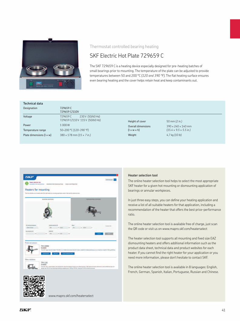
Thermostat controlled bearing heating
SKF Electric Hot Plate 729659 C
The SKF 729659 C is a heating device especially designed for pre-heating batches of
small bearings prior to mounting. The temperature of the plate can be adjusted to provide
temperatures between 50 and 200 °C (120 and 390 °F). The flat heating surface ensures
even bearing heating and the cover helps retain heat and keep contaminants out.
Designation 729659 C
729659 C/110V
Voltage 729659 C 230 V (50/60 Hz)
729659 C/110 V 115 V (50/60 Hz)
Power 1 000 W
Temperature range 50–200 °C (120–390 °F)
Plate dimensions (l × w) 380 × 178 mm (15 × 7 in.)
Height of cover 50 mm (2 in.)
Overall dimensions
(l × w × h)
390 × 240 × 140 mm
(15.4 × 9.5 × 5.5 in.)
Weight 4,7 kg (10 lb)
Technical data
Heater selection tool
The online heater selection tool helps to select the most appropriate
SKF heater for a given hot mounting or dismounting application of
bearings or annular workpieces.
In just three easy steps, you can define your heating application and
receive a list of all suitable heaters for that application, including a
recommendation of the heater that offers the best price-performance
ratio.
The online heater selection tool is available free of charge, just scan
the QR code or visit us on www.mapro.skf.com/heaterselect
The heater selection tool supports all mounting and fixed size EAZ
dismounting heaters and offers additional information such as the
product data sheet, technical data and product websites for each
heater. If you cannot find the right heater for your application or you
need more information, please don’t hesitate to contact SKF.
The online heater selection tool is available in 8 languages: English,
French, German, Spanish, Italian, Portuguese, Russian and Chinese.
www.mapro.skf.com/heaterselect

Heating tools
A portable solution for bearing heating
Portable induction heater TWIM 15
The SKF portable induction heater TWIM 15 is designed to heat up roller bearings that are mounted
with an interference fit onto a shaft. Heating the bearing causes it to expand, which eliminates the need
to use force during installation. Generally, using the TWIM 15 to generate a 90 °C (162 °F) temperature
difference between the bearing and shaft is sufficient to enable installation. In addition, the TWIM 15
can be used to heat other ring-shaped, metallic components, providing flexibility of use.
Utilizing electrical power, the TWIM 15 features glass-fiber, high-
temperature-resistant plastic construction that allows a low temperature
difference between the inner and outer rings of the bearing. This helps to
reduce internal tensions that are generated due to excessive thermal
expansion of the inner ring compared to the outer ring.
The unit has a user-friendly LED control panel that requires no special training
and is simple to understand. The panel is used to regulate temperature and
also indicates that the TWIM 15 is operational.
TWIM 15 advantages:
• Innovative heating of bearings
• Portable, compact and lightweight
• No support yokes required
• Automatic temperature monitoring
• Detects bearing size and heats appropriately
• Two power levels and three power configurations
• User-friendly LED control panel
• Quiet operation
The TWIM 15 portable induction heater package includes:
• Portable induction heater TWIM 15
• Magnetic K-type 400 mm temperature probe TWIM 15-3
• Temperature-resistant gloves TMBA G11
• Instructions for use
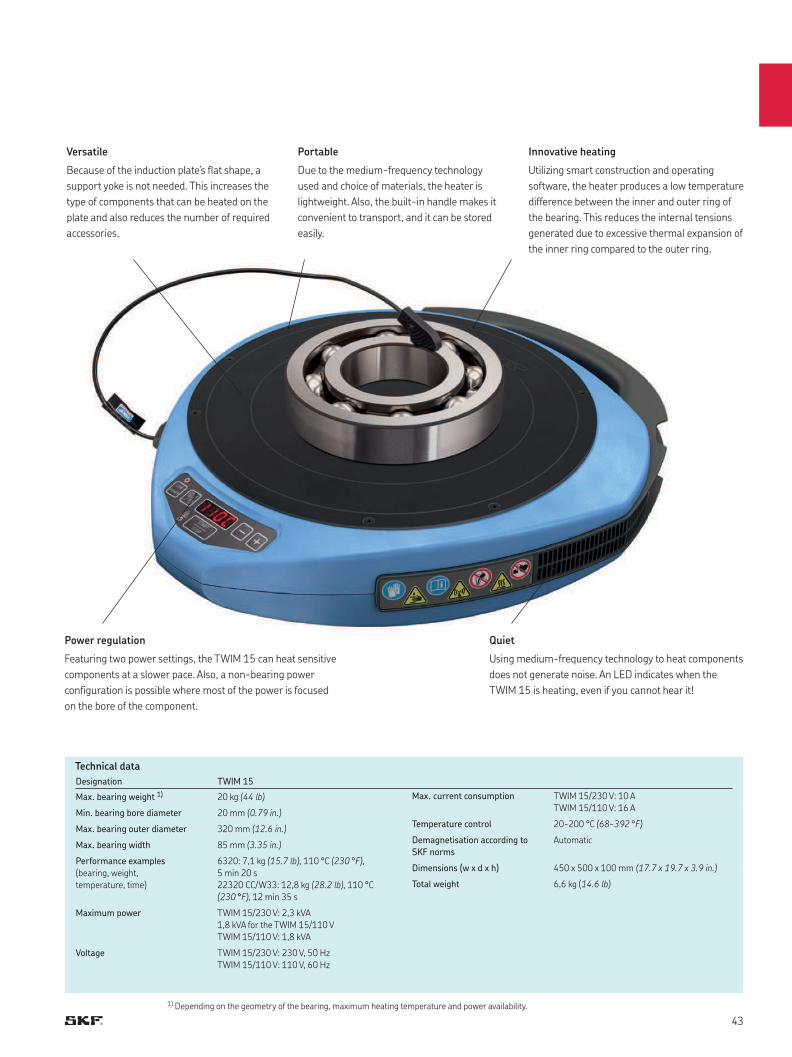
Technical data
Versatile
Because of the induction plate’s flat shape, a
support yoke is not needed. This increases the
type of components that can be heated on the
plate and also reduces the number of required
accessories.
Portable
Due to the medium-frequency technology
used and choice of materials, the heater is
lightweight. Also, the built-in handle makes it
convenient to transport, and it can be stored
easily.
Power regulation
Featuring two power settings, the TWIM 15 can heat sensitive
components at a slower pace. Also, a non-bearing power
configuration is possible where most of the power is focused
on the bore of the component.
Innovative heating
Utilizing smart construction and operating
software, the heater produces a low temperature
difference between the inner and outer ring of
the bearing. This reduces the internal tensions
generated due to excessive thermal expansion of
the inner ring compared to the outer ring.
Quiet
Using medium-frequency technology to heat components
does not generate noise. An LED indicates when the
TWIM 15 is heating, even if you cannot hear it!
Designation TWIM 15
Max. bearing weight 1) 20 kg (44 lb)
Min. bearing bore diameter 20 mm (0.79 in.)
Max. bearing outer diameter 320 mm (12.6 in.)
Max. bearing width 85 mm (3.35 in.)
Performance examples
(bearing, weight,
temperature, time)
6320: 7,1 kg (15.7 lb), 110 °C (230 °F),
5 min 20 s
22320 CC/W33: 12,8 kg (28.2 lb), 110 °C
(230 °F), 12 min 35 s
Maximum power TWIM 15/230 V: 2,3 kVA
1,8 kVA for the TWIM 15/110 V
TWIM 15/110 V: 1,8 kVA
Voltage TWIM 15/230 V: 230 V, 50 Hz
TWIM 15/110 V: 110 V, 60 Hz
Max. current consumption TWIM 15/230 V: 10 A
TWIM 15/110 V: 16 A
Temperature control 20-200 °C (68-392 °F)
Demagnetisation according to
SKF norms
Automatic
Dimensions (w x d x h) 450 x 500 x 100 mm (17.7 x 19.7 x 3.9 in.)
Total weight 6,6 kg (14.6 lb)
1) Depending on the geometry of the bearing, maximum heating temperature and power availability.
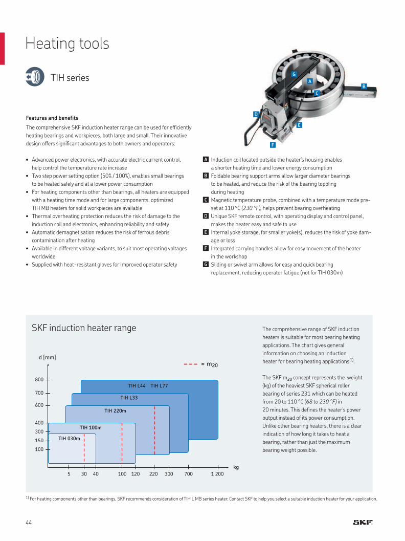
100
150
300
400
600
700
800
5 30 40 120 220100 300 700 1 200
d [mm]
kg
TIH 030m
TIH 100m
TIH 220m
TIH L44
TIH L33
TIH L77
= m20
The comprehensive range of SKF induction
heaters is suitable for most bearing heating
applications. The chart gives general
information on choosing an induction
heater for bearing heating applications 1).
The SKF m20 concept represents the weight
(kg) of the heaviest SKF spherical roller
bearing of series 231 which can be heated
from 20 to 110 °C (68 to 230 °F) in
20 minutes. This defines the heater’s power
output instead of its power consumption.
Unlike other bearing heaters, there is a clear
indication of how long it takes to heat a
bearing, rather than just the maximum
bearing weight possible.
SKF induction heater range
1) For heating components other than bearings, SKF recommends consideration of TIH L MB series heater. Contact SKF to help you select a suitable induction heater for your application.
• Advanced power electronics, with accurate electric current control,
help control the temperature rate increase
• Two step power setting option (50% / 100%), enables small bearings
to be heated safely and at a lower power consumption
• For heating components other than bearings, all heaters are equipped
with a heating time mode and for large components, optimized
TIH MB heaters for solid workpieces are available
• Thermal overheating protection reduces the risk of damage to the
induction coil and electronics, enhancing reliability and safety
• Automatic demagnetisation reduces the risk of ferrous debris
contamination after heating
• Available in different voltage variants, to suit most operating voltages
worldwide
• Supplied with heat-resistant gloves for improved operator safety
Features and benefits
The comprehensive SKF induction heater range can be used for efficiently
heating bearings and workpieces, both large and small. Their innovative
design offers significant advantages to both owners and operators:
Induction coil located outside the heater’s housing enables
a shorter heating time and lower energy consumption
Foldable bearing support arms allow larger diameter bearings
to be heated, and reduce the risk of the bearing toppling
during heating
Magnetic temperature probe, combined with a temperature mode pre-
set at 110 °C (230 °F), helps prevent bearing overheating
Unique SKF remote control, with operating display and control panel,
makes the heater easy and safe to use
Internal yoke storage, for smaller yoke(s), reduces the risk of yoke dam-
age or loss
Integrated carrying handles allow for easy movement of the heater
in the workshop
Sliding or swivel arm allows for easy and quick bearing
replacement, reducing operator fatigue (not for TIH 030m)
Heating tools
TIH series
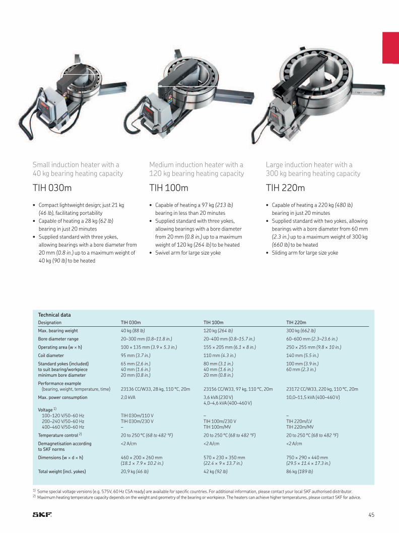
Small induction heater with a 40 kg bearing heating capacity
TIH 030m
• Compact lightweight design; just 21 kg
(46 lb), facilitating portability
• Capable of heating a 28 kg (62 lb)
bearing in just 20 minutes
• Supplied standard with three yokes,
allowing bearings with a bore diameter from
20 mm (0.8 in.) up to a maximum weight of
40 kg (90 lb) to be heated
Medium induction heater with a 120 kg bearing heating capacity
TIH 100m
• Capable of heating a 97 kg (213 lb)
bearing in less than 20 minutes
• Supplied standard with three yokes,
allowing bearings with a bore diameter
from 20 mm (0.8 in.) up to a maximum
weight of 120 kg (264 lb) to be heated
• Swivel arm for large size yoke
Large induction heater with a 300 kg bearing heating capacity
TIH 220m
• Capable of heating a 220 kg (480 lb)
bearing in just 20 minutes
• Supplied standard with two yokes, allowing
bearings with a bore diameter from 60 mm
(2.3 in.) up to a maximum weight of 300 kg
(660 lb) to be heated
• Sliding arm for large size yoke
Designation TIH 030m TIH 100m TIH 220m
Max. bearing weight 40 kg (88 lb) 120 kg (264 lb) 300 kg (662 lb)
Bore diameter range 20–300 mm (0.8–11.8 in.) 20–400 mm (0.8–15.7 in.) 60–600 mm (2.3–23.6 in.)
Operating area (w × h) 100 × 135 mm (3.9 × 5.3 in.) 155 × 205 mm (6.1 × 8 in.) 250 × 255 mm (9.8 × 10 in.)
Coil diameter 95 mm (3.7 in.) 110 mm (4.3 in.) 140 mm (5.5 in.)
Standard yokes (included) to suit bearing/workpiece minimum bore diameter
65 mm (2,6 in.)40 mm (1.6 in.)20 mm (0.8 in.)
80 mm (3.1 in.)40 mm (1.6 in.)20 mm (0.8 in.)
100 mm (3.9 in.)60 mm (2.3 in.)
Performance example (bearing, weight, temperature, time) 23136 CC/W33, 28 kg, 110 °C, 20m 23156 CC/W33, 97 kg, 110 °C, 20m 23172 CC/W33, 220 kg, 110 °C, 20m
Max. power consumption 2,0 kVA 3,6 kVA (230 V)4,0–4,6 kVA (400–460 V)
10,0–11,5 kVA (400–460 V)
Voltage 1)
100–120 V/50–60 Hz200–240 V/50–60 Hz400–460 V/50–60 Hz
TIH 030m/110 VTIH 030m/230 V–
–TIH 100m/230 VTIH 100m/MV
–TIH 220m/LVTIH 220m/MV
Temperature control 2) 20 to 250 °C (68 to 482 °F) 20 to 250 °C (68 to 482 °F) 20 to 250 °C (68 to 482 °F)
Demagnetisation according to SKF norms
<2 A/cm <2 A/cm <2 A/cm
Dimensions (w × d × h) 460 × 200 × 260 mm(18.1 × 7.9 × 10.2 in.)
570 × 230 × 350 mm(22.4 × 9 × 13.7 in.)
750 × 290 × 440 mm(29.5 × 11.4 × 17.3 in.)
Total weight (incl. yokes) 20,9 kg (46 lb) 42 kg (92 lb) 86 kg (189 lb)
Technical data
1) Some special voltage versions (e.g. 575V, 60 Hz CSA ready) are available for specific countries. For additional information, please contact your local SKF authorised distributor.2) Maximum heating temperature capacity depends on the weight and geometry of the bearing or workpiece. The heaters can achieve higher temperatures, please contact SKF for advice.
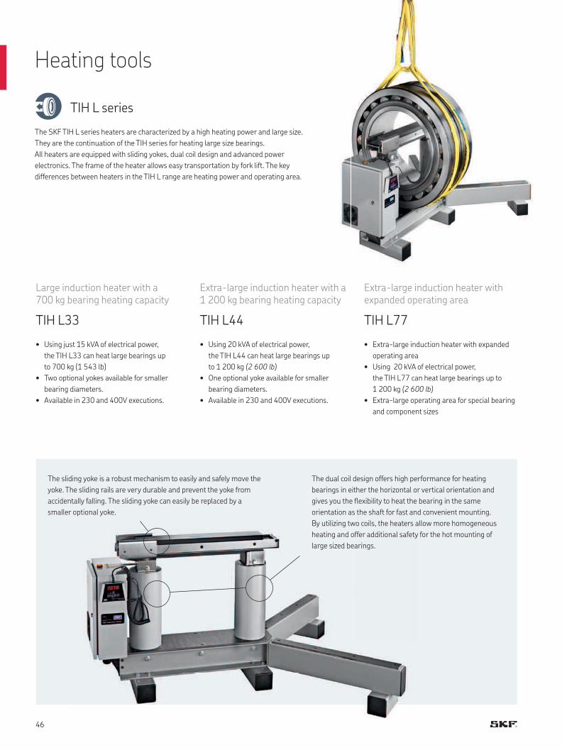
Large induction heater with a700 kg bearing heating capacity
TIH L33
• Using just 15 kVA of electrical power,
the TIH L33 can heat large bearings up
to 700 kg (1 543 lb)
• Two optional yokes available for smaller
bearing diameters.
• Available in 230 and 400V executions.
Heating tools
TIH L series
The dual coil design offers high performance for heating
bearings in either the horizontal or vertical orientation and
gives you the flexibility to heat the bearing in the same
orientation as the shaft for fast and convenient mounting.
By utilizing two coils, the heaters allow more homogeneous
heating and offer additional safety for the hot mounting of
large sized bearings.
The sliding yoke is a robust mechanism to easily and safely move the
yoke. The sliding rails are very durable and prevent the yoke from
accidentally falling. The sliding yoke can easily be replaced by a
smaller optional yoke.
Extra-large induction heater with a 1 200 kg bearing heating capacity
TIH L44
• Using 20 kVA of electrical power,
the TIH L44 can heat large bearings up
to 1 200 kg (2 600 lb)
• One optional yoke available for smaller
bearing diameters.
• Available in 230 and 400V executions.
Extra-large induction heater with expanded operating area
TIH L77
• Extra-large induction heater with expanded
operating area
• Using 20 kVA of electrical power,
the TIH L77 can heat large bearings up to
1 200 kg (2 600 lb)
• Extra-large operating area for special bearing
and component sizes
The SKF TIH L series heaters are characterized by a high heating power and large size.
They are the continuation of the TIH series for heating large size bearings.
All heaters are equipped with sliding yokes, dual coil design and advanced power
electronics. The frame of the heater allows easy transportation by fork lift. The key
differences between heaters in the TIH L range are heating power and operating area.
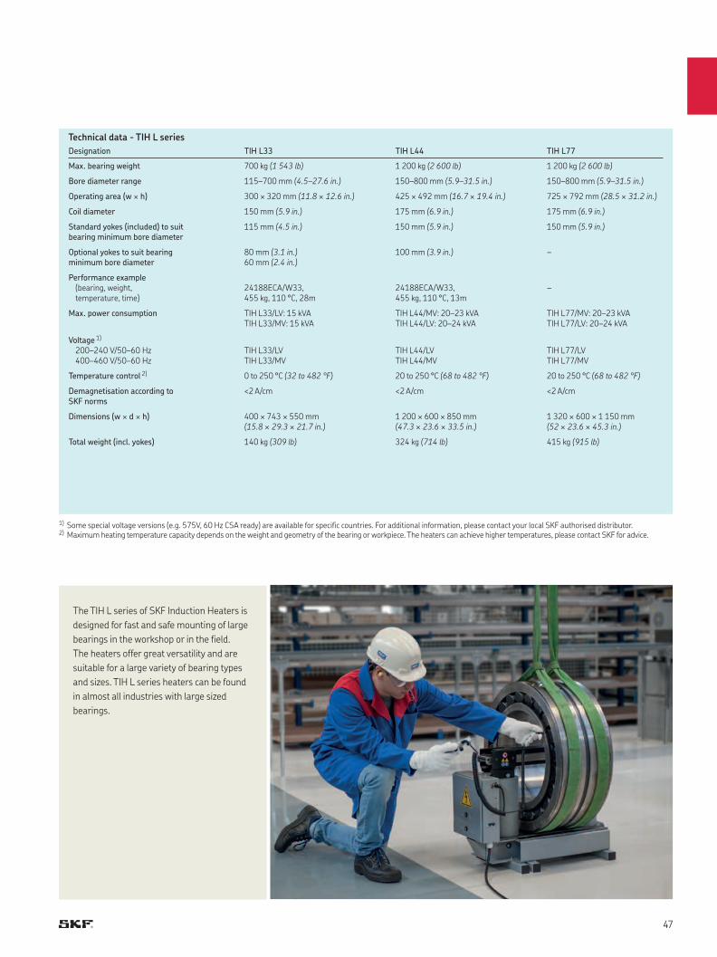
Designation TIH L33 TIH L44 TIH L77
Max. bearing weight 700 kg (1 543 lb) 1 200 kg (2 600 lb) 1 200 kg (2 600 lb)
Bore diameter range 115–700 mm (4.5–27.6 in.) 150–800 mm (5.9–31.5 in.) 150–800 mm (5.9–31.5 in.)
Operating area (w × h) 300 × 320 mm (11.8 × 12.6 in.) 425 × 492 mm (16.7 × 19.4 in.) 725 × 792 mm (28.5 × 31.2 in.)
Coil diameter 150 mm (5.9 in.) 175 mm (6.9 in.) 175 mm (6.9 in.)
Standard yokes (included) to suit bearing minimum bore diameter
115 mm (4.5 in.) 150 mm (5.9 in.) 150 mm (5.9 in.)
Optional yokes to suit bearing minimum bore diameter
80 mm (3.1 in.)60 mm (2.4 in.)
100 mm (3.9 in.) –
Performance example (bearing, weight, temperature, time)
24188ECA/W33, 455 kg, 110 °C, 28m
24188ECA/W33, 455 kg, 110 °C, 13m
–
Max. power consumption TIH L33/LV: 15 kVATIH L33/MV: 15 kVA
TIH L44/MV: 20–23 kVATIH L44/LV: 20–24 kVA
TIH L77/MV: 20–23 kVATIH L77/LV: 20–24 kVA
Voltage 1)
200–240 V/50–60 Hz400–460 V/50–60 Hz
TIH L33/LVTIH L33/MV
TIH L44/LVTIH L44/MV
TIH L77/LVTIH L77/MV
Temperature control 2) 0 to 250 °C (32 to 482 °F) 20 to 250 °C (68 to 482 °F) 20 to 250 °C (68 to 482 °F)
Demagnetisation according to SKF norms
<2 A/cm <2 A/cm <2 A/cm
Dimensions (w × d × h) 400 × 743 × 550 mm (15.8 × 29.3 × 21.7 in.)
1 200 × 600 × 850 mm (47.3 × 23.6 × 33.5 in.)
1 320 × 600 × 1 150 mm (52 × 23.6 × 45.3 in.)
Total weight (incl. yokes) 140 kg (309 lb) 324 kg (714 lb) 415 kg (915 lb)
Technical data - TIH L series
1) Some special voltage versions (e.g. 575V, 60 Hz CSA ready) are available for specific countries. For additional information, please contact your local SKF authorised distributor.2) Maximum heating temperature capacity depends on the weight and geometry of the bearing or workpiece. The heaters can achieve higher temperatures, please contact SKF for advice.
The TIH L series of SKF Induction Heaters is
designed for fast and safe mounting of large
bearings in the workshop or in the field.
The heaters offer great versatility and are
suitable for a large variety of bearing types
and sizes. TIH L series heaters can be found
in almost all industries with large sized
bearings.

Induction heaters for non-bearing applications
TIH L MB series
The TIH L MB series provides the following advantages for quick and effective heating
of solid workpieces:
• Simple and safe operation with remote-control and power level selection
• Superior heating performance for solid workpieces with low energy consumption
• Quick and easy placement of solid components with sliding yoke
• Automatic demagnetization reduces risk of ferrous debris contamination
• Easy to transport using standard forklift
• Available in three voltage variants to suit most operating voltages worldwide
• Available with three different operating areas
The TIH L MB induction heater is equipped with
a remote control panel for operator safety.
Advice: The SKF TIH L MB series heaters
are designed for induction heating of solid,
non-bearing components. For bearing-heating
applications, we recommend the use of
equivalent SKF TIH L series heaters.
The TIH L MB heats non-bearing workpieces up
to 600 kg (1 323 lb), depending on the model.
Heating tools
The SKF TIH L MB series is specially designed to heat solid workpieces, such as rings, sleeves,
gears, couplings, bushings and pulleys, as well as train wheels, tires or similar components.
Featuring one magnetic coil in the center, these powerful and durable heaters localize the
heating in the workpiece bore for superior performance on solid components.
Solid workpiece heaters
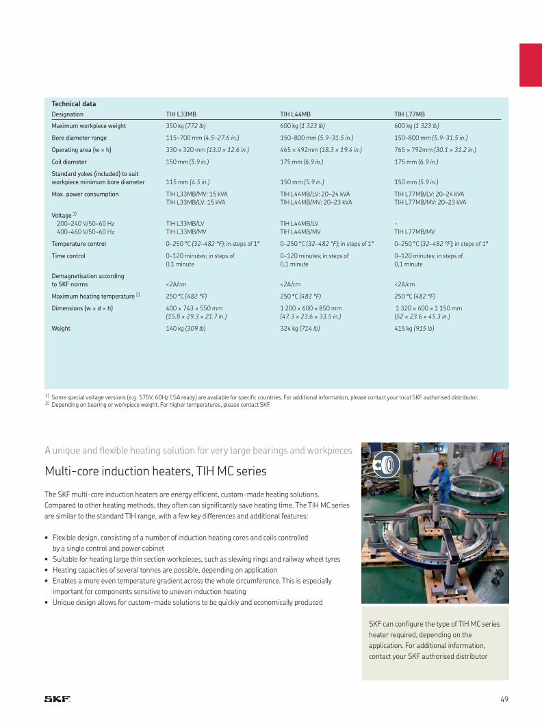
Designation TIH L33MB TIH L44MB TIH L77MB
Maximum workpiece weight 350 kg (772 lb) 600 kg (1 323 lb) 600 kg (1 323 lb)
Bore diameter range 115–700 mm (4.5–27.6 in.) 150–800 mm (5.9–31.5 in.) 150–800 mm (5.9–31.5 in.)
Operating area (w × h) 330 × 320 mm (13.0 × 12.6 in.) 465 × 492mm (18.3 × 19.4 in.) 765 × 792mm (30.1 × 31.2 in.)
Coil diameter 150 mm (5.9 in.) 175 mm (6.9 in.) 175 mm (6.9 in.)
Standard yokes (included) to suit
workpiece minimum bore diameter 115 mm (4.5 in.) 150 mm (5.9 in.) 150 mm (5.9 in.)
Max. power consumption TIH L33MB/MV: 15 kVA
TIH L33MB/LV: 15 kVA
TIH L44MB/LV: 20–24 kVA
TIH L44MB/MV: 20–23 kVA
TIH L77MB/LV: 20–24 kVA
TIH L77MB/MV: 20–23 kVA
Voltage 1)
200–240 V/50–60 Hz
400–460 V/50–60 Hz
TIH L33MB/LV
TIH L33MB/MV
TIH L44MB/LV
TIH L44MB/MV
-
TIH L77MB/MV
Temperature control 0–250 °C (32–482 °F); in steps of 1° 0–250 °C (32–482 °F); in steps of 1° 0–250 °C (32–482 °F); in steps of 1°
Time control 0–120 minutes; in steps of
0,1 minute
0–120 minutes; in steps of
0,1 minute
0–120 minutes; in steps of
0,1 minute
Demagnetisation according
to SKF norms <2A/cm <2A/cm <2A/cm
Maximum heating temperature 2) 250 °C (482 °F) 250 °C (482 °F) 250 °C (482 °F)
Dimensions (w × d × h) 400 × 743 × 550 mm
(15.8 × 29.3 × 21.7 in.)
1 200 × 600 × 850 mm
(47.3 × 23.6 × 33.5 in.)
1 320 × 600 × 1 150 mm
(52 × 23.6 × 45.3 in.)
Weight 140 kg (309 lb) 324 kg (714 lb) 415 kg (915 lb)
Technical data
1) Some special voltage versions (e.g. 575V, 60Hz CSA ready) are available for specific countries. For additional information, please contact your local SKF authorised distributor.2) Depending on bearing or workpiece weight. For higher temperatures, please contact SKF.
The SKF multi-core induction heaters are energy efficient, custom-made heating solutions.
Compared to other heating methods, they often can significantly save heating time. The TIH MC series
are similar to the standard TIH range, with a few key differences and additional features:
• Flexible design, consisting of a number of induction heating cores and coils controlled
by a single control and power cabinet
• Suitable for heating large thin section workpieces, such as slewing rings and railway wheel tyres
• Heating capacities of several tonnes are possible, depending on application
• Enables a more even temperature gradient across the whole circumference. This is especially
important for components sensitive to uneven induction heating
• Unique design allows for custom-made solutions to be quickly and economically produced
A unique and flexible heating solution for very large bearings and workpieces
Multi-core induction heaters, TIH MC series
SKF can configure the type of TIH MC series
heater required, depending on the
application. For additional information,
contact your SKF authorised distributor
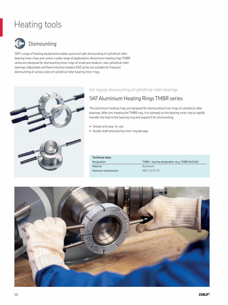
SKF’s range of heating equipment enables quick and safe dismounting of cylindrical roller
bearing inner rings and covers a wide range of applications. Aluminium heating rings TMBR
series are designed for dismounting inner rings of small and medium-size cylindrical roller
bearings. Adjustable and fixed induction heaters EAZ series are suitable for frequent
dismounting of various sizes of cylindrical roller bearing inner rings.
For regular dismounting of cylindrical roller bearings
SKF Aluminium Heating Rings TMBR series
The aluminium heating rings are designed for dismounting inner rings of cylindrical roller
bearings. After pre-heating the TMBR ring, it is clamped on the bearing inner ring to rapidly
transfer the heat to the bearing ring and expand it for dismounting.
• Simple and easy-to-use
• Avoids shaft and bearing inner ring damage
Designation TMBR + bearing designation (e.g. TMBR NU216E)
Material Aluminium
Maximum temperature 300 °C (572 °F)
Technical data
Heating tools
Dismounting
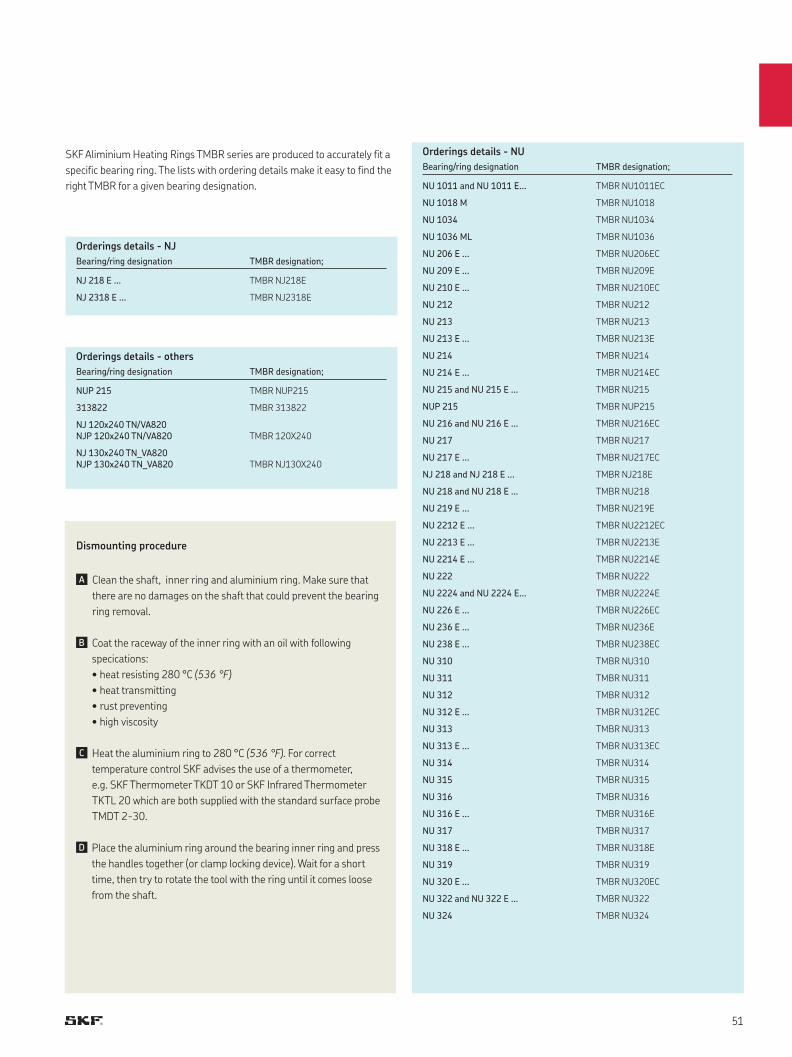
SKF Aliminium Heating Rings TMBR series are produced to accurately fit a
specific bearing ring. The lists with ordering details make it easy to find the
right TMBR for a given bearing designation.
Dismounting procedure
Clean the shaft, inner ring and aluminium ring. Make sure that
there are no damages on the shaft that could prevent the bearing
ring removal.
Coat the raceway of the inner ring with an oil with following
specications:
• heat resisting 280 °C (536 °F)
• heat transmitting
• rust preventing
• high viscosity
Heat the aluminium ring to 280 °C (536 °F). For correct
temperature control SKF advises the use of a thermometer,
e.g. SKF Thermometer TKDT 10 or SKF Infrared Thermometer
TKTL 20 which are both supplied with the standard surface probe
TMDT 2-30.
Place the aluminium ring around the bearing inner ring and press
the handles together (or clamp locking device). Wait for a short
time, then try to rotate the tool with the ring until it comes loose
from the shaft.
Bearing/ring designation TMBR designation;
NJ 218 E ... TMBR NJ218E
NJ 2318 E ... TMBR NJ2318E
Bearing/ring designation TMBR designation;
NUP 215 TMBR NUP215
313822 TMBR 313822
NJ 120x240 TN/VA820NJP 120x240 TN/VA820
TMBR 120X240
NJ 130x240 TN_VA820NJP 130x240 TN_VA820
TMBR NJ130X240
Bearing/ring designation TMBR designation;
NU 1011 and NU 1011 E... TMBR NU1011EC
NU 1018 M TMBR NU1018
NU 1034 TMBR NU1034
NU 1036 ML TMBR NU1036
NU 206 E ... TMBR NU206EC
NU 209 E ... TMBR NU209E
NU 210 E ... TMBR NU210EC
NU 212 TMBR NU212
NU 213 TMBR NU213
NU 213 E ... TMBR NU213E
NU 214 TMBR NU214
NU 214 E ... TMBR NU214EC
NU 215 and NU 215 E ... TMBR NU215
NUP 215 TMBR NUP215
NU 216 and NU 216 E ... TMBR NU216EC
NU 217 TMBR NU217
NU 217 E ... TMBR NU217EC
NJ 218 and NJ 218 E ... TMBR NJ218E
NU 218 and NU 218 E ... TMBR NU218
NU 219 E ... TMBR NU219E
NU 2212 E ... TMBR NU2212EC
NU 2213 E ... TMBR NU2213E
NU 2214 E ... TMBR NU2214E
NU 222 TMBR NU222
NU 2224 and NU 2224 E... TMBR NU2224E
NU 226 E ... TMBR NU226EC
NU 236 E ... TMBR NU236E
NU 238 E ... TMBR NU238EC
NU 310 TMBR NU310
NU 311 TMBR NU311
NU 312 TMBR NU312
NU 312 E ... TMBR NU312EC
NU 313 TMBR NU313
NU 313 E ... TMBR NU313EC
NU 314 TMBR NU314
NU 315 TMBR NU315
NU 316 TMBR NU316
NU 316 E ... TMBR NU316E
NU 317 TMBR NU317
NU 318 E ... TMBR NU318E
NU 319 TMBR NU319
NU 320 E ... TMBR NU320EC
NU 322 and NU 322 E ... TMBR NU322
NU 324 TMBR NU324
Orderings details - NJ
Orderings details - others
Orderings details - NU
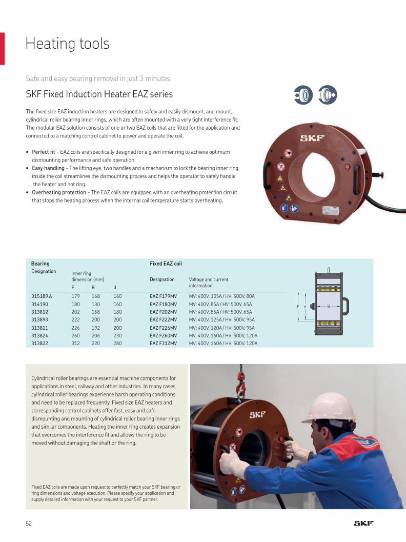
F d B
Cylindrical roller bearings are essential machine components for
applications in steel, railway and other industries. In many cases
cylindrical roller bearings experience harsh operating conditions
and need to be replaced frequently. Fixed size EAZ heaters and
corresponding control cabinets offer fast, easy and safe
dismounting and mounting of cylindrical roller bearing inner rings
and similar components. Heating the inner ring creates expansion
that overcomes the interference fit and allows the ring to be
moved without damaging the shaft or the ring.
Fixed EAZ coils are made upon request to perfectly match your SKF bearing or
ring dimensions and voltage execution. Please specify your application and
supply detailed information with your request to your SKF partner.
Safe and easy bearing removal in just 3 minutes
SKF Fixed Induction Heater EAZ series
The fixed size EAZ induction heaters are designed to safely and easily dismount, and mount,
cylindrical roller bearing inner rings, which are often mounted with a very tight interference fit.
The modular EAZ solution consists of one or two EAZ coils that are fitted for the application and
connected to a matching control cabinet to power and operate the coil.
• Perfect fit - EAZ coils are specifically designed for a given inner ring to achieve optimum
dismounting performance and safe operation.
• Easy handling - The lifting eye, two handles and a mechanism to lock the bearing inner ring
inside the coil streamlines the dismounting process and helps the operator to safely handle
the heater and hot ring.
• Overheating protection - The EAZ coils are equipped with an overheating protection circuit
that stops the heating process when the internal coil temperature starts overheating.
Bearing Fixed EAZ coil
Designation Inner ring dimension (mm) Designation Voltage and current
information F B d
315189 A 179 168 160 EAZ F179MV MV: 400V, 105A / HV: 500V, 80A
314190 180 130 160 EAZ F180MV MV: 400V, 85A / HV: 500V, 65A
313812 202 168 180 EAZ F202MV MV: 400V, 85A / HV: 500V, 65A
313893 222 200 200 EAZ F222MV MV: 400V, 125A / HV: 500V, 95A
313811 226 192 200 EAZ F226MV MV: 400V, 120A / HV: 500V, 95A
313824 260 206 230 EAZ F260MV MV: 400V, 160A / HV: 500V, 120A
313822 312 220 280 EAZ F312MV MV: 400V, 160A / HV: 500V, 120A
Heating tools
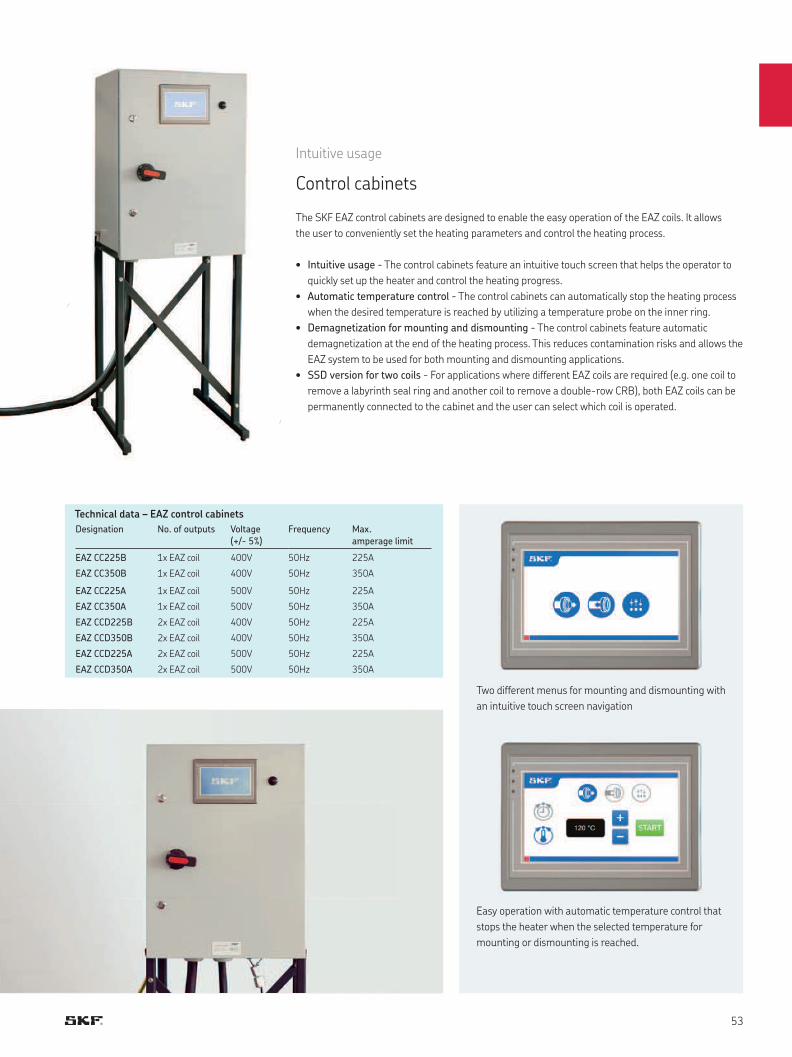
Intuitive usage
Control cabinets
The SKF EAZ control cabinets are designed to enable the easy operation of the EAZ coils. It allows
the user to conveniently set the heating parameters and control the heating process.
• Intuitive usage - The control cabinets feature an intuitive touch screen that helps the operator to
quickly set up the heater and control the heating progress.
• Automatic temperature control - The control cabinets can automatically stop the heating process
when the desired temperature is reached by utilizing a temperature probe on the inner ring.
• Demagnetization for mounting and dismounting - The control cabinets feature automatic
demagnetization at the end of the heating process. This reduces contamination risks and allows the
EAZ system to be used for both mounting and dismounting applications.
• SSD version for two coils - For applications where different EAZ coils are required (e.g. one coil to
remove a labyrinth seal ring and another coil to remove a double-row CRB), both EAZ coils can be
permanently connected to the cabinet and the user can select which coil is operated.
Designation No. of outputs Voltage (+/- 5%)
Frequency Max. amperage limit
EAZ CC225B 1x EAZ coil 400V 50Hz 225A
EAZ CC350B 1x EAZ coil 400V 50Hz 350A
EAZ CC225A 1x EAZ coil 500V 50Hz 225A
EAZ CC350A 1x EAZ coil 500V 50Hz 350A
EAZ CCD225B 2x EAZ coil 400V 50Hz 225A
EAZ CCD350B 2x EAZ coil 400V 50Hz 350A
EAZ CCD225A 2x EAZ coil 500V 50Hz 225A
EAZ CCD350A 2x EAZ coil 500V 50Hz 350A
Technical data – EAZ control cabinets
Two different menus for mounting and dismounting with
an intuitive touch screen navigation
Easy operation with automatic temperature control that
stops the heater when the selected temperature for
mounting or dismounting is reached.
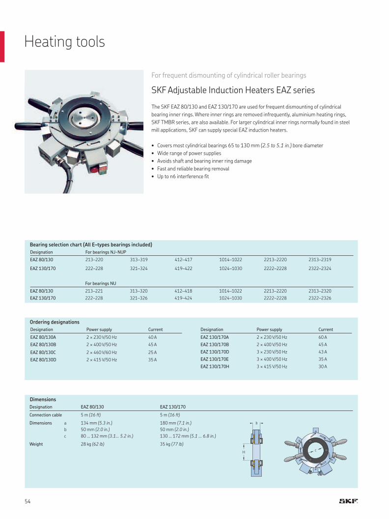
c
b
H
Dimensions
Designation EAZ 80/130 EAZ 130/170
Connection cable 5 m (16 ft) 5 m (16 ft)
Dimensions a
b
c
134 mm (5.3 in.)
50 mm (2.0 in.)
80 ... 132 mm (3.1... 5.2 in.)
180 mm (7.1 in.)
50 mm (2.0 in.)
130 ... 172 mm (5.1 ... 6.8 in.)
Weight 28 kg (62 lb) 35 kg (77 lb)
For frequent dismounting of cylindrical roller bearings
SKF Adjustable Induction Heaters EAZ series
The SKF EAZ 80/130 and EAZ 130/170 are used for frequent dismounting of cylindrical
bearing inner rings. Where inner rings are removed infrequently, aluminium heating rings,
SKF TMBR series, are also available. For larger cylindrical inner rings normally found in steel
mill applications, SKF can supply special EAZ induction heaters.
• Covers most cylindrical bearings 65 to 130 mm (2.5 to 5.1 in.) bore diameter
• Wide range of power supplies
• Avoids shaft and bearing inner ring damage
• Fast and reliable bearing removal
• Up to n6 interference fit
Bearing selection chart (All E–types bearings included)
Ordering designations
Designation Power supply Current
EAZ 80/130A 2 × 230 V/50 Hz 40 A
EAZ 80/130B 2 × 400 V/50 Hz 45 A
EAZ 80/130C 2 × 460 V/60 Hz 25 A
EAZ 80/130D 2 × 415 V/50 Hz 35 A
Designation Power supply Current
EAZ 130/170A 2 × 230 V/50 Hz 60 A
EAZ 130/170B 2 × 400 V/50 Hz 45 A
EAZ 130/170D 3 × 230 V/50 Hz 43 A
EAZ 130/170E 3 × 400 V/50 Hz 35 A
EAZ 130/170H 3 × 415 V/50 Hz 30 A
Designation For bearings NJ-NUP
EAZ 80/130 213–220 313–319 412–417 1014–1022 2213–2220 2313–2319
EAZ 130/170 222–228 321–324 419–422 1024–1030 2222–2228 2322–2324
For bearings NU
EAZ 80/130 213–221 313–320 412–418 1014–1022 2213–2220 2313–2320
EAZ 130/170 222–228 321–326 419–424 1024–1030 2222–2228 2322–2326
Heating tools

Accessories
Designation TMBA G11
Material Hytex
Inner lining Cotton
Size 9
Colour White
Maximum temperature 150 °C (302 °F)
Pack size 1 pair
Designation TMBA G11ET
Material Kevlar
Inner lining Cotton
Size 10 (EN 420 size)
Colour Yellow
Maximum temperature 500 °C (932 °F)
Pack size 1 pair
Designation TMBA G11H
Material Polyaramid
Inner lining Nitrile
Size 10
Colour Black
Maximum temperature 250 °C (482 °F)
Pack size 1 pair
Technical data
Technical data
Technical data
For safe handling of heated components up to 150 °C (302 °F)
SKF Heat Resistant Gloves TMBA G11
The SKF TMBA G11 are specially designed for the handling of heated bearings.
• Lint free
• Heat resistant up to 150 °C (302 °F)
• Cut resistant
• Tested and certified for mechanical risks
(EN 388) and thermal risks (EN 407)
For safe handling of heated components up to 500 °C (932 °F)
SKF Extreme Temperature Gloves TMBA G11ET
The SKF TMBA G11ET are especially designed for the safe handling of heated bearings
or other components for prolonged periods.
• Withstands extreme temperatures of up to
500 °C (932 °F)
unless in the presence of hot liquid or steam
• Allows the safe handling of heated components
• High-degree of non-flammability reduces
the risk of burning
For safe handling of oily and heated components up to 250 °C (482 °F)
SKF Heat and Oil Resistant Gloves TMBA G11H
The SKF TMBA G11H are specially designed for the handling of hot and oily bearings.
• Offers a high degree of heat, cut, oil and
water resistance
• Melt and burn resistant
• Maximum temperature: 250 °C (482 °F)
• Cut resistant
• Lint free
• Suitable for submerging in liquids with a
temperature up to 120 °C (248 °F)
(e.g. hot oil bath)
• Remains heat resistant when wet
• Tested and certified for mechanical risks
(EN 388) and thermal risks (EN 407)
• Extremely tough Kevlar gloves with high cut,
abrasion, puncture and tear resistance for
increased safety
• Lint free
• Tested and certified for mechanical risks
(EN 388) and thermal risks (EN 407)
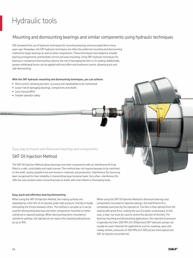
Mounting and dismounting bearings and similar components using hydraulic techniques
SKF pioneered the use of hydraulic techniques for mounting bearings and associated items many
years ago. Nowadays, the SKF hydraulic techniques are often the preferred mounting and dismounting
method for larger bearings as well as other components. These techniques have helped to simplify
bearing arrangements and facilitate correct and easy mounting. Using SKF hydraulic techniques for
bearing or component dismounting reduces the risk of damaging the item or its seating. Additionally,
greater withdrawal forces can be applied with less effort and maximum control, allowing quick and
safe dismounting.
With the SKF hydraulic mounting and dismounting techniques, you can achieve:
• More control, allowing precision, accuracy and repeatability to be maintained
• Lower risk of damaging bearings, components and shafts
• Less manual effort
• Greater operator safety
Easy way to mount and dismount bearings and components
SKF Oil Injection Method
The SKF Oil Injection Method allows bearings and other components with an interference fit to be
fitted in a safe, controllable and rapid manner. The method does not require keyways to be machined
on the shaft, saving valuable time and money in materials and production. Interference fits have long
been recognised for their reliability in transmitting large torsional loads. Very often, interference fits
offer the only solution when connecting hubs to shafts with intermittent or fluctuating loads.
Easy, quick and effortless bearing dismounting
When using the SKF Oil Injection Method, the mating surfaces are
separated by a thin film of oil injected under high pressure, thereby virtually
eliminating the friction between them. The method is versatile as it can be
used for dismounting bearings and other components mounted on either
cylindrical or tapered seatings. When dismounting items mounted on
cylindrical seatings, the injected oil can reduce the required pulling forces
by up to 90%.
When using the SKF Oil Injection Method to dismount bearings and
components mounted on tapered seatings, the interference fit is
completely overcome by the injected oil. The item is then ejected from the
seating with great force, making the use of a puller unnecessary. In this
case, a stop-nut must be used to control the ejection of the item. For
bearing mounting and dismounting applications, the required oil pressure
is typically less than 100 MPa (14 500psi) and SKF hydraulic pumps can
usually be used. However for applications such as couplings, gear and
railway wheels, pressures of 300 MPa (43 500 psi) are more typical and
SKF oil injectors are preferred.
Hydraulic tools
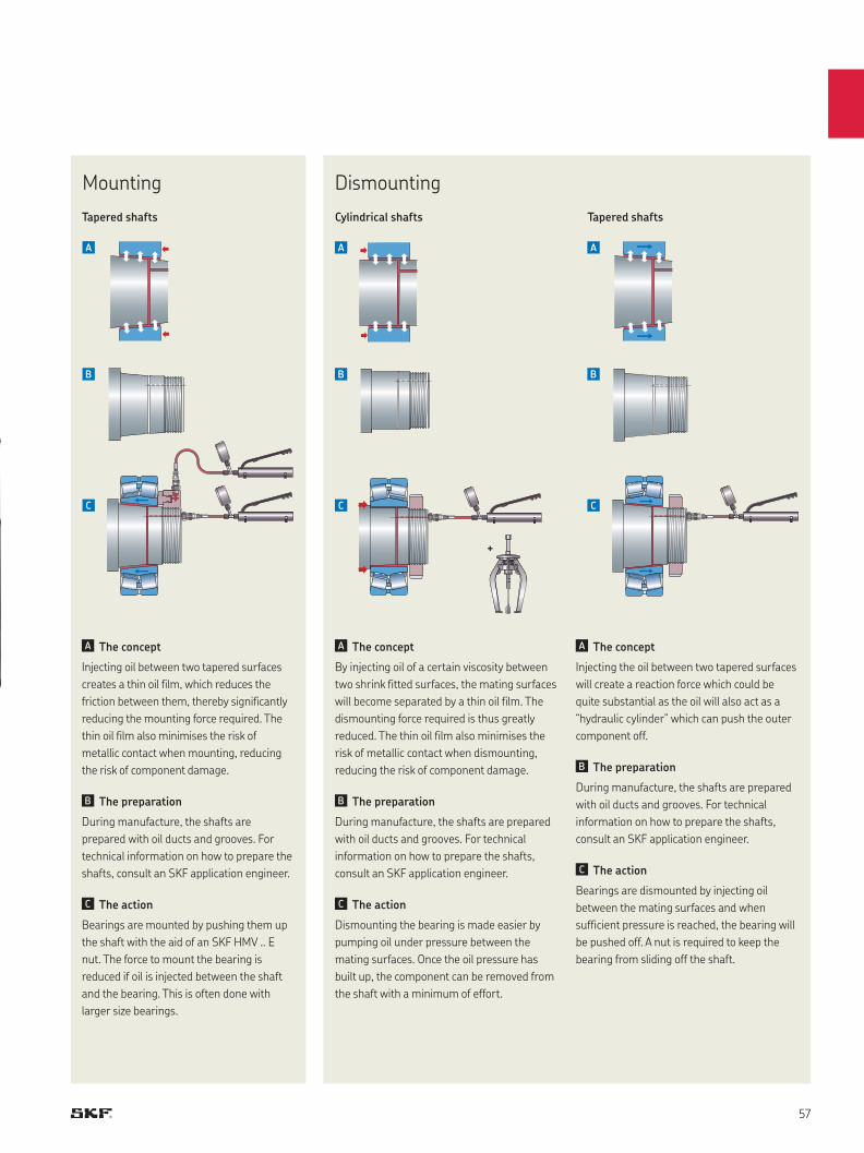
+
The concept
Injecting oil between two tapered surfaces
creates a thin oil film, which reduces the
friction between them, thereby significantly
reducing the mounting force required. The
thin oil film also minimises the risk of
metallic contact when mounting, reducing
the risk of component damage.
The preparation
During manufacture, the shafts are
prepared with oil ducts and grooves. For
technical information on how to prepare the
shafts, consult an SKF application engineer.
The action
Bearings are mounted by pushing them up
the shaft with the aid of an SKF HMV .. E
nut. The force to mount the bearing is
reduced if oil is injected between the shaft
and the bearing. This is often done with
larger size bearings.
The concept
By injecting oil of a certain viscosity between
two shrink fitted surfaces, the mating surfaces
will become separated by a thin oil film. The
dismounting force required is thus greatly
reduced. The thin oil film also minimises the
risk of metallic contact when dismounting,
reducing the risk of component damage.
The preparation
During manufacture, the shafts are prepared
with oil ducts and grooves. For technical
information on how to prepare the shafts,
consult an SKF application engineer.
The action
Dismounting the bearing is made easier by
pumping oil under pressure between the
mating surfaces. Once the oil pressure has
built up, the component can be removed from
the shaft with a minimum of effort.
The concept
Injecting the oil between two tapered surfaces
will create a reaction force which could be
quite substantial as the oil will also act as a
“hydraulic cylinder” which can push the outer
component off.
The preparation
During manufacture, the shafts are prepared
with oil ducts and grooves. For technical
information on how to prepare the shafts,
consult an SKF application engineer.
The action
Bearings are dismounted by injecting oil
between the mating surfaces and when
sufficient pressure is reached, the bearing will
be pushed off. A nut is required to keep the
bearing from sliding off the shaft.
Tapered shafts
Mounting Dismounting
Cylindrical shaftsTapered shafts
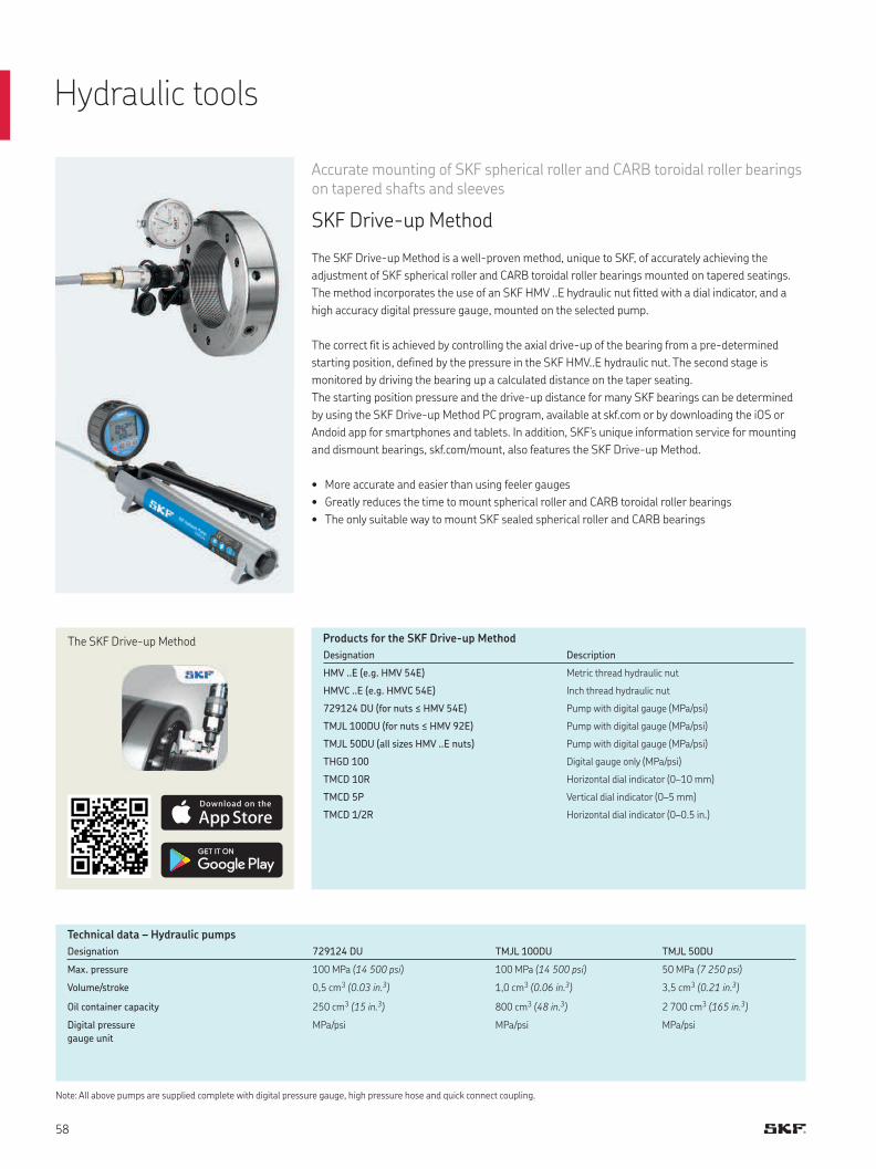
Accurate mounting of SKF spherical roller and CARB toroidal roller bearings on tapered shafts and sleeves
SKF Drive-up Method
The SKF Drive-up Method is a well-proven method, unique to SKF, of accurately achieving the
adjustment of SKF spherical roller and CARB toroidal roller bearings mounted on tapered seatings.
The method incorporates the use of an SKF HMV ..E hydraulic nut fitted with a dial indicator, and a
high accuracy digital pressure gauge, mounted on the selected pump.
The correct fit is achieved by controlling the axial drive-up of the bearing from a pre-determined
starting position, defined by the pressure in the SKF HMV..E hydraulic nut. The second stage is
monitored by driving the bearing up a calculated distance on the taper seating.
The starting position pressure and the drive-up distance for many SKF bearings can be determined
by using the SKF Drive-up Method PC program, available at skf.com or by downloading the iOS or
Andoid app for smartphones and tablets. In addition, SKF’s unique information service for mounting
and dismount bearings, skf.com/mount, also features the SKF Drive-up Method.
• More accurate and easier than using feeler gauges
• Greatly reduces the time to mount spherical roller and CARB toroidal roller bearings
• The only suitable way to mount SKF sealed spherical roller and CARB bearings
Products for the SKF Drive-up Method
Designation 729124 DU TMJL 100DU TMJL 50DU
Max. pressure 100 MPa (14 500 psi) 100 MPa (14 500 psi) 50 MPa (7 250 psi)
Volume/stroke 0,5 cm3 (0.03 in. 3) 1,0 cm3 (0.06 in. 3) 3,5 cm3 (0.21 in. 3)
Oil container capacity 250 cm3 (15 in. 3) 800 cm3 (48 in. 3) 2 700 cm3 (165 in. 3)
Digital pressure
gauge unit
MPa/psi MPa/psi MPa/psi
Note: All above pumps are supplied complete with digital pressure gauge, high pressure hose and quick connect coupling.
The SKF Drive-up MethodDesignation Description
HMV ..E (e.g. HMV 54E) Metric thread hydraulic nut
HMVC ..E (e.g. HMVC 54E) Inch thread hydraulic nut
729124 DU (for nuts ≤ HMV 54E) Pump with digital gauge (MPa/psi)
TMJL 100DU (for nuts ≤ HMV 92E) Pump with digital gauge (MPa/psi)
TMJL 50DU (all sizes HMV ..E nuts) Pump with digital gauge (MPa/psi)
THGD 100 Digital gauge only (MPa/psi)
TMCD 10R Horizontal dial indicator (0–10 mm)
TMCD 5P Vertical dial indicator (0–5 mm)
TMCD 1/2R Horizontal dial indicator (0–0.5 in.)
Technical data – Hydraulic pumps
Hydraulic tools
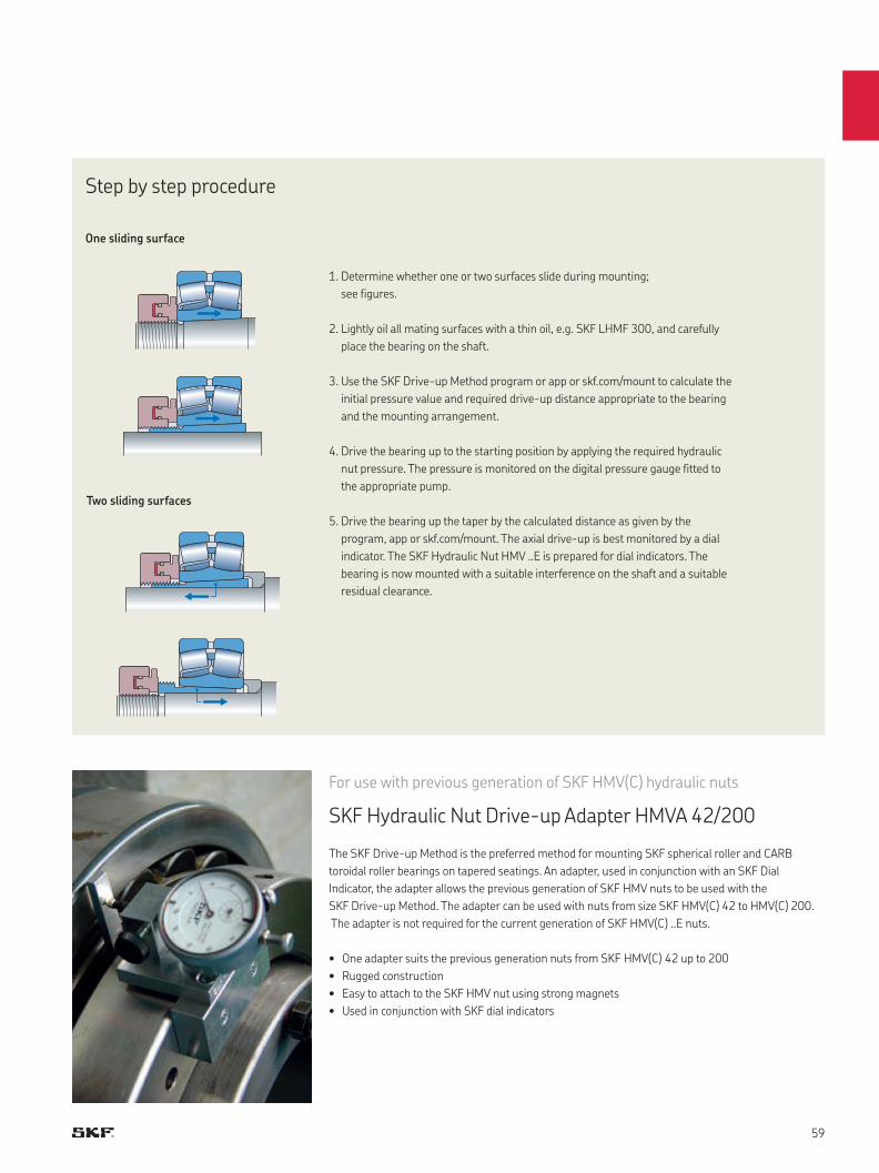
For use with previous generation of SKF HMV(C) hydraulic nuts
SKF Hydraulic Nut Drive-up Adapter HMVA 42/200
The SKF Drive-up Method is the preferred method for mounting SKF spherical roller and CARB
toroidal roller bearings on tapered seatings. An adapter, used in conjunction with an SKF Dial
Indicator, the adapter allows the previous generation of SKF HMV nuts to be used with the
SKF Drive-up Method. The adapter can be used with nuts from size SKF HMV(C) 42 to HMV(C) 200.
The adapter is not required for the current generation of SKF HMV(C) ..E nuts.
One sliding surface
Two sliding surfaces
Step by step procedure
• One adapter suits the previous generation nuts from SKF HMV(C) 42 up to 200
• Rugged construction
• Easy to attach to the SKF HMV nut using strong magnets
• Used in conjunction with SKF dial indicators
1. Determine whether one or two surfaces slide during mounting;
see figures.
2. Lightly oil all mating surfaces with a thin oil, e.g. SKF LHMF 300, and carefully
place the bearing on the shaft.
3. Use the SKF Drive-up Method program or app or skf.com/mount to calculate the
initial pressure value and required drive-up distance appropriate to the bearing
and the mounting arrangement.
4. Drive the bearing up to the starting position by applying the required hydraulic
nut pressure. The pressure is monitored on the digital pressure gauge fitted to
the appropriate pump.
5. Drive the bearing up the taper by the calculated distance as given by the
program, app or skf.com/mount. The axial drive-up is best monitored by a dial
indicator. The SKF Hydraulic Nut HMV ..E is prepared for dial indicators. The
bearing is now mounted with a suitable interference on the shaft and a suitable
residual clearance.
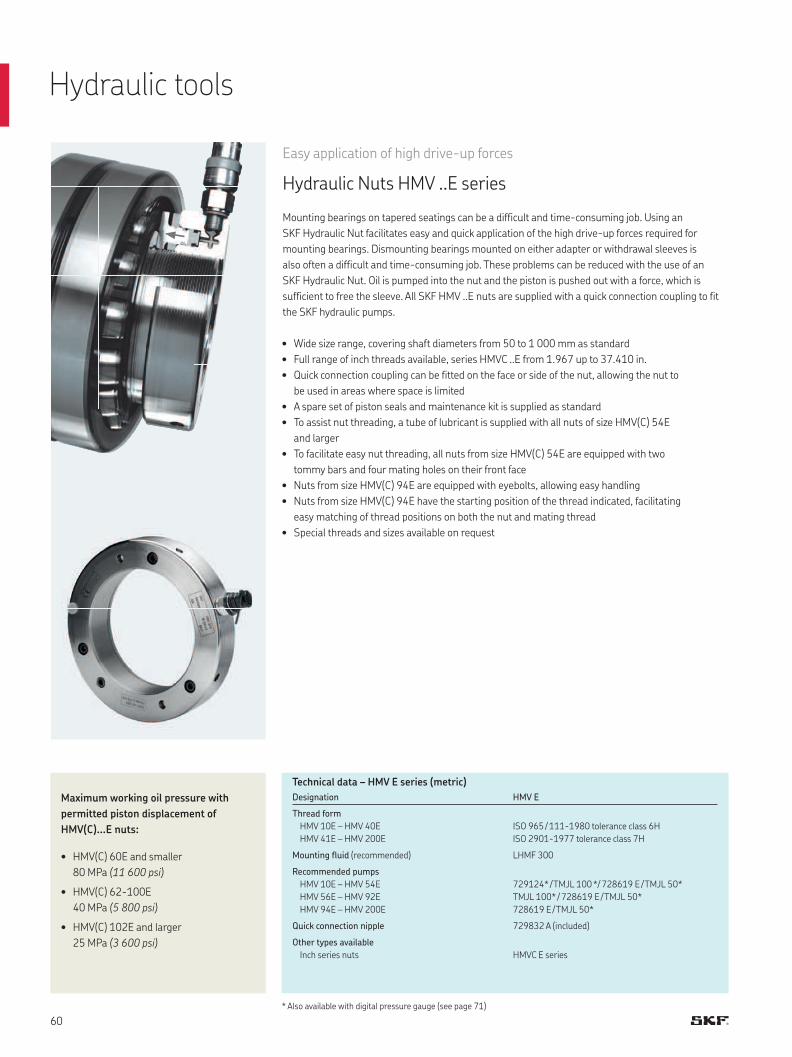
Easy application of high drive-up forces
Hydraulic Nuts HMV ..E series
Mounting bearings on tapered seatings can be a difficult and time-consuming job. Using an
SKF Hydraulic Nut facilitates easy and quick application of the high drive-up forces required for
mounting bearings. Dismounting bearings mounted on either adapter or withdrawal sleeves is
also often a difficult and time-consuming job. These problems can be reduced with the use of an
SKF Hydraulic Nut. Oil is pumped into the nut and the piston is pushed out with a force, which is
sufficient to free the sleeve. All SKF HMV ..E nuts are supplied with a quick connection coupling to fit
the SKF hydraulic pumps.
• Wide size range, covering shaft diameters from 50 to 1 000 mm as standard
• Full range of inch threads available, series HMVC ..E from 1.967 up to 37.410 in.
• Quick connection coupling can be fitted on the face or side of the nut, allowing the nut to
be used in areas where space is limited
• A spare set of piston seals and maintenance kit is supplied as standard
• To assist nut threading, a tube of lubricant is supplied with all nuts of size HMV(C) 54E
and larger
• To facilitate easy nut threading, all nuts from size HMV(C) 54E are equipped with two
tommy bars and four mating holes on their front face
• Nuts from size HMV(C) 94E are equipped with eyebolts, allowing easy handling
• Nuts from size HMV(C) 94E have the starting position of the thread indicated, facilitating
easy matching of thread positions on both the nut and mating thread
• Special threads and sizes available on request
Designation HMV E
Thread form
HMV 10E – HMV 40E
HMV 41E – HMV 200E
ISO 965 / 111-1980 tolerance class 6H
ISO 2901-1977 tolerance class 7H
Mounting fluid (recommended) LHMF 300
Recommended pumps
HMV 10E – HMV 54E
HMV 56E – HMV 92E
HMV 94E – HMV 200E
729124* / TMJL 100 */ 728619 E / TMJL 50*
TMJL 100* / 728619 E / TMJL 50*
728619 E / TMJL 50*
Quick connection nipple 729832 A (included)
Other types available
Inch series nuts HMVC E series
Technical data – HMV E series (metric)
• HMV(C) 60E and smaller
80 MPa (11 600 psi)
• HMV(C) 62-100E
40 MPa (5 800 psi)
• HMV(C) 102E and larger
25 MPa (3 600 psi)
Maximum working oil pressure with
permitted piston displacement of
HMV(C)…E nuts:
Hydraulic tools
* Also available with digital pressure gauge (see page 71)
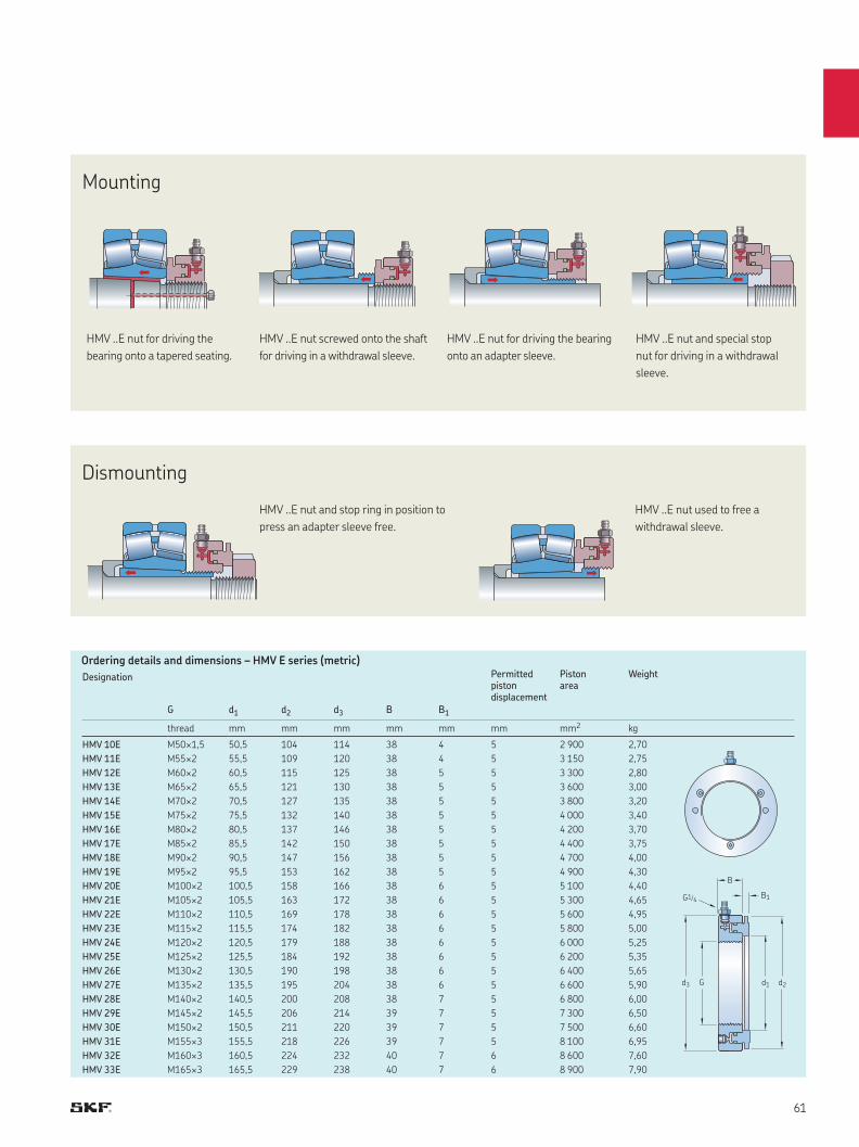
G1/4
d3 G d1
B1
d2
B
HMV ..E nut screwed onto the shaft
for driving in a withdrawal sleeve.
HMV ..E nut for driving the
bearing onto a tapered seating.
HMV ..E nut and special stop
nut for driving in a withdrawal
sleeve.
HMV ..E nut for driving the bearing
onto an adapter sleeve.
HMV ..E nut and stop ring in position to
press an adapter sleeve free.
HMV ..E nut used to free a
withdrawal sleeve.
Ordering details and dimensions – HMV E series (metric)
Dismounting
Mounting
Designation
G d1 d2 d3 B B1
Permitted piston displacement
Piston area
Weight
thread mm mm mm mm mm mm mm2 kg
HMV 10E M50×1,5 50,5 104 114 38 4 5 2 900 2,70
HMV 11E M55×2 55,5 109 120 38 4 5 3 150 2,75
HMV 12E M60×2 60,5 115 125 38 5 5 3 300 2,80
HMV 13E M65×2 65,5 121 130 38 5 5 3 600 3,00
HMV 14E M70×2 70,5 127 135 38 5 5 3 800 3,20
HMV 15E M75×2 75,5 132 140 38 5 5 4 000 3,40
HMV 16E M80×2 80,5 137 146 38 5 5 4 200 3,70
HMV 17E M85×2 85,5 142 150 38 5 5 4 400 3,75
HMV 18E M90×2 90,5 147 156 38 5 5 4 700 4,00
HMV 19E M95×2 95,5 153 162 38 5 5 4 900 4,30
HMV 20E M100×2 100,5 158 166 38 6 5 5 100 4,40
HMV 21E M105×2 105,5 163 172 38 6 5 5 300 4,65
HMV 22E M110×2 110,5 169 178 38 6 5 5 600 4,95
HMV 23E M115×2 115,5 174 182 38 6 5 5 800 5,00
HMV 24E M120×2 120,5 179 188 38 6 5 6 000 5,25
HMV 25E M125×2 125,5 184 192 38 6 5 6 200 5,35
HMV 26E M130×2 130,5 190 198 38 6 5 6 400 5,65
HMV 27E M135×2 135,5 195 204 38 6 5 6 600 5,90
HMV 28E M140×2 140,5 200 208 38 7 5 6 800 6,00
HMV 29E M145×2 145,5 206 214 39 7 5 7 300 6,50
HMV 30E M150×2 150,5 211 220 39 7 5 7 500 6,60
HMV 31E M155×3 155,5 218 226 39 7 5 8 100 6,95
HMV 32E M160×3 160,5 224 232 40 7 6 8 600 7,60
HMV 33E M165×3 165,5 229 238 40 7 6 8 900 7,90
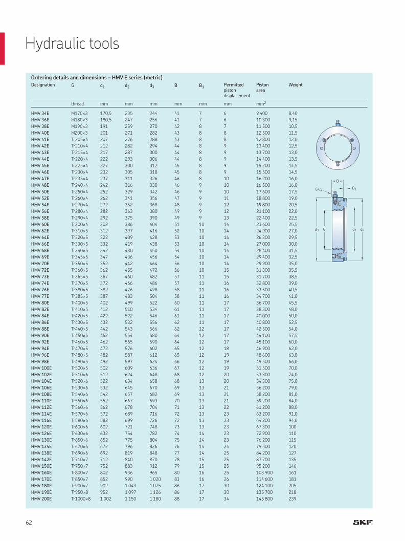
G1/4
d3 G d1
B1
d2
B
Ordering details and dimensions – HMV E series (metric)
Designation G d1 d2 d3 B B1Permitted pistondisplacement
Pistonarea
Weight
thread mm mm mm mm mm mm mm2
HMV 34E M170×3 170,5 235 244 41 7 6 9 400 8,40
HMV 36E M180×3 180,5 247 256 41 7 6 10 300 9,15
HMV 38E M190×3 191 259 270 42 8 7 11 500 10,5
HMV 40E M200×3 201 271 282 43 8 8 12 500 11,5
HMV 41E Tr205×4 207 276 288 43 8 8 12 800 12,0
HMV 42E Tr210×4 212 282 294 44 8 9 13 400 12,5
HMV 43E Tr215×4 217 287 300 44 8 9 13 700 13,0
HMV 44E Tr220×4 222 293 306 44 8 9 14 400 13,5
HMV 45E Tr225×4 227 300 312 45 8 9 15 200 14,5
HMV 46E Tr230×4 232 305 318 45 8 9 15 500 14,5
HMV 47E Tr235×4 237 311 326 46 8 10 16 200 16,0
HMV 48E Tr240×4 242 316 330 46 9 10 16 500 16,0
HMV 50E Tr250×4 252 329 342 46 9 10 17 600 17,5
HMV 52E Tr260×4 262 341 356 47 9 11 18 800 19,0
HMV 54E Tr270×4 272 352 368 48 9 12 19 800 20,5
HMV 56E Tr280×4 282 363 380 49 9 12 21 100 22,0
HMV 58E Tr290×4 292 375 390 49 9 13 22 400 22,5
HMV 60E Tr300×4 302 386 404 51 10 14 23 600 25,5
HMV 62E Tr310×5 312 397 416 52 10 14 24 900 27,0
HMV 64E Tr320×5 322 409 428 53 10 14 26 300 29,5
HMV 66E Tr330×5 332 419 438 53 10 14 27 000 30,0
HMV 68E Tr340×5 342 430 450 54 10 14 28 400 31,5
HMV 69E Tr345×5 347 436 456 54 10 14 29 400 32,5
HMV 70E Tr350×5 352 442 464 56 10 14 29 900 35,0
HMV 72E Tr360×5 362 455 472 56 10 15 31 300 35,5
HMV 73E Tr365×5 367 460 482 57 11 15 31 700 38,5
HMV 74E Tr370×5 372 466 486 57 11 16 32 800 39,0
HMV 76E Tr380×5 382 476 498 58 11 16 33 500 40,5
HMV 77E Tr385×5 387 483 504 58 11 16 34 700 41,0
HMV 80E Tr400×5 402 499 522 60 11 17 36 700 45,5
HMV 82E Tr410×5 412 510 534 61 11 17 38 300 48,0
HMV 84E Tr420×5 422 522 546 61 11 17 40 000 50,0
HMV 86E Tr430×5 432 532 556 62 11 17 40 800 52,5
HMV 88E Tr440×5 442 543 566 62 12 17 42 500 54,0
HMV 90E Tr450×5 452 554 580 64 12 17 44 100 57,5
HMV 92E Tr460×5 462 565 590 64 12 17 45 100 60,0
HMV 94E Tr470×5 472 576 602 65 12 18 46 900 62,0
HMV 96E Tr480×5 482 587 612 65 12 19 48 600 63,0
HMV 98E Tr490×5 492 597 624 66 12 19 49 500 66,0
HMV 100E Tr500×5 502 609 636 67 12 19 51 500 70,0
HMV 102E Tr510×6 512 624 648 68 12 20 53 300 74,0
HMV 104E Tr520×6 522 634 658 68 13 20 54 300 75,0
HMV 106E Tr530×6 532 645 670 69 13 21 56 200 79,0
HMV 108E Tr540×6 542 657 682 69 13 21 58 200 81,0
HMV 110E Tr550×6 552 667 693 70 13 21 59 200 84,0
HMV 112E Tr560×6 562 678 704 71 13 22 61 200 88,0
HMV 114E Tr570×6 572 689 716 72 13 23 63 200 91,0
HMV 116E Tr580×6 582 699 726 72 13 23 64 200 94,0
HMV 120E Tr600×6 602 721 748 73 13 23 67 300 100
HMV 126E Tr630×6 632 754 782 74 14 23 72 900 110
HMV 130E Tr650×6 652 775 804 75 14 23 76 200 115
HMV 134E Tr670×6 672 796 826 76 14 24 79 500 120
HMV 138E Tr690×6 692 819 848 77 14 25 84 200 127
HMV 142E Tr710×7 712 840 870 78 15 25 87 700 135
HMV 150E Tr750×7 752 883 912 79 15 25 95 200 146
HMV 160E Tr800×7 802 936 965 80 16 25 103 900 161
HMV 170E Tr850×7 852 990 1 020 83 16 26 114 600 181
HMV 180E Tr900×7 902 1 043 1 075 86 17 30 124 100 205
HMV 190E Tr950×8 952 1 097 1 126 86 17 30 135 700 218
HMV 200E Tr1000×8 1 002 1 150 1 180 88 17 34 145 800 239
Hydraulic tools
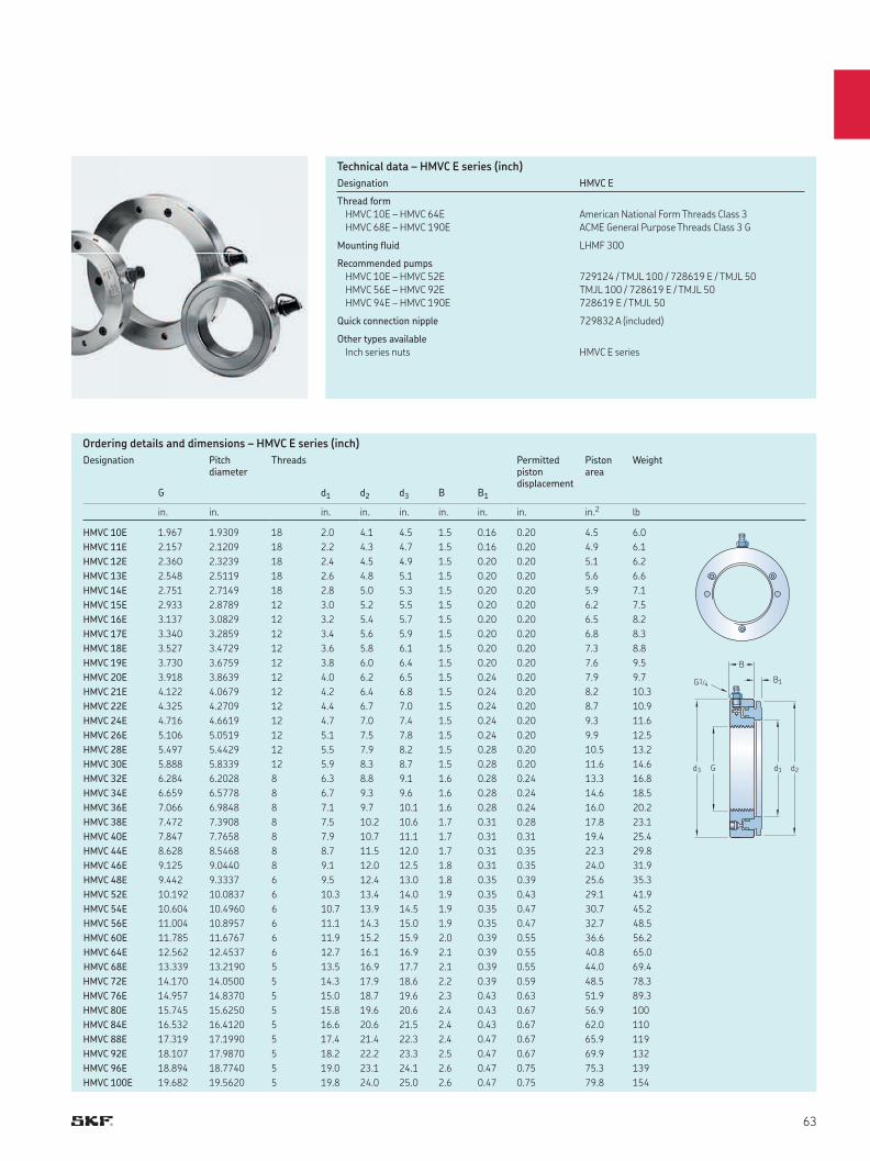
G1/4
d3 G d1
B1
d2
B
Ordering details and dimensions – HMVC E series (inch)
Designation HMVC E
Thread form
HMVC 10E – HMVC 64E
HMVC 68E – HMVC 190E
American National Form Threads Class 3
ACME General Purpose Threads Class 3 G
Mounting fluid LHMF 300
Recommended pumps
HMVC 10E – HMVC 52E
HMVC 56E – HMVC 92E
HMVC 94E – HMVC 190E
729124 / TMJL 100 / 728619 E / TMJL 50
TMJL 100 / 728619 E / TMJL 50
728619 E / TMJL 50
Quick connection nipple 729832 A (included)
Other types available
Inch series nuts HMVC E series
Designation Pitchdiameter
Threads Permittedpistondisplacement
Pistonarea
Weight
G d1 d2 d3 B B1
in. in. in. in. in. in. in. in. in.2 lb
HMVC 10E 1.967 1.9309 18 2.0 4.1 4.5 1.5 0.16 0.20 4.5 6.0
HMVC 11E 2.157 2.1209 18 2.2 4.3 4.7 1.5 0.16 0.20 4.9 6.1
HMVC 12E 2.360 2.3239 18 2.4 4.5 4.9 1.5 0.20 0.20 5.1 6.2
HMVC 13E 2.548 2.5119 18 2.6 4.8 5.1 1.5 0.20 0.20 5.6 6.6
HMVC 14E 2.751 2.7149 18 2.8 5.0 5.3 1.5 0.20 0.20 5.9 7.1
HMVC 15E 2.933 2.8789 12 3.0 5.2 5.5 1.5 0.20 0.20 6.2 7.5
HMVC 16E 3.137 3.0829 12 3.2 5.4 5.7 1.5 0.20 0.20 6.5 8.2
HMVC 17E 3.340 3.2859 12 3.4 5.6 5.9 1.5 0.20 0.20 6.8 8.3
HMVC 18E 3.527 3.4729 12 3.6 5.8 6.1 1.5 0.20 0.20 7.3 8.8
HMVC 19E 3.730 3.6759 12 3.8 6.0 6.4 1.5 0.20 0.20 7.6 9.5
HMVC 20E 3.918 3.8639 12 4.0 6.2 6.5 1.5 0.24 0.20 7.9 9.7
HMVC 21E 4.122 4.0679 12 4.2 6.4 6.8 1.5 0.24 0.20 8.2 10.3
HMVC 22E 4.325 4.2709 12 4.4 6.7 7.0 1.5 0.24 0.20 8.7 10.9
HMVC 24E 4.716 4.6619 12 4.7 7.0 7.4 1.5 0.24 0.20 9.3 11.6
HMVC 26E 5.106 5.0519 12 5.1 7.5 7.8 1.5 0.24 0.20 9.9 12.5
HMVC 28E 5.497 5.4429 12 5.5 7.9 8.2 1.5 0.28 0.20 10.5 13.2
HMVC 30E 5.888 5.8339 12 5.9 8.3 8.7 1.5 0.28 0.20 11.6 14.6
HMVC 32E 6.284 6.2028 8 6.3 8.8 9.1 1.6 0.28 0.24 13.3 16.8
HMVC 34E 6.659 6.5778 8 6.7 9.3 9.6 1.6 0.28 0.24 14.6 18.5
HMVC 36E 7.066 6.9848 8 7.1 9.7 10.1 1.6 0.28 0.24 16.0 20.2
HMVC 38E 7.472 7.3908 8 7.5 10.2 10.6 1.7 0.31 0.28 17.8 23.1
HMVC 40E 7.847 7.7658 8 7.9 10.7 11.1 1.7 0.31 0.31 19.4 25.4
HMVC 44E 8.628 8.5468 8 8.7 11.5 12.0 1.7 0.31 0.35 22.3 29.8
HMVC 46E 9.125 9.0440 8 9.1 12.0 12.5 1.8 0.31 0.35 24.0 31.9
HMVC 48E 9.442 9.3337 6 9.5 12.4 13.0 1.8 0.35 0.39 25.6 35.3
HMVC 52E 10.192 10.0837 6 10.3 13.4 14.0 1.9 0.35 0.43 29.1 41.9
HMVC 54E 10.604 10.4960 6 10.7 13.9 14.5 1.9 0.35 0.47 30.7 45.2
HMVC 56E 11.004 10.8957 6 11.1 14.3 15.0 1.9 0.35 0.47 32.7 48.5
HMVC 60E 11.785 11.6767 6 11.9 15.2 15.9 2.0 0.39 0.55 36.6 56.2
HMVC 64E 12.562 12.4537 6 12.7 16.1 16.9 2.1 0.39 0.55 40.8 65.0
HMVC 68E 13.339 13.2190 5 13.5 16.9 17.7 2.1 0.39 0.55 44.0 69.4
HMVC 72E 14.170 14.0500 5 14.3 17.9 18.6 2.2 0.39 0.59 48.5 78.3
HMVC 76E 14.957 14.8370 5 15.0 18.7 19.6 2.3 0.43 0.63 51.9 89.3
HMVC 80E 15.745 15.6250 5 15.8 19.6 20.6 2.4 0.43 0.67 56.9 100
HMVC 84E 16.532 16.4120 5 16.6 20.6 21.5 2.4 0.43 0.67 62.0 110
HMVC 88E 17.319 17.1990 5 17.4 21.4 22.3 2.4 0.47 0.67 65.9 119
HMVC 92E 18.107 17.9870 5 18.2 22.2 23.3 2.5 0.47 0.67 69.9 132
HMVC 96E 18.894 18.7740 5 19.0 23.1 24.1 2.6 0.47 0.75 75.3 139
HMVC 100E 19.682 19.5620 5 19.8 24.0 25.0 2.6 0.47 0.75 79.8 154
Technical data – HMVC E series (inch)
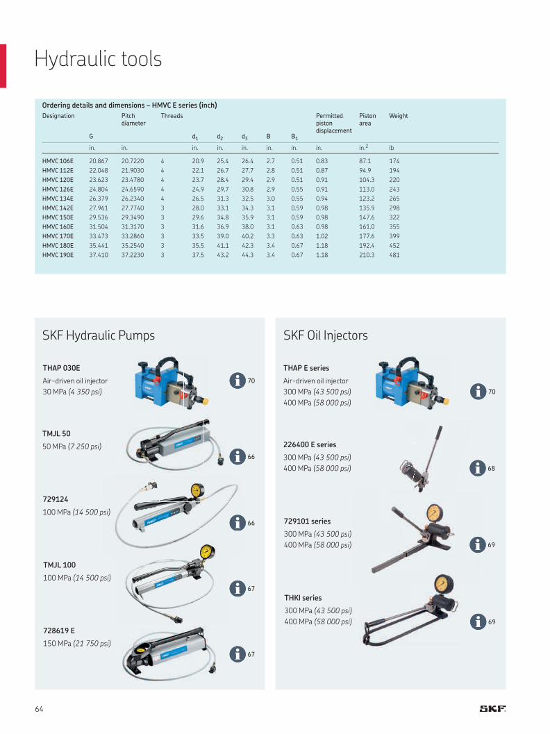
66
66
67
67
70
70
68
69
69
Designation Pitchdiameter
Threads Permittedpistondisplacement
Pistonarea
Weight
G d1 d2 d3 B B1
in. in. in. in. in. in. in. in. in.2 lb
HMVC 106E 20.867 20.7220 4 20.9 25.4 26.4 2.7 0.51 0.83 87.1 174
HMVC 112E 22.048 21.9030 4 22.1 26.7 27.7 2.8 0.51 0.87 94.9 194
HMVC 120E 23.623 23.4780 4 23.7 28.4 29.4 2.9 0.51 0.91 104.3 220
HMVC 126E 24.804 24.6590 4 24.9 29.7 30.8 2.9 0.55 0.91 113.0 243
HMVC 134E 26.379 26.2340 4 26.5 31.3 32.5 3.0 0.55 0.94 123.2 265
HMVC 142E 27.961 27.7740 3 28.0 33.1 34.3 3.1 0.59 0.98 135.9 298
HMVC 150E 29.536 29.3490 3 29.6 34.8 35.9 3.1 0.59 0.98 147.6 322
HMVC 160E 31.504 31.3170 3 31.6 36.9 38.0 3.1 0.63 0.98 161.0 355
HMVC 170E 33.473 33.2860 3 33.5 39.0 40.2 3.3 0.63 1.02 177.6 399
HMVC 180E 35.441 35.2540 3 35.5 41.1 42.3 3.4 0.67 1.18 192.4 452
HMVC 190E 37.410 37.2230 3 37.5 43.2 44.3 3.4 0.67 1.18 210.3 481
Ordering details and dimensions – HMVC E series (inch)
THAP 030E
Air-driven oil injector
30 MPa (4 350 psi)
TMJL 100
100 MPa (14 500 psi)
THKI series
300 MPa (43 500 psi)
400 MPa (58 000 psi)
TMJL 50
50 MPa (7 250 psi) 226400 E series
300 MPa (43 500 psi)
400 MPa (58 000 psi)
728619 E
150 MPa (21 750 psi)
729124
100 MPa (14 500 psi)729101 series
300 MPa (43 500 psi)
400 MPa (58 000 psi)
Hydraulic tools
SKF Hydraulic Pumps SKF Oil Injectors
THAP E series
Air-driven oil injector
300 MPa (43 500 psi)
400 MPa (58 000 psi)
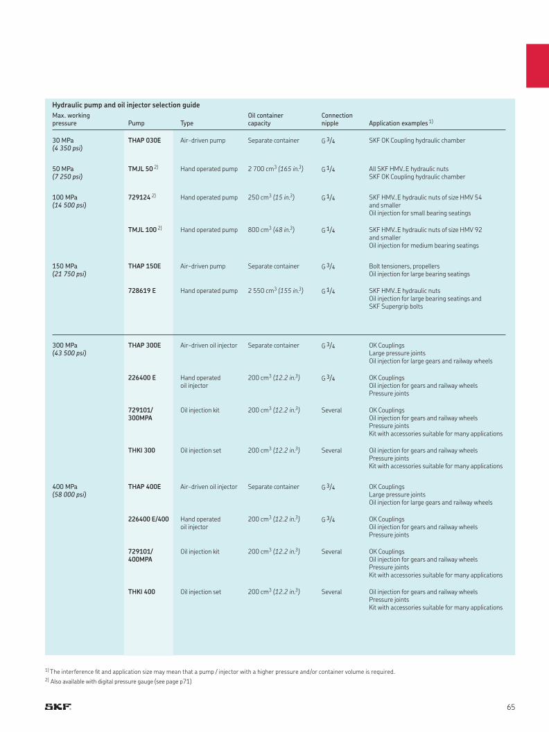
Hydraulic pump and oil injector selection guide
Max. working pressure
Pump
Type
Oil container capacity
Connection nipple
Application examples 1)
30 MPa (4 350 psi)
THAP 030E Air-driven pump Separate container G 3/4 SKF OK Coupling hydraulic chamber
50 MPa (7 250 psi)
TMJL 50 2) Hand operated pump 2 700 cm3 (165 in.3) G 1/4 All SKF HMV..E hydraulic nuts SKF OK Coupling hydraulic chamber
100 MPa (14 500 psi)
729124 2) Hand operated pump 250 cm3 (15 in.3) G 1/4 SKF HMV..E hydraulic nuts of size HMV 54 and smaller Oil injection for small bearing seatings
TMJL 100 2) Hand operated pump 800 cm3 (48 in.3) G 1/4 SKF HMV..E hydraulic nuts of size HMV 92 and smaller Oil injection for medium bearing seatings
150 MPa (21 750 psi)
THAP 150E Air-driven pump Separate container G 3/4 Bolt tensioners, propellers Oil injection for large bearing seatings
728619 E Hand operated pump 2 550 cm3 (155 in.3) G 1/4 SKF HMV..E hydraulic nuts Oil injection for large bearing seatings and SKF Supergrip bolts
300 MPa (43 500 psi)
THAP 300E Air-driven oil injector Separate container G 3/4 OK Couplings Large pressure joints Oil injection for large gears and railway wheels
226400 E Hand operated oil injector
200 cm3 (12.2 in.3) G 3/4 OK Couplings Oil injection for gears and railway wheels Pressure joints
729101/ 300MPA
Oil injection kit 200 cm3 (12.2 in.3) Several OK Couplings Oil injection for gears and railway wheels Pressure joints Kit with accessories suitable for many applications
THKI 300 Oil injection set 200 cm3 (12.2 in.3) Several Oil injection for gears and railway wheels Pressure joints Kit with accessories suitable for many applications
400 MPa (58 000 psi)
THAP 400E Air-driven oil injector Separate container G 3/4 OK Couplings Large pressure joints Oil injection for large gears and railway wheels
226400 E/400 Hand operated oil injector
200 cm3 (12.2 in.3) G 3/4 OK Couplings Oil injection for gears and railway wheels Pressure joints
729101/ 400MPA
Oil injection kit 200 cm3 (12.2 in.3) Several OK Couplings Oil injection for gears and railway wheels Pressure joints Kit with accessories suitable for many applications
THKI 400 Oil injection set 200 cm3 (12.2 in.3) Several Oil injection for gears and railway wheelsPressure joints Kit with accessories suitable for many applications
1) The interference fit and application size may mean that a pump / injector with a higher pressure and/or container volume is required.2) Also available with digital pressure gauge (see page p71)
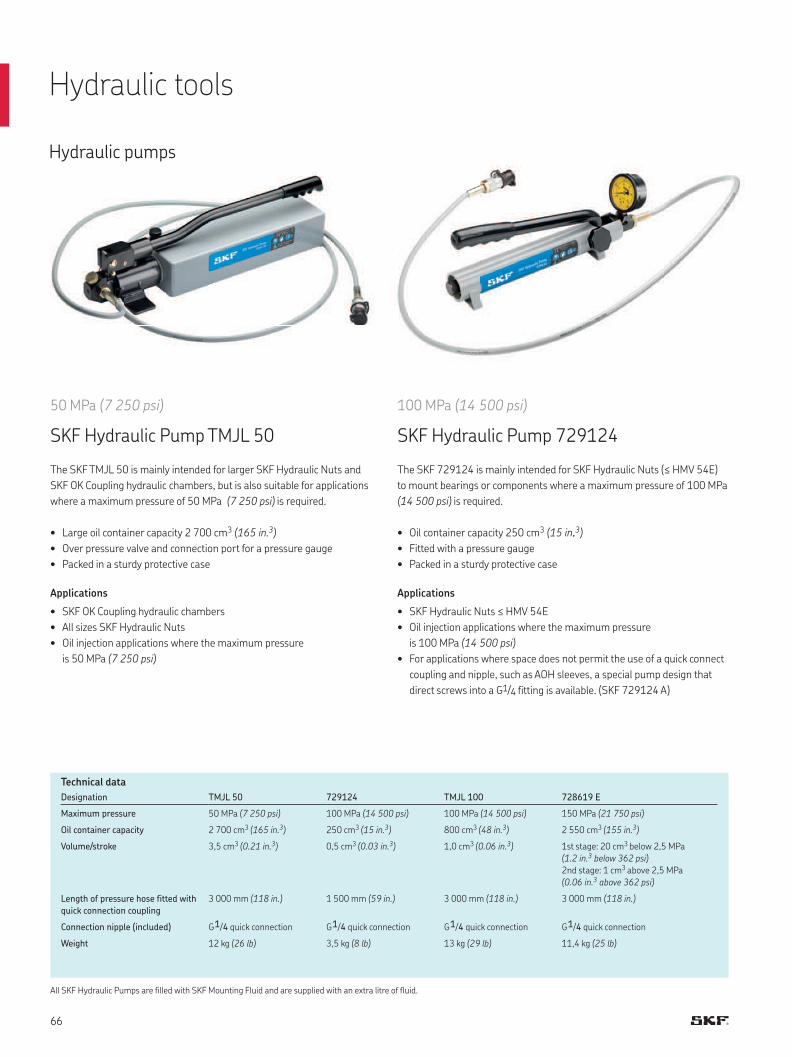
Hydraulic pumps
50 MPa (7 250 psi)
SKF Hydraulic Pump TMJL 50
The SKF TMJL 50 is mainly intended for larger SKF Hydraulic Nuts and
SKF OK Coupling hydraulic chambers, but is also suitable for applications
where a maximum pressure of 50 MPa (7 250 psi) is required.
• Large oil container capacity 2 700 cm3 (165 in. 3)
• Over pressure valve and connection port for a pressure gauge
• Packed in a sturdy protective case
Applications
• SKF OK Coupling hydraulic chambers
• All sizes SKF Hydraulic Nuts
• Oil injection applications where the maximum pressure
is 50 MPa (7 250 psi)
100 MPa (14 500 psi)
SKF Hydraulic Pump 729124
The SKF 729124 is mainly intended for SKF Hydraulic Nuts (≤ HMV 54E)
to mount bearings or components where a maximum pressure of 100 MPa
(14 500 psi) is required.
• Oil container capacity 250 cm3 (15 in.. 3)
• Fitted with a pressure gauge
• Packed in a sturdy protective case
Applications
• SKF Hydraulic Nuts ≤ HMV 54E
• Oil injection applications where the maximum pressure
is 100 MPa (14 500 psi)
• For applications where space does not permit the use of a quick connect
coupling and nipple, such as AOH sleeves, a special pump design that
direct screws into a G1/4 fitting is available. (SKF 729124 A)
Technical data
All SKF Hydraulic Pumps are filled with SKF Mounting Fluid and are supplied with an extra litre of fluid.
Designation TMJL 50 729124 TMJL 100 728619 E
Maximum pressure 50 MPa (7 250 psi) 100 MPa (14 500 psi) 100 MPa (14 500 psi) 150 MPa (21 750 psi)
Oil container capacity 2 700 cm3 (165 in. 3) 250 cm3 (15 in. 3) 800 cm3 (48 in. 3) 2 550 cm3 (155 in. 3)
Volume/stroke 3,5 cm3 (0.21 in. 3) 0,5 cm3 (0.03 in. 3) 1,0 cm3 (0.06 in. 3) 1st stage: 20 cm3 below 2,5 MPa
(1.2 in. 3 below 362 psi)
2nd stage: 1 cm3 above 2,5 MPa
(0.06 in. 3 above 362 psi)
Length of pressure hose fitted with
quick connection coupling
3 000 mm (118 in.) 1 500 mm (59 in.) 3 000 mm (118 in.) 3 000 mm (118 in.)
Connection nipple (included) G 1/4 quick connection G 1/4 quick connection G 1/4 quick connection G 1/4 quick connection
Weight 12 kg (26 lb) 3,5 kg (8 lb) 13 kg (29 lb) 11,4 kg (25 lb)
Hydraulic tools
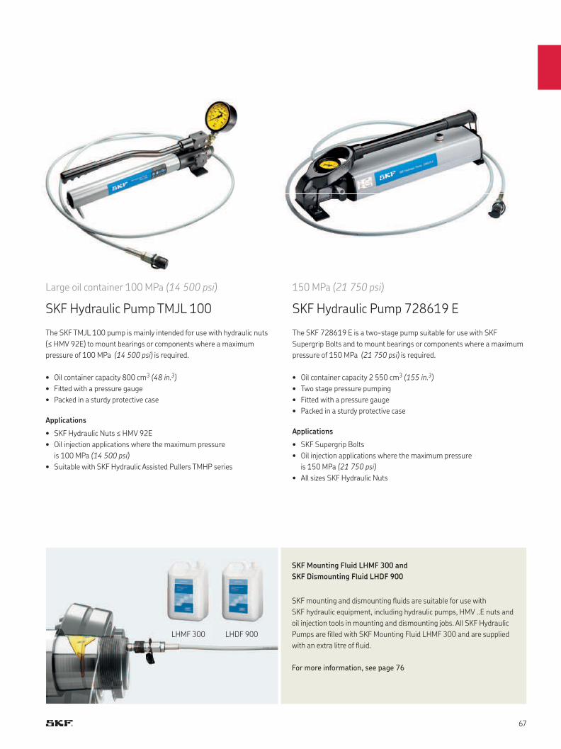
Large oil container 100 MPa (14 500 psi)
SKF Hydraulic Pump TMJL 100
The SKF TMJL 100 pump is mainly intended for use with hydraulic nuts
(≤ HMV 92E) to mount bearings or components where a maximum
pressure of 100 MPa (14 500 psi) is required.
• Oil container capacity 800 cm3 (48 in. 3)
• Fitted with a pressure gauge
• Packed in a sturdy protective case
Applications
• SKF Hydraulic Nuts ≤ HMV 92E
• Oil injection applications where the maximum pressure
is 100 MPa (14 500 psi)
• Suitable with SKF Hydraulic Assisted Pullers TMHP series
150 MPa (21 750 psi)
SKF Hydraulic Pump 728619 E
The SKF 728619 E is a two-stage pump suitable for use with SKF
Supergrip Bolts and to mount bearings or components where a maximum
pressure of 150 MPa (21 750 psi) is required.
• Oil container capacity 2 550 cm3 (155 in. 3)
• Two stage pressure pumping
• Fitted with a pressure gauge
• Packed in a sturdy protective case
Applications
• SKF Supergrip Bolts
• Oil injection applications where the maximum pressure
is 150 MPa (21 750 psi)
• All sizes SKF Hydraulic Nuts
SKF Mounting Fluid LHMF 300 and
SKF Dismounting Fluid LHDF 900
SKF mounting and dismounting fluids are suitable for use with
SKF hydraulic equipment, including hydraulic pumps, HMV ..E nuts and
oil injection tools in mounting and dismounting jobs. All SKF Hydraulic
Pumps are filled with SKF Mounting Fluid LHMF 300 and are supplied
with an extra litre of fluid.
For more information, see page 76
LHMF 300 LHDF 900
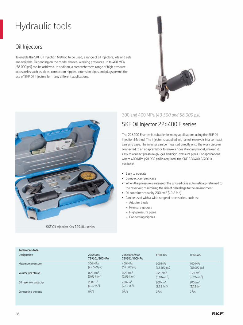
Oil Injectors
300 and 400 MPa (43 500 and 58 000 psi)
SKF Oil Injector 226400 E series
The 226400 E series is suitable for many applications using the SKF Oil
Injection Method. The injector is supplied with an oil reservoir in a compact
carrying case. The injector can be mounted directly onto the work piece or
connected to an adapter block to make a floor standing model, making it
easy to connect pressure gauges and high-pressure pipes. For applications
where 400 MPa (58 000 psi) is required, the SKF 226400 E/400 is
available.
• Easy to operate
• Compact carrying case
• When the pressure is released, the unused oil is automatically returned to
the reservoir, minimizing the risk of oil leakage to the environment
• Oil container capacity 200 cm3 (12.2 in. 3)
• Can be used with a wide range of accessories, such as:
– Adapter block
– Pressure gauges
– High pressure pipes
– Connecting nipples
Designation 226400 E
729101/300MPA
226400 E/400
729101/400MPA
THKI 300 THKI 400
Maximum pressure 300 MPa
(43 500 psi)
400 MPa
(58 000 psi)300 MPa
(43 500 psi)
400 MPa
(58 000 psi)
Volume per stroke 0,23 cm3
(0.014 in. 3)
0,23 cm3
(0.014 in. 3)0,23 cm3
(0.014 in. 3)
0,23 cm3
(0.014 in. 3)
Oil reservoir capacity 200 cm3
(12.2 in.. 3)
200 cm3
(12.2 in. 3)200 cm3
(12.2 in. 3)
200 cm3
(12.2 in. 3)
Connecting threads G 3/4 G 3/4 G 3/4 G 3/4
Technical data
To enable the SKF Oil Injection Method to be used, a range of oil injectors, kits and sets
are available. Depending on the model chosen, working pressures up to 400 MPa
(58 000 psi) can be achieved. In addition, a comprehensive range of high pressure
accessories such as pipes, connection nipples, extension pipes and plugs permit the
use of SKF Oil Injectors for many different applications.
Hydraulic tools
SKF Oil Injection Kits 729101 series
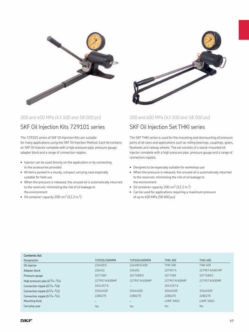
Designation 729101/300MPA 729101/400MPA THKI 300 THKI 400
Oil injector 226400 E 226400 E/400 THKI 300 THKI 400
Adapter block 226402 226402 227957 A 227957 A/400 MP
Pressure gauge 1077589 1077589/3 1077589 1077589/3
High pressure pipe (G3/4–1/4) 227957 A/400MP 227957 A/400MP 227957 A/400MP 227957 A/400MP
Connection nipple (G1/4–1/8) 1014357 A – 1014357 A –
Connection nipple (G1/4–1/2) 1016402E 1016402E 1016402E 1016402E
Connection nipple (G1/4–3/4) 228027E 228027E 228027E 228027E
Mounting fluid – – LHMF 300/1 LHMF 300/1
Carrying case Yes Yes Yes Yes
Contents list
300 and 400 MPa (43 500 and 58 000 psi)
SKF Oil Injection Set THKI series
The SKF THKI series is used for the mounting and dismounting of pressure
joints of all sizes and applications such as rolling bearings, couplings, gears,
flywheels and railway wheels. The set consists of a stand-mounted oil
injector complete with a high pressure pipe, pressure gauge and a range of
connection nipples.
• Designed to be especially suitable for workshop use
• When the pressure is released, the unused oil is automatically returned
to the reservoir, minimizing the risk of oil leakage to
the environment
• Oil container capacity 200 cm3 (12.2 in. 3)
• Can be used for applications requiring a maximum pressure
of up to 400 MPa (58 000 psi)
300 and 400 MPa (43 500 and 58 000 psi)
SKF Oil Injection Kits 729101 series
The 729101 series of SKF Oil Injection Kits are suitable
for many applications using the SKF Oil Injection Method. Each kit contains
an SKF Oil Injector complete with a high pressure pipe, pressure gauge,
adapter block and a range of connection nipples.
• Injector can be used directly on the application or by connecting
to the accessories provided
• All items packed in a sturdy, compact carrying case especially
suitable for field use
• When the pressure is released, the unused oil is automatically returned
to the reservoir, minimizing the risk of oil leakage to
the environment
• Oil container capacity 200 cm3 (12.2 in. 3)

THAP E/SK1
THAP E
30, 150, 300 and 400 MPa (4 350, 21 750, 43 500 and 58 000 psi)
SKF Air-driven Hydraulic Pumps and Oil Injectors, THAP E series
The THAP E air-driven hydraulic pumps and oil injectors are available in four different
pressure versions. They can be used for mounting OK Couplings, large pressure joints such
as bearings, flywheels, couplings and railway wheels. The THAP E unit consists
of a hydraulic pump or high pressure oil injector, driven by an air motor.
The units are supplied in a sturdy case including oil suction and return hoses with quick
connect couplings. The units can also be supplied in complete sets, consisting of a THAP E
and such accessories as a pressure gauge, high pressure pipe or pressure hose.
• Time savings compared to hand operated pumps and oil injectors
• Portable
• Continuous supply of oil
• Internal air pressure limiter helps ensure safe operation
• Low air consumption
• Wide operating temperature range
• Sturdy storage boxes
• Low, medium and high pressure units
Applications
• SKF OK Couplings
• Mounting bearings
• Mounting ship propellers, rudder pintles,
railway wheels and other similar applications
Designation THAP 030E THAP 150E THAP 300E THAP 400E
Nominal hydraulic pressure 30 MPa (4 350 psi) 150 MPa (21 750 psi) 300 MPa (43 500 psi) 400 MPa (58 000 psi)
Operating air pressure 1) 7 bar (101.5 psi) 7 bar (101.5 psi) 7 bar (101.5 psi) 7 bar (101.5 psi)
Volume/stroke 10 cm3 (0.61 in. 3) 1,92 cm3 (0.12 in. 3) 0,83 cm3 (0.05 in. 3) 0,64 cm3 (0.039 in. 3)
Oil outlet G 3/4 G 3/4 G 3/4 G 3/4
Length 350 mm (13.9 in.) 350 mm (13.9 in.) 405 mm (16 in.) 405 mm (16 in.)
Height 202 mm (8 in.) 202 mm (8 in.) 202 mm (8 in.) 202 mm (8 in.)
Width 171 mm (6.7 in.) 171 mm (6.7 in.) 171 mm (6.7 in.) 171 mm (6.7 in.)
Weight 11,5 kg (25.3 lb) 11,5 kg (25.3 lb) 13 kg (28.6 lb) 13 kg (28.6 lb)
Also available as complete set in carrying case
THAP 030E/SK1 Consisting of pump, high pressure hose and connecting nipples.
THAP 150E/SK1 Consisting of pump, pressure gauge, high pressure hose and connecting nipples.
THAP 300E/SK1 Consisting of oil injector, pressure gauge and high pressure pipe.
THAP 400E/SK1 Consisting of oil injector, pressure gauge and high pressure pipe.
Technical data
1) Air pressures above 7 bar are automatically limited to 7 bar by an internal air limiter.
Hydraulic tools
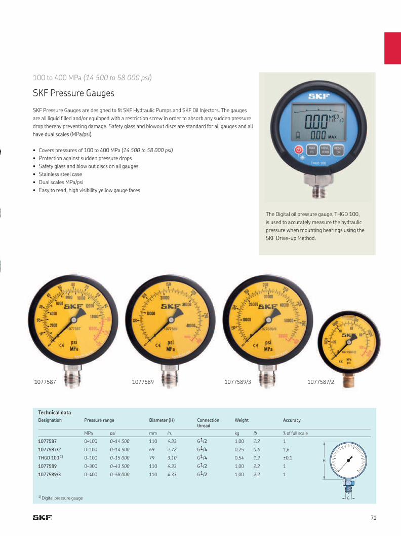
H
G
1077587 1077589/31077589 1077587/2
100 to 400 MPa (14 500 to 58 000 psi)
SKF Pressure Gauges
SKF Pressure Gauges are designed to fit SKF Hydraulic Pumps and SKF Oil Injectors. The gauges
are all liquid filled and/or equipped with a restriction screw in order to absorb any sudden pressure
drop thereby preventing damage. Safety glass and blowout discs are standard for all gauges and all
have dual scales (MPa/psi).
• Covers pressures of 100 to 400 MPa (14 500 to 58 000 psi)
• Protection against sudden pressure drops
• Safety glass and blow out discs on all gauges
• Stainless steel case
• Dual scales MPa/psi
• Easy to read, high visibility yellow gauge faces
Designation Pressure range Diameter (H) Connection thread
Weight Accuracy
MPa psi mm in. kg lb % of full scale
1077587 0–100 0–14 500 110 4.33 G 1/2 1,00 2.2 1
1077587/2 0–100 0–14 500 69 2.72 G 1/4 0,25 0.6 1,6
THGD 100 1) 0–100 0–15 000 79 3.10 G 1/4 0,54 1.2 ±0,1
1077589 0–300 0–43 500 110 4.33 G 1/2 1,00 2.2 1
1077589/3 0–400 0–58 000 110 4.33 G 1/2 1,00 2.2 1
Technical data
The Digital oil pressure gauge, THGD 100,
is used to accurately measure the hydraulic
pressure when mounting bearings using the
SKF Drive-up Method.
1) Digital pressure gauge
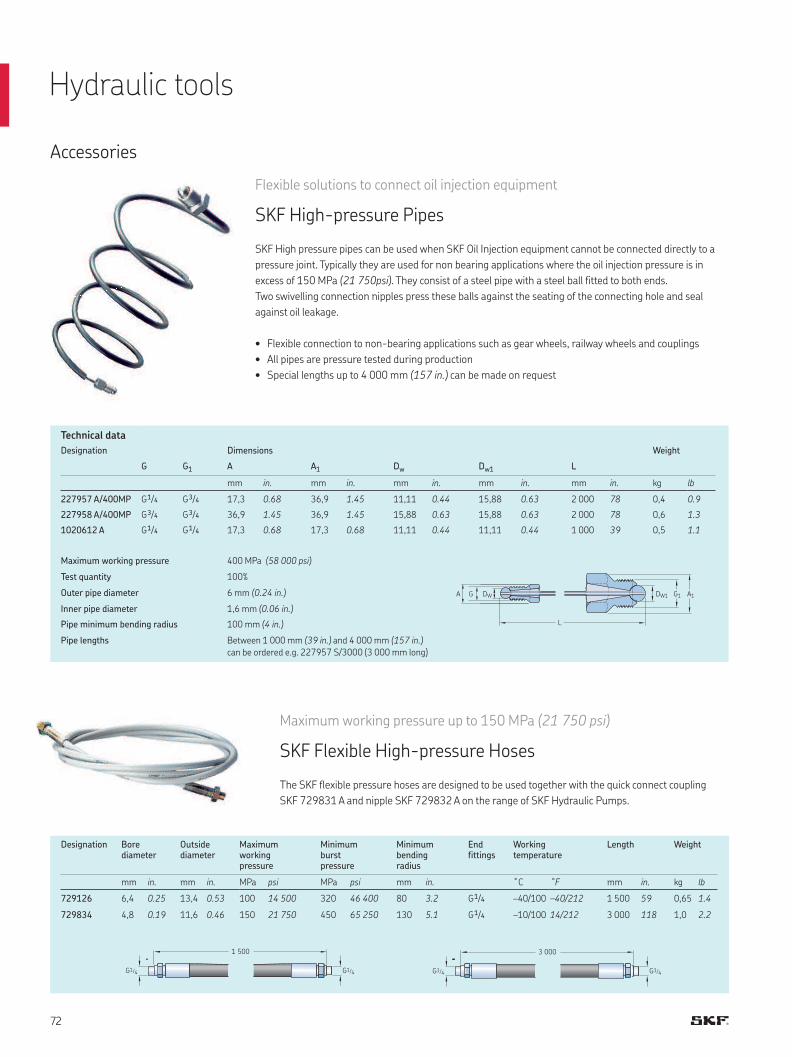
1 500
G1/4 G1/4
3 000
G1/4 G1/4
L
G1 DW1 A1 DW G A
Accessories
Flexible solutions to connect oil injection equipment
SKF High-pressure Pipes
SKF High pressure pipes can be used when SKF Oil Injection equipment cannot be connected directly to a
pressure joint. Typically they are used for non bearing applications where the oil injection pressure is in
excess of 150 MPa (21 750psi). They consist of a steel pipe with a steel ball fitted to both ends.
Two swivelling connection nipples press these balls against the seating of the connecting hole and seal
against oil leakage.
• Flexible connection to non-bearing applications such as gear wheels, railway wheels and couplings
• All pipes are pressure tested during production
• Special lengths up to 4 000 mm (157 in.) can be made on request
Maximum working pressure 400 MPa (58 000 psi)
Test quantity 100%
Outer pipe diameter 6 mm (0.24 in.)
Inner pipe diameter 1,6 mm (0.06 in.)
Pipe minimum bending radius 100 mm (4 in.)
Pipe lengths Between 1 000 mm (39 in.) and 4 000 mm (157 in.)
can be ordered e.g. 227957 S/3000 (3 000 mm long)
Maximum working pressure up to 150 MPa (21 750 psi)
SKF Flexible High-pressure Hoses
The SKF flexible pressure hoses are designed to be used together with the quick connect coupling
SKF 729831 A and nipple SKF 729832 A on the range of SKF Hydraulic Pumps.
Designation Dimensions Weight
G G1 A A1 Dw Dw1 L
mm in. mm in. mm in. mm in. mm in. kg lb
227957 A/400MP G 1/4 G 3/4 17,3 0.68 36,9 1.45 11,11 0.44 15,88 0.63 2 000 78 0,4 0.9
227958 A/400MP G 3/4 G 3/4 36,9 1.45 36,9 1.45 15,88 0.63 15,88 0.63 2 000 78 0,6 1.3
1020612 A G 1/4 G 1/4 17,3 0.68 17,3 0.68 11,11 0.44 11,11 0.44 1 000 39 0,5 1.1
Designation Bore diameter
Outside diameter
Maximumworkingpressure
Minimum burst pressure
Minimum bending radius
End fittings
Working temperature
Length Weight
mm in. mm in. MPa psi MPa psi mm in. ˚C ˚F mm in. kg lb
729126 6,4 0.25 13,4 0.53 100 14 500 320 46 400 80 3.2 G 1/4 –40/100 –40/212 1 500 59 0,65 1.4
729834 4,8 0.19 11,6 0.46 150 21 750 450 65 250 130 5.1 G 1/4 –10/100 14/212 3 000 118 1,0 2.2
Technical data
Hydraulic tools
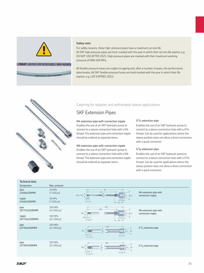
300
325
25,4 G1/4M6
2,5
1215
34
400
20 G1/4G1/4 15
4
1715
300
20 G1/4G1/8 15
3
1515
6095
25,4M4 × 0,5 G1/4
15
42
2
7
6
Safety note:
For safety reasons, these high-pressure pipes have a maximum service life.
All SKF high pressure pipes are hard-marked with the year in which their service life expires; e.g.
DO NOT USE AFTER 2023. High pressure pipes are marked with their maximum working
pressure of MAX 400 MPa.
All flexible pressure hoses are subject to ageing and, after a number of years, the performance
deteriorates. All SKF flexible pressure hoses are hard marked with the year in which their life
expires, e.g. LIFE EXPIRES 2023.
Designation Max. pressure
pipe
234064/50MPA
50 MPa
(7 250 psi)
nipple
234063/50MPA
50 MPa
(7 250 psi)
pipe
1077453/100MPA
100 MPa
(14 500 psi)
nipple
1077454/100MPA
100 MPa
(14 500 psi)
pipe
227966/100MPA
100 MPa
(14 500 psi)
pipe
227965/100MPA
100 MPa
(14 500 psi)
M4 extension pipe with connection nipple
Enables the use of an SKF hydraulic pump to
connect to a sleeve connection hole with a M4
thread. The extension pipe and connection nipple
should be ordered as separate items.
M6 extension pipe with connection nipple
Enables the use of an SKF hydraulic pump to
connect to a sleeve connection hole with a M6
thread. The extension pipe and connection nipple
should be ordered as separate items.
Catering for adapter and withdrawal sleeve applications
SKF Extension Pipes
M4 extension pipe with
connection nipple
M6 extension pipe with
connection nipple
G 1/4 extension pipe
G 1/8 extension pipe
G1/4 extension pipe
Enables the use of an SKF hydraulic pump to
connect to a sleeve connection hole with a G 1/4
thread. Can be used for applications where the
sleeve position does not allow a direct connection
with a quick connector.
G1/8 extension pipe
Enables the use of an SKF hydraulic pump to
connect to a sleeve connection hole with a G 1/8
thread. Can be used for applications where the
sleeve position does not allow a direct connection
with a quick connector.
Technical data
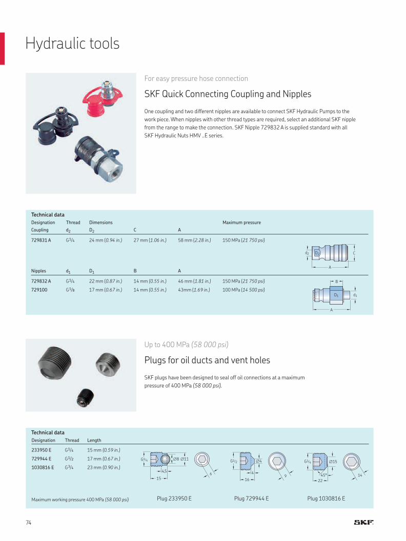
A
Cd2 D2
B
A
d1D1
16
G1/2
4
∅4
9
G3/4
22
45°
∅15
14
G1/4
15
4,5
∅8 ∅11
6
Maximum working pressure 400 MPa (58 000 psi)
Designation Thread Dimensions Maximum pressure
Coupling d2 D2 C A
729831 A G 1/4 24 mm (0.94 in.) 27 mm (1.06 in.) 58 mm (2.28 in.) 150 MPa (21 750 psi)
Nipples d1 D1 B A
729832 A G 1/4 22 mm (0.87 in.) 14 mm (0.55 in.) 46 mm (1.81 in.) 150 MPa (21 750 psi)
729100 G 1/8 17 mm (0.67 in.) 14 mm (0.55 in.) 43mm (1.69 in.) 100 MPa (14 500 psi)
Designation Thread Length
233950 E G 1/4 15 mm (0.59 in.)
729944 E G 1/2 17 mm (0.67 in.)
1030816 E G 3/4 23 mm (0.90 in.)
Plug 233950 E Plug 729944 E Plug 1030816 E
For easy pressure hose connection
SKF Quick Connecting Coupling and Nipples
One coupling and two different nipples are available to connect SKF Hydraulic Pumps to the
work piece. When nipples with other thread types are required, select an additional SKF nipple
from the range to make the connection. SKF Nipple 729832 A is supplied standard with all
SKF Hydraulic Nuts HMV ..E series.
Up to 400 MPa (58 000 psi)
Plugs for oil ducts and vent holes
SKF plugs have been designed to seal off oil connections at a maximum
pressure of 400 MPa (58 000 psi).
Technical data
Technical data
Hydraulic tools
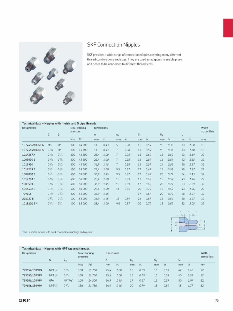
A G2
G1G3
A1 G
L
Designation Max. working
pressure
Dimensions Width
across flatsG G2 A A1 G1 G3 L
Mpa Psi mm in. mm in. mm in. mm in. mm in. mm
1077456/100MPA M8 M6 100 14 500 11 0.43 5 0.20 15 0.59 9 0.35 33 1.30 10
1077455/100MPA G 1/8 M6 100 14 500 11 0.43 7 0.28 15 0.59 9 0.35 33 1.30 10
1014357 A G 1/8 G 1/4 300 43 500 25,4 1.00 7 0.28 15 0.59 15 0.59 43 1.69 22
1009030 B G 1/8 G 3/8 300 43 500 25,4 1.00 7 0.28 15 0.59 15 0.59 42 1.65 22
1019950 G 1/8 G 1/2 300 43 500 36,9 1.45 7 0.28 15 0.59 14 0.55 50 1.97 32
1018219 E G 1/4 G 3/8 400 58 000 25,4 1.00 9,5 0.37 17 0.67 15 0.59 45 1.77 22
1009030 E G 1/4 G 3/4 400 58 000 36,9 1.45 9,5 0.37 17 0.67 20 0.79 54 2.13 32
1012783 E G 3/8 G 1/4 400 58 000 25,4 1.00 10 0.39 17 0.67 15 0.59 43 1.96 22
1008593 E G 3/8 G 3/4 400 58 000 36,9 1.45 10 0.39 17 0.67 20 0.79 53 2.09 32
1016402 E G 1/2 G 1/4 400 58 000 25,4 1.00 14 0.55 20 0.79 15 0.59 43 1.96 22
729146 G 1/2 G 3/4 300 43 500 36,9 1.45 – – 17 0.67 20 0.79 50 1.97 32
228027 E G 3/4 G 1/4 400 58 000 36,9 1.45 15 0.59 22 0.87 15 0.59 50 1.97 32
1018220 E 1) G 1/4 G 1/4 400 58 000 25,4 1.00 9.5 0.37 20 0.79 15 0.59 52 2.05 22
Designation Max. working
pressure
Dimensions Width
across flatsG G2 A G1 G3 L
Mpa Psi mm in. mm in. mm in. mm in. mm
729654/150MPA NPT 1/4” G 1/4 150 21 750 25,4 1.00 15 0.59 15 0.59 42 1.65 22
729655/150MPA NPT 3/8” G 1/4 150 21 750 25,4 1.00 15 0.59 15 0.59 40 1.57 22
729106/100MPA G 1/4 NPT 3/8” 100 14 500 36,9 1.45 17 0.67 15 0.59 50 1.97 32
729656/150MPA NPT 3/4” G 1/4 150 21 750 36,9 1.45 20 0.79 15 0.59 45 1.77 32
SKF Connection Nipples
SKF provides a wide range of connection nipples covering many different
thread combinations and sizes. They are used as adapters to enable pipes
and hoses to be connected to different thread sizes.
Technical data – Nipples with metric and G pipe threads
Technical data – Nipples with NPT tapered threads
1) Not suitable for use with quick connection couplings and nipples !
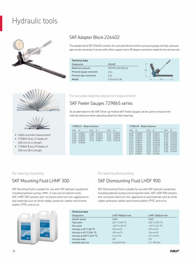
610
245
SKF Adapter Block 226402
The adapter block SKF 226402 consists of a cast steel block to which a pressure gauge and high-pressure
pipe can be connected. It comes with a floor support and a 90 degree connection nipple for the oil reservoir.
Designation 226402
Maximum pressure 400 MPa (58 000 psi)
Pressure gauge connection G 1/2
Pressure pipe connection G 3/4
Weight 2,55 kg (5.6 lb)
Technical data
Hydraulic tools
729865 A - Blade thickness
mm in. mm in. mm in.
0,030,04 0,050,060,07
0.00120.00160.00200.00240.0028
0,080,090,100,12
0.00310.00350.00390.0047
0,140,150,200,30
0.00550.00590.00790.0118
729865 B - Blade thickness
mm in. mm in. mm in.
0,050,090,100,110,120,130,140,150,160,17
0.00200.00350.00390.00430.00470.00510.00550.00590.00630.0067
0,180,190,200,250,300,350,400,450,500,55
0.00710.00750.00790.00980.01180.01380.01570.01770.01970.0216
0,600,650,700,750,800,850,900,951,00
0.02360.02560.02760.02950.03150.03350.03540.03740.0394
For accurate bearing clearance measurement
SKF Feeler Gauges 729865 series
As an alternative to the SKF Drive-up method SKF Feeler Gauges can be used to measure the
internal clearance when adjusting spherical roller bearings.
• Highly accurate measurement
• 729865 A has 13 blades of
100 mm (4 in.) length
• 729865 B has 29 blades of
200 mm (8 in.) length
For bearing dismounting
SKF Dismounting Fluid LHDF 900
SKF Dismounting Fluid is suitable for use with SKF hydraulic equipment,
including hydraulic pumps and oil injection tools. SKF LHDF 900 contains
anti-corrosives which are non-aggressive to seal materials such as nitrile
rubber, perbunan, leather and chrome leather, PTFE, and so on.
For bearing mounting
SKF Mounting Fluid LHMF 300
SKF Mounting Fluid is suitable for use with SKF hydraulic equipment,
including hydraulic pumps, HMV ..E nuts and oil injection tools.
SKF LHMF 300 contains anti-corrosives which are non-aggressive to
seal materials such as nitrile rubber, perbunan, leather and chrome
leather, PTFE, and so on.
Designation LHDF 900/pack size LHMF 300/pack size
Specific gravity 0,885 0,882
Flash point 202 °C (395 °F) 200 °C (390 °F)
Pour point –28 °C (–18 °F) –30 °C (–22 °F)
Viscosity at 20 °C (68 °F) 910 mm2/s 307 mm2/s
Viscosity at 40 °C (104 °F) 330 mm2/s 116 mm2/s
Viscosity at 100 °C (212 °F) 43 mm2/s 17,5 mm2/s
Viscosity index 187 167
Available pack size 5 and 205 litre 1, 5, 205 litre
Technical data
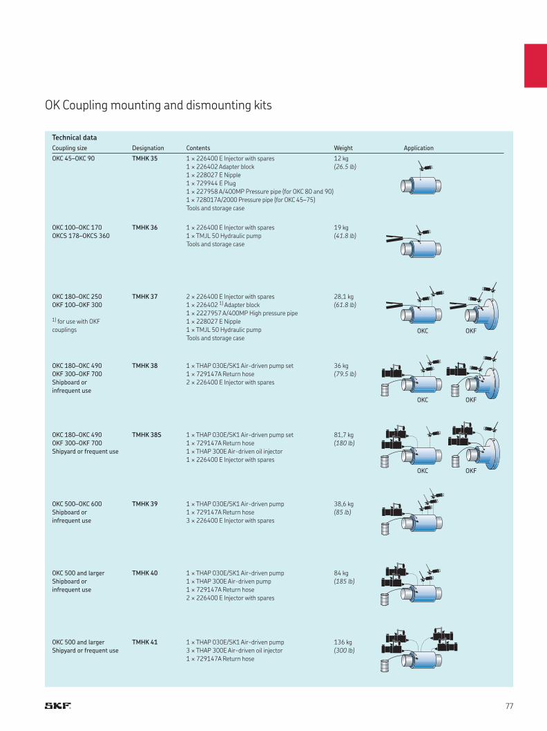
OKC
OKC
OKC
OKF
OKF
OKF
Coupling size Designation Contents Weight Application
OKC 45–OKC 90 TMHK 35 1 × 226400 E Injector with spares
1 × 226402 Adapter block
1 × 228027 E Nipple
1 × 729944 E Plug
1 × 227958 A/400MP Pressure pipe (for OKC 80 and 90)
1 × 728017A/2000 Pressure pipe (for OKC 45–75)
Tools and storage case
12 kg
(26.5 lb)
OKC 100–OKC 170
OKCS 178–OKCS 360
TMHK 36 1 × 226400 E Injector with spares
1 × TMJL 50 Hydraulic pump
Tools and storage case
19 kg
(41.8 lb)
OKC 180–OKC 250
OKF 100–OKF 300
1) for use with OKF
couplings
TMHK 37 2 × 226400 E Injector with spares
1 × 226402 1) Adapter block
1 × 2227957 A/400MP High pressure pipe
1 × 228027 E Nipple
1 × TMJL 50 Hydraulic pump
Tools and storage case
28,1 kg
(61.8 lb)
OKC 180–OKC 490
OKF 300–OKF 700
Shipboard or
infrequent use
TMHK 38 1 × THAP 030E/SK1 Air-driven pump set
1 × 729147A Return hose
2 × 226400 E Injector with spares
36 kg
(79.5 lb)
OKC 180–OKC 490
OKF 300–OKF 700
Shipyard or frequent use
TMHK 38S 1 × THAP 030E/SK1 Air-driven pump set
1 × 729147A Return hose
1 × THAP 300E Air-driven oil injector
1 × 226400 E Injector with spares
81,7 kg
(180 lb)
OKC 500–OKC 600
Shipboard or
infrequent use
TMHK 39 1 × THAP 030E/SK1 Air-driven pump
1 × 729147A Return hose
3 × 226400 E Injector with spares
38,6 kg
(85 lb)
OKC 500 and larger
Shipboard or
infrequent use
TMHK 40 1 × THAP 030E/SK1 Air-driven pump
1 × THAP 300E Air-driven pump
1 × 729147A Return hose
2 × 226400 E Injector with spares
84 kg
(185 lb)
OKC 500 and larger
Shipyard or frequent use
TMHK 41 1 × THAP 030E/SK1 Air-driven pump
3 × THAP 300E Air-driven oil injector
1 × 729147A Return hose
136 kg
(300 lb)
OK Coupling mounting and dismounting kits
Technical data
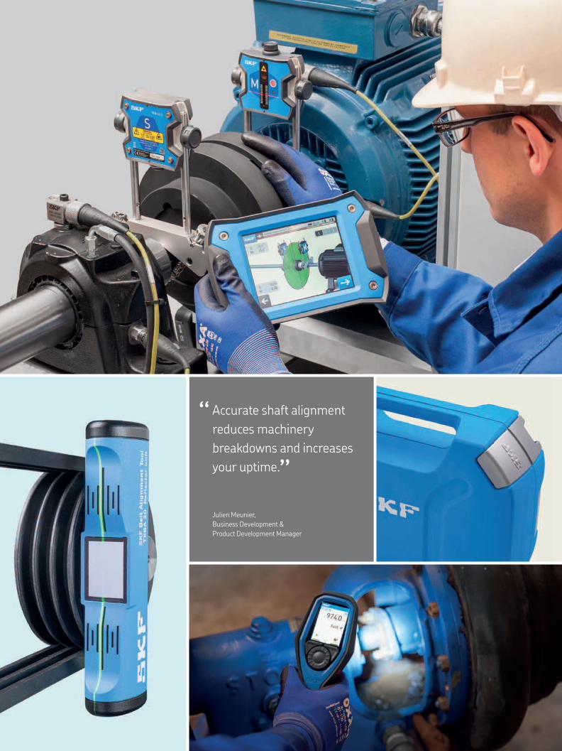
Accurate shaft alignment
reduces machinery
breakdowns and increases
your uptime.
“ “
Julien Meunier,
Business Development &
Product Development Manager
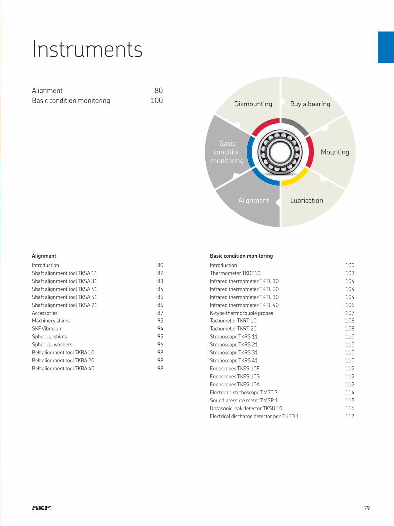
Alignment
Introduction 80
Shaft alignment tool TKSA 11 82
Shaft alignment tool TKSA 31 83
Shaft alignment tool TKSA 41 84
Shaft alignment tool TKSA 51 85
Shaft alignment tool TKSA 71 86
Accessories 87
Machinery shims 92
SKF Vibracon 94
Spherical shims 95
Spherical washers 96
Belt alignment tool TKBA 10 98
Belt alignment tool TKBA 20 98
Belt alignment tool TKBA 40 98
Basic condition monitoring
Introduction 100
Thermometer TKDT10 103
Infrared thermometer TKTL 10 104
Infrared thermometer TKTL 20 104
Infrared thermometer TKTL 30 104
Infrared thermometer TKTL 40 105
K-type thermocouple probes 107
Tachometer TKRT 10 108
Tachometer TKRT 20 108
Stroboscope TKRS 11 110
Stroboscope TKRS 21 110
Stroboscope TKRS 31 110
Stroboscope TKRS 41 110
Endoscopes TKES 10F 112
Endoscopes TKES 10S 112
Endoscopes TKES 10A 112
Electronic stethoscope TMST 3 114
Sound pressure meter TMSP 1 115
Ultrasonic leak detector TKSU 10 116
Electrical discharge detector pen TKED 1 117
Instruments
Alignment 80
Basic condition monitoring 100
Alignment Lubrication
Mounting
Buy a bearing
Basic condition
monitoring
Dismounting
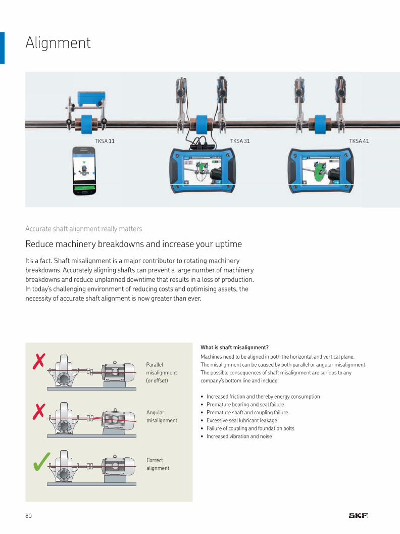
TKSA 11 TKSA 31 TKSA 41
Parallel
misalignment
(or offset)
Angular
misalignment
Correct
alignment
Alignment
Accurate shaft alignment really matters
Reduce machinery breakdowns and increase your uptime
It’s a fact. Shaft misalignment is a major contributor to rotating machinery
breakdowns. Accurately aligning shafts can prevent a large number of machinery
breakdowns and reduce unplanned downtime that results in a loss of production.
In today’s challenging environment of reducing costs and optimising assets, the
necessity of accurate shaft alignment is now greater than ever.
What is shaft misalignment?
Machines need to be aligned in both the horizontal and vertical plane.
The misalignment can be caused by both parallel or angular misalignment.
The possible consequences of shaft misalignment are serious to any
company’s bottom line and include:
• Increased friction and thereby energy consumption
• Premature bearing and seal failure
• Premature shaft and coupling failure
• Excessive seal lubricant leakage
• Failure of coupling and foundation bolts
• Increased vibration and noise
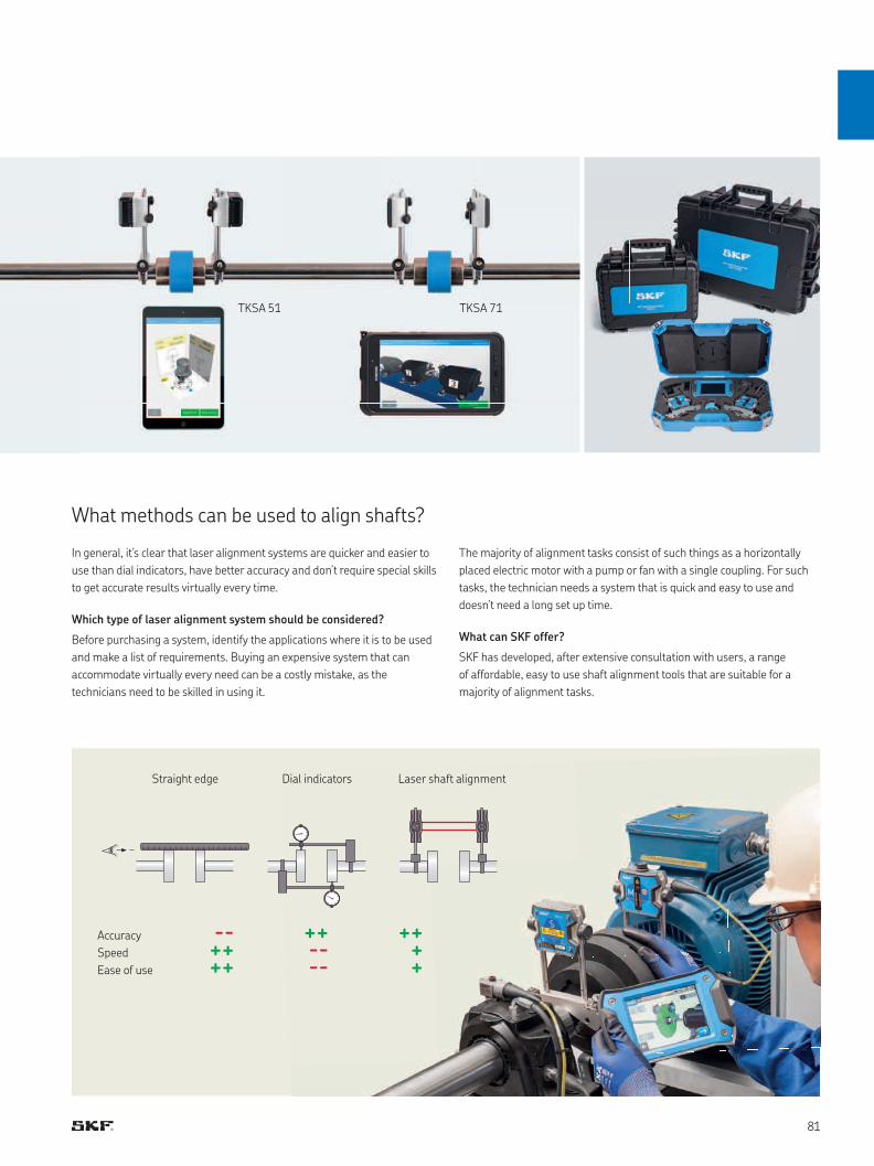
TKSA 80
--++++
++----
++++
TKSA 51 TKSA 71
What methods can be used to align shafts?
Accuracy
Speed
Ease of use
In general, it’s clear that laser alignment systems are quicker and easier to
use than dial indicators, have better accuracy and don’t require special skills
to get accurate results virtually every time.
Which type of laser alignment system should be considered?
Before purchasing a system, identify the applications where it is to be used
and make a list of requirements. Buying an expensive system that can
accommodate virtually every need can be a costly mistake, as the
technicians need to be skilled in using it.
The majority of alignment tasks consist of such things as a horizontally
placed electric motor with a pump or fan with a single coupling. For such
tasks, the technician needs a system that is quick and easy to use and
doesn’t need a long set up time.
What can SKF offer?
SKF has developed, after extensive consultation with users, a range
of affordable, easy to use shaft alignment tools that are suitable for a
majority of alignment tasks.
Straight edge Dial indicators Laser shaft alignment
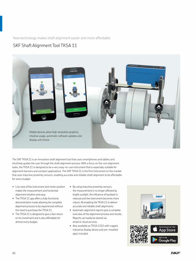
The SKF TKSA 11 is an innovative shaft alignment tool that uses smartphones and tablets and
intuitively guides the user through the shaft alignment process. With a focus on the core alignment
tasks, the TKSA 11 is designed to be a very easy-to-use instrument that is especially suitable for
alignment learners and compact applications. The SKF TKSA 11 is the first instrument on the market
that uses inductive proximity sensors, enabling accurate and reliable shaft alignment to be affordable
for every budget.
• Live view of the instrument and motor position
makes the measurement and horizontal
alignment intuitive and easy.
• The TKSA 11 app offers a fully functional
demonstration mode allowing the complete
alignment process to be experienced without
the need to purchase the TKSA 11.
• The TKSA 11 is designed to give a fast return
on its investment and is also affordable for
almost every budget.
• By using inductive proximity sensors,
the measurement is no longer affected by
bright sunlight, the influence of backlash is
reduced and the instrument becomes more
robust. All enabling the TKSA 11 to deliver
accurate and reliable shaft alignments.
• Automatic alignment reports give a complete
overview of the alignment process and results.
Reports can easily be shared via
email or cloud services.
• Also available as TKSA 11D2 with rugged,
industrial display device and pre-installed
apps included.
New technology makes shaft alignment easier and more affordable
SKF Shaft Alignment Tool TKSA 11
Mobile devices allow high resolution graphics,
intuitive usage, automatic software updates and
display unit choice.

The intuitive and affordable laser shaft alignment system
SKF Shaft Alignment Tool TKSA 31
The TKSA 31 is SKF’s most affordable solution for easy laser shaft alignment. The ergonomic display
unit with touch screen makes the instrument very easy to use and the built-in machine library helps
storing alignment reports for multiple machines. Large sized laser detectors in the measuring heads
reduce the need for pre-alignments and the embedded soft foot tool helps establish the foundation
for a successful alignment. Additional functions such as live view and automatic measurement
support fast and effective alignment tasks and make the TKSA 31 an innovative laser shaft alignment
tool that is affordable for almost every budget.
• Easy measurements can be performed
by using the well-known three position
measurement (9-12-3 o’clock) with additional
positioning flexibility of 40°
around each measurement position.
• High affordability is achieved by focussing
on the standard shaft alignment process
and essential functions to allow quick and
effective shaft alignments.
• "Automatic measurement” enables hands-free
measurements by detecting the position of the
heads and only taking a measurement when
the heads are in the right position.
• Automatic reports are generated after each
alignment and can be customised with notes
about the application. All reports can be
exported as pdf files.
• The machine library gives an overview
of all machines and alignment reports.
It simplifies the machine identification
and improves the alignment workflow.
Live view supports intuitive measurements and
facilitates horizontal and vertical machine
position corrections.
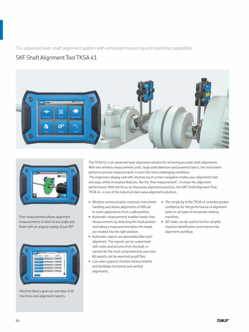
The advanced laser shaft alignment system with enhanced measuring and reporting capabilities
SKF Shaft Alignment Tool TKSA 41
The TKSA 41 is an advanced laser alignment solution for achieving accurate shaft alignments.
With two wireless measurement units, large sized detectors and powerful lasers, the instrument
performs precise measurements in even the most challenging conditions.
The ergonomic display unit with intuitive touch screen navigation makes your alignments fast
and easy, whilst innovative features, like the “free measurement”, increase the alignment
performance. With the focus on improving alignment practices, the SKF Shaft Alignment Tool,
TKSA 41, is one of the industry’s best value alignment solutions.
Free measurement allows alignment
measurements to start at any angle and
finish with an angular sweep of just 90°.
Machine library gives an overview of all
machines and alignment reports.
• Wireless communication improves instrument
handling and allows alignments of difficult
to reach applications from a safe position.
• Automatic measurement enables hands-free
measurements by detecting the head position
and taking a measurement when the heads
are rotated into the right position.
• Automatic reports are generated after each
alignment. The reports can be customised
with notes and pictures from the built-in
camera for the most comprehensive overview.
All reports can be exported as pdf files.
• Live view supports intuitive measurements
and facilitates horizontal and vertical
alignments.
• The simplicity of the TKSA 41 provides greater
confidence for the performance of alignment
tasks on all types of horizontal rotating
machines.
• QR codes can be used to further simplify
machine identification and improve the
alignment workflow.
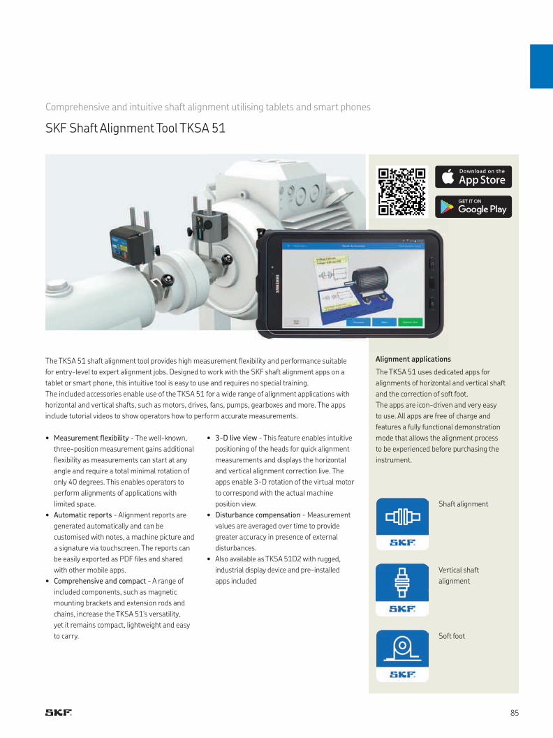
Alignment applications
The TKSA 51 uses dedicated apps for
alignments of horizontal and vertical shaft
and the correction of soft foot.
The apps are icon-driven and very easy
to use. All apps are free of charge and
features a fully functional demonstration
mode that allows the alignment process
to be experienced before purchasing the
instrument.
Comprehensive and intuitive shaft alignment utilising tablets and smart phones
SKF Shaft Alignment Tool TKSA 51
The TKSA 51 shaft alignment tool provides high measurement flexibility and performance suitable
for entry-level to expert alignment jobs. Designed to work with the SKF shaft alignment apps on a
tablet or smart phone, this intuitive tool is easy to use and requires no special training.
The included accessories enable use of the TKSA 51 for a wide range of alignment applications with
horizontal and vertical shafts, such as motors, drives, fans, pumps, gearboxes and more. The apps
include tutorial videos to show operators how to perform accurate measurements.
Shaft alignment
Vertical shaft
alignment
Soft foot
• Measurement flexibility - The well-known,
three-position measurement gains additional
flexibility as measurements can start at any
angle and require a total minimal rotation of
only 40 degrees. This enables operators to
perform alignments of applications with
limited space.
• Automatic reports - Alignment reports are
generated automatically and can be
customised with notes, a machine picture and
a signature via touchscreen. The reports can
be easily exported as PDF files and shared
with other mobile apps.
• Comprehensive and compact - A range of
included components, such as magnetic
mounting brackets and extension rods and
chains, increase the TKSA 51’s versatility,
yet it remains compact, lightweight and easy
to carry.
• 3-D live view - This feature enables intuitive
positioning of the heads for quick alignment
measurements and displays the horizontal
and vertical alignment correction live. The
apps enable 3-D rotation of the virtual motor
to correspond with the actual machine
position view.
• Disturbance compensation - Measurement
values are averaged over time to provide
greater accuracy in presence of external
disturbances.
• Also available as TKSA 51D2 with rugged,
industrial display device and pre-installed
apps included
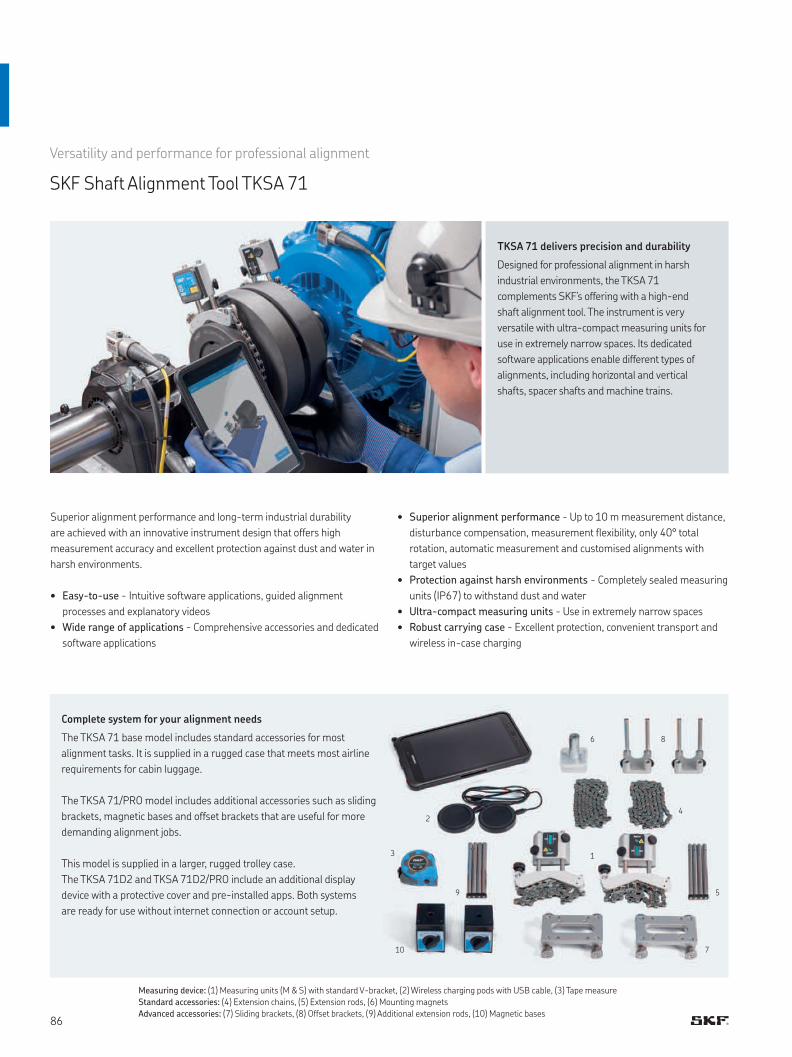
8
13
24
59
6
710
Versatility and performance for professional alignment
SKF Shaft Alignment Tool TKSA 71
Superior alignment performance and long-term industrial durability
are achieved with an innovative instrument design that offers high
measurement accuracy and excellent protection against dust and water in
harsh environments.
• Easy-to-use - Intuitive software applications, guided alignment
processes and explanatory videos
• Wide range of applications - Comprehensive accessories and dedicated
software applications
• Superior alignment performance - Up to 10 m measurement distance,
disturbance compensation, measurement flexibility, only 40° total
rotation, automatic measurement and customised alignments with
target values
• Protection against harsh environments - Completely sealed measuring
units (IP67) to withstand dust and water
• Ultra-compact measuring units - Use in extremely narrow spaces
• Robust carrying case - Excellent protection, convenient transport and
wireless in-case charging
Complete system for your alignment needs
The TKSA 71 base model includes standard accessories for most
alignment tasks. It is supplied in a rugged case that meets most airline
requirements for cabin luggage.
The TKSA 71/PRO model includes additional accessories such as sliding
brackets, magnetic bases and offset brackets that are useful for more
demanding alignment jobs.
This model is supplied in a larger, rugged trolley case.
The TKSA 71D2 and TKSA 71D2/PRO include an additional display
device with a protective cover and pre-installed apps. Both systems
are ready for use without internet connection or account setup.
Measuring device: (1) Measuring units (M & S) with standard V-bracket, (2) Wireless charging pods with USB cable, (3) Tape measure
Standard accessories: (4) Extension chains, (5) Extension rods, (6) Mounting magnets
Advanced accessories: (7) Sliding brackets, (8) Offset brackets, (9) Additional extension rods, (10) Magnetic bases
TKSA 71 delivers precision and durability
Designed for professional alignment in harsh
industrial environments, the TKSA 71
complements SKF’s offering with a high-end
shaft alignment tool. The instrument is very
versatile with ultra-compact measuring units for
use in extremely narrow spaces. Its dedicated
software applications enable different types of
alignments, including horizontal and vertical
shafts, spacer shafts and machine trains.
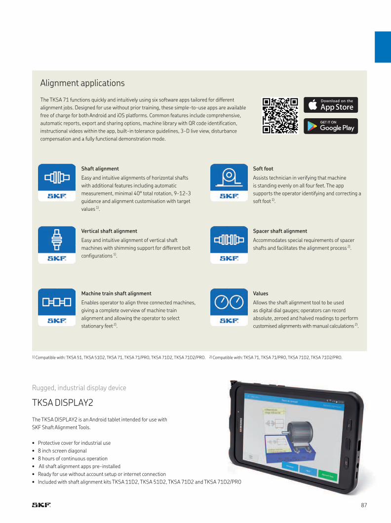
Rugged, industrial display device
TKSA DISPLAY2
Alignment applications
The TKSA 71 functions quickly and intuitively using six software apps tailored for different
alignment jobs. Designed for use without prior training, these simple-to-use apps are available
free of charge for both Android and iOS platforms. Common features include comprehensive,
automatic reports, export and sharing options, machine library with QR code identification,
instructional videos within the app, built-in tolerance guidelines, 3-D live view, disturbance
compensation and a fully functional demonstration mode.
Shaft alignment
Easy and intuitive alignments of horizontal shafts
with additional features including automatic
measurement, minimal 40° total rotation, 9-12-3
guidance and alignment customisation with target
values 1).
Vertical shaft alignment
Easy and intuitive alignment of vertical shaft
machines with shimming support for different bolt
configurations 1).
Machine train shaft alignment
Enables operator to align three connected machines,
giving a complete overview of machine train
alignment and allowing the operator to select
stationary feet 2).
Soft foot
Assists technician in verifying that machine
is standing evenly on all four feet. The app
supports the operator identifying and correcting a
soft foot 1).
Spacer shaft alignment
Accommodates special requirements of spacer
shafts and facilitates the alignment process 2).
Values
Allows the shaft alignment tool to be used
as digital dial gauges; operators can record
absolute, zeroed and halved readings to perform
customised alignments with manual calculations 2).
The TKSA DISPLAY2 is an Android tablet intended for use with
SKF Shaft Alignment Tools.
• Protective cover for industrial use
• 8 inch screen diagonal
• 8 hours of continuous operation
• All shaft alignment apps pre-installed
• Ready for use without account setup or internet connection
• Included with shaft alignment kits TKSA 11D2, TKSA 51D2, TKSA 71D2 and TKSA 71D2/PRO
1) Compatible with: TKSA 51, TKSA 51D2, TKSA 71, TKSA 71/PRO, TKSA 71D2, TKSA 71D2/PRO. 2) Compatible with: TKSA 71, TKSA 71/PRO, TKSA 71D2, TKSA 71D2/PRO.
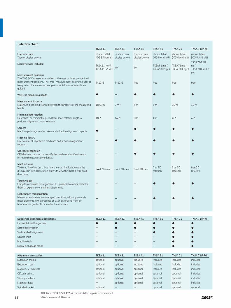
TKSA 11 TKSA 31 TKSA 41 TKSA 51 TKSA 71 TKSA 71/PRO
User interface Type of display device
phone, tablet(iOS & Android)
touch screen display device
touch screen display device
phone, tablet(iOS & Android)
phone, tablet(iOS & Android)
phone, tablet(iOS & Android)
Display device includedTKSA 11: no 1) TKSA 11D2: yes
yes yesTKSA 51: no 1) TKSA 51D2: yes
TKSA 71: no 1) TKSA 71D2: yes
TKSA 71/PRO: no 1) TKSA 71D2/PRO: yes
Measurement positions The ”9-12-3” measurement directs the user to three pre-defined measurement positions. The ”free” measurement allows the user to freely select the measurement positions. All measurements are guided.
9-12-3 9-12-3 free free free free
Wireless measuring heads • - • • • •Measurment distance Maximum possible distance between the brackets of the measuring heads.
18,5 cm 2 m 2) 4 m 5 m 10 m 10 m
Minimal shaft rotation Describes the minimal required total shaft rotation angle to perform alignment measurements.
180° 140° 90° 40° 40° 40°
Camera Machine picture(s) can be taken and added to alignment reports.
• - • • • •
Machine library Overview of all registered machines and previous alignment reports.
- • • • • •
QR code recognition QR labels can be used to simplify the machine identification and increase the usage convenience.
- - • • • •
Machine view The machine view describes how the machine is shown on the display. The free 3D rotation allows to view the machine from all directions.
fixed 2D view fixed 3D view fixed 3D viewfree 3D rotation
free 3D rotation
free 3D rotation
Target values Using target values for alignment, it is possible to compensate for thermal expansion or similar adjustments.
- - - • • •
Disturbance compensation Measurement values are averaged over time, allowing accurate measurements in the presence of laser distortions from air temperature gradients or similar disturbances.
- - - • • •
Supported alignment applications TKSA 11 TKSA 31 TKSA 41 TKSA 51 TKSA 71 TKSA 71/PRO
Horizontal shaft alignment • • • • • •Soft foot correction - • • • • •Vertical shaft alignment - - - • • •Spacer shaft - - - - • •Machine train - - - - • •Digital dial gauge mode - - - - • •
Alignment accessories TKSA 11 TKSA 31 TKSA 41 TKSA 51 TKSA 71 TKSA 71/PRO
Extension chains optional optional included included included included
Extension rods optional optional included included included included
Magnetic V-brackets optional optional optional included included included
Offset brackets optional optional optional optional optional included
Sliding brackets optional optional optional optional optional included
Magnetic base - optional optional optional optional included
Spindle bracket optional - - optional optional optional
Selection chart
1) Optional TKSA DISPLAY2 with pre-installed apps is recommended 2) With supplied USB cables
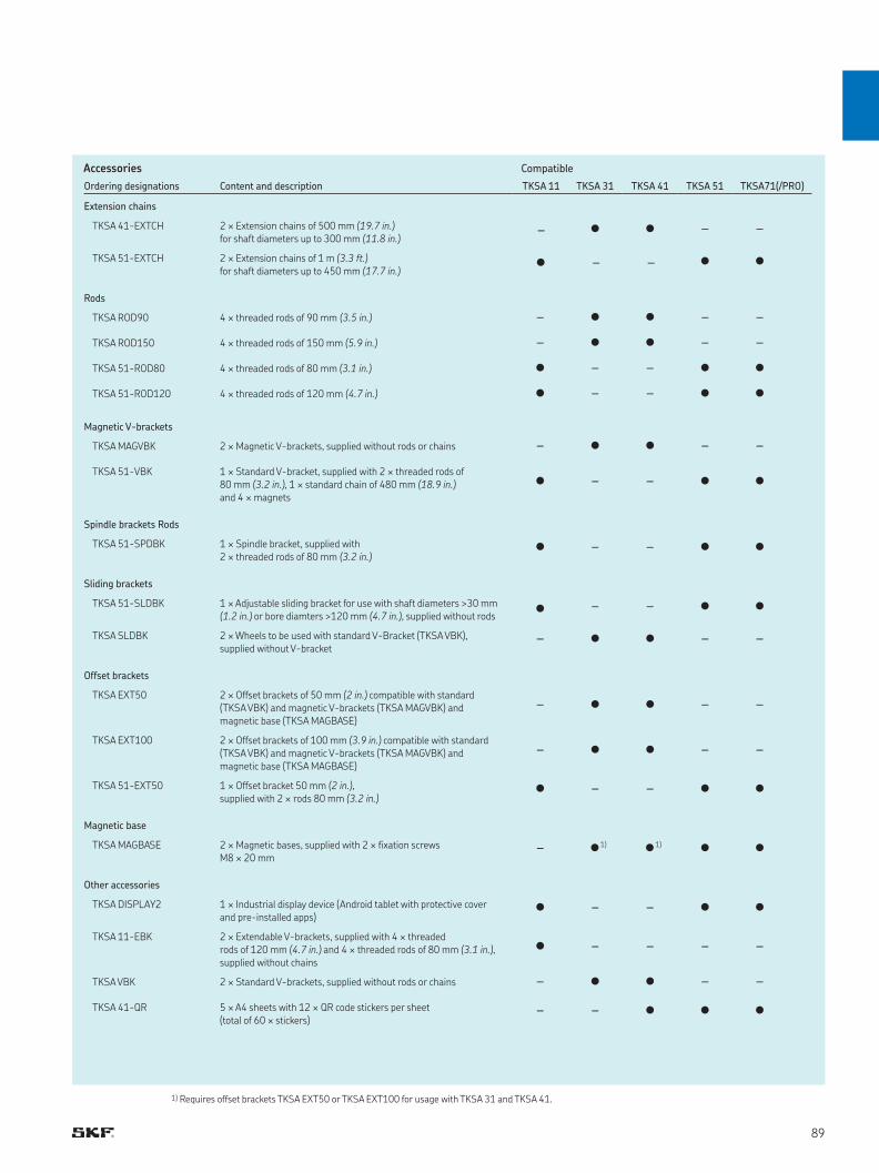
Ordering designations Content and description TKSA 11 TKSA 31 TKSA 41 TKSA 51 TKSA71(/PRO)
Extension chains
TKSA 41-EXTCH 2 × Extension chains of 500 mm (19.7 in.) for shaft diameters up to 300 mm (11.8 in.) - • • - -
TKSA 51-EXTCH 2 × Extension chains of 1 m (3.3 ft.) for shaft diameters up to 450 mm (17.7 in.) • - - • •
Rods
TKSA ROD90 4 × threaded rods of 90 mm (3.5 in.) - • • - -TKSA ROD150 4 × threaded rods of 150 mm (5.9 in.) - • • - -TKSA 51-ROD80 4 × threaded rods of 80 mm (3.1 in.) • - - • •TKSA 51-ROD120 4 × threaded rods of 120 mm (4.7 in.) • - - • •
Magnetic V-brackets
TKSA MAGVBK 2 × Magnetic V-brackets, supplied without rods or chains - • • - -TKSA 51-VBK 1 × Standard V-bracket, supplied with 2 × threaded rods of
80 mm (3.2 in.), 1 × standard chain of 480 mm (18.9 in.) and 4 × magnets
• - - • •
Spindle brackets Rods
TKSA 51-SPDBK 1 × Spindle bracket, supplied with 2 × threaded rods of 80 mm (3.2 in.)
• - - • •
Sliding brackets
TKSA 51-SLDBK 1 × Adjustable sliding bracket for use with shaft diameters >30 mm (1.2 in.) or bore diamters >120 mm (4.7 in.), supplied without rods • - - • •
TKSA SLDBK 2 × Wheels to be used with standard V-Bracket (TKSA VBK), supplied without V-bracket
- • • - -
Offset brackets
TKSA EXT50 2 × Offset brackets of 50 mm (2 in.) compatible with standard (TKSA VBK) and magnetic V-brackets (TKSA MAGVBK) and magnetic base (TKSA MAGBASE)
- • • - -
TKSA EXT100 2 × Offset brackets of 100 mm (3.9 in.) compatible with standard (TKSA VBK) and magnetic V-brackets (TKSA MAGVBK) and magnetic base (TKSA MAGBASE)
- • • - -
TKSA 51-EXT50 1 × Offset bracket 50 mm (2 in.), supplied with 2 × rods 80 mm (3.2 in.)
• - - • •
Magnetic base
TKSA MAGBASE 2 × Magnetic bases, supplied with 2 × fixation screws M8 × 20 mm
- •1) •1) • •
Other accessories
TKSA DISPLAY2 1 × Industrial display device (Android tablet with protective cover and pre-installed apps)
• - - • •
TKSA 11-EBK 2 × Extendable V-brackets, supplied with 4 × threaded rods of 120 mm (4.7 in.) and 4 × threaded rods of 80 mm (3.1 in.), supplied without chains
• - - - -
TKSA VBK 2 × Standard V-brackets, supplied without rods or chains - • • - -TKSA 41-QR 5 × A4 sheets with 12 × QR code stickers per sheet
(total of 60 × stickers)- - • • •
Accessories Compatible
1) Requires offset brackets TKSA EXT50 or TKSA EXT100 for usage with TKSA 31 and TKSA 41.
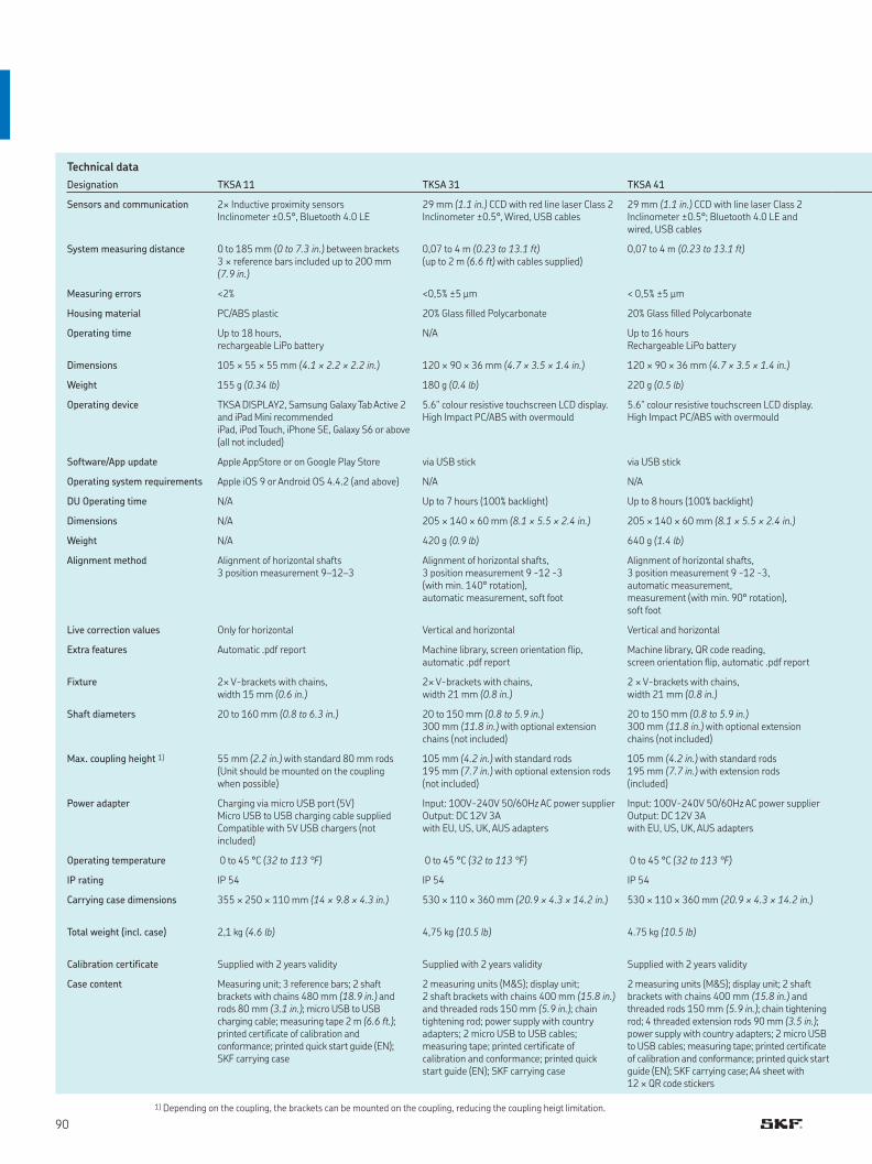
Technical data
Designation TKSA 11 TKSA 31 TKSA 41
Sensors and communication 2× Inductive proximity sensors Inclinometer ±0.5°, Bluetooth 4.0 LE
29 mm (1.1 in.) CCD with red line laser Class 2 Inclinometer ±0.5°, Wired, USB cables
29 mm (1.1 in.) CCD with line laser Class 2 Inclinometer ±0.5°; Bluetooth 4.0 LE and wired, USB cables
System measuring distance 0 to 185 mm (0 to 7.3 in.) between brackets3 × reference bars included up to 200 mm (7.9 in.)
0,07 to 4 m (0.23 to 13.1 ft)(up to 2 m (6.6 ft) with cables supplied)
0,07 to 4 m (0.23 to 13.1 ft)
Measuring errors <2% <0,5% ±5 μm < 0,5% ±5 μm
Housing material PC/ABS plastic 20% Glass filled Polycarbonate 20% Glass filled Polycarbonate
Operating time Up to 18 hours,rechargeable LiPo battery
N/A Up to 16 hoursRechargeable LiPo battery
Dimensions 105 × 55 × 55 mm (4.1 × 2.2 × 2.2 in.) 120 × 90 × 36 mm (4.7 × 3.5 × 1.4 in.) 120 × 90 × 36 mm (4.7 × 3.5 × 1.4 in.)
Weight 155 g (0.34 lb) 180 g (0.4 lb) 220 g (0.5 lb)
Operating device TKSA DISPLAY2, Samsung Galaxy Tab Active 2 and iPad Mini recommendediPad, iPod Touch, iPhone SE, Galaxy S6 or above (all not included)
5.6" colour resistive touchscreen LCD display. High Impact PC/ABS with overmould
5.6" colour resistive touchscreen LCD display. High Impact PC/ABS with overmould
Software/App update Apple AppStore or on Google Play Store via USB stick via USB stick
Operating system requirements Apple iOS 9 or Android OS 4.4.2 (and above) N/A N/A
DU Operating time N/A Up to 7 hours (100% backlight) Up to 8 hours (100% backlight)
Dimensions N/A 205 × 140 × 60 mm (8.1 × 5.5 × 2.4 in.) 205 × 140 × 60 mm (8.1 × 5.5 × 2.4 in.)
Weight N/A 420 g (0.9 lb) 640 g (1.4 lb)
Alignment method Alignment of horizontal shafts 3 position measurement 9–12–3
Alignment of horizontal shafts,3 position measurement 9 -12 -3 (with min. 140° rotation),automatic measurement, soft foot
Alignment of horizontal shafts,3 position measurement 9 -12 -3,automatic measurement, measurement (with min. 90° rotation), soft foot
Live correction values Only for horizontal Vertical and horizontal Vertical and horizontal
Extra features Automatic .pdf report Machine library, screen orientation flip, automatic .pdf report
Machine library, QR code reading, screen orientation flip, automatic .pdf report
Fixture 2× V-brackets with chains, width 15 mm (0.6 in.)
2× V-brackets with chains, width 21 mm (0.8 in.)
2 × V-brackets with chains, width 21 mm (0.8 in.)
Shaft diameters 20 to 160 mm (0.8 to 6.3 in.) 20 to 150 mm (0.8 to 5.9 in.) 300 mm (11.8 in.) with optional extension chains (not included)
20 to 150 mm (0.8 to 5.9 in.) 300 mm (11.8 in.) with optional extension chains (not included)
Max. coupling height 1) 55 mm (2.2 in.) with standard 80 mm rods(Unit should be mounted on the coupling when possible)
105 mm (4.2 in.) with standard rods195 mm (7.7 in.) with optional extension rods (not included)
105 mm (4.2 in.) with standard rods195 mm (7.7 in.) with extension rods (included)
Power adapter Charging via micro USB port (5V) Micro USB to USB charging cable supplied Compatible with 5V USB chargers (not included)
Input: 100V-240V 50/60Hz AC power supplier Output: DC 12V 3A with EU, US, UK, AUS adapters
Input: 100V-240V 50/60Hz AC power supplier Output: DC 12V 3A with EU, US, UK, AUS adapters
Operating temperature 0 to 45 °C (32 to 113 °F) 0 to 45 °C (32 to 113 °F) 0 to 45 °C (32 to 113 °F)
IP rating IP 54 IP 54 IP 54
Carrying case dimensions 355 × 250 × 110 mm (14 × 9.8 × 4.3 in.) 530 × 110 × 360 mm (20.9 × 4.3 × 14.2 in.) 530 × 110 × 360 mm (20.9 × 4.3 × 14.2 in.)
Total weight (incl. case) 2,1 kg (4.6 lb) 4,75 kg (10.5 lb) 4.75 kg (10.5 lb)
Calibration certificate Supplied with 2 years validity Supplied with 2 years validity Supplied with 2 years validity
Case content Measuring unit; 3 reference bars; 2 shaft brackets with chains 480 mm (18.9 in.) and rods 80 mm (3.1 in.); micro USB to USB charging cable; measuring tape 2 m (6.6 ft.); printed certificate of calibration and conformance; printed quick start guide (EN); SKF carrying case
2 measuring units (M&S); display unit; 2 shaft brackets with chains 400 mm (15.8 in.) and threaded rods 150 mm (5.9 in.); chain tightening rod; power supply with country adapters; 2 micro USB to USB cables; measuring tape; printed certificate of calibration and conformance; printed quick start guide (EN); SKF carrying case
2 measuring units (M&S); display unit; 2 shaft brackets with chains 400 mm (15.8 in.) and threaded rods 150 mm (5.9 in.); chain tightening rod; 4 threaded extension rods 90 mm (3.5 in.); power supply with country adapters; 2 micro USB to USB cables; measuring tape; printed certificate of calibration and conformance; printed quick start guide (EN); SKF carrying case; A4 sheet with 12 × QR code stickers
1) Depending on the coupling, the brackets can be mounted on the coupling, reducing the coupling heigt limitation.
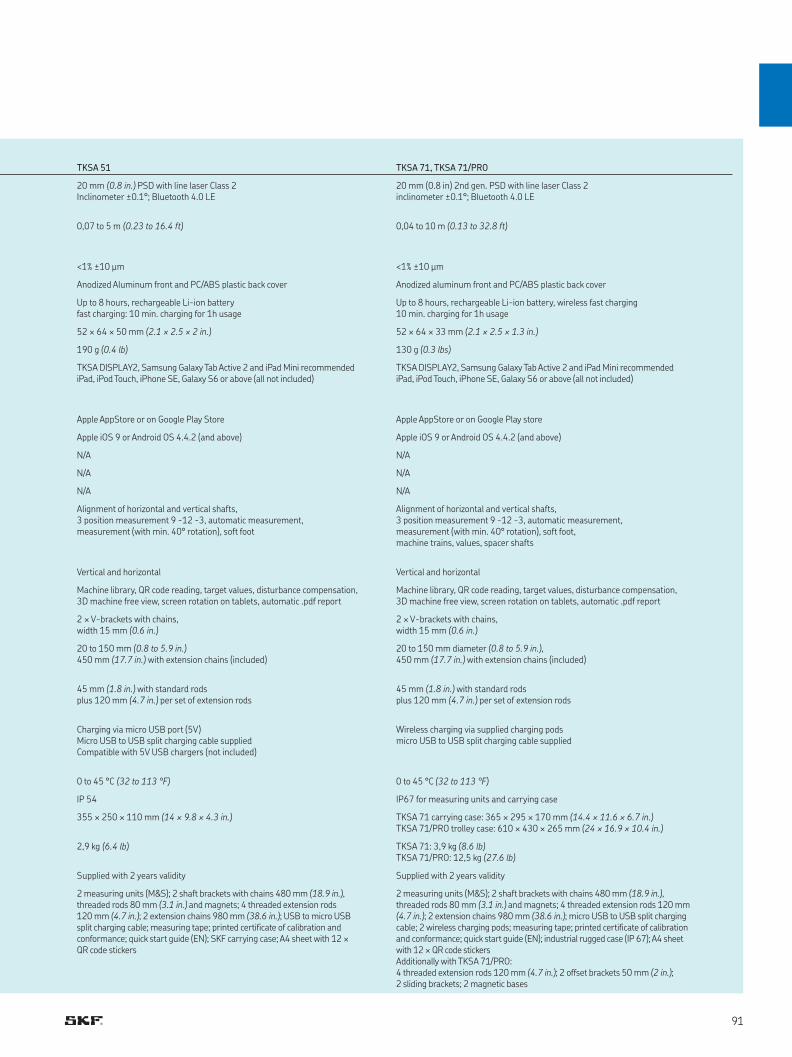
TKSA 51 TKSA 71, TKSA 71/PRO
20 mm (0.8 in.) PSD with line laser Class 2 Inclinometer ±0.1°; Bluetooth 4.0 LE
20 mm (0.8 in) 2nd gen. PSD with line laser Class 2inclinometer ±0.1°; Bluetooth 4.0 LE
0,07 to 5 m (0.23 to 16.4 ft) 0,04 to 10 m (0.13 to 32.8 ft)
<1% ±10 μm <1% ±10 μm
Anodized Aluminum front and PC/ABS plastic back cover Anodized aluminum front and PC/ABS plastic back cover
Up to 8 hours, rechargeable Li-ion batteryfast charging: 10 min. charging for 1h usage
Up to 8 hours, rechargeable Li-ion battery, wireless fast charging10 min. charging for 1h usage
52 × 64 × 50 mm (2.1 × 2.5 × 2 in.) 52 × 64 × 33 mm (2.1 × 2.5 × 1.3 in.)
190 g (0.4 lb) 130 g (0.3 lbs)
TKSA DISPLAY2, Samsung Galaxy Tab Active 2 and iPad Mini recommendediPad, iPod Touch, iPhone SE, Galaxy S6 or above (all not included)
TKSA DISPLAY2, Samsung Galaxy Tab Active 2 and iPad Mini recommendediPad, iPod Touch, iPhone SE, Galaxy S6 or above (all not included)
Apple AppStore or on Google Play Store Apple AppStore or on Google Play store
Apple iOS 9 or Android OS 4.4.2 (and above) Apple iOS 9 or Android OS 4.4.2 (and above)
N/A N/A
N/A N/A
N/A N/A
Alignment of horizontal and vertical shafts,3 position measurement 9 -12 -3, automatic measurement,measurement (with min. 40° rotation), soft foot
Alignment of horizontal and vertical shafts,3 position measurement 9 -12 -3, automatic measurement,measurement (with min. 40° rotation), soft foot,machine trains, values, spacer shafts
Vertical and horizontal Vertical and horizontal
Machine library, QR code reading, target values, disturbance compensation, 3D machine free view, screen rotation on tablets, automatic .pdf report
Machine library, QR code reading, target values, disturbance compensation, 3D machine free view, screen rotation on tablets, automatic .pdf report
2 × V-brackets with chains, width 15 mm (0.6 in.)
2 × V-brackets with chains, width 15 mm (0.6 in.)
20 to 150 mm (0.8 to 5.9 in.) 450 mm (17.7 in.) with extension chains (included)
20 to 150 mm diameter (0.8 to 5.9 in.), 450 mm (17.7 in.) with extension chains (included)
45 mm (1.8 in.) with standard rodsplus 120 mm (4.7 in.) per set of extension rods
45 mm (1.8 in.) with standard rodsplus 120 mm (4.7 in.) per set of extension rods
Charging via micro USB port (5V) Micro USB to USB split charging cable supplied Compatible with 5V USB chargers (not included)
Wireless charging via supplied charging podsmicro USB to USB split charging cable supplied
0 to 45 °C (32 to 113 °F) 0 to 45 °C (32 to 113 °F)
IP 54 IP67 for measuring units and carrying case
355 × 250 × 110 mm (14 × 9.8 × 4.3 in.) TKSA 71 carrying case: 365 × 295 × 170 mm (14.4 × 11.6 × 6.7 in.) TKSA 71/PRO trolley case: 610 × 430 × 265 mm (24 × 16.9 × 10.4 in.)
2,9 kg (6.4 lb) TKSA 71: 3,9 kg (8.6 lb)TKSA 71/PRO: 12,5 kg (27.6 lb)
Supplied with 2 years validity Supplied with 2 years validity
2 measuring units (M&S); 2 shaft brackets with chains 480 mm (18.9 in.), threaded rods 80 mm (3.1 in.) and magnets; 4 threaded extension rods 120 mm (4.7 in.); 2 extension chains 980 mm (38.6 in.); USB to micro USB split charging cable; measuring tape; printed certificate of calibration and conformance; quick start guide (EN); SKF carrying case; A4 sheet with 12 × QR code stickers
2 measuring units (M&S); 2 shaft brackets with chains 480 mm (18.9 in.), threaded rods 80 mm (3.1 in.) and magnets; 4 threaded extension rods 120 mm (4.7 in.); 2 extension chains 980 mm (38.6 in.); micro USB to USB split charging cable; 2 wireless charging pods; measuring tape; printed certificate of calibration and conformance; quick start guide (EN); industrial rugged case (IP 67); A4 sheet with 12 × QR code stickersAdditionally with TKSA 71/PRO:4 threaded extension rods 120 mm (4.7 in.); 2 offset brackets 50 mm (2 in.); 2 sliding brackets; 2 magnetic bases
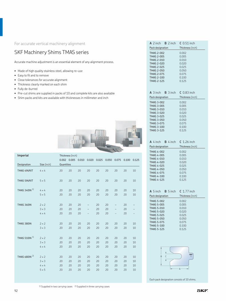
B C
A
1) Supplied in two carrying cases 2) Supplied in three carrying cases
For accurate vertical machinery alignment
SKF Machinery Shims TMAS series
Accurate machine adjustment is an essential element of any alignment process.
• Made of high quality stainless steel, allowing re-use
• Easy to fit and to remove
• Close tolerances for accurate alignment
• Thickness clearly marked on each shim
• Fully de-burred
• Pre-cut shims are supplied in packs of 10 and complete kits are also available
• Shim packs and kits are available with thicknesses in millimeter and inch
0.002 0.005 0.010 0.020 0.025 0.050 0.075 0.100 0.125
Designation Size (inch) Quantities
TMAS 4IN/KIT 4 × 4 20 20 20 20 20 20 20 20 10
TMAS 5IN/KIT 5 × 5 20 20 20 20 20 20 20 20 10
TMAS 340IN 1) 4 × 4 20 20 20 20 20 20 20 20 10
5 × 5 20 20 20 20 20 20 20 20 10
TMAS 360IN 2 × 2 20 20 20 – 20 20 – 20 –
3 × 3 20 20 20 – 20 20 – 20 –
4 × 4 20 20 20 – 20 20 – 20 –
TMAS 380IN 2 × 2 20 20 20 20 20 20 20 20 10
3 × 3 20 20 20 20 20 20 20 20 10
TMAS 510IN 1) 2 × 2 20 20 20 20 20 20 20 20 10
3 × 3 20 20 20 20 20 20 20 20 10
4 × 4 20 20 20 20 20 20 20 20 10
TMAS 680IN 2) 2 × 2 20 20 20 20 20 20 20 20 10
3 × 3 20 20 20 20 20 20 20 20 10
4 × 4 20 20 20 20 20 20 20 20 10
5 × 5 20 20 20 20 20 20 20 20 10
Thickness (inch)
Pack designation Thickness (inch)
TMAS 2-002
TMAS 2-005
TMAS 2-010
TMAS 2-020
TMAS 2-025
TMAS 2-050
TMAS 2-075
TMAS 2-100
TMAS 2-125
0.0020.0050.0100.0200.0250.0500.0750.1000.125
Pack designation Thickness (inch)
TMAS 3-002
TMAS 3-005
TMAS 3-010
TMAS 3-020
TMAS 3-025
TMAS 3-050
TMAS 3-075
TMAS 3-100
TMAS 3-125
0.0020.0050.0100.0200.0250.0500.0750.1000.125
Pack designation Thickness (inch)
TMAS 4-002
TMAS 4-005
TMAS 4-010
TMAS 4-020
TMAS 4-025
TMAS 4-050
TMAS 4-075
TMAS 4-100
TMAS 4-125
0.0020.0050.0100.0200.0250.0500.0750.1000.125
Pack designation Thickness (inch)
TMAS 5-002
TMAS 5-005
TMAS 5-010
TMAS 5-020
TMAS 5-025
TMAS 5-050
TMAS 5-075
TMAS 5-100
TMAS 5-125
0.0020.0050.0100.0200.0250.0500.0750.1000.125
A 2 inch B 2 inch C 0.51 inch
A 3 inch B 3 inch C 0.83 inch
A 4 inch B 4 inch C 1.26 inch
A 5 inch B 5 inch C 1.77 inch
Imperial
Each pack designation consists of 10 shims.
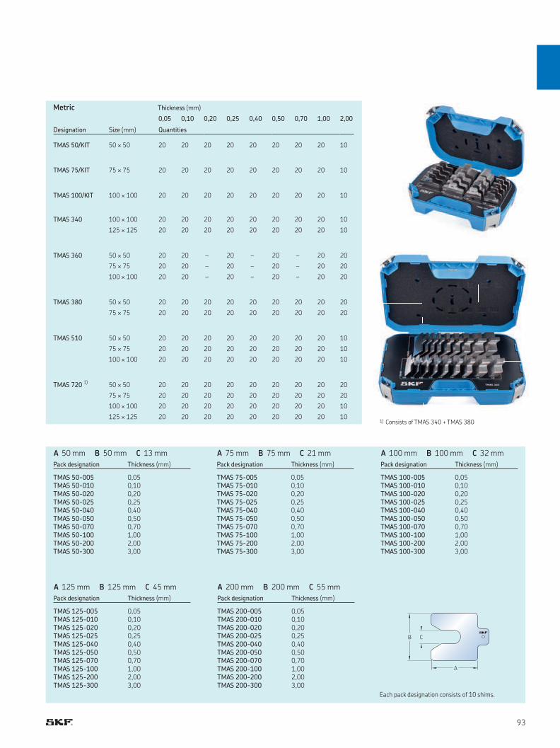
B C
A
1) Consists of TMAS 340 + TMAS 380
0,05 0,10 0,20 0,25 0,40 0,50 0,70 1,00 2,00
Designation Size (mm) Quantities
TMAS 50/KIT 50 × 50 20 20 20 20 20 20 20 20 10
TMAS 75/KIT 75 × 75 20 20 20 20 20 20 20 20 10
TMAS 100/KIT 100 × 100 20 20 20 20 20 20 20 20 10
TMAS 340 100 × 100 20 20 20 20 20 20 20 20 10
125 × 125 20 20 20 20 20 20 20 20 10
TMAS 360 50 × 50 20 20 – 20 – 20 – 20 20
75 × 75 20 20 – 20 – 20 – 20 20
100 × 100 20 20 – 20 – 20 – 20 20
TMAS 380 50 × 50 20 20 20 20 20 20 20 20 20
75 × 75 20 20 20 20 20 20 20 20 20
TMAS 510 50 × 50 20 20 20 20 20 20 20 20 10
75 × 75 20 20 20 20 20 20 20 20 10
100 × 100 20 20 20 20 20 20 20 20 10
TMAS 720 1) 50 × 50 20 20 20 20 20 20 20 20 20
75 × 75 20 20 20 20 20 20 20 20 20
100 × 100 20 20 20 20 20 20 20 20 10
125 × 125 20 20 20 20 20 20 20 20 10
Thickness (mm)
Pack designation Thickness (mm)
TMAS 75-005TMAS 75-010TMAS 75-020TMAS 75-025TMAS 75-040TMAS 75-050TMAS 75-070TMAS 75-100TMAS 75-200TMAS 75-300
0,050,100,200,250,400,500,701,002,003,00
Pack designation Thickness (mm)
TMAS 100-005TMAS 100-010TMAS 100-020TMAS 100-025TMAS 100-040TMAS 100-050TMAS 100-070TMAS 100-100TMAS 100-200TMAS 100-300
0,050,100,200,250,400,500,701,002,003,00
Pack designation Thickness (mm)
TMAS 50-005TMAS 50-010TMAS 50-020TMAS 50-025TMAS 50-040TMAS 50-050TMAS 50-070TMAS 50-100TMAS 50-200TMAS 50-300
0,050,100,200,250,400,500,701,002,003,00
Pack designation Thickness (mm)
TMAS 125-005TMAS 125-010TMAS 125-020TMAS 125-025TMAS 125-040TMAS 125-050TMAS 125-070TMAS 125-100TMAS 125-200TMAS 125-300
0,050,100,200,250,400,500,701,002,003,00
Pack designation Thickness (mm)
TMAS 200-005TMAS 200-010TMAS 200-020TMAS 200-025TMAS 200-040TMAS 200-050TMAS 200-070TMAS 200-100TMAS 200-200TMAS 200-300
0,050,100,200,250,400,500,701,002,003,00
A 75 mm B 75 mm C 21 mm A 100 mm B 100 mm C 32 mmA 50 mm B 50 mm C 13 mm
A 125 mm B 125 mm C 45 mm A 200 mm B 200 mm C 55 mm
Metric
Each pack designation consists of 10 shims.
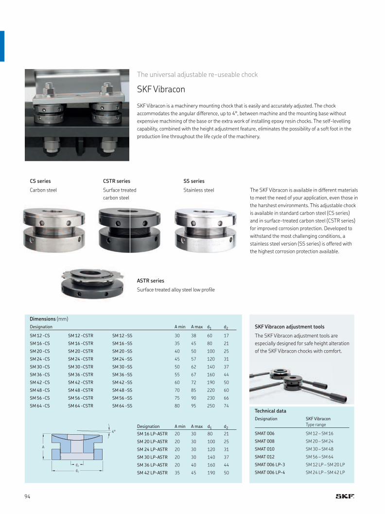
A
d2
d1
4°
The SKF Vibracon is available in different materials
to meet the need of your application, even those in
the harshest environments. This adjustable chock
is available in standard carbon steel (CS series)
and in surface-treated carbon steel (CSTR series)
for improved corrosion protection. Developed to
withstand the most challenging conditions, a
stainless steel version (SS series) is offered with
the highest corrosion protection available.
The universal adjustable re-useable chock
SKF Vibracon
SKF Vibracon is a machinery mounting chock that is easily and accurately adjusted. The chock
accommodates the angular difference, up to 4°, between machine and the mounting base without
expensive machining of the base or the extra work of installing epoxy resin chocks. The self-levelling
capability, combined with the height adjustment feature, eliminates the possibility of a soft foot in the
production line throughout the life cycle of the machinery.
CS series
Carbon steel
SS series
Stainless steel
CSTR series
Surface treated
carbon steel
ASTR series
Surface treated alloy steel low profile
Designation A min A max d1 d2
SM 12 -CS SM 12 -CSTR SM 12 -SS 30 38 60 17
SM 16 -CS SM 16 -CSTR SM 16 -SS 35 45 80 21
SM 20 -CS SM 20 -CSTR SM 20 -SS 40 50 100 25
SM 24 -CS SM 24 -CSTR SM 24 -SS 45 57 120 31
SM 30 -CS SM 30 -CSTR SM 30 -SS 50 62 140 37
SM 36 -CS SM 36 -CSTR SM 36 -SS 55 67 160 44
SM 42 -CS SM 42 -CSTR SM 42 -SS 60 72 190 50
SM 48 -CS SM 48 -CSTR SM 48 -SS 70 85 220 60
SM 56 -CS SM 56 -CSTR SM 56 -SS 75 90 230 66
SM 64 -CS SM 64 -CSTR SM 64 -SS 80 95 250 74
Designation A min A max d1 d2
SM 16 LP-ASTR 20 30 80 21
SM 20 LP-ASTR 20 30 100 25
SM 24 LP-ASTR 20 30 120 31
SM 30 LP-ASTR 20 30 140 37
SM 36 LP-ASTR 20 40 160 44
SM 42 LP-ASTR 35 45 190 50
Dimensions (mm)
Designation SKF Vibracon
Type range
SMAT 006 SM 12 – SM 16
SMAT 008 SM 20 – SM 24
SMAT 010 SM 30 – SM 48
SMAT 012 SM 56 – SM 64
SMAT 006 LP-3 SM 12 LP – SM 20 LP
SMAT 006 LP-4 SM 24 LP – SM 42 LP
Technical data
SKF Vibracon adjustment tools
The SKF Vibracon adjustment tools are
especially designed for safe height alteration
of the SKF Vibracon chocks with comfort.
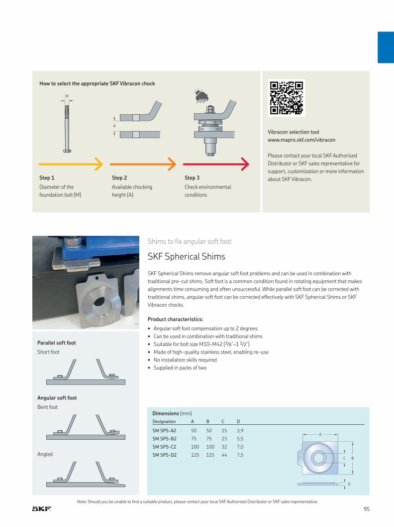
B
A
C
D
M
A
Shims to fix angular soft foot
SKF Spherical Shims
SKF Spherical Shims remove angular soft foot problems and can be used in combination with
traditional pre-cut shims. Soft foot is a common condition found in rotating equipment that makes
alignments time consuming and often unsuccessful. While parallel soft foot can be corrected with
traditional shims, angular soft foot can be corrected effectively with SKF Spherical Shims or SKF
Vibracon chocks.
Product characteristics:
• Angular soft foot compensation up to 2 degrees
• Can be used in combination with traditional shims
• Suitable for bolt size M10–M42 (3/8”–1 1/2”)
• Made of high-quality stainless steel, enabling re-use
• No installation skills required
• Supplied in packs of two
Designation A B C D
SM SPS-A2 50 50 15 3,9
SM SPS-B2 75 75 23 5,5
SM SPS-C2 100 100 32 7,0
SM SPS-D2 125 125 44 7,5
Dimensions (mm)
Note: Should you be unable to find a suitable product, please contact your local SKF Authorised Distributor or SKF sales representative.
Parallel soft foot
Short foot
Angular soft foot
Bent foot
Angled
Vibracon selection tool
www.mapro.skf.com/vibracon
Please contact your local SKF Authorised
Distributor or SKF sales representative for
support, customization or more information
about SKF Vibracon.
How to select the appropriate SKF Vibracon chock
Step 1
Diameter of the
foundation bolt (M)
Step 2
Available chocking
height (A)
Step 3
Check environmental
conditions
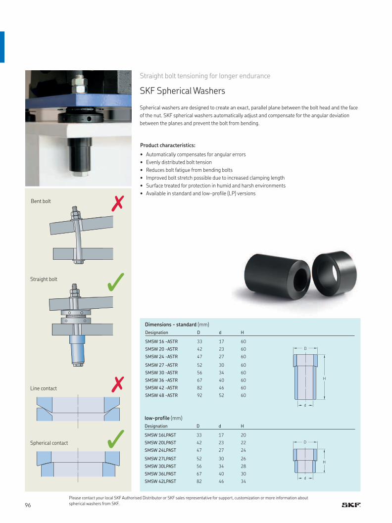
d
D
H
d
D
H
Straight bolt tensioning for longer endurance
SKF Spherical Washers
Spherical washers are designed to create an exact, parallel plane between the bolt head and the face
of the nut. SKF spherical washers automatically adjust and compensate for the angular deviation
between the planes and prevent the bolt from bending.
Designation D d H
SMSW 16 -ASTR 33 17 60
SMSW 20 -ASTR 42 23 60
SMSW 24 -ASTR 47 27 60
SMSW 27 -ASTR 52 30 60
SMSW 30 -ASTR 56 34 60
SMSW 36 -ASTR 67 40 60
SMSW 42 -ASTR 82 46 60
SMSW 48 -ASTR 92 52 60
Designation D d H
SMSW 16LPAST 33 17 20
SMSW 20LPAST 42 23 22
SMSW 24LPAST 47 27 24
SMSW 27LPAST 52 30 26
SMSW 30LPAST 56 34 28
SMSW 36LPAST 67 40 30
SMSW 42LPAST 82 46 34
Dimensions - standard (mm)
low-profile (mm)
Product characteristics:
• Automatically compensates for angular errors
• Evenly distributed bolt tension
• Reduces bolt fatigue from bending bolts
• Improved bolt stretch possible due to increased clamping length
• Surface treated for protection in humid and harsh environments
• Available in standard and low-profile (LP) versions
Bent bolt
Line contact
Spherical contact
Straight bolt
Please contact your local SKF Authorised Distributor or SKF sales representative for support, customization or more information about
spherical washers from SKF.
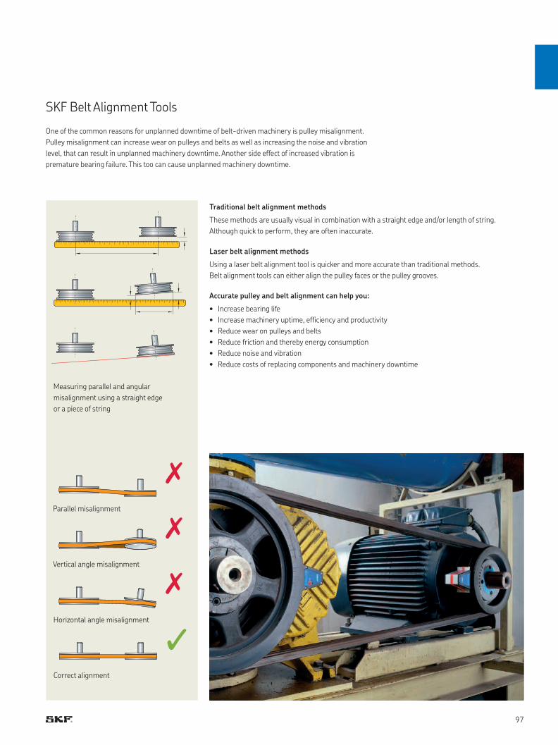
SKF Belt Alignment Tools
One of the common reasons for unplanned downtime of belt-driven machinery is pulley misalignment.
Pulley misalignment can increase wear on pulleys and belts as well as increasing the noise and vibration
level, that can result in unplanned machinery downtime. Another side effect of increased vibration is
premature bearing failure. This too can cause unplanned machinery downtime.
Traditional belt alignment methods
These methods are usually visual in combination with a straight edge and/or length of string.
Although quick to perform, they are often inaccurate.
Laser belt alignment methods
Using a laser belt alignment tool is quicker and more accurate than traditional methods.
Belt alignment tools can either align the pulley faces or the pulley grooves.
Accurate pulley and belt alignment can help you:
• Increase bearing life
• Increase machinery uptime, efficiency and productivity
• Reduce wear on pulleys and belts
• Reduce friction and thereby energy consumption
• Reduce noise and vibration
• Reduce costs of replacing components and machinery downtime
Measuring parallel and angular
misalignment using a straight edge
or a piece of string
Parallel misalignment
Vertical angle misalignment
Horizontal angle misalignment
Correct alignment
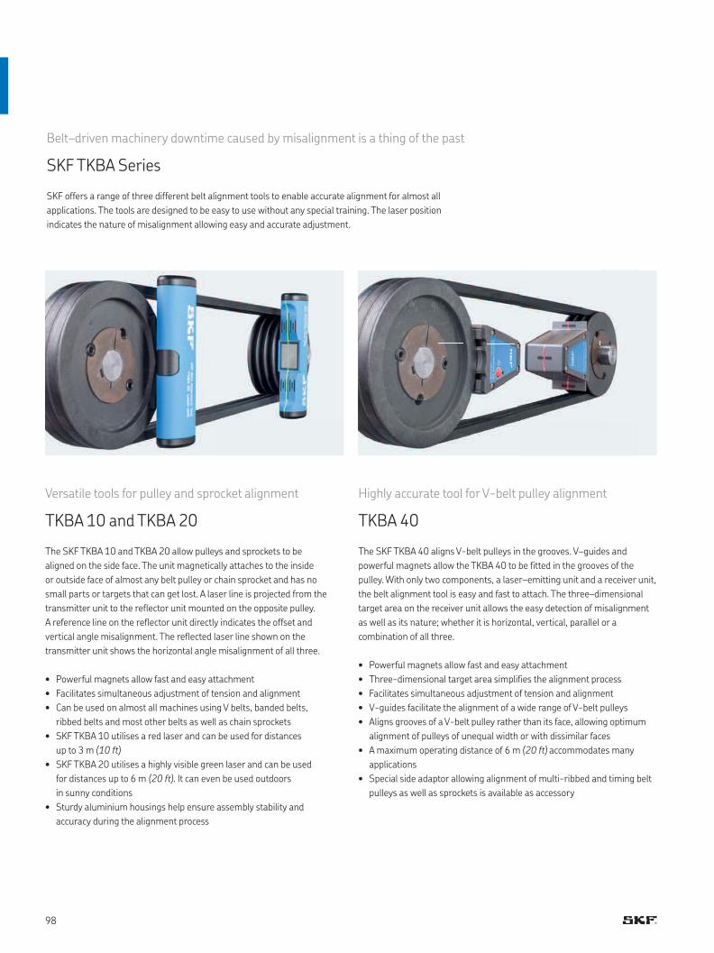
Highly accurate tool for V-belt pulley alignment
TKBA 40
The SKF TKBA 40 aligns V-belt pulleys in the grooves. V–guides and
powerful magnets allow the TKBA 40 to be fitted in the grooves of the
pulley. With only two components, a laser–emitting unit and a receiver unit,
the belt alignment tool is easy and fast to attach. The three–dimensional
target area on the receiver unit allows the easy detection of misalignment
as well as its nature; whether it is horizontal, vertical, parallel or a
combination of all three.
• Powerful magnets allow fast and easy attachment
• Three-dimensional target area simplifies the alignment process
• Facilitates simultaneous adjustment of tension and alignment
• V-guides facilitate the alignment of a wide range of V-belt pulleys
• Aligns grooves of a V-belt pulley rather than its face, allowing optimum
alignment of pulleys of unequal width or with dissimilar faces
• A maximum operating distance of 6 m (20 ft) accommodates many
applications
• Special side adaptor allowing alignment of multi-ribbed and timing belt
pulleys as well as sprockets is available as accessory
Versatile tools for pulley and sprocket alignment
TKBA 10 and TKBA 20
The SKF TKBA 10 and TKBA 20 allow pulleys and sprockets to be
aligned on the side face. The unit magnetically attaches to the inside
or outside face of almost any belt pulley or chain sprocket and has no
small parts or targets that can get lost. A laser line is projected from the
transmitter unit to the reflector unit mounted on the opposite pulley.
A reference line on the reflector unit directly indicates the offset and
vertical angle misalignment. The reflected laser line shown on the
transmitter unit shows the horizontal angle misalignment of all three.
• Powerful magnets allow fast and easy attachment
• Facilitates simultaneous adjustment of tension and alignment
• Can be used on almost all machines using V belts, banded belts,
ribbed belts and most other belts as well as chain sprockets
• SKF TKBA 10 utilises a red laser and can be used for distances
up to 3 m (10 ft)
• SKF TKBA 20 utilises a highly visible green laser and can be used
for distances up to 6 m (20 ft). It can even be used outdoors
in sunny conditions
• Sturdy aluminium housings help ensure assembly stability and
accuracy during the alignment process
Belt–driven machinery downtime caused by misalignment is a thing of the past
SKF TKBA Series
SKF offers a range of three different belt alignment tools to enable accurate alignment for almost all
applications. The tools are designed to be easy to use without any special training. The laser position
indicates the nature of misalignment allowing easy and accurate adjustment.
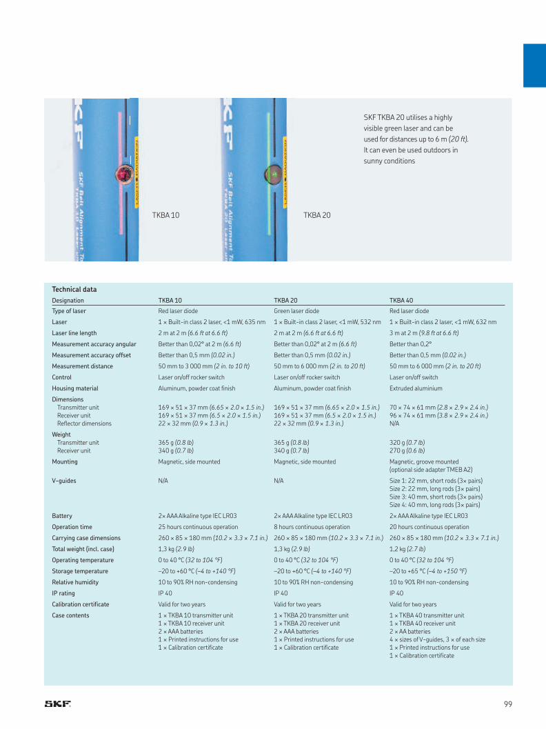
TKBA 10 TKBA 20
SKF TKBA 20 utilises a highly
visible green laser and can be
used for distances up to 6 m (20 ft).
It can even be used outdoors in
sunny conditions
Designation TKBA 10 TKBA 20 TKBA 40
Type of laser Red laser diode Green laser diode Red laser diode
Laser 1 × Built-in class 2 laser, <1 mW, 635 nm 1 × Built-in class 2 laser, <1 mW, 532 nm 1 × Built-in class 2 laser, <1 mW, 632 nm
Laser line length 2 m at 2 m (6.6 ft at 6.6 ft) 2 m at 2 m (6.6 ft at 6.6 ft) 3 m at 2 m (9.8 ft at 6.6 ft)
Measurement accuracy angular Better than 0,02° at 2 m (6.6 ft) Better than 0,02° at 2 m (6.6 ft) Better than 0,2°
Measurement accuracy offset Better than 0,5 mm (0.02 in.) Better than 0,5 mm (0.02 in.) Better than 0,5 mm (0.02 in.)
Measurement distance 50 mm to 3 000 mm (2 in. to 10 ft) 50 mm to 6 000 mm (2 in. to 20 ft) 50 mm to 6 000 mm (2 in. to 20 ft)
Control Laser on/off rocker switch Laser on/off rocker switch Laser on/off switch
Housing material Aluminum, powder coat finish Aluminum, powder coat finish Extruded aluminium
DimensionsTransmitter unitReceiver unitReflector dimensions
169 × 51 × 37 mm (6.65 × 2.0 × 1.5 in.)169 × 51 × 37 mm (6.5 × 2.0 × 1.5 in.)22 × 32 mm (0.9 × 1.3 in.)
169 × 51 × 37 mm (6.65 × 2.0 × 1.5 in.)169 × 51 × 37 mm (6.5 × 2.0 × 1.5 in.)22 × 32 mm (0.9 × 1.3 in.)
70 × 74 × 61 mm (2.8 × 2.9 × 2.4 in.)96 × 74 × 61 mm (3.8 × 2.9 × 2.4 in.)N/A
WeightTransmitter unitReceiver unit
365 g (0.8 lb)340 g (0.7 lb)
365 g (0.8 lb)340 g (0.7 lb)
320 g (0.7 lb)270 g (0.6 lb)
Mounting Magnetic, side mounted Magnetic, side mounted Magnetic, groove mounted (optional side adapter TMEB A2)
V-guides N/A N/A Size 1: 22 mm, short rods (3× pairs)Size 2: 22 mm, long rods (3× pairs)Size 3: 40 mm, short rods (3× pairs)Size 4: 40 mm, long rods (3× pairs)
Battery 2× AAA Alkaline type IEC LR03 2× AAA Alkaline type IEC LR03 2× AAA Alkaline type IEC LR03
Operation time 25 hours continuous operation 8 hours continuous operation 20 hours continuous operation
Carrying case dimensions 260 × 85 × 180 mm (10.2 × 3.3 × 7.1 in.) 260 × 85 × 180 mm (10.2 × 3.3 × 7.1 in.) 260 × 85 × 180 mm (10.2 × 3.3 × 7.1 in.)
Total weight (incl. case) 1,3 kg (2.9 lb) 1,3 kg (2.9 lb) 1,2 kg (2.7 lb)
Operating temperature 0 to 40 °C (32 to 104 °F) 0 to 40 °C (32 to 104 °F) 0 to 40 °C (32 to 104 °F)
Storage temperature –20 to +60 °C (–4 to +140 °F) –20 to +60 °C (–4 to +140 °F) –20 to +65 °C (–4 to +150 °F)
Relative humidity 10 to 90% RH non-condensing 10 to 90% RH non-condensing 10 to 90% RH non-condensing
IP rating IP 40 IP 40 IP 40
Calibration certificate Valid for two years Valid for two years Valid for two years
Case contents 1 × TKBA 10 transmitter unit1 × TKBA 10 receiver unit2 × AAA batteries1 × Printed instructions for use1 × Calibration certificate
1 × TKBA 20 transmitter unit1 × TKBA 20 receiver unit2 × AAA batteries1 × Printed instructions for use1 × Calibration certificate
1 × TKBA 40 transmitter unit1 × TKBA 40 receiver unit2 × AA batteries4 × sizes of V-guides, 3 × of each size1 × Printed instructions for use1 × Calibration certificate
Technical data
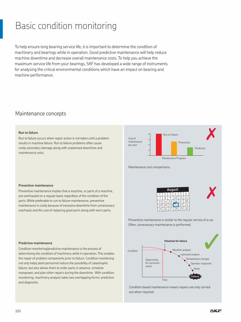
Basic condition monitoring
Maintenance concepts
Run to failure
Run to failure occurs when repair action is not taken until a problem
results in machine failure. Run to failure problems often cause
costly secondary damage along with unplanned downtime and
maintenance costs.
Predictive maintenance
Condition monitoring/predictive maintenance is the process of
determining the condition of machinery while in operation. This enables
the repair of problem components prior to failure. Condition monitoring
not only helps plant personnel reduce the possibility of catastrophic
failure, but also allows them to order parts in advance, schedule
manpower, and plan other repairs during the downtime. With condition
monitoring, machinery analysis takes two overlapping forms: predictive
and diagnostic.
Preventive maintenance
Preventive maintenance implies that a machine, or parts of a machine,
are overhauled on a regular basis regardless of the condition of the
parts. While preferable to run to failure maintenance, preventive
maintenance is costly because of excessive downtime from unnecessary
overhauls and the cost of replacing good parts along with worn parts.
To help ensure long bearing service life, it is important to determine the condition of
machinery and bearings while in operation. Good predictive maintenance will help reduce
machine downtime and decrease overall maintenance costs. To help you achieve the
maximum service life from your bearings, SKF has developed a wide range of instruments
for analysing the critical environmental conditions which have an impact on bearing and
machine performance.
Preventive maintenance is similar to the regular service of a car.
Often, unnecessary maintenance is performed.
Condition based maintenance means repairs are only carried
out when required.
Maintenance cost comparisons.
Cost of maintenance per year
Condition
Opportunity for corrective action
Run to Failure
Vibration analysis
Lubricant analysis
Temperature changes
Operator inspection
Noise
Potential for failure
Time
Preventive
Predictive
Maintenance Program
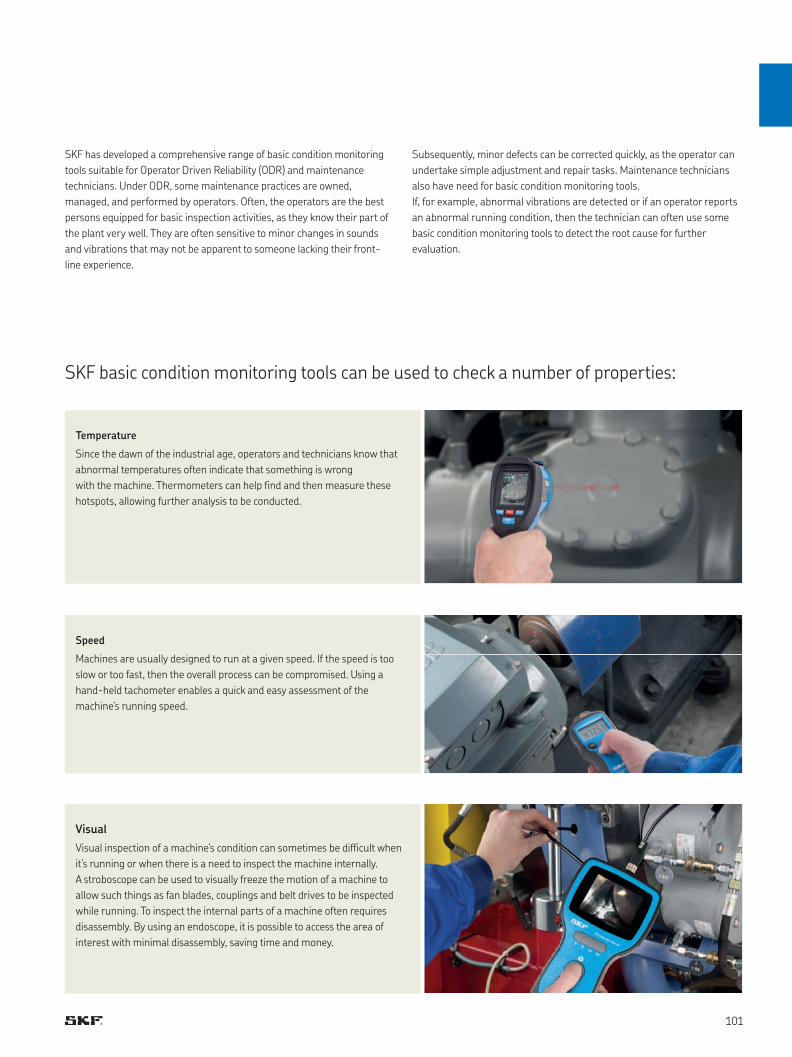
SKF basic condition monitoring tools can be used to check a number of properties:
Visual
Visual inspection of a machine’s condition can sometimes be difficult when
it’s running or when there is a need to inspect the machine internally.
A stroboscope can be used to visually freeze the motion of a machine to
allow such things as fan blades, couplings and belt drives to be inspected
while running. To inspect the internal parts of a machine often requires
disassembly. By using an endoscope, it is possible to access the area of
interest with minimal disassembly, saving time and money.
Speed
Machines are usually designed to run at a given speed. If the speed is too
slow or too fast, then the overall process can be compromised. Using a
hand-held tachometer enables a quick and easy assessment of the
machine’s running speed.
Temperature
Since the dawn of the industrial age, operators and technicians know that
abnormal temperatures often indicate that something is wrong
with the machine. Thermometers can help find and then measure these
hotspots, allowing further analysis to be conducted.
SKF has developed a comprehensive range of basic condition monitoring
tools suitable for Operator Driven Reliability (ODR) and maintenance
technicians. Under ODR, some maintenance practices are owned,
managed, and performed by operators. Often, the operators are the best
persons equipped for basic inspection activities, as they know their part of
the plant very well. They are often sensitive to minor changes in sounds
and vibrations that may not be apparent to someone lacking their front-
line experience.
Subsequently, minor defects can be corrected quickly, as the operator can
undertake simple adjustment and repair tasks. Maintenance technicians
also have need for basic condition monitoring tools.
If, for example, abnormal vibrations are detected or if an operator reports
an abnormal running condition, then the technician can often use some
basic condition monitoring tools to detect the root cause for further
evaluation.
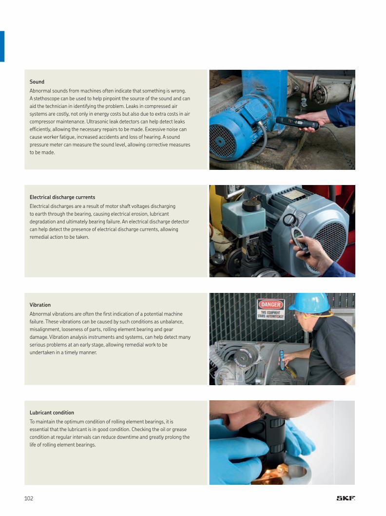
Lubricant condition
To maintain the optimum condition of rolling element bearings, it is
essential that the lubricant is in good condition. Checking the oil or grease
condition at regular intervals can reduce downtime and greatly prolong the
life of rolling element bearings.
Vibration
Abnormal vibrations are often the first indication of a potential machine
failure. These vibrations can be caused by such conditions as unbalance,
misalignment, looseness of parts, rolling element bearing and gear
damage. Vibration analysis instruments and systems, can help detect many
serious problems at an early stage, allowing remedial work to be
undertaken in a timely manner.
Electrical discharge currents
Electrical discharges are a result of motor shaft voltages discharging
to earth through the bearing, causing electrical erosion, lubricant
degradation and ultimately bearing failure. An electrical discharge detector
can help detect the presence of electrical discharge currents, allowing
remedial action to be taken.
Sound
Abnormal sounds from machines often indicate that something is wrong.
A stethoscope can be used to help pinpoint the source of the sound and can
aid the technician in identifying the problem. Leaks in compressed air
systems are costly, not only in energy costs but also due to extra costs in air
compressor maintenance. Ultrasonic leak detectors can help detect leaks
efficiently, allowing the necessary repairs to be made. Excessive noise can
cause worker fatigue, increased accidents and loss of hearing. A sound
pressure meter can measure the sound level, allowing corrective measures
to be made.

Accurate temperature measurement with dual channel capability
SKF Thermometer TKDT 10
The SKF TKDT 10 is suitable for a wide range of applications and has the ability to have two
SKF temperature probes connected. A large back-lit LCD display helps ensure that the
temperatures can be easily read in almost all lighting conditions.
• Large back-lit LCD display
• Supplied with temperature probe TMDT 2-30 (max. 900 °C / (1 652 °F)); suitable for many
direct contact applications.
• Can be used with an optional second SKF temperature probe enabling either probe
temperature, or the temperature difference between the probes, to be displayed.
• Temperature display can be frozen for ease of reading.
• User selectable auto power off function increases battery life.
Designation TKDT 10
Display Large back-lit LCD
Displayed resolution 0,1 ° up to 1 000 °, otherwise 1°
Measurement modes Min, max, average, differential, dual temperature reading
Measurement units °C, °F, K
Temperature using probe –200 to +1 372 °C (–328 to +2 501 °F)
Accuracy >–100 °C (>–148 °F): ±0.5% of reading ±1 °C (1.8 °F)
Probe compatibility 2 × Type-K connectors
Probe supplied TMDT 2-30, suitable for use up to 900 °C (1 650 °F)
Battery 3× AAA Alkaline type IEC LR03
Operation time 18 hours typical use (backlight on)
Product dimensions 160 × 63 × 30 mm (6.3 × 2.5 × 1.2 in.)
Carrying case dimensions 530 × 85 × 180 mm (20.9 × 3.4 × 7.0 in.)
Product weight 200 g (0.4 lb)
Technical data
Temperature difference
between the probes
Dual temperature
measurement

They are extremely user-friendly; simply aim and pull the trigger and the temperature is shown on the display.
These robust instruments are equipped with a back-lit display and laser sighting. They are fitted with a bright
LED illuminator to allow the application object to be seen even in poorly lit environments.
TKTL 10
An infrared thermometer that’s an essential tool
for every technician
TKTL 20
An infrared and contact thermometer offering
versatile temperature measurement options
TKTL 30
An infrared and contact temperature thermometer
with a wide measurement range and dual laser sighting
Infrared thermometers are portable, lightweight instruments for safely measuring temperature at a distance
SKF Infrared thermometers
• Maximum temperature always shown;
helps identify the real hotspots
• Auto shut off feature; helps optimise
battery life
• Colour display with temperature trend
indication
• Supplied with temperature probe TMDT 2-30
(max. 900 °C (1 652 °F)); suitable for many
direct contact applications
• Can be used with any SKF temperature probe
• User selectable, multiple temperature
measurement modes including: maximum,
minimum, average, differential and probe/
infrared dual display, scan function
• User selectable high and low alarm levels with
audible warning signal
• Mode dependant auto shut off feature
optimises battery life
• Colour display with temperature trend
indication
• Dual laser sighting feature defines the
diameter of the area being measured; helps
the user to precisely pin-point the
temperature measurement area
• Supplied with temperature probe TMDT 2-30
(max. 900 °C (1 652 °F)); suitable for many
direct contact applications
• Can be used with any SKF temperature probe
• User selectable, multiple temperature
measurement modes including: maximum,
minimum, average, differential and probe/
infrared dual display, scan function
• User selectable high and level alarm levels with
audible warning signal
• Mode dependant auto shut off feature
optimises battery life
ε = 0,95
D:S = 16:1
ε = 0,1–1,0
D:S = 16:1
ε = 0,1–1,0
D:S = 50:1

TKTL 40
An infrared and contact temperature thermometer with video and
data logging capabilities
• Built-in camera allows pictures and videos, with all measurement
information to be taken, stored, recalled and exported to PC
• Environmental properties such as ambient, dew point and wet-bulb
temperatures, as well as relative humidity, can be displayed and stored
• Dual laser sighting defines the temperature measurement area
Temperature range using infrared –60 to +625 °C
(–76 to +1 157 °F)
–60 to +625 °C
(–76 to +1 157 °F)
–60 to +1 000 °C
(–76 to +1 832 °F)
–50 to +1 000 °C
(–58 to +1 832 °F)
Temperature range using probe – –64 to +1 400 °C
(–83 to +1 999 °F)
–64 to +1 400 °C
(–83 to +1 999 °F)
–50 to +1 370 °C
(–58 to +2 498 °F)
Distance to spot size 16:1 16:1 50:1 50:1
Emissivity Pre-set 0,95 0,1–1,0 0,1–1,0 0,1–1,0
When used in non-contact mode, the thermometer senses the
thermal energy radiated from an object with an infrared detector.
When pointed at an object, the infrared detector collects energy,
producing a signal that the microprocessor translates as a reading on
the backlit display. As the trigger is squeezed, the object temperature
is continuously measured by the infrared detector.
This allows for fast and accurate realtime readings.
• Supplied with temperature probe TMDT 2-30 (max. 900 °C (1 652 °F))
for direct contact applications. Can also be used with any other
SKF temperature probe
• User selectable, multiple temperature measurement modes including:
maximum, minimum, average, differential and probe/infrared
dual display
• Data logging function can be used to visualise temperature changes
over time
• User selectable high and low alarm levels with audible warning signal
• User selectable auto shut off feature optimises the rechargeable
battery life
TKTL 10 TKTL 20 TKTL 30 TKTL 40
ε = 0,1–1,0
D:S = 50:1
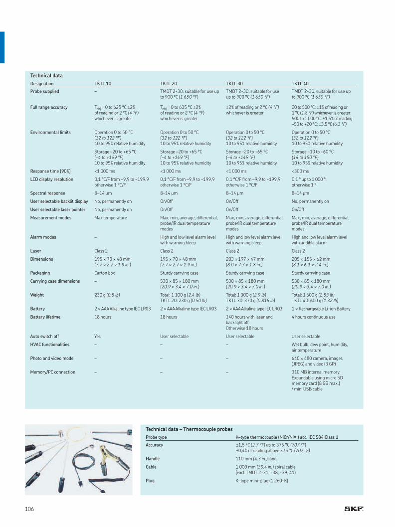
Designation TKTL 10 TKTL 20 TKTL 30 TKTL 40
Probe supplied – TMDT 2-30, suitable for use up to 900 °C (1 650 °F)
TMDT 2-30, suitable for use up to 900 °C (1 650 °F)
TMDT 2-30, suitable for use up to 900 °C (1 650 °F)
Full range accuracy Tobj = 0 to 625 °C ±2% of reading or 2 °C (4 °F)whichever is greater
Tobj = 0 to 635 °C ±2% of reading or 2 °C (4 °F)whichever is greater
±2% of reading or 2 °C (4 °F)whichever is greater
20 to 500 °C: ±1% of reading or 1 °C (1.8 °F) whichever is greater500 to 1 000 °C: ±1,5% of reading–50 to +20 °C: ±3,5 °C (6.3 °F)
Environmental limits Operation 0 to 50 °C (32 to 122 °F)10 to 95% relative humidity
Operation 0 to 50 °C (32 to 122 °F)10 to 95% relative humidity
Operation 0 to 50 °C (32 to 122 °F)10 to 95% relative humidity
Operation 0 to 50 °C (32 to 122 °F)10 to 95% relative humidity
Storage –20 to +65 °C (–4 to +149 °F)10 to 95% relative humidity
Storage –20 to +65 °C (–4 to +149 °F)10 to 95% relative humidity
Storage –20 to +65 °C (–4 to +149 °F)10 to 95% relative humidity
Storage –10 to +60 °C (14 to 150 °F)10 to 95% relative humidity
Response time (90%) <1 000 ms <1 000 ms <1 000 ms <300 ms
LCD display resolution 0,1 °C/F from –9,9 to ~199,9 otherwise 1 °C/F
0,1 °C/F from –9,9 to ~199,9 otherwise 1 °C/F
0,1 °C/F from –9,9 to ~199,9 otherwise 1 °C/F
0,1 ° up to 1 000 °, otherwise 1 °
Spectral response 8–14 μm 8–14 μm 8–14 μm 8–14 μm
User selectable backlit display No, permanently on On/Off On/Off No, permanently on
User selectable laser pointer No, permanently on On/Off On/Off On/Off
Measurement modes Max temperature Max, min, average, differential, probe/IR dual temperature modes
Max, min, average, differential, probe/IR dual temperature modes
Max, min, average, differential, probe/IR dual temperature modes
Alarm modes – High and low level alarm level with warning bleep
High and low level alarm level with warning bleep
High and low level alarm level with audible alarm
Laser Class 2 Class 2 Class 2 Class 2
Dimensions 195 × 70 × 48 mm (7.7 × 2.7 × 1.9 in.)
195 × 70 × 48 mm (7.7 × 2.7 × 1.9 in.)
203 × 197 × 47 mm(8.0 × 7.7 × 1.8 in.)
205 × 155 × 62 mm(8.1 × 6.1 × 2.4 in.)
Packaging Carton box Sturdy carrying case Sturdy carrying case Sturdy carrying case
Carrying case dimensions – 530 × 85 × 180 mm(20.9 × 3.4 × 7.0 in.)
530 × 85 × 180 mm(20.9 × 3.4 × 7.0 in.)
530 × 85 × 180 mm(20.9 × 3.4 × 7.0 in.)
Weight 230 g (0.5 lb) Total: 1 100 g (2.4 lb)TKTL 20: 230 g (0.50 lb)
Total: 1 300 g (2.9 lb)TKTL 30: 370 g (0.815 lb)
Total: 1 600 g (2.53 lb)TKTL 40: 600 g (1.32 lb)
Battery 2 × AAA Alkaline type IEC LR03 2 × AAA Alkaline type IEC LR03 2 × AAA Alkaline type IEC LR03 1 × Rechargeable Li-ion Battery
Battery lifetime 18 hours 18 hours 140 hours with laser and backlight offOtherwise 18 hours
4 hours continuous use
Auto switch off Yes User selectable User selectable User selectable
HVAC functionalities – – – Wet bulb, dew point, humidity, air temperature
Photo and video mode – – – 640 × 480 camera, images (JPEG) and video (3 GP)
Memory/PC connection – – – 310 MB internal memory. Expandable using micro SD memory card (8 GB max.)/ mini USB cable
Probe type K–type thermocouple (NiCr/NiAl) acc. IEC 584 Class 1
Accuracy ±1,5 °C (2.7 °F) up to 375 °C (707 °F) ±0,4% of reading above 375 °C (707 °F)
Handle 110 mm (4.3 in.) long
Cable 1 000 mm (39.4 in.) spiral cable (excl. TMDT 2-31, -38, -39, 41)
Plug K–type mini–plug (1 260-K)
Technical data
Technical data – Thermocouple probes
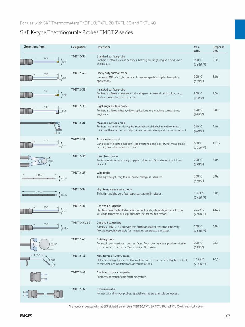
130
∅8
1 000
∅1,5
1 500 ∅1,5
∅35
∅≥50
1 500
1 500
130
∅3
130
∅8
130
∅8
250
∅3
130
∅1,5
14
130
∅8
All probes can be used with the SKF digital thermometers TKDT 10, TKTL 20, TKTL 30 and TKTL 40 without recalibration.
Dimensions (mm) Designation Description Max.
temp
Response
time
TMDT 2-30 Standard surface probe
For hard surfaces such as bearings, bearing housings, engine blocks, oven
shields, etc.
900 °C
(1 650 °F)
2,3 s
TMDT 2-43 Heavy duty surface probe
Same as TMDT 2-30, but with a silicone encapsulated tip for heavy duty
applications.
300 °C
(570 °F)
3,0 s
TMDT 2-32 Insulated surface probe
For hard surfaces where electrical wiring might cause short circuiting, e.g.
electric motors, transformers, etc.
200 °C
(390 °F)
2,3 s
TMDT 2-33 Right angle surface probe
For hard surfaces in heavy-duty applications, e.g. machine components,
engines, etc.
450 °C
(840 °F)
8,0 s
TMDT 2-31 Magnetic surface probe
For hard, magnetic surfaces; the integral heat sink design and low mass
minimise thermal inertia and provide an accurate temperature measurement.
240 °C
(460 °F)
7,0 s
TMDT 2-35 Probe with sharp tip
Can be easily inserted into semi-solid materials like food-stuffs, meat, plastic,
asphalt, deep-frozen products, etc.
600 °C
(1 110 °F)
12,0 s
TMDT 2-36 Pipe clamp probe
For temperature measuring on pipes, cables, etc. Diameter up to ø 35 mm
(1.4 in.).
200 °C
(390 °F)
8,0 s
TMDT 2-38 Wire probe
Thin, lightweight, very fast response, fibreglass insulated.
300 °C
(570 °F)
5,0 s
TMDT 2-39 High temperature wire probe
Thin, light weight, very fast response, ceramic insulation.
1 350 °C
(2 460 °F)
6,0 s
TMDT 2-34 Gas and liquid probe
Flexible shank made of stainless steel for liquids, oils, acids, etc. and for use
with high temperatures, e.g. open fire (not for molten metals).
1 100 °C
(2 010 °F)
12,0 s
TMDT 2-34/1.5 Gas and liquid probe
Same as TMDT 2-34 but with thin shank and faster response time. Very
flexible, especially suitable for measuring temperature of gases.
900 °C
(1 650 °F)
6,0 s
TMDT 2-40 Rotating probe
For moving or rotating smooth surfaces. Four roller bearings provide suitable
contact with the surfaces. Max. velocity 500 m/min.
200 °C
(390 °F)
0,6 s
TMDT 2-41 Non-ferrous foundry probe
Holder including dip-element for molten, non-ferrous metals. Highly resistant
to corrosion and oxidation at high temperatures.
1 260 °C
(2 300 °F)
30,0 s
TMDT 2-42 Ambient temperature probe
For measurement of ambient temperature.
TMDT 2-37 Extension cable
For use with all K-type probes. Special lengths are available on request.
For use with SKF Thermometers TKDT 10, TKTL 20, TKTL 30 and TKTL 40
SKF K-type Thermocouple Probes TMDT 2 series

Pinpoint accuracy combined with measurement versatility
SKF Tachometer Series
TKRT 10 TKRT 20
The SKF Tachometers are fast and accurate instruments utilizing laser or contact to measure
rotational and linear speeds. Equipped with a laser and a range of contact adapters, they are versatile
instruments that suit a wide range of applications. Having a compact design, they can be operated with
just one hand and are supplied in a sturdy carrying case.
• Wide speed measurement range: up to 99 999 r/min for laser
measurement and 20 000 r/min using contact adapters
• Measurement modes include; rotational speed, total revolutions,
frequency, surface speed and length in both metric and imperial units
• Laser can be used for safe and quick, non-contact rotational speed
measurements at distances up to 0,5 m (20 in.)
• Large back-lit LCD display enables easy reading in almost all
light conditions
• Angular range of ±45° to target helps facilitate easy measuring
• Up to 10 readings can be stored for later reference
• The user can select the following to measure:
– rpm, rps, m, ft or yds per minute or second,
– length or revolution counting, or
– time interval
• Wide speed range and the various measurement modes make the SKF
TKRT 20 suitable for measuring speed in many applications
• Large angular range of ±80° to target facilitates easy measuring in areas
where straight–line access is difficult
• The laser optical system allows easy and quick measurements at a safe
distance from rotating machinery
• The large inverting LCD display facilitates easy reading, even when
pointing the unit down into the machinery
• The SKF TKRT 20 can also be equipped with a remote laser sensor,
which is optionally available
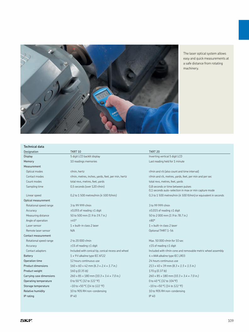
Technical data
The laser optical system allows
easy and quick measurements at
a safe distance from rotating
machinery.
Designation TKRT 10 TKRT 20
Display 5 digit LCD backlit display Inverting vertical 5 digit LCD
Memory 10 readings memories Last reading held for 1 minute
Measurement
Optical modes r/min, hertz r/min and r/s (also count and time interval)
Contact modes r/min, metres, inches, yards, feet, per min, hertz r/min and r/s, metres, yards, feet, per min and per sec
Count modes total revs, metres, feet, yards total revs, metres, feet, yards
Sampling time 0,5 seconds (over 120 r/min) 0,8 seconds or time between pulses
0,1 seconds auto-selection in max or min capture mode
Linear speed 0,2 to 1 500 metres/min (4 500 ft/min) 0,3 to 1 500 metres/min (4 500 ft/min) or equivalent in seconds
Optical measurement
Rotational speed range 3 to 99 999 r/min 3 to 99 999 r/min
Accuracy ±0,05% of reading ±1 digit ±0,01% of reading ±1 digit
Measuring distance 50 to 500 mm (1.9 to 19.7 in.) 50 to 2 000 mm (1.9 to 78.7 in.)
Angle of operation ±45° ±80°
Laser sensor 1 × built-in class 2 laser 1 × built-in class 2 laser
Remote laser sensor N/A Optional TMRT 1-56
Contact measurement
Rotational speed range 2 to 20 000 r/min Max. 50 000 r/min for 10 sec
Accuracy ±1% of reading ±1 digit ±1% of reading ±1 digit
Contact adaptors Included with conical tip, conical recess and wheel Included with r/min cone and removable metric wheel assembly
Battery 1 × 9 V alkaline type IEC 6F22 4 × AAA alkaline type IEC LR03
Operation time 12 hours continuous use 24 hours continuous use
Product dimensions 160 × 60 × 42 mm (6.3 × 2.4 × 1.7 in.) 213 × 40 × 39 mm (8.3 × 1.5 × 1.5 in.)
Product weight 160 g (0.35 lb) 170 g (0.37 lb)
Carrying case dimensions 260 × 85 × 180 mm (10.3 × 3.4 × 7.0 in.) 260 × 85 × 180 mm (10.3 × 3.4 × 7.0 in.)
Operating temperature 0 to 50 °C (32 to 122 °F) 0 to 40 °C (32 to 104°F)
Storage temperature –10 to +50 °C (14 to 122 °F) –10 to +50 °C (14 to 122 °F)
Relative humidity 10 to 90% RH non-condensing 10 to 90% RH non-condensing
IP rating IP 40 IP 40

High-performance, hand-held stroboscopes for visual inspection
SKF Stroboscopes
SKF offers a wide range of portable TKRS stroboscopes for visual inspection of running machines in
challenging industrial environments. These portable tools provide early detection of abnormalities to help
schedule maintenance tasks and reduce additional loads on rotating equipment in order to reach planned
performance levels. Designed for ease of use, the four TKRS models offer from 3 to 118 ultra-bright
LEDs. Each stroboscope features a large screen and multifunctional selector switch to help you quickly
navigate to the correct menu. Brightness and performance levels are adjustable.
TKRS 11
• Quick speed selection with rotary button
• Black and white LCD display
• Three ultra-bright LEDs
TKRS 21
• High luminescence with seven
ultra-bright LEDs
• Multi-line backlit TFT
TKRS 31
• Built-in laser tachometer with flash
synchronization
• Pro-mode with additional features like slow
motion phase shift
• Trigger input and output with signal modification
TKRS 41
• Extreme luminescence with 118 ultra-bright LEDs
• Portable operation with built-in rechargeable battery
• Continuous operation for long term inspection with
power adapter
• Flash synchronization from laser tachometer
or trigger input
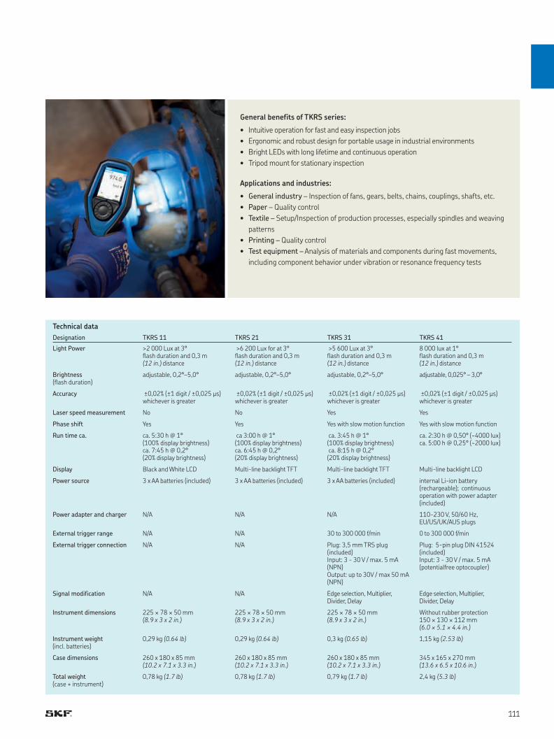
Technical data
General benefits of TKRS series:
• Intuitive operation for fast and easy inspection jobs
• Ergonomic and robust design for portable usage in industrial environments
• Bright LEDs with long lifetime and continuous operation
• Tripod mount for stationary inspection
Applications and industries:
• General industry – Inspection of fans, gears, belts, chains, couplings, shafts, etc.
• Paper – Quality control
• Textile – Setup/Inspection of production processes, especially spindles and weaving
patterns
• Printing – Quality control
• Test equipment – Analysis of materials and components during fast movements,
including component behavior under vibration or resonance frequency tests
Designation TKRS 11 TKRS 21 TKRS 31 TKRS 41
Light Power >2 000 Lux at 3° flash duration and 0,3 m (12 in.) distance
>6 200 Lux for at 3° flash duration and 0,3 m (12 in.) distance
>5 600 Lux at 3° flash duration and 0,3 m (12 in.) distance
8 000 lux at 1° flash duration and 0,3 m (12 in.) distance
Brightness (flash duration)
adjustable, 0,2°–5,0° adjustable, 0,2°–5,0° adjustable, 0,2°–5,0° adjustable, 0,025° – 3,0°
Accuracy ±0,02% (±1 digit / ±0,025 μs) whichever is greater
±0,02% (±1 digit / ±0,025 μs) whichever is greater
±0,02% (±1 digit / ±0,025 μs) whichever is greater
±0,02% (±1 digit / ±0,025 μs) whichever is greater
Laser speed measurement No No Yes Yes
Phase shift Yes Yes Yes with slow motion function Yes with slow motion function
Run time ca. ca. 5:30 h @ 1° (100% display brightness)ca. 7:45 h @ 0,2° (20% display brightness)
ca 3:00 h @ 1° (100% display brightness)ca. 6:45 h @ 0,2° (20% display brightness)
ca. 3:45 h @ 1° (100% display brightness) ca. 8:15 h @ 0,2° (20% display brightness)
ca. 2:30 h @ 0,50° (~4000 lux)ca. 5:00 h @ 0,25° (~2000 lux)
Display Black and White LCD Multi-line backlight TFT Multi-line backlight TFT Multi-line backlight LCD
Power source 3 x AA batteries (included) 3 x AA batteries (included) 3 x AA batteries (included) internal Li-ion battery (rechargeable); continuous operation with power adapter (included)
Power adapter and charger N/A N/A N/A 110-230 V, 50/60 Hz, EU/US/UK/AUS plugs
External trigger range N/A N/A 30 to 300 000 f/min 0 to 300 000 f/min
External trigger connection N/A N/A Plug: 3,5 mm TRS plug (included)Input: 3 - 30 V / max. 5 mA (NPN)Output: up to 30V / max 50 mA (NPN)
Plug: 5-pin plug DIN 41524 (included)Input: 3 - 30 V / max. 5 mA (potentialfree optocoupler)
Signal modification N/A N/A Edge selection, Multiplier, Divider, Delay
Edge selection, Multiplier, Divider, Delay
Instrument dimensions 225 × 78 × 50 mm (8.9 x 3 x 2 in.)
225 × 78 × 50 mm (8.9 x 3 x 2 in.)
225 × 78 × 50 mm (8.9 x 3 x 2 in.)
Without rubber protection 150 × 130 × 112 mm (6.0 × 5.1 × 4.4 in.)
Instrument weight (incl. batteries)
0,29 kg (0.64 lb) 0,29 kg (0.64 lb) 0,3 kg (0.65 lb) 1,15 kg (2.53 lb)
Case dimensions 260 x 180 x 85 mm (10.2 x 7.1 x 3.3 in.)
260 x 180 x 85 mm (10.2 x 7.1 x 3.3 in.)
260 x 180 x 85 mm (10.2 x 7.1 x 3.3 in.)
345 x 165 x 270 mm (13.6 x 6.5 x 10.6 in.)
Total weight (case + instrument)
0,78 kg (1.7 lb) 0,78 kg (1.7 lb) 0,79 kg (1.7 lb) 2,4 kg (5.3 lb)
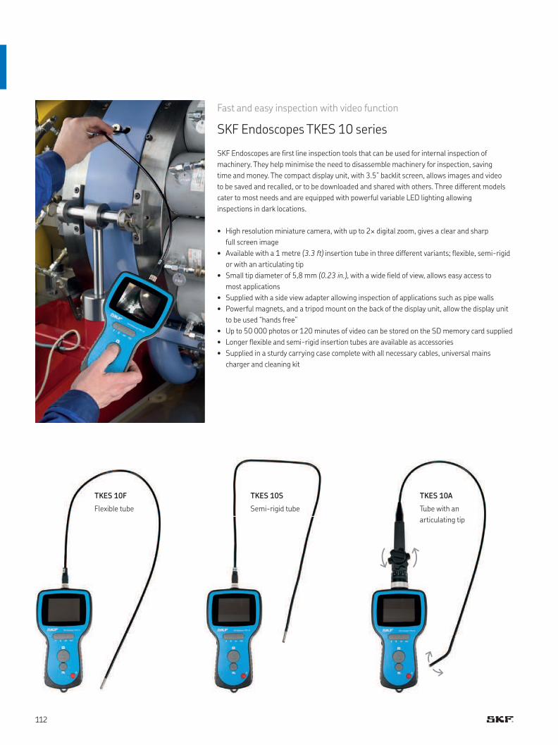
Fast and easy inspection with video function
SKF Endoscopes TKES 10 series
SKF Endoscopes are first line inspection tools that can be used for internal inspection of
machinery. They help minimise the need to disassemble machinery for inspection, saving
time and money. The compact display unit, with 3.5” backlit screen, allows images and video
to be saved and recalled, or to be downloaded and shared with others. Three different models
cater to most needs and are equipped with powerful variable LED lighting allowing
inspections in dark locations.
• High resolution miniature camera, with up to 2× digital zoom, gives a clear and sharp
full screen image
• Available with a 1 metre (3.3 ft) insertion tube in three different variants; flexible, semi-rigid
or with an articulating tip
• Small tip diameter of 5,8 mm (0.23 in.), with a wide field of view, allows easy access to
most applications
• Supplied with a side view adapter allowing inspection of applications such as pipe walls
• Powerful magnets, and a tripod mount on the back of the display unit, allow the display unit
to be used “hands free”
• Up to 50 000 photos or 120 minutes of video can be stored on the SD memory card supplied
• Longer flexible and semi-rigid insertion tubes are available as accessories
• Supplied in a sturdy carrying case complete with all necessary cables, universal mains
charger and cleaning kit
TKES 10F
Flexible tube
TKES 10S
Semi-rigid tube
TKES 10A
Tube with an
articulating tip
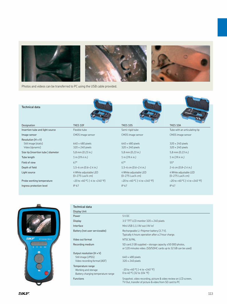
Photos and videos can be transferred to PC using the USB cable provided.
Designation TKES 10F TKES 10S TKES 10A
Insertion tube and light source Flexible tube Semi-rigid tube Tube with an articulating tip
Image sensor CMOS image sensor CMOS image sensor CMOS image sensor
Resolution (H × V)
Still image (static)
Video (dynamic)
640 × 480 pixels
320 × 240 pixels
640 × 480 pixels
320 × 240 pixels
320 × 240 pixels
320 × 240 pixels
Size tip (insertion tube ) diameter 5,8 mm (0.23 in.) 5,8 mm (0.23 in.) 5,8 mm (0.23 in.)
Tube length 1 m (39.4 in.) 1 m (39.4 in.) 1 m (39.4 in.)
Field of view 67° 67° 55°
Depth of field 1,5–6 cm (0.6–2.4 in.) 1,5–6 cm (0.6–2.4 in.) 2–6 cm (0.8–2.4 in.)
Light source 4 White adjustable LED
(0–275 Lux/4 cm)
4 White adjustable LED
(0–275 Lux/4 cm)
4 White adjustable LED
(0–275 Lux/4 cm)
Probe working temperature –20 to +60 °C (–4 to +140 °F) –20 to +60 °C (–4 to +140 °F) –20 to +60 °C (–4 to +140 °F)
Ingress protection level IP 67 IP 67 IP 67
Display Unit
Power 5 V DC
Display 3.5" TFT LCD monitor 320 × 240 pixels
Interface Mini USB 1.1 / AV out / AV in/
Battery (not user serviceable) Rechargeable Li-Polymer battery (3.7 V).
Typically 4 hours operation after a 2 hour charge.
Video out format NTSC & PAL
Recording medium SD card 2 GB supplied – storage capacity ±50 000 photos,
or 120 minutes video. (SD/SDHC cards up to 32 GB can be used)
Output resolution (H × V)
Still image (JPEG)
Video recording format (ASF)
640 × 480 pixels
320 × 240 pixels
Temperature range
Working and storage
Battery charging temperature range
-20 to +60 °C (–4 to +140 °F)
0 to 40 °C (32 to 104 °F)
Functions Snapshot, video recording, picture & video review on LCD screen,
TV Out, transfer of picture & video from SD card to PC
Technical data
Technical data
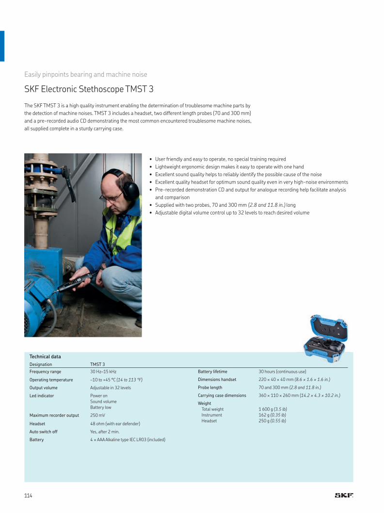
Easily pinpoints bearing and machine noise
SKF Electronic Stethoscope TMST 3
• User friendly and easy to operate, no special training required
• Lightweight ergonomic design makes it easy to operate with one hand
• Excellent sound quality helps to reliably identify the possible cause of the noise
• Excellent quality headset for optimum sound quality even in very high-noise environments
• Pre-recorded demonstration CD and output for analogue recording help facilitate analysis
and comparison
• Supplied with two probes, 70 and 300 mm (2.8 and 11.8 in.) long
• Adjustable digital volume control up to 32 levels to reach desired volume
The SKF TMST 3 is a high quality instrument enabling the determination of troublesome machine parts by
the detection of machine noises. TMST 3 includes a headset, two different length probes (70 and 300 mm)
and a pre-recorded audio CD demonstrating the most common encountered troublesome machine noises,
all supplied complete in a sturdy carrying case.
Designation TMST 3
Frequency range 30 Hz–15 kHz
Operating temperature –10 to +45 °C (14 to 113 °F)
Output volume Adjustable in 32 levels
Led indicator Power on
Sound volume
Battery low
Maximum recorder output 250 mV
Headset 48 ohm (with ear defender)
Auto switch off Yes, after 2 min.
Battery 4 × AAA Alkaline type IEC LR03 (included)
Battery lifetime 30 hours (continuous use)
Dimensions handset 220 × 40 × 40 mm (8.6 × 1.6 × 1.6 in.)
Probe length 70 and 300 mm (2.8 and 11.8 in.)
Carrying case dimensions 360 × 110 × 260 mm (14.2 × 4.3 × 10.2 in.)
Weight
Total weight
Instrument
Headset
1 600 g (3.5 lb)
162 g (0.35 lb)
250 g (0.55 lb)
Technical data
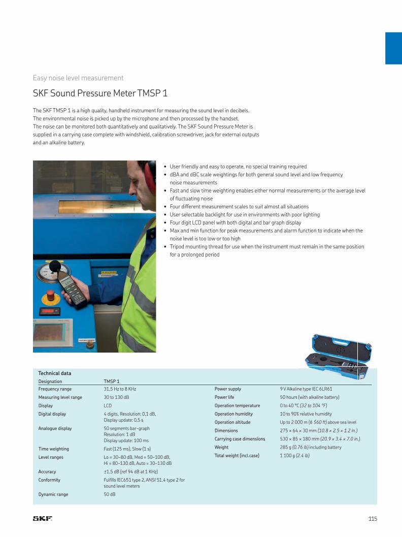
Designation TMSP 1
Frequency range 31,5 Hz to 8 KHz
Measuring level range 30 to 130 dB
Display LCD
Digital display 4 digits, Resolution: 0,1 dB,
Display update: 0,5 s
Analogue display 50 segments bar-graph
Resolution: 1 dB
Display update: 100 ms
Time weighting Fast (125 ms), Slow (1 s)
Level ranges Lo = 30~80 dB, Med = 50~100 dB,
Hi = 80~130 dB, Auto = 30~130 dB
Accuracy ±1,5 dB (ref 94 dB at 1 KHz)
Conformity Fulfills IEC651 type 2, ANSI S1.4 type 2 for
sound level meters
Dynamic range 50 dB
Power supply 9 V Alkaline type IEC 6LR61
Power life 50 hours (with alkaline battery)
Operation temperature 0 to 40 °C (32 to 104 °F)
Operation humidity 10 to 90% relative humidity
Operation altitude Up to 2 000 m (6 560 ft) above sea level
Dimensions 275 × 64 × 30 mm (10.8 × 2.5 × 1.2 in.)
Carrying case dimensions 530 × 85 × 180 mm (20.9 × 3.4 × 7.0 in.)
Weight 285 g (0.76 lb) including battery
Total weight (incl.case) 1 100 g (2.4 lb)
The SKF TMSP 1 is a high quality, handheld instrument for measuring the sound level in decibels.
The environmental noise is picked up by the microphone and then processed by the handset.
The noise can be monitored both quantitatively and qualitatively. The SKF Sound Pressure Meter is
supplied in a carrying case complete with windshield, calibration screwdriver, jack for external outputs
and an alkaline battery.
• User friendly and easy to operate, no special training required
• dBA and dBC scale weightings for both general sound level and low frequency
noise measurements
• Fast and slow time weighting enables either normal measurements or the average level
of fluctuating noise
• Four different measurement scales to suit almost all situations
• User selectable backlight for use in environments with poor lighting
• Four digit LCD panel with both digital and bar graph display
• Max and min function for peak measurements and alarm function to indicate when the
noise level is too low or too high
• Tripod mounting thread for use when the instrument must remain in the same position
for a prolonged period
Easy noise level measurement
SKF Sound Pressure Meter TMSP 1
Technical data

Designation TKSU 10
Keyboard 5 function keys
Measuring range -6 to 99,9 dBμV (reference 0 dB = 1 μV)
Resolution 0,1 dBμV
Amplification 5 adjustable positions in steps of 6 dB
Maximum output +83 dB SPL with supplied headset
Headset 25 dB NRR Peltor HQ headset
Battery 2 AA batteries
Battery life 7 hours
Operating temperature –10 to +50 °C (14 to 122 °F)
IP rating IP42
Flexible rod length 445 mm (17.51 in.)
Carrying case dimensions 530 × 110 × 360 mm (20.9 × 4.3 × 14.2 in.)
Total weight (incl. case) 3 kg (6.6 lbs)
Quick and easy detection of air leaks
SKF Ultrasonic Leak Detector TKSU 10
The SKF TKSU 10 is an ultrasonic leak detector that helps users to quickly find leakages in compressed air
or vacuum systems. The instrument is very simple to use and features adjustable sensitivity and intuitive
guidance for superior leak detection results. Any compressed air system can experience leaks, which
amplify the load on compressors and increase costs.
The TKSU 10 helps users to easily find leaks from a distance, even in noisy industrial
environments, via its ultrasound measurement sensor. The built-in LED display assists
the user in adjusting sensitivity and shows the measured ultrasound noise from leaking air,
allowing the quantification of leaks and prioritization of repairs.
• Easy to use; no training required
• Leak detection from a distance in noisy industrial environments
• Color LED display assists in adjusting sensitivity settings and shows measurement values
• Reduces energy and maintenance costs via leak identification and repair
• Lightweight, handheld device with industrial headset included
• Independently adjustable sensor sensitivity and headset volume
• Flexible probe helps find leaks in difficult-to-access locations
The TKSU 10 is designed for use in all industries utilizing compressed air, and it is particularly
recommended for paper and chemical industries, as well as workshops with air-driven
power tools.
Technical data
Sensor bandwidth
35 to 42 kHz
Headset features neck-band design to wear
with protective helmet
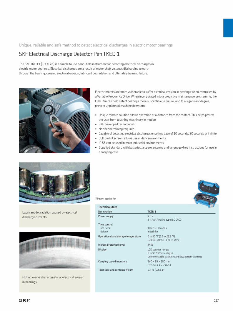
Designation TKED 1
Power supply 4,5 V
3 × AAA Alkaline type IEC LR03
Time control
pre-sets
default
10 or 30 seconds
indefinite
Operational and storage temperature 0 to 50 °C (32 to 122 °F)
–20 to +70 °C (–4 to +158 °F)
Ingress protection level IP 55
Display LCD counter range:
0 to 99 999 discharges.
User selectable backlight and low battery warning
Carrying case dimensions 260 × 85 × 180 mm
(10.3 × 3.4 × 7.0 in.)
Total case and contents weight 0,4 kg (0.88 lb)
The SKF TKED 1 (EDD Pen) is a simple to use hand-held instrument for detecting electrical discharges in
electric motor bearings. Electrical discharges are a result of motor shaft voltages discharging to earth
through the bearing, causing electrical erosion, lubricant degradation and ultimately bearing failure.
Unique, reliable and safe method to detect electrical discharges in electric motor bearings
SKF Electrical Discharge Detector Pen TKED 1
Electric motors are more vulnerable to suffer electrical erosion in bearings when controlled by
a Variable Frequency Drive. When incorporated into a predictive maintenance programme, the
EDD Pen can help detect bearings more susceptible to failure, and to a significant degree,
prevent unplanned machine downtime.
• Unique remote solution allows operation at a distance from the motors. This helps protect
the user from touching machinery in motion
• SKF developed technology 1)
• No special training required
• Capable of detecting electrical discharges on a time base of 10 seconds, 30 seconds or infinite
• LED backlit screen, allows use in dark environments
• IP 55 can be used in most industrial environments
• Supplied standard with batteries, a spare antenna and language-free instructions for use in
a carrying case
1) Patent applied for
Technical data
Lubricant degradation caused by electrical
discharge currents
Fluting marks characteristic of electrical erosion
in bearings
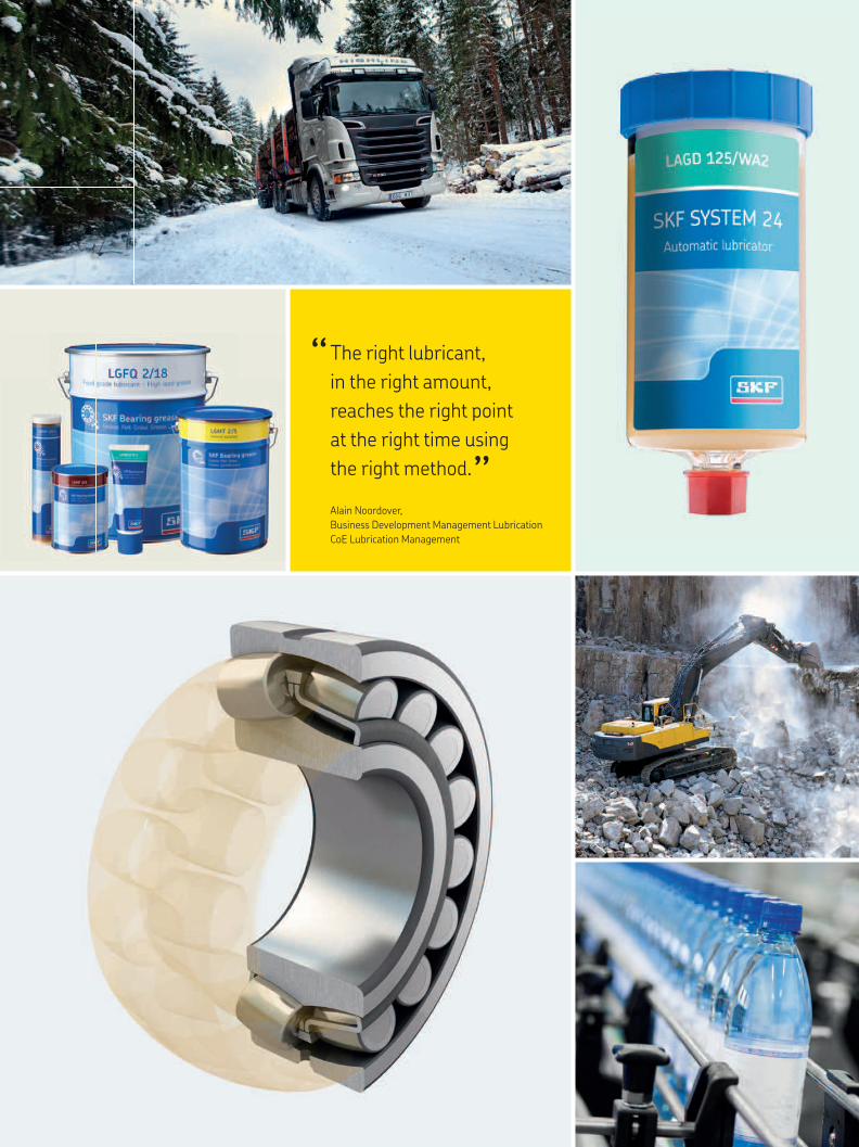
The right lubricant,
in the right amount,
reaches the right point
at the right time using
the right method.
“ “
Alain Noordover,
Business Development Management Lubrication
CoE Lubrication Management
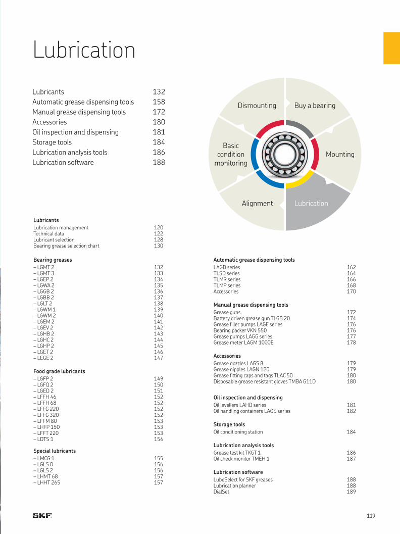
Lubricants
Lubrication management 120Technical data 122 Lubricant selection 128Bearing grease selection chart 130
Bearing greases
– LGMT 2 132– LGMT 3 133– LGEP 2 134– LGWA 2 135– LGGB 2 136– LGBB 2 137– LGLT 2 138– LGWM 1 139– LGWM 2 140– LGEM 2 141– LGEV 2 142– LGHB 2 143– LGHC 2 144– LGHP 2 145– LGET 2 146– LEGE 2 147
Food grade lubricants
– LGFP 2 149– LGFQ 2 150– LGED 2 151– LFFH 46 152– LFFH 68 152– LFFG 220 152– LFFG 320 152– LFFM 80 153– LHFP 150 153– LFFT 220 153– LDTS 1 154
Special lubricants
– LMCG 1 155– LGLS 0 156– LGLS 2 156– LHMT 68 157– LHHT 265 157
Automatic grease dispensing tools
LAGD series 162TLSD series 164TLMR series 166TLMP series 168Accessories 170
Manual grease dispensing tools
Grease guns 172Battery driven grease gun TLGB 20 174Grease filler pumps LAGF series 176Bearing packer VKN 550 176Grease pumps LAGG series 177Grease meter LAGM 1000E 178
Accessories
Grease nozzles LAGS 8 179Grease nipples LAGN 120 179Grease fitting caps and tags TLAC 50 180Disposable grease resistant gloves TMBA G11D 180
Oil inspection and dispensing
Oil levellers LAHD series 181Oil handling containers LAOS series 182
Storage tools
Oil conditioning station 184
Lubrication analysis tools
Grease test kit TKGT 1 186Oil check monitor TMEH 1 187
Lubrication software
LubeSelect for SKF greases 188Lubrication planner 188DialSet 189
Lubrication
Lubricants 132
Automatic grease dispensing tools 158
Manual grease dispensing tools 172
Accessories 180
Oil inspection and dispensing 181
Storage tools 184
Lubrication analysis tools 186
Lubrication software 188
Alignment Lubrication
Mounting
Buy a bearing
Basic condition
monitoring
Dismounting

Lubrication management
Poor lubrication accounts for more than 36% of premature bearing failures
Include contamination, and this number rises to well above 50%.
The importance of proper lubrication and cleanliness is self-evident
in the determination of bearing life.
Increase
• Productivity
• Reliability
• Availability and durability
• Machine uptime
• Service intervals
• Safety
• Health
• Sustainability
Reduce
• Energy consumption due to friction
• Heat generation due to friction
• Wear due to friction
• Noise due to friction
• Downtime
• Operating expenses
• Product contamination
• Maintenance and repair costs
• Lubricant consumption
• Corrosion
From lubrication to lubrication management
A good lubrication programme can be defined by applying the
5R approach:
“ The right lubricant, in the right amount, reaches the right point
at the right time using the right method”
This simple and logical approach, however, requires
a detailed action plan that must include aspects as varied as:
• Logistics and supply chain
• Lubricant selection
• Lubricant storage, transfer and dispensing
• Lubrication tasks planning and scheduling
• Lubricant application procedures
• Lubricant analysis and condition monitoring
• Lubricant disposal
• Training
What the right lubrication programme can do for you
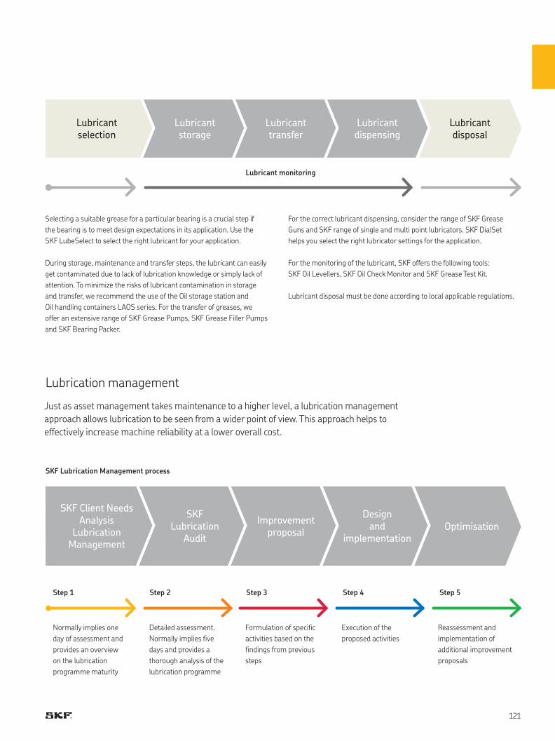
Just as asset management takes maintenance to a higher level, a lubrication management
approach allows lubrication to be seen from a wider point of view. This approach helps to
effectively increase machine reliability at a lower overall cost.
Selecting a suitable grease for a particular bearing is a crucial step if
the bearing is to meet design expectations in its application. Use the
SKF LubeSelect to select the right lubricant for your application.
During storage, maintenance and transfer steps, the lubricant can easily
get contaminated due to lack of lubrication knowledge or simply lack of
attention. To minimize the risks of lubricant contamination in storage
and transfer, we recommend the use of the Oil storage station and
Oil handling containers LAOS series. For the transfer of greases, we
offer an extensive range of SKF Grease Pumps, SKF Grease Filler Pumps
and SKF Bearing Packer.
Lubrication management
For the correct lubricant dispensing, consider the range of SKF Grease
Guns and SKF range of single and multi point lubricators. SKF DialSet
helps you select the right lubricator settings for the application.
For the monitoring of the lubricant, SKF offers the following tools:
SKF Oil Levellers, SKF Oil Check Monitor and SKF Grease Test Kit.
Lubricant disposal must be done according to local applicable regulations.
Lubricant transfer
Improvement proposal
Lubricant dispensing
Design and
implementation
Lubricant disposal
Optimisation
Lubricant storage
SKFLubrication
Audit
Lubricant selection
SKF Client NeedsAnalysis
LubricationManagement
Step 1 Step 2 Step 3 Step 4 Step 5
Lubricant monitoring
Normally implies one
day of assessment and
provides an overview
on the lubrication
programme maturity
Detailed assessment.
Normally implies five
days and provides a
thorough analysis of the
lubrication programme
Formulation of specific
activities based on the
findings from previous
steps
Execution of the
proposed activities
Reassessment and
implementation of
additional improvement
proposals
SKF Lubrication Management process
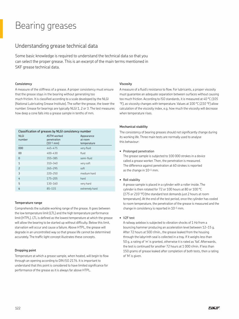
Understanding grease technical data
Some basic knowledge is required to understand the technical data so that you
can select the proper grease. This is an excerpt of the main terms mentioned in
SKF grease technical data.
Consistency
A measure of the stiffness of a grease. A proper consistency must ensure
that the grease stays in the bearing without generating too
much friction. It is classified according to a scale developed by the NLGI
(National Lubricating Grease Institute). The softer the grease, the lower the
number. Grease for bearings are typically NLGI 1, 2 or 3. The test measures
how deep a cone falls into a grease sample in tenths of mm.
NLGI
number
ASTM worked
penetration
(10–1 mm)
Appearance
at room
temperature
000 445–475 very fluid
00 400–430 fluid
0 355–385 semi-fluid
1 310–340 very soft
2 265–295 soft
3 220–250 medium hard
4 175–205 hard
5 130–160 very hard
6 85–115 extremely hard
Classification of greases by NLGI consistency number
Temperature range
Comprehends the suitable working range of the grease. It goes between
the low temperature limit (LTL) and the high temperature performance
limit (HTPL). LTL is defined as the lowest temperature at which the grease
will allow the bearing to be started up without difficulty. Below this limit,
starvation will occur and cause a failure. Above HTPL, the grease will
degrade in an uncontrolled way so that grease life cannot be determined
accurately. The traffic light concept illustrates these concepts.
Dropping point
Temperature at which a grease sample, when heated, will begin to flow
through an opening according to DIN ISO 2176. It is important to
understand that this point is considered to have limited significance for
performance of the grease as it is always far above HTPL.
Viscosity
A measure of a fluid’s resistance to flow. For lubricants, a proper viscosity
must guarantee an adequate separation between surfaces without causing
too much friction. According to ISO standards, it is measured at 40 °C (105
°F), as viscosity changes with temperature. Values at 100 °C (210 °F) allow
calculation of the viscosity index, e.g. how much the viscosity will decrease
when temperature rises.
Mechanical stability
The consistency of bearing greases should not significantly change during
its working life. Three main tests are normally used to analyse
this behaviour:
• Prolonged penetration
The grease sample is subjected to 100 000 strokes in a device
called a grease worker. Then, the penetration is measured.
The difference against penetration at 60 strokes is reported
as the change in 10–1 mm.
• Roll stability
A grease sample is placed in a cylinder with a roller inside. The
cylinder is then rotated for 72 or 100 hours at 80 or 100 °C
(175 or 210 °F) (the standard test demands just 2 hours at room
temperature). At the end of the test period, once the cylinder has cooled
to room temperature, the penetration of the grease is measured and the
change in consistency is reported in 10–1 mm.
• V2F test
A railway axlebox is subjected to vibration shocks of 1 Hz from a
bouncing hammer producing an acceleration level between 12–15 g.
After 72 hours at 500 r/min., the grease leaked from the housing
through the labyrinth seal is collected in a tray. If it weighs less than
50 g, a rating of ‘m’ is granted, otherwise it is rated as ‘fail’. Afterwards,
the test is continued for another 72 hours at 1 000 r/min. If less than
150 grams of grease leaked after completion of both tests, then a rating
of ‘M’ is given.
Bearing greases
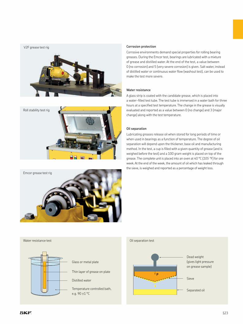
Roll stability test rig
Emcor grease test rig
V2F grease test rig Corrosion protection
Corrosive environments demand special properties for rolling bearing
greases. During the Emcor test, bearings are lubricated with a mixture
of grease and distilled water. At the end of the test, a value between
0 (no corrosion) and 5 (very severe corrosion) is given. Salt water, instead
of distilled water or continuous water flow (washout test), can be used to
make the test more severe.
Water resistance
A glass strip is coated with the candidate grease, which is placed into
a water-filled test tube. The test tube is immersed in a water bath for three
hours at a specified test temperature. The change in the grease is visually
evaluated and reported as a value between 0 (no change) and 3 (major
change) along with the test temperature.
Oil separation
Lubricating greases release oil when stored for long periods of time or
when used in bearings as a function of temperature. The degree of oil
separation will depend upon the thickener, base oil and manufacturing
method. In the test, a cup is filled with a given quantity of grease (and is
weighed before the test) and a 100 gram weight is placed on top of the
grease. The complete unit is placed into an oven at 40 °C (105 °F) for one
week. At the end of the week, the amount of oil which has leaked through
the sieve, is weighed and reported as a percentage of weight loss.
Water resistance test
Glass or metal plate
Thin layer of grease on plate
Distilled water
Temperature controlled bath,
e.g. 90 ±1 °C
Oil separation test
Dead weight
(gives light pressure
on grease sample)
SieveP
Separated oil
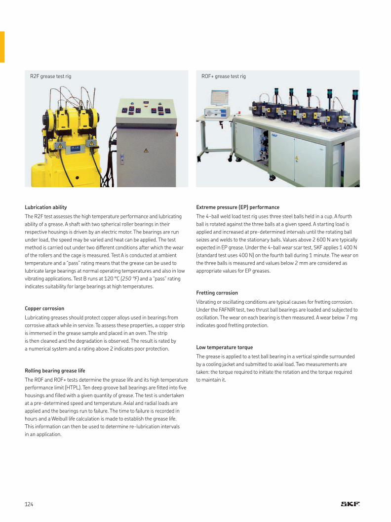
Lubrication ability
The R2F test assesses the high temperature performance and lubricating
ability of a grease. A shaft with two spherical roller bearings in their
respective housings is driven by an electric motor. The bearings are run
under load, the speed may be varied and heat can be applied. The test
method is carried out under two different conditions after which the wear
of the rollers and the cage is measured. Test A is conducted at ambient
temperature and a “pass” rating means that the grease can be used to
lubricate large bearings at normal operating temperatures and also in low
vibrating applications. Test B runs at 120 °C (250 °F) and a “pass” rating
indicates suitability for large bearings at high temperatures.
Copper corrosion
Lubricating greases should protect copper alloys used in bearings from
corrosive attack while in service. To assess these properties, a copper strip
is immersed in the grease sample and placed in an oven. The strip
is then cleaned and the degradation is observed. The result is rated by
a numerical system and a rating above 2 indicates poor protection.
Rolling bearing grease life
The R0F and ROF+ tests determine the grease life and its high temperature
performance limit (HTPL). Ten deep groove ball bearings are fitted into five
housings and filled with a given quantity of grease. The test is undertaken
at a pre-determined speed and temperature. Axial and radial loads are
applied and the bearings run to failure. The time to failure is recorded in
hours and a Weibull life calculation is made to establish the grease life.
This information can then be used to determine re-lubrication intervals
in an application.
R2F grease test rig ROF+ grease test rig
Extreme pressure (EP) performance
The 4-ball weld load test rig uses three steel balls held in a cup. A fourth
ball is rotated against the three balls at a given speed. A starting load is
applied and increased at pre-determined intervals until the rotating ball
seizes and welds to the stationary balls. Values above 2 600 N are typically
expected in EP grease. Under the 4-ball wear scar test, SKF applies 1 400 N
(standard test uses 400 N) on the fourth ball during 1 minute. The wear on
the three balls is measured and values below 2 mm are considered as
appropriate values for EP greases.
Fretting corrosion
Vibrating or oscillating conditions are typical causes for fretting corrosion.
Under the FAFNIR test, two thrust ball bearings are loaded and subjected to
oscillation. The wear on each bearing is then measured. A wear below 7 mg
indicates good fretting protection.
Low temperature torque
The grease is applied to a test ball bearing in a vertical spindle surrounded
by a cooling jacket and submitted to axial load. Two measurements are
taken: the torque required to initiate the rotation and the torque required
to maintain it.
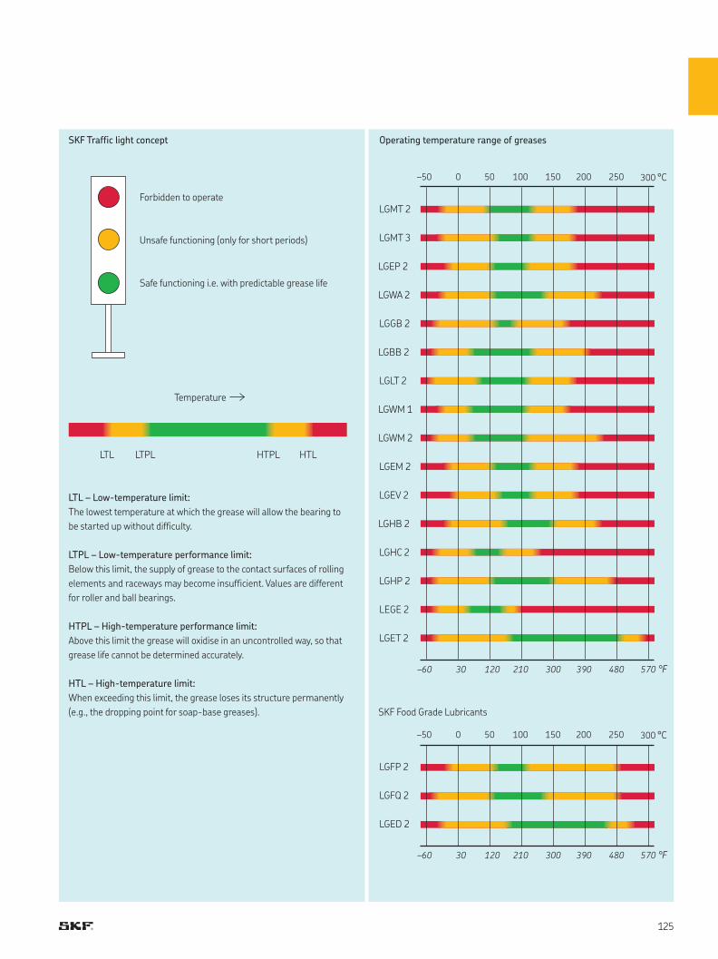
LGMT 2
LGMT 3
LGEP 2
LGWA 2
LGGB 2
LGBB 2
LGLT 2
LGWM 1
LGWM 2
LGEM 2
LGEV 2
LGHB 2
LGHC 2
LGHP 2
–50 0 50 100 150 200 250 300 °C
–60 30 120 210 300 390 480 570 °F
LEGE 2
LGET 2
LGFP 2
–50 0 50 100 150 200 250 300 °C
–60 30 120 210 300 390 480 570 °F
LGFQ 2
LGED 2
LTL LTPL HTPL HTL
SKF Food Grade Lubricants
Forbidden to operate
Operating temperature range of greasesSKF Traffic light concept
LTL – Low-temperature limit:
The lowest temperature at which the grease will allow the bearing to
be started up without difficulty.
LTPL – Low-temperature performance limit:
Below this limit, the supply of grease to the contact surfaces of rolling
elements and raceways may become insufficient. Values are different
for roller and ball bearings.
HTPL – High-temperature performance limit:
Above this limit the grease will oxidise in an uncontrolled way, so that
grease life cannot be determined accurately.
HTL – High-temperature limit:
When exceeding this limit, the grease loses its structure permanently
(e.g., the dropping point for soap-base greases).
Unsafe functioning (only for short periods)
Safe functioning i.e. with predictable grease life
Temperature
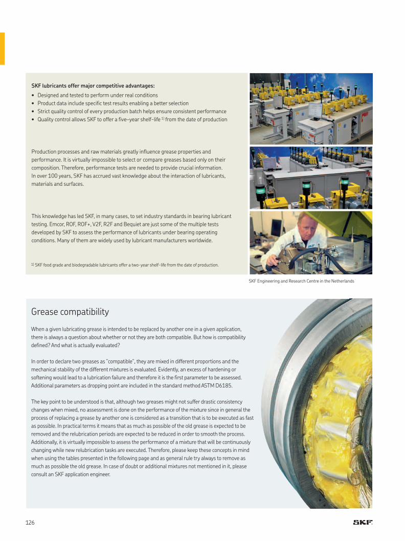
SKF lubricants offer major competitive advantages:
• Designed and tested to perform under real conditions
• Product data include specific test results enabling a better selection
• Strict quality control of every production batch helps ensure consistent performance
• Quality control allows SKF to offer a five–year shelf-life 1) from the date of production
Production processes and raw materials greatly influence grease properties and
performance. It is virtually impossible to select or compare greases based only on their
composition. Therefore, performance tests are needed to provide crucial information.
In over 100 years, SKF has accrued vast knowledge about the interaction of lubricants,
materials and surfaces.
This knowledge has led SKF, in many cases, to set industry standards in bearing lubricant
testing. Emcor, ROF, ROF+, V2F, R2F and Bequiet are just some of the multiple tests
developed by SKF to assess the performance of lubricants under bearing operating
conditions. Many of them are widely used by lubricant manufacturers worldwide.
SKF Engineering and Research Centre in the Netherlands
1) SKF food grade and biodegradable lubricants offer a two-year shelf-life from the date of production.
When a given lubricating grease is intended to be replaced by another one in a given application,
there is always a question about whether or not they are both compatible. But how is compatibility
defined? And what is actually evaluated?
In order to declare two greases as “compatible“, they are mixed in different proportions and the
mechanical stability of the different mixtures is evaluated. Evidently, an excess of hardening or
softening would lead to a lubrication failure and therefore it is the first parameter to be assessed.
Additional parameters as dropping point are included in the standard method ASTM D6185.
The key point to be understood is that, although two greases might not suffer drastic consistency
changes when mixed, no assessment is done on the performance of the mixture since in general the
process of replacing a grease by another one is considered as a transition that is to be executed as fast
as possible. In practical terms it means that as much as possible of the old grease is expected to be
removed and the relubrication periods are expected to be reduced in order to smooth the process.
Additionally, it is virtually impossible to assess the performance of a mixture that will be continuously
changing while new relubrication tasks are executed. Therefore, please keep these concepts in mind
when using the tables presented in the following page and as general rule try always to remove as
much as possible the old grease. In case of doubt or additional mixtures not mentioned in it, please
consult an SKF application engineer.
Grease compatibility
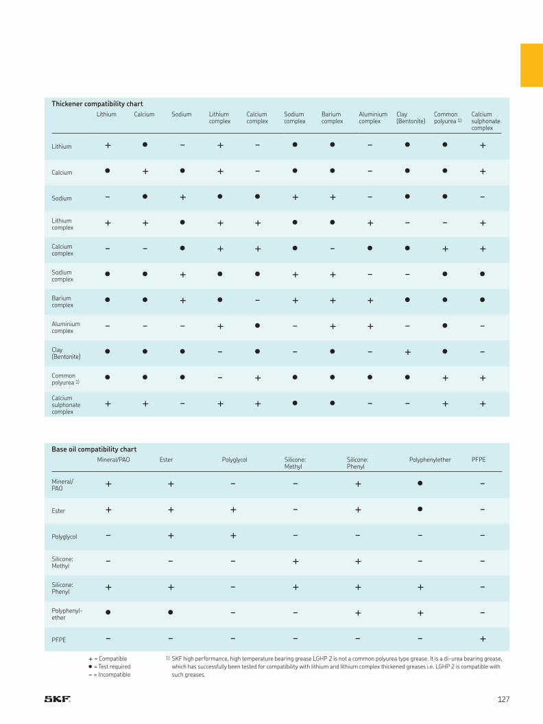
+ = Compatible
• = Test required
- = Incompatible
1) SKF high performance, high temperature bearing grease LGHP 2 is not a common polyurea type grease. It is a di-urea bearing grease,
which has successfully been tested for compatibility with lithium and lithium complex thickened greases i.e. LGHP 2 is compatible with
such greases.
Thickener compatibility chart
Base oil compatibility chart
Lithium Calcium Sodium Lithiumcomplex
Calciumcomplex
Sodiumcomplex
Bariumcomplex
Aluminiumcomplex
Clay(Bentonite)
Commonpolyurea 1)
Calciumsulphonatecomplex
Lithium + • - + - • • - • • +
Calcium • + • + - • • - • • +
Sodium - • + • • + + - • • -
Lithium complex + + • + + • • + - - +
Calcium complex - - • + + • - • • + +
Sodium complex • • + • • + + - - • •
Barium complex • • + • - + + + • • •
Aluminium complex - - - + • - + + - • -
Clay(Bentonite) • • • - • - • - + • -
Common polyurea 1) • • • - + • • • • + +
Calcium sulphonatecomplex
+ + - + + • • - - + +
Mineral/PAO Ester Polyglycol Silicone:Methyl
Silicone: Phenyl
Polyphenylether PFPE
Mineral/PAO + + - - + • -
Ester + + + - + • -
Polyglycol - + + - - - -
Silicone: Methyl - - - + + - -
Silicone: Phenyl + + - + + + -
Polyphenyl-ether • • - - + + -
PFPE - - - - - - +
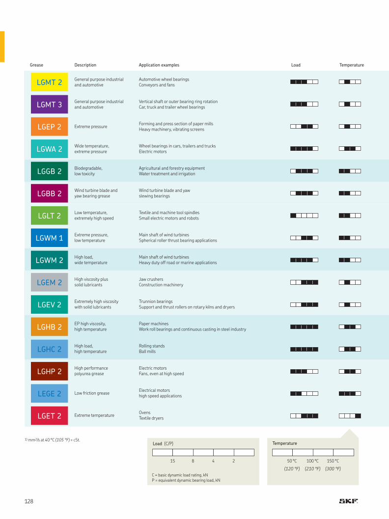
LGHP 2
LGHC 2
LGET 2
LEGE 2
LGHB 2
LGEV 2
LGEM 2
LGWM 2
LGWM 1
LGLT 2
LGBB 2
LGGB 2
LGWA 2
LGEP 2
LGMT 3
LGMT 2
1) mm2/s at 40 °C (105 °F) = cSt.
Grease Description Application examples Load Temperature
General purpose industrial and automotive
Automotive wheel bearings Conveyors and fans
General purpose industrial and automotive
Vertical shaft or outer bearing ring rotationCar, truck and trailer wheel bearings
Extreme pressureForming and press section of paper millsHeavy machinery, vibrating screens
Wide temperature, extreme pressure
Wheel bearings in cars, trailers and trucksElectric motors
Biodegradable, low toxicity
Agricultural and forestry equipmentWater treatment and irrigation
Wind turbine blade and yaw bearing grease
Wind turbine blade and yawslewing bearings
Low temperature, extremely high speed
Textile and machine tool spindlesSmall electric motors and robots
Extreme pressure, low temperature
Main shaft of wind turbinesSpherical roller thrust bearing applications
High load, wide temperature
Main shaft of wind turbinesHeavy duty off road or marine applications
High viscosity plus solid lubricants
Jaw crushersConstruction machinery
Extremely high viscosity with solid lubricants
Trunnion bearingsSupport and thrust rollers on rotary kilns and dryers
EP high viscosity, high temperature
Paper machinesWork roll bearings and continuous casting in steel industry
High load, high temperature
Rolling stands Ball mills
High performance polyurea grease
Electric motorsFans, even at high speed
Low friction greaseElectrical motorshigh speed applications
Extreme temperatureOvensTextile dryers
15 8 4 2 50 °C 100 °C 150 °C
(120 °F) (210 °F) (300 °F)
C = basic dynamic load rating, kNP = equivalent dynamic bearing load, kN
TemperatureLoad (C/P)
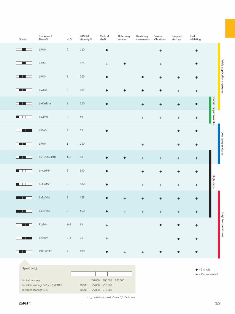
• = Suitable
+ = Recommended
SpeedThickener / Base Oil NLGI
Base oil viscosity 1)
Vertical shaft
Outer ring rotation
Oscillating movements
Severe Vibrations
Frequent start up
Rust inhibiting
Li/Min 2 110 • + +
Li/Min 3 125 + • + •
Li/Min 2 200 • • + + +
Lix/Min 2 185 • • • • + +
Li-Ca/Ester 2 110 • + + + •
Lix/PAO 2 68 + + + +
Li/PAO 2 18 • • •
Li/Min 1 200 + + +
CaSx/Min-PAO 1–2 80 • • + + + +
Li-Ca/Min 2 500 • + + + +
Li-Ca/Min 2 1020 • + + + +
CaSx/Min 2 425 • + + + + +
CaSx/Min 2 450 • + + + + +
PU/Min 2–3 96 + • • +
Li/Ester 2-3 25 + • +
PTFE/PFPE 2 400 • + + • • •
Wid
e applicatio
ns g
reases
Special req
uirem
ents
Low
temperatu
resH
igh tem
peratu
res
Hig
h lo
ads
for ball bearings 100 000 300 000 500 000
for roller bearings SRB/TRB/CARB 30 000 75 000 210 000
for roller bearings CRB 30 000 75 000 270 000
n dm = rotational speed, r/min x 0,5 (D+d), mm
Speed (n dm)
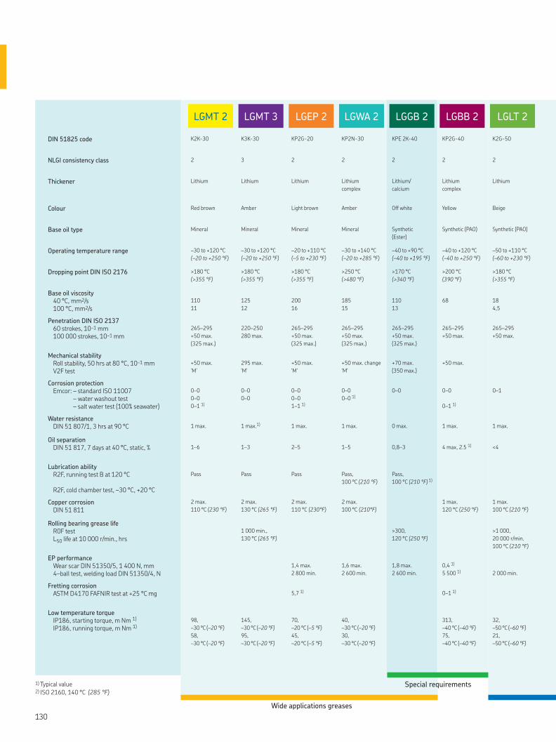
LGLT 2LGBB 2LGGB 2LGWA 2LGEP 2LGMT 3LGMT 2
DIN 51825 code K2K-30 K3K-30 KP2G-20 KP2N-30 KPE 2K-40 KP2G-40 K2G-50
NLGI consistency class 2 3 2 2 2 2 2
Thickener Lithium Lithium Lithium Lithium
complex
Lithium/
calcium
Lithium
complex
Lithium
Colour Red brown Amber Light brown Amber Off white Yellow Beige
Base oil type Mineral Mineral Mineral Mineral Synthetic
(Ester)
Synthetic (PAO) Synthetic (PAO)
Operating temperature range –30 to +120 °C
(–20 to +250 °F)
–30 to +120 °C
(–20 to +250 °F)
–20 to +110 °C
(–5 to +230 °F)
–30 to +140 °C
(–20 to +285 °F)
–40 to +90 °C
(–40 to +195 °F)
–40 to +120 °C
(–40 to +250 °F)
–50 to +110 °C
(–60 to +230 °F)
Dropping point DIN ISO 2176 >180 °C
(>355 °F)
>180 °C
(>355 °F)
>180 °C
(>355 °F)
>250 °C
(>480 °F)
>170 °C
(>340 °F)
>200 °C
(390 °F)
>180 °C
(>355 °F)
Base oil viscosity 40 °C, mm2/s100 °C, mm2/s
110
11
125
12
200
16
185
15
110
13
68
18
4,5
Penetration DIN ISO 213760 strokes, 10–1 mm100 000 strokes, 10–1 mm
265–295
+50 max.
(325 max.)
220–250
280 max.
265–295
+50 max.
(325 max.)
265–295
+50 max.
(325 max.)
265–295
+50 max.
(325 max.)
265–295
+50 max.
265–295
+50 max.
Mechanical stabilityRoll stability, 50 hrs at 80 °C, 10–1 mmV2F test
+50 max.
‘M’
295 max.
'M'
+50 max.
'M'
+50 max. change
'M'
+70 max.
(350 max.)
+50 max.
Corrosion protectionEmcor: – standard ISO 11007
– water washout test – salt water test (100% seawater)
0–0
0–0
0–1 1)
0–0
0–0
0–0
0–0
1–1 1)
0–0
0–0 1)
0–0
0–0
0–1 1)
0–1
Water resistanceDIN 51 807/1, 3 hrs at 90 °C
1 max.
1 max.1)
1 max.
1 max.
0 max.
1 max.
1 max.
Oil separation DIN 51 817, 7 days at 40 °C, static, %
1–6
1–3
2–5
1–5
0,8–3 4 max, 2.5 1)
<4
Lubrication ability R2F, running test B at 120 °C
R2F, cold chamber test, –30 °C, +20 °C
Pass
Pass
Pass
Pass,
100 °C (210 °F)
Pass,
100 °C (210 °F) 1)
Copper corrosion DIN 51 811
2 max.
110 °C (230 °F)
2 max.
130 °C (265 °F)
2 max.
110 °C (230°F)
2 max.
100 °C (210°F)
1 max.
120 °C (250 °F)
1 max.
100 °C (210 °F)
Rolling bearing grease life R0F test L50 life at 10 000 r/min., hrs
1 000 min.,
130 °C (265 °F)
>300,
120 °C (250 °F)
>1 000,
20 000 r/min.
100 °C (210 °F)
EP performance Wear scar DIN 51350/5, 1 400 N, mm4–ball test, welding load DIN 51350/4, N
1,4 max.
2 800 min.
1,6 max.
2 600 min.
1,8 max.
2 600 min.
0,4 1)
5 500 1)
2 000 min.
Fretting corrosionASTM D4170 FAFNIR test at +25 °C mg
5,7 1)
0–1 1)
Low temperature torqueIP186, starting torque, m Nm 1)
IP186, running torque, m Nm 1)98,
–30 °C (–20 °F)
58,
–30 °C (–20 °F)
145,
–30 °C (–20 °F)
95,
–30 °C (–20 °F)
70,
–20 °C (–5 °F)
45,
–20 °C (–5 °F)
40,
–30 °C (–20 °F)
30,
–30 °C (–20 °F)
313,
–40 °C (–40 °F)
75,
–40 °C (–40 °F)
32,
–50 °C (–60 °F)
21,
–50 °C (–60 °F)
Wide applications greases
Special requirements1) Typical value 2) ISO 2160, 140 °C (285 °F)
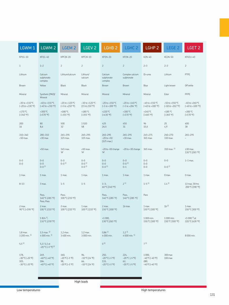
LGHP 2 LGET 2LGHB 2LGEV 2LGEM 2LGWM 2LGWM 1 LEGE 2LGHC 2
KP1G-30 KP2G-40 KPF2K-20 KPF2K-10 KP2N-20 KP2N-20 K2N-40 KE2N-50 KFK2U-40
1 1–2 2 2 2 2 2–3 2–3 2
Lithium Calcium
sulphonate
complex
Lithium/calcium Lithium/
calcium
Calcium
sulphonate
complex
Complex calcium
sulphonate
Di–urea Lithium PTFE
Brown Yellow Black Black Brown Brown Blue Light brown Off white
Mineral Synthetic (PAO)/
Mineral
Mineral Mineral Mineral Mineral Mineral Ester PFPE
–30 to +110 °C
(–20 to +230 °F)
–40 to +110 °C
(–40 to +230 °F)
–20 to +120 °C
(–5 to +250 °F)
–10 to +120 °C
(15 to 250 °F)
–20 to +150 °C
(–5 to +300 °F)
–20 to +140 °C
(–5 to +284 °F)
–40 to +150 °C
(–40 to +300 °F)
–50 to +150 °C
(–58 to +302 °F)
–40 to +260 °C
(–40 to +500 °F)
>170 °C
(>340 °F)
>300 °C
(>570 °F)
>180 °C
(>355 °F)
>180 °C
(>355 °F)
>220 °C
(>430 °F)
>300 °C
(>570 °F)
>240 °C
(>465 °F)
>185 °C
(>365 °F)
>300 °C
(>570 °F)
200
16
80
8,6
500
32
1 020
58
425
26,5
450
31
96
10,5
25
4,9
400
38
310–340
+50 max.
280–310
+30 max
265–295
325 max.
265–295
325 max.
265–295
–20 to +50
(325 max.)
265–295
+30 max.
245–275
365 max.
240–270
330 max.
265–295
–
+50 max.
345 max.
‘M’
+50 max.
‘M’
–20 to +50 change
‘M’
–20 to +30 change
365 max.
310 max. 1)
±30 max.
130 °C (265 °F)
0–0
0–0
0–0
0–0
0–0 1)
0–0
0–0 1)
0–0
0–0 1)
0–0 1)
0–0
0–0
0–0 1)
0–0
0–0 1)
0–1
0–0
0–0
0–0
0–0
0–0 1)
1–1 max.
1 max.
1 max.
1 max.
1 max.
1 max.
1 max.
1 max.
0 max.
0 max.
8–13
3 max.
1–5
1–5
1–3,
60 °C (140 °F)
2 1)
1–5 1)
1.4 1)
13 max. 30 hrs
200 °C (390 °F)
Pass,
140 °C (285 °F)
Pass, Pass
Pass,
100 °C (210 °F)
Pass,
140 °C (285 °F)
Pass,
140 °C (285 °F)
Pass
2 max.
90 °C (>195 °F)
2 max.
100 °C (210 °F)
2 max.
100 °C (210 °F)
1 max.
100 °C (210 °F)
2 max.
150 °C (300 °F)
1b max. 1 max.
150 °C (300 °F)
1b 2) 1 max.
150 °C (300 °F)
1 824 1),
110 °C (230 °F)
>1 000,
130 °C (265 °F)
1 000 min.
150 °C (300 °F)
1 000 min.
150 °C (300 °F)
>1 000 1) at
220 °C (428 °F)
1,8 max.
3 200 min. 1)
1,5 max. 1)
4 000 min. 1)
1,2 max.
3 400 min.
1,2 max.
3 000 min.
0,86 1)
4 000 min.
1,2 1)
4 000 min. 1)
8 000 min.
5,5 1) 5,2 / 1,1 at
–20 °C (–5 °F) 1)
0 1)
7 1)
178,
–30 °C (–20 °F)
103,
–30 °C (–20 °F)
249,
–40 °C (–40 °F)
184,
–40 °C (–40 °F)
160,
–20 °C (–5 °F)
98,
–20 °C (–5 °F)
96,
–10 °C (14 °F)
66,
–10 °C (14 °F)
250,
–20 °C (–5 °F)
133,
–20 °C (–5 °F)
224,
–20 °C (–5 °F)
62,
–20 °C (–5 °F)
1 000,
–40 °C (–40 °F)
280,
–40 °C (–40 °F)
300 max
100 max
Low temperatures
High loads
High temperatures
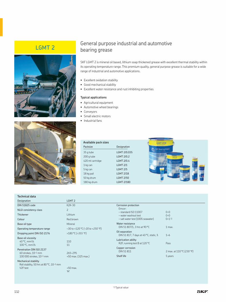
LGMT 2
Designation LGMT 2
DIN 51825 code K2K-30
NLGI consistency class 2
Thickener Lithium
Colour Red brown
Base oil type Mineral
Operating temperature range –30 to +120 °C (–20 to +250 °F)
Dropping point DIN ISO 2176 >180 °C (>355 °F)
Base oil viscosity
40 °C, mm2/s
100 °C, mm2/s
110
11
Penetration DIN ISO 2137
60 strokes, 10–1 mm
100 000 strokes, 10–1 mm
265–295
+50 max. (325 max.)
Mechanical stability
Roll stability, 50 hrs at 80 °C, 10–1 mm
V2F test +50 max.
‘M’
1) Typical value
Corrosion protection
Emcor:
– standard ISO 11007
– water washout test
– salt water test (100% seawater)
0–0
0–0
0–1 1)
Water resistance
DIN 51 807/1, 3 hrs at 90 °C 1 max.
Oil separation
DIN 51 817, 7 days at 40 °C, static, % 1–6
Lubrication ability
R2F, running test B at 120 °C Pass
Copper corrosion
DIN 51 811 2 max. at 110 °C (230 °F)
Shelf life 5 years
General purpose industrial and automotive bearing grease
SKF LGMT 2 is mineral oil based, lithium soap thickened grease with excellent thermal stability within
its operating temperature range. This premium quality, general purpose grease is suitable for a wide
range of industrial and automotive applications.
• Excellent oxidation stability
• Good mechanical stability
• Excellent water resistance and rust inhibiting properties
Typical applications
• Agricultural equipment
• Automotive wheel bearings
• Conveyors
• Small electric motors
• Industrial fans
Technical data
Available pack sizes
Packsize Designation
35 g tube LGMT 2/0.035
200 g tube LGMT 2/0.2
420 ml cartridge LGMT 2/0.4
1 kg can LGMT 2/1
5 kg can LGMT 2/5
18 kg pail LGMT 2/18
50 kg drum LGMT 2/50
180 kg drum LGMT 2/180
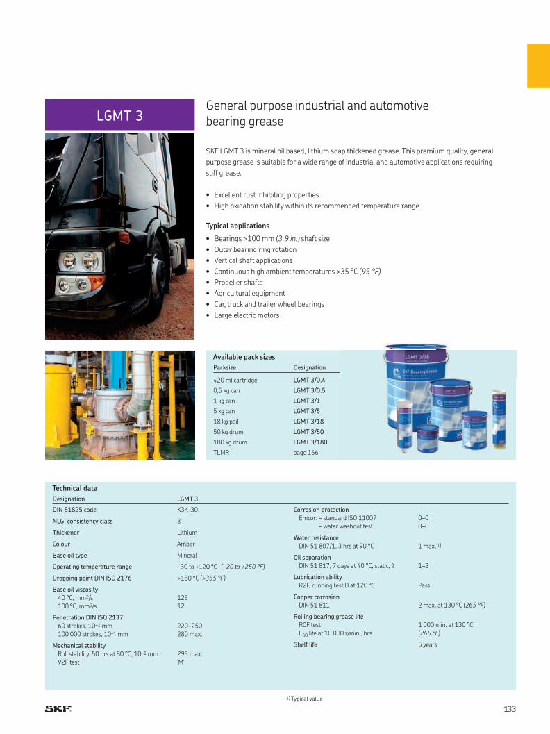
LGMT 3
1) Typical value
Designation LGMT 3
DIN 51825 code K3K-30
NLGI consistency class 3
Thickener Lithium
Colour Amber
Base oil type Mineral
Operating temperature range –30 to +120 °C (–20 to +250 °F)
Dropping point DIN ISO 2176 >180 °C (>355 °F)
Base oil viscosity
40 °C, mm2/s
100 °C, mm2/s
125
12
Penetration DIN ISO 2137
60 strokes, 10–1 mm
100 000 strokes, 10–1 mm
220–250
280 max.
Mechanical stability
Roll stability, 50 hrs at 80 °C, 10–1 mm
V2F test
295 max.
'M'
Corrosion protection
Emcor: – standard ISO 11007
– water washout test
0–0
0–0
Water resistance
DIN 51 807/1, 3 hrs at 90 °C 1 max. 1)
Oil separation
DIN 51 817, 7 days at 40 °C, static, % 1–3
Lubrication ability
R2F, running test B at 120 °C Pass
Copper corrosion
DIN 51 811 2 max. at 130 °C (265 °F)
Rolling bearing grease life
R0F test
L50 life at 10 000 r/min., hrs
1 000 min. at 130 °C
(265 °F)
Shelf life 5 years
General purpose industrial and automotive bearing grease
SKF LGMT 3 is mineral oil based, lithium soap thickened grease. This premium quality, general
purpose grease is suitable for a wide range of industrial and automotive applications requiring
stiff grease.
• Excellent rust inhibiting properties
• High oxidation stability within its recommended temperature range
Typical applications
• Bearings >100 mm (3.9 in.) shaft size
• Outer bearing ring rotation
• Vertical shaft applications
• Continuous high ambient temperatures >35 °C (95 °F)
• Propeller shafts
• Agricultural equipment
• Car, truck and trailer wheel bearings
• Large electric motors
Technical data
Available pack sizes
Packsize Designation
420 ml cartridge LGMT 3/0.4
0,5 kg can LGMT 3/0.5
1 kg can LGMT 3/1
5 kg can LGMT 3/5
18 kg pail LGMT 3/18
50 kg drum LGMT 3/50
180 kg drum LGMT 3/180
TLMR page 166
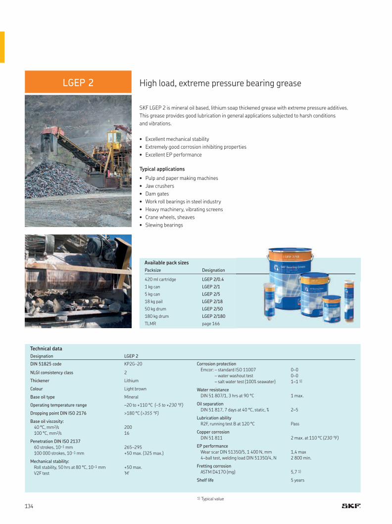
LGEP 2
Designation LGEP 2
DIN 51825 code KP2G-20
NLGI consistency class 2
Thickener Lithium
Colour Light brown
Base oil type Mineral
Operating temperature range –20 to +110 °C (–5 to +230 °F)
Dropping point DIN ISO 2176 >180 °C (>355 °F)
Base oil viscosity:
40 °C, mm2/s
100 °C, mm2/s
200
16
Penetration DIN ISO 2137
60 strokes, 10–1 mm
100 000 strokes, 10–1 mm
265–295
+50 max. (325 max.)
Mechanical stability:
Roll stability, 50 hrs at 80 °C, 10–1 mm
V2F test
+50 max.
'M'
Corrosion protection
Emcor: – standard ISO 11007
– water washout test
– salt water test (100% seawater)
0–0
0–0
1–1 1)
Water resistance
DIN 51 807/1, 3 hrs at 90 °C 1 max.
Oil separation
DIN 51 817, 7 days at 40 °C, static, % 2–5
Lubrication ability
R2F, running test B at 120 °C Pass
Copper corrosion
DIN 51 811 2 max. at 110 °C (230 °F)
EP performance
Wear scar DIN 51350/5, 1 400 N, mm
4–ball test, welding load DIN 51350/4, N
1,4 max
2 800 min.
Fretting corrosion
ASTM D4170 (mg) 5,7 1)
Shelf life 5 years
1) Typical value
SKF LGEP 2 is mineral oil based, lithium soap thickened grease with extreme pressure additives.
This grease provides good lubrication in general applications subjected to harsh conditions
and vibrations.
• Excellent mechanical stability
• Extremely good corrosion inhibiting properties
• Excellent EP performance
Typical applications
• Pulp and paper making machines
• Jaw crushers
• Dam gates
• Work roll bearings in steel industry
• Heavy machinery, vibrating screens
• Crane wheels, sheaves
• Slewing bearings
Technical data
Available pack sizes
Packsize Designation
420 ml cartridge LGEP 2/0.4
1 kg can LGEP 2/1
5 kg can LGEP 2/5
18 kg pail LGEP 2/18
50 kg drum LGEP 2/50
180 kg drum LGEP 2/180
TLMR page 166
High load, extreme pressure bearing grease
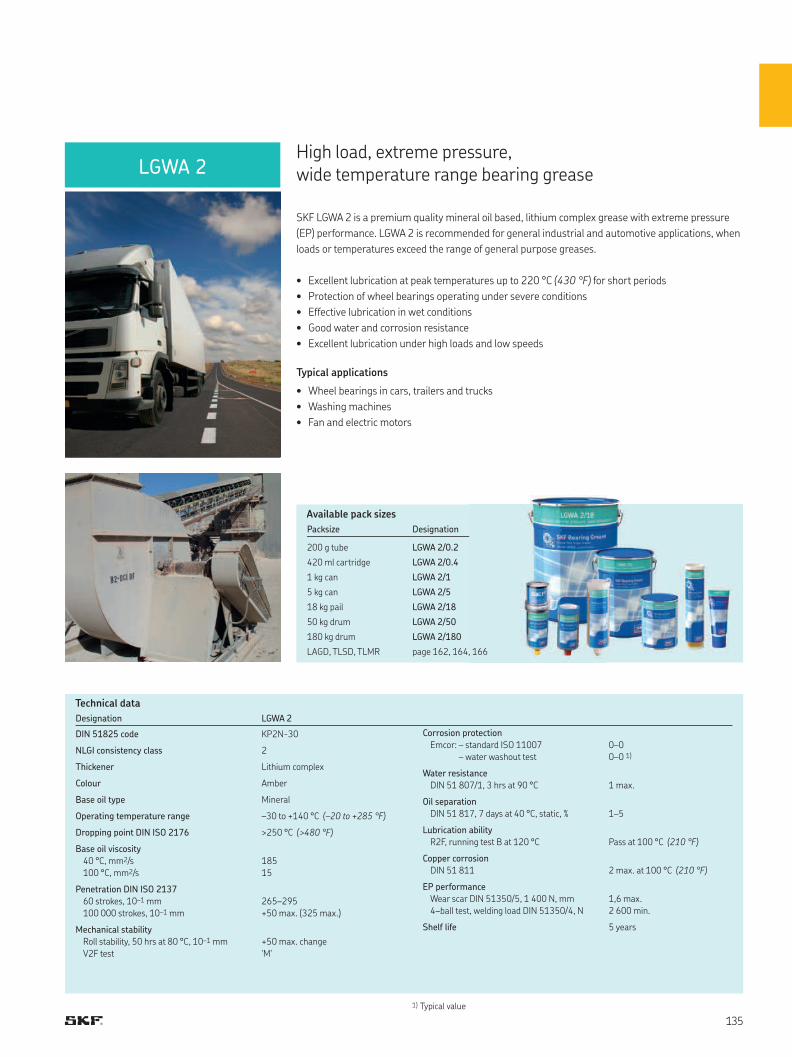
LGWA 2
Designation LGWA 2
DIN 51825 code KP2N-30
NLGI consistency class 2
Thickener Lithium complex
Colour Amber
Base oil type Mineral
Operating temperature range –30 to +140 °C (–20 to +285 °F)
Dropping point DIN ISO 2176 >250 °C (>480 °F)
Base oil viscosity
40 °C, mm2/s
100 °C, mm2/s
185
15
Penetration DIN ISO 2137
60 strokes, 10–1 mm
100 000 strokes, 10–1 mm
265–295
+50 max. (325 max.)
Mechanical stability
Roll stability, 50 hrs at 80 °C, 10–1 mm
V2F test
+50 max. change
'M'
Corrosion protection
Emcor: – standard ISO 11007
– water washout test
0–0
0–0 1)
Water resistance
DIN 51 807/1, 3 hrs at 90 °C 1 max.
Oil separation
DIN 51 817, 7 days at 40 °C, static, % 1–5
Lubrication ability
R2F, running test B at 120 °C Pass at 100 °C (210 °F)
Copper corrosion
DIN 51 811 2 max. at 100 °C (210 °F)
EP performance
Wear scar DIN 51350/5, 1 400 N, mm
4–ball test, welding load DIN 51350/4, N
1,6 max.
2 600 min.
Shelf life 5 years
High load, extreme pressure,wide temperature range bearing grease
SKF LGWA 2 is a premium quality mineral oil based, lithium complex grease with extreme pressure
(EP) performance. LGWA 2 is recommended for general industrial and automotive applications, when
loads or temperatures exceed the range of general purpose greases.
• Excellent lubrication at peak temperatures up to 220 °C (430 °F) for short periods
• Protection of wheel bearings operating under severe conditions
• Effective lubrication in wet conditions
• Good water and corrosion resistance
• Excellent lubrication under high loads and low speeds
Typical applications
• Wheel bearings in cars, trailers and trucks
• Washing machines
• Fan and electric motors
Technical data
1) Typical value
Available pack sizes
Packsize Designation
200 g tube LGWA 2/0.2
420 ml cartridge LGWA 2/0.4
1 kg can LGWA 2/1
5 kg can LGWA 2/5
18 kg pail LGWA 2/18
50 kg drum LGWA 2/50
180 kg drum LGWA 2/180
LAGD, TLSD, TLMR page 162, 164, 166
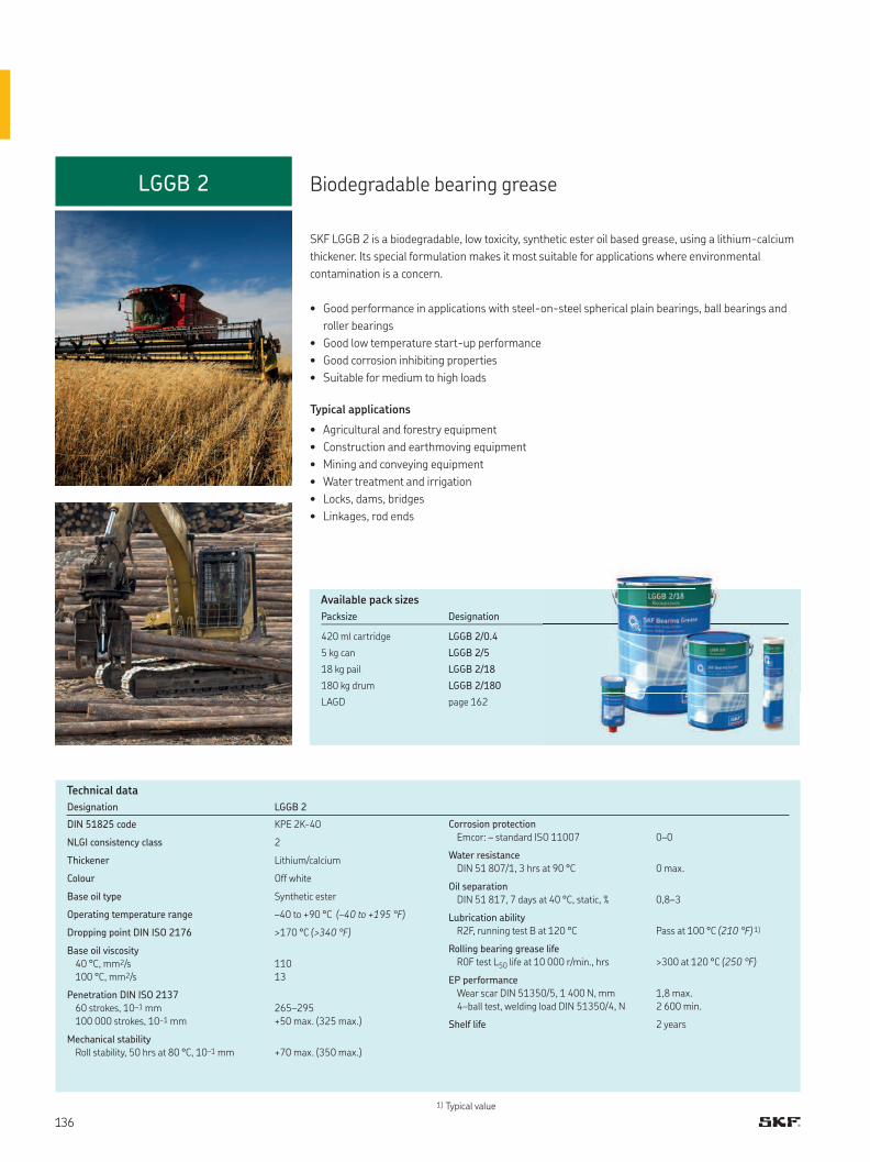
LGGB 2
Designation LGGB 2
DIN 51825 code KPE 2K-40
NLGI consistency class 2
Thickener Lithium/calcium
Colour Off white
Base oil type Synthetic ester
Operating temperature range –40 to +90 °C (–40 to +195 °F)
Dropping point DIN ISO 2176 >170 °C (>340 °F)
Base oil viscosity
40 °C, mm2/s
100 °C, mm2/s
110
13
Penetration DIN ISO 2137
60 strokes, 10–1 mm
100 000 strokes, 10–1 mm
265–295
+50 max. (325 max.)
Mechanical stability
Roll stability, 50 hrs at 80 °C, 10–1 mm +70 max. (350 max.)
Corrosion protection
Emcor: – standard ISO 11007 0–0
Water resistance
DIN 51 807/1, 3 hrs at 90 °C 0 max.
Oil separation
DIN 51 817, 7 days at 40 °C, static, % 0,8–3
Lubrication ability
R2F, running test B at 120 °C Pass at 100 °C (210 °F) 1)
Rolling bearing grease life
R0F test L50 life at 10 000 r/min., hrs >300 at 120 °C (250 °F)
EP performance
Wear scar DIN 51350/5, 1 400 N, mm
4–ball test, welding load DIN 51350/4, N
1,8 max.
2 600 min.
Shelf life 2 years
1) Typical value
Biodegradable bearing grease
SKF LGGB 2 is a biodegradable, low toxicity, synthetic ester oil based grease, using a lithium-calcium
thickener. Its special formulation makes it most suitable for applications where environmental
contamination is a concern.
• Good performance in applications with steel-on-steel spherical plain bearings, ball bearings and
roller bearings
• Good low temperature start-up performance
• Good corrosion inhibiting properties
• Suitable for medium to high loads
Typical applications
• Agricultural and forestry equipment
• Construction and earthmoving equipment
• Mining and conveying equipment
• Water treatment and irrigation
• Locks, dams, bridges
• Linkages, rod ends
Technical data
Available pack sizes
Packsize Designation
420 ml cartridge LGGB 2/0.4
5 kg can LGGB 2/5
18 kg pail LGGB 2/18
180 kg drum LGGB 2/180
LAGD page 162
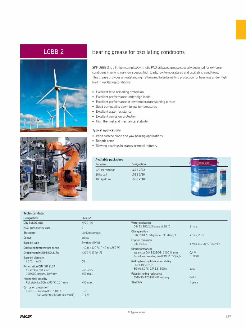
LGBB 2
Designation LGBB 2
DIN 51825 code KP2G-40
NLGI consistency class 2
Thickener Lithium complex
Colour Yellow
Base oil type Synthetic (PAO)
Operating temperature range –40 to +120 °C (–40 to +250 °F)
Dropping point DIN ISO 2176 >200 °C (390 °F)
Base oil viscosity
40 °C, mm2/s 68
Penetration DIN ISO 2137
60 strokes, 10–1 mm
100 000 strokes, 10–1 mm
265–295
+50 max.
Mechanical stability
Roll stability, 50h at 80 °C, 10–1 mm +50 max.
Corrosion protection
Emcor: – Standard ISO 11007
– Salt water test (100% sea water)
0–0
0–1 1)
Water resistance
DIN 51 807/1, 3 hours at 90 °C 1 max.
Oil separation
DIN 51817, 7 days at 40 °C, static, % 4 max, 2,5 1)
Copper corrosion
DIN 51 811 1 max. at 120 °C (250 °F)
EP performances
Wear scar DIN 51350/5, 1400 N, mm
4-ball test, welding load DIN 51350/4, N
0,4 1)
5 500 1)
Rolling bearing lubrication ability
Fe8, DIN 51819,
80 kN, 80 °C, C/P 1.8, 500 h pass
False brinellng resistance
ASTM D4170 FAFNIR test, mg 0–1 1)
Shelf life 5 years
1) Typical value
Bearing grease for oscillating conditions
SKF LGBB 2 is a lithium complex/synthetic PAO oil based grease specially designed for extreme
conditions involving very low speeds, high loads, low temperatures and oscillating conditions.
This grease provides an outstanding fretting and false brinelling protection for bearings under high
load in oscillating conditions.
• Excellent false brinelling protection
• Excellent performance under high loads
• Excellent performance at low temperature starting torque
• Good pumpability down to low temperatures
• Excellent water resistance
• Excellent corrosion protection
• High thermal and mechanical stability
Typical applications
• Wind turbine blade and yaw bearing applications
• Robotic arms
• Slewing bearings in cranes or metal industry
Technical data
Available pack sizes
Packsize Designation
420 ml cartridge LGBB 2/0.4
18 kg pail LGBB 2/18
180 kg drum LGBB 2/180
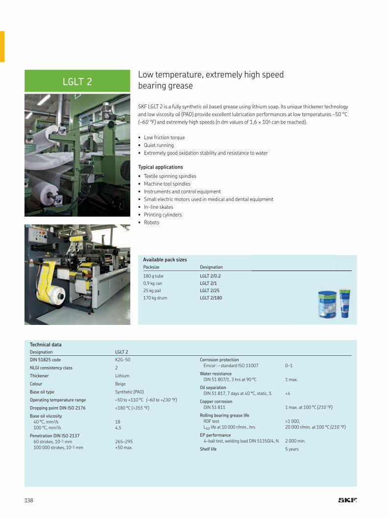
LGLT 2
Designation LGLT 2
DIN 51825 code K2G-50
NLGI consistency class 2
Thickener Lithium
Colour Beige
Base oil type Synthetic (PAO)
Operating temperature range –50 to +110 °C (–60 to +230 °F)
Dropping point DIN ISO 2176 >180 °C (>355 °F)
Base oil viscosity
40 °C, mm2/s
100 °C, mm2/s
18
4,5
Penetration DIN ISO 2137
60 strokes, 10–1 mm
100 000 strokes, 10–1 mm
265–295
+50 max.
Corrosion protection
Emcor: – standard ISO 11007 0–1
Water resistance
DIN 51 807/1, 3 hrs at 90 °C 1 max.
Oil separation
DIN 51 817, 7 days at 40 °C, static, % <4
Copper corrosion
DIN 51 811 1 max. at 100 °C (210 °F)
Rolling bearing grease life
R0F test
L50 life at 10 000 r/min., hrs
>1 000,
20 000 r/min. at 100 °C (210 °F)
EP performance
4–ball test, welding load DIN 51350/4, N 2 000 min.
Shelf life 5 years
Low temperature, extremely high speed bearing grease
SKF LGLT 2 is a fully synthetic oil based grease using lithium soap. Its unique thickener technology
and low viscosity oil (PAO) provide excellent lubrication performances at low temperatures –50 °C
(–60 °F) and extremely high speeds (n dm values of 1,6 × 10⁶ can be reached).
• Low friction torque
• Quiet running
• Extremely good oxidation stability and resistance to water
Typical applications
• Textile spinning spindles
• Machine tool spindles
• Instruments and control equipment
• Small electric motors used in medical and dental equipment
• In-line skates
• Printing cylinders
• Robots
Technical data
Available pack sizes
Packsize Designation
180 g tube LGLT 2/0.2
0,9 kg can LGLT 2/1
25 kg pail LGLT 2/25
170 kg drum LGLT 2/180
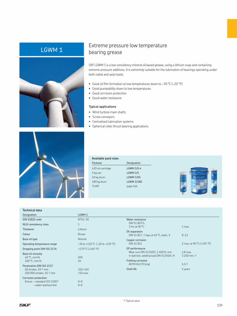
LGWM 1
1) Typical value
Designation LGWM 1
DIN 51825 code KP1G-30
NLGI consistency class 1
Thickener Lithium
Colour Brown
Base oil type Mineral
Operating temperature range –30 to +110 °C (–20 to +230 °F)
Dropping point DIN ISO 2176 >170 °C (>340 °F)
Base oil viscosity
40 °C, mm2/s
100 °C, mm2/s
200
16
Penetration DIN ISO 2137
60 strokes, 10–1 mm
100 000 strokes, 10–1 mm
310–340
+50 max.
Corrosion protection:
Emcor: – standard ISO 11007
– water washout test
0–0
0–0
Water resistance
DIN 51 807/1,
3 hrs at 90 °C 1 max.
Oil separation
DIN 51 817, 7 days at 40 °C, static, % 8–13
Copper corrosion
DIN 51 811 2 max. at 90 °C (>195 °F)
EP performance
Wear scar DIN 51350/5, 1 400 N, mm
4–ball test, welding load DIN 51350/4, N
1,8 max.
3 200 min. 1)
Fretting corrosion
ASTM D4170 (mg) 5,5 1)
Shelf life 5 years
Extreme pressure low temperature bearing grease
SKF LGWM 1 is a low consistency mineral oil based grease, using a lithium soap and containing
extreme pressure additives. It is extremely suitable for the lubrication of bearings operating under
both radial and axial loads.
• Good oil film formation at low temperatures down to –30 °C (–20 °F)
• Good pumpability down to low temperatures
• Good corrosion protection
• Good water resistance
Typical applications
• Wind turbine main shafts
• Screw conveyors
• Centralised lubrication systems
• Spherical roller thrust bearing applications
Technical data
Available pack sizes
Packsize Designation
420 ml cartridge LGWM 1/0.4
5 kg can LGWM 1/5
50 kg drum LGWM 1/50
180 kg drum LGWM 1/180
TLMR page 166
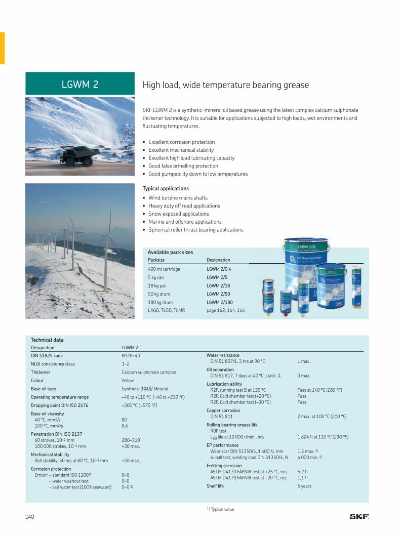
LGWM 2
Designation LGWM 2
DIN 51825 code KP2G-40
NLGI consistency class 1–2
Thickener Calcium sulphonate complex
Colour Yellow
Base oil type Synthetic (PAO)/ Mineral
Operating temperature range –40 to +110 °C (–40 to +230 °F)
Dropping point DIN ISO 2176 >300 °C (>570 °F)
Base oil viscosity
40 °C, mm2/s
100 °C, mm2/s
80
8,6
Penetration DIN ISO 2137
60 strokes, 10–1 mm
100 000 strokes, 10–1 mm
280–310
+30 max.
Mechanical stability
Roll stability, 50 hrs at 80 °C, 10–1 mm +50 max.
Corrosion protection
Emcor: – standard ISO 11007
– water washout test
– salt water test (100% seawater)
0–0
0–0
0–0 1)
Water resistance
DIN 51 807/1, 3 hrs at 90 °C 1 max.
Oil separation
DIN 51 817, 7 days at 40 °C, static, % 3 max.
Lubrication ability
R2F, running test B at 120 °C
R2F, Cold chamber test (+20 °C)
R2F, Cold chamber test (–30 °C)
Pass at 140 °C (285 °F)
Pass
Pass
Copper corrosion
DIN 51 811 2 max. at 100 °C (210 °F)
Rolling bearing grease life
R0F test
L50 life at 10 000 r/min., hrs 1 824 1) at 110 °C (230 °F)
EP performance
Wear scar DIN 51350/5, 1 400 N, mm
4–ball test, welding load DIN 51350/4, N
1,5 max. 1)
4 000 min. 1)
Fretting corrosion
ASTM D4170 FAFNIR test at +25 °C, mg
ASTM D4170 FAFNIR test at –20 °C, mg
5,2 1)
1,1 1)
Shelf life 5 years
High load, wide temperature bearing grease
SKF LGWM 2 is a synthetic-mineral oil based grease using the latest complex calcium sulphonate
thickener technology. It is suitable for applications subjected to high loads, wet environments and
fluctuating temperatures.
• Excellent corrosion protection
• Excellent mechanical stability
• Excellent high load lubricating capacity
• Good false brinelling protection
• Good pumpability down to low temperatures
Typical applications
• Wind turbine mains shafts
• Heavy duty off road applications
• Snow exposed applications
• Marine and offshore applications
• Spherical roller thrust bearing applications
Technical data
Available pack sizes
Packsize Designation
420 ml cartridge LGWM 2/0.4
5 kg can LGWM 2/5
18 kg pail LGWM 2/18
50 kg drum LGWM 2/50
180 kg drum LGWM 2/180
LAGD, TLSD, TLMR page 162, 164, 166
1) Typical value
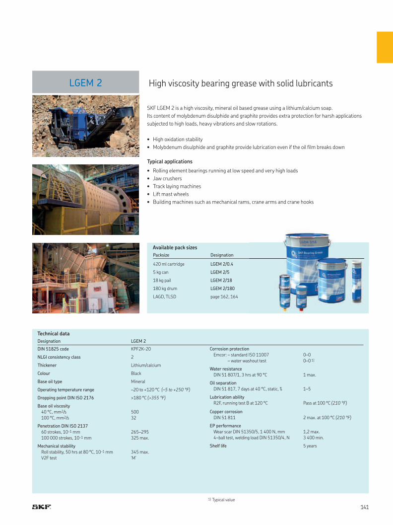
LGEM 2
Designation LGEM 2
DIN 51825 code KPF2K-20
NLGI consistency class 2
Thickener Lithium/calcium
Colour Black
Base oil type Mineral
Operating temperature range –20 to +120 °C (–5 to +250 °F)
Dropping point DIN ISO 2176 >180 °C (>355 °F)
Base oil viscosity
40 °C, mm2/s
100 °C, mm2/s
500
32
Penetration DIN ISO 2137
60 strokes, 10–1 mm
100 000 strokes, 10–1 mm
265–295
325 max.
Mechanical stability
Roll stability, 50 hrs at 80 °C, 10–1 mm
V2F test
345 max.
‘M’
Corrosion protection
Emcor: – standard ISO 11007
– water washout test
0–0
0–0 1)
Water resistance
DIN 51 807/1, 3 hrs at 90 °C 1 max.
Oil separation
DIN 51 817, 7 days at 40 °C, static, % 1–5
Lubrication ability
R2F, running test B at 120 °C Pass at 100 °C (210 °F)
Copper corrosion
DIN 51 811 2 max. at 100 °C (210 °F)
EP performance
Wear scar DIN 51350/5, 1 400 N, mm
4–ball test, welding load DIN 51350/4, N
1,2 max.
3 400 min.
Shelf life 5 years
High viscosity bearing grease with solid lubricants
SKF LGEM 2 is a high viscosity, mineral oil based grease using a lithium/calcium soap.
Its content of molybdenum disulphide and graphite provides extra protection for harsh applications
subjected to high loads, heavy vibrations and slow rotations.
• High oxidation stability
• Molybdenum disulphide and graphite provide lubrication even if the oil film breaks down
Typical applications
• Rolling element bearings running at low speed and very high loads
• Jaw crushers
• Track laying machines
• Lift mast wheels
• Building machines such as mechanical rams, crane arms and crane hooks
Technical data
Available pack sizes
Packsize Designation
420 ml cartridge LGEM 2/0.4
5 kg can LGEM 2/5
18 kg pail LGEM 2/18
180 kg drum LGEM 2/180
LAGD, TLSD page 162, 164
1) Typical value
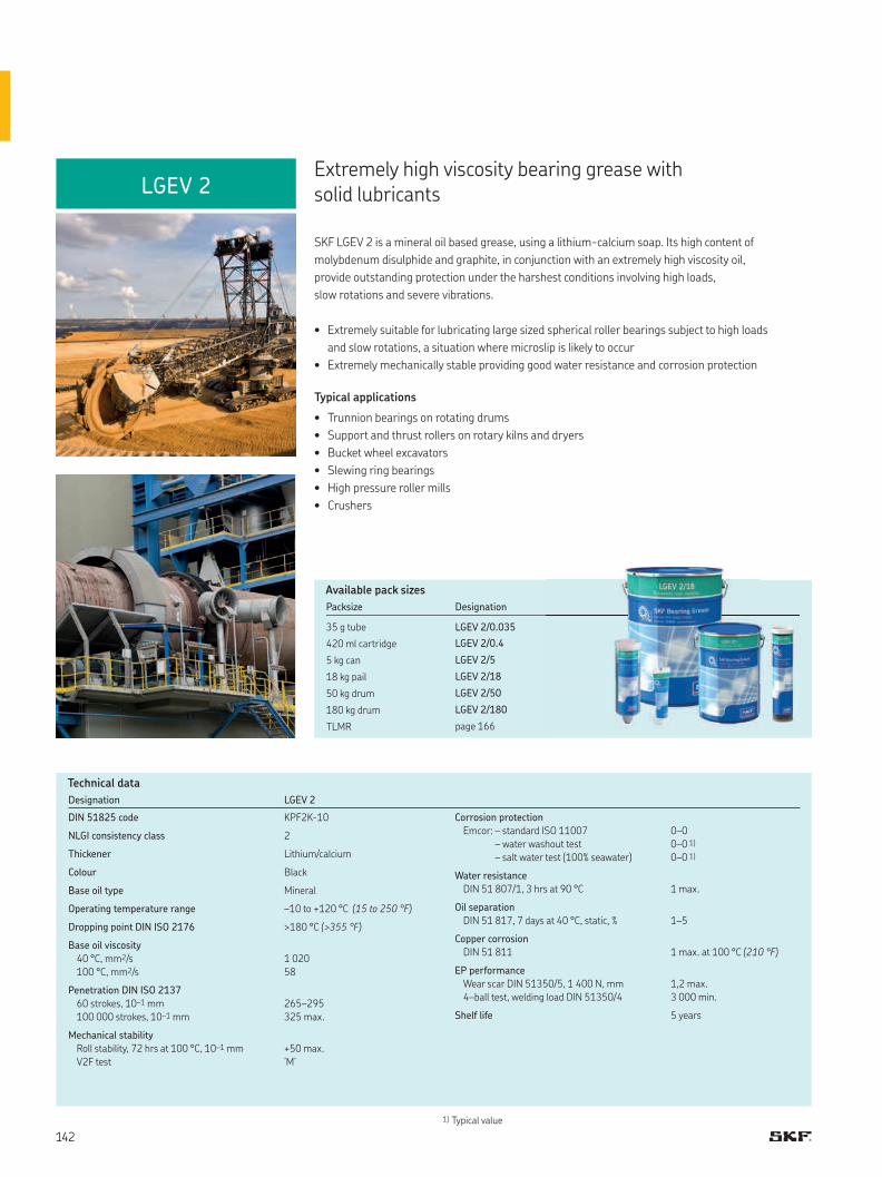
LGEV 2
1) Typical value
Designation LGEV 2
DIN 51825 code KPF2K-10
NLGI consistency class 2
Thickener Lithium/calcium
Colour Black
Base oil type Mineral
Operating temperature range –10 to +120 °C (15 to 250 °F)
Dropping point DIN ISO 2176 >180 °C (>355 °F)
Base oil viscosity
40 °C, mm2/s
100 °C, mm2/s
1 020
58
Penetration DIN ISO 2137
60 strokes, 10–1 mm
100 000 strokes, 10–1 mm
265–295
325 max.
Mechanical stability
Roll stability, 72 hrs at 100 °C, 10–1 mm
V2F test
+50 max.
‘M’
Corrosion protection
Emcor: – standard ISO 11007
– water washout test
– salt water test (100% seawater)
0–0
0–0 1)
0–0 1)
Water resistance
DIN 51 807/1, 3 hrs at 90 °C 1 max.
Oil separation
DIN 51 817, 7 days at 40 °C, static, % 1–5
Copper corrosion
DIN 51 811 1 max. at 100 °C (210 °F)
EP performance
Wear scar DIN 51350/5, 1 400 N, mm
4–ball test, welding load DIN 51350/4
1,2 max.
3 000 min.
Shelf life 5 years
Extremely high viscosity bearing grease with solid lubricants
SKF LGEV 2 is a mineral oil based grease, using a lithium-calcium soap. Its high content of
molybdenum disulphide and graphite, in conjunction with an extremely high viscosity oil,
provide outstanding protection under the harshest conditions involving high loads,
slow rotations and severe vibrations.
• Extremely suitable for lubricating large sized spherical roller bearings subject to high loads
and slow rotations, a situation where microslip is likely to occur
• Extremely mechanically stable providing good water resistance and corrosion protection
Typical applications
• Trunnion bearings on rotating drums
• Support and thrust rollers on rotary kilns and dryers
• Bucket wheel excavators
• Slewing ring bearings
• High pressure roller mills
• Crushers
Technical data
Available pack sizes
Packsize Designation
35 g tube LGEV 2/0.035
420 ml cartridge LGEV 2/0.4
5 kg can LGEV 2/5
18 kg pail LGEV 2/18
50 kg drum LGEV 2/50
180 kg drum LGEV 2/180
TLMR page 166
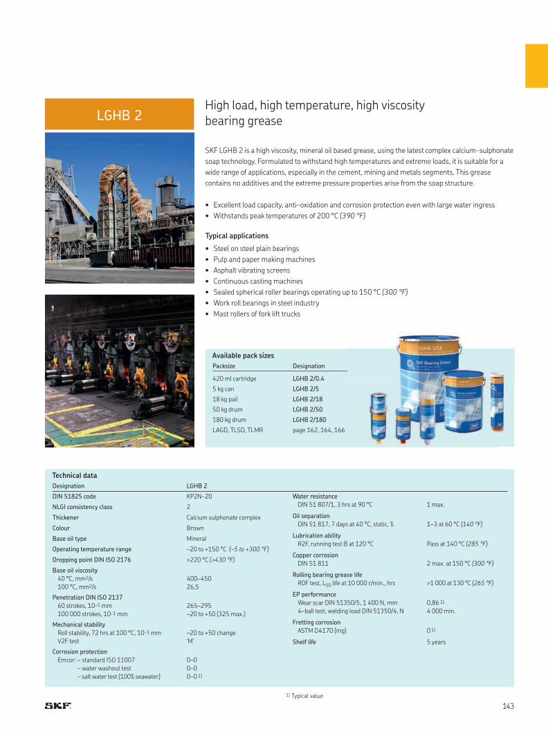
LGHB 2
1) Typical value
Designation LGHB 2
DIN 51825 code KP2N-20
NLGI consistency class 2
Thickener Calcium sulphonate complex
Colour Brown
Base oil type Mineral
Operating temperature range –20 to +150 °C (–5 to +300 °F)
Dropping point DIN ISO 2176 >220 °C (>430 °F)
Base oil viscosity
40 °C, mm2/s
100 °C, mm2/s
400–450
26,5
Penetration DIN ISO 2137
60 strokes, 10–1 mm
100 000 strokes, 10–1 mm
265–295
–20 to +50 (325 max.)
Mechanical stability
Roll stability, 72 hrs at 100 °C, 10–1 mm
V2F test
–20 to +50 change
‘M’
Corrosion protection
Emcor: – standard ISO 11007
– water washout test
– salt water test (100% seawater)
0–0
0–0
0–0 1)
Water resistance
DIN 51 807/1, 3 hrs at 90 °C 1 max.
Oil separation
DIN 51 817, 7 days at 40 °C, static, % 1–3 at 60 °C (140 °F)
Lubrication ability
R2F, running test B at 120 °C Pass at 140 °C (285 °F)
Copper corrosion
DIN 51 811 2 max. at 150 °C (300 °F)
Rolling bearing grease life
R0F test, L50 life at 10 000 r/min., hrs >1 000 at 130 °C (265 °F)
EP performance
Wear scar DIN 51350/5, 1 400 N, mm
4–ball test, welding load DIN 51350/4, N
0,86 1)
4 000 min.
Fretting corrosion
ASTM D4170 (mg) 0 1)
Shelf life 5 years
High load, high temperature, high viscosity bearing grease
SKF LGHB 2 is a high viscosity, mineral oil based grease, using the latest complex calcium-sulphonate
soap technology. Formulated to withstand high temperatures and extreme loads, it is suitable for a
wide range of applications, especially in the cement, mining and metals segments. This grease
contains no additives and the extreme pressure properties arise from the soap structure.
• Excellent load capacity, anti-oxidation and corrosion protection even with large water ingress
• Withstands peak temperatures of 200 °C (390 °F)
Typical applications
• Steel on steel plain bearings
• Pulp and paper making machines
• Asphalt vibrating screens
• Continuous casting machines
• Sealed spherical roller bearings operating up to 150 °C (300 °F)
• Work roll bearings in steel industry
• Mast rollers of fork lift trucks
Technical data
Available pack sizes
Packsize Designation
420 ml cartridge LGHB 2/0.4
5 kg can LGHB 2/5
18 kg pail LGHB 2/18
50 kg drum LGHB 2/50
180 kg drum LGHB 2/180
LAGD, TLSD, TLMR page 162, 164, 166
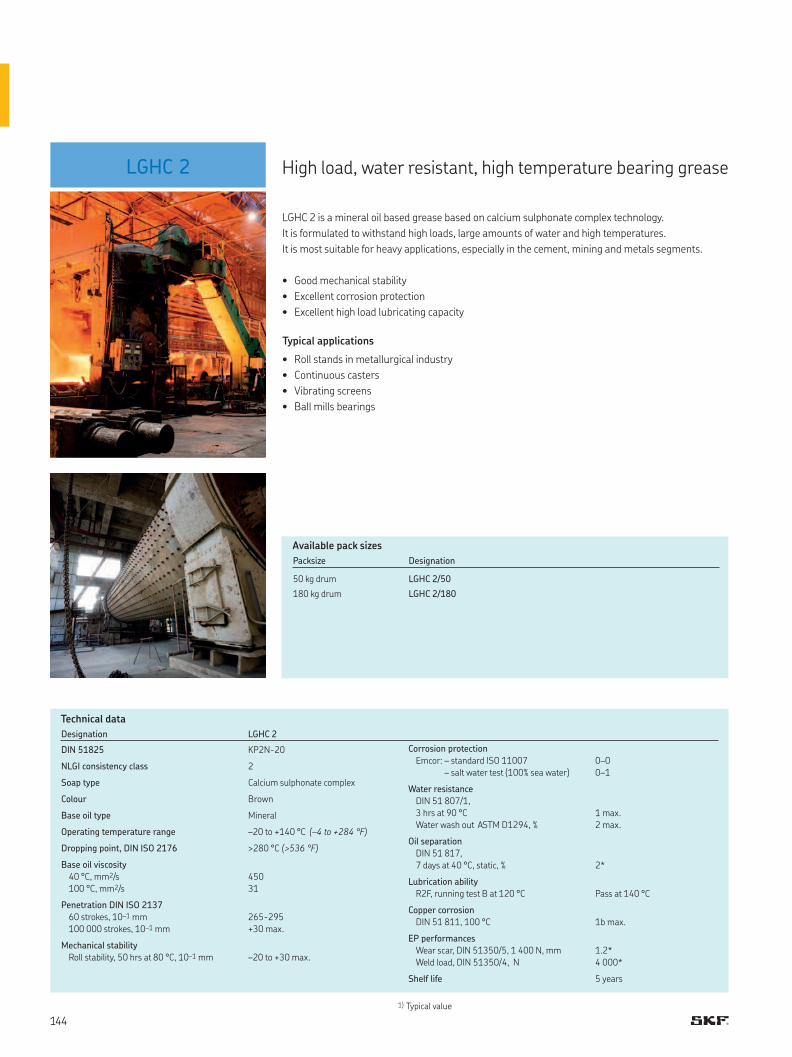
LGHC 2
Designation LGHC 2
DIN 51825 KP2N-20
NLGI consistency class 2
Soap type Calcium sulphonate complex
Colour Brown
Base oil type Mineral
Operating temperature range –20 to +140 °C (–4 to +284 °F)
Dropping point, DIN ISO 2176 >280 °C (>536 °F)
Base oil viscosity
40 °C, mm2/s
100 °C, mm2/s
450
31
Penetration DIN ISO 2137
60 strokes, 10–1 mm
100 000 strokes, 10–1 mm
265-295
+30 max.
Mechanical stability
Roll stability, 50 hrs at 80 °C, 10–1 mm
–20 to +30 max.
Corrosion protection
Emcor: – standard ISO 11007
– salt water test (100% sea water)
0–0
0–1
Water resistance
DIN 51 807/1,
3 hrs at 90 °C
Water wash out ASTM D1294, %
1 max.
2 max.
Oil separation
DIN 51 817,
7 days at 40 °C, static, %
2*
Lubrication ability
R2F, running test B at 120 °C
Pass at 140 °C
Copper corrosion
DIN 51 811, 100 °C
1b max.
EP performances
Wear scar, DIN 51350/5, 1 400 N, mm
Weld load, DIN 51350/4, N
1.2*
4 000*
Shelf life 5 years
1) Typical value
High load, water resistant, high temperature bearing grease
LGHC 2 is a mineral oil based grease based on calcium sulphonate complex technology.
It is formulated to withstand high loads, large amounts of water and high temperatures.
It is most suitable for heavy applications, especially in the cement, mining and metals segments.
• Good mechanical stability
• Excellent corrosion protection
• Excellent high load lubricating capacity
Typical applications
• Roll stands in metallurgical industry
• Continuous casters
• Vibrating screens
• Ball mills bearings
Technical data
Available pack sizes
Packsize Designation
50 kg drum LGHC 2/50
180 kg drum LGHC 2/180
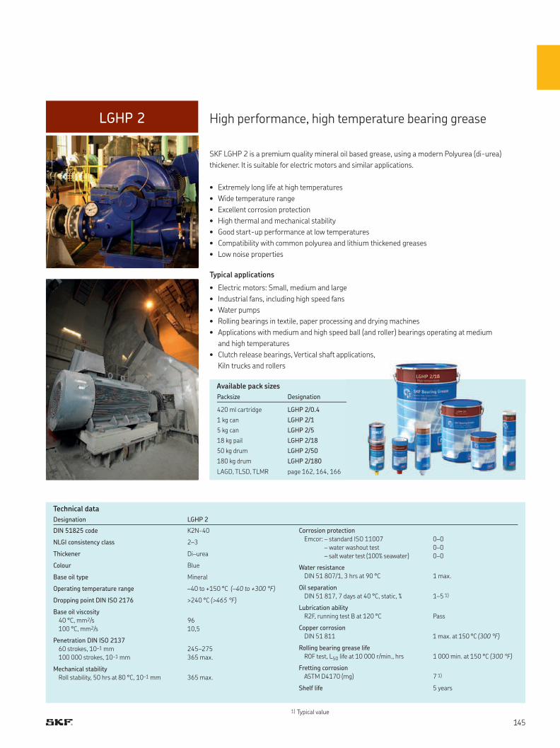
LGHP 2
1) Typical value
Designation LGHP 2
DIN 51825 code K2N-40
NLGI consistency class 2–3
Thickener Di–urea
Colour Blue
Base oil type Mineral
Operating temperature range –40 to +150 °C (–40 to +300 °F)
Dropping point DIN ISO 2176 >240 °C (>465 °F)
Base oil viscosity
40 °C, mm2/s
100 °C, mm2/s
96
10,5
Penetration DIN ISO 2137
60 strokes, 10–1 mm
100 000 strokes, 10–1 mm
245–275
365 max.
Mechanical stability
Roll stability, 50 hrs at 80 °C, 10–1 mm 365 max.
Corrosion protection
Emcor: – standard ISO 11007
– water washout test
– salt water test (100% seawater)
0–0
0–0
0–0
Water resistance
DIN 51 807/1, 3 hrs at 90 °C 1 max.
Oil separation
DIN 51 817, 7 days at 40 °C, static, % 1–5 1)
Lubrication ability
R2F, running test B at 120 °C Pass
Copper corrosion
DIN 51 811 1 max. at 150 °C (300 °F)
Rolling bearing grease life
R0F test, L50 life at 10 000 r/min., hrs 1 000 min. at 150 °C (300 °F)
Fretting corrosion
ASTM D4170 (mg) 7 1)
Shelf life 5 years
High performance, high temperature bearing grease
SKF LGHP 2 is a premium quality mineral oil based grease, using a modern Polyurea (di-urea)
thickener. It is suitable for electric motors and similar applications.
• Extremely long life at high temperatures
• Wide temperature range
• Excellent corrosion protection
• High thermal and mechanical stability
• Good start-up performance at low temperatures
• Compatibility with common polyurea and lithium thickened greases
• Low noise properties
Typical applications
• Electric motors: Small, medium and large
• Industrial fans, including high speed fans
• Water pumps
• Rolling bearings in textile, paper processing and drying machines
• Applications with medium and high speed ball (and roller) bearings operating at medium
and high temperatures
• Clutch release bearings, Vertical shaft applications,
Kiln trucks and rollers
Technical data
Available pack sizes
Packsize Designation
420 ml cartridge LGHP 2/0.4
1 kg can LGHP 2/1
5 kg can LGHP 2/5
18 kg pail LGHP 2/18
50 kg drum LGHP 2/50
180 kg drum LGHP 2/180
LAGD, TLSD, TLMR page 162, 164, 166
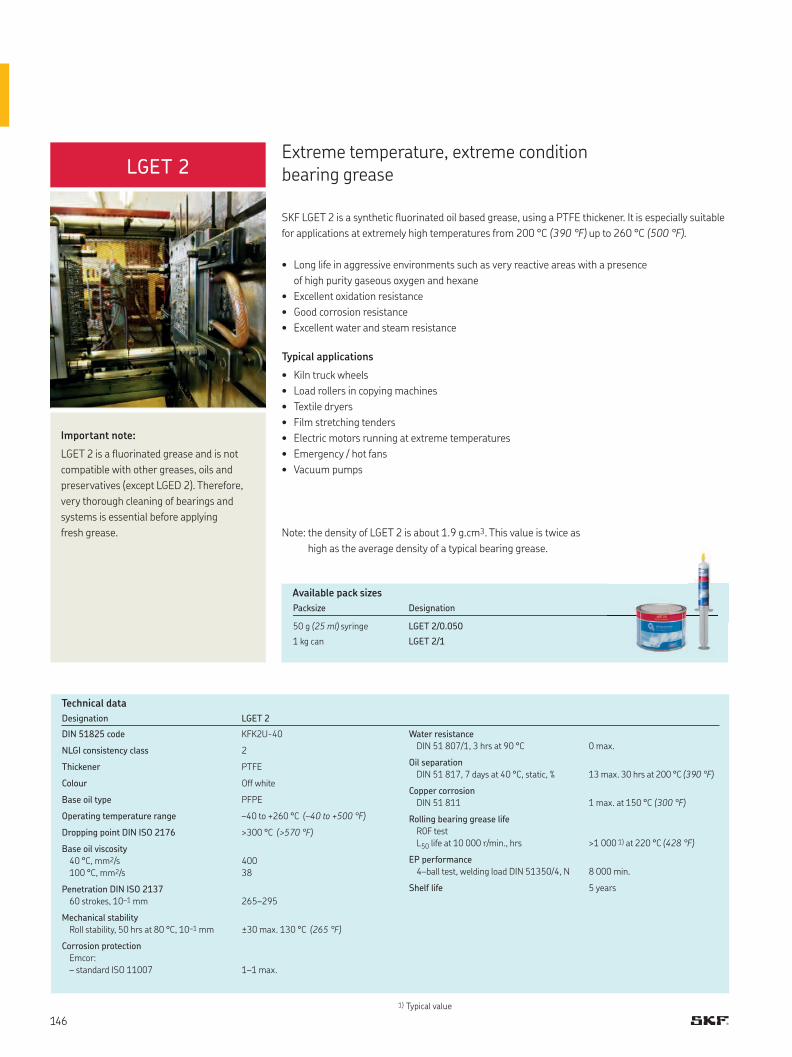
LGET 2
1) Typical value
Designation LGET 2
DIN 51825 code KFK2U-40
NLGI consistency class 2
Thickener PTFE
Colour Off white
Base oil type PFPE
Operating temperature range –40 to +260 °C (–40 to +500 °F)
Dropping point DIN ISO 2176 >300 °C (>570 °F)
Base oil viscosity
40 °C, mm2/s
100 °C, mm2/s
400
38
Penetration DIN ISO 2137
60 strokes, 10–1 mm 265–295
Mechanical stability
Roll stability, 50 hrs at 80 °C, 10–1 mm ±30 max. 130 °C (265 °F)
Corrosion protection
Emcor:
– standard ISO 11007 1–1 max.
Water resistance
DIN 51 807/1, 3 hrs at 90 °C 0 max.
Oil separation
DIN 51 817, 7 days at 40 °C, static, % 13 max. 30 hrs at 200 °C (390 °F)
Copper corrosion
DIN 51 811 1 max. at 150 °C (300 °F)
Rolling bearing grease life
R0F test
L50 life at 10 000 r/min., hrs >1 000 1) at 220 °C (428 °F)
EP performance
4–ball test, welding load DIN 51350/4, N 8 000 min.
Shelf life 5 years
SKF LGET 2 is a synthetic fluorinated oil based grease, using a PTFE thickener. It is especially suitable
for applications at extremely high temperatures from 200 °C (390 °F) up to 260 °C (500 °F).
• Long life in aggressive environments such as very reactive areas with a presence
of high purity gaseous oxygen and hexane
• Excellent oxidation resistance
• Good corrosion resistance
• Excellent water and steam resistance
Typical applications
• Kiln truck wheels
• Load rollers in copying machines
• Textile dryers
• Film stretching tenders
• Electric motors running at extreme temperatures
• Emergency / hot fans
• Vacuum pumps
Extreme temperature, extreme condition bearing grease
Important note:
LGET 2 is a fluorinated grease and is not
compatible with other greases, oils and
preservatives (except LGED 2). Therefore,
very thorough cleaning of bearings and
systems is essential before applying
fresh grease.
Technical data
Available pack sizes
Packsize Designation
50 g (25 ml) syringe LGET 2/0.050
1 kg can LGET 2/1
Note: the density of LGET 2 is about 1.9 g.cm3. This value is twice as
high as the average density of a typical bearing grease.

LEGE 2 Low friction bearing grease
SKF LEGE 2 grease combines a fully synthetic ester oil with a unique lithium soap thickener.
This premium quality, low friction grease has been specially developed for high performance
in low friction SKF ball bearings.
• Low friction torque
• Low level of power loss
• Quiet running behavior
• Extremely good oxidation stability
• Wide temperature range
Typical applications
• Electrical motors
• High speed / High temperature fans
• Vertical shafts
Technical data
1) Typical value
Designation LEGE 2
DIN 51825 code KE2N-50
NLGI consistency class 2–3
Soap type Lithium
Colour Light brown
Base oil type Ester
Operating temperature range –50 to +150 °C (–58 to +302 °F)
Dropping point DIN ISO 2176 > 185 °C (365 °F)
Base oil viscosity
40 °C, mm2/s
100 °C, mm2/s
25
4,9
Penetration DIN ISO 2137
60 strokes, 10–1 mm
100 000 strokes, 10–1 mm
240–270
330 max.
Corrosion protection
SKF Emcor standard ISO 11007
SKF Emcor 0,5% salt water
0-0
0-0 1)
Water resistance
DIN 51 807/1, 3hrs at 90 °C 0 1)
Oil separation
DIN 51 817, 7 days at 40 °C, static, % 1.4 1)
Copper corrosion
ISO 2160 at 140 °C 1b 1)
Mechanical stability
Roll stability, 50 hrs at 80 °C, 310 max. 1)
Low temperature performance
Torque ASTM D1478-63, mNm
Starting torque at –40 °C
Running torque at –40 °C
300 max.
100 max.
BeQuiet + test GN3 min, GN4 1)
Rolling bearing grease life
R0F test
L50 life at 10 000 r/min., hrs >1 000 at 150 °C (302 °F)
Shelf life 5 years
Available pack sizes
Packsize Designation
420 ml cartridge LEGE 2/0.4
1 kg can LEGE 2/1
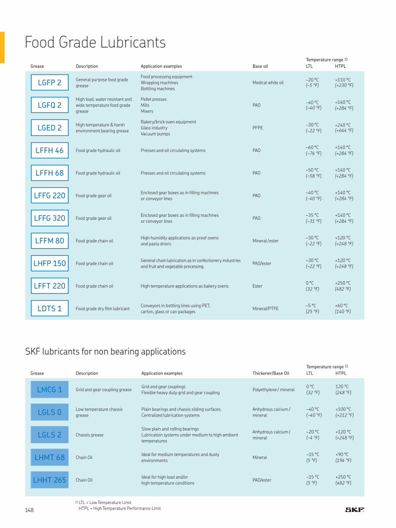
LGFP 2
LGFQ 2
LGED 2
LFFH 46
LFFH 68
LFFG 220
LFFG 320
LFFM 80
LHFP 150
LFFT 220
LDTS 1
LMCG 1
LGLS 0
LGLS 2
LHMT 68
LHHT 265
Food Grade Lubricants
SKF lubricants for non bearing applications
Temperature range 1)
Grease Description Application examples Base oil LTL HTPL
General purpose food grade
grease
Food processing equipment
Wrapping machines
Bottling machines
Medical white oil–20 °C(–5 °F)
+110 °C(+230 °F)
High load, water resistant and
wide temperature food grade
grease
Pellet presses
Mills
Mixers
PAO–40 °C(–40 °F)
+140 °C
(+284 °F)
High temperature & harsh
environment bearing grease
Bakery/brick oven equipment
Glass industry
Vacuum pumps
PFPE–30 °C
(–22 °F)+240 °C(+464 °F)
Food grade hydraulic oil Presses and oil circulating systems PAO–60 °C
(–76 °F)
+140 °C
(+284 °F)
Food grade hydraulic oil Presses and oil circulating systems PAO–50 °C
(–58 °F)
+140 °C
(+284 °F)
Food grade gear oilEnclosed gear boxes as in filling machines
or conveyor linesPAO
–40 °C
(–40 °F)
+140 °C
(+284 °F)
Food grade gear oilEnclosed gear boxes as in filling machines
or conveyor linesPAO
–35 °C
(–31 °F)
+140 °C
(+284 °F)
Food grade chain oilHigh humidity applications as proof ovens
and pasta driers Mineral / ester
–30 °C
(–22 °F)
+120 °C
(+248 °F)
Food grade chain oilGeneral chain lubrication as in confectionery industries
and fruit and vegetable processing.PAO/ester
–30 °C
(–22 °F)
+120 °C
(+248 °F)
Food grade chain oil High temperature applications as bakery ovens Ester0 °C
(32 °F)
+250 °C
(482 °F)
Food grade dry film lubricantConveyors in bottling lines using PET,
carton, glass or can packagesMineral/PTFE
–5 °C
(25 °F)
+60 °C
(140 °F)
Temperature range 1)
Grease Description Application examples Thickener/Base Oil LTL HTPL
Grid and gear coupling greaseGrid and gear couplings
Flexible heavy duty grid and gear couplingPolyethylene / mineral
0 °C
(32 °F)
120 °C
(248 °F)
Low temperature chassis
grease
Plain bearings and chassis sliding surfaces.
Centralized lubrication systems
Anhydrous calcium /
mineral
–40 °C
(–40 °F)
+100 °C
(+212 °F)
Chassis grease
Slow plain and rolling bearings
Lubrication systems under medium to high ambient
temperatures
Anhydrous calcium /
mineral
–20 °C
(–4 °F)
+120 °C
(+248 °F)
Chain OilIdeal for medium temperatures and dusty
environmentsMineral
–15 °C
(5 °F)
+90 °C
(194 °F)
Chain OilIdeal for high load and/or
high temperature conditionsPAO/ester
–15 °C
(5 °F)
+250 °C
(482 °F)
1) LTL = Low Temperature Limit
HTPL = High Temperature Performance Limit
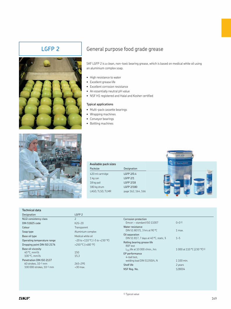
LGFP 2
1) Typical value
Designation LGFP 2
NLGI consistency class 2
DIN 51825 code K2G-20
Colour Transparent
Soap type Aluminium complex
Base oil type Medical white oil
Operating temperature range –20 to +110 °C (–5 to +230 °F)
Dropping point DIN ISO 2176 >250 °C (>480 °F)
Base oil viscosity
40 °C, mm2/s
100 °C, mm2/s
150
15,3
Penetration DIN ISO 2137
60 strokes, 10–1 mm
100 000 strokes, 10–1 mm
265–295
+30 max.
Corrosion protection
Emcor: – standard ISO 11007 0–0 1)
Water resistance
DIN 51 807/1, 3 hrs at 90 °C 1 max.
Oil separation
DIN 51 817, 7 days at 40 °C, static, % 1–5
Rolling bearing grease life
R0F test
L50 life at 10 000 r/min., hrs 1 000 at 110 °C (230 °F) 1)
EP performance
4–ball test,
welding load DIN 51350/4, N 1 100 min.
Shelf life 2 years
NSF Reg. No. 128004
General purpose food grade grease
SKF LGFP 2 is a clean, non-toxic bearing grease, which is based on medical white oil using
an aluminium complex soap.
• High resistance to water
• Excellent grease life
• Excellent corrosion resistance
• An essentially neutral pH value
• NSF H1 registered and Halal and Kosher certified
Typical applications
• Multi-pack cassette bearings
• Wrapping machines
• Conveyor bearings
• Bottling machines
Technical data
Available pack sizes
Packsize Designation
420 ml cartridge LGFP 2/0.4
1 kg can LGFP 2/1
18 kg pail LGFP 2/18
180 kg drum LGFP 2/180
LAGD, TLSD, TLMR page 162, 164, 166
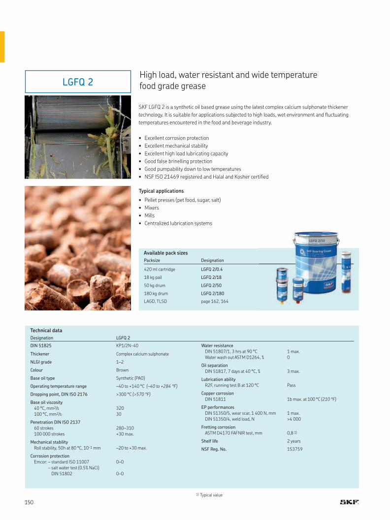
LGFQ 2
Designation LGFQ 2
DIN 51825 KP1/2N-40
Thickener Complex calcium sulphonate
NLGI grade 1–2
Colour Brown
Base oil type Synthetic (PAO)
Operating temperature range –40 to +140 °C (–40 to +284 °F)
Dropping point, DIN ISO 2176 >300 °C (>570 °F)
Base oil viscosity
40 °C, mm2/s
100 °C, mm2/s
320
30
Penetration DIN ISO 2137
60 strokes
100 000 strokes
280–310
+30 max.
Mechanical stability
Roll stability, 50h at 80 °C, 10-1 mm –20 to +30 max.
Corrosion protection
Emcor: – standard ISO 11007
– salt water test (0.5% NaCl)
DIN 51802
0–0
0–0
Water resistance
DIN 51807/1, 3 hrs at 90 °C
Water wash out ASTM D1264, %
1 max.
0
Oil separation
DIN 51817, 7 days at 40 °C, % 3 max.
Lubrication ability
R2F, running test B at 120 °C Pass
Copper corrosion
DIN 51811 1b max. at 100 °C (210 °F)
EP performances
DIN 51350/5, wear scar, 1 400 N, mm
DIN 51350/4, weld load, N
1 max.
>4 000
Fretting corrosion
ASTM D4170 FAFNIR test, mm 0,8 1)
Shelf life 2 years
NSF Reg. No. 153759
SKF LGFQ 2 is a synthetic oil based grease using the latest complex calcium sulphonate thickener
technology. It is suitable for applications subjected to high loads, wet environment and fluctuating
temperatures encountered in the food and beverage industry.
• Excellent corrosion protection
• Excellent mechanical stability
• Excellent high load lubricating capacity
• Good false brinelling protection
• Good pumpability down to low temperatures
• NSF ISO 21469 registered and Halal and Kosher certified
Typical applications
• Pellet presses (pet food, sugar, salt)
• Mixers
• Mills
• Centralized lubrication systems
High load, water resistant and wide temperature food grade grease
Technical data
1) Typical value
Available pack sizes
Packsize Designation
420 ml cartridge LGFQ 2/0.4
18 kg pail LGFQ 2/18
50 kg drum LGFQ 2/50
180 kg drum LGFQ 2/180
LAGD, TLSD page 162, 164
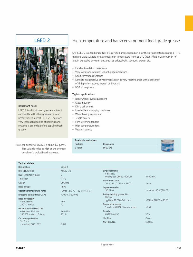
LGED 2 High temperature and harsh environment food grade grease
1) Typical value
Designation LGED 2
DIN 51825 code KFK2U-30
NLGI consistency class 2
Thickener PTFE
Colour Off white
Base oil type PFPE
Operating temperature range –30 to +240 °C (–22 to +464 °F)
Dropping point DIN ISO 2176 >300 °C (>570 °F)
Base oil viscosity
40 °C, mm2/s
100 °C, mm2/s
460
42
Penetration DIN ISO 2137
60 strokes, 10–1 mm
100 000 strokes, 10–1 mm
265–295
271 1)
Corrosion protection
Skf Emcor:
– standard ISO 11007 0–0 1)
EP performance
4–ball test,
welding load DIN 51350/4, N 8 000 min.
Water resistance
DIN 51 807/1, 3 hrs at 90 °C 1 max.
Copper corrosion
ISO 2160 1 max. at 100 °C (210 °F)
Rolling bearing grease life
R0F test
L50 life at 10 000 r/min., hrs >700, at 220 °C (430 °F)
Evaporation losses
6 weeks at 200 °C, % weight losses <3,5%
Density
at 20 °C, g/cm3 1,96
Shelf life 2 years
NSF Reg. No. 156010
SKF LGED 2 is a food grade NSF H1 certified grease based on a synthetic fluorinated oil using a PTFE
thickener. It is suitable for extremely high temperature from 180 °C (392 °F) up to 240 °C (464 °F)
and/or agressive environments such as acids/alkalis, vacuum, oxygen etc.
• Excellent oxidation resistance
• Very low evaporation losses at high temperature
• Good corrosion resistance
• Long life in aggressive environments such as very reactive areas with a presence
of high purity gaseous oxygen and hexane
• NSF H1 registered
Typical applications
• Bakery/brick oven equipment
• Glass industry
• Kiln truck wheels
• Load rollers in copying machines
• Wafer baking equipment
• Textile dryers
• Film streching tenders
• High temperature fans
• Vacuum pumps
Important note:
LGED 2 is a fluorinated grease and is not
compatible with other greases, oils and
preservatives (except LGET 2). Therefore,
very thorough cleaning of bearings and
systems is essential before applying fresh
grease.
Technical data
Available pack sizes
Packsize Designation
1 kg can LGED 2/1Note: the density of LGED 2 is about 1.9 g.cm3.
This value is twice as high as the average
density of a typical bearing grease.
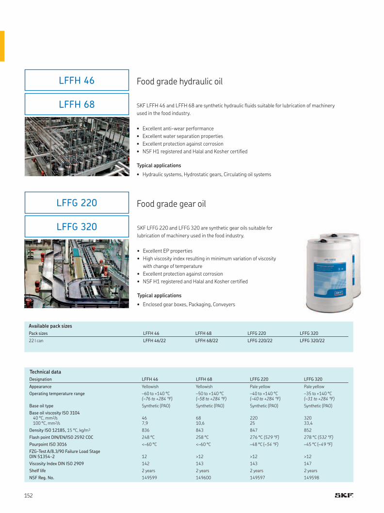
LFFH 46
LFFH 68
LFFG 220
LFFG 320
Food grade hydraulic oil
Designation LFFH 46 LFFH 68 LFFG 220 LFFG 320
Appearance Yellowish Yellowish Pale yellow Pale yellow
Operating temperature range –60 to +140 °C (–76 to +284 °F)
–50 to +140 °C (–58 to +284 °F)
–40 to +140 °C (–40 to +284 °F)
–35 to +140 °C (–31 to +284 °F)
Base oil type Synthetic (PAO) Synthetic (PAO) Synthetic (PAO) Synthetic (PAO)
Base oil viscosity ISO 310440 °C, mm2/s100 °C, mm2/s
467,9
6810,6
22025
32033,4
Density ISO 12185, 15 °C, kg/m3 836 843 847 852
Flash point DIN/EN/ISO 2592 COC 248 °C 258 °C 276 °C (529 °F) 278 °C (532 °F)
Pourpoint ISO 3016 <–60 °C <–60 °C –48 °C (–54 °F) –45 °C (–49 °F)
FZG-Test A/8.3/90 Failure Load Stage DIN 51354-2 12 >12 >12 >12
Viscosity Index DIN ISO 2909 142 143 143 147
Shelf life 2 years 2 years 2 years 2 years
NSF Reg. No. 149599 149600 149597 149598
Technical data
SKF LFFH 46 and LFFH 68 are synthetic hydraulic fluids suitable for lubrication of machinery
used in the food industry.
• Excellent anti-wear performance
• Excellent water separation properties
• Excellent protection against corrosion
• NSF H1 registered and Halal and Kosher certified
Typical applications
• Hydraulic systems, Hydrostatic gears, Circulating oil systems
Pack sizes LFFH 46 LFFH 68 LFFG 220 LFFG 320
22 l can LFFH 46/22 LFFH 68/22 LFFG 220/22 LFFG 320/22
Food grade gear oil
SKF LFFG 220 and LFFG 320 are synthetic gear oils suitable for
lubrication of machinery used in the food industry.
• Excellent EP properties
• High viscosity index resulting in minimum variation of viscosity
with change of temperature
• Excellent protection against corrosion
• NSF H1 registered and Halal and Kosher certified
Typical applications
• Enclosed gear boxes, Packaging, Conveyers
Available pack sizes
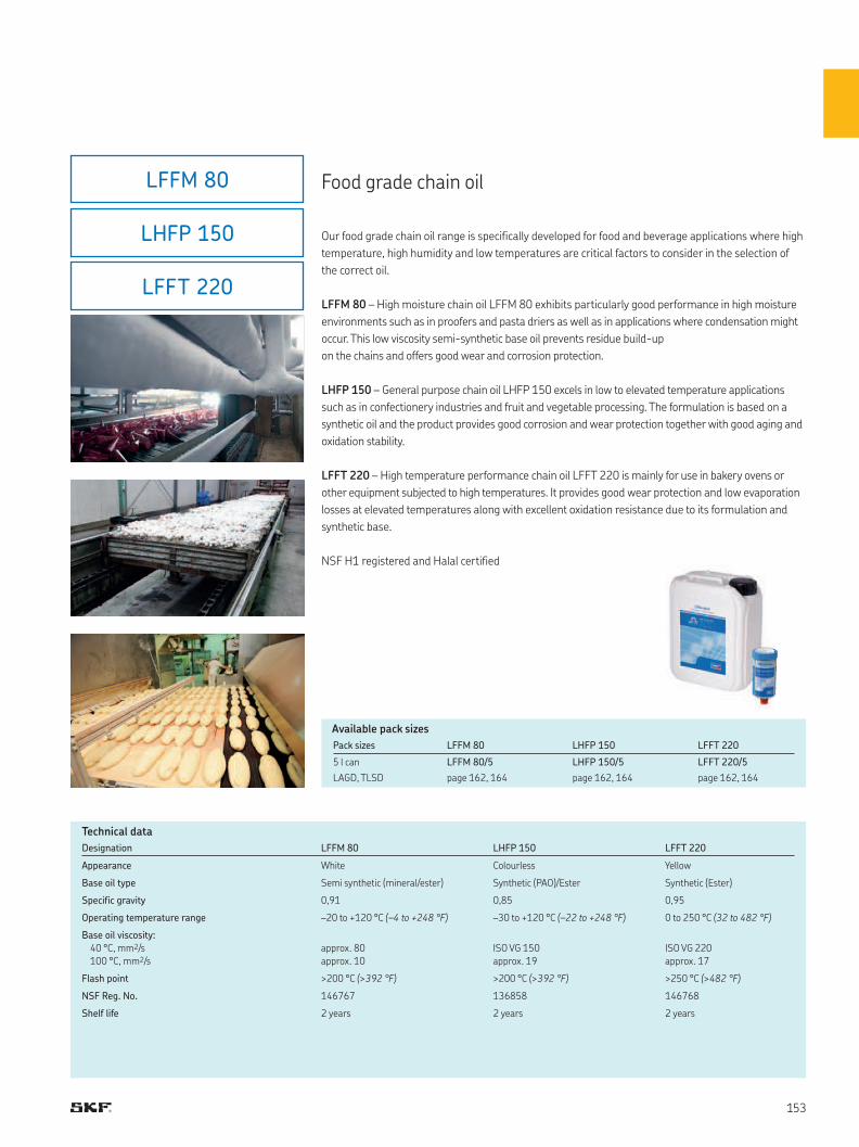
LFFM 80
LHFP 150
LFFT 220
Pack sizes LFFM 80 LHFP 150 LFFT 220
5 l can LFFM 80/5 LHFP 150/5 LFFT 220/5
LAGD, TLSD page 162, 164 page 162, 164 page 162, 164
Designation LFFM 80 LHFP 150 LFFT 220
Appearance White Colourless Yellow
Base oil type Semi synthetic (mineral/ester) Synthetic (PAO)/Ester Synthetic (Ester)
Specific gravity 0,91 0,85 0,95
Operating temperature range –20 to +120 °C (–4 to +248 °F) –30 to +120 °C (–22 to +248 °F) 0 to 250 °C (32 to 482 °F)
Base oil viscosity:
40 °C, mm2/s
100 °C, mm2/s
approx. 80
approx. 10
ISO VG 150
approx. 19
ISO VG 220
approx. 17
Flash point >200 °C (>392 °F) >200 °C (>392 °F) >250 °C (>482 °F)
NSF Reg. No. 146767 136858 146768
Shelf life 2 years 2 years 2 years
Technical data
Food grade chain oil
Our food grade chain oil range is specifically developed for food and beverage applications where high
temperature, high humidity and low temperatures are critical factors to consider in the selection of
the correct oil.
LFFM 80 – High moisture chain oil LFFM 80 exhibits particularly good performance in high moisture
environments such as in proofers and pasta driers as well as in applications where condensation might
occur. This low viscosity semi-synthetic base oil prevents residue build-up
on the chains and offers good wear and corrosion protection.
LHFP 150 – General purpose chain oil LHFP 150 excels in low to elevated temperature applications
such as in confectionery industries and fruit and vegetable processing. The formulation is based on a
synthetic oil and the product provides good corrosion and wear protection together with good aging and
oxidation stability.
LFFT 220 – High temperature performance chain oil LFFT 220 is mainly for use in bakery ovens or
other equipment subjected to high temperatures. It provides good wear protection and low evaporation
losses at elevated temperatures along with excellent oxidation resistance due to its formulation and
synthetic base.
NSF H1 registered and Halal certified
Available pack sizes
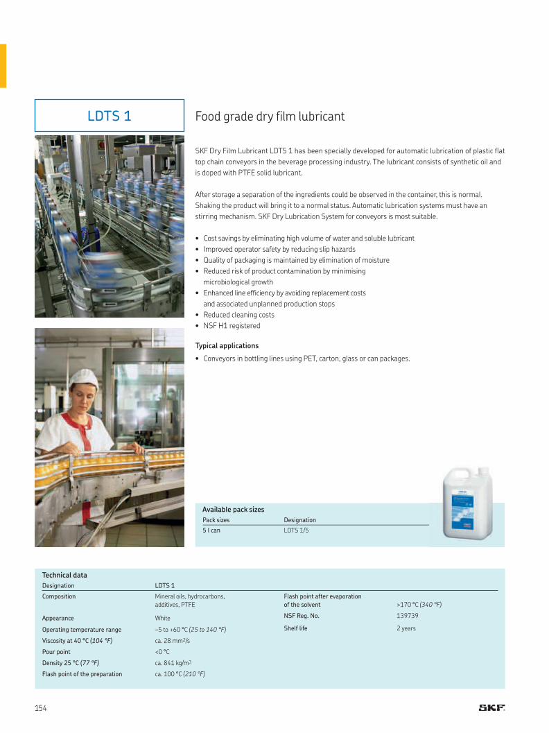
LDTS 1
Designation LDTS 1
Composition Mineral oils, hydrocarbons,
additives, PTFE
Appearance White
Operating temperature range –5 to +60 °C (25 to 140 °F)
Viscosity at 40 °C (104 °F) ca. 28 mm2/s
Pour point <0 °C
Density 25 °C (77 °F) ca. 841 kg/m3
Flash point of the preparation ca. 100 °C (210 °F)
Flash point after evaporation
of the solvent >170 °C (340 °F)
NSF Reg. No. 139739
Shelf life 2 years
Technical data
Pack sizes Designation
5 l can LDTS 1/5
Food grade dry film lubricant
SKF Dry Film Lubricant LDTS 1 has been specially developed for automatic lubrication of plastic flat
top chain conveyors in the beverage processing industry. The lubricant consists of synthetic oil and
is doped with PTFE solid lubricant.
After storage a separation of the ingredients could be observed in the container, this is normal.
Shaking the product will bring it to a normal status. Automatic lubrication systems must have an
stirring mechanism. SKF Dry Lubrication System for conveyors is most suitable.
• Cost savings by eliminating high volume of water and soluble lubricant
• Improved operator safety by reducing slip hazards
• Quality of packaging is maintained by elimination of moisture
• Reduced risk of product contamination by minimising
microbiological growth
• Enhanced line efficiency by avoiding replacement costs
and associated unplanned production stops
• Reduced cleaning costs
• NSF H1 registered
Typical applications
• Conveyors in bottling lines using PET, carton, glass or can packages.
Available pack sizes
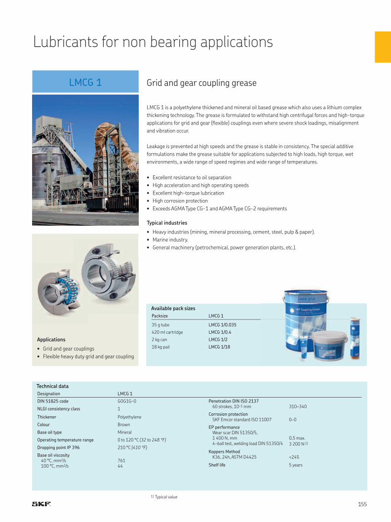
LMCG 1 Grid and gear coupling grease
LMCG 1 is a polyethylene thickened and mineral oil based grease which also uses a lithium complex
thickening technology. The grease is formulated to withstand high centrifugal forces and high-torque
applications for grid and gear (flexible) couplings even where severe shock loadings, misalignment
and vibration occur.
Leakage is prevented at high speeds and the grease is stable in consistency. The special additive
formulations make the grease suitable for applications subjected to high loads, high torque, wet
environments, a wide range of speed regimes and wide range of temperatures.
• Excellent resistance to oil separation
• High acceleration and high operating speeds
• Excellent high-torque lubrication
• High corrosion protection
• Exceeds AGMA Type CG-1 and AGMA Type CG-2 requirements
Typical industries
• Heavy industries (mining, mineral processing, cement, steel, pulp & paper).
• Marine industry.
• General machinery (petrochemical, power generation plants, etc.).
Applications
• Grid and gear couplings
• Flexible heavy duty grid and gear coupling
Technical data
1) Typical value
Packsize LMCG 1
35 g tube LMCG 1/0.035
420 ml cartridge LMCG 1/0.4
2 kg can LMCG 1/2
18 kg pail LMCG 1/18
Available pack sizes
Designation LMCG 1
DIN 51825 code GOG1G-0
NLGI consistency class 1
Thickener Polyethylene
Colour Brown
Base oil type Mineral
Operating temperature range 0 to 120 °C (32 to 248 °F)
Dropping point IP 396 210 °C (410 °F)
Base oil viscosity40 °C, mm2/s100 °C, mm2/s
76144
Penetration DIN ISO 2137 60 strokes, 10–1 mm 310–340
Corrosion protectionSKF Emcor standard ISO 11007 0–0
EP performance Wear scar DIN 51350/5, 1 400 N, mm4–ball test, welding load DIN 51350/4
0,5 max.
3 200 N 1)
Koppers MethodK36, 24h, ASTM D4425 <24%
Shelf life 5 years
Lubricants for non bearing applications
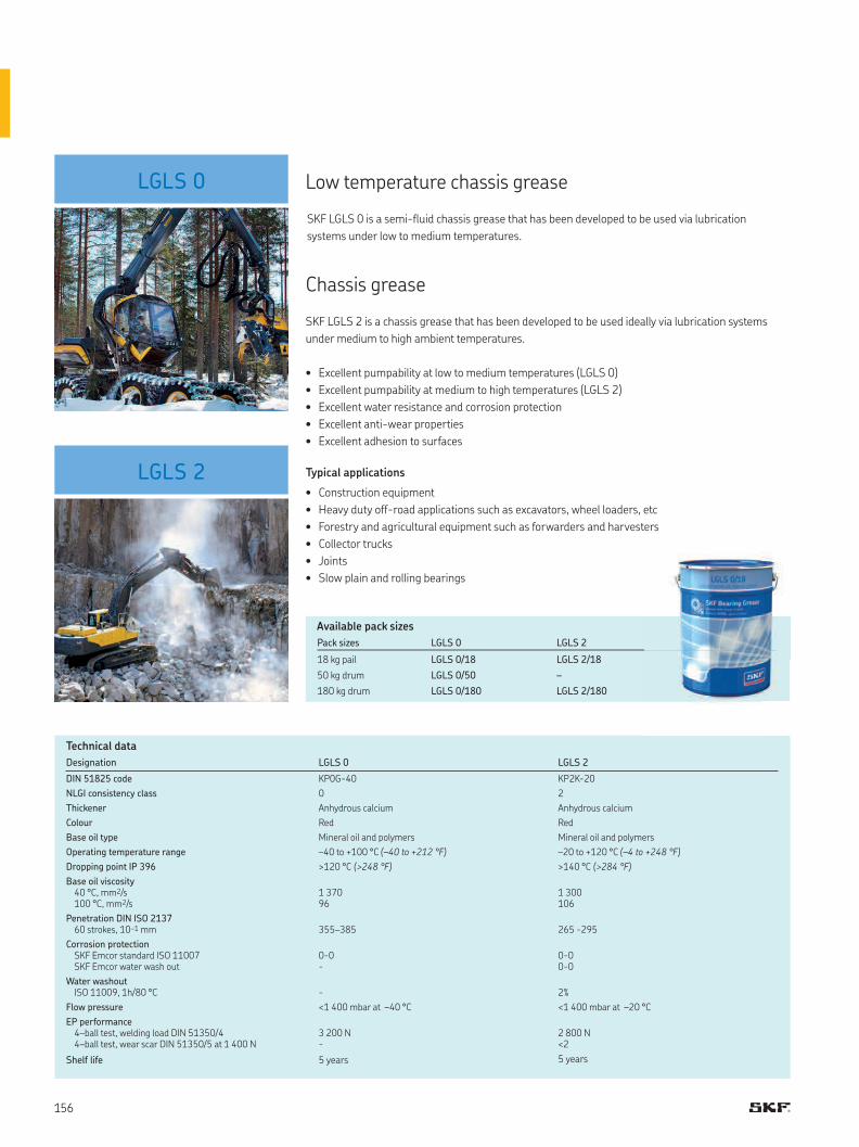
LGLS 0
LGLS 2
Pack sizes LGLS 0 LGLS 2
18 kg pail LGLS 0/18 LGLS 2/18
50 kg drum LGLS 0/50 –
180 kg drum LGLS 0/180 LGLS 2/180
Available pack sizes
Low temperature chassis grease
Chassis grease
SKF LGLS 2 is a chassis grease that has been developed to be used ideally via lubrication systems
under medium to high ambient temperatures.
• Excellent pumpability at low to medium temperatures (LGLS 0)
• Excellent pumpability at medium to high temperatures (LGLS 2)
• Excellent water resistance and corrosion protection
• Excellent anti-wear properties
• Excellent adhesion to surfaces
Typical applications
• Construction equipment
• Heavy duty off-road applications such as excavators, wheel loaders, etc
• Forestry and agricultural equipment such as forwarders and harvesters
• Collector trucks
• Joints
• Slow plain and rolling bearings
Technical data
Designation LGLS 0 LGLS 2
DIN 51825 code KP0G-40 KP2K-20
NLGI consistency class 0 2
Thickener Anhydrous calcium Anhydrous calcium
Colour Red Red
Base oil type Mineral oil and polymers Mineral oil and polymers
Operating temperature range –40 to +100 °C (–40 to +212 °F) –20 to +120 °C (–4 to +248 °F)
Dropping point IP 396 >120 °C (>248 °F) >140 °C (>284 °F)
Base oil viscosity40 °C, mm2/s100 °C, mm2/s
1 37096
1 300106
Penetration DIN ISO 2137 60 strokes, 10–1 mm 355–385 265 -295
Corrosion protectionSKF Emcor standard ISO 11007SKF Emcor water wash out
0-0-
0-00-0
Water washoutISO 11009, 1h/80 °C - 2%
Flow pressure <1 400 mbar at –40 °C <1 400 mbar at –20 °C
EP performance 4–ball test, welding load DIN 51350/44–ball test, wear scar DIN 51350/5 at 1 400 N
3 200 N-
2 800 N<2
Shelf life 5 years 5 years
SKF LGLS 0 is a semi-fluid chassis grease that has been developed to be used via lubrication
systems under low to medium temperatures.
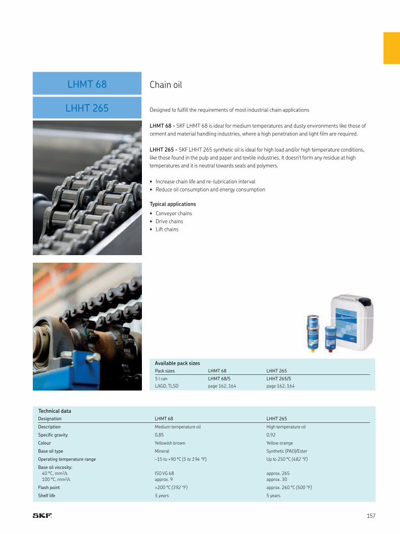
LHMT 68
LHHT 265 Designed to fulfill the requirements of most industrial chain applications
LHMT 68 - SKF LHMT 68 is ideal for medium temperatures and dusty environments like those of
cement and material handling industries, where a high penetration and light film are required.
LHHT 265 - SKF LHHT 265 synthetic oil is ideal for high load and/or high temperature conditions,
like those found in the pulp and paper and textile industries. It doesn’t form any residue at high
temperatures and it is neutral towards seals and polymers.
• Increase chain life and re-lubrication interval
• Reduce oil consumption and energy consumption
Typical applications
• Conveyor chains
• Drive chains
• Lift chains
Designation LHMT 68 LHHT 265
Description Medium temperature oil High temperature oil
Specific gravity 0,85 0,92
Colour Yellowish brown Yellow orange
Base oil type Mineral Synthetic (PAO)/Ester
Operating temperature range –15 to +90 °C (5 to 194 °F) Up to 250 °C (482 °F)
Base oil viscosity:
40 °C, mm2/s
100 °C, mm2/s
ISO VG 68
approx. 9
approx. 265
approx. 30
Flash point >200 °C (392 °F) approx. 260 °C (500 °F)
Shelf life 5 years 5 years
Technical data
Chain oil
Pack sizes LHMT 68 LHHT 265
5 l can LHMT 68/5 LHHT 265/5
LAGD, TLSD page 162, 164 page 162, 164
Available pack sizes
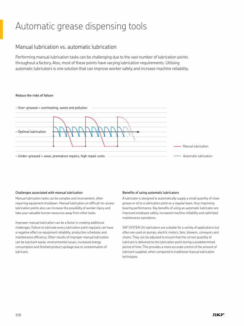
Performing manual lubrication tasks can be challenging due to the vast number of lubrication points
throughout a factory. Also, most of these points have varying lubrication requirements. Utilising
automatic lubricators is one solution that can improve worker safety and increase machine reliability.
Manual lubrication vs. automatic lubrication
Challenges associated with manual lubrication
Manual lubrication tasks can be complex and inconvenient, often
requiring equipment shutdown. Manual lubrication on difficult-to-access
lubrication points also can increase the possibility of worker injury and
take your valuable human resources away from other tasks.
Improper manual lubrication can be a factor in creating additional
challenges. Failure to lubricate every lubrication point regularly can have
a negative effect on equipment reliability, production schedules and
maintenance efficiency. Other results of improper manual lubrication
can be lubricant waste, environmental issues, increased energy
consumption and finished product spoilage due to contamination of
lubricant.
Benefits of using automatic lubricators
A lubricator is designed to automatically supply a small quantity of clean
grease or oil to a lubrication point on a regular basis, thus improving
bearing performance. Key benefits of using an automatic lubricator are
improved employee safety, increased machine reliability and optimized
maintenance operations.
SKF SYSTEM 24 lubricators are suitable for a variety of applications but
often are used on pumps, electric motors, fans, blowers, conveyors and
chains. They can be adjusted to ensure that the correct quantity of
lubricant is delivered to the lubrication point during a predetermined
period of time. This provides a more accurate control of the amount of
lubricant supplied, when compared to traditional manual lubrication
techniques.
– Over-greased = overheating, waste and pollution
– Optimal lubrication
Automatic lubrication
Manual lubrication
– Under-greased = wear, premature repairs, high repair costs
Reduce the risks of failure
Automatic grease dispensing tools

Use of SKF SYSTEM 24 lubricators can have a positive impact on workplace safety
because technicians can spend less time in confined spaces, with safety cages or guards
removed, and on rooftop or elevated lubrication tasks.
Improving employee safety
Lubrication point behind safety guards
Safety cages and guards are utilised for a reason - to protect workers
and others from injury caused by moving parts. By reducing the amount
of time these implements are not in place, SKF SYSTEM 24 lubricators
increase safety and eliminate the need to manually lubricate difficult-to-
access lubrication points.
Elevated lubrication point
Lubrication points on rooftops or other high elevations can create a
significant challenge, and the safety implications are evident. Due to
apprehension, these lubrication points often are not lubricated properly
and equipment reliability suffers.
Manual handling of lubricants
Improper handling of loose lubricant can expose technicians to
chemicals. By eliminating manual handling of lubricant, SKF SYSTEM 24
lubricators reduce the potential for chemical exposure of workers.

The importance of lubrication often is overlooked due to its underestimated impact on equipment
total cost of ownership. However, machine reliability can be enhanced substantially with proper
lubrication. As the leading supplier of bearings worldwide, SKF has conducted extensive research
and determined that up to 50 percent of premature bearing failures are due to either improper
lubrication practices or contamination.
Machine reliability
Premature bearing failure
Approximately 36 percent of premature bearing
failures are due to improper lubrication, such as too
much, too little or the wrong type of lubricant.
Another 14 percent of bearing failures occur
because of contamination via poor seals or lubricant
handling practices.
Clean, fresh lubricant
A continuous supply of clean, fresh grease or oil is
essential when lubricating equipment.
SKF SYSTEM 24 lubricators feature high quality
SKF lubricants in a water- and dust-resistant
design.
Positive pressure
Positive pressure prevents contaminants
from entering the bearing through the seal.
SKF SYSTEM 24 lubricators can provide fresh
lubricant and purge seals of smaller-sized
bearings operating at lower speeds, while larger
bearings may benefit from a separate lubricator
for lubrication and seal purging.
Missed lubrication points
With manual lubrication, it is difficult and time
consuming to find every lubrication point. Use
of SKF SYSTEM 24 lubricators helps to ensure
that each point is receiving the proper amount
of lubricant on a set schedule.
Fatigue 34%
Poor lubrication 36%
Contamination 14%
Poor fitting 16%
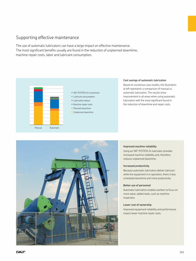
•
•
•
•
•
•
The use of automatic lubricators can have a large impact on effective maintenance.
The most significant benefits usually are found in the reduction of unplanned downtime,
machine repair costs, labor and lubricant consumption.
Supporting effective maintenance
Cost savings of automatic lubrication
Based on numerous case studies, the illustration
at left represents a comparison of manual vs.
automatic lubrication. The results show
improvement in all areas when using automatic
lubrication with the most significant found in
the reduction of downtime and repair costs.
Improved machine reliability
Using an SKF SYSTEM 24 lubricator provides
increased machine reliability and, therefore,
reduces unplanned downtime.
Increased productivity
Because automatic lubricators deliver lubricant
while the equipment is in operation, there is less
scheduled downtime and more productivity.
Better use of personnel
Automatic lubrication enables workers to focus on
more value-added tasks, such as machine
inspection.
Lower cost of ownership
Improved equipment reliability and performance
means lower machine repair costs.
SKF SYSTEM 24 investment
Lubricant consumption
Lubrication labour
Machine repair costs
Planned downtime
Unplanned downtime
Manual Automatic
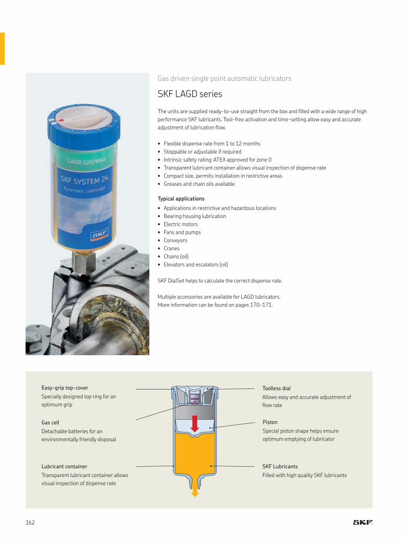
Gas driven single point automatic lubricators
SKF LAGD series
The units are supplied ready-to-use straight from the box and filled with a wide range of high
performance SKF lubricants. Tool-free activation and time-setting allow easy and accurate
adjustment of lubrication flow.
• Flexible dispense rate from 1 to 12 months
• Stoppable or adjustable if required
• Intrinsic safety rating: ATEX approved for zone 0
• Transparent lubricant container allows visual inspection of dispense rate
• Compact size, permits installation in restrictive areas
• Greases and chain oils available
Typical applications
• Applications in restrictive and hazardous locations
• Bearing housing lubrication
• Electric motors
• Fans and pumps
• Conveyors
• Cranes
• Chains (oil)
• Elevators and escalators (oil)
SKF DialSet helps to calculate the correct dispense rate.
Multiple accessories are available for LAGD lubricators.
More information can be found on pages 170-171.
Toolless dial
Allows easy and accurate adjustment of
flow rate
Gas cell
Detachable batteries for an
environmentally friendly disposal
Easy-grip top-cover
Specially designed top ring for an
optimum grip
Piston
Special piston shape helps ensure
optimum emptying of lubricator
Lubricant container
Transparent lubricant container allows
visual inspection of dispense rate
SKF Lubricants
Filled with high quality SKF lubricants
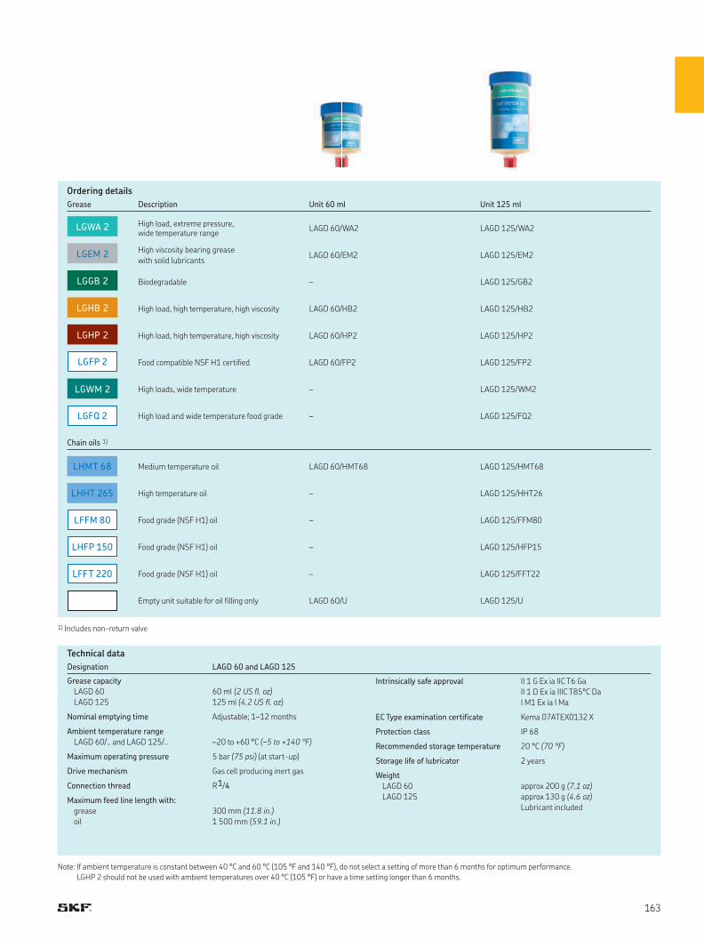
LGHP 2
LGHB 2
LGEM 2
LGWM 2
LGGB 2
LGWA 2
LGFP 2
LGFQ 2
LFFM 80
LHFP 150
LFFT 220
LHMT 68
LHHT 265
Designation LAGD 60 and LAGD 125
Grease capacity
LAGD 60
LAGD 125
60 ml (2 US fl. oz)
125 ml (4.2 US fl. oz)
Nominal emptying time Adjustable; 1–12 months
Ambient temperature range
LAGD 60/.. and LAGD 125/.. –20 to +60 °C (–5 to +140 °F)
Maximum operating pressure 5 bar (75 psi) (at start-up)
Drive mechanism Gas cell producing inert gas
Connection thread R 1/4
Maximum feed line length with:
grease
oil
300 mm (11.8 in.)
1 500 mm (59.1 in.)
Intrinsically safe approval II 1 G Ex ia IIC T6 Ga
II 1 D Ex ia IIIC T85°C Da
I M1 Ex ia I Ma
EC Type examination certificate Kema 07ATEX0132 X
Protection class IP 68
Recommended storage temperature 20 °C (70 °F)
Storage life of lubricator 2 years
Weight
LAGD 60
LAGD 125
approx 200 g (7.1 oz)
approx 130 g (4.6 oz)
Lubricant included
Note: If ambient temperature is constant between 40 °C and 60 °C (105 °F and 140 °F), do not select a setting of more than 6 months for optimum performance.
LGHP 2 should not be used with ambient temperatures over 40 °C (105 °F) or have a time setting longer than 6 months.
Technical data
Ordering details
Grease Description Unit 60 ml Unit 125 ml
High load, extreme pressure, wide temperature range
LAGD 60/WA2 LAGD 125/WA2
High viscosity bearing grease
with solid lubricantsLAGD 60/EM2 LAGD 125/EM2
Biodegradable – LAGD 125/GB2
High load, high temperature, high viscosity LAGD 60/HB2 LAGD 125/HB2
High load, high temperature, high viscosity LAGD 60/HP2 LAGD 125/HP2
Food compatible NSF H1 certified LAGD 60/FP2 LAGD 125/FP2
High loads, wide temperature – LAGD 125/WM2
High load and wide temperature food grade – LAGD 125/FQ2
Chain oils 1)
Medium temperature oil LAGD 60/HMT68 LAGD 125/HMT68
High temperature oil – LAGD 125/HHT26
Food grade (NSF H1) oil – LAGD 125/FFM80
Food grade (NSF H1) oil – LAGD 125/HFP15
Food grade (NSF H1) oil – LAGD 125/FFT22
Empty unit suitable for oil filling only LAGD 60/U LAGD 125/U
1) Includes non-return valve
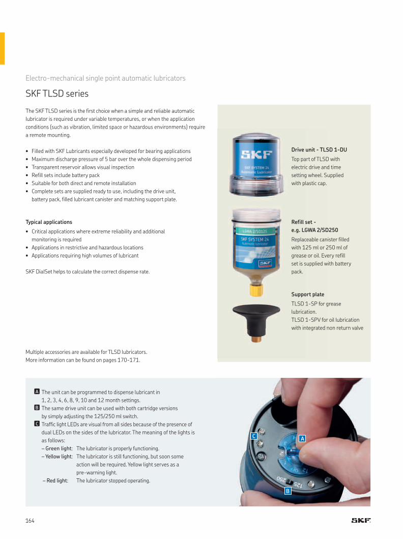
A
B
C
Drive unit - TLSD 1-DU
Top part of TLSD with
electric drive and time
setting wheel. Supplied
with plastic cap.
Refill set -
e.g. LGWA 2/SD250
Replaceable canister filled
with 125 ml or 250 ml of
grease or oil. Every refill
set is supplied with battery
pack.
Support plate
TLSD 1-SP for grease
lubrication.
TLSD 1-SPV for oil lubrication
with integrated non return valve
Multiple accessories are available for TLSD lubricators.
More information can be found on pages 170-171.
Electro-mechanical single point automatic lubricators
SKF TLSD series
The SKF TLSD series is the first choice when a simple and reliable automatic
lubricator is required under variable temperatures, or when the application
conditions (such as vibration, limited space or hazardous environments) require
a remote mounting.
• Filled with SKF Lubricants especially developed for bearing applications
• Maximum discharge pressure of 5 bar over the whole dispensing period
• Transparent reservoir allows visual inspection
• Refill sets include battery pack
• Suitable for both direct and remote installation
• Complete sets are supplied ready to use, including the drive unit,
battery pack, filled lubricant canister and matching support plate.
Typical applications
• Critical applications where extreme reliability and additional
monitoring is required
• Applications in restrictive and hazardous locations
• Applications requiring high volumes of lubricant
SKF DialSet helps to calculate the correct dispense rate.
nA The unit can be programmed to dispense lubricant in
1, 2, 3, 4, 6, 8, 9, 10 and 12 month settings.
nB The same drive unit can be used with both cartridge versions
by simply adjusting the 125/250 ml switch.
nC Traffic light LEDs are visual from all sides because of the presence of
dual LEDs on the sides of the lubricator. The meaning of the lights is
as follows:
– Green light: The lubricator is properly functioning.
– Yellow light: The lubricator is still functioning, but soon some
action will be required. Yellow light serves as a
pre-warning light.
– Red light: The lubricator stopped operating.
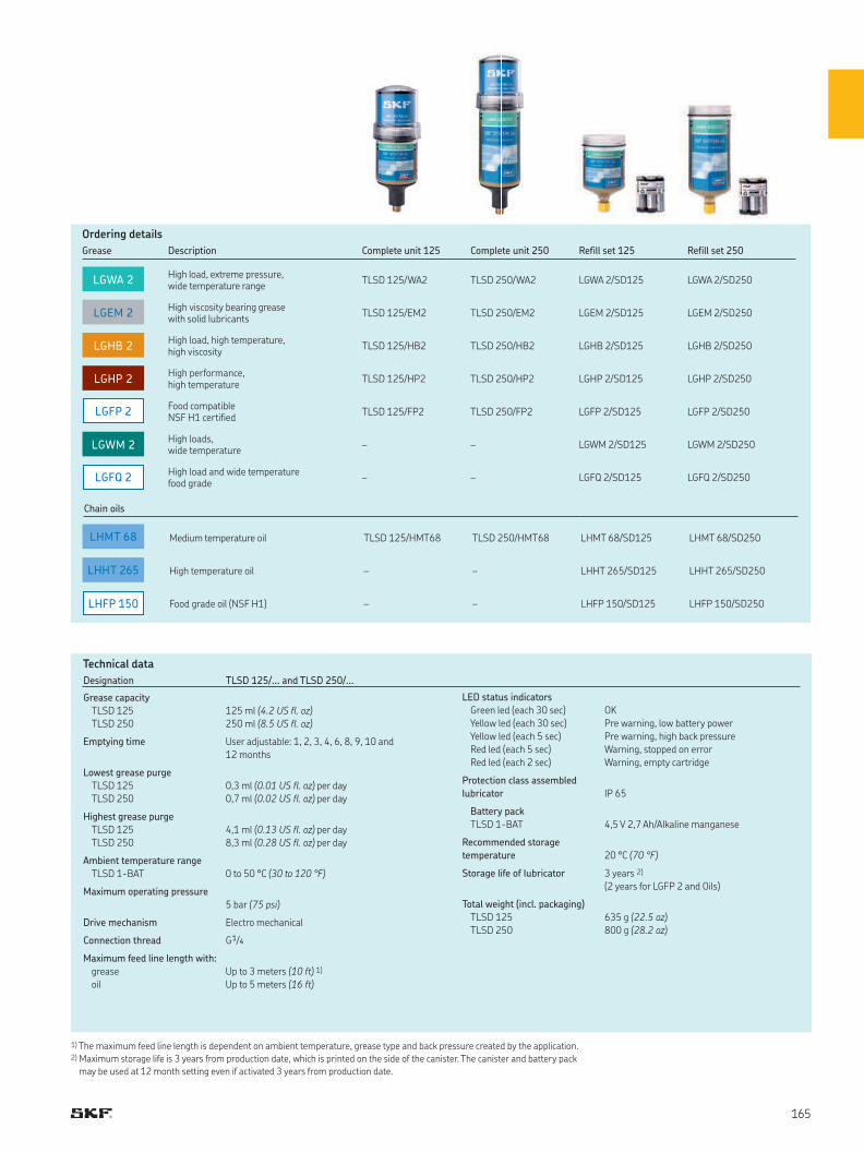
LGHP 2
LGHB 2
LGEM 2
LGWM 2
LGWA 2
LGFP 2
LGFQ 2
LHFP 150
LHMT 68
LHHT 265
Ordering details
Grease Description Complete unit 125 Complete unit 250 Refill set 125 Refill set 250
High load, extreme pressure, wide temperature range
TLSD 125/WA2 TLSD 250/WA2 LGWA 2/SD125 LGWA 2/SD250
High viscosity bearing grease with solid lubricants
TLSD 125/EM2 TLSD 250/EM2 LGEM 2/SD125 LGEM 2/SD250
High load, high temperature, high viscosity
TLSD 125/HB2 TLSD 250/HB2 LGHB 2/SD125 LGHB 2/SD250
High performance,high temperature
TLSD 125/HP2 TLSD 250/HP2 LGHP 2/SD125 LGHP 2/SD250
Food compatibleNSF H1 certified
TLSD 125/FP2 TLSD 250/FP2 LGFP 2/SD125 LGFP 2/SD250
High loads,wide temperature
– – LGWM 2/SD125 LGWM 2/SD250
High load and wide temperature food grade
– – LGFQ 2/SD125 LGFQ 2/SD250
Chain oils
Medium temperature oil TLSD 125/HMT68 TLSD 250/HMT68 LHMT 68/SD125 LHMT 68/SD250
High temperature oil – – LHHT 265/SD125 LHHT 265/SD250
Food grade oil (NSF H1) – – LHFP 150/SD125 LHFP 150/SD250
Designation TLSD 125/... and TLSD 250/...
Grease capacity
TLSD 125
TLSD 250
125 ml (4.2 US fl. oz)
250 ml (8.5 US fl. oz)
Emptying time User adjustable: 1, 2, 3, 4, 6, 8, 9, 10 and
12 months
Lowest grease purge
TLSD 125
TLSD 250
0,3 ml (0.01 US fl. oz) per day
0,7 ml (0.02 US fl. oz) per day
Highest grease purge
TLSD 125
TLSD 250
4,1 ml (0.13 US fl. oz) per day
8,3 ml (0.28 US fl. oz) per day
Ambient temperature range
TLSD 1-BAT 0 to 50 °C (30 to 120 °F)
Maximum operating pressure
5 bar (75 psi)
Drive mechanism Electro mechanical
Connection thread G 1/4
Maximum feed line length with:
grease
oil
Up to 3 meters (10 ft) 1)
Up to 5 meters (16 ft)
LED status indicators
Green led (each 30 sec)
Yellow led (each 30 sec)
Yellow led (each 5 sec)
Red led (each 5 sec)
Red led (each 2 sec)
OK
Pre warning, low battery power
Pre warning, high back pressure
Warning, stopped on error
Warning, empty cartridge
Protection class assembled
lubricator IP 65
Battery pack
TLSD 1-BAT 4,5 V 2,7 Ah/Alkaline manganese
Recommended storage
temperature 20 °C (70 °F)
Storage life of lubricator 3 years 2)
(2 years for LGFP 2 and Oils)
Total weight (incl. packaging)
TLSD 125
TLSD 250
635 g (22.5 oz)
800 g (28.2 oz)
Technical data
1) The maximum feed line length is dependent on ambient temperature, grease type and back pressure created by the application.2) Maximum storage life is 3 years from production date, which is printed on the side of the canister. The canister and battery pack
may be used at 12 month setting even if activated 3 years from production date.
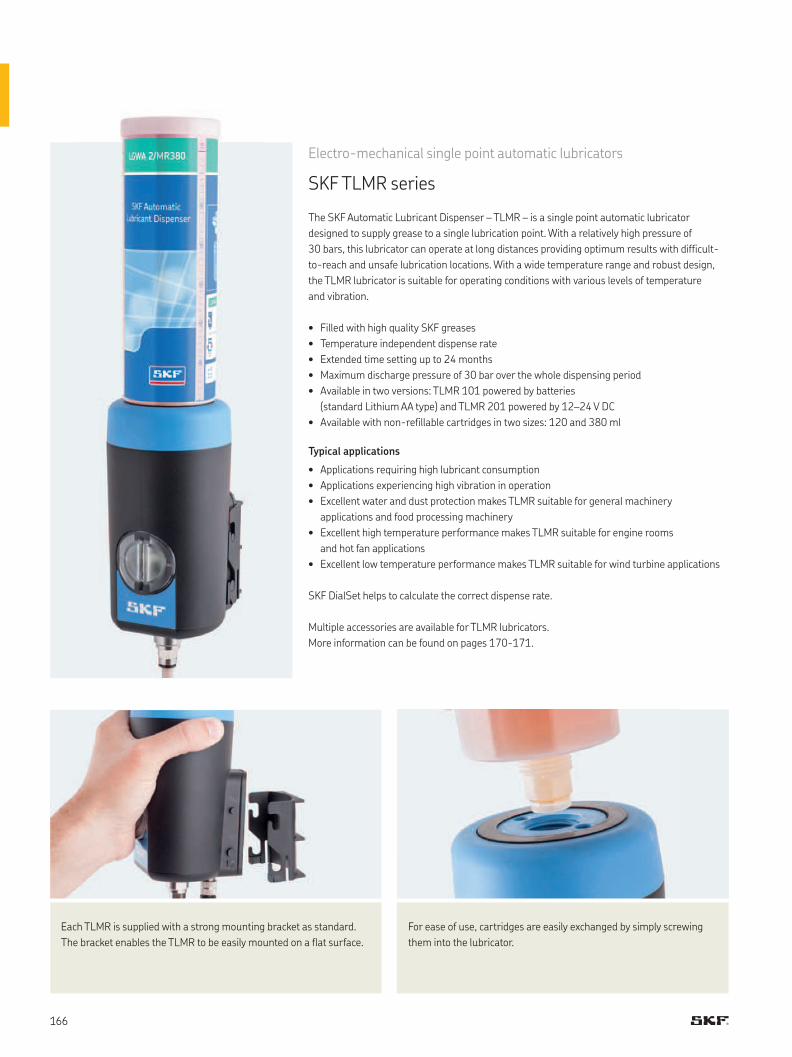
• Filled with high quality SKF greases
• Temperature independent dispense rate
• Extended time setting up to 24 months
• Maximum discharge pressure of 30 bar over the whole dispensing period
• Available in two versions: TLMR 101 powered by batteries
(standard Lithium AA type) and TLMR 201 powered by 12–24 V DC
• Available with non-refillable cartridges in two sizes: 120 and 380 ml
Typical applications
• Applications requiring high lubricant consumption
• Applications experiencing high vibration in operation
• Excellent water and dust protection makes TLMR suitable for general machinery
applications and food processing machinery
• Excellent high temperature performance makes TLMR suitable for engine rooms
and hot fan applications
• Excellent low temperature performance makes TLMR suitable for wind turbine applications
SKF DialSet helps to calculate the correct dispense rate.
Multiple accessories are available for TLMR lubricators.
More information can be found on pages 170-171.
Electro-mechanical single point automatic lubricators
SKF TLMR series
The SKF Automatic Lubricant Dispenser – TLMR – is a single point automatic lubricator
designed to supply grease to a single lubrication point. With a relatively high pressure of
30 bars, this lubricator can operate at long distances providing optimum results with difficult-
to-reach and unsafe lubrication locations. With a wide temperature range and robust design,
the TLMR lubricator is suitable for operating conditions with various levels of temperature
and vibration.
Each TLMR is supplied with a strong mounting bracket as standard.
The bracket enables the TLMR to be easily mounted on a flat surface.
For ease of use, cartridges are easily exchanged by simply screwing
them into the lubricator.
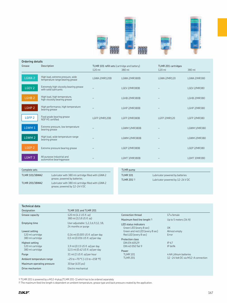
LGHP 2
LGHB 2
LGEV 2
LGWM 2
LGWM 1
LGWA 2
LGEP 2
LGMT 3
LGFP 2
Designation TLMR 101 and TLMR 201
Grease capacity 120 ml (4.1 US fl. oz)
380 ml (12.8 US fl. oz)
Emptying time User adjustable: 1,2,3,6,9,12, 18,
24 months or purge
Lowest setting
120 ml cartridge
380 ml cartridge
0,16 ml (0.005 US fl. oz) per day
0,5 ml (0.016 US fl. oz) per day
Highest setting
120 ml cartridge
380 ml cartridge
3,9 ml (0.13 US fl. oz) per day
12,5 ml (0.42 US fl. oz) per day
Purge 31 ml (1 US fl. oz) per hour
Ambient temperature range –25 to +70 °C (–13 to +158 °F)
Maximum operating pressure 30 bar (435 psi)
Drive mechanism Electro mechanical
Connection thread G 1/4 female
Maximum feed line length 2) Up to 5 meters (16 ft)
LED status indicators
Green LED (every 8 sec)
Green and red LED (every 8 sec)
Red LED (every 8 sec)
OK
Almost empty
Error
Protection class
DIN EN 60529
DIN 40 050 Teil 9
IP 67
IP 6k9k
Power
TLMR 101
TLMR 201
4 AA Lithium batteries
12 -24 Volt DC via M12-A connection
1) TLMR 201 is powered by a M12-A plug (TLMR 201-1) which has to be ordered separately 2) The maximum feed line length is dependent on ambient temperature, grease type and back pressure created by the application.
Technical data
Ordering details
Grease Description TLMR 101 refill sets (cartridge and battery) TLMR 201 cartridges
120 ml 380 ml 120 ml 380 ml
High load, extreme pressure, widetemperature range bearing grease
LGWA 2/MR120B LGWA 2/MR380B LGWA 2/MR120 LGWA 2/MR380
Extremely high viscosity bearing grease with solid lubricants
– LGEV 2/MR380B – LGEV 2/MR380
High load, high temperature, high viscosity bearing grease
– LGHB 2/MR380B – LGHB 2/MR380
High performance, high temperature bearing grease
– LGHP 2/MR380B – LGHP 2/MR380
Food grade bearing greaseNSF H1 certified
LGFP 2/MR120B LGFP 2/MR380B LGFP 2/MR120 LGFP 2/MR380
Extreme pressure, low temperaturebearing grease
– LGWM 1/MR380B – LGWM 1/MR380
High load, wide temperature rangebearing grease
– LGWM 2/MR380B – LGWM 2/MR380
Extreme pressure bearing grease – LGEP 2/MR380B – LGEP 2/MR380
All purpose industrial and automotive bearinggrease
– LGMT 3/MR380B – LGMT 3/MR380
Complete sets
TLMR 101/38WA2 Lubricator with 380 ml cartridge filled with LGWA 2
grease, powered by batteries.
TLMR 201/38WA2 Lubricator with 380 ml cartridge filled with LGWA 2
grease, powered by 12-24 V DC
TLMR pump
TLMR 101 Lubricator powered by batteries
TLMR 201 1) Lubricator powered by 12-24 V DC
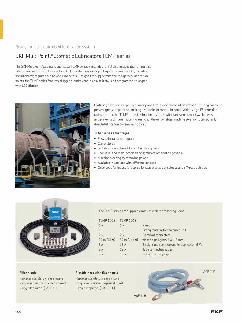
Ready-to-use centralised lubrication system
SKF MultiPoint Automatic Lubricators TLMP series
The SKF MultiPoint Automatic Lubricator TLMP series is intended for reliable relubrication of multiple
lubrication points. This sturdy automatic lubrication system is packaged as a complete kit, including
the lubricator, required tubing and connectors. Designed to supply from one to eighteen lubrication
points, the TLMP series features pluggable outlets and is easy to install and program via its keypad
with LED display.
Featuring a reservoir capacity of nearly one litre, this versatile lubricator has a stirring paddle to
prevent grease separation, making it suitable for more lubricants. With its high IP protection
rating, the durable TLMP series is vibration resistant, withstands equipment washdowns
and prevents contamination ingress. Also, the unit enables machine steering to temporarily
disable lubrication by removing power.
TLMP series advantages
• Easy to install and program
• Complete kit
• Suitable for one to eighteen lubrication points
• Low-level and malfunction alarms; remote notification possible
• Machine steering by removing power
• Available in versions with different voltages
• Developed for industrial applications, as well as agricultural and off-road vehicles
Filler nipple
Replaces standard grease nipple
for quicker lubricant replenishment
using filler pump. (LAGF 1-H)
Flexible hose with filler nipple
Replaces standard grease nipple
for quicker lubricant replenishment
using filler pump. (LAGF 1-F)
LAGF 1-F
LAGF 1-H
The TLMP series are supplied complete with the following items
TLMP 1008 TLMP 1018
1 × 1 × Pump
1 × 1 × Fitting material for the pump unit
2 × 2 × Electrical connectors
20 m (65 ft) 50 m (164 ft) plastic pipe Nylon, 6 × 1,5 mm
8 × 18 × Straight tube connectors for application G 1/8
8 × 18 × Tube connectors plugs
7 × 17 × Outlet closure plugs
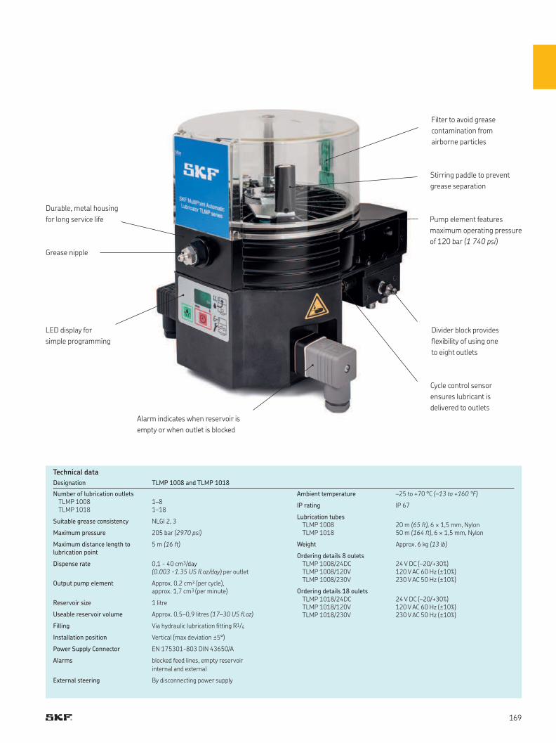
Designation TLMP 1008 and TLMP 1018
Number of lubrication outletsTLMP 1008TLMP 1018
1–81–18
Suitable grease consistency NLGI 2, 3
Maximum pressure 205 bar (2970 psi)
Maximum distance length to lubrication point
5 m (16 ft)
Dispense rate 0,1 - 40 cm3/day (0.003 -1.35 US fl.oz/day) per outlet
Output pump element Approx. 0,2 cm3 (per cycle), approx. 1,7 cm3 (per minute)
Reservoir size 1 litre
Useable reservoir volume Approx. 0,5–0,9 litres (17–30 US fl.oz)
Filling Via hydraulic lubrication fitting R1/4
Installation position Vertical (max deviation ±5°)
Power Supply Connector EN 175301-803 DIN 43650/A
Alarms blocked feed lines, empty reservoir
internal and external
External steering By disconnecting power supply
Ambient temperature –25 to +70 °C (–13 to +160 °F)
IP rating IP 67
Lubrication tubesTLMP 1008TLMP 1018
20 m (65 ft), 6 × 1,5 mm, Nylon50 m (164 ft), 6 × 1,5 mm, Nylon
Weight Approx. 6 kg (13 lb)
Ordering details 8 ouletsTLMP 1008/24DCTLMP 1008/120VTLMP 1008/230V
24 V DC (–20/+30%)120 V AC 60 Hz (±10%)230 V AC 50 Hz (±10%)
Ordering details 18 ouletsTLMP 1018/24DCTLMP 1018/120VTLMP 1018/230V
24 V DC (–20/+30%)120 V AC 60 Hz (±10%)230 V AC 50 Hz (±10%)
Technical data
Stirring paddle to prevent
grease separation
Filter to avoid grease
contamination from
airborne particles
Divider block provides
flexibility of using one
to eight outlets
Durable, metal housing
for long service life
LED display for
simple programming
Alarm indicates when reservoir is
empty or when outlet is blocked
Pump element features
maximum operating pressure
of 120 bar (1 740 psi)
Cycle control sensor
ensures lubricant is
delivered to outlets
Grease nipple
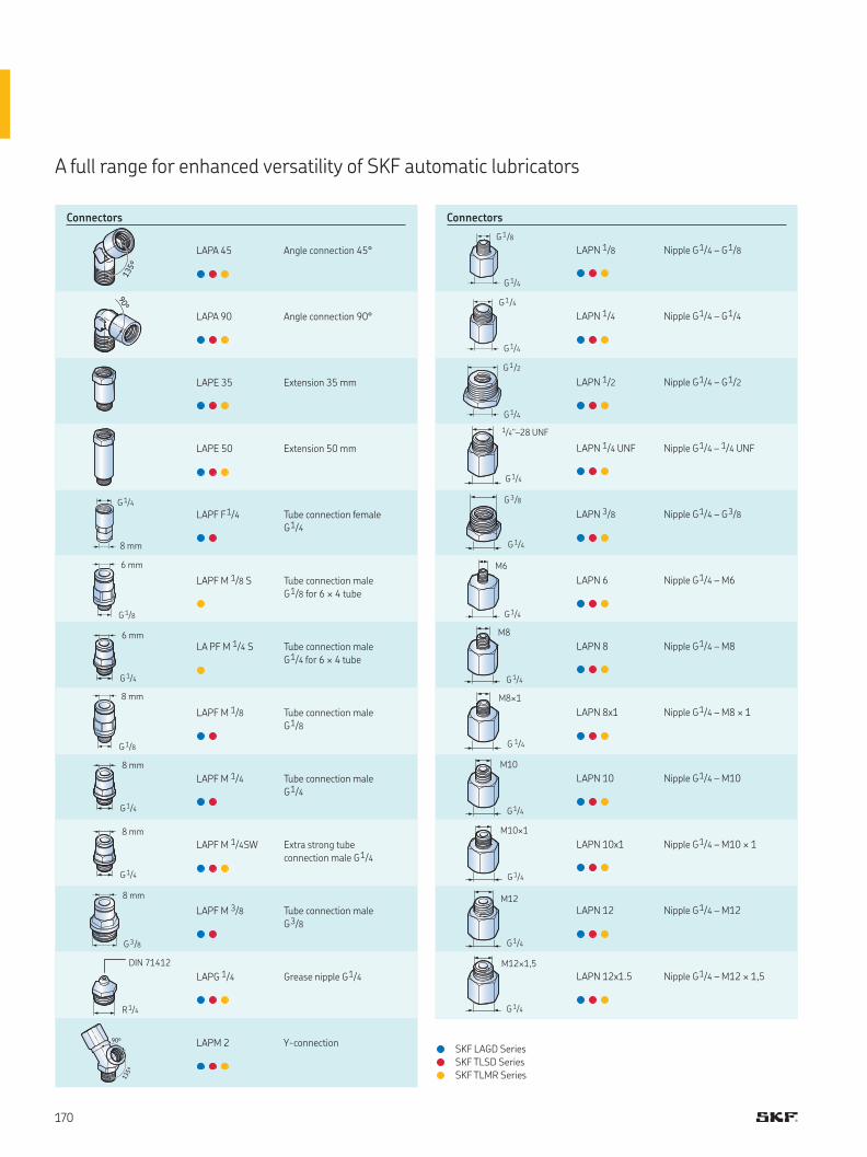
•••
•••
•••
•••
•••
•••
•••
•••
•••
•••
•••
•••
•
•
•
•••
•••
•••
•••
••
•
•
••
••
•••
••
•••
•••
8 mm
G 1/4
6 mm
G 1/4
8 mm
G 1/4
8 mm
G 1/4
6 mm
G 1/8
8 mm
G 1/8
8 mm
G 3/8
R 1/4
DIN 71412
G 1/4
G 1/8
G 1/4
G 1/2
G 1/4
G 1/4
G 1/4
1/4"–28 UNF
G 1/4
G 3/8
G 1/4
M6
G 1/4
M8
G 1/4
M8×1
G 1/4
M10
G 1/4
M10×1
G 1/4
M12
G 1/4
M12×1,5
A full range for enhanced versatility of SKF automatic lubricators
ConnectorsConnectors
SKF LAGD Series
SKF TLSD Series
SKF TLMR Series
LAPA 45 Angle connection 45°
LAPA 90 Angle connection 90°
LAPE 35 Extension 35 mm
LAPE 50 Extension 50 mm
LAPF F 1/4 Tube connection female
G 1/4
LAPF M 1/8 S Tube connection male
G 1/8 for 6 × 4 tube
LA PF M 1/4 S Tube connection male
G 1/4 for 6 × 4 tube
LAPF M 1/8 Tube connection male
G 1/8
LAPF M 1/4 Tube connection male
G 1/4
LAPF M 1/4SW Extra strong tube
connection male G 1/4
LAPF M 3/8 Tube connection male
G 3/8
LAPG 1/4 Grease nipple G 1/4
LAPM 2 Y-connection
LAPN 1/8 Nipple G 1/4 – G 1/8
LAPN 1/4 Nipple G 1/4 – G 1/4
LAPN 1/2 Nipple G 1/4 – G 1/2
LAPN 1/4 UNF Nipple G 1/4 – 1/4 UNF
LAPN 3/8 Nipple G 1/4 – G 3/8
LAPN 6 Nipple G 1/4 – M6
LAPN 8 Nipple G 1/4 – M8
LAPN 8x1 Nipple G 1/4 – M8 × 1
LAPN 10 Nipple G 1/4 – M10
LAPN 10x1 Nipple G 1/4 – M10 × 1
LAPN 12 Nipple G 1/4 – M12
LAPN 12x1.5 Nipple G 1/4 – M12 × 1,5
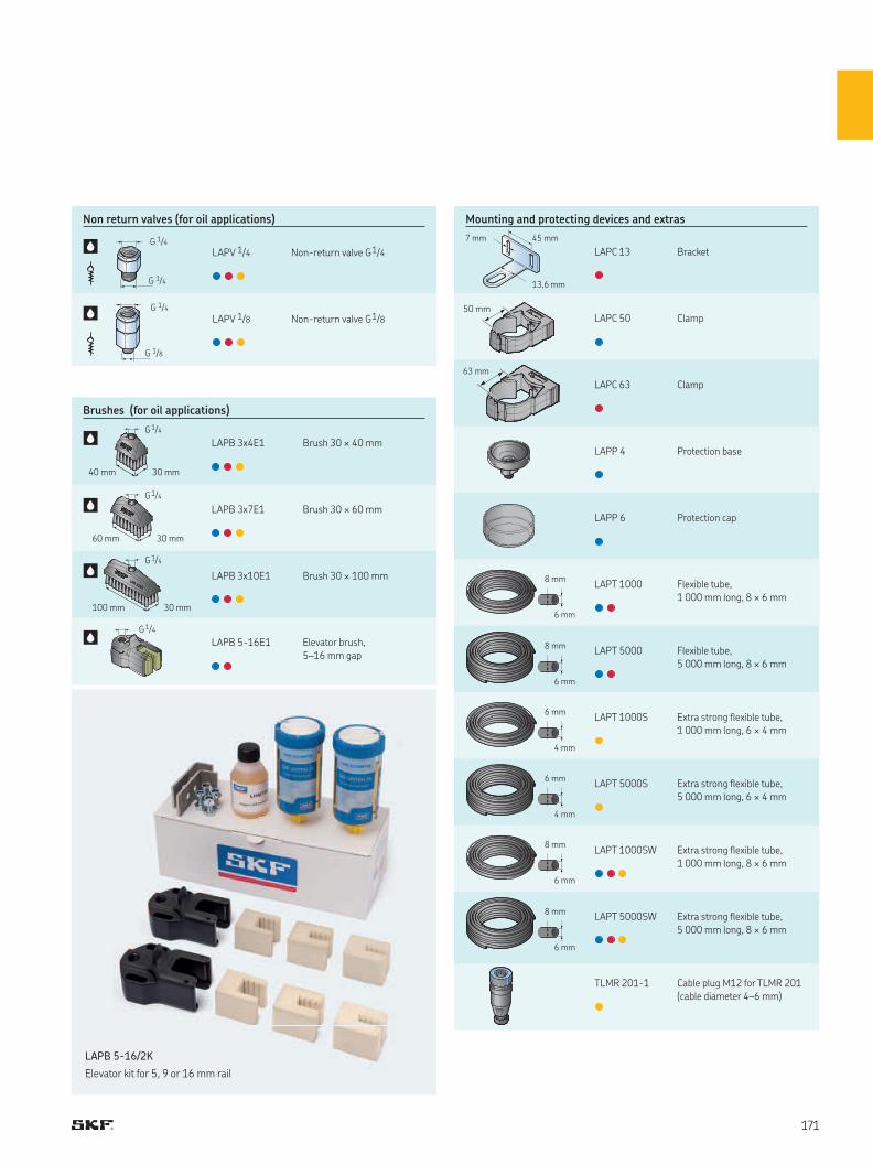
•
•
•
•
•
••
••
•
•
•••
•••
•
•••
•••
•••
••
•••
•••
6 mm
4 mm
8 mm
6 mm
8 mm
6 mm
50 mm
G 1/4
G 1/4
G 1/4
G 1/8
G1/4
G1/4
30 mm40 mm
G1/4
30 mm60 mm
LAPB 3x10E1
LAPB 3x10E1
G1/4
30 mm100 mm
13,6 mm
7 mm 45 mm
63 mm
6 mm
4 mm
8 mm
6 mm
8 mm
6 mm
LAPB 5-16/2K
Elevator kit for 5, 9 or 16 mm rail
Brushes (for oil applications)
Mounting and protecting devices and extrasNon return valves (for oil applications)
LAPC 13 Bracket
LAPC 50 Clamp
LAPC 63 Clamp
LAPP 4 Protection base
LAPP 6 Protection cap
LAPT 1000 Flexible tube,
1 000 mm long, 8 × 6 mm
LAPT 5000 Flexible tube,
5 000 mm long, 8 × 6 mm
LAPT 1000S Extra strong flexible tube,
1 000 mm long, 6 × 4 mm
LAPT 5000S Extra strong flexible tube,
5 000 mm long, 6 × 4 mm
LAPT 1000SW Extra strong flexible tube,
1 000 mm long, 8 × 6 mm
LAPT 5000SW Extra strong flexible tube,
5 000 mm long, 8 × 6 mm
TLMR 201-1 Cable plug M12 for TLMR 201
(cable diameter 4–6 mm)
LAPB 3x4E1 Brush 30 × 40 mm
LAPB 3x7E1 Brush 30 × 60 mm
LAPB 3x10E1 Brush 30 × 100 mm
LAPB 5-16E1 Elevator brush,
5–16 mm gap
LAPV 1/4 Non-return valve G 1/4
LAPV 1/8 Non-return valve G 1/8
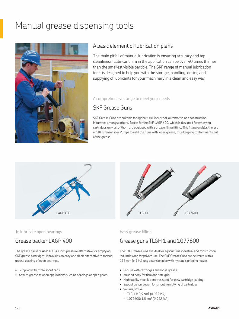
Manual grease dispensing tools
A basic element of lubrication plans
The main pitfall of manual lubrication is ensuring accuracy and top
cleanliness. Lubricant film in the application can be over 40 times thinner
than the smallest visible particle. The SKF range of manual lubrication
tools is designed to help you with the storage, handling, dosing and
supplying of lubricants for your machinery in a clean and easy way.
To lubricate open bearings
Grease packer LAGP 400
The grease packer LAGP 400 is a low-pressure alternative for emptying
SKF grease cartridges. It provides an easy and clean alternative to manual
grease packing of open bearings.
• Supplied with three spout caps
• Applies grease to open applications such as bearings or open gears
Easy grease filling
Grease guns TLGH 1 and 1077600
The SKF Grease Guns are ideal for agricultural, industrial and construction
industries and for private use. The SKF Grease Guns are delivered with a
175 mm (6.9 in.) long extension pipe with hydraulic gripping nozzle.
• For use with cartridges and loose grease
• Knurled body for firm and safe grip
• High quality steel is dent-resistant for easy cartridge loading
• Special piston design for smooth emptying of cartridges
• Volume/stroke
– TLGH 1: 0,9 cm3 (0.055 in.3)
– 1077600: 1,5 cm3 (0.092 in.3)
A comprehensive range to meet your needs
SKF Grease Guns
SKF Grease Guns are suitable for agricultural, industrial, automotive and construction
industries amongst others. Except for the SKF LAGP 400, which is designed for emptying
cartridges only, all of them are equipped with a grease filling fitting. This fitting enables the use
of SKF Grease Filler Pumps to refill the guns with loose grease, thus keeping contaminants out
of the grease.
TLGH 1LAGP 400 1077600
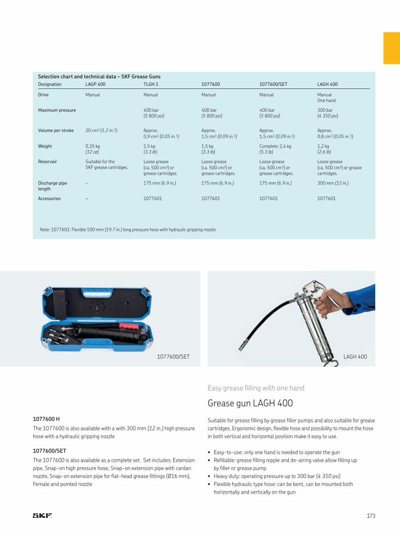
Selection chart and technical data – SKF Grease Guns
1077600 H
The 1077600 is also available with a with 300 mm (12 in.) high pressure
hose with a hydraulic gripping nozzle
1077600/SET
The 1077600 is also available as a complete set. Set includes: Extension
pipe, Snap-on high pressure hose, Snap-on extension pipe with cardan
nozzle, Snap-on extension pipe for flat-head grease fittings (Ø16 mm),
Female and pointed nozzle
Easy grease filling with one hand
Grease gun LAGH 400
Suitable for grease filling by grease filler pumps and also suitable for grease
cartridges. Ergonomic design, flexible hose and possibility to mount the hose
in both vertical and horizontal position make it easy to use.
• Easy-to-use: only one hand is needed to operate the gun
• Refillable: grease filling nipple and de-airing valve allow filling up
by filler or grease pump
• Heavy duty: operating pressure up to 300 bar (4 350 psi)
• Flexible hydraulic type hose: can be bent, can be mounted both
horizontally and vertically on the gun
Designation LAGP 400 TLGH 1 1077600 1077600/SET LAGH 400
Drive Manual Manual Manual Manual ManualOne hand
Maximum pressure 400 bar(5 800 psi)
400 bar(5 800 psi)
400 bar(5 800 psi)
300 bar(4 350 psi)
Volume per stroke 20 cm3 (1.2 in. 3) Approx.
0,9 cm3 (0.05 in. 3)
Approx.
1,5 cm3 (0.09 in. 3)
Approx.
1,5 cm3 (0.09 in. 3)
Approx.
0,8 cm3 (0.05 in. 3)
Weight 0,35 kg(12 oz)
1,5 kg(3.3 lb)
1,5 kg(3.3 lb)
Complete: 2,4 kg (5.3 lb)
1,2 kg(2.6 lb)
Reservoir Suitable for the SKF grease cartridges.
Loose grease
(ca. 500 cm3) or grease cartridges.
Loose grease
(ca. 500 cm3) or grease cartridges.
Loose grease
(ca. 500 cm3) or grease cartridges.
Loose grease
(ca. 500 cm3) or grease cartridges.
Discharge pipe length
– 175 mm (6.9 in.) 175 mm (6.9 in.) 175 mm (6.9 in.) 300 mm (12 in.)
Accessories – 1077601 1077601 1077601 1077601
Note: 1077601: Flexible 500 mm (19.7 in.) long pressure hose with hydraulic gripping nozzle.
1077600/SET LAGH 400

Technology and reliability in a durable design
SKF Battery Driven Grease Gun TLGB 20
Developed to maximize efficiency, the SKF Battery Driven Grease Gun TLGB 20 includes an integrated
grease meter to help prevent over- and under-lubrication. This unique tool features a durable,
ergonomic design with a three-point stand for operator comfort and convenience and
a 20-volt, lithium-ion battery for longer life. Suitable for a variety of manual lubrication tasks,
the TLGB 20 can be used to lubricate bearings and machines in industrial and manufacturing
environments, as well as agricultural and construction vehicles.
Three-point stand
Keeps grease gun upright
for easy handling
Integrated grease meter
Tracks how much grease has been dispensed
Two-speed flow rate
Enables adjustment from low-volume to high-volume flow to suit the application
Battery charge display
Indicates lithium battery charge level
The tool’s display indicates battery charge level, amount of grease dispensed, pump/motor
speed and blocked lubrication points. This versatile grease gun provides two flow rates – low
and high – and can dispense up to 15 grease cartridges per battery charge. The TLGB 20 can
deliver pressures up to 700 bar (10 000 psi) and features a built-in light to illuminate the
work area.
Integrated grease meter delivers precise lubrication
The TLGB 20’s grease meter allows the technician to see exactly how much lubricant has
been dispensed in order to avoid over- and under-lubrication. Under-lubrication can lead to
premature bearing failure or contaminants entering the bearing. Over-lubrication wastes
grease and can cause serious complications as well. In applications involving fast-moving
equipment, such as electric motors, too much lubricant can cause high temperatures to
develop and can damage seals, allowing contamination ingress. High temperatures also
reduce lubricant life significantly, thereby increasing operational costs.
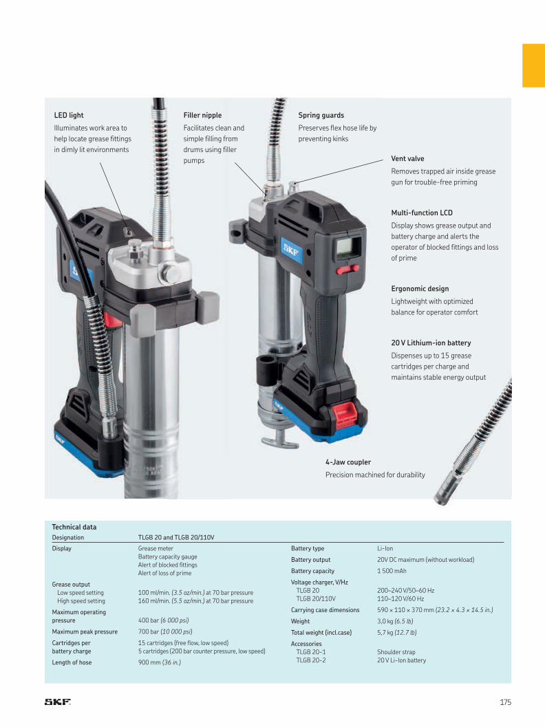
Multi-function LCD
Display shows grease output and
battery charge and alerts the
operator of blocked fittings and loss
of prime
LED light
Illuminates work area to
help locate grease fittings
in dimly lit environments
20 V Lithium-ion battery
Dispenses up to 15 grease
cartridges per charge and
maintains stable energy output
4-Jaw coupler
Precision machined for durability
Vent valve
Removes trapped air inside grease
gun for trouble-free priming
Spring guards
Preserves flex hose life by
preventing kinks
Ergonomic design
Lightweight with optimized
balance for operator comfort
Filler nipple
Facilitates clean and
simple filling from
drums using filler
pumps
Designation TLGB 20 and TLGB 20/110V
Display Grease meter
Battery capacity gauge
Alert of blocked fittings
Alert of loss of prime
Grease output
Low speed setting
High speed setting
100 ml/min. (3.5 oz/min.) at 70 bar pressure
160 ml/min. (5.5 oz/min.) at 70 bar pressure
Maximum operating
pressure 400 bar (6 000 psi)
Maximum peak pressure 700 bar (10 000 psi)
Cartridges per
battery charge
15 cartridges (free flow, low speed)
5 cartridges (200 bar counter pressure, low speed)
Length of hose 900 mm (36 in.)
Battery type Li-Ion
Battery output 20V DC maximum (without workload)
Battery capacity 1 500 mAh
Voltage charger, V/Hz
TLGB 20
TLGB 20/110V
200–240 V/50–60 Hz
110–120 V/60 Hz
Carrying case dimensions 590 × 110 × 370 mm (23.2 × 4.3 × 14.5 in.)
Weight 3,0 kg (6.5 lb)
Total weight (incl.case) 5,7 kg (12.7 lb)
Accessories
TLGB 20-1
TLGB 20-2
Shoulder strap
20 V Li-Ion battery
Technical data
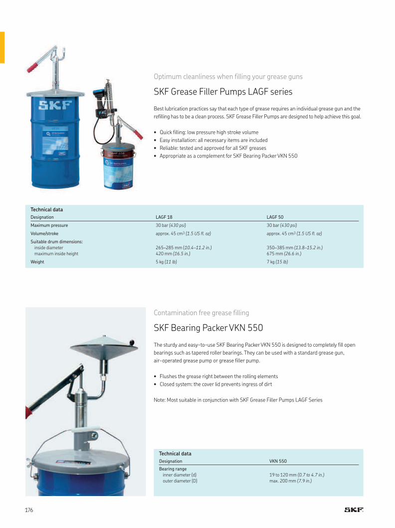
Optimum cleanliness when filling your grease guns
SKF Grease Filler Pumps LAGF series
Best lubrication practices say that each type of grease requires an individual grease gun and the
refilling has to be a clean process. SKF Grease Filler Pumps are designed to help achieve this goal.
• Quick filling: low pressure high stroke volume
• Easy installation: all necessary items are included
• Reliable: tested and approved for all SKF greases
• Appropriate as a complement for SKF Bearing Packer VKN 550
Designation LAGF 18 LAGF 50
Maximum pressure 30 bar (430 psi) 30 bar (430 psi)
Volume/stroke approx. 45 cm3 (1.5 US fl. oz) approx. 45 cm3 (1.5 US fl. oz)
Suitable drum dimensions:
inside diameter
maximum inside height
265–285 mm (10.4–11.2 in.)
420 mm (16.5 in.)
350–385 mm (13.8–15.2 in.)
675 mm (26.6 in.)
Weight 5 kg (11 lb) 7 kg (15 lb)
Contamination free grease filling
SKF Bearing Packer VKN 550
The sturdy and easy-to-use SKF Bearing Packer VKN 550 is designed to completely fill open
bearings such as tapered roller bearings. They can be used with a standard grease gun,
air-operated grease pump or grease filler pump.
• Flushes the grease right between the rolling elements
• Closed system: the cover lid prevents ingress of dirt
Note: Most suitable in conjunction with SKF Grease Filler Pumps LAGF Series
Designation VKN 550
Bearing range
inner diameter (d)
outer diameter (D)
19 to 120 mm (0.7 to 4.7 in.)
max. 200 mm (7.9 in.)
Technical data
Technical data
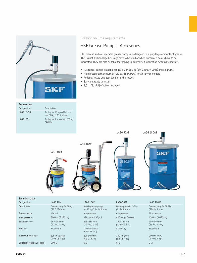
LAGG 18M
LAGG 18AE
LAGG 50AE LAGG 180AE
Designation Description
LAGT 18-50 Trolley for 18 kg (40 lb) cans
and 50 kg (110 lb) drums
LAGT 180 Trolley for drums up to 200 kg
(440 lb)
Accessories
For high volume requirements
SKF Grease Pumps LAGG series
SKF manual and air-operated grease pumps are designed to supply large amounts of grease.
This is useful when large housings have to be filled or when numerous points have to be
lubricated. They are also suitable for topping up centralised lubrication systems reservoirs.
• Full range: pumps available for 18, 50 or 180 kg (39, 110 or 400 lb) grease drums
• High pressure: maximum of 420 bar (6 090 psi) for air-driven models
• Reliable: tested and approved for SKF greases
• Easy and ready to install
• 3,5 m (11.5 ft) of tubing included
Designation LAGG 18M LAGG 18AE LAGG 50AE LAGG 180AE
Description Grease pump for 18 kg
(39.6 lb) drums
Mobile grease pump
for 18 kg (39.6 lb) drums
Grease pump for 50 kg
(110 lb) drums
Grease pump for 180 kg
(396 lb) drums
Power source Manual Air–pressure Air–pressure Air–pressure
Max. pressure 500 bar (7 250 psi) 420 bar (6 090 psi) 420 bar (6 090 psi) 420 bar (6 090 psi)
Suitable drum 265–285 mm
(10.4–11.2 in.)
265–285 mm
(10.4–11.2 in.)
350–385 mm
(13.8–15.2 in.)
550–590 mm
(21.7–23.2 in.)
Mobility Stationary Trolley included
(LAGT 18-50)
Stationary Stationary
Maximum flow rate 1,6 cm3/stroke
(0.05 US fl. oz)
200 cm3/min.
(6.8 US fl. oz)
200 cm3/min.
(6.8 US fl. oz)
200 cm3/min.
(6.8 US fl. oz)
Suitable grease NLGI class 000–2 0–2 0–2 0–2
Technical data
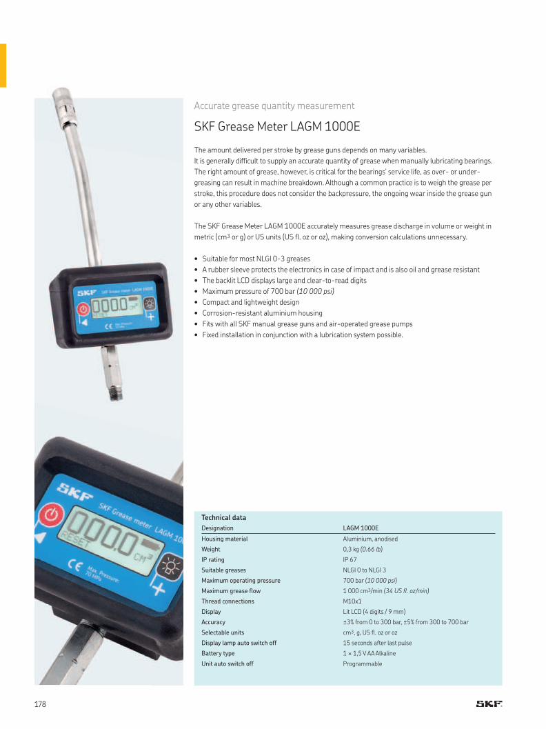
Accurate grease quantity measurement
SKF Grease Meter LAGM 1000E
The amount delivered per stroke by grease guns depends on many variables.
It is generally difficult to supply an accurate quantity of grease when manually lubricating bearings.
The right amount of grease, however, is critical for the bearings’ service life, as over- or under-
greasing can result in machine breakdown. Although a common practice is to weigh the grease per
stroke, this procedure does not consider the backpressure, the ongoing wear inside the grease gun
or any other variables.
The SKF Grease Meter LAGM 1000E accurately measures grease discharge in volume or weight in
metric (cm3 or g) or US units (US fl. oz or oz), making conversion calculations unnecessary.
• Suitable for most NLGI 0-3 greases
• A rubber sleeve protects the electronics in case of impact and is also oil and grease resistant
• The backlit LCD displays large and clear-to-read digits
• Maximum pressure of 700 bar (10 000 psi)
• Compact and lightweight design
• Corrosion-resistant aluminium housing
• Fits with all SKF manual grease guns and air-operated grease pumps
• Fixed installation in conjunction with a lubrication system possible.
Designation LAGM 1000E
Housing material Aluminium, anodised
Weight 0,3 kg (0.66 lb)
IP rating IP 67
Suitable greases NLGI 0 to NLGI 3
Maximum operating pressure 700 bar (10 000 psi)
Maximum grease flow 1 000 cm3/min (34 US fl. oz/min)
Thread connections M10x1
Display Lit LCD (4 digits / 9 mm)
Accuracy ±3% from 0 to 300 bar, ±5% from 300 to 700 bar
Selectable units cm3, g, US fl. oz or oz
Display lamp auto switch off 15 seconds after last pulse
Battery type 1 × 1,5 V AA Alkaline
Unit auto switch off Programmable
Technical data
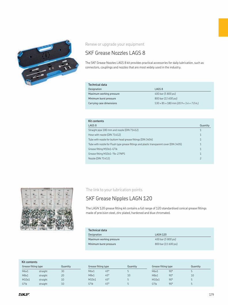
Renew or upgrade your equipment
SKF Grease Nozzles LAGS 8
The SKF Grease Nozzles LAGS 8 kit provides practical accessories for daily lubrication, such as
connectors, couplings and nozzles that are most widely used in the industry.
The link to your lubrication points
SKF Grease Nipples LAGN 120
The LAGN 120 grease fitting kit contains a full range of 120 standardised conical grease fittings
made of precision steel, zinc plated, hardened and blue chromated.
Kit contents
Kit contents
Designation LAGS 8
Maximum working pressure 400 bar (5 800 psi)
Minimum burst pressure 800 bar (11 600 psi)
Carrying case dimensions 530 × 85 × 180 mm (20.9 × 3.4 × 7.0 in.)
LAGS 8 Quantity
Straight pipe 180 mm and nozzle (DIN 71412) 1
Hose with nozzle (DIN 71412) 1
Tube with nozzle for buttom head grease fittings (DIN 3404) 1
Tube with nozzle for Flush type grease fittings and plastic transparent cover (DIN 3405) 1
Grease fitting M10x1–G 1/8 1
Grease fitting M10x1– 1/8 –27NPS 1
Nozzle (DIN 71412) 2
Grease fitting type Quantity
M6x1 straight 30
M8x1 straight 20
M10x1 straight 10
G 1/8 straight 10
Designation LAGN 120
Maximum working pressure 400 bar (5 800 psi)
Minimum burst pressure 800 bar (11 600 psi)
Grease fitting type Quantity
M6x1 45° 5
M8x1 45° 10
M10x1 45° 5
G 1/8 45° 5
Technical data
Technical data
Grease fitting type Quantity
M6x1 90° 5
M8x1 90° 10
M10x1 90° 5
G 1/8 90° 5
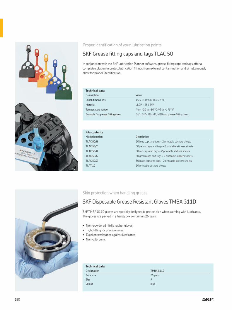
Proper identification of your lubrication points
SKF Grease fitting caps and tags TLAC 50
In conjunction with the SKF Lubrication Planner software, grease fitting caps and tags offer a
complete solution to protect lubrication fittings from external contamination and simultaneously
allow for proper identification.
Kits contents
Description Value
Label dimensions 45 × 21 mm (1.8 × 0.8 in.)
Material LLDP + 25% EVA
Temperature range from –20 to +80 °C (–5 to +175 °F)
Suitable for grease fitting sizes G 1/4, G 1/8, M6, M8, M10 and grease fitting head
Kit designation Description
TLAC 50/B 50 blue caps and tags + 2 printable stickers sheets
TLAC 50/Y 50 yellow caps and tags + 2 printable stickers sheets
TLAC 50/R 50 red caps and tags + 2 printable stickers sheets
TLAC 50/G 50 green caps and tags + 2 printable stickers sheets
TLAC 50/Z 50 black caps and tags + 2 printable stickers sheets
TLAT 10 10 printable stickers sheets
Skin protection when handling grease
SKF Disposable Grease Resistant Gloves TMBA G11D
SKF TMBA G11D gloves are specially designed to protect skin when working with lubricants.
The gloves are packed in a handy box containing 25 pairs.
• Non-powdered nitrile rubber gloves
• Tight fitting for precision wear
• Excellent resistance against lubricants
• Non-allergenic
Designation TMBA G11D
Pack size 25 pairs
Size 9
Colour blue
Technical data
Technical data
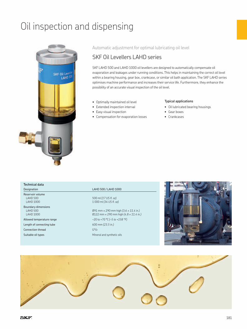
Oil inspection and dispensing
• Optimally maintained oil level
• Extended inspection interval
• Easy visual inspection
• Compensation for evaporation losses
Automatic adjustment for optimal lubricating oil level
SKF Oil Levellers LAHD series
SKF LAHD 500 and LAHD 1000 oil levellers are designed to automatically compensate oil
evaporation and leakages under running conditions. This helps in maintaining the correct oil level
within a bearing housing, gear box, crankcase, or similar oil bath application. The SKF LAHD series
optimises machine performance and increases their service life. Furthermore, they enhance the
possibility of an accurate visual inspection of the oil level.
Typical applications
• Oil lubricated bearing housings
• Gear boxes
• Crankcases
Designation LAHD 500 / LAHD 1000
Reservoir volume
LAHD 500
LAHD 1000
500 ml (17 US fl. oz)
1 000 ml (34 US fl. oz)
Boundary dimensions
LAHD 500
LAHD 1000
Ø91 mm × 290 mm high (3.6 × 11.4 in.)
Ø122 mm × 290 mm high (4.8 × 11.4 in.)
Allowed temperature range –20 to +70 °C (–5 to +158 °F)
Length of connecting tube 600 mm (23.5 in.)
Connection thread G 1/2
Suitable oil types Mineral and synthetic oils
Technical data
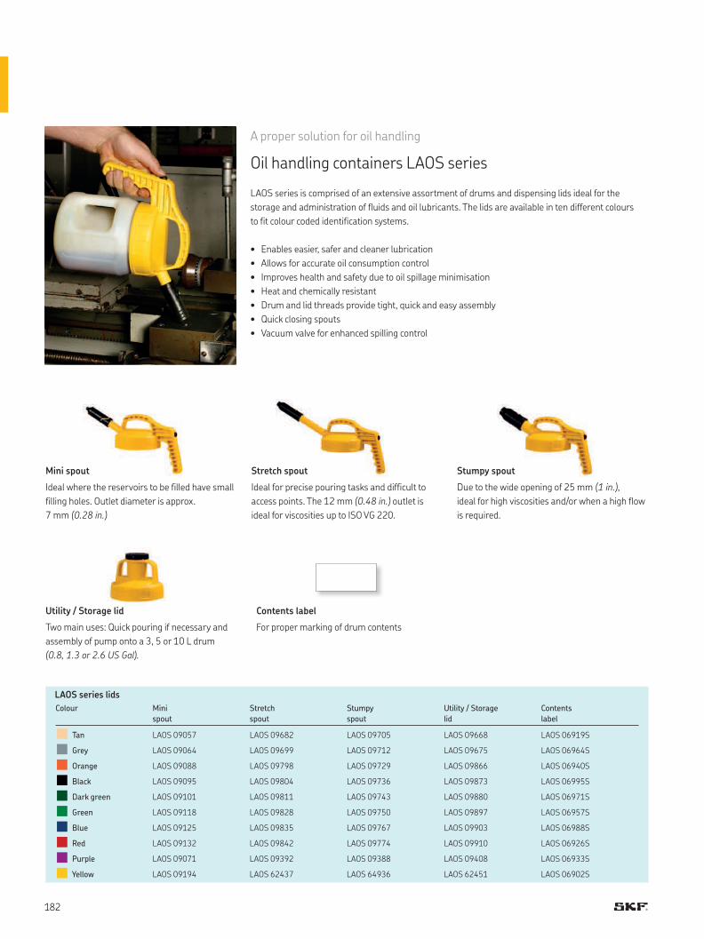
A proper solution for oil handling
Oil handling containers LAOS series
LAOS series is comprised of an extensive assortment of drums and dispensing lids ideal for the
storage and administration of fluids and oil lubricants. The lids are available in ten different colours
to fit colour coded identification systems.
• Enables easier, safer and cleaner lubrication
• Allows for accurate oil consumption control
• Improves health and safety due to oil spillage minimisation
• Heat and chemically resistant
• Drum and lid threads provide tight, quick and easy assembly
• Quick closing spouts
• Vacuum valve for enhanced spilling control
LAOS series lids
Ideal where the reservoirs to be filled have small
filling holes. Outlet diameter is approx.
7 mm (0.28 in.)
Two main uses: Quick pouring if necessary and
assembly of pump onto a 3, 5 or 10 L drum
(0.8, 1.3 or 2.6 US Gal).
Ideal for precise pouring tasks and difficult to
access points. The 12 mm (0.48 in.) outlet is
ideal for viscosities up to ISO VG 220.
Due to the wide opening of 25 mm (1 in.),
ideal for high viscosities and/or when a high flow
is required.
For proper marking of drum contents
Mini spout Stretch spout Stumpy spout
Contents labelUtility / Storage lid
Colour Mini
spout
Stretch
spout
Stumpy
spout
Utility / Storage
lid
Contents
label
Tan LAOS 09057 LAOS 09682 LAOS 09705 LAOS 09668 LAOS 06919S
Grey LAOS 09064 LAOS 09699 LAOS 09712 LAOS 09675 LAOS 06964S
Orange LAOS 09088 LAOS 09798 LAOS 09729 LAOS 09866 LAOS 06940S
Black LAOS 09095 LAOS 09804 LAOS 09736 LAOS 09873 LAOS 06995S
Dark green LAOS 09101 LAOS 09811 LAOS 09743 LAOS 09880 LAOS 06971S
Green LAOS 09118 LAOS 09828 LAOS 09750 LAOS 09897 LAOS 06957S
Blue LAOS 09125 LAOS 09835 LAOS 09767 LAOS 09903 LAOS 06988S
Red LAOS 09132 LAOS 09842 LAOS 09774 LAOS 09910 LAOS 06926S
Purple LAOS 09071 LAOS 09392 LAOS 09388 LAOS 09408 LAOS 06933S
Yellow LAOS 09194 LAOS 62437 LAOS 64936 LAOS 62451 LAOS 06902S
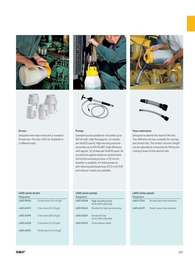
LAOS series drums LAOS series pumps LAOS series spouts
Designation Designation Designation
LAOS 09224 1,5 litre drum (0.4 US gal) LAOS 62568 High viscosity pump (to fit LAOS utility lids)
LAOS 67265 Stumpy spout hose extension
LAOS 63571 2 litre drum (0.5 US gal) LAOS 09423 Breather for high viscosity pump LAOS 62499 Stretch spout hose extension
LAOS 63595 3 litre drum (0.8 US gal) LAOS 62567 Standard Pump
(to fit LAOS utility lids)
LAOS 63618 5 litre drum (1.3 US gal) LAOS 09422 Pump reducer nozzle
LAOS 66251 10 litre drum (2.6 US gal)
Drums
Designed with wide necks and a standard
thread size. Fits any LAOS lid. Available in
5 different sizes.
Pumps
Standard pump suitable for viscosities up to
ISO VG 460. High flow (approx. 14 strokes
per litre/US quart). High viscosity pump for
viscosities up to ISO VG 680. High efficiency
with approx. 12 strokes per litre/US quart. As
a protection against airborne contaminants
during the pumping process, a 10 micron
breather is available. For both pumps an
anti-drip long discharge hose of 1,5 m (4.9 ft)
and reducer nozzles are available.
Hose extensions
Designed to extend the reach of the lids.
Two different versions available for stumpy
and stretch lids. The stretch version‘s length
can be adjusted by removing the fitting and
cutting it down to the desired size.

Storage tools
Keep your oil clean from the beginning
Oil conditioning station
The reliability of oil lubricated machinery depends very much on the cleanliness of the oil.
Given its liquid nature, oil easily gets contaminated from the moment it is delivered up to
application in the machine.
An oil conditioning station helps to clean the oil while it is being loaded into the tanks, during
delivery, and maybe most importantly while it remains in the tank. A continuous filtration process
helps to ensure that the desired cleanliness level is achieved. Finally, an additional step in order to
improve machine reliability, is to verify the topping up process at the machine level and its sealing
conditions, in order to prevent the ingress of new contaminants. After this point, it’s all about oil
condition monitoring. Devices like the oil conditioning station can help to maintain the desired
cleanliness level of a given machine.
Impact of cleanliness in bearing life
SKF Bearing Calculator is an online tool available from www.skf.com/kc
that can be used (among others) to calculate the expected bearing life.
Let’s consider an SKF 22222 E under the following conditions:
• Radial load: 100 kN
• Axial load: 10 kN
• Rotational speed of the inner ring: 500 r/min
• Operating temperature: 70 °C
• Lubricant: ISO VG 100 mineral oil with VI 95
The expected life values for two different contamination levels are:
• ISO 4406 -/21/18: 1 060 hours
• ISO 4406 -/19/16: 1 950 hours
This means that by cleaning the oil, the bearing life is increased over 80%.
ISO contamination classification and filter rating
The standard method for classifying the contamination level in an oil
is described in ISO 4406. In this classification system, the result of the
solid particle count is converted into a code using a scale number.
A given oil with a code 22/18/13 for example, contains per millilitre of oil:
• 20 000 to 40 000 particles ≥4 μm
• 1 300 to 2 500 particles ≥6 μm
• 40 to 80 particles ≥14 μm
Sometimes, only the two larger particle size ranges are used.
Effect of oil cleanlines in bearing life
1 06O hours
1 95O hours
O 500 1 000 1 500 2 00O
Cleanliness level
ISO -/21/18
Cleanliness level
ISO -/19/16
Life (hours)
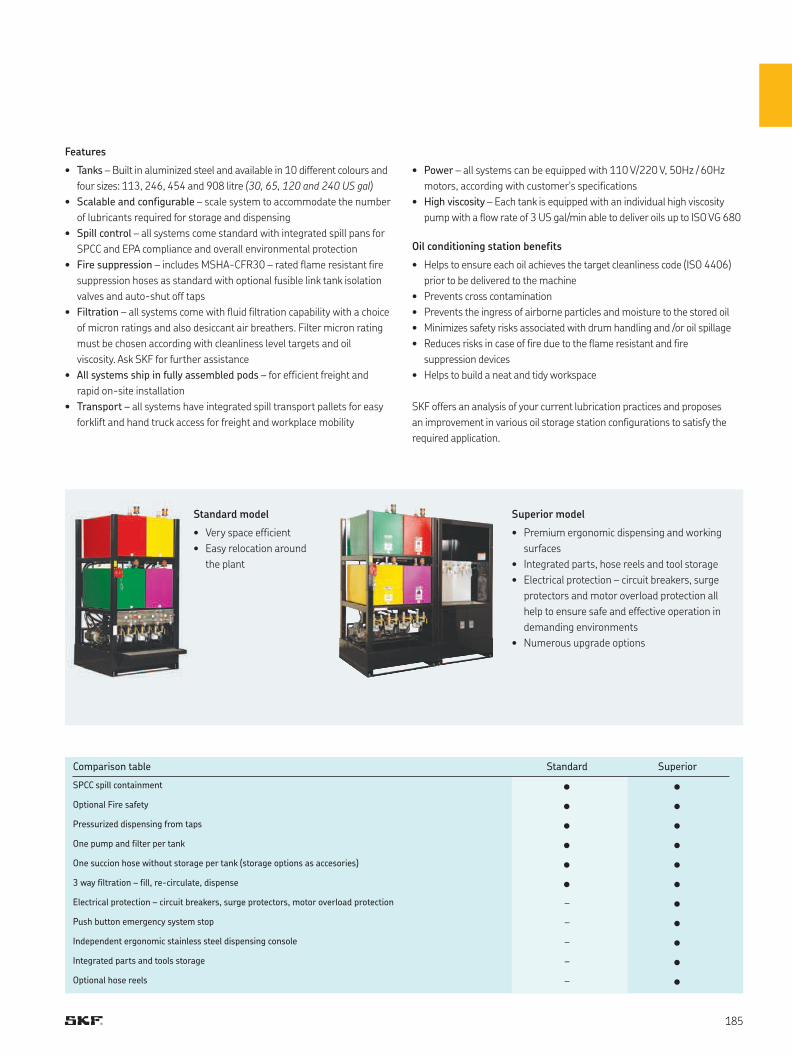
Features
• Tanks – Built in aluminized steel and available in 10 different colours and
four sizes: 113, 246, 454 and 908 litre (30, 65, 120 and 240 US gal)
• Scalable and configurable – scale system to accommodate the number
of lubricants required for storage and dispensing
• Spill control – all systems come standard with integrated spill pans for
SPCC and EPA compliance and overall environmental protection
• Fire suppression – includes MSHA-CFR30 – rated flame resistant fire
suppression hoses as standard with optional fusible link tank isolation
valves and auto-shut off taps
• Filtration – all systems come with fluid filtration capability with a choice
of micron ratings and also desiccant air breathers. Filter micron rating
must be chosen according with cleanliness level targets and oil
viscosity. Ask SKF for further assistance
• All systems ship in fully assembled pods – for efficient freight and
rapid on-site installation
• Transport – all systems have integrated spill transport pallets for easy
forklift and hand truck access for freight and workplace mobility
Standard model
• Very space efficient
• Easy relocation around
the plant
Superior model
• Premium ergonomic dispensing and working
surfaces
• Integrated parts, hose reels and tool storage
• Electrical protection – circuit breakers, surge
protectors and motor overload protection all
help to ensure safe and effective operation in
demanding environments
• Numerous upgrade options
Comparison table Standard Superior
SPCC spill containment • •Optional Fire safety • •Pressurized dispensing from taps • •One pump and filter per tank • •One succion hose without storage per tank (storage options as accesories) • •3 way filtration – fill, re-circulate, dispense • •Electrical protection – circuit breakers, surge protectors, motor overload protection - •Push button emergency system stop - •Independent ergonomic stainless steel dispensing console - •Integrated parts and tools storage - •Optional hose reels - •
• Power – all systems can be equipped with 110 V/220 V, 50Hz / 60Hz
motors, according with customer's specifications
• High viscosity – Each tank is equipped with an individual high viscosity
pump with a flow rate of 3 US gal/min able to deliver oils up to ISO VG 680
Oil conditioning station benefits
• Helps to ensure each oil achieves the target cleanliness code (ISO 4406)
prior to be delivered to the machine
• Prevents cross contamination
• Prevents the ingress of airborne particles and moisture to the stored oil
• Minimizes safety risks associated with drum handling and /or oil spillage
• Reduces risks in case of fire due to the flame resistant and fire
suppression devices
• Helps to build a neat and tidy workspace
SKF offers an analysis of your current lubrication practices and proposes
an improvement in various oil storage station configurations to satisfy the
required application.
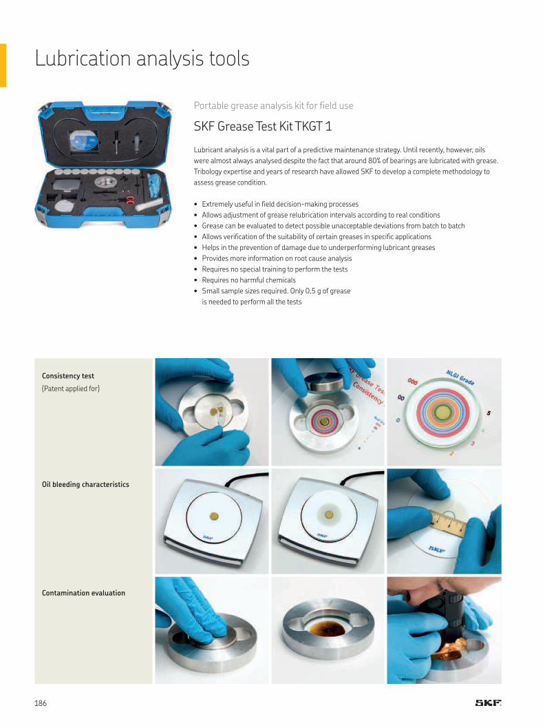
Lubrication analysis tools
Portable grease analysis kit for field use
SKF Grease Test Kit TKGT 1
Lubricant analysis is a vital part of a predictive maintenance strategy. Until recently, however, oils
were almost always analysed despite the fact that around 80% of bearings are lubricated with grease.
Tribology expertise and years of research have allowed SKF to develop a complete methodology to
assess grease condition.
• Extremely useful in field decision-making processes
• Allows adjustment of grease relubrication intervals according to real conditions
• Grease can be evaluated to detect possible unacceptable deviations from batch to batch
• Allows verification of the suitability of certain greases in specific applications
• Helps in the prevention of damage due to underperforming lubricant greases
• Provides more information on root cause analysis
• Requires no special training to perform the tests
• Requires no harmful chemicals
• Small sample sizes required. Only 0,5 g of grease
is needed to perform all the tests
Consistency test
(Patent applied for)
Oil bleeding characteristics
Contamination evaluation
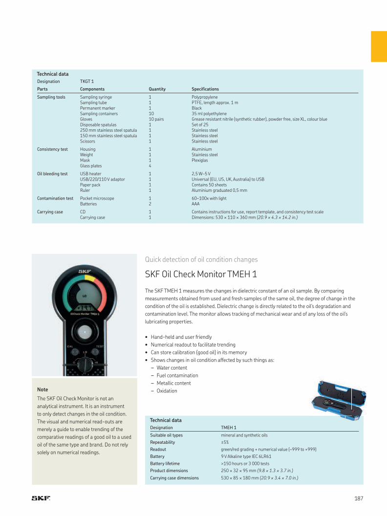
Designation TKGT 1
Parts Components Quantity Specifications
Sampling tools Sampling syringe Sampling tube Permanent marker Sampling containersGloves Disposable spatulas 250 mm stainless steel spatula 150 mm stainless steel spatula Scissors
1111010 pairs1111
PolypropylenePTFE, length approx. 1 mBlack35 ml polyethyleneGrease resistant nitrile (synthetic rubber), powder free, size XL, colour blueSet of 25Stainless steelStainless steelStainless steel
Consistency test Housing Weight MaskGlass plates
1114
AluminiumStainless steelPlexiglas
Oil bleeding test USB heater USB/220/110 V adaptor Paper pack Ruler
1111
2,5 W–5 VUniversal (EU, US, UK, Australia) to USBContains 50 sheetsAluminium graduated 0,5 mm
Contamination test Pocket microscope Batteries
12
60–100x with lightAAA
Carrying case CD Carrying case
11
Contains instructions for use, report template, and consistency test scale Dimensions: 530 × 110 × 360 mm (20.9 × 4.3 × 14.2 in.)
Quick detection of oil condition changes
SKF Oil Check Monitor TMEH 1
The SKF TMEH 1 measures the changes in dielectric constant of an oil sample. By comparing
measurements obtained from used and fresh samples of the same oil, the degree of change in the
condition of the oil is established. Dielectric change is directly related to the oil’s degradation and
contamination level. The monitor allows tracking of mechanical wear and of any loss of the oil’s
lubricating properties.
• Hand-held and user friendly
• Numerical readout to facilitate trending
• Can store calibration (good oil) in its memory
• Shows changes in oil condition affected by such things as:
– Water content
– Fuel contamination
– Metallic content
– Oxidation
Designation TMEH 1
Suitable oil types mineral and synthetic oils
Repeatability ±5%
Readout green/red grading + numerical value (–999 to +999)
Battery 9 V Alkaline type IEC 6LR61
Battery lifetime >150 hours or 3 000 tests
Product dimensions 250 × 32 × 95 mm (9.8 × 1.3 × 3.7 in.)
Carrying case dimensions 530 × 85 × 180 mm (20.9 × 3.4 × 7.0 in.)
Note
The SKF Oil Check Monitor is not an
analytical instrument. It is an instrument
to only detect changes in the oil condition.
The visual and numerical read-outs are
merely a guide to enable trending of the
comparative readings of a good oil to a used
oil of the same type and brand. Do not rely
solely on numerical readings.
Technical data
Technical data
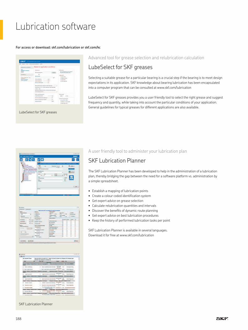
Lubrication software
For access or download: skf.com/lubrication or skf.com/kc
Advanced tool for grease selection and relubrication calculation
LubeSelect for SKF greases
Selecting a suitable grease for a particular bearing is a crucial step if the bearing is to meet design
expectations in its application. SKF knowledge about bearing lubrication has been encapsulated
into a computer program that can be consulted at www.skf.com/lubrication
LubeSelect for SKF greases provides you a user friendly tool to select the right grease and suggest
frequency and quantity, while taking into account the particular conditions of your application.
General guidelines for typical greases for different applications are also available.
A user friendly tool to administer your lubrication plan
SKF Lubrication Planner
The SKF Lubrication Planner has been developed to help in the administration of a lubrication
plan, thereby bridging the gap between the need for a software platform vs. administration by
a simple spreadsheet.
• Establish a mapping of lubrication points
• Create a colour coded identification system
• Get expert advice on grease selection
• Calculate relubrication quantities and intervals
• Discover the benefits of dynamic route planning
• Get expert advice on best lubrication procedures
• Keep the history of performed lubrication tasks per point
SKF Lubrication Planner is available in several languages.
Download it for free at www.skf.com/lubrication
LubeSelect for SKF greases
SKF Lubrication Planner
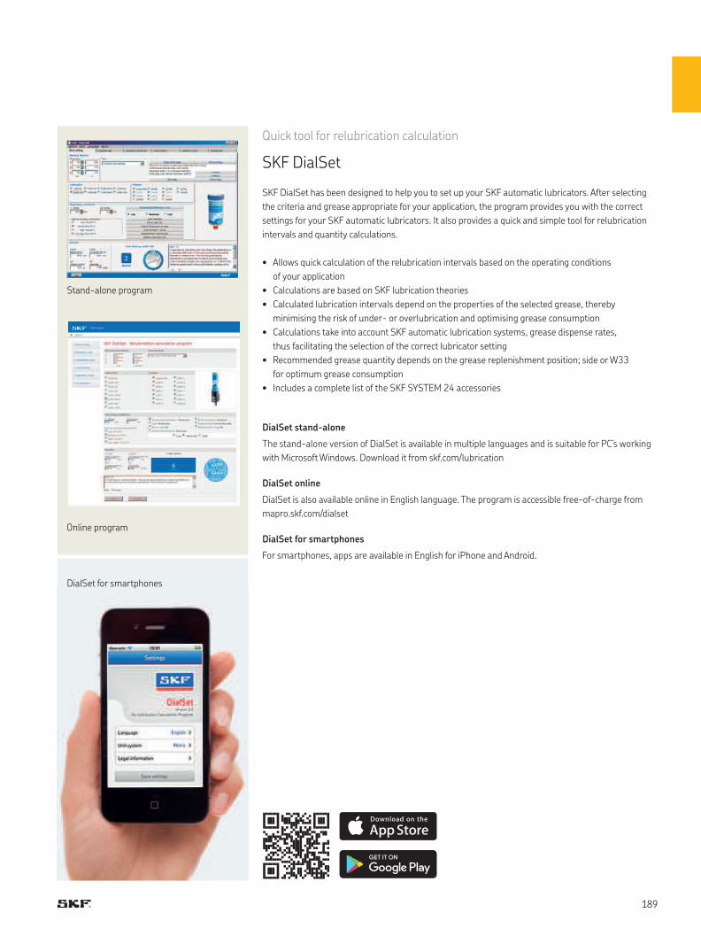
Quick tool for relubrication calculation
SKF DialSet
SKF DialSet has been designed to help you to set up your SKF automatic lubricators. After selecting
the criteria and grease appropriate for your application, the program provides you with the correct
settings for your SKF automatic lubricators. It also provides a quick and simple tool for relubrication
intervals and quantity calculations.
• Allows quick calculation of the relubrication intervals based on the operating conditions
of your application
• Calculations are based on SKF lubrication theories
• Calculated lubrication intervals depend on the properties of the selected grease, thereby
minimising the risk of under- or overlubrication and optimising grease consumption
• Calculations take into account SKF automatic lubrication systems, grease dispense rates,
thus facilitating the selection of the correct lubricator setting
• Recommended grease quantity depends on the grease replenishment position; side or W33
for optimum grease consumption
• Includes a complete list of the SKF SYSTEM 24 accessories
DialSet stand-alone
The stand-alone version of DialSet is available in multiple languages and is suitable for PC’s working
with Microsoft Windows. Download it from skf.com/lubrication
DialSet online
DialSet is also available online in English language. The program is accessible free-of-charge from
mapro.skf.com/dialset
DialSet for smartphones
For smartphones, apps are available in English for iPhone and Android.
Stand-alone program
Online program
DialSet for smartphones
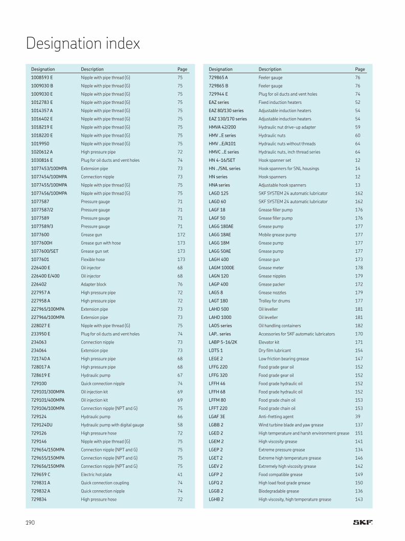
Designation index
Designation Description Page
1008593 E Nipple with pipe thread (G) 75
1009030 B Nipple with pipe thread (G) 75
1009030 E Nipple with pipe thread (G) 75
1012783 E Nipple with pipe thread (G) 75
1014357 A Nipple with pipe thread (G) 75
1016402 E Nipple with pipe thread (G) 75
1018219 E Nipple with pipe thread (G) 75
1018220 E Nipple with pipe thread (G) 75
1019950 Nipple with pipe thread (G) 75
1020612 A High pressure pipe 72
1030816 E Plug for oil ducts and vent holes 74
1077453/100MPA Extension pipe 73
1077454/100MPA Connection nipple 73
1077455/100MPA Nipple with pipe thread (G) 75
1077456/100MPA Nipple with pipe thread (G) 75
1077587 Pressure gauge 71
1077587/2 Pressure gauge 71
1077589 Pressure gauge 71
1077589/3 Pressure gauge 71
1077600 Grease gun 172
1077600H Grease gun with hose 173
1077600/SET Grease gun set 173
1077601 Flexible hose 173
226400 E Oil injector 68
226400 E/400 Oil injector 68
226402 Adapter block 76
227957 A High pressure pipe 72
227958 A High pressure pipe 72
227965/100MPA Extension pipe 73
227966/100MPA Extension pipe 73
228027 E Nipple with pipe thread (G) 75
233950 E Plug for oil ducts and vent holes 74
234063 Connection nipple 73
234064 Extension pipe 73
721740 A High pressure pipe 68
728017 A High pressure pipe 68
728619 E Hydraulic pump 67
729100 Quick connection nipple 74
729101/300MPA Oil injection kit 69
729101/400MPA Oil injection kit 69
729106/100MPA Connection nipple (NPT and G) 75
729124 Hydraulic pump 66
729124DU Hydraulic pump with digital gauge 58
729126 High pressure hose 72
729146 Nipple with pipe thread (G) 75
729654/150MPA Connection nipple (NPT and G) 75
729655/150MPA Connection nipple (NPT and G) 75
729656/150MPA Connection nipple (NPT and G) 75
729659 C Electric hot plate 41
729831 A Quick connection coupling 74
729832 A Quick connection nipple 74
729834 High pressure hose 72
Designation Description Page
729865 A Feeler gauge 76
729865 B Feeler gauge 76
729944 E Plug for oil ducts and vent holes 74
EAZ series Fixed induction heaters 52
EAZ 80/130 series Adjustable induction heaters 54
EAZ 130/170 series Adjustable induction heaters 54
HMVA 42/200 Hydraulic nut drive-up adapter 59
HMV ..E series Hydraulic nuts 60
HMV ..E/A101 Hydraulic nuts without threads 64
HMVC ..E series Hydraulic nuts, inch thread series 64
HN 4-16/SET Hook spanner set 12
HN ../SNL series Hook spanners for SNL housings 14
HN series Hook spanners 12
HNA series Adjustable hook spanners 13
LAGD 125 SKF SYSTEM 24 automatic lubricator 162
LAGD 60 SKF SYSTEM 24 automatic lubricator 162
LAGF 18 Grease filler pump 176
LAGF 50 Grease filler pump 176
LAGG 180AE Grease pump 177
LAGG 18AE Mobile grease pump 177
LAGG 18M Grease pump 177
LAGG 50AE Grease pump 177
LAGH 400 Grease gun 173
LAGM 1000E Grease meter 178
LAGN 120 Grease nipples 179
LAGP 400 Grease packer 172
LAGS 8 Grease nozzles 179
LAGT 180 Trolley for drums 177
LAHD 500 Oil leveller 181
LAHD 1000 Oil leveller 181
LAOS series Oil handling containers 182
LAP.. series Accessories for SKF automatic lubricators 170
LABP 5-16/2K Elevator kit 171
LDTS 1 Dry film lubricant 154
LEGE 2 Low friction bearing grease 147
LFFG 220 Food grade gear oil 152
LFFG 320 Food grade gear oil 152
LFFH 46 Food grade hydraulic oil 152
LFFH 68 Food grade hydraulic oil 152
LFFM 80 Food grade chain oil 153
LFFT 220 Food grade chain oil 153
LGAF 3E Anti-fretting agent 39
LGBB 2 Wind turbine blade and yaw grease 137
LGED 2 High temperature and harsh environment grease 151
LGEM 2 High viscosity grease 141
LGEP 2 Extreme pressure grease 134
LGET 2 Extreme high temperature grease 146
LGEV 2 Extremely high viscosity grease 142
LGFP 2 Food compatible grease 149
LGFQ 2 High load food grade grease 150
LGGB 2 Biodegradable grease 136
LGHB 2 High viscosity, high temperature grease 143
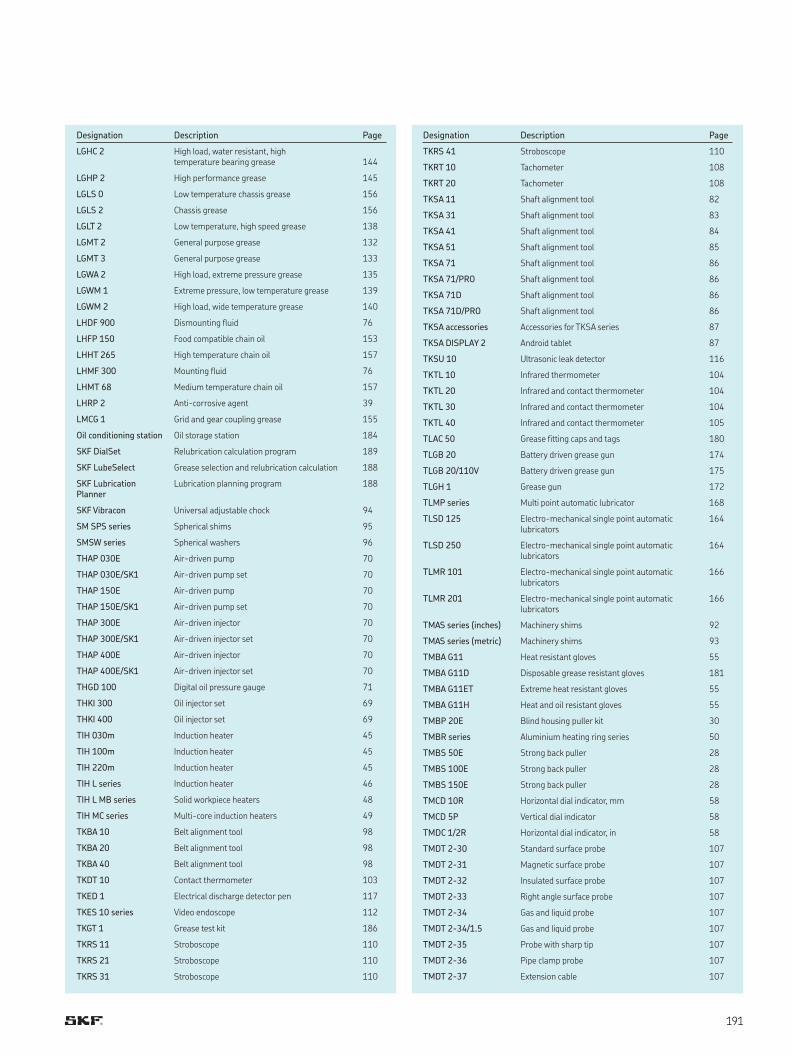
Designation Description Page
LGHC 2 High load, water resistant, high temperature bearing grease
144
LGHP 2 High performance grease 145
LGLS 0 Low temperature chassis grease 156
LGLS 2 Chassis grease 156
LGLT 2 Low temperature, high speed grease 138
LGMT 2 General purpose grease 132
LGMT 3 General purpose grease 133
LGWA 2 High load, extreme pressure grease 135
LGWM 1 Extreme pressure, low temperature grease 139
LGWM 2 High load, wide temperature grease 140
LHDF 900 Dismounting fluid 76
LHFP 150 Food compatible chain oil 153
LHHT 265 High temperature chain oil 157
LHMF 300 Mounting fluid 76
LHMT 68 Medium temperature chain oil 157
LHRP 2 Anti-corrosive agent 39
LMCG 1 Grid and gear coupling grease 155
Oil conditioning station Oil storage station 184
SKF DialSet Relubrication calculation program 189
SKF LubeSelect Grease selection and relubrication calculation 188
SKF Lubrication Planner
Lubrication planning program 188
SKF Vibracon Universal adjustable chock 94
SM SPS series Spherical shims 95
SMSW series Spherical washers 96
THAP 030E Air-driven pump 70
THAP 030E/SK1 Air-driven pump set 70
THAP 150E Air-driven pump 70
THAP 150E/SK1 Air-driven pump set 70
THAP 300E Air-driven injector 70
THAP 300E/SK1 Air-driven injector set 70
THAP 400E Air-driven injector 70
THAP 400E/SK1 Air-driven injector set 70
THGD 100 Digital oil pressure gauge 71
THKI 300 Oil injector set 69
THKI 400 Oil injector set 69
TIH 030m Induction heater 45
TIH 100m Induction heater 45
TIH 220m Induction heater 45
TIH L series Induction heater 46
TIH L MB series Solid workpiece heaters 48
TIH MC series Multi-core induction heaters 49
TKBA 10 Belt alignment tool 98
TKBA 20 Belt alignment tool 98
TKBA 40 Belt alignment tool 98
TKDT 10 Contact thermometer 103
TKED 1 Electrical discharge detector pen 117
TKES 10 series Video endoscope 112
TKGT 1 Grease test kit 186
TKRS 11 Stroboscope 110
TKRS 21 Stroboscope 110
TKRS 31 Stroboscope 110
Designation Description Page
TKRS 41 Stroboscope 110
TKRT 10 Tachometer 108
TKRT 20 Tachometer 108
TKSA 11 Shaft alignment tool 82
TKSA 31 Shaft alignment tool 83
TKSA 41 Shaft alignment tool 84
TKSA 51 Shaft alignment tool 85
TKSA 71 Shaft alignment tool 86
TKSA 71/PRO Shaft alignment tool 86
TKSA 71D Shaft alignment tool 86
TKSA 71D/PRO Shaft alignment tool 86
TKSA accessories Accessories for TKSA series 87
TKSA DISPLAY 2 Android tablet 87
TKSU 10 Ultrasonic leak detector 116
TKTL 10 Infrared thermometer 104
TKTL 20 Infrared and contact thermometer 104
TKTL 30 Infrared and contact thermometer 104
TKTL 40 Infrared and contact thermometer 105
TLAC 50 Grease fitting caps and tags 180
TLGB 20 Battery driven grease gun 174
TLGB 20/110V Battery driven grease gun 175
TLGH 1 Grease gun 172
TLMP series Multi point automatic lubricator 168
TLSD 125 Electro-mechanical single point automatic lubricators
164
TLSD 250 Electro-mechanical single point automatic lubricators
164
TLMR 101 Electro-mechanical single point automatic lubricators
166
TLMR 201 Electro-mechanical single point automatic lubricators
166
TMAS series (inches) Machinery shims 92
TMAS series (metric) Machinery shims 93
TMBA G11 Heat resistant gloves 55
TMBA G11D Disposable grease resistant gloves 181
TMBA G11ET Extreme heat resistant gloves 55
TMBA G11H Heat and oil resistant gloves 55
TMBP 20E Blind housing puller kit 30
TMBR series Aluminium heating ring series 50
TMBS 50E Strong back puller 28
TMBS 100E Strong back puller 28
TMBS 150E Strong back puller 28
TMCD 10R Horizontal dial indicator, mm 58
TMCD 5P Vertical dial indicator 58
TMDC 1/2R Horizontal dial indicator, in 58
TMDT 2-30 Standard surface probe 107
TMDT 2-31 Magnetic surface probe 107
TMDT 2-32 Insulated surface probe 107
TMDT 2-33 Right angle surface probe 107
TMDT 2-34 Gas and liquid probe 107
TMDT 2-34/1.5 Gas and liquid probe 107
TMDT 2-35 Probe with sharp tip 107
TMDT 2-36 Pipe clamp probe 107
TMDT 2-37 Extension cable 107
Designation Description Page
TMMA 100H SKF EasyPull - Hydraulic jaw puller 22
TMMA 100H/SET SKF EasyPull - Hydraulic jaw puller set 23
TMMD 100 Deep groove ball bearing puller kit 31
TMMK 10-35 Combi kit 18
TMMK 20-50 Combi kit 18
TMMP 6 Heavy duty jaw puller 24
TMMP 10 Heavy duty jaw puller 24
TMMP 15 Heavy duty jaw puller 24
TMMP 2x65 Standard jaw puller 24
TMMP 2x170 Standard jaw puller 24
TMMP 3x185 Standard jaw puller 24
TMMP 3x230 Standard jaw puller 24
TMMP 3x300 Standard jaw puller 24
TMMR 4F/SET Reversible jaw puller set 27
TMMR 8F/SET Reversible jaw puller set 27
TMMR 8XL/SET Reversible jaw puller set 27
TMMR 40F Reversible jaw puller 26
TMMR 60F Reversible jaw puller 26
TMMR 80F Reversible jaw puller 26
TMMR 120F Reversible jaw puller 26
TMMR 160F Reversible jaw puller 26
TMMR 200F Reversible jaw puller 26
TMMR 250F Reversible jaw puller 26
TMMR 350F Reversible jaw puller 26
TMMR 160XL Reversible jaw puller 26
TMMR 200XL Reversible jaw puller 26
TMMR 250XL Reversible jaw puller 26
TMMR 350XL Reversible jaw puller 26
TMMS 50 Tri-section pulling plate 37
TMMS 100 Tri-section pulling plate 37
TMMS 160 Tri-section pulling plate 37
TMMS 260 Tri-section pulling plate 37
TMMS 380 Tri-section pulling plate 37
TMMX 210 Puller protection blanket 38
TMMX 280 Puller protection blanket 38
TMMX 350 Puller protection blanket 38
TMSP 1 Sound pressure meter 115
TMST 3 Electronic stethoscope 114
TWIM 15 Portable induction heater 42
VKN 550 Bearing packer 176
Designation Description Page
TMDT 2-38 Wire probe 107
TMDT 2-39 High temperature wire probe 107
TMDT 2-40 Rotating probe 107
TMDT 2-41 Non-ferrous foundry probe 107
TMDT 2-42 Ambient temperature probe 107
TMDT 2-43 Heavy duty surface probe 107
TMEH 1 Oil check monitor 187
TMEM 1500 SensorMount indicator 74
TMFN series Impact spanners 16
TMFS series Axial lock nut sockets 15
TMFT 24 Bearing fitting tool kit 10
TMFT 36 Bearing fitting tool kit 10
TMHC 110E Hydraulic puller kit 28
TMHK 35 Mounting & dismounting kit for OK Couplings 77
TMHK 36 Mounting & dismounting kit for OK Couplings 77
TMHK 37 Mounting & dismounting kit for OK Couplings 77
TMHK 38 Mounting & dismounting kit for OK Couplings 77
TMHK 38S Mounting & dismounting kit for OK Couplings 77
TMHK 39 Mounting & dismounting kit for OK Couplings 77
TMHK 40 Mounting & dismounting kit for OK Couplings 77
TMHK 41 Mounting & dismounting kit for OK Couplings 77
TMHN 7 Lock nut spanner kit 17
TMHP 10E Hydraulic jaw puller kit 27
TMHP 15 series Hydraulically assisted heavy duty jaw puller 25
TMHP 30 series Hydraulically assisted heavy duty jaw puller 25
TMHP 50 series Hydraulically assisted heavy duty jaw puller 25
TMHS 75 Advanced hydraulic spindle 36
TMHS 100 Advanced hydraulic spindle 36
TMIC 7-28 Internal bearing puller kit 32
TMIP 7-28 Internal bearing puller kit 32
TMIP 30-60 Internal bearing puller kit 32
TMJL 100 Hydraulic pump 67
TMJL 100DU Hydraulic pump with digital gauge 67
TMJL 50 Hydraulic pump 66
TMJL 50DU Hydraulic pump with digital gauge 58
TMMA 60 SKF EasyPull - Mechanical jaw puller 22
TMMA 80 SKF EasyPull - Mechanical jaw puller 22
TMMA 120 SKF EasyPull - Mechanical jaw puller 22
TMMA 75H SKF EasyPull - Hydraulic jaw puller 22
TMMA 75H/SET SKF EasyPull - Hydraulic jaw puller set 23
Designation index
SKF Maintenance and Lubrication Products
Our mission is to maximize our customer bearing
performance through effective lubrication and
maintenance solutions.


skf.com | mapro.skf.com | skf.com/lubrication
® SKF, CARB, SYSTEM and VIBRACON are registered trademarks of the SKF Group. KEVLAR is a registered trademark of DuPont. Microsoft and Windows are either registered trademarks or trademarks of Microsoft Corporation in the United States and/or other countries. App Store is a service mark of Apple Inc. registered in the US and other countries. Android and Google Play are trademarks of Google Inc.
© SKF Group The contents of this publication are the copyright of the publisher and may not be reproduced (even extracts) unless prior written permission is granted. Every care has been taken to ensure the accuracy of the information contained in this publication but no liability can be accepted for any loss or damage whether direct, indirect or consequential arising out of the use of the information contained herein.
PUB MP/P EN · July
This publication supersedes publication PUB MP/P EN · July . Certain image(s) used under license from Shutterstock.com