Intelligent System for Fault Diagnosis in Automotive Applications

Abstract— The OceanRINGS is a set of components that should be installed on an ROV and inside the Control Cabin, in order to increase the level of automation, to make ROV operations easier and save expensive ship time by 20% or more. ROV LATIS is a next generation smart ROV, designed as a prototype platform to demonstrate OceanRINGS validity & operability and to prove smart technologies developed in the Mobile and Marine Robotics Research Centre, UL. Research outcomes are applicable to the growing international off-shore oil and gas sector, and also for future deployment, monitoring, and maintenance of ocean energy devices. System validation and technology demonstration was performed through a series of test trials with different support vessels off the west coast of Ireland. Selected results of the most recent field trials are presented in this paper.
I. INTRODUCTION EPLOYMENT, installation & maintenance of ocean
energy devices require use of underwater robots and support vessels, which are also used by other offshore industry, e.g. oil & gas. These vessels may be very expensive and, moreover, their costs are very volatile, depending on offshore peak demands. Thus, it is important to address the requirements for vessels to be used in ocean energy deployments and how these requirements may be configured to reduce the costs of these vessels and, simultaneously, affect technology development.
According to Richard Vandervoort, chief of ROV operations & underwater robotics, Marine Institute, Memorial University of Newfoundland and Labrador, Canada, “the only real automatic controls present on modern work-class ROVs, used in the offshore oil and gas
Manuscript received January 18, 2012. This work has been supported
by funding under the Irish Marine Institute and the Marine RTDI Measure, Productive Sector Operational Programme, National Development Plan 2000 – 2006 (PhD -05-004, INF-06-013 and IND-05-03); Science Foundation Ireland under Grant Number 06/CP/E007 (Science Foundation Ireland - Charles Parsons Energy Research Awards 2006); HEA PRTLI 3 (MSR3.2 project -Deep Ocean Habitat Mapping using and ROV; HEA PRTLI 4 Environment & Climate Change Impacts and Responses Project/ Environment Graduate Programme; and Enterprise Ireland Commercialisation Fund Technology Development 2007 projects – MPPT Ring (CFTD/07/IT/313, "Multi-Purpose Platform Technologies for Subsea Operations) and PULSE RT (CFTD/07/323, "Precision Underwater Accelerated Sonar Emulation in Real Time) with ERDF funding.
E. O. is with the Mobile & Marine Robotics Research Centre, University of Limerick, Ireland (phone: +353 61 202355; e-mail: [email protected]).
D. T. is with the Mobile & Marine Robotics Research Centre, University of Limerick, Ireland (e-mail: [email protected]).
sector, are auto heading, auto depth and auto altitude. It really depends on pilot skills to do good piloting.” Challenges faced by ROV pilots during deep water operations include low visibility, time-varying ocean currents and umbilical drag effects, among others.
The research team at the Mobile and Marine Robotics Research Centre (MMRRC), University of Limerick, has developed the OceanRINGS (previously known as MPPT Ring, [1]), a set of components that should be installed on an ROV and inside the Control Cabin, in order to increase the level of automation, to make ROV operations easier and save expensive ship time by 20% or more. Smart technologies developed under the OceanRINGS project are applicable to the growing international off-shore oil and gas sector, and also for future deployment, monitoring, and maintenance of ocean energy devices.
In the period 2006 - 2011 the MMRRC developed a flexible multi-mode of operation survey class ROV LATIS (Fig. 1), which serves as a platform to test OceanRINGS validity and viability [2]. To date, the MMRRC team deployed the ROV LATIS from the RV Celtic Explorer & Celtic Voyager (Marine Institute, Galway) and Shannon One Multi-Cat (Shannon Port Company).
Fig. 1. Smart ROV LATIS, prototype platform with built-in OceanRINGS smart technologies.
The maritime sector offers a broad variety of applications for advanced computer graphics technology. Review of these applications, based on virtual/augmented reality, is given in [3]. Use of virtual reality in underwater tele-operation and training has been proposed in [4]. Recent advances in high-level simulators of underwater vehicles are described in [5].
The cost of operation & maintenance represents a significant share of the build up of overall offshore energy
OceanRINGS: System Concept & Applications
Edin Omerdic and Daniel Toal
D

cost. Thus, the development of tools to assist in the operation and maintenance of ocean energy farms has been identified as a research priority, [6]. As highlighted in [7], the major obstacles restricting the development of wave and tidal energy devices include high deployment and maintenance costs, due to the harsh nature of locations where ocean energy devices are deployed. The smart technologies, built into the design of ROV LATIS, directly address these issues by reducing these costs in two ways: making offshore operations (including ROV operations) easier & more efficient, and saving in expensive support vessel time during deployment, ongoing servicing, inspection, maintenance and repair (IRM) on ocean energy installations.
The outline of the paper is given in the following. Section II presents the main design concept of OceanRINGS. Section III describes work undertaken in Virtual Environment, prior to field trials. Selected results from field trials are presented in Section IV. Finally, Section V summarises the concluding remarks.
II. OCEANRINGS
A. System Concept With the OceanRINGS (Fig. 2), a single set of hardware & software tools (System Core) is used for both lab development (Virtual Environment) and field trials (Real-World Environment) [8]. Since virtual and real-world components are compatible on a signal level, switching between them is easy and transparent. The Virtual Environment is used for development of new control algorithms.
Fig. 2. OceanRINGS: System concept.
B. Switching Between Environments Software switches S1, S2 & S3 inside the System Core are
used to select the source of navigation and measurement data for a support vessel, ROV and underwater structure (Fig. 3). Depending on the position of switches S1, S2 & S3, eight application modes can be distinguished, as illustrated in Fig. 4. Mode A was mostly used during the ROV LATIS development stage. Mode C was used when the physical work on the ROV was completed, but the support vessel (ship) was not yet available. An interesting example of
Mode E application is a pre-mission practice with the virtual ROV in a real-world environment [8]. Mode G was used during the real-world tests with the real ROV, real support vessel and virtual structure (ocean energy device). Finally, Mode H could be used when real ocean energy devices become available.
Fig. 3. Data source selection using software switches.
Fig. 4. Application modes.
C. Application Mode A: Pure Virtual Mode This mode was initially used during the development
stage of ROV LATIS. Later, this mode was regularly used between field trials, to upgrade and develop new control algorithms and to test system functionality & interconnection prior to field trials.
The system interconnection for Mode A is shown in Fig. 5. Simulator PC with two LabVIEW real-time applications (Virtual Ship (SHIP Simulator) and Virtual ROV (ROV Simulator)) is used to simulate dynamics of an ROV and support vessel (ship). Each simulator is fully input-output compatible with corresponding real-world component on a signal level. This means, for example, that the output message with control and navigation data for the virtual
ROV is sent through the serial ports in the same format as the output of the real inertial navigation system (INS) installed on the ROV (identical message formats including checksums; identical RS232 port settings including baud rate, parity, number of stop bits, etc.). In this way the System Core cannot distinguish the origin of data source, i.e. if data is coming from the real-world or virtual components.
Fig. 5. System interconnection in Virtual Environment.
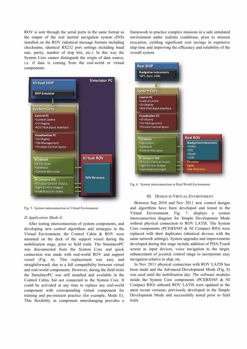
D. Application Mode G After testing interconnection of system components, and
developing new control algorithms and strategies in the Virtual Environment, the Control Cabin & ROV were mounted on the deck of the support vessel during the mobilisation stage, prior to field trials. The SimulatorPC was disconnected from the System Core and quick connection was made with real-world ROV and support vessel (Fig. 6). This replacement was easy and straightforward, due to a full compatibility between virtual and real-world components. However, during the field trials the SimulatorPC was still installed and available in the Control Cabin, but not connected to the System Core. It could be activated at any time to replace any real-world component with corresponding virtual component for training and pre-mission practice (for example, Mode E). This flexibility in component interchanging provides a
framework to practice complex missions in a safe simulated environment under realistic conditions, prior to mission execution, yielding significant cost savings in expensive ship time and improving the efficiency and reliability of the overall system.
Fig. 6. System interconnection in Real-World Environment.
III. DESIGN IN VIRTUAL ENVIRONMENT Between Sep 2010 and Nov 2011 new control designs
and algorithms have been developed and tested in the Virtual Environment. Fig. 7. displays a system interconnection diagram for Simple Development Mode without physical connection to ROV LATIS. The System Core components (PCEBX945 & NI Compact RIO) were replaced with their duplicates (identical devices with the same network settings). System upgrades and improvements developed during this stage include addition of PDA/Touch screen as input devices, voice navigation to the target, enhancement of joystick control range to incorporate easy navigation relative to ship, etc.
In Nov 2011 physical connection with ROV LATIS has been made and the Advanced Development Mode (Fig. 8) was used until the mobilisation day. The software modules inside the System Core components (PCEBX945 & NI Compact RIO) onboard ROV LATIS were updated to the most recent versions, previously developed in the Simple Development Mode and successfully tested prior to field trials.

Fig. 7. Simple Development Mode: Virtual Environment.
Fig. 8. Advanced Development Mode: Virtual Environment.
IV. FIELD TRIALS The list of field trials performed with ROV LATIS
onboard different research vessels is given in Table 1. During the most recent cruise (CV-11-026) ROV LATIS was mobilised using RV Celtic Voyager. The main objectives included testing of smart technologies in Cork
Harbour and multibeam/sidescan/video surveys of ship wrecks in Bantry Bay. Selected results from these trials are given in the following.
TABLE I ROV LATIS FIELD TRIALS
Cruise Date Ship Location CE-09-04 Mar 2009 Celtic Explorer Connemara Demo Jul 2009 Shannon One Limerick Dock CV-10-029 Aug 2010 Celtic Voyager Shannon Estuary,
Galway Bay CV-11-026 Dec 2011 Celtic Voyager Cork Harbour,
Bantry Bay
A. Touch screen as Input Device The “Follow Desired Speed & Course” Speed Mode
enables reliable and precise speed & course following with excellent dynamic performances (speed settling time of 3 seconds and course turn resolution of 1°). A simple and intuitive graphical user interface enables control of Speed/Course Over Ground (SOG & COG) using knob controls. Fig. 9. shows operator setting desired COG using the Touch screen as Input Device.
Fig. 9. Setting desired COG using Touch screen.
B. Joystick & PDA as Input Devices Joystick (Wireless Interface) and HP PDA (WiFi
Interface) were used as Input Devices for ROV surface operations in close proximity of the ship.
Fig. 10. ROV control using joystick & PDA.
Although each device can be used standalone, the best performance is achieved when they are used simultaneously: joystick to generate desired commands and

PDA to provide feedback display (desired and actual states) in real-time.
Joystick extended functionality includes 1-button click switching of Speed Modes (“Manual”, ”Follow Desired Speed/Course” and “Hold Position”). In particular, with simple HatSwitch button click, the ROV can be commanded to go away/toward/parallel to ship, while its speed can be updated with inc/dec buttons in 0.05 m/s step size. The ROV then follows desired commands regardless of sea state and automatically compensate effects of waves and currents. This feature is extremely important for operations close to the ship and during deployment/recovery stages. Mobility and intuitive user interface of these devices makes them very attractive for near-the-ship ROV control, yielding improved risk/safety ratio.
C. Bridge Remote Displays Remote displays were installed on the ship’s bridge,
providing real-time 2D and 3D view of the ship and ROV (Fig. 11). In this particular case, remote displays show ROV on the ship’s deck waiting to be deployed. Remote displays present all mission critical information to the ship bridge in a simple and intuitive way, yielding improved situation awareness and better understanding of mission progress. Another important feature of remote displays is their ability to enhance communications between the ROV pilot and the helmsman of the ship for easy synchronisation of ROV and ship motion. For example, the ROV pilot can mark desired ship position on his display in the Control Cabin. The same information is presented to the helmsman on his display on the bridge as a highly visible target with predetermined distance, bearing and approach speed. The helmsman only needs to input this data into the Dynamic Positioning (DP) system as set points.
Fig. 11. Remote displays installed on the ship’s bridge.
D. Real Camera vs Virtual Camera A comparison of real and virtual camera views is shown
in Fig. 12. The view from the real onboard pilot camera is shown in the top left monitor, while the corresponding view from the virtual pilot camera is shown in the lower right monitor. The picture was taken between two missions,
while the vehicle was on the deck. Owing to independent open-loop tilt control of real and virtual cameras, a small difference in elevation can be observed, since the real camera was slightly tilted down, while the virtual camera was not tilted at all.
Fig. 12. Comparison: Real Camera vs Virtual Camera.
E. ROV Voice Navigation Similar to voice navigation used in car GPS nav systems,
the ROV Voice Navigation system has been developed to assist ROV control & navigation during different mission stages, including ROV deployment and recovery. The original idea for voice navigation was developed by researcher A. Vasilijevic from LABUST research team, University of Zagreb.
Depending on relative position between ROV (R) and target (T), a set of the voice instructions is generated and continuously updated to assist ROV pilot to navigate and reach the target. In horizontal plane voice instructions include LEFT ( HTR εψψ >− ), RIGHT
( HTR εψψ −<− ) and BEEP ( HTR εψψ ≤− ) (Fig.
13). In addition, voice instructions indicating distance to the target are triggered when the ROV enters a circle iC with a
radius ir centred at T. In the current implementation, circles are defined with the following radiuses: {100m, 90m, ..., 20m, 10m, 9m, 8m, 7m, ..., 2m, 1m}.
In vertical plane voice instructions include UP ( VTR zz ε>− ) and DOWN ( VTR zz ε−<− ) (Fig. 14).
ROV Voice Navigation system has been successfully tested during the field trials, as indicated in Fig. 15 & 16. While ROV pilot was absent from the Control Cabin, a member of the research team placed target to a new position & depth, and switched off the monitors. Then, ROV pilot entered the cabin and started search for target, listening the voice instructions on PC speakers (Fig. 15). Using the voice instructions, ROV pilot was able to determine distance & direction to the target, and its depth, in the first step. Then, modifying the speed and course with SOG/COG controls, the ROV pilot navigated ROV to reach the target (Fig. 16).
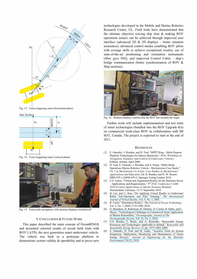
Fig. 13. Voice-triggering zones (horizontal plane).
Fig. 14. Voice-triggering zones (vertical plane).
Fig. 15. Voice-only navigation, with monitor displays switched off.
V. CONCLUSIONS & FUTURE WORK This paper described the main concept of OceanRINGS
and presented selected results of recent field trials with ROV LATIS, the next generation smart underwater vehicle. The vehicle was built as a prototype platform to demonstrate system validity & operability and to prove new
technologies developed in the Mobile and Marine Robotics Research Centre, UL. Field trials have demonstrated that the ultimate objective (saving ship time & making ROV operations easier) can be achieved through improved user interface (advanced 2D & 3D displays – better situation awareness), advanced control modes (enabling ROV pilots with average skills to achieve exceptional results), use of state-of-the-art positioning and orientation instruments (fibre gyro INS), and improved Control Cabin – ship’s bridge communication (better synchronisation of ROV & Ship motions).
Fig. 16. Monitor displays confirm that the ROV has reached the target.
Further work will include implementation and test trials of smart technologies (bundled into the ROV Upgrade Kit) on commercial work-class ROV in collaboration with MI SOT, Canada. The project is expected to start at the end of 2011.
REFERENCES [1] E. Omerdic, J. Riordan, and D. Toal, “MPPT Ring – Multi-Purpose
Platform Technologies for Subsea Operations,” IFAC Workshop on Navigation, Guidance and Control of Underwater Vehicles, Killaloe, Ireland, April 2008.
[2] D. Toal, E. Omerdic, J. Riordan, and S. Nolan, “Multi-Mode Operations Marine Robotics Vehicle - Mechatronics Case Study,” Ch. 7 in Mechatronics in Action: Case Studies in Mechatronics - Applications and Education, Ed. D. Bradley and D. W. Russel, ISBN 978-1-84996-079-3, Springer-Verlag London 2010.
[3] U.F. Lukas, “Virtual and Augmented Reality for the Maritime Sector – Applications and Requirements,” 8th IFAC Conference CAMS 2010 (Control Applications in Marine Systems), Rostock-Warnemünde, Germany, 15-17 September 2010.
[4] Q. Lin, and C. Kuo, “On Applying Virtual Reality to Underwater Robot Tele-Operation and Pilot Training,” The International Journal of Virtual Reality, Vol. 5, No. 1, 2001.
[5] B. Curtis, “Simulation Reality”. The Journal of Ocean Technology, Vol. 5, No. 3, ISSN 1718-3200, 2010.
[6] G. Beaudoin, D. Robertson, R. Doherty, D. Corren, B. Staby, and L. Meyer, “Technological Challenges to Commercial-Scale Application of Marine Renewables,” Oceanography, Journal of The Oceanography Society, Vol. 23, No. 2, 2010.
[7] F.O. Rourke, F. Boyle, and A. Reynolds, “Renewable Energy Resources and Technologies Applicable to Ireland,” Renewable and Sustainable Energy Reviews 13, pp: 1975-1984, 2009.
[8] E. Omerdic, D. Toal, and M. Leahy, “Assistive Tools for System Integration, Deployment, Monitoring and Maintenance of Ocean Energy Devices,” Journal of Engineering for the Maritime Environment 224 (2), 2010.
Copyright © 2022 FDOKUMEN