A Concept for an Intrusion Detection System over Automotive ...
112
A Concept for an Intrusion Detection System over Automotive Ethernet Hanna Lindwall Pontus Ovhagen [email protected] [email protected] Department of Electrical and Information Technology Lund University Supervisor: Paul Stankovski Wagner Examiner: Thomas Johansson March 18, 2020
-
Upload
khangminh22 -
Category
Documents
-
view
0 -
download
0
Transcript of A Concept for an Intrusion Detection System over Automotive ...
A Concept for an Intrusion Detection Systemover Automotive Ethernet
Hanna Lindwall Pontus [email protected] [email protected]
Department of Electrical and Information TechnologyLund University
Supervisor: Paul Stankovski Wagner
Examiner: Thomas Johansson
March 18, 2020

© 2020Printed in SwedenTryckeriet i E-huset, Lund
Abstract
A modern automotive vehicle is a complex technical system, containing manyelectronic, mechanical, and software parts. Typically, a high-end vehicle contains70 or more electronic control units (ECUs) on average. These are controllinga large number of distributed functions, of which many are safety-critical, andadding complexity, which is surpassing 100 million lines of code.
Furthermore, the communication link in the automotive architecture is alsobeing upgraded from the traditional controller area network (CAN) bus to Auto-motive Ethernet, in order to enable higher communication bandwidth and handlethe increasing complexity. However, introducing Ethernet opens up for new at-tacks and loopholes to be exploited by hackers. Attacks on ECUs are even moredangerous than web attacks, as these involve the safety of the persons inside thevehicle. To secure the in-vehicle communication the automotive industry needsto look into traditional cybersecurity protection techniques from an automotiveperspective. One security solution gaining more and more attention regardingin-vehicle security is the concept of an intrusion detection system (IDS).
In this thesis, we propose a concept for a host-based IDS relying on two differ-ent detection methods. We suggest a combination of specification-based, focusingon message sequencing and allowed elapsed time in between a request and its re-spective response, and anomaly-based detection, evaluating the frequency, payloadlength and timeout for request-response pairs. To evaluate our IDS we executefive different attack scenarios, where we calculate binary classification metrics andmeasure its classification speed. Our evaluation shows that the proposed IDS suc-cessfully detects malicious events such as delay, packet injection, exhaustion andtwo different flooding attacks.
Based on our experience designing an in-vehicle IDS, we describe potential dif-ficulties, limitations and future improvements that engineers can use to implementor improve their adaptation of an in-vehicle IDS system. We believe the resultsof this master’s thesis can be applied in more advanced research, especially in thefield of IDS for in-vehicle networks, and can hopefully contribute to a safer drivingexperience.
Keywords: Intrusion Detection System, Deep Packet Inspection, Specification-based Detection, Anomaly-based Detection, V2G, Automotive Ethernet.
i

Acknowledgements
Throughout this master’s thesis, we have acquired help from ESCRYPT and otherresearch teams at Bosch. The IDS team at ESCRYPT conducted a demonstrationof their solution and always answered our questions. Due to tough competitionin the industry and for security reasons, it is not easy to find public research onsecurity solutions for vehicles, so we are grateful for their support.
iii

Popular Science Summary
A Concept for an Intrusion Detection System over AutomotiveEthernet by Hanna Lindwall and Pontus Ovhagen
With the transition to automotive Ethernet as a standard network bus,the faster network speeds and additional bandwidth benefits will be themain advantages for internal vehicle networks. However, there are alsoinevitable security risks by introducing Ethernet in vehicles and this isthe main problem we are trying to address in our master’s thesis.
The automotive industry has to in-vestigate traditional cybersecurity so-lutions used to secure traditional net-works, in order to reach the goal of se-curing in-vehicle automotive Ethernetnetworks. Today, firewalls are com-monly used as a first layer of protection,but as attacks have become increas-ingly sophisticated, a firewall’s detec-tion mechanisms can easily be bypassed.Therefore, the automotive industry hasstarted to look into proactive securitysolutions that can detect new threats,which have not been made public or dis-covered yet. One solution is implement-ing an intrusion detection system (IDS),which has been practiced in various in-dustries since the early days of networksecurity and is now being applied forautomotive use cases. An IDS moni-tors and detects attacks or other threatspresent inside the network. Comparedto a firewall, the IDS takes a moreproactive position by reporting, alertingand logging detected threats against a
system. An IDS often relies on exten-sive deep packet inspection to inspectdeeper into a packet and can, therefore,screen packets on an application-levelbasis. Common functionalities of IDSinclude, for example, updating the sys-tem for future attacks, analysis of po-tential attack patterns on the network,alerting other security mechanisms inplace or generating warnings for net-work administrators.
In this master’s thesis we propose aconcept for a host-based in-vehicle IDS.We then implement and test its capa-bilities by launching a series of attacksagainst the IDS and measure its de-tection performance. To detect threatswe incorporated two different detec-tion methods: specification-based andanomaly-based detection.
The specification-based detectionfocuses on deviations from specified be-havior in a protocol. We chose tofocus on the ISO 15118 specification,which describes a protocol for perform-
v
ing Vehicle-to-Grid charging sessions.In our implementation, we mainly focuson deviations in message sequences andtimeouts outlined in the protocol.
After further research, it became ap-parent that the specification-based de-tection did not have full detection cov-erage. For this reason, we decided onintegrating an anomaly-based detectionmethod into our IDS. Anomaly-baseddetection is also a method for detectinganomalous behavior and relies on a sta-tistical approach. In our IDS, we collectdata from different examples of charg-
ing sessions and based on this data theIDS classifies the incoming packet eitheras a threat or a normal packet. Theanomaly-based detection method eval-uates the expected frequency, payloadlength and the time elapsed between amessage request and its respective re-sponse.
The IDS overall performed very wellfor the five attack scenarios we deployedand shows that an IDS with this hybridapproach is a promising security solu-tion for in-vehicle automotive Ethernetnetworks.
vi
Table of Contents
1 Introduction 11.1 Background . . . . . . . . . . . . . . . . . . . . . . . . . . . . . . . 11.2 Problem Statement and Goals . . . . . . . . . . . . . . . . . . . . . 21.3 Delimitations . . . . . . . . . . . . . . . . . . . . . . . . . . . . . . 31.4 Contributions . . . . . . . . . . . . . . . . . . . . . . . . . . . . . . 41.5 Related Work . . . . . . . . . . . . . . . . . . . . . . . . . . . . . . 41.6 Literature Study . . . . . . . . . . . . . . . . . . . . . . . . . . . . 5
2 Background 72.1 Network Basics . . . . . . . . . . . . . . . . . . . . . . . . . . . . . 72.2 The Modern Automotive Industry . . . . . . . . . . . . . . . . . . . 102.3 Automotive Ethernet . . . . . . . . . . . . . . . . . . . . . . . . . . 132.4 Security in Vehicles . . . . . . . . . . . . . . . . . . . . . . . . . . . 19
3 Method 273.1 General Research . . . . . . . . . . . . . . . . . . . . . . . . . . . . 273.2 Establish Requirements and Select a Concept . . . . . . . . . . . . . 273.3 Implementation . . . . . . . . . . . . . . . . . . . . . . . . . . . . . 283.4 Evaluation Framework . . . . . . . . . . . . . . . . . . . . . . . . . 30
4 Design Concept 374.1 IDS Requirements . . . . . . . . . . . . . . . . . . . . . . . . . . . 374.2 DPI Requirements . . . . . . . . . . . . . . . . . . . . . . . . . . . 384.3 Security Analysis . . . . . . . . . . . . . . . . . . . . . . . . . . . . 404.4 V2G IDS Proof of Concept . . . . . . . . . . . . . . . . . . . . . . . 45
5 Implementation 515.1 IDS . . . . . . . . . . . . . . . . . . . . . . . . . . . . . . . . . . . 515.2 V2G Session . . . . . . . . . . . . . . . . . . . . . . . . . . . . . . 55
6 Result 596.1 Specification-based Results . . . . . . . . . . . . . . . . . . . . . . . 596.2 Anomaly-based Results . . . . . . . . . . . . . . . . . . . . . . . . . 59
vii
7 Discussion 677.1 Evaluation of the IDS Implementation . . . . . . . . . . . . . . . . . 677.2 Key Takeaways from Result . . . . . . . . . . . . . . . . . . . . . . 727.3 Future Work . . . . . . . . . . . . . . . . . . . . . . . . . . . . . . 73
8 Conclusions 75
References 77
Appendices 85
A V2G Related Information 85
B Anomaly-based detection Results 89B.1 Anomaly-based Detection Performance for AC V2G Sessions . . . . . 89B.2 Anomaly-based Detection Performance for DC V2G Sessions . . . . . 91
C Scoreboards for Configurations 93
viii
List of Figures
1.1 Future vehicle architectural setup with a distributed gateway and DCUs.Figure inspired by [3]. . . . . . . . . . . . . . . . . . . . . . . . . . 2
2.1 The TCP/IP model compared with the OSI model. . . . . . . . . . . 72.2 An illustration of a frame for Ethernet II. . . . . . . . . . . . . . . . 82.3 TCP header . . . . . . . . . . . . . . . . . . . . . . . . . . . . . . . 92.4 TCP connection establishes through a three-way handshake. . . . . . 92.5 UDP header. . . . . . . . . . . . . . . . . . . . . . . . . . . . . . . 102.6 Automotive electronics cost as a percentage of total car cost worldwide
from 1950 to 2030. Credit to Deloitte for statistics [21]. . . . . . . . 112.7 An ISO model of ESCRYPT’s CycurGATE. Protocols used for vehicle
communication, with protocols in grey representing protocols usedover automotive Ethernet [35]. . . . . . . . . . . . . . . . . . . . . . 14
2.8 Simple overview over communication between EV, V2G unit, homeand power grid [40]. . . . . . . . . . . . . . . . . . . . . . . . . . . 15
2.9 The eight different specifications within the ISO 15118 family. SourceWikipedia [43]. . . . . . . . . . . . . . . . . . . . . . . . . . . . . . 16
2.10 IDS placement inside a network. . . . . . . . . . . . . . . . . . . . . 222.11 A snippet of V2G communication from the ISO 15118 specification. . 242.12 Visual comparison of inspection range between shallow and deep packet
inspection. . . . . . . . . . . . . . . . . . . . . . . . . . . . . . . . 25
3.1 Hardware setup for the project development environment. . . . . . . 283.2 The confusion matrix for binary classification in an IDS [71]. . . . . . 313.3 An illustration of anomaly-based detection outputs with an upper
bound threshold and a tolerance of three. The x-axis represent anarbitrary class value ranging from zero to higher values. . . . . . . . 34
5.1 Illustration of the implemented IDS. . . . . . . . . . . . . . . . . . . 525.2 The V2G session object (struct) which the IDS updates depending
on the incoming message. . . . . . . . . . . . . . . . . . . . . . . . 535.3 A terminal window running the EVCC application. . . . . . . . . . . 565.4 A terminal window running the SECC server application with a suc-
cessful connection made to EVCC client. . . . . . . . . . . . . . . . 57
ix

5.5 A terminal window running the EVCC client application with attacks.The initiated attack is SDP flooding from a single source address(indicated by the number one following -a flag). . . . . . . . . . . . 58
x
List of Tables
2.1 Possible attackers or persons performing unauthorized modifications[52]. . . . . . . . . . . . . . . . . . . . . . . . . . . . . . . . . . . . 20
3.1 Table of metrics taken for evaluation. . . . . . . . . . . . . . . . . . 313.2 The different configurations used when testing the IDS. . . . . . . . 343.3 Implemented attack scenarios for testing of the IDS. . . . . . . . . . 35
4.1 Possible attacker scenarios in V2G communications. . . . . . . . . . 41
6.1 The specification-based results for both AC and DC tests. . . . . . . 596.2 The configurations resulting in the best performance for the anomaly-
based detection performing an attack delaying a random number ofmessage types with timeout 2 seconds, see Table 3.2 . . . . . . . . . 61
6.3 The configurations resulting in the best performance for the anomaly-based detection when performing an attack injecting a random numberof SessionSetup-, ServiceDiscovery- and CableCheck request-response pairs. . . . . . . . . . . . . . . . . . . . . . . . . . . . . . 62
6.4 The configurations resulting in the best performance for the anomaly-based detection when performing an attack trying to exhaust the serverby sending 80-200 ChargeParameterDiscovery requests in a row. . 62
6.5 The configurations resulting in the best performance for the anomaly-based detection when performing an attack trying to flood the serverby sending 210 ChargeStatus requests in a row. . . . . . . . . . . . 63
6.6 Classification speed measurements in microseconds during AC charg-ing sessions. . . . . . . . . . . . . . . . . . . . . . . . . . . . . . . . 63
6.7 The configurations resulting in the best performance for the anomaly-based detection performing an attack delaying a random number ofmessage types with timeout 2 seconds, see Table 3.2 . . . . . . . . . 64
6.8 The configurations resulting in the best performance for the anomaly-based detection when performing an attack injecting a random numberof SessionSetup-, ServiceDiscovery- and CableCheck request-response pairs. . . . . . . . . . . . . . . . . . . . . . . . . . . . . . 64
xi
6.9 The configurations resulting in the best performance for the anomaly-based detection when performing an attack trying to exhaust the serverby sending 80-200 ChargeParameterDiscovery requests in a row. . 65
6.10 The configurations resulting in the best performance for the anomaly-based detection when performing an attack trying to flood the serverby sending 310 ChargeStatus requests in a row. . . . . . . . . . . . 65
6.11 Classification speed measurements in microseconds during DC charg-ing sessions. . . . . . . . . . . . . . . . . . . . . . . . . . . . . . . . 66
7.1 Best configurations for anomaly-based detection for each attack for AC. 687.2 Best configurations for anomaly-based detection for each attack for DC. 687.3 Scoreboard for balanced accuracy, f1-score and f0.5-score showcasing
which configuration worked best overall. . . . . . . . . . . . . . . . . 69
A.1 Different message types defined in the ISO 15118 specification for aV2G session. . . . . . . . . . . . . . . . . . . . . . . . . . . . . . . 85
A.2 Different timeouts for message types defined in the ISO 15118 speci-fication for a V2G session. . . . . . . . . . . . . . . . . . . . . . . . 86
A.3 The different definitions of the detection codes and their respectivehexadecimal representation used by the IDS. . . . . . . . . . . . . . 87
B.1 Different configurations used when testing the IDS. . . . . . . . . . . 89B.2 Performance for the anomaly-based detection when performing an at-
tack delaying random number of message types with timeout 2 sec-onds, see Table A.2. . . . . . . . . . . . . . . . . . . . . . . . . . . 89
B.3 Performance for the anomaly-based detection when performing an at-tack injecting random number of SessionSetup-, ServiceDiscovery-and CableCheck request and response pairs. . . . . . . . . . . . . . 90
B.4 Performance for the anomaly-based detection when performing an at-tack trying to exhaust the server by sending 80-200 ChargeParameterDiscoveryrequests in a row. . . . . . . . . . . . . . . . . . . . . . . . . . . . . 90
B.5 Performance for the anomaly-based detection when performing an at-tack trying to flood the server by sending 210 ChargeStatus requestsin a row. . . . . . . . . . . . . . . . . . . . . . . . . . . . . . . . . 90
B.6 Performance for the anomaly-based detection when performing an at-tack delaying random number of message types with timeout 2 sec-onds, see Table A.2. . . . . . . . . . . . . . . . . . . . . . . . . . . 91
B.7 Performance for the anomaly-based detection when performing an at-tack injecting random number of SessionSetup-, ServiceDiscovery-and CableCheck request and response pairs. . . . . . . . . . . . . . 91
B.8 Performance for the anomaly-based detection when performing an at-tack trying to exhaust the server by sending 80-200 ChargeParameterDiscoveryrequests in a row. . . . . . . . . . . . . . . . . . . . . . . . . . . . . 92
B.9 Performance for the anomaly-based detection when performing an at-tack trying to flood the server by sending 310 ChargeStatus requestsin a row. . . . . . . . . . . . . . . . . . . . . . . . . . . . . . . . . 92
xii

C.1 Scoreboard for balanced accuracy for each attack scenario with ses-sions which included false positives. . . . . . . . . . . . . . . . . . . 93
C.2 Scoreboard for f1-score for each attack scenario with sessions whichincluded false positives. . . . . . . . . . . . . . . . . . . . . . . . . . 93
C.3 Scoreboard for f0.5-score for each attack scenario with sessions whichincluded false positives. . . . . . . . . . . . . . . . . . . . . . . . . . 94
xiii

Abbreviations
AC Alternating Current
CA Certificate Authority
CAN Controller Area Network
DC Direct Current
DCU Domain Control Unit
DoS Denial of Service
DPI Deep Packet Inspection
ECDH Elliptic Curve Diffie-Hellman
ECDSA Elliptic Curve Digital Signature Algorithm
ECU Electronic Control Unit
E/E Electrical/Electronic
EIM External Identification Means
EV Electric Vehicle
EVCC Electric Vehicle Communication Controller
EXI Efficient XML Interchange
FNR False Negative Rate
FPR False Positive Rate
HIDS Host-based Intrusion Detection System
HSM Hardware Security Model
IDPS Intrusion Detection and Prevention System
IDS Intrusion Detection System
IoT Internet of Things
xv
IV Initialization Vector
LIN Local Interconnect Network
LnUB Lower- and Upper Bound
MAC Media Access Control
MCU Microcontroller Unit
MOST Media Oriented Systems Transport
NIDS Network-based Intrusion Detection System
OEM Original Equipment Manufacturer
PKI Public Key Infrastructure
PnC Plug and Charge
ROC Receiver Operating Characteristic
SDP SECC Discovery Protocol
SECC Server Communication Controller
SOME/IP Scalable Service-Oriented Middleware over IP
SSL Secure Socket Layer
TCAM Ternary Content-Addressable Memory
TCP Transmission Control Protocol
TLS Transport Layer Security
TPR True Positive Rate
UDP User Datagram Protocol
V2G Vehicle-to-Grid
V2GTP V2G Transfer Protocol
V2I Vehicle-to-infrastructure
V2V Vehicle-to-vehicle
XML Extensible Markup Language
xvi
Chapter1Introduction
This chapter gives the reader a brief introduction to the master’s thesis. We alsoaddress the problem at hand and what goals have been set for the project. Further-more, this section recognizes previous work and further explains the contributionsof this thesis.
1.1 Background
The modern automobile industry has to provide drivers with a wide range of safety,comfort and assistance functionalities to keep up with consumer demands and theharsh competition. This development has resulted in an evolution of additionalfeatures in new vehicle generations. Most of the functional domains are electronic,which has led to the emergence of advanced electrical/electronic (E/E) architec-tures. More and more of the vehicle system is dependent on connectivity andcommunications within and outside the vehicle, hence manufacturers are nowa-days required to develop systems that can handle high bandwidth in addition tobeing well-timed [1].
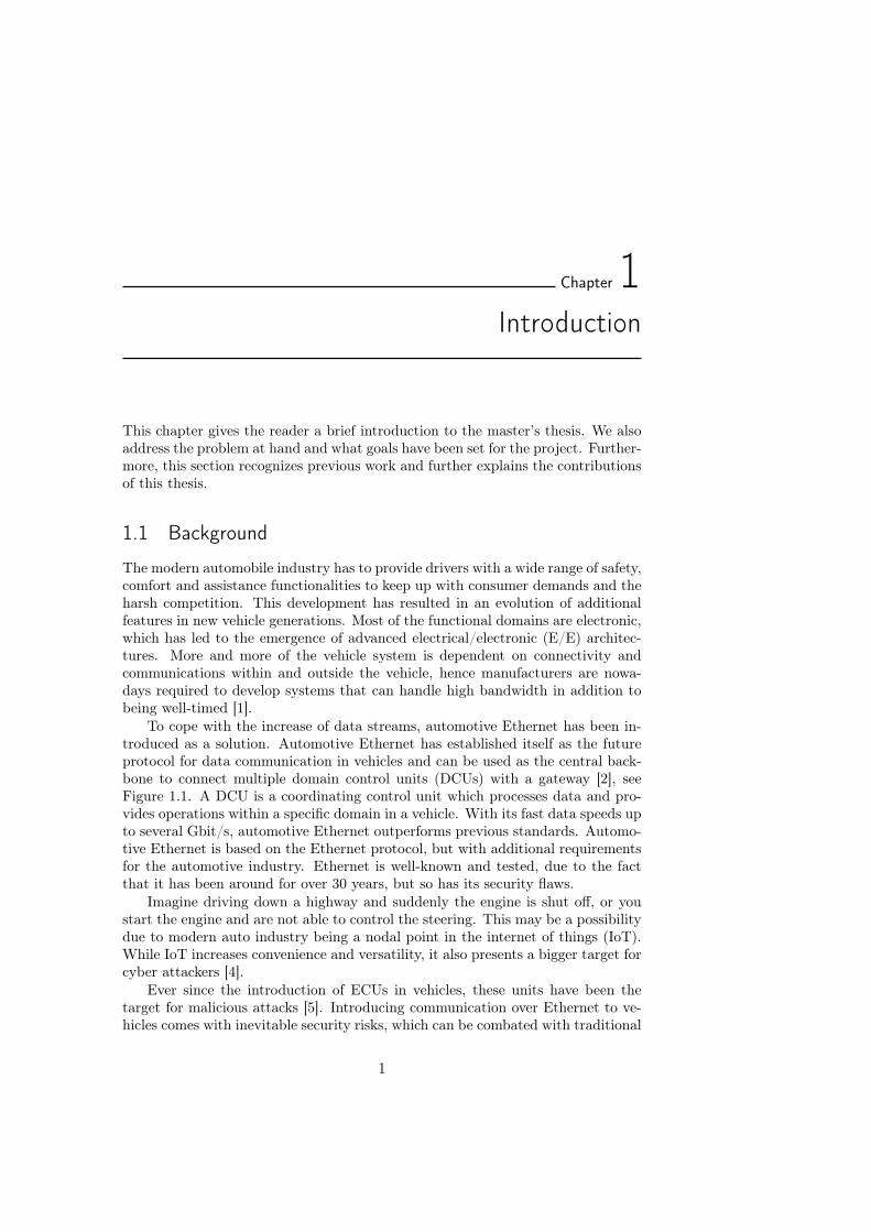
To cope with the increase of data streams, automotive Ethernet has been in-troduced as a solution. Automotive Ethernet has established itself as the futureprotocol for data communication in vehicles and can be used as the central back-bone to connect multiple domain control units (DCUs) with a gateway [2], seeFigure 1.1. A DCU is a coordinating control unit which processes data and pro-vides operations within a specific domain in a vehicle. With its fast data speeds upto several Gbit/s, automotive Ethernet outperforms previous standards. Automo-tive Ethernet is based on the Ethernet protocol, but with additional requirementsfor the automotive industry. Ethernet is well-known and tested, due to the factthat it has been around for over 30 years, but so has its security flaws.
Imagine driving down a highway and suddenly the engine is shut off, or youstart the engine and are not able to control the steering. This may be a possibilitydue to modern auto industry being a nodal point in the internet of things (IoT).While IoT increases convenience and versatility, it also presents a bigger target forcyber attackers [4].
Ever since the introduction of ECUs in vehicles, these units have been thetarget for malicious attacks [5]. Introducing communication over Ethernet to ve-hicles comes with inevitable security risks, which can be combated with traditional
1
2 Introduction
Figure 1.1: Future vehicle architectural setup with a distributedgateway and DCUs. Figure inspired by [3].
security solutions, such as a firewall or an intrusion detection system. However,as mentioned, the automotive industry has requirements for in-vehicle communi-cation, such as low latency and well-timed communication, which has to be takeninto account when developing security solutions for vehicles.
Robert Bosch GmbH is a renowned international company in the technologyindustry and delivers vast amounts of products and software within multiple fields.One of these fields is security in the automobile industry, where Bosch is developingembedded software for devices that will be utilized for the automotive Ethernetstandard.
The ambition is to introduce new features using deep packet inspection (DPI)in combination with an intrusion detection system to discover potential threats.This master’s thesis is a cooperation with ESCRYPT, a wholly-owned subsidiaryof a Bosch company called ETAS GmbH, and will focus on DPI and IDS forautomotive Ethernet.
1.2 Problem Statement and Goals
The problem addressed in this thesis is: How can one integrate IDS using DPIin an automotive setting to increase security coverage? Moreover, the answer tothis problem is based on specified key questions that can be seen below. Thesequestions are essential to the scope of this report and serve as a foundation for themodel implementation, discussions and conclusions presented.
Academic questions
1. Which requirements are associated with DPI for automotive Ethernet?
Introduction 3
2. Which requirements are associated with IDS in the context of automotiveEthernet?
• What functions of IDS are valuable from the perspective of automotiveEthernet?
To measure progress and set tangible milestones for the project, a set of goalshave been established. These goals, in addition to the key questions mentionedabove, are further evaluated in the closing chapters of this thesis.
Goals
• Analyse which IDS features would fit the automotive domain from securityand resource point of view.
• Propose a proof of concept of how some of those features would be designedand implemented.
• Implement the proof of concept for at least one attack vector.
1.3 Delimitations
This report mainly focuses on the use of DPI and IDS in the context of automotiveEthernet.
With the use of Ethernet in automobiles, the car’s internal systems now in-teract as any device connected to the Internet. Hence, there is extensive amountof protocol implementations which could be studied in detail for security threats.The scope of this thesis is therefore delimited to the ISO 15118 specification, boththeoretically and for the implementation of IDS features. The specification coversVehicle-to-Grid (V2G) interaction and the thesis will focus on this type of com-munication. The main focus is on delivering a working proof of concept that wecan test and evaluate.
In this project, we will not evaluate the actual integration aspects of deployingan IDS into a vehicle, we leave this part of the project for others to pursue andevaluate. The reason being the time constraints on completing the project withinthe set deadline. Furthermore, this implementation cannot be seen as production-ready, and we do not address further challenges that come with porting, runningand testing successfully in a different environment than the one mentioned in thisthesis.
V2G charging is a fairly new and unexplored area for ESCRYPT. Conse-quently, there is no prior work for us to build on. With no luck finding captureswith ISO 15118 traffic, we have to rely on the fairly static session generation fromopen-source projects. The two projects OpenV2G and RISEV2G were used asbasis for training and testing our implementation. This will make the IDS par-tially biased towards our training examples, with no complete assurance of similarresults being produced for authentic in-vehicle session data.
4 Introduction
1.4 Contributions
The major contributions of this report can be stated as follows.
• We select an evaluation framework based on binary classification and statehow this framework is used to evaluate the IDS in Chapter 3.
• We outline requirements for an IDS implemented for automotive Ethernetin Chapter 4.
• We outline requirements for DPI incorporated into a security solution forautomotive Ethernet in Chapter 4.
• We propose a proof of concept for a host-based IDS (Chapter 5) and showthat the implementation works by launching a series of attacks against it.The best configurations of our IDS are presented in Chapter 6. The config-urations can be used for other studies or as a stepping stone for developersto use in their implementation.
1.5 Related Work
1.5.1 Design and Implementation of an IDS for In-vehicle Networks
The controller area network data link protocol has been the standard for the auto-mobile industry under a considerable amount of time. The science community hasover the years researched CAN thoroughly and many contributions have pointedout its security flaws [6, 7, 8].
Salman and Bresch [9] implemented an IDS system for a CAN network topol-ogy, but rather than being present in a network switch, the IDS is deployed on asingle ECU in the car network. Their implementation highlights how to design ahybrid IDS using specification-based and anomaly-based detection methods. Somevaluable features include: detection of unauthorized messages in specific domainson the network, setting a threshold for fluctuations of speedometer data and ac-counting cycle times for messages sent on the CAN bus. Even though the CANprotocol differs from the ISO 15118 specification in several aspects, these featuresaccentuate what type of functions are of interest from an automotive perspectivewhen implementing an IDS. Finally, they conclude that having one detection ap-proach is not enough. Instead, using a combination of two methods is a morepromising alternative.
1.5.2 Anomaly Detection for SOME/IP using Complex Event Processing
Herold et al. [10] also implemented an IDS but for the SOME/IP protocol, whichis a service-oriented protocol that manages both CAN and automotive Ethernetrelated messages. Their solution incorporated specification-based and anomaly-based detection where they used static rule sets and checked both frequency andtiming. Their prototype was implemented in Java, and Esper was chosen as theComplex Event Processing engine. It accepts rules written in the Event ProcessingLanguage, a subset of SQL, extended with features for stream processing.
Introduction 5
1.6 Literature Study
1.6.1 Security Analysis of Ethernet in Cars
Talic [11] conducted a thorough security investigation of automotive Ethernet withits associated protocols. The evaluation in this thesis was carried out with thehelp of a framework called OSSTMM. This framework allowed him to perform anextensive comparison between different configurations of his testbed and effectivelymeasure the impact on security from adding or removing features he discoveredin his analysis. Notable attack surfaces that were successfully discovered includeARP cache poisoning, SOME/IP spoofing of real-time data and denial of service(DoS).
1.6.2 Deep Packet Inspection for Intrusion Detection Systems: A Survey
Abuhmed et al. conducted a survey over techniques, challenges, and algorithmsfor DPI in 2007 [12]. Their work highlights several key challenges such as whichsearch algorithm should be used, how to handle an increasing number of intrudersignatures and also the challenge of inspecting locations of unknown signaturelocations. The latter is a central problem when performing DPI and dictates thedegree of packet inspection performed at certain locations in security architecture.Furthermore, they compared hardware implementations of DPI from a collectionof different sources where a matching algorithm using a Quad Bloom filter wasfound to be the highest performer with an output of 20.4 Gbit/s, compared toternary content-addressable memories (TCAMs) that had a throughput of 12.35Gbit/s.
1.6.3 Firewall and IDPS Concept for Automotive Ethernet
An important aspect of security architectures in vehicles is to divide the responsi-bilities between different subsystems or devices. In Firewall and IDPS concept forautomotive Ethernet [13] written by Yilmaz in cooperation with Bosch, he derivesa concept for an automotive firewall and IDPS (Intrusion Detection and PreventionSystem) to secure in-vehicle communication over automotive Ethernet. His modelconsists of a firewall that acts as an initial filter of incoming packets, where mostlyheader data is checked for malicious signatures. These signatures are identified assequences of bytes or as a set of malicious instructions. The firewall is equippedwith a TCAM and a rate meter for fast initial processing of packets at wire-speed.However, TCAM has its limitations due to e.g., high resource consumption. More-over, unclassified packets from the firewall are routed to an IDPS for an extendedsearch in the packet payload, where appropriate measures are taken to filter orblock malicious packets. Both subsystems interchange information about detectedthreats and create dynamic rules as they adapt to newly discovered threats.
6 Introduction
1.6.4 An approach to Specification-based Attack Detection for In-vehicleNetworks
Larson et al. [14] presented a specification-based approach based on the CANv2.0 and CANopen v3.01 specifications. Some features include the specificationrules for message correctness, expected values and message cycle times. Theyfurther analyze the implications of placement and find that placing one detectoron each ECU was optimal since they can omit transmitter and receiver identities.Conclusively, they state that their approach readily shows that most attack vectorsspecified can be detected from the attack scenarios they considered.
1.6.5 An Assessment Method for Automotive Intrusion Detection Sys-tem Performance
On the behalf of the United States Department of Transportation, Stachowski etal. [15] present an assessment method on how to test and assess IDS solutions in avehicle. Through simulating attacks over a CAN bus (by injecting packets), theyevaluate the implementation by viewing the IDS as a binary classifier. With the useof receiver operating characteristic (ROC) plots and calculated ratio metrics, theyevaluate several suppliers’ IDSs by running the tests on three different vehicles.ROC plots are used to graphically illustrate the diagnostic ability of the binaryclassifier system (i.e., the IDS).
Even though this work is tailored towards an IDS designed for CAN use cases,the test methodology can be applied on IDS implementations supporting otherprotocols.
1.6.6 Road Vehicles - Vehicle-to-Grid Communication Interface
The ISO 15118 specification [16] describes a communication protocol for V2Gcharging that is expected to be one of the leading charging standards in the fu-ture. With the increased adoption of this standard, Hauck et al. [17] made ahigh-level overview of some of the security challenges and mitigation techniquesthat can be used to limit risks associated with modern vehicles. Among otherthreats, they highlight the risk of tampering in a charging station – enabling theattacker to affect the power quality of the local power system or obtain free charg-ing sessions. This attack vector can be prevented with the use of strong encryption,removal of all external input jacks and integrating alerting mechanics. Further-more, they suggest mitigation approaches such as always utilizing transport layersecurity (TLS) when possible, having highly protective storage for digital certifi-cates and private/public keys as well as using digital signatures and encryptionfor all vulnerable messages.
Chapter2Background
This chapter covers both basic and more advanced material in network securityand automotive Ethernet. The chapter is meant to inform the reader of all the factsneeded to better understand the discussions presented in the subsequent chaptersin the report.
The experienced reader with knowledge in network basics, network security orautomobile technologies may skip parts of the background, though it is advised toat least cover the material for security in vehicles (Section 2.4) and V2G charging(Section 2.3.1).
2.1 Network Basics
2.1.1 Transmission Control Protocol/Internet Protocol Model: TCP/IPModel
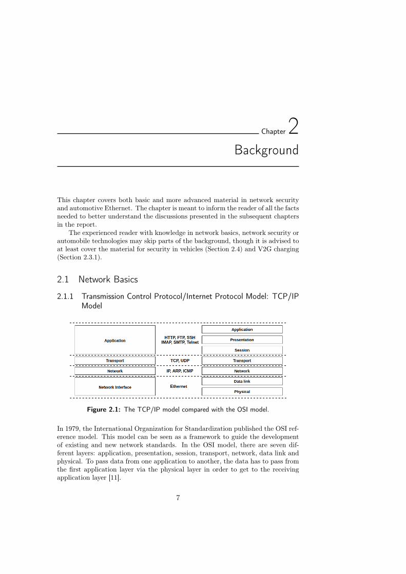
Figure 2.1: The TCP/IP model compared with the OSI model.
In 1979, the International Organization for Standardization published the OSI ref-erence model. This model can be seen as a framework to guide the developmentof existing and new network standards. In the OSI model, there are seven dif-ferent layers: application, presentation, session, transport, network, data link andphysical. To pass data from one application to another, the data has to pass fromthe first application layer via the physical layer in order to get to the receivingapplication layer [11].
7
8 Background
In contrast, the TCP/IP model provides a framework for networking protocolsand uses a four-layer architecture, which combines the three upper layers andcombines the first and second lower layers from the OSI model. The model wasdeveloped to provide a mechanism for implementing the internet by the defenseadvanced research projects agency DARPA [18]. TCP and IP were developedalmost hand in hand, creating this widely used model. One can see the comparisonbetween the two models in Figure 2.1. In this report, we commonly refer to theapplication- or transport layer defined in this model.
Ethernet
Ethernet is a collection of several computer network technologies used to transferdata between devices – defined in the ISO 802.3 specification.
There exist multiple standards for Ethernet, the first commercially availablestandard was 10BASE5 and it allowed for speeds of 10 Mbit/s. However, the suc-ceeding development of 10BASE-T introduced a full-duplex which makes it possi-ble to send and receive simultaneously [19]. Advances in Ethernet have progressedsignificantly during the last two decades, the introduction of Fast Ethernet (i.e.,100BASE–X) and Gigabit Ethernet (i.e., 1000BASE–X) have greatly increasedperformance with speeds of up to 1 Gbit/s.
Ethernet is in its design a connectionless protocol with support for broadcast,multicast, and unicast communication. Typically, all participants are connected toa switch where frames are processed and exchanged between endpoints. A deviceconnected to an Ethernet network uses a media access control (MAC) address toidentify itself and other hosts on the network, though, there is no routing basedon MAC addresses that enables cross-network communications. Features such asnetwork routing are left to protocols applied on top of Ethernet.
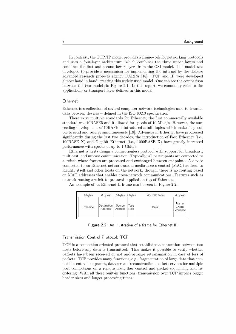
An example of an Ethernet II frame can be seen in Figure 2.2.
Figure 2.2: An illustration of a frame for Ethernet II.
Transmission Control Protocol: TCP
TCP is a connection-oriented protocol that establishes a connection between twohosts before any data is transmitted. This makes it possible to verify whetherpackets have been received or not and arrange retransmission in case of loss ofpackets. TCP provides many functions, e.g., fragmentation of large data that can-not be sent as one packet, data stream reconstruction, socket services for multipleport connections on a remote host, flow control and packet sequencing and re-ordering. With all these built-in functions, transmission over TCP implies biggerheader sizes and longer processing times.
Background 9
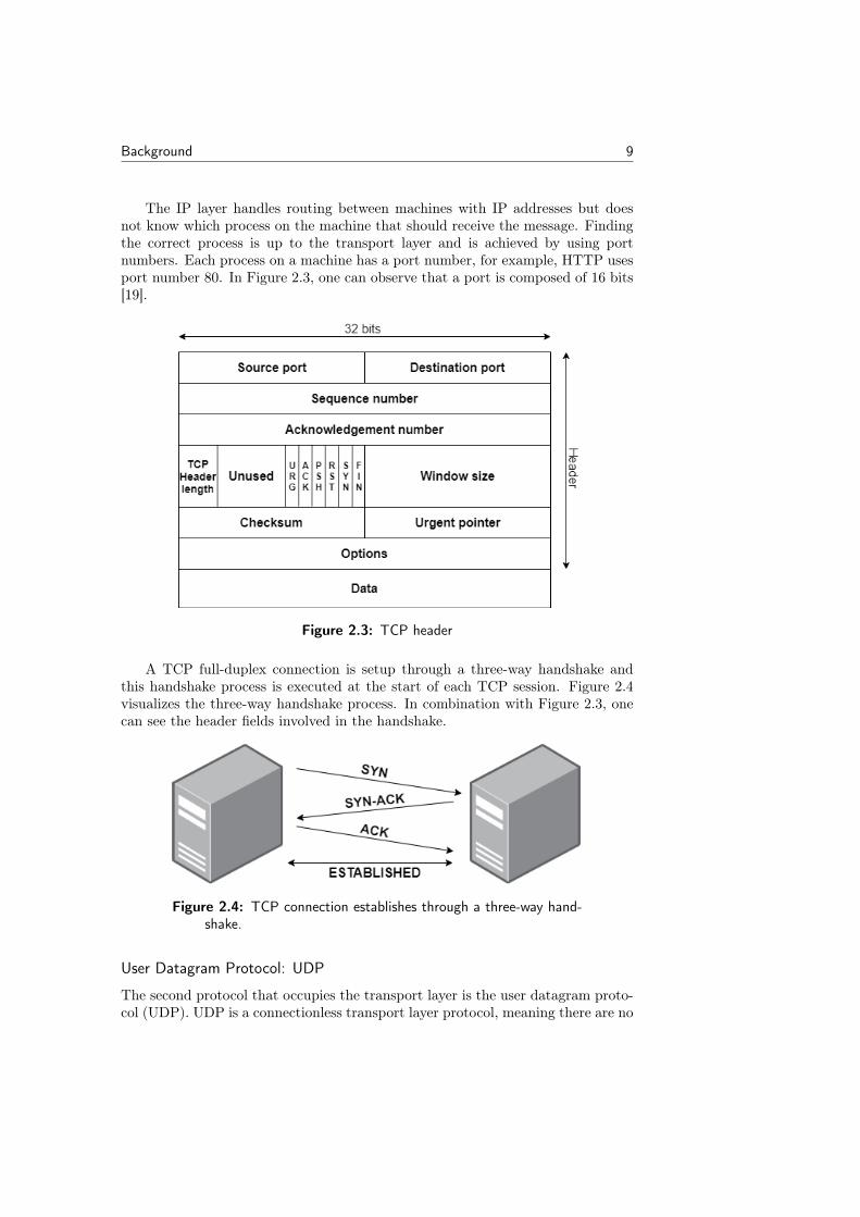
The IP layer handles routing between machines with IP addresses but doesnot know which process on the machine that should receive the message. Findingthe correct process is up to the transport layer and is achieved by using portnumbers. Each process on a machine has a port number, for example, HTTP usesport number 80. In Figure 2.3, one can observe that a port is composed of 16 bits[19].
Figure 2.3: TCP header
A TCP full-duplex connection is setup through a three-way handshake andthis handshake process is executed at the start of each TCP session. Figure 2.4visualizes the three-way handshake process. In combination with Figure 2.3, onecan see the header fields involved in the handshake.
Figure 2.4: TCP connection establishes through a three-way hand-shake.
User Datagram Protocol: UDP
The second protocol that occupies the transport layer is the user datagram proto-col (UDP). UDP is a connectionless transport layer protocol, meaning there are no
10 Background
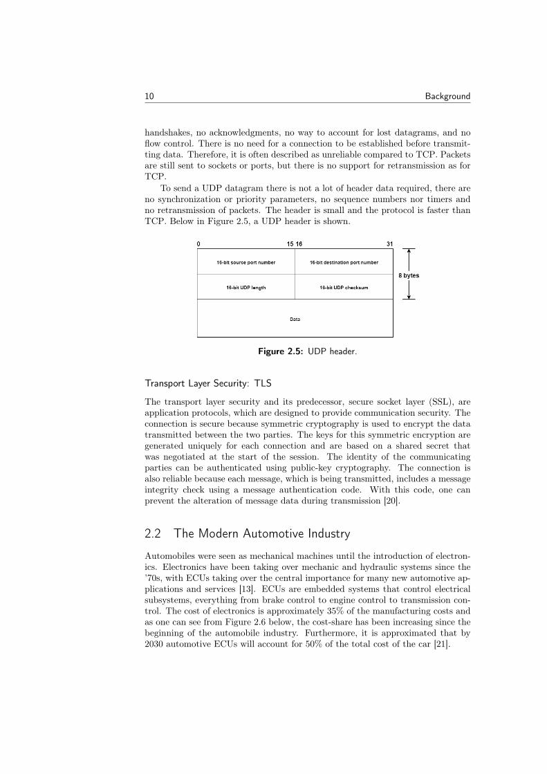
handshakes, no acknowledgments, no way to account for lost datagrams, and noflow control. There is no need for a connection to be established before transmit-ting data. Therefore, it is often described as unreliable compared to TCP. Packetsare still sent to sockets or ports, but there is no support for retransmission as forTCP.
To send a UDP datagram there is not a lot of header data required, there areno synchronization or priority parameters, no sequence numbers nor timers andno retransmission of packets. The header is small and the protocol is faster thanTCP. Below in Figure 2.5, a UDP header is shown.
Figure 2.5: UDP header.
Transport Layer Security: TLS
The transport layer security and its predecessor, secure socket layer (SSL), areapplication protocols, which are designed to provide communication security. Theconnection is secure because symmetric cryptography is used to encrypt the datatransmitted between the two parties. The keys for this symmetric encryption aregenerated uniquely for each connection and are based on a shared secret thatwas negotiated at the start of the session. The identity of the communicatingparties can be authenticated using public-key cryptography. The connection isalso reliable because each message, which is being transmitted, includes a messageintegrity check using a message authentication code. With this code, one canprevent the alteration of message data during transmission [20].
2.2 The Modern Automotive Industry
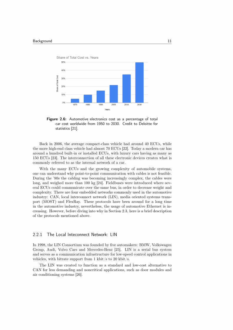
Automobiles were seen as mechanical machines until the introduction of electron-ics. Electronics have been taking over mechanic and hydraulic systems since the’70s, with ECUs taking over the central importance for many new automotive ap-plications and services [13]. ECUs are embedded systems that control electricalsubsystems, everything from brake control to engine control to transmission con-trol. The cost of electronics is approximately 35% of the manufacturing costs andas one can see from Figure 2.6 below, the cost-share has been increasing since thebeginning of the automobile industry. Furthermore, it is approximated that by2030 automotive ECUs will account for 50% of the total cost of the car [21].
Background 11
Figure 2.6: Automotive electronics cost as a percentage of totalcar cost worldwide from 1950 to 2030. Credit to Deloitte forstatistics [21].
Back in 2006, the average compact-class vehicle had around 40 ECUs, whilethe more high-end class vehicle had almost 70 ECUs [22]. Today a modern car hasaround a hundred built-in or installed ECUs, with luxury cars having as many as150 ECUs [23]. The interconnection of all these electronic devices creates what iscommonly referred to as the internal network of a car.
With the many ECUs and the growing complexity of automobile systems,one can understand why point-to-point communication with cables is not feasible.During the ’80s the cabling was becoming increasingly complex, the cables werelong, and weighed more than 100 kg [24]. Fieldbuses were introduced where sev-eral ECUs could communicate over the same bus, in order to decrease weight andcomplexity. There are four embedded networks commonly used in the automotiveindustry: CAN, local interconnect network (LIN), media oriented systems trans-port (MOST) and FlexRay. These protocols have been around for a long timein the automotive industry, nevertheless, the usage of automotive Ethernet is in-creasing. However, before diving into why in Section 2.3, here is a brief descriptionof the protocols mentioned above.
2.2.1 The Local Inteconnect Network: LIN
In 1998, the LIN Consortium was founded by five automakers: BMW, VolkswagenGroup, Audi, Volvo Cars and Mercedes-Benz [25]. LIN is a serial bus systemand serves as a communication infrastructure for low-speed control applications invehicles, with bitrate support from 1 kbit/s to 20 kbit/s.
The LIN was created to function as a standard and low-cost alternative toCAN for less demanding and noncritical applications, such as door modules andair conditioning systems [26].
12 Background
2.2.2 The Control Area Network: CAN
The CAN is a widely-used communication fieldbus system, which efficiently sup-ports distributed real-time control, developed by Robert Bosch GmbH in 1983 andstandardized in 1994 [11].
Nowadays the CAN is used as a society of automotive engineers network forreal-time control in, e.g., the powertrain, body and chassi domains in vehicles. It isa faster protocol, compared to the LIN, supporting bitrates up to 1 Mbit/s. Carriersense multiple access with collision avoidance is used in the broadcast bus CAN.CAN also implements fixed priority to guarantee that real-time processes receivemessages in time. Nevertheless, with the growing number of ECUs connected tothe CAN and computing power, the maximum speed of the CAN is not enoughfor distributed real-time systems [27].
2.2.3 FlexRay
In 2000, the two automotive original equipment manufacturers (OEMs) Daimler-Chrysler and BMW joined together with the two chip producers Motorola andPhilips to create the foundation FlexRay Consortium [28]. FlexRay is a fault-tolerant protocol designed for high data rates, advanced control applications [27].Safety- and time-critical automotive applications were the focus when creating thisprotocol. FlexRay evolved as an alternative to CAN for tasks which needed betterperformance and higher data rate [11, 28]. Today FlexRay is used for anti-lockbraking, electronic power steering, and vehicle stability functions.
2.2.4 Media Oriented Systems Transport: MOST
The development of the MOST protocol was initiated in 1998 and it is designed forinfotainment and media-oriented communication, such as audio, video, navigationand telecommunication systems. MOST is a high-speed protocol with a maximumdata rate of 24.8 Mbit/s and it provides support for up to 64 nodes. The high datarates make the MOST bus a good fit for real-time audio and video transmissionapplications [29]. However, in the advent of Ethernet, the usage of MOST isdecreasing.
2.2.5 E/E Architecture
As mentioned previously, the continuous development of the automotive indus-try is inevitable, and a big reason for this is that the industry is moving moreand more towards autonomous systems, Vehicle-to-Vehicle (V2V) and Vehicle-to-Infrastructure (V2I) communication. Both the amount of ECUs and micro-controller units (MCUs) have been and probably will continue increasing, withemphasis on the amount of MCUs [30]. The growing number of control units hasled to an evolution of embedded memory, power, and processing systems. In anear-future vehicles will generate and consume approximately 40 TB of data everyeight hours of driving, and the average vehicle will produce 4 TB of data a day formerely one hour of driving. Today, cameras alone generate 20-40 Mbit/s and theradar system generates 10-100 kbit/s [31].
Background 13
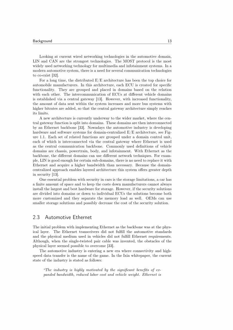
Looking at current wired networking technologies in the automotive domain,LIN and CAN are the strongest technologies. The MOST protocol is the mostwidely used networking technology for multimedia and infotainment systems. In amodern automotive system, there is a need for several communication technologiesto co-exist [32].
For a long time, the distributed E/E architecture has been the top choice forautomobile manufacturers. In this architecture, each ECU is created for specificfunctionality. They are grouped and placed in domains based on the relationwith each other. The intercommunication of ECUs at different vehicle domainsis established via a central gateway [13]. However, with increased functionality,the amount of data sent within the system increases and more bus systems withhigher bitrates are added, so that the central gateway architecture simply reachesits limits.
A new architecture is currently underway to the wider market, where the cen-tral gateway function is split into domains. These domains are then interconnectedby an Ethernet backbone [33]. Nowadays the automotive industry is developinghardware and software systems for domain-centralized E/E architecture, see Fig-ure 1.1. Each set of related functions are grouped under a domain control unit,each of which is interconnected via the central gateway where Ethernet is usedas the central communication backbone. Commonly used definitions of vehicledomains are chassis, powertrain, body, and infotainment. With Ethernet as thebackbone, the different domains can use different network techniques. For exam-ple, LIN is good enough for certain sub-domains, there is no need to replace it withEthernet and acquire a higher bandwidth than necessary. Because the domain-centralized approach enables layered architecture this system offers greater depthin security [13].
One essential problem with security in cars is the storage limitations, a car hasa finite amount of space and to keep the costs down manufacturers cannot alwaysinstall the largest and best hardware for storage. However, if the security solutionsare divided into domains or down to individual ECUs the solutions become bothmore customized and they separate the memory load as well. OEMs can usesmaller storage solutions and possibly decrease the cost of the security solution.
2.3 Automotive Ethernet
The initial problem with implementing Ethernet as the backbone was at the phys-ical layer. The Ethernet transceivers did not fulfill the automotive standardsand the physical medium used in vehicles did not fulfill Ethernet requirements.Although, when the single-twisted pair cable was invented, the obstacles of thephysical layer seemed possible to overcome [33].
The automotive industry is entering a new era where connectivity and high-speed data transfer is the name of the game. In the Ixia whitepaper, the currentstate of the industry is stated as follows:
“The industry is highly motivated by the significant benefits of ex-panded bandwidth, reduced labor cost and vehicle weight. Ethernet is
14 Background
poised to replace the disparate communication means, or to tie themtogether in a single backbone.” ([34], p.18)
The Ethernet backbone is formed by an Ethernet switch, which in fact main-tains point-to-point connections to the domain gateway. The advantage of thisarchitecture is that the gateway processing is split, and at the same time, thedomain gateway can perform additional tasks for its local domain [33]. This archi-tecture also prevents message congestion and enables a more customized securitysolution for each domain [13].
Automotive Ethernet has four main areas of usage, which include advanceddriver assistance systems, diagnostics over IP, infotainment and communicationbackbone [11]. The reason why automotive Ethernet is preferred as the commu-nication network for these services is that it can handle and adapt to the growingbandwidth requirements. In addition to the high data rates Ethernet technologycan support, it is a protocol that is stable, long-established and well-understoodas a result of the widespread deployment.
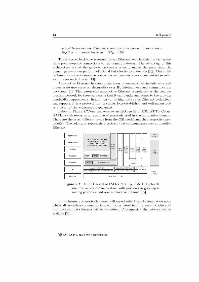
Below in Figure 2.7,1one can observe an ISO model of ESCRYPT’s Cycur-GATE, which serves as an example of protocols used in the automotive domain.There are the seven different layers from the OSI model and their respective pro-tocol(s). The color grey represents a protocol that communicates over automotiveEthernet.
Figure 2.7: An ISO model of ESCRYPT’s CycurGATE. Protocolsused for vehicle communication, with protocols in grey repre-senting protocols used over automotive Ethernet [35].
In the future, automotive Ethernet will expectantly form the foundation uponwhich all in-vehicle communications will occur, resulting in a network where allprotocols and data formats will be consistent. Consequently, the network will bescalable [36].
1©ESCRYPT, used with permission.
Background 15
2.3.1 Vehicle to Charging Grid: V2G
There are many factors which have driven the automotive industry towards electricvehicles (EVs), not only the fact that ECUs weigh less and enable more services,it is also due to political and environmental factors the industry has taken stepsto move away from fossil fuel-driven vehicles [37]. Furthermore, the improvementsin EV technology have changed the outlook for the automotive industry.
EVs are considered promising candidates to replace fossil fuel-powered vehicles.Not only do they have the potential to lead to cleaner transportation, but can alsoprovide electric storage capabilities for other applications, such as V2G, Vehicle-to-Home, Vehicle-to-Load, V2I and V2V [38]. This is why EVs are such an importantpart of the IoT industry.
V2G technology enables bi-directional sharing of electricity between EVs andthe electric power grid. The technology turns each vehicle into a power storagesystem, increasing power reliability and the amount of renewable energy availableto the grid during peak power usage [39]. There are 50 V2G projects around theworld trying to figure out how to make it work for all participants — EV owners,EV utilities, auto OEMs and EV charging developers [40].
ISO 15118
In Sweden, there are 3670 public charging stations with a total of 17097 chargingplugs [41]. Whereas most of the charging is approximated to be done at home,where the projected influx of EVs could increase stress on the grid during peakdemand hours of 6-9 a.m. and 5-9 p.m [40].
In 2010, the creation of the ISO 15118 standard for V2G communication wasinitiated. The international standard outlines the digital communication protocolthat an EV and charging station should use to recharge the EV’s battery. Thisincludes wired (AC and DC) and wireless charging applications.
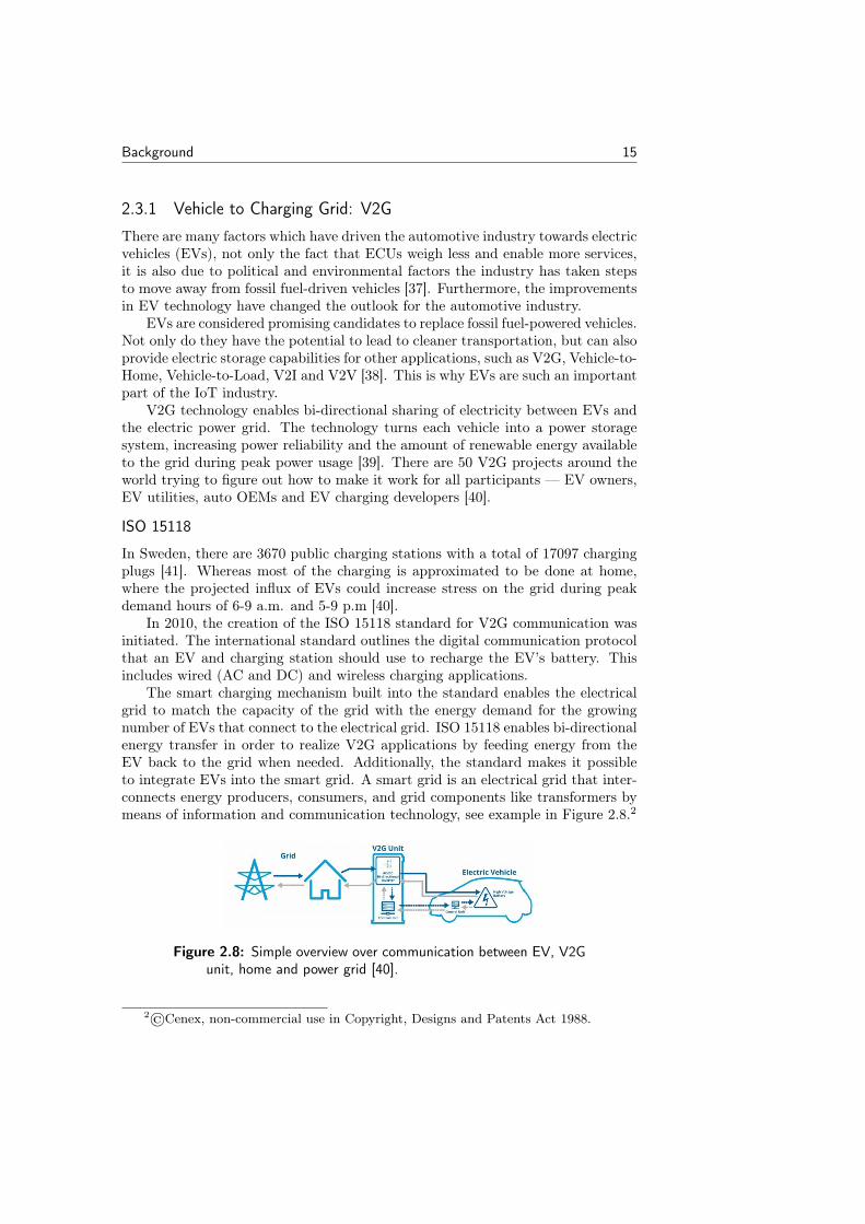
The smart charging mechanism built into the standard enables the electricalgrid to match the capacity of the grid with the energy demand for the growingnumber of EVs that connect to the electrical grid. ISO 15118 enables bi-directionalenergy transfer in order to realize V2G applications by feeding energy from theEV back to the grid when needed. Additionally, the standard makes it possibleto integrate EVs into the smart grid. A smart grid is an electrical grid that inter-connects energy producers, consumers, and grid components like transformers bymeans of information and communication technology, see example in Figure 2.8.2
Figure 2.8: Simple overview over communication between EV, V2Gunit, home and power grid [40].
2©Cenex, non-commercial use in Copyright, Designs and Patents Act 1988.
16 Background
Furthermore, this allows the EV and charging station to exchange informa-tion dynamically and a proper charging schedule can be negotiated. It is of greatimportance that the EVs operate in a grid-friendly manner, which means thatthe charging system supports the charging of multiple vehicles at the same time –while preventing the grid from overloading. To ensure that these smart chargingapplications calculate an individual charging schedule for each EV, they use theinformation available about the state of the electrical grid, the energy demandof each EV, and the departure time and driving range of each driver [42]. Inthis report, the charging system is defined as the supply equipment communica-tion controller (SECC) and the charging system deployed by the EV is called theEV communication controller (EVCC), based on definitions from the ISO 15118specification.
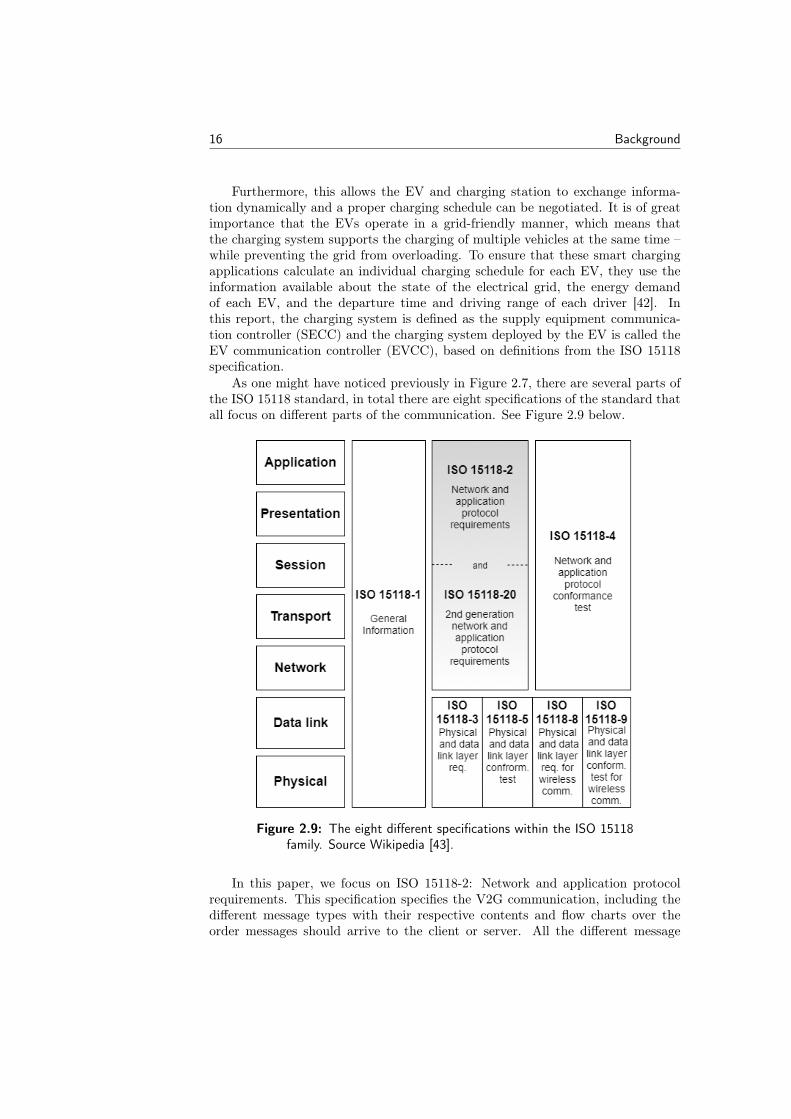
As one might have noticed previously in Figure 2.7, there are several parts ofthe ISO 15118 standard, in total there are eight specifications of the standard thatall focus on different parts of the communication. See Figure 2.9 below.
Figure 2.9: The eight different specifications within the ISO 15118family. Source Wikipedia [43].
In this paper, we focus on ISO 15118-2: Network and application protocolrequirements. This specification specifies the V2G communication, including thedifferent message types with their respective contents and flow charts over theorder messages should arrive to the client or server. All the different message
Background 17
types can be found in Appendix A.Before going into specifics about how a session works, it is important to men-
tion how data is encapsulated. In the ISO 15118 specification [16], the V2Gtransfer protocol (V2GTP) is the transport protocol for V2G data transfers (usedat the session layer) and can be considered the HTTP of V2G communications.The V2GTP frame contains a header and a payload field. The header has a lengthof eight bytes with four different parameters: protocol version, inverse protocolversion, message type, and payload length, while the V2GTP payload field repre-sents the actual data to be transferred. Regardless of which message type is used,a V2G message will always be encapsulated according to this format.
A session starts with the client multicasting its demand for charging, a so-called SECC discovery protocol (SDP) request is sent via UDP. Through the SDPrequest-response pair a security parameter, which indicates whether TCP or TLSshould be used for the session, is set. Following this, a server initiates the TCP orTLS session setup with a handshake [16].
The messages sent after the SDP request-response pair use the XML/EXIdata representation format. Efficient XML interchange (EXI) is a compact rep-resentation of the extensible markup language (XML). Using a relatively simplealgorithm, which is amenable to fast and compact implementation, and a smallset of datatype representations, EXI reliably produces efficient encodings of XMLevent streams [44].
V2G communication can be AC or DC specific and there are message typesthat are only sent for AC respective DC communication. It is stated in Appendix Awhich messages are AC or DC-specific [16].
There is also the matter of authentication of user and payment method. Onecan use external identification means (EIM), the traditional method of paymentwith card or cash. In addition to EIM, the ISO 15118 specification introduces afeature called plug & charge (PnC) [42]. PnC both enables the EV to automat-ically identify itself to the charging station and to gain authorized access to theenergy it needs to recharge. Moreover, PnC deploys several cryptographic mech-anisms to ensure that the communication maintains confidentiality, integrity, andauthenticity of all exchanged data.
Security in ISO 15118
The security of the ISO 15118 specification is based on the digital certificates andpublic key infrastructure made available through the PnC feature. The ISO 15118specification follows a common hybrid approach, using asymmetric-key algorithmsto create and verify digital signatures, in addition to agreeing upon a symmetrickey. The symmetric key can then be used to encrypt and decrypt all messagesduring a charging session with a symmetric key algorithm. In order to achieve asuccessful PnC session, both the EV and the charging system must support thethree main security characteristics: confidentiality, integrity, and authenticity [45].
First off, the messages must be encrypted to ensure that no third party ormalicious actor will be able to eavesdrop on the communication. Secondly, it isimportant that if a message has been modified, it is detected in order to attaindata integrity. Lastly, to ensure that the other party is who they claim to be,
18 Background
the EV and charging system must verify its communication counterpart. To makesure that these three security characteristics are fulfilled, a TLS session is used tosecure the V2G communication.
For the security of the transport layer, the communicated messages betweenEVCC and SECC are encrypted using a symmetric key negotiated during theTLS key negotiation phase. The key agreement protocol used to agree upon ashared symmetric TLS session key is called elliptic curve Diffie-Hellman (ECDH)[45]. ECDH is a key agreement protocol that allows two parties, each having aprivate/public key pair (asymmetric), to establish a shared secret over an insecurechannel [46]. The symmetric key is used to encrypt and decrypt the messages usinga block cipher suite called AES_128_CBC_SHA256. To decrypt the sender’smessage the receiver needs the symmetric key. Therefore, a message cannot bedecrypted if one does not have access to the key, ensuring confidentiality [16].
Similar to the TLS cipher suite, the ISO 15118 specification provides anotherkey agreement scheme that establishes an encryption key for certain messages withsensitive data. This encryption key is used to provide message security – mainlyutilized to encrypt private keys sent between the EVCC and another third party.In this scheme, the ephemeral-static ECDH protocol is used, which allows for thecreation of a shared session key from a static public key already present inside thevehicle. This is further explained in Annex G in the ISO 15118 specification [16].
Verifying authenticity and data integrity are features that are realized throughasymmetric cryptography, using a key pair composed of a private/public key. Theprivate key must be kept secret and is only used by the entity to which it belongs inorder to create digital signatures. The public key is distributed to peers in the sameecosystem and used to verify the signature that was created with the associatedprivate key. The public-key cryptography is used to create and verify signaturesin order to control the authenticity of the sender and the integrity of the receivedmessage. The cryptographic algorithm used for this is the elliptic curve digitalsignature algorithm (ECDSA) [45]. In addition to the security measurementsdescribed by the ISO 15118 specification, there are also security methods built intoTLS. For example, the message authentication code algorithm, which efficientlyverifies the authenticity of the message given a symmetric key and a tag. Themessage is accepted when the message and tag are not tampered with or forged,otherwise, the message is rejected.
The ISO 15118 specification outlines an ecosystem of digital certificates thatneed to be in place for PnC to work. This is where public key infrastructures(PKIs) come into play. A PKI defines an infrastructure including different entities,policies, and devices that can manage, distribute and revoke digital certificatesbased on asymmetric cryptography. In a PKI system, public keys are associatedwith an identity through a process of registration and issuance of certificates.The connection is established both at and by a certificate authority (CA) [47].These CAs manage the creation, storage, distribution, and revocation of digitalcertificates. A digital certificate is an electronic document used to verify that apublic key belongs to an authorized party. Therefore, it is also known as a publickey certificate.
In the case of the ISO 15118 specification, there are SECC certificates that aresigned and placed in the charging station by a certified charging operator. The
Background 19
EVCC uses these to authenticate the SECC over TLS. There are also contract cer-tificates in the EVCC to authenticate against an SECC and/or secondary actor,these are used for signing in the V2G session. Lastly, there are V2G root cer-tificates and potential Sub-CA certificates that certify the aforementioned SECCcertificates and contract certificates. These are all essential to maintaining trustand security in the PnC process.
One of the biggest improvements with the PnC feature is that the driver doesnot need to do anything in order to authenticate the vehicle, beyond plugging thecharging cable into the vehicle and charging station. There is neither a need forentering a credit card, nor scanning a QR code, nor opening an app. This makesthe ISO 15118 specification very user-friendly [42].
2.4 Security in Vehicles
Confidentiality means that one should ensure that communication between au-thorized parties is secret and unauthorized access to data transmission in vehiclesshould be impossible. It is also essential to make sure that unauthorized modi-fication of data is infeasible or at minimum detected. The prospect of unautho-rized modification to system assets or actual transmitted data is obviously badand includes writing, changing and deleting messages. It is also important thatunauthorized modifications of any hardware or software in the vehicle are eitherinfeasible or at least detectable. The purpose of authentication and identificationis to establish and assure that the origin of the message is correctly identified. Ina vehicle, there is a great need for this, because only authenticated and identifi-able assets should be able to communicate with a certain ECU [48]. Security invehicles is becoming a serious matter in the car manufacturing industry and thereis engagement from a legislative perspective as well (e.g., the SPY Car Act inthe US [49]). With autonomous driving and integration of V2V and V2I featuresgaining momentum, new security vulnerabilities are inevitable. This places theresponsibility on the manufacturers to use proper and proven security architecturein their vehicles.
When considering safety in vehicles, one of the most prominent aspects is theconcern of passenger safety. When Miller and Valasek managed to gain remotecontrol over a 2014 Jeep Cherokee, they show that a breach of the internal networkcan have fatal consequences [50, 51]. With their remote exploitation, they sentCAN messages to activate blinkers, lock the car, prompt remote steering andkill the engine. Whereas safety is the number one priority, privacy and integrityconcerns are expected to be upheld as well, just as it is for modern websites today.As a practical example, no one should be able to track a driver by accessing GPSdata or eavesdrop on a hands-free phone call.
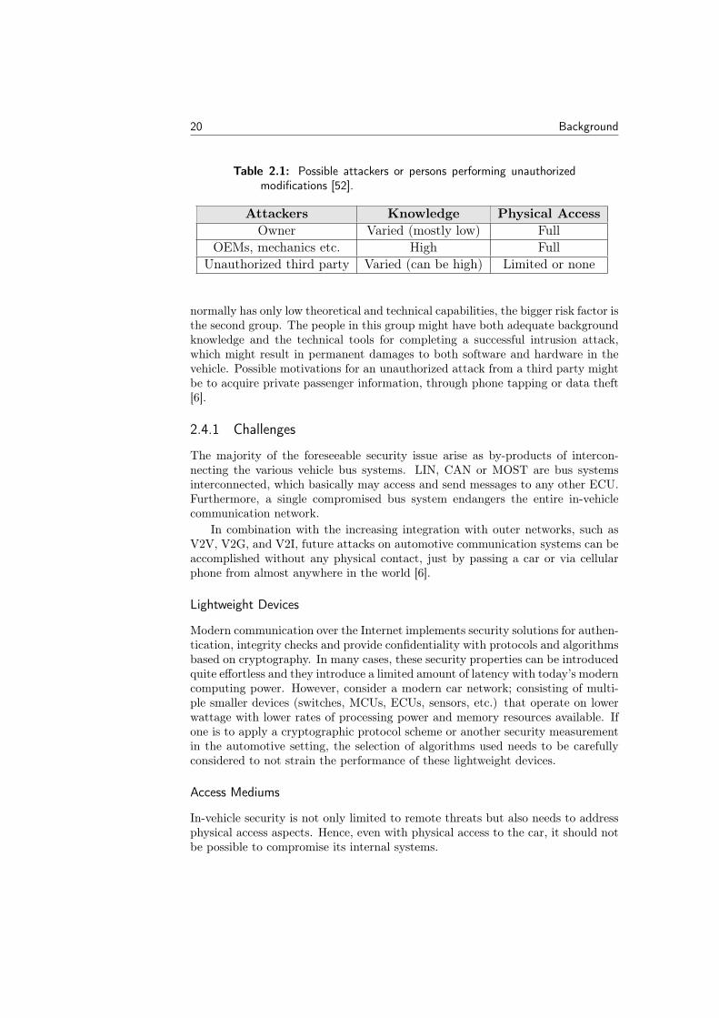
Table 2.1 below shows the three general different groups of possible systemintruders of a vehicle: first-hand user, such as the car owner; car manufacturers,car mechanics and garage personnel; different unauthorized parties, such as aninstitution [6].
The first two attacker groups have full physical access to all transmission mediaand respective affected devices of the automotive network. As the car owner
20 Background
Table 2.1: Possible attackers or persons performing unauthorizedmodifications [52].
Attackers Knowledge Physical AccessOwner Varied (mostly low) Full
OEMs, mechanics etc. High FullUnauthorized third party Varied (can be high) Limited or none
normally has only low theoretical and technical capabilities, the bigger risk factor isthe second group. The people in this group might have both adequate backgroundknowledge and the technical tools for completing a successful intrusion attack,which might result in permanent damages to both software and hardware in thevehicle. Possible motivations for an unauthorized attack from a third party mightbe to acquire private passenger information, through phone tapping or data theft[6].
2.4.1 Challenges
The majority of the foreseeable security issue arise as by-products of intercon-necting the various vehicle bus systems. LIN, CAN or MOST are bus systemsinterconnected, which basically may access and send messages to any other ECU.Furthermore, a single compromised bus system endangers the entire in-vehiclecommunication network.
In combination with the increasing integration with outer networks, such asV2V, V2G, and V2I, future attacks on automotive communication systems can beaccomplished without any physical contact, just by passing a car or via cellularphone from almost anywhere in the world [6].
Lightweight Devices
Modern communication over the Internet implements security solutions for authen-tication, integrity checks and provide confidentiality with protocols and algorithmsbased on cryptography. In many cases, these security properties can be introducedquite effortless and they introduce a limited amount of latency with today’s moderncomputing power. However, consider a modern car network; consisting of multi-ple smaller devices (switches, MCUs, ECUs, sensors, etc.) that operate on lowerwattage with lower rates of processing power and memory resources available. Ifone is to apply a cryptographic protocol scheme or another security measurementin the automotive setting, the selection of algorithms used needs to be carefullyconsidered to not strain the performance of these lightweight devices.
Access Mediums
In-vehicle security is not only limited to remote threats but also needs to addressphysical access aspects. Hence, even with physical access to the car, it should notbe possible to compromise its internal systems.
Background 21
Connectivity
One could argue connectivity is a double-edged sword in the context of in-vehiclesecurity. As car network architecture is growing, with the introduction of V2V,V2G, and V2I concepts there will be new useful features available. For instance,vehicles will be able to find available parking spaces at a parking lot, share in-formation about immediate dangers on the road or support autonomous drivingsystems with traffic information. With all these benefits, there will be trade-offsbetween conveniences and the potential attack surfaces, introduced for exploita-tion or violation of privacy. It is therefore crucial that independent componentsand sub-domains, as well as the entire internal network of the car, are secured forthis new paradigm of connectivity.
2.4.2 Firewall
A firewall is a system used to prevent unauthorized access between networks,primarily screening traffic entering or exiting a private network. It is either im-plemented in hardware or software depending on the network, or in some cases,a combination of both. Firewalls have been used as the first barrier of entry forattacks over a long period of time, and they are now being integrated into modernvehicles. A firewall typically has one or several of the following functionalities (asmentioned by Cisco in [53]):
• Packet filtering: The firewall inspects each and every packet entering orleaving the network. Based on a certain set of rules, it accepts or rejectspackets.
• Stateful filtering: A stateful firewall remembers the state of previous com-munications between parties. Thus, it can filter based on expected state orconnection properties as communication is taking place.
• Operating as a proxy: The firewall acts as a proxy for applications by han-dling e.g., connection establishment in their place.
• Application layer filtering: Newer generations of firewalls can inspect certainapplication protocols such as HTTP, FTP or DNS.
Stateful Inspection
Stateful packet inspection is a type of inspection method done in software and iscarried out with shallow packet inspection into the transport layer. It recalls thestate of previous communications with an entry into a table, this entry will serve asa means to compare incoming packets, belonging to the same session, allowing forfaster processing of arriving packets. A typical characteristic of a stateful filter ishigh latency at the start of reception – since no previous matching has been donein a clean state – but it will quickly become effective as entries are added to thetable. A downside to using stateful packet filters are the memory requirements,maintaining the state of active connections on the network [54].
22 Background
2.4.3 Intrusion Detection System: IDS
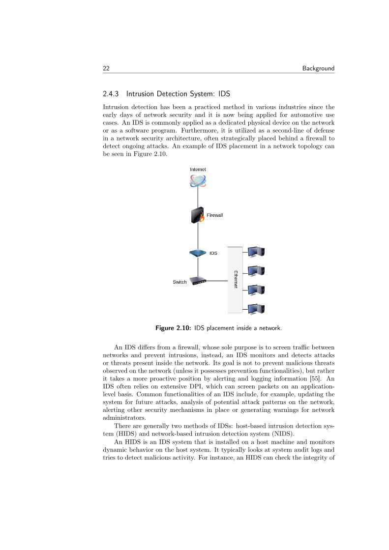
Intrusion detection has been a practiced method in various industries since theearly days of network security and it is now being applied for automotive usecases. An IDS is commonly applied as a dedicated physical device on the networkor as a software program. Furthermore, it is utilized as a second-line of defensein a network security architecture, often strategically placed behind a firewall todetect ongoing attacks. An example of IDS placement in a network topology canbe seen in Figure 2.10.
Figure 2.10: IDS placement inside a network.
An IDS differs from a firewall, whose sole purpose is to screen traffic betweennetworks and prevent intrusions, instead, an IDS monitors and detects attacksor threats present inside the network. Its goal is not to prevent malicious threatsobserved on the network (unless it possesses prevention functionalities), but ratherit takes a more proactive position by alerting and logging information [55]. AnIDS often relies on extensive DPI, which can screen packets on an application-level basis. Common functionalities of an IDS include, for example, updating thesystem for future attacks, analysis of potential attack patterns on the network,alerting other security mechanisms in place or generating warnings for networkadministrators.
There are generally two methods of IDSs: host-based intrusion detection sys-tem (HIDS) and network-based intrusion detection system (NIDS).
An HIDS is an IDS system that is installed on a host machine and monitorsdynamic behavior on the host system. It typically looks at system audit logs andtries to detect malicious activity. For instance, an HIDS can check the integrity of
Background 23
files or check against known signature patterns in a database.A NIDS on the other hand, is referring to an IDS residing on the network. It
acts as an inline sniffer, sampling packets as they arrive at the network. Typically,you would see a NIDS incorporated into a network switch or central gateway, tobe able to process all network traffic. Consequently, a NIDS device must allow forhigh-speed processing of packets to avoid introducing bottlenecks in the network.
There are different detection methods for how to detect anomalous behaviorin an IDS. Namely, signature-, anomaly- and specification-based methods. Oneapproach is to use one of these features to secure a system, or they could be usedin unison as a hybrid IDS implementation.
Signature-based Detection
A signature-based detection engine relies on pattern matching to detect knownmalicious behavior in sequences of bytes or subsets of malicious instructions. Torealize a signature-based approach one has to define unique rule sets for a specificnetwork. For instance, detecting and not responding to an ICMP ECHO requestallows a host to not be discovered by a network mapper (nmap) scan. The commandnmap is used to discover hosts and services on a computer network by sendingpackets and analyzing the responses. It can be used to perform port scan- or portsweep attacks.
In signature-based methods pattern matching algorithms are the central com-ponent determining the performance. Since a software-based IDS operates withinthe boundaries of a typical application, there are subjects of concern regardingCPU usage, memory, and power consumption. There have been multiple studieson enhanced algorithms, some examples are Myers algorithm [56] and Wu-Manber[57]. Nevertheless, which algorithm should be applied depends on the networkrequirements and accessible hardware on a given system.
A clear advantage of signature-based implementations is the ability to use amultitude of signature patterns that can protect against already known attackpatterns, this safely secures the system against discovered threats and gives theincentive to share rules in security communities. Although, the signature-basedmethod has its downsides as well, mainly since it cannot protect against zero-dayattacks (attacks on vulnerabilities that have not been patched or made public)and signatures need to be updated continuously to keep up with new upcomingthreats.
Anomaly-based Detection
Anomaly-based methods take another approach to detect threats and they findmalicious traffic through discrepancies from normal behavior instead. Conversely,from a signature-based method, an anomaly-based IDS tries to detect previouslyunknown attacks and enables protection against future attack vectors. Although,there are negative aspects of anomaly-based detection methods. One is the ten-dency for higher false positive rates [58].
For statistical approaches, the goal is to find a baseline for the characteristicsof communications over the network such as type of packets sent, frequency ofpackets, changes in payload size or data content and sequences of packets. After
24 Background
reaching a baseline, the IDS then classifies traffic as normal or abnormal, send-ing out an alert if the system receives any suspicious packets. For example, ananomaly-based system can detect if a flooding or replay attack is being performedif it keeps track of how often a message type is usually sent through the network.It may also detect whether packets are being dropped based on the same frequencycheck.
As mentioned, anomaly-based approaches try to categorize a baseline and findoutliers that are new unknown threats, such challenges can also be addressed withthe use of machine learning. Yihunie et al. [59] presented an analysis using theNSL-KDD dataset, evaluating the performance of several machine learning modelsincluding stochastic gradient descent, random forests and support vector machine.Their work highlights valuable comparisons between these models where randomforests outperformed the other classifiers. A random forests classifier works bytraining many decision trees on random subsets of the features, then averagingout their predictions.
Specification-based Detection
Another method for detection in an IDS is a specification-based approach, wheredeviations from set specification requirements are used to detect malicious packets.Usually, this is achieved by setting up explicit rules for each protocol’s specificationand thereby finding deviations from normal behavior. Properties such as sourceand destination correspondence, data volume, message times or header values areall examples of metrics that could be taken into consideration. Another moregeneral example could be not allowing processes certain sequences of system calls[60]. Differing from a pure anomaly-based method, it does not tend to suffer fromhigh false positive rates. In part since its rule-based principles yield deterministicperformance similar to that of signature-based methods.
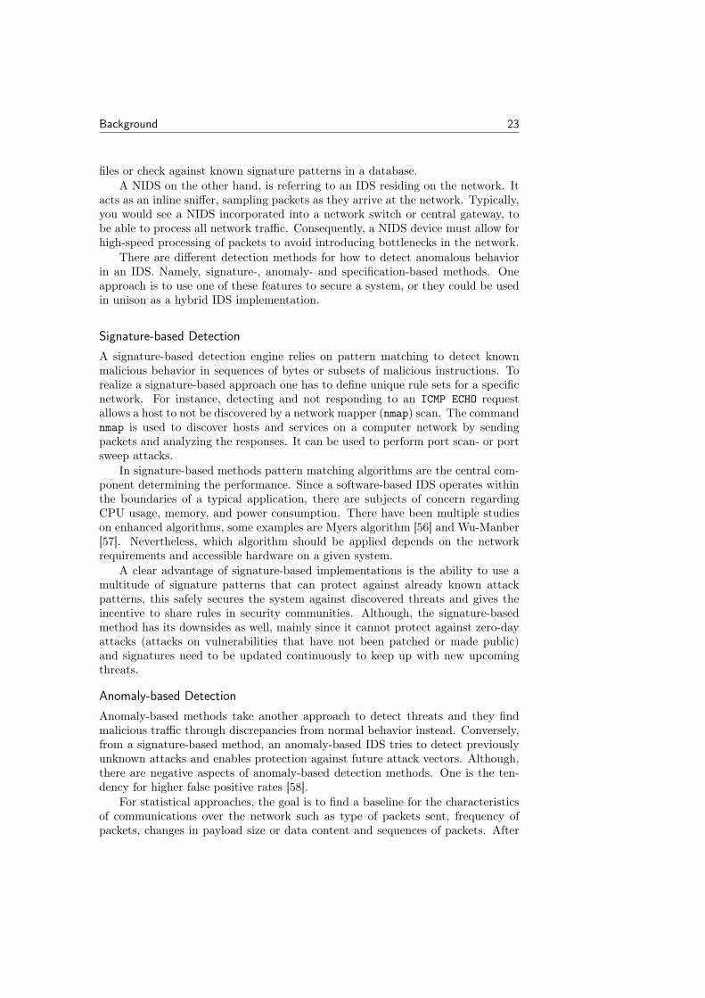
Figure 2.11: A snippet of V2G communication from the ISO 15118specification.
For example, the ISO 15118 standard specifies a flow chart where one canfollow the exact types of messages that should be following each other. Therefore,a specification-based IDS might include some sort of a decision tree ensuring that
Background 25
the V2G communication is following its specification. See Figure 2.11 for a smallsnippet of a V2G session flowchart.
SNORT
SNORT is an open source NIDS solution, which can perform real-time traffic anal-ysis and logging of packets on IP-based networks [61]. SNORT uses a signature-database to match rules in the detection engine, where a signature is defined asdistinctive marks or characteristics being present in an exploit [62]. These rules arecontinuously updated by its community to stay on top of current vulnerabilities.
2.4.4 Deep Packet Inspection: DPI
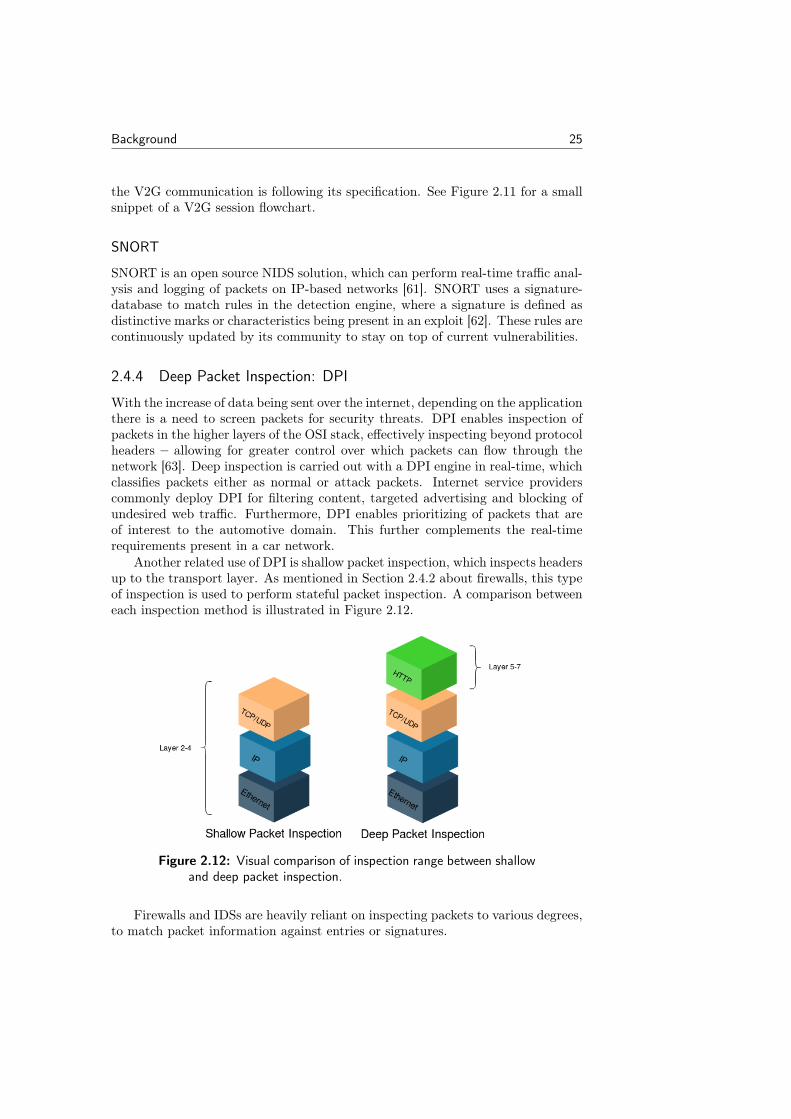
With the increase of data being sent over the internet, depending on the applicationthere is a need to screen packets for security threats. DPI enables inspection ofpackets in the higher layers of the OSI stack, effectively inspecting beyond protocolheaders – allowing for greater control over which packets can flow through thenetwork [63]. Deep inspection is carried out with a DPI engine in real-time, whichclassifies packets either as normal or attack packets. Internet service providerscommonly deploy DPI for filtering content, targeted advertising and blocking ofundesired web traffic. Furthermore, DPI enables prioritizing of packets that areof interest to the automotive domain. This further complements the real-timerequirements present in a car network.
Another related use of DPI is shallow packet inspection, which inspects headersup to the transport layer. As mentioned in Section 2.4.2 about firewalls, this typeof inspection is used to perform stateful packet inspection. A comparison betweeneach inspection method is illustrated in Figure 2.12.
Figure 2.12: Visual comparison of inspection range between shallowand deep packet inspection.
Firewalls and IDSs are heavily reliant on inspecting packets to various degrees,to match packet information against entries or signatures.
26 Background
There exist two types of DPI: hardware and software solutions. Under normalcircumstances, regular switches or processors have limited capabilities to host aDPI system due to a lacking performance under heavy loads of traffic. HardwareDPI uses specialized hardware to accelerate the inspection engine’s processingtime, which enables wire-speed inspection of packets. Since hardware-based so-lutions have a higher price tag, larger corporations often use these. The nDPIlibrary [64] and Solarwinds NPM [65] are, on the other hand, practical examplesof software-based DPI. Instead of relying on hardware, these products apply asoftware-based DPI engine for inspecting packets on an application level.
Chapter3Method
This chapter describes the methodology, which has been used in order to receivethe results in Chapter 6 and helped us draw our conclusions. The chapter in-cludes a description of hardware and software used in order to implement our IDS.Furthermore, test and performance evaluation methods are also described.
3.1 General Research
In the beginning, we did not quite know what to anticipate or expect of thisproject with no previous experience in embedded security. Upon meeting Boschand ESCRYPT a couple of times the master’s thesis took form. We then startedto outline the scope and conduct general research. There had been a studentcompleting his master’s thesis at ESCRYPT the previous semester [13] and ourproject was meant to be a continuation of that. We used the resulting reportas our base in the beginning. Thereafter, trying to collect as much informationabout implementations of IDSs, network systems for in-vehicle communicationand automotive security. The essential research papers used as basis for e.g.,establishing requirements, choosing the different components and selecting featuresfor the IDS are presented in Section 1.6.
After some general research, we realized the sizable challenge of continuingthe previous work and implementing a complete firewall and IDPS solution. Oursupervisors recommended that we narrow our scope down to only focus on oneprotocol, namely ISO 15118. With access to the specification for ISO 15118, westrove to understand how the different actors in a V2G communication sessionoperate, what the different message types were and which functionalities theyprovide. Thereby, we were able to gain a more in-depth view of how an in-vehicleIDS would operate and which features were of importance.
3.2 Establish Requirements and Select a Concept
After we had gained insight into how an IDS works and what requirements areassociated with automotive networks, we established the requirements for an in-vehicle IDS from our research. We settled on implementing two detection methodsfor our IDS: specification-based and anomaly-based detection. The requirements,motivations, and decisions related to the IDS are discussed in Chapter 4. Through
27
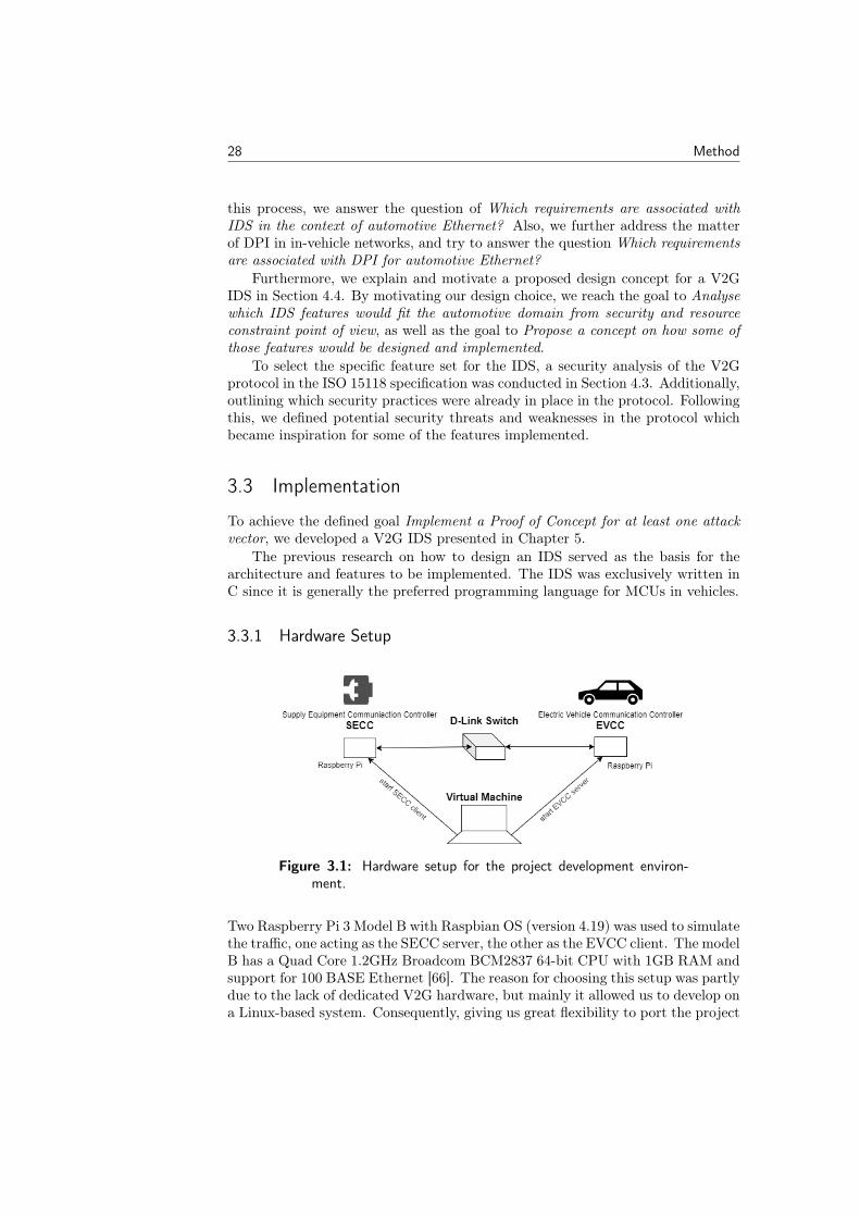
28 Method
this process, we answer the question of Which requirements are associated withIDS in the context of automotive Ethernet? Also, we further address the matterof DPI in in-vehicle networks, and try to answer the question Which requirementsare associated with DPI for automotive Ethernet?
Furthermore, we explain and motivate a proposed design concept for a V2GIDS in Section 4.4. By motivating our design choice, we reach the goal to Analysewhich IDS features would fit the automotive domain from security and resourceconstraint point of view, as well as the goal to Propose a concept on how some ofthose features would be designed and implemented.
To select the specific feature set for the IDS, a security analysis of the V2Gprotocol in the ISO 15118 specification was conducted in Section 4.3. Additionally,outlining which security practices were already in place in the protocol. Followingthis, we defined potential security threats and weaknesses in the protocol whichbecame inspiration for some of the features implemented.
3.3 Implementation
To achieve the defined goal Implement a Proof of Concept for at least one attackvector, we developed a V2G IDS presented in Chapter 5.
The previous research on how to design an IDS served as the basis for thearchitecture and features to be implemented. The IDS was exclusively written inC since it is generally the preferred programming language for MCUs in vehicles.
3.3.1 Hardware Setup
Figure 3.1: Hardware setup for the project development environ-ment.
Two Raspberry Pi 3 Model B with Raspbian OS (version 4.19) was used to simulatethe traffic, one acting as the SECC server, the other as the EVCC client. The modelB has a Quad Core 1.2GHz Broadcom BCM2837 64-bit CPU with 1GB RAM andsupport for 100 BASE Ethernet [66]. The reason for choosing this setup was partlydue to the lack of dedicated V2G hardware, but mainly it allowed us to develop ona Linux-based system. Consequently, giving us great flexibility to port the project
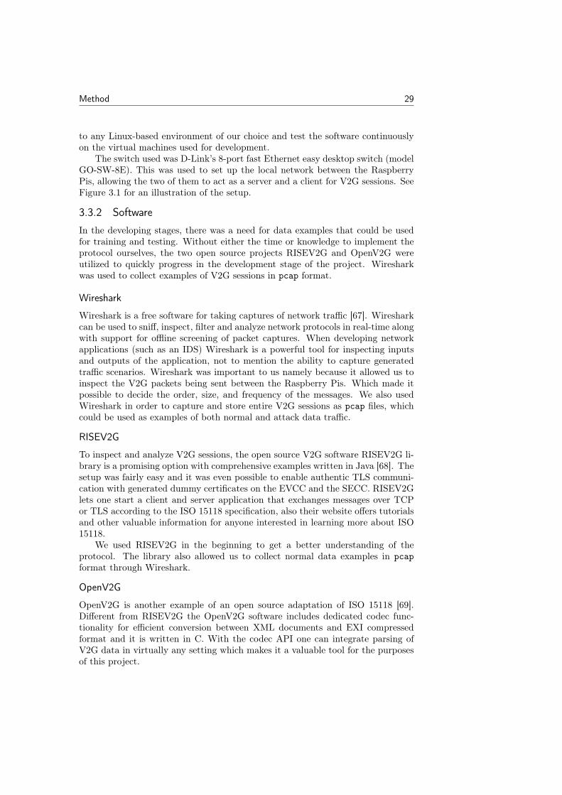
Method 29
to any Linux-based environment of our choice and test the software continuouslyon the virtual machines used for development.
The switch used was D-Link’s 8-port fast Ethernet easy desktop switch (modelGO-SW-8E). This was used to set up the local network between the RaspberryPis, allowing the two of them to act as a server and a client for V2G sessions. SeeFigure 3.1 for an illustration of the setup.
3.3.2 Software
In the developing stages, there was a need for data examples that could be usedfor training and testing. Without either the time or knowledge to implement theprotocol ourselves, the two open source projects RISEV2G and OpenV2G wereutilized to quickly progress in the development stage of the project. Wiresharkwas used to collect examples of V2G sessions in pcap format.
Wireshark
Wireshark is a free software for taking captures of network traffic [67]. Wiresharkcan be used to sniff, inspect, filter and analyze network protocols in real-time alongwith support for offline screening of packet captures. When developing networkapplications (such as an IDS) Wireshark is a powerful tool for inspecting inputsand outputs of the application, not to mention the ability to capture generatedtraffic scenarios. Wireshark was important to us namely because it allowed us toinspect the V2G packets being sent between the Raspberry Pis. Which made itpossible to decide the order, size, and frequency of the messages. We also usedWireshark in order to capture and store entire V2G sessions as pcap files, whichcould be used as examples of both normal and attack data traffic.
RISEV2G
To inspect and analyze V2G sessions, the open source V2G software RISEV2G li-brary is a promising option with comprehensive examples written in Java [68]. Thesetup was fairly easy and it was even possible to enable authentic TLS communi-cation with generated dummy certificates on the EVCC and the SECC. RISEV2Glets one start a client and server application that exchanges messages over TCPor TLS according to the ISO 15118 specification, also their website offers tutorialsand other valuable information for anyone interested in learning more about ISO15118.
We used RISEV2G in the beginning to get a better understanding of theprotocol. The library also allowed us to collect normal data examples in pcapformat through Wireshark.
OpenV2G
OpenV2G is another example of an open source adaptation of ISO 15118 [69].Different from RISEV2G the OpenV2G software includes dedicated codec func-tionality for efficient conversion between XML documents and EXI compressedformat and it is written in C. With the codec API one can integrate parsing ofV2G data in virtually any setting which makes it a valuable tool for the purposesof this project.
30 Method
libpcap
Another important C library used in the project is libpcap (full name of the pack-age is libpcap0.8-dev), specifically we used version 1.8.1 to achieve compatibilitywith the corresponding Debian 10 distribution deployed on the Raspberry Pi. ItsAPI provides function calls for reading of pcap files as well as live capturing ofpackets with filtering capabilities.
Virtualbox
For development, we used Virtualbox to run VMs on our PCs. To test our softwarewe used a virtual machine with Ubuntu 18.04.3 LTS (Bionic).
3.4 Evaluation Framework
To test and evaluate our implementation, a series of metrics were collected duringa real-time session, where different attack scenarios were deployed on top of thesession. The attack client generates data for which packets contain threats andwill be compared against detections made by the IDS. After conducting the testswe were able to answer the question What functions of IDS are valuable from theperspective of automotive Ethernet?
3.4.1 Performance Evaluation
An IDS can be seen as a binary classification method and therefore it is suitableto evaluate it accordingly. To evaluate the performance of the V2G IDS we basedour evaluation metrics on the recent work of Stachowski et al. [15]. In their work,they present an assessment approach where quantitative and qualitative metricsare recorded by rendering the IDS as a binary classifier. The metrics chosen forevaluating and testing the IDS can be seen in Table 3.1 and are based on theirreport. The detection speed defined in [15] was redefined as classification speedand further include normal packet classifications. Our motivation for this is thatonly measuring how long time it takes to detect attacks does not capture theperformance for the majority of packets – which are normal packets (negatives).We further expanded the classification speed to also include best, worst and av-erage speeds, which allows for further insight into the speed dynamics observedin the IDS. Finally, we switched out accuracy for balanced accuracy to evaluatethe overall accuracy of our model, weighing both correct true positive and truenegative classifications rates equally. The balanced accuracy metric is better thanthe normal accuracy for imbalanced data sets. We had imbalanced data sets inour implementation, as there was a significantly larger amount of normal packetscompared to malicious packets [70].
As previously mentioned, the IDS can be seen as a binary classification sys-tem where packets are either classified as a positive (a detection) or a negative.A positive classification implies an attack is ongoing in the system while a neg-ative represents all other possible events (including normal traffic and erroneousmessages).
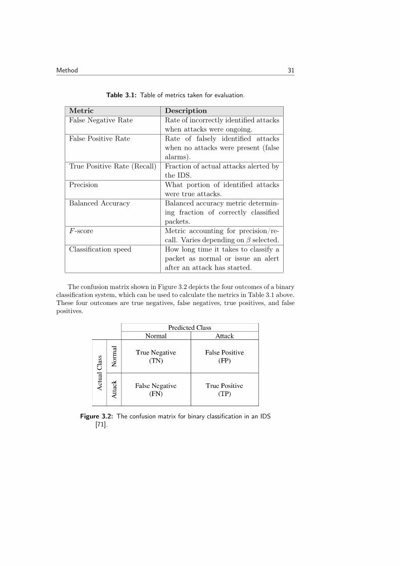
Method 31
Table 3.1: Table of metrics taken for evaluation.
Metric DescriptionFalse Negative Rate Rate of incorrectly identified attacks
when attacks were ongoing.False Positive Rate Rate of falsely identified attacks
when no attacks were present (falsealarms).
True Positive Rate (Recall) Fraction of actual attacks alerted bythe IDS.
Precision What portion of identified attackswere true attacks.
Balanced Accuracy Balanced accuracy metric determin-ing fraction of correctly classifiedpackets.
F -score Metric accounting for precision/re-call. Varies depending on β selected.
Classification speed How long time it takes to classify apacket as normal or issue an alertafter an attack has started.
The confusion matrix shown in Figure 3.2 depicts the four outcomes of a binaryclassification system, which can be used to calculate the metrics in Table 3.1 above.These four outcomes are true negatives, false negatives, true positives, and falsepositives.
Figure 3.2: The confusion matrix for binary classification in an IDS[71].

32 Method
Negative and Positive Rates
True positive rate (TPR) or recall is defined as the correctly identified attacksagainst the system. This metric is used to calculate the balanced accuracy andF -score. Therefore, a classifier that produces no false negatives will attain a recallof 1.0.
TPR (Recall) =TP
TP + FN
Moreover, the false positive rate (FPR) defines the incorrectly identified at-tacks against the system; normal packets being classified as attacks. The optimalFPR would be a rate of 0 with no false positives.
FPR =FP
FP + TN
The false negative rate (FNR) shows the rate of incorrectly rejected attacksagainst the system; attacks being identified as normal packets. Similar to theFPR, the FNR best case performance has a rate of 0 with no false negatives.
FNR =FN
FN + TP
Precision
Precision is defined as the proportion of positive identifications (attacks) that werecorrectly detected. Hence, deciding how many positives were actually correct. Aperfect precision score is 1.0 with no false positives. An important observationis that the precision does only account for positive classifications and does notconsider negatives.
Precision =TP
TP + FP
Precision together with recall (TPR) are both important metrics to measurethe effectiveness of a classifier. The performance of a classifier considering preci-sion and recall typically shows a trade-off between these two metrics. Where theincrease of one will dampen the other.
F -score
The F -score is a measurement of a test’s accuracy, moreover, its the harmonicmean of precision and recall. As mentioned before, models normally experiencea trade-off between precision and recall, and F -score tries to combine both thesemetrics into one score. The F -score is also a weighted metric that can be tunedby changing the β variable. A β value of 1 (called f1-score) balances the scoreevenly between precision and recall, while a value of 0.5 (known as f0.5-score)would weigh precision higher than recall. As a result, depending on if a supplieror OEM prefers higher recall or precision, the F -score can be weighted towards
Method 33
their preferred configuration of an IDS. The perfect F -score that can be attainedis 1.0.
Fβ = (1 + β2)precision · recall
(β2 · precision) + recall
Balanced Accuracy
Balanced accuracy can be defined as the fraction of predictions the IDS got right. Itcan further be seen as a more conclusive metric displaying how accurate the overallperformance of a classifier is – considering both true positive and true negativeclassification rates. This is important since the balanced accuracy compensates forimbalanced data sets (which normal accuracy does not) and yields more reflectiveresults as to how the model is actually performing. A score of 1.0 is a perfectresult for this accuracy metric.
BalancedAccuracy =TPR+ (1− FPR)
2
3.4.2 Testing Different Configurations
When implementing the anomaly-based detection we had a lot of issues figur-ing out which statistical approach we should use. After some trials and errors,we settled on using the minimum and maximum value from expected data. Thefrequency, payload length and timeout for request-response pairs were checkedby comparing them to expected normal V2G session data. All values from theV2G session examples were considered to be normal, and we could use the low-est possible values for minimum and the highest possible values for maximum.For example, in the session examples, a ChargeParameterDiscovery request oc-curred once or twice per session. Therefore, the anomaly-based part would detectif the request occurred five times during a session. It is not expected for theChargeParameterDiscovery request to be sent that many times, and it would beclassified as abnormal behavior. The same logic was applied for payload lengthand timeout detection.
There were three reasons why we chose the minimum and maximum approach.Firstly, we saw that Salman and Bresch [9] successfully used this approach whenimplementing their IDS for the CAN bus. Secondly, when we asked the researchteam for IDS at Bosch they also utilized the static bound approach. Lastly, touse normal data as acceptable data seemed logical. There is no data from theV2G session examples that can be seen as attack data. Because we had capturesof normal data sessions, it seemed logical to use this data in order to set lower-and upper bound (LnUB) thresholds. This LnUB threshold is synonymous witha classification threshold, which determines the boundary for when a message isconsidered an attack or threat. We collected data for each message type, and itwas not too complex to give each message type its own LnUB.
ESCRYPT also suggested the idea of adding a tolerance threshold. Theyargued that a few errors could go undetected without affecting the detection per-formance too negatively. The tolerance threshold turned out to be effective, and
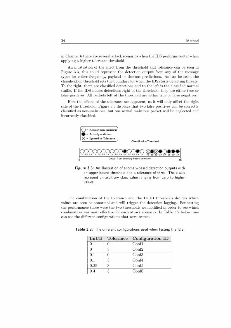
34 Method
in Chapter 6 there are several attack scenarios when the IDS performs better whenapplying a higher tolerance threshold.
An illustration of the effect from the threshold and tolerance can be seen inFigure 3.3, this could represent the detection output from any of the messagetypes for either frequency, payload or timeout predictions. As can be seen, theclassification threshold sets the boundary for when the IDS starts detecting threats.To the right, there are classified detections and to the left is the classified normaltraffic. If the IDS makes detections right of the threshold, they are either true orfalse positives. All packets left of the threshold are either true or false negatives.
Here the effects of the tolerance are apparent, as it will only affect the rightside of the threshold. Figure 3.3 displays that two false positives will be correctlyclassified as non-malicious, but one actual malicious packet will be neglected andincorrectly classified.
Figure 3.3: An illustration of anomaly-based detection outputs withan upper bound threshold and a tolerance of three. The x-axisrepresent an arbitrary class value ranging from zero to highervalues.
The combination of the tolerance and the LnUB thresholds decides whichvalues are seen as abnormal and will trigger the detection logging. For testingthe performance those were the two thresholds we modified in order to see whichcombination was most effective for each attack scenario. In Table 3.2 below, onecan see the different configurations that were tested.
Table 3.2: The different configurations used when testing the IDS.
LnUB Tolerance Configuration ID0 0 Conf10 3 Conf20.1 0 Conf30.1 3 Conf40.25 3 Conf50.4 3 Conf6
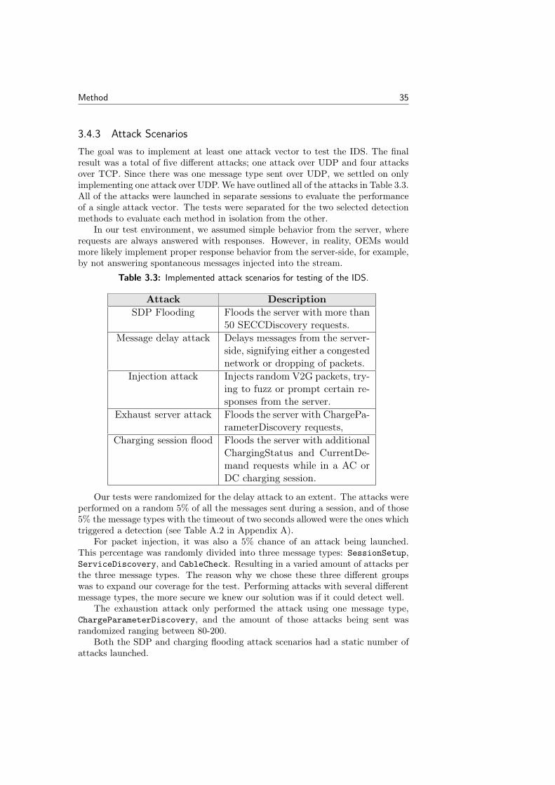
Method 35
3.4.3 Attack Scenarios
The goal was to implement at least one attack vector to test the IDS. The finalresult was a total of five different attacks; one attack over UDP and four attacksover TCP. Since there was one message type sent over UDP, we settled on onlyimplementing one attack over UDP.We have outlined all of the attacks in Table 3.3.All of the attacks were launched in separate sessions to evaluate the performanceof a single attack vector. The tests were separated for the two selected detectionmethods to evaluate each method in isolation from the other.
In our test environment, we assumed simple behavior from the server, whererequests are always answered with responses. However, in reality, OEMs wouldmore likely implement proper response behavior from the server-side, for example,by not answering spontaneous messages injected into the stream.
Table 3.3: Implemented attack scenarios for testing of the IDS.
Attack DescriptionSDP Flooding Floods the server with more than
50 SECCDiscovery requests.Message delay attack Delays messages from the server-
side, signifying either a congestednetwork or dropping of packets.
Injection attack Injects random V2G packets, try-ing to fuzz or prompt certain re-sponses from the server.
Exhaust server attack Floods the server with ChargePa-rameterDiscovery requests,
Charging session flood Floods the server with additionalChargingStatus and CurrentDe-mand requests while in a AC orDC charging session.
Our tests were randomized for the delay attack to an extent. The attacks wereperformed on a random 5% of all the messages sent during a session, and of those5% the message types with the timeout of two seconds allowed were the ones whichtriggered a detection (see Table A.2 in Appendix A).
For packet injection, it was also a 5% chance of an attack being launched.This percentage was randomly divided into three message types: SessionSetup,ServiceDiscovery, and CableCheck. Resulting in a varied amount of attacks perthe three message types. The reason why we chose these three different groupswas to expand our coverage for the test. Performing attacks with several differentmessage types, the more secure we knew our solution was if it could detect well.
The exhaustion attack only performed the attack using one message type,ChargeParameterDiscovery, and the amount of those attacks being sent wasrandomized ranging between 80-200.
Both the SDP and charging flooding attack scenarios had a static number ofattacks launched.

Chapter4Design Concept
In this chapter, we outline requirements for an IDS and DPI, followed by a securityanalysis. Based on these requirements, the security analysis, and general researchwe motivate the design choices for the implemented IDS concept.
4.1 IDS Requirements
When establishing requirements for a security-related product the underlying tech-nology will impose limitations on any new component. In modern vehicle networks,we have mentioned that the real-time requirements are essential. For instance, thecontrol domain requires speeds around 15 microseconds for prioritized traffic [72].It is therefore essential that the IDS does not introduce further bottlenecks ordegrade performance through added latency.
The responsibility of an IDS is to detect all threats against the system withinits scope. Many of these vulnerabilities or attack signatures are known and cansuccessfully be mitigated by extending the IDS static rule set. However, the IDSshould also have the capability to detect previously unseen attack vectors in theform of zero-day attacks. Therefore, detection features monitoring deviations fromnormal session behavior are desired as well. Salman and Bresch (see Section 1.5.1)further confirm that the combination of these two principals allows for betterdetection capabilities in their hybrid implementation [9].
In any IDS, you strive for perfect performance, but in reality, it is almostimpossible to achieve due to the complexity of vehicular systems. Nonetheless,the absence of a detection could have severe consequences for the driver if theattack would be successful [50]. Additionally, false positives also need to be keptlow in quantity, since if combined with prevention mechanisms, the IDS couldremove legitimate traffic. Therefore, it can be concluded that it is desirable tokeep false positive and negative rates at a minimal level.
There is a wide variety of policies, standards, and practices employed at differ-ent automakers and OEMs. Not only does this mean every implementation in eachcar model is unique, but it also demands that the internal devices integrated in thevehicle must be uniquely configured. For this reason, an IDS component deployedin these vehicles should be configurable to adapt to any type of car. Hence, devel-opers working for OEMs should be able to extend the logic or customize detectionthresholds as they please to fit their specific requirements.
37
38 Design Concept
Finally, the resources available for a hosting ECU (e.g., number of cores, avail-able RAM, etc.) are limited. CPU requirements are one of these factors whereCPU usage, CPU time and power usage need to be optimized in order for theIDS software to run on an ECU properly. If the hardware is stressed too severely,it could reduce the lifetime of these micro-controllers and introduce unexpectederrors or shutdowns.
In conclusion, the requirements for an in-vehicle IDS in modern vehicles canbe summarized as seen in the bullet points below. This list further answers theacademic question: Which requirements are associated with IDS in the context ofautomotive Ethernet?
1. Low latency – respects high real-time requirements in vehicle communica-tions.
2. The IDS shall be able to detect known and unknown attack patterns.
3. Low false positive and negative ratio.
4. Configurable – can easily be extended or configured to adjust to a new hostnetwork.
5. The CPU requirements should be kept as low as possible.
4.2 DPI Requirements
The DPI is a core component for many systems plugged in the network includingproxies, packet filters, sniffers, IDS, and intrusion prevention systems. Networkcomponents use DPI as an essential inspector where it is applied in different layersof the OSI model [12]. As mentioned in Section 2.4.4, DPI makes it possible toinspect and analyze all layers in the OSI model.
The ability to examine the packets at the respective depth, at wire speed isnot an easy task, and such a process decreases the throughput of the system andintroduces latency. When designing an effective DPI system one has to considertwo main implementation features: the design of an efficient data structure withan optimized memory access rate, and the design of a high throughput algorithmto process intruder signature [12]. Inspection of packets on application level isa demanding task, especially considering the number of packets that need to beprocessed. Not to mention the importance of addressing the hard real-time re-quirements in-vehicle communications. Careful consideration needs to be takennot to introduce bottlenecks. Hence, the performance of the DPI engine is ofutmost importance.
There are two approaches of performing DPI for any case of application. Onecan either choose to perform the inspection simultaneously but separately as thedata traffic enters the system. There is no bottleneck for the real traffic this way,the traffic is handled completely separately by the DPI. However, this also meansthat the system might work retroactively and the attack can be long foregonebefore the DPI raises a red flag. This type of DPI solution cannot perform actionsat wire speed. The other approach is to capture and analyze the data directly atwire speed as it enters the system. This means attacks will be detected right away,
Design Concept 39
but it is harder to avoid the bottleneck when all packets have to be screened. Thisis the type of approach used for most in-vehicle security solutions [13].
One of the most significant aspects is to choose a search algorithm with anappropriate level of complexity, which can properly compare signatures againstintruder signatures without decreasing the throughput of the system. Furthermore,the data structure has to operate and process data traffic regardless of the stateof the network. The goal is for the DPI to perform at the same level at all timesand under all circumstances.
Memory access time is one of the biggest causes of latency and bottleneckswithin a system. Naturally, a high memory-efficient design is preferable, how-ever, this is one of the hardest criteria to fulfill. What we have gathered fromESCRYPT, is that the process of developing a concept includes both hardwareand software solutions. A team sets out to develop the concept and completes thesoftware, while the hardware is most commonly outsourced to other manufactur-ers. When presenting the complete solution, the cost is often the most importantthing for the client. Money and time have already been spent developing the code,and the only cutback that can be done is on the part that has not been developedyet: the hardware. Therefore, this requirement is the hardest to achieve in thereal world. With less money spent on hardware, there will be more pressure ondeveloping memory-efficient software. The optimal solution would be the signa-ture analysis divided in between software and hardware; with hardware handlingshallow inspection and software handling deep inspection [13].
There is also the matter of the signatures the DPI system should handle.Preferably, the system should be able to handle an infinite amount of signatures.This means there has to be some sort of server storing many signatures, because theECU has very limited data storage. This problem of large amounts of signaturesis why anomaly-based detection is such a hot topic. Instead of looking at staticsignatures – which could reside in overlapping packets or anywhere in the packetframe being sent – the system can look for normal frames in terms of size andcontent. The abnormal behavior could be reported and evaluated if it should bestored as a static signature on a backlog server. This leads to an important securityrequirement overall; the ability to dynamically update signatures.
DPI enables the system to find a signature wherever it is within a frame, bylooking at the entire frame and not only the data provided by the first couple ofOSI layers. This is one of the biggest advantages of DPI and a cornerstone ofits functionality. Stateful security is one possible solution to avoid overlappingsignatures. If the system saves sessions and packet states it is harder to performthese types of attacks.
To summarize the requirements for DPI in vehicular systems, we have madea short list for them in order to answer the question Which requirements areassociated with DPI for automotive Ethernet?
1. Implement an appropriate search and analytical algorithm to acquire highmemory efficiency and low latency.
2. The system should be operational and computational regardless of trafficcircumstances.
40 Design Concept
3. Design system for high memory efficiency. Preferably through the combina-tion of software and hardware.
4. The system should support a large set of different signatures.
5. Overlapping signatures: the system should be able to detect a signature,even if it is overlapping several frames.
6. The system should be able to handle a signature being anywhere in a frame.
7. Implement a method to dynamically update currently stored signatures withnew signatures.
Limitations
A liability of DPI engines is the inability to process encrypted traffic on a network.Hence, communications relying on the use of common security protocols suchas SSL/TLS cannot be inspected by an inline DPI engine. Though there existsolutions for this today called DPI-SSL (e.g., SonicWall products support DPI-SSL [73] as well as nDPI [64]), where the hosting DPI device acts as a man-in-the-middle, decrypting and encrypting communications on the fly as packets areinspected. However, DPI-SSL needs special support by a firewall (or other hostingdevices) and generally requires better hardware facilities.
Another aspect to consider is that DPI is a resource-intensive task to perform.Unless deploying specially designed hardware there is a trade-off in time spent oneach packet and how deep you can inspect a packet’s payload, especially if hostedon a device with limited resources, such as an ECU. There are 8-bit processors usedfor small switching tasks, there are also numerous 16-bit processors being used forECUs. These are computationally too weak to run cryptographic protocols, so tosecure an ECU, considerable processing power is required [13].
4.3 Security Analysis
In this section, we analyze the security aspects of the ISO 15118 specificationand later identify important conditions to be reflected in a V2G implementation.An important note is that we do not focus on third party interaction, which is asignificant part of realizing an ISO 15118 deployment. Instead, we mainly addressconcerns for security in the context of a PnC V2G session and subjects related tohow a V2G session is set up and performed.
4.3.1 Threat picture
If one considers the intuitive and practical use of PnC in V2G charging, there is nodenying we will see further deployment of PnC in the future. Growth in charginginfrastructure, charging networks, and the establishment of new secondary actorswill open up for new attack surfaces to be exploited by attackers. Hence, securingthis growing ecosystem will become all the more prevalent as the adoption of V2Gcharging progresses.
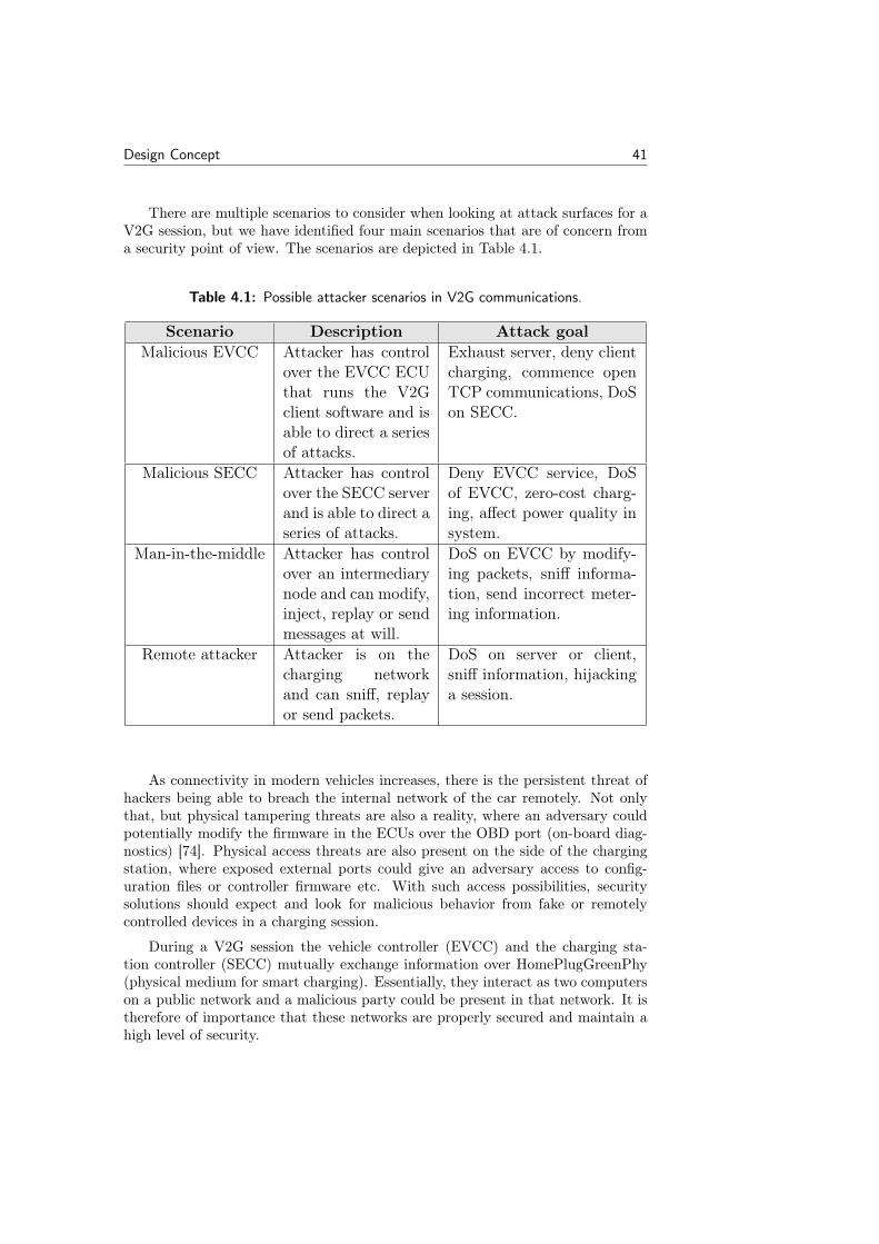
Design Concept 41
There are multiple scenarios to consider when looking at attack surfaces for aV2G session, but we have identified four main scenarios that are of concern froma security point of view. The scenarios are depicted in Table 4.1.
Table 4.1: Possible attacker scenarios in V2G communications.
Scenario Description Attack goalMalicious EVCC Attacker has control
over the EVCC ECUthat runs the V2Gclient software and isable to direct a seriesof attacks.
Exhaust server, deny clientcharging, commence openTCP communications, DoSon SECC.
Malicious SECC Attacker has controlover the SECC serverand is able to direct aseries of attacks.
Deny EVCC service, DoSof EVCC, zero-cost charg-ing, affect power quality insystem.
Man-in-the-middle Attacker has controlover an intermediarynode and can modify,inject, replay or sendmessages at will.
DoS on EVCC by modify-ing packets, sniff informa-tion, send incorrect meter-ing information.
Remote attacker Attacker is on thecharging networkand can sniff, replayor send packets.
DoS on server or client,sniff information, hijackinga session.
As connectivity in modern vehicles increases, there is the persistent threat ofhackers being able to breach the internal network of the car remotely. Not onlythat, but physical tampering threats are also a reality, where an adversary couldpotentially modify the firmware in the ECUs over the OBD port (on-board diag-nostics) [74]. Physical access threats are also present on the side of the chargingstation, where exposed external ports could give an adversary access to config-uration files or controller firmware etc. With such access possibilities, securitysolutions should expect and look for malicious behavior from fake or remotelycontrolled devices in a charging session.
During a V2G session the vehicle controller (EVCC) and the charging sta-tion controller (SECC) mutually exchange information over HomePlugGreenPhy(physical medium for smart charging). Essentially, they interact as two computerson a public network and a malicious party could be present in that network. It istherefore of importance that these networks are properly secured and maintain ahigh level of security.
42 Design Concept
4.3.2 Certificate handling
The first major point of concern is the handling of certificates, which were brieflyintroduced in Section 2.3.1. If certificates in the PKI system were to be compro-mised or if an adversary could forge signatures, this would render the whole V2Gcommunication insecure on several levels. To mention two examples, an adversarycould charge on another person’s behalf (if in possession of the contract certifi-cate) or the attacker could set up a malicious charging station (with the SECCcertificate). The specification implicitly tries to mitigate this issue by limiting thelifetime of a contract certificate (maximum of two years expiration), forcing theclient to engage in sending a CertificateUpdate request to be able to continueusing PnC. Furthermore, this is why proper action would have to be taken by CAsand Sub-CAs to control the issuance of new certificates and responsibly revokeany known compromised certificates in the system. In addition to this, OEMsand other involved parties would also have to secure the private keys stored inthe EVCC as well as the SECC. An option would preferably include the use of ahardware security model (HSM) for efficient cryptographic computation and mostimportantly restrict access to the private keys.
4.3.3 UDP in V2G
TLS is the basis for all security properties upheld on the transport layer. WithoutTLS, the communication would be open and readable, which opens up for manyattack vectors to be executed. For example, this increases the possibility for remoteTCP hijacking attacks with IP spoofing, making it possible for an adversary to sendmessages that appear to originate from the EVCC client. Therefore, concerns forremote exploits and other similar attacks are effectively mitigated by the securityproperties of TLS. With that in mind, the protocol setup phase is of concern sinceit negotiates the terms for TLS. If the security parameter in the SDP request ischanged, communication could commence without TLS by downgrading the clientto use a non-TLS setup. It is therefore essential that OEMs require TLS to beused when deploying their custom build of the ISO 15118 specification.
There could be a possibility to perform DoS with the UDP multicast featureutilized during the startup phase of the protocol. This can be done through amalicious EVCC client or a remote attacker, who floods the SECC with largeSDP requests over UDP. As a result, the attacker could drain the bandwidth ofthe SECC – making the charging station unable to properly continue its services.To prevent this, the SECC server should apply the basic protection of only expectrequests with a length of two bytes and not respond to more than 50 SDP requestsfrom a single IP (as it is defined in the protocol).
Dudek et al. [75] studied the HomePlugGreenPhy standard used for V2Gcommunications. They found that it was possible for an attacker to fake a SDPresponse by sending crafted arbitrary IPv6 address and port pairs. It was onlypossible to establish the physical presence (to send UDP packets) by quickly ob-taining the network membership key used to create or join a HomePlug network.As the attacker has been accepted as the SECC, the attacker could act as a man-in-middle or as a malicious charging station; capable of editing, injecting or droppingpackets as desired. This would however not adventure the security of the vital
Design Concept 43
private keys sent in CertificateInstallation or CertificateUpdate messagepairs. Since these message types demand the use of TLS (according to the ISO).Moreover, this attack presumes that the session can be downgraded from TLS touse open communication (otherwise, the attacker will fail to be authenticated bythe EVCC since he does not have a signed SECC certificate).
4.3.4 TCP in V2G
The V2G protocol defined in the ISO 15118 specification is a deterministic protocolin which messages are sent only at certain stages in the protocol. From a securitystandpoint, this deterministic behavior can be considered an advantage, since anattacker needs to abide by the next expected message structure if an attack is togo undetected. A practical example would be e.g., after sending a SessionSetuprequest, the server should not answer such requests again. This narrows the attacksurface and prevents malicious behavior such as fuzzing, bogus messaging andflooding attacks. With this in mind, the OEMs deploying the protocol shouldstrictly enforce these states and message sequences in their implementations ofISO 15118.
A DCU that hosts the V2G application can have multiple purposes and wouldrealistically operate several applications simultaneously. It is therefore importantthat the number of associated addresses and open ports are restricted, and doesnot reveal any information on port scans or accept random connection attempts.
4.3.5 XML and EXI security
The V2G protocol uses XML-based messages in compressed EXI format with XMLsecurity properties for signatures and encryption. Signatures are applied to ac-tions where authentication, authorization and integrity requirements are needed(i.e., when authorizing a vehicle for charging or signing of metering informa-tion). Encryption on the other hand is only used to obscure the private keysdelivered through CertificateInstallation and CertificateUpdate messages.Note that this encryption sits on the application layer and still implicitly benefitsfrom the encryption properties of TLS. Together, this hybrid scheme serves tosecure critical points of information exchanges and safeguards sensitive data sentduring a session.
Regarding how encryption keys are established; the key used for signing isalready present in the vehicle from the contract certificate. A shared key is derivedfor encryption through ephemeral-static ECDH using the private key associatedwith the contract certificate. If the private key were to be compromised by anadversary the shared key could be recreated from the EVCC private key. Thisshared key can then be used to reveal all data of past and future sessions sentwith this key. Again, we see the further need to safely secure the keys stored inthe vehicle.
When signing documents with the contract certificate using the ECDSA algo-rithm, it is important to maintain high entropy in the scheme. The IV, nonces andchallenges should all be created using a source of proper randomness. Otherwise,an adversary could reveal parts or obtain the full private key if the same IV is
44 Design Concept
used for all signatures. This is further mentioned in the specification [16].XML standard has its advantages and is currently used through widespread
adoption as a way to structure, decode and encode data. However, security re-searchers have criticised XML for its unnecessary complexity and performanceflaws [76], and OWASP has an extensive record of its vulnerabilities [77]. W3Cdescribes in their definition of EXI format 1.0 [44] that EXI shares the same secu-rity issues as XML, defined in RFC3023 [78]. As an example, EXI is compatiblewith user-defined datatype representations, which can be processed incorrectly ifnot careful. This may introduce new vulnerabilities that can be exploited. Thus,the ISO 15118 implementations utilizing XML/EXI should be deliberately ana-lyzed not to introduce security weaknesses.
4.3.6 Vehicle Charging
Another aspect of V2G sessions is how charging progress in exchanged between theserver and the client. When a vehicle is charging, using either AC or DC transfer,there exists a field that represents the current charging progress of the vehicle.The parameter is called chargeProgress and is present in the PowerDeliveryrequest. An attacker who is able to modify this value could effectively deny theclient service by modifying the parameter and setting it to "Stop". Another variantof this malicious act would be to trigger constant renegotiations between the EVCCand the SECC by continuously modifying the value to "Renegotiation". In a bestcase scenario, the operator receiving EV reports from the SECC could perhapspick-up on this anomalous activity, and report the vehicle’s status to responsibleagencies. To perform the described attack, the adversary would have to be incontrol over the ECU or be established as a man-in-the-middle.
In V2G the charging station needs to employ proper power management notto overload the grid. Hauck et al. [17] (mentioned in Section 1.6) also made asecurity analysis of the ISO 15118 specification. In their quite extensive analy-sis, they highlight the danger of gaining physical access to a charging station andwhat implications it could have for the grid infrastructure. For example, a mali-cious actor could change the PowerDelivery or CurrentDemand messages (whichdeliver information about charging configurations, power and voltage demands,etc.) to affect the power quality of the local grid, or delay or even exit charg-ing sessions on command. Even more beneficial for the adversary controlling theEVCC, they could change the metering information sent from the charging stationand subsequently charge for zero cost. To lower the exposure to physical accessthreats, Hauck et al. [17] suggest mitigation techniques using tampering alarmsand encrypting the flash memory used in the charging station, among others.
4.3.7 Error Handling
Another topic to consider is how errors are handled during a session. In theISO 15118 specification, there are explicitly specified ways to handle errors on anapplication level, e.g., specifying when certain error codes should be sent fromthe server or client. An aspect not covered by the specification is how the EVCCand SECC should behave in such instances, and it is mostly up to the OEMs and
Design Concept 45
suppliers to define this on their own. For instance, the client could be configured toexit a session after a certain error has occurred a set number of times, this couldbe leveraged to effectively stop a session by prompting a series of such errors.Another example could be a configuration where sending a certain error from theserver-side will prompt the client to send a new request. This could be exploited inorder to try to force the client to be stuck in an endless loop, without any meansto exit or progress in the session. In conclusion, it can be stated that definedbehaviors for error handling must be carefully analyzed to not enable exploits asmentioned above.
4.3.8 Recommendations
Based on the findings presented in this section, we here summarize the key take-aways into a list of recommendations for realizing a secure deployment of ISO15118 PnC solutions.
• TLS should always be the default for ensuring secure communications. OEMsshould, to whatever extent possible, avoid open data exchange since it opensup several attack vectors.
• The SECC server should be stateful and not respond to messages outsideits state progression path during communications.
• The storage of private keys in the EVCC as well as SECC should be cryp-tographically secured.
• Proper random number generators should be used for ECDSA nonce, chal-lenge and IV to prevent an adversary from guessing the secret key.
• The charging station should have tamper-proof mechanisms (tamperingalarms, encrypted flash memory, removal of external input ports, etc.)
• Error handling should be carefully configured not to introduce exploitablebehaviors/actions in the EVCC/SECC.
In conclusion, the V2G communication protocol in the ISO 15118 specificationcan be considered mostly secure and employs proper security practices to safeguarduser data and mitigate several potential exploits and vulnerabilities. The mainsecurity flaws are dependent on the party implementing the protocol, and whetherthis implementation is done properly.
4.4 V2G IDS Proof of Concept
This section presents the reader with our motivations for the design choices of theimplemented IDS.
46 Design Concept
4.4.1 HIDS
The progress of E/E-architectures moving towards domain-centralized topologiesand the fact that the ISO 15118 protocol most likely will be concerning only onedomain (the domain controlling charging of the vehicle), it made sense for us todesign and implement a HIDS for this type of protocol. In practice, this wouldmean that the detection system would be hosted on a single dedicated ECU or amultipurpose DCU. By developing a security solution for one host it is easier tofocus on one specific protocol, as we did for this master’s thesis. Moreover, thedesign principles proposed for this IDS could be applied on more general concepts,such as an in-vehicle NIDS or central gateway.
4.4.2 Detection Methods
There were several reasons why we chose to implement two methods of detection,namely specification-based and anomaly-based detection. First of all, the previousmaster’s thesis completed at ESCRYPT by Yilmaz (see Section 1.6.3) resulted ina security concept for a central gateway, where Yilmaz stated that the combina-tion of an anomaly-based and signature-based detection could perform the DPI.We considered using SNORT, but they did not ship rules for the ISO 15118 spec-ification, which only left the option of writing our own rules and signatures fordetection. This would require a deeper knowledge regarding possible threats andattacks enabled by the ISO 15118 specification, which we did not have time toinvestigate further in this project. After further research, we found a few promis-ing articles using specification-based methods as an alternative to signature-baseddetection. Both Larson et al. (see Section 1.6.4) and Salman and Bresch (seeSection 1.5.1) used a specification-based method with restrictions on e.g., mes-sage type and frequencies. Overall, the specification-based approach seemed as apromising option, which could potentially allow for similar detection coverage assignatures. We found the approach to be quite intuitive to implement, by basicallyreapplying a selected number of conditions defined in the specification.
In Anomaly Detection for SOME/IP using Complex Event Processing (seeSection 1.5.2) the authors list the anomalies they have considered for their imple-mentation of an anomaly-based IDS for the protocol SOME/IP, which is a protocolused for service-oriented communication in vehicles. Herold et al. considered mal-formed packets, protocol violations, system-specific violations and timing issues[10]. We would argue malformed packets and timing issues would go under bothcategories of detection methods, while protocol violations goes under specification-based detection. Malformed packets are packets whose structure does not complywith the protocol, they are either not expected by the specification or they behaveabnormally in some other way. Malformed packets may be used to trigger bugs inthe protocol implementation or covert the channel to exchange undetected infor-mation. Protocol violations occur when a packet deviates from the standard. Asthe name might indicate, timing issues has to do with violations of time-relatedconditions.
Another master’s thesis, which influenced our choice of implementing the com-bination of specification-based and anomaly-based detection was Design and im-plementation of an intrusion detection system (IDS) for in-vehicle networks by
Design Concept 47
Salman and Bresch (see Section 1.5.1). They implemented an IDS for the CANbus, incorporating both of the detection methods [9].
Overall, the recent reports we found in our research about IDSs in vehiclesseem to lean towards this kind of two method approach, and therefore we decidedto implement an IDS with specification-based and anomaly-based detection.
4.4.3 DPI
We wanted to incorporate DPI into our solution as well, the IDS covers detectionfrom the IP layer and up all the way to the application layer of the OSI model.The packets sent through a V2G session are analyzed through all the layers, sinceOpenV2G uses codec functionality that parses EXI/XML data. If the data wereincorrect, the parser would generate an error, discard the packet and continue.Therefore, some of the specification-based detection is already covered by theOpenV2G library, packets are required to be well-formed or the parser will notdecode or encode the EXI/XML data. By using open source libraries, we chose tofocus on implementing the IDS, rather than implementing the ISO 15118 standardfrom scratch.
4.4.4 Specification-based Detection
When implementing the specification-based detection we were required to read theISO 15118 protocol to some extent. As one could see Figure 2.9 in Section 2.3.1there are eight different parts of the ISO 15118 family, which adds up to over700 pages, and frankly, we found that amount of pages a little overwhelming.We discussed our concerns with our supervisors and came to the conclusion thatwe could not cover all parts of the specification, and they recommended that weshould only focus on the message types and sequence of messages. This was coveredin ISO 15118-2, which we started to read rather thoroughly. The standard wasstraightforward and easy to understand, there were flow charts of both AC and DCsessions using both external payment and PnC, which helped us to understand theallowed message sequences. After getting the background knowledge, we tried tocome up with possible attack scenarios and flaws within the protocol, see Table 4.1in Section 4.3.1 for our threat picture of the standard.
As mentioned, the ISO 15118 specification included some flowcharts describingthe exact message sequence allowed, and we decided to start out with implementingstateful logic for our IDS. We defined states for all message types, both requests andresponses. Then when a message entered the system its type was compared withthe waiting state of the IDS, to check whether the message was indeed expectedbased on the current state of the IDS. The specification-based detection moved thestates along, confirming that the incoming message followed the allowed sequenceorder. This prevents the attacker from performing replay attacks to some extent,dropping packets, sending bogus packets and exhausting the server.
The protocol also included a table stating all the allowed timeouts betweena request and its respective response, in other words the time allowed to elapsebetween a request being sent and the response to arrive, see Table A.2. We decidedto implement a check for these timeouts as well, this could detect a possible drop
48 Design Concept
of packet or that an attacker tried to sniff and modify a packet.We also saw it as important to make sure that AC and DC specific messages
were not allowed in the other respective session. Even if a packet is well-formedand well-structured it should not be allowed if it is not the right energy transfermode. Therefore, the energy transfer mode was also stored in the IDS, to ensurethat only messages with the valid energy transfer mode was allowed.
It was the same with method of payment; PnC requires that a TLS sessionis set up between the EVCC and SECC. In order to set up a TLS session oneis required to exchange certificates and certificate messages requires that TLS isused. The method of payment and a TLS flag are stored in the IDS for us to checkthat these types of messages are allowed to be sent. There were no frequencylimitations except for SDP messages, and we used the frequency limitation onthese SDP messages to implement protection against SDP flooding. The protocoloffered no real protection against replay, flooding or DoS attacks for other messagetypes. The payload length limitation for all messages except SDP messages is setto 4294967295 bytes in the protocol, which is a quite substantial size. For SDPmessages, there were a static size for the request and response, and we implementeda check for the payload length for these types of messages. Again, for generalmessages there is no protection against exhaustion or DoS attacks.
There is a need for storing the V2G session ID, it is not allowed to changethrough the entire session when it has been set and it is sent in every header.Therefore, the IDS stores the session ID to ensure that it has not been modified.This prevents some impostor attacks, where the attacker spoofs the session andtries to send his or her own messages.
4.4.5 Anomaly-based Detection
Anomaly-based detection is one of the more effective approaches to detect futureattacks. It analyzes packets to decide whether they are deviating from expectedbehavior. With the anomaly-based part, we wanted to fill some of the securityloopholes that the specification-based detection did not cover. One of the majorones being DoS attacks, for the frequency, payload length and timeout of a messagetype.
The protocol had a clear definition of which order the messages were supposedto arrive, but had poor protection against flooding attacks. There were somemessages that were allowed to be sent repeatedly, which opens up for floodingand replay attacks for those types of messages. There was no real payload lengthlimit for the messages either; the fact that they had to be well-formed and well-structured helped a bit. However, an attacker could still exhaust the server withlarge messages.
The protocol actually had strict timeouts for all message types, but some ofthem had up to five seconds. A potential attack could be to resend these types ofmessages in order to deny charging for others.
Timeout and payload length checks prevent an attacker from sending sniffedand to some extent modified packets, the modification may result in an abnormaldelay or payload length, which will be detected by the IDS.
We decided to separate the anomaly-based detection based on the energy trans-
Design Concept 49
fer mode, AC or DC. The ISO 15118 specification differentiates the two energytransfer modes and we came to the conclusion that it would be beneficial to imple-ment this as well. Not only for the specification-based part, but for the anomaly-based part as well.
4.4.6 Prevention through IP Address and Port Number Storage
We decided to store the IP address and port number of the SECC and EVCC forthe TCP or TLS session. This way, if another party tried to spoof the chargingsession the IDS would detect if they used another IP address or port number.This also prevents port scanning, which means that someone is trying to sendclient requests to a range of server port addresses on a host, with the goal offinding an active port and exploiting a known vulnerability of that service. Forexample, the IDS will detect if a rouge charging station is trying to set up anothersession during an ongoing one.
One major exploit of the ISO 15118 standard is when the sender is not yetauthenticated, which is before the handshake. There is a limit of 50 on the amountof SDP requests, a client can send before the server terminates the session. This isopens up the system for potential DoS attacks. We chose to store the IP addresseswhich were unsuccessful with setting up a V2G session and the respective amountof times an SDP request had been sent from that IP address. If an IP address sentmore than 50 requests the IDS detected this. We chose to store five IP addresses,so no more than five different IP addresses were allowed to try to connect to thesame SECC. They were stored for two hours before they were flushed. Thesesecurity measures helps the IDS to detect SDP flooding and SDP flooding frommultiple addresses.

Chapter5Implementation
This chapter will describe the implementation of the IDS concept. It will outlinethe different detection methods within the IDS and how we managed to set upattack sessions between an SECC server and an EVCC client.
5.1 IDS
Since the ISO 15118 specification is expected to be deployed on a single ECUor DCU, we decided that the IDS would be designed as a HIDS, which in turnadopted a hybrid approach with two main parts: specification- and anomaly-baseddetection. We further decided that the IDS was to be implemented as a passivepacket sniffer that generates reports, and not have any prevention mechanisms inplace. Furthermore, the IDS was designed to have awareness of the higher protocollayers in the OSI model, starting from the IP layer. Figure 5.1 below illustratesthe implemented IDS and its different components.
The specification-based detection is implemented based on the ISO 15118 spec-ification and its main detection feature is to inform the IDS if an incoming packageis out of order based on the specification standard. There are also some messagesthat are AC or DC specific, in addition to messages that depend on the selectedmethod of payment. This is described in the specification and therefore, this typeof detection is handled by the specification-based part.
A data collector was implemented in order to collect data from the examplepcap files for the anomaly-based detection methods. The data is stored in binarydata files and categorized based on if the transfer mode of the example file wasAC or DC. The anomaly-based part detects whether a message has been senttoo few or too many times during a session (frequency). It also detects if thepayload length of the package is seen as larger or smaller than usual. Finally, boththe specification- and anomaly-based detection detects whether the time elapsedbetween a request-response pair is out of bounds. From these data categories, thecollector separates the data into distinct data files for frequency, payload lengthand time elapsed for each respective request-response pair.
The anomaly-based detection was implemented to use the data files to extractthe message-specific data, compute individual thresholds for each category and usethese thresholds as a reference for classifying packets. These thresholds are thencompared to the actual values for incoming packets in real-time. The anomaly-
51
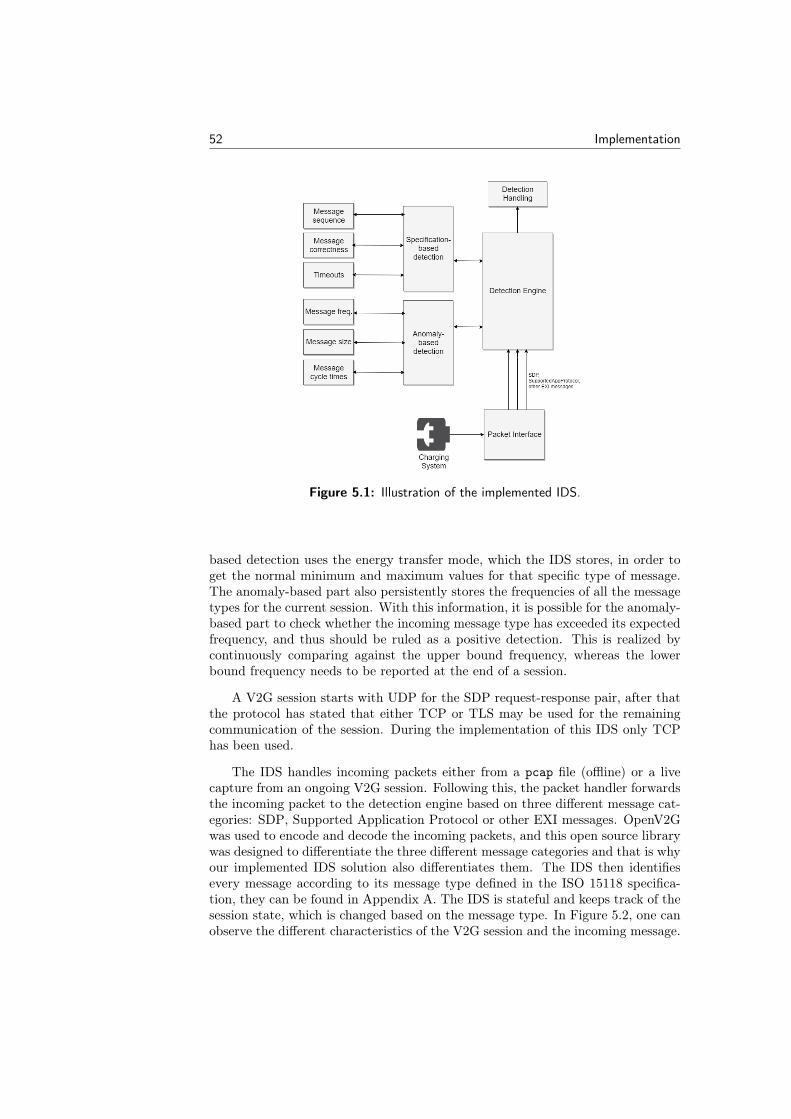
52 Implementation
Figure 5.1: Illustration of the implemented IDS.
based detection uses the energy transfer mode, which the IDS stores, in order toget the normal minimum and maximum values for that specific type of message.The anomaly-based part also persistently stores the frequencies of all the messagetypes for the current session. With this information, it is possible for the anomaly-based part to check whether the incoming message type has exceeded its expectedfrequency, and thus should be ruled as a positive detection. This is realized bycontinuously comparing against the upper bound frequency, whereas the lowerbound frequency needs to be reported at the end of a session.
A V2G session starts with UDP for the SDP request-response pair, after thatthe protocol has stated that either TCP or TLS may be used for the remainingcommunication of the session. During the implementation of this IDS only TCPhas been used.
The IDS handles incoming packets either from a pcap file (offline) or a livecapture from an ongoing V2G session. Following this, the packet handler forwardsthe incoming packet to the detection engine based on three different message cat-egories: SDP, Supported Application Protocol or other EXI messages. OpenV2Gwas used to encode and decode the incoming packets, and this open source librarywas designed to differentiate the three different message categories and that is whyour implemented IDS solution also differentiates them. The IDS then identifiesevery message according to its message type defined in the ISO 15118 specifica-tion, they can be found in Appendix A. The IDS is stateful and keeps track of thesession state, which is changed based on the message type. In Figure 5.2, one canobserve the different characteristics of the V2G session and the incoming message.
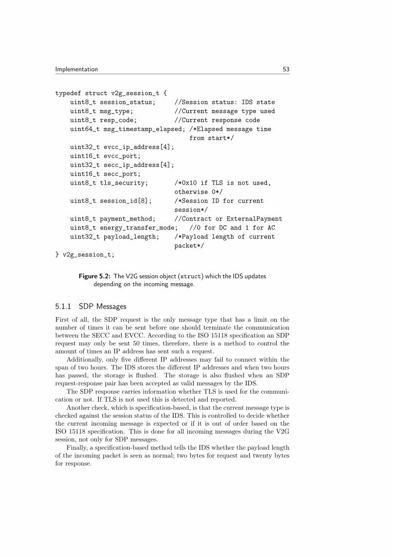
Implementation 53
typedef struct v2g_session_t {uint8_t session_status; //Session status: IDS stateuint8_t msg_type; //Current message type useduint8_t resp_code; //Current response codeuint64_t msg_timestamp_elapsed; /*Elapsed message time
from start*/uint32_t evcc_ip_address[4];uint16_t evcc_port;uint32_t secc_ip_address[4];uint16_t secc_port;uint8_t tls_security; /*0x10 if TLS is not used,
otherwise 0*/uint8_t session_id[8]; /*Session ID for current
session*/uint8_t payment_method; //Contract or ExternalPaymentuint8_t energy_transfer_mode; //0 for DC and 1 for ACuint32_t payload_length; /*Payload length of current
packet*/} v2g_session_t;
Figure 5.2: The V2G session object (struct) which the IDS updatesdepending on the incoming message.
5.1.1 SDP Messages
First of all, the SDP request is the only message type that has a limit on thenumber of times it can be sent before one should terminate the communicationbetween the SECC and EVCC. According to the ISO 15118 specification an SDPrequest may only be sent 50 times, therefore, there is a method to control theamount of times an IP address has sent such a request.
Additionally, only five different IP addresses may fail to connect within thespan of two hours. The IDS stores the different IP addresses and when two hourshas passed, the storage is flushed. The storage is also flushed when an SDPrequest-response pair has been accepted as valid messages by the IDS.
The SDP response carries information whether TLS is used for the communi-cation or not. If TLS is not used this is detected and reported.
Another check, which is specification-based, is that the current message type ischecked against the session status of the IDS. This is controlled to decide whetherthe current incoming message is expected or if it is out of order based on theISO 15118 specification. This is done for all incoming messages during the V2Gsession, not only for SDP messages.
Finally, a specification-based method tells the IDS whether the payload lengthof the incoming packet is seen as normal; two bytes for request and twenty bytesfor response.
54 Implementation
5.1.2 Supported App Protocol Handshake Messages
The purpose of this request-response pair is to establish which protocols are sup-ported by both the SECC and EVCC.
As with the SDP messages the current message type is checked against thesession status of the IDS. The specification-based detection also covers timeoutsfor every message type’s request-response pair, except for SDP messages accordingto the ISO 15118 specification. In Appendix A, one can see all the timeouts for therespective message types. This timeout is the time elapsed between the requestand response. For example, the timestamp for the SupportedAppProtocol requestis stored upon arrival to the anomaly-based detector and when the correspondingresponse arrives, the elapsed time in between the pair is calculated. If the timeexceeds two seconds a detection is reported, see Table A.2 in Appendix A. Aspreviously mentioned, this control is performed for all messages except for SDPmessages.
As there is a specification-based check performed, similarly there is an anomaly-based check performed. The anomaly-based part detects on frequency, payloadlength and time elapsed. This is done for all the remaining message types, exceptfor SDP messages.
There is also an IP address and port number control from now on for allthe remaining messages during the session. As can be seen in Figure 5.2, portand address pairs are stored for EVCC as well as SECC. This is to make surethat a V2G session has the same receiver and sender throughout the completecommunication. If an incoming message has a different IP address or port numberthis is detected.
5.1.3 Other EXI Messages
As mentioned previously, the categorization is due to how the encoding and decod-ing of OpenV2G is performed. This makes it possible to handle all the remainingEXI messages in the same manner.
Firstly, there is an IP address and port number control for every other EXImessage. Moreover, during the session setup the SECC decides a random andunique session ID for the established connection and informs the EVCC of thesession ID through the SessionSetup response. Similarly to IP address and portnumber control, this is also checked for every remaining incoming message tomake sure the session ID has not been modified. The SECC is not allowed tosend another SessionSetup response with a new session ID during the rest ofthe session, and other incoming messages are not allowed to modify the attachedsession ID.
The method of payment is set by the EVCC through a message type calledPaymentServiceSelection request, as can be seen in Table A.1 in Appendix Acertificates are only allowed to be handled if the payment method contract is chosenby the EVCC. The contract payment method is used when PnC is deployed forcharging the vehicle. Naturally, the specification-based detector controls whetherthe correct payment is chosen before handling certificates.
There is also the matter of energy transfer mode, which has been mentionedto play a part in the detection for both the specification-based and anomaly-
Implementation 55
based parts. The transfer mode is set by the EVCC through a message typecalled ChargeParameterDiscovery request. The messages that are dependent ona specific transfer mode are controlled by the specification-based detector.
Similarly as for the handshake messages, other EXI messages have specification-based detection controlling the message sequence order and request-response pairtimeout table. While the anomaly-based detector checks the frequency, payloadlength and request-response pair timeout.
The upper frequency bound is checked for every message type during the ses-sion, and when the SessionStop response has arrived, the lower frequency boundis checked. The SessionStop response is sent from the SECC – signaling thetermination of the V2G session.
5.1.4 Detection Handling
Whenever an anomaly is detected, whether it is by the specification-based oranomaly-based detector, a detection is generated and forwarded to an incidentresponse manager. The manager logs the detection based on a detection code, alldetection codes can be found in the Table A.3 in Appendix A. The manager alsohas a set tolerance threshold for the anomaly-based detections. The effect of thistolerance threshold will be reviewed further in Chapter 7.
5.1.5 Statistical Data Tracker
When evaluating the IDS we used the binary classification metrics as mentionedin Section 3.4.1. The IDS uses a utility we call the statistical data tracker togather data for which detection codes were generated for a given packet. Thiscan seamlessly be switched on or off by adding an ending flag for tracking inthe command line. Together with expected detection codes generated from theattacker client, the final performance metrics are then calculated at the close ofthe IDS client (by e.g., exiting with Ctrl-C).
The tracker also registers classification speed – the time it takes for a packetentering the IDS until it has been ruled as a negative or positive – and calculatesaverage, worst and best case classification times. The classification speed mea-surements can be started by changing the tracker flag to 2 as the last parameterof the IDS terminal command.
5.2 V2G Session
To establish a V2G session we have based the client and server software on the testexamples available in the OpenV2G source code (present in the file main_example.c).The examples accessible in OpenV2G use byte streams exclusively to simulate asession between client and server, there is no differentiating between the serverand client. Since we wanted to simulate real communications according to theISO 15118 specification, the server- and client-specific calls were divided into sep-arate c files (evcc_client and secc_server). Depending on the command lineinput upon starting the executable main file; either an EVCC or SECC is started.To run a V2G session one starts the SECC first and then the EVCC, as they are
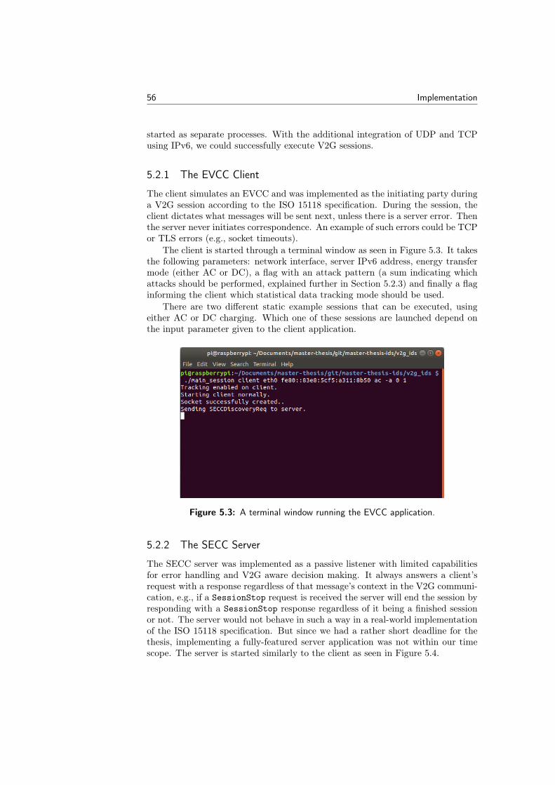
56 Implementation
started as separate processes. With the additional integration of UDP and TCPusing IPv6, we could successfully execute V2G sessions.
5.2.1 The EVCC Client
The client simulates an EVCC and was implemented as the initiating party duringa V2G session according to the ISO 15118 specification. During the session, theclient dictates what messages will be sent next, unless there is a server error. Thenthe server never initiates correspondence. An example of such errors could be TCPor TLS errors (e.g., socket timeouts).
The client is started through a terminal window as seen in Figure 5.3. It takesthe following parameters: network interface, server IPv6 address, energy transfermode (either AC or DC), a flag with an attack pattern (a sum indicating whichattacks should be performed, explained further in Section 5.2.3) and finally a flaginforming the client which statistical data tracking mode should be used.
There are two different static example sessions that can be executed, usingeither AC or DC charging. Which one of these sessions are launched depend onthe input parameter given to the client application.
Figure 5.3: A terminal window running the EVCC application.
5.2.2 The SECC Server
The SECC server was implemented as a passive listener with limited capabilitiesfor error handling and V2G aware decision making. It always answers a client’srequest with a response regardless of that message’s context in the V2G communi-cation, e.g., if a SessionStop request is received the server will end the session byresponding with a SessionStop response regardless of it being a finished sessionor not. The server would not behave in such a way in a real-world implementationof the ISO 15118 specification. But since we had a rather short deadline for thethesis, implementing a fully-featured server application was not within our timescope. The server is started similarly to the client as seen in Figure 5.4.
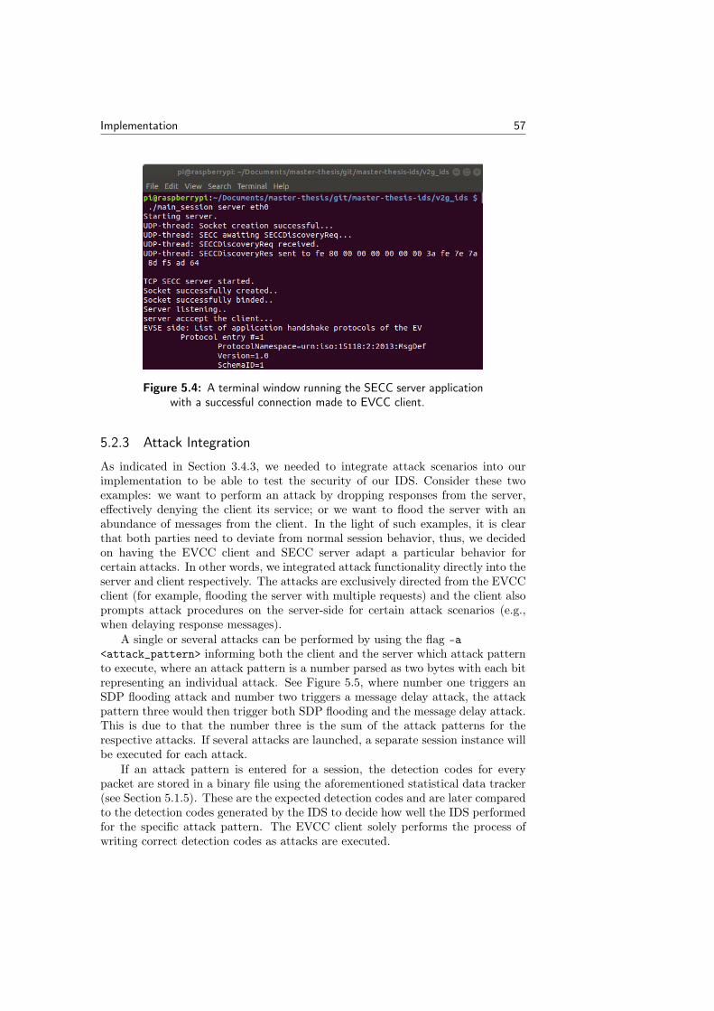
Implementation 57
Figure 5.4: A terminal window running the SECC server applicationwith a successful connection made to EVCC client.
5.2.3 Attack Integration
As indicated in Section 3.4.3, we needed to integrate attack scenarios into ourimplementation to be able to test the security of our IDS. Consider these twoexamples: we want to perform an attack by dropping responses from the server,effectively denying the client its service; or we want to flood the server with anabundance of messages from the client. In the light of such examples, it is clearthat both parties need to deviate from normal session behavior, thus, we decidedon having the EVCC client and SECC server adapt a particular behavior forcertain attacks. In other words, we integrated attack functionality directly into theserver and client respectively. The attacks are exclusively directed from the EVCCclient (for example, flooding the server with multiple requests) and the client alsoprompts attack procedures on the server-side for certain attack scenarios (e.g.,when delaying response messages).
A single or several attacks can be performed by using the flag -a<attack_pattern> informing both the client and the server which attack patternto execute, where an attack pattern is a number parsed as two bytes with each bitrepresenting an individual attack. See Figure 5.5, where number one triggers anSDP flooding attack and number two triggers a message delay attack, the attackpattern three would then trigger both SDP flooding and the message delay attack.This is due to that the number three is the sum of the attack patterns for therespective attacks. If several attacks are launched, a separate session instance willbe executed for each attack.
If an attack pattern is entered for a session, the detection codes for everypacket are stored in a binary file using the aforementioned statistical data tracker(see Section 5.1.5). These are the expected detection codes and are later comparedto the detection codes generated by the IDS to decide how well the IDS performedfor the specific attack pattern. The EVCC client solely performs the process ofwriting correct detection codes as attacks are executed.
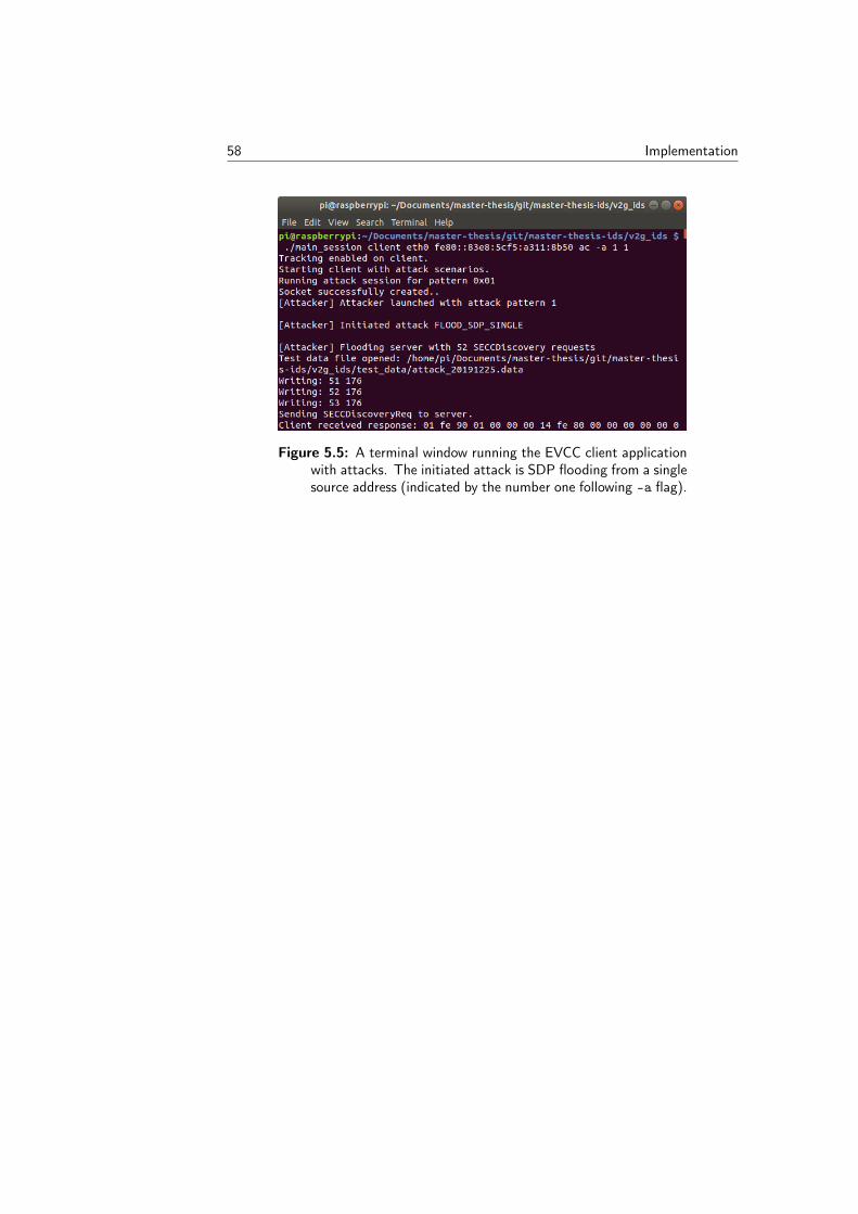
58 Implementation
Figure 5.5: A terminal window running the EVCC client applicationwith attacks. The initiated attack is SDP flooding from a singlesource address (indicated by the number one following -a flag).
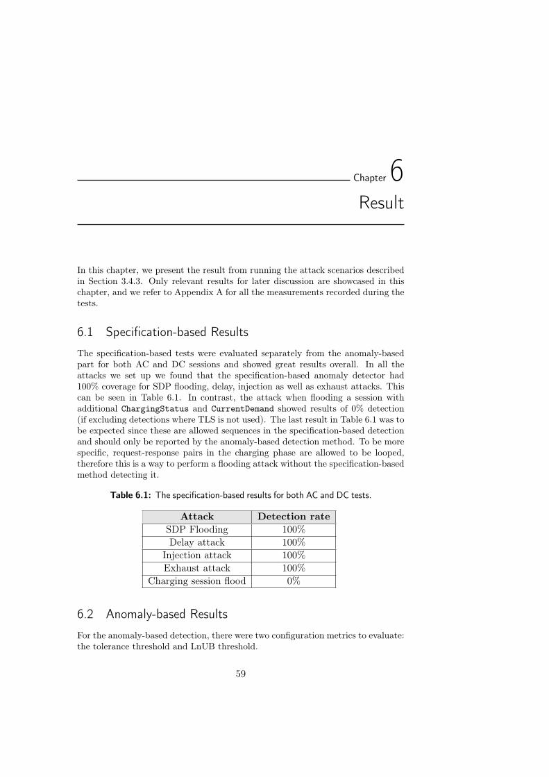
Chapter6Result
In this chapter, we present the result from running the attack scenarios describedin Section 3.4.3. Only relevant results for later discussion are showcased in thischapter, and we refer to Appendix A for all the measurements recorded during thetests.
6.1 Specification-based Results
The specification-based tests were evaluated separately from the anomaly-basedpart for both AC and DC sessions and showed great results overall. In all theattacks we set up we found that the specification-based anomaly detector had100% coverage for SDP flooding, delay, injection as well as exhaust attacks. Thiscan be seen in Table 6.1. In contrast, the attack when flooding a session withadditional ChargingStatus and CurrentDemand showed results of 0% detection(if excluding detections where TLS is not used). The last result in Table 6.1 was tobe expected since these are allowed sequences in the specification-based detectionand should only be reported by the anomaly-based detection method. To be morespecific, request-response pairs in the charging phase are allowed to be looped,therefore this is a way to perform a flooding attack without the specification-basedmethod detecting it.
Table 6.1: The specification-based results for both AC and DC tests.
Attack Detection rateSDP Flooding 100%Delay attack 100%
Injection attack 100%Exhaust attack 100%
Charging session flood 0%
6.2 Anomaly-based Results
For the anomaly-based detection, there were two configuration metrics to evaluate:the tolerance threshold and LnUB threshold.
59
60 Result
As mentioned in Section 3.4.2, the tolerance threshold is the threshold wehave decided is an acceptable number of anomaly-based detection codes to gounnoticed. The different tolerance values we have tested are 0 and 3, meaning 0 or3 unreported detection codes for each type of anomaly-based detection: frequency,payload length, and request-response pair timeout. No more than the chosentolerance threshold of each anomaly-based detection type may go unreported bythe IDS.
The LnUB threshold decides how much above the minimum or maximum valuethe IDS will allow an incoming packet value to go unreported. We have tested fournumbers of LnUB thresholds: 0, 0.1, 0.25 and 0.4. For example, if a SessionSetuprequest has been sent during a DC session and the IDS is checking the payloadlength, the length cannot be lower than 36 or higher than 68 if the LnUB thresholdzero has been chosen. In the case of the threshold being 0.25, the LnUB would be27 respective 85.
The tables below are showing the different configurations used when testingattack scenarios, which resulted in the best case scenario for balanced accuracy,f1-score and f0.5-score for each type of attack scenario. The best metric value hasa colored background. There are tables that contain merely one row because usingthe same configuration aligns the three values. There are also tables were differentconfigurations lead to separate rows because the values do not align.
Each attack is either in AC or DC energy mode, therefore the results arepresented in separate sections for each energy mode type. Furthermore, the ACsessions recorded between 850–1300 packets while the DC sessions registered be-tween 1200–1700 packets per session.
Lastly, the classification speed is obtained in microseconds for both AC andDC charging sessions. The classification speed is the time it takes from the entryof a packet until the IDS has either let the packet through or classified it asa detection. Best, worst and average speeds are calculated continuously as thesession progresses. For one of the measurements, we run the IDS under a normalsession to evaluate speeds during normal circumstances. In the other case, we runthe IDS with attacks that trigger multiple detections.
6.2.1 AC Results
Delay Attack
When we performed the attack that delayed a random number of packets therewere two best case scenarios. First, there was the configuration that had thetolerance threshold of 0 and the LnUB threshold of 0.1, which resulted in the bestbalanced accuracy score. And the tolerance threshold 3 and the LnUB of 0.25resulted in the best f1-score and f0.5-score. See Table 6.2 below for all metrics forthe two best configurations.
Balanced accuracy prioritizes that the TPR is high and that the FPR is low.One may note that the FPR actually is lower in Conf5. But due to the FPR beingrelatively small for Conf3 and that the TPR is higher, the balanced accuracy isstill better for Conf3.
Both of the F -scores prioritize precision and recall (TPR), and one can observethat the precision for Conf5 is 1, which is the highest value possible. As mentioned,
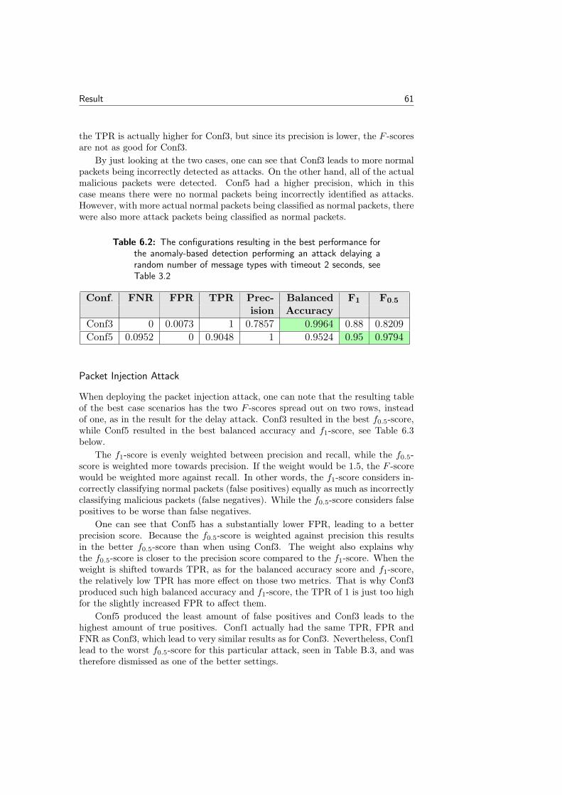
Result 61
the TPR is actually higher for Conf3, but since its precision is lower, the F -scoresare not as good for Conf3.
By just looking at the two cases, one can see that Conf3 leads to more normalpackets being incorrectly detected as attacks. On the other hand, all of the actualmalicious packets were detected. Conf5 had a higher precision, which in thiscase means there were no normal packets being incorrectly identified as attacks.However, with more actual normal packets being classified as normal packets, therewere also more attack packets being classified as normal packets.
Table 6.2: The configurations resulting in the best performance forthe anomaly-based detection performing an attack delaying arandom number of message types with timeout 2 seconds, seeTable 3.2
Conf. FNR FPR TPR Prec- Balanced F1 F0.5
ision AccuracyConf3 0 0.0073 1 0.7857 0.9964 0.88 0.8209Conf5 0.0952 0 0.9048 1 0.9524 0.95 0.9794
Packet Injection Attack
When deploying the packet injection attack, one can note that the resulting tableof the best case scenarios has the two F -scores spread out on two rows, insteadof one, as in the result for the delay attack. Conf3 resulted in the best f0.5-score,while Conf5 resulted in the best balanced accuracy and f1-score, see Table 6.3below.
The f1-score is evenly weighted between precision and recall, while the f0.5-score is weighted more towards precision. If the weight would be 1.5, the F -scorewould be weighted more against recall. In other words, the f1-score considers in-correctly classifying normal packets (false positives) equally as much as incorrectlyclassifying malicious packets (false negatives). While the f0.5-score considers falsepositives to be worse than false negatives.
One can see that Conf5 has a substantially lower FPR, leading to a betterprecision score. Because the f0.5-score is weighted against precision this resultsin the better f0.5-score than when using Conf3. The weight also explains whythe f0.5-score is closer to the precision score compared to the f1-score. When theweight is shifted towards TPR, as for the balanced accuracy score and f1-score,the relatively low TPR has more effect on those two metrics. That is why Conf3produced such high balanced accuracy and f1-score, the TPR of 1 is just too highfor the slightly increased FPR to affect them.
Conf5 produced the least amount of false positives and Conf3 leads to thehighest amount of true positives. Conf1 actually had the same TPR, FPR andFNR as Conf3, which lead to very similar results as for Conf3. Nevertheless, Conf1lead to the worst f0.5-score for this particular attack, seen in Table B.3, and wastherefore dismissed as one of the better settings.
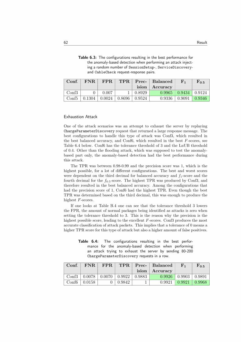
62 Result
Table 6.3: The configurations resulting in the best performance forthe anomaly-based detection when performing an attack inject-ing a random number of SessionSetup-, ServiceDiscovery-and CableCheck request-response pairs.
Conf. FNR FPR TPR Prec- Balanced F1 F0.5
ision AccuracyConf3 0 0.007 1 0.8929 0.9965 0.9434 0.9124Conf5 0.1304 0.0024 0.8696 0.9524 0.9336 0.9091 0.9346
Exhaustion Attack
One of the attack scenarios was an attempt to exhaust the server by replayingChargeParameterDiscovery request that returned a large response message. Thebest configurations to handle this type of attack was Conf3, which resulted inthe best balanced accuracy, and Conf6, which resulted in the best F -scores, seeTable 6.4 below. Conf6 has the tolerance threshold of 3 and the LnUB thresholdof 0.4. Other than the flooding attack, which was supposed to test the anomaly-based part only, the anomaly-based detection had the best performance duringthis attack.
The TPR was between 0.98-0.99 and the precision score was 1, which is thehighest possible, for a lot of different configurations. The best and worst scoreswere dependent on the third decimal for balanced accuracy and f1-score and thefourth decimal for the f0.5-score. The highest TPR was produced by Conf3, andtherefore resulted in the best balanced accuracy. Among the configurations thathad the precision score of 1, Conf6 had the highest TPR. Even though the bestTPR was determined based on the third decimal, this was enough to produce thehighest F -scores.
If one looks at Table B.4 one can see that the tolerance threshold 3 lowersthe FPR, the amount of normal packages being identified as attacks is zero whensetting the tolerance threshold to 3. This is the reason why the precision is thehighest possible score, leading to the excellent F -scores. Conf3 produces the mostaccurate classification of attack packets. This implies that a tolerance of 0 means ahigher TPR score for this type of attack but also a higher amount of false positives.
Table 6.4: The configurations resulting in the best perfor-mance for the anomaly-based detection when performingan attack trying to exhaust the server by sending 80-200ChargeParameterDiscovery requests in a row.
Conf. FNR FPR TPR Prec- Balanced F1 F0.5
ision AccuracyConf3 0.0078 0.0070 0.9922 0.9883 0.9926 0.9903 0.9891Conf6 0.0158 0 0.9842 1 0.9921 0.9921 0.9968
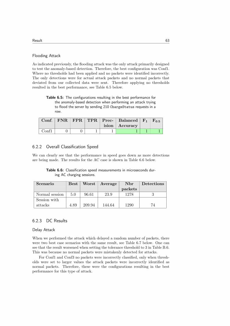
Result 63
Flooding Attack
As indicated previously, the flooding attack was the only attack primarily designedto test the anomaly-based detection. Therefore, the best configuration was Conf1.Where no thresholds had been applied and no packets were identified incorrectly.The only detections were for actual attack packets and no normal packets thatdeviated from our collected data were sent. Therefore applying no thresholdsresulted in the best performance, see Table 6.5 below.
Table 6.5: The configurations resulting in the best performance forthe anomaly-based detection when performing an attack tryingto flood the server by sending 210 ChargeStatus requests in arow.
Conf. FNR FPR TPR Prec- Balanced F1 F0.5
ision AccuracyConf1 0 0 1 1 1 1 1
6.2.2 Overall Classification Speed
We can clearly see that the performance in speed goes down as more detectionsare being made. The results for the AC case is shown in Table 6.6 below.
Table 6.6: Classification speed measurements in microseconds dur-ing AC charging sessions.
Scenario Best Worst Average Nbr Detectionspackets
Normal session 5.0 96.61 23.9 1278 3Session withattacks 4.89 209.94 144.64 1290 74
6.2.3 DC Results
Delay Attack
When we performed the attack which delayed a random number of packets, therewere two best case scenarios with the same result, see Table 6.7 below. One cansee that the result worsened when setting the tolerance threshold to 3 in Table B.6.This was because no normal packets were mistakenly detected for attacks.
For Conf1 and Conf3 no packets were incorrectly classified, only when thresh-olds were set to larger values the attack packets were incorrectly identified asnormal packets. Therefore, these were the configurations resulting in the bestperformance for this type of attack.
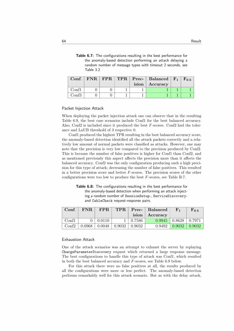
64 Result
Table 6.7: The configurations resulting in the best performance forthe anomaly-based detection performing an attack delaying arandom number of message types with timeout 2 seconds, seeTable 3.2
Conf. FNR FPR TPR Prec- Balanced F1 F0.5
ision AccuracyConf1 0 0 1 1 1 1 1Conf3 0 0 1 1 1 1 1
Packet Injection Attack
When deploying the packet injection attack one can observe that in the resultingTable 6.9, the best case scenarios include Conf1 for the best balanced accuracy.Also, Conf2 is included since it produced the best F -scores. Conf2 had the toler-ance and LnUB threshold of 3 respective 0.
Conf1 produced the highest TPR resulting in the best balanced accuracy score,the anomaly-based detection identified all the attack packets correctly and a rela-tively low amount of normal packets were classified as attacks. However, one maynote that the precision is very low compared to the precision produced by Conf2.This is because the number of false positives is higher for Conf1 than Conf2, andas mentioned previously this aspect affects the precision more than it affects thebalanced accuracy. Conf2 was the only configuration producing such a high preci-sion for this type of attack; decreasing the number of false positives. This resultedin a better precision score and better F -scores. The precision scores of the otherconfigurations were too low to produce the best F -scores, see Table B.7.
Table 6.8: The configurations resulting in the best performance forthe anomaly-based detection when performing an attack inject-ing a random number of SessionSetup-, ServiceDiscovery-and CableCheck request-response pairs.
Conf. FNR FPR TPR Prec- Balanced F1 F0.5
ision AccuracyConf1 0 0.0110 1 0.7586 0.9945 0.8628 0.7971Conf2 0.0968 0.0048 0.9032 0.9032 0.9492 0.9032 0.9032
Exhaustion Attack
One of the attack scenarios was an attempt to exhaust the server by replayingChargeParameterDiscovery request which returned a large response message.The best configurations to handle this type of attack was Conf1, which resultedin both the best balanced accuracy and F -scores, see Table 6.9 below.
For this attack there were no false positives at all, the results produced byall the configurations were more or less perfect. The anomaly-based detectionperforms remarkably well for this attack scenario. But as with the delay attack,
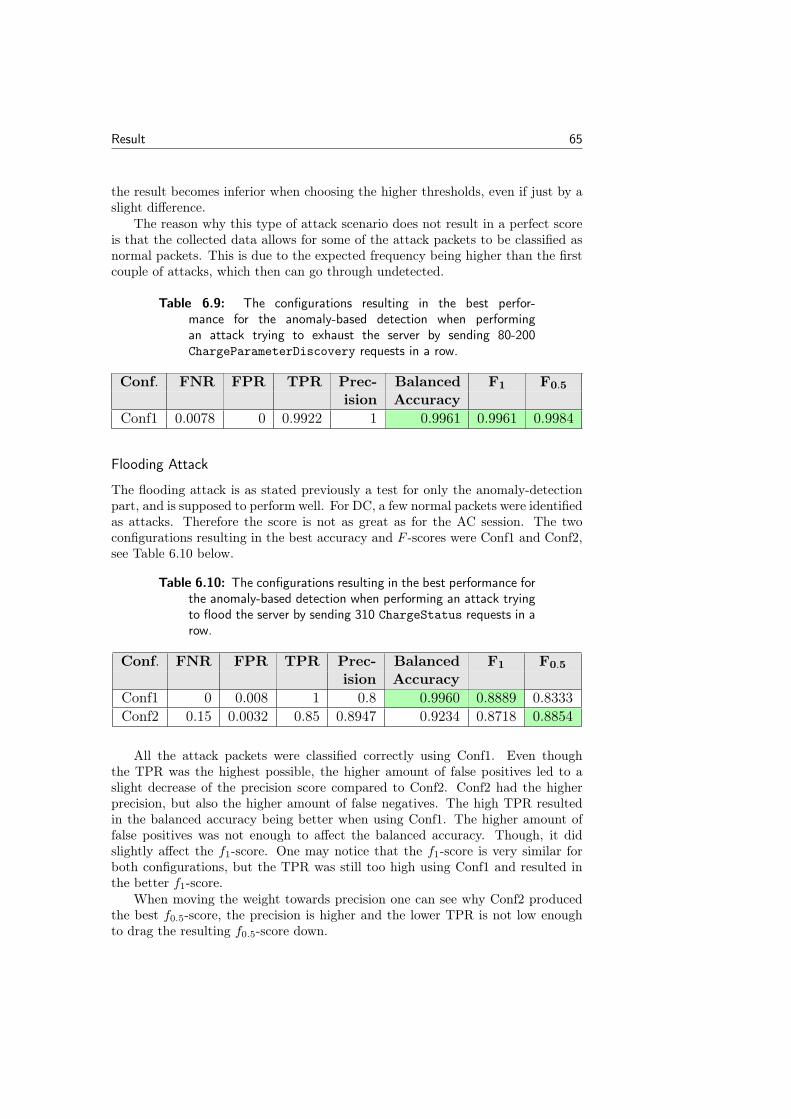
Result 65
the result becomes inferior when choosing the higher thresholds, even if just by aslight difference.
The reason why this type of attack scenario does not result in a perfect scoreis that the collected data allows for some of the attack packets to be classified asnormal packets. This is due to the expected frequency being higher than the firstcouple of attacks, which then can go through undetected.
Table 6.9: The configurations resulting in the best perfor-mance for the anomaly-based detection when performingan attack trying to exhaust the server by sending 80-200ChargeParameterDiscovery requests in a row.
Conf. FNR FPR TPR Prec- Balanced F1 F0.5
ision AccuracyConf1 0.0078 0 0.9922 1 0.9961 0.9961 0.9984
Flooding Attack
The flooding attack is as stated previously a test for only the anomaly-detectionpart, and is supposed to perform well. For DC, a few normal packets were identifiedas attacks. Therefore the score is not as great as for the AC session. The twoconfigurations resulting in the best accuracy and F -scores were Conf1 and Conf2,see Table 6.10 below.
Table 6.10: The configurations resulting in the best performance forthe anomaly-based detection when performing an attack tryingto flood the server by sending 310 ChargeStatus requests in arow.
Conf. FNR FPR TPR Prec- Balanced F1 F0.5
ision AccuracyConf1 0 0.008 1 0.8 0.9960 0.8889 0.8333Conf2 0.15 0.0032 0.85 0.8947 0.9234 0.8718 0.8854
All the attack packets were classified correctly using Conf1. Even thoughthe TPR was the highest possible, the higher amount of false positives led to aslight decrease of the precision score compared to Conf2. Conf2 had the higherprecision, but also the higher amount of false negatives. The high TPR resultedin the balanced accuracy being better when using Conf1. The higher amount offalse positives was not enough to affect the balanced accuracy. Though, it didslightly affect the f1-score. One may notice that the f1-score is very similar forboth configurations, but the TPR was still too high using Conf1 and resulted inthe better f1-score.
When moving the weight towards precision one can see why Conf2 producedthe best f0.5-score, the precision is higher and the lower TPR is not low enoughto drag the resulting f0.5-score down.

66 Result
No attacks were being incorrectly classified using Conf1, though there were afew false positives. The increased tolerance threshold decreased the FPR as wellas the TPR. But overall, Conf2 produced the better precision score out of the twoconfigurations.
6.2.4 Overall Classification Speed
Precisely as for the AC case, the results for the DC sessions show a clear declinein the classification speed as more detections are generated. Results are presentedin Table 6.11 below.
Table 6.11: Classification speed measurements in microseconds dur-ing DC charging sessions.
Scenario Best Worst Average Nbr Detectionspackets
Normal session 4.38 151.25 30.65 1878 3Session withattacks 7.19 212.92 120.53 1898 80
Chapter7Discussion
In this chapter, we discuss the result of the tests and evaluate the design of our IDSimplementation. We also present potential improvements for the implementationand future work based on our master’s thesis.
7.1 Evaluation of the IDS Implementation
Overall, the implemented IDS showed promising results, one can see that theperformance of specification-based detection was at a 100% for all cases exceptfor the flooding attack. The charging flood attack shows that there are attackscenarios in which the specification-based part does not cover. This attack scenarioproves that there is a need for another detection method. This is something weexpected when we outlined the possible attack vectors. We did not have the timeto test all the possible vectors on our IDS. The anomaly-based detection engineperformed well during the test of the flooding attack, which shows that anomaly-based detection could be an appropriate compensating method for specification-based detection.
The advantage of the anomaly-based detection is that it is not dependenton a specification, if a specification is modified or the OEM wants an IDS par-tially covering the standard protocol, the specification-based detection may haveto be updated as well. The disadvantage with the anomaly-based detection isthat it requires a substantial amount of training data to make accurate predic-tions, preferably on authentic V2G session data. From our results, we could seethat with different configurations, the performance of the anomaly-based detectionvaried. We would have preferred more example data for more trustworthy results.The anomaly-based detection engine performed at its best for the flooding attackand exhaustion attack. It performed very well overall for attacks dependent onfrequency. However, the results varied for the delay and packet injection attacks.The reason for this was mainly that it classified several normal packets as attacks,which is not optimal. We would still argue that the IDS cannot merely dependon a specification-based detection engine for covering the entire threat pictureof the ISO 15118 specification. Since the anomaly-based detection covers attackscenarios the other cannot.
67
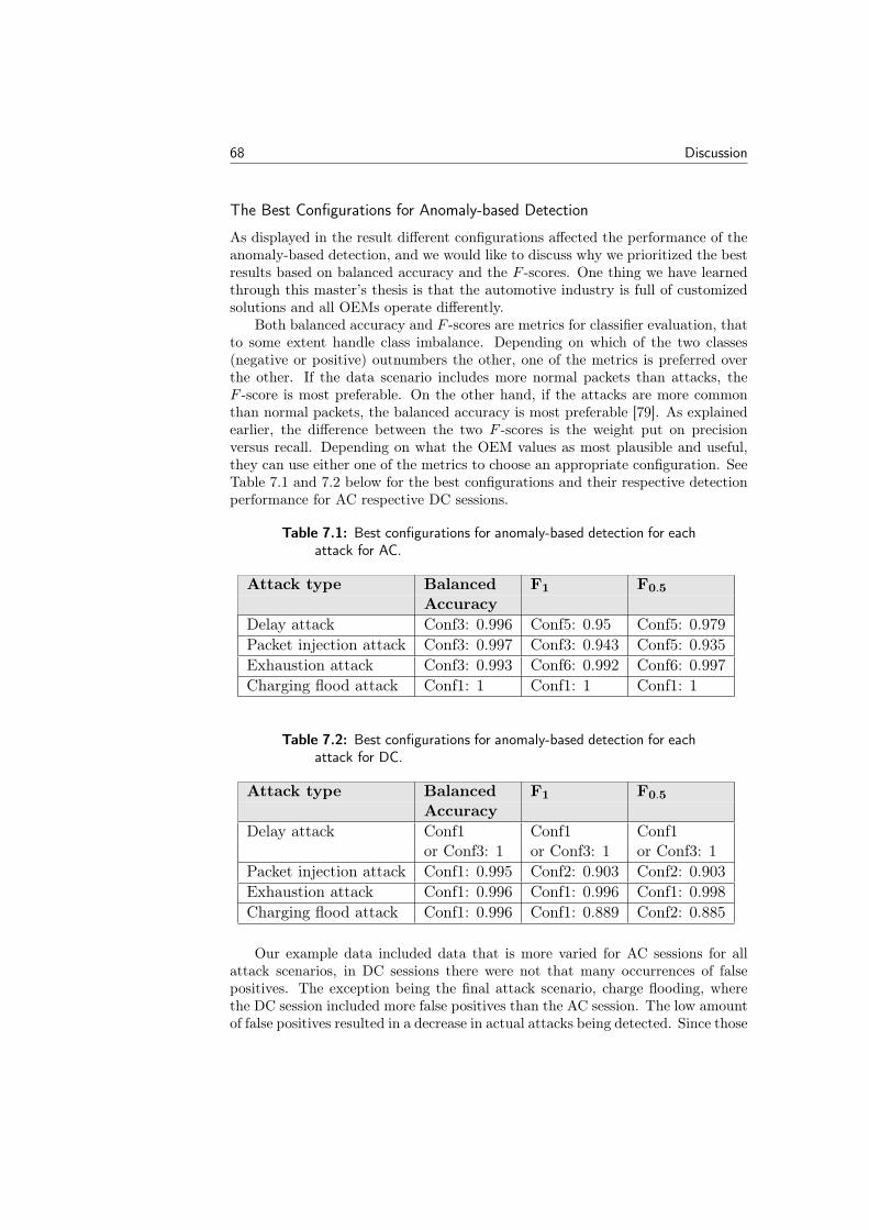
68 Discussion
The Best Configurations for Anomaly-based Detection
As displayed in the result different configurations affected the performance of theanomaly-based detection, and we would like to discuss why we prioritized the bestresults based on balanced accuracy and the F -scores. One thing we have learnedthrough this master’s thesis is that the automotive industry is full of customizedsolutions and all OEMs operate differently.
Both balanced accuracy and F -scores are metrics for classifier evaluation, thatto some extent handle class imbalance. Depending on which of the two classes(negative or positive) outnumbers the other, one of the metrics is preferred overthe other. If the data scenario includes more normal packets than attacks, theF -score is most preferable. On the other hand, if the attacks are more commonthan normal packets, the balanced accuracy is most preferable [79]. As explainedearlier, the difference between the two F -scores is the weight put on precisionversus recall. Depending on what the OEM values as most plausible and useful,they can use either one of the metrics to choose an appropriate configuration. SeeTable 7.1 and 7.2 below for the best configurations and their respective detectionperformance for AC respective DC sessions.
Table 7.1: Best configurations for anomaly-based detection for eachattack for AC.
Attack type Balanced F1 F0.5
AccuracyDelay attack Conf3: 0.996 Conf5: 0.95 Conf5: 0.979Packet injection attack Conf3: 0.997 Conf3: 0.943 Conf5: 0.935Exhaustion attack Conf3: 0.993 Conf6: 0.992 Conf6: 0.997Charging flood attack Conf1: 1 Conf1: 1 Conf1: 1
Table 7.2: Best configurations for anomaly-based detection for eachattack for DC.
Attack type Balanced F1 F0.5
AccuracyDelay attack Conf1 Conf1 Conf1
or Conf3: 1 or Conf3: 1 or Conf3: 1Packet injection attack Conf1: 0.995 Conf2: 0.903 Conf2: 0.903Exhaustion attack Conf1: 0.996 Conf1: 0.996 Conf1: 0.998Charging flood attack Conf1: 0.996 Conf1: 0.889 Conf2: 0.885
Our example data included data that is more varied for AC sessions for allattack scenarios, in DC sessions there were not that many occurrences of falsepositives. The exception being the final attack scenario, charge flooding, wherethe DC session included more false positives than the AC session. The low amountof false positives resulted in a decrease in actual attacks being detected. Since those
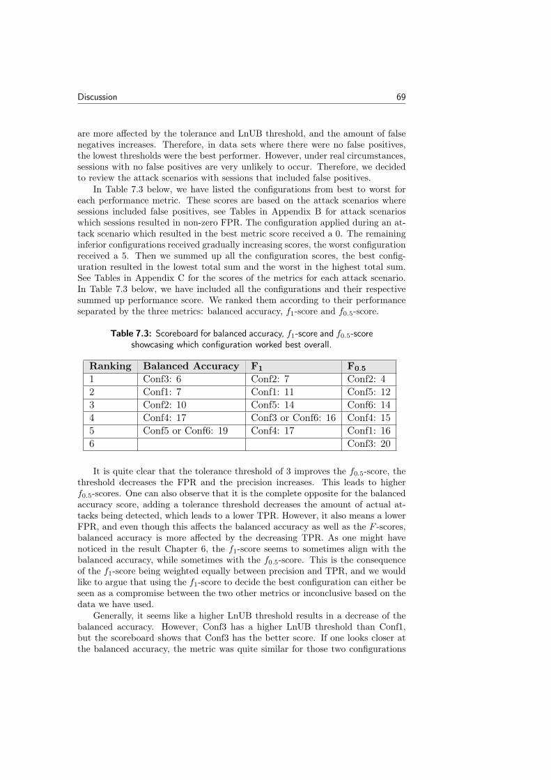
Discussion 69
are more affected by the tolerance and LnUB threshold, and the amount of falsenegatives increases. Therefore, in data sets where there were no false positives,the lowest thresholds were the best performer. However, under real circumstances,sessions with no false positives are very unlikely to occur. Therefore, we decidedto review the attack scenarios with sessions that included false positives.
In Table 7.3 below, we have listed the configurations from best to worst foreach performance metric. These scores are based on the attack scenarios wheresessions included false positives, see Tables in Appendix B for attack scenarioswhich sessions resulted in non-zero FPR. The configuration applied during an at-tack scenario which resulted in the best metric score received a 0. The remaininginferior configurations received gradually increasing scores, the worst configurationreceived a 5. Then we summed up all the configuration scores, the best config-uration resulted in the lowest total sum and the worst in the highest total sum.See Tables in Appendix C for the scores of the metrics for each attack scenario.In Table 7.3 below, we have included all the configurations and their respectivesummed up performance score. We ranked them according to their performanceseparated by the three metrics: balanced accuracy, f1-score and f0.5-score.
Table 7.3: Scoreboard for balanced accuracy, f1-score and f0.5-scoreshowcasing which configuration worked best overall.
Ranking Balanced Accuracy F1 F0.5
1 Conf3: 6 Conf2: 7 Conf2: 42 Conf1: 7 Conf1: 11 Conf5: 123 Conf2: 10 Conf5: 14 Conf6: 144 Conf4: 17 Conf3 or Conf6: 16 Conf4: 155 Conf5 or Conf6: 19 Conf4: 17 Conf1: 166 Conf3: 20
It is quite clear that the tolerance threshold of 3 improves the f0.5-score, thethreshold decreases the FPR and the precision increases. This leads to higherf0.5-scores. One can also observe that it is the complete opposite for the balancedaccuracy score, adding a tolerance threshold decreases the amount of actual at-tacks being detected, which leads to a lower TPR. However, it also means a lowerFPR, and even though this affects the balanced accuracy as well as the F -scores,balanced accuracy is more affected by the decreasing TPR. As one might havenoticed in the result Chapter 6, the f1-score seems to sometimes align with thebalanced accuracy, while sometimes with the f0.5-score. This is the consequenceof the f1-score being weighted equally between precision and TPR, and we wouldlike to argue that using the f1-score to decide the best configuration can either beseen as a compromise between the two other metrics or inconclusive based on thedata we have used.
Generally, it seems like a higher LnUB threshold results in a decrease of thebalanced accuracy. However, Conf3 has a higher LnUB threshold than Conf1,but the scoreboard shows that Conf3 has the better score. If one looks closer atthe balanced accuracy, the metric was quite similar for those two configurations
70 Discussion
for most of the attack scenarios and therefore resulting in similar scores. Thescoreboard shows that Conf3 has the score 6 and Conf1 has the score 7, which areclose values. According to us, if an OEM is prioritizing a high TPR and balancedaccuracy score, Conf1 and Conf3 can be seen as interchangeable. However, wewould like to interpose that more studies should be conducted using data fromreal use cases and investigating the effect different tolerance thresholds may haveon the balanced accuracy score.
For the f0.5-score using a higher LnUB does not necessarily lead to a betterscore. As we can see Conf2 was the configuration with the best overall performancefor this metric, followed by Conf5 which received the score 12. One may note thatthere is a significant jump between the best and second best score (4 vs 12), whichmight imply that if the LnUB threshold is to result in a better performance itis with the combination of a tolerance threshold. What we can say is that bynot setting a tolerance threshold the f0.5-score gets worse. Again, there shouldbe more studies conducted on the detection performance effects of different LnUBvalues. We conducted tests with the two thresholds set at the same time, but ifone might have had the time, one could conduct more tests with different LnUBand tolerance thresholds both combined and separately.
Classification Speed
The implementation shows promising results based on the classification speedsrecorded in Table 6.6 and Table 6.11. As can be seen, there is a significant con-trast between the results obtained under normal circumstances versus when attacksare performed. This is to be expected since additional procedures are triggeredafter detection (such as report generation). Best speed detections remained sta-ble around 4-7 microseconds with minor fluctuations, which shows that a highernumber of detections does not considerably affect the IDS ability to deliver peakperformance in speeds. Different from the best speed, the worst speed increasedby roughly 116% for AC and 40% for DC. Also, the average speed increased byalmost 6x (24 to 144) in the AC case and 4x (30 to 120) for DC. From theseresults, we can conclude that overall detection performance of the IDS will sufferfrom higher detection rates in a session. On the other hand, the average speedrecorded could be considered sufficient for the automotive use case. As the mea-sured average speeds are in the order of 20-150 microseconds, while end-to-enddelays in car domains could fluctuate between 20 microseconds and single-digitmilliseconds [72]. This indicates that the IDS would not contribute to any majorperformance downgrades in latency or introduce bottlenecks in its current statefrom a classification speed perspective – even when detection rates are high. Itis however important to note that these results might not be consistent with anactual in-vehicle implementation of this IDS. Nonetheless, we remain optimisticabout its performance capabilities.
DPI
Our IDS rely on full DPI, since the EXI/XML messages need to be parsed bythe codec methods. Decoding and encoding does not add any overhead and is a
Discussion 71
fast process, we did not face any issues incorporating DPI into our solution. Thecharging station is not a part of the vehicle and the vehicle is probably shut off whilecharging, hence, the same time-sensitive requirements for most other protocolsused in vehicles does not apply on the same level for this type of communication.Therefore, we are certain that DPI is something that one can incorporate in anIDS for the ISO 15118 specification.
Improvements
The previous master’s thesis done at ESCRYPT by Yilmaz (Section 1.6.3) investi-gated a concept for a complete security solution, including both a firewall and anIDS. We would have liked to extend our solution to incorporate a firewall, whichcould cooperate with the IDS. With this set up the IDS could trigger dynamic up-dates in the firewall, based on new signatures that is within a firewall’s domain. Asa result, the firewall could help levitate the responsibilities of the IDS, which couldhelp in improving system performance. On the contrary, integrating a firewall withdynamic updates would increase the complexity of the security architecture, andmight be more bothersome than levitating.
Yilmaz also integrated hardware used for shallow inspection, which would havebeen an interesting aspect to investigate. Shallow inspection tasks in our solutionincluded storing and checking IP addresses and port numbers, and we could haveextended the IDS to check for MAC addresses as well. These are examples ofshallow inspection features that could have been added to extend the scope of theIDS.
Overall, it would have been beneficial to run the IDS solution in an authenticV2G environment and see how it performs. Our solution is not inline, it is a passivesniffer and does not affect latency. Nevertheless, if the IDS is to be deployed onan ECU it would have to be inline. A normal ECU typically only has one corewith limited capacity for multi-threading, and the IDS must be able to operatesimultaneously as the V2G software in the vehicle. By further adapting the IDSto be inline, we could have evaluated its system performance with metrics such aslatency and bandwidth. These metrics would have better displayed how the IDSwould have performed under real-world circumstances.
In regard of the architecture and design choices, further investigation into thecomplete ISO 15118 protocol would have helped to extend the specification-baseddetection engine. There was a limit to how much time we had and thus we had toprioritize which features to select. Furthermore, our lack of knowledge on vehiclemechanics and manufacturing surely affected the extent to which we could operate.If we would have known more about what was viewed as normal V2G session data,in regards to e.g., expected voltage and current limits. For example, how youcould integrate anomaly-based profiling of the vehicle’s charging progress. Thiscould have been integrated into the IDS and would perhaps improve its detectioncapabilities.
Limitations
The biggest limitation was the lack of normal data sessions, which we have men-tioned being an issue throughout the report. The lack of example data did not
72 Discussion
only affect our training data but also our knowledge of what real data should looklike. The examples from RISEV2G were very different from the ones acquiredfrom OpenV2G and the ones captured from the live V2G sessions we set up. Fur-thermore, there were no one from ESCRYPT or Bosch with knowledge in V2Gsessions whom we could ask for advice. Therefore, we are not sure which fre-quencies, payload lengths or timeouts can be seen as normal. More training datafrom real use cases would have helped us get a deeper understanding and it wouldprobably have affected our results. A statistical study over normal data wouldhave helped us setting appropriate thresholds and help minimize the amount ofincorrect detections.
Additionally, a security solution can only be objectively judged on the testsconducted, and we did not have the time to extend the test suite with other attackscenarios. When we asked about the kind of security evaluation methods they useat ESCRYPT, they answered that they outsource the final security tests to otherorganizations abroad. Where these organizations tries to continuously hack theirsecurity solutions and iterate this process for up to over one and a half years. Thiswas not an option for us. Nonetheless, we managed to set up five different attackscenarios which our IDS managed to detect in the majority of cases. Either byusing the specification-based or the anomaly-based method.
7.2 Key Takeaways from Result
To answer our last academic questions What functions of IDS are valuable fromthe perspective of automotive Ethernet?, we here summarize our findings with thismaster’s thesis project. We do this by highlighting essential performance, designand feature aspects of our implementation – in the context of our established IDSrequirements (see Section 4.1).
First, the two detection methods chosen seem to be a promising combinationto achieve high correct detection rates. The specification-based detection designperformed extremely well overall, but we have acknowledged scenarios where it isflawed and the anomaly-based detection could work as a compensating party.
If considering the anomaly-based detection design, we would encourage theuse of a tolerance threshold, which seems to lead to a higher precision. However,we cannot draw any conclusions as to whether the LnUB threshold is a beneficialfeature.
Incorporating DPI into the software was not difficult for the ISO 15118 speci-fication, and we would argue that it is conceivable and applicable for the V2G usecase.
Overall, the IDS performed very well during our attack scenarios. There was alow FPR and FNR. It should be able to detect general abnormal behavior regardingmessage sequencing, frequency, payload length and timeout for request-responsepairs. Nevertheless, this can truly only be confirmed through extensive testing, andwe cannot say whether the IDS covers all known and unknown attack scenarios.
The classification speeds measured were relatively good, but as mentionedbefore, a V2G session might not be as time-sensitive as other protocols used invehicles.
Discussion 73
The IDS is configurable, the specification-based detection engine can be ex-tended to include more features, until it covers the entire protocol if one choosestoo. Although, then there will most likely be a trade-off in added latency. We havenot explored whether the classification speed is affected by adding more detectionfeatures, though, we think it is safe to say that there would be an increased la-tency. The anomaly-based detection is mostly dependent on the training data andthe data collector’s properties can be customized as long as the collector includesthe frequency, payload length and the time elapsed between each message type’srequest-response pair. Also, the anomaly-based detection is further configurable toadd additional metrics to evaluate if desired. Finally, the LnUB threshold and tol-erance can be modified to tune the performance for special detection preferences,making them configurable as well.
We did not have the opportunity to test our solution on a real ECU or underreal circumstances. It is therefore hard for us to say whether the solution wouldsatisfy the CPU requirements.
In retrospect we found our method for reaching our goals for this projectquite effective. The established requirements, general research and outlining ofthe security for ISO 15118 all contributed in the process of designing the IDSconcept. Furthermore, the combination of the specification- and anomaly-basedmethods was successful and holds great promise for deployment. In not only V2Guse cases, but also for other in-vehicle IDS applications.
7.3 Future Work
We have shown that our implementation can achieve high correct detection ratesfor the attack scenarios presented in this report. In reality, getting the IDS to runon available hardware and not affecting other systems negatively (by introducinge.g., latency) are more desirable before optimizing classification performance. Wetherefore encourage others to take the next step and apply the IDS functions wehave presented in an in-vehicle setting (i.e., by either deploying it on a dedicatedECU or another internal network security device) and further evaluate its qualities.
The anomaly-based detection method applied in this thesis leveraged an intu-itive approach to configure a decision threshold. With data studies of authenticV2G sessions, we believe a more statistically sound threshold could be selected(using e.g., machine learning or confidence intervals) to better fit the detectionboundary for normal session data and thereby excel its performance.
In this thesis we conducted a security analysis and we found that the securitypractices used in the ISO 15118 specification were motivated and helped provideconfidentiality, authenticity and integrity, among other properties. The analysisfurther inspired some of the features implemented in our proof of concept. How-ever, there still exist multiple attack surfaces that could be further researched.Through the discovery of new vulnerabilities and exploits in the protocol, securitydevices such as the IDS could be further improved to detect new threats.

Chapter8Conclusions
In this master’s thesis we attempt to find valuable functions for an IDS overautomotive Ethernet. In this endeavor, we research in-vehicle security and study aV2G charging specification to establish requirements and features for implementingan IDS and incorporating deep packet inspection. We then propose and implementa proof of concept for a V2G IDS with the use of specification- and anomaly-basedmethods.
The specification-based detection focuses on deviations from specified behaviorin a session, which are considered as abnormal in regards to the specificationdefining a V2G session: ISO 15118. In our implementation, we mainly focus onmessage sequencing and timeouts outlined by the protocol.
Anomaly-based detection is also a method for detecting anomalous behavior,but instead, it relies on a statistical approach. In our IDS, we collect data fromdifferent examples of V2G sessions and based on this data classify the packet eitheras a threat or a normal packet. The anomaly-based detection engine evaluates theexpected frequency, payload length and timeout for each message type’s request-response pair. Furthermore, the detection of a packet depends on two differentthresholds: tolerance and lower/upper bound. Both thresholds affect the numberof packets allowed to go undetected.
To evaluate our implementation, we construct tests for different attack scenar-ios and launch attacks against the IDS. The results show that the implementationcan successfully detect the attacks and is a promising solution to detect threats ina V2G charging environment.
When evaluating our IDS, we find that separately the detection methods havetheir respective advantages and disadvantages, but together they can operate inunison as a hybrid method to detect both previously known and unseen threats.The specification-based approach is intuitive to implement and shows almost per-fect results for all attacks. In contrast, the anomaly-based approach was found tobe more difficult to configure for optimal performance, but it does detect attacksin situations where the other cannot. Our tests show that during normal V2Gsessions with few false positives, an increased tolerance threshold will increase theprecision, while slightly decreasing the true positive rate. Further investigationand evaluation of both of the two thresholds should be done to determine theirimportance for the performance of the anomaly-based detection.
A great next step would be to implement the IDS in a real ECU and evaluateits performance on real use cases as well as testing additional attack scenarios.
75

References
[1] Corbett C et al. Automotive Ethernet: Security opportunity or chal-lenge? [Online; accessed September 23, 2019]. url: https://subs.emis.de/LNI/Proceedings/Proceedings256/45.pdf.
[2] Pesé M, Schmidt K, and Zweck H. WCM 17: SAE World CongressExperience. In: Hardware/Software Co-Design of an Automotive Em-bedded Firewall. SAE Mobilus. USA, 2017.
[3] Yilmaz E. Firewall and IDPS concept for Automotive Ethernet. Figure2.2. MA thesis. Uppsala Universitet, 2019.
[4] ESCRYPT. Intrusion detection and prevention for vehicles. [OnlineVideo; accessed February 4, 2020]. July 2017. url: https://www.youtube.com/watch?v=QS0Dx70vHz4.
[5] Business Wire. Autonomous and Connected Vehicles Face 300,000 At-tacks Per Month, According to Karamba Security. [Online; updatedJanuary 8, 2019; accessed February 2, 2020]. 2019. url: https://www.businesswire.com/news/home/20190108005204/en/Autonomous-Connected-Vehicles-Face-300000-Attacks-Month.
[6] Wolf M, Weimerskirch A, and Paar C. Security in automotive bussystems. In: Proceedings of the workshop on embedded security in cars(ESCAR)’04. 2004.
[7] Huybrechts T et al. Automatic Reverse Engineering of CAN BusData Using Machine Learning Techniques. In: International Confer-ence on P2P, Parallel, Grid, Cloud and Internet Computing. Jan.2018, pp. 751–761. isbn: 978-3-319-69834-2. doi: 10.1007/978-3-319-69835-9_71.
[8] Buttigieg R, Farrugia M, and Meli C. Security Issues in ControllerArea Networks in Automobiles. In: CoRR abs/1711.05824. 2017.
77
78 REFERENCES
[9] Salman N and Bresch M. Design and implementation of an intrusiondetection system (IDS) for in-vehicle networks. [Online; accessed Oc-tober 5, 2019]. MA thesis. Gothenburg, Sweden: Chalmers Universityof Technology, 2017. url: https://odr.chalmers.se/bitstream/20.500.12380/251871/1/251871.pdf.
[10] Nadine Harold et al. Anomaly Detection for SOME/IP using ComplexEvent Processing. [Online; accessed January 26, 2020]. url: https://ieeexplore.ieee.org/stamp/stamp.jsp?tp=%5C&arnumber=7502991%5C&tag=1.
[11] Talic A. Security Analysis of Ethernet in Cars. [Online; accessed Septem-ber 28, 2019]. MA thesis. Kungliga Tekniska Högskolan, 2017. url:http : / / kth . diva - portal . org / smash / get / diva2 : 1147703 /FULLTEXT01.pdf.
[12] Abuhmed T, Mohaisen A, and Nyang D. Deep Packet Inspectionfor Intrusion Detection Systems: A Survey. In: Magazine of KoreaTelecommunication Society 24.11. 2007, pp. 24–36.
[13] Yilmaz E. Firewall and IDPS concept for Automotive Ethernet. MAthesis. Uppsala Universitet, 2019.
[14] Larson U. E., Nilsson D. K., and Jonsson E. An approach to specification-based attack detection for in-vehicle networks. In: 2008 IEEE Intelli-gent Vehicles Symposium. June 2008, pp. 220–225.
[15] Stachowski S, Gaynier R, and LeBlanc D. J. An Assessment Methodfor Automotive Intrusion Detection System Performance (Report No.DOT HS 812 708). Washington, DC: National Highway Traffic SafetyAdministration., Apr. 2019, pp. 1–50. url: https://deepblue.lib.umich.edu/bitstream/handle/2027.42/151378/UMTRI- 2017-11.pdf?sequence=1%5C&isAllowed=y.
[16] ISO 15118:2014(E). Road vehicles - Vehicle-to-grid communication In-terface - Part 2: Network and application protocol requirements (ISO15118-2:2014). Standard 32000– 1:2008. Geneva, Switzerland: Inter-national Organization for Standardization, 2008.
[17] Cabell H et al. Vehicle Cybersecurity Threats and Mitigation Ap-proaches. Golden, CO: National Renewable Energy Laboratory. NREL/TP-5400-74247, 2019, pp. 1–27. url: https://www.nrel.gov/docs/fy19osti/74247.pdf.
[18] Kozierok C. The TCP/IP Guide: A Comprehensive, Illustrated Inter-net Protocols Reference. San Francisco, United States: William Pol-lock, 2005, pp. 122–123. isbn: 1-59327-047-X.
REFERENCES 79
[19] Reynders D and Wright E. Practical TCP/IP and Ethernet Network-ing. Oxford: Newnes an imprint of Elsevier, 2003, pp. 59–73. isbn:978-0-7506-5806-5.
[20] Network Working Group. The Transport Layer Security (TLS) Pro-tocol Version 1.2. Introduction; section 1 [Online; accessed December1, 2019]. Aug. 2008. url: https://tools.ietf.org/html/rfc5246.
[21] Deloitte. Automotive electronics cost as a percentage of total car costworldwide from 1950 to 2030. [Online; accessed September 26, 2019].2019. url: https://www2.deloitte.com/content/dam/Deloitte/cn/Documents/technology-media-telecommunications/deloitte-cn-tmt-semiconductors-the-next-wave-en-190422.pdf.
[22] Adelsbach A, Huber U, and Sadeghi A. Secure Software Delivery andInstallation in Embedded Systems. Berlin, Heidelberg: Springer, 2006,p. 28. isbn: 978-3-540-28384-3. doi: https://doi.org/10.1007/3-540-28428-1_3.
[23] embitel. ‘ECU’ is a Three Letter Answer for all the Innovative Fea-tures in Your Car: Know How the Story Unfolded. [Online; accessedSeptember 25, 2019]. 2017. url: https://www.embitel.com/blog/embedded-blog/automotive-control-units-development-innovations-mechanical-to-electronics.
[24] Lawrenz EW. CAN System Engineering. London: Springer London,2013. isbn: 978-1-4471-5612-3. doi: 10.1007/978-1-4471-5613-0.
[25] Wikipedia. Local Interconnect Network. [Online; accessed September25, 2019]. 2019. url: https://en.wikipedia.org/wiki/Local_Interconnect_Network.
[26] ISO. Road vehicles - Local Interconnect Network (LIN) - Part 7: Elec-trical Physical Layer (EPL) conformance test specification. [Online;accessed September 25, 2019]. 2016. url: https://www.iso.org/obp/ui/#iso:std:iso:17987:-7:ed-1:v1:en.
[27] Nouvel F et al. Automotive Network Architecture for ECUs Commu-nications. [Online; accessed September 24, 2019]. 2015. url: https://www.researchgate.net/publication/264234515_Automotive_Network_Architecture_for_ECUs_Communications.
[28] Vector. FlexRay Consortium. [Online; accessed September 26, 2019].2018. url: https://elearning.vector.com/mod/page/view.php?id=378.
[29] Schmid M. Automotive Bus Systems. [Online; accessed September 26,2019]. url: https : / / user . eng . umd . edu / ~austin / enes489p /project-resources/SchmidAutoBusSystems.pdf.
80 REFERENCES
[30] Kenji Suzuki ESPEC CORP. Car electronization trend in automo-tive industry. Increase of Electronics (2); Slide 28 [Online PowerPointpresentation; accessed October 1, 2019]. 2014. url: https://www.slideshare.net/kenjisuzuki397/car-electronization-trend-in-automotive-industry-44007679.
[31] Nelson P. Just one autonomous car will use 4,000 GB of data/day.[Online; updated December 6, 2016; accessed September 26, 2019].2016. url: https://www.networkworld.com/article/3147892/one-autonomous-car-will-use-4000-gb-of-dataday.html.
[32] Nolte T, Hansson H, and Bello LL. Automotive communications-past,current and future. In: 2005 IEEE Conference on Emerging Technolo-gies and Factory Automation. Vol. 1. Sept. 2005, 8 pp.-992.
[33] Renesas Electronics Europe Roland Lieder. The evolution of gate-way processors in the auto market. Figure 2, New car network ar-chitecture [Online; accessed September 30, 2019]. 2013. url: https://automotive.electronicspecifier.com/driver- assistance-systems/the-evolution-of-gateway-processors-in-the-auto-market.
[34] ixia. Automotive Ethernet: An Overview. [Online; accessed Septem-ber 25, 2019]. 2014. url: https://support.ixiacom.com/sites/default/files/resources/whitepaper/ixia-automotive-ethernet-primer-whitepaper_1.pdf.
[35] Holle J and Shukla S. Gatekeeper for In-vehicle Network Communica-tion. In: ATZelektronik worldwide 13.6. Dec. 2018. Figure 3, Automo-tive firewall (CycurGATE) as ISO layer model (© Bosch | Escrypt);p. 43, pp. 40–43.
[36] Mash C. How Ethernet Will Change Automotive Networks. [Online;updated February 1, 2018; accessed October 1, 2019]. 2018. url:https : / / semiengineering . com / how - ethernet - will - change -automotive-networks/.
[37] Miao Tan K, Ramachandaramurthy V K, and Ying Yong J. Integra-tion of electric vehicles in smart grid: A review on vehicle to gridtechnologies and optimization techniques. In: Renewable and Sustain-able Energy Reviews 53.1. 2016, pp. 720–732.
[38] Robledo C. B. et al. Integrating a hydrogen fuel cell electric vehiclewith vehicle-to-grid technology, photovoltaic power and a residentialbuilding. In: Applied Energy 215.4. 2018, pp. 615–629.
REFERENCES 81
[39] PG&E News Department. Pacific Gas and Electric Company Ener-gizes Silicon Valley With Vehicle-to-Grid Technology. In: PG&E NewsDepartment 415.4. 2007.
[40] Cenex. EV Charging. [accessed December 4, 2019]. url: https://www.cleantech.com/ev-charging-software-and-grid-services/.
[41] Uppladning.nu. General statistics over charging stations in the world.[Online; accessed December 4, 2019]. 2019. url: https://uppladdning.nu/List.aspx.
[42] V2G Clarity. What Is ISO 15118? [Online; accessed January 9, 2020].2019. url: https://v2g-clarity.com/knowledgebase/basics-of-plug-and-charge/#pkis-basis-of-pnc.
[43] Wikipedia. ISO 15118. [Online; accessed February 18, 2020]. May2018. url: https://en.wikipedia.org/wiki/ISO_15118.
[44] W3C. Efficient XML Interchange (EXI) Format 1.0 (Second Edition).[Online; accessed January 6, 2020]. 2014. url: https://www.w3.org/TR/exi/.
[45] V2G Clarity. The Basics of Plug & Charge. [Online; accessed Decem-ber 4, 2019]. 2019. url: https://v2g-clarity.com/knowledgebase/what-is-iso-15118/.
[46] Wikipedia. Elliptic-curve Diffie–Hellman. [Online; accessed JAnuary9, 2020]. 2019. url: https://en.wikipedia.org/wiki/Elliptic-curve_Diffie%5C%E2%5C%80%5C%93Hellman.
[47] Wikipedia. Public Key Infrastructure. [Online; accessed January 9,2020]. url: https : / / en . wikipedia . org / wiki / Public _ key _infrastructure.
[48] Wolf M, Weimerskirch A, and Wollinger T. State of the Art: Embed-ding Security in Vehicles. In: EURASIP Journal on Embedded Systems(2007) 2007:074706. Apr. 2017.
[49] Security Magazine. Senators Markey and Blumenthal Reintroduce Leg-islation to Protect Cybersecurity on Aircrafts and in Cars. [Online; ac-cessed October 2, 2019]. June 2019. url: https://www.securitymagazine.com/articles/90584-senators-markey-and-blumenthal-reintroduce-legislation-to-protect-cybersecurity-on-aircrafts-and-in-cars.
[50] Miller C and Valasek C. Remote Exploitation of an Unaltered Pas-senger Vehicle. [Online; accessed October 2, 2019]. Aug. 2015. url:http://illmatics.com/Remote%5C%20Car%5C%20Hacking.pdf.
82 REFERENCES
[51] Greenberg A. Hackers Remotely Kill a Jeep on the Highway—WithMe in It. [Online Video; accessed October 1, 2019]. July 2015. url:https://www.wired.com/2015/07/hackers-remotely-kill-jeep-highway/.
[52] Wolf M, Weimerskirch A, and Paar C. Security in automotive bussystems. In: IN: Proceedings of the workshop on embedded security incars (ESCAR)’04. Table 4, Attackers in the automotive area basedon [Pa03]; p. 6. 2004.
[53] Cisco. What Is a Firewall? [Online; accessed October 3, 2019]. url:https://www.cisco.com/c/en/us/products/security/firewalls/what-is-a-firewall.html.
[54] Cuppens F et al. Handling Stateful Firewall Anomalies. IFIP Inter-national Federation for Information Processing, 2012, pp. 174–185.
[55] Kuang J, Mei L, and Bian J. An innovative implement in organizingcomplicated and massive intrusion detection rules of IDS. In: 2012IEEE 2nd International Conference on Cloud Computing and Intel-ligence Systems Cloud Computing and Intelligent Systems (CCIS).Hangzhou, China: IEEE, Oct. 2012, pp. 1328–1332. doi: 10.1109/CCIS.2012.666460.
[56] Aldwairi M, Abu-Dalo AM, and Jarrah M. Pattern matching of signature-based IDS using Myers algorithm under MapReduce framework. In:EURASIP Journal on Information Security. 2017, pp. 1–11.
[57] Mazen Kharbutli, Monther Aldwairi, and Abdullah Mughrabi. Func-tion and Data Parallelization of Wu-Manber Pattern Matching forIntrusion Detection Systems. In: Network Protocols and Algorithms4. Sept. 2012, pp. 46–61.
[58] Han J, Kamber M, and Pei J. 13 - Data Mining Trends and ResearchFrontiers: Data Mining (Third Edition). Boston: Morgan Kaufmann,2012, pp. 585–631. isbn: 978-0-12-381479-1.
[59] Yihunie F, Abdelfattah E, and Regmi A. Applying Machine Learningto Anomaly-Based Intrusion Detection Systems. In: 2019 IEEE LongIsland Systems, Applications and Technology Conference (LISAT).May 2019, pp. 1–5. doi: 10.1109/LISAT.2019.8817340.
[60] Uppuluri P and Sekar R. Experiences with Specification-Based Intru-sion Detection. In: Recent Advances in Intrusion Detection. Ed. byLee W, Mé L, and Wespi A. Berlin, Heidelberg: Springer Berlin Hei-delberg, 2001, pp. 172–189.
[61] Snort. What is Snort? [Online; accessed September 12, 2019]. url:https://www.snort.org.
REFERENCES 83
[62] Snort. What is a signature? [Online; accessed September 27, 2019].url: https://www.snort.org/faq/what-is-a-signature.
[63] Wilson M. Deep Packet Inspection – A Look at What It Is, Tutorial &Software/Tools for DPI. [Online; updated March 30, 2019; accessedSeptember 26, 2019]. 2019. url: https://www.pcwdld.com/deep-packet-inspection.
[64] ntop. nDPI: Open and Extensible LGPLv3 Deep Packet InspectionLibrary. [Online; accessed October 8, 2019]. url: https://www.ntop.org/products/deep-packet-inspection/ndpi/.
[65] Solarwinds. Deep Packet Inspection and Analysis with Network Per-formance Monitor. [Online; accessed October 8, 2019]. url: https:/ / www . solarwinds . com / network - performance - monitor / use -cases/deep-packet-inspection.
[66] Raspberry PI Foundation. Raspberry Pi 3 Model B. [Online; accessedDecember 25, 2019]. url: https://www.raspberrypi.org/products/raspberry-pi-3-model-b/.
[67] Wireshark Foundation. About Wireshark. [Online; accessed December25, 2019]. url: https://www.wireshark.org/.
[68] V2G Clarity. RISE V2G. [Online; accessed December 25, 2019]. url:https://v2g-clarity.com/rise-v2g/.
[69] Käbisch S et al. OpenV2G. [Online; accessed December 25, 2019]. url:http://openv2g.sourceforge.net/.
[70] scikit-learn developers. sklearn.metrics.balanced_accuracy_score. [On-line; accessed January 24, 2020]. 2020. url: https://scikit-learn.org / stable / modules / generated / sklearn . metrics . balanced _accuracy_score.html.
[71] S McElwee. Probabilistic Clustering Ensemble Evaluation for Intru-sion Detection. Figure 3, Confusion matrix for binary classification;p. 29. PhD thesis. Aug. 2018, p.29. doi: 10.13140/RG.2.2.13702.83525.
[72] Lim H, Völker L, and Herrscher D. Challenges in a future IP/Ethernet-based in-car network for real-time applications. In: 2011 48th ACM/EDAC/IEEEDesign Automation Conference (DAC). June 2011, pp. 7–12.
[73] SonicWall. Network Security Firewalls. [Online; accessed October 8,2019]. url: https://www.sonicwall.com/products/firewalls/.
84 REFERENCES
[74] Klinedinst D and King C. On Board Diagnostics: Risks and Vulnera-bilities of the Connected Vehicle. [Online; accessed January 24, 2020].Mar. 2016. url: https://resources.sei.cmu.edu/asset_files/WhitePaper/2016_019_001_453877.pdf.
[75] Dudek S, Delaunay JC, and Fargues V. V2G Injector: Whispering tocars and charging units through the Power-Line. In: Synacktiv. 2019,pp. 1–26.
[76] Peter Gutmann. Why XML Security is Broken. [Online; accessed Jan-uary 24, 2020]. 2004. url: https://www.cs.auckland.ac.nz/~pgut001/pubs/xmlsec.txt.
[77] OWASP. XML Security Cheat Sheet. [Online; accessed January 24,2020]. url: https://owasp.org/www- project- cheat- sheets/cheatsheets/XML_Security_Cheat_Sheet.html.
[78] Murata M, St.Laurent S, and Kohn D. RFC 3023: XML Media Types.Security considerations; section 10 [Online; accessed October 3, 2019].2001. url: https://www.ietf.org/rfc/rfc3023.txt.
[79] Shashwat. Balanced accuracy vs F-1 score. [Online; accessed Jan-uary 27, 2020]. 2013. url: https://stats.stackexchange.com/questions/49579/balanced-accuracy-vs-f-1-score.
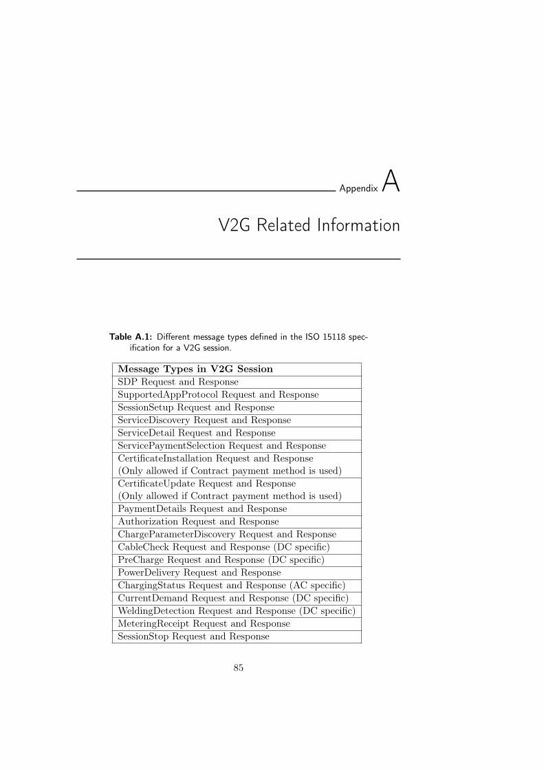
AppendixAV2G Related Information
Table A.1: Different message types defined in the ISO 15118 spec-ification for a V2G session.
Message Types in V2G SessionSDP Request and ResponseSupportedAppProtocol Request and ResponseSessionSetup Request and ResponseServiceDiscovery Request and ResponseServiceDetail Request and ResponseServicePaymentSelection Request and ResponseCertificateInstallation Request and Response(Only allowed if Contract payment method is used)CertificateUpdate Request and Response(Only allowed if Contract payment method is used)PaymentDetails Request and ResponseAuthorization Request and ResponseChargeParameterDiscovery Request and ResponseCableCheck Request and Response (DC specific)PreCharge Request and Response (DC specific)PowerDelivery Request and ResponseChargingStatus Request and Response (AC specific)CurrentDemand Request and Response (DC specific)WeldingDetection Request and Response (DC specific)MeteringReceipt Request and ResponseSessionStop Request and Response
85
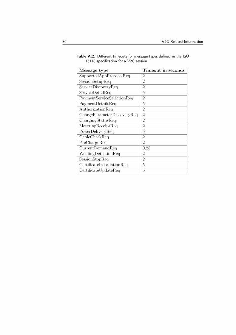
86 V2G Related Information
Table A.2: Different timeouts for message types defined in the ISO15118 specification for a V2G session.
Message type Timeout in secondsSupportedAppProtocolReq 2SessionSetupReq 2ServiceDiscoveryReq 2ServiceDetailReq 5PaymentServiceSelectionReq 2PaymentDetailsReq 5AuthorizationReq 2ChargeParameterDiscoveryReq 2ChargingStatusReq 2MeteringReceiptReq 2PowerDeliveryReq 5CableCheckReq 2PreChargeReq 2CurrentDemandReq 0,25WeldingDetectionReq 2SessionStopReq 2CertificateInstallationReq 5CertificateUpdateReq 5
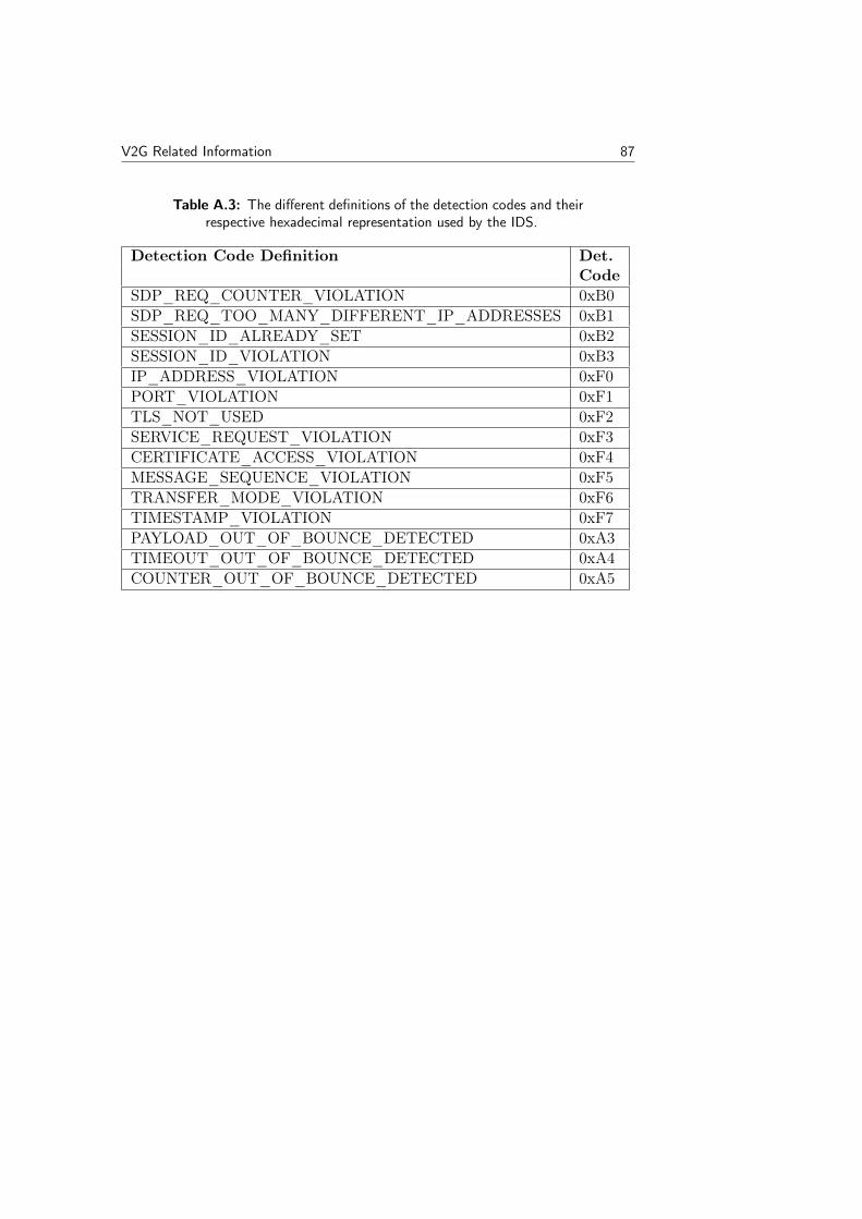
V2G Related Information 87
Table A.3: The different definitions of the detection codes and theirrespective hexadecimal representation used by the IDS.
Detection Code Definition Det.Code
SDP_REQ_COUNTER_VIOLATION 0xB0SDP_REQ_TOO_MANY_DIFFERENT_IP_ADDRESSES 0xB1SESSION_ID_ALREADY_SET 0xB2SESSION_ID_VIOLATION 0xB3IP_ADDRESS_VIOLATION 0xF0PORT_VIOLATION 0xF1TLS_NOT_USED 0xF2SERVICE_REQUEST_VIOLATION 0xF3CERTIFICATE_ACCESS_VIOLATION 0xF4MESSAGE_SEQUENCE_VIOLATION 0xF5TRANSFER_MODE_VIOLATION 0xF6TIMESTAMP_VIOLATION 0xF7PAYLOAD_OUT_OF_BOUNCE_DETECTED 0xA3TIMEOUT_OUT_OF_BOUNCE_DETECTED 0xA4COUNTER_OUT_OF_BOUNCE_DETECTED 0xA5

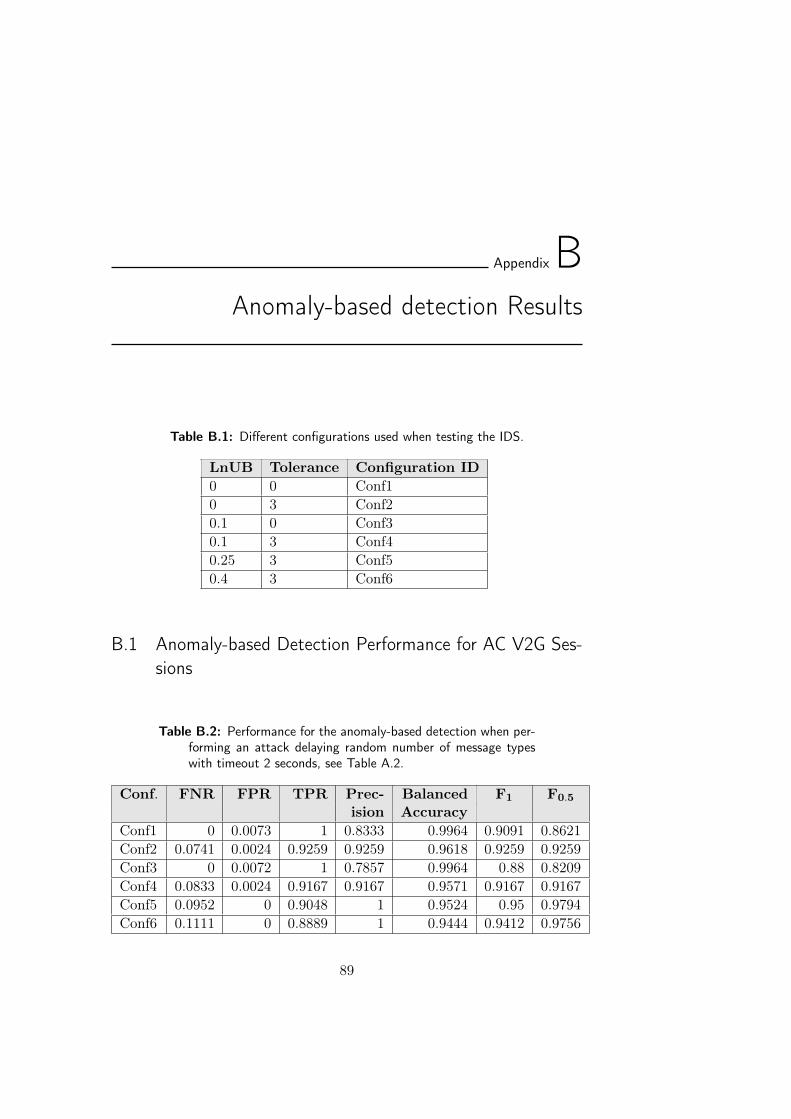
AppendixBAnomaly-based detection Results
Table B.1: Different configurations used when testing the IDS.
LnUB Tolerance Configuration ID0 0 Conf10 3 Conf20.1 0 Conf30.1 3 Conf40.25 3 Conf50.4 3 Conf6
B.1 Anomaly-based Detection Performance for AC V2G Ses-sions
Table B.2: Performance for the anomaly-based detection when per-forming an attack delaying random number of message typeswith timeout 2 seconds, see Table A.2.
Conf. FNR FPR TPR Prec- Balanced F1 F0.5
ision AccuracyConf1 0 0.0073 1 0.8333 0.9964 0.9091 0.8621Conf2 0.0741 0.0024 0.9259 0.9259 0.9618 0.9259 0.9259Conf3 0 0.0072 1 0.7857 0.9964 0.88 0.8209Conf4 0.0833 0.0024 0.9167 0.9167 0.9571 0.9167 0.9167Conf5 0.0952 0 0.9048 1 0.9524 0.95 0.9794Conf6 0.1111 0 0.8889 1 0.9444 0.9412 0.9756
89
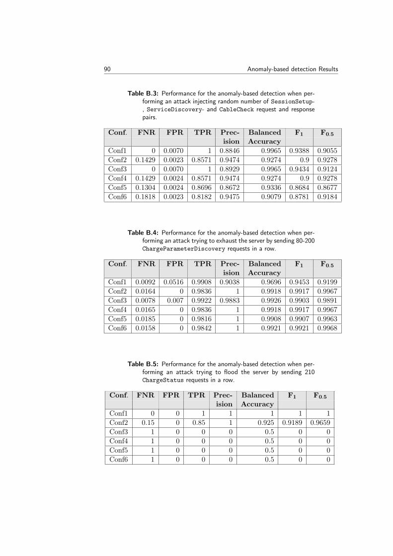
90 Anomaly-based detection Results
Table B.3: Performance for the anomaly-based detection when per-forming an attack injecting random number of SessionSetup-, ServiceDiscovery- and CableCheck request and responsepairs.
Conf. FNR FPR TPR Prec- Balanced F1 F0.5
ision AccuracyConf1 0 0.0070 1 0.8846 0.9965 0.9388 0.9055Conf2 0.1429 0.0023 0.8571 0.9474 0.9274 0.9 0.9278Conf3 0 0.0070 1 0.8929 0.9965 0.9434 0.9124Conf4 0.1429 0.0024 0.8571 0.9474 0.9274 0.9 0.9278Conf5 0.1304 0.0024 0.8696 0.8672 0.9336 0.8684 0.8677Conf6 0.1818 0.0023 0.8182 0.9475 0.9079 0.8781 0.9184
Table B.4: Performance for the anomaly-based detection when per-forming an attack trying to exhaust the server by sending 80-200ChargeParameterDiscovery requests in a row.
Conf. FNR FPR TPR Prec- Balanced F1 F0.5
ision AccuracyConf1 0.0092 0.0516 0.9908 0.9038 0.9696 0.9453 0.9199Conf2 0.0164 0 0.9836 1 0.9918 0.9917 0.9967Conf3 0.0078 0.007 0.9922 0.9883 0.9926 0.9903 0.9891Conf4 0.0165 0 0.9836 1 0.9918 0.9917 0.9967Conf5 0.0185 0 0.9816 1 0.9908 0.9907 0.9963Conf6 0.0158 0 0.9842 1 0.9921 0.9921 0.9968
Table B.5: Performance for the anomaly-based detection when per-forming an attack trying to flood the server by sending 210ChargeStatus requests in a row.
Conf. FNR FPR TPR Prec- Balanced F1 F0.5
ision AccuracyConf1 0 0 1 1 1 1 1Conf2 0.15 0 0.85 1 0.925 0.9189 0.9659Conf3 1 0 0 0 0.5 0 0Conf4 1 0 0 0 0.5 0 0Conf5 1 0 0 0 0.5 0 0Conf6 1 0 0 0 0.5 0 0
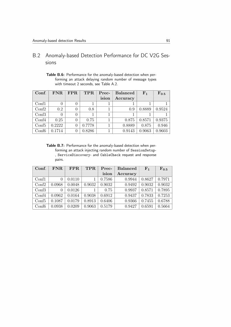
Anomaly-based detection Results 91
B.2 Anomaly-based Detection Performance for DC V2G Ses-sions
Table B.6: Performance for the anomaly-based detection when per-forming an attack delaying random number of message typeswith timeout 2 seconds, see Table A.2.
Conf. FNR FPR TPR Prec- Balanced F1 F0.5
ision AccuracyConf1 0 0 1 1 1 1 1Conf2 0.2 0 0.8 1 0.9 0.8889 0.9524Conf3 0 0 1 1 1 1 1Conf4 0.25 0 0.75 1 0.875 0.8571 0.9375Conf5 0.2222 0 0.7778 1 0.8889 0.875 0.946Conf6 0.1714 0 0.8286 1 0.9143 0.9063 0.9603
Table B.7: Performance for the anomaly-based detection when per-forming an attack injecting random number of SessionSetup-, ServiceDiscovery- and CableCheck request and responsepairs.
Conf. FNR FPR TPR Prec- Balanced F1 F0.5
ision AccuracyConf1 0 0.0110 1 0.7586 0.9944 0.8627 0.7971Conf2 0.0968 0.0048 0.9032 0.9032 0.9492 0.9032 0.9032Conf3 0 0.0126 1 0.75 0.9937 0.8571 0.7895Conf4 0.0962 0.0164 0.9038 0.6912 0.9437 0.7833 0.7253Conf5 0.1087 0.0179 0.8913 0.6406 0.9366 0.7455 0.6788Conf6 0.0938 0.0209 0.9063 0.5179 0.9427 0.6591 0.5664
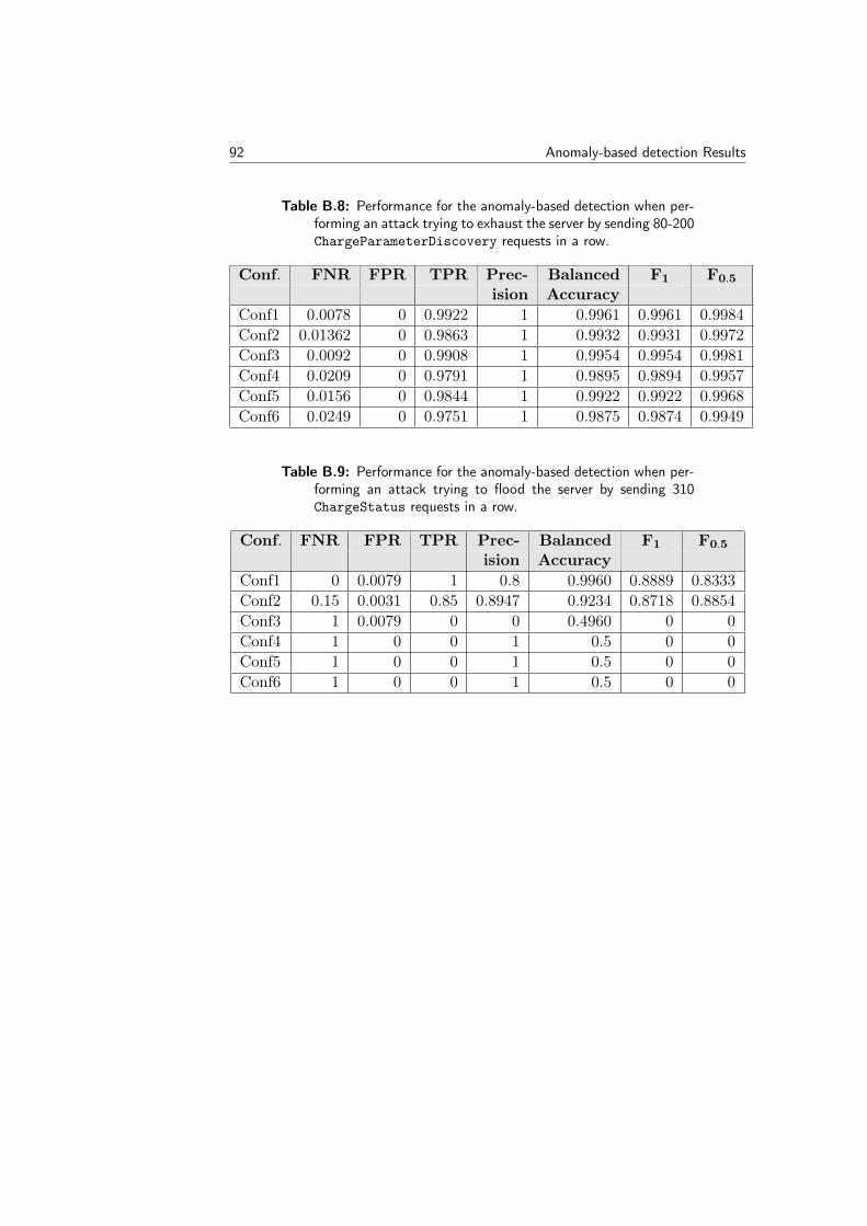
92 Anomaly-based detection Results
Table B.8: Performance for the anomaly-based detection when per-forming an attack trying to exhaust the server by sending 80-200ChargeParameterDiscovery requests in a row.
Conf. FNR FPR TPR Prec- Balanced F1 F0.5
ision AccuracyConf1 0.0078 0 0.9922 1 0.9961 0.9961 0.9984Conf2 0.01362 0 0.9863 1 0.9932 0.9931 0.9972Conf3 0.0092 0 0.9908 1 0.9954 0.9954 0.9981Conf4 0.0209 0 0.9791 1 0.9895 0.9894 0.9957Conf5 0.0156 0 0.9844 1 0.9922 0.9922 0.9968Conf6 0.0249 0 0.9751 1 0.9875 0.9874 0.9949
Table B.9: Performance for the anomaly-based detection when per-forming an attack trying to flood the server by sending 310ChargeStatus requests in a row.
Conf. FNR FPR TPR Prec- Balanced F1 F0.5
ision AccuracyConf1 0 0.0079 1 0.8 0.9960 0.8889 0.8333Conf2 0.15 0.0031 0.85 0.8947 0.9234 0.8718 0.8854Conf3 1 0.0079 0 0 0.4960 0 0Conf4 1 0 0 1 0.5 0 0Conf5 1 0 0 1 0.5 0 0Conf6 1 0 0 1 0.5 0 0
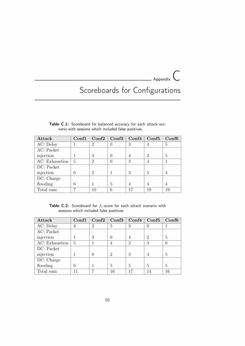
AppendixCScoreboards for Configurations
Table C.1: Scoreboard for balanced accuracy for each attack sce-nario with sessions which included false positives.
Attack Conf1 Conf2 Conf3 Conf4 Conf5 Conf6AC: Delay 1 2 0 3 4 5AC: Packetinjection 1 3 0 4 2 5AC: Exhaustion 5 2 0 3 4 1DC: Packetinjection 0 2 1 3 5 4DC: Chargeflooding 0 1 5 4 4 4Total sum 7 10 6 17 19 19
Table C.2: Scoreboard for f1-score for each attack scenario withsessions which included false positives.
Attack Conf1 Conf2 Conf3 Conf4 Conf5 Conf6AC: Delay 4 2 5 3 0 1AC: Packetinjection 1 3 0 4 2 5AC: Exhaustion 5 1 4 2 3 0DC: Packetinjection 1 0 2 3 4 5DC: Chargeflooding 0 1 5 5 5 5Total sum 11 7 16 17 14 16
93
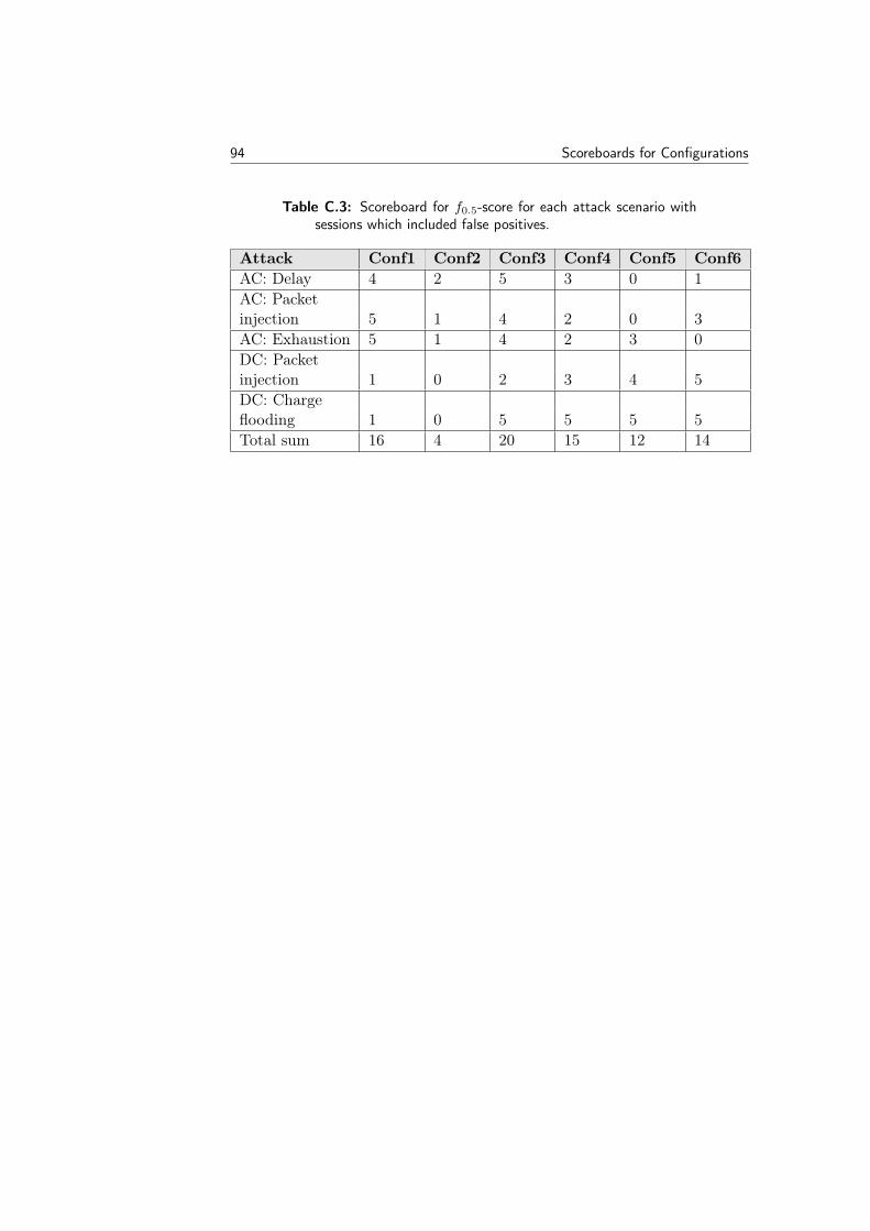
94 Scoreboards for Configurations
Table C.3: Scoreboard for f0.5-score for each attack scenario withsessions which included false positives.
Attack Conf1 Conf2 Conf3 Conf4 Conf5 Conf6AC: Delay 4 2 5 3 0 1AC: Packetinjection 5 1 4 2 0 3AC: Exhaustion 5 1 4 2 3 0DC: Packetinjection 1 0 2 3 4 5DC: Chargeflooding 1 0 5 5 5 5Total sum 16 4 20 15 12 14