Intrusion-aware Alert Validation Algorithm for Cooperative Distributed Intrusion Detection Schemes...
19
Sensors 2009, 9, 5989-6007; doi:10.3390/s90805989 OPEN ACCESS sensors ISSN 1424-8220 www.mdpi.com/journal/sensors Article Intrusion-Aware Alert Validation Algorithm for Cooperative Distributed Intrusion Detection Schemes of Wireless Sensor Networks Riaz Ahmed Shaikh 1 , Hassan Jameel 2 , Brian J. d’Auriol 1 , Heejo Lee 3 , Sungyoung Lee 1,? and Young-Jae Song 1 1 Department of Computer Engineering, Kyung Hee University, Suwon, Korea; E-Mails: [email protected] (R.A.S.); [email protected] (B.J.D.); [email protected] (Y.J.S.) 2 Computing Department, Macquarie University, NSW, Australia; E-Mail: [email protected] 3 Department of Computer Science & Engineering, Korea University, Seoul, Korea; E-Mail: [email protected] ? Author to whom correspondence should be addressed; E-Mail: [email protected]; Tel.: +82-31-201-2514; Fax: +82-31-202-2520 Received: 24 April 2009; in revised form: 25 June 2009 / Accepted: 17 July 2009 / Published: 28 July 2009 Abstract: Existing anomaly and intrusion detection schemes of wireless sensor networks have mainly focused on the detection of intrusions. Once the intrusion is detected, an alerts or claims will be generated. However, any unidentified malicious nodes in the network could send faulty anomaly and intrusion claims about the legitimate nodes to the other nodes. Veri- fying the validity of such claims is a critical and challenging issue that is not considered in the existing cooperative-based distributed anomaly and intrusion detection schemes of wireless sensor networks. In this paper, we propose a validation algorithm that addresses this prob- lem. This algorithm utilizes the concept of intrusion-aware reliability that helps to provide adequate reliability at a modest communication cost. In this paper, we also provide a security resiliency analysis of the proposed intrusion-aware alert validation algorithm. Keywords: alerts; anomalies; intrusions; trust management; wireless sensor networks
-
Upload
independent -
Category
Documents
-
view
6 -
download
0
Transcript of Intrusion-aware Alert Validation Algorithm for Cooperative Distributed Intrusion Detection Schemes...
Sensors 2009, 9, 5989-6007; doi:10.3390/s90805989
OPEN ACCESS
sensorsISSN 1424-8220
www.mdpi.com/journal/sensors
Article
Intrusion-Aware Alert Validation Algorithm for CooperativeDistributed Intrusion Detection Schemes of Wireless SensorNetworksRiaz Ahmed Shaikh 1, Hassan Jameel 2, Brian J. d’Auriol 1, Heejo Lee 3, Sungyoung Lee 1,? andYoung-Jae Song 1
1 Department of Computer Engineering, Kyung Hee University, Suwon, Korea; E-Mails:[email protected] (R.A.S.); [email protected] (B.J.D.); [email protected] (Y.J.S.)
2 Computing Department, Macquarie University, NSW, Australia; E-Mail: [email protected] Department of Computer Science & Engineering, Korea University, Seoul, Korea;
E-Mail: [email protected]
? Author to whom correspondence should be addressed; E-Mail: [email protected];Tel.: +82-31-201-2514; Fax: +82-31-202-2520
Received: 24 April 2009; in revised form: 25 June 2009 / Accepted: 17 July 2009 /Published: 28 July 2009
Abstract: Existing anomaly and intrusion detection schemes of wireless sensor networkshave mainly focused on the detection of intrusions. Once the intrusion is detected, an alertsor claims will be generated. However, any unidentified malicious nodes in the network couldsend faulty anomaly and intrusion claims about the legitimate nodes to the other nodes. Veri-fying the validity of such claims is a critical and challenging issue that is not considered in theexisting cooperative-based distributed anomaly and intrusion detection schemes of wirelesssensor networks. In this paper, we propose a validation algorithm that addresses this prob-lem. This algorithm utilizes the concept of intrusion-aware reliability that helps to provideadequate reliability at a modest communication cost. In this paper, we also provide a securityresiliency analysis of the proposed intrusion-aware alert validation algorithm.
Keywords: alerts; anomalies; intrusions; trust management; wireless sensor networks
Sensors 2009, 9 5990
1. Introduction
Many anomaly and intrusion detection schemes (IDS) have been proposed for wireless sensor net-works (WSNs) [1–6], but those schemes mainly focus on the detection of malicious or faulty nodes.All those anomaly and intrusion detection schemes (IDS) that are cooperative in nature [1, 2, 4] needto share anomalies or intrusion claims with the other node(s). However, those schemes are unable toascertain that the alert or claim received by the other node(s) is in fact sent by the trusted node(s). As aresult, any unidentified malicious node(s) in the network could send faulty anomaly and intrusion claimsabout the legitimate node(s) to the other node(s). Verifying the validity of such claims is a critical issuethat is not considered in existing cooperative-based distributed anomaly and IDS schemes of WSNs [7].Recently, some intrusion prevention schemes that are based on alerts have been proposed in the litera-ture [8, 9]. However, these schemes are based on the assumption that the monitoring nodes are trustedor the claim will be trusted if the monitoring node passed simple authentication and integrity test basedon shared pair-wise key.
In this paper, we propose a new intrusion-aware alert validation algorithm that provides a mechanismfor verifying anomaly and intrusion claims sent by any unidentified malicious node(s). This algorithmis simple and easy to implement. Our proposed algorithm execute on alert sender monitoring nodes andalert receiver monitoring nodes. Sender monitoring nodes are mainly responsible for the detection ofmalicious nodes, assignment of threat level, and generation of alert messages, whereas receiver moni-toring nodes are mainly responsible for the validation of alert messages. Validation mechanism consistsof two phases: consensus phase and decision phase. Although the consensus approach is widely usedin distributed computing domain to solve many problems like fault-tolerance [10], here we used this ap-proach with variation to solve problem of trusting anomaly and intrusion claims. In consensus phase, weuniquely introduce an intrusion-aware reliability concept that helps to provide an adequate reliability ata modest communication cost. In the decision phase, a node will make the decision regarding validationand invalidation of a claim based on the result of consensus phase.
The rest of the paper is organized as follows: Section 2 contains description on taxonomy of IDS.Section 3 describes related work. Section 4 discusses the network model, assumptions and definitions.Section 5 describes the proposed validation algorithm. Section 6 provides the analysis and evaluationof proposed algorithm in terms of communication overhead, reliability and security. Finally, Section 7concludes the paper and highlights some future work.
2. Taxonomy of IDS
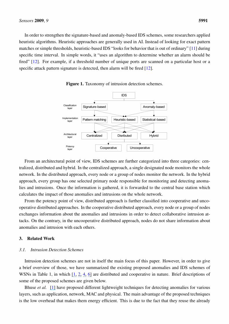
From the classification point of view, IDS have often been categorized into two types: signature-based IDS and anomaly-based IDS as shown in Figure 1. The signature-based IDS schemes (mostlyimplemented via pattern matching approach) detect intrusions based on the attack’s signature, such as,specific byte sequence in the payload or specific information in the header fields like sender address,last hop address, etc. On the other hand, the anomaly-based IDS (mostly implemented via statisticalapproach), first determines the normal network activity and then checks all traffic that deviates from thenormal and marks it as anomalous.
Sensors 2009, 9 5991
In order to strengthen the signature-based and anomaly-based IDS schemes, some researchers appliedheuristic algorithms. Heuristic approaches are generally used in AI. Instead of looking for exact patternmatches or simple thresholds, heuristic-based IDS “looks for behavior that is out of ordinary” [11] duringspecific time interval. In simple words, it “uses an algorithm to determine whether an alarm should befired” [12]. For example, if a threshold number of unique ports are scanned on a particular host or aspecific attack pattern signature is detected, then alarm will be fired [12].
Figure 1. Taxonomy of intrusion detection schemes.
From an architectural point of view, IDS schemes are further categorized into three categories: cen-tralized, distributed and hybrid. In the centralized approach, a single designated node monitors the wholenetwork. In the distributed approach, every node or a group of nodes monitor the network. In the hybridapproach, every group has one selected primary node responsible for monitoring and detecting anoma-lies and intrusions. Once the information is gathered, it is forwarded to the central base station whichcalculates the impact of those anomalies and intrusions on the whole network.
From the potency point of view, distributed approach is further classified into cooperative and unco-operative distributed approaches. In the cooperative distributed approach, every node or a group of nodesexchanges information about the anomalies and intrusions in order to detect collaborative intrusion at-tacks. On the contrary, in the uncooperative distributed approach, nodes do not share information aboutanomalies and intrusion with each others.
3. Related Work
3.1. Intrusion Detection Schemes
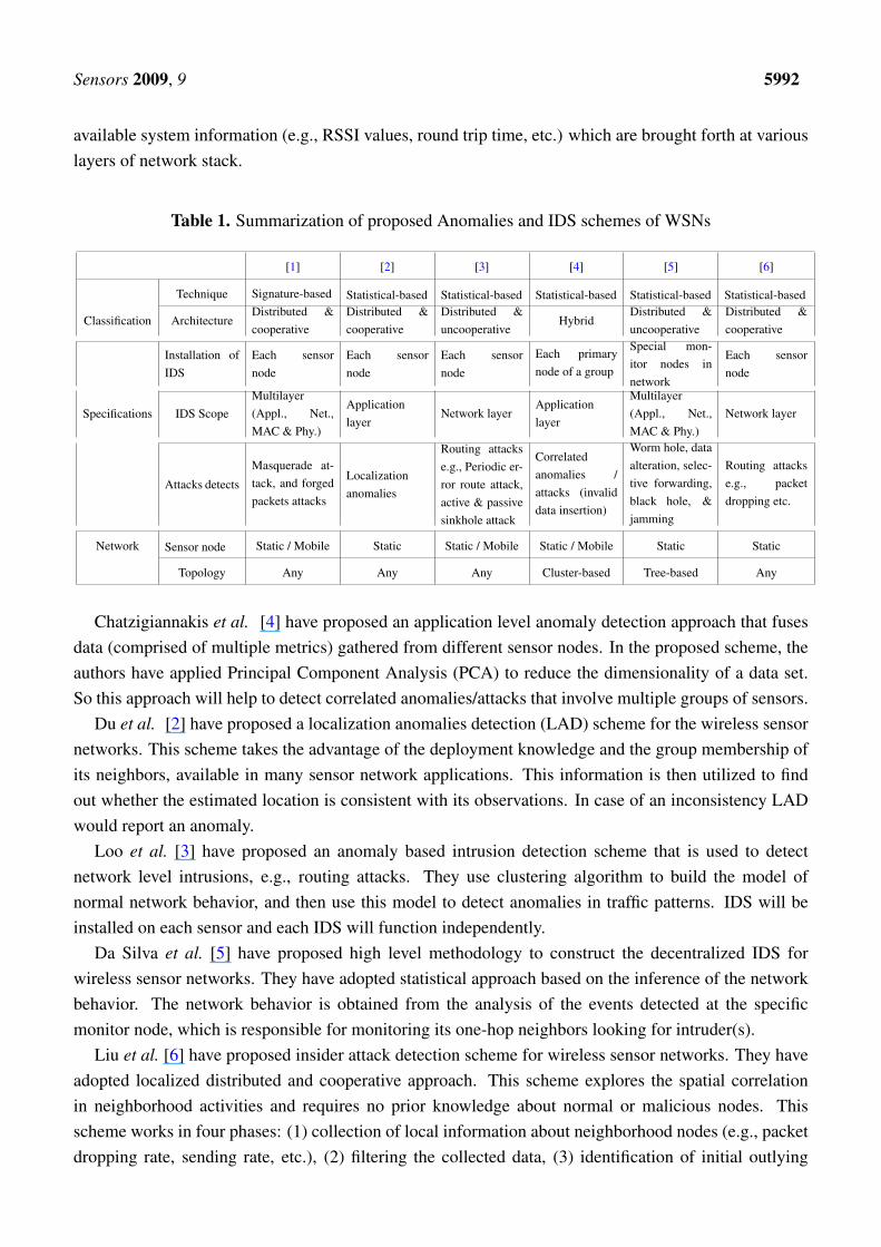
Intrusion detection schemes are not in itself the main focus of this paper. However, in order to givea brief overview of those, we have summarized the existing proposed anomalies and IDS schemes ofWSNs in Table 1, in which [1, 2, 4, 6] are distributed and cooperative in nature. Brief descriptions ofsome of the proposed schemes are given below.
Bhuse et al. [1] have proposed different lightweight techniques for detecting anomalies for variouslayers, such as application, network, MAC and physical. The main advantage of the proposed techniquesis the low overhead that makes them energy efficient. This is due to the fact that they reuse the already
Sensors 2009, 9 5992
available system information (e.g., RSSI values, round trip time, etc.) which are brought forth at variouslayers of network stack.
Table 1. Summarization of proposed Anomalies and IDS schemes of WSNs
[1] [2] [3] [4] [5] [6]
Technique Signature-based Statistical-based Statistical-based Statistical-based Statistical-based Statistical-based
Classification ArchitectureDistributed &cooperative
Distributed &cooperative
Distributed &uncooperative
HybridDistributed &uncooperative
Distributed &cooperative
Installation ofIDS
Each sensornode
Each sensornode
Each sensornode
Each primarynode of a group
Special mon-itor nodes innetwork
Each sensornode
Specifications IDS ScopeMultilayer(Appl., Net.,MAC & Phy.)
Applicationlayer
Network layerApplicationlayer
Multilayer(Appl., Net.,MAC & Phy.)
Network layer
Attacks detects
Masquerade at-tack, and forgedpackets attacks
Localizationanomalies
Routing attackse.g., Periodic er-ror route attack,active & passivesinkhole attack
Correlatedanomalies /attacks (invaliddata insertion)
Worm hole, dataalteration, selec-tive forwarding,black hole, &jamming
Routing attackse.g., packetdropping etc.
Network Sensor node Static / Mobile Static Static / Mobile Static / Mobile Static Static
Topology Any Any Any Cluster-based Tree-based Any
Chatzigiannakis et al. [4] have proposed an application level anomaly detection approach that fusesdata (comprised of multiple metrics) gathered from different sensor nodes. In the proposed scheme, theauthors have applied Principal Component Analysis (PCA) to reduce the dimensionality of a data set.So this approach will help to detect correlated anomalies/attacks that involve multiple groups of sensors.
Du et al. [2] have proposed a localization anomalies detection (LAD) scheme for the wireless sensornetworks. This scheme takes the advantage of the deployment knowledge and the group membership ofits neighbors, available in many sensor network applications. This information is then utilized to findout whether the estimated location is consistent with its observations. In case of an inconsistency LADwould report an anomaly.
Loo et al. [3] have proposed an anomaly based intrusion detection scheme that is used to detectnetwork level intrusions, e.g., routing attacks. They use clustering algorithm to build the model ofnormal network behavior, and then use this model to detect anomalies in traffic patterns. IDS will beinstalled on each sensor and each IDS will function independently.
Da Silva et al. [5] have proposed high level methodology to construct the decentralized IDS forwireless sensor networks. They have adopted statistical approach based on the inference of the networkbehavior. The network behavior is obtained from the analysis of the events detected at the specificmonitor node, which is responsible for monitoring its one-hop neighbors looking for intruder(s).
Liu et al. [6] have proposed insider attack detection scheme for wireless sensor networks. They haveadopted localized distributed and cooperative approach. This scheme explores the spatial correlationin neighborhood activities and requires no prior knowledge about normal or malicious nodes. Thisscheme works in four phases: (1) collection of local information about neighborhood nodes (e.g., packetdropping rate, sending rate, etc.), (2) filtering the collected data, (3) identification of initial outlying
Sensors 2009, 9 5993
(malicious) nodes, and (4) applying majority vote to obtain a final list of malicious nodes. Once the nodedetects some malicious node, it will forward the report to the base station. Afterwards the base stationwill isolate that node from the network.
3.2. Intrusion Prevention Schemes
Su et al. [8] have proposed an energy-efficient Hybrid Intrusion Prohibition (eHIP) system for cluster-based wireless sensor networks. The eHIP system consists of two subsystems: Authentication-basedIntrusion Prevention (AIP) subsystem and Collaboration-based Intrusion Detection (CID) subsystem.In AIP, two distinguish authentication mechanisms are proposed to verify the control and sensed datamessages with the help of HMAC and the modified form of one-key chain [13] mechanisms. CID isalso consisted of two subsystems: cluster head monitoring (CHM) system and member node monitoring(MNM) system. In CHM, all member nodes are divided into multiple monitoring groups. With respectto security requirements, each monitoring group has various number of monitoring nodes. Every moni-toring group monitors the cluster head. Whenever any monitoring group detects malicious activity of thecluster head, it generates an alarm that is forwarded to all member nodes of the cluster. Each membernode maintains the alarm table. If the number of alarms exceeds then the alarm threshold, the clusterhead will be declared as a malicious node. The member node monitoring mechanism is performed at thecluster head and limited to the detection of compromised nodes through the used pair-wise key only.
Zhang et al. [9] have proposed a nice application-independent framework for identifying compro-mised nodes. This framework is based on alerts generated by specific intrusion detection system. Theauthors have adopted a centralized approach and used a simple graph theory. However, this schemehas some limitations, e.g., it provides some late detection of compromised nodes, because the detectionprocess will always start at the end of each time window. If the size of the time window is large (e.g.,one hour, as mentioned in [9]), then it is very likely that an adversary can achieve its objective duringthat time window. If the time window is small, then the result may not be accurate. Also, the detectionaccuracy is mainly dependent on the size of the network density. If the network size decreases, then thedetection accuracy will also decrease.
4. Network Model, Assumptions and Definitions
4.1. Network Model and Assumptions
Sensor nodes are deployed in an environment either in a random fashion or in a grid fashion. After de-ployment nodes become static, nodes are organized into clusters. The reason behind taking cluster-basednetwork model is that it is widely used in real world scenarios for efficient network organization [14].Within a cluster, communication mechanism could be single-hop [15] or multi-hop [16]. In case of amulti-hop clustering environment, the cluster could be divided into two or three sensor sub-clusters forthe purpose of distributed detection [17].
We assume that any cooperative-based distributed anomaly detection or IDS is already deployed inthe WSNs and forwards claims to the other node(s) whenever it detects anomalies or intrusions. Basedon the mechanism of the IDS, every node or subset of nodes (within a cluster) acts as a monitoring node.The malicious node must fall into the radio range of the monitoring node. And the node (who received
Sensors 2009, 9 5994
the claim from the monitoring node) has the knowledge about the neighboring nodes of the monitoringand malicious nodes (the malicious and monitoring nodes belong to the same cluster). Within a clusteror sub-cluster, all monitoring nodes can communicate with each other directly. We also assume that themultiple sensor nodes in a neighborhood can sense the same anomaly/intrusion. We also assume that allinformation is exchanged in a secure encrypted manner. For this purpose, every monitoring node sharea unique secret key [18] with other monitoring node(s) that are in the same cluster.
4.2. Definitions
A legitimate node compromised by an adversary is called a malicious node. In order to hide thepresence of the adversary, a malicious node could also perform all activities of the normal nodes, suchas monitoring, ciphering of data, forwarding of packets, etc.
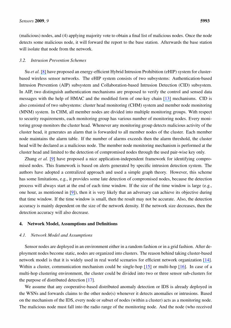
Reliability means the confidence level on a certain decision. It can simply be categorized into threelevels: (1) low, (2) medium, and (3) high. At low reliability, validation is based on the confirmation fromany single available trusted source. At medium reliability, validation is based on the confirmation fromhalf of the available trusted sources. At high reliability, validation is based on the confirmation from allof the trusted sources. In general, the reliability level (RL) is define as:
RL = q ; q ≤ n (1)
where n represents the total number of available trusted nodes, and q represents the number of nodesconsulted. However, in order to achieve more flexibility and adaptability, we have adopted the intrusion-aware reliability mode concept, in which the validation is based on the level of a threat of an anomaly orintrusion. This approach will also reduce the communication cost as described in Section 6.1. Threatscould also be categorized into low, medium, high or other. Depending on the level of the threat, intrusion-aware reliability mode is set to low, medium, high or other, as shown in Figure 2.
Figure 2. Intrusion-aware reliability mode concept.
5. Intrusion-aware Alert Validation Algorithm
Our proposed intrusion-aware alert validation algorithm execute on sender as well as on receivermonitoring nodes. Sender monitoring nodes are mainly responsible for the detection of maliciousnodes and generation of alert messages, whereas receiver monitoring nodes are mainly responsible
Sensors 2009, 9 5995
for the validation of alert messages. Both sender and receiver nodes go through different phases asdescribed below.
5.1. Sender Monitoring Node
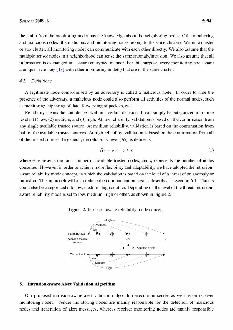
In our proposed algorithm, sender monitoring node will perform mainly three steps (as shown inFigure 3): (1) detection of malicious node, (2) threat level assignment, and (3) generation ofalert message.
Figure 3. Intrusion-aware validation algorithm at sender end.
Phase 1: Detection of Malicious Node
A node can be classified into one of the three categories [19]: trustworthy, untrustworthy, and uncer-tain. A node is considered to be trustworthy if it interacts successfully most of the time with the othernodes. A node is considered untrustworthy if it tries to do as many unsuccessful interactions as possiblewith the other nodes. An untrustworthy node could be a faulty [20] or malicious node. A node is con-sidered uncertain if it performs both successful and unsuccessful interactions. Detailed definition of thesuccessful and unsuccessful interactions and trust calculation methodology is available in our paper [21]and provided here in a simplified form.
A sender will consider an interaction successful if the sender receives confirmation that the packetis successfully received by the neighbor node and forwarded towards the destination in an unalteredfashion. The first requirement of successful reception is achieved on the reception of the link layeracknowledgment (ACK). The second requirement of forwarding towards the destination is achievedwith the help of enhanced passive acknowledgment (PACK) by overhearing the transmission of a nexthop on the route, since they are within the radio range [22]. If the sender node does not overhear theretransmission of the packet within a threshold time from its neighboring node or the overheard packet is
Sensors 2009, 9 5996
found to be illegally fabricated (by comparing the payload that is attached to the packet), then the sendernode will consider that interaction as unsuccessful.
With the help of this simple approach, several attacks can be prevented, i.e., the black hole attackis straightforwardly detected when malicious node drops the incoming packets and keeps sending self-generated packets [23]. Similarly, sink hole attack [24], an advanced version of the black hole attack,is also easily detectable by looking at the passive acknowledgment. Likewise, the selective forwardingattack [25] and gray-hole attack [26] can also be eliminated with the aid of above mentioned approach.
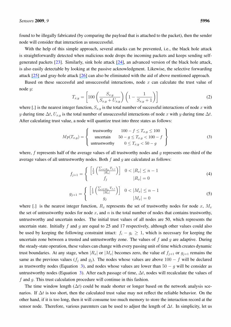
Based on these successful and unsuccessful interactions, node x can calculate the trust value ofnode y:
Tx,y =
[100
(Sx,y
Sx,y + Ux,y
)(1− 1
Sx,y + 1
)](2)
where [.] is the nearest integer function, Sx,y is the total number of successful interactions of node x withy during time ∆t, Ux,y is the total number of unsuccessful interactions of node x with y during time ∆t.After calculating trust value, a node will quantize trust into three states as follows:
Mp(Tx,y) =
trustworthy 100− f ≤ Tx,y ≤ 100uncertain 50− g ≤ Tx,y < 100− f
untrustworthy 0 ≤ Tx,y < 50− g
(3)
where, f represents half of the average values of all trustworthy nodes and g represents one-third of theaverage values of all untrustworthy nodes. Both f and g are calculated as follows:
fj+1 =
{ [12
(∑i∈Rx
Tx,i
|Rx|
)]0 < |Rx| ≤ n− 1
fj |Rx| = 0(4)
gj+1 =
{ [13
(∑i∈Mx
Tx,i
|Mx|
)]0 < |Mx| ≤ n− 1
gj |Mx| = 0(5)
where [.] is the nearest integer function, Rx represents the set of trustworthy nodes for node x, Mx
the set of untrustworthy nodes for node x, and n is the total number of nodes that contains trustworthy,untrustworthy and uncertain nodes. The initial trust values of all nodes are 50, which represents theuncertain state. Initially f and g are equal to 25 and 17 respectively, although other values could alsobe used by keeping the following constraint intact: fi − gi ≥ 1, which is necessary for keeping theuncertain zone between a trusted and untrustworthy zone. The values of f and g are adaptive. Duringthe steady-state operation, these values can change with every passing unit of time which creates dynamictrust boundaries. At any stage, when |Rx| or |Mx| becomes zero, the value of fj+1 or gj+1 remains thesame as the previous values (fj and gj). The nodes whose values are above 100 − f will be declaredas trustworthy nodes (Equation 3), and nodes whose values are lower than 50 − g will be consider asuntrustworthy nodes (Equation 3). After each passage of time, ∆t, nodes will recalculate the values off and g. This trust calculation procedure will continue in this fashion.
The time window length (∆t) could be made shorter or longer based on the network analysis sce-narios. If ∆t is too short, then the calculated trust value may not reflect the reliable behavior. On theother hand, if it is too long, then it will consume too much memory to store the interaction record at thesensor node. Therefore, various paremters can be used to adjust the length of ∆t. In simplicity, let us
Sensors 2009, 9 5997
assume a cluster size, n, as the single paramters; then, ∆t is equal to n − 1. This approach reduces theproblems associated with too short or too long time window lengths. Moreover, the time window lengthsare adaptive based on the cluster size. If the size of the cluster changes, then the time window length willalso change.
Phase 2: Threat Level Assignment
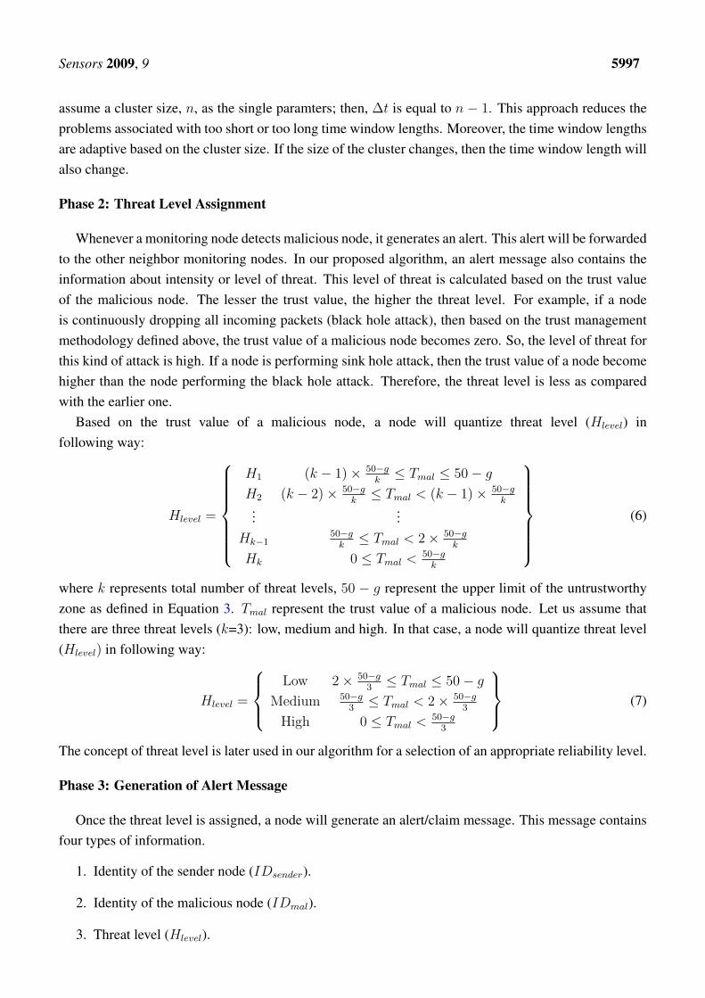
Whenever a monitoring node detects malicious node, it generates an alert. This alert will be forwardedto the other neighbor monitoring nodes. In our proposed algorithm, an alert message also contains theinformation about intensity or level of threat. This level of threat is calculated based on the trust valueof the malicious node. The lesser the trust value, the higher the threat level. For example, if a nodeis continuously dropping all incoming packets (black hole attack), then based on the trust managementmethodology defined above, the trust value of a malicious node becomes zero. So, the level of threat forthis kind of attack is high. If a node is performing sink hole attack, then the trust value of a node becomehigher than the node performing the black hole attack. Therefore, the threat level is less as comparedwith the earlier one.
Based on the trust value of a malicious node, a node will quantize threat level (Hlevel) infollowing way:
Hlevel =
H1 (k − 1)× 50−gk≤ Tmal ≤ 50− g
H2 (k − 2)× 50−gk≤ Tmal < (k − 1)× 50−g
k...
...Hk−1
50−gk≤ Tmal < 2× 50−g
k
Hk 0 ≤ Tmal < 50−gk
(6)
where k represents total number of threat levels, 50 − g represent the upper limit of the untrustworthyzone as defined in Equation 3. Tmal represent the trust value of a malicious node. Let us assume thatthere are three threat levels (k=3): low, medium and high. In that case, a node will quantize threat level(Hlevel) in following way:
Hlevel =
Low 2× 50−g3≤ Tmal ≤ 50− g
Medium 50−g3≤ Tmal < 2× 50−g
3
High 0 ≤ Tmal < 50−g3
(7)
The concept of threat level is later used in our algorithm for a selection of an appropriate reliability level.
Phase 3: Generation of Alert Message
Once the threat level is assigned, a node will generate an alert/claim message. This message containsfour types of information.
1. Identity of the sender node (IDsender).
2. Identity of the malicious node (IDmal).
3. Threat level (Hlevel).
Sensors 2009, 9 5998
4. Threat detail, like code etc.
This message will be forwarded to the other monitoring nodes.
5.2. Receiver Monitoring Node
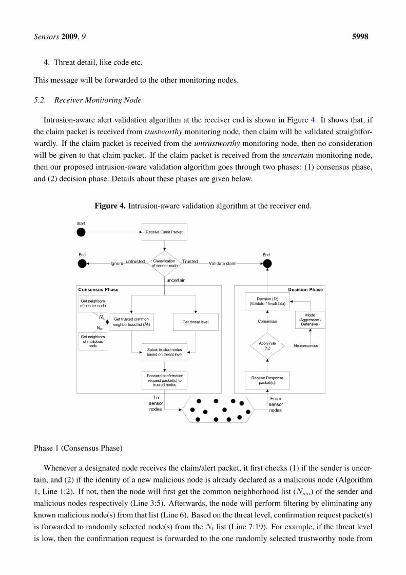
Intrusion-aware alert validation algorithm at the receiver end is shown in Figure 4. It shows that, ifthe claim packet is received from trustworthy monitoring node, then claim will be validated straightfor-wardly. If the claim packet is received from the untrustworthy monitoring node, then no considerationwill be given to that claim packet. If the claim packet is received from the uncertain monitoring node,then our proposed intrusion-aware validation algorithm goes through two phases: (1) consensus phase,and (2) decision phase. Details about these phases are given below.
Figure 4. Intrusion-aware validation algorithm at the receiver end.
Phase 1 (Consensus Phase)
Whenever a designated node receives the claim/alert packet, it first checks (1) if the sender is uncer-tain, and (2) if the identity of a new malicious node is already declared as a malicious node (Algorithm1, Line 1:2). If not, then the node will first get the common neighborhood list (Nsm) of the sender andmalicious nodes respectively (Line 3:5). Afterwards, the node will perform filtering by eliminating anyknown malicious node(s) from that list (Line 6). Based on the threat level, confirmation request packet(s)is forwarded to randomly selected node(s) from the Nt list (Line 7:19). For example, if the threat levelis low, then the confirmation request is forwarded to the one randomly selected trustworthy node from
Sensors 2009, 9 5999
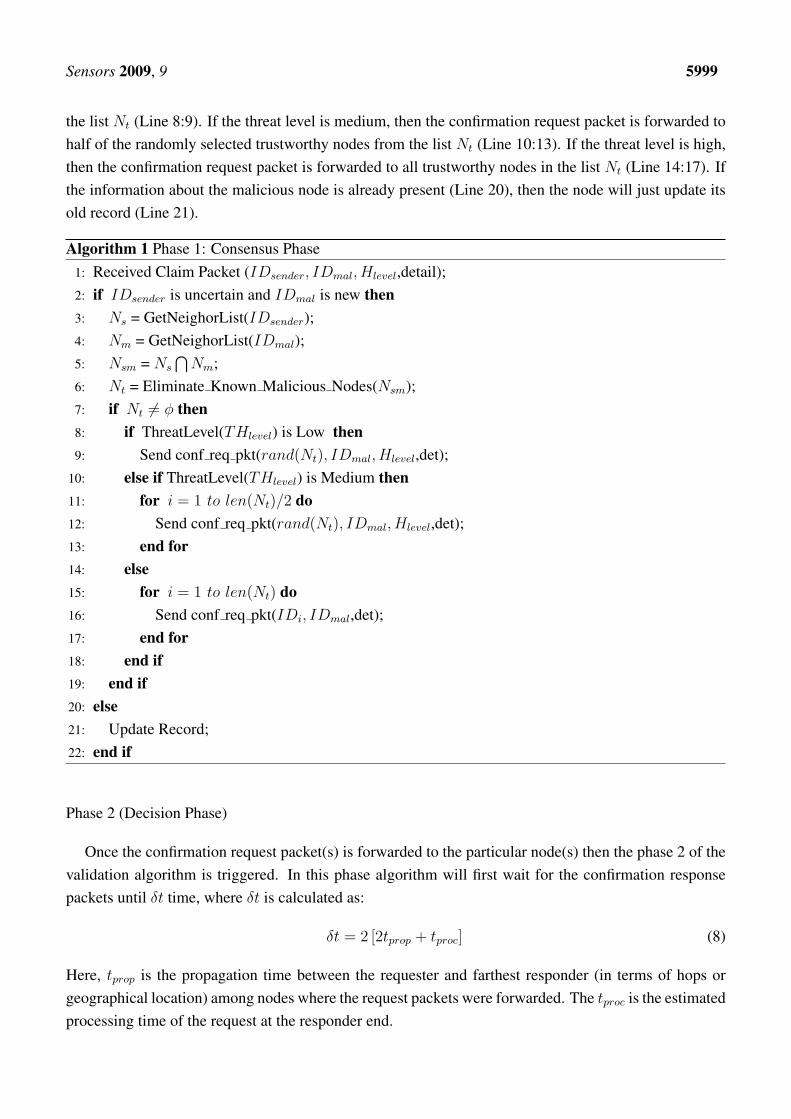
the list Nt (Line 8:9). If the threat level is medium, then the confirmation request packet is forwarded tohalf of the randomly selected trustworthy nodes from the list Nt (Line 10:13). If the threat level is high,then the confirmation request packet is forwarded to all trustworthy nodes in the list Nt (Line 14:17). Ifthe information about the malicious node is already present (Line 20), then the node will just update itsold record (Line 21).
Algorithm 1 Phase 1: Consensus Phase1: Received Claim Packet (IDsender, IDmal, Hlevel,detail);2: if IDsender is uncertain and IDmal is new then3: Ns = GetNeighorList(IDsender);4: Nm = GetNeighorList(IDmal);5: Nsm = Ns
⋂Nm;
6: Nt = Eliminate Known Malicious Nodes(Nsm);7: if Nt 6= φ then8: if ThreatLevel(THlevel) is Low then9: Send conf req pkt(rand(Nt), IDmal, Hlevel,det);
10: else if ThreatLevel(THlevel) is Medium then11: for i = 1 to len(Nt)/2 do12: Send conf req pkt(rand(Nt), IDmal, Hlevel,det);13: end for14: else15: for i = 1 to len(Nt) do16: Send conf req pkt(IDi, IDmal,det);17: end for18: end if19: end if20: else21: Update Record;22: end if
Phase 2 (Decision Phase)
Once the confirmation request packet(s) is forwarded to the particular node(s) then the phase 2 of thevalidation algorithm is triggered. In this phase algorithm will first wait for the confirmation responsepackets until δt time, where δt is calculated as:
δt = 2 [2tprop + tproc] (8)
Here, tprop is the propagation time between the requester and farthest responder (in terms of hops orgeographical location) among nodes where the request packets were forwarded. The tproc is the estimatedprocessing time of the request at the responder end.
Sensors 2009, 9 6000
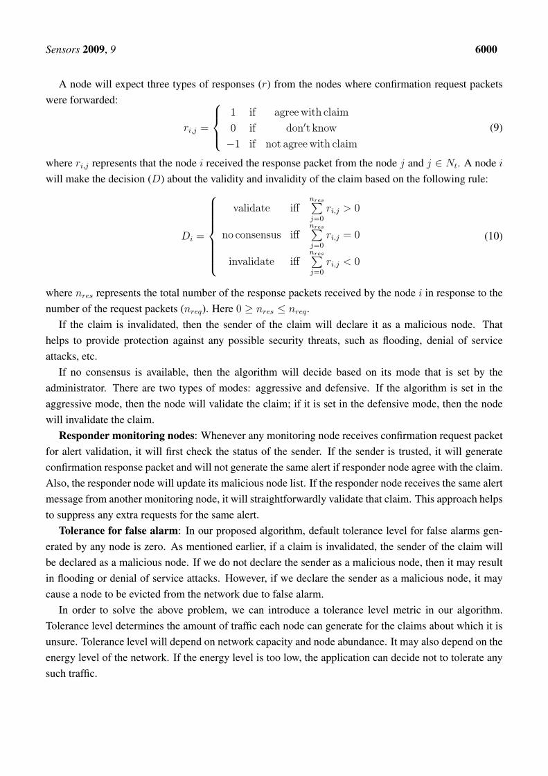
A node will expect three types of responses (r) from the nodes where confirmation request packetswere forwarded:
ri,j =
1 if agree with claim
0 if don′t know
−1 if not agree with claim
(9)
where ri,j represents that the node i received the response packet from the node j and j ∈ Nt. A node i
will make the decision (D) about the validity and invalidity of the claim based on the following rule:
Di =
validate iffnres∑j=0
ri,j > 0
no consensus iffnres∑j=0
ri,j = 0
invalidate iffnres∑j=0
ri,j < 0
(10)
where nres represents the total number of the response packets received by the node i in response to thenumber of the request packets (nreq). Here 0 ≥ nres ≤ nreq.
If the claim is invalidated, then the sender of the claim will declare it as a malicious node. Thathelps to provide protection against any possible security threats, such as flooding, denial of serviceattacks, etc.
If no consensus is available, then the algorithm will decide based on its mode that is set by theadministrator. There are two types of modes: aggressive and defensive. If the algorithm is set in theaggressive mode, then the node will validate the claim; if it is set in the defensive mode, then the nodewill invalidate the claim.
Responder monitoring nodes: Whenever any monitoring node receives confirmation request packetfor alert validation, it will first check the status of the sender. If the sender is trusted, it will generateconfirmation response packet and will not generate the same alert if responder node agree with the claim.Also, the responder node will update its malicious node list. If the responder node receives the same alertmessage from another monitoring node, it will straightforwardly validate that claim. This approach helpsto suppress any extra requests for the same alert.
Tolerance for false alarm: In our proposed algorithm, default tolerance level for false alarms gen-erated by any node is zero. As mentioned earlier, if a claim is invalidated, the sender of the claim willbe declared as a malicious node. If we do not declare the sender as a malicious node, then it may resultin flooding or denial of service attacks. However, if we declare the sender as a malicious node, it maycause a node to be evicted from the network due to false alarm.
In order to solve the above problem, we can introduce a tolerance level metric in our algorithm.Tolerance level determines the amount of traffic each node can generate for the claims about which it isunsure. Tolerance level will depend on network capacity and node abundance. It may also depend on theenergy level of the network. If the energy level is too low, the application can decide not to tolerate anysuch traffic.
Sensors 2009, 9 6001
6. Analyses and Evaluation
6.1. Communication Overhead Analysis
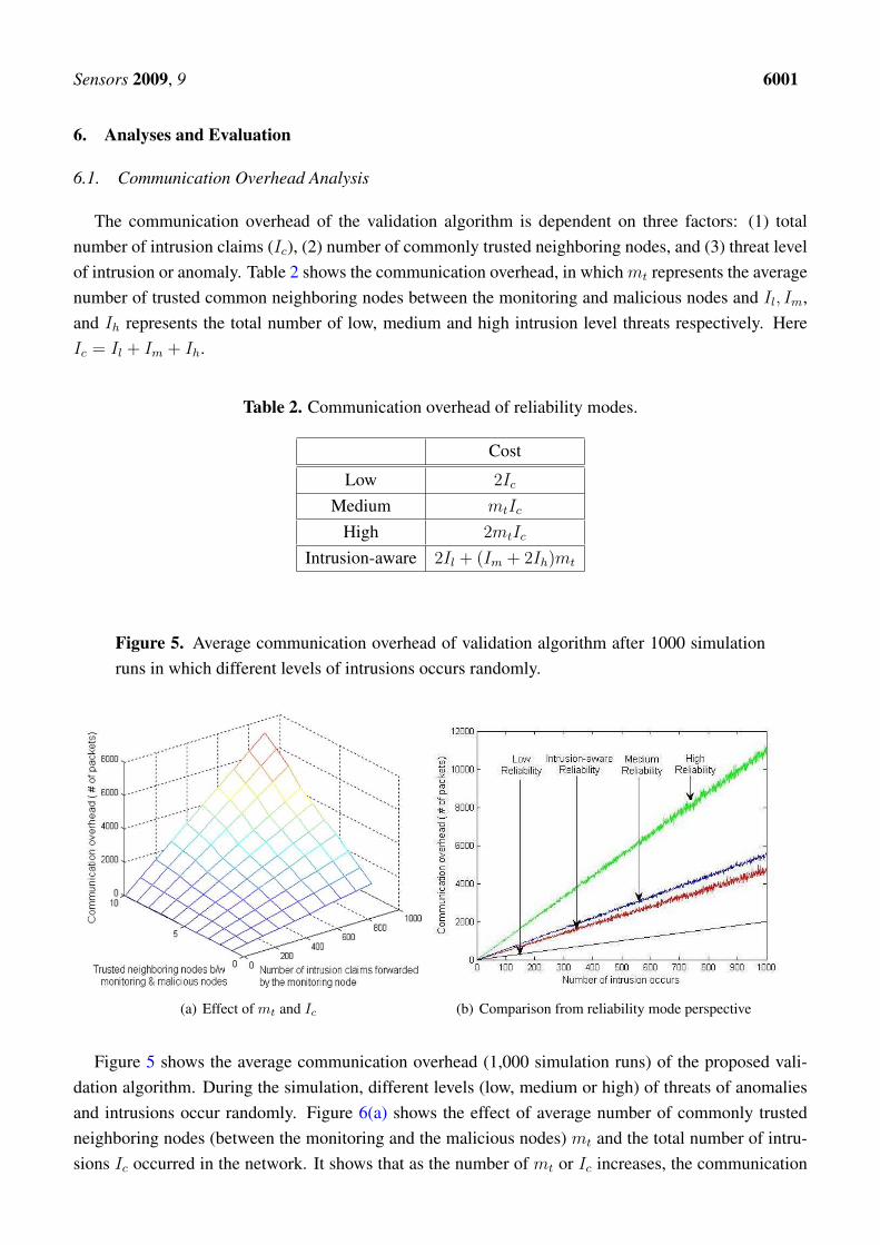
The communication overhead of the validation algorithm is dependent on three factors: (1) totalnumber of intrusion claims (Ic), (2) number of commonly trusted neighboring nodes, and (3) threat levelof intrusion or anomaly. Table 2 shows the communication overhead, in which mt represents the averagenumber of trusted common neighboring nodes between the monitoring and malicious nodes and Il, Im,and Ih represents the total number of low, medium and high intrusion level threats respectively. HereIc = Il + Im + Ih.
Table 2. Communication overhead of reliability modes.
Cost
Low 2Ic
Medium mtIc
High 2mtIc
Intrusion-aware 2Il + (Im + 2Ih)mt
Figure 5. Average communication overhead of validation algorithm after 1000 simulationruns in which different levels of intrusions occurs randomly.
(a) Effect of mt and Ic (b) Comparison from reliability mode perspective
Figure 5 shows the average communication overhead (1,000 simulation runs) of the proposed vali-dation algorithm. During the simulation, different levels (low, medium or high) of threats of anomaliesand intrusions occur randomly. Figure 6(a) shows the effect of average number of commonly trustedneighboring nodes (between the monitoring and the malicious nodes) mt and the total number of intru-sions Ic occurred in the network. It shows that as the number of mt or Ic increases, the communication
Sensors 2009, 9 6002
overhead of the validation scheme also increases linearly. Figure 6(b) shows the comparison betweenthe four different levels of the reliability modes. In the simulation, each monitoring node has a randomnumber of commonly trusted neighboring nodes. This figure shows that the intrusion-aware reliabilitymode introduces less communication overhead then the medium and high level reliability modes. At amodest communication cost, it provides adequate reliability required by the nature of the intrusion claim.
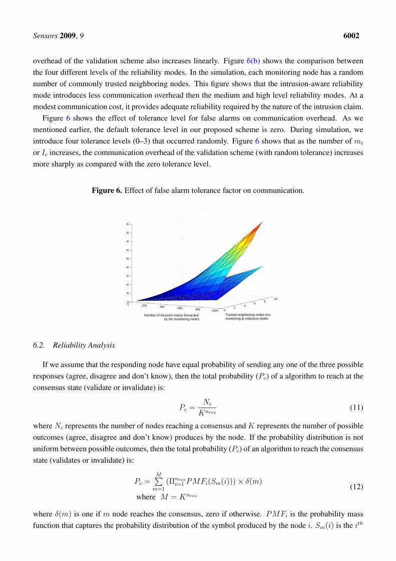
Figure 6 shows the effect of tolerance level for false alarms on communication overhead. As wementioned earlier, the default tolerance level in our proposed scheme is zero. During simulation, weintroduce four tolerance levels (0–3) that occurred randomly. Figure 6 shows that as the number of mt
or Ic increases, the communication overhead of the validation scheme (with random tolerance) increasesmore sharply as compared with the zero tolerance level.
Figure 6. Effect of false alarm tolerance factor on communication.
0 200 400 600 800 1000 02
46
810
0
2000
4000
6000
8000
10000
12000
14000
16000
18000
Trusted neighboring nodes b/w monitoring & malicious nodes
Number of intrusion claims forwarded by the monitoring nodes
6.2. Reliability Analysis
If we assume that the responding node have equal probability of sending any one of the three possibleresponses (agree, disagree and don’t know), then the total probability (Pc) of a algorithm to reach at theconsensus state (validate or invalidate) is:
Pc =Nc
Knres(11)
where Nc represents the number of nodes reaching a consensus and K represents the number of possibleoutcomes (agree, disagree and don’t know) produces by the node. If the probability distribution is notuniform between possible outcomes, then the total probability (Pc) of an algorithm to reach the consensusstate (validates or invalidate) is:
Pc =M∑
m=1
(Πnresi=1 PMFi(Sm(i)))× δ(m)
where M = Knres
(12)
where δ(m) is one if m node reaches the consensus, zero if otherwise. PMFi is the probability massfunction that captures the probability distribution of the symbol produced by the node i. Sm(i) is the ith
Sensors 2009, 9 6003
symbol in the mth node result. More details and derivation of these two probability equations are givenin [27].
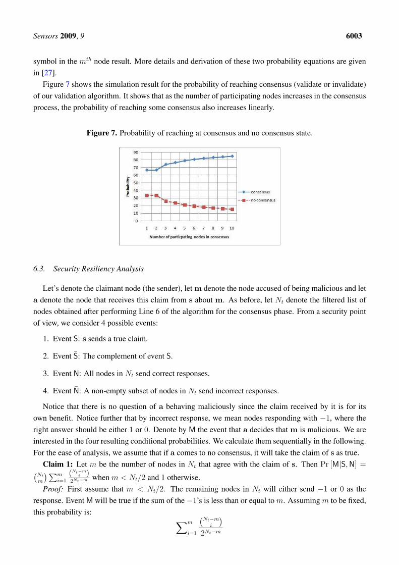
Figure 7 shows the simulation result for the probability of reaching consensus (validate or invalidate)of our validation algorithm. It shows that as the number of participating nodes increases in the consensusprocess, the probability of reaching some consensus also increases linearly.
Figure 7. Probability of reaching at consensus and no consensus state.
6.3. Security Resiliency Analysis
Let’s denote the claimant node (the sender), let m denote the node accused of being malicious and leta denote the node that receives this claim from s about m. As before, let Nt denote the filtered list ofnodes obtained after performing Line 6 of the algorithm for the consensus phase. From a security pointof view, we consider 4 possible events:
1. Event S: s sends a true claim.
2. Event S̄: The complement of event S.
3. Event N: All nodes in Nt send correct responses.
4. Event N̄: A non-empty subset of nodes in Nt send incorrect responses.
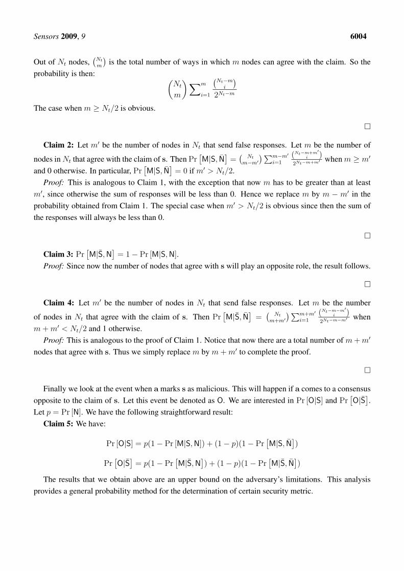
Notice that there is no question of a behaving maliciously since the claim received by it is for itsown benefit. Notice further that by incorrect response, we mean nodes responding with −1, where theright answer should be either 1 or 0. Denote by M the event that a decides that m is malicious. We areinterested in the four resulting conditional probabilities. We calculate them sequentially in the following.For the ease of analysis, we assume that if a comes to no consensus, it will take the claim of s as true.
Claim 1: Let m be the number of nodes in Nt that agree with the claim of s. Then Pr [M|S, N] =(Nt
m
) ∑mi=1
(Nt−mi )
2Nt−m when m < Nt/2 and 1 otherwise.Proof: First assume that m < Nt/2. The remaining nodes in Nt will either send −1 or 0 as the
response. Event M will be true if the sum of the−1’s is less than or equal to m. Assuming m to be fixed,this probability is:
∑m
i=1
(Nt−m
i
)
2Nt−m
Sensors 2009, 9 6004
Out of Nt nodes,(
Nt
m
)is the total number of ways in which m nodes can agree with the claim. So the
probability is then: (Nt
m
) ∑m
i=1
(Nt−m
i
)
2Nt−m
The case when m ≥ Nt/2 is obvious.
¤
Claim 2: Let m′ be the number of nodes in Nt that send false responses. Let m be the number of
nodes in Nt that agree with the claim of s. Then Pr[M|S, N̄
]=
(Nt
m−m′) ∑m−m′
i=1
(Nt−m+m′i )
2Nt−m+m′ when m ≥ m′
and 0 otherwise. In particular, Pr[M|S, N̄
]= 0 if m′ > Nt/2.
Proof: This is analogous to Claim 1, with the exception that now m has to be greater than at leastm′, since otherwise the sum of responses will be less than 0. Hence we replace m by m − m′ in theprobability obtained from Claim 1. The special case when m′ > Nt/2 is obvious since then the sum ofthe responses will always be less than 0.
¤
Claim 3: Pr[M|S̄, N
]= 1− Pr [M|S, N].
Proof: Since now the number of nodes that agree with s will play an opposite role, the result follows.
¤
Claim 4: Let m′ be the number of nodes in Nt that send false responses. Let m be the number
of nodes in Nt that agree with the claim of s. Then Pr[M|S̄, N̄
]=
(Nt
m+m′) ∑m+m′
i=1
(Nt−m−m′i )
2Nt−m−m′ whenm + m′ < Nt/2 and 1 otherwise.
Proof: This is analogous to the proof of Claim 1. Notice that now there are a total number of m + m′
nodes that agree with s. Thus we simply replace m by m + m′ to complete the proof.
¤
Finally we look at the event when a marks s as malicious. This will happen if a comes to a consensusopposite to the claim of s. Let this event be denoted as O. We are interested in Pr [O|S] and Pr
[O|S̄]
.Let p = Pr [N]. We have the following straightforward result:
Claim 5: We have:
Pr [O|S] = p(1− Pr [M|S, N]) + (1− p)(1− Pr[M|S, N̄
])
Pr[O|S̄]
= p(1− Pr[M|S̄, N
]) + (1− p)(1− Pr
[M|S̄, N̄
])
The results that we obtain above are an upper bound on the adversary’s limitations. This analysisprovides a general probability method for the determination of certain security metric.
Sensors 2009, 9 6005
7. Conclusion and Future Work
Existing cooperative-based distributed anomaly and intrusion detection schemes of WSNs do notprovide assurance that the reports/alerts/claims received by the other node(s) were really sent by thetrusted legitimate node(s). Therefore, in this paper we have proposed the first validation algorithm fortrusting anomalies and intrusion claims. This algorithm uses the concept of an intrusion-aware reliabilityparameter that helps to provide adequate reliability at a modest communication cost.
The proposed work is based on a few strict assumptions, i.e., multiple nodes can sense same anomalyor intrusion. In practice, it is quite possible that only one node can detect some specific anomaly orintrusion. Our proposed scheme does not adequetly deal with this case. Therefore, more work is neededto make the proposed scheme further flexible.
Acknowledgments
This research was supported by the MKE (Ministry of Knowledge Economy), Korea, under the ITRC(Information Technology Research Center) support program supervised by the IITA (Institute of Infor-mation Technology Advancement) (IITA-2009-(C1090-0902-0002)) and was supported by the IT R&Dprogram of MKE/KEIT, [10032105, Development of Realistic Multiverse Game Engine Technology].This work also was supported by the Brain Korea 21 projects and Korea Science & Engineering Foun-dation (KOSEF) grant funded by the Korea government (MOST) (No. 2008-1342).
References and Notes
1. Bhuse, V.; Gupta, A. Anomaly Intrusion Detection in Wireless Sensor Networks. J. High SpeedNetw. 2006, 15, 33–51.
2. Du, W.; Fang, L.; Ning, P. LAD: Localization Anomaly Detection for Wireless Sensor Networks.J. Parallel Distrib. Comput. 2006, 66, 874–886.
3. Loo, C.E.; Ng, M.Y.; Leckie, C.; Palaniswami, M. Intrusion Detection for Routing Attacks inSensor Networks. Inter. J. Distrib. Sensor Netw. 2006, 2, 313–332.
4. Chatzigiannakis, V.; Papavassiliou, S. Diagnosing Anomalies and Identifying Faulty Nodes inSensor Networks. IEEE Sens. J. 2007, 7, 637–645.
5. da Silva, A.P.R.; Martins, M.H.T.; Rocha, B.P.S.; Loureiro, A.A.F.; Ruiz, L.B.; Wong, H.C. Decen-tralized Intrusion Detection in Wireless Sensor Networks. In Proceedings of the 1st ACM interna-tional workshop on Quality of service & security in wireless and mobile networks (Q2SWinet’05) .ACM: New York, NY, USA, 2005; pp. 16–23.
6. Liu, F.; Cheng, X.; Chen, D. Insider Attacker Detection in Wireless Sensor Networks. In Proceed-ings of 26th Annual IEEE Conference on Computer Communications (INFOCOM07), Anchorage,Alaska, USA, 2007; pp. 1937–1945.
7. Bhuse, V.S. Lightweight Intrusion Detection: A Second Line of Defense for Unguarded WirelessSensor Networks, PhD thesis, Western Michigan University, Kalamazoo, MI, USA, 2007.
8. Su, W.-T.; Chang, K.-M.; Kuo, Y.-H. eHIP: An Energy-Efficient Hybrid Intrusion ProhibitionSystem for Cluster-Based Wireless Sensor Networks. Comput. Netw. 2007, 51, 1151–1168.
Sensors 2009, 9 6006
9. Zhang, Q.; Yu, T.; Ning, P. A Framework for Identifying Compromised Nodes in Wireless SensorNetworks. ACM Trans. Infor. Syst. Secur. 2008, 11, 1–37.
10. Barborak, M.; Dahbura, A.; Malek, M. The Consensus Problem in Fault-Tolerant Computing.ACM Comput. Surv. 1993, 25, 171–220.
11. Pfleeger, S.L. Security in Computing. Prentice Hall: Upper Saddle River, New Jersey, USA, 2003.12. Newman, D.P.; Manalo, K.M.; Tittel, E. CSIDS Exam Cram 2 (Exam Cram 623-531). Que
Publishing: Upper Saddle River, NJ, USA, 2004.13. Perrig, A.; Canetti, R.; Tygar, J.D.; Song, D. Efficient Authentication and Signing of Multicast
Streams Over Lossy Channels. In Proceedings of IEEE Symposium on Research in Security andPrivacy, Oakland, Canada, 2000; pp. 56–73.
14. Younis, O.; Krunz, M.; Ramasubramanian, S. Node Clustering in Wireless Sensor Networks:Recent Developments and Deployment Challenges. IEEE Netw. 2006, 20, 20–25.
15. Heinzelman, W.B.; Chandrakasan, A.P.; Balakrishnan, H. An Application-Specific Protocol Ar-chitecture for Wireless Microsensor Networks. IEEE Trans. Wirel Comm. 2002, 1, 660-670.
16. Jin, Y.; Wang, L.; Kim, Y.; Yang, X.-Z. Energy Efficient Non-uniform Clustering Division Schemein Wireless Sensor Networks. Wirel. Pers. Comm. 2008, 45, 31–43.
17. Hac, A. Wireless Sensor network Designs. John Wiley & Sons, Ltd.: New Jersey, USA, 2003.18. Shaikh, R.A.; Lee, S.; Khan, M.A.U.; Song, Y.J. LSec: Lightweight Security Protocol for Dis-
tributed Wireless Sensor Network. Lect. Not. Comput. Sci. 2006, 4217, 367–377.19. Shaikh, R.A.; Jameel, H.; Lee, S.; Song, Y.J.; Rajput, S. Trust Management Problem in Distributed
Wireless Sensor Networks. In Proceedings of 12th IEEE International Conference on EmbeddedReal Time Computing Systems and its Applications (RTCSA 2006). IEEE Computer Society: Syd-ney, Australia, 2006; pp. 411–415.
20. Jiang, P. A New Method for Node Fault Detection in Wireless Sensor Networks. Sensors 2009,9, 1282–1294.
21. Shaikh, R.A.; Jameel, H.; d’Auriol, B.J.; Lee, H.; Lee, S.; Song, Y.J. Group-based Trust Man-agement Scheme for Clustered Wireless Sensor Networks. IEEE Trans. Parall Distrib. Sys.(in press).
22. Buchegger, S.; Le Boudec, J.-Y. A Robust Reputation System for Peer-To-Peer and Mobile Ad-HocNetworks. In Proceedings of P2PEcon, Harvard University, MA,USA, 2004.
23. Gupta, S. Automatic Detection of DOS Routing Attacks in Wireless Sensor Networks. MS thesis,University of Houston, Houston, USA, 2006.
24. Du, X.; Guizani, M.; Xiao, Y.; Chen, H.H. Two Tier Secure Routing Protocol for HeterogeneousSensor Networks. IEEE Trans. Wirel. Commun. 2007, 6, 3395–3401.
25. Karlof, C.; Wagner, D. Secure Routing in Wireless Sensor Networks: Attacks and Countermea-sures. In Proceedings of the First IEEE International Workshop on Sensor Network Protocols andApplications (WSNA’03). IEEE Computer Society: Anchorage, Alaska, USA, 2003; pp. 113–127.
26. Srinivasan, A.; Teitelbaum, J.; Liang, H.; Wu, J.; Cardei, M. Reputation and Trust-based Systemsfor Ad Hoc and Sensor Networks. In Algorithms and Protocols for Wireless Ad Hoc and SensorNetworks, Boukerche, A., Ed.; Wiley & Sons: New Jersey, USA, 2006.

Sensors 2009, 9 6007
27. Yacoub, S.; Lin, X.; Burns, J. Analysis of the Reliability and Behavior of Majority and PluralityVoting Systems. Hewlett-Packard Development Company, L.P.: Palo Alto, CA, USA, 2002.
c© 2009 by the authors; licensee Molecular Diversity Preservation International, Basel, Switzerland.This article is an open-access article distributed under the terms and conditions of the Creative CommonsAttribution license (http://creativecommons.org/licenses/by/3.0/).