
Object- Oriented Software Composition - CiteSeerX
380
Object- Oriented Software Composition E DITED BY Oscar Nierstrasz U NIVERSITY OF B ERNE AND Dennis Tsichritzis U NIVERSITY OF G ENEVA
-
Upload
khangminh22 -
Category
Documents
-
view
0 -
download
0
Transcript of Object- Oriented Software Composition - CiteSeerX

Object-
Oriented
Software
Composition
EDITED BY
Oscar NierstraszUNIVERSITY OFBERNE
AND
Dennis TsichritzisUNIVERSITY OFGENEVA

ii
Placeholder page (blank)

iii
Placeholder page (blank)

iv
Placeholder page (blank)

7 9
4349
v
Contents
Contributors ix
Foreword xiAkinori Yonezawa
Preface xiiiOscar Nierstrasz and Dennis Tsichritzis
PART I Introduction 1
1 Component-Oriented Software Technology 3Oscar Nierstrasz and Laurent Dami1.1 Introduction 31.2 Objects vs. Components 1.3 Technical Support for Components1.4 Component Engineering 201.5 Conclusions 24
PART II Concurrency and Distribution 29
2 Concurrency in Object-Oriented Programming Languages 31Michael Papathomas2.1 Introduction 312.2 Design Space 332.3 Criteria for Evaluating Language Design Choices 2.4 Exploring the Language Design Space 2.5 Conclusion 63

vi Contents
3 Interoperation of Object-Oriented Applications 69
91
756
90
13
080
2
Dimitri Konstantas3.1 Reusing Objects from Different Environments 63.2 Procedure-Oriented Interoperability 73.3 Object-Oriented Interoperability 733.4 Comparison of Interoperability Support Approaches 3.5 Interface Bridging — Object-Oriented Interoperability 73.6 Interface Adaption 813.7 Object Mapping 873.8 Conclusions and Research Directions
PART III Specification and Composition 97
4 Regular Types for Active Objects 99Oscar Nierstrasz4.1 Introduction 994.2 Types, Substitutability and Active Objects 104.3 Intersecting Service Types 104.4 Request Substitutability 1054.5 Viewing Objects as Regular Processes 14.6 Subtyping Regular Types 114.7 Request Satisfiability 1134.8 Open Problems 1174.9 Concluding Remarks 119
5 A Temporal Perspective of Composite Objects 123Constantin Arapis5.1 Introduction 1235.2 Propositional Temporal Logic 1265.3 The Specification of Temporal Properties 135.4 Verification 1445.5 Concluding Remarks 150

Contents vii
6 Functions, Records and Compatibility in theλN Calculus 153
56
93
691
1
8
Laurent Dami6.1 Introduction 1536.2 A Lambda Calculus with Named Parameters 16.3 The Calculus at Work 1626.4 Compatibility Relationship 1676.5 Conclusion 172
PART IV Software Information Management 175
7 Component Classification in the Software Information Base 177Panos Constantopoulos and Martin Dörr7.1 Introduction 1777.2 The Software Information Base 177.3 Information Retrieval and User Interface 187.4 The Classification Scheme 187.5 Streamlining the Classification Process 17.6 Experiences 1927.7 Conclusion 197
8 Managing Class Evolution in Object-Oriented Systems 201Eduardo Casais8.1 Object Design and Redesign 208.2 Class Tailoring 2038.3 Class Surgery 2068.4 Class Versioning 2128.5 Class Reorganization 218.6 Change Avoidance 2308.7 Conversion 2338.8 Filtering 2368.9 Conclusion 240
9 The Affinity Browser 245Xavier Pintado9.1 Introduction 2459.2 Browsing Requirements 2519.3 The Affinity Browser 2529.4 The Affinity Browser by Example 2599.5 Conclusion 270

viii Contents
PART V Frameworks and Applications 273
87
06
093
1
433
1
10 Visual Composition of Software Applications 275Vicki de Mey10.1 Introduction 27510.2 Related Work 27610.3 A Framework for Visual Composition 2710.4 Vista — A Prototype Visual Composition Tool 2810.5 Sample Applications 29010.6 Discussion 29710.7 Conclusion 300
11 Multimedia Component Frameworks 305Simon Gibbs11.1 Digital Media and Multimedia 30511.2 Multimedia Systems and Multimedia Programming 311.3 Multimedia Frameworks 30811.4 A Multimedia Framework Example — Components 311.5 Video Widgets — A Programming Example 3111.6 Summary 317
12 Gluons and the Cooperation between Software Components 32Xavier Pintado12.1 Introduction 32112.2 An Overview of Cooperation Patterns 3212.3 Requirements for a Financial Framework 312.4 Gluons 33812.5 Gluons and the Financial Framework 3412.6 Conclusion 347
Index 351

ix
Contributors
Dr. Costas Arapis, GMD, Abtl. VMSD, Schloß Birlinghoven, D-53757 Sankt Augustin,GERMANY. E-mail: [email protected]
Dr. Eduardo Casais, Forschungszentrum Informatik (FZI), Haid-und-Neu-Straße 10-14,D-76131 Karlsruhe, GERMANY. E-mail: [email protected]
Prof. Panos Constantopoulos, Institute of Computer Science, Foundation for Researchand Technology — Hellas, Science and Technology Park of Crete, Vassilika Vouton, P.O.Box 1385, GR-71110 Heraklion, Crete, GREECE. E-mail: panos@ ics.forth.gr
Dr. Laurent Dami, Centre Universitaire d’Informatique, Université de Genève,24, rue Général-Dufour, CH-1211 Genève 4, SWITZERLAND.E-mail: [email protected]
Dr. Vicki de Mey, Apple Computer, Inc., One Infinite Loop, MS 301-4I, Cupertino,CA 95014, UNITED STATES. E-mail: [email protected]
Dr. Martin Dörr, Institute of Computer Science, Foundation for Research and Technology— Hellas, Science and Technology Park of Crete, Vassilika Vouton, P.O. Box 1385,GR-71110 Heraklion, Crete, GREECE. E-mail: doerr@ ics.forth.gr
Dr. Simon Gibbs, GMD, Schloß Birlinghoven, D-53757 Sankt Augustin, GERMANY.E-mail: [email protected]
Dr. Dimitri Konstantas, Centre Universitaire d’Informatique, Université de Genève,24, rue Général-Dufour, CH-1211 Genève 4, SWITZERLAND.E-mail: [email protected]
Prof. Oscar Nierstrasz, Institut für Informatik (IAM), Universität Bern, Neubrückstrasse 10, CH-3012 Bern, SWITZERLAND. E-mail: [email protected]
Dr. Michael Papathomas, Lancaster University, Computing Department,Lancaster LA1 4YR, UNITED KINGDOM.E-mail: [email protected]
Dr. Xavier Pintado, Centre Universitaire d’Informatique, Université de Genève,24, rue Général-Dufour, CH-1211 Genève 4, SWITZERLAND.E-mail: [email protected]
Prof. Dennis Tsichritzis, GMD, Schloß Birlinghoven, D-53757 Sankt Augustin, GERMANY.E-mail: [email protected]
Up-to-date information concerning the authors is also available on the World Wide Webat: http://iamwww.unibe.ch/~oscar/OOSC/

x

ortion
soft-e de- been
s a dra- to be the re-
t Sys-s to ex-ple oforient- largeent
form,’ clearblemsht by
some
ce ontraszhere
e ofuturesitionjects, of this
ts” innationent ... wish
xi
Foreword
Perhaps, “Going Beyond Objects” should be the subtitle of this volume, as a large pof the contents departs from the early and popularly perceived image of “Objects.”
The object-oriented programming paradigm has now been firmly accepted in theware community as offering the most powerful and promising technology for softwarvelopment currently available, and its expressiveness and modelling power havemuch appreciated. But, one of the greatest promises it made in its early stage wamatic improvement in the ease of software composition and reuse, which is yetachieved. (People are sometimes entangled with webs of class hierarchies.) Andsearch continues.
About ten years ago, Dennis and Oscar, moving from Toronto, founded the Objectems Group at the University of Geneva, and started a number of research projecttend the object-oriented paradigm in various ways. It did not take more than a couyears for the group to become the most active and visible research centre of object-ed technology in Europe. In the mean time, part of the group became involved in aESPRIT project called ITHACA which aimed at producing an application developmenvironment based object-oriented technology. This volume presents, in a writtenthe fruits of the group’s ten-year research and development, as directed by Dennisphilosophy on research and innovation. The group attacked real problems and profirmly based on reality. Dennis’ early career as a recursive function theorist, taugAlonzo Church in Princeton, also encouraged foundational work in the group, andchapters in this volume represent it.
“Beyond Objects” was the title of the panel discussion at the European ConferenObject-Oriented Programming (ECOOP’91), which was organized by Oscar Niersand Dennis Tsichritzis in Geneva in July, 1991. They already had clear visions of wwe/they should go from the “Objects” that only partially fulfil the early promise. Ontheir visions was the “Component-Based” approach for software construction. Fsoftware construction for flexible open application should be performed by compoand configuration of plug-compatible software components that generalize obagents and functions. Oscar and Laurent explain this approach in the first chaptervolume.
Now in the mid 90’s, advanced researchers are struggling to go beyond “Objecsearch for better software development approaches. Intelligent Agents, CoordiLanguages, Integration of Constraints and Objects, Component-Based DevelopmThe contributions in this volume offer valuable clues and suggestions to those whogo beyond “Objects.”
University of Tokyo, January 1995 Akinori Yonezawa

xii Foreword

have ad badis not so. Some
per-pingured
e” —ge andp, and
ject- very
pearsn fam-ges inw sucht deal
ct-ori-
h-
g way Thisoftwareity ofut ten
e devel-
nd toheth-viron-
xiii
Preface
Object-oriented technology has been with us since the mid 1960s, but has begun tosignificant industrial impact only since the mid 1980s. There are both good anreasons for adopting the technology, and even the success stories suggest that it easy to introduce object-oriented techniques where they were not practised beforeof the questionable reasons for “going OO” are:
• “Object-oriented programming is a better kind of structured programming” — haps, but structured programming methods won’t help you very much in develoobject-oriented applications. Object-oriented programming is not just structprogramming wearing a new hat.
• “We’ll be able to build applications more quickly because objects are reusablthere can be a huge gap between software written in an object-oriented languaa truly reusable framework of object classes. Frameworks are hard to develonot always easy to use.
• “It will be easier to sell our products if we can tell our customers that they are oboriented” — the cost and risk of adopting object-oriented technology can behigh, and should not be taken lightly.
Still, there are good reasons for adopting object-oriented technology: so far it apto offer the best means to cope with complexity and variation in large systems. Wheilies of similar systems must be built, or single systems must undergo frequent chanrequirements, object-oriented languages, tools and methods offer the means to viesystems as flexible compositions of software components. It may still require a greaof skill to build flexible systems that can meet many different needs, but at least objeented technology simplifies the task.
Object-Oriented Software Composition adopts the viewpoint that object-oriented tecnology is essentially aboutcomposing flexible software applications from softwarecom-ponents. Although object-oriented languages, tools and methods have come a lonsince the birth of object-oriented programming, the technology is not yet mature.book presents the results of a series of research projects related to object-oriented scomposition that were carried out within the Object Systems Group at the UniversGeneva, or by partners in collaborative research projects, during a period of aboyears. As such, this book is an attempt to synthesize and juxtapose ideas that weroped by a group of people working closely together over several years.
Although many different topics are treated, by presenting them together, we inteshow how certain ideas and principles are closely related to software composition, wer one considers programming language design, formal specification, tools and en

xiv Preface
ments, or application development. Common threads running throughout the bookts,
-
entedn. Al-d sem-e ordergram-enevae intof relat-
e hadAt theofficeced of-ut thece ob-ppli-
ng on
entedsearchods tonts isyclesole ofme-ookng lan-
ssues.onal”
callyte of ain-y 2), and The
includeplug compatibility as a way of formalizing valid ways of composing componenactive objects as being fundamental to the development of open systems,protocols as anecessary aspect of plug-compatibility for active objects,higher-order functional compo-sition as complementary to object composition, andevolution of objects and object frameworks as an essential aspect to capture in the software lifecycle.
This book should appeal to researchers and practitioners familiar with object-oritechnology, who are interested in research trends related to software compositiothough this book was not designed as a textbook, it would be suitable for an advanceinar on object-oriented research. Individual chapters can be read independently. Thof presentation has been selected mainly to illustrate a progression of ideas from proming language design issues to environments and applications. Not only is the “Gview” of object-oriented development presented, but considerable effort has gonplacing the work in context, and several of the chapters contain extensive surveys oed work.
The Object Systems Group was founded by Dennis Tsichritzis in 1985, after hspent several years directing research in the area of Office Information Systems. time, it became clear that (1) object-oriented modelling was essential to modelling systems, but these models were not yet well developed, and (2) prototypes of advanfice tools would be easier to develop using object-oriented tools and techniques, btechnology was not available. These two observations led us to conclude that, sinject-orientation was a critical factor for the construction of advanced and complex acations, we should concentrate on developing this technology rather than carryiresearch in office systems with inadequate tools and methodological support.
The first chapter of this book summarizes the relationship between object-oriapproaches and component-oriented development, and surveys the principle reproblems in the design of programming languages, tools, environments and methsupport compositional development.The distinction between objects and componediscussed in detail, and the impact of compositional development on software lifecis introduced. An important theme that runs through this book is the notion that the ra component engineer —as a person who is responsible for defining component fraworks — must be explicitly represented in the software lifecycle. Although this bfocuses on technological issues, there is a progression of concerns from programmiguages and systems towards tools, frameworks and methods.
The first two research projects of the group focused on programming language iHybrid was an early attempt to integrate classes and inheritance with other, “orthogfeatures such as strong-typing, concurrency and persistence.Knos were active objects thatcould migrate from computer to computer within a local area network, and dynamichange their behaviour according to rules triggered by internal conditions or the stacommunications blackboard.Knos bear close comparison to what are now known as “telligent agents.” The work onHybrid ultimately led to more detailed investigations bMichael Papathomas into the relationship between concurrency and reuse (chapterby Dimitri Konstantas into distribution support for flexible open systems (chapter 3).

xv
work onKnos led to fundamental work by Eduardo Casais into more disciplined forms ofierar-
h theup’s in-tion of Oscar Ar-stems and
sts ins visit- of a intoThe
pre-ar howneral.tionixdorf Bullna) goal
sed ont ob-
icationent ofy for Martinentsents
ay toe keynted
ftwarebject-
e anal-trategyn sys-
ol”ents.
evolution of object-oriented libraries and to new techniques to reorganize class hchies (chapter 8).
This initial phase of experimentation allowed us to gain essential insight into bottheoretical and practical issues of object systems. As a first consequence, the groterest in the formal aspects of programming language semantics and the specificaobject systems became deeper, and led to work by Michael Papathomas andNierstrasz on notions of “plug compatibility” for active objects (chapter 4), by Costasapis on modelling and reasoning about temporal aspects of collaborating object sy(chapter 5), and by Laurent Dami on new models of compositionality, extensibilitysubtyping for objects (chapter 6).
In parallel with these theoretical investigations, the group developed new interethe area of software tools and development environments. Eugene Fiume, who waing from the University of Toronto, and Laurent Dami in 1988 developed a prototype“temporal scripting language” for animated objects. This was the group’s first forayapplying object-oriented technology to the domain of multimedia applications. notion of a “script” as a high-level specification of coordination amongst a set ofpackaged objects became a key theme in the group at the time, though it was not clethe idea could be carried over from the domain of animation to software objects in ge
At about this time we became involved in ITHACA, a large Technology IntegraProject of the European Community’s ESPRIT programme. The lead partner was NInformationssysteme (later Siemens-Nixdorf) in Berlin, and other partners included(Paris), Datamont (Milan), TAO — Tècnics en Automatitzaciò d’Oficines (Barceloand FORTH—the Foundation of Research and Technology, Hellas (Heraklion). Theof the project was to produce a complete, application development environment baobject-oriented technology, including a state-of-the-art fourth-generation persistenject-oriented programming language and its associated tools, and a set of appl“workbenches” to support development in a selected set of domains. A key componITHACA was the “software information base” (SIB) that was to serve as a repositorall reusable software artefacts (see chapter 7, by Panos Constantopoulos andDörr). The SIB was intended to drive application development from requiremcollection and specification (according to stored domain knowledge and requiremmodels), through design (according to reusable generic designs), all the wimplementation (according to reusable software components and frameworks). Thinsight of this approach is that the potential for reuse offered by object-orietechnology lies not only in libraries of object classes, but runs through the entire sodevelopment process. To exploit this potential, however, one needs more than ooriented languages and tools: the software lifecycle must reflect the role of reuse; thysis and design methods must reflect the new lifecycle; the project management smust support the lifecycle and the methods; and some form of software informatiotem is needed to store and manage the reusable artefacts.
Our contribution to ITHACA was more specifically to develop a “visual scripting tofor dynamically configuring applications from visually presented software compon

xvi Preface
We developed a first prototype, called VST, in which the notions of ports and “plug-erged
anticre to-
oloject
r nav-e arte-
iques
andns of overrk. Theftwarecordingion toolus C++
d anden to
mpat-
appli-
ts,s thatdariousspectsent ofs,mpo-
forma- that
Arapis,d 1994,e now
compatibility,” and the idea that a script could be packaged up as a component, emnaturally. Eventually we came to realize the term “script” carried too much sembaggage from other domains in which timing was a concern (such as animation). Mothe-point was the view of an application as acomposition of software components, and swe began to speak ofvisual composition rather than “scripting.” A framework for visuacomposition was elaborated and realized by Vicki de Mey as part of the ITHACA pr(chapter 10).
An important aspect of a software information system is a convenient interface foigation. Whereas traditional browsers based on class hierarchies display softwarfacts only according to fixed relationships, anaffinity browser dynamically adapts itspresentation according to changing notions of affinity between entities. New technwere developed by Xavier Pintado and incorporated into a prototype (chapter 9).
Within ITHACA, object technology was applied to the areas of office systemspublic administration. In Geneva, we also explored its application to the domaimultimedia systems and financial applications. A multimedia laboratory was built upseveral years, and was used as an experimental platform for a multimedia framewoframework, designed by Simon Gibbs, allowed heterogeneous hardware and somultimedia components to be encapsulated as objects that could be connected acto a standard set of paradigms (chapter 11). One of the uses of the visual compositdeveloped within ITHACA was its application to the multimedia framework, thallowing one to compose multimedia objects interactively instead of having to codeprograms to glue them together explicitly.
A second framework for the visualization of real-time financial data was designerealized by Xavier Pintado. In this framework, a complementary approach was takvisual composition. Instead of requiring that components provide standard plug-coible interfaces, the bindings between components are encapsulated asgluons (chapter 12).
Various themes run through this book. The dominant theme is that flexible, open cations should be seen not only as object-oriented constructions, but ascompositions ofplug-compatible software components. The distinction between objects and componenand the notion of plug-compatibility must be specified with care. A second theme iconcurrency and distribution are fundamental, but that integration of concurrency another dynamic aspects into the object model of a programming language poses vtechnical difficulties. New computational models are needed that take behavioural aof objects to be fundamental rather than orthogonal. A third theme is that developmopen systems should beframework-driven, and that this in turn requires new lifecyclemethods and tools. In particular, the development of component frameworks by conent engineers is an evolutionary process, which must be supported by software intion management tools. Application developers similarly need appropriate toolsfacilitate instantiation of applications from frameworks and component libraries.
Our research on object systems resulted in a number of Ph.D. theses (by Casais,Papathomas, Konstantas, de Mey, Dami and Pintado), produced between 1991 anwhich form the basis for seven chapters of this book. Since most of the authors hav
Acknowledgements xvii
left the group, the book also represents the end of a cycle (and the beginnings of new ones).finan-ctions
a me-stems
t:
ssibly VSTjects.is and fromouple
Hogg,audia
ciallyler,ral of
is, Lau-s togiotta
n fore thanktribu- forbe. Wenan-tners
Work on high-level coordination languages, on distributed object systems, and on cial frameworks is continuing in Geneva, whereas some of the other research direare being pursued at new locations.
It is a hopeless task to try to indicate such a moving target as current activities indium as archival as a book. Up-to-date information on the activities of the Object SyGroup can be found on the World Wide Web at:
http://cuiwww.unige.ch/OSG/
More information concerning the editors and authors of this book can be found ahttp://iamwww.unibe.ch/~oscar/OOSC/
Acknowledgements
Many more people participated in the projects reported here than could pocontribute as authors. Marc Stadelmann and Jan Vitek implemented the firstprototype. Betty Junod and Serge Renfer contributed to ITHACA and to other proGérald Burnand, Philippe Cornu, Jean-Henry Morin, Frédéric Pot, Vassilis PrevelakDidier Vallet have contributed much to the group. The group also benefited greatlythe participation of several visitors, who stayed anywhere from several months to a cof years. Jean Bell, Christian Breiteneder, Eugene Fiume, Rosario Girardi, John Nigel Horspool, Gerti Kappel, Barbara Pernici, Claudio Trotta, Peter Wegner and ClWerner helped a great deal in the elaboration of our ideas.
A number of people were also invaluable in the preparation of this book. We espethank Jiri Dvorak, Karl Guggisberg, Thilo Kielmann, Markus Lumpe, Theo Dirk MeijJean-Guy Schneider, Patrick Varone and Jan Vitek for their careful reviews of sevethe chapters of this book. We also thank the authors, and especially Eduardo Casarent Dami, Simon Gibbs, Dimitri Konstantas and Vicki de Mey for their contributionchapters they did not co-author. Finally, we thank Isabelle Huber and Angela Marfor their help in preparing the final manuscript.
We gratefully acknowledge the financial support of the Swiss National FoundatioScientific Research (FNRS) which sponsored a series of projects over the years. Wthe Commission for the Encouragement of Scientific Research (CERS) for their contion to our participation in the ITHACA project. We thank the University of Genevaproviding the infrastructure and support needed to carry out the research we descrialso thank the Union Bank of Switzerland’s Ubilab research facility for its generous ficial support. Finally we would like to thank our various industrial and academic parfor their stimulating support over the years.
Geneva Oscar NierstraszMay, 1995 Dennis Tsichritzis

xviii

PART I
Introduction

2

Chapter 1
y fromgely at-reasedcomexploit
rk withmust be
Component-OrientedSoftware Technology
Oscar Nierstrasz and Laurent Dami
Abstract Modern software systems are increasingly required to be open anddistributed. Such systems are open not only in terms of network connectionsand interoperability support for heterogeneous hardware and softwareplatforms, but, above all, in terms of evolving and changing requirements.Although object-oriented technology offers some relief, to a large extent thelanguages, methods and tools fail to address the needs of open systemsbecause they do not escape from traditional models of software developmentthat assume system requirements to be closed and stable. We argue that opensystems requirements can only be adequately addressed by adopting acomponent-oriented as opposed to a purely object-oriented softwaredevelopment approach, by shifting emphasis away from programming andtowards generalized software composition.
1.1 Introduction
There has been a continuing trend in the development of software applications awaclosed, proprietary systems towards so-called open systems. This trend can be lartributed to the rapid advances in computer hardware technology that have vastly incthe computational power available to end-user applications. With new possibilities new needs: in order to survive, competitive businesses must be able to effectively enew technology as it becomes available, so existing applications must be able to wonew, independently developed systems. We can see, then, that open systems “open” in at least three important ways [49]:
1. Topology: open applications run on configurable networks.
2. Platform: the hardware and software platforms are heterogeneous.
3. Evolution: requirements are unstable and constantly change.

4 Component-Oriented Software Technology
Object-oriented software development partially addresses these needs by hiding dataermit-
nges sincered ands onlyrend in
s data
oppor-n ap-be ablected
must differrovide in theds ac-
logicalompo-erbut as ab-
onentss, func-ompo-de for mayt data, in de-
ftware
verymingech- soft-
representation and implementation details behind object-oriented interfaces, thus pting multiple implementations of objects to coexist while protecting clients from chain implementation or representation. Evolution is only partially addressed, however,changes in requirements may entail changes in the way that the objects are structuconfigured. In fact, to address evolution, it is necessary to view each application aone instance of ageneric classof applications, each built up of reconfigurable softwacomponents. The notion of component is more general than that of an object, aparticular may be of either much finer or coarser granularity. An object encapsulateand its associated behaviour, whereas a component may encapsulateany useful softwareabstraction. Since not all useful abstractions are necessarily objects, we may misstunities for flexible software reuse by focusing too much on objects. By viewing opeplications as compositions of reusable and configurable components, we expect to to cope with evolving requirements by unplugging and reconfiguring only the affeparts.
1.1.1 What Are Components?
If we accept that open systems must be built in a component-oriented fashion, westill answer the following questions: What exactly are components, and how do theyfrom objects? What mechanisms must programming languages and environments pto support component-oriented development? Where do components come fromsoftware development lifecycle, and how should the software process and methocommodate them?
In attempting to answer these questions, we must distinguish between methodoand technical aspects. At a methodological level, a component, we will argue, is a cnent because it has beendesigned to be used in a compositional way together with othcomponents. This means that a component is not normally designed in isolation, part of aframework of collaborating components. A framework may be realized as anstract class hierarchy in an object-oriented language [23], but more generally, compneed not be classes, and frameworks need not be abstract class hierarchies. Mixintions, macros, procedures, templates and modules may all be valid examples of cnents [3], and component frameworks may standardize interfaces and generic covarious kinds of software abstractions. Furthermore, components in a frameworkalso be other entities than just software, namely specifications, documentation, tesexample applications, and so on. Such components, however, will not be discussedtail in this paper: we will mainly concentrate on some technical aspects related to socomponents.
At a software technology level, the vision of component-oriented development is aold idea, which was already present in the first developments of structured programand modularity [32]. Though it obtained a new impulse through the compositional manisms provided by object-oriented programming languages, component-oriented

Introduction 5
gicalent, it
ty thatchieve
aytions,n indi-aight-rrencycom-ly im-of thetime”as dy-rtially
res, at both
ce, we over
e base,meansulates.
ware development is not easy to realize for both technological and methodoloreasons. For a programming language to support component-oriented developmmust cleanly integrate both thecomputational and thecompositional aspects of softwaredevelopment. An application can be viewed simultaneously as a computational entidelivers results, and as a construction of software components that fit together to athose results (figure 1.1). A componentper se does not perform any computation, but mbe combined with others so that their composition does perform useful computamuch in the way that the parts of a machine do not necessarily perform any functiovidually, but their composition does. The integration of these two aspects is not strforward, however, since their goals may conflict. To take a concrete example, concumechanisms, which are computational, may conflict with inheritance, which is a a positional feature, in that implementation details must often be exposed to correctplement inheriting subclasses [26] [31] (see chapter 2 for a detailed discussion issues). To complicate things even further, the distinction between “composition and “run time” is not always as clear as in the picture above: with techniques such namic loading, dynamic message lookup or reflection, applications can also be pacomposed or recomposed at run-time.
In order to achieve a clean integration of computational and compositional featucommon semantic foundation is therefore needed in which one may reason aboukinds of features and their interplay. As we shall see, the notions ofobjects, functions andagents appear to be the key concepts required for such a foundation. In consequenwill adopt a definition of software component which is sufficiently abstract to rangethese various paradigms.
In short, we say that a component is a“static abstraction with plugs”.By “static”, wemean that a software component is a long-lived entity that can be stored in a softwarindependently of the applications in which it has been used. By “abstraction”, we that a component puts a more or less opaque boundary around the software it encap
Figure 1.1 Static and dynamic views of an application.
Dynamic assembly ofcooperating andcommunicating “entities”(objects, agents, ...)
Static assembly ofcomponents

6 Component-Oriented Software Technology
th theponent
d, and blackresen-ion of
nentsatibil-sentiale.
f com-om?”olving
erativenents a “re-nalyzean beto use,blems,onent-
tponentt only
ss thetwareity of
s toets of
“With plugs” means that there are well-defined ways to interact and communicate wicomponent (parameters, ports, messages, etc.). So, seen from the outside, a commay appear as in figure 1.2: a single entity, which may be moved around and copiein particular may be instantiated in a particular context, where the plugs (the smallrectangles) will be bound to values or to other components. In fact, such visual reptations of components can be very convenient for supporting interactive compositapplications from component frameworks (see chapter 10).Software composition, then,is the process of constructing applications by interconnecting software compothrough their plugs. The nature of the plugs, the binding mechanisms and the compity rules for connecting components can vary quite a bit, as we shall see, but the esconcepts of components, plugs, plug-compatibility and composition remain the sam
1.1.2 Where Do Components Come From?
Once the programming language and associated tools support the development oponents, we are still left with the question, “Where do the components come frAlthough we argue that a component-oriented approach is necessary to deal with evrequirements, it turns out that components themselves only emerge through an itand evolutionary software lifecycle. This is reasonable, if we consider that compoare only useful as components if they can be easily used in many contexts. Beforeuseful” component can be designed [23], one must first collect, understand and aknowledge about these different contexts to determine how their different needs caddressed by some common frameworks. When component frameworks are put they must be evaluated with respect to how easily they can be applied to new proand improvements must then be introduced on the basis of new experience. Comporiented development is therefore acapital-intensive activity that treats componenframeworks as capital goods (or “reusable assets”), and requires investment in comdevelopment to achieve economic benefits in the long-term [53]. This means that nomust the programming language technology and support environment addretechnical requirements of component-oriented development, but the entire sofprocess, including the analysis and design methods, must incorporate the activ“component engineering” into the software lifecycle.
Udell, who has provocatively proclaimed the “failure of object-oriented systemdeliver on the promise of software reuse,” [50] supports this view by arguing that s
Figure 1.2 A software component and its plugs.

Objects vs. Components 7
components, such as those delivered with VisualBasic are a much more successfulssionsfulobject- mores are
where all in
under-velop-
rencees andgicalre of
e tech-
ollab-the cor-h thismod-d case,ftware repre-ey theharing
ll true
nd. Incannotmpose
ct head-
example of software reuse than object-oriented programming. An animated discufollowed on the Internet* which finally came to the obvious agreement that successoftware reuse is a matter of methodology and design, more than technology; so oriented systems cannot be taken as responsible for lack of reusability: they arelikely to help in producing reusable software, provided that the right design decisiontaken in the first place. Additional arguments on the same line can be found in [22], various authors discuss software reuse not only in terms of technology, but aboveterms of economical, human and organizational factors.
Our position is that both software methods and development technology need to go some significant changes in order to take advantage of component-oriented dement. We will first focus on some of the foundational issues concerning the diffebetween objects and components, and their integration in programming languagenvironments; then we will briefly survey related technological and methodoloproblems to be resolved; finally, we will conclude with some prospects for the futucomponent-oriented development.
1.2 Objects vs. Components
Object-oriented programming languages and tools constitute an emerging softwarnology that addresses the development of open systems in two important ways:
1. as anorganizing principle;
2. as aparadigm for reuse.
In the first case, one may view an object-oriented application as a collection of corating objects. The fact that each object properly encapsulates both the data and responding behaviour of some application entity, and that one may only interact witentity through a well-defined interface means that reliability in the face of software ifications is improved, as long as client–server interfaces are respected. In the seconone may view applications as compositions of both predefined and specialized socomponents. Application classes inherit interfaces and some core behaviour andsentation from predefined abstract classes. Interactions within an application obprotocols defined in the generic design. Inheritance is the principle mechanism for sand reusing generic designs within object-oriented applications.
Despite these two significant advantages of object-oriented development, it is stithat present-day object-oriented languages emphasizeprogramming overcomposition,that is, they emphasize the first view of applications to the detriment of the secogeneral, it is not possible to reuse classes without programming new ones — one simply compose object classes to obtain new classes in the way that one can co
* The discussion took place during September 1994 in the newsgroup comp.object, under the subjeing “Objects vs Components.”

8 Component-Oriented Software Technology
functions to obtain new functions. Furthermore, one is either forced to define a given com-if other
e no-mpo- sevenrrency occuraction,asy or
t at alle pres- serveextend-arated
classe needse vio-
houldTypesrrencystems.typestion is
tion, as ab-rencesy may. Hence, diffi-d by andidered
enta-, ifencap-an be
ponent as a class, whether or not the object paradigm is an appropriate one, or, kinds of components are supported, the list is typically ad hoc (for example, mixins, mac-ros, modules, templates).
If we consider the various dimensions of programming languages supporting somtion of objects, we discover a mix of features concerned with computational and cositional issues. Wegner [54] has proposed a classification scheme with the following“dimensions”: objects, classes, inheritance, data abstraction, strong typing, concuand persistence. According to the criterion that sets of features are orthogonal if theyindependently in separate programming languages, it turns out that objects, abstrtypes, concurrency and persistence are orthogonal. But this does not tell us how edifficult it is to cleanly integrate combinations of features within a single language.
In fact, if we consider just objects, classes and inheritance, it turns out that it is nostraightforward to ensure both object encapsulation and class encapsulation in thence of inheritance [47]. One way of explaining this is that classes are overloaded toboth as templates for instantiating objects and as software components that can be ed by inheritance to form new classes. Typically, these two roles are not cleanly sepby the introduction of separate interfaces. Instead, variousad hoc rules must be introducedinto each object-oriented programming language to determine what features of amay be visible to subclasses. Since these rules cannot possibly take into account thof all possible component libraries, the net effect is that encapsulation must often blated* in order to achieve the desired degree of software reusability.
A reasonably complete programming language for open systems development snot only support objects and inheritance, but also strong typing and concurrency. are needed to formalize and maintain object and component interfaces, and concufeatures are needed to deal with interaction between concurrent or distributed subsy(Fine-grain parallelism is also of interest, but is not an overriding concern.) Though and concurrency are supposedly orthogonal to objects and inheritance, their integranot a simple matter.
One source of difficulty for types is that objects are not simply values taken in isolalike integers, strings, higher-order functions, or even more complex constructs suchstract datatypes. Objects typically belong to a global context, and may contain refeto other objects in that context. Furthermore, since they are dynamic entities, thechange behaviour or state, and hence the meaning of references changes over timeextracting static type information from such dynamic systems is considerably morecult. Modelling inheritance is also problematic, due to the two different roles playeclasses. Many difficulties in early attempts arose from efforts to identify inheritancesubtyping. It turns out, on the contrary, that subtyping and inheritance are best cons
* We say that encapsulation is violated if clients of a software component must be aware of implemtion details not specified in the interface in order to make correct use of the component. In particularchanges in the implementation that respect the original interface may affect clients adversely, then sulation is violated. If the inheritance interface cannot be separately specified, then encapsulation cviolated when implementation changes cause subclasses to behave incorrectly.

Technical Support for Components 9
as independent concepts [1] [7]. It may even be convenient to have a separate notion of
an ex-
to be
menta-
of ob-ertain
po-ir own
e kindnentnother
as itsavoidished
sideredich toments, that agrate par-ntities,compo- wherenction
bjects.
et andview
type for the inheritance interface [28].When concurrency is also brought into the picture, the same conflicts are seen to
aggerated degree:
1. Concurrency features may conflict with object encapsulation if clients need aware of an object’s use of these features [45] (see chapter 2).
2. Class encapsulation may be violated if subclasses need to be aware of impletion details [26] [31].
3. Type systems generally fail to express any aspect of the concurrent behaviourjects that could be of interest to clients (such as the requirement to obey a cprotocol in issuing requests — see chapter 4).
The source of these technical difficulties, we claim, is the lack of a sufficiently comnent-oriented view of objects. Components need to be recognized as entities in theright, independently of objects. A class as a template for instantiating objects is onof component with a particular type of interface. An object is another kind of compowith an interface for client requests. A class as a generator for subclasses is yet akind of component with a different kind of interface. Each of these components hown interface for very different purposes. It is possible to provide syntactic sugar to a proliferation of names for all of these different roles, but the roles must be distinguwhen the semantics of composition is considered.
The other lesson to learn is that each of these dimensions cannot simply be conas an “add-on” to the others. An appropriate semantic foundation is needed in whstudy the integration issues. If state change and concurrency are modelling requirethen a purely functional semantics is not appropriate. As a minimum, it would seemcomputational model for modelling both objects and components would need to intebothagents andfunctions, since objects, as computational entities, can be viewed asticular kinds of communicating agents, whereas components, as compositional ecan be seen as abstractions, or functions over the object space. Moreover, since nents may be first-class values, especially in persistent programming environmentsnew components may be dynamically created, it is essential that the agent and fuviews be consistently integrated. From the point of view of the type system, both oand components are typed entities, although they may have different kinds of types
1.3 Technical Support for Components
Component-oriented software development not only requires a change of mind-smethodology: it also requires new technological support. In this section, we will resome of the issues that arise:
• What are theparadigmsandmechanisms for binding components together?• What is thestructure of a software component?

10 Component-Oriented Software Technology
• At which stage do composition decisions occur, i.e. how can we characterize the
i-
ompo-r soft- andmbine them
soft-princi-
ctionalund toverymingreated form.les, for spec-
efore thenthe
n tasksomposi-rty ofr somepertiesr func-e sys-
ly in-environ-
be put
composition process?• How do we formally model components and composition, and how can weverify that
fragments are correctly composed?• To which extend does aconcurrent computational model affect software compos
tion?These questions obviously are interrelated; moreover, they depend heavily on the csition paradigm being used. We have argued that, ideally, a complete environment foware composition should somehow provide a combination of objects, functionsagents. So far, these paradigms have evolved quite independently. In order to cothem into a common environment, considerable care must be taken to integratecleanly. In the following, we examine the specific contributions of each paradigm toware composition, we discuss how they may be integrated, and we summarize the ple open research problems.
1.3.1 Paradigms for Assembling Components
Probably the most fundamental composition mechanism to mention isfunctional compo-sition. In this paradigm one entity is first encapsulated and parameterized as a funabstraction, and is then “activated” (instantiated) by receiving arguments that are boits parameters. Obviously this compositional mechanism occurs in nearly eprogramming environment, and is by no means restricted to functional programlanguages. Many languages, however, do not allow arbitrary software entities to be tas values, and therefore do not support functional composition in its most generalParameterized modules, containing variables that can be bound later to other moduexample, are still absent from many programming languages. At the other end of thetrum, functional languages use functional composition at every level and therprovidehomogeneity: any aspect of a software fragment can be parameterized andbound to another component, thereby providing much flexibility for delimiting boundaries of components. Furthermore, functional programming supportshigher-ordercomposition, i.e. components themselves are data. In consequence, compositiothemselves can be encapsulated as components, and therefore some parts of the ction process can be automated. Finally, functional composition has the nice propebeing easily verifiable, since functions can be seen externally as black boxes: undeassumptions about the parameters of a function, it is possible to deduce some proof the result, from which one can know if that result can safely be passed to anothetion. Current functional programming languages have developed sophisticated typtems to check correctness of composed software [37][21].
Functional composition is a local composition mechanism, in the sense that it onvolves one abstraction and the values passed as parameters. By contrast, agent ments typically use a global composition mechanism, often called ablackboard. Ablackboard is a shared space, known by every component, in which information can

Technical Support for Components 11
and retrieved at particularlocations. For systems of agents communicating through chan- globalard.m-
ace im-owever,tnessedy to
lationnce isl prop-
oblems
mpo--llyortanter, is
enly with
which ton be
cular,d com-us in
com- repre-etweenl para- global
e put atroughce forn be
ed byg theme co-s need
nels, the blackboard is the global space of channel names. Even without agents,memory in traditional imperative programming also constitutes a kind of blackboBlackboard composition supportsn-ary assemblies of components (whereas local coposition mechanisms are mostly binary); furthermore, free access to the shared spposes less constraints on the interface of components. The other side of the coin, his that blackboard composition systems are much more difficult to check for correcbecause interaction between components is not precisely localized. As a partial remthe problem, blackboard composition systems often incorporate encapsumechanisms for setting up boundaries inside the global space within which interfererestricted to a well-known subset of components. By this means, at least some locaerties of a blackboard system can be statically verified. Theπ-calculus [35], for example,has an operator to restrict the visibility of names; in the world of objects,islands[19] havebeen proposed as a means to protect local names and avoid certain traditional prwith aliasing.
Finally, object-oriented systems have introduced a new paradigm for software cosition with the notion ofextensibility — the possibility of adding functionality to a component while remaining “compatible” with its previous uses. Extensibility, typicaobtained in object-oriented languages through inheritance or delegation, is an impfactor for smooth evolution of software configurations. The delicate question, howevto understand whatcompatibility means exactly. For example, compatibility betweclasses is usually decided on the basis of the sets of methods they provide, possibtheir signatures; in the context of active objects, this view does not take into accountsequences of methods invocations are accepted by an object. Chapter 4 studies howcapture this aspect through so-called regular types. Moreover, compatibility cameaningful not only for classes, but for more generalized software entities; in partiobject-oriented systems based on prototypes and delegation need to understanpatibility directly at the level of objects. Chapter 6 investigates a functional calculwhich compatibility is defined at a fundamental level, directly on functions.
Figure 1.3 is an attempt to represent visually the different paradigms. Functionalposition is pictured through the usual image of functions as boxes, with parameterssented as input ports and results of computation as output ports. Connections bcomponents are established directly and represent bindings of values to formameters. The blackboard paradigm has an addressing scheme that structures thespace; it sometimes also uses direct connections, but in addition, components arspecific locations, and they may establish connections with other components ththeir locations. Here locations are pictured as coordinates in a two-dimensional spathe purpose of the visual illustration. In practice, the common space will most oftestructured by names or by linear memory addresses. Finally, extensibility is picturadditional ports and connections added to an existing component, without affectinfeatures that were already present. Seen at this informal level, it is quite clear that sohabitation of the paradigms should be possible, but it is also clear that many detail

12 Component-Oriented Software Technology
, mech-
gmentot telle valid
e
mod-t of theire as-namics,namicly par-mple, are not.
careful study. The next subsections discuss the notions of components (the boxes)anisms (the arrows), and software configurations (the assemblies).
1.3.2 Components as Static Abstractions
In the introduction, we described components in terms of their usage: a software frais a component if it is designed for reuse and is part of a framework. This does nmuch about the structural aspects of a component. Some global invariants seem to bwithin any composition paradigm: components typically arestatic entities; moreover,they always consist of some kind ofabstraction.Both notions, however, deserve morcareful examination.
There are many different kinds of static software entities: procedures, functions,ules, classes and so on. In each case, they have a persistent existence independensurrounding context, allowing them to be manipulated and stored individually. Oncsembled into a program, these static entities control the creation and evolution of dyentities, which in current languages are usuallynot components (procedure activationobjects, dynamic data structures). Several examples can be found, however, of dyentities that could be interesting as reusable software fragments, but cannot directticipate in a composition because of limitations of the software environment. For exain most object-oriented languages the classes are static, but the objects (instances)
(x1, y1)
Functional Composition Blackboard
Extensibility
Figure 1.3 Composition paradigms.
(x2, y2)
(x3, y3)
(x4, y4)

Technical Support for Components 13
In such languages various strategies are typically used by programmers to have objects asstance).ex ar- files); to rec-s likelly and con-nfig-
thated stati-hange
es for
stage,ollab-
d with an ab-ct thatdes aerify-estric-ing toented withoutancer. Fullo bes. Asctional
tionallity inpen in
a greatac-ious-. Theularityle, since
composable entities, such as defining a class that encapsulates a single object (inAnother strategy, heavily used in the NeXTStep environment [39], is to define complchiving procedures so that groups of objects can be stored into files (so-called “nib”the corresponding files can then be composed and the resulting configuration usedreate at run-time the collection of objects defined in the individual groups. In casethis, where the structure of the objects composing a user interface is known staticadoes not evolve at run-time, the ability to directly store objects would be much morevenient than writing programs or description files that will dynamically recreate a couration of objects.
Another limitation to composition occurs in exactly the reverse situation: sayingcomponents are static entities does not mean that they should be always assemblcally. Open systems have an increasing need to dynamically manipulate and exccomponents, and dynamically link them with a running application. Recent languagdistributed agents such as Telescript [56] orObliq [5] are good examples of this newdirection. Dynamic assembly means that software can be configured at the latestaccording to user’s needs, or that several running applications can dynamically corate to exchange information.
The notion of a component is also closely related to that of anabstraction, a self-contained entity, with some kind of boundary around it, which can later be composeother entities. A procedure is an abstraction for a sequence of instructions; a class isstraction for a collection of objects; a module is a set of named abstractions. The faabstractions have boundaries is crucial for software composition, since it provimeans for structuring software, controlling interaction between components, and ving proper assembly. Unfortunately, most software environments impose some rtions on the use of abstractions: boundaries cannot be drawn arbitrarily, accorduser’s needs, but must follow specific patterns. For example, in most object-orisystems, boundaries cannot cross inheritance paths, i.e. a class cannot be definedexplicitly referencing its superclass. Only CLOS [27] supports a notion of inheritthroughmixins in which the superclass need not be known and can be bound lateflexibility for drawing abstraction boundaries requires all software components ttreated asfirst-class values that can be passed as parameters to other componentdiscussed above, the languages that are most advanced in that direction are funlanguages, where “everything is a function,” and functions are data. Since funcabstraction is the only abstraction mechanism, programmers have great flexibichoosing which aspects to fix in a function definition and which aspects to leave oparameters.
Besides treating components as values, another property of abstractions that hasimpact on compositionality isscalability, namely the possibility to use the same abstrtion and composition mechanisms at every level of a configuration. Again this is obvly the case with functions, where an assembly of functions is a function againadvantage is the economy of concepts, and the fact that there is no limit on the granof components. Through their inheritance interface, classes can be seen as scalab

14 Component-Oriented Software Technology
the incremental modifications of a subclass, together with the parent class, form a class a mod-itionf com-tudiest suc-
can beli withmple-tem of
ng anules,d mod-nelly, oneace tos, but itore, ine same
emeponent-es thatware.k new
arded, needs
otheres mayat can
ge in-e — advo-el ofthat mem-t they
again. By contrast, modules are usually not scalable: an assembly of modules is notule itself. An environment without scalability imposes a fixed granularity of compos(modules can only be assembled into programs), and therefore restrict reusability oponents. Furthermore, the absence of scalability often creates problems for formal sof programming and composition environments, because formal theories are moscessful when they can rely on a small set of universal operators. A striking example observed in the area of concurrency, where theoreticians typically use process calcuscalability (a pool of agents or processes is itself a process), while most practical imentations involving concurrency clearly distinguish between a process and a sysprocesses.
1.3.3 The Composition Process
In traditional environments for software development the various phases for buildiapplication are well-defined and distinct: first one has to write a collection of modpossibly with some interdependencies, and with some dependencies to predefineules stored in libraries; then one has tocompile the modules, in order to generate machicode and, in strongly typed systems, to check type correctness of the modules; finahas tolink the various pieces of machine code together, using a global name spresolve all cross-references. This, of course, is the schema for compiled languageaccounts for the great majority of development environments in current use. Therefsuch systems, the granularity of components seen by programmers is basically thas the granularity of units manipulated by the development environment.
In order to get more flexible composition environments, this well-established schof program development has to be reviewed. There are several reasons why a comoriented lifecycle is needed, and there are several tendencies in modern languagdemonstrate the possibility of improving the traditional three-phase assembly of soft
We discussed above the necessity for open systems to be able to dynamically linagents into a running system. This implies that the information that is normally discat link-time, namely the association between global names and memory addressesto be kept both in the running system and in the agent that will be added to it. Inwords, even a complete system can no longer considered to be totally closed: nambe locally resolved, but they still need to be considered as potential free variables thbe linked later to a dynamic entity.
In some object-oriented systems, this is true to a further degree: not only the linkaformation, but also a major part of compile-time information is required at run-timthis is necessary to implement features such as delegation or even reflection. Earlycates of object-oriented programming were often arguing in favour of the high levflexibility offered by fully dynamic object-oriented systems, even if they admitted such choices have a cost in terms of resources: dynamicity typically consumes moreory and more computing power than statically optimized code. Later, some though

Technical Support for Components 15
had found the adequate compromise with C++: use objects and classes, but compile aways forcom-ber of
entedons inrge-
bility, longer stead- like frome run-s notrms of
inter- manyediatearious done for2] andat isivalenteters thes ef-
ilation has to intonown moreod at
sen- left to guidesystemoblem of apila-
a maximum of information, only keeping what is strictly necessary (namely tabledynamic binding of virtual functions); this is one of the main reasons why the C++ munity grew so rapidly. Indeed, C++ has been and is very successful for a large numapplications, but one could say that the original target of proponents of object-oriprogramming has shifted: C++ is being used as a replacement for C, for applicatiwhich interaction with operating system, efficient use of resources, tractability for lascale projects are essential. We are slowly rediscovering, however, that if flexiopenness, fast prototyping are really important issues, then the choice of C++ is nojustified. In the recent years, demand for qualified Smalltalk programmers has beenily increasing, and large-scale high-level platforms for application developmentOpenStep[40] are being based on Objective-C instead of C++; both languages differC++ in that they maintain full information about objects, classes and methods in thtime environment. So the market is progressively acknowledging that efficiency inecessarily the most important feature in any case, and that it also has its cost in telack of openness and flexibility.
We are not saying that the future of software components is necessarily in fully preted languages, but that flexible open systems need to deal with components inpossible forms, ranging from source code to machine code through several intermrepresentations, partially compiled and optimized. Some modern languages in vareas already demonstrate this tendency, and show that much progress has beensuch implementation strategies. For example, both the scripting language Perl [5the functional language CAML-Light [30] are compiled into an intermediate form ththen interpreted; actually, interpreted Perl programs are sometimes faster than equcompiled programs written in C, and the implementation of the CAML-Light interpris faster than compiled versions of the original CAML language! Another example iSelf language [51], which provides a very high level of run-time flexibility, and yet haficient implementations based on the principle ofcompile-by-need: the run-time systemincludes a Self compiler, and methods are compiled whenever needed. Static compof a method in an object-oriented system is sometimes complicated, because onemake assumptions about the context in which it will be called (taking inheritanceaccount); if, instead, the method is compiled at run-time, then more information is kabout the context (i.e. which actual object the method belongs to), which allows for aefficient compilation of the method. In other words, the time lost to compile the methrun-time may be quickly recovered through subsequent calls to the same method.
Ideally, the responsibility of switching between high-level, human-readable repretations of components and low-level, optimized internal representations should bethe composition environment. In practice, however, programmers still often need tothese choices. This means that the granularity of components manipulated by the is visible to programmers. In itself, this is not necessarily a disadvantage, but the pris that this granularity is often identified with the granularity of logical componentssoftware system. In other words, programmers are forced to think in terms of “com

16 Component-Oriented Software Technology
tion units,” instead of thinking in terms of “modules.” Leroy [29] explained very clearly
a-
be-
ut inmayssedr-order hasuage,
king on
an im-ble tod to be
. How-act, be-ith thisinter-omisesm, and
pass-xpres-
ly in theages
than the are noming objectvey by typet years,
the distinction:
Modularization is the process of decomposing a program in[to] small units (mod-ules) that can be understood in isolation by the programmers, and making the reltions between those units explicit to the programmers.Separate compilation is theprocess of decomposing a program in[to] small units (compilation units)that can betype-checked and compiled separately by the compiler, and making the relationstween these units explicit to the compiler and linker.
Identifying the two concepts is very common, and yet is limiting, as Leroy points othe context of the SML language [37]. Modules — i.e. logical units of a program — be structurally much more complex than compilation units, especially if, as discuabove, one wants to be able to treat them as first-class values and to perform highemodule combinations, either statically or even dynamically. In this respect, SMLprobably the most sophisticated module system for an existing programming langyet it does not support separate compilation. Several researchers are currently worremoving this limitation [29][16].
1.3.4 Verification of Composition
Whenever components are assembled to perform a common task, there is alwaysplicit contract between them about the terms of the collaboration. In order to be averify the correctness of a configuration, the contracts need to be made explicit ancompared for eventual discrepancies. This issue can be addressed by a type systemever, conventional type systems cannot capture in general all the aspects of a contrcause of their limited expressiveness. Two approaches can be taken for dealing wproblem. One approach, taken by Meyer in the Eiffel language [33], is to enrich the faces of components with additional constraints expressing the expectations and prof each partner in the contract. Part of the constraints are checked by the type systepart of them are verified at run-time, each time that an actual collaboration (controling) between two components takes place. The other approach is to improve the esiveness of type systems. Much research has been done in this direction, especialarea of functional programming languages. Polymorphic type inference in langusuch as ML or Haskell [21] actually provides a level of security that is much higherin a traditional language like Pascal, without putting any additional burden onprogrammer. However, as soon as one leaves the functional model, such resultslonger applicable: in systems with blackboard composition (imperative programlanguages, concurrent systems) one cannot infer much type information. As far assystems are concerned, this is still an open question, examined in detail in a surFisher and Mitchell [11]. The addition of subtyping makes both type inference andchecking considerably harder, so despite important progress made over the recenno object-oriented language with an ML-like type system has yet been developed.

Technical Support for Components 17
To capture the recursive semantics of objects at a type level, most researchers use ex-solu-plied prob- that
oughcult sub-al for
typen prin-
houldut out-ld bexam-ifies therespect-tweene rigid:d later;istinct
e alsoi- variesoach to
ever, in thetween fall into
chine-fore,elopedtionald aremingrefore
veral ofpmentmanticsnowl-hould
plicitly typed systems with either recursive types or existential quantification; such tions have improved the state of the art for object typing, but are not likely to be apsoon in real languages, since the complexity of the resulting type expressions wouldably appal most programmers not familiar with type theory. Therefore we believepracticability of object typing will be achieved through type inference rather than threxplicit typing; preliminary results in that direction are discussed in [18]. The diffipoint, however, is to be able to infer types that are both “minimal” in the sense oftyping, and “principal” in the sense of Curry type schemes (a type scheme is principa term if and only if it can generate all other types of that term by substitution ofvariables). To our knowledge, this is still an open problem; but some recent results ocipal types for objects are collected in [15].
Coming back to the problem of explicit contracts between components, we smention another family of solutions that puts the contract, not inside components, bside. For interlanguage composition, this is even the only possibility, since it wouquite difficult to compare contracts specified in different languages and models. An eple of a contract being outside of the components is a database schema that specconditions under which a common database may be accessed, and which must be ed by every program doing transactions on the database.While providing a glue beheterogeneous components, this kind of solution has the disadvantage of being quitthe terms of the contract are specified from the beginning and can hardly be changemoreover, this approach cannot support scalability, since components are clearly dfrom configurations of multiple components. Contracts outside of components arfound inmodule interconnection languages, whose job is precisely to perform compostion of software components. The amount of information handled in such languagesfrom one system to the other; Goguen, for example, advocates an algebraic apprcapture semantic information about the components [13]. It should be noted, howthat module interconnection languages seem to have lost part of their importanceliterature in favour of more homogeneous approaches in which the distinction becomponents and component assemblies is less strict. Object-oriented approachesthat category, as do functional approaches to an even greater degree.
Type systems and algebraic specifications aim at verifying correctness in a macheckable way by statically looking at a software configuration. They belong, thereto the world of static semantics. By contrast, a number of techniques have been devfor studying the dynamic behaviour of programs, like denotational, algebraic, operaor axiomatic semantics. Since such techniques deal with dynamic information, antherefore not decidable in general, they are commonly used for studying programlanguages and environments rather than particular software configurations. It is thenot our purpose here to discuss them in detail. It should be noted, however, that sethe points discussed above for the evolution of component-oriented software develowill have some impact on these analysis techniques. For example, most of these seare compositional, but they are not modular (for denotational semantics, this is ackedged by Mosses [38]). In the scenario of iterative compositional development, it s

18 Component-Oriented Software Technology
be possible to progressively refine the semantics of a component according to the availa- givennctiong timeg to the
lenceo stateming, com-se areages
{x=1,nre thise-
urther- have atures.antic
s com-
mpu-
re dy-tween
er- [55].
ble knowledge about its context: we know more about a component inserted into aconfiguration than about this component seen in isolation. Instead of the usual distibetween static semantics, dynamic semantics, and what Jones [25] calls “bindinanalysis,” we should again have a whole range of intermediate steps, correspondinvarious intermediate stages of assembly.
Finally, it should be noted that traditional semantic techniques induce an equivarelationship over software components — they have been designed to be able twhether two components are equal or not. In the context of object-oriented programthis is no longer sufficient, since the idea is to extend components — to produce newponents that are not just “equal” to previous ones (plug-compatible), but in some sen“better” (extended). To deal with this aspect, theoreticians of object-oriented languhave developed the notion ofpartial equivalence relationships (PERs)[4], which equatescomponents not universally, but relative to a given type: for example the records y=3}, {x=1, y=4, z=10} are equivalent as type {x:Int}, but not as type {x:Int, y:Int}. Aalternative approach is proposed in this book in chapter 6, in which components atime universally related, but by acompatibility partial order instead of an equivalence rlationship.
1.3.5 Objects as Processes
Earlier in this chapter we argued thatcomponents andconcurrency are both fundamentalconcepts, and cannot be considered as “add-ons” to programming languages. Fmore, the semantic issues are sufficiently subtle and complex that it is essential toformal object model and a semantic foundation for reasoning about all language feaWhat, then, should the object model look like, and what would be an appropriate semfoundation?
Let us consider the features we would need to model in a language that supportponent-oriented development:
1. Active Objects: objects can be viewed as autonomous agents or processes.
2. Components: components are abstractions, possibly higher-order, over the cotational space of active objects.
3. Composition: generalized composition is supported, not just inheritance.
4. Types: both objects and components have typed interfaces, but, since objects anamic entities and components are static, the type system must distinguish bethem.
5. Subtypes: subtyping should be based on a notion of “plug compatibility” that pmits both objects and components to be substituted if their clients are satisfied

Technical Support for Components 19
An object model must therefore cope with both objects and components. Objects en-drject/nction-on-go-ts arel
ects of on aocessan ex-ssentials frompro-sen
CS)w, thistendedn ofing on
Hondacom-
l-
e their
velop-ingvelop-genera-
s.
l rea-one can
capsulateservices, and possessidentity, state andbehaviour* . The services are obtainethrough the behaviour according to some client/serverprotocol. Components, on the othehand, areabstractions used to build object systems, i.e., they are functions over the obprocess space. Although functions are fundamental, we cannot model objects as fual entities because they are long-lived and concurrent. Since input and output are ing, and the same input may produce different results at different times, objecessentially non-functional. Ideally, anobject calculus [41] would merge the operationafeatures of a process calculus with the compositional features of theλ calculus.
Interestingly, recent progress in the study of process calculi addresses many aspthe semantics of concurrent object-oriented systems. The original work by MilnerCalculus of Communicating Systems (CCS) [34] resulted in a highly expressive prcalculus that nevertheless could not be used to model “mobile processes” that cchange the names of their communication ports in messages. This, of course, is eto model objects. Work by Engberg and Nielsen [10] borrowed and adapted concepttheλ-calculus to deal with this, and Milner [36] refined and simplified their results to duce theπ-calculus, a true “calculus for mobile processes.” In the meantime, Thom[48] developed the first “Calculus for Higher-Order Communicating Systems” (CHOwhich essentially added term-passing to CCS. From an object systems point of vieshould allow one to model objects and components as values at run-time. Milner extheπ-calculus to a polyadic form [35], which allows one to express communicatiocomplex messages, and he introduced a simple type system for the calculus. Followwork by Milner, Sangiorgi [46] developed a higher-order process calculus (HOπ), whosesemantics can be faithfully preserved by a mapping to the unadornedπ-calculus, and Hen-nessy [17] has developed a denotational model of higher-order process calculi. [20] has also developed theν-calculus, a process calculus based on asynchronous munication, whose semantics is obtained by areduction of the features of theπ-calculus.Going in the opposite direction, Dezaniet al. [9] have investigated synchronous paralleism and asynchronous non-determinism in the classicalλ-calculus. In the object-orientedcommunity, there have been several other attempts to develop object calculi that takinitial inspiration from either process calculi or theλ-calculus, or both [8] [20] [41].
We propose that a formal model of objects and components based on recent dements in process calculi andλ-calculi should form a good basis not only for understandand explaining abstraction and composition in a component-oriented software dement method, but can actually serve as an abstract machine for developing a new tion of component-oriented languages [43] [44], much in the same way that the λ-calculushas served as a semantic foundation for modern functional programming language
* The distinction between “state” and “behaviour” is admittedly artificial, but is useful for conceptuasons, since state is thought of as hidden and behaviour as visible. In fact, the notions are dual, and consider the “state” of an object to be its “current behaviour.”

20 Component-Oriented Software Technology
1.3.6 Summary of Research Topics
nent-ns al-out ful- most
and
vingate auldents
tionsediateon todiate
ill bey that
currentmming
ponentloped,
prin- otherven be
e--riousguide- imple-
In this section we have listed some very ambitious wishes for the future of compooriented development environments, but we have also shown that several directioready present in modern programming languages can give us some confidence abfilment of that program. To summarize, here are the points that we consider asimportant research issues:
• Merge current notions of abstraction in process calculi, functional languagesobject-oriented languages into a single notion ofcomponent, which should be afirstclass, storable entity equipped with the notions of parameterization (leasome aspects of the component “open”) and instantiation (ability to gener“copy” of the component in a given run-time context), and furthermore shosupport scalability (possibility to encapsulate a partial configuration of componas a new component).
• Develop software manipulation tools that are able to deal with partial configuraand support an iterative assembly process, by using various levels of intermrepresentations of components. Current tasks of type checking, compilatimachine code and linkage will be replaced by incremental change of intermerepresentation.
• Find expressive, yet decidable type inference/partial evaluation systems, that wable to statically decide about the correctness of a partial configuration, in a wais transparent to (or requires minimal typing information from) programmers.
It can be seen that these research directions require a tight integration between research being done both at a theoretical level (semantics and types of progralanguages) and at a practical level (implementations, compiler/interpreter design).
1.4 Component Engineering
Once we have a language and environment that permits us to develop software comframeworks, there remains the question how these components should be devemaintained and applied. With traditional software development, applications are inciple designed to meet very specific requirements. Component frameworks, on thehand, must be designed to meet many different sets of requirements, and should ebuilt to anticipate unknown requirements.
Consider the following scenario* [42] for application development: an application dveloper has access to asoftware information system (SIS)that contains not only descriptions of available component frameworks, but domain knowledge concerning vaapplication domains, descriptions of requirements models, generic designs, and lines for mapping requirements specifications in the problem space to designs and
* This scenario was elaborated as part of the ITHACA project (described briefly in the preface).

Component Engineering 21
mentations in the solution space (see chapter 7 for a description of a such a system). Ary; in
ired by
rele- to asn
e GAFtion is lead
t frame- com-
pter 10ction
s ande willdatione-vious
is do-gns andand en-e con-e SISeric ap-narioell-lving
nifferente cli-
ponent
tivity?bject- tradi-objectsn be
software information system is closer in spirit to an expert system than to a repositofact, the principle of a SIS is that it should encode and present the knowledge acqua domain expert.
To use the SIS, the application developer first enters into a dialogue to identify thevant application domain. The information pertaining to this domain can be referreda Generic Application Frame (GAF). The GAF determines the context for applicatiodevelopment. The next step in the dialogue is to specify the requirements. Since thincludes domain knowledge and requirements models, the requirements specificalargely performed according to existing patterns. The specific requirements will thenthe SIS to suggest, according to stored guidelines, generic designs and componenworks that can be used to build the application. The guidelines may also suggest howponents should be instantiated or specialized to meet specific requirements. (Chacontains a brief description of RECAST, an interactive tool for requirements colleand specification, based on this scenario.)
The process of completing requirements specifications, making design decisionrefining and composing components results in a new information structure that wcall aSpecific Application Frame (SAF). The SAF consists not only of the completeapplication, but all the information that was generated along the way. When applicrequirements evolve, the SIS is again used, but in this case the dialogue results in prdecisions being reconsidered and a new SAF being built from the old.
This scenario is very appealing, but suggests more questions than it answers. Howmain knowledge to be captured and represented in the SIS? How are generic desicomponent frameworks developed and described? How are guidelines determined coded? Who is responsible for maintaining the SIS and its contents, and how are thtents evaluated and maintained? Is the scenario even realistic? How much will thneed to be supported by human experts? We believe it is, because successful genplications and component frameworks do exist, but nobody knows how far this scecan be pushed to work well in practice. Will it only work for very restricted and wunderstood application domains, or is it also valid for more complex and evodomains?
This suggests that the role ofcomponent engineering is fundamentally different fromthe more traditional role ofapplication development. Although the same person may isome cases play both roles, it is important to separate them in order to keep the dsets of requirements distinct. In particular, the clients for each are very different. Thents of an application are (ultimately) the end-users, whereas the clients of a comframework are the application developers.
Why is it necessary to elevate component engineering to a distinguished acShould it not be possible to find reusable components by scavenging existing ooriented applications? A plausible scenario might have application developers usetional methods to arrive at an object-oriented design, and then search for reusable that would at least partially meet the specifications. The “found” objects would thetailored to fit the task at hand.

22 Component-Oriented Software Technology
The problem with this scenario is that you do not get something for nothing. Software
kely andost ofiloredrationich isantion
f com-iture islearly evalu-ponentrentlso the arework,
e moree de-isting
lopersene-
termvest-
long-ing ajectsdopt
components are only reusable if they have beendesigned for reuse. A repository of soft-ware objects from previous applications is like a “software junkyard” that, more lithan not, will not contain just what you are looking for. The cost of searching forfinding something that approximately meets one’s needs, and the additional cadapting it to fit may exceed the cost of developing it from scratch. Worse, the tacomponents are not maintainable, since such an approach will encourage a prolifeof hacked-up, incompatible versions of somewhat similar components, none of whultimately reusable.Systematic rather than accidental software reuse requires investment in component framework development and in software informamanagement [53].
1.4.1 Benefits and Risks
A component that has been designed for reuse always forms part of a framework oponents that are intended to be used together, much in the way that modular furnmade of components that can be combined in many ways to suit different needs. Cthe development of a component framework represents an investment that must beated against the expected return. The benefits can be measured in two ways: a comframework should make it easier (i) to fill (at least partially) the needs of many diffeapplications, and (ii) to adapt a given application to changing needs. (These are amain selling points of modular furniture.) If either or both of these requirementspresent to a sufficient degree, it may be worthwhile developing a component frameor investing in the use and possible adaptation of an existing framework.
In fact, one can easily argue that component frameworks shouldalways be used: long-lived applications necessarily undergo changes in requirements with time that can beasily met with the use of a framework, and short-lived applications must typically bveloped under tight time constraints, which can also be facilitated by the use of an exframework. The risks, however, must also be considered:
1. A steep learning curve can be associated with the use of a framework. Devemust be willing to invest time and effort into learning a framework before the bfits can be realized. Thenot invented here syndrome can be difficult to overcome.
2. Development of new frameworks is a costly and long-term activity. The long-benefits must be justified in terms of the opportunities for recovering the inment.
3. Individual projects have short-term goals and deadlines that conflict with the term goals of component-engineering. Management must commit to developservice-oriented infrastructure to support the provision of frameworks to pro[14]. If the use of frameworks introduces too much overhead, projects will not athem.

Component Engineering 23
4. New frameworks evolve rapidly in the beginning, and may undergo several com-ationsof re-worksll notf ap-
oftwarengwareed and
it asdigests and
ame- do-onent
ectioncipes,pecific affordse is re-wer alloblems
com-lection bene-knowl-
ny op-suitable
sed to
ftware and fromasis of
plete redesigns before they stabilize. The costs of re-engineering client applicof a redesigned framework may be quite high, though the long-term benefits engineering can be significant. In principle one should not use unstable framefor a large base of client applications, but on the other hand, a framework wievolve to the point that it stabilizes unless it is applied to many different kinds oplications.
The reason that each of these points can be considered a risk is that present sengineering practice actuallydiscourages component-oriented development by focusion the individual application rather than viewing it as part of a much broader softprocess. To address these points we need to rethink the way software is developintroduce new activities into the software lifecycle.
If we reject the “software junkyard” model of software reuse, we can still considera starting point for component engineering. A component engineer processes and the results of previous development efforts to synthesize (i) domain knowledgerequirements models [2], (ii) design patterns [12] and generic architectures, (iii) frworks [24] and component libraries, (iv) guidelines to map from problem to solutionmains (i.e. from requirements to designs and implementations). The result of compengineering, therefore, resembles a well-designed cookbook — it is not just a collof prepackaged recipes, but it contains a lot of background information, generic resuggestions on how to combine and tailor recipes, and advice on how to meet sneeds. The “cookbook” is intended to compensate for the fact that not everyone canthe time and expense required to become an expert, and so the acquired expertiduced to a standard set of guidelines and rules. Naturally one cannot hope to anspossible needs with such an approach, but a large class of relatively mundane prcan be addressed.
Note that component engineering is not concerned only with developing softwareponents, but touches all aspects of software development from requirements coland specification, through to design and implementation. The point is that the mostficial artefacts to reuse are often not software components themselves but domain edge and generic designs. Software reuse is most successful if oneplans for it in advance.By waiting until after requirements are specified and the systems are designed, maportunities for reuse may have been wasted, and one may not even be able to find components to reuse.
Component engineering can only be considered successful if the results are ubuild more flexible applications. Ideally, these results actuallydrive the application devel-opment process: an application developer should be quickly positioned in the soinformation space to some GAF, and the activities of requirements collectionspecification, application design, component selection and refinement should followa flexible dialog between the developer and a software information system on the bthe contents of the GAF.

24 Component-Oriented Software Technology
1.4.2 How to Get There from Here
boutiscus--callede as-ms ofains assetslysisompo-
at cans are:
nd
can bee that
tedorks.
uldain-
t ofopinge sizeining
ed a waympo-
mingon and
However attractive such a software information system might be, little is known ahow one should build one that would be successful in practice. (See chapter 7 for a dsion of some of the issues.) Good results have been achieved by introducing a so“Expert Services Team” of individuals who are responsible for introducing reusablsets into projects [14]. In this way, some of the domain expertise is formalized in terreusable assets, but the knowledge of how to apply them to particular situations remresponsibility of this team. The hard parts remain: (i) how to identify the reusable aapplicable to a given situation (identifying the GAF), (ii) mapping the results of anato available architectures and designs, (iii) elaborating missing subsystems and cnents, (iv) adapting frameworks to unforeseen requirements.
More generally, there are various aspects of component-oriented development thonly be considered open research problems. Some of the more significant problem
1. Domain knowledge engineering: how should domain knowledge be captured aformalized to support component-oriented development?
2. Synergy between analysis and design: traditional software engineering wisdomwould keep design issues separate from analysis, but opportunities for reusemissed unless one plans for it. How can analysis benefit from the knowledgframeworks will be used in system design?
3. Framework design: what methods apply to framework design? Object-orienanalysis and design methods do not address the development of framewGuidelines exist, but no methods [23].
4. Framework evolution: frameworks evolve as they stabilize. What principles shobe applied to their evolution? How do we resolve the technical difficulties of mtaining applications based on evolving frameworks? [6]
5. Reuse metrics: traditional software metrics are of limited use in the developmenobject-oriented software. Less is known about measuring the cost of develcomponent-oriented software. How does one measure potential for reuse? Thand cost of framework-based applications? The cost of developing and maintareusable assets? [14]
6. Tools and environments: what software tools would facilitate component-orientdevelopment? How can the software information space be managed in suchas to provide the best possible support both for application developers and conent engineers?
1.5 Conclusions
Component-oriented software development builds upon object-oriented programtechniques and methods by exploiting and generalizing object-oriented encapsulati

References 25
extensibility, and by shifting emphasis from programming towardscomposition. Presentment
d to anents toented
ins com-
e enti-ding
vise aand
s seen suitablen about
ies in com-
le soft-s to be wide-
is theailor-
thet can betingeuse ofity ofiented
a De-ys-, pp.
ce,’’
object-oriented technology is limited in its support for component-oriented developin several ways. First and foremost, the notion of asoftware component is not explicitlyand generally supported by object-oriented languages. A component, as opposeobject, is a static software abstraction that can be composed with other componmake an application. Various kinds of components can be defined with object-orilanguages, but their granularity is typically too closely linked with that of objects —addition to classes, both more finely and coarsely grained abstractions are useful aponents.
Supporting both components, as software abstractions, and objects, as run-timties, within a common framework requires some care in integrating corresponlanguage features within a common framework. In particular, it is not so easy to desatisfactory type system that captures “plug compatibility” in all its useful forms guises. Concurrency and evolving object behaviour pose particular difficulties, as iin chapters 2, 4 and 5. For these reasons, we argue, it is necessary to establish asemantic foundation of objects, functions and agents that can be used to reasosoftware composition at all levels.
Foundational issues, though important, address only a small part of the difficultmaking component-oriented development practical. Even if we manage to produceputer languages that are better suited to expressing frameworks of plug-compatibware components, there is a vast range of technological and methodological issueresolved before we can expect that component-oriented development will becomespread. The most fundamental question — where do the components come from? —hardest to answer. In a traditional software lifecycle, application “components” are tmade to specific requirements. In a component-oriented approach, the activity ofcompo-nent engineering must be explicitly incorporated into the lifecycle, and supported bysoftware process, the methods and the tools. “Software reuse” is not something thaachieved cheaply by arbitrarily introducing libraries or “repositories” into an exismethod. In fact, rather than focusing on software reuse, we must concentrate on rdesign, of architecture and of expertise. Component engineering is the activdistilling and packaging domain expertise in such a way as to make component-orapplication development possible.
References
[1] Pierre America, “A Parallel Object-Oriented Language with Inheritance and Subtyping,”Proceed-ings OOPSLA/ECOOP ’90, ACM SIGPLAN Notices, vol. 25, no. 10, Oct. 1990, pp. 161–168.
[2] Roberto Bellinzona, Mariagrazia Fugini, Vicki de Mey, “Reuse of Specifications and Designs in velopment Information System,”Proceedings IFIP WG 8.1 Working Conference on Information Stem Development Process,ed. N. Prakash, C. Rolland, B. Pernici, Como, Italy, Sept. 1–3 199379–96.
[3] Gilad Bracha, ‘‘The Programming Language Jigsaw: Mixins, Modularity and Multiple InheritanPh.D. thesis, Dept. of Computer Science, University of Utah, March 1992.

26 Component-Oriented Software Technology
[4] Kim B. Bruce and Giuseppe Longo, “A Modest Model of Records, Inheritance, and Bounded Quan-
y
nted
for
IMI
–
action
ct
ith
ges,”
guage
-
,
tification,” in Information and Computation, vol. 87, 196–240, 1990.
[5] Luca Cardelli, “Obliq: A Language with Distributed Scope,” preliminary draft, March 1994.
[6] Eduardo Casais, ‘‘An Incremental Class Reorganization Approach,’’Proceedings ECOOP ’92, ed. O.Lehrmann Madsen,Lecture Notes in Computer Science, vol. 615, Springer-Verlag, Utrecht, June/Jul1992, pp. 114–132.
[7] William Cook, Walter Hill and Peter Canning, ‘‘Inheritance is not Subtyping,’’Proceedings POPL’90, San Francisco, Jan. 17–19, 1990, pp. 125–135.
[8] Laurent Dami, ‘‘Software Composition: Towards an Integration of Functional and Object-OrieApproaches,’’ Ph.D. thesis no. 396, University of Geneva, 1994.
[9] Mariangiola Dezani-Ciancaglini, Ugo de’Liguoro, Adolfo Piperno, “Fully Abstract SemanticsConcurrent Lambda-calculus,” inProceedings TACS ’94, Lecture Notes in Computer Science, vol.789, Springer-Verlag, 1994, pp. 16–35.
[10] Uffe Engberg and M. Nielsen, ‘‘A Calculus of Communicating Systems with Label Passing,’’ DAPB-208, University of Aarhus, 1986.
[11] Kathleen Fisher and John C. Mitchell, “Notes on Typed Object-Oriented Programming,” inProceed-ings TACS 94, Lecture Notes in Computer Science, vol. 789, Springer-Verlag, Utrecht, 1994, pp. 844885.
[12] Erich Gamma, Richard Helm, Ralph E. Johnson and John Vlissides, “Design Patterns: Abstrand Reuse of Object-Oriented Design,”Proceedings ECOOP ’93, Lecture Notes in ComputerScience, Springer-Verlag, vol. 707, 1993, pp. 406–431.
[13] Joseph A. Goguen, “Reusing and Interconnecting Software Components,” inIEEE Computer, Feb.1986, pp. 16–27.
[14] Adele Goldberg and Kenneth S. Rubin,Succeeding with Objects: Decision Frameworks for ProjeManagement, Addison-Wesley, 1995, forthcoming.
[15] Carl A. Gunter and John C. Mitchell,Theoretical Aspects of Object-Oriented Programming, MITPress, Cambridge, Mass. , 1994.
[16] Robert Harper and Mark Lillibridge, “A Type-Theoretic Approach to Higher-Order Modules wSharing,” inProceedings POPL ’95, ACM Press, 1995, pp. 123–137.
[17] Matthew Hennessy, “A Fully Abstract Denotational Model for Higher-Order Processes,” inInforma-tion and Computation, vol. 112(1), pp. 55–95, 1994.
[18] Andreas Hense, “Polymorphic Type Inference for Object-Oriented Programming LanguaDissertation, Saarbrücken, Pirrot, 1994.
[19] John Hogg, “Islands: Aliasing Protection in Object-Oriented Languages,” inProceedings OOPSLA91, ACM SIGPLAN Notices, vol. 26, no. 11, pp. 271–285, Nov. 1991.
[20] Kohei Honda and Mario Tokoro, ‘‘An Object Calculus for Asynchronous Communication,’’Proceed-ings ECOOP ’91, ed. P. America,Lecture Notes in Computer Science, vol. 512, Springer-Verlag, Ge-neva, July 15–19, 1991, pp. 133–147.
[21] Paul Hudak, Simon Peyton Jones and Philip Wadler (eds), ‘‘Report on the Programming LanHaskell — A Non-Strict, Purely Functional Language (Version 1.2),’’ACM SIGPLAN Notices, vol.27, no. 5, May 1992.
[22] IEEE Software,Software Reuse, vol. 11, no. 5, Sept. 1994.
[23] Ralph E. Johnson and Brian Foote, ‘‘Designing Reusable Classes,’’Journal of Object-OrientedProgramming, vol. 1, no. 2, 1988, pp. 22–35.
[24] Ralph E. Johnson, “Documenting Frameworks using Patterns,”Proceedings OOPSLA ’92, ACM SIGPLAN Notices, vol. 27, no. 10, Oct. 1992, pp. 63–76.
[25] Neil D. Jones, “Static Semantics, Types, and Binding Time Analysis,”Theoretical Computer Sciencevol. 90, 1991, pp. 95–118.

References 27
[26] Dennis G. Kafura and Keung Hae Lee, ‘‘Inheritance in Actor Based Concurrent Object-Orienteduly
o-
ntedo-. 107–
.
ept.,
/
n
elop-
d3, pp.
.
bject-
ara-ity of
’
Languages,’’Proceedings ECOOP ’89, ed. S. Cook, Cambridge University Press, Nottingham, J10–14, 1989, pp. 131–145.
[27] Gregor Kiczales, Jim des Rivières and Daniel G. Bobrow,The Art of the Metaobject Protocol, MITPress, Cambridge, Mass., 1991.
[28] John Lamping, ‘‘Typing the Specialization Interface,’’Proceedings OOPSLA 93, ACM SIGPLAN Ntices, vol. 28, no. 10, Oct. 1993, pp. 201–214.
[29] Xavier Leroy, “Manifest Types, Modules, and Separate Compilation,” inProceedings POPL’94,ACM Press, 1994, pp. 109–122.
[30] Xavier Leroy and Pierre Weiss,Manuel de Référence du Langage CAML, InterEditions, 1994. Alsoavailable by WWW at http://pauillac.inria.fr/doc-caml-light/refman.html.
[31] Satoshi Matsuoka and Akinori Yonezawa, ‘‘Analysis of Inheritance Anomaly in Object-OrieConcurrent Programming Languages,’’Research Directions in Concurrent Object-Oriented Prgramming, ed. G. Agha, P. Wegner and A. Yonezawa, MIT Press, Cambridge, Mass., 1993, pp150.
[32] M.D. McIlroy, ‘‘Mass Produced Software Components,’’Software Engineering, ed. P. Naur and B.Randell, NATO Science Committee, Jan. 1969, pp. 138–150.
[33] Bertrand Meyer,Object-Oriented Software Construction,Prentice Hall, Englewood Cliffs, NJ, 1988
[34] Robin Milner,Communication and Concurrency, Prentice Hall, Englewood Cliffs, NJ, 1989.
[35] Robin Milner, ‘‘The Polyadic pi Calculus: a tutorial,’’ ECS-LFCS-91-180, Computer Science DUniversity of Edinburgh, Oct. 1991.
[36] Robin Milner, Joachim Parrow and David Walker, ‘‘A Calculus of Mobile Processes, Part I/II,’’Infor-mation and Computation, vol. 100, 1992, pp. 1–77.
[37] Robin Milner, Mads Tofte and Robert Harper,The Definition of Standard ML, MIT Press, Cambridge,Mass., 1990.
[38] Peter D. Mosses, “Denotational Semantics,” in ed. J. van Leuwen,Handbook of Theoretical Compu-ter Science,vol. B, Elsevier, Amsterdam, 1990, pp. 575–631.
[39] NeXTstep Reference Manual, NeXT Computer, Inc., 1990.
[40] Next Computer, Inc. and SunSoft, Inc.,OpenStep Specification, 1994. Available at ftp address ftp:/ftp.next.com/pub/OpenStepSpec/.
[41] Oscar Nierstrasz, ‘‘Towards an Object Calculus,’’Proceedings of the ECOOP ’91 Workshop oObject-Based Concurrent Computing, ed. M. Tokoro, O. Nierstrasz, P. Wegner,Lecture Notes inComputer Science, vol. 612, Springer-Verlag, pp. 1–20, 1992.
[42] Oscar Nierstrasz, Simon Gibbs and Dennis Tsichritzis, ‘‘Component-Oriented Software Devment,’’ Communications of the ACM, vol. 35, no. 9, Sept. 1992, pp. 160–165.
[43] Oscar Nierstrasz, ‘‘Composing Active Objects,’’Research Directions in Concurrent Object-OrienteProgramming, ed. G. Agha, P. Wegner and A. Yonezawa, MIT Press, Cambridge, Mass., 199151–171.
[44] Oscar Nierstrasz and Theo Dirk Meijler, ‘‘Requirements for a Composition Language,’’Proceedingsof the ECOOP ’94 Workshop on Coordination Languages, ed. P. Ciancarini, O. Nierstrasz, AYonezawa,Lecture Notes in Computer Science, Springer-Verlag, 1995, to appear.
[45] Michael Papathomas and Oscar Nierstrasz, ‘‘Supporting Software Reuse in Concurrent OOriented Languages: Exploring the Language Design Space,’’Object Composition, ed. D. Tsichritzis,Centre Universitaire d’Informatique, University of Geneva, June 1991, pp. 189–204.
[46] Davide Sangiorgi, ‘‘Expressing Mobility in Process Algebras: First-Order and Higher-Order Pdigms,’’ Ph.D. thesis, CST-99-93 (also: ECS-LFCS-93-266), Computer Science Dept., UniversEdinburgh, May 1993.
[47] Alan Snyder, ‘‘Encapsulation and Inheritance in Object-Oriented Programming Languages,’Pro-ceedings OOPSLA ’86, ACM SIGPLAN Notices, vol. 21, no. 11, Nov. 1986, pp. 38–45.

28 Component-Oriented Software Technology
[48] Bent Thomsen, ‘‘Calculi for Higher Order Communicating Systems,’’ Ph.D. thesis, Imperial College,
m or
London, 1990.
[49] Dennis Tsichritzis, ‘‘Object-Oriented Development for Open Systems,’’Information Processing 89(Proceedings IFIP ’89), North-Holland, San Francisco, Aug. 28–Sept. 1, 1989, pp. 1033–1040.
[50] Jon Udell, “Componentware,” inByte, vol. 19, no. 5, May 1994, pp. 46–56.
[51] David Ungar and Randall B. Smith, ‘‘Self: The Power of Simplicity,’’Proceedings OOPSLA ’87,ACM SIGPLAN Notices, vol. 22, no. 12, Dec. 1987, pp. 227–242.
[52] Larry Wall and Randal L. Schwartz,Programming Perl, O’Reilly & Associates, Inc., 1990.
[53] Peter Wegner, ‘‘Capital-Intensive Software Technology,’’IEEE Software, vol. 1, no. 3, July 1984.
[54] Peter Wegner, ‘‘Dimensions of Object-Based Language Design,’’Proceedings OOPSLA ’87, ACMSIGPLAN Notices, vol. 22, no. 12, Dec. 1987, pp. 168-182.
[55] Peter Wegner and Stanley B. Zdonik, ‘‘Inheritance as an Incremental Modification MechanisWhat Like Is and Isn’t Like,’’Proceedings ECOOP ’88, ed. S. Gjessing and K. Nygaard,LectureNotes in Computer Science, vol. 322, Springer-Verlag, Oslo, Aug. 15–17, 1988, pp. 55–77.
[56] J.E. White,Telescript Technology: The Foundation for the Electronic Marketplace, White Paper,General Magic, Inc.

PART II
Concurrency andDistribution

30

Chapter 2
of con-aimedllow-
nerectly eas-
Concurrency inObject-OrientedProgramming Languages
Michael Papathomas
Abstract An essential motivation behind concurrent object-orientedprogramming is to exploit the software reuse potential of object-orientedfeatures in the development of concurrent systems. Early attempts to introduceconcurrency to object-oriented languages uncovered interferences betweenobject-oriented and concurrency features that limited the extent to which thebenefits of object-oriented programming could be realized for developingconcurrent systems. This has fostered considerable research into languagesand approaches aiming at a graceful integration of object-oriented andconcurrent programming. We will examine the issues underlying concurrentobject-oriented programming, examine and compare how differentapproaches for language design address these issues. Although it is not ourintention to make an exhaustive survey of concurrent object-orientedlanguages, we provide a broad coverage of the research in the area.
2.1 Introduction
Considerable research activity in the past few years has concentrated on the designcurrent object-oriented programming languages (COOPLs). This research activity at providing an integration of object-oriented and concurrent programming. The foing points discuss some motivation for concurrent object-based programming:
• To augment themodelling power of the object-oriented programming paradigm. Ogoal of object-oriented programming can be seen as to model the real world diand naturally [89]. Concurrency then adds to the modelling power by making itier to model the inherently concurrent aspects of the real world.

32 Concurrency in Object-Oriented Programming Languages
• To take advantage of thesoftware design benefits of object-oriented programmingedand theessedvid-
ectsed, ac-rovidesthisgementity hasever,bject
rarallelir per-ed tor con- of ex- anda ab-lasses
riented pro-g for
morencur-been a How-gram-re notthe re-rence
bject-oices.
do not
and the potential forsoftware reuse in the development of concurrent and distributsystems. Concurrent and distributed systems are becoming more widespread need to develop concurrent programs is becoming more common. This is witnby the support provided for concurrent programming at the application level proed by modern operating systems.
• To supportsharing of distributed persistent data. The object-oriented paradigmlends itself well for providing location transparency by encapsulating within objaccess to distributed persistent data. However, as information has to be sharcess to the objects has to be scheduled in a way that avoids interference and psupport for recovering from failures in the distributed environment. Although could be left to the language implementation, as is the case in database manasystems, taking advantage of the semantics of object types to ensure atomicsubstantial benefits with respect to performance and availability. This, howrequires the use of concurrency control mechanisms for the implementation of otypes[90].
• To take advantage ofparallelism in the implementation of object classes foincreased execution speeds. Data abstraction can be used to conceal pimplementations of objects from programs that use them so as to increase theformance when run on parallel machines. Parallelizing compilers could be usgenerate parallel implementations of object classes, thus avoiding the need focurrency constructs. However, better results are generally achieved by the useplicit parallel algorithms as implicit approaches for parallel execution uncoverexploit only a number of restricted classes of parallelism [46]. Moreover, as datstraction hides the details of the implementation of classes, users of these cneed not be aware of their concurrent implementation.
In all of the above cases it is necessary to combine the concurrent and object-oprogramming paradigms, provide linguistic support for concurrent object-orientedgramming and, ideally, exploit the reuse potential of object-oriented programminconcurrent software.
However, combining object-oriented and concurrency features has proven to bedifficult than might seem at first sight. Clearly, devising a language that has both corent programming and object-oriented constructs poses no problem. There has large number of proposals for combining object-oriented and concurrency features.ever, they are not equally successful in drawing the benefits of object-oriented proming for concurrent software development. The problem is that these features aorthogonal, and consequently they cannot be combined in an arbitrary way. Most of search in the area is devoted to devising graceful combinations that limit the interfeof features.
In this chapter we present a design space for the approaches for combining ooriented and concurrency features and a set of criteria for evaluating the various chWe use the criteria to evaluate some proposals and identify approaches that

Design Space 33
adequately support object-oriented programming as well as approaches that do achieve a
urren-discussogram-e pro-nt our
the de- aspects.g how
ir con-ported.t withcationall con-
rren-r may
ions.ctur-
con-te thatl state
inurrency
er thatructsnce.
graceful combination of the features. In section 2.2 we present a design space for combining object-oriented and conc
cy features with respect to several aspects of language design. In section 2.3, we the issues that have to be addressed to provide the benefits of object-oriented prming. Section 2.4 examines the impact of some proposals on the integration of thgramming paradigms and their potential for reuse. Finally, in section 2.5 we preseconclusions, discuss open problems and directions for further work in the area.
2.2 Design Space
We start by presenting three aspects of COOPLs that we consider for constructing sign space, and then we discuss the design choices with respect to each of theseLater, in section 2.4, we will examine more closely some existing languages showinthe design of their features situate them in the design space.
2.2.1 A Design Space for Concurrent Object-Oriented Languages
We seek to evaluate language design choices with respect to the integration of thecurrency and object-oriented features and the degree to which software reuse is supIn particular, we wish to understand how choices of concurrency constructs interacobject-oriented techniques and affect the reusability of objects. As such, our classifischeme concentrates on the relationship between objects and concurrency. We shsider the following aspects:
• Object models:how is object consistency maintained in the presence of concucy? The way objects are considered with respect to concurrent execution may onot provide them with a default protection with respect to concurrent invocatFurthermore, different languages may favour or enforce a particular way of struing programs to protect objects.
• Internal concurrency:can objects manage multiple internal threads? This issue cerns the expressive power that is provided to objects for handling requests. Nothe execution of internal threads is also related to the protection of the internaobjects, which is determined by the choice of object model.
• Constructs for object interaction:how much freedom and control do objects havethe way that requests and replies are sent and received? The choice of concconstructs for sending and receiving messages determines the expressive powis provided for implementing concurrent objects. Moreover, the design of constfor conditional acceptance of messages interacts with the use of class inherita

34 Concurrency in Object-Oriented Programming Languages
In the presentation of the design space, it will become apparent that these aspects are notare re-
rder tor eventicular
ts.cks” forplicitd their
atelayedat canOL-
ncept
siveare Eif-nnotgle-
bjects
94]
e atbrid
entirely independent: certain combinations of choices are contradictory and others dundant or lack expressive power.
2.2.2 Concurrent Object Models
There are different ways one can structure a concurrent object-based system in oprotect objects from concurrency. A language may support constructs that favour oenforce one particular way, or may leave it entirely to the programmer to adopt a parmodel. There are three main approaches:
• The orthogonal approach:Concurrent execution is independent of objecSynchronization constructs such as semaphores in Smalltalk-80 [40], “lock bloas in Trellis/Owl [68] or monitors as in Emerald [19] must be judiciously usedsynchronizing concurrent invocations of object methods. In the absence of exsynchronization, objects are subject to the activation of concurrent requests aninternal consistency may be violated.
• The homogeneous approach:All objects are considered to be “active” entities thhave control over concurrent invocations. The receipt of request messages is duntil the object is ready to service the request. There is a variety of constructs thbe used by an object to indicate which message it is willing to accept next. In POT [6] this is specified by executing an explicit accept statement. In Rosette [83] aen-abled set is used for specifying which set of messages the object is willing to acnext.
• The heterogeneous approach:Both active and passive objects are provided. Pasobjects do not synchronize concurrent requests. Examples of such languages fel // [26] [27] and ACT++ [45]. Both languages ensure that passive objects cabe invoked concurrently by requiring that they be used only locally within sinthreaded active objects. Argus [55] provides bothguardians (active objects) andCLU clusters (passive objects) [52].
2.2.3 Internal Concurrency
Wegner [87] classifies concurrent object-based languages according to whether oare internally sequential, quasi-concurrent or concurrent:
• Sequential objectspossess a single active thread of control. Objects in ABCL/1 [and POOL-T and Ada tasks [9] are examples of sequential objects.
• Quasi-concurrent objectshave multiple threads but only one thread may be activa time. Control must be explicitly released to allow interleaving of threads. Hydomains [47][70][71][72] and monitors [42] are examples of such objects.

Design Space 35
are
mall- Fromhen-
d free-cts may. In or- aboutincludeey are
s fol-
ob- sent to
jects
ored forthods
cep-
e ob-e is aads.
• Concurrent objects do not restrict the number of internal threads. New threadscreated freely when accepting requests. Adapackages and POOL-Tunits resembleconcurrent objects (though they are not first-class objects). Languages like Stalk-80 that adopt the orthogonal object model also support concurrent objects.the point of view of the called objects, a new local thread is effectively created wever a method is activated in response to a message.
According to the above classification, the threads of concurrent objects are creately when an object receives a message. However, there are languages where objehave internally concurrent threads that are not freely created by message receptionder to include these languages in the classification and to capture more informationthe way that threads are created, we generalize the concurrent object category to any language in which objects have concurrent threads, irrespective of the way thcreated, and consider separately the issue of thread creation.
We identify three, non-exclusive ways for the creation of threads within objects alows:
• By message reception: Thread creation is triggered by reception of a message. Anject cannot create a thread on its own unless it can arrange for a message to beit without blocking the currently executing thread. Depending on whether obmay control the creation of threads, we have the following subcategories:— Controlled by the object:The object may delay the creation of threads. F
example, in the language Sina [84] a new concurrent thread may be creatthe execution of a method belonging to a select subset of the object’s meonly if the currently active thread executes thedetach primitive.
— Unconstrained creation:Threads are created automatically at message retion. This is the default for languages with an orthogonal object model.
• Explicit creation: Thread creation is not triggered by message reception but thject itself initiates the creation of the new thread. For instance, in SR [12] therconstruct similar to a “cobegin” [11] to initiate the execution of concurrent thre
Internal concurrency
Sequential
Single thread of control
ABCL/1, POOL-T
Quasi-noncurrent
There are several logical threadsbut only one at a time. Threadinterleaving occurs at programmerdefined places
Hybrid, monitors
Concurrent
There may be severalthreads of control activewithin an object.
Figure 2.1 Approaches to internal concurrency.

36 Concurrency in Object-Oriented Programming Languages
to calllls aref Sina.the re-e new
ber- object’s
lled share
that In they, ob-
by ex-
pecialhich
ised by
Another way to create a new thread, in the absence of a special construct, isasynchronously an operation of the object. This requires, however, that such canot blocked at the object’s interface. This approach is used in a recent version oSuch calls bypass the normal method synchronization constraints as well as quest queue at the object’s interface. Finally, it would also be possible to creatindependent objects to call the object methods in parallel. However, this is cumsome and it also requires some means of bypassing the message queue at theinterface.
Thenext andbecome primitives in Rosette and ACT++ can be viewed as a controcreation of threads, with the additional restriction that concurrent threads may notthe object’s state since they execute on different “versions” of the object.
In Guide [48], an object may be associated with a set of activation conditionsspecify which methods may be executed in parallel by internally concurrent threads.default case, as with any language following an orthogonal approach for concurrencjects may be viewed as concurrent with unconstrained creation of threads triggeredternal messages.
The creation of threads by reception of external messages or by execution of a sconstruct are neither mutually exclusive design choices — as illustrated by SR, wsupports both — nor redundant, as we will see in section 2.3.
2.2.4 Constructs for Object Interaction
We classify these constructs with respect to the degree of control that can be exercobjects in the client and server roles. We specifically considerreply scheduling, whichconcerns the degree of flexibility the client has in accepting a reply, andrequest schedul-ing, which concerns the control the server can exercise in accepting a request.
Thread creation
By message reception Explicit creation
SR co, Smalltalk-80 fork
Uncontraintsedcreation of threads⇒Orthogonal object model
Smalltalk-80, Ada packages
Creation of threads iscontrolled by the object
Sina, Act++
Figure 2.2 Approaches to thread creation.

Design Space 37
2.2.4.1 Issuing Requestsorted
andeduce
u-uests?e re-
acally?
ifferent
identi-ssingpropos-
st. Inh that itntial re-upportnt in a
object
est. passivesent bygemulti-
The following important issues can be identified with respect to the constructs suppfor issuing requests:
• Addressing:How are the recipients of a request specified and determined? Howwhere is the reply to be sent? Flexible control over the reply destination can rthe amount of message passing required.
• Synchronization for requests and replies: Can the current thread continue after issing the request? What mechanisms are supported for matching replies to reqHow does the client synchronize itself with the computation and delivery of thply?
• First-class representation of requests and replies:Do requests and replies havefirst-class representation that permits them to be forged or changed dynamiWhat aspects (e.g. destination, method name) can be changed dynamically?
We further discuss these issues below and present how they are addressed by dproposals.
Addressing
In most languages the recipient of a request is specified directly by using its object fier. However, there are some proposals allowing for more flexible ways of addrewhere the system determines the recipient of the request. We review some of these al below.
Types as Recipients in PROCOL
In PROCOL [49] [85] an object type may be used to specify the recipient of a requethis case the potential recipients are any instance of the type that is in a state sucmay accept the request. The system determines one recipient among the set of potecipients and delivers the request. It is important to note that this feature does not sany form of multicast; exactly one message is exchanged with the chosen recipiepoint to point fashion.
ActorSpace
ActorSpace [2] is a general model providing a flexible and open-ended approach tocommunication that has been developed in the context of the actor model.
In this mode,destination patterns may by used to designate the recipients of a requPatterns are matched against attributes of actors in an specified actorspace — acontainer of actors — to determine a set of potential recipients. A message may be either one of two primitives:send orbroadcast.The former delivers exactly one messato a recipient chosen non-deterministic by the system. The latter provides a form of cast by delivering the request to all potential recipients.

38 Concurrency in Object-Oriented Programming Languages
ndon of
ctnisms
es en- replytheuilt-in
P [43]rleaveitrary
Extra flexibility is provided in this model by allowing the dynamic inclusion aremoval of actors from ActorSpaces as well as by allowing the dynamic modificatiactor attributes. Moreover, ActorSpaces may be nested.
Synchronization for Requests and Replies
We initially distinguish betweenone-way message passing communication primitivesand constructs supporting arequest/reply protocol. The latter provide support for objeinteractions where requests will be eventually matched by replies. These mechavary in flexibility when sending requests and receiving replies. Strict RPC approachforce that requests will be matched by a reply and delay the calling thread until theis available. Further flexibility is provided by “proxy” objects which disassociate sending or receiving of messages from the current thread of control. Examples of bproxy objects arefuture variables[94] andCBoxes[92].
One-Way Message Passing
Whether communication is synchronous with one-way message passing, as in CSor PROCOL [85], or asynchronous, as in actor languages, clients are free to inteactivities while there are pending requests. Similarly, replies can be directed to arbaddresses since the delivery of replies must be explicitly programmed.
Client–server interaction
One -way message passing
Higher-level protocols mustbe explicitly programmed
PROCOL, CSP
Request/reply
Balanced requests andreplies are supported
Proxies
Sending requests and receivingreplies may be delegated, as withCBoxes and futures
ABCL/1, ConcurrentSmalltalk, Eiffel //
RPC
Sending a requestblocks the currentthread until a reply isreceived
Figure 2.3 Client–server interaction mechanisms.

Design Space 39
The main difficulty with one-way message passing is getting the replies. The client and 2.3, thest/re-imple-d in a
quest,es sup-roce-
whentain a
d re- of first-
otself
) re-4][92],ssing.eplies
ng. Iny usesage to.2.
ce sub-sts andlmost) of re-ges that
the server must cooperate to match replies to requests. As we shall see in sectionadditional flexibility and control provided by one-way message passing over requeply based approaches can only be properly exploited if objects (i.e. servers) are mented in such a way that the reply destination can always be explicitly specifierequest.
Remote Procedure Call
With RPC the calling thread of the client is blocked until the server accepts the reperforms the requested service and returns a reply. Most object-oriented languagport this form of interaction, though “message passing” is generally compiled into pdure calls.
Supporting RPC as the only means for object interaction may be a disadvantageobjects are sequential as we will see in the next section. Although it is trivial to obreply, it is not possible to interleave activities or to specify reply addresses.
Proxies
An alternative approach that provides the client with more flexibility in sending anceiving replies is to introduceproxies. The main idea is to delegate the responsibilitydelivering the request and obtaining the reply to a proxy. (The proxy need not be aclass object, as is the case withfuture variables [94].) The actual client is therefore free tswitch its attention to another activity while the proxy waits for the reply. The proxy imay also perform additional computation or even call multiple servers.
If necessary, the reply is obtained by the original client by an ordinary (blockingquest. This approach, variants of which are supported by several languages [27][9maintains the benefits of an RPC interface and the flexibility of one-way message paIn contrast to one-way message passing, however, there is no difficulty in matching rto requests.
A closely related approach is to combine RPC with one-way message passiABCL/1, for example, an object that externally has an RPC interface may internalllower-level message-passing primitives to reply by sending an asynchronous mesthe client or to its proxy. The use of such facilities is further discussed in section 2.4
First-Class Representation of Requests and Replies
The ability to have a first-class representation of requests and replies may enhanstantially the expressive power of a language. There is a range of aspects of requereplies that may have a first-class representation in a language. This varies from (ano first-class representation at all to a full first-class representation of all aspectsquests and replies. Below we discuss how this issue is addressed in some languaare characteristic of the various possibilities.

40 Concurrency in Object-Oriented Programming Languages
Minimal First-Class Representation
methodguages
the ar-aspects as CSP
on iner thats rep- should
meth-t to be
re- section
ctivealltalks andfully
entedn the and
uestscing state
itionaliscrim-tivation
been
urrency
Apart from the method’s arguments and the target, all other aspects, such as the name and the return address, cannot be specified dynamically. This the case for lansuch as POOL-T, Hybrid and Trellis/Owl. One could argue that since the target and guments can be specified at run-time, there is a first-class representation of some and that the categorization is not accurate. In fact, in older language proposals such[43] the targets of messages were determined statically. This, however, is uncommmore recent languages since it makes it hard to develop software libraries: a servmust be statically bound to its potential callers has a low reuse potential. A first-clasresentation of the target and arguments can be considered as a minimum that oneexpect to find in every language.
First-Class Representation of Method Names and Reply Addresses
PROCOL supports the first-class representation of method names. The name of theod to call may be supplied as a string. This allows the method names for a requespassed in messages or computed at run-time.
With ABCL/1 it is possible to specify dynamically and explicitly the object that is toceive the reply of a request. The benefits of the use of this feature are discussed in2.4.2.
Full First-Class Representation
As one would expect, full first-class representation of requests is provided in reflelanguages such as ABCL/R. However, it is also provided in languages such as Smand Sina which are not fully reflective. In fact, the latter two illustrate the usefulnesthe possibility of having such features in any concurrent language which is not reflective. Briot [23] has used the features of Smalltalk to build a several object-oriprogramming models using the relative primitive concurrency features provided iSmalltalk system. Aksitet al. [4] show how these features may be used to abstractreuse several object coordination paradigms.
2.2.4.2 Accepting RequestsA main concern from the point of view of an object acting as a server is whether reqcan be conditionally accepted.* When a request arrives, the server may be busy servia previous request, waiting itself for a reply to request it has issued, or idle, but in athat requires certain requests to be delayed. We distinguish initially between condand unconditional acceptance of requests. Conditional acceptance can be further dinated according to whether requests are scheduled by explicit acceptance, by acconditions or by means of reflective computation (see figure 2.4).
* A secondary issue is whether further activity related to a request may continue after the reply has
sent as in the Send/Receive/Reply model [39], but this can also be seen as concern of internal conc
where follow-up activity is viewed as belonging to a new thread.
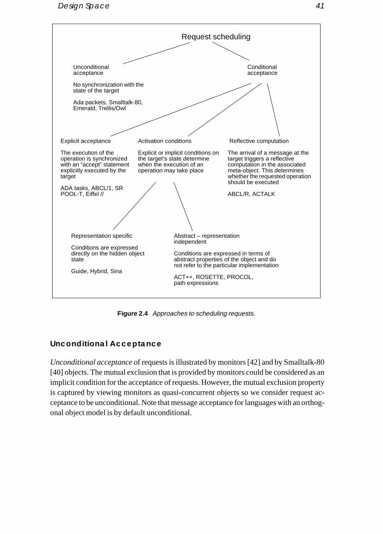
Design Space 41
80 as anpertyest ac- orthog-
Unconditional Acceptance
Unconditional acceptance of requests is illustrated by monitors [42] and by Smalltalk-[40] objects. The mutual exclusion that is provided by monitors could be consideredimplicit condition for the acceptance of requests. However, the mutual exclusion prois captured by viewing monitors as quasi-concurrent objects so we consider requceptance to be unconditional. Note that message acceptance for languages with anonal object model is by default unconditional.
Request scheduling
Unconditionalacceptance
No synchronization with thestate of the target
Ada packets, Smalltalk-80,Emerald, Trellis/Owl
Explicit acceptance
The execution of theoperation is synchronizedwith an “accept” statementexplicitly executed by thetarget
ADA tasks, ABCL/1, SRPOOL-T, Eiffel //
Activation conditions
Explicit or implicit conditions onthe target’s state determinewhen the execution of anoperation may take place
Abstract – representationindependent
Conditions are expressed in terms ofabstract properties of the object and donot refer to the particular implementation
ACT++, ROSETTE, PROCOL,path expressions
Representation specific
Conditions are expresseddirectly on the hidden objectstate
Guide, Hybrid, Sina
Reflective computation
The arrival of a message at thetarget triggers a reflectivecomputation in the associatedmeta-object. This determineswhether the requested operationshould be executed
ABCL/R, ACTALK
Conditionalacceptance
Figure 2.4 Approaches to scheduling requests.

42 Concurrency in Object-Oriented Programming Languages
Explicit Acceptance
tate-pecifynts (i.e.se thisach
e ob-rtly im-in thearticu-rms. Ines theage isr-ge ac-L [85].
sthe
meth-nding
e con-o store
thod byd is de-e dura-
by the
tifying to the
xes as
With explicit acceptance, requests are scheduled by means of an explicit “accept” sment executed in the body of the server. Accept statements vary in their power to swhich messages to accept next. Acceptance may be based on message conteoperation name and arguments) as well as the object’s state. Languages that uapproach are Ada, ABCL/1, Concurrent C, Eiffel//, POOL-T and SR. With this approobjects are typically single-threaded, though SR is an exception to this rule.
Activation Conditions
With activation conditions, requests are accepted on the basis of a predicate over thject’s state and, possibly, the message contents. The activation condition may be paplicit, such as the precondition that there be no other threads currently active withobject. An important issue is whether the conditions are expressed directly over a plar representation of the object’s state or if they are expressed in more abstract teGuide, for example, each method is associated with a condition that directly referencobject’s instance variables, whereas in ACT++ the condition for accepting a messthat the object be in an appropriateabstract state which abstracts from the state of a paticular implementation. Another approach is to specify the legal sequences of messaceptance by means of a regular expression, as in path expressions [24] and PROCO
There are also some proposals such assynchronizers [38],separate method argument[66] andstate predicates[74], for activation conditions that depend on the state or computation history of other objects.
A synchronizer [38] is a special object associated with a group of objects. When aod of any of these objects is called a condition in the synchronizer is evaluated. Depeon the outcome, the execution of the method may proceed, or be delayed until thdition becomes true. Synchronizers may have their own variables that are used tinformation about the computation history of a group of objects.
Separate method arguments [66] can be used to constraint the execution of a mepreconditions on the argument declared as “separate.” The execution of the metholayed until the preconditions are true and the separate objects are “reserved” for thtion of the call. That is, they can only be used in the body of a method.
With state predicate notifiers [74], the execution of a method can be constrained notification that another object has reached a state that satisfies astate predicate.This fea-ture has synchronous and asynchronous forms. In the synchronous variant, the noobject waits until the method is executed and the method gains exclusive accessobject. In the asynchronous variant the notifying object proceeds independently.
Reflective Computation
With reflective computation the arrival of a request triggers a method of the server’smeta-object. The meta-object directly then manipulates object-level messages and mailbo

Criteria for Evaluating Language Design Choices 43
objects. This approach is followed by the language ABCL/R [86] and it is also illustratedto in-mulates
designs ap-
ages oft firstre theh reuse thanynchro-
d lan-se. Forndingationng thense, be-
erentsitionmoteution,al ise the
del fors sup-ld bees. Thisn con-lement
tly ex-
in Actalk [23] where some reflective facilities of the Smalltalk-80 system are used tercept messages sent to an object and synchronize their execution in a way that simessage execution in actor-based languages.
2.3 Criteria for Evaluating Language Design Choices
So far we have presented a design space covering the most significant choices in theof concurrency features for OOPLs, but we have said little about how the variouproaches compare. Since our goal is to arrive at COOPLs that provide the advantobject-oriented programming for the development of concurrent systems, we musformulate our requirements as precisely as possible, before beginning to compaapproaches. We first discuss the issue of developing object classes that have higpotential. Then, we turn our attention to the support for reuse at a finer granularityobjects and examine the issues related to the use of inheritance and the reuse of snization constraints.
2.3.1 Object-Based Features — Support for Active Objects
The main issue for reuse at the object level is that concurrency in an object-orienteguage should not diminish the benefits of object-based features with respect to reuinstance, encapsulation should still protect the internal state of objects from surrouobjects and it should still be possible to insulate objects’ clients from implementchoices. This should make it possible to change the implementations without affecticlients provided that the interfaces are maintained and that changes are, in some sehaviourally compatible.
Object-oriented and concurrent programming have different aims that incur diffsoftware structuring paradigms. Object-oriented programming aims at the decompoof software into self-contained objects to achieve higher software quality and to proreusability. Concurrent programming aims at expressing and controlling the execsynchronization and communication of conceptually parallel activities. Its primary goto provide notations that are suitable for devising solutions to problems that involvcoordination of concurrent activities [11].
In order to compare language designs it is necessary to adopt a programming moconcurrent object-based programming and evaluate how well the various languageport this model. Our view regarding the way the two programming paradigms shoucombined is by structuring programs as cooperating objects that exchange messagis similar to the way sequential object-oriented programs are structured, however, icurrent programs objects may encapsulate one or more concurrent threads that imptheir behaviour. Moreover, the operations of an object may be invoked by concurrenecuting objects.

44 Concurrency in Object-Oriented Programming Languages
We use the termactive objectsfor this programming model to emphasize that objectsility to
with thehe ob-an beg poli-ted by
ld beot alln sup-e lan-el. Ind iden-
upportciple abouttructsur re-
ll betion.
gould be
he co-ince
n-se ofssingreadsntlyernalenta-
v-otherquest
themselves rather than the threads that invoke their operations have the responsibschedule concurrent requests. Requests should be scheduled in a way consistent object’s internal state and the possibly spontaneous execution of internal threads. Tjects developed following this model are independent self-contained entities. They creused across applications and they may be refined to support different schedulincies for invoked operations. The programs that use the objects should not be affecsuch changes.
Although any language combining concurrent and object-oriented features couused to develop software following this model, as will be illustrated in section 2.4, ncombinations of concurrent and object-oriented features are equally successful iporting this programming model. Below we develop a number of requirements on thguage features to adequately support programming following an active object modsection 2.4 we will use these requirements to evaluate language design choices antify the shortcomings of some approaches.
2.3.1.1 RequirementsAccording to the active object model discussed above, we would like languages to sthe development of self-contained objects with high reuse potential. A general prinfor achieving this is that reusable object classes should make minimal assumptionsthe behaviour of applications that will use them. Furthermore, the choice of consshould not constrain the possible implementations of a class. We can formulate oquirements as follows:
1. Mutual exclusion — protecting the objects’ state:The internal state of objectsshould be automatically protected from concurrent invocations so that it wipossible to reuse existing objects in concurrent applications without modifica
2. Request scheduling transparency:An object should be able to delay the servicinof requests based on its current state and on the nature of the request. This shaccomplished in a way that is transparent to the client. Solutions that require toperation of the client are not acceptable from the point of view of reusability sthe client then cannot be written in a generic fashion.
3. Internal concurrency:The concurrency constructs should allow for the implemetation of objects that service several requests in parallel or that make uparallelism in their implementation for increased execution speed in the proceof a single request. This could be done either by supporting concurrent thwithin an object or by implementing an object as a collection of concurreexecuting objects. Whatever approach is chosen, it is important that intconcurrency be transparent to the object’s clients so that sequential implemtions of objects may be replaced by parallel ones.
4. Reply scheduling transparency:A client should not be forced to wait until the sering object replies. In the meantime it may itself accept further requests or call objects in parallel. It may even want replies to be directly sent to a proxy. Re

Criteria for Evaluating Language Design Choices 45
e thiss.
use re-re: then ofmainults.oses-tor. be re-
ions.urposed bal-
ationonstructcts, and, several pos-
est as
reuse
scheduling by the client should not require the cooperation of the server sincwould limit the ability to combine independently developed clients and server
2.3.1.2 An ExampleIn order to compare the design choices and their combinations with respect to the requirements, we shall refer to an instance of a “generic” concurrent program structuadministrator inspired by [39]. The administrator is an object that uses a collectio“worker” objects to service requests. An administrator application consists of four kinds of components. Theclients issue requests to the administrator and get back resThe administrator accepts requests from multiple concurrent clients and decompthem into a number of subrequests. Theworkload manager maintains the status of workers and pending requests.Workers handle the subrequests and reply to the administraThe administrator collects the intermediate replies and computes the final results toturned to clients (see figure 2.5).
The administrator is a very general framework for structuring concurrent applicatFor example, workers may be very specialized resources or they may be general-pcompute servers. The workload manager may seek to maximize parallelism by loaancing or it may allocate jobs to workers based on their individual capabilities.
The components described above identify functionally distinct parts of the applicthat could have been developed independently and reused as indicated above to ca new application.These components do not have to be implemented as single objeindeed, as we see later, depending on the constructs provided by certain languagesobjects will be necessary for realizing the desired functionality. However, it should besible to modify the implementation of the above components without affecting the rif they were single objects.
The following points relate the language design requirements listed above to theissues in the case of the example application:
Clients
Administrator
WorkersWorkload manager
Figure 2.5 The administrator example.

46 Concurrency in Object-Oriented Programming Languages
• Mutual exclusion: (i) Workload manager reuse – the workload manager must be pro-ere the such not be con- mayouldrious
-lay)ction.houldted as
ene in-
d-plies
nher- in us-egrateitance syn-
thoutdvan-es ared haveerclassurren-
classing toble to
tected from concurrent requests by the administrator. There may be cases whadministrator does not invoke the workload manager concurrently. Although incases no protection is needed, workload managers that are not protected couldreused in different concurrent implementations of the administrator. In such acurrent implementation the administrator may use a collection of proxies thatinvoke the workload manager concurrently. (ii) Worker reuse – workers shsimilarly be protected so that arbitrary objects may be used as workers with vaimplementations of the administrator, including concurrent ones.
• Request scheduling transparency: (iii) Genericity of clients, reusing the administrator with different clients — the administrator must be able to interleave (or demultiple client requests, but the client should not be required to take special aIn fact it should be possible to implement any object as an administrator and it snot matter to the object’s clients if the serving object happens to be implemenan administrator.
• Internal concurrency: (iv) Client/worker reuse — the administrator should be opto concurrent implementation (possibly using proxies) without constraining thterface of either clients or workers;
• Reply scheduling transparency: (v) Worker reuse — it must be possible for the aministrator to issue requests to workers concurrently and to receive their rewhen it chooses without special action by workers;
2.3.2 Inheritance and Synchronization
There are two main issues concerning reuse at a finer granularity than objects.• The first is to maintain in concurrent languages the reuse potential offered by i
itance in sequential languages. Several early papers have reported difficultiesing class inheritance in COOPLs as well as in the design of languages that intclass inheritance and concurrency constructs [19] [6] [22]. In some cases inherwas left out as it was deemed difficult to integrate and of limited use. The need tochronize the execution of inherited, overridden and newly defined methods, wibreaking the encapsulation between classes, makes it more difficult to take atage of class inheritance than in sequential languages. For instance, if mutexused for synchronizing method execution, a method defined in a subclass woulto access a mutex defined in a superclass in order to be synchronized with supmethods. This would break encapsulation between classes. The design of conccy constructs should be made in way to avoid such problems.
• The second is to make it possible to reuse algorithms, often calledsynchronizationconstraints, for scheduling the execution of methods of a class. For instance, amay implement a synchronization algorithm that schedules its methods accordthe readers and writers synchronization scheme. It would be desirable to be a

Criteria for Evaluating Language Design Choices 47
reuse this algorithm in other classes taking into account the reader/writer property of
h class
hether pointitance
d pro-lk and
These class;asses, type asr entitys repre-
ource ofse dif-elation- of theomplydonikdifica--I [8] differ-
code re-cation
chro-ionsse dif-
y of therclass
rithms
luded
its methods.In most languages the reuse of synchronization constraints is achieved throug
inheritance and the term inheritance of synchronization constraints is often used for thisissue. We have chosen the term reuse of synchronization constraints since class inherit-ance is only one possible means to achieve reuse. Furthermore, it is questionable wclass inheritance should be used for this purpose. We will further elaborate on thisbelow. Then, we will discuss separately the requirements for supporting class inherand for reusing synchronization constraints.
Inheritance is often considered as the most prominent feature of object-orientegramming. The most widespread object-oriented languages such as C++, SmalltaEiffel provide an inheritance mechanism that may be used for different purposes. include: the reuse of the implementation of a class in the implementation of a newthe specification of a type compatibility relation between a class and its parent clconsidering for type-checking purposes that instances of the class are of the sameinstances of its superclasses; finally, it may be used to express that the concept omodelled by the subclass is, in some sense, a refinement of the concepts or entitiesented by its parent classes.
The use of a single mechanism for all these purposes can, on one hand, be a sconfusion and on the other, limit the effectiveness of the mechanism for each of theferent purposes. For instance, subtypes have to be related to a class inheritance rship even if they do not share any part of their implementation. In order to use partimplementation of a class in a new class, all the methods have to be inherited to cwith the subtype relation that is also expressed by the inheritance link.Wegner and Z[88] provide a general and in-depth discussion of inheritance as an incremental motion mechanism and illustrate its use for different purposes. Guide [48] and POOLare concrete examples of languages with mechanisms that distinguish between theent uses of inheritance. Both languages distinguish between class inheritance as a use mechanism and typing. POOL-I goes even further by also allowing the specifiof behaviourally compatible classes.
In section 2.4.3 we will examine more closely the approaches for the reuse of synnization constraints followed by different languages. This will illustrate the interactthat class inheritance may have with the reuse of synchronization constraints in theferent approaches.
2.3.2.1 Class InheritanceThe issues listed below have to be addressed in order to take advantage effectivelreuse potential of inheritance. The first two are concerned with the reuse of supemethods. The third one concerns the use of inheritance for providing generic algothrough the definition and refinement ofabstract classes[36] [44].
• Separate specification of the synchronization constraints:If the code that imple-ments the synchronization decisions related to the execution of methods is inc
48 Concurrency in Object-Oriented Programming Languages
directly in methods, inherited methods typically will have to be modified to account
-sarilyut anys thece be- in theiated
and invo-
als for
n-y bess (thes thattrainte with
ngtend-e.s isd in ay be
mech-
sir-hroni-roughation
rarchy.g this
for the synchronization constraints of the subclass [45].• Interface between methods and the synchronization constraints:The separate speci
fication of synchronization control actions and method code does not necesmean that the execution of methods once started should be carried out withofurther interaction with the synchronization constraints. Such an approach limitexpressive power of a language. Instead, there should be a well-defined interfatween methods and the synchronization constraints that allows several actionsexecution of the method to interact with the synchronization constraints assocwith the various classes where it is reused.
• Consistency with other uses of inheritance for software composition:Apart from re-using individual methods, inheritance serves to facilitate sharing of algorithmsdesigns [36]. For this purpose, inheritance is paired with other features such ascation of methods through pseudo-variables such asself orsuper in Smalltalk.
2.3.2.2 Reuse of Synchronization ConstraintsThe issues discussed below are important for evaluating and comparing the proposthe specification and reuse of synchronization constraints:
• Flexibility of the binding mechanism:The mechanism that is used to apply costraints to a particular class determines the flexibility with which constraints mareused. Depending on the mechanism, constraints are bound to exactly one claclass where they were introduced), or to any class that inherits from the clasintroduced the constraints. Additionally, method names appearing in a consspecification may be considered as variables to be substituted at binding timmethod names defined in a particular class.
• Compositionality and extensibility: This concerns the support provided for reusipreviously defined constraints in the definition of new ones. A related issue is exing the application of constraints to methods that are introduced at a later stag
• Polymorphism:The potential applicability of constraints to different classes. Thirelated to the binding mechanism and modularity; constraints could be specifieway that would allow them to be applied to different classes. However, this maimpossible or inconvenient because of the absence of an appropriate binding anism.
• Modifiability and locality of change:There are circumstances where it may be deable or necessary to change the implementation of a class or of just the synczation constraint. Depending on the approach, this may be achieved easily thsome local modification or it may require a cascade of changes in synchronizconstraints. In some cases it may even be needed to modify the inheritance hieMost of the other aspects discussed above come into play when considerinissue.

Exploring the Language Design Space 49
2.4 Exploring the Language Design Space
ystem-t the re-n spaceocca-reebina-
con-ection
onalurrentif they
uishble if itsabil-
abil-
etero-gnmentr couldnent is inde-
objecting has
reply.uest.essage
ds theoses
We now propose to compare the various approaches to the design of COOPLs by satically exploring the language design space and evaluating design choices againsquirements specified in the previous section. Since the various aspects of the desigare sometimes intertwined, we will find ourselves returning to common issues on sion. Basically we will take the following course: first we briefly consider the thcategories of object models; then we consider object interaction mechanisms in comtion with internal concurrency; finally we explore inheritance and synchronization straints as a topic worthy of separate study. We summarize our conclusions in s2.4.4.
2.4.1 Object Models
By the requirement of mutual exclusion, we can immediately discount the orthogobject model as it provides no default protection for objects in the presence of concrequests. The reusability of workers and workload managers is clearly enhanced will function correctly independently of assumptions of sequential access.
The heterogeneous model is similarly defective since one must explicitly distingbetween active and passive objects. A generic administrator would be less reusawould have to distinguish between active and passive workers. Similarly worker reuity is weakened if we can have different kinds of workers.
Thehomogeneous object model is the most reasonable choice with respect to reusity. No distinction is made between active and passive objects.
Note that it is not clear whether the performance gains one might expect of a hgeneous model are realizable since they depend on the programmer’s (static) assiof objects to active or passive classes. With a homogeneous approach, the compileconceivably make such decisions based on local consideration — whether a composhared by other concurrently executing objects is application specific and should bependent of the object type.
2.4.2 Object Interaction Mechanisms
Request-reply mechanisms such as an RPC-like interface provide more support forreuse. Using our administrator example, we can see that one-way message passseveral disadvantages over RPC for reusing objects.
A concurrent client may issue several requests to the administrator before it gets aIn this case it is important for the client to know which reply corresponds to which reqAre replies returned in the same order as requests? In the case of synchronous mpassing an additional difficulty is that the administrator may get blocked when it senreply until the client is willing to accept it. Requiring the client to accept the reply imp

50 Concurrency in Object-Oriented Programming Languages
additional requirements on the client and makes reuse more difficult. Either a different
tweentting
lel, as ad-
carry’s replyC thes.
e thansingle replye lim-ismsce oration [54].choice
ents’t. Theple:e cli-o ac-oach is, since
of an as ad-uire-ace theer, issts con-erface
mechanism has to be supported for sending replies or proxies have to be created.One-way message passing is also inconvenient for coping with the interaction be
the administrator and worker objects. A difficulty with using one-way messages is gethe replies from workers: as there will be several workers that are invoked in paralwell as potentially concurrent invocations of single worker, it can be difficult for theministrator to tell which reply is associated with which request.
A solution to this problem is to create a proxy for each request. The proxy would out the request and then send a message to the administrator containing the workerplus some extra information used for identifying the request. As with sequential RPadministrator will also have to manage local queues for partially completed request
2.4.2.1 Sequential ObjectsWe argued that an RPC interface for objects provides better support for object reusone-way message passing. However, we quickly discover that if objects have a thread of control and RPC is the only communication mechanism, the request andscheduling requirements of the administrator are not satisfied. We further discuss thitation of this design choice combination below. Then we show additional mechanthat may be used to overcome these limitations without giving up the RPC-interfacompletely discarding sequential object design choice. The limitation of the combinof sequential objects (“modules” in their case) and RPC is discussed at length inHowever, they reach the conclusion that either the sequential object or the RPC should be discarded.
Limitations of the Sequential Object–RPC Combination
In particular, a sequential RPC administrator will not be able to interleave multiple clirequests as it will be forced to reply to a client before it can accept another requesonly “solution” under this assumption requires the cooperation of the client, for examthe administrator returns the name of a “request handler” proxy to the client, which thent must call to obtain the result. In this way the administrator is immediately free tcept new requests after returning the name of the request handler. Such an apprhowever, incompatible with the requirement on request scheduling transparencyscheduling of requests by the administrator is not transparent to its clients.
Consider for instance that we would like to replace the sequential implementationexisting object class by a parallel implementation where instances of the class actministrators for a collection of appropriate worker objects. In accord with our reqments we would like to take advantage of encapsulation and data abstraction to replold implementation without having to modify the programs that used it. This, howevnot possible since, as discussed above, in order to be able to process client requecurrently, an object, implemented as an administrator, has to have a different intthan an object having a sequential implementation.
Exploring the Language Design Space 51
The sequential RPC combination also provides limited support for reply scheduling byingle reply.work-lt and
es notd in ant ofd as a
comee theill in-
ethodtor’s
ed if iter, thenot use
all theroceed
eededlies.grammetersefined
rieruld beork-
can bebjectse allow-
the administrator. If the administrator invokes workers directly using RPC, its sthread will get blocked until the invoked worker computes the result and returns theThe sequential RPC combination prevents the administrator from invoking several ers in parallel, or accepting further client requests while a worker computes the resureceiving the workers’ replies at a later time.
It is also possible to have the workers cooperate with the administrator so that it doblock when delegating work to them, but such solutions require workers to be codespecial way to implement the cooperation. This is incompatible with our requiremerequest scheduling transparency, which would allow any object to be potentially useworker.
Using Proxies for Reply Scheduling
The limitation of the sequential RPC combination for reply scheduling can be overby the use of “courier” proxies used by the administrator to invoke workers. Each timadministrator needs to invoke a worker it creates an appropriate courier proxy that wvoke the worker instead. To get a worker’s reply, the administrator could invoke a mof the corresponding courier or alternatively the courier could call an administramethod when the reply becomes available.
The former alternative has the disadvantage that the administrator may get blockinvokes the courier too early. This may never occur with the latter approach. Howevadministrator has to manage local queues for replies that are sent to it and that it canimmediately. Furthermore, each time a reply is returned, it should check whether replies needed so far for handling a client’s request are available so that it may pwith the client’s request.
The use of proxy objects for carrying out requests and for storing replies is also nin the case of one-way message passing for allowing requests to be paired with rep
Although proxies are a general programming approach, it is cumbersome to proand use them explicitly. In fact unless the language supports classes with type paraand a flexible manipulation of method names, a new proxy class would have to be dfor each different worker class in an administrator application.
Future variables in ABCL/1 [94], theprocess type in PAL [18] and CBox objects inConcurrentSmalltalk [92] provide functionality which is somewhat similar to the couproxies that were used by the administrator to call workers. These mechanisms coused by the administrator to call workers without getting blocked and for collecting wer replies at a later time.
The advantage of these mechanisms over program-defined proxies is that theyused for calling workers of any class. Future variables, however, are not first-class oand so are not as flexible. For instance, a future variable cannot be sent in a messaging a different object than the one that made the request to receive the reply.

52 Concurrency in Object-Oriented Programming Languages
A difficulty with built-in proxies is that the administrator may at some point in timeorker
rator to or re-s. Thistanceld re- that woulds re-
einge used, it ap-rt forlicitly
ay toas thee time,is il- sideer, thes evenplies
hows
ult is
ge pat-
in thee
have to get blocked and wait for a further client request or the reply to a previous wrequest. Unless there exists a synchronization mechanism that allows the administwait on either of these events, the administrator may get blocked to obtain a replyquest that is not available and will thus be unable to accept other requests or replieproblem could be circumvented either by polling if a non-blocking request accepmechanism is supported or by additional, explicitly programmed proxies that wouturn the replies by invoking some administrator’s operation especially provided forpurpose. This way a synchronization mechanism for selectively accepting requestsallow the administrator to be woken up either for receiving the results of a previouquests or for accepting new requests.
Still, the administrator’s code may get quite involved. If there is no way to prevent bwoken up by messages containing client requests or worker replies that cannot bright away, local message queues will have to be managed by the administrator. Sopears that built-in proxies combined with single-thread objects provide limited supporeply scheduling by the administrator since one should again rely on the use of expprogrammed proxies.
Combining Request/Reply and One-Way Message Passing
It is also possible to relax the RPC style of communication without going all the wsupporting one-way message passing as the main communication primitive. This hadvantage that it is possible to present an RPC interface to clients and, at the samobtain more flexibility for processing requests by the administrator. This possibility lustrated by ABCL/1 [94] which permits the pairing of an RPC interface at the clientwith one-way asynchronous message passing at the administrator’s side. Moreovreply message does not have to be sent by the administrator object. This providemore flexibility in the way that the administrator may handle requests since the remay be directly returned to the client by proxies. The following segment of code show this is accomplished. The RPC call at the client side looks like:
result := [ administrator <== :someRequest arg1 ... argn] ...
A message is sent to the administrator to execute the requestsomeRequest with argumentsarg1,...,argn. The client is blocked until the reply to the request is returned and the resstored in the client’s local variableresult.
At the administrator’s side the client’s request is accepted by matching the messatern:
(=> :someRequest arg1 ... argn @ whereToReply.... actions executed in response to this request ... )
When the administrator accepts this request, the arguments are made availablelocal variablesarg1,...,argn and thereply destination of the request in the local variabl

Exploring the Language Design Space 53
whereToReply. The reply destination may be used as the target of a “past type,” i.e. asyn-lso be
ssage to
thet.ssingn, on able prob-somests so
to wait-way, the
ing theen bes thests and
g: someest andmmedi-
is by thread
echa-t to thency in
he sup-dmin-
d by asd as
chronous, message for returning the reply to the client. As a reply destination may apassed around in messages, it is possible for another object to send the reply methe client. This action would look like:
[ whereToReply <== result ]
wherewhereToReply is a local variable containing the reply destination obtained bymessage acceptance statement shown above, andresult is the result of the client’s reques
Another interesting way of using the possibility to combine one-way message pawith RPC is for flexible reply scheduling by the administrator. In the previous sectiobuilt-in proxies, we mentioned that a difficulty was that the administrator should beto wait to accept both returned replies and further requests. A way to circumvent thislem was to use explicitly programmed proxies that would return results by invoking operation provided by the administrator. In this way, replies were returned by requethat a request acceptance mechanism was sufficient for allowing the administrator for both requests and replies. A different approach is possible by pairing onemessages to the RPC interface supported by workers. With this approachadministrator may use a past type message, with itself as reply destination, for callworkers which present an RPC interface. The replies from the workers can threceived by the administrator as any past-type message request. This allowadministrator to use the message acceptance mechanism for receiving both requereplies.
This approach has, however, some of the drawbacks of one-way message passinextra work is needed in order to find out which reply message is related to what requalso that the administrator has to manage queues for replies that may not be used iately.
2.4.2.2 Multi-Threaded ObjectsAnother way for allowing the administrator to service several concurrent requestssupporting multiple concurrent or quasi-concurrent threads. A separate concurrentmay now be used for handling each client request. However, depending on the mnisms provided for thread creation and scheduling, it may still be necessary to resorsolutions discussed previously in order to achieve a satisfactory level of concurrethe processing of client requests.
We consider in turn quasi-concurrent and concurrent approaches and examine tport provided by the thread creation and scheduling mechanisms for programming aistrators.
Quasi-Concurrent Approaches
A traditional example of “objects” with quasi-concurrent thread structure is providemonitors [42] [21]. However, monitors present some well-known difficulties such“nested monitor calls,” and they unduly constrain parallelism [56] [77] [20] when use

54 Concurrency in Object-Oriented Programming Languages
the main modular units of concurrent programs. These limitations are due to some extentonitorspporting aThispt
varia-not allal inde-
n if lan-
to theply
aminerency
re for
ts. The case auest in
cceptg sup-wing
t forposedould proto-ccept-
rrent-actoryurrentrthog-
to the quasi-concurrent structure of threads. However, an approach based on mwould also constrain concurrency among different objects because of its limited sufor reply scheduling. Assuming that the administrator is a monitor, then when callworker the monitor would remain blocked until the invoked operation would return. situation, calledremote delay[53], makes it impossible for the administrator to accefurther client requests or to call a second worker.
Consequently, certain object-oriented languages have adopted more flexible tions. For example, Emerald [19] uses monitors as defined by Hoare [42]. However, operations of an object have to be declared as monitor procedures and also severpendent monitors may be used in the implementation of an object.Lock blocks andwaitqueues in Trellis/Owl [68] also allow for more flexible implementation schemes thaobjects were identified to monitors. With this approach, however, objects in theseguages are not quasi-concurrent any more.
The restricted support for concurrency among objects by monitors is not due quasi-concurrent structure of objects, but rather to the limited flexibility for rescheduling. This is illustrated by the second quasi-concurrent approach we exwhich by providing a more flexible reply scheduling scheme does not restrict concuramong objects.
Hybrid [71] is another language which adopts a quasi-concurrent thread structuobjects. However, in contrast to monitors, thedelegated callmechanism provides a moreflexible reply scheduling approach that does not restrain concurrency among objecadministrator may use the delegated call mechanism to invoke workers. In such anew thread may be activated in the administrator for processing another client reqthe meantime.
The delegated call mechanism is satisfactory for allowing the administrator to afurther client requests while a worker is executing a previous request, thus providinport for concurrency among several client requests. However, it is of no help for alloseveral workers to execute in parallel for a single client request.
This may only be done by using proxies for invoking the workers or by a construcspecifying the creation of a new quasi-concurrent thread. Such a construct was proin the original design of Hybrid. The newly created quasi-concurrent threads wresume each other by using delegated calls. This construct was not included in thetype because it substantially increased the complexity of the rules for message aance.
Concurrent Objects
With concurrent threads it is straightforward to process several client requests conculy by creating a new thread for processing each client request. Provided that satisfmechanisms are supported for constraining the creation and activation of concthreads, this does not result in the mutual exclusion problems of languages with an o

Exploring the Language Design Space 55
onal object model. The concurrent execution that may take place is explicitly specified bys is re-
r avoidt for re-ts may
hreadstion ofncur-
threadsone ofs doneessar-rimi-
hro-eated infashion.otherests to
f inher- con- todressedve notns anduse of
the programmer and the scope of the potential interference of the concurrent threadstricted to the state of a single object.
Provided that there is some way to suspend the execution of a concurrent thread oits creation, languages that support concurrent threads provide adequate supporquest scheduling and for internal concurrency to the extent that several client requesbe processed concurrently.
A different issue that is not necessarily addressed by the support for concurrent tis the possibility to use concurrency for processing a single request. Unless the creamultiple threads can be initiated by the object, the support for reply scheduling of corent threads is not sufficient for processing a request in parallel.
For example, the language Sina [84] makes it possible to use several concurrent within an object for processing requests; there is no direct means, however, for these threads to create more threads for calling the worker objects in parallel. This iindirectly by creating a courier proxy, as described previously. It is therefore not necily redundant to support both multiple threads and non-blocking communication ptives.
A satisfactory way for calling workers in parallel without using proxies or asyncnous message passing is to support a construct by which more threads may be crthe object. In this case a worker can be called by each of these threads in an RPC With quasi-concurrent threads, a call to a worker should trigger the execution of anthread. In SR the code segment of the administrator that is used for issuing requworkers in parallel would look like this:
co result1 := w1.doWork(...) -> loadManager.terminated(w1)// result2 := w2.doWork(...) -> loadManager.terminated(w2)ocglobalResult := computResult(result1,result2);...
2.4.3 Inheritance and Reuse of Synchronization Constraints
A large body of research has concentrated on the issues of making effective use oitance in COOPLs as well as on the related issue of reusing synchronizationstraints.We will provide a brief overview of this work. Then we will turn our attentionthe issues discussed in section 2.3.2 and illustrate the issues and how they are adby various language designs putting particular emphasis on some points that hareceived the attention they deserved in related work. More extensive presentatiosystematic comparisons of the proposals for supporting inheritance and the resynchronization constraints may be found in [63] [60] and [16].

56 Concurrency in Object-Oriented Programming Languages
2.4.3.1 A Brief Overview of Related Researchd to from
end thes. Theingh
spects to ab- the set
sses,r pro-ds, ande used
in var- [59],ntsider
niza- inher-
ts.blemsizationwriting
ation
raints aboutf sever-
pecifyited by most, how-sses.es ofeth-
Eiffel// [26][27] and Guide [34][48] were two of the earliest proposals that attemptecombine inheritance and synchronization constraints by removing the constraintsthe bodies of methods.
These approaches presented some shortcomings with respect to the ability to extsynchronization constraints to account for new methods introduced by subclasseproblems were independently identified by Kafura and Lee [45] and Tomlinson and S[83], who in turn proposed their own approaches for overcoming them. A common aof these proposals is that constraints are specified by associating sets of methodstractions of the object state in which they can be executed. The main idea was thatof methods would be extended in subclasses with the additional methods.
Matsuokaet al. [62], however, showed that there existed certain cases, calledinherit-ance anomalies, where new state abstractions would have to be introduced in subclaconsequently requiring extensive redefinition of inherited methods. Matsuoka lateposed his own approach, where he retained the idea of sets of acceptable methoprovided a combination of guards and accept sets allowing the best technique to bfor the problem at hand.
The issue of extending and combining inherited constraints was also addressedious other proposals, notably: Synchronizing Actions [69], Scheduling PredicatesCeiffel [57], Frølund’s framework [37], PO [29], SINA [16] and SPN [74]. It is importato note that Synchronizing Actions and SPN are two of the very few proposals to conthe issue of suspending method execution, which is important for reply scheduling.
The language DRAGOON [13] [14] supports the specification of generic synchrotion constraints and provides a special inheritance mechanism separate from classitance of sequential aspects of classes for reusing these synchronization constrain
Meseguer [67] has proposed a somewhat different approach for avoiding the prorelated to the use of inheritance in COOPLs. He proposes to eliminate the synchroncode which causes inheritance anomalies. His language is based on a concurrent relogic; the use of appropriate rewrite rules allows the specification of synchronizwithout introducing inheritance anomalies.
Synchronizers [38] is an approach for the specification of synchronization constthat allows constraints to be associated to objects dynamically. An interesting pointthis proposal is that constraints may depend on the state and computation history oal other objects.
2.4.3.2 Binding Mechanisms for Synchronization ConstraintsThe most direct way to associate synchronization constraints to methods is to sthem together as part of a class definition. Constraints defined in a class are inherthe ordinary class inheritance mechanism. Such an approach is followed byCOOPLs, such as Guide, PO, PROCOL and ACT++, to name a few. This approachever, has the shortcoming that it may be difficult to apply constraints to different claA first problem is with method names: if constraints refer to particular method namthe class in which they are defined, it will be difficult to apply them to classes where m

Exploring the Language Design Space 57
ce forethodsve been
ener-anismnts are
echa-ance)int defi-
am-
with SIMPLE; class body UNI_BUFFER is
ods have different names. Another problem comes from the use of class inheritanreusing constraints. If one uses class inheritance to reuse the constraints, the mdefined in the class are also inherited. Below we examine some approaches that haproposed for addressing these problems.
Genericity of Synchronization Constraints in DRAGOON
DRAGOON [13] [14] is an example of a language that supports the specification of gic synchronization constraints and of one that dissociates inheritance from the mechused for binding synchronization constraints to a class’s methods. Generic constraidefined as behavioural classes (b-classes). The constraints may be applied to asequentialclass having no associated constraints, through the b-inheritance (behavioural) mnism. This mechanism is independent from the inheritance mechanism (f-inheritused for sequential classes. Figure 2.6 shows an example of the use of the constranition and binding mechanism in DRAGOON. A classUNI_BUFFER is defined in (a) and(b) with methodsPUT andPEEK used to insert a new element into the buffer and to exine the number of elements in the buffer. In (c) a generic constraintREADERS_WRITERS
class UNI_BUFFERintroduces
procedure PUT(I : in SIMPLE.ITEM);procedure PEEK (NB: out INTEGER);
end UNI_BUFFER;
... definition of the instance variables andimplementation of the operations...
end UNI_BUFFER;
behavioural class READERS_WRITERS isruled WOP, ROP;where
per (WOP) <=> active(WOP) + active(ROP) = 0;per(ROP) <=> (active(WOP) = 0) and (requested(WOP) = 0);
end READERS_WRITERS;
class READERS_WRITERS_UNI_BUFFERinherits UNI_BUFFERruled by READERS_WRITERSwhere
PUT => WOP,PEEK => ROP
end;
Figure 2.6 Constraint definition in DRAGOON.
(a) (b)
(c)
(d)

58 Concurrency in Object-Oriented Programming Languages
is defined for controlling execution of the methods of a class according to the readers, andlass
s meth-ethod
e key-round
hod thatrclass
ch asies that DRA-
s
on-ioneneric
sses. Meth-ization use of
writers, scheduling policy [81]. This synchronization constraint is bound to the cUNI_BUFFER in (d) wherePUT is associated with the constraints for writers andPEEK withthe ones for readers.
Using the Inheritance mechanism of Beta
A similar effect for specifying and binding constraints may be achieved by using theinnermechanism of Beta. In Beta a method in a subclass is associated with the superclasod it specializes. Instead of the subclass method explicitly invoking the superclass mthrough the use ofsuper mechanism, as in Smalltalk, the superclass method isalways in-voked, and subclasses may only introduce additional behaviour at the point where thword inner occurs. In a sense, the execution of the superclass method is wrapped athe invoked subclass method. First are executed the actions in the superclass metprecedeinner, then the subclass method is executed, then the actions of the supemethod that followinner are executed.
This feature may be combined with low-level synchronization mechanisms, susemaphores, to implement classes that encapsulate generic synchronization policcan be applied to methods defined in subclasses in a way similar to how it is done inGOON.
Assume there is a classReaderWriterSched (not shown) with methodsreader andwriterthat use semaphores to implement a reader/writer scheduling policy for the methodread-er andwriter. This synchronization may be applied to a classSynchedBuffer with operationsempty, get, put as follows:
SynchedBuffer: @ | ReaderWriterSched(# .... instance variables....
peek: Reader(# ...implementation of peek... #)get: Writer(# ...implementation of get... #)put: Writer(# ....implementation of put..#)
#)
This allows the execution ofpeek to be constrained according the synchronization cstraints of a reader, whereasget andput are synchronized according to the synchronizatconstraints that apply to writers. More on the use of inheritance in Beta to define gsynchronization policies can be found in [58].
Method Sets and Abstract Classes in ABCL/AP100
Themethod set feature provided in this language may be combined with abstract clato define generic synchronization constraints that can be applied to several classesod sets are specified as part of class definitions, and are associated with synchronconstraints. Method sets can be inherited and modified in subclasses. Systematic

Exploring the Language Design Space 59
methods sets solves the problem of applying constraints to classes with different methodere notON.
traints,wever,guageis that
abili-opriate in ap- varia- use oft intra-
als ofes. Inect’s in-ted inult to
les ref-oblemhe con- the re-hat was
of ac-nction, onlyt state.speci-condrom the. This
cy. In, syn- mainethoded im-ifferent
names. The possibility of combining method sets with abstract classes (classes whall methods are defined) can be used to provide facilities similar to those of DRAGOAbstract classes, making systematic use of method sets in synchronization conscan be used to represent generic constraints similar to DRAGOON’s b-classes. Hoin contrast to DRAGOON, programmers have to use the features provided by the lanin a disciplined way. Another interesting feature of this language, discussed below, it is possible to combine synchronization constraints.
2.4.3.3 Polymorphism and Synchronization ConstraintsPolymorphism of synchronization constraints is concerned with the potential applicty of constraints to different classes provided that the language supports an apprbinding mechanism. There are two potential deficiencies with respect to this issueproaches for specifying synchronization. The first is related to the use of instancebles in conditions constraining the activation of methods. The second concerns theconstraints that specify mutual exclusion among methods in languages that supporobject concurrency.
The first deficiency, also discussed by Bergmans [16], occurs in the proposFrølund [37] and Matsuoka [63], and in Guide and PROCOL, to cite a few examplthese languages the conditions that are used in their constraints reference the objstance variables. This makes it difficult to apply the constraints to classes implemena way that does not require these instance variables. Moreover, it makes it difficchange the implementation of a class without having to consider the instance variaberenced in the constraints and, eventually, modifying the constraints as well. The prmay also be more severe than just modifying the constraints of a single class, as tstraints to be modified may be used by other subclasses as well. This could causeexamination and adjustment of the constraints of several subclasses of the class tmodified.
Two approaches have been be followed for alleviating this problem. First, insteadcessing directly the instance variables, conditions could be specified through a futhat accesses the object state indirectly. If the implementation had to be modifiedthese functions would need to be modified to account for the changes in the objecThis approach is followed for this precise reason by Sina in the way conditions are fied in wait filters [16] as well as in the specification of state predicates [74]. A seapproach is to use condition variables to maintain an abstract state that is separate factual class implementation and is used purely for synchronization purposesapproach is followed Synchronizing Actions, DRAGOON and PO.
The second potential deficiency occurs in languages with intra-object concurrenseveral languages with intra-object concurrency, such as Guide, DRAGOON and POchronization constraints specify mutual exclusion properties among methods. Thereason for imposing mutual exclusion constraints on method executions is that mimplementations access common instance variables. However, a different or modifiplementation of a class may use a different set of instance variables and may have d

60 Concurrency in Object-Oriented Programming Languages
needs for mutual exclusion. Consequently, constraints that specify mutual exclusion prop-men- areause thehas not
ints islasseslasses)ges andritance wouldstraints
se class con-
se in- in sub-w bytions
odi-akingsses.-
ubclassat canaviour
it fil-
atch-ect andrgmanstraintss thati-
-
erties among methods may find limited applicability to classes with a different impletation. Also, modifying the implementation of a class to which such constraintsattached, as discussed above for guards that reference instance variables, may cmodification of the constraints attached to several classes. This problem, however, received any attention by other work in the area.
2.4.3.4 Extensibility and CompositionalityIn languages such as DRAGOON, the issue of combining synchronization constraavoided by the way the language is designed; inheritance is not allowed among cthat are associated with synchronization constraints, r-classes, or the classes (b-cthat are use to describe the constraints themselves. This approach has advantadisadvantages. The separation of constraints from classes allows the use of inhebetween f-classes without having to be concerned how the associated constraintshave to be combined. The disadvantage is that there is no support for reusing conin the definition of new ones.
In other languages the issue of combining constraints is addressed either becauinheritance mechanism is tight up to the constraint binding mechanism or to allowstraints to be defined incrementally.
Frølund [37] proposed an approach for combining constraints of a class with thotroduced in subclasses based on the view that constraints should become stricterclasses. The proposed approach for combining constraints supports this vieincrementally combining conditions that disable method execution. This way condimay only become more strict in subclasses.
Matsuoka [63] provides a more elaborate way of combining constraints through mfication ofmethod sets and by the fact that method sets are recomputed in a subclass tinto account the full set of methods including the methods inherited from all superclaFor instance, the method set all-except(LOCKED), whereLOCKED is another method set defined elsewhere, denotes all the object’s methods except the ones inLOCKED. This methodset is recomputed in subclasses to account for additional methods defined in the sor inherited from other superclasses. Such features enable the definition of mixins thbe combined with the constraints of other classes to obtain the synchronization behspecified by the mixin. An example of such a mixin class is presented in [63].
A powerful way of composing synchronization constraints is also provided by waters in Sina. In order to get accepted, messages are matched against patterns of wait filters.Wait filters are associated with conditions, a form of guards, that must be true to let ming messages go through the filter. Filters can be stacked at the interface of an objmessages have to traverse all of them before being accepted by the object. Beshows in [16] how this approach can be used for the locking mixin and for other conscomposition examples. The locking mixin discussed above can be realized by a claprovides a wait filter that matches all messages butunlock and is associated with a condtion, Unlocked, that is true only when the object is unlocked.Lock andUnlock methodschange the state of a lock object so as to render theUnlock condition false and true respec

Exploring the Language Design Space 61
tively. A lock object can be used in the definition of another class in such a way that mes-fined
class.eaded,e par-n of
lattice. com-
oniza-ave ton 2.4.2ethodsssed in
ethodhe for the
proxyended
alls illus-n as-xible
sed inlexitythodsbjects.se al-
pend-hieved
suspen-om the
explo-
sages have to go through its filter first. In this way the synchronization constraint deby lock can be reused in other classes.
PO [29] also supports the composition of constraints defined in superclasses of aIn contrast to the proposals of Frølund and Matsuoka, where objects are single-thrPO constraints are designed for objects with internal concurrency. Constraints on thallel execution of methods are partially ordered in a lattice with fully parallel executiomethods at the top and mutual exclusion among all methods at the bottom of the When incompatible constraints are inherited from different superclasses, they arepared according to this order and the more strict constraint is retained.
2.4.3.5 Combining Inheritance with Request/Reply SchedulingIn most work on the design of mechanisms for the specification and reuse of synchrtion constraints, little attention has been paid to the eventuality that methods may hbe suspended halfway through their execution. However, as we discussed in sectiothis may be necessary to support reply scheduling. The possibility of suspending musing mechanisms designed for the reuse of synchronization constraints is addreSynchronizing Actions [69] and in the design of thestate predicate [74] mechanism.
Synchronizing Actions are based on multi-thread objects. The execution of a mmay be suspended by calling, throughself, another method with a pre-action such that tcall is delayed. This approach may be used to support request and reply schedulingadministrator as shown in figure 2.7. The administrator calls workers by creating objects that do the actual call. After creating a proxy the administrator thread is suspby calling the methodsuspend. The proxy calls the worker and when the call returns it ctheworkerDone method to cause the administrator thread to be resumed. Figure 2.7trates the implementation of the administrator concentrating on the synchronizatiopects. Other languages that support internally concurrent objects and flespecification of synchronization constraints, for instance Guide or Sina, could be ua similar way. This approach, however, has some shortcomings. First, its compwould make it difficult to use in practice. Second, it relies on the assumption that meinvoked through self are subject to the same constraints as invocations from other oThis may not be appropriate when self is used in conjunction with inheritance to reugorithms defined in abstract superclasses.
The state predicate approach [74] provides a simpler and more direct way for susing method execution based on a state predicate. The effect is similar to the one acby the approach discussed above. However, the resulting code is simpler as thread sion and resumption is supported by the language and the complications deriving frneed to call the objects methods through self are avoided.
2.4.4 Summary
Below we present our observations with respect to reuse issues resulting from ourration of language design approaches.

62 Concurrency in Object-Oriented Programming Languages
-ficed.l
lution
-cts is
or by
roxieson-rate
-ining
cur- pur-severales are
method workerDone()class Admin;
Object-Based Features
• Homogeneous object models promote reuse: Concurrent applications can safely reuse objects developed for sequential applications; efficiency need not be sacri
• Sequential objects with strict RPC are inadequate: Request scheduling and internaconcurrency can only be implemented by sacrificing the RPC interface; the sois either to support concurrent threads or to relax the strict RPC protocol.
• One-way message passing is expressive but undesirable: Since higher-level requestreply protocols must be explicitly programmed, development and reuse of objepotentially more error-prone.
• Acceptance of concurrent requests is handled well either by concurrent threadsexplicit request/reply scheduling.
• Issuing concurrent requests is handled well by one-way message passing, by por by internal concurrency: The combination of both concurrent threads and nblocking communication primitives may be appropriate for handling the sepaissues of accepting and issuing concurrent requests.
• Built-in proxies used bysequential objects with non-blocking request issuing mechanisms provide adequate support for reply scheduling but are weak at combreply and request scheduling.
• Both concurrent objects and multi-object approaches are useful for internal conrency: These approaches for internal concurrency are both useful for differentposes. Concurrent threads make it easy to implement objects that may service concurrent requests that do not modify the objects state. Multi-object approach
Figure 2.7 Request/reply scheduling with synchronization constraints.
matching (true)pre { worker_finished := true }action { }post { }
method request()matching ( admin_idle )pre { admin_idle := false}action {
do some local processing...request := worker_proxy.doWork();self!waitWorker ();...some more processing...
}post { admin_idle := true };
concurrency_control:boolean worker_finished := false,
admin_idle := true;
method suspend()matching (true)pre { admin_idle := true }action{
self!waitWorker () }post { admin_idle := false}
method waitWorker()matching (worker_finished );pre { worker_finished := false;admin_idle := false}action { }post { };

Conclusion 63
interesting when the implementation of a new object class, with internal concurren-isting
ill belasses.
er, itds to
izationcha-gram
stanceferentt way.
able.
appli-
eem atcur-y and
ientedsteredully in-everal
all these
variousting de-ve illus- chosen pro-
cy, may be realized by using several concurrently executing instances of exobject classes.
Inheritance and Synchronization Constraints
• Synchronization constraints should not be hardwired in methods:If the synchroniza-tion code that schedules the execution of methods is hardwired in methods, it wnecessary to modify the method code in order to meet the constraints of other c
• Multiple threads are needed to cope with reply scheduling: To support reply sched-uling it is important to be able to suspend the execution of a method. Howevseems difficult to do this if synchronization code is kept separate from methosupport inheritance.
• Method suspension and resumption should be taken into account by synchronconstraints: Taking into account the suspension of method execution by the menism that implements the synchronization constraints makes it simpler to proreply scheduling problems without compromising the reusability of methods.
• Specification of mutual exclusion may lead to non-polymorphic constraints: Mutualexclusion properties of methods are often related to the way methods access invariables. Such constraints may thus not be applicable to classes with difinstance variables or in which methods access instance variables in a differenIncluding mutual exclusion specifications in constraints makes them less reus
• It is advantageous to separate the reuse of constraints from inheritance. It is easier toreuse synchronization constraints is they are specified generically and if their cation to different classes is not accomplished through class inheritance.
2.5 Conclusion
Integrating concurrency and object-oriented programming is not as easy as it may sa first sight. There is no major difficulty in introducing both object-oriented and conrency features in a single language. However, arbitrary combinations of concurrencobject-oriented features do not allow programmers draw the benefits of object-orprogramming for the development of concurrent systems. These difficulties have fosubstantial research in the past few years in the design of languages that graceftegrate both kinds of features. However, the interference of the features occurs in saspects of language design and the various proposals are not equally successful in aspects.
In this chapter we have discussed a number of issues that should be addressed inaspects of language design, and we have formulated some criteria to use in evaluasign choices. We have used these criteria to evaluate various proposals, and we hatrated the issues by examining specific languages. The languages discussed wereto illustrate particular points rather than to present a complete survey of all existing

64 Concurrency in Object-Oriented Programming Languages
posals. It was not our intention to compare individual languages; other issues not dis-fferentproto-
e basicditions
h are dis-use at aating
tingt-
-
220.
an-tation
tance.
al
ming,”
men-
ency
cussed in this chapter would have to be considered in such an endeavour. Diconsiderations come in to play, for example, when designing a language for rapid typing or a language for programming embedded systems.
We have presented some guidelines for the design of languages that support thobject-oriented features promoting reuse. Although these seem to be necessary conmore is needed to achieve reuse at a larger scale. These are research issues whiccussed in other chapters. The further development and the use of techniques for relarger scale for developing concurrent systems may provide more criteria for evalulanguage features and may result in more requirements on language design.
References
[1] Gul Agha,ACTORS: A Model of Concurrent Computation in Distributed Systems, MIT Press, Cam-bridge, Mass., 1986.
[2] Gul Agha and C. J. Callsen, “ActorSpace: An Open Distributed Programming Paradigm,”Proceed-ings 4th ACM Conference on Principles and Practice of Parallel Programming, ACM SIGPLAN No-tices, vol. 28, no. 7, 1993, pp. 23–323
[3] Alfred V. Aho, Ravi Sethi and Jeffrey D. Ullman,Compilers Principles, Techniques and Tools, Add-ison-Wesley, Reading, Mass., 1986.
[4] Mehmet Aksit, Ken Wakita, Jan Bosch, Lodewijk Bergmans and Akinori Yonezawa, “AbstracObject Interactions Using Composition Filters,”Proceedings of the ECOOP ’93 Workshop on ObjecBased Distributed Programming, ed. R. Guerraoui, O. Nierstrasz, M. Riveill,Lecture Notes in Com-puter Science, vol. 791, Springer-Verlag, 1994, pp. 152–184
[5] Pierre America, “Inheritance and Subtyping in a Parallel Object-Oriented Language,”ProceedingsECOOP ’87, ed. J. Bézivin, J-M. Hullot, P. Cointe and H. Lieberman ,Lecture Notes in Computer Science, vol. 276, Springer-Verlag, Paris, 1987, pp. 234–242.
[6] Pierre America, “POOL-T: A Parallel Object-Oriented Language,” inObject-Oriented ConcurrentProgramming, ed. A. Yonezawa and M. Tokoro, MIT Press, Cambridge, Mass., 1987, pp. 199–
[7] Pierre America, “A Behavioural Approach to Subtyping in Object-Oriented Programming Lguages,” inProceedings of the Workshop on Inheritance Hierarchies in Knowledge Represenand Programming Languages, Viareggio, Italy, Feb. 1989, pp. 141–156.
[8] Pierre America and Frank van der Linden, “A Parallel Object-Oriented Language with Inheriand Subtyping,”Proceedings OOPSLA’90, ACM SIGPLAN Notices, vol. 25, no. 10, ACM Press, Oct1990, pp. 161–168.
[9] American National Standards Institute, Inc.,The Programming Language Ada Reference Manu,Lecture Notes in Computer Science,vol. 155, Springer-Verlag, 1983.
[10] S. Andler, “Predicate Path Expressions,” inProceedings of 6th ACM POPL, ACM SIGPLAN Notices,1979.
[11] Gregory R. Andrews and Fred B. Schneider, “Concepts and Notations for Concurrent ProgramACM Computing Surveys, vol. 15, no. 1, March 1983, pp. 3–43.
[12] Gregory R. Andrews, R.A. Olsson and M. Coffin, “An Overview of the SR Language and Impletation,” TOPLAS, vol. 10, no. 1, Jan. 1988, pp. 51–86.
[13] Colin Atkinson, Stephen Goldsack, Andrea Di Maio and R. Bayan,“Object-Oriented Concurrand Distribution in DRAGOON,”Journal of Object-Oriented Programming, March/April 1991.

References 65
[14] Colin Atkinson, Object-Oriented Reuse, Concurrency and Distribution, Addison-Wesley/ACM
ibuted
94.
Sys-
m
OP,”
mall-p
Ex-–
hism,”
ing,”ming,
urrent,
et de
Notic-
Press, 1991.
[15] Henri E. Bal, J.G. Steiner and Andrew S. Tanenbaum, “Programming Languages for DistrComputing Systems,”ACM Computing Surveys, vol. 21, no. 3, Sept. 1989, pp. 261–322.
[16] Lodewijk Bergmans, “Composing Concurrent Objects,” Ph.D. Thesis, University of Twente, 19
[17] Ted Biggerstaff and C. Richter, “Reusability Framework, Assessment and Directions,”IEEE Soft-ware, vol. 4, no. 2, March 1987, pp. 41–49.
[18] Anders Bjornerstedt and Stefan Britts, “AVANCE: An Object Management System,”ProceedingsOOPSLA’88, ACM SIGPLAN Notices, vol. 23, no. 11, San Diego, Nov. 1988, pp. 206–221.
[19] Andrew Black, Norman Hutchinson, Eric Jul and Henry Levy, “Object Structure in the Emeraldtem,” Proceedings OOPSLA’86, ACM SIGPLAN Notices, vol. 21, no. 11, Nov. 1986, pp. 78–86.
[20] Toby Bloom, “Evaluating Synchronisation Mechanisms,” inProceedings of the Seventh Symposiuon Operating System Principles, ACM-SIGOPS, Dec. 1979.
[21] Per Brinch Hansen, “The Programming Language Concurrent Pascal,”IEEE Transactions on Soft-ware Engineering, vol. SE-1, June 1975, pp. 199–207.
[22] Jean-Pierre Briot and Akinori Yonezawa, “Inheritance and Synchronisation in Concurrent OProceedings ECOOP 87, Paris, June 1987, BIGRE, no. 54, June 1987, pp. 35–43.
[23] Jean-Pierre Briot, “Actalk: A Testbed for Classifying and Designing Actor Languages in the Stalk-80 Environment,” inProceedings ECOOP 89, ed. S. Cook, British Computer Society WorkshoSeries, Cambridge University Press, 1989.
[24] Roy H. Campbell and A.Nico Habermann, “The Specification of Process Synchronisation by Path pressions,” Lecture Notes in Computer Science, vol. 16, Springer-Verlag, New York, 1974, pp. 89102.
[25] Luca Cardelli and Peter Wegner, “On Understanding Types, Data Abstraction, and PolymorpACM Computing Surveys, vol. 17, no. 4, Dec. 1985, pp. 471–523.
[26] Denis Caromel,”A General Model for Concurrent and Distributed Object-Oriented ProgrammProceedings ACM SIGPLAN OOPSLA 88 workshop on Object-Based Concurrent ProgramACM SIGPLAN Notices, vol. 24, no. 4, April 1989, pp. 102–104.
[27] Denis Caromel, “Concurrency and Reusability: From Sequential to Parallel,”Journal of Object-Ori-ented Programming, Sept./Oct. 1990.
[28] William Cook, “A Proposal for Making Eiffel Type-Safe,” inProceedings ECOOP 89, ed. S. Cook,British Computer Society Workshop Series, Cambridge University Press, 1989.
[29] Antonio Corradi and L. Leonardi, “Parallelism in Object-Oriented Programming Languages,”Pro-ceedings of IEEE International Conference on Computer Languages, March 1990, New Orleans,IEEE Computer Society Press, pp. 261–270.
[30] P. Courtois, F. Heymans and D. Parnas, “Concurrent Control with Readers and Writers,”Communi-cations of the ACM, vol. 14, no. 10, Oct. 1971, pp. 667–668.
[31] Brad J. Cox,Object Oriented Programming: An Evolutionary Approach, Addison-Wesley, Reading,Mass., 1986.
[32] Stefano Crespi Reghizzi, G. Galli de Paratesi and S. Genolini, “Definition of Reusable ConcSoftware Components,”Lecture Notes in Computer Science, vol. 512, Springer-Verlag, July 1991Proceedings of ECOOP 91, Geneva, pp. 148–166.
[33] S. Danforth and Chris Tomlinson, “Type Theories and Object-Oriented Programming,”ACM Com-puting Surveys, vol. 20, no. 1, March 1988, pp. 29–72.
[34] Dominique Decouchant, Sacha Krakowiak, M. Meysembourg, Michel Rivelli and X. RoussPina, “A Synchronisation Mechanism for Typed Objects in a Distributed System,” Proceedings ACMSIGPLAN OOPSLA 88 workshop on Object-Based Concurrent Programming, ACM SIGPLAN es, vol. 24, no. 4, April 1989, pp. 105–107.

66 Concurrency in Object-Oriented Programming Languages
[35] L. Peter Deutsch, “Reusability in the Smalltalk-80 Programming system,” inIEEE Tutorial on Soft-
Pro-
and the
Lan-m-
rid,”of
et deuted
e and
nted
s in
ith
ware Reusability, 1987.
[36] L. Peter Deutsch, “Design Reuse and Frameworks in the Smalltalk-80 system,” inSoftware Reusabil-ity, ed. T. J. Biggerstaff and A. J. Perlis, vol. 2, ACM Press, 1989, pp. 57–71.
[37] Svend Frølund, ‘‘Inheritance of Synchronization Constraints in Concurrent Object-Orientedgramming Languages,’’Proceedings ECOOP 92, ed. O. Lehrmann Madsen,Lecture Notes in Com-puter Science, vol.615, Springer-Verlag, Utrecht, June/July 1992, pp. 185–196.
[38] Svend Frølund and Gul Agha, “A Language Framework for Multi-Object Coordination,”ProceedingsECOOP’ 93, Lecture Notes in Computer Science, vol. 707, July 1993, pp. 346–360.
[39] Morven Gentleman, “Message Passing Between Sequential Processes: the Reply Primitive Administrator Concept,”Software—Practice and Experience, vol. 11, 1981, pp. 435–466.
[40] Adele Goldberg and David Robson,Smalltalk-80: The Language and its Implementation, Addison-Wesley, Reading, Mass., 1983.
[41] C. A. R. Hoare, “Proof of correctness of data representations,”Acta Informatica, vol. 1, Feb. 1972, pp.271–281.
[42] C. A. R. Hoare, “Monitors: An Operating System Structuring Concept,”Communications of theACM, vol. 17, no. 10, Oct. 1974, pp. 549–557.
[43] C. A. R. Hoare, “Communicating Sequential Processes,”Communications of the ACM, vol. 21, no. 8,Aug. 1978, pp. 666–677.
[44] Ralph E. Johnson and Brian Foote, “Designing Reusable Classes,”Journal of Object-Oriented Pro-gramming, June/July 1988, pp. 22–35.
[45] Dennis G. Kafura and Kueng Hae Lee, “Inheritance in Actor Based Concurrent Object-Orientedguages,” inProceedings ECOOP’ 89, ed. S. Cook, British Computer Society Workshop Series, Cabridge University Press, 1989.
[46] Alan H. Karp, “Programming for Parallelism,”IEEE Computer, 1987, pp. 43–577
[47] Dimitri Konstantas, Oscar M. Nierstrasz and Michael Papathomas, “An Implementation of Hybin Active Object Environments,ed. D. Tsichritzis, Centre Universitaire d’Informatique, University Geneva, 1988, pp. 61–105.
[48] Sacha Krakowiak, M. Meysembourg, H. Nguyen Van, Michel Riveill, C. Roisin and X. RoussPina, “Design and Implementation of an Object-Oriented Strongly Typed Language for DistribApplications,”Journal of Object-Oriented Programming, vol. 3, no. 3, Sept./Oct. 1990, pp. 11–22
[49] Chris Laffra, “PROCOL: A Concurrent Object Language with Protocols, Delegation, PersistencConstraints,” Ph.D. thesis, Erasmus University, Rotterdam, 1992.
[50] Butler W. Lampson and D.D. Redell, “Experience with Processes and Monitors in Mesa,”Communi-cations of the ACM, vol. 23, no. 2, 1980, pp. 105–117.
[51] Henry Lieberman, “Using Prototypical Objects to Implement Shared Behavior in Object OrieSystems,”Proceedings OOPSLA ’86, ACM SIGPLAN Notices, vol. 21, no. 11, Nov. 1986, pp. 214–223.
[52] Barbara Liskov, Alan Snyder, Robert Atkinson and Craig Schaffert, “Abstraction MechanismCLU,” Communications of the ACM, vol. 20, no. 8, Aug. 1977, pp. 564–576.
[53] Barbara Liskov and S. Zilles, “Programming with Abstract Data Types,”Proceedings of the ACMSymposium on Very High Level Languages, ACM SIGPLAN Notices, vol. 9, no. 4, 1974, pp. 50–59.
[54] Barbara Liskov, Maurice Herlihy and L. Gilbert, “Limitations of Synchronous Communication wStatic Process Structure in Languages for Distributed Computing,” inProceedings of the 13th ACMPOPL, St Petersburg, Fla., 1986.
[55] Barbara Liskov, “Distributed Programming in Argus,”Communications of the ACM, vol. 31, no. 3,1988, pp. 300–313.
[56] A. Lister, “The Problem of Nested Monitor Calls,”ACM Operating Systems Review, July 1977, pp. 5–7.

References 67
[57] Peter Löhr, “Concurrency Annotations for Reusable Software,”Communications of the ACM, vol. 36,
ationputerbject-
cur--
e
o. 2,
g
p.
Pro-
pp.
ersity
no. 9, Sept. 1993, pp.81–89.
[58] Ole Lehrmann Madsen, Birger Møller-Pedersen and Kristen Nygaard,Object-Oriented Program-ming in the Beta Programming Language, Addison-Wesley, Reading, Mass., 1993.
[59] Ciaran McHale, Bridget Walsh, Sean Baker and Alexis Donnelly,”Scheduling Predicates,”Proceed-ings of the ECOOP’91 workshop on Object-Based Concurrent Computing, ed. M. Tokoro, O.Nierstrasz and P. Wegner,Lecture Notes in Computer Science , vol. 612, 1992, pp. 177–193.
[60] Ciaran McHale, Bridget Walsh, Sean Baker and Alexis Donnelly, “Evaluating SynchronisMechanisms: The Inheritance Matrix,” Technical Report, TCD-CS-92-18, Department of ComScience, Trinity College, Dublin 2, July 1992, (presented at the ECOOP’92 Workshop on OBased Concurrency and Reuse).
[61] Pattie Maes, “Concepts and Experiments in Computational Reflection,” inProceedings OOPSLA’87,ACM SIGPLAN Notices, vol. 22, no. 12, Dec. 1987.
[62] Satoshi Matsuoka, Ken Wakita and Akinori Yonezawa, “Analysis of Inheritance Anomaly in Conrent Object-Oriented Languages,” (Extended Abstract),Proceedings of OOPSLA/ECOOP’90 workshop on Object-Based Concurrent Systems, ACM SIGPLAN Notices, 1990.
[63] Satoshi Matsuoka, Kenjiro Taura and Akinori Yonezawa,“ Highly Efficient and Encapsulated Re-usof Synchronisation Code in Concurrent Object-Oriented Languages,” Proceedings OOPSLA’93,ACM SIGPLAN Notices, vol. 28, no. 10, Oct. 1993, pp. 109–129
[64] Bertrand Meyer,Object-Oriented Software Construction, Prentice Hall, New York, 1988.
[65] Bertrand Meyer, “Reusability: The Case for Object-Oriented Design,” IEEE Software, vol. 4, nMarch 1987, pp. 50–64.
[66] Bertrand Meyer, “Systematic Concurrent Object-Oriented Programming,”Communications of theACM, vol. 36, no. 9, Sept. 1993, pp. 56–80.
[67] José Meseguer, “Solving the Inheritance Anomaly in Object-Oriented Programming,” inProceedingsECOOP’93, Lecture Notes in Computer Science, vol. 707, ed. O.M. Nierstrasz, Springer-Verla1993.
[68] J. Eliot B. Moss and Walter H. Kohler, “Concurrency Features for the Trellis/Owl Language,”Pro-ceedings of ECOOP ’87, BIGRE, no. 54, June 1987, pp. 223–232.
[69] Christian Neusius, “Synchronizing Actions,”Proceedings of ECOOP’91, Lecture Notes in ComputerScience, vol. 512, Springer-Verlag, July 1991, pp. 118–132.
[70] Oscar Nierstrasz, “Active Objects in Hybrid,”Proceedings OOPSLA’87, ACM SIGPLAN Notices,vol. 22, no. 12, Dec. 1987, pp. 243–253.
[71] Oscar Nierstrasz, “A Tour of Hybrid — A Language for Programming with Active Objects,”Advanc-es in Object-Oriented Software Engineering, ed. D. Mandrioli and B. Meyer, Prentice Hall, 1992, p167–182.
[72] Michael Papathomas and Dimitri Konstantas, “Integrating Concurrency and Object-Orientedgramming: An Evaluation of Hybrid,” inObject Management, ed. D. Tsichritzis, Centre Universitaired’Informatique, University of Geneva, 1990, pp. 229–244.
[73] Michael Papathomas, “Concurrency Issues in Object-Oriented Languages,” inObject Oriented De-velopment,ed. D. Tsichritzis, Centre Universitaire d’Informatique, University of Geneva, 1989,207–245.
[74] Michael Papathomas, “State Predicate Notifiers: A Concurrent Object Model,” Lancaster UnivReport, April 1994.
[75] David L. Parnas, “A Technique for Software Module Specification with Examples,”Communicationsof the ACM, vol. 15, no. 5, May 1972, pp. 330–336.
[76] David L. Parnas, “On the Criteria to be Used in Decomposing Systems into Modules,”Communica-tions of the ACM, vol. 15, no. 12, Dec. 1972, pp. 1053–1058.

68 Concurrency in Object-Oriented Programming Languages
[77] David L. Parnas, “The Non-Problem of Nested Monitor Calls,”ACM Operating Systems Review, vol.
ACM
in Si-
age,”
sm or
ed De-
–
.
ming
12, no. 1, 1978, pp. 12–14.
[78] Geoffrey A. Pascoe, “Encapsulators: A New Software Paradigm in Smalltalk 80,” inProceedings ofOOPSLA ’86, ACM SIGPLAN Notices, Sept. 1986.
[79] Alan Snyder, “Encapsulation and Inheritance in Object-Oriented Programming Languages,” SIGPLAN Notices, vol. 21, no. 11, Nov. 1986, pp. 38–45.
[80] Bjarne Stroustrup,The C++ Programming Language, Addison-Wesley, Reading, Mass., 1986.
[81] T. J. Teorey and T. B. Pinkerton, “A Comparative Analysis of Disk Scheduling Policies,”Communi-cations of the ACM, vol. 15, no. 3, March 1972, pp. 177–184.
[82] Tom Thompson, “System 7.5: A Step Toward the Future,”Byte, August 1994.
[83] Chris Tomlinson and Vineet Singh, “Inheritance and Synchronisation with Enabled Sets,”Proceed-ings OOPSLA ’89, ACM SIGPLAN Notices, vol. 24, no. 10, Oct. 1989, pp. 103–112.
[84] Anand Tripathi and Mehmet Aksit, “Communication, Scheduling, and Resource Managementna,”Journal of Object-Oriented Programming, Nov./Dec. 1988, pp. 24–36.
[85] Jan Van Den Bos and Chris Laffra, “PROCOL: A Parallel Object Language with Protocols,”Proceed-ings OOPSLA ’89, ACM SIGPLAN Notices, vol. 24, no. 10, Oct. 1989, pp. 95–102.
[86] Takuo Watanabe and Akinori Yonezawa, “Reflection in an Object Oriented Concurrent LanguACM SIGPLAN Notices, vol. 23, no. 11, 1988, pp. 306–315.
[87] Peter Wegner, “Dimensions of Object-Based Language Design,” inProceedings OOPSLA ’87, ACMSIGPLAN Notices, vol. 22, Orlando, Florida, Dec. 1987, pp. 168–182.
[88] Peter Wegner and Stanley B. Zdonik, “Inheritance as an Incremental Modification MechaniWhat Like Is and Isn’t Like,” inProceedings ECOOP’88, Lecture Notes in Computer Science, vol.322, Springer-Verlag, 1988, pp. 55–77.
[89] Peter Wegner, “Concepts and Paradigms of Object-Oriented Programming,”ACM OOPS Messenger,vol. 1, no. 1, August 1990.
[90] William E. Weihl, “Linguistic Support for Atomic Data Types,”ACM Transactions on ProgrammingLanguages and Systems, vol. 12, no. 2, 1990.
[91] Rebecca J. Wirfs-Brock and Ralph E. Johnson, “Surveying Current Research in Object-Orientsign,”Communications of the ACM, vol. 33, no. 9, Sept. 1990, pp. 104–123.
[92] Yasuhiko Yokote and Mario Tokoro, “Concurrent Programming in ConcurrentSmalltalk,” inObject-Oriented Concurrent Programming, ed. M. Tokoro,MIT Press, Cambridge, Mass., 1987, pp. 129158.
[93] Yasuhiko Yokote and Mario Tokoro, “Experience and Evolution of ConcurrentSmalltalk,” inPro-ceedings OOPSLA ’87, ACM SIGPLAN Notices, vol. 22, Orlando, Florida, Dec. 1987, pp. 168–182
[94] Akinori Yonezawa, Etsuya Shibayama, T. Takada and Yasuaki Honda, “Modelling and Programin an Object-Oriented Concurrent Language ABCL/1,” inObject-Oriented Concurrent Program-ming, ed. M. Tokoro,MIT Press, Cambridge, Mass., 1987, pp. 55–89.
Chapter 3
r con- A per- in” simplyplugloy ahingsll dis-, butn ex-o the
Interoperation ofObject-OrientedApplications
Dimitri Konstantas
Abstract One of the important advantages of the object-oriented design anddevelopment methodology is the ability to reuse existing software modules.However the introduction of many programming languages with differentsyntax, semantics and/or paradigms has created the need for a consistentinter-language interoperability support framework. We present a briefoverview of the most characteristic interoperability support methods andframeworks allowing the access and reuse of objects from differentprogramming environments and focus on the interface bridging object-oriented interoperability support approach.
3.1 Reusing Objects from Different Environments
One of the problems that people face when travelling from one country to anothecerns the operation of electric appliances, like electric razors and coffee machines.son living in Switzerland, for example, travelling to Germany will not be able to “plugand use his coffee machine as he is used in doing when back home. The reason isthat the “interfaces” for connecting to the electricity distribution network, that is the of the appliance and the wall socket, are different. Our traveller will need to empsmall inexpensive adaptor in order to bridge the differences of the “interfaces”. But tare not always that simple. If the same person is travelling to North America he wicover that not only is his (Swiss) plug different from the (North American) wall socketalso that the electricity voltage differs. Fortunately also in this case a simple solutioists: the use of a transformer that will convert the North American voltage (110 V) tSwiss standard (220 V).

70 Interoperation of Object-Oriented Applications
In object-oriented programming where the reuse of objects is highly encouraged wemed inC++lace, onencepts dif-nt lan-
ts intothe ob-ntacticrame-
aviour linkedbjects
ppli- imple-ivationge of
n of in-on theich the
s:hey an in-es theed) in-terface
h aition way apro-e com-gram-
pport
face similar problems when we wish to access or reuse objects that are programdifferent programming languages. A programmer implementing an application in cannot easily (re)use (if at all) objects and code written in Smalltalk [5] or even repwithout resorting to extensive reprogramming, a C++ object with some otherperforming the same function but under a different interface. What we need are cosimilar to the electricity transformer and plug adaptor that will allow us to bridge theferences between the interfaces and paradigms of objects programmed in differeguages.
In general we can classify the problems of bridging the differences between objecthree categories. The first category includes the computation differences between jects, like the low-level data representations; the second category includes the syparticularities of the object interfaces, like the operation names and the required paters; the third category includes the differences of the semantic and functional behof the objects, like the representation of a collection of objects as an array or as alist. We will refer to the bridging of all these differences for the reuse and access of owritten in one or more languages as theinteroperability support problem.
Interoperability is the ability of two or more entities, such as programs, objects, acations or environments, to communicate and cooperate despite differences in thementation language, the execution environment or the model abstractions. The motin the introduction of interoperability support between entities is the mutual exchaninformation and the use of resources available in other environments.
During the past few years several approaches have been taken for the introductioteroperability support. We classify these approaches in two ways. First depending way that they solve the interface differences’ problem and second on the point at whinteroperability support is handled.
For the first classification, interface differences, we identify two general categorie• The interface bridging approaches bridge the differences between interfaces. T
are characterized by the notions of offered and requested interface and defineterface transformation language. The interface transformation language requirexistence of two interfaces and allows one to express how the offered (requestterface can be transformed to the requested (offered) interface. Note that the intransformation language is programming language dependent.
• The interface standardization approaches standardize the interface under whicservice (functionality) is offered. They are characterized by an interface definlanguage that allows one to express in a programming language independentspecific interface. From the abstract definition of an interface a compiler will duce the necessary stub-interface in the implementation language selected. Thpiler will always generate the same stub-interface for the selected target proming language.
For the second classification depending on the point at which interoperability suis handled, we also identify two categories:

Procedure-Oriented Interoperability 71
• Theprocedure-oriented interoperability approaches that handle interoperability at
he
ojectsantag-rame-
n iden-igh- of theigm andbility
nality
quested
- of theis the
ers of aaram-ercion
e trans-sions,hat ares (arraysetweene using
nsfor-
the point of the procedure call.• Theobject-oriented interoperability approaches that handle interoperability at t
point of the object.In the rest of this chapter we present a brief overview of some representative pr
from different interoperability approaches, discussing their advantages and disadves, and describe in detail the object-oriented interoperability approach of the Cell fwork [12].
3.2 Procedure-Oriented Interoperability
The problem of interface matching between offered and requested services has beetified by many researchers [6][15][18][21][22][25][26] as an essential factor for a hlevel interoperability in open systems (see also chapter 12). Nevertheless, mostapproaches taken in the past are based on the remote procedure call (RPC) paradhandle interoperability at the point of procedure call. We call this type of interoperasupport approachprocedure-oriented iteroperability (POI). In POI support it is assumedthat the functionality offered by the server’s procedures matches exactly the functiorequested by the client. Thus the main focus of the interoperability support is theadaption[21] of the actual parameters passed to the procedure call at the client side to the reprocedures at the server side.
3.2.1 Interface bridging
An example of this approach is the one taken in thePolylith system [21]. The basic assumption of the approach is that the interface requested by the client (at the pointprocedure call) and the interface offered by the server “fail to match exactly”. That offered and requested parameters of the operation calls differ. A language calledNIMBLEhas been developed that allows programmers to declare how the actual parametprocedure call should be rearranged and transformed in order to match the formal peters of the target procedure. The supported parameter transformations include coof parameters, e.g. five integers to an array of integers, parameter evaluation, e.g.thformation of the strings “male” and “female” to integer values, and parameter exteni.e. providing default values for missing parameters. The types of the parameters thandled are basic data types (integers, strings, Booleans, etc.) and their aggregateor structures of integers, characters, etc.). The programmer specifies the mapping bthe actual parameters at the client side and the formal parameters at the server sidNIMBLE and the system will then automatically generate code that handles the tramations at run-time.
72 Interoperation of Object-Oriented Applications
3.2.2 Interface standardization
ested
mentjor ad-tion)s. This as ang theg pro-
thattanc-nta-nition theared
assist-t-TM
ion andmated UTMratediron-
r-est
s inar- request
its inter-ion’sendingwillcessed
Whereas NIMBLE focuses on bridging the differences between the offered and requservice interfaces, theSpecification Level Interoperability (SLI) support of theArcadiaproject [25] focuses on the generation of interfaces in the local execution environthrough which services in other execution environments can be accessed. The mavantage of SLI is that it defines type compatibility in terms of the properties (specificaof the objects and hides representation differences for both abstract and simple typeway SLI will hide, for example, the fact that a stack is represented as a linked list orarray, making its representation irrelevant to the interoperating programs sharinstack. In SLI the specifications of the types that are shared between interoperatingrams are expressed in theUnifying Type Model (UTM) notation. UTM is a unifying mod-el in the sense “that it is sufficient for describing those properties of an entity’s type are relevant from the perspective of any of the interoperating programs that share inses of that type”[25]. SLI provides a set of language bindings and underlying implemetions that relate the relevant parts of a type definition given in the language to a defias given in the UTM. With SLI the implementer of a new service will need to specifyservice interface with UTM and provide any needed new type definitions for the shobjects and language bindings that do not already exist. In doing so the user will beed by theautomated assistance tools which allow him or her to browse through the exising UTM definitions, language bindings and underlying implementations. Once a Udefinition for a service has been defined theautomated generation tool will produce thenecessary interface in the implementation language selected plus any representatcode needed to affect the implementation of object instances. This way the autogeneration tool will always produce the same interface specification from the sameinput. However, SLI can provide different bindings and implementations for the geneinterface allowing a service to be obtained from different servers on different envments, provided that they all have the same UTM interface definition.
An approach similar to SLI has been taken in theCommon Object Request Broker Achitecture(CORBA) [18] of the Object Management Group (OMG). The Object RequBroker (ORB) “provides interoperability between applications on different machinedistributed environments”[18] and it is a common layer through which objects transpently exchange messages and receive replies. The interfaces that the client objectsand the object implementations provide are described through theInterface DefinitionLanguage (IDL). IDL is the means by which a particular object implementation tellspotential clients what operations are available and how they should be invoked. Anface definition written in IDL specifies completely the interface and each operatparameters. The IDL concepts are mapped accordingly to the client languages depon the facilities available in them. This way, given an IDL interface, the IDL compiler generate interface stubs for the client language through which the service can be acusing the predefined language bindings.

Object-Oriented Interoperability 73
3.2.3 Advantages and Disadvantages
ber ofabilityrabil-ided
impor-y pro-
nter-onger created andetween
fromrface.s withe the
ictionent thehes,e serv-
e the envi-heses, struc-da-eless is aort forfined.s was
ratable)hichigher- con-
bility suited
Although the above approaches can provide interoperability support for a large numapplications, they have a number of drawbacks that severely restrict their interopersupport. The first drawback is the degeneration of the “interface” for which interopeity support is provided to the level of a procedure call. A service is generally provthrough an interface that is composed of a set of interrelated procedures. What is oftance is not the actual set of the interface procedures but the overall functionality thevide. By reducing the interoperability “interface” to the level of a procedure call, the irelation of the interface procedures is lost, since the interoperability support no lsees the service interface as a single entity but as isolated procedures. This willproblems in approaches like Polylith’s that bridge the differences between the offererequested service interface, when there is no direct one-to-one correspondence bthe interface’s procedures (interface mismatch problem).
Interoperability approaches like SLI and CORBA, on the other hand, do not sufferthe interface mismatch problem, since the client is forced to use a predefined inteNevertheless, the enforcement of predefined interfaces (i.e. sets of procedurespecified functionality) makes it very difficult to access alternative servers that providsame service under a different interface. This is an important interoperability restrsince we can neither anticipate nor we can enforce in an open distributed environminterface through which a service will be provided. With the SLI and CORBA approacthe service’s interface must also be embedded in the client’s code. Any change in ther’s interface will result in changes in the client code.
Another restriction of the above interoperability approaches is that they requirmigration of the procedure parameters from the client’s environment to the server’sronment. As a result onlymigratable types can be used as procedure parameters. Tare the basic data types (integers, strings, reals, etc.) and their aggregates (arraytures, etc.), which we calldata types. Composite non-migratable abstract types, like a tabase or keyboard type, cannot be passed as procedure parameters. This neverthreasonable restriction since the above approaches focus in interoperability suppsystems based on non-object-oriented languages where only data types can be de
The need for allowing non-migratable objects as parameters to operation callidentified in the CORBA and a special data type was introduced calledobject reference.CORBA object references are data types that encapsulate a handle to a (non-migobject and are globally valid. However object references are a low level primitives wmust be explicitly referenced and de-referenced by the server and the client. A hlevel primitive allowing direct access to object is clearly needed if we wish to havesistent access in an object-oriented environment.
3.3 Object-Oriented Interoperability
Although procedure-oriented interoperability provides a good basis for interoperasupport between non-object-oriented language based environments, it is not well

74 Interoperation of Object-Oriented Applications
for a high level interoperability support for environments based on object-oriented lan-e an ob-his will, a rec-epend-
sent arinted.por-erop-
idedll is a sys-asedible in-rface
dging
pportations
ction
rabil-ted
nviron-re the
bility How-appli-
guages. The reason is that in an object-oriented environment we cannot decomposject into a set of independent operations and data and view them separately, since tmean loss of the object’s semantics. For example, a set of operations that draw a linetangle and print characters on a screen, have a different meaning if they are seen indently or in the context of a window server object where the rectangle can reprewindow into which the characters that represent the user/machine interactions are pIn object-oriented environments it is the overall functionality of the object that is of imtance and not the functionality of the independent operations. We call this type of interability where the semantics of the objects as a whole are preservedobject-orientedinteroperability (OOI).
3.3.1 Interface Bridging
An example of interface bridging in object-oriented interoperability is the one provby the Cell framework [12] (where the concept of OOI was also introduced). The Ceframework for the design and implementation of “strongly distributed object-basedtems”. The purpose of the Cell is to allow objects of different independent object-bsystems to communicate and access each other’s functionality regardless of possterface differences. That is, the same functionality can be offered with a different intefrom different objects found either on the same or on different environments. The briof the interface differences is done via theInterface Adaption Language (IAL). From thespecification given in the IAL a compiler generates the required stub objects that suthe requested interface and translate the incoming operation invocations to the invocof the target object interface.
A more detailed presentation of the Cell interoperability approach is given in se3.5.
3.3.2 Interface Standardization
The most important example of interface standardization in object-oriented interopeity is version 2 of CORBA. In contrast to the first version of CORBA, which was orientowards C and C procedure calls, the second version is oriented towards a C++ ement and objects. Otherwise the functionality of CORBA and the basic elements asame as described in section 3.2.2.
3.3.3 Summary
Object-oriented interoperability is a generalization of procedure-oriented interoperain the sense that it will use, at its lower levels, the mechanisms and notions of POI.ever OOI has several advantages over POI. First of all it allows the interoperation of

Comparison of Interoperability Support Approaches 75
cations in higher-level abstractions, like the objects, and thus supports a more reliable and appli-erententingange is thatn both whenneral
ce inter-
d their
erfaceogram-ationuse it forservice
sump-s. Eachype onf di-
ct thatopera- result inde-
aptionviron-ating
consistent interoperation. A second advantage is that it supports fast prototyping incation development and experimentation with different object components from diffenvironments. The programmer can develop a prototype by reusing and experimwith different existing objects in remote (or local) environments without having to chthe code of the prototype when the reused object interfaces differ. A last advantagesince OOI is a generalization of POI, it can be used to provide interoperation betweeobject-oriented and conventional (non-object-oriented) environments. FurthermoreIB-OOI support is used for non-object-oriented environments it provides a more geframe than POI and can also handle cases where the requested and offered servifaces do not match.
In table 3.1 we give a summary of the different approaches presented above anposition in the two classifications.
3.4 Comparison of Interoperability Support Approaches
The interface bridging approaches provide a more general solution than the intstandardization approaches for the access and reuse of objects from different prming environments since they do not enforce any specific interface. The applicdesigner can choose the interface that he wants to use for accessing a service and accessing not only the target server but also alternative servers offering the same under different interfaces.
Another advantage of the interface bridging approaches is that they make no astions about the existence and semantics of types in the interoperating environmenttype, even the simplest and most banal integer type, must be explicitly related to a tthe remote environment. This way they provide flexibility in the interconnection overse environments based on different models and abstractions.
One of the disadvantage of the interface bridging approaches comes from the fathey do not enforce a common global representation model for expressing the interbility bindings. Each execution environment is free to choose its own language. As athe interoperability interface adaption specifications for a server need to be definedpendently by the programmer for each execution environment in an interface adlanguage that is specially tailored for the programming languages of the two enments. However, bilateral mappings can offer a higher flexibility when the interoper
Procedure-orientedinteroperability (POI)
Object-orientedinteroperability (OOI)
Interface standardization (IS) SLI, CORBA v. 1 CORBA v. 2
Interface bridging (IB) NIMBLE Cell
Table 3.1 Classification of interoperability support approaches.

76 Interoperation of Object-Oriented Applications
languages support special features. For example, a common interface definition language,
IDL-
chesviron-ientedls the be ap-en ob-
inct inoper-mers
iron-ion in-ill bey de-
g thepecificrencesrvers,hat is
donesequests
inter-
envi-e run-
like the CORBA IDL, does not include the notion of atransaction; thus, even when the in-teroperating languages support transactions, like Argus [16] and KAROS [4], their based interoperation will not be able to use transactions.
Object-oriented interoperability and procedure-oriented interoperability approacannot be directly compared since they are designed for different programming enments: the first for object-oriented environments and the second for non-object-orenvironments. Nevertheless OOI is a generalization of POI using at its lower levesame mechanisms as POI. Thus the major advantage of OOI over POI is that it canplied as well to both types of programming environments and serve as bridge betweject-oriented and non-object-oriented environments.
Although the interface bridging and interface standardization approaches are distthe way they approach the interoperability problem, they are not exclusive. An interability support system can very well support both approaches and give the programmaximum flexibility in the reuse and access of objects in different programming envments. As an example we can consider CORBA which is an interface standardizatteroperability support system. In a large CORBA-based open distributed system it wdifficult for all service providers to agree on a common interface for the servers thevelop. As a result a number of different server interfaces will be available providinsame or similar services. However, applications being developed to access a sserver interface will not be able to access any other server even if the interface diffeare minor. In addition, since it is not possible to anticipate the interfaces of future seapplications will not be able to take advantage of newer, more advanced services. Wneeded is to introduce interface bridging interoperability support. This can be easilywith the introduction of aninterface adaption service that will allow a client to adapt itrequested service interface to a specific offered interface and dispatch the service raccordingly.
3.5 Interface Bridging — Object-OrientedInteroperability
We identify two basic components necessary for the support and implementation offace bridging OOI (IB-OOI):interface adaption andobject mapping. Interface adaptionprovides the means for defining the relations between types on different executionronments based on their functionality abstraction, and object mapping provides thtime support for the implementation of the interoperability links.
3.5.1 Terminology
In the rest of this section we use the termclient interface to specify the interface throughwhich the client wishes to access a service, and the termserver interface to specify the ac-
Interface Bridging — Object-Oriented Interoperability 77
tual interface of the server. In addition we will use the termnode to specify the executioniron-r morelthough
tly.ts
rvers frome canht notffered,oach-e samerobleme that inter-
lem.e havepera- it in ae func-ames
out theful, theiramednvi-ion toe therationtween
e bind-
blem.s
m can
environment of an application (client or server), e.g. the Hybrid [7] execution envment or the Smalltalk [5] execution environment. In this sense a node can span ovethan one computer, and more than one node can coexist on the same computer. Awe will assume that the client is in thelocal node and the server in theremote node, localand remote nodes can very well be one and the same. By the termparameter we mean theoperation call parametersand the returned values, unless we explicitly state differenFinally we should note that by the termuser we mean the physical person who interacand maintains the interoperability support system.
3.5.2 Interface Adaption
In a strongly distributed environment [24] a given service will be offered by many seunder different interfaces. As a result a client wishing to access a specific servicemore than one server will have to use a different interface for each server. Although wdevelop the client to support different interfaces for the accessed services, we migalways be able to anticipate all possible interfaces through which a service can be oor force service providers to offer their services via a specific interface. IB-OOI appres this problem by handling all interface transformations, so that a client can use thinterface to access all servers offering the same service. The interface adaption pconsists of defining and realizing the bindings and transformations from the interfacthe client uses (requested interface), to the actual interface of the service (offeredface).
Ideally we would like to obtain an automatic solution to the interface adaption probUnfortunately in the current state of the art this is not possible. The reason is that wno way of expressing the semantics of the arbitrary functionality of a service or an otion in a machine-understandable form. In practice the best we can do is describemanual page and choose wisely a name so that some indication is given about thtionality of the entity. Nevertheless, since nothing obliges us to choose meaningful nfor types, operations or their parameters, we cannot make any assumptions abmeaning of these names. Furthermore even if the names are chosen to be meaninginterpretation depends in the context in which they appear. For example a type nAccount has a totally different meaning and functionality when found in a banking eronment and when found in a system administrator’s environment. Thus any solutthe interface adaption problem will require, at some point, human intervention sincsystem can automatically deduce neither which type matches which, nor which opecorresponds to which, or even which operation parameter corresponds to which betwo matching operations. What the system can do is assist the user in defining things, and generate the corresponding implementations.
We distinguish three phases in providing a solution to the interface adaption proIn the first phase, which we call thefunctionality phase, the user specifies the type or typeon the remote environment providing the needed functionality (service). The syste

78 Interoperation of Object-Oriented Applications
assist the user in browsing the remote type hierarchy and retrieving information describ-n ex-
-entedpond-rationst. As inarding
enmetersrationd andsforms of the
ng they addi-
type
.datawever, on theort in-ationce of atringsed to bee and
not the founduivalent migrat-
cs andw the
node,ata. In
ing the functionality of the types. This information can be manual pages, informatiotracted from the type implementation or even usage examples.
In the second phase, which we call theinterface phase, the user defines how the operations of the remote type(s) should be combined to emulate the functionality represby the client’s operations. This can a be a very simple task if there is a direct corresence between requested and offered operations, or a complicated one if the opefrom several remote types must be combined in order to achieve the needed resulthe functionality phase the system can assist the user by providing information regthe functionality of the operations.
The third phase is theparameter phase. After specifying the correspondence betwethe requested and remote interface operations the user will need to specify the paraof the remote operations in relation to the ones that will be passed in the local opecall. This might require not only a definition of the correspondence between offererequested parameters, but also the introduction of adaption functions that will tranor preprocess the parameters. The system can assist the user by identifying the typecorresponding parameters, reusing any information introduced in the past regardirelation between types and standard adaption functions, and prompt the user for antional information that might be required.
3.5.2.1 Type RelationsIn IB-OOI we distinguish three kinds of type relations, depending on how the localcan be transformed to the remote type. Namely we haveequivalent, translated andtypematched types.
Migrating an object from one node to another means moving both of its parts, i.eand operations, to the remote node, while preserving the semantics of the object. Homoving the object operations essentially means that a new object type is introducedremote node. This case is presently of no interest to IB-OOI since we wish to suppteroperability through the reuse of existing types. Thus in IB-OOI, migrating an opercall parameter object means moving the data and using them to initialize an instanpre-existing equivalent type. This is a common case with data types, like integers, sand their aggregates, where the operations exist on all nodes and only the data nemoved. In IB-OOI when this kind of a relation exists between a type of the local noda type of the remote node we say that the local typeX has anequivalent typeX´ on the re-mote node.
Although data types are the best candidates for an equivalence relation, they areonly ones. Other non-data types can also exist for which an equivalent type can beon a remote node. For example, a raster image or a database type can have an eqtype on a remote node and only the image or database data need to be moved whening the object. In general, two types can be defined as equivalent if their semantistructure are equivalent and the transfer of the data of the object is sufficient to allomigration of their instances. In migrating an object to its equivalent on the remote the IB-OOI support must handle the representation differences of the transferred d

Interface Bridging — Object-Oriented Interoperability 79
this sense thetype equivalence of IB-OOI corresponds torepresentation level interopera-
objectybrid
cs
formeds are
lation case- of thee, then
d in-
e in-less,ame
solu-inter-
ed and more
ionalityd types
sump-er, thes in theated toode arejects on
ly thatple, if
roject
bility [25].In an object-oriented environment we are more interested in the semantics of an
rather than its structure and internal implementation. For example, consider the H[17] typestring and the CooL* [1] typeARRAY OF CHAR. In the general case the semantiof the two types are different: thestring is a single object, while theARRAY OF CHAR is anaggregation of independent objects. Nevertheless when in CooL anARRAY OF CHAR isused for representing a string, it becomes semantically equivalent and can be transto a Hybridstring, although the structure, representation and interfaces of the two typedifferent. In IB-OOI this type relation is defined astype translation.
Translation of the local type to the remote type is done with a user-definable transfunction. This way the particularities of the semantic equivalence can be handled in aspecific way. The user can specify different translations according to the semanticsobjects. For example, if the local node is a CooL node and the remote a Hybrid nodwe can define two different translations for anARRAY OF CHAR — the first when theAR-RAY OF CHAR represents a character string and is translated to astring, and the secondwhen theARRAY OF CHAR represents a collection of characters that need to be treatedependently and which is translated to a Hybridarray of integer (in Hybrid characters arerepresented via integers).
Type translation can be compared to specification level interoperability, where thteroperability support links the objects according to their specifications. Neverthetype translation is more flexible than SLI since it allows multiple translations of the stype according to the specific needs and semantics of the application.
A local type for which bindings to a remote type or types have been defined, as ation to the interface adaption problem (i.e. bindings and transformations from the face that the client uses, to the actual interface of the service), is said to betype matched tothe remote node. We can have two kinds of type matched types: multi-type matchuni-type matched types. Multi-type-matched types are the ones that are bound tothat one type on the remote node, when for example one part of the requested functis offered from one type and another part from a second type, and uni-type matcheare the ones that are bound to a single type on the remote node.
The target of IB-OOI is to allow access to objects on remote nodes. The basic astion being that the object in question cannot be migrated to the local node. Howevaccess and use of the remote object will be done with the exchange of other objectform of operation call parameters. The parameter objects can, in their turn, be migrthe remote node or not. Parameter objects that cannot be migrated to the remote naccessed on the local node via a type match, becoming themselves servers for obthe remote node.
Type relations are specific to the node for which they are defined and do not impa reverse type relation exists, or that they can be applied for another node. For examthe local node is a Hybrid node and the remote is a C++ node, the Hybrid typeboolean has
* CooL is a an object-oriented language designed and implemented in the ITHACA ESPRIT [20] p

80 Interoperation of Object-Oriented Applications
as equivalent in the C++ node anint (integer) (Booleans in C++ are represented by inte-
d in allransla- objectsed fre-valent datability of with anal sen-fining
sup-typepment
re the to beished,ay thetively
rio thentro--OOI
tem-terop-mic.imple-e dy-t of the
gers), while the reverse is, in general, false.
3.5.2.2 To Type-Match or not to Type-Match?Type matching is a general mechanism for interoperability support and can be usecases in place of equivalence and translation of types. However, the existence of ttion and equivalence of types is needed for performance reasons since accessingthrough the node boundary is an expensive operation. If an object is to be accessquently on the remote node, then it might be preferable to migrate it, either as equior translated type. For example, it is preferable to migrate “small” objects, like thetypes, rather than access them locally. Nevertheless the user always has the possiaccessing any object locally, even an integer if this is needed, as might be the caseinteger that is stored at a specific memory address which is hard-wired to an externsor (like a thermometer) and which is continuously updated. This can be done by dea type match and using it in the parameter’s binding definitions.
A typical scenario we envisage in the development of an application with IB-OOI port is the following. The user (application programmer) will first define a set of matchings for accessing objects on remote nodes. These will be used in the develoof the application prototype. When the prototype is completed the user will measuperformance of the prototype and choose for which types a local implementation isprovided. For these types an equivalency or translation relation will also be establpossibly on both nodes, so that they can be migrated and accessed locally. This wperformance of the prototype will be improved. This process can be repeated iterauntil the performance gains are no longer justifiable by the implementation effort.
One of the major advantages of the IB-OOI approach is that in the above scenaapplication prototype will not be modified when local implementations of types are iduced* and the type relations change. The new type relations are introduced in the IBsupport and do not affect the application programs.
3.5.3 Object Mapping
Whereas interface adaption maintains the static information of the interoperabilityplates, object mapping provides the dynamic support and implementation of the inerability links. We distinguish two parts in object mapping: the static and the dynaThe static part of object mapping is responsible for the creation of the classes that ment the interoperability links as specified by the corresponding type matching. Thnamic part, on the other hand, is responsible for the instantiation and managemenobjects used during the interoperation.
* With the exception of a possible recompilation if dynamic linking is not supported.
Interface Adaption 81
3.5.3.1 Inter-Classes and Inter-Objectsrvices
the ac- object-sents
roxy,viron-s. The
server,ts.ly pro-oxy is accesse local
. Theapper
g the
moteject,sed asbjectsh an
cts forode. objectis wayircum--timeunde-comes are not
an be
The essence of object mapping is to dynamically introduce in the local node the seof servers found on other nodes. This, however, must be done in such way so thatcess of the services is done according to the local conventions and paradigms. In anoriented node this will be achieved with the instantiation of a local object that reprethe remote server, which in IB-OOI we call aninter-object. An inter-object differs from aproxy, as this is defined in [23], in three important respects. First in contrast with a pan inter-object and its server can belong to different programming and execution enments and thus they follow different paradigms, access mechanisms and interfacesecond difference is that while a proxy provides the only access point to the actual i.e. the server can be accessedonly via its proxies, this is not the case with inter-objecObjects on the same node with the server can access it directly. An inter-object simpvides the gateway for accessing the server from remote nodes. Finally, while a prbound to a specific server, an inter-object can dynamically change its server or evenmore than one server, combining their services to appear as a single service on thnode.
An inter-object is an instance of a type for which a type match has been definedclass (i.e. the implementation of a type) of the inter-object is created by the object mfrom the type match information and we call it an inter-class.An inter-class is generatedautomatically by the object mapper and it includes all code needed for implementinlinks to the remote server or servers.
3.5.3.2 Dynamic Support of the Object MappingAfter the instantiation of an inter-object and the establishment of the links to the reserver, the controlling application will start invoking the operations of the inter-obpassing other objects as parameters. IB-OOI allows objects of any type to be uparameters at operation calls. The object mapper will handle the parameter oaccording to their type relations with the remote node. This way objects for whicequivalent or translated type exists on the remote node will be migrated, while objewhich a type match exists will be accessed through an inter-object on the remote n
In the case where no type relation exists for the type of a parameter object, themapper will invoke the type matcher and ask the user to provide a type relation. Thtype relations can be specified efficiently, taking into account the exact needs and cstances of their use. In addition the dynamic definition of type relations during runrelieves the user from the task of searching the implementation type hierarchy for fined type relations. Also the incremental development and testing of a prototype beeasier since no type relations need to be defined for the parts of the prototype thatcurrently tested.
3.6 Interface Adaption
Expressing the relations and transformations between two (or more) interfaces cdone using a language which we callInterface Adaption Language (IAL). IAL, just like

82 Interoperation of Object-Oriented Applications
the existing interface definition languages (like the CORBA IDL) that allow the expres- of the
r in an
to- goale serv-r to ex-x of thepe
pleses. A
me.
y-
and
id cell
ted
like
sion of an interface in an abstract language independent way, allows the expressionrelations and transformations required for the adaption of one interface to anotheabstract language independent way.
An IAL for the object-oriented interoperability support of the Cell framework protype [8][9][11] was designed and implemented at the University of Geneva. The mainof the Cell framework is to allow the objects of a node transparently to access and usices found on other heterogeneous nodes using the OOI support. IAL allows the usepress the interface relations between object types of the different nodes. The syntaIAL is very similar to the Hybrid language syntax [7][10][17], in which the Cell prototywas implemented.
In the rest of this section we give an overview of the implemented IAL using examfor the adaption of interfaces between Hybrid object types and CooL [1] object typcomplete description of IAL can be found in [13].
3.6.1 Type Relations
A type relation in IAL is defined for a specific remote cell which is identified by its naFor the examples given below we assume that the local Hybrid cell is namedHybridCell andthe remote CooL cell is namedCooLCell. The general syntax of a type relation on the Hbrid cell is
IdOfRemoteCell :: <TypeRelation> ;
where TypeRelation can be either equivalent, translated or type matched IdOfRemoteCell is the id of the remote cell, which in the case of the CooL cell isCooLCell.
3.6.1.1 Equivalent and Translated typesIn both CooL and Hybrid, integers and Booleans are equivalent types. On the Hybrthis is expressed as
CooLCell :: integer => INT ;CooLCell :: boolean => BOOL ;
Although the notion of astring exists in both languages, in CooL, strings are represenas arrays of characters while in Hybrid they arebasic data types. Thus the relation be-tween them is of a translated type
CooLCell :: string +> ARRAY OF CHAR : string2arrayOfChar ;
In the CooL cell the corresponding definitions will be:HybridCell :: INT => integer ;HybridCell :: BOOL => boolean ;HybridCell :: ARRAY OF CHAR +> string : arrayOfChar2string ;
In the definition of translated types we specify a translation function, string2arrayOfChar andarrayOfChar2string, which performs the data translation.

Interface Adaption 83
types
ll
nstancee willt a newrver. In
ile theer- accu-
t-
Op-
type windowServer : abstract {
3.6.1.2 Type-Matched Types.A type can be matched to either a single remote type or to a collection of remote(multi-type match). For example, if we have on the local Hybrid cell a typewindowServer,which is matched to the typeWINDOW_CONTROL of the remote cell, the type match wibe expressed as
CooLCell :: windowServer -> WINDOW_CONTROL {<operation bindings>*} ;
while a multi-type match will be expressed asCooLCell :: windowManager -> < WINDOW_CONTROL, SCREEN_MANAGER >
{ <operation bindings>} ;
When an object of the local nucleus in its attempt to access a service creates an iof a type-matched type (an inter-object), a corresponding instance of the target typbe instantiated on the remote cell. However, there are cases where we do not waninstance to be created on the remote cell but we need to connect to an existing seIAL this is noted with the addition of@ at the of remote type name:
CooLCell :: personnel -> PERMANENT_PERSONEL_DB @ { <operation bindings>} ;
3.6.2 Description of the Running Example
In order to describe the IAL syntax we use as examples a Hybrid typewindowServer and aCooL typeWINDOW_CONTROL. The HybridwindowServer defines in the Hybrid cell theinterface through which a window server is to be accessed (requested interface), whCooLWINDOW_CONTROL provides an implementation of a window server (offered intface). For simplicity we assume that the operation names of the two types describerately the functionality of the operations. That is, the operation namednewWindow createsa new window, while the operationget_Position returns the position pointed to by the poining devices.
The Hybrid typewindowServer (figure 3.1) has five operations. OperationsnewWindowandnewSquareWin return the id of the newly created window or zero in case of failure.
* The syntax of the operation bindings is described in detail in section 3.6.3.
newWindow : (integer #{ : topLeftX #}, integer #{ : topLeftY #}, integer #{ : botRightX #}, integer #{ : botRightY #}) -> integer #{: windowId #} ;
newSquareWin : (integer #{ : topLeftX #}, integer #{ : topLeftY #}, integer #{ : side #} )-> integer #{ : windowId #} ;
refreshDisplay : (display ) -> boolean ;readCoordinates : ( mouse, keyboard, touchScreen, integer #{ : scaleFactor #} ) -> point ;windowSelected : (mouse, keyboard, touchScreen ) -> integer ;
} ;
Figure 3.1 Hybrid type windowServer.

84 Interoperation of Object-Oriented Applications
ionm the-
dsow
scaling
iredifferent
f the in-
estedon calluested
ion
ity.
TYPE WINDOW_CONTROL =
eration refreshDisplay returns true or false, signifying success or failure. OperatreadCoordinates returns the coordinates of the active point on the screen as read fropointing devices and operationwindowSelected returns the id of the currently selected window or zero if no window is selected.
The CooL typeWINDOW_CONTROL (figure 3.2) has four methods. The methocreate_win andselect_Window return the id of the newly created window and of the windinto which the specific position is found, or−1 in case of an error. Methodredisplay_all re-turns 0 or 1, signifying failure or success, and methodget_Position returns the positionpointed by the I/O devices (i.e. keyboard, mouse, touch-screen) as adapted by the factor.
3.6.3 Binding of Operations
Although typeWINDOW_CONTROL provides all the functionality that typewindowServerrequires, this is done via an interface different to the one thatwindowServer expects. Ingeneral in the IAL we anticipate two levels of interface differences — first in the requparameters (order, type, etc.) and second in the set of supported operations, i.e. dnumber of operations with aggregated, segregated or slightly* different functionality. Theresolution of these differences corresponds to the parameter and interface phases oterface adaption definition.
3.6.3.1 Parameter PhaseAssuming that the functionality of the provided operation corresponds to the requfunctionality, the differences between the parameters passed to the local operati(offered parameters) and of the parameters required by the remote operation (reqparameters) can fall into one or more of the following categories:
• Different order of parameters. For example, the first parameter of the local operatmight correspond to the second on the remote operation.
* The term is used loosely and it is up to the user to define what is a “slight” difference in functional
OBJECTMETHOD create_win ( IN botRightX : INT, IN botRightY : INT,
IN topLeftX : INT, IN topLeftY : INT, IN color : INT ) : INTMETHOD redisplay_all (IN display : DISPLAY) : INTMETHOD get_Position (IN inDevices : IO_DEVICES, IN scaling : INT) : POSITIONMETHOD select_Window (IN position : POSITION) : INT
BODY...END OBJECT
Figure 3.2 CooL type WINDOW_CONTROL.

Interface Adaption 85
• Different representation of the information held by the parameter. For example aile on
- will
muni-
lessorma-
eeded
h as-
ofeless,le the
L and
ically.
-
reeans
the re-rs to be
result of
boolean condition TRUE or FALSE can be represented locally by an integer whthe remote operation the string“TRUE” or “FALSE” might be expected.
• Different semantic representation of the information. For example if we have a Hybrid array with ten elements indexed from 10 to 19, an equivalent array in CooLbe indexed 1 to 10. Thus an index, say 15, of the Hybrid array should be comcated as 6 to the CooL cell.
• Different number of parameters. The requested parameters might be more or than the offered ones. In this case the parameters offered might include all inftion needed or more information might be required.
The IAL anticipates all the above differences and allows the user to specify the ntransformations for handling them.
Migrated parameters
In our example we consider first the operationsnewWindow andcreate_win which have thesame functionality specification. The binding ofnewWindow to create_win is expressed inIAL as follows:
newWindow : create_win($3, $4, $1, $2, 17 ) RET ;
OperationnewWindow offers four parameters which are identified by their position witpositive integer ($1 to $4). Methodcreate_win will be called with these parameters tranposed. Its first parameter will be the third passed bynewWindow, the second will be thefourth and so on. The fifth parameter ofcreate_win is an integer that specifies the colour the new window. This information does not exists in the offered parameters. Neverthin this case, we can use a default value using a integer literal, like in the exampnumber 17. The returned value fromcreate_win, noted asRET in IAL, is passed back to theHybrid cell and becomes the value thatnewWindow will return.
In the above operation binding definition we assume that a relation for the CooHybrid integers exists. That is we assume that on the Hybrid cell we have
CooLCell :: integer => INT ;
and on the CooL cellHybridCell :: INT => integer ;
This way migration of the parameters and returned values will be handled automatOperationnewSquareWin does not exist in the interface ofWINDOW_CONTROL but its
functionality can be achieved by operationcreate_win called with specific parameter values. That is we can have
newSquareWin : create_win (bottomRX($1, $3), bottomRY($2, $3), $1, $2, 17) RET;
where functionsbottomRX andbottomRY are adaption functions. Adaption functions auser-defined functions, private to the specific interface adaption. They provide the mthrough which the user can adapt the offered parameters to a format compatible toquested parameters. They can be called with or without parameters. The parametepassed to the adaption functions can be any of the offered parameters or even the

86 Interoperation of Object-Oriented Applications
another adaption function. In the type matching definition of the IAL the adaption func-
ell)
its in-
corre-will be type
ing on
h
y thehis isity
tions are included at the end of the interface adaption definition between@{ and@}. Thusfor the previous example we have the following adaption functions:
@{bottomRX : (integer : topLeftX, side ) -> integer ;
{ return (topLeftX + side ) ; }
bottomRY : (integer : topLeftY, side ) -> integer ;{ return (topLeftY - side ) ; }
@}
The adaption functions will be invoked locally (i.e. in our example, in the Hybrid cand their result will be passed as parameter to the remote call (create_win). An adaptionfunction is effectively a private operation of the inter-class and as such it can accessstance variables or other operations.
Mapped Parameters
When the parameter cannot be migrated to the remote cell, i.e. when there is nosponding equivalent or translated type, it should be accessed on the local cell. This done via amapping of a remote object to the local parameter according to an existingmatch. In our example this will need to be done for therefreshDisplay operation andredisplay_all method.
The parameter passed torefreshDisplay is an object of typedisplay which cannot bemigrated to the CooL cell. Thus it must be accessed on the Hybrid cell via a mappthe CooL cell. For this a type match must exist on the CooL cell to the Hybriddisplay type.
HybridCell :: DISPLAY -> display { .... } ;
This way the binding ofrefreshDisplay to redisplay_all is expressed asrefreshDisplay : redisplay_all ( $1 : display <- DISPLAY ) int2bool(RET) ;
meaning that the first parameter of the methodredisplay_all will be an object mapped to thefirst parameter passed to the operationrefreshDisplay, according to the specified type matcon the CooL cell. In addition the returned value ofredisplay_all, which is an integer, istransformed to a Boolean via the adaption functionint2bool which is defined as follows:
@{int2bool : ( integer : intval ) -> boolean ;
{ return ( intval ~=? 0); }@}
Multi-type mapped parameters
In IAL we also anticipate the case where the functionality of a type is expressed bcomposite functionality of more than one type on the remote cell. In our example tthe case for the CooL typeIO_DEVICES, which corresponds to the composite functionalof the Hybrid typesmouse, keyboard andtouchScreen.
HybridCell :: IO_DEVICES -> < keyboard @, mouse @, touchScreen @ > { ... } ;

Object Mapping 87
Note that in this example theIO_DEVICES inter-object will be connected to the existing
ypesumen
d can-typely one
entsof theerfacens upition func-f
dram-
n lan-apping
e first
keyboard, mouse andtouchScreen objects on the Hybrid cell.The definition of multi-type match operation bindings is similar to that of single t
match bindings, but with the definition of the operation’s type. If, for example, we asthat typeIO_DEVICES has a methodread_keyboard which corresponds to the operatioreadInput of the Hybrid keyboard type, the binding would be expressed as
read_keyboard : keyboard.readInput (...) ... ;
In fact this syntax is the general syntax for the definition of an operation binding anbe used in both single- or multi- type matchings. Nevertheless for simplicity in singlematchings the definition of the corresponding type can be omitted since there is ontype involved.
In our example, the binding of the Hybrid operationreadCoordinates to the operationget_Position will be expressed as
readCoordinates : get_Position (< $2, $1, $3 > : < keyboard, mouse, touchScreen > <- IO_DEVICES,$4 ) RET
assuming that we have on the CooL cell the relationHybridCell :: POSITION +> point ;
3.6.3.2 Interface PhaseWhen defining the operation bindings between two types from different environmthere will be cases where the functionality of the local operation is an aggregation functionality of more than one remote operation. Adapting a requested operation intto an offered one might require anything from simple combinations of the operatioto extensive programming. In order to simplify the user’s task, IAL allows the definof simple operation combinations in the type match specification. For example, thetionality of the Hybrid operationwindowSelected can be obtained with the combination othe CooL methodsget_Position andselect_Window. The operation binding is thus:
windowSelected : select_Window ( WINDOW_CONTROL.get_Position (< $2, $1, $3 > : < keyboard, mouse, touchScreen > <- IO_DEVICES, $4 ) ) RET ;
This defines that the methodget_Position will first be called on the remote CooL cell anits result will not be returned to the calling Hybrid cell but it will be used as the first paeter to theselect_Window method. Since the result of theget_Position method is not re-turned to the Hybrid cell, there is no need for a type relation of the CooL typePOSITION toexist on the Hybrid cell.
3.7 Object Mapping
Whereas interface adaption provides the means to express in an implementatioguage-independent way the relations between heterogeneous interfaces, object mprovides the required language-dependent run-time interoperability support. Th
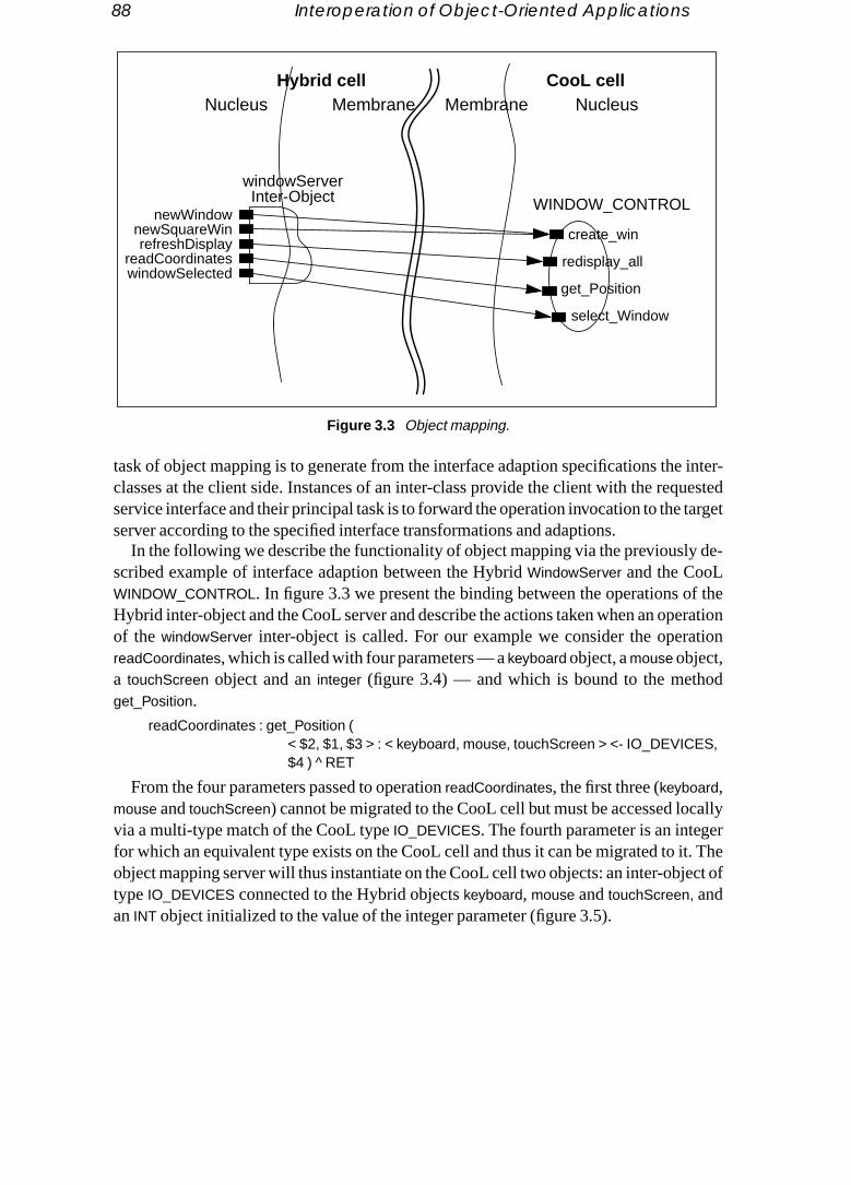
88 Interoperation of Object-Oriented Applications
inter-uestedtarget
de-
f theerationtion
d
callyr
t. Thect of
task of object mapping is to generate from the interface adaption specifications theclasses at the client side. Instances of an inter-class provide the client with the reqservice interface and their principal task is to forward the operation invocation to the server according to the specified interface transformations and adaptions.
In the following we describe the functionality of object mapping via the previouslyscribed example of interface adaption between the HybridWindowServer and the CooLWINDOW_CONTROL. In figure 3.3 we present the binding between the operations oHybrid inter-object and the CooL server and describe the actions taken when an opof the windowServer inter-object is called. For our example we consider the operareadCoordinates, which is called with four parameters — akeyboard object, amouse object,a touchScreen object and aninteger (figure 3.4) — and which is bound to the methoget_Position.
readCoordinates : get_Position (< $2, $1, $3 > : < keyboard, mouse, touchScreen > <- IO_DEVICES,$4 ) RET
From the four parameters passed to operationreadCoordinates, the first three (keyboard,mouse andtouchScreen) cannot be migrated to the CooL cell but must be accessed lovia a multi-type match of the CooL typeIO_DEVICES. The fourth parameter is an integefor which an equivalent type exists on the CooL cell and thus it can be migrated to iobject mapping server will thus instantiate on the CooL cell two objects: an inter-objetypeIO_DEVICES connected to the Hybrid objectskeyboard, mouse andtouchScreen, andanINT object initialized to the value of the integer parameter (figure 3.5).
CooL cellHybrid cellNucleus Membrane Membrane Nucleus
newWindowcreate_win
redisplay_all
get_Position
windowServer
WINDOW_CONTROL
select_Window
newSquareWinrefreshDisplay
readCoordinateswindowSelected
Inter-Object
Figure 3.3 Object mapping.

Object Mapping 89
ver will
e
When the transfer of the parameters has been completed the object mapping serproceed with the invocation of the remote operation. The operationget_Position will be in-voked with theIO_DEVICES inter-object and theINT object (figure 3.6) as parameters. Th
CooL cellHybrid cellNucleus Membrane Membrane Nucleus
windowServerWINDOW_CONTROL
get_Position
readCoordinates
keyboard
mouse
touchScreen
integer
Figure 3.4 Operation call forwarding.
CooL cellHybrid cellNucleus Membrane Membrane Nucleus
windowServerWINDOW_CONTROL
get_Position
readCoordinates
IO_DEVICESkeyboard
mouse
touchScreen
integer
INT
Figure 3.5 Parameter transfer.

90 Interoperation of Object-Oriented Applications
e-
t
pe forL cellnuestatch
they typed type
dology pro-stricts
result, an object of typePOSITION, will then need to be returned to the Hybrid caller. Bcause for the CooL typePOSITION there exists a translation to the Hybrid typepoint, theobject mapping server will instantiate an object of typepoint on the Hybrid cell which willbe initialized to the translated value of thePOSITION object. This object will be the resulreturned to the caller of thereadCoordinates operation.
During the transfer of parameters the object mapping server might encounter a tywhich no type relation has been defined. For example, it might be that on the Coothere is no type relation for the typeIO_DEVICES. In this case when the instantiation of aIO_DEVICES inter-object is requested, the type-matching server will dynamically reqthe definition of the type match. The user will be required to define on the fly a type mfor the IO_DEVICES type. Once this is done the object-mapping server will resumetransfer of the parameters. This way an application can be started even without anrelations defined. The object-mapping server will prompt the user to define all neederelations during the first run of the application.
3.8 Conclusions and Research Directions
One of the important advantages of object-oriented design and development methois the ability to reuse existing software modules. However, the introduction of manygramming languages with different syntaxes, semantics and paradigms severely rethe reuse of objects programmed in different programming languages. Althoughadhoc
CooL cellHybrid cellNucleus Membrane Membrane Nucleus
windowServerWINDOW_CONTROL
get_Position
keyboard
mouse
touchScreen
readCoordinates
IO_DEVICES
INT
Figure 3.6 Remote operation invocation.

Conclusions and Research Directions 91
solutions can be given to solve specific inter-language reuse cases, different interoperabil-d reuse
n theoint ath the
serv-e
t of-
bilityrfacesviron-f the
ach-s, e.g.
t. Fur-k forgacy
romi-
kingisting
nnotRBA
ple, en-ion to
e com- a new
ity support methods provide the framework for consistent inter-language access anof objects.
We classify the interoperability support approaches in two ways: first depending oway that they solve the problem of the different interfaces, and second on the pwhich the interoperability support is handled. For the first classification we distinguisinterface standardization approaches, which standardize the interface under which a ice (functionality) is offered, and theinterface bridging approaches, which bridge thdifferences between interfaces. For the second classification we distinguish theproce-dure-oriented interoperability approaches, which handle interoperability at the pointhe procedure call, and theobject-oriented interoperability approaches, which handle interoperability at the point of the object.
From the above approaches the interface bridging object-oriented interopera(IB-OOI) approach is the most flexible one since it does not impose predefined inteand can be applied equally well to both object-oriented and non-object-oriented enments. The Cell framework, which we describe in detail, provides an example oIB-OOI approach.
Because the IB-OOI is by no means incompatible with other interoperability approes, its ideas and concepts can be incorporated into other interoperability frameworkthe CORBA, and significantly enhance their openness and interoperability supporthermore the flexibility and generality of the IB-OOI ideas can provide a frameworthe solution of software integration and software evolution problems related to lesystems.
3.8.1 Openness of Interoperability Platforms
One of the major disadvantages of existing interoperability frameworks, the most pnent of which is CORBA, is that they areclosed to themselves. That is, client and serverapplications interacting via the interoperability platform must be implemented mause the specific platform interfaces. As a result, taking CORBA as an example, exapplications cannot be incorporated in the CORBA “world” (non-CORBA clients cause CORBA services, and non-CORBA servers cannot offer their services to COclients), nor can CORBA applications be moved to a non-CORBA environment.
Designing an interface adaption service for CORBA that will allow C++, for examclient applications to access CORBA services via their IDL interface will significantlyhance the openness and acceptability of CORBA and will allow almost any applicattake advantage of the services CORBA offers.
3.8.2 Interoperability and Legacy System Migration
One of the major problems that companies are facing due to the rapid advances of thputer software and hardware technologies is the migration of their legacy systems to

92 Interoperation of Object-Oriented Applications
platform. Most of the given solutions areadhoc case-dependent solutions; only recentlyblem
ecog-of inter-g thens.idedothnentsts withnentses.
on,”
ms to
In-arch
oning
,” inof
ys-DS ’93
the-
has some kind of methodology started appearing [2][3]. However, although the proof legacy system migration is in effect an interoperability problem, it has not been rnized as such. The reason is that most of the work and research done in the area operability support focuses on the interoperability support of new applications usininterface standardization approach and does not consider existing legacy applicatio
A prominent framework for the support of legacy system migration can be provwith the interface bridging object-oriented interoperability (IB-OOI) approach. A smoincremental migration of a legacy system can be achieved by identifying its compoand their interfaces and using an IB-OOI support to replace the legacy componennew ones, which most probably have a different interface [14]. This way new compocan be incrementally added to the system without affecting the remaining legacy on
References
[1] Denise Bermek and Hugo Pickardt, “HooDS 0.3/00 Pilot Release InformatiITHACA.SNI.91.D2#4, Deliverable of the ESPRIT Project ITHACA (2705), 28 Aug. 1991.
[2] Thomas J. Brando and Myra Jean Prelle, “DOMIS Project Experience: Migrating Legacy SysteCORBA Environments,” Technical Report, The MITRE Corporation, Bedford, Mass., 1994.
[3] Michael L. Brodie and Michael Stonebraker, “DARWIN: On the Incremental Migration of Legacyformation Systems,” DOM Technical Report, TR-0222-10-92-165, GTE Laboratories Inc., M1993.
[4] Rachid Guerraoui,Programmation Repartie par Objets: Etudes et Propositions, Ph.D. thesis, Univer-site de Paris-Sud, Oct. 1992.
[5] Adele Goldberg,Smalltalk-80, Addison-Wesley, Reading, Mass. 1984.
[6] Yoshinori Kishimoto, Nobuto Kotaka, Shinichi Honiden, “OMEGA: A Dynamic Method AdaptiModel for Object Migration,” Laboratory for New Software Architectures, IPA Japan, WorkPaper, April 1991.
[7] Dimitri Konstantas, Oscar Nierstrasz and Michael Papathomas, “An Implementation of HybridActive Object Environments, ed. D. Tsichritzis, Centre Universitaire d’Informatique, University Geneva, 1988, pp. 61–105.
[8] Dimitri Konstantas, “Cell: A Model for Strongly Distributed Object Based Systems,” inObject Com-position ed. D. Tsichritzis, CUI, University of Geneva, 1991, pp. 225–237.
[9] Dimitri Konstantas, “Design Issues of a Strongly Distributed Object Based System,”Proceedings of2nd International Workshop for Object-Orientation in Operating Systems (I-WOOOS ’91), IEEE,Palo Alto, Oct. 17–18, 1991, pp. 156–163.
[10] Dimitri Konstantas, “Hybrid Update,” inObject Frameworks, ed. D. Tsichritzis, Centre Universitaired’Informatique, University of Geneva, 1992, pp. 109–118.
[11] Dimitri Konstantas, “Hybrid Cell: An Implementation of an Object Based Strongly Distributed Stem,”Proceedings of the International Symposium on Autonomous Decentralized Systems ISA,Kawasaki, Japan, March 1993.
[12] Dimitri Konstantas, “Cell: A Framework for a Strongly Distributed Object Based System,” Ph.D.sis No. 2598, University of Geneva, May 1993.

References 93
[13] Dimitri Konstantas, ‘‘Object-Oriented Interoperability,’’Proceedings ECOOP ’93, ed. O. Nierstrasz,93,
abilityarch
t Lan-n
s,” in
.
nd
at-
.
N
l In-
ction
Lecture Notes in Computer Science, vol. 707, Springer-Verlag, Kaiserslautern, Germany, July 19pp. 80–102.
[14] Dimitri Konstantas, “Towards the Design and Implementation of a Safe and Secure InteroperSupport Layer in CHASSIS,” CHASSIS SPP project technical report, University of Geneva, M1994.
[15] Jintae Lee and Thomas W. Malone, “How Can Groups Communicate when they use Differenguages? Translating Between Partially Shared Type Hierarchies,”Proceedings of the Conference oOffice Information Systems, March 1988, Palo Alto, CA.
[16] Barbara Liskov, Dorothy Curtis, Paul Johnson and Robert Scheifler, “Implementation of ArguProceedings of the 11th ACM Symposium on Operating Systems Principles, ACM, Austin, Tex., Nov.1987, pp. 111–122.
[17] Oscar Nierstrasz, ‘‘A Tour of Hybrid — A Language for Programming with Active Objects,’’Advanc-es in Object-Oriented Software Engineering, ed. D. Mandrioli, B. Meyer, Prentice Hall, 1992, pp167–182.
[18] Object Management Group and X Open, The Common Object Request Broker: Architecture aSpecification, Document Number 91.12.1 Revision 1.1
[19] Object Management Group, Object Management Architecture Guide, OMG TC Document 92.11.1,Revision 2.0, Sept. 1992.
[20] Anna-Kristin Pröfrock, Dennis Tsichritzis, Gerhard Müller and Martin Ader, “ITHACA: An Integred Toolkit for Highly Advanced Computer Applications,” inObject Oriented Development, ed. D.Tsichritzis, Centre Universitaire d’Informatique, University of Geneva, July 1989, pp. 321–344
[21] James M. Purtilo and Joanne A. Atlee, “Module Reuse by Interface Adaption,”Software Practice &Experience,vol. 21 no. 6, June 1991.
[22] Ken Sakamura, “Programmable Interface Design in HFDS,”Proceedings of the Seventh TROProject Symposium, Springer-Verlag, Tokyo, 1990.
[23] Marc Shapiro, “Structure and Encapsulation in Distributed Systems: The Proxy Principle,”6th Inter-national Conference on Distributed Computing Systems, Boston, Mass., May 1986.
[24] Peter Wegner, ‘‘Concepts and Paradigms of Object-Oriented Programming,’’ACM OOPS Messen-ger, vol. 1, no. 1, Aug. 1990, pp. 7–87.
[25] Jack C. Wileden, Alexander L. Wolf, William R. Rosenblatt and Peri L. Tarr, “Specification Leveteroperability,”Communications of ACM, vol. 34, no. 5, May 1991.
[26] Daniel M. Yellin and Robert E. Strom, “Interfaces, Protocols, and the Semi-Automatic Construof Software Adaptors,” proceedings of the 9th annual conference onObject Oriented ProgrammingSystems, Languages and Applications — OOPSLA’94, Portland, Oreg., 23–27 Oct. 1994.

94 Interoperation of Object-Oriented Applications
Annex I: Interface Adaption Language
typeMatchDef : remoteCellId ‘::’ typeMatch ‘;’
typeMatch : localType ‘->’ remoteTypes typeMatchSpec| localType ‘=>’ remoteType [ ‘:’ transFunction ]| localType ‘+>’ remoteType [ ‘:’ transFunction ]
remoteTypes : ‘<’ remoteTypeList ‘>’
remoteTypeList : remoteType [‘@’] [‘,’ remoteTypeList]
typeMatchSpec : ‘{’ operMatchList ‘}’ [ adaptDefList ]
adaptDefList : ‘@{’ Program ‘@}’ [adaptDefList]
operMatchList : operMatch [operMatchList]
operMatch : localOpName ‘:’ remoteOpDef ‘(’argMatchList ‘)’ ‘^’ returnValDef ‘;’
remoteOpDef : remoteType ‘.’ remoteOpName
argMatchList : argMatch [‘,’ argMatchList]
argMatch : localArgId| adaptFunct ‘(’ localArgId ‘)’| localArgId ‘:’ localType ‘<-’ remoteType| ‘<’ localArgIdList ‘>’ ‘:’ ‘<’ localTypeList ‘>’ ‘<-’ remoteType| remoteOpDef ‘(’ argMatchList ‘)’
returnValDef : RET| adaptFunct ‘(’ RET ‘)’| RET ‘:’ localType ‘->’ remoteType
localArgIdList : localArgId [‘,’ localArgIdList]
localTypeList : localType [ ‘,’ localTypeList]
localArgId : ‘$’SMALL_INTEGER| INTEGER_LITERAL
localType : STRING
remoteType : STRING
remoteOpName : STRING
remoteCellId : STRING
transFunction : STRING
adaptFunct : STRING
Program : Program code in Native Language.

Annex II: Type Match Definition Example 95
Annex II: Type Match Definition Example
CooLCell :: windowServer -> WINDOW_CONTROL {newWindow : create_win($3, $4, $1, $2, 17 ) ^ RET ;newSquareWin : create_win ( bottomRX($1, $3), bottomRY($2, $3), $1, $2, 17 )
^ RET ;refreshDisplay : redisplay_all ( $1 : display <- DISPLAY ) ^ int2bool(RET) ;readCoordinates : get_Position
(< $2, $1, $3 > : < keyboard, mouse, touchScreen > <- IO_DEVICES, $ 4 ) ^ RET
windowSelected : select_Window (WINDOW_CONTROL.get_Position
( < $2, $1, $3 > : < keyboard, mouse, touchScreen > <- IO_DEVICES, 1) ) ^ RET ;
}@{
bottomRX : (integer : topLeftX, side ) -> integer ;{ return (topLeftX + side ) ; }
bottomRY : (integer : topLeftY, side ) -> integer ;{ return (topLeftY - side ) ; }
int2bool : ( integer : intval ) -> boolean ;{
return (intval ~=? 0) ;}
@} ;

96

PART III
Specification andComposition

98
Chapter 4
ram-bject isle this
r part advan-n thatblish,
Regular Types forActive Objects*
Oscar Nierstrasz
Abstract Previous work on type-theoretic foundations for object-orientedprogramming languages has mostly focused on applying or extendingfunctional type theory to functional “objects.” This approach, while benefitingfrom a vast body of existing literature, has the disadvantage of dealing withstate change either in a roundabout way or not at all, and completely side-stepping issues of concurrency. In particular, dynamic issues of non-uniformservice availability and conformance to protocols are not addressed byfunctional types. We propose a new type framework that characterizes objectsas regular (finite state) processes that provide guarantees of service alongpublic channels. We also propose a new notion of subtyping for active objects,based on Brinksma’s notion of extension, that extends Wegner and Zdonik’s“principle of substitutability” to non-uniform service availability. Finally, weformalize what it means to “satisfy a client’s expectations,” and we show howregular types can be used to tell when sequential or concurrent clients aresatisfied.
4.1 Introduction
Much of the work on developing type-theoretic foundations for object-oriented progming languages has its roots in typed lambda calculus. In such approaches, an oviewed as a record of functions together with a hidden representation type [10]. Whi
* This chapter is a revised and corrected version of a previously published paper. ACM. ProceedingsOOPSLA ’93, Washington DC, Sept. 26 – Oct. 1, 1993, pp. 1–15. Permission to copy without fee all oof this material is granted provided that the copies are not made or distributed for direct commercialtage, the ACM copyright notice and the title of the publication and its date appear, and notice is givecopying is by permission of the Association for Computing Machinery. To copy otherwise, or to repurequires a fee and/or specific permission.

100 Regular Types for Active Objects
view has the advantage of benefiting from a well-developed body of literature that has afor ex-uages
ch lan-vicingy fur-l) fors and arientedtion
o notproto-Ls, weneral
objectstractMilner’sheydistin-t behav-els for typing
) ex-n the
re-
ilableontracts objecttually)en pro-
t state
prin-s areular
hown
great deal to say of relevance to OOP about polymorphism and subtyping — see, ample, chapter 6 of this book — the fact that objects in real object-oriented langchange state is typically dealt with in an indirect way.
The mismatch is even more acute in concurrent object-oriented languages. In suguages, “active objects” may have their own thread of control and may delay the serof certain requests according to synchronization constraints [20]. Such objects mathermore require a particular protocol to be obeyed (such as an initialization protocothem to behave properly. Chapter 2 of this book presents a survey of such languagethorough discussion of issues. See also chapter 12 for an example of an object-oframework in which “gluons” encapsulate protocols to facilitate dynamic interconnecof components. Existing notions of object types coming from a functional setting daddress the issues of non-uniform service availability or conformance to a service col. (Although these issues are also relevant for passive objects and sequential OOPdraw our main motivation from object-based concurrency, and so we will refer in a geway to “active” objects.)
We argue that, in order to address these issues, it is essential to start by viewing anas aprocess, not a function. (See [26] for other reasons.) By “process” we mean an abmachine that communicates by passing messages along named channels, as in CCS [24] or the polyadicπ-calculus [25]. Processes naturally model objects since trepresent pure behaviour (i.e. by message passing). Behaviour and “state” are inguishable in such an approach, since the current state of a process is just its curreniour. Unfortunately there has been considerably less research done on type modprocesses than for functions, and the work that has been done focuses primarily onchannels, not processes (see, for example [25] [33]).
Although processes in general may exhibit arbitrary behaviour, we can (normallypect objects to conform to fairly regular patterns of behaviour. In fact, we propose oone hand to characterize theservice types associated with an object in terms of types of quest and reply messages, and on the other hand to characterize theavailability of theseservices byregular types that express the abstract states in which services are avaand when transitions between abstract states may take place. Services represent cor “promises” over the message-passing behaviour of the object: in a given state thewill accept certain types of requests over its public channels, and promises to (evensend a reply along a private channel (supplied as part of the request message). Whviding a particular service, an object may (non-deterministically) change its abstracto alter the availability of selected services.
Subtyping in our framework is based on a generalization of Wegner and Zdonik’s “ciple of substitutability” [34]: services may be refined as long as the original promisestill upheld (by means of a novel application of intersection types [5] [31]), and regtypes may be refined according to a subtype relation — based on Brinksma’sextension re-lation for LOTOS processes [7] — that we call “request substitutability.”
In section 4.2 we shall briefly review what we mean by “type” and “subtype,” and we may understand the notion ofsubstitutability in the context of active objects. In sectio

Types, Substitutability and Active Objects 101
4.3 we introduceservice types as a means to characterize the types of request messages un-
-
requestsimplext, we
o prac- with
houldes arer dataseman-
ut thesespeci-
tronger
all
of a
ed byioural
bjects specify
derstood by an object and their associated replies, and we show howintersection overservice types provides us with a means to refine these specifications.
In section 4.4 we definerequest substitutability for transition systems and we demonstrate its relationship to failures equivalence. In section 4.5 we introduceregular types asa means to specify the protocols of active objects. In section 4.6 we propose to use substitutability as a subtype relationship for regular types, and we demonstrate a algorithm for checking that one regular type is request substitutable for another. Neformalize a client’s expectations in terms ofrequest satisfiability, and we show how regu-lar types relate to this notion.
In section 4.8 we summarize a number of open issues to be resolved on the way ttically applying our type framework to real object-oriented languages. We concludesome remarks on unexplored directions.
4.2 Types, Substitutability and Active Objects
Before we embark on a discussion of what types should do for active objects, we sbe careful to state as precisely as possible (albeit informally) what we believe typand what they are for. Historically, types have meant many things from templates fostructures and interface descriptions, to algebraic theories and retracts over Scott’s tic domains. We are interested in viewing types aspartial specifications of behaviour ofvalues in some domain of discourse. Furthermore, types should express things abovalues that tell us how we may use them safely. Naturally, we would also like these fications to (normally) be statically checkable.
Subtyping is a particular kind of type refinement. Theinterpretation of a type for somevalue space determines which values satisfy the type. A subtype, then, is simply a sspecification and guarantees that the set of values satisfying the subtype is asubset ofthose that satisfy the supertype. IfT is a type (expression) andU is some universal valuespace of interest, then we shall writex:T to meanx satisfiesT, and[[T]] to mean{ x x:T }(i.e. whereU is understood). Another typeS is a subtype ofT, writtenS≤T, if x:S ⇒ x:T, i.e.[[S]]⊆[[T]].
But specifically whatkinds of properties should types specify? It is worthwhile to recWegner and Zdonik’s principle of substitutability:
An instance of a subtype can always be used in any context in which an instance supertype was expected. [34]
It is important to recognize that “can be used” impliesonly “safely,” and nothing more.It does not imply, for instance, that an application in which a type has been replacsome subtype will exhibit the same behaviour. We are not concerned with full behavcompatibility, but only with safe usage.
What does type safety mean in an object-oriented setting? First of all, that oshould only be sent messages that they “understand.” We must therefore be able to

102 Regular Types for Active Objects
ects asn types certainy, in
requestsnteed to
tain or-’s typey, envi-. Type
e valided of
jectsal-
of thismal.)s rep-icationre for.nnels, of argu-f the cor-ut the
the types of request and reply messages exchanged by objects. If we think of obj“servers,” then the services they provide are promises that they understand certaiof requests, and that, in response to a particular request, they will eventually send atype of reply. Subtyping of services can then be defined in a fairly conventional wathat a subtype at least guarantees the promises of the supertype: at least the sameare understood (possibly more) and consequent replies to those requests are guarabe of the right type.
Services may not always be available, however. If requests must be sent in a cerder, or if certain services may be temporarily unavailable, then, we argue, the objectshould describe this. Type safety, in this case, means that clients (or, more generallronments) that interact with such objects do not deadlock because of protocol errorssubstitutability is correspondingly defined so that sequences of interactions that arfor a supertype are also valid for a subtype. A client will never be unexpectedly starvservice because a subtype instance has been substituted.
In order to explain our type approach, we will adopt an object model that views obas certain kinds of communicating processes [4][8][17][24]. (Although we could formize our model in process-theoretic terms, as in, for example, [30], for the purposes presentation we will attempt to be rigorous and precise without being excessively for
Figure 4.1 depicts an object’s behaviour in an idealized fashion. The large circleresent the object in its various states and the small circles represent its communchannels, white for input and black for output. The input channels on the left side areceiving requests. Note that the set of “enabled” input requests changes over time
In our object model, every object receives requests along uniquely identified chaone per request name. Each request consists of a message containing a numberments and a unique reply address (also a channel name). The arguments must be orect type. (We will not be concerned with what kinds of values may be passed, b
Figure 4.1 Non-uniform service availability.
Accept requestsSend requests
Receive repliesSend reply
Accept requests

Intersecting Service Types 103
reader may assume that any reasonable value — objects, object identifiers, channel
annels,.b-
ed byct mayt chan-hannels,
for any
ciatedection
es).
a
ices
phy).. If we
ermits
names, etc. — is fair game.)An object, then, accepts requests addressed to it through its (public) request ch
and it may issue requests to other objects it is acquainted with viatheir request channelsAll replies, however, are communicated alongprivate channels that are temporarily estalished by clients of requests. When an object accepts a request, it implicitlyguarantees to(eventually) send a reply (of the correct type) to the client. This reply may be delivera third party to which the reply address has been forwarded. Furthermore, the objevary the requests accepted over time by selectively listening only to certain requesnels. When an object is ready to accept a message addressed to one of its request cwe say that the request isenabled, and that the corresponding service isavailable. We as-sume that the complete set of public request channels is finite and fixed in advanceobject.
We will now separately discuss the issues of specifying types of services assowith an object (section 4.3), and specifying when those services are available (s4.4).
4.3 Intersecting Service Types
We will start by introducing the following syntax for service types:S ::= all none M(V)→V S SV ::= all none (V,...) ...
whereM is a request name andV is a value type (i.e. types for argument and return valu“→” binds more tightly than “”. We assume thatV includes some base types, the typesall
andnone, and tuples over value types.We will write x : m(A)→R to mean that objectx may receive a valuea of typeA together
with a reply address along a request channelxm and will consequently promise to returnvaluer of typeR. We may also writex.m(a) : R to say thatx understands the messagem(a)
and returns a value of typeR. We call the type expressionm(A)→R aservice of x, and wesay thatx offers this service. Note that this does not imply anything about other servthatx may or may not offer.
We may refine these expressions by theintersection operator for types (^). Intersectiontypes have been studied extensively in functional settings (see [31] for a bibliograHere we propose to assign an interpretation to them for objects in a process settingwrite x:S1^S2, we wish that to mean precisely thatx:S1 andx:S2. In set-theoretic terms,then:
[[S1^S2]] = [[S1]] ∩ [[S2]]As specifications, we mean that bothS1 andS2 are true statements aboutx. As we shall
see, this device allows us not only to attribute sets of services to objects, but also pus to refine their types in interesting ways.

104 Regular Types for Active Objects
The expressionsall andnone represent, respectively, the set of all objects and the empty
s are
hen thepes
andon.
set. That is,all tells us nothing about the services of an object, andnone demands so muchthat no object can possibly satisfy it. (all andnone are the “top” and “bottom” of our typehierarchy.)
Let us now briefly look at the subtyping properties of service types. Some factclear:
1. T ≤ all (i.e. for any value or service typeT)
2. none ≤ T
3. m(none)→T = all (since no such request can ever be received)
4. R1 ≤ R2 ⇒ m(A)→R1 ≤ m(A)→R2
5. A2 ≤ A1 ⇒ m(A1)→R ≤ m(A2)→R (i.e. a contravariant rule)
Now, considering intersections, the following are straightforward:
6. S1^S2 ≤ S1 andS1^S2 ≤ S2
7. S ≤ S1 andS ≤ S2 ⇒ S ≤ S1^S2
8. S1 ≤ S2 ⇒ (S1^S2) = S1 (follows from (6) and (7))
Now consider:
9. m(A1)→R1 m(A2)→R2 ≤ m(A1^A2)→(R1^R2)
Normally we may expect to write type expressions like:put(all)→(Ok) get()→(all)
but nothing prevents us from writing:inc(Int)→Int inc(Real)→Real
or even:update(Point)→Point update(Colour)→Colour
If an incoming message satisfies more than one request type in the intersection, tresult must satisfyeach of the result types. Our (informal) semantics of intersection tyrequires thatall applicable service guarantees must hold. In this case, if:
cp:ColouredPoint,
whereColouredPoint = Point^Colourthenx.update(cp):Point andx.update(cp):Colour. The result, therefore, must have typeCol-
ouredPoint.Notice that as a corollary of (9), via (6) , (4) and (7), we also have:
10.m(A)→(R1^R2) = m(A)→R1 m(A)→R2
This also means, however, that we must take care not to intersect services with abFor example, supposeInt andReal are disjoint types. Then:
size(Point)→Int size(Colour)→Real≤ size(ColouredPoint) → (Int^Real)= size(ColouredPoint) → none
Request Substitutability 105
Since the twosize services have contradictory result types, their intersection yields the re-
r
ypes of.ls aretute theb-e sup-
e ap-
sts, is-ould belast ofan objectations,hen itt only
s is-
st rep-f re-w stable
these, but ifof non-pon theject’s
sult typenone.As a final remark, notice that type-safe covariance is naturally expressed:
update(Point) → Point update(ColouredPoint) → ColouredPoint
is a subtype of bothupdate(Point)→Point andupdate(ColouredPoint)→ColouredPoint. A cli-ent supplying an instance ofColouredPoint as an argument can be sure of getting aColoured-
Point back as a result, whereas clients that supplyPoint arguments will only be able to infethat the result is of the more general typePoint.
4.4 Request Substitutability
Service types tell us what types of requests are understood by an object and what treply values it promises to return, but they do not tell uswhen those services are availableIn particular, we are interested in specifying when an object’s request channeenabled. The sequences of requests that an object is capable of servicing constiobject’sprotocol. An object thatconforms to the protocol of another object is safely sustitutable for that second object, in the sense that clients expecting that protocol to bported will receive no “unpleasant surprises.”
Before tackling the issue of how to specify protocols, let us first try to formalize thpropriate substitutability relation.
According to our abstract object model, objects can do four things: accept requesue requests, receive replies and send replies. Since the behaviour of objects shproperly encapsulated, clients should only need to know about the first and the these, i.e. the requests accepted and the replies sent. If we can safely assume that that accepts requests promises to deliver replies according to service type specificthen the only additional thing a client needs to know about an object’s protocol is wwill accept requests. We therefore adopt an abstract view of an object’s protocol thaconsidersrequests received along its request channels, andignores all other messages.(Later, in section 4.7, we will model clients’ protocols by considering only requestsued.)
In this view we model an object as a transition system where each state of intereresents astable state of the object, in which it blocks for acceptance of some set oquests. A transition takes places upon the receipt of some request and leads to a nestate. If an object in statex can accept a requestr leading to a new statex′, we would write:
x →r x′Note that we ignore all intervening communications leading to the new state. If
communications are purely internal to the object, we can view it as a closed systemsome of these communications are with external acquaintances, then an element determinism is introduced, since the transitions to new stable states may depend ucurrent state of the environment. In cases like this, we feel it is correct to view the ob

106 Regular Types for Active Objects
protocol as inherently non-deterministic, since it would be unreasonable to expect clients
series
that it
ient
r sup-
rise
a-
set
l
lients
to monitor the environment to know the state of an object’s protocol.Clients are typically interested not just in issuing a single request, but in issuing
of related requests. Supposes is such a sequencer1,r2,... of requests. If an object in statexcan accept such a sequence, leading to statex′, then we write:
x ⇒s x′An important part of the protocol of an object is the set of sequences of requests
may accept. This is conventionally captured by the notion of set oftraces[8] of a transitionsystem:
Defini t ion 1 traces(x) ≡ { s ∃x′, x ⇒s x′ }.Suppose we wish to express that an object in statex isrequest substitutable for an object
in statey, which we will writex:<y. Then clearly we must havetraces(y) ⊆ traces(x), for ifa client ofy expectsy to accept a sequence of requestss, and we substitutex for y, thenxmust accept the same sequences. x may accept additional sequences, but since the cldoes not expect* them, they are of no concern to us.
But the inclusion of traces is not enough to guarantee request substitutability, fopose that after a sequence of requestss, y will move to statey′, butx will move to eitherstatex′ orx′′. Furthermore, suppose that statex′ is identical toy′ — i.e. behaviour from thatpoint on is identical — andx′ permits a requestr to be accepted, butx′′ denies it. Then it ispossible thattraces(y) ⊆ traces(x), but nevertheless the client may receive a nasty surpif x is substituted fory and the requestr is refused after the sequences. Traces tell us whatsequences are acceptable, but they do not tell us if they arenecessarily acceptable! Forthis, we need the help of a finer notion offailures [8].
First, we need to define theinitials of an object — the requests which are initially enbled:
Defini t ion 2 init(x) ≡ { r ∃x′, x →r x′ }.Defini t ion 3 The set offailures of an object x is
failures(x) ≡ { (s,R) ∃x′, x ⇒s x′, R is finite, R ∩ init(x′) = ∅ }.
That is,(s,R) is a failure ofx if x may simultaneously refuse all of the requests in theR after accepting the sequences. It may be the case thatx will reach a state in which someor all of the requests inR will be accepted, but we know that it ispossible that they will allbe refused. (NB: It is also important that the statex′ be stable for the setR to be well-defined, but we have already assumed that.)
Now, suppose that we wantx:<y and we know that(s,R) is a failure ofx. Furthermore,suppose thats is a sequence of requests intraces(y). Then a client will be satisfiedonly ifit expected that(s,R) was also a failure ofy. Note that ifs isnot a sequence in the protocoof y, then the client is unconcerned whether(s,R) is a failure ofx or not, since it is in any
* Although we have not yet formalized clients’ expectations, we are implicitly assuming here that caresequential, i.e. they only issue a single request at a time. Later, when we definerequest satisfiability, wewill see how request substitutability relates to concurrent clients.

Request Substitutability 107
case not expected to be handled. To express this notion ofrelative failures, we need the fol-
t
esion,
f
ore will
es
to de-set bynd the
xample,y re-
lowing definition:
Defini t ion 4 The set ofrelative failures of an object in statex with respect to an objecin statey is: failuresy(x) ≡ { (s,R) ∈ failures(x) s ∈ traces(y)}.
Now we come to the definition of request substitutability:
Defini t ion 5 An object in statex isrequest substitutable for an object in statey, writtenx:<y iff: (i) traces(y) ⊆ traces(x)
(ii) failuresy(x) ⊆ failures(y).
(This turns out to be identical to theextension relation introduced by Brinksma [7]. Sealso Cusack [13] for a discussion of various conformance relations, including extenin the context of CSP [8].)
That is, a client expectingx to follow the protocol ofy will expect that all sequences orequests supported byy will also be accepted byx, and that any requests refused byx afteraccepting one of those sequences might also have been refused byy. Note thatx may (1)accept additional sequences of requests that the client does not expect and therefnot use, and (2) may eliminate some non-determinism iny by providingfewer possibletransitions between states. On the other hand,x may introduce new transitions and statas long as they can be explained from the viewpoint ofy. In general, eitherx ory may havemore or less states or transitions.
Note also that the set of failures of an object tells us all we need to know in ordertermine request substitutability, since the traces can be derived from the failures projections, and relative failures can be determined from the failures of one object atraces of another.
Proposit ion 1 Request substitutability is a pre-order.
Proof(i) :< is reflexive: ∀x, x:<x — immediate, since failuresx(x) = failures(x).(ii) :< is transitive: Supposex:<y andy:<z. Thentraces(z) ⊆ traces(y) ⊆ traces(x).
Next, suppose(s,R) ∈ failuresz(x). Thens ∈ traces(z) ⊆ traces(y),so(s,R) ∈ failuresy(x) ⊆ failures(y). But then(s,R) ∈ failuresz(y) ⊆ failures(z),so we concludex:<z. ❑
There exists a vast literature on process equivalences and pre-orders (see, for e[1][14] for some interesting comparisons). Interestingly, the equivalence induces bquest substitutability is the same as failures equivalence [7][8].
Defini t ion 6 Objects in statesx and y are failures equivalent iff failures(x) =failures(y).
Proposit ion 2 x andy are failures equivalent iffx:<y andy:<x.
Proof⇒) failures(x) = failures(y) ⇒ traces(x) = traces(y)
⇒ failures(x) = failuresy(x) = failuresx(y) = failures(y) ⇒ x:<y andy:<x.⇐) x:<y andy:<x ⇒ traces(x) = traces(y).

108 Regular Types for Active Objects
Hencefailuresy(x) = failures(x) ⊆ failures(y).
lures
stitut-bjectl case,ce isse itspropo-
lly a uponess a
y re-imple
er ofes.bility.jects
et of cur- finite, a of en-. Frome this
By symmetry,failures(x) = failures(y). ❑
Although failures equivalence is exactly request equivalence, the inclusion of faisets does not imply request substitutability, nor vice versa. It suffices to consider:
It is easy to see that x:<y (but not the reverse, sincey does not permita.b) andfailures(y) ⊆failures(x) (but not the reverse, since(a.b,{a,b}) is a failure ofx but not ofy). See also Brin-skma [7] for a detailed discussion.
4.5 Viewing Objects as Regular Processes
We now have a plausible definition of protocol conformance in terms of request subability — what we still need is a way to specify protocols, and a way to check that an oconforms to a protocol, or that one protocol conforms to another. In the most generaunfortunately, request substitutability will be undecidable since failures equivalenundecidable in general [18]. (If request substitutability were decidable, we could udecision procedure to check if two processes were failures equivalent according to sition 2.)
We therefore propose to specify protocols asregular processes, i.e. processes with a fi-nite number of “states” or behaviours [6][11][15][23]. A regular process is essentiafinite state machine (hence the adjective “regular”), where transitions take placecommunications with other processes. We will call the specification of such a procregular type, since we intend to use it to specify object protocols. It turns out that bstricting ourselves to finite state protocols, request substitutability is decidable by a sprocedure.
Furthermore, although we cannot specify all protocols exactly with a finite numbstates, we canapproximate infinite state protocols by non-deterministic regular processThese approximations can then be used in many cases to check request substituta
Let us consider a few canonical examples using various kinds of “container” ob(bounded buffers, stacks, variables) each supporting (at least)put andget requests. We canassociate with these objects a number of abstract states, each corresponding to a srently enabled requests. Since we assume that the total set of possible services isfinite number of abstract states suffices to characterize all the possible combinationsabled requests (and normally only a few of these combinations should be needed)the client’s point of view, transitions may take place when services are provided (sincis all the client may observe).
a b a
a
x = y =

Viewing Objects as Regular Processes 109
First, consider a one-slot bounded buffer.
this
ct
td be-
in.ess theinistic
we
causeegular
It has two abstract states: one in which only aput is accepted, and one in which only agetis allowed. Upon accepting aput or aget request, the object changes state. We expressby the protocol (regular type)Buf.
Now consider an uninitialized variable with the protocolVar.
Its protocol requires that aput must first be requested, but thenput andget requests may beinterleaved arbitrarily. In this case, we see thatVar:<Buf since a client that expects an objeto obey theBuf protocol will never be “disappointed” if an object obeyingVar is substitut-ed. The reverse does not hold, becauseBuf will refuse the sequenceput.get.get, whereasVarwill not.
In these two cases, the transitions are deterministic, sinceBuf andVar are really finitestate protocols.
Now consider a stack (with put andget instead ofpush andpop). Initially only aput ispossible. Then bothput andget are enabled. Furtherput requests will not change this, buaget may bring us back to the initial state. The corresponding regular type is specifielow asNDStack.
It resemblesVar except that after aget, we do not necessarily know what state we areClearly, such a description is an approximation because we are attempting to exprservice availability of a deterministic process (the object) by means of a non-determone (the regular type).
We can try to add another intermediate state, as inNDStack2:
but after twoput requests and aget we again do not know what state we are in. In fact, would need an infinite number of states to describe completely theStack protocol.
As we argued before, however, non-determinism is inherent in some protocols, beobjects are not, in general, closed systems. Furthermore, the non-deterministic r
put
get
Buf =
put
put, getVar =
put
put, get
get
NDStack =
put
get
put
get
NDStack2 =
put, get

110 Regular Types for Active Objects
types are still useful to us. We can determine, for example, that an object conforming to
rob-ular
:
ular
seen
ns to
tell use reg-rec-
ce reason,rmin-
a pre-
theNDStack regular type also conforms toBuf sinceNDStack:<Buf.Choosing a simpleand readable syntax for specifying regular types is somewhat p
lematic. For the purpose of this chapter we will opt for simplicity. We specify a regtype by a pair, (x1,E) consisting of a finite system of equationsE of the form:
E = { x=t, ...}wherex1 is a distinguished start state, and thet are regular type expressions of the form
t ::= r.x t + tr is a request name andx is a state name. Everyx used inE must have exactly one definingequation inE (except fornil, which stands for a dead state with no transitions). Regtypes have the following interpretation as transition systems:
1. init(nil) = ∅2. r.nil →r nil
3. x=t ∈ E ⇒ r.x →r t
4. t1 →r1 t1′ ⇒ t1+t2 →r1 t1′5. t2 →r2 t2′ ⇒ t1+t2 →r2 t2′With this simple syntax, then, we could specify the various regular types we have
as follows:Buf = (b1, { b1=put.b2, b2=get.b1 })Var = (v1, { v1=put.v2, v2=put.v2+get.v2 })NDStack = (s1, { s1=put.s2, s2=put.s2+get.s2+get.s1 })NDStack2 = (s1, { s1=put.s2, s2=put.s3+get.s1,
s3=put.s3+get.s2+get.s3 })
At this point the reader may wonder why we cannot simply use regular expressiospecify regular types. The reason is that regular expressions stand for regularlanguages,i.e. sets of strings, not regular processes. Regular expressions can consequentlyabout the traces of a transition system but not its failures. Consider, for example, thular typesVar andNDStack. If we consider any state to be a valid final state, then they ognize exactly the same regular language, namely:
ε + put.(put+get)*But this does not tell us that after accepting aput followed by aget, NDStack mayrefuseanotherget, whereasVar never will. (A similar argument is elaborated in [16] to introduthe difference between language and process equivalence.) For precisely the sameit is not generally possible to convert a non-deterministic regular process into a deteistic one without losing information.
4.6 Subtyping Regular Types
We now propose to use request substitutability as asubtyping relationship over regulartypes. We are justified in this since we have shown that request substitutability is order, so ifVar:<NDStack andNDStack:<Buf, then we can conclude thatVar:<Buf.

Subtyping Regular Types 111
The fact that regular types have finite states means that a simple algorithm exists fort for
intro-
tional
f-
state
hether
stateparison
able
-uestll com-
checking the subtype relationship (not surprisingly, the algorithm is similar to thachecking equivalence of finite state automata [2]). To derive the algorithm, we mustduce a multi-state variant of request substitutability. First let us extendinit() and→ towork with sets of states:
Defini t ion 7 init(X) ≡ { r ∃x∈X, x′, x →r x′ }.
Defini t ion 8 X →r X′ iff X′ = { x′ ∃x∈X, x →r x′ }.Note in particular that→ for sets of states is afunction, not just a relation. In effect, we
are turning a non-deterministic transition system into a deterministic one in the tradiway by expanding single states into sets of reachable states [2].
Now let us consider the following definition:
Defini t ion 9 A set of object statesX is multi-state request substitutable for a set ofstatesY, writtenX:<<Y, iff:
(i) init(Y) ⊆ init(X)(ii) ∀x∈X, ∃y∈Y, init(y) ⊆ init(x)
(iii) ∀r∈init(Y), if X →r X′ andY →r Y′, thenX′:<<Y′.Condition (i) guarantees that all transitions possible from some state ofY are also pos-
sible from some state ofX. Condition (ii) says that any failure possible in some state oXcan be explained by a failure of some corresponding state ofY (somey has the same or fewer initial transitions possible). Condition (iii) is simply the recursive case.
Proposit ion 3 { x } :<< { y } ⇔ x:<y.
Proof⇒ ) Suppose that{ x } :<< { y }, thentraces(y) ⊆ traces(x) by 9(i) and 9(iii).
Next, suppose (s,R) ∈ failuresy(x). Then∃x′, x ⇒s x′, init(x′) ∩ R =∅ and∃y′, y ⇒s y′,init(y′) ⊆ init(x′) by 9.ii and 9.iii so (s,R) ∈ failures(y) and failuresy(x) ⊆ failures(y)hencex:<y.⇐ ) Similar argument in reverse. ❑
Note that this result is independent of whether we restrict our attention to finitetransition systems or not. If the sets of reachable states are finite, however, i.e. ifx andy areregular types, then proposition 3 provides us with a simple procedure to check wx:<y by simply generating all the sets of states reachable from{x} and{y} by transitions intraces(y) and checking conditions 9(i) and 9(ii) for all the comparable sets. Since thespace is finite, the set of reachable state sets must also be finite, and so the commust terminate in finite time.
The following iterative algorithm suggests itself: we maintain a LIST of comparsets of states and possible transitions, of the form (X,Y,R), whereX andY are the sets ofstates ofx andy reachable from some common traces of y, andR is the set of possible transitions (requests) fromY that the algorithm must traverse. We follow each possible reqto new comparable state sets until we have exhausted all transitions and checked aparable state sets, or until we fail to satisfy one of the conditions in definition 9.

112 Regular Types for Active Objects
1. Verify thatinit(y) ⊆ init(x), else FAIL
f
not allres two
t
list:
e:
2. Add ({x},{ y}, init(y)) to LIST
3. If possible, select some (X,Y,R) from LIST whereR is not empty, else SUCCEED
4. Select somer in R and replace (X,Y,R) by (X,Y,R\{r}) in LIST
5. ComputeX′ andY′, whereX →r X′ andY →r Y′6. If (X′,Y′,R′) for someR′ is already in LIST, then go to step 3, else continue
7. If init(Y′) ⊆ init(X′), then continue, else FAIL
8. If for eachxi ∈ X′ there exists someyj ∈ Y′ such thatinit(yj) ⊆ init(xi), then continue, else FAIL
9. Add (X′,Y′,init(Y′)) to LIST and go to step 3.
Note that steps 2 and 7 guarantee thatX′ generated in step 5 will never be empty.Since there is a finite number of reachable setsX andY to compare, the algorithm clearly
terminates. In the worst case, there will be (2n–1)×(2m–1) comparisons (i.e. the size oLIST), wheren andm are the number of states reachable fromx andy respectively, but nor-mally there will be far fewer, since not all subsets of states will be generated, and possible combinations will need to be compared. In the special case that one compadeterministic regular types, the maximum number of comparisons is justn×m, but may beeven as little asm (in case of success, that is).
Let us briefly look at an example that comparesBuf to the regular type of a stack thasupports an additionalswap operation:
NewNDStack = (s1, { s1=put.s2,s2=put.s2+get.s2+get.s1+swap.s2 })
We wish to check whetherNewNDStack:<Buf. We start with:({s1},{b1},{put}). Boths1 andb1 permit aput, and they have the same requests enabled, so we can add this to our
({s1},{b1},{put})
The only possible transition isput, so we remove it from LIST and generat({s2},{b2},{get}). s2 enables at least the requests thatb2 enables, so we add this to our list:
({s1},{b1},{put})({s2},{b2},{get})
Now only aget is possible, so we generate:({s1,s2},{b1},{put}). We verify thats1 ands2 eachenable at least the requests ofb1 and add this to our list:
({s1},{b1},{put})({s2},{b2},{get})({s1,s2},{b1},{put})
put put, get, swap
get
s1 s2

Request Satisfiability 113
ection
le (9).
e havence
st sub-ed byns. But to de-
Now we can perform aput, but this just generates({s2},{b2},{get}), which is already repre-sented in the list. There is nothing left to check, so we SUCCEED. (In the reverse dirwe would quickly FAIL in step 7 after a singleput becauseb2 enables neitherput norswap.)Note that the total number of comparisons (3) is far less than the worst case possib
Note thatNewNDStack is request substitutable forBuf even though it is, in a sense,lessdeterministic thanBuf. The key point is that it is safe to use wherever we are expectingBuf-like behaviour.
Figure 4.2 shows the subtype relationships between a few of the regular types wseen. Curiously,NDStack andNDStack2 are not related (to see why, consider the sequeput.get.get, which is in traces(NDStack) but not in traces(NDStack2), and the failure(put.put.get,{get}), which is infailures(NDStack), but not infailures(NDStack2)).
4.7 Request Satisfiability
Up to now our discussion has focused on the protocols of service providers. Requestitutability tells us when an object obeying some protocol can be safely substitutsome second object, assuming that the first object satisfies the client’s expectatiowe have not yet formalized what it means to satisfy a client. It turns out that we needfine a new relation, calledrequest satisfiability, which expresses this idea.
Figure 4.2 Some subtype relationships between regular types.
put
get
Buf =
put
put, getVar =
put, getNDStack =
put, getNDStack2 =
Buf2 =
putput, get,swap
get
NewNDStack =
put, getFaultyStack =
get
put
getput
get
put
get
put
get
put
get
put

114 Regular Types for Active Objects
If the protocol of a service provider expresses when its services are available, then the a client thatultipletingsts be one re-arily behablean beect can
f
abilitycheck-
xpecte.
(par-e sat-
protocol of its client expresses when those services are requested. We propose thatissatisfied if its requests are always honoured. Up to now we have implicitly assumedclients issue at most one request at a time. In general, however, a client may issue mrequests simultaneously (particularly if the “client” is actually an environment consisof multiple concurrent clients) — in such cases, we do not ask that all of the requehonoured together, just that the client be guaranteed to make progress, i.e. at leastquest must always be accepted. Since the current state of the client may not necessdeterministic, the object must be prepared for the client to be in any one of its reacstates. The object is allowed to terminate (i.e. refuse all further requests) only if it csure that the client will issue no more requests. In short, we must ensure that an objonly fail if the client makes no moreoffers.
We can formalize this as follows:
Defini t ion 10 The set ofoffers of a transition systemc is:
offers(c) ≡ { (s,R) ∃c′, c ⇒s c′, R = init (c′) }.So, if (s,R) is an offer ofc, then we know thatc may issue the sequence of requestss andthen may issue the set of requestsR. It is also possible thatc may issue some other set orequestsR′, if (s,R′) is also an offer ofc.
Defini t ion 11 An objectx is request satisfiable for a clientc, writtenx c, iff:(s,R) ∈ failures(x)∩offers(c) ⇒ R = ∅
If both client and server protocols are specified as regular types, then request satisfican be determined by an algorithm along the lines of the one we demonstrated for ing request substitutability.
4.7.1 Sequential Clients
How does request substitutability relate to request satisfiability? Clearly, we would ethat ifx:<y andy c, thenx c. It turns out that ifc is sequential, then this is in fact the cas
Defini t ion 12 A clientc is sequential if (s,R)∈offers(c) ⇒ |R| ≤ 1.Lemma 4 If c is sequential, theny c⇒ traces(c) ⊆ traces(y).
Proof By induction on the length of traces ofc. ❑
Proposit ion 5 If c is sequential, thenx:<y andy c ⇒ x c.
Proof (s,R) ∈ failures(x)∩offers(c) ⇒ s ∈ traces(c) ⊆ traces(y)⇒ (s,R) ∈ failuresy(x) ⊆ failures(y) ⇒ R = ∅. ❑
We are taking advantage of the fact thatc is sequential to conclude thaty completely sat-isfies the expectations ofc. (Note that it also suffices to require thattraces(c) ⊆ traces(y)for the same result to go through.) But if there are different ways of satisfying a clientticularly a concurrent one), then it is no longer true that the client will necessarily b

Request Satisfiability 115
isfied by a request substitutable service provider. Some additional preconditions must be
a con-eir own
urrent
er re-
erb the
sum-
as
imposed.
4.7.2 Concurrent Clients
Let us consider a simple example of a concurrent client consisting of a producer andsumer connected by a bounded buffer. The producer and the consumer each have thview of the buffer, but we are interested in the requirements posed by their conccomposition.
Presently we might separately specify expectations of the producer and consumspectively as:
We might write their concurrent composition asProd&Cons, where:c1 →r c1′ ⇒ c1&c2 →r c1′&c2
andc2 →r c2′ ⇒ c1&c2 →r c1&c2′
So we can conclude:
Note thatProd&Cons isnot sequential according to definition 12.It is easy to check thatBuf Prod&Cons, sinceBuf never refuses bothput andget. But
what is the role of request substitutability now? Since we know thatVar:<Buf can wenecessarily conclude also thatVar Prod&Cons? Unfortunately this is not quite right. Threason is that a regular subtype may introduce additional behaviour that can pertuclient’s expectations. Consider, for example, a deletable buffer:
It is clear thatDelBuf:<Buf. But suppose that we now compose the producer and coner with a malevolent object whose only goal is to try to delete the buffer:
Now Buf Prod&Cons&Del but it is not the case thatDelBuf Prod&Cons&Del. In the firstcase onlyDel will be starved out becauseBuf provides no delete operation, but the clientwhole will still be satisfied sinceProd&Cons continues to make progress.
putProd = getCons =
put, getProd&Cons =
put
get
DelBuf =del
Del =del

116 Regular Types for Active Objects
In the second case, however, the delete operation may succeed, then causing the client
.
uenceecta-] whoea istype of
ur that
e sub-
sure,super-
as a whole to deadlock, and thus remain unsatisfied.What we need to do in order to be sure thatDelBuf can be safely substituted forBuf is to
restrict its behaviour to that allowed byBuf:
Defini t ion 13 x/Y →r x′/Y′ iff x →r x′ andY →r Y′.What we mean to capture byx/Y is that some object in statex is restricted to accept onlythe requests allowed by a second object whose state is somey∈Y. We do not know precise-ly which state the second object is in, so we keep track of the set of possible states
Usually the initial state of the second object is known, so we will simply writex/y in-stead ofx/{y}.
Proposit ion 6 x:<y ⇒ x/y :< y.
Proof(i) traces(x/y) = traces(x) ∩ traces(y). Butx:<y ⇒ traces(y) ⊆ traces(x),
sotraces(x/y) = traces(y).
(ii) (s,R) ∈ failures(x/y) ⇒ ∃x′, x ⇒s x′, { y } ⇒s Y′, such thatR ∩ init(x′) ∩ init(Y′) = ∅⇒ R ∩ init(x′) ∩ ∪{ init(y′) y′∈Y′} = ∪ { R ∩ init(x′) ∩ init(y′) y′∈Y′} = ∅.But x:<y ⇒ { x } :<< { y } ⇒ ∃y′ ∈ Y′, init(y′) ⊆ init(x′)⇒ ∃y′ ∈ Y′, R ∩ init(y′) = ∅ ⇒ (s,R) ∈ failures(y) ⇒ failures(x/y) ⊆ failures(y).But failuresy(x/y) = failures(x/y), sox/y :< y. ❑
Finally, the result we want:
Proposit ion 7 x:<y andy c⇒ x/y c.
Proof x:<y ⇒ x/y :< y (by proposition 6), sofailures(x/y) ⊆ failures(y).Now (s,R) ∈ failures(x/y) ∩ offers(c) ⇒ (s,R) ∈ failures(y) ∩ offers(c) ⇒ R = ∅.Hencex/y c. ❑
So, for example, we can conclude that:DelBuf/Buf Prod&Cons&Del
since we effectivelyhide the additional behaviour introduced byDelBuf from the client.This is not as strong a result as we might have hoped for, but it is a natural conseq
of the fact that multiple concurrent clients may interfere with one another if their exptions are not consistent. This is essentially the observation of Liskov and Wing [22propose a new definition of subtyping that requires view consistency. Briefly, the idthat a type that extends the behaviour of another type may only be considered a subthe second if the additional behaviour can always be explained in terms of behaviowasalready there in the supertype.
In some cases we may get this consistency for free. Note, for example, that if thtype’s behaviour is properly included in the supertype’s, in the sense thatfailures(x) = fail-ures(x/y), then the subtype will be request substitutable for the supertype. We must bethough, that the subtype behaviour is consistent with the restriction imposed by the type. This leads to the following result:

Open Problems 117
Proposit ion 8 If traces(x) = traces(y) and
more
ce withect thates ofncur-
ject pro-n bothed whatg plays
oningrams,eptableme of
ssues.requestservicee type
be as-
tls sepa-
failures(x) ⊆ failures(y), then y c ⇒ x c.
Proof Follows from proposition 7 sincefailures(x) = failures(x/y). ❑
It may still be the case that a subtype provides additional behaviour that doesnot perturbthe client. But to be sure that the subtype is truly substitutable, it is necessary to knowabout the client’s expectations. We have previously exploredinteraction equivalence withrespect to the expectations of particular sets of observers, and found that equivalenrespect to all possible observers (also) reduces to failures equivalence [27]. We exprelativizing request substitutability with respect to the expectations of specific classclients will lead to more general and more useful results for the case of multiple corent clients.
4.8 Open Problems
We have proposed service types as a means of characterizing the services an obvides, and regular types as a means to express non-uniform service availability. Icases we have presented an approach to subtyping. Furthermore, we have formalizit means to satisfy a client’s expectations, and we have shown the role that subtypinin determining substitutability.
Although regular types appear to be a novel and promising approach for reasabout some of the dynamic (type) properties of concurrent object-oriented progthere remains much to be studied before we can claim to have a pragmatically accapproach for type-checking object-oriented languages. Let us briefly summarize sothese considerations.
4.8.1 Regular Service Types
So far we have treated the typing of services and their availability as orthogonal iService types express types of requests and replies, and regular types tell us when are enabled. There is nothing to prevent us from proposing a syntax for regular stypes that simply expands request names in regular types to the complete servicspecification corresponding to that request. For example, an integer variable couldsigned the regular service type:
IntVar = (v1, { v1 = put(Int)→Ok.v2,v2 = put(Int)→Ok.v2 + get→Int.v2 })
Since this is somewhat verbose (the type of theput service must be given twice), iseems more desirable to keep the type specifications of services and their protocorate.

118 Regular Types for Active Objects
It is conceivable, however, that the type of a service may itself change with time. In par-nt types handlexpress]). It isstitut-
sincey stud-of re-
hoseded”
to our
ypes.lly byld be toe or a
ofobject-bstracto
espe-tasier.s are
, and,
nerateat leastrst
e as-
s. Such
ticular, the result types associated with certain requests may depend on the argumeof earlier requests (as is the case with all of the container objects we have seen). Tothis case, it would seem necessary to introduce term variables into regular types to ethe dependencies between services in the protocol (i.e. à la “dependent types” [32not clear, however, what effect this would have on the determination of request subability.
It may also be interesting to consider bounded polymorphism in our framework, the integration of intersection types and bounded polymorphism has been previouslied [31], but only in a functional setting. Finally, we have not considered the issue cursively defined types, in which the regular type of an object may contain services wargument and return types refer to the object’s own type. Previous work on “F-bounquantification [9] addresses subtyping for such types [3], and is likely to be relevant framework.
4.8.2 Applying Regular Types to Object-Oriented Languages
We have presented our type model without giving any concrete interpretation for tThe objects to which we wish to assign types have been described only informameans of a very general model of objects as transition systems. The next step wouprovide a concrete syntax for objects, either in terms of a programming languagprocess calculus that can model objects in a straightforward way.
We have been working towards anobject calculus that incorporates those features process calculi that are most needed for expressing the semantics of concurrent oriented languages [28]. We intend to use the object calculus as an (executable) amachine for apattern language for (typed) active objects [29], and assign regular types tthe expressions of this language.
Since the type expressions we are dealing with can become rather unwieldy, it iscially important that we be able to do as much typeinference as possible. In languages thadirectly represent abstract states of objects (such as ACT++ [20]) this job will be eThe main difficulty will be in determining what transitions between the abstract statepossible.
We have already pointed out that objects may satisfy many different regular typessince regular types are only approximations, in some cases they may be refinedad nause-am. In order to assign regular types automatically to objects, it is necessary to gesome type assignment which is perhaps not the finest possible but which assigns one abstract state to every reachable subset of available services. (Recall that our fiND-Stack was such a minimal representation, whereasNDStack2 had two distinct states withthe same services available.)
Another consideration, however, is whether a deterministic regular type can bsigned to an object. If such a type specification exists (e.g.Var andBuf), then this is in anycase to be preferred to a non-deterministic regular type that may have less state

Concluding Remarks 119
types not only completely describe service availability for an object, but are well-behaved single-
hes-
definedcialtypes,ed as
prac-ts thatnts.oncur-ch as
epts
t deal ofies ofeneraloning
ntuallypport,orpo-an wee
an weting,
omas,e orig-
during type-checking since the sets of reachable nodes for a given trace are alwaystons. (So LIST stays small.)
4.9 Concluding Remarks
We have proposed a type framework for object-oriented languages that expresses tserv-ices of an object as an intersection ofservice types characterizing request and reply mesages, andnon-uniform service availability in terms ofregular types over a finite numberof abstract states associated with subsets of services. Subtyping of regular types isby introducingrequest substitutability, a novel pre-order over processes that has speinterest for object-oriented applications. Subtyping is easy to determine for regular and a simple algorithm is presented. Satisfaction of client’s expectations is formalizrequest satisfiability, and we show how request substitutability relates to it.
A number of technical issues must first be resolved before the framework can betically applied to real object-oriented languages. In particular, we seek some resulwill simplify reasoning about substitutability with respect to multiple concurrent clie
We expect that it will be easier to reason about regular types in the presence of crency if we interpret them either using a temporal logic or a modal process logic (suHennessy–Milner logic with recursion [21]). A logical characterization of the concwe have presented will be the topic of further research.
Despite a number of open research problems, the approach seems to hold a greapromise, since numerous tools and algorithms exist not only for analysing propertfinite state processes [11][15][23] but also for reasoning about processes in g[12][19]. This suggests that regular types may be more generally useful for reasabout temporal properties of concurrent objects.
We have concentrated on client–server-based protocols in which requests eveentail replies. Can we accommodate other kinds of communication protocols (to sufor example, transactions)? If so, must we modify our model of regular types to incrate bidirectional communications (instead of just enabling of request channels)? Ceasily accommodateexceptions in our framework by, for example, allowing replies to bunion types?
Finally, our approach considers only objects with fixed sets of known services. Caccommodatereflective objects that acquire new services with time? In such a setwould we have to consider not only services, but also types as first-class values?
Acknowledgements
Many thanks are due to José Rolim, Didier Buchs, Laurent Dami, Michael Papathand to the anonymous referees for their help and suggestions in the preparation of thinal version of this work published inOOPSLA ’93. I would also like to thank Benjamin

120 Regular Types for Active Objects
Pierce, Egil Andersen, William Ferreira and Patrick Varone for their careful reading of the
-
,
bra ofe
enta-
ential
edc-
hism,”
cur-
llable
.
esis,
manuscript, and for uncovering various technical errors and deficiencies.
References
[1] Samson Abramsky, “Observation Equivalence as a Testing Equivalence,”Theoretical Computer Sci-ence, vol. 53, North-Holland, 1987, pp. 225–241.
[2] Alfred V. Aho, John E. Hopcroft and Jeffrey D. Ullman,The Design and Analysis of Computer Algorithms, Addison-Wesley, Reading, Mass., 1974.
[3] Roberto M. Amadio and Luca Cardelli, ‘‘Subtyping Recursive Types,’’Proceedings POPL ’91, pp.104–118.
[4] Jos C.M. Baeten and Peter Weijland,Process Algebra, Cambridge University Press, Cambridge1990.
[5] Franco Barbanera and Mariangiola Dezani-Ciancaglini, “Intersection and Union Types,” inProceed-ings Theoretical Aspects of Computer Software (TACS ’91), ed. T. Ito and A.R. Meyer,Lecture Notesin Computer Science 526, Springer-Verlag, Sendai, Japan, Sept. 1991, pp. 651–674.
[6] Jan A. Bergstra and J.W. Klop, “The Algebra of Recursively Defined Processes and the AlgeRegular Processes,” inProceedings ICALP ’84, ed. J. Paredaens,Lecture Notes in Computer Scienc172, Springer-Verlag, Antwerp, pp. 82–95.
[7] Ed Brinksma, Giuseppe Scollo and Chris Steenbergen, ‘‘LOTOS Specifications, Their Implemtions and Their Tests,’’Protocol Specification, Testing and Verification VI, ed. G. Bochmann and B.Sarikaya, North Holland, 1987, pp. 349–360.
[8] Stephen D. Brookes, C.A.R. Hoare and Andrew W. Roscoe, “A Theory of Communicating SequProcesses,”Journal of the ACM, vol. 31, no. 3, July 1984, pp. 560–599.
[9] Peter S. Canning, William Cook, Walter L. Hill, John C. Mitchell and Walter G. Olthoff, “F-BoundQuantification for Object-Oriented Programming,”Proceedings of the ACM Conference on Funtional Programming and Computer Architecture, 11–13 Sept. 1989, pp. 273–280.
[10] Luca Cardelli and Peter Wegner, “On Understanding Types, Data Abstraction, and PolymorpACM Computing Surveys, vol. 17, no. 4, Dec. 1985, pp. 471–522.
[11] Edmund M. Clarke, E. A. Emerson and A. P. Sistla, “Automatic Verification of Finite-State Conrent Systems Using Temporal Logic Specifications,”ACM TOPLAS, vol. 8, no. 2, April 1986, pp.244–263.
[12] Rance Cleaveland, Joachim Parrow and Bernhard Steffen, “The Concurrency Workbench,” inAuto-matic Verification Methods for Finite State Systems: Proceedings, ed. Joseph Sifakis,Lecture Notesin Computer Science 407, Springer-Verlag, 1989, pp. 24–37.
[13] Elspeth Cusack, ‘‘Refinement, Conformance and Inheritance,’’Formal Aspects of Computing, vol. 3,1991, pp. 129–141.
[14] Rocco De Nicola, “Extensional Equivalences for Transition Systems,”Acta Informatica, vol. 24,1987, pp. 211–237.
[15] Suzanne Graf and Joseph Sifakis, “A Logic for the Specification and Proof of Regular ControProcesses of CCS,”Acta Informatica, vol. 23, no. 5, 1986, pp. 507–528.
[16] Matthew Hennessy, “Acceptance Trees,”Journal of the ACM, vol. 32, no. 4, Jan. 1985, pp. 896–928
[17] Matthew Hennessy,Algebraic Theory of Processes, MIT Press, Cambridge, Mass., 1988.
[18] Hans Hüttel, “Decidability, Behavioural Equivalences and Infinite Transition Graphs,” Ph.D. thECS-LFCS-91-181, Computer Science Dept., University of Edinburgh, Dec. 1991.

References 121
[19] Paola Inverardi and Corrado Priami, “Evaluation of Tools for the Analysis of Communicating Sys-
d Lan-14
-
ity
gents,”
OPSstems,
b-
d3, pp.
bject-rent
-
-
sm or
tems,”Bulletin of EATCS, vol. 45, Oct. 1991, pp. 158–185.
[20] Dennis G. Kafura and Keung Hae Lee, “Inheritance in Actor Based Concurrent Object-Orienteguages,” inProceedings ECOOP ’89, ed. S. Cook, Cambridge University Press, Nottingham, 10–July, 1989, pp. 131–145.
[21] Kim G. Larsen, “Proof Systems for Hennessy-Milner Logic with Recursion,” inProceedings CAAP’88, ed. M. Dauchet and M. Nivat,Lecture Notes in Computer Science 299, Springer-Verlag, Nancy,March 1988, pp. 215–230.
[22] Barbara Liskov and Jeannette Wing, “A New Definition of the Subtype Relation,” inProceedingsECOOP ’93, ed. O. Nierstrasz,Lecture Notes in Computer Science 707, Springer-Verlag, Kaiserslautern, Germany, July 1993, pp. 118–141.
[23] Robin Milner, “A Complete Inference System for a Class of Regular Behaviours,”Journal of Compu-ter and System Sciences, vol. 28, Academic Press, 1984, pp. 439–466.
[24] Robin Milner,Communication and Concurrency, Prentice-Hall, 1989.
[25] Robin Milner, “The Polyadicπ Calculus,” ECS-LFCS-91-180, Computer Science Dept., Universof Edinburgh, Oct. 1991.
[26] Oscar Nierstrasz and Michael Papathomas, “Viewing Objects as Patterns of Communicating AProceedings OOPSLA/ECOOP ’90, ACM SIGPLAN Notices, vol. 25, no. 10, Oct. 1990, pp. 38–43.
[27] Oscar Nierstrasz and Michael Papathomas, “Towards a Type Theory for Active Objects,” ACM OMessenger, Proceedings OOPSLA/ECOOP ’90 Workshop on Object-Based Concurrent Syvol. 2, no. 2, April 1991, pp. 89–93.
[28] Oscar Nierstrasz, “Towards an Object Calculus,” inProceedings of the ECOOP ’91 Workshop on Oject-Based Concurrent Computing, ed. M. Tokoro, O. Nierstrasz and P. Wegner,Lecture Notes inComputer Science 612, Springer-Verlag, 1992, pp. 1–20.
[29] Oscar Nierstrasz, ‘‘Composing Active Objects,’’Research Directions in Concurrent Object-OrienteProgramming, ed. G. Agha, P. Wegner and A. Yonezawa, MIT Press, Cambridge, Mass., 199151–171.
[30] Michael Papathomas, “A Unifying Framework for Process Calculus Semantics of Concurrent OOriented Languages,” inProceedings of the ECOOP ’91 Workshop on Object-Based ConcurComputing, ed. M. Tokoro, O. Nierstrasz and P. Wegner,Lecture Notes in Computer Science 612,Springer-Verlag, 1992, pp. 53–79.
[31] Benjamin C. Pierce, ‘‘Intersection Types and Bounded Polymorphism,’’Conference on Typed Lambda Calculi and Applications, March 1993, pp. 346–360.
[32] Simon Thompson,Type Theory and Functional Programming, International Computer Science Series, Addison-Wesley, 1991.
[33] Vasco T. Vasconcelos and Mario Tokoro, ‘‘A Typing System for a Calculus of Objects,’’Object Tech-nologies for Advanced Software, First JSSST International Symposium, Lecture Notes in ComputerScience, vol. 742, Springer-Verlag, Nov. 1993, pp. 460–474.
[34] Peter Wegner and Stanley B. Zdonik, “Inheritance as an Incremental Modification MechaniWhat Like Is and Isn’t Like,” inProceedings ECOOP ’88, ed. S. Gjessing and K. Nygaard,LectureNotes in Computer Science 322, Springer-Verlag, Oslo, Aug. 15–17, 1988, pp. 55–77.

122

Chapter 5
dec-nities,nd sys-[5] [6]t-ori-
ptiony con-] “forrmallyst bel infor-ortantideredrrent
A Temporal Perspective ofComposite Objects
Constantin Arapis
Abstract For the development of object-oriented applications, the descriptionof temporal aspects of object behaviour often turns out to be an important issue.We present a collection of notions and concepts intended for the description ofthe temporal order in which messages are sent to and received from an object.We also propose notions for the description of the temporal order of messagesexchanged between cooperating objects related with part-of relationships.Using propositional temporal logic as the underlying formalism of our approach,we show how to verify the consistency of object specifications.
5.1 Introduction
The increasing popularity of object-oriented systems [7] [12] [18] [22] over the pastade, within both the research and commercial/industrial computer science commuhave promoted the use of the object-oriented approach for requirements analysis atem design. Thus, several object-oriented analysis and design methodologies [4] [15] [20] [21] [23] [24] are currently available to assist the early phases of the objecented application development process.
An important activity during object-oriented design often turns out to be the descriof temporal aspects of object behaviour. Indeed, the design of many applications matain objects whose behaviour exhibits important temporal traits. As Booch states [4some objects, this time ordering of operations is so pervasive that we can best focharacterize the behaviour of an object in terms of a finite state machine.” It mustressed that even for applications which are not designed for processing temporamation, their development requires several objects whose behaviour exhibits imptemporal aspects. Yet the description of temporal properties of objects, either consin isolation or in cooperation with other objects, is not exclusively relevant to concu

124 A Temporal Perspective of Composite Objects
environments. Often, the description of temporal properties of objects is deemed critical
and
eptsg for-thod-
]. Thesons:eans of
ay: a
ly de-
ologyts. Thepera- anen themporal of the
of anyTL).cking
shallporalntale de-
e de-iche notose is
and even mandatory in sequential environments.
5.1.1 Specifying Temporal Aspects of Object Behaviour
A number of object-oriented design methodologies [4] [20] [21] integrate notionsconcepts for the description of temporal properties of objects. We will call thetemporalcomponent of an object-oriented design method the collection of notions and concintended for the description of temporal aspects of object behaviour. The underlyinmalisms upon which the various temporal components of object-oriented design meologies are founded are finite state machines (FSMs) or extensions of FSMs [13preponderance of FSMs over other formalisms is attributed to the following two reafirst, FSMs are easy to understand, and second, a FSM can be easily depicted by ma state transition diagram.
In general, object-oriented design methodologies use FSMs in the following wFSMMc models temporal aspects of the behaviour of an instance of classC. Transitions ofMc are labelled with operations that an instance ofC is expected to carry out. States ofMccorrespond to the various possible states of an instance ofC. A transition ofMc, labelledp,from states1 to states2, models the fact that operationp can be requested of an instanceoof C when the current state ofo is s1. After p is carried out, the current state ofo becomess2. Thus, by means of FSMs, temporal aspects of object behaviour are ultimatescribed in terms of sequences of pairs: (state, operation).
Note that the role of the temporal component of an object-oriented design methodis limited to the description of sequences of operations and state transitions of objectemporal component is not designed for specifying how an object will carry out an otion. In addition, the design and integration of a temporal component withinobject-oriented design methodology should guarantee harmonious synergy betwevarious other parts of the methodology. The above requirement suggests that the tecomponent should be complementary and orthogonal to the fundamental principlesobject-oriented approach.
We will present a temporal component which has been designed independently design methodology and is founded on the theory of propositional temporal logic (PThe aim of the temporal component is to enhance existing design methodologies laor offering limited support for the description of temporal properties of objects. We introduce the temporal component in terms of a specification model called the TemSpecification Object Model (TSOM). The specification model blends fundamenotions of the object-oriented approach and temporal notions, thus illustrating thpendence and/or orthogonality existing between them.
In contrast with temporal components founded on FSMs, TSOM emphasizes thscription of temporal properties of an objecto in terms of sequences of messages whare sent to and received fromo. Thus, the user is not compelled to devise states that arnecessarily relevant to the description of an object’s behaviour and whose only purp

Introduction 125
to complete the FSM under development. However, TSOM provides the concept ofat-he de-hould
al or-
ject and behav-entedatingject
rder toordina-d for
objectotherbject,
eory exam-nent ises bution andFail-inated
st suit-ed byized ashow atem. Ind first.
foun-erningsis ofn: theobjectsed the
tribute by means of which the user may introduce states he considers relevant for tscription of an object’s behaviour and may also describe the various conditions that sbe verified for enabling state transitions to occur.
Another important point that TSOM emphasizes is the description of the temporder of messages exchanged between a collection of cooperating objects related bypart-ofrelationships. The temporal order of messages exchanged between a composite obits constituent objects provides a temporal perspective of what has been called theioural composition of objects. Promoted as a fundamental feature of object-oridesign methodologies, behavioural composition consists of combining and coordinthe functionality of existing objects to create new objects [8] [14] [19]. A composite obin TSOM encapsulates and coordinates a collection of objects that cooperate in oreach some goal or perform some task. The composite object plays the role of a cotor taking into account the various temporal properties and constraints specifieconstituent objects. Furthermore, TSOM enables an incremental specification of coordination. In particular, a composite object may become a constituent of ancomposite object, which in turn may become a constituent of another composite oand so on.
5.1.2 Design Choices for TSOM
First and foremost, let us justify our decision for TSOM to be founded on a formal thrather than developing a temporal component founded on some informal basis, forple a natural language. Establishing a formal basis upon which a temporal compofounded permits us not only to test the consistency of the various notions it integratalso to test the consistency of user-provided specifications. Indeed, the early detectcorrection of design errors is critical for the whole application development activity. ing to correct design errors causes their harmful effects to be amplified and dissemthroughout the subsequent stages of the application development process.
From a number of candidate formalisms the language of PTL appears as the moable formalism for TSOM. Indeed, temporal properties can be very easily specifimeans of PTL formulas. Formalisms like FSMs and Petri nets have been characterlow level in the following sense: by means of FSMs and Petri nets we can specify system operates and then verify which properties are satisfied by the modelled systemporal logic the contrary is done. The desirable properties of a system are specifieA system satisfying the specified properties is derived subsequently.
Another important argument in favour of PTL is the fact that it has been used as adation for various investigations performed in the area of concurrent systems, concthe synthesis of a collection of parallel communicating processes [9] [17]. Synthecommunicating processes bears many similarities with object behaviour compositiocollection of communicating processes can be seen as a collection of cooperating which should be synchronized in order to perform a particular task. We have borrow

126 A Temporal Perspective of Composite Objects
main ideas proposed for synthesizing communicating processes from [17] whilst we have
ven aneralp-ronepealingoraler totions.erfuledi-r veri-
weof ob-tions.
aves ob-
ties at-ints, shall
ators Dif-al sys-rators:
adapted and tailored them when necessary to meet our specific needs.We have acknowledged the verification of specifications to be an important and e
mandatory activity of the design process. However, verifying specifications is in gea difficult and lengthy process carried out without computer assistance. Automated suport for the verification of specifications, relieving users from laborious and error-pprocedures, has been selected among the most important requirements. An approperty of PTL is the existence of algorithms for testing the satisfiability of a templogic formula [2] [16] [17]. These algorithms may be used in a straightforward mannprovide an automated procedure for verifying the consistency of object specificaThe decidability of PTL outweighed substantial arguments for choosing a more powformalism, in particular predicate temporal logic [1]. Since the satisfiability test of prcate temporal logic is no longer decidable the design of an automated procedure fofying specifications could be seriously compromised.
5.1.3 Layout
In the following section we provide a brief introduction to the temporal logic systemshall be using. In section 5.3 we describe the specification of temporal properties jects in TSOM. Section 5.4 presents the verification procedure of object specificaThe last section presents our concluding remarks.
5.2 Propositional Temporal Logic
PTL is an extension of propositional logic (PL) in which atomic propositions htime-varying truth value assignments. The time-varying truth value assignment itained by associating each time-point with aworld. A world is a particular interpretationin the sense of classical PL. Thus, the truth value of an atomic propositionp at instanttwould be the truth value assigned top in the world associated witht.
Several temporal logical systems have been developed. They differ in the propertributed to time, i.e. whether it is discrete or continuous, with or without start or end poor viewed as containing linear or branching past and future. The logical system weuse considers time to be discrete, with a starting point, and linear [11].
Another important extension characterizing PTL is the collection of temporal operwhich, in addition to the usual operators of PL, are used for forming PTL formulas.ferent collections of temporal operators may be encountered depending on the logictem used. The logical system we have chosen to use has the following temporal ope
❑ f called the always in thefuture operator, meaning thatf is satisfied* in thecurrent and all future worlds,
* We say that an atomic propositionp or a formulaf is satisfied in a worldw if p or f is assigned the truthvaluetrue in w.

Propositional Temporal Logic 127
◊ f called the eventually in thefuture operator, meaning thatf is satisfied in
s
ra-rators
he
akbeen
ce
s
each
the current or in some future world,❍ f called the next operator, meaning thatf is satisfied in the next world,f1 U f2 called the until operator, meaning that eitherf1 is satisfied in the current
and all future worlds orf1 is satisfied in the current and all future worlduntil the world whenf2 is satisfied.
The first three operators are unary, while the last is binary. Note that for theuntil opera-tor we do not claimf2 will eventually be satisfied in some future world. The above opetors deal only with future situations. We can extend the system with symmetric opefor the past:
■ f called the always in thepast operator, meaning thatf is satisfied in thecurrent and all previous worlds,
◆ f called the eventually in thepast operator, meaning thatf is satisfied in thecurrent or in some past world,
● f called the previous operator, meaning that the current world is not tstarting point andf is satisfied in the previous world,
◗ f called the weak-previous operator, meaning that eitherf is satisfied in theprevious world or the current world is the starting point; the weprevious operator has no symmetric future operator and has included because of our assumption that time has a starting point,
f1 S f2 called the since operator, meaning that eitherf1 is satisfied in the currentand all past worlds orf1 is satisfied in the current and all past worlds sinthe world whenf2 was satisfied.
Figure 5.1 illustrates the meaning of each temporal operator over the time axiτ. Atime-pointt which is labelled with a PTL formulaf means thatf is satisfied att. Operatorsuntil andsince require two alternative time axes for representing their meaning, so pair of time axes is enclosed within a rectangular box.
5.2.1 Syntax of PTL
Given:
1. P = {p1, p2, p3, …} the set of atomic propositions
2. non-temporal operators:¬, ∧, ∨, ⇒, ⇔3. temporal operators:❑, ◊, ❍, U, ■, ◆, ●, ◗, S
formulas are formed as follows:
1. An atomic proposition is a formula.
2. If f1 andf2 are formulas then
(f1), ¬f1, f1 ∧ f2, f1 ∨ f2, f1 ⇒ f2, f1 ⇔ f2 are formulas, and❑ f1, ◊ f1, ❍ f1, f1 U f2, ■ f1, ◆ f1, ● f1, ◗ f1, f1 S f2 are formulas.
3. Every formula is obtained by application of the above two rules.
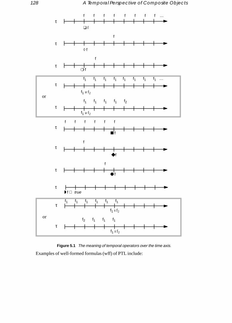
128 A Temporal Perspective of Composite Objects
f ff f f ff f …
Examples of well-formed formulas (wff) of PTL include:
❑ f
◊ f
f
❍ f
f
■ f
f ff f ff
◆ f
f
● f
f
f1 s f2
f2 f1 f1f1
◗ f ⇔ true
f1 u f2
f1 f1f1 f1τ
τ
τ
τ
τ
τ
τ
τ
τ
f1 u f2
f1 f1f1 f1 f2τ
f1 s f2
f1 f1f1 f1 f1f1τ
f1 f1f1 f1 …
or
or
Figure 5.1 The meaning of temporal operators over the time axis.

Propositional Temporal Logic 129
❑ ((p ∧ q) ∨ r)
d
mean-bilityTo be
❑ (p ⇒ ◆ q)
❍ (r U (p ∧ q))
The first wff says that in all time-points eitherp andq are satisfied orr is satisfied. Thesecond wff says that for any time-pointtp in whichp is satisfied,q must have been satisfiein some time-pointt, t ≤ tp. The last wff says that from the next time-pointtnext eitherr issatisfied for all time-pointst ≥ tnext or there exists a time-point tp ∧ q, tp ∧ q ≥ tnext, whereq ∧ p is satisfied and for allt, tnext ≤ t < tp ∧ q, r is satisfied.
5.2.2 Semantics of PTL
The time-varying truth value assignment of atomic propositions and the time-based ing attributed to temporal operators leads to a definition of the notion of satisfiawhere the truth or falsity of PTL formulas is evaluated over sequences of worlds. more precise, letσ = w0, w1, w2, w3, … be an infinite sequence of worlds, eachwi ∈ W be-ing an element of the powerset2P, W the set of all worlds andP the set of atomic proposi-tions.
The satisfiability of a formulaf in a world wi ∈ W of a sequenceσ is denoted by(σ, wi) f and can be deduced by the following rules:
(σ, wi) p iff p ∈ wi(σ, wi) p iff p ∉ wi(σ, wi) f1 ∧ f2 iff ( σ, wi) f1 and (σ, wi) f2(σ, wi) f1 ∨ f2 iff ( σ, wi) f1 or (σ, wi) f2(σ, wi) ¬f1 iff not (σ, wi) f1(σ, wi) f1⇒ f2 iff ( σ, wi) (¬f1) ∧ f2(σ, wi) f1⇔ f2 iff ( σ, wi) (f1 ⇒ f2) ∧ (f2⇒ f1)(σ, wi) ❑ f1 iff ∀ j, j ≥ i, (σ, wj) f1(σ, wi) ◊ f1 iff ∃ j, j ≥ i, (σ, wj) f1(σ, wi) ❍ f1 iff ( σ, wi+1) f1(σ, wi) f1 U f2 iff either ∀ j, j ≥ i, (σ, wj) f1
or ∃ j, j ≥ i, (σ, wj) f2 and∀ k, i ≤ k < j, (σ, wk) f1(σ, wi) ■ f1 iff ∀ j, 0 ≤ j ≤ i, (σ, wj) f1(σ, wi) ◆ f1 iff ∃ j, 0 ≤ j ≤ i, (σ, wj) f1(σ, wi) ● f1 iff i > 0 and (σ,wi-1) f1(σ, wi) ◗ f1 iff i > 0 and (σ,wi-1) f1 or i = 0(σ, wi) f1 S f2 iff either ∀ j, 0 ≤ j ≤ i, (σ, wj) f1
or ∃ j, 0 ≤ j ≤ i, (σ, wj) f2 and∀ k, j < k ≤ i, (σ, wk) f1A formula f is initially satisfied or simplysatisfied by a sequenceσ iff (σ, w0) f. A
formulaf issatisfiable iff there exists a sequence satisfyingf. Such a sequence is amodelof f. A formula isvalid iff it is satisfiable by all possible sequences.

130 A Temporal Perspective of Composite Objects
In order to check the satisfiability of PTL formulas we can use one of the tableau-based
d-
bility
odes-
ous
e
iss aretops.s-
s that
htenat-
fy
e thatdges
rmulaode.
ode.
sat-
algorithms presented in [2] [16] or [17]. Such algorithms we will callsatisfiability algo-rithms. The algorithm takes as input a formulaF and outputs a graph representing all moels satisfyingF. Such a graph we will call asatisfiability graph. If F is not satisfiable thealgorithm signals that it is unable to produce a graph.
The main idea of the algorithm presented in [2] consists of building up the satisfiagraph in the following way. Start with an initial node labelled with the input formulaF. Forthe initial node and all other nodes the following procedure is applied until no more nremain unprocessed. The formula labelling a nodeN is decomposed into disjunctive normal form, each disjunct being of the form:
current-instant-formula ∧ ❍ next-instant-formula ∧ ● previous-instant-formula
The previous-instant-formula specifies what should have been verified the previtime-point. For any nodeN´ from which an edge points toN, the formula labellingN´should satisfyprevious-instant-formula. Otherwise nodeN and all edges pointing toNshould be deleted. Thenext-instant-formula specifies what should be verified the next timpoint. LetN´´ be the node labelled withnext-instant-formula. If there exists no node labelledwith next-instant-formula then a new node N´´ is created with labelnext-instant-formula. Thenan edge fromN to N´´ labelled withcurrent-instant-formula is introduced in the graph. Thecurrent-instant-formula specifies what should be verified the current time-point andalways a formula of PL. Thus edges are labelled with formulas of PL while nodelabelled with formulas of PTL. The following remark ensures that the process sWhen transforming a formulaf into disjunctive normal form, each conjunct within a dijunct is a conjunction of either subformulas off or negated subformulas off. Thus the max-imum number of nodes that possibly will be generated equals the number of formulaare conjunctions of either subformulas ofF or negated subformulas ofF.
Given a satisfiability graph corresponding to a formulaF, a possible modelµ of F isidentified by traversing the graph. Initiallyµ is empty. Starting at the initial node, eactime an edge is traversed, a world satisfying the formula labelling that edge is concaed to the sequence of worlds forming the modelµ. In general, several worlds may satisa formula but a single world should be chosen to be concatenated inµ. In other words, aformula labelling an edge identifies a worldwi of some modelµ. The formula labellingeach node identifies the rest of the sequence of worlds ofµ, that iswi+1, wi+2, … Note thatthe graph produced from the satisfiability algorithm may not be minimal in the sensthe models of the input formula could be identified with a graph with less nodes and e.
The satisfiability graph corresponding to the formula❑ ((p ∧ q) ⇒ ❍ r) is shown in fig-ure 5.2. Each node is divided into two parts: the lower part of the node contains the foin disjunctive normal form equivalent to the formula labelling the upper part of the nThe node drawn with a thick line is the initial node. Note that thecurrent-instant-formula ismissing from the second disjunct of the formula labelling the lower part of the initial nIn such cases any non-contradictory PL formula can be taken as thecurrent-instant-formula.We use the symbol⊥ to denote any non-contradictory PL formula. The various worlds isfying the formulas labelling the edges of the satisfiability graph are:

Propositional Temporal Logic 131
s hav-
fyset of
[{ p}, { q}, { r}, { p, r}, { q, r}] satisfy the formula¬ (p ∧ q),[{ r}, { p, r}, { q, r}, { p, q, r}] satisfy the formular,[{ r}, { p, r}, { q, r}] satisfy the formula¬ (p ∧ q) ∧ r,
[{ p}, { q}, { r}, { p, q}, { p, r}, { q, r}, { p, q, r}] satisfy ⊥Each world is represented by enclosing within curly brackets the atomic propositioning truth valuetrue and assuming that all other propositions have truth valuefalse.
Figure 5.3 shows three sequences of worlds relative to the formula❑ ((p ∧ q) ⇒ ❍ r).Sequences (a) and (b) satisfy the formula❑ ((p ∧ q) ⇒ ❍ r). Sequence (c) does not satis❑ ((p ∧ q) ⇒ ❍ r). The world which causes the sequence to be excluded from the models of❑ ((p ∧ q) ⇒ ❍ r) is the third one in which the atomic propositionr is not satis-fied while in the previous world the formula (p ∧ q) was satisfied.
¬ (p ∧ q)
❑ ((p ∧ q) ⇒ ❍ r) ❑ ((p ∧ q) ⇒ ❍ r) ∧ r
⊥
¬ (p ∧ q) ∧ r
r
[¬(p ∧ q) ∧ ❍ ❑ (¬(p ∧ q) ∨ ❍ r)] ∨[❍ r ∧ ❍ ❑ (¬(p ∧ q) ∨ ❍ r)]
[r ∧ ¬(p ∧ q) ∧ ❍ ❑ (¬(p ∧ q) ∨ ❍ r)] ∨[r ∧ ❍ r ∧ ❍ ❑ (¬(p ∧ q) ∨ ❍ r)]
Figure 5.2 Satisfiability graph corresponding to the formula ❑ ((p ∧ q) ⇒ ❍ r).
{p, q}
{p, q, r}
{r}
{r, q} {r}
{r}
{p, q}
{r}
{p, q}
{p, q, r} {r}
{r} {q, r}
{p, r} {p, r} {q, r}
{p, q}
{p, q, r}
{p}
{r, q} {r}
{r} {p, q}
(a)
(b)
(c)
Figure 5.3 Sequences (a) and (b) satisfy ❑((p ∧ q) ⇒ ❍r);Sequence (c) does not satisfy ❑((p ∧ q) ⇒ ❍r)).

132 A Temporal Perspective of Composite Objects
5.3 The Specification of Temporal Properties
Each the
objectnt from
the re- to theate, a or somee vari-
rt of]. Werestedat the
men-ts ofposite
mong
tems:s. To
ing
ra-
ply as-e, in a
d at-
In TSOM objects are intended for modelling the various entities of an application. object is associated with a unique object identifier (oid) permitting one to identifyobject independently of its behaviour and the values of its instance variables. An communicates with other objects by sending and receiving messages. Messages sean object (sender) to another object (receiver) may be interpreted as requests forceiver to perform some task or simply as requests to send back some informationsender. The reaction of the receiver may result in a modification of its internal stnumber of messages being sent to other objects, the return of a value to the sender,combination of the above cases. The internal state of an object stored in its instancables and how it reacts to messages is assumed to be hidden from other objects.
Although we qualify TSOM as object-oriented, the notion of inheritance is not pait. TSOM is the object-based part of the specification model presented in [2] and [3shall not discuss any further the absence of inheritance in TSOM. However, the intereader is referred to [2] where the notions of role and role playing can replace, specification level, the notion of inheritance.
We distinguish betweenelementary objects andcomposite objects. The difference be-tween the two kinds of objects lies in the definition of their structural aspects. An eletary object is defined independently of other objects. A composite object consisreferences to one or several elementary objects or composite objects. When a comobjecto references an objectz we say thatz is acomponent of o. Note that a compositeobject is not the exclusive owner of its components. A component may be shared aseveral composite objects.
Objects are instantiated from classes. A class definition comprises the following i• Public messages, which can be sent to and received from an instance of the clas
indicate whether a message is to be sent to (incoming message) or received from (out-going message) an instance, the message identifier is suffixed with a left← orright → arrow respectively. In an object-oriented system, the effect of an incommessage defined in a classC would be implemented by an operation defined inC. Theeffect of an outgoing messagemsg of C is expected to be implemented by an opetion defined in another classC´. The definition ofmsg as outgoing message inC sim-ply affirms that an instance ofC will send messagemsg to an instance ofC´.
• Attributes of an instanceo store values representing either abstract states or simcharacteristic aspects whicho wishes advertise to other objects. Each attribute issociated with a finite domain from which it can be assigned values. For examplclassCAR two attributes can be defined,speed andengine_status with associated do-mains {stopped, moving_slowly, moving_fast} and {turned_on, turned_off} respectively.
• Public constraints describe the set of legal sequences of public messages antribute-value assignments.
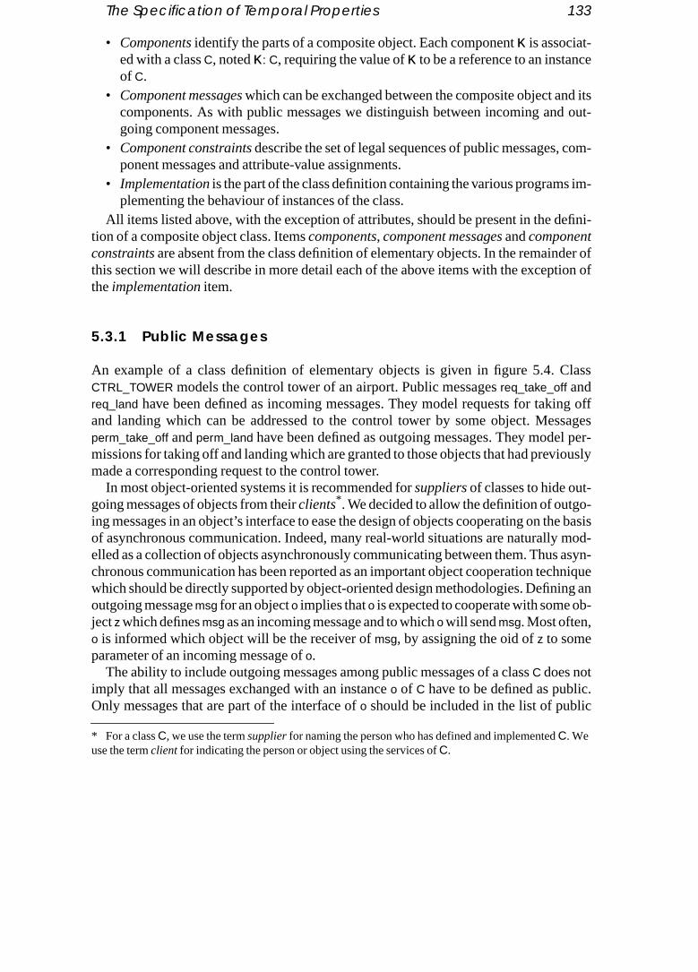
The Specification of Temporal Properties 133
• Components identify the parts of a composite object. Each componentκ is associat-e
d its out-
com-
im-
efini-
der ofion of
lass
ing offsages
l per-iously
-he basis mod- asyn-hnique
ing anb-
.c
ed with a classC, notedκ: C, requiring the value ofκ to be a reference to an instancof C.
• Component messages which can be exchanged between the composite object ancomponents. As with public messages we distinguish between incoming andgoing component messages.
• Component constraints describe the set of legal sequences of public messages, ponent messages and attribute-value assignments.
• Implementationis the part of the class definition containing the various programsplementing the behaviour of instances of the class.
All items listed above, with the exception of attributes, should be present in the dtion of a composite object class. Items components, component messages andcomponentconstraints are absent from the class definition of elementary objects. In the remainthis section we will describe in more detail each of the above items with the excepttheimplementation item.
5.3.1 Public Messages
An example of a class definition of elementary objects is given in figure 5.4. CCTRL_TOWER models the control tower of an airport. Public messagesreq_take_off andreq_land have been defined as incoming messages. They model requests for takand landing which can be addressed to the control tower by some object. Mesperm_take_off andperm_land have been defined as outgoing messages. They modemissions for taking off and landing which are granted to those objects that had prevmade a corresponding request to the control tower.
In most object-oriented systems it is recommended forsuppliers of classes to hide out-going messages of objects from theirclients* . We decided to allow the definition of outgoing messages in an object’s interface to ease the design of objects cooperating on tof asynchronous communication. Indeed, many real-world situations are naturallyelled as a collection of objects asynchronously communicating between them. Thuschronous communication has been reported as an important object cooperation tecwhich should be directly supported by object-oriented design methodologies. Definoutgoing messagemsg for an objecto implies thato is expected to cooperate with some ojectz which definesmsg as an incoming message and to whicho will sendmsg. Most often,o is informed which object will be the receiver ofmsg, by assigning the oid ofz to someparameter of an incoming message ofo.
The ability to include outgoing messages among public messages of a classC does notimply that all messages exchanged with an instanceo of C have to be defined as publicOnly messages that are part of the interface ofo should be included in the list of publi
* For a classC, we use the termsupplier for naming the person who has defined and implementedC. Weuse the termclient for indicating the person or object using the services ofC.

134 A Temporal Perspective of Composite Objects
aven has
lass
g PTL.
tweeneithere two
is de-
t a timence ofunsat-
messages. For example, assuming thato is an instance ofCTRL_TOWER, the four publicmessages defined in classCTRL_TOWER are all meaningful for clients ofo. The imple-mentation ofo could use a hidden component,plane_list, having the functionality of typeLIST. The usefulness ofplane_list would be to represent the list of aeroplanes that hmade a request for taking off or landing and for which the corresponding permissionot been yet granted. In contrast with the collection of public messages ofCTRL_TOWER,messages exchanged betweeno andplane_list, like insert_into_list anddelete_from_list, aremeaningless for clients ofo and should not appear in the list of public messages of cCTRL_TOWER.
5.3.2 Public Constraints
Public constraints associated with a class are specified in a language resemblinMore precisely, for a classC, we associate with each public messagep an atomic proposi-tionp in PTL. We model the fact that a public incoming (outgoing) messagep is sent to (re-ceived from) an instance ofC at time-pointt by associating witht a world wherep issatisfied. Mapping messages to atomic propositions implies that the distinction beincoming and outgoing messages is essentially informative for the user since it is ncaptured nor enforced in PTL. However, the relevance for distinguishing between thkinds of messages will be fully appreciated when the notion of composite object scribed in detail.
Concerning the specification of constraints we assume that only one message acan be sent to or received from an object. In other words, in each world of a sequeworlds we require that exactly one atomic proposition is satisfied and all others are
class CTRL_TOWER {public messages
req_take_off ←, req_land ←,perm_take_off →, perm_land →
public constraintsreq_take_off ∨ req_land;❑ (req_take_off ⇒ (◊ perm_take_off));❑ (req_land ⇒ (◊ perm_land));
implementationreq_take_off (perm_receiver: oid, …){ … };req_land (perm_receiver: oid, …){ … };…
}
Figure 5.4 Class CTRL_TOWER modelling the lifecycle of a control tower of an airport.

The Specification of Temporal Properties 135
t is
-
er
poral
rateened
ofnders PTL ande arempositeith the
spec-
he re-sage
isfied. Assuming thatn messagesmsgi are defined in a class, the above requiremenexpressed in PTL with the formula:
Public constraints defined in classCTRL_TOWER (figure 5.4) formally describe the behaviour of a control tower. Leto be an instance ofCTRL_TOWER. The first constraint saysthat the first message to be sent too must be eitherreq_take_off or req_land. The secondconstraint says that whenever messagereq_take_off is sent too, then sometime in the futuremessageperm_take_off will be received from o. The last constraint says that whenevmessagereq_land is sent too, then sometime in the future messageperm_land will be re-ceived from o. Figure 5.5 shows two sequences of public messages satisfying the temconstraints defined in classCTRL_TOWER.
Class CTRL_TOWER constitutes an example of a class definition expecting to coopewith its clients on the basis of asynchronous communication. Indeed, an instanco ofCTRL_TOWER will send messageperm_land to those objects whose oid has been assigto some parameter, e.g.perm_receiver, of the incoming messagereq_land. Similarly, theparameter perm_receiver of req_take_off will be used for determining the receivers perm_take_off messages. Note, however, that the above relationships involving seand receivers of messages, and parameters of messages cannot be described intherefore they cannot be explicitly specified in the constraint definition language wproposing. They have to be annotated as comments. Nevertheless, in the case of coobjects (see below), messages exchanged with internal components are prefixed widentifier of the involved component, thus allowing at least some form of constraint ification on internal messages.
Whether public constraints associated with a class are or are not violated is tsponsibility of both the supplier and the client. For example, not receiving mesperm_take_off from an instanceCTRL_TOWER after having sent messagereq_take_off is the
❑ ((∨ msgk) ∧ ( ∧ ¬(msgi ∧ msgj))1 ≤ k ≤ n 1 ≤ i ≠ j ≤ n
perm_take_off
req_take_off
req_land
perm_land perm_take_off
perm_land
(a)
(b)
req_take_off
req_land
req_land
perm_land
req_take_off
perm_take_off
Figure 5.5 Sequences of public and state messages relative to the class CTRL_TOWER.
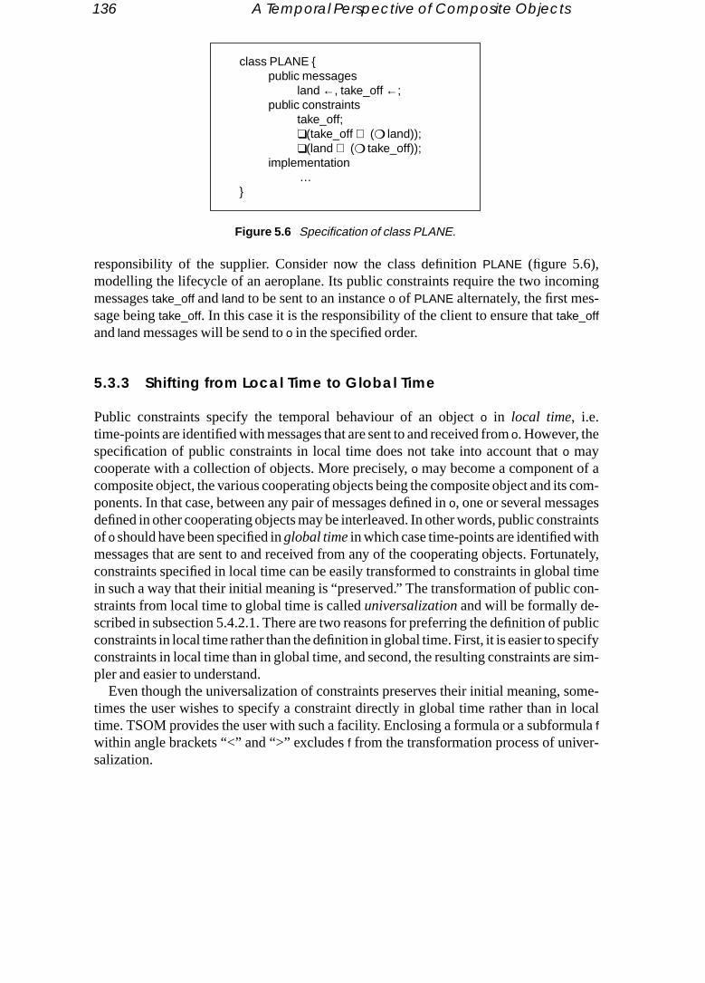
136 A Temporal Perspective of Composite Objects
ming
as com-straintshnately,l timecon-
publicecifye sim-
ome- localula
r-
responsibility of the supplier. Consider now the class definitionPLANE (figure 5.6),modelling the lifecycle of an aeroplane. Its public constraints require the two incomessagestake_off and land to be sent to an instanceo of PLANE alternately, the first mes-sage beingtake_off. In this case it is the responsibility of the client to ensure thattake_offand land messages will be send too in the specified order.
5.3.3 Shifting from Local Time to Global Time
Public constraints specify the temporal behaviour of an objecto in local time, i.e.time-points are identified with messages that are sent to and received fromo. However, thespecification of public constraints in local time does not take into account thato maycooperate with a collection of objects. More precisely,o may become a component of composite object, the various cooperating objects being the composite object and itponents. In that case, between any pair of messages defined ino, one or several messagedefined in other cooperating objects may be interleaved. In other words, public consof o should have been specified inglobal time in which case time-points are identified witmessages that are sent to and received from any of the cooperating objects. Fortuconstraints specified in local time can be easily transformed to constraints in globain such a way that their initial meaning is “preserved.” The transformation of public straints from local time to global time is calleduniversalization and will be formally de-scribed in subsection 5.4.2.1. There are two reasons for preferring the definition of constraints in local time rather than the definition in global time. First, it is easier to spconstraints in local time than in global time, and second, the resulting constraints arpler and easier to understand.
Even though the universalization of constraints preserves their initial meaning, stimes the user wishes to specify a constraint directly in global time rather than intime. TSOM provides the user with such a facility. Enclosing a formula or a subformfwithin angle brackets “<” and “>” excludesf from the transformation process of univesalization.
class PLANE {public messages
land ←, take_off ←;public constraints
take_off;❑(take_off ⇒ (❍ land));❑(land ⇒ (❍ take_off));
implementation …
}
Figure 5.6 Specification of class PLANE.

The Specification of Temporal Properties 137
cility con-
res
alized
-
dabil-en weertaken
ute
Let us elucidate with an example of both the usefulness for providing the above faand the meaning of “preserves” in the definition of universalization. Consider thestraint❑ (p ⇒ ❍ q) defined in a classC requiring every messagep to beimmediately fol-lowed by messageq. The universalization of the above constraint would require aftep,the next messageamong those defined inC to beq, yet permitting zero or more messagmsgi to be interleaved betweenp andq, provided that messagesmsgi have not been definedin C. Thus when specifying a formula❑ (p ⇒ ❍ q) in public constraints, its meaning inglobal time would be the second one, i.e. the meaning corresponding to its universversion. However, specifying the constraint❑ <(p ⇒ ❍ q)> will ensure,even in globaltime, that every messagep beimmediately followed by messageq, without allowing anymessage be interleaved betweenp andq.
5.3.4 Attributes
Figure 5.7 presents a more elaborate version of the classPLANE presented in subsection5.3.2 (figure 5.6). Its definition includes an attributepl_status with associated domain {op-erational, maintenance}. Value maintenance is assigned topl_status during a maintenanceperiod for the aeroplane. Valueoperational assigned topl_status indicates that the aeroplane can travel.
The main reason for providing attributes in class definitions is to enhance the reaity of constraints and ease their specification. Indeed, attributes are very useful whwant to express the fact that one or several actions on a particular object can be unddepending on the current values of one or several attributes of that object.
Let o be an instance ofPLANE. The first of the public constraints says that the attribpl_status should be assigned either the valueoperational or the valuemaintenance* . The sec-ond constraint says that whenevero receives messagetake_off the value ofpl_status should
class PLANE {attributes
pl_status: {operational, maintenance};public messages
land ←, take_off ←;public constraints
pl_status := (operational ∨ maintenance);❑(take_off ⇒ ((pl_status == operational) ∧ ❍ land));❑(land ⇒ (● take_off ∧ ❍ ((pl_status := maintenance) ∨ take_off)));❑((pl_status == maintenance) ⇒ (❍ (pl_status := operational)));
implementation …
}
Figure 5.7 Enhanced version of class definition PLANE.

138 A Temporal Perspective of Composite Objects
beoperational and the next message to be sent too should beland. The third constraint says
eriod.
te with
s atort-
t
der andtwo ob-definedm-
he class. The
plane
a
thato may receive messageland if the previous message received istake_off. In addition,whenever messageland is received, then either the next message to be sent too should betake_off or the attributepl_status should be assigned the valuemaintenance. In other words,after a flight the aeroplane can either continue travelling or begin a maintenance pThe last constraint says that if the value of attributepl_status ismaintenance, then the nextaction should be the assignment of valueoperational topl_status.
In order to treat attributes and messages within the same framework we associaeach valueval belonging in the domain of attributeat a messageassign_at_val. Let us callthese messages assignment messages. Sending the assignment messageassign_at_val toan objecto models the assignment of valueval to the attributeat of o. Thus, whenever anassignment of the format := val appears within constraint definitions, it is intended ashorthand for the assignment message identifierassign_at_val. In addition, whenever a tesequality of the format == vali appears within constraint definitions it is intended as a shhand for the formula
where {val1, …, valn} is supposed to be the domain associated withat. This expresses thaat a given instant the current value of attributeat isvali.
What differentiates an assignment message from a public message is that the senreceiver of an assignment message should be the same object. It is not possible for jects to exchange any assignment message, which implies that values of attributes in an objecto can only be updated byo itself. Attribute-value updates constitute an exaple where the supplier of a classC is responsible for providing an implementation ofC thatsatisfies the temporal order of attribute assignment defined inC’s public constraints.
Figure 5.8 shows two sequences of public and assignment messages relative to tPLANE. The first is a legal sequence satisfying the temporal constraints in figure 5.7second is an illegal sequence since messagetake_off follows the assignment of valuemain-tenance to attributepl_status thus violating the second and fourth public constraints.
5.3.5 Components
An example of a class definition of a composite object modelling the flight of an aerois given in figure 5.9. Class FLIGHT contains three components:pl, ctt andctl. Componentpl is constrained to be assigned an instance ofPLANE modelling the aeroplane making trip. Componentsctt andctl are constrained to be assigned instances ofCTRL_TOWER.
* If y is an attribute with associated domain {x1, …,xn} theny := (x1 ∨ … ∨ xk) with k ≤ n is a shorthand fory := x1 ∨ … ∨ y := xk andy == (x1 ∨ … ∨ xk) with k ≤ n is a shorthand fory == x1 ∨ … ∨ y == xk
“ :=” is used for assigning a value to an attribute“==” is the test-equal-value operator
(◆ assign_at_vali) ∧ (¬ (∨ assign_at_valj) S assign_at_vali)1 ≤ i ≠ j ≤ n

The Specification of Temporal Properties 139
es off
ts,- a mes-es
-ublicment.nt of thes; theylf and
trol tow-
edc-et
They represent the control towers of airports from which the plane respectively takand lands.
Even though an objectw may be a shared component of several composite objecw
cannot be referenced from two different componentsκ1 andκ2 of the same composite object. Indeed, PTL does not permit us to distinguish whether the sender or receiver ofsage referenced by componentsκ1 andκ2 is the same object or not. Thus TSOM assumthat different components of a composite object reference distinct objects.
Let us call theenvironment of a composite objecto the set of all objects existing at a given point in time excludingo and its components. Public messages, attributes and pconstraints are considered to be the interface of a composite object for its environPublic messages are exchanged between the composite object and the environmecomposite object. Public constraints may not contain component message identifierdescribe the behaviour of a composite object as if the communication between itseits components has been filtered out. For example, an instanceo of FLIGHT may receivemessagesstart_flight anddispl_report from its environment. The effect of thestart_flight
message would be to set up a cooperation between the aeroplane and the two coners necessary for an aeroplane to make a trip. The effect of thedispl_report message wouldbe to display a complete report once the flight has been completed. Messagesstart_flight
anddispl_report can be sent too depending on the current abstract state ofo. Domain valuesof attributefl_status model the various abstract states ofo, which are:comp_pb when thereis a problem encountered with some ofo’s components and the flight cannot be carriout;ready when there is no problem with any ofo’s components and the coordination proess between components can be started;started when the plane has taken off but not ylanded;completed when the plane has landed.
take_off land take_off land landtake_off
take_off land take_off
(a)
(b)
assign_pl_status_
assign_pl_status_
operational
operational
assign_pl_status_maintenance
Figure 5.8 Sequences of public and state messages relative to the class PLANE((a) legal sequence; (b) illegal sequence).

140 A Temporal Perspective of Composite Objects
onents.isthexam-
-
5.3.6 Component Messages
Component messages are exchanged between the composite object and its compThe definition of each component messagemsg should indicate the component which the sender or receiver ofmsg. This is achieved by prefixing the message identifier with component identifier and separating the two identifiers with the character “$”. For eple, the definition of component messagectt$req_take_off means that message req_take_off
can be sent from an instance ofFLIGHT to componentctt. In addition, assuming the component definitionκ: C, each incoming (outgoing) component messageκ$msg, shouldmatch an outgoing (incoming) public messagemsg defined in classC. For example, for thedefinition of the incoming component messagectl$perm_land ← in classFLIGHT, the
class FLIGHT {attributes
fl_status: {comp_pb, ready, started, completed};public messages
start_flight ←, displ_report ←public constraints
fl_status := (ready ∨ comp_pb)❑ (start_flight ⇒
[(fl_status == ready) ∧ ❍ ((fl_status := started) ∧ ((fl_status == started) U (fl_status := completed)))]);
❑ (displ_report ⇒ (fl_status == completed));❑ ((fl_status == (completed ∨ pl_maintenance)) ⇒
¬ (fl_status := (started ∨ comp_pb ∨ ready ∨ completed)));components
ctt: CTRL_TOWER;ctl: CTRL_TOWER;pl: PLANE;
component messagesctt$req_take_off →, ctt$perm_take_off ←,ctl$req_land →, ctl$perm_land ←,pl$take_off →, pl$land →;
component constraints…
implementationperm_take_off(sender: oid, …){ … };perm_land(sender: oid, …){ … };…
}
Figure 5.9 Class FLIGHT modelling the flight of an aeroplane.
The Specification of Temporal Properties 141
outgoing messageperm_land → should appear in the list of public messages of class
ndn to the com- pa-
nt
sages
x-
ssages the en-ject isnts ofus thatcies in-ed withmuni-
ge
- com- topositeessage
CTRL_TOWER.Implementing a component incoming messageκ$msg would require certifying that the
sender ofmsg isκ, therefore necessitating a comparison between the sender’s oid aκ’soid. However, in most object-oriented systems, the sender of a message is not knowreceiver of the message. A simple solution for identifying the sender of an incomingponent messageκ$msg ← would be the assignment of the sender’s oid to a particularrameter ofmsg. In particular, for any outgoing public messagemsg defined in a classC, itwould be a good practice to anticipate a parameter for the sender ofmsg. Indeed, a com-ponent definitionκ: C in a classCC enables the definition of the incoming componemessageκ$msg ←. The implementation ofmsg in CC needs the oid of the sender ofmsg.An example of the above strategy is illustrated with the implementation of mesperm_take_off and perm_land in class FLIGHT (Figure 5.9). Messageperm_take_off(perm_land) uses the parametersender for identifying the sender of the message while epecting instances ofCTRL_TOWER to assign their oid tosender when sendingperm_take_off (perm_land).
5.3.7 Component Constraints
Component constraints specify the legal sequences of public and component meexchanged between the composite object, components of the composite object andvironment of the composite object. For all component messages the composite obinvolved either as sender or receiver. A direct communication between two componea composite object cannot be defined. From the above restriction it becomes obvioa composite object acts as a coordinator for its components. Temporal dependenvolving different components must be described by means of messages exchangthe composite object. Component constraints in figure 5.10 describing the comcation between an instanceo of FLIGHT ando’s componentspl, ctl andctt, constitute anexample of such a dependency.
The first component constraint requires attributefl_status to be initialized either withvalueready or pl_maintenance depending on the value assigned to the attribute pl_status ofcomponent pl. More precisely, fl_status will be initialized to ready (comp_pb) if pl_status isassigned valueoperational (maintenance). The second constraint says that messastart_flight may be sent too if the current value offl_status is ready. In addition, ifstart_flightis sent too then the next instant component messagereq_take_off should be sent to componentctt from the composite object. The purpose of the communication between theposite object and componentctt is to grant permission to take off. Once the permissiontake off is granted, the command to take off for the aeroplane is issued from the comobject. This is expressed by the third component constraint. It says that whenever mperm_take_off is received from componentctt, then the next message to be sent istake_offwith sender the composite object and receiverpl. In addition, attributefl_status is assignedvaluestarted immediately after messagepl$take_off has been sent topl. The fourth and fifth

142 A Temporal Perspective of Composite Objects
ite ob-es-
t mes-
. In
hat
nentite ob-ust beg thepo-
aints
d
bjects.
component constraints specify an analogous communication between the composject and componentctl. More precisely, the fourth constraint requires that component msagereq_land to be sent toctl sometime in the future after the value offl_status is started.The fifth constraint specifies that once the permission to land is granted (componensageperm_land is sent to the composite object from componentctl), the command to land(component messagepl$land) for the aeroplane is issued from the composite objectaddition, for indicating that the aeroplane has landed the valuecompleted is assigned toattributefl_status. The sixth constraint says that messagedisp_report may be sent too if thecurrent value offl_status is completed. Finally, the last component constraint ensures toncefl_status has been assigned one of the valuescomp_pb or completed it cannot be laterupdated.
Let us now clarify the rationale for introducing both public constraints and compoconstraints in composite object class definitions. To test consistency of a composject’s specification, the specification of the temporal behaviour of its components mtaken into account. As we will describe in the next section, this is achieved by testinsatisfiability of the logical conjunction of public constraints of components and comnent constraints of the composite object. Taking the conjunction of public constrwithout regard to component constraints of a componentv of a composite objecto permitsirrelevant details of the eventual composition ofv from other objects to be abstracteaway. Ifo is in turn a component of a composite objectz, the satisfiability of the conjunc-tion of component constraints ofz and public constraints ofo should be tested in order toconfirm either the consistency or inconsistency ofz’s specifications.
Figure 5.11 depicts the use of public and component constraints for composing oOvals represent class definitions. An edge labelledκ connecting a classC with a classC´
class FLIGHT {...
component constraints((pl$pl_status == operational) ⇒ (fl_status := ready)) ∧
((¬ (pl$pl_status == operational)) ⇒ (fl_status := comp_pb));
❑ (start_flight ⇒ ((fl_status == ready) ∧ ❍ ctt$req_take_off));❑ (ctt$perm_take_off ⇒ ❍ (pl$take_off ∧ ❍ (fl_status := started)));
❑ ((fl_status == started) ⇒ ◊ ctl$req_land)));❑ (ctl$perm_land ⇒ ❍ (pl$land ∧ ❍ (fl_status := completed)));
❑ (displ_report ⇒ (fl_status == completed));❑ ((fl_status == (completed ∨ pl_maintenance)) ⇒
¬ (fl_status := (started ∨ comp_pb ∨ ready ∨ completed)));…
}
Figure 5.10 Component constraints of class FLIGHT.

The Specification of Temporal Properties 143
f
ints ofhat for
inatedn
indicates that componentκ: C´ is defined within the definition ofC. For classC4 the con-junction of component constraints ofC4 with public constraints of classesC1, C2 andC3should be made. Then for the composition ofC6 the conjunction of public constraints oclasses ofC4 andC5 with the component constraints ofC6 should be made.
The above schema of object composition requires public and component constrathe same object to be related by some compatibility rule. In fact, we must ensure tany sequenceσ satisfying component constraints there exists a sequenceσ´ of public mes-sages satisfying public constraints such that when component messages are elimfromσ we get a sequence identical toσ´. We will call the above compatibility rule betweecomponent constraints and public constraints of the same composite object thecorre-
Component constraints
Public constraints Public constraints Public constraints
Public constraints
C1 C2 C3
C4
C5
C6
... ... ...
. . .
κ4κ5
κ1 κ2 κ3
Component constraintsPublic constraints
Component constraintsPublic constraints
C4 composition =
C6 composition = public-constraints-C 4 ∧
public-constraints-C 5
component-constraints-C 6 ∧
public-constraints-C 1 ∧
public-constraints-C 2 ∧ public-constraints-C 3
component-constraints-C 4 ∧
Figure 5.11 Using public and component constraints to compose objects.

144 A Temporal Perspective of Composite Objects
spondence property. The correspondence property requires us to verify the validity of the
ne orages. Inlocalositentified
con-
d,
es- intect its more
).
formula:component constraints ⇒ universalized public constraints
The universalization of public constraints is necessary for taking into account that oseveral component messages can be interleaved between any pair of public messother words the universalization of public constraints corresponds to a shift from time to global time. In this case time-points in local time are identified with the compobject’s public and assignment messages whereas time-points in global time are idewith the composite object’s component, public, and assignment messages.
5.4 Verification
To verify the consistency of object specifications we make the following assumptionscerning the object model of TSOM. Each classC owns an infinite number of oids. An oido becomes an instance ofC when it receives the predefined messagecreate_C. An instanceo of C is deleted wheno receives the predefined messagedelete_C. The deletion ofo ismodelled by restrictingo to only be able to acceptdelete_C messages.
5.4.1 Verification of Elementary Objects
The consistency of a class definitionC, from which elementary objects are instantiatecan be verified by giving as input to the satisfiability algorithm the formula:
(¬ (delete_C ∨ m1 ∨ … ∨ mn) U create_C) ∧ (4.1)❑ (create_C ⇒ ❍ public_constraint_C) ∧ (4.2)
❑ (create_C ⇒ (❍ ❑ ¬ create_C)) ∧ (4.3)❑ (delete_C ⇒ ❍ delete_C) (4.4)
In the previous formulam1, …, mn is assumed to be the set of public and assignment msages defined inC* . public_constraint_C stands for the conjunction of constraints definedclassC. Conjunct (4.1) says that no public message nor thedelete_C message can be sento an object prior to its creation. Conjunct (4.2) says that after the creation of an objpublic constraints must be verified. Conjunct (4.3) forbids an object to be createdthan once. Finally conjunct (4.4) ensures that after accepting adelete_C message, an ob-ject will then only be able to accept furtherdelete_C messages.
For a classC we will nameLCpublic_C† the conjunction of (4.1), (4.2), (4.3) and (4.4The output of the satisfiability algorithm corresponding to the formulaLCpublic_C deter-mines the consistency ofC. If no graph is produced, the definition ofC is inconsistent. If asatisfiability graph is produced, the definition ofC is consistent. This satisfiability graph
* Assignment messages are indirectly defined via attribute definitions.† LCpublic stands for lifecycle according to public constraints.

Verification 145
e sent to
situa-pond-ints.
s. Ther part
ed to
-
o-
then represents all legal sequences of public and assignment messages that can band received from an instance ofC.
5.4.2 Verification of Composite Objects
To describe the verification of a composite object’s specification let us assume thetion presented in figure 5.12. An object is depicted by a rectangle. A rectangle corresing to an elementary object is labelled with a formula describing its public constraRectangles corresponding to composite objects are divided into two horizontal partupper part is used for listing the public constraints of the composite object. The loweis used for listing the list of component messages and component constraints.
A grey arrow connecting two rectangles is drawn when the two objects are assumexchange messages. A black arrow connecting two rectanglesx andy, leavingx and lead-ing toy, is drawn wheny is a component ofx. Thusco in figure 5.12 is assumed to be a composite object having two componentsχ andξ. Let componentsχ andξ be assignedinstances of classesC1 andC2 respectively.co is assumed to be an instance ofCC.
Component constraints ofco say that the first message to be sent toco must be the publicmessagestart. Immediately after the reception ofstart, messages p andq should be sent tocomponentsχ andξ alternately, starting with ap message. Public constraints of compnents are very simple. Componentχ expects always to receive messagep. Componentξexpects always to receive either messageq or messager.
❑ p
❑ (q ∨ r)
component messagesco: CC
χ: C1
ξ: C2
Environment of co
…
component constraints start ∧ ❍ (χ$p ∧ ❑ ((χ$p ∧ ❍ ξ$q) ∨ (ξ$q ∧ ❍ χ$p)))
χ$p, ξ$q
Figure 5.12 A composite object and component specifications.

146 A Temporal Perspective of Composite Objects
The basic idea for testing the consistency of a composite object’s specification is to giveents’
ts
sagesn-
he last
t
erelyenefitxity
g sit-
t-
ld
en as ad-t of the
as input to the satisfiability algorithm the conjunction of the object’s and its componspecifications. If a class definitionCC contains the definitions of componentsκi: Ci,i = 1, …, n, the input to the satisfiability algorithm would be the formula:
LCpublic_C1 ∧ … ∧ LCpublic_Cn ∧ LCcomponent_CC ∧ (4.5)(¬ create_CC U create_C1) ∧ … ∧ (¬ create_CC U create_Cn) ∧ (4.6)
❑ (¬ (s1 ∨ … ∨ sj)) (4.7)ConjunctsLCpublic_C1, …, LCpublic_Cn specify lifecycles corresponding to componenκi: Ci, i = 1, …, n, respectively. ConjunctLCcomponent_CC* specifies the lifecycle of thecomposite object and stands for the formula:
(¬ (delete_C ∨ m1 ∨ … ∨ mn) U create_CC) ∧❑ (create_CC ⇒ ❍ component_constraint_CC) ∧
❑ (create_CC ⇒ (❍ ❑ ¬ create_CC)) ∧❑ (delete_CC ⇒ ❍ delete_CC) ∧
wherem1, …, mn is assumed to be the list of public, assignment and component mesdefined inCC andcomponent_constraint_CC stands for the conjunction of component costraints defined inCC. Conjuncts¬ create_CC U create_Ci, i = 1, …, n, say that all compo-nents must have been created before the creation of the composite object. Tconjunct says that component messages not defined inCC cannot be exchanged. Thus,si,i = 1, …, j, are all such messages identifiers of the formκ$msg such that the componendefinition κ: C appears inCC, msg is a public message defined inC and κ$msg does notappear in the list of component messages ofCC.
The constraint on component creation we have expressed with conjunct (4.6) is mintroduced for expository reasons. Its omission would not represent any significant bfor the description of object lifecycles at the specification level but additional complefor the various formulas formalizing the notions we are proposing. Indeed, modellinuations where an objectz could be created either before or after a composite objecto andthenz be assigned to a component ofo requires the introduction of lengthy and complicaed formulas.
For the composite objectco in figure 5.12, the input to the satisfiability algorithm woube the formula:
LCpublic_C1 ∧ LCpublic_C2 ∧ LCcomponent_CC ∧ (4.8)(¬ create_CC U create_C1) ∧ (¬ create_CC U create_C2) ∧ (4.9)
❑ (¬ ξ$r) (4.10)ConjunctsLCpublic_C1, LCpublic_C2 andLCcomponent_CC correspond to componentsχ,ξ and to the composite objectco respectively.
However, the conjunctions of formulas (4.5), (4.6) and (4.7) cannot be directly givinput to the satisfiability algorithm. A number of transformations must be applied invance. The rationale for these transformations and their exact nature is the subjec
* LCcomponent stands for lifecycle according to component constraints.

Verification 147
following subsections. The various transformations can be carried out automatically,
ject’sbilityall legalthe com-t of the
ed on
ject and
e
n-
t
the
ed
meaning that the whole verification process can be automated.The output of the algorithm will determine the consistency of the composite ob
specification. If no graph is produced, the specification is inconsistent. If a satisfiagraph is produced, the specification is consistent. The graph produced represents sequences of public, assignment and component messages exchanged between posite object, the various components of the composite object and the environmencomposite object.
5.4.2.1 Transformations on Component DefinitionsIn this subsection we describe the various transformations that should be performconjunctsLCpublic_C1, …, LCpublic_Cn of formula (4.5).
Message Renaming
To achieve the matching between component messages defined for a composite obpublic messages of componentκ: Ci each messagemsg appearing within conjunctLCpublic_Ci of (4.5) should be renamedκ$msg. Thus, if a class specification contains thcomponent definitionsκ1: C andκ2: C (i.e. both componentsκ1 andκ2 are associatedwith the same classC), the component which is the sender or receiver ofmsg can be distin-guished sincemsg is renamed eitherκ1$msg or κ2$msg. The formula resulting from thattransformation will be namedκ$LCpublic_Ci. For example, according to the public costraints of componentχ in figure 5.12,χ$LCpublic_C1 stands for the formula:
(¬ (χ$delete_C1 ∨ χ$p) U χ$create_C1) ∧❑ (χ$create_C1 ⇒ ❍ ❑ χ$p) ∧
❑ (χ$create_C1 ⇒ (❍ ❑ ¬ χ$create_C1)) ∧❑ (χ$delete_C1 ⇒ ❍ χ$delete_C1)
Sharing Components
To take into account that componentκ: Ci may be shared between the composite objec co
and the environment ofco, each messageκ$msg within the conjunctκ$LCpublic_Ci,should be replaced by the formula:
κ$msg ∨ env$κ$msg (4.11)Messages exchanged between a component and the environment (namedenvironmentmessages) are prefixed with “env$”. Messages exchanged between a component andcomposite object are not renamed. Replacing a messageκ$msg with the formula (4.11)implies that the sender or receiver of a messagemsg could be eitherco or an object fromthe environment ofco. The resulting formula from that transformation is namenv$κ$LCpublic_Ci.
For example, for componentχ in figure 5.12, env$χ$LCpublic_C1 would stand for theformula:

148 A Temporal Perspective of Composite Objects
(¬ (χ$delete_C1 ∨ env$χ$delete_C1 ∨ χ$p ∨ env$χ$p) U env$χ$create_C1) ∧
ore onlye send-essage
othe
ects.
sts of
❑ (env$χ$create_C1 ⇒ ❍ ❑ (χ$p ∨ env$χ$p)) ∧❑ (env$χ$create_C1 ⇒ (❍ ❑ ¬ env$χ$create_C1)) ∧
❑ ((χ$delete_C1 ∨ env$χ$delete_C1) ⇒ ❍ (χ$delete_C1 ∨ env$χ$delete_C1))Recall that assignment messages cannot be exchanged between objects. Theref
environment-assignment messages can exist since a composite object cannot be ther of an assignment message to any of its components. Thus, any assignment mκ$msg should be simply renamedenv$κ$msg. In addition, the composite object cannsend a creation message to a componentκ: C, since components should exist before tcreation of the composite object. Therefore anyκ$create_C must be simply renamedenv$κ$create_C.
Universalization of Public Constraints of Components
Let us assume thatm1, …, mn is the collection of public messages defined in a classC andthat κ: C is a component definition appearing in a class definition for composite objThen we introduce the following shorthand expressions:
public_msg_C ≡ m1 ∨ … ∨ mn ∨ delete_Cκ$public_msg_C ≡ κ$m1 ∨ … ∨ κ$mn ∨ κ$delete_Cenv$κ$public_msg_C ≡ env$κ$m1 ∨ … ∨ env$κ$mn ∨ env$κ$delete_Cκ$env_pub_msg_C ≡ κ$public_msg ∨ env$κ$public_msg ∨ κ$create_C
The rationale for the universalization of conjunctenv$κ$LCpublic_C corresponding tocomponentκ: C has been described in subsection 5.3.1. The universalization consithe following transformations:
replace p by ¬ κ$env_pub_msg_C U preplace ❍ f by ¬ κ$env_pub_msg_C U (κ$env_pub_msg_C ∧ ❍ f)replace ● f by ¬ κ$env_pub_msg_C S (κ$env_pub_msg_C ∧ ● f)
wherep is an atomic proposition andf a wff of PTL appearing withinenv$κ$LCpublic_C.Applying the universalization ofenv$χ$LCpublic_C1 we will obtain the following for-
mula:
(¬((¬ χ$env_pub_msg_C1 U(χ$delete_C1 ∨ env$χ$delete_C1 ∨ χ$p ∨ env$χ$p)) U
(¬ χ$env_pub_msg_C1 U env$χ$create_C1)) ∧❑ (¬ χ$env_pub_msg_C1 U env$χ$create_C1 ⇒
(¬ χ$env_pub_msg_C1 U(χ$env_pub_msg_C1 ∧
❍ ❑ (¬ χ$env_pub_msg_C1 U (χ$p ∨ env$χ$p))))) ∧❑ (¬ χ$env_pub_msg_C1 U env$χ$create_C1 ⇒
(¬ χ$env_pub_msg_C1 U(χ$env_pub_msg_C1 ∧
❍ ❑ (¬ χ$env_pub_msg_C1 U ¬ env$χ$create_C1)))) ∧

Verification 149
❑ ((¬ χ$env_pub_msg_C1 U (χ$delete_C1 ∨ env$χ$delete_C1)) ⇒
s
- pair ofer the
ndencew-
idity of
(¬ χ$env_pub_msg_C1 U(χ$env_pub_msg_C1 ∧
❍ (¬ χ$env_pub_msg_C1 U (χ$delete_C1 ∨ env$χ$delete_C1))))))In the above formula we have used the equivalence:
f U (f1 ∨ f2) ⇔ (f U f1) ∨ (f U f2)
while χ$env_pub_msg_C1 is the shorthand for the formula:χ$delete_C1 ∨ env$χ$delete_C1 ∨ χ$p ∨ env$χ$p ∨ env$χ$create_C1
5.4.2.2 Universalization of Component Constraints of CompositeObjects
Let us assume thatq1, …, qp are the various component messages defined in a clasCC.Then we introduce the following shorthand expressions:
component_msg_CC ≡ q1 ∨ … ∨ qpmsg_CC ≡ public_msg_CC ∨ component_msg_CC ∨ create_CCThe universalization of conjunctLCcomponent_CC in (4.5) is required to take into ac
count that one or several environment messages may be interleaved between acomponent, assignment or public messages in which the composite object is eithsender or the receiver. The universalization ofLCcomponent_CC consists of the followingtransformations:
replace p by ¬ msg_CC U preplace ❍ f by ¬ msg_CC U (msg_CC ∧ ❍ f)replace ● f by ¬ msg_CC S (msg_CC ∧ ● f)
wherep is an atomic proposition andf a wff of PTL appearing withinLCcomponent_CC.
5.4.2.3 Verification of the Correspondence PropertyAccording to the shorthand expressions we have already introduced, the correspoproperty for a classCC for composite objects is easily formalized by requiring the folloing formula to be valid:
component_constraint_CC ⇒ (universalization of public_constraint_CC)
The universalization ofpublic_constraint_CC consists of the following transformations:replace p by ¬ public_msg_CC U preplace ❍ f by ¬ public_msg_CC U (public_msg_CC ∧ ❍ f)replace ● f by ¬ public_msg_CC S (public_msg_CC ∧ ● f)
wherep is an atomic proposition andf a wff of PTL appearing withinpublic_constraint_CC.As an example consider a composite object for which one public messagep and one
component messageκ$q have been defined, the formula❑ p being its public constraintand the formula
❑ ((p ∧ ❍ κ$q) ∨ (κ$q ∧ ❍ p))
its component constraint. The correspondence property requires us to test the valthe formula:
150 A Temporal Perspective of Composite Objects
❑ ((p ∧ ❍ κ$q) ∨ (κ$q ∧ ❍ p)) ⇒ ❑ (¬ p U p)
eri-
poral tem- con-een as if thecribed on the
en thetionsject ing thees-
ss
PTLiesationelling
ur ap-itrarye nest-ompo-e facttroduce Final- In ourtions.
se-aints.st andSOM
ves forg the
Using the satisfiability algorithm of PTL, the validity of the above formula is easily vfied.
5.5 Concluding Remarks
We have presented a formal approach, founded on PTL, for the description of temaspects of an object’s behaviour and its composition with other objects. An object’sporal properties are specified by means of a collection of component and publicstraints. The former specify the temporal order of messages exchanged betwcomposite object and its components. The latter specify the behaviour of an object acommunication between it and its internal components has been filtered out. We desan automated procedure for verifying the consistency of object specifications basedsatisfiability algorithm of PTL.
A significant source of influence for the various ideas we have presented has bework of Manna and Wolper who investigated the composition of synchronized collecof concurrent processes [17]. For Manna and Wolper a process specification (an obour approach) consists of a collection of PTL formulas (public constraints) describintemporal order of its input/output communication operations (incoming/outgoing msages). The consistency of a concurrent system consisting of a synchronizer proceS (acomposite object) communicating with a collection of processesPi, 1 ≤ i ≤ n (componentsof a composite object), is verified by giving as input to the satisfiability algorithm of the composition ofS andPi specifications. Even though one may find strong similaritconcerning both the behaviour specification of a process (object) and the verificprocedure for consistency, the two approaches are characterized by different modprerequisites and divergent objectives. An important prerequisite emphasized in oproach is the ability of specifying composite objects having a nested structure of arbdepth (composite objects having components that are other composite objects). Thed structure of composite objects necessitated the distinction between public and cnent constraints and the validation of the correspondence property. In addition, ththat an object may be a shared component of several composite objects led us to in“env” messages. None of the above modelling issues have been investigated in [17].ly, there is an important distinction concerning the objectives of the two approaches.approach we ended up with a procedure for verifying an object’s temporal specificaIn [17] the satisfiability graph corresponding to the composition ofS andPi specificationsis further used for deriving the synchronization parts of code ofS and thePi’s. More pre-cisely, for each process,Pi andS, Manna and Wolper derive from the set of all possible quences of communication operations a subset which satisfies the specified constr
Several improvements can be envisaged for TSOM along various directions. Firforemost, there is a need for providing the specifier with assistance for translating Tspecifications into some object-oriented language. Assessing the various alternatiproviding higher-level assistance than that of guidelines, we ended up investigatin

References 151
eventuality of enriching an existing object-oriented language with constructs that wouldrt thefor ob-pects ofscrip- is dif-d foring ob-.vingponws ex-
g thecifica-atingow-
iencye thether
esis
r Ev-
tation-
chro-
directly support most of the notions integrated in TSOM. Further evidence to suppovalidity of this approach is given by Nierstrasz (see chapter 4). There, a type system ject-oriented languages is proposed which enables users to describe temporal asobject behaviour and provides rules for analyzing the type-consistency of such detions. Even though the formalism upon which that type system has been developedferent from PTL, it is likely that most of the ideas and results could also be appliePTL. Thus, the proposed type system could serve as the starting point for enhancject-oriented languages with constructs directly supporting most of TSOM’s notions
Another important direction along which additional efforts are necessary for improTSOM concerns the verification procedure. The satisfiability algorithm of PTL, uwhich the verification procedure is based, may generate a number of nodes that groponentially with the number of temporal operators of the input formula. By operatinalgorithm the way we have described, i.e. applying the algorithm to each object spetion separately and not to the composition of all constraints of those objects participin a whole part-of hierarchy, the size of input formulas is considerably minimized. Hever, the exponential nature of the satisfiability algorithm still remains a serious effichandicap for its computer implementation. Restricted forms of PTL may reducnumber of nodes of the satisfiability algorithm to polynomial size [10]. However, whesuch restrictions of PTL are still suitable for TSOM remains to be investigated.
References
[1] Constantin Arapis, “Temporal Specifications of Object Interactions,”Proceedings Third Internation-al Workshop on Foundations of Models and Languages for Data and Objects, Aigen, Austria, Sept.1991, pp. 15–35.
[2] Constantin Arapis, “Dynamic Evolution of Object Behaviour and Object Cooperation,” Ph.D. thno 2529, Centre Universitaire d’Informatique, University of Geneva, 1992.
[3] Constantin Arapis, “A Temporal Logic Based Approach for the Description of Object Behaviouolution,” Journal of Annals of Mathematics and Artificial Intelligence, vol. 7, 1993, pp. 1–40.
[4] Grady Booch,Object-Oriented Design with Applications, Benjamin/Cummings, 1991.
[5] Peter Coad and Edward Yourdon,Object-Oriented Analysis, 2nd edn., Prentice-Hall, EnglewoodCliffs, 1991.
[6] Peter Coad and Edward Yourdon,Object-Oriented Design, Prentice Hall, Englewood Cliffs, 1991.
[7] Brad Cox,Object-Oriented Programming An Evolutionary Approach, Addison Wesley, Reading,Mass., 1987.
[8] Vicki De Mey, Betty Junod, Serge Renfer, Marc Stadelmann and Ino Simitsek, “The Implemenof Vista — A Visual Scripting Tool,” inObject Composition, ed. Dennis Tsichritzis, Centre Universitaire d’Informatique, University of Geneva, June 1991, pp. 31–56.
[9] Allen Emerson and Edmund Clarke, “Using Branching Time Temporal Logic to Synthesize Synnization Skeletons,”Science of Computer Programming, vol. 2, 1982, pp. 241–266.
[10] Allen Emerson, Tom Sadler and Jai Srinivasan, “Efficient Temporal Reasoning,”Proceedings 16thACM Symposium on Principles of Programming Languages,1989, pp. 166–178.

152 A Temporal Perspective of Composite Objects
[11] Dov Gabbay, Amir Pnueli, Saharon Shelah and Jonathan Stavi, “On the Temporal Analysis of Fair-
Com-
c
Ap-i-
tation
ness,”Proceedings 7th ACM Symposium on Principles of Programming Languages,1980, pp. 163–173.
[12] Adele Goldberg and David Robson,Smalltalk-80: The Language and its Implementation, Addison-Wesley, Reading, Mass., 1983.
[13] David Harel, “On Visual Formalisms,”Communications of the ACM, vol. 31, no. 5, May 1988, pp.514–530.
[14] Richard Helm, Ian Holland and Dipayan Gangopadhyay, “Contracts: Specifying Behavioural positions in Object-Oriented Systems,”Proceedings of the ECOOP/OOPSLA Conference,Ottawa,Oct. 1990, pp. 169–180.
[15] Ivar Jacobson,Object-Oriented Software Engineering, Addison-Wesley, Reading, Mass., 1992.
[16] Orna Lichtenstein and Amir Pnueli, “The Glory of The Past,”Proceedings of the Workshop on Logiof Programs, Brooklyn, Lecture Notes in Computer Science, vol. 193, Springer-Verlag, 1985, pp. 97–107.
[17] Zohar Manna and Pierre Wolper, “Synthesis of Communicating Process,”ACM Transactions on Pro-gramming Languages and Systems,vol. 6, no. 1, June 1984, pp. 68–93.
[18] Bertrand Meyer,Object-oriented Software Construction, Prentice Hall, 1988.
[19] Oscar Nierstrasz, Dennis Tsichritzis, Vicki De Mey and Marc Stadelmann, “Objects + Scripts =plications,” inObject Composition, ed. Dennis Tsichritzis, Centre Universitaire d’Informatique, Unversity of Geneva, June 1991, pp. 11–29.
[20] James Rumbaugh, M. Blaha, W. Premerlani, F. Eddy and W. Lorensen,Object-Oriented Modelingand Design, Prentice Hall, 1991.
[21] Sally Shlaer and Stephen Mellor,OBJECT LIFECYCLES: Modeling the World in States, PrenticeHall, Englewood Cliffs, NJ, 1992.
[22] Bjarne Stroustrup,The C++ Programming Language, Addison-Wesley, Reading, Mass., 1986.
[23] Anthony Wassermann, P. Pircher and R. Muller, “The Object-Oriented Structured Design Nofor Software Design Representation,”IEEE Computer, vol. 23, no. 3, March 1990, pp. 50–63.
[24] Rebecca Wirfs-Brock, Brian Wilkerson and Laurent Wiener,Designing Object-Oriented Software,Prentice Hall, Englewood Cliffs, NJ, 1990.

Chapter 6
ming cannot
ed by-
Functions, Records andCompatibility in the λNCalculus
Laurent Dami
Abstract Subtyping, a fundamental notion for software reusability, establishes aclassification of data according to a compatibility relationship. This relationship isusually associated with records. However, compatibility can be defined in othersituations, involving for example enumerated types or concrete data types. Weargue that the basic requirement for supporting compatibility is an interactionprotocol between software components using names instead of positions.Based on this principle, an extension of the lambda calculus is proposed, whichcombines de Bruijn indices with names. In the extended calculus varioussubtyping situations mentioned above can be modelled; in particular, recordsare encoded in a straightforward way. Compatibility is formally defined in termsof an operational lattice based on observation of error generation. Unlike manyusual orderings, errors are not identified with divergence; as a matter of fact,both are even opposite since they respectively correspond to the bottom andtop elements of the lattice. Finally, we briefly explore a second extension of thecalculus, providing meet and join operators through a simple operationaldefinition, and opening interesting perspectives for type checking andconcurrency.
6.1 Introduction
The lambda calculus is a widely used tool for studying the semantics of programlanguages. However, there are at least two categories of programming features thatbe modelled in the lambda calculus. One isconcurrent programming, in which the non-determinism introduced by operations taking place in parallel cannot be capturlambda expressions. The other issubtyping, which plays a prominent role in object

154 Functions, Records and Compatibility in the λN Calculus
oriented systems, and is interesting for software reuse in general. Subtyping is based on aid for
pera-lculus
ose ans —atibil-
ly due;tend- valid
i- be anycord
ters;
trac--com-onlyncod-
make
classification of data according to collections of valid operations; an operation valone type is also valid for its subtypes. The termplug compatibility is sometimes used toexpress this relationship. In the lambda calculus, functional application is the only otion, and provides no support for such a classification. Therefore, the lambda camust be extended to deal with subtyping: the common approach is to userecords [9][10].In this paper we argue that subtyping does not reduce to record systems. We propextended lambda calculusλN (lambda calculus with names) which can encode recordand therefore objects as well — but is more general since it also supports plug compity on enumerated types and concrete data types.
Our calculus is based on the observation that reusability in record systems is mainto the use ofnames for accessing fields, instead ofpositionsin simple Cartesian productsthe difference is important when considering extensibility. A product type can be exed in one direction, by adding a new component in the last position: any projectionsfor the original product are still valid for the extended product. In that view, the type(Int ×Int) can be seen as a supertype of(Int × Int× Colour) . However, this ordering based on postions can only have a tree structure. By contrast, an ordering based on names canpartial order. A well-known example is the ordering of various types of points in a resystem:
Like Cartesian products, functions use positional information to identify paramethis is the basis for thecurrying property, which allows any function ofn arguments to beencoded as a hierarchy ofn lambda abstractions, with one single argument at each abstion level. However, functions cannot be ordered in a tree structure: there is no plugpatibility relationship between a function with three arguments and a function with two arguments. This can be illustrated with a simple example: consider the Church eing of Booleans and thenot function in standardλ calculus[5]:
True = λt.λf.tFalse = λt.λf.fNot = λb.λt.λf.b f t
and imagine we now want a three-valued logic, with anunknown value. We must add anew argument, and everything has to be recoded:
TrueU = λt.λf.λu.tFalseU = λt.λf.λu.fUnknownU= λt.λf.λu.uNotU = λb.λt.λf.λu.b f t u
The new encoding is incompatible with the previous one. In particular, it does not sense to applyNotU to True: it can only be applied toTrueU. In a software reusability per-
2DPoint = (x: Int; y: Int)
3DPoint = (x: Int; y: Int; z: Int) 2DColouredPoint = (x: Int; y: Int; c: Colour)
3DColouredPoint = (x: Int; y: Int; z: Int; c: Colour)
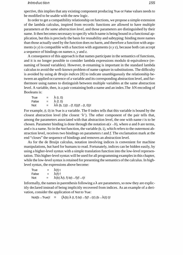
Introduction 155
spective, this implies that any existing component producingTrue orFalse values needs to
nsionltipleeirnal ap-ames argu-t
ctions,
dacultye-nd fur-raction
thet,
-
inesily, bysen-pter, high-
ic-deri-
be modified to be usable with the new logic.In order to get a compatibility relationship on functions, we propose a simple exte
of the lambda calculus, inspired from records: functions are allowed to have muparametersat the same abstraction level, and those parameters are distinguished by thname. It then becomes necessary to specify which name is being bound in a functioplication, but this is precisely the basis for reusability and subtyping: binding more nthan those actually used by the function does no harm, and therefore a function withments (x y) is compatible with a function with arguments (x y z), because both can accepa sequence of bindings on namesx, yandz.
A consequence of this approach is that names participate in the semantics of funand it is no longer possible to consider lambda expressions moduloα-equivalence (re-naming of bound variables). However,α-renaming is important in the standard lambcalculus to avoid the well-known problem of name capture in substitutions. The diffiis avoided by usingde Bruijn indices [8] to indicate unambiguously the relationship btween an applied occurrence of a variable and its corresponding abstraction level, athermore using names to distinguish between multiple variables at the same abstlevel. A variable, then, is a pair containing both a name and an index.TheλN encoding ofBooleans is:
True = λ (t, 0)False = λ (f, 0)Not = λλ (b, 1)(t→(f, 0))(f→(t, 0))!
For example,(t, 0) in True is a variable. The 0 index tells that this variable is bound byclosest abstraction level (the closest ‘λ’). The other component of the pair tells thaamong the parameters associated with that abstraction level, the one with namet is to bechosen. Parameter binding is done through the notationa(x→b), wherea andb are terms,andx is a name. So in theNot function, the variable(b, 1), which refers to the outermost abstraction level, receives two bindings on parameterst andf. The exclamation mark at theend “closes” the sequence of bindings and removes an abstraction level.
As for the de Bruijn calculus, notation involving indices is convenient for machmanipulations, but hard for humans to read. Fortunately, indices can be hidden eausing a higher-level syntax with a simple translation function into the low-level repretation. This higher-level syntax will be used for all programming examples in this chawhile the low-level syntax is retained for presenting the semantics of the calculus. Inlevel syntax, the expressions above become:
True = λ(t) tFalse = λ(f) fNot = λ(b) λ(t, f) b(t→f)(f→t)!
Informally, the names in parenthesis following aλ are parameters, so now they are explitly declared instead of being implicitly recovered from indices. As an example of a vation, consider the application ofNot toTrue:
Not(b→True)! = (λ(b) λ (t, f) b(t→f)(f→t)!) (b→λ(t) t)!

156 Functions, Records and Compatibility in the λN Calculus
The outermost binding onb is reduced, substituting the internal reference tob byTrue, and
no
logic,
and
g was
con-
ress ace that otherro-
occur-
removingb from the parameter list:(λ() λ(t, f) (λ(t) t)(t→f)(f→t)!)!
Then, by reducing the outermost ‘!’, one abstraction level (one ‘λ’) is removed:λ(t, f) (λ(t) t)(t→f)(f→t)!
The binding ont substitutest by f and removest from the parameter list:λ(t, f) (λ() f)(f→t)!
The binding onf is simply dropped, because the abstraction to which it is applied hasfparameter:
λ(t, f) (λ() f)!
Finally, one ‘λ’ is removed because of the ‘!’:λ(t, f) f
and although this final result declares botht andf as parameters instead of onlyf, it isequivalent toFalse, because its translation into low-level syntax with indices is also λ(f, 0).
Now the interesting point about this calculus is that, in order to get an augmentedwe just write:
Unknown = λ(u) uNotU = λ(b) λ(t f u) b(t→f)(f→t)(u→u)!
Not is recoded (which is normal), but we can keep the original encodings ofTrue andFalse.This cannot be done in the standard lambda calculus, and is interesting forreusability: anyother module based on the original encoding is still compatible with our new logicdoes not need modification.
To the best of our knowledge, the idea of using names in a lambda calculus settinnot studied much in the literature. Two related systems are John Lamping’sunified systemof parameterization [19] and Garrigue and Aït-Kaci’slabel-selective lambda calculus[3][16]. However, both calculi treat names (or “labels”) and variables as orthogonalcepts, whereas we unify them through the use of de Bruijn indices.
6.2 A Lambda Calculus with Named Parameters
It is well known that names in the standard lambda calculus are only useful to exprelationship between binding occurrences and applied occurrences of variables. Onrelationship is established, i.e. with bound variables, names can be replaced bynames throughα substitution, or can even be removed altogether: in [8] de Bruijn pposed a modified lambda calculus in which variables are simply denoted byindices.A deBruijn index is a non-negative integer expressing the distance between an appliedrence of a variable and the abstraction level to which it refers. For example, thenot func-tion, written
Not = λb.λt.λf.b f t

A Lambda Calculus with Named Parameters 157
e dif-a ex-
rther-jn isre re- thetension
of
ders: theomes
n can name.fevels.incehem is
in the standard calculus, becomesNot = λλλ 2 0 1
in de Bruijn notation (here we start indices with 0, while some authors start with 1; thference is not significant). There is a straightforward translation from usual lambdpressions to their de Bruijn version. The de Bruijn notation provides acanonicalrepresentation: allα-equivalent lambda expressions have the same translation. Fumore, the well-known problem ofname capture is avoided. Both in standard and de Bruicalculi, each abstraction level (each ‘λ’) introduces exactly one variable. Our proposalto allowseveral variables at the same abstraction level. To do so, de Bruijn indices atained, but in additionnames are used to distinguish between different variables atsame level. This section defines the calculus; the next section shows that this exprovides support for plug-compatibility.
6.2.1 Abstract (Low-level) Syntax
Figure 6.1 presents the abstract syntax ofλN. The language is built over a (finite) set names.
An abstraction corresponds to the traditional notion of abstraction. Like in theBruijn lambda calculus, abstractions need not introduce names for their parameteconnection between variables and their corresponding abstraction level directly cfrom the indices associated with variables (see below).
A variable is a name together with a de Bruijn index. This means that an abstractiohave several parameters, all with the same index, which are distinguished by theirThe index indicates the abstraction level (which ‘λ’) a variable is referring to: an index o0 refers to the closest abstraction, and higher numbers refer to farther abstraction l
A bind operation partly corresponds to the usual notion of application. However, san abstraction may have several parameters, it is necessary to specify which of tbound in the expression. Therefore the constructa(x->b) means: “bindb to the parameter
x, y, z∈ Namesi, j ∈ Nata, b, ...∈ Terms
a := λ a abstraction| (x, i) variable| a(x→b) bind operation| a! close operation
Figure 6.1 Abstract syntax.
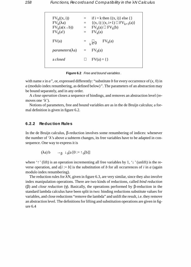
158 Functions, Records and Compatibility in the λN Calculus
ay
el (re-
; a for-
vern con-
lve
es formoven fig-
with namex in a” , or, expressed differently: “substituteb for every occurrence of (x, 0) ina (modulo index renumbering, as defined below)” . The parameters of an abstraction mbe bound separately, and in any order.
A close operation closes a sequence of bindings, and removes an abstraction levmoves one ‘λ’).
Notions of parameters, free and bound variables are as in the de Bruijn calculusmal definition is given in figure 6.2.
6.2.2 Reduction Rules
In the de Bruijn calculus,β-reduction involves some renumbering of indices: whenethe number of ‘λ’s above a subterm changes, its free variables have to be adapted isequence. One way to express it is
(λa) b →β ↓0[a [0 :=↑0[b]]
where ‘↑’ (lift) is an operation incrementing all free variables by 1,‘↓’ (unlift) is the re-verse operation, anda[i := b] is the substitution ofb for all occurrences ofi in a (againmodulo index renumbering).
The reduction rules forλN, given in figure 6.3, are very similar, since they also invoindex manipulation operations. There are two kinds of reductions, calledbind reduction(β) andclose reduction (γ). Basically, the operations performed byβ-reduction in thestandard lambda calculus have been split in two: binding reductions substitute valuvariables, and close reductions “remove the lambda” and unlift the result, i.e. they rean abstraction level. The definitions for lifting and substitution operations are given iure 6.4
FVk((x, i)) = if i = k then {(x, i)} else {}FVk(λa) = {(x, i) | (x, i+1)∈ FVk+1(a)}FVk(a(x→b)) = FVk(a)∪ FVk(b)FVk(a!) = FVk(a)
FV(a) = ∪k ≥ 0 FVk(a)
parameters(λa) = FV0(a)
aclosed ⇔ FV(a) = {}
Figure 6.2 Free and bound variables .

A Lambda Calculus with Named Parameters 159
n
atter ofs.ate lan-
se the done,ay that
Careful readers will have noticed that inλN we may need to unlift a 0 index, a situatiowhich never occurs in the de Bruijn calculus. Consider de Bruijn’sβ-reduction rule above:all 0 indices are substituted ina, so the expression passed to ‘↓’ contains no 0 index. Bycontrast, theλN expression(λ (x, 0))! reduces to↓0[ (x, 0) ], which intuitively correspondsto an error (we are trying to access a parameter that has not been bound). As a mfact, in such situations the definition of ‘↓’ yields err, a specific term representing errorThis will be discussed in detail in section 6.4; for the time being it suffices to know therris not an additional syntactic construct, but rather is defined as a usual term in thguage, with the property that further binding or close operations onerr yielderr again.
A binding reduction can never introduce new parameters in an abstraction, becauterm passed in the substitution is lifted. Therefore if several successive bindings arethe final result does not depend on the order of the substitutions. This amounts to sbindings are commutative, i.e. expressions of the form
a(x→b)(y→c) and a(y→c)(x→b)derive to the same thing, provided thatx andy aredifferent names. If x andy are the same
(λa)(x→b) →β λ(a[(x, 0) : =↑0[b]])(λa)! →γ ↓0[a]
Figure 6.3 Reduction rules.
Lifting/Unlifting↑k[(x, i)] = if (i < k) then (x, i) else (x, i+1)↓k[(x, i)] = if (i < k) then (x, i) else if (i=k) thenerr else (x, i-1)
k [λa] = λ (k+1 [a])k [a(x→b)] = k [a](x→k [b])k [a!] = (k [a])! where‘’ is either‘↓’ or ‘↑’
err =def E(x→E)! whereE = λλ (x, 1)(x→(x, 1))!
Substitution(y, j)[(x, i) := b] = if ((x, i) = (y,j)) then b else (y, j)(λa) [(x, i) := b] = λ(a[(x, i+1) :=↑0[b]])(a(y→c)) [(x, i) := b] = (a[(x, i) := b])(y→c[(x, i) := b])(a!)[(x, i) := b] = (a[(x, i) := b])!
Figure 6.4 Lifting and substitution operations.

160 Functions, Records and Compatibility in the λN Calculus
name, all references to that name are substituted in the first binding, so the second binding
es).eration
meter.he se-tould
nt fromessionthat re-
-
work, in
ionthis
is just ignored, and those bindings are not commutative.
6.2.3 Reduction Example
For illustrating the rules, we use again the expressionNot(b→True)!. The derivation wasgiven in an informal way in the introduction, using high-level syntax (without indicHere, the low-level syntax is used; at each step, the lambda and the bind or close opinvolved in the next reduction step are underlined.
1 (λλ (arg, 1) (true→(false, 0))(false→(true, 0))!)(arg→λ(true, 0))!2 (λλ (λ(true, 0))(true→(false, 0))(false→(true, 0))!) !3 λ (λ(true, 0))(true→(false, 0))(false→(true, 0))!4 λ (λ(false, 1))(false→(true, 0))!5 λ (λ(false, 1)) !6 λ (false, 0)
The final result isFalse. Notice at line 4 that the binding offalse simply gets eliminated:this is because the abstraction(λ(false, 1)) hasno parameter calledfalse; it indeed uses avariable with that name, but since the index is not 0 this is a free variable, not a para
At some intermediate stages (e.g. at line 2) several reductions could occur; tquence shown here corresponds tonormal-order reduction (choosing leftmost outermosredex first). It is therefore legitimate to ask whether a different reduction sequence wyield the same result (whether the language is confluent). The answer isyes, and has beenestablished in [13]. So, as in the standard lambda calculus, results are independethe reduction sequences through which they were obtained; furthermore, if an exprdoes have a result, then the normal-order reduction strategy is guaranteed to yield sult (i.e. not to diverge).
Notice that if we “forget” to supply an argument toNot before applying a close operation, as inNot!, we have the reduction
(λλ (arg, 1) (true→(false, 0))(false→(true, 0))!) !λ err (true→(false, 0))(false→(true, 0))!λ err (false→(true, 0))!λ err !λ err
which is equivalent toerr, i.e. an error is produced.
6.2.4 Higher-level Syntax
Indices were necessary for defining the calculus, but are difficult to read. In order topractically with the calculus, we will use a higher-level syntax, given in figure 6.5which the indices need not be explicitly written. There is a straightforward translatTfrom this syntax into the original syntax, which is formally defined in figure 6.6. In

A Lambda Calculus with Named Parameters 161
-losestveral ab-e nameslationr sev-owing
et (as-ith the
ardlationupdat-bles.
new notation, the parameters of an abstraction aredeclared as a list of names in parenthesis. A variable is written simply as a name: the index is recovered by looking for the cabstraction which declares the same name. In case the same name is used at sestraction levels, and one wants to override the default variable matching scheme, thof the variable can be preceded by a collection of backslashes. This tells the tranfunction to start looking for a declaration, not at the next abstraction level, but one oeral levels higher (according to the number of backslashes). The parameter list folla lambda can be empty, as in
λ() Not(arg→True)!
This is like a closure, i.e. a function that needs no arguments but is not evaluated ysuming a lazy interpretation as in section 6.4.1). Forcing evaluation is then done w‘!’ operator.
The translationT from this syntax into the original syntax is like translating the standlambda calculus into de Bruijn notation (see [12]). The first argument to the transfunction is a set of currently declared variables; at each abstraction level this set is ed. The translation is defined for closed terms by taking the initially empty set of variaVariables which are not declared at any level are translated into an error by thematchVarfunction. As an example of a translation, consider the expression
v := x simple variable| \v “outer” variable
a := λ(x1 … xn) a abstraction| v variable| a(x→b) bind operation| a! close operation
Figure 6.5 Higher-level syntax.
TV [λ(x1 … xn) a] = λ (TV' [a])where V' ={(x, i+1) | (x, i)∈ V} ∪ {(x1, 0), ..., (xn, 0)}
TV [\...\x ] = matchVarV (x, i) wherei is the number of‘\’TV [a(x→b)] = TV [a](x→ TV [b])TV [a!] = (TV [a])!matchVar V (x, i) = let J={j | (x, j)∈ V, j ≥ i} in
if (J = {}) then errelse (x,min (J))
Figure 6.6 Translation function.

162 Functions, Records and Compatibility in the λN Calculus
λ(x y) λ(x z) x + y + z + \x + \y + \z + \\x
ction
ith the
n-
in stringsc,hown tointo thedy, and
the lan- to givetheough
le arbi-
(assuming that infix addition is part of the language). After crossing the two abstralevels, the set V of declared variables is
V={(x, 1), (y, 1), (x, 0), (z, 0)}
and therefore the translation isλλ (x, 0) + (y, 1) + (z, 0) + (x, 1) + (y, 1) + err + err
This shows how the backslash can be used to distinguish between parameters wsame name, but at different levels. Notice thatx and \x are different variables, while bothy and \y are translated into (y, 1), because there is noy parameter at the inner abstractiolevel. Furthermore, both \z and \\x are translated intoerr, because no corresponding variable declaration can be found.
6.3 The Calculus at Work
In this section we show how several common programming constructs are encodedλN.To make the examples more appealing, we assume that integers, Booleans andhave been added to the language, with corresponding operations (integer arithmetiif ex-pression, etc.). Such extensions are common for the lambda calculus and can be sbe conservative, i.e. expressions in the extended language are always convertible original language. As a matter of fact, an encoding of Booleans has been seen alreaan encoding of integers is given in section 6.3.4. In consequence, the semantics of guage does not change. We start with a discussion on functions and recursion, justa clearer map of the relationship betweenλN and the standard lambda calculus. Then specificity ofλN, namely the encoding of extensible constructs, is demonstrated threnumerated types, concrete data types and records.
6.3.1 Functions
It can be seen easily thatλN contains the usual lambda calculus. Any expressioneof thepure lambda calculus can be encoded in a straightforward way, by choosing a singtrary name (sayarg) to be associated with variables:
• Take the de Bruijn encoding ofe.• Replace every application MN by M(arg→N)!, i.e. a binding ofarg immediately fol-
lowed by a close operation.• Replace every variablei by (arg , i).
For example, the lambda expression λf x y. f(x + y) has de Bruijn encoding λλλ 2(1+0) andbecomes here
λλλ(arg, 2)(arg→(arg, 1)+(arg, 0))!
which corresponds to

The Calculus at Work 163
λ(arg) λ(arg) λ(arg) \\arg(arg→\arg+arg)!
ound argu-on, theyinternall, as wepoly-
bind-ich im-nt andl func-
as. Thehoicesus ex-
b-on.
r
ar: an
ed type
in the higher-level notation. Now how does this compare to the expression:λ(f x y) f(arg→(x+y))!
which intuitively seems more natural? In both formulations, the arguments can be band the final result evaluated. The difference appears with partial bindings. Whenments are declared at the same abstraction level, as we do in the second formulatican be bound separately, in any order, and even if all arguments are supplied, the expression is not evaluated until a close operation takes place. This can be usefuwill see later, for building lazy data structures. Furthermore, such functions are morphic, in the sense that any context which binds more arguments than justf, xandy willaccept this abstraction without generating an error. However, if we want to do partialings, leaving the other arguments open, the close operation cannot be inserted, whplies that we lose the currying property, i.e. the possibility to bind one single argumeget in return another function over the remaining arguments. This is because usuational application corresponds here to a bindingand a close operation. When writing function, there is therefore a choice to make about how to organize its argumentmethodological issues involved in such choices have not been explored yet. Our cin the coming examples are guided by some heuristics acquired during our varioperiences in using the system.
6.3.2 Recursion
A fixed-point operation over a functionalλ(x)a yields a recursive function, as in the lamda calculus; however, the namex must be taken into account in the fixed-point operatiSo for each namex we define a corresponding fixed-point operator
Yx = λ(x) (λ(x) \x(x→x(x→x)!)!)(x→ (λ(x) \x(x→x(x→x)!)!))!
This is like the usual combinator Y, specialized to bind namex. It can be checked that fof=λ(x)a we have
Yx(x→f)! →* f(x→Yx(x→f)!)!
In order to facilitate such recursive definitions we introduce some syntactic sugexpression with recursion over parameterx is writtenµ(x)a and is translated into
Yx(x→λ(x)a)!
With this extension we can write Factorial = µ(f) λ(arg) if (arg > 1) then arg*f(arg→(arg-1))! else 1
6.3.3 Extensible Enumerated Types and Case Selection
We already have seen an encoding of Boolean values, which is a simple enumeratwith two values. The approach can be generalized ton-ary enumerated types:
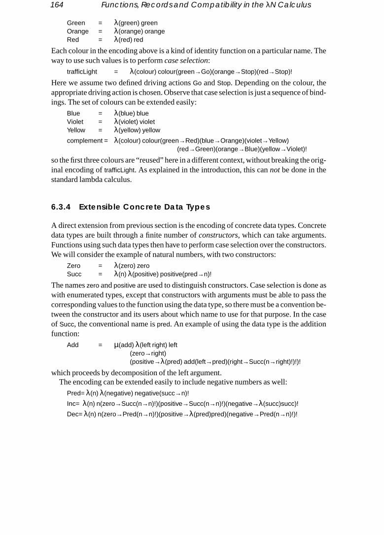
164 Functions, Records and Compatibility in the λN Calculus
Green = λ(green) green
. The
of bind-
orig-
ncrete.ructors.
ne asass thetion be-he caseon
Orange = λ(orange) orangeRed = λ(red) red
Each colour in the encoding above is a kind of identity function on a particular nameway to use such values is to performcase selection:
trafficLight = λ(colour) colour(green→Go)(orange→Stop)(red→Stop)!
Here we assume two defined driving actionsGo andStop. Depending on the colour, theappropriate driving action is chosen. Observe that case selection is just a sequence ings. The set of colours can be extended easily:
Blue = λ(blue) blueViolet = λ(violet) violetYellow = λ(yellow) yellow
complement = λ(colour) colour(green→Red)(blue→Orange)(violet→Yellow)(red→Green)(orange→Blue)(yellow→Violet)!
so the first three colours are “reused” here in a different context, without breaking theinal encoding oftrafficLight. As explained in the introduction, this cannot be done in thestandard lambda calculus.
6.3.4 Extensible Concrete Data Types
A direct extension from previous section is the encoding of concrete data types. Codata types are built through a finite number ofconstructors, which can take argumentsFunctions using such data types then have to perform case selection over the constWe will consider the example of natural numbers, with two constructors:
Zero = λ(zero) zeroSucc = λ(n) λ(positive) positive(pred→n)!
The nameszero andpositive are used to distinguish constructors. Case selection is dowith enumerated types, except that constructors with arguments must be able to pcorresponding values to the function using the data type, so there must be a conventween the constructor and its users about which name to use for that purpose. In tof Succ, the conventional name ispred. An example of using the data type is the additifunction:
Add = µ(add) λ(left right) left(zero→right)(positive→λ(pred) add(left→pred)(right→Succ(n→right)!)!)!
which proceeds by decomposition of the left argument.The encoding can be extended easily to include negative numbers as well:
Pred= λ(n) λ(negative) negative(succ→n)!
Inc= λ(n) n(zero→Succ(n→n)!)(positive→Succ(n→n)!)(negative→λ(succ)succ)!
Dec= λ(n) n(zero→Pred(n→n)!)(positive→λ(pred)pred)(negative→Pred(n→n)!)!

The Calculus at Work 165
Add= µ(add) λ(left right) left(zero→right)
n-
ever,n func-
ords. trans- more
ndard
srning
rgu-Sim- tos addedles
a
(positive→λ(pred) add(left→pred)(right→Inc(n→right)!)!)(negative→λ(succ) add(left→succ)(right→Dec(n→right)!)!)!
Again, functions using only positive numbers neednot be recoded because of that extesion.
Generally speaking, the encoding of data types given here is pretty low-level. Howsyntactic sugar for data type constructors and pattern matching, as in most modertional languages, could be added easily.
6.3.5 Records
A more interesting example of extensibility and polymorphism is the encoding of recWe extend the syntax with a record constructor and a field selection operation; thelation of these constructs is given in figure 6.7. The translation can be understood
easily through a comparison with the encoding of binary products (pairs) in the stalambda calculus:
(a, b) = λsel. sel a bfst = λpair. pair (λfirst. λsecond. first)snd = λpair. pair (λfirst. λsecond. second)
The encoding of a pair is a function which takes aselector and then binds both memberof the pair to that selector. A selector is just a function taking two arguments and retuone of them, so thefst projection function applies a selector which extracts the first ament, while thesnd function applies a selector which extracts the second argument. ilarly, a record inλN is a function which takes a selector, and binds all fieldscorresponding named parameters in that selector. Since one abstraction level wabecause of thesel argument, all internal fields are lifted in order to protect free variabfrom being captured. A selector for fieldx is just an identity function on that name, sofield selection operation simply binds the appropriate selector to thesel argument of therecord. Here are some examples:
{x=5} = λ(sel) sel(x→5)!{x=3 y=2} = λ(sel) sel(x→3)(y→2)!{x=5}.x = (λ(sel) sel(x→5)!)(sel→(λ(x)x))! →* 5{x=3 y=2}.x = (λ(sel) sel(x→3)(y→2)!)(sel→(λ(x)x))!→* 3{x=3 y=2}.z = (λ(sel) sel(x→3)(y→2)!)(sel→(λ(z)z))!→* (λ(z)z)! → err
T [{x 1=a1 … xn=an}] = λ(sel) sel(x1→↑0[a1])…(xn→↑0[an])!T [a.x] = a(sel→λ(x)x)!
Figure 6.7 Records

166 Functions, Records and Compatibility in the λN Calculus
ng at
of “ex-ks of
ryspaceshical
. This
ts of a
We see that“.x” is a polymorphic operation that can be applied to any record containileast anx field.
The same encoding can support more general operations on records, like a form ecute in context” operation, similar to quoted expressions in LISP or to the blocSmalltalk: for example an expression like
r.[x + y +z] = r(sel→λ(x y z)x + y + z)!
asks recordr to add its fieldsx, y andz and return the result.Moreover recursion can be used to get recursive records:
Seasons= µ(rec) { spring= {name=”spring” next= rec.summer}summer= {name=”summer” next= rec.autumn}autumn= {name=”autumn” next= rec.winter}winter= {name=”winter” next= rec.spring}
}
so for exampleSeasons.autumn.next.next.name yields “spring”.Seasons can be seen as arecursive record, but also as a memory with four locations. Expressions likerec.summerwork as “pointers” in the memory fixed bySeasons. Here we have a flat space of memolocations, but the approach can be easily extended to define hierarchical memory with corresponding fixed-point operations at different levels. Pointers in the hierarcspace simply would use variables with different indices (using the ‘\’ syntax).
6.3.6 Updatable Records (Memories)
The next step is to define updatable records, or, seen differently, writable memoriescan be done using the previous constructs, as pictured in figure 6.8. An updatable recordis a recursive function, with one named parameter for each field; internally it consissimple record with aget field, which returns the internal values, and aset field, which re-
T [⟨x1 … xn⟩] = µ(rec)λ(x1 … xn) {get={x1=x1 … xn=xn}set={x1= λ(arg) rec(x1→arg)(x2→x2)…(xn→xn)!
…xi= λ(arg) rec(x1→x1)…(xi→arg)…(xn→xn)!…xn= λ(arg) rec(x1→x1)…(xi→xi)…(xn→arg)!}
}T [⟨x1=a1 … xn=an⟩] = (T [⟨x1 … xn⟩])(x1→a1)…(xn→an)!T [a⟨x := b⟩] = a.set.x(arg→b)!
Figure 6.8 Updatable records.

Compatibility Relationship 167
turns a record of update functions. An update function for fieldxi takes one argumentarg,und toating aalue totion
ly
jectbjec-d thentifiers.ect canure re-
xistingo con-
d as a
ee”,
fields;
far wetion-dviour:
and uses recursion to return the same updatable record, in which all fields are botheir current values except the one being updated which takes the new value. Updrecord consists of selecting the appropriate update function, and binding the new vits arg parameter. Functions using this encoding are naturally polymorphic: the func
ZeroX = λ(aRecord) aRecord⟨x := 0⟩
can be applied toany record containing anx field and returns the original record, with onfield x being updated.
Updatable records give full flexibility for modelling local state of objects and obidentifiers. In languages using a flat domain of object identifiers, like Smalltalk or Otive-C, each object would have its own updatable record, representing local state, anall objects would be stored in a global record, representing the space of object idenSome other languages have a more complex structure: for example in C++, an objbe contained in the memory space of another object (so the implementation structflects the “has-a” relationship). Modelling such structures inλN would involve hierarchi-cal updatable records, in which some fields contain sub-records.
6.3.7 Field Overwriting
The encoding presented in the previous subsection supports modification of an efield, but not addition of new fields. An alternative approach to updatable records is tsider field overwriting. Here is how it can be done:
r[x←a] = λ(sel) r(sel→sel(x→a))!
This creates a new record fromr in which fieldx has valuea, whether or notx was alreadypresent inr. Observe that the encoding is based on the fact that the selector receiveparameter is immediately bound toa on namex, without a close operation, before beingpassed to the recordr. This explains why any binding onx in r will be ignored. Given afield overwriting operation, it is possible to implement record concatenation “for frfollowing Rémy’s technique [26]: one would start with an empty record
λ(sel) sel!
and then consider each record as a “record-modifying function”, adding the desired such functions can be combined by functional composition.
6.4 Compatibility Relationship
Several examples of extensible and reusable constructs have been shown, but sohave no formal definition of a compatibility relationship. In this section such a relaship is studied, through an observational classification ofλΝ expressions. In the standarlambda calculus, the only observable property of terms is their termination beha

168 Functions, Records and Compatibility in the λN Calculus
can bebserva-rms onms ongs in
tion-nce,
plex
e anyssical
s justit be-] sayoestimeult isuence,
errors never occur, since all values are functions. Here, we have seen that errorsgenerated during a computation, and therefore errors also represent a valuable otion. So, as a complement to the usual approximation ordering, which compares tethe basis of convergence, we also consider a compatibility ordering, comparing terthe basis of error generation. This section is mainly inspired from operational orderinScott Smith’s work [28], who himself draws from a vast body of literature on observaal relations (see for example [20][1]). However, Smith identifies errors with divergewhereas we treat them as distinct observations.
6.4.1 Errors and Lazy Operational Semantics
Now it is time to justify our encoding of errors, as it was given in figure 6.4. The comexpression definingerr could be written, in high-level notation, asµ(x) λ() x, i.e. as anabstraction without any parameters, containing itself. Such a term can consumsequence of bind or close operations, but always reduces back to itself. In a clalambda calculus, a similar behaviour is displayed by the term
(λx.λy.xx)(λx.λy.xx)
which consumes any input without ever using it. Under a usual interpretation, this iidentified with the bottom element (divergence); however, in a lazy interpretation, comes the top element. Boudol [7] calls this an “ogre”, while Abramsky and Ong [1“a term of order∞”. Usually the “ogre” is not considered very interesting, because it dnot interact with its environment. However, this is precisely the behaviour of a run-error: once it occurs, the “continuation” of the program is ignored, and the final resthe error. So the ogre is a natural choice for representing run-time errors. In conseqwe define in figure 6.9 a lazy convergence relation, wherea⇓b @m means “a convergestob in m steps of computation”. We simply writea⇓ if there area', m such thata⇓ a' @m,and a⇑ if ¬(a⇓).
λa ⇓ λa @ 0
Figure 6.9 Convergence to weak normal form.
a(x→b) ⇓ λ(a' [(x, 0) :=↑0[b]]) @ m+1
a ⇓ λa' @m
a! ⇓ c @m+n+1
a ⇓ λb@m ↓0[b] ⇓ c @n

Compatibility Relationship 169
Defini t ion 14 A terma iserroneous (writtena?) iff it converges and any binding or
erthatat
racticeefined
efined (typecked,
s
(butproxi- benlyut their in the
close operation on it yields an erroneous term again. Formally:
a? ⇔ a⇓ and (a!)? and∀b. (a(x→b))?
Another way to state this is to say thata is erroneous iff∀o, ao⇓, whereo is asequence of bind or close operations. We writea¿ whenever¬(a?). It is an easyexercise to check that (err?).
6.4.2 Approximation and Compatibility
Defini t ion 15 The approximation ordering, written≤⊥, is
a ≤⊥ b ⇔ ∀C[–]. C[a]⇓ ⇒ C[b]⇓
where acontext C[–] is a term with “holes”, which can be filled by another termathrough the context-filling operation C[a].
Defini t ion 16 The compatibility ordering, written≤err, is
a ≤err b ⇔ ∀C[–]. C[b]¿⇒ C[a]¿
Observe that herea andb are in reverse order in the implication. The first preordstates that whenevera converges,b also converges. The second preorder states wheneverb does not generate an error,a does not either. It may seem strange ththese definitions are in opposite directions, but this corresponds to standard pin semantic domains and subtype orderings. In semantic domains, the least delement (representing the divergent program) is at the bottom, and more delements are higher up in the ordering. In type systems, the least defined typeof anything) is usually at the top, and more refined types are lower. It can be chefor example, thatNotU ≤err Not , i.e. our extended version of thenot operation for athree-valued logic, is indeed compatible with thenot operation on Boolean valueonly.
In [14] we have defined similar orderings for a pure lambda calculus with recordswithout extensible records), and we have shown that both orderings coincide, i.e. apma and compatibility are the same whenerr is chosen as the top element. The proof cantransposed toλN without difficulty. So we have a formal framework for reasoning not oabout equivalence of software components, as in usual semantics, but also aboplug-compatibility relationships. Some consequences of this result are discussedrest of this section.

170 Functions, Records and Compatibility in the λN Calculus
6.4.3 Lattice Structure
uces tor-
inallynt was
itive-like
uppertions.
tices.against someatural
oft pro-
iallyat lat-n used
is thatition-
,estab-rentdol’s alsoalculusevel-
rief ap-
Define ⊥ = µ(x) x. This is the divergent term [observe the difference witherr = µ(x) λ() x].⊥ is smaller than any term: a divergent term never generates an error, and never reda WNF in any relevant context. On the other hand,err is a greatest element in both ordeings, since it never diverges and is an error. This implies that the order is alatticewith topelementerr and bottom element⊥.
The fact that we get a lattice is interesting in many respects. Lattices were origconsidered by Scott for solving domain equations. Then the presence of a top elemecriticized, in particular by Plotkin [25], because this element fails to satisfy some intuly natural identities about the conditional function: for example we expect a phrase
if a then b else c
always to give eitherb orc; however, this does not hold whena is the top element, and it isnot clear then what the answer should be: it could be TOP itself, or it could be the bound ofb andc, but none of these solutions seems to make sense in usual interpretaTherefore the semantics community moved to algebraic CPO models instead of lat
Since our approach is purely operational, there is no reason here to argue for or a particular model. Nevertheless, it is worth noticing that the operational lattice hasnatural properties. In particular, interpreting the top element as an error, it is quite nthat we should have
if err then b else c = err
The answer is neitherb norc, but this does not contradict our intuitive understandingthe conditional statement: if the first argument is an error, then the whole statemenduces an error.
A more recent discussion about lattice models was written by Bloom [6], partbased on Plotkin’s previous work. Bloom supports the view that, despite the fact thtices are mathematically more tractable than CPOs, they have several defects wheas models for programming languages. One of his main criticisms to lattice models they are not single-valued: for example if we choose the second solution for the condal statement above, namely
if TOP then b else c = b c
we get the upper bound ofb andc, which, if not TOP itself, is a “multiple value”. Howeverthe justification for taking single-valuedness as an essential criterion is not strongly lished. Therefore Boudol [7] criticizes Bloom’s position, and argues that under a diffenotion of observation, multiple values make perfect sense. Parallel functions in Boupaper yield a lattice model. Similarly, powerdomains used for modelling concurrencyhave a lattice structure. These observations lead us to another extension of the cwhich completes the operational structure by introducing all meets and joins. Full dopment of these constructs would go beyond the scope of this paper; however, a bpetizer will be given.

Compatibility Relationship 171
implyn-com-cture.m theile al-founda-s:
imilar
g the
6.4.4 Meets and Joins
Figure 6.10 introduces twon-ary constructs calledcombination andalternation. Thereduction rules are exactly the same for both: any binding or close operation is sdistributed to the internal members. Therefore they can be seen as an array of nomunicating processors accepting common operations, in a kind of SIMD architeThe difference between combinations and alternations comes observationally frodefinition of convergence: combinations converge if all their members converge, whternations converge if at least one member converges. Since convergence is at the tion of our approximation/compatibility relationship, we have the following propertie
• The combination is aglb (greatest lower bound, meet) operator.• The alternation is alub (least upper bound, join) operator.
This has many interesting applications, all related to various possible uses ofsets ofvalues.
The alternation operator can be interpreted to model non-determinism. A very sproposal has been made by Boudol under the nameparallel functions [7]. Boudol mainlydiscusses the use of parallel functions for solving the full abstraction problem (relatin
Syntaxa := ... |
&(a1 … an) | combination|(a1 … an) | alternation
Convergence
Figure 6.10 Combinations and alternations.
|(a1 … an)⇓ |(a1 … ai-1 b ai+1…an)@m+1
∃ai. ai ⇓ b @m
&(a1 … an)⇓ &(b1 … bn)@(m1+ … mn + 1)
∀ai. ai ⇓ bi @mi
θ(a1 … an)!⇓ a' @ m+1
θ(a1!… an!)⇓ a' @ m
θ(a1 … an)(x→b)⇓ a' @ m+1
θ(a1(x→b) … an(x→b))⇓ a' @ m
whereθ is either ‘|’ or ‘&’

172 Functions, Records and Compatibility in the λN Calculus
operational ordering with the semantic ordering). Another application is concurrency alter-
shared possi-pensbtype
eforesets ofxed-
istic”e. This
nter-7].
s usingfnly isd for
gmy of]) or ex-
ing. Ittion for
f con- to see
the-anticeoriesosi-rred.rds an
uery
modelling, where all possible outcomes of a computation are grouped together in annation, on which further processes can compute: in [13] we discuss an encoding of memory, processes and synchronization primitives using alternations. Yet anotherbility is to interpret an alternation as a type, “containing” all its member terms. This overy interesting perspectives for typing, since the notions of type membership and surelationship are both captured by the approximation/compatibility ordering, and thervalues and types are merged into one single concept. Finally, since we deal with values we can directly apply Scott Smith’s results [28] for proving theorems like fipoint induction in a purely operational setting, without going to semantic domains.
Applications of the combination construct, which in a sense is an “overdeterminoperator, are less intuitive. Remembering thaterr is the top element, combinations can bused to remove errors in a computation, by taking the lower bound of a set of valuescan be applied for operations such asrecord concatenation [10][17]. Moreover, followingthe idea of unifying types and values, combinations have the same properties asinter-section types[4][24]. Interestingly, a connection between record concatenation and isection types as also been proposed by John Reynolds in his Forsythe language[2
6.5 Conclusion
A lambda calculus with name-based interaction has been described. A few systemsimilar ideas have been mentioned in the introduction [19][16]; the original aspect oλNis the unification of names with variables through the use of de Bruijn indices. Not othis more practical; it also allows us to directly import most of the results establishethe standard lambda calculus. Extensible functions inλN are a good basis for studyinreusability mechanisms (in particular inheritance and subtyping), and the econoconstructs compares advantageously to other approaches based on records ([9][17tensible methods [23].
The other extension (alternations and combinations) is perhaps more venturtouches several hot research areas, like observational equivalences and full abstraclambda models [1], parallel functions [7], extensible records [17], and semantics ocurrency. Most of these issues require further investigation. An exciting challenge ishow theπ-calculus[21], also based on names, relates toλN.
The issue of typing was mentioned very briefly, and the development of a full typeory for the calculus is under investigation [13][15]. Using the term ordering as a sembasis for types seems a promising direction, and has some similarities with type thbased on the Curry–Howard isomorphism (identification of types with logical proptions)[29], in which the usual distinction between terms and types is also bluIncluding name-based interaction in such theories would be a promising step towaobject-oriented logic, and would relate to what Aït-Kaci callsfeatures [2]. Related to this,the term ordering inλN can be useful for object-oriented databases, since it gives a qlanguage for free!

References 173
Apart from those foundational issues, there are several practical directions in which thisg thetancegram-
loca-uildming
ps toes can withterna-evalu-rm of
rk, too com-elped
tical.
cience
work can be extended. One, which in fact was the original motivation for developincalculus, is to use it for explaining the differences between various forms of inheriand delegation in object-oriented languages. In addition, many other aspects of proming languages, like modularity, state manipulation or restricted islands of memorytions [18] can be studied in this framework. Ultimately, it is of course tempting to bhigher-level syntactic constructs on top of the calculus and make it a full programlanguage integrating these various aspects.
Finally, it is worth considering implementation issues for this calculus, and perhadesign a name-based abstract functional machine. As noted by Garrigue [16], nambe translated into offsets in a machine implementation; however, their combinationde Bruijn indices probably raises some technical problems. Combinations and altions are more challenging. Evaluating a combination can be done by sequentially ating all of its members, but evaluating an alternation must be done in some foparallelism, to be consistent with our notion of WNF.
Acknowledgments
I am grateful to Oscar Nierstrasz, who gave much of his time for examining this woBenjamin Pierce, Christian Breiteneder, John Lamping, and Jacques Garrigue, whmented earlier versions, and to Patrick Varone, who read this version carefully and hto correct several points.
References
[1] Samson Abramsky and C.-H. L. Ong, “Full Abstraction in the Lazy Lambda Calcul,”Information andComputation, vol. 105, 1993, pp. 159–267.
[2] Hassan Aït-Kaci and Andreas Podelski, “Towards a Meaning of LIFE,”Proceedings PLILP '91, Lec-ture Notes in Computer Science, vol. 528, Springer-Verlag, 1991, pp. 255–274.
[3] Hassan Aït-Kaci and Jacques Garrigue, “Label-Selectiveλ-Calculus, Syntax and Confluence,”Pro-ceedings 13th International Conference on Foundations of Software Technology and TheoreComputer Science, Lecture Notes in Computer Science, vol. 761, Springer-Verlag, 1993, pp. 24–40
[4] Franco Barbanera and Mariangiola Dezani-Ciancaglini, “Intersection and Union Types,”Proceed-ings Symposium on Theoretical Aspects of Computer Science, Lecture Notes in Computer S,vol. 526, Springer-Verlag, 1991, pp. 651–674.
[5] H. P. Barendregt,The Lambda Calculus, its Syntax and Semantics, vol. 103 ofStudies in Logic and theFoundations of Mathematics, North-Holland, 1985 (2nd printing).
[6] Bard Bloom, “Can LCF Be Topped? Flat Lattice Models of Typedλ-Calculus,”Information andComputation, vol. 87, 1990, pp. 264–301.
[7] Gérard Boudol, “Lambda-Calculi for (Strict) Parallel Functions,”Information and Computation, vol.108, 1994, pp. 51–127.

174 Functions, Records and Compatibility in the λN Calculus
[8] N. de Bruijn, “Lambda-Calculus Notation with Nameless Dummies, a Tool for Automatic Formula
-
m-
nted
pa-
n,”
,”
ty
Spe-
din-
eport
l
-
Manipulation,”Indag. Mat., vol. 34, 1972, pp. 381–392.
[9] Luca Cardelli, “A Semantics of Multiple Inheritance,”Information and Computation, vol. 76, 1988,pp. 138–164.
[10] Luca Cardelli and John C. Mitchell, “Operations on Records,”Proceedings Conference on Mathematical Foundations of Programming Semantics, Lecture Notes in Computer Science, vol. 442,Springer-Verlag, 1989, pp. 22–52.
[11] Thierry Coquand and Gérard Huet, “The Calculus of Constructions,”Information and Computation,vol. 76, 1988, pp. 95–120.
[12] Pierre-Louis Curien,Categorical Combinators, Sequential Algorithms, and Functional Programing, 2nd edn., Birkhäuser, Boston, 1993.
[13] Laurent Dami, “Software Composition: Towards and Integration of Functional and Object-OrieApproaches,” Ph.D. Thesis, University of Geneva, 1994.
[14] Laurent Dami, “Pure Lambda Calculus with Records: from Compatibility to Subtyping,” workingper, 1994.
[15] Laurent Dami, “Type Inference forλN, and Principal Type Schemes for Record Concatenatioworking paper, 1994.
[16] Jacques Garrigue and Hassan Aït-Kaci, “The Typed Polymorphic Label-Selectiveλ-Calculus,”Proceedings 21st ACM Symposium on Principles of Programming Languages, 1994, pp. 35–47.
[17] Robert Harper and Benjamin Pierce, “A Record Calculus Based on Symmetric ConcatenationPro-ceedings 18th ACM Symposium on Principles of Programming Languages, ACM Press, 1990, pp.131–142.
[18] John Hogg, “Islands: Aliasing Protection In Object-Oriented Languages,”Proceedings OOPSLA ’91,ACM SIGPLAN Notices, vol. 26, no. 11, Nov. 1991, pp. 271–285.
[19] John Lamping, “A Unified System of Parameterization for Programming Languages,”ProceedingsACM Conference on Lisp and Functional Programming, 1988, pp. 316–326.
[20] Robin Milner, “Fully Abstract Models of Typedλ-Calculi,” Theoretical Computer Science,vol. 4,1977, pp. 1–22.
[21] Robin Milner, “The Polyadicπ-Calculus: A Tutorial,” Tech. Report ECS-LFCS-91-180, Universiof Edinburgh, 1991.
[22] Robin Milner, “Elements of Interaction,” (Turing Award Lecture),Communications of the ACM, vol.36, no. 1, Jan. 1993, pp. 78–89.
[23] John C. Mitchell, Furio Honsell, Kathleen Fisher, “A Lambda Calculus of Objects and Methodcialization,”Proceedings 8th Annual IEEE Symposium on Logic in Computer Science, 1993.
[24] Benjamin C. Pierce, “Intersection Types and Bounded Polymorphism,” Proceedings Conference onTyped lambda-calculi and Applications,” Lecture Notes in Computer Science, vol. 664, Springer-Ver-lag, March 1993, pp. 346–360.
[25] Gordon Plotkin, “Domains,” Course Notes, Department of Computer Science, University of Eburgh, 1983.
[26] Didier Rémy, “Typing Record Concatenation for Free,”Proceedings ACM POPL’92, ACM Press,1992, pp. 166–176.
[27] John C. Reynolds, “Preliminary Design of the Programming Language Forsythe,” Technical RCMU-CS-88-159, Carnegie-Mellon University, 1988.
[28] Scott F. Smith, “From Operational to Denotational Semantics,”Proceedings Conf on Mathematicafoundations of Programming Semantics, Lecture Notes in Computer Science, vol. 598, Springer-Ver-lag, 1992, pp. 54–76.
[29] Simon Thompson,Type Theory and Functional Programming, International Computer Science Series, Addison-Wesley, Reading, Mass., 1991.

PART IV
Software InformationManagement

176

Chapter 7
meet-s to re-ing,
A.H
Component Classificationin the Software InformationBase
Panos Constantopoulos and Martin Dörr
Abstract A key component in a reuse-oriented software developmentenvironment is an appropriate software repository. We present a repositorysystem which supports the entire software development lifecycle, providing forthe integrated and consistent representation, organization, storage, andmanagement of reusable artefacts. The system can support multipledevelopment and representation models and is dynamically adaptable tonew ones. The chapter focuses on the facilities offered by the system forcomponent classification, an important technique for retrieving reusablesoftware. It is demonstrated that the inherently delicate and complex processof classification is streamlined and considerably facilitated by integrating it intoa wider documentation environment and, especially, by connecting it withsoftware static analysis. The benefits in terms of precision, consistency and easeof use can be significant for large scale applications.*
7.1 Introduction
Software reuse is a promising way of increasing productivity, assuring quality and ing deadlines in software development. There are several, non-exclusive approacheuse, including organizational support, software libraries, object-oriented programmAI-based methods for design reuse and process analysis.
* Work on the SIB was partly funded by the European Commission through ESPRIT project ITHACPartners in ITHACA were: Siemens-Nixdorf (Germany), University of Geneva (Switzerland), FORT(Greece), Bull (France), TAO (Spain) and Datamont (Italy).

178 Component Classification in the Software Information Base
A common theme in all these approaches is that reuse concerns not only software code,ting thedevel-re de-
twarementsation,t proc-ent of
ion, in-se theds infacts. tech-
d in an largef class-senta-on andupport
impleherit- class
arisingPrieto-to sixich ar suited[17].[16];nd- SIB
ES-Thepts in- to ac-on theringare de-
but also design, requirements specifications and development processes. Supporcommunication of all these aspects of software development between the original oper and the reuser, and, furthermore, the cooperation within communities of softwavelopers (“software communities” [14]), is a basic concern of reuse technology. Sofrepositories are key components in reuse-oriented software development environ[9] supporting the organization and management of software and of related informas well as the selection and comprehension of relevant software and of developmenesses. In an orthogonal manner, object-oriented languages facilitate the developmreusable software components through encapsulation, data abstraction, instantiatheritance, genericity and strong typing. For broad, comprehensive surveys of reureader is referred to [5] [18]. Krueger presents in [18] a taxonomy of reuse methoterms of their ability to abstract, select, specialize (adapt) and integrate software arte
In this chapter we assume that applications are developed using object-orientednology, and that the software components of interest are mainly classes specifieobject-oriented programming language. As pointed out in [14], the management ofclass collections introduces a number of problems concerning the representation oes, in particular, the expression of structural and descriptive information, the repretion of relationships and dependencies among classes in a collection, the selectiunderstanding of classes by appropriate querying and browsing facilities, and the sof class evolution.
Small to medium size collections of software classes can be organized by fairly sschemes in the style of Smalltalk-80 [15]. Classes are hierarchically organized by inance and are grouped by functionality into possibly overlapping categories. Thebrowser allows the selection and exploration of reusable classes.
Various approaches have been proposed for addressing the selection problemsin large collections. One such is the faceted classification scheme developed by Diaz and Freeman [23]. In this scheme, components are classified according descriptors (“facets”), the values of which are hierarchically organized and on whconceptual distance is defined. A variant of the faceted classification scheme, bettefor object-oriented software, was developed within the ESPRIT REBOOT project Other approaches to organizing software collections include: library cataloguing hypertext (DIF, [13]); object-oriented libraries (Eiffel [20], Objective-C); ER and exteed models (IBM Repository [19], Lassie of AT&T [11]); and hybrid approaches (e.g.[8]).
The Software Information Base (SIB) is a repository system, developed within thePRIT ITHACA project, that stores information about the entire software lifecycle. SIB offers a uniform representation scheme for the various artefacts and concevolved in the different stages of the software lifecycle; the scheme can be extendedcommodate new ones. It also supports multiple forms of presentation, depending tool using the particular artefact. Finally, it provides querying, browsing and filtemechanisms for selecting and understanding artefacts, and interfaces to other softwvelopment tools.

The Software Information Base 179
In this chapter we first give an overview of the SIB and of its concepts in section 7.2. We clas-tion ofith the
ctively them.
DT);
C++
rmbjectsssible
ptions
de-stan-
g-
examine the querying and browsing capabilities of the SIB in section 7.3. The SIB’ssification scheme is described in section 7.4; section 7.5 explains how the classificasoftware artefacts is automated, whereas section 7.6 reports on our experiences wSIB. We conclude with perspectives for future work.
7.2 The Software Information Base
7.2.1 General Concepts
The SIB is structured as an attributed directed graph, with nodes and links resperepresenting descriptions of software artefacts (objects) and relations betweenThere are three kinds of descriptions, namely:
1. requirements descriptions (RD);
2. design descriptions (DD); and
3. implementation descriptions (ID).
These descriptions provide three corresponding views of a software object:
1. an application view, according to a requirements specification model (e.g. SA
2. a system view, according to a design specification model (e.g. DFD); and
3. an implementation view, according to an implementation model (e.g. set ofclasses along with documentation).
Descriptions can be simple or composite, consisting of other descriptions. The tede-scriptions reflects the fact that these entities only describe software objects. The othemselves reside outside the SIB (e.g. in a Unix file storing a C++ program), accefrom the corresponding descriptions.
There are several kinds of relationship between descriptions or parts of descriserving a variety of purposes:
• Flexibility in definingor modifying types of artefacts and relationships, or even scription models, accomplished through multiple instantiation and a series of intiation levels.
• Classification of artefacts and relationships ingeneralization/specialization hierar-chies supporting multiple strict inheritance.
• expression ofsemantic andstructural relationships between artefacts, including agregation, correspondence, genericity and similarity.
• expression ofuser-defined andinformal links— including links for hypertext navi-gation, annotations, and for defining version derivation graphs.
• grouping of software artefacts descriptions into larger functional units.

180 Component Classification in the Software Information Base
An important concept in the SIB is theapplication frame (AF). Application frames rep-
rtherDs ofns).roces-actionne or
n thepo-
yations
cation
ellingsing
e IBMts at-se fea-xploited
s. Wepport
re- to beer the
and
resent complete systems or families of systems and comprise (hasPart) at least one imple-mentation and optional design and requirements descriptions. AFs are fudistinguished into specific and generic (SAFs and GAFs) while the RDs, DDs and Ian AF should be considered as groupings of such descriptions (i.e. other associatio
A SAF describes a complete system (be it a linear programming package, a text psor or an airline reservation system) and includes exactly one ID. A GAF is an abstrof a collection of systems pertinent to a particular application and includes one RD, omore DDs and one or more IDs for each DD. Application frames play a key role ireuse-oriented software development lifecycle envisaged in ITHACA. Generic comnents and applications are produced byapplication engineers. These are represented bGAFs and constitute a core of, presumably good quality, components and applicwhich are configured and adapted to fit particular needs byapplication developers. Suchderived, specific systems are represented by SAFs. For more on the ITHACA applidevelopment methodology and the role of application frames see [10] [9].
The representation language employed in the SIB is Telos [21]: a conceptual modlanguage in the family of entity–relationship models [7]. The main reason for chooTelos over other E-R extensions, such as those used by the PCTE+ OMS or thRepository Manager, MVS, is that it supports unlimited instantiation levels and treatributes as objects in their own right (which, therefore, can also have attributes). Thetures account for great expressiveness and easy schema extension, and are fully ein the SIB.
7.2.2 Relationships Between Software Artefacts
Relationships are essential for the classification and retrieval of software artefacttherefore elaborate on each kind of link and indicate, when appropriate, how they suthe querying and browsing activities in the SIB.
Attribution
Attribution is represented byattribute links. This is a general, rather unconstrained repsentation of semantic relations, whereby the attributes of a description are definedinstances of other descriptions. An attribute can have zero or more values. Considfollowing example:
Description SoftwareObject withattributes
author : Personversion : VersionNumber
SoftwareObject has attributesauthor andversion whose values are instances ofPerson andVersionNumber respectively. Dynamic properties, such as ‘calls’ relations of methodsprocedures, also fall into this category.

The Software Information Base 181
Aggregation
or
y pos-
an onestanceshas ton hier-okens.. Thus
[33]
gener- moreined,
ospond-nd candescrip-ethere partsond to
Aggregation is represented byhasPart links. This relates an object to its components. Fexample:
Description SoftwareObject with... hasPart
components: SoftwareObject
The components of an object have a distinct role in the function of the object and ansible changes to them affect the aggregate object as well (e.g. new version).
Classification
Classification (converseinstantiation) is represented byinstanceOf links. Objects sharingcommon properties can be grouped into classes. An object can belong to more thclass. Classes themselves are treated as generic objects, which, in turn, will be inof other, more generic objects (so-called “meta-classes”). In fact, every SIB object be declared as an instance of at least one class. Effectively, an infinite classificatioarchy is established starting with objects that have no instances of their own, called tInstantiation of a class involves instantiating all the associated semantic relationsrelations are treated as objects themselves. For example:
Description BankIS instanceOf SoftwareObject withauthor : Panosversion : 0.1
components : CustomerAccounts, Credit, Investments
Theattribute andhasPart links of BankIS are instances of the correspondingattribute andcomponents links ofSoftwareObject.
Classification is perhaps the most important modelling mechanism in the SIB.gives a detailed account of the construction of models and descriptions in the SIB.
Generalization
Generalization (conversespecialization) is represented byisA links. This allows multiple,strict inheritance of properties between classes leading to the creation of multiple alization hierarchies. A class inherits all the attributes of its superclasses (possiblythan one — multiple inheritance); however, inherited properties can only be constranot overridden (strict inheritance).
Correspondence
Correspondence is represented bycorrespondsTo links. A software object can have zeror more associated requirements, design and implementation descriptions. Correence relations concern the identity of an object described by different descriptions ahave as parts other correspondence relations between parts of the corresponding tions. Correspondence links actually indicate that the descriptions they link togdescribe the same object from different perspectives. The correspondences of thneed not be one-to-one. For instance, a requirements specification may corresp

182 Component Classification in the Software Information Base
more than one design and a design may have more than one alternative implementation.. Ap-
ide achol- con-ations re-
d ob-
tware
allyned
cri-bers inan bes, theeas-
ationf the
atingIB can
meas-ilarityinter-
nnother.oth be
sing theecialta-w the
Similarly, a single implementation could correspond to more than one design entityplication Frames are an important type of controlled correspondence in the SIB.
Similarity
Similarity links represent similarity relationships among software objects and provfoundation for approximate retrieval from the SIB. Similarity has been studied in psyogy [32] and AI, most relevantly to this work in case-based reasoning [4]. Within thetext of object-oriented systems, similarity has been viewed as a form of generaliz[34]. Alternatively, it has been interpreted as degree of affinity with respect to varioulations, providing the foundation for the dynamically changing presentation of relatejects within a browser (see chapter 9). Its applications include the support ofapproximateretrieval with respect to a software repository as well as the re-engineering of sofsystems [27].
We are primarily interested in similarity links that can be computed automaticfrom information that is loaded into the SIB. For added flexibility, however, user-defisimilarity links are also supported. Similarity is computed with respect to similarityteria and expressed in terms of corresponding similarity measures, which are numthe range [0,1]. An aggregate similarity measure with respect to a set of criteria cobtained as a weighted aggregate function of single-criterion similarity measureweights expressing the relative importance of the individual criteria in the set. This mure may be symmetric or directed. For example, similarity with respect to generalizmay be defined as symmetric, whereas similarity with respect to type compatibility oparameters of two C routines may be defined as directed.
Similarity can be used to define task-specific partial orders on the SIB, thus facilitthe search and evaluation of reusable software objects. Moreover, subsets of the Sbe treated as equivalence classes with respect to a particular symmetric similarityure, provided all pairs of the class are more similar than a given threshold. Such simequivalence classes may span different application domains, thus supporting domain reuse. For details on the similarity analysis of SIB descriptions see [29].
Genericity
Genericity is represented byspecialCaseOf links. This relation is defined only betweeapplication frames to denote that one application frame is less parameterized than aFor example, a bank accounting and a hotel accounting application frame could bderived from a more general, parametric accounting application frame.
Informal and user-defined links
When users have foreseeable needs for other types of links they can define them uattribute definition facility of Telos. For instance, versioning can be modelled by spcorrespondence links labelledderivedFrom. Furthermore, random needs for represention and reference can be served by informal links, such as hypertext links which alloattachment of multimedia annotations to SIB objects.

Information Retrieval and User Interface 183
Association
ptionsticular
uppliedns thats thatn con-ternal
ations.ialized, but
teps. func-pportse SIB of theeries
andttached,y. Non-queryr sig-imum
tten-
Association is an encapsulation mechanism intended to allow the grouping of descrithat together play a functional role [6]. It associates a set of descriptions with a parsymbol table:
Association = (setOfDescriptions, symbolTable)
The contents of an association can only be accessed through the entry points sin its symbol table. For example, we may define as an association the descriptioconstitute a design specification for a hotel information system, or all the classedefine an implementation of that same system. The SIB itself is a global associatiotaining all objects included in any association. Its symbol table contains all the exnames of every object. Name conflicts can be resolved by a precedence rule.
Associations can be derived from other associations through queries or set operFurthermore, associations can be considered as materialized views. Non-materviews, or simplyviews, differ from associations in that they cannot be updated directlyrather, through updates of the associations which they are derived from.
7.3 Information Retrieval and User Interface
7.3.1 Querying and Browsing
The selection of software descriptions from the SIB is accomplished through theselectiontool (ST) in terms of an iterative process consisting of retrieval and browsing sBrowsing is usually the final and sometimes the only step required for selection. Thetional difference between the retrieval and the browsing mode is that the former suthe retrieval of an arbitrary subset of the SIB and presumes some knowledge of thcontents, while the latter supports local exploratory searches within a given subsetSIB without any prior knowledge. Operationally, both selection modes evaluate quagainst the SIB.
The basic selection functions of the SIB are:Retrieve: Queries × Associations → P (Descriptions × Weights) Browse: Identifiers × P (Links × Depths) × Associations → Views
TheRetrieve function takes as input a (compound, in general non-Boolean) queryan association, and returns a subset of the associated descriptions with weights aindicating the degree to which each description in the answer set matches the querBoolean queries are based on similarity. Queries are formulated in terms of the primitives offered by the Programmatic Query Interface. A set of queries of particulanificance can be preformulated and offered as menu options, thus providing maxease-of-use and efficiency for frequent retrieval operations.
Browsing begins with a particular SIB description which is the current focus of ation (called thecurrent object) and produces a view of aneighbourhood of the current ob-

184 Component Classification in the Software Information Base
ject within a given association. Since the SIB has a network structure, the neighbourhoodore-
assesa local
nks ofn topo-
over
lectedf timesoted at (infi-es is
ard or
agea-menueries
r Sci-
withng in atitles,
hematurermore,ion of
of the current object is defined in terms of incoming and outgoing links of interest. Mover, the size of the neighbourhood can also be controlled. Thus, theBrowse functiontakes as input the identifier (name) of the current object, a list of names of link clpaired with depth control parameter values and an association, and determines view centred around the current object.
When the depth control parameters are all equal to 1, astar view results, showing thecurrent object at the centre surrounded by objects directly connected to it through lithe selected types. This is the simplest and smallest neighbourhood of an object, ilogical terms, with a controllable population. Effectively, theBrowse function provides amoving window with controllable filters and size, which allows navigational search subsets of the SIB network.
When the depth control parameters are assigned values greater than 1,Browse displaysall objects connected to the current object via paths consisting of links of the setypes (possibly mixed), where each type of link appears in a path up to a number ospecified by the corresponding depth parameter. This results in a directed graph rothe current object. Finally, when the depth parameters are assigned the value ALLnite), the transitive closure of the current object with respect to one or more link typdisplayed. Such a browse operation can display, for example, the call graph (forwbackward) of a given routine.
Queries to the SIB can be classified from a user’s point of view asexplicit or implicit.An explicit query involves an arbitrary predicate explicitly formulated in a query languor through an appropriate form interface. Animplicit query, on the other hand, is generted through navigational commands in the browsing mode, or through a button or option, for frequently used, “canned” queries. Browsing commands and explicit qucan also be issued through appropriate interfaces from external tools.
7.3.2 Implementation
An application-scale SIB system has been implemented at the Institute of Computeence, FORTH, and is available to other sites for experimentation* (see figure 7.1).
The user interface supports menu-guided and forms-based query formulationgraphical and textual presentation of the answer sets, as well as graphical browsihypertext-like manner. A hypertext annotation mechanism is also provided. Menu menu layout and domain-specific queries are user-configurable.
A forms-based interactive data entry facility is available for entering data and scinformation in a uniform manner. This facility automatically adapts itself to the strucof the various classes and subclasses byemploying the schema information. Furtheit is customizable to application-specific tasks, such as classification of items, additdescriptive elements, etc.
* For details, consult the WWW page for this book (see the preface).

Information Retrieval and User Interface 185
ideo,tically, which
data,n rela-eries
ctures,ess byodes
SIB inders of with
3 min-ith real
Any item in the SIB may reference a multimedia object, comprising images, vsound or text, stored externally. The SIB recognizes such references and automagenerates calls to the appropriate presentation tools with the respective parametersresults in a synchronous display of the multimedia object.
The SIB is optimized for referential access and large amounts of highly structuredespecially for network structures consisting of a large variety of classes, rather thatively few classes with large populations per class (typical in a DBMS). Recursive quon aggregational hierarchies, classification hierarchies, and retrieval of graph strusuch as flow-charts or state-transition diagrams, play a more important role than accvalue conditions. A transitive closure with cycle detection of a binary tree with 1024 ncan be retrieved in 2 seconds on a Sun SPARC Station. The performance of thelook-up and traversal exceeds that of modern relational systems by one and two ormagnitude respectively. This allows for real-time queries that would be prohibitivetraditional databases.
Data entry speed is acceptable: 10,000 references are loaded in batch mode inutes, and 500,000 in 2.5 hours on a SPARC. Both examples were measured w
Figure 7.1 SIB static analyzer and class management system.

186 Component Classification in the Software Information Base
application data from static analysis of a medium (30.000 code lines) and a very large ap-es.
s), theriptority.re- rules
uni- orimal
oriesre called
reuse
- Each
djective
ng soft-
PRITd for
e sen-threere alsoce be- of hu-tion of com-
plication (2.5 million code lines). The theoretical capacity limit is 1 billion referencThe design of the internal catalogue structures is fully scalable.
For more on the SIB, the interested reader is referred to [8] [9].
7.4 The Classification Scheme
7.4.1 Principles
Given a set of entities (objects, concepts) represented by descriptors (keywordgrouping of those entities into disjoint classes according to some criterion of descmatching is calledclassification. Matching may express some kind of semantic similarA classification scheme determines how to perform classification in a given setting, pscribing the sets of descriptors and possible internal ordering, matching criteria, andfor class assignment.
Depending on the number of descriptors used, a classification scheme can be multi-dimensional. An example of a unidimensional scheme is the Universal DecClassification (see [26]). In library science, multidimensional (faceted) classification, wasintroduced by Ranghanathan [25], breaking down information into a number of categthus addressing corresponding aspects of the classified entities. These aspects afacets.
Prieto-Diaz and Freeman developed a faceted classification scheme for software[23] [24] in which they use six facets to describe software:function, object, medium/agent, system type, functional area, andsetting. They mainly describe component functionality, the last three facets pertaining to the internal and external environment.facet has aterm space, i.e. a fixed set of legal values (concepts), in the sense of a controlledvocabulary, and an extensible set ofuser terms. Concepts are organized by a directeacyclic specialization relation, and terms are assigned as leaves to concepts. Subconceptual distances between concepts and terms are defined, to support retrieviware components by their degree of matching.
A variant of the scheme of Prieto-Diaz and Freeman was developed in the ESREBOOT project [17] [28] [22] [31]. This scheme comprises four facets, better suitedescribing object-oriented components:abstraction, operation, operates-on anddepend-ency. The first three are analogous to subject, verb and object in a natural languagtence describing component functionality, while the fourth is the counterpart of the environmental facets of the Prieto-Diaz and Freeman scheme. The term spaces astructured by relations such as specialization and synonymy. A conceptual distantween terms is defined, which, like that of Prieto-Diaz and Freeman, is the outcomeman assessment. Neither Prieto-Diaz and Freeman nor REBOOT relate the derivaclassification terms to the knowledge of structural dependencies between softwareponents. In [28], however, such a connection is suggested as potentially useful.

The Classification Scheme 187
In the SIB classification scheme the REBOOT facets are adopted, except that facets arecifically,
splica-uch as-g con- reflect
a classethod
ofm space
eters. Iny alsojects.)
, includ-rset of
ts owno other
ing sys-eleasems topend- soft- in the. ForNI
NIX, the
ible bygure
assigned not necessarily to a class as a whole but, rather, to the relevant parts. Spethe contents of the SIB classification facets are as follows:
Abstraction
Abstraction terms are nouns representingactive object types. Typically these abstractionindicate the role that the object plays in its interactions with other objects of an aption. An object-oriented software class as a whole is assigned an abstraction, s‘String’, ‘Set’, ‘WindowSystem’, ‘Index’ or ‘NameList’. Abstraction terms do not include expressions that denote processing, such as ‘String concatenation’ or ‘Strinversion’. Since object types are assumed to be active, the Abstraction terms do notprocessing in general either (e.g. ‘String manipulation’).
Operation
Operation terms are verbal types representing specific activities. The active part of comprises its methods. Hence we associate Operation terms with each individual mresponsible for an activity, e.g. ‘Solve’, ‘Invert’, ‘Lock-Unlock’, ‘Open-Close’. Pairsinverse properties, such as ‘Open-Close’, are regarded as one term, to keep the tersmall.
Operates-On
Besides operating on the class to which it belongs, a method operates on its paramobject-oriented design, non-trivial parameters belong to classes. (Methods madirectly access input/output devices, which may or may not be represented as obOperates-On terms are nouns representing the object types acted on by methodsing Abstractions, basic data types and devices. Note that Operates-On is a supeAbstraction and that the abstraction of a class must be a default ‘Operates-On’ for ioperations. Operates-On represents the role an object type plays with respect ttypes.
Dependency
Dependency terms represent environmental conditions, such as hardware, operattem or language. It is good practice in software development groups to test and rcomplete libraries for a certain environment. Accordingly we assign Dependency terclass libraries as a whole. The classes of the library are then indirectly linked to a deency through the library itself. Each combination of programming language, systemware and hardware forms a different environment. Dependency terms are providedSIB which reflect single environmental conditions, as well as combinations of thoseinstance, a library tested, for example, on (SINIX ODT1.1, AT&T C++ 3.0B, SWX200), and (SINIX 5.41, CooL 2.1, SNI WX200) does not necessarily run on (SI5.41, AT&T C++ 3.0B, SNI WX200). Such triples are terms by themselves in the SIBconstituents of which represent their immediate higher terms. Thus retrieval is possthe triple itself, as well as by simple terms, e.g. SINIX 5.41, Unix, C++, etc. (see fi7.2).

188 Component Classification in the Software Information Base
acet, aresses areent of of the
atance,
ivelyr twoation
. On be hid-m.e can
of thets ac-ent of
is de-
ion re-as a
7.4.2 Classification Hierarchies in the SIB
Facets are represented as meta-classes in the SIB. The terms, i.e. the values of a finstances of that facet, and are therefore simple classes. The instances of those clathe software objects sharing the functional property the term denotes. The assignma term to a software object is accomplished by declaring the object to be an instanceterm.
Note that facet terms reflect thefunctional role of components as they cooperate inprocess, as distinguished from structural relations or user application tasks. For ins‘C++ class’, ‘Menu item’, ‘Selection of goods, clients, or accounts’ may be respectthe structural, functional and application roles of one software object. These otheroles are also very pertinent for reuse. In the SIB we take advantage of such informboth independently and jointly with functional classification, as we shall see belowthe other hand, some essential functional parts of a software object are and shouldden from the user, hence they do not have any application task associated with the
In addition to a functional classification scheme, like the one discussed here, onindependently develop a classification scheme with respect to structural aspectsprogramming language, or other criteria. Concurrent classification of software objeccording to more than one scheme is supported by the SIB. Technically, the assignmterms from several schemes is performed by multiple classification: a componentclared to be an instance of all the relevant terms.
The term space for each facet is partially ordered by a specialization/generalizatlation (isA) which, in the SIB, obeys multiple strict inheritance. This organization h
Unix
Object-orientedLanguage
Figure 7.2 The isA hierarchy of combinatory Dependency terms.
SNIMachine
SINIX
C++
CooL
SNI_WX200
SINIX_5.41
SINIX_ODT1.1
C++3.0B
CooL2.1
SNI_WX200:SINIX_5.41/Cool2.1
SNI_WX200:SINIX_ODT1.1/C++3.0B

The Classification Scheme 189
number of advantages. It minimizes the data entry involved in describing a software com-of in-dentwhichrpret
m their theirhadius’he re-
ularity be dy-
e liter-ed with be re-
yn-,lected those
os-
nce,rouperty:
tc. othererties,
op-s), e.g.ationerms.by leaf the re-
riority
atu-ided.etric
a met-insic
ponent, since each term inherits all its predecessors. In addition, the probability consistent classification is limited. Multiple isA relations express multiple indepenproperties. By contrast, simple isA relations generate pure hierarchical structures are not flexible enough for expressing general, multifaceted relationships. If we intethe term space as a set of classes semantically ordered by isA relations derived froimplicit properties, assuming strict inheritance of those properties, the terms loselinguistic nature and become concepts.Homonyms, i.e. instances of the same word witdifferent meanings, must then be assigned different terms. For example, spectral ‘rand circle ‘radius’, law and ‘order’ and warehouse ‘order’ do not share properties. Tcall of such a concept-based system is superior to a linguistic one (see [30]).
No distinction in nature is made between leaf terms and higher terms. The granof analysis depends very much on the breadth of the domains classified, and shouldnamically adaptable to the contents of the repository. As is generally accepted in thature, term spaces are kept small in order to help the user become quickly acquaintthe applicable terms for a given problem. Retrieved components can subsequentlyviewed efficiently by browsing.
In order to combine discipline with linguistic flexibility in developing term spaces, sonyms are introduced. Two different words aresynonyms if they have the same meaningsuch as ‘alter’ and ‘change’ in the Unix system call manual. Preferred words are seas terms for inclusion in the isA-structured term space. Synonyms are attached tothrough the attribute categorysynonym specifically defined in the SIB. Thus access is psible by all synonymous words and term, while vocabulary control is maintained.
Multiple inheritance expresses multiplicity of nature of a term itself. For insta‘Copy’ has the properties of both ‘Put’ and ‘Get’. We adopt the principle that for any gof terms sharing some implicit property, there should be a higher term with this prop‘Get’, ‘Put’, ‘I/O’ share a property ‘transfer’, whereas ‘Put’, ‘Update’ share ‘Modify’, eArbitrary decisions on term placement in a hierarchy can thus be avoided. On thehand, as any conceptual distance or similarity is based on some sharing of propthose notions become closely related to the higher terms structure.
Multiplicity of nature at the item level (components), not resulting from intrinsic prerties of the terms, is expressed through multiple instantiation (assignment of terma method doing ‘Lock’ and ‘Update’. It turns out that the benefits from the specializ(isA) structure of term spaces are fully obtained if items are only assigned to leaf tNevertheless, the system is robust to a dynamic refinement of the term space, whereterms may become higher terms. Items assigned to higher terms can be treated bytrieval query as possible candidates for all leaf terms under it, with a decreasing paccording to the number of levels between them.
The isA organization facilitates exploring, understanding and retrieving terms. Nrally, alphabetical browsing and retrieval by lexical pattern matching are also provFinally, a “conceptual distance” (conversely, similarity) can be defined as a suitable mover the term space partially ordered by the isA relation [29]. The advantage of suchric is that its computation requires no user input, as it effectively relies on the intr

190 Component Classification in the Software Information Base
be ex-
ears,ues; oneRep-pre-
usingr spe-
ine- class.o adaptcture ofe ex-
termspporte the for de-
properties of the common higher terms. To which degree this notion of measure canploited to improve or normalize the hierarchy itself is a topic of further research.
7.4.3 Example
Let us consider the abstractions of a class ‘Time’, which handles arithmetic with yhours, minutes, etc. On the one hand, it has to do with the representation of time valthe other hand, it does not relate to actual time. We therefore choose the term ‘Timresentation’. This term has two higher terms: ‘TemporalObject’, and ‘CompoundResentation’. By ‘CompoundRepresentation’ we denote systems of measurementdifferent units for different orders of magnitude, such as miles, yards, etc. Anothecialization of ‘TemporalObject’ is ‘MachineTime’.
A ‘TimeRepresentation’ class may be directly used, or in conjunction with a ‘MachTime’ class to measure elapsed time. This conforms to the initial intention of such aNote that we could easily change unit names and conversion factors between units tsuch a class to handle miles, yards, etc. In this case we reuse the algorithm or strua specific solution. This property is intrinsic to a time representation module, and wpress it by the higher term ‘CompoundRepresentation’.
This example demonstrates how multiple inheritance can serve to bring relatedtogether, and how a careful analysis of implicit properties of terms may help to sureuse in ways the developer did not originally have in mind (see figure 7.3). Sincdevelopment of generic modules is regarded to be desirable for reuse, any supporttecting candidates to be generalized or parameterized is valuable.
CompoundRepresentation
TemporalObject
HWcomponent
Figure 7.3 The isA hierarchy environment of Abstraction ‘TimeRepresentation’.
TimeRepresentation
MachineTime
Printer
Keyboard
DistanceRepresentation

Streamlining the Classification Process 191
7.5 Streamlining the Classification Process
wareults ofa cor- class,s, calls,
he mod- SIB
eful for
donlydifica-hods,
ds. Pro-a friended fors indi-ds ands. Thess itself, be theysenting
sense,a prop-n in a
enden-
he ob-thoseh ele-
7.5.1 Static Class Analysis
The SIB stores various kinds of structural and descriptive information about softcomponents. In particular, at the implementation description level, it stores the resstatic analysis performed by program parsers. Given a programming language, responding implementation description model defines a set of entities, such asmethod, parameter, source file, and relations between these entities, such as defineuser-of. The static analysis data of a given component are entered as instances of tel concepts. (This information is useful enough in its own right that a version of thehas been developed purely as static analyzer.) Static analysis information is also usstreamlining the classification process.
We distinguish classification intodirect, which is assigned explicitly to an entity, anderived, which is defined by means of queries. Minimizing direct classification not saves human effort, but also improves consistency when software or term space motions take place. Static analysis allows for an automatic mapping of information (metparameters, etc.) to classification facets and terms.
Abstractions are associated to classes, and Operations are associated to methocedures and operators are treated like methods, if they are connected to a class videclarations. Otherwise, an additional class, such as ‘Procedure_group’ is introductheir classification. The operations of a class are derived by queries through the linkcating the methods belonging to that class. The explicit correspondence of methoOperations facilitates maintenance and consistency of code and classification termOperates-On terms of a class are also derived, and include the abstraction of the cla(since its methods can access its instances) and the parameter types of its methodsabstractions (i.e. other classes) or basic data types. (The assignment of terms repredevices, system calls, etc., to methods is done manually at present.) In a linguisticOperates-On is the direct object of the Operation verb. Operates-On is at first hand erty of the method, or even more precisely of the instantiation of a specific operatiomethod, and only in a wider sense a property of the class as a whole.
Dependency terms are assigned to libraries and applications. Therefore, the depcies of a class are derived by relating library files with the classes they contain.
7.5.2 Derived Classification
A number of derivation paths are used, in either direction, depending on whether tjective is to find a class or the valid terms for a class. An example comprising all paths is given in the next section. The following is the complete list of relevant patments:
• From synonyms to established terms through the ‘synonym of’ link.

192 Component Classification in the Software Information Base
• From class terms to higher terms through the ‘isA’ link.verse
e of the
as_-
morey it is, staticfrom
pera-
with exam-uld bete.ighern the
re han-names, whichate sub-ymousclud- Ab-ntrast,rder
rt of aand/or
• From Abstraction terms of classes to methods as ‘Operates-On’ through the in‘has parameter’ link.
• From method terms to classes through the inverse ‘has method’ link.• From class terms to derived classes, in the sense of the PL, through the invers
‘has parent’ or ‘has supertype’ link.• From Dependency terms to classes through the ‘Library.runs_on’ – ‘Library.h
file’ – ‘class.defined_in’ path.Note that the direct assignment of terms is done not to software classes but to
finely-grained entities (e.g. methods) that are structurally related to them. In this wasufficient, in most practical cases, to assign one term to each entity. Furthermoreanalysis information can support the automatic extraction of classification terms formalized source code comments.
When creating term spaces it is important to maintain semantic links between Otion terms and Abstraction terms, in particular:
1. which legal operations belong to an abstraction; and
2. which application domain an operation term is intended for.
The first kind of constraint should naturally be represented by linking abstractionstheir legal operations. Creating higher operation terms would be unnecessary. Forple, Operation’truncate is an operation applicable to both strings and files. This shoindicated by links from Abstraction’file and Abstraction’string to Operation’truncaIntroducing, say, Operation’string_operations and Operation’file_operations as hterms, to which Operation’truncate would be isA related, conveys no information onature of Operation’truncate.
The second kind of constraint introduces a problem related to homonyms. These adled by adding prefixes to the terms, so that the homonyms effectively obtain unique in the SIB. Besides, they preserve the homonym character in the last part of the wordallows access by substring matching. However, great care should be taken not to crestructures in the term space on the basis of homonyms (more precisely: the homonparts of terms), which may prove semantically wrong. For example, a substructure ining Abstraction’order along with its specializations Abstraction’warehouse_order andstraction’serial_order is not based on common semantics as expected. By coAbstraction’warehouse_order isA Abstraction’commerce and Abstraction’serial_oisA Abstraction’memory_management are semantically correct.
7.6 Experiences
7.6.1 The Classification Process
Classification is an iterative process. The user understands the functionality of a pacomponent by studying (through the browser) documentation, static analysis data,

Experiences 193
the code itself, supported in each step by the SIB, matching it with terms in the term space. thenown
d if the groupce, the
termsen do-
lyartic-
ptscture.g
ore termme se- small is one term
onven-
s with they
term
term
3] ofuage
e the
Term understanding is supported by the linguistic form of the term, its position inhierarchy, text comments on its meaning, or use in the classification of similar code kto the user. The user must decide if a given term matches with the component anterm is specific enough. If not, a new term must be introduced in agreement with aof developers responsible for the term space maintenance. With use and experienupper parts of the term space become increasingly stable and complete.
A user should be aware not only of the meaning of terms, but also of theirquality (i.e.for retrieval purposes), which leads to the need to know the principles under whichare created. The following general criteria are proposed for selecting terms in a givmain of interest [12] [22]:
• Terms should bewell-known words, usually technical terms or expressions, wideaccepted in the software engineering community, or at least by experts in the pular domain of interest (object-oriented development).
• Terms should haveclear meanings, relative and easily associated to the conceconveyed by their specializations or generalizations, in the classification struMoreover, they should bedistinct and precise, in order to facilitate the direct linkinof the component to the corresponding classification term.
• Terms should also begeneral enough, in the sense that a term may encompass mthan one specialized term in the classification structure. In other words, everyshould be used to address more than one component, or a specific (under somantic criteria), set of components. Keeping a set of terms general — thereforeenough, and expressive at the same time, thus useful for the reuse process —of the basic and most difficult tasks in classification. Conversely, keeping a largespace usually means confusion for suppliers and reusers of components, incient browsing, poor search performance, etc.
• Redundancy should be avoided, in the sense that there should be no two termvery close meaning in the same classification hierarchy. If this happens, thenshould be related only with synonym relationship, with the most representativepresent in the classification hierarchy.
As these criteria are generally conflicting, the implementation of an effective space requires striking a judicious balance among them: a non-trivial task.
7.6.2 An Example
We draw an example from the classification developed for the Colibri class library [the CooL language environment. CooL [2] is an object-oriented programming langdeveloped at Siemens-Nixdorf within the ESPRIT ITHACA project. We demonstratselection and the assignment of terms, and the resulting valid terms by derivation.
Consider the following partial listing of the classes ‘Date’ and ‘DateRepr’:

194 Component Classification in the Software Information Base
-- -*- Mode: Cool -*-
-- Date.t ------ PURPOSE| Date is an object type representing a calendar entry || consisting of year, month, and day. This object type || offers methods to construct, modify and actualize an || object and to get information about an object. Further || methods deal with arithmetic operations and || predicates |
-- TABLE OF CONTENTSREFER Duration, Interval, time;TYPE Date = OBJECT ( IN Year : INT,
IN Month : INT,IN Day : INT)
-- ------------------------------------------------------------------------------------------------ 2. Actual Date-- ----------------------------------------------------------------------------------------------METHOD SetToActualDate;
-- -------------------------------------------------------------------------------------- -- Set this date to the actual date. -- --------------------------------------------------------------------------------------
-- ------------------------------------------------------------------------------------------------ 4. Selective access-- ----------------------------------------------------------------------------------------------METHOD GetYear : INT;METHOD GetMonth : INT;METHOD GetDay : INT;
-- -------------------------------------------------------------------------------------- -- Return the specific information of this date -- --------------------------------------------------------------------------------------
-- ------------------------------------------------------------------------------------------------ 5. Arithmetic operations-- ----------------------------------------------------------------------------------------------METHOD Add (IN Extent : Duration);METHOD Subtract (IN Extent : Duration);-- ---------------------------------------------------------------------------------------------- -- Add or subtract an extent from this date.-- ----------------------------------------------------------------------------------------------
END OBJECT;-- ----------------------------------------------------------------------------------------------
-- -*- Mode: Cool -*--- DateRepr.t ------ PURPOSE
| DateRepr is a sub type of object type Date representing |

Experiences 195
| a calendar entry...together with a format string |
ach-
ach-, as all
such appli-
er the
sumeoL2.1,pre- inte-hich
| containing the presentation description according to || the C library function strftime()... |
-- TABLE OF CONTENTS
REFER Date, String;
TYPE DateRepr = Date OBJECT(IN Year : INT, IN Month : INT, IN Day : INT, IN Format : STRING)
-- ------------------------------------------------------------------------------------------------ 3. Format representation-- ----------------------------------------------------------------------------------------------METHOD Present : STRING;
-- -------------------------------------------------------------------------------------- -- Return this date formatted with its representation -- --------------------------------------------------------------------------------------
END OBJECT;-- ----------------------------------------------------------------------------------------------
Classification of ‘Date’:
1. Object type ‘Date’ under Abstraction ‘TimeRepresentation’.
2. Method ‘SetToActualDate’ under Operation ‘Set-Reset’ and Operates-On ‘MineTime’. This method uses internally the Unix system call ‘time()’.
3. Method ‘Add’ and ‘Subtract’ under Operation ‘Add-Subtract’.
‘Date’ is not automatically updated to the current date or machine time. Hence ‘MineTime’ was not regarded as a good abstraction for it. The methods GetYear, etc.others not listed above, are omitted for the simplicity of the example.Classification of ‘DateRepr’:
4. (4) Method ‘Present’ under Operation ‘Convert’.
We usually classify within one term the inverse of an operation as well, sinceoperations belong semantically together. The method name ‘Present’ denotes thecation task of the method, not its function within the component. We therefore prefterm ‘Convert’.
More examples on reasoning about good terms are given in [12]. We further asthat, in a previous step, the Colibri library was assigned the Dependency terms (CoSINIX_5.41, SNI_WX200), and ‘Duration’ was assigned the Abstraction ‘TimeResentation’. The classification of built-in types of the programming language, such asger, string, etc., is initially provided in the SIB. Figure 7.4 shows all paths through wleaf terms for the CooL Object Type ‘DateRepr’ are derived.

196 Component Classification in the Software Information Base
leafe thatallyrivationes ob-
e term typi- func-h morection- proc-logyrk, ex-
threendede formen-
The complete list of terms and synonyms for ‘DateRepr’, resulting from the aboveterm assignment and the term space currently in the SIB, is given in table 7.1. Noticthese terms areall derived. Having in mind that good object-oriented applications usuderive some tens of classes from one base class, adding few methods in each destep, the advantage of the SIB system for classifying large class hierarchies becomvious.
Once found, terms are easily attached to components or correctly integrated in thspace by using the SIB facilities. To classify a class with some twenty methods wecally spend half an hour to one hour. These times, however, vary strongly with thetionality of the class. User interface classes or mathematical classes can be mucquickly classified than some internal components or components with complex funality. For instance, characterizing the SIB query processor in contrast to other queryessors is not straightforward. Evidently, the quality and maturity of existing terminoplays an important role. These observations raise interesting issues for further woperimental as well as on the field of terminology.
Our in-house experience with the SIB classification facilities is currently based oncases: the class library Colibri for the CooL language environment, the C++ Exte(APEX 1.0) library [1], and classes of the SIB implementation itself. The term spacthe first two examples has been fully developed. The classification of the SIB imple
Figure 7.4 Leaf terms valid for the CooLObjectType ‘DateRepr’.
SNI_WX200:SINIX_5.41/Cool2.1
Dependency
TimeRepresentation
Abstraction Add-Subtract
Operation
Colibri
DateRepr.t
Date
SetToActualDate
String
Convert
OperationString
Operates-On
Add
has file
runs on
supertype
DateReprdefined in
method
parameter
parameter
method
Set-Reset
Operationmethod
Present
Duration
Static analysis data
Structural links
Classification TermsTerm assignment

Conclusion 197
. Ex-
ill beat theresameorder-ing ofd to im-invest- otherge. Asmmuni-.
Facet Derived leaf terms Higher terms Synonyms
tation is part of an on-going work to use the SIB for its complete self-documentationperience reports are also expected from users outside our institute.
7.7 Conclusion
The SIB classification method defines in an objective way how terms and entities wrelated. This facilitates the consistent usage of the system by a group of users in this a high probability that two users classifying the same object will come up with the usage of given terms, that two users will come up with the same higher–lower term ing of given terms, and that users retrieving objects will have the same understandthe terms as those who have classified the objects. These properties are expecteprove considerably the recall of the system. Nevertheless, there is an intellectual ment in the creation of term spaces, well known from efforts to create thesauri indomains as well. A good term space incorporates a lot of experience and knowledsuch, it should be subject to specific developments and exchange between user coties. In our opinion, this issue has not yet received enough attention in the literature
Abstraction TimeRepresentation TemporalObjectCompoundRepresentation
TimeNonDecimalSystem
Operation Add-SubtractSet-ResetConvert
StateManipulationArithmeticMathematicalFormat
Algebraic
Operates-On TimeRepresentationMachineTimeString
TemporalObjectCompoundRepresentationHWcomponentListOrdered_CollectionCollectionBag
TimeNonDecimalSystemCurrentTimeDateFormatComputerTimeDateCalendar
Dependency SNI_WX200:SINIX_5.41:CooL2.1
UnixSINIXSINIX_5.41SNIMachineSNI_WX200CooLObjectOrientedLanguageCooL2.1
Table 7.1 Terms and synonyms for the CooLObjectType ‘DateRepr’.

198 Component Classification in the Software Information Base
Classification of software objects is a time-consuming task. We argue that the variousd fored, ins. Both
ilities,ifica-mes, it is
duction
anal-blem.rther
ty of be pro-uid- froment oftion
G,
April
pril
tions,”mingork,
: Thevel-
derivation mechanisms offered in the SIB will reduce considerably the time needeclassification. They further improve the consistency of the code with the terms appliparticular the maintenance of the applied terms after updates of the software objectaspects are essential for the industrial usage of such a system.
The SIB is different from a series of other approaches in its data modelling capabwhich allow it to integrate, without redundancies and in a single tool, the above classtion mechanism with other organization principles, such as libraries, application fraassociations and lifecycle information in general. As an open, configurable systemeasily adapted to new methodologies and standards embedded into software proenvironments.
Integrating all aspects in a logically consistent way, as discussed above for staticysis and functional classification, gives rise to a bootstrapping and verification proThe larger the population of the system, the more useful it is, the more important fuorganization principles and lifecycle information become, and the better the validitheir interconnections can be tested. To attract real users of the system, they mustvided from the very beginning with immediately useful functionalities and usage gance. The reduction of manual work by importing as much information as possibleexisting sources plays an important role in this context. The incremental developmfurther chains of functionality in the SIB, like the static analysis–functional classificapresented here, is a main line of our future work.
References
[1] C++ Extended Library, APEX 1.0 Information brochure, Siemens Nixdorf Informationssysteme ABerlin, April 1992.
[2] CooL V1.0, Language Reference Manual, Siemens Nixdorf Informationssysteme AG, Berlin, 1992.
[3] CooL V1.0, CoLibri, Reference Manual, Siemens Nixdorf Informationssysteme AG, Berlin, A1992.
[4] Ralph Barletta, “An Introduction to Case-Based Reasoning,”AI Expert, vol. 6, no. 8, Aug. 1991, pp.42–49.
[5] Ted J. Biggerstaff and Alan J. Perlis,Software Reusability, Volume I:Concepts and Models, Volume2: Applications and Experience, Addison-Wesley, Reading, Mass., 1989.
[6] Michael Brodie and Dzenan Ridjanovic, “On the Design and Specification of Database Transacin On Conceptual Modelling: Perspectives from Artificial Intelligence, Databases and ProgramLanguages, ed. Michael Brodie, John Mylopoulos and Joachim Schmidt, Springer-Verlag, New Y1984, pp. 277–312.
[7] Peter P.-S. Chen, “The Entity-Relationship Model: Towards a Unified View of Data,”ACM Transac-tions on Database Systems, vol. 1, no. 1, March 1976, pp. 9–36.
[8] Panos Constantopoulos, Martin Dörr and Yannis Vassiliou, “Repositories for Software ReuseSoftware Information Base,” inProceedings IFIP WG 8.1 Conference on Information System Deopment Process, Como, Sept. 1993, pp.285–307.

References 199
[9] Panos Constantopoulos, Matthias Jarke, John Mylopoulos and Yannis Vassiliou, “The Software In-
H-
IE: A
TH-logy -
Man-
s Man-–
nts for
–
nting
1992.
oc-
cation
se: A
-
formation Base: A Server for Reuse,”The VLDB Journal (to appear).
[10] Valeria de Antonellis, et al., “Ithaca Object-Oriented Methodology Manual,” ITHACA Report ITACA.POLIMI-UDUNIV.E.8.6, Politecnico di Milano, 1992.
[11] Premkumar Devanbu, Ronald J. Brachman, Peter G. Selfridge and Bruce W. Ballard, “LaSSKnowledge-Based Software Information System,”Communications of the ACM, vol. 34, no. 5, May1991, pp. 34–49.
[12] Martin Dörr and Eleni Petra, “Classifying C++ Reusable Components,” ITHACA Report IACA.FORTH.94.SIB.#2, Institute of Computer Science, Foundation of Research and TechnoHellas, Jan. 1994.
[13] Pankaj Garg and Walt Scacchi, “On Designing Intelligent Hypertext Systems for Information agement in Software Engineering,”DIF, Proceedings Hypertext ’87, Nov. 1987, pp. 409–431.
[14] Simon Gibbs, Dennis Tsichritzis, Eduardo Casais, Oscar Nierstrasz and Xavier Pintado, “Clasagement for Software Communities,”Communications of the ACM, vol. 33, no. 9, Sept. 1990, pp. 90103.
[15] Adele Goldberg,Smalltalk-80: The Interactive Programming Environment, Addison-Wesley, Read-ing, Mass., 1984.
[16] T. Hopking, C. Phillips,Numerical Methods in Practice: Using the NAG Library, Addison-Wesley,Reading, Mass., 1988.
[17] E. A. Karlsson, S. Sorumgard and E. Tryggeseth, “Classification of Object-Oriented ComponeReuse,”Proceedings TOOLS 7, Dortmund, 1992.
[18] Charles W. Krueger, “Software Reuse,”ACM Computing Surveys, vol.24, no.2, June 1992, pp. 131183.
[19] Colin Low, “A Shared, Persistent Object Store,”Proceedings ECOOP’88, Oslo, Aug. 1988, pp. 390–410.
[20] Bertrand Meyer,Eiffel: the Libraries, Prentice Hall, New York, 1990.
[21] John Mylopoulos, Alex Borgida, Matthias Jarke and Manolis Koubarakis, “Telos: RepreseKnowledge About Information Systems,”ACM Transactions on Information Systems, vol. 8, no. 4,Oct. 1990, pp. 325–362.
[22] P. Paul, “Classification of Software Components for Reuse,” SIEMENS Technical Report, July
[23] Ruben Prieto-Diaz and Peter Freeman, “Classifying Software for Reusability,”IEEE Software, vol. 4,no. 1, Jan.1987, pp.6–16.
[24] Ruben Prieto-Diaz, “Implementing Faceted Classification for Software Reuse,”Communications ofthe ACM, vol. 34, no. 5, May 1991, pp. 88–97.
[25] Sarada R. Ranganathan, “Prolegomena to Library Classification,”Garden City Press, Letchworth,Hertfordshire, 1957.
[26] Geoffrey Robinson, “UDC: A Brief Introduction,” Technical Report, International Federation of Dumentation, 1979.
[27] Robert W. Schwanke, “An Intelligent Tool for Re-Engineering Software Modularity,”ProceedingsInternational Software Engineering Conference, Austin, Tex., 1991, pp. 83–92.
[28] L.S. Sorumgard, G. Sindre and F. Stokke, “Experiences from Application of a Faceted ClassifiScheme,”Proceedings 2nd International Workshop on Software Reusability 1993 (REUSE’93), Luc-ca, March 1993.
[29] George Spanoudakis and Panos Constantopoulos, “Similarity for Analogical Software ReuComputational Model,”Proceedings European Conference on Artificial Intelligence, Amsterdam,Aug. 1994.
[30] E. Svenonius, “Design of Controlled Vocabularies,”Encyclopedia of Library and Information Science, Marcel Dekker, New York, 1989

200 Component Classification in the Software Information Base
[31] S. Thunem and G. Sindre, “Development With and for Reuse: Guidelines from the REBOOT Project,”
Com-rete,
t-Ori-87.
Proceedings ERCIM Workshop on Methods and Tools for Software Reuse, Heraklion, Crete, Oct.1992, pp. 2–16.
[32] Amos Tversky, “Features of Similarity,”Psychological Review, July 1977.
[33] Costis Vezerides, “The Organization of a Software Information Base for Software Reuse by amunity of Programmers,” Master’s Thesis, Department of Computer Science, University of CMay 1992.
[34] Peter Wegner, “The Object-Oriented Classification Paradigm,” in Research Directions in Objecented Programming, ed. Bruce Schriver and Peter Wegner, MIT Press, Cambridge, Mass., 19

Chapter 8
d lan-ng — basicmpo-e fre-ses so of the
e de-ject-
itialed byrms of
Managing Class Evolution inObject-Oriented Systems
Eduardo Casais
Abstract Software components developed with an object-oriented languageundergo considerable reprogramming before they become reusable for a widerange of applications or domains. Tools and methodologies are thereforeneeded to cope with the complexity of designing, updating and reorganizingclass collections. We present a typology of techniques for controlling change inobject-oriented systems, illustrate their functionality with selected examples anddiscuss their advantages and limitations.
8.1 Object Design and Redesign
8.1.1 The Problem
Nowadays, it is generally assumed that the mechanisms provided by object-orienteguages — namely classification, encapsulation, inheritance and delayed binditogether with a comprehensive set of interactive programming tools, provide thefunctionality required for the large-scale production of highly reusable software conents. However, software developers working with an object-oriented system arquently led to modify extensively or even to reprogram supposedly reusable clasthat they fully suit their needs. This problem has been documented during the designEiffel [31] and Smalltalk [21] hierarchies, the construction of user interfaces [20], thvelopment of libraries for VLSI-design algorithms [2], and the development of oboriented frameworks for operating systems [23].
The first difficulty with object-oriented development is achieving a correct inmodelling of an application domain. Because of the variety of mechanisms providobject-oriented languages, the best choice for representing a real-world entity in te

202 Managing Class Evolution in Object-Oriented Systems
classes is not always readily apparent. The problem is compounded by the versatility of, to en-ctures,bjectst beability
ed suc-void-ergonalityts on
mmerss mayaming
tion in
easyking
rimi-s that
ifica-ftwaren do-
on it,use in- and
d afterces is con-ting
the inheritance mechanism, which can serve to denote specialization relationshipsforce typing constraints, or to share implementations. Inadequate inheritance strumissing abstractions in a hierarchy, overly specialized components or deficient omodelling may seriously impair the reusability of a class collection. Such defects mueliminated through an evolutionary process to improve the robustness and the reusof a library [20][22].
Even when a class collection embodies stable abstractions that have been reuscessfully a number of times, repeated reorganizations of the library may still be unaable. Paradoxically, the high degree of reusability of a library may cause it to undmajor reorganizations when developers attempting to take advantage of its functiostretch its range of application to new domains, thus imposing additional constrainthe library and invalidating the assumptions that drove its original design.
Software reuse also raises complex integration issues when teams of prograshare classes that do not originate from a common, compatible hierarchy. Classerequire significant adaptations, like reassigning inheritance dependencies or renproperties, to be exchanged between different environments.
8.1.2 The Solutions
Among the approaches that have been proposed in recent years to control evoluobject-oriented systems, we identify the following general categories:
• Tailoring consists in slightly adapting class definitions when they do not lead to subclassing. Most object-oriented languages provide built-in constructs for malimited adjustments on class hierarchies.
• Surgery. Every possible change to a class can be defined in terms of specific, ptive update operations. Maintaining the consistency of a class hierarchy requirethe consequences of applying these primitives be precisely determined.
• Versioning enables teams of programmers to record the history of class modtions during the design process, to control the creation and dissemination of socomponents, and to coordinate the modelling of variants in complex applicatiomains.
• Reorganization of a class library is needed after significant changes are made like the introduction or the suppression of classes. Reorganization procedures formation on “good” library structures to discover imperfections in a hierarchyto suggest alternative designs.
A second problem, related to class evolution, is that instances must be updatetheir representation is modified. Restarting a program and discarding existing instannot always feasible, since objects may be involved in running applications and maytain useful, long-lived information. This is especially true for environments implemenpersistent objects. We consider in detail three techniques to tackle this issue:

Class Tailoring 203
• Change avoidance consists in preventing any impact from class modifications on ex-ses. con-
of thextends
ferring them,
uper-tions.
h needmple-class.ittinger to
ited to
asses.uage
var-t they
f at-on; ahodvari-type is may
isting instances, for example by restricting the kind of changes brought to clas• Conversion physically transforms objects affected by a class change so that they
form to their new class definition.• Filtering hides the differences between objects belonging to several variants
same class by encapsulating instances with an additional software layer that etheir normal properties.
The remainder of the chapter explains the principles behind these approaches, rewhen appropriate to the research prototypes or industrial products that implementand illustrating their functionality with simple examples.
8.2 Class Tailoring
8.2.1 Issues
Quite often, object-oriented programming does not follow the ideal scenario where sclasses, extended with additional attributes, naturally give rise to new object descripInherited variables and methods do not necessarily satisfy all the constraints whicto be enforced in specialized subclasses [9]. Typically, one prefers an optimized imentation of a method to the general and inefficient algorithm defined in a superSimilarly, a variable with a restricted range may be more appropriate than one admany value. Tailoring mechanisms alleviate these problems by allowing the programmreplace unwanted characteristics from standard classes with properties better sunew applications.
8.2.2 Language Mechanisms
Object-oriented languages have always provided simple constructs for tailoring clWe present here an overview of the tailoring mechanisms provided by the Eiffel lang[30]. Similar mechanisms are available in many other programming languages.
• Renaming is the simplest way to effectively modify a class definition. Renamed iables and methods can no longer be referred to by their previous identifier, bukeep all their remaining properties, like their type or their argument list.
• Redefinition enables the programmer to actually alter the implementation otributes. The body of a method may be replaced with a different implementatispecialundefine clause in Eiffel 3 allows the programmer to turn an inherited metinto a deferred definition in a subclass. Eiffel also allows the type of inherited ables, parameters and function results to be redeclared, provided the new compatible with the old one. Finally, the pre- and post-conditions of a method

204 Managing Class Evolution in Object-Oriented Systems
be redefined, as long as the new pre-condition (or the new post-condition) is weaker
in a visible
tai-riable
(or stronger) than the original one.• Interfaces are not statically defined in Eiffel. An attribute declared as private
superclass may be made accessible in a subclass; conversely, a previouslyattribute may be excluded from the subclass interface.
The following excerpt from the Eiffel 2.1 library illustrates the use of these variousloring mechanisms. Notice the changes in class interfaces, the redefinition of the vaparent and the renaming and overriding of the operations for creating tree objects.
---- Trees where each node has a fixed number of children (The number of children is-- arbitrary but cannot be changed once the node has been created).--class FIXED_TREE [T]
exportstart, finish, is_leaf, arity, child, value, change_value, node_value,change_node_value, first_child, last_child, position, parent, first, last,right_sibling, left_sibling, duplicate, is_root, islast, isfirst, go, go_to_child,delete_child, change_child, attach_to_parent, change_right, change_left,wipe_out
inherit…
featureparent : FIXED_TREE [T];Create (n : INTEGER; v : T) is …
-- Create node with node_value v and n void children.end ; -- Create…
end -- class FIXED_TREE
---- Binary trees.--class BINARY_TREE [T]
exportstart, finish, is_leaf, arity, child, value, change_value, node_value,change_node_value, left, right, has_left, has_right, has_both, has_none,change_left_child, change_right_child
inheritFIXED_TREE [T]rename
Create as fixed_Create, first_child as left, last_child as rightredefine
parentfeature
parent : like Current ;Create (v : T) is
-- Create tree with single node of node value vdo
fixed_Create (2, v)

Class Tailoring 205
ensure
nges tod classlled inclass,d dis-tually re-
e anyriginal,
n. Theherit- han-s into object-ilers.siblerientedology.scures in every maynatureltered, wherecels the
izede type
. Unfor- design
node_value = v;right.Void and left.Void
end ; -- Create…
end -- class BINARY_TREE [T]
Sometimes, adaptations cannot be limited to local class adjustments; global chathe hierarchy are required. Objective-C provides a mechanism where a user-definecan “pose” as any other class in the hierarchy [33]. When the “posing” class is instathe system, it shadows the original definition. Objects depending on the “posed” whether by inheritance or by instantiation, do not have to be changed; the methopatching scheme guarantees that a message sent to an object of the posed class acsults in invoking a procedure in a posing object. The posing class may overridmethod of the posed class and define additional operations; it has access to all onow shadowed, properties.
8.2.3 Evaluation
Tailoring techniques are useful in performing small adjustments on a class collectiooverriding of inherited attributes enables the programmer to escape from a rigid inance structure that is not always well-suited to application modelling. It facilitates thedling of exceptions locally and does not require the factoring of common propertienumerous intermediate classes. Tailoring mechanisms correspond to constructs oforiented languages; consequently, they can be implemented efficiently within comp
On the other hand, overreliance on tailoring may quickly lead to incomprehenstructures overloaded with special cases, which are, as far as persistent object-osystems are concerned, difficult to manage efficiently with current database technIntroducing exceptions in a hierarchy destroys its specialization structure and obthe dependencies between classes since a property cannot be assumed to holdobject derived from a particular definition. Renaming and interface redeclarationcompletely break down the standard type relations between classes. When sigcompatibility is not respected, or when the semantics of a method can be radically apolymorphism becomes impossible; an instance of a class may no longer be usedan instance of a superclass is allowed. Changing attribute representations also canbenefits of code sharing provided by inheritance.
If tailoring is allowed, one must be wary of developing a collection of disorganclasses. Exceptions should not only be accommodated, but also integrated into thhierarchy when they become too numerous to be considered as special cases [10]tunately, the techniques we have described in this section do not really help detectflaws in object descriptions.
206 Managing Class Evolution in Object-Oriented Systems
8.3 Class Surgery
ndingThese over-xistingn classteed.
een ex- the well, son into
s col-ames,
ern theo re-
class”.
on the gen-serve
it
stanceson.
und the-stems.e prop-
tainedhe liter-
8.3.1 Issues
Whenever changes are brought to the modelling of an application domain, correspomodifications must be applied to the classes representing real-world concepts. operations disturb a class hierarchy much more profoundly than tailoring: instead ofriding some inherited properties when new subclasses are defined, the structure of eclasses themselves must be revised. Because of the multiple connections betweedescriptions, care has to be taken so that the consistency of the hierarchy is guaran
This problem also arises in the area of object-oriented databases, where it has btensively investigated [3][4][27][32][35]. There, the available methods determineconsequences of class changes on other definitions and on existing instances, asthat possible integrity violations can be avoided. These methods can be broken dowa number of steps:
1. The first step consists of determining a set of integrity constraints that a claslection must satisfy. For example, all instance variables should bear distinct nno loops are allowed in the hierarchy, and so on.
2. A taxonomy of all possible updates is then established. These changes concstructure of classes, like “add a method”, or “rename a variable”; they may alsfer to the hierarchy as whole, as with “delete a class” or “add a superclass to a
3. For each of these update categories, a precise characterization of its effectsclass hierarchy is given and the conditions for its application are analyzed. Ineral, additional reconfiguration procedures have to be applied in order to preschema invariants. It is for example illegal to delete an attribute from a classC if thisattribute is really inherited from a superclass ofC. If the attribute can be deleted, must also be recursively dropped from all subclasses ofC.
4. Finally, the effects of schema changes are reflected on the persistent store; inbelonging to modified classes are converted to conform to their new descripti
We base our discussion on class surgery mainly on the research performed aroobject-oriented database systems GemStone, ORION, O2 and OTGen, although evolutionary capabilities based on this technique have been proposed for many other syWe defer the description of instance conversion techniques to the section on changagation.
8.3.2 Schema Invariants
Every class collection contains a number of integrity constraints that must be mainacross schema changes. These constraints, generally called schema invariants in tature, impose a certain structure on class definitions and on the inheritance graph.
Class Surgery 207
• Representation invariant. This constraint states that the properties of an object (at-
iesnot re-s root
d by
epte in-eme.
s rep-
de-rclass.ne.
to a
lingy are nobefore
arized
onomy.riant
e class
that order con-ture ofallows alleir ad-
tributes, storage format, etc.) must reflect those defined by its class.• Inheritance graph invariant. The structure deriving from inheritance dependenc
is restricted to form a connected, directed acyclic graph (so that classes may cursively inherit from themselves), possibly restricted to be a tree, and having aa special predefined class usually calledOBJECT.
• Distinct name invariant. All classes, methods and variables must be distinguishea unique name.
• Full inheritance invariant. A class inherits all attributes from its superclasses, excthose that it explicitly redefines. Naming conflicts occurring because of multiplheritance are resolved manually, or by applying some default precedence sch
• Distinct origin invariant. No repeated inheritance is admissible in ORION and O2: anattribute inherited several times via different paths appears only once in a clasresentation.
• Type compatibility invariant. The type of a variable (or of a method argument) refined in a subclass must be consistent with its domain as specified in the supeIn all systems this means that the new type must be a subclass of the original o
• Type variable invariant. The type of each instance variable must correspond class in the hierarchy.
• Reference consistency invariants. GemStone guarantees that there are no dangreferences to objects in the database; instances can only be deleted when thelonger accessible. OTGen requires that two references to the same object modification also point to the same entity after modification.
Schema invariants supported by four object-oriented database systems are summin table 8.1.
8.3.3 Primitives for Class Evolution
Updates to a schema are assigned to a relevant category in a predetermined taxEvery definition affected by these modifications must then be adjusted. If the invaproperties of the inheritance hierarchy cannot be preserved, the transformation of thstructure is rejected. Schema evolution taxonomies are compared in table 8.2.
• The insertion of an attribute, whether it is a variable or a method, is an operation must be propagated to all subclasses of the class where it is initially applied, into preserve the full inheritance invariant. When a naming or a type compatibilityflict occurs, or when the signature of the new method does not match the signaother methods with the same name related to it via inheritance, one either disthe operation (as in O2 and GemStone), or resorts to conflict resolution rules. Insystems, instances of all modified schemas are assigned an initial value for thditional variables that is either specified by the user or the specialnil value.

208 Managing Class Evolution in Object-Oriented Systems
e-lso besub- namee. Of
ches
ass
fiedIONllows aationr gen-to sub-
so beRI-
han-ION
tedcting a
Schema invariants GemStone O2 ORION OTGen
.
• Deleting an attribute is allowed only if the variable or method is not inherited. Bcause of the full inheritance and representation invariants, the attribute must adropped from all subclasses of the definition where it is originally deleted. If a class, or the class itself, inherits another variable or a method with the samethrough another inheritance path, this new attribute replaces the deleted oncourse, all instances lose their values for deleted attributes. O2 forbids the suppres-sion of attributes if the operation results in naming conflicts or in type mismatwith other attributes.
• Attribute renaming is forbidden if the operation gives rise to ambiguities in the clor in its subclasses, or, in GemStone, if the attribute is inherited.
• The type of a variable (or of a method argument) can rarely be arbitrarily modibecause of the subtype relations imposed by the compatibility invariant. In ORand GemStone, the domain of a variable can be generalized. GemStone also avariable to be specialized, except if the new domain causes a compatibility violwith a redefinition in a subclass. Operations that are neither specializations noeralizations are not supported; moreover, type changes are not propagated classes. Instances violating new type constraints have their variables reset tonil.
• Properties like the default value of a variable or the body of a method can almodified. Changing the origin of an attribute is an operation supported only in OON. It serves to override default inheritance precedence rules and is logicallydled as a suppression followed by the insertion of an attribute. In addition, ORprovides operations to update shared variables and special aggregation links.
• Adding a class to an existing hierarchy is a fundamental operation for object-orienprogramming, and, as such, it appears in all systems examined here. Conne
Representation ✓
Inheritance graph ✓ ✓ ✓ ✓
Distinct name ✓ ✓ ✓
Full inheritance ✓ ✓ ✓ ✓
Distinct origin ✓ ✓
Type compatibility ✓ ✓ ✓ ✓
Type variable ✓
Reference consistency ✓ ✓
Table 8.1 Schema invariants of four object-oriented database systems. Someconstraints (like the representation invariant) are implicit in most models

Class Surgery 209
d byws for does
ented
Scope of change GemStone O2 ORION
new class to the leaves of a hierarchy is trivial — possible conflicts causemultiple inheritance are solved with standard precedence rules. GemStone alloinserting a class in the middle of an inheritance graph, provided the new classnot initially define any property: this basic template may be subsequently augm
Instance variables
add a variable ✓ ✓ ✓
remove a variable ✓ ✓ ✓
rename a variable ✓ ✓ ✓
redefine the type of a variable ✓ ✓ ✓
change the inheritance origin ✓
change the default value ✓
modify other kinds of variables ✓
Methods
add a method ✓ ✓
remove a method ✓ ✓
rename a method ✓ ✓
redefine the signature ✓
change the code ✓ ✓
change the inheritance origin ✓
Classes
add a class ✓ ✓ ✓
remove a class ✓ ✓ ✓
rename a class ✓ ✓
modify other class properties ✓
Inheritance links
add a superclass to a class ✓ ✓
remove a superclass ✓ ✓
change superclass precedence ✓
Table 8.2 A comparison of schema evolution taxonomies.

210 Managing Class Evolution in Object-Oriented Systems
by applying the attribute manipulation primitives described in the preceding pages.ss ini-
these
uper-eir typetone as-nd that
exist,
ssefinend their
t bense-
class.
ee com-
essed
m-e, the
onvert
g
capabil-
s for
integ-
With O2, a new class may be connected to only one superclass and one subclatially. The definition must specify how inherited attributes are superseded, andredeclarations must comply with subtyping compatibility rules.
• Removing a class causes inheritance links to be reassigned from the class’s sclasses to its subclasses. All instance variables that have the deleted class as thare assigned the suppressed class’s superclass as their new domain. GemSsumes that a class which is being discarded no longer defines any property ano associated instances exist in the database. O2 forbids class deletion if it results indangling references in other definitions, if instances belonging to the class still or if the deletion leaves the inheritance graph disconnected.
• Renaming a class is allowed only if the new identifier is unique among all clanames in the inheritance hierarchy. As with attributes, each object model may dsupplementary class properties, such as the indexable classes in GemStone, acorresponding manipulation primitives.
• Adding a superclass to a schema is illegal if the inheritance graph invariant cannopreserved. In particular, no circuits may be introduced in a hierarchy. The coquences of this operation are analogous to those of introducing attributes in a
• The deletion of a class S from the list of superclasses of a classC must not leave theinheritance graph disconnected. O2 provides a parameterized modification primitivthat enables the programmer to choose where to link a class that has becompletely disconnected from the inheritance graph (by default, it is connected toOB-JECT). One may also specify whether the attributes acquired through the supprinheritance link are preserved and copied to the definition ofC. In most other sys-tems, ifS is the unique superclass ofC, inheritance links are reassigned to point frothe immediate superclasses ofS toC. In the other cases,C just loses one of its superclasses; no redirection of inheritance dependencies is performed. Of coursproperties ofS no longer pertain to the representation ofC, nor to those of its sub-classes. The primitives for suppressing attributes from a class are applied to cthe definition of all classes and instances affected by this change.
• Reordering inheritance dependencies results in effects similar to those of changinthe precedence of inherited attributes.
8.3.4 Completeness, Correctness and Complexity
Three issues have to be addressed to ensure that class surgery captures interestingities:
• Completeness: does the set of proposed operations actually cover all possibilitieschema modifications?
• Correctness: do these operations really generate class structures that satisfy all rity constraints?
Class Surgery 211
• Complexity: is it possible to detect violations of schema invariants and subsequently
logy,xhibits Gem-
can beerest- up-ierarchyy not be classes.eintro-ble of
at firstes, onee far- intro-od mayplicit
e, sub-ntain-m [39].or typeecomect legaleman-edure con-ts withrations
onse-pproach main-s the
an in-mpactiables
regenerate a schema conforming to these invariants in an efficient way?The first two problems have been studied in the context of the ORION methodo
where it has been demonstrated that a subset of its class transformation primitives ethe desired qualities of completeness and, partially, of correctness. In contrast, theStone approach does not strive for completeness; only meaningful operations thatimplemented without undue restrictions or loss of performance are provided. An inting result is provided by the O2 approach, where it is shown that although a set of basicdate operations may be complete at the schema level (i.e. all changes to a class hcan be derived from a composition of these essential operations), this same set macomplete at the instance level, when changes are carried out on objects and not onFor example, renaming an attribute is equivalent to deleting the attribute and then rducing it with its new name; if the same sequence of operations is applied to a variaan object, the information stored in the attribute is lost.
Ensuring correctness of class changes is much more difficult than it appears sight. Since a method implementation may depend on other methods and variablcannot consider the deletion of one attribute in isolation. This operation may havreaching consequences if an attribute is excluded from a class interface. Similarly,ducing a new method in a class may raise problems because the code of the methrefer to attributes that are not yet present in the class definition and because of imchanges in the scope of attributes. If the method supersedes an inherited routinclasses referring to the previous method may become invalid. Not surprisingly, maiing behavioural consistency across schema changes is an undecidable probleDataflow analysis techniques, like those that are used by some compilers to check fviolations in object-oriented programs, can help detect the parts of the code that bunsafe because of schema updates, but they are typically pessimistic and might rejeprograms as incorrect [14]. Enriching the set of schema invariants to detect more (stical) inconsistencies requires careful selection to avoid turning an efficient test procfor constraint satisfiability into an NP, or even an undecidable problem [26][39]. As asequence, all aforementioned systems capture relatively simple structural constraintheir schema invariants and give little support to update methods upon class alte[41].
8.3.5 Evaluation
Decomposing all class modifications into update primitives and determining the cquences of these operations has several advantages. During class design, this ahelps developers detect the implications of their actions on the class collection andtain consistency within class specifications. During application development, it guidepropagation of schema changes to individual instances. For example, renamingstance variable, changing its type or specifying a new default value usually has no ion an application using the modified class. Introducing or discarding attributes (var

212 Managing Class Evolution in Object-Oriented Systems
or methods), on the other hand, generally leads to changes in programs and requires thebe de-
ject- It isrowserds to airon-n andfiningcon-bject-s ofrmedes car-
carriedmbere avail-Small- the
disas- weres port-
voca-at soft- classthe ef- class
nvi-pmentnsistshe cre-
reorganization of the persistent store — although the conversion procedure can ferred in some situations.
Depending on its modelling capabilities and on the integrity constraints, an oboriented programming environment may provide different forms of class surgery.easy to envision a system where class definitions are first retrieved with a class band then modified with a structured editor where each editing operation corresponschema manipulation primitive like those of ORION or GemStone [32]. Such an envment would nevertheless fall short of providing fully adequate support for the desigevolution processes. Class surgery forms a solid and rigorous framework for de“well-formed” class modifications. In this respect, it improves considerably over untrolled manipulations of class hierarchies that are more or less the rule with current ooriented programming environments. But, it limits its scope to local, primitive kindclass evolution. It gives no guidance as to when the modifications should be perfoand does not deal with the global management of multiple, successive class changried out during software development.
8.4 Class Versioning
8.4.1 Issues
Ensuring that class modifications are consistent is not enough; they must also be out in a disciplined fashion. This is of utmost importance in environments where a nuof programmers collectively reuse and adapt classes developed by their peers madable in a shared repository of software components. The early experiences with the talk system demonstrated that the lack of a proper methodology for controllingextensions and alterations brought to the standard class library quickly resulted in atrous situation. The incompatibilities between variants of the same class hierarchysufficient to hinder the further exchange of software, or at least to severely reduce itability.
In the case of single-user environments, the exploratory way of programming adted by the proponents of the object-oriented approach requires some support so thware developers may correct their mistakes by reverting to a previous stableconfiguration. When experimenting with several variants of the same class, to test ficiency of different algorithms, for example, care has to be taken to avoid mixing updefinitions and dependencies.
Becauseadhoc techniques do not scale well for large, distributed programming eronments, current approaches favour a structured organization of software develoand a tighter control of evolution based on class versioning. Versioning basically coin checkpointing successive and in principle consistent states of a class structure. Tation and manipulation of versions raises complex issues:

Class Versioning 213
• How is version management organized with respect to software development?
is this
patible
aces,erentture:
r. Thesoft-ible to
omain avail-sers,
ta on
le andd give
y areer, i.e. pro-y may
useran be
pro-itionsrivateclassesmain as
• How does one distinguish between different versions of the same class?• What are the circumstances that justify the creation of new versions, and how
operation carried out?• What can be done to handle the relations between different and perhaps incom
versions?
8.4.2 The Organization of Version Management
An environment for version management is divided into several distinct working speach one providing a specific set of privileges and capabilities for manipulating diffkinds of versions [15][24]. Three such domains are generally recognized in the litera
• A private working space supports the development activities of one programmeinformation stored in the programmer’s private environment, in particular the ware components he or she is currently designing or modifying, is not accessother users.
• All classes and data produced during a project are stored in a corresponding dthat is placed under the responsibility of a project administrator. They are madeable to all people cooperating in the project, but remain hidden from other usince they cannot yet be considered as tested and validated.
• A public domain contains all released classes from all projects, as well as datheir status. This information is visible to all users of the system.
It is natural to associate one kind of version with each working space:• Released versions appear in the public domain. They are considered immutab
can therefore neither be updated nor deleted, although they may be copied anrise to new transient versions.
• Working versions exist in project domains and possibly private domains. Theconsidered stable and cannot be modified, but they can be deleted by their ownthe project administrator or the user of a private domain. Working versions aremoted to released versions when they are installed in the public repository; thegive rise to new transient versions.
• A transient version is derived from any other kind of version. It belongs to thewho created it and it is stored in his or her private domain. Transient versions cupdated, deleted and promoted to working versions.
The principal characteristics of version types are summarized in table 8.3.A typical scenario begins when a project is set up to build a new application. The
grammers engaged in the development, copy from the public repository class definthey want to reuse or modify for the project. These definitions are added to their penvironments as transient versions. Each programmer individually updates these and perhaps creates other definitions (via usual subclassing techniques) in the do

214 Managing Class Evolution in Object-Oriented Systems
o savesionsr to com-
thesensient
ched ay the
areful all up-itions.ditionaltimistic
Characteristics of version types Transient Working Released
twovate
additional transient versions. In order to try different designs for the same class, or tthe result of the programming activity, programmers may derive new transient verfrom those they is currently working on, while simultaneously promoting the latteworking versions. When a programmer achieves a satisfactory design for a softwareponent, he or she installs it as a working version in the project domain. Of course,working versions can subsequently be copied by colleagues and give rise to new traversions in their respective environments. Once software components have reagood stage of maturity in terms of reliability and design stability, they are released bproject administrator and made publicly available in the central repository.
Since all operations for version derivation and freezing are done concurrently, calgorithms are required to ensure that the system remains consistent. Fortunately,dates are applied to local, transient objects, and not directly to global, shared definAs a consequence, concurrency control does not have to be as elaborate as tradatabase transaction mechanisms and can use simpler checkin/checkout or oplocking techniques.
Location
public domain ✓
project domain ✓
private domain ✓ ✓
Admissible operations
update ✓
delete ✓ ✓
Origin
from a transient version by derivation promotion
from a working version by derivation promotion
from a released version by derivation
Table 8.3 Principal characteristics of version types. Some systems consider only kinds of versions (transient and released) and two levels of domains (priand public) for managing their visibility.
Class Versioning 215
8.4.3 Version Identification
a soft- sameded to a ref-ing of
e con-d ver-
as cre-efini-
Thisn der-
itiallyntil thede in aal in-is do- publicfer to
refer-d com-el of a
needersionrsion-quiresl classcidesergee form
enericE im-][8].
version;
Class identity is an essential problem to deal with. It is no longer enough to refer to ware component by its name, since it might correspond to multiple variants of theclass. An additional version number, and possibly a domain name, must be proviidentify a component unambiguously [24]. When the version number is absent fromerence, a default class is assumed. Typical choices for resolving the dynamic bindversion references include:
• The very first version of the class referred to.• Its most recent version. The idea behind this decision is that this version can b
sidered the most up-to-date definition of a class. This is a good solution to binsion references in interactive queries in object-oriented databases.
• Its most recent version at the time the component which made the reference wated. This is the preferred option for dealing with dynamic references in class dtions.
• A default class definition specified by the administrator in charge of the domain.definition, called a generic version, can be coerced to be any element in a versioivation history.
The default version is first searched for in the domain where the reference is indiscovered to be unresolved; the hierarchy of domains is then inspected upward uappropriate definition is found. Thus, to bind an incomplete reference to a class maproject domain (i.e. a reference consisting only in the class name, without additionformation), the system first examines the class hierarchy in the current domain; if thmain does not contain the class definition referred to, the search proceeds in therepository. No private domain is inspected, for stable versions are not allowed to retransient versions that could be in the process of being revised. Similarly, dynamicences to classes in the public domain cannot be resolved by looking for unreleaseponents in a project domain. Naturally, dynamic binding can be resolved at the levprivate domain for all classes pertaining to it.
If only the most recent version gives rise to new versions, there is in principle nofor a complex structure to keep track of the history of classes: their name and vnumber suffice to determine their relationship to each other. The situation where veing is not sequential, i.e. where new versions derive from any previous version, rethat the system record a hierarchy of versions somewhat similar to the traditionaherarchy. When a version is copied or installed in a domain, the programmer dewhere to connect it in the derivation hierarchy. AVANCE provides an operation to mseveral versions of the same class. With this scheme, the derivation history takes thof a directed acyclic graph [8].
The information on derivation dependencies is generally associated with the gversion of a class version set. Version management systems like IRIS and AVANCplement a series of primitives for traversing and manipulating derivation graphs [5Programmers can thus retrieve the predecessors and the successors of a particular

216 Managing Class Evolution in Object-Oriented Systems
obtain the first or the most recent version of a class on a particular derivation path; queryn wasrsions,
ge andicate
ich they
ningompo-est mas-f new found
erit-ve new of theions for
l class-n (i.e.
sses or its
es areons.id intro- man- users of themonlyrencing time- classtion” class
compo-
their status (transient, released, date of creation, owner); determine which versiovalid at a certain point in the past and bind a reference to it; freeze or derive new veetc.
The management of versions and related data obviously entails a significant storaprocessing overhead. This is why in most systems one is required to explicitly indthat classes are versionable by making them subclasses of a special class from whinherit their properties of versions — that is often calledVersion, as in AVANCE and IRIS.
8.4.4 Versioning and Class Evolution
It is evidently impossible to delegate full responsibility to the system for determiwhen a transient version should be frozen and a new transient one created, or if a cnent should be released. Such actions must be based on design knowledge that is btered by the software developers themselves. Thus, the automatic generation oversions triggered by update operations on object definitions is a scheme that haslimited application in practice.
Another difficulty arises because of the superimposition of versioning on the inhance graph. For example, when creating a new variant for a class should one deriversions for the entire tree of subclasses attached to it as well? A careful analysisdifferences between two successive versions of the same class gives some directhandling this problem [8].
• If the interface of a class is changed, then new versions should be created for ales depending on it, whether by inheritance (i.e. its subclasses) or by delegatioclasses containing variables whose type refers to the now modified definition).
• If only non-public parts are changed, like the methods visible only to subcla(such methods are called “protected methods” in C++), the type of its variables,inheritance structure, then versioning can be limited to its existing subclasses.
• If only method implementations are changed, no new versions for other classrequired; this kind of change is purely internal and does not affect other definiti
For reasons analogous to those exposed above, some approaches prefer to avoducing a possibly large number of new versions automatically and rely instead on aual procedure for re-establishing the consistency of the inheritance hierarchy. Thewhose programs reference the class that has been updated are simply notifiedchange and warned that the references may be invalid. Two strategies are comadopted to do this: either a message is directly sent to the user, or the classes refethe modified object definition are tagged as invalid. In the latter case, class versionstamps are frequently used to determine the validity of references [15]. Thus, ashould never have a “last modification” date that exceeds the “approved modificadate of the versions referring to it. When this situation occurs, the references to theare considered inconsistent, since recent adaptations have been carried out on the

Class Versioning 217
nent, but have not yet been acknowledged on its dependent classes. It is up to the program-set thein.
mpati-bject-nage- class pro- de-pdate
n. Re-nefits.n do-uction whentwareof theies to. the
rm de-asing
d theytwo in-ivationgning aheir re-mentvariant
inval-or-iented
mer to determine the effects of the class changes on other definitions and to reapproved revision timestamp to indicate that the references have become valid aga
Building consistent configurations of classes and instances, and maintaining cobility between entities belonging to different versions is a major issue and an ooriented system should provide support for dealing with this aspect of version mament. Application developers may want to view objects instantiated from previousversions as if they originated from the currently stable version, or they may want tohibit objects from older versions from referring to instances of future variants. Wescribe in more detail how to achieve these effects in the section devoted to upropagation.
8.4.5 Evaluation
Versioning is an appealing approach for managing class development and evolutiocording the history of class modifications during the design process has several beIt enables the programmer to try different paths when modelling complex applicatiomains and it helps avoid confusion when groups of people are engaged in the prodof a library of common, interdependent classes. Versioning also appears usefulkeeping track of various implementations of the same component for different sofenvironments and hardware platforms. Besides, the hierarchical decomposition programming environment into workspaces, the attribution of precise responsibilittheir administrators, and the possibilities afforded by this kind of organization (e.gseparation of the long-term improvement of reusable components from the short-tevelopment of new applications) are considered to be particularly valuable for increthe quality and efficiency of object-oriented programming [38].
The main drawback of versioning techniques resides in the considerable overheaimpose on the development environment. Programmers have to navigate through terconnected structures, the traditional inheritance hierarchy and the version dergraph. They have to take into account a greater set of dependencies when desiclass. The system must store all information needed for representing versions and tciprocal links, and implement notification. Moreover, methods for version managestill lack some support for design tasks: at what point does a version stop being a of an existing class to become a completely different object definition?
In spite of their overhead, class and object versioning techniques have proveduable in important application domains like CAD/CAM, VLSI design and office infmation systems. They have therefore been integrated into several object-orenvironments, including Orwell [38], AVANCE [7], ORION [3] and IRIS [19].

218 Managing Class Evolution in Object-Oriented Systems
8.5 Class Reorganization
to the
an be
mak-
cing shouldions.d intoments moreBothization.f class-
roduceefini-
the in-acces-
cializa-orm-
li-
nge.resent
h are
mes-
pirical
8.5.1 Issues
The lessons drawn from the construction of collections of reusable classes have ledformulation of some principles that serve to improve object-oriented libraries [22].
The first principle is to make sure that components are really polymorphic. This cachieved in a number of ways:
• Adopt a uniform terminology for related classes and standardize the methodsing up their interface [31].
• Eliminate code that explicitly checks the type of an object. Rather than introducase statements to execute some actions on the basis of an object’s class, oneinvoke a standard message in the object and let it carry out the appropriate act
• Decrease the number of arguments in a method, either by splitting the methoseveral simpler procedures, or by creating a class to represent a group of arguthat often appear together. A method with a reduced number of parameters islikely to bear a signature similar to some other method in a different class. methods may then be given the same name, thus increasing interface standard
A second set of rules aims to increase the degree of abstraction and generality oes:
• Factorize behaviour common to several classes into a shared superclass. Intabstract classes (with deferred methods) if convenient, to avoid attribute redtions.
• Minimize the accesses to variables to reduce the dependency of methods onternal class representation [29]. This can be achieved by resorting to special sors instead of referring directly to variables.
• Ensure that inheritance links express clear semantic relationships such as spetion, or even better, relationships with known mathematical properties like confance or imitation [40].
Finally, reorganizations should improve the modularization of functionality in abrary:
• Split large classes into smaller, cohesive classes that are more resilient to cha• Separate groups of methods that do not interact. Such sets of methods rep
either totally independent behaviour or different views of the same object, whicperhaps better represented by distinct classes.
• Uncouple methods from global attributes or internal class properties by sendingsages to parameters instead of toself or to instance variables.
These guidelines are very general; the problem is therefore to formulate these emrules rigorously and to make them amenable to a subsequent automation.

Class Reorganization 219
8.5.2 Refactoring
ancedificallyith anre ex-s forucingsed inper-
hodsks the
in itsb-ondi-
8.5.2.1 Issues and TechniquesRefactoring is an approach that extends basic class surgery primitives with advredesign mechanisms [23]. Refactoring is based on an object model that is spectailored to represent and manipulate the rich structure of components developed wobject-oriented programming language. The schema invariants of class surgery atended with additional constraints for preserving behaviour, and the preconditionmodification operations are made more precise or more restrictive to avoid introdbehaviour and referential inconsistencies in a class collection. The approach propo[34] is intended to support refactoring specifically for C++ libraries. Four important oations are discussed in detail.
• Distributing the functionality of a class over multiple subclasses by splitting metalong conditional statements. Let us consider a hypothetical class that checrights of users to access a system during weekends and normal working days:
class ACCESS-CONTROLmethods
CheckPrivilegesbegin
-- some general code …if date = Sunday or date = Saturday then
-- restricted access on week-ends …else
-- usual checks during normal working days …end-if
end CheckPrivileges; …end ;
ACCESS-CONTROL is specialized in as many classes as there are branches CheckPrivileges method;CheckPrivileges is itself decomposed so that, in each suclass, it contains only the code corresponding to one branch of the original ctional statement. The common part of all CheckPrivileges variants is left inACCESS-CONTROL.
class ACCESS-CONTROLmethods
CheckPrivilegesbegin
-- some general code …end CheckPrivileges; …
end ;
class CONTROL-WEEK-ENDinherit ACCESS-CONTROL;methods
CheckPrivilegesbegin
super .CheckPrivileges;

220 Managing Class Evolution in Object-Oriented Systems
-- restricted access on week-ends …
ts theirth ini-weenmmonaria-ethod
, con-efac-
ple
rit-
gen-encap-ubclass
end CheckPrivileges; …end ;
class CONTROL-WORKING-DAYSinherit ACCESS-CONTROL;methods
CheckPrivilegesbegin
super .CheckPrivileges;-- usual checks during normal working days …
end CheckPrivileges;end ;
• Creating an abstract superclass. This operation analyses two classes, extraccommon properties, which are placed in a new component, and then makes botial classes subclasses of the new definition. The extraction of similarities bettwo classes is not performed automatically and relies on heuristics to detect costructures in method signatures and implementations. Additional renaming of vbles and methods, reordering of method parameters and transformations of mimplementations may be carried out to achieve a satisfactory result. Howevertrary to the incremental reorganization algorithm described in section 8.5.4.3, rtoring does not propagate through the inheritance graph.
• Transforming an inheritance relation into a part-of relation. The following examshows a classSYMBOL-TABLE that inherits functionality fromHASH-TABLE.
class HASH-TABLEmethods
Insert …Delete …
end ;
class SYMBOL-TABLEinherit HASH-TABLE; …end ;
Rather than being a subclass ofHASH-TABLE, SYMBOL-TABLE can refer to aninstance ofHASH-TABLE via a part-of relation. This requires severing the inheance link between both classes, introducing a variable of typeHASH-TABLE in SYM-BOL-TABLE, and adding a series of procedures inSYMBOL-TABLE for delegating theinvocations of methods previously inherited fromHASH-TABLE to this new variable.In our simplified example, the refactoring does not change the superclass. Ineral, it may be necessary to introduce special operations in the superclass to sulate accesses to its variables, and to change the methods declared in the sso that they manipulate these variables through these operations.
class SYMBOL-TABLEvariables
store : HASH-TABLE; …methods
Insert (…)

Class Reorganization 221
begin
e de-tion cang ag-veralgrated
lopersring
class in an; the of thets thellowing contexts in-
servemongred are
encies be ad-
cts?
ically
store.Insert (…);end Insert;
Delete (…)begin
store.Delete (…);end Delete; …
end ;
• Reshuffling attributes among classes. This operation is intended to improve thsign of classes representing aggregations, where a component of an aggregaonly belong to or be referred to by one object. Redistributing variables denotingregation elements in a behaviour-preserving way is feasible only when sestrong conditions on referencing patterns are satisfied. References to the mivariables are updated or replaced with invocations to appropriate accessors.
8.5.2.2 EvaluationRefactoring is one of the most interesting approaches for providing software devewith high-level, intuitive operations supporting complex redesign activities. Refactoembodies some of the empirical guidelines derived from actual experience withevolution; it would therefore be appealing to integrate such a toolkit of operationsediting and browsing environment. This approach is not without limitations thoughdecision to carry out specific refactorings, the optimization goals and the selectionclasses to modify are left entirely up to the programmer. Thus, refactoring exhibisame shortcomings as class surgery. The automatic approaches discussed in the fosections are based on systematic strategies that are probably more adequate in theof large, complex libraries. As with any other restructuring method, refactoring facetractability problems when trying to achieve all possible transformations or to prebehaviour. For example, all interesting situations where a method could be split asubclasses cannot be detected, and, in fact, the conditional expressions consideonly of a very elementary nature.
8.5.3 Restructuring Interattribute Dependencies
8.5.3.1 IssuesAvoiding unnecessary coupling between classes and reducing interattribute dependare two important prerequisites for well-designed objects. Two major issues have todressed:
• What are the inferior or “harmful” dependencies?• How can unsafe expressions be automatically replaced with adequate construA possible solution to this problem has been proposed by Lieberherret al. [29] under
the name of “Law of Demeter”, together with a small set of techniques for mechantransforming object definitions so that they comply with this law [12].

222 Managing Class Evolution in Object-Oriented Systems
8.5.3.2 The Law of Demeter three
es.
in
to a
ing tolasses context, classated byepliersr theliers.varia-
for alass
The Law of Demeter distinguishes three types of interattribute dependencies andcorresponding categories of relationships between class definitions:
• A classC1 is anacquaintance class of methodM in class C2, if M invokes a methoddefined inC1 and ifC1 does not correspond to the class of an argument ofM, to theclass of a variable ofC2, toC2 itself, or to a superclass of the aforementioned class
• A classC1 is apreferred-acquaintance class of methodM in C2, if C1 corresponds tothe class of an object directly created inM or to the class of a global variable used M.
• A classC1 is apreferred-supplier class of methodM in C2, if M invokes a methoddefined inC1, and ifC1 corresponds to the class of a variable ofC2, or to the class ofan argument ofM, toC2 itself, to a superclass of the aforementioned classes, orpreferred-acquaintance class ofM.
The “class form” of the law states that methods may only access entities belongtheir preferred-supplier classes. The “object form” of the law does not consider the ca method depends on, but rather the objects this method sends messages to. In thisa preferred-supplier object is an instance that is either a variable introduced by thewhere the method is defined, or an argument passed to the method, or an object crethe method, or the pseudo-variableself (identifying the object executing the method). Th“object form” of the law prohibits references to instances that are not preferred-supof a method. In itsweak version, the law considers the classes of inherited variables (ovariables themselves, in the “object form” of the law) as legitimate preferred-suppThestrict version does not consider the classes of inherited variables (or inherited bles) as legitimate preferred-suppliers.
8.5.3.3 Application and ExamplesWe illustrate the main reorganization aspects dealt with by the Demeter approachgroup of simple object descriptions [12][29]. Let us consider the following partial cdefinitions:
class LIBRARYvariables
Catalog : CATALOG; …methods
Search-book (title : STRING) returns LIST [BOOK]begin
books-found : LIST [BOOK];books-found := Catalog.Microfiches.Search-book (title);books-found.Merge (Catalog.Optical-Disk.Search-book (title));return (books-found);
end Search-book; …end ;
class CATALOGvariables
Optical-Disk : CD-ROM;

Class Reorganization 223
Microfiches : MICROFICHE; …
e neither
ulateserion.cular ofmplehave
een of
end ;
class CD-ROMvariables
Book-References : FILE [BOOK]; …methods
Search-book (title : STRING) returns LIST [BOOK]begin
book : BOOK;books-found : LIST [BOOK];books-found.New ();Book-References.First ();loop
exit when Book-References.End ();book := Book-References.Current ();if title.Equal (book.Title) then
books-found.Add (book)end-if ;Book-References.Next ();
end loop ;return (books-found);
end Search-book; …end ;
class MICROFICHEvariables
Book-References : FICHES [BOOK]; …methods
Search-book (title : STRING) returns LIST [BOOK] …end ;
class BOOKvariables
Title : STRING; …end ;
These definitions obviously do not conform to the law: the methodSearch-book inLIBRARY accesses internal components ofCatalog (the attributesMicrofiches and Optical-Disk); it sends messages to these variables and receives as a result objects that arcomponents ofLIBRARY nor instances of a preferred-supplier class ofLIBRARY. We alsonote that the algorithm for retrieving all references stored on the optical disk manipthe internal structure of books to find whether their title matches a specific search crit
It is clear that the details of scanning microfiche and CD-ROM files to find a partireference should be delegated to theCATALOG class. This makes the querying methodsLIBRARY immune to alterations in the internal structure of the catalogue — for exathe replacement of the microfiches with an additional CD-ROM file. In doing so, we to take care thatLIST [BOOK], the type of the result of methodsSearch-book inMICROFICHEandCD-ROM, is not a preferred-supplier ofCATALOG. The introduction of the auxiliarymethodMerge-refs in CATALOG solves this problem and makes the dependency betwclassesCATALOG andLIST [BOOK] explicit. Finally, ensuring the proper encapsulation

224 Managing Class Evolution in Object-Oriented Systems
BOOK objects requires that their variables be manipulated through special-purpose acces-
sors;CD-ROM is adjusted accordingly.class LIBRARYvariables
Catalog : CATALOG; …methods
Search-book (title : STRING) returns LIST [BOOK]begin
return (Catalog.Search-book (title));end Search-book; …
end ;
class CATALOGvariables
Microfiches : MICROFICHE;Optical-Disk : CD-ROM; …
methodsSearch-book (title : STRING) returns LIST [BOOK]
beginreturn (self .Merge-refs (Microfiches.Search-book (title),
Optical-Disk.Search-book (title)));end Search-book;
Merge-refs (microfiche-refs : LIST [BOOK]; cd-rom-refs : LIST [BOOK])returns LIST [BOOK]begin
return (microfiche-refs.Merge (cd-rom-refs));end Merge-refs; …
end ;
class CD-ROMvariables
Book-References : FILE [BOOK]; …methods
Search-book (title : STRING) returns LIST [BOOK]begin
books-found : LIST [BOOK];books-found.New ();Book-References.First ();loop
exit when Book-References.End ();if title.Equal (self .RefTitle (Book-References.Current ()))then books-found.Add (Book-References.Current ());end-if ;Book-References.Next ();
end loop ;return (books-found);
end Search-Book;RefTitle (reference : BOOK) returns STRING
beginreturn (reference.Get-Title);

Class Reorganization 225
end GetRefTitle; …
n andings hasaisesLOSted atr un-red by
ution.alwaysaw of
r rulesry con-refor-w ofel of
over-encies,oachesritance
ues:
end ;
class BOOKvariables
Title : STRING; …methods
Get-Title returns STRINGbegin
return (Title);end Get-Title; …
end ;
8.5.3.4 EvaluationThe Law of Demeter nicely captures some issues dealing with encapsulatiocoupling; although a fully formal model that would mathematically justify its underlyassumptions is still lacking [36], its application to the design of modular class librariebeen found to be beneficial [29]. However, putting the Law of Demeter into practice rseveral difficulties [36]. It cannot be completely enforced with languages, such as Cor Smalltalk, that allow expressions to be constructed dynamically and then execurun-time. In general, the “class form” of the law does not seem to be fully effective fotyped languages; since objects are untyped, violations of the law cannot be discovea static inspection of the source code, but must be monitored during program exec
As far as typed languages are concerned, applying the Demeter principles is not straightforward either. First, there are some special cases where the spirit of the LDemeter is violated, although all the dependencies formally respect all the Demetestated in section 8.5.3.2. Fortunately, such anomalies are rare and occur only in vetrived situations. More importantly, the law requires significant enhancements and mulation to handle language peculiarities correctly; for example, translating the laDemeter into equivalent terms for C++ is far from trivial, because of the hybrid modthis language and the need to take constructs like friend functions into account.
8.5.4 Restructuring Inheritance Hierarchies
8.5.4.1 IssuesA frequent problem during the design of inheritance hierarchies is that programmerslook intermediate abstractions needed for establishing clean subclassing dependand develop components too specialized to be effectively reusable. Several apprhave been proposed to automate the detection and correction of such defects in inhehierarchies. They are distinguished by the way they address a few fundamental iss
• What is the scope of the reorganization applied to an inheritance graph?• What are the criteria driving the reorganization?• What properties are preserved across reorganizations?
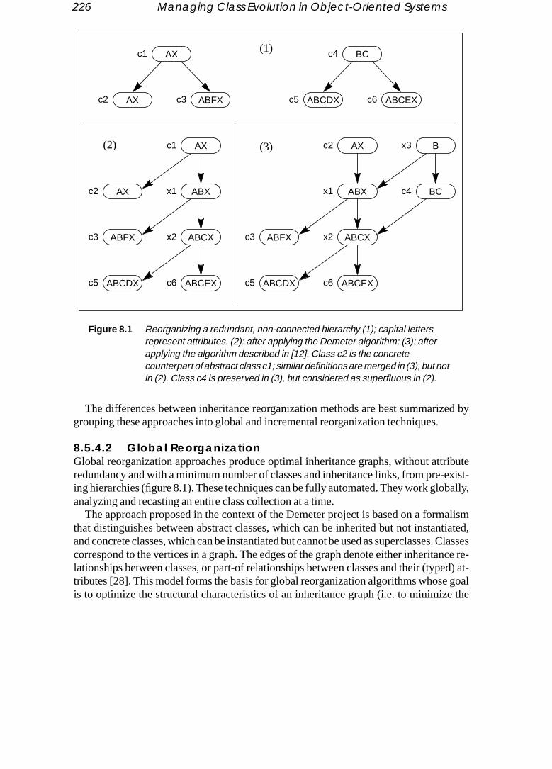
226 Managing Class Evolution in Object-Oriented Systems
zed by
ributeexist-bally,
alismtiated,. Classesnce re-ed) at- goale the
The differences between inheritance reorganization methods are best summarigrouping these approaches into global and incremental reorganization techniques.
8.5.4.2 Global ReorganizationGlobal reorganization approaches produce optimal inheritance graphs, without attredundancy and with a minimum number of classes and inheritance links, from pre-ing hierarchies (figure 8.1). These techniques can be fully automated. They work gloanalyzing and recasting an entire class collection at a time.
The approach proposed in the context of the Demeter project is based on a formthat distinguishes between abstract classes, which can be inherited but not instanand concrete classes, which can be instantiated but cannot be used as superclassescorrespond to the vertices in a graph. The edges of the graph denote either inheritalationships between classes, or part-of relationships between classes and their (typtributes [28]. This model forms the basis for global reorganization algorithms whoseis to optimize the structural characteristics of an inheritance graph (i.e. to minimiz
Figure 8.1 Reorganizing a redundant, non-connected hierarchy (1); capital lettersrepresent attributes. (2): after applying the Demeter algorithm; (3): afterapplying the algorithm described in [12]. Class c2 is the concretecounterpart of abstract class c1; similar definitions are merged in (3), but notin (2). Class c4 is preserved in (3), but considered as superfluous in (2).
AX
ABFXAX
BC
ABCEXABCDX
AX
ABXAX
ABCEX
ABCX
ABCDX
ABFX
AX
ABX
ABFX
ABCEX
ABCX
ABCDX
B
BC
c1
c2 c3
c4
c5 c6
c1
c2 x1
c3 x2
c5 c6
c3
c2 x3
c4
x2
c5 c6
x1
(2)
(1)
(3)

Class Reorganization 227
number of classes and relations in a library). Redefinitions and attribute structures are notted in
ses to
shy. con-
ss def-class and pre-s re- final
eser-al re-e 8.1.
, war-n can
d the re- incre-itioneritance
um.t in the
a hier-equir-ng and
everalnt of the-
(whichstic ofl sub-
mon aux-
taken into account. The formal properties of these algorithms have been investigadetail [28]:
• Transforming a hierarchy to suppress redundant part-of edges, i.e. forcing clasinherit common attributes from a shared superclass, is inP.
• Minimizing the overall number of edges isNP-complete. When the final hierarchy iactually a tree, efficient (polynomial) algorithms exist for optimizing the hierarc
A different method is based on an object model that allows classes to inherit fromcrete superclasses [12]. The corresponding algorithm proceeds by flattening all clainitions present in a hierarchy, then factoring out common structures, relinking all definitions through inheritance, and finally eliminating redundant inheritance linksauxiliary class definitions. Contrary to the Demeter approach, this algorithm doesserve all definitions that actually differ in the library before the reorganization, it takedefinitions into account and it can be tailored to avoid repeated inheritance in thehierarchy.
None of the global algorithms deal with interattribute dependencies or with the prvation of behavioural properties. Global algorithms do not always produce identicsults because of their varying assumptions and goals — as is shown clearly in figur
8.5.4.3 Incremental ReorganizationAdding a subclass is a major step in the development of an object-oriented libraryranting an evaluation, and possibly an improvement of the hierarchy. The evaluatiobe restricted to the relationships between the new class and its superclasses, anorganization can be limited to the location where the new class is introduced. Themental factorization algorithm proposed in [11] is driven by the analysis of redefinpatterns between a new class and its superclasses. It attempts to optimize the inhgraph within reason while keeping the disturbances to the original library to a minimBehavioural properties can be maintained to a certain extent and classes presenhierarchy before the reorganization are not deleted [12]. The algorithm transforms archy automatically to eliminate unwanted subclassing patterns, to pinpoint places ring redesign and to discover missing abstractions. It can take into account renamistructural transformations similar to those discussed in 8.5.2.
The incremental reorganization algorithm extracts the properties shared by sclasses and isolates them in a new, common superclass. Figure 8.2 shows a fragmeEiffel library where classCIRCLE inherits fromELLIPSE. This subclassing operation is accompanied by a partial replacement ofELLIPSE’s behaviour. Simultaneously,CIRCLEchanges its superclass’s interface in a way that corresponds neither to a restrictionwould be expected in a specialization relationship) nor to an extension (characterisubtyping relationships). A transformation of the hierarchy eliminates this unnaturaclassing pattern by inserting an intermediate definition containing the properties comto bothCIRCLE andELLIPSE, and by making these two classes subclasses of the newiliary node.

228 Managing Class Evolution in Object-Oriented Systems
y as isitions
d links
In more complex situations, the factorization propagates as high up in a hierarchneeded to eliminate unwanted subclassing patterns and introduces auxiliary definalong the way. A last simplification phase suppresses redundant auxiliary nodes an(figure 8.3).
CLOSED_FIG
ELLIPSE
Figure 8.2 Factorizing inheritance relationships.
CIRCLE
CLOSED_FIG
Auxiliary class
ELLIPSECIRCLE
— replaced methods:display contains,duplicate
— interface + radius- small_side- big_side- orientation
— additionaloperations
— interface+ orientation+ big_side+ small_side
— new operations— common interface
— deferred: containsdisplay, duplicate
— enhanced interface— concrete methods
— enhanced interface— concrete methods
Figure 8.3 The new class c4 rejects attributes B and C from c3; this triggers anincremental reorganization of the hierarchy whose final result is depicted in (3).
AB
ABC
ABCDE
ABCD
c1
c2
c3
c4
(1) A
A
ADE
AD
x3
x2
x1
c4
(2)
AB
ABC
ABCD
c1
c2
c3
A
ADE
AD
x3
x1
c4
(3)
AB
ABC
ABCD
c1
c2
c3

Class Reorganization 229
hoserimentslass-by oneternsstudy
ithmquateips.
at oneof then of sub-
rrect,of re-.
8.5.4.4 Application of Incremental ReorganizationThe incremental reorganization algorithm of [11] is one of the rare approaches weffectiveness has been quantitatively assessed on the basis of large-scale expeinvolving the reorganization of versions 2.1 and 2.3 of the Eiffel library (98 and 500 ces respectively). Starting from an empty hierarchy, Eiffel classes were added one to the library, triggering incremental reorganizations whenever redefinition patamounting to the rejection of inherited methods were detected (figure 8.4). This brought to light several interesting results [13]:
• A large majority (63%) of the problems uncovered by the reorganization algorwere caused by the utilization of inheritance for code sharing and by an inademodularization of functionality leading to other improper subclassing relationsh
• In 21% of the cases, the outcome of the reorganization corresponds to whwould expect from a manual redesign of the library. The restructuring patterns incremental algorithm closely match empirical observations on the evolutioobject-oriented libraries [2], as well as small-scale reorganizations of a limitedset of the Smalltalk hierarchy [17].
• In 33% of the cases, the incremental algorithm detects, but is not able to comany actual design problems in a library that are best solved by other kinds organizations, such as transforming inheritance links into part-of relationships
Figure 8.4 Restructuring the Eiffel 2.3 library. A few groups of classes responsible forclustered reorganizations are highlighted. Overall, the incrementalfactorization of Eiffel 2.3 adds 166 auxiliary definitions to the library.
Introduced classes
Additional auxiliary classes
60
120
180
100 200 300 400 500
Cursors
User interface,graphics
Datastructures

230 Managing Class Evolution in Object-Oriented Systems
• The algorithm is also useful for evaluating and comparing the quality of object-ques
ormala li-riesits itsranteesal re-ct theidden be-tionsnts offore betively.
redesign-driven
tanti-ystem.eir class avoid
e car-eritedl of theated in- object-dered.pliedction
oriented libraries, especially when it is combined with other incremental technithat are sensitive to naming patterns [13]
8.5.4.5 EvaluationGlobal reorganizations are a prerequisite when the goal is to put a hierarchy into a “nform” free from redundancy. However, global revisions may thoroughly transform brary. The results are therefore difficult to grasp and to utilize, particularly with libracomprising hundreds of classes. Incremental factorization, on the other hand, limscope to the inheritance paths leading to one new class — an approach that also guabetter performance in an interactive environment. Besides, it is doubtful that a globorganization can achieve significant results without additional processing to extrastructural similarities between class interfaces or method signatures that are hbecause of diverging naming and programming conventions [31][34]. Maintaininghavioural properties is a problem with both global and incremental reorganiza[6][12][39] and, anyway, many design problems cannot be solved through adjustmesubclassing relationships alone. Inheritance reorganization techniques must thereenhanced with other methods such as refactoring to support redesign activities effecAutomatic approaches are nevertheless essential to reduce the search space for operations on large libraries to a manageable size before applying interactive, usersurgery or refactoring operations.
8.6 Change Avoidance
8.6.1 Confining the Effects of Evolution
In principle, modifications of class specifications must be propagated to objects insated on the basis of old definitions, so as to maintain the overall consistency of the sNevertheless, in many cases instances need not be updated or enhanced when this modified. Detecting when these situations arise is important, since one can thenthe inconvenience of change propagation without giving up system consistency.
Change avoidance is easily combined with class tailoring. Tailoring operations arried out only for the purpose of defining additional subclasses; no matter how inhproperties are overridden, the modifications appear and take effect only at the levesubclasses performing the redeclarations. New classes obviously have no associstances, so there is no need to care about filtering or conversion procedures. Thus,oriented systems avoid updating instances when subclassing operations are consi
Several other evolution primitives exhibit no side-effects and can safely be apwithout reorganizing running applications. Among the surgery operations listed in se8.3.3, the following have no consequences on object structures:

Change Avoidance 231
es, notat ex-
ances,s.ed and
llowed,atible
gicaled in a].les) is
ery classr its en-hen
corre- subse- class,t gener-
ontainslass iscessing
• Renaming classes, methods and variables only affects the description of classthe structure of instances, although this may not always be true for programs thplicitly manipulate class or attribute names.
• Changing the default value of a variable or a shared slot has no effect on instsince these values pertain to the class definitions, not to the objects themselve
• The implementation of a method can be changed freely; the code is associatkept with a class definition, to be shared among all individual instances.
• Because no arbitrary changes to the domain of variables and arguments are aone can guarantee that the values stored within existing objects remain compwith their new type.
8.6.2 Physical Structures
A technique for confining the effects of class evolution consists of uncoupling the loobject model from its physical representation, so that instances may be implementway immune to change. Transposed files exhibit such desirable characteristics [18
In traditional database systems, the state of an object (i.e. the set of all its variabusually stored in one record (methods are shared and stored in a separate area). Evof a hierarchy is associated with a file which is used as a persistent storage space fotities, with each record of a file containing the state of a particular entity (figure 8.5). Wa variable is added to a class definition, additional space must be allocated for thesponding class and its subclasses; the instances affected by the modification arequently copied into the new storage zones. When a variable is suppressed from aspecial procedures are required for reclaiming unused storage space, a process thaally entails unloading and reloading entire class extents.
Transposed files associate one file with each variable of a class. Each record cthe value of the variable for a particular instance. The complete representation of a cthus spread among several files. One reconstitutes the state of an object by first ac
Figure 8.5 Traditional storage technique for a hypothetical EMPLOYEE class.
class EMPLOYEEvariables
Name : STRING;Salary : INTEGER;Function : STRING;
…end ;
Mucius Scaevola 5100 Programmer
Julius Nepos 8300 Project Leader
…
Titus Livius 7600 Analyst
File: EMPLOYEE

232 Managing Class Evolution in Object-Oriented Systems
getherred inng thishememseededsertion
pond-st objectThe di-
rgery
ds toin the
the values of its various variables in their respective files, and then grouping them toin the main memory for processing. All values for the variables of an object are storecords located at the same rank in the various files; this is made possible by derivirank directly from the identifier assigned to every object in the system. A simple scis to use a pair⟨class-identifier, rank⟩ to identify objects. Because file management systegenerally allocate disk space not by records but by blocks, a level of indirection is nto access the value of a variable. On the other hand, such a structure facilitates the inof objects whose identifiers are not strictly sequentially determined (blocks corresing to unused identifiers need not be reserved), and the release of space after the laassociated with a particular block is deleted. Resource waste is therefore reduced. agram of figure 8.6 represents the simplified structure of a transposed file.
Transposed files provide an efficient kernel for implementing many of the class suprimitives described in section 8.3.3, for example:
• Adding a variable to a class does not require reformatting the existing recormake room for the new attribute. Instead, an additional file is reserved to contasupplementary variable that is initialized to some default value, such asnil or 0, forexisting instances.
Figure 8.6 Using a transposed file organization for storing class EMPLOYEE.Rank 2 contains all information relative to employee “Julius Nepos”,rank 215 the data relative to “Titus Livius”. No instance correspondsto ranks 7–9, so the corresponding block is not allocated.
Mucius Scaevola
Julius Nepos
—
—
Titus Livius
—
1–3
4–6
(7–9)
…
214–216
Transposed file: Name
5100
8300
—
1–3
4–6
(7–9)
…
214–216
Transposed file: Salary
—
7600
—
Programmer
Project Leader
—
—
Analyst
—
1–3
4–6
(7–9)
…
214–216
Transposed file: Function
…… …

Conversion 233
• Suppressing a variable is achieved by deleting the corresponding file and returningired.s. If aes forbles of of the trans-
metrictabasetion inh [18].
ral ap-es arebelong
old and
little as
elities tond re-forma-strong
he pro-s are
all at-ethods;
all the space it occupies to the system. No compaction of the database is requ• A subclass definition comprises all its superclass files plus some additional file
reorganization of the hierarchy results in the destruction of the subclass, all filthe attributes it introduces are deleted, but not those corresponding to the variaits superclass. All instances of the subclass automatically become memberssuperclass, without one having to execute any procedure to save, reformat andfer the objects from one class to the other. Theclass-identifier part of all object identi-fiers must nevertheless be updated to remain consistent across changes.
Transposed files have proved very useful in domains such as statistical and econoinformation systems. They have therefore been implemented in special-purpose dasystems geared towards supporting these categories of applications. Their applicasemantic and object-oriented database systems is currently a field of active researc
8.7 Conversion
8.7.1 Issues
Transforming all entities whose class has been modified seems like the most natuproach to dealing with change propagation. This technique implies that instancphysically updated so that their structure matches the description of the class they to. Two important requirements must be met:
• Because there is in general not a direct or a unique correspondence between new class definitions, care has to be taken to avoid losing information.
• The conversion process has to be organized in such a way that it interferes as possible with normal system operations.
A consequence of the first requirement is thatad hoc reconfiguration procedures havto be programmed to accompany automatic conversion processes whose capabipreserve the semantics of an application domain are evidently limited. The secoquirement forces all conversion procedures to behave as atomic transactions (transtions must be applied completely to the objects involved in the conversion) and puts restrictions on their duration.
8.7.2 Instance Transformation
CLOS provides a good example of how automatic conversion can be enhanced by tgrammer to take supplementary integrity constraints into account [25]. Conversionperformed according to the rules listed in table 8.4. CLOS deletes from objects tributes that have been deleted in their class, including their associated accessor m

234 Managing Class Evolution in Object-Oriented Systems
n, and). These
gram-es dis-s, arect and, and
cesroughritanced andxtend-
. Un-
re in-
viding
evious other
Old slot New slot
leftizeds to.
it adds and initializes those attributes that have been introduced in the class definitioadapts the attributes whose status has passed from shared to local (or vice versaconversions are carried out by a standard function calledupdate-instance-for-redefined-
class that is inherited by every class in a hierarchy and can be customized by the promer. Arguments such as the list of attributes added to the class, or the list of attributcarded from the class or converted from local to shared, with their original valuepassed to this function. This allows the programmer to take proper actions to correaugment the default restructuring and reinitialization procedures provided by CLOSthus to determine freely the mapping from an old to a new object schema.
The OTGen system provides a similar kind of functionality for transforming instanaffected by a class modification, although this capability is presented to the user tha table-driven interface rather than as a programming feature attached to the inhehierarchy [27]. A table lists all class definitions whose instances have to be convertesuggests default transformations that apply, which can of course be overridden or eed by the user. The transformation operations possible with OTGen are as follows:
• Transfer objects which belong to the old class definition to the new databasechanged objects are simply copied from a database to another.
• Delete objects from the database if their class has been deleted.• Initialize the variables of an object. When the old and new types of a variable a
compatible, the default action taken by OTGen consists of assigning thenil value tothe variable. The user can override the standard behaviour of the system by proits own initial values.
• Change local variables to shared variables.• Perform context-dependent changes. One may initialize variables based on pr
information stored in the objects, or partition the instances from a class into twocategories based on the information they contain.
shared local none
shared preserved preserved discarded
local initialized preserved discarded
none initialized initialized —
Table 8.4 Default conversions carried out by CLOS on objects after a classmodification. A slot corresponds to a variable. Preserved slot values areuntouched. Discarded slots are removed and their values are lost. Initialslots are assigned a value determined by the class the instance belongThis table is reproduced from [25].
Conversion 235
• Move information between classes, for example by shuffling variables among class-
tialize
es theed set ad-esort to
trans-
corre-our inobjectnvert-e stor-nversion
whent incurice ofcation.essiveted con-riod of with
need toLOS. Aver-ting to
agat-ation
are non of
es, without losing associated information.• Introduce new objects for classes created while updating the hierarchy and ini
their variables on the basis of information already stored in the database.Providing a framework to handle the most common transformations certainly eas
task of the programmer. It is difficult, however, to guarantee that such a predeterminof primitives effectively covers all possibilities for object conversion. When complexaptations cannot be expressed with these operations, one is eventually forced to rspecial-purpose routines.
8.7.3 Immediate and Delayed Conversion
A major constraint with conversion concerns the time at which objects must be formed.
Immediate conversion consists in transforming all objects at once, as soon as thesponding class modifications are committed. This solution does not find much favpractice, because it may entail the full unloading and reloading of the persistent store, and long service interruptions if a significant number of entities have to be coed. On the other hand, this technique provides ample opportunities for optimizing thage and access paths to objects as part of the conversion process. Immediate cohas been implemented in the GemStone object-oriented database system [35].
Lazy conversion consists in adapting instances on an individual basis, but onlythey are accessed for the first time after a class modification. This method does nothe drawbacks of system shutdown imposed by immediate conversion at the prdegraded response time when instances are initially accessed after a class modifiLazy conversion requires keeping track of the status of each object. When succrevisions are carried out on the same class, the system must record each associaversion procedure, to be able to transform objects that are referenced after a long peinactivity. Lazy conversion is nevertheless an appealing approach for applicationsshort-lived instances that are rapidly garbage-collected and therefore do not even be converted. This technique has been proposed as the standard mechanism for Cversion of the O2 system implements both techniques [41], applying immediate consion to instances present in main memory at the time of the modification and resorlazy conversion for objects residing in secondary storage [4].
8.7.4 Evaluation
Conversion, and in particular lazy conversion, is a very attractive technique for proping changes in an object-oriented system. It requires the programming of transformfunctions, even when the environment supports automatic conversion, but there other alternatives for resolving intricate compatibility conflicts. When the conversio

236 Managing Class Evolution in Object-Oriented Systems
instances is infeasible, scope restriction techniques borrowed from the filtering approach
ecauseforma-
thesebject per-
ost a soft- object;form tohen an exam-
?
on asssor re-
defi- cre-
may prove helpful.
8.8 Filtering
8.8.1 Issues
Under some circumstances, one may not need to physically convert instances, bthey have become obsolete due to class modification, or because they represent intion that is not allowed to be modified for legal reasons, like accounting records. Insituations, it is preferable to ensure a partial compatibility between old and new oschemas, so that an application may still use them, but without striving to make themfectly interchangeable.
Filtering (or screening) is a general framework for dealing with this problem. It is moften used in combination with version management. This can be done by wrappingware layer around objects. The layer intercepts all messages sent to the enclosedthese messages are then handled according to the object’s version, to make it conthe current or to a previous class description, or to cause an exception to pop up wapplication uses an object with an unsuitable definition. Three major issues must beined with this approach:
• How does one characterize the degree of compatibility between class versions• How can one map instances from a class version to another?• How far can a filtering mechanism hide class changes from the users?
8.8.2 Version Compatibility
Fundamentally, filtering is a mechanism for viewing entities of a certain class versiif they belonged to another version of the same class. From the predecessor–succelationship between versions, we identify two types of compatibility [1]:
• A versionCi isbackwards compatible with an earlier versionCj if all instances of Cj
can be used as if they belonged toCi.• A versionCi is forwards compatible with a later versionCj if all instances ofCj can
be used as if they belonged toCi.In the first case, applications can use old instances as if they originated from new
nitions. With the second form of compatibility, old programs can manipulate entitiesated on the basis of later versions.
Each classC is associated with the partial ordering of versions {Ci }. We assume that,at any point in time, someCi is considered the valid version of classC. Building on these

Filtering 237
definitions, we say that a class versionCi isconsistent with respect to versionDj of another
t-
i-es
r-
e clas- accesse sum-
utinetures.edurese pro-er at-lacedwards
sed be-
e basis
mpat-these
ute
ver-
classD (C ≠ D) if one of the following conditions is satisfied [1]:• Dj was the currently valid version ofD whenCi was committed. This is the usual si
uation;Ci references up-to-date, contemporaneous properties ofD.• Dk was the currently valid version ofD whenCi was committed,Dj is a later version
of D, andDk is forwards compatible withDj. HereCi references an obsolete defintion of D, but the forwards compatibility property allows it to work with instanccreated according to the new schema.
• Dk was the currently valid version ofD whenCi was committed,Dj is an earlier ver-sion ofD, andDk is backwards compatible withDj. HereCi is supposed to manipulatean up-to-date representation ofD; thanks to the backwards compatibility, it is nevetheless able to use instances generated from old versions.
8.8.3 Filtering Mechanisms
The operations that cause problems when invoked on a non-compatible object can bsified in a limited number of categories. For example, deleting a method generatesviolations when an object attempts to invoke the deleted method. These effects armarized in table 8.5.
A simple way to deal with this problem is to replace each access primitive with a rospecifically programmed to perform the mapping between different class strucThus, for each variable that violates compatibility constraints, one provides a procthat returns the variable’s value, and another procedure for changing its value. Thecedures perform various transformations, like mapping the variable to a set of othtributes [1]. For example, if the “birthday” attribute of a person class has been repwith an “age” variable, one has to provide the following procedures to ensure backcompatibility:
• A read accessor that determines the age of a person based on the time elaptween the recorded birthday and the current date.
• A write accessor that stores the age of a person as a birthday, computed on thof the current date and the age given as argument to the accessor.
Similarly, one must define two symmetrical operations to guarantee forwards coibility. More generally, one can define so-called substitute functions for carrying out mappings between objects with different structures as follows:
• A substitute read function RCijA(I) is given an instanceI of versioni of classC. Itmaps the values of a group of attributes from this object to a valid value of attribAof versionj of C. In other words, it makes instances of class versionCi appear as ifthey contained the attributeA of class versionCj for reading operations.
• A substitute write function WCijA(I,V) is given an instanceI of versioni of classC,and a valueV for attributeA of Cj. It maps the valueV into a set of values for a groupof attributes defined inCi. In other words, this function makes instances of class

238 Managing Class Evolution in Object-Oriented Systems
accesshe EN- non- per-nt to al val-urning
lers re-
Scope of change Compatibility Consequences
od
ind ofess
sionCi appear as if they could store information in attributeA, although this informa-tion is actually recorded in other variables.
A second approach favours the use of handlers to be invoked before or after a failedto the attribute they are attached to, a technique that has been implemented in tCORE system [37]. Pre-handlers typically take over when attempting to access aexistent attribute, or when trying to assign an illegal value to it. A pre-handler mayform a mapping like those carried out by the substitute functions, coerce its argumevalid value, or simply abort the operation. A post-handler is activated when an illegaue is returned to the invoking object; a common behaviour in this case consists in reta default value.
8.8.4 Making Class Changes Transparent
Where should filters be defined? As originally stated, the technique based on handquires global modifications in all versions of the same class [37]. More precisely,
add a variable backwards undefined variable in old objects
delete a variable forwards undefined variable in new objects
extend variable type backwards writing illegal values into old objects
forwards reading unknown data from new objects
restrict variable type forwards writing illegal values into new objects
backwards reading unknown data from old objects
add a method backwards undefined method in old objects
delete a method forwards undefined method in new objects
extend argument type backwards passing illegal values to old objects
forwards getting unknown data from new objects
restrict argument type forwards passing illegal values to new objects
backwards getting unknown data from old objects
change argument list backwards and forwards similar to dropping and adding a meth
Table 8.5 Consequences of class changes. The middle column indicates which kcompatibility is affected by a modification, the right column describes thexceptions raised when accessing an object from the old or the new cladefinition.

Filtering 239
• Whenever an attribute is added to a class, pre-handlers for the attribute must be intro-
post-
he at-
to re-ity.
ap-on
ply
any. Fur-s defi-
pe re-
ob-
rom
class its ver-m dif-mbers of
is nota-nge so
e its at-e physi-ied torns areed at-
duced in all other versions of the class.• Pre-handlers must be added to a version that suppresses attributes of a class.• When a version extends the domain of an attribute, corresponding pre- and
handlers must be introduced in all other versions of the class.• When the domain of an attribute is restricted, the class version redeclaring t
tribute type must be wrapped with a pre-handler and a post-handler.This solution is rather inelegant: it requires that old class definitions be adjusted
flect new developments and leads to a combinatorial explosion of handler complexThe model of substitute functions allows one to exploit the derivation history for m
ping between versions that have no direct relationships. Thus, one can map a versiCi toanother versionCj if there exist either substitute functions for them (RCijX, WCijX, whereX denotes an attribute ofCj), or a succession of substitute functions that transitively apto them (i.e. there are substitute functions for mapping betweenCi andCk, thenCk andCl
and eventuallyCl andCj for example). Depending on compatibility properties, one ceven relate class definitions placed in different derivation paths in a version hierarchthermore, substitute functions are defined only in the newer versions; previous clasnitions remain unchanged.
When compatibility between versions cannot be achieved, one may install scostrictions that isolate objects pertaining to different definitions from each other:
• A forward scope restriction makes instances from a new version inaccessible tojects from older versions.
• A backward scope restriction makes instances from older versions unreachable fobjects of more recent versions.
Scope restrictions and compatibility relationships make it possible to partition a extension in such a way that operations may be applied to any object regardless ofsion. Naturally, interoperability decreases with such a scheme, since the entities froferent versions of the same class can no longer be referred to and accessed as meone large pool of objects.
8.8.5 Evaluation
Screening has been implemented in some systems, but its application scope therebly reduced. ORION does not immediately convert instances affected by a class chaas to avoid reorganizing the database [3]. When an instance is fetched, and befortributes are accessed, deleted variables are made inaccessible (after, if needed, thcal destruction of the objects they refer to). Default values are automatically supplaccount for the introduction of new properties. Rearrangements of inheritance pattereflected by hiding unwanted properties and supplying default values for new inherittributes.

240 Managing Class Evolution in Object-Oriented Systems
From our discussion, it appears that filtering cannot fulfil its objective of making classmmere var-
s thesectice,
, oneher,ore noteening and
classde im-es and
bclass-inglyto takevarious
lasses incre-er re-ationsactivi-kept as
changes transparent without considerable complexity and overhead. The programust not only develop a series of special-purpose functions for mapping between thiants of a class, but must also accept a degradation of application performance ahandlers accumulate, replacing the originally simple and efficient accessors. In prathis complexity does not appear fully warranted. With lazy conversion, for examplehas also to definead hoc procedures for transforming entities from one version to anotbut these procedures are called only once for every object. Their execution is therefas expensive as the systematic run-time checks and exception raising implied by scrtechniques. On the positive side, filtering provides a rigorous framework for definingdealing with compatibility issues, and it is most adequate during prototyping, whenmodifications may be cancelled just after being tested. Recent approaches proviproved mechanisms derived from database views that encompass filtering techniquthat can also be suitable as modelling tools during application development [16].
8.9 Conclusion
Object-oriented development reveals its iterative nature as successive stages of suing, class modification and reorganization allow software engineers to build increasgeneral and robust classes. We therefore expect object-oriented CASE systems advantage of the large spectrum of tools and techniques available to manage the aspects of class evolution (see table 8.6).
It is appealing to envision an environment where software engineers build new cout of reusable components, tailor them to suit their needs, and launch exploratorymental reorganizations to detect the places in their code most likely to require furthvisions. Software developers may then refine the outcome of automatic reorganizwith class surgery primitives and perhaps embark on comprehensive refactoring ties. The results of different reorganizations and their subsequent adjustments are
Approach Actual impacton instances
In charge of controllingchange propagation
Implementation
change avoidance
confinement logical system side-effect free operations
storage structures physical system transposed files
conversion physical programmer conversion routines
filtering logical programmer handlers/wrappers
Table 8.6 The main characteristics of change propagation techniques.

241
ly can-orrect- When be fro-poraryefinitely
n isola-pport-le in
Approach Scope Phase in library Enforced properties
eso the
versions of the hierarchy, that can be further modified, tested, debugged and possibcelled by the programmers (see table 8.7). Filtering makes it possible to test the cness of various class definitions without having to carry out numerous conversions.a satisfactory design for a new component and its related classes is achieved, it canzen and publicly released as the new version of the class library, while the other temversions are discarded. If necessary, instances from modified classes can then be dconverted to conform to their new definitions.
Some approaches have been partially implemented and already appear, albeit ition, in some object-oriented systems; we hope that integrated tools suitable for suing class evolution in industrial and commercial environments will become availabthe near future.
development
tailoring attributes;interfaces
extension syntactical constraints
surgery attributes;inheritance links;classes
redesign schema invariants
versioning classes extension configuration consistency
reorganization
refactoring classes; attributes;method structures;inheritance links
redesign schema invariants;preservation of behaviour
interattributedependencies
method structures redesign preservation of behaviour
inheritance(global)
classes;inheritance links
redesign preservation of class structures;global optimality of hierarchy
inheritance(incremental)
classes;inheritance links;interfaces;method structures
extension preservation of class structures;local optimality of hierarchy;preservation of behaviour
Table 8.7 The main characteristics of evolution management techniques. Attributrefer to methods as well as to variables; method structures correspond tsignature and the implementation of methods.

242 Managing Class Evolution in Object-Oriented Systems
References
Type.
on of
n
e,” in
Evo-
,” inr
efin-
Ap-
gresslution,”ll,
t,”
113,
tem,”
[1] Matts Ahlsén, Anders Björnerstedt, Stefan Britts, Christer Hultén and Lars Söderlund, “MakingChanges Transparent,” SYSLAB report 22, SYSLAB-S, University of Stockholm, 26 Feb. 1984
[2] Bruce Anderson and Sanjiv Gossain, “Hierarchy Evolution and the Software Lifecycle,” inProceed-ings 2nd TOOLS Conference, ed. J. Bézivin, B. Meyer and J.-M. Nerson, Paris, 1990, pp. 41–50.
[3] Jay Banerjee, Won Kim, Hyoung-Joo Kim and Henry F. Korth, “Semantics and ImplementatiSchema Evolution in Object-Oriented Databases,”SIGMOD Record (special issue on SIGMOD ’87),vol. 16, no. 3, Dec. 1987, pp. 311–322.
[4] Gilles Barbedette, “Schema Modification in the LISPO2 Persistent Object-Oriented Language,” iProceedings 5th ECOOP Conference, ed. P. America,Lecture Notes in Computer Science, vol. 512,Springer-Verlag, Geneva, 15–19 July 1991, pp. 77–96.
[5] David Beech and Brom Mahbod, “Generalized Version Control in an Object-Oriented DatabasProceedings of the 4th IEEE International Conference on Data Engineering, Los Angeles, Feb. 1988,pp. 14–22.
[6] Paul L. Bergstein and Walter L. Hürsch, “Maintaining Behavioral Consistency during Schemalution,” in Object Technologies for Advanced Software (First JSSST International Symposium), Lec-ture Notes in Computer Science, vol. 742, Springer-Verlag, Nov. 1993, pp. 176–193.
[7] Anders Björnerstedt and Stefan Britts, “AVANCE: An Object Management System,”ACM SIGPLANNotices (special issue on OOPSLA ’88), vol. 23, no. 11, Nov. 1988, pp. 206–221.
[8] Anders Björnerstedt and Christer Hultén, “Version Control in an Object-Oriented ArchitectureObject-Oriented Concepts, Databases, and Applications, ed. W. Kim and F. H. Lochovsky, FrontieSeries, Addison-Wesley/ACM Press, 1989, pp. 451–485.
[9] Alexander Borgida, “Modelling Class Hierarchies with Contradictions,”SIGMOD Record (specialissue on SIGMOD ’88), vol. 17, no. 3, Sept. 1988, pp. 434–443.
[10] Alexander Borgida and Keith E. Williamson, “Accommodating Exceptions in Databases, and Ring the Schema by Learning from them,” in VLDB 1985 Proceedings, ed. A. Pirotte and Y. Vassiliou,Stockholm, 21–23 August 1985, pp. 72–81.
[11] Eduardo Casais, “An Incremental Class Reorganization Approach,” inProceedings 6th ECOOP Con-ference, ed. O. Lehrmann Madsen,Lecture Notes in Computer Science, vol. 615, Springer-Verlag,Utrecht, June 29 – July 3 1992, pp. 114–132.
[12] Eduardo Casais, “Managing Evolution in Object-Oriented Environments: An Algorithmic proach,” Ph.D. Thesis, Université de Genève, Geneva, 1991.
[13] Eduardo Casais, ‘‘Automatic Reorganization of Object-Oriented Hierarchies: A Case Study,’’Object-Oriented Systems, vol. 1, no. 2, Dec. 1994., pp. 95–115
[14] Fabiano Cattaneo, Alberto Coen-Porisini, Luigi Lavazza and Roberto Zicari, “Overview and ProReport of the ESSE Project: Supporting Object-Oriented Database Schema Analysis and Evoin Proceedings 10th TOOLS Conference, Versailles, ed. B. Magnusson and J.-F. Perrot, Prentice Ha1993, pp. 63–74
[15] Hong-Tai Chou and Won Kim, “A Unifying Framework for Version Control in a CAD Environmenin 12th VLDB Conference Proceedings, Kyoto, 25–28 August 1986, pp. 336–344.
[16] Stewart M. Clamen, “Type Evolution and Instance Adaptation,” Technical Report CMU-CS-92-Carnegie-Mellon University, Pittsburgh, June 1992.
[17] William R. Cook, “Interfaces and Specifications for the Smalltalk-80 Collection Classes,”ACM SIG-PLAN Notices (special issue on OOPSLA ’92), vol. 27, no. 10, Oct. 1992, pp. 1–15.
[18] Thibault Estier, Gilles Falquet and Michel Léonard, “F2: An Evolution Oriented Database SysCahiers du CUI no. 69, Centre Universitaire d’Informatique, Genève, January 1993.

References 243
[19] D. H. Fishman, J. Annevelink, D. Beech, E. Chow, T. Connors, J. W. Davis, W. Hasan, C. G. Hoch, W.son,
hek,
ses,”
OS
organi-67–
s for
se of23–
ign for
,
om-
BMS,”.
rient-,
gram-35–
Kent, S. Leichner, P. Lyngbaek, B. Mahbod, M. A. Neimat, T. Risch, M. C. Shan and W. K. Wilkin“Overview of the IRIS DBMS,” inObject-Oriented Concepts, Databases, and Applications, ed. W.Kim and F. H. Lochovsky, Frontier Series, Addison-Wesley/ACM Press, 1989, pp. 219–250.
[20] Erich Gamma, “Objektorientierte Software-Entwicklung am Beispiel von ET++: KlassenbibliotWerkzeuge, Design,” Dissertation, Universität Zürich, August 1991.
[21] Adele Goldberg and Daniel Robson,Smalltalk-80: The Language and its Implementation, Addison-Wesley, Reading, Mass., 1983.
[22] Ralph E. Johnson and Brian Foote, “Designing Reusable Classes,”Journal of Object-Oriented Pro-gramming, June-July 1988, pp. 22–35.
[23] Ralph E. Johnson and William F. Opdyke, “Refactoring and Aggregation,” inObject Technologies forAdvanced Software (First JSSST International Symposium), Lecture Notes in Computer Science, vol.742, Springer-Verlag, Nov. 1993, pp. 264–278.
[24] Randy H. Katz, “Towards a Unified Framework for Version Modelling in Engineering DatabaACM Computing Surveys, vol. 22, no. 4, Dec. 1990, pp. 375–408.
[25] Sonya E. Keene,Object-Oriented Programming in Common LISP: A Programmer’s Guide to CL,Addison-Wesley, Reading, Mass., 1989.
[26] Hyoung-Joo Kim, “Algorithmic and Computational Aspects of OODB Schema Design,” inObject-Oriented Dabatases with Applications to CASE, Networks and VLSI CAD, ed. R. Gupta and E.Horowitz, Prentice Hall, 1991, pp. 26–61.
[27] Barbara Staudt Lerner and A. Nico Habermann, “Beyond Schema Evolution to Database Rezation,”ACM SIGPLAN Notices (special issue on OOPSLA ’90), vol. 25, no. 10, Oct. 1990, pp. 76.
[28] Karl J. Lieberherr, Paul Bergstein and Ignacio Silva-Lepe, “From Objects to Classes: AlgorithmOptimal Object-Oriented Design,”BCS/IEE Software Engineering Journal, July 1991, pp. 205–228.
[29] Karl Lieberherr, Ian Holland and Arthur Riel, “Object-Oriented Programming: an Objective SenStyle,”ACM SIGPLAN Notices (special issue on OOPSLA ’88), vol. 23, no. 11, Nov. 1988, pp. 3334.
[30] Bertrand Meyer,Eiffel: The Language, Object-Oriented Series, Prentice Hall, 1992.
[31] Bertrand Meyer, “Tools for the New Culture: Lessons from the Design of the Eiffel Libraries,”Com-munications of the ACM, vol. 33, no. 9, Sept. 1990, pp. 68–88.
[32] Shamkant B. Navathe, Seong Geum, Dinesh K. Desai and Herman Lam, “Conceptual DesNon-Database Experts with an Interactive Schema Tailoring Tool,” inProceedings of the 9th Entity–Relationship Conference, ed. H. Kangassalo, Lausanne, 8–10 Oct. 1990, pp. 3–20.
[33] Objective-C Compiler Version 4—User Reference Manual, StepStone Corporation, Sandy Hook1988.
[34] William F. Opdyke, “Refactoring Object-Oriented Frameworks,” Ph.D. thesis, Department of Cputer Science, University of Illinois at Urbana-Champaign, 1992.
[35] D. Jason Penney and Jacob Stein, “Class Modification in the GemStone Object-Oriented DACM SIGPLAN Notices (special issue on OOPSLA ’87), vol. 22, no. 12, Dec. 1987, pp. 111–117
[36] Markku Sakkinen, “Comments on the ‘Law of Demeter’ and C++,”ACM SIGPLAN Notices, vol. 23,no. 12, pp. 34–44.
[37] Andrea H. Skarra and Stanley B. Zdonik, “The Management of Changing Types in an Object-Oed Database,” inResearch Directions in Object-Oriented Programming, ed. B. Shriver and P. WegnerMIT Press, Cambridge, Mass., 1987, pp. 393–415.
[38] Dave Thomas and Kent Johnson, “Orwell: a Configuration Management System for Team Proming,” ACM SIGPLAN Notices (special issue on OOPSLA ’88), vol. 23, no. 11, Nov. 1988, pp. 1141.

244 Managing Class Evolution in Object-Oriented Systems
[39] Emmanuel Waller, “Schema Updates and Consistency,” inDOOD’91 Proceedings, ed. C. Delobel,,
Covari-
m,” in.
M. Kifer and Y. Yasunaga,Lecture Notes in Computer Science, vol. 566, Springer-Verlag, Dec. 1991pp. 167–188.
[40] Franz Weber, “Getting Class Correctness and System Correctness Equivalent — How to Get ance Right,” inProceedings 8th TOOLS Conference, Santa Barbara, ed. R. Ege, M. Singh and B.Meyer, Prentice Hall, 1992, pp. 199–213.
[41] Roberto Zicari, “A Framework for Schema Updates in an Object-Oriented Database SysteBuilding an Object-Oriented Database System — The Story of O2, ed. F. Bancilhon, C. Delobel and PKanellakis, Morgan Kaufmann, 1992, pp. 146–182.

Chapter 9
diverse, de-
ientedupport
ided byaviga-
The Affinity Browser
Xavier Pintado
Abstract Large numbers of classes, complex inheritance and containmentgraphs, and diverse patterns of dynamic interaction all contribute to difficulties inunderstanding, reusing, debugging, and tuning large object-oriented systems.These difficulties may have a significant impact on the usefulness of such systems.Tools that help in understanding the contents and behaviour of an object-oriented environment should play a major role in reducing such difficulties. Suchtools allow for the exploration of different aspects of a software environment suchas inheritance structures, part-of relationships, etc. However, object-orientedsystems differ in many respects from traditional database systems, and inparticular, conventional querying mechanisms used in databases show poorperformance when used for the exploration of object-oriented environments. Thischapter defines the requirements for effective exploration mechanisms in therealm of object-oriented environments. We propose an approach to browsingbased on the notion of affinity that satisfies such requirements. Our tool, the affinitybrowser, provides a visual representation of object relationships presented in termsof affinity. Objects that appear closer in the visual representation are more stronglyrelated than objects lying farther apart. So, the intensity of a relationship istranslated into distance in the visual representation that provides the support foruser navigation. We provide many examples of metrics defined over the objects ofan environment to illustrate how object relationships can be translated in terms ofaffinity so that they can be used for the exploration of an environment.
9.1 Introduction
Large numbers of classes, complex inheritance and containment graphs, and patterns of dynamic interaction all contribute to difficulties in understanding, reusingbugging, and tuning large object-oriented systems. From the inception of object-orenvironments, developers and software designers have felt the need for tools that sthe process of understanding the objects, the classes and the relationships provtheir environments. For example, reuse of existing software components requires n

246 The Affinity Browser
tion and inspection of classes and how they are related. Inspection and navigation capabil-w thevein,ects is
basedol-
nted inronglyd into
point-iven pro-loring allowsion-ts con- manyllow- a large
ng andstics ofowsingtionalquire-ents. In sec-menty can
ant, for envi-proxi- his orve rela-lection
ities are also instrumental for the combination of instantiated objects since they allouser to go back and forth, inspecting objects and combining them. In a similar discerning global and local patterns of interaction among classes and among objcritical for tuning and debugging.
This chapter proposes an approach to browsing for object-oriented environmentson the notion of affinity. Our tool, the affinity browser, allows for the exploration of clections of objects based on a visual representation of object relationships preseterms of affinity. Objects that appear closer in the visual representation are more strelated than objects lying farther apart. So, the intensity of a relationship is translatedistance in the visual representation.
Our approach displays many advantages. First, affinity browsing is not based onto-point navigation. The user is provided with the set of objects that lie within a gneighbourhood relative to the object currently being inspecting. The affinity browsermotes, therefore, proximity-based navigation whereby exploration proceeds by expfirst the objects that are close to the current object of interest. Second, the browserfor the exploration of dynamically evolving relationships. The evolution of such relatships is visualized as an animation where the change in the relative position of objecveys the change of the underlying relationships expressed in terms of affinity. Third,different kinds of object relationships can be translated into affinity representations aing the same exploration paradigm and the same user interface to be used to explorespectrum of object relationships.
This chapter is organized as follows. Section 9.1.1 addresses the problem of findiselecting objects inside an object-oriented environment. It discusses the characteriobject-oriented systems that may have an impact on the effectiveness of various brmechanisms. Section 9.1.2 surveys work related to browsing ranging from tradigraph-based browsing to graphical and spatial browsing. Section 9.2 defines the rements for effective exploration mechanisms in the realm of object-oriented environmSection 9.3 presents the affinity browser as a tool that satisfies such requirements.tion 9.4 we provide many examples of metrics defined over the objects of an environto illustrate how object relationships can be translated in terms of affinity so that thebe used for the exploration of an environment
9.1.1 Object Selection
We address here the issue of selection in the object-oriented realm. Users may winstance, to select classes, objects, or functionality. Selection in an object-orientedronment has many problems, however. First, an application designer has only apmate selection criteria to select an appropriate reusable object class for developingher application. Second, the object classes and the objects in a running system hationships that change dynamically. Third, objects are encapsulated and content sehas only very limited use.

Introduction 247
Furthermore, object-oriented principles applied to software design seem to promoteftwareelop-
han ex-
tech-its of inter-nitionional-echa-grate
uitionlexity
tance,eosition
istingmber
ls thatnce,gh, itures ofmminge kind code
meth-nation, proc-
nownlection
dimin- brows-
ria aretheulate,
systems with object relationships that are more complex than in more traditional soenvironments. Many authors think that these principles will allow designers and devers to create software environments that are an order of magnitude more complex tisting software systems [19] [4].
A noteworthy supporting reason for such belief is that object-oriented design niques seem to allow significantly better decomposition of complex problems into unmanageable complexity. First, by the virtue of encapsulation an object conceals itsnal complexity and it acquires some level of autonomy. Second, incremental defithrough inheritance allows for the endless refinement of object behaviour and functity without the need to rework the whole hierarchy at each refinement step. These mnisms, with such desirable features, allow for the implementation of models that intemuch detail both at the object level and at the level of object relationships. This intis further supported by experience that shows that it is quite easy to introduce compin the design and in the implementation of an object-oriented environment. For insobject-oriented programming is more an activity ofwiring together sets of objects. For thprogrammer or for the designer whose task is to build a system through the compof objects it might be quite easy to combine them in many different ways— this is theproducer’s view. On the other hand, for a developer who wants to understand exfunctionality for reuse or maintenance, it may be difficult to comprehend the large nuof functional relationships that have been created— this might be the consumer’s view.
Early experiences with object-oriented environments highlighted the need for tooallow for the exploration of object relationships. The Smalltalk environment, for instaalready provided a sophisticated integrated browsing tool [12]. Interestingly enouhas been argued that the Smalltalk browsing tool is one of the most appealing featthat environment and it is often cited as a reference. For sure, almost every prograactivity on the environment relies on the browser to support navigation needed for thof non-linear programming promoted by object-orientation. The browser is used tonew objects, to find reusable classes and to explore object relationships.
9.1.1.1 Querying and BrowsingThe two methods commonly applied for selection are querying and browsing. The ods are usually applied in a complementary manner; we query and browse in alterapplying which method seems more appropriate at different stages of the selectioness.
Querying provides fine selectivity when the structure of the information space is kand when content selection can be used. For instance, querying is the primary semethod in database systems. When querying provides good selectivity, browsing ishes in importance. Most selected items are appropriate and we only need a crudeing tool to inspect them.
Querying, however, can have poor results for many reasons. If the selection criteill-defined and fuzzy querying does not work well, e.g. in information retrieval. If structure of the information space changes dynamically, queries are not easy to form

248 The Affinity Browser
e.g. in financial information systems. Finally, if content selectivity is difficult to exploit, cases
n im-it helps sup-k. Inearchability.angesery with aterms of with
bjectbjectsinter-tem isis in- an en-
lso in
base,to inte-
infor- explo-d to
viron-cepts
querying loses a lot of selectivity power, e.g. in multimedia databases. In all thesepowerful browsing capabilities become indispensable.
9.1.1.2 Dynamically Evolving RelationshipsAs we already mentioned, the analysis of dynamically evolving relationships plays aportant role in debugging but can also be of invaluable assistance for reuse since understanding how objects are related in existing applications. However, providingport for the understanding of dynamically evolving relationships is a challenging tasfact, traditional querying techniques usually assume a user with knowledge of the sstructure that supports selection. Such an assumption usually implies structure stsince it seems unrealistic to assume user knowledge of a quickly evolving structure
With traditional databases it is usually assumed that their information contents chbut not their structure— or at least not frequently. For example, widely used qulanguages such as SQL provide almost no support for selection in an environmentchanging structure. The stability of database schemes represents an advantage in access to information but it makes traditional databases ill-suited for informationdynamically evolving structures.
The need to cope with dynamically evolving relationships appears in many oselection problems. For example, we may be interested in finding which are the othat interact most frequently with a given object in order to determine its patterns of action. The change in the interaction patterns depending on what activities the sysperforming may provide useful information about the intended role of an object. Thformation can be used, for instance, to assess the potential of reuse for an object invironment that may or may not provide the same activity context.
The need for more flexibility than that provided by query mechanisms appeared adatabases. For example, Motro [20] [21] [22] describes browsing tools that allow fornav-igation in a semantic network extracted from the internal structure of a relational dataand provide capabilities for fuzzy queries. The approach has been later extended grate similar capabilities in an object-oriented environment [23].
9.1.2 Related Work
Because there is an observable trend towards more complex and quickly evolvingmation systems we need to investigate how to enhance browsing capabilities for theration of information systems. In this section we describe previous work relatebrowsing.
9.1.2.1 The Smalltalk BrowserTo the best of our knowledge, the Smalltalk system was the first programming enment where exploration tools played a major role. Furthermore, the browsing con

Introduction 249
and mechanisms have been clearly defined [13] [12] and they are quite often cited as the
of ob-n
viewch as:age? class
esentsrrangeses and
ols islypectionreationo per-
s. Theinuousenvi-lltalk
he treeven to
s largerranged
ningd pro-
tem’sing thewever.ame-ventms ofended to
Theirstem.
historical reference to which more recent browsing tools are compared.The Smalltalk environment provides capabilities to inspect the message interface
jects through a system view called abrowser. Similarly, the internal state of an object cabe inspected through another system view called aninspector. Furthermore, it is possibleto obtain interface information about sets of objects through another kind of systemcalled amessage-set browser. These views are generated as responses to queries suwhich classes implement a given message? Which objects send a particular mess
The main way to find out about classes in the environment is to use a systembrowser. The browser presents a hierarchical view of class-related information. It prcategories that organize the classes within the environment, and categories that amessages within each class. Categories provide essentially a way of grouping clasmessages into meaningful groups.
It should be noted that in the Smalltalk environment the role of the exploration tonot restricted to inspection. For example, aninspector allows users to change interactivethe values of instance variables and to send messages to objects. In general, instools are used for both inspection and programming purposes. For instance, the cof a new class derived from an existing one, and the definition of new methods is alsformed through the browser.
Other browsing tools have been described and implemented in various systembrowsing mechanisms implemented in the Smalltalk environment have been a contsource of inspiration for new browsing tools. For example, the Trellis programming ronment [24] provides browsing capabilities that are quite similar to those of the Smaenvironment [12].
The great majority of existing browsing tools allow for apoint-to-point navigation, i.e.the navigation paths are defined by a tree or a network structure. For instance, tstructure of the Smalltalk browser is based on classification. This approach has probe useful for small collections of objects. But when the number of classes becomeusers may feel lost because there is no global view and the structure cannot be reato fit their intuitive perception of the object’s space.
Discerning global and local patterns of interaction among classes is critical for tuand debugging. A few authors have already identified this as an important issue anposed adequate tools. For example, Böcker and Herczeg [1] introduce asoftware oscillo-scope for visually tracking the interactions between objects in a system. The sysdynamic behaviour is inspected by placing obstacles between objects and animatflow of messages across them. The tool focuses only on microscopic behaviour, hoBrüegge, Gottschalk and Luo [3] describe BEE++, an object-oriented application frwork for the analysis of distributed applications. BEE++ is fundamentally an eprocessing system since it views the execution of distributed activities as streaevents. Event processing is encapsulated in a set of core base classes that are intbe derived for customization.
Other authors such as Kleyn and Gingrich [17] focus on object behaviour issues.tool offers concurrently animated views of the behaviour of an object-oriented sy

250 The Affinity Browser
These views include graphs of invocations between objects. Podgursky and Pierce addressaviour.on ob- design
eed fororma-erot tech- sys-
hat therot ar-
pecify
raph-lab-. In uses
xima-o onere rep- [18],
mech-ertextm tothree- a hy- con-
a is toirected
to them. Theith thexplore
devel-sing.
the problem [30] of retrieving reusable software components based on sampled behFinally, Rubin and Goldberg [31] sketch an object-oriented design approach based ject behaviour analysis and stress the importance of exploration tools to support theprocess.
9.1.2.2 Graphical and Spatial BrowsingIn the late 1970s Fields and Negroponte, in a visionary paper [10], expressed the nnew clues to find data. Among the many approaches they envisioned for locating inftion are spatial referencing and proximity. Shortly after, Donelson [7], Bolt [2], and H[14] published papers about spatial management of information which apply manyniques for information exploration and inspection that will serve as a basis for futuretems. They introduced thespatial data management system (SDMS) concept, wherebyinformation is expressed in graphical form and presented in a spatial framework so tinformation has a structure that is more obvious than in a conventional database. Hegues that: “in this way the user can find the information he seeks without having to sit precisely or know exactly where in the DBMS it is stored.”
More recently, Caplinger [5] has described a sophisticated browsing tool with a gical spatial interface that is, in fact, an evolution of the original SDMS idea. A further eoration of SDMS is BEAD [6], a system for the visualization of bibliographical dataBEAD, articles in a bibliography are represented by particles in 3-space. The systemphysically based modelling techniques to take advantage of methods for the approtion of potential fields. Interparticle forces tend to make similar articles move closer tanother and dissimilar ones move apart, so that the relationships between articles aresented by their relative spatial positions. We may also mention the N-Land systemwhich addresses the problem of visualizing higher dimension information spaces.
The growing interest on hypertext systems generalized the use of browsing as aanism for information access. Many things have been written recently about hypbrowsing and hypertext navigation, and we will just mention a few works that seedeserve particular interest in the context of this work. SemNet [8] is a system for the dimensional visualization and exploration of large knowledge bases that promotespertext-like navigation paradigm. Feiner’s work addresses the problem of how toveniently display hypertext structures [9] so as to facilitate hypertext navigation.
Another interesting approach is described by Stotts and Furuta [34]. The basic idereplace the usual directed graph of an hypertext system by a Petri net. Unlike a dgraph, a Petri net also allows the specification ofbrowsing semantics, i.e. the dynamicproperties of a reader’s experience when browsing a document. So, Petri nets addhypertext system access control capabilities based on a formally sound mechanisauthors describe the -Trellis system that has been implemented to experiment wPetri-net-based model. This approach is also discussed in [28] where it is used to ehypertext systems with an affinity browser.
A sophisticated browsing tool with advanced capabilities for databases has beenoped by Stonebraker [33], which combines query refinement techniques and brow
α
Browsing Requirements 251
Jones has described a personal filer with interesting retrieving capabilities [15]. His sys-terms.atch the
edyehip de-se.
have
wouldwithin, nice
. Wet restau- have, from
don’te mul-ever,
ouldchhicallyertain. Eachis ex-wsing
change. Theness.
owserpace.uld all insisttrack.
tem, ME, is a database of files connected through links which represent weighted A retrieval request is a set of terms, and a spreading activation process is used to mfiles that are most relevant. Finally we cite a browsing tool for specific databases; G[11] has discussed the problems associated with accessing information related to csign, and described a browsing tool to inspect the contents of a chip design databa
9.2 Browsing Requirements
To illustrate our browsing requirements we will use a simple paradigm. Suppose wean information base relative to a city. We need acity browser which can guide visitors toplan their stay. For example, suppose we arrive at a hotel and want to go to eat. Welike the city browser to help us choose a restaurant which is geographically close, an interesting and safe walk (or a place easy to reach and park), with good foodsurroundings, good service and within our budget.* It is obvious that we have multiplecriteria for our choice and it will be very difficult to find a restaurant that is best in allneed, therefore, to be guided to reach a compromise. We should also be aware tharants do not always advertise all their points (especially their shortcomings). Theytherefore — like encapsulated objects — hidden information which we can only getpersons that have been there.
To begin, we should point out that if the number of restaurants is small then weneed sophisticated browsing tools. We can explore each one of them according to thtiple criteria, while keeping the rest in the back of our mind. This approach, howbreaks down when the number of objects and criteria becomes large.
The first requirement for effective browsing is a notion of locality. The browser shpresent us first with the choices that areclose. Close implies a measure of distance whidoes not necessarily have a single interpretation. For instance it can be geograpclose, public-transportation close, etc. Each definition of closeness is within a ccontext. The browser should, therefore, be capable of dealing with many contextscontext defines a measure of affinity between the objects we are looking for, in thample city locations. We should also be in a position to change contexts in our broor combine contexts relating independent selection criteria.
The second requirement is that the measure of distance should be able to dynamically. For example, time distances between locations can vary with trafficbrowser should be able, therefore, to deal with quickly changing definitions of close
The third requirement is that we need a notion of set-at-a-time navigation. The brshould present us with many choices which could be pursued in the information sThere are two reasons for this requirement. First, the immediately next objects shobe presented to allow other more subjective criteria to be considered. Second, if weon point-to-point navigation we may reach many dead-ends and be forced to back
* Such a system was implemented at Bell Labs for New York city restaurants.

252 The Affinity Browser
Backtracking is very confusing especially when trying to find an object according to mul-
g. Weional give a
x-on 9.2.ems.ng isics toby add-ociated
upportlltalke con-nship:related largee can
lation-
g ob-ts the of thees andonveysnity to
tiple criteria.Finally, users should be able to visualize the information space they are searchin
need, therefore, to project a multidimensional information space into a two dimensscreen. This projection should somehow preserve the definition of closeness andgood user interface for identification of choices.
To summarize, we need a browsing capability which can incorporate:• a multidimensional space;• a measure of distance among objects defined according to a certain context;• a facility for dealing with many contexts independently or in combination;• a dynamic environment where measures can change;• a set-of-objects-at-a-time navigation;• visualization of contexts in two dimensions.
9.3 The Affinity Browser
We describe in this section an approach to browsing based on the concept ofaffinity. Ourapproach, theaffinity browser, is a tool for the exploration of object relationships epressed as affinity between objects that fulfils the requirements discussed in sectiThe affinity browser is a generic browsing tool for the exploration of information systAs a generic tool it is meant to be tailored to specific browsing activities. The tailoriaccomplished in essentially two ways. First, by defining the appropriate affinity metrdescribe object relationships of interest among the objects of the system. Second, ing concepts and visual features that enhance the navigation guidance of the asssearch space.
Most of the browsing tools that have been discussed in the previous sections seither point-to-point navigation based on hierarchical structures (e.g. the Smabrowser), or they rely on spatial relations for navigation. Our approach is based on thcept of affinity that can be appropriately expressed in visual terms as a spatial relatioproximity. Objects that appear close in the representation space are more strongly than objects that lie farther apart. A significant advantage of this approach is that aspectrum of object relationships can be expressed in terms of affinity provided that wdevise metrics defined on the objects of the system that appropriately portray the reships in terms of affinity.
The first step for the realization of a visual representation of a relationship amonjects portrayed in terms of affinity is the choice of a metric that satisfactorily represenrelationship. The second step is the construction of a multidimensional placementobjects based on the affinity information. The dimension of the space, the coordinatthe measure of distance are chosen in such a way that the position of each object cits relationship to the others. Objects that appear close together should have an affi

The Affinity Browser 253
each other. Finally, the object placement needs to be visualized in order to provide naviga- [28].
e topor-
ne of thend thusrstand-
. Be-ore thethe nextcalledose to-o pur-ndent
pacean be
icons
rexplo-y may
e newhat ap-rhood. repre-
per-hbour-
with if the en-
tion support for the user. A detailed discussion of the affinity browser can be found inAffinity is a powerful conceptual relationship that humans utilize in everyday lif
construct a cognitive structure over a generally loosely structured world. One of its imtant characteristics is that it is highlycontext sensitive. A set of objects that are close in ocontext can appear quite unrelated in another context. Furthermore, different viewssame set of objects relating to different contexts can be displayed simultaneously acomplement one another. Adding new views increases, therefore, the user’s undeing about these object relationships.
Once affinity is visually represented, users perform proximity-based navigationcause users can explore different contexts, the browser should allow them to explsystem by choosing, at each step, the context that seems the most appropriate for move and update the other views accordingly. The set of coordinated views are synchronized views. This capability seems convenient since objects that appear clgether in one view may lie far apart in another view. Conversely, the user may wish tsue many explorations concurrently, so the browser should also allow for indepeviews. These aspects will be discussed in more detail in the next section.
9.3.1 The Affinity Browser Exploration Paradigm
The intended usage of the affinity browser is the exploration of an information sassisted by visual representations of object relationships. Each such affinity cexplored through an affinity browser.
Figure 9.1 represents the typical layout of an affinity browser. Each of the round represents an object. The black icon in the centre of the browser is themarked object. Themarked object is the object around which exploration recurs; users usually select, omarkan object, and then explore the objects in its neighbourhood. Eventually, during the ration they will find an object that appears to be more appropriate, in which case theselect it as the new marked object.
The selection of a new marked object has two main consequences. First, thmarked object is displayed in the centre of the browser. Second, the set of objects tpear in the browser are those that correspond to the new marked object’s neighbouAs a consequence of marking a new object, some objects may disappear from thesentation while others may become visible.
In terms of exploration concepts, marking a new object corresponds to a shift inspective. The user chooses a new navigation focal point and then explores the neighood of the new marked object.
In a typical browsing session users select either an object they are acquainted they already have some knowledge of the information space or they selected one oftry points that may be provided by the system.

254 The Affinity Browser
Theseration
time.of thearam-ve an
n theeigh- explo-es (e.g.es in a
yednts theh thetion of
An exploration path can be characterized by the sequence of marked objects.may act as exploration landmarks and it may be interesting to provide a set of explopaths that represent relevant guided tours.
9.3.1.1 Affinity NeighbourhoodAn affinity browser does not usually show all the objects of an affinity context at a The displayed objects are those that lie within a user-defined neighbourhood marked object. More precisely, the neighbourhood of an object is controlled by a peter which represents a discriminant threshold: only the objects that haaffinity higher than relative to the marked object are displayed.
Alternatively, the user may specify the maximum number of objects to appear idisplay. In practice this is the most commonly used way of specifying the visual nbourhood range. The reason is that by keeping the same number of objects duringration the user avoids situations where the system does not provide enough choicfew objects displayed), or situations where the browser presents too many choiccluttered display.
The notion of set-of-objects-at-a-time navigation results from limiting the displaobjects to those that lie in the specified neighbourhood of an object. This set represeinspection alternatives that the browser offers concurrently to the user. Althoug“radius” of the neighbourhood can be changed at any time, it is an essential assump
Figure 9.1 Typical layout of an affinity browser representing an affinity context.The black icon represents the marked object .
ε 0 1,[ ]∈ε

The Affinity Browser 255
our approach that proximity-based navigation is a convenient exploration paradigm for rather be pre-
for, theywever,usual-
ample,mentalghtlybours,
anoth-a pow-e firstiation; reachind ofion of high- samer con- close,onizedbe un-e factot dis-ser for
tion ofwsersity.-minbout
ndente syn- (a) is withly.
most exploration or inspection tasks. Further, we see the neighbourhood restrictionas a feature than as a limitation. Once users locate a region of interest they shouldsented only with the choices that are close in its exploration context.
9.3.1.2 Synchronised Affinity BrowsersThe proximity-based navigation provided by an affinity browser is mainly intended“fine-grained” exploration. That is, once users have identified an interesting regionexplore the alternatives that are close in order to select the most appropriate. Howhen users are exploring the information space “at large”, local navigation alone is ly not enough.
A powerful mechanism used in human mental processes is association. For exusers proceed by association to recall entities that are close to a given entity. This process corresponds, in terms of browsing, to proximity-based navigation. A slimore elaborate mental process consists of focusing on an object, exploring its neighand investigating how the neighbouring objects in the present context are related iner context, and then exploring the objects that are close in the new context. This is erful process since it allows us to reach objects that are not closely related in thcontext. Loosely speaking, we may say that exploration is based on transitive assocnavigation is proximity-based but by alternating the navigation context the user canmany other interesting objects. The mechanism that we provide to support this ktransitive associations is the synchronization of affinity browsers. The synchronizatthe affinity browsers implies that the object under inspection in one browser is alsolighted in the others. Users may pursue exploration in any of the browsers and thepath is followed in the others provided the inspected object also belongs to the lattetext. We may recall here that two objects that are close in one context might not beor may even be unrelated, in another context. Figure 9.2 shows a set of four synchrbrowsers. Synchronized views allow users to inspect objects that would otherwise reachable if navigation is based on just one exploration context. This stems from ththat, in one browser objects that are not related to the marked object are normally nplayed. So, to reach non-related objects the user needs to switch to another browwhich the objects are related in the displayed context. This emphasizes the nonavigation based on the strict neighbourhood of the marked object. However, the broallow users to display objects that are not directly related but are related by transitiv
When objects are transitively related, their affinity is calculated either by a maxtransitivity rule or by a max-product rule. Refer to [28] for a detailed discussion athese operations.
Finally, the user may also explore the information space based on multiple indepebrowsers or a combination of synchronized and non-synchronized browsers. Thchronization of the browsers is not a symmetric mechanism: saying that browsersynchronized with browser (b) does not imply that browser (b) is synchronizedbrowser (a). To obtain two-way synchronization the user needs to specify it explicit

256 The Affinity Browser
nav-r pro-nd inee ofamic8] and
thentation
ur ex-ace.
9.3.1.3 Exploration Based on Dynamically EvolvingAffinity Contexts
As we stated in our browsing requirements, affinity browsers are intended to provideigation guidance based on dynamically evolving object relationships. The browsevides such support essentially in two ways. First, it is able to track in a visual way ainteractive time-evolving relationships. Second, the browser provides for a degrvisual feedback where the movement of the visual objects gives the illusion of dynmotion and dynamic interaction. Both aspects are addressed in more depth in [2[25].
One difficulty that users may find with dynamically evolving affinity contexts is thatchanges in object relationships may make some objects disappear from the represeand others may show up due to the neighbourhood-restricted display. From operience, this is quite cumbersome for unstable relationships that evolve at a fast p
Figure 9.2 Synchronous affinity browsers. The black icon represents the marked object.The user is performing exploration in the lower left browser where the markedobject appears in the centre. Since the browsers are synchronized, the markedobject is the same in all the browsers.

The Affinity Browser 257
9.3.2 Architectural Elements of an Affinity Browser
twarech em- reusa-ityo meet
trans-
affin-ffinityo en-ngineuently
pabil-so that desirednspar-ew doepth
explo- usefulng ef-displayn and
fined,ntagean besional
The architectural foundation of the affinity browser relies on an approach to sofconstruction based on the composition of software components. Such an approaphasizes modularity and careful study of component interfaces in order to achievebility and flexibility in software configuration. This flexibility is needed for the affinbrowser since the idea is to provide a generic architecture that can be configured tthe exploration requirements that a specific browser is intended to support.
9.3.2.1 Affinity Engine and View EngineAn affinity browser is comprised of two main units: theaffinity engine and theview engine.The affinity engine is responsible for the management of tasks that are related to thelation of object relationships into a standard form of affinity representation.
The view engine is responsible for display and user interaction management. Theity engine and the view engine communicate through well-defined protocols. The aengine often incorporates application-domain-dependent functionality in order thance navigation guidance with domain dependent-features. Similarly, the view ecan also incorporate visual features specific to the application domain and we frequse this capability, in particular for financial tools.
9.3.2.2 Translucency: One Browser, Multiple ContextsIn our architecture, a browser can display multiple contexts simultaneously. This caity is made available by the view engine that supports a stack of translucent views the user can see through the views those that lie behind. The user can specify thedegree of translucency from completely transparent to completely opaque. In a traent view, no objects are visible. In an opaque view, objects hidden behind a front vinot show up. The superimposition of views is displayed with a visual effect of dcueing: views progressively fade away from front to back.
The use of translucency is quite effective because it allows for the simultaneous ration of many contexts on the same visual space. As a rule of thumb, in order to bethe number of displayed views should not usually exceed four since the visual fadifect makes some views unreadable. Translucent visual layers are also effective to domain-dependent information such as names, visual cues, transient informatioalarms.
The interaction protocols between the view engine and the visual layers is well-dewhich allows the dynamic insertion of new layers into the view stack. The main advaof having multiple views displayed in two dimensions is that lengths and distances ccompared visually, which is not usually the case when display relies on three-dimentechniques since projection distorts distances.

258 The Affinity Browser
9.3.3 User Interaction and Event Management
, themany them.t is in- event,
downached. usersisual
by de-of theelation-
d co- define
ve thisplica-e flex- event
ously con-ism.
playsith-por-isual
nvest-matic
cter-
ion-atic orlobal.inde-
tool
In order to conveniently support interaction with multiple superimposed visual layersview engine provides an event distribution mechanism through which events from sources are distributed to the various layers that are responsible for reacting toWhen a new event is queued, it is sent first to the topmost layer, which is asked if iterested in the event. If the layer is not interested or if the layer does not consume thethen it is sent to the next layer in the view stack. The operation is applied recursivelythe view stack until either the event is consumed or the bottom of the view stack is re
The order of the visual layers can be changed interactively by the user. Typically,bring the layer with which they want to interact to the top of the stack. Furthermore, vlayers can be added to and deleted from the stack. A new visual layer is inserted,fault, at the top of the stack. Object relationships displayed in different visual layers same browser can be either synchronized or not, much in the same way as object rships are displayed in different browsers.
The event distribution mechanism plays an important role in implementing coupleoperative strategies between the visual layers. In fact, one of our design goals was toan architecture for the view engine independent of the application domain. To achiegoal, the interaction between the view engine and the visual layers only supports aption-independent operations and not intended to be extended. We decided to providibility in the way cooperation between views can be specified through an extendeddistribution mechanism that acts as a messaging backbone.
The event distribution mechanism allows visual layers to communicate spontaneor in reaction to user-initiated events. Additionally, the browser can be dynamicallytrolled by other applications that send events through the event distribution mechan
We applied the idea of external browser control to a financial application that disreal-time evolving relationships [29]. The application, which runs most of the time wout user interaction, implements various display strategies aimed at highlighting imtant financial instruments relationships. The display and the relative position of the vlayers changes under the control of another application that monitors interesting iment opportunities. This approach to browsing control can be used to provide autonavigation for dynamically evolving system.
To summarize, the affinity browser architecture has the following desirable charaistics for an exploration tool:
• Versatility. Allows users to inspect the underlying system through object relatships expressed in terms of affinity. The exploration can be based both on stdynamic relationships, and the exploration perspective can be either local or g
• Composability. Users can navigate based on multiple object relationships used pendently or in combination. Multiple views can be active concurrently.
• Extensibility. New object relationships can be easily added to the explorationand combined with previously defined ones.

The Affinity Browser by Example 259
9.4 The Affinity Browser by Example
” ob-nto ob-presss are a for-
is thea fewin goals of ann an
f anal-ions; it code.
namices andonsistsecu-
f therma-
nce thet the
is thatplay.
nships.As a
nd this related
ks, thef interac-t the
l class
An intuitive way to describe the affinity browser approach is to say that we “measureject relationships in such a way that the measurements translate the relationships iject affinities. Alternatively, we can say that we quantify a relationship in order to exit in terms of object affinity or proximity. For the affinity browser, these measurementalways performed between pairs of objects and are called metrics (refer to [28] formal presentation of these concepts).
As we may easily anticipate, one of the critical issues related to affinity browsing definition of metrics that portray interesting object relationships. We provide here examples of such metrics describing both static and dynamic relationships. Our mais to illustrate how the affinity browser can help one to understand particular aspectobject-oriented environment, and provide typical examples of the kind of informatioaffinity browser is intended to provide for a system.
We first discuss metrics based on static analysis of class relationships. This kind oysis is usually important to assess design and to understand architectural articulatprovides insight into the relationships among classes without actually executing theTherefore, the information is primarily extracted by source code analysis.
Next we address the issue of extracting relationships corresponding to the dybehaviour of the system. We can identify interesting relationships among both classobjects. Metrics to portray such relationships are based on dynamic analysis that cof collecting statistical information, or simply frequency data during a system’s extion.
The analysis can be performed either dynamically, in which case the display orelationship is synchronized with the execution, or it can be off-line based on the infotion collected. In the latter case, the exploration phase resembles static analysis sirelationships do not evolve dynamically. It is also possible to collect data aboudynamic behaviour of the system and perform the analysis off-line. The advantagethe analysis can be performed at the user’s pace while still allowing for dynamic dis
9.4.1 Class Relationships
We discuss in this section three examples of metrics aimed at revealing class relatioThe first example deals with portraying functional commonality among classes. result of inheritance, derived classes inherit functionality from their base classes, araises the issue of the extent to which classes differ. The example discusses metricsto this issue.
The second example deals with class acquaintances. In order to perform their tasmethods of a class send messages to other classes to invoke services. Patterns otion between a class and its environment may provide useful information abourequired working environment for the class. We discuss metrics intended to reveaacquaintances.
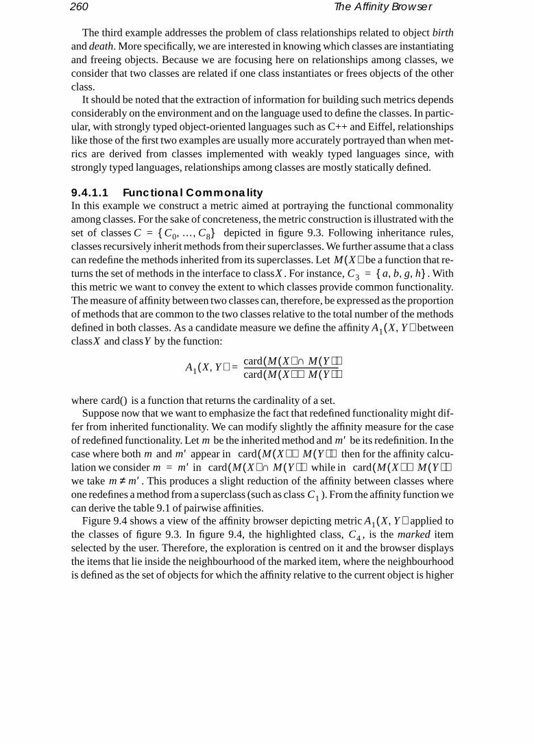
260 The Affinity Browser
The third example addresses the problem of class relationships related to objectbirthatingses, wee other
ends partic-shipsn met-, withd.
alityith the
les,t a classhat re-Withality.portion
ethodstween
ht dif-ase
n thelcu-
heretion we
d to
isplaysrhoodigher
anddeath. More specifically, we are interested in knowing which classes are instantiand freeing objects. Because we are focusing here on relationships among clasconsider that two classes are related if one class instantiates or frees objects of thclass.
It should be noted that the extraction of information for building such metrics depconsiderably on the environment and on the language used to define the classes. Inular, with strongly typed object-oriented languages such as C++ and Eiffel, relationlike those of the first two examples are usually more accurately portrayed than wherics are derived from classes implemented with weakly typed languages sincestrongly typed languages, relationships among classes are mostly statically define
9.4.1.1 Functional CommonalityIn this example we construct a metric aimed at portraying the functional commonamong classes. For the sake of concreteness, the metric construction is illustrated wset of classes depicted in figure 9.3. Following inheritance ruclasses recursively inherit methods from their superclasses. We further assume thacan redefine the methods inherited from its superclasses. Let be a function tturns the set of methods in the interface to class . For instance, . this metric we want to convey the extent to which classes provide common functionThe measure of affinity between two classes can, therefore, be expressed as the proof methods that are common to the two classes relative to the total number of the mdefined in both classes. As a candidate measure we define the affinity beclass and class by the function:
where is a function that returns the cardinality of a set.Suppose now that we want to emphasize the fact that redefined functionality mig
fer from inherited functionality. We can modify slightly the affinity measure for the cof redefined functionality. Let be the inherited method and be its redefinition. Icase where both and appear in then for the affinity calation we consider in while inwe take . This produces a slight reduction of the affinity between classes wone redefines a method from a superclass (such as class ). From the affinity funccan derive the table 9.1 of pairwise affinities.
Figure 9.4 shows a view of the affinity browser depicting metric appliethe classes of figure 9.3. In figure 9.4, the highlighted class, , is themarked itemselected by the user. Therefore, the exploration is centred on it and the browser dthe items that lie inside the neighbourhood of the marked item, where the neighbouis defined as the set of objects for which the affinity relative to the current object is h
C C0 … C8, ,{ }=
M X( )X C3 a b g h, , ,{ }=
A1 X Y,( )X Y
A1 X Y,( ) card M X( ) M Y( )∩( )card M X( ) M Y( )∪( )----------------------------------------------------=
card()
m m′m m′ card M X( ) M Y( )∪( )
m m′= card M X( ) M Y( )∩( ) card M X( ) M Y( )∪( )m m′≠
C1
A1 X Y,( )C4

The Affinity Browser by Example 261
are all
nter-vectors
than a chosen value. In this case, however, due to the small number of items, theydisplayed.
9.4.1.2 Metrics Based on Binary VectorsMany other metrics can be defined to reveal functional commonality. A particularly iesting approach relies on metrics based on binary data. The interest in using binary
2/5 1/2 1/2 1/2 2/7 2/9 2/8 2/11
2/7 2/7 2/7 2/3 4/9 2/11 4/11
1/3 1/3 2/9 4/9 1/2 4/11
1/3 2/9 2/11 2/10 2/13
2/9 2/11 1/2 2/13
4/11 2/13 4/13
4/13 8/11
4/15
Table 9.1 Functional commonality: pairwise affinity.
ab
efcda ij
kl
gh
mn op
qr
C0
C1
C2
C3
C4
C5
C6
C7
C8
Figure 9.3 Inheritance structure of a set of classes.
C1 C2 C3 C4 C5 C6 C7 C8
C0
C1
C2
C3
C4
C5
C6
C7

262 The Affinity Browser
tors to
eachsigna- Refer-
ture islass
to build metrics is that many relationships can be expressed in terms of binary vecwhich we can apply a set of “standard” operations to measure their similarity.
In order to apply these metrics to portray functional commonality we assign to class a binary vector of length , where represents the number of distinct method tures in the system. Each entry of the vector is associated with a method signature.ring to the set of classes depicted in figure 9.3, the binary vector takes the form:
Each entry contains a Boolean value that tells if the associated method signapresent or absent in the class. For example, the binary vector associated with clooks like:
and the vector associated with class:
C7
C4
C8
C6
C5C0
C3
C2
C1
Figure 9.4 Affinity browser display showing a set of classes.
l l
a b c qo p rnd e f g h i j k l m
C0
1 1 0 00 0 000 0 0 0 0 0 0 0 0 0
C6
1 1 1 00 0 011 1 1 0 0 0 0 0 0 1

The Affinity Browser by Example 263
The construction of an affinity metric from binary vectors consists essentially in meas-xiliary
ears
earsearsrnts.ector
erived.ength
ber of metric
ns that
uring to what extent vectors match. These can be defined based on the following auparameters:
wherex andy represent two binary vectors. counts the number of times 1 appsimultaneously in the corresponding entries ofx andy; counts the number of times 1appears inx and 0 iny for corresponding entries; counts the number of times 0 appin x and 1 iny for corresponding entries; and counts the number of times 0 appsimultaneously in the corresponding entries ofx andy. So and count the numbeof entries in whichx andy agree, while and count the number of disagreeme
We propose three metrics to portray functional commonality based on the binary vrepresentation. The first metric is
where and represent the classes from which the binary vectors and are d assesses binary vector similarity in terms of 1-consensus relative to the l
of the binary vectors.The second metric is
With this metric the proportion of the 1-consensus is evaluated relative to the numentries of the vectors excluding those that correspond to a 0-consensus; that is, theassesses affinity in terms of 1-consensus relative to disagreement. This mea
is equivalent to .The third metric
measures binary vector correlation but is not a metric similarity index as areand, consequently, .
ψ11 min xk yk,( )k 1=
l
∑= ψ10 xk ψ11–k 1=
l
∑=
ψ01 yk ψ11–k 1=
l
∑= ψ00 l ψ01 ψ10 ψ11+ +( )–=
Ψ11Ψ10
Ψ01Ψ00
Ψ11 Ψ00Ψ10 Ψ01
A2 X Y,( )Ψ11
l---------=
X Y x yA2 X Y,( )
A3 X Y,( )Ψ11
Ψ11 Ψ10 Ψ01+ +-----------------------------------------=
A3 X Y,( ) A1 X Y,( )
A4 X Y,( )Ψ11Ψ00
Ψ11 Ψ10+( ) Ψ11 Ψ01+( ) Ψ00 Ψ10+( ) Ψ00 Ψ01+( )------------------------------------------------------------------------------------------------------------------------------=
A3 X Y,( )A1 X Y,( )

264 The Affinity Browser
s cancepted
wever,etweene may
sending
formersually work-uratee latter
differboutd thosertray
actually
9.4.1.3 Class AcquaintancesThe functionality of a class is not usually self-contained. Methods belonging to a clasinvoke services from other classes. This perspective corresponds to a commonly acview of object-oriented systems as sets of collaborating objects.
We are interested in understanding patterns of collaboration between objects. Hocollaboration has many aspects. We can focus, for instance, on the relationships bclasses that can be observed by static analysis of the source code. Alternately, wfocus on dynamic acquaintances of classes measured by observing message patterns between objects of the classes.
Both perspectives are interesting and are, to a large extent, complementary. Theperspective usually reflects design decisions since “hard coded” relationships umaterialize links defined at the architectural level. Such links represent the requireding environment for a class. But this perspective may fall short of providing an accpicture if we are looking for working acquaintances between classes. In this case thperspective may be more helpful.
In practice, the collaboration patterns revealed by the two perspectives usuallysignificantly. However, the analysis of the differences might offer useful insight amismatch between the collaborations that have been foreseen by the designer anthat show up in specific execution contexts. We start with a metric intended to postatic class acquaintances. That is, acquaintances that can be determined without executing the methods of the class.
babbbcbdbe
aaabacadae
cacbcccdce
Figure 9.5 A set of cooperating classes. The three classes cooperate by serviceexchange. Each slot represents the body of a method and the arrowsrepresent the activation of a method from the body of another method.
class Cclass A
class B

The Affinity Browser by Example 265
Figure 9.5 represents the analysis context for such a metric. Each class contains a set of, triggercution
letg is a
maxi- many” ac-
nc- might in thissentsy ac-
to dis-lasses. of itsvoca-
ss aber
e serv-ogetheright-
methods and the methods activate methods belonging to other classes that, in turnother methods as well. So the execution of a class’s method usually involves the exeof methods from many classes.
Let denote the number of times class invokes methods from class , and denote the total number of invocations from class to any other class. The followincandidate metric to portray class acquaintances:
which means that the acquaintance affinity between two classes is defined as themum of relative invocation frequency of both classes. We may notice, however, thatdifferent functions can be used instead of to combine the two “one-sidedquaintances. We can define a more general metric as follows:
where and has base . This metric is inspired from a fution proposed by Frank [1] to define the union operation on fuzzy sets. The readerwant to refer to [28] for a detailed discussion about other functions that can be usedcontext. This way of doing things may suggest an interpretation where reprethe affinity degree of an element to affinity set which depicts the unilateral affinitquaintance between class and the other classes.
9.4.1.4 Class Acquaintance SimilaritiesWe may also be interested in class acquaintance similarity. In other words, we wantcover to what extent classes match in terms of the services they ask for from other cLet denote a service; that is, is an association of a class name and onemethods represented by its method’s signature . Let denote the frequency of intion of service from inside the methods of class . We can associate to each clavector with entries containing . The dimension of vector is equal to the numof different services invoked by the classes of the system.
So, the collection of classes can be represented in the -dimensional space of thices, where each class will appear as a point. The idea is that classes lying close tin this space ask for similar services. We may want to modify slightly the service we
I KJ
K J I KK
A5 K J,( ) maxI K
J
I K-----
I JK
I J-----,
=
max()
A5 K J,( ) 1
λ1
I KJ
I K-----–
1–
λ1
I JK
I J-----–
1–
λ 1–--------------------------------------------------------- 1+
log–=
λ 0 1,( ) 1 ∞,( )∪∈ x( )log λ
I KJ
I K⁄J K
K
sC m, s Cm f K
s
s K KvK f K
sd vK
d

266 The Affinity Browser
ing scheme to improve selectivity. Let denote the number of classes from which service
ich few
cisiontween and .
er ob-asons.t pop-s thatggingure oft clean-ifficult
er ofant is-
ically.t per-sourcen andtroy in-
hichects areimpor-ubsys-hase, of both phase
se ac-e
i s
is invoked, and let denote the number of classes. We can defineA service weighting proportional to will assign larger weights to services whare invoked with high frequency in individual classes, but that are only invoked by aclasses. This type of weighting scheme improves substantially both recall and prewhen applied to document retrieval [32]. Finally, we can define a distance metric betwo classes and as the Euclidean distance between the associated vectors
9.4.2 Creation and Destruction Relationships
In an object-oriented environment, objects are usually created and destroyed by othjects. Understanding creation and destruction relationships is important for many reFirst, it provides essential information about which classes are managing the objeculation in the system and, in particular, which are the typical procreators of objectprovide specific kinds of services. Second, this understanding is crucial for debuand, in particular, memory allocation related errors. As a matter of fact, the very natobject-oriented systems as sets of cooperating agents raises the problem of objecup. Designers need to decide who is responsible for freeing the objects. It is often dto assign this responsibility to its creator, especially if the creator is not the consumthe services. The non-destruction of stale objects may become a particularly importsue in the absence of automatic garbage collection.
Creation and destruction relationships can be analyzed either statically or dynamSimilar to acquaintance relationships, dynamic and static analysis provide differenspectives on the creation and destruction relationship. Static analysis based on code scanning essentially provides information about the structure of the creatiodestruction process. We can learn, for instance, which classes can create and desstances of given classes.
Dynamic analysis provides another perspective on the relationship by showing wclass instances are actually creating and destroying objects, and also how many objcreated and destroyed. However, the static perspective falls short of portraying an tant aspect of software execution: execution phases. A typical software system or stem goes through a number of execution phases. It may start with an initialization pthen alternate through several phases. Different phases become evident by analysisinterclass acquaintances and creation and destruction relationships. Entering a newusually corresponds to a significant modification of interaction patterns and an intentivity of object destruction— for phase cleanup— and creation of new objects for thnew execution phase.
s n
Ls log2n log2i s 1.+–=
f Ks
Ls⋅
K J vK vJ

The Affinity Browser by Example 267
The information about the creation relationship can be represented by a matrix like
e iden-lysis.f classution in cre-t has ass
tructionces ofs can
volvedter to-
ichh in-
chro-lready
n. Thean theyocess
where represents the number of times creation of an instance of class can btified inside the source code specifying class , if we are in the context of static anaIn the context of dynamic analysis, represents the number of times instances o
create instances of class during a given time interval. In order to explore execphases we can collect data for several time intervals that should reveal the changesation patterns. The destruction relationship can be represented by a matrix thasimilar form to where entry represents the number of times instances of cladestroy instances of class during a given time interval.
We can derive a matrix
which might represent an acceptable view of the balance between creation and desresponsibilities. For instance, means that class destroyed more instanclass than it created during the time interval under analysis. Many insightful metricbe derived from the information contained in these matrices.
We convey creation relationships in such a way that classes that are frequently inin creation (either by creating or by being created) have more affinity and thus clusgether in the representation. A candidate metric is:
where denotes the maximum value in matrix . fails to show whone of two classes displaying high affinity is responsible for creation. To obtain sucformation we may either define a pair of metrics to be used in exploration with synnized views or create a metric that highlights asymmetry. Both approaches have abeen discussed in the context of the formulation of previous metrics.
We provide another metric to convey the balance between creation and destructioidea is that instances of a class that create more instances of another class thdestroy, display more affinity while a negative balance in the creation/destruction prreduces the affinity between and .
C
CA A, CA B, CA C,
CB A, CB B, CB C,
CC A, CC B, CC C,
=
CX Y, YX
CX Y,X Y
DC DX Y, X
Y
R
CA A, DA A,– CA B, DA B,– CA C, DA C,–
CB A, DB A,– CB B, DB B,– CB C, DB C,–
CC A, DC A,– CC B, DC B,– CC C, DC C,–
=
RX Y, 0< XY
A6 X Y,( )max CX Y, CY X,,( )
max C( )-------------------------------------------=
max C( ) C A6 X Y,( )
X Y
X Y

268 The Affinity Browser
orma-itions,, that In thisects ofstand-rovideis can
s;
ic be-vely,borateation
meject
object to-
metric will
e, forldom
max R min R( )– R min R( )–,( )
9.4.3 Object Relationships
We discussed in the previous section metrics to portray class relationships. The inftion needed to apply those metrics relies either on static analysis of the class definon dynamic analysis of execution activity, or on both. We may notice, in passingmany of the metrics discussed could be used to portray object relationships as well.section we focus specifically on object relationships that are related to dynamic aspthe system’s execution and, therefore, require dynamic behaviour analysis. Undering the dynamic behaviour of a set of objects that collaborate to perform a task can puseful information for reuse and for class management. Dynamic behaviour analysbe helpful:
• in giving useful hints about the usage a developer intended for a particular clas• by showing the typical utilization of classes inside an application;• to tune the performance of classes;• in providing information for the assessment of class designs;• in application debugging.
We now discuss candidate metrics intended to portray different aspects of the dynamhaviour of objects defined in terms of object affinity. In order to perform tasks collectiobjects exchange messages. As a first goal we want to know which objects collaclosely. Because we are interested in dynamic patterns of collaboration, the informneeded to build the metrics is collected by monitoring message passing activity.
Let denote the set of interacting objects during a given tiinterval. We may define an affinity metric between object and ob
by:
where is a function that returns the set of messages sent by object to , and returns the cardinality of a set. So represents the
tal number of messages exchanged during the monitored time interval. With such a of affinity, objects that exchange messages frequently will have more affinity andtherefore cluster together in the affinity browser’s visual representation.
9.4.3.1 Detecting Object Interaction AsymmetryHowever, metric does not show asymmetric interaction patterns. Supposexample, that object sends messages frequently to object while object se
A7 X Y,( ) X Y, Y X,max R( ) min R( )–
-------------------------------------------------------------------------------------------=
O O1 O2 … On, , ,{ }=A8 X Y,( ) X O∈
Y O∈
A8 X Y,( ) card sendX Y,( )( ) card sendY X,( )( )+
card sendOi( )( )i
∑-------------------------------------------------------------------------------------------=
send X Y,( ) XY card x( ) Σicard sendOi( )( )
A8 X Y,( )X Y Y

The Affinity Browser by Example 269
sends messages to object . Measure will not reveal this fact. In order to ex-d to
n
t thatr
o thatrnd to
e playsurther-
estina-
, thew and
ollab-
ppro-s end
X A8 X Y,( )
pose asymmetry we define two metrics, and , that are intendebe used in two synchronized views:We introduce the notion ofsource anddestination to cope with the asymmetry betweethe two metrics; the functions src() and dest() return respectively thesource object and thedestination object. The role of these functions is to enforce a rule so that an objecplays the source role for a given pair (X,Y) in the first metric plays the destination role fothe same pair in the other metric. Additionally, the rule copes with pair symmetry s
and . The rule works as follows: foan affinity context with objects we generate the pairs that correspothe upper right half of a matrix which is illustrated for :
The rule specifies that for each pair, the object that appears on the left-hand sidthe role of the source and the object on the right plays the role of the destination. Fmore, for any such pair (X,Y) the roles for the symmetric pair (Y,X) are assigned to thesame objects. For example, plays the role of the source and the role of the dtion in both and .
When metrics and are represented in synchronized viewsuser can spot asymmetry by looking for pairs of objects that appear close in one viefarther apart in the other. These two metrics provide both global information about coration as well as information about collaboration asymmetry.
However, if we are mostly interested in detecting asymmetry, it might be more apriate to emphasize pairwise interaction instead of global interaction affinity. To thiwe may consider the replacement of metrics and byand . Let
A9a X Y,( ) A9b X Y,( )
A9a X Y,( ) card send srcX Y,( ) dest X Y,( ),( )( )card sendOi( )( )
i∑
-----------------------------------------------------------------------------------=
A9b X Y,( ) card send destX Y,( ) src X Y,( ),( )( )card sendOi( )( )
i∑
-----------------------------------------------------------------------------------=
A9a X Y,( ) A9a Y X,( )= A9b X Y,( ) A9b Y X,( )=n n n 1–( )( ) 2⁄
n 4=
O1 O2,( ) O1 O3,( ) O1 O4,( )
O2 O3,( ) O2 O4,( )
O3 O4,( )
O1 O3O1 O3,( ) O3 O1,( )
A9a X Y,( ) A9b X Y,( )
A9a X Y,( ) A9b X Y,( ) A10a X Y,( )A10b X Y,( )
∆ X Y,( ) card send srcX Y,( ) dest X Y,( ),( ) send destX Y,( ) src X Y,( ),( )∪( )=

270 The Affinity Browser
and
in oneis aage ex-n.
ch [4]
on by
on by
on by or an-
olesn exe-ompo-
ject-bjects related object-g tools
nmentation-relatedrent re- explo-
It is also possible to synthesize information about symmetry of message passingmetric, although the resulting display might be more difficult to interpret.candidate measure for such a view. This measure focuses on symmetry of messchanges and, therefore, suppresses information about frequency of communicatio
Interaction asymmetry is an important issue at the design level. For instance, Booidentifies three roles for objects in terms of message passing activity:
• Actor : an object that operates upon other objects but that is never operated upother objects.
• Server: an object that never operates upon other objects; it is only operated upother objects.
• Agent: an object that can both operate upon other objects and be operated upother objects; an agent is usually created to do some work on behalf of an actorother agent.
Such roles can be identified with metric . The comparison of the rassigned to objects during the design phase, with the effective role they play in givecution contexts, might be instrumental to assess to what extent reusable software cnents are used as intended by their designers.
9.5 Conclusion
This chapter dealt with the exploration of object relationships in the context of oboriented environments. We addressed the important issue of understanding how oare related because such understanding plays an important role in many key issuesto software engineering such as reuse, debugging and software maintenance. Earlyoriented environment designers have identified these issues and provided browsinto help users explore the environment.
We have proposed a new approach to the exploration of an object-oriented envirowhere object relationships are translated into affinity relations so that the object relships can be graphically represented in terms of distance: objects that are strongly appear closer in the representation. The approach has the advantage that many diffelationships can be represented and explored with the same tool and with the same
A10a X Y,( ) card send srcX Y,( ) dest X Y,( ),( )( )∆ X Y,( )
-----------------------------------------------------------------------------------=
A10b X Y,( ) card send destX Y,( ) src X Y,( ),( )( )∆ X Y,( )
-----------------------------------------------------------------------------------=
A11 X Y,( )
A11 X Y,( ) 1abs A9a X Y,( ) A9b X Y,( )–( )abs A9a X Y,( ) A9b X Y,( )+( )---------------------------------------------------------------------–=
A11 X Y,( )

References 271
ration paradigm. From the user’s perspective, affinity is a very intuitive concept that has
-
nowl-
,”
ce on
t Ber-
sonal.
sing
m-
64–
the advantage of being easily translated into a visual distance.
References
[1] Hans-Dieter Böcker, Jürgen Herczeg, “What Tracers are Made Of,”Proceedings of OOPSLA/ECOOP ’90, ACM SIGPLAN Notices, 1990, pp. 89–99.
[2] R. Bolt, “Spatial Data Management,” DARPA Report, MIT, Architecture Machine Group, 1979.
[3] Bernd Brüegge, Tim Gottschalk, Bin Luo, “A Framework for Dynamic Program Analysers,”Pro-ceedings of OOPSLA ’93, ACM SIGPLAN Notices, 1993, pp. 65–82.
[4] Grady Booch,Object Oriented Design With Applications, Benjamin/Cummings, 1991.
[5] Michael Caplinger, “Graphical Database Browsing,”Proceedings of ACM-SIGOIS, SIGOIS bulletin,vol. 7, no. 2–3, Oct. 1986.
[6] Matthew Chalmers and Paul Chitson, “Bead: Explorations in Information Visualization,”Proceed-ings of SIGIR ’92, June 1992, pp. 330–337.
[7] William Donelson, “Spatial Management of Information,”Computer Graphics (Proceedings of SIGGRAPH ’78), Aug. 1978, pp. 203–209.
[8] Furnas Fairchild, Poltrock, “Semnet:Three-dimensional Graphic Representation of Large Kedge Bases,” inCognitive Science and its Applications for Human–Computer Interaction, ed. R.Guindon, Lawrence Erlbaum, Hillsdale, NJ, 1988.
[9] Steven Feiner, “Seeing the Forest for the Trees: Hierarchical Display of Hypertext StructuresPro-ceedings of COIS ’88, Palo Alto, March 1988, pp. 205–212.
[10] C. Fields and N. Negroponte, “Using New Clues to Find Data,” Third International ConferenVery Large Data Bases, Tokyo, Oct. 1977, pp. 156–158.
[11] David Gedye and Randy Katz, “Browsing the Chip Design Database,” University of California akeley, Computer Science Division, Oct. 1987.
[12] Adele Goldberg,Smalltalk-80: The Interactive Programming Environment, Addison-Wesley, Read-ing, Mass., 1984.
[13] I. Goldstein and D. Bobrow, “Browsing in a Programming Environment,”Proceedings of the 14th Ha-waii International Conference on System Science, January 1981.
[14] Charles Herot, “Spatial Management of Data,”ACM Transactions on Database Systems, vol. 5, no. 4,Dec. 1980, pp. 493–513.
[15] William P. Jones, “On the Applied Use of Human Memory Models: The Memory Extender PerFiling System,” International Journal Man–Machine Studies, vol. 25, no. 2, 1986, pp. 191–228
[16] George Klir, Tina Folger,Fuzzy Sets, Uncertainty and Information, Prentice Hall, Englewood Cliffs,NJ, 1988.
[17] M. Kleyn, P. Gingrich, “GraphTrace — Understanding Object-oriented Behaviour Systems UConcurrently Animated Views,”Proceedings of OOPSLA ’88, ACM SIGPLAN Notices, 1988, pp.191–205.
[18] Jeffrey T. LeBlanc, “N-Land: A Visualization Tool for N-Dimensional Data,” Technical Report Coputer Science Department, University of Worcester, May 1991.
[19] Bertrand Meyer,Object-Oriented Software Construction, Prentice Hall, 1988.
[20] Amihai Motro, “Browsing in a Loosely Structured Database,”Proceedings of ACM–SIGMOD 1984,International Conference on Management of Data, 1984, pp. 197–207.
[21] Amihai Motro, “BAROQUE: A Browser for Relational Databases,” vol. 4, no. 2, April 1986, pp. 1181.

272 The Affinity Browser
[22] Amihai Motro, “VAGUE: A User Interface to Relational Databases that Permits Vague Queries,”
ed
tion
ire
ws-p.
Uni-
l
ma-
sing
ACM Transactions on Office Information Systems, vol. 6, no. 2, July 1988, pp. 187–214.
[23] Amihai Motro, Alessandro D’Atri, Laura Tarantino, “The Design of KIVIEW: An Object-OrientBrowser,”Proceedings of the Second International Conference on Expert Database Systems, Virgin-ia, 1988, pp. 17–31.
[24] P. O’Brien and D. Halbert and M. Kilian, “The Trellis Programming Environment,”Proceedings ofOOPSLA ’87, ACM SIGPLAN Notices, Oct. 1987.
[25] Xavier Pintado, Eugene Fiume, “Grafields: Field-directed Dynamic Splines for Interactive MoControl,”Computers & Graphics, vol. 13, no. 1, Jan. 1989, pp. 77–82.
[26] Xavier Pintado, Dennis Tsichritzis, “An Affinity Browser,” Technical Report, Centre Universitad’Informatique, University of Geneva, June 1988.
[27] Xavier Pintado, “Selection and Exploration in an Object-oriented Environment: The Affinity Broer,” in Object Management, ed. D. Tsichritzis, Centre Universitaire d’Informatique, July 1990, p79–88.
[28] Xavier Pintado, “Objects’ Relationships,” Ph.D. Thesis, Centre Universitaire d’Informatique, versity of Geneva, Switzerland, 1994.
[29] Xavier Pintado, “Visualization in the Financial Markets,”VR ’94, Proceedings of the Fourth AnnuaConference on Virtual Reality, Mecklermedia, London, 1994, pp. 80–84.
[30] Andy Podgursky, Lynn Pierce, “Retrieving Reusable Software by Sampling Behaviour,”ACM Trans-actions on Software Engineering and Methodology, vol. 2, no. 3, July 1993, pp. 286–303.
[31] Kenneth Rubin, Adele Goldberg, “Object Behaviour Aanlysis,”Communications of the ACM, vol. 35,no. 9, Sept. 1992.
[32] Gerard Salton,Automatic Text Processing: The Transformation, Analysis, and Retrieval of Infortion by Computer, Addison-Wesley, Reading, Mass. 1988.
[33] Michael Stonebraker and J. Kalash, “Timber: a Sophisticated Database Browser,”Proceedings of the8th International Conference on Very Large Data Bases, Sept. 1982, pp. 1–10.
[34] David Stotts and Richard Furuta, “Petri-Net-Based Hypertext: Document Structure with BrowSemantics,”ACM Transactions on Information Systems, vol. 7, no. 1, Jan. 1989.

PART V
Frameworks andApplications

274

Chapter 10
bynents. rules
morenents
f com-mmu-usable
mposi-mpo-
Visual Composition ofSoftware Applications
Vicki de Mey
Abstract Open applications can be viewed as compositions of reusable andconfigurable components. We introduce visual composition as a way ofconstructing applications from plug-compatible software components. Afterpresenting related work, we describe an object-oriented framework for visualcomposition that supports open system development through the notion ofdomain-specific composition models. We illustrate the use of the frameworkthrough the application of a prototype implementation to a number of verydifferent domains. In each case, a specialized visual composition tool wasrealized by developing a domain-specific composition model. We concludewith some remarks and observations concerning component engineering andapplication composition in a context where visual composition is an essentialpart of the development process.
10.1 Introduction
We definevisual compositionas the interactive construction of running applicationsthe direct manipulation and interconnection of visually presented software compoThe connections between components are governed by a set of plug-compatibilityspecified within acomposition model.
Visual composition is a response to the trends in software development towardscomponent-oriented lifecycles described in chapter 1. With a large number of composupplied by component engineers, application development becomes an activity oposing components into running applications. Visual composition can be used to conicate reusable assets from component engineers to application developers, redesigns to application developers, and open applications to end-users. A visual cotion framework enables the construction of environments and tools to facilitate conent-oriented software development.

276 Visual Composition of Software Applications
In this chapter we present a framework for visual composition. The framework address-) com-
com-ent. A state ofle com-edframe-
ain.soft-.rete
mpo-by an 10.5.owing
ha- notal lan-
devel-ys ofs.
ecy- com-re the
o formrik, Sil-
s ands sim-ompo-
es four issues: (1) components, (2) composition models, (3) user interaction, and (4ponent management. Components are made up of abehaviour and apresentation.Thebehaviour is responsible for the component’s composition interface and the work theponent was designed to do. The presentation is the visual display of the componcomponent can have more than one presentation, and the presentations reflect thethe component. A set of components can be grouped together to function as a singponent through thecomposite component mechanism. Component composition is definas communication between components through their composition interfaces. The work defines the notions ofport andlink to handle the communication. Acompositionmodel is the set of rules for component composition in a particular application domDecoupling the rules for composition from components allows a variety of different ware composition paradigms and increases the potential for reuse of a component
Vista is a prototype implementation of the visual composition framework. A concimplementation of a visual composition tool is obtained by acomponent engineer (chap-ter 1) by completing the framework with components, their presentations and the cosition model governing their interconnection. Finally, the resulting tool can be used application developer to visually compose running applications, as shown in section
In reference to software development environments, Ivar Jacobson made the follstatement:
In the long run, we shall see new development environments that place more empsis on applications and less on technique. Developers will be application experts,Unix or C++ experts. They will work with graphical objects presented in severdimensions, not simply text. The language of today may be handled as a machineguage that is invisible to developers. [23].
These new development environments will have the potential to transform software opment. End-users will play a larger role in putting applications together and new wacreating applications will be necessary. Visual composition is one of these new way
10.2 Related Work
Visual composition is based on work done in many different fields from software lifcles to graphical user interfaces and graphical object editors, visual programming,ponents and connectivity, and component integration. Since the latter two areas amost relevant for this chapter, they will be discussed here.
Visual composition supports components and connecting components together trunning systems. Some exemplary systems based on these ideas are ConMan, Fabicon Graphic’s IRIS Explorer, Apple’s ATG Component Construction Kit and IBM’VisualAge. ConMan [14] is a high-level visual language that allows users to buildmodify graphics applications. To create an application the user interactively connectple components using a directed dataflow metaphor. No concept of composite c

Related Work 277
nents exists. Fabrik [22] is a contemporary of ConMan. Fabrik is a visual programmingat can
e usedhroughviron-d, de-stomn Kitallowsts: (1) (2) aly con-mpo- in thent–s. Thel pro-estinge way
p com-es andecha-can ben con-ages, oronents Harri-proachtionsh are
ration. inte-wlettom- Re-ple2 for ae of an
environment that supplies a kit of computational and user interface components thbe wired together using a bidirectional dataflow metaphor. The environment can bto build new components and applications. Composite components are supported tthe gateway construct. IRIS Explorer is an application creation system and user enment that provides visualization and analysis functionality. It is based on a distributecentralized dataflow model. Its graphical user interface allows users to build cuapplications by connecting modules together. Apple’s ATG Component Constructio(CCK) [43] is a prototype component architecture and set of test components that end-users to plug components into a framework at run-time. The kit has four elemena component framework (the structure within which components are connected);component palette (source of components); (3) an inference engine for automaticalnecting components; (4) a component inspector for display and modification of conent information. Objects are the medium of communication between componentsCCK. VisualAge [20] is a product from IBM designed to build the client side of clieserver applications, focusing on business applications and decision support systemtool is based on the “construction by parts” paradigm that is supported by a visuagramming tool for creating applications non-procedurally. These systems are interbut limited since some cater only to specific application domains or are based on onof expressing the relationships between components.
A component can be seen as a separate tool, application or process. This brings uponent integration issues that run very close to the issues of component interfaccomponent interconnection. Visual composition needs component integration mnisms to implement the connections between components. Integration issues viewed on two levels: coarse-grained and fine-grained. Coarse-grained integratiocerns components that may be large objects that cooperate by exchanging messtools that cooperate through shared files. Fine-grained integration concerns compthat are smaller and usually need to communicate with each other more frequently.son, Ossher and Kavianpour [17] have discussed this issue and proposed an apcalled Object-Oriented Tool Integration Services (OOTIS). They believe that applicaare moving more towards fine-grained integration, but that current systems, whiccoarse-grained, must still be supported while this move takes place.
Many proposals have been made for specific solutions to coarse-grained integSome examples are: Unix facilities that provide a variety of different tools and toolgration mechanisms (character files, I/O redirection, pipes, shell programming); HePackard’s Softbench environment [19]; and Sun’s ToolTalk [26] for interapplication cmunication. Fine-grained integration solutions include efforts by the OMG (Objectquest Broker), NeXT (Distributed Objects [36]), Microsoft (OLE [34]) and Apple (Apevents and the Apple event object model [1], and OpenDoc [2]). See also chapter 1more thorough discussion of these commercial efforts, and chapter 3 for an examplobject-oriented framework to support interoperability.

278 Visual Composition of Software Applications
10.3 A Framework for Visual Composition
ition.: com-ation
pose.
alk’snd-erent
s thellows
es thempo-nentmayenus,
ts the theyerento be-
The framework we present provides a simple and flexible core for visual composThere are three pieces of information that are needed in order to use the frameworkponent behaviours, component presentations and rules for composition. This informis plugged into the framework to produce a visual composition tool for a specific pur
10.3.1 Component Definition
The framework defines a component as abehaviour together with one or morepresenta-tions. Such a “division of labour” has been seen in other frameworks including SmalltMVC framework [13], Unidraw [48] and Andrew [38]. Table 10.1 shows the correspoing terms in the different frameworks. This division promotes reuse, because diffpresentations can be reused with the same or different behaviours.
Behaviour
The behaviour is responsible for the following:• Communication with the presentation(s).• The component’s composition interface. The composition interface advertise
component’s services and requests for services. The composition interface athe component to be reused in different contexts. A component’s context includcomponents it is immediately connected to as well as the entire ensemble of conents in which it finds itself embedded. The composition interface of a compoconsists of a set ofports, each of which has a name, a type and a polarity. Ports be visually presented in a variety of ways, such as knobs, buttons, text fields, metc., depending on the intended semantics.
• Executing whatever the component was designed to do. The behaviour reflecinner part of the component. From the outside, two components can look likehave the same behaviour, but their internal implementations could be very diff(e.g. implemented in different programming languages). A component can alshave differently depending on the other components it is connected to.
Visual composition Behaviour Presentation
MVC Model View, Controller
Unidraw subject view
Andrew data object view
Table 10.1 Comparison of the behaviour/presentation division of labour.

A Framework for Visual Composition 279
not,ains an
. Theation
put canaviour.play
nent is (or re- frame-idered add to set ofesenta-posite illus-
onentse-y is the
Presentation
The presentation is responsible for the following:• Communication with the behaviour.• Visual display of the component. All components, whether inherently visual or
have a visual presentation. A presentation can also process user input if it continteraction component such as a button or a text field.
Communication between the behaviour and presentation is pictured in figure 10.1presentation informs the behaviour of its location and dimensions so that this informcan be passed on to other components that need it to display themselves. Also, inbe done through the presentation, and this information is communicated to the behThe behaviour only informs the presentation of information that it might need to dison the screen.
Composite Components
Components can be created by programming or by composition. When a compocreated by programming, only the behaviour and presentation need to be specifiedused if an appropriate behaviour or presentation already exists) and hooked into thework. A composite component is a set of components linked together that is consuseful as a component in its own right. To define a composite component, one mustthe set of components (1) a composition interface (by specifying which ports of thecomponents are to become ports of the composite component), and (2) a visual prtion (which can be composed of existing presentations). The behaviour of a comcomponent is simply the behaviour of the components it encapsulates. Figure 10.2trates the idea of composite component. The framework supports composite compby definingexternal_port andexternal_view entities. A set of external_port entities reprsents the composite component’s composition interface, and an external_view entit
User input
Values
Location of presentationDimension of presentation
BehaviourPresentation
Figure 10.1 Communication between the behaviour and presentationentities in the framework.

280 Visual Composition of Software Applications
l_view
ion ofefines in-ort in ampo-igure
cationction- that
presentation used for the composite component. Both external_port and externaentities are created interactively when a composite component is being defined.
10.3.2 Component Composition
The way component composition is supported in the framework is through the creatnetworks. The framework uses components for the nodes in the network and dactive_port andlink entities for edges in the network. Not all ports in the compositionterface of a component need to be used. An active_port is created only when a pcomponent’s composition interface is connected to a port in another component’s cosition interface. A link represents the connection from one active_port to another. F10.3 illustrates the relationship between the elements of the framework. Communibetween components can be either one-way (the dark arrows in figure 10.3) or bidireal (both the dark and the grey arrows in figure 10.3). The format of the information
Becomes
Figure 10.2 Composite component.
External ports
External view
Figure 10.3 Framework entities.
Link
ComponentComponent
Active port Active port

A Framework for Visual Composition 281
nt. Theme-
that theation
.5, arerts, thecertain
ghforma-ism toprop-lly ande the of a
p of
can
passes from component to component is defined in the behaviour of the componeformat is not restricted by the framework. The display information is internal to the frawork and should at least include the location and dimensions of the presentation so active_ports and links can be displayed correctly. Figure 10.4 summarizes the informthat is communicated between the active_port and link entities of the framework.
As components are composed, networks, such as the one pictured in figure 10generated. The grey ovals in the figure are components, the black circles are poclear circles are active_ports and the rectangles are links. These networks have characteristics:
• Automatic network update: Information must be automatically propagated throuthe network. Propagation occurs when a node indicates some change to the intion on its outputs. This indicates the need for some type of constraint mechanspecify the relations in the network that must always be satisfied. Information agation could imply some change to the display that must be done automaticaimmediately to support the requirement of direct manipulation. There must boption for immediate propagation or batching for the display, since the updatedensely populated screen can be expensive and possibly postponed
• Hierarchical decomposition: The network must support nodes that are made uother network structures.
• Cyclic networks: In visual composition, the relationships between componentscreate cycles in the network.
Location of presentation
Dimension of presentation
Values
Port location
Values
Values
values
Link
Figure 10.4 Communication between a component, active_port and link.
Component
Active port

282 Visual Composition of Software Applications
gen-_portutput links
y just
rticu-, i.e.pen-
ther ap-om-plingposi-ponent
with
ompo-h, butels in
The division of labour among components, active_ports and links is flexible, but ineral, a link is used to transport information between two active_ports, an input activecontrols whether information should be passed into a component, and an oactive_port packages up information for leaving a component. Both active_ports andcan have an associated visual display.
Composition Model
The active_port and link framework entities do not impose rules on connections; theenable connections. Whether or not a connection is valid is determined by acompositionmodel. The composition model is the set of rules for component composition in a palar application domain. The rules determine compatibility between componentswhich component can be linked to which other component. The type of rules is oended and based on the component, the component’s composition interface, and oplication domain-specific information. Different from many other frameworks, the cpatibility between components is not determined by the components. Decoucomposition models from components supports a variety of different software comtion paradigms and increases the potential for reuse of a component, because a comcan be reused without modification in different application domains by associating itdifferent composition models. A composition model isactive when it is dynamically ap-plied to a set of components to get them to cooperate in a specific application. The csition model can have some knowledge of what components it can be used witusually components do not have to be designed with particular composition modmind.
Figure 10.5 Network of components.
Component Port Active port Link

A Framework for Visual Composition 283
phic flowsroughr com-ailableportsort. If a, thenf data.or en-com-aflow
Thisompo-
of typeied outn two-
Composition Model Examples
Three examples of composition models will be given: dataflow, two-dimensional graobjects and class hierarchy diagrams. Dataflow composition is used for specifyingof data in a network of components. Components have input and output ports thwhich dataflow. Each data value is associated with some component responsible foputing the value as a function of its inputs. The component makes the data value avat one or more of its output ports. Input and output ports can be joined by links. All have an associated type reflecting the type of the data that passes through the pcomponent has only output ports, then it is a supplier of data; if it has only input portsit is a user of data; and if it has both input and output ports, then it is a transformer oLinks represent data flowing between components. Links are primarily responsible fforcing valid dataflow networks. They allow ports to be connected only if they have patible types and compatible directions (input to output and output to input). The datcomponents and composition model are pictured in figure 10.6
Another example is a composition model for two-dimensional graphic objects. model is used to attach and keep two-dimensional graphics objects connected. A cnent (a graphic object) has ports that represent points on the object, i.e. ports arepoint. These ports are either input or output depending on the operation being carron the graphic object to which they belong. The points are the location of the object i
Component Port LinkDataflow
Supplier Transformer User Data Dataflow
Figure 10.6 Dataflow composition model and some connected components.

284 Visual Composition of Software Applications
top of whendateo-di-
e usedmpo-n have of type will not
y. Links,bclassnother;bout its
ponents
s areulate
dimensional space. Links are created between components by placing one point onthe other. Any point can be linked to any other point. When some point changes, asa graphic object is moved, all other points linked to this point will be updated. This upguarantees the connectivity between graphic objects. The composition model for twmensional graphic objects is pictured in figure 10.7.
A third example is that of a class hierarchy diagram. Class hierarchy diagrams arto show the class structure of an object-oriented application. There is one kind of conent for this type of diagram, namely the class component. The class component caports of type subclass and superclass. Some class components will not have portssuperclass; these are leaf classes in the class hierarchy. Some class componentshave subclass ports; these components are top-level classes in the class hierarchwhich represent class relationships, are unidirectional and connect ports of type suto ports of type superclass. Links do not pass data from one class component to atheir role is to make relationships between classes so that when a class is asked asuperclasses and subclasses, it will be able to respond. The class hierarchy comand composition model are pictured in figure 10.8.
10.3.3 Interactive Environment
The interactive environment is responsible for ensuring that the framework entitieused correctly. The interactive environment supplies ways for the user to manip
Graphic objects
LinkTwo-dimensionalgraphic objects
Implicit inposition ofobjects
Component Port
Point Position
Figure 10.7 Two-dimensional graphic composition model and some connected components.

A Framework for Visual Composition 285
aphorsinimald/or re-
tionconceptsen any
expect“try itt is go-
At thes do not
ree-ibilitypo-ke ele-e in,ompo-ing inodatepos-
components, ports and links. This is accomplished using various user interface metdepending on the implementation. The operations listed in table 10.2 make up a mset. The interactive environment is customizable so that operations can be added anmoved.
The interactive environment supports direct manipulation [42]. Direct manipulamakes objects more concrete and thus helps people to grasp better the ideas and being described. Users get immediate feedback to their actions and are informed whof their actions cause a change in the system. Ideally, users always know what tofrom the system. Development becomes more of an exploratory activity where a and see what happens” attitude is encouraged. Being able to see immediately whaing on in an application is important in the early stages of application development. same time, the interactive environment is as transparent as possible so that userhave to do things that make no sense in their specific application domain.
The environment is visual — a mixture of text, graphics (two-dimensional and/or thdimensional), and other media like video, sound and images — and therefore viscontrol is very important. Visibility control is used to modify the presentations of comnents, ports and links. There are operations (see table 10.2) that allow a user to maments invisible according to different criteria like, for instance, what group they arwhat component they are attached to, etc. An application developer using visual csition usually needs more objects visible than an end-user. The developer is workmore general terms, while the end-user is working in a specific domain. To accommthis situation, visibility control can hide information that is not appropriate. The com
Component Port LinkClass hierarchy
Figure 10.8 Class hierarchy composition model and some connected components.
Classrelationship
Subclass
Superclass
Class

286 Visual Composition of Software Applications
unnec-
e con-as win-
Components Ports Links
ite component capability can also be used to shield an end-user from unwanted or essary detail.
Some of the more common characteristics of interactive environment must also bsidered. It is necessary that some type of grouping mechanism be available, such
instantiationmake a functional copy ofthe chosen component
identificationname, type andpolarity of port
createManual creation relies onthe user manually selectingthe start port and target portfor the linkAutomatic connectionwould attempt to automati-cally connect compatibleports when a component isplaced in a compositioncomposition model verifieslink
determine location in spacefixed into a particular loca-tion in space, fixed in rela-tion to other components’locations, or left free to bemoved
copystate is also copied
deletelinks referencing the del-eted component are alsodeleted
delete
replaceThe links that referencedthe original component arereconnected to the newcomponent
display different presenta-tions
Table 10.2 Manipulations on components, ports and links.

Vista — A Prototype Visual Composition Tool 287
dows in the desktop metaphor. The environment supports the undo/redo functionality,helpingiar with hand,llow-enta-e thening anitchese andput is
orma-be re-d. The usedossiblycom-catedities.
e. The] waseface gen-ST, animple
rts ofto thephd froms. Ine dis-
because all users make mistakes. Skill levels, such as novice or expert, are ways of users learn to use a system. These levels usually assume that a novice is not familthe system and therefore needs a bit of “hand-holding.” Expert users, on the othercould consider such hand-holding distracting. Skill levels can be implemented by aing or disallowing certain actions on the objects being manipulated. Different prestions of a component can be used to reflect different skill levels. To further facilitatusage of the environment, mode switches, such as those between building and runapplication, are minimized. The literature [39] suggests that avoiding such mode swis important for new users because it gives them the flexibility simultaneously to usmodify an application, and that typically there is almost no confusion about when indirected to the tool and when it is directed to the application.
10.3.4 Component Management
The activities of storing, organizing and retrieving components are external to theframework, but the framework supplies a simple mechanism that records enough inftion about the network to a text file so that when the file is read, the network can created. Composition models also need to be stored, organized and retrieveinformation stored in the composition model must be activated when a network isand constantly accessible since it is consulted whenever a link is created and pwhenever information flows through a link. Some notation, possibly textual, for the position model is necessary. The framework supports “hooks” for more sophistitools, such as the software information base described in chapter 7, for these activ
10.4 Vista — A Prototype Visual Composition Tool
Vista is a prototype visual composition tool based on the framework described abovprototype is meant as a test-bed for the visual composition framework. Vista [29][37developed as part of ITHACA’s application development environment. (See the prand chapter 7 for more information about the ITHACA project.) Vista is a seconderation prototype; some of the ideas of visual composition were demonstrated in Vearlier prototype based on a Unix composition model [45]. Vista is meant to be a sand evolutionary prototype.
The layers of software supporting Vista are pictured in figure 10.10. The major paVista are in the shaded region of the figure. The implementation of Vista conforms ITHACA software platform which includes C++, X Windows and OSF/Motif. Gramanagement for Vista is supplied by a set of class definitions and functions extractethe Labyrinth System [27], a generic framework for developing graphical applicationVista, components and links are displayed on the screen using Motif widgets and thplay capabilities of Labyrinth.

288 Visual Composition of Software Applications
sitione thatodel.pat-om-nents,sets of
Composition Model Manager
There are at least two ways to go about implementing the functionality of the compomodel. One possibility is to implement a composition model manager as an oracloversees the correct functioning of the framework based on the active composition m
The other possibility is to delegate responsibility for checking and maintaining comibility rules to framework entities. If composition models are used to define global cpatibility between components or global rules encompassing large groups of compoan oracle would probably be the best choice. The oracle can have an overview of
Figure 10.9 RECAST example.

Vista — A Prototype Visual Composition Tool 289
ystemsgraph Vista,ositionsed by
imple-lementour of aass
rnale sub-
enteds. The
e the
aysatiblen be- has a con-
of thes.
networks on which to base global decisions. Some powerful graph management scan also work on a global level in the network; thus the decision for a certain type of manager could influence the implementation of the composition model manager. Inthe composition model manager is an oracle implemented as a C++ class. A compmodel is expressed in a textual notation that expresses port compatibility and is parthe composition model manager.
Components, Active_ports and Links
In Vista, components (behaviours and presentations), active_ports and links are mented as C++ classes. Vista supplies default active_port and link classes. To impthe component behaviour and presentation, four classes are defined. The behavicomponent is implemented in thecmp_Node class and subclasses of the abstract clV_Base. The presentation of a component is implemented in theview_Node class and sub-classes of the abstract classFramer. The cmp_Node and view_Node classes are inteto Vista and maintain network connectivity. The V_Base and Framer classes arclassed by the user of Vista. This division is advantageous because Vista is implemin C++ and modifications to superclasses necessitate recompilation of subclassedivision avoids much of this recompilation since the information added from outsidsystem does not directly impact the internal framework classes and vice versa.
Dividing up the responsibilities of components, active_ports and links is not alwstraightforward. For example, if two ports of different types are defined to be compby a particular composition model, and they are linked, where should the coerciotween port types take place? The input active_port participating in the connectiontype and can coerce things that it receives into that type. The link participating in thenection knows it is connecting ports of compatible types and can coerce the typeinformation from the output active_port to the type that the input active_port expect
Figure 10.10 Layers of software supporting Vista.
Unix
Graph management(Labyrinth)
X Windows
OSF/Motif
Application-specific components andcomposition models
Components
Composition modelmanager
Active ports Links
C++

290 Visual Composition of Software Applications
ience.ctiontion” in fig-ut the
coulddding
re com-e pre-) linksnother
cribedks sim-der to
lassesr and
ta. Com-
Responsibilities can be divided up in certain ways to ameliorate the user’s experFor example, a four-way interaction where all four components interact. The interacan be a new component with the original four components linked to it by “interaclinks or all of the components can be linked together. These two options are picturedure 10.11. Figure 10.11(a) might not look hard to understand as it is pictured here, bpicture would become indecipherable if twenty components were interacting. Portsaccept more than one connection, but this does not reduce the number of links. Acomponents to a system does not necessarily imply that the system becomes moplex. The number of components is not that important; it is how the components arsented that is important, as seen in figure 10.11(b) and 10.11(c). In figure 10.11(care represented by the location of components (e.g. all components contained in acomponent interact) and not by lines connecting the components.
In Vista, active_ports and links can be used to implement any of the scenarios desabove. But as classes are developed, the goal should be to keep active_ports and linple, since too much hidden behaviour will make the system unpredictable and harunderstand.
Application-Specific Components and Composition Models
Components and composition models for specific domains are defined using the cand functionality of the lower layers of software. For components, only the behavioupresentation need to be defined as subclasses of abstract classes supplied by Visposition models are expressed in the textual notation supported by Vista.
10.5 Sample Applications
Johnson and Russo [25] have stated that:
Figure 10.11 Four-way component interaction.
(c) Interaction seen ascontainment
(b) A componentmoderating the
interaction
(a) Direct interaction betweencomponents

Sample Applications 291
a use of a framework validates it when the use does not require any changes to thet.
d getal com- camel com-
rk andptersition
llectiongy thatvisualAST.. Theroce-s was
isfiedhe code
nningre rela-e spec-More
edias wereionsdia
warempo-lica-
e ex-
po-
framework, and helps improve the framework when it points out weaknesses in i
Iteration is a major part of the validation cycle of a framework. The framework shoulbetter (more reusable) as results are gathered from its usage. To this end, the visuposition framework was used in three sample applications. The sample applicationsfrom actual ongoing projects and were not artificially devised as test cases for visuaposition.
The first application was part of a project that addresses the creation of a frameworapid prototyping environment for distributed multimedia applications [32] (see cha11). The visual composition framework was then used to implement a visual compotool for multimedia applications.
The second application was part of a project that addresses the requirements coand specification phase of software development. The project defines a methodolofunctions as a formal basis for requirements specification and support tools. The composition framework was used to implement one of the support tools called REC
The third application was part of a project that addresses workflow applicationsproject defines a complete environment for designing and running coordination pdures. The need for some type of visual representation of coordination procedurerecognized by the participants in the project. The visual composition framework satthis need and was used to draw pictures of coordination procedures and generate tthat the procedures represented.
The scope of these sample applications varies considerably. The first deals with ruapplications and components represent actual executing modules.The other two ated to software specification, where components represent elements of the softwarification model. We will describe the first and second sample applications here. information about all three applications can be found in the author’s thesis [30].
Sample Application 1: Multimedia Component Kit
Chapter 11 introduces the basic concepts of a multimedia framework and multimcomponents. Based on this work, multimedia components and composition modelcreated for visual composition. The visual composition tool for multimedia applicatis a rapid prototyping tool for experimenting with different combinations of multimecomponents.
A multimedia application is implemented by large number of interconnected hardand software components. Visual composition can be used to interactively plug conents together — rather than permanently “hard-wiring” them — thus making apptions more flexible and reconfigurable.
Various composition paradigms are appropriate to multimedia applications. Threample composition models follow:
1. Dataflow composition describes an application as a configuration of media comnents and the data (media streams) that flow between them.

292 Visual Composition of Software Applications
2. Activity composition describes the behaviour of an application with respect to activ-
nd is
sitionw the
will be
er in- can
Some. Theappli- in the.sSeqt, a
inputplica-
encesld).
plica-trib-ccepty, as
eCubecan beender
ities and events.
3. Temporal composition describes relationships between temporal sequences aa special case of activity composition [31].
These three ways of viewing multimedia applications can be reflected in compomodels that determine the types of components useful in the applications and hocomponents interact. The dataflow composition model has been implemented and discussed in detail here.
Viewed from a dataflow perspective, a typical multimedia application accepts usput and displays multimedia information related to the input. This type of applicationbe built from components that represent input devices and multimedia renderers.example multimedia components for dataflow composition are listed in table 10.3GeoBall and Navigator components are responsible for getting user input into the cation. The GeoBall component represents an actual hardware device, picturedpresentation of the component, that generates 4 × 4 geometric transformation matricesThis component can be considered a producer of information of type GeoTran(sequences of 4 × 4 geometric transformation matrices). The Navigator componentransformer component, is responsible for taking the information produced by thedevice and transforming it into a type understandable by other components in the aption. Here, the Navigator component produces information of type MoveSeq (sequof Render requests dealing with movement of objects in the three-dimensional wor
The Modeler component represents the content that will be displayed by the aption. The Modeler gathers together all the information in the application that will conute to the content and prepares the information for display. The Modeler can ainformation from the Navigator component to incorporate user input into the displawell as information from other components that generate content such as the Activcomponent. The ActiveCube component represents a graphical cube object that displayed. The Modeler produces information of type RenderSeq (sequences of R
GeoBall Renderer Modeler Navigator ActiveCube
out:GeoTransSeq in: RenderSeq in: MoveSeqin: RenderSeqout:RenderSeq
in: GeoTransSeqout:MoveSeq
out:RenderSeq
Table 10.3 Components for dataflow composition.

Sample Applications 293
r com-
of the ensures ensurebe putle likegatoree the
multi-e Geo-f the com-sliders
requests) that represent the content in a format suitable for rendering. The Rendereponent accepts information of type RenderSeq and is responsible for its display.
A simple composition model for dataflow can check to make sure that only ports same type are connected as a user interactively creates an application. This modelthat the components making up the application are correctly connected but cannotthat the application is producing the desired result. More semantic information can into the composition model to produce a particular desired result. For example, a ru“if a GeoBall component is in the application, then it must be connected to a Navicomponent” would eliminate the need to explicitly connect them, and would guarantcorrect use of these two components.
Figure 10.12 shows a screen image of the tool displaying a simple dataflow of a media application using the components described in the preceding paragraphs. ThBall component is implemented as a composite component. The internal view ocomposite component is pictured in the upper right side of the figure. The compositeponent contains a geometry ball component and two sets of horizontal sliders. The
Figure 10.12 Multimedia dataflow composition.

294 Visual Composition of Software Applications
adjust the parameters of the device (x, y, z translation andx, y, zrotation sensitivity). Theseput de-vigator
d to aobjects
om-ction ofAST
icationsed
gm ex-ct canl thatcom-onents
ded in a
y thedia-ooper-ms are imple-
cies be-ework.
. Roles in the
st either
ferent exam-d, then a pos- conse-
r of theation.
of the
parameters can be changed interactively and thereby modify the behaviour of the invice as a user navigates through the museum. The input device is connected to a Nacomponent, which connects to a Modeler component, which, in turn, is connecteRenderer component. ActiveCube components, which move cube-shaped graphic given a velocity, are also connected into the Modeler component.
Sample Application 2: RECAST
The RECAST tool [3][4] in the ITHACA software development environment uses a cposition-based approach to requirements specification and provides assisted inspeavailable components by accessing the software information base (SIB). RECassumes that requirements are specified according to an object-oriented specifmodel, called the Functionality in the Objects with Roles Model (F-ORM), which is ufor requirements representation. The model is based on the object-oriented paraditended with the concept of roles [8] to represent the different behaviours that an objehave during its lifetime. F-ORM is a textual definition language and RECAST is a toographically manipulates F-ORM requirements. RECAST was built using the visual position framework. F-ORM classes and class elements are represented by compand class relationships are represented by links. The class relationships are recorcomposition model so that a user of RECAST is assured of using F-ORM correctly.
The composition concept of RECAST is reflected in a set of diagrams defined bITHACA object-oriented methodology [9]. The methodology defines five types of grams at the application design level: class diagram, cluster tree diagram, cluster cation diagram, state/transition diagram and IsA/PartOf diagrams. These five diagraused by the application designer when specifying requirements. The class diagrammented in RECAST is described here.
The class diagram represents F-ORM classes and roles along with the dependentween classes and roles. Classes have corresponding Class components in the framThe presentation of the Class component contains at least the name of the classhave corresponding Role components and are graphically displayed embeddedClass component to which they belong. Class components can be in theirbase represen-tation, where all the roles are visible, or in acompact representation, where only the clasname is visible. Role components are connected by message links that represenunidirectional or bidirectional message flows.
Colours are used extensively to distinguish different types of components and diftypes of links. Shading is used to signal if certain classes or roles are selected. Forple, if a class or role is not selected, it is not shaded. If a class or role is darkly shadeit was selected by the user. If a class or role is lightly shaded, then it was selected bysible design action. If a class or role is moderately shaded, then it was selected as aquence of a design action.
The components for class diagrams are summarized in table 10.4. The behaviouClass component is responsible for changes in the F-ORM requirements specificThese changes are made by direct manipulation of the graphical representation

Sample Applications 295
class. Such changes include the addition of classes to the diagram, adding and deletingrespon-ut theions ofs to the
nent is cluster
r. Thisicationpro-
ation frame
compo- roles,ide the
roles, and the transformation of a class into a set of classes. The behaviour is also sible for the display of the class (base or compact) and the display of information aboclass. The behaviour of the Role component is responsible for managing design actthe role, the presentation of the role, access to the properties of the role, and accesstate/transition diagram for the role. The behaviour of the Cluster-reference comporesponsible for mediating the connection between the active class diagram and thethe reference is representing.
Figure 10.13 shows the class diagram for the OrderManagementSystem clustediagram is generated by using RECAST to transform a request-processing applinto an order-processing application. Interacting with RECAST in the following way duces the OrderManagementSystem cluster:
1. The user starts a new application called OrderManagementSystem.
2. The user consults the SIB for the application domain and a generic applicframe. In this case the application domain is sales and the generic applicationis request processing. The RequestProcessing class is chosen.
3. The RequestProcessing class is copied into the diagram generating a Class nent called MyReqProc. The MyReqProc component has a set of associatedrepresented as Role components in the diagram, which are embedded inspresentation of MyReqProc.
Process class Resource class Role Cluster-reference
in: messagein: roleout: messageout: classin/out: classin/out: classin/out: message
all from process classplus:in/out: resclassin/out: resclass
in: messagein: classin: stdiagramout: messageout: rolein/out: message
in: messageout: messagein/out: messagein/out: classin/out: classin/out: resclassin/out: resclass
Table 10.4 Class diagram components.
namelevel

296 Visual Composition of Software Applications
T con-nd a cli-ation
mation
are re-nagerented
4. The Receive Role component is selected. Because of the selection, RECASsults its design suggestions and suggests adding a request manager agent aent agent to the diagram. The client agent represents the source of the informfor MyReqProc. The request manager agent represents the requested inforof MyReqProc.
5. The suggestions are executed and the corresponding Class components trieved. For the client agent, MyClient class is retrieved. For the request maagent, MyRequest and MyReqAdmin are retrieved. The message links, represby thin black arrows, between all the Class components are displayed.
Figure 10.13 RECAST example.

Discussion 297
6. MyReqProc is specialized to MyOrderProc and MyRequest is specialized to My-
es theuch of
ple-stions
ful in-ame-ctions,mmonppli-s for
es or
e thent in-
at firsth dif-
that areonentm the
e two at the
ese re-
set ofns.
Order. Specialization is represented by thick grey arrows.
The sample applications demonstrate that the visual composition framework makprocess of building graphical, component-based applications easier by supplying mthe infrastructure such applications require.
10.6 Discussion
As a result of the work done on the visual composition framework, the prototype immentation of a visual composition tool and the sample applications, certain suggeconcerning component definition, composition and visualization can be made.
10.6.1 Component Definition
The choice of components for a particular application is still somewhatad hoc, and resultsfrom other fields, such as the reverse engineering of applications, could supply useformation for component design. Work by, among others, Johnson [24] [11] on frwork design has highlighted some key strategies such as finding common abstradecomposing problems into standard components, parameterizing and finding copatterns of interaction. With this work in mind and the experience from the sample acations described in the previous section, we present the following list of guidelinedesigning reusable components:
• If a concept is used, or looks like it could be used, in a number of different placapplication domains, this concept should probably be a component.If the same concept were included explicitly in every component, there would bsame functionality spread throughout the component set, proliferating redundaformation and negating efforts of encapsulation and reuse.Parameterization can be used to generalize concepts that might look different glance but, with further investigation, they could really be the same concept witferent values for a few different parameters.User interface components are a good example since they represent conceptsreused in many applications. The Modeler component in the multimedia compkit is also a good example. If the Modeler component had not been separate fro3DRenderer component, the same model information would not be able to drivdifferent renderers, say a three-dimensional and a two-dimensional renderer,same time.
• If a component requires an undetermined or variable number of resources, thsources should probably be components.Since this type of information can be quite variable, it seems natural to define alower-level primitive components and compose them into different configuratio

298 Visual Composition of Software Applications
An example of this is found in RECAST for the implementation of the class and role be dy-ferentrole as
ke ad-
unt of
ave tos are
nkingents, must
con-
, “big-ess longmore.
dele- shouldmon
es. Ef-d de-
sitiont typescribeuld bentainss, both
components. Since a class can have a variable number of roles, and roles cannamically added or removed, it is much easier to make classes and roles difcomponents that share the relationships roleOf and class than to include the part of the class.
• Composite components should contain a small number of components and tavantage of hierarchical decomposition.This allows concepts to be organized more effectively and reduces the amoscreen clutter.
• The number of components should be small but extensible.A small set of components helps people remember what components they hwork with, but the set must be extensible so that when valuable new primitivediscovered they do not have to be simulated with the existing components.
• Components should strike a balance between concreteness and abstraction.From their experience with the world around them, people are more used to thiconcretely rather than abstractly. Visual composition uses a set of componwhich are abstractions, for application construction. A balance between the twobe made. Components cannot require the user to fill in every detail— if they had todo that, then visual composition would be worthless. But components cannotceal all the details since the user would never figure out what to do with them.
• Big components can be reusable.It is claimed that the bigger a component gets, the harder it is to reuse [5]. Hereger” means more complexand more specific. A component being more specific domake it harder to reuse, but being complex does not have to cause problems. Aas the composition interface of a component correctly reflects its behaviour, complex components can be reused just as well as less complex components
10.6.2 Composition
Choosing an effective set of rules for composition is not easy. Visual composition gates this decision to the users, on the basis that they know best how componentscommunicate in their particular application. More effort is needed to determine comsets of rules that are often observed in applications as well as domain-specific rulforts such as the Law of Demeter [28], contracts [18], law-governed systems [35] ansign by contract [33] all contribute to this area.
Alternative ways for expressing composition models are needed. The compomodel was implemented as a small textual language (essentially just listing the porand their compatibilities) in Vista. It could be useful to use visual composition to descomposition models. Certain rules, like no cycles allowed between components, coillustrated by diagrams like the ones pictured in figure 10.14. If a component set coa huge number of components, and a composition model has a huge number of rule

Discussion 299
nother
g ableontrib-
designsenta-on willility is visualment
-di-ten berooks sim-
ncep-s. It ismptson-
newibili- flow-
the textual and graphical representation of the model could get awkward, and astrategy might become necessary.
10.6.3 Visualization
The visual aspect of visual composition is one of its most important features. Beinto see the pieces that make up applications and manipulate these pieces directly cutes greatly to the understanding of an application. Seeing the impact of certain choices is very advantageous. But, as with all visual communication, a suitable pretion must be chosen otherwise the effectiveness and quality of the visual expressibe brought into question. What is suitable can vary from person to person, so flexibimportant, but people still have to understand each other. Any enhancements to thepresentation must give a user a more comfortable, informative and familiar environin which to work.
Visualization is the visual representation of information using, for example, twomensional/three-dimensional computer graphics. Solutions and problems can ofeasier and faster to recognize visually than having to sort through program text. Bdoes not favour visualizing software, saying: “In spite of progress in restricting andplifying the structures of software, they remain inherently unvisualizable, and thusdo notpermit the mind to use some of its most powerful conceptual tools” [6] (emphasis added).Despite Brooks’s pessimistic view, a person’s visual capacity is such a powerful cotual tool that it must be explored as a possible aid in dealing with complex systempossible that not every level of software is visualizable, but this should not limit atteto try to profit from visualization where appropriate. Scientific visualization has “demstrated previously unknown flaws in numerical simulations and made possibleknowledge and insight” [41]. Harel [15] takes a more optimistic view about the possties of visualization. Like Brooks, he agrees that the “traditional” diagrams, such as
Figure 10.14 Example visualizations of some composition model rules.
Cycles allowed betweenany two components
Cycles allowed betweenneighbouring components

300 Visual Composition of Software Applications
charts, are not what is needed for modeling systems. But a lot of the conceptual constructsnd to-senta-
epts and col-ul men-
erest-s that
dimen-awn hasompo-movesed and
appli- becomeTo sup-
ent ints and new putshical
resentcribedlmann anddia
bbs,
underlying software systems can be captured naturally by notions from set-theory apology that have natural spatial/graphical representations. Harel calls these repretionsvisual formalisms [16] and they all have rigorous mathematical semantics. Concsuch as containment, connectedness, overlap and adjacency as well as shape, sizeour are used to depict a system. Combining these techniques can trigger many useftal images of what is going on in a system.
In Vista, only two-dimensional presentations have been used, and it would be inting to see if a third dimension could enhance the effectiveness of the tool. Situationcurrently use up too much screen space could be more effectively treated in three sions. Examples of this type of work exist [7][40][46]. Different conclusions can be drif the application domain is inherently non-graphic or inherently graphic. Animationalso been used to help understand systems [10][12][44] and would enhance visual csition. For example, a “data map” that shows where data is, how it is used and how it around the application could give a global picture of data usage. Data could be taggfollowed through the executing application.
10.7 Conclusion
The landscape of software is changing from monolithic closed applications to open cations composed of reusable components. As the landscape changes, end-usersapplication developers and application developers become component engineers. port this new landscape, the software industry needs to promote the idea of investmcomponents. Among other things, this means developing repositories of componentools for developing applications from components. Visual composition can lead totools and environments which would contribute to the fulfilment of our duty, as Harelit, “to forge ahead to turn system modeling into a predominately visual and grapprocess.”
Acknowledgements
The work described in this chapter has benefited from the efforts of many past and pmembers of the Object Systems Group. The prototype visual composition tool deshere includes efforts by Betty Junod, Oscar Nierstrasz, Serge Renfer, Marc Stadeand Ino Simitsek. The precursor to Vista — VST — was implemented by Jan VitekMarc Stadelmann, with contributions from Gerti Kappel. The work on the multimeframework includes efforts by Christian Breiteneder, Laurent Dami, Simon GiMichael Papathomas and Dennis Tsichritzis.

References 301
Much of this work was done in the context of the ITHACA project. Roberto Bellinzonaad of
LI-
ents
ork-
dol- in
In--
r of
raction
pp.
Fine-
of Politecnico di Milano worked on the RECAST sample application and Hayat IssIFATEC worked on the component set of the workflow sample application.
References
[1] Apple Computer, Inc.,Inside Macintosh: Interapplication Communication, Addison-Wesley, Read-ing, Mass.
[2] Jeff Alger, “OpenDoc vs. OLE,”MacTech Magazine, vol. 10, no. 8, Aug. 1994, pp. 58–70.
[3] Roberto Bellinzona and Mariagrazia Fugini, “RECAST Prototype Description,” ITHACA.POMI.91.E.2.8.#1, Politecnico di Milano, Nov. 28, 1991.
[4] Roberto Bellinzona, Mariagrazia Fugini and Giampo Bracchi, “Scripting Reusable RequiremThrough RECAST,” ITHACA.POLIMI.92.E.2.9.#1, Politecnico di Milano, July, 1992.
[5] Ted J. Biggerstaff and C. Richter, “Reusability Framework, Assessment and Directions,”IEEE Soft-ware, March 1987, pp. 41–49.
[6] Fred P. Brooks, “No Silver Bullet,”IEEE Computer, April 1987, pp. 10–19.
[7] Stuart Card, G. Robertson and J. Mackinlay, “The Information Visualizer: An Information Wspace,”CHI ’91 Conference Proceedings, New Orleans.
[8] Valeria De Antonellis, Barbara Pernici and P. Samarati, “F-ORM METHOD: A F-ORM Methoogy for Reusing Specifications,”IFIP WG 8.4 Working Conference on Object-Oriented AspectsInformation Systems, Quebec, Oct. 1991.
[9] Valeria De Antonellis and Barbara Pernici, “ITHACA Object-Oriented Methodology Manual —troduction and Application Developer Manual (IOOM/AD),” ITHACA.POLIMI.UDUNIV.91.E.8.1, Oct., 1991.
[10] Wim De Pauw, Richard Helm, Doug Kimelman and John Vlissides, “Visualizing the BehavioObject-Oriented Systems,” inProceedings OOPSLA ’93, ACM SIGPLAN Notices, vol. 28, no. 10,Oct. 1993, pp. 326–337.
[11] Erich Gamma, Richard Helm, JohnVlissides and Ralph E. Johnson, “Design Patterns: Abstand Reuse of Object-Oriented Design,” inProceedings ECOOP ’93, ed. O. Nierstrasz,LectureNotes in Computer Science, vol. 707, Springer-Verlag, Kaiserslautern, Germany, July 1993, 406–431.
[12] Steven C. Glassman, “A Turbo Environment for Producing Algorithm Animations,” inProceedingsIEEE Symposium on Visual Languages, Aug. 1993, pp. 32–36.
[13] Adele Goldberg, “Information Models, Views and Controllers,”Dr. Dobb’s Journal, July, 1990.
[14] Paul E. Haeberli, ”ConMan: A Visual Programming Language for Interactive Graphics,”ACMComputer Graphics, vol. 22, no. 4, Aug. 1988, pp. 103–111.
[15] David Harel, “Biting the Silver Bullet,”IEEE Computer, vol. 25 no. 1, Jan., 1992, pp.8–20.
[16] David Harel, “On Visual Formalisms,”Communications of the ACM, vol. 31, no. 5, May 1988, pp.514–530.
[17] William Harrison, Harold Ossher and Mansour Kavianpour, “Integrating Coarse-Grained andGrained Tool Integration,”Proceedings CASE ’92, July 1992.

302 Visual Composition of Software Applications
[18] Richard Helm, Ian Holland and Dipayan Gangopadhyay, “Contracts: Specifying Behavioural Com-
inois,
.0),”lion,
tation
y of
sual
1992.
ram-
= Ap-
, pp.
rfacehnol-
positions in Object-Oriented Systems,”Proceedings OOPSLA/ECOOP ’90, ACM SIGPLAN Notic-es, vol. 25, no. 10, Oct. 1990, pp. 169–180.
[19] HP Journal, vol. 41, no. 3, June 1990 (HP SoftBench).
[20] IBM, VisualAge documentation and demo diskette.
[21] ITHACA Tecnical Annex, Sept. 1988.
[22] Dan Ingalls, “Fabrik: A Visual Programming Environment,”ACM SIGPLAN Notices, vol. 23, no.11, Nov. 1988, pp. 176–190.
[23] Ivar Jacobson, “Is Object Technology Software’s Industrial Platform?”IEEE Software, vol. 10, no.1, Jan. 1993, pp. 24–30.
[24] Ralph E. Johnson, “How to Design Frameworks,” OOPSLA ’93 tutorial notes.
[25] Ralph E. Johnson and Vincent F. Russo, “Reusing Object-Oriented Designs,” University of IllTR UIUCDCS 91-1696.
[26] A. Julienne and L. Russell, “Why You Need ToolTalk,”SunExpert Magazine, vol. 4, no. 3, March1993, pp. 51–58.
[27] Manolis Katevenis, T. Sorilos and P. Kalogerakis, “Laby Programmer’s Manual (version 3ITHACA report FORTH.92.E3.3.#1, Foundation of Research and Technology — Hellas, IrakCrete, Jan. 1992.
[28] Karl Lieberherr and Ian Holland, “Assuring Good Style for Object-Oriented Programs,”IEEE Soft-ware, Sept. 89, pp. 38–48.
[29] Vicki de Mey, Betty Junod, Serge Renfer, Marc Stadelmann and Ino Simitsek, “The Implemenof Vista — A Visual Scripting Tool,” inObject Composition, ed. D. Tsichritzis, Centre Universitaired’Informatique, University of Geneva, June 1991, pp. 31–56.
[30] Vicki de Mey, “Visual Composition of Software Applications,” Ph.D. thesis no. 2660, UniversitGeneva, 1994.
[31] Vicki de Mey, Christian Breiteneder, Laurent Dami, Simon Gibbs and Dennis Tsichritzis, “ViComposition and Multimedia,”Proceedings Eurographics ’92.
[32] Vicki de Mey and Simon Gibbs, “A Multimedia Component Kit,”Proceedings ACM Multimedia’93.
[33] Bertrand Meyer, “Applying ‘Design by Contract’,”IEEE Computer, Oct. 1992, pp. 40–51.
[34] Microsoft, Object Linking and Embedding Programmer’s Reference (pre-release), version 2,
[35] Naftaly H. Minsky and David Rozenshtein, “ A Law-Based Approach to Object-Oriented Progming,” Proceedings OOPSLA ’87, Oct. 1987, pp. 482–493.
[36] NeXT, Distributed Objects, release 3.1, 1993.
[37] Oscar Nierstrasz, Dennis Tsichritzis, Vicki de Mey and Marc Stadelmann, “Objects + Scripts plications,”Proceedings, Esprit 1991 Conference, Kluwer, Dordrecht, 1991, pp. 534–552.
[38] Andrew J. Palay, “Towards an ‘Operating System’ for User Interface Components,” inMultimediaInterface Design, ed. M. M. Blattner and R. B. Dannenberg, Frontier Series, ACM Press, 1992339–355.
[39] Randy Pausch, Nathaniel R. Young and Robert DeLine, “SUIT: The Pascal of User InteToolkits,” Proceedings of the Fourth Annual Symposium on User Interface Software and Tecogy, Nov. 1991, pp. 117–125.

References 303
[40] Steven P. Reiss, “A Framework for Abstract 3D Visualization,” inProceedings IEEE Symposium
tion
ware,”
een
ell,”e-
rmat-
tan-
on Visual Languages, Aug. 1993, pp. 108–115.
[41] Lawrence J. Rosenblum and Gregory M. Nielson, “Guest Editors’ Introduction: VisualizaComes of Age,”IEEE Computer Graphics and Applications, vol. 11, no. 3, May 1991, pp. 15–17.
[42] Ben Shneiderman, “Direct Manipulation: A Step Beyond Programming Languages,”IEEE Compu-ter, vol. 16, no. 8, Aug. 1983, pp. 57–69.
[43] David C. Smith and Joshua Susser, “A Component Architecture for Personal Computer Softin Languages for Developing User Interfaces, ed. B. Myers, Jones & Bartlett, 1992, pp. 31–56.
[44] Randall B. Smith, “Experiences with the Alternate Reality Kit: An Example of the Tension BetwLiteralism and Magic,”IEEE Computer Graphics and Applications, Sept. 1987, pp. 42–50.
[45] Marc Stadelmann, Gerti Kappel and Jan Vitek, “VST: A Scripting Tool Based on the UNIX Shin Object Management, ed. D. Tsichritzis, Centre Universitaire d’Informatique, University of Genva, July 1990, pp. 333–344.
[46] John T. Stasko and Joseph F. Wehrli, “Three-Dimensional Computation Visualization,” inProceed-ings IEEE Symposium on Visual Languages, Aug. 1993, pp. 100–107.
[47] Dennis Tsichritzis and Simon Gibbs, “Virtual Museums and Virtual Realities”Proceedings Inter-national Conference on Hypermedia & Interactivity in Museums, Archives and Museum Infoics,Technical Report no. 14, Pittsburgh, Oct. 14–16, 1991, pp. 17–25.
[48] John Vlissides, “Generalized Graphical Object Editing,” Technical Report CSL-TR-90-427, Sford University June 1990.

304

Chapter 11
n off ex-
is thegs pro-
ral ar-intings,l arte-int pro-ed by
d sogh, that
Multimedia ComponentFrameworks
Simon Gibbs
Abstract This chapter looks at the use of object-oriented technology, inparticular class frameworks, in the domain of multimedia programming. Afterintroducing digital media and multimedia programming, the central notion ofmultimedia frameworks is examined; an example of a multimedia frameworkand an application that uses the framework are presented. The exampleapplication demonstrates how object-oriented multimedia programming helpsto insulate application developers from “volatility” in multimedia processingcapabilities — this volatility and related uncertainty is currently one of the keyfactors hindering multimedia application development.
11.1 Digital Media and Multimedia
In discussing object-oriented multimedia, a convenient starting point is the notiomedia artefacts. Here the term “media” is used in the sense of materials and forms opression. This includes bothnatural media, such as inks and paints, anddigital mediamade possible by computer technology. The latter either mimic natural media, ascase with drawing and paint programs, or have no natural counterparts. Those thinduced by working in or with a particular medium are what we call media artefacts.
The distinction between natural and digital media also applies to artefacts. Natutefacts are those produced using natural media. Among natural artefacts are paprints, sculptures, photographs, musical recordings, and video and film clips. Digitafacts include both the artefacts of digital media, such as an image produced by a pagram, and the digitized artefacts of natural media, for instance an image producscanning a photograph.
Until fairly recently, artists and designers primarily worked with natural media anproduced what we have just described as natural artefacts (it should be noted, thou

306 Multimedia Component Frameworks
we are including such technologies as film and video as “natural” media). But the tools ofputer,
There can bes net- arte- bytes,igitalio and
cord-ltime-iques,posi-
dia or large the
ple, re-epareiron-
nd
eri-
e-
ith dig-
soft-dia isbroughtsor norance
the trade are changing, and now, as a result of the increasing capabilities of the comhigh-quality digital artefacts are becoming easier, and less expensive, to produce.are many advantages to digital, as opposed to natural, artefacts — digital artefactseasily modified, copied, stored or retrieved. They can be sent over communicationworks and can be made interactive. Equally intriguing is the ease with which digitalfacts are combined. Because, ultimately, digital artefacts simply reduce to bits andthere are no physical restrictions on combining artefacts of different digital media. Dvideo can be placed in text, or, vice versa, text can be placed in video; similarly audgraphics can be combined, speech and text can be combined, and so on.
The notion of media artefacts leads to a natural definition formultimedia. We considermultimedia to be broadly concerned with the creation, composition, presentation, reing, editing and, in general, manipulation, of artefacts from diverse media. Since mudia is so free in style, an immense variety of techniques, and combinations of technare available to the artist. This is reflected in the wealth of media manipulation, comtion and transformational capabilities packaged in multimedia authoring tools.
11.2 Multimedia Systems and Multimedia Programming
A complex multimedia production, whether a video game, a multimedia encyclopaea “location-based entertainment environment,” often requires the concerted effort ofteams of people. Like film and video production, multimedia production calls upontalents of artists, actors, musicians, script writers, editors and directors. These peosponsible for “content design” to use current terminology, create raw material and prit for presentation and interaction. In doing so they rely on multimedia authoring envments to edit and compose digital media.
The authoring environments used for multimedia production are examples ofmulti-media systems [9]. Some other examples are:
• multimedia database systems — used to store and retrieve, or better, to “play” a“record” digital media;
• hypermedia systems — used to navigate through interconnected multimedia matal;
• video-on-demand systems — used to deliver interactive video services over widarea networks.
The design and implementation of the above systems, and other systems dealing wital media, forms the domain ofmultimedia programming.
Multimedia programming is based on the manipulation of media artefacts throughware. One of the most important consequences arising from the digitization of methat artefacts are released from the confines of studios and museums and can be into the realm of software. For instance, the ordinary spreadsheet or wordproceslonger need content itself with simple text and graphics, but can embellish its appea

Multimedia Systems and Multimedia Programming 307
with high-resolution colour images and video sequences. (Although the example is in-y op-ssinga can
rs arestand-ossibletill becation
the
alongc-vents;ted
aveoush theperat-e syn-se re-
ple-, ques-udio,nter-is an-
andppli-e-offs
a-asesed that
sed tocation
tended somewhat facetiously, we should keep in mind that digital media offer manportunities for abuse. Just as the inclusion of multiple fonts in document procesystems led to many “formatting excesses,” so the ready availability of digital medilead to their gratuitous use.)
With the appearance of media artefacts in software applications, programmefaced with new issues and new problems. Although recent work in data encoding ards, operating system design and network design has identified a number of pservices for supporting multimedia applications, the application programmer must saware of the capabilities and limitations of these services. Issues influencing applidesign include:
• Media composition — digital media can be easily combined and merged. Amongcomposition mechanisms found in practice are:spatial composition (the documentmetaphor) which deals with the spatial layout of media elements;temporal composi-tion (the movie metaphor) considers the relative positioning of media elements a temporal dimension;procedural composition (the script metaphor) describes ations to be performed on media elements and how media elements react to eand semantic composition (the web metaphor) establishes links between relamedia elements.
• Media synchronisation — media processing and presentation activities often hsynchronisation constraints [10][13]. A familiar example is the simultaneplayback of audio and video material where the audio must be “lip synched” witvideo. In general, synchronisation cannot be solved solely by the network or oing system and, at the very least, application developers must be aware of thchronisation requirements of their applications and be capable of specifying thequirements to the operating system and network.
• User-interfaces — multimedia enriches the user-interface but complicates immentation since a greater number of design choices are available. For exampletions of “look-and-feel” and interface aesthetics must now take into account avideo and other digital media, instead of just text and graphics. Multimodal iaction [2], where several “channels” can be used for information presentation, other challenge in the design of multimedia user-interfaces.
• Compression schemes — many techniques are currently used, some standardsome proprietary, for the compression of digital audio and video data streams. Acation developers need to be aware of the various performance and quality tradamong the numerous compression schemes.
• Database services — application programming interfaces (APIs) for multimedia dtabases are likely to differ considerably from the APIs of both traditional databand the more recent object-oriented databases. For example, it has been argumultimedia databases require asynchronous, multithreaded APIs [6] as oppothe more common synchronous and single-threaded APIs (where the appli

308 Multimedia Component Frameworks
sends the database a request and then waits for the reply). The introduction of con-
rtnewmedia.vic- must
ort suc-tionsessor
cture,at wetrac-
vail-mingpe of multi-on and
earlya ap-o re-11])nts andve the
ming in the at theirents. a wayveral
currency and asynchrony has a major impact on application architecture.• Operating system and network services — recent work on operating system suppo
for multimedia — see Tokuda [14] for an overview — proposes a number of services such as real-time scheduling and stream operations for time-based Similarly, research on “multimedia networks” (e.g. [4], [12]) introduces new seres such as multicasting and “quality of service” (QoS) guarantees. Developersconsider these new services and their impact on application architecture.
• Platform heterogeneity — cross-platform development, and the ability to easily pan application from one platform to another, are important for the commercialcess of multimedia applications. It is also desirable that multimedia applicaadapt to performance differences on a given platform (such as different procspeeds, device access times and display capabilities).
In summary, a rich set of data representation, user interface, application architeperformance and portability issues face the developers of multimedia systems. Whseek from environments for multimedia programming are high-level software abstions that help developers explore this wide design space.
11.3 Multimedia Frameworks
In identifying abstractions for multimedia programming one should consider the preing programming paradigms such as functional programming, rule-based programand object-oriented programming. While discussion of this topic is beyond the scothis chapter, our position is that each of these paradigms has something to offer tomedia, but that object-oriented programming, because of its support for encapsulatisoftware extension, is perhaps the most natural.
The apparent affinity between multimedia and object-oriented programming is clevident if one looks at the short history of programming environments for multimediplications. From the earliest multimedia toolkits, such as Muse [8] and Andrew [3], tcent commercial multimedia development environments (e.g. Apple [1], Microsoft [one can see the influence of the object-oriented paradigm. Often these environmetoolkits, in addition to structuring interfaces into classes and class hierarchies, hamore ambitious goal of building class frameworks for multimedia programming.
Perhaps the main benefits of object-oriented technology to multimedia programare its mechanisms for extending software environments. Many of the issues listedprevious section (media composition techniques, compression schemes, etc.) are,core, questions of how best to cope with the uncertainties of evolving environmFrameworks, or hierarchies of extensible and interworking classes, offer developersof coping with evolution (see chapter 1). In the case of multimedia programming, se“evolutionary processes” are of concern, in particular:

A Multimedia Framework Example — Components 309
• Platform evolution — the hardware platforms for multimedia applications are rapid-pres-e “set
m-. Such plat-ptimales or
me-nd re-
hangesenta-evel-
for
port fully, trans-
es of earlier
ner.pera-ed bylicatedlems
. val-F, two
a soft-m media
ly evolving. Capabilities that were once considered exotic, such as video comsion and digital signal processing, are now found on the desktop (and soon thtop”).
• Performance evolution — many of the operations of interest to multimedia programing have real-time constraints, consider audio or video playback as examplestemporal dependencies make multimedia applications particularly sensitive toform performance. It may be necessary, for instance, to adapt to less than oprocessing capacity by reducing presentation “quality” (e.g. lowering frame ratsample sizes).
• Format evolution — new data representations for image, audio, video and otherdia types are likely to appear as a result of on-going standardization activities asearch in data compression and media composition.
Developers want to create applications that can adapt to and take advantage of cin platform functionality, increases in platform performance and new data represtions. Of course it is impossible to write applications that can fully anticipate future dopments in multimedia technology, but frameworks at least offer a mechanismincorporating these changes into the programming environment.
11.4 A Multimedia Framework Example — Components
We now look at a particular multimedia framework — one that provides explicit supfor component-oriented software development. This framework is described moreelsewhere [5]. In essence it consists of four main class hierarchies: media classesform classes, format classes and component* classes (see figure 11.1):
• Media classes correspond to audio, video and the other media types. Instancthese classes are particular media values — what were called media artefactsin the chapter.
• Transform classes represent media operations in a flexible and extensible manFor example, many image editing programs provide a large number of filter otions with which to transform images. These operations could be representmethods of an image class; however, this makes the image class overly compand adding new filter operations would require modifying this class. These probare avoided by using separate transform classes to represent filter operations
• Format classesencapsulate information about external representations of mediaues. Format classes can be defined for both file formats (such as GIF and TIF
* The term “component” appears throughout this book, here the term is used in the specific sense of ware interface encapsulating software and/or hardware processes that produce, consume or transforstreams. Some examples are video codecs and audio players.

310 Multimedia Component Frameworks
eam
con-onentt 44.1
rk isate thected byompo-
tanceivided
image file formats) and for “stream” formats (for instance, CCIR 601 4:2:2, a strformat for uncompressed digital video).
• Component classes represent hardware and software resources that produce,sume and transform media streams. For instance, a CD-DA player is a compthat produces a digital audio stream (specifically, stereo 16 bit PCM samples akHz).
Components are central to the framework for two reasons. First, the framewoadapted to a particular platform by implementing component classes that encapsulmedia processing services found on the platform. Second, applications are construinstantiating and connecting components. The remainder of this section looks at cnents in more detail.
11.4.1 Producers, Consumers and Transformers
The structure of a component is depicted graphically in figure 11.2. Of central imporare theports through which media streams enter and leave. Components can be d
MediaTextImage
BinaryImageGrayScaleImageColourImage
Graphic2dGraphic3dGraphic
TemporalMediaAudio
RawAudioCompressedAudio
VideoRawVideoCompressedVideo
AnimationEventBasedAnimationSceneBasedAnimation
MusicEventBasedMusicScoreBasedMusic
Figure 11.1 Four class hierarchies of a multimedia framework: the Media, Format,Transform and Component classes and examples of their immediatesubclasses. The classes shown are abstract (with the exception of thosein italics) — concrete classes appear deeper in the hierarchies.
TransformImageTransformAudioTransformVideoTransform
FormatTextFormatImageFormatGraphicFormatTemporalMediaFormat
AudioFormatVideoFormatAnimationFormatMusicFormat
ComponentProducerConsumerTransformer

A Multimedia Framework Example — Components 311
inter-
nter-ociated
t. Forerying
therween playerframeoring
into three broad categories based on the directionality of their ports:producers have onlyoutput ports,consumers have only input ports, andtransformers have both input and out-put ports.
11.4.2 Component Interfaces
Components communicate with other components, and with other objects, via threefaces:
• Synchronous interface — components, since they are objects, have a method iface describing messages that can be sent to the component and the assreplies. This interface is intended to allow external control over the componenexample, methods might include starting and stopping the component and quor modifying operational parameters.
• Asynchronous interface — components emit events that can be caught by oobjects (including other components, although building in dependencies betcomponents is not recommended). As an example of event generation, a videocomponent might emit a “frame completed” event each time it produces a new on its output port. Generally the asynchronous interface is intended for monitand coordinating component behaviour.
Figure 11.2 Structure of a component. Three interfaces are available to the programmer: asynchronous interface based on message passing, an asynchronous interfacebased on events, and an isochronous interface based on streams. Streamsenter and leave components through their ports and flow over the connectorsjoining components.
Messages
Event emission
Event
Connector
Port
Component

312 Multimedia Component Frameworks
• Isochronous interface — finally the input and output ports provide a third form of in-mationoided,nected
ticular:
e in a con-
et of-
of the
input. port
te thatircular”roduc-ceptsat wein that
roughle fore on
terface. Streams of media data (such as audio samples, video frames or anievents) enter and leave through ports. If congestion (or starvation) is to be avconnected components must operate at the same rate — in other words, concomponents areisochronous.
11.4.3 Plug Compatibility
Several conditions must be satisfied before a pair of ports can be connected. In par• One port must be an output port, the other an input port.• The ports must beplug compatible.• Creating the connection cannot exceed either port’sfan-limit (the number of simul-
taneous incoming or outgoing connections a port may accept).• The ports must accept the same form of connector. Generally connectors com
variety of “forms” such as shared memory connectors, network connectors andnectors using a hardware bus.
Plug compatibility is related to type compatibility. Each port is associated with a sstream format classes; these are thesupported types of the port. When a port is to be connected, a specific member of this set is specified and is called theactivated type of the port.An input and output port are then said to be plug compatible when the activated typeoutput port is either identical to or a subtype of the activated type of the input port.
Plug compatibility rules out such errors as connecting a video output to an audio Of more interest though, are the situations involving subtyping. It is best to think of atype as specifying the form of elements in the stream that flows through the port. Nostreams need not be homogeneous, one could have a stream containing both “celements and “square” elements. Plug compatibility then says that an output port ping, for instance, only “circular” elements, can be connected to an input port that acstreams containing both “circular” and “square” elements. In practice this means thcan connect a source to a sink provided the “vocabulary” of the source is included of the sink.
11.4.4 Component Networks
Groups of connected components are calledcomponent networks. A component networkresembles a dataflow machine — streams of media data flow from producers, thtransformers, and finally to consumer components. Applications are responsibbuilding component networks — in other words, applications build the virtual machinwhich they run. This involves:

Video Widgets — A Programming Example 313
• Instantiation — the instantiation of a component results in resources being allocated band-
era-ethod
con- whennam-ationg). Anedia
lar,ompo-nisationnt net-tivere re-
ppli-nt han-
e re-oundedia
red byhouldnt plat-s mul- no
ientedorks
for its operation. Resources include such things as memory, bus and networkwidth, processor cycles, and hardware devices.
• Initialization — after creating a component object it must be initialized, i.e. optional parameters such as “speed” or “volume” must be set. The component’s minterface is used for this purpose.
• Connection — after instantiating and initializing components, they can then be nected. Depending on the application, all connections may be made staticallythe application begins (e.g. a two-party desktop conferencing application) or dyically as the application runs (e.g. a multi-party desktop conferencing applicwhere users have the ability to enter and leave conferences as they are runninexample of a tool that can be adapted to allow the visual configuration of mprocessing components is described in chapter 10.
• Synchronisation — components are subject to real-time constraints. In particumedia values enter and leave their ports at specific rates. If for some reason cnents are no longer able to process streams at the proper rates, then synchroerrors start to appear (such as video lagging behind audio). When a componework falls “out-of-sync” it may be necessary for the application to specify correcaction (such as shutting down components, reducing quality, or acquiring mosources).
• Event-handling — during operation, components generate a variety of events. Acations can register interest in events and must then provide appropriate evedlers.
11.4.5 Media Processing Platforms and Component Kits
Finally, two important notions related to components aremedia processing platforms andcomponent kits. A media processing platform is simply a set of hardware and softwarsources. Some examples would be a CD-i player, a MIDI network, a PC with a sboard, a video editing suite, a digital signal processor, and a network of “multimworkstations” (workstations with audio and video capabilities).
Given a media processing platform, a component kit is the set of components offethe platform. Clearly applications can only use available components. However, it sbe possible for applications to adapt themselves, at least to some extent, to differeforms and different component kits. For instance, consider an application that playtiple audio, video and MIDI tracks. If the application finds itself on a platform withMIDI components, it might select simply to ignore any MIDI tracks during playback.
11.5 Video Widgets — A Programming Example
The preceding section contained a short overview of a proposal for an object-orframework for multimedia programming. To give a better idea of how such framew

314 Multimedia Component Frameworks
chitec-
gets”-inter-ts areor dig-
sim-ng tor situ-
andThe in-
idget
can be used, and how they can help shield applications from changes in platform arture, we will look at a programming example based on an existing prototype.
The programming example we have chosen is the implementation of “video wid[7]. Video widgets, like graphics widgets (menus, buttons, icons and so on) are userface elements encapsulating both visual and behavioural information. Video widgerendered (i.e. displayed) by compositing video sequences (stored either in analog ital form) over application graphics.
An example of a video widget is shown in figure 11.3. This widget is the basis of aple “video assistant” for explaining and demonstrating the use of buttons belongisome application. Such a video widget could be of use in multimedia kiosks or otheations where users may not be familiar with the operation of the application.
The implementation of video widgets involves components for playing, mixing displaying video — these are producers, transformers and consumers respectively. stantiation and connection of these components is performed by a class calledVideo-Widget, this class also provides application programmers methods for controlling wbehaviour. A partial class definition forVideoWidget is as follows:
class VideoWidget {private:
VideoPlayer* player; // a Component object (a Producer)VideoMixer* mixer; // a Component object (a Transformer)WindowServer* wserver; // a Component object (a Producer)Display* display; // a Component object (a Consumer)ActionTable* atab; // identifies widget actions
Figure 11.3 A video widget and application windows.

Video Widgets — A Programming Example 315
jectsdget
ither
chro-
dowrt. by a
appli-
layer
public:// create a video widget
VideoWidget(WindowServer* w, Display* d,Video* v, ActionTable* a, ChromaKey k);
// have widget perform some action// this may generate events that can be// caught by the application
void Perform(ActionId aid, float speed, bool blockFlag);};
TheVideoWidget class includes instance variables that refer to the component obused to build the “virtual machine” (i.e. component network) on which a video wiruns. The classes of these components are:
• VideoPlayer — an abstract class for components that playback video values (eanalog or digital). Some specializations could include:VideoTapePlayer, VideoDisc-
Player, MpegPlayer andJpegPlayer. Methods declared byVideoPlayer (and implement-ed by the subclasses) includeLoad, Cue, Play andPause.
• VideoMixer — a class for components that mix video using techniques such as ma-keying. Methods includeSetChromaKey, EnableKeying, BypassKeying.
• WindowServer — a class used to encapsulate window server functionality. A winserver is represented by a producer component with a video-valued output po
• Display — a class used for display devices. A particular display is representedconsumer component with a video-valued input port.
Using the framework’s notion of components and connections, a typical graphics cation would consist of aWindowServer component connected to aDisplay component.Video widgets can then be implemented by “splicing” a video mixer and a video pinto this connection. The resulting component network is shown in figure 11.4.
Configuration of the component network takes place in the constructor forVideoWidget.An outline of this method is:
Figure 11.4 A component network for a video widget.
displaywserver mixer
player

316 Multimedia Component Frameworks
VideoWidget::VideoWidget(WindowServer* w, Display* d,
e onto takesalueyed
io ca-et).designks are
uresg androcess-
needingle as
s of the
Video* v, ActionTable* a, ChromaKey k){
player = new VideoPlayer(v->Format( ));mixer = new VideoMixer;wserver = w;display = d;atab = a;
// connect player and wserver outputs to mixer inputs// connect mixer output to display input
// initialize componentsplayer->Load(v);mixer->SetChromaKey(k);mixer->EnableKeying( );
}
In addition to making component connections, the constructor loads a video valuthe video player and configures the mixer for chroma-keying. The constructor alsoanActionTable argument; this is a data structure identifying offsets within the video vfor particular “actions” that can be performed by the widget. A particular action is plaback by using thePerform method:
VideoWidget::Perform(ActionId aid, float speed, bool blockFlag){
player->Cue(atab[aid]); // cue at start frame of action aidplayer->Play(speed, blockFlag); // start playing, this method blocks
// if blockFlag is TRUE}
TheVideoWidget class can be expanded in many ways to include such things as audpabilities, multi-layer mixing and video effects (e.g. fading in or out a video widgHowever, our purpose here is not really to discuss the use of video widgets or their requirements, but rather to provide a non-trivial example of how component networmapped to media processing platforms.
Two possible, but radically different, platforms for video widgets are shown in fig11.5 and 11.6. The first is based on analog video and external devices for mixinswitching. The second assumes a fast internal bus and hardware components for ping high data rate uncompressed digital video.
The important point of this example is that the differences between the platformsnot be visible to the user of video widgets. More specifically, it is possible to have a simplementation of theVideoWidget class for both platforms. The code for methods suchPerform remains the same; what changes between platforms are the implementationcomponents used byVideoWidget. However, as long as implementations ofVideoMixer,VideoPlayer, etc., provide the same interfaces, there is no reason to change theVideoWidget
class.

Summary 317
ons ofase in-s. To to con-s of theterface
lica-sultsove-
11.6 Summary
Multimedia raises a host of new design issues for application developers. Questimedia composition, media synchronisation, data formats, user interfaces and databterfaces must be re-examined in the light of the capabilities of multimedia platformtake one example, advances in video compression techniques now make it possiblestruct “video servers.” These digital video storage and delivery systems are the basinew family of video-on-demand services and lead us to question the nature of the inbetween applications and database systems.
One of the more severe practical difficulties facing developers of multimedia apptions is the lack of stable target platforms. What can be called “platform volatility” refrom the rapid pace of additions to the functionality of multimedia hardware, impr
Figure 11.5 An analog video platform for “video widgets”. The two video signals F (front)and B (back) come from the video widget and the application respectively.Thecentral part of this layout is an analog video routing switch allowing videoequipment to be connected under computer control. The TBCs (time-basecorrectors) synchronize video signals against some reference signal (cominghere from a sync generator) and are needed when video signals are mixed.
Analog video routing switch
TBC
Sync generator
Scan converter
Videodisc
TBC
Videomonitor
Serial portexpander
Ethernet
RGB
“House Sync”
F B F+B
RS-232control lines
B
F
Control
NTSC
RGB
Video mixer
Workstation
SCSI
B F
F+B

318 Multimedia Component Frameworks
edia en-roughonent-tionsn radi-
sion, Uni-
e-
ments in performance and quality characteristics, and the introduction of new mformats. In order to simplify cross-platform development, multimedia programmingvironments must address the issue of platform volatility. This chapter has argued, tha concrete example, that object-oriented programming, class frameworks and compbased software allow us to cope with platform evolution — that constructing applicafrom connectable and “swappable” components helps protect developers from evecal changes in target platforms.
References
[1] Apple Computer Inc.,QuickTime 1.5 Developer’s Kit, 1992.
[2] Meera Blattner and Roger Dannenberg (eds.),Multimedia Interface Design, ACM Press, Reading,Mass., 1992.
[3] Nathaniel Borenstein,Multimedia Applications Development with the Andrew Toolkit, Prentice Hall,Englewood Cliffs, NJ, 1990.
[4] Dominico Ferrari, Anindo Banerjea and Hui Zhang, “Network Support for Multimedia: A Discusof the Tenet Approach,” Technical Report TR-92-072, International Computer Science Instituteversity of California at Berkeley, 1992.
[5] Simon Gibbs and Dennis Tsichritzis,Multimedia Programming: Objects, Environments and Framworks, Addison-Wesley / ACM Press, Wokingham, England, 1994.
Figure 11.6 A digital video platform for “video widgets”. Heavy lines indicate high datarate streams. The analog-to-digital converter (ADC) and digital-to-analogconverter (DAC) connect the “video studio subsystem” to external analogsources (e.g. video cameras) and sinks (e.g. monitors).
CPU CDDisk
System bus
“video studio”subsystem
NetworkinterfaceRAM
To analog sinkFrom analog source
Decompress Grab
Mixer Transform
Compress
DACADC
Crossbar switch or high speed bus
Framebuffer

References 319
[6] Simon Gibbs, Christian Breiteneder and Dennis Tsichritzis, “Audio/Video Databases: An Object-
s and
lica-
ed by
Oriented Approach,” inProceedings IEEE Data Engineering Conference, Vienna, 1993, pp. 381–390.
[7] Simon Gibbs, Christian Breiteneder, Vicki de Mey and Michael Papathomas, “Video WidgetVideo Actors,” inSymposium on User Interface Software and Technology (UIST ’93), 1993, pp. 179–185.
[8] Matthew Hodges, Russel Sasnett and Mark Ackerman, “A Construction Set for Multimedia Apptions,” IEEE Software, vol. 6, no. 1, 1989, pp. 37–43.
[9] John Koegel Buford (ed.),Multimedia Systems, Addison-Wesley, Reading, Mass., 1994.
[10] Thomas D.C. Littleet al., “Multimedia Synchronization,IEEE Data Engineering Bulletin, vol. 14,no. 3, 1991, pp. 26–35.
[11] Microsoft Corporation,Microsoft Windows Multimedia Programmer’s Reference, Microsoft Press,1991.
[12] Doug Shepherd and Michale Salmony, “Extending OSI to Support Synchronization RequirMultimedia Applications,”Computer Communications, vol. 13, no. 7, 1990, pp. 399–406.
[13] Ralf Steinmetz, “Synchronization Properties in Multimedia Systems,”IEEE Journal on Selected Ar-eas in Communications, vol. 8, no. 3, 1990, pp. 401–412.
[14] Hideyuki Tokuda, “Operating System Support for Continuous Media Applications,” inMultimediaSystems, ed. John Koegel Buford, Addison-Wesley, Reading, Mass., 1994, pp. 201–220.

320

Chapter 12
f soft-onomystruc-utono-
Gluons and theCooperation betweenSoftware Components
Xavier Pintado
Abstract A major problem in software engineering is how to specify the patternsof interaction among software components so that they can be assembled toperform tasks in a cooperative way. Such cooperative assembly requires thatcomponents obey rules ensuring their interaction compatibility. The choice of aspecific approach to specifying rules depends on various criteria such as thekind of target environment, the nature of the software components or the kind ofprogramming language. This chapter reviews major efforts to develop andpromote standards that address this issue. We present our own approach to theconstruction of a development framework for software applications that makeuse of real-time financial information. For this domain, the two main requirementsare (1) to facilitate the integration of new components into an existing system,and (2) to allow for the run-time composition of software components.The goalof the development framework is to provide dynamic interconnectioncapabilities. The basic idea is to standardize and reuse interaction protocols thatare encapsulated inside special objects called gluons. These objects mediatethe cooperation of software components. We discuss the advantages of theapproach, and provide examples of how gluons are used in the financialframework.
12.1 Introduction
The advent of object-oriented techniques has brought many benefits to the field oware engineering. One notable benefit is that objects provide a higher degree of autthan obtained with the traditional separation of software into functions and data tures. This autonomy promotes component-oriented software construction, since a

322 Gluons and the Cooperation between Software Components
mous objects can be reused in many different context with reasonable integration efforts.ed reli-e of re-
ten-is thensid-terfacessump-
y kindration
a “law”gree-
twarely sup-w” orvelop-t areiron-ensives: theydeviceneric
ts of
vadesfor thelying a
mpt tort and
ions.ievalrk is
relatedn run-ental
evel-
ly ofpo-
Component reuse can reduce development time and costs, and can lead to improvability, since reusable components will become thoroughly tested as a consequencuse.
Although component-oriented software is fairly promising in terms of its reuse potial some major problems remain to be solved. Among these, a salient problem definition of the patterns of cooperation between software components, to which coerable effort has already been devoted. We may notice, for instance, that a class incondenses assumptions about the objects that can be instantiated from it, but not ations about the interactions that those objects may have with other objects.
We may better capture the essence of the problem by observing that virtually anof cooperation requires agreement between the cooperating entities [29]. Coopeagreements can take many forms, however. They can be specified, for instance, by to which all the cooperating entities obey. But cooperation can also rely on bilateral aments each defining the cooperation between pairs of entities.
In the context of component-oriented software design, the goal is to make sofcomponents cooperate through reliable and flexible mechanisms that appropriateport and enforce convenient interaction patterns. In this context, the interaction “lacooperation agreement is usually captured by the notion of an object-oriented dement framework [9] [10]. An object-oriented framework is a collection of classes thadesigned to work together. A framework is intended to provide a development envment that promotes reuse and reduces development effort by providing a comprehset of classes and development rules. Frameworks come in many different flavourcan, for example, target a narrow application domain such as the development of drivers (e.g. NeXTStep Driver Kit [19]), or they can address the requirements of a gedevelopment environment (e.g. Visual C++ framework [4]) comprising multiple seclasses and development rules.
The distinguishing characteristic of a framework is the design philosophy that perall aspects of the framework such as the definition of foundation classes, the rules design of new classes and the tools that support the development process. By appconsistent design philosophy to all the aspects of the framework, designers atteprovide the user with a uniform development model that reduces the learning effodefines a generic architecture for applications developed with the framework.
In this chapter we develop a framework for the development of financial applicatThe framework is intended for the development of applications that involve the retrof real-time financial data sources. The typical target environment for the frameworapidly evolving, in the sense that the behaviour of the objects and the way they are evolves at a fast pace to reflect the real world of finance. The framework focuses otime connection of software components and on capabilities that support the incremdevelopment of applications. Figure 12.1 shows a typical display of an application doped with the financial framework.
The distinguishing feature of the framework is the introduction of a special famiobjects, calledgluons, which are responsible for the cooperation among software com

Introduction 323
lay a
w dif-erationftwarere of
frame-d ap-n 12.4. Sectionusedworks.
nents. Although gluons essentially encapsulate communication protocols, they pprominent role at the design level by promoting a protocol-centered design.
This chapter is organized as follows: the next section provides an overview of hoferent frameworks address the issue of object cooperation and the patterns of coopthat they promote. We focus on standardization proposals promoted by major sohouses since they will most likely have a significant impact on the future architectusoftware applications. Section 12.3 discusses the requirements for the financial work. Such requirements cannot be easily satisfied with the previously describeproaches and we therefore introduce a new protocol-centered approach. Sectiodiscusses gluons as special components that enable a protocol-centered approach12.5 presents the financial framework, focusing on the illustration of commonly gluons. We conclude with a summary of the advantages of protocol-centered frame
Figure 12.1 Display presenting some of the visualization tools available for the display ofreal-time information. Windows 1 and 2 display real-time information aboutDEC and IBM stocks in the Zurich stock exchange. Windows 3 and 4 providetransaction information about foreign exchange rates. Window 5 and 6 displayindex values (French Cac 40 and Dow Jones Industrial). Finally, window 7displays information in page format, and window 8 offers news highlights.
1
2
7
43
8
6
5

324 Gluons and the Cooperation between Software Components
12.2 An Overview of Cooperation Patterns
ompo-or in-edurelica-
ments, how-e inter-
motemes-te in allowssense,ment
tion ofcturency,ponents path,el, the
f ob-ct are OMGpicalcom-ns if an
th. An
inally,ecttributed
The development of mechanisms that support communication between software cnents is hardly a new problem. A significant effort has been devoted in the past, fstance, to interapplication communication. A typical mechanism is the remote proccall (RPC), which allows an application to invoke routines belonging to another apption. RPC is the kind of cooperation mechanism one expects in software environwhere the principal entities are functions and data structures. In a word of objectsever, we might expect to have remote message capabilities since the message is thobject communication mechanism.
To the best of our knowledge the first commercially available implementation of remessages came bundled with NeXTStep AppKit framework[19]. However, remote saging only provides a communication layer. For software components to cooperadependable and flexible way we need to define the laws of cooperation. In what fowe provide an overview of various standardization efforts that address, in a broad the problem of defining laws of cooperation in the context of software developframeworks.
12.2.1 Object Management Group
The Object Management Group (OMG) promotes a standard to support the interacsoftware components within a framework called the Object Management Archite(OMA). One of the main goals of OMA is to achieve object distribution transparewhich means that the interaction between a client component and a server comthrough the server’s interface should be independent of its physical location, accesand should be relocation invariant. This standard relies on a common object modOMG Object Model which is used by all OMG-compliant technologies.
12.2.1.1 The OMG Object ModelThe OMG Object Model defines a way to specify externally visible characteristics ojects in an implementation-independent way. The visible characteristics of an objedescribed as a collection of operation signatures called the object’s interface. TheObject Model definition of an operation signature extends in interesting ways the tydefinition of a method’s signature in order to make it more convenient for distributed puting environments. The optionaloneway keyword specifies an exactly-once operatiosemantics if the operation successfully returns results or a at-most-once semanticexception is returned. Each parameter is flagged with one of the three qualifiers —in , outor inout — to specify the write access to the parameter of the client, the server or boexception is an indication that the request was not performed successfully. Theraises key-word introduces the list of possible exceptions that can be raised by the operation. Fthecontext keyword allows for the specification of additional information that may affthe performance of the operation. These extensions address issues related to dis

An Overview of Cooperation Patterns 325
echa-
ORB).ation,te any
efinedsure) that essen-nly ORBcts asontrol.ess to
n dis-s sys-
andard
mic thant run onpasses
odel. Inclientlishes a
environments such as unreliable communications, and the need for appropriate mnisms for exception handling.
12.2.1.2 Object Request BrokerThe communication between objects is mediated by an Object Request Broker (The ORB is responsible for finding the object implementation for the requested operto perform any preprocessing needed to perform an operation, and to communicadata associated with the operation. The functionality of object request brokers is din the Common Object Request Broker Architecture (CORBA)[21]. In order to enlanguage independence, CORBA defines a Interface Definition Language (IDLobeys the same lexical rules as C++, although additional keywords are introducedtially to support distributed environments. However, IDL differs from C++ in that it is oa declarative language. In order for object implementations to communicate with thethey need to implement a Basic Object Adaptor (BOA) which deals with such aspeinterface registration, implementation activation, and authentication and access cAn important component of the ORB is the interface repository which provides acca collection of object interfaces specified in IDL.
To summarize, the OMG provides a standard for the communication of objects itributed environments. The standard focuses on interoperability of heterogeneoutems, where interoperability is achieved through a request broker that defines stinterface rules which the interacting agents need to obey.
12.2.2 Microsoft DDE and OLE
Microsoft provides two main standards for interapplication cooperation: DDE (DynaData Exchange) and OLE (Object Linking and Embedding). DDE is much simplerOLE since it addresses essentially the exchange of data between applications thathe same computer. On the other hand, OLE is an ambitious standard that encommany aspects related to the structures of software components.
12.2.2.1 Dynamic Data ExchangeDDE focuses on data exchange between applications based on a client–server mDDE parlance, a client is any application that initiates a DDE connection. Usually a requests data after establishing a connection with a server. The connection estab
[oneway ] <return_type> <operation>(in |out |inout param1, ..., in |out |inout paramK)[raises (except1, ..., exceptL)][context (name1, ..., nameM)]
Figure 12.2 The OMG Object Model operation signature.

326 Gluons and the Cooperation between Software Components
be oneithd. Thedata
ed but thenally,ide.
icies clienth call-
gnizes topict it can
specifyh DDE.r for aded byn con- is es-mitedbilitiesr to re-
link that according to the way the link deals with data updates on the server side canof three types:cold, warm andhot. These three links are illustrated in figure 12.3. Wcold links the server plays a passive role: it takes no action whenever data is updateclient is, therefore, responsible for implementing the update policy by issuing requests when appropriate. Withwarm links the responsibility for data update is sharbetween the client and the server: the server notifies the client upon a data updatedata request to perform the update on the client’s side is initiated by the client. Fiwith hot links the server is responsible for the whole update process on the client’s s
The three types of links allow for the implementation of data consistency polbetween the client and the server that appropriately reflect the requirements of theapplication. The actions on both the client and the server side are carried out througback functions.
The data organization at the server end follows a three-level hierarchy that recothree entity types: services, topics and items, as illustrated in figure 12.4. Typically, acorresponds to a document (e.g. an open document in a wordprocessor server) bualso represent a relation in a relational database since the DDE standard does notwhat a topic should be. Items are the smallest entities that can be addressed througItems can be of any type and format recognized by the Windows clipboard. In ordeclient to request data from a server it needs to know the name of the service provithe server, the name of the topic and the name of the item it is looking for. A client canect to multiple servers and a server can be linked to multiple clients. Although DDEsentially a mechanism for data exchange among applications it also provides licapabilities that allow a client to execute commands on the server side. These capacan be used to implement cooperation mechanisms that are, to some extent, similamote messaging in other environments.
Figure 12.3 DDE involves three types of links between clients and servers. The varietyof links reflects the different requirements of applications on how tomaintain client’s data consistent with the corresponding server’s data.
Client requests data
(1) Server notifies client about data update
Cold link
Warm link
Hot link
(2) Client eventually requests new data
Server updates data on the client side
Client Server
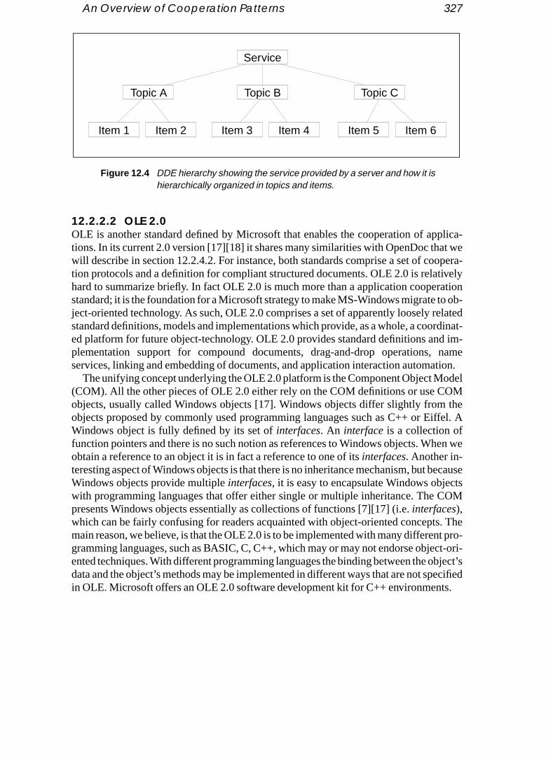
An Overview of Cooperation Patterns 327
plica-t weopera-ivelyrationo ob-elatedrdinat-d im-nametion.odelOM theffel. A
en we
ecausetsOM
. Thet pro-ct-ori-bject’secifieds.
12.2.2.2 OLE 2.0OLE is another standard defined by Microsoft that enables the cooperation of aptions. In its current 2.0 version [17][18] it shares many similarities with OpenDoc thawill describe in section 12.2.4.2. For instance, both standards comprise a set of cotion protocols and a definition for compliant structured documents. OLE 2.0 is relathard to summarize briefly. In fact OLE 2.0 is much more than a application coopestandard; it is the foundation for a Microsoft strategy to make MS-Windows migrate tject-oriented technology. As such, OLE 2.0 comprises a set of apparently loosely rstandard definitions, models and implementations which provide, as a whole, a cooed platform for future object-technology. OLE 2.0 provides standard definitions anplementation support for compound documents, drag-and-drop operations, services, linking and embedding of documents, and application interaction automa
The unifying concept underlying the OLE 2.0 platform is the Component Object M(COM). All the other pieces of OLE 2.0 either rely on the COM definitions or use Cobjects, usually called Windows objects [17]. Windows objects differ slightly fromobjects proposed by commonly used programming languages such as C++ or EiWindows object is fully defined by its set ofinterfaces. An interface is a collection offunction pointers and there is no such notion as references to Windows objects. Whobtain a reference to an object it is in fact a reference to one of itsinterfaces. Another in-teresting aspect of Windows objects is that there is no inheritance mechanism, but bWindows objects provide multipleinterfaces, it is easy to encapsulate Windows objecwith programming languages that offer either single or multiple inheritance. The Cpresents Windows objects essentially as collections of functions [7][17] (i.e.interfaces),which can be fairly confusing for readers acquainted with object-oriented conceptsmain reason, we believe, is that the OLE 2.0 is to be implemented with many differengramming languages, such as BASIC, C, C++, which may or may not endorse objeented techniques. With different programming languages the binding between the odata and the object’s methods may be implemented in different ways that are not spin OLE. Microsoft offers an OLE 2.0 software development kit for C++ environment
Service
Topic A Topic B
Item 4
Topic C
Item 3Item 2Item 1 Item 6Item 5
Figure 12.4 DDE hierarchy showing the service provided by a server and how it ishierarchically organized in topics and items.

328 Gluons and the Cooperation between Software Components
A key feature of OLE 2.0 is the definition of structured documents. Structured docu-le
d orides aort the
picalt, etc.) of the items
-s do notgether termi-
. An
n anon-ely, anment
s way
ans-ectsm op-
t Mod-mentss dataplica-
tivesd easilyre, as a
ments containstorages andstreams that are organized in a similar way to traditional fisystems:streams are analogous to files whilestorages act as directories. So,storages con-tain eitherstreams or storages. Storages and streams provide support for structurecomposite documents that are organized in a hierarchical structure. OLE 2.0 provstandard definition for the document’s structure and also a set of functions that suppstandard operations on structured documents.
The best-known features of OLE 2.0 are probably embedding and linking. A tycompound document (e.g. a text with graphics, sound, data in spreadsheet formacontains data objects that have been created by different applications. The ownercompound document, say a wordprocessor, may know how to display most of thesebut cannot deal with the full complexity of retrieving and modifying them. An OLEcon-tainer is any application that can incorporate OLE objects.Containers usually display theOLE objects and accept commands for them. However,containers are not intended toprocess the objects. Objects retain an association withserver applications that are responsible for servicing the requests addressed to the objects. The idea here is that clientneed to be aware of the internals of the objects they contain. The object (data) towith its associate server corresponds to the usual notion of object in object-orientednology which encapsulates both data and operations on the data.Servers accept com-mands, calledverbs, that correspond to actions that can be applied to the objectsinterface is the set of operations that can be applied to an object via its server.
OLE 2.0 offers two ways to integrate an object into a compound document:linking andembedding. Embedding is most frequently used. Thecontainer application owns andstores each embedded object, but the server retrieves the object. The server plays aymous role by processing the object on behalf of the container application. Conversobject can be linked into a document. A linked document belongs to a given docu(and is stored in the document’s file) but it is referenced in another document. In thiseveralcontainers can share a single linked object.
Additionally, OLE 2.0 provides a standard for data transfer called Uniform Data Trfer (UDT) and a standard for scripting called Automation. Automation allows objassociated with one application to be directed from another application, or to perforerations on a set of objects under the control of a macro language [18].
To summarize the OLE 2.0 standard suite we may say that the Component Objecel standardizes how an object and an object’s client communicate; compound docustandardize document structure and storage; Uniform Data Transfer standardizeexchange capabilities and Automation provides a support for remote control of aptions.
It should be noted that with OLE version 2.0 the interapplication cooperation primiare restricted to the scope of the same machine. However, these mechanisms coulbe extended to provide the same capabilities across networks and serve, therefofoundation for distributed computing.

An Overview of Cooperation Patterns 329
rd foro rea-s fromture, oner object
m thehrough
bases,
ple-d dataciated theents on
n ofhas a
12.2.3 ODBC 2.0
Although the Open Database Connectivity standard from Microsoft is more a standathe interconnection of applications and databases, it is worth mentioning here for twsons. First, it represents a much-needed standardization effort to isolate applicationthe access to specific databases. Second, databases will be, at least in the near fuof the most prominent reusable software components since they are responsible fopersistence.
The architecture of an ODBC 2.0 application is represented in figure 12.5. Froview point of the application, the access to the various data sources is transparent tthe ODBC interface. The ODBC 2.0 standard interface provides the following:
• a standard way to connect to databases;• a set of function calls that allows an application to connect to one or many data
execute SQL statements, and retrieve the results;• a standard representation for data types.The Driver Manager loads drivers on behalf of the application, while the Drivers im
ment ODBC function calls and submit, when appropriate, requests to the associatesource. The Drivers are responsible for adapting to the specific syntax of the assoDBMS. ODBC 2.0 does not rely on object-oriented principles and is fairly low level insense that it provides a vendor-independent mechanism to execute SQL statemhost databases.
12.2.4 Apple’s Interapplication Communication Architectureand OpenDoc
Like Microsoft, Apple devoted significant efforts to the definition and implementatiostandard mechanism for the cooperation of applications. Also like Microsoft, Apple
Application DriverManager Driver B
Driver C
Driver D
Driver A
ODBC interface
Data source A
Data source B
Data source C
Data source D
Figure 12.5 ODBC 2.0 application architecture.
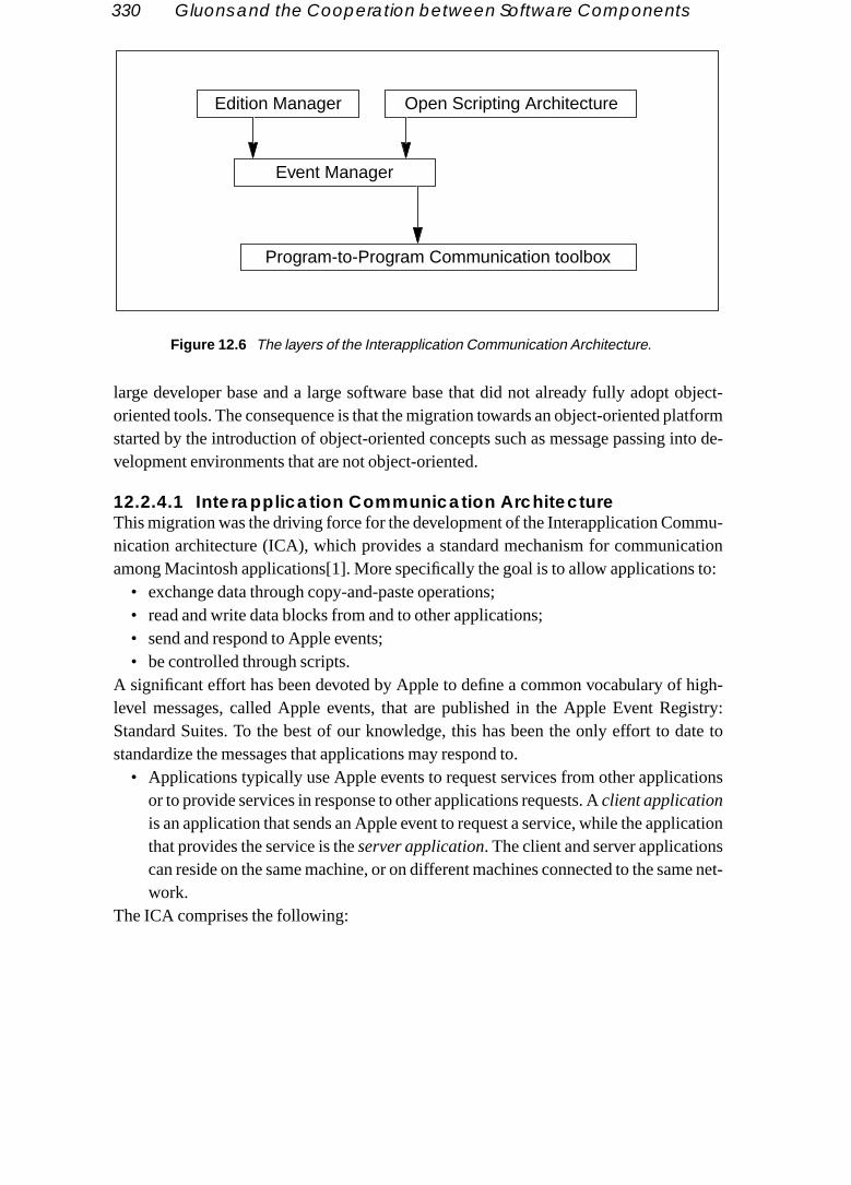
330 Gluons and the Cooperation between Software Components
object-atforminto de-
mu-ation to:
high-gistry:ate to
tions
cationsme net-
large developer base and a large software base that did not already fully adopt oriented tools. The consequence is that the migration towards an object-oriented plstarted by the introduction of object-oriented concepts such as message passing velopment environments that are not object-oriented.
12.2.4.1 Interapplication Communication ArchitectureThis migration was the driving force for the development of the Interapplication Comnication architecture (ICA), which provides a standard mechanism for communicamong Macintosh applications[1]. More specifically the goal is to allow applications
• exchange data through copy-and-paste operations;• read and write data blocks from and to other applications;• send and respond to Apple events;• be controlled through scripts.
A significant effort has been devoted by Apple to define a common vocabulary of level messages, called Apple events, that are published in the Apple Event ReStandard Suites. To the best of our knowledge, this has been the only effort to dstandardize the messages that applications may respond to.
• Applications typically use Apple events to request services from other applicaor to provide services in response to other applications requests. Aclient applicationis an application that sends an Apple event to request a service, while the applithat provides the service is theserver application. The client and server applicationcan reside on the same machine, or on different machines connected to the sawork.
The ICA comprises the following:
Edition Manager Open Scripting Architecture
Event Manager
Program-to-Program Communication toolbox
Figure 12.6 The layers of the Interapplication Communication Architecture.

An Overview of Cooperation Patterns 331
• TheEdition Manager, which provides support for copy-and-paste operations amongocu-
low, totingnt that
and pieces
. Theport.
applica-nica-f the
anduch aspe tostruc- Objectica- docu-art of
NTOts areniquees ofe corre-
ased:manipu-alizedeets. Onal is toroach
tains anhe in-
applications and updating information automatically when data in the source dment changes.
• TheOpen Scripting Architecture, which defines the standard mechanisms that alfor the external control of single or multiple applications. OSA is comparablesome extent, to Automation in OLE 2.0. OSA is not tied to any specific scriplanguage. Each scripting language has a corresponding scripting componetranslates the scripts into events.
• TheEvent Manager, which provides the support that allows applications to sendreceive events. The Event Manager standard defines the architecture and theof Apple messaging backplane.
• The Program-to-Program Communication toolbox, which provides low-levelsupport that allows applications to exchange blocks of data in an efficient wayEdition Manager and the Open Scripting Architecture provide the user level supThey both rely on the Event Manager to exchange data and messages across tions. The Event Manager, in turn, relies on the Program-to-Program Commution toolbox to transport data. Figure 12.6 illustrates how the different parts oICA are related.
12.2.4.2 OpenDocAs opposed to OLE, the ICA only deals with the problem of application interactiondoes not define a standard for documents. Apple, together with other companies sNovell and IBM, is proposing another standard, OpenDoc, that is quite similar in scoOLE 2.0. It defines both standards for application interaction mechanisms and for tured documents. In reality, OpenDoc integrates three other standards: (1) SystemModel (SOM), which originated as a CORBA compliant IBM standard for interappltion message exchange; (2) BENTO, which standardizes the format of structuredments and (3) the Open Scripting Architecture that we already mentioned as pApple’s ICA.
BENTO defines the standard elements for structuring documents in OpenDoc. BEdocuments are stored in containers which are collections of objects. BENTO objecorganized as schematized in figure 12.7. An object has a persistent ID which is uwithin its container. Objects contain a set of properties, which in turn contain valusome type. The values are where data is actually stored and their types describe thsponding formats.
The ideas underlying OpenDoc are quite similar to those on which OLE 2.0 is bcomposite documents may contain heterogeneous objects that are managed and lated using a variety of specialized software components. With OLE 2.0 the specicomponents are heavyweight applications such as wordprocessors and spreadshthe other hand, OpenDoc targets components that are more fine-grained. The gomake the concept of application vanish, giving place to a document-centered appthat promotes the document as the main user concept. Each part of a document reassociation with a specialized component that knows how to retrieve it. Naturally, t

332 Gluons and the Cooperation between Software Components
ase theg new
otingndardstand-
ubsys-equest stand-2.0 ap-y, OLEndard
s both docu-
nd theware, thesethe ap-
vocation of the retrieving component is transparent to the user, who can easily increvariety of the parts that can be incorporated into composite documents by purchasinspecialized software components.
12.2.5 Discussion
The considerable effort that has been devoted to designing, implementing and promthe adoption of these cooperation standards suggests the critical role that such stamay play in future software technology. We may notice, however, that the various sards differ considerably in scope.
For example, OMG standards focus on interoperability among heterogeneous stems and they essentially provide mechanisms that allow software components to rservices from other software components. Software components need to provide aard layer that adapts them to the request broker in much the same way that ODBC plications need drivers to adapt data sources to the ODBC 2.0 interface. Conversel2.0 and OpenDoc each provide a complete integration platform-centered on a stadefinition of composite document. The document-centered approach that underliestandards seems appropriate for office information systems where the compositement seems to be indeed the fundamental user abstraction.
However, there exist many software application domains that do not revolve arounotion of document. For example, in real-time software and communications softthe notion of document does not play an important role. We may also notice thatstandards do not promote interaction at the software component level, but rather at
ObjectValue of type AValue of type BValue of type CValue of type D
Value of type CValue of type A
Property X
ObjectValue of type AValue of type BValue of type CValue of type D
Property Y
ObjectValue of type CValue of type AValue of type CValue of type S
Property ZObjectValue of type F
Value of type GValue of type AValue of type B
Value of type HValue of type A
Property U
Object “Budget”
Figure 12.7 A Bento object contains a collection of properties and properties containvalues which are the placeholders where data is actually stored.

Requirements for a Financial Framework 333
plication level, even though OpenDoc encourages document retrieval through a set of full-
t ap-andardread-
that arect, they by in-This ispplica-mpo-
generictwarepment andplay
nd allowesente dis-
mongncialcking
stemsppor-h vari-oice ofrder tofinan-t. Thismpo-ould be archi-nents
small and specialized retrieval units while OLE 2.0 promotes communication amongfledged applications such as wordprocessors, spreadsheets, etc.
The ICA from Apple (in particular, the Apple events suite) takes a rather differenproach, focusing on the standardization of operations. The goal is to promote a stvocabulary for services so that applications that provide similar services (e.g. spsheets) can be replaced by one another.
Another observation is that any of the standards discussed requires mechanismsspecific to object-oriented languages such as inheritance and encapsulation. In faare being used as a vehicle for the migration towards object-oriented environmentstroducing object-oriented concepts expressed in non-object-oriented languages. probably the reason why these standards focus mainly on interaction between ations; the same interaction rules do not usually apply to interaction of software conents occupying the same address space.
12.3 Requirements for a Financial Framework
The application cooperation standards we have discussed address the needs of asoftware environment and reflect many other constraints not all related to sofengineering, such as market constraints and applicability of standards to old develoenvironments. Our financial framework targets applications that retrieve real-timehistorical data from financial information sources. Typically, these applications disdata such as the price of securities, interest rates and currency exchange rates, ausers to explore real-time and financial historical information. These applications prto the professional user a window into financial activities which provides access to thtributed world-wide financial market.
Financial markets are characterized by rapidly evolving, complex relationships athe wide variety of financial instruments. Market relationships that hold among finainstruments are continuously evolving, and professional investors are constantly trathat evolution in order to detect new investment opportunities. Decision support sy(DSSs) play an important role in supporting the user while finding such investment otunities. The user needs to combine financial instruments, test the combination witous economic scenarios, look at the present cost of the combination, refine the chinstruments, re-evaluate them, and eventually make an investment decision. In oprovide the appropriate support the DSS should allow the dynamic combination of cial instruments so that any instrument can be combined with any other instrumenasks for a DSS architecture that facilitates the run-time interaction of software conents. Furthermore, new financial instruments are frequently added so the DSS sheasily extendable with operational models for new instruments. To summarize, thetecture needs to provide capabilities for the dynamic connection of software compoand facilitate the integration of new software components.

334 Gluons and the Cooperation between Software Components
12.3.1 Towards a Protocol-Centered Framework
are de-ays.quest
r mainpen-
cern isach,ard op-he firstheet op- secondplica-
e in-vide a
nativecoulde aref corehe sameervices
ed byidenti-nt pro-ee liste serv-al-timer class
rmedrs. Theng for
As we already mentioned, the goal of a framework is to provide a set of classes that signed to work together. This operational compatibility can be achieved in many wThe Object Management Group focuses on compatibility mediated by an object rebroker. They impose no restriction on the software components themselves. Theiconcern is to provide interoperability in heterogeneous environments. OLE 2.0 and ODoc emphasize the compound document as the main shared entity. Their main conto provide the most flexible environment for document retrieval. Apple’s ICA approon the other hand, attempts to standardize common operations by defining a standerations vocabulary and its associated semantics. ICA pursues two main goals. Tgoal is to make the access to core standards functionality, such as common spreadserations, database access and wordprocessor tasks, application independent. Thegoal is to offer powerful scripting capabilities to automate tasks and to compose aptions together.
The goal of the financial framework is to provide support for dynamic control of thteraction between software components. To achieve such a goal we need to promechanism that allows for dynamic interconnection of software components.
12.3.2 Standardizing a Service’s Vocabulary
During the early stages of the framework’s design we considered a number of alterintercomponent interaction principles. The goal was to find a mechanism that provide the highest degree of dynamic interconnection for the kind of applications wtargeting with the financial framework. We tried, for instance, to standardize a set oservices so that each service is associated to a unique name called a verb, much in tway as the Apple events suite standardizes the operations vocabulary of common sprovided by wordprocessors, spreadsheets, databases, etc.
12.3.2.1 The AdvantagesThe intuition behind this approach is that we can identify among the services providthe various software components of a framework many services that, although not cal, have comparable semantics. For example, most components in our environmevide services such asevaluate, print, andnotify. We attempted to identify within the scopof the financial framework the principal groups of services and we ended up with thshown in table 12.1. Software components may provide other services as well. Thesices belong either to more specialized groups, such as a group that is related to reservices, or they do not belong to any group since they are too specific to a particulaof components.
A major advantage of this approach is simplicity. A service request can be perfoby sending a message, a mechanism that every object-oriented environment offeadvantage of standardizing a vocabulary for services is perhaps more compelli

Requirements for a Financial Framework 335
ilar oring theed be- a printotocol.mpo-mo-
nnec-onentsse soft-hanged
iate way, andonents,
al-timewareompo- an in-o stopotifica-ption,e trans-pera-
many reasons. First, reusing components is made easier since services with simclose semantics bear the same name on all the software components, thus simplifyname space. Second, dynamic interconnection of software components is improvcause if a component provides a service conforming to a standard protocol, such asservice, then that service can be invoked by any client understanding the same prThird, interchangeability of software components is increased since two software conents that provide similar functionality will most probably show a fair degree of comnality in their interfaces.
12.3.2.2 The ShortcomingsWe noticed, however, that this approach is not the best in terms of dynamic intercotion. The main reason is that, in general, the interaction between two or more compinvolves more operations than simply sending a message. Although we can compoware components by specifying the appropriate sequences of messages to be excbetween the components, a collection of sequences of messages is not the approprto specify components’ interactions. All but the simplest interactions involve a statethe set of permissible messages that can be exchanged between interacting compat a given point in time, usually depends on the present state of the interaction. Refinancial environments provide many illustrations. Consider, for example, a softcomponent, called the server, that offers real-time data updating services to other cnents. A component may register to be notified for data updates. Registering startsteraction that ends, hopefully, when the client component requests the server tnotification. Such interaction may comprise many data updates, error messages, ntion of temporary interruption of real-time services, with subsequent service resumetc. Another example is a database transaction. A server may execute a databasaction on a client component’s behalf. The transaction may involve many different o
Service group name Description
Common services Services that are usually provided by most componentssuch as: print, show-services, identify-error, and store
Messaging and notification Services related to messaging and event notification suchas: call-back, notify, add-to-broadcast-list, message,forward-message
Computational Services related to computational servers: evaluate,iterate, perform-aggregation, set-value, get-value
Display Services related to visual operations such as: display,undisplay, front, drag-and-drop
Object management Services related to software component managementsuch as: create, replicate, destroy, add-object, instance-of-class, component-id
Table 12.1

336 Gluons and the Cooperation between Software Components
tions server the in-y exe-
mpo-e call
ounda-works
ationunc-n be-ies that2.8
tures.ctionsthe role
tions that individually succeed or fail. The transaction succeeds if all its operasucceed, otherwise the transaction fails. The interaction between the client and thedepends on the state of the transaction, which can be defined as the logical “and” ofdividual operation results. Whenever, the state condition switches to fail, the alreadcuted operations need to be unrolled before terminating the transaction.
The two examples illustrate the need for a higher-level mechanism to specify conents’ interactions that allows for interaction states and state-dependent actions. Wsuch a mechanism a component’s interaction protocol. These observations lay the ftions that lead us from message-based frameworks to protocol-centered framewhich focus on protocols as the main components interaction mechanisms.
12.3.3 Component Interaction Protocols
Software component protocols share many similarities with computer communicprotocols. Both specify object interaction patterns. As such they fulfil two important ftions. First, they provide a mechanism or a formalism to specify the rules of interactiotween objects. Second, protocols define compatibility classes in the sense that entitobey the same protocol display an interaction compatibility as illustrated in figure 1
12.3.3.1 Requirements for Interaction ProtocolsSoftware component interaction protocols should support a number of important feaFirst, they should be appropriate to specify various aspects of component interasuch as synchronization, negotiation and data exchange. Second, they should play
AB
C
E
G
F
D H
Figure 12.8 Protocols define compatibility classes inside which members are able tointeract. Protocol X allows interaction between objects A, B, C and D, whileprotocol Y defines an interaction pattern between D, C, B and F. Object Hcannot interact with other objects since it does not adhere to any specifiedprotocol.
X
Y
Z

Requirements for a Financial Framework 337
of “contracts” or “interaction agreements” that represent the necessary and sufficient con-mplys.ilater-
men-, a proto-n in anted to com- con- which
ents. to the andl is toed by
to ex- they do neces-
s the
le ofan playibility small.li-
ed in themple, ob-proto-
ditions for a software component to interact with other software components that cowith the same “agreement”. Helmet al. [12] focus on this important aspect of interactionThird, the interaction specifications should be multilateral agreements rather than bal interaction agreements between two software components.
Another desirable property of component interaction protocols is that their impletations reside as much as possible outside the components since as an agreementcol does not belong to any component. We may observe, looking at programs writteobject-oriented language, that a significant fraction of a component’s code is devothe communication of the component with other software components. Most of themunication functionality is inside the component. This has two main objectionablesequences. First, components tend to become “hard-wired” to their environments,has the undesirable side effect of reducing their reuse potential within other environmSecond, the intermix of code responsible for interaction with the code that is propercomponent reduces readability and maintainability. Naturally, it might be impossibleperhaps undesirable to strip all the interaction code out of a component. The goaleave inside the component only the sufficient interaction functionality that can be usmany different protocols. For example, we will keep inside the component methodsport values, methods to notify events, and methods to send generic messages sincenot implement any interaction among specific components and represent the hookssary to build protocols.
12.3.3.2 Roles and Interplay RelationsWe will be more precise now about what we mean by a protocol. A protocol specifieinteraction between software components. Aprotocol P = (R, I, F) consists of a set ofroles, R, aninterplay relation, I, and afinite state automaton, F.
defines a set of roles:
Each component that is -compliant plays one or more roles. A typical examproles are the client and server roles in a client–server protocol, where components ceither the client’s role, the server’s role, or both depending on the specific responsassigned to the components. In general, the number of roles defined by a protocol is
A protocol also defines aninterplay relation that specifies the interaction compatibities allowed by protocol . The interplay relation is defined by a set:
Moreover, if , then . In words, it is always assumfor a one-role protocol that all the software components obeying are compatiblesense that they are able to interact under . Referring to the previous exa
specifies that the protocol allows for the interaction betweenjects that play a server’s role and objects that play a client’s role. To specify that the
P
R R1 R2 … Rr, , ,{ }=
P
P
I I 1 I 2 … I i, , ,{ } whereI k R Ik ∅ 1 k i≤ ≤,≠,⊆,=
R r{ }= I I 1{ } r r,{ }{ }= =P
PI server,client{ }{ }=

338 Gluons and the Cooperation between Software Components
col also allows for the interaction between objects that play the role of servers, the
roto- con-
,.
theyfinede the same
lid se-formalectionntrols
ay re-d en-actionpport ans we
ap-
- of a
roto-erviceftware dataut the
stand-t, andded tos of
interplay relation should be specified as:
Each object of the environment eventually conforms to roles of one or many pcols. Let denote a function that returns the set of all roles componentforms to. A protocol together with an element (i.e. a set of roles)
of its interplay relation defines a domain of interaction compatibilityDomains of interaction compatibility play an important role in our framework since define which are the components that can potentially interact. The compatibility deby a domain of interaction extends not only to the components that exist at the timprotocol is defined and implemented, but also to all future components that obey theprotocol and are compatible through an interplay relation.
Finally, each protocol is associated with a finite state automaton that specifies vaquences of interactions between participants in the protocol. (See chapter 4 for a treatment of two-party protocols based on finite state processes.) In the following swe will see examples of how the state of a protocol can be specified, and how it cothe interactions between components.
12.4 Gluons
Gluons encapsulate and implement interaction protocols by instantiating an interpllation for a given protocol. The principle idea underlying gluons is to standardize ancapsulate protocols, rather than just standardizing service names, since interprotocols should represent one of the primary resources to be reused. Gluons suprotocol-centered reuse strategy. By embedding interaction protocols inside gluocan use them as agents to implement many different interaction strategies.
Applications that we developed with the financial framework show that with thisproach we can achieve the following:
• A high degree of dynamic interconnection —The reuse of interaction protocols provides significantly more flexibility to express interaction patterns than the reusenaming convention. In particular, we typically need a small set of interaction pcols to express interactions that would require a large quantity of standard snames to achieve the same result. For example, all interactions between two socomponents that involve a service request followed by an agreement on thetypes to be exchanged, and ending with a notification of both components aboresult of the operation, can be expressed with just one protocol. Service nameardization would require standard names for each possible service requeswould probably ask for additional code to build the sequence of messages neeperform the interaction. This point will be better illustrated later with examplegluons from the financial framework.
I server client,{ } server server′,{ },{ }=
Oiroles Oi( ) Oi
P I k xs … xt, ,{ }=x R∈ D P Ik,( )=

Gluons 339
• Easy integration of new software components into an environment —This stemsnt re-
ourceact inedurempo-
cal in- Oncee iden-
such
inter-t in they therst de-s in a
or the
e statecon-ny end
tter to’s finite can beftware mes-
tions.
s:t assign-ctor as-ct that
from the fact that the unique interoperability constraint is that the new componeuses existing interaction protocols that can be instantiated through gluons.
12.4.1 Gluons and Software Design
We already mentioned that in a protocol-centered framework the primary reuse resis the protocol. The adoption of a protocol-centered approach has a significant impsoftware design. While methods such as CRC [5] promote an iterative design procthat emphasizes identification of the responsibilities and collaboration for each conent, in a protocol-centered framework the design team attempts to identify the typiteraction protocols for the specific environment prior to any other design decisions.the choice of the basic interaction protocols has been made, we then proceed with thtification of the components’ responsibilities and the collaborations needed to fulfilresponsibilities.
At first, we seem to be adding just another layer (i.e. the definition of the reusableaction protocols) to the design process. However, experience shows that, at leascase of the financial framework, the addition of such a layer simplifies significantlwhole design process provided the reusable protocols are properly defined. Our fisign defined only eight protocols that allowed us to express most of the interactionsimple system. The reusable interaction protocols represent the “glue” that allow fconnection of software components.
12.4.2 Anatomy of a Gluon
In terms of its internal structure, a gluon is a software component that handles a finitautomaton with output to control the execution of a protocol’s interplay relation. It tains a start state and any number of intermediate states. A gluon can provide mastates (i.e. accepting states in finite automation parlance) but for simplicity it is behave a unique end state. Figure 12.9 shows the symbols that can appear in a gluonstate automaton. States and state transitions are the common constituents thatfound in any finite state automaton [8]. A participant’s role stores a reference to a socomponent that is compatible with the role defined by the interplay relation, while asage selector container stores an arbitrary message selector.
A state transition triggers the execution of an action which is composed of operaA state transition is fired whenever the gluon receives a message.
There are three types of operations that compose an action: messages sends, object as-signments andmessage selector assignments. A message send is what its name impliethe gluon sends a message to a software component requesting a service. Objecments allows a gluon to keep a reference to software components. Message selesignments are similar to object assignment operations, the difference lies in the fa

340 Gluons and the Cooperation between Software Components
are com-e onlyelector
vided
ions as-
and act thatompo- and the
luon’ss are for-m therk
the gluon keeps a reference to a message selector instead of a reference to a softwponent. These are the only allowable operations in a gluon’s action. Furthermore, thassignments allowed are those that involve either a participant’s role or a message scontainer in the left side of the assignment.
Figure 12.10 shows the finite automaton embedded inside the simplest gluon proby the financial framework. The SimpleGluon contains two states,Start andEnd, and threetransitions. The diagram also shows a participant, theServer and a message selectorMess-
Sel that can store an arbitrary message selector. State transition triggers and the actsociated with state transitions are shown in table 12.2.
The SimpleGluon handles an asymmetric interaction protocol between a serverclient. The protocol handles message forwarding. The asymmetry stems from the faa gluon is associated with a unique server component while the client can be any cnent that can send a message to the gluon. The association between the servergluon is requested by the server component by sending messageregisterServer to the gluon(refer to table 12.2). This message triggers state transition 0 which initiates the gprotocol. Any component can now send messages to the gluon and these messagewarded to the server with transition 1. Finally, the gluon can be disconnected froserver by sending it the messageexit. SimpleGluons are used in the financial framewo
Figure 12.9 Symbols for the gluon’s finite state automaton.
Server0Start MessSel
State State transition Participant roleMessage selector
container
Figure 12.10 The SimpleGluon finite state automaton. SimpleGluons forwardmessages to an attached software component called the Server.
End
Server
0
2
Start
1MessSel

Gluons and the Financial Framework 341
rs. Byrvicescond
apa- mes-
ble for otheriner fortimest up- Eachct
. Theyown thernal dataams ofrs. They
mpo-o com-
for two main purposes. The first purpose is to isolate services from service provideassigning different components to the server’s role, the clients can be granted sefrom different components. The SimpleGluon plays here the role of a proxy. The setypical usage of SimpleGluons requires a slightly modified gluon with multicasting cbilities. The modified version accepts the registration of multiple servers so that thesages sent by the clients are forwarded to all the servers.
12.5 Gluons and the Financial Framework
Gluons are the architectural elements of the financial framework that are responsithe way in which other components are composed. The financial framework offerscomponents as well. One such component, the RealTimeRecord acts as a contareal-time information. This component plays a central role in the distribution of real-information. The RealTimeRecord plays usually the role of a server to clients requedate notifications. The structure of RealTimeRecords is illustrated in figure 12.11.entry of the record is a pair(key, obj_ref), where the key allows for the lookup of an objeby name.
Most of the components in an application act as data sinks, data sources or bothare connected through notifications chains so that updates are readily broadcast dchain. Pure data sources are those components that are either connected to extesource such as those provided by Reuters, or are associated to files providing stredata. Components that act both as data sinks and data sources are data transformeusually get information from data sources, transform it and redistribute it to client conents. Pure sink components usually correspond either to display components or t
Protocol transitionsEvent / action
State Transition State
0 StartSource: registerServer{server}
Server := server
Start 1 Start<any_obj>: <message>
MessSel := <message><message> →Server
Start 2 End<any_obj>: exit
gluonDisconnecting{self} → ServerServer := none
Table 12.2 Protocol transition table for the SimpleGluon.

342 Gluons and the Cooperation between Software Components
nnected
plesl-time
aintedationonented byce andraggingith the the as-
sultch ex-ing the of the
ponents that write to files. So an application can be seen as a set of components coby a notification web.
The rest of this section illustrates the financial framework by providing two examof gluons that play an essential role in the framework: the dragging gluon and the readata notification gluon.
12.5.1 The Dragging Gluon
The dragging gluon implements the common dragging mechanism we are acquwith from most windowing systems (see figure 12.12). A drag operation is an operinitiated by a component, the dragging source, that attempts to find a partner compto cooperate with. The choice of the partner, the destination component, is performthe user with the visual assistance of the windowing system. Both the dragging sourthe dragging destination need to be associated with a visual representation since dis a visual operation. Figure 12.13 illustrates the finite state automaton associated wdragging gluon, while table 12.3 shows the events that fire each state transition andsociated actions.
To simplify the understanding of how the dragging gluon works it is useful to consimultaneously figure 12.13, which shows the state transitions, and table 12.3, whihibits the events that trigger a state transition together with the actions executed durtransition. The three boxes in the lower left corner of figure 12.13 represent the rolescomponents that participate in the dragging process.
(IBM)(DEC)(HP)(NeXT)(SUN)(SG)(Options)(Futures)(Forex)
(price) 234.34(volat) 24.34(high) 235.20(low) 230,30(date) 12 jul(moves) 123(news) LRTS(yearhg) 235.7(yearlo) 200.1
(price) 234.34(volat) 24.34(high) 235.20(low) 230,30(date) 12 jul(moves) 123(news) LRTS(yearhg) 235.7(yearlo) 200.1
(price) 234.34(volat) 24.34(high) 235.20(low) 230,30(date) 12 jul(moves) 123(news) LRTS(yearhg) 235.7(yearlo) 200.1
(price) 234.34(volat) 24.34(high) 235.20(low) 230,30(date) 12 jul(moves) 123(news) LRTS(yearhg) 235.7(yearlo) 200.1
(price) 234.34(volat) 24.34(high) 235.20(low) 230,30(date) 12 jul(moves) 123(news) LRTS(yearhg) 235.7(yearlo) 200.1
(price) 234.34(volat) 24.34(high) 235.20(low) 230,30(date) 12 jul(moves) 123(news) LRTS(yearhg) 235.7(yearlo) 200.1
(SBC)(UBS)(CS1800)(CS1900)(CS2000)(NESTL)
(SBC)(UBS)(CS1800)(CS1900)(CS2000)(NESTL)
(SBC)(UBS)(CS1800)(CS1900)(CS2000)(NESTL)
(ATL)(SWI)(FRF)(CHF)(DEM)(LSTR)
(ATL)(SWI)(FRF)(CHF)(DEM)(LSTR)
(ATL)(SWI)(FRF)(CHF)(DEM)(LSTR)
Figure 12.11 Structure of the RealTimeRecord component. The data is contained indictionaries. Dictionary 1, for instance, contains references to all theinformation updated in real time by a data source. The other dictionariescontain either values (2) or references to other objects (3).
1 2
3
DataFeed

Gluons and the Financial Framework 343
en 0).
eource
objectds to
e begin-onent.e samee as thel repre-ing. In
ve thesponds
sual rep-luon is
The server is the component that initiates the interaction by sending the messagstart-
Dragging to the gluon with its object identifier as parameter (see table 12.3, transitioUpon receipt of this message the gluon enters stateStart followed by the execution of anaction that makes the gluon send the messagestartDragging to the component that plays thWindowManager role, and assigns object identifiers to the destination and the sroles. The destination is assigned the void object identifier since at this stage thethat will play the destination role is not yet determined. The WindowManager responthe first the message by sending back to the gluon thedragCandidateEntered message. Thereception of this message triggers state transition 1 on the gluon. Thecandidate objectidentifier that is sent as parameter corresponds to the source component since at thning of the drag operation the mouse is over the visual representation of that compConsequently, the first component that is assigned the destination role is always thcomponent as the one that plays the source role. Later, the assignment will changuser drags the mouse out of the source visual representation to enter another visuasentation (i.e. icon) that is associated to a software component that accepts draggthe process of finding the appropriate destination component, the user may momouse in and out of visual representations that accept dragging. This process correto alternations between stateIN and stateOUT.
If the user releases the mouse button when the gluon is in stateOUT, then the draggingoperation stops with no side effects since the mouse has been released outside a viresentation that accepts dragging. Conversely, if the mouse is released when the g
Figure 12.12 User interfaces of some software components available. The gluons thatallow for the connection of the components are indicated by arrows. Toconnect the components the user drags the circle from one gluon to another.
Gluons

344 Gluons and the Cooperation between Software Components
sourceee, the be-g oper-efore
h-. Like-
tion
tocolefined. com-ges thee im-ion,e ex-e type
in theIN state, the gluon undergoes state transition 2 which puts the gluon in statePRE.This state corresponds to a pre-operation that is usually a negotiation between theand destination components to agree on an operation to be performed. If both agrgluon transits to stateOPER, which corresponds to execution of the agreed operationtween the source and the destination. If no agreement is reached, then the draggination will end through transition 5. State POST allows for post-operation cleanup bthe interaction ends.
We may notice that stateIN and stateOUT correspond to the visual process of establising a relationship between two software components: the source and the destinationwise, statesPRE, OPER andPOST manage the negotiation and execution of an operabetween two components.
The dragging gluon illustrates the generality and usefulness of an interaction prospecified as a finite state automaton. Such generic protocols are intended to be rTypically, when the source component negotiates an operation with the destinationponent, they agree on another gluon to which both are compatible. This gluon manaexecution of an operation, or in other terms it mediates the delivery of a service. In thplementation of a visual workbench for the retrieval of real-time financial informatcalled ReutersLab [25], which has been implemented with the financial framework wtensively use the dragging protocol together with another protocol that negotiates th
OPER
POST
PREIN
OUT
0End
Figure 12.13 Finite automata for the dragging protocol. The ellipses represent the stateswhile the the arrows represent state transitions. The three boxes at the lower leftcorner represent the roles of the components that participate in the interaction.
Start
WindowManager
9
8
10
1 2
3
4
5
6
7
Source
Destination

Gluons and the Financial Framework 345
Protocol transitionsEvent / action
State Transition State
0 Start
Source: startDragging{Source}
startDragging{source} → WindowManagerSource := sourceDestination := none
Start 1 InWindowManager: dragCandidateEntered{candidate}
Destination := candidatedragEnter{Source} → Destination
In 2 PreWindowManager: endDragging
preOperation{Source} → Destination
Pre 3 OperDestination: ACK{destination} | Source: ACK{source}
operation{source} → Destination
Oper 4 PostDestination: ACK{destination} | Source: ACK{source}
postOperation{Source} → Destination
Pre 5 EndDestination: NACK{destination}
slideDragViewBack → WindowManager
Oper 6 EndDestination: NACK{destination}
slideDragViewBack → WindowManager
Post 7 EndDestination: ACK{destination}
operationComplete{Destination} → Source
In 8 OutWindowManager:dragCandidateExit{candidate}
dragExited → DestinationDestination := none
Out 9 InWindowManager: dragCandidateEntered{candidate}
Destination := candidatedragEnter{Source} → Destination
Out 10 End
WindowManager: endDragging
dragAborted → SourceslideDragViewBack → WindowManagerSource := none
Table 12.3 Dragging gluon protocol transition table.
346 Gluons and the Cooperation between Software Components
of data to be exchanged between the source and destination components. Once the com-on that notifi-
es thatn be- side theclienteates a
no-pro-s of
pdatelay of
on theents cor-change corre-otify- to thesibleource. data
cation of thethat as- source
il-ters theeptione
threeint in
otifiesdiary
ponents agree on a data type, they interact under the control of another type of gluestablishes a real-time update notification between the components. The real-timecation gluon is discussed next.
12.5.2 Real-time Data Notification Gluon
Since the financial framework is intended to support the access to information sourcare updated in real time, the framework provides a gluon that supports notificatiotween data sources and client components so that after data updates on the sourceclient can be updated to reflect the information change. In a typical situation the component registers with the source to request update notification. The request crlink between the source and the client.
In order to provide for flexible notification, the framework allows for three types oftification links — cold, warm and hot — which correspond to the three type of links vided by Microsoft DDE depicted in figure 12.3. The reason for providing three typenotification links stems from the fact that different components have different data urequirements. For example, a client software component that handles a visual dispreal-time data usually needs to be updated as soon as the information changessource side since the user is expecting the fastest update possible. These requiremrespond to a hot link between the client and the source. Other components expect notifications but they only need actually to update the values in a few cases. Thesespond to the typical requirements for a warm link where the source is in charge of ning the client while the client is responsible for eventually issuing an update requestsource. The least demanding kind of link is the cold link in which the client is responfor requesting updates to the source at its own pace with no notification from the sA typical usage of cold links is portfolio evaluations that require access to marketonly when the portfolio is evaluated with no need for further updates.
Figure 12.14 represents the finite automaton embedded in a real-time data notifigluon. The protocol defines three roles: the source, the client and the data. The rolesource and client components has been discussed above, while the component sumes the data role acts as an information container that is exchanged between theand the client. The statesCOLD, HOT andWARM, correspond to three types of links avaable. When the link is established between the source and the client, the gluon enCOLD state and waits for a message from the client requesting an update. Upon recof the client’s request the gluon enters stateCUP in which it waits until an update messagissued by the source puts the gluon back in stateCOLD through transition 3. A gluon canbe requested to switch from one type of link to another provided it is in any one of thestates,COLD, HOT orWARM, so that the update mechanism can be changed at any potime to adapt to evolving requirements on the client’s side. We may notice that stateWARMhas a self-looping state transition (i.e. number 11), which is fired when the source nthe client for an update, and two transitions (i.e. transitions 9 and 10) with an interme

Conclusion 347
d, the transi-
mongesign
he con-
is onize andoftwaren be ob-s in the
dataction
stateWUP which handles the update request from the client component. As expecteactions associated with transitions 9 and 10 are similar to actions associated withtions 2 and 3 since they perform the same task.
12.6 Conclusion
We have addressed in this chapter the problem of defining patterns of interaction asoftware components. We adopt the point of view of component-oriented software dand development which promotes an approach to software construction based on tnection of software components.
We provide a survey of previous efforts that address similar problems. The focuswork from large software houses since they represent significant efforts to standardpromote approaches that may have a considerable impact, in the near future, on sdesign and development. The survey suggest that the sizeable differences that caserved between such approaches reflect differences in design goals and differencerequirements of the target environments.
Our development framework targets financial applications that retrieve real-timeand require support that allows for fast reconfiguration of the patterns of intera
Figure 12.14 Finite automata for a real-time data notification protocol.
Source
7
EndHOT
Start COLD
CUP
WARMWUP
1
23
45
6
89
10
11
12
13
14 1516
0
Client
Data

348 Gluons and the Cooperation between Software Components
among the software components as well as mechanisms that facilitate the introduction ofmic in-
rveyed
n pro-. Our
ree of thanrow to
esis
a-
intoer-
s Man-–
mpo-.
e, and
ent,”
new software components. These requirements can be equated to support for dynaterconnection of software components. Unfortunately none of the approaches suachieves the desired level of dynamic interconnection capabilities.
We propose a new approach which focuses on the reuse of component interactiotocols. We call a framework based on such principle a protocol-centered frameworkexperience with a financial framework shows that we can achieve a fairly high degdynamic interconnection with a small number of reusable protocols (typically lesstwenty). However, the applications that we developed have a scope that is too narallow us to infer that the approach is of wide applicability.
References
[1] Apple Computer Inc.,Inside Macintosh: Interapplication Communication, 1993.
[2] Constantin Arapis, “Specifying Object Interactions,” inObject Composition, ed. D. Tsichritzis, Cen-tre Universitaire d'Informatique, June 1991.
[3] Constantin Arapis, “Dynamic Evolution of Object Behavior and Object Cooperation,” Ph.D. thno. 2529, Centre Universitaire d'Informatique, University of Geneva, Switzerland,1992.
[4] Nabajyoti Barkakati, Peter D. Hipson,Visual C++ Developer's Guide, Sams, Carmel, 1993.
[5] Kent Beck and Ward Cunningham, “A Laboratory for Teaching Object-Oriented Thinking,”Proceed-ings of OOPSLA ’89, ACM SIGPLAN Notices, vol. 24, no. 10, Oct. 1989, pp. 1–6.
[6] Ted J. Biggerstaff and Alan J. Perlis,Software Reusability, Volume I, Concepts and Models, FrontierSeries, ACM Press, 1989.
[7] Kraig Brockschmidt,Inside OLE 2 : The Fast Track to Buiding Powerful Object-Oriented Applictions, Microsoft Press, Redmond, Wash., 1993.
[8] Daniel I. A. Cohen,Introduction to Computer Theory, John Wiley, 1986.
[9] L. Peter Deutsch, “Design Reuse and Frameworks in the Smalltalk-80 System,” inSoftware Reusabil-ity, ed. T.J. Biggerstaff and A.J. Perlis, ACM Press, 1989, pp. 57–71.
[10] Erich Gamma, Andre Weinand and Rudolf Marty, “Integration of a Programming EnvironmentET++,” Proceedings of ECOOP ’89, British Computer Society Workshop Series, Cambridge Univsity Press, Cambridge, 1989.
[11] Simon Gibbs, Dennis Tsichritzis, Eduardo Casais, Oscar Nierstrasz and Xavier Pintado, “Clasagement for Software Communities,”Communications of the ACM, vol. 33, no. 9, Sept. 1990, pp. 90103.
[12] Richard Helm, Ian Holland and Dipayan Gangopadhyay, “Contracts: Specifying Behavioral Cositions in Object-Oriented Systems,”ACM SIGPLAN Notices, vol. 25, no. 10, Oct. 1990, pp.169–180
[13] Dan Ingalls, “Fabrik: A Visual Programming Environment,”Proceedings of OOPSLA '88, ACM SIG-PLAN Notices, vol. 23, no. 11, Nov. 1988, pp. 176–190.
[14] Ralph E. Johnson and Brian Foote, “Designing Reusable Classes,”Journal of Object-Oriented Pro-gramming, vol. 1, no. 2, 1988, pp. 22–35.
[15] Chris Laffra, “Procol, a Concurrent Object Language with Protocols, Delegation, PersistencConstraints,” Ph.D. Thesis, Amsterdam, 1992.
[16] Michael Mahoney, “Interface Builder and Object-Oriented Design in the NeXTstep EnvironmTutorial Notes of CHI ’91, available through anonymous ftp at nova.cc.purdue.edu.

References 349
[17] Microsoft Press,OLE 2 Programmer’s Reference: Working with Windows Objects, Vol. 1, Redmond,
Ole
= Ap-ne
cifi-
9, pp.
ted
Wash., 1994.
[18] Microsoft Press,OLE 2 Programmer’s Reference: Creating Programmable Applications with Automation, Vol. 2, Redmond, Wash., 1994.
[19] NeXT Computer Inc., NextStep Concepts Manual, 1990.
[20] Oscar Nierstrasz, Dennis Tsichritzis, Vicki de Mey and Marc Stadelmann, “Objects + Scripts plications,” in Object Composition, ed. D. Tsichritzis, Centre Universitaire d'Informatique, Ju1991, pp. 11–30.
[21] Object Management Group, Common Object Request Broker: Architecture and Specification, 1991.
[22] Object Management Group, Object Management Architecture Guide, 1992.
[23] Object Management Group (OMG),The Common Object Request Broker: Architecture and Specation, Object Management Group and X Open, OMG document 91.12.1, revision 1.1, 1992.
[24] Xavier Pintado, Dennis Tsichritzis, “Gluons: Connecting Software Components,” inObject Compo-sition, ed. D. Tsichritzis, Centre Universitaire d'Informatique, 1991, pp. 73–84.
[25] Xavier Pintado, Betty Junod, “Gluons: A Support for Software Component Cooperation,” inObjectFrameworks, ed. D. Tsichritzis, Centre Universitaire d'Informatique, 1992, pp. 311–330.
[26] Xavier Pintado, “Gluons: a Support for Software Component Cooperation,” inProceedings ofISOTAS ’93, International Symposium on Object Technologies for Advanced Software, ed. S. Nishioand A. Yonezawa, Kanazawa, Japan, November 1993, Springer-Verlag, pp. 43–54.
[27] Xavier Pintado, “Fuzzy Relationships and Affinity Links,” inObject Composition, ed. D. Tsichritzis,Centre Universitaire d'Informatique, 1991.
[28] Rajendra Raj, Henry Levy, “A Compositional Model for Software Reuse,”Proceedings of ECOOP’89, British Computer Society Workshop Series, Cambridge University Press, Cambridge, 1983–24.
[29] Jeffrey S. Rosenschein and Gilad Zlotkin,Rules of encounter : Designing Conventions for AutomaNegotiation Among Computers, MIT Press, Cambridge, Mass., 1994.
[30] Al Williams, OLE 2.0 and DDE Distilled : A Programmer’s Crash Course, Addison-Wesley, Read-ing, Mass., 1994.

350

Index
ABCL/1 35, 38–42, 51, 52 application development 21, 180
ABCL/AP100 58ABCL/R 40, 41, 43Abramsky, Samson 168abstract class 47abstract superclass 220abstract state 59, 108, 109, 118abstraction 13, 187ACT++ 34, 36, 41, 42, 56, 118ACTALK 41, 43activated type 312activation condition 42active object 18, 43, 100, 187ActiveCube component 292activity composition 292actor-based languages 43ActorSpace 37, 38Ada 34, 35, 41, 42adaption function 85administrator 45, 49, 50–54, 61affinity 182
browser xvi, 245, 252example 259
engine 257neighbourhood 254
agents 9, 11aggregation 181Aït-Kaci, Hassan 156, 172α substitution 156α-Trellis 250Andrew 278, 308Apple 277, 329–331, 334
ATG Component Construction Kit276, 277
application engineer 180application frame 180
see also GAF, SAFapplication programming interface 307approximation ordering 169Arcadia 72Argus 34, 76association 183asynchronous
communication 133interface 311
asynchronous interface 311atomicity 32attribute redefinition 203attribution 180AVANCE 215, 217
backtracking 252backward scope restriction 239Basic 327Basic Object Adaptor 325BEAD 250become primitive 36BEE++ 249behaviour 19, 276, 278BENTO 331Bergmans, Lodewijk 59Beta 58bind reduction 158blackboard 10, 11Bloom, Bard 170BOA 325Böcker, Hans-Dieter 249

352 Index
Booch, Grady 123
,,
evaluation 205
bottom element 168Boudol, Gérard 168, 170, 171bounded buffer 108, 109Brinksma, Ed 99, 100, 107broadcast primitive 37browsermessage-set 249see also affinity browsersee also Smalltalk browser
browsing 178, 182, 183, 247semantics 250spatial 250tool 247
Brüegge, Bernd 249built-in proxy 52, 62Bull, S.A. xv
C 15, 74C++ xvi, 15, 47, 70, 74, 79, 91, 167, 179
187, 188, 196, 216, 219, 225, 276287, 325, 327
CAD/CAM 217CAML-Light 15category 249CBox 38, 51CCS 19, 100Ceiffel 56Cell 75, 82
framework 71, 74, 91change avoidance 203, 230channels 100CHOCS 19Church encoding of Booleans 154Church, Alonzo xiclass
evolution 202, 216refactoring 221relationship 259renaming 203, 210, 231reorganization 218–230surgery 202tailoring 202, 203, 230
versioning 202classification 181CLOS 13, 225, 233, 235close reduction 158CLU 34cobegin 35Colibri 193, 195, 196COM 327combination and alternation 171Common Object Request Broker
Architecture,see CORBAcommunicating processes 125comp.object newsgroup 7compatibility 11, 18, 153, 167, 205
class 336ordering 169
component 18, 20, 309class 310classification 177–200constraints universalization 149definition 297engineer xiv, 23, 275, 276engineering 20–23framework 4, 22, 277initialization 313inspector 277instantiation 313interface 311management 287network 312–313palette 277synchronisation 313visual composition 280
Component Object Model 327component-oriented
development 4lifecycle 14
compositionactivity 292dataflow 283, 291framework 275functional 10

Index 353
higher-order 10 analysis 211
media 307model 275, 276, 282manager 288procedural 307run-time 321semantic 307spatial 307temporal 292, 307Unix composition model 287visual,see visual composition
compression scheme 307concurrency 5, 8, 9, 14, 18, 25, 31–68,
100, 115, 119see also internal concurrency
Concurrent C 42concurrent object 35concurrent rewriting 56ConcurrentSmalltalk 38, 51condition variable 59conformance 99, 100, 107, 108, 218congestion 312ConMan 276, 277connection 275, 280, 282, 286, 289, 295,
312–316dynamic 335, 338
connector 311, 312consumer 311container 108, 328contracts 16, 17, 100, 298, 337conversion 203CooL 79, 82, 85–86, 187, 193, 195CORBA 72–76, 91, 325, 331correspondence 181
property 144CSP 38, 40, 107Curry type scheme 17Curry-Howard isomorphism 172currying 154, 163Cusack, Elspeth 107
database service 307dataflow 276, 283, 312
composition 283, 291Datamont, S.p.A. xvDDE 325, 346de Bruijn
calculus 158indices 153, 155, 156
de Bruijn, N. 156, 159, 162deadlock 102, 116decision support systems 333delegated call 54delegation 11, 38, 39denotational semantics 17dependency 187dependent type 118derivation graph 215derived classification 191design by contract 298
see also contractsdesign description 179destination pattern 37detach primitive 35Dezani-Ciancaglini, Mariangiola 19direct manipulation 285distinct name invariant 207distinct origin invariant 207Distributed Objects 277divergence 168domain knowledge 23dragging gluon 342
see also gluonsDRAGOON 56–59, 60dynamic analysis 266Dynamic Data Exchange 325dynamic interconnection 335, 338dynamic linking 13
Eiffel 16, 47, 178, 201, 203, 327Ceiffel 56library 227, 229
Eiffel // 34, 38, 41, 42, 56Emerald 34, 41, 54enabled set 34

354 Index
encapsulation 8, 178, 201, 225, 247, 297, first class representation of requests and
y,
308, 333and concurrency 9blackboard 11violation of 8, 46
ENCORE 238Engberg, Uffe 19equivalent type 78erroneous term 169ESPRIT xi, xv, 79, 177, 178event distribution mechanism 258event-handling 313evolution
class 202, 216format 309framework 24platform 309schema evolution taxonomy 209
expert services team 24explicit acceptance 42extensibility 11, 48, 154, 165, 258extension 99, 100, 107
Fabrik 276, 277faceted classification 186factorization 218
algorithm 227class refactoring 221incremental 230
failures 106equivalence 107
F-bounded quantification 118features 172filtering 236
mechanisms 237financial framework 321finite state
automata 108, 111, 123, 124, 337,338, 339, 344
process 119, 338protocol 108, 109transition system 111
replies 39Fisher, Kathleen 16fixed-point
induction 172operation 163
F-ORM 294format class 309format evolution 309Forsythe 172FORTH xvforward scope restriction 239Foundation of Research and Technolog
Hellas xvframework xiii, 4, 69, 99, 201, 291, 322
Cell, see Cell frameworkcomponent,see component
frameworkdesign 24evolution 24financial 321multimedia,see multimedia
frameworkNeXTStep AppKit 324protocol-centered,see protocol-
centered frameworkvisual composition 275
Freeman, Peter 178, 186Frølund, Svend 56, 59–61full inheritance invariant 207functional commonality 260functional composition 10functionality phase 77future variable 38, 39, 51fuzzy querying 247
GAF 21, 23, 180Garrigue, Jacques 156, 173GemStone 207, 235generalization 181Generic Application Frame,see GAFgenericity 46, 57, 182GeoBall component 292

Index 355
Gingrich, P. 271 invariant 207
,
global reorganization 226global time 136gluons xvi, 100, 321–349Goguen, Joseph A. 17Gottschalk, Tim 249Guide 36, 41, 42, 47, 56–61
Haskell 16Hennessy, Matthew 119Hennessy–Milner logic 119Herczeg, Jürgen 249heterogeneous object model 34, 49Hewlett Packard 277higher-order
composition xiv, 10process calculus 19
homogeneous object model 34, 49, 62Hybrid xiv, 34, 35, 40, 41, 54, 77, 79, 82,
85–86hypermedia systems 306hypertext 184, 250
IAL 74, 81, 85–87IBM 276, 277, 331
repository 178, 180ICA 333, 334IDL 72, 76, 325imitation 218implementation description 179incremental reorganization algorithm 220inheritance 7, 8, 13, 201, 245, 260
and synchronisation 47anomaly 56in Beta 58code sharing 205concurrency 5, 33, 46consistency 216dependencies 202in DRAGOON 57graph invariant 207hierarchy 178, 207interface 8, 9, 13
mixins 13multiple, strict 179, 181, 188request/reply scheduling 61restructuring 225reuse potential 47strict 181and subtyping 8, 47, 172and synchronisation 43, 46, 47, 55
63versioning 216Windows 327
initials 106inner mechanism 58inspector 249interaction
compatibility 321pattern 248, 322protocol 257, 321, 336, 337
Interapplication CommunicationArchitecture,see ICA
interconnection,see connectioninterface
adaption 76, 87adaption language, see IALbridging 74definition language,see IDLphase 78re-declaration 205
interference of features 32internal concurrency 44, 46Internet 7inter-object 81, 83, 87–90interoperability 69–95, 332
object-oriented 71, 73procedure-oriented 71specification level 72, 79
intersection type 103, 118, 172intra-object concurrency 59IRIS 215, 217
Explorer 276, 277islands 11isochronous interface 311, 312

356 Index
ITHACA xi, xv–xvii, 20, 79, 177, 178,
t
marked object 253
180, 193, 287, 294, 301object-oriented methodology 294software development environmen
294software platform 287
Kafura, Dennis G. 56KAROS 76Kleyn, M. 250Knos xivKrueger, Charles W. 178
Labyrinth System 287λ calculus 19, 154
label-selective 156λN calculus 153–174Lamping, John 156Lassie 178lattice structure 170Law of Demeter 221, 222, 225, 298law-governed systems 298lazy data structure 163Lee, Kueng Hae 56Leroy, Xavier 16Lieberherr, Karl 221lifecycle 134, 198
component-oriented 14ITHACA 180object 134, 136, 146software 6, 198software development 177
lifting operation 158link 276Liskov, Barbara 116LISP 166local time 136locality 251LOTOS 100Luo, Bin 249
Macintosh 330Manna, Zohar 150
Matsuoka, Satoshi 56, 59, 60, 61ME database system 251media
artefacts 305class 309composition 307synchronization 307
Meseguer, José 56message-set browser 249meta-class 188meta-object 42method set 60metrics 245
binary vector 261reuse 24
Meyer, Bertrand 16Microsoft 277, 325, 327, 329, 346MIDI 313migration 73, 78, 85Milner, Robin 19, 100, 119Mitchell, John C. 16mixin 4, 8, 13, 60ML 16
ML-like type system 16SML 16
modal process logic 119mode switch 287modeler component 292module 14, 16, 69
interconnection language 17monitor 34, 35, 41, 53Mosses, Peter D. 17Motro, Amihai 248MS-Windows 327multimedia xvi, 185
application 291component kit 291database 248database system 306framework xvi, 291, 305, 309programming 305
multimodal interaction 307

Index 357
multi-threaded object 53 object-oriented interoperability,see
2
Muse 308mutual exclusion 44, 46, 49MVC 278MVS 180
navigation 245navigator component 292nested monitor call 53NeXT 277NeXTStep 13
AppKit framework 324Driver Kit 322
nib file 13Nielsen, M. 19NIMBLE 71, 75Nixdorf Informationssysteme xvN-Land 250non-determinism 107, 109non-uniform service availability 99normal-order reduction 160Novell 331NP-complete 227ν calculus 19
O2 206, 207, 235object calculus 19, 118object invocation graph 250Object Linking and Embedding,see OLEObject Management Architecture 324Object Management Group,see OMGobject mapping 76, 81, 87object model 18
COM 327heterogeneous 34homogeneous,see homogeneous
object modelOMG 324SOM 331temporal specification 124
Object Request Broker,see ORBObject Systems Group xiii, xivObjective-C 167, 178, 205
interoperabilityObject-Oriented Tool Integration
Services 277Obliq 13observational equivalence 172ODBC 329, 332offers 114ogre 168OLE 277, 325, 327, 332–334OMA 324OMG 72, 74, 277, 324
Object Model 324one-way message passing 38, 50, 53, 6Open Database Connectivity,see ODBCOpen Scripting Architecture 331open systems 3OpenDoc 277, 327, 331–334OpenStep 15operation term 187ORB 72, 277, 325ORION 207, 208, 217, 239Orwell 217OSA 331OSF/Motif 287OTGen 206, 207, 234
PAL 51parallel functions 170, 171parallelism 32, 53parameter phase 78part-of relation 123, 220, 245Pascal 16path expressions 41, 42PCTE+ OMS 180performance evolution 309Perl 15persistence 12, 32Petri net 125, 250π-calculus 11, 19, 172
polyadic 100platform evolution 309Plotkin, Gordon 170

358 Index
plug compatibility xiv, xvi, 18, 154, 275, proximity 2505
312plugs 6PO 56–61point-to-point navigation 249, 252Polylith 71, 73polymorphism 48, 100, 163, 205
bounded 118POOL-I 47POOL-T 34, 35, 40–42port 276, 278, 310posing 205powerdomains 170pre- and post-conditions 203presentation
of component 276, 279Prieto-Diaz, Ruben 178, 186principle of substitutability 99, 100, 101procedural composition 307procedure-oriented interoperability,see
interoperabilityPROCOL 37, 38, 40–42, 56, 59producer 311propositional logic 126propositional temporal logic,see PTLprotected method 216protocol
client/server 19conformance 99, 105, 335dragging 344errors 102generic 344implementation 338initialization 100interaction 7, 257, 321, 336, 337non-determinism 106protocol-centered framework 323,
334request/reply 38, 62RPC 62service provider 114specification 108, 337
prototypes 11
proximity-based navigation 246, 253, 25proxy 38, 50, 61, 62, 81PTL 126
semantics 129syntax 127
public component constraintsuniversalization 148
quasi-concurrent object 34, 54querying 183, 247
Ranghanathan, Sarada 186reader/writer
property 47scheduling policy 58
real-timedata notification gluon 346financial data 321, 333multimedia constraint 313multimedia scheduling 308
REBOOT 178, 186RECAST 21, 291, 294, 298records
encoding of 165re-engineering 23, 182reference consistency invariant 207reflective computation 42regular
expression 110language 110process 108type 99, 108, 151
relationshipdynamically evolving 248evolving 246
relative failure 107remote delay 54renderer component 293reorganization
class library 201, 202global 226incremental algorithm 220
Index 359
reply scheduling 36, 44, 46, 51 semaphore 34, 58
repositoryIBM 178, 180representation invariant 207request channel 103request satisfiability 114request scheduling 36, 44, 46request substitutability 100, 106, 107
multiple state 111requirements description 179reuse 70, 245
metrics 24Reuters 341ReutersLab 344roles 337Rosette 34, 36RPC 38, 39, 49–52, 55, 62, 71, 324run-time composition 321
SAF 21, 180Sangiorgi, Davide 19satisfiability
algorithm 144graph 130of PTL 130
scalability 13Scheduling Predicates 56schema evolution taxonomy 209schema invariant 206, 208scientific visualization 299SDMS 250Selection Tool 183Self 15self 48, 61semantic composition 307semantic domain 101semantics 17, 153
browsing 250concurrency 118, 172intersection types 104lazy operational 168of functions 155PTL 129
SemNet 250send primitive 37send/receive/reply 40separate method argument 42sequential objects 62service type 100set-at-a-time navigation 251SIB xv, 178, 179, 287, 294Siemens-Nixdorf xv, 193similarity link 182Sina 35, 41, 55, 56, 59–61Singh, Vineet 56SINIX 187SLI 72, 73, 75Smalltalk 15, 34, 35, 40, 41, 43, 47, 48,
58, 70, 77, 166, 167, 178, 201,212, 225, 248
browser 247, 248, 252class hierarchy 229environment 247
Smith, Scott 168, 172SML 16Softbench 277software
community 178component 5cookbook 23junkyard 22lifecycle,see lifecycleoscilloscope 249reuse 7, 31, 32, 202
Software Information Base,see SIBSOM 331spatial
browsing 250composition 307data management system 250referencing 250
specialization 181Specific Application Frame,see SAFspecification level interoperability,see
interoperability

360 Index
SPN 56 α-Trellis 250
SQL 248SR 35, 41, 42, 55starvation 312state predicate 42, 59, 61static analysis 177, 266storage 328stream 311, 328strongly distributed environment 77strongly distributed object-based system74structured programming xiiisubstitutability 100, 105
see also request substitutabilitysubstitution operation 158subtyping 8, 101, 110, 153super 48, 58synchronisation constraint 46Synchronising Actions 56, 59, 61synchronized view 253synchronizers 42, 56synchronous interface 311System Object Model 331
TAO xvTècnics en Automatitzaciò d’Oficines xvTelescript 13Telos 180temporal
composition 292, 307logic 119, 123scripting language xv
Temporal Specification Object Model124
Tomlinson, Chris 56ToolTalk 277traces 106transaction 76transform class 309transformer 311translucency 257transposed file 231Trellis 249
Owl 34, 40, 41, 54TSOM 124type
compatibility 312invariant 207
inference 118matching 80translation 79variable invariant 207
type translation 79
unconditional acceptance 41Unidraw 278unified system of parameterization 156Unifying Type Model 72Universal Decimal Classification 186universalization 136Unix 179, 187, 189, 195, 197
composition model 287UTM 72
verificationcomposite objects 145correspondence property 149elementary objects 144
versioncompatibility 236identification 215
videoassistant 314on demand 306widgets 313
Vista 287–297visual
composition xvi, 275framework 275tool 275
configuration 313formalism 300representation 246scripting tool xv
Visual C++ 322

Index 361
VisualAge 276, 277
VisualBasic 7visualisation xviVLSI Design 217VST xvi, xvii, 287wait filter 59, 60Wegner, Peter 8, 34, 47, 99–101Wing, Jeannette 116Wolper, Pierre 150worker 45, 49, 51, 52, 54, 61workflow application 291World Wide Web xvii
X Windows 287
Zdonik, Stanley 47, 99–101