Object Oriented Software Engineering Laboratory (CSE 4.1.8)
83
Object Oriented Software Engineering Laboratory (CSE 4.1.8) DEPARTMENT OF COMPUTER SCIENCE AND ENGINEERING Object Oriented Software Engineering (CSE- 4.1.8) SIR C.R.REDDY COLLEGE OF ENGINEERING ELURU – 534 007 1
-
Upload
khangminh22 -
Category
Documents
-
view
0 -
download
0
Transcript of Object Oriented Software Engineering Laboratory (CSE 4.1.8)

Object Oriented Software Engineering Laboratory (CSE 4.1.8)
DEPARTMENT OF COMPUTER SCIENCE ANDENGINEERING
Object Oriented Software Engineering (CSE- 4.1.8)
SIR C.R.REDDY COLLEGE OF ENGINEERINGELURU – 534 007
1

Object Oriented Software Engineering Laboratory (CSE 4.1.8)Object Oriented software Engineering Laboratory (CSE 4.1.8)
S. no Content Page No.
1. Object oriented software engineering laboratory Syllabus 2
2. Introduction to Project and Definition 5
3. Software Requirement Specification 9
4. Introduction to UML and Use Case Diagram 13
5. System Modeling 18
6. Documenting Use Cases and Activity Diagrams 22
7. Object Oriented Analysis: Discovering Classes 27
8. Interaction Diagrams: Sequence and Collaboration Diagrams 31
9.Software Design: Software Architecture and Object Oriented Design
37
10. State Chart Diagram 40
11. Implementation Diagrams: Component and Deployment Diagrams 44
12. Template Code 48
13. Appendix A 50
14. Appendix B 58
2

Object Oriented Software Engineering Laboratory (CSE 4.1.8)
Laboratory Syllabus 1
3

Object Oriented Software Engineering Laboratory (CSE 4.1.8)1. OBJECT ORIENTED SOFTWARE ENGINEERING LAB
Instruction: 3 periods/ week Sessional marks: 50
UNIV: 3 hours UNIV-Exam marks: 50
Sessional marks allotment:
Monthly meeting participation 10%
Monthly progress report 15%
Design / code document 15%
Presentation 10%
Proto type demonstration 10%
Final project 30%
Final project report 10%
Course Objectives:
To Design & implement complex software solutions using state of the art software solutions
using state of art software Engineering Techniques. To provide working knowledge of UML (Unified Modeling Languages) Sources control
and project Management. To provide working knowledge of the technologies essentially for incorporating in the
project. To expertise for testing and document software. To inculcate and excel working capabilities as part of software term and develop significant
projects under a tight deadline time / schedules. To present the project in a professional manner.TOPICS TO BE COVERED:
1: Introduction and Project Definition
2: Software Requirements Specification
3: Introduction to Unified Modeling Languages (UML) and Use case Diagram
4: System Modeling (DFD or ER or Both)
5: Flow of Events and Activity Diagrams
6: OO Analysis: Discovering classes
7: Interaction Diagrams: Sequence and Collaboration Diagrams
8: Software Design: Software Architecture and Object Oriented Design
9: State Chart Diagram
10: Component and Deployment Diagrams
11: Software Testing
12: Presentations
4
Object Oriented Software Engineering Laboratory (CSE 4.1.8)
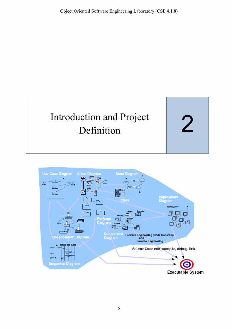
Introduction and ProjectDefinition 2
5

Object Oriented Software Engineering Laboratory (CSE 4.1.8)
Lab 2: Introduction and Project Definition
Objectives
Introduce the lab environment and tools used in the software engineering lab.
Discuss the project and learn how to write project definition.
1. Outline
Introduction to the lab plan and objectives.
Project definition.
2. Background
The software engineer is a key person and analyzing the business, identifying opportunitiesfor improvement, and designing information systems to implement these ideas. It isimportant to understand and develop through practice the skills needed to successfullydesign and implement new software systems.
2.1 Introduction
In this lab you will practice the software development life cycle (Project
Management, Requirements Engineering, System Modeling, Software Design,Prototyping and Testing) using CASE tools within a team work environment.
UML notation is covered in this lab as the modeling language for analysis and
design.
2.2 Tools used in the lab
Software Engineering lab is one of the most challenging of all labs. Developing a complete software application requires from each of you a good level of know – how of various tools.
There are some tools which will be taught, but there are some which are assumed you
already know, if you don’t then you learn should it individually.
o Rational Rose for UML diagrams (Object Oriented Analysis and Design)
2.3 Software Engineering Lab Objectives
Learn the software life cycle phases (Project management, requirements engineering,
software design, prototyping and testing).
Practice the software phases using a project.
6

Object Oriented Software Engineering Laboratory (CSE 4.1.8)
Learn a number of CASE tools and use them in a project within a team work
environment.
Get familiar with UML (modeling language for analysis and design).
2.4 Lab Plan
Week # Lab Content Deliverables Tool
Week 1Introduction and projectdefinition
Week 2 Software requirementsSpecification
Plan doc
Week 3Introduction to UML and usecase diagrams
Requirement and designtool (Rational Rose)
Week 4 System modeling (DFD orER)
Microsoft Word
Week 5 Flow of events and activitydiagram
SRS doc Rational Rose
Week 6 OO analysis: discoveringclasses
Rational Rose
Week 7Interaction diagrams:sequence and collaborationdiagrams
Rational Rose
Week 8Software Design: softwarearchitecture and object oriented design
Design doc (ver. 1) Rational Rose
Week 9 State Transition Diagram Rational Rose
Week 10Component and deploymentdiagrams
Design doc (Final ver.) Rational Rose
Week 11 Template Code Generation Rational Rose
Week 12 Presentations Final document Microsoft Word
3. CASE tools – No tools are used for this lab.
4. Exercises
1. Form groups of 4 students (with one of them as a leader).
2. Brainstorm and list 3 suitable project titles
3. Present these to the class
4. Choose one of the projects from your list
5. Try to write (a hypothetical) project definition for it.
7

Object Oriented Software Engineering Laboratory (CSE 4.1.8)
6. Present it to the instructor/ class
5. Deliverables
Form teams of 4 students for the term mini-project.
Suggest/ research a project and write a project definition/ problem statement.
8
Object Oriented Software Engineering Laboratory (CSE 4.1.8)
Software RequirementSpecification 3
9

Object Oriented Software Engineering Laboratory (CSE 4.1.8)
Lab 3: Software Requirement Specification (SRS)
Objectives
Gain a deeper understanding of the Software Requirement Specification phase and theSoftware Requirement Specification (SRS).
Learn how to write requirements and specifications.
1. Outline
Review of the requirements engineering process.
Write requirements and specifications.
Software Requirement Specification (SRS).
2. Background
A requirement is a statement of a behavior or attribute that a system must possess for thesystem to be acceptable to a stakeholder.
Software Requirement Specification (SRS) is a document that describes the requirements ofa computer system from the user's point of view. An SRS document specifies:
The required behavior of a system in terms of: input data, required processing, outputdata, operational scenarios and interfaces.
The attributes of a system including: performance, security, maintainability,reliability, availability, safety requirements and design constraints.
Requirements management is a systematic approach to eliciting, organizing anddocumenting the requirements of a system. It is a process that establishes and maintainsagreement between the customer and the project team on the changing requirements of asystem.
Requirements management is important because, by organizing and tracking therequirements and managing the requirement changes, you improve the chances ofcompleting the project on time and under budget. Poor change management is a key cause ofproject failure.
2.1 Requirements Engineering Process
Requirements engineering process consists of four phases:
Requirements elicitation: getting the customers to state exactly what the requirements are.
Requirements analysis: making qualitative judgments and checking for consistency and feasibility of requirements.
Requirements validation: demonstrating that the requirements define the system that the customer really wants.
10

Object Oriented Software Engineering Laboratory (CSE 4.1.8)
Requirements management: the process of managing changing requirements during the requirements engineering process and system development, and identifying missing and extra requirements.
2.2 Writing Requirements
Requirements always need to be correct, unambiguous, complete, consistent, and testable.
2.2.1 Recommendations When Writing Requirements
Never assume: others do now know what you have in mind. Use meaningful words; avoid words like: process, manage, perform, handle, and
support.
State requirements not features:
o Feature: general, tested only for existence.
o Requirement: specific, testable, measurable.
Avoid:
o Conjunctions: ask yourself whether the requirement should it be split into two requirements.
o Conditionals: if, else, but, except, although.
o Possibilities: may, might, probably, usually.
2.3 Writing Specifications
Specification is a description of operations and attributes of a system. It can be adocument, set of documents, a database of design information, a prototype, diagrams orany combination of these things.
Specifications are different from requirements: specifications are sufficiently complete -not only what stakeholders say they want; usually, they have no conflicts; they describethe system as it will be built and resolve any conflicting requirements.
Creating specifications is important. However, you may not create specifications if:
You are using a very incremental development process (small changes). You are building research or proof of concept projects.
You rebuilding very small projects.
It is not cheaper or faster than building the product.
2.4 Software Requirement Specification (SRS)
Remember that there is no “Perfect SRS”. However, SRS should be:
11
Object Oriented Software Engineering Laboratory (CSE 4.1.8)
Correct: each requirement represents something required by the target system. Unambiguous: every requirement in SRS has only one interpretation.
Complete: everything the target system should do is included in SRS (no sectionsare marked TBD-to be determined).
Verifiable: there exists some finite process with which a person/machine can check that the actual as-built software product meets the requirements.
Consistent in behavior and terms.
Understandable by customers.
Modifiable: changes can be made easily, completely and consistently.
Design independent: doesn't imply specific software architecture or algorithm.
Concise: shorter is better.
Organized: requirements in SRS are easy to locate; related requirements are together.
Traceable: each requirement is able to be referenced for later use (by the using paragraph numbers, one requirement in each paragraph, or by using convention for indication requirements)
3. CASE Tools – Nil
4. In-Class Demo
An overview of the requirements engineering process, and writing requirements and specifications.
5. Exercises
Write SRS for your project
6. Deliverables
SRS for your project
12
Object Oriented Software Engineering Laboratory (CSE 4.1.8)
Introduction to UML and UseCase Diagram 4
13

Object Oriented Software Engineering Laboratory (CSE 4.1.8)
14

Object Oriented Software Engineering Laboratory (CSE 4.1.8)
Lab 4: Introduction to UML and Use Case Diagram
Objectives Study the benefits of visual modeling. Learn use case diagrams: discovering actors and discovering use cases. Practice use cases diagrams using Rational Rose.
1. Outline
Visual modeling. Introduction to UML.
Introduction to visual modeling with UML.
Use case diagrams: discovering actors and use cases.
2. Background
Visual Modeling is a way of thinking about problems using models organized around real-worldideas. Models are useful for understanding problems, communicating with everyone involvedwith the project (customers, domain experts, analysts, designers, etc.), modeling enterprises,preparing documentation, and designing programs and databases.
2.1 Visual Modeling
Capture the structure and behavior of architectures and components. Show how the elements of the system fit together.
Hide or expose details appropriate for the task.
Maintain consistency between a design and its implementation.
Promote unambiguous communication.
2.2 What is UML?
The UML is the standard language for visualizing, specifying, constructing and documenting theartifacts of a software-intensive system. UML can be used with all processes throughout thedevelopment life cycle and across different implementation technologies.
2.3 History of UML
The UML is an attempt to standardize the artifacts of analysis and design: semantic models,syntactic notation and diagrams. The first public draft (version 0.8) was introduced in October1995. Feedback from the public and Ivar Jacobson's input were included in the next two versions(0.9 in July 1996 and 0.91 in October 1996). Version 1.0 was presented to the ObjectManagement Group (OMG) for standardization in July 1997. Additional enhancements wereincorporated into the 1.1 version of UML, which was presented to the OMG in September 1997.In November 1997, the UML was adopted as the standard modeling language by the OMG.
15
Object Oriented Software Engineering Laboratory (CSE 4.1.8)
2.4 Putting UML into Work: Use Case Diagram
The behavior of the system under development (i.e. what functionality must be provided by the system) is documented in a use case model that illustrates the system's intended functions (use cases), its surroundings (actors), and relationships between the use cases and actors (use case diagrams).
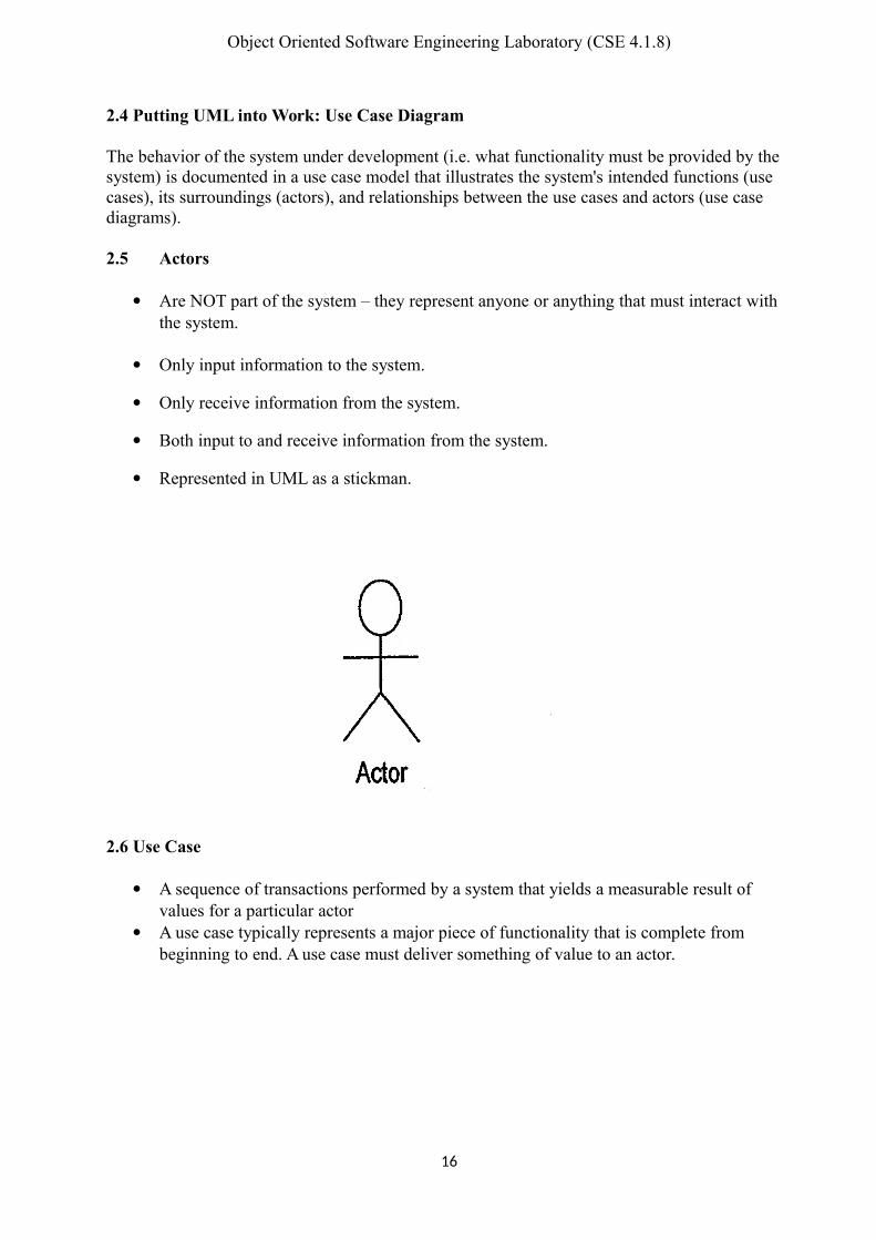
2.5 Actors
Are NOT part of the system – they represent anyone or anything that must interact with the system.
Only input information to the system.
Only receive information from the system.
Both input to and receive information from the system.
Represented in UML as a stickman.
2.6 Use Case
A sequence of transactions performed by a system that yields a measurable result of values for a particular actor
A use case typically represents a major piece of functionality that is complete from beginning to end. A use case must deliver something of value to an actor.
16

Object Oriented Software Engineering Laboratory (CSE 4.1.8)
2.7 Use Case Relationships
Between actor and use case. Association / Communication.
Arrow can be in either or both directions; arrow indicates who initiates communication.
Between use cases (generalization):
– Include
o Where inclusion use case is compulsory.
– Extends
o Optional behavior.o Behavior only runs under certain conditions (such as alarm).
o Several different flows run based on the user’s selection.
3. CASE Tools
The Rational Rose product family is designed to provide the software developer with a completeset of visual modeling tools for development of robust, efficient solutions to real business needsin the client/server, distributed enterprise and real-time systems environments. Rational Roseproducts share a common universal standard, making modeling accessible to nonprogrammerswanting to model business processes as well as to programmers modeling applications logic.
4. In-Class Example
Now you will learn how to apply the above-mentioned methods to draw use case diagrams fromthe problem statement. Please refer to Lab 5 slides which explain the process in detail with someexamples.
17
Object Oriented Software Engineering Laboratory (CSE 4.1.8)
5. Exercises
Read carefully the following problem statement
We are after a system that controls a recycling machine for returnable bottles and cans. Themachine will allow a customer to return bottles or cans on the same occasion. When thecustomer returns an item, the system will check what type has been returned. The system willregister how many items each customer returns and, when the customer asks for a receipt, thesystem will print out what he deposited, the value of the returned items and the total return sumthat will be paid to the customer. The system is also be used by an operator. The operator wantsto know how many items of each type have been returned during the day. At the end of the day,the operator asks for a printout of the total number of items that have been deposited in themachine on that particular day. The operator should also be able to change information in thesystem, such as the deposit values of the items. If something is amiss, for example if a can getsstuck or if the receipt roll is finished, the operator will be called by a special alarm signal.
After reading the above problem statement, find:
1. Actors
2. Use cases with each actor
3. Find extend or include use cases (if applicable)
4. Finally: draw the main use case diagram:
6. Deliverables
You should submit the solutions for the previous exercises.
You should use these techniques to draw use case diagrams for your term project using Rational Rose.
18

Object Oriented Software Engineering Laboratory (CSE 4.1.8)
System Modeling 5
19

Object Oriented Software Engineering Laboratory (CSE 4.1.8)
Lab 5: System Modeling
ObjectiveDeeper understanding of System modeling: Data model: entity-relationship diagram (ERD).Functional model: data flow diagram (DFD).
1. Outline
System analysis model elements:Data model: entity-relationship diagram (ERD)Functional model: data flow diagram (DFD)
2. Background
Modeling consists of building an abstraction of reality. These abstractions aresimplifications because they ignore irrelevant details and they only represent the relevantdetails (what is relevant or irrelevant depends on the purpose of the model).
2.1 Why Model Software?
Software is getting larger, not smaller; for example, Windows XP has more than 40 millionlines of code. A single programmer cannot manage this amount of code in its entirety. Codeis often not directly understandable by developers who did not participate in thedevelopment; thus, we need simpler representations for complex systems (modeling is amean for dealing with complexity). A wide variety of models have been in use within variousengineering disciplines for a long time. In software engineering a number of modelingmethods are also available.
2.2 Analysis Model ObjectivesTo describe what the customer requires.To establish a basis for the creation of a software design.To define a set of requirements that can be validated once the software is built.
2.3 The Elements of the Analysis Model
The generic analysis model consists of:An entity-relationship diagram (data model).A data flow diagram (functional model).A state transition diagram (behavioral model).
20
Object Oriented Software Engineering Laboratory (CSE 4.1.8)
NOTE: state transition diagram will be covered in lab 9.
2.3.1 Entity Relationship Diagram
An entity relationship diagram (ERD) is one means of representing the objects and theirrelationships in the data model for a software product.
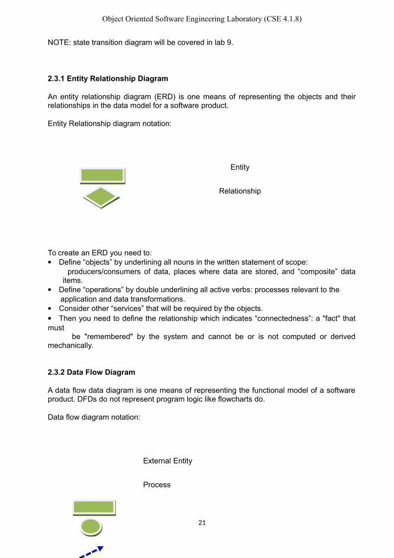
Entity Relationship diagram notation:
Entity
Relationship
To create an ERD you need to:Define “objects” by underlining all nouns in the written statement of scope: producers/consumers of data, places where data are stored, and “composite” data
items.Define “operations” by double underlining all active verbs: processes relevant to the application and data transformations.Consider other “services” that will be required by the objects.Then you need to define the relationship which indicates “connectedness”: a "fact" thatmust be "remembered" by the system and cannot be or is not computed or derivedmechanically.
2.3.2 Data Flow Diagram
A data flow data diagram is one means of representing the functional model of a softwareproduct. DFDs do not represent program logic like flowcharts do.
Data flow diagram notation:
External Entity
Process
21

Object Oriented Software Engineering Laboratory (CSE 4.1.8)
Data Flow
Control Flow
Data Store
To create a DFD you need to: Review ERD to isolate data objects and grammatical parse to determine operations. Determine external entities (producers and consumers of data). Create a level 0 DFD “Context Diagram” (one single process). Balance the flow to maintain data flow continuity. Develop a level 1 DFD; use a 1:5 (approx.) expansion ratio.
Data Flow Diagram Guidelines:All icons must be labeled with meaningful names.Always show external entities at level 0.Always label data flow arrows.Do not represent procedural logic.Each bubble is refined until it does just one thing.
3. CASE Tools
You can use MS word to create your ERD and DFD since we do not have a license for acase tool that supports these diagrams.
4. In-Class Example
Now you will learn how to create ERD and DFD.
5. Exercises
ERD and DFD for your Project
6. Deliverables
You should create ERD and DFD for your term project
22

Object Oriented Software Engineering Laboratory (CSE 4.1.8)
Documenting Use Cases andActivity Diagrams 6
23

Object Oriented Software Engineering Laboratory (CSE 4.1.8)
24

Object Oriented Software Engineering Laboratory (CSE 4.1.8)
Lab 6: Documenting Use Cases and Activity Diagrams
Objectives Study how to document use cases in detail. Know about scenarios (flow of events) and its importance. Deeper understanding of UML activity diagrams. Practicing flow of events and activity diagrams using Rational Rose.
1. Outline Writing flow of events. Flow of events template and example. Activity diagrams. Examples.
2. BackgroundEach use case is documented with a flow of events. The flow of events for a use case is adescription of the events needed to accomplish the required behavior of the use case. Activitydiagrams may also be created at this stage in the life cycle. These diagrams represent thedynamics of the system. They are flow charts that are used to show the workflow of a system;that is, they show the flow of control from one activity to another in the system.
2.1 Flow of EventsA description of events required to accomplish the behavior of the use case, that:
Show WHAT the system should do, not HOW the system does it. Written in the language of the domain, not in terms of implementation. Written from an actor point of view.
A flow of events document is created for each use case: Actors are examined to determine how they interact with the system. Break down into the most atomic actions possible.
2.2 Contents of Flow of Events When and how the use case starts and ends. What interaction the use case has with the actors. What data is needed by the use case. The normal sequence of events for the use case. The description of any alternate or exceptional flows.
2.3 Template for the flow of events documentEach project should use a standard template for the creation of the flow of events document. Thefollowing template seems to be useful.X Flow of events for the <name> use caseX.1 PreconditionsX.2 Main flowX.3 Sub-flows (if applicable)X.4 Alternative flowswhere X is a number from 1 to the number of use cases.
25

Object Oriented Software Engineering Laboratory (CSE 4.1.8)
A sample completed flow of events document for the Select Courses to Teach use case follows.1. Flow of Events for the Select Courses to Teach Use Case1.1 PreconditionsCreate course offerings sub-flow of the maintain course information use case must executebefore this use case begins.
1.2 Main FlowThis use case begins when the professor logs onto the registration system and enters his/herpassword. The system verifies that the password is valid (E-1) and prompts the professor toselect the current semester or a future semester (E-2). The professor enters the desired semester.The system prompts the Professor to select the desired activity: ADD, DELETE, REVIEW,PRINT, or QUIT.
If the activity selected is ADD, the S-1: add a course offering sub-flow is performed.
If the activity selected is DELETE, the S-2: delete a course offering sub-flow is performed.
If the activity selected is REVIEW, the S-3: review schedule sub-flow is performed.
If the activity selected is PRINT, the S-4: print a schedule sub-flow is performed.
If the activity selected is QUIT, the use case ends.
1.3 Sub-flowsS-1: Add a Course Offering:The system displays the course screen containing a field for a course name and number. Theprofessor enters the name and number of a course (E-3). The system displays the courseofferings for the entered course (E-4). The professor selects a course offering. The system linksthe professor to the selected course offering (E-5). The use case then begins again.
S-2: Delete a Course Offering:The system displays the course offering screen containing a field for a course offering name andnumber. The professor enters the name and number of a course offering (E-6). The systemremoves the link to the professor (E-7). The use case then begins again.
S-3: Review a Schedule:The system retrieves (E-8) and displays the following information for all course offerings forwhich the professor is assigned: course name, course number, course offering number, days ofthe week, time, and location. When the professor indicates that he or she is through reviewing,the use case begins again.
S-4: Print a ScheduleThe system prints the professor schedule (E-9). The use case begins again.
1.4 Alternative FlowsE-1: An invalid professor ID number is entered. The user can re-enter a professor ID number orterminate the use case.
E-2: An invalid semester is entered. The user can re-enter the semester or terminate the use case.
E-3: An invalid course name/number is entered. The user can re-enter a valid name/numbercombination or terminate the use case.
26

Object Oriented Software Engineering Laboratory (CSE 4.1.8)
E-4: Course offerings cannot be displayed. The user is informed that this option is not availableat the current time. The use case begins again.
E-5: A link between the professor and the course offering cannot be created. The information issaved and the system will create the link at a later time. The use case continues.
E-6: An invalid course offering name/number is entered. The user can re-enter a valid courseoffering name/number combination or terminate the use case.
E-7: A link between the professor and the course offering cannot be removed. The information issaved and the system will remove the link at a later time. The use case continues.
E-8: The system cannot retrieve schedule information. The use case then begins again.
E-9: The schedule cannot be printed. The user is informed that this option is not available at thecurrent time. The use case begins again.Use case flow of events documents are entered and maintained in documents external toRational Rose. The documents are linked to the use case.
2.4 Activity DiagramsActivity diagrams are flow charts that are used to show the workflow of a system.They also:
Represent the dynamics of the system. Show the flow of control from activity to activity in the system. Show what activities can be done in parallel, and any alternate paths through
the flow.Activity diagrams may be created to represent the flow across use cases or they may be createdto represent the flow within a particular use case. Later in the life cycle, activity diagrams maybe created to show the workflow for an operation.
2.5 Activity Diagram Notation Activities- performance of some behavior in the workflow. Transition- passing the flow of control from activity to activity. Decision- show where the flow of control branches based on a decision point:
o Guard condition is used to determine which path from the decision point is taken.
Synchronization-what activities are done concurrently? What activities must be completed before processing may continue (join).
3. CASE ToolsRational Rose.
4. In-Class ExampleNow you will learn how to apply the above mentioned methods to write flow of events and drawing activity diagrams from the use case(s) flow of events.
5. ExercisesApply to your Project
6. Deliverables
27

Object Oriented Software Engineering Laboratory (CSE 4.1.8)
You should use these techniques to write flow of events and draw activity diagrams for your term project.
28

Object Oriented Software Engineering Laboratory (CSE 4.1.8)
29

Object Oriented Software Engineering Laboratory (CSE 4.1.8)
Object Oriented Analysis:Discovering Classes 7
Lab 7: Object-Oriented Analysis: Discovering Classes
Objective Learn the object-oriented analysis phase by understanding the methods of class
elicitation and finding the classes in an object-oriented system.
1. Outline Object-Oriented concepts Discovering classes’ approaches: noun phrase approach, common class patterns, use case
driven method, CRC (Class-Responsibility-Collaboration) and mixed approach. Examples.
2. BackgroundClasses: a description of a group of objects with common properties (attributes), commonbehavior (operations), common relationships to other objects and common semantics.
2.1 Object-Oriented Concepts Attribute: the basic data of the class. Method (operation): an executable procedure that is encapsulated in a class and is
designed to operate on one or more data attributes that are defined as part of the class. Object: when specific values are assigned to all the resources defined in a class, the
result is an instance of that class. Any instance of any class is called an object.
2.2 Discovering ClassesDiscovering and defining classes to describe the structure of a computerized system is not an easy task. When the problem domain is new or unfamiliar to the software developers it can be difficult to discover classes; a cookbook for finding classes does not exist.
2.3 Classes CategoriesClasses are divided into three categories:
30
Object Oriented Software Engineering Laboratory (CSE 4.1.8)
Entity: models information and associated behavior that is long-lived, independent of thesurrounding, application independent, and accomplishes some responsibility
Boundary: handles the communication between the system surroundings and the inside of the system, provides interface, and facilitates communication with other systems
Control: model sequencing behavior specific to one or more use cases. Control classes coordinate the events needed to realize the behavior specified in the use case, and they are responsible for the flow of events in the use case.
2.4 Discovering Classes Approaches Methods of discovering classes:
2.4.1 Noun Phrase Approach: Examine the requirements and underline each noun. Each noun is a candidate class; divide the list of candidate classes into:
Relevant classes: part of the application domain; occur frequently in requirements. Irrelevant classes: outside of application domain Fuzzy classes: unable to be declared relevant with confidence; require additional
analysis
2.4.2 Common Class Patterns: Derives candidate classes from the classification theory ofobjects; candidate classes and objects come from one of the following sources: Tangible things: e.g. buildings, cars. Roles: e.g. teachers, students. Events: things that happen at a given date and time, or as steps in an ordered
sequence: e.g. landing, request, interrupt. Interactions: e.g. meeting, discussion. Sources, facilities: e.g. departments. Other systems: external systems with which the application interacts. Concept class: a notion shared by a large community. Organization class: a collection or group within the domain. People class: roles people can play. Places class: a physical location relevant to the system.
2.4.3 Use Case Driven Method: The scenarios - use cases that are fundamental to the systemoperation are enumerated. Going over each scenario leads to the identification of theobjects, the responsibilities of each object, and how these objects collaborate with otherobjects.
2.4.4 CRC (Class-Responsibility-Collaboration): Used primarily as a brainstorming tool foranalysis and design. CRC identifies classes by analyzing how objects collaborate toperform business functions (use cases). A CRC card contains: name of the class,responsibilities of the class and collaborators of the class. Record name of class at thetop; record responsibilities down the left-hand side; record other classes (collaborators)that may be required to fulfill each responsibility on the right-hand side. CRC cards areeffective at analyzing scenarios; they force you to be concise and clear; they are cheap,portable and readily available.
2.4.5 Mixed Approach: A mix of these approaches can be used, one possible scenario is: Use CRC for brainstorming. Identify the initial classes by domain knowledge.
31
Object Oriented Software Engineering Laboratory (CSE 4.1.8)
Use common class patterns approach to guide the identification of the classes. Use noun phrase approach to add more classes. Use the use case approach to verify the identified classes.
2.5 Class Elicitation Guidelines A class should have a single major role. A class should have defined responsibilities (use CRC cards if needed). Classes should be of a manageable size: if a class has too many attributes or operations,
consider splitting it. A class should have a well-defined behavior, preferably by implementing a given
requirement or an interface.
3. CASE ToolsRational Rose.
32

Object Oriented Software Engineering Laboratory (CSE 4.1.8)
4. In-Class ExampleNow you will learn how to apply the above mentioned methods of finding classes from the problem statement.
5. ExercisesApply to your Project
6. DeliverablesYou should use these class elicitation techniques to identify the classes for your term project.
33

Object Oriented Software Engineering Laboratory (CSE 4.1.8)
Interaction Diagrams:Sequence and Collaboration
Diagrams 8
34

Object Oriented Software Engineering Laboratory (CSE 4.1.8)
Lab 8: Interaction Diagrams: Sequence & Collaboration Diagrams
Objectives Better understanding of the interaction diagrams. Get familiar with sequence & collaboration diagrams. Practice drawing the interaction diagrams using Rational Rose.
1. OutlineInteraction diagrams:
Sequence diagrams Collaboration diagrams
2. BackgroundInteraction diagrams describe how groups of objects collaborate in some behavior. Aninteraction diagram typically captures the behavior of a single use case. Interaction diagrams donot capture the complete behavior, only typical scenarios.
2.1 Analyzing a System’s BehaviorUML offers two diagrams to model the dynamics of the system: sequence and collaborationdiagrams. These diagrams show the interactions between objects.
2.2 Sequence DiagramsSequence diagrams are a graphical way to illustrate a scenario:
They are called sequence diagrams because they show the sequence of message passingbetween objects.
Another big advantage of these diagrams is that they show when the objects are createdand when they are destructed. They also show whether messages are synchronous orasynchronous.
2.3 Creating Sequence Diagrams You must know the scenario you want to model before diagramming sequence diagrams. After that specify the classes involved in that scenario. List the involved objects in the scenario horizontally on the top of the page. Drop a dotted line beneath every object. They are called lifelines. The scenario should start by a message pass from the first object. You must know how to place the objects so that the sequence is clear. You may start the scenario by an actor. Timing is represented vertically downward. Arrows between life lines represents message passing. Horizontal arrows may pass through the lifeline of another object, but must stop at some
other object.
35

Object Oriented Software Engineering Laboratory (CSE 4.1.8)
You may add constraints to these horizontal arrows. Objects may send messages to themselves.
Long, narrow rectangles can be placed over the lifeline of objects to show when theobject is active. These rectangles are called activation lines.
2.4 Collaboration DiagramsThey are the same as sequence diagrams but without a time axis:
Their message arrows are numbered to show the sequence of message sending. They are less complex and less descriptive than sequence diagrams. These diagrams are very useful during design because you can figure out how
objects communicate with each other.
2.5 Notes Always keep your diagrams simple. For “IF... then ...” else scenarios, you may draw separate sequence diagrams for the
different branches of the “if statement”. You may even hide them, (at least during theanalysis phase) and document them by the text description accompanying the sequence diagrams.
3. CASE ToolsRational Rose.
4. In-Class ExampleNow you will learn how to apply the above mentioned methods of drawing sequence and collaboration diagrams from the problem statement.
5. ExercisesApply to your Project.
6. DeliverablesYou should use these techniques to create sequence and collaboration diagrams for your term project.
36

Object Oriented Software Engineering Laboratory (CSE 4.1.8)
Software Design: SoftwareArchitecture and Object
Oriented Design 9
37

Object Oriented Software Engineering Laboratory (CSE 4.1.8)
38

Object Oriented Software Engineering Laboratory (CSE 4.1.8)
Lab 9: Software Design: Software Architecture and Object-Oriented Design
Objectives Deeper understanding of software design and the software design document (SDD). Learn how to find the relationships between classes to create UML class diagram.
1. Outline Software design concepts and principals. Software architecture. Specifying the attributes and the operations and finding the relationships between
classes. Creating UML class diagram. Software design document.
2. BackgroundThe purpose of software design is “to produce a workable (implementable) solution toa given problem.” David Budgen in Software Design: An Introduction.
2.1 The Design ProcessSoftware design is an iterative process that is traceable to the software requirements analysisprocess. Many software projects iterate through the analysis and design phases several times.Pure separation of analysis and design may not always be possible.
2.2 Design Concepts The design should be based on requirements specification. The design should be documented (so that it supports implementation, verification, and
maintenance). The design should use abstraction (to reduce complexity and to hide unnecessary detail). The design should be modular (to support abstraction, verification, maintenance, and
division of labor). The design should be assessed for quality as it is being created, not after the fact. Design should produce modules that exhibit independent functional characteristics. Design should support verification and maintenance.
2.3 Software ArchitectureSoftware architecture is a description of the subsystems and components of a software systemand the relationships between them.You need to develop an architectural model to enable everyone to better understand the system,to allow people to work on individual pieces of the system in isolation, to prepare for extensionof the system and to facilitate reuse and reusability.
2.4 Describing an Architecture Using UMLAll UML diagrams can be useful to describe aspects of the architectural model. FourUML diagrams are particularly suitable for architecture modeling:
Package diagrams Subsystem diagrams Component diagrams Deployment diagrams
39

Object Oriented Software Engineering Laboratory (CSE 4.1.8)
2.5 Specifying ClassesEach class is given a name, and then you need to specify:
Attributes: initially those that capture interesting object states. Attributes can be public, protected, private or friendly/package.
Operations: can be delayed till later analysis stages or even till design. Operations also can be public, protected, private or friendly/package.
Object-Relationships:o Associations: denote relationships between classes.o An aggregation: a special case of association denoting a “consists of” hierarchy.o Composition: a strong form of aggregation where components cannot exist without
the aggregate.o Generalization relationships: denote inheritance between classes.
This will build the class diagram, which is a graphical representation of the classes (including their attributes and operations) and their relationship with other classes.
3. CASE ToolsRational Rose.
4. In-Class ExampleNow you will learn how to specify classes’ attributes, methods and the relationships between theclasses.
6. ExercisesApply to your Project
7. DeliverablesAlso you should use specifying class attributes, methods and the relationship with other classes you learned in your term project.
40
Object Oriented Software Engineering Laboratory (CSE 4.1.8)
State Chart Diagram 10
41

Object Oriented Software Engineering Laboratory (CSE 4.1.8)
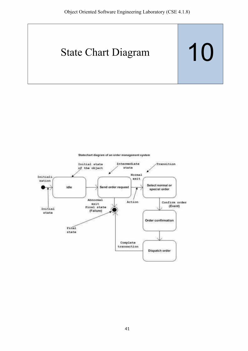
Lab 10: State Transition Diagrams
Objectives Deeper understanding of UML state transition diagrams (STD). Practicing using Rational Rose.
1. Outline UML state diagrams. UML state diagram notation UML state details Examples
2. BackgroundMainly, we use interaction diagrams to study and model the behavior of objects in our system.Sometimes, we need to study the behavior of a specific object that shows complex behavior tobetter understand its dynamics. For that sake, UML provides state transition diagrams used tomodel the behavior of objects of complex behavior. In this Lab, UML state transition diagramswill be introduced. We will study their notation and how can we model them using RationalRose.
2.1 UML State DiagramsState diagrams show how one specific object changes state as it receives and processesmessages:
Since they are very specific, they are used for analyzing very specific situations if wecompare them with other diagrams.
A state refers to the set of values that describe an object at a specific moment in time. As messages are received, the operations associated with the object’s parent class are
invoked to deal with the messages. These messages change the values of these attributes. There is no need to prepare a state diagram for every class you have in the system.
2.2 Creating State Transition Diagrams States are represented by rectangles with rounded corners with an attribute name with a
values associated with it. The name of the state is placed within the box. Events are shown by arrows. An event occurs when at an instant in time when a value is changed. A message is data passed from one object to another. The name of a state usually refers to the name of the attribute and the values associated
to it. Example, a student object may receive a message to change its name. The state of that
object changes from the first name state to the new state name. The name of the state is placed in the top compartment. State variables are placed in the next compartment. The operations associated with the state are listed in the lowest compartment of the state
box. In the operations part, we usually use one of the following reserved words:
o Entry: a specific action performed on the entry to the state.
42

Object Oriented Software Engineering Laboratory (CSE 4.1.8)
o Do: an ongoing action performed while in the state.o On: a specific action performed while in the state.o Exit: a specific action performed on exiting the state.
There are two special states added to the state transition diagram- start state and end state.
Notation of start state is a solid black circle and for the end state a bull’s eye is used.
2.3 State Transition Details A state transition may have an action and/or guard condition associated with it and it may
also trigger an event. An action is the behavior that occurs when the state transition occurs. An event is a message that is sent to another object in the system. A guard condition is a Boolean expression of attribute values that allows a state
transition only if the condition is true. Both actions and guards are behaviors of the object and typically become operations.
Also they are usually private operations (used by the object itself). Actions that accompany all state transitions into a state may be placed as an entry action
within the state. Actions that accompany all state transitions out of a state may be placed as exit actions
within the state. A behavior that occurs within the state is called an activity. An activity starts when the state is entered and either completes or is interrupted by an
outgoing state transition. A behavior may be an action, or it may be an event sent to another object. This behavior is mapped to operations on the object.
43

Object Oriented Software Engineering Laboratory (CSE 4.1.8)
3. CASE ToolsRational Rose.
4. In-Class ExampleNow you will learn how to apply the above mentioned methods of drawing state transition diagrams (STD).
5. ExercisesApply to your Project.
6. DeliverablesYou should use these techniques to create state transition diagrams for your term project.
44

Object Oriented Software Engineering Laboratory (CSE 4.1.8)
Implementation Diagrams:Component and Deployment Diagrams 11
45

Object Oriented Software Engineering Laboratory (CSE 4.1.8)
46
Object Oriented Software Engineering Laboratory (CSE 4.1.8)
Lab 11: Implementation Diagrams: Component & Deployment Diagrams
Objectives Become familiar with the implementation diagrams: component and deployment
diagrams. Practice using Rational Rose.
1. Outline Implementation diagrams: component and deployment diagrams. Examples.
2. BackgroundImplementation diagrams capture design information. The main implementation diagrams inUML are: component and deployment diagrams. In this Lab we will study these diagrams andtheir notation.
2.1 UML Implementation DiagramsThe main implementation diagrams we have in UML are: component diagrams and deploymentdiagrams. These diagrams are high level diagrams in comparison with old diagrams you havealready learned.
2.2 UML Component DiagramComponent diagrams capture the physical structure of the implementation.
Remember always that when you talk about components, you are talking about thephysical models of code.
You can name them and show dependency between different components using arrows. A component diagram shows relationships between component packages and
components. Each component diagram provides a physical view of the current model. Component diagrams contain icons representing:
o Component packages.o Components.o Main programs.o Packages.o Subprograms.o Tasks.o Dependencies.
2.3 Deployment DiagramsA deployment diagram shows processors, devices and connections. Each model contains a singledeployment diagram which shows the connections between its processors and devices, and theallocation of its processes to processors.
2.3.1 Deployment Diagrams: ProcessorA processor is a hardware component capable of executing programs.
A processor is given a name and you should specify the processes that will run on that processor.
You can also specify the scheduling of these processes on that processor.
47

Object Oriented Software Engineering Laboratory (CSE 4.1.8)
Types of scheduling are:o Pre-emptive: a higher priority process may take the process from lower priority one.o Non-preemptive: a process will own the processor until it finisheso Cyclic: control passes from one process to another.o Executive: an algorithm controls the scheduling of the processes.o Manual: scheduling buy the user.
2.3.2 Deployment Diagrams: DeviceA device is a hardware component with no computing power. Each device must have a name. Device names can be generic, such as “modem” or “terminal.”
2.3.3 Deployment diagrams: ConnectionA connection represents some type of hardware coupling between two entities. An entity is either a processor or a device. The hardware coupling can be direct, such as an RS232 cable, or indirect, such as satellite-to-ground communication. Connections are usually bi-directional.
3. CASE ToolsRational Rose.
4. In-Class ExampleNow you will learn how to apply the above mentioned methods of creating component and deployment diagrams.
5. ExercisesApply system and its components and draw deployment and component diagrams.
6. DeliverablesYou should use these techniques to create component and deployment diagrams for your term project.
48

Object Oriented Software Engineering Laboratory (CSE 4.1.8)
Template Code 12
49

Object Oriented Software Engineering Laboratory (CSE 4.1.8)
50

Object Oriented Software Engineering Laboratory (CSE 4.1.8)
Lab 12: Template Code
Objectives Generating Template Code. Practicing using Rational Rose.
1. Outline Forward Engineering. Reverse Engineering. Examples.
2. BackgroundWe can generate template code using Rational Rose. Logic should be written by student afterobtaining template code. Template code will be generated by unique identity number for everygeneration.In this Lab, UML template code generation will be introduced. We will study their generationand how can we add logic code to template code.
2.1 Forward EngineeringFrom model to code.
2.2 Reverse EngineeringFrom code to model.
3. CASE ToolsRational Rose.
4. In-Class ExampleNow you will learn how to generate template code.
5. ExercisesApply to your Project
6. DeliverablesYou should use these techniques to generate template code for your term project.
51
Object Oriented Software Engineering Laboratory (CSE 4.1.8)
Appendix A
52

Object Oriented Software Engineering Laboratory (CSE 4.1.8)
RATIONAL ROSE
Rational Rose is the visual modeling ware solution that lets you create, analyze, design,
view, modify and manipulate components. You can graphically depict on overview of the
behavior your system with a use case diagram .Rational Rose provides the collaboration diagram
as an alternative to a use case diagram .It shows object interactions organized around objects and
their links to one another. The state chart diagram provides additional analysis techniques for
classes with significant dynamic behavior .Activity diagrams provide a way to model a class
operation or the work flow of a business process.
Rational Rose provides the notation needed to specify and document the system
architecture .The logical architecture is captured in class diagrams that contain the classes and
relationships that represent the key abstractions of the system under development .The
component architecture is captured in component diagrams that focus
on the actual software module organization with in the development environment .The
deployment architecture is captured in deployment diagrams that map software to processing
nodes showing the configuration of the run time processing elements and their software
processes .
FEATURES
Rational Rose provides the following features facilitates the analysis, design and iterative
construction of your application
Use-Case Analysis
Object –Oriented Modeling
User-configurable Support for UML ,COM ,OMT and Booch’93
Semantic Checking
Support for Controlled Iterative Development
Round-Trip Engineering
Parallel Multi- user Development.
Integration with Data Modeling tools
Document generation
Rational Rose scripting for integration and Extensibility
OLE Linking
53

Object Oriented Software Engineering Laboratory (CSE 4.1.8)
OLE Automation
Multi Platform Availability
EXTENDING RATIONAL ROSE
The add-in feature allows you to quickly and accurately customize your Rational Rose
environment depending on your development needs. Using the add-in tool, you can install
language and non language tools while in Rational Rose.
When an add-in is installed, it is automatically in an activated state. Add-ins can install
Menus(.mnu files)
Help files(.hlp files)
Contents tab files(.cnt files)
Properties (.pty files)
Executables (.exe)
Script files(.ebs script source file and .ebx compiled script file)
OLE servers(.dll files)
Additionally, an add-in can define fundamental types, predefined stereotypes,
and metafiles. Note that an add-in is not to be considered strictly a one-to one association
with a round-trip engineering integration.
ADD-IN MANAGER
The Add-in Manager allows you to control the state of the add-in, whether it is activated
or deactivated. If the add-in is deactivated, it is still visible through the Add-in Manager.
However, the add-in’s properties and menus are not available.
The student is expressed to take up about five mini-projects and model them andproduce Use Cases, Anal
Actors in the University Course Registration System:
1.Student want to register for courses.
2.Professors want to select courses to teach
3.The register must create the curriculum to teach
54

Object Oriented Software Engineering Laboratory (CSE 4.1.8)
4.The register must maintain all the information about courses ,professors and students.
5.The billing system must receive billing information from the system.
The actors identified are:
1 Student
2 Professors
3 Register
A use case represents the functionality provided by the system.
The following questions will help to identify the use cases in the system:
1. What are the tasks of each actor?2. Will any actor create, store,change ,remove,or read this information?3. What use case will create ,store,change,remove or read this information?4. Does any actor need to be informed about certain occurance in the system?5. What use cases will support and maintain the system?6. Can all functional requirements be performed by the use access?
The following needs must be addressed by the system.
1 The student actor needs to use the system to register for courses.
2 After the courses selection process is completed ,the billing system must be supplied withbilling information.
3 The professor actor needs to use the system to select the course to teach for a semester andmust be able to receive a course roster from the system.
4 The register is responsible for the generation of the course for a semester and for themaintenance of all information about the curriculum, the students and the professors neededby the system.
The uses cases identified are
1. Register for courses2. Select courses to teach3. Request for roster 4. Maintain courses information5. Maintain professor information6. Maintain student information7. Create course catalog.
Creating Class Diagrams:
The purpose of a class diagram is to specify the structural makeup of the system. Thisincludes class relationship and the attributes and behaviors associated with class. Classdiagrams are remarkable at inheritance and composite relations hips.
55

Object Oriented Software Engineering Laboratory (CSE 4.1.8)
A good class captures one and only one abstraction-it should have one major theme.
The following questions will help to identify the classes in the system:
1. Identify the main members of the problem given.2. Determine how they are related to each other3. Identify the characteristics of each member of the problem.4. Find relations among the members.5. Decide the inheritance of personal traits and characters.
The following needs must be addresses by the system for classes are:
1 Courses that are offered by the system for classes are:
2 Details about the professors present.
3 Information about the students that are taking admissions.
4 Information about the university
The classes that are identified are:
1 Courses
2 professor
3 student
4 Home
The following questions will help to identify the attributes for classes:
1 What it is going to do with a property or characteristic?
2 How it is going to collaborate with other classes?
3 What it need to know?
4 What state information it should remember over time?
5 In what sates it will exist?
For example for the class student the attributes are name, age ,roll no, address, branch etc.
Guidelines for identifying methods for classes:
Object provides and describes abstract data. Method or behaviour or operations usuallycorresponding to queries about attributes.
For example for the class student the methods are get detail (), registration request () etc.
Guidelines for identifying relationship between classes:
56

Object Oriented Software Engineering Laboratory (CSE 4.1.8)
1 Is the class of fulfilling the required task by itself?2 If not, what does it need?3 From what other class can it require it needs?
For example there is a relationship between students class and professor’s class.
Creating interaction diagrams:
There are two of interaction diagrams: sequence and collaboration diagrams.
A Sequence diagram is a model that describe how groups of objects Collaboration in somebehaviour over time. The Sequence diagram captures the behaviour of a single use case andshows the objects and the messages that are passed between these objects in the timeframe of thespecific use case The Sequence diagram does not show relationships between objects.
The sequence diagram may be used to:
1 Describe the overall sequence of the flow of control when there are many short methodsin different classes.
2 Show concurrent processes and activations.3 Show time sequences that are not easily depicted in a Collaboration diagram.4 Show general forms that do not deal with objects but with class interaction.
Guidelines for identifying relationship between objects:
1 We need to identify a set of software objects with clearly defined responsibilities.
2 Use of Jacobsen’s ‘interference’, ‘control’, and ‘entity’ categories, or of the CRC technique,
are well –defined and fruitful approaches.
3 The initial development of object interaction diagrams (sequence diagrams andcollaboration
Diagrams) provides much of the information required to develop an initial class diagram.
4 Messages received by an object require you to define corresponding operations in theobject’s class
5 Parameters or return data involved in the message imply a requirement for attributes;interaction between two objects implies some form of relation between their classes.
CERATING ACTIVITY DIAGRAM:
Activity diagram represent the dynamics of the system. They are used to show the flow ofcontrol from activity to activity in the system, what activities can be done in parallel and anyalternate paths through the flow. Activity diagrams may be created to represent the flow with ina particular use cases or across the use cases. It may be created to shoe the work flow for anoperation
57

Object Oriented Software Engineering Laboratory (CSE 4.1.8)
THE FOLLOWING POINTS TO DRAW THE ACTIVITY DIAGRAM IN THESYSTEM:
1. Identify the scope of the activity diagram.
Begin by identifying what it is you are modeling. Is it a single use case? A portion of ause case? A business process that includes several use cases? A single method of a class?Once you identify the scope of your diagram, you should a label at the top, using a note,indicating an appropriate title for the diagram and a unique identifier for it. you may alsowant to include the date and even the names of the authors of the diagram.
2. Add start and end points
Every activity diagram has a starting point and ending point.3. add activities
if you are modeling a use case, introduce an activity in each major step initiated by anactor if you are modeling a high level business process, introduce an activity for eachmajor process, often a usecase or a package of usecases. finally if you are modelling amethod, then it is common to9 have an activity for this step in the code.
4. Add transitions from the activities.
My Style is always to exit an activity even if it is simply toan ending point.whwnever there ismore than one transition out of activity,you must label each transition appropriately.
5. Add decision points
Sometimes the logic of what you are modelling calls for a decision to be made.
6.Identity oppurtunities for parallel activities
Two Activities can occur in parallel when no direct relationship exits between them andtehey must both finish before a third activity can.
The activities identified are:
1.create the curriculum
2.select courses to each
3.create catalogue
4.Open registration
5.Assign professors to teach
6.Place catalogue in the book store
7.Mail catalogue to students.
58

Object Oriented Software Engineering Laboratory (CSE 4.1.8)
59

Object Oriented Software Engineering Laboratory (CSE 4.1.8)
Appendix B
60

Object Oriented Software Engineering Laboratory (CSE 4.1.8)
A Point-of-Sale (POS) system
Project Analysis:
A POS system is a computerized application used to record sales and handle payments; it istypically used in retail store. It includes hardware components such as a computer and bar codescanner , and software to run to run the system. It interfaces to various applications, such asthird party tax calculator and inventory control. These systems must be relatively fault tolerant;that is ,even if remote services are temporarily unavailable they must still be of capturing salesand handling at least cash payments . A POS system must support multiple and varied client-sideterminals and interfaces such as browser, PDAs, touch-screens.
Creating Use case Diagrams:
Identifying actors:
1. Supermarket is a hardware thing where goods are brought2. Customer is a person who buys items in a super market.3. Staff is a person who interacts with super market.4. Bank is a actor who gives loan to super market.5. Items are part of super market
Identifying use cases:
1. Sell items2. Pay salaries3. Maintenance4. Issue bills5. Take salary6. Select items7. Buy items 8. Give loans 9. Collect loans10. Display11. Sales12. Profit13. Loss14. Pay money
Identifying relationships:
Association:
1. Supermarket Sell items2. Supermarket Pay salaries3. Supermarket Maintain4. Supermarket Issue bills5. Staff works in Supermarket6. Customer selects items7. Star takes salaries 8. Customer selects items9. Bank gives loans
61

Object Oriented Software Engineering Laboratory (CSE 4.1.8)
10. Bank collects loans11. Items are display in supermarket
Creating Class Diagrams:
Identifying classes:
1. Supermarket2. Customer3. Cash payment4. Staff5. Items6. Bank7. Sales8. Cashier9. Profit10. Loss11. Billing system12. hardware13. software14. scanner15. Barcode reader16. Determine tax17. Stationary
Identifying relationship between classes:
Aggregation:
1. Staff is a part of supermarket2. Items are a part of supermarket3. Billing system is a part of supermarket
Association:
1. Items are sold through sales2. Bank provide loans to supermarket3. Customer pays the cash payment4. Cashier determine the tax5. Sale are done by supermarket 6. Billing system determine the tax
Generalization:
1. Stationary is a kind of item2. Vegetables is a kind of item3. Chocolates is a kind of item4. Fruits is a kind of item5. Glossaries is a kind of item6. Hardware is a kind of billing system7. Software is a kind of billing system8. Scanner is a kind of hardware
62

Object Oriented Software Engineering Laboratory (CSE 4.1.8)
9. Barcode reader is a kind of hardware
Dependency:
1. Profit is dependent on sales2. Loss is dependent on sales
Identifying attributes:
1. Supermarket: name, location, branches, code2. Cash payment: cheque, credit card, debit card, cash 3. Billing system: sensors, serial no4. Barcode scanner5. Loss 6. Customer: name, credit card7. Bank; name, location 8. Sales: no of items sold, cost of item sold9. Staff: name, id, designation10. Items: name, code, cost, quantity11. Cashier: name, id12. Hardware: name, serial no13. Software 14. Scanner15. Determine tax: amount, percentage16. Glossaries17. Stationary 18. Profit
Identifying operations
1.Supermaket:sell items
2.Customer:buy items
3.Cash patment:display
4.Staff:Worktimings:salary
5.Items:display
6.Sales:Display
7.Cashier:Collect cash
8.profit:display
9.loss:display
10.billing system:issuable,display
11.hardware
63

Object Oriented Software Engineering Laboratory (CSE 4.1.8)
12.software
13.scanner:scam code
14.barcode reader:barcodescan
15.determine tax;display
16.staionary:display
Creating collaboration diagrams:
Identifying objects:
1.s.supermarket
2.cp.cash payment
3.st.staff
4.i.items5.b.bank
6.sl.sales
7.cs.cashier
8.bs.billing systems
9.br.barcode reader
Identifying messages:
1.Supermarket exhibit items to customer
2.Supermarket gives item details to customers
3.customer enters to super market
4.pos check password of customer
5.customer selects item
6.staff guide customer
7.Barcode scanner identify product of super market
8.Super market produces the billing from
9.Cashier verifies the account of customer
10.customer pay bill system
11.Cashier give product to customer
64

Object Oriented Software Engineering Laboratory (CSE 4.1.8)
Creating activity diagrams:
Identifying activities:
1. Take loans from bank 2. Customer enters supermarket 3. Staff shows the items4. Customer selects the items5. Select6. Decline7. Selected items submit at cashier8. Enter details in billing system 9. Issue the bill10. Pay bill11. Cashier collects the bill
65

Object Oriented Software Engineering Laboratory (CSE 4.1.8)
ONLINE BOOKSHOP Example
Project Analysis:
Online book shop is an application used to maintain information about the items that aregenerally available in that book shop. Any customer can access the information about the itemand he can also order item through online by creating his login in that site. Customer can changethe already entered details. The items information in that site is entered by the bookshop staffand it can be change if there are any modifications.
Creating use case diagrams:
The following needs must be addressed by the system for actors are:
1 Customers to order books, access the details of the books and to receive books.2 Bookshop staff provides the details of books and to send the books.
Actors identified are:
1 Costumer 2 Bookshop staff
The following needs must be addressed by the system for use cases are:
1 Customer registers the details of the books that are required and his personal details.2 Customer browses the site of bookshop and selects the required books and orders.3 The books that ordered by the customers are delivered to the appropriate customers.4 If customer wants to change his details that are registered then it is possible through
customer update details.5 If any new items enter the book shop or any items that removed are entered by the
bookshop details.
The uses cases identified are:
1 Customer registers details
2 Customer browses and orders items
3 Bookshop staff ships to customer4 Customer updates details5 Bookshop staff updates items
Creating class diagrams:
The following needs must be addressed by the system for classes are:
1 Home page of the bookshop is placed in the class book.2 Details of customer who wants to order books.3 Information about the items those are present the bookshop.
66

Object Oriented Software Engineering Laboratory (CSE 4.1.8)
The main classes identified are:
1 Book2 Item3 Customer
From these classes sub classes can be identified. They are:
1 Bookshop staff
2 Music cd3 Software4 Book5 Address
For each class attributes, relationships must be made.
For example the book attributes are book name, book id, author name etc.
Identifying relationships between classes:
Inheritance:
1 Book is an item2 Music cd is an item3 Software is an item4 Billing address is an address5 Shipping address is an address
Aggregation:
1 Item is part of book shop2 Bookshop staff is a part of bookshop
Association:
1 address is given to customer 2 Billing address is given to customer3 Shipping address is given to bookshop
Dependency:
1 Order is dependent on bookshop.2 Customer is dependent on bookshop.3 Item order is dependent on customer.
Identify attributes:
1 Bookshop: name, address2 Bookshop staff: name, id3 Item: title, publisher, year published, price 4 Book: author5 Music cd: software6 Software: version
67

Object Oriented Software Engineering Laboratory (CSE 4.1.8)
7 Item order: item, quantity8 Order: sales tax, shipping fee, total9 Customer: name, id, password10 Address: street number, street name, city, state, country, postcode11 Shopping cart12 Billing address13 Shipping address
Identifying operations for classes:
Bookshop
Welcome message
Login and password
Error message
Browse and order
Show order and cost
Book:
Display
Music cd:
Display
Software:
Display
Shopping cart:
Additem
Display
Itemorder
Order:
Computeitemstotal
Printinvoice
Display
Itemorder
Customer:
68

Object Oriented Software Engineering Laboratory (CSE 4.1.8)
Verifypassward
Additemtoshoppingcart
Creat order
Printbillinglable
Printshppinglable
Address:
Billingaddress:
Shippingadrress:
Creating collaboration diagram:
Identifying objects:
1. B.Bookshop2. Bs.Bookshop staff3. O.Order4. C.Customer5. a.Address6. sc.Shopping
Identifying messages:
1. Bookshop gives welcome message to customer2. Bookshop checks password of customer3. Customer gets verify of password from bookshop4. Item are displayed for the customers5. Staff explains to customer6. Customer selects an item7. Staff maintains customer details 8. Bookshop takes order from customer 9. Bookshop sends items to customers10. Customer pay bill to bookshop11. A bookshop collects travelling charges from customers12. Bookshop sends item to the customers address
Creating activity diagrams:
The following needs must be the addresses by the systems for the activities are:
1. When the custom opens the site then welcome message must be displayed.2. If the customer wants to order books then he creates the login name and password.
69
Object Oriented Software Engineering Laboratory (CSE 4.1.8)
3. Authentication is done after the customer login.4. Customer can login the desired books.5. The ordered books are transferred to the appropriate customers.
Activities identified are:
1. System welcome message.
2. Customer login
3. System validates password.
4. Customer browses.
5. System displays item information.
6. Customer selects number
7. System creates order
8. Customer done
9. System creates order
10. System shows order and cost
11. Customer agree to pay
12. System sends invoice to customer
13. Bookshop staff ships to customer
70

Object Oriented Software Engineering Laboratory (CSE 4.1.8)
An Automated Company
Projected Analysis:
Automate a small manufacturing company. The resulting application will enable the user to take out a loan, purchase a machine, and over a series of monthly production runs, follow the performance of their company.
Creating use case diagram:
Identifying actors
1. Company is hardware thing2. Employee is a person in company3. Technical employee is a person in company4. Non technical employee is person in company5. Bank is hardware thing that gives loan to company6. Customer is a person who buys goods
Identifying use cases
1. Recruit employee2. Give salary3. Pay for raw materials4. Maintain machines5. Dismiss employee6. Product goods7. Work8. Maintain union 9. Take salary10. Give loan11. Collect interest12. Collect loan13. Bye goods14. Pay money
Identifying relationshipsGeneralization
1. Technical staff is a type of employee2. Non technical staff is a type of employee
Association
1.Company recruits employee
2.Company gives salaries.
3.Company pays for raw materials
4.Company maintains machines
5.Company dismisses employee.
71

Object Oriented Software Engineering Laboratory (CSE 4.1.8)
6.Company product goods
7.Employee works in company.
8.Employee takes salary.
9.Bank gives loan
10.Bank collect interest
11.Customer buy goods
12.Customer pays
Create class diagrams:
Identifying classes:
1.Company
2.Bank
3.Employees
4.Technical
5.Non technical
6.Customers
7.Shares
8.Machines
9.Goods
10.Customer
11.Market
12.Sales
13.Status
14.Profit
15.Loss
16.Rawmaterials
17.Department
Identifying relationships between classes:
Inheritence:
72

Object Oriented Software Engineering Laboratory (CSE 4.1.8)
1.status contains profit
2.status contains loss
3.employee contais non technical
Aggregation:
1.employee is a part of company
2.machines are part of company
3.department is a part of company
Association:
1.shares are provided by the company
2.bank provide loan for company
3.machines produce the goods
4.raw materials are given to the company
5.sales tells the status
6.customer buys goods through sales in market
Dependency:
1.market is dependent on goods
Identifying attributes:
1.company:name,code,address
2.bank:name,address,branchname
3.employee:department,hrswork
4.technical:name,id,hourswork
5.nontechnical:name,id,hourswork
6.shares:code
7.machines:type,cost,size,capacity
8.goods:name,code
9.customer:name
10.market:name,address
11.sales:quantity,quantity sold, quantity left
73

Object Oriented Software Engineering Laboratory (CSE 4.1.8)
12.status:mention status
13.profit
14.loss
15.rawmaterials:type,code, quality type
16.department:name of dept, type
Identifying operations for classes:
Company:
1.check attendance
2.give salary
3.pay for salary
4.maintained machines
5.sell goods to markets
6.recruit employee
7.dismiss employee
8.note raw materials
Customer:
1.buy goods
2.pay money
Bank:
1.give loan
2.collect interest
3.collect loan
Employee:
1.work
2.take salary
3.maintain union
Non technical:
1.work
74

Object Oriented Software Engineering Laboratory (CSE 4.1.8)
2.take salary
3.maintain union
Shares
1.increase on profit
2.decrease on loss
machines
1.process raw materials
2.give finished goods
market
1.receive goods
2.sell goods
3.pay for company
4.collect form customer
sales
1.calculate status
Status
profit
1.compute profit or loss
2.calculate status
3.profit amount
loss
1.compute profit or loss
2.calculate status
3.loss amount
Creating collaboration diagram:
Identifying objects
1.c:company
2.s:shares
75
Object Oriented Software Engineering Laboratory (CSE 4.1.8)
3.r:raw materials
4.m:machinery
5.sa:sales
6.c:customer
7. m:market
8.g:goods
9.e:employee
10.b:bank
Identifying messages
1.company plans for its development
2.company request loan from bank
3.bank check account of the company
4.company purchase machinery
5.company purchase raw materials
6.company receives order
7.company decides the quality of products
8.company manufactures the products
9.company analyze quality in market
10.customer buys from market
11.production analyses the sales depending on market
12.monthly production decides profit or loss depending on sales
Creating activity diagrams:
Identification of activities:
1.company takes loan from banks2.buy raw materials
Multi-threaded airport automation
Automate the operations in an airport. your application should support multi aircrafts using several run ways and gates avoiding collisions/conflicts. landing: an aircraft uses the runway,
76

Object Oriented Software Engineering Laboratory (CSE 4.1.8)
lands and then taxes over to the terminal. Take-off: an air craft taxies to the run way and then takes off.
Creating use case diagram:
Identifying the cases:
1. check luggage
2. give ticket
3. ticket booking
4. take money
5. maintainance
6. give salary
7. take off
8. land off
9. visa check
10. shopping stalls
11. timings
12. pays the amount
13. management
Identifying relationships:
Genenaralization:
1.technical is a kind of staff
2.non technical is a kind of staff
3.local plane are part of aero planes
4.non local planes are part of aero planes
Association:
1. Staff checks luggage
2. Staff gives ticket
3. Staff does the ticket booking
4. Staff maintains the airport
77

Object Oriented Software Engineering Laboratory (CSE 4.1.8)
5. Pilot makes the aero plane to take off
6. Pilot makes the aero plane to lane
7. Passenger books the ticket
8. Passenger pays the amount
Include
1. After ticket booking money should be taken
2. Management should give salaries
Extend
1 .after ticket booking the air plane may or may not come in time
Creating class diagram:
Identifying classes:
1. Airport
2. Location management
3. Staff
4. Security
5. Technical staff
6. Non technical staff
7. Customer
8. Visa check
9. Ticket booking
10. online booking
11. aeroplane
12.local planes
13.international planes
14. stopping stalls
15. bakery
16. stationary
17. electronic restaurant
78
Object Oriented Software Engineering Laboratory (CSE 4.1.8)
18. Timings
19. Pilots
20. Helpdesk
Identifying relationships between classes:
Aggregation:
1.staff is a part of airport
2.aeroplanes is a part of airport
3.shopping stalls is a part of airport
4.online booking is a part of ticket booking
Generalization:
1. Staff contain visa check2. Staff contains security3. Staff contains technical staff4. Staff contains customs5. Staff contains nontechnical6. Staff contains helpdesk7. Aeroplanes contains local planes8. Aeroplanes contains international planes9. Shopping stalls contains bakery10. Shopping stalls contains stationery11. Shopping stalls contains electronic12. Shopping stalls contains restaurant
Dependency:
1.timings are dependent on airport
2.ticket booking is dependent on technical staff
3.aeroplanes are dependent on pilots
Identifying attributes:
1. Airport: name, code
2 . location: name, city, country, state, pincode
3.management: name, designation
4.staff:name,id,type, salary, workinghrs
5.security: name,id,type
6.technical staff: name, id
79

Object Oriented Software Engineering Laboratory (CSE 4.1.8)
7.nontechnical staff: name, id, type
8.customs:name,id
9.visacheck:name,id
10.ticketbooking:name of the lane, code, price, seatno, classtype, timings
11.onlinebooking:name,code,destination
12.shopping stalls: name, code, type
13.bakery:name, code, type of items
14.stationery:name, code, type of goods
15.electronic:name,code, type of items
16.restaurant:name,code, type of items
17.timings:name of the plane, code of the plane, time of plane
18.pilots:name, id
19.helpdesk:name, id
Identifying operations for classes:
airport
take off
landing
parking of planes
management
gives salary
maintenance
control staff
staff
work
take salary
customs
check luggage
check persons
80

Object Oriented Software Engineering Laboratory (CSE 4.1.8)
visa check
visa check
ticket booking
book ticket
give ticket
Take money
Aeroplanes
Reach destination
Takeoff
Buy goods
Bakery
Pay to management
Stationary
Pay to management
Electronic
Pay to management
Restaurant
Pay to management
Pilots
Fly the plane
Helpdesk
Tell details
Creating collaboration diagrams:
Identifying objects:
1.P:Passenger
2.T:ticket booking
3.St:timings
4.Aa:aeroplanes
81

Object Oriented Software Engineering Laboratory (CSE 4.1.8)
5.T:timings
6.A:airport
7.S:shoppingstalls
Identifying messages:
1.passenger uses online reservation of ticket reservation counter
2.passenger know details form ticket booking
3.passenger reserve ticket from ticket booking
4.ticket booking staff check allotments for passenger
5.ticket booking staff allots ticket to passengers
6.passenger know the arrival time of air plane
7.passenger enter to passenger
8.staff check passport
9.Custom staff check luggage of passenger
10.airplane starts check luggage of passenger
11.Passenger travels in plane
Creating Activity Diagram:
Identification of activities;
1.passenger enters
2. Check visa.
3. Grant permission
4.Send out
5.if brought good in shop
6.pay money
7.Don’t pay
8.Pilots land aeroplane in airport
9.inform arrival
10.Boarding of passenger
11.take off of plane
82

Object Oriented Software Engineering Laboratory (CSE 4.1.8)
12.reach destination.
83