Object-oriented simulation of integrated whole farms: GPFARM framework
21
Computers and Electronics in Agriculture 28 (2000) 29–49 Object-oriented simulation of integrated whole farms: GPFARM framework M.J. Shaffer *, P.N.S. Bartling, J.C. Ascough II USDA-ARS, Great Plains Systems Research Unit, P.O. Box E, Fort Collins, CO 80522, USA Received 1 November 1999; received in revised form 13 January 2000; accepted 15 February 2000 Abstract Simulation frameworks for Decision Support Systems (DSSs) at the whole-farm level have not adequately supported process level management and integration of complex farming systems. Development of the Great Plains Framework for Agricultural Resource Manage- ment (GPFARM) DSS for whole-farm management required a simulation package that could handle this complex system. Object-oriented (OO) techniques now offer improved opportunity for the development of suitable whole-farm simulations. A whole-farm simula- tion framework was developed using Object-oriented programming (OOP) and executes appropriate simulation modules, written in procedural languages (FORTRAN and BASIC), for the lower-level processes. Abstraction, encapsulation, and hierarchy were crucial to simplifying whole-farm complexity. OOP relationships, particularly inheritance in crops, animals, and events were key in allowing dynamic (runtime) setup and simulation of the farm system. Event objects were positioned outside of the simulation class and farm state to provide event input format flexibility and allow the framework to check the system state before events were implemented. The inclusion of existing or extended procedural modules cut development time, helped insure maintenance support from cooperators, and assisted with deployment of computationally efficient code. The resulting package simulates whole- farm management involving interactive land units, integrated crop and livestock operations, crop rotation systems and multiple commodities, and soil and climate variability. Simulation of whole-farm scenarios provides information for DSS applications to display and compare management alternatives. This research showed that an effective OO framework for inte- grated farming systems should consist of a thorough object model of a farm state, a flexible input and implementation of events, and a simulation environment to accomplish the biological, chemical, and physical simulation of a farm. www.elsevier.com/locate/compag * Corresponding author. Fax: +1-970-4908310. E-mail address: [email protected] (M.J. Shaffer). Published by Elsevier Science B.V. 0168-1699/00/$ - see front matter Published by Elsevier Science B.V. PII:S0168-1699(00)00117-4
-
Upload
independent -
Category
Documents
-
view
0 -
download
0
Transcript of Object-oriented simulation of integrated whole farms: GPFARM framework

Computers and Electronics in Agriculture
28 (2000) 29–49
Object-oriented simulation of integrated wholefarms: GPFARM framework
M.J. Shaffer *, P.N.S. Bartling, J.C. Ascough IIUSDA-ARS, Great Plains Systems Research Unit, P.O. Box E, Fort Collins, CO 80522, USA
Received 1 November 1999; received in revised form 13 January 2000; accepted 15 February 2000
Abstract
Simulation frameworks for Decision Support Systems (DSSs) at the whole-farm level havenot adequately supported process level management and integration of complex farmingsystems. Development of the Great Plains Framework for Agricultural Resource Manage-ment (GPFARM) DSS for whole-farm management required a simulation package thatcould handle this complex system. Object-oriented (OO) techniques now offer improvedopportunity for the development of suitable whole-farm simulations. A whole-farm simula-tion framework was developed using Object-oriented programming (OOP) and executesappropriate simulation modules, written in procedural languages (FORTRAN and BASIC),for the lower-level processes. Abstraction, encapsulation, and hierarchy were crucial tosimplifying whole-farm complexity. OOP relationships, particularly inheritance in crops,animals, and events were key in allowing dynamic (runtime) setup and simulation of the farmsystem. Event objects were positioned outside of the simulation class and farm state toprovide event input format flexibility and allow the framework to check the system statebefore events were implemented. The inclusion of existing or extended procedural modulescut development time, helped insure maintenance support from cooperators, and assistedwith deployment of computationally efficient code. The resulting package simulates whole-farm management involving interactive land units, integrated crop and livestock operations,crop rotation systems and multiple commodities, and soil and climate variability. Simulationof whole-farm scenarios provides information for DSS applications to display and comparemanagement alternatives. This research showed that an effective OO framework for inte-grated farming systems should consist of a thorough object model of a farm state, a flexibleinput and implementation of events, and a simulation environment to accomplish thebiological, chemical, and physical simulation of a farm.
www.elsevier.com/locate/compag
* Corresponding author. Fax: +1-970-4908310.E-mail address: [email protected] (M.J. Shaffer). Published by Elsevier Science B.V.
0168-1699/00/$ - see front matter Published by Elsevier Science B.V.
PII: S0168 -1699 (00 )00117 -4

M.J. Shaffer et al. / Computers and Electronics in Agriculture 28 (2000) 29–4930
Keywords: Whole-farm management; Soil-crop models; Ranching; Environmental quality; Decisionsupport systems
1. Introduction
A whole-farm Decision Support System (DSS) should provide the agriculturalmanager with information about resources across the farm and potential impacts ofmanagement decisions on those resources. To accomplish this, a DSS like the GreatPlains Framework for Agricultural Resource Management (GPFARM) must in-clude many components to supply information to the user. The GPFARM DSScomponents assisting users include: a Graphical User Interface (GUI) for input, ascenario manager, economic and environmental simulation models, site databasegenerators, an information system, output visualization, and indices to compareresults (Shaffer and Brodahl, 1998; Ascough et al., 2000). In particular, GPFARMmust rely on a rigorous integration framework and process-based simulationpackage that can handle the complexity of the system. Many complex issues mustbe addressed before a viable whole-farm DSS can be designed or constructed. Thepresence of multiple land units and uses; interactions across the farm/ranch;production of multiple commodities; and variable soils, climate and managementactivities are a few examples.
Traditionally, simulation of the soil–plant–atmosphere system involved readinginput for a site, implementing management events through time, and calling processlevel science models. These models yielded single point data and were evaluated forperformance at a location (Khakural and Robert, 1993; Shaffer et al., 1994; Beckieet al., 1995). More recently, models have been used in conjunction with geographicinformation systems (GIS) and executed multiple times for points across a land-scape to give spatial simulation results (Shaffer et al., 1995; Engel et al., 1997).However, a dynamic spatial link generally has been absent, that is, having thesimulation at one location impact other locations at each time step. This link isrequired for whole farm simulation because farm parts often share or transferresources affecting their simulation.
Whole farms consist of many components that may be sharing or competing forresources. This complex array of components and their interactions is challengingto program, especially using procedural languages such as FORTRAN and BASIC.As a result, there is a lack of effective whole-farm simulation models. Rather, thetendency has been to create convoluted code that is difficult to interpret and debug,and cannot be easily extended or ported to related applications. Object-orientedprogramming (OOP) methodology was developed with the intent of alleviatingsome of these problems, but not without the introduction of a coincident, steeplearning curve for FORTRAN and BASIC programmers. However, the specificbenefits of OOP methods: data organization, code reuse, and code flexibility appearpromising especially with extremely complex systems such as whole-farms.

M.J. Shaffer et al. / Computers and Electronics in Agriculture 28 (2000) 29–49 31
OOP methodology applied to simulation in agriculture is not new. For example,OOP applications have been developed for specific parts of the system such as fieldoperations, nitrogen dynamics, and individual plant growth (Crosby, 1990; Se-queira, 1990; Lal, 1991; Freeman, 1992). Object-oriented (OO) frameworks forinformation delivery in DSSs have been implemented in conjunction with OOdatabases and expert systems (Power, 1993; Van Evert and Campbell, 1994;Gauthier and Neel, 1996). Whole farm modeling with the use of heuristic basedconstraint satisfaction or linear programming approaches have also been docu-mented previously (Buick, et al., 1992; Pannel, 1996; Schilizzi and Boulier, 1997).
A fully object-oriented simulation of a large agricultural system like a wholeproduction farm with multiple products and environmental impacts is lacking.Silvert (1993) suggests the reason is that most process-level models are written inprocedural languages, and the code would need to be redesigned and rewrittenbefore it could be used directly in object-oriented modeling. This was a key issue inthe development of the GPFARM environmental simulation model. Contributingscientists had considerable time invested in their respective science process moduleswritten in FORTRAN and BASIC. Therefore, an Object-oriented (OO) simulationframework was developed that describes key farm system components and interac-tions, and provides a medium for simulation. OO system analysis, design, andprogramming were key in simplifying the complex farm, and increasing simulationflexibility while making use of existing FORTRAN and BASIC code for lower-levelprocess simulation.
The OO approach in simulation allowed GPFARM DSS to meet its objectives ofproviding the model user (agricultural producers and consultants) with informationfor a whole-farm analysis based on interactions between cropping systems, animals,weather, soils, and other management components in terms of bottom line econom-ics and environmental impacts. The objective of this paper is to present thedevelopment of an OO framework for simulation at the whole-farm/ranch levelwith emphasis on the GPFARM Simulation Framework. The primary challengewas the development of an OO structure for a whole-farm suitable for inclusion ina DSS, and yet also compatible with process-level simulation.
2. The object-oriented farm simulation
An object-oriented analysis, design, and programming approach was used in theGPFARM Simulation Framework. Object-oriented analysis (OOA) examines‘What’ will be in the model and uses classes to describe objects defining the farm.Object-oriented design (OOD) addresses ‘How’ the model will work focusing onrelationships and interactions on the farm. Object-oriented programming (OOP) isthe method of implementation (Booch, 1994). There are many ways to accomplishOOA and OOD. The Object Modeling Technique (OMT), the Object OrientedSoftware Engineering (OOSE) method, and the Booch Method are typical examples(Rumbaugh et al., 1991; Jacobson et al., 1992; Booch, 1994). The Booch Methodwas used for the GPFARM Simulation Framework; and simplified Booch Lite

M.J. Shaffer et al. / Computers and Electronics in Agriculture 28 (2000) 29–4932
notation is used for the object-oriented design figures in this paper (Booch, 1994).The programming was implemented using C++. Four of seven elements explainedin the object model must be present to be OOP; they are abstraction, encapsulation,modularity and hierarchy (Booch, 1994). These are accomplished by organizingdata and characterizing them by classes, hiding data, partitioning the program withwell defined boundaries, and establishing inheritance relationships, respectively.Relationships among objects are a key concept in OOP. The framework makesextensive use of the ‘Is a’ (generalization/specialization), ‘Has a’ (whole/part) and‘Uses’ (association) relationships (Booch, 1994). The simulation framework andDSS simulation objectives resonate throughout this approach. They are: to becomputationally efficient for fast execution, minimize input or hide complexityfrom the user, maintain enough detail to simulate effects of changing managementon resources, and allow flexibility in the farming systems simulated.
A good abstraction can simplify the system complexity and emphasize detailsthat are significant to the user and suppress those details, for the moment, that arediversionary (Shaw, 1984). As applied to an integrated farm (a place havingactivities dealing with the cultivation of land and raising of animals) simulation,abstractions must bring out key concepts important to the farmer and scientist. Forthe farmer, the focus is on products and resources, namely the crop produced, theherd of animals, or the land condition. The scientist focuses on accurate simulationof those objects and adds others like climate, crop parameters, breed traits, andpesticide parameters to name a few. The number of potential objects may be ascomplex as the original problem. Specifically, abstraction, encapsulation, andhierarchy are crucial to simplifying whole farm complexity. Modularity and thedynamic (at run time) creation of objects greatly enhance the simulation’s flexibilityto handle a changing farm structure as well as changes in programming andsimulation technology.
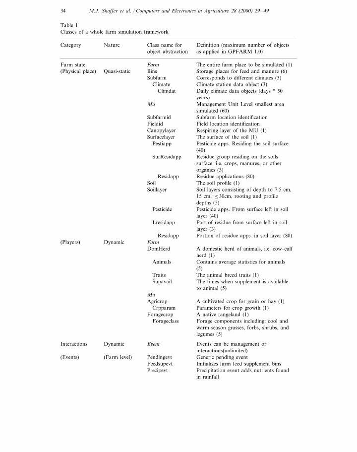
The simulation framework objects can be classified into three categories fordiscussion purposes, Fig. 1. The details of the categories and associated classescharacterizing framework simulation objects are presented in Table 1. The farmstate category includes objects describing the farm system that can be physical(quasi-static places, meaning static at least in location) or dynamic (elements alwayschanging in type or location) in nature. The interactions category includes objectsdescribing events or interactions across the farm, and the simulation categoryrepresents objects executing process level science modules. The GPFARM simula-tion framework uses these objects to maintain the status of the farm system, createand implement events, and iterate time and space while creating simulationenvironments to execute and integrate FORTRAN and BASIC process level sciencemodules. The science modules are: nutrient cycling and residues (Shaffer et al.,1991; Hansen et al., 1995), weed impacts on crop yield (Wiles et al., 1996; Canneret al., 1998), water/solute transport and soil properties (Nachabe and Ahuja, 1996;Ahuja et al., 1999), forage and animal production (Baker et al., 1992; Hanson et al.,1992) crop growth (Williams et al., 1984; Arnold et al., 1995), evapotranspiration(Farahani and Ahuja, 1996; Farahani and DeCoursey, 1999), and soil loss due toerosion (Ascough et al., 1995, 1997).

M.J. Shaffer et al. / Computers and Electronics in Agriculture 28 (2000) 29–49 33
2.1. The farm state category
In general, a farm state category includes all objects that hold the status of thefarm for the simulation. Objects are, by one definition, structures, locations, rolesplayed or events (Coad and Yourdon, 1991). The farm state has both physicalplaces (objects static in location) and dynamic players (objects not static in type orlocation). The physical objects include the farm, subfarm, field, management unit,and the various layers making up the environmental layer system. The dynamicelements or players, which change in type or move across the farm, include cropsand animals (Fig. 1).
2.2. Farm state physical character
2.2.1. FarmThe farm place has many features associated with it. Some physical farm features
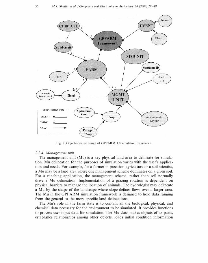
include fields and pastures, while others are man-made like storage silos andcorrals. Some require significant simulation be preformed on them. Others arepresent to account for storage and use of resources on the farm. The role of a farmin this framework is to hold information about all of its parts so they can besimulated. Fig. 2 shows the Farm’s parts through the ‘Has a’ relationships.
Fig. 1. Components of an integrated whole farm.
M.J. Shaffer et al. / Computers and Electronics in Agriculture 28 (2000) 29–4934
Table 1Classes of a whole farm simulation framework
Class name forNatureCategory Definition (maximum number of objectsas applied in GPFARM 1.0)object abstraction
Farm state The entire farm place to be simulated (1)Farm(Physical place) Storage places for feed and manure (6)Quasi-static Bins
Corresponds to different climates (3)SubfarmClimate Climate station data object (3)
Daily climate data objects (days * 50Climdatyears)Management Unit Level smallest areaMusimulated (60)
Subfarmid Subfarm location identificationField location identificationFieldid
Canopylayer Respiring layer of the MU (1)Surfacelayer The surface of the soil (1)
Pesticide apps. Residing the soil surfacePestiapp(40)Residue group residing on the soilsSurResidappsurface, i.e. crops, manures, or otherorganics (3)Residue applications (80)ResidappThe soil profile (1)SoilSoil layers consisting of depth to 7.5 cm,Soillayer15 cm, 530cm, rooting and profiledepths (5)
Pesticide Pesticide apps. From surface left in soillayer (40)Part of residue from surface left in soilLresidapplayer (3)
Residapp Portion of residue apps. in soil layer (80)(Players) FarmDynamic
A domestic herd of animals, i.e. cow–calfDomHerdherd (1)
Animals Contains average statistics for animals(5)The animal breed traits (1)Traits
Supavail The times when supplement is availableto animal (5)
MuA cultivated crop for grain or hay (1)AgricropParameters for crop growth (1)CrpparamA native rangeland (1)ForagecropForage components including: cool andForageclasswarm season grasses, forbs, shrubs, andlegumes (5)
Interactions Events can be management orDynamic E6entinteractions(unlimited)
(Farm level) Pendingevt Generic pending event(Events)Initializes farm feed supplement binsFeedsupevtPrecipitation event adds nutrients foundPrecipevtin rainfall

M.J. Shaffer et al. / Computers and Electronics in Agriculture 28 (2000) 29–49 35
Table 1 (Continued)
Definition (maximum number of objects asClass name for objectCategory Natureabstraction applied in GPFARM 1.0)
(Mu level) Plantevt Planting event for cultivated cropsHarvestevt Harvest event for cultivated crops
Tillage event for cropland unitTillageevtHerbevt Herbicide application event for cropland
unitIrrigevt Irrigation event for cultivated crops
Herd movement event on rangeland man-Grazestrtevtagement unit
Grazeendevt Herd movement event off rangeland man-agement unit
Nutricevt A chemical nutrient applicationNutrimevt A manure nutrient application
Framework simulation class which callsSuSimulation Simulation unitFORTRAN libraries and initiates BASICapplications
2.2.2. SubfarmThe farm can physically be widely distributed, having parts of the farm in
different climate regions. For example, a farmer may want to use the GPFARMDSS to look at whole farm economics, environmental impacts, and productionacross mountain grazing areas as well as crop production on the plains. Thesubfarm concept was designed to address simulating areas with different climates.A subfarm identification is attached to the land unit to load the appropriate dailyclimate for simulation of that unit. In GPFARM 1.0, the framework is designed tohandle up to three subfarms. Each subfarm reference identifies a position in adynamic template array of climates. Each climate template holds climate stationdata as daily climate for the simulation.
2.2.3. FieldFarmers generally define their land units as fields or pastures. Roads, fences or
natural features like streams usually delineate these land areas, and managementwithin can be constant or variable. The field is a key concept for the manager tolocate land units on the farm and identify their land use. However, this is anextremely variable environment where soil conditions, weed pressures, and land-scape characteristics impact simulation outcomes significantly even with a givenland use. Smaller delineated land units (management units) are necessary to holdinformation specific enough to simulate variability across the field. However,maintaining the field as a location tag in the farm state category of the frameworkis crucial to the presentation and aggregation of simulation results for the user.Therefore, management unit (Mu) ‘Has’ a FIELDID (Fig. 2).
M.J. Shaffer et al. / Computers and Electronics in Agriculture 28 (2000) 29–4936
Fig. 2. Object-oriented design of GPFARM 1.0 simulation framework.
2.2.4. Management unitThe management unit (Mu) is a key physical land area to delineate for simula-
tion. Mu delineation for the purposes of simulation varies with the user’s applica-tion and needs. For example, for a farmer in precision agriculture or a soil scientist,a Mu may be a land area where one management scheme dominates on a given soil.For a ranching application, the management scheme, rather than soil normallydrive a Mu delineation. Implementation of a grazing rotation is dependent onphysical barriers to manage the location of animals. The hydrologist may delineatea Mu by the shape of the landscape where slope defines flows over a larger area.The Mu in the GPFARM simulation framework is designed to hold data rangingfrom the general to the more specific land delineations.
The Mu’s role in the farm state is to contain all the biological, physical, andchemical data necessary for the environment to be simulated. It provides functionsto process user input data for simulation. The Mu class makes objects of its parts,establishes relationships among other objects, loads initial condition information
M.J. Shaffer et al. / Computers and Electronics in Agriculture 28 (2000) 29–49 37
into its parts, and contains special functions for the soil system. These functionsinclude depth weighting incoming soil layer data to a simulation soil-layer system,and calculating the status of the soil water.
The Mu is the smallest unit to be simulated and results can be output to the useror transferred during runtime (dynamically) to another Mu as input. For example,interactions among Mu’s in water runoff and runon can be handled with interfaceinput on Mu flow dependencies and an event implementation defined for whenrunoff occurs on a Mu. The event implementation defined by user or the frame-work would dictate the timing of runoff as run-on to another unit.
The framework simulates each Mu daily and writes output from it. The frame-work relies on other applications for output aggregation. In GPFARM 1.0,separate post-processing applications such as the GPFARM Visualization orGPFARM economics package aggregate and process Mu biological, chemical andphysical output in a manner and at the level the user wishes to see.
2.2.5. Mu and en6ironmental layer systemFig. 1 shows a schematic representation of an integrated farm where parts
depicted assist in abstracting the Mu class. OO Design phases demonstrated that aMu has area extent, location, environmental layers, and ‘use’ associations withcrops and animals (Fig. 2). Further abstraction of the environmental layers forGPFARM 1.0, resulted in a Mu having one canopy layer, one surface layer, onesoil profile, and up to five soil layers (Fig. 3). Table 1 shows the Mu class structure(indentations representing ‘has parts’ relationships with other class objects).
The Canopylayer object holds state variable information with regards to canopydynamics. These include wind speed in the canopy, light interception, canopyhumidity, and arial and basal covers. The object holds potential and actualevaporation and transpiration for the grain or forage crop. Many of the plantattributes residing in this layer such as height, leaf area index, and cover and areassigned to a crop base class discussed in the dynamic (changing in type orlocation) aspect farm-state objects.
The Surfacelayer object contains all data characterizing the soil surface, such asresidues and pesticides present, topography, roughness, reflectance, infiltrationattributes, erosivity, and functions to aggregate some of its parts. These compo-nents are crucial to the soil nutrient budget and are affected by managementdecisions regarding tillage. In addition, the presence of residues and pesticides aretracked for each application through time. This seemingly complex accountingsystem is simplified into a few ‘Has a’ relationships with classes which can beutilized in the system above and below ground. For example, the Surfacelayer ‘has’three types of SurResidapp which ‘has’ many Residapp objects (Table 1).
The soil profile object (ASoil) contains the condition of the soil profile. Inputinformation for the soil series resource is stored here, such as layer restrictions,series name and texture, wet and dry albedo, and depth to water table and hardpan. A soil profile schematic has soil layers as its parts (Fig. 1). However, a modeldeveloper must judge whether further nesting of parts will add functionality orencumber it. For the GPFARM 1.0 simulation framework application where ten

M.J. Shaffer et al. / Computers and Electronics in Agriculture 28 (2000) 29–4938
FORTRAN/BASIC coded science modules would be loading data to and from thephysical Mu object, another parts hierarchy provided more encumbrances thanfunctionality; therefore, the Mu object has a soil and soillayer objects directlyinstead of nested (Fig. 3). In addition, the Mu class has a Nbudget object that isused to maintain variables calculating nutrient and water mass balance in theprofile. It also holds additions of various forms of nutrients to the Mu from theimplemented daily events for simulation.
Soil layers represented by the Soillayer class have variables describing bothphysical and chemical layer attributes. These include bulk density, pH, soil organicmatter, nitrate nitrogen, ammonium nitrogen, water content, and root mass toname a few. As with a Surfacelayer object, each soil layer would contain anyresidue or pesticide objects that infiltrated into the soil from the surface applica-tions through time (Table 1). Soil profile attributes likely to impact a manager’splan, such as root zone water and residual nitrates, are derived from these layerobjects.
Fig. 3. Object-oriented design of Mu’s environmental layers (canopylayer, surfacelayer, soil profile andsoil layers).

M.J. Shaffer et al. / Computers and Electronics in Agriculture 28 (2000) 29–49 39
2.3. Farm state dynamic character
Dynamic character refers to the environmental players whose presence or naturechanges with time on the farm. While the farm physical character holds data aboutplaces static in location, the farm dynamic character holds data about the changingand moving players on the farm.
2.3.1. En6ironmental playersAnimal types and crop types are key examples of environmental players. Animals
move across the farm and crop types are transitory, changing with each year in acrop rotation. These players are present and interact at different levels of thephysical farm (Fig. 1). Farm physical places have associations or ‘use’ relationshipswith these players (Fig. 2). For example, a Mu object can use information storedwith the farm level animal herd. Mu herds can be all or part of the farm herd andthe herds can be domesticated or wild. The farm state base structure must beflexible enough to handle new players in the system, as new science modules becomeavailable to simulate them.
The animal kingdom is a complex aspect of the farm players needing simplifica-tion. There are both wild and domesticated animals that are either confined or freeranging; all impact the environment, use resources, and may produce revenues. Ageneralized base class, Herd has animal type and herd size as its variables andprovides a good foundation class on which to derive herds for simulation. Aspecialized domestic herd (DomHerd) is a Herd (Fig. 2). In GPFARM 1.0, acow–calf herd is the domestic herd on the farm but other herds could be derivedif the application warranted it. The domestic herd has many parts including breedtraits, animals, and several kinds of supplement available to it (Table 1). The farmobject’s role is to read the user provided information and if an animal herd ispresent, a Domherd is allocated in memory at runtime and passed arguments onherd type and animal size for the base class data requirements.
Farm players can also be abstracted from land use. The GPFARM crop players,Agricrop and Foragecrop, are created in the management unit object constructionby reading a management unit land use which is either cropland or rangeland(Table 1). Classifying similarities into generalized objects and differences intospecialized objects (‘is a’ relationship) accomplishes the framework’s objectives insimplifying complexity with animals and plants, but also increases their simulationflexibility (Fig. 2). Framework simulation flexibility increases by allowing dynamic(runtime) execution of process simulation models depending on the specializedobject present. For example, a base class crop provides the crop variables needed bythe potential evapotranspiration and the water balance and chemical transportmodels. These variables include plant height, totals for live and dead leaf areaindex, canopy cover, and water and nitrogen stress. These same models runregardless of the specialization of the crop. However, when a specialized player ispresent, the appropriate plant growth model is called in the simulation environment(Simunit). If a Foragecrop object is present, the rangeland forage model will becalled; and, if an Agricrop object is present, the crop growth model will be called.

M.J. Shaffer et al. / Computers and Electronics in Agriculture 28 (2000) 29–4940
In the same manner, if a Domherd object exists the animal growth, intake, andpopulation models will be called.
2.4. Interactions — the e6ent system
The simulation framework creates and implements event objects for managementoperations and interactions across the farm. The framework has access to the eventand the condition of the farm and its parts before the event is implemented. It callsthe event implementation function or delays it until the state is favorable. Thisconcept gives users the flexibility of fixed date or rule-based management operationsas a means to input events. The GPFARM 1.0 simulation framework handles farmevents such as the marketing of animals and the maintenance of feed bins. It alsocreates and implements management operation objects for the Mu such as, plant-ing, harvesting, tillage, weed control, and nutrient application events for croplandunits. For rangeland management units, it allows herd on and off events. Theseevents are all derived and inherit information from the base class Event using the‘is a’, inheritance relationship (Fig. 2). In general, the Event object has a place(usually a Mu identification or Muid) and type of event (usually a four letter code).The date is conspicuously absent from the event base class. This is becauserule-based events may be derived from this class and have no need of a date. Inaddition, fixed date events are read every day for implementation so that datestorage is not necessary. The main concern of this approach was the time require-ments for the interface to write an event file for 20 years and the framework to readit daily. However, three important elements in the simulation framework’s develop-ment picture eased that concern. First, advancements in database system querylanguage (SQL) and database class development like Open Data Base Connectivity(ODBC) or Data Access Object (DAO) have made it almost effortless to read atable, maintain position, and manipulate records. Secondly, reserving programmemory to handle more simulation objects for the whole farm rather than storingevent history is certainly desirable. Finally, once a rule-based management inputsystem is attached and operational, writing input events for 20 years will soon beobsolete.
The framework can also link a rule-based management system developed concur-rently with GPFARM (Shaffer and Brodahl, 1998). A Beta version of GPFARMran with this rule-based management system applied as the only means of generat-ing management operations for the simulation. Work is currently underway to fullyimplement this system to run concurrent with a fixed date system allowing the nextGPFARM simulation framework application more mixed event input capabilities.The user could fix dates for certain events, but allow irrigation by a rule rather thanthe current system of fixed date or at a scheduled interval. An application interfaceobject allows the rule script, generated from user interface input, runtime access toappropriate GPFARM state variables and transfers the action to be taken back tothe simulation program as an event. For example, an irrigation application includesquerying rules for the Mu and checking the water depletion status. If waterdepletion is below a user defined level, the application’s interface object will be give

M.J. Shaffer et al. / Computers and Electronics in Agriculture 28 (2000) 29–49 41
an appropriate irrigation event (AnIrrigevt) back to the framework for the Mu andday. The same event format can be used by the fixed date system only it is initiatedfrom an event table record written by the GPFARM DSS graphical user interface(GUI).
2.5. Simulation — the simulation en6ironment
The simulation environment or Simunit class is a key abstraction for the scientistand programmer to execute process level models. Process level models execute usingdaily climate, date and the Mu place, however not all models execute on every Muor every day. For GPFARM 1.0 the overall suite of models include: potentialevapotranspiration, water balance and chemical transport, soil properties, nutrientsand residues, agricultural crop growth, forage crop growth, soil erosion, weedcompetition, herd dynamics, and animal growth and intake.
These models could have been part of the farm layer system with the canopylayer able to call the potential evapotranspiration model. However, many scientistswere contributing these models to GPFARM in different languages andprogramming styles. Isolating them to their own object seemed prudent. Oftenwhen existing programs are put within other applications they are put in a wrapper.Isolating submodels in their own object increases programming flexibility to replacecomponents, as better options become available.
2.6. Implementation of the integrated farm simulation framework
The simulation framework is a C++ executable called from a dialog box in theGPFARM Graphical User Interface (GUI). The simulation framework makes thefarm place and dynamically allocates the climate template array. For each day andplace, it reads events or queries a rule system (resulting in events), and implementsevents in the Mu place. All interactions between Mus are considered as events andare implemented daily before the Mu is sent to simulation. The frameworkperforms the simulation by making the simulation environment, ASu (Fig. 4, partD). It also reports the status of the farm at crucial management times throughoutthe simulation.
2.6.1. Creation of the farm systemThe creation of the GPFARM whole farm place is accomplished in one state-
ment, ‘Farm AFarm’; (Fig. 4, Part A). The physical place and the dynamic playersof the farm are built by creating objects, data and function hiding, expressingrelationships including ‘has a’ and ‘uses’ and establishing a hierarchy throughinheritance with the ‘is a’ relationship. All essential aspects of object-orientedprogramming which when implemented in the agricultural system state takes thecomplex and makes it simple.

M.J. Shaffer et al. / Computers and Electronics in Agriculture 28 (2000) 29–4942
Fig. 4. C++ code implementation of the GPFARM simulation framework.
2.6.2. Time iterationProgram–Date objects are made for the starting, ending, and simulation dates of
the run (Fig. 4, Part A). These objects inherit standard Date accounting from thebase class Date but also provide functions for testing end-of-month and end-of-yearuseful in output reporting. It is incremented daily in a While loop as long asSimdate is less than or equal to Stopdate (Fig. 4, Part B).
M.J. Shaffer et al. / Computers and Electronics in Agriculture 28 (2000) 29–49 43
2.6.3. Space iterationDaily iteration of space is implemented in a For loop for all Mu’s on the farm
(Fig. 4, Part B). This aspect was debated as to whether the load and save on eachMu each day would slow the simulation too much. The overwhelming advantagewas the possible interaction among Mus on a daily basis. This meant transfer ofwater, nutrients, residues and other resources or products from one Mu to the nextover a field or a farm was possible during runtime (dynamically). For example, Murunoff and erosion output could be routed, given some Mu routing scheme fromthe user, thus creating a watershed simulation environment. With the currentnumber (60) of allowable Mus in the program, such iteration affords more landunit interaction advantages than limitations.
2.6.4. Implementation of the e6entsFor each Mu all fixed date events are read and implemented. A fixed date event
is read from presorted Microsoft Access tables first into a pending event where typeof event is read. Based on the type of event, the event object is filled andimplemented before the Mu is passed to the simulation unit (Fig. 4, Part C).
2.6.5. Creation of the simulation unitThe simulation of the Mu occurs when a simulation object (ASu) is made (Fig.
4, Part D). The Simunit object is passed farm resources like cattle herds andsupplement bins, a Mu, and a daily climate in its construction. Having all requiredagricultural system state information to process, the FORTRAN variableconnections are established, and nine FORTRAN models and one BASIC sciencemodel are called depending on the dynamic players present. All newly simulatedinformation is saved back to the agricultural system place.
2.6.6. Reporting on the farmReporting the status of the farm can be initiated when the simulation reaches
predefined crucial dates; for example, the last day of the year for annual output(Fig. 4, Part D). Often it is initiated by an event (i.e. plant, harvest) and can beincluded with the event implementation or split into its own function and calledafter the event implementation. As an example, the soil profile status of each Muis written on the planting date (Fig. 4, Part C).
2.7. GPFARM connection between interface and simulation framework
The connection between the GPFARM GUI and the science framework utilizesMicrosoft Access databases to pass information. Fig. 5 illustrates the connection.The user enters the required input information (e.g. equipment, investments, Mulanduse and area, Mu resources and management operations, and climate) in theGUI. The simulation framework may then be run by selecting a ‘Run Simulation’dialog box in the GUI (Fig. 5, Block 1). At this time, the scenario(s) to be run andthe time range for the simulation are also specified. A scenario is a farm setup witha given management plan and resources. A farmer can set up multiple scenarioswith the DSS and simulate management plans before implementing them.

M.J. Shaffer et al. / Computers and Electronics in Agriculture 28 (2000) 29–4944
All input tables, necessary to run the GPFARM science model, are contained inthe scenario Microsoft Access database USERDB. The GUI fills the USERDBtables as the next step (Fig. 5, Block 2). The major tables filled contain informationon farm name and location; farm equipment and investments; Mu area andlanduse; Mu soils, topography, residue, and initial weed population; and Mucropping systems and management operations. Other tables are filled depending onadditional options chosen within the GUI. For example, if weed management ischosen, tables containing information on weed pressure, pesticide efficacies, andpesticide properties (e.g. half-life) are filled. If rangeland is chosen for any of theMu’s, then tables containing information on herd description, forage and supple-mental feed properties, and herd physical characteristics are filled. If the Mu is tobe irrigated, then tables containing information on the irrigation system(s) are alsopopulated.
The GPFARM science framework simulation is then executed (Fig. 5, Block 3)after USERDB has been filled. The CLIMDB (climate) input tables (Fig. 5, Block6) and the USERDB input tables are used as input to the GPFARM simulationframework application. The OUTPUTDB (output) tables (Fig. 5, Block 7) are filledas the simulation is run. The major tables filled contain information on waterrunoff, nitrate leaching, wind and water erosion, and crop yield. If weed manage-ment is chosen, then tables containing information on yield loss due to weedpressure, and pesticide runoff and leaching are filled. If rangeland is chosen for anyof the Mu’s, then tables containing information on animal average daily gain, sales,forage and supplement consumption and peak forage biomass are filled.
After the science simulation framework is run, the economic simulation isperformed (Fig. 5, Block 4). The economic simulation consists of two phases. First,required economic information is obtained from the equipment and investmentsdatabase tables. Operating cost calculations are then conducted for equipment andinvestments on a per-hour basis. Second, the management operations for each Muare examined one-by-one and per-hour operating cost calculations applied whereverapplicable. In cases where there are also material costs (e.g. seed cost), the material
Fig. 5. Overview of GPFARM connection between GUI and simulation framework.

M.J. Shaffer et al. / Computers and Electronics in Agriculture 28 (2000) 29–49 45
costs are directly combined with the operating costs. Crop yield and market priceinformation are then used to calculate returns. Once all Mu economic calculationsare performed, information on ownership costs, operating costs, returns on operat-ing costs, and returns over total costs are placed into economic output databasetables. These tables, along with some USERDB input tables, are used for thecreation of detailed economic reports.
The visualization setup (Fig. 5, Block 5) uses the information gathered in theUSERDB and OUTPUTDB tables to create a set of ASCII files that are used forquick access by the visualization output tool. The user may then select variables tobe displayed in the visualization output tool at the level of farm aggregation theywish to see (Fig. 5, Block 8). Results from multiple management scenarios (simula-tions) may be compared with this tool.
3. Discussion and conclusions
In general, an effective OO framework for integrated farming systems shouldconsist of a thorough object model of a farm state, a flexible input and implemen-tation of events, a simulation environment to accomplish the process level simula-tion of the biological, chemical, and physical components of a farm, and iterationof time and space to allow interactions among spatial units and resources on thefarm. The benefits realized from an OOP approach in whole farm simulationinclude simplifying system complexity and increasing flexibility of the simulationapplication. The object model together with OOP relationships, that is-whole/part,generalization/ specialization (inheritance), works to achieve these benefits. Inaddition, the OOP approach makes addition and reconfiguration of Mus and theirinteractions a much simpler and compact process than would be needed using otherprogramming approaches. This allows potential users, such as farmers and consul-tants, to utilize the model as a close approximation of their farming or ranchingoperations. They may then draw conclusions from the simulation results and fromeconomic and environmental analyses to help refine or define operations thatmaximize profits, yet protect the environment.
The magnitude of benefits from OOP however is dependent on its judicious use(Power, 1993). Whether an organism traverses the farm as an animal herd or residesat a location like a plant, the organism itself is as complex as the environment inwhich it exists. Simplifying this complex system starts with finding similarities,differences and subparts and bringing them out in the design. One of the mostdifficult design judgements to make is whether the organisms’ attributes aredifferent enough to abstract them to a new derived class. Certainly, process levelmodels and their capabilities influence design abstractions. For example, onesimulation model for forage production and one for annual crops calls for at leasttwo objects. However, developers should avoid letting simulation capabilities drivethe framework design, as new models will always present themselves requiringchanges in the design. As an example, the GPFARM simulation frameworkdefinition of a domestic herd class is biased toward animal operations producing

M.J. Shaffer et al. / Computers and Electronics in Agriculture 28 (2000) 29–4946
meat and not broad enough to cover domestic animals kept for other products. Agood framework modification to simulate goats would be to make the domesticherd class (DomHerd) more generic and derive GoatDomHerd and Cattle-DomHerd from it.
Flexibility in simulation indicates a framework is responsive to change. Thesechanges can be in the areas of farm structure and resources, input/output formats,farm management events, or simulation modeling techniques. The OO frameworkdirectly addresses changes in farm structure and resources through the dynamic(runtime) allocation of objects on the farm. The positioning of event objects outsidethe simulation class or farm object provides input/output format flexibility forevents as well as allowing the framework to check farm state before events areimplemented. Therefore, the framework can implement events in a practical mannersimilar to the methods of a farm manager in the field. The capability of aframework to handle fixed date and rule-based events will bring management eventsimulation closer to emulating the farmers own decisions. How close could only beanswered by the attached rule system and its capabilities to handle complex rulesentered by the farmer.
Previously, the importance of using inheritance and its advantages in reuse ofcode was explored (Silvert, 1993; Power, 1993). These previous findings provedvalid in the GPFARM 1.0 simulation framework flexibility. The inheritance rela-tionships in crops, animals and events were key in allowing dynamic (runtime)setup and simulation of the farm system. The subdivision of crops into agriculturaland forage was particularly useful in executing their different simulation models.
Unfortunately, first-time designs are often skewed by the current simulationcapabilities of the submodels. For example, GPFARM 1.0 science modules couldnot handle herds grazing actively growing crops like winter wheat. Fortunately,OOP approaches provide tools to handle this; such as, inheritance (to extend thecurrent Agricrop to a grazed derived class) or polymorphism (to define a grazefunction to mean a separate implementation for each derived crop class). Theframework will likely be expanded using these OOP tools as the need arises.
It has been also suggested that ‘frameworks provide the easiest and mostproductive bases for effective reuse of existing software’ (Gauthier and Neel, 1996).This framework did provide a good base for the effective use of pre-existing processlevel models; and, the decision to allow incorporation of procedural based FOR-TRAN and BASIC process simulation modules has proven beneficial in severalways. The scientists who developed these modules continue to support and extendtheir code used in GPFARM. The use of the minimal wrapper concept to executethese modules in the C++ object-oriented environment has allowed a more rapidturn around time when maintenance and updating are needed. However, theexisting wrappers could be enhanced to make module additions and replacementseven more streamlined. The addition of new simulation capabilities is made easierby the availability of a large array of FORTRAN and BASIC soil-plant processmodules compared to object-oriented C++ equivalents. Although the contents ofeach FORTRAN or BASIC module are procedural, each module can be treated asan individual object or related modules can be grouped and treated as an object by
M.J. Shaffer et al. / Computers and Electronics in Agriculture 28 (2000) 29–49 47
the framework. Judicious grouping of process simulation modules can improve runtimes for the overall simulation. Also, in many cases, the FORTRAN versions ofalgorithms used to solve sets of equations are more efficient than their C++equivalents.
4. Availability
The GPFARM simulation framework application 1.0 is currently operationalwithin the GPFARM decision support system 1.0 in limited release to collaboratingColorado farmers and agricultural consultants. Although evaluation and validationtests are on-going, the integrated whole-farm simulation, the DSS, and its featureshave already proven useful in assisting managers with strategic farm planning.Additional information is available on the USDA-ARS, Great Plains SystemsResearch Unit, Internet Web site at URL: http://www.gpsr.colostate.edu.
Acknowledgements
Many thanks to Mary Brodahl for collaborating discussions on object-orientedevent design, rule based event systems, and her authorship of the Date class andderived classes. A special thanks to the GPFARM Team, especially DecisionSupport System programmers, Debbie Edmunds and Bruce Vandenberg, whosecollaboration contributed to the framework’s successful application in GPFARM1.0. Thanks to Charlie Bay for the instruction in OOA, OOD and OOP resulting ina successful application.
References
Ahuja, L.R., Johnsen, K.E., Rojas, K.W., 1999. Water and chemical transport in soil matrix andmacropores, ch. 2. In: Ahuja, et al. (Eds.), Root Zone Water Quality Model: Modelling ManagementEffects on Water Quality and Crop Production, Water Resources Publications, LLC, HighlandsRanch, Colorado, pp. 13–50 (in press).
Arnold, J.G., Weltz, M.A., Alberts, E.E., Flanagan, D.C., 1995. Plant growth component (ch. 8). In:Flanagan, D.C., Nearing, M.A. II (Eds.), USDA-Water Erosion Prediction Project: Hillslope Profileand Watershed Model Technical Documentation. NSERL Report No. 101-8.41. USDA-ARSNational Soil Erosion Research Laboratory, West Lafayette, IN, pp. 8.1–8.41.
Ascough, J.C. II, Baffaut, C., Nearing, M.A., Liu, B.Y., 1997. The WEPP watershed model: I.Hydrology and erosion. Trans. ASAE 40 (4), 921–933.
Ascough, J.C. II, Baffaut, C., Nearing, M.A., Flanagan, D.C., 1995. Watershed model channelhydrology and erosion processes (ch. 13). In: Flanagan, D.C., Nearing, M.A. (Eds.), USDA-WaterErosion Prediction Project: Hillslope Profile and Watershed Model Technical Documentation.NSERL Report No. 10. USDA-ARS National Soil Erosion Research Laboratory, West Lafayette,IN, pp. 13.1–13.20.
Ascough II, J.C., Shaffer, M.J., Hoag, D.L., McMaster, G.S., Ahuja, L.R., 2000. GPFARM: Anintegrated decisions support systems for sustainable Great Plains Agriculture. Proceedings of the 10th
International Soil Conservation Organization Conference (ISCO): Sustaining the Global Farm —
M.J. Shaffer et al. / Computers and Electronics in Agriculture 28 (2000) 29–4948
Local Action for Land Leadership, Purdue University, West Lafayette, IN, May 23–28, 1999 (inpress).
Baker, B.B, Bourdon, R.M., Hanson, J.D., 1992. FORAGE: a simulation model of grazing behavior inbeef cattle. Ecol. Model. 60, 257–279.
Beckie, H.J., Moullin, A.P., Campbell, C.A., Brandt, S.A., 1995. Testing effectiveness of four simulationmodels for estimating nitrates and water in two soils. Can. J. Soil Sci. 75, 135–143.
Buick, R.D., Stone, N.D., Scheckler, R.K., Roach, J.W., 1992. CROPS: a whole-farm crop rotationplanning system to implement sustainable agriculture. AI Applic. 6 (3), 29–50.
Booch, G., 1994. The object model (ch. 2). In: Object-Oriented Analysis and Design with Applications,2nd edn. Benjamin/Cummins Publishing Co., Inc, Redwood City, CA.
Canner, S.R., Wiles, L.J., Dunan, C.R., Erskine, R.H., 1998. A new approach for modeling long termmulti-species weed population dynamics. Proc. Western Weed Sci. Soc. 51, 30.
Coad, P., Yourdon, E., 1991. Object-Oriented Analysis. Prentice-Hall, Englewood Cliffs, NJ, p. 232.Crosby, C.J., 1990. A simulation modeling tool for nitrogen dynamics using object-oriented program-
ming. AI Applic. Nat. Res. Manage. 4 (2), 94–100.Engel, T., Hoogenboom, G., Jones, J.W., Wilkens, P.W., 1997. AEGIS/WIN: a computer program for
the application of crop simulation models across geographic areas. Agron. J. 89 (6), 919–928.Farahani, H.J., Ahuja, L.R., 1996. Evapotranspiration modeling of partial canopy/residue covered
fields. Trans. ASAE 39 (6), 2051–2064.Farahani, H.J., DeCoursey, D.G., 1999. Potential evaporation and transpiration processes in the
soil-residue-canopy system, ch. 3. In: Ahuja, et al. (Eds.), Root Zone Water Quality Model:Modelling Management Effects on Water Quality and Crop Production, Water Resources Publica-tions, LLC, Highlands Ranch, Colorado, pp. 51–80 (in press).
Freeman, S.A., 1992. Object-oriented methodology for analyzing and allocating resources for fieldoperations. Appl. Eng. Agric. 8 (4), 525–535.
Gauthier, L., Neel, T., 1996. SAGE: an object-oriented framework for the construction of farm decisionsupport systems. Comput. Electron. Agric. 16 (1), 1–20.
Hansen, S., Shaffer, M.J., Jensen, H.E., 1995. Developments in modelling nitrogen transformations insoil, ch. 3. In: Nitrogen Fertilization and the Environment. Dekker, New York, pp. 83–107.
Hanson, J.D., Baker, B.B., Bourdon, R.M. 1992. SPUR2 Documentation and User Guide. GPSRTechnical Report No. 1. 46 pp.
Jacobson, I., Christerson, M., Jonsson, P., Overgaard, G., 1992. Object-Oriented Software Engineering:A Use Case Driven Approach. Addison-Wesley, Reading, MA.
Khakural, B.R., Robert, P.C., 1993. Soil nitrate leaching potential indices: using a simulation model asa screening system. J. Environ. Qual. 22, 839–845.
Lal, H., 1991. An object-oriented field operations simulator in PROLOG. Trans. ASAE 34 (3),1031–1039.
Nachabe, M.H., Ahuja, L.R., 1996. Quasi-analytical solution for predicting the redistribution ofsurface-applied chemicals. Trans. ASAE 39, 1659–1664.
Pannel, D.J., 1996. Lessons from a decade of whole-farm modelling in Western Australia. Rev. Agric.Econ. 18 (3), 373–383.
Power, J.M., 1993. Object-oriented design of decision support systems in natural resource management.Comput. Electron. Agric. 8 (4), 301–324.
Rumbaugh, J., Blaha, M., Premerlani, W., Eddy, F., Lorensen, W., 1991. Object-oriented modeling anddesign. Prentice-Hall, Englewood Cliffs, NJ.
Schilizzi, G.M., Boulier, F., 1997. Agric. Syst. 54 (4), 477–499.Sequeira, R.A., Makela, M.E., El-Zik, K.M., Stone, N.D. 1990. Coughing object-oriented plant and
Heliothis models. Proceedings—Beltwide cotton Production Research Conferences, 339–342.Shaffer, M.J., Brodahl, M.K., 1998. Rule-based management for simulation in agricultural decision
support systems. Comput. Electron. Agric. 21, 135–152.Shaffer, M.J, Halvorson, A.D., Pierce, F.J., 1991. Nitrate leaching and economic analysis package
(NLEAP): model description and application (ch. 13). In: Follett, R.F., Keeney, D.R., Cruse, R.M.(Eds.), Managing Nitrogen for Groundwater Quality and Farm Profitability. Soil Science Society ofAmerica, Madison, WI, pp. 285–322..

M.J. Shaffer et al. / Computers and Electronics in Agriculture 28 (2000) 29–49 49
Shaffer, M.J., Wylie, B.K., Follett, R.F., Bartling, P.N.S., 1994. Using climate/weather data with theNLEAP model to manage soil nitrogen. Agric. Forest Meteor. 69, 111–123.
Shaffer, M.J., Wylie, B.K., Hall, M.D., 1995. Identification and mitigation of nitrate leaching hot spotsusing NLEAP-GIS technology. J. Contaminant Hydrol. 20 (1995), 253–263.
Shaw, M., 1984. Abstraction techniques in modern programming languages. IEEE Software 1 (4), 10.Silvert, W., 1993. Object-oriented ecosystem modelling. Ecol. Model. 68 (1993), 91–118.Van Evert, F.K., Campbell, G.S., 1994. CropSyst: a collection of object oriented simulation models of
agricultural systems. Agron. J. 86 (2), 325–331.Williams, J.R., Jones, C.A., Dyke, P.T., 1984. A modeling approach to determining the relationship
between erosion and soil productivity. Trans. ASAE 27, 129–144.Wiles, L.J., King, R.P., Schweizer, E.E., Lybecker, D.W., Swinton, S.M., 1996. GWM: Gen. Weed
Manage. Model. 50, 355–376.
.