NUREG/CR-7291 - Assessments on Eddy Current Detection of ...
Upload
khangminh22Category
view
0download
0
Safety Evaluation Report Related to the License Renewal of Sequoyah Nuclear Plant Units 1 and 2 Docket Numbers 50-327 and 50-328 Tennessee Valley Authority
Office of Nuclear Reactor Regulation
NUREG-2181

AVAILABILITY OF REFERENCE MATERIALSIN NRC PUBLICATIONS
NRC Reference Material
As of November 1999, you may electronically access NUREG-series publications and other NRC records at NRC’s Library at www.nrc.gov/reading-rm.html. Publicly released records include, to name a few, NUREG-series publications; Federal Register notices; applicant, licensee, and vendor documents and correspondence; NRC correspondence and internal memoranda; bulletins and information notices; inspection and investigative reports; licensee event reports; and Commission papers and their attachments.
NRC publications in the NUREG series, NRC regulations, and Title 10, “Energy,” in the Code of Federal Regulations may also be purchased from one of these two sources.
1. The Superintendent of Documents U.S. Government Publishing Office Mail Stop IDCC Washington, DC 20402-0001 Internet: bookstore.gpo.gov Telephone: (202) 512-1800 Fax: (202) 512-2104
2. The National Technical Information Service 5301 Shawnee Rd., Alexandria, VA 22312-0002 www.ntis.gov 1-800-553-6847 or, locally, (703) 605-6000
A single copy of each NRC draft report for comment isavailable free, to the extent of supply, upon writtenrequest as follows:
Address: U.S. Nuclear Regulatory Commission Office of Administration Publications Branch Washington, DC 20555-0001 E-mail: [email protected] Facsimile: (301) 415-2289
Some publications in the NUREG series that are posted at NRC’s Web site address www.nrc.gov/reading-rm/doc-collections/nuregs are updated periodically and may differ from the last printed version. Although references to material found on a Web site bear the date the material was accessed, the material available on the date cited may subsequently be removed from the site.
Non-NRC Reference Material
Documents available from public and special technical libraries include all open literature items, such as books, journal articles, transactions, Federal Register notices, Federal and State legislation, and congressional reports. Such documents as theses, dissertations, foreign reports and translations, and non-NRC conference proceedings may be purchased from their sponsoring organization.
Copies of industry codes and standards used in asubstantive manner in the NRC regulatory process are maintained at—
The NRC Technical LibraryTwo White Flint North11545 Rockville PikeRockville, MD 20852-2738
These standards are available in the library for reference use by the public. Codes and standards are usually copyrighted and may be purchased from the originating organization or, if they are American National Standards, from—
American National Standards Institute11 West 42nd StreetNew York, NY 10036-8002www.ansi.org(212) 642-4900
Legally binding regulatory requirements are stated only in laws; NRC regulations; licenses, including technical speci-fications; or orders, not in NUREG-series publications. The views expressed in contractorprepared publications in this series are not necessarily those of the NRC.
The NUREG series comprises (1) technical and adminis-trative reports and books prepared by the staff (NUREG–XXXX) or agency contractors (NUREG/CR–XXXX), (2) proceedings of conferences (NUREG/CP–XXXX), (3) reports resulting from international agreements (NUREG/IA–XXXX), (4) brochures (NUREG/BR–XXXX), and (5) compilations of legal decisions and orders of the Commission and Atomic and Safety Licensing Boards and of Directors’ decisions under Section 2.206 of NRC’s regulations (NUREG–0750).
DISCLAIMER: This report was prepared as an account of work sponsored by an agency of the U.S. Government. Neither the U.S. Government nor any agency thereof, nor any employee, makes any warranty, expressed or implied, or assumes any legal liability or responsibility for any third party’s use, or the results of such use, of any information, apparatus, product, or process disclosed in this publication, or represents that its use by such third party would not infringe privately owned rights.

Safety Evaluation Report Related to the License Renewal of Sequoyah Nuclear Plant Units 1 and 2 Docket Numbers 50-327 and 50-328 Tennessee Valley Authority
Manuscript Completed: March 2015 Date Published: July 2015 Office of Nuclear Reactor Regulation
NUREG-2181


iii
ABSTRACT This safety evaluation report (SER) documents the technical review of the Sequoyah Nuclear Plant, Units 1 and 2, license renewal application (LRA) by the United States (U.S.) Nuclear Regulatory Commission (NRC) staff (the staff). By letter dated January 7, 2013, Tennessee Valley Authority (TVA or the applicant) submitted the LRA in accordance with Title 10, Part 54, “Requirements for Renewal of Operating Licenses for Nuclear Power Plants,” of the Code of Federal Regulations. TVA requests renewal of the operating licenses (Facility Operating License Nos. DPR-77 and DPR-79) for a period of 20 years beyond the current expiration at midnight September 17, 2020, for Unit 1, and at midnight September 15, 2021, for Unit 2. Sequoyah is located approximately 18 miles (15.3 kilometers) northeast of Chattanooga, TN. The NRC issued the Unit 1 construction permit on May 27, 1970, and operating license on September 17, 1980. The NRC issued the Unit 2 construction permit on May 27, 1970, and operating license on September 15, 1981. Both units are of a pressurized water reactor design. Westinghouse Electric Corporation supplied the nuclear steam supply system, and TVA originally designed and constructed the balance of the plant. The licensed power output for each unit is 3,455 megawatts thermal with a gross electrical output of approximately 1,199 megawatts electric. This SER presents the staff’s review of information submitted through December 11, 2014, the cutoff date for consideration in the SER. The staff identified one open item as part of this review that was resolved. SER Section 1.5 summarizes these open items.


v
TABLE OF CONTENTS
ABSTRACT ................................................................................................................................ iii
TABLE OF CONTENTS ............................................................................................................... v
LIST OF TABLES ........................................................................................................................ xi
ABBREVIATIONS ...................................................................................................................... xiii
SECTION 1 INTRODUCTION AND GENERAL DISCUSSION ................................................. 1-1 1.1 Introduction ............................................................................................................. 1-1 1.2 License Renewal Background ................................................................................. 1-2
1.2.1 Safety Review .......................................................................................... 1-3 1.2.2 Environmental Review .............................................................................. 1-4
1.3 Principal Review Matters ......................................................................................... 1-5 1.4 Interim Staff Guidance ............................................................................................ 1-6 1.5 Summary of Open Items ......................................................................................... 1-8 1.6 Summary of Confirmatory Items ............................................................................. 1-9 1.7 Summary of Proposed License Conditions ............................................................. 1-9
SECTION 2 STRUCTURES AND COMPONENTS SUBJECT TO AGING MANAGEMENT REVIEW .................................................................................... 2-1
2.1 Scoping and Screening Methodology ..................................................................... 2-1 2.1.1 Introduction ............................................................................................... 2-1 2.1.2 Summary of Technical Information in the Application .............................. 2-1 2.1.3 Scoping and Screening Program Review ................................................. 2-1
2.1.3.1 Implementation Procedures and Documentation Sources for Scoping and Screening ......................................... 2-2
2.1.4.4 Plant-Level Scoping of Systems and Structures ...................... 2-15 2.1.4.5 Mechanical Component Scoping ............................................. 2-16 2.1.4.6 Structural Component Scoping ................................................ 2-17 2.1.4.7 Electrical Component Scoping ................................................. 2-20 2.1.4.8 Conclusion for Scoping Methodology ...................................... 2-20
2.1.5 Screening Methodology .......................................................................... 2-21 2.1.5.1 General Screening Methodology ............................................. 2-21 2.1.5.2 Mechanical Component Screening .......................................... 2-22 2.1.5.3 Structural Component Screening ............................................. 2-23 2.1.5.4 Electrical Component Screening ............................................. 2-24 2.1.5.5 Conclusion for Screening Methodology ................................... 2-25
2.1.6 Summary of Evaluation Findings ............................................................ 2-25 2.2 Plant-Level Scoping Results ................................................................................. 2-25
2.2.1 Introduction ............................................................................................. 2-25 2.2.2 Summary of Technical Information in the Application ............................ 2-25 2.2.3 Staff Evaluation ...................................................................................... 2-26 2.2.4 Conclusion .............................................................................................. 2-27
2.3 Scoping and Screening Results: Mechanical Systems ........................................ 2-27 2.3.1 Reactor Coolant System ........................................................................ 2-28
2.3.1.1 Reactor Vessel ........................................................................ 2-28 2.3.1.2 Reactor Vessel Internals .......................................................... 2-30 2.3.1.3 Reactor Coolant Pressure Boundary ....................................... 2-31

vi
2.3.1.4 Steam Generators ................................................................... 2-33 2.3.1.5 Miscellaneous RCSs in Scope for 10 CFR 54.4(a)(2) ............. 2-34
2.3.2 Engineered Safety Features ................................................................... 2-35 2.3.2.1 Safety Injection ........................................................................ 2-35 2.3.2.2 Containment Spray .................................................................. 2-37 2.3.2.3 Residual Heat Removal ........................................................... 2-38 2.3.2.4 Containment Penetrations ....................................................... 2-39 2.3.2.5 Miscellaneous ESF Systems in Scope for
10 CFR 54.4(a)(2) .................................................................. 2-40 2.3.3 Auxiliary Systems ................................................................................... 2-41
2.3.3.1 Fuel Oil .................................................................................... 2-43 2.3.3.2 High Pressure Fire Protection .................................................. 2-44 2.3.3.3 Fire Protection CO2 and RCP Oil Collection ............................ 2-51 2.3.3.4 Miscellaneous Heating, Ventilating and Air Conditioning
Systems .................................................................................. 2-53 2.3.3.5 Auxiliary Building and Reactor Building Gas Treatment
and Ventilation Systems ......................................................... 2-54 2.3.3.6 Control Building HVAC ............................................................ 2-56 2.3.3.7 Compressed Air ....................................................................... 2-57 2.3.3.8 Station Drainage ...................................................................... 2-59 2.3.3.9 Sampling and Water Quality .................................................... 2-60 2.3.3.10 Chemical and Volume Control ............................................... 2-61 2.3.3.11 Essential Raw Cooling Water ................................................ 2-63 2.3.3.12 Component Cooling ............................................................... 2-65 2.3.3.13 Waste Disposal ...................................................................... 2-66 2.3.3.14 Spent Fuel Pit Cooling ........................................................... 2-69 2.3.3.15 Standby Diesel Generator ..................................................... 2-70 2.3.3.16 Flood Mode Boration Makeup ................................................ 2-71 2.3.3.17 Miscellaneous Auxiliary Systems in Scope for
10 CFR 54.4(a)(2) .................................................................. 2-73 2.3.4 Steam and Power Conversion Systems ................................................. 2-80
2.3.4.1 Main Steam.............................................................................. 2-81 2.3.4.2 Main and Auxiliary Feedwater ................................................. 2-83 2.3.4.3 Miscellaneous Steam and Power Conversion Systems
in Scope for 10 CFR 54.4(a)(2) .............................................. 2-85 2.4 Scoping and Screening Results: Structures ......................................................... 2-88
2.4.1 Reactor Building ..................................................................................... 2-89 2.4.1.1 Summary of Technical Information in the Application .............. 2-89 2.4.1.2 Staff Evaluation........................................................................ 2-90 2.4.1.3 Conclusion ............................................................................... 2-90
2.4.2 Water Control Structures ........................................................................ 2-90 2.4.2.1 Summary of Technical Information in the Application .............. 2-90 2.4.2.2 Staff Evaluation........................................................................ 2-91 2.4.2.3 Conclusion ............................................................................... 2-91
2.4.3 Turbine Building, Aux/Control Building, and Other Structures ................ 2-91 2.4.3.1 Summary of Technical Information in the Application .............. 2-91 2.4.3.2 Staff Evaluation...................................................................... 2-100 2.4.3.3 Conclusion ............................................................................. 2-100
2.4.4 Bulk Commodities ................................................................................ 2-100 2.4.4.1 Summary of Technical Information in the Application ............ 2-100 2.4.4.2 Staff Evaluation...................................................................... 2-100

vii
2.4.4.3 Conclusion ............................................................................. 2-103 2.5 Scoping and Screening Results: Electrical and Instrumentation and
Control Systems .................................................................................................. 2-103 2.5.1 Electrical, and Instrumentation, and Controls Commodity Groups ....... 2-104
2.5.1.1 Summary of Technical Information in the Application ............ 2-104 2.5.1.2 Staff Evaluation...................................................................... 2-105 2.5.1.3 Conclusion ............................................................................. 2-109
2.6 Conclusion for Scoping and Screening ............................................................... 2-109
SECTION 3 AGING MANAGEMENT REVIEW RESULTS ....................................................... 3-1 3.0 Applicant’s Use of the Generic Aging Lessons Learned Report ............................. 3-1
3.0.1 Format of the License Renewal Application ............................................. 3-2 3.0.1.1 Overview of Table 1s ................................................................. 3-2 3.0.1.2 Overview of Table 2s ................................................................. 3-3
3.0.2 Staff’s Review Process ............................................................................. 3-4 3.0.2.1 Review of AMPs ........................................................................ 3-4 3.0.2.2 Review of AMR Results ............................................................. 3-5 3.0.2.3 UFSAR Supplement .................................................................. 3-6 3.0.2.4 Documentation and Documents Reviewed ................................ 3-7
3.0.3 Aging Management Programs .................................................................. 3-7 3.0.3.1 AMPs Consistent With the GALL Report ................................. 3-11 3.0.3.2 AMPs Consistent With the GALL Report With
Exceptions or Enhancements ................................................. 3-92 3.0.3.3 AMPs Not Consistent With or Not Addressed in the
GALL Report ......................................................................... 3-203 3.0.3.3.1 Periodic Surveillance and Preventive Maintenance Program ................... 3-203
3.0.4 Quality Assurance Program Attributes Integral to Aging Management Programs ...................................................................... 3-217 3.0.4.1 Summary of Technical Information in Application .................. 3-217 3.0.4.2 Staff Evaluation...................................................................... 3-218 3.0.4.3 Conclusion ............................................................................. 3-219
3.0.5 Operating Experience for Aging Management Programs ..................... 3-219 3.0.5.1 Summary of Technical Information in Application .................. 3-219 3.0.5.2 Staff Evaluation...................................................................... 3-219 3.0.5.3 UFSAR Supplement .............................................................. 3-227 3.0.5.4 Conclusion ............................................................................. 3-228
3.1 Aging Management of Reactor Vessel, Internals, and Reactor Coolant System ................................................................................................................ 3-228
3.1.1 Summary of Technical Information in the Application .......................... 3-228 3.1.2 Staff Evaluation .................................................................................... 3-228
3.1.2.1 AMR Results Consistent With the GALL Report .................... 3-253 3.1.2.2 AMR Results Consistent With the GALL Report for
Which Further Evaluation Is Recommended ........................ 3-260 3.1.2.3 AMR Results Not Consistent With or Not Addressed in
the GALL Report ................................................................... 3-282 3.1.3 Conclusion ............................................................................................ 3-288
3.2 Aging Management of Engineered Safety Features Systems............................. 3-288 3.2.1 Summary of Technical Information in the Application .......................... 3-288 3.2.2 Staff Evaluation .................................................................................... 3-288
3.2.2.1 AMR Results Consistent With the GALL Report .................... 3-300 3.2.2.2 AMR Results Consistent With the GALL Report for
Which Further Evaluation Is Recommended ........................ 3-307

viii
3.2.2.3 AMR Results Not Consistent With or Not Addressed in the GALL Report ................................................................... 3-311
3.3 Aging Management of Auxiliary Systems ............................................................ 3-317 3.3.1 Summary of Technical Information in the Application .......................... 3-318 3.3.2 Staff Evaluation .................................................................................... 3-318
3.3.2.1 AMR Results Consistent With the GALL Report .................... 3-341 3.3.2.2 AMR Results Consistent With the GALL Report for
Which Further Evaluation Is Recommended ........................ 3-361 3.3.2.3 AMR Results Not Consistent With or Not Addressed in
the GALL Report ................................................................... 3-367 3.3.3 Conclusion ............................................................................................ 3-394
3.4 Aging Management of Steam and Power Conversion Systems.......................... 3-394 3.4.1 Summary of Technical Information in the Application .......................... 3-395 3.4.2 Staff Evaluation .................................................................................... 3-395
3.4.2.1 AMR Results Consistent With the GALL Report .................... 3-405 3.4.2.2 AMR Results Consistent With the GALL Report for
Which Further Evaluation Is Recommended ........................ 3-413 3.4.2.3 AMR Results Not Consistent With or Not Addressed in
the GALL Report ................................................................... 3-416 3.4.3 Conclusion ............................................................................................ 3-426
3.5 Aging Management of Containments, Structures, and Component Supports .............................................................................................................. 3-426
3.5.1 Summary of Technical Information in the Application .......................... 3-427 3.5.2 Staff Evaluation .................................................................................... 3-427
3.5.2.1 AMR Results Consistent With the GALL Report .................... 3-446 3.5.2.2 AMR Results Consistent With the GALL Report for
Which Further Evaluation Is Recommended ........................ 3-458 3.5.2.3 AMR Results Not Consistent With or Not Addressed in
the GALL Report ................................................................... 3-475 3.5.3 Conclusion ............................................................................................ 3-483
3.6 Aging Management of Electrical and Instrumentation and Controls ................... 3-483 3.6.1 Summary of Technical Information in the Application .......................... 3-484 3.6.2 Staff Evaluation .................................................................................... 3-484
3.6.2.1 AMR Results Consistent With the GALL Report .................... 3-492 3.6.2.2 AMR Results Consistent With the GALL Report for
Which Further Evaluation Is Recommended ........................ 3-495 3.6.2.3 AMR Results Not Consistent With or Not Addressed in
the GALL Report ................................................................... 3-498 3.6.3 Conclusion ............................................................................................ 3-503
3.7 Conclusion for Aging Management Review Results ........................................... 3-503
SECTION 4 TIME-LIMITED AGING ANALYSES ..................................................................... 4-1 4.1 Identification of Time-Limited Aging Analyses ........................................................ 4-1
4.1.1 Summary of Technical Information in the Application .............................. 4-2 4.1.1.1 Identification of TLAAs ............................................................... 4-2 4.1.1.2 Identification of Exemptions ....................................................... 4-2 4.1.1.3 Identification of Technical Specification Changes or
Additions Needed to Manage Aging During the Period of Extended Operation .............................................................. 4-2
4.1.2 Staff Evaluation ........................................................................................ 4-3 4.1.2.1 Identification of TLAA ................................................................. 4-3 4.1.2.2 Identification of Exemptions ..................................................... 4-26

ix
4.1.3 Conclusion .............................................................................................. 4-29 4.2 Reactor Vessel Neutron Embrittlement ................................................................. 4-29
4.2.1 Reactor Vessel Fluence ......................................................................... 4-30 4.2.1.1 Summary of Technical Information in the Application .............. 4-30 4.2.1.2 Staff Evaluation........................................................................ 4-30 4.2.1.3 UFSAR Supplement ................................................................ 4-31 4.2.1.4 Conclusion ............................................................................... 4-35
4.2.2 Upper-Shelf Energy ................................................................................ 4-35 4.2.2.1 Summary of Technical Information in the Application .............. 4-35 4.2.2.2 Staff Evaluation........................................................................ 4-36 4.2.2.3 UFSAR Supplement ................................................................ 4-43 4.2.2.4 Conclusion ............................................................................... 4-43
4.2.3 Pressurized Thermal Shock ................................................................... 4-43 4.2.3.1 Summary of Technical Information in the Application .............. 4-44 4.2.3.2 Staff Evaluation........................................................................ 4-45 4.2.3.3 UFSAR Supplement ................................................................ 4-49 4.2.3.4 Conclusion ............................................................................... 4-50
4.2.4 Pressure-Temperature Limits ................................................................. 4-50 4.2.4.1 Summary of Technical Information in the Application .............. 4-50 4.2.4.2 Staff Evaluation........................................................................ 4-51 4.2.4.3 UFSAR Supplement ................................................................ 4-51 4.2.4.4 Conclusion ............................................................................... 4-55
4.2.5 Low Temperature Overpressure Protection PORV Setpoints ................ 4-55 4.2.5.1 Summary of Technical Information in the Application .............. 4-55 4.2.5.2 Staff Evaluation........................................................................ 4-55 4.2.5.3 UFSAR Supplement ................................................................ 4-56 4.2.5.4 Conclusion ............................................................................... 4-57
4.3 Metal Fatigue ........................................................................................................ 4-57 4.3.1 Class 1 Fatigue ...................................................................................... 4-58
4.3.1.1 Summary of Information in the Application .............................. 4-58 4.3.1.2 Staff Evaluation........................................................................ 4-62 4.3.1.3 UFSAR Supplement ................................................................ 4-81 4.3.1.4 Conclusion ............................................................................... 4-84
4.3.2 Non-Class 1 Systems ............................................................................. 4-85 4.3.2.1 Summary of Technical Information in the Application .............. 4-85 4.3.2.2 Staff Evaluation........................................................................ 4-87 4.3.2.3 UFSAR Supplement ................................................................ 4-95 4.3.2.4 Conclusion ............................................................................... 4-97
4.3.3 Effects of the Reactor Coolant Environment on Fatigue Life .................. 4-98 4.3.3.1 Summary of Technical Information in the Application .............. 4-98 4.3.3.2 Staff Evaluation........................................................................ 4-99 4.3.3.3 UFSAR Supplement .............................................................. 4-101 4.3.3.4 Conclusion ............................................................................. 4-102
4.4 Environmental Qualification (EQ) of Electric Equipment ..................................... 4-102 4.4.1 Summary of Technical Information in the Application .......................... 4-102 4.4.2 Staff Evaluation .................................................................................... 4-103 4.4.3 UFSAR Supplement ............................................................................. 4-104 4.4.4 Conclusion ............................................................................................ 4-104
4.5 Concrete Containment Tendon Prestress ........................................................... 4-104 4.5.1 Summary of Technical Information in the Application .......................... 4-104 4.5.2 Staff Evaluation .................................................................................... 4-105

x
4.5.3 UFSAR Supplement ............................................................................. 4-105 4.5.4 Conclusion ............................................................................................ 4-105
4.6 Containment Liner Plate, Metal Containment, and Penetrations Fatigue Analysis ............................................................................................................... 4-105
4.6.1 Summary of Technical Information in the Application .......................... 4-105 4.6.2 Staff Evaluation .................................................................................... 4-106
4.6.2.1 Absence of a TLAA for the Containment Vessels .................. 4-106 4.6.2.2 Containment Penetration Bellows Assemblies ...................... 4-106 4.6.2.3 Absence of a TLAA for the Upper-to-Lower Containment
Compartment Seals .............................................................. 4-107 4.6.3 UFSAR Supplement ............................................................................. 4-107 4.6.4 Conclusion ............................................................................................ 4-108
4.7 Other Plant-Specific Time-Limited Aging Analyses ............................................. 4-108 4.7.1 Underclad Cracking Analysis ............................................................... 4-108
4.7.1.1 Summary of Technical Information in the Application ............ 4-108 4.7.1.2 Staff Evaluation...................................................................... 4-108 4.7.1.3 UFSAR Supplement .............................................................. 4-109 4.7.1.4 Conclusion ............................................................................. 4-109
4.7.2 Crane Load Cycle Analysis .................................................................. 4-110 4.7.2.1 Summary of Technical Information in the Application ............ 4-110 4.7.2.2 Staff Evaluation...................................................................... 4-110 4.7.2.3 UFSAR Supplement .............................................................. 4-112 4.7.2.4 Conclusion ............................................................................. 4-113
4.7.3 Leak-Before-Break Analysis ................................................................. 4-113 4.7.3.1 Summary of Technical Information in the Application ............ 4-113 4.7.3.2 Evaluation .............................................................................. 4-114 4.7.3.3 UFSAR Supplement .............................................................. 4-122 4.7.3.4 Conclusion ............................................................................. 4-122
4.8 Conclusion .......................................................................................................... 4-122
SECTION 5 REVIEW BY THE ADVISORY COMMITTEE ON REACTOR SAFEGUARDS ..................................................................................................... 5-1
SECTION 6 CONCLUSION ....................................................................................................... 6-1
APPENDIX A: SEQUOYAH NUCLEAR PLANT, UNITS 1 AND 2, LICENSE RENEWAL COMMITMENTS ............................................................................ A-1
APPENDIX B: CHRONOLOGY ................................................................................................ B-1
APPENDIX C: PRINCIPAL CONTRIBUTORS ........................................................................ C-1
APPENDIX D: REFERENCES ................................................................................................. D-1

xi
LIST OF TABLES
Table 1.4-1 Current Interim Staff Guidance ............................................................................. 1-7 Table 3.0-1 Aging Management Programs .............................................................................. 3-8 Table 3.1-1 Staff Evaluation for Reactor Vessel, RVIs, RCS Components in the GALL
Report ............................................................................................................... 3-230 Table 3.2-1 Staff Evaluation for ESF Systems Components in the GALL Report ............... 3-289 Table 3.3-1 Staff Evaluation for Auxiliary Systems Components in the GALL Report ......... 3-319 Table 3.4-1 Staff Evaluation for Steam and Power Conversion Systems Components
in the GALL Report ........................................................................................... 3-396 Table 3.5-1 Staff Evaluation for Containment, Structures, and Component Supports
Components in the GALL Report ...................................................................... 3-428 Table 3.6-1 Staff Evaluation for Electrical and I&C in the GALL Report .............................. 3-485 Table A-1 Sequoyah License Renewal Commitments ......................................................... A-2 Table B-1 Chronology .......................................................................................................... B-1 Table C-1 Principal Contributors .......................................................................................... C-1


xiii
ABBREVIATIONS A/LAI Applicant/Licensee Action Item AAC all-aluminum conductor [transmission conductor] ABGTS auxiliary building gas treatment system ABRBGTVS Auxiliary Building and Reactor Building Gas Treatment and Ventilation Systems ABSCE auxiliary building secondary containment enclosure AC alternating current ACAR aluminum-conductor alloy-reinforced [transmission conductor] ACC accumulator ACI American Concrete Institute ACRS Advisory Committee on Reactor Safeguards ACSR aluminum-conductor steel-reinforced [transmission conductor] ADAMS Agencywide Documents Access and Management System ADGB additional diesel generator building AERM aging effect(s) requiring management AFW auxiliary feedwater AISC American Institute of Steel Construction Al aluminum AMG Aging Management Guide AMP aging management program AMPER Aging Management Program Evaluation Report AMR aging management review ANL Argonne National Laboratory ANS American Nuclear Society ANSI American National Standards Institute APCSB Auxiliary Power Conversion System Branch ART adjusted reference temperature ASCE American Society of Civil Engineers ASME American Society of Mechanical Engineers ATWS anticipated transient without scram AUX auxiliary [systems] B&PV Boiler and Pressure Vessel [Code] B&W Babcock & Wilcox Co. B&W-NSSS Babcock & Wilcox nuclear steam supply system BIT boron injection tank BL bulletin BTP branch technical position BWR boiling-water reactor CAP corrective-action procedure CASS cast austenitic stainless steel CCS component cooling (water) system CCW component cooling water or condenser circulating water or condenser cooling water CDCT cask decontamination collection tank CDWEB condensate demineralizer waste evaporator building

xiv
CE Combustion Engineering, Inc. CENSSS Combustion Engineering nuclear steam supply system CFR Code of Federal Regulations CII-IWE Containment Inservice Inspection for ASME Section XI, Subsection IWE CILRT containment integrated leak rate test CLB current licensing basis/bases CMAA Crane Manufacturers Association of America CMTR certified material test report CO2 carbon dioxide COMS cold overpressure mitigation system CRD control rod drive CRDM control rod drive mechanism CRGT control rod guide tube CSS core support structure CSST common station service transformer CST condensate storage tank CTT cooling tower transformer Cu copper CUF cumulative usage factor CUI corrosion under insulation CVC chemical and volume control [system] CVCS chemical and volume control system DBA design-basis accident DBE design-basis event DC direct current DCD design control document DCN design change notice DG diesel generator DO dissolved oxygen DOE U.S. Department of Energy EAF environmentally assisted fatigue EBR Electrical Board Room ECCS emergency core cooling system EDG emergency diesel generator EFPY effective full-power year(s) EGTS emergency gas treatment system EMA equivalent margins analysis EPDM ethylene propylene diene monomer EPFM elastic-plastic fracture mechanics EPR ethylene propylene rubber EPRI Electric Power Research Institute EQ environmental qualification ER Environmental Report (Applicant’s Environmental Report Operating License
Renewal Stage) ERCW essential raw cooling water ESF engineered safety feature ESW essential service water EVT Enhanced Visual Testing

xv
FAC flow-accelerated corrosion Fen environmental fatigue life correction factor FERC Federal Energy Regulatory Commission FMECA failure mode, effects, and criticality analysis/analyses FR Federal Register FRP fiber reinforced polyester FSAR final safety analysis report ft-lb foot-pound(s) FW feedwater GALL Generic Aging Lessons Learned [Report] GDC General Design Criterion GEIS Generic Environmental Impact Statement GL generic letter GSI generic safety issue HDPE high-density polyethylene HELB high-energy line break HEPA high-efficiency particulate air HH handhole HPFP high-pressure fire protection [system] HPSI high-pressure safety injection HPT high-pressure turbine HTP high-thermal-performance [fuel] HVAC heating, ventilation, and air conditioning I&C instrumentation and control(s) I&E Inspection and Enforcement IASCC irradiation-assisted stress-corrosion cracking IE Inspection and Enforcement [Bulletin] IEEE Institute of Electrical and Electronics Engineers IGA intergranular attack IGSCC intergranular stress-corrosion cracking ILRT integrated leak rate test IN information notice INPO Institute of Nuclear Power Operations IPA integrated plant assessment IR infrared or inspection report or insulation resistance ISA International Society of Automation ISG interim staff guidance ISI inservice inspection ksi kilogram(s) per square inch kV kilovolt(s) LAS low-alloy steel LBB leak-before-break LCO limiting condition(s) for operation LLRT local leak rate test

xvi
LOCA loss-of-coolant accident LPT low-pressure turbine LR-ISG License Renewal Interim Staff Guidance LRT leak rate test LTOP low-temperature overpressure/overpressurization protection LWR light-water reactor MCM [number] thousand circular mils MCR main control room MeV mega electron-volts MEB metal-enclosed bus MFPT main feedwater pump turbine MFW main feedwater MH manhole MIC microbiologically induced/influenced corrosion MRP Materials Reliability Program MS main steam MSIV main steam isolation valve MWe megawatts electric MWt megawatts thermal n/cm2 neutrons per square centimeter NDE nondestructive examination NEI Nuclear Energy Institute NFPA National Fire Protection Association Ni nickel NPS nominal pipe size NRC U.S. Nuclear Regulatory Commission NSSS nuclear steam supply system OE operating experience OI open item P-T pressure-temperature PB pressure boundary PD partial discharge PER plant event record or problem evaluation report PFM probabilistic fracture mechanics pH potential of hydrogen PM preventive maintenance PORV power-operated relief valve ppb part(s) per billion ppm part(s) per million PSPM Periodic Surveillance and Preventive Maintenance [Program] PTLR pressure-temperature limits report PTS pressurized thermal shock PVC polyvinyl chloride PWR pressurized-water reactor PWSCC primary water stress-corrosion cracking

xvii
QA quality assurance QAP Quality-Assurance Program RAI request for additional information RCCA rod cluster control assembly RCP reactor coolant pump RCPB reactor coolant pressure boundary RCS reactor coolant system RCSC Research Council for Structural Connections RFO refueling outage RG regulatory guide RHR residual heat removal RI-ISI risk-informed inservice inspection RPV reactor pressure vessel RSGs replacement steam generators RTNDT reference temperature for nil ductility transition RTPTS reference temperature for pressurized thermal shock RVH reactor vessel head RVI reactor vessel internals RWST refueling water storage tank SAMA severe accident mitigation alternatives SBO station blackout SC structure and/or component SCC stress-corrosion cracking SCV steel containment vessel SE safety evaluation SER safety evaluation report SFP spent fuel pit/pool SFPC spent fuel pit/pool cooling SGMP Steam Generator Management Program SGR steam generator replacement SIS safety injection system SMP scheduled maintenance program SOC statement of consideration SPC steam and power conversion [systems] SQN Sequoyah Nuclear Plant SR silicone rubber SRP Standard Review Plan SRP-LR Standard Review Plan for Review of License Renewal Applications for Nuclear
Power Plants SS stainless steel SSCs systems, structures, and components SSCC structure(s) and/or structural component(s) and/or commodity/commodities SSE safe-shutdown earthquake SW service water SWOL structural weld overlay TB turbine building TFPI triennial fire protection inspection TG transgranular [stress-corrosion cracking]

xviii
TLAA time-limited aging analysis TMI Three Mile Island TR technical report TRM Technical Requirements Manual TS technical specification TSC technical support center TVA Tennessee Valley Authority UFSAR updated final safety analysis report USAS United States of America Standards USE upper-shelf energy USSD United States Society on Dams UT ultrasonic testing UUSE unirradiated upper-shelf energy UV ultraviolet V volt(s) VCT volume control tank VLF very low-frequency VT Visual Testing WCAP Westinghouse Commercial Atomic Power XLPE cross-linked polyethylene yr year Zn zinc ¼ T one-fourth of the way through the vessel wall measured from the internal surface
of the vessel

1-1
1SECTION 1
INTRODUCTION AND GENERAL DISCUSSION 1.1 Introduction This document is a safety evaluation report (SER) on the license renewal application (LRA) for Sequoyah Nuclear Plant (Sequoyah or SQN), Units 1 and 2, as filed by Tennessee Valley Authority (TVA or the applicant). By letter dated January 7, 2013, TVA submitted its application to the United States (U.S.) Nuclear Regulatory Commission (NRC) for renewal of the Sequoyah, Units 1 and 2, operating licenses for an additional 20 years. The NRC staff (the staff) prepared this report to summarize the results of its safety review of the LRA for compliance with Title 10, Part 54, “Requirements for renewal of operating licenses for nuclear power plants,” of the Code of Federal Regulations (10 CFR Part 54). The NRC project manager for the license renewal review is Emmanuel Sayoc. Mr. Sayoc may be contacted by telephone at 301-415-4084 or by electronic mail at [email protected]. Alternatively, written correspondence may be sent to the following address: Division of License Renewal U.S. Nuclear Regulatory Commission Washington, DC 20555-0001 Attention: Emmanuel Sayoc, Mail Stop 011-F1 In its January 7, 2013, submission letter, the applicant requested renewal of the operating licenses issued under Section 104(b) (Operating License Nos. DPR-77 and DPR-79) of the Atomic Energy Act of 1954, as amended, for a period of 20 years beyond their current expiration at midnight September 17, 2020, for Unit 1, and at midnight September 15, 2021. Sequoyah is located approximately 18 miles northeast of Chattanooga, Tennessee. The NRC staff issued the Unit 1 construction permit on May 27, 1970, and the operating license on September 17, 1980. The staff issued the Unit 2 construction permit on May 27, 1970, and the operating license on September 15, 1981. Westinghouse Electric Corporation supplied the nuclear steam supply system, and TVA originally designed and constructed the balance of the plant. The licensed power output for both units is 3,455 MWt with a gross electrical output of approximately 1,199 MWe. The updated final safety analysis report (UFSAR) shows details of the plant and the site. The license renewal process consists of two concurrent reviews, a technical review of safety issues and an environmental review. The NRC regulations in 10 CFR Part 54 and 10 CFR Part 51, “Environmental protection regulations for domestic licensing and related regulatory functions,” respectively, set forth requirements for these reviews. The safety review for the Sequoyah license renewal is based on the applicant’s LRA and responses to the staff’s requests for additional information (RAIs). The applicant supplemented the LRA and provided clarifications through its responses to the staff’s RAIs in audits, meetings, and docketed correspondence. Unless otherwise noted, the staff reviewed and considered information submitted through Decmeber 11, 2014. The staff reviewed information received after this date depending on the stage of the safety review and the volume and complexity of the information. The public may view the LRA and all pertinent information and materials, including the UFSAR, at the NRC Public Document Room located on the first floor of One White Flint North, 11555 Rockville Pike, Rockville, MD 20852-2738 (301-415-4737 / 800-397-4209), and at the

1-2
Chattanooga–Hamilton County Library – Northgate Branch, 520 Northgate Mall, Chattanooga, TN 37415; the Chattanooga–Hamilton County Library – Downtown Branch, 1001 Broad St., Chattanooga, TN 37402; and the Signal Mountain Library, 1114 James Blvd., Signal Mountain, TN 37377. In addition, the public may find the LRA, as well as materials related to the license renewal review, on the NRC website at http://www.nrc.gov. This SER summarizes the results of the staff’s safety review of the LRA and describes the technical details considered in evaluating the safety aspects of both units’ proposed operation for an additional 20 years beyond the term of the current operating licenses. The staff reviewed the LRA in accordance with NRC regulations and the guidance in NUREG-1800, Revision 2, “Standard Review Plan for Review of License Renewal Applications for Nuclear Power Plants” (SRP-LR), dated December 2010. SER Sections 2 through 4 address the staff’s evaluation of license renewal issues considered during the review of the application. SER Section 5 is reserved for the report of the Advisory Committee on Reactor Safeguards (ACRS). The conclusions of this SER are in Section 6. SER Appendix A is a table showing the applicant’s commitments for renewal of the operating licenses. SER Appendix B is a chronology of the principal correspondence between the staff and the applicant regarding the LRA review. SER Appendix C is a list of principal contributors to the SER and Appendix D is a bibliography of the references in support of the staff’s review. In accordance with 10 CFR Part 51, the staff is preparing a plant-specific supplement to NUREG-1437, Revision 1, “Generic Environmental Impact Statement for License Renewal of Nuclear Plants.” Issued separately from this SER, this supplement will discuss the environmental considerations for the license renewal of SQN. 1.2 License Renewal Background In accordance with the Atomic Energy Act of 1954, as amended, and NRC regulations, operating licenses for commercial power reactors are issued for 40 years and can be renewed for up to 20 additional years. The original 40-year license term was selected based on economic and antitrust considerations rather than on technical limitations; however, some individual plant and equipment designs may have been engineered for an expected 40-year service life. In 1982, the staff anticipated interest in license renewal and held a workshop on nuclear power plant aging. This workshop led the NRC to establish a comprehensive program plan for nuclear plant aging research. From the results of that research, a technical review group concluded that many aging phenomena are readily manageable and pose no technical issues precluding life extension for nuclear power plants. In 1986, the staff published a request for comment on a policy statement that would address major policy, technical, and procedural issues related to license renewal for nuclear power plants. In 1991, the staff published 10 CFR Part 54, the License Renewal Rule (Volume 56, page 64943, of the Federal Register (56 FR 64943), dated December 13, 1991). The staff participated in an industry-sponsored demonstration program to apply 10 CFR Part 54 to a pilot plant and to gain the experience necessary to develop implementation guidance. To establish a scope of review for license renewal, 10 CFR Part 54 defined age-related degradation unique to license renewal; however, during the demonstration program, the staff found that adverse aging effects on plant systems and components are managed during the period of initial license and
1-3
that the scope of the review did not allow sufficient credit for management programs, particularly the implementation of 10 CFR 50.65, “Requirements for Monitoring the Effectiveness of Maintenance at Nuclear Power Plants,” which regulates management of plant-aging phenomena. As a result of this finding, the staff amended 10 CFR Part 54 in 1995. As published May 8, 1995, in 60 FR 22461, amended 10 CFR Part 54 establishes a regulatory process that is simpler, more stable, and more predictable than the previous 10 CFR Part 54. In particular, as amended, 10 CFR Part 54 focuses on the management of adverse aging effects rather than on the identification of age-related degradation unique to license renewal. The staff made these rule changes to ensure that important systems, structures, and components (SSCs) will continue to perform their intended functions during the period of extended operation. In addition, the amended 10 CFR Part 54 clarifies and simplifies the integrated plant assessment (IPA) process to be consistent with the revised focus on passive, long-lived structures and components (SCs). Concurrently with these initiatives, the staff pursued a separate rulemaking effort (61 FR 28467, June 5, 1996) and amended 10 CFR Part 51 to focus the scope of the review of environmental impacts of license renewal in order to fulfill NRC responsibilities under the National Environmental Policy Act of 1969. 1.2.1 Safety Review License renewal requirements for power reactors are based on two key principles: (1) The regulatory process is adequate to ensure that the licensing bases of all currently
operating plants maintain an acceptable level of safety with the possible exceptions of the detrimental aging effects on the functions of certain SSCs, as well as a few other safety-related issues, during the period of extended operation.
(2) The plant-specific licensing basis must be maintained during the renewal term in the same manner and to the same extent as during the original licensing term.
In implementing these two principles, 10 CFR 54.4, “Scope,” defines the scope of license renewal as including those SSCs that (1) are safety-related, (2) could affect safety-related functions in the event of failure, or (3) are relied on to demonstrate compliance with the NRC’s regulations for fire protection, environmental qualification, pressurized thermal shock, anticipated transients without scram (ATWS), and station blackout (SBO). In accordance with 10 CFR 54.21(a), a license renewal applicant must review all SSCs within the scope of 10 CFR Part 54 to identify SCs subject to an aging management review (AMR). SCs subject to an AMR are those that perform an intended function without moving parts or a change in configuration or properties (i.e., are passive) and are not subject to replacement based on a qualified life or specified time period (i.e., are long lived). In accordance with 10 CFR 54.21(a), a license renewal applicant must demonstrate that, for each identified SC, the effects of aging will be adequately managed so that the intended function(s) of those SCs will be maintained consistent with the current licensing basis (CLB) for the period of extended operation. However, active equipment is considered to be adequately monitored and maintained by existing programs. In other words, detrimental aging effects that may affect active equipment can be readily identified and corrected through routine surveillance, performance monitoring, and maintenance. Surveillance and maintenance programs for active equipment, as well as other maintenance aspects of plant design and licensing basis, are required throughout the period of extended operation.

1-4
In accordance with 10 CFR 54.21(d), each LRA is required to include a UFSAR supplement that must contain a summary description of the applicant’s programs and activities for managing the effects of aging and an evaluation of time-limited aging analyses (TLAA) for the period of extended operation. License renewal also requires TLAA identification and updating. During the plant design phase, certain assumptions about the length of time the plant can operate are incorporated into design calculations for several plant SSCs. In accordance with 10 CFR 54.21(c)(1), the applicant must either show that these calculations will remain valid for the period of extended operation, project the analyses to the end of the period of extended operation, or demonstrate that the aging effects on the intended function(s) of these SSCs will be adequately managed for the period of extended operation. In 2005, the NRC revised Regulatory Guide (RG) 1.188, “Standard Format and Content for Applications to Renew Nuclear Power Plant Operating Licenses.” This RG endorses Nuclear Energy Institute (NEI) 95-10, Revision 6, “Industry Guideline for Implementing the Requirements of 10 CFR Part 54 - The License Renewal Rule,” issued in June 2005. NEI 95-10 details an acceptable method of implementing 10 CFR Part 54. The staff also used the SRP-LR to review the LRA. In the LRA, the applicant stated that it used the process defined in NUREG-1801, Revision 2, “Generic Aging Lessons Learned (GALL) Report,” dated December 2010. The GALL Report summarizes staff-approved aging management programs (AMPs) for many SCs subject to an AMR. If an applicant commits to implementing these staff-approved AMPs, the time, effort, and resources for LRA review can be greatly reduced, improving the efficiency and effectiveness of the license renewal review process. The GALL Report summarizes the aging management evaluations, programs, and activities credited for managing aging for most of the SCs used throughout the industry. The report is also a quick reference for both applicants and staff reviewers to AMPs and activities that can adequately manage aging during the period of extended operation. 1.2.2 Environmental Review Part 51 of 10 CFR contains environmental protection regulations. In December 1996, the staff revised the environmental protection regulations to facilitate the environmental review for license renewal. The staff prepared the GEIS to document its evaluation of possible environmental impacts associated with nuclear power plant license renewals. For certain types of environmental impacts (i.e., Category 1 issues), the GEIS contains generic findings that apply to all nuclear power plants and are codified in Appendix B, “Environmental Effect of Renewing the Operating License of a Nuclear Power Plant,” to Subpart A, “National Environmental Policy Act - Regulations Implementing Section 102(2),” of 10 CFR Part 51. In accordance with 10 CFR 51.53(c)(3)(i), a license renewal applicant may incorporate these generic findings in its Environmental Report (ER). In accordance with 10 CFR 51.53(c)(3)(ii), an ER also must include analyses of environmental impacts that must be evaluated on a plant-specific basis (i.e., Category 2 issues). In accordance with the National Environmental Policy Act of 1969 and 10 CFR Part 51, the staff reviewed the plant-specific environmental impacts of license renewal, including whether there was new and significant information not considered in the GEIS. As part of its scoping process, the staff held a public meeting on April 3, 2013, at Soddy-Daisy Town Hall, to identify

1-5
plant-specific environmental issues. The draft, plant-specific GEIS supplement documents the results of the environmental review and makes a preliminary recommendation as to the license renewal action. The staff held another public meeting to discuss the draft, plant-specific GEIS supplement on September 17, 2014. The staff plans to publish the final, plant-specific GEIS supplement separately from this report, after considering comments on the draft. 1.3 Principal Review Matters Part 54 of 10 CFR describes the requirements for renewal of operating licenses for nuclear power plants. The staff performed its technical review of the LRA in accordance with NRC guidance and 10 CFR Part 54 requirements. Section 54.29, “Standards for Issuance of a Renewed License,” of 10 CFR sets forth the license renewal standards. This SER describes the results of the staff’s safety review. In accordance with 10 CFR 54.19(a), the NRC requires a license renewal applicant to submit general information, which the applicant provided in LRA Section 1. The staff reviewed LRA Section 1 and finds that the applicant has submitted the required information. In accordance with 10 CFR 54.19(b), the NRC requires that each LRA include “conforming changes to the standard indemnity agreement, 10 CFR 140.92, Appendix B, to account for the expiration term of the proposed renewed license.” On this issue, the applicant stated in the LRA:
10 CFR 54.19(b) requires that license renewal applications include “conforming changes to the standard indemnity agreement, 10 CFR 140.92, Appendix B, to account for the expiration term of the proposed renewal license.” TVA requests that, as appropriate, conforming changes be made to Article VII of the indemnity agreement and Item 3 of the Attachment to that agreement, specifying the extension of agreement until the expiration date of the renewed facility operating licenses as sought in this application.
The staff intends to maintain the original license numbers upon issuance of the renewed licenses, if approved. Therefore, conforming changes to the indemnity agreement need not be made and the 10 CFR 54.19(b) requirements have been met. In accordance with 10 CFR 54.21, “Contents of Application - Technical Information,” the NRC requires that the LRA contain (a) an IPA, (b) a description of any CLB changes during the staff’s review of the LRA, (c) an evaluation of TLAA, and (d) a UFSAR supplement. LRA Sections 3 and 4 and Appendix B address the license renewal requirements of 10 CFR 54.21(a), (b), and (c). LRA Appendix A satisfies the license renewal requirements of 10 CFR 54.21(d). In accordance with 10 CFR 54.21(b), the NRC requires that, each year following submission of the LRA and at least 3 months before the scheduled completion of the staff’s review, the applicant submit an LRA amendment identifying any CLB changes to the facility that materially affect the contents of the LRA, including the UFSAR supplement. By letter dated April 22, 2014, the applicant submitted an LRA update which summarizes the CLB changes that have occurred during the staff’s review of the LRA. This submission satisfies 10 CFR 54.21(b) requirements upto the publication of this document. In accordance with 10 CFR 54.22, “Contents of Application—Technical Specifications,” the NRC requires that the LRA includes changes or additions to the technical specifications (TSs) that are necessary to manage aging effects during the period of extended operation. In LRA

1-6
Appendix D, the applicant stated that it had not identified any TS changes necessary for issuance of the renewed Sequoyah operating licenses. This statement adequately addresses the 10 CFR 54.22 requirement. The staff evaluated the technical information required by 10 CFR 54.21 and 10 CFR 54.22 in accordance with NRC regulations and SRP-LR guidance. SER Sections 2, 3, and 4 document the staff’s evaluation of the LRA technical information. As required by 10 CFR 54.25, “Report of the Advisory Committee on Reactor Safeguards,” the ACRS will issue a report documenting its evaluation of the staff’s LRA review and SER. SER Section 5 is reserved for the ACRS report when it is issued. SER Section 6 documents the findings required by 10 CFR 54.29. 1.4 Interim Staff Guidance License renewal is a living program. The staff, industry, and other interested stakeholders gain experience and develop lessons learned with each renewed license. The lessons learned address the staff’s performance goals of maintaining safety, improving effectiveness and efficiency, reducing regulatory burden, and increasing public confidence. Interim staff guidance (ISG) is documented for use by the staff, industry, and other interested stakeholders until incorporated into such license renewal guidance documents as the SRP-LR and GALL Report. Table 1.4-1 shows the current set of ISGs, as well as the SER sections in which the staff addresses them.

1-7
Table 1.4-1 Current Interim Staff Guidance ISG Issue
(Approved ISG Number) Purpose SER Section
Ongoing Review of Operating Experience
(LR-ISG-2011-05)
This LR-ISG clarifies the staff’s existing position in the SRP-LR that acceptable license renewal AMPs should be informed and enhanced when necessary, based on the ongoing review of both plant-specific and industry operating experience.
SER Section 3.0.5
Aging Management of Stainless Steel Structures and Components in Treated Borated Water, Revision 1
(LR-ISG-2011-01)
This LR-ISG provides guidance as to one acceptable approach for managing the effects of aging during the period of extended operation for stainless steel SCs exposed to treated borated water within the scope of 10 CFR Part 54.
SER Section 3.3.2
Generic Aging Lessons Learned (GALL) Report, Revision 2, Aging Management Program (AMP) XI.M41, “Buried and Underground Piping and Tanks”
(LR-ISG-2011-03)
This LR-ISG provides changes to GALL Report AMP XI.M41, which, as modified herein, provides one acceptable approach for managing the effects of aging of buried and underground piping and tanks within the scope of 10 CFR Part 54.
SER Sections 3.0.3, 3.2.2, and 3.3.2
Updated Aging Management Criteria for Reactor Vessel Internal Components of Pressurized Water Reactors
(LR-ISG-2011-04)
This LR-ISG reconciles the inconsistencies between the staff’s safety evaluation (SE) (Rev. 1) on MRP-227 and the AMR items and AMP for pressurized-water reactor (PWR) reactor vessel internals (RVI) components in the GALL Report, Revision 2.
SER Sections 3.0.3 and 3.1.2
Wall Thinning due to Erosion Mechanisms
(LR-ISG-2012-01)
This LR-ISG provides interim guidance for an approach acceptable to the staff to manage the effects of aging during the period of extended operation for wall thinning due to various erosion mechanisms for piping and components within the scope of 10 CFR Part 54.
SER Sections 3.0.3 and 3.3.2
Aging Management of Internal Surfaces, Fire Water, Atmospheric Storage Tanks, and Corrosion Under Insulation
(LR-ISG-2012-02)
This LR-ISG provides changes to the GALL Report, Revision 2, and the SRP-LR, Revision 2, that provide one acceptable approach for managing the associated aging effects for internal surfaces, fire water systems, atmospheric storage tanks, and corrosion under insulation within the scope of 10 CFR Part 54.
SER Sections 3.0.3, 3.2.2, 3.3.2.2.8, 3.3.2.3.2, and 3.5.2

1-8
ISG Issue (Approved ISG Number)
Purpose SER Section
Aging Management of Loss of Coating or Lining Integrity for Internal Coatings/Linings on In-Scope Piping, Piping Components, Heat Exchangers, and Tanks
(LR-ISG-2013-01)
This LR-ISG provides changes to the GALL Report, Revision 2, and the SRP-LR, Revision 2, descriing one acceptable approach for managing the associated aging effects for loss of coating or lining integrity due to blistering, cracking, flaking, peeling, delamination, rusting, or physical damage, and spalling for cementitious coatings/linings, of components within the scope of 10 CFR Part 54.
SER Section 3.0.3.3.1
1.5 Summary of Open Items As a result of its review of the LRA—including additional information submitted through December 11, 2014—the staff closed the following open item previously identified in the “Safety Evaluation Report with Open Items Related to the License Renewal of Sequoyah Nuclear Plant Units 1 and 2,” dated September 29, 2014 (ADAMS Accession No. ML14266A033). The staff has identified no other open items (OIs). An item is considered open if the staff has not made a finding under 10 CFR 54.29, “Standards for Issuance of a Renewed License,” with respect to that particular item. A summary of the closed OI is presented here. Open Item B.1.34-1 Reactor Vessel Internals LRA Section B.1.34 describes the existing Reactor Vessel Internals Program taken together with its enhancements, as being consistent with GALL Report AMP XI.M16A, “PWR Vessel Internals,” as revised by Final LR-ISG-2011-04. The applicant’s PWR Vessel Internals Program implements the guidance of Materials Reliability Program (MRP)-227-A, “Pressurized Water Reactor Internals Inspection and Evaluation Guideline” dated December 23, 2011, which includes the applicant’s plant-specific responses to action items, conditions, and limitations identified in the NRC safety evaluation (SE) for MRP-227-A, Revision 1. The staff’s review of the applicant’s program and responses to action items (A/LAIs) for MRP-227-A resulted in the issuance of RAI B.1.34-9, requesting that the applicant clarify the existence of nonwelded or austenitic stainless steel components with specific fabrication and operating stress conditions as well as specifics on fuel design and management as bounded by the assumptions of MRP-227-A A/LAI No. 1. By letter dated August 21, 2014, the applicant provided its response to staff’s RAI B.1.34-9. The staff reviewed the applicant’s response and issued a follow up RAI B.1.34-9c, requesting the applicant demonstrate 60-year fluence below embrittlement threshold. The applicant provided its response to the staff’s follow up RAI by letter dated October 22, 2014. The staff reviewed the information provided by the applicant and required additional clarifications, which resulted in another follow up RAI B.1.34-9d, requesting the applicant identify the UCP locations with peak projected fluence values, comparison with previous models, qualification/adequacy of methodology, and any uncertainty or margin of accuracy. By letter dated December 11, 2014, the applicant provided its response. As documented in SER Section 3.0.3.2.17, the staff found that the applicant had adequately addressed the staff’s concerns expressed in these RAIs. Therefore, the staff closed OI B.1.34-1.

1-9
1.6 Summary of Confirmatory Items As a result of its review of the LRA, including additional information submitted through June 13, 2014, the staff determined that no confirmatory items (CIs) exist that would require a formal response from the applicant. 1.7 Summary of Proposed License Conditions Following the staff’s review of the LRA, including subsequent information and clarifications from the applicant, the staff identified two proposed license conditions. License Condition No. 1: The first license condition will require the applicant to include the UFSAR supplement required by 10 CFR 54.21(d) in the next UFSAR update, required by 10 CFR 50.71(e), following the issuance of the renewed license. The applicant may make changes to the programs and activities described in the UFSAR supplement provided that the applicant evaluates such changes in accordance with the criteria set forth in 10 CFR 50.59 and otherwise complies with the requirements in that section. License Condition No. 2: The second license condition will state that the applicant’s UFSAR supplement describes certain programs to be implemented and activities to be completed before the period of extended operation. The second license condition will also state that: (a) The applicant shall implement those new programs and enhancements to existing
programs no later than 6 months before the period of extended operation. (b) The applicant shall complete those inspection and testing activities before the end of the
last refueling outage before the period of extended operation or 6 months before the period of extended operation, whichever occurs later.
The second license condition will further state that the applicant shall notify the NRC in writing within 30 days after having accomplished item (a) above and include the status of those activities that have been or remain to be completed in item (b) above. The purpose of requiring the completion of implementation, inspection, and testing either before the end of the last refueling outage (RFO) or before the 6-month time frame is to ensure that the implementation of programs and completion of specific activities can be confirmed by the NRC’s oversight process before the plant enters the period of extended operation. LRA Appendix A, “Updated Final Safety Analysis Report Supplement,” together with a separate SQN License Renewal Commitment List, contains commitments for license renewal and an associated schedule for when the applicant plans to implement or complete the commitments. The staff notes that through the commitments in the LRA, Appendix A, the applicant will implement new programs, implement enhancements to existing programs, and will also complete inspection or testing activities. The staff notes that the applicant’s implementation schedule for some commitments, as provided originally in LRA, Appendix A, may conflict with the implementation schedule intended by the generic second license condition described above. Therefore, by letter dated December 23, 2013, the staff issued RAI A.1-2, requesting, in part 1, that the applicant identify those commitments to implement new programs and enhancements to existing programs and state when the implementation of these programs will be completed. In addition, RAI A.1-2, requested, in part 2, that the applicant identify those commitments to complete inspection or testing activities and state when the completion of these inspection and
1-10
testing activities will occur. Finally RAI A.1-2, in part 3, requested that the applicant identify for each commitment the proposal for incorporation into either a license condition or into the SQN UFSAR. By letter dated January 16, 2014, the applicant provided its response to RAI A.1-2. In response to RAI A.1-2, part 1, the applicant revised the SQN License Renewal Commitment List Revision 14, LRA Appendices A.1 and B.0.1 to state in part:
A.1 Aging Management Programs The integrated plant assessment for license renewal identified aging management programs (AMPs) necessary to provide reasonable assurance that components within the scope of license renewal will continue to perform their intended functions consistent with the CLB for the period of extended operation(. This section describes the AMPs and activities required during the period of extended operation. AMPs will be implemented prior to entering the period of extended operation.
The phrase “prior to entering the period of extended operation” means the SQN AMPs will be implemented six months prior to the period of extended operation (for SQN1: prior to 03/17/20; for SQN2: prior to 03/15/21) or the end of the last refueling outage prior to each unit’s entering the period of extended operation, whichever occurs later. The specific implementation date is provided in the commitment list for each individual commitment. The corrective action, confirmation process, and administrative controls of the SQN (10 CFR Part 50, Appendix B) Quality Assurance Program are applicable to all aging management programs and activities during the period of extended operation. B.0.1 Overview
…For plant-specific aging management programs (AMPs) that do not correlate with NUREG-1801, the ten elements are addressed in the program description. Throughout License Renewal Application Appendix B, the phrase “prior to entering the period of extended operation” means the SQN AMPs will be implemented six months prior to the period of extended operation (for SQN1: prior to 03/17/20; for SQN2: prior to 03/15/21) or the end of the last refueling outage prior to each unit’s entering the PEO, whichever occurs later. The specific implementation date is provided in the commitment list for each individual commitment.
Furthermore, in letter response, dated January 16, 2014, to RAI A.1-2, part 2, the applicant responded by providing SQN License Renewal Commitment List Revision 14, which states in part:
…implementation due dates have been revised to specify “six months prior to the PEO [period of extended operation]” to indicate when the license renewal commitments will be completed.

1-11
Expected date for completion of inspection and testing activities for SQN1: prior to 03/17/20; for SQN2: prior to 03/15/21; or the end of the last refueling outage prior to each unit enters the PEO, whichever occurs later. SQN shall notify the NRC in writing within 30 days after having accomplished items listed in the license renewal Commitment List and include the status of those activities that have been or remain to be completed.
Finally, in letter response, dated January 16, 2014, to RAI A.1-2, part 3, the applicant responded by stating in part:
The SQN Final License Renewal Regulatory Commitment List will be included in the UFSAR Supplement (License Renewal Application Appendix A) prior to its incorporation into the UFSAR (after the NRC approved the SQN License Renewal Application). After incorporation into the SQN UFSAR, changes to information in the UFSAR Supplement will be made in accordance with 10 CFR 50.59.
The staff finds the applicant response to RAI A.1-2, parts 1, 2, and 3, acceptable because: (1) the staff reviewed the applicant’s response and SQN License Renewal Commitment List Revision 14 of LRA Appendix A, “Updated Final Safety Analysis Report Supplement,” and confirmed that the applicant identified those commitments that implement new programs and enhancements to existing programs and stated that these commitments will be implemented no later than 6 months before the period of extended operation, which is consistent with the proposed second license condition; (2) the staff also confirmed that as part of its response, in SQN License Renewal Commitment List Revision 14, the applicant identified those commitments to complete inspection or testing activities and stated, consistent with the proposed second license condition, that these commitments will be implemented 6 months before the period of extended operation or by the end of the last refueling outage before the period of extended operation, whichever occurs later; and (3) the SQN Final License Renewal Regulatory Commitment List will be included in the UFSAR supplement and will be subject to the information change regulations in accordance with 10 CFR 50.59. Therefore, the staff’s concerns described in RAI A.1-2, parts 1, 2, and 3, are resolved.


2-1
2SECTION 2
STRUCTURES AND COMPONENTS SUBJECT TO AGING MANAGEMENT REVIEW
2.1 Scoping and Screening Methodology 2.1.1 Introduction Section 54.21, “Contents of application—technical information,” of Title 10, “Energy,” of the Code of Federal Regulations (10 CFR 54.21), requires the applicant to identify the systems, structures, and components (SSCs) within the scope of license renewal in accordance with 10 CFR 54.4(a). In addition, the license renewal application (LRA) must contain an integrated plant assessment (IPA) that identifies and lists those structures and components (SCs) that are contained in the SSCs identified to be within the scope of license renewal and are subject to an aging management review (AMR). 2.1.2 Summary of Technical Information in the Application LRA Section 2.0, “Scoping And Screening Methodology for Identifying Structures and Components Subject to Aging Management Review and Implementation Results,” provides the technical information required by 10 CFR 54.21(a). LRA Section 2.1, “Scoping and Screening Methodology,” describes the methodology used by the Tennessee Valley Authority (TVA or the applicant) to identify the SSCs at the Sequoyah Nuclear Plant (SQN) within the scope of license renewal (scoping) and the SCs subject to an AMR (screening). LRA Section 2.1.1, “Scoping Methodology,” states, in part, that the applicant had considered the following in developing the scoping and screening methodology described in LRA Section 2: • 10 CFR Part 54, “Requirements for renewal of operating licenses for nuclear power
plants” (the Rule)
• Nuclear Energy Institute (NEI) 95-10, Revision 6, “Industry Guideline for Implementing the Requirements of 10 CFR Part 54 - The License Renewal Rule,” dated June 2005 (NEI 95-10)
2.1.3 Scoping and Screening Program Review The United States (U.S.) Nuclear Regulatory Commission (NRC) staff (the staff) evaluated the applicant’s scoping and screening methodology in accordance with the guidance contained in NUREG-1800, Revision 2, “Standard Review Plan for Review of License Renewal Applications for Nuclear Power Plants” (SRP-LR), Section 2.1, “Scoping and Screening Methodology.” The following regulations provide the basis for the acceptance criteria used by the staff to assess the adequacy of the scoping and screening methodology that the applicant used to develop the LRA:

2-2
• 10 CFR 54.4(a), as it relates to the identification of SSCs within the scope of the Rule
• 10 CFR 54.4(b), as it relates to the identification of the intended functions of SSCs determined to be within the scope of the Rule
• 10 CFR 54.21(a), as it relates to the methods used by the applicant to identify SCs subject to an AMR
The staff reviewed the information in LRA Section 2.1 to confirm that the applicant had described a process for identifying SSCs that are within the scope of license renewal in accordance with the requirements of 10 CFR 54.4(a) and SCs that are subject to an AMR in accordance with the requirements of 10 CFR 54.21(a). In addition, the staff conducted a scoping and screening methodology audit at the SQN during the week of March 11-14, 2013, at the applicant’s facility located in Hamilton County, Tennessee. The audit focused on ensuring that the applicant had developed and implemented adequate guidance to conduct the scoping and screening of SSCs in accordance with the methodology described in the LRA and the requirements of the Rule. The staff reviewed the project-level guidelines, topical reports and implementing procedures that described the applicant’s scoping and screening methodology. The staff conducted detailed discussions with the applicant on the implementation and control of the license renewal program, the quality practices used by the applicant during the LRA development and the training of the applicant’s staff that had participated in the LRA development. On a sampling basis, the staff performed a review of scoping and screening results reports and supporting current licensing basis (CLB) information for the auxiliary feedwater system and the turbine building. In addition, the staff performed walkdowns of selected portions of the auxiliary feedwater system and the turbine building as a part of the sampling review of the implementation of the applicant’s 10 CFR 54.4(a)(2) scoping methodology. 2.1.3.1 Implementation Procedures and Documentation Sources for Scoping and
Screening 2.1.3.1.1 Summary of Technical Information in the Application The applicant had developed implementing procedures used to identify SSCs within the scope of license renewal and SCs subject to an AMR to implement the processes described in LRA Sections 2.0 and 2.1. Additionally, the applicant’s implementing procedures provided guidance on the review and consideration of CLB documentation sources relative to the requirements of 10 CFR 54.4 and 10 CFR 54.21. LRA Section 2.1.1 listed the following documentation sources for the license renewal scoping and screening process:
• the updated final safety analysis report (UFSAR) • design control documents (DCDs) • maintenance rule basis documents • SQN equipment database • fire hazards analysis • Appendix R safe shutdown analysis • technical specifications (TSs) • piping flow diagrams

2-3
• structural layout drawings 2.1.3.1.2 Staff Evaluation Scoping and Screening Implementing Procedures. The staff reviewed the applicant’s scoping and screening methodology implementing procedures, including license renewal guidelines, documents and reports, as documented in the staff’s audit report, to ensure that the guidance is consistent with the requirements of the Rule, the SRP-LR, and Regulatory Guide 1.188, “Standard Format and Content for Applications to Renew Nuclear Power Plant Operating Licenses,” which endorses the use of NEI 95-10. The staff determined that the overall process used to implement the 10 CFR Part 54 requirements described in the implementing procedures and AMRs is consistent with the Rule, the SRP-LR, and the endorsed industry guidance. The applicant’s implementing procedures contain guidance for determining plant SSCs within the scope of the Rule and SCs, contained in systems within the scope of license renewal, that are subject to an AMR. During the review of the implementing procedures, the staff focused on the consistency of the detailed procedural guidance with information contained in the LRA, including the implementation of the staff positions documented in the SRP-LR, and the information in the applicant’s responses dated June 7, 2013, as amended by letter dated July 30, 2013, to the staff’s requests for additional information (RAIs) dated May 8, 2013. After reviewing the LRA and supporting documentation, the staff determined that the scoping and screening methodology instructions are consistent with the methodology description provided in LRA Section 2.1. The staff also determined that the methodology is sufficiently detailed in the implementing procedures to provide concise guidance on the scoping and screening process to be followed during the LRA activities. Sources of Current Licensing Basis Information. Section 54.21(a)(3) of 10 CFR requires, for each SC determined to be subject to an AMR, demonstration that the effects of aging will be adequately managed so that the intended functions will be maintained consistent with the CLB for the period of extended operation. Section 54.3(a) of 10 CFR defines the CLB, in part, as the set of NRC requirements applicable to a specific plant and a licensee’s written commitments for ensuring compliance with, and operation within, applicable NRC requirements and the plant-specific design bases that are docketed and in effect. The CLB includes applicable NRC regulations, orders, license conditions, exemptions, TSs, and design basis information documented in the most recent UFSAR. The CLB also includes licensee commitments remaining in effect that were made in docketed licensing correspondence, such as licensee responses to NRC bulletins, generic letters, and enforcement actions, and licensee commitments documented in NRC safety evaluations (SEs) or licensee event reports. The staff considered the scope and depth of the applicant’s CLB review to verify that the methodology is sufficiently comprehensive to identify SSCs within the scope of license renewal and as SCs requiring an AMR. During the scoping and screening methodology audit, the staff confirmed that the applicant’s detailed license renewal program guidelines specified the use of the CLB source information in developing scoping evaluations. The staff reviewed pertinent information sources used by the applicant including the UFSAR, design criteria documents (DCDs), maintenance rule basis documents, SQN equipment database, fires hazards analysis, Appendix R safe shutdown analysis, TSs, piping flow diagrams, and structural layout drawings. During the audit, the staff discussed the applicant’s administrative controls for the equipment database and the other information sources used to verify system information. These controls

2-4
are described and implemented by plant procedures. Based on a review of the administrative controls, and a sample of the system classification information contained in the applicable documentation, the staff determined that the applicant has established adequate measures to control the integrity and reliability of system identification and safety classification data; therefore, the information sources the applicant used during the scoping and screening process provided a controlled source of system and component data to support scoping and screening evaluations. In addition, the staff reviewed the implementing procedures and results reports used to support identification of SSCs that the applicant relied on to demonstrate compliance with the requirements of 10 CFR 54.4(a). The applicant’s license renewal program guidelines provided a listing of documents used to support scoping evaluations. The staff determined that the design documentation sources, required to be used by the applicant’s implementing procedures, provided sufficient information to ensure that the applicant identified SSCs to be included within the scope of license renewal consistent with the plant’s CLB. 2.1.3.1.3 Conclusion Based on its review of LRA Section 2.1, the scoping and screening implementing procedures and the results from the scoping and screening audit, the staff concludes that the applicant’s use of implementing procedures and consideration of document sources including CLB information is consistent with the rule, the SRP-LR and NEI 95-10 guidance and, therefore, is acceptable. 2.1.3.2 Quality Controls Applied To License Renewal Application Development 2.1.3.2.1 Staff Evaluation The staff reviewed the quality controls used by the applicant to ensure that the scoping and screening methodologies used to develop the LRA were adequate for the activity. The applicant used the following quality control processes during the LRA development: • scoping and screening activities using approved documents and procedures
• procedurally controlled databases to guide and support scoping and screening and to generate license renewal documents
• processes and procedures that incorporate preparation, review, comment and owner acceptance
• incorporation of industry lessons learned
• inclusion of independent review by industry senior consultants, industry peer review, and review by the Onsite Review Committee in the LRA preparation process
The audit team performed a review of implementing procedures and guides, examined the applicant’s documentation of activities in reports, reviewed the applicant’s activities performed to assess the quality of the LRA, and held discussions with the applicant’s license renewal management and staff. The audit team determined that the applicant’s activities provided assurance that the LRA was developed consistent with the applicant’s license renewal program requirements.

2-5
2.1.3.2.2 Conclusion On the basis of its review of pertinent LRA development guidance, discussion with the applicant’s license renewal staff, and review of the applicant’s documentation of the activities performed to assess the quality of the LRA, the staff concludes that the applicant’s quality assurance (QA) activities are adequate to ensure that LRA development activities were performed in accordance with the applicant’s license renewal program requirements. 2.1.3.3 Training 2.1.3.3.1 Staff Evaluation The staff reviewed the training process used by the applicant for license renewal project personnel to confirm that it was appropriate for the activity. As outlined in the implementing procedures, the applicant had required training for personnel participating in the development of the LRA and had used trained and qualified personnel to prepare the scoping and screening implementing procedures. License renewal project personnel had been trained using license renewal project procedures and other relevant license renewal information, as appropriate to their functions. Training topics had included 10 CFR Part 54, relevant NRC and industry guidance documents, lessons learned from other nuclear power plant license renewals, and applicable implementing procedures. The staff discussed training activities with the applicant’s management and license renewal project personnel and performed a sampling review of applicable documentation. The staff determined that the applicant had developed and implemented adequate controls for the training of personnel performing LRA activities. 2.1.3.3.2 Conclusion On the basis of discussions with the applicant’s license renewal personnel responsible for the scoping and screening process and its review of selected documentation in support of the process, the staff concludes that the applicant developed and implemented adequate procedures to train personnel to implement the scoping and screening methodology described in the applicant’s implementing procedures and the LRA. 2.1.3.4 Conclusion of Scoping and Screening Program Review On the basis of a review of information provided in LRA Section 2.1, a review of the applicant’s scoping and screening implementing procedures, discussions with the applicant’s license renewal personnel, review of the quality controls applied to the LRA development, training of personnel participating in the LRA development, and the results from the scoping and screening methodology audit, the staff concludes that the applicant’s scoping and screening program is consistent with the SRP-LR and the requirements of 10 CFR Part 54 and, therefore, is acceptable. 2.1.4 Plant Systems, Structures, and Components Scoping Methodology LRA Section 2.1.1, “Scoping Methodology” described the applicant’s methodology used to identify SSCs within the scope of license renewal in accordance with the requirements of the 10 CFR 54.4(a) criteria. The LRA states that the scoping process identified the SSCs that are

2-6
safety-related and perform and support an intended function for responding to a design-basis event (DBE), are nonsafety-related whose failure could prevent accomplishment of a safety-related function, or support a specific requirement for one of the regulated events applicable to license renewal. In addition, the LRA states that the scoping methodology is consistent with 10 CFR Part 54 and with the industry guidance contained in NEI 95-10. 2.1.4.1 Application of the Scoping Criteria in 10 CFR 54.4(a)(1) 2.1.4.1.1 Summary of Technical Information in the Application The applicant addressed the methods used to identify SSCs included within the scope of license renewal, in accordance with the requirements of 10 CFR 54.4(a)(1) in LRA Section 2.1.1.1, “Application of Safety-Related Scoping Criteria,” which states:
A TVA procedure provides the criteria and methodology for determining and evaluating the safety and quality classification of systems, structures and components. The procedure defines safety-related or quality assurance Category SR [safety-related], as: Those structures, systems, and components which are important to safety because they perform a function necessary to ensure either: • the integrity of the reactor coolant pressure boundary,
• the capability to shut down the reactor and maintain it in a safe condition,
• the capability to prevent or mitigate the consequences of an incident which could result in potential offsite exposures comparable to those specified in 10 CFR Part 100.
Section 2.1.1.1 further states:
The procedural definition does not specify any set of conditions during which SSCs must be capable of performing their safety functions. The definition is not limited to design basis accidents or any other set of design basis events. Consequently, the definition applies during all licensing basis conditions, encompassing the design basis events as described by 10 CFR 50.49(b)(1)…. Section 50.34(a)(1)(ii) is not applicable since the SQN construction permit was issued before January 10, 1997. Section 50.34(a)(1)(i) refers to Part 100 and therefore imposes no additional requirements. The exposure guidelines of 10 CFR 50.67(b)(2) address the alternate source term which SQN has credited in the fuel handling accident analysis. A review was performed of the systems and components that are credited for this limited use of 10 CFR 50.67 to ensure that the applicable systems and components were included in the scope of the license renewal. No new [structures, systems, and components] (SSC) functional requirements, beyond those established to meet the guidelines of 10 CFR 100, were credited for the application of the alternate source term, so no additional SSC were included in the scope of license renewal.

2-7
Since the two differences in the functional criteria definitions do not affect the requirements or create new SSC functional requirements, the SQN definition of safety-related is consistent with the definition of safety-related SSC in 10 CFR 54.4(a)(1). Those SSC with intended safety functions for license renewal are therefore classified as safety-related (quality assurance Category SR).
2.1.4.1.2 Staff Evaluation In accordance with 10 CFR 54.4(a)(1), the applicant must consider all safety-related SSCs relied upon to remain functional during and following a design basis event (DBE) to ensure the following functions: (1) the integrity of the reactor coolant pressure boundary (RCPB), (2) the capability to shut down the reactor and maintain it in a safe shutdown condition, or (3) the capability to prevent or mitigate the consequences of accidents that could result in potential offsite exposures comparable to those referred to in 10 CFR 50.34(a)(1), 10 CFR 50.67(b)(2), or Part 100.11, as applicable. With regard to identification of DBEs, SRP-LR Section 2.1.3, “Review Procedures,” states:
The set of design basis events as defined in the rule is not limited to Chapter 15 (or equivalent) of the UFSAR. Examples of design basis events that may not be described in this chapter include external events, such as floods, storms, earthquakes, tornadoes, or hurricanes, and internal events, such as a high energy line break. Information regarding design basis events as defined in 10 CFR 50.49(b)(1) may be found in any chapter of the facility UFSAR, the Commission’s regulations, NRC orders, exemptions, or license conditions within the CLB. These sources should also be reviewed to identify systems, structures, and components that are relied upon to remain functional during and following design basis events (as defined in 10 CFR 50.49(b)(1)) to ensure the functions described in 10 CFR 54.4(a)(1).
During the audit the applicant stated that it evaluated the types of events listed in NEI 95-10 (i.e., anticipated operational occurrences, design-basis accidents (DBAs), external events, and natural phenomena) that were applicable to SQN. The staff reviewed the applicant’s basis documents which described design basis conditions in the CLB and addressed events defined by 10 CFR 50.49(b)(1) and 10 CFR 54.4(a)(1). The SQN UFSAR and basis documents discussed events such as internal and external flooding, tornados, and missiles. Therefore, the staff concludes that the applicant’s evaluation of DBEs was consistent with SRP-LR. The staff determined that the applicant performed scoping of SSCs for the 10 CFR 54.4(a)(1) criterion in accordance with the license renewal implementing procedures which provide guidance for the preparation, review, verification, and approval of the scoping evaluations to ensure the adequacy of the results of the scoping process. The staff reviewed the implementing procedures governing the applicant’s evaluation of safety-related SSCs and sampled the applicant’s reports of the scoping results to ensure that the applicant had applied the methodology in accordance with the implementing procedures. In addition, the staff discussed the methodology and results with the applicant’s personnel who were responsible for these evaluations. The staff reviewed the applicant’s evaluation of the Rule and CLB definitions pertaining to 10 CFR 54.4(a)(1) and determined that the SQN CLB definition of “safety-related” was

2-8
equivalent to the definition of “safety-related” specified in the Rule. The staff reviewed a sample of the license renewal scoping results for the auxiliary feedwater system and the turbine building to provide additional assurance that the applicant adequately implemented their scoping methodology with respect to 10 CFR 54.4(a)(1). The staff confirmed that the applicant had developed the scoping results for each of the sampled systems consistently with the methodology, identified the SSCs credited for performing intended functions, and adequately described the basis for the results, as well as the intended functions. The staff also confirmed that the applicant had identified and used pertinent engineering and licensing information to identify the SSCs required to be within the scope of license renewal in accordance with the 10 CFR 54.4(a)(1) criteria. The staff determined that additional information would be required to complete its review. Therefore, by letter dated May 8, 2013, the staff issued RAI 2.1-1 which states, in part:
During the on-site scoping and screening methodology audit, the staff determined that the applicant had used a plant equipment database, which provides the component quality classification, as an information source used in identifying SSCs within the scope of license renewal. The plant equipment database uses the terms “safety-related” or “SR” to identify safety-related SSCs. However, during the audit the staff determined that not all components identified as safety-related in the plant equipment database were included within the scope of license renewal in accordance with 10 CFR 54.4(a)(1).
The applicant responded to RAI 2.1-1, by letters dated June 7, 2013, as amended by letter dated July 30, 2013. The July 30, 2013, letter stated, in part:
In response to the NRC request, mechanical components classified as safety-related in the plant equipment database but determined not to be subject to an aging management review were re-evaluated. The process used in this re-evaluation was to confirm that these mechanical components are either:
(1) Subject to replacement based on a qualified life or specified time period (2) Perform their intended function with moving parts or a change in
configuration or properties, or (3) Do not perform a safety function as defined in 10 CFR 54.4(a)(1).
The review, following the process described above, confirmed that the mechanical components classified as safety-related in the plant equipment database and determined not to be subject to aging management review either
(1) Are replaced based on a qualified life or specified time period, (2) Perform their intended function with moving parts or a change in
configuration or properties, or (3) Do not perform a license renewal intended function defined in 10 CFR
54.4(a)(1), but had been conservatively classified as safety-related based on management decision.

2-9
The review concluded that the use of the scoping methodology did not preclude the identification of systems, structures, or components (SSCs) that should have been included within the scope of license renewal in accordance with 10 CFR 54.4(a)(1).
The staff reviewed the applicant’s responses to RAI 2.1-1 and determined that the applicant had evaluated all mechanical components identified as safety-related or non-safety-related in the plant equipment database to determine if the components had a safety-related function. It included those that did within the scope of license renewal in accordance with 10 CFR 54.4(a)(1). Components identified as safety-related in the plant equipment database that were evaluated to not have an intended function meeting the criteria of 10 CFR 54.4(a)(1) were not included within the scope of license renewal. Components identified as safety-related in the plant equipment database that were evaluated to be periodically replaced or active components were not included within the scope of license renewal and subject to an AMR. The staff determined that the results of the applicant’s evaluation were in accordance with the requirements of 10 CFR 54.4(a)(1) and 10 CFR 54.21. Therefore RAI 2.1-1 is resolved. The staff determined additional information would be required to complete its review. RAI 2.1-2, dated May 8, 2013, states, in part:
During the on-site scoping and screening methodology audit, the staff reviewed the definitions of the term safety-related contained in the fleet procedures, the UFSAR and the license renewal application, used to identify SSCs within the scope of license renewal. The staff determined that the License Renewal Application Section 2.1.1.1 definition of safety-related [and the UFSAR definition of the function of SSCs designated as Category I are] equivalent to the criteria in 10 CFR 54.4(a)(1). However, during its audit, the staff determined that there were structures designated as Category I that were not included within the scope of license renewal in accordance with 10 CFR 54.4(a)(1).
The applicant responded to RAI 2.1-2, by letter dated June 7, 2013, which states, in part:
[A] review identified the waste packaging area as a Category I structure that was not included in the scope of license renewal for 10 CFR 54.4(a)(1). The waste packaging area is listed as Category I in the UFSAR but is not identified in the scope of license renewal for 10 CFR 54.4(a)(1); however, it is included for 10 CFR 54.4(a)(2) as indicated in License Renewal Application Section 2.4.3... There are no systems or components that are in the scope of license renewal for 10 CFR 54.4(a)(1) located within the waste packaging area structure. The structure’s only license renewal intended function is to maintain structural integrity such that its failure could not impact the auxiliary building and condensate demineralizer waste evaporator building in a manner that could prevent satisfactory accomplishment of any of the functions identified in paragraphs (a)(1)(i), (ii), or (iii) of 10 CFR 54. This review confirmed the acceptability of the basis for not including the waste packaging area within the scope of license renewal in accordance with 10 CFR 54.4(a)(1). This review also identified that the Condenser Cooling Water (CCW) pumping station intake channel forebay side slopes were not included in the scope of license renewal in accordance with 10 CFR 54.4 (a)(1) in the Sequoyah LRA. As

2-10
discussed in LRA Section 2.4.2, the CCW pumping station intake channel was designed with Category I side slopes in the forebay area. As discussed in UFSAR Section 2.4A.2.2 the forebay area of the CCW pumping station intake channel is relied upon to retain a source of water to supply two steam generators in each unit for decay heat removal and provide spent fuel pit with evaporation makeup flow during design-basis flood events. Therefore, the forebay area of the CCW pumping station intake channel has a 10 CFR 54.4(a)(1) function that should have been indicated, in addition to 10 CFR 54.4(a)(3), as the basis for its inclusion in the scope of license renewal.
The staff reviewed the applicant’s response to RAI 2.1-2 and determined that the applicant had performed a review of Category I structures and determined that the Category I waste packaging area did not house 10 CFR 54.4(a)(1) components nor did it have a 10 CFR Part 54.4(a)(1) intended function. However, as indicated in the LRA, the waste packaging area was included within the scope of license renewal in accordance with 10 CFR 54.4(a)(2) due to being adjacent to the auxiliary building and condensate demineralizer waste evaporator building (CDWEB), both of which were within the scope of license renewal in accordance with 10 CFR 54.4(a)(1). In addition, the applicant had determined in its review that the forebay side slopes of the CCW pumping station intake channel had an intended function that required inclusion within the scope of license renewal in accordance with 10 CFR 54.4(a)(1). The staff determined that the results of the applicant’s evaluation were in accordance with the requirements of 10 CFR 54.4(a)(1) and 10 CFR 54.21. Therefore, RAI 2.1-2 is resolved. 2.1.4.1.3 Conclusion On the basis of its review of the LRA and the applicant’s implementing procedures and reports, reviews of a system on a sampling basis, discussions with the applicant, and review of the information provided in the response to RAIs 2.1-1 and 2.1-2, the staff concludes that the applicant’s methodology for (1) identifying safety-related SSCs, relied upon to remain functional during and following DBEs and (2) including the SSCs within the scope of license renewal is consistent with the SRP-LR and 10 CFR 54.4(a)(1) and, is therefore acceptable. 2.1.4.2 Application of the Scoping Criteria in 10 CFR 54.4(a)(2) 2.1.4.2.1 Summary of Technical Information in the Application The applicant addressed the methods used to identify SSCs included within the scope of license renewal, in accordance with the requirements of 10 CFR 54.4(a)(2), in LRA Section 2.1.1.2, “Application of Criterion for Nonsafety-Related SSCs Whose Failure Could Prevent the Accomplishment of Safety Functions,” which states, in part:
Functional Failures of Nonsafety-Related SSCs At SQN, systems and structures required to perform a function to support a safety function are classified as safety-related and have been included in the scope of license renewal per Section 2.1. For the exceptions where nonsafety-related equipment is required to remain functional to support a safety function (e.g., systems with components that support safe plant operation during a natural flood above plant grade), the system containing the equipment has

2-11
been included in scope, and the function is listed as an intended function for 10 CFR 54.4(a)(2) for the system. Nonsafety-Related SSCs Directly Connected to Safety-Related SSCs For nonsafety-related SSCs directly connected to safety-related SSCs (typically piping systems), components within the scope of license renewal include the connected piping and supports up to and including the first seismic or equivalent anchor beyond the safety-nonsafety interface, or up to a point determined by alternative bounding criteria (such as a base-mounted component or buried piping). Nonsafety-Related SSCs with the Potential for Spatial Interaction with Safety-Related SSCs Nonsafety-related systems that contain water, oil, or steam with components located inside structures containing safety-related SSCs are potentially in scope for possible spatial interaction under criterion 10 CFR 54.4(a)(2). These systems were evaluated further to determine if system components were located in a space such that safety-related equipment could be affected by a component failure.
2.1.4.2.2 Staff Evaluation RG 1.188, Revision 1, endorses the use of NEI 95-10, Revision 6, which discusses the implementation of the staff’s position on 10 CFR 54.4(a)(2) scoping criteria, to include nonsafety-related SSCs whose failure could prevent satisfactory accomplishments of safety-related intended functions. This includes nonsafety-related SSCs connected to safety-related SSCs, nonsafety-related SSCs in proximity to safety-related SSCs, and mitigative and preventive options related to nonsafety-related and safety-related SSCs interactions. LRA Section 2.1.1.2 states that the applicant’s methodology is consistent with the guidance contained in NEI 95-10, Revision 6, Appendix F. In addition, the staff’s position (as discussed in the SRP-LR Section 2.1.3.1.2) is that the applicant should not consider hypothetical failures, but rather should base its evaluation on the plant’s CLB, engineering judgment and analyses, and relevant operating experience (OE). NEI 95-10 further describes OE as all documented plant-specific and industry-wide experience that can be used to determine the plausibility of a failure. Documentation would include NRC generic communications and event reports, plant-specific condition reports, industry reports such as safety operational event reports, and engineering evaluations. The staff reviewed LRA Section 2.1.1.2, in which the applicant described the scoping methodology for nonsafety-related SSCs in accordance with 10 CFR 54.4(a)(2). In addition, the staff reviewed the applicant’s implementing procedure and results report, which documented the guidance and corresponding results of the applicant’s scoping review in accordance with 10 CFR 54.4(a)(2). Nonsafety-Related SSCs Required To Perform a Function That Supports a Safety-Related SSC. The staff reviewed LRA Section 2.1.1.2 and the applicant’s 10 CFR 54.4(a)(2) implementing procedure that described the method used to identify nonsafety-related SSCs that are required to perform a function that supports an safety-related SSC intended function within the scope of license renewal in accordance with 10 CFR 54.4(a)(2). The staff confirmed that the applicant reviewed the UFSAR, plant drawings, the equipment database, and other CLB

2-12
documents to identify the nonsafety-related systems and structures that function to support a safety-related system whose failure could prevent the performance of a safety-related intended function. The staff determined that the applicant’s methodology for identifying (for inclusion within the scope of license renewal) nonsafety-related systems that perform functions that support safety-related intended functions was in accordance with the guidance of the SRP-LR and the requirements of 10 CFR 54.4(a)(2). Nonsafety-Related SSCs Directly Connected to Safety-Related SSCs. The staff reviewed LRA Section 2.1.2.1.2 and the applicant’s 10 CFR 54.4(a)(2) implementing procedure that described the method used to identify nonsafety-related SSCs that are directly connected to safety-related SSCs within the scope of license renewal in accordance with 10 CFR 54.4(a)(2). The applicant had reviewed the safety-related-to-nonsafety-related interfaces for each mechanical system in order to identify the nonsafety-related components located between the safety-related-to-nonsafety-related interface and license renewal structural boundary. The staff determined that the applicant had used a combination of the following to identify the portion of nonsafety-related piping systems to include within the scope of license renewal: • seismic anchors
• equivalent anchors
• bounding conditions described in NEI 95-10 Revision 6, Appendix F (base-mounted component, flexible connection, buried piping exiting the ground, inclusion to the free end of nonsafety-related piping, or inclusion of the entire piping run)
The staff determined that the applicant’s methodology for identifying and including nonsafety-related SSCs that are directly connected to safety-related SSCs within the scope of license renewal was in accordance with the guidance of the SRP-LR and the requirements of 10 CFR 54.4(a)(2). Nonsafety-Related SSCs With the Potential for Spatial Interaction With Safety-Related SSCs. The staff reviewed LRA Section 2.1.2.1.2 and the applicant’s 10 CFR 54.4(a)(2) implementing procedure that described the method used to identify nonsafety-related SSCs that have the potential for spatial interaction with safety-related SSCs within the scope of license renewal in accordance with 10 CFR 54.4(a)(2). The staff determined that the applicant had used a spaces approach to identify the portions of nonsafety-related systems with the potential for spatial interaction with safety-related SSCs. The spaces approach focused on the interaction between nonsafety-related and safety-related SSCs that are located in the same space, which was described in the LRA as a structure containing active or passive safety-related SSCs. The staff determined that the applicant identified all nonsafety-related SSCs containing liquid or steam that were located in spaces containing safety-related SSCs and had included the nonsafety-related SSCs within the scope of license renewal, unless the applicant had evaluated them and determined that the failure of the nonsafety-related SSC would not result in the loss of a 10 CFR 54.4(a)(1) intended function. The staff also determined that, based on plant and industry OE, the applicant excluded the nonsafety-related SSCs containing air or gas from the scope of license renewal, with the exception of portions that are attached to safety-related SSCs and required for structural support.

2-13
The staff determined that the applicant’s methodology for identifying and including nonsafety-related SSCs that have the potential for spatial interaction with safety-related SSCs within the scope of license renewal was in accordance with the guidance of the SRP-LR and the requirements of 10 CFR 54.4(a)(2). 2.1.4.2.3 Conclusion On the basis of its review of the LRA and the applicant’s implementing procedures and reports, selected system reviews and walkdowns, and discussions with the applicant, the staff concludes that the applicant’s methodology for identifying and including nonsafety-related SSCs whose failure could prevent satisfactory accomplishment of the intended functions of safety-related SSCs within the scope of license renewal is in accordance with the requirements of 10 CFR 54.4(a)(2) and, is therefore acceptable. 2.1.4.3 Application of the Scoping Criteria in 10 CFR 54.4(a)(3) 2.1.4.3.1 Summary of Technical Information in the Application The applicant addressed the methods used to identify SSCs included within the scope of license renewal in accordance with the requirements of 10 CFR 54.4(a)(3) in LRA Section 2.1.1.3, “Application of Criterion for Regulated Events,” which states, in part:
The scope of license renewal includes those systems, structures, and components relied on in safety analyses or plant evaluations to perform a function that demonstrates compliance with the Commission’s regulations for fire protection (10 CFR 50.48), environmental qualification (10 CFR 50.49), pressurized thermal shock (10 CFR 50.61), anticipated transients without scram (10 CFR 50.62), and station blackout (10 CFR 50.63).
2.1.4.3.2 Staff Evaluation The staff reviewed LRA Section 2.1.1.3, which described the method used to identify and include within the scope of license renewal those SSCs relied on in safety analyses or plant evaluations to perform a function that demonstrates compliance with the Commission’s regulations for fire protection (10 CFR 50.48), environmental qualification (EQ) (10 CFR 50.49), pressurized thermal shock (PTS) (10 CFR 50.61), anticipated transients without scram (ATWS) (10 CFR 50.62), and station blackout (SBO) (10 CFR 50.63). As part of this review, during the scoping and screening methodology audit, the staff had discussions with the applicant and reviewed the applicant’s implementing procedure and technical basis documents , license renewal drawings, and scoping results reports. The staff determined that the applicant evaluated the CLB to identify SSCs that perform functions addressed in 10 CFR 54.4(a)(3) and included these SSCs within the scope of license renewal as documented in the scoping report. In addition, the staff determined that the scoping report results referenced the information sources used for determining the SSCs credited for compliance with the events. Fire Protection. The staff reviewed the applicant’s implementing procedure and basis documents that described the method used to identify SSCs within the scope of license renewal in accordance with 10 CFR 54.4(a)(3) (Fire Protection – 10 CFR 50.48). The implementing procedure described a process that considered CLB information, including the UFSAR and the fire protection technical

2-14
bases documents. The staff reviewed applicable portions of the LRA, CLB information, and license renewal drawings to verify that the methodology would identify the appropriate SSCs to be included within the scope of license renewal. In addition, the staff reviewed a selected sample of scoping report descriptions for the systems and structures identified as being within the scope of license renewal in accordance with 10 CFR 54.4(a)(3) for fire protection. Based on its review of the CLB documents and the sample report review, the staff determined that the applicant’s methodology was adequate for identifying and including SSCs credited in performing Fire Protection functions within the scope of license renewal in accordance with the requirements of 10 CFR 54.4(a)(3). Environmental Qualification (EQ). The staff reviewed the applicant’s implementing procedure and basis documents that described the method used to identify SSCs within the scope of license renewal in accordance with 10 CFR 54.4(a)(3) (EQ – 10 CFR 50.49). The implementing procedure described a process that considered CLB information, including the UFSAR and the EQ technical basis document. The staff reviewed applicable portions of the LRA, CLB information, EQ Program documentation, and license renewal drawings to verify that the methodology would identify the appropriate SSCs to be included within the scope of license renewal. In addition, the staff reviewed a selected sample of scoping reports for the systems and structures identified as being within the scope of license renewal in accordance with 10 CFR 54.4(a)(3) for EQ. Based on its review of the CLB documents and the sample report review, the staff determined that the applicant’s methodology was adequate for identifying and including SSCs credited in performing EQ functions within the scope of license renewal in accordance with the requirements of 10 CFR 54.4(a)(3). Pressurized Thermal Shock. The staff reviewed the applicant’s implementing procedure and basis documents that described the method used to identify SSCs within the scope of license renewal in accordance with 10 CFR 54.4(a)(3) (Pressurized Thermal Shock – 10 CFR 50.61). The basis documents described the process to review the licensing basis for PTS. The reactor coolant system (RCS), which contains the reactor pressure vessel (RPV), is included within the scope of license renewal for PTS. The staff reviewed applicable portions of the LRA, CLB information, and license renewal drawings and, based on its review, determined that the applicant’s methodology was adequate for identifying and including the RPV (because it performs PTS functions) within the scope of license renewal in accordance with the requirements of 10 CFR 54.4(a)(3). Anticipated Transients Without Scram (ATWS). The staff reviewed the applicant’s implementing procedure and basis documents that described the method used to identify SSCs within the scope of license renewal in accordance with 10 CFR 54.4(a)(3) (Anticipated Transients Without Scram – 10 CFR 50.62). The implementing procedure described a process that considered CLB information, including the UFSAR and the ATWS technical basis document. The staff reviewed applicable portions of the LRA, CLB information, and license renewal drawings, to verify that the methodology would identify the appropriate SSCs to be included within the scope of license renewal. In addition, the staff reviewed a selected sample of scoping reports for the systems and structures identified as being within the scope of license renewal in accordance with 10 CFR 54.4(a)(3) for ATWS. Based on its review of the CLB documents and the sample report review, the staff determined that the applicant’s methodology was adequate for identifying and including SSCs credited with

2-15
performing ATWS functions within the scope of license renewal in accordance with the requirements of 10 CFR 54.4(a)(3). Station Blackout (SBO). The staff reviewed the applicant’s implementing procedure and basis documents that described the method used to identify SSCs within the scope of license renewal in accordance with 10 CFR 54.4(a)(3) (Station Blackout – 10 CFR 50.63). The implementing procedure described a process that considered CLB information, including the UFSAR and the SBO technical basis document. The staff reviewed applicable portions of the LRA, CLB information, the UFSAR, commitments and analyses that demonstrate compliance with 10 CFR 50.63, and license renewal drawings to verify that the appropriate SSCs were included within the scope of license renewal. In addition, the staff reviewed a selected sample of scoping reports for the systems and structures identified as being within the scope of license renewal in accordance with 10 CFR 54.4(a)(3) for SBO. Based on its review of the CLB documents and the sample report review, the staff determined that the applicant’s methodology was adequate for identifying and including SSCs credited with performing SBO functions within the scope of license renewal in accordance with the requirements of 10 CFR 54.4(a)(3). 2.1.4.3.3 Conclusion On the basis of its review of the LRA and the applicant’s implementing procedures and reports, reviews of systems on a sampling basis, and discussions with the applicant, the staff concludes that the applicant’s methodology for identifying and including SSCs relied upon to remain functional during regulated events is consistent with the SRP-LR and 10 CFR 54.4(a)(3) and, therefore, is acceptable. 2.1.4.4 Plant-Level Scoping of Systems and Structures 2.1.4.4.1 Summary of Technical Information in the Application System and Structure Level Scoping. The applicant described the methods used to identify SSCs included within the scope of license renewal in accordance with the requirements of 10 CFR 54.4(a) in LRA Section 2.1.1, “Scoping Methodology,” which states:
NEI 95-10, Industry Guideline for Implementing the Requirements of 10 CFR Part 54 – The License Renewal Rule …, provides industry guidance for determining what SSCs are in the scope of license renewal. The process used to determine the systems and structures in the scope of license renewal for SQN followed the recommendations of NEI 95-10. Consistent with NEI 95-10, the scoping process developed a list of plant systems and structures and identified their intended functions. Intended functions are those functions that are the basis for including a system or structure within the scope of license renewal (as defined in 10 CFR 54.4(b)) and are identified by comparing the system or structure function with the criteria in 10 CFR 54.4(a).

2-16
2.1.4.4.2 Staff Evaluation The staff reviewed the applicant’s methodology for identifying SSCs within the scope of license renewal to verify that it met the requirements of 10 CFR 54.4. The applicant had developed implementing procedures that described the processes used to (1) identify the systems and structures that are subject to 10 CFR 54.4 review, (2) determine whether the system or structure performed intended functions consistent with the criteria of 10 CFR 54.4(a), and (3) document the activities in a scoping results report. The process defined the plant in terms of systems and structures and was completed for all systems and structures on site to ensure that the entire plant was assessed. The staff determined that the applicant identified the SSCs within the scope of license renewal and documented the results of the scoping process in a report in accordance with the implementing procedures. The report included a description of the structure or system, a listing of functions performed by the system or structure, identification of intended functions, the 10 CFR 54.4(a) scoping criteria met by the system or structure, references, and the basis for the classification of the system or structure intended functions. During the audit, the staff reviewed a sampling of the implementing documents and report and determined that the applicant’s scoping results contained an appropriate level of detail to document the scoping process. 2.1.4.4.3 Conclusion Based on its review of the LRA, implementing procedures, and a sampling of system scoping results reviewed during the audit, the staff concludes that the applicant’s methodology for identifying systems and structures within the scope of license renewal and their intended functions is consistent with the requirements of 10 CFR 54.4 and, therefore, is acceptable. 2.1.4.5 Mechanical Component Scoping 2.1.4.5.1 Summary of Technical Information in the Application The applicant addressed the methods used to identify mechanical SSCs within the scope of license renewal in accordance with the requirements of 10 CFR 54.4(a). LRA Section 2.1.1 states, in part:
The SQN equipment database was used to develop a list of plant systems. The equipment database is a controlled list of plant systems and components. Components in the database have unique identifiers that include the system code assigned to the component. For mechanical system scoping, a system is defined as the collection of mechanical components in the equipment database assigned to the system code. System functions are determined based on the functions performed by those components. Defining a system by the components in the database is consistent with the evaluations performed for maintenance rule scoping by the site…. Intended functions for structures and mechanical systems were identified based on reviews of applicable plant licensing and design documentation. Documents reviewed included the UFSAR, maintenance rule basis document, DCDs, the fire

2-17
hazards analysis, the Appendix R safe shutdown analyses, Technical Specifications, piping flow diagrams, and structural layout drawings. Each structure and mechanical system was evaluated against the criteria of 10 CFR 54.4….
2.1.4.5.2 Staff Evaluation The staff evaluated LRA Section 2.1.1, implementing procedures, report, and the CLB source information associated with mechanical scoping. The staff determined that the CLB source information and the implementing procedure guidance used by the applicant were acceptable to identify mechanical SSCs within the scope of license renewal. The staff conducted detailed discussions with the applicant’s license renewal project personnel and reviewed documentation pertinent to the scoping process during the scoping and screening methodology audit. The staff assessed whether the applicant had appropriately applied the scoping methodology outlined in the LRA and implementing procedures and whether the scoping results were consistent with CLB requirements. The staff determined that the applicant’s procedure was consistent with (1) the description provided in the LRA Section 2.1.1 and (2) the guidance contained in the SRP-LR, Section 2.1, and was adequately implemented. On a sampling basis, the staff reviewed the applicant’s scoping report for the auxiliary feedwater system and the process used to identify mechanical component that met the scoping criteria of 10 CFR 54.4. The staff reviewed the implementing procedures, confirmed that the applicant had identified and used pertinent engineering and licensing information, and discussed the methodology and results with the applicant. As part of the review process, the staff evaluated the system’s identified intended functions and the process used to identify system component types. The staff confirmed that the applicant had identified and highlighted license renewal drawings to identify the license renewal boundaries in accordance with the implementing procedure guidance. Additionally, the staff determined that the applicant independently confirmed the results in accordance with the implementing procedures. The staff confirmed that the applicant’s license renewal personnel who confirmed the results performed independent reviews of the scoping report and the applicable license renewal drawings to ensure accurate identification of the system’s intended functions. The staff confirmed that the systems and components identified by the applicant were evaluated against the criteria of 10 CFR 54.4(a)(1), (a)(2), and (a)(3). The staff verified that the applicant used pertinent engineering and licensing information in order to determine that systems and components were included within the scope of license renewal in accordance with the 10 CFR 54.4(a). 2.1.4.5.3 Conclusion On the basis of its review of information contained in the LRA and implementing procedures, and the sampling review of scoping results, the staff concludes that the applicant’s methodology for identifying mechanical SSCs within the scope of license renewal is in accordance with the requirements of 10 CFR 54.4 and, therefore, is acceptable. 2.1.4.6 Structural Component Scoping 2.1.4.6.1 Summary of Technical Information in the Application The applicant addressed the methods used to identify structural SSCs included within the scope of license renewal in accordance with the requirements of 10 CFR 54.4(a). LRA Section 2.1.1, states, in part:

2-18
As the starting point for structural scoping, a list of plant structures was developed from a review of the UFSAR, general site plan UFSAR Figure 2.1.2-1, plant layout drawing, fire hazards analysis, design criteria documents (DCDs), and maintenance rule basis document. The structures list includes structures that potentially support plant operations or could adversely impact structures that support plant operations (i.e., seismic II/I). In addition to buildings and facilities, the list of structures includes other structures that support plant operation (e.g., electrical manholes and foundations for freestanding tanks)…. Intended functions for structures and mechanical systems were identified based on reviews of applicable plant licensing and design documentation. Documents reviewed included the UFSAR, maintenance rule basis document, DCDs, the fire hazards analysis, the Appendix R safe shutdown analyses, Technical Specifications, piping flow diagrams, and structural layout drawings. Each structure and mechanical system was evaluated against the criteria of 10 CFR 54.4….
2.1.4.6.2 Staff Evaluation The staff evaluated LRA Section 2.1.1, implementing procedures, report and the CLB source information associated with structural scoping. The staff determined that the CLB source information and the implementing procedure guidance used by the applicant were acceptable to identify structural SSCs within the scope of license renewal. The staff conducted detailed discussions with the applicant’s license renewal project personnel and reviewed documentation pertinent to the scoping process during the scoping and screening methodology audit. The staff assessed whether the applicant had appropriately applied the scoping methodology outlined in the LRA and implementing procedures and whether the scoping results were consistent with CLB requirements. The staff determined that the applicant’s procedure was consistent with the description provided in the LRA Sections 2.1.1 and the guidance contained in the SRP-LR, Section 2.1, and was adequately implemented. On a sampling basis, the staff reviewed the applicant’s scoping report for the turbine building and the process used to identify structural systems and components that met the scoping criteria of 10 CFR 54.4. The staff reviewed the implementing procedures, confirmed that the applicant had identified and used pertinent engineering and licensing information, and discussed the methodology and results with the applicant. As part of the review process, the staff evaluated the identified SSC intended functions and the process used to identify structural component types. Additionally, the staff determined that the applicant confirmed the results in accordance with the implementing procedures. The staff confirmed that the applicant’s license renewal personnel who confirmed the results have performed independent reviews of the scoping report and the applicable license renewal drawings to ensure accurate identification of the SSC intended functions. The staff confirmed that the SSCs identified by the applicant were evaluated against the criteria of 10 CFR 54.4(a)(1), (a)(2), and (a)(3). The staff verified that the applicant used pertinent engineering and licensing information in order to determine that SSCs were included within the scope of license renewal in accordance with the 10 CFR 54.4(a). In addition, the staff reviewed the applicant’s consideration of nonsafety-related structures adjacent to the auxiliary building and the control building, both of which were included within the scope of license renewal in accordance with 10 CFR 54.4(a)(1).

2-19
The staff determined that additional information would be required to complete its review. RAI 2.1-3, dated May 8, 2013, states, in part:
During the on-site scoping and screening methodology audit the staff reviewed the license renewal application, license renewal implementing documents, as-built drawings, and CLB documentation. The staff determined that the service building that is immediately adjacent to the control building (within the scope of license renewal in accordance with 10 CFR 54.4(a)(1)), is not included within the scope of license renewal in accordance with 10 CFR 54.4(a)(2). During the audit the applicant indicated that the determination to not include the service building within the scope of license renewal in accordance with 10 CFR 54.4(a)(2) was based on an analysis that demonstrated that the service building would not impact the control building during or following design bases events. However, the applicant did not provide information that demonstrated that the service building would not be subject to the effects of aging similar to other buildings of the same construction that the applicant had included within the scope of license renewal and made subject to an aging management program.
The applicant responded to RAI 2.1-3, by letter dated June 7, 2013, which states, in part:
The SQN service building is a non-Category I structure located adjacent to but separate from the SQN Unit 1 turbine, auxiliary and control buildings. The service building is constructed of reinforced concrete and structural steel framing with a built-up roofing membrane on metal roof decking. The interior walls are constructed of reinforced concrete or concrete masonry block. The building was designed in accordance with SQN design criteria and uniform building code. To ensure that the effects of aging do not affect its structural integrity, the license renewal application will be revised to include the service building within the scope of License Renewal for 10 CFR 54.4(a)(2) and subject to aging management review (AMR). No analysis is credited as the technical basis for not including the service building within the scope of license renewal.
The staff reviewed the applicant’s response to RAI 2.1-3 and determined that the applicant had performed a review and determined that the nonsafety-related service building, adjacent to the auxiliary building and the control building, would be included within the scope of license renewal in accordance with 10 CFR 54.4(a)(2). The staff determined that the results of the applicant’s evaluation were in accordance with the requirements of 10 CFR 54.4(a)(1). Therefore, RAI 2.1-3 is resolved. 2.1.4.6.3 Conclusion On the basis of its review of information contained in the LRA and implementing procedures, the sampling review of scoping results, and review of information provided in the response to RAI 2.1-3, the staff concludes that the applicant’s methodology for identifying structural SSCs within the scope of license renewal is in accordance with the requirements of 10 CFR 54.4 and, therefore, is acceptable.

2-20
2.1.4.7 Electrical Component Scoping 2.1.4.7.1 Summary of Technical Information in the Application The applicant addressed the methods used to identify electrical SSCs included within the scope of license renewal in accordance with the requirements of 10 CFR 54.4(a). LRA Section 2.1.1 states, in part:
For the purposes of system level scoping, plant electrical and I&C [instrumentation and control] systems are included in the scope of license renewal by default. Electrical and I&C components in mechanical systems are included in the evaluation of electrical and I&C components, regardless of whether the mechanical system is included in scope. Intended functions for electrical and I&C systems are not identified since the bounding (i.e., included by default) scoping approach makes it unnecessary to determine if an electrical and I&C system has an intended function.
2.1.4.7.2 Staff Evaluation The staff reviewed LRA Section 2.1.1, implementing procedures, reports, and the CLB source information associated with electrical scoping. The staff determined that the CLB source information and implementing procedures’ guidance used by the applicant was acceptable to identify electrical SSCs within the scope of license renewal. The staff conducted detailed discussions with the applicant’s license renewal project personnel and reviewed documentation pertinent to the scoping process during the scoping and screening methodology audit. The staff assessed whether the applicant had appropriately applied the scoping methodology outlined in the LRA and implementing procedures and whether the scoping results were consistent with CLB requirements. The staff determined that the applicant’s procedure was consistent with the description provided in LRA Section 2.1.1 and the guidance contained in the SRP-LR, Section 2.1, and was adequately implemented. The staff notes that after the scoping of electrical and I&C components was performed, the in-scope electrical components were categorized into electrical commodity groups. Commodity groups include electrical and I&C components with common characteristics. Component level intended functions of the component types were identified. The electrical commodities included insulated cable and connections, buses, electrical portions of electrical and I&C penetration assemblies, fuse holders outside of cabinets of active electrical components, high-voltage insulators, switchyard buses and connections, and transmission conductors and connections. 2.1.4.7.3 Conclusion On the basis of its review of information contained in the LRA and implementing procedures and its sampling review of scoping results, the staff concludes that the applicant’s methodology for identifying electrical SSCs within the scope of license renewal is in accordance with the requirements of 10 CFR 54.4 and, therefore, is acceptable. 2.1.4.8 Conclusion for Scoping Methodology On the basis of its review of information contained in the LRA and implementing procedures, and a sampling review of scoping results, and information provided in response to RAI 2.1-3, the staff concludes that the applicant’s scoping methodology is consistent with the guidance

2-21
contained in the SRP-LR and identified those SSCs (1) that are safety-related, (2) whose failure could affect safety-related intended functions, and (3) that are necessary to demonstrate compliance with the NRC’s regulations for fire protection, EQ, PTS, ATWS, and SBO. The staff concludes that the applicant’s methodology is consistent with the requirements of 10 CFR 54.4(a), and, therefore, is acceptable. 2.1.5 Screening Methodology 2.1.5.1 General Screening Methodology After identifying systems and structures within the scope of license renewal, the applicant implemented a process for identifying SCs subject to an AMR, in accordance with 10 CFR 54.21. 2.1.5.1.1 Summary of Technical Information in the Application The applicant addressed the methods used to identify SCs included within the scope of license renewal that are subject to an AMR in accordance with the requirements of 10 CFR 54.21. LRA Section 2.1.2, “Screening Methodology,” states, in part:
NEI 95-10… provides industry guidance for screening structures and components to identify the passive, long-lived structures and components that support an intended function. The screening process for SQN followed the recommendations of NEI 95-10. Within the group of systems and structures that are in scope, passive long-lived components or structural elements that perform intended functions require aging management review. Components or structural elements that support an intended function do not require aging management review if they are either active or subject to replacement based on a qualified life.
2.1.5.1.2 Staff Evaluation In accordance with 10 CFR 54.21, each LRA must contain an IPA that identifies SCs that are within the scope of license renewal and subject to an AMR. The IPA must identify components that perform an intended function without moving parts or a change in configuration or properties (i.e., passive), as well as components that are not subject to periodic replacement based on a qualified life or specified time period (i.e., long-lived). In addition, the IPA must include a description and justification of the methodology used to identify passive and long-lived SCs, and a demonstration that the effects of aging on those SCs will be adequately managed so that the intended function(s) will be maintained under all design conditions imposed by the plant-specific CLB for the period of extended operation. The staff reviewed the methodology used by the applicant to identify the mechanical, structural and electrical SSCs within the scope of license renewal that are subject to an AMR. The applicant implemented a process for determining which SCs were subject to an AMR in accordance with the requirements of 10 CFR 54.21(a)(1). The staff determined that the screening process evaluated the component types and commodity groups included within the scope of license renewal to determine which ones were long-lived and passive and therefore subject to an AMR. The staff reviewed, on a sampling basis, the screening results report for the essential service water system and the turbine building. The applicant provided the staff with a detailed discussion of the processes used for each discipline and provided administrative documentation that described the screening methodology. Specific methodology for

2-22
mechanical, structural, and electrical SCs is discussed in safety evaluation report (SER) Sections 2.1.5.2, 2.1.5.3, and 2.1.5.4, respectively. 2.1.5.1.3 Conclusion On the basis of a review of the LRA, the implementing procedures, and a sample of screening results, the staff concludes that the applicant’s screening methodology is consistent with the guidance contained in the SRP-LR and is capable of identifying passive, long-lived components within the scope of license renewal that are subject to an AMR. The staff concludes that the applicant’s process for determining the SCs that are subject to an AMR is consistent with the requirements of 10 CFR 54.21 and, therefore, is acceptable. 2.1.5.2 Mechanical Component Screening 2.1.5.2.1 Summary of Technical Information in the Application The applicant addressed the methods used to identify mechanical SCs included within the scope of license renewal that are subject to an AMR in accordance with the requirements of 10 CFR 54.21. LRA Section 2.1.2.1, “Screening of Mechanical Systems,” states, in part:
… components [within the scope of license renewal] are subject to aging management review if they perform an intended function without moving parts or a change in configuration or properties and if they are not subject to replacement based on a qualified life or specified time period. In making the determination that a component performs an intended function without moving parts or a change in configuration or properties, it is not necessary to consider the piece parts of the component. However, in the case of valves, pumps, and housings for fans and dampers, the valve bodies, pump casings, and housings may perform an intended function by maintaining the pressure boundary and may therefore be subject to aging management review. Replacement programs are based on vendor recommendations, plant experience, or any means that establishes a specific service life, qualified life, or replacement frequency under a controlled program. Components that are subject to replacement based on qualified life or specified time period are not subject to aging management review. Where flexible elastomer hoses/expansion joints or other components are periodically replaced, these components are not subject to aging management review.
2.1.5.2.2 Staff Evaluation The staff reviewed the applicant’s methodology used for mechanical component screening as described in LRA Section 2.1.2.1, implementing procedures, basis documents, and mechanical scoping and screening report. The staff determined that the applicant used the screening process described in these documents, along with the information contained in NEI 95-10 Appendix B and the SRP-LR, to identify the mechanical SCs subject to an AMR. The staff determined that the applicant had identified SCs that were found to meet the passive criteria in accordance with the guidance contained in NEI 95-10. In addition, the staff determined that the applicant evaluated the identified passive commodities to determine that

2-23
they were not subject to replacement based on a qualified life or specified time period (i.e., long-lived) and that the remaining passive, long-lived components were subject to an AMR. During the scoping and screening methodology audit, the staff performed a sample review of the auxiliary feedwater system to determine whether the screening methodology outlined in the LRA and implementing procedures was adequately implemented. The staff reviewed the screening report and basis documents, had discussions with the applicant, and confirmed proper implementation of the screening process. 2.1.5.2.3 Conclusion On the basis of its review of information contained in the LRA, implementing procedures, and the sampled mechanical screening results, the staff concludes that the applicant’s methodology for identification of mechanical SCs within the scope of license renewal and subject to an AMR is in accordance with the requirements of 10 CFR 54.21(a)(1) and, therefore, is acceptable. 2.1.5.3 Structural Component Screening 2.1.5.3.1 Summary of Technical Information in the Application The applicant addressed the methods used to identify structural SCs included within the scope of license renewal that are subject to an AMR in accordance with the requirements of 10 CFR 54.21. LRA Section 2.1.2.2, “Screening of Structures,” states, in part:
For each structure within the scope of license renewal, the structural components and commodities were evaluated to determine those subject to aging management review. This evaluation (screening process) for structural components and commodities involved a review of design basis documents (UFSAR, design criteria documents, design specifications, site drawings, etc.) to identify specific structural components and commodities that make up the structure. Structural components and commodities subject to aging management review are those that (1) perform an intended function without moving parts or a change in configuration or properties, and (2) are not subject to replacement based on qualified life or specified time period.
2.1.5.3.2 Staff Evaluation The staff reviewed the applicant’s methodology used for structural component screening as described in LRA Section 2.1.2.2, implementing procedures, basis documents, and the structural scoping and screening report. The staff determined that the applicant used the screening process described in these documents, along with the information contained in NEI 95-10 Appendix B and the SRP-LR, to identify the structural SCs subject to an AMR. The staff determined that the applicant identified structural SCs which were found to meet the passive criteria in accordance with NEI 95-10. In addition, the staff determined that the applicant evaluated the identified passive commodities to determine that they were not subject to replacement based on a qualified life or specified time period (i.e., long-lived) and that the remaining passive, long-lived components were determined to be subject to an AMR. The staff performed a sample review to determine whether the screening methodology outlined in the LRA and implementing procedures was adequately implemented. During the scoping and

2-24
screening methodology audit, the staff reviewed the turbine building screening report and basis documents, had discussions with the applicant, and confirmed proper implementation of the screening process. 2.1.5.3.3 Conclusion On the basis of its review of information contained in the LRA, implementing procedures, and the sampled structural screening results, the staff concludes that the applicant’s methodology to identify structural SCs within the scope of license renewal and subject to an AMR is in accordance with the requirements of 10 CFR 54.21(a)(1) and, therefore, is acceptable. 2.1.5.4 Electrical Component Screening 2.1.5.4.1 Summary of Technical Information in the Application The applicant addressed the methods used to identify electrical SCs included within the scope of license renewal that are subject to an AMR in accordance with the requirements of 10 CFR 54.21. LRA Section 2.1.2.3, “Electrical and Instrumentation and Control Systems,” states, in part:
The electrical and I&C aging management review evaluates commodity groups containing components with similar characteristics. Screening applied to commodity groups determines which electrical and I&C components are subject to aging management review. An aging management review is required for commodity groups that perform an intended function, as described in 10 CFR 54.4, without moving parts or without a change in configuration or properties (passive) and that are not subject to replacement based on a qualified life or specified time period (long-lived).
2.1.5.4.2 Staff Evaluation The staff reviewed the applicant’s methodology used for electrical component screening as described in LRA Section 2.1.2.3, implementing procedures, basis documents, and the electrical scoping and screening report. The staff confirmed that the applicant used the screening process described in these documents, along with the information contained in NEI 95-10 Appendix B and the SRP-LR, to identify the electrical SCs subject to an AMR. The staff determined that the applicant identified electrical commodity groups which were found to meet the passive criteria in accordance with NEI 95-10. In addition, the staff determined that the applicant evaluated the identified passive commodity groups to determine which were not subject to replacement based on a qualified life or specified time period (long-lived) and that the remaining passive, long-lived components were determined to be subject to an AMR. The staff performed a sample review to determine whether the screening methodology outlined in the LRA and implementing procedures was adequately implemented. During the scoping and screening methodology audit, the staff reviewed electrical screening report and basis documents, had discussions with the applicant and confirmed proper implementation of the screening process.

2-25
2.1.5.4.3 Conclusion On the basis of its review of information contained in the LRA, implementing procedures, and the sampled screening results, the staff concludes that the applicant’s methodology to identify electrical and I&C SCs within the scope of license renewal and subject to an AMR is in accordance with the requirements of 10 CFR 54.21(a)(1) and, therefore, is acceptable. 2.1.5.5 Conclusion for Screening Methodology On the basis of its review of the LRA, the screening implementing procedures, discussions with the applicant’s staff, and a sample review of screening results, the staff concludes that the applicant’s screening methodology is consistent with the guidance contained in the SRP-LR and identified those passive, long-lived components within the scope of license renewal that are subject to an AMR. The staff concludes that the applicant’s methodology is consistent with the requirements of 10 CFR 54.21(a)(1) and, therefore, is acceptable. 2.1.6 Summary of Evaluation Findings On the basis of its review of the information presented in LRA Section 2.1, the supporting information in the scoping and screening implementing procedures and report, the information presented during the scoping and screening methodology audit, discussions with the applicant, sample system reviews; and the applicant’s responses dated June 7, 2013, and July 30, 2013, to the staff’s RAIs dated May 8, 2013, the staff confirmed that the applicant’s scoping and screening methodology is consistent with the requirements of 10 CFR 54.4 and 10 CFR 54.21(a)(1). The staff also confirmed that the applicant’s description and justification of its scoping and screening methodology are adequate to meet the requirements of 10 CFR 54.21(a)(1). Therefore, based on this review, the staff concludes that the applicant’s methodology for identifying systems and structures within the scope of license renewal and SCs requiring an AMR is acceptable. 2.2 Plant-Level Scoping Results 2.2.1 Introduction In LRA Section 2.1, the applicant described the methodology for identifying SSCs within the scope of license renewal. In LRA Section 2.2, the applicant used the scoping methodology to determine which SSCs must be included within the scope of license renewal. The staff reviewed the plant-level scoping results to determine whether the applicant has properly identified all systems and structures relied upon to mitigate DBEs, as required by 10 CFR 54.4(a)(1); systems and structures the failure of which could prevent satisfactory accomplishment of any safety-related functions, as required by 10 CFR 54.4(a)(2); and systems and structures relied on in safety analyses or plant evaluations to perform functions required by regulations referenced in 10 CFR 54.4(a)(3). 2.2.2 Summary of Technical Information in the Application In LRA Table 2.2-1-A, the applicant listed plant mechanical systems within the scope of license renewal. In LRA Table 2.2-3, the applicant listed the structures that are within the scope of license renewal. In LRA Table 2.2-1-B, the applicant listed plant electrical and I&C systems within the scope of license renewal. Based on the DBEs considered in the plant’s CLB, other CLB information relating to nonsafety-related systems and structures, and certain regulated

2-26
events, the applicant identified plant-level systems and structures within the scope of license renewal as defined by 10 CFR 54.4. 2.2.3 Staff Evaluation In LRA Section 2.1, the applicant described its methodology for identifying systems and structures within the scope of license renewal and subject to an AMR. The NRC staff reviewed the scoping and screening methodology and provides its evaluation in the SER Section 2.1. To verify that the applicant properly implemented its methodology, the staff’s review focused on the implementation results shown in LRA Table 2.2-1-A, “Mechanical Systems Within the Scope of License Renewal,” and Table 2.2-2, “Mechanical Systems Not Within the Scope of License Renewal,” to confirm that there were no omissions of plant-level systems and structures within the scope of license renewal. The staff determined whether the applicant properly identified the systems and structures within the scope of license renewal in accordance with 10 CFR 54.4. The staff reviewed systems and structures that the applicant did not identify as within the scope of license renewal to verify whether the systems and structures have any intended functions requiring their inclusion within the scope of license renewal. The staff’s review of the applicant’s implementation was conducted in accordance with the guidance in SRP-LR Section 2.2, “Plant-Level Scoping Results.” In Request for Additional Information (RAI) 2.2-1, dated June 25, 2013, the staff notes that LRA Tables 2.2-1-A, 2.2-1-B, 2.2-2, and 2.2-3 provide the results of applying the license renewal scoping criteria to the systems, structures, and commodities. The license renewal scoping criteria were described in Section 2.1. The following UFSAR systems could not be located in the LRA tables.
UFSAR Section System
9.2.5 Ultimate Heat Sink
9.3.5 Auxiliary Charging System
9.5.8 Hydrogen System
9.5.9 Nitrogen System
The NRC requested that the application justify the exclusion of the above systems from the LRA tables. In its response, by letter dated July 25, 2013, the applicant provided the following clarifications of where the above systems are located: • The Ultimate Heat Sink is the Tennessee River, which is used by the essential raw
cooling system, which is described in License Renewal Application Section 2.3.3.11 and is listed in License Renewal Application Table 2.2-1-A as being within the scope of license renewal, and
• The Auxiliary Charging System is stated in License Renewal Application Section 2.3.3.16 as being the flood mode boration system, which is also listed in License Renewal Application Table 2.2-1-A as being within the scope of license renewal.

2-27
• The Hydrogen System provides hydrogen to the chemical and volume control system (CVCS) (LRA Section 2.3.3.10), waste disposal system (LRA Section 2.3.3.13), and the Generator Cooling System, which is described as part of the Miscellaneous Auxiliary Systems in Scope for 10 CFR 54.4(a)(2) in LRA Section 2.3.3.17. LRA Table 2.2-1-A lists all three of these systems as being within the scope of license renewal.
• The Nitrogen System is described as part of the waste disposal system in both LRA Sections 2.3.3.13 and 2.3.3.17. As described above, the waste disposal system is listed in LRA Table 2.2-1-A as being within the scope of license renewal.
Based on its review, the staff finds the applicant’s response to RAI 2.2-1 acceptable because the applicant explained that these systems are part of systems that are included in LRA Table 2.2-1-A and are within the scope of license renewal. Therefore, the staff’s concern described in RAI 2.2-1 is resolved. 2.2.4 Conclusion The staff reviewed LRA Section 2.2, the RAI response, and the UFSAR supporting information to determine whether the applicant failed to identify any systems and structures within the scope of license renewal. On the basis of its review the staff concludes that the applicant has appropriately identified the systems and structures within the scope of license renewal in accordance with 10 CFR 54.4. 2.3 Scoping and Screening Results: Mechanical Systems This section documents the staff’s review of the applicant’s scoping and screening results for mechanical systems. Specifically, this section discusses the: • reactor vessel, internals, and the RCS • engineered safety features (ESFs) systems • auxiliary systems • steam and power conversion (SPC) systems
In accordance with the requirements of 10 CFR 54.21(a)(1), the applicant must list passive, long-lived SCs within the scope of license renewal and subject to an AMR. To verify that the applicant properly implemented its methodology, the staff’s review focused on the implementation results. This focus allowed the staff to verify that the applicant identified the mechanical system SCs that met the scoping criteria and were subject to an AMR, confirming that there were no omissions. The staff’s evaluation of mechanical systems was performed using the evaluation methodology described here and in the guidance in SRP-LR Section 2.3, and took into account the system function(s) described in the UFSAR. The objective was to determine whether the applicant has identified, in accordance with 10 CFR 54.4, components and supporting structures for mechanical systems that meet the license renewal scoping criteria. Similarly, the staff evaluated the applicant’s screening results to verify that all passive, long-lived components are subject to an AMR as required by 10 CFR 54.21(a)(1). In its scoping evaluation, the staff reviewed the LRA, applicable sections of the UFSAR, license renewal drawings, and other licensing basis documents, as appropriate, for each mechanical system within the scope of license renewal. The staff reviewed relevant licensing basis

2-28
documents for each mechanical system to confirm that the LRA specified all intended functions defined by 10 CFR 54.4(a). The review then focused on identifying any components with intended functions defined by 10 CFR 54.4(a) that the applicant may have omitted from the scope of license renewal. After reviewing the scoping results, the staff evaluated the applicant’s screening results. For those SCs with intended functions delineated under 10 CFR 54.4(a), the staff confirmed that the applicant properly screened out only: (1) SCs that have functions performed with moving parts or a change in configuration or properties or (2) SCs that are subject to replacement after a qualified life or specified time period, as described in 10 CFR 54.21(a)(1). For SCs not meeting either of these criteria, the staff identified the remaining SCs subject to an AMR, as required by 10 CFR 54.21(a)(1). The staff requested additional information to resolve any omissions or discrepancies identified. 2.3.1 Reactor Coolant System LRA Section 2.3.1 states that the RCS transfers the heat generated in the reactor core to the steam generators, where steam is produced to drive the turbine generator, and provides a pressure boundary (PB) for containing the coolant under all anticipated temperature and pressure conditions and for limiting the release of radioactivity. The RCS consists of four similar heat transfer loops connected in parallel to the reactor vessel. Each loop contains a reactor coolant pump (RCP), a steam generator, and interconnecting piping to various auxiliary or safety systems. The RCS also includes a pressurizer, interconnecting piping, pressurizer safety and relief valves, a pressurizer relief tank, and instrumentation that provide operational pressure control. Borated pressurized water is circulated in the system and acts as a neutron moderator and reflector, as well as a neutron absorber for chemical shim control. A reactor vessel head (RVH) vent system is provided for the removal of noncondensable gases and for additional letdown capability from the RCS. LRA Tables 2.3.1-1 through 2.3.1-5 list the component types that require an AMR. LRA Section 2.3.1 identifies the reactor vessel, internals, and RCS SCs subject to an AMR for license renewal. The applicant described the supporting SCs of reactor vessel, internals, and RCS in the following LRA Sections: • LRA Section 2.3.1.1, “Reactor Vessel” • LRA Section 2.3.1.2, “Reactor Vessel Internals” • LRA Section 2.3.1.3, “Reactor Coolant Pressure Boundary” • LRA Section 2.3.1.4, “Steam Generators” • LRA Section 2.3.1.5, “Miscellaneous RCS Systems in Scope for 10 CFR 54.4(a)(2)”
The staff’s findings on review of LRA Sections 2.3.1.1 through 2.3.1.5 are provided in SER Sections 2.3.1.1 through 2.3.1.5, respectively. 2.3.1.1 Reactor Vessel 2.3.1.1.1 Summary of Technical Information in the Application LRA Section 2.3.1.1 states that the reactor vessel is a cylindrical vessel with a welded hemispherical bottom head and a removable, bolted, flanged, and gasketed hemispherical

2-29
upper head. The vessel contains the core, core supporting structures, control rods, and other parts directly associated with the core. The top head also has penetrations for the control rod drive mechanisms (CRDMs) and the upper head injection head adaptors. The O-ring leak monitoring tube penetrations are in the vessel flange. Reactor coolant flows through the vessel inlet and outlet nozzles located in a horizontal plane just below the reactor vessel flange, but above the top of the core. The bottom head of the vessel contains penetration nozzles for connection and entry of the nuclear incore instrumentation. The control rod drive (CRD) system forms part of the reactor vessel PB. The purpose of the CRD system is to provide reactivity control and to shut down the reactor. The system comprises the rod cluster control assemblies, the CRDMs, the motor-generator sets, and the related power supplies, instrumentation, and controls. The incore instrumentation system provides information about the neutron flux distribution and fuel assembly outlet temperatures at selected core locations and forms a part of the RCPB. The intended functions of the reactor vessel within the scope of license renewal include the following: • to serve as a PB for containing reactor coolant
• to provide a barrier against the release of radioactivity
• to support and contain the reactor core and core support structures (CSSs)
• to provide support, orientation, guidance, and protection of the reactor controls, CRDM, and instrumentation
• to direct the main flow of coolant through the core
• to provide secondary flows for cooling of the reactor vessel and internals
• to maintain fuel alignment and limit fuel assembly movement
• to provide gamma and neutron shielding
• to provide reactivity control and ensure rapid shutdown upon release of a reactor trip signal
• to maintain integrity of nonsafety-related components such that no physical interaction with safety-related components could prevent satisfactory accomplishment of a safety function in accordance with the requirements of 10 CFR 54.4(a)(2)
• to support fire protection (10 CFR 50.48), PTS (10 CFR 50.61), and SBO (10 CFR 50.63) requirements
Table 2.3.1-1 lists the component types that require an AMR. Additional details for components subject to an AMR are provided in the UFSAR Sections 4.2.3, 4.4.5.1, 5.4, and 7.7.1.9. 2.3.1.1.2 Staff Evaluation The staff evaluated the system functions described in the LRA and UFSAR to verify that the applicant has not omitted from the scope of license renewal any components with intended functions delineated under 10 CFR 54.4(a). The staff then reviewed those components that the

2-30
applicant has identified as within the scope of license renewal to verify that the applicant has not omitted any passive and long-lived components subject to an AMR in accordance with the requirements of 10 CFR 54.21(a)(1). 2.3.1.1.3 Conclusion Based on the results of the staff evaluation discussed in SER Section 2.3 and on a review of the LRA and UFSAR, the staff concludes that the applicant appropriately identified the reactor vessel components within the scope of license renewal, as required by 10 CFR 54.4(a). The staff also concludes that the applicant has adequately identified the reactor vessel components subject to an AMR, as required by 10 CFR 54.21(a)(1). 2.3.1.2 Reactor Vessel Internals 2.3.1.2.1 Summary of Technical Information in the Application LRA Section 2.3.1.2 states that the reactor vessel internals (RVI) consist of the lower CSS, the upper CSS, and the incore instrumentation support structure. The lower CSS consists of the core barrel, the core baffle, the lower core plate and support columns, the thermal shield, and the core support, which is welded to the core barrel. The upper CSS consists of the upper support assembly and the upper core plate, between which are contained support columns and guide tube assemblies. The incore instrumentation support structures consist of an upper system to convey and support thermocouples penetrating the vessel through the head, and a lower system to convey and support flux thimbles penetrating the vessel through the bottom. The intended functions of the RVI within the scope of license renewal include the following: • to serve as a PB for containing reactor coolant
• to provide a barrier against the release of radioactivity
• to support and contain the reactor core and CSSs
• to provide support, orientation, guidance, and protection of the reactor controls and instrumentation
• to mitigate thermal shock
• to direct the main flow of coolant through the core
• to provide for secondary flows for cooling of the reactor vessel and internals
• to maintain fuel alignment and limit fuel assembly movement
• to provide gamma and neutron shielding
• to maintain alignment between fuel assemblies and CRDMs
• to direct coolant flow to the pressure vessel head
• to maintain integrity of nonsafety-related components such that no physical interaction with safety-related components could prevent satisfactory accomplishment of a safety function in accordance with the requirements of 10 CFR 54.4(a)(2)
• to support fire protection (10 CFR 50.48), PTS (10 CFR 50.61), and SBO (10 CFR 50.63) requirements

2-31
LRA Table 2.3.1-2 identifies the RVI component types that are within the scope of license renewal and subject to an AMR. Additional details for components subject to an AMR are provided in the UFSAR Section 4.2.2. 2.3.1.2.2 Staff Evaluation The staff evaluated the system functions described in the LRA and UFSAR to verify that the applicant has not omitted from the scope of license renewal any components with intended functions delineated under 10 CFR 54.4(a). The staff then reviewed those components that the applicant has identified as within the scope of license renewal to verify that the applicant has not omitted any passive and long-lived components subject to an AMR in accordance with the requirements of 10 CFR 54.21(a)(1). 2.3.1.2.3 Conclusion Based on the results of the staff evaluation discussed in SER Section 2.3 and on a review of the LRA and UFSAR, the staff concludes that the applicant appropriately identified the RVI components within the scope of license renewal, as required by 10 CFR 54.4(a). The staff also concludes that the applicant has adequately identified the RVI components subject to an AMR, as required by 10 CFR 54.21(a)(1). 2.3.1.3 Reactor Coolant Pressure Boundary 2.3.1.3.1 Summary of Technical Information in the Application LRA Section 2.3.1.3 states that, per the 10 CFR 50.2 definition, the RCPB includes ASME Section XI Code Class 1 components, including the pressurizer, and other non-Class 1 components of the RCS, with the exception of the reactor vessel, RVI, and steam generators. For the purposes of the AMR, the major Class 1 components of the RCPB include the RCPs, reactor coolant piping, pressurizer, pressurizer relief valves, and the Class 1 portions (piping and valves) of the following systems connected to the RCS: safety injection, residual heat removal (RHR), and CVCS. RCPB also includes non-Class 1 components of the RCS that have an intended function for license renewal but were not included in another review. Each reactor coolant loop contains a vertical single-stage centrifugal pump that employs a controlled leakage seal assembly. Reactor coolant is pumped by the impeller attached to the bottom of the rotor shaft. The coolant is drawn up through the impeller, discharged through passages in the diffuser and out through a discharge nozzle in the side of the casing. A flywheel at the top of the rotor shaft extends the pump coastdown flow if power to the pump motor is lost. A portion of the flow from the CVCS charging pumps is injected into the RCP between the impeller and the controlled leakage seal. Component cooling system (CCS) water is supplied to the motor bearing oil coolers and the thermal barrier cooling coil. Essential raw cooling water (ERCW) is supplied to the motor air coolers. Pressure in the system is controlled by the pressurizer, where water and steam pressure is maintained through the use of electrical heaters and sprays. Steam can either be formed by the heaters or condensed by a pressurizer spray to minimize pressure variations due to contraction and expansion of the coolant. The RCS is protected against overpressure by control and protective circuits such as the high-pressure trip and by code relief valves connected to the top head of the pressurizer. The relief valves discharge into the pressurizer relief tank, which condenses and collects the valve effluent. Two power-operated relief valves (PORVs) and three code safety valves are provided

2-32
to protect against pressure surges that are beyond the pressure limiting capacity of the pressurizer spray. The PORVs are operated automatically or manually from the main control room (MCR). The PORVs also operate to prevent RCS pressure from exceeding the limits during low temperature operation. Remotely operated stop valves are provided to isolate the PORVs if excessive leakage occurs. Discharge from smaller relief valves located inside and outside the containment is also piped to the pressurizer relief tank. The pressurizer relief tank is partially filled with water at or near ambient containment conditions. The tank normally contains water in a predominantly nitrogen atmosphere. Steam is discharged under the water level to condense and cool by mixing with the water. The tank is equipped with an internal spray and a drain which are used to cool the tank following a discharge. The tank is protected against a discharge exceeding the design value by rupture discs which discharge into the containment. The intended functions of the RCPB within the scope of license renewal include the following: • to draw, circulate around the core, and discharge reactor coolant
• to provide a PB for reactor coolant entering the reactor vessel
• to control reactor coolant pressure within the reactor vessel;
• to protect against overpressurization of the reactor vessel
• to control relief pressure leakage
• to store relief pressure coolant
• to control the mixture of reactor coolant steam and liquid
• to maintain integrity of nonsafety-related components such that no physical interaction with safety-related components could prevent satisfactory accomplishment of a safety function in accordance with the requirements of 10 CFR 54.4(a)(2)
• to support fire protection (10 CFR 50.48), PTS (10 CFR 50.61), and SBO (10 CFR 50.63) requirements
LRA Table 2.3.1-3 identifies the RCPB component types that are within the scope of license renewal and subject to an AMR. Additional details for components subject to an AMR are provided in UFSAR Sections 5.2 and 5.5. 2.3.1.3.2 Staff Evaluation The staff evaluated the system functions described in the LRA and UFSAR to verify that the applicant has not omitted from the scope of license renewal any components with intended functions delineated under 10 CFR 54.4(a). The staff then reviewed those components that the applicant has identified as within the scope of license renewal to verify that the applicant has not omitted any passive and long-lived components subject to an AMR in accordance with the requirements of 10 CFR 54.21(a)(1). 2.3.1.3.3 Conclusion Based on the results of the staff evaluation discussed in SER Section 2.3 and on a review of the LRA and UFSAR, the staff concludes that the applicant appropriately identified the RCPB components within the scope of license renewal, as required by 10 CFR 54.4(a). The staff also

2-33
concludes that the applicant has adequately identified the RCPB components subject to an AMR, as required by 10 CFR 54.21(a)(1). 2.3.1.4 Steam Generators 2.3.1.4.1 Summary of Technical Information in the Application LRA Section 2.3.1.4 states that each reactor coolant loop contains replacement steam generators (RSGs). Unit 1 and Unit 2 both use RSGs. The Unit 1 RSGs were installed in 2003, and the Unit 2 RSGs were installed in 2012. The RSGs are vertical shell and U-tube evaporators with integral moisture-separating equipment. The reactor coolant flows through the inverted tubes, entering and leaving through the nozzles located in the hemispherical bottom head of the steam generator. The head is divided into inlet and outlet chambers by a vertical partition plate extending from the head to the tube sheet. Steam is generated on the shell side and travels through swirl vanes and moisture separators to the outlet nozzle at the top of the vessel. Feedwater (FW) flows directly into the annulus formed by the shell and tube bundle wrapper before entering the boiler section of the steam generator. Subsequently, water-steam mixture flows upward through the tube bundle and into the steam drum section. A set of centrifugal moisture separators, located above the tube bundle, removes most of the entrained water from the steam. The moisture separators recirculate the separated water, which mixes with FW as it passes through the annulus formed by the shell and tube bundle wrapper. The intended functions of the steam generators within the scope of license renewal include the following: • to generate pressurized steam to drive generator turbines
• to provide a boundary for containing the coolant under operating temperature and pressure
• to support the RCS
• to remove sensible and decay heat from the reactor core by natural circulation or forced circulation following DBAs
• to support the main and auxiliary steam systems
• to provide steam to the auxiliary feedwater (AFW) pump turbines to ensure decay heat removal
• to provide capability to cool down RCS by discharging steam to the atmosphere
• to limit RCS cooldown by limiting the steam release following a steam line rupture
• to maintain integrity of nonsafety-related components such that no physical interaction with safety-related components could prevent satisfactory accomplishment of a safety function in accordance with the requirements of 10 CFR 54.4(a)(2)
• to support fire protection (10 CFR 50.48) and SBO (10 CFR 50.63) requirements LRA Table 2.3.1-4 identifies the steam generator component types that are within the scope of license renewal and subject to an AMR. Additional details for components subject to an AMR are provided in UFSAR Section 5.5.2.

2-34
2.3.1.4.2 Staff Evaluation The staff evaluated the system functions described in the LRA and UFSAR to verify that the applicant has not omitted from the scope of license renewal any components with intended functions delineated under 10 CFR 54.4(a). The staff then reviewed those components that the applicant has identified as within the scope of license renewal to verify that the applicant has not omitted any passive and long-lived components subject to an AMR in accordance with the requirements of 10 CFR 54.21(a)(1). 2.3.1.4.3 Conclusion Based on the results of the staff evaluation discussed in SER Section 2.3 and on a review of the LRA and UFSAR, the staff concludes that the applicant appropriately identified the components of the steam generators that are within the scope of license renewal, as required by 10 CFR 54.4(a). The staff also concludes that the applicant has adequately identified the components of the steam generators that are subject to an AMR, as required by 10 CFR 54.21(a)(1). 2.3.1.5 Miscellaneous RCSs in Scope for 10 CFR 54.4(a)(2) 2.3.1.5.1 Summary of Technical Information in the Application LRA Section 2.3.1.5 states that systems within the scope of license renewal based on the criterion of 10 CFR 54.4(a)(2) interact with safety-related systems in one of two ways: functional or physical. A functional failure is one where the failure of a nonsafety-related SSC to perform its function impacts a safety function. A physical failure is one where a safety function is impacted by the loss of structural or mechanical integrity of an SSC. The intended functions of the miscellaneous RCS component types within the scope of license renewal include: • to maintain the RCPB
• to maintain integrity of nonsafety-related components such that no physical interaction with safety-related components could prevent satisfactory accomplishment of a safety function in accordance with the requirements of 10 CFR 54.4(a)(2)
• to support fire protection (10 CFR 50.48), EQ (10 CFR 50.49), and SBO (10 CFR 50.63) requirements
LRA Table 2.3.1-5 identifies the miscellaneous RCSs in scope for 10 CFR 54.4(a)(2) component types that are within the scope of license renewal and subject to an AMR. Additional details for components subject to an AMR are provided in the UFSAR Chapters 4 and 5. 2.3.1.5.2 Staff Evaluation The staff evaluated the system functions described in the LRA and UFSAR to verify that the applicant has not omitted from the scope of license renewal any components with intended functions delineated under 10 CFR 54.4(a). The staff then reviewed those components that the applicant has identified as within the scope of license renewal to verify that the applicant has not

2-35
omitted any passive and long-lived components subject to an AMR in accordance with the requirements of 10 CFR 54.21(a)(1). 2.3.1.5.3 Conclusion Based on the results of the staff evaluation discussed in SER Section 2.3 and on a review of the LRA and the UFSAR, the staff concludes that the applicant appropriately identified the miscellaneous RCS components within the scope of license renewal, as required by 10 CFR 54.4(a). The staff also concludes that the applicant has adequately identified the miscellaneous RCS components subject to an AMR, as required by 10 CFR 54.21(a)(1). 2.3.2 Engineered Safety Features LRA Section 2.3.2 identifies the ESFs SCs subject to an AMR for license renewal. The applicant described the supporting SCs of the ESFs in the following LRA sections: • LRA Section 2.3.2.1, “Safety Injection” • LRA Section 2.3.2.2, “Containment Spray” • LRA Section 2.3.2.3, “Residual Heat Removal” • LRA Section 2.3.2.4, “Containment Penetrations” • LRA Section 2.3.2.5, “Miscellaneous ESF Systems in Scope for 10 CFR 54.4(a)(2)”
The staff’s findings on review of LRA Sections 2.3.2.1 through 2.3.2.5 are in SER Sections 2.3.2.1 through 2.3.2.5, respectively. 2.3.2.1 Safety Injection 2.3.2.1.1 Summary of Technical Information in the Application LRA Section 2.3.2.1 states that the purpose of the safety injection system (SIS) is to provide core cooling and additional shutdown margin following an accident, as a part of the emergency core cooling system (ECCS). The SIS together with the CVCS and the RHR system compose the ECCS. The ECCS provides core cooling for a spectrum of accident conditions, injecting coolant into the RCS up to full RCS operating pressure. Major components of each of the Unit 1 and Unit 2 SISs include the safety injection pumps, cold leg accumulators (ACCs), centrifugal charging pump injection tank, refueling water storage tank (RWST), and containment sump strainer assembly. The system also includes the piping and valves supporting SIS operation and the piping connections to and from the CVCS and RHR system that support their operation as part of the ECCS. The cold leg ACCs are filled with borated water and pressurized with nitrogen gas. Should the RCS pressure fall below the ACC pressure, borated water is forced into the RCS. One ACC is attached to each of the cold legs of the RCS. The injection tank contains normal RCS water and is connected to the discharge of the centrifugal charging pumps. When required for safety injection, the charging pumps provide flow through the tank into the RCS when the isolation valves open. The SIS also provides piping connections from the RWST and containment sump to the containment spray system. The safety injection pumps deliver water from the RWST after the RCS pressure is reduced below their shutoff head. A minimum flow bypass line is provided on each pump discharge to recirculate flow to the RWST if the pumps are started with the RCS pressure above the pump shutoff head.

2-36
The intended functions of the SIS within the scope of license renewal include the following: • to provide coolant injection to the RCS as a part of the ECCS to provide core cooling
and additional shutdown margin
• to provide coolant flow between the RWST, the RCS cold legs, ACCs, and containment sump, as well as recirculation within the RCS
• to support the ECCS functions of the CVCS and RHR system
• to provide coolant flow between the RWST, the RCS cold and hot legs, the RHR, system, and the containment sump, as well as recirculation within the RHR system
• to provide flow from the RWST or the containment sump to the containment spray system
• to maintain the integrity of the RCPB
• to support the ERCW system PB
• to support the containment PB
• to maintain integrity of nonsafety-related components such that no physical interaction with safety-related components could prevent satisfactory accomplishment of a safety function in accordance with the requirements of 10 CFR 54.4(a)(2)
• to support to support fire protection (10 CFR 50.48) requirements LRA Table 2.3.2-1 identifies the safety injection component types that are within the scope of license renewal and subject to an AMR. 2.3.2.1.2 Staff Evaluation The staff reviewed LRA Section 2.3.2.1, UFSAR Section 6.3, and LRA Table 2.3.2-1 using the evaluation methodology described in SER Section 2.3 and the guidance in SRP-LR Section 2.3. The staff evaluated the SIS functions described in the LRA and UFSAR to verify that the applicant has not omitted from the scope of license renewal any components with intended functions delineated under 10 CFR 54.4(a). The staff then reviewed those components that the applicant has identified as within the scope of license renewal to verify that the applicant has not omitted any passive and long-lived components subject to an AMR in accordance with the requirements of 10 CFR 54.21(a)(1). 2.3.2.1.3 Conclusion Based on the results of the staff evaluation discussed in SER Section 2.3 and on a review of the LRA and UFSAR, the staff concludes that the applicant appropriately identified the SIS components within the scope of license renewal, as required by 10 CFR 54.4(a). The staff also concludes that the applicant has adequately identified the SIS components subject to an AMR, as required by 10 CFR 54.21(a)(1).

2-37
2.3.2.2 Containment Spray 2.3.2.2.1 Summary of Technical Information in the Application LRA Section 2.3.2.2 states that the purpose of the containment spray (CS) system is to spray cool water into the containment atmosphere following a loss-of-coolant accident (LOCA) to ensure that the containment pressure cannot exceed the containment shell design pressure. The containment spray trains supplement the ice condenser until all the ice is melted after the LOCA, at which time the containment spray and the RHR trains become the sole systems for removing energy directly from the containment. Upon system activation during a LOCA, adequate containment cooling is provided in sequential modes: (1) spraying a portion of the contents of the RWST into the containment atmosphere using the containment spray trains; (2) after the RWST has reached a low level, recirculation of water from the containment sump through the containment spray trains and back into containment; and (3) diversion of a portion of the recirculation flow from the RHR system through an RHR spray train and back into containment. The latter operation occurs if the containment pressure reaches a predetermined value after the ice condenser has been depleted. The CS system includes two complete CS trains, each of which is independently capable of meeting system requirements. Each train includes a pump, heat exchanger cooled by ERCW, ring header with nozzles, isolation valves and associated piping, and I&C. The CS system can also be supplied from the RHR system. Piping from the RWST and from the containment sump to the CS pumps is part of the SIS. The intended functions of the Containment Spray within the scope of license renewal include the following: • to mitigate the containment pressure and temperature after a LOCA or steam line
rupture inside containment
• to support the ERCW system PB
• to support the containment PB
• to maintain integrity of nonsafety-related components such that no physical interaction with safety-related components could prevent satisfactory accomplishment of a safety function in accordance with the requirements of 10 CFR 54.4(a)(2)
• to support fire protection (10 CFR 50.48) requirements LRA Table 2.3.2-2 identifies the containment spray component types that are within the scope of license renewal and subject to an AMR. 2.3.2.2.2 Staff Evaluation The staff reviewed LRA Section 2.3.2.2, UFSAR Section 6.2.2, and LRA Table 2.3.2-2 using the evaluation methodology described in SER Section 2.3 and the guidance in SRP-LR Section 2.3. The staff evaluated the containment spray system functions described in the LRA and UFSAR to verify that the applicant has not omitted from the scope of license renewal any components with intended functions delineated under 10 CFR 54.4(a). The staff then reviewed those

2-38
components that the applicant has identified as within the scope of license renewal to verify that the applicant has not omitted any passive and long-lived components subject to an AMR in accordance with the requirements of 10 CFR 54.21(a)(1). 2.3.2.2.3 Conclusion Based on the results of the staff evaluation discussed in Section 2.3 and on a review of the LRA, UFSAR, and drawings, the staff concludes that the applicant appropriately identified the Containment Spray System components within the scope of license renewal, as required by 10 CFR 54.4(a). The staff also concludes that the applicant has adequately identified the Containment Spray System components subject to an AMR, as required by 10 CFR 54.21(a)(1). 2.3.2.3 Residual Heat Removal 2.3.2.3.1 Summary of Technical Information in the Application LRA Section 2.3.2.3 states that the purpose of the RHR system is to remove heat from the core and reduce the temperature of the RCS during plant cooldown or following a LOCA as part of the ECCS. The heat load handled by the RHR system is primarily residual and decay heat from the core and RCP heat during the later stages of cooldown, when heat transfer to the SPC system is less efficient. As part of the ECCS, the RHR system will deliver water from the RWST or the containment sump to the RCS should the RCS pressure fall below RHR pump shutoff head. The RHR system is also used for filling the refueling cavity before refueling and pumping water back to the RWST after refueling operations. During RHR system operation for a normal cooldown, reactor coolant flows from the RCS to the RHR pumps, through the tube side of the residual heat exchangers, and back to the RCS. The heat is transferred to the component cooling water (CCW) circulating through the shell side of the residual heat exchangers. Following a LOCA, the RHR pumps would take suction from the RWST and deliver borated water to the four RCS cold legs. These pumps begin to deliver water to the RCS only after the pressure has fallen below the pump shutoff head. The RHR system is designed such that there are four injection legs for ECCS operation. The injection mode continues until the RWST inventory is depleted and RHR pumps have been realigned to take suction from the containment sump in the recirculation mode. The intended functions of the RHR System within the scope of license renewal include the following: • to support RHR spray flow through the containment spray system
• to provide low-pressure injection to the RCS as a part of the ECCS to provide core cooling and additional shutdown margin
• to provide initial injection from the RWST and recirculation of the RCS from the containment sump
• to provide suction from the containment sump to the safety injection and centrifugal charging pumps during cold leg and hot leg recirculation
• to transfer decay heat from the RCS to the CCS during post-accident and normal cooldown and shutdown operations
• to provide hot leg recirculation

2-39
• to support core cooling by the SFPC system during extreme flooding with either vessel open for refueling
• to maintain the integrity of the RCPB and support the containment PB
• to maintain integrity of nonsafety-related components such that no physical interaction with safety-related components could prevent satisfactory accomplishment of a safety function in accordance with the requirements of 10 CFR 54.4(a)(2)
• to support fire protection (10 CFR 50.48) requirements
LRA Table 2.3.2-3 identifies the RHR component types that are within the scope of license renewal and subject to an AMR. Additional details for components subject to an AMR are provided in UFSAR Sections 2.4A, 5.5.7, and 6.3. 2.3.2.3.2 Staff Evaluation The staff reviewed LRA Section 2.3.2.3.3; UFSAR Sections 5.5.7, 6.3, and 2.4A; and LRA Table 2.3.2-3 using the evaluation methodology described in SER Section 2.3 and the guidance in SRP-LR Section 2.3. The staff evaluated the system functions described in the LRA and UFSAR to verify that the applicant has not omitted from the scope of license renewal any components with intended functions delineated under 10 CFR 54.4(a). The staff then reviewed those components that the applicant has identified as within the scope of license renewal to verify that the applicant has not omitted any passive and long-lived components subject to an AMR in accordance with the requirements of 10 CFR 54.21(a)(1). 2.3.2.3.3 Conclusion Based on the results of the staff evaluation discussed in Section 2.3 and on a review of the LRA, UFSAR, and drawings, the staff concludes that the applicant appropriately identified the RHR system components within the scope of license renewal, as required by 10 CFR 54.4(a). The staff also concludes that the applicant has adequately identified the RHR components subject to an AMR, as required by 10 CFR 54.21(a)(1). 2.3.2.4 Containment Penetrations 2.3.2.4.1 Summary of Technical Information in the Application LRA Section 2.3.2.4 states that the primary and secondary containments contain mechanical penetrations that provide openings for process fluids to pass through the containment boundaries and still maintain containment integrity. The primary containment consists of a containment vessel and a separate reactor shield building enclosing the containment vessel and annulus. Two secondary containment barriers are provided at SQN, where one of these is formed by the reactor shield building that surrounds the steel primary containment vessel and the other secondary containment barrier is the auxiliary building secondary containment enclosure (ABSCE), which is the auxiliary building structure that encloses all equipment in the building that may handle, collect, or store radioactive materials during normal operation or accidents.

2-40
The intended functions of the containment penetrations within the scope of license renewal include the following: • Valves and piping components supporting the penetrations and some of these
mechanical components support the containment PB. LRA Table 2.3.2-4 identifies the containment penetrations component types that are within the scope of license renewal and subject to an AMR. 2.3.2.4.2 Staff Evaluation The staff reviewed LRA Section 2.3.2.4, UFSAR Sections 6.2, 6.2.4, 3.7.4 and 7.6.5, and LRA Table 2.3.2-4 using the evaluation methodology described in SER Section 2.3 and the guidance in SRP-LR Section 2.3. During its review, the staff evaluated the system functions described in the LRA and UFSAR to verify that the applicant has not omitted from the scope of license renewal any components with intended functions delineated under 10 CFR 54.4(a). The staff then reviewed those components that the applicant has identified as within the scope of license renewal to verify that the applicant has not omitted any passive and long-lived components subject to an AMR in accordance with the requirements of 10 CFR 54.21(a)(1). 2.3.2.4.3 Conclusion Based on the results of the staff evaluation discussed in Section 2.3 and on a review of the LRA, UFSAR, and drawings, the staff concludes that the applicant appropriately identified the Containment Penetrations components within the scope of license renewal, as required by 10 CFR 54.4(a). The staff also concludes that the applicant has adequately identified the Containment Penetrations components subject to an AMR, as required by 10 CFR 54.21(a)(1). 2.3.2.5 Miscellaneous ESF Systems in Scope for 10 CFR 54.4(a)(2) 2.3.2.5.1 Summary of Technical Information in the Application LRA Section 2.3.2.5 states that systems within the scope of license renewal based on the criterion of 10 CFR 54.4(a)(2) interact with safety-related systems in one of two ways: functional or physical. A functional failure is one where the failure of a nonsafety-related SSC to perform its function impacts a safety function. A physical failure is one where a safety function is impacted by the loss of structural or mechanical integrity of an SSC. Systems that could give rise to interactions resulting from physical impact or flooding; systems that contain nonsafety-related high-energy lines that can affect safety-related equipment; and nonsafety-related portions of safety-related systems containing oil, steam or liquid, are considered within the scope of license renewal based on the criterion of 10 CFR 54.4(a)(2). The following ESF systems, described in the referenced LRA sections, are within the scope of license renewal based on the criterion of 10 CFR 54.4(a)(2) for physical interactions: • safety injection (LRA Section 2.3.2.1) • containment spray (LRA Section 2.3.2.2)

2-41
• RHR (LRA Section 2.3.2.3) LRA Tables 2.3.2-5-1, 2.3.2-5-2, and 2.3.2-5-3 identify the miscellaneous ESF systems in scope for 10 CFR 54.5(a)(2) component types that are within the scope of license renewal and subject to an AMR. 2.3.2.5.2 Staff Evaluation The staff reviewed LRA Sections 2.3.2.1, 2.3.2.2, 2.3.2.3, and 2.3.2.5.2; UFSAR Sections 2.4A, 5.5.7, 6.2.2, and 6.3; and LRA Tables 2.3.2.5-1, 2.3.2.5-2, and 2.3.2.5-3 using the evaluation methodology described in SER Section 2.3 and the guidance in SRP-LR Section 2.3. During its review, the staff evaluated the system functions described in the LRA and UFSAR to verify that the applicant has not omitted from the scope of license renewal any components with intended functions delineated under 10 CFR 54.4(a). The staff then reviewed those components that the applicant has identified as within the scope of license renewal to verify that the applicant has not omitted any passive and long-lived components subject to an AMR in accordance with the requirements of 10 CFR 54.21(a)(2). 2.3.2.5.3 Conclusion Based on the results of the staff evaluation discussed in Section 2.3 and on a review of the LRA, UFSAR, and drawings, the staff concludes that the applicant appropriately identified the Miscellaneous ESF Systems in Scope for 10 CFR 54.4(a)(2) components within the scope of license renewal, as required by 10 CFR 54.4(a). The staff also concludes that the applicant has adequately identified the Miscellaneous ESF Systems in Scope for 10 CFR 54.4(a)(2) components subject to an AMR, as required by 10 CFR 54.21(a)(2). 2.3.3 Auxiliary Systems LRA Section 2.3.3 identifies the auxiliary systems SCs subject to an AMR for license renewal. The applicant described the supporting SCs of the auxiliary systems in the following LRA sections: • LRA Section 2.3.3.1, “Fuel Oil”
• LRA Section 2.3.3.2, “High Pressure Fire Protection”
• LRA Section 2.3.3.3, “Fire Protection CO2 and RCP Oil Collection”
• LRA Section 2.3.3.4, “Miscellaneous Heating Ventilating and Air Conditioning Systems”
• LRA Section 2.3.3.5, “Auxiliary Building and Reactor Building Gas Treatment and Ventilation Systems”
• LRA Section 2.3.3.6, “Control Building HVAC Systems”
• LRA Section 2.3.3.7, “Compressed Air”
• LRA Section 2.3.3.8, “Station Drainage”
• LRA Section 2.3.3.9, “Sampling and Water Quality”
• LRA Section 2.3.3.10, “Chemical and Volume Control”
• LRA Section 2.3.3.11, “Essential Raw Cooling Water”
2-42
• LRA Section 2.3.3.12, “Component Cooling”
• LRA Section 2.3.3.13, “Waste Disposal”
• LRA Section 2.3.3.14, “Spent Fuel Pit Cooling”
• LRA Section 2.3.3.15, “Standby Diesel Generator”
• LRA Section 2.3.3.16, “Flood Mode Boration Makeup”
• LRA Section 2.3.3.17, “Miscellaneous Auxiliary Systems in Scope for 10 CFR 54.4(a)(2)” Auxiliary Systems Generic Request for Additional Information In RAI 2.3.3-1, dated June 25, 2013, the staff notes 26 instances on license renewal drawings where the continuation of in-scope piping could not be identified. The NRC requested that the applicant provide sufficient information to locate the appropriate license renewal boundaries. For those continuations that cannot be shown on license renewal drawings, the staff asked the applicant to provide additional information describing the extent of the scoping boundary and verify whether or not there are additional component types subject to an AMR between the continuation and the termination of the scoping boundary. The NRC also requested that the applicant provide additional information to discuss any changes in the scoping classification if any sections of piping changed over the continuations. In its response letter, dated July 25, 2013, the applicant provided detailed information regarding the LRA scoping and AMR screening process as it related to the license renewal drawings. The applicant also provided the following details regarding the items in question: • There were no additional component types subject to an AMR between the continuation
and the termination of the scoping boundary that have not been included in the AMR for that system.
• None of the continuations have a change in scoping classification. The scoping criterion met as shown by the highlighting on the drawing is unchanged across the continuation.
• Where LRA drawings have the note, “Not a license renewal drawing,” this indicates that the referenced drawing is a plant equipment layout drawing or other type of drawing that is not a flow diagram.
The applicant provided specific responses to each of the 26 instances identified by the staff in its RAI response, which can be found at ADAMS Accession No. ML13213A026. The RAI response references 5 of the 26 items with the correct license renewal drawing numbers to allow the staff to identify the complete scoping boundaries of the continuation lines. Based on its review, the staff finds the applicant’s response to RAI 2.3.3-1 acceptable because the applicant clarified each of the 26 continuation piping examples as described above and identified the system scoping and screening boundary in each instance. For the license renewal drawings in which the applicant provided the correct continuation drawings above, the staff reviewed those drawings to confirm the scoping boundaries as described in the applicant’s RAI response. Therefore, the staff’s concern described in RAI 2.3.3-1 is resolved.

2-43
2.3.3.1 Fuel Oil 2.3.3.1.1 Summary of Technical Information in the Application LRA Section 2.3.3.1 states that the purpose of the fuel oil system is to provide fuel oil for the DGs and auxiliary boilers. The system includes fuel oil storage tanks and transfer equipment to supply the standby DGs, the HPFP diesel engine, and the backup security DG. The system also includes the piping, valves, and connections to supply fuel oil from a temporary fuel oil tanker. The safety-related portion of the fuel oil system supporting the standby DGs includes four embedded 7-day storage tank assemblies (one for each DG unit) and associated pumps, valves, and piping. The intended functions of the fuel oil system within the scope of license renewal include the following: • to provide fuel oil for the HPFP diesel fire pump, standby DGs, and auxiliary boilers
• to maintain integrity of nonsafety-related components such that no physical interaction with safety-related components could prevent satisfactory accomplishment of a safety function in accordance with the requirements of 10 CFR 54.4(a)(2)
• to support fire protection (10 CFR 50.48) requirements LRA Table 2.3.3-1 identifies the fuel oil component types that are within the scope of license renewal and subject to an AMR. 2.3.3.1.2 Staff Evaluation The staff reviewed LRA Section 2.3.3.1 using the evaluation methodology described in SER Section 2.3 and the guidance in SRP-LR Section 2.3. On the basis of its review, the staff did not identify the need for any additional information. During its review, the staff evaluated the system functions described in the LRA and UFSAR to verify that the applicant has not omitted from the scope of license renewal any components with intended functions delineated under 10 CFR 54.4(a). The staff then reviewed those components that the applicant has identified as within the scope of license renewal to verify that the applicant has not omitted any passive and long-lived components subject to an AMR in accordance with the requirements of 10 CFR 54.21(a)(2). 2.3.3.1.3 Conclusion Based on the results of the staff evaluation discussed in SER Section 2.3 and on a review of the LRA, UFSAR, and license renewal drawings, the staff concludes that the applicant appropriately identified the fuel oil system components within the scope of license renewal, as required by 10 CFR 54.4(a). The staff also concludes that the applicant has adequately identified the fuel oil system mechanical components subject to an AMR, as required by 10 CFR 54.21(a)(1).

2-44
2.3.3.2 High Pressure Fire Protection 2.3.3.2.1 Summary of Technical Information in the Application LRA Section 2.3.3.2 states that the purpose of the HPFP system (Code 026) is to provide a source of water for fire suppression around the site. The system includes the system water supply tanks and pumps, fire water distribution piping, valves, sprinklers, hydrants, hose stations, instruments and controls, and fire extinguishers used for fire suppression throughout the plant. The HPFP system is also connected to two fire/flood mode pumps (old fire pumps), which can be used by opening the normally closed valves which isolate them from the system. The system water supply is common to both units and consists of an electric fire pump and a diesel fire pump. Each pump can take suction from either of two 300,000-gallon potable water storage tanks (pumps are normally aligned to their own associated tanks) which are supplied by the local municipal utility. The electric pump is the lead pump and the diesel pump is a backup. Each pump is connected to the HPFP system looped yard main which supplies the site’s fire water distribution system. The HPFP system is normally pressurized by a cross-connect to the fire tank potable water to supply and two jockey pumps that automatically start if the potable water supply cannot maintain system header pressure. The fire pumps automatically start on low HPFP system header pressure. The fire water distribution system supplies yard hydrants, interior manual hose installations, manually actuated fixed water suppression systems, and automatic suppression systems throughout the plant. Portable fire extinguishers of a size and type compatible with specific hazards are located throughout the plant and are included in the HPFP system code. The HPFP system supplies fire suppression equipment inside containment system components to support the containment pressure boundary (PB). Two safety-related standby pumps in the fire protection system (fire/flood mode pumps) are for use during the flood mode condition to assure a long-term source of water to remove RCS and spent fuel pit (SFP) decay heat. These pumps take suction from the forebay and are normally isolated from the HPFP system by closed valves. In the event of a natural flood above plant grade, the auxiliary feed water system for each unit can be connected to the common fire protection looped header through a spool piece connection and used to feed the steam generators. Decay heat can be removed by steam relief through the MS PORVs. Water can be added to the SFP from the HPFP system using fire hoses located in the SFP area, with SFP decay heat removed by steam exhausted through the area ventilation system. The intended functions of the HPFP System within the scope of license renewal include the following: • to support RCS and SFP decay heat removal in the event of a natural flood above plant
grade
• to support the containment PB
• to maintain integrity of nonsafety-related components such that no physical interaction with safety-related components could prevent satisfactory accomplishment of a safety function in accordance with the requirements of 10 CFR 54.4(a)(2)

2-45
• to support fire protection (10 CFR 50.48) requirements LRA Table 2.3.3-2 identifies the HPFP component types that are within the scope of license renewal and subject to an AMR. 2.3.3.2.2 Staff Evaluation The staff reviewed LRA Section 2.3.3.2 and the relevant LRA drawings using the evaluation methodology described in the SER Section 2.3 and guidance in SRP-LR, Section 2.3. The staff also reviewed the Fire Protection Report which describes the fire protection plan developed for SQN, for its compliance with the requirements of 10 CFR 50.48(a) and Appendix R, Sections III.G, J, L, and O and the guidelines of Appendix A to branch technical position (BTP) Auxiliary Power Conversion System Branch (APCSB) 9.5-1. The staff also reviewed the following fire protection documents cited in the CLB listed in the SQN, Operating License Conditions 2.C.(16), for Unit 1, and 2.C.(13), for Unit 2: • NUREG-0011, supplements 1, 2, and 5
• NUREG-1232, Volume 2
• NRC letters dated May 29 and October 6, 1986
• SEs issued on August 12, 1997, for Unit 1 License Amendment No. 227 and for Unit 2 License Amendment No. 218
During its review, the staff evaluated the system functions described in the LRA and Fire Protection Report to verify that the applicant had not omitted from the scope of license renewal any components with intended functions in accordance with 10 CFR 54.4(a). The staff then reviewed those components that the applicant identified as within the scope of license renewal to verify that the applicant had not omitted any passive or long-lived components subject to an AMR in accordance with 10 CFR 54.21(a)(1). During its review of LRA Section 2.3.3.2, the staff identified areas in which additional information was necessary to complete its review of the applicant’s scoping and screening results. The applicant responded to the staff’s RAIs as discussed below. In RAI 2.3.3.2-1 dated June 5, 2013, the staff stated that the following LRA boundary drawing shows the following fire protection systems/components as out of scope (i.e., not colored in orange):
LRA Drawing Systems/Components Location
LRA-1,2-47W850-10 Fire suppression system associated with 5th diesel generator building F8
LRA-1,2-47W850-27 Fire hydrant – 0-HYD-26-2661 Fire hydrant – 0-HYD-26-2663
F9 B9
The staff requested that the applicant verify whether these sprinkler systems and hydrants installed in various areas of the plant are in the scope of license renewal in accordance with 10 CFR 54.4(a) and subject to an AMR in accordance with 10 CFR 54.21(a)(1). If they are excluded from the scope of license renewal and not subject to an AMR, the applicant was requested to provide justification for the exclusion.

2-46
In a letter dated July 3, 2013, the applicant responded to RAI 2.3.3.2-1 by stating the following:
The fire suppression system associated with the 5th diesel generator [DG] building (also known as the additional diesel generator building) includes no equipment credited with fire prevention, detection, or mitigation in areas containing equipment important to safe operation of the plant or systems that contain plant components credited for safe-shutdown following a fire per 10 CFR 50.48.
Further, the applicant stated that the fire hydrants 0-HYD-026-2661 and 0-HYD-026-2663 are located on LRA drawing LRA-1,2-47W850-27 at coordinates F9 and B9, respectively. This is the HPFP pump house in fire area FAF-001 and fire area FAF-002. The applicant stated that in Appendix A of the Sequoyah Nuclear Plant, Units 1 and 2, Fire Hazards Analysis Calculation, these areas are not safety-related (do not contain safety-related equipment or equipment required for safe shutdown). The primary fire suppression for these areas is automatic suppression (wet pipe sprinklers). Also, the electric and diesel fire pumps are located in the HPFP house, each in its own room, with the rooms separated by a 3-hour rated fire wall. There is no manual suppression required for these areas, so hydrants 0-HYD-026-2661 and 0-HYD-026-2663 are not required as a backup for the HPFP pump house. There are no other buildings containing safety-related equipment or equipment required for safe shutdown in the proximity of fire hydrants 0-HYD-026-2661 and 0-HYD-026-2663. Therefore, these two fire hydrants are not required for primary or backup fire suppression, are properly excluded from the scope of license renewal, and are not subject to an AMR. Based on its review, the staff finds the applicant’s response to RAI 2.3.3.2-1 acceptable because the applicant clarified that the 5th DG building has no equipment credited for safe-shutdown following a fire per 10 CFR 50.48. The fire suppression system associated with the 5th DG building shown in LRA drawing LRA-1,2-47W850-10 is not within the scope of license renewal. The fire suppression system and associated components in question are not credited to meet the requirement of 10 CFR 50.48. The license renewal drawing correctly left un-highlighted the fire suppression system and associated components. The staff confirmed Sequoyah’s 5th DG and associated equipment was abandoned in 1986. Therefore, since there is no intended function associated with 10 CFR 54.4(a), the fire suppression system and associated components were correctly excluded from the scope of license renewal and are not subject to an AMR. Therefore, the staff’s concern described in RAI 2.3.3.2-1 is resolved. For fire hydrants 0-HYD-026-2661 and 0-HYD-026-2663, the applicant clarified that these hydrants are located at the HPFP pump house (the electric and diesel fire pumps are also located in the HPFP house) in fire area FAF-001 and fire area FAF-002, and these areas are not safety-related (do not contain safety-related equipment or equipment required for safe shutdown). These areas are equipped with a wet pipe sprinkler system, and each pump is located in its own room, with the rooms separated by a 3-hour rated fire wall. There is no manual suppression required for these areas, so hydrants 0-HYD-026-2661 and 0-HYD-026-2663 are not required as a backup for the HPFP pump house. The applicant explained that there are no other buildings containing safety-related equipment or equipment required for safe shutdown in the proximity of fire hydrants 0-HYD-026-2661 and 0-HYD-026-2663. Therefore, hydrants 0-HYD-026-2661 and 0-HYD-026-2663 were correctly excluded from the scope of license renewal and not subject to an AMR. The staff’s concern is resolved.

2-47
In RAI 2.3.3.2-2 dated June 5, 2013, the staff stated that the Tables 2.3.3-2 and 3.3.2-2 of the LRA do not include the following fire protection components: • fire hose connections and hose racks
• pipe supports, hangers, and couplings
• yard fire hydrants
• water sprinklers and hose standpipe
• manual sprinkler systems for post-accident facility, post-accident system filters, and 125-volt vital battery board rooms I, II, III, and IV
• outdoor oil-filled transformer fire suppression system
• charcoal and high-efficiency particulate air (HEPA) filter automatic fixed water spray system
• floor drains for fire water
• dikes and curbs for oil spill confinement
• fire damper housing
The staff requested that the applicant verify whether the fire protection components listed above are in the scope of license renewal in accordance with 10 CFR 54.4(a) and whether they are subject to an AMR in accordance with 10 CFR 54.21(a)(1). If they are excluded from the scope of license renewal and are not subject to an AMR, the applicant was requested to provide justification for the exclusion. In a letter dated July 3, 2013, the applicant responded to RAI 2.3.3.2-2 by stating the following:
Fire hose connections are within the scope of license renewal and subject to an AMR. Fire hose connections are included in LRA Table 2.3.3-2 under the component type ‘piping’ with AMR results in LRA Table 3.3.2-2. Hose racks are within the scope of license renewal and subject to an AMR. Hose racks are included in the structural AMR as component type ‘fire hose reels.’ This item is included in LRA Table 2.4-4 with AMR results in LRA Table 3.5.2-4. Pipe supports and hangers are within the scope of license renewal and subject to an AMR. Pipe support and hangers are included in the structural AMR as component type ‘component and piping supports.’ This item is included in LRA Table 2.4-4 with AMR results in LRA Table 3.5.2-4. Couplings are within the scope of license renewal and subject to an AMR. Couplings are included in LRA Table 2.3.3-2 under the component type ‘piping’ with AMR results in LRA Table 3.3.2-2. Yard fire hydrants are within the scope of license renewal and subject to an AMR where the hydrant performs an intended function for license renewal, as indicated on license renewal drawings in the LRA-1,2-47W850-x series of drawings. The intended function for yard hydrants for license renewal is to

2-48
provide a secondary fire suppression option for ‘defense in depth’ for structures containing safety-related equipment or equipment required for safe shutdown. Yard fire hydrants are included in LRA Table 2.3.3-2 under the component type ‘valve body’ with AMR results in LRA Table 3.3.2-2. Water sprinklers are within the scope of license renewal and subject to an AMR. Sprinklers are included in LRA Table 2.3.3-2 under the component type ‘nozzle’ with AMR results in LRA Table 3.3.2-2. Hose standpipes are within the scope of license renewal and subject to an AMR. Standpipes are included in LRA Table 2.3.3-2 under the component type ‘piping’ with AMR results in LRA Table 3.3.2-2. The sprinkler system for the post-accident sampling facility is an automatic system that is within the scope of license renewal and subject to an AMR. The post-accident sampling facility is shown on LRA drawing LRA-1,2-47W850-7 in locations C-D, 1 and E, 10. The facility consists of two rooms in the auxiliary building, which are described on the drawing as ‘Fuel Transfer Valve Rm/Post Accident Sampling Rm’ followed by the room designations 706.0-A9 and 706.0-A8, respectively. The sprinkler system for the post-accident sampling filters, which are part of the ventilation system for the post-accident sampling facility described in LRA Section 2.3.3.5, are shown on LRA drawing LRA-1,2-47W850-2 in location D-E, 7. These filters have no intended function for license renewal; therefore, the manual sprinkler system for these filters is not within the scope of license renewal in accordance with 10 CFR 54.4(a)(3). However, as shown on drawing LRA-1,2-47W850-2, the sprinkler supply lines up to the filters are within the scope of license renewal in accordance with 10 CFR 54.4(a)(2). These components are included in LRA Table 2.3.3-17-6 with AMR results in LRA Table 3.3.2-17-6. The manual fire protection system for the 125-volt vital battery board rooms I, II, III, and IV is within the scope of license renewal and subject to an AMR. Fire water piping for the 125-volt vital battery board rooms I, II, III, and IV is shown on LRA drawing LRA-1,2-47W850-6 in location A-B, 10-12. The outdoor oil-filled transformers fire suppression system depicted on LRA drawings LRA-1,2-47W850-4 and -12 are not safety-related, nor are they required for safe shutdown. As discussed in LRA Section 2.5, common station service transformers A, B, and C are within the scope of license renewal as part of the recovery from station blackout; however, they are not required for safe shutdown in accordance with 10 CFR 50.48 and Appendix R. Also, openings in exterior walls of safety-related buildings are greater than 50 feet from any flammable oil-filled transformer. Therefore, the outdoor oil-filled transformer fire suppression system is not within the scope of license renewal.
Various ventilation systems have filter trains that include a HEPA filter and a charcoal adsorber: • The auxiliary building gas treatment system (ABGTS), described in LRA Section 2.3.3.5,
has HEPA filters followed by charcoal filters, as shown on LRA drawing

2-49
LRA-1,2-47W866-1 0 in locations E, 8 and E, 2. Fire water spray protection for these filters is within the scope of license renewal and subject to an AMR as shown on LRA drawing LRA-1,2-47W850-8 in locations E, 8-9 and E, 3-4.
• The reactor building purge (also known as containment purge), described in LRA Section 2.3.3.5, has HEPA filters followed by charcoal filters. The fire water spray protection for these filters is within the scope of license renewal and subject to an AMR as shown on LRA drawing LRA-1,2-47W850-8 in locations H, 1-2 and H, 8-9.
• The emergency gas treatment system (EGTS), described in LRA Section 2.3.3.5, has HEPA filters followed by charcoal filters. The fire water spray protection for these filters is within the scope of license renewal and subject to an AMR as shown on LRA drawing LRA-1,2-47W850-8 in locations A, 3 and A, 6-7.
• The MCR emergency air cleanup system, described in LRA Section 2.3.3.6 and located in the control building, contains HEPA filters followed by charcoal adsorbers. Fire water spray protection for these filters is within the scope of license renewal and subject to an AMR as shown on LRA drawing LRA-1,2-47W850-9 in location A, 11.
Floor drains for fire water are not credited for draining in the internal flooding analysis. However, floor drains are within the scope of license renewal in accordance with 10 CFR 54.4(a)(2) as components with a PB intended function. Floor drains within the scope of license renewal and subject to an AMR may be seen on LRA drawings in the LRA-1,2-47W852-x series, Floor and Equipment Drains. Floor drains are included in LRA Table 2.3.3-17-15 under the component type “piping” with AMR results in LRA Table 3.3.2-17-15.
Dikes and curbs for oil spill confinement are within the scope of license renewal and subject to an AMR. These structural components are included in the structural AMR under component type curbs with a flood barrier intended function. They are included in LRA Table 2.4-4 with AMR results in LRA Table 3.5.2-4. Fire damper housings are within the scope of license renewal and subject to an AMR. Where fire damper housings are in ductwork, they are included in the AMR covering the ductwork as depicted on LRA ventilation drawings (LRA-1,2-47W866-x series). Where fire damper housings are embedded in walls, they are considered to be structural components and are included in LRA Table 2.4-4, line items for “Fire protection components - miscellaneous steel including framing steel/Fire barrier/Carbon steel,” with AMR results in LRA Table 3.5.2-4.
In reviewing the applicant’s response to the RAI, the staff finds that the applicant had addressed and resolved each item in the RAI, as discussed in the following paragraphs. Although the description of the “fire hose connections,” “couplings,” and “hose standpipe,” line item in LRA Table 2.3.3-2 does not list these components specifically, the applicant stated that it considers this line item to include the “piping.” LRA Table 3.3.2-2 provides the AMR results of these components. The applicant indicated that the hose racks are included in the category of “fire hose reel” in LRA Table 2.4-4, with AMR results provided in LRA Table 3.5.2-4.

2-50
The pipe supports and hangers are included in LRA Table 2.4-4 with AMR results in LRA Table 3.5.2-4, under component type “pipe supports.” The yard fire hydrants are included in component types “valve body,” in LRA Table 2.3.3-2 with the AMR results provided in LRA Table 3.3.2-2. In its response, the applicant also confirmed that “water sprinklers” are included in component type “nozzle” in LRA Table 2.3.3-2, with AMR results provided in LRA Table 3.3.2-2. The automatic sprinkler system associated with the post-accident sampling facility is highlighted on drawing LRA-1,2-47W850-7 in locations C-D, 1 and E, 10. The system is within the scope of license renewal and subject to an AMR. The manual sprinkler system associated with the post-accident filters is not within the scope of license renewal in accordance with 10 CFR 54.4(a)(3), since these have no intended function for license renewal. The manual fire protection system associated with 125-volt battery board rooms I, II, III, and IV is highlighted on drawing LRA-1,2-47W850-6 in locations A-B, 10-12. The system is within the scope of license renewal and subject to an AMR. In its response to staff concerns regarding outside oil-filled transformer fire suppression systems, the applicant stated that the openings in exterior walls of safety-related buildings are greater than 50 feet from any flammable oil-filled transformer; further, the applicant stated that these transformers are not required for safe shutdown in accordance with 10 CFR 50.48 and Appendix R. The staff finds applicant’s response acceptable because it clarifies that the outdoor transformers are located greater than 50 ft (15.24 m) away from building containing safety-related systems, and satisfies the Appendix A to BTP APCSB 9.5-1 requirements for spatial separation distance. The staff’s concern is resolved. The applicant indicated that fire spray systems associated with the ABGTS HEPA and charcoal filters, reactor building purge HEPA and charcoal filters, EGTS HEPA and charcoal filters, and MCR emergency air cleanup system HEPA and charcoal filters are within the scope of license renewal and subject to an AMR. The floor drains are included in LRA Table 2.3.3-17-15 under the component type “piping” with AMR results in LRA Table 3.3.2-17-15. The applicant indicated that dikes and curbs for oil spill confinement are included in the structural component type “curbs” in LRA Table 2.4-4, with the AMR results provided in LRA Table 3.5.2-4. The applicant confirmed that the fire damper housings are within the scope of license renewal and subject to an AMR. Further, the applicant indicated that where fire damper housings are in ductwork, they are included in the AMR covering the ductwork as depicted on LRA ventilation drawings (LRA-1,2-47W866-x series). Where fire damper housings are embedded in walls, they are considered to be structural components and are included in LRA Table 2.4-4, line items for “Fire protection components - miscellaneous steel including framing steel/Fire barrier/Carbon steel,” with AMR results in LRA Table 3.5.2-4.

2-51
Based on its review, the staff finds the applicant’s response to RAI 2.3.3.2-2 acceptable because the applicant provided clarification that the fire protection system and components listed above are within the scope of license renewal and subject to an AMR as required by 10 CFR 54.4(a) and 54.21(a)(1) respectively. The staff’s concern described in RAI 2.3.3.2-2 is resolved. 2.3.3.2.3 Conclusion Based on the results of the staff evaluation discussed in SER Section 2.3 and on a review of the LRA, Fire Protection Report, RAI responses, and license renewal boundary drawings, the staff concludes that the applicant has appropriately identified the high pressure fire protection system components within the scope of license renewal, as required by 10 CFR 54.4(a). The staff also concludes that the applicant has adequately identified the high pressure fire protection system components subject to an AMR in accordance with the requirements stated in 10 CFR 54.21(a)(1). 2.3.3.3 Fire Protection CO2 and RCP Oil Collection 2.3.3.3.1 Summary of Technical Information in the Application LRA Section 2.3.3.3 states that the purpose of the carbon dioxide (CO2) fire protection and purging system (Code 039) is to provide CO2 for fire suppression and for purging of the main generator. The system includes two storage units and related equipment, piping and valves to the main generator for purging and the distribution piping, valves, nozzles, instruments and controls for the fire suppression systems. Automatic total flooding CO2 suppression systems are provided for the auxiliary instrument rooms and computer room in the control building and the lube oil storage room, each diesel engine room, the fuel oil transfer room, and each 480-V board room in the DG building. Actuation of the CO2 system causes selective closure of dampers and doors to the area protected. CO2 for the control building and main generator is supplied from a storage tank in an underground vault in the yard. The CO2 is stored in a tank in the DG building. The intended functions of the fire protection CO2 system within the scope of license renewal include the following: • to provide fire-fighting CO2 to the DGs, the auxiliary instrument rooms, the computer
rooms in the control building, the lube oil storage room, each diesel engine room, and the fuel oil transfer room
• to purge air from the main generator before the addition of hydrogen during a plant startup
• on plant shutdown, to purge hydrogen from the generator before opening it to the atmosphere
• to maintain integrity of nonsafety-related components such that no physical interaction with safety-related components could prevent satisfactory accomplishment of a safety function in accordance with the requirements of 10 CFR 54.4(a)(2)
• to support fire protection (10 CFR 50.48) requirements

2-52
The RCPs are equipped with an oil collecting system and comply with 10 CFR 50, Appendix R, Section III.O. The oil collection system is capable of collecting lube oil from potential pressurized and unpressurized leakage sites in the RCP lube oil system. The oil leakage is collected and drained to the vented closed sumps. The RCP collection system consists of drain piping located between the oil collection basins (access platforms around the pumps) and the auxiliary containment sumps. The intended function of the RCPs oil collection system within the scope of license renewal includes collecting lube oil from potential pressurized and unpressurized leakage sites in the RCP lube oil system. The oil leakage is collected and drained to the vented closed sumps. The system is also intended to maintain integrity of nonsafety-related components such that no physical interaction with safety-related components could prevent satisfactory accomplishment of a safety function in accordance with the requirements of 10 CFR 54.4(a)(2), and to support fire protection (10 CFR 50.48) requirements. LRA Table 2.3.3-3 identifies the fire protection CO2 and RCP oil collection component types that are within the scope of license renewal and subject to an AMR. 2.3.3.3.2 Staff Evaluation The staff reviewed LRA Section 2.3.3.3 and LRA drawings using the evaluation methodology described in the SER Section 2.3 and guidance in SRP-LR, Section 2.3. The staff also reviewed the Fire Protection Report which describes the fire protection plan developed for SQN, Units 1 and 2, to comply with the requirements of 10 CFR 50.48(a) and Appendix R, Sections III.G, J, L, and O and the guidelines of Appendix A to BTP APCSB 9.5-1. The staff also reviewed the following fire protection documents cited in the CLB listed in SQN, Operating License Conditions 2.C(16), for Unit 1, and 2.C(13), for Unit 2: • NUREG-0011, supplements 1, 2, and 5
• NUREG-1232, Volume 2
• NRC letters dated May 29 and October 6, 1986, and SEs issued on August 12, 1997, for Unit 1 License Amendment No. 227 and for Unit 2 License Amendment No. 218
During its review, the staff evaluated the system functions described in the LRA and Fire Protection Report to verify that the applicant had not omitted from the scope of license renewal any components with intended functions in accordance with 10 CFR 54.4(a). The staff then reviewed those components that the applicant identified as within the scope of license renewal to verify that the applicant had not omitted any passive or long-lived components subject to an AMR in accordance with 10 CFR 54.21(a)(1). In LRA Section 2.3.3.3, the applicant listed applicable license renewal drawings for CO2 and RCP oil collection systems. The drawings are highlighted to identify those portions of the system that are within the scope of license renewal. The staff compared the LRA drawings to the system descriptions in the Fire Protection Report and NRC SERs listed in the SQN CLB to ensure that they were representative of the CO2 and RCP oil collection systems. To verify that the applicant included the applicable portions of the CO2 and RCP oil collection systems within the scope of license renewal, the staff focused its review on those portions of the CO2 and RCP oil collection systems that were not identified as within the scope of license renewal and confirmed that they did not meet the scoping criteria of 10 CFR 54.4(a).

2-53
The staff confirmed that the CO2 and RCP oil collection systems’ associated components are included in LRA Table 2.3.3-3 as subject to an AMR. The staff confirmed that these components are highlighted in the LRA drawings. On the basis of the information in the LRA drawings, Fire Protection Report, and CLB documents, the staff did not identify any omissions by the applicant in scoping of the CO2 and RCP oil collection systems and components in accordance with 10 CFR 54.4(a). 2.3.3.3.3 Conclusion Based on the results of the staff evaluation discussed in SER Section 2.3 and on a review of the LRA, Fire Protection Report, and license renewal boundary drawings, the staff concludes that the applicant has appropriately identified the CO2 and RCP oil collection systems components within the scope of license renewal, as required by 10 CFR 54.4(a). The staff also concludes that the applicant has adequately identified the system components subject to an AMR in accordance with the requirements stated in 10 CFR 54.21(a)(1). 2.3.3.4 Miscellaneous Heating, Ventilating and Air Conditioning Systems 2.3.3.4.1 Summary of Technical Information in the Application LRA Section 2.3.3.4 states that the purpose of the miscellaneous heating, ventilation, and air conditioning (HVAC) systems is to maintain suitable temperature and humidity conditions within plant buildings for the operation of electrical equipment and the comfort and safety of plant personnel during normal and accident conditions. The HVAC systems also support post-accident containment heat removal, air purification, and air cleanup to keep offsite dose rates within limits. The purpose of the miscellaneous HVAC system is to provide conditioned outside air to the tendon access gallery for cooling or heating and to provide outside air to the MS enclosure building for ventilation and cooling or heating. The miscellaneous buildings HVAC system provides a suitable atmosphere for personnel and equipment within the access tunnel and auxiliary boiler room and for the electric motor drivers and safety-related motor-driven AFW pumps within the AFW pump room. The miscellaneous buildings HVAC system also provides heating for the RWST valve house, the reactor makeup water storage tank valve house, and the condensate and demineralized water pipe tunnels. The intended functions of the miscellaneous HVAC systems within the scope of license renewal include the following: • to provide a suitable environment for the electric motor drivers in the motor-driven AFW
pump rooms
• to provide the capability to isolate HVAC system penetrations of the auxiliary building boundary
• to maintain integrity of nonsafety-related components such that no physical interaction with safety-related components could prevent satisfactory accomplishment of a safety function in accordance with the requirements of 10 CFR 54.4(a)(2)
• to support fire protection (10 CFR 50.48), EQ, and SBO (10 CFR 50.63) requirements

2-54
LRA Table 2.3.3-4 identifies the miscellaneous HVAC systems’ component types that are within the scope of license renewal and subject to an AMR. 2.3.3.4.2 Staff Evaluation The staff reviewed LRA Section 2.3.3.4, UFSAR Section 9.4, and LRA Table 2.3.3-4 using the evaluation methodology described in SER Section 2.3 and the guidance in SRP-LR Section 2.3. During its review, the staff evaluated the system functions described in the LRA and UFSAR to verify that the applicant has not omitted from the scope of license renewal any components with intended functions delineated under 10 CFR 54.4(a). The staff then reviewed those components that the applicant has identified as within the scope of license renewal to verify that the applicant has not omitted any passive and long-lived components subject to an AMR in accordance with the requirements of 10 CFR 54.21(a)(1). 2.3.3.4.3 Conclusion Based on the results of the staff evaluation discussed in Section 2.3 and on a review of the LRA, UFSAR, and drawings, the staff concludes that the applicant appropriately identified the Miscellaneous HVAC components within the scope of license renewal, as required by 10 CFR 54.4(a). The staff also concludes that the applicant has adequately identified the components subject to an AMR, as required by 10 CFR 54.21(a)(1). 2.3.3.5 Auxiliary Building and Reactor Building Gas Treatment and Ventilation Systems 2.3.3.5.1 Summary of Technical Information in the Application LRA Section 2.3.3.5 states that the purpose of the Auxiliary Building and Reactor Building Gas Treatment and Ventilation Systems (ABRBGTVS) is to maintain suitable temperature and humidity conditions within plant buildings for the operation of equipment and the comfort and safety of plant personnel during normal and accident conditions. These systems also support post-accident containment heat removal, air purification, and air cleanup to keep offsite dose rates within limits. Component systems include the air return fan system, ABGTS, auxiliary building ventilation systems, containment air cooling systems, containment vacuum relief system, post-accident sampling ventilation system, reactor building purge system, and EGTS. The intended functions of the ABRBGTVS within the scope of license renewal are described below, including the function to maintain integrity of nonsafety-related components such that no physical interaction with safety-related components could prevent satisfactory accomplishment of a safety function in accordance with the requirements of 10 CFR 54.4(a)(2). The purpose of the air return fan system is to enhance the ice condenser and containment spray heat removal operation following an accident by circulating air from the upper compartment to the lower compartment, through the ice condenser, and then back to the upper compartment. It also limits hydrogen concentration in potentially stagnant regions by ensuring a flow of air from these regions. The purpose of the ABGTS is to reduce radioactive nuclide releases from the ABSCEs following accidents. When initiated, this system draws air from various parts of the auxiliary building to

2-55
establish a negative pressure in the auxiliary building with respect to outside atmosphere. Air is directed to air cleanup equipment before being discharged through the shield building vent. The purpose of the auxiliary building ventilating systems is to maintain temperature and humidity conditions suitable for equipment operation and personnel access in the auxiliary building, including the radwaste areas and the fuel handling area. Under license renewal the system is also intended to support SBO (10 CFR 50.63) requirements. The purpose of the containment air cooling systems is to maintain acceptable temperatures within the reactor building upper and lower compartments, reactor well, CRDM shroud, and instrument room for the protection of equipment and controls during normal reactor operation and normal shutdown. The purpose of the containment vacuum relief system is to protect the vessel from an excessive external force. The system limits external pressure on the freestanding containment vessel by allowing air flow from the annulus into upper containment. The purpose of the post-accident sampling ventilation system is to provide heating, cooling, and ventilation for the post-accident sampling facility during normal plant operations. The system also provides heating, ventilation, and control of airborne radiological contamination during post-accident acquisition and testing of samples. The purpose of the reactor building purge ventilating system is to provide ventilation of the primary containment, the instrument room within the containment, and the annulus secondary containment. The purpose of the EGTS is to keep the annular space (annulus) between the shield building and the containment at a negative pressure for all plant operating conditions, including during and after accidents, to remove radioactive iodine and particulates from the annulus air before its discharge to the atmosphere. LRA Table 2.3.3-5 identifies the ABRBGTVS’s component types that are within the scope of license renewal and subject to an AMR. 2.3.3.5.2 Staff Evaluation The staff reviewed LRA Section 2.3.3.5, UFSAR Sections 6.2.3 and 9.4, and LRA Table 2.3.3-5 using the evaluation methodology described in SER Section 2.3 and the guidance in SRP-LR Section 2.3. During its review, the staff evaluated the system functions described in the LRA and UFSAR to verify that the applicant has not omitted from the scope of license renewal any components with intended functions delineated under 10 CFR 54.4(a). The staff then reviewed those components that the applicant has identified as within the scope of license renewal to verify that the applicant has not omitted any passive and long-lived components subject to an AMR in accordance with the requirements of 10 CFR 54.21(a)(1). 2.3.3.5.3 Conclusion Based on the results of the staff evaluation discussed in Section 2.3 and on a review of the LRA, UFSAR, and drawings, the staff concludes that the applicant appropriately identified the

2-56
ABRBGTVS components within the scope of license renewal, as required by 10 CFR 54.4(a). The staff also concludes that the applicant has adequately identified the components subject to an AMR, as required by 10 CFR 54.21(a)(1). 2.3.3.6 Control Building HVAC 2.3.3.6.1 Summary of Technical Information in the Application LRA Section 2.3.3.6 states that the purpose of the control building heating, ventilating, air-conditioning, and air cleanup systems is to maintain temperature and humidity conditions suitable for equipment operation and for safe occupancy of the MCR habitability zone during normal operation or following an accident. The control building HVAC systems consist of the following subsystems: • MCR air-conditioning system and Electrical Board Rooms (EBRs) air-conditioning
system
• MCR emergency air cleanup system
• MCR emergency pressurization system
• battery rooms ventilation system
• miscellaneous ventilation systems
During accident conditions the MCR and EBR Air-Conditioning System’s air flow is induced from the battery rooms to keep these rooms at a negative pressure relative to the MCR. In the event of a design-basis flood, the MCR air-conditioning system provides air conditioning to the shutdown board rooms and auxiliary control room. The MCR emergency air cleanup system includes two emergency air cleanup fans and two air cleanup filter/fan assemblies for removing air toxins. During air cleanup system operation, a portion of the control room air-conditioning system return air is continuously routed through one or both of the HEPA filter-charcoal adsorber trains. The MCR is pressurized with filtered outdoor air during operation of the control room emergency air cleanup system. To minimize the in-leakage of unprocessed air, the MCR Emergency Pressurization System maintains a positive pressure in the MCR and other rooms in the habitability zone relative to adjoining spaces and the outside atmosphere. The battery rooms ventilation system discharges battery room air to the outdoors. During control room isolation, a continuous stream of fresh air is drawn in through the EBR’s air handling unit to replace that exhausted from each battery room. The battery rooms ventilation system is required to operate at all times, except during the design-basis flood, to prevent the potential accumulation of hydrogen gas. The miscellaneous ventilation system consists primarily of the spreading room exhaust system and some habitability room ventilation. The spreading room exhaust system exhausts spreading room air to the outdoors. Both systems cut off air to prevent leakage of unfiltered air into the control room during isolation. The intended functions of the control building HVAC system within the scope of license renewal include the following:

2-57
• to maintain an acceptable environment for the operation of safety-related electrical and
mechanical equipment
• to keep the MCR habitability zone at a slight positive pressure and recirculate and purify the MCR air and incoming emergency pressurization air
• to maintain acceptable hydrogen concentrations in battery rooms
• to support the ERCW system PB
• to support isolation of the MCR during an accident condition
• to provide air conditioning of the shutdown board rooms and auxiliary control room in the event of a design-basis flood
• to maintain integrity of nonsafety-related components such that no physical interaction with safety-related components could prevent satisfactory accomplishment of a safety function in accordance with the requirements of 10 CFR 54.4(a)(2)
• to support fire protection (10 CFR 50.48) requirements LRA Table 2.3.3-6 identifies the control building HVAC component types that are within the scope of license renewal and subject to an AMR. 2.3.3.6.2 Staff Evaluation The staff reviewed LRA Section 2.3.3.6, UFSAR Section 9.4.1, and LRA Table 2.3.3-6 using the evaluation methodology described in SER Section 2.3 and the guidance in SRP-LR Section 2.3. During its review, the staff evaluated the system functions described in the LRA and UFSAR to verify that the applicant has not omitted from the scope of license renewal any components with intended functions delineated under 10 CFR 54.4(a). The staff then reviewed those components that the applicant has identified as within the scope of license renewal to verify that the applicant has not omitted any passive and long-lived components subject to an AMR in accordance with the requirements of 10 CFR 54.21(a)(1). 2.3.3.6.3 Conclusion Based on the results of the staff evaluation discussed in Section 2.3 and on a review of the control building HVAC system, UFSAR, and drawings, the staff concludes that the applicant appropriately identified the control building HVAC system components within the scope of license renewal, as required by 10 CFR 54.4(a). The staff also concludes that the applicant has adequately identified the components subject to an AMR, as required by 10 CFR 54.21(a)(1). 2.3.3.7 Compressed Air 2.3.3.7.1 Summary of Technical Information in the Application LRA Section 2.3.3.7 states that the purpose of the compressed air systems is to supply adequate compressed air capacity for general plant service, instrumentation, testing, and control. The compressed air systems are common to both units and include the control air system and the service air system. The control air system includes a safety-related subsystem, the auxiliary control air system, which supplies air to vital equipment of Units 1 and 2. The

2-58
auxiliary control air system ensures that all vital equipment will have an adequate instrument-grade air supply during both normal and accident conditions. The intended functions of the compressed air systems within the scope of license renewal include the following: • to supply instrument-grade air to vital equipment during both normal and accident
conditions
• to support the ERCW system PB
• to support the containment PB
• to maintain integrity of nonsafety-related components such that no physical interaction with safety-related components could prevent satisfactory accomplishment of a safety function in accordance with the requirements of 10 CFR 54.4(a)(2)
• to support fire protection (10 CFR 50.48) and SBO (10 CFR 50.63) requirements LRA Table 2.3.3-7 identifies the compressed air component types that are within the scope of license renewal and subject to an AMR. 2.3.3.7.2 Staff Evaluation The staff reviewed LRA Section 2.3.3.7 and UFSAR Section 9.3.1, as well as the license renewal drawings, using the evaluation methodology discussed in SER Section 2.3 and the guidance in SRP-LR Section 2.3. On the basis of its review, the staff identified an area in which additional information was necessary to complete the review of the applicant’s scoping and screening results. In RAI 2.3.3.7-1, dated June 25, 2013, the staff noted that license renewal drawing LRA-1,2-47W848-1, at coordinate C-4, depicts a line from the auxiliary building on drawing 47W848-9 (not provided with the LRA) not highlighted as being within the scope of license renewal. However, the line is attached to valve 32-251, which is depicted as being within the scope of license renewal for 10 CFR 54.4(a)(1). A similar line from the Auxiliary Building on the same license renewal drawing, at coordinate F-4, is highlighted as being within the scope of license renewal for 10 CFR 54.4(a)(2) attached to valve 32-310. The staff would have expected that the line attached to valve 32-251 should also have been highlighted for 10 CFR 54.4(a)(2). The NRC requested that the applicant provide the basis for excluding the line attached to valve 32-251 from the scope of license renewal for 10 CFR 54.4(a)(2). In its response letter, dated July 25, 2013, the applicant stated the line upstream of nonsafety-related valve SQN-0-VLV-032-0251 (32-251) is not required for structural support of safety-related equipment. The applicant clarified that the nonsafety-related-to-safety-related interface for this portion of the system is at filter SQN-0-FLT-032-0074, downstream of valve 32-251, with the required structural support for the line located between valve 32-251 and the filter. Therefore, the line upstream of valve 32-251 was excluded from scope of license renewal. The similar highlighted line shown on the license renewal drawing LRA-1,2-47W848-1, upstream of nonsafety-related valve SQN-0-VLV-032-0310 (32-310), is within the scope of license renewal for 10 CFR 54.4(a)(2) and subject to an AMR because the required structural support is upstream of valve 32-310.

2-59
Based on its review, the staff finds the applicant’s response to RAI 2.3.3.7-1 acceptable because the applicant provided its basis for excluding the line upstream from valve 32-251 from scope of license renewal due to not having an intended function for the support of safety-related equipment. The applicant also clarified the structural support intended function for the line between valve 32-251 and filter SQN-0-FLT-032-0074. Therefore, the staff’s concern described in RAI 2.3.3.7-1 is resolved. 2.3.3.7.3 Conclusion Based on the results of the staff evaluation discussed in SER Section 2.3 and on a review of the LRA, UFSAR, RAI response, and license renewal drawings, the staff concludes that the applicant appropriately identified the compressed air system mechanical components within the scope of license renewal, as required by 10 CFR 54.4(a). The staff also concludes that the applicant has adequately identified the system components subject to an AMR, in accordance with the requirements stated in 10 CFR 54.21(a)(1). 2.3.3.8 Station Drainage 2.3.3.8.1 Summary of Technical Information in the Application LRA Section 2.3.3.8 states that the purpose of the station drainage and sewage systems is to provide drainage for various equipment and buildings and to collect and process sewage from the plant facilities. The station drainage system collects building roof and floor drains, equipment drains, and yard drainage from the entire site, with the exception of the reactor buildings and auxiliary building which use the waste disposal system for drainage collection. The station drainage and sewage systems together provide the sanitary water services for the plant. The systems include pumps, sumps, piping, valves, instruments and controls. The station drainage system includes safety-related and nonsafety-related equipment that provides protection to plant equipment during a design-basis flood (natural flood above plant grade). This equipment includes two deck sump pumps in the ERCW pumping station that provide protection for ERCW safety-related equipment, two SFP cooling pump platform sump pumps that provide protection for the SFP pumps, and drain lines and isolation valves that protect the DG building from flooding. The intended functions of the drainage and sewage systems within the scope of license renewal include the following: • to provide protection for plant equipment during a design-basis flood
• to support ERCW system operation
• to support the containment PB
• to support the MCR habitability system PB
• to maintain integrity of nonsafety-related components such that no physical interaction with safety-related components could prevent satisfactory accomplishment of a safety function in accordance with the requirements of 10 CFR 54.4(a)(2)
LRA Table 2.3.3-8 identifies the station drainage component types that are within the scope of license renewal and subject to an AMR.

2-60
2.3.3.8.2 Staff Evaluation The staff reviewed LRA Section 2.3.3.8 and UFSAR Sections 9.3.3.1, 9.3.3.2 and Appendix 2.4A, as well as the license renewal drawings, using the evaluation methodology discussed in SER Section 2.3 and the guidance in SRP-LR Section 2.3. On the basis of its review, the staff identified an area in which additional information was necessary to complete the review of the applicant’s scoping and screening results. In RAI 2.3.3.8-1, dated June 25, 2013, the staff notes that license renewal drawing LRA-1,2-47W853-10, at coordinates G-5 through H-5, depicts 6″ lines within the scope of license renewal for 10 CFR 54.4(a)(1) from the DG building. However, these 6″ lines are not highlighted within the scope of license renewal after valves 0-40-840 and 0-40-584 through 0-40-587. The staff would have expected that the 6″ lines should have been highlighted for 10 CFR 54.4(a)(2) after valves 0-40-840 and 0-40-584 through 0-40-587. The staff requested that the applicant provide the basis for excluding the 6″ lines from the scope of license renewal for 10 CFR 54.4(a)(2) after valves 0-40-840 and 0-40-584 through 0-40-587. In its response letter, dated July 25, 2013, the applicant stated that the nonsafety-related floor drain isolation valves SQN-0-VLV-040-0840 (0-40-840) and SQN-0-VLV-040-0584 (0-40-584) through SQN- VLV-0-040-0587 (0-40-587) shown on license renewal drawing LRA-1,2-47W853-10 are within the scope of license renewal for 10 CFR 54.4(a)(2) with the intended function of maintaining the PB. The applicant stated that the 6″ lines extending from these valves were excluded from scope of license renewal because the valves and piping between the valves and the DG building were providing the PB for external flooding. Based on its review, the staff finds the applicant’s response to RAI 2.3.3.8-1 acceptable because the applicant clarified that the 6″ lines for the above valves do not provide an intended function for the safety-related equipment and were excluded from scope of license renewal. Therefore, the staff’s concern described in RAI 2.3.3.8-1 is resolved. 2.3.3.8.3 Conclusion Based on the results of the staff evaluation discussed in SER Section 2.3 and on a review of the LRA, UFSAR, RAI response, and license renewal drawings, the staff concludes that the applicant appropriately identified the station drainage system mechanical components within the scope of license renewal, as required by 10 CFR 54.4(a). The staff also concludes that the applicant has adequately identified the system components subject to an AMR, in accordance with the requirements stated in 10 CFR 54.21(a)(1). 2.3.3.9 Sampling and Water Quality 2.3.3.9.1 Summary of Technical Information in the Application LRA Section 2.3.3.9 states that the purpose of the sampling and water quality system is to obtain water and gas samples from process systems, waste collection systems, and sumps. The system includes post-accident sampling equipment. The sampling and water quality system includes heat exchangers to cool samples, pumps as needed to transfer samples to sampling stations, pressure regulators, holding tanks, sample sinks, analyzers, piping, valves, instruments, and controls. The sampling and water quality system also includes piping and valves that compose part of the PB of the sampled system.

2-61
The intended functions of the sampling and water quality system within the scope of license renewal include the following: • to support the PB of sampled safety-related systems
• to support the PB of the waste disposal system
• to support the component cooling water system’s (CCS’s) PB
• to support the containment PB
• to maintain integrity of nonsafety-related components such that no physical interaction with safety-related components could prevent satisfactory accomplishment of a safety function in accordance with the requirements of 10 CFR 54.4(a)(2)
LRA Table 2.3.3-9 identifies the sampling and water quality component types that are within the scope of license renewal and subject to an AMR. 2.3.3.9.2 Staff Evaluation The staff reviewed LRA Section 2.3.3.9, UFSAR Sections 9.3.2, 9.5.10, and LRA Table 2.3.3-9 using the evaluation methodology described in SER Section 2.3 and the guidance in SRP-LR Section 2.3. During its review, the staff evaluated the system functions described in the LRA and UFSAR to verify that the applicant has not omitted from the scope of license renewal any components with intended functions delineated under 10 CFR 54.4(a). The staff then reviewed those components that the applicant has identified as within the scope of license renewal to verify that the applicant has not omitted any passive and long-lived components subject to an AMR in accordance with the requirements of 10 CFR 54.21(a)(1). 2.3.3.9.3 Conclusion Based on the results of the staff evaluation discussed in SER Section 2.3 and on a review of the LRA, UFSAR, and license renewal drawings, the staff concludes that the applicant appropriately identified the sampling and water quality system components within the scope of license renewal, as required by 10 CFR 54.4(a). The staff also concludes that the applicant has adequately identified the system components subject to an AMR, as required by 10 CFR 54.21(a)(1). 2.3.3.10 Chemical and Volume Control 2.3.3.10.1 Summary of Technical Information in the Application LRA Section 2.3.3.10 states that the purpose of the CVCS is to manage the coolant inventory and chemistry of the RCS during normal operation. The CVCS maintains pressurizer level, controls the concentration of boron and other chemicals, removes corrosion and fission products from the coolant, and provides seal-water injection flow to the RCPs. Following an accident, the CVCS provides high-head coolant injection as part of the ECCS. The CVCS consists of the charging, letdown, and seal water subsystem and the chemical control, purification, and makeup subsystem. Components of the charging, letdown, and seal water subsystem include heat exchangers (regenerative, seal water, and letdown), letdown

2-62
orifices, volume control tank, two centrifugal charging pumps, filters, piping, valves, instruments, and controls. Reactor coolant discharged from the reactor coolant loop piping flows through the regenerative heat exchanger where its temperature is reduced by heat transfer to the charging flow. The coolant pressure is reduced by the letdown orifice(s) and coolant temperature is further reduced by the letdown heat exchanger. The coolant then flows through the reactor coolant filter and into the volume control tank through a spray nozzle in the top of the tank. The charging pumps normally take suction from the volume control tank and return the cooled, purified reactor coolant to the RCS through the charging line. The bulk of the charging flow is pumped back to the RCS through the regenerative heat exchanger where its temperature is raised by heat transfer from the letdown flow. The flow is then injected into a cold leg of the RCS. Components of the chemical control, purification, and makeup subsystem include demineralizers, boric acid tanks, boric acid transfer pumps, holdup tanks, holdup tank recirculation pump, and various pumps, tanks, filters, piping, valves, instruments, and controls. The subsystem supports pH and oxygen control, removal of impurities, addition or removal of boron as needed for reactivity control, and the addition or removal of coolant inventory. The intended functions of the CVCS within the scope of license renewal include the following: • to maintain the coolant inventory in the RCS
• to provide high-head injection of borated water to the RCS
• to regulate the concentration of boron in the reactor coolant
• to provide seal water to the RCP seals during all pump operations
• to maintain the integrity of the RCPB
• to support the CCS and ERCW system pressure boundaries
• to support the containment PB
• to provide containment isolation for containment penetrations
• to provide high-head safety injection pumps for emergency core cooling
• to maintain integrity of nonsafety-related components such that no physical interaction with safety-related components could prevent satisfactory accomplishment of a safety function in accordance with the requirements of 10 CFR 54.4(a)(2)
• to support fire protection (10 CFR 50.48) requirements LRA Table 2.3.3-10 identifies the chemical and volume control (CVC) component types that are within the scope of license renewal and subject to an AMR. 2.3.3.10.2 Staff Evaluation The staff evaluated the CVCS functions in the LRA and UFSAR to verify that the applicant has not omitted from the scope of license renewal any components with intended functions delineated under 10 CFR 54.4(a). The staff then reviewed those components that the applicant has identified as within the scope of license renewal to verify that the applicant has not omitted any passive and long-lived components subject to an AMR in accordance with the requirements of 10 CFR 54.21(a)(1).

2-63
2.3.3.10.3 Conclusion Based on the results of the staff evaluation discussed in SER Section 2.3 and on a review of the LRA, UFSAR, and license renewal boundary drawings, the staff concludes that the applicant appropriately identified the CVCS components within the scope of license renewal, as required by 10 CFR 54.4(a). The staff also concludes that the applicant has adequately identified the system components subject to an AMR, as required by 10 CFR 54.21(a)(1). 2.3.3.11 Essential Raw Cooling Water 2.3.3.11.1 Summary of Technical Information in the Application LRA Section 2.3.3.11 states that the purpose of the ERCW system is to supply cooling water to various safety-related and nonsafety-related heat loads under all the postulated modes of plant operation. The system provides an uninterrupted source of cooling water from and to the ultimate heat sink, the Tennessee River. The ERCW system supplies water to the following components during normal operation: • component cooling heat exchangers • containment spray heat exchangers • emergency diesel generators • control building air-conditioning systems • auxiliary building space coolers (for safeguard equipment) • containment ventilation system coolers • auxiliary control air compressors • RCP motor coolers • CRD ventilation coolers
The ERCW system serves as an alternate cooling supply to the station air compressors through normally closed connections to the raw cooling water system. The system serves as a source of emergency makeup to the steam generators through normally closed connections to the AFW system. The system can also serve as a source of emergency makeup to the CCS surge tank through a temporary spool piece connection to normally blanked flanges. The intended functions of the ERCW system within the scope of license renewal include the following: • to provide cooling water to various safety and nonsafety-related components during
normal operating and accident conditions, including flood mode operation
• to provide makeup flow to the AFW pumps and component cooling surge tank
• to support the containment PB
• to provide protection for plant equipment during a design-basis flood
• to maintain integrity of nonsafety-related components such that no physical interaction with safety-related components could prevent satisfactory accomplishment of a safety function in accordance with the requirements of 10 CFR 54.4(a)(2)
• to support fire protection (10 CFR 50.48)
2-64
LRA Table 2.3.3-11 identifies the ERCW component types that are within the scope of license renewal and subject to an AMR. 2.3.3.11.2 Staff Evaluation The staff reviewed LRA Section 2.3.3.11 and UFSAR Sections 9.2.2 and Appendix 2.4A, as well as the license renewal drawings, using the evaluation methodology discussed in SER Section 2.3 and the guidance in SRP-LR Section 2.3. On the basis of its review, the staff identified areas in which additional information was necessary to complete the review of the applicant’s scoping and screening results. In RAI 2.3.3.11-01, dated June 25, 2013, the staff notes that license renewal drawing LRA-1,2-47W845-1, at coordinate E-6, depicts a 14″ overflow line that is not highlighted within the scope of the license renewal. This 14″ overflow line is attached to a 36″ line that is highlighted within the scope of license renewal for 10 CFR 54.4 (a)(1). The staff would have expected that the 14″ overflow line should have been highlighted for 10 CFR 54.4(a)(2) past the safety/nonsafety-related interface on the 36″ line. The staff requested that the applicant provide the basis for excluding the 14″ overflow line from the scope of license renewal for 10 CFR 54.4(a)(2). In its response letter, dated July 25, 2013, the applicant stated that both the 14″ and 36″ lines are buried lines and hence the nonsafety-related 14″ line will not affect the 36″ line through spatial interaction, nor is it required for structural support of the 36″ line. Therefore, the 14″ line shown on license renewal drawing LRA-1,2-47W845-1 was excluded from the scope of license renewal. Based on its review, the staff finds the applicant’s response to RAI 2.3.3.11-01 acceptable because the applicant described the 14″ and 36″ lines as being buried piping and the 14″ line as not having an impact on the safety function of the 36″ through spatial interaction or structural support. Based on the 14″ line not having an intended function, it was excluded from the scope of license renewal. Therefore, the staff’s concern described in RAI 2.3.3.11-01 is resolved. In RAI 2.3.3.11-02, dated June 25, 2013, the staff notes that it could not locate seismic or equivalent anchors on the 10 CFR 54.4(a)(2) nonsafety-related continuation lines to the gutter drains on license renewal drawing LRA-1,2-47W845-5, coordinates C-3, E-3, H-3, and K-3. The staff requested that the applicant provide the locations of the seismic or equivalent anchors on the nonsafety-related continuation lines past the safety/nonsafety interface and the end of the 10 CFR 54.4(a)(2) scoping boundary. In its response letter, dated July 25, 2013, the applicant stated that the ½″ continuation lines discharge into the gutter drains and, as described in LRA Section 2.1.2.1.2(3), the boundary of the piping can proceed beyond the safety/nonsafety interface to the end of the piping run, which in this case would be the gutter drains. The applicant indicated that the AMR boundary endpoint at the end of the nonsafety-related line ensures that the seismic or equivalent anchors provided in the original piping analysis are included. Based on its review, the staff finds the applicant’s response to RAI 2.3.3.11-02 acceptable because the applicant explained that the continuation lines end at the gutter drains, which serve as the end of the nonsafety-related piping run, and that the seismic or equivalent anchors are included in the original piping analysis. No new seismic or equivalent anchors were needed

2-65
along the ½″ continuation lines. Therefore, the staff’s concern described in RAI 2.3.3.11-02 is resolved. In RAI 2.3.3.11-03, dated June 25, 2013, the staff notes that license renewal drawing LRA-1,2-47W845-1, at coordinate D-1, depicts a 48″ overflow line that is not highlighted within the scope of the license renewal. This 48″ overflow line is attached to a 36″ line that is highlighted within the scope of license renewal for 10 CFR 54.4(a)(1). The staff would have expected that the 48″ overflow line should have been highlighted for 10 CFR 54.4(a)(2) past the safety/nonsafety-related interface on the 36″ line. The NRC requested that the applicant provide the basis for excluding the 48″ overflow line from the scope of license renewal for 10 CFR 54.4(a)(2). In its response letter, dated July 25, 2013, the applicant stated that the 48″ gravity drain line is not a continuation of the 36″ discharge lines. This nonsafety-related 48″ overflow line is anchored at the discharge box and buried and has no intended function for license renewal. Therefore, the 48″ line is excluded from the scope of license renewal. Based on its review, the staff finds the applicant’s response to RAI 2.3.3.11-03 acceptable because the applicant clarified that the 48″ line is anchored at the discharge box and buried and does not have an intended function for license renewal. Therefore, the staff’s concern described in RAI 2.3.3.11-03 is resolved. 2.3.3.11.3 Conclusion Based on the results of the staff evaluation discussed in SER Section 2.3 and on a review of the LRA, UFSAR, and license renewal drawings, the staff concludes that the applicant appropriately identified the ERCW components within the scope of license renewal, as required by 10 CFR 54.4(a). The staff also concludes that the applicant has adequately identified the system components subject to an AMR, as required by 10 CFR 54.21(a)(1). 2.3.3.12 Component Cooling 2.3.3.12.1 Summary of Technical Information in the Application LRA Section 2.3.3.12 states that the purpose of the CCS is to provide cooling to potentially radioactive systems including the CVC, RHR, sampling, reactor coolant, waste disposal, safety injection, spent fuel pool cooling (SFPC), and containment spray systems. The CCS provides cooling to various safety-related and nonsafety-related heat loads and is an intermediate cooling loop to prevent release of radioactive contaminated water into the environment through the ERCW system, which cools the CCS. The CCS is a closed-loop, two-train cooling system consisting of five CCS pumps (two per unit and one common), two thermal barrier booster pumps per unit, three pairs of component cooling heat exchangers (one pair per unit and one common), one surge tank per unit, a CCS pump seal water collection unit, and associated valves, piping, and instrumentation serving both units. The intended functions of the CCS within the scope of license renewal include the following: • to provide cooling water to remove waste heat from safety-related heat exchangers
during normal operations and post-accident conditions

2-66
• to support connections to the ERCW system to remove waste heat from safety-related heat exchangers in the event of a natural flood above plant grade
• to support the ERCW system PB
• to support the containment PB
• to perform a safe-shutdown function
• to maintain integrity of nonsafety-related components such that no physical interaction with safety-related components could prevent satisfactory accomplishment of a safety function in accordance with the requirements of 10 CFR 54.4(a)(2)
• to support fire protection (10 CFR 50.48) requirements LRA Table 2.3.3-12 identifies the component cooling component types that are within the scope of license renewal and subject to an AMR. 2.3.3.12.2 Staff Evaluation The staff reviewed LRA Section 2.3.3.12 using the evaluation methodology described in SER Section 2.3 and the guidance in SRP-LR Section 2.3. On the basis of its review, the staff did not identify the need for any additional information. During its review, the staff evaluated the system functions described in the LRA and UFSAR to verify that the applicant has not omitted from the scope of license renewal any components with intended functions delineated under 10 CFR 54.4(a). The staff then reviewed those components that the applicant has identified as within the scope of license renewal to verify that the applicant has not omitted any passive and long-lived components subject to an AMR in accordance with the requirements of 10 CFR 54.21(a)(1). 2.3.3.12.3 Conclusion Based on the results of the staff evaluation discussed in SER Section 2.3 and on a review of the LRA, UFSAR, and license renewal drawings, the staff concludes that the applicant appropriately identified the CCS components within the scope of license renewal, as required by 10 CFR 54.4(a). The staff also concludes that the applicant has adequately identified the system components subject to an AMR, as required by 10 CFR 54.21(a)(1). 2.3.3.13 Waste Disposal 2.3.3.13.1 Summary of Technical Information in the Application LRA Section 2.3.3.13 states that the purpose of the waste disposal system is to collect, process and dispose of radioactive waste. The waste disposal system includes the liquid, gaseous and solid waste processing systems, the nitrogen system, and portions of the hydrogen system that supply gas to the CVCS volume control tank. The liquid waste processing system receives, segregates, processes, recycles for further processing, and discharges liquid wastes. Liquids are processed as necessary for release to the environment using vendor-supplied demineralizers and filters.

2-67
The gaseous waste disposal system removes fission product gases from the primary-side nuclear steam supply system and processes them for internal recirculation or release to the atmosphere. Waste gas, received by the compressors through the vent header, is compressed and flows into one of the nine gas decay tanks. The gas can then be returned to the CVCS holdup tanks for reuse as cover gas or remain in the decay tank prior to being discharged into the atmosphere. Before release to the atmosphere, the decayed gases travel through an activated carbon unit, a HEPA filter, and a radiation monitor. The solid waste disposal system supports the collection, processing, packaging, and disposal of solid wastes. The system includes equipment to transfer, store and package spent demineralizer resins. The nitrogen system provides nitrogen gas for various purposes throughout the plant. Nitrogen gas is supplied by a liquid nitrogen storage/vaporizer system, by bottled gas, or by use of a tank truck. The portion of the hydrogen system included in the waste disposal system supplies hydrogen gas to the CVCS volume control tank (VCT). The intended functions of the waste disposal system within the scope of license renewal include the following:
• to maintain the PB of the safety-related waste gas disposal system’s components credited in the waste gas decay tank rupture analysis
• to support the CCS PB
• to support the containment PB
• to remove water from containment in the event of a natural flood above plant grade
• to maintain integrity of nonsafety-related components such that no physical interaction with safety-related components could prevent satisfactory accomplishment of a safety function in accordance with the requirements of 10 CFR 54.4(a)(2)
• to support fire protection (10 CFR 50.48) requirements LRA Table 2.3.3-13 identifies the waste disposal component types that are within the scope of license renewal and subject to an AMR. 2.3.3.13.2 Staff Evaluation The staff reviewed LRA Section 2.3.3.13 and UFSAR Sections 9.5.8, 11.3, 9.5.9, 11.5, and 11.2, as well as the license renewal drawings, using the evaluation methodology discussed in SER Section 2.3 and the guidance in SRP-LR Section 2.3. On the basis of its review, the staff identified areas in which additional information was necessary to complete the review of the applicant’s scoping and screening results. In RAI 2.3.3.13-1, dated June 25, 2013, the staff notes that it could not locate seismic or equivalent anchors on ACCs TK-1, -2, -3, and -4 on license renewal drawing LRA-1,2-47W830-6 at coordinates B/C-8. The staff also could not locate seismic or equivalent anchors on four 10 CFR 54.4(a)(2) nonsafety-related lines, which continue and are attached to safety-related lines as depicted on license renewal drawing LRA-1,2-47W811-1 at

2-68
coordinates A-1, A-2, A-3, and A-5. The NRC requested that the applicant provide the locations of the seismic or equivalent anchors on accum. TK-1, -2, -3, and -4 and the four 10 CFR 54.4(a)(2) lines that continue onto license renewal drawing LRA-1,2-47W811-1. In its response letter, dated July 25, 2013, the applicant stated that a review of applicable isometric drawings confirmed that these four lines associated with the safety injection ACCs TK-1, -2, -3 and -4, shown on license renewal drawings LRA-1,2-47W811-1 and continuing to license renewal drawings LRA-1,2-47W830-6, were included within AMR up to and including an equivalent anchor (restraints or supports). The applicant stated that the 1″ header shown on license renewal drawing LRA-1,2-47W830-6 encompassed the location of the equivalent anchors in the AMR of the four lines and that no additional components beyond the header are necessary to provide structural support for the ACCs. Based on its review, the staff finds the applicant’s response to RAI 2.3.3.13-1 acceptable because the applicant indicated that the equivalent anchors were included on the isometric drawings associated with license renewal drawings LRA-1,2-47W811-1 and LRA-1,2-47W830-6. The applicant also confirmed that the four lines associated with the safety injection ACCs TK-1, -2, -3 and -4 were included within the scope of license renewal with equivalent anchors. Therefore, the staff’s concern described in RAI 2.3.3.13-1 is resolved. In RAI 2.3.3.13-2, dated June 25, 2013, the staff notes that license renewal drawing LRA-1,2-47W830-6, coordinates A/B/C/D-8, depicts the ACC tanks and steam generator loops within the scope of license renewal for 10 CFR 54.4(a)(2). However, the lines and components between the ACC tanks and steam generator loops are not highlighted within the scope of license renewal for 10 CFR 54.4(a)(2). The NRC requested that the applicant provide the basis for excluding the lines and components between the ACC tanks and steam generator loops from the scope of license renewal. In its response letter, dated July 25, 2013, the applicant stated that the scoping boundary for the steam generator loops was determined using the bounding approach to include piping beyond the safety-to-nonsafety interface up to a flexible connection. The applicant stated that the components beyond the flexible connection do not provide a structural support function for the piping to the steam generator loops and perform no other intended functions for license renewal. Based on its review, the staff finds the applicant’s response to RAI 2.3.3.13-2 acceptable because the lines and components beyond the flexible connections do not provide a structural support function for the piping to the steam generator loops and do not perform any other intended function for license renewal. Therefore, the staff’s concern described in RAI 2.3.3.13-2 is resolved. 2.3.3.13.3 Conclusion Based on the results of the staff evaluation discussed in SER Section 2.3 and on a review of the LRA, UFSAR, RAI responses, and license renewal drawings, the staff concludes that the applicant appropriately identified the waste disposal system mechanical components within the scope of license renewal, as required by 10 CFR 54.4(a). The staff also concludes that the applicant has adequately identified the system components subject to an AMR, in accordance with the requirements stated in 10 CFR 54.21(a)(1).

2-69
2.3.3.14 Spent Fuel Pit Cooling 2.3.3.14.1 Summary of Technical Information in the Application LRA Section 2.3.3.14 states that the purpose of the SFPC system is to remove decay heat generated by spent fuel assemblies stored in the SFP. The system clarifies and purifies the water in the SFP, transfer canal, and RWSTs. In the event of extreme flooding of the site during refueling operations, the system also supports cooling of the reactor core. The SFPC system (common to both units) consists of two cooling trains with a pump and heat exchanger (plus a backup pump capable of operation in either train), a purification loop with a demineralizer, and a surface skimmer loop with a pump and filter. The system also includes the gate valves on the SFP side of the fuel transfer tube, which serve as secondary containment isolation valves, and the containment penetrations supporting purification of the refueling canal water. When the cooling system is in operation, water from the SFP is pumped through the tube side of the heat exchanger and returned to the pit. Heat is transferred from the heat exchangers to the CCS. The intended functions of the SFPC within the scope of license renewal include the following: • to remove the decay heat from the spent fuel assemblies and maintain the SFP water
temperature and boron concentration
• to support core cooling during a design-basis flood by connection to the RHR system
• to support the CCS PB
• to support the containment PB
• to support the transfer of water from the RWST as the backup source of makeup water to the SFP
• to maintain integrity of nonsafety-related components such that no physical interaction with safety-related components could prevent satisfactory accomplishment of a safety function in accordance with the requirements of 10 CFR 54.4(a)(2)
LRA Table 2.3.3-14 identifies the SFPC component types that are within the scope of license renewal and subject to an AMR. 2.3.3.14.2 Staff Evaluation The staff reviewed LRA Section 2.3.3.14 using the evaluation methodology described in SER Section 2.3 and the guidance in SRP-LR Section 2.3. On the basis of its review, the staff did not identify the need for any additional information. The staff evaluated the system functions in the LRA and UFSAR to verify that the applicant has not omitted from the scope of license renewal any components with intended functions delineated under 10 CFR 54.4(a). The staff then reviewed those components that the applicant has identified as within the scope of license renewal to verify that the applicant has not omitted any passive and long-lived components subject to an AMR in accordance with the requirements of 10 CFR 54.21(a)(1).

2-70
2.3.3.14.3 Conclusion Based on the results of the staff evaluation discussed in SER Section 2.3 and on a review of the LRA, UFSAR, and license renewal drawings, the staff concludes that the applicant appropriately identified the SFPC system components within the scope of license renewal, as required by 10 CFR 54.4(a). The staff also concludes that the applicant has adequately identified the system components subject to an AMR, as required by 10 CFR 54.21(a)(1). 2.3.3.15 Standby Diesel Generator 2.3.3.15.1 Summary of Technical Information in the Application LRA Section 2.3.3.15 states that the purpose of the standby DG system is to supply power to safety systems through the 6.9-kV shutdown boards if offsite power is lost. The DG sets, normally in a standby condition, will start automatically in the event of sustained low voltage on the 6.9-kV shutdown boards or in the event of a safety injection signal. There are four DG sets. Each set consists of two 16-cylinder engines connected directly to a generator in a tandem arrangement; that is, each set consists of two diesel engines with a generator between them, connected together to form a common shaft. The system includes the diesel engines and generators, air start, cooling, lubrication, combustion air and exhaust subsystems, instruments, and controls. This system also includes the engine-driven fuel oil priming pumps. The intended functions of the standby DG system within the scope of license renewal include the following: • to supply power to safety systems through the 6.9-kV shutdown boards if offsite power is
lost
• to support the ERCW system PB
• to support plant safe shutdown from outside the control room
• to maintain integrity of nonsafety-related components such that no physical interaction with safety-related components could prevent satisfactory accomplishment of a safety function in accordance with the requirements of 10 CFR 54.4(a)(2)
• to support fire protection (10 CFR 50.48) requirements LRA Table 2.3.3-15 identifies the standby DG component types that are within the scope of license renewal and subject to an AMR. 2.3.3.15.2 Staff Evaluation The staff reviewed LRA Section 2.3.3.15 and UFSAR Sections 8.3.1.1, 9.5.5, 9.5.6, and 9.5.7, as well as the license renewal drawings, using the evaluation methodology discussed in SER Section 2.3 and the guidance in SRP-LR Section 2.3. On the basis of its review, the staff identified areas in which additional information was necessary to complete the review of the applicant’s scoping and screening results In RAI 2.3.3.15-1, dated June 25, 2013, the staff notes that license renewal drawing LRA-1,2-47W839-1 depicts various lines in scope for license renewal for 10 CFR 54.4(a)(1). However, the license renewal boundary of these lines, at coordinates H-5 and H-6, is shown to end at the hydraulic unloader of air compressors 1 and 2. Furthermore,

2-71
the compressor housings are depicted on the license renewal drawing LRA-1,2-47W839-1 as not being highlighted within the scope of license renewal and are excluded from LRA Table 2.3.3-15 as a component type subject to an AMR. The staff requested that the applicant indicate the appropriate license renewal boundary near the hydraulic unloader and provide justification for the exclusion of the compressor housing component type from LRA Table 2.3.3-15. In its response letter, dated July 25, 2013, the applicant stated that the compressor housings meet the criterion of 10 CFR 54.4(a)(2) for structural support. The applicant also amended LRA Table 3.3.2-17-30 as part of its RAI response to include all of the necessary SSCs subject to an AMR. Based on the 10 CFR 54.4(a)(2) criterion, the compressor housing should also be included as a component type in LRA Table 2.3.3-15. However, the applicant did not provide any information in its RAI response about its exclusion from LRA Table 2.3.3-15. Based on its initial review, the staff finds the applicant’s response to RAI 2.3.3.15-1 unacceptable because the applicant did not clarify the exclusion of the compressor housing component type from LRA Table 2.3.3-15. The staff documented its concerns in followup RAI 2.3.3.15-1 letters dated July 25, 2013, and September 20, 2013. In the supplemental response to RAI 2.3.3.15-1a, dated September 20, 2013, the applicant indicated that the air compressor housing met the criterion of 10 CFR 54.4(a)(2) for structural support of the hydraulic unloader and the ¼-inch line from the hydraulic unloader to the high pressure tank. As part of its response to the supplemental RAI, the applicant also revised LRA Table 2.3.3.17-30, “Standby Diesel Generator System, Nonsafety-Related Components Affecting Safety-Related Systems, Components Subject to Aging Management Review,” to include the air compressor housing component type. Based on its review, the staff finds the applicant’s supplemental response to RAI 2.3.3.15-1a acceptable because the applicant included the air compressor housing as being within the scope of license renewal for 10 CFR 54.4(a)(2) and subject to an AMR. The staff also finds the applicant’s inclusion of the air compressor housing into LRA Table 2.3.3.17-30 acceptable since the component was subject to an AMR based on the criterion of 10 CFR 54.4(a)(2). Therefore, the staff’s concerns described in RAI 2.3.3.15-1 and RAI 2.3.3.15-1a are resolved. 2.3.3.15.3 Conclusion Based on the results of the staff evaluation discussed in SER Section 2.3 and on a review of the LRA, UFSAR, RAI responses, and license renewal drawings, the staff concludes that the applicant has appropriately identified the standby DG mechanical components within the scope of license renewal, as required by 10 CFR 54.4(a). The staff also concludes that the applicant has adequately identified the system components subject to an AMR, in accordance with the requirements stated in 10 CFR 54.21(a)(1). 2.3.3.16 Flood Mode Boration Makeup 2.3.3.16.1 Summary of Technical Information in the Application LRA Section 2.3.3.16 states that the purpose of the flood mode boration makeup system, also referred to as the auxiliary charging system, is to provide makeup to the RCS during extreme flooding conditions. The flood mode boration makeup system is common to both units. The flood mode boration makeup system includes four auxiliary charging pumps (two per unit),

2-72
two auxiliary charging booster pumps, an auxiliary makeup tank, demineralizer, filter, piping and valves. The flood mode boration makeup system is normally isolated from other systems by blank flanges and kept dry. If required during extreme flooding conditions, spool piece connections are made to the waste disposal systems and the CVCSs for each unit. The initial supply of makeup water is from the demineralized water tanks. The connection to the waste disposal system, on the discharge line from the reactor coolant drain tank pumps, provides various sources of makeup water to the auxiliary makeup tank. Auxiliary makeup water in the tank can be borated to the extent necessary to maintain refueling shutdown concentration in the RCS. The booster pumps draw from the tank to supply the auxiliary charging pumps that inject makeup water through the spool piece connection to the CVCS and into the RCS through the normal charging line. The makeup water can be processed through the demineralizer and filter if necessary. The system includes components within the isolation boundary of containment penetrations. The intended functions of the flood mode boration makeup system within the scope of license renewal include the following: • to provide borated makeup to the RCS during a design-basis flood
• to support the containment PB
• to maintain integrity of nonsafety-related components such that no physical interaction with safety-related components could prevent satisfactory accomplishment of a safety function in accordance with the requirements of 10 CFR 54.4(a)(2)
LRA Table 2.3.3-16 identifies the flood mode boration makeup component types that are within the scope of license renewal and subject to an AMR. 2.3.3.16.2 Staff Evaluation The staff reviewed LRA Section 2.3.3.16, UFSAR Appendix 2.4A and Section 9.3.5, as well as the license renewal drawings using the evaluation methodology discussed in SER Section 2.3 and the guidance in SRP-LR Section 2.3. On the basis of its review, the staff identified an area in which additional information was necessary to complete the review of the applicant’s scoping and screening results. In RAI 2.3.3.16-1, dated June 25, 2013, the staff notes that is could not locate seismic or equivalent anchors on the 10 CFR 54.4(a)(2) nonsafety-related lines attached to the Unit 1 and Unit 2 primary water storage tanks, cask decon storage tank, or the demin water storage tank found on license renewal drawing LRA-1,2-47W809-7 at coordinate E-6 and continuing to license renewal drawing LRA-1,2-47W856-1 at coordinate E-5. The staff requested that the applicant provide the locations of the seismic or equivalent anchors on the 10 CFR 54.4(a)(2) lines attached to the Unit 1 and Unit 2 primary water storage tanks, cask decon storage tank, or the demin water storage tank. In its response letter, dated July 25, 2013, the applicant stated that a review of isometric drawings confirmed that the nonsafety-related piping attached to safety-related piping was included within the scope of license renewal up to an equivalent anchor between the safety-related-to-nonsafety-related class change and valve 0-59-534 on license renewal drawing LRA-1,2-47W856-1 for the Unit 1 and Unit 2 primary water storage tanks, cask decon

2-73
storage tank, and the demin water storage tank. The applicant stated that the piping encompassing the equivalent anchor is within the scope of license renewal for 10 CFR 54.4(a)(2). Based on its review, the staff finds the applicant’s response to RAI 2.3.3.16-1 acceptable because the applicant indicated that equivalent anchors were included for the 10 CFR 54.4(a)(2) lines on the Unit 1 and Unit 2 primary water storage tanks, cask decon storage tank, and the demin water storage tank. The applicant confirmed that the equivalent anchors were included by the review of isometric drawings associated with license renewal drawings LRA-1,2-47W809-7 and LRA-1,2-47W856-1. Therefore, the staff’s concern described in RAI 2.3.3.16-1 is resolved. 2.3.3.16.3 Conclusion Based on the results of the staff evaluation discussed in SER Section 2.3 and on a review of the LRA, UFSAR, RAI response, and license renewal drawings, the staff concludes that the applicant appropriately identified the flood mode boration makeup components within the scope of license renewal, as required by 10 CFR 54.4(a). The staff also concludes that the applicant has adequately identified the system components subject to an AMR, in accordance with the requirements stated in 10 CFR 54.21(a)(1). 2.3.3.17 Miscellaneous Auxiliary Systems in Scope for 10 CFR 54.4(a)(2) 2.3.3.17.1 Summary of Technical Information in the Application LRA Section 2.3.3.17 states that the following systems were identified as within the scope of license renewal because portions of them consist of nonsafety-related components that could potentially interact physically with safety-related components based on 10 CFR 54.4(a)(2) criteria: • auxiliary boiler • fuel oil • central lubricating oil • raw cooling water • raw service water • HPFP • water treatment system and makeup water treatment plant • potable (treated) water distribution • containment and DG HVAC • control building HVAC • auxiliary building HVAC • turbine building ventilation • controlled air and service air • vacuum priming • generator cooling • FW secondary treatment • gland seal water • station drainage and sewage • layup water treatment • sampling and water quality

2-74
• turbogenerator control • hypochlorite • injection water • demineralized water and cask decon • demineralized water storage and distribution • ice condenser • CVC • emergency gas treatment • ERCW • component cooling • waste disposal • SFPC • primary water makeup • standby DG • upper head injection • radiation monitoring
For the systems not described in previous sections, the following provides a technical summary for these systems as described in LRA Section 2.3.3.17. Auxiliary Boiler. The purpose of the auxiliary boiler system is to distribute auxiliary steam for various uses and to provide a source of steam during plant startup. The system distributes steam provided by the extraction steam system during normal operation and steam generated by the auxiliary boilers during startup and shutdown operations. The system provides steam to the building heating system heat exchangers when required, and to the main turbine and main FW pump turbine gland seals during startup or shutdown conditions when main and extraction steam are unavailable. The auxiliary boiler system has the additional intended function, for 10 CFR 54.4(a)(2), to support containment PB. Central Lubricating Oil. The purpose of the central lubricating oil system is to provide lube oil services for the main turbine and main feedwater pump turbines (MFPTs). The system provides lube oil storage, transfer, filtration, purification and cooling. Raw Cooling Water. The purpose of the raw cooling water system is to remove heat from the nonsafety-related equipment it serves. The raw cooling water system furnishes cooling water to various SPC equipment heat loads in the turbine building, nonessential room coolers in the auxiliary building, ice condenser package chillers in the additional equipment building, and other miscellaneous equipment. Raw Service Water. The purpose of the raw service water system is to provide a source of raw water for various nonsafety-related uses. The system provides cooling water to ventilation coolers in the service building, supplies water to the makeup water treatment facility, and provides water for general-purpose uses at various locations around the plant. Water Treatment System and Makeup Water Treatment Plant. The purpose of the water treatment system and makeup water treatment plant is to provide treated water of suitable quality for use in plant systems. Potable (Treated) Water Distribution. The purpose of the potable (treated) water distribution system is to distribute treated water to facilities around the plant, primarily for use by personnel.

2-75
Vacuum Priming. The purpose of the vacuum priming system is to ensure that the circulating water side of the main condenser is kept full to maximize condenser cooling. The system is used to remove air from the condenser water boxes during condenser CCW system startup. Generator Cooling. The purpose of the generator cooling system is to remove heat from the main generator during normal operation. The system also establishes and maintains the hydrogen environment inside the generator to minimize friction losses and promote rotor cooling. The system removes heat from the stator coils using a closed cooling water system. Feedwater Secondary Treatment. The purpose of the FW secondary treatment system is to provide the means to inject chemicals into the secondary system to scavenge oxygen and maintain proper pH of the condensate and FW. The system can inject chemicals such as ammonia, hydrazine, and boric acid at various points in the secondary system such as the hotwell pump discharge, the condensate polisher discharge, the steam generator wet layup recirculation lines, and the auxiliary boiler FW pump suction. Gland Seal Water. The purpose of the gland seal water system is to provide water to various equipment seals. The system provides seal water to the condenser vacuum pumps, auxiliary boiler FW pumps and the condenser vacuum breaker water seal. Layup Water Treatment. The purpose of the layup water treatment system is to support the wet layup of the steam generators. The system uses separate recirculation pumps, one per generator, to recirculate the steam generators during layup. The pumps are in normally isolated lines between the steam generator blowdown lines and the MFW lines. For its additional intended function, for 10 CFR 54.4(a)(2), the layup water treatment system provides steam for the safe shutdown of the AFW pump turbines and motive power to the associated AFW pumps for fire protection events under Appendix R, 10 CFR 50.48. Turbine Building Ventilation. The purpose of the turbine building heating, cooling, and ventilating systems is to maintain an acceptable building environment for the protection of plant equipment and controls and for the comfort and safety of personnel. Turbogenerator Control. The purpose of the turbogenerator control system is to provide support services for the operation of the main turbine. Components of the system provide control of the main stop, governing, intercept, and reheat stop valves; support the operation of the turbine gland seals; and monitor operation of the main turbine. The turbine uses an electrohydraulic control system for control of both speed and load. Hypochlorite. The primary function of the hypochlorite (or raw water chemical treatment) system is to remove existing corrosion products, reduce corrosion rates, and reduce biological fouling in raw water systems. Removing existing corrosion products in raw water systems will help ensure sufficient flow through pipes and components. For its additional intended function, for 10 CFR 54.4(a)(2), the hypochlorite system supports the safety-related PB of the essential raw water cooling and HPFP systems. Injection Water. The purpose of the injection water system is to provide sealing water to secondary system pumps. Water from the hotwell pump discharge is used for seal injection for heater drain tank pumps and condensate booster pumps. Injection pumps provide higher-pressure seal injection for the FW pumps.

2-76
Demineralized Water. The purpose of the demineralized water systems is to supply highly purified water for makeup to the steam generators and the primary water system, for cask decontamination, and for cleaning, flushing, and makeup for miscellaneous services. For its additional intended function, for 10 CFR 54.4(a)(2), the demineralized water system supports the containment PB. Ice Condenser. The purpose of the ice condenser system is to support containment energy removal and pressure suppression for a LOCA or high-energy line break (HELB) event. The system contains about 2 million pounds of ice located in 1,944 baskets. The ice contains sodium tetraborate needed for pH control and maintenance of the boron concentration required for iodine removal during a LOCA. The ice condenser system supports the containment PB and, for its additional intended function for 10 CFR 54.4(a)(2), the ice condenser system supports post-accident containment cooling. Primary Water Makeup. The purpose of the primary water makeup system is to provide a source of clean water for makeup and other support of the RCS. The system includes a primary makeup water storage tank for each unit, two primary makeup water pumps per unit, piping, valves, and instrumentation. The primary water makeup system supports the containment PB and, for its additional intended function, for 10 CFR 54.4(a)(2), the primary water makeup system supports RCP seal stand pipe operation. Upper Head Injection. The original purpose of the upper head injection system was to provide an additional source of water for post-accident core cooling. The system was removed from service (Cycle 4 for both units) by cutting and capping system piping to isolate unused portions of the system. The components that remain in service (nozzles in the RVH and containment penetrations) have been reassigned to different system codes. The remaining isolated portion of the system is abandoned in place, but may contain water in sections of the piping. Radiation Monitoring. The purpose of the radiation monitoring system is to detect abnormal conditions that could result in release of radioactivity to the environment beyond prescribed limits or high radioactivity levels in the plant. The system consists of approximately 90 monitors strategically installed throughout the plant. The system provides continuous indication, alarm, and recording in the MCR. Some subsystems have local indication and automatic protective action if the radiation level exceeds pre-established limits. The additional functions of the radiation monitoring system within the scope of license renewal include the following:
• to support the safety function of the containment building’s purge air exhaust and the
MCR’s air intake monitors
• to support the PB of monitored safety-related systems
• to support the containment PB LRA Tables 2.3.3-17-1 through 2.3.3-17-32 identify the miscellaneous auxiliary systems in scope for 10 CFR 54.4(a)(2) component types that are within the scope of license renewal and subject to an AMR.

2-77
2.3.3.17.2 Staff Evaluation The staff reviewed LRA Section 2.3.3.17 and UFSAR Sections 5.4.2, 6.2.3, 6.5, 9.2.3, 9.2.3.2, 9.2.4.1, 9.2.7, 9.3.4.2.2, 9.4.4, 10.2.2, 10.4.3, 10.4.5.2, 11.4, and 12.2.4, as well as the license renewal drawings, using the evaluation methodology discussed in SER Section 2.3 and the guidance in SRP-LR Section 2.3. On the basis of its review, the staff identified areas in which additional information was necessary to complete the review of the applicant’s scoping and screening results. In RAI 2.3.3.17-01, dated June 25, 2013, the staff notes that license renewal drawing LRA-1,2-47W815-1, at coordinates B/C-10/11 and B/C-7, depicts several lines in and out of auxiliary boilers “A” and “B” as being within the scope of license renewal for 10 CFR 54.4(a)(2). However, auxiliary boilers “A” and “B” are not depicted as being within the scope of license renewal. The auxiliary boilers are also not included in LRA Table 2.3.3-17-1. The staff requested that the applicant provide the basis for excluding the auxiliary boilers from the scope of license renewal as indicated on license renewal drawing LRA-1,2-47W815-1 and LRA Table 2.3.3-17.1. In its response letter, dated July 25, 2013, the applicant stated that the auxiliary boilers do not contain water or steam and are not safety-related. The applicant also stated that the auxiliary boilers do not have an intended function of spatial interaction since they cannot leak or spray on SCs in the turbine building. Both factors excluded the auxiliary boilers from the scope of license renewal. Based on its review, the staff finds the applicant’s response to RAI 2.3.3.17-01 acceptable because the applicant described the functions and scoping classification of the auxiliary boilers. The auxiliary boilers do not provide a safety function or intended function for license renewal and were appropriately excluded from the scope of license renewal. Therefore, the staff’s concern described in RAI 2.3.3.17-01 is resolved. In RAI 2.3.3.17-02, dated June 25, 2013, the staff could not locate seismic or equivalent anchors on the 10 CFR 54.4(a)(2) nonsafety-related lines attached to safety-related lines on the following license renewal drawings: License Renewal Drawing Number & Coordinate 10 CFR 54.4(a)(2) Pipe Line(s) or Identifier
LRA-1,2-47W815-2, coordinate C-1 3″ line downstream and upstream of loop seal 2-VLV-40-536
LRA-1,2-47W815-2, coordinate C-2 8″ line downstream of 16″ sleeve
The NRC requested that the applicant provide the locations of the seismic or equivalent anchors on the 10 CFR 54.4(a)(2) nonsafety-related lines between the safety/nonsafety interface and the end of the 10 CFR 54.4(a)(2) scoping boundary. In its response letter, dated July 25, 2013, the applicant described the 3″ line as being downstream and upstream of the loop seal and valve, which forms part of the ABSCE, which is not safety-related. The 3″ line is not safety-related nor does it have an intended function to support the ABSCE. The applicant also described the 8″ line as being downstream of the 16″ sleeve and piping that forms part of the ABSCE. The 8″ line is also not safety-related. The applicant indicated that both 3″ and 8″ lines are required to remain functional to support a safety function, as described in LRA Section 2.1.1.2.1, and are within the scope of license renewal for
2-78
10 CFR 54.4(a)(2). The applicant also stated that because the lines are not safety-related, seismic or equivalent anchors are not necessary. Based on its review, the staff finds the applicant’s response to RAI 2.3.3.17-02 acceptable because the 3″ and 8″ lines are functional lines needed to support a safety function, which puts them within the scope of license renewal for 10 CFR 54.4(a)(2). Neither line serves an intended function of structural support, which would justify why no seismic or equivalent anchors would be included on license renewal drawing LRA-1,2-47W815-2. Therefore, the staff’s concern described in RAI 2.3.3.17-02 is resolved. In RAI 2.3.3.17-03, dated June 25, 2013, the staff notes that it could not locate seismic or equivalent anchors on the 10 CFR 54.4(a)(2) nonsafety-related lines downstream of valves 2-59-633 and 1-59-633 and upstream of valves 2-59-522 and 1-59-522 to the Unit 1 and Unit 2 primary water storage tanks, cask decon storage tank, and demin water storage tank on license renewal drawing LRA-1,2-47W856-1 at coordinates E-3 and C-3. The applicant was requested to provide the locations of the seismic or equivalent anchors on the 10 CFR 54.4(a)(2) nonsafety-related lines downstream of valves 2-59-633 and 1-59-633 and upstream of valves 2-59-522 and 1-59-522 to the Unit 1 and Unit 2 primary water storage tanks, cask decon storage tank, and demin water storage tank. In its response letter, dated July 25, 2013, the applicant stated that a review of isometric drawings associated with license renewal drawing LRA-1,2-47W856-1 depicted a bounding condition on the nonsafety-related piping to the end of the piping run downstream of valves 2-59-633 and 1-59-633. The applicant also described that a boundary supported by the piping stress analyses exists for the nonsafety-related piping between valves 2-59-522 and 1-59-522 and valves 2-59-696 and 1-59-696. In both cases, the piping is in scope per the criterion of 10 CFR 54.4(a)(2) and subject to an AMR. Based on its review, the staff finds the applicant’s response to RAI 2.3.3.17-03 acceptable because the applicant identified a bounding condition and a boundary supported by the existing piping stress analyses for the nonsafety-related lines described above. Although the nonsafety-related lines provide structural support as an intended function, the two cases described above exclude the applicant from having to add seismic or equivalent anchors to the nonsafety-related lines as described in LRA Section 2.1.2.1.2. Therefore, the staff’s concern described in RAI 2.3.3.17-03 is resolved. In RAI 2.3.3.17-04, dated June 25, 2013, the staff notes that it could not locate seismic or equivalent anchors on eight 10 CFR 54.4(a)(2) nonsafety-related lines attached to ERCW valves 1-50-513, 1-50-514, 1-50-517, 1-50-518, 2-50-515, 2-50-516, 2-50-519, and 2-50-520 on license renewal drawing LRA-1,2-47W860-1 at coordinates G/H-7/9. The NRC requested that the applicant provide the locations of the seismic or equivalent anchors on eight 10 CFR 54.4(a)(2) nonsafety-related lines attached to ERCW valves 1-50-513, 1-50-514, 1-50-517, 1-50-518, 2-50-515, 2-50-516, 2-50-519, and 2-50-520. In its response letter, dated July 25, 2013, the applicant stated that a review of isometric drawings confirmed that the eight 10 CFR 54.4(a)(2) nonsafety-related lines attached to the ERCW safety-related valves terminate at a concrete wall. The piping is embedded in a 2-foot-thick concrete wall, which is considered an equivalent anchor. Additionally, the applicant noted that the environment of concrete was missing from the corresponding LRA Section. As part of its RAI response, the applicant revised LRA Section 3.3.2.1.17, LRA Table 3.3.1, and LRA Table 3.3.2-17-19 to include a concrete environment.

2-79
Based on its review, the staff finds the applicant’s response to RAI 2.3.3.17-04 acceptable because the applicant described the equivalent anchors for the eight 10 CFR 54.4(a)(2) nonsafety-related lines as piping embedded in a concrete wall. Therefore, the staff’s concern described in RAI 2.3.3.17-04 is resolved. In RAI 2.3.3.17-05, dated June 25, 2013, the staff notes that license renewal drawing LRA-1,2-47W860-1, at coordinate E-1, depicts a 1½″ line between component 0-LG-50-1100 and the bulk chemical storage tank (0-TNK-50-1100) as being within the scope of license renewal for 10 CFR 54.4(a)(2). However, a 1½″ vent line directly attached above the 10 CFR 54.4(a)(2) 1½″ line is not highlighted within the scope of license renewal. The staff would expect that the 1½″ vent line should have been included within the scope of license renewal for 10 CFR 54.4(a)(2). The NRC requested that the applicant provide the basis for excluding the 1½″ vent line from the scope of license renewal. In its response letter, dated July 25, 2013, the applicant stated that the nonsafety-related 1½″ vent line has an internal environment of air and therefore does not meet the criterion of 10 CFR 54.4(a)(2) for spatial interaction. The applicant also indicated the 1½″ vent line does not provide structural support for a safety-related component. The 1½″ vent line was excluded from the scope of license renewal since it did not have an intended function. Based on its review, the staff finds the applicant’s response to RAI 2.3.3.17-05 acceptable because the 1½″ vent line does not perform an intended function for license renewal and does not have the capacity to leak, spray, or physically impact safety-related components. Therefore, the staff’s concern described in RAI 2.3.3.17-05 is resolved. In RAI 2.3.3.17-06, dated June 25, 2013, the staff notes that license renewal drawing LRA-1,2-47W862-2, at coordinates B-3, E-3, B-9, and E-9, depicts several lines as being within the scope of license renewal for 10 CFR 54.4(a)(2). However, these lines are attached to additional lines and components, which were not highlighted as being within the scope of license renewal. The staff could not identify the scoping boundary termination indicators on the 10 CFR 54.4(a)(2) lines at the above locations. The NRC requested that the applicant provide the scoping boundary termination indicators at the above locations for the 10 CFR 54.4(a)(2) lines. In its response letter, dated July 25, 2013, the applicant stated that license renewal drawing LRA-1,2-47W862-2 depicts the steam generator wet layup system, where the layup water lines at the above coordinates are connected to the FW lines. The applicant clarified that license renewal drawing LRA-1,2-47W803-1 depicts the FW lines as being within the scope of license renewal for 10 CFR 54.4(a)(2). The license renewal drawing LRA-1,2-47W803-1 also lists a note for the connections, “SGWS SUCTION CONT ON 47W862-2.” Based on its review, the staff finds the applicant’s response to RAI 2.3.3.17-06 acceptable because the applicant provided information for the associated license renewal drawing LRA-1,2-47W803-1, which depicts the continuation of the 10 CFR 54.4(a)(2) nonsafety-related lines from license renewal drawing LRA-1,2-47W862-2. Therefore, the staff’s concern described in RAI 2.3.3.17-06 is resolved. In RAI 2.3.3.17-07, the staff notes that it could not locate seismic or equivalent anchors on the 10 CFR 54.4(a)(2) nonsafety-related lines attached to safety-related lines on the following license renewal drawings:

2-80
License Renewal Drawing Number & Coordinate 10 CFR 54.4(a)(2) Pipe Line(s) or Identifier
LRA-1,2-47W819-1, coordinates C-4 and F-4 3″ lines upstream of Unit 1 and Unit 2 valves FCV-81-12 to the primary water storage tanks
LRA-1,2-47W819-1, coordinates C-5 and D-5 1″ lines upstream of valves 2-81-512 and 1-81-512 to the primary water storage tanks
The NRC requested that the applicant provide the scoping boundary termination indicators at the above locations for the 10 CFR 54.4(a)(2) lines at the locations of the seismic or equivalent anchors on the 10 CFR 54.4(a)(2) nonsafety-related lines between the safety/nonsafety interface and the end of the 10 CFR 54.4(a)(2) scoping boundary. In its response letter, dated July 25, 2013, the applicant stated that on license renewal drawing LRA-1,2-47W819-1, equivalent anchors exist on the 3″ line between the Unit 1 and Unit 2 valves FCV-81-12, at coordinates C-4 and F-4, and on the 4″-to-3″ line reducers shown, at coordinates C-5 and D-5, respectively. The applicant also stated that on license renewal drawing LRA-1,2-47W819-1, at coordinates C-5 and D-5, a seismic anchor is located on the nonsafety-related 1″ line between valves 2-81-512 and 1-81-512 and the connection to the 3″ line. Based on its review, the staff finds the applicant’s response to RAI 2.3.3.17-07 acceptable because the applicant provided the location of the seismic or equivalent anchors on license renewal drawing LRA-1,2-47W819-1 at the above coordinates for the 3″ and 1″ lines. Therefore, the staff’s concern described in RAI 2.3.3.17-07 is resolved. 2.3.3.17.3 Conclusion Based on the results of the staff evaluation discussed in SER Section 2.3 and on a review of the LRA, UFSAR, RAI responses, and license renewal drawings, the staff concludes that the applicant appropriately identified the miscellaneous auxiliary systems in scope for 10 CFR 54.4(a)(2) mechanical components within the scope of license renewal, as required by 10 CFR 54.4(a). The staff also concludes that the applicant has adequately identified the system components subject to an AMR, in accordance with the requirements stated in 10 CFR 54.21(a)(1). 2.3.4 Steam and Power Conversion Systems LRA Section 2.3.4 identifies the SPC systems SCs subject to an AMR for license renewal. The applicant described the supporting SCs of the SPC systems in the following LRA Sections: • LRA Section 2.3.4.1, “Main Steam”
• LRA Section 2.3.4.2, “Main and Auxiliary Feedwater”
• LRA Section 2.3.4.3, “Miscellaneous Steam and Power Conversion Systems in Scope for 10 CFR 54.4(a)(2)”
Steam and Power Conversion Generic Request for Additional Information In RAI 2.3.4-1, dated June 25, 2013, the staff notes 12 instances on license renewal drawings where the continuation of in-scope piping could not be identified. The NRC requested that the

2-81
applicant provide sufficient information to locate the appropriate license renewal boundaries. For those continuations that cannot be shown on license renewal drawings, the NRC asked the applicant to provide additional information describing the extent of the scoping boundary and verify whether or not there are additional component types subject to an AMR between the continuation and the termination of the scoping boundary. The NRC also requested that the applicant provide additional information to discuss any changes in the scoping classification if any sections of piping changed over the continuations. In its response letter, dated July 25, 2013, the applicant provided detailed information regarding the LRA scoping and AMR screening process as related to the license renewal drawings. The applicant also provided the following details regarding the items in question: • There were no additional component types subject to an AMR between the continuation
and the termination of the scoping boundary that have not been included in the AMR for that system.
• None of the continuations have a change in scoping classification. The scoping criterion met (as shown by the highlighting on the drawing) is unchanged across the continuation.
• Where LRA drawings have the note, “Not a license renewal drawing,” this indicates that the referenced drawing is a plant equipment layout drawing or other type of drawing that is not a flow diagram.
The applicant provided specific responses to each of the 12 instances identified by the staff in its RAI response, which can be found in ADAMS Accession No. ML13213A026. Seven of the twelve items were referenced in the RAI response with the correct license renewal drawing numbers to allow the staff to identify the complete scoping boundaries of the continuation lines. Based on its review, the staff finds the applicant’s response to RAI 2.3.4-1 acceptable because the applicant clarified each of the 12 continuation piping examples above and identified the system scoping and screening boundary in each instance. For the license renewal drawings in which the applicant provided the correct continuation drawings above, the staff reviewed those drawings to confirm the scoping boundaries as described in the applicant’s RAI response. Therefore, the staff’s concern described in RAI 2.3.4-1 is resolved. The staff’s findings on review of LRA Sections 2.3.4.1 through 2.3.4.3 are in SER Sections 2.3.4.1 through 2.3.4.3, respectively. 2.3.4.1 Main Steam 2.3.4.1.1 Summary of Technical Information in the Application As described in LRA Section 2.3.4.1, the purpose of the MS system is to conduct steam from the steam generator outlets to the turbine, which converts the thermal energy of the steam to mechanical energy used to drive the main generator. The MS system includes the MS piping and components from the outlets of the steam generators up to and including the main turbine, FW pump turbines, AFW pump turbines, main turbine second stage reheaters, safety valves, and turbine bypass valves. The MS supplies steam to the FW pump turbines and AFW pump turbines, which provide power to their respective FW pumps, and to the main turbine second stage reheaters, which dry and reheat high-pressure turbine (HPT) exhaust steam for use by the low-pressure turbines (LPTs). The MS also includes piping and components from the steam generators to the steam generator blowdown system.

2-82
The steam flows from each of four steam generators through containment and the main steam isolation valves (MSIVs). Each steam supply includes a flow restrictor, which will limit the maximum flow and the resulting thrust force created by a steam line break. The steam generator safety valves and atmospheric relief valves provide emergency pressure relief for the steam generators if steam generation exceeds steam consumption. The MSIVs and MSIV bypass valves are provided to protect the plant during accident conditions, such as MS line breaks and steam generator tube ruptures. The intended functions of the MS system within the scope of license renewal include the following: • to provide overpressure protection for the steam generator
• to provide isolation capability and limit steam release during a steam generator tube or steam line rupture
• to support the containment PB
• to provide steam to the AFW pump turbines and motive power to the associated AFW pumps to ensure decay heat removal, including during an SBO event
• to provide MS line condensation removal in the event of a natural flood above plant grade
• to maintain integrity of nonsafety-related components such that no physical interaction with safety-related components could prevent satisfactory accomplishment of a safety function in accordance with the requirements of 10 CFR 54.4(a)(2)
• to provide steam generator pressure control and decay heat removal by discharging steam to the atmosphere, including cooling of the RCS by discharging steam to the atmosphere for an Appendix R firefighting event (10 CFR 50.48) or for SBO (10 CFR 50.63)
• to provide steam to the AFW pump turbines and motive power to the associated AFW pumps during an SBO (10 CFR 50.63)
• to provide steam to the AFW pump turbines and motive power to the associated AFW pumps for an Appendix R event (10 CFR 50.48) (includes system isolation using valves downstream of the MSIVs and blowdown containment isolation valves if these valves fail to close)
LRA Table 2.3.4-1 identifies the MS component types that are within the scope of license renewal and subject to an AMR. 2.3.4.1.2 Staff Evaluation The staff reviewed LRA Section 2.3.4.1, UFSAR Sections 10.2, 10.3, 10.4, and 15.2.9, as well as the license renewal drawings using the evaluation methodology discussed in SER Section 2.3 and the guidance in SRP-LR Section 2.3. On the basis of its review, the staff identified an area in which additional information was necessary to complete the review of the applicant’s scoping and screening results. In RAI 2.3.4.1-01, dated June 25, 2013, the staff notes that it could not locate seismic or equivalent anchors on the 10 CFR 54.4(a)(2) nonsafety-related 4″ line to the station sump on

2-83
license renewal drawing LRA-1,2-47W801-2, coordinate A-6. The NRC requested that the applicant provide the locations of the seismic or equivalent anchors on the 4″ line, which is attached to the station sump. In its response letter, dated July 25, 2013, the applicant stated that the 4″ line leading to the station sump is attached to the nonsafety-related MS and steam generator blowdown components that are required for Appendix R safe shutdown. The applicant indicated that 4″ line is not safety-related and is not seismically qualified, thereby excluding the need to identify seismic or equivalent anchors. The applicant further stated that the safety/nonsafety interface for the MS system is shown on license renewal drawing LRA-1,2-47W801-2, at coordinates B/C/E/F-3, and that the nonsafety-related piping and components are within the scope of license renewal for 10 CFR 54.4(a)(2) under spatial interaction. The applicant indicated that the seismic or equivalent anchors for the 10 CFR 54.4(a)(2) nonsafety-related piping downstream of the safety/nonsafety interface were not identified since the spatial interaction intended function was beyond what would be needed to provide seismic support of the attached safety-related system. Based on its review, the staff finds the applicant’s response to RAI 2.3.4.1-01 acceptable because the 4″ line is within the scope of license renewal for 10 CFR 54.4(a)(2) with the intended function of spatial interaction, which supersedes the structural support function beyond the safety/nonsafety-related interface as shown on license renewal drawing LRA-1,2-47W801-2. Also, the 4″ line is not seismically qualified or safety-related. Therefore, the staff’s concern described in RAI 2.3.4.1-01 is resolved. 2.3.4.1.3 Conclusion Based on the results of the staff evaluation discussed in SER Section 2.3 and on a review of the LRA, UFSAR, RAI responses, and license renewal drawings, the staff concludes that the applicant appropriately identified the MS system mechanical components within the scope of license renewal, as required by 10 CFR 54.4(a). The staff also concludes that the applicant has adequately identified the system components subject to an AMR, in accordance with the requirements stated in 10 CFR 54.21(a)(1). 2.3.4.2 Main and Auxiliary Feedwater 2.3.4.2.1 Summary of Technical Information in the Application As described in LRA Section 2.3.4.2, the purpose of the main and AFW system is to supply FW to the steam generator secondary side inlets during all operating conditions. The MFW system delivers FW to the steam generators to remove primary system thermal energy during normal operation. The AFW system supplies FW to the steam generators if the MFW supply is lost. The MFW system includes components and piping from the MFW pumps to the inlet of the steam generators. The AFW system includes components and piping from the pump suction water sources to the connection to the FW line feeding each steam generator. The intended functions of the main and AFW system within the scope of license renewal include the following: • to support isolation of MFW flow to the steam generators when required
• to support the containment PB

2-84
• to maintain integrity of nonsafety-related components such that no physical interaction with safety-related components could prevent satisfactory accomplishment of a safety-related function in accordance with the requirements of 10 CFR 54.4(a)(2)
• to provide AFW flow to the steam generators to ensure decay heat removal during accident conditions, including for Appendix R (10 CFR 50.48) or SBO (10 CFR 50.63) events
LRA Table 2.3.4-2 identifies the main and AFW component types that are within the scope of license renewal and subject to an AMR. 2.3.4.2.2 Staff Evaluation The staff reviewed LRA Section 2.3.4.2, UFSAR Sections 10.4.7, 10.4.7.1, and 10.4.7.2, and the license renewal drawings using the evaluation methodology discussed in SER Section 2.3 and the guidance in SRP-LR Section 2.3. On the basis of its review, the staff identified areas in which additional information was necessary to complete the review of the applicant’s scoping and screening results. In RAI 2.3.4.2-01, dated June 25, 2013, the staff notes that seismic or equivalent anchors on the 10 CFR 54.4(a)(2) nonsafety-related lines attached to safety-related lines could not be located on the following license renewal drawings:
License Renewal Drawing Number & Coordinate
10 CFR 54.4(a)(2) Pipe Line(s) or Identifier
LRA-1,2-47W803-1, coordinate B-3 18″ line upstream of valve TW 3-104 and 8″ line downstream of valve FCV 3-194
LRA-1,2-47W803-1, coordinate C-3 18″ line upstream of valve TW 3-36 and 6″ line downstream of valve FCV 3-191
LRA-1,2-47W803-1, coordinate E-3 18″ line upstream of valve TW 3-49 and 8″ line downstream of valve FCV 3-192
LRA-1,2-47W803-1, coordinate F-3 18″ line upstream of valve TW 3-91 and 8″ line downstream of valve FCV 3-193
The NRC requested that the applicant provide the locations of the seismic or equivalent anchors on the 10 CFR 54.4(a)(2) nonsafety-related lines between the safety/nonsafety interface and the end of the 10 CFR 54.4(a)(2) scoping boundary. In its response letter, dated July 25, 2013, the applicant stated that a review of the isometric drawings associated with license renewal drawing LRA-1,2-47W803-1 identified a seismic anchor on the 18″ line at the safety-related to nonsafety-related class changes for each of the coordinates listed above. Based on its review, the staff finds the applicant’s response to RAI 2.3.4.2-01 acceptable because the applicant provided the location of the seismic anchors on the 18″ line, which is within the scope of license renewal for 10 CFR 54.4(a)(2). Therefore, the staff’s concern described in RAI 2.3.4.2-01 is resolved. In RAI 2.3.4.2-02, dated June 25, 2013, the staff notes that license renewal drawing LRA-2-47W804-1 depicts several lines in and out of the condensers, pumps, and FW

2-85
heaters as being within the scope of license renewal for 10 CFR 54.4(a)(2). However, the 10″ line between valves TW 2-329A and 2-742, at coordinates A-5/6, is depicted as not being within the scope of license renewal. The staff would expect that the 10″ line would also be included within the scope of license renewal for 10 CFR 54.4(a)(2). The NRC requested that the applicant provide the basis for excluding the 10″ line between valves TW 2-329A and 2-742 from the scope of license renewal. In its response letter, dated July 25, 2013, the applicant stated that the 10″ line between valves SQN-2-TW-002-0329A (TW 2-329A) and SQN-2-VLV-002-0742 (2-742) is within the scope of license renewal for 10 CFR 54.4(a)(2), but was inadvertently not highlighted on license renewal drawing LRA-2-47W804-1. The applicant stated that the 10″ line is evaluated in LRA Table 3.4.2-3-2. Based on its review, the staff finds the applicant’s response to RAI 2.3.4.2-02 acceptable because the applicant identified the 10″ line between valves TW 2-329A and 2-742 as being within the scope of license renewal for 10 CFR 54.4(a)(2) in a way similar to the other lines identified on license renewal drawing LRA-2-47W804-1. No additional components were included as part of the applicant’s response. Therefore, the staff’s concern described in RAI 2.3.4.2-02 is resolved. 2.3.4.2.3 Conclusion Based on the results of the staff evaluation discussed in SER Section 2.3 and on a review of the LRA, UFSAR, RAI responses, and license renewal drawings, the staff concludes that the applicant appropriately identified the main and AFW system components within the scope of license renewal, as required by 10 CFR 54.4(a). The staff also concludes that the applicant has adequately identified the system components subject to an AMR, in accordance with the requirements stated in 10 CFR 54.21(a)(1). 2.3.4.3 Miscellaneous Steam and Power Conversion Systems in Scope for
10 CFR 54.4(a)(2) 2.3.4.3.1 Summary of Technical Information in the Application LRA Section 2.3.4.3 states that the following systems were identified as being within the scope of license renewal because portions of them consist of nonsafety-related components affecting safety-related components based on 10 CFR 54.4(a)(2) criteria: • MS • condensate • MFW and AFW • extraction steam • heater drains and vents • turbine extraction traps and drains • condensate demineralizer • steam generator blowdown • CCW • FW control

2-86
For the systems not described in previous sections, the following provides a technical summary for said systems as described in LRA Section 2.3.4.3. Extraction Steam. The purpose of the extraction steam system is to improve turbine cycle thermal efficiency by providing steam extracted from the HPT and LPT stages to the moisture separator reheaters and the FW heaters. Extraction steam from the HPT provides heat to the moisture separator reheaters and the final stage of FW heaters. Extraction steam from the LPTs provides heat to the three low-pressure FW heater stages. Heater Drains and Vents. The purpose of the heater drains and vents system is to remove condensed steam and noncondensable gases from secondary system equipment during all modes of unit operations. The heater drain system removes and disposes of all drainage from the moisture separators, reheaters, FW heaters, main feed pump turbine condensers, and gland steam condensers by returning the condensed water back to the condensate and FW systems. The heater vent system vents all heat exchangers to the condenser to remove noncondensable gases. Turbine Extraction Traps and Drains. The purpose of the turbine extraction traps and drains system is to support the operation of various main turbine and MFPT equipment. The system provides drains for turbine main and crossunder steam piping, the MFW turbines, and the gland steam condenser. Condensate Demineralizer. The purpose of the condensate demineralizer system is to remove dissolved and suspended impurities from the secondary system. The system removes corrosion products that are carried over from the turbine, condenser, FW heaters, and piping. The system also removes impurities that might enter the system in the makeup water or from steam generator or condenser tube leaks. Steam Generator Blowdown. The purpose of the steam generator blowdown system is to support control of the solids and soluble content of the secondary coolant. Continuous blowdown is normally maintained from each steam generator during plant operation. Each steam generator is provided with a blowdown connection. The individual blowdown lines pass though containment and join into a common header. From there the blowdown can be routed for processing or discharge through the blowdown flash tank or through the blowdown heat exchangers. Vapors from the flash tank are routed to the main condenser. An additional intended function of the steam generator blowdown system is to provide steam to the AFW pump turbines and motive power to the associated AFW pumps for an Appendix R event (10 CFR 50.48). Condenser Circulating Water. The purpose of the CCW system is to provide cooling water to the condensers of the MS turbines. This system also provides cooling water for auxiliary equipment and a means of rejecting waste heat from the power generation cycle into the ambient surroundings. The CCW can also be used to dilute and disperse low-level radioactive liquid wastes. Feedwater Control. The purpose of the FW control system is to regulate the flow of MFW and AFW to the steam generators. Although primarily an I&C system, the FW control system includes mechanical hydraulic control components supporting the operation of the MFW pumps. An additional intended function of the FW control system is to provide steam to the AFW pump turbines and motive power to the associated AFW pumps for an Appendix R event (10 CFR 50.48).

2-87
LRA Tables 2.3.4.3-1 through 2.3.4.3-10 identify the component types that are within the scope of license renewal and subject to an AMR for the miscellaneous SPC systems in scope for 10 CFR 54.4(a)(2). 2.3.4.3.2 Staff Evaluation The staff reviewed LRA Section 2.3.4.3, UFSAR Sections 7.7.1.7, 10.4.5, 10.4.6, 10.4.8, and 10.4.9, and the license renewal drawings using the evaluation methodology discussed in SER Section 2.3 and the guidance in SRP-LR Section 2.3. On the basis of its review, the staff identified an area in which additional information was necessary to complete the review of the applicant’s scoping and screening results. In RAI 2.3.4.3-5, dated June 25, 2013, the staff notes that license renewal drawings LRA-1-47W857-1 and LRA-2-47W857-1, at coordinates G-1/2, G-3, G-5, G-6, G-8, G-10, B-1/2, B-3, B-5, B-6, B-8 and B-10, depict CCW strainer housings “1A3,” “1A4,” “1B3,” “1B4,” “1C3,” “1C4,” “1A1,” “1A2,” “1B1,” “1B2,” “1C1,” “1C2,” “2A3,” “2A4,” “2B3,” “2B4,” “2C3,” “2C4,” “2A1,” “2A2,” “2B1,” “2B2,” “2C1,” and “2C2” as not being within the scope of license renewal for 10 CFR 54.4(a)(2). LRA Table 2.3.4-3-9 lists the strainer housing component types as being subject to an AMR with the intended function of supporting the PB. The NRC requested that the applicant provide the basis for not including the above CCW strainer housings within the scope of license renewal. In its response letter, dated July 25, 2013, the applicant stated that license renewal drawings LRA-1-47W857-1 and LRA-2-47W857-1, at coordinates G-1/2, G-3, G-5, G-6, G-8, and G-10, depict the CCW inlets, which do not have strainer housings. The applicant also stated that license renewal drawings LRA-1-47W857-1 and LRA-2-47W857-1, at coordinates B-1/2, B-3, B-5, B-6, B-8, and B-10, depict CCW strainer housings that are located within the CCW outlet piping. The applicant described the strainer housings as being enclosed, which would not meet the spatial interaction criteria associated with 10 CFR 54.4(a)(2) and would not be subject to an AMR. However, the applicant did not clarify whether the CCW inlets at coordinates G-1/2, G-3, G-5, G-6, G-8, and G-10 would be subject to an AMR for spatial interaction or any other intended function. Based on its review, the staff found the applicant’s response to RAI 2.3.4.3-5 unacceptable because the applicant did not specify whether the CCW inlets on license renewal drawings LRA-1-47W857-1 and LRA-2-47W857-1, at coordinates G-1/2, G-3, G-5, G-6, G-8, and G-10, were excluded from the scope of license renewal nor subject to an AMR. The staff documented its concerns in followup RAI 2.3.4.3-5a. In the supplemental response to RAI 2.3.4.3-5a, dated September 20, 2013, the applicant indicated that license renewal drawings LRA-1-47W857-1 and LRA-2-47W857-1 depict the condenser tube cleaning system, which is subject to an AMR. Additionally, the applicant indicated that license renewal drawings LRA-1-47W831-1-1 and LRA-2-47W831-1-1, which show the CCW system, also depict the CCW inlets and outlets as being within the scope of license renewal for 10 CFR 54.4(a)(2) for spatial interaction. Based on its review, the staff finds the applicant’s supplemental response to RAI 2.3.4.3-5a acceptable because it clarified whether the CCW inlets were included within the scope of license renewal and subject to an AMR. The applicant described, as part of its response to the supplemental RAI, the associated license renewal drawings which depict the CCW inlets as

2-88
being within the scope of license renewal. The staff was able to verify that the CCW inlets were highlighted within the scope of license renewal. Therefore, the staff’s concerns described in RAI 2.3.4.3-5 and RAI 2.3.4.3-5a are resolved. 2.3.4.3.3 Conclusion Based on the results of the staff evaluation discussed in SER Section 2.3 and on a review of the LRA, UFSAR, RAI responses, and license renewal drawings, the staff concludes that the applicant appropriately identified the miscellaneous SPC systems in scope for 10 CFR 54.4(a)(2) components within the scope of license renewal, as required by 10 CFR 54.4(a). The staff also concludes that the applicant has adequately identified the system components subject to an AMR, in accordance with the requirements stated in 10 CFR 54.21(a)(1). 2.4 Scoping and Screening Results: Structures This section documents the staff’s review of the applicant’s scoping and screening results for structures. Specifically, this section describes the following structures: • reactor building • water control structures • turbine building, auxiliary(aux) and control building, and other structures • bulk commodities
In accordance with the requirements of 10 CFR 54.21(a)(1), the applicant identified and listed passive, long-lived SCs that are within the scope of license renewal and subject to an AMR. To verify that the applicant properly implemented its methodology, the staff focused its review on the implementation results. This approach allowed the staff to confirm that there were no omissions of structural components that met the scoping criteria and are subject to an AMR. The staff’s evaluation of the information provided in the LRA was performed in the same manner for all structures. The objective of the review was to determine whether the structural components, which appeared to meet the scoping criteria specified in the rule, were identified by the applicant as within the scope of license renewal, in accordance with 10 CFR 54.4. Similarly, the staff evaluated the applicant’s screening results to verify that all long-lived, passive SCs were subject to an AMR in accordance with 10 CFR 54.21(a)(1). In its scoping evaluation, the staff reviewed the applicable LRA Sections, focusing its review on components that had not been identified as within the scope of license renewal. The staff reviewed the UFSAR for each structure to determine whether the applicant omitted components with intended functions delineated under 10 CFR 54.4(a) from the scope of license renewal. The staff also reviewed the UFSAR to determine whether all intended functions delineated under 10 CFR 54.4(a) were specified in the LRA. The staff asked for additional information to resolve any omissions or discrepancies. After completing its review of the scoping results, the staff evaluated the applicant’s screening results. For those components with intended functions, the staff sought to determine whether the functions are performed with moving parts or a change in configuration or properties or whether they are subject to replacement based on a qualified life or specified time period, as described in 10 CFR 54.21(a)(1). For those that did not meet either of these criteria, the staff

2-89
sought to confirm that these structural components were subject to an AMR, as required by 10 CFR 54.21(a)(1). The staff asked for additional information to resolve any omissions or discrepancies. 2.4.1 Reactor Building 2.4.1.1 Summary of Technical Information in the Application As described in LRA Section 2.4.1, the purpose of the SQN reactor building is to house the enclosed vital mechanical and electrical equipment, including the reactor vessel, the RCS, the steam generators, pressurizer, and auxiliary and ESFs systems required for safe operation and shutdown of the reactor. The reactor building also limits the release of radioactive fission products following an accident, thereby limiting the dose to the public and control room operators, ensuring that any leakages limits are within acceptable regulatory limits during normal plant operation and during the postulated DBAs. The Seismic Category I reactor building contains vital mechanical and electrical equipment, including the reactor vessel, the RCS, the steam generators, pressurizer, and auxiliary and ESFs systems required for safe operation and shutdown of the reactor. The reactor building houses a Westinghouse 4-loop pressurized water reactor within a freestanding steel structure or steel containment vessel (SCV), with an ice condenser that is enclosed by reinforced concrete. The reactor building includes, but is not Iimited to, the following: • shield building • SCV • concrete interior structures • ice condenser • equipment access hatch and personnel air locks • penetrations
The structural commodities that are unique to the reactor building are included in this review. Those that are common to in-scope systems and structures (anchors, embedments, pipe and equipment supports, instrument panels and racks, cable trays, conduits, etc.) were reviewed in Section 2.4.4, “Bulk Commodities.” The reactor building is within the scope of license renewal based on the criteria of 10 CFR 54.4(a)(1). The reactor building shelters and protects nonsafety-related SSCs whose failure could prevent performance of a safety-related function. Therefore, it is within the scope of license renewal based on the criterion of 10 CFR 54.4(a)(2). The reactor building is also relied upon to demonstrate compliance with the Commissions’ regulations for fire protection (10 CFR 50.48) and SBO (10 CFR 50.63). Therefore, it is also within the scope of license renewal based on the criterion of 10 CFR 54.4(a)(3). The intended functions of the reactor building within the scope of license renewal include the following: • to provide physical support, shelter, and protection for safety- and nonsafety-related
SSCs that prevent or mitigate accidents
• to control the potential release of fission products to the external environment so that offsite consequences of DBEs are within acceptable limits

2-90
• to provide sufficient sodium tetraborate ice and air volumes to absorb the energy released to the SCV during DBEs so that the pressure is within acceptable limits
• to provide a source of water for ECCSs
• to provide physical support, shelter, and protection for nonsafety-related SSCs whose failure could prevent satisfactory accomplishment of a safety-related function in accordance with 10 CFR 54.4(a)(2)
• to support fire protection (10 CFR 50.48) and SBO (10 CFR 50.63) requirements LRA Table 2.4-1 identifies reactor building component types that are within the scope of license renewal and subject to an AMR. 2.4.1.2 Staff Evaluation The staff reviewed LRA Section 2.4.1 and the UFSAR using the evaluation methodology described in SER Section 2.4 and the guidance in SRP-LR Section 2.4. The staff’s review did not identify the need for any additional information. 2.4.1.3 Conclusion On the basis of its review of the LRA and UFSAR, the staff concludes that the applicant has appropriately identified the reactor building structural components within the scope of license renewal, as required by 10 CFR 54.4(a). The staff also finds that the applicant has adequately identified the reactor building structural components subject to an AMR in accordance with the requirements stated in 10 CFR 54.21(a)(1). 2.4.2 Water Control Structures 2.4.2.1 Summary of Technical Information in the Application As described in LRA Section 2.4.2, the purpose of the CCW pumping station (also known as the intake pumping station) is to house the CCW pumps, cooling tower makeup pumps, the fire/flood mode pumps, and safety-related ERCW system components. The purpose of the retaining walls or wing walls of the intake structure is to protect the forebay of the intake channel against earth slides during a DBE. The Seismic Category I pumping stations and retaining walls enclose vital mechanical and electrical equipment required for safe operation of the reactor. The following were reviewed under “water control structures”: • CCW pumping station and retaining walls • CCW pumping station intake channel • ERCW discharge box • ERCW protective dike • ERCW pumping station and access cells • skimmer wall, skimmer wall dike A, and underwater dam
The water control structures are within the scope of license renewal based on the criteria of 10 CFR 54.4(a)(1) because they provide physical support, shelter and protection for safety-related SSCs. The water control structures also shelter and protect nonsafety-related SSCs

2-91
whose failure could prevent performance of a safety-related function. Therefore, they are within the scope of license renewal also based on the criterion of 10 CFR 54.4(a)(2). The water control structures are also relied upon to demonstrate compliance with the Commission’s regulations for fire protection (10 CFR 50.48) and SBO (10 CFR 50.63). Therefore, they are also within the scope of license renewal based on the criterion of 10 CFR 54.4(a)(3). Structural commodities that are unique to the water control structures are included in this review. Those that are common to within-scope systems and structures (e.g., anchors, embedments, equipment supports, instrument panels, racks, cable trays, and conduits) were reviewed in Section 2.4.4, “Bulk Commodities.” LRA Table 2.4-2 identifies water control structures component types that are within the scope of license renewal and subject to an AMR. 2.4.2.2 Staff Evaluation The staff reviewed LRA Section 2.4.2 and the UFSAR using the evaluation methodology described in SER Section 2.4 and the guidance in SRP-LR Section 2.4. The staff’s review did not identify the need for any additional information. 2.4.2.3 Conclusion On the basis of its review of the LRA and UFSAR, the staff concludes that the applicant has appropriately identified the water control structural components within the scope of license renewal, as required by 10 CFR 54.4(a). The staff also finds that the applicant has adequately identified the water control structural components subject to an AMR in accordance with the requirements stated in 10 CFR 54.21(a)(1). 2.4.3 Turbine Building, Aux/Control Building, and Other Structures 2.4.3.1 Summary of Technical Information in the Application LRA Section 2.4.3 describes the following structures: • turbine building • auxiliary control building, including
o the auxiliary building itself o control bay (or control building) o additional equipment buildings, Unit 1 and Unit 2 o CDWEB o waste packaging area
• additional diesel generator building (ADGB) • CO2 storage building • condensate storage tanks’ (CSTs’) foundations and pipe trench • DG building • east steam valve room, Unit 1 • east steam valve room, Unit 2 • HPFP pump house and water storage tanks’ foundations • manhole (MH), handhole (HH), and duct banks • radiation monitoring station, Unit 1

2-92
• radiation monitoring station, Unit 2 • RWST foundation and pipe tunnel, Unit 1 • RWST foundation and pipe tunnel, Unit 2 • transformer and switchyard support structures and foundations • service building
2.4.3.1.1 Turbine Building As described in LRA Section 2.4.3, the purpose of the turbine building is to provide housing for the SPC systems components. The turbine building is a non-Category 1 multistory reinforced concrete and steel framed structure that has a steel superstructure with a metal siding enclosure above the turbine operating deck. The turbine building’s reinforced concrete base foundation is founded on bedrock. Below the operating deck, the structure consists of structural steel framing and reinforced concrete floors, walls, and foundations. The foundation for the turbine-generator is within the turbine building but structurally isolated from the turbine building. The turbine building houses equipment associated with the main turbine generator. The walls and roof of the control building are designed to resist the forces resulting from missiles from the turbine building. The turbine building will not collapse against the control building in a DBE in such a way that its failure would result in failure of the control building. During a DBE, radiation shielding at the entrances from the turbine building to the control building attenuate radiation from the radioactive cloud which is assumed to occupy the turbine building during the event. The intended functions of the turbine building that bring it within the scope of license renewal include the following: • to provide physical support, shelter, and protection for safety-related and
nonsafety-related SSCs whose failure could prevent satisfactory accomplishment of an safety-related function in accordance with the requirements of 10 CFR 54.4(a)(2)
• to provide physical support, shelter, and protection for SSCs that support SBO (10 CFR 50.63) requirements in accordance with 10 CFR 54.4(a)(3)
2.4.3.1.2 Auxiliary Control Building The auxiliary control building is a Category 1 multistory reinforced concrete structure which provides housing for the ESF systems as well as other systems necessary to the two reactor units. The auxiliary control building consists of five major divisions: the auxiliary building portion, the control bay portion, the waste packaging area, the CDWEB portion, and the additional equipment building portion (Unit 1 and Unit 2). The five major divisions of the auxiliary control building are described as individual structures below.
Auxiliary Building. The purpose of the auxiliary building is to provide housing to portions of engineered safety features systems, auxiliary systems, steam and power conversion systems, and control systems such that their safety functions are not impacted. The auxiliary building also supports and protects nonsafety-related equipment, including chemistry lab equipment. The auxiliary building is designed to maintain its structural integrity during and following postulated design-basis accidents and extreme environmental conditions. The spent fuel pool, the cask set-down area and loading pit, and the fuel transfer canal are housed within the auxiliary building. The structure includes cranes, monorails and jib cranes. The auxiliary building performs a secondary

2-93
containment intended function of providing a positive barrier to all potential primary containment leakage pathways during a LOCA and to radioactive contaminants released in accidental spills and fuel-handling accidents that might occur in the auxiliary building. The building is intended to provide physical support, shelter and protection to safety-related SSCs in accordance with the requirements of 10 CFR 54.4(a)(1) and also to nonsafety-related SSCs whose failure could prevent satisfactory accomplishment of a safety-related function in accordance with the requirements of 10 CFR 54.4(a)(2), and to support fire protection (10 CFR 50.48), anticipated transients without scram (ATWS) (10 CFR 50.62), and SBO (10 CFR 50.63) requirements in accordance with requirements of 10 CFR 54.4(a)(3). Control Bay. The purpose of the control bay (or control building) is to house the main control room, auxiliary instrument room, computer room, battery and dc equipment rooms, switchyard relay room, plant communications room, and service facilities (office space, kitchen, toilet facilities, and mechanical equipment room for heating, ventilation, and air conditioning equipment). The control room in conjunction with the control room HVAC system provides a habitable environment for plant operators so that the plant can be safely operated and shut down under design-basis accident conditions. The control building provides physical support, shelter and protection to safety-related SSCs in accordance with requirements of 10 CFR 54.4(a)(1). The control bay is also intended to provide physical support, shelter and protection to nonsafety-related SSCs whose failure could prevent satisfactory accomplishment of a safety-related function in accordance with the requirements of 10 CFR 54.4(a)(2), and to support fire protection (10 CFR 50.48), anticipated transients without scram (ATWS) (10 CFR 50.62), and SBO (10 CFR 50.63) requirements in accordance with requirements of 10 CFR 54.4(a)(3). Additional Equipment Buildings. The purpose of the additional equipment buildings is to provide accommodations for additional accumulators housed within the building. The Unit 2 additional equipment building also houses ice condenser support equipment. These additional equipment buildings are multistory reinforced concrete structures founded on bedrock and separated from their respective reactor buildings and the auxiliary building by an expansion joint filled with fiberglass insulation, which prevents interaction of the buildings when they are subjected to seismic motion. These buildings provide physical support, shelter and protection to safety-related SSCs SSCs in accordance with requirements of 10 CFR 54.4(a)(1). The buildings are also intended to provide physical support, shelter and protection to nonsafety-related SSCs whose failure could prevent satisfactory accomplishment of a safety-related function in accordance with the requirements of 10 CFR 54.4(a)(2), and to support fire protection (10 CFR 50.48) requirements requirements in accordance with requirements of 10 CFR 54.4(a)(3). Condensate Demineralizer Waste Evaporator Building. The purpose of the condensate demineralizer waste evaporator building (CDWEB) is to house equipment necessary for processing condensate demineralizer wastes and for serving as a backup in processing floor drain wastes. The CDWEB is a multi-story reinforced concrete structure south of the waste packaging area. The building provides physical support, shelter and protection to safety-related SSCs

2-94
and also to nonsafety-related SSCs whose failure could prevent satisfactory accomplishment of a safety-related function in accordance with the requirements of 10 CFR 54.4(a)(2). Waste Packaging Area. The purpose of the waste packaging area structure is to provide an area for receiving, sorting, and compacting dry active waste. The area is also intended to provide physical support, shelter and protection to nonsafety-related SSCs whose failure could prevent satisfactory accomplishment of a safety-related function in accordance with the requirements of 10 CFR 54.4(a)(1) and 10 CFR 54.4(a)(2).
2.4.3.1.3 Additional Diesel Generator Building The purpose of the ADGB was to house the fifth DG, which SQN has since abandoned. However, the ADGB contains unisolable sections of safety-related ERCW piping. Blind flanges are installed where the piping immediately emerges through the base slab floor and a missile protection structure is installed over the blind flanges. The ADGB is a multistory reinforced concrete structure consisting of reinforced concrete walls, floors, and roof supported on a concrete base mat founded on structural fill. The intended functions of the ADGB building that brings it within the scope of license renewal include the following: • to provide physical support, shelter, and protection for safety-related and
nonsafety-related SSCs whose failure could prevent satisfactory accomplishment of a safety-related function in accordance with the requirements of requirements of 10 CFR 54.4(a)(1) and 10 CFR 54.4(a)(2)
• to provide physical support, shelter, and protection for SSCs that support SBO (10 CFR 50.63) requirements in accordance with 10 CFR 54.4(a)(3)
2.4.3.1.4 Carbon Dioxide Storage Building The CO2 storage building, located south of the control building, is a reinforced concrete rectangular box structure comprising a concrete base slab on structural backfill, concrete walls, and a concrete roof slab at grade. The structure is below grade with the exception of the top of the roof slab. The structure contains no safety-related systems or components. The CO2 storage building is relied upon to demonstrate compliance with the Commissions’ regulations for fire protection (10 CFR 50.48). Therefore, it is within the scope of license renewal based on the criterion of 10 CFR 54.4(a)(3). 2.4.3.1.5 Condensate Storage Tanks’ Foundations and Pipe Trench The foundations and pipe trench for the CSTs provide structural support to the CSTs and house the associated piping. The condensate storage facility comprises two large storage tanks, each supported on a reinforced concrete ring foundation that is cast on structural backfill, with the associated piping for the system routed in reinforced concrete trenches from the CSTs into the Unit 2 turbine building. Support for each CST consists of a circular reinforced concrete ring foundation supporting the outer shell base with the bottom of the tank founded on compacted

2-95
structural fill and oil treated sand. The pipe trench consists of reinforced concrete located on compacted structural fill with a concrete slab roofing cover. The foundations and pipe trench for the CSTs shelter and protect nonsafety-related SSCs whose failure could prevent performance of safety-related functions. Therefore, they are within the scope of license renewal based on the criterion of 10 CFR 54.4(a)(2). The foundations and pipe trench for the CSTs are also relied upon to demonstrate compliance with the Commission’s regulations for SBO (10 CFR 50.63). Therefore, they are also within the scope of license renewal based on the criterion of 10 CFR 54.4(a)(3). 2.4.3.1.6 Diesel Generator Building The Seismic Category I DG building is a two-story rectangular reinforced concrete box-type structure founded on a structural backfill. The DG building comprises a reinforced concrete foundation slab with diesel fuel storage tanks, exterior and interior walls, floor slabs and a roof slab, masonry walls, and miscellaneous structural steel. The reinforced concrete interior walls compartmentalize the four DGs housed within the structure. The DG building is within the scope of license renewal based on the criteria of 10 CFR 54.4(a)(1) by providing physical support, shelter and protection to safety-related SSCs. The DG building shelters and protects nonsafety-related SSCs whose failure could prevent performance of safety-related functions. Therefore, it is within the scope of license renewal based on the criterion of 10 CFR 54.4(a)(2). The diesel generator building is also relied upon to demonstrate compliance with the Commissions’ regulations for fire protection (10 CFR 50.48). Therefore, it is also within the scope of license renewal based on the criterion of 10 CFR 54.4(a)(3). 2.4.3.1.7 East Steam Valve Room, Unit 1 The Unit 1 east steam valve room is a Seismic Category I reinforced concrete and steel structure, located on the east end of the Unit 1 reactor building, at azimuth 180 degrees. The structure consists principally of three reinforced concrete walls, anchored into a 7-foot-thick base slab, with the exterior of the reactor building serving as the west wall of the structure. The structure is supported by concrete caissons anchored in bedrock. An expansion joint separates the east steam valve room from the other adjacent structures. Structural steel framing supports the steel roof which supports the corrugated steel decking. The Unit 1 east steam valve room is within the scope of license renewal based on the criteria of 10 CFR 54.4(a)(1) by providing physical support, shelter, and protection for safety-related SSCs. The Unit 1 east steam valve room shelters and protects nonsafety-related SSCs whose failure could prevent performance of safety-related functions. Therefore, it is within the scope of license renewal based on the criterion of 10 CFR 54.4(a)(2). The Unit 1 east steam valve room is also relied upon to demonstrate compliance with the Commissions’ regulations for fire protection (10 CFR 50.48) and SBO (10 CFR 50.63). Therefore, it is also within the scope of license renewal based on the criterion of 10 CFR 54.4(a)(3). 2.4.3.1.8 East Steam Valve Room, Unit 2 The Unit 2 east steam valve room is a Seismic Category I reinforced concrete and steel structure located on the east end of the Unit 2 reactor building, at azimuth 180 degrees. The structure consists principally of three reinforced concrete walls, anchored into a 7-foot-thick

2-96
base slab, with the exterior of the reactor building serving as the west wall of the structure. The structure is supported by concrete caissons anchored in bedrock. An expansion joint separates the east steam valve room from other adjacent structures. Structural steel framing supports the steel roof which supports the corrugated steel decking. The Unit 2 east steam valve room is within the scope of license renewal based on the criteria of 10 CFR 54.4(a)(1) by providing physical support, shelter, and protection for safety-related SSCs. The Unit 2 east steam valve room shelters and protects nonsafety-related SSCs whose failure could prevent performance of safety-related functions. Therefore, it is within the scope of license renewal based on the criterion of 10 CFR 54.4(a)(2). The Unit 2 east steam valve room is also relied upon to demonstrate compliance with the Commissions’ regulations for fire protection (10 CFR 50.48) and SBO (10 CFR 50.63). Therefore, it is also within the scope of license renewal based on the criterion of 10 CFR 54.4(a)(3). 2.4.3.1.9 High-Pressure Fire Protection Pump House and Water Storage Tanks’ Foundations The HPFP pump house is a single-story above-grade commercial-grade structure, located in the yard, south of the Unit 2 reactor building. It is separated from safety-related SSCs in such a way that its failure would not impact a safety function. The exterior walls are constructed of metal insulated panels. The interior of the building is partitioned with a concrete masonry-block wall that forms a fire barrier and provides a separate area for the different pumps housed by the structure. The pumphouse is supported on a reinforced concrete foundation slab, on engineered compacted backfill. The roof is constructed of metal decking, on structural steel framing, supported on pilasters integral to the exterior walls. The roof is protected with a roofing membrane. The purpose of the HPFP pump house water storage tanks’ foundations is to provide structural support of the water storage tanks. The HPFP pump house and water storage tanks’ foundations are relied upon to demonstrate compliance with the Commissions’ regulations for fire protection (10 CFR 50.48). Therefore, they are within the scope of license renewal based on the criterion of 10 CFR 54.4(a)(3). 2.4.3.1.10 Manhole, Handhole, and Duct Banks The purpose of the MHs, HHs, and duct banks is to allow underground routing of cables and piping. The redundant trains of Class 1E electrical cable are routed through Seismic Category I MHs and HHs, which are either entirely separated or designed with separating, reinforced concrete walls between the trains. The following are Seismic Category I MHs and HHs, located in the yard areas, and are within the scope of license renewal: • MHs 7B, 8B, 9A, 10A, 12, 13A, 13B, 14A, 14B, and 33 • MH groups 31 and 32 • HHs 3 and 29 • HH groups 52, 53, 54, 55, and 56
The MHs and HHs consist of reinforced concrete rectangular box structures, buried underground, with a reinforced concrete panel on top. The MHs have an opening and a cover to allow access. There are safety-related and nonsafety-related MHs located in the yard area. The safety-related MHs are provided with a steel plate over the standard MH cover or an

2-97
18-inch-thick concrete cover for missile protection. Safety-related HH 29 has a 12-inch-thick concrete cover for missile protection. The duct banks comprise multiple raceways, in an excavated trench in the yard, that are encased in concrete and then backfilled with soil or engineered compacted backfill. The duct banks are used to route cables between structures and the switchyard areas. Safety-related duct banks that are buried shallowly in the yard are provided with a reinforced concrete protection slab that is cast over the duct bank for missile protection. Manholes, HHs, and duct banks are within the scope of license renewal based on the criteria of 10 CFR 54.4(a)(1) by providing physical support, shelter, and protection for safety-related SSCs. Manholes, HHs, and duct banks shelter and protect nonsafety-related SSCs whose failure could prevent performance of safety-related functions. Therefore, they are within the scope of license renewal based on the criterion of 10 CFR 54.4(a)(2). Manholes, HHs, and duct banks are also relied upon to demonstrate compliance with Commission’s regulations for fire protection (10 CFR 50.48) and SBO (10 CFR 50.63). Therefore, they are also within the scope of license renewal based on the criterion of 10 CFR 54.4(a)(3). 2.4.3.1.11 Radiation Monitoring Station, Unit 1 The purpose of the Unit 1 radiation monitoring station is to house radiation monitoring equipment for MS lines and other safety-related systems. The structure consists of reinforced concrete walls and floor and roof slabs and is supported on a reinforced concrete foundation slab located on caissons. The roof is a reinforced concrete slab and is protected with a polyurethane elastomer weather coating. The structure is separated from the Unit 1 reactor building, the Unit 1 east steam valve room, and the Unit 1 additional equipment building with an expansion joint filled with fiberglass insulation that prevents interaction of the buildings when they are subjected to seismic motion. The Unit 1 radiation monitoring station is within the scope of license renewal based on the criteria of 10 CFR 54.4(a)(1) by providing physical support, shelter, and protection for safety-related SSCs that prevent or mitigate consequences of accidents that could result in potential offsite exposures. The Unit 1 radiation monitoring station shelters and protects nonsafety-related SSCs whose failure could prevent performance of safety-related functions. Therefore, it is within the scope of license renewal based on the criterion of 10 CFR 54.4(a)(2). 2.4.3.1.12 Radiation Monitoring Station, Unit 2 The purpose of the Unit 2 radiation monitoring station is to house radiation monitoring equipment for MS lines and other safety-related systems. The structure consists of reinforced concrete walls and floor and roof slabs and is supported on a reinforced concrete foundation slab located on caissons. The roof is a reinforced concrete slab and is protected with a polyurethane elastomer weather coating. The structure is separated from the Unit 2 reactor building, the Unit 2 east steam valve room, and the Unit 2 additional equipment building with an expansion joint filled with fiberglass insulation that prevents interaction of the buildings when they are subjected to seismic motion. The Unit 2 radiation monitoring station is within the scope of license renewal based on the criteria of 10 CFR 54.4(a)(1). The Unit 2 radiation monitoring station shelters and protects nonsafety-related SSCs whose failure could prevent performance of SR functions. Therefore, it is within the scope of license renewal based on the criterion of 10 CFR 54.4(a)(2).

2-98
2.4.3.1.13 Refueling Water Storage Tank Foundation and Pipe Tunnel, Unit 1 The Unit 1 RWST is a Seismic Category I tank but is not qualified for a tornadic event. Integral to the tank foundation, a storage basin or reservoir around the tank retains sufficient borated water if the tank is ruptured by a tornado missile or other initiating event. The RWST foundation comprises a reinforced concrete slab founded on engineered compacted backfill. Shear keys under the foundation slab ensure no sliding displacement. The RWST sits on a steel ring plate that has steel shear lugs welded to the bottom of the ring plate and keyed into the concrete foundation slab. The tank is secured to the concrete foundation slab by anchor bolts. The pipe tunnels housing the piping between the RWST and the auxiliary building are reinforced concrete box-type structures. The tops of the pipe tunnels are located approximately 18 inches below plant grade with earthen material above the top slab. A self-supported rainwater diversion skirt is located over the RWST storage basin/reservoir. The rainwater diversion skirt is a Category I structure and is within the scope of licese renewal under 10 CFR 54.4(a)(2). The Unit 1 RWST foundation and pipe tunnels are within the scope of license renewal based on the criteria of 10 CFR 54.4(a)(1) by providing physical support, shelter, and protection to safety-related SSCs including those that prevent or mitigate consequences of accidents that could result in potential offsite exposures. The Unit 1 RWST foundation and pipe tunnels shelter and protect nonsafety-related SSCs whose failure could prevent performance of safety-related functions. Therefore, they are within the scope of license renewal based on the criterion of 10 CFR 54.4(a)(2). 2.4.3.1.14 Refueling Water Storage Tank Foundation and Pipe Tunnel, Unit 2 The Unit 2 RWST is a Seismic Category I tank but is not qualified for a tornadic event. Integral to the tank foundation, a storage basin or reservoir around the tank retains sufficient borated water if the tank is ruptured by a tornado missile or other initiating event. The RWST foundation comprises a reinforced concrete slab founded on engineered compacted backfill. Shear keys under the foundation slab ensure no sliding displacement. The RWST sits on a steel ring plate that has steel shear lugs welded to the bottom of the ring plate and keyed into the concrete foundation slab. The tank is secured to the concrete foundation slab by anchor bolts. The pipe tunnels housing the piping between the RWST and the auxiliary building are reinforced concrete box-type structures. The tops of the pipe tunnels are located approximately 18 inches below plant grade with earthen material above the top slab. A self-supported rainwater diversion skirt is located over the RSWT storage basin/reservoir. The rainwater diversion skirt is a Category I structure and is within the scope of licese renewal under 10 CFR 54.4(a)(2). The Unit 2 RWST foundation and pipe tunnels are within the scope of license renewal based on the criteria of 10 CFR 54.4(a)(1). The Unit 2 RWST foundation and pipe tunnels shelter and protect nonsafety-related SSCs whose failure could prevent performance of safety-related functions. Therefore, they are within the scope of license renewal based on the criterion of 10 CFR 54.4(a)(2).

2-99
2.4.3.1.15 Transformer and Switchyard Support Structures and Foundations Two separate switchyards provide the interface connection between the two reactor units and the electrical distribution grid. Unit 1 is connected to the 500-kV transmission system and Unit 2 is connected to the 161-kV transmission system. A common transformer yard is located west of the turbine building for Units 1 and 2. The switchyard and transformer yard foundations are reinforced concrete pedestals or piers that are supported by reinforced concrete spread footings, at grade or below grade. Structural steel members support the electrical components necessary for the electrical distribution system, in the transformer yard and switchyards, and are supported by the reinforced concrete pedestals or piers. Transmission and pull-off towers are steel tower structures supported on reinforced concrete pier foundations. The switchyards and the transformer yard have reinforced concrete cable tunnels below grade that provide pathways for electrical cables that support power generation and perform an intended function in support of the SBO regulated event and intended function. The transformer and switchyard support structures and foundations are relied upon to demonstrate compliance with the Commissions’ regulations for SBO (10 CFR 50.63). Therefore, they are within the scope of license renewal based on the criterion of 10 CFR 54.4(a)(3). Structural commodities that are unique to the turbine building, auxiliary control building, and other structures were included in this review. Those that are common to in-scope systems and structures (anchors, embedments, equipment supports, instrument panels, racks, cable trays, conduits, etc.) were reviewed in Section 2.4.4, “Bulk Commodities.” For the turbine building, aux/control building, and other structures, LRA Table 2.4-3 identifies component types that are within the scope of license renewal and subject to an AMR. 2.4.3.1.16 Service Building The purpose of the service building is to provide office space for maintenance, operations and planning personnel, and janitorial offices and maintenance shops for site personnel. The service building, located adjacent to but separate from the Unit 1 auxiliary, control and turbine buildings, is a multi-level structure constructed of reinforced concrete and structural steel framing with a built up roofing membrane on a metal roof decking. The service building is comprised of basement, grade floor and superstructure floor above the grade floor. The basement contains column footings, a floor slab and substructure retaining walls. The grade floor consists of slabs on structure steel framing, grade beams and slabs on grade. The superstructure slabs are support on structural steel framing. The interior walls are constructed of reinforced concrete or concrete masonry block. The various structural components of the building are founded on structural backfill. The service building has no safety function, however, to ensure that its structural integrity is maintained and that it will not affect 10 CFR 54.4(a)(1) structures or components, the service building reinforced concrete, structural steel framing and roofing membrane have been included in the scope of license renewal for 10 CFR 54.4(a)(2).

2-100
2.4.3.2 Staff Evaluation The staff reviewed LRA Section 2.4.3 and the UFSAR using the evaluation methodology described in SER Section 2.4 and the guidance in SRP-LR Section 2.4. The staff’s review did not identify the need for any additional information. 2.4.3.3 Conclusion On the basis of its review of the LRA and UFSAR, the staff concludes that the applicant has appropriately identified the structural components within the scope of license renewal of the “Turbine Building, Auxiliary Control Building, and Other Structures” described in Section 2.4.3.1 above, as required by 10 CFR 54.4(a). The staff also finds that the applicant has adequately identified the structural components, of the above-mentioned structures, subject to an AMR in accordance with the requirements stated in 10 CFR 54.21(a)(1). 2.4.4 Bulk Commodities 2.4.4.1 Summary of Technical Information in the Application LRA Section 2.4 provides scoping and screening results for structures. Specific structures are included in the review in LRA Sections 2.4.1, “Reactor Building”; 2.4.2, Water Control Structures”; and 2.4.3, “Turbine Building, Aux/Control Building and Other Structures.” LRA Tables 2.4-1, 2.4-2, and 2.4-3 listed all components subject to an AMR and their license renewal intended function. Bulk commodities are structural components that support the various intended functions performed by the structures in which they are located. These functions for 10 CFR 54.4(a)(1), (a)(2), and (a)(3) include the following: • provide support, shelter and protection for safety-related equipment and
nonsafety-related equipment within the scope of license renewal (10 CFR 54.4(a)(1))
• maintain integrity of nonsafety-related structural components so that safety functions are not affected (10 CFR 54.4(a)(2))
• provide support and protection for equipment credited in the Appendix R safe-shutdown analysis and for fire protection (10 CFR 50.48)
LRA Table 2.4-4 identifies bulk commodity component types that are within the scope of license renewal and subject to an AMR. 2.4.4.2 Staff Evaluation The staff reviewed LRA Section 2.4.4 (only scoping and screening results of fire barriers), the Fire Protection Report, and LRA drawings using the evaluation methodology described in the SER Section 2.4 and guidance in SRP-LR, Section 2.4. During its review, the staff evaluated the system functions described in the LRA and Fire Protection Report to verify that the applicant had not omitted from the scope of license renewal any components with intended functions in accordance with 10 CFR 54.4(a). The staff then reviewed those components that the applicant identified as within the scope of license renewal to verify that the applicant had not omitted any passive or long-lived components subject to an AMR, in accordance with 10 CFR 54.21(a)(1).

2-101
The staff also reviewed the following fire protection documents cited in the CLB listed in the SQN, Operating License Conditions 2.C(16) , for Unit 1, and 2.C(13), for Unit 2: • NUREG-0011, supplements 1, 2, and 5
• NUREG-1232, Volume 2
• NRC letters dated May 29 and October 6, 1986, and SEs issued on August 12, 1997, for Unit 1 License Amendment No. 227 and for Unit 2 License Amendment No. 218
To perform its evaluation, the staff reviewed the applicable LRA Sections, focusing its review on fire barriers and components that had not been identified as within the scope of license renewal. The staff reviewed the Fire Protection Report for each structure to determine whether the applicant had omitted components with intended functions delineated under 10 CFR 54.4(a) from the scope of license renewal. The staff also reviewed the Fire Protection Report to determine if all intended functions delineated under 10 CFR 54.4(a) were specified in the LRA. During its review of LRA Section 2.4.4, the staff identified areas in which additional information was necessary to complete its review of the applicant’s scoping and screening results. The applicant responded to the staff’s RAIs as discussed below. In RAI 2.4.4-1 dated June 5, 2013, the staff notes that the Section 2.4.4, “Bulk Commodities,” of the LRA provides the scoping and screening results of various structures within the scope of license renewal and subject to an AMR. LRA Table 2.4-4 includes fire barriers (doors; fire protection components, miscellaneous steel, including framing steel; penetration seals (end caps) and sleeves; manways, hatches, MH covers and hatch covers; fire stops; fire wrap; and penetration seals). However, scoping and screening results in Table 2.4-4 of the LRA does not include the following types of fire barriers: • walls, floors, and ceilings • fire retardant coating for exposed structural steel • ERCW system fire retardant coating for metal enclosure (junction box) • cable fire retardant coating • radiant energy shields
The staff requested that the applicant verify whether the fire barriers listed above are in the scope of license renewal in accordance with 10 CFR 54.4(a) and whether they are subject to an AMR in accordance with 10 CFR 54.21(a)(1). If they were excluded from the scope of license renewal and are not subject to an AMR, the applicant was requested to justify the exclusion. In its response letter dated July 3, 2013, the applicant provided the results of the scoping and screening for the listed fire barriers types as follows: The applicant stated that fire barriers listed above are in the scope of the SQN license renewal in accordance with 10 CFR 54.4(a) and are subject to an AMR in accordance with 10 CFR 54.21(a)(1). They are shown in the LRA tables as described below.

2-102
The fire barriers’ “walls, floors, and ceilings” are included in the LRA in several places as follows: (1) The concrete component “Concrete (accessible areas): Shield building wall and dome;
interior” with an intended function of “Fire barrier” is listed in LRA Table 2.4-1 and the AMR results for the component are provided in LRA Table 3.5.2-1.
(2) The concrete component “Beams, columns, floor slabs and interior walls” with an intended function of “Fire barrier” is listed in LRA Table 2.4-2 and AMR results for the component are provided in LRA Table 3.5.2-2.
(3) The concrete component “Concrete (accessible areas): all” with an intended function of “Fire barrier” is listed in LRA Table 2.4-2 and the AMR results for the component are provided in LRA Table 3.5.2-2.
(4) The concrete component “Beams, columns, floor slabs and interior walls” with an intended function of “Fire barrier” is listed in LRA Table 2.4-3 and AMR results for the component are provided in LRA Table 3.5.2-3.
(5) The concrete component “Concrete (accessible areas): interior and above-grade exterior” with an intended function of “Fire barrier” is listed in LRA Table 2.4-3 and AMR results for the component are provided in LRA Table 3.5.2-3.
(6) The concrete component “Roof slabs” with an intended function “Fire barrier” is listed in LRA Table 2.4-3 and the AMR results for the component are provided in LRA Table 3.5.2-3.
The fire barrier “fire retardant coating for exposed structural steel” is included in the LRA as Other Materials component “Fire wrap” with an intended function of “Fire barrier” in LRA Table 2.4-4. The material of the component is Pyrocrete and AMR results for the component and the material Pyrocrete are provided in LRA Table 3.5.2-4. The fire barrier “essential raw cooling water system fire retardant coating for metal enclosure (junction box)” is included in the LRA as Other Materials component “Fire wrap” with an intended function of “Fire barrier” in LRA Table 2.4-4. The material of the component is Pyrocrete and AMR results for the component and the material Pyrocrete are provided in LRA Table 3.5.2-4. The fire barrier “cable fire retardant coating” is listed in the LRA as Other Materials component “Fire wrap” with an intended function of “Fire barrier” in LRA Table 2.4-4. The material of the cable fire retardant coating is Thermo-lag and AMR results are provided in LRA Table 3.5.2-4. The change to the LRA Table 3.5.2-4 indicated that Thermo-lag instead of Flamemastic is the credited cable fire retardant coating for SQN. The changes to LRA Section 3.5.2.1.4 and LRA Table 3.5.2-4 follow with additions underlined and deletions lined through. The fire barrier “radiant energy shields” is included in the LRA as part of the Steel and Other Metals component “Fire protection components miscellaneous steel including framing steel” in LRA Table 2.4-4 with an intended function of “Fire barrier.” The material of the component is carbon steel and AMR results for the component and material carbon steel are provided in LRA Table 3.5.2-4. In reviewing its response to RAI 2.4.4-1, the staff finds that the applicant had addressed and resolved staff’s concern in the RAI, as discussed in the following paragraph.

2-103
The applicant confirmed that: (1) concrete components with intended functions of fire barriers are included in LRA Tables 2.4-1, 2.4-2, 2.4-3, 3.5.2-1, 3.5.2-2, and 3.5.2-3; (2) fire retardant coating for exposed structural steel with intended function of fire barrier is included in the LRA Tables 2.4-4 and 3.5.2-4; (3) ERCW system fire retardant coating for metal enclosure (junction box) with intended function of fire barrier is included in the LRA Tables 2.4-4 and 3.5.2-4; (4) cable fire retardant coating with intended function of fire barrier is included in LRA Tables 2.4-4 and 3.5.2-4; and (5) radiant energy shields with intended function of fire barrier are included in Tables 2.4-4 and 3.5.2-4. Based on its review, the staff finds the applicant’s response to RAI 2.4.4-1 acceptable, because it clarified that the fire barrier assemblies and components in question (walls, floors, and ceilings, fire retardant coating for exposed structural steel, ERCW system fire retardant coating for metal enclosure (junction box), cable fire retardant coating, and radiant energy shields) are within the scope of license renewal and subject to an AMR. Therefore, the staff’s concern is resolved. 2.4.4.3 Conclusion The staff reviewed the LRA and UFSAR to determine whether the applicant identified all SCs within the scope of license renewal and to determine whether the applicant had identified all SCs subject to an AMR. On the basis of its review, the staff concludes that the applicant adequately identified the bulk commodities SCs within the scope of license renewal, as required by 10 CFR 54.4(a), and those subject to an AMR, as required by 10 CFR 54.21(a)(1). 2.5 Scoping and Screening Results: Electrical and Instrumentation and Control
Systems This section documents the staff’s review of the applicant’s scoping and screening results for electrical and I&C systems. Specifically, this section discusses electrical and I&C component commodity groups. In accordance with the requirements of 10 CFR 54.21(a)(1), the applicant must list passive, long-lived systems, structures and components (SSCs) within the scope of license renewal and subject to an AMR. To verify that the applicant properly implemented its methodology, the staff’s review focused on the implementation results. This focus allowed the staff to confirm that there were no omissions of electrical and I&C system components that meet the scoping criteria and are subject to an AMR. The staff’s evaluation of the information in the LRA was the same for all electrical and I&C systems. The objective was to determine whether the applicant had identified, in accordance with 10 CFR 54.4, components and supporting structures for electrical and I&C systems that appear to meet the license renewal scoping criteria. Similarly, the staff evaluated the applicant’s screening results to verify that all passive, long-lived components were subject to an AMR in accordance with 10 CFR 54.21(a)(1). In its scoping evaluation, the staff reviewed the applicable LRA Sections and RAI responses, focusing on components that have not been identified as within the scope of license renewal. The staff reviewed the UFSAR for each electrical and I&C system to determine whether the application has omitted from the scope of license renewal any components with intended functions delineated under 10 CFR 54.4(a).

2-104
After its review of the scoping results, the staff evaluated the applicant’s screening results. For those SSCs with intended functions, the staff sought to determine whether (1) the functions are performed with moving parts or a change in configuration or properties or (2) the SSCs are subject to replacement after a qualified life or specified time period, as described in 10 CFR 54.21(a)(1). For those SSCs meeting neither of these criteria, the staff sought to confirm that these SSCs were subject to an AMR, as required by 10 CFR 54.21(a)(1). 2.5.1 Electrical, and Instrumentation, and Controls Commodity Groups 2.5.1.1 Summary of Technical Information in the Application LRA Section 2.5 describes the electrical and I&C systems. The bounding approach for the scoping of electrical systems includes, in the scope of license renewal, all electrical and I&C systems as well as electrical components needed for offsite power recovery following an SBO. The IPA approach for the review of the electrical and I&C components that are in the scope of license renewal eliminates the need to uniquely identify each individual component and its specific location and precludes improper exclusion of components from an AMR. The IPA screening process groups all electrical and I&C components in commodity groups and identifies those electrical commodity groups that are subject to an AMR by applying 10 CFR 54.21 (a)(1)(i) and 10 CFR 54.21 (a)(1)(ii). Electrical components in the SBO offsite power recovery path are identified based on their intended function. Components interfacing with the electrical and I&C components are assessed in the appropriate mechanical or structural sections. In the applicant’s letter dated September 20, 2013, the revised LRA Table 2.5-1 identified the following components/commodities that are subject to an AMR and their license renewal intended functions: • cable connections (metallic parts)—conduct electricity
• insulation material for electrical cables and connections (including terminal blocks, fuse holders, etc.) not subject to 10 CFR 50.49 EQ requirements (includes non-EQ electrical and I&C penetration conductors and connections)—insulation
• insulation material for electrical cables not subject to 10 CFR 50.49 EQ requirements used in instrumentation circuits—insulation
• fuse holders (not part of active equipment): insulation material—insulation
• fuse holders (not part of active equipment): metallic clamps—conduct electricity
• high-voltage insulators (for SBO recovery)—insulation
• conductor insulation for inaccessible power cables (400 V to 35 kV) not subject to 10 CFR 50.49 EQ requirements—insulation
• metal-enclosed bus (MEB): bus/connections—conduct electricity
• MEB: enclosure assemblies—conduct electricity
• MEB: external surface of enclosure assemblies—conduct electricity
• MEB: insulation; insulators—insulation
• 161-kV oil-filled cable—conduct electricity, insulation
• 161-kV oil-filled cable: reservoir tanks—insulation

2-105
• 161-kV oil-filled cable: tubing, valves, instruments—insulation
• switchyard bus and connections (switchyard bus for SBO recovery)—conduct electricity
• transmission conductors (for SBO recovery)—conduct electricity
• transmission connectors (for SBO recovery)—conduct electricity
• connector contacts for electrical connectors exposed to borated water leakage—conduct electricity
2.5.1.2 Staff Evaluation The staff reviewed LRA Section 2.5, the revised annual update to LRA Section 2.5, and UFSAR Chapters 7 and 8 using the evaluation methodology described in SER section 2.5 and the guidance in SRP-LR Section 2.5, “Scoping and Screening Results: Electrical and Instrumentation and Controls Systems.” During its review, the staff evaluated the system functions described in the LRA and UFSAR to verify that the applicant has not omitted from the scope of license renewal any components with intended functions delineated under 10 CFR 54.4(a). The staff then reviewed those components that the applicant has identified as within the scope of license renewal to verify that the applicant has not omitted any passive and long-lived components subject to an AMR in accordance with the requirements of 10 CFR 54.21(a)(1). 10 CFR 54.4(a)(3) requires that all systems, structures, and components (SSCs) relied on in safety analyses or plant evaluations to perform a function that demonstrates compliance with the Commission’s regulations for SBO (10 CFR 50.63) be included within the scope of license renewal. SRP-LR section 2.5.2.1.1 provides the guidance to identify electrical and I&C systems components that are relied upon to meet the requirements of the SBO Rule for license renewal. This includes equipment that is required to cope with an SBO (e.g., alternate ac power sources) meeting the requirements in 10 CFR 54.4(a)(3) and the plant system portion of the offsite power system, including the electrical distribution equipment out to the first circuit breaker with the offsite distribution system (i.e., equipment in the switchyard), that is used to connect the plant to the offsite power source meeting the requirements under 10 CFR 54.4(a)(3). In addition, General Design Criteria 17 of 10 CFR Part 50, Appendix A, requires that electric power from the transmission network to the onsite electric distribution system is supplied by two physically independent circuits to minimize the likelihood of their simultaneous failure. SSCs that are relied upon to meet the requirements of the SBO Rule in both circuits are to be included within the scope of license renewal. The applicant provided the annual update to SQN LRA Section 2.5, by letter dated April 22, 2014 (ADAMS Accession No. ML14113A208). The applicant revised the SBO scoping boundaries to specifically identify the offsite power sources required to support SBO recovery as two physically and electrically independent circuits from the 161 kV and 500 kV switchyards. The applicant stated that the two physically and electrically independent circuits consist of normal and alternate offsite power sources. During its review, the staff noted that the applicant did not identify which of the 161-kV and 500-kV offsite power sources are the normal and which are the alternate power sources for SQN Units 1 and 2 and did not provide an updated LRA drawing for the SBO recovery boundaries. By letter dated May 28, 2014, the staff issued a request for additional information (RAI) 2.5-4 requesting the applicant to clarify the normal and

2-106
alternate offsite power sources and to provide an updated LRA drawing LRA-E-001 that shows components in the SBO recovery paths included within the scope of license renewal and subject to an AMR. In its response letter dated June 13, 2014, the applicant revised the description of the SBO scoping boundaries in LRA Section 2.5 and the offsite recovery paths shown on drawing LRA-E-001 to include the unit station service transformers (USSTs) (1A, 1B, and 2A, 2B) and the 500-kV switchyard. These changes superseded the annual update to LRA Section 2.5 in the April 22, 2014, letter. The applicant clarified that the phrase “normal and alternate offsite power sources” referenced in the April 22, 2014, letter referred to the SQN offsite power source configuration during normal plant operation and was not relevant to the SBO recovery boundaries. Based on the above, the applicant removed the phrase “normal and alternate offsite power sources” with respect to the SBO discussion in Section 2.5. In the revised annual update to SQN LRA Section 2.5, the applicant stated that the 6.9-kV shutdown boards (SBDs) receive credited recovery offsite power from two physically and electrically independent offsite power sources through separate common station service transformers (CSSTs) (A and C) and from an additional offsite power source through a CSST B, which does not normally carry loads. CSST B is a standby-spare transformer, which powers loads that are automatically transferred from either CSST A or C in case either CSST A or C becomes unavailable. Each CSST A, B or C is capable of supplying power to all 6.9-kV SDBs in both Units 1 and 2. The applicant included, within the scope of license renewal, the circuits between the 6.9-kV SDBs up to and including the 161-kV switchyard circuit breakers supplying the CSSTs. For SQN Unit 1, as shown on drawing LRA-E-001, the circuits supplying offsite power recovery to the 6.9-kV SBDs 1A-A and 1B-B consist of (1) the circuit from the 161-kV switchyard circuit breakers (994, 998) through CSST A, circuit breaker 1514, the 6.9-kV start bus (SB) 1A, circuit breakers 1522 and 1524, the unit boards (UBs) 1A and 1C, and circuit breakers (1712, 1716) and (1722, 1726), (2) the circuit from the 161-kV switchyard circuit breakers (944, 948) through CSST C, circuit breaker 1418, the 6.9-kV SB 1B, circuit breakers 1622 and 1624, the UBs 1B and 1D, and circuit breakers (1714, 1718) and (1724, 1728), and (3) the circuit from the 161-kV switchyard circuit breakers (874, 878) through CSST B, circuit breakers 1614 and 1416, the 6.9-kV SBs 1A and 1B, circuit breakers 1522, 1524, 1622, and 1624, the UBs 1A, 1B, 1C, and 1D, and circuit breakers (1712, 1716), (1722, 1726), (1714, 1718), and (1724, 1728). For SQN Unit 2, as shown on drawing LRA-E-001, the circuits supplying offsite power recovery to the 6.9-kV SBDs 2A-A and 2B-B consist of (1) the circuit from the 161-kV switchyard circuit breakers (944, 948) through CSST C, circuit breaker 1414, the 6.9-kV SB 2B, circuit breakers 1632 and 1634, the UBs 2B and 2D, and circuit breakers (1814, 1818) and (1824, 1828), (2) the circuit from the 161-kV switchyard circuit breakers (994, 998) through CSST A, circuit breaker 1512, the 6.9-kV SB 2A, circuit breakers 1532 and 1534, the UBs 2A and 2C, and circuit breakers (1812, 1816) and (1822, 1826), and (3) the circuit from the 161-kV switchyard circuit breakers (874, 878) through CSST B, circuit breakers 1412 and 1612, the 6.9-kV SBs 2A and 2B, circuit breakers 1532, 1534, 1632, and 1634, the UBs 2A, 2B, 2C, and 2D, and circuit breakers (1814, 1818), (1824, 1828), (1812, 1816), and (1822, 1826). Components in the 161-kV CSSTs offsite power recovery paths are switchyard bus and connections, transmission conductors and connections, high-voltage insulators, 161-kV oil-filled cables and connections, control circuit cables and connections, metal-enclosed bus

2-107
(nonsegregated), and inaccessible power cables and connections with manholes. Components that are subject to AMR are identified in LRA Table 2.5-1. In addition to components in the SBO credited recovery offsite power sources, the applicant included within the scope of license renewal, components in the offsite power paths from the 161-kV and 500-kV switchyards through the main transformers (MTs), the USSTs, and the UBs to the 6.9-kV SDBs. As shown on drawing LRA-E-001, the circuit from the 500-kV switchyard circuits breakers (5034, 5038) to the 6.9-kV SDBs 1A-A and 1B-B include the MT 1, USSTs 1A and 1B, UBs 1A, 1B, 1C, and 1D, and corresponding circuit breakers for Unit 1. The circuit from the 161-kV switchyard circuits breakers (924, 928) to the 6.9-kV SDBs 2A-A and 2B-B include the MT 2, USSTs 2A and 2B, UBs 2A, 2B, 2C, and 2D, and corresponding circuit breakers for Unit 2. The applicant stated that the offsite power paths through the USSTs are not credited in the SQN current SBO recovery procedures, but the components in these offsite power paths are conservatively included in the AMR. Components in the 161 kV and 500 kV USSTs offsite power paths are switchyard bus and connections (PCBs 928, 924, 5038, 5034), transmission conductors and connections, high-voltage insulators, control circuit cables and connections, and metal-enclosed bus (isolated phase and nonsegregated). Components that are subject to AMR are identified in LRA Table 2.5-1. The applicant stated that structures supporting breakers, disconnects, transformers, transmission conductors and switchyard bus within the 161 kV and 500 kV offsite power recovery paths are evaluated in Section 2.4, “Scoping and Screening Results: Structures.” Based on the review of this information, the staff concludes that the scoping is consistent with the guidance in SRP-LR Section 2.5.2.1.1. The staff’s concerns described in RAI 2.5-4 are resolved. In UFSAR Section 8.2.1.1, the licensee stated that there are overhead conductors between the CSSTs and the 6.9-kV shutdown boards. In RAI 2.5-1 dated June 25, 2013, the staff requested the applicant to clarify whether those overhead conductors are within the scope of license renewal. In its response letter dated July 25, 2013, the applicant stated that the overhead conductors identified in the UFSAR are the switchyard bus and transmission conductors for the 161-kV (high side) connections to CSSTs A, B, and C whereas the conductors between the CSSTs and the 6.9-kV start buses are an MEB and an underground medium-voltage cable. The applicant also stated that the switchyard bus, the transmission conductors, the MEB, and the underground medium-voltage cable are in the scope of license renewal and subject to an AMR. The staff confirmed that this information is consistent with the LRA drawing LRA-E-001 and with the SBO restoration information found in LRA Section 2.5. Therefore, the staff finds the applicant’s response acceptable and the staff’s concern is resolved. In the LRA Section 2.4, the applicant stated that “the offsite power source required to support the SBO recovery is the Chickamauga No. 1 Line or Watts Bar Hydro Line, fed through one of the common station service transformers (CSST) A, B, C or D,” while in LRA Section 2.5, the applicant mentioned only 3 CSSTs (A, B, and C) that are shown on LRA drawing LRA-E-001. In an email dated August 14, 2013, the NRC requested that the applicant clarify the conflicting statements in the LRA Sections 2.4 and 2.5. In its response letter dated September 3, 2013, the applicant revised the SBO restoration information found in LRA Section 2.4 to delete the reference to CSST “D” and “Chickamauga No. 1 Line or Watts Bar Hydro Line.” The staff confirmed that the revised statement is consistent with the SBO restoration information found in
2-108
LRA Section 2.5. Therefore, the staff finds the applicant’s response acceptable and the staff’s concern is resolved. The applicant did not include uninsulated ground conductors in the commodity groups subject to an AMR, because the applicant identified that SQN uninsulated ground conductors are nonsafety-related and are not credited for mitigation of regulated events. The applicant also stated that uninsulated ground conductors limit equipment damage if a circuit failure occurs but do not perform a license renewal intended function. Further, the applicant stated that industry and SQN operating experiences for uninsulated ground conductors do not indicate credible failure modes that would adversely affect an intended function. The staff reviewed the UFSAR and found that uninsulated ground conductors are not credited in the SQN’s design basis. Therefore, the staff concludes that the exclusion of uninsulated ground conductors from the commodity groups subject to an AMR is acceptable. In LRA Tables 2.5-1 and 3.6-2, the applicant used the term “Conducts electricity” to describe the intended functions of the following components/commodities: • insulation material for electrical cables and connections (including terminal blocks, fuse
holders, etc.) not subject to 10 CFR 50.49 EQ requirements (includes non-EQ electrical and I&C penetration conductors and connections)
• insulation material for electrical cables not subject to 10 CFR 50.49 EQ requirements used in instrumentation circuits
• fuse holders (not part of active equipment): insulation material
• conductor insulation for inaccessible power cables (400 V to 35 kV) not subject to 10 CFR 50.49 EQ requirements
In LRA Table 3.6-2, the applicant listed “various organic polymers” as the material for the above components. In LRA Table 2.0-1, the applicant provided the definition for the intended function “Conducts electricity” as “Provide electrical connections to specified sections of an electrical circuit to deliver voltage, current or signals.” The use of the intended function “Conducts electricity” for the above components is inconsistent with the material listed in LRA Table 3.6-2 and the definition found in LRA Table 2.0-1. In RAI 2.5-2 dated June 25, 2013, and during a followup phone call, the staff requested the applicant to revise the intended functions of the above components. In its response letter dated September 20, 2013, the applicant stated that the license renewal intended function of the cables and connections commodity group is “conducts electricity,” but the intended function of the insulation material is changed to “Insulation” to clarify the aging management of the cables and connections commodity group. Accordingly he applicant revised LRA Tables 2.5-1 and 3.6-2 to change the intended functions of the above components to “Insulation.” The staff confirmed that the revised LRA Table 2.5-1 and LRA Table 3.6-2 are consistent. Therefore, the staff finds the applicant’s response acceptable and the staff’s concern is resolved. In the LRA Section 2.1.2.3.1, “Passive Screening,” the applicant stated that electrical and I&C components (i.e., elements, resistance temperature detectors, sensors, thermocouples, transducers, solenoid valves, and heaters) having a mechanical PB function are evaluated in the mechanical review in Section 2.3, “Scoping and Screening Results: Mechanical Systems.” The applicant also stated that structural commodities (e.g., cable trays, electrical penetrations, conduit, or cable trenches) which support electrical components are included in the structural AMRs.

2-109
The applicant did not discuss cable tie-wraps AMR in the LRA. In RAI 2.5-3 dated June 25, 2013, the staff requested the applicant to clarify whether cable tie wraps are included in the structural AMR. In its response letter dated July 25, 2013, the applicant stated that cable tie-wraps are not subject to an AMR because they do not perform a credited design function at SQN. The applicant clarified that SQN has no CLB requirement that cable tie-wraps remain functional during and following DBEs, and that cable tie-wraps provide no license renewal intended function and do not meet any criteria found in 10 CFR 54.4(a)(1), 10 CFR 54.4(a)(2), or 10 CFR 54.4(a)(3). The applicant also stated that electrical cable tie-wraps are used as an aid during cable installation to establish power cable spacing in cable trays at SQN, do not function as cable supports in raceway support analysis, and are not credited in the seismic qualification of cable trays. In addition, the applicant stated that the only plant document that identifies the criteria for electrical cable tie-wrap usage is the specification for the installation, modification, and maintenance of insulated cables rated up to 15,000 volts. Based on the review of this information, the staff finds the exclusion of cable tie-wraps from commodity groups subject to an AMR acceptable and the staff’s concern is resolved. 2.5.1.3 Conclusion The staff reviewed the LRA, the UFSAR, RAI responses, the revised annual update to the LRA, and license renewal boundary drawings to determine whether the applicant had identified all components subject to an AMR. On the basis of its review, the staff concludes that there is reasonable assurance that the applicant has adequately identified the electrical and I&C systems components within the scope of license renewal, as required by 10 CFR 54.4(a), and those subject to an AMR, as required by 10 CFR 54.21(a)(1). 2.6 Conclusion for Scoping and Screening The staff reviewed the information in LRA Section 2, “Scoping and Screening Methodology for Identifying Structures and Components Subject to Aging Management Review and Implementation Results.” The staff determined that the applicant’s scoping and screening methodology is consistent with 10 CFR 54.21(a)(1) and the staff’s positions on (1) the treatment of safety-related and nonsafety-related SSCs within the scope of license renewal and (2) that the applicant’s determination of SCs subject to an AMR is consistent with the requirements of 10 CFR 54.4 and 10 CFR 54.21(a)(1). On the basis of its review, the staff concludes that the applicant has adequately identified those systems and components within the scope of license renewal, as required by 10 CFR 54.4(a), and those subject to an AMR, as required by 10 CFR 54.21(a)(1).


3-1
3SECTION 3
AGING MANAGEMENT REVIEW RESUTS This section of the safety evaluation report (SER) evaluates aging management programs (AMPs) and aging management reviews (AMRs) for Sequoyah Nuclear Plant (SQN), by the staff of the United States (U.S.) Nuclear Regulatory Commission (NRC) (the staff). In Appendix B of its license renewal application (LRA), Tennessee Valley Authority (TVA or the applicant) described the 43 AMPs that it relies on to manage or monitor the aging of passive, long-lived structures and components (SCs). In LRA Section 3, the applicant provided the results of the AMRs for those SCs identified in LRA Section 2 as within the scope of license renewal and subject to an AMR. 3.0 Applicant’s Use of the Generic Aging Lessons Learned Report In preparing its LRA, the applicant credited NUREG-1801, Revision 2, “Generic Aging Lessons Learned (GALL) Report,” dated December 2010. The GALL Report contains the staff’s generic evaluation of the existing plant programs and documents the technical basis for determining where existing programs are adequate without modification, and where existing programs should be augmented for the period of extended operation. The evaluation results documented in the GALL Report indicate that many of the existing programs are adequate to manage the aging effects for particular license renewal SCs. The GALL Report also contains recommendations on specific areas for which existing programs should be augmented for license renewal. An applicant may reference the GALL Report in its LRA to demonstrate that its programs correspond to those reviewed and approved in the report. The purpose of the GALL Report is to provide a summary of staff-approved AMPs to manage or monitor the aging of SCs subject to an AMR. If an applicant commits to implementing these staff-approved AMPs, the time, effort, and resources for LRA review will be greatly reduced, improving the efficiency and effectiveness of the license renewal review process. The GALL Report also serves as a quick reference for applicants and staff reviewers to AMPs and activities that the staff has determined will adequately manage or monitor aging during the period of extended operation. The GALL Report identifies the following: • systems, structures, and components (SSCs)
• SC materials
• environments to which the SCs are exposed
• aging effects of the materials and environments
• AMPs credited with managing or monitoring the aging effects
• recommendations for further applicant evaluations of aging management for certain component types

3-2
The staff’s review was in accordance with Title 10, Part 54, of the Code of Federal Regulations (10 CFR Part 54), “Requirements for Renewal of Operating Licenses for Nuclear Power Plants”; the guidance provided in NUREG-1800, Revision 2, “Standard Review Plan for Review of License Renewal Applications for Nuclear Power Plants” (SRP-LR), dated December 2010; and the guidance provided in the GALL Report. In addition to its review of the LRA, the staff conducted an onsite audit of selected AMPs, during the weeks of March 18 and March 25, 2013, as described in the “Aging Management Programs Audit Report (ML13141A320Regarding the Sequoyah Nuclear Plant Units 1 and 2 License Renewal Application,” dated June 13, 2013. The onsite audits and reviews are designed for maximum efficiency of the staff’s LRA review. The applicant can respond to questions, the staff can readily evaluate the applicant’s responses, and the need for formal correspondence between the staff and the applicant is reduced, resulting in improvement review efficiency. 3.0.1 Format of the License Renewal Application The applicant submitted an application that follows the standard LRA format agreed to by the staff and the Nuclear Energy Institute (NEI) by letter dated December 15, 2011. The organization of LRA Section 3 parallels that of SRP-LR Chapter 3. LRA Section 3 presents the results of AMR information in the following two table types: (1) Table 1s: Table 3.x.1 – where “3” indicates the LRA Section number, “x” indicates the
subsection number from the GALL Report, and “1” indicates that this table type is the first in LRA Section 3.
(2) Table 2s: Table 3.x.2-y – where “3” indicates the LRA Section number, “x” indicates the subsection number from the GALL Report, “2” indicates that this table type is the second in LRA Section 3, and “y” indicates the system table number.
The content of the previous LRAs and of the Sequoyah application is essentially the same. The intent of the revised format of the Sequoyah LRA was to modify the tables in LRA Section 3 to provide additional information that would assist in the staff’s review. In Table 1s, the applicant summarized the portions of the application that it considered to be consistent with the GALL Report. In Table 2s, the applicant identified the linkage between the scoping and screening results in LRA Section 2 and the AMRs in LRA Section 3. 3.0.1.1 Overview of Table 1s Each Table 3.x.1 (Table 1) provides a summary comparison of how the facility aligns with the corresponding tables of the GALL Report. The table is essentially the same as Tables 1 through 6 provided in the GALL Report, Volume 1, except that the “Type” column has been replaced by an “Item Number” column and the “Related Generic Item” and “Unique Item” columns have been replaced by a “Discussion” column. The applicant used the “Discussion” column to provide clarifying and amplifying information. The following are examples of information that might be contained within this column: • further evaluation recommended—information or reference to where that information is
located
• name of a plant-specific program

3-3
• exceptions to the GALL Report assumptions
• discussion of how the line is consistent with the corresponding AMR item in the GALL Report when the consistency may not be obvious
• discussion of how the item is different from the corresponding AMR item in the GALL Report (e.g., when an exception is taken to a GALL Report AMP)
The format of Table 1s allows the staff to align a specific Table 1 row with the corresponding GALL Report table row so that the consistency can be checked efficiently. 3.0.1.2 Overview of Table 2s Each Table 3.x.2-y (Table 2) provides the detailed AMR results for those components identified in LRA Section 2 as subject to an AMR. The LRA contains a Table 2 for each of the systems or components within a system grouping (e.g., reactor coolant systems (RCSs), engineered safety features (ESFs), auxiliary systems). For example, the ESF group contains tables specific to the containment spray system, residual heat removal (RHR) system, and safety injection system (SIS). Each Table 2 consists of the following nine columns: (1) Component Type: The first column lists LRA Section 2 component types subject to an
AMR in alphabetical order. (2) Intended Function: The second column identifies the license renewal intended
functions, including abbreviations, where applicable, for the listed component types. Definitions and abbreviations of intended functions are in LRA Table 2.0-1.
(3) Material: The third column lists the particular construction material(s) for the component type.
(4) Environment: The fourth column lists the environments to which the component types are exposed indicating internal and external service environments. A list of these environments is provided in LRA Tables 3.0-1, 3.0-2, and 3.0-3.
(5) Aging Effect Requiring Management (AERM): The fifth column lists AERM. As part of the AMR process, the applicant determined any AERM for each combination of material and environment.
(6) AMPs: The sixth column lists the AMPs that the applicant uses to manage the identified aging effects.
(7) The GALL Report Item: The seventh column lists the GALL Report item(s) identified in the LRA as similar to the AMR results. The applicant compared each combination of component type, material, environment, AERM, and AMP in LRA Table 2 with the GALL Report items. If there were no corresponding items in the GALL Report, the applicant left the column blank.
(8) Table 1 Item: The eighth column lists the corresponding summary item number from LRA Table 1. If the applicant identifies in each LRA Table 2 AMR results consistent with the GALL Report, the Table 1 AMR item summary number should be listed in LRA Table 2. If there is no corresponding item in the GALL Report, column eight is left blank. In this manner, the information from the two tables can be correlated.
(9) Notes: The ninth column lists the corresponding notes used to identify how the information in each Table 2 aligns with the information in the GALL Report. The notes, identified by letters, were developed by an NEI work group and will be used in future

3-4
LRAs. Any plant-specific notes identified by numbers provide additional information about the consistency of the AMR item with the GALL Report.
3.0.2 Staff’s Review Process The staff conducted the following three types of evaluations of the AMRs and AMPs: (1) For items that the applicant stated were consistent with the GALL Report, the staff
conducted either an audit or a technical review to determine consistency. (2) For items that the applicant stated were consistent with the GALL Report with
exceptions, enhancements, or both, the staff conducted either an audit or a technical review of the item to determine consistency. In addition, the staff conducted either an audit or a technical review of the applicant’s technical justifications for the exceptions or the adequacy of the enhancements. The SRP-LR states that an applicant may take one or more exceptions to specific GALL Report AMP elements; however, any exception to the GALL Report AMP should be described and justified. Therefore, the staff considers exceptions as being portions of the GALL Report AMP that the applicant does not intend to implement. In some cases, an applicant may choose an existing plant program that does not meet all the program elements defined in the GALL Report AMP. However, the applicant may make a commitment to augment the existing program to satisfy the GALL Report AMP before the period of extended operation. Therefore, the staff considers these augmentations or additions to be enhancements. Enhancements include, but are not limited to, activities needed to ensure consistency with the GALL Report recommendations. Enhancements may expand, but not reduce, the scope of an AMP.
(3) For other items, the staff conducted a technical review to verify conformance with 10 CFR 54.21(a)(3) requirements.
These audits and technical reviews of the applicant’s AMPs and AMRs determine whether the effects of aging on SCs can be adequately managed so that the intended functions can be maintained consistent with the plant’s current licensing basis (CLB) for the period of extended operation, as required by 10 CFR Part 54. 3.0.2.1 Review of AMPs For those AMPs for which the applicant had claimed consistency with the GALL Report AMPs, the staff conducted either an audit or a technical review to confirm that the applicant’s AMPs were consistent with the GALL Report. For each AMP that had one or more deviations, the staff evaluated each deviation to determine whether the deviation was acceptable and whether the AMP, as modified, would adequately manage the aging effect(s) for which it was credited. For AMPs that were not addressed in the GALL Report, the staff performed a full review to determine their adequacy. The staff evaluated the AMPs against the following 10 program elements defined in SRP-LR Appendix A: (1) “scope of the program”—should include the specific SCs subject to a license renewal
AMR. (2) “preventive actions”—should prevent or mitigate aging degradation.

3-5
(3) “parameters monitored or inspected”—should be linked to the degradation of the particular structure’s or component’s intended function(s).
(4) “detection of aging effects”—should occur before there is a loss of the structure’s or component’s intended function(s). This includes aspects such as method or technique (i.e., visual, volumetric, surface inspection), frequency, sample size, data collection, and timing of new and one-time inspections to ensure timely detection of aging effects.
(5) “monitoring and trending”—should provide predictability of the extent of degradation, as well as timely corrective or mitigative actions.
(6) “acceptance criteria”—these criteria, against which the need for corrective action will be evaluated, should ensure that the structure’s or component’s intended function(s) are maintained under all CLB design conditions during the period of extended operation.
(7) “corrective actions”—these actions, including root cause determination and prevention of recurrence, should be timely.
(8) “confirmation process”—should ensure that preventive actions are adequate and that appropriate corrective actions have been completed and are effective.
(9) “administrative controls”—should provide for a formal review and approval process. (10) “operating experience”—this AMP-related experience, including past corrective actions
resulting in program enhancements or additional programs, should provide objective evidence to support the conclusion that the effects of aging will be adequately managed so that the SC intended function(s) will be maintained during the period of extended operation.
Details of the staff’s audit evaluation of program elements (1) through (6) and (10) are documented in the AMP audit report and summarized in SER Section 3.0.3. The staff reviewed the applicant’s Quality Assurance (QA) Program and documented its evaluations in SER Section 3.0.4. The staff’s evaluation of the QA Program included an assessment of the “corrective actions,” “confirmation process,” and “administrative controls” program elements. The staff reviewed the information on the “operating experience” program element and documented its evaluation in SER Sections 3.0.3 and 3.0.5. 3.0.2.2 Review of AMR Results Each LRA Table 2 contains information concerning whether the AMRs identified by the applicant align with the GALL Report AMRs. For a given AMR in a Table 2, the staff reviewed the intended function, material, environment, AERM, and AMP combination for a particular system component type. Item numbers in column seven of the LRA, “GALL Report Item,” correspond to an AMR combination as identified in the GALL Report. A blank in column seven indicates that the applicant was unable to identify an appropriate correlation in the GALL Report. The staff also conducted a technical review of combinations not consistent with the GALL Report. The next column, “Table 1 Item,” refers to a number indicating the correlating row in Table 1. For component groups evaluated in the GALL Report for which the applicant claimed consistency and for which it does not recommend further evaluation, the staff determined, on

3-6
the basis of its review, whether the plant-specific components of these GALL Report component groups were bounded by the GALL Report evaluation. The applicant noted for each AMR item how the information in the tables aligns with the information in the GALL Report. The staff audited those AMRs with notes A through E, indicating how the AMR is consistent with the GALL Report. Note A indicates that the AMR item is consistent with the GALL Report for component, material, environment, and aging effect. In addition, the AMP is consistent with the GALL Report AMP. The staff audited these items to verify consistency with the GALL Report and validity of the AMR for the site-specific conditions. Note B indicates that the AMR item is consistent with the GALL Report for component, material, environment, and aging effect. In addition, the AMP takes some exceptions to the GALL Report AMP. The staff audited these items to verify consistency with the GALL Report and confirmed that the identified exceptions to the GALL Report AMPs have been reviewed and accepted. The staff also determined whether the applicant’s AMP was consistent with the GALL Report AMP and whether the AMR was valid for the site-specific conditions. Note C indicates that the component for the AMR item, although different from that in the GALL Report, is consistent with that in the GALL Report for material, environment, and aging effect. In addition, the AMP is consistent with the GALL Report AMP. This note indicates that the applicant was unable to find a listing of some system components in the GALL Report; however, the applicant identified in the GALL Report a different component with the same material, environment, aging effect, and AMP as the component under review. The staff audited these items to verify consistency with the GALL Report. The staff also determined whether the AMR item of the different component was applicable to the component under review and whether the AMR was valid for the site-specific conditions. Note D indicates that the component for the AMR item, although different from that in the GALL Report, is consistent with that in the GALL Report for material, environment, and aging effect. In addition, the AMP takes some exceptions to the GALL Report AMP. The staff audited these items to verify consistency with the GALL Report. The staff confirmed whether the AMR item of the different component was applicable to that of the component under review and whether the identified exceptions to GALL Report AMPs have been reviewed and accepted. The staff also determined whether the applicant’s AMP was consistent with the GALL Report AMP and whether the AMR was valid for the site-specific conditions. Note E indicates that the AMR item is consistent with the GALL Report for material, environment, and aging effect, but it credits a different AMP. The staff audited these items to verify consistency with the GALL Report. The staff also determined whether the credited AMP would manage the aging effect consistently with the GALL Report AMP and whether the AMR was valid for the site-specific conditions. 3.0.2.3 UFSAR Supplement Consistent with the SRP-LR for the AMRs and AMPs that it reviewed, the staff also reviewed the updated final safety analysis report (UFSAR) supplement, which summarizes the applicant’s programs and activities for managing aging effects for the period of extended operation, as required by 10 CFR 54.21(d).

3-7
3.0.2.4 Documentation and Documents Reviewed In performing its review, the staff used the LRA, LRA supplements, the SRP-LR, the GALL Report, and requests for additional information (RAIs) responses. Also, during the onsite audit, the staff examined the applicant’s justifications, as documented in the audit summary report, to verify that the applicant’s activities and programs will adequately manage the effects of aging on SCs. The staff also conducted detailed discussions and interviews with the applicant’s license renewal project personnel and others with technical expertise relevant to aging management. 3.0.3 Aging Management Programs SER Table 3.0-1 below presents the AMPs credited by the applicant and described in LRA Appendix B. The table also indicates the GALL Report AMP that the applicant claimed its AMP was consistent with and whether the program is a new or existing AMP. The SER section in which the staff’s evaluation of the program is documented also is provided, as well as the staff’s final disposition of the AMP.

3-8
Table 3.0-1 Aging Management Programs Applicant AMP LRA
Sections New or existing program
LRA Initial GALL Report
Comparison
GALL Report AMPs SER section (Disposition)
Aboveground Metallic Tanks
A.1.1 B.1.1
New Consistent XI.M29, “Aboveground Metallic Tanks”
3.0.3.1.1 (Consistent)
Bolting Integrity A.1.2 B.1.2
Existing Consistent with Enhancements
XI.M18, “Bolting Integrity” 3.0.3.2.1 (Consistent with Enhancements)
Boric Acid Corrosion A.1.3 B.1.3
Existing Consistent XI.M10, “Boric Acid Corrosion”
3.0.3.1.2 (Consistent)
Buried and Underground Piping and Tanks Inspection
A.1.4 B.1.4
New Consistent XI.M41, “Buried and Underground Piping and Tanks”
3.0.3.1.3 (Consistent)
Compressed Air Monitoring
A.1.5 B.1.5
Existing Consistent with Enhancements
XI.M24, “Compressed Air Monitoring”
3.0.3.2.2 (Consistent with Enhancements)
Containment Inservice Inspection – IWE
A.1.6 B.1.6
Existing Consistent XI.S1, “ASME Section XI, Subsection IWE”
3.0.3.1.4 (Consistent)
Containment Leak Rate A.1.7 B.1.7
Existing Consistent with Enhancements
XI.S4, “10 CFR Part 50, Appendix J”
3.0.3.1.5 (Consistent with Enhancements)
Diesel Fuel Monitoring A.1.8 B.1.8
Existing Consistent with Enhancements
XI.M30, “Fuel Oil Chemistry”
3.0.3.2.3 (Consistent with Enhancements)
Environmental Qualification (EQ) of Electric Components
A.1.9 B.1.9
Existing Consistent X.E1, “Environmental Qualification (EQ) of Electric Components”
3.0.3.1.6 (Consistent)
External Surfaces Monitoring
A.1.10 B.1.10
Existing Consistent with Enhancements
XI.M36, “External Surfaces Monitoring of Mechanical Components”
3.0.3.2.4 (Consistent with Enhancements)
Fatigue Monitoring A.1.11 B.1.11
Existing Consistent with Enhancements
X.M1, “Fatigue Monitoring”
3.0.3.2.5 (Consistent with Enhancements)
Fire Protection A.1.12 B.1.12
Existing Consistent with Enhancements
XI.M26, “Fire Protection” 3.0.3.2.6 (Consistent with Enhancements)
Fire Water System A.1.13 B.1.13
Existing Consistent with Enhancements
XI.M27, “Fire Water System”
3.0.3.2.7 (Consistent with Enhancements and Exceptions)
Flow-Accelerated Corrosion
A.1.14 B.1.14
Existing Consistent with Enhancements
XI.M17, “Flow-Accelerated Corrosion”
3.0.3.2.8 (Consistent with Enhancements)
Flux Thimble Tube Inspection
A.1.15 B.1.15
Existing Consistent with Enhancements
XI.M37, “Flux Thimble Tube Inspection”
3.0.3.2.9 (Consistent with Enhancements)
Inservice Inspection A.1.16 B.1.16
Existing Consistent XI.M1, “ASME Section XI Inservice Inspection, Subsections IWB, IWC, and IWD”
3.0.3.1.7 (Consistent)

3-9
Applicant AMP LRA Sections
New or existing program
LRA Initial GALL Report
Comparison
GALL Report AMPs SER section (Disposition)
Inservice Inspection – IWF
A.1.17 B.1.17
Existing Consistent with Enhancements
XI.S3, “ASME Section XI, Subsection IWF”
3.0.3.2.10 (Consistent with Enhancements)
Inspection of Overhead Heavy Load and Light Load (Related to Refueling) Handling Systems
A.1.18 B.1.18
Existing Consistent with Enhancements
XI.M23, “Inspection of Overhead Heavy Load and Light Load (Related to Refueling) Handling Systems”
3.0.3.2.11 (Consistent with Enhancements)
Internal Surfaces in Miscellaneous Piping and Ducting Components
A.1.19 B.1.19
New Consistent XI.M38, “Inspection of Internal Surfaces in Miscellaneous Piping and Ducting Components”
3.0.3.1.8 (Consistent)
Masonry Wall A.1.20 B.1.20
Existing Consistent with Enhancements
XI.S5, “Masonry Walls” 3.0.3.2.12 (Consistent with Enhancements)
Metal Enclosed Bus Inspection
A.1.21 B.1.21
New Consistent XI.E4, “Metal Enclosed Bus”
3.0.3.1.9 (Consistent)
Neutron-Absorbing Material Monitoring
A.1.22 B.1.22
Existing Consistent with Enhancements
XI.M40, “Monitoring of Neutron-Absorbing Materials Other than Boraflex”
3.0.3.2.13 (Consistent with Enhancements)
Nickel Alloy Inspection A.1.23 B.1.23
Existing Consistent XI.M11B, “Cracking of Nickel-Alloy Components and Loss of Material Due to Boric Acid-Induced Corrosion in Reactor Coolant Pressure Boundary Components (PWRs Only)”
3.0.3.1.10 (Consistent)
Non-EQ Cable Connections
A.1.24 B.1.24
New Consistent XI.E6, “Electrical Cable Connections Not Subject to 10 CFR 50.49 Environmental Qualification Requirements”
3.0.3.1.11 (Consistent)
Non-EQ Inaccessible Power Cables (400 V to 35 kV)
A.1.25 B.1.25
New Consistent XI.E3, “Inaccessible Power Cables Not Subject to 10 CFR 50.49 Environmental Qualification Requirements”
3.0.3.1.12 (Consistent)
Non-EQ Instrumentation Circuits Test Review
A.1.26 B.1.26
New Consistent XI.E2, “Insulation Material for Electrical Cables and Connections Not Subject to 10 CFR 50.49 Environmental Qualification Requirements Used in Instrumentation Circuits”
3.0.3.1.13 (Consistent)

3-10
Applicant AMP LRA Sections
New or existing program
LRA Initial GALL Report
Comparison
GALL Report AMPs SER section (Disposition)
Non-EQ Insulated Cables and Connections
A.1.27 B.1.27
New Consistent XI.E1, “Insulation Material for Electrical Cables and Connections Not Subject to 10 CFR 50.49 Environmental Qualification Requirements”
3.0.3.1.14 (Consistent)
Oil Analysis A.1.28 B.1.28
Existing Consistent with Enhancements
XI.M39, “Lubricating Oil Analysis”
3.0.3.2.14 (Consistent with Enhancements)
One-Time Inspection A.1.29 B.1.29
New Consistent XI.M32, “One-Time Inspection”
3.0.3.1.15 (Consistent)
One-Time Inspection – Small-Bore Piping
A.1.30 B.1.30
New Consistent XI.M35, “One-Time Inspection of ASME Code Class 1 Small-Bore Piping”
3.0.3.1.16 (Consistent)
Periodic Surveillance and Preventive Maintenance
A.1.31 B.1.31
Existing Plant-Specific N/A 3.0.3.3.1 (Plant Specific)
Protective Coating Monitoring and Maintenance
A.1.32 B.1.32
Existing Consistent with Enhancements
XI.S8, “Protective Coating Monitoring and Maintenance Program”
3.0.3.2.15 (Consistent with Enhancements)
Reactor Head Closure Studs
A.1.33 B.1.33
Existing Consistent with Enhancements
XI.M3, “Reactor Head Closure Stud Bolting”
3.0.3.2.16 (Consistent with Enhancements)
Reactor Vessel Internals
A.1.34 B.1.34
Existing Consistent with Enhancements
XI.M16A, “PWR Vessel Internals”
3.0.3.2.17 (Consistent with Enhancements)
Reactor Vessel Surveillance
A.1.35 B.1.35
Existing Consistent with Enhancements
XI.M31, “Reactor Vessel Surveillance”
3.0.3.2.18 (Consistent with Enhancements)
RG 1.127, Inspection of Water-Control Structures Associated with Nuclear Power Plants
A.1.36 B.1.36
Existing Consistent with Enhancements
XI.S7, “RG 1.127, Inspection of Water-Control Structures Associated with Nuclear Power Plants”
3.0.3.2.19 (Consistent with Enhancements)
Selective Leaching A.1.37 B.1.37
New Consistent XI.M33, “Selective Leaching”
3.0.3.1.17 (Consistent)
Service Water Integrity A.1.38 B.1.38
Existing Consistent XI.M20, “Open-Cycle Cooling Water System”
3.0.3.1.18 (Consistent with Enhancements)
Steam Generator Integrity
A.1.39 B.1.39
Existing Consistent with Enhancement
XI.19, “Steam Generators”
3.0.3.2.20 (Consistent with Enhancements)
Structures Monitoring A.1.40 B.1.40
Existing Consistent with Enhancements
XI.S6, “Structures Monitoring”
3.0.3.2.21 (Consistent with Enhancements)

3-11
Applicant AMP LRA Sections
New or existing program
LRA Initial GALL Report
Comparison
GALL Report AMPs SER section (Disposition)
Thermal Aging Embrittlement of Cast Austenitic Stainless Steel (CASS)
A.1.41 B.1.41
New Consistent XI.M12, “Thermal Aging Embrittlement of CASS”
3.0.3.1.19 (Consistent)
Water Chemistry Control – Closed Treated Water Systems
A.1.42 B.1.42
Existing Consistent with Enhancements
XI.M21A, “Closed Treated Water Systems”
3.0.3.2.22 (Consistent with Enhancements)
Water Chemistry Control – Primary and Secondary
A.1.43 B.1.43
Existing Consistent XI.M2, “Water Chemistry” 3.0.3.1.20 (Consistent)
3.0.3.1 AMPs Consistent With the GALL Report In LRA Appendix B, the applicant identified the following AMPs as consistent with the GALL Report: • Aboveground Metallic Tanks
• Boric Acid Corrosion
• Buried and Underground Piping and Tanks Inspection
• Containment Inservice Inspection – IWE (CII-IWE) [from ASME Section XI, Subsection IWE]
• Environmental Qualification (EQ) of Electric Components
• Inservice Inspection
• Internal Surfaces in Miscellaneous Piping and Ducting Components
• Metal Enclosed Bus Inspection
• Nickel Alloy Inspection
• Non-EQ Cable Connections
• Non-EQ Inaccessible Power Cables (400 V to 35 kV)
• Non-EQ Instrumentation Circuits Test Review
• Non-EQ Insulated Cables and Connections
• One-Time Inspection
• One-Time Inspection – Small-Bore Piping
• Selective Leaching
• Thermal Aging Embrittlement of Cast Austenitic Stainless Steel (CASS)
• Water Chemistry Control – Primary and Secondary

3-12
3.0.3.1.1 Aboveground Metallic Tanks Program Summary of Technical Information in the Application. LRA Section B.1.1 describes the new Aboveground Metallic Tanks Program as consistent with GALL Report AMP XI.M29, “Aboveground Metallic Tanks.” The LRA states that the AMP addresses metallic tanks to manage the effects of loss of material and cracking. The LRA also states that the AMP proposes to manage these aging effects through periodic visual inspections, ultrasonic thickness measurements of the tank bottoms, and inspections of coatings for steel tanks. Staff Evaluation. During its audit, the staff reviewed the applicant’s claim of consistency with the GALL Report. The staff compared program elements 1 through 6 of the applicant’s program to the corresponding program elements of GALL Report AMP XI.M29. For the “detection of aging effects” program element, the staff determined the need for additional information, which resulted in the issuance of an RAI, as discussed below. The “detection of aging effects” program element in GALL Report AMP XI.M29 recommends that a visual examination of the external surfaces of the tank be conducted on a refueling outage (RFO) interval. However, during its audit, the staff finds that the applicant’s refueling water storage tank (RWST) is insulated and jacketed and, therefore, the external surface is not available for visual inspections unless insulation is removed. By letter dated August 2, 2013, the staff issued RAI 3.0.3-1, Item (6) requesting that the applicant state how LRA Appendices A.1.1 and B.1.1 will be revised to address how the program will manage aging effects (e.g., loss of material, cracking) that could be occurring underneath the tank’s insulation or state the basis for why changes to the program are not necessary. In its response dated September 3, 2013, the applicant amended its program to include removing a minimum of either twenty-five 1-square-foot sections of the tank insulation surfaces, including at least 1-linear-foot of weld length, or uncovering 20 percent of the tank’s surface. The sample inspection points are distributed such that inspections occur in those areas most susceptible to cracking (e.g., areas where contaminants could collect, inlet and outlet nozzles, welds). The insulation removal will occur each 10-year period starting 10 years before the period of extended operation. Surface exams will be conducted to detect cracking, and visual examinations will be conducted to detect loss of material. The staff finds the applicant’s response acceptable because: • Removing 20 percent of the insulation on the tank’s surface or removing insulation at
25 discrete locations is consistent with the sample population size recommended in the GALL Report AMP XI.M32, “One-Time Inspection,” and GALL Report AMP XI.M33, “Selective Leaching.” Both programs include a sample size of 20 percent of each population with the same material, environment, and aging effect, or a maximum of 25 components per population.
• The applicant’s proposal is also consistent with GALL Report AMP XI.M32 and GALL Report AMP XI.M33 in that the sample selection points are based on the likelihood of contaminants collecting or those locations most susceptible to cracking.
• Surface examinations and visual examinations can detect cracking and loss of material.
• Although inspections will not be conducted on an RFO interval basis, the insulation and jacketing acts as a barrier for the tank’s external surfaces, similar to a coating, such that

3-13
it mitigates the potential for cracking and loss of material. Therefore the likelihood of these aging effects occurring is much lower than for a tank without insulation and jacketing. The inspection interval of 10 years is consistent with the inspection interval for other programs such as GALL Report AMP XI.M41, “Buried and Underground Piping and Tanks,” in which mitigative actions (e.g., coating) are included.
The staff’s concern described in RAI 3.0.3-1, item 6, related to outdoor tanks is resolved. The staff’s evaluation of corrosion under insulated surfaces related to other outdoor components, and indoor components operated below the dew point, is addressed in SER Section 3.0.3.2.4. The staff notes that, in response to RAI 3.0.3-1, Item 4, the Aboveground Metallic Tanks Program was amended by letter dated December 16, 2013, to remove the fire water storage tanks from the scope of the program. The fire water storage tanks were added to the scope of the Fire Water System Program in the same RAI response. The staff’s evaluation of this change is documented in SER Section 3.0.3.2.7. Based on its audit and review of the applicant’s response to RAI 3.0.3-1, item 6, the staff finds that program elements 1 through 6 for which the applicant claimed consistency with the GALL Report are consistent with the corresponding program elements of GALL Report AMP XI.M29 and, as stated in the staff’s evaluation of the “operating experience” program element below, License Renewal Interim Staff Guidance (LR-ISG)-2012-02, “Aging Management of Internal Surfaces, Fire Water Systems, Atmospheric Storage Tanks, and Corrosion Under Insulation,” AMP XI.M29. Operating Experience. LRA Section B.1.1 summarizes operating experience (OE) related to the Aboveground Metallic Tanks Program. The applicant stated, “[t]he review of operating experience at SQN concluded that no age-related degradation that threatened the intended function of these tanks has occurred at SQN, and no aging mechanisms not considered in the GALL Report have been identified.” The staff reviewed OE information in the application and during the audit to determine whether the applicable aging effects and industry and plant-specific OE were reviewed by the applicant. As discussed in the Audit Report, the staff conducted an independent search of the plant OE information to determine whether the applicant had adequately evaluated and incorporated OE related to this program. During its review, the staff identified OE for which it determined the need for additional clarification, and resulted in the issuance of an RAI as discussed below. Based on a review of industry OE, the staff identified that there have been several instances of OE related to age-related degradation of tanks. Tanks with defects variously described as wall thinning, pinhole leaks, cracks, and through-wall flaws have been identified by detecting external leakage rather than through internal inspections. In addition, the staff identified an indoor tank with external stress-corrosion cracking (SCC) that, except for its location, would normally be in the scope of GALL Report AMP XI.M29. By letter dated August 2, 2013, the staff issued RAI 3.0.3-1, item 5, requesting that the applicant (a) state whether there are any in-scope indoor welded storage tanks that: have a large volume (i.e., greater than 100,000 gallons), are designed to near-atmospheric internal pressures, sit on concrete, and are exposed internally to water (and if so, include them within the scope of the Aboveground Metallic Tanks Program), and (b) state how LRA Section 3 Table 2s and

3-14
Sections A.1.1 and B.1.1 will be revised to address the staff’s recommendations contained in Table 5a, “Tank Inspection Recommendations,” of the RAI, or state and justify portions that will not be consistent. In its response dated September 3, 2013, the applicant: • Stated that there are two indoor welded storage tanks that meet the above criteria.
These are holdup tanks in the chemical and volume control system (CVCS).
• Amended LRA Table 3.3.2-10 to include the above stainless steel tanks exposed to concrete, which will be managed for loss of material by the Aboveground Metallic Tanks Program. The item cited LRA Table 3.4-1, item 3.4.1-31, and plant-specific note 312, which states, “[t]he CVCS holdup tanks are indoor tanks on a concrete foundation with an oiled sand cushion.”
• Amended LRA Section A.1.1 to include (a) indoor large volume tanks situated on concrete that are designed for internal pressures approximating atmospheric pressure, (b) periodic external visual and surface examinations, (c) internal visual and surface examinations, (d) tank bottom thickness measurements conducted whenever the tank is drained with a minimum frequency of at least once every 10 years beginning in the 10-year interval before the period of extended operation, and (e) a tank inspection table, consistent with Table 5a, including the inspection methods and frequencies from the inside and outside surfaces of the tank for each material, environment and aging effect combination.
The staff notes that the changes to LRA Section A.1.1 allow for a one-time inspection conducted in accordance with the One-Time Inspection Program of the tank bottom thickness if the soil under the tank is demonstrated to be not corrosive during each 10-year period starting 10 years before the period of extended operation or the tank bottom has been cathodically protected in accordance with the availability and effectiveness criteria of LR-ISG-2011-03, “Changes to the Generic Aging Lessons Learned (GALL) Report Revision 2 Aging Management Program (AMP) XI.M41, ‘Buried and Underground Piping and Tanks,’ ” Table 4a., “Inspection of Buried Pipe.” The staff notes that the applicant proposed to conduct the alternative one-time inspection within the 10-year period before the period of extended operation. Conducting a one-time inspection in lieu of periodic inspections is consistent with the staff position when the above criteria are met; however, the GALL Report, Revision 2, AMP XI.29, recommends that tank bottom thickness inspections occur within the 5-year period before entering the period of extended operation. By letter dated September 16, 2013, the staff issued RAI 3.0.3-1, item (5a) requesting that the applicant amend its program to conduct the alternative one-time thickness measurements within the 5-year period before the period of extended operation, or state the basis for why inspections occurring before this time period will be effective at detecting potential aging effects. In its response dated October 17, 2013, the applicant revised LRA Section A.1.1 to state that internal tank inspections will commence in the 5-year period before the period of extended operation. By letter dated August 21, 2014, the applicant amended the tank internal surfaces inspection frequency for the RWST to state, “[i]nternal inspections are conducted whenever the tank is drained, with a minimum frequency of at least once every 10 years, beginning in the 6 year interval prior to the PEO [period of extended operation].” The applicant stated that the basis for the

3-15
change is: (a) RWST internal inspections result in the potential for significant dose and personnel contamination events; (b) draining the tank for internal inspections is an infrequent and complex operation; and (c) the current plan is to conduct an inspection of the Unit 1 RWST in the Spring of 2015, approximately 5.5 years prior to the period of extended operation.
The staff noted that LR-ISG-2012-02 AMP XI.M29, Table 4a, “Tank Inspection Recommendations,” states that tank bottom inspections should be conducted each 10-year period starting 10 years prior to the period of extended operation. The staff also noted that Table 4a states that the internal inspection of stainless steel tanks exposed to treated water should be conducted in accordance with GALL Report AMP XI.M32, “One-Time Inspection.” GALL Report AMP XI.M32 recommends that inspections should commence no earlier than 10 years prior to the period of extended operation.
• Amended LRA Section B.1.1 to include (a) indoor tanks situated on concrete, (b) inspections on inside as well as outside surfaces of tanks, (c) use of visual and surface examination methods, (d) ultrasonic thickness measurements of tank bottoms to verify thickness, and (e) a reference to the inspection table included in LRA Section A.1.1
The staff finds the applicant’s responses to RAIs 3.0.3-1, item 5, and 3.0.3-1, item 5a, as amended by letter dated August 21, 2014, acceptable because the Aboveground Metallic Tanks Program and UFSAR supplement identification of tanks that are within the scope of the program, inspection methods, and timing and frequency of inspections are consistent with LR-ISG-2012-02 AMP XI.M29 and are capable of detecting loss of material and cracking. The staff’s concerns described in RAIs 3.0.3-1, item 5, and 3.0.3-1, item 5a, are resolved. Based on its audit and review of the application, and review of the applicant’s responses to RAIs 3.0.3-1, item 5, and 3.0.3-1, item 5a, as modified by letter dated August 21, 2014, the staff finds that the applicant has appropriately evaluated plant-specific and industry OE. In addition, the staff finds that the conditions and OE at the plant are bounded by those for which LR-ISG-2012-02 AMP XI.M29, “Aboveground Metallic Tanks,” was evaluated. UFSAR Supplement. LRA Section A.1.1, as amended by letters dated October 17, 2013, December 16, 2013, and August 21, 2014, provides the UFSAR supplement for the Aboveground Metallic Tanks Program. The staff reviewed this UFSAR supplement description of the program and noted that it is consistent with the recommended description in SRP-LR Table 3.0-1, as amended by LR-ISG 2012-02. The staff also notes that the applicant has committed to implement the new Aboveground Metallic Tanks Program before the period of extended operation for managing aging of applicable components. The staff finds that the information in the UFSAR supplement is an adequate summary description of the program. Conclusion. On the basis of its audit and review of the applicant’s Aboveground Metallic Tanks Program, the staff concludes that those program elements for which the applicant claimed consistency with the GALL Report are consistent. The staff concludes that the applicant has demonstrated that the effects of aging will be adequately managed so that the intended function(s) will be maintained consistent with the CLB for the period of extended operation, as required by 10 CFR 54.21(a)(3). The staff also reviewed the UFSAR supplement for this AMP and concludes that it provides an adequate summary description of the program, as required by 10 CFR 54.21(d).

3-16
3.0.3.1.2 Boric Acid Corrosion Program Summary of Technical Information in the Application. LRA Section B.1.3 describes the existing Boric Acid Corrosion Program as consistent with GALL Report AMP XI.M10, “Boric Acid Corrosion.” The LRA states that the AMP manages loss of material and increase in connection resistance for components on which borated water may leak. The LRA also states that the AMP proposes to manage these aging effects through visual inspections of external surfaces, timely discovery of leak paths and removal of boric acid residues, damage assessments, and followup inspections. Staff Evaluation. During its audit, the staff reviewed the applicant’s claim of consistency with the GALL Report. The staff compared program elements 1 through 6 of the applicant’s program to the corresponding program elements of GALL Report AMP XI.M10. The applicant defined its mechanical service environments in LRA Table 3.0-1, which states that the environment of “air-indoor” may include borated water leakage. When leakage could be present, the GALL Report recommends that susceptible materials be managed for loss of material due to boric acid corrosion by GALL Report AMP XI.M10, “Boric Acid Corrosion.” Because the applicant used the generic “air-indoor” environment description in the LRA without defining when borated water leakage could be present, the staff did not have sufficient information to determine whether boric acid corrosion was an applicable aging effect. During the audit of the applicant’s Boric Acid Corrosion Program, the staff sought additional information to clarify the when borated water leakage could be present. As documented in the Audit Report (ML13057A873), the applicant stated that it included the borated water leakage environment within the general “air-indoor” environment in the LRA because this is consistent with the treatment in Electric Power Research Institute (EPRI) 1010639, “Non-Class 1 Mechanical Implementation Guideline and Mechanical Tools,” Revision 4. The applicant also stated that the use of the Boric Acid Corrosion Program in an AMR item in the LRA effectively defines the environment as containing borated water leakage. If the Boric Acid Corrosion Program was not cited, the applicant did not consider the environment for that item to potentially contain borated water leakage. In order to confirm that the applicant’s program inspects all components that are potentially exposed to borated water leakage, the staff reviewed procedures 0-TI-DXX-000-097.1, “Boric Acid Corrosion Control Program,” 0-PI-DXX-000-105, “Boric Acid Leak Monitoring Program,” and NPG-SPP-09.7, “Corrosion Control Program.” The staff confirmed that the applicant performed walkdowns of all components that contain borated water and has visually inspected all adjacent components to ensure that leakage is detected, cleaned, and evaluated in a timely manner, consistent with GALL Report guidance. As a result of the additional information acquired during the audit of the Boric Acid Corrosion Program, the staff finds that it has sufficient information to determine whether the proper aging effects and AMPs have been identified for components that may be exposed to air with borated water leakage. The staff’s individual AMR item evaluations for components exposed to indoor air environments are documented in the appropriate SER sections for their associated LRA Table 1 references. Based on its audit, the staff finds that program elements 1 through 6 for which the applicant claimed consistency with the GALL Report are consistent with the corresponding program elements of GALL Report AMP XI.M10.

3-17
Operating Experience. LRA Section B.1.3 summarizes OE related to the Boric Acid Corrosion Program. The applicant’s program has undergone several improvements since the inception of a new Boric Acid Corrosion Program procedure in 2005. The applicant made these improvements as a result of recognized deficiencies and recommendations by the Institute of Nuclear Power Operations (INPO). For example, in 2008, the applicant revised procedures and provided training to address boric acid leak evaluations that did not consistently provide reinspection intervals, identify expiration dates for evaluations, or require followup monitoring when work was deferred. Also, in 2011, the applicant provided coaching to the mechanical shop manager after noting that several boric acid leak work orders had not received a boric acid evaluation. Further, the applicant cited examples of boric acid leak discoveries and evaluations on valves and a containment spray pump outboard bearing housing as evidence that the program provides timely leak identification and initiation of correction actions. The staff reviewed OE information in the application and during the audit to determine whether the applicable aging effects and industry and plant-specific OE were reviewed by the applicant. As discussed in the Audit Report, the staff conducted an independent search of the plant OE information to determine whether the applicant had adequately evaluated and incorporated OE related to this program. During its review, the staff finds no OE to indicate that the applicant’s program would not be effective in adequately managing aging effects during the period of extended operation. Based on its audit and review of the application, the staff finds that the applicant has appropriately evaluated plant-specific and industry OE and implementation of the program has resulted in the applicant’s taking corrective actions. In addition, the staff finds that the conditions and OE at the plant are bounded by those for which GALL Report AMP XI.M10 was evaluated. UFSAR Supplement. LRA Section A.1.3 provides the UFSAR supplement for the Boric Acid Corrosion Program. The staff reviewed this UFSAR supplement description of the program and noted that it is consistent with the recommended description in SRP-LR Table 3.0-1. The staff finds that the information in the UFSAR supplement is an adequate summary description of the program. Conclusion. On the basis of its audit and review of the applicant’s Boric Acid Corrosion Program, the staff concludes that those program elements for which the applicant claimed consistency with the GALL Report are consistent. The staff concludes that the applicant has demonstrated that the effects of aging will be adequately managed so that the intended function(s) will be maintained consistent with the CLB for the period of extended operation, as required by 10 CFR 54.21(a)(3). The staff also reviewed the UFSAR supplement for this AMP and concludes that it provides an adequate summary description of the program, as required by 10 CFR 54.21(d). 3.0.3.1.3 Buried and Underground Piping and Tanks Inspection Program Summary of Technical Information in the Application. LRA Section B.1.4 describes the new Buried and Underground Piping and Tanks Inspection Program and states that it will be consistent with GALL Report AMP XI.M41 “Buried and Underground Piping and Tanks.” The LRA states that the AMP addresses carbon steel and stainless steel buried and underground piping to manage the effects of loss of material and cracking. The LRA also states that the AMP

3-18
proposes to manage these aging effects through periodic visual inspections, and preventive measures such as coatings, and backfill. Staff Evaluation. During its audit, the staff reviewed the applicant’s claim of consistency with the GALL Report. The staff compared program elements 1 through 6 of the applicant’s program to the corresponding program elements of LR-ISG-2011-03, “Changes to the Generic Aging Lessons Learned (GALL) Report Revision 2 AMP XI.M41, ‘Buried and Underground Piping and Tanks,’ ” which contains the current staff recommendation on aging management of buried and underground piping and tanks. For the “scope of the program,” “preventive actions,” “parameters monitored or inspected,” “detection of aging effects,” “monitoring and trending,” and “acceptance criteria” program elements, the staff determined the need for additional information, which resulted in the issuance of RAIs, as discussed below. LRA Section B.1.4 states that the Buried and Underground Piping and Tanks Inspection Program will be consistent with the program described in GALL Report, Section XI.M41. LRA Section 2.1.3, “Interim Staff Guidance Discussion,” states in relation to LR-ISG-2011-03, “[t]he revised guidance has been considered in the integrated plant assessment and is reflected in the aging management results presented in Section 3 and the AMP description presented in Appendix B, Section B.1.4.” It was not clear to the staff whether the applicant’s program will be consistent with the GALL Report AMP or the LR-ISG-2011-03. Therefore, by letter dated May 21, 2013, the staff issued RAI B.1.4-1 requesting that the applicant clarify with which program it will be consistent. In its response dated July 25, 2013, the applicant stated that the Buried and Underground Piping and Tanks Inspection Program is consistent with GALL Report AMP XI.M41 as modified by LR-ISG-2011-03. In addition, the applicant revised LRA Section B.1.4 to state the same. The staff finds the applicant’s response acceptable because the applicant’s program appropriately states that it is consistent with GALL Report AMP XI.M41 as modified by LR-ISG-2011-03, and when implementing procedures are developed for this new program, LR-ISG-2011-03 will be used as the reference document. The staff’s concern described in RAI B.1.4-1 is resolved. The program description in GALL Report AMP XI.M41 and LR-ISG-2011-03 recommend that the aging of buried tanks be managed by AMP XI.M41. LR-ISG-2011-03 defines buried as tanks in direct contact with soil or concrete. However, during its audit, the staff finds that LRA Table 3.3.2-1, “Fuel Oil System,” states that steel tanks exposed to concrete (embedded in concrete) have no AERM and no recommended AMP. LRA Table 3.3.2-1 cites item 3.3.1-112. It is the staff’s intent that to be consistent with LR-ISG-2011-03, tanks buried in concrete should be managed in accordance with the guidance in LR-ISG-2011-03 and item 3.4.1-47 be cited instead of 3.3.1-112. By letter dated May 21, 2013, the staff issued RAI B.1.4-2 requesting that the applicant state the basis for why reasonable assurance can be established that the buried (encased in concrete) fuel oil storage tanks will meet their intended function consistent with the CLB if no AMP is used to manage their aging, or to include these tanks within the scope of the Buried and Underground Piping and Tanks Inspection Program.

3-19
In its response dated July 25, 2013, amended by letter dated August 9, 2013, the applicant stated:
There is reasonable assurance that the exterior surface of the seven-day emergency diesel generator (EDG) fuel oil storage tanks will continue to perform their intended function during the period of extended operation consistent with the current licensing basis because the tanks are encased in structural concrete that meets American Concrete Institute (ACI) 318. Cracking of this concrete is controlled through proper arrangement and distribution of reinforcing steel and is constructed of a dense, well-cured concrete with an amount of cement suitable for strength development, and achievement of a water-to-cement ratio which is characteristic of concrete having low permeability. This is consistent with the recommendations and guidance provided by ACI. The EDG tanks are located approximately twenty three feet above the anticipated high ground water elevation. In addition the exterior of the tanks are coated with red lead in oil paint.
In addition, the applicant stated that internal ultrasonic thickness measurements were conducted on all of the tanks, completed in February 2013, after 30 years of service. The inspections were conducted at 96 locations in each of the tanks. The thickness measurements showed no loss of material when factoring in the mill tolerance allowed by American Petroleum Institute (API-650, “Welded Tanks for Oil Storage.” The applicant further stated that the minimum wall thickness reading for all of the tanks was 0.24 inches with the nominal wall thickness being 0.25 inches, and the minimum design wall thickness being 0.175 inches. The staff finds the applicant’s response acceptable because: • The steel tanks are encased in concrete that meets ACI 318, including consideration for
curing, an amount of cement suitable for strength development, and achievement of a water-to-cement ratio, which is characteristic of concrete having low permeability.
• The tanks are located sufficiently high above the water table, 23 feet, that it would not be anticipated that the concrete surrounding the tank would be in contact with water-bearing soil during the period of extended operation.
• Absent the presence of water entering the concrete matrix and proceeding to the steel surface, steel buried in concrete has a very low potential for loss of material.
• The tanks are coated, which further reduces the potential for water to come in contact with the steel surface of the tank.
• Wall thickness measurements conducted after 30 years of service demonstrated no loss of material in that the minimum reading was within the mill tolerance allowed by API-650, 1998 Edition, Section 2.2.1.2.3. In addition, the minimum tank wall thickness reading was higher than the minimum design wall thickness.
In summary, given the above plant-specific details provided by the applicant, staff has reasonable assurance that the fuel oil storage tanks will meet their intended function consistent with the CLB without requiring an AMP. The staff’s concern described in RAI B.1.4-2 is resolved.

3-20
The “preventive actions” program element in LR-ISG-2011-03 recommends that backfill in the vicinity of buried steel pipe should be size 67 under ASTM International standard ASTM D448-08, “Standard Classification for Sizes of Aggregate for Road and Bridge Construction.” In addition, it is recommended that coatings should meet the criteria of Table 1, “Generic External Coating Systems with Material Requirements and Recommended Practices for Application” of NACE International standard NACE SP0169-2007, “Control of External Corrosion on Underground or Submerged Metallic Piping Systems,” or use of other coatings is justified in the LRA. However, during its audit, the staff identified that several problem evaluation reports (PERs) cited examples of potentially unacceptable backfill, unacceptable items in the backfill, and uncoated piping. In addition, the staff finds that the site procedure controlling backfill quality potentially allows earthfill and rockfill to be used in the vicinity of in-scope buried piping. In the definition portion of this procedure, earthfill may or may not include organic material, while the “Material” portion of the procedure, states that earthfill, “shall be free of stones (larger than 3 inches), roots, brush, rubbish, organic matter and other debris.” The “Material” section of the procedure for rockfill has no size limit except for the longest dimension must be less than 3 times the thickness. By letter dated May 21, 2013, the staff issued RAI B.1.4-3 requesting that the applicant: • State whether earthfill or rockfill has been or will be used as backfill in the vicinity of
buried in-scope components.
• If nonconforming backfill was used in the vicinity of buried in-scope piping components, state how it compares to the recommendations for backfill quality in LR-ISG-2011-03.
• State whether the procedure controls for backfilling buried in-scope piping components were or are similar to those for the piping that was found to have deleterious materials in contact with the pipe coating.
• State whether any of the above adverse conditions exist (or could exist) and state the basis for why reasonable assurance can be established that the buried in-scope components will meet their intended function consistent with the CLB.
• State the plant system, material type, and quantity of in-scope buried piping that is not coated and what adjustments will be made to the Buried and Underground Piping and Tanks Inspection Program to account for uncoated buried in-scope piping.
In its response dated July 25, 2013, amended by letter dated August 9, 2013, the applicant stated that: • Earthfill has been used as backfill in the vicinity of buried in-scope components;
however, the engineering specifications require that earth used for earthfill be free of organic matter. Fine granular fill (sand), meeting the gradation limitations of ASTM C33 and free of deleterious material, may have also been used as backfill. The design requirements for backfill in the vicinity of in-scope buried piping did not allow the use of rockfill. The backfill as defined in installation requirement documents meets the aggregate size and compactibility requirements defined in LR-ISG-2011-03.
• The backfill described in PER 63662 was used in the vicinity of buried in-scope fire protection piping. Testing of this backfill identified a slight deviation from the No. 16 and 30 medium gradation ranges defined in ASTM C33, “Standard Specification for Concrete Aggregates.” The deviation was evaluated against the criteria for fine granular fill and determined to be satisfactory. The backfill used in the vicinity of in-scope buried pipe

3-21
meets that specified in LR-ISG-2011-03, Table 2a, “Preventive Actions for Buried Piping and Tanks,” Note 5.
• The engineering requirements documents and procedures for controlling backfill on in-scope buried piping components are the same as the procedures used to bury the piping described in the PER. The localized piping wall degradation was likely associated with an incorrectly installed grounding cable above the pipe. Installation requirements defined on engineering drawings require grounding cables to be installed with a minimum of 3 feet of clearance between the ground cable and buried metallic pipe. A review of plant PERs over the last 10 years identified no other similar installation issues.
• All buried in-scope piping is coated by design. The piping identified by PER 22693 should have been coated and all of the piping in the area excavated was coated except the elbows that had been replaced. Based on a 15-year search of plant-specific operating experience, this was an installation oversight and is considered an isolated event.
The staff finds the applicant’s response acceptable because (a) backfill in the vicinity of buried in-scope piping meets the recommendations of LR-ISG-2011-03 in that the engineering specifications required that earthfill not contain organic matter and rockfill was not used; (b) plant-specific design documents state that all buried in-scope piping should be coated; and (c) similar backfill procedures were used for in-scope buried piping and those associated with the conditions adverse to quality; however, the applicant’s search of plant-specific OE demonstrated that the pipe coating damaged by a ground wire and uncoated elbow were isolated events. The staff’s concern described in RAI B.1.4-3 is resolved. The “preventive actions” program element in LR-ISG-2011-03 recommends that the LRA include the justification for not having cathodic protection. However, during its audit, the staff finds that the applicant’s Buried and Underground Piping and Tanks Inspection Program states, “[i]f cathodic protection is not provided before the period of extended operation, the program will include documented justification that cathodic protection is not warranted.” By letter dated May 21, 2013, the staff issued RAI B.1.4-4 requesting that the applicant: (a) provide an analysis for not providing cathodic protection 10 years before commencing the period of extended operation consistent with the recommendations in LR-ISG-2011-03 Section 2.a.iii.; (b) state the results of a 10-year search of plant-specific OE related to in-scope and out-of-scope buried piping consistent with the recommendations in LR-ISG-2011-03 Section 2.a.iv.; and (c) based on the results of (a) and (b), state what adjustments to the program will be implemented if cathodic protection is not installed and the study results demonstrate adverse results. If no adjustments are made, state the basis for why reasonable assurance can be established that the buried in-scope components will meet their intended function consistent with the CLB. In its response dated July 25, 2013, the applicant stated:
[c]athodic protection will be provided based on the guidance of NUREG-1801, section XI.M41, as modified by LR-ISG-2011-03. Thus, as indicated in LRA Section B.1.4, the Buried and Underground Piping and Tanks Inspection Program will be consistent with the program described in NUREG-1801, section XI.M41, as modified by LR-ISG-2011-03, including provisions for providing cathodic protection.
In addition, the applicant revised LRA Sections A.1.4 and B.1.4 to delete the Program Description wording relating to the conditional installation of cathodic protection.

3-22
The staff notes that a 10-year search of plant-specific OE is only recommended for instances in which cathodic protection will not be installed. The staff finds the applicant’s response acceptable because the applicant will install cathodic protection before the period of extended operation, and the UFSAR supplement was updated accordingly. The staff’s concern described in RAI B.1.4-4 is resolved. Based on its audit, and review of the applicant’s responses to RAIs B.1.4-1, B.1.4-2, B.1.4-3, and B.1.4-4 the staff finds that program elements 1 through 6 for which the applicant claimed consistency with the GALL Report are consistent with the corresponding program elements of LR-ISG-2011-03. Operating Experience. LRA Section B.1.4 summarizes OE related to the Buried and Underground Piping and Tanks Inspection Program. The applicant stated that plant OE will be gained as the program is implemented and will be factored into the program through the confirmation and corrective action elements of its 10 CFR 50 Appendix B Quality Assurance Program (QAP). The applicant also stated that a 2003 leak in buried high-pressure fire protection (HPFP) system piping was repaired by replacement, and a 2008 leak in fuel oil system piping was repaired with weld overlays, scab plates, and clam shells. The staff reviewed OE information in the application and during the audit to determine whether the applicable aging effects and industry and plant-specific OE were reviewed by the applicant. As discussed in the Audit Report, the staff conducted an independent search of the plant OE information to determine whether the applicant had adequately evaluated and incorporated OE related to this program. During its review, the staff finds no OE to indicate that the applicant’s program would not be effective in adequately managing aging effects during the period of extended operation. Based on its audit and review of the application, the staff finds that the applicant has appropriately evaluated plant-specific and industry OE. In addition, the staff finds that the conditions and OE at the plant are bounded by those for which the AMP as described in LR-ISG-2011-03 was evaluated. UFSAR Supplement. LRA Section A.1.4 provides the UFSAR supplement for the Buried and Underground Piping and Tanks Inspection Program. The staff reviewed this UFSAR supplement description of the program and noted that it is consistent with the recommended description in SRP-LR Table 3.0-1. The staff also notes that the applicant has committed to implement the new Buried and Underground Piping and Tanks Inspection Program by September 17, 2021, for Unit 1 and September 15, 2021, for Unit 2 for managing aging of applicable components. The staff finds that the information in the UFSAR supplement, as amended by letter dated July 25, 2013, is an adequate summary description of the program. Conclusion. On the basis of its audit and review of the applicant’s Buried and Underground Piping and Tanks Inspection Program, the staff concludes that those program elements for which the applicant claimed consistency with the GALL Report are consistent. The staff concludes that the applicant has demonstrated that the effects of aging will be adequately managed so that the intended function(s) will be maintained consistent with the CLB for the

3-23
period of extended operation, as required by 10 CFR 54.21(a)(3). The staff also reviewed the UFSAR supplement for this AMP and concludes that it provides an adequate summary description of the program, as required by 10 CFR 54.21(d). 3.0.3.1.4 Containment Inservice Inspection – IWE Program Summary of Technical Information in the Application. LRA Section B.1.6 describes the existing Containment Inservice Inspection (CII) – IWE Program as being consistent with GALL Report AMP XI.S1, “ASME Section XI, Subsection IWE.” The scope of the SQN CII-IWE Program includes the freestanding steel containment vessel (SCV) and its welds, base metal, and integral attachments, metal liner, containment hatches, airlocks, moisture barriers, and pressure-retaining bolting. The LRA states that the AMP, through visual examinations, assesses the general condition of the containment and hardware to detect evidence of degradation that may affect structural integrity or leak tightness. The LRA also states that the current program is in accordance with the 2001 Edition with the 2003 Addenda of the ASME Boiler & Pressure Vessel Code, Section XI, Subsection IWE. The LRA also states that the portion of SQN’s containment that is classified as Class CC equivalent is the circular concrete foundation slab of the shield building. The bottom steel liner plate of the SCV was erected on top of the circular concrete foundation slab with a 2-foot-thick concrete slab poured on top of the liner plate. Since the Class CC equivalent concrete foundation slab and the bottom steel liner plate are inaccessible, they are exempted from examination in accordance with IWL-1220(b) and IWE-1220(b). Staff Evaluation. During its audit, the staff reviewed the applicant’s claim of consistency with the GALL Report. The staff compared program elements 1 through 6 of the applicant’s program to the corresponding program elements of GALL Report AMP XI.S1. For the “scope of the program” program element, the staff determined the need for additional information, which resulted in the issuance of an RAI, as discussed below. The LRA AMP states all elements of the CII-IWE Program are consistent with the program described in GALL Report Section XI.S1, ASME Section XI, Subsection IWE. The “scope of the program” program element of the GALL Report AMP recommends that the components within the scope of Subsection IWE be Class MC pressure-retaining components (steel containments) and their integral attachments, metallic shell and penetration liners of Class CC containments and their integral attachments, containment moisture barriers, containment pressure-retaining bolting, and metal containment surface areas, including welds and base metal. During the audit the staff notes that during steam generator replacement (SGR) for SQN Units 1 and 2 in 2003 and 2012 respectively, the steel containment domes were cut and full penetration welds were added. LRA Section B.1.6 states that in 2011, the program was revised to change the scope of examinations performed on the containment vessel dome cut welds, based on OE. However, the details of the change are not identified in the AMP. It is not clear whether the change satisfies the requirements of IWE-2412 for welds added during an inspection interval. Therefore, by letter dated May 31, 2013, the staff issued RAI B.1.6-2 requesting that the applicant provide details of the change in scope of examinations required by IWE that will continue to be performed on the containment vessel dome cut welds during the period of extended operation. In addition the staff requested the applicant to include OE across the fleet that was used to implement the change in scope and describe whether the change meets the requirements of IWE-2412.

3-24
In its response dated July 1, 2013, for the items 1 and 2 of RAI B.1.6-2, the applicant stated that SQN elected to perform augmented volumetric examinations at the location of the full penetration welds where the steel containment vessel (SCV) domes were cut for the steam generator replacements (SGRs). The applicant added that this voluntary volumetric examination is not required by the ASME Code and changes to this examination do not represent a change in scope to the requirements established under IWE-2412. Furthermore, the applicant stated that IWE-2412 is not applicable to the examination frequency for this owner-elected examination. The applicant also stated that “a similar owner-elected augmented examination plan was performed at TVA Watts Bar Nuclear Plant.” The staff reviewed the applicant’s response to RAI B.1.6-2 against the requirements of the 2001 ASME Section XI and noted that IWE-1241 states “surface areas likely to experience accelerated degradation and aging require the augmented examinations identified in Table IWE-2500-1, Examination Category E-C.” It was not clear from the applicant’s response whether the voluntarily-performed volumetric examinations were added to the inspection activities in anticipation that there would be age-related accelerated degradation of the welds, such that augmented examinations would be necessary per IWE. To obtain further clarification on why there was not a need for Code-required augmented examination, the staff issued followup RAI B.1.6-2a by letter dated August 30, 2013. In its response, dated September 30, 2013, the applicant clarified that after SGRs it is performing volumetric examinations at the locations where the SCV was welded but containment coatings were not reinstalled. The applicant stated that these examinations are not ASME Code augmented examinations, and therefore they are not being performed in accordance with the ASME Code requirements in Table IWE-2500-1, Examination Category E-C for scope and schedule. The applicant also stated that although the examinations are currently being performed at the frequency specified in IWE-2412, the ASME Code is not the basis for the examination and frequency may be modified through the period of extended operation. The applicant stated that the volumetric examinations will continue at a frequency determined by SQN Engineering until the coatings are reinstalled. The applicant updated its response, by letter dated November 4, 2013, to add a commitment (Commitment No. 35.C) to perform volumetric examinations on the welds at least once every 5 years through the period of extended operation until the welds are recoated. The staff finds the applicant’s response acceptable because: • Following SGR, the applicant added the new welds to its ASME IWE inspection program
and performs visual inspection with the scope and frequency required by IWE-2412(b)(2).
• The SGR weld areas are not anticipated to experience accelerated degradation and aging, and thus are not subject to the augmented examination requirement of IWE-1241.
• The applicant will continue to inspect the welds in accordance with the examination methods, frequency, and scope specified in 10 CFR 50.55a and IWE, which the GALL Report states will ensure that aging effects are detected before they compromise the design-basis requirements of the containment.
• The applicant has committed to perform volumetric examinations of the SGR welds at a frequency of at least once every 5 years. These volumetric inspections the applicant performs at regular intervals are an additional measure beyond the Code requirements

3-25
that adds assurance that the effects of aging will be managed for the newly installed SGR welds through the period of extended operation.
The staff’s concerns described in RAI B.1.6-2 and followup RAI B.1.6-2a are resolved. Based on its audit, and review of the applicant’s response to RAIs B.1.6-2 and 2a, the staff finds that program elements 1 through 6 for which the applicant claimed consistency with the GALL Report are consistent with the corresponding program elements of GALL Report AMP XI.S1, “ASME Section XI, Subsection IWE.” Operating Experience. LRA Section B.1.6 summarizes OE related to the CII-IWE. The applicant stated that the Unit 1 and 2 steel containments were examined during different RFOs between 2009 and 2011. Examination reports document the visual inspections of the inboard and outboard portions of the containment vessel at all accessible locations. In general, the examinations identified indications consisting mostly of light rust, discoloration, scratches, or localized areas of flaking/blistering/missing paint. The inspected areas contained no detrimental flaws or significant degradation of the containment vessel. However, several localized pits were identified and evaluated, and the evaluations concluded that the pits do not impact structural integrity of the SCV. The applicant also stated in the LRA that the program was enhanced in 2011 to require inspection of the containment vessel moisture barrier in accordance with industry standards based on OE. Also in 2011, the program was revised to change the scope of examinations performed on the containment vessel dome cut welds, based on OE. The staff reviewed OE information in the application and during the audit to determine whether the applicable aging effects and industry and plant-specific OE were reviewed by the applicant. As discussed in the audit report, the staff conducted an independent search of the plant OE information to determine whether the applicant had adequately evaluated and incorporated OE related to this program. During its review, the staff identified OE for which it determined the need for additional clarification, which resulted in the issuance of RAIs, as discussed below. Section 50.55a(b)(2)(ix) of 10 CFR specifies additional examination requirements for containment inaccessible areas. It states that the licensee is to evaluate the acceptability of inaccessible areas when conditions exist in accessible areas that could indicate the presence of or result in degradation of such inaccessible areas. In addition, the applicant’s program states that “SQN has augmented the IWE program to emphasize the inspection of the steel shell at the concrete floor embedment and inaccessible portions (behind mechanical equipment) of the shell.” However, during the audit, the staff noted the following: • The carbon steel pressure test piping that connects to the embedded leak chase
channels in the containment base slab concrete were found to be corroded. Some of the pipes had through-wall corrosion, including a hole in carbon steel tubing in the containment leak chase channel system. Followup boroscopic examination confirmed the existence of water and corrosion in the leak chase channel areas. This condition was documented in SQN-NRC Integrated Inspection Report (IR)-2012005, dated February 13, 2013. The IR indicated that the applicant had failed to conduct the required visual inspections of the access boxes per IWE, and that the applicant

3-26
subsequently performed visual examinations that revealed significant corrosion of the access boxes.
• The applicant has issued a design change notice (DCN) that allows, as an option, permanent sealing of the pressure test piping by a steel plate after removing a portion of the piping. It was not clear to the staff how this change will prevent further corrosion of the pressure test piping, containment liner plate, including the full penetration welds in the base slab, and associated embedded leak chase channels.
• There is evidence of corrosion in the steel containment shell at the moisture barrier due to water leakage. The moisture barrier had been found to be degraded in certain areas. The water may have also leaked past the degraded moisture barrier into the inaccessible area of steel containment embedded in the concrete resulting in corrosion of the liner plate.
The staff determined the need for additional information to complete its review. Therefore, by letter dated May 31, 2013, the staff issued RAI B.1.6-1 requesting that the applicant describe the actions initiated or planned to ensure that the steel containment pressure boundary (PB) integrity will be maintained during the period of extended operation. The staff requested the applicant to provide specific details of any periodic tests to be performed on the liner plate and leak chase channels, including plans for any ultrasonic testing (UT) examinations of the steel containment below the moisture barrier from the annulus area, and any plans for exposure of a portion of the embedded liner plate and rebar in concrete to determine the presence and extent of corrosion. In its response dated July 1, 2013, for item 1 of RAI B.1.6-1, the applicant provided Exhibit A showing the design modification that was installed in SQN Unit 2, and plans are in place to install a similar modification in SQN Unit 1. The applicant also stated that “before installing this design modification in SQN Unit 2, remote visual examinations were performed, to the extent possible, inside the leak test channels by inserting a boroscope video probe into the test connection tubing. Similar inspections will also be performed before installation of the modification on Unit 1. Based on the satisfactory examination results to date, following installation of the design modification SQN has no plans to perform future visual examinations of the embedded SCV liner plate or embedded leak test channels,” and “additional examinations of the inaccessible portions of the SCV were performed in accordance with 10 CFR 50.55a(b)(2)(ix), by removing the moisture barrier sealant to allow direct visual examination of the affected portion of the SCV. These direct visual examinations have identified minor degradation that was determined acceptable. These visual examinations did not identify corrosion extending into the inaccessible area of the SCV embedded in the concrete. SQN modified the SCV moisture barrier sealant material to provide a more robust moisture seal with a stronger bond to the SCV surface.” For item 2 of RAI B.1.6-1, the applicant stated:
Based on past satisfactory examination results, SQN has no plans to perform ultrasonic testing (UT) examination of the SCV below the moisture barrier from the annulus area or from inside the SCV. Furthermore, SQN has no plans to remove concrete inside the SCV or the annulus outside the SCV examination. However, if future examinations identify moisture intrusion below the moisture barrier sealant in the inaccessible area of SCV embedded in concrete, one or both of these examination techniques may be necessary for compliance with 10 CFR 50.55a(b)(2)(ix), and would be performed if necessary.

3-27
The staff also notes that, by letter dated July 1, 2013, the applicant has added Commitment No. 35.A that TVA will modify the configuration of the SQN Unit 1 test connection access boxes to prevent moisture intrusion to the leak test channels. The applicant’s commitment also stated that before installing this modification, TVA will perform remote visual examinations inside the leak test channels by inserting a boroscope video probe through the test connection tubing. Commitment 35.A is to be implemented before the period of extended operation for SQN Unit 1. The staff needed clarification on the how the modification would be configured to (1) ensure that there would not be moisture intrusion beyond the seal weld and (2) determine whether it was acceptable that the applicant does not plan to perform future visual examinations of the embedded leak test channels. The staff requested this information through followup RAIs B.1.6-1a and B.1.6-1b dated August 30, 2013. The applicant responded by letter dated September 30, 2013, and provided further details on the modification, including how it will be effective in preventing water intrusion into the leak chase channel area. In addition, the applicant explained that since the configuration prevents any water from draining into the floor penetration piping and thus preventing moisture from contacting the test connection tubing, the pressure test channel, and the SCV liner plate surface, there is no need to remove the welded cover plates to access the embedded portions of the SCV liner plate for visual inspection. The applicant stated that there is no viable flow path unless a through-wall flaw occurs in the access box base metal, cover plate, or weld. If conditions are identified for the accessible areas that indicate potential degradation of inaccessible areas, the applicant will perform further examinations in accordance with 10 CFR 50.55a(b)(2)(ix)(A). The applicant finally stated that it has implemented an examination program for inspection of the access boxes. Visual examinations of all accessible surfaces, including the access box surfaces, cover plate, welds, and gasket sealing surfaces are performed at the access boxes on each unit every other RFO with the gasketed access box lid removed. The applicant subsequently revised the LRA, by letter dated November 04, 2013, to add a Commitment (No. 35.B) to perform these inspections at the stated frequency. The staff finds the applicant’s response acceptable because the applicant is installing a modification that will prevent water from infiltrating and potentially affecting the leak chase tubing and SCV. The applicant is implementing periodic inspections of the area and has plans to address inaccessible areas (including the SCV) if there is degradation in accessible areas that would indicate such conditions in inaccessible areas. Also, the applicant has committed to inspecting the access boxes on each unit every other RFO, which is roughly equivalent to once per inspection period frequency stated in IWE for inspection of accessible containment surfaces. The staff’s concerns described in RAI B.1.6-1 and followup RAIs B.1.6-1a and B.1.6-1b are resolved. Based on its audit and review of the application, as well as its review of the applicant’s response to RAI B.1.6-1 and followup RAIs B.1.6-1a and B.1.6-1b, the staff finds that the applicant has appropriately evaluated plant-specific and industry OE and implementation of the program has resulted in the applicant taking corrective actions. In addition, the staff finds that the conditions and OE at the plant are bounded by those for which GALL Report AMP XI.S1 was evaluated. UFSAR Supplement. LRA Section A.1.6 provides the UFSAR supplement for the CII-IWE Program. The staff reviewed this UFSAR supplement description of the program and noted that it is consistent with the recommended description in SRP-LR Table 3.0-1. The staff also noted that the applicant committed (Commitment Nos. 35.A, 35.B, and 35.C) to do the following before the period of extended operation:

3-28
• Modify the configuration of the SQN Unit 1 test connection access boxes to prevent
moisture intrusion to the leak test channels. Before installing this modification, TVA will perform remote visual examinations inside the leak test channels by inserting a boroscope video probe through the test connection tubing.
• Monitor the condition of the access boxes and associated material, as well as perform
visual examination of all accessible surfaces, including the access box surfaces, cover plate, welds, and gasket sealing surfaces of the access boxes on each unit, during every other refueling outage with the gasketed access box lid removed.
• Continue volumetric examinations where the SCV domes were cut at the frequency of
once every 5 years until the coatings are reinstalled at these locations. The staff finds that the information in the UFSAR supplement, as amended by letter dated July 1, 2013, is an adequate summary description of the program. Conclusion. On the basis of its audit and review of the applicant’s CII-IWE Program, the staff concludes that those program elements for which the applicant claimed consistency with the GALL Report are consistent. The staff concludes that the applicant has demonstrated that the effects of aging will be adequately managed so that the intended function(s) will be maintained in a way consistent with the CLB for the period of extended operation, as required by 10 CFR 54.21(a)(3). The staff also reviewed the UFSAR supplement for this AMP and concludes that it provides an adequate summary description of the program, as required by 10 CFR 54.21(d). 3.0.3.1.5 Containment Leak Rate Program Summary of Technical Information in the Application. LRA Section B.1.7 describes the existing Containment Leak Rate Program as consistent with GALL Report AMP XI.S4, “10 CFR Part 50, Appendix J,” and consistent with enhancement as amended by the applicant’s response to RAI B.1.7-1. The LRA states that the program monitors the leakage rates of the SCV and associated welds, penetrations, fittings, and other access openings. The Containment Leak Rate Program consists of tests performed in accordance with the regulations and guidance provided in 10 CFR Part 50, Appendix J, “Primary Reactor Containment Leakage Testing for Water-Cooled Power Reactors,” Option B. The LRA also states that the SQN Containment Leak Rate Program does not prevent degradation due to aging effects but provides measures for condition monitoring to detect degradation of the containment shell and liner and components that may compromise the containment PB, including seals and gaskets. The LRA further states that the use of pressure tests verifies the pressure retaining integrity of the containment. The CII-IWE Program, as described in Section 3.0.3.1.4, provides information that would indicate that aging degradation has initiated or that the capacity of the containment may have been reduced. Staff Evaluation. During its audit, the staff reviewed the applicant’s claim of consistency with the GALL Report. The staff compared program elements 1 through 6 of the applicant’s program to the corresponding program elements of GALL Report AMP XI.S4. For the “scope of the program” and “parameters monitored or inspected” program elements, the staff determined the need for additional information, which resulted in the issuance of RAIs, as discussed below.

3-29
GALL Report AMP XI.S4 states that the scope of the containment leak-rate test (LRT) program includes all containment boundary pressure-retaining components. The LRA AMP states that the Containment Leak Rate Program is consistent (with no exceptions or enhancements) with the GALL Report, Revision 2, AMP XI.S4. The LRA further states that SQN through the Containment Leak Rate Program detects degradation of the containment shell and liner and components that may compromise the containment PB. However, Sequoyah Plant Units 1 and 2 UFSAR and supplement 1 of the original SER indicate that a number of penetrations and valves are excluded from local leak-rate tests (LLRTs). It is not clear how the applicant will manage the aging effects for any components that are not included in its “scope of the program” program element. Therefore, by letter dated May 31, 2013, the staff issued RAI B.1.7-2 requesting that the applicant explain how aging effects of the components that have been excluded from the Containment Leak Rate Program will be managed during the period of extended operation. In addition, the applicant was requested to indicate which AMPs or AMR line items will be used to manage the aging effects for each of the exempted/excluded components, or justify why an AMP and/or AMR line item is not necessary for the period of extended operation. In its response dated July 1, 2013, the applicant stated that the effects of aging on penetrations (with associated lines and containment isolation valves) X-12, X-13, X-14, and X-43 (all with A,B,C,D designations); X-19, X-20, X-27, and X-40 (all with A and B designations); and X-16, X-17, X-21, X-22, X-24, X-25B, X-32, X-33, X-85B, X-102, X-104, and X-107 have been exempted or excluded from 10 CFR Part 50, Appendix J Type B and C testing. The applicant also stated, “[t]he components listed in the table provided in the response of RAI B.1.7-2 are exempted/excluded from 10 CFR Part 50, Appendix J Type B and C testing. The components listed do not meet the criteria of 10 CFR 50, Appendix J, for designation as containment isolation valves that are required to be Type C tested, although they are classified as containment isolation valves per General Design Criterion 55 or 56.” The applicant identified five AMPs (listed below) to manage the effects of aging on the exempted or excluded components from the Containment Leak Rate Program (10 CFR Part 50, Appendix J Type B and C testing) and two material environment combinations that have no AERM during the period of extended operation. The excluded components that have no aging effects to be managed are either made of carbon steel with their external surfaces exposed to temperatures greater than 212 °F or are stainless steel exposed to indoor air. The applicant proposed the following five programs to manage the effects of aging: (a) for external surfaces:
the External Surfaces Monitoring and/or the Inservice Inspection Programs (evaluated in SER Sections 3.0.3.2.4 and 3.0.3.1.7, respectively)
(b) for internal surfaces: the Water Chemistry Control - Primary and Secondary and/or the Service Water Integrity and/or the Flow Accelerated Corrosion Programs (evaluated in SER Sections 3.0.3.1.20, 3.0.3.1.18, and 3.0.3.2.8 respectively)
The staff’s individual AMR item evaluations for containment isolation valves and penetrations excluded from 10 CFR Part 50, Appendix J, but still age managed within the scope of license renewal are documented in the appropriate SER sections based on their listing in Table 2 system sections and associated Table 1 references.

3-30
The staff finds the applicant’s response acceptable because the applicant has demonstrated that either the mechanical components do not require aging management, or SQN has identified AMPs (evaluated elsewhere in this SER, as indicated above) to manage aging effects of internal and external surfaces. The staff’s concern described in RAI B.1.7-2 is resolved. The “parameters monitored or inspected” program element in GALL Report AMP XI.S4 recommends monitoring leakage rates through containment shells, containment liners, and associated welds, penetrations, fittings, and other access openings. However, during the audit the staff notes that the applicant has issued a DCN 23160 that allows permanent sealing of the pressure test piping that is connected to leak chase channels embedded in the concrete base slab. These leak chase channels were originally provided to test the leak tightness of the containment base slab liner plate full penetration welds. It is not clear how the applicant plans to monitor leakage rates through the containment base slab liner plate and associated welds during future integrated leak rate tests (ILRTs) as recommended in the GALL Report AMP XI.S4, “10 CFR 50, Appendix J,” with the pressure test piping, which is connected to the leak chase channels embedded in the concrete base slab, permanently sealed. Therefore, by letter dated May 31, 2013, the staff issued RAI B.1.7-1 requesting that the applicant describe how the GALL Report AMP XI.S4, “10 CFR 50, Appendix J” recommendations will be met or justify alternatives to the leak rate tests to assure the integrity of containment base slab liner plate welds is maintained during the period of extended operation. In its response dated July 1, 2013, the applicant stated that “The Sequoyah Nuclear Plant (SQN) containment base slab liner plate welds will be exposed to peak accident pressure during performance of periodic containment integrated leak rate tests (CILRTs) in accordance with 10 CFR Part 50, the Appendix J during the period of extended operation. Relative to the design modification sealing the pressure test piping, the design allows the leak test channels to be vented to the containment atmosphere during performance of the CILRT. This assures that the containment base slab liner plate welds are exposed to peak accident pressure during each CILRT. A vent path to the containment atmosphere through the pressure test piping will be created before conduct of the CILRT. Following completion of the CILRT, the vent path will then be sealed to prevent moisture intrusion during plant operation.” The applicant also added the following enhancement to Section A.1.7, “Containment Leak Rate Program,” of the UFSAR and to the “scope of the program” program element of Section B.1.7, “Containment Leak Rate Program.” The applicant included this enhancement as Commitment No. 34 to be implemented before the period of extended operation for both units.
Revise Containment Leak Rate Program procedures to require venting the SCV bottom liner plate weld leak test channels to the containment atmosphere before the CILRT and resealing the vent path after the CILRT to prevent moisture intrusion during plant operation.
Enhancement 1. The staff reviewed this proposed enhancement based on the response to RAI B.1.7-1 against the “scope of the program” program element in GALL Report AMP XI.S4 and finds it acceptable because, when it is implemented, it will revise the Containment Leak Rate Program procedures to provide clear guidance on how to take appropriate steps of venting the leak chase channels to the containment atmosphere. It will assure that the containment base slab liner plate welds are to be exposed to CILRT pressure, and prevent moisture intrusion during plant operations by sealing the pressure test piping as shown on Exhibit A in the
3-31
response to RAI B.1.6-1a of July 1, 2013. The staff’s concern described in RAI B.1.7-1 is resolved. Based on its audit and its review of the applicant’s responses to RAIs B.1.7-1 and B.1.7-2, the staff finds that program elements 1 through 6 for which the applicant claimed consistency with the GALL Report are consistent with the corresponding program elements of GALL Report AMP XI.S4. Operating Experience. LRA Section B.1.7 summarizes OE related to the Containment Leak Rate Program. Type A tests conducted to measure the containment system overall integrated leakage rate for Unit 1 (October 2007) and Unit 2 (December 2006) were found to be satisfactory with the final leak rate well below the technical specification (TS) requirements. The general visual examinations of the accessible containment interior and exterior surfaces before the ILRTs for Unit 1 (October 2007) and Unit 2 (December 2006) did not indicate any structural deterioration or leak tightness degradation of the SCVs. In addition, LLRTs performed on Unit 1 and 2 components identified eight components in Unit 2 and three components in Unit 1 that exceeded the administrative limits but were well below the acceptable limits prescribed in 10 CFR 50, Appendix J and plant TSs. Work orders were performed to repair, rework, or replace these components. An engineering programs audit in 2010 reviewed data packages associated with testing for containment leakage and identified a deficient temperature indicator for an in-process performance of an LLRT that was outside the accuracy specified in the test procedures. However, after performing a post-use calibration of the temperature indicator, its accuracy was found to be acceptable. The staff reviewed OE information in the application and during the audit to determine whether the applicable aging effects and industry and plant-specific OE were reviewed by the applicant. As discussed in the Audit Report, the staff conducted an independent search of the plant OE information to determine whether the applicant had adequately evaluated and incorporated OE related to this program. During its review, the staff finds no OE to indicate that the applicant’s program would not be effective in adequately managing aging effects during the period of extended operation. Based on its audit and review of the application, the staff finds that the applicant has appropriately evaluated plant-specific and industry OE and implementation of the program has resulted in the applicant’s taking corrective actions. In addition, the staff finds that the conditions and OE at the plant are bounded by those for which GALL Report AMP XI.S4 was evaluated. UFSAR Supplement. LRA Section A.1.7 provides the UFSAR supplement for the Containment Leak Rate Program. The staff reviewed this UFSAR supplement description of the program and noted that it is consistent with the recommended description in SRP-LR Table 3.0-1. The staff finds that the information in the UFSAR supplement is an adequate summary description of the program.
Conclusion. On the basis of its audit and review of the applicant’s Containment Leak Rate Program, the staff determines that those program elements for which the applicant claimed consistency with the GALL Report are consistent. Also, the staff reviewed the enhancement and confirmed that its implementation through Commitment No. 30 before the period of

3-32
extended operation will make the AMP adequate to manage the applicable aging effects. The staff concludes that the applicant has demonstrated that the effects of aging will be adequately managed so that the intended function(s) will be maintained consistent with the CLB for the period of extended operation, as required by 10 CFR 54.21(a)(3). The staff also reviewed the UFSAR supplement for this AMP and concludes that it provides an adequate summary description of the program, as required by 10 CFR 54.21(d). 3.0.3.1.6 Environmental Qualification of Electric Components Program Summary of Technical Information in the Application. LRA Section B.1.9 describes the existing Environmental Qualification (EQ) of Electric Components as consistent with GALL Report AMP X.E1, “Environmental Qualification (EQ) of Electric Components.” The LRA states that the AMP addresses electrical EQ components exposed to thermal, radiation, and cyclic aging through the use of aging evaluation based on 10 CFR 50.49(f) qualification methods. The LRA also states that the AMP proposes to address the significant aging mechanisms as part of EQ. Staff Evaluation. During its audit, the staff reviewed the applicant’s claim of consistency with the GALL Report. The staff compared program elements 1 through 6 of the applicant’s program to the corresponding program elements of GALL Report AMP X.E1. Based on its audit, the staff finds that program elements 1 through 6 for which the applicant claimed consistency with the GALL Report are consistent with the corresponding program elements of GALL Report AMP X.E1. Operating Experience. LRA Section B.1.9 summarizes OE related to the EQ of Electric Components. During its review, the staff identified OE for which it determined the need for additional clarification, and resulted in the issuance of an RAI, as discussed below. The staff reviewed OE information in the application and during the audit to determine whether the applicable aging effects and industry and plant-specific OE were reviewed by the applicant. As discussed in the Audit Report, the staff conducted an independent search of the plant OE information to determine whether the applicant had adequately evaluated and incorporated OE related to this program. The LRA states that in 2010, it was observed that program procedures specify that an environmental qualification information release shall be filled out by the maintenance organization and sent to engineering each time changes are made when work is performed on any piece of 10 CFR 50.49-designated equipment. This is done to ensure that the equipment traceability is maintained and that engineering documents reflect the “as constructed” status of the plant. The procedure requires this information to be sent to engineering within 15 days of the equipment being returned to service. The LRA states notes that work was performed on a pressurizer gas space sample containment isolation valve in March 2010, and the equipment was returned to service. However, as of June 2010, no information had been forwarded to engineering to document equipment changes. The required documentation was subsequently submitted to engineering. The staff is concerned that the Environmental Qualification (EQ) of Electric Components Program, when implemented by the applicant, may not meet corrective action criteria in the

3-33
GALL Report as reflected in the two indicators in the EQ Program health report (3 & 6E) designated as yellow for 3 years: (1) 3 – Identified that the qualified permanent backup engineer position has been vacant
since October 2010. (2) 6E – Identified that no permanent maintenance EQ coordinator is available at Sequoyah
which resulted in two instances of site EQ procedure violations. By letter dated June 21, 2013, the staff issued RAI B.1.9-1 requesting that the applicant provide the corrective action for these self-identified ongoing issues. In its response dated July 29, 2013, the applicant stated that plans to improve the yellow indicators to acceptable status are being addressed in the SQN corrective action program (CAP).
The staff found the applicant’s response insufficient because the applicant did not address the staff’s concerns. A conference call between the staff and applicant was conducted on August 12, 2013. In its followup response dated September 3, 2013, the applicant stated that:
A fully qualified electrical design engineer is now designated as a backup to the EQ Program owner. As a result, the EQ Program health report indicator 3 is forecast to improve to a “white or green” rating the next reporting period. The EQ maintenance coordinator position has now been staffed. The assigned individual has completed the necessary training requirements. As a result of new personnel assignments, the EQ Program health indicator 6E is forecast to improve to a “white” rating in the next reporting period.
The staff find the applicant’s response acceptable because the applicant addressed the staff’s concerns regarding program health report yellow indicators. Based on its audit and review of the application, and review of the applicant’s responses to RAI B.1.9-1, the staff finds that the applicant has appropriately evaluated plant-specific and industry OE and implementation of the program has resulted in the applicant’s taking corrective actions. In addition, the staff finds that the conditions and OE at the plant are bounded by those for which GALL Report AMP X.E1 was evaluated. UFSAR Supplement. LRA Section A.1.9 provides the UFSAR supplement for the Environmental Qualification (EQ) of Electric Components. The staff reviewed this UFSAR supplement description of the program and noted that it is consistent with the recommended description in SRP-LR Table 3.0-1. The staff finds that the information in the UFSAR supplement is an adequate summary description of the program. Conclusion. On the basis of its audit and review of the applicant’s Environmental Qualification (EQ) of Electric Components, the staff concludes that those program elements for which the applicant claimed consistency with the GALL Report are consistent. The staff concludes that the applicant has demonstrated that the effects of aging will be adequately managed so that the

3-34
intended function(s) will be maintained consistent with the CLB for the period of extended operation, as required by 10 CFR 54.21(a)(3). The staff also reviewed the UFSAR supplement for this AMP and concludes that it provides an adequate summary description of the program, as required by 10 CFR 54.21(d). 3.0.3.1.7 Inservice Inspection Program Summary of Technical Information in the Application. LRA Section B.1.16 describes the applicant’s existing Inservice Inspection Program, as consistent with GALL Report AMP XI.M1 “ASME Section XI Inservice Inspections, Subsections IWB, IWC, and IWD.” The LRA states that the program manages loss of material, cracking, thermal embrittlement, flaw growth, and reduction in fracture toughness for ASME Class 1, 2, and 3 pressure-retaining components, including welds, pump casings, valve bodies, integral attachments, and pressure-retaining bolting using volumetric, surface, or visual examinations and leakage testing, as specified in ASME Section XI. In addition, the LRA states that limitations, modifications, and augmentations described in 10 CFR 50.55a are included as a part of this program. The LRA further states that the program is updated every 10 years to the latest ASME Section XI Code Edition and Addenda approved by the NRC in 10 CFR 50.55a. The LRA also states that repair and replacement activities for these components are covered in Subsection IWA of the ASME Code of record. Staff Evaluation. During its audit, the staff reviewed the applicant’s claim of consistency with the GALL Report. The staff compared program elements 1 through 6 of the applicant’s program to the corresponding program elements of GALL Report AMP XI.M1. As discussed in the Audit Report, the staff confirmed that each element of the applicant’s program is consistent with the corresponding element of GALL Report AMP XI.M1. The “detection of aging effects” program element in GALL Report AMP XI.M1 states that components are examined and tested as specified in ASME Section XI, Tables IWB-2500-1, IWC-25001, and IWD-2500-1, for Code Class 1, 2, and 3 components, respectively. The staff notes that the applicant implemented risk-informed inservice inspection (RI-ISI) as an alternative to the inspection requirements of the Class 1 and 2 piping welds for Units 1 and 2. The staff also notes that the use of RI-ISI Program is only approved for the current third 10-year inservice inspection (ISI) interval. Future implementation of the RI-ISI is subject to the NRC approval in accordance with 10 CFR Part 50.55a for each subsequent 10-year ISI interval, including the period of extended operation. The staff confirmed during the onsite audit that the applicant’s ISI Program plan includes a review of the current RI-ISI implementation before submitting future relief requests for NRC approval. The staff finds this acceptable because the applicant will have to seek NRC approval for its proposed alternative of its RI-ISI Program for future inspection intervals, including for the period of extended operations. The applicant’s ISI Program is currently in its third 10-year ISI interval, which began on June 1, 2006. The applicant’s fourth 10-year ISI interval will be from June 1, 2016, to May 31, 2026. The proposed period of extended operation will commence on September 18, 2020, and September 16, 2021, for Units 1 and 2 respectively. The current ASME Code of record for the applicant’s ISI Program is the ASME Section XI 2001 Edition with 2003 addenda. Based on its audit and its review of the applicant’s Inservice Inspection Program, the staff finds that program elements 1 through 6 for which the applicant claimed consistency with the

3-35
GALL Report are consistent with the corresponding program elements of GALL Report AMP X.M1. Operating Experience. LRA Section B.1.16 summarizes OE related to the applicant’s Inservice Inspection Program. The applicant stated that an assessment of its Inservice Inspection Program against industry standards was completed in 2002 and determined that all necessary inspections were scheduled as required. The applicant also stated that ISI summary report assessments were performed during the 2006 RFO for both units. The applicant further stated that assessments performed in June of 2006 for Unit 1 resulted in several editorial recommendations which were incorporated into the ISI Program. In addition, the applicant stated that assessments performed in February of 2007 for Unit 2 found the ISI summary report in compliance with applicable program and regulatory requirements. The applicant also stated that NRC integrated inspection of the ISI Program completed in June 2009, December 2009, December 2010, and June 2011, identified no significant findings. LRA Section B.1.1.16 provides specific examples of the applicant’s OE. The LRA states that during the Unit 1 RFO in spring of 2009, an indication requiring evaluation for continued service was discovered as part of the applicant’s augmented ISI program. In addition, the applicant stated that during the Unit 2 RFO in fall of 2009, two subsurface flaws in a nozzle-to-vessel weld in the main steam (MS) system were recorded and evaluated; these flaws had been previously identified and had not changed in size since they were initially identified. The applicant stated that since the two flaws exceeded the allowable flaw size limits, it performed an analytical evaluation and found the flaws to be acceptable for continued operation. The applicant further stated that the history of identification of degradation and initiation of corrective action before loss of intended function, along with identification of program deficiencies and subsequent corrective actions, provides reasonable assurance that the Inservice Inspection Program will remain effective. The staff notes that the OE provided by the applicant illustrates specific examples of the capability and effectiveness of the applicant’s ISI Program in detecting and addressing the aging effects. Specifically, the applicant’s program is effective in identifying indications and flaws, and when detected flaws are found to exceed the Code allowable flaw size, the flaws are either repaired or are evaluated by analytical methods for continued operation, as allowed by ASME Section XI, Section IWB-3600. The staff reviewed OE information in the application and during the audit to determine whether the applicable aging effects and industry and plant-specific OE were reviewed by the applicant. As discussed in the Audit Report, the staff conducted an independent search of the plant OE information to determine whether the applicant had adequately evaluated and incorporated OE related to this program. During its review, the staff finds no OE to indicate that the applicant’s program would not be effective in adequately managing aging effects during the period of extended operation. Based on its audit and review of the application, the staff finds that the applicant has appropriately evaluated plant-specific and industry OE and implementation of the program has resulted in the applicant’s taking appropriate corrective actions. In addition the staff finds that the conditions and OE at the plant are bounded by those for which the GALL Report AMP XI.M1 was evaluated.

3-36
UFSAR Supplement. LRA Section A.1.16 provides the UFSAR supplement, as amended by letters dated July 25, 2013, July 29, 2013, November 15, 2013, January 16, 2014, March 3, 2014, and August 21, 2014 for the Inservice Inspection Program. These revisions to LRA Section A.1.16 were necessary as a result of the staff’s review of LRA Sections 3.1.2.2.6, B.1.23, and B.1.34, and are documented in SER Sections 3.1.2.2.6, 3.0.3.1.10, and 3.0.3.2.17, respectively. Conclusion. On the basis of its audit and review of the applicant’s Inservice Inspection Program, the staff concludes that those program elements for which the applicant claimed consistency with the GALL Report are consistent. The staff concludes that the applicant has demonstrated that the effects of aging will be adequately managed so that the intended function(s) will be maintained consistent with the CLB for the period of extended operation, as required by 10 CFR 54.21(a)(3). The staff also reviewed the UFSAR supplement for this AMP and concludes that it provides an adequate summary description of the program, as required by 10 CFR 54.21(d). 3.0.3.1.8 Internal Surfaces in Miscellaneous Piping and Ducting Components Program Summary of Technical Information in the Application. LRA Section B.1.19 describes the new Internal Surfaces in Miscellaneous Piping and Ducting Components Program as consistent with GALL Report AMP XI.M38, “Inspection of Internal Surfaces in Miscellaneous Piping and Ducting Components.” The LRA states that the AMP will manage fouling, cracking, loss of material, and change in material properties of the internal surfaces of piping and components using opportunistic visual inspections. Staff Evaluation. During its audit, the staff reviewed the applicant’s claim of consistency with the GALL Report. The staff compared program elements 1 through 6 of the applicant’s program to the corresponding program elements of GALL Report AMP XI.M38. Based on its audit, the staff finds that program elements 1 through 6 for which the applicant claimed consistency with the GALL Report are consistent with the corresponding program elements of GALL Report AMP XI.M38. Operating Experience. LRA Section B.1.19 summarizes OE related to the Internal Surfaces in Miscellaneous Piping and Ducting Components Program. The applicant stated that a review of OE for plant systems with repetitive losses of component intended function due to aging effects was performed. The applicant also stated that based on that review there were material, environment, and system combinations for which the Internal Surfaces in Miscellaneous Piping and Ducting Components Program would be inappropriate to manage the aging effects. The staff reviewed OE information in the application and during the audit to determine whether the applicable aging effects and industry and plant-specific OE were reviewed by the applicant. As discussed in the Audit Report, the staff conducted an independent search of the plant OE information to determine whether the applicant had adequately evaluated and incorporated OE related to this program. During its review, the staff identified OE for which it determined the need for additional clarification, and resulted in the issuance of an RAI, as discussed below. The OE Summary Report and “operating experience” program element state that the Internal Surfaces in Miscellaneous Piping and Ducting Components Program is inappropriate to use for

3-37
copper (Cu) alloy exposed to condensation and carbon steel exposed to waste water in ventilation, station drain, waste disposal and diesel generator systems due to repetitive losses of component intended function due to aging effects. However there are several instances in the LRA in which the Internal Surfaces in Miscellaneous Piping and Ducting Components Program is being used to manage those material/environment/system combinations. By letter dated May 31, 2013, the staff issued RAI B.1.19-1 requesting that the applicant state how the Internal Surfaces of Miscellaneous Piping and Ducting Components Program is adequate to monitor material/environment and system combinations, when OE indicates that another program should be used to monitor the aging effects of repetitive failures. In its response dated July 01, 2013, the applicant stated:
The statement that lists these material-environment combinations for the specified systems is in the LRA Section B.1.19, Internal Surfaces in Miscellaneous Piping and Ducting Components, in the discussion of OE. The statement was based on a preliminary screening of OE that identified miscellaneous heating, ventilation and air conditioning (HVAC); aux building and reactor building gas treatment and ventilation; station drainage; waste disposal; and standby diesel generator systems as possibly experiencing repetitive failures, which would require for certain components use of the Periodic Surveillance and Preventive Maintenance (PSPM) Program instead of the Internal Surfaces in Miscellaneous Piping and Ducting Components Program.
The applicant also stated that the only repetitive failure was identified for a specific set of components in the waste disposal system that are subject to an AMR in accordance with 10 CFR 54.4(a)(2) and represented by the component types listed in LRA Table 3.3.2-17-27. This occurred in piping and valves associated with the cask decontamination collection tank (CDCT), as shown on LRA drawing LRA-1,2-47W30-2, locations A–F, 10–12. The CDCT is used during outages for water processing. As a result of this finding, the effects of aging on the affected components will now be managed by the Periodic Surveillance and Preventive Maintenance Program rather than the Internal Surfaces in Miscellaneous Piping and Ducting Components Program. The applicant further stated that it came to the above conclusions based on re-reviewing all applicable corrective action entries for the material/environment and system combinations. The staff finds the applicant’s response acceptable because a final review of the plant-specific OE for this RAI revealed that there were no instances in which copper alloy exposed to condensation and carbon steel exposed to waste water in ventilation, station drain, waste disposal and diesel generator (DG) systems experienced repetitive losses of component intended function due to aging effects. The staff also finds the applicant’s response acceptable because in the instances in which the OE identified repetitive failures, the applicant will use the GALL Report recommendation of a plant-specific program to periodically monitor components where repetitive failures have been identified rather than Internal Surfaces in Miscellaneous Piping and Ducting Components Program. The staff further finds that response acceptable because the “operating experience” program element of this program was updated to reflect the above conclusions and the Periodic Surveillance and Preventive Maintenance Program and UFSAR supplement were updated to reflect the need to conduct the inspections of the CDCT. The staff’s concern described in RAI B.1.19-1 is resolved. GALL Report AMP XI.M38 recommends that inspections be performed during periodic system and component surveillances or during the performance of maintenance activities when the

3-38
surfaces are made accessible for visual inspection. As stated in program element 4, “detection of aging effects,” “[v]isual and mechanical inspections conducted under this program are opportunistic in nature; they are conducted whenever piping or ducting is opened for any reason.” It is possible that opportunistic inspections may not be available for one or more material, environment, and aging effect combinations presented in the AMR line items that cite GALL Report AMP XI.M38. With the exception of a few GALL Report AMR items in which preventive actions alone are considered sufficient to manage aging effects, it is the staff’s position that, to credit a GALL Report AMP for aging management, some assurance that a representative sample of all material, environment, and aging effect combinations will be inspected is necessary. The staff lacks sufficient information to conclude that a representative sample of all material, environment, and aging effect combinations will be inspected. By letter dated August 2, 2013, the staff issued RAI 3.0.3-1, item (2) requesting that the applicant state how LRA Sections A.1.19 and B.1.19 will be revised to ensure that the Internal Surfaces in Miscellaneous Piping and Ducting Components Program conducts periodic inspections on a representative sample of in-scope components. Alternatively, state why no changes to the program are necessary to ensure that each applicable material, environment, and aging effect will be appropriately managed during the period of extended operation. In its response dated September 3, 2013, the applicant stated that the opportunistic approach in LRA Sections A.1.19 and B.1.19 will be revised to include the following sampling approach: • In each 10-year period during the period of extended operation, an assessment will be
made of the opportunistic inspections completed during that period for each material–environment–aging effect combination within the scope of this program.
• Directed inspections will be conducted to ensure that an inspection sample size of 20 percent, with a maximum sample size of 25 inspections, is completed for each of these material-environment-aging effect combinations during the 10-year period under review.
• Where practical, inspections shall be conducted at locations that are most susceptible to the effects of aging because of time in service, severity of operating conditions (e.g., low or stagnant flow), and lowest design margin.
• An inspection conducted of a material in a more severe environment may also be credited as an inspection of the same material in a less severe environment.
The staff finds the applicant’s response acceptable because: • Assessing the opportunistic inspections completed will ensure that the sample size and
inspection locations are consistent with the staff’s sampling methodology recommendations. The 10-year inspection frequency is consistent with GALL Report AMP XI.M41, “Buried and Underground Piping and Tanks,” a program that, like GALL Report AMP XI.M38, manages surfaces not typically observed during operations.
• The minimum sample size, inspection location, and frequency are consistent with other sampling programs such as GALL Report AMP XI.M32, “One-Time Inspection,” and GALL Report AMP XI.M33, “Selective Leaching.”
• Inspections of more severe environments to be credited as an inspection on less severe environments are consistent with the current staff position related to representative sampling for this opportunistic program.

3-39
UFSAR Supplement. LRA Section A.1.19, as amended by letter dated December 16, 2013, provides the UFSAR supplement for the Internal Surfaces in Miscellaneous Piping and Ducting Components Program. The staff reviewed this UFSAR supplement description of the program and noted that it is consistent with the recommended description in SRP-LR Table 3.0-1 and noted that the UFSAR needed to be revised in accordance with RAI 3.0.3-1, item (2), which is documented above. The staff also notes that the applicant has committed (in Commitment No. 14) to implement the new Internal Surfaces in Miscellaneous Piping and Ducting Components Program by September 17, 2020, for Unit 1 and September 15, 2021, for Unit 2 for managing aging of applicable components. The staff finds that the information in the UFSAR supplement, as amended by letter dated September 3, 2013, is an adequate summary description of the program. Conclusion. On the basis of its audit and review of the applicant’s Inspection of Internal Surfaces of Miscellaneous Piping and Ducting Components, the staff concludes that those program elements for which the applicant claimed consistency with the GALL Report are consistent. The staff concludes that the applicant has demonstrated that the effects of aging will be adequately managed so that the intended function(s) will be maintained consistent with the CLB for the period of extended operation, as required by 10 CFR 54.21(a)(3). The staff also reviewed the UFSAR supplement for this AMP and concludes that it provides an adequate summary description of the program, as required by 10 CFR 54.21(d). 3.0.3.1.9 Metal Enclosed Bus Inspection Program Summary of Technical Information in the Application. LRA Section B.1.21 describes the new Metal Enclosed Bus (MEB) program as consistent with the GALL Report AMP XI.E4, "Metal Enclosed Bus.” The applicant stated that the Metal Enclosed Bus Inspection Program is a new condition monitoring program that will provide for the inspection of the internal and external portions of MEB to identify age-related degradation of the bus and bus connections, the bus enclosure assemblies, and the bus insulation and insulators. The program will inspect the MEBs associated with equipment required for offsite power recovery. Staff Evaluation. During its audit, the staff reviewed the applicant’s claim of consistency with the GALL Report. The staff compared elements 1 through 6 of the applicant’s program to the corresponding elements of GALL AMP XI.E4. Based on its audit, the staff finds that program elements 1 through 6 for which the applicant claimed consistency with the GALL Report are consistent with the corresponding program elements of GALL Report AMP XI.E4. Operating Experience. LRA Section B.1.21 summarizes operating experience related to the Metal Enclosed Bus program. The applicant stated that the Metal Enclosed Bus Inspection Program is a new program. Industry operating experience will be considered in the implementation of this program. The applicant further stated that plant operating experience will be gained as the program is executed and will be factored into the program via the confirmation and corrective action elements of the SQN 10 CFR 50 Appendix B quality assurance program. The applicant further stated that there is no operating experience at SQN involving the aging effects managed by this program. The staff reviewed operating experience information in the application and during the audit to determine whether the applicable aging effects and industry and plant-specific operating experience were reviewed by the applicant. As discussed in the Audit Report, the staff

3-40
conducted an independent search of the plant operating experience information to determine whether the applicant had adequately evaluated and incorporated operating experience related to this program. During its review, the staff identified operating experience for which it determined the need for additional clarification, and resulted in issuance of RAIs as discussed below. During the walk down, the staff became aware of a metal enclosed bus failure that occurred in 2009. The cause of this event was due to cracked bus insulation and moisture intrusion. The staff is concerned that a similar failure mode may occur in the in-scope MEBs during the extended period of operation. Therefore, SQN operating experience may not support the applicant’s conclusion that LRA AMP B.1.21 will provide reasonable assurance that the aging effects will be managed such that the in-scope MEBs will continue to perform their intended functions consistent with the current licensing basis for the period of extended operation. By letter dated May 31, 2013, the staff requested the applicant (RAI B.1.21-1) to describe corrective actions taken or planned to prevent recurrence of MEB failure in the scope of license renewal. The staff also requested the applicant to revise element 10 of the LRA to incorporate lessons learned from this OE and explain why LRA AMP B.1.21 will be effective in managing MEB aging mechanisms and effects. In response to the staff’s request, in a letter dated July 1, 2013, the applicant stated in part: (1) The equipment failures associated with the SQN Units 1 and 2 automatic reactor trip on
reactor coolant pump (RCP) bus under voltage on March 26, 2009. The cause of the reactor trip was a phase-to-phase fault of a 6900V MEB due to cracked Noryl sleeving insulation over a bus bar and water intrusion into the bus enclosure. The applicant also stated that prior to the event; preventive maintenance tasks did not identify cracked sleeving or ensure the bus enclosure was adequately sealed upon completion of the tasks. Corrective actions to prevent recurrence of this event include the following: • Replaced the bus and bus enclosure that contained degraded Noryl insulation
(sleeving), which were associated with transformers Common Station Service Transformer C, Cooling Tower Transformer (CTT) A and CTT B with an improved design that is more resistant to moisture intrusion.
• Revised preventive maintenance instructions for metal-enclosed bus (MEB) to increase the inspection frequency, emphasize monitoring to identify cracked sleeving, reseal the bus duct after the inspection and enter deficiencies found into the corrective action program. In addition, the instructions include direction to review OE relative to medium-voltage bus prior to performance of the preventive maintenance task.
These items have been effective to date for preventing reoccurrence of MEB failures at SQN.
(2) The proposed SQN Metal Enclosed Bus Inspection Program will provide an effective
aging management program for the period of extended operation because it is the same program described in NUREG-1801, Section XI.E4, which incorporates industry OE. The lessons learned from the SQN OE with MEB failure are addressed by the SQN OE program. Specifically, consistent with NUREG-1801, Section XI.E4, Detection of Aging

3-41
Effects, the SQN Metal Enclosed Bus Inspection Program provides for visual inspection of insulating material for signs of embrittlement and cracking. The program also includes inspection of accessible elastomers (e.g., gaskets, boots, and sealants) for degradation that could lead to a path for water intrusion into the bus.
To provide specific discussion of this SQN OE, the applicant made changes to LRA Section B.1.21 as follows, with additions underlined and deletions lined through.
B.1.21 METAL ENCLOSED BUS INSPECTION
Operating Experience:
“The Metal Enclosed Bus Inspection Program is a new program. Industry operating experience and SQN operating experience will be considered in the implementation of this program. Plant operating experience will be gained as the program is executed and will be factored into the program via the confirmation and corrective action elements of the SQN 10 CFR 50 Appendix B quality assurance program.
There is no operating experience SQN has experienced metal enclosed bus failures associated with cracked Noryl insulation and moisture intrusion into the bus enclosure. The most recent failure occurred in 2009. The failure resulted from degraded Noryl sleeving insulation on bus bars coupled with water intrusion into the bus. Corrective actions included replacing the degraded MEB and providing enhanced preventive maintenance instructions. The enhanced instructions are consistent with Metal Enclosed Bus Inspection Program provisions to inspect bus insulation and bus enclosure seals and gaskets that prevent moisture intrusion.
Increased connection resistance, reduced insulation resistance, loss of material, hardening and loss of strength are at SQN involving the aging effects managed by this program. The past MEB failures at SQN were the result of aging effects that the new Metal Enclosed Bus Inspection Program is designed to manage.
The elements of the program inspections (e.g., the scope of the inspections and inspection techniques) are consistent with industry practice and have been used effectively at SQN in other programs. Accordingly, there is reasonable assurance that this new aging management program will be effective during the period of extended operation. As discussed in element 10 to NUREG-1801, Section XI.E4, this program considers the technical information and industry operating experience provided in SAND 96-0344, IEEE Std. 1205-2000, NRC IN 89-64, NRC IN 98-36, NRC IN 2000-14, and NRC IN 2007-01.”
The staff finds the applicant’s response acceptable. The applicant has taken corrective actions to prevent recurrence of MEB failures. The applicant has replaced the degraded Noryl insulated MEB with an improved design that is more resistant to moisture intrusion. The applicant also revised preventive maintenance instructions to emphasize the identification of cracked insulation, and reseal the bus duct after the inspection. The applicant also enters into the corrective action program deficiencies found during inspection to address issues before failures

3-42
occur. In addition, the applicant now includes new instructions to review OE relative to MEB prior to performing preventive maintenance. The applicant also revised element 10 of LRA B.1.21 to incorporate lessons learned from recent MEB operating experience. The staff finds that the applicant’s MEB program, which is consistent with GALL AMP XI.E4, will be effective in managing MEB aging effects. This resolves the staff concern in RAI B.1.21-1. During the review of SQN-1-Bus-202-CC/CE, the staff identified an issue with torque check in the plant procedure. Section 5.7.e of the procedure requires verifying that bolts have the proper torque. Retorquing is not recommended per industry guidance. EPRI TR-104213, “Bolted Joint Maintenance & Application Guide”, states that bolts should not be retorqued unless the joint requires service or the bolts are clearly loose. Verifying the torque is not recommended. The torque required to turn the fastener in the tightening direction (restart torque) is not a good indicator of the preload once the fastener is in service. Due to relaxation of the parts of the joint, the final loads are likely to be lower than the install loads. GALL AMP XI.E4 recommends checking bus connections for increased resistance by using thermography or by measuring connection resistance using a micro-ohmmeter. In a letter dated May 31, 2013, the staff requested (RAI B.1.21-2) the applicant to explain the practice used to perform torque checks versus the industry recommended practice not to retorque once the fastener is in service. The staff also requested the applicant to describe corrective action taken to prevent the re-torque practice. In response to the staff’s request, in a letter dated July 1, 2013, the applicant stated that:
TVA has reevaluated the practice of retorquing to verify bolt torque on SQN MEB bolted connections. A corrective action 702763-001 has been entered into the SQN corrective action program to revise the applicable preventive maintenance procedure to eliminate the retorquing practice and alternatively use connection resistance to evaluate MEB bolted connections. This revision will make the SQN procedure consistent with the recommended industry practice. The practice of retorquing MEB connections is not part of the SQN Metal Enclosed Bus Inspection Program. Therefore, this change has no effect on the program description in LRA Section B.1.21.
The staff finds the applicant’s response acceptable. The applicant has initiated a corrective action to revise the preventive maintenance procedure to eliminate the retorquing practice and will use connection resistance to evaluate MEB bolted connections. The bolted connection resistance check is consistent with industry practice and GALL AMP XI.E4 guidance. The staff’s concern described in RAI B.1.21-2 is resolved. During the breakout meeting, the applicant indicated that it currently performs thermography of the MEB connections with the MEB covers in place with the bus fully loaded. The applicant also indicated that the thermography test case was not able to identify enough detail (i.e., temperature between individual components was not apparent) to consider this method effective. The staff noted that typically, Infrared (IR) windows are installed on metal enclosed bus covers for the purpose of thermography inspection. Without IR windows, the MEB cover may mask the temperature difference between the buses and may not be able to detect bus connection high resistance due to bolt loosening. In a letter dated May 31, 2013, the staff requested (RAI B.1.21-3) the applicant to explain if it chooses thermography for MEB inspections, how this test will be effective in detecting bus connection high resistance due to bolt loosening.

3-43
In response to the staff’s request, in a letter dated July 1, 2013, the applicant stated that:
For clarification, SQN preventive maintenance tasks do not specify thermography of MEB connections with the MEB covers in place. When a new bus was placed in service, SQN performed thermography one time with the MEB covers in place. The distinction by temperature between component parts was determined inadequate to allow use of this method to assess the MEB conditions. Based on this experience, SQN will perform thermography of the MEB with the covers in place only if there is an IR window installed.
The staff finds the applicant’s response acceptable because the applicant will only use thermography if IR windows are installed on the MEB. If IR windows are not installed, the applicant will use resistance measurement to check for bolted connections loosening. The use of resistance measurement is consistent with GALL Report AMP XI.E4 guidance. The staff’s concern described in RAI B.1.21-3 is resolved. Based on its audit and review of the application and responses to RAIs, the staff finds that the applicant has appropriately evaluated plant-specific and industry operating experience and the program, when implemented, can adequately manage the effects of aging on SSCs within the scope of the program. UFSAR Supplement. LRA Section A.1.21 provides the UFSAR supplement for the Metal Enclosed Bus Program. The staff reviewed this UFSAR supplement description of the program against the recommended description for this type of program as described in SRP-LR Table 3.0-1. The staff reviewed this UFSAR Supplement description of the program and noted that it is consistent with the recommended description in SRP-LR Table 3.0-1. The staff also noted that the applicant committed (Commitment No. 15) to implement the new Metal Enclosed Bus Program prior to September 17, 2020, for SQN Unit 1 and September 15, 2021, for SQN Unit 2 for managing aging of applicable components. The staff finds that the information in the UFSAR supplement is an adequate summary description of the program. Conclusion. On the basis of its audit and review of the applicant’s Metal Enclosed Bus Program, the staff concludes that those program elements for which the applicant claimed consistent with the GALL Report are consistent. The staff concludes that the applicant has demonstrated that the effects of aging will be adequately managed so that the intended function(s) will be maintained consistent with the CLB for the period of extended operation, as required by 10 CFR 54.21(a)(3). The staff also reviewed the UFSAR supplement for this AMP and concludes that it provides an adequate summary description of the program, as required by 10 CFR 54.21(d). 3.0.3.1.10 Nickel Alloy Inspection Program Summary of Technical Information in the Application. LRA Section B.1.23 describes the existing Nickel Alloy Inspection Program as consistent with GALL Report AMP XI.M11B, “Cracking of Nickel-Alloy Components and Loss of Material Due to Boric Acid-Induced Corrosion in Reactor Coolant Pressure Boundary Components (PWRs Only).” The Nickel Alloy Inspection Program monitors and manages cracking due to primary water stress-corrosion

3-44
cracking (PWSCC) for nickel (Ni)-alloy components and loss of material due to boric-acid-induced corrosion in susceptible safety-related components in the vicinity of nickel-alloy reactor coolant PB components. The program performs nondestructive examinations (NDEs) to detect and manage cracking and loss of material in accordance with 10 CFR 50.55a and industry guidelines. Staff Evaluation. During its audit, the staff reviewed the applicant’s claim of consistency with the GALL Report. The staff compared program elements 1 through 6 of the applicant’s program to the corresponding program elements of GALL Report AMP XI.M11B. Based on its review, the staff finds that program elements 1 through 6, for which the applicant claimed consistency with the GALL Report, are consistent with the corresponding program elements of GALL Report AMP XI.11B. Operating Experience. LRA Section B.1.23 summarizes the OE related to the Nickel Alloy Inspection Program. The LRA states that on Unit 2, bottom head visual examination was performed during the RFOs in the fall of 2006 and the fall of 2009, and the results of the visual examination were acceptable. The LRA also states that during the Unit 1 RFO in the fall of 2007, an enhanced bare-metal visual examination of the reactor vessel head (RVH) and head penetrations was performed, and the results of the visual examination were acceptable. The staff reviewed OE information in the application and during the audit to determine whether the applicable aging effects and industry and plant-specific OE were reviewed by the applicant. As discussed in the Audit Report, the staff conducted an independent search of the plant OE information to determine whether the applicant had adequately evaluated and incorporated OE related to this program. During the audit, the staff notes two OE events requiring additional clarification resulting in RAIs. The staff notes that the applicant identified evidence of borated-water leakage and corrosion during its visual inspection of the Unit 1 reactor pressure vessel (RPV) bottom head and keyway area during the 2006 RFO. The applicant’s plant event record (PER) related to these inspection results also indicates that the affected components were the RPV, vertical and horizontal section of insulation surrounding the RPV, thimble tubes and thimble tube support structure, and concrete wall surrounding the RPV. In its review, the staff notes that LRA Section B.1.23 for the Nickel Alloy Inspection Program does not address which component was the source of the borated-water leakage discussed above. In addition, the LRA does not describe whether this leakage resulted from aging-related degradation of RPV and piping components. Therefore, the staff needed to clarify the source of the leakage and adequacy of the applicant’s corrective action. The staff also needed clarification regarding how the applicant’s program would manage corrosion products from borated-water leakage interfering with visual examination of components that are included in the scope of the program. By letter dated May 31, 2013, the staff issued RAI B.1.23-1 requesting that the applicant describe the source of the borated-water leakage that was observed at Unit 1 during the 2006 RFO. The staff also requested that the applicant clarify whether the leakage resulted from aging-related degradation of reactor vessel and piping components. The staff further requested that the applicant clarify whether it has cleaned the past borated-water leakage residues and corrosion products, and, if not, justify why borated-water leakage residues and corrosion products left in service would not interfere with the visual examination of the components that

3-45
are included in the program. In addition, the applicant was requested to clarify how the program manages corrosion products from borated water leakage interfering with visual examination of the components that are included in the scope of the program. In its response dated July 1, 2013, the applicant stated that the source of the leakage observed during the 2006 nickel alloy inspection was refueling water leaking past the refueling cavity seal over the Loop 2 cold leg nozzle area of Unit 1. The applicant also stated that this seal and other removable reactor refueling cavity seals are installed during refueling before filling the refueling cavity. The applicant further stated that the leakage was due to a seal design that was not sufficiently robust, and was not attributed to age-related degradation of the reactor vessel or piping components. In addition, the applicant stated that the seal design was changed to an improved design. In its response regarding the cleaning of the affected areas, the applicant stated that plant maintenance personnel removed the boric acid residue noted during the 2006 nickel alloy inspection. The applicant also stated that the area below the reactor vessel was inspected after cleaning and that the boric acid residue was removed. The applicant further clarified that the IR for the 2006 nickel alloy inspection documented that all reactor vessel penetrations were accessible with no obstructions for inspections and the overall condition of the penetrations and bare head surface was very good. In addition, the applicant stated that the Nickel Alloy Inspection Program resolves visual examination interference by removing interferences as necessary to allow effective examinations. The applicant stated that in accordance with industry guidance for an effective boric acid inspection program for pressurized water reactors (PWRs), corrective actions for an identified leak should not be completed until boric acid cleanup is sufficient to ensure that the base metal condition is adequately assessed. In addition, the applicant confirmed that its implementing procedures for the Nickel Alloy Inspection Program include relevant provisions that implement this industry guidance. Based on its review, the staff finds the applicant’s response acceptable because the applicant clarified that (1) the leakage source was refueling water that leaked through the removable seals for the refueling cavity, (2) the leakage was not attributed to aging-related degradation of reactor coolant pressure boundary (RCPB) components, (3) the refueling cavity seal design was changed to an improved design to prevent future leakage from the refueling cavity, (4) the affected areas were cleaned to remove interference with visual examinations, consistent with industry guidance, and (5) the applicant’s implementing procedures include provisions to ensure sufficient cleanup activities for effective visual examinations. Therefore, the staff’s concern described in RAI B.1.23-1 is resolved. During the audit, the staff also notes that the applicant had detected wear indications in its reactor upper head control rod drive mechanism (CRDM) nozzles, which are also called CRDM penetration nozzles or CRDM head adapters. The wear indications were detected in five CRDM nozzles at Unit 1 in 2007. Volumetric examinations of reactor upper head penetration nozzles had been performed in accordance with NRC Order EA-03-009. The applicant’s PER regarding this OE indicated that the wear indications were due to the interaction between the inside surfaces of the CRDM nozzles and the centering pads of the CRDM nozzle thermal sleeves. The PER also indicated that typical wear was approximately 0.7 inches in the axial direction and 360 degrees in circumference.

3-46
The staff notes that the applicant’s program basis document and implementing procedures do not clearly describe how these wear indications will be monitored and managed to maintain the RCPB function of the CRDM nozzles during the period of extended operation. By letter dated May 31, 2013, the staff issued RAI B.1.23-2 requesting that the applicant provide the following information related to the observed wear indications: • (Request 1a) identification of the total number of the CRDM nozzles for each unit and
the number of CRDM nozzles that have been found with wear in each unit
• (Request 1b) clarification of whether any of the wear indications are located in the RCPB portions of the penetration nozzles
• (Request 1c) clarification of whether all of the wear indications are located within the examination volumes that are inspected in the scope of the program (e.g., within the examination volume of the volumetric examination specified in ASME Code Case N-729-1)
• (Request 1d) identification of the maximum depth of the observed wear indications in each unit and the nominal wall thickness of the CRDM nozzles
• (Request 1e) identification of the acceptance criteria that were used to justify the continued service of the CRDM nozzles with the wear indications and the technical basis for these acceptance criteria
In RAI B.1.23-2, the staff also requested that the applicant provide the following: • (Request 2) Clarify whether applicant’s other reactor vessel upper head penetration
nozzles (e.g., vent line nozzles) are susceptible to wear due to the interaction with penetration nozzle thermal sleeves. If so, provide the information, which is requested in Request 1 of RAI B.1.23-2, as applied to the non-CRDM-type penetration nozzles.
• (Request 3) Clarify why the LRA does not identify loss of material due to wear as an applicable aging effect that should be managed for the CRDM nozzles and other types of reactor vessel upper head penetration nozzles.
• (Request 4) If loss of material due to wear is determined to be an applicable aging effect for the reactor vessel upper head penetration nozzles, describe the inspection method, scope, frequency, and acceptance criteria that will be used to detect and manage the aging effect for the period of extended operation. In addition, describe the technical bases of the applicant’s inspection approach and acceptance criteria.
• (Request 5) Ensure that the LRA is consistent with the applicant’s response, including program enhancements and additional AMR items as necessary.
By letter dated July 1, 2013, the applicant responded to RAI B.1.23-2. In its response to Request 1a, the applicant stated that there are 78 CRDM nozzles in each unit and both units had areas of thinning identified on the inside surface of the same five CRDM nozzle locations (i.e., Nozzles 1 through 5). The applicant also stated that these five nozzles are located approximately at the top dead center of each RVH. The applicant further indicated that these nozzles are the only RVH nozzles for which the weld examination volumes of the program are adjacent to the wear locations. In addition, the applicant stated that since these nozzles have the greatest length of thermal sleeve exposed to fluid flow forces, wear at these locations should be representative of, if not bounding for, wear on the other reactor vessel nozzles.

3-47
In its response to Request 1b, the applicant stated that the wear locations are in the RCPB (i.e., ASME Code Section III Class 1 PB). In its response to Request 1c, the applicant stated that the 78 CRDM nozzles on each unit have thermal sleeves with centering pads where analyzed wear could occur. The applicant also stated that not all of the potential wear locations are within the examination volume that is inspected in the scope of the program, as discussed in Request 1a. However, the ASME Code mandated examinations of the CRDM nozzles include a representative number of wear locations that are inspected in accordance with ASME Code Case N-729-1 and 10 CFR 50.55a. In its response to Request 1d, the applicant stated that the observed depth of wear is equal to or less than 0.05 inches in comparison with a nominal CRDM nozzle wall thickness of 0.625 inches. In its response to Request 1e, the applicant stated that the wear acceptance criteria are less than or equal to 0.05 inches. The applicant also stated that the technical basis for the acceptance criteria is that 0.05 inches is the maximum credible amount of wear based on the design features. The applicant further stated that the maximum wear cannot exceed 0.05 inches because the thermal sleeve centering pads are designed to protrude a maximum of 0.1075 inches beyond the thermal sleeve tube outside diameter, the centering pads consist of weaker material than the nozzles, and the centering pads will also wear due to the interaction with the CRDM nozzles. In addition, the applicant stated that with that amount of wear, the remaining wall thickness of the CRDM nozzle is sufficient to perform its design function. The applicant stated that all of the stress intensity and fatigue usage factor limits used in the design of the Unit 1 and 2 CRDM nozzles as specified in the applicable ASME Code Editions remain satisfied with the incorporation of the reduced CRDM nozzle wall thickness. In its response to Request 2 of RAI B.1.23-2, the applicant indicated that there are five additional RVH penetrations at each unit. The applicant also confirmed that since none of these penetrations have a thermal sleeve, these penetrations are not subject to wear due to the interaction with thermal sleeves. In its response to Request 3 of RAI B.1.23-2, the applicant stated that the LRA does not identify loss of material due to wear because during the integrated plant assessment (IPA), it was determined that the issue related to wear caused by the thermal sleeves on the CRDM nozzles had been analyzed and resolved. The applicant further stated that the design of the thermal sleeve centering pads is identical on all CRDM penetrations and, as discussed above, the worst case postulated wear used in the analysis is bounding for all centering pads. In addition, the applicant stated that its analysis demonstrates that loss of material due to wear associated with the thermal sleeve centering pads is not an AERM. The applicant also stated that although inspections are not deemed necessary to manage loss of material due to wear, the CRDM nozzles with thermal sleeve centering pads located within the nozzle examination volume specified in the program are representative locations and these representative nozzles are re-inspected at the volumetric examination frequency specified in ASME Code Case N-729-1 and 10 CFR 50.55a. In its response to Request 4 of RAI B.1.23-2, the applicant stated that for reasons provided above, loss of material due to wear is not an AERM for the CRDM nozzles. In its response to Request 5 of RAI B.1.23-2, the applicant stated that since the LRA is consistent with the

3-48
response to this RAI, no additional AMR line items are necessary because loss of material due to wear is not an AERM for the CRDM nozzles. In its review of the applicant’s response, the staff notes that the applicant’s analysis indicated that the maximum wear depth would not exceed 0.05 inches based on design parameters and the assumption of uniform material properties and wear progression. The staff also notes that on the basis of this analysis, the applicant’s response states that loss of material due to wear is not an AERM for the CRDM nozzles. However, the staff notes that the applicant’s analysis involves uncertainties due to unknown variations in local vibratory motions, residual stresses, and hardness levels of the CRDM nozzles, thermal sleeves, and centering pads. The staff further noted that without inspections, the actual progression of the wear profiles could not be well characterized and localized severe wear conditions could not be excluded. In addition, the LRA does not identify an inspection program to manage loss of material due to wear for the CRDM nozzles. By letter dated August 2, 2013, the staff issued RAI B.1.23-2a requesting that the applicant justify why an inspection program is not necessary to confirm that wear is not impacting the RCPB function of the CRDM nozzles. The staff also requested that alternatively, the applicant identify an inspection program and justify why it will adequately manage loss of material due to wear for the CRDM nozzles. In its response dated September 30, 2013, the applicant provided the following justification for why an inspection program is not necessary to confirm that wear does not affect the RCPB function of the CRDM nozzles (also called CRDM head adaptors): • The thermal sleeve centering pads are made of the same material (i.e., 304 stainless
steel) as the thermal sleeves and are not hardened. The thermal sleeve centering pads and CRDM nozzle inside surface (i.e., Alloy 600) have identical surface finishes.
• The specific hardness values of the thermal sleeve, centering pads and CRDM nozzles are unknown, but similar grades of stainless steel and Inconel nickel alloy materials have similar hardness values (i.e., approximately 90 on Rockwell B scale).
• When contact occurs between the thermal sleeve centering pads and the CRDM nozzle inside surface, only a relatively small wear volume of the three centering pads is distributed over the relatively large area of the CRDM nozzles inside surface.
• The industry OE indicates that a circumferential wear groove in a CRDM nozzle at one four-loop reactor was measured to be 0.01 inches deep. The wear groove was located in the centermost CRDM nozzle where the lower centering pads are closest to the J-groove weld.
• The Plant-specific analysis assumed a maximum wear depth of 0.05 inches based on the assumption of equal wear rates between the CRDM nozzle and the thermal sleeve centering pads. This maximum wear depth provides a significant margin over the measured wear depth of 0.01 inches which the industry OE indicates as described above.
As previously discussed in RAI B.1.23-2a, the staff notes that the applicant’s analysis on the maximum wear depth involves uncertainties in local vibratory motions, residual stresses, and hardness levels of the CRDM nozzles, thermal sleeves, and centering pads. The staff also notes that, without an inspection of the wear indications of the CRDM nozzles, localized severe

3-49
wear-induced conditions cannot be excluded. Therefore, an inspection program is necessary to confirm the adequacy of the applicant’s analysis on the maximum wear depth (i.e., 0.05 inches). In addition, wear of the CRDM nozzles may interfere with the volumetric examination of the CRDM nozzles which is specified in the applicant’s Nickel Alloy Inspection Program. The staff needed to clarify how the applicant’s program would resolve the situation that wear of the CRDM nozzles interferes with the volumetric examination of the CRDM nozzles. By letter dated October 18, 2013, the staff issued RAI B.1.23-2c requesting that the applicant do the following: • (Request 1) Identify an inspection program to confirm the adequacy of the applicant’s
analysis on the maximum wear depth of the CRDM nozzles. In addition, describe how applicant’s inspection program confirms the adequacy of the applicant’s analysis.
• (Request 2) Clarify whether the applicant’s Nickel Alloy Inspection Program accounts for a potential loss of ultrasonic testing signal due to the surface irregularities of the wear areas.
• (Request 3) Describe how the applicant’s program would resolve the situation that CRDM nozzle wear interferes with the volumetric examination of CRDM nozzles. As part of the response, clarify how the applicant’s Nickel Alloy Inspection Program will confirm the absence of cracking in CRDM nozzle wear areas.
By letter dated November 15, 2013, the applicant responded to RAI B.1.23-2c. In its response to Request 1, the applicant stated that as part of the existing ASME Code Case N-729-1 augmented ISI for CRDM nozzles, the inside diameters of CRDM nozzles with thermal sleeve centering pads in the weld examination volume will be inspected for evidence of thinning at the centering pad locations. The applicant also stated that it continues to evaluate industry initiatives and OE related to CRDM nozzle wear and to measure CRDM nozzle wear and resultant wall thickness. The applicant further indicated that upon successful demonstration of a wear depth measurement process, the applicant will use the demonstrated process at accessible locations to measure wear depth on the CRDM nozzle wall in contact with CRDM thermal sleeves (Commitment No. 36.C). The applicant stated that the depth of wear determined from this inspection would be used to confirm the adequacy of the design basis analyses and to estimate the projected wear at the end of the next inspection interval. In addition, the applicant revised LRA Table 3.1.2-1 to identify an AMR item which manages loss of material due to wear for nickel alloy CRDM nozzles exposed to treated water using the applicant’s Inservice Inspection Program. The applicant also revised LRA Section B.1.16 (UFSAR supplement) for the Inservice Inspection Program to identify the following program enhancements for aging management of CRDM nozzle wear: • Revised the Inservice Inspection Program procedure to monitor wear of the accessible
CRDM nozzles in weld examination volume (Commitment No. 36.F).
• Revised the Inservice Inspection Program procedure to perform an examination of the accessible CRDM nozzles to determine the amount of wear in the area of the thermal sleeve centering pads for Units 1 and 2. The accessible locations consist of the centermost CRDM nozzles 1 through 5 (Commitment No. 36.D).
• Revised the Inservice Inspection Program procedure to estimate the wall thickness at the end of the next reactor vessel head inspection interval and compare this projected

3-50
wall thickness to the thickness used in Sequoyah design basis analyses to demonstrate validity of the analyses (Commitment No. 36.E).
In its review of the applicant’s response to RAI B.1.23-2c, Request 1, the staff finds the applicant’s response acceptable because (1) the applicant identified program enhancements to the Inservice Inspection Program to periodically measure the wear depths of CRDM nozzles, (2) these inspections will be performed in conjunction with the existing volumetric examination of RVH nozzles, (3) the results of these inspections will be used to confirm that the applicant’s analyses regarding CRDM nozzle wear are valid to ensure the integrity of the components, and (4) the applicant clarified that it will continue to evaluate industry OE and initiatives related to CRDM nozzle wear for aging management. In its response to RAI B.1.23-2c, Request 2, the applicant confirmed that its volumetric examination for the CRDM nozzles uses qualified UT examination procedures and equipment which were demonstrated to be capable of detecting cracking on a CRDM nozzle inside surface with wear indications. In its review of the applicant’s response to RAI B.1.23-2c, Request 2, the staff finds the applicant’s response acceptable because the applicant clarified that it uses qualified procedures and equipment which account for potential loss of signal caused by wear-induced surface irregularities as further described below. In its response to RAI B.1.23-2c, Request 3, the applicant stated that in order to evaluate the effectiveness of the ultrasonic testing (UT) procedures in adapting to the centering pad wear geometry, two mockups were fabricated to replicate the centering pad wear conditions from Alloy 600 and Alloy 690, respectively. The applicant also stated that these mockups contained axial and circumferential electrical discharge machined notches placed within and adjacent to the centering pad wear locations to determine whether the technique is limited by a specific wear depth and to evaluate the effects the centering pad wear grooves have on the ultrasonic leak path signature. In addition, the applicant indicated that the transition of the intact mockup cylinder surface to the centering pad wear locations causes UT probe lift-off as the probe moves from the intact surface to the wear surface. The applicant also stated that the probe lift-off causes a shift (water delay) of the UT data at the wear groove and the transition from the wear groove to its adjacent cylindrical section of the CRDM nozzle. The applicant further clarified that the results of UT examination using the mockups confirmed the ability of the water to flood the wear region for adequate examination. In addition, the applicant stated that the UT examination results confirmed the ability of the procedure to compensate for the interference due to wear of the CRDM nozzle. In its review of the applicant’s response to RAI B.1.23-2c, Request 3, the staff finds the applicant’s response acceptable because the applicant confirmed that the tests using the CRDM mockups with wear grooves demonstrated that the applicant’s UT examination procedures and equipment were capable of detecting cracking of the CRDM nozzles near and in the wear grooves. As discussed above, the staff reviewed the applicant’s responses to RAIs B.1.23-2, B.1.23-2a, and B.1.23-2c regarding CRDM nozzle wear and finds the applicant’s responses acceptable; therefore, the concerns described in these RAIs are resolved. The staff also notes that in its response to RAI B.1.23-2, the applicant has indicated that wear occurred in the thermal sleeves of CRDM nozzles. The staff further noted that the CRDM

3-51
nozzle thermal sleeves perform the following safety-significant functions: (1) shielding the CRDM nozzles from thermal transients, (2) providing a lead-in for the rod cluster control assembly (RCCA) drive rods into the CRDM nozzles, and (3) protecting the RCCA drive rods from the head cooling spray cross flow in the reactor vessel upper head plenum region. However, the staff notes that the LRA does not address aging management for loss of material due to wear of the CRDM nozzle thermal sleeves. By letter dated August 30, 2013, the staff issued RAI B.1.23-2b requesting that the applicant identify an AMP for the CRDM nozzle thermal sleeves and describe how the applicant’s program will adequately manage loss of material due to wear for these components. In its response dated October 17, 2013, the applicant revised LRA Table 2.3.1-2 to include the CRDM nozzle thermal sleeves in its AMR. The applicant also identified the intended function of the thermal sleeves as structural support. The applicant further revised LRA Table 3.1.2-2 to identify loss of material due to wear of the CRDM nozzle thermal sleeves and to manage this aging effect using the Inservice Inspection Program. In addition, the applicant added an AMR item in LRA Table 3.1.2-2 to manage cracking of CRDM nozzle thermal sleeves using the Inservice Inspection Program and Water Chemistry Control – Primary and Secondary Program. The applicant also revised LRA Table 3.1.2-2 to manage loss of material due to pitting and crevice corrosion of these components using the Water Chemistry Control – Primary and Secondary Program. In its response, the applicant also stated that in parallel with the volumetric examination or surface examination performed on the RPV head CRDM nozzles, the thermal sleeves are examined for loss of material in accordance with Westinghouse Technical Bulletin TB-07-2, Revision 1, “Reactor Vessel Head Adapter Thermal Sleeve Wear.” The applicant further stated that the examination inspects underneath the RVH where the thermal sleeves penetrate in the two outermost concentric rows of CRDM nozzles and areas of loss of material are identified and documented in the CAP. In its review, the staff notes that the applicant revised the LRA to identify the applicant’s AMPs for the aging effects of CRDM nozzle thermal sleeves as discussed above. However, the staff notes that the applicant’s response does not provide enough information to demonstrate the adequacy of the applicant’s aging management for loss of material and cracking of the CRDM nozzle thermal sleeves. By letter dated October 25, 2013, the staff issued RAI B.1.23-2d requesting the applicant provide the following additional information: (1) inspection methods to detect loss of material and cracking, (2) inspection frequencies to manage loss of material and cracking, (3) total number of thermal sleeves in the two outermost concentric rows of CRDM nozzles for each unit (as baseline information), and (4) how the applicant’s program confirms that loss of material and cracking are not occurring in thermal sleeves which are not located in the two outermost concentric rows of CRDM nozzles. By letter dated November 15, 2013, the applicant responded to RAI B.1.23-2d as follows. In its response regarding the inspection methods, the applicant stated that during the 2007 RVH inspection, 100 percent of the CRDM thermal sleeves were visually inspected where the thermal sleeve penetrates underneath the RVH for cracking and loss of material due to wear. The applicant also stated that during the upcoming outages for SQN Units 1 and 2, the same locations will be visually inspected and the six locations exhibiting the greatest amount of wear

3-52
will be examined with a zero-degree ultrasonic technique, or equivalent, to measure actual wall thickness of the thermal sleeve at the identified locations. In its response regarding the inspection frequencies, the applicant stated that the CRDM thermal sleeve inspections are augmented examinations in the Inservice Inspection Program and performed at the same frequency as the RVH volumetric examinations in accordance with ASME Code Case N-729-1. In its response regarding the number of thermal sleeves in the two outermost concentric rows, the applicant stated that there are 16 thermal sleeves in the two outermost concentric rows of CRDM nozzles in each unit. In its response regarding the thermal sleeves not located in the two outermost concentric rows of CRDM nozzles, the applicant indicated that the initial inspection performed during the 2007 RFO examined all of the CRDM nozzles in Unit 1 and was not limited to those in the two outermost concentric rows. The applicant also stated that this inspection did not identify any cracking, but the thermal sleeves at nozzles 20, 39, 40, 45, 47, 51, 53 and 57 were noted as having the most wear. The applicant further stated that the maximum wear was identified on the CRDM thermal sleeve at nozzle 20. In addition, the applicant stated that its engineering evaluation included a comparison of the observed wear of Unit 1 nozzle 20 with the wear observed at another facility. The applicant stated that the observed wear of nozzle 20 was less than the wear at the other facility and on this basis, the most significant measured wear at the other facility was conservatively used to evaluate the remaining service life of the applicant’s thermal sleeves. The applicant also indicated that using this conservative wear depth in applicant’s analysis for wear projections, a minimum remaining life of 21.6 effective full-power years (EFPY) was determined for the most severely worn thermal sleeve. The applicant further stated that because this projected life is much longer than the required interval for the existing RVH inspection, the frequency of the proposed augmented inspection is adequate to manage loss of material and cracking of the CRDM nozzle thermal sleeves. Furthermore, the applicant stated that in order to supplement the CRDM thermal sleeve inspections, the applicant plans to conduct confirmatory thermal sleeve wall thickness inspections and the results of these inspections will confirm the adequacy of the applicant’s analysis on thermal sleeve wear projections for each unit. In its response to RAI B.1.23-2d, the applicant also identified Commitment No. 36.B as follows and revised the UFSAR supplement (LRA Section A.1.16) for the Inservice Inspection Program to incorporate this commitment into the UFSAR supplement:
Revise the Inservice Inspection Program procedures to perform an augmented visual inspection of the Unit 1 and Unit 2 CRDM thermal sleeves and a wall thickness measurement of the six thermal sleeves exhibiting the greatest amount of wear. The results of the augmented inspection should be used to project if there is sufficient wall thickness for the period of extended of operation, or until the next inspection.
In its review of the applicant’s response, the staff notes that the applicant clarified the inspection methods for CRDM nozzle thermal sleeves are visual examination and ultrasonic testing (or equivalent). The staff also notes that the inspections of CRDM nozzle thermal sleeves are augmented inspections of ASME Code Case N-729-1 and the inspection schedule is consistent with ASME Code Case N-729-1, which specifies volumetric examination of RVH nozzles. The staff further noted that the applicant performed visual examination of all the CRDM thermal sleeves of Unit 1 and that the applicant’s engineering evaluation, including wear projections,

3-53
determined that the existing inspection interval for RVH nozzles is long enough to ensure adequate aging management for loss of material and cracking of thermal sleeves. However, the staff notes that the applicant’s response to RAI B.1.23-2d for the Inservice Inspection Program is not clear on the following: (1) whether or not the visual inspections of CRDM nozzle thermal sleeves are periodic inspections at the same frequency as the RVH volumetric examinations, and (2) whether the six most severe wear locations of each unit will be examined using ultrasonic testing (or the six most severe wear locations will cover both units). By letter dated December 6, 2013, the staff issued RAI B.1.23-2e requesting clarification on these items described above. In its response dated December 16, 2013, the applicant clarified that the visual examinations will be performed periodically at the same frequency as specified in ASME Code Case N-729-1 for augmented volumetric examinations unless the analysis of the periodic examination data indicates that a revised examination frequency is appropriate. The applicant also clarified that thermal sleeve thickness measurements using ultrasonic testing will be taken on six thermal sleeves from each unit and the locations selected will include the six thermal sleeves exhibiting the greatest wear from each unit. The staff finds these responses acceptable because the applicant clarified that: (1) the visual examination is not a one-time inspection, but periodic inspections which will consider the potential need for adjusting the inspection frequency based on inspection results, and (2) the UT thickness measurements will be performed for each unit to examine the six thermal sleeves which exhibit the greatest wear in each unit. As discussed above, the concerns described in RAIs B.1.23-2b, B.1.23-2d and B.1.23-2e are resolved. The staff reviewed OE information in the application and during the audit to determine whether the applicable aging effects and industry and plant-specific OE were reviewed by the applicant. As discussed in the Audit Report, the staff also conducted an independent search of the plant OE information to determine whether the applicant had adequately evaluated and incorporated OE related to this program. During its review, the staff finds that the applicant’s OE indicated wear of CRDM nozzles and CRDM nozzle thermal sleeves as described above. Based on its audit and review of the application and responses to the RAIs, the staff finds that the applicant has appropriately evaluated plant-specific and industry OE. The staff also finds that the program, when implemented with the augmented ISIs for CRDM nozzles and thermal sleeves, can adequately manage the effects of aging for components within the scope of the program. UFSAR Supplement. LRA Section A.1.23 provides the UFSAR supplement for the Nickel Alloy Inspection Program. The staff reviewed this UFSAR supplement description of the program and noted that it is consistent with the generically recommended description in SRP-LR Table 3.01. As described in the staff’s evaluation regarding the applicant’s OE, the applicant also revised the UFSAR supplement for the Inservice Inspection Program by its letter dated November 15, 2013. In the revised UFSAR supplement, the applicant specified the implementation of Commitment Numbers 36.B through 36.F prior to the period of extended operation in order to manage the effects of aging for CRDM nozzles and thermal sleeves. As previously discussed, the staff also finds that these commitments in the UFSAR supplement provide an adequate summary of the applicant’s aging management for CRDM nozzles and thermal sleeves. The staff finds that the information in the UFSAR supplement, as amended by the letter of November 15, 2013, is an adequate summary description of the program.

3-54
Conclusion. On the basis of its audit and review of the applicant’s Nickel Alloy Inspection Program, the staff concludes that those program elements for which the applicant claimed consistency with the GALL Report are consistent. The staff concludes that the applicant has demonstrated that, when coordinated with the augmented inspections of the Inservice Inspection Program, the effects of aging will be adequately managed so that the intended function(s) will be maintained in a consistent way with the CLB for the period of extended operation, as required by 10 CFR 54.21(a)(3). The staff also reviewed the UFSAR supplement for this AMP and the Inservice Inspection Program and concludes that it provides an adequate summary description of the programs, as required by 10 CFR 54.21(d). 3.0.3.1.11 Non-EQ Cable Connections Program Summary of Technical Information in the Application. LRA Section B.1.24 describes the new Non-EQ Cable Connections Program as consistent with the GALL Report AMP XI.E6, “Electrical Cable Connections Not Subject to 10 CFR 50.49 Environmental Qualification Requirements.” The applicant stated that the Non-EQ Cable Connections Program will manage connections in the scope of license renewal susceptible to age-related degradation resulting in increased resistance of connection due to thermal cycling, ohmic heating, electrical transients, vibration, chemical contamination, corrosion, or oxidation that are not subject to the EQ requirements of 10 CFR 50.49. The applicant also stated that this program provides for one-time inspections that will be completed prior to the period of extended operation on a sample of connections. The applicant further stated that factors considered for sample selection will be application (medium and low voltage, defined as less than 35 kV), circuit loading (high loading), connection type, and location (high temperature, high humidity, vibration, etc.). The representative sample size will be based on 20 percent of the connection population with a maximum sample of 25. Staff Evaluation. During its audit, the staff reviewed the applicant’s claim of consistency with the GALL Report. The staff compared elements 1 through 6 of the applicant’s program to the corresponding elements of the GALL Report AMP XI.E6. Based on its audit, the staff finds that program elements 1 through 6 for which the applicant claimed consistency with the GALL Report are consistent with the corresponding program elements of the GALL Report AMP XI.E6. Operating Experience. LRA Section B.1.24 summarizes OE related to the Non-EQ Cable Connections Program. The applicant stated that the Non-EQ Cable Connections Program is a new program and that industry OE will be considered in the implementation of this program. The applicant also stated that plant OE will be gained as the program is executed and will be factored into the program through the confirmation and corrective action elements of the SQN 10 CFR 50 Appendix B QAP. The applicant further stated that no site-specific OE was identified to indicate a need for a periodic AMP, and that this one-time inspection will confirm this for SQN. The staff reviewed OE information in the application and during the audit to determine whether the applicable aging effects and industry and plant-specific OE were reviewed by the applicant. As discussed in the Audit Report, the staff conducted an independent search of the plant OE information to determine whether the applicant had adequately evaluated and incorporated OE related to this program. During its review, the staff identified OE for which it determined the need for additional clarification, and resulted in issuance of an RAI as discussed below.

3-55
SRP-LR Section A.1.2.3.10 states that for new AMPs that have yet to be implemented at an applicant’s facility, the programs have not yet generated any OE. However, there may be other relevant plant-specific OE at the plant that is relevant to the AMP’s program elements even though the OE was not identified as a result of implementation of the new program. Thus, for new programs, an applicant may need to consider the impact of relevant OE that results from the past implementation of its existing AMPs that are existing programs and the impact of relevant generic OE on developing the program elements. Therefore, OE applicable to a new program should be discussed. In the LR-ISG 2011-05, the staff stated that it intends for the ongoing review of OE to inform every AMP, regardless of the AMP’s implementation schedule. The staff notes that there were instances of OEs relating to electrical AMPs which were not discussed in the OE program element. In a letter dated May 31, 2013, the applicant was requested to (RAI E-1) describe relevant plant-specific OE and lessons learned, as discussed above, for each electrical AMP. The staff also requested that the applicant identify areas where the AMP was enhanced and revise the LRA Appendix B “operating experience” elements, as appropriate. The OE being considered should include plant-specific OE that is relevant to the AMP’s program elements even though the OE was not identified as a result of implementation of the program. In response to the staff’s request, in a letter dated July 1, 2013, the applicant stated:
To support the SQN LRA [license renewal application], a review was performed to determine if there are aging effects requiring management not identified by the industry guidance documents for implementing the license renewal rule. The basis for this approach was that if an aging effect was identified in industry guidance documents, then it would be addressed in such documents as NUREG-1801, Generic Aging Lessons Learned Report. Aging effects requiring management that were not identified in industry guidance documents would require plant-specific activities for their management. This review included an assessment of ten years of SQN OE, from 2001 through 2010. The review did not identify plant-specific or new industry OE different from the industry OE addressed in NUREG-1801 electrical aging management programs. The review concluded that the NUREG-1801 electrical AMPS were applicable to SQN and that no changes to NUREG-1801 electrical AMPs were necessary. … On 8/30/00 vital battery IV had a loose connection which was detected during the recharge of vital battery IV following its discharge test. The condition was detected through the smell and discoloration of the insulator due to the heat that was produced during the high current flow (175 amp draw) of the battery recharge. The charger was removed from service and the loose connection tightened. This OE involved a loose connection that caused the associated aging effect of increased connection resistance. Increased connection resistance and the associated stressors are addressed in the SQN License Renewal Application. Lessons learned from review of this OE were that existing maintenance practices, specifically the battery charger preventive maintenance (PM), are effective at identifying cable connection issues before connection failure. The Non-EQ Cable Connections Program described in the license renewal application includes activities that are consistent with the lessons learned from the SQN OE. The one-time test discussed in the Non-EQ Cable Connections

3-56
Program provides additional confirmation to support industry OE that shows that electrical connections have experienced a low number of failures, and that existing installation and maintenance practices are effective. There have been limited numbers of age related failures of cable connections reported at SQN. Therefore, changes to this program were not warranted.
The staff finds the applicant’s response acceptable because the applicant evaluated plant-specific OE relevant to element 10 (“operating experience”) even though Non-EQ Cable Connections is a new program and this OE was not identified as a result of implementation of the program. This OE demonstrates that the existing PM program was effective in detecting a loose connection that caused increased cable connection resistance. The GALL Report AMP XI.E6 one-time test provides additional confirmation to support industry OE that shows that electrical connections have not experienced a high degree of failures, and that existing installation and maintenance practices are effective. Furthermore, the applicant revised LRA Section B.1.24 to include plant-specific OE that is relevant to the AMP’s program elements. The staff’s concern described in RAI E-1 is resolved. Based on its audit, review of the application, and RAI E-1 response letter dated July 1, 2013, the staff finds that the applicant has appropriately evaluated plant-specific and industry OE. In addition, the staff finds that the conditions and OE at the plant are bounded by those for which GALL Report AMP XI.E6 was evaluated. UFSAR Supplement. LRA Section A.1.24 provides the UFSAR supplement for the Non-EQ Cable Connections Program. The staff reviewed this UFSAR supplement description of the program against the recommended description for this type of program as described in SRP-LR Table 3.0-1. The staff reviewed this UFSAR supplement description of the program and noted that it is consistent with the recommended description in SRP-LR Table 3.0-1. The staff also notes that the applicant has committed (in Commitment No. 17) to implement the new Non-EQ Cable Connections Program prior to September 17, 2020, for Unit 1 and September 15, 2021, for Unit 2 for managing aging of applicable components. The staff finds that the information in the UFSAR supplement is an adequate summary description of the program. Conclusion. On the basis of its audit and review of the applicant’s Non-EQ Cable Connections Program, the staff concludes that those program elements for which the applicant claimed consistency with the GALL Report are consistent. The staff concludes that the applicant has demonstrated that the effects of aging will be adequately managed so that the intended function(s) will be maintained consistent with the CLB for the period of extended operation, as required by 10 CFR 54.21(a)(3). The staff also reviewed the UFSAR supplement for this AMP and concludes that it provides an adequate summary description of the program, as required by 10 CFR 54.21(d). 3.0.3.1.12 Non-EQ Inaccessible Power Cables (400 V to 35 kV) Program Summary of Technical Information in the Application. LRA Section B.1.25 describes the new Non-EQ Inaccessible Power Cables Program as a new program which is consistent with GALL Report AMP XI.E3, “Inaccessible Power Cables Not Subject to 10 CFR 50.49 Environmental Qualification Requirements.” The applicant stated that the Non-EQ Inaccessible Power Cables (400 V to 35 kV) Program is a new condition monitoring program that will manage the aging

3-57
effect of reduced insulation resistance (IR) on inaccessible power (400 V to 35 kV) cables that have a license renewal intended function. The applicant also stated that the Non-EQ Inaccessible Power Cables (400 V to 35 kV) Program will include periodic actions to prevent inaccessible cables from being exposed to significant moisture. Significant moisture is defined as periodic exposures to moisture that last more than a few days (e.g., cable wetting or submergence in water). The applicant also stated that in this program, inaccessible power (400 V to 35 kV) cables exposed to significant moisture will be tested at least once every 6 years to provide an indication of the condition of the cable insulation properties. Test frequencies are adjusted based on test results and OE. The specific type of test performed is a proven test for detecting deterioration of the cable insulation. The applicant further stated that the program will include periodic inspections for water accumulation in MHs at least once every year (annually). In addition to the periodic MH inspections, MH inspections for water after event-driven occurrences, such as flooding, will be performed. Inspection frequency will be increased as necessary based on evaluation of inspection results. Staff Evaluation. During its audit, the staff reviewed the applicant’s claim of consistency with the GALL Report. The staff compared elements 1 through 6 of the applicant’s program to the corresponding elements of GALL Report AMP XI.E3. Based on its audit, the staff finds that program elements 1 through 6 for which the applicant claimed consistency with GALL Report are consistent with the corresponding program elements of GALL Report AMP XI.E3. Operating Experience. LRA Section B.1.25 summarizes OE related to the Non-EQ Inaccessible Power Cables Program. The applicant stated that the Non-EQ Inaccessible Power Cables (400 V to 35 kV) Program is a new program and that industry OE will be considered in the implementation of this program. The applicant also stated that plant OE will be gained as the program is executed and will be factored into the program through the confirmation and corrective action elements of the SQN 10 CFR 50 Appendix B QAP. The applicant further stated that a review of plant-specific OE identified no age-related failures nor any aging mechanisms not considered in the GALL Report. Additionally, the applicant stated that although sump pumps are installed in some MHs at SQN, unacceptable amounts of water have been found in some of them, with this condition documented in 2011 and 2012. Finally, the applicant stated that the resultant corrective actions are expected to improve the capability to prevent water accumulation in MHs. The staff reviewed OE information in the application and during the audit to determine whether the applicable aging effects and industry and plant-specific OE were reviewed by the applicant. As discussed in the Audit Report, the staff conducted an independent search of plant OE information to determine whether the applicant had adequately evaluated and incorporated OE related to this program. During its review, the staff identified OE for which it determined the need for additional clarification, and resulted in issuance of RAIs as discussed below. The GALL Report addresses inaccessible power cables in AMP XI.E3, “Inaccessible Power Cables Not Subject to 10 CFR 50.49 Environmental Qualification Requirements.” The purpose of this AMP is to provide reasonable assurance that the intended functions of inaccessible or underground power cables (400 V to 35 kV), that are not subject to EQ requirements of 10 CFR 50.49 and are exposed to wetting or submergence will be maintained consistent with the CLB. The scope of the program applies to inaccessible (e.g., in conduit, duct bank, or direct buried installations) power cables within the scope of license renewal that are subject to significant moisture. Significant moisture is defined as periodic exposures to moisture that last

3-58
more than a few days (e.g., cable wetting or submergence in water. Industry OE provided by NRC licensees in response to generic letter (GL) 2007-01 has shown: (a) that there is an increasing trend of cable failures with length in service, (b) that the presence of water/moisture or submerged conditions is a predominant factor contributing to inaccessible or underground power cable failure. The staff has determined, based on the review of the cable failure data, that an annual inspection of MHs and a cable test frequency of at least every 6 years (with evaluation of inspection and test results to determine the need for an increased inspection or test frequencies) is a conservative approach to ensure the operability of power cables and, therefore, should be considered. In addition, industry OE has shown that some NRC licensees have experienced cable MH water intrusion events, such as flooding or heavy rain, that subjects cables within the scope of GALL Report AMP XI.E3 to significant moisture. The staff has determined that event driven inspections of cable MHs, in addition to the one year periodic inspection frequency, is a conservative approach and, therefore, should also be considered. The GALL Report AMP XI.E3 states that periodic actions should be taken to prevent inaccessible cables from being exposed to significant moisture. Examples of periodic actions are inspecting for water collection in MHs and conduits and draining water as needed. The inspection should include direct observation that cables are not wetted or submerged, and cables/spices and cable support structures are intact, and that de-watering/drainage systems (sump pumps) and associated alarms operate properly. SRP-LR Section A.1.2.3.10 states that for new AMPs that have yet to be implemented at an applicant’s facility, the programs have not yet generated any OE. However, there may be other relevant plant-specific OE at the plant that is relevant to the AMP’s program elements even though the OE was not identified as a result of implementation of the new program. Thus, for new programs, an applicant may need to consider the impact of relevant OE that results from the past implementation of its existing AMPs that are existing programs and the impact of relevant generic OE on developing the program elements. Therefore, OE applicable to a new program should be discussed. In LR-ISG 2011-05, the staff stated that it intends for the ongoing review of OE to inform every AMP, regardless of the AMP’s implementation schedule. The staff notes that there were instances of OE relating to electrical AMPs which were not discussed in the OE program element. For example, during review of the applicant’s OE, including work orders, PERs, and IRs, the staff identified unresolved cases of unacceptable levels of water in MHs and handholes (HHs) which could potentially expose in-scope power cables to significant moisture. When a power cable is exposed to wet or submerged conditions for which it is not designed, an aging effect of reduced IR may result, causing a decrease in the dielectric strength of the conductor insulation. This insulation degradation caused by wetting or submergence can potentially lead to failure of the cable’s insulation system. Sequoyah inaccessible power cable operating history includes reference to PERs 432510, 585074, 589672, and 622595 and Sequoyah internal letter dated March 12, 2013, to S.L. Harvey titled “Response to Corporate Oversight - Level 1 Escalation letter (ERCW Duct bank de-watering efforts)”; these identify unresolved concerns with standing water and timely de-watering of MHs. NRC Integrated IR 05000327/2012002 and 05000328/2012002 identified a green finding for the applicant’s failure to meet the requirements of CAP procedure NPG-SPP-03.1.7, PER Actions, Revision 2. The finding involved the applicant’s failure to ensure that the corrective action plan (CAP) and associated actions addressed the required action and schedule associated with PER 432510. The issue was entered into the applicant’s CAP.

3-59
This OE represents plant-specific OE directly applicable to the aging mechanisms and effects relating to the Inaccessible Power Cable Program AMP. Reviewing OE should be on an ongoing review basis to ensure the effectiveness of license renewal AMPs. In a letter dated May 31, 2013, the applicant was requested to (RAI E-1) describe relevant plant-specific OE and lessons learned, as discussed above, for each electrical AMP. The staff also requested that the applicant identify areas where the AMP was enhanced and revise the LRA Appendix B “operating experience” elements, as appropriate. The OE being considered should include plant-specific OE that is relevant to the AMP’s program elements even though the OE was not identified as a result of implementation of the program. In response to the staff’s RAI, in a letter dated July 1, 2013, the applicant stated:
To support the SQN LRA, a review was performed to determine if there are aging effects requiring management not identified by the industry guidance documents for implementing the license renewal rule. The basis for this approach was that if an aging effect was identified in industry guidance documents, then it would be addressed in such documents as NUREG-1801, Generic Aging Lessons Learned Report. Aging effects requiring management that were not identified in industry guidance documents would require plant-specific activities for their management. This review included an assessment of ten years of SQN OE, from 2001 through 2010. The review did not identify plant-specific or new industry OE different from the industry OE addressed in NUREG-1801 electrical aging management programs. The review concluded that the NUREG-1801 electrical AMPS were applicable to SQN and that no changes to NUREG-1801 electrical AMPs were necessary. …
The 5/4/2007 SQN response to GL 2007-01 identified two in-service failures of underground safety-related power cables. One of these failures was the 2002 in-service failure of a 6.9-kV ERCW supply pump circuit that was attributed to water treeing of the underground cable and the other failure was due to a manufacturing defect. SQN also reported 14 test failures. These were failures to meet withstand testing acceptance criteria, which was either DC hipot or AC VLF withstand testing. The testing failures occurred during assessment of the condition of medium-voltage underground safety-related cables following the discovery of water treeing that caused the failed cable in 2002. These medium-voltage cable circuits are now subject to retesting at intervals dictated by the results of the “tan delta” assessments. …
As documented in the SQN corrective action program, there have been multiple instances of water in manholes at SQN. In 2012, a report was initiated in the correction action program to document the trend of high levels of water in manholes that the work control process is not resolving in a timely manner. The NRC, in an inspection report dated 4/30/2012, identified a finding of very low safety significance (green) related to water in manholes. In response to the identified issues with untimely removal of water from manholes, the PM task instructions were revised to require water removal, if found, from the manholes before the PM task could be closed. SQN experience since revising the PM instructions has been that the water, if any, has been removed within a week of initiating the PM activity.

3-60
As a result of the negative OE with water in the manholes, a team of TVA personnel was established in early 2013 to resolve the dewatering issues with safety-related manholes. The team is scheduling activities which will affect repair or replacement of sump pumps discharge piping as necessary to improve dewatering performance. In addition, TVA is issuing a modification to enlarge the size of the openings in the covers of manholes thereby enhancing the ability to remove water from manholes without having to remove the heavy missile shield manhole covers.
An inspection of cable support structures is scheduled for completion in 2014. This inspection is performed at least once every five years as part of the SQN SMP. The inspections described in NUREG-1801, Section XI.E3 will be implemented as part of the new SQN Non-EQ Inaccessible Power Cables (400 V to 35 kV) Program described in license renewal application Section B.1.25 prior to entering the period of extended operation. During the period of extended operation, the periodic inspections of manholes including cable support structures will be completed at least once every year (annually). The lessons learned from the underground cable OE were evaluated during preparation of the SQN license renewal application. The evaluation found that the Non-EQ Inaccessible Power Cables (400 V to 35 kV) Program described in the license renewal application includes activities that are consistent with the lessons learned from the SQN OE. Therefore, changes to this program were not warranted.
The staff finds the applicant’s response acceptable because the applicant evaluated plant-specific OE relevant to element 10 (“operating experience”) even though Non-EQ Cable Connections is a new program and this OE was not identified as a result of implementation of the program. Furthermore, the applicant revised LRA Section B.1.24 to include plant-specific OE that is relevant to the AMP’s program elements. The staff’s concern described in RAI E-1 is resolved. In addition the staff is concerned that the applicant’s MH inspections, including maintenance of sump pumps and cable support structures may not be adequate to prevent in-scope inaccessible power cables form being subjected to significant moisture. Additional information is required before a determination can be made regarding the sufficiency of the Non-EQ Inaccessible Power Cables (400 V to 35 kV) Program to detect and manage the effects of aging. In a letter dated May 31, 2013, the staff issued RAI B.1.25-1 requesting that the applicant provide additional information to demonstrate proactive and satisfactory MH, sump pump, and cable support structure inspection, maintenance and corrective actions to prevent in-scope inaccessible power cable from being exposed to significant moisture. The staff also requested that the applicant include a summary discussion of corrective actions and schedule for completion. In addition, the staff requested that the applicant describe how plant-specific and industry OE will be evaluated and incorporated into the Non-EQ Inaccessible Power Cables (400 V to 35 kV) Program to prevent exposure of in-scope inaccessible power cables to significant moisture before and during the period of extended operation. The staff further requested the applicant to describe inaccessible power cable testing, test frequencies, and test applicability that demonstrate that in-scope inaccessible power cables will continue to perform their intended function before and during the period of extended operation.

3-61
In response to the staff’s RAI, in a letter dated July 1, 2013, the applicant provided a summary description of the maintenance and corrective actions as stated below:
As documented in the SQN corrective action program, there have been multiple instances of water in manholes at SQN. In 2012, a report was initiated in the correction action program to document the trend of high levels of water in manholes that the work control process is not resolving in a timely manner. The NRC Integrated Inspection Report 05000327/2012002 and 05000328/2012002, dated April 30, 2012, identified a finding of very low safety significance (green) related to water in manholes. In response to the identified issues with untimely removal of water from manholes, the PM task instructions were revised to require the removal of water, if any is found, from the manholes before the PM task could be closed. SQN experience since revising the PM instructions has been that water, if any, has been removed within a week of initiating the PM activity. As a result of the negative OE with water in the manholes, a team of TVA personnel was established in early 2013 to resolve the dewatering issues with safety-related manholes. The team is scheduling activities which will repair or replace sump pumps and discharge piping as necessary to improve dewatering performance. In addition, TVA is issuing a modification to enhance the ability to remove water from manholes without having to remove the heavy missile shield manhole covers. The modification will enlarge the size of the openings in the covers of manholes. The cable support structure inspection is performed at least once every five years as part of the SQN [scheduled maintenance program (SMP)]. The inspections described in NUREG-1801, Section XI.E3 will be implemented as part of the new SQN Non-EQ Inaccessible Power Cables (400 V to 35 kV) Program described in LRA Section B.1.25 prior to entering the PEO. During the PEO, the periodic inspections of manholes, including inspections of cable support structures, will be completed at least once every year (annually).
Additionally the applicant stated that the Non-EQ Inaccessible Cables (400 V to 35 kV) Program is based on industry OE which will be considered in the implementation of the program and plant-specific OE will be acquired and factored into the program as it is implemented. The applicant also stated that the Non-EQ Inaccessible Cables (400 V to 35 kV) Program is consistent with GALL Report AMP XI.E3 without exception. Further, the applicant stated that test frequencies and test applicability including low-voltage power cables are as described in GALL Report AMP XI.E3. The staff finds the applicant’s response unacceptable. The applicant’s PM program for inaccessible cables may allow unacceptable water levels to remain in the MH for up to a week before corrective action to remove the water is completed. The staff notes that, due to the difficulty in removal of the heavy MH covers, there was limited PM of the sump pumps to ensure that sump pumps were operable and capable of preventing cable submergence. In addition, based on OE with water in MHs, the staff is concerned that the 5-year inspection frequency for cable supports may not be adequate. The applicant’s RAI response did not indicate what actions will be taken to ensure the operation of sump pumps to prevent exposure of cables to unacceptable water levels. The staff is concerned that the applicant’s MH inspections and corrective actions may not be adequate to prevent in-scope inaccessible power cables form being subjected to significant moisture. The staff could not determine whether the applicant’s

3-62
non-EQ Inaccessible Power Cables AMP will be effective during the period of extended operation. In a letter dated August 22, 2013, the staff issued RAI B.1.25-1a requesting that the applicant describe what corrective actions (e.g., inspection, PM) have been taken to ensure the operation of sump pumps to prevent exposure of in-scope inaccessible power cables to significant moisture. The staff also requested that the applicant include a discussion of the completion schedule to implement the corrective actions. In addition, the staff requested the applicant provide a technical justification for the current 5-year inspection frequency for in-scope MH cable support structures given plant-specific OE with water in the MHs and GALL Report AMP XI.E3 guidance. The staff also requested that the applicant include a discussion on how the interval for water collection and inspection of MH structures, including cable supports, is established and adjusted for plant-specific and industry OE. Further, for in-scope inaccessible power cables subjected to submergence (significant moisture), the applicant was requested to discuss how the condition and operability of these cables is determined. Finally, the staff requested the applicant to describe the tests and inspections performed as part of the corrective action to ensure that these cables remain capable of performing their intended function consistent with the CLB. In its response dated October 21, 2013, the applicant stated that:
Corrective actions (e.g., inspection, preventive maintenance) that have been taken and are planned to minimize exposure of in-scope inaccessible power cables to significant moisture include improvements in water management processes, resolution of sump pump deficiencies, and re-grading the ground surface in the vicinity of one manhole. Following are details regarding each of these corrective actions. SQN procedures for managing water levels in manholes with [safety-related] SR cables have been revised to require that any water found above two inches is evacuated before closing the manhole water monitoring preventive maintenance (PM). As-found water levels are recorded and discrepancies are documented in TVA’s CAP. If water levels indicate inadequate dewatering system performance, corrective actions are planned and prioritized in accordance with plant maintenance procedures to restore the proper functioning of the dewatering system. Sump pump deficiencies that have historically resulted in submergence of SR power cables have been addressed through repairs to sump pumps and associated piping. The success of these corrective actions is demonstrated through the results of recent water level inspections. During the period of March through July of 2013, the inspections identified no SR cable submergence. In the most recent water level inspections, water was detected in only seven of the 38 inspected SR manholes/handholes. In each case where water was detected, the water elevation was 12 inches or more below the SR cables in the manholes/handholes. These results demonstrate reasonable assurance that SQN water management features and processes can minimize the exposure of inaccessible power cables to significant moisture. To provide additional assurance, further actions to correct sump pump and discharge piping deficiencies associated with accumulation of water in these

3-63
seven manholes/handholes are scheduled for correction and/or mitigation by September 2015. (See Commitment #18.A) Historically, a significant amount of surface water has run into manhole 31 during heavy rains. This condition will be corrected by re-grading the ground surface in the vicinity of the manhole to redirect the runoff away from the manhole. The re-grading is scheduled for completion by September 2014. (See Commitment #18.A) Following water management process improvements and resolution of several long standing sump pump deficiencies, operating experience (OE) has demonstrated that SQN manhole and handhole dewatering processes and features provide reasonable assurance of minimizing the exposure of SR cables to significant moisture. Prior to the period of extended operation (PEO), the program described in LRA Section B.1.25 will be implemented which will include these same water management processes for the [nonsafety-related] NSR cables manholes that are in the scope of license renewal and subject to aging management review. (See Commitment #18.A)…. An enhancement is specified in Section B.1.40 of the SQN LRA to revise the Structures Monitoring Program (SMP) Section B.1.40 procedures to include inspections of manholes at least once every five years. Under the current SMP, manhole inspections have not been routinely performed due to access limitations…. [Structural inspection] engineering reviews indicate no structural concern with the minor surface corrosion of the carbon steel supports identified in the opportunistic inspections. The results of these inspections indicate that the once per five year frequency as stated in the enhanced SMP is acceptable. Prior to the PEO, the Non-EQ Inaccessible Power Cables (400 V to 35 kV) Program described in LRA Section B.1.25 will specify visual inspection of the cable supports in these manholes at least once per year (annually), which is consistent with the program described in NUREG-1801, Section XI.E3. The frequencies for water accumulation inspections and inspection of manhole structures, including cable supports, are evaluated and adjusted, as necessary, based on plant-specific and industry OE. Specifically, the SQN inspections for water accumulation are performed on one-month intervals based on historical inspection results. While manhole structures have not been periodically inspected, SQN OE indicates that the frequency of once per year under the new Non-EQ Inaccessible Power Cables (400 V to 35 kV) Program will be acceptable during the PEO. (See commitment 18.A) The program description in NUREG-1801 Section XI.E3 indicates that inspecting for water in manholes and draining water, as needed, are not sufficient to ensure that water is not trapped elsewhere in the raceways. Therefore, the Section XI.E3 program recommends periodic testing to indicate the condition of the conductor insulation. Consistent with the recommendation, SQN currently performs diagnostic testing of inaccessible 6.9 KV SR cables at least once every five years or once every three refueling outages. In accordance with license renewal commitments, TVA will implement the program described in LRA Section

3-64
B.1.25 prior to the PEO. Program implementation entails providing diagnostic testing at least once every six years for all inaccessible power cables that are in the scope of license renewal and subject to aging management review…. The most recent tan delta cable testing in the 2011 to 2012 timeframe indicated no degradation of inaccessible 6.9 KV SR cables. TVA performs the established diagnostic testing activities on inaccessible SR medium voltage cables at SQN. Prior to the PEO, the license renewal commitment for the Non-EQ Inaccessible Power Cables (400 V to 35 kV) Program will establish diagnostic testing activities on all inaccessible power cables in the 400-V to 35-kV range that are in the scope of license renewal and subject to aging management review. (See Commitment #18A) As an additional corrective action, TVA plans to add to the monthly manhole inspection procedures the maximum allowable water level to preclude SR cable submergence in the manhole. If the inspection identifies submergence of inaccessible power cable for more than a few days, the condition will be documented and evaluated in the SQN CAP. The evaluation will consider results of the most recent diagnostic testing, insulation type, submergence level, voltage level, energization cycle (usage), and various other inputs to determine whether the cables remain capable of performing their intended current licensing basis function. (See Commitment 18.A)
The staff finds the applicant’s response acceptable because the applicant has indicated the corrective actions, including inspection and PM, that have been completed or scheduled. The applicant also addressed the adequacy of performing cable support structure inspections, including revising the current inspection schedule and (prior to period of extended operation) adopting an inspection schedule consistent with the GALL Report AMP XI.E3. In addition, the applicant also provided a discussion on diagnostic testing and the most recent test results performed on 6.9-kV cables. Further, the applicant, before period of extended operation, will establish diagnostic testing for all inaccessible cables in scope of license renewal and establish monthly MH inspections, including the establishment of maximum allowable water levels. The applicant revised Commitment #18 to include corrective actions, implementation schedules, and revisions to inspections and testing. The staff’s concern described in RAI B.1.25-1a is resolved. Based on its audit, review of the application, and review of the applicant’s responses to RAIs E-1, B.1.25-1, and B.1.25-1a, the staff finds that the applicant has appropriately evaluated plant-specific and industry OE. In addition, the staff finds that the conditions and OE at the plant are bounded by those for which GALL Report AMP XI.E3 was evaluated. UFSAR Supplement. LRA Section A.1.25 provides the UFSAR supplement for the Non-EQ Inaccessible Power Cables Program. The staff reviewed this UFSAR supplement description of the program against the recommended description for this type of program as described in SRP-LR Table 3.0-1 and noted that LRA UFSAR supplement Section A.1.25 does not include the test techniques consistent with SRP, Table 3.0-1, as follows:
[T]he applicant can assess the condition of the cable insulation with reasonable confidence using one or more of the following techniques: Dielectric loss (Dissipation Factor/Power Factor), AC Voltage withstand, Partial Discharge, Step Voltage, Time Domain Reflectometry, Insulation Resistance and Polarization

3-65
Index, Line Resonance Analysis, or other testing that is state-of-the-art at the time the tests are performed. One or more tests are used to determine the condition of the cables so they will continue to meet their intended function during the period of extended operation.
The staff also notes that LRA UFSAR supplement Section A.1.25 does not provide periodic inspection specifics consistent with SRP, Table 3.0-1 as follows:
The inspection should include direct observation that cables are not wetted or submerged, that cables/splices and cable support structures are intact, and de-watering/ drainage systems (i.e., sump pumps) and associated alarms operate properly. In addition, operation of de-watering devices should be inspected and operation verified prior to any known or predicted heavy rain or flooding events.
With the absence of periodic inspection guidance, the staff is concerned that applicant’s UFSAR supplement is inconsistent with basis document SQN-RPT-10-LRD04 and the GALL Report AMP XI.E3, “preventive actions” program element, which list the periodic inspection specifics. In a letter dated May 31, 2013, the staff issued RAI A.1.25-2 requesting that the applicant explain why the lack of periodic inspection guidance in the UFSAR supplement is consistent with the GALL Report AMP XI.E3 and SRP, Table 3.0-1, including inspection specifics. In response to the staff’s request, in a letter dated July 1, 2013, the applicant stated that to be consistent with the SQN basis document SQN-RPT-10-LRD04; GALL Report, Section XI.E3; and SRP-LR, Table 3.0-1, LRA Section A.1.25 is revised to be consistent with SRP-LR, Table 3.0-1. This revision to LRA Section A.1.25 applied to both RAI A.1.25-1 and RAI A.1.25-2, both of which affect this section. The staff finds the applicant’s response to RAI A.1.25-1 and A.1.25-2 acceptable because the applicant revised the UFSAR supplement to include testing techniques and periodic inspection specifics such as direct observation that cables are not wetted or submerged, that cables/splices and cable support structures are intact, and de-watering/drainage systems (i.e., sump pumps) and associated alarms operate properly. In addition, the applicant revised the UFSAR supplement to describe specific actions to be taken before any known or predicted flooding event. The revised UFSAR supplement is now consistent with Standard Review Plan (SRP) Table 3.0-1. The staff’s concern discussed in RAIs A.1.25-11 and A.1.25-2 are resolved. The staff notes that the applicant committed (Commitment 18) to implement the new Non-EQ Inaccessible Power Cables Program before 09/17/20 for SQN Unit 1 and 09/15/21 for SQN Unit 2. The staff finds the UFSAR supplement, as amended by letter dated July 1, 2013, to be an adequate summary description of the program. Conclusion. On the basis of its audit and review of the applicant’s Non-EQ Inaccessible Power Cables Program, the staff concludes that those program elements for which the applicant claimed consistency with the GALL Report are consistent. The staff concludes that the applicant has demonstrated that the effects of aging will be adequately managed so that the intended function(s) will be maintained consistent with the CLB for the period of extended operation, as required by 10 CFR 54.21(a)(3). The staff also reviewed the UFSAR supplement for this AMP and concludes that it provides an adequate summary description of the program, as required by 10 CFR 54.21(d).

3-66
3.0.3.1.13 Non-EQ Instrumentation Circuits Test Review Program Summary of Technical Information in the Application. LRA Section B.1.26 describes the new Non-EQ Instrumentation Circuits Test Review Program as a new program which is consistent with the GALL Report AMP XI.E2, “Insulation Material for Electrical Cables and Connections Not Subject to 10 CFR 50.49 Environmental Qualification Requirements Used in Instrumentation Circuits.” The applicant stated that the Non-EQ Instrumentation Circuits Test Review Program will provide reasonable assurance that the intended functions of sensitive, high-voltage, low-signal cables exposed to adverse localized equipment environments caused by heat, radiation and moisture (i.e., neutron flux monitoring instrumentation and process radiation monitoring) can be maintained consistent with the CLB through the period of extended operation. The applicant also stated that most sensitive instrumentation circuit cables and connections are included in the instrumentation loop calibration at the normal calibration frequency, which provides sufficient indication of the need for corrective actions based on acceptance criteria related to instrumentation loop performance. The applicant further stated that the review of calibration results or findings of surveillance testing programs will be performed once every 10 years, with the first review occurring before the period of extended operation. In addition, the applicant stated that for sensitive instrumentation circuit cables that are disconnected during instrument calibrations, testing using a proven method for detecting deterioration for the insulation system will occur at least once every 10 years, with the first test occurring before the period of extended operation. Staff Evaluation. During its audit, the staff reviewed the applicant’s claim of consistency with the GALL Report. The staff compared elements 1 through 6 of the applicant’s program to the corresponding elements of the GALL Report AMP XI.E2. Based on its audit, the staff finds that program elements 1 through 6 for which the applicant claimed consistency with the GALL Report are consistent with the corresponding program elements of the GALL Report AMP XI.E2. Operating Experience. LRA Section B.1.26 summarizes OE related to the Non-EQ Instrumentation Circuits Test Review Program. The applicant stated that the Non-EQ Instrumentation Circuits Test Review Program is a new program. Industry OE will be considered in the implementation of this program. Plant OE will be gained as the program is executed and will be factored into the program through the confirmation and corrective action elements of the SQN 10 CFR 50 Appendix B QAP. The applicant further stated that there is no OE at SQN involving age-related failures of neutron monitoring and high range radiation monitoring system cables and connections, and no aging mechanisms not considered in the GALL Report have been identified. The applicant then concluded that there is reasonable assurance that this new AMP will be effective during the period of extended operation. The staff reviewed OE information in the application and during the audit to determine whether the applicable aging effects and industry and plant-specific OE were reviewed by the applicant. As discussed in the Audit Report, the staff conducted an independent search of the plant OE information to determine whether the applicant had adequately evaluated and incorporated OE related to this program. During its review, the staff identified OE for which it determined the need for additional clarification, which resulted in issuance of an RAI as discussed below. SRP-LR Section A.1.2.3.10 states that for new AMPs that have yet to be implemented at an applicant’s facility, the programs have not yet generated any OE. However, there may be other relevant plant-specific OE at the plant that is relevant to the AMP’s program elements even

3-67
though the OE was not identified as a result of implementation of the new program. Thus, for new programs, an applicant may need to consider the impact of relevant OE that results from the past implementation of its existing AMPs and the impact of relevant generic OE on developing the program elements. Therefore, OE applicable to a new program should be discussed. In LR-ISG)-2011-05, the staff stated that it intends for the ongoing review of OE to inform every AMP, regardless of the AMP’s implementation schedule. The staff notes that there were instances of OEs relating to electrical AMPs which were not discussed in the OE program element. By letter dated May 31, 2013, the staff issued RAI E-1 requesting that the applicant describe relevant plant-specific OE and lessons learned, as discussed above, for each electrical AMP. The staff also requested that the applicant identify areas where the AMP was enhanced and revise the LRA Appendix B “operating experience” elements as appropriate. The OE being considered should include plant-specific OE at the plant that is relevant to the AMP’s program elements even though the OE was not identified as a result of implementation of the program. In response to the staff’s request, in a letter dated July 1, 2013, the applicant stated:
To support the SQN LRA, a review was performed to determine if there are aging effects requiring management not identified by the industry guidance documents for implementing the license renewal rule. The basis for this approach was that if an aging effect was identified in industry guidance documents, then it would be addressed in such documents as NUREG-1801, Generic Aging Lessons Learned Report. Aging effects requiring management that were not identified in industry guidance documents would require plant-specific activities for their management. This review included an assessment of ten years of SQN OE, from 2001 through 2010. The review did not identify plant-specific or new industry OE different from the industry OE addressed in NUREG-1801 electrical aging management programs. The review concluded that the NUREG-1801 electrical AMPS were applicable to SQN and that no changes to NUREG-1801 electrical AMPs were necessary. …
The aging effects applicable to SQN insulation materials are taken from[Department of Energy (DOE) Cable Aging Management Guidelines (AMG) Contractor Report SAND96-0344, “Aging Management Guideline for Commercial Nuclear Power Plants - Electrical Cable and Terminations,”] which is based on a comprehensive review of industry OE through 1996. The EPRI electrical handbook [Plant Support Engineering: License Renewal Electrical Handbook, Revision 1, February 2007, EPRI Report 1003057] incorporated these results and consolidated the passive electrical commodity aging effects into one concise document. The aging management review used guidance from industry documents and considered lessons learned from previous [license renewal applications], including associated RAIs. The OE review is the examination of industry data and plant-specific data relative to the aging of passive electrical commodities included in the aging management review. The purpose of the review is to validate aging effects requiring management. This review did not identify plant-specific or industry OE different from the industry OE cited in NUREG-1801, Section XI.E2 and concludes that

3-68
the aging effects identified and discussed in NUREG-1801, Section XI.E2 are bounding for SQN. The lessons learned from the sensitive instrumentation cable and connection OE were evaluated during preparation of the SQN LRA. The evaluation found that the Non-EQ Instrumentation Circuits Test Review Program described in the LRA includes activities that are consistent with the lessons learned from industry OE. Therefore, changes to this program were not warranted.
The applicant also stated that during implementation of the new B.1.26 AMP, inspection activities will be modified or new activities developed as necessary to achieve consistency with the B.1.26 AMP and consequently with the AMP described in NUREG-1801, Section XI.E2. The applicant further stated that the industry aging effect OE discussed above is addressed by the Non-EQ Instrumentation Circuits Test Review Program, so an enhancement to this program is not warranted. The applicant also revised the Non-EQ Instrumentation Circuits Test Review Program to reflect that plant-specific OE is also considered in program implementation. The staff finds the applicant’s response acceptable because the applicant has evaluated plant-specific OE and OE impacts on the AMP program elements consistent with the guidance of SRP-LR Section A.1.2.3.10. The applicant also revised the Non-EQ Instrumentation Circuits Test Review Program “operating experience” to include plant-specific OE in the program implementation. Additionally, the OE evaluated did not identify any OE related to aging of electrical commodities not covered by GALL Report AMP XI.E2. The staff’s concern described in RAI E-1 is resolved Based on its audit, review of the application, and review of the applicant’s response to RAI E-1, the staff finds that the applicant has appropriately evaluated plant-specific and industry OE. In addition, the staff finds that the conditions and OE at the plant are bounded by those of which GALL Report AMP XI.E2 was evaluated. UFSAR Supplement. LRA Section A.1.26 provides the UFSAR supplement for Non-EQ Instrumentation Circuits Test Review Program. The staff reviewed this UFSAR supplement description of the program against the recommended description for this type of program as described in SRP-LR Table 3.0-1 and noted that the applicant does not identify the type of tests that can be used in the UFSAR supplement. The licensing basis for this program for the period of extended operation may not be adequate if the applicant does not incorporate this information in its UFSAR supplement. By letter dated May 31, 2013, the staff issued RAI B.1.26-1 requesting that the applicant provide a list of proven tests that will be performed to detect deterioration of insulation system for instrumentation cables and revise the LRA Section A.1.26 to be consistent with SRP Table 3.0-1. In response to the staff’s request, in a letter dated July 1, 2013, the applicant stated that consistent with GALL Report, Section XI.E2 and SRP-LR, Table 3.0-1, LRA Section A.1.26 has been revised to include tests using a proven method for detecting deterioration of the insulation system such as IR tests and time domain reflectometry. The staff finds the applicant’s response acceptable because the modified UFSAR supplement describes the type of test that can be used. The UFSAR supplement is now consistent with SRP-LR Table 3.0-1. The staff’s concern discussed in RAI B.1.26-1 is resolved.

3-69
The staff also notes that the applicant has committed (Commitment 19) to implement the new Non-EQ Instrumentation Circuits Test Review Program prior to September 17, 2020, for SQN Unit 1 and September 15, 2021, for SQN Unit 2 for managing aging of applicable components. The staff finds that the information in the UFSAR supplement, as amended by letter dated July 1, 2013, is an adequate summary description of the program. Conclusion. On the basis of its audit and review of the applicant’s Non-EQ Instrumentation Circuits Test Review Program, the staff concludes that those program elements for which the applicant claimed consistency with the GALL Report are consistent. The staff concludes that the applicant has demonstrated that the effects of aging will be adequately managed so that the intended function(s) will be maintained consistent with the CLB for the period of extended operation, as required by 10 CFR 54.21(a)(3). The staff also reviewed the UFSAR supplement for this AMP and concludes that it provides an adequate summary description of the program, as required by 10 CFR 54.21(d). 3.0.3.1.14 Non-EQ Insulated Cables and Connections Program Summary of Technical Information in the Application. LRA Section B.1.27 describes the new Non-EQ Insulated Cables and Connections Program as consistent with the GALL Report AMP XI.E1, “Insulation Material for Electrical Cables and Connections Not Subject to 10 CFR 50.49 Environmental Qualification Requirements.” The LRA states that the AMP addresses insulated cables and connections exposed to adverse localized environments caused by heat, radiation and moisture and can be maintained consistent with the CLB through the period of extended operation. The LRA also states that the AMP proposes to visually inspect cable and connections for jacket surface anomalies such as embrittlement, discoloration, cracking, melting, swelling, or surface contamination. Staff Evaluation. During its audit, the staff reviewed the applicant’s claim of consistency with the GALL Report. The staff compared program elements 1 through 6 of the applicant’s program to the corresponding program elements of GALL Report AMP XI.E1. For the “parameters monitored or inspected” program element, the staff determined the need for additional information, which resulted in the issuance of an RAI, as discussed below. The “parameters monitored or inspected” program element in the GALL Report AMP XI.E1 recommends that the applicant should clearly define how an adverse localized environment is defined. However, during its review, the staff finds that the applicant’s Non-EQ Insulated Cables and Connections Program stated that it will be determined based on a plant spaces approach. By letter dated June 21, 2013, the staff issued RAI B.1.27-1 requesting that the applicant clarify the definition of adverse localized environment and the plant’s approach to identify new adverse localized environments. In its response dated July 29, 2013, the applicant stated that:
The most limiting temperature for cable or connection insulation or jacket materials at SQN for a 60 year service life is 112 °F for polyvinyl chloride (PVC) insulation. The most limiting radiation for cable or connection insulation or jacket

3-70
materials at SQN for a 60 year service life is 2E6 Rads for chlorosulfonated polyethylene (CSPE). With the plant spaces approach, environmental conditions in each plant space are assessed against the most limiting environmental conditions. If an observed environmental parameter exceeds one of the limiting environmental conditions, the space will be identified as a potential adverse localized environment. Actual localized temperatures are assessed in the plant during performance of inspections under the SQN Non-EQ Insulated Cables and Connections Program. Accessible cables in each potential adverse localized environment are visually inspected and inaccessible cables are identified. Potential adverse localized environments in the plant are documented and evaluated in the corrective action program to determine the significance and the need for specific corrective actions.
The staff finds the applicant’s response acceptable because the applicant clarified the definition of adverse localized environment and the plant’s approach to identify new adverse localized environments. The staff’s concern described in RAI B.1.27-1 is resolved. Based on its audit, and review of the applicant’s response to RAI B.1.27-1, the staff finds that program elements 1 through 6 for which the applicant claimed consistency with the GALL Report are consistent with the corresponding program elements of the GALL Report AMP XI.E1. Operating Experience. LRA Section B.1.27 summarizes OE related to the Non-EQ Insulated Cables and Connections Program. The staff reviewed OE information in the application and during the audit to determine whether the applicable aging effects and industry and plant-specific OE were reviewed by the applicant. As discussed in the Audit Report, the staff conducted an independent search of the plant OE information to determine whether the applicant had adequately evaluated and incorporated OE related to this program. The staff determined that the OE provided by the applicant and identified by the staff’s independent database search is not sufficient to allow the staff to verify that the LRA AMP, as implemented by the applicant, is sufficient to detect and manage the effects of aging. In order to obtain the information necessary to determine whether the applicant’s OE supports the sufficiency of the LRA AMP, the staff identified OE for which it determined the need for additional clarification, and resulted in the issuance of an RAI as discussed below. In LRA Section B.1.27, under Element 10, “operating experience,” the applicant stated that the Non-EQ Cable Connections Program is a new program. Industry OE will be considered in the implementation of this program. Plant OE will be gained as the program is executed and will be factored into the program through the confirmation and corrective action elements of the SQN 10 CFR 50 Appendix B QAP. SRP-LR Section A.1.2.3.10 states that for new AMPs that have yet to be implemented at an applicant’s facility, the programs have not yet generated any OE. However, there may be other relevant plant-specific OE at the plant that is relevant to the AMP’s program elements even though the OE was not identified as a result of implementation of the new program. Thus, for new programs, an applicant may need to consider the impact of relevant OE that results from the past implementation of its existing AMPs that are existing programs and the impact of relevant generic OE on developing the program elements.

3-71
Therefore, OE applicable to a new program should be discussed. In the LR-ISG 2011-05, the staff stated that it intends for the ongoing review of OE to inform every AMP, regardless of the AMP’s implementation schedule. The staff notes that there were instances of OE relating to electrical AMPs which were not discussed in the OE program element. By letter dated May 31, 2013, the staff issued RAI E-1 requesting the applicant describe relevant plant-specific OE and lessons learned, as discussed above, for each electrical AMP. The staff also requested that the applicant identify areas where the AMP was enhanced and revise the LRA Appendix B “operating experience” elements, as appropriate. The OE being considered should include plant-specific OE at the plant that is relevant to the AMP’s program elements even though the OE was not identified as a result of implementation of the program. In its response dated July 1, 2013, the applicant stated that:
To support the SQN license renewal application, a review was performed to determine if there are aging effects requiring management not identified by the industry guidance documents for implementing the license renewal rule. The basis for this approach was that if an aging effect was identified in industry guidance documents, then it would be addressed in such documents as NUREG-1801, Generic Aging Lessons Learned Report. Aging effects requiring management that were not identified in industry guidance documents would require plant-specific activities for their management. This review included an assessment of ten years of SQN OE, from 2001 through 2010. The review did not identify plant-specific or new industry OE different from the industry OE addressed in NUREG-1801 electrical aging management programs. The review concluded that the NUREG-1801 electrical AMPS were applicable to SQN and that no changes to NUREG-1801 electrical AMPs were necessary…. The following summary discussion addresses the results of the OE review for electrical commodities that are included in the Non-EQ Insulated Cables and Connections Program. Cables associated with a fire detection panel experienced outer insulation breaking down due to high localized temperatures caused by a nearby main steam line. The breakdown of the outer jacket due to excess heat allowed the exuding of the cable plasticizer. Cables associated with a 120V AC vital instrument power board experienced outer insulation breaking down due to high localized temperatures. The breakdown of the outer jacket due to excess heat allowed the exuding of the cable plasticizer. The cable jacket and insulation on a thermocouple cable located underneath the hot leg 1 nozzle cover in the reactor cavity was degraded to the point that the cable jacket and insulation fell off due to heat and/or radiation exposure when the cable was removed. Mirror insulation was left off hot piping near conduit containing field cables for RTDs. The missing insulation caused a cable temperature higher than the cable temperature rating. This OE is for an EQ cable, but it is applicable to other cables.

3-72
The above conditions are examples of adverse local environments associated with heat. The SQN Non-EQ Insulated Cables and Connections Program address identification and evaluation of adverse local environments caused by high local temperatures. Motor leads for a HDTP motor have deteriorated (spongy insulation). This problem was caused by prolonged exposure to oil and the normal internal motor temperatures. Replacement leads should have insulation material with good resistance to degradation from oil saturation. This is because of the history of these motors misting oil into the motor housing. This is an example of an adverse environment associated with exposure to contaminants, which in this case is oil. The stressors of adverse environments and the associated aging effect of reduced insulation resistance are addressed in the SQN license renewal application and the Non-EQ Insulated Cables and Connections Program. The lessons learned from the insulated cable and connection OE were evaluated during preparation of the SQN license renewal application. The evaluation found that the Non-EQ Insulated Cables and Connections Program described in the license renewal application includes activities that are consistent with the lessons learned from the SQN OE. Therefore, changes to this program were not warranted.
The applicant revised license renewal application Section B.1.27 to reflect the above operating experience. The staff finds the applicant’s response acceptable because the applicant provided relevant plant-specific OE, lessons learned, and revised LRA Section B.1.27 accordingly. The staff’s concern described in RAI E-1 is resolved. Based on its audit, review of the application, and review of the applicant’s response to RAI E-1, the staff finds that the applicant has appropriately evaluated plant-specific and industry OE and implementation of the program has resulted in the applicant’s taking corrective actions. In addition, the staff finds that the conditions and OE at the plant are bounded by those for which GALL Report AMP XI.E1 was evaluated. UFSAR Supplement. LRA Section A.1.27 provides the UFSAR supplement for the Non-EQ Insulated Cables and Connections Program. The staff reviewed this UFSAR supplement description of the program and noted that it is consistent with the recommended description in SRP-LR Table 3.0-1. The staff also notes that the applicant has committed (Commitment No. 20) to implement the new Non-EQ Insulated Cables and Connections Program before entering the period of extended operation for managing aging of applicable components. The staff finds that the information in the UFSAR supplement is an adequate summary description of the program. Conclusion. On the basis of its audit and review of the applicant’s Non-EQ Insulated Cables and Connections Program, the staff concludes that those program elements for which the applicant claimed consistency with the GALL Report are consistent. The staff concludes that the applicant has demonstrated that the effects of aging will be adequately managed so that the intended function(s) will be maintained consistent with the CLB for the period of extended operation, as required by 10 CFR 54.21(a)(3). The staff also reviewed the UFSAR supplement

3-73
for this AMP and concludes that it provides an adequate summary description of the program, as required by 10 CFR 54.21(d). 3.0.3.1.15 One-Time Inspection Program Summary of Technical Information in the Application. LRA Section B.1.29 describes the new One-Time Inspection Program as consistent with GALL Report AMP XI.M32, “One-Time Inspection.” The One-Time Inspection Program consists of a one-time inspection of selected components to verify the effectiveness of the Diesel Fuel Monitoring, Oil Analysis, Water Chemistry Control programs, the reactor vessel flange leak-off lines, internal surfaces of the containment spray piping water seal area at water line region, and external surfaces of the RHR heat exchanger tubes. The aging effects evaluated are loss of material, cracking, and fouling. The One-Time Inspection Program is also used to confirm the insignificance of an aging effect for situations in which additional confirmation is appropriate using inspections that verify unacceptable degradation does not occur, and to trigger additional actions if necessary to ensure that the intended functions of affected components are maintained during the period of extended operation. Staff Evaluation. During its audit, the staff reviewed the applicant’s claim of consistency with the GALL Report. The staff compared program elements 1 through 6 of the applicant’s program to the corresponding program elements of GALL Report AMP XI.M32. For the “parameters monitored or inspected,” “detection of aging effects,” and “acceptance criteria” program elements, the staff determined the need for additional information, which resulted in the issuance of an RAI, as discussed below. The “parameters monitored or inspected” program element of the LRA and Aging Management Program Evaluation Report (AMPER) are inconsistent in that the LRA states that eddy current inspection method will be used to detect loss of material due to wear for the RHR heat exchanger tubes, whereas the AMPER states that either visual inspections or wall thickness measurements will be used. The staff was unsure whether the applicant would be using visual inspections or the eddy current inspections to detect loss of material due to wear. Additionally, it was unclear to the staff how visual inspection would be effective in detecting loss of material due to wear. By letter dated June 25, 2013, the staff issued RAI B.1.29-1 requesting that the applicant state whether visual inspection methods will be used to detect loss material due wear for RHR heat exchanger tubes. If visual inspection methods will be used, state the basis for how they will be capable of detecting loss of material due to wear for the RHR heat exchanger tubes. In its response dated July 25, 2013, the applicant stated that visual inspections are not used to detect loss of material due to wear on the heat exchanger tubes. The applicant also stated that the eddy current inspection method will be used to detect loss of material due to wear on the heat exchanger tubes. The applicant further pointed to LRA Sections A.1.29 and B.1.29, which state that loss of material due to wear will be managed using the eddy current inspection method. The staff finds the applicant’s response acceptable because the eddy current inspection method is capable of detecting loss of material due to wear on heat exchanger tubes and the LRA references this method. The staff’s concern described in RAI B.1.29-1 is resolved. The “parameters monitored or inspected,” “detection of aging effects,” and “acceptance criteria” program elements of the AMPER and “parameters monitored or inspected” program element of the LRA state that one-time inspections will confirm that cracking and loss of material are not occurring or are so insignificant that an AMP is not warranted. The staff lacked sufficient

3-74
information to understand how it will be determined that cracking and loss of material will be so insignificant that an AMP is not warranted. By letter dated June 25, 2013, the staff issued RAI B.1.29-2 requesting that the applicant describe what specific steps will be taken to demonstrate that cracking or loss of material is found so insignificant that an AMP is not warranted. In its response dated July 25, 2013, the applicant stated:
Any indication or relevant condition of degradation detected would be evaluated by personnel familiar with a) the program, b) the acceptance criteria, and c) the need for an evaluation of as found aging effects, if any. Insignificance would be exhibited by confirming that either the aging effect is not occurring or that the aging effect is occurring very slowly and does not affect the component’s or structure’s intended function during the period of extended operation based on prior operating experience data.
In addition, the applicant amended the LRA table on page B-108 Section B.1.29, “One-Time Inspection,” by replacing “so insignificant that an AMP is not warranted” with “occurring so slowly that they will not affect the component intended function during the period of extended operation.” The staff finds the applicant’s response acceptable because the applicant will be using the One-Time Inspection Program to verify that cracking or loss of material does not occur, or that the aging effect is occurring very slowly and will not affect the component’s or structure’s intended function during the period of extended operation based on prior OE data. This is consistent with the “scope of the program” program element in GALL Report AMP XI.M32. The staff’s concern described in RAI B.1.29-2 is resolved. Based on its audit of the applicant’s One-Time Inspection Program, the staff finds that program elements 1 through 6 for which the applicant claimed consistency with the GALL Report are consistent with the corresponding program elements of GALL Report AMP XI.M32. Operating Experience. LRA Section B.1.29 summarizes OE related to the One-Time Inspection Program. The LRA states that the One-Time Inspection Program is a new program for which industry OE will be considered in the implementation of this program. Plant OE will be gained as the program is executed and will be factored into the program through the confirmation and corrective action elements of its 10 CFR 50 Appendix B QAP. The staff reviewed OE information in the application and during the audit to determine whether the applicable aging effects and industry and plant-specific OE were reviewed by the applicant. As discussed in the Audit Report, the staff conducted an independent search of the plant OE information to determine whether the applicant had adequately evaluated and incorporated OE related to this program. During its review, the staff finds no OE to indicate that the applicant’s program would not be effective in adequately managing aging effects during the period of extended operation. UFSAR Supplement. LRA Section A.1.29 provides the UFSAR supplement for the One-Time Inspection Program. The staff reviewed this UFSAR supplement description of the program and noted that it is consistent with the recommended description in SRP-LR Table 3.0-1. The staff also notes that the applicant has committed (Commitment No. 22) to implement the program prior to the period of extended operation. The staff finds that the information in the UFSAR supplement is an adequate summary description of the program.

3-75
Conclusion. On the basis of its audit and review of the applicant’s One-Time Inspection Program, the staff concludes that those program elements for which the applicant claimed consistency with the GALL Report are consistent. The staff concludes that the applicant has demonstrated that the effects of aging will be adequately managed so that the intended function(s) will be maintained consistent with the CLB for the period of extended operation, as required by 10 CFR 54.21(a)(3). The staff also reviewed the UFSAR supplement for this AMP and concludes that it provides an adequate summary description of the program, as required by 10 CFR 54.21(d). 3.0.3.1.16 One-Time Inspection – Small-Bore Piping Program Summary of Technical Information in the Application. LRA Section B.1.30 describes the new One-Time Inspection – Small-Bore Piping Program as consistent with GALL Report AMP XI.M35, “One-Time Inspection of ASME Code Class 1 Small-Bore Piping.” The applicant stated that this program is a new program which augments ASME Section XI requirements and is applicable to ASME Code Class 1 piping and components with a nominal pipe size (NPS) diameter less than 4 inches and greater than or equal to 1 inch, in systems that have not experienced cracking of ASME Code Class 1 small-bore piping. The applicant also stated it has not experienced cracking of ASME Code Class 1 small-bore piping due to stress corrosion, cyclical loading, thermal stratification, or thermal turbulence. The applicant further stated that since it has extensive operating history, the program provides for a one-time volumetric or opportunistic destructive inspection of a 3-percent sample or a maximum of 10 ASME Class 1 piping butt weld locations and a 3-percent or a sample of 10 ASME Class 1 socket weld locations that are susceptible to cracking. In addition, the applicant stated that volumetric examinations are performed using a demonstrated technique that is capable of detecting the aging effects. The applicant stated that in the event the opportunity arises to perform a destructive examination of an ASME Class 1 small-bore weld that meets the susceptibility criteria, the program takes credit for two volumetric examinations. The applicant also stated that the program includes pipes, fittings, branch connections, and full and partial penetration welds. The applicant further stated that the program’s sampling approach is based on susceptibility to stress corrosion, cyclic loading (including thermal, mechanical, and vibration fatigue), thermal stratification, thermal turbulence, dose considerations, OE, and limiting locations of the total population of ASME Class 1 small-bore piping locations. Staff Evaluation. During its audit, the staff reviewed the applicant’s claim of consistency with the GALL Report. The staff compared elements 1 through 6 of the applicant’s program to the corresponding elements of GALL Report AMP XI.M35. The applicant stated that the program provides a one-time volumetric or opportunistic destructive inspection of a 3-percent sample or a maximum of 10 ASME Class 1 piping butt weld locations and a 3-percent or a sample or a maximum of 10 ASME Class 1 socket weld locations that are susceptible to cracking. In addition, the applicant stated that when the opportunity arises to perform a destructive examination of a small-bore weld which meets the susceptibility criteria, the program will take credit for having volumetrically examined two welds for each destructive examination. The staff notes that LRA Sections A.1.30 and B.1.30 do not provide the total population of in-scope butt welds and socket welds. Furthermore, the GALL Report AMP recommends that when opportunistic destructive examinations are used in lieu of volumetric examinations for socket welds, the applicant may credit one destructive examination as being equivalent to having volumetrically examined two socket welds. Therefore, the staff needed additional information to determine the inspection sample size for butt welds and socket

3-76
welds, as well as clarification of whether the applicant intends to perform opportunistic destructive examinations of butt welds and how it will be credited versus having performed volumetric examinations. By letter dated May 31, 2013, the staff issued RAI B.1.30-1 requesting that the applicant provide the total population and the inspection sample size for each weld type (e.g., butt welds and socket welds) for each unit. The staff also requested that the applicant clarify whether opportunistic destructive examinations will be performed for butt welds and how they will be credited. In addition, the applicant was requested to update LRA Sections A.1.30 and B.1.30 as appropriate and in accordance with its response to RAI B.1.30-1. In its response dated July 1, 2013, the applicant stated that there are 585 ASME Class 1 small-bore socket welds and 133 ASME Class 1 small-bore butt welds for Unit 1 and 563 ASME Class 1 small-bore socket welds and 129 ASME Class 1 small-bore butt welds for Unit 2. The applicant also stated that only volumetric examinations will be credited for the inspection of butt welds. In addition, the applicant revised LRA Sections A.1.30 and B.1.30 to clearly state that opportunistic destructive examinations, if used, would be applicable to socket welds only. Furthermore, the revised LRA states that the program provides a one-time volumetric or opportunistic destructive inspection of 10 ASME Class 1 socket weld locations and volumetric examinations of four butt welds for each unit. The staff notes that the applicant’s response provided specific information on small-bore piping weld populations for butt welds and socket welds for both Unit 1 and Unit 2. The staff also notes that the inspection sample size is 10 socket welds and four butt welds for each of the applicant’s units. The staff finds the applicant’s response acceptable because: (1) based on the applicant’s plant-specific OE (i.e., more than 30 years of operation and no incidence of failures observed for its ASME Class 1 small-bore piping), its sample size is consistent with the guidance provided in GALL Report AMP XI.M35, which recommends that the inspection should include 3 percent of the weld population or a maximum of 10 welds for each weld type for each unit; (2) the applicant’s response clarified that opportunistic destructive examinations, if used, would be applicable to socket welds only; and (3) the applicant amended LRA Sections A.1.30 and B.1.30 in accordance with its response to RAI B.1.30-1. Therefore, the staff’s concerns expressed in RAI B.1.30-1 are resolved. The staff notes that the applicant will implement a risk-informed methodology for sample selection to ensure that the most susceptible and risk-significant welds are selected. The “detection of aging effects” program element of GALL Report AMP XI.M35 recommends a methodology that selects the most susceptible and risk-significant welds to inspect. The staff finds that the sample selection methodology is consistent with GALL Report AMP XI.M35 and, therefore, acceptable. The staff also notes that the inspections will be completed within 6 years before the period of extended operation. The staff finds the applicant’s proposal consistent with GALL Report AMP XI.M35 regarding timely implementation of the small-bore piping inspections and, therefore, acceptable. Based on its audit and its review of the applicant’s responses to RAI B.1.30-1 the staff finds that elements 1 through 6 for which the applicant claimed consistency with the GALL Report are consistent with the corresponding program elements of GALL Report AMP XI.M35.

3-77
Operating Experience. LRA Section B.1.30, as amended by letter dated July 1, 2013, summarizes OE related to the One-Time Inspection - Small-Bore Piping Program. The applicant indicated that this is a new program, and it does not have any OE related to cracking of ASME Class 1 small-bore piping. The LRA states that industry OE will be considered in its application of the program. The LRA also states that plant-specific OE will be gained as the program is executed and will be factored into the program through its corrective action and QAPs. The staff reviewed OE information in the application and during the audit to determine whether the applicable aging effects and industry and plant-specific OE were reviewed by the applicant and are evaluated in the GALL Report. As discussed in the Audit Report, the staff conducted an independent search of the applicant’s OE information to determine whether the applicant had adequately incorporated and evaluated OE related to this program. During its review, the staff finds no OE to indicate that the applicant’s program would not be effective in adequately managing aging effects during the period of extended operation. Based on its audit and review of the application, and review of the applicant’s response to RAI B.1.30-1, the staff finds that the applicant has appropriately evaluated plant-specific and industry OE. In addition, the staff finds that the conditions and OE at the plant are bounded by those for which the GALL Report AMP XI.M35 was evaluated. UFSAR Supplement. LRA Section A.1.30, as amended by letter dated July 1, 2013, provides the One-Time Inspection – Small-Bore Piping Program. The staff reviewed this UFSAR supplement description of the program against the recommended description for this type of program as described in SRP-LR Table 3.0-1 and finds it consistent with the corresponding program description in SRP-LR. The staff also notes that the applicant has committed to implement the new One-Time Inspection – Small-Bore Piping Program as described in LRA Section B.1.30, which states that the inspections will be conducted within 6 years before entering the period of extended operation. The staff finds that the information in the UFSAR supplement is an adequate summary description of the program. Conclusion. On the basis of its audit and review of the applicant’s One-Time Inspection – Small-Bore Piping Program, the staff finds that the program elements for which the applicant claimed consistency with the GALL Report are consistent with the corresponding program elements of GALL AMP XI.35. The staff concludes that the applicant has demonstrated that the effects of aging will be adequately managed so that the intended function(s) will be maintained consistent with the CLB for the period of extended operation, as required by 10 CFR 54.21(a)(3). The staff also reviewed the UFSAR supplement for this AMP and concludes that it provides an adequate summary description of the program, as required by 10 CFR 54.21(d). 3.0.3.1.17 Selective Leaching Program Summary of Technical Information in the Application. LRA Section B.1.37 describes the new Selective Leaching Program and states that it will be consistent with GALL Report AMP XI.M33, “Selective Leaching.” The LRA states that a selected sample of components (i.e., 20 percent of the population with a maximum of 25 components), fabricated from gray cast iron and copper alloys (except for inhibited brass) that contain greater than 15 percent zinc or greater than 8 percent aluminum (Al) exposed to raw water, waste water, treated water, or ground water will

3-78
be inspected to determine whether loss of material is occurring due to selective leaching. The applicant defined a sample population as components with the same material and environment combination and stated that the sample population will focus on bounding or leading components most susceptible to aging due to time in service, severity of operating condition, and lowest design margin. The absence of selective leaching will be determined through a one-time visual inspection of selected components coupled with hardness measurement or other mechanical examination techniques such as destructive testing, scraping or chipping. Staff Evaluation. During its audit, the staff reviewed the applicant’s claim of consistency with the GALL Report. The staff compared program elements 1 through 6 of the applicant’s program to the corresponding program elements of GALL Report AMP XI.M33. Based on its audit of the applicant’s Selective Leaching Program, the staff finds that program elements 1 through 6 for which the applicant claimed consistency with the GALL Report are consistent with the corresponding program elements of GALL Report AMP XI.M33. Operating Experience. LRA Section B.1.37 states that the Selective Leaching Program is a new program, and that industry OE will be considered in the implementation of the program. The applicant stated that it reviewed its plant OE but did not identify any occurrence of selective leaching. The applicant also stated that plant OE will be gained as the program is executed and will be factored into the program through the confirmation and corrective action elements of its 10 CFR 50 Appendix B QAP. The staff reviewed OE information in the application and during the audit to determine whether the applicable aging effects and industry and plant-specific OE were reviewed by the applicant. As discussed in the Audit Report, the staff conducted an independent search of the plant OE information to determine whether the applicant had adequately evaluated and incorporated OE related to this program. During its review, the staff finds no OE to indicate that the applicant’s program would not be effective in adequately managing aging effects during the period of extended operation. UFSAR Supplement. LRA Section A.1.37 provides the UFSAR supplement for the Selective Leaching Program. The staff reviewed the UFSAR supplement description of the program and noted that it is consistent with the recommended description in SRP-LR Table 3.0-1. The staff also notes that the applicant has committed (Commitment No. 29) to implement the new Selective Leaching Program as described in LRA Section B.1.37, which states that the inspections will be conducted within 5 years prior to entering the period of extended operation. The staff finds that the information in the UFSAR supplement is an adequate summary description of the program. Conclusion. On the basis of its audit and review of the applicant’s Selective Leaching Program, the staff concludes that those program elements for which the applicant claimed consistency with the GALL Report are consistent. The staff concludes that the applicant has demonstrated that the effects of aging will be adequately managed so that the intended function(s) will be maintained consistent with the CLB for the period of extended operation, as required by 10 CFR 54.21(a)(3). The staff also reviewed the UFSAR supplement for this AMP and concludes that it provides an adequate summary description of the program, as required by 10 CFR 54.21(d).

3-79
3.0.3.1.18 Service Water Integrity Program Summary of Technical Information in the Application. LRA Section B.1.38—as modified by letters dated November 4, 2013, January 16, 2014, and August 21, 2014—describes the existing Service Water Integrity Program, taken together with its enhancements, as consistent with GALL Report AMP XI.M20 “Open-Cycle Cooling Water System.” The LRA states that the program manages loss of material and fouling, as described in the SQN response to NRC GL 89-13, “Service Water System Problems Affecting Safety-Related Equipment,” for carbon steel, stainless steel, cast iron, copper-alloy, and nickel alloy components that are exposed to essential raw cooling water (ERCW). The LRA also states that the program includes surveillance and control techniques to manage the effects of biofouling, corrosion, erosion, coating failures, and silting, as well as performance tests to verify heat transfer capability. Staff Evaluation. During its audit, the staff reviewed the applicant’s claim of consistency with the GALL Report. The staff compared program elements 1 through 6 of the applicant’s program to the corresponding program elements of GALL Report AMP XI.M20. For the “scope of the program” program element, the staff determined the need for additional information, which resulted in the issuance of RAIs, as discussed below. The “scope of the program” program element in GALL Report AMP XI.M20 states that the program addresses loss of material as described in the applicant’s response to GL 89-13. The staff notes that the applicant’s response to GL 89-13 did not include loss of material due to cavitation. The staff also notes that, although GL 89-13 addressed erosion, it neither addressed nor discussed cavitation. During its audit, the staff found that the applicant’s Service Water Integrity Program includes loss of material due to cavitation, and considered this to be inconsistent with GALL Report AMP XI.M20. By letter dated June 21, 2013, the staff issued RAI B.1.38-1, requesting that the applicant discuss whether the Service Water Integrity Program manages loss of material due to cavitation and provide the bases to demonstrate that the implementing procedures will adequately manage the effects of aging. In its response dated August 9, 2013, the applicant stated that loss of material due to cavitation is an AERM, and that this aging effect will be managed under the Flow-Accelerated Corrosion Program. The applicant also stated that the Flow-Accelerated Corrosion Program will be enhanced to specifically address erosion due to cavitation as provided in LR-ISG-2012-01, “Wall Thinning Due to Erosion Mechanisms.” The staff finds the response acceptable because the applicant clarified that the Service Water Integrity Program will not manage loss of material due to cavitation, but instead this AERM will be managed through an enhancement to the Flow-Accelerated Corrosion Program. The staff’s evaluation of this enhancement to the Flow-Accelerated Corrosion Program is addressed in SER Section 3.0.3.2.8. In addition, based on the responses to RAIs B1.14-1 and B.1.14-1a by letters dated August 9, 2013, and September 20, 2013, the applicant revised LRA Tables 3.3.2-2, 3.3.2-11, 3.3.2-17-4, 3.3.2-17-6, 3.3.2-17-25, 3.4.2-2, 3.4.2-3-2, 3.4.2-3-3, 3.4.2-3-4, 3.4.2-3-5, and 3.4.2-3-9 to include new AMR items listing the Flow-Accelerated Corrosion Program as managing loss of material due to erosion in a number of treated water and raw water systems, including the ERCW system. These items all cite generic note H, indicating that this aging effect is not in the GALL Report for the component, material, and environment combination, and they are evaluated in SER Sections 3.3.2.3.11 and 3.4.2.3.2. The staff’s concerns described in RAI B.1.38-1 are resolved.

3-80
The “scope of the program” program element in GALL Report AMP XI.M20 states that the program addresses loss of material as described in the applicant’s response to GL 89-13. The staff notes that the applicant’s response to GL 89-13 did not include loss of material due to wear and also noted that GL 89-13 itself did not address loss of material due to wear in heat exchanger tubes. However, during its audit, the staff noted that the Service Water Integrity Program manages loss of material due to wear, and considered this to be inconsistent with GALL Report AMP XI.M20. The staff further noted that the applicant’s response to GL 89-13 states that periodic inspections are performed on the raw water side of the DG engine heat exchangers, but the wear being managed on these heat exchangers is on the treated water side of the tubes. By letter dated June 21, 2013, the staff issued RAI B.1.38-3 requesting that the applicant provide information regarding how the Service Water Integrity Program will manage loss of material due to wear by describing the inspection method or technique, stating whether sampling is used, and specifying the inspection frequency and acceptance criteria. In its response dated August 9, 2013, the applicant stated that the external side of the DG jacket water cooler tubes are susceptible to wear caused by the relative motion between the tubes and the tube support members due to vibration during engine operation. The applicant also stated that the Service Water Integrity Program periodically performs eddy current testing of these heat exchanger tubes and that this testing is capable of locating wall thinning on the external surfaces of the tubes. The applicant further stated that eddy current testing is performed on 100 percent of the tubes at the frequency described in its commitments to GL 89-13, and that any abnormal degradation, including any wear damage or volumetric loss detected during these PM activities, is entered into the CAP. The staff finds the applicant’s response acceptable because the periodic inspections of the DG jacket water heat exchanger tubes are performed with eddy current testing, which is capable of detecting loss of material on the external surfaces of the tubes. In addition, any tube degradation will be detected since all tubes are inspected, and the inspection frequency is adjusted using test results, which is in accordance with the applicant’s commitments to GL 89-13. The staff’s concerns described in RAI B.1.38-3 are resolved. Enhancement 1. By letters dated August 2, 2013, and December 23, 2013, the staff issued RAI 3.0.3 1, Request 3 and Request 3a, to broadly address issues associated with loss of coating integrity for internal coatings on in-scope components. The applicant responded to these RAIs in letters dated November 4, 2013, and January 16, 2014, and provided an enhancement to the “parameters monitored or inspected,” “detection of aging effects,” “monitoring and trending,” and “acceptance criteria” program elements by revising LRA Sections A.1.38 and B.1.38. In this enhancement, the applicant stated that it would revise the Service Water Integrity Program procedures to monitor the condition of coated surfaces for loss of coating integrity in the heat exchangers credited in its response to GL 89 13. The applicant also provided the acceptance criteria and the qualifications of individuals performing and evaluating the coating inspections. The enhancement is fully described in Commitment Nos. 38B through F. The staff reviewed this enhancement against the staff’s recommended actions to manage loss of coating integrity of internal coatings of piping, piping components, heat exchangers, and tanks, which is documented in SER Section 3.0.3.3.1. The staff finds the enhancement acceptable because the revisions to the Service Water Integrity Program procedures will establish appropriate inspection activities by individuals with appropriate qualifications, using appropriate acceptance criteria and evaluations of inspection results. These revisions are

3-81
capable of ensuring that degradation of coating integrity will be detected before loss of intended function. Enhancement 2. In response to an issue in the Fire Water System Program associated with using ultrasonic testing (UT) to detect flow blockage (see the discussion in SER Section 3.0.3.2.7 for RAI 3.0.3 1, Request 4b), by letter dated December 16, 2013, the applicant stated that it had demonstrated the use of UT on the ERCW system to identify blockage from silt and clams. In its response to followup RAI B.1.13 4, regarding practical demonstrations for this technique, by letter dated April 22, 2014, the applicant stated that no demonstrations were formally conducted or documented for the UT technique, and TVA did not perform any demonstration UT field test inspection for flow blockage. Based on the inspection information provided, the staff noted that the applicant had used the UT technique to perform clam and silt inspections in stagnant and dead leg portions of the ERCW system and had drawn conclusions about the system’s ability to perform its intended function based on the UT results. By letter dated June 13, 2014, the applicant supplemented its response to RAI B.1.13 4a by stating that the previously discussed “clam/silt inspections” are not credited inspections in the Service Water Integrity Program nor in SQN’s response to GL 89 13. Since the applicant had not demonstrated the effectiveness of the UT technique, and the associated inspections were not credited in SQN’s GL 89 13 program, the staff was unclear about how the applicant will manage fouling of the stagnant or dead leg piping in the ERCW system during the period of extended operation. During a telephone conference on June 19, 2014, the staff discussed RAI B.1.38-4 (draft) that would request additional information about the status of the UT inspections conducted in the ERCW system to identify clams and silt in stagnant and dead leg piping. As noted in the telephone conference summary, dated July 30, 2014, the staff elected not to send RAI B.1.38-4 (draft) because the applicant had issued a Problem Event Report (PER) 900557 to document issues related to SQN’s response from 1995 for GL 89-13. Subsequently, by letter dated August 21, 2014, the applicant addressed the staff’s concerns discussed during the telephone conference and provided an enhancement to the “parameters monitored or inspected,” “detection of aging effects,” and “acceptance criteria” program elements of the Service Water Integrity Program. The enhancement, as documented in Commitment No. 38G, included revising the Service Water Integrity Program procedures to monitor fouling of stagnant or dead leg piping by periodic flushing, radiographic testing, demonstrated UT, or visual inspections. The staff notes that resolution of PER 900557 will address any CLB issues associated with the use of UT to detect fouling in stagnant or dead leg piping. The staff finds this enhancement acceptable because the proposed activities will be able to detect flow blockage due to fouling. Based on its audit and review of the applicant’s responses to RAIs B.1.38-1, B.1.38-3, B.1.38-4 (draft), B.1.13-4, B.1.13-4a, B.1.14-1, and B.1.14-1a, and RAI 3.0.3-1, Request 3 and 3a, the staff finds that program elements 1 through 6 for which the applicant claimed consistency with the GALL Report are consistent with the corresponding program elements of GALL Report AMP XI.M20 and the changes to address loss of coating integrity are consistent with the staff’s recommended actions to manage loss of coating integrity documented in SER Section 3.0.3.3.1. Operating Experience. LRA Section B.1.38 summarizes OE related to the Service Water Integrity Program. The LRA states that the annual inspection of an ERCW heat exchanger in March 2011 identified live Asiatic clams, and that SQN initiated plans to modify the chemical

3-82
injection system, to install new and more reliable chemical pumps, and to change the injection frequency from a batch injection to round-the-clock injection. The LRA also states that procedures were revised to provide more comprehensive guidance on monitoring systems susceptible to microbiologically induced corrosion (MIC) as a result of an assessment in 2009, which found an increasing trend in the number of leaks in the ERCW system. The LRA further stated that SQN implemented a raw water pipe replacement project based on a combination of the “Sequoyah Raw Water Corrosion Program” susceptibility study and internal OE. The staff reviewed OE information in the application and during the audit to determine whether the applicable aging effects and industry and plant-specific OE were reviewed by the applicant. As discussed in the Audit Report, the staff conducted an independent search of the plant OE information to determine whether the applicant had adequately evaluated and incorporated OE related to this program. During its review, the staff identified OE for which it determined the need for additional clarification, which resulted in the issuance of an RAI, as discussed below. The LRA states that SQN implemented a raw water pipe replacement project; however, the LRA and the onsite program basis documents did not provide any details regarding the scope or timing of the raw water replacement project. By letter dated June 21, 2013, the staff issued RAI B.1.38-2 requesting that the applicant clarify whether SQN intends to credit the ERCW Piping Replacement Project as part of its license renewal activities and, if the Project is being credited, to provide additional information to demonstrate that the effects of aging will be adequately managed. In its response dated July 29, 2013, the applicant stated that TVA has elected to organize piping replacement activities under the ERCW piping replacement program; however, the project is not an ongoing program that is credited as part of the license renewal activities for the Service Water Integrity Program. On a related subject, by letter dated August 2, 2013, the staff issued RAI 3.0.3-1 requesting that the applicant address past plant-specific OE related to recurring internal corrosion. In its response dated October 17, 2013, the applicant stated that its reviews of past OE identified recurring internal corrosion due to MIC in the ERCW as well as several other in-scope systems. The applicant addressed management of recurring internal corrosion in the involved systems by specifying additional activities in the Periodic Surveillance and Preventive Maintenance Program. The staff’s evaluation of the applicant’s response to RAI 3.0.3-1 is documented in SER Section 3.3.2.2.8, and the changes to the Periodic Surveillance and Preventive Maintenance Program are evaluated in SER Section 3.0.3.3.1. The staff notes that in its response to RAI 3.0.3-1, the applicant included Commitment 9.F, subsequently changed to Commitment 24.C, to select an inspection method for monitoring wall thickness in a representative sample of buried piping in the high-pressure fire water and the ERCW systems, which will supplement the existing inspection locations in these systems. Based on the additional information in response to RAI 3.0.3-1, the applicant provided reasonable assurance that the causes of the previously identified trend in ERCW system leaks is being adequately managed and that further details of the ERCW Piping Replacement Project were not needed. The staff’s concerns described in RAI B.1.38-2 are resolved. Based on its audit and review of the application, and review of the applicant’s response to RAI B.1.38-2 and RAI 3.0.3-1, the staff finds that the applicant has appropriately evaluated plant-specific and industry OE and that implementation of the program has resulted in the applicant’s taking corrective actions. In addition, the staff finds that the conditions and OE at the plant are bounded by those for which GALL Report AMP XI.M20 was evaluated.

3-83
UFSAR Supplement. LRA Section A.1.38, as revised in the applicant’s letters dated November 4, 2013, and August 21, 2014, provides the UFSAR supplement for the Service Water Integrity Program. The staff reviewed this UFSAR supplement description of the program and noted that it is consistent with the recommended description in SRP-LR Table 3.0-1. The staff also noted that the UFSAR supplement describes the enhancement to the program that addresses loss of coating integrity, which includes specific inspections, acceptance criteria, and personnel qualifications. In addition, the staff noted that the UFSAR supplement also describes the enhancement to the program that addresses fouling of stagnant or dead leg piping. The staff finds that the information in the UFSAR supplement is an adequate summary description of the program. Conclusion. On the basis of its audit and review of the applicant’s Service Water Integrity Program, the staff concludes that those program elements for which the applicant claimed consistency with the GALL Report are consistent. The staff also reviewed the enhancements and confirmed that their implementation through Commitment No. 38 before the period of extended operation will make the AMP adequate to manage the applicable aging effects. The staff concludes that the applicant has demonstrated that the effects of aging will be adequately managed so that the intended function(s) will be maintained consistent with the CLB for the period of extended operation, as required by 10 CFR 54.21(a)(3). The staff also reviewed the UFSAR supplement for this AMP and concludes that it provides an adequate summary description of the program, as required by 10 CFR 54.21(d). 3.0.3.1.19 Thermal Aging Embrittlement of Cast Austenitic Stainless Steel (CASS) Program Summary of Technical Information in the Application. LRA Section B.1.41 describes the new Thermal Aging Embrittlement of CASS Program, as consistent with GALL Report AMP XI.M12, “Thermal Aging Embrittlement of Cast Austenitic Stainless Steel (CASS).” The LRA states that the program consists of a determination of the susceptibility of CASS piping and piping components to thermal aging embrittlement based on casting method, molybdenum content, and percent ferrite. The LRA also states that, for potentially susceptible components, aging management is accomplished through implementation of qualified visual inspections, qualified ultrasonic testing examinations, or a component-specific flaw tolerance evaluation, consistent with the recommended program elements in GALL Report AMP XI.M12. Staff Evaluation. During its audit, the staff reviewed the applicant’s claim of consistency with the GALL Report. The staff compared program elements 1 through 6 of the applicant’s program to the corresponding program elements of GALL Report AMP XI.M12. For the “scope of the program,” “detection of aging effects” and “acceptance criteria” program elements, the staff determined the need for additional information, which resulted in the issuance of RAIs, as discussed below. The “scope of the program” program element of GALL Report AMP XI.M12 states that in the susceptibility screening method, the ferrite content is calculated by using the Hull’s equivalent factor (described in NUREG/CR-4513, Revision 1) or a staff-approved method for calculating delta ferrite in CASS materials. By contrast, the applicant’s program basis document does not clearly address whether the applicant’s screening method for susceptibility to thermal aging embrittlement uses the Hull’s equivalent factor, as described in NUREG/CR-4513, Revision 1, or a staff-approved method.

3-84
By letter dated May 31, 2013, the staff issued RAI B.1.41-1 requesting that the applicant clarify whether the applicant’s screening method for susceptibility to thermal aging embrittlement is consistent with the GALL Report, as discussed above. The staff also requested that, if an alternative method will be used to determine the ferrite contents, the applicant identify the specific alternative method and clarify whether the alternative method has been approved for use by the NRC. In addition, the staff requested that, if the applicant’s program uses an alternative method for the susceptibility screening, the applicant provide the technical basis for the alternative method to confirm the adequacy of the method. In its response dated July 1, 2013, the applicant stated that the screening method for susceptibility to thermal aging embrittlement will use the Hull’s equivalent factor as described in NUREG/CR-4513, Revision 1. The staff finds the applicant’s response acceptable because the applicant clarified that its screening method for determining a CASS component’s material susceptibility to thermal aging embrittlement will use the Hull’s equivalent factor methodology for calculating the delta-ferrite content of the CASS material, as recommended in the GALL Report. The staff’s concern described in RAI B.1.41-1 is resolved. The “detection of aging effects” program element of GALL Report AMP XI.M12 states that for potentially susceptible piping components, aging management is accomplished through either (a) qualified visual inspections, such as enhanced visual examination; (b) qualified ultrasonic testing (UT) inspections; or (c) a component-specific flaw tolerance evaluation. The GALL Report also states that if the inspection option is used, the scope of the inspection should cover those portions determined to be limiting from the standpoint of applied stress, operating time, and environmental considerations. In its review, the staff notes that the LRA does not clearly address the scope of inspection for potentially susceptible CASS components, which the applicant’s program uses when the inspection option is selected for the program. By letter dated May 31, 2013, the staff issued RAI B.1.41-3 requesting that the applicant describe the scope of inspection that will be used when the inspection option is selected. In its response dated July 1, 2013, the applicant stated that when the inspection option is selected for aging management of susceptible CASS components, the scope of the inspection covers those portions of the CASS components determined to be limiting from the standpoint of applied stress, operating time, and environmental considerations in accordance with the GALL Report. In its review, the staff notes that for those CASS piping components that are screened as being susceptible to loss of fracture toughness due to thermal aging embrittlement, the GALL Report permits an applicant to select either inspection or performance of a flaw tolerance evaluation to manage the aging effect in the susceptible components. However, the applicant’s response does not clearly address whether or not the limiting portions of each susceptible component will be inspected if the inspection option is selected for the program. By letter dated August 2, 2013, the staff issued RAI B.1.41-3a, requesting that the applicant clarify whether or not the scope of inspection covers the limiting portions of each susceptible component if the inspection option is selected for the program. In its response dated September 3, 2013, as revised by its letter dated September 20, 2013, the applicant stated that the use of a flaw tolerance evaluation is the preferred approach to demonstrate that potentially susceptible components have adequate toughness. The applicant

3-85
also stated that in the event that a volumetric inspection method becomes qualified for this application, the applicant may use the qualified method to inspect some or all potentially susceptible components in lieu of the flaw tolerance evaluation. The applicant further indicated that for each of the components selected for the inspection option, inspections will be performed on the limiting portions of the component from the standpoint of applied stress, operating time and environmental considerations. The staff finds the applicant’s response acceptable because the applicant clarified that for each of the susceptible components selected for the inspection option, the limiting portions of the component will be inspected, consistent with GALL Report AMP XI.M12. The staff’s concern described in RAIs B.1.41-3 and RAI B.1.41-3a is resolved. The “acceptance criteria” program element of GALL Report AMP XI.M12 states that flaw tolerance evaluation for components with a ferrite content up to 25 percent is performed in accordance with the principles associated with ASME Code, Section XI, IWB-3640 for submerged arc welds. The GALL Report also states that flaw tolerance evaluation for piping with greater than 25 percent ferrite is performed on a case-by-case basis by using the applicant’s fracture toughness data. The staff notes that the LRA does not address whether the applicant has any susceptible CASS components with a ferrite content greater than 25 percent. In addition, the LRA does not clearly address whether the flaw tolerance evaluation for susceptible CASS components with greater than 25 percent ferrite will be performed on a case-by-case basis in the applicant’s program. The staff also needed additional information regarding the high-ferrite CASS components and flaw tolerance evaluation for the components. By letter dated June 11, 2013, the staff issued RAI B.1.41-4 requesting that the applicant clarify whether the applicant has any susceptible CASS components with a ferrite content greater than 25 percent. The staff also requested that, if the applicant has any susceptible CASS components that have a ferrite content greater than 25 percent, the applicant provide the following information for the CASS components: (1) component name, (2) casting method and material grade (e.g., centrifugally cast CF8M), (3) ferrite content based on a method consistent with GALL Report AMP XI.M12, (4) clarification as to whether the applicant’s flaw tolerance evaluation will be performed on a case-by-case basis using relevant fracture toughness data, and (5) applicant’s methodology to be used in the flaw tolerance evaluation and the technical basis for the methodology. In its response dated August 9, 2013, the applicant stated that, based on the Hull’s equivalent factor method described in the GALL Report, none of Sequoyah Unit 1 CASS piping components has a ferrite content greater than 25 percent. The applicant also stated that eight sections of Sequoyah Unit 2 CASS piping components have a ferrite content greater than 25 percent. The applicant further stated that all eight sections of the Unit 2 CASS piping components are made of centrifugally-cast CF8M material. In addition, the applicant indicated that the heat numbers and ferrite contents of these components are as follows: B-2408 (ferrite 26.51 percent), C-2199A (26.46 percent), C-2199B (26.46 percent), C-2260A (33.24 percent), C-2260B (33.24 percent), C-2216A (26.56 percent), C-2216B (26.56 percent), and C-2317 (25.57 percent). The applicant also stated that a flaw tolerance evaluation for these high-ferrite CASS piping components will be performed on a case-by-case basis using relevant fracture toughness data, consistent with GALL Report AMP XI.M12. The applicant further stated the following:

3-86
• A flaw tolerance evaluation will be performed with an approach such as the probabilistic
fracture mechanics (PFM) method for CASS piping. This PFM approach defines and uses the material properties such as strength and fracture toughness in terms of probability distribution functions.
• The probability distribution functions of fracture toughness for potentially susceptible CASS materials are determined using information obtained from the certified material test reports (CMTRs) or their equivalent. In this determination, the ferrite content for the various heats of the CASS components are correlated to the fracture toughness of the components.
• The modeling of fracture toughness in the PFM method, in part, relies on the relationships between the saturated Charpy impact energy and the J-R curve for fully saturated, thermally-aged CASS materials as given in NUREG/CR-4513, Revision 1. CASS materials with greater than 25 percent ferrite content require a slight extrapolation of these relationships beyond the normal applicability region (i.e., 20 to 25 percent ferrite).
• The probabilistic flaw tolerance evaluation includes the elastic-plastic fracture mechanics analysis of assumed cracks to calculate the maximum allowable flaw depths for a specific (very low) probability of failure based on crack tip stability or instability.
In addition, the applicant stated that while reviewing the CASS materials, it was determined that the regenerative heat exchanger channel heads are made of CASS materials as well as stainless steel and that this clarification has also been entered in the applicant’s CAP. The applicant also revised LRA Sections A.1.41 (UFSAR supplement) and B.1.41 (program description) to clarify that the regenerative heat exchanger channel heads are included in the scope of the applicant’s program. In its review, the staff notes that the applicant’s proposal to perform a plant-specific flaw tolerance evaluation for the high-ferrite CASS components is consistent with the GALL Report. However, the staff notes that GALL Report AMP XI.M12 recommends deterministic principles (as described in ASME Section XI, IWB-3640) for flaw tolerance evaluation of CASS components with a ferrite content up to 25 percent. The staff also notes that GALL Report AMP XI.M12 does not include technical evaluation of PFM methods for aging management. By contrast, the applicant’s response to RAI B.1.41-4 indicates that the applicant’s program may use probabilistic flaw tolerance evaluation for aging management of CASS components with a ferrite content greater than 25 percent. Therefore, the staff finds that the applicant should submit its probabilistic flaw tolerance evaluation for the staff’s review to demonstrate the adequacy of the evaluation. The staff also notes that the revised UFSAR supplement for the applicant’s program (as described in the August 9, 2013, response) addressed flaw tolerance evaluation for detected flaws, which is not relevant to flaw tolerance evaluation for postulated flaws. In addition, the staff needed clarification on how the applicant’s program will confirm that CASS components, for which flaw tolerance evaluation is performed, do not have a flaw greater than the maximum allowable flaw size of the applicant’s evaluation. By letter dated September 16, 2013, the staff issued RAI B.1.41-4a requesting that the applicant submit its probabilistic flaw tolerance evaluation to demonstrate that the evaluation is adequate for aging management. The staff also requested that the applicant identify any NRC-approved methods and associated safety evaluations (SEs) which are used for the applicant’s flaw

3-87
tolerance evaluation. The staff further requested that the applicant clarify why the revised UFSAR supplement refers to detected flaws rather than postulated flaws in relation to the flaw tolerance evaluation. In addition, the NRC requested that the applicant describe how its program will confirm that CASS components, for which flaw tolerance evaluation is performed, do not have a flaw greater than the maximum allowable flaw size of the applicant’s evaluation. The staff also added a note indicating that this part of the request applies to all CASS components in the scope of the applicant’s program regardless of whether the ferrite content is greater than 25 percent. In its letter dated October 21, 2013, the applicant stated that for potentially susceptible components, the applicant’s program accomplishes aging management through qualified visual inspections, such as enhanced visual examination, qualified ultrasonic testing methodology, or component-specific flaw tolerance evaluation in accordance with the 2001 Edition with 2003 Addenda of ASME Code Section Xl. In its response regarding the flaw tolerance evaluations, the applicant indicated that for the CASS materials with ferrite contents up to 20 percent, as estimated using the Hull’s equivalent factors described in NUREG/CR-4513, Revision 1, the applicant will use the flaw tolerance evaluation method given in ASME Code Section Xl, IWB-3640, consistent with the GALL Report. The applicant stated that for CASS materials with estimated ferrite contents exceeding 20 percent that have been determined to be susceptible to thermal aging, flaw tolerance evaluations per GALL Report AMP XI.M12 may be necessary. The applicant also stated that such flaw tolerance evaluations will apply ASME Code approaches that have been accepted and approved by the time that flaw tolerance must be demonstrated for the CASS materials. The applicant further stated, that deterministic methods combined with ASME Section Xl safety factors may lead to maximum allowable flaw sizes that are considered undetectable using ultrasonic examination techniques. In addition, the applicant stated that while no alternate method has been approved by regulatory authorities, considerable industry activity is underway that may produce a reasonable alternative. The applicant stated that this ongoing activity has produced a draft ASME Code Case intended to demonstrate flaw tolerance of CASS components in the fully aged condition with estimated ferrite contents exceeding 20 percent. The applicant also stated that a technical basis that explains the approach for calculating maximum allowable flaw sizes will soon be published by EPRI and will be made available to the ASME Code committees for their consideration. The applicant further stated that the industry continues to work with the ASME Code bodies and to maintain technical communications with regulatory staff in order to provide the necessary information and application data to justify the alternate approach. The applicant also stated that for those components with ferrite contents exceeding 25 percent, additional analyses will be performed using plant-specific materials data and best available fracture toughness curves. In its letter dated December 16, 2013, the applicant provided additional clarification on its response regarding the flaw tolerance evaluation option and submitted Commitment No. 32 as part of the UFSAR supplement. In Part A of this commitment, the applicant committed that for those CASS components with ferrite contents greater than 25 percent, additional analyses will be performed using plant-specific materials data and best available fracture toughness curves prior to the period of extended operation. The applicant also stated that for CASS materials that have estimated ferrite contents greater than 20 percent and have been determined susceptible

3-88
to thermal aging, a flaw tolerance analysis may be necessary. In Part B of this commitment, the applicant committed, that if a flaw tolerance analysis will be required for the susceptible CASS components, to submit the plant-specific flaw tolerance method to the NRC for review and approval at least 2 years prior to the period of extended operation, unless ASME has approved the flaw tolerance analysis methodology that the applicant will use. In its review of the applicant’s responses, the staff finds these responses acceptable because (1) the applicant will use its plant-specific materials data in the flaw tolerance evaluation of the CASS materials with ferrite contents greater than 25 percent, consistent with the GALL Report and (2) the applicant will submit its flaw tolerance evaluation method to the NRC for review and approval at least 2 years prior to the period of extended operation if the method is not approved by ASME. The staff also finds these responses acceptable because the staff reviews editions and addenda of ASME Section XI for incorporation by reference into 10 CFR Part 50.55a with necessary conditions on licensee’s use of the Code. In addition, the staff reviews ASME Code Cases to determine their acceptability as alternatives to ASME Section XI and to specify necessary conditions on licensee’s use of the Code Cases (such as those specified in Regulatory Guide (RG) 1.147, “Inservice Inspection Code Case Acceptability, ASME Section XI, Division 1”). Therefore, the staff’s review and approval of the ASME Section XI and Code Cases will also ensure that, if the applicant’s flaw tolerance evaluation uses an ASME methodology, it will be adequate to manage cracking and reduction in fracture toughness for the CASS materials. In its response dated October 21, 2013, as supplemented by letter dated December 16, 2013, the applicant revised the UFSAR supplement, consistent with the applicant’s response regarding the flaw tolerance evaluation methodology as described above. The staff also notes that the applicant has appropriately removed a reference to detected flaws from the UFSAR supplement to clarify that flaw tolerance evaluation is applied to postulated flaws. In its response dated October 21, 2013, the applicant further stated that volumetric inspections will be used to confirm the absence of flaws greater than the maximum allowable flaw depths from the flaw tolerance evaluations. In its review, the staff finds this response acceptable because the applicant confirmed that volumetric examination will be performed to ensure that the CASS components, subject to flaw tolerance evaluations, do not have a flaw greater than the maximum allowable flaw size of the applicant’s evaluation. As discussed above, the staff’s concern described in RAIs B.1.41-4 and B.1.41-4a is resolved. Based on its audit, and review of the applicant’s responses to RAIs B.1.41-1, B.1.41-3, B.1.41-3a, B.1.41-4, and B.1.41-4a, the staff finds that program elements 1 through 6 for which the applicant claimed consistency with the GALL Report are consistent with the corresponding program elements of GALL Report AMP XI.M12. Operating Experience. LRA Section B.1.41 summarizes OE related to the Thermal Aging Embrittlement of CASS Program. The LRA indicates that this program applies to the potential reduction of fracture toughness due to thermal aging embrittlement in CASS components and no OE involves this aging effect at SQN. The staff reviewed OE information in the application and during the audit to determine whether the applicable aging effects and industry and plant-specific OE were reviewed by the applicant. During its review, the staff finds no OE to indicate that the applicant’s program would not be effective in adequately managing aging effects during the period of extended operation.

3-89
UFSAR Supplement. LRA Section A.1.41 provides the UFSAR supplement for the Thermal Aging Embrittlement of CASS Program. The staff reviewed this UFSAR supplement description of the program against the recommended description for this type of program as described in SRP-LR Table 3.0-1. The staff notes that the applicant’s UFSAR supplement states that for potentially susceptible components, aging management is accomplished through qualified visual inspections, such as enhanced volumetric examination, qualified ultrasonic testing methodology, or component-specific flaw tolerance evaluation. In its review of the UFSAR supplement description, the staff determined that “qualified visual inspections, such as enhanced volumetric examination,” should be corrected to “qualified visual inspections, such as enhanced visual examination,” consistent with GALL Report AMP XI.M12. The staff also notes that LRA Sections B.1.41 (program description) and 3.1.2.2.6 need to be revised in a similar manner to correctly identify the inspection methods used in the program, as consistent with GALL Report AMP XI.M12. By letter dated May 31, 2013, the staff issued RAI B.1.41-2 requesting that the applicant ensure that LRA Sections A.1.41, B.1.41, and 3.1.2.2.6 correctly identify the inspection methods used in the program, consistent with GALL Report AMP XI.M12. In its response dated July 1, 2013, the applicant stated that LRA Sections A.1.41, B.1.41, and 3.1.2.2.6 inadvertently identified the wrong inspection method (i.e., enhanced volumetric examination) instead of the correct method of “enhanced visual examination.” The applicant also revised LRA Sections A.1.41, B.1.41, and 3.1.2.2.6, consistent with its response. The staff finds the applicant’s response acceptable because the applicant clarified that the previous references to “enhanced volumetric examination” as an example for the visual inspection method were editorial errors and that these errors were corrected to identify the appropriate relevant inspection methods, as recommended in the GALL Report. The staff’s concern described in RAI B.1.41-2 is resolved. As documented in the staff’s evaluation regarding the program consistency and flaw tolerance evaluation method, the applicant further revised the UFSAR supplement and included Commitment No. 32 in the UFSAR supplement by letters dated October 21, 2013, and December 16, 2013. As previously discussed, the staff finds that these revisions to the UFSAR supplement (including Commitment No. 32) are acceptable to manage the effects of aging for the CASS components within the scope of the program. The staff finds that the information in the UFSAR supplement is an adequate summary description of the program. Conclusion. On the basis of its audit and review of the applicant’s Thermal Aging Embrittlement of CASS Program, the staff concludes that those program elements for which the applicant claimed consistency with the GALL Report are consistent. The staff concludes that the applicant has demonstrated that the effects of aging will be adequately managed so that the intended function(s) will be maintained in a way consistent with the CLB for the period of extended operation, as required by 10 CFR 54.21(a)(3). The staff also reviewed the UFSAR supplement for this AMP and concludes that it provides an adequate summary description of the program, as required by 10 CFR 54.21(d). 3.0.3.1.20 Water Chemistry Control – Primary and Secondary Program Summary of Technical Information in the Application. LRA Section B.1.43 describes the existing Water Chemistry Control – Primary and Secondary Program as consistent with GALL Report AMP XI.M2, “Water Chemistry.” The Water Chemistry Control – Primary and Secondary Program manages loss of material, cracking, and fouling in components exposed to a treated

3-90
water environment through periodic monitoring and control of water chemistry. The program monitors and controls water chemistry parameters such as pH, chloride, fluoride, and sulfate using EPRI Report 1014986, “PWR Primary Water Chemistry Guidelines,” Revision 6 for primary water chemistry, and EPRI Report 1016555, “PWR Secondary Water Chemistry Guidelines,” Revision 7 for secondary water chemistry. The LRA also states that the One-Time Inspection Program will be used to verify the effectiveness of the Water Chemistry Control – Primary and Secondary Program. The staff sought clarity regarding when the One-Time Inspection Program will be used to verify the effectiveness of the water chemistry controls. The staff notes that some AMR items that cite the Water Chemistry Control – Primary and Secondary Program have a plant-specific note that states that the One-Time Inspection Program also will be used. However, other such AMR items do not have this plant-specific note. Therefore, by letter dated June 21, 2013, the staff issued RAI 3.4.2.1-1 and requested that the applicant clarify the use of the One-Time Inspection Program, particularly for AMR items for certain aluminum and nickel components that cite only the Water Chemistry Control – Primary and Secondary Program. In its response dated July 29, 2013, the applicant stated that the use of the One-Time Inspection Program applies equally to all AMR items that cite the Water Chemistry Control—Primary and Secondary Program, regardless of whether the plant-specific note was used to describe the AMR item. The staff finds the applicant’s response acceptable because the applicant has clarified when the One-Time Inspection Program is applicable, such that the staff has sufficient information to evaluate the AMR items associated with the Water Chemistry Control – Primary and Secondary Program. The staff’s evaluations of these AMR items are documented in the appropriate SER sections. The staff’s concern described in RAI 3.4.2.1-1 is resolved. Staff Evaluation. During its audit, the staff reviewed the applicant’s claim of consistency with the GALL Report. The staff compared program elements 1 through 6 of the applicant’s program to the corresponding program elements of GALL Report AMP Xl.M2. Based on its audit of the applicant’s Water Chemistry Control – Primary and Secondary Program, the staff finds that program elements 1 through 6 for which the applicant claimed consistency with the GALL Report are consistent with the corresponding program elements of GALL Report AMP XI.M2. Operating Experience. LRA Section B.2.1.2 summarizes OE related to the Water Chemistry Control – Primary and Secondary Program. A summary of the OE is given below. Primary Chemistry • Laboratory tests performed by Westinghouse indicate a beneficial effect of zinc addition
on the major materials in a PWR system. Therefore, an RCS depleted-zinc treatment program was initiated to reduce plant exposure rates for Unit 1 in May 2002 and for Unit 2 in September 2002.
• Based upon industry OE at Ginna, Byron, Robinson, and South Texas, SQN now uses macroporous strong base anion resins in CVCS mixed beds and the spent fuel pool (SFP) demineralizer during power operation and outages for improved particulate

3-91
cleanup. This has reduced the number of filter element replacements for the reactor coolant, seal injection, and SFP filters.
• In December 2007, an approach for RCS constant pH increase was initiated.
• In 2008, industry OE documented by EPRI in the latest PWR water chemistry guidelines was used to update the primary chemistry specifications at SQN.
• A 2011 review of SQN lithium control assessed it as extremely effective in maintaining primary lithium control.
Secondary Chemistry • Copper alloy tubing in various plant equipment, including feedwater (FW) heater tubing,
moisture separator reheater tubing, and condenser tubes has been removed. Copper interferes with pH control and increases corrosion products on the secondary side, eventually being deposited in the steam generators.
• Condensate polishers were a major source of sodium. A new water treatment plant was installed in 1997. This water treatment plant was further upgraded in 2011. The condensate polishers are no longer used for normal operation.
• Chemistry personnel identified that the Unit 1 condensate storage tank (CST) internal coating was having a negative effect on steam generator sulfates. Based on this OE, the Unit 1 CST internal coating was replaced in 2003, and the Unit 2 CST internal coating was replaced in 2005.
• A 2004 evaluation of statistical quality control for bench, on-line, and count room instrumentation identified areas for improvement regarding chemistry software qualification and actions to be taken in response to control limits and warning limits. Corrective actions were developed and implemented.
• A 2007 study of the secondary chemistry strategic plan found it to be well-written and an adequate description of the program. However, this same study identified that condensate polisher performance was marginal. Corrective actions were taken to ensure that secondary chemistry was maintained within program limits.
• A 2010 assessment evaluated specific elements of the SQN secondary chemistry strategic program for compliance with requirements contained in the EPRI Secondary Water Chemistry Guidelines (Revision 7). Areas for improvement were identified and implemented. SQN has taken no exceptions to “mandatory” or “shall” requirements contained within the EPRI Secondary Water Chemistry Guidelines (Revision 7).
• Chemistry personnel noted that contaminants and oxygen were entering the secondary side through equipment seals supplied by the gland seal system. The original equipment seals were replaced with an improved equipment seal design, resulting in fewer contaminants and less oxygen entering the secondary side.
• During a Unit 2 forced outage in 2010, sample results indicated elevated steam generator sodium, chloride, and sulfate levels. However, the cause of the high contaminants in the sample was determined to be inadequate nitrogen sparging before sampling at the drain valve coming off the side of the steam generator near the tube sheet. Training was performed with lab personnel to specify that mixing the steam generator using the wet layup system and collecting samples off the wet layup pump discharge sample valves provides more representative samples of the steam generator water.

3-92
The staff reviewed OE information in the application and during the audit to determine whether the applicable aging effects and industry and plant-specific OE were reviewed by the applicant. As discussed in the Audit Report, the staff conducted an independent search of the plant OE information to determine whether the applicant had adequately evaluated and incorporated OE related to this program. During its review, the staff finds no OE to indicate that the applicant’s program would not be effective in adequately managing aging effects during the period of extended operation. Based on its audit and review of the application, the staff finds that the applicant has appropriately evaluated plant-specific and industry OE and implementation of the program has resulted in the applicant’s taking corrective actions. In addition, the staff finds that the conditions and OE at the plant are bounded by those for which GALL Report AMP XI.M2 was evaluated. UFSAR Supplement. LRA Section A.1.43 provides the UFSAR supplement for the Water Chemistry Control – Primary and Secondary Program. The staff reviewed this UFSAR supplement description of the program and noted that it is consistent with the recommended description in SRP-LR Table 3.0-1. The staff finds that the information in the UFSAR supplement is an adequate summary description of the program. Conclusion. On the basis of its audit and review of the applicant’s Water Chemistry Control – Primary and Secondary Program, the staff concludes that those program elements for which the applicant claimed consistency with the GALL Report are consistent. The staff concludes that the applicant has demonstrated that the effects of aging will be adequately managed so that the intended function(s) will be maintained consistent with the CLB for the period of extended operation, as required by 10 CFR 54.21(a)(3). The staff reviewed the UFSAR supplement for this AMP and concludes that it provides an adequate summary description of the program, as required by 10 CFR 54.21(d). 3.0.3.2 AMPs Consistent With the GALL Report With Exceptions or Enhancements In LRA Appendix B, the applicant stated that the following AMPs are, or will be, consistent with the GALL Report, with exceptions or enhancements: • Bolting Integrity
• Containment Leak Rate
• Compressed Air Monitoring
• Diesel Fuel Monitoring
• External Surfaces Monitoring
• Fatigue Monitoring
• Fire Protection
• Fire Water System
• Flow-Accelerated Corrosion
• Flux Thimble Tube Inspection
• Inservice Inspection – IWF [from ASME Section XI, Subsection IWF]

3-93
• Inspection of Overhead Heavy Load and Light Load (Related to Refueling) Handling Systems
• Masonry Wall
• Neutron-Absorbing Material Monitoring
• Oil Analysis
• Protective Coating Monitoring and Maintenance
• Reactor Head Closure Studs
• Reactor Vessel Internals
• Reactor Vessel Surveillance
• RG 1.127, Inspection of Water-Control Structures Associated with Nuclear Power Plants
• Service Water Integity
• Steam Generator Integrity
• Structures Monitoring
• Water Chemistry Control – Closed Treated Water Systems For AMPs that the applicant claimed are consistent with the GALL Report, with exceptions or enhancements, the staff performed an audit to confirm that those attributes or features of the program for which the applicant claimed consistency with the GALL Report were indeed consistent. The staff also reviewed the exceptions and enhancements to the GALL Report to determine whether they were acceptable and adequate. The results of the staff’s audits and reviews are documented in the following sections. 3.0.3.2.1 Bolting Integrity Program Summary of Technical Information in the Application. LRA Section B.1.2 describes the existing Bolting Integrity Program, taken together with its enhancements, as being consistent with GALL Report AMP XI.M18, “Bolting Integrity.” The LRA states that the AMP manages loss of preload, cracking, and loss of material for closure bolting for safety-related and nonsafety-related pressure-retaining components. The LRA also states that the AMP proposes to manage these aging effects through inspections required by ASME Section XI for ASME Code Classes 1, 2, and 3 components and periodic system walkdowns and inspections for non-ASME Code class bolting. The LRA further states that preventive measures include appropriate material and lubricant selection, the application of appropriate bolt preload (torque), and checking for uniformity of gasket compression. Staff Evaluation. During its audit, the staff reviewed the applicant’s claim of consistency with the GALL Report. The staff compared program elements 1 through 6 of the applicant’s program to the corresponding program elements of GALL Report AMP XI.M18. For the “detection of aging effects” program element, the staff determined the need for additional information, which resulted in the issuance of RAIs, as discussed below. The “detection of aging effects” program element of GALL Report AMP XI.M18, “Bolting Integrity,” recommends that periodic system walkdowns and inspections to detect leakage be performed at least once per refueling cycle for both ASME Code Class bolting and non-ASME Code Class bolting. However, the staff finds that required leakage inspections for ASME Code

3-94
Classes 2 and 3 bolting in the applicant’s Bolting Integrity Program are less frequent (every ASME Section XI inspection period, or 40 months). By letter dated May 31, 2013, the staff issued RAI B.1.2-1 requesting that the applicant state why leakage inspections every ASME Section XI inspection period will be adequate to detect leakage in ASME Code Classes 2 and 3 bolted connections. In its response dated July 1, 2013, the applicant stated that the LRA was inadvertently worded to indicate that the subject bolting would be inspected based on the less frequent ASME Section XI period of 40 months. The applicant revised LRA Sections A.1.2 and B.1.2 to state that leakage inspections of all ASME Code Class bolting would be performed at least once per RFO, consistent with the guidance in GALL Report AMP XI.M18. The staff finds the applicant’s response acceptable because the revised inspection frequency for ASME Code Class bolting is consistent with the GALL Report guidance. The staff’s concern described in RAI B.1.2-1 is resolved. The “detection of aging effects” program element in GALL Report AMP XI.M18 recommends periodic system walkdowns and inspections to detect leakage that is indicative of age-related degradation of closure bolting. However, during its audit, the staff finds that the applicant’s Bolting Integrity Program manages bolting in submerged environments where visual inspections for leakage are not possible. By letter dated May 31, 2013, the staff issued RAI B.1.2-2 requesting that the applicant describe the configuration of the submerged bolting, the associated aging management activities, and how these activities are capable of detecting bolting degradation. In its response dated July 1, 2013, the applicant stated that the submerged bolting in the ERCW system connects the multiple stages of the vertical ERCW pump and that the submerged bolting in the spent fuel pit cooling (SFPC) system is associated with the fuel transfer tube’s isolation valve within the fuel transfer canal. For the ERCW pump bolting, the applicant stated that inspections for loss of material will be opportunistic, when adverse pump testing performance trends prompt the removal of the pumps from the water for refurbishment. For the spent fuel pit (SFP) bolting, the applicant stated that inspections for loss of material occur at least once per RFO as part of the pre-outage fuel handling equipment inspection with the fuel transfer canal drained. To reflect this activity, the applicant added an enhancement to the Bolting Integrity Program to revise procedures to specify a corrosion inspection and a check-off for the transfer canal isolation valve flange bolts. For all submerged bolting, the applicant also stated that preventive actions will manage loss of preload by proper use of bolting material and lubricants, proper torquing, checking for uniform gasket compression, and application of proper preload. The staff finds the applicant’s response regarding the SFPC system bolting acceptable because the preventive actions and the proposed inspection frequency for loss of material, occurring at least once per RFO, are consistent with the guidance in GALL Report AMP XI.M18. The staff noted that, although the pre-outage fuel handling equipment inspection would not disassemble the fuel transfer tube’s isolation valve to see the bolt threads, the potential for crevice corrosion in the threads is mitigated by the water chemistry controls in the SFP. As discussed in SER Section 3.0.3.1.20, the applicant’s Water Chemistry Control – Primary and Secondary Program uses the guidance in EPRI Report 1014986, “PWR Primary Water Chemistry Guidelines,” Revision 6 to monitor and control contaminants that promote crevice corrosion. These EPRI guidelines include upper limits of 150 ppb for chloride, fluoride, and sulfate in the SFP.

3-95
The staff did not find the applicant’s response regarding managing loss of material for the ERCW system bolting acceptable because it was unclear to the staff what the anticipated inspection frequency would be and whether that frequency is adequate to prevent significant age-related degradation. By letter dated August 2, 2013, the staff issued followup RAI B.1.2-2a requesting that the applicant state the expected inspection frequency for the ERCW bolted connections, the basis for that expectation, and why the frequency will be sufficient to manage loss of material. In its response dated September 3, 2013, the applicant stated that a representative sample of ERCW system submerged bolts will be visually inspected at least once every 5 years during the period of extended operation. The applicant also stated that a representative inspection sample is 20 percent of the population, with a maximum of 25 bolts, during each 5-year inspection interval. The applicant further stated that the basis for the inspection frequency is provided by OE, which showed that there was no significant bolting degradation in an ERCW pump that was replaced in 2013 after 20 years of service. The staff notes that the applicant’s proposal to visually inspect the ERCW pump bolting on a five-year frequency is consistent with NRC guidance for structural bolting in GALL Report AMP XI.S6, “Structures Monitoring,” for monitoring of loss of material and loose or missing nuts. The staff finds the applicant’s response acceptable because (a) the ERCW bolting, including the threads, will be available for inspection whenever the stages of the ERCW pumps are disassembled during repair and replacement activities, (b) the addition of the 5-year backstop will ensure that visual inspections of a representative sample of bolting, are conducted at a frequency capable of detecting degradation before the integrity of the bolted ERCW pump joints are challenged, and (c) recent OE has shown no significant bolt degradation after 20 years of service in a submerged raw water environment. The staff’s concerns described in RAI B.1.2-2 and B.1.2-2a are resolved. The staff also reviewed the portions of the “preventive actions,” “detection of aging effects,” and “corrective actions” program elements associated with enhancements to determine whether the program will be adequate to manage the aging effects for which it is credited. The staff’s evaluation of these enhancements follows. Enhancement 1. LRA Section B.1.2 describes an enhancement to the “preventive actions” program element. In this enhancement, the applicant stated that procedures will be revised to ensure that the actual yield strength of replacement or newly procured bolts will be less than 150 ksi. The “preventive actions” program element of GALL Report AMP XI.M18 recommends that preventive measures include using bolting material that has an actual measured yield strength limited to less than 150 ksi. The staff reviewed this enhancement against the corresponding program element in GALL Report AMP XI.M18 and finds it acceptable because, when it is implemented, it will make the program consistent with the GALL Report AMP. Enhancement 2. LRA Section B.1.2 describes an enhancement to the “corrective actions” program element. In this enhancement, the applicant stated that procedures will be revised to include the additional guidance and recommendations of EPRI NP-5769 and EPRI TR-104213 for replacement of ASME pressure-retaining bolts and other pressure-retaining bolts, respectively. The “corrective actions” program element of GALL Report AMP XI.M18 recommends that the replacement of ASME bolting is subject to the guidelines and recommendations in EPRI NP-5769 and the replacement of other bolting is in accordance with EPRI TR-104213. The staff reviewed this enhancement against the corresponding program

3-96
element in GALL Report AMP XI.M18 and finds it acceptable because, when it is implemented, it will make the program consistent with the GALL Report AMP. Enhancement 3. LRA Section B.1.2, as revised by letter dated July 1, 2013, describes an enhancement to the “detection of aging effects” program element. In this enhancement, the applicant stated that procedures will be revised to specify a corrosion inspection and a check-off for the fuel transfer canal isolation valve flange bolts. The staff notes that the applicant added this enhancement in response to RAI B.1.2-2, in which the applicant was requested to describe aging management activities for bolting that is normally submerged. As documented above, the staff finds the applicant’s response and enhancement acceptable because the enhancement will ensure that the subject bolting will be inspected every RFO, which is consistent with the inspection frequency in the GALL Report AMP. Enhancement 4. LRA Section B.1.2, as revised by letter dated September 3, 2013, describes an enhancement to the “detection of aging effects” program element. In this enhancement, the applicant stated that procedures will be revised to visually inspect a representative sample of normally submerged ERCW system bolts at least once every 5 years. The staff notes that the applicant added this enhancement in response to RAI B.1.2-2a, in which the applicant was requested to state and justify the inspection frequency for submerged ERCW system bolts. As documented above, the staff finds the applicant’s response to the RAI and this associated enhancement acceptable because the proposed inspections are capable of detecting bolting degradation before loss of intended function. Based on its audit and review of the applicant’s responses to RAIs B.1.2-1, B.1.2-2, and B.1.2-2a, the staff finds that program elements 1 through 6 for which the applicant claimed consistency with the GALL Report are consistent with the corresponding program elements of GALL Report AMP XI.M18. In addition, the staff reviewed the enhancements associated with the “preventive actions” and “corrective actions” program elements and finds that, when implemented, they will make the AMP adequate to manage the applicable aging effects. Operating Experience. LRA Section B.1.2 summarizes OE related to the Bolting Integrity Program. The LRA describes instances in which bolting degradation was identified and corrective actions were taken. For example, during a 2004 walkdown of the ERCW pumping station, the applicant identified instances of corrosion in which dissimilar metals were in contact. The applicant subsequently implemented a design change to use stainless steel bolting, rather than carbon steel bolting, to alleviate the galvanic corrosion issue. The LRA also describes revisions to the guidance for bolted connections in 2010, including replacing “snug tight” bolt tensioning requirements with actual torque requirements, specifying allowable lubricants, clarifying the use of washers and requirements to achieve full thread engagement, and providing guidance to help craftsmen in the field determine when bolting must be replaced. The staff reviewed OE information in the application and during the audit to determine whether the applicable aging effects and industry and plant-specific OE were reviewed by the applicant. As discussed in the Audit Report, the staff conducted an independent search of the plant OE information to determine whether the applicant had adequately evaluated and incorporated OE related to this program. During its review, the staff finds no OE to indicate that the applicant’s program would not be effective in adequately managing aging effects during the period of extended operation.

3-97
Based on its audit and review of the application, the staff finds that the applicant has appropriately evaluated plant-specific and industry OE and implementation of the program has resulted in the applicant’s taking corrective actions. In addition, the staff finds that the conditions and OE at the plant are bounded by those for which GALL Report AMP XI.M18 was evaluated. UFSAR Supplement. LRA Section A.1.2, as revised by letters dated July 1, 2013, and September 3, 2013, provides the UFSAR supplement for the Bolting Integrity Program. The staff reviewed this UFSAR supplement description of the program and noted that it is consistent with the recommended description in SRP-LR Table 3.0-1. The staff also notes that the applicant has committed to implement the enhancements to the program prior to the period of extended operation. The staff finds that the information in the UFSAR supplement is an adequate summary description of the program. Conclusion. On the basis of its audit and review of the applicant’s Bolting Integrity Program, the staff determined that those program elements for which the applicant claimed consistency with the GALL Report are consistent. Also, the staff reviewed the enhancements and confirmed that their implementation prior to the period of extended operation will make the AMP adequate to manage the applicable aging effects. The staff concludes that the applicant has demonstrated that the effects of aging will be adequately managed so that the intended function(s) will be maintained consistent with the CLB for the period of extended operation, as required by 10 CFR 54.21(a)(3). The staff also reviewed the UFSAR supplement for this AMP and concludes that it provides an adequate summary description of the program, as required by 10 CFR 54.21(d). 3.0.3.2.2 Compressed Air Monitoring Program Summary of Technical Information in the Application. LRA Section B.1.5 describes the existing Compressed Air Monitoring Program, taken together with its enhancements, as being consistent with GALL Report AMP XI.M24, “Compressed Air Monitoring.” The LRA states that the Compressed Air Monitoring Program manages loss of material in compressed air systems by periodically monitoring air samples for moisture and contaminants and by opportunistically inspecting internal surfaces within compressed air systems. The program maintains air quality in accordance with limits established by considering manufacturer recommendations as well as industry recommendations in ASME OM-S/G-1998 (Part 17), EPRI NP-7079, and International Society of Automation (ISA) S7.0.1-1996. Additionally, these standards are used for guidance on preventive measures, inspection and testing of components, and monitoring of air quality. Staff Evaluation. During its audit, the staff reviewed the applicant’s claim of consistency with the GALL Report. The staff compared program elements 1 through 6 of the applicant’s program to the corresponding program elements of GALL Report AMP XI.M24. The staff also reviewed the portions of the “scope of the program,” “preventive actions,” “parameters monitored or inspected,” “detection of aging effects,” “monitoring and trending,” and “acceptance criteria” program elements associated with enhancements to determine whether the program will be adequate to manage the aging effects for which it is credited. The staff’s evaluation of these enhancements follows. Enhancement 1. LRA Section B.1.5 describes an enhancement to the “scope of the program” program element. In this enhancement, the applicant stated that the Compressed Air Monitoring Program procedures will be revised to include the standby diesel generator (DG)

3-98
starting air subsystem. The staff reviewed this enhancement against the corresponding program element in GALL Report AMP XI.M24 and finds it acceptable because, when it is implemented, it will include the DG starting air subsystem within the scope of the AMP. Enhancement 2. LRA Section B.1.5 describes two enhancements to the “preventive actions” program element. In these enhancements, the applicant stated that the Compressed Air Monitoring Program procedures will be revised to include keeping moisture and other contaminants below specified limits in the standby DG starting air subsystem, and to apply consideration of the guidance of “Performance Testing of Instrument Air Systems in Light-Water Reactor Power Plants” (ASME OM-S/G-1998 (Part 17)), “Instrument Air Systems: A Guide for Power Plant Maintenance Personnel” (EPRI NP-7079), and “Compressor and Instrument Air System Maintenance Guide” (EPRI TR-108147) to the limits specified for the air system contaminants. The staff reviewed these enhancements against the corresponding program elements in GALL Report AMP XI.M24 and finds them acceptable because, when they are implemented, the air contaminant limits will be informed by the cited standards, which is consistent with the GALL Report. Additionally, the program will keep the moisture and contaminants below the limits in the standby DG starting air subsystem. Enhancement 3. LRA Section B.1.5 describes an enhancement to the “parameters monitored or inspected,” and “detection of aging effects” program elements. In this enhancement, the applicant stated that the Compressed Air Monitoring Program procedures will be revised to keep moisture, particulate size, and particulate quantity below acceptable limits in the standby DG starting air subsystem to mitigate loss of material. The staff reviewed this enhancement against the corresponding program elements in GALL Report AMP XI.M24 and finds it acceptable because, as quoted in the GALL Report AMP XI.M24, keeping moisture and other corrosive contaminants below acceptable limits mitigates loss of material. Enhancement 4. LRA Section B.1.5 describes an enhancement to the “parameters monitored or inspected,” “detection of aging effects,” and “monitoring and trending,” program elements. In this enhancement, the applicant stated that the Compressed Air Monitoring Program procedures will be revised to include periodic and opportunistic visual inspections of surface conditions consistent with frequencies described in ASME OM-S/G-1998 (Part 17) on accessible internal surfaces such as compressors, dryers, after-coolers, and filter boxes of the following compressed air systems: • diesel starting air subsystem • auxiliary controlled air subsystem • nonsafety-related controlled air subsystem
The staff reviewed this enhancement against the corresponding program elements in GALL Report AMP XI.M24 and finds it acceptable because, when it is implemented, visual inspections of accessible internal surfaces of critical components will be conducted at frequencies recommended in an industry consensus standard, which is consistent with the GALL Report. Enhancement 5. LRA Section B.1.5 describes an enhancement to the “monitoring and trending” program element. In this enhancement, the applicant stated that the Compressed Air Monitoring Program procedures will be revised to monitor and trend moisture content in the standby DG starting air subsystem. The staff reviewed this enhancement against the corresponding program elements in GALL Report AMP XI.M24 and finds it acceptable because,
3-99
when it is implemented, the applicant will trend data for the DG starting air subsystem, which is to be added to the scope of the AMP. Enhancement 6. LRA Section B.1.5 describes an enhancement to the “acceptance criteria” program element. In this enhancement, the applicant stated that the Compressed Air Monitoring Program will be revised to include consideration of the guidance for acceptance criteria in ASME OM-S/G-1998 (Part 17), EPRI NP-7079, and EPRI TR-108147. The staff reviewed this enhancement against the corresponding program elements in GALL Report AMP XI.M24 and finds it acceptable because, when it is implemented, it will be consistent with the GALL Report. Based on its audit, the staff finds that program elements 1 through 6 for which the applicant claimed consistency with the GALL Report are consistent with the corresponding program elements of GALL Report AMP XI.M24. In addition, the staff reviewed the enhancements associated with the “scope of the program,” “preventive actions,” “parameters monitored or inspected,” “detection of aging effects,” “monitoring and trending,” and “acceptance criteria” program elements and finds that, when they are implemented, they will make the AMP adequate to manage the applicable aging effects. Operating Experience. LRA Section B.1.5 summarizes OE related to the Compressed Air Monitoring Program. In 2010, the applicant performed an assessment of the instrument air system quality with respect to the recommendations of INPO Significant Operating Experience Report 88-01, “Instrument Air System Failures,” and implemented several improvements, including changes to the air quality testing procedure, changes to the auxiliary building controlled air quality test procedure to include testing for hydrocarbons, and revisions to the criteria for providing statistical assurance on the particle size evaluation, including precautions for avoiding external contamination. The applicant stated that it did not identify any OE with degraded conditions of air system piping due to internal environment conditions. The staff reviewed OE information in the application and during the audit to determine whether the applicable aging effects and industry and plant-specific OE were reviewed by the applicant. As discussed in the Audit Report, the staff conducted an independent search of the plant OE information to determine whether the applicant had adequately evaluated and incorporated OE related to this program. During its review, the staff finds no OE to indicate that the applicant’s program would not be effective in adequately managing aging effects during the period of extended operation. Based on its audit and review of the application, the staff finds that the applicant has appropriately evaluated plant-specific and industry OE and implementation of the program has resulted in the applicant’s taking corrective actions. In addition, the staff finds that the conditions and OE at the plant are bounded by those for which GALL Report AMP XI.M24 was evaluated. UFSAR Supplement. LRA Section A.1.5 provides the UFSAR supplement for the Compressed Air Monitoring Program. The staff reviewed this UFSAR supplement description of the program and noted that it is consistent with the recommended description in SRP-LR Table 3.0-1. The staff also notes that the applicant has committed (Commitment No. 4) to implement the enhancements to the program for SQN Units 1 and 2 prior to the period of extended operation.

3-100
The staff finds that the information in the UFSAR supplement is an adequate summary description of the program. Conclusion. On the basis of its audit and review of the applicant’s Compressed Air Monitoring Program, the staff determined that those program elements for which the applicant claimed consistency with the GALL Report are consistent. Also, the staff reviewed the enhancements and confirmed that their implementation through Commitment No. 4 prior to the period of extended operation will make the AMP adequate to manage the applicable aging effects. The staff concludes that the applicant has demonstrated that the effects of aging will be adequately managed so that the intended function(s) will be maintained consistent with the CLB for the period of extended operation, as required by 10 CFR 54.21(a)(3). The staff also reviewed the UFSAR supplement for this AMP and concludes that it provides an adequate summary description of the program, as required by 10 CFR 54.21(d). 3.0.3.2.3 Diesel Fuel Monitoring Program Summary of Technical Information in the Application. LRA Section B.1.8 describes the existing Diesel Fuel Monitoring Program, taken together with its enhancements, as being consistent with GALL Report AMP XI.M30, “Fuel Oil Chemistry.” The applicant stated that this program manages loss of material in piping, tanks, and other components exposed to an environment of diesel fuel oil by verifying quality of the fuel oil source. The applicant stated that parameters monitored include water, sediment, total particulate, and levels of microbiological activity. The program requires multi-level sampling of fuel oil storage tanks where possible. Where multilevel sampling is not possible due to design, a representative sample is taken from the lowest part of the tank. The applicant stated that when water is identified, biocides are added to prevent biological activity. The licensee performs periodic inspections of low-flow areas where contaminants may collect, such as in the bottom of tanks. The tanks are periodically sampled, drained, cleaned, and internally inspected for signs of moisture, contaminants, and corrosion. The LRA states that internal tank inspections will be performed at least once during the 10-year period prior to the period of extended operation and at least once every 10 years during the period of extended operation. Staff Evaluation. During its audit, the staff reviewed the applicant’s claim of consistency with the GALL Report. The staff compared program elements 1 through 6 of the applicant’s program to the corresponding program elements of GALL Report AMP XI.M30. The staff also reviewed the portions of the “parameters monitored or inspected,” “detection of aging effects,” and “monitoring and trending” program elements associated with enhancements to determine whether the program will be adequate to manage the aging effects for which it is credited. The staff’s evaluation of these enhancements follows. Enhancement 1. LRA Section B.1.8 describes an enhancement to the “parameters monitored or inspected,” and “monitoring and trending” program elements. In this enhancement, the applicant stated that the program procedures will be revised to monitor and trend sediment and particulates in the standby DG day tanks. The staff reviewed this enhancement against the corresponding program elements in GALL Report AMP XI.M30 and finds it acceptable because the GALL Report recommends monitoring and trending of particulate contamination. The staff finds that when this enhancement is implemented it will make the program consistent with the recommendations of GALL Report AMP XI.M30.

3-101
Enhancement 2. LRA Section B.1.8 describes an enhancement to the “parameters monitored or inspected,” and “monitoring and trending” program elements. In this enhancement, the applicant stated that the program procedures will be revised to monitor and trend levels of microbiological organisms in the 7-day storage tanks. The staff reviewed this enhancement against the corresponding program elements in GALL Report AMP XI.M30 and finds it acceptable because the GALL Report recommends monitoring and trending of biological activity. The staff finds that when this enhancement is implemented, it will make the program consistent with the recommendations of GALL Report AMP XI.M30. Enhancement 3. LRA Section B.1.8 describes an enhancement to the “detection of aging effects” program element. In this enhancement, the applicant stated that the program procedures will be revised to include a 10-year periodic cleaning and internal visual inspection of the standby DG diesel fuel oil day tanks and HPFP diesel fuel oil storage tank. The applicant further stated that these cleanings and internal inspections will be performed at least once during the 10-year period prior to the period of extended operation and at succeeding 10-year intervals. If visual inspection is not possible, a volumetric inspection will be performed. The staff reviewed this enhancement against the corresponding program elements in GALL Report AMP XI.M30 and finds it acceptable because the GALL Report recommends performing cleaning and internal inspections of fuel oil tanks. The staff finds that when this enhancement is implemented, it will make the program consistent with the recommendations of GALL Report AMP XI.M30. Enhancement 4. LRA Section B.1.8 describes an enhancement to the “detection of aging effects” program element. In this enhancement, the applicant stated that the program procedures will be revised to include a volumetric examination of affected areas of the diesel fuel oil tanks if evidence of degradation is observed during visual inspection. The staff reviewed this enhancement against the corresponding program elements in GALL Report AMP XI.M30 and finds it acceptable because the GALL Report recommends performing volumetric examinations if evidence of degradation is observed. The staff finds that when this enhancement is implemented, it will make the program consistent with the recommendations of GALL Report AMP XI.M30. Based on its audit, the staff finds that program elements 1 through 6 for which the applicant claimed consistency with the GALL Report are consistent with the corresponding program elements of GALL Report AMP XI.M30. In addition, the staff reviewed the enhancements associated with the “parameters monitored or inspected,” “detection of aging effects,” and “monitoring and trending” program elements and finds that when implemented, they will make the AMP adequate to manage the applicable aging effects. Operating Experience. LRA Section B.1.8 summarizes OE related to the Diesel Fuel Monitoring Program. The applicant stated that in 2009, a sample of the Unit 2 diesel 7-day tank #1 was found to have particulates above the administrative goal but below the TS limit. A subsequent sample was taken and the results were within the limits. The applicant added this data to trend data. As a result of NRC information notice (IN) 2009-02, “Biodiesel in Fuel Oil Could Adversely Impact Diesel Engine Performance,” the applicant changed the program procedures to support testing for biodiesel. The applicant performed an assessment of diesel fuel testing in 2010. The applicant found the program sound, meeting industry requirements. The applicant indicated that the assessment

3-102
identified two areas for improvement. The first area of improvement was related to clarifying the use of ASTM revisions (primarily ASTM D975). The second area was related to formally specifying the use of lubricity testing and biodiesel testing as a quality control analysis. The applicant stated that there were differences in ASTM revisions referenced by the testing lab and the Licensing department. The applicant revised procedures to resolve the differences. The staff reviewed OE information in the application and during the audit to determine whether the applicable aging effects and industry and plant-specific OE were reviewed by the applicant. As discussed in the Audit Report, the staff conducted an independent search of the plant OE information to determine whether the applicant had adequately evaluated and incorporated OE related to this program. During its review, the staff finds no OE to indicate that the applicant’s program would not be effective in adequately managing aging effects during the period of extended operation. Based on its audit and review of the application, the staff finds that the applicant has appropriately evaluated plant-specific and industry OE and that implementation of the program has resulted in the applicant’s taking corrective actions. In addition, the staff finds that the conditions and OE at the plant are bounded by those for which GALL Report AMP XI.M30 was evaluated. UFSAR Supplement. LRA Section A.1.8 provides the UFSAR supplement for the Diesel Fuel Monitoring Program. The staff reviewed this UFSAR supplement description of the program and noted that it is consistent with the recommended description in SRP-LR Table 3.0-1. The staff also notes that the applicant has committed (in Commitment No. 5) to ongoing implementation of the existing Diesel Fuel Monitoring Program for managing aging of applicable components during the period of extended operation. The staff finds that the information in the UFSAR supplement is an adequate summary description of the program. Conclusion. On the basis of its audit and review of the applicant’s Diesel Fuel Monitoring Program, the staff determined that those program elements for which the applicant claimed consistency with the GALL Report are consistent. Also, the staff reviewed the enhancements and confirmed that their implementation through Commitment No. 5 prior to the period of extended operation will make the AMP adequate to manage the applicable aging effects. The staff concludes that the applicant has demonstrated that the effects of aging will be adequately managed so that the intended function(s) will be maintained consistent with the CLB for the period of extended operation, as required by 10 CFR 54.21(a)(3). The staff also reviewed the UFSAR supplement for this AMP and concludes that it provides an adequate summary description of the program, as required by 10 CFR 54.21(d). 3.0.3.2.4 External Surfaces Monitoring Program Summary of Technical Information in the Application. LRA Section B.1.10 describes the existing External Surfaces Monitoring Program, taken together with its enhancements, as being consistent with GALL Report AMP XI.M36, “External Surfaces Monitoring of Mechanical Components.” The LRA states that the AMP manages aging effects for metallic and polymeric

3-103
components through periodic visual inspections for evidence of leakage, loss of material (including loss of material due to wear), cracking, and change in material properties. By letter dated November 4, 2013, the applicant amended the External Surfaces Monitoring Program to address corrosion under insulation (CUI). Staff Evaluation. During its audit, the staff reviewed the applicant’s claim of consistency with the GALL Report. The staff compared program elements 1 through 6 of the applicant’s program to the corresponding program elements of GALL Report AMP XI.M36. Recent OE and questions raised during the staff’s review of several LRAs has resulted in the staff concluding that CUI may not have been adequately addressed in the LRA. By letter dated August 2, 2013, the staff issued RAI 3.0.3-1, Request 6, requesting that the applicant state how the LRA will be revised in order to manage aging effects associated with CUI for outdoor insulated components and indoor insulated components operated below the dew point. In its response dated November 4, 2013, as amended by letter dated December 16, 2013, the applicant stated that: • It has plant-specific procedures to control the installation of jacketing and insulation.
• Each representative inspection will be conducted during each 10-year period during the period of extended operation.
• It will conduct a representative sample of outdoor and indoor components (except tanks) identified with more than nominal degradation on the exterior of the component where the insulation is removed for visual inspection of the component surface.
• The inspection scope consists of a minimum of 20 percent of the in-scope piping length for each material type (i.e., steel, stainless steel, copper alloy, aluminum) or, for components with a configuration which does not conform to an axial length determination, 20 percent of the surface area is inspected. The inspection population is 20 percent of the population of each material type, with a minimum of 25 inspections being performed that can be a combination of 1-foot axial length sections and individual components for each material type.
• It will conduct a representative sample of indoor components operated below the dew point (except tanks) which have not been identified with more than nominal degradation on the exterior of the component. The insulation exterior surface or jacketing is inspected. These visual inspections verify that the jacketing and insulation is in good condition. The number of representative jacketing inspections will be at least 50 during each 10-year period. If the inspection determines that there are gaps in the insulation or damage to the jacketing that would allow moisture to get behind the insulation, removal of the insulation is required to inspect the component surface for degradation.
• It will conduct a representative sample of indoor insulated tanks operated below the dew point and all insulated outdoor tanks. Insulation will be removed from either 25 one-square-foot sections or 20 percent of the surface area for inspections of the exterior surface of each tank. The sample inspection points are distributed so that inspections occur on the tank dome, sides, near the bottom, at points where structural supports or instrument nozzles penetrate the insulation, and where water collects (for example, on top of stiffening rings).
• Inspection locations are based on the likelihood of CUI occurring.

3-104
• If tightly adhering insulation is installed, a small number of inspections (one or more) of the external moisture barrier of this type of insulation will be performed and credited toward the sample population.
• If, during the initial inspection, only nominal degradation (defined as no evidence of cracking and no loss of material due to general, pitting, or crevice corrosion beyond that which could have been present during initial construction) is detected, subsequent inspections will consist of an examination of the exterior surface of the insulation for indications of damage to the jacketing or protective outer layer of the insulation. If the external visual inspections of the insulation reveal damage to the exterior surface of the insulation or there is evidence of water intrusion through the insulation (e.g., water seepage through insulation seams/joints), periodic inspections under the insulation will continue as described above.
LRA Section B.1.10 was revised in accordance with the above description of changes. The staff finds the applicant’s response to RAI 3.0.3-1, Request 6, acceptable because the frequency of inspections, number of inspections, inspection location selection criteria, and methods of inspection are consistent with LR-ISG-2012-02, “Aging Management of Internal Surfaces, Fire Water Systems, Atmospheric Storage Tanks, and Corrosion Under Insulation.” The recommendations related to CUI in LR-ISG-2012-02 ensure that sufficient insulation is removed, or the jacketing inspected, in the appropriate locations during each 10-year period in order to provide reasonable assurance that the CLB intended function(s) of in-scope insulated components are met. The staff also reviewed the portions of the “scope of the program,” “parameters monitored or inspected,” “detection of aging effects,” and “acceptance criteria” program elements associated with enhancements to determine whether the program will be adequate to manage the aging effects for which it is credited. The staff’s evaluation of these enhancements follows. Enhancement 1. LRA Section B.1.10 describes an enhancement to the “scope of the program” program element. In this enhancement, the applicant stated that it will revise procedures to clarify that periodic inspections of systems in scope and subject to an AMR for license renewal will be performed. The “scope of the program” program element of GALL Report AMP XI.M36 recommends that external surfaces of in-scope mechanical components be visually inspected. The staff reviewed this enhancement against the corresponding program elements in GALL Report AMP XI.M36 and finds it acceptable because, when it is implemented, it will make the program consistent with the GALL Report AMP. Enhancement 2. LRA Section B.1.10 describes an enhancement to the “parameters monitored or inspected” program element. In this enhancement, the applicant stated that it will revise procedures to include instructions to monitor for the following related to metallic components: corrosion and material wastage (loss of material); leakage from or onto external surfaces (loss of material); worn, flaking, or oxide-coated surfaces (loss of material); corrosion stains on thermal insulation (loss of material); protective coating degradation (cracking, flaking, and blistering); and leakage for detection of cracks on the external surface of stainless steel components exposed to an air environment containing halides. The “parameters monitored or inspected” program element of GALL Report AMP XI.M36 recommends the same examples as inspection parameters for metallic components. The staff reviewed this enhancement against the corresponding program elements in GALL Report AMP XI.M36 and finds it acceptable

3-105
because, when it is implemented, it will make the program consistent with the GALL Report AMP. Enhancement 3. LRA Section B.1.10 describes an enhancement to the “parameters monitored or inspected” and “detection of aging effects” program elements. In this enhancement, the applicant stated that it will revise procedures to include instructions for monitoring aging effects for flexible polymeric manipulations of the material, including manual or physical manipulations of the material, with a sample size for manipulation of at least 10 percent of the available surface area. The applicant also stated that the inspection parameter for polymers shall include the following: surface cracking, crazing, scuffing, dimensional changes (e.g., ballooning and necking); discoloration; exposure of internal reinforcement for reinforced elastomers (loss of material); and hardening as evidenced by loss of suppleness during manipulation where the component and material can be manipulated. The “parameters monitored or inspected” and “detection of aging effects” program elements of GALL Report AMP XI.M36 recommend that manual or physical manipulation can be used to augment visual inspections for polymeric materials, with the sample size of at least 10 percent of the available surface area, and should include the same parameters as mentioned in the enhancement. The staff reviewed this enhancement against the corresponding program elements in GALL Report AMP XI.M36 and finds it acceptable because, when it is implemented, it will make the program consistent with the GALL Report AMP. Enhancement 4. LRA Section B.1.10 describes an enhancement to the “detection of aging effects” program element. In this enhancement, the applicant stated that it will revise procedures to ensure surfaces that are insulated will be inspected when the external surface is exposed (i.e., during maintenance) at such intervals that would ensure that the components’ intended function is maintained. The “detection of aging effects” program element of GALL Report AMP XI.M36 recommends that insulated surfaces be inspected when the external surface is exposed (i.e., during maintenance) at such intervals that would ensure that the components’ intended functions are maintained. The staff reviewed this enhancement against the corresponding program elements in GALL Report AMP XI.M36 and finds it acceptable because, when it is implemented, it will make the program consistent with the GALL Report AMP. Enhancement 5. LRA Section B.1.10 describes an enhancement to the “acceptance criteria” program element. In this enhancement, the applicant stated that it will revise procedures to include the following acceptance criteria: stainless steel should have a clean shiny surface with no discoloration; other metals should not have any abnormal surface indications; flexible polymers should have a uniform surface texture and color with no cracks, no unanticipated dimensional change, and no abnormal surface with the material in an as-new condition with respect to hardness, flexibility, physical dimensions, and color; and rigid polymers should have no erosion, cracking, checking, or chalks. The staff notes that the “acceptance criteria” program element of GALL Report AMP XI.M36 recommends the same acceptance criteria for metallic and polymeric materials. In addition, by letter dated December 16, 2013, the applicant revised this enhancement to also state that specific, measurable, actionable/attainable, and relevant acceptance criteria will be established in the maintenance and surveillance procedures or will be established during engineering evaluation of the degraded condition. The applicant stated that this portion of the enhancement was added to address staff observations made during activities in support of Inspection Procedure 71002, “License Renewal Inspection,” where acceptance criteria were considered to be too general in some cases. The staff reviewed this enhancement against the corresponding program elements in GALL Report AMP XI.M36 and finds it acceptable because, when it is implemented, it will make the program consistent with the GALL

3-106
Report AMP and it will also ensure that acceptance criteria are established with appropriate detail such that intended functions can be maintained. Enhancement 6. As amended by letter dated November 4, 2013, LRA Section B.1.10 describes an enhancement to incorporate the changes associated with CUI as described above. The staff reviewed this enhancement against the corresponding program elements in GALL Report AMP XI.M36 and finds it acceptable because, when it is implemented, it will make the program consistent with LR-ISG-2012-02. Operating Experience. LRA Section B.1.10 summarizes OE related to the External Surfaces Monitoring Program. The LRA describes instances in which external surface corrosion and degradation was identified and corrective actions were taken. During a 2002 walkdown of the raw cooling water booster pumps casing and skids, the applicant identified extensive external corrosion for which a work order was initiated and completed. The LRA also describes another walkdown in 2003 during which white crusty deposits were noted on a vertical run of pipe. The applicant processed a work order to replace the affected sections of piping. In 2006, the applicant inspected the Unit 2 incore instrument room chilled water isolation valves for corrosion. The inspection revealed several corroded valves and components. The applicant processed work orders to remove the corrosion and apply an approved coating to prevent future corrosion. In 2009, during an observation of work in the auxiliary building, the applicant identified extensive external corrosion on the inlet and discharge piping of both incore instrument room chiller pumps. Copper corrosion was also present on the flex portion of the piping. The applicant processed work orders to clean and repair this piping. The staff reviewed OE information in the application and during the audit to determine whether the applicable aging effects and industry and plant-specific OE were reviewed by the applicant. As discussed in the Audit Report, the staff conducted an independent search of the plant OE information to determine whether the applicant had adequately evaluated and incorporated OE related to this program. During its review, the staff finds no OE to indicate that the applicant’s program would not be effective in adequately managing aging effects during the period of extended operation. Based on its audit and review of the application, the staff finds that the applicant has appropriately evaluated plant-specific and industry OE and that implementation of the program has resulted in the applicant’s taking corrective actions. In addition, the staff finds that the conditions and OE at the plant are bounded by those for which GALL Report AMP XI.M36 was evaluated. UFSAR Supplement. LRA Section A.1.10, as amended by letters dated November 4, 2013, and December 16, 2013, provides the UFSAR supplement for the External Surfaces Monitoring Program. The staff reviewed this UFSAR supplement description of the program and noted that it is consistent with the recommended description in SRP-LR Table 3.0-1, as revised by LR-ISG-2012-02. The staff also notes that the applicant has committed to implement the enhancements as described above prior to entering the period of extended operation. The staff finds that the information in the UFSAR supplement is an adequate summary description of the program. Conclusion. On the basis of its audit and review of the applicant’s External Surface Monitoring Program, the staff determined that those program elements for which the applicant claimed consistency with the GALL Report are consistent. Also, the staff reviewed the enhancements

3-107
and confirmed that their implementation prior to the period of extended operation will make the AMP adequate to manage the applicable aging effects. The staff concludes that the applicant has demonstrated that the effects of aging will be adequately managed so that the intended function(s) will be maintained consistent with the CLB for the period of extended operation, as required by 10 CFR 54.21(a)(3). The staff also reviewed the UFSAR supplement for this AMP and concludes that it provides an adequate summary description of the program, as required by 10 CFR 54.21(d). 3.0.3.2.5 Fatigue Monitoring Program Summary of Technical Information in the Application. LRA Section B.1.11 describes the existing Fatigue Monitoring Program, taken together with its enhancements, as being consistent with GALL Report AMP X.M1, “Fatigue Monitoring.” The LRA states that the program ensures that fatigue usage remains within allowable limits by (a) tracking the number of critical thermal and pressure transients for selected components, (b) verifying that the severity of monitored transients is bounded by the design transient definitions for which they are classified, (c) assessing the impact of the reactor coolant environment on a set of sample critical components, and (d) addressing applicable fatigue exemptions. Staff Evaluation. During its audit, the staff reviewed the applicant’s claim of consistency with the GALL Report. The staff compared program elements 1 through 6 of the applicant’s program to the corresponding program elements of GALL Report AMP X.M1. For the “scope of the program” program element, the staff determined the need for additional information, which resulted in the issuance of RAIs, as discussed below. The staff notes that UFSAR Table 5.2.1-1 includes limits of 18,300 cycles of “Loading and unloading power changes per unit at 5% per minute” and 2000 cycles of “Step load increase and decrease of 10% per unit.” LRA Section 4.3.1.6 includes a limit of 15 cycles of design tensioning for RCP hydraulic studs/nuts. LRA Section 4.3.2.3 identifies the following five additional transients for the fatigue calculations for CVCS Regenerative Heat Exchangers and the limits on these transients: (1) 2,000 cycles of “Step changes in letdown stream fluid temperature from 100 °F to 560 °F,” (2) 24,000 cycles of “Step changes in letdown stream temperature from 400 °F to 560 °F,” (3) 200 cycles of “Changes in letdown stream temperature from 100 °F to 560 °F occurring over four hours,” (4) 200 cycles of “Changes in letdown stream fluid temperature from 560 °F to 140 °F occurring over 20 hours,” and (5) 200 cycles of “Pressurizations to respective design pressure and temperature.” The staff also notes that the aforementioned eight transients were inputs to various metal fatigue time-limited aging analyses (TLAA) dispositioned in accordance with 10 CFR 54.21(c)(1)(iii). However, all these transients were not included in LRA Tables 4.3-1 and 4.3-2, and it is unclear to the staff whether these transients are monitored by the applicant’s Fatigue Monitoring Program. By letter dated May 31, 2013, the staff issued RAI B.1.11-1 requesting that the applicant clarify whether the aforementioned transients will be monitored as part of the Fatigue Monitoring Program or justify why the specific transient would not need to be monitored by the Fatigue Monitoring Program during the period of extended operation. By letter dated July 1, 2013, the applicant responded to RAI B.1.11-1, which provided a clarification for each of the aforementioned transients, as described below.

3-108
The applicant stated that the 200 cycles of “Changes in letdown stream temperature from 100 °F to 560 °F occurring over four hours” design transient, the 200 cycles of “Changes in letdown stream fluid temperature from 560 °F to 140 °F occurring over 20 hours” design transient, and the 200 cycles of “Pressurizations to respective design pressure and temperature” design transient for the CVCS Regenerative Heat Exchangers are specified to correspond to temperature and pressure changes that occur in the heat exchanger during plant heatups and cooldowns. The staff notes that plant heatup and cooldown transients are monitored as part of the Fatigue Monitoring Program. The staff finds the applicant’s response acceptable because these three transients are captured by the 200 cycles of plant heatups and cooldowns, which are monitored by the Fatigue Monitoring Program and are included in LRA Tables 4.3-1 and 4.3-2, as well as in UFSAR Table 5.2.1-1. The applicant stated that the 2,000 cycles of “Step changes in letdown stream fluid temperature from 100 °F to 560 °F” and the 24,000 cycles of “Step changes in letdown stream temperature from 400 °F to 560 °F” for the CVCS Regenerative Heat Exchangers will not be monitored by the Fatigue Monitoring Program. The applicant stated that the letdown fluid temperature normally remains stable for both units. The applicant further stated that a maximum of 90 cycles for each of the transients are expected through the period of extended operation, which is far below the number of cycles used in the analyses. However, the applicant did not explain how it determined that the letdown fluid temperature normally remains stable or how it would confirm that the temperature during the transient will remain stable for the period of extended operation. The applicant did not clarify whether the temperature stability is during normal operation or during the transient. Also, the applicant did not provide an explanation, based on its plant configuration and operational history, to support its calculation that 90 cycles is expected for each transient through the period of extended operation. The applicant stated that the 15 design tensioning cycles for RCP hydraulic studs/nuts will not be monitored by the Fatigue Monitoring Program. The applicant stated that the RCPs are rarely disassembled to the degree that tensioning the studs and nuts is necessary. The applicant stated that only one RCP was installed with hydraulically tensioned studs in 2005, and the studs have not been disassembled since its installation. The applicant further stated that the transient does not need to be monitored due to the infrequency of disassembling the RCPs. LRA Section 4.3.1.6 states that the Fatigue Monitoring Program will manage the effects of aging due to fatigue on the RCP. However, the applicant did not justify how the Fatigue Monitoring Program will manage the effects of aging due to fatigue on the RCPs if this transient is not monitored. By letter dated August 22, 2013, the staff issued RAI B.1.11-1a requesting that the applicant (1) clarify whether the letdown fluid temperature remains stable during normal operation or during the transient and (2) describe and justify its calculation of 90 maximum cycles for the two aforementioned transients for the CVCS Regenerative Heat Exchangers. The applicant was further requested to justify how the aging effects due to fatigue will be managed by the Fatigue Monitoring Program for the RCPs if the design tensioning cycles for the RCP hydraulic studs/nuts will not be monitored. By letter dated September 20, 2013, the applicant responded to RAI B.1.11-1a. The applicant stated that CVCS Regenerative Heat Exchanger letdown fluid temperature remains within a narrow range during normal operation. The applicant stated that it reviewed its 2 years of temperature data to confirm the stability of the letdown fluid and that its normal operating procedures do not result in a large number of these transients. Based on its review of its plant data, the applicant stated that one cycle of the “Step changes in letdown stream fluid

3-109
temperature from 100 °F to 560 °F” transient was observed for both units over this 2-year period. The applicant calculated the 90 expected cycles by assuming 3 cycles every 2 years for 60 years of operation. The design cycles limit is 2,000. The applicant also stated that the two cycles for Unit 1 and five cycles for Unit 2 were observed for “Step changes in letdown stream temperature from 400 °F to 560 °F” transient over the 2-year period. The applicant clarified that it estimated 2,000 cycles for this transient, which was calculated using 10 cycles and multiplying this by heatup and cooldown cycles (200). The applicant stated that the design limit for the “Step changes in letdown stream temperature from 400 °F to 560 °F” transient is 24,000 cycles. The staff finds it acceptable that the applicant does not monitor these two transients for the CVCS Regenerative Heat Exchangers because the design cycles far exceed the number of expected cycles. The applicant used its plant-specific operational experience and a conservative approach to calculate its expected number of cycles for these transients. Also in its response to RAI B.1.11-1a, the applicant stated that the design tensioning cycles for the RCP hydraulic studs/nuts will be tracked by the Fatigue Monitoring Program. The applicant amended the LRA to include an enhancement to the Fatigue Monitoring Program to track the tensioning cycles for the RCP hydraulic studs. The staff finds this response acceptable because the transient will be monitored by the Fatigue Monitoring Program, which will prevent exceeding the cycle limit and will manage the effects of aging due to fatigue for the RCPs. The staff’s concerns described in RAI B.1.11-1a are resolved. In its response to RAI B.1.11-1, the applicant stated that the 18,300 cycles of “Loading and unloading power changes per unit at 5% per minute” and 2,000 cycles of “Step load increase and decrease of 10% per unit” will not be monitored by the Fatigue Monitoring Program. The applicant stated that these transients were assumed in the design to allow the plants to be loaded and unloaded frequently to follow the grid load demand. The applicant further noted that Sequoyah Units 1 and 2 are base-loaded plants that do not perform frequent power changes. The staff finds the applicant’s technical basis acceptable because these transients are not expected to occur since they are associated with load-following operation, and the applicant operates its plants as base-loaded. However, the staff notes that this is not consistent with their TS 6.8.4.l cycle counting requirements in the CLB to track these transients in UFSAR Section 5.2.1, including UFSAR Table 5.2.1-1. By letter dated September 16, 2013, the staff issued RAI 4.7.3-3a, which requested the applicant provide further clarification on the two transients. By letter dated October 17, 2013, the applicant responded to RAI 4.7.3-3a. The applicant stated that, to ensure continued compliance with the cycle count and design transient monitoring requirements in TS 6.8.4.l, UFSAR Table 5.2.1-1 will be amended to identify that these transients do not require tracking. The staff finds this response acceptable because the transients monitored and tracked in the amended UFSAR Table 5.2.1-1 will be consistent with the TS 6.8.4.l cycle counting requirements. The staff’s concern in RAI 4.7.3-3a is resolved. The staff also reviewed the portions of the “scope of the program,” “preventive actions,” “parameters monitored or inspected,” “detection of aging effects,” and “corrective actions” program elements associated with the enhancements to determine whether the program will be adequate to manage the aging effects for which it is credited. The staff’s evaluation of these enhancements follows. Enhancement 1. LRA Section B.1.11 describes an enhancement to the “scope of the program,” “preventive actions,” and “parameters monitored or inspected” program elements. In this

3-110
enhancement, the applicant stated that Fatigue Monitoring Program procedures will be revised to monitor and track critical thermal and pressure transients for components that have been identified to have a fatigue TLAA. The “scope of the program” program element of GALL Report AMP X.M1 states that the scope includes those components that have been identified to have a fatigue TLAA and that the program monitors and tracks the number of critical thermal and pressure transients for the selected components. When enhanced, the applicant’s program will monitor components that have been identified to have a fatigue TLAA. The staff finds this consistent with the “scope of the program” program element. The staff notes that the “preventive actions” program element of GALL Report AMP X.M1 states that the program prevents the fatigue analyses from becoming invalid by assuring that the fatigue usage resulting from actual operational transients does not exceed the Code design limit of 1.0, including environmental effects where applicable. The staff notes that by managing those transients assumed in the design fatigue analyses, the applicant prevents the calculated CUF values from becoming invalid, which the staff finds consistent with the “preventive actions” program element. The staff also notes that the “parameters monitored or inspected” program element of GALL Report AMP X.M1 states that the program monitors all plant design transients that cause cyclic strains and which are significant contributors to the fatigue usage factor. The staff further noted that the number of occurrences of the plant transients that cause significant fatigue usage for each component will be monitored. Also, the applicant’s program will monitor those additional transients that are not already monitored by the existing program (i.e., those transients assumed in a fatigue analysis) and ensure that the fatigue analyses do not become invalid. The staff finds this consistent with the “parameters monitored or inspected” program elements. The staff reviewed this enhancement against the corresponding program elements in GALL Report AMP X.M1 and finds it acceptable because, when it is implemented, the applicant’s program will be consistent with the recommendations of the GALL Report, as described above. Enhancement 2. LRA Section B.1.11 describes an enhancement to the “scope of the program,” “preventive actions,” and “acceptance criteria” program elements. In this enhancement, the applicant stated that fatigue usage calculations that consider the effects of the reactor water environment will be developed for a set of sample RCS components. This sample set will include the locations identified in NUREG/CR-6260 and additional plant-specific component locations in the RCPB if they are found to be more limiting than those considered in NUREG/CR-6260. Environmental fatigue life correction (Fen) factors will be determined as described in LRA Section 4.3.3. LRA Section 4.3.1.2 provides the applicant’s TLAA for reactor vessel internal components with fatigue usage calculations, which include the lower core plates and control rod drive (CRD) guide tube pins. The applicant dispositioned the TLAA in accordance with 10 CFR Part 54.21(c)(1)(iii) in such a way that the Fatigue Monitoring Program will manage the effects of aging due to fatigue on the intended functions of the reactor vessel internals (RVI) components. The staff notes that LRA Section 4.3 and LRA Appendix C did not address Applicant/Licensee Action Item (A/LAI) No. 8, Part 5 of the NRC’s SE, Revision 1 of MRP-227-A, which states that “the existing fatigue CUF analyses shall include the effects of the reactor coolant system water environment.” By letter dated April 26, 2013, the staff issued RAI B.1.34-3 requesting that the applicant justify how the existing fatigue CUF analyses for the reactor vessel internal components will include the effects of the RCS water environment as discussed in Part 5 of A/LAI No. 8.

3-111
By letter dated June 25, 2013, the applicant responded to RAI B.1.34-3. The applicant stated that the CUF analyses for the RVI components (lower core plates and control rod drive guide tube pins) will be revised to account for the effects of the reactor coolant water environment before the period of extended operation. The applicant amended Enhancement 2 of the Fatigue Monitoring Program to indicate that the fatigue usage calculations for the lower core plate and control rod drive guide tube pins will be evaluated for the effects of the reactor coolant water environment. The staff finds this acceptable because the Fatigue Monitoring Program will be used to address the effects of the RCS environment for the reactor vessel components that include existing CUF analyses by the application of an appropriate Fen factor using guidance consistent with GALL Report X.M1. The staff’s concern in RAI B.1.34-3 is resolved. The “scope of the program” program element of GALL Report AMP X.M1 states that for purposes of monitoring and tracking, applicants should include, for a set of sample RCS components, fatigue usage calculations that consider the effects of the reactor water environment. This sample set is to include the locations identified in NUREG/CR-6260 and additional plant-specific component locations in the RCPB if they may be more limiting than those considered in NUREG/CR-6260. In a way consistent with the recommendations of GALL Report AMP X.M1, the applicant proposed to enhance its program to address environmentally assisted fatigue (EAF) for the NUREG/CR-6260 sample locations for a newer-vintage Westinghouse Plant and plant-specific bounding EAF locations. The staff’s review of the applicant’s evaluation of the NUREG/CR-6260 sample locations for a newer-vintage Westinghouse Plant and the methodology to identify plant-specific bounding EAF locations is documented in SER Section 4.3.3.2. The staff notes that the “preventive actions” program element of GALL Report AMP X.M1 states that the program prevents the fatigue analyses from becoming invalid by assuring that the fatigue usage resulting from actual operational transients does not exceed the ASME Code design limit of 1.0, including environmental effects where applicable. By managing those transients assumed in the design fatigue analyses and environmental fatigue calculations, the applicant prevents the calculated CUFen values from becoming invalid, which the staff finds consistent with the “preventive actions” program element. The “acceptance criteria” program element of GALL Report AMP X.M1 states that the acceptance criterion is keeping the cumulative fatigue usage below the design limit through the period of extended operation, with consideration of the reactor water environmental fatigue effects described in the program description and scope of the program. The staff notes that the program, when enhanced, would limit the number of cycles identified in the design fatigue analyses that included the effects of reactor water environment. Thus, the program would ensure that the Code design limit of 1.0 is not exceeded, consistent with the “acceptance criteria” program element. The staff reviewed this enhancement against the corresponding program elements in GALL Report AMP X.M1 and finds it acceptable because, when it is implemented, the applicant’s program will be consistent with the recommendations of the GALL Report, as described above. Enhancement 3. LRA Section B.1.11 describes an enhancement to the “scope of the program” program element. In this enhancement, the applicant stated that the fatigue usage factors for the RCS limiting components will be determined to incorporate the effects of the cold

3-112
overpressure mitigation system (COMS) event (i.e., low-temperature overpressurization (LTOP) event) and the effects of structural weld overlays. The staff notes that the applicant has not identified the components that are within the scope of the stated enhancement. Furthermore, the staff notes that the effects of the structural weld overlays for fatigue usage factors may include, but are not limited to, the update or addition of components and transients to existing fatigue analyses. By letter dated May 31, 2013, the staff issued RAI B.1.11-2 requesting that the applicant identify all plant systems and components that are within the scope of license renewal that have been affected by or will be affected by occurrences of COMS events. The applicant was requested to identify and explain all impacts that the presence of structural weld overlays will have on the scope of the Fatigue Monitoring Program. The applicant was also requested to justify why the proposed enhancement, when implemented, provides assurance that the “scope of the program” element of the Fatigue Monitoring Program will be consistent with that in GALL Report AMP X.M1, “Fatigue Monitoring.” By letter dated July 1, 2013, the applicant responded to RAI B.1.11-2, providing a clarification of how the enhancement will address the effects of the COMS transient and structural weld overlays. The applicant stated that the enhancement to the Fatigue Monitoring Program will expand the scope of the COMS event review to include the RCS PB components. The applicant noted that the COMS event was not one of the original design transients used in the Class 1 fatigue analyses. The applicant further stated that an addendum to the pressurizer stress analyses was identified that included the COMS event review. The applicant noted that the other RCS PB components were not re-evaluated for the potential fatigue effects from the COMS event. Therefore, the applicant stated that the enhancement will review the RCS component stress analyses to determine the changes in CUFs required due to the COMS event effects. The applicant stated that structural weld overlays are installed on four control rod drive mechanism lower canopy seal welds in Unit 1 and on pressurizer safety/relief, spray, and surge nozzles in both units. The applicant stated that there are no current plans to install additional structural weld overlays. The applicant stated that this enhancement will not affect the list of components, design transients, or cycle counting activities. The applicant stated that the enhancement will evaluate the effects of the structural weld overlays on the Class 1 fatigue analyses. The applicant noted that the revised analyses may cause a change to the calculated CUFs. The applicant stated that this enhancement to the “scope of the program” program element of the Fatigue Monitoring Program will adjust the CUFs as necessary for the RCS PB components to consider the effects of the COMS event and structural weld overlays. The applicant noted that this enhancement does not add components or require tracking of additional transients. To address the staff’s request in RAI B.1.11-2, the applicant also revised the enhancement for the Fatigue Monitoring Program to state:
Fatigue usage factors for the RCS pressure boundary components will be adjusted as necessary to incorporate the effects of the Cold Overpressure Mitigation System (COMS) event (i.e., low temperature overpressurization event) and the effects of structural weld overlays.

3-113
The staff notes that this enhancement will not impact the cycle counting activities in the scope of the Fatigue Monitoring Program but will ensure that the impacts of potential LTOP events will be assessed for their impacts on the fatigue calculations for the components managed by the Fatigue Monitoring Program. The staff finds this response to RAI B.1.11-2 acceptable because the applicant revised the enhancement and clarified that the enhancement would consider the effects of the COMS event and structural weld overlays on the effects of fatigue for the RCS PB components. The applicant provided further details on how consideration of the COMS event and structural weld overlays would impact the “scope of the program” program element of the Fatigue Monitoring Program. The staff’s concern described in RAI B.1.11-2 is resolved. The “scope of the program” program element of GALL Report AMP X.M1 states that the scope includes those components that have been identified to have a fatigue TLAA and that the program monitors and tracks the number of critical thermal and pressure transients for the selected components. The staff reviewed this enhancement against the corresponding program element in GALL Report AMP X.M1 and finds it acceptable because, when it is implemented, the applicant’s program will monitor and track the effects of the COMS events and structural weld overlays, which could contribute to the fatigue usage for the RCS PB components. This is consistent with the “scope of the program” program element. Enhancement 4. LRA Section B.1.11 describes an enhancement to the “detection of aging effects” program element. In this enhancement, the applicant stated that the program will be enhanced to revise program documents to provide updates of the fatigue usage calculations on an as-needed basis if an allowable cycle limit is approached, or for cases in which a transient definition has been changed, unanticipated new thermal events are discovered, or the geometry of a given component has been modified. The staff reviewed this enhancement against the corresponding program elements in GALL Report AMP X.M1 and finds it acceptable because, when it is implemented, the applicant’s program will be capable of determining when a fatigue evaluation may become invalid or if an allowable limit may be exceeded and the action limits will be set to provide sufficient time to provide updates to the “detection of aging effects” program element. In addition, the staff finds it acceptable because, when it is implemented, the applicant’s program will update its fatigue usage calculations if any inputs such as a transient definition, new thermal events, or component geometry are changed, which is also consistent with this program element of the GALL Report. Enhancement 5. LRA Section B.1.11 describes an enhancement to the “scope of the program” program element. In this enhancement, the applicant stated that the program will be enhanced to revise program procedures to track the tensioning cycles for the RCP hydraulic studs. The staff reviewed this enhancement against the corresponding program elements in GALL Report AMP X.M1 and finds it acceptable because, when it is implemented, the applicant’s program will monitor and track the critical transients to manage the effects of aging due to fatigue for the RCPs. This is consistent with the “scope of the program” program element. Based on its audit of the applicant’s Fatigue Monitoring Program, and review of the applicant’s responses to RAIs B.1.11-1, B.1.11-2, and B.1.11-1a, the staff finds that program elements 1

3-114
through 6 for which the applicant claimed consistency with the GALL Report are consistent with the corresponding program elements of GALL Report AMP X.M1. In addition, the staff reviewed the enhancements associated with the “scope of the program,” “preventive actions,” “parameters monitored or inspected,” “detection of aging effects,” and “acceptance criteria” program elements and finds that when implemented, the AMP will adequately manage the applicable aging effects. Operating Experience. LRA Section B.1.11 summarizes OE related to the Fatigue Monitoring Program. The LRA provides a discussion regarding an applicant’s assessment of the technical content and execution of the program in 2010. The team identified four deficiencies. The applicant initiated corresponding corrective actions to resolve these deficiencies. The applicant concluded that the history of identifying program deficiencies and subsequent corrective actions provides reasonable assurance that the Fatigue Monitoring Program will remain effective. The staff reviewed OE information in the application and during the audit to determine whether the applicable aging effects and industry and plant-specific OE were reviewed by the applicant. As discussed in the Audit Report, the staff conducted an independent search of the plant OE information to determine whether the applicant had adequately evaluated and incorporated OE related to this program. During its review, the staff finds no OE to indicate that the applicant’s program would not be effective in adequately managing aging effects during the period of extended operation. Based on its audit and review of the application, the staff finds that the applicant has appropriately evaluated plant-specific and industry OE and that implementation of the program has resulted in the applicant taking corrective action. In addition, the staff finds that the conditions and OE at the plant are bounded by those for which GALL Report AMP X.M1 was evaluated. UFSAR Supplement. LRA Section A.1.11 provides the UFSAR supplement for the Fatigue Monitoring Program. The staff reviewed this UFSAR supplement description of the program against the recommended description for this type of program in SRP-LR Table 3.0-1. The staff also notes that the applicant has committed (in Commitment No. 7) to ongoing implementation of the existing Fatigue Monitoring Program for managing aging of applicable components during the period of extended operation. The staff finds that the information in the UFSAR supplement is an adequate summary description of the program. Conclusion. On the basis of its audit and review of the applicant’s Fatigue Monitoring Program, the staff determined that those program elements for which the applicant claimed consistency with the GALL Report are consistent. Also, the staff reviewed the enhancements and confirmed that their implementation through Commitment No. 7 at least 2 years prior to the period of extended operation will make the AMP adequate to manage the applicable aging effects. The staff concludes that the applicant has demonstrated that the effects of aging will be adequately managed so that the intended function(s) will be maintained consistent with the CLB for the period of extended operation, as required by 10 CFR 54.21(a)(3). The staff also reviewed the UFSAR supplement for this AMP and concludes that it provides an adequate summary description of the program, as required by 10 CFR 54.21(d).

3-115
3.0.3.2.6 Fire Protection Program Summary of Technical Information in the Application. LRA Section B.1.12 describes the existing Fire Protection Program, taken together with its enhancements, as being consistent with GALL Report AMP XI.M26, “Fire Protection.” The LRA states that the program manages cracking, loss of material, delamination, separation, and change in material properties through periodic visual inspection of components and structures with a fire barrier intended function at least once per refueling cycle. The program includes visual inspections of not less than 10 percent of each type of fire barrier penetration seal at least once per refueling cycle. The program also performs periodic visual and functional testing of fire doors to ensure their operability and periodic visual inspections and testing of the carbon dioxide (CO2) fire suppression system every 18 months. Staff Evaluation. During its audit, the staff reviewed the applicant’s claim of consistency with the GALL Report. The staff compared program elements 1 through 6 of the applicant’s program to the corresponding program elements of GALL Report AMP XI.M26. The staff also reviewed the portions of the “parameters monitored or inspected” and “acceptance criteria” program elements associated with the enhancements to determine whether the program will be adequate to manage the aging effects for which it is credited. The staff’s evaluation of these enhancements follows. Enhancement 1. LRA Section B.1.12 describes an enhancement to the “parameters monitored or inspected” program element. In this enhancement, the LRA states that procedures will be revised to include an inspection of fire barrier walls, ceilings, and floors for any signs of degradation such as cracking, spalling, or loss of material caused by freeze/thaw, chemical attack, or reaction with aggregates. GALL Report AMP XI.M26 recommends that visual inspection of the fire barrier walls, ceilings, and floors and other fire barrier materials be performed at a frequency in accordance with an NRC-approved fire protection program to detect any sign of degradation, such as cracking, spalling, and loss of material caused by freeze/thaw, chemical attack, and reaction with aggregates that could affect their intended fire protection function. The staff reviewed this enhancement against the corresponding program element in GALL Report AMP XI.M26 and finds it acceptable because, when it is implemented, it will ensure that visual inspections of fire barriers are performed consistent with the recommendations in the GALL Report. Enhancement 2. LRA Section B.1.12 describes an enhancement to the “acceptance criteria” program element. In this enhancement, the LRA states that procedures will be revised to specify acceptance criteria of “no significant indications of concrete cracking, spalling, and loss of material of fire barrier walls, ceilings, and floors and in other fire barrier materials.” GALL Report AMP XI.M26 recommends that acceptance criteria include “no significant indications of concrete cracking, spalling, and loss of material of fire barrier walls, ceilings, and floors and in other fire barrier materials.” The staff reviewed this enhancement against the corresponding program element in GALL Report AMP XI.M26 and finds it acceptable because, when it is implemented, it will ensure that the acceptance criteria for fire barriers are consistent with the recommendations in the GALL Report. For the “detection of aging effects” program element, GALL Report AMP XI.M26 recommends that visual inspection by fire-protection-qualified personnel of not less than 10 percent of each type of fire barrier seal during walkdowns be performed at a frequency in accordance with an NRC-approved fire protection program or at least once every RFO. As documented in the SQN,

3-116
Units 1 and 2 AMP Audit Report (Agencywide Document Access and Management System (ADAMS) Accession No. ML13141A320, the staff determined that the applicant’s “detection of aging effects” program element is consistent with the GALL Report recommendation. However, the staff reviewed the most recent version of the applicant’s Fire Protection Report and noted that the applicant currently verifies that all fire barrier penetrations seals (including cable penetration barriers, fire doors, and fire dampers) in fire zone boundaries protecting safety-related areas are functional at least once every 18 months by visual inspection. Based on its audit, the staff finds that the program elements for which the applicant claimed consistency with the GALL Report are consistent with the corresponding program elements of GALL Report AMP XI.M26. In addition, the staff reviewed the enhancements associated with the “parameters monitored or inspected” and “acceptance criteria” program elements and finds that, when they are implemented, they will make the AMP adequate to manage the applicable aging effects. Operating Experience. LRA Section B.2.1.12 summarizes OE related to the Fire Protection Program. A summary of the operating experience is given below. • In 2005, a crack was discovered in the concrete block wall between the Unit 2 480 V
shutdown board room 2B1 and the 6.9-kV shutdown board room corridor on the 2B1 side of the wall. A similar crack was found in the 2A1 480 V shutdown board room that had been repaired, and an additional crack was discovered in the wall at the end of the corridor between the 2A1 and 2B1 rooms. Three cracks were identified in almost the same locations on Unit 1. Since the walls are rated fire barriers, work orders were completed to repair the cracked walls.
• During a 2005 visual inspection of fire barriers, it was noted that a building interface was configured with a ¼″ plate welded on a 6″ sleeve but had no other sealant material associated with it. A work order was processed to seal the penetration in accordance with specifications.
• During a 2007 audit of the program, fire barriers were reviewed against design and regulatory bases. The audit team identified that some fire barriers credited to support 10 CFR 50 Appendix R-approved deviations (termed “special fire barriers”) were not specifically inspected in fire barrier inspection surveillances. A revision to the fire barrier inspection to inspect special fire barriers was approved in April 2007.
• During the 2008 NRC triennial fire protection inspection (TFPI), the team inspected accessible passive fire barriers surrounding and within the fire areas selected for review. No findings of significance were identified.
• A Nuclear Electric Insurance Limited evaluation in 2009 included inspection of various hose stations, hydrant hose houses, fire hydrants, and fixed extinguishing systems. The fire protection impairment list was reviewed during this evaluation and no long-term impairments were found.
• A 2010 assessment of fire barriers to verify that materials of appropriate fire rating were used to fill openings and penetrations found no discrepancies.
• During the 2011 TFPI, the inspectors evaluated the adequacy of fire barrier walls, ceilings, floors, mechanical and electrical penetration seals, fire doors, fire dampers and electrical raceway fire barrier systems. No findings were identified.

3-117
The staff reviewed OE information in the application and during the AMP audit to determine whether the applicable aging effects and industry and plant-specific OE were reviewed by the applicant. As discussed in the AMP Audit Report, the staff conducted an independent search of the plant OE information to determine whether the applicant had adequately evaluated and incorporated OE related to this program. During its review, the staff finds no OE to indicate that the applicant’s program would not be effective in adequately managing aging effects during the period of extended operation. Based on its audit and review of the application, the staff finds that the applicant has appropriately evaluated plant-specific and industry OE and that implementation of the program has resulted in the applicant’s taking corrective actions. In addition, the staff finds that the conditions and OE at the plant are bounded by those for which GALL Report AMP XI.M26 was evaluated. UFSAR Supplement. LRA Section A.1.12 provides the UFSAR supplement for the Fire Protection Program. The staff reviewed this UFSAR supplement description of the program and noted that it is consistent with the recommended description in SRP-LR Table 3.0-1. The staff also notes that the applicant has committed (Commitment No. 8) to enhance the approved Fire Protection Program procedures prior to entering the period of extended operation to include an inspection of fire barrier walls, ceilings, and floors for any signs of degradation, and to include acceptance criteria of “no significant indications of concrete cracking, spalling, and loss of material of fire barrier walls, ceilings, and floors and in other fire barrier materials.” The staff finds that the information in the UFSAR supplement is an adequate summary description of the program. Conclusion. On the basis of its audit and review of the applicant’s Fire Protection Program, the staff determined that those program elements for which the applicant claimed consistency with the GALL Report are consistent. Also, the staff reviewed the enhancements and confirmed that their implementation through Commitment No. 8 prior to the period of extended operation will make the fire protection AMP adequate to manage the applicable aging effects. The staff concludes that the applicant has demonstrated that the effects of aging will be adequately managed so that the intended function(s) will be maintained consistent with the CLB for the period of extended operation, as required by 10 CFR 54.21(a)(3). The staff also reviewed the UFSAR supplement for this AMP and concludes that it provides an adequate summary description of the program, as required by 10 CFR 54.21(d). 3.0.3.2.7 Fire Water System Program Summary of Technical Information in the Application. LRA Section B.1.13 describes the existing Fire Water System Program as consistent, with enhancements, with GALL Report AMP XI.M27, “Fire Water System.” The LRA states that the AMP addresses fire protection components that are tested in accordance with the Fire Protection Report to manage the effects of loss of material and fouling. The LRA also states that the AMP proposes to manage these aging effects through system performance testing, periodic flushing, internal visual inspections, and continuously monitoring water system pressure. Staff Evaluation. During its audit, the staff reviewed the applicant’s claim of consistency with the GALL Report. The staff compared program elements 1 through 6 of the applicant’s program to the corresponding program elements of GALL Report AMP XI.M27.

3-118
For the “scope of the program” and “detection of aging effects” program elements, the staff determined the need for additional information, which resulted in the issuance of RAIs, as discussed below. During its review of the UFSAR, the staff notes that the two safety-related standby fire/flood mode pumps are used to provide makeup to the steam generators and RCS during a flooding event. Based on the staff’s review of LRA Sections 2.3.3.2, 3.3, and 3.4, and LRA Drawing 1,2-47W850-24, “Mechanical Flow Diagram Fire Protection,” the pumps and their suction and discharge piping are within the scope of the Fire Water System Program. The staff notes that comparable components in the same environment, which provide makeup to either the steam generators or the RCS, should be in the scope of GALL Report AMP XI.M38, “Inspection of Internal Surfaces in Miscellaneous Piping and Ducting Components,” instead of the Fire Water System Program. It is not clear to the staff that the Fire Water System Program is appropriate to manage the portion of a system whose intended functions are to support auxiliary feedwater (AFW) and RCS makeup. By letter dated May 31, 2013, the staff issued RAI B.1.13-1 requesting that the applicant state whether the aging effects for the safety-related standby fire and flood mode pumps and associated suction and discharge piping will be managed by the Fire Water System Program. The staff also asked if the components will be managed by the Fire Water System Program and, if not, to state why reasonable assurance can be established that the components will meet their intended function consistent with the CLB or to propose an alternative AMP. In its response dated July 1, 2013, the applicant revised LRA Sections A.1.31 and B.1.31, “Periodic Surveillance and Preventive Maintenance,” to include managing loss of material for the interior and exterior surfaces of the carbon steel safety-related standby fire/flood mode pumps and associated suction and discharge piping and piping components exposed to raw water. The staff notes that GALL Report item SP 136 recommends that AMP XI.M38 be used to manage steel piping exposed to raw water for loss of material. The staff finds the applicant’s response acceptable because (a) the Periodic Surveillance and Preventive Maintenance Program states that visual inspections will be conducted at least every 5 years, (b) visual inspections are capable of detecting loss of material, and (c) the Periodic Surveillance and Preventive Maintenance Program, even though it is a plant-specific program, is consistent with AMP XI.M38 in all critical aspects for this application (e.g., inspection method, frequency, selection of inspection locations). The staff’s concern described in RAI B.1.13-1 is resolved. The “detection of aging effects” program element recommends that continuous system pressure monitoring or equivalent methods (e.g., number of jockey fire pump starts or run time) be conducted. However, during its audit, the staff notes that plant-specific OE revealed that the fire jockey pump is running continuously. During the audit, the applicant stated that the nominal flowrate of the fire jockey pump is 50 gpm and in the early 2000s, system leakage was identified between 13 and 18 gpm. By letter dated May 31, 2013, the staff issued RAI B.1.13-3 requesting that the applicant state how the Fire Water System Program will be adjusted during the period of extended operation if the jockey pump is running continuously. In its response dated July 1, 2013, the applicant stated that “[w]ith regard to the fire jockey pump leakage, a CAP has been developed under the SQN CAP to identify and repair the leaks in the Fire Water System. The SQN Fire Water System remains capable of performing its license renewal intended function.” The applicant also stated, “[w]ith respect to performance of the jockey fire pump, continuous system pressure monitoring is provided regardless of whether

3-119
the jockey pump is running continuously. If pressure decreases below normal, low system pressure is immediately detected and corrective actions initiated.” The applicant further stated that no changes were necessary to the program based on the above. The staff finds the applicant’s response acceptable because (a) the applicant is continuously monitoring system pressure, as recommended in the “detection of aging effects” program element of AMP XI.M27, (b) the purpose of continuous system pressure monitoring is, in part, to ensure that the system’s intended function is maintained, and (c) plant-specific jockey pump performance and system pressure monitoring resulted in a CAP’s being developed to identify system leakage and implement repairs. The staff’s concern described in RAI B.1.13-3 is resolved. Subsequent to the submittal of the LRA, the staff issued LR-ISG-2012-02, “Aging Management of Internal Surfaces, Fire Water Systems, Atmospheric Storage Tanks, and Corrosion Under Insulation,” which revised several AMPs including the guidance for AMP XI.M27, “Fire Water System.” Consequently, the staff notes that the applicant’s Fire Water System Program did not include some aspects of the revised guidance and by letter dated August 2, 2013, the staff issued RAI 3.0.3-1 Request 4 requesting the following: (a) State which tests and inspections listed in Table 4a issued in LR-ISG-2012-02 AMP
XI.M27 will be conducted. In addition, for tests and inspections that will not be conducted, the basis for why there will be reasonable assurance that the fire water system will be capable of performing its current licensing basis intended functions without the tests and inspections.
(b) If the program enhancement to use wall thickness evaluations to identify loss of material is in lieu of conducting flow tests or internal visual examinations to identify flow blockage, then provide the basis for why wall thickness measurements in the absence of flow-testing or internal visual examinations provide reasonable assurance that the intended functions of in-scope fire water system components will be maintained consistent with the CLB for the period of extended operation.
(c) State whenever augmented inspections will be conducted when internal visual inspections detect surface irregularities and the type of inspections, if applicable,
(d) For any portions of water-based fire protection system components that are periodically subjected to flow and are designed to be normally dry, but are not configured to completely drain, state whether augmented inspections will be conducted to ensure that fouling is not occurring. If augmented inspections will be conducted state the parameters to be inspected, the inspection frequency, the inspection extent, and the acceptance criteria.
(e) State why conducting inspections of the fire water storage tank in accordance with the Aboveground Metallic Tanks Program provides reasonable assurance that the intended functions of fire water storage tank will be maintained consistent with the CLB for the period of extended operation.
By letter dated November 4, 2013, the applicant responded to RAI 3.0.3.-1 Request 4; however, based on further discussions with the staff, the applicant provided additional clarifications by letters dated December 16, 2013, and January 16, 2014. The staff’s evaluation of the applicant’s responses is organized in the remaining AMP evaluation as follows.

3-120
• evaluation of RAI 3.0.3-1 Requests 4b, 4d, and 4e • evaluation of Exceptions 1 – 5 (including response to Request 4a) • evaluation of Enhancements 1 – 14 (including response to Request 4c)
Applicant’s Response to RAI 3.0.3-1 Request 4b. In its response dated November 4, 2013, as amended by letter dated December 16, 2013, the applicant stated that it will use nonintrusive techniques (e.g., volumetric testing) in lieu of conducting flow testing or internal inspections to detect flow blockage. The applicant also stated that it has used UT to detect blockage from clams and silt in its ERCW system. The staff noted that, although NFPA 25 Section 14.2.1.1 allows the use of nondestructive techniques as an alternative to internal inspections, the staff lacks sufficient information to conclude that the applicant’s UT technique can effectively detect flow blockage. However, by letters dated June 13, 2014, and August 21, 2014, the applicant amended its response and LRA Section B.1.13, respectively, to delete the option to perform a 100 percent UT examination to identify potential blockage in areas that do not drain. As amended, the staff finds the applicant’s response to RAI 3.0.3-1 Request 4b acceptable because as recommended by LR-ISG-2012-02, internal visual examinations or flushes sufficient to detect potential flow blockage are effective techniques to detect potential flow blockage. The staff’s concern described in RAI 3.0.3-1 Request 4b is resolved. Applicant’s Response to RAI 3.0.3-1 Request 4d. In its response dated November 4, 2013, as amended by letters dated December 16, 2013, January 16, 2014, and June 13, 2014, the applicant stated that, for portions of the fire water system that are periodically subject to flow, and are designed to be normally dry, but where drainage does not occur as expected: (a) either a flow test or flush sufficient to detect potential flow blockage will be performed, or a 100 percent internal visual inspection will be conducted to detect flow blockage; (b) if a flow test or flush is performed, controls will be established to ensure any potential blockage is not moved to another part of the system where it may not be detected; (c) the inspections will be conducted in each 5-year period beginning 5 years prior to the period of extended operation; (d) the acceptance criteria will be no debris that could impede flow or cause downstream components to be clogged, and no internal surface irregularities that could indicate wall loss below nominal pipe wall thickness; (e) any signs of abnormal corrosion or blockage will be entered into the CAP; (f) in each 5-year period during the period of extended operation, 20 percent of the length of piping segments that cannot be drained or piping segments that allow water to collect will be subjected to volumetric UT wall thickness evaluations; and (g) the 20 percent of length of piping that will be inspected will be different than the 20 percent of pipe that was previously inspected. The applicant also stated that if the results of a 100 percent internal visual inspection are acceptable, and the segment is not subsequently wetted, future augmented tests and inspections will not be performed. The applicant amended LRA Sections A.1.13 and B.1.13 and added Enhancement 14 to its program to reflect the above. The staff finds the applicant’s response to RAI 3.0.3-1 Request 4d acceptable because it is consistent with LR-ISG-2012-02 AMP XI.M27, which ensures that normally dry piping that is periodically subject to flow, for which drainage is not occurring, is inspected for blockage and loss of material at appropriate intervals. The staff’s concern addressed in RAI 3.0.3-1 Request 4d is resolved. Applicant’s Response to RAI 3.0.3-1 Request 4e. In its response dated November 4, 2013, the applicant revised LRA Sections A.1.1 and B.1.1 to exclude the fire water storage tanks from the

3-121
scope of the Aboveground Metallic Tanks Program. It also revised LRA Sections A.1.13 and B.1.13 to include the fire water storage tanks within the scope of the Fire Water System Program. The applicant stated that the fire water storage tanks would be inspected in accordance with NFPA 25 (2011) Edition. The staff finds the applicant’s response to RAI 3.0.3-1 Request 4e acceptable because it is consistent with LR-ISG-2012-02 AMP XI.M27, which ensures that the fire water storage tanks are inspected to the more rigorous requirements of NFPA 25. The staff’s concern addressed in RAI 3.0.3-1 Request 4e is resolved. Applicant’s Response to RAI 3.0.3-1 Request 4a. In its response dated November 4, 2013, (and amended as noted below), the applicant stated that the inspections and testing of in-scope fire water system components will be conducted in accordance with relevant guidance of the NFPA 25 (2011 Edition) sections listed in LR-ISG-2012-02 Table 4a with Exception Nos. 1, 2, 3, 4, and 5 described below. Exception 1 - The response to RAI 3.0.3-1 Request 4a states an exception to the “detection of aging effects” program element. In this exception the applicant stated that the annual sprinkler inspections described in NFPA 25 Section 5.2.1.1 will be conducted on an 18-month basis. The applicant also stated that the exception is appropriate based on the lack of past inspection findings and the need to perform some inspections during an RFO. The staff reviewed this exception against the corresponding program element in LR-ISG-2012-02 AMP XI.M27 and finds it acceptable because, consistent with the applicant’s statement regarding a lack of past inspection findings, (1) the staff’s independent search of plant-specific OE during the audit did not reveal any evidence that sprinkler degradation was occurring on anything more than an infrequent basis, (2) the 18-month inspection frequency is consistent with the staff-approved Fire Protection Report for the applicant, and (3) there is a large enough number of sprinklers installed at the applicant’s site sufficient to establish an adverse performance trend, even with plant-specific inspections being completed on an 18-month basis rather than annually. Exception 2 - The response to RAI 3.0.3-1 Request 4a, as amended by letters dated December 16, 2013 and January 16, 2014, states an exception to the “detection of aging effects” program element. In this exception the applicant stated that obstruction inspections would not be conducted exactly as described in NFPA 25 Section 14.2. The applicant stated that in lieu of the obstruction inspections as described in NFPA 25:
SQN performs internal inspection of the 72 high pressure fire protection (HPFP) water system strainers and associated accessible piping every 36 months. If foreign material or corrosion that could cause blockage is identified, the condition is entered into the CAP [Corrective Action Program]. In the last 10 years, only one incident of organic material (clam shells) was identified in the strainer. It was determined that the clam shells entered the system before the HPFP system was switched from raw water to potable water in 1998.
In conjunction with this exception, the applicant included an enhancement (No. 13) to perform internal inspections of the accessible piping associated with the strainer inspections for corrosion and foreign material. The applicant also included an enhancement (No. 1) to perform internal visual inspections of a representative sample every 5 years of dry fire water system piping for evidence of corrosion, loss of wall thickness, and foreign material that may result in flow blockage using the methodology described in NFPA-25 Section 14.2.1. In addition, the applicant included an enhancement (No. 5) to include acceptance criteria for the dry piping

3-122
inspections to include “no debris” or no corrosion products that could impede flow or cause downstream components to become clogged. The staff notes that NFPA 25 Section 14.2.1 requires that every 5 years an internal visual inspection be conducted by opening a flushing connection at the end of one main and by removing a sprinkler toward the end of one branch line. The staff reviewed this exception against the corresponding program element in LR-ISG-2012-02 AMP XI.M27 and finds it acceptable because conducting internal visual inspections after removal of a representative sample of components, such as sprinkler heads or couplings, every 5 years and internal inspections of 72 system strainers as well as associated accessible piping conducted every 36 months during the period of extended operation will expose a sufficient amount of internal piping to provide the equivalent insights concerning potential accumulation of corrosion products as that accomplished by the NFPA 25 inspections and therefore provides a reasonable alternative to the periodic inspections described in NFPA 25 Section 14.2.1. Exception 3 - The response to RAI 3.0.3-1 Request 4a, as amended by letters dated December 16, 2013, and January 16, 2014, includes an exception to the “detection of aging effects” program element associated with conducting flow tests (NFPA 25 Section 6.3.1) and main drain tests (NFPA 25 Section 13.2.5) of each zone of the automatic standpipe system. For flow tests, the applicant will conduct the following tests and inspections: (a) every 3 years it flow tests the highest elevation areas in the ERCW building; (b) every 3 years it flow tests a total of 63 fire water hoses in accordance with the staff-approved Fire Protection Report to ensure required minimum flows are established, in the control building, auxiliary building, CCW building, DG building, and ERCW Building; and (c) other fire water hose stations are tested to ensure there is an open flow path through each hose station every 5 years. For the main drain tests, the applicant will initially conduct 25 tests at 18-month intervals (with at least one test performed in the control building, auxiliary building, turbine building, DG building, and ERCW building), and based on the results from three intervals, the applicant will either continue conducting 25 main drain tests every 18 months or conduct individual building main drain tests in accordance with NFPA 25 (2014 Edition) Sections 13.2.5 and 13.2.5.1. The applicant stated that the acceptance criteria for the testing described in (b) above is verifying valve operability, flow through the valve and connection, and no indication of obstruction or other undue restriction of water flow. Acceptance criteria for the main drain tests is any change in pressure drop during the main drain testing greater than 10 percent at a specific location, which will be entered into the CAP. The applicant further stated that any flow blockage or abnormal discharge identified during flow testing is identified and entered into the CAP. The applicant added Enhancement No. 11 to its program to address the main drain tests. The staff notes that: (a) LR-ISG-2012-02 states that the purpose of the test and inspections associated with
AMP XI.M27 Table 4a is, “[t]he new table specifies those inspections and tests that are related to age-managing applicable aging effects that are associated with loss of material and flow blockage for passive long-lived in-scope components in the fire water system.” The staff notes that the purpose of flow tests and main drain tests is to detect potential flow blockage.
(b) NFPA 25 (2014 Edition) Section 13.2.5 and 13.2.5.1 allows a reduced number of main drain tests to be conducted. It states, “[a] main drain test shall be conducted annually for each water supply lead-in to a building water-based fire protection system to determine

3-123
whether there has been a change in the condition of the water supply. Where the lead-in to a building supplies a header or manifold serving multiple systems, a single main drain test shall be permitted.”
(c) NFPA 25H, “Water-Based Fire Protection Systems Handbook,” Fourth Edition, Section 4.3.5 states in part, “[t]his requirement for records retention is intended to provide evidence of trending. For example, a main drain test performed on an annual basis should result in a total of three test reports: the original test, results for the current year, and results from the prior year.”
The staff reviewed this exception against the corresponding program element in LR-ISG-2012-02 AMP XI.M27. Although the applicant has not proposed to flow test each zone of an automatic standpipe system and conduct main drain tests in each water-based fire protection system riser, the staff finds the exception acceptable because the proposed alternative testing is sufficient to establish reasonable assurance that flow blockage will be detected prior to a CLB intended function not being met. The staff based this conclusion on: (a) the alternative flow tests, both in number and scope of locations, provide insights concerning potential accumulation of corrosion products that are comparable to those gained from testing the most hydraulically remote locations recommended in LR-ISG-2012-02 AMP XI.M27; (b) in regard to the number of tests, the applicant has proposed to periodically perform 64 (i.e., a flow test and fire hose flow tests) which far exceeds the maximum of 25 inspections cited in random sampling programs recommended in the GALL Report AMPs XI.M32, XI.M33, and XI.M38; and (c) in addition, the applicant will conduct either 25 main drain tests every 18 months or meet NFPA 25 (2014 Edition) for main drain testing; (d) conducting 25 main drain tests for three 18-month intervals is sufficient to establish a trend as stated in NFPA 25H; and (e) in regard to the scope of testing, the testing will encompass piping located in five different buildings and every fire hose connection is periodically flow tested or tested to ensure there is an open flow path; therefore, all buildings with in-scope components that are protected by the fire water system are tested in some manner. Exception 4 - The response to RAI 3.0.3-1 Request 4a states an exception to the “detection of aging effects” program element. In this exception the applicant stated that it takes an exception to flow testing (NFPA 25 Section 7.3.1) of additional underground and exposed piping in the control, DG, and ERCW buildings. The applicant also stated:
The station performs testing to determine friction loss characteristics on approximately 80% of the of the exterior fire water system piping eight inches diameter and larger. In addition, portions of the main ring headers are flow tested in the turbine, service and auxiliary buildings. The tests assess the pressure loss of the various pipe segments. The tests are performed every three years and the results are trended. Based on ten years of test results and the use of potable water, there is reasonable assurance of an open flow path without performing additional flow testing. In addition, hydrants are tested annually.
The staff notes that NFPA 25 Section 7.3.1 states, “[u]nderground and exposed piping shall be flow tested to determine the internal condition of the piping at minimum 5-year intervals.” The staff reviewed this exception against the corresponding program element in LR-ISG-2012-02 AMP XI.M27 and finds it acceptable because (a) most of the large diameter (8 inches and greater) piping, the principal size of piping that is tested during the recommended NFPA flow testing, is flow tested; (b) the flow testing measures pressure losses in the piping, which

3-124
provides insight into the internal conditions of the piping, (c) pressure loss results are trended; (d) plant-specific OE has demonstrated that there is reasonable assurance that an open flow path exists; (e) microbiologically influenced corrosion (MIC), the principle contributor to flow blockage in water-filled piping, is less likely in a potable water than raw water environment; (f) the testing described in Exception 2 (i.e., 72 HPFP strainers every 36 months) and Exception 3 (i.e., 89 tests consisting of a flow test, fire hose flow tests, main drain tests), above, provides additional insights, given that the material and environment is the same as that of the underground and exposed piping; and (g) the tests, both in number and breadth of locations, are adequate to provide insights concerning potential accumulation of corrosion products that are comparable to those gained from the tests recommended by LR-ISG-2012-02 AMP XI.M27. Exception 5 - The response to RAI 3.0.3-1 Request 4a states an exception to the “detection of aging effects” program element. In this exception the applicant stated that, as allowed by NFPA-25 (2011 Edition) Section 13.4.3.2.2.2, it will use air, smoke, or other medium to test deluge valves in critical equipment areas. The staff notes that NFPA 25 Section 13.4.3.2.2.2 addresses configurations where water cannot be discharged for test purposes and allows the test to be conducted in a manner that does not necessitate discharge in the protected area. The staff also notes that other licensees have used air as a test medium for deluge testing of indoor subsystems. The staff notes that footnote 1 of LR-ISG-2012-02 AMP XI.M27 Table 4a, states, “[t]his table specifies those inspections and tests that are related to age-managing applicable aging effects associated with loss of material and flow blockage for passive long-lived in-scope components in the fire water system.” The staff also notes that, as described in footnote 1, the purpose of recommending deluge valve testing is not to demonstrate valve operability, but rather to detect blockage in the piping. The staff reviewed this exception against the corresponding program element in LR-ISG-2012-02 AMP XI.M27 and finds it acceptable because air, smoke or other mediums are sufficient to demonstrate that the flow nozzles and piping are not blocked. The staff finds the applicant’s response to RAI 3.0.3-1 Request 4a acceptable because the applicant stated that it will conduct fire water system tests and inspections to Table 4a of LR-ISG-2012-02 with Exceptions 1 through 5, and the staff finds each of the exceptions acceptable. The staff’s concern described in RAI 3.0.3-1 Request 4a is resolved. The staff also reviewed the portions of the “parameters monitored or inspected,” “detection of aging effects,” and “acceptance criteria” program elements associated with enhancements to determine whether the program will be adequate to manage the aging effects for which it is credited. The staff notes that, by letters dated November 4, 2013, December 16, 2013, and January 16, 2014, the applicant revised Enhancements 1 through 5 and added new Enhancements 6 through 14 to address RAI 3.0.3-1. The staff’s evaluation of these enhancements follows. Enhancement 1. As amended by letters dated November 4, 2013, December 16, 2013, January 16, 2014, and April 22, 2014 this enhancement, associated with the “parameters monitored or inspected” program element, states that the Fire Water System Program procedures will be revised to periodically remove a representative sample of components such as sprinkler heads or couplings, within 5 years prior to and every 5 years during the period of extended operation, to perform an internal visual inspection of dry fire water system piping for evidence of corrosion, loss of wall thickness, and foreign material using methods described in NFPA-25 Section 14.2.1. The staff reviewed this enhancement against the corresponding program element in LR-ISG-2012-02 AMP XI.M27 and finds it acceptable because (a) internal visual inspection to

3-125
detect corrosion that could lead to reduced wall thickness and flow blockage due to fouling is recommended by LR-ISG-2012-02 AMP XI.M27; and (b) as discussed in the staff’s evaluation of Exception 2, the applicant’s proposed alternative to the inspection methodology of the NFPA 25 Section 14.2.1 will expose a sufficient amount of internal piping during the period of extended operation to provide the equivalent insights concerning potential accumulation of corrosion products as that accomplished by the NFPA 25 inspections. Enhancement 2. LRA Section B.1.13 initially included an enhancement to the “detection of aging effects” program element to revise Fire Water System Program procedures to include periodic wall thickness evaluations of fire protection piping using nonintrusive techniques. However, as amended by letters dated December 16, 2013, and January 16, 2014, the applicant deleted this enhancement and replaced it by tests and inspections described in LR-ISG-2012-02 AMP XI.M27, Table 4a through Enhancements 6, 7, 11, and 12. Enhancement 3. As amended by letter dated November 4, 2013, in response to RAI 3.0.3-1, Request 4a, this enhancement, associated with the “detection of aging effects” program element, states that Fire Water System Program procedures will be revised to ensure sprinkler heads are tested in accordance with NFPA-25 (2011 Edition), Section 5.3.1. The staff reviewed this enhancement against the corresponding program element in LR-ISG-2012-02 AMP XI.M27 and finds it acceptable because when it is implemented it will be consistent with NFPA 25 and AMP XI.M27 (i.e., timing of testing, frequency of testing, and number of sprinklers tested). Enhancement 4. LRA Section B.1.13 initially included an enhancement to the “detection of aging effects” program element to consider implementing the flow testing requirements of NFPA 25. By letter dated May 31, 2013, the staff issued RAI B.1.13-2 requesting additional information for this enhancement. However, by letter dated January 16, 2014, the applicant deleted Enhancement No. 4, based on the alternative inspections and tests proposed in Exceptions 2 through 4. The staff’s concern described in RAI B.1.13-2 is resolved because the associated enhancement has been deleted. Enhancement 5. As amended by letter dated January 16, 2014, LRA Section B.1.13 states an enhancement to the “acceptance criteria” program element. In this enhancement, the applicant will revise Fire Water System Program procedures to state, “the acceptance criteria will be no corrosion products that could impede flow or cause downstream components to become clogged; and any signs of abnormal corrosion or blockage will be removed, and its source determined and corrected, and entered into the CAP.” The staff reviewed this enhancement against the corresponding program element in LR-ISG-2012-02 AMP XI.M27 and finds it acceptable because when it is implemented it will make the acceptance criteria in the program procedures consistent with those in LR-ISG-2012-02 AMP XI.M27, which incorporated a new recommendation regarding identifying and correcting debris in fire water system piping. Enhancement 6. As amended by letter dated November 4, 2013, in response to RAI 3.0.3-1 Request 4c, LRA Section B.1.13 states an enhancement to the “detection of aging effects” program element. In this enhancement, the applicant stated that it will revise Fire Water System Program procedures to conduct followup volumetric examinations if internal visual inspections detect surface irregularities that could be indicative of wall loss below nominal pipe wall thickness. The staff reviewed this enhancement against the corresponding program element in LR-ISG-2012-02 AMP XI.M27 and finds it and the response to RAI 3.0.3-1 Request 4c acceptable because when it is implemented it will be consistent with AMP XI.M27 and volumetric examinations, when required, are effective at detecting loss of material. The staff’s concern addressed in RAI 3.0.3-1 Request 4c is resolved.
3-126
Enhancement 7. As amended by letter dated November 4, 2013, in response to RAI 3.0.3-1 Request 4a, LRA Section B.1.13 states an enhancement to the “detection of aging effects” program element. In this enhancement, the applicant stated that it will revise Fire Water System Program procedures to perform obstruction evaluations in accordance with NFPA-25 (2011 Edition), Section 14.3.1. The staff finds this enhancement acceptable because when it is implemented it will make the program consistent with LR-ISG-2012-02 AMP XI.M27 in regards to requiring obstruction investigations when specified degraded conditions exist. Enhancement 8. As amended by letters dated November 4, 2013, and January 16, 2014, in response to RAI 3.0.3-1 Request 4e, LRA Section B.1.13 states an enhancement to the “detection of aging effects” program element. In this enhancement, the applicant stated that it will revise Fire Water System Program procedures to annually inspect the fire water storage tank exterior painted surface for signs of degradation and, if degradation is identified, conduct followup volumetric examinations to ensure wall thickness is equal to or exceeds nominal wall thickness. The staff reviewed this enhancement against the corresponding program element in LR-ISG-2012-02 AMP XI.M27 and finds it acceptable because when it is implemented it will be consistent with AMP XI.M27 and NFPA 25 Section 9.2.5.5, which recommends annual external inspections of fire water storage tanks, and the visual examinations are capable of detecting signs of degradation. Enhancement 9. As amended by letter dated November 4, 2013, in response to RAI 3.0.3-1 Request 4e, LRA Section B.1.13 states an enhancement to the “detection of aging effects” program element. In this enhancement, the applicant stated that it will revise Fire Water System Program procedures to (a) conduct interior visual inspections of fire water storage tanks every 5 years; (b) inspect the tank for degradation; and (c) conduct tank interior coating testing if any degradation is identified, including testing in accordance with ASTM D 3359 or equivalent, dry film thickness tests at random locations to determine overall coating thickness, and a wet sponge test to detect pinholes, cracks or other compromises of the coating. The staff reviewed this enhancement against the corresponding program element in LR-ISG-2012-02 AMP XI.M27 and finds it acceptable because when it is implemented it will be consistent with AMP XI.M27 and NFPA 25 Sections 9.2.6 and 9.2.7, which ensure that tank visual inspections capable of detecting degradation are conducted on a periodic basis and signs of degradation result in followup testing to determine the condition of internal coatings. Enhancement 10. As amended by letter dated November 4, 2013, in response to RAI 3.0.3-1 LRA Section B.1.13 states an enhancement to the “detection of aging effects” program element. In this enhancement, the applicant stated that it will revise Fire Water System Program procedures to perform an NDE to determine wall thickness whenever degradation is identified during internal tank inspections. The staff reviewed this enhancement against the corresponding program element in LR-ISG-2012-02 AMP XI.M27 and finds it acceptable because when it is implemented it will be consistent with AMP XI.M27 and NFPA 25 Sections 9.2.6.4 and 9.2.7, which ensure that signs of pitting or corrosion have followup wall thickness measurements sufficient to evaluate the condition of the tank. Enhancement 11. As amended by letter dated December 16, 2013, and January 16, 2014, in response to RAI 3.0.3-1, LRA Section B.1.13 states an enhancement to the “detection of aging effects” program element. In this enhancement, the applicant stated that it will revise Fire Water System Program procedures to perform 25 main drain tests every 18 months with at least one main drain test performed in the control building, auxiliary building, turbine building, DG building, and ERCW building. Any evidence of flow blockage or abnormal discharge identified during

3-127
flow testing or any change in pressure drop during the main drain testing greater than 10 percent at a specific location will be entered into the CAP. The staff finds this enhancement acceptable because it supports program changes necessary to implement alternative testing described in Exception 3, above. Enhancement 12. As amended by letters dated November 4, 2013, December 16, 2013, and January 16, 2014, in response to RAI 3.0.3-1, LRA Section B.1.13 states an enhancement to the “detection of aging effects” program element. In this enhancement, the applicant stated that it will revise Fire Water System Program procedures to perform annual spray head discharge pattern tests from all open spray nozzles to ensure that patterns are not impeded by plugged nozzles, to ensure that nozzles are correctly positioned, and to ensure that obstructions do not prevent discharge patterns from wetting surfaces to be protected. The enhancement also states that, where the nature of the critical equipment is such that water cannot be discharged, the nozzles will be inspected for proper orientation and the system tested with smoke or some other medium to ensure that the nozzles are not obstructed. The staff reviewed this enhancement against the corresponding program element in LR-ISG-2012-02 AMP XI.M27 and finds it acceptable because when it is implemented it will be consistent with AMP XI.M27; discharge pattern tests will reveal potential flow blockage; the use of smoke or other medium has been proven effective at detecting obstructions, because if a flow nozzle port is blocked, smoke or other testing medium will not flow out of the nozzle; and NFPA 25 Section 13.4.3.2.2.5(A) recognizes that air is an effective test medium. Enhancement 13. As amended by letter dated December 16, 2013, in response to RAI 3.0.3-1, LRA Section B.1.13 states an enhancement to the “detection of aging effects” program element. In this enhancement, the applicant stated that it will revise Fire Water System Program procedures to perform internal inspections of the accessible piping associated with the strainer inspections for corrosion and foreign material that may cause blockage and to document any abnormal corrosion or foreign material in the CAP. The staff finds this enhancement acceptable because it supports program changes necessary to implement alternative testing described in Exception 2, above. Enhancement 14. As amended by letters dated January 16, 2014, June 13, 2014, and August 21, 2014, in response to RAI 3.0.3-1 Request 4d, LRA Section B.1.13 states an enhancement to the “detection of aging effects” program element. In this enhancement, the applicant stated that it will revise Fire Water System Program procedures to perform inspections or tests of normally dry piping that is periodically subject to flow, for which drainage does not occur, as described in the staff’s evaluation of the response to RAI 3.0.3-1 Request 4d, above. The applicant also stated that, “[i]f the results of a 100% internal visual inspection are acceptable, and the segment is not subsequently wetted, no further augmented tests or inspections will be performed.” The staff finds this enhancement acceptable because it supports program changes necessary to implement test and inspections consistent with LR ISG 2012 02 AMP XI.M27. Based on its audit, and review of the applicant’s responses to RAIs B.1.13-1, B.1.13-2, B.1.13-3, and RAI 3.0.3-1, Request 4, the staff finds that the program elements one through six, for which the applicant claimed consistency with the GALL Report, are consistent with the corresponding program elements of GALL Report AMP XI.M27, as modified through LR-ISG-2012-02. The staff also reviewed the exceptions associated with the “detection of aging effects” program element, and their justifications, and finds that the AMP, with the exceptions, is adequate to manage the applicable aging effects. In addition, the staff reviewed the enhancements to the “parameters monitored or inspected,” “detection of aging effects,” and

3-128
“acceptance criteria” program elements and finds that when implemented, they will make the AMP adequate to manage the applicable aging effects. Operating Experience. LRA Section B.1.13 summarizes OE related to the Fire Water System Program. The applicant stated that in 2008 a program audit identified missing inspections on the sprinkler system. The inspections were subsequently conducted and procedures were revised to require the use of the CAP in lieu of work order documentation to document incomplete inspections. The applicant also stated that a leaking sprinkler head was identified and replaced in 2010. The staff reviewed OE information in the application and during the audit to determine whether the applicable aging effects and industry and plant-specific OE were reviewed by the applicant. As discussed in the Audit Report, the staff conducted an independent search of the plant OE information to determine whether the applicant had adequately evaluated and incorporated OE related to this program. During its review, the staff finds no OE, beyond the industry OE evaluated in the response to RAI 3.0.3-1 Request 4, above, to indicate that the applicant’s program would not be effective in adequately managing aging effects during the period of extended operation. Based on its audit and review of the application, the staff finds that the applicant has appropriately evaluated plant-specific and industry OE. In addition, the staff finds that the conditions and OE at the plant are bounded by those for which LR-ISG-2012-02 AMP XI.M27 was evaluated. UFSAR Supplement. LRA Section A.1.13 provides the UFSAR supplement for the Fire Water System Program. The staff reviewed this UFSAR supplement description of the program and noted that it is consistent with the recommended description in LR-ISG-2012-02 SRP-LR Table 3.0-1. The staff also notes that the applicant has committed (Commitment No. 9) to implement the enhancement(s) to the program prior to the period of extended operation. The staff finds that the information in the UFSAR supplement, as amended by letters dated June 13, 2014, and August 21, 2014, is an adequate summary description of the program. Conclusion. On the basis of its audit and review of the applicant’s Fire Water System Program, the staff determines that those program elements for which the applicant claimed consistency with the GALL Report are consistent. In addition, the staff reviewed the exceptions and their justifications and determines that the AMP, with the exceptions, is adequate to manage the applicable aging effects. Also, the staff reviewed the enhancements and confirmed that their implementation prior to the period of extended operation will make the AMP adequate to manage the applicable aging effects. The staff concludes that the applicant has demonstrated that the effects of aging will be adequately managed so that the intended function(s) will be maintained consistent with the CLB for the period of extended operation, as required by 10 CFR 54.21(a)(3). The staff also reviewed the UFSAR supplement for this AMP and concludes that it provides an adequate summary description of the program, as required by 10 CFR 54.21(d).

3-129
3.0.3.2.8 Flow-Accelerated Corrosion Program Summary of Technical Information in the Application. LRA Section B.1.14 describes the existing Flow-Accelerated Corrosion Program, taken together with its enhancements, as being consistent with GALL Report AMP XI.M17, “Flow-Accelerated Corrosion.” The LRA states that the AMP manages loss of material due to wall thinning for carbon steel piping and components by determining systems that are subject to flow-accelerated corrosion (FAC) and external erosion, conducting analyses to predict wall thinning, measuring wall thicknesses with ultrasonic or other approved techniques, and evaluating the results to predict when minimum wall thicknesses will be reached and to determine when component repair or replacement is needed. The LRA also states that the program relies on implementation of guidelines published by EPRI in NSAC-202L, “Recommendations for an Effective Flow-Accelerated Corrosion Program,” Revision 3, and internal and external OE. Staff Evaluation. During its audit, the staff reviewed the applicant’s claim of consistency with the GALL Report. The staff compared program elements 1 through 6 of the applicant’s program to the corresponding program elements of GALL Report AMP XI.M17. For the “scope of the program” program element, the staff determined the need for additional information, which resulted in the issuance of an RAI, as discussed below. GALL Report AMP XI.M17, “Flow-Accelerated Corrosion,” relies on implementation of the guidelines in NSAC-202L. Section 1, “Introduction,” of the guidelines states that the program is directed at wall thinning caused by FAC and that it does not address other thinning mechanisms, such as erosive wear. In addition, NSAC-202L, Section 4.2.2, “Exclusion of Systems from Evaluation,” states that mechanisms such as cavitation erosion and liquid impingement erosion are not part of a Flow-Accelerated Corrosion Program and should be evaluated separately. However, during its audit the staff notes that LRA Section B.1.14 states that this program is consistent with AMP XI.M17, but that it also manages loss of material due to erosion. The staff also notes that SQN-RPT-10-LRD08, “Operating Experience Report - Aging Effects Requiring Management,” identified a number of reports associated with loss of material due to erosion, and that in certain cases this aging effect was being managed by the Flow-Accelerated Corrosion Program. The staff further noted that the LRA only lists SRP-LR item 3.4.1-5 for all components being managed by the Flow-Accelerated Corrosion Program, and that this item is only for carbon steel and only for wall thinning due to FAC, even though some components are stainless steel and are being managed for erosion. By letter dated June 21, 2013, the staff issued RAI B.1.14-1 requesting that the applicant amend the LRA to reflect that the program is inconsistent with GALL Report AMP XI.M17 and to reflect the appropriate materials and mechanisms in the AMR items. In its responses dated August 9, 2013, and September 20, 2013, the applicant revised LRA Sections A.1.14 and B.1.14 by noting that the program also manages loss of material due to various erosion mechanisms and added an additional enhancement to revise the Flow-Accelerated Corrosion Program procedures to implement the guidance in LR-ISG-2012-01, “Wall Thinning Due to Erosion Mechanisms.” In addition, the applicant added AMR items to LRA Tables 3.3.2-2, 3.3.2-11, 3.3.2-17-4, 3.3.2-17-6, 3.3.2-17-25, 3.4.2-2, 3.4.2-3-2, 3.4.2-3-3, 3.4.2-3-4, 3.4.2-3-5, and 3.4.2-3-9 to manage piping made of several materials and exposed to several environments for loss of material due to erosion. The staff finds the applicant’s response acceptable because (a) the program description now reflects the aging management activities being performed by the Flow-Accelerated Corrosion Program, and (b) the enhancement to revise the program’s implementing procedures will ensure that the

3-130
effects of aging will be adequately managed. The staff’s concerns described in RAI B.1.14-1 are resolved. The staff also reviewed the portions of the “scope of the program,” parameters monitored or inspected,” “detection of aging effects,” “monitoring and trending,” and corrective actions” program elements associated with the enhancements to determine whether the program will be adequate to manage the aging effects for which it is credited. The staff’s evaluation of this enhancement follows. Enhancement 1. LRA Section B.1.14 describes an enhancement to the “scope of the program” and “detection of aging effects” program elements. In this enhancement, the applicant stated that the implementing procedures for this program will be revised to include guidance from NSAC-202L to examine components upstream of piping locations where significant wear is detected. The staff reviewed this enhancement against the corresponding program elements in GALL Report AMP XI.M17 and finds it acceptable because, when it is implemented, the program will appropriately expand its inspection sample in a way consistent with the recommendations in industry guidance for an effective Flow-Accelerated Corrosion Program. Enhancement 2. LRA Section B.1.14, as amended by letters dated August 9, 2013, and September 20, 2013, describes an enhancement to the “scope of the program,” “parameters monitored or inspected,” “detection of aging effects,” “monitoring and trending,” and “corrective actions” program elements. As discussed above, in this enhancement the applicant stated that the Flow-Accelerated Corrosion Program procedures will be revised to implement the guidance of LR-ISG-2012-01, “Wall Thinning Due to Erosion Mechanisms.” The guidance in GALL Report AMP XI.M17 was revised by LR-ISG-2012-01 to include the aging management of wall thinning due to mechanisms other than FAC. The staff reviewed this enhancement against the corresponding program elements in GALL Report AMP XI.M17 and finds it acceptable because, when it is implemented, it will make the program consistent with the revised staff guidance. Based on its audit, and review of the applicant’s responses to RAI B.1.14-1, the staff finds that program elements 1 through 6 for which the applicant claimed consistency with the GALL Report are consistent with the corresponding program elements of GALL Report AMP XI.M17. The staff also reviewed the enhancements associated with the “scope of the program,” “parameters monitored or inspected,” “detection of aging effects,” “monitoring and trending,” and “corrective actions” program elements and finds that, when they are implemented, they will make the AMP adequate to manage the applicable aging effects. Operating Experience. LRA Section B.1.14 summarizes OE related to the Flow-Accelerated Corrosion Program. The LRA discussed the Unit 2 outage in 2009 and stated that there were no emergent issues for repair or replacement due to FAC degradation discovered during the outage. The LRA also discussed the Unit 1 outage in 2010 and noted that there were no unplanned repairs or replacements due to inspections during the outage. The LRA states that SQN has had no steam leaks due to FAC in the previous 10 years and that it has extensively upgraded piping in the susceptible nonmodeled small-bore category. The staff reviewed OE information in the application and during the audit to determine whether the applicable aging effects and industry and plant-specific OE were reviewed by the applicant. As discussed in the Audit Report, the staff conducted an independent search of the plant OE information to determine whether the applicant had adequately evaluated and incorporated OE related to this program. During its review, as noted above, the staff identified OE reports associated with loss of material due to erosion and noted that these non-FAC mechanisms were

3-131
being managed by the Flow-Accelerated Corrosion Program. However, the staff notes that, by revising LRA Sections A.1.14 and B.1.14 and by committing to revise the Flow-Accelerated Corrosion Program procedures to implement the guidance in LR-ISG-2012-01, the staff finds no OE to indicate that the applicant’s program would not be effective in adequately managing aging effects during the period of extended operation. Based on its audit and review of the application the staff finds that the applicant has appropriately evaluated plant-specific and industry OE and implementation of the program has resulted in the applicant’s taking corrective actions. In addition, the staff finds that the conditions and OE at the plant are bounded by those for which GALL Report AMP XI.M17, as modified by LR-ISG-2012-01, was evaluated. UFSAR Supplement. LRA Section A.1.14 provides the UFSAR supplement for the Flow-Accelerated Corrosion Program. The staff reviewed this UFSAR supplement description of the program and noted that it is consistent with the recommended description in SRP-LR Table 3.0-1. The staff also notes that the applicant has committed to implement the enhancement to the program prior to the period of extended operation. The staff finds that the information in the UFSAR supplement is an adequate summary description of the program. Conclusion. On the basis of its audit and review of the applicant’s Flow-Accelerated Corrosion Program, the staff determined that those program elements for which the applicant claimed consistency with the GALL Report, as modified by LR-ISG-2012-01, are consistent. In addition, the staff reviewed the enhancements and confirmed that their implementation prior to the period of extended operation will make the AMP adequate to manage the applicable aging effects. The staff concludes that the applicant has demonstrated that the effects of aging will be adequately managed so that the intended function(s) will be maintained consistent with the CLB for the period of extended operation, as required by 10 CFR 54.21(a)(3). The staff also reviewed the UFSAR supplement for this AMP and concludes that it provides an adequate summary description of the program, as required by 10 CFR 54.21(d). 3.0.3.2.9 Flux Thimble Tube Inspection Program Summary of Technical Information in the Application. LRA Section B.1.15 describes the existing Flux Thimble Tube Inspection Program as consistent with enhancement with GALL Report AMP XI.M37, “Flux Thimble Tube Inspection.” The LRA states that the program manages loss of material due to wear of the flux thimble tube walls in the path from the reactor vessel instrument nozzles to the fuel assembly instrument guide tubes. The LRA also states that NDE methodology such as eddy current testing or other NRC-accepted inspection methods are used to measure wall thickness and will be used during the period of extended operation. This program implements the recommendations of NRC Bulletin (BL) 88-09, “Thimble Tube Thinning in Westinghouse Reactors,” in regards to NDE such as eddy current testing or other justified and NRC-approved method used to monitor flux thimble tube wear. The LRA states that flux thimble tubes are subject to loss of material where flow-induced fretting causes wear at discontinuities in the path from the reactor vessel instrument nozzle to the fuel assembly guide tube. The LRA further states that the applicant’s response to NRC BL 88-09, “Thimble Tube Thinning in Westinghouse Reactors,” established the program requirements, including inspection methodology, tube wear acceptance criterion, inspection frequency, corrective actions, and maintenance of program documents and test results.

3-132
The LRA also states that additional program guidance was developed from Westinghouse WCAP-12866, “Bottom Mounted Instrumentation Flux Thimble Tube Wear” (1991), which established a new acceptance and repair criterion and implemented a calculation and prediction of future wall loss rates. Staff Evaluation. During its audit, the staff reviewed the applicant’s claim of consistency with the GALL Report. The staff compared program elements 1 through 6 of the applicant’s program to the corresponding program elements of GALL Report AMP XI.M37, “Flux Thimble Tube Inspection.” The staff also reviewed the portions of the “detection of aging effects,” and “corrective action” program elements associated with an enhancement to determine whether the program will be adequate to manage the aging effects for which it is credited. The staff’s evaluation of this enhancement follows. Enhancement 1. LRA Section B.1.15 states an enhancement to the Flux Thimble Tube Inspection Program “detection of aging effects,” and “corrective action,” program elements. In this enhancement, the applicant stated that the revised Flux Thimble Tube Inspection Program procedures will include a requirement to determine whether a tube will exceed 80 percent predictive wall wear prior to the next planned inspection. The applicant also stated that a service request will be initiated to define actions (i.e., plugging, repositioning, replacement, evaluations, etc.) to ensure that the projected wall wear does not exceed 80 percent. If any tube is found to have greater than 80 percent through-wall wear, the applicant will initiate a service request to evaluate the predictive methodology used and modify it as required to define corrective actions (i.e., plugging, repositioning, replacement, etc.). The staff notes that the applicant’s enhancement of the “corrective actions” and “detection of aging effects” program elements will incorporate these corrective action criteria. The staff reviewed this enhancement against the corresponding program elements in GALL Report AMP XI.M37 and finds it acceptable because, when it is implemented, it will make the “corrective actions” and “detection of aging effects” program elements in the Flux Thimble Tube Program consistent with the corresponding program element in GALL AMP XI.M37. Based on its audit, the staff finds that program elements 1 through 6 for which the applicant claimed consistency with the GALL Report are consistent with the corresponding program elements of GALL Report AMP XI.M37, “Flux Thimble Tube Inspection.” In addition, the staff reviewed the enhancement associated with the “detection of aging effects,” and “corrective action” program elements and finds that when implemented, it will make the AMP adequate to manage the applicable aging effects. During the onsite audit of this program, the staff notes that the applicant’s program trends wall thickness measurements and calculates actual wear rates. The staff also notes that the applicant’s existing process already requires detection of aging effects and corrective actions. Specifically, if the measured wear exceeds the acceptance criteria or if the predicted wear (as a measure of percent through-wall) for a given flux thimble tube is projected to exceed the acceptance criteria, corrective actions will be taken to reposition, cap, or replace the tube at the next planned inspection. Operating Experience. LRA Section B.1.15 summarizes OE related to the Flux Thimble Tube Inspection Program. The LRA states that program OE was used in 2003 to revise the procedure for maintenance and inspection of the bottom-mounted instrument incore flux detector thimble tubes, adding steps to update the acceptance criteria for remake of fittings and to add enhanced guidance for tightening fittings and for the use of an inspection gauge. A caution was added concerning expansion of thimble tubes. In 2006, this procedure was again

3-133
revised to add a step for documenting borated water leaks. In 2010, guidance was provided to allow the use of chrome-plated thimble tubes. During the RFOs in 2010 and 2011, chrome-plated thimble tubes were used for the first time as thimble tube replacements. No detectable wear of the chrome-plated tubes was identified during the most recent Unit 1 outage. During the review and onsite audit, the staff reviewed details of the operating history and inspection results of the applicant’s Flux Thimble Tube Inspection Program, and noted that the applicant has not experienced any wear-related failures in its flux thimble tubes. The staff reviewed OE information in the application and during the audit to determine whether the applicable aging effects, and industry and plant-specific OE were reviewed by the applicant. As discussed in the Audit Report, the staff conducted an independent search of the plant OE information to determine whether the applicant had adequately evaluated and incorporated OE related to this program. During its review, the staff finds no OE to indicate that the applicant’s program would not be effective in adequately managing aging effects during the period of extended operation. Based on its audit and review of the application, the staff finds that the applicant has appropriately evaluated plant-specific and industry OE and that implementation of the program has resulted in the applicant’s taking corrective actions. In addition, the staff finds that the conditions and OE at the plant are bounded by those for which GALL Report AMP XI.M37, “Flux Thimble Tube Inspection,” was evaluated. The staff confirmed that the “operating experience” program element satisfies the criterion in SRP-LR Section A.1.2.3.10 and, therefore, the staff finds it acceptable. UFSAR Supplement. LRA Section A.1.15 provides the UFSAR supplement for the Flux Thimble Tube Inspection Program. The staff reviewed this UFSAR supplement description of the program and notes that it conforms to the recommended description for this type of program as described in SRP-LR Table 3.0-1. The staff also notes that the applicant has committed to implement Enhancement 1 as captured in the UFSAR supplement prior to the period of extended operation. The staff finds that the information in the UFSAR supplement is an adequate summary description of the program. Conclusion. On the basis of its audit and review of the applicant’s Flux Thimble Tube Inspection Program, the staff concludes that those program elements for which the applicant claimed consistency with the GALL Report are consistent. Also, the staff reviewed the enhancement and confirmed that its implementation prior to the period of extended operation will make the AMP adequate to manage the applicable aging effects. The staff concludes that the applicant has demonstrated that the effects of aging will be adequately managed so that the intended function will be maintained consistent with the CLB for the period of extended operation, as required by 10 CFR 54.21(a)(3). The staff also reviewed the UFSAR supplement for this AMP and concludes that it provides an adequate summary description of the program, as required by 10 CFR 54.21(d). 3.0.3.2.10 Inservice Inspection – IWF Program Summary of Technical Information in the Application. LRA Section B.1.17 describes the existing Inservice Inspection (ISI) – IWF Program, taken together with its enhancements, as being consistent with GALL Report AMP XI.S3, “ASME Section XI, Subsection IWF.” The AMP manages the effects of aging for ASME Class 1, 2, and 3 piping and component supports. SQN uses a freestanding SCV design and does not have Class MC supports. The program was

3-134
developed in accordance with ASME Section XI, 2001 Edition through the 2003 Addenda, as approved by 10 CFR 50.55a. In accordance with 10 CFR 50.55a(g)(4)(ii), the SQN ISI Program is updated during each successive 120-month inspection interval to comply with the requirements of the latest edition of the ASME Code specified 12 months before the start of the inspection interval. The ISI-IWF Program scope of inspection for component supports is based on sampling of piping supports and 100 percent of component supports other than piping as specified in Table IWF-2500-1, Examination Category F-A. The sample size is limited to ASME Classes 1, 2, and 3 piping supports and varies depending on the ASME Code classification of the piping. For the rest of the component supports a sampling process is not used; 100 percent of these supports are examined at each ISI inspection interval. For multiple components other than piping (within a system of similar design, function, and service), the supports of only one of the multiple components are examined. Deficiencies are addressed through the CAP and if the IWF-2500 acceptance criteria are exceeded, the scope of inspection is expanded to include additional supports in order to ensure that the full extent of the deficiencies is identified. The method of inspection is by visual examination in accordance with IWF-2500 requirements. Visual examinations are conducted to determine the general mechanical and structural condition or degradation of component supports, and inspects for indications such as verification of clearances, settings, physical displacements, loose or missing parts, debris, corrosion, wear, erosion, or the loss of integrity at welded or bolted connections. The ISI-IWF Program is augmented by plant procedures to ensure that the selection of bolting material, installation torque or tension, and the use of lubricants and sealants are appropriate for the intended purpose. These procedures include the guidance of EPRI TR-104213, NUREG-1339, and EPRI NP-5769 to ensure proper specification of bolting material, lubricant, and installation torque. Plant procedures prohibit the use of lubricants containing molybdenum disulfide to prevent SCC for high-strength structural bolting material, (i.e., material covered by ASTM A325 and A490). Staff Evaluation. During its audit, the staff reviewed the applicant’s claim of consistency with the GALL Report. The staff compared program elements 1 through 6 of the applicant’s program to the corresponding program elements of GALL Report AMP XI.S3. For the “monitoring and trending” program element, the staff determined the need for additional information, which resulted in the issuance of an RAI, as discussed below. The “monitoring and trending” program element in GALL Report AMP XI.S3, states that examinations of Class 1, 2, 3, and MC component supports and related hardware that reveal unacceptable conditions which exceed the acceptance criteria and require corrective measures are extended to include additional examinations in accordance with ASME Section XI, Subsection IWF-2430. However, during the audit, the staff notes cases in which degraded conditions were found during IWF examinations of Class 1, 2, and 3 piping supports and other component supports and related hardware that were determined to be acceptable-as-is, but the component/hardware was still reworked to as-new condition. Since it was determined that the as-found condition did not affect the support’s capability to perform its design function, the licensee did not perform successive or additional examinations as specified in ASME Sections IWF-2420 and IWF-2430.

3-135
It is not clear how the IWF supports that are part of the inspection sample, when reworked to as-new condition, can be considered typical of the other supports and related hardware in the sample population. Therefore, by letter dated May 31, 2013, the staff issued RAI B.1.17-2 requesting that the applicant describe how the ASME Section XI, Subsection IWF Program will be effective in managing aging of Classes 1, 2, and 3, and MC component supports that are similar/adjacent to a support that is reworked to as-new condition without expanding or revising the sample size. In its response dated July 1, 2013, the applicant stated that “When the identified condition is evaluated and found to be acceptable for service (i.e., have no adverse impact to the design function of the support) the program will be enhanced (enhancement 2, see below) to require evaluation of the identified condition against similar/adjacent supports, to ensure the condition would not adversely affect the design function of similar/adjacent supports throughout the period of extended operation. Because the ISI-IWF Program was established based on inspecting a sample to infer the condition of the total population of like components, this enhancement will ensure any identified active degradation mechanism is considered, either by evaluation or inspection as appropriate, for the similar/adjacent supports, regardless of whether any elective corrective measures are taken to restore the subject support to its original design condition.” The staff finds the applicant’s response acceptable because the applicant will revise Section A.1.17 “Inservice Inspection – IWF” of the UFSAR and Section B.1.17 “Inservice Inspection – IWF” of the LRA to state that “When an indication is identified on a component support exceeding the acceptance criteria of IWF-3400, but an evaluation concludes the support is acceptable for service, the program shall require examination of additional similar/adjacent supports per IWF-2430 unless the evaluation of the identified condition against similar/adjacent supports concludes that it would not adversely affect the design function of similar/adjacent supports. This evaluation will be performed regardless of whether the program owner chooses to perform corrective measures to restore the component to its original design condition, per IWF-3112.3(b) or IWF-3122.3(b).” The staff’s concern described in RAI B.1.17-2 is resolved. The staff also reviewed the portions of the “detection of aging effects” and “corrective actions” program elements associated with enhancements to determine whether the program will be adequate to manage the aging effects for which it is credited. The staff’s evaluation of enhancements follows. Enhancement 1. LRA Section B.1.17 describes an enhancement to the “detection of aging effects” program element which will be implemented before the period of extended operation. In this enhancement, the applicant stated that ISI-IWF Program procedures will be revised to clarify that detection of aging effects will include monitoring anchor bolts for loss of material, loose or missing nuts, and cracking of concrete around the anchor bolts. The staff reviewed this enhancement for consistency with the “detection of aging effects” program element in GALL Report AMP XI.S3 and finds it acceptable because when implemented, it will be effective in detecting aging degradation of anchor bolts and its effects on their load-carrying capacity. Enhancement 2. LRA Section B.1.17, as supplemented by letter dated July 1, 2013, describes an enhancement to the “corrective actions” program element that will be implemented prior to the period of extended operation. In this enhancement, the applicant stated that it will “[r]evise ISI - IWF Program procedures to include the following corrective action guidance. When an indication is identified on a component support exceeding the acceptance criteria of IWF-3400, but an evaluation concludes the support is acceptable for service, the program shall require examination of additional similar/adjacent supports per IWF-2430 unless the evaluation of the

3-136
identified condition against similar/adjacent supports concludes that it would not adversely affect the design function of similar/adjacent supports. This evaluation will be performed regardless of whether the program owner chooses to perform corrective measures to restore the component to its original design condition, per IWF-3112.3(b) or IWF-3122.3(b).” The staff reviewed this enhancement for consistency with the “corrective actions” program element in GALL Report AMP XI.S3 and finds it acceptable because, when it is implemented, it will be effective in restoring the components to their original design per ASME Section XI requirements. Based on its audit and its review of the applicant’s response to RAI B.1.17-2, the staff finds that program elements 1 through 6 for which the applicant claimed consistency with the GALL Report are consistent with the corresponding program elements of GALL Report AMP XI.S3. In addition, the staff reviewed the enhancements associated with the “detection of aging effects” and “corrective actions” program elements and finds that, when they are implemented, they will make the AMP adequate to manage the applicable aging effects. Operating Experience. LRA Section B.1.17 summarizes OE related to the Inservice Inspection – IWF Program. The LRA states that inspections performed during the 2009–2011 RFOs for Unit 1 and Unit 2 showed that all IWF support inspections were performed as scheduled. The unacceptable indications that were identified that required evaluation were broken tack weld, misalignment of pipe clamps, missing bolt from pipe clamp, loose locknut, damaged retainer wire, and out-of-tolerance spring can settings. Engineering evaluation performed of all the identified indications determined that the support conditions were acceptable as-is; however, in some cases, the support was modified or adjusted to make it consistent with the original design configuration. The applicant also performed a benchmark assessment of the ISI-IWF Program against the same program at Duke Energy in 2011. The adequacy and effectiveness of the program at SQN was confirmed by this assessment. The staff reviewed OE information in the application and during the audit to determine whether the applicable aging effects and industry and plant-specific OE were reviewed by the applicant. As discussed in the Audit Report, the staff conducted an independent search of the plant OE information to determine whether the applicant had adequately evaluated and incorporated OE related to this program. During its review, the staff identified OE for which it determined the need for additional clarification and resulted in the issuance of an RAI, as discussed below. The GALL Report recommends that the extent, frequency, and examination methods for Classes 1, 2, and 3, and MC component supports and related hardware (i.e., structural bolting, high-strength structural bolting, support anchorage to the building structure, accessible sliding surfaces, constant- and variable-load spring hangers, guides, stops, and vibration isolation elements) be based on ASME Section XI, Subsection IWF, in accordance with the ISI requirements of 10 CFR 50.55a. The Visual Testing (VT-) 3 examination method specified by the program can reveal loss of material due to corrosion and wear, verification of clearances, settings, physical displacements, loose or missing parts, debris, or dirt in accessible areas of the sliding surfaces, or loss of integrity at bolted connections. As part of the audit, the staff performed a walkdown of the ERCW building. During the walkdown, the staff notes that one of the ERCW strainer supports is exposed to continuous leakage and has evidence of corrosion of bolts and support plates. Therefore, by letter dated May 31, 2013, the staff issued RAI B.1.17-1 requesting that the applicant describe the actions in place or planned to ensure that corrosion is mitigated and that the degradation of the strainer’s

3-137
support will not prevent it from performing its intended function during the period of extended operation. In its response dated July 1, 2013, the applicant stated that the configuration of the strainer allows leak-off water to flow down the strainer and onto the ERCW strainer support causing corrosion. The applicant stated that planned corrective actions include a design modification of the strainer to prevent the ERCW support from being continuously exposed to water, thus mitigating corrosion. The modification proposed to attach a “catch container” to the ERCW strainer to route the leak-off water coming out of the top of the strainer to a floor drain. The staff did not find the applicant’s response to RAI B.1.17-1 acceptable because changing the degrading environment to a benign environment may not alleviate the initiated corrosion process for carbon steel materials subject to stresses under operating conditions. The incubation stage of the corrosion process may have already been finished on some of the passive components, and the material-weakening stage (cracking) of the passive carbon steel components and the attachment welds may be well in progress. Acceptance for service based on the current conditions of the ERCW strainer support components should follow the requirements of ASME Section XI, Article IWF-3000, “Standards for Examination Evaluations,” to include examinations, corrective measures, evaluations, tests, etc. Therefore, by letter dated August 22, 2013, the staff issued followup RAI B.1.17-1a, requesting that the applicant provide the results of the evaluations of the ERCW strainer support components in accordance with the requirements of ASME Section XI, Article IWF-3000, “Standards for Examination Evaluations.” In its response dated September 20, 2013, the applicant stated that the condition of the ERCW strainer support components was evaluated during the last ISI examination performed in 2008 and subsequently re-evaluated under the TVA CAP in 2012. The evaluation performed concluded that the corrosion of the ERCW strainer support components was surface corrosion only and that the observed surface corrosion has an insignificant effect on the ability of the ERCW strainer support to perform its intended function. The applicant stated that this is consistent with the evaluation in the 2008 ISI report that the corrosion is surface corrosion that does not affect the structural integrity of the support. The applicant also stated that the 2012 engineering review of the ERCW strainer support structural calculation concluded that there was no significant degradation attributable to the ERCW strainer support corrosion, and that review of the support and its associated qualifying calculation determined that the support capacity had not been degraded. As a result, compliance with the evaluation requirements of IWF-3000 in accordance with the acceptance criteria of IWF-3400 was demonstrated and the component will remain capable of performing its intended function during the period of extended operation. The staff finds the applicant’s response acceptable because the applicant performed the evaluations required by the IWF-3400 and concluded that the damage was surface corrosion. The surface corrosion was determined not to have an impact on the load-bearing capacity of the support, so the condition does not meet ASME Code criteria for unacceptability in accordance with IWF-3410(a). In addition, the component will continue to be inspected in accordance with the IWF AMP through the period of extended operation for any unacceptable age-related degradation. If corrective actions are taken, including the applicant’s proposed design modification to remove the corrosive environment, Enhancement 2 to the applicant’s program described above will ensure that aging of this component and similar components will be effectively managed. The staff’s concern described in RAI B.1.17-1 and followup RAI B.1.17-1a is resolved.

3-138
Based on its audit and review of the application, and review of the applicant’s response to RAI B.1.17-1 and B.1.17-1a, the staff finds that the applicant has appropriately evaluated plant-specific and industry OE and that implementation of the program has resulted in the applicant’s taking corrective actions. In addition, the staff finds that the conditions and OE at the plant are bounded by those for which GALL Report AMP XI.S3 was evaluated. UFSAR Supplement. LRA Section A.1.17 provides the UFSAR supplement for the Inservice Inspection – IWF Program. The staff reviewed this UFSAR supplement description of the program against the recommended description for this type of program as described in SRP-LR Table 3.0-1. The staff also notes that the applicant has committed (in Commitment No. 12) to implement the enhancements to the program prior to the period of extended operation. The staff also notes that the applicant has committed to ongoing implementation of the existing Inservice Inspection – IWF Program for managing aging of applicable components during the period of extended operation. The staff finds that the information in the UFSAR supplement is an adequate summary description of the program. Conclusion. On the basis of its audit and review of the applicant’s Inservice Inspection – IWF Program, the staff determined that those program elements for which the applicant claimed consistency with the GALL Report are consistent. Also, the staff reviewed the enhancements and confirmed that its implementation through Commitment No. 12 prior to the period of extended operation will make the AMP adequate to manage the applicable aging effects. The staff concludes that the applicant has demonstrated that the effects of aging will be adequately managed so that the intended functions will be maintained consistent with the CLB for the period of extended operation, as required by 10 CFR 54.21(a)(3). The staff also reviewed the UFSAR supplement for this AMP and concludes that it provides an adequate summary description of the program, as required by 10 CFR 54.21(d). 3.0.3.2.11 Inspection of Overhead Heavy Load and Light Load (Related to Refueling) Handling Systems Program Summary of Technical Information in the Application. LRA Section B.1.18 describes the existing Inspection of Overhead Heavy Load and Light Load (Related to Refueling) Handling Systems Program, taken together with its enhancements, as being consistent with GALL Report AMP XI.M23, “Inspection of Overhead Heavy Load and Light Load (Related to Refueling) Handling Systems.” The LRA states that the AMP proposes to manage loss of material due to corrosion, loose bolting or rivets, and crane rail wear of cranes and hoists through periodic inspections and PM. The LRA also states that visual examinations and functional testing ensure that cranes and hoists are capable of sustaining their rated loads during the period of extended operation. Staff Evaluation. During its audit, the staff reviewed the applicant’s claim of consistency with the GALL Report. The staff compared program elements 1 through 6 of the applicant’s program to the corresponding program elements of GALL Report AMP XI.M23. The staff also reviewed the portions of the “scope of the program,” “parameters monitored or inspected,” “detection of aging effects,” and “acceptance criteria” program elements associated with enhancements to determine whether the program will be adequate to manage the aging effects for which it is credited. The staff’s evaluation of these enhancements follows.

3-139
Enhancement 1. LRA Section B.1.18 describes an enhancement to the “scope of the program” and “parameters monitored or inspected” program elements. In this enhancement, the applicant stated that the program procedures will be revised to include monitoring of rails in the rail system for the aging; monitoring structural components of the bridge, trolley and hoists for the aging effects of deformation, cracking, and loss of material due to corrosion; and monitoring structural connections/bolting for loose or missing bolts, nuts, pins, or rivets and any other conditions indicative of loss of bolting integrity. The staff notes that GALL Report AMP XI.M23 does not specifically discuss some of the aging effects cited in this enhancement, such as deformation and cracking; however, inspection for these aging effects is included in ASME B30.2, “Overhead and Gantry Cranes (Top Running Bridge, Single or Multiple Girder, Top Running Trolley Hoist).” GALL Report AMP XI.M23 uses the guidance in ASME B30.2 to specify aging management activities. The staff reviewed this enhancement against the corresponding program elements in GALL Report AMP XI.M23 and finds it acceptable because, when it is implemented, it will make the program consistent with the GALL Report AMP. Enhancement 2. LRA Section B.1.18 describes an enhancement to the “parameters monitored or inspected” program element. In this enhancement, the applicant stated that the program procedures will be revised to include the inspection requirements of ASME B30.2. The staff reviewed this enhancement against the corresponding program elements in GALL Report AMP XI.M23 and finds it acceptable because, when it is implemented, it will make the program consistent with the GALL Report AMP. Enhancement 3. LRA Section B.1.18 describes an enhancement to the “detection of aging effects” program element. In this enhancement, the applicant stated that the program procedures will be revised to include the inspection frequency requirements of ASME B30.2. The staff reviewed this enhancement against the corresponding program elements in GALL Report AMP XI.M23 and finds it acceptable because, when it is implemented, it will make the program consistent with the GALL Report AMP. Enhancement 4. LRA Section B.1.18 describes an enhancement to the “acceptance criteria” program element. In this enhancement, the applicant stated that the program procedures will be revised to include requirements for evaluation in accordance with ASME B30.2 of significant loss of material for structural components and structural bolts and significant wear of rail in the rail system. In this enhancement, the applicant also stated that the program will be revised to clarify that the acceptance criteria and maintenance and repair activities use the guidance provided in ASME B30.2. The staff reviewed this enhancement against the corresponding program elements in GALL Report AMP XI.M23 and finds it acceptable because, when it is implemented, it will make the program consistent with the GALL Report AMP. Based on its audit, the staff finds that program elements 1 through 6 for which the applicant claimed consistency with the GALL Report are consistent with the corresponding program elements of GALL Report AMP XI.M23. In addition, the staff reviewed the enhancements associated with the “scope of the program,” “parameters monitored or inspected,” “detection of aging effects,” and “acceptance criteria” program elements and finds that, when implemented, they will make the AMP adequate to manage the applicable aging effects. Operating Experience. LRA Section B.1.18 summarizes OE related to the Inspection of Overhead Heavy Load and Light Load (Related to Refueling) Handling Systems Program. The LRA describes instances in which inspection of crane rails identified broken bolts, broken studs, and indications of wear on the ends of some bolts. During an inspection in 2004, an embedded concrete J-bolt holding a rail clip was found to be sheared near the concrete surface. At that

3-140
time the applicant replaced the J-bolt with an upgraded rail clip design. The LRA also describes an inspection of the auxiliary building crane’s bridge trucks during which the applicant identified cracks in the weld and base metal. The applicant identified the cause of the crack as inadequate welds and replaced and reinforced the welds with a structural tube steel member and large vertical stiffeners. The staff reviewed OE information in the application and during the audit to determine whether the applicable aging effects and industry and plant-specific OE were reviewed by the applicant. As discussed in the Audit Report, the staff conducted an independent search of the plant OE information to determine whether the applicant had adequately evaluated and incorporated OE related to this program. During its review, the staff finds no OE to indicate that the applicant’s program would not be effective in adequately managing aging effects during the period of extended operation. Based on its audit and review of the application, the staff finds that the applicant has appropriately evaluated plant-specific and industry OE and that implementation of the program has resulted in the applicant’s taking corrective actions. In addition, the staff finds that the conditions and OE at the plant are bounded by those for which GALL Report AMP XI.M23 was evaluated. UFSAR Supplement. LRA Section A.1.18 provides the UFSAR supplement for the Inspection of Overhead Heavy Load and Light Load (Related to Refueling) Handling Systems Program. The staff reviewed this UFSAR supplement description of the program and noted that it is consistent with the recommended description in SRP-LR Table 3.0-1. The staff also notes that the applicant has committed (Commitment No. 13) to implement the enhancements to the program prior to the period of extended operation. The staff finds that the information in the UFSAR supplement is an adequate summary description of the program. Conclusion. On the basis of its audit and review of the applicant’s Inspection of Overhead Heavy Load and Light Load (Related to Refueling) Handling Systems Program, the staff determined that those program elements for which the applicant claimed consistency with the GALL Report are consistent. Also, the staff reviewed the enhancements and confirmed that their implementation prior to the period of extended operation will make the AMP adequate to manage the applicable aging effects. The staff concludes that the applicant has demonstrated that the effects of aging will be adequately managed so that the intended function(s) will be maintained consistent with the CLB for the period of extended operation, as required by 10 CFR 54.21(a)(3). The staff also reviewed the UFSAR supplement for this AMP and concludes that it provides an adequate summary description of the program, as required by 10 CFR 54.21(d). 3.0.3.2.12 Masonry Wall Program Summary of Technical Information in the Application. LRA Section B.1.20 describes the existing Masonry Wall Program, taken together with its enhancements, as being consistent with GALL Report AMP XI.S5, “Masonry Walls.” The LRA states that the AMP, implemented as part of the Structures Monitoring Program, is based on guidance provided in Inspection and Enforcement (IE) Bulletin 80-11, “Masonry Wall Design,” and IN 87-67, “Lessons Learned from Regional Inspections of Licensee Actions in Response to IE Bulletin 80-11.” The LRA also states that the program manages aging effects through visual inspections of masonry walls

3-141
within the scope of license renewal (i.e., 10 CFR 50.48-required masonry walls, radiation shielding masonry walls, and masonry walls with the potential to affect safety-related components), so that the evaluation basis established for each masonry wall within the scope of license renewal remains valid through the period of extended operation. Structural steel components, steel edge supports, and steel bracing of masonry walls are managed by the Structures Monitoring Program, which is evaluated in SER Section 3.0.3.2.21. The LRA further states the masonry walls are inspected at least every 5 years, with provisions for more frequent inspections, to ensure that there is no loss of intended function between inspections. Staff Evaluation. During its audit, the staff reviewed the applicant’s claim of consistency with the GALL Report. The staff compared program elements 1 through 6 of the applicant’s program to the corresponding program elements of GALL Report AMP XI.S5. The staff also reviewed the portions of the “scope of the program,” and “parameters monitored or inspected” program elements associated with enhancements to determine whether the program will be adequate to manage the aging effects for which it is credited. The staff notes that the Masonry Wall Program is implemented as part of the Structures Monitoring Program, and that the LRA has included the enhancements for the Masonry Wall Program in the enhancements to the Structures Monitoring Program. Therefore, the staff’s evaluation of the following enhancements associated with masonry walls is documented in SER Section 3.0.3.2.21, Structures Monitoring:
Scope of Program: Revise Structures Monitoring Program procedures to specify masonry walls located in the following in-scope structures are in the scope of the Masonry Wall Program:
• auxiliary building • reactor building units 1 & 2 • control bay • ERCW pumping station • HPFP pump house • turbine building
Parameters Monitored or Inspected: Revise Structures Monitoring Program procedures to include the following parameters to be monitored or inspected:
• monitoring gaps between the structural steel supports and masonry walls that could potentially affect wall qualification
Based on its audit, the staff finds that program elements 1 through 6 for which the applicant claimed consistency with the GALL Report are consistent with the corresponding program elements of GALL Report AMP XI.S5. In addition, the staff reviewed the enhancements associated with the “scope of the program” and “parameters monitored or inspected” program elements, which are included with the enhancements to the Structures Monitoring Program, and finds that, when they are implemented, they will make the AMP adequate to manage the applicable aging effects. Operating Experience. LRA Section B.1.20 summarizes OE related to the Masonry Wall Program. A summary of the OE is given below.

3-142
• In 1997, a baseline inspection of the masonry walls was completed, identifying cracks in several reinforced block walls in the DG building. These cracks were evaluated, determined to have an insignificant effect on the ability of the reinforced walls to withstand all design loadings, and identified as a nondegraded condition.
• In 1999, several small-diameter holes were identified in concrete fire barrier block walls in the control building. The holes penetrated through one side of the block face into the hollow core space of the block wall. Although the fire barrier wall remains functional, a work order was completed to repair the holes.
• In 2005, a crack was discovered in the concrete block wall between the Unit 2 480-V shutdown board room 2B1 and the 6.9-kV shutdown board room corridor on the 2B1 side of the wall. A similar crack was found in the 2A1 480-V shutdown board room that had been repaired, and an additional crack was discovered in the wall at the end of the corridor between the 2A1 and 2B1 rooms. Three cracks were identified in almost the same locations in Unit 1. A functional evaluation determined that the cracks had a negligible effect on the structural characteristics of the wall, did not affect the ability of the wall to perform its structural design function, and met Appendix R requirements; however, since the walls are a rated fire barrier, work orders were completed to repair the cracks.
The staff reviewed OE information in the application and during the audit to determine whether the applicable aging effects and industry and plant-specific OE were reviewed by the applicant. As discussed in the Audit Report, the staff conducted an independent search of the plant OE information to determine whether the applicant had adequately evaluated and incorporated OE related to this program. During its review, the staff finds no OE to indicate that the applicant’s program would not be effective in adequately managing aging effects during the period of extended operation. Based on its audit and review of the application, the staff finds that the applicant has appropriately evaluated plant-specific and industry OE and implementation of the program has resulted in the applicant’s taking corrective actions. In addition, the staff finds that the conditions and OE at the plant are bounded by those for which GALL Report AMP XI.S5 was evaluated. UFSAR Supplement. LRA Section A.1.20 provides the UFSAR supplement for the Masonry Wall Program. The staff notes that the enhancements to this program are included in the enhancements to the Structures Monitoring Program. The staff reviewed this UFSAR supplement description of the program and noted that it is consistent with the recommended description in SRP-LR Table 3.0-1. The staff also notes that the applicant has committed to implement the enhancements to the program prior to the period of extended operation. The staff finds that the information in the UFSAR supplement is an adequate summary description of the program. Conclusion. On the basis of its audit and review of the applicant’s Masonry Wall Program, the staff determined that those program elements for which the applicant claimed consistency with the GALL Report are consistent. Also, the staff reviewed the enhancements and confirmed that their implementation, as described in the UFSAR supplement, prior to the period of extended operation will make the AMP adequate to manage the applicable aging effects. The staff concludes that the applicant has demonstrated that the effects of aging will be adequately

3-143
managed so that the intended function(s) will be maintained consistent with the CLB for the period of extended operation, as required by 10 CFR 54.21(a)(3). The staff also reviewed the UFSAR supplement for this AMP and concludes that it provides an adequate summary description of the program, as required by 10 CFR 54. 3.0.3.2.13 Neutron-Absorbing Material Monitoring Program Summary of Technical Information in the Application. LRA Section B.1.22 describes the existing Neutron-Absorbing Material Monitoring Program, taken together with its enhancements, as being consistent with GALL Report AMP XI.M40, “Monitoring of Neutron-Absorbing Materials Other than Boraflex.” The applicant stated that the program provides reasonable assurance that degradation of the neutron-absorbing material used in the spent fuel racks that could compromise the criticality analysis will be detected (SQN uses Boral as the neutron-absorbing material). The applicant also stated that the program relies on periodic inspection, testing, and other monitoring activities to assure that the required five percent subcriticality margin is maintained during the period of extended operation. Furthermore, the applicant stated that it established a program to monitor loss of material and changes in dimension such as gaps, blisters, pits, and bulges that could result in a loss of neutron-absorbing capability. Some of the parameters that are monitored include physical measurements and geometric changes in test coupons. Staff Evaluation. During its audit, the staff reviewed the applicant’s claim of consistency with the GALL Report. The staff compared program elements 1 through 6 of the applicant’s program to the corresponding program elements of GALL Report AMP XI.M40. The staff also reviewed the portions of the “parameters monitored or inspected,” “detection of aging effects,” and “monitoring and trending” program elements associated with enhancements to determine whether the program will be adequate to manage the aging effects for which it is credited. The staff’s evaluation of these enhancements follows. Enhancement 1. LRA Section B.1.22 describes enhancements to the “parameters monitored or inspected” and “detection of aging effects” programs elements. In this enhancement, the applicant stated that the program procedures will be revised to perform blackness testing of the Boral coupons within the 10 years prior to the period of extended operation and at least every 10 years thereafter based on initial testing to determine possible changes in boron-10 areal density. The staff reviewed this enhancement against the corresponding program elements in GALL Report AMP XI.M40 and finds it acceptable because the GALL Report recommends that the frequency of inspection and testing be informed by the condition of the neutron-absorbing material and is determined and justified with plant-specific OE by the licensee (but is not to exceed 10 years). The staff finds that when this enhancement is implemented, it will make the program consistent with the recommendations of GALL Report AMP XI.M40. Enhancement 2. LRA Section B.1.22 describes an enhancement to the “detection of aging effects” program element. In this enhancement, the applicant stated that the program procedures will be revised to relate physical measurement of Boral coupons to the need to perform additional testing. The staff reviewed this enhancement against the corresponding program elements in GALL Report AMP XI.M40 and finds it acceptable because the GALL Report states that the frequency of the inspection and testing depends on the condition of the neutron-absorbing material. It also recommends monitoring physical conditions of the material and relating it to the loss of material or loss of neutron absorption capability. The staff finds that,

3-144
when this enhancement is implemented, it will make the program consistent with the recommendations of GALL Report AMP XI.M40. Enhancement 3. LRA Section B.1.22 describes an enhancement to the “monitoring and trending” program element. In this enhancement, the applicant stated that the program procedures will be revised to perform trending of coupon testing results to determine the rate of degradation and to take action as needed to maintain the intended function of the Boral. The staff reviewed this enhancement against the corresponding program elements in GALL Report AMP XI.M40 and finds it acceptable because the GALL Report recommends performing periodic inspections and analysis and comparing them to baseline information or prior measurements and analysis for trend analysis. The staff finds that when this enhancement is implemented, it will make the program consistent with the recommendations of GALL Report AMP XI.M40. Based on its audit, the staff finds that program elements 1 through 6 for which the applicant claimed consistency with the GALL Report are consistent with the corresponding program elements of GALL Report AMP XI.M40. In addition, the staff reviewed the enhancements associated with the “parameters monitored or inspected,” “detection of aging effects,” and “monitoring and trending” program elements and finds that, when they are implemented, they will make the AMP adequate to manage the applicable aging effects. Operating Experience. LRA Section B.1.22 summarizes OE related to the Neutron-Absorbing Material Monitoring Program. The applicant stated that in 1995, 12 coupons were placed in the SFP. The coupons were made from the same material as the installed high-density fuel storage racks in terms of thickness, chemistry, finish, and temper. The applicant stated that as of November 2009, no indication of degradation (i.e., bulging of cells causing fuel-handling issues) had been observed. However, the applicant had not tested any of the coupons at that time. The applicant stated that in response to industry OE documented in NRC IN 2009-26, “Degradation of Neutron-Absorbing Materials in the Spent Fuel Pool,” Sequoyah developed guidance in 2011 for monitoring their coupons. In addition, the applicant stated that OEs from R.E. Ginna Nuclear Power Plant and from the EPRI neutron absorber users group were applied to the development of its guidance. The guidance directs Sequoyah to periodically remove and inspect coupons. The applicant stated that the inspection monitors the coupons in the SFP to detect or anticipate potential or actual corrosion of the high-density fuel storage racks. In addition, monitoring includes measurement of size and weight and observations of the potential formation and behavior of any blisters. The staff reviewed OE information in the application and during the audit to determine whether the applicable aging effects and industry and plant-specific OE were reviewed by the applicant. As discussed in the Audit Report, the staff conducted an independent search of the plant’s OE information to determine whether the applicant had adequately evaluated and incorporated OE related to this program. During its review, the staff finds no OE to indicate that the applicant’s program would not be effective in adequately managing aging effects during the period of extended operation. Based on its audit and review of the application, the staff finds that the applicant has appropriately evaluated plant-specific and industry OE and that implementation of the program has resulted in the applicant’s taking corrective actions. In addition, the staff finds that the

3-145
conditions and OE at the plant are bounded by those for which GALL Report AMP XI.M40 was evaluated. UFSAR Supplement. LRA Section A.1.22 provides the UFSAR supplement for the Neutron-Absorbing Material Monitoring Program. The staff reviewed this UFSAR supplement’s description of the program and noted that it is consistent with the recommended description in SRP-LR Table 3.0-1. The staff also notes that the applicant has committed (Commitment No. 16) to implement the enhancements to the program prior to the period of extended operation. The staff finds that the information in the UFSAR supplement is an adequate summary description of the program. Conclusion. On the basis of its audit and review of the applicant’s Neutron-Absorbing Material Monitoring Program, the staff determined that those program elements for which the applicant claimed consistency with the GALL Report are consistent. Also, the staff reviewed the enhancements and confirmed that their implementation through Commitment No. 16 prior to the period of extended operation will make the AMP adequate to manage the applicable aging effects. The staff concludes that the applicant has demonstrated that the effects of aging will be adequately managed so that the intended function(s) will be maintained consistent with the CLB for the period of extended operation, as required by 10 CFR 54.21(a)(3). The staff also reviewed the UFSAR supplement for this AMP and concludes that it provides an adequate summary description of the program, as required by 10 CFR 54.21(d). 3.0.3.2.14 Oil Analysis Program Summary of Technical Information in the Application. LRA Section B.1.28 describes the existing Oil Analysis Program, taken together with its enhancements, as being consistent with GALL Report AMP XI.M39, “Lubricating Oil Analysis.” The program ensures that loss of material, cracking, and fouling are not occurring by maintaining the quality of lubricating oil. The applicant stated that the program ensures that contaminants (i.e., water and particulates) are within acceptable limits. The applicant stated that testing activities include sampling and analysis of lubricating oil for detrimental contaminants. The testing results indicate the presence of water in oil samples and initiate corrective action that may include evaluating for in-leakage. The applicant also stated that the program will include sampling and analysis of insulating oil. Staff Evaluation. During its audit, the staff reviewed the applicant’s claim of consistency with the GALL Report. The staff compared program elements 1 through 6 of the applicant’s program to the corresponding program elements of GALL Report AMP XI.M39. The staff also reviewed the portions of the “scope of the program,” “preventive actions,” “parameters monitored or inspected,” “detection of aging effects,” “monitoring and trending,” and “acceptance criteria” program elements associated with enhancements to determine whether the program will be adequate to manage the aging effects for which it is credited. The staff’s evaluation of these enhancements follows. Enhancement 1. LRA Section B.1.28 describes an enhancement to the “scope of the program,” “preventive actions,” “parameters monitored or inspected,” “detection of aging effects,” and “monitoring and trending” program elements. In this enhancement, the applicant stated that the

3-146
program procedures will be revised to monitor contaminants in the 161-kV oil-filled cable system and keep them within acceptable limits through periodic sampling in accordance with industry standards, manufacturer’s recommendations, and plant-specific OE. The staff reviewed this enhancement against the corresponding program elements in GALL Report AMP XI.M39 and finds it acceptable because the GALL Report recommends maintaining oil environments to required quality to prevent degradation of components. The staff finds that when this enhancement is implemented, it will make the program consistent with the recommendations of GALL Report AMP XI.M39. Enhancement 2. LRA Section B.1.28 describes an enhancement to the “acceptance criteria” and “corrective action” program elements. In this enhancement, the applicant stated that the program procedures will be revised to trend oil contaminant levels and initiate a PER if contaminants exceed alert levels or limits in the 161-kV oil-filled cable system. The staff reviewed this enhancement against the corresponding program elements in GALL Report AMP XI.M39 and finds it acceptable because the GALL Report recommends reviewing results for unusual trends and performing corrective actions if limits are reached or exceeded. The staff finds that when this enhancement is implemented, it will make the program consistent with the recommendations of GALL Report AMP XI.M39. Based on its audit, the staff finds that program elements 1 through 6 for which the applicant claimed consistency with the GALL Report are consistent with the corresponding program elements of GALL Report AMP XI.M39. In addition, the staff reviewed the enhancements associated with the “scope of the program,” “preventive actions,” “parameters monitored or inspected,” “detection of aging effects,” “monitoring and trending,” and “acceptance criteria” program elements and finds that when implemented, they will make the AMP adequate to manage the applicable aging effects. Operating Experience. LRA Section B.1.28 summarizes OE related to the Oil Analysis Program. The applicant stated that an assessment of the program was conducted in 2001 and found that during a 2-year period there were no equipment failures that should have been prevented by Oil Analysis Program activities. The assessment concluded that the program was effective. In 2010, an oil sample taken from a DG bearing had a large step increase in iron, lead, copper, and tin. An additional oil sample was taken after the next scheduled diesel engine run to validate this oil sample, and the results did not indicate the same materials. The applicant reviewed vibration run data from the previous five monthly surveillance runs and it was concluded that none of the vibration data were indicative of generator bearing wear or degradation. The applicant also concluded that the most likely cause for the large step increase in iron, lead, copper, and tin in the earlier sample taken was due to incorrectly taking the oil sample from the bottom of the bearing oil sump, which is not a representative oil sample. The staff reviewed OE information in the application and during the audit to determine whether the applicable aging effects and industry and plant-specific OE were reviewed by the applicant. As discussed in the Audit Report, the staff conducted an independent search of the plant OE information to determine whether the applicant had adequately evaluated and incorporated OE related to this program. During its review, the staff finds no OE to indicate that the applicant’s program would not be effective in adequately managing aging effects during the period of extended operation.

3-147
Based on its audit and review of the application, the staff finds that the applicant has appropriately evaluated plant-specific and industry OE and implementation of the program has resulted in the applicant’s taking corrective actions. In addition, the staff finds that the conditions and OE at the plant are bounded by those for which GALL Report AMP XI.M39 was evaluated. UFSAR Supplement. LRA Section A.1.28 provides the UFSAR supplement for the Oil Analysis Program. The staff reviewed this UFSAR supplement description of the program and noted that it is consistent with the recommended description in SRP-LR Table 3.0-1. The staff also notes that the applicant has committed (Commitment No. 21) to implement the enhancements to the program prior to the period of extended operation. The staff finds that the information in the UFSAR supplement is an adequate summary description of the program. Conclusion. On the basis of its audit and review of the applicant’s Oil Analysis Program, the staff determined that those program elements for which the applicant claimed consistency with the GALL Report are consistent. Also, the staff reviewed the enhancements and confirmed that their implementation through Commitment No. 21 prior to the period of extended operation will make the AMP adequate to manage the applicable aging effects. The staff concludes that the applicant has demonstrated that the effects of aging will be adequately managed so that the intended function(s) will be maintained consistent with the CLB for the period of extended operation, as required by 10 CFR 54.21(a)(3). The staff also reviewed the UFSAR supplement for this AMP and concludes that it provides an adequate summary description of the program, as required by 10 CFR 54.21(d). 3.0.3.2.15 Protective Coating Monitoring and Maintenance Program Summary of Technical Information in the Application. LRA Section B.1.32 describes the existing Protective Coating Monitoring and Maintenance Program, taken together with its enhancements, as being consistent with GALL Report AMP XI.S8, “Protective Coating Monitoring and Maintenance Program.” The applicant stated that the program monitors and maintains Service Level I coatings applied to carbon steel and concrete surfaces inside containment. The program serves to prevent or minimize loss of material due to corrosion of carbon steel components and aids in decontamination. The applicant stated that this program addresses accessible coated surfaces inside containment. The applicant stated that the program is based on the guidance contained in RG 1.54, “Service Level I, II, and III Protective Coatings Applied to Nuclear Plants,” Revision 0; however, the program will be enhanced to meet the technical basis of Regulatory Position C4 in NRC RG 1.54, Revision 2, and the ASTM International (formerly known as American Society for Testing and Materials) standard designated ASTM D5163-08, “Standard Guide for Establishing a Program for Condition Assessment of Coating Service Level I Coating Systems in Nuclear Power Plants.” The applicant stated that the program is not credited with managing the effects of aging. The applicant stated that proper monitoring and maintenance of protective coatings inside containment ensure operability of post-accident safety systems that rely on water recycled through the containment.

3-148
Staff Evaluation. During its audit, the staff reviewed the applicant’s claim of consistency with the GALL Report. The staff compared program elements 1 through 6 of the applicant’s program to the corresponding program elements of GALL Report AMP XI.S8. The staff also reviewed the portions of the “detection of aging effects” and “monitoring and trending” program elements associated with enhancements to determine whether the program will be adequate to manage the aging effects for which it is credited. The staff’s evaluation of these enhancements follows. Enhancement 1. LRA Section B.1.32 describes an enhancement to the “detection of aging effects” program element. In this enhancement, the applicant stated that the program procedures will be revised to clarify that detection of aging effects will include inspection of coatings near sumps or screens associated with the emergency core cooling system. The staff reviewed this enhancement against the corresponding program elements in GALL Report AMP XI.S8 and finds it acceptable because the GALL Report recommends conducting inspections of all readily accessible coated surfaces. The staff finds that, when this enhancement is implemented, it will make the program consistent with the recommendations of GALL Report AMP XI.S8. Enhancement 2. LRA Section B.1.32 describes an enhancement to the “detection of aging effects” program element. In this enhancement, the applicant stated that the program procedures will be revised to clarify that instruments and equipment needed for inspection may include, but will not be limited to, flashlights, spotlights, marker pen, mirror, measuring tape, magnifier, binoculars, camera with or without wide-angle lens, and self-sealing polyethylene sample bags. The staff reviewed this enhancement against the corresponding program elements in GALL Report AMP XI.S8 and finds it acceptable because the GALL Report recommends performing periodic inspections of all accessible coated surfaces. Although the GALL Report does not go into the level of detail of recommended equipment to inspect coatings, the staff finds that, when this enhancement is implemented, it will make the program consistent with the recommendations of GALL Report AMP XI.S8 because these tools will aid the inspector in conducting thorough examinations. Enhancement 3. LRA Section B.1.32 describes an enhancement to the “monitoring and trending” program element. In this enhancement, the applicant stated that the program procedures will be revised to clarify that the last two performance monitoring reports pertaining to the coating systems will be reviewed before the inspection or monitoring process. The staff reviewed this enhancement against the corresponding program elements in GALL Report AMP XI.S8 and finds it acceptable because the GALL Report recommends performing a preinspection review of the previous two monitoring reports, which specifies that the IR should prioritize repair areas as either needing repair during the same outage or as postponed to future outages, but under surveillance in the interim period. The staff finds that, when this enhancement is implemented, it will make the program consistent with the recommendations of GALL Report AMP XI.S8. Based on its audit, the staff finds that program elements 1 through 6 for which the applicant claimed consistency with the GALL Report are consistent with the corresponding program elements of GALL Report AMP XI.S8. In addition, the staff reviewed the enhancements associated with the “detection of aging effects” and “monitoring and trending” program elements and finds that, when they are implemented, they will make the AMP adequate to manage the applicable aging effects.

3-149
Operating Experience. LRA Section B.1.32 summarizes OE related to the Protective Coating Monitoring and Maintenance Program. The applicant stated that an assessment was conducted in 2009 and it identified gaps in the implementation of the program. The items the applicant identified for improvement include: • The program owner did not have coatings-related qualification cards. Documentation of
development or contingency plans for addressing coating issues did not exist. As a result, Sequoyah designated an individual and backup program engineer, identified and funded critical skills training, and planned for attrition by developing skills and knowledge of new engineers through cross-training.
• Several exceptions to the coatings specification were not properly approved and documented. As a result, Sequoyah completed actions to approve and properly document the exceptions.
• Uncontrolled coatings logs were not being maintained in a timely manner. As a result, Sequoyah revised the site calculations to update the Unit 1 and Unit 2 uncontrolled coatings logs as required by procedure.
The applicant reviewed IRs from spring 2008 (Unit 2), spring 2009 (Unit 1), fall 2009 (Unit 2), fall 2010 (Unit 1), and spring 2011 (Unit 2) and did not find any indications of coating failures. The staff reviewed OE information in the application and during the audit to determine whether the applicable aging effects and industry and plant-specific OE were reviewed by the applicant. As discussed in the Audit Report, the staff conducted an independent search of the plant’s OE information to determine whether the applicant had adequately evaluated and incorporated OE related to this program. During its review, the staff finds no OE to indicate that the applicant’s program would not be effective in adequately managing aging effects during the period of extended operation. Based on its audit and review of the application, the staff finds that the applicant has appropriately evaluated plant-specific and industry OE and implementation of the program has resulted in the applicant’s taking corrective actions. In addition, the staff finds that the conditions and OE at the plant are bounded by those for which GALL Report AMP XI.S8 was evaluated. UFSAR Supplement. LRA Section A.1.32 provides the UFSAR supplement for the Protective Coating Monitoring and Maintenance Program. The staff reviewed this UFSAR supplement description of the program and noted that it is consistent with the recommended description in SRP-LR Table 3.0-1. The staff also notes that the applicant has committed (in Commitment No. 25) to ongoing implementation of the existing Protective Coating Monitoring and Maintenance Program for managing aging of applicable components during the period of extended operation. The staff finds that the information in the UFSAR supplement is an adequate summary description of the program. Conclusion. On the basis of its audit and review of the applicant’s Protective Coating Monitoring and Maintenance Program, the staff determined that those program elements for which the

3-150
applicant claimed consistency with the GALL Report are consistent. Also, the staff reviewed the enhancements and confirmed that their implementation through Commitment No. 25 before the period of extended operation will make the AMP adequate to manage the applicable aging effects. The staff concludes that the applicant has demonstrated that the effects of aging will be adequately managed so that the intended function(s) will be maintained in a way consistent with the CLB for the period of extended operation, as required by 10 CFR 54.21(a)(2). The staff also reviewed the UFSAR supplement for this AMP and concludes that it provides an adequate summary description of the program, as required by 10 CFR 54.21(d). 3.0.3.2.16 Reactor Head Closure Studs Program Summary of Technical Information in the Application. LRA Section B.1.33 describes the existing Reactor Head Closure Studs Bolting Program, taken together with its enhancements, as being consistent with GALL Report AMP XI.M3, “Reactor Head Closure Stud Bolting.” The LRA states that the Reactor Head Closure Studs Program manages cracking and loss of material due to wear or corrosion for reactor head closure stud bolting (studs, washers, nuts, and threads in flange) using ISI (ASME Section XI, 2001 Edition, 2003 Addenda, Table IWB-2500-1). The LRA also states that preventive actions used include avoiding the use of metal plated stud bolting, use of an acceptable surface treatment, use of stable lubricants, and use of bolting material that has actual yield strength of less than 150 ksi for all studs except one, which has a measured yield strength of 150.7 ksi. The LRA further states that the program detects cracks, loss of material, and leakage using visual, surface, and volumetric examinations as required by ASME Section XI. The program also relies on recommendations to address reactor head closure stud degradation listed in NUREG-1339 and NRC RG 1.65. The applicant also stated that the Reactor Head Closure Studs Program, taken together with its enhancements, will be consistent with the program described in GALL Report, Section XI.M3, Reactor Head Closure Stud Bolting. The applicant further stated that the enhancements will be implemented prior to the period of extended operation, and that the enhancements will revise its program procedures to ensure that replacement studs are fabricated from bolting material with actual measured yield strength less than 150 ksi, and to exclude the use of molybdenum disulfide (MoS2) on the reactor vessel closure studs in accordance with RG 1.65, Revision 1, “Materials and Inspections for Reactor Vessel Closure Studs.” Staff Evaluation. During its audit, the staff reviewed the applicant’s claim of consistency with the GALL Report. The staff compared program elements 1 through 6 of the applicant’s program to the corresponding program elements of GALL Report AMP XI.M3. The staff also reviewed the plant conditions and OE to ensure that they are bounded by the conditions and OE for which the GALL Report was evaluated. In its review of LRA Section B.1.33, the staff notes that the applicant did not state any exceptions to the GALL Report AMP. However, the staff also notes that the applicant has stated that bolting material for one closure stud had a measured yield strength of 150.7 ksi, while GALL Report AMP XI.M3 recommends using bolting material for closure studs that has an actual measured yield strength of less than 150 ksi. By letter dated June 24, 2013, the staff issued RAI B.1.33-1 requesting that the applicant clarify whether the stud with the measured yield strength of 150.7 ksi will be replaced prior to the start of the period of extended operation, or provide a basis for not taking an exception to the GALL Report AMP XI.M3 for use of bolting with greater than 150 ksi measured yield strength. The staff also requested that the applicant revise the LRA as necessary and consistent with its response.

3-151
In its response dated July 25, 2013, the applicant stated that after further review it has been determined that there is no reactor head closure stud with a measured yield strength greater than 150 ksi at SQN Units 1 or 2. The applicant also stated that the value of 150.7 ksi reported in the LRA was the higher of two data points of a specific bar stock, and determination of yield strength by averaging measurements obtained from the top and bottom of bar stock for the stud in question, gives a value of 142.8 ksi. As part of its response to the RAI, the applicant revised the LRA Section B.1.33 to state that there is no reactor head closure stud with a measure yield strength greater than 150 ksi at SQN Units 1 or 2. In its review, the staff notes that it is acceptable industry practice to average individual data points for determining the measured yield strength; therefore, the applicant’s determination that its closure studs have a measured yield strength less than 150 ksi is acceptable. The staff’s concern described in RAI B.1.33-1 is resolved. The staff also reviewed the portions of “preventive actions” and “corrective actions” program elements associated with the enhancements to determine whether the program would be adequate to manage the aging effects for which it is credited. The staff’s evaluation of these enhancements follows. Enhancement 1. LRA Section B.1.33 describes an enhancement to the reactor head closure studs “preventive actions” and “corrective actions” program element. In this enhancement, the applicant stated that the program procedure will be revised to ensure that replacement studs are fabricated from bolting material with actual measured yield strength less than 150 ksi. The staff reviewed this enhancement against the corresponding program elements in GALL Report AMP XI.M3 and finds it acceptable because when implemented it will make the program consistent with the recommendation of using bolting material for closure studs that has an actual measured yield strength less than 150 ksi, as documented in the “preventive action” program element of the GALL Report AMP XI.M3 and the guidance provided in RG 1.65, Revision 1. Enhancement 2. LRA Section B.1.33 describes an enhancement to the reactor head closure studs’ “preventive actions” program element. In this enhancement, the applicant stated that the program procedure will be revised to (a) exclude the use of molybdenum disulfide (MoS2) on the reactor vessel closure studs and (b) refer to RG 1.65, Revision 1. The staff reviewed this enhancement against the corresponding program elements in GALL Report AMP XI.M3 and finds it acceptable because, when it is implemented, it will make the program consistent with the recommendation on the selection of a stable lubricant, as documented in the “preventive action” program element in the GALL Report AMP XI.M3, as well as the guidance provided in RG 1.65, Revision 1. Based on its audit and its review of the applicant’s response to RAI B.1.33-1, the staff finds that program elements 1 through 6 for which the applicant claimed consistency with the GALL Report are consistent with the corresponding program elements of GALL Report AMP XI.M3, “Reactor Head Closure Stud Bolting.” In addition, the staff reviewed the enhancements associated with the “preventive actions,” and “corrective actions” program elements and finds that, when they are implemented, they will make the AMP adequate to manage the applicable aging effects.

3-152
Operating Experience. LRA Section B.1.33 summarizes OE related to the Reactor Head Closure Studs Program. The applicant stated that inspection methods used are visual and ultrasonic techniques that have demonstrated effectiveness for this application. The applicant also stated that the reactor head closure studs, washers, and nuts examined between 2003 and 2011 for Unit 1 had no relevant indications. Reactor head closure studs, washers, and nuts examined between 2005 and 2011 for Unit 2 had no relevant indications. The applicant also stated that examinations included the results of surface and volumetric examinations for the presence of surface and subsurface discontinuities. The applicant further stated that historically, inspections for degradation provide reasonable assurance that the Reactor Head Closure Studs Program will remain effective. The applicant further stated that application of these proven methods provides reasonable assurance that the effects of aging will be managed in such a way that components will continue to perform their intended functions consistent with the CLB through the period of extended operation. The staff reviewed OE information in the application and during the audit to determine whether the applicable aging effects and industry and plant-specific OE were reviewed by the applicant. As discussed in the Audit Report, the staff conducted an independent search of the plant OE information to determine whether the applicant had adequately evaluated and incorporated OE related to this program. During its review, the staff finds no OE to indicate that the applicant’s program would not be effective in adequately managing aging effects during the period of extended operation. Based on its audit and review of the application, the staff finds that the applicant has appropriately evaluated plant-specific and industry OE. In addition, the staff finds that the conditions and OE at the plant are bounded by those for which GALL Report AMP XI.M3 was evaluated. UFSAR Supplement. LRA Section A.1.33 provides the UFSAR supplement for the Reactor Head Closure Studs Program, as amended by letter dated July 25, 2013. The staff reviewed the UFSAR for this type of program as described in SRP-LR Table 3.0-1. The staff also notes that the applicant has committed to implement the enhancements to the program before the period of extended operation. The staff finds that the information in the UFSAR supplement is an adequate summary description of the program. Conclusion. On the basis of its audit and review of the applicant’s Reactor Head Closure Studs Program, the staff determined that those program elements for which the applicant claimed consistency with the GALL Report are consistent. In addition, the staff reviewed the enhancements and confirmed that their implementation prior to the period of extended operation will make the AMP adequate to manage the applicable aging effects. The staff concludes that the applicant has demonstrated that the effects of aging will be adequately managed so that the intended functions will be maintained in a way consistent with the CLB for the period of extended operation, as required by 10 CFR 54.21(a)(3). The staff also reviewed the UFSAR supplement for this AMP and concludes that it provides an adequate summary description of the program, as required by 10 CFR 54.21(d).

3-153
3.0.3.2.17 Reactor Vessel Internals Program Summary of Technical Information in the Application. LRA Section B.1.34 describes the existing Reactor Vessel Internals Program, taken together with its enhancements, as being consistent with GALL Report AMP XI.M16A, “PWR Vessel Internals,” as revised by LR-ISG-2011-04. The applicant’s program includes reactor vessel internal components for Unit 1 and Unit 2, which are of a Westinghouse nuclear steam supply system (NSSS) design, with the exception of fuel assemblies, reactivity control assemblies, nuclear instrumentation, and welded attachments to the reactor vessel. The program (a) manages cracking, loss of material, reduction of fracture toughness, change in dimension, and loss of preload for reactor vessel internal components intended to provide core support and (b) implements the guidance of EPRI 1022863 (MRP-227-A, “Pressurized Water Reactor Internals Inspection and Evaluation Guidelines” dated December 23, 2011) and the guidelines of EPRI 1016609 (MRP-228, “Inspection Standards for PWR Internals” dated July, 2009). Furthermore, the program uses a four-step ranking process (i.e., primary, expansion, existing, and no additional measures components) that was based on appropriate component functionality criteria, age-related degradation susceptibility criteria, and failure consequences criteria to identify the components that will be inspected under the program. Staff Evaluation. During its audit, the staff reviewed the applicant’s claim of consistency with the GALL Report. The staff compared program elements 1 through 6 of the applicant’s program to the corresponding program elements of GALL Report AMP XI.M16A, as revised by Final LR-ISG-2011-04, “Updated Aging Management Criteria for Reactor Vessel Internal Components for Pressurized Water Reactors). The staff notes that Final LR-ISG-2011-04 was issued by letter dated May 28, 2013, and that the revisions in the final version were to clarify and simplify the guidance documented in Draft LR-ISG-2011-04. The applicant submitted its LRA by letter dated January 15, 2013, before the issuance of Final LR-ISG-2011-04. The staff notes that the technical content and recommendations for aging management were not altered between the draft and final versions. Thus, the staff’s review of the applicant’s Reactor Vessel Internals Program was based on Final LR-ISG-2011-04. For the “detection of aging effects” program element, the staff determined the need for additional information, which resulted in the issuance of an RAI, as discussed below. During its audit, the staff finds that the applicant’s “detection of aging effects” program element of the Reactor Vessel Internals Program indicates that the “Existing Programs” components were taken from Table 4-9 in MRP-227-A. The staff notes that Section 4.4 of MRP-227-A states that included in the “Existing Programs” components are PWR internals that are classified as removable core support structures (CSSs) and that factors such as original design, licensing and code of construction variability could result in significant differences in an individual plant’s current ASME Section XI, B-N-3 requirements. Thus, the staff notes that since components may vary from plant to plant, it is not appropriate to rely on the list in Table 4-9 of MRP-227-A to determine the “Existing Programs” components for the Reactor Vessel Internals Program. It was not clear whether the applicant confirmed during its development of the LRA whether the components listed in Table 4-9 in MRP-227-A encompassed all plant-specific “Existing Programs” components in Units 1 and 2.

3-154
In addition, during its review the staff notes that LRA Table 3.1.2-2 indicates the following: • The stainless steel component type “Interfacing components: upper core plate
alignment pins” are subject to cracking, which is managed by the Reactor Vessels Internals Program as an “Existing Programs” component.
• The stainless steel component type “control rod guide tube assembly and downcomer: guide tube support pins (split pins)” are subject to cracking and loss of material-wear, which is managed by the Reactor Vessels Internals Program as an “Existing Programs” component.
LRA Table C-3, “Existing Program Components at SQN Units 1 and 2,” indicates that the “alignment and interfacing components: upper core plate alignment pins” are managed for loss of material (wear) by ASME Section XI inspections but is silent about how cracking is managed. Furthermore, LRA Table C-3 does not identify “control rod guide tube assembly and downcomer: guide tube support pins (split pins)” as a component type that is managed by an existing program. By letter dated April 26, 2013, the staff issued RAI B.1.34-7 requesting that the applicant clarify the discrepancies identified above between LRA Table 3.1.2-2 and LRA Table C-3 for the “interfacing components: upper core plate alignment pins” and “control rod guide tube assembly and downcomer: guide tube support pins (split pins).” In addition, the applicant was requested to confirm that a review was performed to determine whether the components in Table 4-9 of MRP-227-A encompass all of the plant-specific “Existing Programs” components at Units 1 and 2. In its response dated June 25, 2013, the applicant stated that the discrepancy with the “interfacing components: upper core plate alignment pins” between LRA Table 3.1.2-2 and LRA Table C-3 exists because cracking of this component should have been identified as “no additional measures.” The staff notes that through the development of MRP-227-A it was determined that loss of material due to wear was considered to be the first visible degradation effect and that the aging management recommendation for both SCC and wear is to inspect for wear. The applicant explained that gross cracking from SCC could be detected using the ASME Section XI, Examination Category B-N-3, VT-3 inspections. The staff notes that the cracking of the upper core plate alignment pins is managed by the Water Chemistry Control – Primary and Secondary Program, which controls the chemical environment to ensure that the aging effects due to contaminants are limited by managing the primary and secondary water. The staff notes that this is accomplished by limiting the concentration of chemical impurity species that are known to cause age-related degradation and by adding chemical species that are known to inhibit degradation by their influence on pH and dissolved oxygen (DO) levels, thus creating an environment that is not conducive for cracking to occur. Thus, the staff finds it reasonable that age-related degradation of the upper core plate alignment pins is managed during the period of extended operation based on conclusions of MRP-227-A; because the water chemistry is controlled to mitigate SCC; and, because the applicant performs periodic inspections in accordance with ASME Section XI, Examination Category B-N-3 to identify whether age-related degradation is occurring. In addition, the applicant clarified that the Type 316 “CRGT assembly and downcomer: guide tube support pins (split pins)” were supposed to be identified as “no additional measures.”

3-155
The staff notes that, as discussed in the applicant’s response to RAI B.1.34-4, no additional performance monitoring recommendations were defined by the MRP or Westinghouse after the completion of the Westinghouse-recommended replacement of the original Alloy X-750 support pins with the Type 316 stainless steel support pins. However, the applicant clarified that age-related degradation of the control rod guide tube (CRGT) support pins is managed during the period of extended operation by inspections performed in accordance with the ASME Section XI Program. The staff notes that, in accordance with the requirements of 10 CFR 50.55a(g) and ASME Section XI, Examination Category B-N-3, the applicant inspects the CRGT support pins during each 10-year ISI interval. Thus, the staff finds it reasonable that age-related degradation of the Type 316 split pins is addressed for the period of extended operation because applicable aging effects were evaluated, the Type 316 pins were qualified beyond the period of extended operation, and the applicant is periodically inspecting the split pins in accordance with ASME Section XI, Examination Category B-N-3. Further discussion associated with the CRGT support pins is documented below in the staff’s evaluation of the applicant’s response to A/LAI No. 3. The applicant confirmed that during the IPA, Table 4-9 of MRP-227-A was reviewed to develop LRA Table C-3; however, Table 4-9 of MRP-227-A does not include, nor was it intended to include, all RVI component inspection requirements from the Inservice Inspection Program. Based on the applicant’s confirmation, the staff’s question in RAI B.1.34-7 regarding the sole use of Table 4-9 in MRP-227-A to determine components managed by existing programs is resolved. In addition, the staff finds the applicant’s response acceptable because the upper core plate alignment pins and Type 316 split pins will be managed for the effects of aging during the period of extended operation, as discussed above, and the applicant did not rely solely on MRP-227-A to determine components managed by existing programs. RAI B.1.34-7 is resolved. The staff also reviewed the portions of the “detection of aging effects” and “acceptance criteria” program elements associated with enhancements to determine whether the program will be adequate to manage the aging effects for which it is credited. The staff’s evaluation of these enhancements follows. Enhancements 1 and 2. LRA Section B.1.34 describes an enhancement to the “detection of aging effects” program element. In this enhancement, the applicant stated that the program procedures are to be revised to take physical measurements of the Type 304 stainless steel hold-down spring in Unit 1 at each RFO to ensure that preload is adequate for continued operation. LRA Section B.1.34 also describes an enhancement to the “acceptance criteria” program element. In this enhancement, the applicant stated that the program procedures are to be revised to include preload acceptance criteria for the Type 304 stainless steel hold-down spring in Unit 1. The staff’s evaluation of Enhancements 1 and 2 is associated with the Westinghouse hold-down springs and is documented below in conjunction with the staff’s review of A/LAI No. 5. As documented in the staff’s review of the applicant’s response to A/LAI No. 5, the applicant already has defined the method for performing the physical measurements of the Unit 1 Type 304 hold-down spring and determined, in a Westinghouse proprietary calculation, the acceptance criteria for the measurements to ensure adequate hold-down spring force through the period of extended operation. The staff finds the applicant’s Enhancement 1 and 2 acceptable because the activities of these enhancements are strictly administrative and only involve the revisions to the procedures for implementing the Reactor Vessel Internals Program

3-156
to perform and assess the physical measurements of the Unit 1 Type 304 hold-down spring against the acceptance criteria to ensure adequate hold-down spring force through the period of extended operation. 0Review of License Renewal Applicant Action Items. In the staff’s SE, Revision 1, (ADAMS Accession No. ML11308A770) for the topical report, MRP-227-A, “Materials Reliability Program: Pressurized Water Reactor Internals Inspection and Evaluation Guidelines (MRP-227-A),” the staff issued the following license renewal applicant action items on the report:
(1) Applicability of Failure Mode, Effects, and Criticality Analysis (FMECA) and Functionality Analysis Assumptions
(2) PWR Vessel Internal Components Within the Scope of License Renewal (3) Evaluation of the Adequacy of Plant-Specific Existing Programs (4) Babcock & Wilcox Co. (B&W) Core Support Structure Upper Flange Stress Relief (5) Application of Physical Measurements as part of Inspection & Enforcement (I&E)
Guidelines for B&W, Combustion Engineering, Inc. (CE), and Westinghouse RVI Components
(6) Evaluation of Inaccessible B&W Components (7) Plant-Specific Evaluation of CASS Materials (8) Submittal of Information for Staff Review and Approval (five subparts)
(1) The staff reviewed the applicant’s response to A/LAI No. 1, as documented in LRA
Appendix C, which states that the applicant has assessed its plant design and operating history and has determined that MRP-227-A is applicable to the facility. The staff notes that the assessment performed by the applicant addressed the broad set of assumptions about plant operation, which encompass the range of current plant conditions for the U.S. domestic fleet of PWRs, the functionality assessments and supporting aging management strategies performed by the MRP, and the representative configurations and operational histories, which were generally conservative, but not necessarily bounding in every parameter. The staff notes that, although the applicant addressed the assumptions discussed in MRP-227-A, Section 2.4, “Guideline Applicability,” the applicant did not provide verification that the state of the components (based on stress, fluence, temperature, and material) at the end of the period of extended operation is bounded by the assumptions used to develop MRP-227-A. The staff notes that by letter dated October 4, 2013, the MRP issued EPRI Letter No. MRP 2013-025 (ML13322A454) in order to provide Westinghouse-designed PWRs with a basis for responding to the staff’s RAIs on A/LAI No. 1 and a method that could be used to determine whether the technical assumptions in MRP-227-A would be bounding for the design and operations of the reactor vessel internal components at their facilities. In this letter, the EPRI MRP set specific upper bound limits on the assumed amount of cold work in reactor vessel internal components. The EPRI letter also established specific upper bound limits on fuel management in order to assist an applicant in determining whether the cumulative neutron fluence values for the internal components were within those assumed for the components in MRP-227-A and MRP-191 reports. By letter dated December 6, 2013, the staff issued RAI B.1.34-9 requesting that the applicant clarify whether its plant has nonwelded or austenitic stainless steel

3-157
components with 20 percent or greater cold work, and if so, whether the affected components have operating stresses greater than 30 ksi. In addition, the staff also asked the applicant to clarify whether its fuel design and fuel management are bounded by the assumptions of MRP-227-A regarding core loading and core design.
The applicant responded to RAI B.1.34-9 in a letter dated August 21, 2014. In its response, the applicant stated that it used the generic criteria in EPRI Letter No. MRP 2013-025 as the basis for assessing whether the assumptions in MRP-227-A were bounding for the design and operations of the reactor vessel internals at Units 1 and 2. The applicant confirmed that all components applicable for its design were directly included in the component list in the MPR-191 report. The applicant stated that its evaluation included a review of its operating history, plant fabrication procedures and records, and all plant modifications affecting reactor internals. Regarding the question on whether the plant design included reactor vessel components with cold work levels in excess of 20% and operating stresses in excess of 30 ksi, the applicant stated that, when a component had a potential to be cold worked, for the purposes of this assessment, it assumed the component to be cold worked. The applicant also stated that when the historical record was not detailed enough to preclude cold work, it used a conservative approach and assumed that the component was cold worked. The applicant further stated that its evaluation determined that all of the reactor vessel internal components with a potential for cold work had already been assumed to have been cold worked in the MRP-191 report generic assessment and are within the appropriate augmented inspection protocols of the MRP-227-A report. Based on this evaluation, the applicant concluded that the cold work and stress assumptions used to develop the MRP’s sampling based inspection methodology for MRP-227-A, remained bounding and valid for the design of the reactor vessel internals at the Sequoyah units.
In its review of the applicant’s response, the staff notes that the applicant used the available fabrication records and a conservative approach in determining the possibility of cold work. The staff also verified that, for those reactor vessel internals components assumed to be cold worked, the components are already within the augmented inspection bases of the MRP-227-A. Therefore, the staff finds the applicant’s response as it relates to its screening for reactor vessel internal components for cold work acceptable because the applicant demonstrated that its plant-specific internals components were consistent with the generic assumptions for MRP-227-A, as well as the MRP-191 basis report.
In its response regarding the fuel design and fuel management activities, the applicant stated that its units have not used atypical fuel designs or fuel management. The applicant further stated that it has not implemented any power changes or uprates of its reactors which would render the core loading or core design assumptions used for the MRP-227-A report, as being non-representative of the Sequoyah units.
As part of its response, the applicant provided the specific comparisons of the fuel management bases for each of its units to the MRP’s acceptance criteria (EPRI Letter MRP 2013-025), including the upper bound threshold criteria set by the ERPI MRP on the average power density and heat generation figure of merit values for the reactor units and the lower bound limit set on the distance between the top of the active fuel and the lower surface of the unit’s upper core plate. The applicant’s assessment of these parameters and the staff’s review follow in the subsections below:

3-158
Assessment of internal components located laterally around the reactor core
1. The applicant stated that it initiated low leakage fuel management of SQN Unit 1 during the fourth operating cycle, after completing 2.9 effective full-power years (EFPY) of operation. The applicant also stated that Unit 1 has been operating with low leakage fuel management since that time. The applicant stated that it initiated low leakage fuel management of Unit 2 during the third fuel cycle after 1.9 EFPY of operation. The applicant also stated that SQN Unit 2 has been operating with low leakage fuel management since that time. The applicant stated that it does not intend to return the units to out-in fuel management practices. The staff notes that one of the generic assumptions used in MRP-227-A, is 30 years of operation with high leakage core patterns, followed by 30 years of operation with low leakage fuel management. The staff finds this portion of the applicant’s response acceptable, because the applicant demonstrated that its units have been operating with low leakage fuel since early plant life and will continue to operate with low leakage fuel designs, therefore the applicant’s fuel design and fuel management practices are bounded by the fuel loading assumptions in the MRP-227-A.
2. The applicant stated that during the last nine operating cycles at SQN Unit 1, the heat generation figure of merit has been less than 68 Watts/cm3. The applicant also stated that this heat generation rate is also anticipated for future operations. The applicant stated that during the last eight operating cycles at SQN Unit 2, the heat generation figure of merit has been less than 68 Watts/cm3. The applicant also stated that this heat generation rate is also anticipated for future operations. In its review of the applicant’s response, the staff notes that EPRI Letter MRP-2013-025, set the limiting threshold for heat generation figure of merit, to be equal or less than 68 Watts/cm3. Therefore, the staff finds this portion of the applicant’s response acceptable because, the applicant demonstrated that it meets the heat generation figure of merit threshold value assumed in MRP-227-A.
3. The applicant stated that during the last nine operating cycles, SQN Unit 1 average core power density has been 105.8 Watts/cm3. The applicant also stated that during the last eight operating cycles, SQN Unit 2 average core power density has been 105.8 Watts/cm3. The applicant further stated that these values are representative for future operations. In its review of the applicant’s response the staff notes that for Westinghouse designed plants, the EPRI Letter MRP-2013-025 set the limiting threshold for average core power density to less than 125 Watts/cm3. Therefore, the staff finds this portion of the applicant’s response acceptable because, the applicant demonstrated that its average core power density was 105.8 Watts/cm3, lower than the threshold value used for applicability of MRPP-227-A.
Assessment of components located above the core
1. The applicant stated that, since initial operations of the reactor units, the average power density value of the units varied from 104.5 Watts/cm3 to 105.8 Watts/cm3 for both units. In its review of the applicant’s response, the staff notes that the EPRI Letter MRP 2013-025 established an upper bound threshold value on the average power density for fuel cycle operations. The EPRI MRP stated that the average power density value for the reactor core should not exceed 124 Watts/cm3 for a period of more than two EFPY. The staff finds this portion of the applicant’s

3-159
response acceptable, because the applicant demonstrated that during the lifetime of its two units the average power density did not exceed 124 Watts/cm3.
2. The applicant stated that at SQN Unit 1 and Unit 2, the nominal distance between the active fuel and the bottom of the upper core plate (UCP) has been less than 12.2 inches for more than two EFPY. The applicant also stated that because of this, it performed a plant specific analysis to demonstrate that the fluence above the UCP does not exceed the screening criterion for irradiation embrittlement threshold. The applicant further stated that its plant specific analysis projected that the maximum 60-year neutron fluence for both units would be below the screening criterion for irradiation embrittlement. The applicant stated that, based on its evaluations, the fluences for the internal components in the upper core barrel assembly have been within the fluence thresholds assumed for these components in the MRP-227-A or MRP-191 reports. The staff notes that EPRI Letter MRP 2013-025 established a minimum distance (12.2 inches) that would need to be met from the top of the active fuel to the bottom surface of the UCP. The EPRI MRP stated that if this distance requirement is not met for a period of more than two EFPY, then applicants will require additional evaluations to assure applicability to MRP-227-A. In its review of the applicant’s plant-specific evaluations in response to this portion of the RAI, the staff notes that Table 3-3 of TR No. MRP-227-A, the EPRI MRP identifies that irradiation-assisted stress corrosion cracking (IASCC) and irradiation embrittlement (IE) are aging mechanisms that may occur in Westinghouse-designed UCPs. The staff further notes that the applicant’s response to RAI B.1.34-9 does not indicate the specific values of the active fuel to UCP distance, the duration in which operations of the Sequoyah facility were out of conformance with this parameter, or the projected fluence after 60 years.
By letter dated September 22, 2014, the staff issued RAI B.1.34-9c, requesting the applicant provide a brief description of the analysis and methodology used to make the determination that, for the UCPs, the projected fluence after 60 years of operation will be below the threshold limit. In addition, the staff also requested that the applicant identify the neutron fluence values that are used as the lower-bound neutron fluence thresholds for inducing IASCC and IE in the UCPs, and provide the projected neutron fluence values for the UCPs through 60 years of licensed operation for both units. This was identified as OI B.1.34-1.
The applicant responded to RAI B.1.34-9c by letter dated October 22, 2014. In its response the applicant provided the methodology used to determine the projected fluence above the UCP. The applicant stated that the neutron transport methodology meets the guidelines in Regulatory Guide 1.190, “Calculational and Dosimetry Methods for Determining Pressure Vessel Neutron Fluence.” The applicant also stated that the overall analytical methodology had been approved by the NRC and is described in detail in WCAP-14040-A and WCAP-16083-NP-A. The applicant further stated that it used SQN Unit 1 and Unit 2 plant and fuel-cycle specific transport calculations for each operating cycle. The applicant also stated that it performed additional calculations (re-runs) for two dimensional (r,z) and one dimensional (r) neutron flux solutions for a cylindrical reactor model to account for actual axial core power distribution and source per unit height. The applicant further stated that it performed the new calculations in order to get data for the regions directly above the active fuel stack.

3-160
The applicant stated that, based on its plant-specific evaluations, the neutron fluence of UCP for each of its units is projected to be below the fluence criterion of 2 x 10²¹ n/cm2 for inducing IASCC in the UCP. The applicant also stated that the projected fluence for the lower portions of the UCPs exceeded the fluence criterion of 1 x 10²¹ n/cm2 for inducing IE in the UCPs.
As part of its response the applicant provided the maximum projected fluence for the UCPs as follows:
The maximum projected fast neutron (E > 1.0 MeV) fluence near the lower surface of the UCP over 60 years of operation is estimated to be 1.87 × 10²¹ n/cm2 and 1.82 × 10²¹ n/cm2 for SQN1 and SQN2, respectively.
The maximum projected fast neutron (E > 1.0 MeV) fluence near the upper surface of the UCP over 60 years of operation is estimated to be 6.39 × 10²⁰ n/cm2 and 6.22 × 10²⁰ n/cm2 for SQN1 and SQN2, respectively.
The applicant stated that the lower portions of the UCPs for each of its units will exceed the IE threshold value, while the upper portions of the UCPs will remain below the IE threshold value for 60 years of operation. The applicant also stated that because the UCP is not a leading indicator of IE, its classification within the MRP-227-A would be unchanged (i.e., expansion component). The applicant further stated that IE would be added as a potential aging mechanism for the UCPs.
As part of its response the applicant stated that it will revise its ISI Category B-N-3 inspection procedure prior to the period of extended operation to include visual examinations of the accessible regions of the lower portions of the UCP. The applicant identified this as commitment No. 36H.
In its review of the applicant’s response, the staff noted that the applicant did not provide the specific locations for the reported projected fluence values of the UCPs. The staff also noted that the applicant did not specifically state whether the projected values included any uncertainty or margin of accuracy, or whether the methodology used for estimating the fluence values is qualified for estimating fluence at the UCP location.
By letter dated December 4, 2014, the staff issued RAI B.1.34-9d, and requested the applicant provide the following information:
1. (a) Indicate the radial location of the peak estimated fluence values for the upper core plate.
(b) Provide graphics to compare the prior and current (r,z) models.
(c) Show that the current (r,z) spatial representation is sufficiently refined.
(d) Provide information to verify that the detail represented in the (r,θ) model is adequate and produces a reliable fluence estimate. Specifically, Regulatory Guide (RG) 1.190 permits representation of internal fuel assemblies in considerably less detail than peripheral assemblies, particularly because the contribution of fuel, at the core periphery, to the vessel flux is most significant. This is not the case for the upper core plate.

3-161
(e) Provide information to indicate that the chosen fluence methods are qualified for estimating fluence at the upper core plate location.
2. Explain whether the neutron fluence value reported for the lower surface of the upper core plate of SQN Unit 1 (i.e., 1.87 x 10¹⁷ n/cm2 [E > 1.0 MeV]) has been augmented to account for any uncertainty associated with the calculative methods, nuclear data, or modeling accuracy.
The applicant responded to RAI B.1.34-9d in a letter dated December 11, 2014. In its response to part 1 (a) of the RAI, the applicant stated that the radial locations with the maximum estimated fluence values are 75 and 50 centimeters from the core centerline for Sequoyah Units 1 and 2 respectively. The staff finds this portion of the applicant’s response acceptable, because the applicant provided the locations with the highest fluence values. Furthermore, the reported locations are near the center of the core, and correspond to the region of the core with the highest power density.
In its response to part 1 (b) of the RAI, the applicant stated that modifications to the (r,z) geometry model included: “placement of the bottom surface of the UCP to match the expected lifetime-average distance between the top of the active fuel and the lower surface of the UCP, and substitution of the material in the annular axial blanket region at the top of the active fuel with solid pellet material.” The applicant also stated that the (r,z) geometry plot extends radially from the center of the core to the primary bioshield, and axially five feet above and six feet below the active fuel.
The staff finds this portion of the applicant’s response acceptable, because the applicant provided a description of the geometry for the prior and current (r,z) models used in its analysis. Based on the available information, the applicant’s modeling approach is considered adequate for obtaining fluence data in the upper core region.
In its response to part 1 (c) of the RAI, the applicant stated that for the purpose of this evaluation it believes that the axial mesh it used for the analysis is sufficiently refined to determine the fast neutron exposure for the materials directly above the active fuel region. The applicant also stated that the axial mesh it used in the (r,z) model was approximately 0.9 inch in the fuel plenum (end plug region directly above the active fuel), and approximately 0.6 inch in the top nozzle region, and approximately 0.5 inch within the UCP.
The staff finds this portion of the applicant’s response acceptable, because, the mesh density supports the transport solution at a level of detail consistent with the resolution of the axial power density, as discussed in the evaluation of the applicant’s response to part 1 (d), below.
In its response to part 1 (d) of the RAI, the applicant stated that construction of a more detailed axial transport model was not used for this analysis for several reasons. Specifically, for regions located axially above the active fuel, equivalent data which could provide more detailed axial power gradients are not readily available for each fuel assembly, and there are no specific acceptance criteria for performing fluence evaluations for RVIs.
The staff finds this portion of the applicant’s response acceptable, because in the absence of specific regulatory guidance and acceptance criteria for fluence calculations

3-162
of RVIs, the applicant used the best available information for the region above the core to produce a realistic estimate of the UCP fluence.
In its response to part 1 (e) of the RAI, the applicant stated that there is limited actual measurement data available for RVIs to be used for benchmarking calculated fluence values. The applicant also stated that the available measured data (for buffer plates and core barrel), agreed to within 10% of calculated values.
The staff finds this portion of the applicant’s response acceptable, because while there is no specific regulatory guidance for calculational methods or criteria for acceptance of RVI fluence calculations the licensee’s qualification includes RVI components from the VENUS benchmark (fluence data from the VENUS experimental facility located in Belgium), which suggests that the licensee’s estimated 10% uncertainty is valid. Although RG 1.190 allows a 20% uncertainty for reactor vessel fluence calculations, as discussed below, the 10% estimated uncertainty for the upper core plate supports the intended use of the RVI fluence calculation. Specifically, the estimated fluence for the upper core plate is screened against threshold values that are conservative, since those thresholds are established for very highly stressed materials.
In its response to part 2 of the RAI, the applicant stated that its calculated fluence values are estimates, but have no specific applied factors to either increase or decrease the values. The applicant also stated that while the analysis indicates the lower portions of the UCPs are above the IE fluence threshold (i.e., 1 x 10²¹ n/cm2 or 1.5 displacements per atom (dpa)), these results also indicate the projected fluence values for the UCPs is below the fluence threshold for IASCC (2 x 10²¹ n/cm2 or 3.0 dpa). The applicant further stated that the IASCC threshold was selected as a lower limit to be used for highly stressed components such as bolts, springs, or multi-pass welds.
The applicant stated that the maximum projected fluence near the lower part of the UCP was projected to be 1.87 x 10²¹ n/cm2 (2.8 dpa) and 1.82 x 10²¹ n/cm2 (2.7 dpa) for SQN Unit 1 and SQN Unit 2, respectively, after 60 years of operation. The applicant also stated that based on the plant-specific evaluations performed for SQN Unit 1 and SQN Unit 2, it would be appropriate to include loss of toughness due to IE as an aging effect being managed by inspection of the UCPs. The applicant further stated that it believes that including the accessible surfaces of the higher fluence core side of the UCP surfaces to VT-3 examinations during ISI inspections will provide a suitable inspection for managing the potential aging effects of IE.
The applicant stated that it will identify the observation of cracking in the lower core barrel girth weld as an additional primary trigger for expanded inspections of the UCPs by EVT-1 (the UCPs are linked as an expansion component to the CRGT lower flange welds). The applicant also stated that doing so provides an additional level of conservatism, since the lower core barrel girth welds will be inspected by EVT-1, and are exposed to higher irradiation levels and larger residual stresses than the UCPs. As part of its response the applicant amended LRA Table C-1, which identifies SQN Units 1 and 2 primary components, to link the bottom surfaces of the UCPs as an expansion component to the core barrel cylinder girth welds. In addition, the applicant also revised LRA Table C-2 and added IE of the UCPs as a potential aging effect requiring management during the period of extended operation. The applicant identified this as commitment No. 27E. The staff finds this portion of the applicant’s response acceptable, because:

3-163
a) the applicant performed the required plant specific evaluations per EPRI Letter No. MRP 2013-025, b) as stated above these evaluations provided a reasonable fluence estimate for the RVIs, especially in consideration of the conservatism introduced by establishing the screening thresholds for highly stressed components and the lack of regulatory guidance applicable to such calculations, c) the applicant appropriately identified IE as an additional aging effect for the lower portions of the UCPs, d) the applicant revised its inspection procedures to inspect these areas during the period of extended operation by VT-3; e) the applicant conservatively linked the UCPs as an expansion component to the lower core barrel girth welds, and f) UCPs do not exceed the established threshold for inducing IASCC (i.e., 2 x 10²¹ n/cm2 or 3.0 dpa) in the components. Therefore, RAIs B.1.34-9, B.1.34-9c, and B.1.34-9d are resolved, and OI B.1.34-1 is closed.
The staff notes that the purpose of A/LAI No. 1 is to assure that the applicant has assessed its plant specific design and operating history and has determined whether MRP-227-A is applicable to its facility. The staff finds that the applicant has adequately addressed A/LAI No. 1, as discussed above.
(2) The staff reviewed the applicant’s response to A/LAI No. 2, as documented in LRA Appendix C, which states that MRP-189 and Table 4-5 of MRP-191 are not applicable to its site. In addition, it states that the information in Table 4-4 of MRP-191 was reviewed and the applicant determined that there are no additional components contained in its plant design. The staff determined that Table 4-4 of MRP-191 contains all of the RVI components that are within the scope of license renewal for SQN Units 1 and 2. The staff notes that Table 4-4 of MRP-191 indicates that the “control rod guide tube assemblies and flow downcomers: guide plates/cards” were evaluated as Type 304 stainless steel. Similarly, Table 3-3 in MRP-227-A indicates that the guide plates/cards were evaluated as Type 304 stainless steel. However, LRA Table 3.1.2-2 indicates that the “control rode guide tube assembly and downcomer: guide cards and plates” are fabricated from CASS and are considered a “No Additional Measures” component for managing reduction of fracture toughness. It is not clear to the staff whether the results in Table 4-4 in MRP-191 and Table 3-3 in MRP-227-A for the Type 304 stainless steel guide plates (cards) are applicable to the design of the applicant’s CASS guide plates/cards and whether the applicant’s response to A/LAI No. 2 is appropriate. In addition, considering that the applicant’s guide plate (cards) are fabricated of CASS, it appears that this component should be evaluated as part of A/LAI No. 7 to consider the possible loss of fracture toughness due to thermal and irradiation embrittlement and, if applicable, the limitations on accessibility for inspection and the resolution/sensitivity of the inspection techniques for the CRGT guide plates/cards. By letter dated April 26, 2013, the staff issued RAI B.1.34-5 requesting that the applicant clarify the applicability of the MRP-191 and MRP-227-A that evaluated the guide plates (cards) as Type 304 stainless steel. In addition the applicant was requested to confirm that there are no other discrepancies in material fabrication of components evaluated in MRP-191 and MRP-227-A with those at the applicant’s site. In addition, since the guide plates (cards) are fabricated from CASS, the applicant was requested to describe and justify the plant-specific analysis performed in response to A/LAI No. 7 that considers the possible loss of fracture toughness in these components due to thermal and irradiation embrittlement.

3-164
In its response dated August 9, 2013, the applicant stated that a detailed review of the materials of fabrication for reactor internals determined that the guide plates (cards) might have been fabricated from ASTM A351 Grade CF8 CASS as an alternative material to the ASTM A240 Type 304 wrought stainless steel considered in the generic assessment of the guide plates (cards) by the MRP. Since these components may have been fabricated from ASTM A351 Grade CF8 CASS as allowed on the plant drawings, irradiation and thermal embrittlement must be considered potential aging mechanisms. Therefore, the applicant’s expert panel considered the potential impact of the additional mechanisms for aging degradation of guide plates/cards fabricated from ASTM A351 Grade CF8 CASS. Since the applicant’s and vendor’s design documents indicate that the guide plates/cards may be fabricated from two different types of material, the staff finds it is conservative to treat these components as if they were made of CASS because two additional aging mechanisms, thermal aging and irradiation embrittlement, must be considered for potential impact to the applicant’s aging management approach. In the case of irradiation embrittlement, due to their location with respect to the reactor core, the applicant stated that the accumulated fluence for guide plates/cards would still be too low to induce irradiation embrittlement in ASTM A351 Grade CF8 CASS. The applicant clarified that even if the criterion of a 1×10¹⁷ neutrons/cm2 screening level recommended by NRC letter dated May 19, 2000 (ADAMS No. ML003717179), was used, the accumulated fluence for the guide plates/cards would still be too low to induce irradiation embrittlement in ASTM A351 Grade CF8 CASS. The staff finds it acceptable that irradiation embrittlement is not an applicable aging mechanism for the guide plates/cards because the accumulated fluence is less than the threshold criterion for irradiation embrittlement established by the staff in its letter dated May 19, 2000. The applicant’s evaluation of potential aging mechanisms identified thermal embrittlement for the guide plates/cards if they were fabricated from ASTM A351 Type CF8 CASS. The applicant’s plant-specific evaluation adopted the conservative approach that, in the absence of clarifying information, the guide plates/cards would have to be considered potentially susceptible to thermal embrittlement and additional considerations must be incorporated into the inspections recommended in MRP-227-A in order to account for this material fabrication difference. The applicant’s expert panel concluded that the damage as a result of potential thermal embrittlement would be loss of small sections of the guide plates/cards leading to possible liberation of small loose parts and degradation of the control rod drop functions if the loading on the guide plates/cards was sufficient to produce fractures. The applicant clarified that these consequences are identical to those already considered in MRP-227-A for wear of the ASTM SA240 Type 304 stainless steel guide plates/cards. The staff notes that as a result of these concerns for possible wear, MRP-227-A already established VT-3 inspection of the guide plates/cards to address the loss of guide plate/card profile. Since the applicant’s assessment of potential thermal embrittlement for the guide plates/cards assumed small sections of the component would fracture off with sufficient loads, the staff finds the use of VT-3 inspections appropriate and capable of identifying loss of small material sections that occurs by fractures resulting from thermal embrittlement. In addition, since the consequences from damage as a result of potential thermal embrittlement and wear of the guide plates/cards are the same, the staff finds it reasonable that VT-3 inspections recommended by the MRP-227-A are sufficient to manage potential thermal embrittlement of the guide plates/cards. The applicant stated that in addition to the guide plates/cards, the evaluation of plant records discovered that the drawings for upper guide tube enclosure tubes, upper guide

3-165
tube housing plate, and upper instrumentation brackets, clamps, terminal lock and conduit straps are potentially fabricated from CASS. The applicant provided the results of the FMECA conducted on the upper guide tube enclosure tubes, upper guide tube housing plate, and upper instrumentation brackets, clamps, terminal lock and conduit straps. The applicant indicated that, after it considered the impact of possible material changes to CASS, it concluded that these components remained in the “no additional measures” category and that the aging management strategy is not affected. However, the staff notes that the bases for applicant’s conclusions from the FMECA of these CASS components were not provided in its response. For each of these components (i.e., upper guide tube enclosure tubes, upper guide tube housing plate, and upper instrumentation brackets, clamps, terminal lock and conduit straps), the applicant indicated that the likelihood of failure and damage, as assessed in the FMECA, was based on the components being fabricated from an ASTM A351 Grade CF8 material. However, the staff notes that the technical basis that supports the new categorizations was not provided in the applicant’s response to RAI B.1.34-5. By letter dated September 16, 2013, the staff issued followup RAI B.1.34-5a requesting that the applicant provide the technical basis for the FMECA conclusion that the CASS upper guide tube enclosure tubes, upper guide tube housing plate, and upper instrumentation brackets, clamps, terminal lock and conduit straps components remained as components in the “no additional measures” inspection category. In addition, the staff asked the applicant to explain and justify how loss of fracture toughness due to thermal embrittlement was considered in the FMECA for these components when compared to the original FMECA that was performed for the development of MRP-227-A. The applicant was requested to specifically address how the stress and expected loading on these components was considered in the FMECA of these CASS components regarding the likelihood of damage and failure from cracking of the potentially thermally embrittled components. In its response dated November 15, 2013, the applicant provided details of its technical basis to support the FMECA conclusion that the CASS upper guide tube enclosure tubes, upper guide tube housing plate and upper instrumentation brackets, clamps, terminal lock and conduit straps components remained as components in the “no additional measures” inspection category. The applicant stated in part that the original FMECA identified in MRP-227-A for the subject components follows the screening, categorization and ranking process described in MRP-191, when the subject components are fabricated from wrought 304 stainless steel. The applicant stated that the potential for thermal embrittlement has a slight effect on the FMECA for these components. The applicant also stated that the revised FMECA resulted in some of these components being placed in FMECA group 1 (i.e., low susceptibility component) rather than FMECA group 0 (i.e., component is not susceptible to thermal aging embrittlement). As part of its RAI response, the applicant summarized the technical basis of the expert panel, and provided the differences in the FMECA susceptibility grouping for the referenced components as CASS components instead of the material assessed for the components in the MRP-191 report (i.e., wrought stainless steel). The applicant stated that expert panel assigned the upper guide tube housing plates, and upper instrumentation brackets, terminal block and conduit straps a higher component susceptibility category for thermal aging embrittlement (i.e., FMECA group 1 rather than group 0), but clarified that the components remain as components with a low likelihood of failure. Based on this conclusion, the applicant stated that these

3-166
components remain as “no additional measures” components per the MRP-227-A criteria. The staff finds the applicant’s basis acceptable because the change in the susceptibility category for these components would not impact failure consequence assessment for these components or their categorization as “no additional measures” components. The applicant also stated that for its upper guide tube enclosures, the expert panel determined that the likelihood of failure did not increase with the use of CASS and the associated potential for loss of toughness due to thermal embrittlement. The applicant stated that the expert panel identified that the design of the upper guide tube enclosure assessed in the MRP-191 report included a fabrication weld that was the most susceptible to a failure mechanism by SCC. The applicant stated that the expert panel concluded that failure due to thermal embrittlement of the CASS enclosures could occur, but would be less likely than the failure of the weld for the component assessed in the MRP-191 report. In addition, the applicant stated that the expert panel considered that even with the potential for loss of toughness due to thermal embrittlement of the CASS, the components did not have a sufficient load or stress that could induce or result in a fracture of the components. The staff finds the applicant’s basis to be acceptable because the components are not exposed to any significant stresses that could induce cracking of the components, such that thermal aging embrittlement would be an aging effect of concern (i.e., thermal aging embrittlement is only a concern if cracks could initiate and grow in the components). RAIs B.1.34-5 and B.1.34-5a are resolved. The staff notes that the purpose of A/LAI No. 2 is to (a) verify that the applicants have reviewed the information in Tables 4-1 and 4.2 in MRP-189, Revision 1, and Tables 4-4 and 4-5 in MRP-191 and identified whether these tables contain all of the RVI components that are within the scope of license renewal for its facility, and (b) if the tables do not identify all the RVI components that are in scope of license renewal, the applicant shall identify the missing component(s) and propose any modifications to the program as defined in MRP-227-A. The staff confirmed that the applicant’s RVI design did not include any RVI components outside of those assessed in MRP-227-A or its background documents. A/LAI No. 2 is resolved.
(3) The staff reviewed the applicant’s response to A/LAI No. 3, as documented in LRA Appendix C, which states that third-generation CRGT split pins were installed in the fall of 2001 for Unit 1 and spring of 2002 for Unit 2. In addition, the new CRGT split pins were qualified for 40 years from the time of installation and potential aging effects were evaluated, including those identified in MRP-191 Table 5-1. Thus, it was determined by the applicant that no additional inspection requirements were established for the CRGT support pins in the design change packages under which they were installed. The staff notes that the applicant has supported this determination with the following technical rationale: Cold-worked Type 316 SS split pins have been installed at other plants since 1997 and none of these plants have experienced any failures. Since other plants have installed split pins since 1997 and they were not installed until 2001 for Unit 1 and 2002 for Unit 2, the other plants will provide a leading indicator. LRA Appendix C states that, at the applicant’s plant, the effects of aging on these components will be managed in the period of extended operation based on operating experience. The staff notes that A/LAI No. 3 and Section 3.2.5.3 of the staff’s SE, Revision 1, for MRP-227, specifically discuss the inspection of replacement Type 316 stainless steel support pins to ensure that cracking has been mitigated and that aging

3-167
degradation is adequately monitored during the period of extended operation. The staff also notes that the applicant’s response to A/LAI No. 3 indicated that (a) no additional inspection requirements were established for the CRGT support pins and (b) the effects of aging on these components will be managed in the period of extended operation based on operating experience from other plants. The staff notes that the applicant’s approach for aging management is not appropriate based on the staff’s SE, Revision 1, for MRP-227 and A/LAI No. 3. Thus, it is not clear that it is appropriate for the applicant to rely solely on the operating experience at other plants as a means of aging management for its CRGT support pins. By letter dated April 26, 2013, the staff issued RAI B.1.34-4 requesting the applicant justify that age-related degradation of the Type 316 stainless steel CRGT support pins is adequately monitored during the period of extended operation in response to A/LAI No. 3 and Section 3.2.5.3 of the staff’s SE, Revision 1, for MRP-227. In its response dated June 25, 2013, the applicant stated that Section 4.4.3 of MRP-227 states that the guidance for the CRGT support pins is limited to plant-specific recommendations and that subsequent performance monitoring should follow the supplier recommendations. The applicant clarified that no additional performance monitoring recommendations were defined after the completion of the Westinghouse-recommended replacement of the original Alloy X-750 support pins with the Type 316 stainless steel support pins. The staff notes that the evaluation associated with design changes governing the replacement CRGT support pins considered the effects of age-related degradation and qualified the design for 40-years from the time of installation, which, based on the time of installation, extends beyond the period of extended operation. However, the applicant clarified that age-related degradation of the CRGT support pins is managed during the period of extended operation by inspections performed in accordance with the ASME Section XI Program. The staff notes that in accordance with the requirements of 10 CFR 50.55a(g) and ASME Section XI, Examination Category B-N-3, the applicant inspects the CRGT support pins during each 10-year ISI interval. The staff finds that, in a way consistent with MRP-227-A, the applicant is following the supplier recommendations (i.e., evaluation associated with the design change governing the replacement CRGT support pins). In addition, the staff finds that the inspection of the CRGT support pins in accordance with ASME Section XI, Examination Category B-N-3, will identify age-related degradation during the period of extended operation. Thus, the staff finds the applicant’s response acceptable. RAI B.1.34-4 is resolved. The staff notes that the purpose of A/LAI No. 3 is to justify the acceptability of the applicant’s existing program, or to identify changes to the programs that should be implemented to manage the aging of these components for the period of extended operation. The staff finds that the applicant has adequately addressed A/LAI No. 3 because the applicant performed an evaluation that assessed the Type 316 split pins for the effects of age-related degradation and that qualified the design of the split pins for 40 years from the time of installation, which extends beyond the period of extended operation, and the applicant will continue to perform VT-3 inspections in accordance with ASME Section XI, Examination Category B-N-3, to confirm that age-related degradation does not occur in the CRGT support pins. A/LAI No. 3 is resolved.

3-168
(4) The staff reviewed the applicant’s response to A/LAI No. 4, as documented in LRA Appendix C, which states that this action item does not apply to units designed by Westinghouse. The staff confirmed that A/LAI No. 4 of MRP-227-A is associated with confirmation that either (a) the B&W CSS upper flange weld was stress-relieved during the original fabrication or (b) if not, the weld shall be inspected as a “Primary” inspection category component. The staff finds it appropriate that the applicant, a Westinghouse designed plant, did not address A/LAI No. 4 because the components associated with this action item are for B&W plants.
(5) The staff reviewed the applicant’s response to A/LAI No. 5, as documented in LRA Appendix C, which states that both (a) the plant-specific acceptance criteria for Westinghouse-designed RVI holddown springs and (b) an explanation of how the proposed acceptance criteria are consistent with the licensing basis (and the need to maintain the functionality of the holddown springs under all licensing basis conditions) will be developed prior to the first required physical measurement. As mentioned above, the applicant proposed enhancements to the “detection of aging effects” and “acceptance criteria” program elements associated with the Unit 1 Westinghouse hold down springs; the staff’s review follows. The staff notes that A/LAI No. 5 requires the identification of the plant-specific acceptance criteria to be applied when performing the physical measurements and an explanation of how the functionality of the component being inspected will be maintained under all licensing-basis conditions of operation during the period of extended operation. The staff notes that the applicant’s proposed enhancements to revise its procedures to take physical measurements of the Type 304 stainless steel holddown spring in Unit 1 and to include preload acceptance criteria does not adequately address A/LAI No. 5. Specifically, the staff notes that the applicant did not provide its plant-specific acceptance criteria for physical measurements for the Type 304 stainless steel holddown spring in Unit 1 or an explanation of the basis for this acceptance criterion, as outlined in A/LAI No. 5. By letter dated April 26, 2013, the staff issued RAI B.1.34-1 requesting that the applicant define and justify the physical measurement techniques that will be used to determine RVI holddown spring height when inspections are performed on the component in accordance with MRP-227-A. In addition, explain and justify how the proposed acceptance criteria is consistent with the Unit 1 licensing basis and the need to maintain the functionality of the Unit 1 holddown spring under all licensing-basis conditions of operation during the period of extended operation. By letter dated June 25, 2013, the applicant submitted a response to RAI B.1.34-1 and by letter dated July 30, 2013, provided a revised response that states, in accordance with MRP-227-A, that an inspection of the Unit 1 RVI Type 304 stainless steel holddown spring is required to ensure that there is no unacceptable loss of preload. The applicant explained that the physical measurement technique used will be a direct measurement of the hold-down spring height with the spring lying flat on the surface of the core barrel flange. Furthermore, the applicant stated that direct measurement will be made under water using long-handled tools with calibrated measurement instrumentation and that three measurements will be taken every 45 degrees around the circumference of the spring. The staff finds it appropriate that the applicant will take

3-169
several measurements of the hold-spring height every 45 degrees around the circumference of the spring because this practice ensures that any measurement uncertainty of the hold-spring height will be minimized. This practice also ensures that numerous data points will be taken to demonstrate the acceptability of the holddown spring height and adequate holddown spring force through the end of 60 years of licensed operations. The applicant explained that the acceptance criterion is the measured height of the spring as a function of time relative to the required holddown force and that the approach used to develop the holddown spring height acceptance criterion is to consider the actual holddown spring height at plant startup and the holddown spring height required at the end of 60 years to provide adequate holddown force. The applicant stated that the decrease in holddown spring height is assumed to occur linearly over time. The staff notes that, in pure stress relaxation, the decay in spring height over time is expected to be exponential; thus, the staff finds it conservative that applicant is assuming that the holddown spring height is a linear decrease in height with time. The applicant stated that the applicable plant loading conditions consistent with the Unit 1 licensing basis were evaluated to determine the holddown force necessary to maintain functionality and that the details for the holddown spring height measurements, acceptance criteria, and confirmatory actions are summarized in a Westinghouse proprietary calculation. The staff notes that holddown spring height measurements less than the required minimum holddown spring height indicate a need for reevaluation and successive measurement or a replacement holddown spring. The staff finds it appropriate that the Unit 1 plant loading conditions were considered in the evaluation to determine adequate holddown force because this ensures that the Unit 1 Type 304 holddown spring will perform its intended function to provide structural or functional support for RCS components under all licensing-basis conditions of operation. The staff finds the applicant’s response acceptable because the applicant described the details of how the holddown spring physical measurements for the Unit 1 holddown spring will be performed and the applicant clarified that several measurements will be taken on the holddown spring in order to minimize the degree of uncertainty in the measurements and to ensure an adequate number of data points to demonstrate adequate holddown spring height. In addition, the staff finds the applicant’s response acceptable because the applicant will use an acceptance criterion for the physical measurements that is based on the Unit 1 plant loading conditions and will ensure that the component either performs its intended function during the period of extended operation or is appropriately replaced. RAI B.1.34-1 is resolved. The staff notes that LRA Section 3.1.2.2.9.B.2 indicates that Unit 2 uses a Type 403 stainless steel hold-down spring and LRA Table 3.1.2-2 indicates that it is in the “No Additional Measures” component for “loss of material – wear” and “loss of preload” for the Reactor Vessel Internals Program. Furthermore, the staff notes that the Westinghouse Type 403 stainless steel holddown spring is not specifically excluded from the scope of A/LAI No. 5 for MRP-227-A. It is not clear to the staff why the applicant did not address this component in its response to A/LAI No. 5 in LRA Appendix C or justify that this component does not need to be managed for “loss of material – wear” and “loss of preload.” By letter dated April 26, 2013, the staff issued RAI B.1.34-2 requesting that the applicant justify its assertions that the Unit 2 Type 403 stainless steel holddown spring is not subject to stress relaxation and thus that the functionality of the component will be

3-170
maintained under all licensing-basis conditions of operation during the period of extended operation. In lieu of this demonstration, the applicant was requested to revise the LRA in order to specify that the Unit 2 holddown springs made of Type 403 stainless steel are managed for “loss of material – wear” and “loss of preload” as a “Primary” component and to respond to A/LAI No. 5 of MRP-227-A. In its response dated June 25, 2013, the applicant stated that the Westinghouse evaluation of the Unit 2 Type 403 stainless steel holddown spring concluded that the component is not subject to stress relaxation in such a way that the functionality of the component will be jeopardized under all license-basis conditions of operation during the period of extended operation. The applicant stated that the behavior of Type 403 stainless steel was considered significantly improved over that of Type 304 stainless steel, which has been used as an alternative holddown spring material for many years. The applicant explained that, as documented in a Westinghouse evaluation, the stress relaxation of Type 403 stainless steel at 400 °C has been observed to be significantly lower than the stress relaxation of Type 304 stainless steel. The staff notes that stress relaxation is the unloading of preloaded components due to long-term exposure to elevated temperatures (i.e., loss of preload is a thermally activated process). Thus, the staff finds it reasonable that at PWR operating temperatures, which are below 400 °C, the stress relaxation of Type 403 stainless steel would also be lower than the stress relaxation of Type 304 stainless steel. The staff also notes that stress relaxation in springs fabricated from Type 403 stainless steel is not as likely to occur when compared to springs fabricated from Type 304 stainless steel due to the higher yield stress in Type 403 stainless steel, which increases resistance to stress relaxation. The staff finds the applicant’s response acceptable based on its determination during the review of MRP-227-A that Type 403 stainless steel holddown springs are not subject to stress relaxation and that Type 403 stainless steel is more resistant to stress relaxation when compared to Type 304 stainless steel. RAI B.1.34-2 is resolved. The staff notes that the purpose of A/LAI No. 5 is to provide the acceptance criterion for the Westinghouse holddown spring physical measurements and an explanation of how the proposed acceptance criterion is consistent with the applicant’s licensing basis and the need to maintain the functionality of the component during the period of extended operation. The staff finds that the applicant has adequately addressed A/LAI No. 5 because the applicant provided its proposed methods for performing physical measurements, as described above, of the Unit 1 Type 304 holddown spring, which include multiple measurements every 45 degrees around the circumference of the spring; the applicant justified, as described above, its conservative acceptance criterion for the holddown spring height, which is based on the plant-specific loading conditions at Unit 1; and the applicant has demonstrated that corresponding physical measurements do not need to be performed on the Unit 2 Type 403 martensitic stainless steel holddown spring.
(6) The staff reviewed the applicant’s response to A/LAI No. 6, as documented in LRA Appendix C, which states this action item does not apply to Westinghouse designed units. The staff confirmed that A/LAI No. 6 of MRP-227-A is associated with justifying the acceptability for continued operation through the period of extended operation by evaluation or scheduled replacement of the inaccessible B&W core barrel cylinders (including vertical and circumferential seam welds), B&W former plates, B&W external

3-171
baffle-to-baffle bolts and their locking devices, B&W core barrel-to-former bolts and their locking devices, and B&W core barrel assembly internal baffle-to-baffle bolts. The staff finds it appropriate that the applicant, a Westinghouse designed plant, did not address A/LAI No. 6 because the components associated with this action item are for B&W plants.
(7) The staff reviewed the applicant’s response to A/LAI No. 7, as documented in LRA Appendix C, which states the lower support column bodies are fabricated from forged Type 304 and 304a stainless steel; therefore, no site-specific analysis is necessary for the lower support column bodies. In addition, the applicant stated that the lower core support plate is fabricated from CASS. However, based on the CMTR and the determination of susceptibility to reduction in fracture toughness due to thermal embrittlement described in NUREG/CR-4513, the lower core support plate is not subject to reduction in fracture toughness. In addition, in accordance with MRP-191, the lower core support plate is not subject to reduction in fracture toughness due to irradiation embrittlement. Therefore, the applicant determined that the lower core support plate will maintain its functionality under all licensing-basis conditions of operation. The staff notes the A/LAI No. 7 specifically addresses Westinghouse lower support column bodies and any martensitic, precipitation-hardened, or CASS components that were not addressed in the development of MRP-227-A. Since the applicant lower support column bodies are not CASS, the staff finds it acceptable that the applicant is not required to perform a susceptibility, functionality, or flaw tolerance evaluation for its lower support column bodies in response to A/LAI No. 7. In addition, the staff notes that during the development of MRP-227-A, the possibility of the lower core support plate (i.e., lower support casting) being fabricated from CASS was considered; thus, this component is not subject to A/LAI No. 7. The staff confirmed that the applicant is managing the CASS lower core support plate (i.e., lower support casting) in a way consistent with the guidance in MRP-227-A. However, the staff identified additional components that may be fabricated from martensitic, precipitation-hardened, or CASSs that were not evaluated in the development of MRP-227-A. These components that may require a susceptibility, functionality, or flaw tolerance evaluation are documented below. For Unit 2, the applicant stated in LRA Appendix C that the holddown spring is fabricated of Type 403 stainless steel, which is a martensitic stainless steel. Table 5-1 of MRP-191 also indicates that the Type 403 stainless steel hold-down spring may be subject to thermal embrittlement. Since A/LAI No. 7 specifically discusses the performance of a plant-specific analysis for RVI components fabricated from martensitic stainless steel materials, it is not clear whether the applicant has performed an analysis for the Unit 2 Type 403 holddown spring to consider the possible impacts of loss of fracture toughness due to thermal and irradiation embrittlement on the intended function of the Unit 2 Type 403 holddown spring. By letter dated April 26, 2013, the staff issued RAI B.1.34-6 requesting the applicant clarify whether the Unit 2 Type 403 stainless steel holddown spring was evaluated in response to A/LAI No. 7. By letter dated June 25, 2013, the applicant submitted a response to RAI B.1.34-6. In an April 22, 2013, teleconference call, the NRC License Renewal Project Manager requested clarification with regard to RAI B.1.34-6. Therefore, by letter dated

3-172
July 30, 2013, the applicant provided its revised response which states that the Unit 2 Type 403 stainless steel holddown spring was not included in the evaluation discussed in the response to Applicant/License Action Item (A/LAI) #7 provided in LRA Appendix C. The applicant indicated that the Type 403 stainless steel has a low susceptibility to reduction in fracture toughness due to thermal and irradiation embrittlement. The applicant stated that the potential for aging degradation due to thermal embrittlement of Type 403 holddown springs was considered and that it was concluded in the supporting documents for MRP-227-A that, although Type 403 stainless steel must be considered susceptible to thermal embrittlement, the likelihood of failure by thermal embrittlement was considered to be “Low,” as stated in MRP-191. The staff notes that the degree of embrittlement increases with chromium content and embrittlement is considered negligible below 13% chromium (ASM Handbook, Volume 19: Fatigue and Fracture). In addition, the staff notes that, since the chromium content in Type 403 stainless steel is within the specified chromium alloying range, thermal embrittlement in the Unit 2 holddown spring is considered negligible. The applicant also stated that irradiation embrittlement of Type 403 stainless steels can occur under higher accumulated neutron fluence; however, since the holddown spring is located a significant distance from the core, the fluence to which the holddown spring is exposed over 60 years of operation is significantly below the range of accumulated fluence that would be required to cause irradiation embrittlement in martensitic stainless steels. Since the holddown spring is not located within close proximity to the core, the staff finds it reasonable that the fluence the holddown spring will be exposed to is not sufficient to cause irradiation embrittlement. The staff notes that, in support of the development for MRP-227, it was determined that the Westinghouse Type 403 holddown springs are in the “no additional measures” category (i.e., this group has been determined to need no additional aging management); thus, as approved in MRP-227-A, the Type 403 holddown spring does not require aging management for irradiation and thermal embrittlement. The staff finds the applicant’s response acceptable because (a) the applicant justified, as described above, that thermal and irradiation embrittlement are not credible aging effects for the Unit 2 Type 403 holddown springs and (b) it was determined in MRP-227-A that this component requires no additional aging management. RAI B.1.34-6 is resolved. In its response to RAI B.1.34-5, dated August 9, 2013, the applicant confirmed that the (1) CRGT guide plates/cards, (2) upper guide tube enclosure tubes, (3) upper guide tube housing plate, and (4) upper instrumentation brackets, clamps, terminal lock and conduit straps are made of CASS. The staff’s evaluation of these CASS components is documented in the staff’s evaluation of A/LAI No. 2. The staff notes that the purpose of A/LAI No. 7 is to provide assurance that, for RVI components fabricated from 1) CASS materials, 2) martensitic stainless steel materials, and 3) precipitation hardened stainless steel materials, the applicants have performed plant-specific analysis and evaluation which demonstrates that the MRP-227-A recommended inspections will ensure that the structural integrity and functionality of these set of RVI components are maintained during the extended period of operation. The staff finds that, when taken into account with the information provided for resolving the requests in A/LAI No. 2, the applicant has adequately addressed A/LAI No. 7. The staff further confirmed that the applicant performed a plant-specific analysis and has demonstrated that its RVI components fabricated from the above referenced materials will be adequately managed during the extended period of operation in accordance with the recommendations of MRP-227-A. A/LAI No. 7 is resolved.

3-173
(8) The staff reviewed the applicant’s response to A/LAI No. 8, as documented in LRA Appendix C. The staff notes that A/LAI No. 8 includes Items 1 through 5 and each item is reviewed separately, as documented below. A/LAI No. 8, Item 1, states that an AMP for the facility that addresses the 10 program elements defined in the GALL Report, AMP XI.M16A is to be provided in the LRA. The staff notes that applicant’s response to A/LAI No. 8, Item 1, states that the AMP that addresses the 10 program elements defined in GALL Report, Revision 2, AMP XI.M16A, is submitted as LRA Appendix B Section B.1.34. The staff notes that the purpose of A/LAI No. 8, Item 1, is to ensure that the applicant provides an AMP that addresses the 10 program elements of GALL AMP XI.M16A, including any applicable LR-ISG. The staff finds that the applicant has adequately addressed A/LAI No. 8, Item 1, because the staff confirmed the applicant has included its Reactor Vessel Internals Program in LRA Section B.1.34, which the applicant stated is consistent with GALL AMP XI.M16A, as revised by Final LR-ISG-2011-04. The staff’s review of the applicant’s Reactor Vessel Internals Program was based on Final LR-ISG-2011-04 and is documented in SER Section 3.0.3.2.17. A/LAI No. 8, Item 2, states that to ensure that the MRP-227 program and the plant-specific action items will be carried out, applicants are to submit an inspection plan which addresses the identified plant-specific action items for staff review and approval consistent with the licensing basis for the plant. The applicant’s response to A/LAI No. 8, Item 2, states that the RVI inspection plan with the plant-specific action items for the primary components, expansion components, existing program components, and examination acceptance and expansion criteria tables is provided in Tables C-1 through C-4. The staff notes that the purpose of A/LAI No. 8, Item 2, is to ensure that the applicant identifies those components that are managed by the Reactor Vessel Internals Program and to address the applicant’s response to the plant-specific action items (i.e., A/LAIs) for MRP-227-A. The staff notes that the applicant’s inspection plan consists of its Reactor Vessel Internals Program, LRA Tables C-1 through C-4, and responses to A/LAIs and AMR results identified in LRA Table 3.1.2-2. The staff’s review of the applicant’s Reactor Vessel Internals Program and responses to A/LAIs are documented in SER Section 3.0.3.2.17. Except as noted in the staff’s evaluation of RAI 3.1.2-1 and RAI 3.1.2-2 in SER Section 3.1, the staff confirmed that LRA Tables C-1 through C-4 are consistent with Tables 4-3, 4-6, 5-3, and 4-9 of MRP-227-A, respectively. The staff finds that the applicant has adequately addressed A/LAI No. 8, Item 2, by providing all necessary information regarding its inspection plan for the RVI in Appendix C of the LRA, which has been reviewed by the staff, as described above. A/LAI No. 8, Item 3, states that applicants citing MRP-227-A for their RVI component AMP shall ensure that the programs and activities specified as necessary in MRP-227-A are summarily described in the UFSAR supplement. The applicant’s response to A/LAI No. 8, Item 3, states that the UFSAR supplement is included in LRA Section A.1.34 and includes a summary of the programs and activities specified as necessary for the Reactor Vessel Internals Program. The staff notes that the purpose of A/LAI No. 8, Item 3, is to ensure that the use of MRP-227-A to manage the effects of aging on the RVI is summarized in the UFSAR supplement in accordance with 10 CFR 54.21(d). The staff finds that the applicant has adequately addressed A/LAI No. 8, Item 3, because the applicant provided a summary of its Reactor Vessel Internals Program, including the use of MRP-227-A, in the UFSAR

3-174
supplement in LRA Section A.1.34. The staff’s review of LRA Section A.1.34 is documented below in the “UFSAR Supplement” subsection of SER Section 3.0.3.2.17. A/LAI No. 8, Item 4, states that 10 CFR 54.22 requires the applicant to submit any TS changes that are necessary to manage the effects of aging during the period of extended operation. In addition, it states that if the mandated requirements in the operating license or facility TSs differ from the recommended criteria in MRP-227-A, the mandated requirements take precedence over the MRP-227-A recommendations and shall be complied with. The applicant’s response to A/LAI No. 8, Item 4, states that no technical specification changes have been identified as being based on MRP-227-A. The staff notes that the purpose of A/LAI No. 8, Item 4, is to ensure that if the mandated inspection or analysis requirements for the RVI (if any exist) differ from the recommended criteria in MRP-227-A, the mandated requirements take precedence over the MRP-227-A recommendations. The staff reviewed the applicant’s operating license and TSs for Units 1 and 2 and confirmed that they do not contain mandated requirements for analysis or inspection of the RVI. In addition, the staff did not identify any required changes to the TSs as a result of inspection and evaluation guidelines in MRP-227-A. The staff finds that the applicant has adequately addressed A/LAI No. 8, Item 4, because the staff confirmed that no mandated requirements for analysis or inspection of the RVI exist and that no changes to the applicant’s TSs are necessary as a result of MRP-227-A. A/LAI No. 8, Item 5, states, in part, that those cumulative usage factor (CUF) analyses that are TLAA for RVIs may be accepted in accordance with either 10 CFR 54.21(c)(1)(i) or (ii) or 10 CFR 54.21(c)(1)(iii) using the applicant’s program that corresponds to GALL Report, Revision 2, AMP X.M1, “Metal Fatigue of Reactor Coolant Pressure Boundary Program.” To satisfy the evaluation requirements of ASME Code, Section III, Subsections NG-2160 and NG-3121, A/LAI No. 8, Item 5, states that the existing fatigue CUF analyses shall include the effects of the RCS water environment. The staff notes that LRA Section 4.3.1.2 provides the applicant’s TLAA for RVI components with CUF values, which include the lower core plate and CRD guide tube pins, and these TLAA were dispositioned in accordance with 10 CFR 54.21(c)(1)(iii) such that the Fatigue Monitoring Program will manage the effects of aging due to fatigue. Since the TLAA is managed with the Fatigue Monitoring Program, the staff notes that LRA Section 4.3 and LRA Appendix C do not address the aspect in Part 5 of A/LAI No. 8 that states “the existing fatigue CUF analyses shall include the effects of the reactor coolant system water environment.” By letter dated April 26, 2013, the staff issued RAI B.1.34-3 requesting that the applicant justify how the existing fatigue CUF analyses will include the effects of the RCS water environment as discussed in Part 5 of A/LAI No. 8 since the Fatigue Monitoring Program will manage the effects of aging due to fatigue on the RVIs in accordance with 10 CFR 54.21(c)(1)(iii). In its response dated June 25, 2013, the applicant stated that existing CUF analyses for the RVIs do not include the effects of the RCS water environment. However, the applicant clarified that it will revise the CUF analyses for the lower core plate and CRD guide tube pins to account for the effects of the RCS water environment prior to the period of extended operation. The staff notes that the applicant has amended LRA Sections A.1.11 and B.1.11 for the Fatigue Monitoring Program to indicate that the fatigue usage calculations for RVI (lower core plate and control rode drive guide tube pins) will be evaluated for the effects of the

3-175
reactor water environment. The staff’s evaluation of the applicant’s Fatigue Monitoring Program is documented in SER Section 3.0.3.2.5. Furthermore, the applicant’s response to A/LAI No. 8 for MRP-227-A was revised to also include the same statement. The staff notes that Fen factors will be determined as described in LRA Section 4.3.3, which includes NUREG/CR-5704, NUREG/CR-6583, or NUREG/CR-6909 consistent with the recommendations of GALL Report AMP X.M1. The staff’s evaluation of the applicant’s use of these reports is documented in SER Section 4.3.3.2. The staff finds the applicant’s response acceptable because the applicant is using its Fatigue Monitoring Program to address the effects of RCS water environment for RVI components that include existing CUF analyses by the application of an appropriate Fen factor. RAI B.1.34-3 is resolved. The staff notes that the purpose of A/LAI No. 8, Item 5, is to ensure that EAF is addressed for those components that have an existing CUF analysis. The staff finds that the applicant has adequately addressed A/LAI No. 8, Item 5, because as part of its enhanced Fatigue Monitoring Program, the calculations for the RVI with CUFs (the lower core plate and CRGT pins) will be evaluated for the effects of reactor water environment, using guidance recommended in the GALL Report AMP X.M1 (i.e., NUREG/CR-5704, NUREG/CR-6583, or NUREG/CR-6909).
Based on the above information, the staff finds that all of the license renewal applicant action items issued in the staff’s SE, Revision 1, (ADAMS Accession No. ML11308A770) for the topical report, MRP-227-A, “Materials Reliability Program: Pressurized Water Reactor Internals Inspection and Evaluation Guidelines (MRP-227-A),” have been resolved.
Operating Experience. LRA Section B.1.34 summarizes OE related to the Reactor Vessel Internals Program. The staff notes that the applicant’s program relies on MRP-227-A, which includes provisions in Section 7.6 that each commercial U.S. PWR unit shall provide a summary report of all inspections and monitoring, items requiring evaluation, and new repairs to the MRP for PWR internals within the scope of MRP-227 that are examined. The staff notes that this aspect of MRP-227-A ensures that information from RVI inspections from the commercial U.S. PWR fleet is shared and communicated so that potential significant issues are addressed across the fleet, fleet trends are identified, and any needed revisions to MRP-227-A are determined. The staff reviewed OE information in the application and during the audit to determine whether the applicable aging effects and industry and plant-specific OE were reviewed by the applicant. As discussed in the Audit Report, the staff conducted an independent search of the plant OE information to determine whether the applicant had adequately evaluated and incorporated OE related to this program. During its review, the staff identified OE for which it determined the need for additional clarification and which resulted in the issuance of an RAI, as discussed below. The staff notes that LRA Table 3.1.2-2, Reactor Vessel Internals, indicates that the clevis insert bolts are nickel alloy and that cracking will be managed by the Reactor Vessel Internals Program in the “no additional measures” inspection category. Appendix A to MRP-227-A indicates that failures of Alloy X-750, precipitation-hardened nickel-chromium alloy, clevis insert

3-176
bolts were reported by one Westinghouse designed plant in 2010. Furthermore, the staff notes that these clevis insert bolts failed due to cracking, which is an aging effect that was not addressed in MRP-227-A. The only aging mechanism requiring management by MRP-227-A for the clevis insert bolts is wear and the bolts are categorized as an “Existing Programs” component; thus, under MRP-227-A, the staff notes that the clevis insert bolts will be inspected in accordance with the ASME Section XI Inservice Inspection Program to manage the effects due to wear only. The ASME Section XI, specifies a VT-3 visual inspection for the clevis insert bolts, which the staff notes may not be adequate to detect cracking before bolt failure occurs. In addition, since cracking of the clevis insert bolts was not addressed during the development of MRP-227-A, it is not clear to the staff whether this OE is applicable to the applicant and whether the Reactor Vessel Internals Program will need to be modified to account for this OE. By letter dated September 26, 2013, the staff issued RAI B.1.34-8 requesting that the applicant specify the fabrication material, including any applicable heat treatment, for the clevis insert bolts at Units 1 and 2. In addition, the applicant was requested to discuss and justify whether the OE associated with cracking of the clevis insert bolts is applicable to Units 1 and 2. By letter dated January 16, 2014, the applicant submitted its response to RAI B.1.34-8. In its response the applicant indicated that the cap screws/bolts for its clevis inserts were fabricated from Alloy X-750, precipitation-hardenable nickel-chromium alloy. In addition, the applicant stated that the procurement specifications outlined a heat treatment very similar to the clevis insert bolts that were reported by the Westinghouse designed plant in 2010. Further, the applicant stated that cap screws/bolts are of the same design, and installed with the same torque as the referenced plant. The applicant further stated that the design of the inserts is different from the referenced plant, and provided a drawing to illustrate the difference. In its description of the main difference the applicant stated that the clevis inserts are U-shaped, with cap screws/bolts located inboard of the “U”, while the referenced plant the cap screws/bolts are located outboard of the “U” (i.e., they are further apart). The applicant further stated that because the clevis insert cap screws/bolts are of the same design, of the same material, torqued to the same degree, and operated at close to or slightly hotter inlet temperatures as the referenced plant, it is possible that these cap screws can eventually crack in a manner similar to that of the referenced plant. The applicant stated that it considers the operating experience from the referenced plant applicable to its units. The applicant also stated that structural evaluations performed at the referenced plant justified continued safe operation in the as-found condition for an additional fuel cycle (with a total of seven of 48 cap crews/bolt failed, and one dowel pin with failed tack welds). The applicant stated that the only concern was possible long-term effects, such as the potential for vibratory loads to eventually cause loosening and wear. The applicant stated that due to the difference in design of its clevis inserts it performed a similar evaluation to determine if broken cap crews/bolts present a structural concern for safe operation of its units. Following discussions with the NRC License Renewal Project Manager, the applicant supplemented and revised its response by letter dated March 3, 2014. The applicant stated that qualified personnel performing video camera VT-3 visual inspections at 10-year intervals, as specified in ASME Code Section XI and MRP-227-A, are capable of identifying wear or dislodged components of the clevis insert cap screws or dowel pins at any location. As part of its supplemental response the applicant provided a photograph of a typical clevis insert. The applicant stated that ASME Section XI examination category of B-N-2

3-177
includes each unit’s six lower radial support guides and welds, including the clevis insert, clevis insert bolts, dowel pins, and tack welds. The applicant further stated that during the last inservice inspections at Unit 1 in 2006 and Unit 2 in 2005, indications of wear or any other relevant indications were not observed. The applicant also stated that its ASME Section XI Program procedure that defines the Class 1 components subject to examination will be revised to specifically require a visual examination (VT-3) of the clevis insert bolts, dowel pins, tack welds, and the six support pads. As part of its response to the RAI, the applicant revised the LRA Section B.1.34 to reflect the correct dates of the most recent examinations of the interior of the reactor vessel (Unit 1 in 2006 and Unit 2 in 2005). In addition, the applicant revised LRA Section A.1.16 to add a new enhancement, which states that the ASME Section XI Program procedures which define Class 1 components subject to examination will be revised to specifically require a visual examination method VT-3 of the clevis bolts, dowel pins, and tack welds a well as the 6 core support pads. The applicant identified this as commitment No. 36G. The staff finds the applicant’s response acceptable because the applicant reviewed the available operating experience and determined that the degradation of the clevis insert cap screws/bolts observed at the referenced plant is relevant to its facility. Specifically, the applicant determined that similar cracking could occur for its clevis cap screws/bolts and dowel pins. In addition, the applicant reviewed past examination records and determined that it did not observe any wear or relevant indications. In addition, the applicant also committed to enhance its ASME Section XI Program procedure to specifically require that visual examinations by video camera (VT-3 visual inspections) are performed at 10-year intervals. The staff also notes that the applicant’s design is somewhat different from the referenced plant where degradation of the clevis inserts was observed. Specifically, the staff notes that, since the clevis insert bolts and dowel pins are spaced much closer (horizontally) than in the reference plant, a single failure of an insert clevis bolt would not produce as large a bending moment as was the case with the referenced plant. Therefore, the staff notes that, if degradation of the insert bolds does occur, it would progress at a much slower rate than what was observed at the referenced plant. Based on this determination and the fact that the applicant has yet to detect any failures of clevis insert bolts in the SQN design, the staff finds that performing video camera VT-3 visual inspections at 10-year intervals, with a specific requirement to examine all the clevis bolts, dowel pins, and tack welds acceptable. The staff’s concern described in RAI B.1.34-8 is resolved. Based on its audit and review of the application, and review of the applicant’s response to RAI B.1.34-8 and its supplemental response, the staff finds that the applicant has appropriately evaluated plant specific and industry operating experience and that implementation of the enhancement of its ASME Section XI Program to require visual examination of the clevis bolts, dowel pins, and tack welds (commitment No. 36G) will provide a reasonable assurance that degradation of clevis inserts would be identified prior to loss of intended function. In addition, the staff finds that the conditions and operating experience at the plant are bounded by those for which GALL Report AMP XI.16A, “PWR Vessel Internals,” as revised by Final LR-ISG-2011-04 was evaluated. UFSAR Supplement. LRA Section A.1.34 provides the UFSAR supplement for the Reactor Vessel Internals Program, as amended by letters dated November 15, 2013, and December 11, 2014.

3-178
The staff reviewed this UFSAR supplement description of the program and notes that it is consistent with the recommended description in SRP-LR Table 3.0-1, as revised by Draft LR-ISG-2011-04 and Final LR-ISG-2011-04. In addition, the staff finds it acceptable that the applicant included its enhancements in its UFSAR supplement to revise Reactor Vessel Internals Program procedures to: a) take physical measurements of the Type 304 stainless steel holddown springs in Unit 1 at each RFO to ensure that preload is adequate for continued operation and b) to include preload acceptance criteria for the Type 304 stainless steel holddown springs in Unit 1, and c) to revise its ISI Program procedures to specifically require a visual examination of the clevis bolts, dowel pins, tack welds, and the 6 core support pads, d) to identify the observation of cracking in the lower barrel girth weld as an additional primary component link for EVT-1 expansion inspections of the UCPs (i.e., in addition to the CRGT lower flange weld as a primary component for the UCPs). The staff finds that the information in the UFSAR supplement is an adequate summary description of the program. Conclusion. On the basis of its audit and review of the applicant’s Reactor Vessel Internals Program, the staff determined that the program elements for which the applicant claimed consistency with the GALL Report are consistent. Also, the staff reviewed the enhancements and confirmed that their implementation prior to the period of extended operation will make the AMP adequate to manage the applicable aging effects. The staff concludes that the applicant has demonstrated that the effects of aging will be adequately managed so that the intended function(s) will be maintained in a way consistent with the CLB for the period of extended operation, as required by 10 CFR 54.21(a)(3). The staff also reviewed the updated UFSAR supplement for this AMP and concludes that it provides an adequate summary description of the program, as required by 10 CFR 54.21(d). 3.0.3.2.18 Reactor Vessel Surveillance Program Summary of Technical Information in the Application. LRA Section B.1.35, as amended by letter dated July 1, 2013, describes the existing Reactor Vessel Surveillance Program with enhancements as consistent with GALL Report AMP XI.M31, “Reactor Vessel Surveillance.” The LRA states that the AMP manages the long-term operating conditions and reduction of fracture toughness for reactor vessel beltline materials exposed to reactor coolant and neutron flux in accordance with the requirements of 10 CFR Part 50, Appendix H, and ASTM E185-82, “Standard Practice for Conducting Surveillance Tests for Light-Water Cooled Nuclear Power Reactor Vessels.” As part of the AMP, surveillance capsules will be removed and tested in a manner consistent with ASTM E185-82 to the extent possible. The LRA also states that if surveillance capsules are not withdrawn during the period of extended operation, operating restrictions will be used to ensure that the plant is operated under the conditions to which the capsules were exposed. Staff Evaluation. During its audit, the staff reviewed the applicant’s statement of consistency with the GALL Report. The staff compared program elements 1 through 6 of the applicant’s program to the corresponding program elements of GALL Report AMP XI.M31. For the enhancements to the “detection of aging effects” and the “monitoring and trending” program elements, the staff determined the need for additional information, which resulted in the issuance of an RAI, as discussed below as part of the evaluation of the enhancements.

3-179
The staff also reviewed the portions of the program elements associated with enhancements to determine whether the program will be adequate to manage the aging effects for which it is credited. The staff’s evaluation of these enhancements follows. Enhancement 1. LRA Section B.1.35 describes an enhancement to the “scope of the program” and “monitoring and trending” program elements. In this enhancement, the applicant stated that the program procedures will be revised to consider all areas such as nozzles, penetrations, and discontinuities as well as the beltline materials to determine the limiting pressure-temperature limits. The staff reviewed this enhancement against the corresponding program elements in GALL Report AMP XI.M31. In its review, the staff notes that (1) the scope of Section XI.M31 includes all reactor vessel beltline materials as defined by the regulations, and (2) the monitoring and trending can be performed by either of two methods (one using the credible surveillance data and the other using the tables and figures in NRC RG 1.99, Revision 2). The staff finds that the applicant’s proposal to enhance the program procedures as described in LRA Section B.1.35 is acceptable because it will ensure that the applicant’s program will provide sufficient material data and dosimetry in consideration of all areas of the RPV to monitor the neutron embrittlement of the vessel, in ways consistent with GALL Report AMP XI.M31. Enhancement 2. LRA Section B.1.35 describes an enhancement to the “detection of aging effects” program element. In this enhancement, the applicant stated that procedures will be developed to produce an NRC-approved schedule for capsule withdrawals based on the ASTM E185-82 methodology for the period of extended operation and possibly beyond. The staff reviewed this enhancement against the corresponding program element in GALL Report AMP XI.M31. In its review, the staff notes that the “detection of aging effects” program element of GALL Report AMP XI.M31 states that plant-specific or integrated surveillance program shall have at least one capsule with a projected neutron fluence level equal to or exceeding the 60-year peak reactor vessel wall neutron fluence before the end of the period of extended operation. In comparison, the staff notes that by letter dated January 10, 2013, the applicant submitted to the NRC its proposed changes to the surveillance capsule withdrawal schedule, indicating that a capsule will be withdrawn and tested at a fast neutron fluence level between 1 and 2 times the peak neutron fluence for the period of extended of operation. However, the LRA does not include any discussion regarding the applicant’s January 10, 2013, submittal to confirm that the applicant’s surveillance capsule withdrawal schedule for the period of extended operation is consistent with GALL Report AMP XI.M31. Therefore, by letter dated May 31, 2013, the staff issued RAI B.1.35-1 requesting that the applicant clarify why the LRA does not include a specific reference to the January 10, 2013, letter indicating that its surveillance capsule schedule is consistent with the GALL Report. In its response dated July 1, 2013, the applicant changed LRA Sections A.1.35, and B.1.35 and Commitment No. 26 for the Reactor Vessel Surveillance Program to include a specific reference to the January 10, 2013, submittal to the NRC. Furthermore, the applicant stated that the changes to the capsule withdrawal schedule are consistent with GALL Report AMP XI.M31. The staff finds the applicant’s response acceptable because the LRA and UFSAR supplement are revised to include a specific reference to the January 10, 2013, submittal and the applicant’s surveillance capsule schedule described in its January 10, 2013, submittal is consistent with the recommendation in GALL Report AMP XI.M31. The staff’s review and approval of the

3-180
January 10, 2013, submittal, under 10 CFR 50, Appendix H, was addressed in a separate SE, approved on September 27, 2013 (ML13240A320). The staff’s concern described in RAI B.1.35-1 is resolved. The staff reviewed this enhancement, as revised in the applicant’s letter dated July 1, 2013, against the corresponding program element in GALL Report AMP XI.M31 and finds it acceptable because, when it is implemented, it will ensure that a capsule will be withdrawn and tested at a fast neutron fluence level between 1 and 2 times the peak neutron fluence for the period of extended of operation, consistent with the GALL Report. Enhancement 3. LRA Section B.1.35 describes an enhancement to the “monitoring and trending” program element. In this enhancement, the applicant stated that it will revise the program procedures to withdraw and test a standby capsule to cover the peak fluence expected at the end of the period of extended operation. The staff reviewed this enhancement against the corresponding program element in GALL Report AMP XI.M31. In its review, the staff also considered the applicant’s response to RAI B.1.35-1 regarding the applicant’s proposed surveillance capsule schedule (the January 10, 2013, submittal) to cover the period of extended operation as discussed in the staff’s evaluation of Enhancement 2. The staff finds that Enhancement 3 is acceptable because, when it is implemented, it will ensure that the applicant’s surveillance capsule schedule adequately covers the peak reactor vessel fluence level at the end of the extended period of operation, consistent with GALL Report AMP XI.M31. Based on an audit of the applicant’s Reactor Vessel Surveillance Program and review of the applicant’s response to RAI B.1.35-1, the staff finds that program elements 1 through 6, for which the applicant claimed consistency with the GALL Report, are consistent with the corresponding program elements of GALL Report AMP XI.M31. In addition, the staff reviewed the enhancements associated with the “scope of the program,” “detection of aging effects,” and “monitoring and trending” program elements and finds that, when they are implemented, they will make the AMP adequate to manage the applicable aging effects. Operating Experience. LRA Section B.1.35 summarizes OE related to the Reactor Vessel Surveillance Program. As an example of the program effectiveness in providing sufficient material and dosimetry data, the LRA states that the fourth capsule specimens at each unit were already exposed to a neutron fluence level equivalent to approximately 32 EFPY, which corresponds to the end of the current license term. The LRA also states that the test results for the fourth capsule specimens demonstrated that all reactor vessel beltline materials met the upper-shelf energy (USE) acceptance criteria of 10 CFR Part 50, Appendix G and the pressurized thermal shock (PTS) screening criteria of 10 CFR 50.61 up to the end of the current license term. The staff reviewed the OE information in the application to determine whether the applicable aging effects and industry and plant-specific OE were reviewed by the applicant. As discussed in the audit report, the staff conducted an independent search of the plant OE information to determine whether the applicant had adequately evaluated and incorporated OE related to this program. During its review, the staff finds no OE to indicate that the applicant’s program would not be effective in adequately managing aging effects during the period of extended operation. Based on its audit and review of the application, the staff finds that the applicant has appropriately evaluated plant-specific and industry OE and that implementation of the program

3-181
has resulted in the applicant taking corrective action. In addition, the staff finds that the conditions and OE at the plant are bounded by those for which GALL Report AMP XI.M31 was evaluated. UFSAR Supplement. LRA Section A.1.35, as amended by letter dated July 1, 2013, provides the UFSAR supplement for the Reactor Vessel Surveillance Program. The staff reviewed this UFSAR supplement description of the program against the recommended description for this type of program as described in SRP-LR Table 3.0-1. As previously discussed, the applicant amended the UFSAR supplement in the July 1, 2013, letter to include a specific reference to the submittal dated January 10, 2013, that addresses the applicant’s reactor vessel surveillance capsule withdrawal schedule for the period of extended operation. Based on its review, the staff finds that the amended UFSAR supplement (a) includes a relevant reference to the applicant’s vessel surveillance capsule schedule that is consistent with the GALL Report and (b) is an adequate summary description of the program. Conclusion. On the basis of its audit and review of the applicant’s Reactor Vessel Surveillance Program, the staff determined that the program elements for which the applicant claimed consistency with the GALL Report are consistent. Also, the staff reviewed the enhancements and confirmed that their implementation prior to the period of extended operation will make the AMP adequate to manage the applicable aging effects. The staff concludes that the applicant has demonstrated that the effects of aging will be adequately managed so that the intended function(s) will be maintained in a way consistent with the CLB for the period of extended operation, as required by 10 CFR 54.21(a)(3). The staff also reviewed the updated UFSAR supplement for this AMP and concludes that it provides an adequate summary description of the program, as required by 10 CFR 54.21(d). 3.0.3.2.19 RG 1.127, Inspection of Water-Control Structures Associated with Nuclear Power Plants Program Summary of Technical Information in the Application. LRA Section B.1.36 describes the existing RG 1.127, “Inspection of Water-Control Structures Associated with Nuclear Power Plants Program,” taken together with its enhancements, as being consistent with GALL Report AMP XI.S7, “RG 1.127, Inspection of Water-Control Structures Associated with Nuclear Power Plants.” The LRA states that SQN is not committed to the requirements of RG 1.127; however, the program at SQN was developed based on guidance provided in RG 1.127, Revision 1, and provides an ISI and surveillance program for the SQN slopes, channels and raw-water-control structures associated with emergency cooling water systems or flood protection. The LRA also states that the AMP proposes to manage age-related degradation, degradation due to extreme environmental conditions, and the effects of natural phenomena that may affect water-control structures through periodic monitoring and maintenance. The LRA further states that the program provides guidance on engineering data compilation, inspection activities, technical evaluation, inspection frequency, and the content of IRs; that inspections are conducted by or under the direction of qualified engineers; and that technical evaluations are performed if observed degradations have the potential for impacting the intended function of water-control structures. Staff Evaluation. During its audit, the staff reviewed the applicant’s claim of consistency with the GALL Report. The staff compared program elements 1 through 6 of the applicant’s program to the corresponding program elements of GALL Report AMP XI.S7.

3-182
The staff also reviewed the portions of the “scope of the program” and “detection of aging effects” program elements associated with enhancements to determine whether the program will be adequate to manage the aging effects for which it is credited. The staff notes that the RG 1.127 Inspection of Water-Control Structures Associated with Nuclear Power Plants Program is implemented as part of the Structures Monitoring Program, and that the LRA has included the enhancements for the RG 1.127 Inspection of Water-Control Structures Associated with Nuclear Power Plants Program in the enhancements to the Structures Monitoring Program. Therefore, the staff’s evaluation of the following enhancements associated with water-control structures is documented in SER Section 3.0.3.2.21, Structures Monitoring:
Scope of Program: Revise Structures Monitoring Program procedures to specify the following list of in-scope structures are included in the RG 1.127 Inspection of Water-Control Structures Associated with Nuclear Power Plants Program:
• condenser cooling water (CCW) pumping station (also known as intake pumping station) and retaining walls;
• CCW pumping station intake channel;
• essential raw cooling water (ERCW) discharge box;
• ERCW protective dike;
• ERCW pumping station and access cells; and
• skimmer wall, skimmer wall Dike A, and underwater dam
Detection of Aging Effects: Revise Structures Monitoring Program procedures to include the following for detection of aging effects:
• inspection of submerged structures at least once every five years;
• inspections of water-control structures which should be conducted under the direction of qualified personnel experienced in investigation, design, construction, and operation of these types of facilities;
• inspection of water-control structures on an interval not to exceed five years; and
• performance of special inspection of water-control structures immediately (within 30 days) following the occurrence of significant natural phenomena, such as large floods, earthquakes, hurricanes, tornadoes, and intense local rainfalls.
Based on its audit, the staff finds that program elements 1 through 6 for which the applicant claimed consistency with the GALL Report are consistent with the corresponding program elements of GALL Report AMP XI.S7. In addition, the staff reviewed the enhancements associated with the “scope of the program” and “detection of aging effects” program elements, which are included with the enhancements to the Structures Monitoring Program, and finds that, when they are implemented, they will make the AMP adequate to manage the applicable aging effects. Operating Experience. LRA Section B.1.36 summarizes OE related to the RG 1.127 Inspection of Water-Control Structures Associated with Nuclear Power Plants Program. A summary of the OE is given below.

3-183
• From 1996 to 1999, a baseline inspection of the ERCW pumping station and discharge
box identified cracking and spalling defects in the water-control structures that are reinspected during followup inspections, or were evaluated and determined to be “acceptable with deficiencies.” In 2002, 2006, and 2007, followup inspections were completed and no additional defects were identified. All defects were identified, evaluated, corrected, or monitored as necessary. In 2009, concrete spalls were identified on the bottom of the concrete slab associated with the hydraulic crane boom support on the roof of the ERCW intake structure, which had previously been identified in 1996, and continue to be monitored.
• In 1999, a series of surveys, photographs, and observations began to establish documentation of the condition of ponds, dikes, and channels in order to quantify changes that may occur as the result of an unusual event or slowly occurring long-term changes. The first 5-year interval inspection in 2004 identified little erosion of the skimmer wall dike and CCW intake channel and very little increase in silting of the CCW intake channel and ERCW intake channels. The second 5-year interval inspection in 2009 identified minor erosion in the CCW intake channel and several small shrubs, bushes, and trees were noted on the interior slopes. Inspection of the ERCW protective dike revealed no issues concerning settlement, slope stability, seepage, obstructions, or embankment-structure interfaces.
The staff reviewed OE information in the application and during the audit to determine whether the applicable aging effects and industry and plant-specific OE were reviewed by the applicant. As discussed in the Audit Report, the staff conducted an independent search of the plant OE information to determine whether the applicant had adequately evaluated and incorporated OE related to this program. During its review, the staff finds no OE to indicate that the applicant’s program would not be effective in adequately managing aging effects during the period of extended operation. Based on its audit and review of the application, the staff finds that the applicant has appropriately evaluated plant-specific and industry OE and that implementation of the program has resulted in the applicant’s taking corrective actions. In addition, the staff finds that the conditions and OE at the plant are bounded by those for which GALL Report AMP XI.S7 was evaluated. UFSAR Supplement. LRA Section A.1.36 provides the UFSAR supplement for the RG 1.127 Inspection of Water-Control Structures Associated with Nuclear Power Plants Program. The staff notes that the enhancements to this program are included in the enhancements to the Structures Monitoring Program. The staff reviewed this UFSAR supplement description of the program and noted that it is consistent with the recommended description in SRP-LR Table 3.0-1. The staff also notes that the applicant has committed to implement the enhancements to the program prior to the period of extended operation. The staff finds that the information in the UFSAR supplement is an adequate summary description of the program. Conclusion. On the basis of its audit and review of the applicant’s RG 1.127 Inspection of Water-Control Structures Associated with Nuclear Power Plants Program, the staff determined that those program elements for which the applicant claimed consistency with the GALL Report

3-184
are consistent. Also, the staff reviewed the enhancements and confirmed that their implementation prior to the period of extended operation, as described in the UFSAR supplement, will make the AMP adequate to manage the applicable aging effects. The staff concludes that the applicant has demonstrated that the effects of aging will be adequately managed so that the intended function(s) will be maintained in a way consistent with the CLB for the period of extended operation, as required by 10 CFR 54.21(a)(3). The staff also reviewed the UFSAR supplement for this AMP and concludes that it provides an adequate summary description of the program, as required by 10 CFR 54.21(d). 3.0.3.2.20 Steam Generator Integrity Program Summary of Technical Information in the Application. LRA Section B.1.39 describes the existing Steam Generator Integrity Program, taken together with its enhancement, as being consistent with GALL Report AMP XI.M19, “Steam Generators.” The applicant stated that the program manages aging effects for the steam generator tubes, plugs, sleeves, and secondary-side components contained within the steam generator in accordance with the plant TSs and commitments to NEI 97-06. The preventive and mitigative measures include foreign material exclusion programs and other primary- and secondary-side maintenance activities, such as sludge lancing, and inspecting any installed plugs and replacing them when needed with updated materials. The applicant stated that the program has acceptance criteria for describing tube plugging based on wall thickness measurements. The applicant stated that the thermally treated Alloy 690 tubes are monitored for wear based on industry experience using inspection techniques capable of detecting the aging effect. The general condition of components (e.g., installed plugs, sleeves, and other secondary-side components) is monitored visually. Condition monitoring assessments are performed and documented in accordance with site-approved procedures to confirm that adequate tube integrity has been maintained since the previous inspection. Operational assessments are performed to ensure the tube integrity will be maintained until the next scheduled inspection. The applicant stated that the acceptance criteria are in accordance with TSs. Staff Evaluation. During its audit, the staff reviewed the applicant’s claim of consistency with the GALL Report. The staff compared program elements 1 through 6 of the applicant’s program to the corresponding program elements of GALL Report AMP XI.M19. The staff also reviewed the portions of the “preventive actions” program element associated with an enhancement to determine whether the program will be adequate to manage the aging effects for which it is credited. The staff’s evaluation of this enhancement follows. Enhancement. LRA Section B.1.39 describes an enhancement to the “preventive actions” program element. In this enhancement, the applicant stated that the program procedures will be revised to ensure that corrosion-resistant materials are used for replacement steam generator (RSG) tube plugs. The staff reviewed this enhancement against the corresponding program elements in GALL Report AMP XI.M19 and finds it acceptable because, when it is implemented, it will make the tube plugs resistant to corrosion degradation mechanisms. Based on its audit, the staff finds that program elements 1 through 6 for which the applicant claimed consistency with the GALL Report are consistent with the corresponding program elements of GALL Report AMP XI.M19. In addition, the staff reviewed the enhancement associated with the “preventive actions” program element and finds that, when it is implemented, it will make the AMP adequate to manage the applicable aging effects.

3-185
Operating Experience. LRA Section B.1.39 summarizes OE related to the Steam Generator Integrity Program. The applicant stated that Unit 1 steam generators with mill-annealed Alloy 600 tubing were replaced in 2003. The RSGs have thermally treated Alloy 690 tubing and have undergone three ISIs. The applicant stated that a total of 33 tubes have been plugged in the RSGs. This includes 20 tubes plugged during preservice inspections primarily due to potential wear concerns related to broken lock bars identified during pre-shipment inspections. Of the 33 tubes, 13 have been plugged due to inservice degradation (i.e., anti-vibration bar wear and tube support wear) over six cycles of operation. The applicant stated that the original Unit 2 steam generators had 737 tubes plugged, representing 5.4 percent of the total tubes. In 2012, the original steam generators were replaced with steam generators using thermally treated Alloy 690 tubing. The staff reviewed OE information in the application and during the audit to determine whether the applicable aging effects and industry and plant-specific OE were reviewed by the applicant. As discussed in the Audit Report, the staff conducted an independent search of the plant OE information to determine whether the applicant had adequately evaluated and incorporated OE related to this program. During its review, the staff finds no OE to indicate that the applicant’s program would not be effective in adequately managing aging effects during the period of extended operation. Based on its audit and review of the application, the staff finds that the applicant has appropriately evaluated plant-specific and industry OE and that implementation of the program has resulted in the applicant taking corrective actions. In addition, the staff finds that the conditions and OE at the plant are bounded by those for which GALL Report AMP XI.M19 was evaluated. UFSAR Supplement. LRA Section A.1.39 provides the UFSAR supplement for the Steam Generator Integrity Program. The staff reviewed this UFSAR supplement description of the program and noted that it is consistent with the recommended description in SRP-LR Table 3.0-1. The staff also notes that the applicant has committed (in Commitment No. 30) to implement the enhancement to the program prior to the period of extended operation. The staff finds that the information in the UFSAR supplement is an adequate summary description of the program. Conclusion. On the basis of its audit and review of the applicant’s Steam Generator Integrity Program, the staff determined that those program elements for which the applicant claimed consistency with the GALL Report are consistent. Also, the staff reviewed the enhancement and confirmed that its implementation through Commitment No. 30 prior to the period of extended operation will make the AMP adequate to manage the applicable aging effects. The staff concludes that the applicant has demonstrated that the effects of aging will be adequately managed so that the intended function(s) will be maintained consistent with the CLB for the period of extended operation, as required by 10 CFR 54.21(a)(3). The staff also reviewed the UFSAR supplement for this AMP and concludes that it provides an adequate summary description of the program, as required by 10 CFR 54.21(d).

3-186
3.0.3.2.21 Structures Monitoring Program Summary of Technical Information in the Application. LRA Section B.1.40 describes the existing Structures Monitoring Program, taken together with its enhancements, as being consistent with GALL Report AMP XI.S6, “Structures Monitoring.” The LRA states that the AMP provides for the aging management of structures and structural components, including structural bolting, within the scope of license renewal. This program was developed based on guidance in RG 1.160, Revision 2, “Monitoring the Effectiveness of Maintenance at Nuclear Power Plants,” and NUMARC 93-01, Revision 2, “Industry Guidelines for Monitoring the Effectiveness of Maintenance at Nuclear Power Plants,” to satisfy the requirements of 10 CFR 50.65, “Requirements for Monitoring the Effectiveness of Maintenance at Nuclear Power Plants.” The LRA also states that the scope of the program includes the condition monitoring of masonry walls and water-control structures as described in the Masonry Wall Program and in RG 1.127, “Inspection of Water-Control Structures Associated with Nuclear Power Plants Program.” The staff’s evaluations of the Masonry Wall Program and RG 1.127 Inspection of Water-Control Structures Associated with Nuclear Power Plants Program are documented in SER Sections 3.0.3.2.12 and 3.0.3.2.19, respectively. The structures and structural components are inspected by qualified personnel at least once every 5 years. Structures, structural components, and the associated parameters will be monitored as follows: • concrete structures for indications of deterioration and distress, using the guidelines
provided in ACI 201.1R, “Guide for Making a Condition Survey of Existing Buildings,” and ACI 349.3R, “Evaluation of Existing Nuclear Safety-Related Concrete Structures”
• masonry walls for cracking
• elastomers for hardening, shrinkage and loss of sealing
• earthen structures for loss of material and loss of form
• component supports for loss of material and reduction in anchor capacity due to local concrete degradation
• exposed surfaces of bolting for loss of material and loose or missing nuts and bolts The program is augmented by existing plant procedures to ensure that the selection of bolting material, installation torque or tension, and the use of lubricants and sealants are appropriate and use the guidance of EPRI TR-104213, NUREG-1339, and EPRI NP-5769. Underground concrete structures and structures in contact with groundwater are not subject to an aggressive environment; however, the program will be enhanced to perform periodic sampling and analysis of groundwater chemistry for pH, chlorides, and sulfates on a frequency of once every 5 years to ensure that prompt corrective actions will be taken, if the groundwater chemistry test results indicate an aggressive groundwater/soil environment in contact with below-grade areas of the structure. The LRA further states that for surfaces provided with protective coatings, observation of the condition of the paint or coating is an effective method for identifying the absence of degradation of the underlying material and, therefore, is implicitly included within the program.

3-187
Staff Evaluation. During its audit, the staff reviewed the applicant’s claim of consistency with the GALL Report. The staff compared program elements 1 through 6 of the applicant’s program to the corresponding program elements of GALL Report AMP XI.S6. For the “preventive actions,” “detection of aging effects,” and “acceptance criteria” program elements, the staff determined the need for additional information, which resulted in the issuance of RAIs, as discussed below. The “preventive actions” program element in GALL Report AMP XI.S6 recommends using the preventive actions for storage, lubricants, and SCC potential discussed in Section 2 of the Research Council for Structural Connections (RCSC) publication “Specification for Structural Joints Using ASTM A325 or A490 Bolts,” if structural bolting consists of ASTM A325, ASTM F1852, and ASTM A490 bolts. However, during its audit, the staff notes that the “preventive actions” program element of the LRA AMP states that the preventive actions of Section 2 of RCSC have been considered in the existing procedures for ASTM A325 and A490 bolting. Therefore, by letter dated May 31, 2013, the staff issued RAI B.1.40-1 requesting that the applicant clarify that the preventive actions for storage, lubricants and corrosion potential described in Section 2 of RCSC publication “Specification for Structural Joints Using ASTM A325 or A490 Bolts” will be used or describe alternate methods used, if any, and provide justification for their use and any deviations from Section 2 of the RCSC publication. In its response dated July 1, 2013, the applicant stated that the Structures Monitoring Program employs the preventive actions for storage, lubricants, and corrosion potential described in Section 2 of RCSC, “Specification for Structural Joints Using ASTM A325 or A490 Bolts.” The staff finds that the applicant’s response lacks sufficient information and is unable to confirm that the “preventive actions” program element is consistent with the GALL Report. Therefore, by letter dated August 22, 2013, the staff issued followup RAI B.1.40-1a, requesting that the applicant (1) describe the preventive actions for storage, lubricants, and corrosion potential employed by the Structures Monitoring Program and (2) make revisions to the LRA and UFSAR supplement as necessary. In its response dated September 20, 2013, the applicant stated that SQN procedures G29B-S01, 4.M.1.1, Section 3.9.2; G29B-S01, 4.M.4.4, Section 4.2; and NPG-SPP-04.3 provide for protected storage of bolts, nuts, washers, and other fastener components to ensure that their conditions are kept as near as possible to the as-manufactured conditions, including the manufacturer-applied coatings or lubricants, until they are installed. The applicant also stated that these procedures include provisions for storing the fastener components in containers for protection from dirt and corrosion, and that the containers are within a protected compartment, removed from protected storage only as necessary. The applicant further stated that the procedures describing these preventive actions are not clearly identified in the Structures Monitoring Program basis document; however, the Structures Monitoring Program follows the recommendations of the RCSC publication’s preventive actions for storage, lubricant, and corrosion potential. For clarification, the applicant enhanced the Structures Monitoring Program, revised the UFSAR supplement, and committed (in Commitment No. 31.L) to revise the Structures Monitoring Program procedures to include the following preventive actions:
Specify protected storage requirements for high-strength fastener components (specifically ASTM A325 and A490 bolting). Storage of these fastener components shall include:

3-188
(1) maintaining fastener components in closed containers to protect from dirt
and corrosion; (2) storage of the closed containers in a protected shelter; (3) removal of fastener components from protected storage only as
necessary; and (4) prompt return of any unused fastener components to protected storage.
The staff finds the applicant’s response acceptable because (1) the preventive actions that the applicant employs are consistent with the recommendations of the RCSC publication “Specification for Structural Joints Using ASTM A325 and A490 Bolts” and (2) the applicant has enhanced the Structures Monitoring Program, revised the UFSAR supplement, and committed (in Commitment No. 31.L) to revise the Structures Monitoring Program procedures to clarify and explicitly list the preventive actions for appropriate storage of fasteners, their components, lubricants, and protection from corrosion potential. The staff’s concern described in RAI B.1.40-1 and followup RAI B.1.40-1a is resolved. The “detection of aging effects” program element in GALL Report AMP XI.S6 recommends that inspector qualifications be consistent with industry guidelines and standards. However, during its audit, the staff notes that the “detection of aging effects” program element states that the inspection and evaluation personnel qualifications are consistent with industry guidelines and standards and guidance for implementing 10 CFR 50.65 and meet the intent of ACI 349.3R. The staff also notes that the qualifications of personnel described in the plant procedures do not align with those described in ACI 349.3R. By letter dated May 31, 2013, the staff issued RAI B.1.40-2 requesting that the applicant (1) describe the qualifications of personnel performing the evaluations (i.e., the responsible engineer) and the qualifications of personnel performing the inspections or testing, and (2) if the qualifications of personnel are not consistent with those recommended in Chapter 7 of ACI 349.3R, describe and provide justification for the deviations. In its response dated July 1, 2013, the applicant stated that the qualifications of personnel performing the inspections or testing and the qualifications of personnel performing the evaluations (i.e., the responsible engineer under the Structures Monitoring Program) are as follows.
Inspector shall have the following minimum qualifications:
(a) Suitably knowledgeable or trained (b) Three years structural design/analysis/field evaluation experience (c) Approved by Site Lead Civil Engineer Responsible Engineer shall have the following minimum qualifications: (a) Knowledgeable or trained in the design, evaluation, and performance
requirements of structures (b) Degreed Civil/Structural Engineer or equivalent (c) Five years structural design/analysis/field evaluation experience (d) Approved by the Site Lead Civil Engineer

3-189
The applicant further stated that the qualifications of personnel meet the intent of recommendations in ACI 349.3R but, for clarification, the enhancement to the Detection of Aging effects for the Structures Monitoring Program will be revised to ensure that qualifications of personnel performing the inspection or testing and evaluation of structures and structural components within the scope of the Structures Monitoring Program are consistent with the guidance in Chapter 7 of ACI 349.3R. The staff finds the applicant’s response acceptable because, although the qualifications of personnel performing the evaluations and qualifications of personnel performing the inspections or testing do not currently meet the recommendations of ACI 349.3R, the applicant has added an enhancement to the “detection of aging effects” program element in the LRA, revised the UFSAR supplement, and committed (in Commitment No. 31.J) to clarify that the Structures Monitoring Program procedures will be revised to ensure that the qualifications of personnel meet the guidance in Chapter 7 of ACI 349.3R. The staff’s concern described in RAI B.1.40-2 is resolved. The “acceptance criteria” program element in GALL Report AMP XI.S6 recommends that inspection results be evaluated by qualified engineering personnel, based on acceptance criteria selected for each structure or aging effect to ensure that the need for corrective actions is identified before loss of intended functions. The GALL Report further states that applicants who are not committed to use ACI 349.3R and elect to use plant-specific criteria for concrete structures should describe the criteria and provide a technical basis for deviations from those in ACI 349.3R. During its audit, the staff finds that the applicant’s Structures Monitoring Program acceptance criteria described in procedures are qualitative and determine conditions as “acceptable,” “acceptable with deficiencies,” or “unacceptable.” The staff notes that the “acceptance criteria” program element will be enhanced to prescribe acceptance criteria considering information provided in industry codes, standards, and guidelines, including NEI 96-03, ACI 201.1R-92, American National Standards Institute/American Society of Civil Engineers (ANSI/ASCE) 11-99, and ACI 349.3R; however, it is not clear how the qualitative acceptance criteria listed in the applicant’s procedures will be aligned with the quantitative criteria described in Chapter 5 of ACI 349.3R, during the period of extended operation. By letter dated May 31, 2013, the staff issued RAI B.1.40-3 requesting that the applicant (1) clarify how the qualitative acceptance criteria align with the quantitative acceptance criteria of ACI 349.3R, and (2) if not committed to follow ACI 349.3R acceptance criteria and elect to use plant-specific criteria, describe and provide a technical basis for each deviation. In its response dated July 1, 2013, the applicant stated that the enhancement to the Structures Monitoring Program specifies acceptance criteria considering information provided in industry (design basis) codes, standards, and guidelines, including NEI 96-03, ACI 201.1R-92, ANSI/ASCE 11-99, and ACI 349.3R-02. The applicant further stated that the purpose of the enhancement is to align the qualitative acceptance criteria of the Structures Monitoring Program with the quantitative acceptance criteria of ACI 349.3R and other industry (design basis) codes and standards. To clarify this alignment, the applicant has revised the enhancement to state the following:
Revise Structures Monitoring Program procedures to prescribe quantitative acceptance criteria based on the quantitative acceptance criteria of ACI 349.3R and information provided in industry codes, standards, and guidelines, including ACI 318, ANSI/ASCE 11, and relevant AISC [American Institute of Steel

3-190
Construction] specifications. Industry and plant-specific operating experience will also be considered in the development of the acceptance criteria.
The applicant stated that with the revised wording of the enhancement, the Structures Monitoring Program acceptance criteria is consistent with the ACI 349.3R acceptance criteria and additional industry codes and standards; it does not elect to use plant-specific criteria. The staff finds the applicant’s response acceptable because the applicant (1) revised the enhancement to clarify that the qualitative acceptance criteria described in the current Structures Monitoring Program procedures will be revised to prescribe quantitative acceptance criteria based on the quantitative acceptance criteria of ACI 349.3R, and information provided in industry codes, standards, and guidelines, including ACI 318, ANSI/ASCE 11, and relevant AISC specifications, and will consider industry and plant-specific OE; and (2) revised the enhancement to reflect such clarifications in both the LRA and UFSAR supplement. The staff’s concern described in RAI B.1.40-3 is resolved. The staff also reviewed the portions of the “scope of the program,” “preventive actions,” “parameters monitored or inspected,” “detection of aging effects,” and “acceptance criteria” program elements associated with enhancements to determine whether the program will be adequate to manage the aging effects for which it is credited. The staff’s evaluation of these enhancements follows. Enhancement 1. LRA Section B.1.40 describes an enhancement to the “scope of the program” program element. In this enhancement, the applicant stated that the Structures Monitoring Program procedures will be revised to specify each of the in-scope structures and structural components for the Structures Monitoring, RG 1.127 Inspection of Water-Control Structures Associated with Nuclear Power Plants, and Masonry Wall AMPs. The staff understands this revision to the Structures Monitoring Program procedures to be an enhancement to the existing program in order to make the program consistent with the GALL Report; however, because this is an existing program, it is not clear which structures and structural components are being added to the scope for license renewal that are not already within the scope of the existing program. Therefore, by letter dated June 24, 2013, the staff issued RAI B.1.40-6 requesting that the applicant identify the structures and structural components that are being added to the scope of the Structures Monitoring Program for license renewal and are not currently included in the existing Structures Monitoring Program. In its response dated July 25, 2013, the applicant stated that although the existing SQN Structures Monitoring Program includes inspections of the structures and structural components and commodities (SSCC), the Structures Monitoring Program procedures do not specifically identify each SSCC. The applicant further stated that, as shown in the enhancement in LRA Section B.1.40, the scope of the Structures Monitoring Program will be revised to ensure that the applicable SSCC are explicitly identified in the SMP procedures prior to the period of extended operation. The staff finds the applicant’s response acceptable because, although the existing program does not specifically identify SSCC, the scope of the Structures Monitoring Program will be revised to explicitly identify the applicable SSCC, consistent with the GALL Report for including SSCC in the scope of license renewal not covered for aging management by other structural AMPs. The staff’s concern described in RAI B.1.40-6 is resolved.

3-191
The staff reviewed this enhancement against the corresponding program elements in GALL Report AMPs XI.S5, XI.S6, and XI.S7 and finds it acceptable because, when it is implemented, it will make the scope of the Structures Monitoring, RG 1.127 Inspection of Water-Control Structures Associated with Nuclear Power Plants, and Masonry Wall Programs (which are implemented as part of the Structures Monitoring Program) consistent with the GALL Report. Enhancement 2. LRA Section B.1.40 describes an enhancement to the “scope of the program,” “parameters monitored or inspected,” and “detection of aging effects” program elements. In this enhancement, the applicant stated that the Structures Monitoring Program procedures will be revised to include periodic sampling and chemical analysis of groundwater chemistry for pH, chlorides, and sulfates on a frequency of at least once every 5 years. The staff reviewed this enhancement against the corresponding program elements in GALL Report AMPs XI.S6 and XI.S7 and finds it acceptable because, when it is implemented, it will make the Structures Monitoring Program (and the RG 1.127 Inspection of Water-Control Structures Program, which is implemented as part of the Structures Monitoring Program), consistent with the recommendations in the GALL Report for sampling and chemical analysis of groundwater. Enhancement 3. LRA Section B.1.40 describes an enhancement to the “parameters monitored or inspected” program element. In this enhancement, the applicant stated that the Structures Monitoring Program procedures will be revised to include the following parameters to be monitored or inspected: • concrete structures for compliance with the requirements of ACI 349-3R and ASCE 11
and their surface conditions for loss of material, loss of bond, increase in porosity and permeability, loss of strength, and reduction in concrete anchor capacity due to local concrete degradation
• loose or missing nuts for structural bolting
• gaps between the structural steel supports and masonry walls that could potentially affect wall qualification
In this enhancement, the applicant also stated that the Structures Monitoring Program procedures will be revised to include the following components to be monitored for the associated parameters: • anchors or fasteners (nuts and bolts) for loose or missing nuts and bolts and cracking of
concrete around the anchor bolts
• elastomeric vibration isolators and structural sealants for cracking, loss of material, loss of sealing, and change in material properties (e.g., hardening)
The staff reviewed this enhancement against the corresponding program elements in GALL Report AMPs XI.S5 and XI.S6 and finds it acceptable because, when it is implemented, it will make the Structures Monitoring Program (and the Masonry Wall and RG, 1.127 Inspection of Water-Control Structures Associated with Nuclear Power Plants Programs, which are implemented as part of the Structures Monitoring Program) consistent with the GALL Report for parameters monitored or inspected.

3-192
By letter dated September 3, 2013, in response to RAI 3.5.2.3.4-1a, the applicant supplemented LRA Section B.1.40 to include an enhancement to the “parameters monitored or inspected” program element. In this enhancement, the applicant stated that the Structures Monitoring Program procedures will be revised to include the following parameter to be monitored or inspected: • the surface condition of insulation (fiberglass or calcium silicate) for exposure to
moisture that can cause loss of insulation effectiveness The staff reviewed this enhancement and finds that monitoring the surface condition of insulation through the visual inspections performed under the Structures Monitoring Program, at a frequency of at least once every 5 years, would be adequate to detect loss of material and evidence of moisture in insulation (fiberglass or calcium silicate). The staff’s evaluation of the applicant’s response to RAI 3.5.2.3.4-1a is documented in SER Section 3.5.2.3.4. Enhancement 4. LRA Section B.1.40 describes an enhancement to the “detection of aging effects” program element. In this enhancement, the applicant stated that the Structures Monitoring Program procedures will be revised to include the following for detection of aging effects: • inspection of structural bolting for loose or missing nuts
• inspection of anchor bolts for loose or missing nuts or bolts and cracking of concrete around the anchor bolts
• visual inspection of elastomeric material for cracking, loss of material, loss of sealing, and change in material properties (e.g., hardening), and supplemental inspection by feel or touch to detect hardening if the intended function of the elastomeric material is suspect. Include instructions to augment the visual examination of elastomeric material with physical manipulation of at least 10 percent of available surface area.
• opportunistic inspections when normally inaccessible areas (e.g., high-radiation areas, below-grade concrete walls or foundations, buried structures) become accessible due to required plant activities. Additionally, inspections will be performed of inaccessible areas in environments where observed conditions in accessible areas exposed to the same environment indicate that significant degradation is occurring.
• inspection of submerged structures at least once every 5 years
• inspections of water control structures, which should be conducted under the direction of qualified personnel experienced in the investigation, design, construction, and operation of these types of facilities
• inspections of water control structures on an interval not to exceed once every 5 years
• performance of special inspections of water control structures immediately (within 30 days) following the occurrence of significant natural phenomena, such as large floods, earthquakes, hurricanes, tornadoes, and intense local rainfalls
• confirmation that the qualifications of personnel conducting the inspections or testing and evaluation of structures and structural components meet the guidance in Chapter 7 of ACI 349.3R
The staff reviewed this enhancement against the corresponding program elements in GALL Report AMPs XI.S6 and XI.S7 and finds it acceptable because, when it is implemented, it

3-193
will make the Structures Monitoring Program (and RG 1.127 Inspection of Water-Control Structures Associated with Nuclear Power Plants Program, which is implemented as part of the Structures Monitoring Program) consistent with the GALL Report for detection of aging effects. By letter dated September 3, 2013, in response to RAI 3.5.2.3.4-1a, the applicant supplemented LRA Section B.1.40 to include an enhancement to the “detection of aging effects” program element. In this enhancement, the applicant stated that the Structures Monitoring Program procedures will be revised to include the following for detection of aging effects: • inspection of insulation (fiberglass or calcium silicate) to manage loss of material and
change in material properties due to exposure to moisture that can cause loss of insulation effectiveness
The staff reviewed this enhancement and finds that the visual inspections performed under the Structures Monitoring Program, at a frequency of at least once every 5 years, would be adequate to detect loss of material and change in material properties of insulation (fiberglass or calcium silicate). The staff’s evaluation of the applicant’s response to RAI 3.5.2.3.4-1a is documented in SER Section 3.5.2.3.4. Enhancement 5. LRA Section B.1.40 describes an enhancement to the “acceptance criteria” program element. In this enhancement, revised by letter dated July 1, 2013, the applicant stated that it will revise the Structures Monitoring Program to prescribe quantitative acceptance criteria based on the quantitative acceptance criteria of ACI 349.3R and information provided in industry codes, standards, and guidelines, including ACI 318, ANSI/ASCE 11 and relevant AISC specifications. The applicant also stated that industry and plant-specific OE will also be considered in the development of the acceptance criteria. The staff reviewed this enhancement against the corresponding program elements in GALL Report AMP XI.S6 and finds it acceptable because, when it is implemented, it will make the Structures Monitoring Program consistent with the GALL Report for its acceptance criteria. By letter dated September 3, 2013, in response to RAI 3.5.2.3.4-1a, the applicant supplemented LRA Section B.1.40 to include an enhancement to the “acceptance criteria” program element. In this enhancement, the applicant stated that the Structures Monitoring Program procedures will be revised to include the following acceptance criterion for insulation (calcium silicate or fiberglass): • no moisture or surface irregularities that indicate exposure to moisture
The staff reviewed this enhancement and finds that no evidence of moisture or surface irregularities is an adequate acceptance criterion by which to inspect insulation (fiberglass or calcium silicate). The staff’s evaluation of the applicant’s response to RAI 3.5.2.3.4-1a is documented in SER Section 3.5.2.3.4. Enhancement 6. LRA Section B.1.40, supplemented by letter dated September 20, 2013, describes an enhancement to the “preventive actions” program element. In this enhancement, the applicant stated that it will specify protected storage requirements for high-strength fastener components (specifically ASTM A325 and A490 bolting). Storage of these fastener components shall include: (1) keeping fastener components in closed containers to protect from dirt and corrosion, (2) storage of the closed containers in a protected shelter, (3) removal of fastener components from protected storage only as necessary, and (4) prompt return of any unused fastener components to protected storage. The staff reviewed this enhancement against the

3-194
corresponding program element in GALL Report AMPs XI.S6 and XI.S7 and finds it acceptable because, when it is implemented, it will make the Structures Monitoring Program (and the RG 1.127 Inspection of Water-Control Structures Associated with Nuclear Power Plants Program, which is implemented as part of the Structures Monitoring Program) consistent with the GALL Report for preventive actions. Based on its audit and its review of the applicant’s responses to RAIs B.1.40-1, B.1.40-1a, B.1.40-2, B.1.40-3, and B.1.40-6, the staff finds that program elements 1 through 6 for which the applicant claimed consistency with the GALL Report are consistent with the corresponding program elements of GALL Report AMPs XI.S5, XI.S6, and XI.S7. In addition, the staff reviewed the enhancements associated with the “scope of the program,” “preventive actions,” “parameters monitored or inspected,” “detection of aging effects,” and “acceptance criteria” program elements and finds that, when they are implemented, they will make the AMP adequate to manage the applicable aging effects. Operating Experience. LRA Section B.1.40 summarizes OE related to the Structures Monitoring Program. The LRA states that baseline inspections were completed from 1996 to 1999. Followup inspections were completed in 2002, 2006, and 2007, when a general walkdown was performed and all previous defects tracked as “open” were re-inspected. The LRA also states that when it is confirmed that a defect has been repaired, the defect may either be closed or left open so that it may be monitored, or in other cases, it may be accepted without the need for repair. The applicant provided a summary list of defects that were identified and evaluated as (1) ”acceptable” that remain open for continued monitoring, (2) ”acceptable” that have been repaired or corrected and closed, (3) ”acceptable with deficiencies” that remain open for continued monitoring, and (4) ”acceptable with deficiencies” that have been repaired and closed. The LRA also states that unacceptable deficiencies are those that do not meet applicable acceptance criteria or could degrade to condition that would not meet applicable acceptance criteria if not evaluated or corrected before the next scheduled examination. No “unacceptable” deficiencies were identified by the Structures Monitoring Program. The LRA further states that the history of identification of degradation and initiation of corrective action before loss of intended function, along with identification of program deficiencies and subsequent corrective action, provide reasonable assurance that the Structures Monitoring Program will remain effective. The staff reviewed OE information in the application and during the audit to determine whether the applicable aging effects and industry and plant-specific OE were reviewed by the applicant. As discussed in the Audit Report, the staff conducted an independent search of the plant OE information to determine whether the applicant had adequately evaluated and incorporated OE related to this program. During its review, the staff identified OE for which it determined the need for additional clarification and resulted in the issuance of RAIs, as discussed below During a walkdown of the Turbine Building, the staff observed dampness and water in-leakage through degraded expansion/isolation joints and cracks in exterior walls. In addition, the staff notes the presence of concrete leaching, spalling, and rust-colored stains on the walls. In some areas, groundwater was seeping through cracks in the basement floor. The staff also notes a large diagonal crack on the north wall extending upward and eastward approximately 6 feet, which appeared to be greater than 40 mils. Concrete exposed to groundwater in-leakage over a period of time can lead to corrosion of rebars, concrete cracking, loss of material (spalling, scaling), aggregate reactions, and leaching resulting in increased porosity and permeability and

3-195
loss of strength. A crack the size of that observed in the North wall of the Turbine Building may expose the rebars to corrosion and concrete to further deterioration that may affect the structural integrity of the affected structures. The staff also notes that LRA Sections 3.5.2.2.1.9, 3.5.2.2.2.1.4, and 3.5.2.2.2.3.3 address leaching in inaccessible areas of concrete and state that increase in porosity and permeability due to leaching is not an applicable AERM; however, based on the observed leaching and water infiltration in accessible areas of concrete, it is not clear how this conclusion was reached. Therefore, by letter dated May 31, 2013, the staff issued RAI B.1.40-4 requesting that the applicant (1) in areas susceptible to moisture or groundwater infiltration (including inaccessible areas), describe (and provide the technical basis for) actions that have been and will be taken to ensure that (a) reinforced concrete walls and floor retain their strength and durability and (b) there is no active corrosion of the rebar taking place; and (2) for the diagonal crack in the north wall of the Turbine Building, provide a summary of any evaluation that may have been performed demonstrating acceptability of the crack and describe any actions that will be taken to demonstrate that for this and other similar cracks, the effects of aging will be adequately managed during the period of extended operation. In its response dated July 1, 2013, with respect to Request 1, of RAI B.1.40-4, the applicant stated that during the baseline Structures Monitoring Program inspections performed in 1996 and 1997, minor ground water in-leakage was observed and documented in several Category I structures. The technical evaluation concluded that the condition would not affect the intended functions of the affected structural elements, and SQN initiated maintenance activities to reduce the in-leakage. The applicant also stated that the baseline inspections of the turbine building, a non-Category I structure, noted in-leakage in the basement floor slab at elevation 662.5′ and significant in-leakage for the north and south perimeter walls above floor elevation 662.5′ and floor elevation 685′. The technical evaluation concluded that the condition would not affect the intended function of the structure elements, and leak repairs were initiated to stop the in-leakage with some success. Subsequent inspections in 2002 and 2007 noted a decrease in the amount of in-leakage that was attributed to the injection of the sealant material into the leaking construction joints and cracks. The applicant further stated that the inspections under the enhanced Structures Monitoring Program provide the basis to ensure that the reinforced concrete walls and floor slabs are maintaining their strength and durability, and no active corrosion of the reinforcement steel is occurring. In its response dated July 1, 2013, with respect to Request (2) of RAI B.1.40-4, the applicant stated that the diagonal crack on the north wall of the turbine building was observed during the baseline Structures Monitoring Program inspections performed in 1996 and 1997, and the technical evaluation concluded that the structural capability of the turbine building north wall was not unacceptably impaired and that the wall would continue to perform its design function. The applicant also stated that the diagonal crack on the north wall of the turbine building and similar cracks observed during Structures Monitoring Program inspections during the period of extended operation will be evaluated in accordance with quantitative acceptance criteria in ACI 349.3R. The staff finds the applicant’s response to be lacking sufficient technical details in addressing the staff’s concerns; therefore, by letter dated August 22, 2013, the staff issued followup RAI B.1.40-4a requesting that the applicant provide the following.

3-196
(1) Provide additional information regarding the technical evaluation that was performed, which concluded that the groundwater in-leakage would not affect the intended function of the turbine building. Include the following details in the response: (a) completion date in which the technical evaluation was performed and if or when it
was reevaluated (b) description of activities performed (e.g., visual inspection, testing, structural
analyses, and chemical analyses) (c) description of the qualitative or quantitative acceptance criteria used (d) discussion of results obtained supporting the conclusion reached (e) corrective actions taken, if any (f) structural drawing(s) detailing the below grade-concrete in the area considered to
have the most significant in-leakage, indicating floor elevations, water table elevation, concrete wall and floor slab thickness, and rebar details
(g) and the approximate locations of groundwater in-leakage (2) Provide additional information regarding the technical evaluation of the large diagonal
crack on the north wall of the turbine building which concluded that the structural capacity of the turbine building north wall was not unacceptably impaired. Include the following details in the response: (a) width of the crack at its widest point (b) history of crack growth (c) discussion about the source of rust-colored stains on the wall and flowing out of
the crack (d) description of activities performed (e.g., visual inspection, testing, structural
analyses, chemical analyses) (e) discussion of results obtained supporting the conclusion reached (f) corrective actions taken, if any (g) sketch detailing the location and dimensions of the crack and areas of spalling
(3) In the absence of a plan to mitigate the groundwater in-leakage, explain how the proposed Structures Monitoring Program will adequately manage the potential increase in porosity and permeability and loss of strength due to leaching of calcium hydroxide; cracking caused by expansion from reaction with aggregates; and cracking, loss of bond, and loss of material because of corrosion of embedded steel. Include any plans for testing or inspections that may demonstrate that the effects of aging will be adequately managed during the period of extended operation.
In its response dated October 21, 2013, the applicant stated the following:
The intended function of the turbine building (TB) is to provide physical support, shelter and protection for safety-related (SR) and nonsafety-related (NSR) systems, structures and components whose failure could prevent satisfactory accomplishment of function(s) identified for 10 CFR 54.4(a)(1) and to provide physical support, shelter, and protection for systems, structures, and components relied upon in safety analyses or plant evaluations to perform a function that demonstrates compliance with the Commission’s regulation for station blackout

3-197
(10 CFR 50.63)…The area in question is remote from any SR component in the TB. There is no structural connection between the area in question and the structural support for SR components.
The applicant also provided the additional detailed technical information requested in response to Requests 1 and 2 of RAI B.1.40-4a. In summary, the turbine building groundwater inleakage was documented in the CAP in early 1993. The applicant stated that “visual inspections were performed followed by engineering evaluation of the inspection findings, as documented in the SCG1S596, Maintenance Rule Structures inspection and in the SQN CAP documents.” A qualitative assessment determined that the loadings on the wall were not sufficient to require a detailed analysis, and the engineering evaluation concluded that the structural integrity of the affected structural elements of the turbine building would not be adversely affected. The corrective actions taken were to address the water inleakage by sealing the crack and redirecting future potential water inleakage away from plant equipment. The large diagonal crack on the north wall of the turbine building, which according to the applicant “was most likely due to shrinkage soon after initial construction,” is less than 1∕16 inch at its widest point, with the exception of one location where the crack opens up to a ½-inch-wide by 6-inch-long spall. Based on the appearance of the spall and location of drain tubes and abandoned injection ports, the applicant stated that the spall appears to be the result of previous attempts to inject epoxy material to stop the water inleakage. In response to Request 3 of RAI B.1.40-4a, the applicant further stated the following:
To assess that the concrete walls and floor slabs are not degrading from the inleakage of water, SQN will test the water inleakage for minerals and iron content to determine if the concrete or reinforcing steel are being affected. Additionally, SQN will obtain and test core samples of the TB condenser pit north wall to determine its in-situ strength capacity and compare to the design strength requirements. The results of tests and SMP inspections will be used to determine the need for future corrective measures including, but not limited to, more frequent inspections, sampling and analysis of water for minerals and iron, and evaluation of the affected area using evaluation criteria and acceptance criteria of ACI 349.3R.
The applicant added Commitment #31.M by letter dated October 21, 2013, revised by letter dated January 16, 2014, augmenting part 4, to include the following additional actions:
(1) SQN will map and trend the crack in the condenser pit north wall. (2) SQN will test water inleakage samples from the turbine building
condenser pit walls and floor slab for minerals and iron content to assess the effect of the water inleakage on the concrete and the reinforcing steel.
(3) SQN will test concrete core samples removed from the turbine building condenser pit north wall with a minimum of one core sample in the area of the crack. The core samples will be tested for compressive strength and modulus of elasticity and subjected to petrographic examination.
(4) The results of tests and SMP inspections will be used to determine further corrective actions, including, but not limited to, more frequent inspections, sampling and analysis of the inleakage water for minerals and iron, and

3-198
evaluation of the affected area using evaluation criteria and acceptance criteria of ACI 349.3R.
(5) Commitment #31.M will be implemented prior to the period of extended operation for SQN Unit 1 and Unit 2.
The staff reviewed the applicant’s responses and finds them acceptable because: • The groundwater inleakage through the condenser pit walls and slabs has been
documented in the CAP since 1993, and visual inspections followed by engineering evaluation of the condition concluded that the structural integrity of the affected structural elements were not adversely affected.
• Although the applicant determined that the diagonal crack on the north wall of the condenser pit was most likely due to shrinkage soon after initial construction, the applicant has committed to map and trend this crack through the period of extended operation, which will indicate whether this crack is active or passive so that it can be appropriately evaluated in accordance with ACI 349.3R.
• The applicant has committed to test water inleakage samples from the condenser pit walls and floor slab for minerals and iron content to assess the effect of the water inleakage on the concrete and reinforcing steel. This analysis will provide additional information on the effect of the groundwater inleakage on the reinforced concrete structure.
• The applicant has committed to test concrete core samples removed from the turbine building condenser pit north wall, with a minimum of one core sample in the area of the crack. Testing for compressive strength, modulus of elasticity, and subjecting the cores to petrographic examination will indicate whether the constant groundwater inleakage has had an aging effect on the strength and durability of the reinforced concrete structure.
• The applicant has committed to use the results of these tests and SMP inspections “to determine further corrective actions, including, but not limited to, more frequent inspections sampling and analysis of the water for minerals and iron, and evaluation of the affected area using evaluation criteria and acceptance criteria of ACI 349.3R.”
Based on the inspections and engineering evaluations conducted to date and the actions the applicant is planning to take prior to the period of extended operation, the staff finds that the aging effects on the turbine building reinforced concrete will be adequately managed during the period of extended operation. The staff’s concern described in RAIs B.1.40-4 and B.1.40-4a are resolved. During a walkdown of the SFP, the staff notes concrete leaching on the outer surfaces of SFP walls. The staff also notes that one of the open tell-tale drains was not collecting borated water leakage, which may indicate that the leak chase channel is clogged or blocked. If the leak chase channels are clogged or blocked, borated water leakage could accumulate in the channels, behind the liner, and eventually migrate through the concrete, possibly causing degradation of the leak chase system, concrete, and reinforcing steel. Therefore, by letter dated May 31, 2013, the staff issued RAI B.1.40-5 requesting that the applicant (1) indicate whether the concrete leaching is active and explain how the borated water leakage may have affected the condition of the concrete and (2) discuss actions that have been or will be taken to

3-199
ensure that the leak chase system remains free and clear so that it can effectively prevent borated water from seeping into (and thus contributing to the aging of) the reinforced concrete. In its response dated July 1, 2013, with respect to Request 1, of RAI B.1.40-5, the applicant stated that the concrete leaching observed on the SFP walls is not active. A system engineer observed the leakage indication in early 2012 and the most current condition observed in May 2013 is very similar. The observed leakage during the most recent walkdown appeared dry and, since the March 2013 walkdown during the audit, has been documented in the CAP. The applicant further stated:
While filling the fuel transfer canal in December 2011, several thousand gallons of water spilled over into the surrounding heating ventilation and air conditioning (HVAC) duct system embedded in the concrete around the fuel transfer canal. This water was outside of the leak chase system of the spent fuel pool liner and fuel transfer canal liner drainage system. The water spilled out of the HVAC system onto lower floor elevations and was collected in floor drains. One embedded drain line is located within the wall of the spent fuel pool and fuel transfer canal foundation in the area where the noted concrete leaching was observed approximately five months after the water spill. The concrete leaching was assumed to be a result of the water spill into the duct work servicing the fuel transfer canal in 2011. Samples of the residue material were collected for testing of various parameters, including boron, chlorides, pH and iron. The sample results include some levels of boron which would indicate that the water source that caused the leaching was spent fuel pool water. It appears that this was an isolated event that resulted in the observed concrete leaching indication. Additionally the residue material was white indicating no active corrosion of the reinforcement steel.
With respect to Request (2) of RAI B.1.40-5, the applicant stated that operations personnel conduct routine rounds which include observation of the tell-tale drains from the leak chase channels of the SFP, cask area, and the fuel transfer canal, documenting leakage in either the SQN work order process or CAP. A review of work order and corrective action document databases identified multiple instances in which leakage has been noted from the tell-tale drains over the years, indicating that they are performing their intended function and are not clogged or obstructed. The applicant further stated that the historical trend of the rate of makeup water for the SFP has not shown any significant change that would indicate loss of pool water resulting from a leak in the SFP or cask area liner plates. The staff finds the applicant’s response acceptable because (1) the applicant determined that the observed leaching indication was from an isolated event, the origin of which was accidental spillage, and that continued monitoring of this area has shown that there is no ongoing leakage; and (2) a review of work order and corrective action document databases has shown instances of leakage from the tell-tale drains, and historical trend data of the rate of makeup does not indicate a loss of pool water resulting from a leak in the SFP or cask area liner plates. The staff’s concern described in RAI B.1.40-5 is resolved. Based on its audit and review of the application, and review of the applicant’s responses to RAIs B.1.40-4, B.1.40-4a, and B.1.40-5, the staff finds that the applicant has appropriately evaluated plant-specific and industry OE and implementation of the program has resulted in the
3-200
applicant’s taking corrective actions. In addition, the staff finds that the conditions and OE at the plant are bounded by those for which GALL Report AMP XI.S6 was evaluated UFSAR Supplement. LRA Section A.1.40 provides the UFSAR supplement for the Structures Monitoring Program. The staff reviewed this UFSAR supplement description of the program against the recommended description for this type of program as described in SRP-LR Table 3.0-1 and noted that enhancements and associated commitments (Commitment No. 31) to the Structures Monitoring Program primarily describe revisions to the Structures Monitoring Program procedures, which will be completed prior to the period of extended operation; however, it is not clear that the implementation of the activities associated with the revisions to the procedures will be completed prior to the period of extended operation. By letter dated June 24, 2013, the staff issued RAI B.1.40-7 requesting that the applicant revise the UFSAR supplement and associated commitments to clarify the implementation of the activities associated with the revisions to the Structures Monitoring Program procedures. In its response dated July 25, 2013, the applicant stated that a revision of the UFSAR supplement and associated commitment(s) is not necessary. The enhancements listed in LRA Sections B.1.40 and A.1.40 ensure that the program is conducted in a way consistent with GALL Report, Section XI.S6 and that the program procedures clearly demonstrate that consistency. TVA intends to ensure that the documents, instructions, or procedures necessary to perform the activities have been revised, and that the revisions have been approved and authorized for site use, prior to the period of extended operation. The applicant further stated that TVA plans to proceed with implementation activities on a schedule that will result in performance of field activities well in advance of the period of extended operation. The staff finds the applicant’s response acceptable because the applicant clarified that it intends to proceed with implementation activities on a schedule that will result in performance of field activities well in advance of the period of extended operation. Therefore, the UFSAR supplement for the Structures Monitoring Program is consistent with the corresponding program description in SRP-LR Table 3.0-1. The staff’s concern described in RAI B.1.40-7 is resolved. The staff also notes that the applicant has committed (in Commitment No. 31) to implement the enhancement(s) to the program prior to the period of extended operation. Conclusion. On the basis of its audit and review of the applicant’s Structures Monitoring Program, the staff determined that those program elements for which the applicant claimed consistency with the GALL Report are consistent. Also, the staff reviewed the enhancements and confirmed that their implementation through Commitment No. 31 prior to the period of extended operation will make the AMP adequate to manage the applicable aging effects. The staff concludes that the applicant has demonstrated that the effects of aging will be adequately managed so that the intended function(s) will be maintained consistent with the CLB for the period of extended operation, as required by 10 CFR 54.21(a)(3). The staff also reviewed the UFSAR supplement for this AMP and concludes that it provides an adequate summary description of the program, as required by 10 CFR 54.21(d). 3.0.3.2.22 Water Chemistry Control – Closed Treated Water Systems Program Summary of Technical Information in the Application. LRA Section B.1.42 describes the existing Water Chemistry Control – Closed Treated Water Systems Program, taken together with its enhancements, as being consistent with GALL Report AMP XI.M21A, “Closed Treated Water Systems.” The LRA states that the AMP manages loss of material, cracking, and fouling

3-201
of components exposed to a treated water environment. The LRA also states that the AMP proposes to manage these aging effects through monitoring and control of water chemistry and visual inspections of internal surface condition to determine the presence of corrosion or cracking. Staff Evaluation. During its audit, the staff reviewed the applicant’s claim of consistency with the GALL Report. The staff compared program elements 1 through 6 of the applicant’s program to the corresponding program elements of GALL Report AMP XI.M21A. The staff also reviewed the portions of the “scope of the program,” “parameters monitored or inspected,” and “detection of aging effects” program elements associated with enhancements to determine whether the program will be adequate to manage the aging effects for which it is credited. The staff’s evaluation of these enhancements follows. Enhancement 1. LRA Section B.1.42 describes an enhancement to the “scope of the program” program element. In this enhancement, the applicant stated that it will revise procedures to provide a corrosion inhibitor for the chilled water portions of miscellaneous HVAC systems. The “scope of the program” program element of GALL Report AMP XI.M21A states that the water used in the systems covered by this AMP receives chemical treatment, including corrosion inhibitors. The staff reviewed this enhancement against the corresponding program element in GALL Report AMP XI.M21A and finds it acceptable because, when it is implemented, it will make the program consistent with the GALL Report AMP. Enhancement 2. LRA Section B.1.42 describes an enhancement to the “parameters monitored or inspected” program element. In this enhancement, the applicant stated that it will revise procedures to conduct inspections whenever a boundary is opened. The “detection of aging effects” program element of GALL Report AMP XI.M21A states that, because the control of water chemistry may not be fully effective in mitigating aging effects, inspections are conducted whenever the system boundary is opened. The staff reviewed this enhancement against the corresponding program element in GALL Report AMP XI.M21A and finds it acceptable because, when it is implemented, it will make the program consistent with the GALL Report AMP. Enhancement 3. LRA Section B.1.42 describes an enhancement to the “detection of aging effects” program element. In this enhancement, the applicant stated that it will revise procedures to state that inspections will be conducted in accordance with applicable American Society of Mechanical Engineers (ASME) Code requirements, industry standards, or other plant-specific inspection and personnel qualification procedures that are capable of detecting corrosion or cracking. The “detection of aging effects” program element of GALL Report AMP XI.M21A states that inspections are conducted in accordance with applicable ASME Code requirements or, if no such requirements exist, industry standards or appropriate plant-specific inspection and personnel qualification procedures. The staff reviewed this enhancement against the corresponding program element in GALL Report AMP XI.M21A and finds it acceptable because, when it is implemented, it will make the program consistent with the GALL Report AMP. Enhancement 4. LRA Section B.1.42 describes an enhancement to the “detection of aging effects” program element. In this enhancement, the applicant stated that procedures will be revised to provide for sampling and analysis of the glycol cooling system in accordance with industry standards and in no case greater than quarterly unless justified with additional analysis. The “detection of aging effects” program element of GALL Report AMP XI.M21A states that water testing is in accordance with the selected industry standard and the testing interval is no

3-202
greater than quarterly unless justified with an additional analysis. The staff reviewed this enhancement against the corresponding program element in GALL Report AMP XI.M21A and finds it acceptable because, when it is implemented, it will make the program consistent with the GALL Report AMP. Enhancement 5. LRA Section B.1.42 describes an enhancement to the “detection of aging effects” program element. In this enhancement, the applicant stated that procedures will be revised to inspect a representative sample of piping and components at a frequency of once every 10 years. The applicant also stated that the components inspected will be those with the highest likelihood of corrosion or cracking. The applicant further stated that a representative sample is 20 percent of the population of components having the same material, environment, and aging effect combination. The “detection of aging effects” program element of GALL Report AMP XI.M21A states that a representative sample of piping and components is selected based on likelihood of corrosion or cracking and inspected at an interval not to exceed once in 10 years. The staff reviewed this enhancement against the corresponding program element in GALL Report AMP XI.M21A and finds it acceptable because, when it is implemented, it will make the program consistent with the GALL Report AMP. Based on its audit, the staff finds that program elements 1 through 6 for which the applicant claimed consistency with the GALL Report are consistent with the corresponding program elements of GALL Report AMP XI.M21A. In addition, the staff reviewed the enhancements associated with the “scope of the program,” “parameters monitored or inspected,” and “detection of aging effects” program elements and finds that, when they are implemented, they will make the AMP adequate to manage the applicable aging effects. Operating Experience. LRA Section B.1.42 summarizes OE related to the Water Chemistry Control – Closed Treated Water Systems Program. The applicant stated that it has successfully controlled closed cooling water chemistry parameters within the center of target bands, specifically citing efforts to sustain adequate pH levels in the DG jacket cooling water. The applicant also discussed closed cooling water system assessments in 2002 and 2009, including examples in which improvements were made to trend corrosion inhibitor ratios and implement needed updates to the Closed Cooling System Chemistry Strategic Plan. The staff reviewed OE information in the application and during the audit to determine whether the applicable aging effects and industry and plant-specific OE were reviewed by the applicant. As discussed in the Audit Report, the staff conducted an independent search of the plant OE information to determine whether the applicant had adequately evaluated and incorporated OE related to this program. During its review, the staff finds no OE to indicate that the applicant’s program would not be effective in adequately managing aging effects during the period of extended operation. Based on its audit and review of the application, the staff finds that the applicant has appropriately evaluated plant-specific and industry OE and that implementation of the program has resulted in the applicant’s taking corrective actions. In addition, the staff finds that the conditions and OE at the plant are bounded by those for which GALL Report AMP XI.M21A was evaluated. UFSAR Supplement. LRA Section A.1.42 provides the UFSAR supplement for the Water Chemistry Control – Closed Treated Water Systems Program. The staff reviewed this UFSAR supplement description of the program and noted that it is consistent with the recommended description in SRP-LR Table 3.0-1. The staff also notes that the applicant has committed to

3-203
implement the enhancements to the program prior to the period of extended operation. The staff finds that the information in the UFSAR supplement is an adequate summary description of the program. Conclusion. On the basis of its audit and review of the applicant’s Water Chemistry Control – Closed Treated Water Systems Program, the staff determined that those program elements for which the applicant claimed consistency with the GALL Report are consistent. Also, the staff reviewed the enhancements and confirmed that their implementation prior to the period of extended operation will make the AMP adequate to manage the applicable aging effects. The staff concludes that the applicant has demonstrated that the effects of aging will be adequately managed so that the intended function(s) will be maintained consistent with the CLB for the period of extended operation, as required by 10 CFR 54.21(a)(3). The staff also reviewed the UFSAR supplement for this AMP and concludes that it provides an adequate summary description of the program, as required by 10 CFR 54.21(d). 3.0.3.3 AMPs Not Consistent With or Not Addressed in the GALL Report In LRA Appendix B, the applicant identified the following AMP as plant-specific: • Periodic Surveillance and Preventive Maintenance
For AMPs not consistent with or not addressed in the GALL Report, the staff performed a complete review to determine their adequacy to monitor or manage aging. The staff’s review of these plant-specific AMPs is documented in the following sections. 3.0.3.3.1 Periodic Surveillance and Preventive Maintenance Program Summary of Technical Information in the Application. LRA Section B.1.31 describes the existing Periodic Surveillance and Preventive Maintenance (PSPM) Program as plant-specific. The LRA states that the AMP manages specific components’ aging effects that are not managed by other AMPs, including loss of material, fouling, cracking, loss of coating integrity, and change in material properties. The tables in the LRA include a variety of materials that are addressed by this AMP, including carbon steel, stainless steel, copper alloy, aluminum, and elastomeric componnets, and include several environments such as air, lube oil, diesel exhaust gas, condensation, treated borated water, and waste water. The LRA further states that the program consists of PM activities and periodic inspection to detect aging effects. After the LRA was submitted, the staff issued LR-ISG 2012 02, “Aging Management of Internal Surfaces, Fire Water Systems, Atmospheric Storage Tanks, and Corrosion Under Insulation,” that included recommendations associated with recurring internal corrosion. In addition, based on reviews conducted by the staff, the staff identified an issue concerning loss of coating integrity of internal coatings of piping, piping components, heat exchangers, and tanks. By letter dated August 2, 2013, the staff issued RAI 3.0.3-1, Requests 1 and 3 to address recurring internal corrosion and loss of coating integrity, respectively. By letter dated December 23, 2013, the staff issued RAI 3.0.3 1, Request 3a to address followup questions associated with loss of coating integrity. By letters dated October 17, 2013, November 4, 2013, December 16, 2013, January 16, 2014, and March 3, 2014, the applicant responded to these RAIs, in part by making changes to the Periodic Surveillance and Preventive Maintenance Program. The staff’s evaluation of these responses is documented as part of the Enhancements discussion below.

3-204
Staff Evaluation. The staff reviewed program elements 1 through 6 of the applicant’s program against the acceptance criteria for the corresponding elements as stated in SRP-LR Section A.1.2.3. The staff’s review focused on how the applicant’s program manages aging effects through the effective incorporation of these program elements. The staff’s evaluation of each of these program elements follows. The staff’s review of the “corrective actions,” “confirmation process,” and “administrative controls” program elements are documented in SER Section 3.0.4. However, the applicant enhanced the “corrective action” program element to address loss of coating integrity in its letter dated January 16, 2014, and the staff’s evaluation of this enhancement to the “corrective action” program element is documented below. Scope of Program. LRA Section B.1.31 includes a table listing the SSCs and the corresponding program activities that are credited in the AMR for Periodic Surveillance and Preventive Maintenance Program. The LRA states that the specific SCs identified in the AMRs are listed in that table. The staff reviewed the applicant’s “scope of the program” program element against the criteria in SRP-LR Section A.1.2.3.1, which states that the scope of the program should include the specific SCs, the aging of which the program manages. The staff notes that the table in LRA Section B.1.31 listed the system or structure and described the component associated with each program activity. The staff also notes that the inspections associated with cracking of carbon steel piping exposed to stagnant treated water greater than 130 °F in the component CCS appear to be based on previous OE reports for piping near the RCPs. However, it was not clear to the staff whether the piping associated with this activity is only located near the RCPs or whether there were locations in other parts of the CCS that are included in this activity. By letter dated June 25, 2013, the staff issued RAI B.1.31-1 requesting that the applicant provide details regarding the specific components included in the activity. In its response dated July 25, 2013, the applicant stated that the only part of the component cooling system (CCS) that is consistently exposed to temperatures near 130 °F with stagnant conditions is the small-bore carbon steel instrument lines inside containment near the RCPs which are the only sample locations. The staff finds the applicant’s response acceptable because the applicant clarified that the components included in this activity are only the small-bore carbon steel instrument lines near the RCPs and that no other components are included. The concerns identified in RAI B.1.31-1 are resolved. The staff finds the applicant’s “scope of the program” program element to be adequate because the program includes the specific SCs that the Periodic Surveillance and Preventive Maintenance Program manages. Based on its review of the application and its review of the applicant’s response(s) to RAI B.1.31-1, the staff confirmed that the “scope of the program” program element satisfies the criteria defined in SRP-LR Section A.1.2.3.1 and, therefore, the staff finds it acceptable. Preventive Action. LRA Section B.1.31 states that similar to other condition monitoring programs, the Periodic Surveillance and Preventive Maintenance Program does not include preventive actions. The staff reviewed the applicant’s “preventive actions” program element against the criteria in SRP-LR Section A.1.2.3.2, which states that some condition or performance monitoring programs do not rely on preventive actions and this information does not need to be provided.

3-205
The staff finds the applicant’s “preventive actions” program element to be adequate because the Periodic Surveillance and Preventive Maintenance Program is described as a condition monitoring program and therefore, preventive actions do not need to be described. Based on its review of the application, the staff confirmed that the “preventive actions” program element satisfies the criteria defined in SRP-LR Section A.1.2.3.2 and, therefore, the staff finds it acceptable. Parameters Monitored or Inspected. LRA Section B.1.31 states that the Periodic Surveillance and Preventive Maintenance Program monitors and inspects parameters linked to the degradation of the particular SC intended function. The staff reviewed the applicant’s “parameters monitored or inspected” program element against the criteria in SRP-LR Section A.1.2.3.3, which states that (1) for a condition monitoring program, the monitoring or inspection of a parameter should be capable of detecting the presence and extent of aging effects, and (2) for performance monitoring programs, a link should be established between the degradation and the parameter being monitored. The staff notes that the table in LRA Section B.1.31 listed the parameter being monitored or inspected for each specific activity. The staff finds the applicant’s “parameters monitored or inspected” program element to be adequate because each program activity included the parameter being monitored or inspected for the specific components. Based on its review of the application, the staff confirmed that the “parameters monitored or inspected” program element satisfies the criteria defined in SRP-LR Section A.1.2.3.3 and, therefore, the staff finds it acceptable. By letters dated November 4, 2013, and January 16, 2014, the applicant amended the “parameters monitored or inspected” program element to address loss of coating integrity. The staff’s evaluation of the enhancements to address loss of coating integrity is documented below. Detection of Aging Effects. LRA Section B.1.31 states that the Periodic Surveillance and Preventive Maintenance Program periodically inspects components or monitors parameters at least once every 5 years to detect aging effects and that the inspection intervals provide timely detection of degradation before loss of intended functions. The LRA also states that the program detects aging effects by using established inspection methods that include (1) visual inspections and manual flexing of elastomeric components and (2) visual inspections or other NDE techniques for metallic components, which are performed by personnel qualified to perform the inspections. The LRA further states that for activities involving sampling, the selection of components to be inspected will focus on locations which are most susceptible to aging, where practical, and a representative sample consists of 20 percent of the population, up to a maximum of 25 components. The staff reviewed the applicant’s “detection of aging effects” program element against the criteria in SRP-LR Section A.1.2.3.4, which states that the parameters being monitored or inspected should be appropriate to ensure that the intended function(s) of the SCs will be adequately maintained under all CLB design conditions. The SRP-LR also states that for condition monitoring programs, applicants should provide the basis for the inspection population and sample size, when sampling is used, and that the samples should be biased toward locations most susceptible to the specific aging effect of concern.

3-206
The staff notes that this program manages loss of material due to wear on the lube oil side of the copper-alloy heat exchanger tubes of the standby DG system lube oil coolers, by performing Enhanced Visual Testing (EVT)-1 of the external surfaces on a representative sample of tubes. It was not clear to the staff that an EVT-1 will be able to detect loss of material due to wear because of potential restrictions caused by tube support plates. In that regard, the staff notes that eddy current testing is typically used to detect wall thinning of heat exchanger tubes. By letter dated June 25, 2013, the staff issued RAI B.1.31-2 requesting that the applicant (1) demonstrate that an EVT-1 will be able to detect loss of material due to wear before a loss of intended function occurs and (2) provide information related to the cause of wear to show that an EVT-1 will be effective. In its response dated July 25, 2013, the applicant stated that the lube oil coolers do not have tube supports and determined that wear could not occur due to vibration during engine operation. Based on this, the applicant concluded that loss of material due to wear was not a credible AERM. Consequently, the applicant revised Table 3.3.2-16 by deleting the item for the copper-alloy heat exchanger tubes externally exposed to lube oil that were being managed for loss of material due to wear through the Periodic Surveillance and Preventive Maintenance Program. The applicant also revised LRA Appendix A, Section A.1.31, and Appendix B, Section B.1.31, by deleting the corresponding information. The staff finds this response acceptable because it did not find any industry OE related to loss of material due to wear in lube oil coolers, and aging management activities are not required for aging effects that have been determined to not be credible. The staff notes that the applicant continues to manage these heat exchanger tubes for loss of material due to other mechanisms through the Oil Analysis and the Water Chemistry Control – Closed Treated Water Systems Programs. The staff’s concern described in RAI B.1.31-2 is resolved. For the reactor building activity associated with the seal between the upper and lower compartments (divider barrier), the staff issued RAI B.1.31-5, which addressed several program elements, including the “detection of aging effects.” This RAI is discussed later in this section, but is considered as part of the staff’s evaluation for the “detection of aging effects” program element. The staff finds the applicant’s “detection of aging effects” program element to be adequate because the inspection techniques specified in the LRA for each activity in the program are capable of detecting the aging effect being managed, the sample size specified is comparable to other condition monitoring AMPs that use sampling, the component selection will focus on locations most susceptible to the aging effect, the inspection frequency is comparable to other condition monitoring AMPs, and the inspections are performed by qualified personnel. Based on its review of the application and its review of the applicant’s response to RAI B.1.31-2 and B.1.31-5, the staff confirmed that the “detection of aging effects” program element satisfies the criteria defined in SRP-LR Section A.1.2.3.4 and, therefore, the staff finds it acceptable. By letters dated November 4, 2013, and January 16, 2014, the applicant amended the “detection of aging effects” program element to address loss of coating integrity. The staff’s evaluation of the enhancements to address loss of coating integrity is documented below. Monitoring and Trending. LRA Section B.1.31 states that PM activities provide for monitoring and trending of aging degradation. The LRA also states that the inspection intervals are established to provide for timely detection of component degradation and that these intervals

3-207
depend on the component, material, and environment, and consider OE and manufacturers’ recommendations. The staff reviewed the applicant’s “monitoring and trending” program element against the criteria in SRP-LR Section A.1.2.3.5, which states that monitoring and trending activities should be described and should prompt corrective actions by predicting the extent of degradation. The SRP-LR also states that this element describes how data are evaluated to predict the rate of degradation in order to confirm that the timing of the next inspection will occur before there is a loss of intended function. The staff notes that SQN-RPT-10-LRD03, “Aging Management Program Evaluation Report, Non-Class I Mechanical,” Section 4.11, “Periodic Surveillance and Preventive Maintenance,” cites NEDP-12, “Equipment Failure Trending,” as the site’s implementing procedure for this program element. The staff also notes that the stated purpose of NEDP-12 is to establish the requirements and processes for evaluation of equipment failures. It is not clear to the staff what “preventive maintenance activities provide for monitoring and trending,” as stated in the LRA, because the trending of equipment failures would not provide a prediction of the rate of degradation in order to confirm that the timing of the next inspection will occur before there is a loss of function. By letter dated June 25, 2013, the staff issued RAI B.1.31-3 requesting that the applicant describe the specific PM activities that provide monitoring and trending and indicate whether these activities are prescribed and controlled in an implementing procedure. In its response dated July 25, 2013, the applicant stated that personnel follow site procedure NPG-SPP-06.2, “Preventive Maintenance (PM) Program,” to record and review all relevant information about equipment maintenance activities, including as-found conditions. The applicant also stated that the as-found conditions are trended and used to adjust the PM interval to ensure that the monitored components can continue to perform their design function until the next inspection. The staff finds the applicant’s response acceptable because the applicant clarified that trending of relevant as-found conditions is prescribed in the site’s PM procedure, in addition to the activities performed through its equipment failure trending procedure. The staff’s concern described in RAI B.1.31-3 is resolved. The staff finds the applicant’s “monitoring and trending” program element to be adequate because the PM program includes monitoring and trending activities to monitor the rate of degradation to ensure that the next inspection will occur before there is a loss of function. Based on its review of the application and its review of the applicant’s response to RAI B.1.31-3, the staff confirmed that the “monitoring and trending” program element satisfies the criteria defined in SRP-LR Section A.1.2.3.5 and, therefore, the staff finds it acceptable. By letter dated November 4, 2013, the applicant amended the “monitoring and trending” program element to address loss of coating integrity. The staff’s evaluation of the enhancement to address loss of coating integrity is documented below. Acceptance Criteria. LRA Section B.1.31 states that the acceptance criteria are defined in specific inspection procedures, and that the procedures confirm that intended functions are maintained by verifying the absence of aging effects or by comparing applicable parameters to limits established by the plant design basis. The LRA also states that acceptance criteria for metallic components include no unacceptable loss of material such that wall thicknesses remain above the required minimum.

3-208
The staff reviewed the applicant’s “acceptance criteria” program element against the criteria in SRP-LR Section A.1.2.3.6, which states that acceptance criteria should be qualitative or quantitative and should ensure that the SC intended functions are maintained in a way consistent with all CLB design conditions. This program element also states that, if the acceptance criteria do not permit degradation, it is not necessary to discuss CLB loads, but if the acceptance criteria do permit degradation, these criteria are based on maintaining the intended function under all CLB design loads. The staff notes that the program basis document, SQN-RPT-10-LRD03, “Aging Management Program Evaluation Report, Non-Class I Mechanical,” Section 4.11, “Periodic Surveillance and Preventive Maintenance,” states that a list of activities and their specific acceptance criteria is contained in Attachment 2, “Periodic Surveillance and Preventive Maintenance Activities.” The staff also notes that the enhancement included in Section 4.11 will revise the procedures as necessary to incorporate the activities in Attachment 2. The staff further noted that Attachment 2 contains acceptance criteria for each activity that do not reflect the same information as the information in the LRA. By letter dated June 25, 2013, the staff issued RAI B.1.31-4 requesting that the applicant clarify whether acceptance criteria will not permit degradation by verifying the absence of the aging effect, or whether acceptance criteria will permit degradation by verifying no unacceptable aging effect. In addition, for activities managing cracking, the RAI requested the applicant to confirm that the acceptance criteria will be the absence of cracking or to provide the bases to demonstrate that intended functions of components will be maintained under all CLB design loads if acceptance criteria permit cracking. In its response dated July 25, 2013, the applicant revised LRA Section B.1.31 by deleting “significant,” and “exceed minimum wall thickness requirements,” from the program activities listed for the “reactor building” and “component cooling,” respectively. In addition, the applicant revised program element 6, “acceptance criteria,” by deleting the discussion about “significant changes in material properties” and “unacceptable loss of material,” and by inserting a new sentence stating that “any indication or relevant condition of degradation detected is evaluated.” The staff finds the applicant’s response acceptable because the acceptance criteria have been clarified to ensure that any relevant condition is evaluated, which is consistent with verifying the absence of an aging effect. The staff’s concerns described in RAI B.1.31-4 are resolved. For the reactor building activity associated with the seal between the upper and lower compartments (divider barrier), the LRA states that the divider barrier seal test coupons are pressure-tested and that the elastomeric components related to the seal will be manually flexed and visually monitored to verify the absence of cracks, loss of material, and change in material properties. From a “detection of aging effects” perspective, the LRA does not provide any details regarding the pressure test of the divider barrier seal coupons, while, from an “acceptance criteria” perspective, the LRA does not provide the acceptance criteria for the pressure test of the divider barrier seal coupons. Furthermore, from an “operating experience” perspective, the LRA did not provide any past OE for this activity even though TS Section 4.6.5.9 requires the divider barrier seal coupons to be tested and the seal inspected every 18 months. By letter dated June 25, 2013, the staff issued RAI B.1.31-5 requesting that the applicant provide details regarding how the pressure test is conducted, the acceptance criteria for the pressure test, and OE for past tests and inspections of the divider barrier seal. In its response dated July 25, 2013, the applicant provided substantially the same information as TS Table 3.6-3, “Divider Barrier Seal Acceptable Physical Properties,” regarding the test sequence of the coupon pressure test. The applicant stated that the test acceptance criterion is

3-209
no ruptures of the coupons and that all coupons tested in the past 10 years have passed at the initial differential pressure of 60 psi. The applicant also stated that (1) although visual inspections of the divider barrier seal have found holes and other minor damage, the identified degradation has not been attributed to the effects of aging; and (2) the total estimated leakage from the degradation areas has been less than the total allowable leakage. The staff finds the response acceptable because the applicant provided the pressure test details and acceptance criteria, and because—based on OE, when used in conjunction with the manual flexing while visually inspecting the seal—the surveillance activities will adequately manage the effects of aging. The staff’s concerns described in RAI B.1.31-5 are resolved. By letter dated December 16, 2013, the applicant revised the acceptance criteria to state that if a Periodic Surveillance and Preventive Maintenance Program acceptance criterion is not defined in specific inspection procedures, it will be established during engineering evaluation of the degraded condition. The staff finds this change acceptable because in the absence of pre-established acceptance criteria, the engineering organization includes the staff with the appropriate (based on accredited training programs) knowledge, skills, and abilities to establish acceptance criteria. By letters dated November 4, 2013, December 16, 2013, January 16, 2014, and March 3, 2014, the applicant amended the “acceptance criteria” program element to address loss of coating integrity. The staff’s evaluation of the enhancements to address loss of coating integrity is documented below. The staff finds the applicant’s “acceptance criteria” program element to be adequate because any relevant condition is evaluated against acceptance criterion defined in specific inspection procedures or engineering will evaluate the degraded condition, and therefore component functions will be maintained in a way consistent with all CLB design conditions. Based on its review of the application, and review of the applicant’s responses to RAIs B.1.31-4 and B.1.31-5, the staff confirmed that the “acceptance criteria” program element satisfies the criteria defined in SRP-LR Section A.1.2.3.6 and, therefore, the staff finds it acceptable. The staff also reviewed the portions of the “scope of the program,” “parameters monitored or inspected,” “detection of aging effects,” and “acceptance criteria,” “monitoring and trending,” and “corrective action” program elements associated with enhancements to determine whether the program will be adequate to manage the aging effects for which it is credited. LRA Section B.1.31 describes an enhancement to the “scope of the program,” “parameters monitored or inspected,” “detection of aging effects,” and “acceptance criteria” program elements. In this enhancement, the applicant stated that the program will be enhanced to revise program procedures as necessary to include all activities provided in LRA Section B.1.31 program description. Enhancements. LRA Section B.1.31 initially described an enhancement to the “scope of program,” “parameters monitored or inspected,” “detection of aging effects,” and “acceptance criteria” program elements. In this enhancement, the applicant stated that the program will be enhanced to revise program procedures as necessary to include all activities provided in LRA Section B.1.31 program description. By letters dated October 17, 2013, December 16, 2013, and January 16, 2014, in response to RAI 3.0.3-1, Request 1, the applicant added additional activities to the table provided in the program description of LRA Section B.1.31 to address recurring internal corrosion of carbon

3-210
steel piping components exposed to raw water. The staff’s evaluation of the applicant’s response to address recurring internal corrosion is documented in SER Sections 3.2.2.2.9, 3.3.2.2.8, and 3.4.2.2.6. By letters dated November 4, 2013, December 16, 2013, and January 16, 2014, in response to RAI 3.0.3-1, Request 3 and 3a, the applicant added additional activities to LRA Section B.1.31 to address loss of coating integrity. Enhancement to Address Recurring Internal Corrosion. As noted above, after the LRA was submitted, the staff issued LR-ISG-2012-02 with recommendations for aging management activities to address recurring internal corrosion. By letter dated August 2, 2013, the staff issued RAI 3.0.3-1, Request 1, to address recurring internal corrosion. In its responses dated October 17, 2013, December 16, 2013, and January 16, 2014, the applicant amended the Program Description for LRA Section B.1.31 by adding inspection activities to identify loss of material due to MIC for systems where recurring internal corrosion had been identified. The change to this section also included considerations for selecting inspection locations, the methodology for determining the interval between inspections, the minimum number of annual inspections to be performed, and the criteria for increasing the number of inspections. In addition, the applicant stated that, prior to the period of extended operation, it would select a method from available technologies for inspecting internal surfaces of buried piping that provides suitable indication of pipe wall thickness to supplement the set of selected inspection locations. The staff reviewed these enhancements and finds them acceptable, because these enhancements to the program, as revised by the responses to RAIs B.1.31-1, B.1.31-2, B.1.31-3, B.1.31-4, B.1.31-5, and 3.0.3-1, Requests 1, 3, and 3a, establish appropriate inspection activities that are capable of ensuring that degradation will be detected before loss of intended function. Staff’s Recommended Actions to Manage Loss of Coating Integrity for Internal Coatings of Piping, Piping Components, Heat Exchangers, and Tanks. Based on industry operating experience (OE) and the staff’s review of several LRAs, the staff has determined that additional recommendations beyond those in the GALL Report are appropriate to manage loss of coating integrity for internal coatings of piping, piping components, heat exchangers, and tanks. Throughout the remainder of this SER Section, the statement, “staff’s recommended actions to manage loss of coating integrity,” is in reference to this subsection of the SER. The staff concluded the following: • Periodic visual inspections of coatings to detect blistering, cracking, flaking, peeling,
delamination, rusting, spalling (for cementitious coatings), and physical damage should be conducted. For purposes of license renewal, physical damage would be limited to age-related mechanisms such as that occurring downstream of a throttled valve as a result of cavitation versus damage caused by inspection activities (e.g., chipping of the coating due to installation of scaffolding, removal and reinstallation of inspection ports). Inspections are conducted for each coating material and environment combination. The coating environment includes both the environment inside the component (e.g., raw water) and the metal to which the coating is attached.
• Baseline inspections should be conducted in the 10-year period prior to the period of extended operation. Subsequent inspections should be based on the results of these and follow-on inspections as follows:

3-211
(a) If no peeling, delamination, blisters, or rusting are observed during inspections, and cracking, flaking, or spalling (in cementitious coatings) has been found acceptable, subsequent inspections should be conducted 6 years after the most recent inspection. Peeling, delamination, blisters, or rusting can be indicative of loss of adhesion that could result in the coating becoming debris or not being able to perform a corrosion deterrence function. Cracking, flaking, or spalling, although indicators of some degree of coating degradation, are not significant enough to require more frequent inspections as long as the condition has been found acceptable by qualified personnel. For example, despite cracking being found, the base metal could still be isolated from the environment and the coating retain sufficient integrity so as not to become debris.
(b) If the prior inspection results do not meet a, above and a coatings specialist has determined that no remediation is required, subsequent inspections should be conducted 4 years after the most recent inspection. More frequent inspections are warranted to confirm the coatings specialist’s evaluation. If two sequential subsequent inspections demonstrate no change in coating condition, subsequent inspections may be conducted at 6-year intervals.
(c) Given that coatings in redundant trains are exposed to the same environment, the inspection interval may be extended to 12 years as long as: (a) the identical coating material was installed with the same installation requirements in redundant trains (e.g., piping segments, tanks) with the same operating conditions and at least one of the trains is inspected every 6 years; and (b) the coating is not in a location subject to turbulence that could result in mechanical damage to the coating.
(d) Given that the coatings installed on the internal surfaces of diesel fuel oil storage tanks are generally exposed to a static environment, the inspection interval may be conducted in accordance with GALL Report AMP XI.M30, “Fuel Oil Chemistry,” as long as the inspection results meet a, above.
• The extent of inspections should include all accessible tank and heat exchanger internal surfaces. The staff recognizes that, for piping, extensive amounts of coating could be installed. GALL Report AMPs such as XI.M38, “Inspection of Internal Surfaces in Miscellaneous Piping and Ducting Components,” are based on sampling a portion of the population. The staff has concluded that using a sampling based extent of inspections is appropriate for coatings installed on the internal surfaces of piping. Where documentation exists that manufacturer recommendations and industry consensus documents (i.e., those recommended in RG 1.54, “Service Level I, II, and III Protective Coatings Applied to Nuclear Plants” or earlier versions of those standards) were used during installation, the extent of piping inspections may be 25 1-foot axial length circumferential segments of piping or 20 percent of the total length of each coating material and environment combination. This extent of sampling is consistent with several GALL Report AMPs. However, where documentation does not exist that manufacturer recommendations and industry consensus documents were used during installation, the staff has concluded that a larger extent of inspection is appropriate, consisting of 73 1-foot axial length circumferential segments of piping or 50 percent of the total length of each coating material and environment combination. Regardless of the extent of inspections, the inspection surface includes the entire inside surface of the 1-foot sample. If geometric limitations impede movement of remote or robotic inspection tools, the number of inspection segments is increased in order to cover an equivalent length.

3-212
• The staff has concluded that, where loss of coating integrity cannot result in downstream effects such as reduction in flow, drop in pressure, or reduction in heat transfer for in-scope components, a representative sample of external wall thickness measurements can be used to confirm the acceptability of the corrosion rate of the base metal in lieu of visual inspections of the coating. The wall thickness measurements are an appropriate method to manage loss of coating integrity in this case because base metal corrosion is the only effect of loss of coating integrity.
• RG 1.54 provides the staff position for training and qualification of individuals involved in coating inspections and evaluating degraded conditions.
• A pre-inspection review of the previous two inspections should be conducted, including reviewing the results of inspections and any subsequent repair activities. A coatings specialist should prepare the post-inspection report to include: a list and location of all areas evidencing deterioration, a prioritization of the repair areas into areas that must be repaired before returning the system to service and areas where repair can be postponed to the next refueling outage, and where possible, photographic documentation indexed to inspection locations. When corrosion of the base material is the only issue related to coating degradation of the component and external wall thickness measurements are used in lieu of internal visual inspections of the coating, the corrosion rate of the base metal should be trended. These recommendations are consistent with ASTM D7167-05, “Standard Guide for Establishing Procedures to Monitor the Performance of Safety-Related Coating Service Level III Lining Systems in an Operating Nuclear Power Plant,” which is referenced in RG 1.54.
• Based on the staff’s review of industry documents (e.g., ASTM, EPRI) the staff has concluded that, with the exception of Service Level I qualification testing, there are no acceptance criteria in recognized industry consensus documents. Acceptance of degraded coatings is established by the coatings specialist. RG 1.54 states that for Service Level I coatings: (a) peeling and delamination is not permitted; (b) cracking is not considered a failure unless it is accompanied by delamination or loss of adhesion; and (c) blisters are limited to intact blisters that are completely surrounded by sound coating bonded to the surface. The staff has established the following acceptance criteria for loss of coating integrity based on the recommendations in RG 1.54. (a) Indications of peeling and delamination are not acceptable and the coating is
repaired or replaced. (b) Blisters can be evaluated by a coatings specialist qualified in accordance with an
ASTM International standard endorsed in RG 1.54 including staff guidance associated with use of a particular standard. Blisters should be limited to a few intact small blisters which are completely surrounded by sound coating bonded to the substrate. If the blister is not repaired, physical testing (e.g., lightly tapping the coating, adhesion testing) is conducted to ensure that the blister is completely surrounded by sound coating bonded to the surface. Acceptance of a blister to remain in-service should be based both on the potential effects of flow blockage and degradation of the base material beneath the blister.
(c) If coatings are credited for corrosion prevention (e.g., corrosion allowance in design calculations is zero, the “preventive actions” program element credited the coating) and the base metal has been exposed or it is beneath a blister, the component’s base material in the vicinity of the degraded coating is examined to determine if the minimum wall thickness is met and will be met until the next inspection.

3-213
(d) Indications such as cracking, flaking, and rusting are to be evaluated by a coatings specialist qualified in accordance with an ASTM International standard endorsed in RG 1.54 including staff guidance associated with use of a particular standard.
(e) Minor cracking and spalling of cementitious coating is acceptable provided there is no evidence that the coating is debonding from the base material.
(f) As applicable, wall thickness measurements meet design minimum wall requirements.
(g) Adhesion testing results, when conducted, meet or exceed the degree of adhesion recommended in engineering documents specific to the coating and substrate.
• Coatings that do not meet acceptance criteria should be repaired or replaced. Testing or examination is conducted to ensure that the extent of repaired or replaced coatings encompasses sound coating material. These recommendations are consistent with ASTM D7167-05, “Standard Guide for Establishing Procedures to Monitor the Performance of Safety-Related Coating Service Level III Lining Systems in an Operating Nuclear Power Plant,” which is referenced in RG 1.54.
Enhancements to Address Loss of Coating Integrity for Internal Coatings of Piping, Piping Components, Heat Exchangers, and Tanks. By letters dated August 2, 2013, and December 23, 2013, the staff issued RAI 3.0.3-1, Requests 3 and 3a to address loss of coating integrity. RAI 3.0.3-1, Request 3, requested that if Service Level III coatings have been installed on the internal surfaces of in-scope components, the applicant state the inspection method, when inspections will commence and the frequency of subsequent inspections, the extent of inspections, the training and qualification of individuals involved in coating inspections, how trending of coating degradation will be conducted, and acceptance criteria. RAI 3.0.3-1, Request 3a, requested that the applicant provide further details associated with: the extent of inspections for piping, the minimum surface area to be inspected, the basis for sample selection, and additional inspection techniques when delamination, peeling or blistering is detected. In its responses dated November 4, 2013, December 16, 2013, January 16, 2014, and March 3, 2014, the applicant amended LRA Section B.1.31 by modifying the program description, the “detection of aging effects,” “acceptance criteria,” and “corrective action” program elements. The applicant also identified the piping, tanks and heat exchangers with internal coatings by adding AMR items to LRA Tables 3.1.2-5, 3.2.2-1, 3.3.2-1, 3.3.2-2, 3.3.2-3, 3.3.2-17-6, 3.3.2-17-25, 3.3.2-17-27, and 3.4.2-2 that credit the Periodic Surveillance and Preventive Maintenance Program for managing loss of coating integrity. The applicant stated that: • The surface condition of the coating will be visually inspected.
• Initial inspections will begin no later than the last scheduled refueling outage prior to the period of extended operation and (except for the EDG 7-day fuel oil tanks), subsequent inspections will be performed based on the initial inspection results including: (a) if no peeling, delamination, blisters, or rusting are observed, and any cracking and flaking has been found acceptable, subsequent inspections will be performed at least once every 6 years and if no indications are found during inspection of one train, the redundant train would not be inspected; (b) if the inspection results do not meet the preceding
3-214
conditions, but a coating specialist has determined that no remediation is required, then subsequent inspections will be conducted every other refueling outage; and (c) if coating degradation is observed that requires repair or replacement, or newly installed coatings, subsequent inspections will occur during each of the next two refueling outage intervals to establish a performance trend on the coating. The applicant’s coating inspections for the EDG 7-day fuel oil tanks is described below.
• The visible portions of coated tanks and heat exchangers are inspected upon disassembly or entry. The extent of inspection of coated piping is an area equivalent to the entire inside surface of 73 piping segments (1 foot long) or 50 percent of the total length of each coating type, substrate material, and environment combination. The inspection surface includes the entire inside surface of each 1-foot sample. If geometric limitations impede movement of remote or robotic inspection tools, the number of inspection segments will be increased in order to cover an area equivalent to the area of 73 1-foot piping segments. Inspection location selection will be based on an evaluation of the effect of a coating failure on component intended functions, potential problems identified during prior inspections, and service life history. In addition, if coatings are credited for corrosion prevention, the base material (in the vicinity of delamination, peeling, or blisters where base metal has been exposed) will be inspected to determine if corrosion has occurred.
• Coating inspections are performed by individuals certified to ANSI N45.2.6, “Qualifications of Inspection, Examination, and Testing Personnel for Nuclear Power Plants.” The subsequent evaluation of inspection findings is conducted by a nuclear coatings subject matter expert qualified in accordance with ASTM D 7108-05, “Standard Guide for Establishing Qualifications for a Nuclear Coatings Specialist.”
• The as-found conditions are trended and used to adjust the time interval between preventive maintenance activities to ensure that the monitored components can continue to perform their design function until the next inspection. An individual knowledgeable and experienced in nuclear coatings work will prepare reports that include: (a) the location of all areas identified with deterioration; (b) a prioritization of the repair areas into areas that must be repaired before returning the system to service and areas where repair can be postponed to the next inspection; and (c) where available, photographs indexed to inspection locations.
• In regard to acceptance criteria, (a) peeling and delamination are not permitted, (b) cracking is not permitted if accompanied by delamination or loss of adhesion, and (c) blisters are limited to intact blisters that are completely surrounded by sound coating bonded to the surface.
• In regard to corrective actions, when delamination, peeling, or blisters are detected, followup physical testing will be performed where physically possible (i.e., sufficient room to conduct testing) on at least three locations. The testing will consist of destructive or nondestructive adhesion testing using ASTM International standards endorsed in Regulatory Guide 1.54, “Service Level I, II, and III Protective Coatings Applied to Nuclear Plants.” In addition, for coatings that do not meet acceptance criteria, the applicant stated, “[c]orrective actions for unacceptable inspection findings will be determined in accordance with the SQN 10 CFR 50 Appendix B Corrective Action Program.”
• The PSPM and Service Water Integrity Programs (the staff’s evaluation of changes to the Service Water Integrity Program is documented in SER Section 3.0.3.1.18) have been enhanced to incorporate the above responses.
3-215
The staff finds the applicant’s responses and associated enhancements acceptable because the scope of piping, tanks and heat exchangers with internal coatings has been identified and the responses are consistent with the current staff recommended actions to manage loss of coating integrity. Specifically, (a) visual inspections are an effective means to detect potential coating degradation; (b) the frequency of inspections is based on the results of prior inspections; (c) all visible portions of the internal surfaces of heat exchangers and tanks are inspected; (d) the extent of inspections for the internal surfaces of piping is sufficient to establish reasonable assurance that degraded coatings will be identified; (e) ASTM D 7108-05 is recommended by Regulatory Guide 1.54 as an acceptable standard for the qualification of nuclear coating specialists; (f) the reports, as described in the applicant’s response provide adequate information to determine appropriate corrective actions and selection of future inspection locations; (g) the acceptance criteria and threshold for repair can provide reasonable assurance that loss of coating integrity will not occur prior to subsequent inspections; (h) followup physical testing, when possible, can provide sufficient information to determine the extent of delamination, peeling, or blisters; and (i) followup inspections of the base metal (when the coating is credited for corrosion prevention) when delamination, peeling, or blistering has occurred can ensure that loss of material has not adversely affected the CLB intended function of the component. In its response dated January 16, 2014, the applicant stated that the EDG 7-day fuel oil tanks would be inspected every 10 years in conjunction with the Technical Specification Surveillance Requirement 4.8.1.1.2.f inspection in lieu of the recommended intervals in Draft LR-ISG-2013-01. The applicant stated that in 2001, Belzona coating was applied to small localized pits in two of these tanks. The applicant also stated that a 10-year inspection interval for these tanks is acceptable for the existing Belzona configurations and those potentially installed in the future because: • Based on volumetric examinations of the coated area, at the worst location, the tank wall
was approximately twice the required minimum thickness.
• The potential for clogging downstream components was evaluated when the Belzona was applied and it was determined to be of minimal concern in part because the Belzona’s specific gravity is 2.5 to 3 times higher than the diesel fuel; the fuel fluid velocity during a fuel transfer operation is insufficient to transport the detached Belzona; and the suction lines in the vicinity of the Belzona-applied area are approximately eight inches from the bottom of the tanks, further limiting the potential for fuel flow to entrain.
• Level instrumentation and alarms are provided to initiate tank refilling operations should leakage occur.
• If any applied Belzona coating on the interior of the fuel oil tanks is peeling, delaminating, or blistering, then the condition will be repaired and entered into the CAP.
• Plant-specific OE with the coating has been favorable.
• Future applications of Belzona will be evaluated for transportability considering factors such as the coatings specific gravity, potential size of loosened Belzona particles, surface area and depth of the applied Belzona, diesel fuel fluid velocity in the immediate area of the applied Belzona, and proximity of the repaired area to the suction line.

3-216
The staff finds the proposed inspection interval acceptable because (a) plant-specific OE has demonstrated that only minor pitting has occurred in the tanks; (b) should the coating fail, sufficient wall thickness should be available to ensure that the CLB function of the tank can be met because pitting generally results only in local through-wall flaws versus structural failure of a tank; (c) level instrumentation and alarms are available to alert plant staff of leakage; and (d) the factors to be used by the applicant should be sufficient to determine whether loose coatings could transport. Operating Experience. LRA Section B.1.31 summarizes OE related to the Periodic Surveillance and Preventive Maintenance Program and discusses typical inspection results from recent surveillance and PM activities. The LRA states that the 2009 inspection of the internal surfaces in the standby DG exhaust system found wall thicknesses to be acceptable. The LRA also states that the air flow tests of the ESFs room coolers in 2011 and the inspections of the spool pieces for the component cooling water (CCW), essential service water (ESW), and HPFP water systems were satisfactorily completed. The LRA further states that the process for review of future plant-specific and industry OE for AMPs is discussed in LRA Section B.0.4. The staff reviewed this information against the acceptance criteria in SRP-LR Section A.1.2.3.10, which states that future plant-specific and industry OE should be discussed and that OE information should provide objective evidence to demonstrate that the effects of aging will be adequately managed. During its review, the staff finds no OE to indicate that the applicant’s program would not be effective in adequately managing aging effects during the period of extended operation. UFSAR Supplement. LRA Section A.1.31 provides the UFSAR supplement for the Periodic Surveillance and Preventive Maintenance Program. The staff reviewed this UFSAR supplement description of the program against the recommended description for this type of program as described in SRP-LR Table 3.0-1 and noted that the description did not include the frequency of the inspections and did not discuss the sample size for inspections involving a representative sample. Without this information in the UFSAR supplement, it was not clear to the staff that changes to this program would be adequately controlled by 10 CFR 50.59. By letter dated June 25, 2013, the staff issued RAI B.1.31-6 requesting that the applicant include in the UFSAR supplement the frequency of the inspections to be conducted and the sample size for inspections involving a representative sample, or show that changes to these aspects would be controlled by 10 CFR 50.59 without being included in the UFSAR supplement. In its response dated July 25, 2013, the applicant revised LRA Section A.1.31 by specifying that the inspections occur at least every 5 years, and that the sample size, for activities that refer to a representative sample, is 20 percent with a maximum of 25 components. The staff finds the applicant’s response acceptable because the revised UFSAR supplement provides sufficient detail regarding frequency and sample size to ensure that changes to the program will be adequately controlled. Therefore, the UFSAR supplement for the Periodic Surveillance and Preventive Maintenance Program is consistent with the corresponding program description in SRP-LR Table 3.0-1. The staff’s concern described in RAI B.1.31-6 is resolved. The staff notes that the applicant has modified LRA Section A.1.31 in response to RAI 3.0.3-1, Requests 1, 3, and 3a by letters dated October 17, 2013, November 4, 2013, December 16, 2013, and January 16, 2014. The staff also notes that the applicant has committed (in Commitment Nos. 24 A, B, C, D, E, F, and G): to revise the Periodic Surveillance and Preventive Maintenance Program procedures prior to the period of extended operation to

3-217
include all of the activities described in LRA Section B.1.31; to inspect components with internal Service Level III coatings before the last RFO prior to the period of extended operation; to perform a minimum of five MIC inspections per year until the rate no longer meets the criteria for recurring internal corrosion; to perform additional inspections each year if more than one MIC-caused leak or wall thickness less than minimum allowable wall thickness is identified; to visually inspect a sample of HPFP and ERCW piping for loss of coating integrity; to visually inspect tanks and heat exchangers for loss of coating integrity; to include acceptance criteria and corrective actions for loss of coating integrity; and to specify qualifications of individuals performing coating inspections and evaluating coating inspection findings. The staff finds that the information in the UFSAR supplement, as amended by letters dated July 25, 2013, October 17, 2013, November 4, 2013, December 16, 2013, and January 16, 2014, is an adequate summary description of the program. Conclusion. On the basis of its technical review of the applicant’s Periodic Surveillance and Preventive Maintenance Program, the staff concludes that the applicant has demonstrated that the effects of aging will be adequately managed so that the intended functions will be maintained in a way consistent with the CLB for the period of extended operation, as required by 10 CFR 54.21(a)(3). The staff also reviewed the UFSAR supplement for this AMP and concludes that it provides an adequate summary description of the program, as required by 10 CFR 54.21(d). 3.0.4 Quality Assurance Program Attributes Integral to Aging Management Programs 3.0.4.1 Summary of Technical Information in Application In LRA Appendix A, “Updated Final Safety Analysis Report Supplement,” Section A.1, “Aging Management Programs,” and Appendix B, “Aging Management Programs and Activities,” Section B.0.3, “Corrective Actions, Confirmation Process and Administrative Controls,” the applicant described the elements of “corrective action,” “confirmation process,” and “administrative controls” that are applied to the AMPs for both safety-related and nonsafety-related components. LRA Appendix A, Section A.1 states, in part:
The corrective action, confirmation process, and administrative controls of the SQN (10 CFR Part 50, Appendix B) Quality Assurance Program are applicable to all aging management programs and activities during the period of extended operation. SQN quality assurance (QA) procedures, review and approval processes, and administrative controls are implemented in accordance with the requirements of 10 CFR 50, Appendix B. The SQN Quality Assurance Program applies to safety-related and important-to-safety structures and components. Corrective actions and administrative (document) control for both safety-related and nonsafety-related structures and components are accomplished in accordance with the established SQN corrective action program and document control program and are applicable to all aging management programs and activities during the period of extended operation. The confirmation process is part of the corrective action program and includes reviews to assure adequacy of corrective actions, tracking and reporting of open corrective actions, and review of corrective action effectiveness. Any followup inspection required by the

3-218
confirmation process is documented in accordance with the corrective action program.
LRA Appendix B, Section B.0.3 states, in part:
The corrective action controls of the SQN (10 CFR Part 50, Appendix B) Quality Assurance Program are applicable to all aging management programs and activities during the period of extended operation. … The SQN Quality Assurance Program applies to SQN safety-related and important-to-safety structures and components. Corrective actions and administrative (document) control for both safety-related and nonsafety-related structures and components are accomplished in accordance with the established SQN Corrective Action Program (CAP) and document control program. … SQN QA procedures, review and approval processes, and administrative controls are implemented in accordance with the requirements of 10 CFR Part 50, Appendix B. The SQN Quality Assurance Program applies to SQN safety-related structures and components. Administrative (document) control for both safety-related and nonsafety-related structures and components is accomplished according to the existing document control program. …
3.0.4.2 Staff Evaluation Pursuant to 10 CFR 54.21(a)(3), an applicant is required to demonstrate that the effects of aging on SCs subject to an AMR will be adequately managed so that their intended functions will be maintained consistent with the CLB for the period of extended operation. The SRP-LR branch technical position (BTP) RLSB-1, “Aging Management Review - Generic,” describes 10 attributes of an acceptable AMP. Three of these ten attributes are associated with the QA activities of corrective action, confirmation process, and administrative controls. Table A.1-1, “Elements of an Aging Management Program for License Renewal,” of BTP RLSB-1 provides the following description of these quality attributes: • Attribute No. 7 – Timeliness of Corrective Actions, including root cause determination
and prevention of recurrence
• Attribute No. 8 – Confirmation Process, which should ensure that preventive actions are adequate and that appropriate corrective actions have been completed and are effective
• Attribute No. 9 – Administrative Controls, which should provide a formal review and approval process
The SRP-LR BTP IQMB-1, “Quality Assurance for Aging Management Programs,” states that those aspects of the AMP that affect quality of safety-related SSCs are subject to the QA requirements of 10 CFR Part 50, Appendix B. Additionally, for nonsafety-related SCs subject to an AMR, the applicant’s existing 10 CFR Part 50, Appendix B, QAP may be used to address the elements of “corrective action,” “confirmation process,” and “administrative control.” Branch Technical Position IQMB-1 provides the following guidance with regard to the QA attributes of AMPs: Safety-related SCs are subject to Appendix B to 10 CFR Part 50 requirements which are adequate to address all quality-related aspects of an AMP in a way consistent with the CLB of

3-219
the facility for the period of extended operation. For nonsafety-related SCs that are subject to an AMR for license renewal, an applicant has an option to expand the scope of its Appendix B to 10 CFR Part 50 program to include these SCs to address corrective action, confirmation process, and administrative control for aging management during the period of extended operation. In this case, the applicant should document such a commitment in the final safety analysis report supplement in accordance with 10 CFR 54.21(d). The staff reviewed LRA Appendix A, Section A.1, and LRA Appendix B, Section B.0.3, which describe how the existing QAP includes the QA-related elements (“corrective action,” “confirmation process,” and “administrative controls”) for AMPs consistent with the staff’s guidance described in BTP IQMB-1. The staff also reviewed a sample of AMP program basis documents and confirmed that the AMPs implement the CAP, confirmation processes, and administrative controls as described in the LRA. Based on its review, the staff determined that the quality attributes presented in the AMP program basis documents and that the associated AMPs are consistent with the staff’s position regarding QA for aging management. 3.0.4.3 Conclusion On the basis of the staff’s evaluation of Appendix A, Section A.1, and Appendix B, Section B.0.3, of the LRA, and the AMP basis documents, the staff concludes that the QA attributes (corrective action, confirmation process, and administrative control) of the applicant’s AMPs are consistent with SRP-LR BTP RLSB-1. 3.0.5 Operating Experience for Aging Management Programs 3.0.5.1 Summary of Technical Information in Application LRA Section B.0.4 describes the consideration of “operating experience” for AMPs. The LRA states that the applicant reviewed past OE from CAP records; test, examination, and sample results from inspection and monitoring programs; and results from self-assessments and QA audits. The LRA also states that the applicant uses its Quality Assurance Program and Operating Experience Program to systematically capture and review plant-specific and industry OE on an ongoing basis. The LRA states that, in accordance with these programs, the applicant screens incoming OE items to determine whether they may involve age-related degradation or impacts to AMPs. The applicant then evaluates these items and either enhances the AMPs or develops new AMPs if it determined that the effects of aging are not adequately managed. 3.0.5.2 Staff Evaluation Overview In accordance with 10 CFR 54.21(a)(3), an applicant is required to demonstrate that the effects of aging on SCs subject to an AMR will be adequately managed so that their intended functions will be maintained consistent with the CLB for the period of extended operation. SRP-LR Appendix A describes 10 elements of an acceptable AMP. SRP-LR Section A.1.2.3.10 describes program element 10, “operating experience.” On March 16, 2012, the staff issued Final LR-ISG-2011-05, “Ongoing Review of Operating Experience.” This LR-ISG includes interim revisions to the SRP-LR to clarify criteria for the “operating experience” program element. Specifically, there are three criteria from SRP-LR Section A.1.2.3.10, as revised by LR-ISG-2011-05:

3-220
(1) Consideration of future plant-specific and industry operating experience relating to AMPs
should be discussed. The ongoing review of operating experience may identify areas where AMPs should be enhanced or new AMPs developed. As such, an applicant should ensure that it has adequate processes to monitor and evaluate plant-specific and industry operating experience related to aging management to ensure that the AMPs are effective in managing the aging effects for which they are credited. The AMPs are informed by this review of operating experience on an ongoing basis, regardless of the AMP’s implementation schedule. The ongoing review of operating experience information should provide objective evidence to support the conclusion that the effects of aging are managed adequately so that the [SC] intended function(s) will be maintained during the period of extended operation.
(2) Currently available operating experience with existing programs should be discussed. The operating experience of existing programs, including past corrective actions resulting in program enhancements or additional programs, should be considered. A past failure would not necessarily invalidate an AMP because the feedback from operating experience should have resulted in appropriate program enhancements or new programs. This information can show where an existing program has succeeded and where it has not been fully effective in intercepting aging degradation in a timely manner. This information should provide objective evidence to support the conclusion that the effects of aging will be managed adequately so that the [SC] intended function(s) will be maintained during the period of extended operation.
(3) Currently available operating experience applicable to new programs also should be discussed. For new AMPs that have yet to be implemented at an applicant’s facility, the programs have not yet generated any operating experience. However, there may be other relevant plant-specific or generic industry operating experience that is relevant to the program elements, even though the operating experience was not identified through implementation of the new program. Thus, when developing the elements for new programs, an applicant should consider the impact of relevant operating experience from implementation of its existing AMPs and from generic industry operating experience.
SER Section 3.0.3 discusses the staff’s review of the second and third criteria, which concern currently available OE associated with existing and new programs, respectively. The following evaluation covers the staff’s review of the first criterion, which concerns the consideration of future OE. 3.0.5.2.1 Consideration of Future Operating Experience The staff reviewed LRA Sections B.0.4 and B.1 to determine how the applicant will use future OE to ensure that the AMPs are effective. Each of the program descriptions in LRA Section B.1 indicate that LRA Section B.0.4 describes the process for review of future plant-specific and industry OE. In addition, LRA Section B.1 indicates that nearly all of the applicant’s AMPs are consistent with AMPs described in the GALL Report. By issuance of LR-ISG-2011-05, the staff revised the “operating experience” program elements for all of the GALL Report AMPs. The revised program elements state that each of the AMPs should be informed and enhanced when necessary through programmatic OE review activities that are consistent with guidelines in GALL Report Appendix B (a new appendix also established in LR-ISG-2011-05). Based on its review, the staff determined that LRA Section B.0.4 provides a general description of the applicant’s programmatic activities for review of future plant-specific and industry OE; however, the LRA does not contain sufficient information to demonstrate that these activities are

3-221
consistent with the new GALL Report Appendix B. Therefore, it was not clear to staff whether the applicant’s programs take exception to the GALL Report with respect to their “operating experience” program elements. By letter dated June 21, 2013, the staff issued RAI B.0.4-1 requesting that the applicant provide additional information on its ongoing OE review activities to support their consistency with the areas described in GALL Report Appendix B. Otherwise, the staff requested the applicant to provide a basis for determining that its OE review activities will ensure the adequate review of OE on an ongoing basis to address new age-related degradation and aging management information during the term of the renewed licenses. By letter dated July 29, 2013, the applicant responded to RAI B.0.4-1 with additional information on its programmatic activities for the ongoing review of OE. The applicant stated that its activities, primarily implemented under the Operating Experience Program and CAP, include monitoring of plant-specific and industry OE for items involving age-related degradation and aging management. The applicant stated that it will identify and track age-related issues and outlined certain information that plant personnel will consider when evaluating OE items related to aging. In addition, the applicant stated that it has a training program for personnel that process and evaluate OE items in the Operating Experience Program and CAP. Further, the applicant described how it will consider the results of implementing the AMPs and the criteria it will use to report its own OE to the industry. The applicant’s response also identifies several enhancements to its existing OE review activities. SRP-LR Section A.4, which was established in LR-ISG-2011-05 and is consistent with GALL Report Appendix B, provides a framework for activities acceptable to the staff for the ongoing review of OE concerning age-related degradation and aging management to ensure the effectiveness of AMPs and activities. The staff evaluated the applicant’s OE review activities, as described in the LRA and its response to RAI B.0.4-1, against the guidance in SRP-LR Section A.4.2 on “Acceptable Use of Existing Programs” and “Areas of Further Review.” The staff’s evaluations with respect to these SRP-LR sections follow in SER Sections 3.0.5.2.3 and 3.0.5.2.4, respectively. 3.0.5.2.2 Acceptability of Existing Programs SRP-LR Section A.4.2 describes existing programs generally acceptable to the staff for the capture, processing, and evaluation of OE concerning age-related degradation and aging management during the term of a renewed operating license. The acceptable programs are those relied upon to meet the requirements of 10 CFR Part 50, Appendix B, and NUREG-0737, item I.C.5. SRP-LR Section A.4.2 also states that, as part of meeting the requirements of NUREG-0737, item I.C.5, the applicant’s OE Program should rely on active participation in the INPO OE Program (formerly the INPO Significant Event Evaluation and Information Network (SEE-IN) program endorsed in NRC GL 82-04, “Use of INPO SEE-IN Program,” dated March 9, 1982). LRA Section B.0.4 states that the applicant uses its Quality Assurance Program and Operating Experience Program to systematically capture and review plant-specific and industry OE on an ongoing basis. LRA Section B.0.3 states that the CAP is implemented as part of the Quality Assurance Program to meet the requirements of 10 CFR Part 50, Appendix B. In response to RAI B.0.4-1, the applicant stated that the Operating Experience Program implements the requirements of NUREG-0737, item I.C.5, and is consistent with the guidelines in INPO 10-006, Revision 1, “Operating Experience (OE) Program and Construction Experience Program Descriptions,” and INPO 97-011, “Guidelines for the Use of Operating Experience.” Based on

3-222
this information, the staff determined that the applicant’s CAP and Operating Experience Program are consistent with the programs described in SRP-LR Section A.4.2. 3.0.5.2.3 Areas of Further Review Notwithstanding the general acceptability of existing programs, certain areas of the applicant’s OE review activities are subject to further staff review as described in SRP-LR Section A.4.2. The staff’s evaluation of these areas follows. Application of Existing Programs and Procedures to the Processing of Operating Experience Related to Aging. SRP-LR Section A.4.2 states that the programs and procedures relied upon to meet the requirements of 10 CFR Part 50, Appendix B, and NUREG-0737, item I.C.5, should not preclude the consideration of OE on age-related degradation and aging management. The applicant relies on its CAP to meet the requirements of 10 CFR Part 50, Appendix B, and its Operating Experience Program to meet the requirements of NUREG-0737, item I.C.5. In response to RAI B.0.4-1, the applicant stated that these programs capture age-related OE. To ensure that the consideration of age-related OE is not precluded, the applicant also stated that it will enhance these programs to provide specific direction to identify and evaluate OE related to aging. The staff reviewed the applicant’s response and determined that, after enhancement, the processes implemented under the CAP and Operating Experience Program would not preclude consideration of age-related OE, which is consistent with the guidance in SRP-LR Section A.4.2. Also, SRP-LR Section A.4.2 states that the applicant should use the option described in SRP-LR Appendix A.2 to expand the scope of the 10 CFR Part 50, Appendix B, program to include nonsafety-related SCs. As discussed in SER Section 3.0.4, the staff determined that the applicant’s inclusion of nonsafety-related SCs within the scope of its 10 CFR Part 50, Appendix B, program is consistent with the guidance in SRP-LR Section A.2. This approach, therefore, is also consistent with the guidance in SRP-LR Section A.4.2. Consideration of Guidance Documents as Industry Operating Experience. SRP-LR Section A.4.2 states that NRC and industry guidance documents and standards applicable to aging management, including revisions to the GALL Report, should be considered as sources of industry OE and evaluated accordingly. In response to RAI B.0.4-1, the applicant stated that it uses its Operating Experience Program to monitor sources of industry OE based on guidelines from INPO. The staff reviewed the applicant’s response and determined that these sources are acceptable because the staff considers them to be the primary sources of industry OE information. Review of these sources is also consistent with the NRC’s endorsement of the INPO guidelines in NRC GL 82-04. In its response to RAI B.0.4-1, the applicant also stated that it will review revisions to the GALL Report. The staff has emphasized that updates to the GALL Report contain new information and important lessons learned that are relevant to maintaining the effectiveness of AMPs. Thus, reviewing these revisions is appropriate, and the staff determined that the applicant’s plans to do so are consistent with the guidelines in SRP-LR Section A.4.2. The staff notes that LR-ISG documents would also constitute revisions to the GALL Report. Additionally, although the INPO guidelines specify reviews of certain sources of NRC and industry OE, the staff determined that there are other sources that could be applicable to aging management. Because the applicant did not describe how it will identify and evaluate these other sources, by letter dated September 26, 2013, the staff issued RAI B.0.4-1a requesting that the applicant describe its written plans and expectations for finding and processing these additional sources. The applicant responded to RAI B.0.4-1a by letter dated October 17, 2013. The applicant stated that its Operating Experience Program procedures contain the written plans and

3-223
expectations for capturing and reviewing sources of industry OE. The applicant stated that it will enhance these procedures to ensure that they specifically address OE involving unanticipated degradation or impacts to aging management activities. The applicant also explained that it has processes in place to capture NRC notification documents, industry publications, and industry-initiated guidance documents and standards. The applicant stated that the procedure enhancements also will note that documents applicable to age-related degradation and aging management are considered sources of industry OE. The staff reviewed this response and determined that the applicant’s enhancements, along with the existing activities to identify NRC and industry documents, will ensure that the applicant considers other appropriate sources of industry OE under its Operating Experience Program. Based on its review of the applicant’s responses to RAIs B.0.4-1 and B.0.4-1a, the staff finds that the applicant will consider an appropriate breadth of industry OE for impacts to its AMPs. The applicant’s consideration of industry guidance documents as OE is, therefore, consistent with the guidance in SRP-LR Section A.4.2. Screening of Incoming Operating Experience. SRP-LR Section A.4.2 states that all incoming plant-specific and industry OE should be screened to determine whether it involves age-related degradation or impacts to aging management activities. In response to RAI B.0.4-1, the applicant stated that it monitors and screens plant-specific and industry OE on an ongoing basis. Under the Operating Experience Program, which is used primarily for capturing industry OE, a team of OE coordinators screens all incoming items for impact to the applicant’s fleet of plants. The applicant stated that it will enhance this program to include unanticipated age-related degradation or impacts to aging management activities as a screening attribute. In addition, the applicant stated that personnel with knowledge of the AMPs will screen new items in the CAP, which is used primarily for capturing plant-specific OE. The applicant explained that these individuals will assign items associated with potential unanticipated age-related degradation or impacts to aging management activities to the AMP owners to determine whether the OE warrants any changes to the aging management activities. The applicant stated that it also will enhance the CAP to provide a screening process for aging management items. The staff reviewed the response to RAI B.0.4-1 and determined that the applicant’s OE review processes are acceptable because, after enhancement, these processes will include screening of all new OE items to identify and evaluate items that have the potential to impact the aging management activities. The applicant’s screening of plant-specific and industry OE is, therefore, consistent with the guidance in SRP-LR Section A.4.2. Identification of Operating Experience Related to Aging. SRP-LR Section A.4.2 states that coding should be used within the plant CAP to identify OE involving age-related degradation applicable to the plant. The SRP-LR also states that the associated entries should be periodically reviewed and any adverse trends should receive further evaluation. In response to RAI B.0.4-1, the applicant stated that its CAP already includes trend codes for identifying aging management and license renewal issues. In addition, the applicant stated that it will enhance the program to provide consideration of these trend codes in the OE screening process. The applicant also stated that it performs site-level trending of the codes on a monthly and quarterly basis. The staff reviewed the applicant’s response to RAI B.0.4-1 and determined that, in a way consistent with the guidance in SRP-LR Section A.4.2, the applicant has implemented codes for identifying age-related degradation issues and described processes for periodically reviewing these codes to identify trends. However, the applicant did not describe how it will address adverse trends. As part of RAI B.0.4-1a, the applicant was requested to indicate whether it will enter adverse trends identified from its periodic reviews of the aging management and license renewal trend codes into the CAP. In response, the applicant confirmed that it will enter adverse trends associated with these codes into its CAP. The applicant stated that its CAP

3-224
includes an existing requirement for trend review with identification and correction of adverse trends. The staff reviewed the activities described in response to RAIs B.0.4-1 and B.0.4-1a and finds them acceptable because the applicant has a means at a programmatic level to identify, trend, and evaluate OE that involves age-related degradation. The applicant’s identification of age-related OE applicable to the plant is, therefore, consistent with the guidance in SRP-LR Section A.4.2. Information Considered in Operating Experience Evaluations. SRP-LR Section A.4.2 states that OE identified as involving aging should receive further evaluation based on consideration of information such as the affected SSCs, materials, environments, aging effects, aging mechanisms, and AMPs. The SRP-LR also states that actions should be initiated within the CAP to either enhance the AMPs or develop and implement new AMPs if it is found through an OE evaluation that the effects of aging may not be adequately managed. In response to RAI B.0.4-1, the applicant stated that it assigns OE items potentially involving unanticipated degradation or impacts to AMPs to an appropriate AMP subject matter expert for evaluation. The applicant also stated that the evaluations consider the affected plant SSCs, materials, environments, aging effects, aging mechanisms, and AMPs, as well as the activities, criteria, and evaluations integral to the elements of the AMPs. In addition, the applicant stated that, if it identifies inadequate aging management, it will address the issue by developing plans within the CAP to either enhance the AMPs or develop new AMPs. The staff reviewed the response to RAI B.0.4-1 and determined that the applicant’s evaluations of age-related OE will include the assessment of appropriate information to determine potential impacts to the aging management activities. The staff also determined that the applicant will use its CAP to implement any changes necessary to manage the effects of aging, as determined through its OE evaluations. Therefore, the staff finds that the information considered in the applicant’s OE evaluations and use of the CAP to ensure that the effects of aging are adequately managed is consistent with the guidance in SRP-LR Section A.4.2.

3-225
Evaluation of AMP Implementation Results. SRP-LR Section A.4.2 states that the results of implementing the AMPs, such as data from inspections, tests, and analyses, should be evaluated regardless of whether the acceptance criteria of the particular AMP have been met. SRP-LR Section A.4.2 states that this information should be used to determine whether it is necessary to adjust the inspection activities for aging management. In addition, SRP-LR Section A.4.2 states that actions should be initiated within the plant CAP to either enhance the AMPs or develop and implement new AMPs if these evaluations indicate that the effects of aging may not be adequately managed. In response to RAI B.0.4-1, the applicant stated that it will evaluate the results obtained through implementation of its AMPs. If the results do not meet the acceptance criteria of the AMPs, the applicant stated that it will enter them into its CAP. The applicant also stated that, as an enhancement, it will require reviews of AMP implementation results even when they do meet the acceptance criteria of the AMPs. The applicant stated that the purpose of these reviews will be to determine whether there are any unexpected results or whether the results indicate a significant deviation from what would be predicted based on industry data. If these reviews find adverse conditions, the applicant stated that it also will enter them into the CAP. All items entered into the CAP will be screened and evaluated by the applicant for potential changes to the inspection frequency and scope of AMPs, and the applicant will initiate actions to either enhance the AMPs or develop and implement new AMPs if appropriate. The staff reviewed the response to RAI B.0.4-1 and finds the applicant’s treatment of AMP implementation results as OE acceptable because the applicant will evaluate these results and use the information to determine whether to adjust the aging management activities. The applicant’s activities for the evaluation of the AMP implementation results are, therefore, consistent with the guidance in SRP-LR Section A.4.2. Training. SRP-LR Section A.4.2 states that training on age-related degradation and aging management should be provided to those personnel responsible for implementing the AMPs and those personnel that may submit, screen, assign, evaluate, or otherwise process plant-specific and industry OE. SRP-LR Section A.4.2 also states that the training should be periodic and include provisions to accommodate the turnover of plant personnel. In response to RAI B.0.4-1, the applicant stated that it has a program in place to train personnel that submit OE to the CAP and Operating Experience Program. The applicant stated that the training also covers screening of OE items, assigning them for evaluation, conducting the evaluations, and other processing activities. Personnel responsible for developing and implementing the AMPs are also trained under this program. The applicant explained that the level of training is based on the complexity of the job performance requirements and assigned responsibilities. In addition, the applicant stated that it schedules the training on a recurring basis to accommodate personnel turnover and the need for new training content. The staff reviewed the response to RAI B.0.4-1 and determined that the scope of personnel included in the applicant’s training program is consistent with the guidelines in SRP-LR Section A.4.2. The staff also determined that the provisions for recurring training and training when personnel turn over are also consistent with the SRP-LR. However, the staff finds that the applicant’s response does not state that the content of the training will include specific topics on age-related degradation and aging management. As part of RAI B.0.4-1a, the staff requested the applicant to demonstrate that its training program includes aging management topics. In response to RAI B.0.4-1a, the applicant stated that it will enhance its training program to include aging management topics in the initial and periodic training of key plant personnel. As part of this enhancement, the applicant stated that it will develop a comprehensive and holistic training topic list. The applicant provided an example topic outline to show how its training will cover aging management information. The staff reviewed this outline and noted that the applicant’s training activities will include a combination of classroom training, required reading,

3-226
and mentored skills demonstrations. In addition, the training objectives include areas such as understanding and identifying various aging effects, knowledge of relevant industry OE documents, and knowledge of site-specific AMPs and procedures. Based on its review of this information, the staff determined that the applicant’s response to RAI B.0.4-1a is acceptable because the applicant has demonstrated that its training program, once enhanced, will cover age-related degradation and aging management topics. The applicant’s enhanced training activities are, therefore, consistent with the guidance in SRP-LR Section A.4.2. Reporting Operating Experience to the Industry. SRP-LR Section A.4.2 states that guidelines should be established for reporting plant-specific OE on age-related degradation and aging management to the industry. In response to RAI B.0.4-1, the applicant stated that it routinely evaluates all of its plant-specific OE to determine whether it would potentially benefit the industry. The applicant also stated that its existing procedures address the process for reporting items to the industry using the INPO Consolidated Event System. As an enhancement, the applicant stated that it will revise these procedures to provide guidance for reporting OE involving unanticipated age-related degradation or impact to aging management activities. The staff reviewed the response to RAI B.0.4-1 and determined that, after enhancement, the applicant will have established appropriate expectations and guidelines for identifying and communicating noteworthy plant-specific OE concerning aging management and age-related degradation to the industry. The applicant’s establishment of these guidelines is, therefore, consistent with the guidance in SRP-LR Section A.4.2. Schedule for Implementing the Operating Experience Review Activities. SRP-LR Section A.4.2 states that any enhancements to existing OE review activities should be put in place no later than the date when the renewed operating license is issued. In RAIs B.0.4-1 and B.0.4-1a, the applicant was requested to identify any enhancements to its existing OE review activities and provide the schedule for implementing these enhancements. The applicant identified several enhancements in its responses to these RAIs and stated that it will fully implement these enhancements no later than the scheduled issuance date of the renewed operating licenses. The staff reviewed the applicant’s responses and finds the schedule for implementing the programmatic enhancements acceptable because the applicant will complete implementation before issuance of the renewed licenses, which is consistent with the guidance in SRP-LR Section A.4.2. SRP-LR Section A.4.2 also states that the OE review activities should be implemented on an ongoing basis throughout the term of a renewed license. LRA Section A.1, as amended by letter dated October 17, 2013, provides the UFSAR supplement summary description of the applicant’s enhanced programmatic activities for the ongoing review of OE. As discussed below in SER Section 3.0.5.3, the staff finds that this summary description is sufficiently comprehensive. On issuance of the renewed licenses in accordance with 10 CFR 54.31(c), this summary description will be incorporated into each plant’s CLB and, at that time, the applicant will be obligated to conduct its OE review activities accordingly. The staff finds the implementation schedule acceptable because the applicant will implement the enhanced OE review activities on an ongoing basis throughout the term of the renewed operating licenses. This ongoing implementation is, therefore, consistent with the guidance in SRP-LR Section A.4.2.

3-227
3.0.5.2.4 Summary Based on its review of the applicant’s responses to RAIs B.0.4-1 and B.0.4-1a, the staff determined that the applicant’s programmatic activities for the ongoing review of OE are consistent with the guidance in SRP-LR Section A.4.2, as established in LR-ISG-2011-05. These activities are therefore acceptable for: (a) the systematic review of plant-specific and industry OE to ensure that the license renewal AMPs are and will continue to be effective in managing the aging effects for which they are credited and (b) the enhancement of AMPs or development of new AMPs when it is determined through the evaluation of OE that the effects of aging may not be adequately managed. Based on the completion of the staff’s review and the consistency of the applicant’s OE review activities with the guidance in LR-ISG-2011-05, the staff’s concerns described in RAIs B.0.4-1 and B.0.4-1a are resolved. 3.0.5.3 UFSAR Supplement In accordance with 10 CFR 54.21(d), the UFSAR supplement must contain a summary description of the programs and activities for managing the effects of aging. LRA Section A.1 provides the UFSAR supplement summary description of the applicant’s programmatic activities for the ongoing review of OE. By letter dated July 29, 2013, the applicant amended LRA Section A.1 based on its response to RAI B.0.4-1. The revised summary description identifies enhancements to the applicant’s existing OE review activities and other changes that provide more detail for the summary description. The staff reviewed the revised summary description in conjunction with its review of the applicant’s response to RAI B.0.4-1. The staff finds that the applicant’s response to RAI B.0.4-1 describes certain key OE review activities that were not addressed in the corresponding UFSAR supplement summary description. Specifically, the summary description did not address: (a) the applicant’s plans to review future revisions of the GALL Report as a source of industry OE or (b) OE evaluations that determine potential impacts to the aging management activities based on consideration of the affected plant SSCs, materials, environments, aging effects, aging mechanisms, and AMPs. By letter dated September 16, 2013, the staff issued RAI A.1-1 requesting that the applicant either revise LRA Section A.1 to capture these key activities or provide justification otherwise. The applicant responded to RAI A.1-1 by letter dated October 17, 2013. The response further revises LRA Section A.1 to capture the applicant’s plans to review future revisions of the GALL Report and the specific information that the applicant will consider when evaluating OE items with the potential to involve age-related degradation. The revised summary description also captures additional enhancements related to personnel training, which the applicant identified in its response to RAI B.0.4-1a. SRP-LR Section A.4.2, as established in LR-ISG-2011-05, states that the programmatic activities for the ongoing review of plant-specific and industry OE concerning age-related degradation and aging management should be described in the UFSAR supplement. LR-ISG-2011-05 also revises SRP-LR Table 3.0-1 to include example summary description language for the UFSAR supplement. The staff reviewed the content of LRA Section A.1, as amended by letter dated October 17, 2013, against the example language in SRP-LR Table 3.0-1. Based on its review, the staff determined that the content of the applicant’s summary description is consistent with the example and also sufficiently comprehensive to describe the applicant’s programmatic activities for evaluating OE to maintain the effectiveness of the AMPs. Therefore, the staff finds the applicant’s UFSAR supplement summary description acceptable. The staff’s concern described in RAI A.1-1 is resolved.

3-228
3.0.5.4 Conclusion Based on its review of the applicant’s programmatic activities for the ongoing review of OE, as described in response to RAIs B.0.4-1 and B.0.4-1a, the staff concludes that the applicant has demonstrated that OE will be reviewed to ensure that the effects of aging will be adequately managed so that the intended functions will remain consistent with the CLB for the period of extended operation, as required by 10 CFR 54.21(a)(3). The staff also reviewed the UFSAR supplement for these activities and concludes that it provides an adequate summary description, as required by 10 CFR 54.21(d). 3.1 Aging Management of Reactor Vessel, Internals, and Reactor Coolant System This section of the SER documents the staff’s review of the applicant’s AMR results for the reactor vessel, RVIs, and RCS components and component groups of the following: • reactor vessel • RVI • RCS • pressurizer • steam generators
3.1.1 Summary of Technical Information in the Application LRA Section 3.1 provides AMR results for the reactor vessel, RVIs, RCS components and components groups. LRA Table 3.1.1, “Summary of Aging Management Programs in Chapter IV of NUREG-1801 for Reactor Vessel, Internals, and Reactor Coolant System,” is a summary comparison of the applicant’s AMRs with those evaluated in the GALL Report for the reactor vessel, RVIs, and RCS components and component groups. The applicant’s AMRs evaluated and incorporated applicable plant-specific and industry OE in the determination of AERM. The plant-specific evaluation included issue reports and discussions with appropriate site personnel to identify AERM. The applicant’s review of industry OE included a review of the GALL Report and OE issues identified since the issuance of the GALL Report. 3.1.2 Staff Evaluation The staff reviewed LRA Section 3.1 to determine whether the applicant provided sufficient information to demonstrate that the effects of aging for the reactor vessel, RVIs, and RCS components within the scope of license renewal and subject to an AMR will be adequately managed so that the intended function(s) will remain consistent with the CLB for the period of extended operation, as required by 10 CFR 54.21(a)(3). The staff conducted an onsite audit of the applicant’s AMPs to ensure the applicant’s claim that certain AMPs were consistent with the GALL Report. The purpose of this audit was to examine the applicant’s AMPs and related documentation and to confirm the applicant’s claim of consistency with the corresponding GALL Report AMPs. The staff did not repeat its review of the matters described in the GALL Report. The staff’s evaluations of the AMPs are documented in SER Section 3.0.3.

3-229
The staff reviewed the AMRs to confirm the applicant’s claim that certain identified AMRs were consistent with the GALL Report. The staff did not repeat its review of the matters described in the GALL Report; however, the staff did confirm that the material presented in the LRA was applicable and that the applicant identified the appropriate GALL Report AMRs. Details of the staff’s evaluation are discussed in SER Sections 3.1.2.1. During its review, the staff also selected AMRs consistent with the GALL Report and for which further evaluation is recommended. The staff confirmed that the applicant’s further evaluations are consistent with the SRP-LR Section 3.1.2.2 acceptance criteria. The staff’s evaluations are documented in SER Section 3.1.2.2. The staff also reviewed the AMRs not consistent with or not addressed in the GALL Report. The review evaluated whether all plausible aging effects were identified and whether the aging effects listed were appropriate for the combination of materials and environments specified. Details of the staff’s evaluation are discussed in SER Section 3.1.2.3. For components that the applicant claimed were not applicable or required no aging management, the staff reviewed the AMR items and the plant’s OE to confirm the applicant’s claims.

3-230
Table 3.1-1 summarizes the staff’s evaluation of components, aging effects or mechanisms, and AMPs listed in LRA Section 3.1 and addressed in the GALL Report.
Table 3.1-1 Staff Evaluation for Reactor Vessel, RVIs, RCS Components in the GALL Report
Component Group (SRP-LR Item No.)
Aging Effect or Mechanism
Recommended AMP in SRP-LR
Further Evaluation in SRP-LR
AMP in LRA, Supplements,
or Amendments
Staff Evaluation
High strength, low-alloy steel top head closure stud assembly exposed to air with potential for reactor coolant leakage (3.1.1-1)
Cumulative fatigue damage caused by fatigue
Fatigue is a TLAA evaluated for the period of extended operation (See SRP, Section 4.3 “Metal Fatigue,” for acceptable methods to comply with 10 CFR 54.21(c)(1))
Yes, TLAA TLAA Consistent with the GALL Report (see SER Section 3.1.2.2.1)
Nickel alloy tubes and sleeves exposed to reactor coolant and secondary feedwater or steam (3.1.1-2)
Cumulative fatigue damage caused by fatigue
Fatigue is a TLAA evaluated for the period of extended operation (See SRP, Section 4.3 “Metal Fatigue,” for acceptable methods to comply with 10 CFR 54.21(c)(1))
Yes, TLAA TLAA Consistent with the GALL Report (see SER Section 3.1.2.2.1)
Stainless steel or nickel alloy RVI components exposed to reactor coolant and neutron flux (3.1.1-3)
Cumulative fatigue damage caused by fatigue
Fatigue is a TLAA evaluated for the period of extended operation (See SRP, Section 4.3 “Metal Fatigue,” for acceptable methods to comply with 10 CFR 54.21(c)(1))
Yes, TLAA TLAA Consistent with the GALL Report (see SER Section 3.1.2.2.1)
Steel pressure vessel support skirt and attachment welds (3.1.1-4)
Cumulative fatigue damage caused by fatigue
Fatigue is a TLAA evaluated for the period of extended operation (See SRP, Section 4.3 “Metal Fatigue,” for acceptable methods to comply with 10 CFR 54.21(c)(1))
Yes, TLAA Not applicable Not applicable. The SQN reactor vessels do not use support skirts (see SER Section 3.1.2.2.1).

3-231
Component Group (SRP-LR Item No.)
Aging Effect or Mechanism
Recommended AMP in SRP-LR
Further Evaluation in SRP-LR
AMP in LRA, Supplements,
or Amendments
Staff Evaluation
Steel, stainless steel, or steel (with stainless steel or nickel alloy cladding) steam generator components, pressurizer relief tank components or piping components or bolting (3.1.1-5)
Cumulative fatigue damage caused by fatigue
Fatigue is a TLAA evaluated for the period of extended operation (See SRP, Section 4.3 “Metal Fatigue,” for acceptable methods to comply with 10 CFR 54.21(c)(1))
Yes, TLAA TLAA Consistent with the GALL Report (see SER Section 3.1.2.2.1)
Steel (with or without nickel-alloy or stainless steel cladding), or stainless steel; or nickel alloy reactor coolant pressure boundary components: piping, piping components, and piping elements exposed to reactor coolant (3.1.1-6)
Cumulative fatigue damage caused by fatigue
Fatigue is a TLAA evaluated for the period of extended operation, and for Class 1 components environmental effects on fatigue are to be addressed (See SRP, Section 4.3 “Metal Fatigue,” for acceptable methods to comply with 10 CFR 54.21(c)(1))
Yes, TLAA Not applicable Not applicable to PWRs (see SER Section 3.1.2.2.1)
Steel (with or without nickel-alloy or stainless steel cladding), or stainless steel; or nickel alloy reactor vessel components: flanges; nozzles; penetrations; safe ends; thermal sleeves; vessel shells, heads and welds exposed to reactor coolant (3.1.1-7)
Cumulative fatigue damage caused by fatigue
Fatigue is a TLAA evaluated for the period of extended operation, and for Class 1 components environmental effects on fatigue are to be addressed (see SRP, Section 4.3 “Metal Fatigue,” for acceptable methods to comply with 10 CFR 54.21(c)(1))
Yes, TLAA Not applicable Not applicable to PWRs (see SER Section 3.1.2.2.1)
Steel (with or without nickel-alloy or stainless steel cladding), or stainless steel; or nickel alloy steam generator components exposed to reactor coolant (3.1.1-8)
Cumulative fatigue damage caused by fatigue
Fatigue is a TLAA evaluated for the period of extended operation, and for Class 1 components environmental effects on fatigue are to be addressed (see SRP, Section 4.3 “Metal Fatigue,” for acceptable methods to comply with 10 CFR 54.21(c)(1))
Yes, TLAA TLAA Consistent with the GALL Report (see SER Section 3.1.2.2.1)

3-232
Component Group (SRP-LR Item No.)
Aging Effect or Mechanism
Recommended AMP in SRP-LR
Further Evaluation in SRP-LR
AMP in LRA, Supplements,
or Amendments
Staff Evaluation
Steel (with or without nickel-alloy or stainless steel cladding), stainless steel; nickel alloy RCPB piping; flanges; nozzles & safe ends; pressurizer shell heads & welds; heater sheaths & sleeves; penetrations; thermal sleeves exposed to reactor coolant (3.1.1-9)
Cumulative fatigue damage caused by fatigue
Fatigue is a TLAA evaluated for the period of extended operation, and for Class 1 components environmental effects on fatigue are to be addressed (see SRP, Section 4.3 “Metal Fatigue,” for acceptable methods to comply with 10 CFR 54.21(c)(1))
Yes, TLAA TLAA Consistent with the GALL Report (see SER Section 3.1.2.2.1)
Steel (with or without nickel-alloy or stainless steel cladding), stainless steel; nickel alloy reactor vessel flanges; nozzles; penetrations; pressure housings; safe ends; thermal sleeves; vessel shells, heads and welds exposed to reactor coolant (3.1.1-10)
Cumulative fatigue damage caused by fatigue
Fatigue is a TLAA evaluated for the period of extended operation, and for Class 1 components environmental effects on fatigue are to be addressed (see SRP, Section 4.3 “Metal Fatigue,” for acceptable methods to comply with 10 CFR 54.21(c)(1))
Yes, TLAA TLAA Consistent with the GALL Report (see SER Section 3.1.2.2.1)
Steel or stainless steel pump and valve closure bolting exposed to high temperatures and thermal cycles (3.1.1-11)
Cumulative fatigue damage caused by fatigue
Fatigue is a TLAA evaluated for the period of extended operation; check ASME Code limits for allowable cycles (<7,000 cycles) of thermal stress range (see SRP Section 4.3 “Metal Fatigue,” for acceptable methods to comply with 10 CFR 54.21(c)(1))
Yes, TLAA Not applicable Not applicable to SQN (see SER Section 3.1.2.2.1)

3-233
Component Group (SRP-LR Item No.)
Aging Effect or Mechanism
Recommended AMP in SRP-LR
Further Evaluation in SRP-LR
AMP in LRA, Supplements,
or Amendments
Staff Evaluation
Steel steam generator components: upper and lower shells, transition cone; new transition cone closure weld exposed to secondary feedwater or steam (3.1.1-12)
Loss of material caused by general, pitting, and crevice corrosion
Chapter XI.M1, “ASME Section XI Inservice Inspection, Subsections IWB, IWC, and IWD,” and Chapter XI.M2, “Water Chemistry,” and, for Westinghouse Model 44 and 51 S/G, if corrosion of the shell is found, additional inspection procedures are developed
Yes, detection of aging effects is to be evaluated.
Inservice Inspection, and Water Chemistry Control – Primary and Secondary
Consistent with the GALL Report (see SER Section 3.1.2.2.2)
Steel (with or without stainless steel cladding) reactor vessel beltline shell, nozzles, and welds exposed to reactor coolant and neutron flux (3.1.1-13)
Loss of fracture toughness caused by neutron irradiation embrittlement
TLAA is to be evaluated in accordance with Appendix G of 10 CFR Part 50 and Regulatory Guide (RG) 1.99. The applicant may choose to demonstrate that the materials of the nozzles are not controlling for the TLAA evaluations
Yes, TLAA TLAA Consistent with the GALL Report (see SER Section 3.1.2.2.3(1))
Steel (with or without cladding) reactor vessel beltline shell, nozzles, and welds; safety injection nozzles (3.1.1-14)
Loss of fracture toughness caused by neutron irradiation embrittlement
Chapter XI.M31, “Reactor Vessel Surveillance”
Yes, plant-specific or integrated surveillance program
Reactor Vessel Surveillance
Consistent with the GALL Report (see SER Section 3.1.2.2.3(2))
Stainless steel and nickel alloy RVI components exposed to reactor coolant and neutron flux (3.1.1-15)
Reduction in ductility and fracture toughness caused by neutron irradiation
Ductility - Reduction in Fracture Toughness is a TLAA to be evaluated for the period of extended operation (see SRP, Section 4.7, “Other Plant-Specific TLAAs,” for acceptable methods for meeting the requirements of 10 CFR 54.21(c)(1))
Yes, TLAA TLAA Consistent with the GALL Report (see SER Section 3.1.2.2.3(3))

3-234
Component Group (SRP-LR Item No.)
Aging Effect or Mechanism
Recommended AMP in SRP-LR
Further Evaluation in SRP-LR
AMP in LRA, Supplements,
or Amendments
Staff Evaluation
Stainless steel and nickel alloy top head enclosure vessel flange leak detection line (3.1.1-16)
Cracking caused by stress-corrosion cracking, intergranular stress-corrosion cracking
A plant-specific AMP is to be evaluated because existing programs may not be capable of mitigating or detecting crack initiation and growth caused by SCC in the vessel flange leak detection line
Yes, plant-specific
Not applicable Not applicable to PWRs (see SER Section 3.1.2.2.4(1))
Stainless steel isolation condenser components exposed to reactor coolant (3.1.1-17)
Cracking caused by stress-corrosion cracking, intergranular stress-corrosion cracking
Chapter XI.M1, “ASME Section XI Inservice Inspection, Subsections IWB, IWC, and IWD” for Class 1 components, and Chapter XI.M2, “Water Chemistry” for BWR water, and a plant-specific verification program
Yes Not applicable Not applicable to PWRs (see SER Section 3.1.2.2.4)
Reactor vessel shell fabricated of SA508-Cl 2 forgings clad with stainless steel using a high-heat-input welding process exposed to reactor coolant (3.1.1-18)
Crack growth caused by cyclic loading
Growth of intergranular separations is a TLAA evaluated for the period of extended operation (see SRP, Section 4.7, “Other Plant-Specific TLAAs,” for acceptable methods for meeting the requirements of 10 CFR 54.21(c))
Yes, TLAA TLAA Consistent with the GALL Report (see SER Section 3.1.2.2.5)
Stainless steel reactor vessel closure head flange leak-detection line and bottom-mounted instrument guide tubes (external to reactor vessel) (3.1.1-19)
Cracking caused by stress-corrosion cracking
A plant-specific AMP is to be evaluated.
Yes, plant-specific
One-Time Inspection Program, and Inservice Inspection and Water Chemistry Control – Primary and Secondary Programs.
Consistent with the GALL Report (see SER Sections 3.1.2.2.6(1))

3-235
Component Group (SRP-LR Item No.)
Aging Effect or Mechanism
Recommended AMP in SRP-LR
Further Evaluation in SRP-LR
AMP in LRA, Supplements,
or Amendments
Staff Evaluation
Cast austenitic stainless steel Class 1 piping, piping components, and piping elements exposed to reactor coolant (3.1.1-20)
Cracking caused by stress-corrosion cracking
Chapter XI.M2, “Water Chemistry” and, for CASS components that do not meet the NUREG-0313 guidelines, a plant-specific AMP
Yes, plant-specific
Inservice Inspection, Thermal Aging Embrittlement of CASS, and Water Chemistry Control – Primary and Secondary
Consistent with the GALL Report (see SER Section 3.1.2.2.6)
Steel and stainless steel isolation condenser components exposed to reactor coolant (3.1.1-21)
Cracking caused by cyclic loading
Chapter XI.M1, “ASME Section XI Inservice Inspection, Subsections IWB, IWC, and IWD” for Class 1 components. The ISI Program is to be augmented by a plant-specific verification program.
Yes Not applicable Not applicable to PWRs (see SER Section 3.1.2.2.7)
Steel steam generator feedwater impingement plate and support exposed to secondary feedwater (3.1.1-22)
Loss of material caused by erosion
A plant-specific AMP is to be evaluated.
Yes, plant-specific
Not applicable Not applicable to SQN (see SER Section 3.1.2.2.8)
Stainless steel or nickel alloy PWR RVI components (inaccessible locations) exposed to reactor coolant and neutron flux (3.1.1-23)
Cracking caused by stress-corrosion cracking and irradiation-assisted stress-corrosion cracking
Chapter XI.M16A, “PWR Vessel Internals,” and Chapter XI.M2, “Water Chemistry”
Yes Reactor Vessel Internals, and Water Chemistry Control – Primary and Secondary
Consistent with the GALL Report (see SER Section 3.1.2.2.9.A.4)

3-236
Component Group (SRP-LR Item No.)
Aging Effect or Mechanism
Recommended AMP in SRP-LR
Further Evaluation in SRP-LR
AMP in LRA, Supplements,
or Amendments
Staff Evaluation
Stainless steel or nickel alloy PWR RVI components (inaccessible locations) exposed to reactor coolant and neutron flux (3.1.1-24)
Loss of fracture toughness caused by neutron irradiation embrittlement; or changes in dimension caused by void swelling; or loss of preload caused by thermal and irradiation enhanced stress relaxation; or loss of material caused by wear
Chapter XI.M16A, “PWR Vessel Internals”
Yes Reactor Vessel Internals
Consistent with the GALL Report (see SER Section 3.1.2.2.9.A.4)
Steel (with nickel-alloy cladding) or nickel alloy steam generator primary side components: divider plate and tube-to-tube sheet welds exposed to reactor coolant (3.1.1-25)
Cracking caused by primary water stress-corrosion cracking
Chapter XI.M2, “Water Chemistry”
Yes, plant-specific
Steam Generator Integrity, Water Chemistry Control – Primary and Secondary, and Water Chemistry Control – Primary and Secondary
Consistent with the GALL Report (see SER Section 3.1.2.2.11)

3-237
Component Group (SRP-LR Item No.)
Aging Effect or Mechanism
Recommended AMP in SRP-LR
Further Evaluation in SRP-LR
AMP in LRA, Supplements,
or Amendments
Staff Evaluation
Stainless steel combustion engineering core support barrel assembly: lower flange weld exposed to reactor coolant and neutron flux. Upper internals assembly: fuel alignment plate (applicable to plants with core shrouds assembled with full height shroud plates) exposed to reactor coolant and neutron flux. Lower support structure: core support plate (applicable to plants with a core support plate) exposed to reactor coolant and neutron flux (3.1.1-26)
Cracking caused by fatigue
Chapter XI.M16A, “PWR Vessel Internals,” and Chapter XI.M2, “Water Chemistry,” if fatigue life cannot be confirmed by TLAA
Yes Evaluate to determine whether cracking due to fatigue can be adequately managed by a fatigue analysis TLAA.
Not applicable to SQN (see SER Section 3.1.2.2.9.C)
Nickel alloy Westinghouse control rod guide tube assemblies, guide tube support pins exposed to reactor coolant and neutron flux (3.1.1-27)
Cracking caused by stress-corrosion cracking and fatigue
A plant-specific AMP is to be evaluated.
Yes, plant-specific
Reactor Vessel Internals , and Water Chemistry Control – Primary and Secondary
Consistent with the GALL Report (see SER Section 3.1.2.2.9.B.1)
Nickel alloy Westinghouse control rod guide tube assemblies, guide tube support pins, and Zircaloy-4 Combustion Engineering incore instrumentation thimble tubes exposed to reactor coolant and neutron flux (3.1.1-28)
Loss of material caused by wear
A plant-specific AMP is to be evaluated.
Yes, plant-specific
Not applicable Not applicable to SQN (see SER Section 3.1.2.2.9.C)

3-238
Component Group (SRP-LR Item No.)
Aging Effect or Mechanism
Recommended AMP in SRP-LR
Further Evaluation in SRP-LR
AMP in LRA, Supplements,
or Amendments
Staff Evaluation
Nickel alloy core shroud and core plate access hole cover (welded covers) exposed to reactor coolant (3.1.1-29)
Cracking caused by stress-corrosion cracking, intergranular stress-corrosion cracking, irradiation-assisted stress-corrosion cracking
Chapter XI.M1, “ASME Section XI Inservice Inspection, Subsections IWB, IWC, and IWD,” and Chapter XI.M2, “Water Chemistry,” and for BWRs with a crevice in the access hole covers, augmented inspection using UT or other acceptable techniques
No Not applicable Not applicable to PWRs (see SER Section 3.1.2.1.1)
Stainless steel or nickel alloy penetration: drain line exposed to reactor coolant (3.1.1-30)
Cracking caused by stress-corrosion cracking, intergranular stress-corrosion cracking, cyclic loading
Chapter XI.M1, “ASME Section XI Inservice Inspection, Subsections IWB, IWC, and IWD,” and Chapter XI.M2, “Water Chemistry”
No Not applicable Not applicable to PWRs (see SER Section 3.1.2.1.1)
Steel and stainless steel isolation condenser components exposed to reactor coolant (3.1.1-31)
Loss of material caused by general (steel only), pitting, and crevice corrosion
Chapter XI.M1, “ASME Section XI Inservice Inspection, Subsections IWB, IWC, and IWD,” and Chapter XI.M2, “Water Chemistry”
No Not applicable Not applicable to PWRs (see SER Section 3.1.2.1.1)
Stainless steel, nickel alloy, or CASS RVIs, core support structure, exposed to reactor coolant and neutron flux (3.1.1-32)
Cracking, or loss of material caused by wear
Chapter XI.M1, “ASME Section XI Inservice Inspection, Subsections IWB, IWC, and IWD”
No Reactor Vessel Internals, and Inservice Inspection
Consistent with the GALL Report (see SER Section 3.1.2.2.9.A.6)
Stainless steel, steel with stainless steel cladding Class 1 reactor coolant pressure boundary components exposed to reactor coolant (3.1.1-33)
Cracking caused by stress-corrosion cracking
Chapter XI.M1, “ASME Section XI Inservice Inspection, Subsections IWB, IWC, and IWD” for ASME components, and Chapter XI.M2, “Water Chemistry”
No Inservice Inspection, and Water Chemistry Control – Primary and Secondary
Consistent with the GALL Report
Stainless steel, steel with stainless steel cladding pressurizer relief tank (tank shell and heads, flanges, nozzles) exposed to treated borated water >60 °C (>140 °F) (3.1.1-34)
Cracking caused by stress-corrosion cracking
Chapter XI.M1, “ASME Section XI Inservice Inspection, Subsections IWB, IWC, and IWD” for ASME components, and Chapter XI.M2, “Water Chemistry”
No Inservice Inspection, Subsections IWB, IWC, and IWD
Not applicable to SQN (see SER Section 3.1.2.1.1)

3-239
Component Group (SRP-LR Item No.)
Aging Effect or Mechanism
Recommended AMP in SRP-LR
Further Evaluation in SRP-LR
AMP in LRA, Supplements,
or Amendments
Staff Evaluation
Stainless steel, steel with stainless steel cladding RCS cold leg, hot leg, surge line, and spray line piping and fittings exposed to reactor coolant (3.1.1-35)
Cracking caused by cyclic loading
Chapter XI.M1, “ASME Section XI Inservice Inspection, Subsections IWB, IWC, and IWD” for Class 1 components
No Inservice Inspection
Consistent with the GALL Report
Steel, stainless steel pressurizer integral support exposed to air with metal temperature up to 288 °C (550 °F) (3.1.1-36)
Cracking caused by cyclic loading
Chapter XI.M1, “ASME Section XI Inservice Inspection, Subsections IWB, IWC, and IWD” for Class 1 components
No Inservice Inspection
Consistent with the GALL Report
Steel reactor vessel flange (3.1.1-37)
Loss of material caused by wear
Chapter XI.M1, “ASME Section XI Inservice Inspection, Subsections IWB, IWC, and IWD” for Class 1 components
No Inservice Inspection
Consistent with the GALL Report
Cast austenitic stainless steel Class 1 pump casings, and valve bodies and bonnets exposed to reactor coolant >250° C (>482° F) (3.1.1-38)
Loss of fracture toughness caused by thermal aging embrittlement
Chapter XI.M1, “ASME Section XI Inservice Inspection, Subsections IWB, IWC, and IWD” for Class 1 components. For pump casings and valve bodies, screening for susceptibility to thermal aging is not necessary.
No Inservice Inspection, Subsections IWB, IWC, and IWD
Consistent with the GALL Report
Steel, stainless steel, or steel with stainless steel cladding Class 1 piping, fittings and branch connections <NPS 4 exposed to reactor coolant (3.1.1-39)
Cracking caused by stress-corrosion cracking, intergranular stress-corrosion cracking (for stainless steel only), and thermal, mechanical, and vibratory loading
Chapter XI.M1, “ASME Section XI Inservice Inspection, Subsections IWB, IWC, and IWD” for Class 1 components, Chapter XI.M2, “Water Chemistry,” and XI.M35, “One-Time Inspection of ASME Code Class 1 Small-bore Piping”
No Inservice Inspection, and Water Chemistry Control – Primary and Secondary, One-Time Inspection – Small-Bore Piping
Consistent with the GALL Report

3-240
Component Group (SRP-LR Item No.)
Aging Effect or Mechanism
Recommended AMP in SRP-LR
Further Evaluation in SRP-LR
AMP in LRA, Supplements,
or Amendments
Staff Evaluation
Steel with stainless steel or nickel alloy cladding; or stainless steel pressurizer components exposed to reactor coolant (3.1.1-40)
Cracking caused by cyclic loading
Chapter XI.M1, “ASME Section XI Inservice Inspection, Subsections IWB, IWC, and IWD” for Class 1 components, and Chapter XI.M2, “Water Chemistry”
No Inservice Inspection, and Water Chemistry Control – Primary and Secondary
Consistent with the GALL Report
Nickel alloy core support pads; core guide lugs exposed to reactor coolant (3.1.1-40a)
Cracking caused by primary water stress-corrosion cracking
Chapter XI.M1, “ASME Section XI Inservice Inspection, Subsections IWB, IWC, and IWD” for Class 1 components, and Chapter XI.M2, “Water Chemistry”
No Inservice Inspection, and Water Chemistry Control – Primary and Secondary
Consistent with the GALL Report
Nickel alloy core shroud and core plate access hole cover (mechanical covers) exposed to reactor coolant (3.1.1-41)
Cracking caused by stress-corrosion cracking, intergranular stress-corrosion cracking, irradiation-assisted stress-corrosion cracking
Chapter XI.M1, “ASME Section XI Inservice Inspection, Subsections IWB, IWC, and IWD” for Class 1 components, and Chapter XI.M2, “Water Chemistry”
No Not applicable Not applicable to PWRs (see SER Section 3.1.2.1.1)
Steel with stainless steel or nickel alloy cladding or stainless steel primary side components; steam generator upper and lower heads, and tube sheet weld; or pressurizer components exposed to reactor coolant (3.1.1-42)
Cracking caused by stress-corrosion cracking, primary water stress-corrosion cracking
Chapter XI.M1, “ASME Section XI Inservice Inspection, Subsections IWB, IWC, and IWD” for Class 1 components, and Chapter XI.M2, “Water Chemistry”
No Inservice Inspection, and Water Chemistry Control – Primary and Secondary
Consistent with the GALL Report
Stainless steel and nickel-alloy RVIs exposed to reactor coolant (3.1.1-43)
Loss of material caused by pitting and crevice corrosion
Chapter XI.M1, “ASME Section XI Inservice Inspection, Subsections IWB, IWC, and IWD” for Class 1 components, and Chapter XI.M2, “Water Chemistry”
No Not applicable Not applicable to PWRs (see SER Section 3.1.2.1.1)

3-241
Component Group (SRP-LR Item No.)
Aging Effect or Mechanism
Recommended AMP in SRP-LR
Further Evaluation in SRP-LR
AMP in LRA, Supplements,
or Amendments
Staff Evaluation
Steel steam generator secondary manways and handholds (cover only) exposed to air with leaking secondary-side water and/or steam (3.1.1-44)
Loss of material caused by erosion
Chapter XI.M1, “ASME Section XI Inservice Inspection, Subsections IWB, IWC, and IWD” for Class 2 components
No Leaking closure seal is an event-driven condition that is not expected to occur with proper maintenance. However, ASME Section XI Class 2 pressure testing requirements apply to the secondary side closures of the SQN steam generators.
Not applicable to SQN (see SER Section 3.1.2.1.1)
Nickel alloy and steel with nickel-alloy cladding reactor coolant pressure boundary components exposed to reactor coolant (3.1.1-45)
Cracking caused by primary water stress-corrosion cracking
Chapter XI.M1, “ASME Section XI ISI, IWB, IWC & IWD,” and Chapter XI.M2, “Water Chemistry,” and, for nickel-alloy, Chapter XI.M11B, “Cracking of Nickel-Alloy Components and Loss of Material due to Boric Acid-induced Corrosion in RCPB Components (PWRs Only)”
No Inservice Inspection, Nickel Alloy Inspection and Water Chemistry Control – Primary and Secondary, and Inservice Inspection and Water Chemistry Control – Primary and Secondary
Consistent with the GALL Report (see SER Section 3.1.2.1.3)
Stainless steel, nickel-alloy, nickel-alloy welds and/or buttering control rod drive head penetration pressure housing or nozzles safe ends and welds (inlet, outlet, safety injection) exposed to reactor coolant (3.1.1-46)
Cracking caused by stress-corrosion cracking, primary water stress-corrosion cracking
Chapter XI.M1, “ASME Section XI ISI, IWB, IWC & IWD,” and Chapter XI.M2, “Water Chemistry,” and, for nickel-alloy, Chapter XI.M11B, “Cracking of Nickel-Alloy Components and Loss of Material due to Boric Acid-induced corrosion in RCPB Components (PWRs Only)”
No Inservice Inspection, Water Chemistry Control – Primary and Secondary, and Nickel Alloy Inspection
Consistent with the GALL Report

3-242
Component Group (SRP-LR Item No.)
Aging Effect or Mechanism
Recommended AMP in SRP-LR
Further Evaluation in SRP-LR
AMP in LRA, Supplements,
or Amendments
Staff Evaluation
Stainless steel, nickel-alloy control rod drive head penetration pressure housing exposed to reactor coolant (3.1.1-47)
Cracking caused by stress-corrosion cracking, primary water stress-corrosion cracking
Chapter XI.M1, “ASME Section XI ISI, IWB, IWC & IWD,” and Chapter XI.M2, “Water Chemistry”
No Inservice Inspection, and Water Chemistry Control – Primary and Secondary
Consistent with the GALL Report
Steel external surfaces: reactor vessel top head, reactor vessel bottom head, reactor coolant pressure boundary piping or components adjacent to dissimilar metal (Alloy 82/182) welds exposed to air with borated water leakage (3.1.1-48)
Loss of material caused by boric acid corrosion
Chapter XI.M10, “Boric Acid Corrosion,” and Chapter XI.M11B, “Cracking of Nickel-Alloy Components and Loss of Material due to Boric Acid-Induced Corrosion in RCPB Components (PWRs Only)”
No Boric Acid Corrosion, and Nickel Alloy Inspection
Consistent with the GALL Report
Steel reactor coolant pressure boundary external surfaces or closure bolting exposed to air with borated water leakage (3.1.1-49)
Loss of material caused by boric acid corrosion
Chapter XI.M10, “Boric Acid Corrosion”
No Boric Acid Corrosion
Consistent with the GALL Report
Cast austenitic stainless steel Class 1 piping, piping component, and piping elements and control rod drive pressure housings exposed to reactor coolant >250° C (>482° F) (3.1.1-50)
Loss of fracture toughness caused by thermal aging embrittlement
Chapter XI.M12, “Thermal Aging Embrittlement of Cast Austenitic Stainless Steel (CASS)”
No Thermal Aging Embrittlement of CASS
Consistent with the GALL Report
Stainless steel or nickel-alloy Babcock & Wilcox reactor internal components exposed to reactor coolant and neutron flux (3.1.1-51)
Cracking caused by stress-corrosion cracking, irradiation-assisted stress-corrosion cracking, or fatigue
Chapter XI.M16A, “PWR Vessel Internals,” and Chapter XI.M2, “Water Chemistry”
No Not applicable Not applicable to SQN (see SER Section 3.1.2.1.1)

3-243
Component Group (SRP-LR Item No.)
Aging Effect or Mechanism
Recommended AMP in SRP-LR
Further Evaluation in SRP-LR
AMP in LRA, Supplements,
or Amendments
Staff Evaluation
Stainless steel or nickel-alloy Combustion Engineering reactor internal components exposed to reactor coolant and neutron flux (3.1.1-52)
Cracking caused by stress-corrosion cracking, irradiation-assisted stress-corrosion cracking, or fatigue
Chapter XI.M16A, “PWR Vessel Internals,” and Chapter XI.M2, “Water Chemistry”
No Not applicable Not applicable to SQN (see SER Section 3.1.2.1.1)
Stainless steel or nickel-alloy Westinghouse reactor internal components exposed to reactor coolant and neutron flux (3.1.1-53)
Cracking caused by stress-corrosion cracking, irradiation-assisted stress-corrosion cracking, or fatigue
Chapter XI.M16A, “PWR Vessel Internals,” and Chapter XI.M2, “Water Chemistry”
No Reactor Vessel Internals, and Water Chemistry Control – Primary and Secondary
Consistent with the GALL Report
Stainless steel bottom mounted instrument system flux thimble tubes (with or without chrome plating) exposed to reactor coolant and neutron flux (3.1.1-54)
Loss of material caused by wear
Chapter XI.M16A, “PWR Vessel Internals,” and Chapter XI.M37, “Flux Thimble Tube Inspection”
No Flux Thimble Tube Inspection
Consistent with the GALL Report
Stainless steel thermal shield assembly, thermal shield flexures exposed to reactor coolant and neutron flux (3.1.1-55)
Cracking caused by fatigue; loss of material caused by wear
Chapter XI.M16A, “PWR Vessel Internals”
No Reactor Vessel Internals
Consistent with the GALL Report (see SER Section 3.1.2.2.9.A.4)
Stainless steel or nickel-alloy Combustion Engineering reactor internal components exposed to reactor coolant and neutron flux (3.1.1-56)
Loss of fracture toughness caused by neutron irradiation embrittlement; or changes in dimension caused by void swelling; or loss of preload caused by thermal and irradiation enhanced stress relaxation; or loss of material caused by wear
Chapter XI.M16A, “PWR Vessel Internals”
No Not applicable Not applicable to SQN (see SER Section 3.1.2.1.1)

3-244
Component Group (SRP-LR Item No.)
Aging Effect or Mechanism
Recommended AMP in SRP-LR
Further Evaluation in SRP-LR
AMP in LRA, Supplements,
or Amendments
Staff Evaluation
Stainless steel or nickel-alloy Babcock & Wilcox reactor internal components exposed to reactor coolant and neutron flux (3.1.1-58)
Loss of fracture toughness caused by neutron irradiation embrittlement; or changes in dimension caused by void swelling; or loss of preload caused by thermal and irradiation enhanced stress relaxation; or loss of material caused by wear
Chapter XI.M16A, “PWR Vessel Internals”
No Not applicable Not applicable to SQN (see SER Section 3.1.2.1.1)
Stainless steel or nickel-alloy Westinghouse reactor internal components exposed to reactor coolant and neutron flux (3.1.1-59)
Loss of fracture toughness caused by neutron irradiation embrittlement; or changes in dimension caused by void swelling; or loss of preload caused by thermal and irradiation enhanced stress relaxation; or loss of material caused by wear
Chapter XI.M16A, “PWR Vessel Internals”
No Reactor Vessel Internals
Consistent with the GALL Report (see SER Sections 3.1.2.2.9.A.4, 3.1.2.2.9.A.5, 3.1.2.2.9.A.6)
Steel piping, piping components, and piping elements exposed to reactor coolant (3.1.1-60)
Wall thinning caused by flow-accelerated corrosion
Chapter XI.M17, “Flow-Accelerated Corrosion”
No Not applicable Not applicable to PWRs (see SER Section 3.1.2.1.1)

3-245
Component Group (SRP-LR Item No.)
Aging Effect or Mechanism
Recommended AMP in SRP-LR
Further Evaluation in SRP-LR
AMP in LRA, Supplements,
or Amendments
Staff Evaluation
Steel steam generator steam nozzle and safe end, feedwater nozzle and safe end, AFW nozzles and safe ends exposed to secondary feedwater/steam (3.1.1-61)
Wall thinning caused by flow-accelerated corrosion
Chapter XI.M17, “Flow-Accelerated Corrosion”
No Steam generator outlet nozzles use nickel alloy flow inserts which protects the steel nozzle from FAC. The FW nozzles contain an alloy steel (Cr-Mo) thermal sleeve that isolates the carbon steel nozzle from FW flow, so the FW nozzles are not susceptible to FAC.
Not applicable to SQN (see SER Section 3.1.2.1.1)
High-strength, low alloy steel, or stainless steel closure bolting; stainless steel control rod drive head penetration flange bolting exposed to air with reactor coolant leakage (3.1.1-62)
Cracking caused by stress-corrosion cracking
Chapter XI.M18, “Bolting Integrity”
No Bolting Integrity Consistent with the GALL Report
Steel or stainless steel closure bolting exposed to air with reactor coolant leakage (3.1.1-63)
Loss of material caused by general (steel only), pitting, and crevice corrosion or wear
Chapter XI.M18, “Bolting Integrity”
No Not applicable Not applicable to PWRs (see SER Section 3.1.2.1.1)
Steel closure bolting exposed to air – indoor uncontrolled (3.1.1-64)
Loss of material caused by general, pitting, and crevice corrosion
Chapter XI.M18, “Bolting Integrity”
No Bolting Integrity Consistent with the GALL Report
Stainless steel control rod drive head penetration flange bolting exposed to air with reactor coolant leakage (3.1.1-65)
Loss of material caused by wear
Chapter XI.M18, “Bolting Integrity”
No Not applicable Not applicable to SQN (see SER Section 3.1.2.1.1)

3-246
Component Group (SRP-LR Item No.)
Aging Effect or Mechanism
Recommended AMP in SRP-LR
Further Evaluation in SRP-LR
AMP in LRA, Supplements,
or Amendments
Staff Evaluation
High-strength, low alloy steel, or stainless steel closure bolting; stainless steel control rod drive head penetration flange bolting exposed to air with reactor coolant leakage (3.1.1-66)
Loss of preload caused by thermal effects, gasket creep, and self-loosening
Chapter XI.M18, “Bolting Integrity”
No Bolting Integrity Consistent with the GALL Report
Steel or stainless steel closure bolting exposed to air – indoor with potential for reactor coolant leakage (3.1.1-67)
Loss of preload caused by thermal effects, gasket creep, and self-loosening
Chapter XI.M18, “Bolting Integrity”
No Bolting Integrity Consistent with the GALL Report
Nickel alloy steam generator tubes exposed to secondary feedwater or steam (3.1.1-68)
Changes in dimension (“denting”) caused by corrosion of carbon steel tube support plate
Chapter XI.M19, “Steam Generators,” and Chapter XI.M2, “Water Chemistry”
No Not applicable Not applicable to SQN (see SER Section 3.1.2.1.1)
Nickel alloy steam generator tubes and sleeves exposed to secondary feedwater or steam (3.1.1-69)
Cracking caused by outer diameter stress-corrosion cracking and intergranular attack
Chapter XI.M19, “Steam Generators,” and Chapter XI.M2, “Water Chemistry”
No Steam Generator Integrity, and Water Chemistry Control – Primary and Secondary
Consistent with the GALL Report
Nickel alloy steam generator tubes, repair sleeves, and tube plugs exposed to reactor coolant (3.1.1-70)
Cracking caused by primary water stress-corrosion cracking
Chapter XI.M19, “Steam Generators,” and Chapter XI.M2, “Water Chemistry”
No Steam Generator Integrity, and Water Chemistry Control – Primary and Secondary
Consistent with the GALL Report
Steel, chrome plated steel, stainless steel, nickel alloy steam generator U-bend supports including anti-vibration bars exposed to secondary feedwater or steam (3.1.1-71)
Cracking caused by stress-corrosion cracking or other mechanism(s); loss of material caused by general (steel only), pitting, and crevice corrosion
Chapter XI.M19, “Steam Generators,” and Chapter XI.M2, “Water Chemistry”
No Steam Generator Integrity, and Water Chemistry Control – Primary and Secondary
Consistent with the GALL Report

3-247
Component Group (SRP-LR Item No.)
Aging Effect or Mechanism
Recommended AMP in SRP-LR
Further Evaluation in SRP-LR
AMP in LRA, Supplements,
or Amendments
Staff Evaluation
Steel steam generator tube support plate, tube bundle wrapper, supports, and mounting hardware exposed to secondary feedwater or steam (3.1.1-72)
Loss of material caused by erosion, general, pitting, and crevice corrosion, ligament cracking caused by corrosion
Chapter XI.M19, “Steam Generators,” and Chapter XI.M2, “Water Chemistry”
No Steam Generator Integrity, and Water Chemistry Control – Primary and Secondary
Consistent with the GALL Report
Nickel alloy steam generator tubes and sleeves exposed to phosphate chemistry in secondary feedwater or steam (3.1.1-73)
Loss of material caused by wastage and pitting corrosion
Chapter XI.M19, “Steam Generators,” and Chapter XI.M2, “Water Chemistry”
No Not applicable Not applicable to SQN (see SER Section 3.1.2.1.1)
Steel steam generator upper assembly and separators including feedwater inlet ring and support exposed to secondary feedwater or steam (3.1.1-74)
Wall thinning caused by flow-accelerated corrosion
Chapter XI.M19, “Steam Generators,” and Chapter XI.M2, “Water Chemistry”
No Not applicable Not applicable to SQN (see SER Section 3.1.2.1.1)
Steel steam generator tube support lattice bars exposed to secondary feedwater or steam (3.1.1-75)
Wall thinning caused by flow-accelerated corrosion and general corrosion
Chapter XI.M19, “Steam Generators,” and Chapter XI.M2, “Water Chemistry”
No Not applicable Not applicable to SQN (see SER Section 3.1.2.1.1)
Steel, chrome plated steel, stainless steel, nickel alloy steam generator U-bend supports including anti-vibration bars exposed to secondary feedwater or steam (3.1.1-76)
Loss of material caused by fretting
Chapter XI.M19, “Steam Generators”
No Steam Generator Integrity
Consistent with the GALL Report
Nickel alloy steam generator tubes and sleeves exposed to secondary feedwater or steam (3.1.1-77)
Loss of material caused by wear and fretting
Chapter XI.M19, “Steam Generators”
No Steam Generator Integrity
Consistent with the GALL Report

3-248
Component Group (SRP-LR Item No.)
Aging Effect or Mechanism
Recommended AMP in SRP-LR
Further Evaluation in SRP-LR
AMP in LRA, Supplements,
or Amendments
Staff Evaluation
Nickel alloy steam generator components such as secondary side nozzles (vent, drain, and instrumentation) exposed to secondary feedwater or steam (3.1.1-78)
Cracking caused by stress-corrosion cracking
Chapter XI.M2, “Water Chemistry,” and Chapter XI.M32, “One-Time Inspection,” or Chapter XI.M1, “ASME Section XI Inservice Inspection, Subsections IWB, IWC, and IWD.”
No Not applicable Not applicable to SQN (see SER Section 3.1.2.1.1)
Stainless steel; steel with nickel-alloy or stainless steel cladding; and nickel-alloy reactor coolant pressure boundary components exposed to reactor coolant (3.1.1-79)
Loss of material caused by pitting and crevice corrosion
Chapter XI.M2, “Water Chemistry,” and Chapter XI.M32, “One-Time Inspection”
No Not applicable Not applicable to PWRs (see SER Section 3.1.2.1.1)
Stainless steel or steel with stainless steel cladding pressurizer relief tank: tank shell and heads, flanges, nozzles (non-ASME Section XI components) exposed to treated borated water >60 °C (>140 °F) (3.1.1-80)
Cracking caused by stress-corrosion cracking
Chapter XI.M2, “Water Chemistry,” and Chapter XI.M32, “One-Time Inspection”
No Water Chemistry Control – Primary and Secondary, One-Time Inspection
Consistent with the GALL Report
Stainless steel pressurizer spray head exposed to reactor coolant (3.1.1-81)
Cracking caused by stress-corrosion cracking
Chapter XI.M2, “Water Chemistry,” and Chapter XI.M32, “One-Time Inspection”
No Water Chemistry Control – Primary and Secondary, and One-Time Inspection
Consistent with the GALL Report
Nickel alloy pressurizer spray head exposed to reactor coolant (3.1.1-82)
Cracking caused by stress-corrosion cracking, primary water stress-corrosion cracking
Chapter XI.M2, “Water Chemistry,” and Chapter XI.M32, “One-Time Inspection”
No Not applicable Not applicable to SQN (see SER Section 3.1.2.1.1)
Steel steam generator shell assembly exposed to secondary feedwater or steam (3.1.1-83)
Loss of material caused by general, pitting, and crevice corrosion
Chapter XI.M2, “Water Chemistry,” and Chapter XI.M32, “One-Time Inspection”
No Water Chemistry Control – Primary and Secondary, and One-Time Inspection
Consistent with the GALL Report

3-249
Component Group (SRP-LR Item No.)
Aging Effect or Mechanism
Recommended AMP in SRP-LR
Further Evaluation in SRP-LR
AMP in LRA, Supplements,
or Amendments
Staff Evaluation
Steel top head enclosure (without cladding) top head nozzles (vent, top head spray or RCIC, and spare) exposed to reactor coolant (3.1.1-84)
Loss of material caused by general, pitting, and crevice corrosion
Chapter XI.M2, “Water Chemistry,” and Chapter XI.M32, “One-Time Inspection”
No Not applicable Not applicable to PWRs (see SER Section 3.1.2.1.1)
Stainless steel, nickel-alloy, and steel with nickel-alloy or stainless steel cladding reactor vessel flanges, nozzles, penetrations, safe ends, vessel shells, heads and welds exposed to reactor coolant (3.1.1-85)
Loss of material caused by pitting and crevice corrosion
Chapter XI.M2, “Water Chemistry,” and Chapter XI.M32, “One-Time Inspection”
No Not applicable Not applicable to PWRs (see SER Section 3.1.2.1.1)
Stainless steel steam generator primary side divider plate exposed to reactor coolant (3.1.1-86)
Cracking caused by stress-corrosion cracking
Chapter XI.M2, “Water Chemistry”
No Not applicable Not applicable to SQN (see SER Section 3.1.2.1.1)
Stainless steel or nickel-alloy PWR reactor internal components exposed to reactor coolant and neutron flux (3.1.1-87)
Loss of material caused by pitting and crevice corrosion
Chapter XI.M2, “Water Chemistry”
No Water Chemistry Control – Primary and Secondary, and One-Time Inspection
Consistent with the GALL Report
Stainless steel; steel with nickel-alloy or stainless steel cladding; and nickel-alloy reactor coolant pressure boundary components exposed to reactor coolant (3.1.1-88)
Loss of material caused by pitting and crevice corrosion
Chapter XI.M2, “Water Chemistry”
No Water Chemistry Control – Primary and Secondary, and One-Time Inspection
Consistent with the GALL Report (see SER Section 3.1.2.1.2)
Steel piping, piping components, and piping elements exposed to closed cycle cooling water (3.1.1-89)
Loss of material caused by general, pitting, and crevice corrosion
Chapter XI.M21A, “Closed Treated Water Systems”
No Water Chemistry Control – Closed Treated Water Systems
Consistent with the GALL Report

3-250
Component Group (SRP-LR Item No.)
Aging Effect or Mechanism
Recommended AMP in SRP-LR
Further Evaluation in SRP-LR
AMP in LRA, Supplements,
or Amendments
Staff Evaluation
Copper-alloy piping, piping components, and piping elements exposed to closed cycle cooling water (3.1.1-90)
Loss of material caused by pitting, crevice, and galvanic corrosion
Chapter XI.M21A, “Closed Treated Water Systems”
No Water Chemistry Control – Closed Treated Water Systems
Consistent with the GALL Report
High-strength low alloy steel closure head stud assembly exposed to air with potential for reactor coolant leakage (3.1.1-91)
Cracking caused by stress-corrosion cracking; loss of material caused by general, pitting, and crevice corrosion, or wear (BWR)
Chapter XI.M3, “Reactor Head Closure Stud Bolting”
No Not applicable Not applicable to PWRs (see SER Section 3.1.2.1.1)
High-strength low alloy steel closure head stud assembly exposed to air with potential for reactor coolant leakage (3.1.1-92)
Cracking caused by stress-corrosion cracking; loss of material caused by general, pitting, and crevice corrosion, or wear (PWR)
Chapter XI.M3, “Reactor Head Closure Stud Bolting”
No Reactor Head Closure Studs
Consistent with the GALL Report
Copper-alloy >15% Zn or >8% Al piping, piping components, and piping elements exposed to closed cycle cooling water (3.1.1-93)
Loss of material caused by selective leaching
Chapter XI.M33, “Selective Leaching”
No Selective Leaching
Consistent with the GALL Report
Stainless steel and nickel alloy vessel shell attachment welds exposed to reactor coolant (3.1.1-94)
Cracking caused by stress-corrosion cracking, intergranular stress-corrosion cracking
Chapter XI.M4, “BWR Vessel ID Attachment Welds,” and Chapter XI.M2, “Water Chemistry”
No Not applicable Not applicable to PWRs (see SER Section 3.1.2.1.1)
Steel (with or without stainless steel cladding) feedwater nozzles exposed to reactor coolant (3.1.1-95)
Cracking caused by cyclic loading
Chapter XI.M5, “BWR Feedwater Nozzle”
No Not applicable Not applicable to PWRs (see SER Section 3.1.2.1.1)
Steel (with or without stainless steel cladding) control rod drive return line nozzles exposed to reactor coolant (3.1.1-96)
Cracking caused by cyclic loading
Chapter XI.M6, “BWR Control Rod Drive Return Line Nozzle”
No Not applicable Not applicable to PWRs (see SER Section 3.1.2.1.1)

3-251
Component Group (SRP-LR Item No.)
Aging Effect or Mechanism
Recommended AMP in SRP-LR
Further Evaluation in SRP-LR
AMP in LRA, Supplements,
or Amendments
Staff Evaluation
Stainless steel and nickel alloy piping, piping components, and piping elements greater than or equal to 4 NPS; nozzle safe ends and associated welds (3.1.1-97)
Cracking caused by stress-corrosion cracking, intergranular stress-corrosion cracking
Chapter XI.M7, “BWR Stress-corrosion cracking,” and Chapter XI.M2, “Water Chemistry”
No Not applicable Not applicable to PWRs (see SER Section 3.1.2.1.1)
Stainless steel or nickel alloy penetrations: instrumentation and standby liquid control exposed to reactor coolant (3.1.1-98)
Cracking caused by stress-corrosion cracking, intergranular stress-corrosion cracking, cyclic loading
Chapter XI.M8, “BWR Penetrations,” and Chapter XI.M2, “Water Chemistry”
No Not applicable Not applicable to PWRs (see SER Section 3.1.2.1.1)
Cast austenitic stainless steel; PH martensitic stainless steel; martensitic stainless steel; X-750 alloy reactor internal components exposed to reactor coolant and neutron flux (3.1.1-99)
Loss of fracture toughness caused by thermal aging and neutron irradiation embrittlement
Chapter XI.M9, “BWR Vessel Internals”
No Not applicable Not applicable to PWRs (see SER Section 3.1.2.1.1)
Stainless steel RVIs components (jet pump wedge surface) exposed to reactor coolant (3.1.1-100)
Loss of material caused by wear
Chapter XI.M9, “BWR Vessel Internals”
No Not applicable Not applicable to PWRs (see SER Section 3.1.2.1.1)
Stainless steel steam dryers exposed to reactor coolant (3.1.1-101)
Cracking caused by flow-induced vibration
Chapter XI.M9, “BWR Vessel Internals” for steam dryer
No Not applicable Not applicable to PWRs (see SER Section 3.1.2.1.1)
Stainless steel fuel supports and control rod drive assemblies control rod drive housing exposed to reactor coolant (3.1.1-102)
Cracking caused by stress-corrosion cracking, intergranular stress-corrosion cracking
Chapter XI.M9, “BWR Vessel Internals,” and Chapter XI.M2, “Water Chemistry”
No Not applicable Not applicable to PWRs (see SER Section 3.1.2.1.1)

3-252
Component Group (SRP-LR Item No.)
Aging Effect or Mechanism
Recommended AMP in SRP-LR
Further Evaluation in SRP-LR
AMP in LRA, Supplements,
or Amendments
Staff Evaluation
Stainless steel and nickel alloy reactor internal components exposed to reactor coolant and neutron flux (3.1.1-103)
Cracking caused by stress-corrosion cracking, intergranular stress-corrosion cracking, irradiation-assisted stress-corrosion cracking
Chapter XI.M9, “BWR Vessel Internals,” and Chapter XI.M2, “Water Chemistry”
No Not applicable Not applicable to PWRs (see SER Section 3.1.2.1.1)
X-750 alloy RVI components exposed to reactor coolant and neutron flux (3.1.1-104)
Cracking caused by intergranular stress-corrosion cracking
Chapter XI.M9, “BWR Vessel Internals” for core plate, and Chapter XI.M2, “Water Chemistry”
No Not applicable Not applicable to PWRs (see SER Section 3.1.2.1.1)
Steel piping, piping components, and piping element exposed to concrete (3.1.1-105)
None None, provided (1) attributes of the concrete are consistent with ACI 318 or ACI 349 (low water-to-cement ratio, low permeability, and adequate air entrainment) as cited in NUREG-1557, and (2) plant OE indicates no degradation of the concrete
No, if conditions are met
Not applicable Not applicable to SQN (see SER Section 3.1.2.1.1)
Nickel alloy piping, piping components, and piping element exposed to air – indoor, uncontrolled, or air with borated water leakage (3.1.1-106)
None None NA Not applicable Consistent with the GALL Report
Stainless steel piping, piping components, and piping element exposed to gas, concrete, air with borated water leakage, air – indoors, uncontrolled (3.1.1-107)
None None NA Not applicable Consistent with the GALL Report

3-253
Component Group (SRP-LR Item No.)
Aging Effect or Mechanism
Recommended AMP in SRP-LR
Further Evaluation in SRP-LR
AMP in LRA, Supplements,
or Amendments
Staff Evaluation
Stainless steel Babcock and Wilcox Core support assembly: upper flange welds exposed to reactor coolant and neutron flux (3.1.1-108)
Cracking due to stress-corrosion cracking; loss of fracture toughness due to neutron irradiation embrittlement
Chapter XI.M16A, “PWR Vessel Internals”
Yes Basis for aging management is dependent on whether the IPA confirms a weld heat treatment/stress relief process was performed as part of the initial weld fabrication process.
Not applicable to SQN (see SER Section 3.1.2.2.9.D)
The staff’s review of the reactor vessel, RVIs, and RCS component groups followed several approaches. One approach, documented in SER Section 3.1.2.1, discusses the staff’s review of AMR results for components the applicant indicated are consistent with the GALL Report and require no further evaluation. Another approach, documented in SER Section 3.1.2.2, discusses the staff’s review of AMR results for components the applicant indicated are consistent with the GALL Report and for which further evaluation is recommended. A third approach, documented in SER Section 3.1.2.3, discusses the staff’s review of AMR results for components the applicant indicated are not consistent with or not addressed in the GALL Report. The staff’s review of AMPs credited to manage or monitor aging effects of the reactor vessel, RVIs, and RCS components is documented in SER Section 3.0.3. 3.1.2.1 AMR Results Consistent With the GALL Report LRA Section 3.1.2.1 identifies the materials, environments, AERM, and the following programs that manage aging effects for the reactor vessel, RVIs, and RCS components: • ASME Section XI Inservice Inspection, Subsections IWB, IWC, and IWD
• Bolting Integrity
• Boric Acid Corrosion
• Closed Treated Water Systems
• Cracking of Nickel-Alloy Components and Loss of Material due to Boric Acid-Induced Corrosion in Reactor Coolant Pressure Boundary Components
• External Surfaces Monitoring of Mechanical Components Flux Thimble Tube Inspection
• Lubricating Oil Analysis
• One-Time Inspection
• One-Time Inspection of ASME Code Class 1 Small-Bore Piping
• PWR Vessel Internals
• Reactor Head Closure Stud Bolting

3-254
• Reactor Vessel Surveillance
• Selective Leaching
• Steam Generator Integrity
• Thermal Aging Embrittlement of CASS
• Water Chemistry LRA Tables 3.1.2-1 through 3.1.2-5 summarize the results of AMRs for the reactor vessel, RVIs, and RCS components and indicate AMRs claimed to be consistent with the GALL Report. For component groups evaluated in the GALL Report for which the applicant had claimed consistency and for which the GALL Report does not recommend further evaluation, the staff performed an audit and review to determine if the plant-specific components in these GALL Report component groups were bounded by the GALL Report evaluation. The applicant provided a note for each AMR item describing how the information in the tables aligns with the information in the GALL Report. The staff reviewed those AMRs with notes A through E, which indicate how the AMR was consistent with the GALL Report. Note A indicates that the AMR item is consistent with the GALL Report for component, material, environment, and aging effect. In addition, the AMP is consistent with the GALL Report AMP. The staff reviewed these AMR items to confirm consistency with the GALL Report and the validity of the AMR for the site-specific conditions. Note B indicates that the AMR item is consistent with the GALL Report for component, material, environment, and aging effect. In addition, the AMP takes some exceptions to the AMP identified in the GALL Report. The staff reviewed these AMR items to confirm consistency with the GALL Report and ensure that the applicant reviewed and accepted the identified exceptions to the GALL Report AMPs. The staff also determined whether the AMP identified by the applicant was consistent with the AMP identified in the GALL Report and whether the AMR was valid for the site-specific conditions. Note C indicates that the component for the AMR item, although different from, is consistent with the GALL Report for material, environment, and aging effect. In addition, the AMP is consistent with the AMP identified by the GALL Report. This note indicates that the applicant was unable to find a listing of some system components in the GALL Report; however, the applicant identified a different component in the GALL Report that had the same material, environment, aging effect, and AMP as the component under review. The staff reviewed these AMR items to confirm consistency with the GALL Report. The staff also determined whether the AMR item of the different component applied to the component under review and whether the AMR was valid for the site-specific conditions. Note D indicates that the component for the AMR item, although different from, is consistent with the GALL Report for material, environment, and aging effect. In addition, the AMP takes some exceptions to the AMP identified in the GALL Report. The staff reviewed these AMR items to confirm consistency with the GALL Report. The staff confirmed whether the AMR item of the different component was applicable to the component under review and whether the exceptions to the GALL Report AMPs had been reviewed and accepted by the staff. The staff also determined whether the AMP identified by the applicant was consistent with the AMP identified in the GALL Report and whether the AMR was valid for the site-specific conditions.

3-255
Note E indicates that the AMR item is consistent with the GALL Report for material, environment, and aging effect, but a different AMP is credited. The staff reviewed these items to confirm consistency with the GALL Report and determined whether the identified AMP would manage the aging effect consistent with the AMP identified in the GALL Report and whether the AMR was valid for the site-specific conditions. The staff audited and reviewed the information in the LRA. The staff did not repeat its review of the matters described in the GALL Report; however, it did confirm that the material presented in the LRA was applicable and that the applicant identified the appropriate GALL Report AMRs. The staff’s evaluation is discussed below. 3.1.2.1.1 AMR Results Identified as Not Applicable For LRA Table 3.1.1, items 3.1.1-6, 3.1.1-7, 3.1.1-11, 3.1.1-17, 3.1.1-21, 3.1.1-29 through 3.1.1-30, 3.1.1-41, 3.1.1-43, 3.1.1-60, 3.1.1-79, 3.1.1-84, 3.1.1-85, 3.1.1-91, and 3.1.1-94 through 3.1.1-104, the applicant claimed that the corresponding AMR items in the GALL Report are not applicable because the associated items are only applicable to boiling-water reactors (BWRs). The staff reviewed the SRP-LR, confirmed these items only apply to BWRs, and finds that these items are not applicable to SQN, which is a PWR. For LRA Table 3.1.1, items 3.1.1-4, 3.1.1-6, 3.1.1-7, 3.1.1-28, 3.1.1-34, 3.1.1-44, 3.1.1-51, 3.1.1-52, 3.1.1-56, 3.1.1-58, 3.1.1-61, 3.1.1-65, 3.1.1-68, 3.1.1-73 through 3.1.1-75, 3.1.1-78, 3.1.1-82, 3.1.1-86, and 3.1.1-105, the applicant claimed that the corresponding items in the GALL Report are not applicable because the component, material, and environment combination described in the SRP-LR does not exist for in-scope SCs at SQN. The staff reviewed the LRA and UFSAR and confirmed that the applicant’s LRA does not have any AMR results applicable for these items. For LRA Table 3.1.1 items discussed below, the applicant claimed that the corresponding AMR items in the GALL Report are not applicable; however, the staff nonapplicability verification of these items required the review of sources beyond the LRA and UFSAR, or the issuance of RAIs. LRA Table 3.1.1, item 3.1.1-44 addresses carbon steel manway and HH covers exposed to air with leaking secondary side water and/or steam subject to loss of material due to erosion for this component group. The GALL Report recommends GALL Report AMP XI.M1, “ASME Section XI Inservice Inspection, Subsections IWB, IWC, and IWD” for Class 2 components. In the discussion for this component group, the LRA states that a leaking closure seal is an event driven condition that is not expected to occur with proper maintenance, therefore the LRA did not contain an applicable Table 3.1.2.-4 line item. The staff notes that erosion is an applicable aging effect for the component group, given the environment (water or steam) and the material group (carbon steel). The staff also notes that adherence to proper maintenance practices does not preclude the occurrence of the associated aging effect. By letter dated June 21, 2013, the staff issued RAI 3.1.1-44-01 requesting that the applicant justify why loss of material due to erosion is not an applicable aging effect for the carbon steel manway and HH covers, or explain which AMP will be credited to manage loss of material due to erosion for these components. In its response dated July 29, 2013, the applicant stated that unlike erosion of the internal surfaces of PB components exposed to flow by design, erosion of steam generator manway and HH covers can only occur due to persistent leakage through the sealing surface. The applicant

3-256
also stated that the leakage would be the direct result of improper closure of the connection; consequently, proper maintenance practices will preclude erosion of the sealing surfaces of steam generator manway and HH covers. SQN has vertical U-tube recirculation-type steam generators, and theapplicant points out that there is no corresponding aging effect for recirculating-type steam generators defined on the GALL report. The applicant further stated that nonetheless, loss of material due to erosion of the carbon steel manway and HH covers sealing surfaces will be conservatively considered an aging effect, consistent with the GALL Report for secondary manways and HHs for once-through steam generators. As part of its response the applicant amended LRA Table 3.1.1, item 3.1.1-44, to state that the Inservice Inspection Program will be used to manage loss of material due to erosion for steel secondary side steam generator manway and HH covers. The applicant also amended LRA Table 3.1.2-4, and inserted a specific line item 3.1.1-44 to address its revised AMR results for the carbon steel manway and manway and HH covers exposed to air with leaking secondary side water or steam, with a Generic Note C and Plant-specific Note 106 which states:
This environment is considered the same as the NUREG-1801 environment because steam or water leakage through steam generator manways and handholes consists of treated water.
The staff finds the response acceptable because, consistent with SRP-LR A.1.2.1, the applicant’s determination of applicable aging effects is now based on those aging effects that potentially could cause component degradation. In addition, the staff notes that the applicant’s use of the Inservice Inspection Program to manage loss of material for carbon steel manway and HH covers exposed to air with leaking secondary side water or steam is consistent with the GALL Report. The staff’s concern described in RAI 3.1.1-44-01 is resolved. The staff’s evaluation of the applicant’s Inservice Inspection Program is documented in SER Section 3.0.3.1.7. The staff finds the applicant’s proposal to manage aging using the Inservice Inspection Program acceptable because it is consistent with the recommendations provided in the GALL Report. The staff concludes that for the components associated with LRA item 3.1.1-44, the applicant has demonstrated that the effects of aging for these components will be adequately managed so that the intended function(s) will be maintained consistent with the CLB during the period of extended operation as required by 10 CFR 54.21(a)(3). LRA Table 3.1.1, item 3.1.1-63 addresses steel or stainless steel closure bolting exposed to air with reactor coolant leakage. The GALL Report recommends GALL Report AMP XI.M18, “Bolting Integrity,” to manage loss of material due to general (steel only), pitting, and crevice corrosion for this component group. The applicant stated that this item is not applicable because it is only applicable to BWRs. However, the staff notes that the applicant has in-scope steel and stainless steel bolting that is being managed in a manner consistent with an environment of air with borated water or reactor coolant leakage in the RCS. LRA Table 3.1.2-2 contains carbon steel bolting exposed to indoor air that is being managed for loss of material due to boric acid corrosion, which is an aging mechanism unique to air with borated water leakage. This same component is also managed for loss of material with the Bolting Integrity Program, citing LRA Table 3.1.1, item 3.1.1-64. The staff evaluated the applicant’s claim for carbon steel bolting and finds it acceptable because the applicant has evaluated this component with LRA item 3.1.1-64, which manages loss of material due to

3-257
general, pitting, and crevice corrosion with the Bolting Integrity Program, consistent with the GALL Report recommendation for item 3.1.1-63. LRA Table 3.1.2-2 contains stainless steel bolting exposed to indoor air that is being managed for loss of preload and cracking due to SCC, which is a bolting aging mechanism unique to air when reactor coolant leakage is present. The staff notes that this component does not have an AMR item for the loss of material aging effect. However, the staff also notes that the Bolting Integrity Program’s inspection activities for the loss of preload and cracking aging effects are also appropriate for evaluating loss of material for the subject components. The Bolting Integrity Program includes ASME Code-required volumetric and visual inspections of Code class bolting, and periodic leakage inspections (at least once per refueling cycle) of both Code class and non-ASME Code class bolted connections. The staff evaluated the applicant’s claim for stainless steel bolting and finds it acceptable because the Bolting Integrity Program includes inspections of the subject bolting that are capable of detecting loss of material prior to loss of intended function, consistent with the GALL Report recommendation for item 3.1.1-63. 3.1.2.1.2 Loss of Material Due to General Pitting and Crevice Corrosion LRA Table 3.1.1, item 3.1.1-88 addresses stainless steel, steel with nickel-alloy or stainless steel cladding, and nickel alloy RCPB components exposed to reactor coolant, which will be managed for loss of material due to pitting and crevice corrosion. For the AMR item that cites generic note E, the LRA credits the One-Time Inspection Program to manage the aging effect for the stainless steel reactor vessel closure head flange leak detection line. The GALL Report recommends GALL Report AMP XI.M2, “Water Chemistry,” to ensure that this aging effect is adequately managed. GALL Report AMP XI.M2 recommends using water chemistry controls to manage aging. The staff notes that the leak detection line is exposed to reactor coolant only when there is leakage past the reactor vessel flange O-rings, and the water chemistry of any leaking reactor coolant would no longer be controlled. As a result, the use of GALL Report AMP XI.M2 for this item is not applicable. The staff also notes that GALL Report item IV.E.RP-05 states that, for stainless steel piping exposed to air with borated water leakage in the reactor vessel, internals, and RCS, there is no aging effect and no recommended AMP. The staff’s evaluation of the applicant’s One-Time Inspection Program is documented in SER Section 3.0.3.1.15. The staff notes that the One-Time Inspection Program proposes to manage loss of material for the leak detection line through the use of visual inspections or volumetric testing. As documented in the audit report for the applicant’s program, the staff also notes that the leak detection line is included in the applicant’s ASME Section XI, Inservice Inspection Program, and thus is also subject to the Code inspection requirements. In its review of components associated with item 3.1.1-88 for which the applicant cited generic note E, the staff finds the applicant’s proposal to manage loss of material using the One-Time Inspection Program acceptable because, although the GALL Report does not cite an aging effect for the stainless steel in the reactor coolant leakage environment, the use of visual and volumetric inspections is capable of verifying the absence of this aging effect. The staff concludes that for LRA item 3.1.1-88, the applicant has demonstrated that the effects of aging for these components will be adequately managed so that the intended function(s) will be maintained consistent with the CLB during the period of extended operation as required by 10 CFR 54.21(a)(3).

3-258
3.1.2.1.3 Cracking Due to Primary Water Stress-Corrosion Cracking LRA Table 3.1.1, item 3.1.1-45 addresses nickel alloy and steel with nickel-alloy cladding reactor coolant pressure boundary components exposed to reactor coolant, which will be managed for cracking due to primary water stress-corrosion cracking. The GALL Report recommends GALL Report AMP XI.M1, “ASME Section XI Inservice Inspection, IWB, IWC & IWD,” AMP XI.M2, “Water Chemistry,” and AMP XI.M11B, “Cracking of Nickel-Alloy Components and Loss of Material Due to Boric Acid-induced Corrosion in Reactor Coolant Pressure Boundary Components (PWRs Only)” to ensure that these aging effects are adequately managed. During its review of the components associated with AMR item 3.1.1-45, the staff noted that the applicant credited the Inservice Inspection Program and Water Chemistry Control – Primary and Secondary Program to manage cracking of flex connections in LRA Table 3.1.2-3. The staff also noted that plant-specific note 103 for these flex connections indicates that these components are not included in the scope of the Nickel Alloy Inspection Program because they are not composed of Alloy 600/82/182 materials. In its review, the staff found the need to clarify what inspection method(s) will be used to manage cracking of the flex connections in the applicant’s Inservice Inspection Program. By letter dated June 21, 2013, the staff issued RAI 3.1.1-45-1 requesting that the applicant describe the inspection method(s) that will be used to detect and manage cracking of the flex connections in its Inservice Inspection Program. The staff also requested that the applicant provide information to demonstrate that the inspection method(s) is adequate to manage the aging effect. In its response dated July 29, 2013, the applicant stated that the flex connection components are ½-inch flexible hose assemblies in pressurizer relief valve inlet loop drain piping and pressurizer instrumentation piping. The applicant also stated that, consistent with the requirements of ASME Code Section XI for Class 1 piping of this size, the hose assemblies are checked for leakage after each refueling outage as part of the pressure test specified in the Inservice Inspection Program. The applicant further clarified that its post-refueling pressure test uses VT-2 examination to detect leakage, if any, from these components. In its review, the staff finds that the applicant’s use of the pressure test with VT-2 examination is acceptable to manage the aging effect and to ensure the leakage integrity of the small-bore piping components, consistent with GALL Report AMP XI.M1 and the inservice inspection requirements of ASME Code Section XI. The staff’s concern described in RAI 3.1.1-45-1 is resolved. 3.1.2.1.4 Reduction Of Fracture Toughness In The Lower Core Support Plate/Lower Support Casting And The Upper And Lower Core Barrel Cylinder Girth Welds LRA Table 3.1.1, item 3.1.1-59 addresses stainless steel (including CASS, PH SS or martensitic SS) Westinghouse reactor internal components exposed to reactor coolant and neutron flux, which will be managed for loss of fracture toughness. The GALL Report, as updated by final LR-ISG-2011-04, recommends GALL Report AMP XI.M16A, PWR Vessel Internals, to ensure that this aging effect is adequately managed. During its review of components associated with item number 3.1.1-59 for which the applicant cited generic note A, the staff noted that LRA Table 3.1.2-2 and LRA Table C-2 indicates that

3-259
the CASS lower core support plate (also known as the lower support casting) is being managed for “loss of fracture toughness” by the Reactor Vessel Internals Program as an “expansion” component. However, in response to applicant/licensee action item (A/LAI) No. 7 in LRA Appendix C the applicant indicates that reduction in fracture toughness due to thermal and irradiation embrittlement is not applicable to the lower core support plate; thus, it was not clear whether the lower core support plate (i.e., lower support casting) was managed by the Reactor Vessel Internals Program for loss of fracture toughness. By letter dated June 5, 2013, the staff issued RAI 3.1.2-1 requesting the applicant clarify this discrepancy and confirm whether “loss of fracture toughness” for the lower core support plate (i.e., lower support casting) is managed in the “expansion” component category within the Reactor Vessel Internals Program. In its response dated July 3, 2013, the applicant confirmed that the lower core support plate is managed for reduction in fracture toughness by the Reactor Vessels Internals Program as an expansion component, which is consistent with the inspection guidelines in MRP-227-A. The applicant also clarified that the response to A/LAI No. 7 on MRP-227 does not exclude the Reactor Vessels Internals Program from managing this potential aging effect; thus, the applicant revised its response to A/LAI No. 7 in LRA Appendix C to state that “[t]he Reactor Vessels Internals Program will continue to manage the effects of aging on the lower core support plate as an expansion component.” The staff’s evaluation of the applicant’s response to A/LAI No. 7 of MRP-227 is documented in SER Section 3.0.3.2.17. The staff finds it conservative that the applicant is managing the effects of reduction of fracture toughness even though the component was determined not to be susceptible to thermal and irradiation embrittlement. The staff finds the applicant’s response acceptable because the applicant is continuing to manage the effects of reduction of fracture toughness consistent with MRP-227-A for the lower core support plate even though it was determined that the component is not susceptible to thermal and irradiation embrittlement, as described in SER Section 3.0.3.2.17. RAI 3.1.2-1 is resolved. The staff noted that LRA Table 3.1.2-2 indicates that the stainless steel core barrel: upper core barrel and lower core barrel circumferential (girth) welds are being managed for “loss of fracture toughness” by the Reactor Vessel Internals Program as a “primary” component. Furthermore, the staff noted that LRA Table C-1, “Primary Components at SQN Units 1 and 2,” indicates that the core barrel assembly: upper and lower core barrel cylinder girth welds are only managed for cracking (stress corrosion cracking, irradiation-assisted stress corrosion cracking, fatigue) and provides the expansion link, examination method/frequency and examination coverage for these components. Since the upper and lower core barrel cylinder girth welds are being managed for loss of fracture toughness as “primary components,” it was not clear to the staff what the expansion link, examination method/frequency and examination coverage are. By letter dated June 5, 2013, the staff issued RAI 3.1.2-2 requesting the applicant identify and justify the expansion link, examination method/frequency and examination coverage for the upper and lower core barrel cylinder girth welds when being managed for the aging effect of loss of fracture toughness as a “primary” component. In its response dated July 3, 2013, the applicant stated that reduction of fracture toughness is not directly managed for the upper and lower core barrel girth welds; rather, they are indirectly monitored by EVT-1 inspections for cracks. The applicant stated that MRP-227-A, Table 3-3,

3-260
identifies the core barrel girth welds as a primary component susceptible to SCC, IASCC and irradiation embrittlement. The staff noted that the significance of thermal and irradiation embrittlement is directly related to the probability of a flaw existing in the component (i.e., embrittlement becomes more significant if there is an existing flaw in the component). Furthermore, the staff noted that there are no recommendations for inspection to determine embrittlement level because these mechanisms cannot be directly observed. Therefore, the staff finds the applicant’s approach appropriate to perform inspections of components to identify flaws in the component and then consider the potential embrittlement in flaw tolerance evaluations. As discussed in Section 3.2.3 of the staff’s SE, Rev. 1, on MRP-227, to ensure that the structural integrity and functionality of these high consequence of failure RVI components, which are subject to IASCC and neutron embrittlement, are maintained under all licensing basis conditions of operation during the period of extended operation, the staff determined that the upper and lower core barrel girth welds in Westinghouse-designed reactors shall be included in the “Primary” inspection category in the NRC-approved version of MRP-227. The staff finds the applicant’s response acceptable because the applicant is managing the upper and lower core barrel girth welds for loss of fracture toughness as a “primary” inspection category consistent with the staff’s SE, Rev. 1, on MRP-227 and is using the best available inspection techniques to manage the effects loss of fracture toughness. RAI 3.1.2-2 is resolved. The staff concludes that for LRA Item 3.1.1 59, the applicant has demonstrated that the effects of aging for these components will be adequately managed so that the intended function(s) will be maintained consistent with the CLB during the period of extended operation as required by 10 CFR 54.21(a)(3). 3.1.2.2 AMR Results Consistent With the GALL Report for Which Further Evaluation Is
Recommended In LRA Section 3.1.2.2, the applicant further evaluates aging management, as recommended by the GALL Report, for the RCS components and provides information concerning how it will manage the following aging effects: • cumulative fatigue damage
• loss of material due to general, pitting, and crevice corrosion
• loss of fracture toughness due to neutron irradiation embrittlement
• cracking due to SCC and intergranular stress-corrosion cracking (IGSCC)
• crack growth due to cyclic loading
• cracking due to SCC
• cracking due to cyclic loading
• loss of material due to erosion
• loss of preload
• change in dimensions
• fouling

3-261
• cracking due to SCC and irradiation-assisted stress-corrosion cracking (IASCC)
• loss of fracture toughness due to neutron irradiation embrittlement; change in dimension due to void swelling; loss of preload due to stress relaxation; or loss of material due to wear
• cracking due to PWSCC
• cracking due to fatigue
• cracking due to SCC and fatigue
• loss of material due to wear
• QA for aging management of nonsafety-related components For component groups evaluated in the GALL Report for which the applicant claimed consistency with the GALL Report and for which the GALL Report recommends further evaluation, the staff audited and reviewed the applicant’s evaluations to determine whether it adequately addressed the issues further evaluated. In addition, the staff reviewed the applicant’s further evaluations against the criteria contained in SRP-LR Section 3.1.2.2. The staff’s review of the applicant’s further evaluation follows. 3.1.2.2.1 Cumulative Fatigue Damage The staff reviewed LRA Section 3.1.2.2.1 against the following criteria in SRP-LR Section 3.1.2.2.1: LRA Section 3.1.2.2.1, associated with Table 3.1.1 items 1, and 3-11, states that the TLAA on Metal Fatigue Analyses for Safety Class 1 mechanical components are evaluated in accordance with 10 CFR 54.21(c)(1) and that the evaluation of these TLAA are addressed in Section 4.3.1 and its subsections. The staff reviewed the applicant’s basis in accordance with “acceptance criteria” in SRP-LR Section 3.1.2.2.1, which states that the analyses of fatigue are TLAA as defined in 10 CFR 54.3(a) and that the TLAA are required to be evaluated in accordance with 10 CFR 54.21(c)(1). The staff performed its review in accordance with the review procedures in SRP-LR Section 3.1.3.2.1, which instructs the reviewer to perform its review in accordance with the guidelines in SRP-LR Section 4.3, “Metal Fatigue Analysis.” The staff notes that the applicant has included the following AMR items to manage cumulative fatigue damage in the RCS components during the period of extended operation: • an AMR item in LRA Table 3.1.2-1 on “cracking – fatigue” of reactor vessel components
• an AMR item in LRA Table 3.1.2-1 on “cracking – fatigue” of the reactor vessel closure stud assembly components
• an AMR item in LRA Table 3.1.2-2 on “cracking –fatigue” of reactor vessel internal (RVI) components
• an AMR item in LRA Table 3.1.2-3 on “cracking – fatigue” of RCS components
• an AMR item in LRA Table 3.1.2-3 on “cracking – fatigue” of RCPB components

3-262
• three AMR items in LRA Table 3.1.2-4 on “cracking – fatigue” of steam generator components
• AMR items in LRA Table 3.1.2-5 on “cracking – fatigue” in the following non-Safety Class 1 or non-Safety Class A components in the RCS: (a) piping, piping components, and piping elements, (b) rupture discs, (c) thermowells, (d) tubing, and (e) valve bodies
The staff notes that the applicant’s AMR items on “cracking – fatigue” in LRA Tables 3.1.2-1, 3.1.2-2, 3.1.2-3, and 3.1.2-4 are often based on commodity group descriptions that do not specify which reactor vessel, RVI, pressurizer, RCS, RCPB, or steam generator components are within the scope of the AMR items. The staff also notes that in LRA Section 4.3, the applicant has included fatigue analyses for RCS components that fall into one of three categories: (a) RCS components that were analyzed in accordance with a fatigue usage factor analysis; (b) RCS components with a fatigue waiver TLAA; and (c) RCS piping components and piping elements that were designed to either the United States of America Standards (USAS) B31.1 code requirements and were analyzed in accordance with a maximum allowable stress reduction analysis (i.e., implicit fatigue analysis). However, it was not evident which components were within the scope of the AMR items on “cracking – fatigue” in LRA Tables 3.1.2-1, 3.1.2-2, 3.1.2-3, 3.1.2-4, and 3.1.2-5 or which fatigue-based TLAA in LRA Section 4.3 were being referenced by these AMR items. By letter dated June 24, 2013, the staff issued RAI 3.1.2.2.1-1, Requests 1 and 2, requesting further clarification on the components that were within the scope of the AMR items on “cracking–fatigue” in LRA Tables 3.1.2-1, 3.1.2-2, 3.1.2-3, 3.1.2-4, and 3.1.2-5. In RAI 3.1.2.2.1-1, Request 1, the staff asked the applicant to identify all components that were within the scope of the commodity groups in the AMR items on ‘cracking – fatigue” in LRA Tables 3.1.2-1, 3.1.2-2, 3.1.2-3, and 3.1.2-4 and for each component in a given AMR item, to identify whether the applicable TLAA was referring to a fatigue usage factor analysis, fatigue waiver analysis or an implicit fatigue analysis. In RAI 3.1.2.2.1-1, Request 2, for the AMR items that were included in the LRA on “cracking – fatigue” of non-Safety Class 1/non-Safety Class A rupture discs, tubing and valve bodies, the staff asked the applicant to justify why LRA Section 4.3 failed to mention that these components were within the scope of a an applicable fatigue usage factor TLAA, fatigue waiver TLAA, or maximum allowable stress range reduction TLAA. The applicant responded to RAI 3.1.2.2.1-1, Requests 1 and 2, in a letter dated July 25, 2013. In its response to RAI 3.1.2.2.1-1, Request 1, the applicant stated that the component types in Tables 3.1.2-1, 3.1.2-2, 3.1.2-3, and 3.1.2-4 have the potential for cracking from fatigue when exposed to elevated temperatures (above the fatigue thresholds of 220 °F for carbon steel components or 270 °F for stainless steel). The applicant stated that, for these tables, an AMR item identifying cracking from fatigue applies to every component type in the table with that environment. The applicant stated that the review of fatigue of Class 1 components including the identification of specific locations for which cumulative usage factors (CUFs) were calculated are included in LRA Section 4.3.1. The staff notes that LRA Tables 4.3-3 through 4.3-9 provide the list of Safety Class 1 or Class A components that were analyzed in accordance with an applicable CUF analysis. The staff confirmed that the Safety Class 1 or Class A components that were analyzed in accordance with a CUF analysis are those reactor vessel components, RVI CSS components, steam generator components, CRDM, RCP, and sole reactor coolant pressurizer boundary (RCPB) piping component (i.e., the pressurizer surge line) that were analyzed in accordance with an

3-263
applicable ASME Section III CUF fatigue analysis requirements, as identified in LRA Tables 4.3-3 through 4.3-9. The staff also notes that the remaining components with fatigue analyses are the remaining Safety Class 1 piping components, which were evaluated in accordance with implicit fatigue analyses requirements in the ANSI B31.1 standard, and the RCS thermowells which were evaluated in accordance with an applicable ASME Section III fatigue waiver analysis. The staff confirmed that these locations are identified and evaluated by the applicant in LRA Section 4.3.1 and its subsections. The staff did not identify any additional Safety Class 1 or Class A components that were assessed in accordance with an ASME Section III CUF analysis. Thus, the staff finds that the applicant adequately resolved the request in RAI 3.1.2.2.1-1, Request 1, because: (a) the applicant identified that the Safety Class 1 or Class A components within the scope of the AMR items are those in LRA Tables 4.3-3 through 4.3-9, (b) the staff has confirmed that there are not any additional Safety Class 1 or Class A components that would need to be assessed in accordance with applicable CUF analyses, and (c) this demonstrates that the LRA Tables 3.1.2-1 through 3.1.2-4 do not need to be amended to include any additional AMR items on “cracking – fatigue” of Safety Class 1 or Class A components beyond that currently included in the LRA. The staff’s evaluations of the fatigue analyses for the Safety Class 1 or Class A components are given in SER Section 4.3.1 and its subsections. RAI 3.1.2.2.1-1, Request 1, is resolved. In its response to RAI 3.1.2.2.1-1, Request 2, the applicant stated that LRA Table 3.1.2-5 is a listing of the nonsafety-related components affecting safety-related systems. The applicant stated that the component types that were designated to operate above the fatigue thresholds of 220 °F for carbon steel components or 270 °F for stainless steel components are identified as susceptible to cracking from fatigue in Table 3.1.2-5. The results of the metal fatigue review of all non-Class 1 components in scope for license renewal (including those in Table 3.1.2-5) are included in LRA Section 4.3.2. The staff confirmed that the applicant has provided additional information on this matter in the applicant’s response to RAI 4.3.2-1, Requests 1 and 2, dated July 25, 2013. The staff notes that in the response to RAI 4.3.2-1, Request 1, the applicant has identified that the non-Class 1 RCS components that are within the scope of this analysis are those nonsafety-related RCS piping system components that were subject to an implicit fatigue analysis, as analyzed in accordance with the cyclical loading analysis requirements for USAS/ANSI B31.1 components or for ASME Code Section III, Code Class 2 or 3 components. The staff also notes that, in the applicant’s response to RAI 4.1-7, dated August 7, 2013, the applicant has amended the LRA to include additional AMR item on “cracking – fatigue” of non-Class 1 or non-Class A components. Specifically, the staff notes that the applicant’s responses to RAI 4.1-7, Requests a. and b., confirm that the flexible connections and instrumentation flexible hoses in the RCS, the flexible hoses and flexible joints in the CCW systems, the expansion joints in spent fuel pool cooling (SFPC) systems, and flexible hoses in the ERCW systems are within the scope of the applicant’s implicit fatigue analyses for ANSI B31.1 components or ASME Section III, Safety Class 2 or 3 components and the metal fatigue TLAA in LRA Section 4.3.2. The staff also notes that, in the applicant’s response to RAI 4.1-7, Request c., the applicant has amended the LRA to include the applicable AMR items for these additional flexible connection, hose, and joint components. Based on this assessment and the staff evaluations in SER Sections 4.1.2 and 4.3.2 for evaluating and resolving the responses to RAIs 4.1-7 and 4.3.2-1, Requests 1, 2, and 3, the staff finds that the applicant has

3-264
provided an adequate basis for identifying the AMR items on “cracking – fatigue” of non-Class 1/non-Class 1 components. RAI 3.1.2.2.1-1, Request 2 is resolved. Based on this review, the staff finds the applicant’s AMR and further evaluation basis for managing “cracking – fatigue” in these components is consistent with SRP-LR Section 3.1.2.2.1 and is, therefore, acceptable. The staff’s evaluation of the TLAA for the Safety Class 1/Safety Class A mechanical components is documented in SER Section 4.3.1 and its subsections. The staff’s evaluation of the fatigue TLAA for non-Class 1 components in the RCS that can impact the intended function of safety-related systems and components is documented in SER Section 4.3.2. 3.1.2.2.2 Loss of Material Due to General, Pitting, and Crevice Corrosion The staff reviewed LRA Section 3.1.2.2.2 against the following criteria in SRP-LR Section 3.1.2.2.2: Item 1. LRA Section 3.1.2.2.2.2, Item 1, associated with LRA Table 3.1.1, item 12, addresses the steam generator upper and lower shell and transition cone exposed to secondary FW and steam. The LRA states that the existing program relies on control of water chemistry to mitigate corrosion and ISI to detect loss of material. The LRA also states that the steam generators for both units have been replaced with Westinghouse Model 57 generators and that the RSGs do not have the high-stress region at the shell to transition cone weld found in Model 44 and 51 generators. The GALL Report states that this aging effect for the component is limited to Westinghouse Models 44 and 51 Steam Generators, where a high-stress region exists at the shell to transition cone weld. In its review of components associated with item 3.1.1-12, the staff confirmed that the applicant has replaced its steam generators with Westinghouse Model 57 steam generators and finds that the augmented inspection is not applicable to the applicant’s steam generators. Item 2. LRA Section 3.1.2.2.2.2, Item 2, associated with LRA Table 3.1.1 item 12 addresses the steam generator upper and lower shell assembly and transition cone exposed to secondary FW and steam which, in SRP-LR, pertains to plants where partial SGRs have been made. For both of the applicant’s units the original steam generators were entirely replaced with Westinghouse Model 57 generators. In its review of components associated with item 3.1.1-12, the staff confirmed that the applicant’s RSGs did not require a cut and insertion of a field weld in the middle of the steam generator transition cone, so that there is no field weld in the middle of the applicant’s steam generators transition cones. Therefore, the staff finds that this item is not applicable to the design of the applicant’s steam generators. 3.1.2.2.3 Loss of Fracture Toughness Due to Neutron Irradiation Embrittlement The staff reviewed LRA Section 3.1.2.2.3 against the following criteria in SRP-LR Section 3.1.2.2.3: Item 1. LRA Section 3.1.2.2.3, Item 1, states that TLAA on neutron irradiation embrittlement of the reactor vessel (TLAA on RV neutron embrittlement) are evaluated in accordance with the requirements in 10 CFR 54.21(c)(1) and that the evaluations of these TLAA are addressed in Section 4.2 and its subsections.

3-265
SRP-LR Section 3.1.2.2.3, Item 1, states neutron irradiation embrittlement is a TLAA to be evaluated for the period of extended operation for all ferritic materials that have a neutron fluence greater than 1.0×10¹⁷ n/cm2 (E greater than 1 MeV) at the end of the license renewal term. The SRP-LR section states that the evaluations of RV neutron irradiation embrittlement are TLAA as defined in 10 CFR 54.3(a) and that the TLAA are required to be evaluated in accordance with 10 CFR 54.21(c)(1). This SRP-LR section states that the recommendations for evaluating these TLAAs are addressed separately in SRP-LR Section 4.2, “Reactor Vessel Neutron Embrittlement Analysis.” The relevant commodity-group based AMR item that correlates to these SRP-LR further evaluation recommendations is given in SRP-LR Table 3.1-1, AMR Item #13, which invokes the component-specific AMR items in GALL Table IV.A2, Item #IV.A2.R-84 for RV beltline shell and associated weld components and Item #IV.A2.R-81 for RV inlet and outlet nozzle components (including associated nozzle welds) that are located in the beltline region of the vessel. The staff reviewed the applicant’s AMR basis in LRA Table 3.1.1, item 3.1.1-13, for consistency with the recommended “Table 1” AMR item in SRP-LR Table 3.1-1, Item 13; the staff reviewed the applicant’s basis for the applicable AMR listed in LRA Table 3.1.2-1 for consistency with the recommended AMR items in GALL AMR Items #IV.A2.R-84 and IV.A2.R-81. The staff also reviewed the applicant’s TLAA bases for the RV beltline and extended beltline components against the TLAA criteria in SRP-LR Section 3.1.2.2.3, Item 1. The staff confirmed that the applicant includes the applicable TLAA in following sections of the LRA: (a) LRA Section 4.2.1 for the TLAA on “Reactor Vessel Fluence”; (b) LRA Section 4.2.2 for the TLAA on “Upper Shelf Energy” (USE); (c) LRA Section 4.2.3 for the TLAA on “Pressurized Thermal Shock” (PTS); (d) LRA Section 4.2.4 for the TLAA on “Pressure-Temperature Limits”; and (e) LRA Section 4.2.5 for the TLAA on “Low Temperature Overpressurization Protection (LTOP) Power-Operated Relief Valve (PORV) Setpoints.” The staff also confirmed that the applicant credited these TLAA as part of its basis for managing loss of fracture toughness due to neutron irradiation embrittlement in the applicable RV components during the period of extended operation and that the applicant included the applicable AMR items that credit these TLAA in LRA Table 3.1.1, Item 3.1.1-13 and in the applicable AMR item in LRA Table 3.1.2-1 that correlates to GALL AMR Item #IV.A2.R-84. The staff verified that the applicable AMR item in LRA Table 3.1.2-1 appropriately addressed both the original set of RV beltline components (i.e., the RV intermediate shell forgings and lower shell forgings and their associated RV circumferential welds) and those RV components that needed to be included in the AMR item as RV extended beltline components (i.e., the RV upper shell forgings and lower shell rings, and their associated RV circumferential welds). The staff noted that the applicant included these RV extended beltline components in the scope of the AMR item as a result of projecting neutron exposures that would be above the neutron fluence threshold of 1×10¹⁷ n/cm2 (E greater than 1.0 MeV) during the period of extended operation. Thus, the staff determined that the applicant’s basis was consistent with the neutron fluence threshold-scoping requirement basis for defining RV beltline components in 10 CFR Part 50, Appendix H. As a result, the staff verified that the applicant was applying GALL AMR Item IV.A2.R-84 as an applicable AMR basis for the components that are defined as RV beltline and extended beltline components.

3-266
The staff also verified that the RV inlet and outlet nozzle components and their associated nozzle-to-vessel welds are located outside of regions of the vessel that would cause them to be defined as RV beltline or extended beltline components. The staff also verified that the RV designs do not include any other RV nozzles or nozzle weld components that would need to be included in the scope of RV beltline and extended beltline components. Thus, the staff confirmed that GALL AMR Item #IV.A2.R-81 for RV inlet and outlet nozzles located in the beltline region of the RV is not applicable to the design basis for the RV nozzles at Sequoyah. As a result of this review, the staff verified that the applicable AMR items appropriately identified those RV components that would need to be included in the AMR items as appropriate RV beltline and extended beltline components for the RV design and that the applicant’s AMR basis was consistent with the staff’s further evaluation recommendations in SRP-LR Section 3.1.2.2.1, Item 1. Based on this review, the staff finds the applicant’s basis to be acceptable because it is consistent with the recommended basis in SRP-LR Section 3.1.2.2.3, Item 1, and the recommended AMR items in SRP-LR Table 3.1-1, Item #13 and GALL AMR Item IV.A2.R-84. The staff’s evaluation of the TLAA on RV neutron embrittlement is documented in SER Section 4.2 and includes the evaluations of the TLAA in SER subsections 4.2.1, 4.2.2, 4.2.3, 4.2.4, and 4.2.5. Item 2. LRA Section 3.1.2.2.3, Item 2, states that the Reactor Vessel Surveillance Program manages reduction in fracture toughness due to neutron embrittlement of reactor vessel RV beltline materials. The applicant states that this AMP monitors changes in the fracture toughness properties of the RV base metal (forging) and weld components that are fabricated from ferritic steel materials (i.e., from carbon steel or LAS materials). The applicant states that the Reactor Vessel Surveillance Program is consistent with the AMP that is given and described in GALL Report, Section XI.M31 (i.e., GALL AMP XI.M13), Reactor Vessel Surveillance. The applicant states that the program includes criteria to submit the proposed withdrawal schedule for NRC approval prior to any implementation of the RV capsule withdrawal schedule and for maintaining untested RV surveillance capsules in storage for future reinsertion. SRP-LR Section 3.1.2.2.3, Item 2, states that loss of fracture toughness due to neutron irradiation embrittlement could occur in PWR reactor vessel beltline shell, nozzle, and welds that are exposed to a reactor coolant and neutron flux environment. The SRP-LR section states that a Reactor Vessel Materials Surveillance Program monitors for the degree of neutron irradiation embrittlement in the reactor vessel. The Reactor Vessel Surveillance Program is based on the requirements in 10 CFR Part 50, Appendix H, and is dependent on matters such as the composition of limiting materials, availability of surveillance capsules, and projected neutron fluence levels. The SRP-LR section states that, under this regulation, an applicant is required to submit its proposed withdrawal schedule or any changes to the withdrawal schedule for approval prior to implementation. The SRP-LR section recommends that untested RV capsules placed in storage must be maintained for future insertion. Thus, the SRP-LR section states that further evaluation is required for license renewal and that specific recommendations for an acceptable AMP are provided in Chapter XI, Section XI.M31 of the GALL Report. The relevant commodity-group based AMR item that correlates to these SRP-LR further evaluation recommendations are given in SRP-LR Table 3.1-1, AMR Item #14, which invokes the component-specific AMR items in GALL Table IV.A2, Item #IV.A2.R-229 for RV beltline shell and associated weld components and Item #IV.A2.R-228 for RV inlet and outlet nozzle

3-267
components (including associated nozzle welds) that are located in the beltline region of the vessel. The staff reviewed the applicant’s AMR basis in LRA Table 3.1.1, Item 3.1.1-13 for consistency the recommended “Table 1” AMR item in SRP-LR Table 3.1-1, Item 14; the staff reviewed the applicant’s basis for the applicable AMR listed in LRA Table 3.1.2-1 for consistency with the recommended AMR items in GALL AMR Items #IV.A2.R-229 and IV.A2.R-228. The staff also reviewed the applicant’s TLAA bases for the RV beltline and extended beltline components against the TLAA criteria in SRP-LR Section 3.1.2.2.3, Item 2. The staff confirmed that the applicant’s LRA does include an AMP that correlates to GALL AMP XI.M31, “Reactor Vessel Surveillance,” and that this AMP is given in LRA Section B.1.35. The staff also verified that this AMP is based on compliance with the RV Surveillance Program and surveillance capsule withdrawal schedule requirements in 10 CFR Part 50, Appendix H. The staff also confirmed that the applicant is crediting this AMP as part of its basis for managing loss of fracture toughness due to neutron irradiation embrittlement in the applicable RV beltline components during the period of extended operation and that the applicant included the applicable AMR items that credit use of this AMP in both LRA Table 3.1.1, Item 3.1.1-14 and the applicable AMR item in LRA Table 3.1.2-1 that corresponds to GALL AMR Item #IV.A2.R-229. The staff verified that the applicable AMR item in LRA Table 3.1.2-1 appropriately addressed both the original set of RV beltline components (i.e., the RV intermediate shell forgings and lower shell forgings and their associated RV circumferential welds) and those RV components that needed to be included in the AMR item as RV extended beltline components (i.e., the RV upper shell forgings and lower shell rings, and their associated RV circumferential welds). The staff noted that the applicant included these RV extended beltline components in the scope of the AMR item as a result of projecting neutron exposures that would be above the neutron fluence threshold of 1×10¹⁷ n/cm2 (E greater than 1.0 MeV) during the period of extended operation. Thus, the staff determined that the applicant’s basis was consistent and in compliance with the neutron fluence threshold-scoping requirement basis for defining RV beltline components in 10 CFR Part 50, Appendix H and the AMR recommendations in the SRP-LR and GALL reports. As a result, the staff verified that the applicant was applying GALL AMR Item IV.A2.R-229 as an applicable AMR basis for the components that are defined as RV beltline and extended beltline components. The staff also verified that the RV inlet and outlet nozzle components and their associated nozzle-to-vessel welds are located outside of regions of the vessel that would cause them to be defined as RV beltline or extended beltline components. The staff also verified that the RV designs do not include any other RV nozzles or nozzle weld components that would need to be included in the scope of RV beltline and extended beltline components. Thus, the staff confirmed that GALL AMR Item #IV.A2.R-228 for RV inlet and outlet nozzles located in the beltline region of the RV is not applicable to the design basis for the RV nozzles at Sequoyah. The staff noted that the applicant’s Reactor Vessel Surveillance Program did not originally define those RV Surveillance Program and surveillance capsule withdrawal schedule changes that would need to be proposed to support plant operations during the period of extended operation. Instead, the staff observed that the applicant had addressed this issue in a separate TVA licensing action request that was docketed apart from the docketing of the applicant’s LRA. Specifically, the staff noted that the applicant docketed the proposed changes to the RV Surveillance Program and RV surveillance capsule withdrawal schedule in the TVA letter of

3-268
January 10, 2013, “Sequoyah Reactor Pressure Vessel Surveillance Capsule Withdrawal Schedule Revision Due to License Renewal Amendment” (refer to ADAMS Accession No. ML13032A251). The staff also noted that, in this letter, the applicant identified those changes to the RV Surveillance Program and RV surveillance capsule withdrawal schedule that would be needed to comply with the requirements of 10 CFR Part 50, Appendix H, during the period of extended operation. The staff observed that this submittal satisfies the recommendations in SRP-LR Section 3.1.2.2.3, Item 2 in lieu of proposing these RV Surveillance Program and withdrawal schedule changes in the AMP itself. As a result of this review, the staff verified that the applicable AMR items appropriately identified those RV components that would need to be included in the AMR items as appropriate RV beltline and extended beltline components for the RV design and that the applicant’s AMR basis was consistent with the staff’s further evaluation recommendations in SRP-LR Section 3.1.2.2.1, Item 3. The staff evaluates the ability of the Reactor Vessel Surveillance Program to manage loss of fracture toughness due to neutron irradiation embrittlement in the RV beltline and extended beltline components in SER Section 3.0.3.2.18. The staff’s review in SER Section 3.0.3.2.18 includes a review of the acceptability of the RV Surveillance Program and capsule withdrawal schedule changes that were proposed in the license amendment request of January 10, 2013, and the impact that these changes will have on the program element criteria for LRA AMP B.1.35, “Reactor Vessel Surveillance Program.” Item 3. LRA Section 3.1.2.2.3, Item 3, associated with LRA Table 3.1.1, items 3.1.1-13 and 3.1.1-15, addresses loss of fracture toughness due neutron irradiation embrittlement and reduction of ductility, respectively, in PWR reactor vessel internal (RVI) components that are made from nickel alloy or stainless steel materials and are exposed to a PWR reactor coolant environment. The criteria in SRP-LR Section 3.1.2.2.3, Item 3, states that potential reductions in the ductility properties of the materials used to fabricate Babcock and Wilcox (B&W) RVI components may be a plant-specific TLAA for B&W-designed PWRs and may need to be evaluated for the period of extended operation in accordance with the generic analysis in B&W Technical Report (TR) No. BAW-2248-A “Demonstration of the Management of Aging Effects for the Reactor Vessel Internals.” The NRC approved TR No. BAW-2248-A for application to B&W-based LRAs in a safety evaluation dated December 19, 1999. The applicant stated that this item is not applicable because the aging management topic in LRA AMR Item 3.1.1-15 is only applicable to PWRs designed by B&W. The applicant stated that the analogous AMR item in SRP-LR Table 3.1.1 (AMR Item 15) does not apply to the design of the RVI components at SQN Units 1 and 2 because the components were designed by the Westinghouse Electric Company and not by B&W. The staff evaluated the applicant’s claim and finds it acceptable because: (a) the reduction of ductility analysis in TR No. BAW-2248-A is only applicable to PWRs designed by B&W and not PWRs designed by Westinghouse Electric Company, (b) UFSAR Sections 1.1 and 4.2.2 confirm that the NSSS components for the reactor units (which include the RVI components) were designed and furnished by the Westinghouse Electric Company, and (c) this demonstrates that the reduction of ductility analysis in TR No. BAW-2248-A is not applicable to the CLB or the design of the RVI components at SQN.

3-269
3.1.2.2.4 Cracking Due to Stress-Corrosion Cracking (SCC) and Intergranular Stress-Corrosion Cracking (IGSCC) The staff reviewed LRA Section 3.1.2.2.4 against the following criteria in SRP-LR Section 3.1.2.2.4: Item 1. LRA Section 3.1.2.2.4, item 1, associated with LRA Table 3.1.1, item 3.1.1-16, addresses cracking in stainless steel and nickel alloy BWR reactor vessel flange leakage detection lines exposed to a reactor coolant leakage environment. The criteria in SRP-LR Section 3.1.2.2.4, Item 1, state that a plant-specific AMP should be evaluated based on the acceptance criteria in SRP-LR Section A.1 because existing programs may not be capable of mitigating or detecting cracking due to SCC and IGSCC. The applicant stated that this item is not applicable because it is only for BWRs, and the reactors at SQN are PWRs. The staff evaluated the applicant’s claim and finds it acceptable because, per the UFSAR, the reactors at SQN are PWRs and do not include BWR reactor vessel flange leakage detection lines. Instead, LRA Section 3.1.2.2.6, Item 1, associated with LRA Table 3.1.1, item 3.1.1-19, provides the applicant’s AMR for cracking due to SCC in the PWR reactor vessel flange leakage detection lines at SQN. SER Section 3.1.2.2.6, Item 1, documents the staff’s evaluation of this AMR item. Item 2. LRA Section 3.1.2.2.4, Item 2, associated with LRA Table 3.1.1, item 3.1.1-17, addresses cracking due to SCC and IGSCC in stainless steel BWR isolation condenser components that are exposed to a reactor coolant environment. The criteria in SRP-LR Section 3.1.2.2.4, Item 2, states that cracking due to SCC and IGSCC may occur in stainless steel BWR isolation condenser components that are exposed to reactor coolant and that the existing program relies on control of reactor water chemistry to mitigate SCC and on ASME Section XI ISIs to detect cracking. However, SRP-LR Section 3.1.2.2.4, Item 2, also states that the existing program should be augmented to detect cracking that may occur in the isolation condensers as a result of SCC or IGSSC and that the GALL Report recommends an augmented program be proposed to include temperature and radioactivity monitoring of the shell-side coolant and eddy current testing of the isolation condenser tubes to ensure that the component’s intended function will be maintained during the period of extended operation. Acceptance criteria for these types of programs are described in BTP RLSB-1 (Appendix A.1 of this SRP-LR). The applicant stated that this item is not applicable to the SQN LRA because it is only applicable to BWR-designed nuclear plants and the reactors units at Sequoyah are PWRs. The staff evaluated the applicant’s claim and finds it acceptable because: (a) Chapter 1 of the UFSAR confirms that the reactor units at Sequoyah are PWRs that were designed by the Westinghouse Electric Company, (b) this demonstrates that the units are not BWRs, and (c) UFSAR Section 6 confirms that the emergency safety feature systems at Sequoyah do not include or rely on any analogous type of isolation condenser components for shutdown cooling or RHR safety purposes. The staff’s aging management evaluations of the emergency safety feature components that are needed for shutdown cooling or RHR objectives are given in SER Section 3.2 and its subsections. 3.1.2.2.5 Crack Growth Due to Cyclic Loading LRA Section 3.1.2.2.5, associated with LRA Table 3.1.1, item 3.1.1-18, addresses intergranular separations (underclad cracks) in welds that are used join cladding to RPV shell or nozzle

3-270
forgings made from SA-508 Class 2 alloy steel materials and are exposed to the reactor coolant environment. The applicant addressed the further evaluation criteria of the SRP-LR by stating that its evaluation of the underclad cracking TLAA is addressed separately in LRA Section 4.7.1. The staff’s evaluation of the TLAA is documented in SER Section 4.7.1. 3.1.2.2.6 Cracking Due to Stress-Corrosion Cracking The staff reviewed LRA Section 3.1.2.2.6 against the following criteria in SRP-LR Section 3.1.2.2.6: Item 1. LRA Section 3.1.2.2.6, Item 1, associated with LRA Table 3.1.1 item 3.1.1-19, addresses the management of cracking for stainless steel flange leakage detection lines and reactor vessel bottom-mounted instrument (BMI) guide tubes exposed to a reactor coolant environment in a PWR reactor vessel. The criteria in SRP-LR Section 3.1.2.2.6, Item 1, states that cracking due to an SCC mechanism could occur in PWR stainless steel reactor vessel flange leakage detection lines and BMI guide tubes that are exposed to a reactor coolant environment. SRP-LR Section 3.1.2.2.6, Item 1, also states that the GALL Report recommends further evaluation to ensure that this aging effect will be adequately managed and that a plant-specific AMP be evaluated to ensure that this aging effect is adequately managed during the period of extended operation. The applicant addressed the further evaluation criteria in SRP-LR Section 3.1.2.2.6, Item 1, by stating that cracking of the BMI guide tubes will be managed using a combination of the applicant’s Water Chemistry Control – Primary and Secondary Program and Inservice Inspection Program. The applicant also identified that cracking of the reactor vessel closure head flange leakage detection line will be managed by the One-Time Inspection Program. In its review of components associated with item 3.1.1-19, the staff finds that, for the stainless steel BMI guide tubes, the applicant has met the further evaluation criteria. The LRA states that SCC of the BMI guide tubes is managed by the Water Chemistry Control – Primary and Secondary Program and is augmented by the Inservice Inspection Program, which provides periodic pressure testing and leakage testing of these components. The staff reviewed LRA Section 3.1.2.2.6.1 against the criteria in SRP-LR Section 3.1.2.2.6, item 1. In its review of the stainless steel BMI guide tubes associated with LRA Table 3.1.1, item 3.1.1-19, the staff finds the applicant’s proposal to manage aging using the Water Chemistry Control– Primary and Secondary and Inservice Inspection Programs acceptable, because the Water Chemistry Control – Primary and Secondary Program will mitigate the potential development and progression of the aging effect, by limiting and controlling contaminants that may contribute to SCC, and the Inservice Inspection Program will verify the effectiveness of the Water Chemistry Control Program. During its review, the staff confirmed that these components fall under examination category B-P, and will require a periodic VT-2 examination during every RFO and during system leakage testing. The extent and frequency of these examinations provide reasonable assurance that leakage, if present, would be identified as reactor coolant leakage and corrected during scheduled plant outages. In its review of the applicant’s reactor vessel flange leakage detection lines, which are also associated with LRA Table 3.1.1, item 3.1.1-19; the staff notes that the applicant has stated that SCC of the reactor vessel flange leak detection line will be managed by the One-Time Inspection Program. The staff notes that the One-Time Inspection Program proposes to manage cracking for reactor vessel flange leak detection line through the use of visual or other NDE methods. The staff finds the applicant’s proposal to manage aging of the reactor vessel

3-271
flange leakage detection line using the One-Time Inspection Program acceptable because, during normal operation of the reactor, the applicant’s reactor vessel flange leakage detection line is not expected to be in contact with borated water. The environment of air with borated water leakage would be expected only in the unlikely event that leakage is occurring past the applicant’s O-ring seal. Therefore, the staff finds that the applicant’s proposal to use its One-Time Inspection Program is acceptable because, if leakage has occurred past the inner O-ring of the flange and the flange leak detection line is exposed to borated water for a sufficient number of cycles, then the credited One-Time Inspections should be able to detect the aging affects and appropriate corrective actions would be taken prior to loss of intended function. Based on the applicant’s programs and components identified above, the staff concludes that the applicant met the criteria in SRP-LR Section 3.1.2.2.6, item 1, and that the applicant has demonstrated that the effects of aging will be adequately managed for the items discussed above, so that the intended function(s) will be maintained consistent with the CLB during the period of extended operation. SER Sections 3.0.3.1.20, 3.0.3.1.7, and 3.0.3.1.15 document the staff’s evaluation of the applicant’s Water Chemistry Control – Primary and Secondary, Inservice Inspection, and the One-Time Inspection Programs, respectively. Item 2. LRA Section 3.1.2.2.6, Item 2, addresses CASS Class 1 piping, piping components, and piping elements exposed to reactor coolant, which do not meet the NUREG-0313 guidelines with regard to ferrite and carbon contents. The item is also associated with LRA Table 3.1.1, item 3.1.1-20. The applicant stated that these CASS components will be managed for cracking due to SCC by the Water Chemistry Control – Primary and Secondary Program and the ISI Program. The applicant also stated that the Inservice Inspection Program provides qualified inspection techniques to monitor cracking due to SCC for these CASS components. The applicant further stated that aging management for components that are determined to be susceptible to thermal aging embrittlement is accomplished using either enhanced volumetric examinations or component-specific flaw tolerance evaluations. In its review of components associated with LRA Table 3.1.1, item 3.1.1-20, the staff notes that LRA Section 3.1.2.2.6, Item 2, does not provide specific information for the “qualified inspection techniques to monitor cracking” and “enhanced volumetric examinations.” By letter dated June 21, 2013, the staff issued RAI 3.1.2.2.6.2-1 requesting that the applicant provide specific information for the “qualified inspection techniques to monitor cracking” and “enhanced volumetric examinations.” The staff also requested that the applicant clarify whether or not the susceptible CASS components will be inspected on a sampling basis. In its response dated July 29, 2013, the applicant stated that LRA Section 3.1.2.2.6, Item 2, inadvertently identified the wrong inspection method (i.e., enhanced volumetric examination) instead of the correct method “enhanced visual examination (EVT-1)” as one of the options for managing reduction of fracture toughness of CASS components under the Thermal Aging Embrittlement of CASS Program. The applicant also explained that currently, neither enhanced visual examination nor any other inspection technique is qualified by ASME or EPRI for the detection of cracking due to SCC in CASS piping for PWRs. The applicant further stated that it will work with ASME and EPRI to identify a viable inspection method for the detection of cracking in CASS piping for PWRs and, when developed, it will implement the inspections as supplemental inspections under the Inservice Inspection Program. In addition, the applicant revised the UFSAR supplement (LRA Section A.1.16) for the Inservice Inspection Program to identify a program enhancement. The applicant’s program enhancement states that the

3-272
Inservice Inspection Program will perform a supplemental inspection on a sampling basis to monitor cracking in Class 1 CASS piping components that do not meet the material selection criteria of NUREG-0313, Revision 2. In its review, the staff notes that the LRA Section 3.1.2.2.6 had initially included a wrong reference to “enhanced volumetric examinations” by mistake and that the applicant appropriately removed the wrong reference to the inspection method in its response to RAI 3.1.2.2.6.2-1. The staff finds that, currently, there is no qualified volumetric examination technique to detect and manage cracking due to SCC for the subject CASS components. The staff also finds that the enhanced visual examination, which the applicant proposed under Thermal Aging Embrittlement of CASS Program, represents the best-effort examination that is currently available to the applicant as recommended in the GALL Report. In addition, the staff notes that the applicant has appropriately revised its UFSAR supplement for the Inservice Inspection Program to identify a program enhancement that will implement a supplemental inspection to manage cracking of the Class 1 CASS components as discussed above. The staff finds the applicant’s response acceptable because the applicant removed the wrong reference to the inspection method and identified an appropriate program enhancement to implement a supplement inspection to manage cracking of the CASS components. The staff’s concerns in RAI 3.1.2.2.6.2-1 related to item 3.1.1-20 are resolved. The staff finds the applicant’s proposal to manage aging using the Water Chemistry Control – Primary and Secondary Program and the Inservice Inspection Program acceptable because the Water Chemistry Control Program will mitigate the potential for SCC, while the Inservice Inspection Program will verify the effectiveness of the Water Chemistry Program. The staff’s evaluations of the applicant’s Water Chemistry Control Program and Inservice Inspection Program are documented in SER Sections 3.0.3.1.43 and 3.0.3.1.16, respectively. Based on the programs identified, the staff determined that the applicant’s program meets the criteria of SRP-LR Section 3.1.2.2.6, Item 2. For the items associated with LRA Section 3.1.2.2.6, Item 2, the staff concludes that the LRA is consistent with the GALL Report and that the applicant has demonstrated that the effects of aging will be adequately managed so that the intended function(s) will be maintained consistent with the CLB during the period of extended operation as required by 10 CFR 54.21(a)(3). 3.1.2.2.7 Cracking Due to Cyclic Loading LRA Section 3.1.2.2.7 associated with LRA Table 3.1.1, item 3.1.1-21, address cracking due to cyclical loading in stainless steel BWR isolation condenser components that are exposed to a reactor coolant environment. The criteria in SRP-LR Section 3.1.2.2.7 states that cracking due to cyclical loading may occur in stainless steel BWR isolation condenser components that are exposed to reactor coolant and that the existing program relies on control of reactor water chemistry to mitigate SCC and on ASME Section XI ISIs to detect cracking. However, SRP-LR Section 3.1.2.2.7 also states that the existing program should be augmented to detect cracking that may occur in the isolation condensers as a result of cyclical loading and that the GALL Report recommends an augmented program be proposed to include temperature and radioactivity monitoring of the shell-side coolant and eddy current testing of the isolation condenser tubes to ensure that the component’s intended function will be maintained during the period of extended operation. Acceptance criteria for these types of programs are described in BTP RLSB-1 (Appendix A.1 of this SRP-LR). The applicant stated that this item is not applicable because it is only applicable to BWR-designed nuclear plants and the reactors units at Sequoyah are PWRs. The staff

3-273
evaluated the applicant’s claim with the UFSAR and finds it acceptable. The staff’s aging management evaluations of the emergency safety feature components that are needed for shutdown cooling or RHR objectives are given in SER Section 3.2 and its subsections. 3.1.2.2.8 Loss of Material Due to Erosion LRA Section 3.1.2.2.8, associated with LRA Table 3.1.1, item 3.1.1-22, states that the item associated with steam generator FW impingement plates is not applicable for further evaluation. The LRA further states that the applicant’s steam generators do not have FW impingement plates; therefore, the applicable GALL Report line was not used. The GALL Report recommends further evaluation of a plant-specific AMP for the management of loss of material due to erosion of steel steam generator FW impingement plates and supports exposed to secondary FW. In its review of components associated with the applicant’s steam generator FW impingement plates (3.1.1-22), the staff confirmed that the applicant’s RSGs do not have FW impingement plates. The staff finds that this item is not applicable to the applicant’s steam generators. 3.1.2.2.9 Augmented Inspection Bases for PWR Vessel Internal Components A. Further Evaluation “Acceptance Criteria” Recommendations for PWR Reactor Vessel Internals (RVI) Components – Generic Items A.1 - Response to A/LAIs on the MRP-227 Report
The staff noted that the applicant provided a response to SRP-LR Section 3.1.2.2.9.A.1 as a result of the issuance of Final LR-ISG-2011-04. The staff noted that SRP-LR Section 3.1.2.2.9.A.1 in Final LR-ISG-2011-04 is associated with responses to applicant/licensee action items (A/LAIs), specifically A/LAI No. 8, Item 3, which is associated with the applicant/licensee providing a summary description of the AMP for managing RVI components as an UFSAR supplement in accordance with 10 CFR 54.21(d).
LRA Section 3.1.2.2.9.A.1 states that A/LAIs are identified in the NRC’s SER incorporated in MRP-227-A and responses to the A/LAI are provided in LRA Appendix C. The LRA also states that the A/LAI responses are reflected as appropriate in the sections of this LRA, including the AMR results in LRA Section 3.1, relevant TLAA in LRA Section 4, the UFSAR supplement in LRA Appendix A, and the Reactor Vessel Internals Program description in LRA Appendix B.
The staff noted that Final LR-ISG-2011-04 was issued May 28, 2013, and that SRP-LR Section 3.1.2.2.9.A.1 was removed and is no longer applicable; instead the staff’s review of the applicant’s response to A/LAI No. 8, Item 3, is located in its evaluation of the Reactor Vessel Internals Program as documented in SER Section 3.0.3.2.17 and TLAA for RVIs in SER Section 4.
A.2 - RVI Program and Inspection Plans for PWR RVI Components
The staff noted that the applicant provided a response to SRP-LR Section 3.1.2.2.9.A.2 as a result of the issuance of Final LR-ISG-2011-04. The staff noted that SRP-LR Section 3.1.2.2.9.A.2 in Final LR-ISG-2011-04 is associated with A/LAI No. 8, Items 1

3-274
and 2, for the submittal of an AMP that addresses GALL Report AMP XI.M16A and an inspection plan (i.e., details of how RVI components are managed for age-related degradation), respectively. LRA Section 3.1.2.2.9.A.2 states that the Reactor Vessel Internals Program is presented in LRA Appendix B, which addresses the ten program elements of GALL Report AMP XI.M16A. In addition, the applicant stated that program elements have been enhanced as necessary to assure consistency with the GALL Report and the A/LAI responses regarding the design of SQN vessel internals components. The LRA also states that the RVI inspection plan is included in Appendix C and does not include deviations from the MRP’s proposed inspection and evaluation methodology. The staff noted that Final LR-ISG-2011-04 was issued May 28, 2013, and that SRP-LR Section 3.1.2.2.9.A.2 was removed and is no longer applicable. Instead, the staff’s review of the applicant’s response to A/LAI No. 8, Item 1 is located in its evaluation of the Reactor Vessel Internals Program as documented in SER Section 3.0.3.2.17. In addition, the staff’s review of A/LAI No. 8, Item 2, is located in its evaluation of the Reactor Vessel Internals Program and associated AMR items, as documented in SER Section 3.0.3.2.17 and SER Section 3.1, respectively.
A.3 - PWR Vessel Internals Scoping and Inspection Category Review
The staff noted that the applicant provided a response to SRP-LR Section 3.1.2.2.9.A.3 as a result of the issuance of Final LR-ISG-2011-04. The staff noted that SRP-LR Section 3.1.2.2.9.A.3 in Final LR-ISG-2011-04 is associated with A/LAI No. 1 that states each applicant/licensee is responsible for assessing its plant’s design and operating history and demonstrating that MRP-227-A is applicable to the facility. In addition, SRP-LR Section 3.1.2.2.9.A.3 in Final LR-ISG-2011-04 is also associated with A/LAI No. 2 that states each applicant/licensee is responsible for identifying which RVI components are within the scope of license renewal for its facility in accordance with 10 CFR 54.4 and that any components within the scope of license renewal for its facility that were not addressed during the development of MRP-227 shall be identified with any necessary modifications to the program defined in MRP-227-A. LRA Section 3.1.2.2.9.A.3 states that as described in LRA Appendix C, operation of Units 1 and 2 is consistent with the base-load and fuel load management assumptions in MRP-227-A and the internals design includes no components beyond those identified in Table 4-4 of MRP-191. The LRA also states that, as described in LRA Appendix C, the Reactor Vessel Internals Program does not require component inspections other than those delineated in the MRP’s recommended inspection criteria for Primary, Expansion and Existing Program components in MRP-227-A, nor different component inspection categories from those identified in MRP-227-A. The staff noted that Final LR-ISG-2011-04 was issued May 28, 2013, and that SRP-LR Section 3.1.2.2.9.A.3 was removed and is no longer applicable; instead the staff’s review of the applicant’s responses to A/LAI Nos. 1 and 2 is located in its evaluation of the Reactor Vessel Internals Program and associated AMR items, as documented in SER Section 3.0.3.2.17 and SER Section 3.1.

3-275
A.4 - Partially Inaccessible Components
The staff noted that the applicant provided a response to SRP-LR Section 3.1.2.2.9.A.4 as a result of the issuance of Final LR-ISG-2011-04. The staff also noted that MRP-227-A establishes specific examination coverage for “Primary” and “Expansion” components for Westinghouse plants. The staff noted that Final LR-ISG-2011-04 was issued May 28, 2013, and that SRP-LR Section 3.1.2.2.9.A.4 was removed and is no longer applicable. LRA Section 3.1.2.2.9.A.4, associated with Table 3.1.1, items 3.1.1-23, 3.1.1-24, 3.1.1-55, and 3.1.1-59, states, in part, that the applicant expects to meet the examination coverage requirements for “Primary” components in Table 4-3 of MRP-227-A when those inspections are performed. In addition, the LRA also states, in part, that the applicant expects to meet the examination coverage requirements for “Expansion” components in Table 4-6 of MRP-227-A if and when those inspections are performed. Based on its review of the applicant’s Reactor Vessel Internals Program, the staff confirmed that the applicant has proposed to follow the examination coverage established in Table 4-3 and Table 4-6 of MRP-227-A for “Primary” and “Expansion” components, respectively, in Westinghouse plants. In addition, the staff noted that specific examination coverage for “Primary” and “Expansion” components in Westinghouse plants was found to be acceptable, as documented in the staff’s SE, Revision 1, on MRP-227. Therefore, the staff finds the applicant’s examination coverage acceptable because it is consistent with the examination coverage documented in MRP-227-A. Furthermore, consistent with GALL Report AMP XI.M16A and Section 7 of MRP-227-A, any deviations from this topical report, including examination coverage for “Primary” and “Expansion” components, require that the applicant notify the NRC staff of the deviation and provide justification for the deviation no later than 45 days after approval of the deviation by a licensee executive.
A.5 - Re-Inspection Frequencies
The staff noted that the applicant provided a response to SRP-LR Section 3.1.2.2.9.A.5 as a result of the issuance of Final LR-ISG-2011-04. The staff also noted that MRP-227-A establishes specific re-inspection frequencies for “Primary” and “Expansion” components for Westinghouse plants. The staff noted that Final LR-ISG-2011-04 was issued May 28, 2013, and that SRP-LR Section 3.1.2.2.9.A.5 was removed and is no longer applicable. LRA Section 3.1.2.2.9.A.5, associated with Table 3.1.1, item 3.1.1-59, states that the Reactor Vessel Internals Program is consistent with MRP-227-A including examination frequency guidance and that there are no changes proposed to the inspection intervals specified in MRP-227-A. Based on its review of the applicant’s Reactor Vessel Internals Program, the staff confirmed that the applicant has proposed the use of re-inspection frequencies consistent with those specified in MRP-227-A for “Primary” and “Expansion” components in Westinghouse plants. In addition, the staff noted that the applicant stated that these re-inspection frequencies for “Primary” and “Expansion” components in Westinghouse plants have been found to be acceptable as documented in the staff’s SE, Revision 1, on MRP-227. Therefore, the staff finds the applicant’s re-inspection frequencies for

3-276
“Primary” and “Expansion” components acceptable because they are consistent with MRP-227-A. Furthermore, consistent with GALL Report AMP XI.M16A and Section 7 of MRP-227-A, any deviations from this topical report, including re-inspection frequencies, require that the applicant notify the NRC staff of the deviation and provide justification for the deviation no later than 45 days after approval of the deviation by a licensee executive.
A.6 - Thermal Aging Embrittlement
The staff noted that the applicant provided a response to SRP-LR Section 3.1.2.2.9.A.6 as a result of the issuance of Final LR-ISG-2011-04. The staff noted that SRP-LR Section 3.1.2.2.9.A.6 in Final LR-ISG-2011-04 is associated with A/LAI No. 7 that states, in part, “applicants/licensees are required to develop plant-specific analyses to demonstrate that RVI components fabricated from CASS, martensitic stainless steel or precipitation hardened stainless steel materials consider the possible loss of fracture toughness due to thermal and irradiation embrittlement. LRA Section 3.1.2.2.9.A.6, associated with Table 3.1.1, items 3.1.1-32 and 3.1.1-59, states that of the reactor vessel internals components that require aging management, only the lower core support plate is composed of one of these susceptible materials; thus, the CASS lower core support plates for SQN Unit 1 and Unit 2 have been evaluated for susceptibility to thermal aging embrittlement. In addition, LRA Appendix C provides the applicant’s response to A/LAI No. 7. The staff noted that Final LR-ISG-2011-04 was issued May 28, 2013, and that SRP-LR Section 3.1.2.2.9.A.6 was removed and is no longer applicable; instead the staff’s reviews of the applicant’s responses to A/LAI No. 7 are documented in the staff evaluation of the Reactor Vessel Internals Program, as provided in SER Section 3.0.3.2.17 and the staff’s AMR evaluation that is provided in SER Section 3.1.2.1.4.
A.7 - Use of VT-3 Visual Inspection Techniques for Detection of Cracking
The staff noted that the applicant provided a response to SRP-LR Section 3.1.2.2.9.A.7 as a result of the issuance of Final LR-ISG-2011-04. The staff also noted that the use of VT-3 visual techniques is permitted for certain components as specified in MRP-227-A. The staff noted that Final LR-ISG-2011-04 was issued May 28, 2013, and that SRP-LR Section 3.1.2.2.9.A.7 was removed and is no longer applicable. LRA Section 3.1.2.2.9.A.7 states that consistent with MRP-227-A, VT-3 visual techniques will be used to detect effects of cracking in three Primary (baffle edge bolts, baffle former assembly, thermal shield flexures) and one Expansion (BMI column bodies) component sets. Based on its review of the applicant’s Reactor Vessel Internals Program, the staff confirmed that the applicant is not using VT-3 visual techniques for the inspection of any components other than specified in MRP-227-A for Westinghouse plants or required by ASME Section XI. Thus, the staff finds the use of VT-3 visual techniques for inspection of the baffle edge bolts, the baffle former assembly, thermal shield flexures and BMI column bodies is consistent with the staff’s SE, Revision 1, on MRP-227 and MRP-227-A. Furthermore, consistent with GALL Report AMP XI.M16A and Section 7 of

3-277
MRP-227-A, any deviations from this topical report, including inspection techniques, require that the applicant notify the NRC staff of the deviation and provide justification for the deviation no later than 45 days after approval of the deviation by a licensee executive.
A.8 - Impact of Applicable Technical Specification Requirements or Operating License Requirements on Aging Management Programs for PWR RVI Components
The staff noted that the applicant provided a response to SRP-LR Section 3.1.2.2.9.A.8 as a result of the issuance of Final LR-ISG-2011-04. The staff noted that SRP-LR Section 3.1.2.2.9.A.8 in Final LR-ISG-2011-04 is associated with A/LAI No. 8, Item 4, that states for the plants that include mandated inspection or analysis requirements for RVI either in the operating license or technical specifications (TS), the applicant/licensee shall compare the mandated requirements with the recommendations in MRP-227-A and if the mandated requirements differ from MRP-227-A the conditions in the applicable license conditions or TS requirements take precedence over the MRP recommendations. LRA Section 3.1.2.2.9.A.8 states that no specific reactor vessel internals inspections are mandated by the operating license or technical specifications. Consequently, no technical specification changes are required or requested for license renewal. The staff noted that Final LR-ISG-2011-04 was issued May 28, 2013, and that SRP-LR Section 3.1.2.2.9.A.8 was removed and is no longer applicable; instead the staff’s review of A/LAI No. 8, Item 4, is located in its evaluation of the Reactor Vessel Internals Program as documented in SER Section 3.0.3.2.17.
A.9 - Identification of TLAA for PWR-Design RVI Components
The staff noted that the applicant provided a response to SRP-LR Section 3.1.2.2.9.A.8 as a result of the issuance of Final LR-ISG-2011-04. The staff noted that SRP-LR Section 3.1.2.2.9.A.8 in Final LR-ISG-2011-04 is associated with A/LAI No. 8, Item 5, that states MRP-227 does not specifically address the resolution of TLAA that may apply to applicant/licensee RVI components; hence, applicants/licensees who implement MRP-227-A shall still evaluate the CLB for their facilities to determine if they have plant-specific TLAA that shall be addressed. In addition, A/LAI No. 8, Item 5, addresses the effects of the reactor coolant system water environment on the existing fatigue CUF analyses for RVI components. LRA Section 3.1.2.2.9.A.9 states that as described in LRA Section 3.1.2.2.1, TLAA applicable to reactor vessel internals components are addressed in Section 4.3 and the Reactor Vessel Internals Program is not credited as the basis for demonstrating acceptability of TLAA in accordance with 10 CFR 54.21(c)(1)(iii). The staff noted that Final LR-ISG-2011-04 was issued May 28, 2013, and that SRP-LR Section 3.1.2.2.9.A.9 was removed and is no longer applicable; instead the staff’s review of A/LAI No. 8, Item 5, is located in its evaluation of the Reactor Vessel Internals Program as documented in SER Section 3.0.3.2.17 and TLAA for RVI components as documented in SER Section 4.

3-278
B. Further Evaluation “Acceptance Criteria” Recommendations for PWR RVI Components – Recommendations Applicable to Westinghouse-NSSS Designs B.1 - Westinghouse-Design CRGT Support Pins
The staff noted that the applicant provided a response to SRP-LR Section 3.1.2.2.9.B.1 as a result of the issuance of Final LR-ISG-2011-04. The staff noted that SRP-LR Section 3.1.2.2.9.B.1 in LR-ISG-2011-04 is associated with A/LAI No. 3 that states, in part, applicants/licensees of Westinghouse are required to perform plant-specific analysis either to justify the acceptability of an applicant’s/licensee’s existing programs, or to identify changes to the programs that should be implemented to manage the aging of these components for the period of extended operation for the Westinghouse guide tube support pins (split pins). LRA Section 3.1.2.2.9.B.1, associated with Table 3.1.1, item 3.1.1-27, states that the original nickel alloy split pins have been replaced with stainless steel pins in both units. As described in the response to A/LAI 3 in LRA Appendix C, the third generation of split pins was installed in the fall of 2001 for Unit 1 and spring of 2002 for Unit 2. In addition, the applicant stated that the new split pins were qualified for 40 years from the time of installation, which encompasses the extended period of operation and no vendor recommended inspections are required to support this qualification. In its response to RAI B.1.34-4, as documented in SER Section 3.0.3.2.17, the applicant clarified that age-related degradation of the CRGT support pins are managed during the period of extended operation by inspections performed in accordance with the ASME Section XI Program. The staff noted that in accordance with the requirements of 10 CFR 50.55a(g) and ASME Code Section XI, Examination Category B-N-3, the applicant inspects the CRGT support pins during each 10-year ISI interval. The staff noted that Final LR-ISG-2011-04 was issued May 28, 2013, and that SRP-LR Section 3.1.2.2.9.B.1 was removed and is no longer applicable; instead the staff’s review of A/LAI No. 3 is located in its evaluation of the Reactor Vessel Internals Program as documented in SER Section 3.0.3.2.17.
B.2 - Westinghouse-Design Hold-Down Springs
The staff noted that the applicant provided a response to SRP-LR Section 3.1.2.2.9.B.1 as a result of the issuance of Final LR-ISG-2011-04. The staff noted that SRP-LR Section 3.1.2.2.9.B.1 in Final LR-ISG-2011-04 is associated with A/LAI No. 5 that states, in part, the applicant/licensee shall provide its proposed acceptance criteria for the physical measurements to determine loss of compressibility for Westinghouse hold down springs. In addition, applicant/licensee shall provide an explanation of how it is consistent with the plants’ licensing basis and the need to maintain the functionality of the component during the period of extended operation. LRA Section 3.1.2.2.9.B.2 states that Unit 1 uses a stainless steel Type 304 hold-down spring, while Unit 2 uses a stainless steel Type 403 hold-down spring. In addition, the LRA states that, as described in the LRA Appendix C, plant-specific acceptance criteria for hold-down springs will be developed prior to the first required physical measurement and will be sufficiently conservative to assure the hold-down springs remain functional between successive measurements and provide the required hold-down force under all licensing basis conditions.

3-279
The staff noted that Final LR-ISG-2011-04 was issued May 28, 2013, and that SRP-LR Section 3.1.2.2.9.B.2 was removed and is no longer applicable; instead the staff’s review of A/LAI No. 5 is located in its evaluation of the Reactor Vessel Internals Program as documented in SER Section 3.0.3.2.17.
C. Further Evaluation “Acceptance Criteria” Recommendations for PWR RVI Components – Recommendations Applicable to Combustion Engineering NSSS (CENSSS) Designs
The staff noted that the applicant provided a response to SRP-LR Section 3.1.2.2.9.C as a result of the issuance of Final LR-ISG-2011-04. LRA Section 3.1.2.2.9.C, associated with Table 3.1.1, items 3.1.1-26 and 3.1.1-28, states that these sections of SRP-LR apply to Combustion Engineering NSSS designs only. The staff noted that Final LR-ISG-2011-04 was issued May 28, 2013, and that SRP-LR Section 3.1.2.2.9.C was removed and is no longer applicable. The staff determined that SRP-LR Section 3.1.2.2.9.C in Final LR-ISG-2011-04 is associated with reactor vessel internals designed by Combustion Engineering and is not applicable to the applicant’s site because Units 1 and 2 are a Westinghouse designed plant.
D. Further Evaluation “Acceptance Criteria” Recommendations for PWR RVI Components – Recommendations Applicable to Babcock and Wilcox NSSS (B&W-NSSS) Designs
The staff noted that the applicant provided a response to SRP-LR Section 3.1.2.2.9.D as a result of the issuance of Final LR-ISG-2011-04. LRA Section 3.1.2.2.D states that these sections of SRP-LR apply to B&W NSSS designs only. The staff noted that Final LR-ISG-2011-04 was issued May 28, 2013, and that SRP-LR Section 3.1.2.2.9.D was removed from the ISG and is no longer applicable. The staff also determined that SRP-LR 3.1.2.2.9.D in Final LR-ISG-2011-04 is associated with reactor vessel internals designed by Babcock and Wilcox and is not applicable to the applicant’s site because Units 1 and 2 are a Westinghouse designed plant.
3.1.2.2.10 Loss of Fracture Toughness due to Neutron Irradiation Embrittlement, Change in Dimension due to Void Swelling, Loss of Preload due to Stress Relaxation, or Loss of Material due to Wear The staff reviewed LRA Section 3.1.2.2.10 against the criteria in SRP-LR Section 3.1.2.2.10: LRA Section 3.1.2.2.10 states that loss of fracture toughness due to neutron irradiation embrittlement, change in dimension due to void swelling, loss of preload due to stress relaxation, or loss of material due to wear in inaccessible locations for stainless steel and nickel-alloy PWR reactor vessel internal components is addressed in LRA Section 3.1.2.2.9, Item A, Part 6. Based on the issuance of Final LR-ISG-2011-04, the staff’s review of this further evaluation is documented in SER Section 3.1.2.2.9.A.6. The staff noted that Final LR-ISG-2011-04 was issued May 28, 2013, and that SRP-LR Section 3.1.2.2.10 was removed and is no longer applicable.

3-280
3.1.2.2.11 Cracking due to Primary Water Stress Corrosion Cracking Item 1. LRA Section 3.1.2.2.11 associated with LRA Table 3.1.1, item 3.1.1-25 addresses steel (with nickel-alloy cladding) or nickel alloy steam generator primary side components: divider plate and tube-to-tube sheet welds exposed to reactor coolant which will be managed for cracking due to stress-corrosion cracking by the Steam Generator Integrity and Water Chemistry Control-Primary and Secondary Programs. The criteria in SRP-LR Section 3.1.2.2.11, item 1 state that foreign operating experience identified that cracking due to primary water stress-corrosion cracking could occur in steam generator divider plate assemblies fabricated of Alloy 600 and/or the associated Alloy 600 weld materials, even with proper primary water chemistry. The SRP-LR also states that a plant-specific AMP be evaluated, along with the Primary Water Chemistry Program, to address this degradation mechanism because the existing Primary Water Chemistry Program may not be capable of mitigating cracking due to primary water stress-corrosion cracking (PWSCC). The applicant addressed the further evaluation criteria of the SRP-LR by stating that the divider plate assemblies and the associated welds of the replacement steam generators do not consist of Alloy 600 materials. The staff’s evaluations of the applicant’s Steam Generator Integrity and Water Chemistry Control-Primary and Secondary Programs are documented in SER Sections 3.0.3.2.20 and 3.0.3.1.20. The staff noted that in the Unit 1 steam generators, Alloy 600 clad material is used as a buffer zone between austenitic stainless steel clad on the primary head and the Alloy 690 clad near the divider plate attachment welds. The Alloy 600 clad material is not part of the divider plate weld material. In its review of components associated with item 3.1.1-25, the staff finds that the applicant has met the further evaluation criteria, and the applicant’s proposal to manage aging using the Steam Generator Integrity and Water Chemistry Control-Primary and Secondary Programs is acceptable because the Alloy 600 material is cladding; therefore, not part of the weld attaching the divider plate to the shell. Based on the programs identified, the staff determined that the applicant’s programs meet SRP-LR Section 3.1.2.2.11, item 1. For this item, which is associated with LRA Section 3.1.2.2.11, the staff concludes that the LRA is consistent with the GALL Report and that the applicant has demonstrated that the effects of aging will be adequately managed so that the intended function(s) will be maintained consistent with the CLB during the period of extended operation as required by 10 CFR 54.21(a)(3). Item 2. LRA Section 3.1.2.2.11 associated with LRA Table 3.1.1, item 3.1.1-25 addresses steel (with nickel-alloy cladding) or nickel alloy steam generator primary side components: divider plate and tube-to-tube sheet welds exposed to reactor coolant which will be managed for cracking due to stress-corrosion cracking by the Steam Generator Integrity and Water Chemistry Control-Primary and Secondary Programs. The criteria in SRP-LR Section 3.1.2.2.11, item 2 states that cracking due to PWSCC could occur in steam generator nickel alloy tube-to-tubesheet welds exposed to reactor coolant. The SRP-LR also states that for plants with thermally treated Alloy 690 (Alloy 690TT) steam generator tubes and Alloy 690 tubesheet cladding, the water chemistry program is sufficient to ensure cracking does not occur, and no further action or plant-specific AMP is required. The applicant addressed the further evaluation criteria of the SRP-LR by stating that the replacement steam generators use Alloy 690TT steam generator tubes with Alloy 690 tubesheet cladding. The staff’s evaluations of the applicant’s Steam Generator Integrity and Water Chemistry Control-Primary and Secondary Programs are documented in SER Sections 3.0.3.2.20 and

3-281
3.0.3.1.20. In its review of components associated with item 3.1.1-25, the staff finds that the applicant has met the further evaluation criteria, and the applicant’s proposal to manage aging using the Steam Generator Integrity and Water Chemistry Control-Primary and Secondary Programs is acceptable because the steam generators use Alloy 690TT steam generator tubes with Alloy 690 tubesheet cladding; therefore, the water chemistry program is sufficient to ensure cracking does not occur. Based on the programs identified, the staff determined that the applicant’s programs meet SRP-LR Section 3.1.2.2.11, item 2. For this item, which is associated with LRA Section 3.1.2.2.11, the staff concludes that the LRA is consistent with the GALL Report and that the applicant has demonstrated that the effects of aging will be adequately managed so that the intended function(s) will be maintained consistent with the CLB during the period of extended operation as required by 10 CFR 54.21(a)(3). 3.1.2.2.12 Cracking due to Fatigue LRA Section 3.1.2.2.12 states that this paragraph in the SRP-LR (now addressed in LRA Section 3.1.2.2.9, Item C) pertains to cracking due to fatigue for reactor vessel internals designed by Combustion Engineering and the reactors at Sequoyah were designed by Westinghouse. The staff noted these components include the lower flange weld in the core support barrel assembly, fuel alignment plate in the upper internals assembly, and core support plate lower support structure. Based on the issuance of Final LR-ISG-2011-04, the staff’s review of this further evaluation is documented in SER Section 3.1.2.2.9.C. The staff determined that the portion of SRP-LR Section 3.1.2.2.12 associated with cracking due to fatigue for reactor vessel internals designed by Combustion Engineering is not applicable to the applicant’s site because Units 1 and 2 are a Westinghouse-designed plant. The staff noted that cracking due to fatigue for reactor vessel internals is addressed by the inspection and evaluation guidelines in MRP-227-A and the Reactor Vessel Internals Program. The staff noted that Final LR-ISG-2011-04 was issued May 28, 2013, and that SRP-LR Section 3.1.2.2.12 was removed and is no longer applicable. 3.1.2.2.13 Cracking due to Stress Corrosion Cracking and Fatigue LRA Section 3.1.2.2.13 states that this paragraph in the SRP-LR pertains to cracking due to stress corrosion cracking and fatigue in nickel alloy control rod guide tube assemblies and guide tube support pins. The control rod guide tube assemblies and guide tube support pins are stainless steel and are addressed in LRA Section 3.1.2.2.9, Item B, Part 1. Based on the issuance of Final LR-ISG-2011-04, the staff’s review of this further evaluation is documented in SER Section 3.1.2.2.9.B.1. The staff noted that Final LR-ISG-2011-04 was issued May 28, 2013, and that SRP-LR Section 3.1.2.2.13 was removed and is no longer applicable. 3.1.2.2.14 Loss of Material due to Wear LRA Section 3.1.2.2.14 states that this paragraph in the SRP-LR pertains to loss of material due to wear in nickel alloy control rod guide tube assemblies and guide tube support pins, and in CE-designed Zircaloy-4 incore instrumentation lower thimble tubes. The control rod guide tube assemblies and guide tube support pins are stainless steel and are addressed in LRA

3-282
Section 3.1.2.2.9, Item B, Part 1. The Westinghouse reactor internals design does not use Zircaloy-4 incore instrumentation lower thimble tubes. Based on the issuance of Final LR-ISG-2011-04, the staff’s review of this further evaluation is documented in SER Section 3.1.2.2.9.B.1. The staff determined that the portion of SRP-LR Section 3.1.2.2.14 associated with the CE-designed Zircaloy-4 incore instrumentation lower thimble tubes is not applicable to the applicant’s site because Units 1 and 2 are a Westinghouse-designed plant. The staff noted that Final LR-ISG-2011-04 was issued May 28, 2013, and that SRP-LR Section 3.1.2.2.14 was removed and is no longer applicable. 3.1.2.2.15 Quality Assurance for Aging Management of Nonsafety-Related Components SER Section 3.0.4 “Quality Assurance Program Attributes Integral to Aging Management Programs,” documents the staff’s evaluation of the applicant’s QA Program. 3.1.2.2.16 Operating Experience SER Section 3.0.5 “Operating Experience for Aging Management Programs” documents the staff’s evaluation of the applicant’s consideration of Operating Experience of AMPs. 3.1.2.3 AMR Results Not Consistent With or Not Addressed in the GALL Report In LRA Tables 3.1.2-1 through 3.1.2-5, the staff reviewed additional details of the AMR results for material, environment, AERM, and AMP combinations not consistent with or not addressed in the GALL Report. In LRA Tables 3.1.2-1 through 3.1.2-5, the applicant indicated, via notes F through J, that the combination of component type, material, environment, and AERM does not correspond to an AMR item in the GALL Report. The applicant provided further information about how it will manage the aging effects. Specifically, note F indicates that the material for the AMR item component is not evaluated in the GALL Report. Note G indicates that the environment for the AMR item component and material is not evaluated in the GALL Report. Note H indicates that the aging effect for the AMR item component, material, and environment combination is not evaluated in the GALL Report. Note I indicates that the aging effect identified in the GALL Report for the AMR item component, material, and environment combination is not applicable. Note J indicates that neither the component nor the material and environment combination for the AMR item is evaluated in the GALL Report. For component type, material, and environment combinations not evaluated in the GALL Report, the staff reviewed the applicant’s evaluation to determine whether the applicant has demonstrated that the effects of aging will be adequately managed so that the intended function(s) will be maintained consistent with the CLB during the period of extended operation. The staff’s evaluation is discussed in the following sections. 3.1.2.3.1 Reactor Vessel—Summary of Aging Management Evaluation—Reactor Vessel, Internals, and Reactor Coolant System— License Renewal Application Table 3.1.2-1 The staff reviewed LRA Table 3.1.2-1, which summarizes the results of AMR evaluations for the Reactor Vessel component groups. The staff’s review found that the combinations of component type, material, environment, and AERM for the RCS sayoccomponent groups in this table are consistent with the GALL Report.

3-283
3.1.2.3.2 Reactor Vessel Internals—Summary of Aging Management Evaluation—Reactor Vessel, Internals, and Reactor Coolant System— License Renewal Application Table 3.1.2-2 The staff reviewed LRA Table 3.1.2-2, which summarizes the results of AMR evaluations for the RVI component groups. The staff’s review found that the combinations of component type, material, environment, and AERM for the RCS component groups in this table are consistent with the GALL Report. 3.1.2.3.3 Reactor Coolant Pressure Boundary—Summary of Aging Management Evaluation—Reactor Vessel, Internals, and Reactor Coolant System— License Renewal Application Table 3.1.2-3 The staff reviewed LRA Table 3.1.2-3, which summarizes the results of AMR evaluations for the RCPB component groups. The staff’s review found that the combinations of component type, material, environment, and AERM for the pressurizer component groups in this table are consistent with the GALL Report. 3.1.2.3.4 Steam Generator System—Summary of Aging Management Evaluation— Reactor Vessel, Internals, and Reactor Coolant System -- License Renewal Application Table 3.1.2-4 The staff reviewed LRA Table 3.1.2-4, which summarizes the results of AMR evaluations for the steam generators component groups. Carbon Steel Clad With Nickel Alloy Tubesheet Internally Exposed to Treated Water. In LRA Table 3.1.2-4, the applicant stated that the carbon steel clad with nickel alloy tubesheet internally exposed to treated water will be managed for loss of material by the Water Chemistry Control – Primary and Secondary Program. Also, as documented in SER Section 3.0.3.1.20, the One-Time Inspection Program will be used to verify the effectiveness of the water chemistry controls. The AMR item cites generic note H. Although the AMR item describes the material as carbon steel clad with nickel alloy, the staff notes that the cladding is present only on the primary side of the tubesheet, as described in UFSAR Section 5.5.2.2. As a result, the material on the secondary (treated water) side of the tubesheet is carbon steel. The staff notes that a similar material and environment combination is identified in the GALL Report, which states that steel steam generator components exposed to secondary FW or steam are susceptible to loss of material and recommends GALL Report AMPs XI.M2, “Water Chemistry” and XI.M32, “One-Time Inspection,” to manage the aging effect. The staff’s evaluations of the applicant’s Water Chemistry Control – Primary and Secondary and One-Time Inspection Programs are documented in SER Sections 3.0.3.1.20 and 3.0.3.1.15, respectively. The applicant’s Water Chemistry Control – Primary and Secondary Program prevents corrosion in the secondary side by addition of ethanol amine and hydrazine. The applicant’s One-Time Inspection Program detects loss of material by visual or volumetric examinations. The staff finds the applicant’s proposal to manage loss of material using the Water Chemistry Control – Primary and Secondary Program and One-Time Inspection Program acceptable because (1) use of hydrazine will aid in maintaining a protective oxide film and a reducing environment, (2) use of ethanol amine will minimize the transport and accumulation of corrosion products that create aggressive environments in and on the steam generator components, and (3) one-time inspection of a representative sample of components will verify the effectiveness of the water chemistry controls.

3-284
Nickel Alloy Tubes Externally Exposed to Treated Water. In LRA Table 3.1.2-4, the applicant stated that nickel alloy tubes externally exposed to treated water will be managed for loss of material by the Water Chemistry Control – Primary and Secondary Program. Also, as documented in SER Section 3.0.3.1.20, the One-Time Inspection Program will be used to verify the effectiveness of the water chemistry controls. The AMR item cites generic note H. The staff notes that this material and environment combination is identified in the GALL Report, which states that nickel alloy tubes exposed to secondary FW or steam are susceptible to cracking and recommends GALL Report AMPs XI.M19, “Steam Generators,” and XI.M2, “Water Chemistry,” to manage the aging effect. The applicant addressed the GALL Report identified aging effect for this component, material and environment combination in other AMR items in LRA Table 3.1.2-4. However, the applicant has identified loss of material as an additional aging effect. The staff’s evaluations of the applicant’s Water Chemistry Control – Primary and Secondary and One-Time Inspection Programs are documented in SER Sections 3.0.3.1.20 and 3.0.3.1.15, respectively. The applicant’s Water Chemistry Control – Primary and Secondary Program prevents corrosion in the secondary side by addition of ethanol amine and hydrazine. The applicant’s One-Time Inspection Program detects loss of material by visual or volumetric examinations. The staff finds the applicant’s proposal to manage loss of material using the Water Chemistry Control – Primary and Secondary Program and One-Time Inspection Program acceptable because use of hydrazine will aid in maintaining a protective oxide film and a reducing environment, use of ethanol amine will minimize the transport and accumulation of corrosion products that create aggressive environments in and on the steam generator components, and one-time inspection of a representative sample of components will verify the effectiveness of the water chemistry controls. Steam Generator Carbon Steel Shell Locations, Nozzles, Attachments, Trunnions and Support Pads Exposed To Indoor Air. In LRA Table 3.1.2-4, the applicant stated that for various steam generator carbon steel shell locations, nozzles, attachments, trunnions, and support pads exposed to indoor air there is no aging effect and no AMP is proposed. The AMR items cite generic note G. The AMR items also cite plant-specific note 102, which states, “[h]igh component surface temperature precludes moisture accumulation that could result in corrosion.” The staff reviewed the associated items in the LRA to confirm that no credible aging effects are applicable for this component, material and environmental combination. The staff lacked sufficient information to complete its evaluation of this component group. The GALL Report definition for indoor uncontrolled air is, “[u]ncontrolled indoor air is associated with systems with temperatures higher than the dew point (i.e., condensation can occur, but only rarely; equipment surfaces are normally dry). The staff notes that, during RFOs, these components will be at ambient temperatures for prolonged periods of time, which may or may not be above the dew point. Therefore, even though the LRA Table 3.1.2-4 items are at temperatures well above the dew point for most of the operating period, they are susceptible to a condensation environment during outages which exceed in length what would be considered as “rarely” exposed. The GALL Report recommends that AMP XI.M36, “External Surfaces Monitoring of Mechanical Components,” be used to manage loss of material due to general corrosion for steel exposed to indoor uncontrolled air. The plant-specific note did not provide any basis for why general corrosion has not occurred during repeated outages or would not continue to occur during the period of extended operation. Therefore, by letter dated June 21, 2013, the staff issued RAI 3.1.2.1.1-1 requesting that the applicant provide the technical basis to justify why there are

3-285
no AERM given that, during normal plant events such as RFOs, these components will be at or near ambient temperatures or propose an AMP for these components (e.g., GALL Report AMP XI.M32, “One Time Inspection”). In its response dated July 29, 2013, the applicant stated that OE is that these components do not experience loss of material due to corrosion. For example, apart from minor surface rust, the exterior surfaces of the original Unit 2 steam generators showed no significant corrosion when they were removed in 2012. In the RAI response, the applicant also provided clarification regarding whether multiple AMR items in Table 3.4.2-1 refer to the same component or different components. The staff had noted that for some steel bolting, flow elements, piping, and valve bodies listed in LRA Table 3.4.2-1, there is no AERM and no recommended AMP. In the same LRA table, other steel bolting, flow elements, piping, and valve bodies have an aging effect of loss of material and a proposed AMP. The applicant stated that the components with no AERM are associated with systems with normal operating temperatures above 212 °F while those with an aging effect of loss of material are associated with systems with normal operating temperatures below 212 °F during normal operation. The staff finds the applicant’s response acceptable because the applicant cited plant-specific OE demonstrating that only minor surface corrosion occurred during the life of the steam generator steel components; steel bolting, flow elements, piping, and valve bodies would be expected to have a similar degree of degradation; and in-scope components were assigned to AMR items based on the normal operating temperature, with those operating below 212 °F being managed for loss of material. The staff’s concern described in RAI 3.1.2.1.1-1 is resolved. Reduction of Heat Transfer. In LRA Table 3.1.2-4, the applicant stated that for nickel alloy exposed to treated water (external), there is no aging effect and no AMP is proposed. The applicant cited generic note H for this AMR item. In its review, the staff notes that the applicant’s Steam Generator Integrity Program, in part, includes secondary side maintenance activities, such as sludge lancing, for removing deposits that may contribute to aging-related degradation. The staff also notes that EPRI 1012987, “Steam Generator Integrity Assessment Guidelines, Revision 2” provides guidance on maintenance for steam generator components, including secondary side cleaning. Specifically, Section 10.4 of the EPRI report describes the guidance for preventing “heat transfer limitation,” which is intended to manage reduction of heat transfer for steam generator tubes. The staff further noted that the applicant’s program should implement these EPRI guidelines in accordance with NEI 97-06, consistent with the GALL Report. However, the LRA does not provide any technical justification for why reduction of heat transfer is not an applicable aging effect for the steam generator tubes which have an intended function of heat transfer. By letter dated June 21, 2013, the staff issued RAI 3.1.2-4-1 requesting that the applicant provide justification for why reduction of heat transfer is not an applicable aging effect for the steam generator tubes, or the applicant discuss how the aging effect will be managed. In its response dated July 29, 2013, the applicant stated that reduction of heat transfer for the steam generator tubes is not an applicable aging effect because the degree of heat transfer required for a post-accident heat transfer safety function is less than the degree of heat transfer required for normal plant operation.

3-286
In its review of the applicant’s response, the staff notes that the response is not consistent with the fact that the applicant’s Steam Generator Integrity Program includes cleaning activities to manage reduction of heat transfer for steam generator tubes in accordance with the EPRI guidelines. The staff also notes that the applicant’s AMR results in the need for the LRA to adequately address reduction of heat transfer as an AERM. By letter dated August 22, 2013, the staff issued followup RAI 3.1.2-4-1a requesting that the applicant discuss how reduction of heat transfer will be managed for steam generator tubes. The staff also requested that the applicant revise its LRA consistent with its response to the RAI. In its response dated September 20, 2013, the applicant stated that the aging effect of reduction of heat transfer due to fouling is identified as an applicable aging effect and will be managed by Water Chemistry Control – Primary and Secondary Program for steam generator tubes. The applicant also updated Table 3.1.2-4, Steam Generators, to reflect this change. The Water Chemistry Control – Primary and Secondary Program manages loss of material, cracking, and fouling in components exposed to a treated water environment through periodic monitoring and control of water chemistry. The staff’s evaluation of the program is documented in Section 3.0.3.1.20 of this SER. The staff finds the applicant’s proposal to manage reduction of heat transfer using the Water Chemistry Control – Primary and Secondary Program acceptable because maintaining proper secondary water chemistry will minimize the amount of sludge deposits that can lead to a reduction in heat transfer of the steam generator tubes. Additionally, periodic cleaning of the steam generator secondary side internals, including tubes and tubesheet, will remove accumulated deposits from the steam generator thus ensuring that the heat transfer ability of the tubes is maintained adequately. Therefore, the staff’s concern described in RAI 3.1.2-4-1a is resolved. On the basis of its review, the staff finds, for items in table 3.1.2-4, that the applicant has appropriately evaluated the AMR results of material, environment, AERM, and AMP combinations not evaluated in the GALL Report. The staff finds that the applicant has demonstrated that the effects of aging will be adequately managed so that the intended function(s) will be maintained consistent with the CLB for the period of extended operation, as required by 10 CFR 54.21(a)(3). 3.1.2.3.5 Reactor Coolant System Nonsafety-Related Components Affecting Safety-Related Systems—Summary of Aging Management Evaluation—Reactor Vessel, Internals, and Reactor Coolant System—Pressurizer— License Renewal Application Table 3.1.2-5 Stainless Steel Valve Body Components Exposed to Lubricating Oil. In LRA Table 3.1.2-5, the applicant stated that stainless steel valve body components exposed to lubricating oil will be managed for cracking by the Oil Analysis Program. The AMR item cites generic note H. The staff notes that this material and environment combination is identified in the GALL Report, which states that stainless steel valve body components exposed to lubricating oil are susceptible to loss of material and recommends the Lubricating Oil Analysis Program to manage the aging effect. However the applicant has identified an additional aging effect. The

3-287
applicant addressed the GALL Report identified aging effects for these components, material and environment combination in other AMR items in LRA Table 3.1.2-5. The staff’s evaluation of the applicant’s Oil Analysis Program is documented in SER Section 3.0.3.2.14. Note: The aging mechanisms that cause cracking in the lubricating oil environment are SCC and intergranular attack (IGA). A corrosive environment (i.e., water) and a susceptible material must be present for these aging mechanisms to occur. The components stated above may consist of susceptible material (austenitic stainless steel) and when subjected to a caustic environment, SSC and IGA is possible. The Oil Analysis Program described in LRA Section B.1.28 manages the oil environments through periodic sampling and analysis so that water content may be maintained at a level that precludes a corrosive environment and thereby manages cracking of stainless steel. The staff finds the applicant’s proposal to manage cracking using the Oil Analysis Program acceptable because the Oil Analysis Program requires periodic sampling and testing of lubricating oil to ensure that contaminants (primarily water and particulates) are within acceptable limits. Metal Tanks With Service Level III or Other Internal Coatings Exposed to Treated Borated Water. As amended by letter dated November 4, 2013, in LRA Table 3.1.2-5, the applicant stated that metal tanks with Service Level III or other internal coatings exposed to treated borated water greater than 140 °F will be managed for loss of coating integrity by the Periodic Surveillance and Preventive Maintenance Program. The new AMR item cites generic note H, indicating that this aging effect for the component, material, and environment combination is not included in the GALL Report. The staff notes that, because the GALL Report only addresses loss of coating integrity for Service Level I coatings, it is considering changes in the near future to address Service Level III and other coatings. As a result, the staff issued RAI 3.0.3-1 on August 2, 2013, requesting the applicant to address loss of coating integrity for Service Level III and other coatings, based on recent industry OE. In its response dated November 4, 2013, the applicant stated that it had identified components where coating degradation has the potential to adversely affect the passive functions of downstream components, an aging effect not addressed in the GALL Report. The applicant addressed the other aging effects identified in the GALL Report for this component, material, and environment combination with other AMR items in LRA Table 3.1.2-5. The staff’s evaluation of the applicant’s Periodic Surveillance and Preventive Maintenance Program is documented in SER Section 3.0.3.3.1. The staff notes that the applicant will make a number of enhancements to the program to address loss of coating integrity, including a visual inspection of the applicable coated tank prior to the period of extended operation. The staff finds the applicant’s proposal to manage loss of coating integrity using the above program acceptable because the Periodic Surveillance and Preventive Maintenance Program now includes periodic visual inspections by appropriately certified individuals, with specified acceptance criteria, and evaluations of inspection findings conducted by appropriately qualified coatings specialist, which will ensure that degradation of coating integrity is detected before causing a loss of intended function. On the basis of its review, the staff finds, for items in table 3.1.2-5, that the applicant has appropriately evaluated the AMR results of material, environment, AERM, and AMP combinations not evaluated in the GALL Report. The staff finds that the applicant has demonstrated that the effects of aging will be adequately managed so that the intended function(s) will be maintained consistent with the CLB for the period of extended operation, as required by 10 CFR 54.21(a)(3).

3-288
3.1.3 Conclusion The staff concludes that the applicant has provided sufficient information to demonstrate that the effects of aging for the reactor vessel, RVIs, RCPB, steam generators, pressurizer, and RCS components within the scope of license renewal and subject to an AMR will be adequately managed so that the intended functions will be maintained consistent with the CLB for the period of extended operation, as required by 10 CFR 54.21(a)(3). 3.2 Aging Management of Engineered Safety Features Systems This section of the SER documents the staff’s review of the applicant’s AMR results for the ESF systems components and component groups of the following systems: • containment spray system • CILRT system • containment hydrogen control system • containment purge system • high-pressure coolant injection system • RHR system
3.2.1 Summary of Technical Information in the Application LRA Section 3.2 provides AMR results for the ESF systems components and component groups. LRA Table 3.2.1, “Summary of Aging Management Programs for Engineered Safety Features Evaluated in Chapter V of NUREG-1801,” provides a summary comparison of its AMRs to those evaluated in the GALL Report for ESF systems components and component groups. The applicant’s AMRs evaluated and incorporated applicable plant-specific and industry OE in the determination of AERM. The plant-specific evaluation included issue reports and discussions with appropriate site personnel to identify AERM. The applicant’s review of industry OE included a review of the GALL Report and OE issues identified since the issuance of the GALL Report. 3.2.2 Staff Evaluation The staff reviewed LRA Section 3.2 to determine whether the applicant provided sufficient information to demonstrate that the effects of aging for ESF systems components within the scope of license renewal and subject to an AMR will be adequately managed so that the intended function(s) will remain consistent with the CLB for the period of extended operation, as required by 10 CFR 54.21(a)(3). The staff conducted an onsite audit of AMPs to ensure the applicant’s claim that certain AMPs were consistent with the GALL Report. The purpose of this audit was to examine the applicant’s AMPs and related documentation and to confirm the applicant’s claim of consistency with the corresponding GALL Report AMPs. The staff did not repeat its review of the matters described in the GALL Report. The staff’s evaluations of the AMPs are documented in SER Section 3.0.3.

3-289
The staff reviewed the AMRs to confirm the applicant’s claim that certain identified AMRs were consistent with the GALL Report. The staff did not repeat its review of the matters described in the GALL Report; however, the staff did confirm that the material presented in the LRA was applicable and that the applicant identified the appropriate GALL Report AMRs. Details of the staff’s evaluation are discussed in SER Sections 3.2.2.1. During its review, the staff also selected AMRs consistent with the GALL Report and for which further evaluation is recommended. The staff confirmed that the applicant’s further evaluations are consistent with the SRP-LR Section 3.2.2.2 acceptance criteria. The staff’s evaluations are documented in SER Section 3.2.2.2. The staff also reviewed the AMRs not consistent with or not addressed in the GALL Report. The review evaluated whether all plausible aging effects were identified and whether the aging effects listed were appropriate for the combination of materials and environments specified. Details of the staff’s evaluation are discussed in SER Section 3.2.2.3. For components that the applicant claimed were not applicable or required no aging management, the staff reviewed the AMR items and the plant’s OE to confirm the applicant’s claims. Table 3.2-1 summarizes the staff’s evaluation of components, aging effects or mechanisms, and AMPs listed in LRA Section 3.2 and addressed in the GALL Report. Table 3.2-1 Staff Evaluation for ESF Systems Components in the GALL Report
Component Group (SRP-LR Item No.)
Aging Effect or Mechanism
Recommended AMP in SRP-LR
Further Evaluation in SRP-LR
AMP in LRA, Supplements,
or Amendments
Staff Evaluation
Stainless steel, Steel Piping, piping components, and piping elements exposed to Treated water (borated) (3.2.1-1)
Cumulative fatigue damage caused by fatigue
Fatigue is a time-limited aging analysis (TLAA) to be evaluated for the period of extended operation. See SRP, Section 4.3 “Metal Fatigue,” for acceptable methods for meeting the requirements of 10 CFR 54.21(c)(1)).
Yes TLAA Consistent with the GALL Report (see SER Section 3.2.2.2.1)
Steel (with stainless steel cladding) Pump casings exposed to Treated water (borated) (3.2.1-2)
Loss of material caused by cladding breach
A plant-specific AMP is to be evaluated Reference NRC Information Notice 94-63, “Boric Acid Corrosion of Charging Pump Casings Caused by Cladding Cracks.”
Yes Not applicable; the SQN charging pump casings have been replaced with solid stainless steel casings.
Not applicable to SQN (see SER Section 3.2.2.2.2)

3-290
Component Group (SRP-LR Item No.)
Aging Effect or Mechanism
Recommended AMP in SRP-LR
Further Evaluation in SRP-LR
AMP in LRA, Supplements,
or Amendments
Staff Evaluation
Stainless steel Partially-encased tanks with breached moisture barrier exposed to Raw water (3.2.1-3)
Loss of material caused by pitting and crevice corrosion
A plant-specific AMP is to be evaluated for pitting and crevice corrosion of tank bottom because moisture and water can egress under the tank caused by cracking of the perimeter seal from weathering.
Yes, plant- specific
Aboveground Metallic Tanks
Consistent with the GALL Report (see SER Section 3.2.2.2.3)
Stainless steel Piping, piping components, and piping elements; tanks exposed to Air – outdoor (3.2.1-4)
Loss of material caused by pitting and crevice corrosion
Chapter XI.M36, “External Surfaces Monitoring of Mechanical Components”
Yes, environ-mental conditions need to be evaluated
External Surfaces Monitoring, Buried and Underground Piping and Tanks Inspection
Consistent with the GALL Report (see SER Section 3.2.2.2.3)
Stainless steel Orifice (miniflow recirculation) exposed to Treated water (borated) (3.2.1-5)
Loss of material caused by erosion
A plant-specific AMP is to be evaluated for erosion of the orifice caused by extended use of the centrifugal HPSI pump for normal charging. See LER 50-275/94-023 for evidence of erosion.
Yes, plant- specific
Periodic Surveillance and Preventive Maintenance Program
Consistent with the GALL Report(see SER Section 3.2.2.2.4)
Steel Drywell and suppression chamber spray system (internal surfaces): flow orifice; spray nozzles exposed to Air – indoor, uncontrolled (Internal) (3.2.1-6)
Loss of material caused by general corrosion; fouling that leads to corrosion
A plant-specific AMP is to be evaluated
Yes Not applicable Not applicable to PWRs (see SER Section 3.2.2.2.5)
Stainless steel Piping, piping components, and piping elements; tanks exposed to Air – outdoor (3.2.1-7)
Cracking caused by stress corrosion cracking
Chapter XI.M36, “External Surfaces Monitoring of Mechanical Components”
Yes, environ-mental conditions need to be evaluated
External Surfaces Monitoring, Buried and Underground Piping and Tanks Inspection
Consistent with the GALL Report (see SER Sections 3.2.2.1.2, 3.2.2.2.6)

3-291
Component Group (SRP-LR Item No.)
Aging Effect or Mechanism
Recommended AMP in SRP-LR
Further Evaluation in SRP-LR
AMP in LRA, Supplements,
or Amendments
Staff Evaluation
Aluminum, copper-alloy (>15% Zn or >8% Al) piping, piping components, and piping elements exposed to air with borated water leakage (3.2.1-8)
Loss of material caused by boric acid corrosion
Chapter XI.M10, “Boric Acid Corrosion”
No Boric Acid Corrosion Program
Consistent with the GALL Report
Steel External surfaces, Bolting exposed to Air with borated water leakage (3.2.1-9)
Loss of material caused by boric acid corrosion
Chapter XI.M10, “Boric Acid Corrosion”
No Boric Acid Corrosion Program
Consistent with the GALL Report
Cast austenitic stainless steel Piping, piping components, and piping elements exposed to Treated water (borated) >250 °C (>482 °F), Treated water >250 °C (>482 °F) (3.2.1-10)
Loss of fracture toughness caused by thermal aging embrittlement
Chapter XI.M12, “Thermal Aging Embrittlement of Cast Austenitic Stainless Steel (CASS)”
No Thermal Aging Embrittlement of CASS
Consistent with the GALL Report
Steel Piping, piping components, and piping elements exposed to Steam, Treated water (3.2.1-11)
Wall thinning caused by flow-accelerated corrosion
Chapter XI.M17, “Flow-Accelerated Corrosion”
No Not applicable Not applicable to PWRs (see SER Section 3.2.2.1.1)
Steel, high-strength Closure bolting exposed to Air with steam or water leakage (3.2.1-12)
Cracking caused by cyclic loading, stress corrosion cracking
Chapter XI.M18, “Bolting Integrity”
No Not applicable, there is no high-strength steel closure bolting in the ESF systems
Not applicable to SQN (see SER Section 3.2.2.1.1)
Steel; stainless steel Bolting, Closure bolting exposed to Air – outdoor (External), Air – indoor, uncontrolled (External) (3.2.1-13)
Loss of material caused by general (steel only), pitting, and crevice corrosion
Chapter XI.M18, “Bolting Integrity”
No Bolting Integrity
Consistent with the GALL Report (see SER Section 3.2.2.1.3
Steel Closure bolting exposed to Air with steam or water leakage (3.2.1-14)
Loss of material caused by general corrosion
Chapter XI.M18, “Bolting Integrity”
No Bolting Integrity
Not applicable to SQN (see SER Section 3.2.2.1.1)

3-292
Component Group (SRP-LR Item No.)
Aging Effect or Mechanism
Recommended AMP in SRP-LR
Further Evaluation in SRP-LR
AMP in LRA, Supplements,
or Amendments
Staff Evaluation
Copper alloy, nickel alloy, steel; stainless steel, stainless steel, steel; stainless steel bolting, closure bolting exposed to any environment, air – outdoor (external), raw water, treated borated water, fuel oil, treated water, air – indoor, uncontrolled (external) (3.2.1-15)
Loss of preload caused by thermal effects, gasket creep, and self-loosening
Chapter XI.M18, “Bolting Integrity”
No Bolting Integrity Consistent with the GALL Report
Steel Containment isolation piping and components (Internal surfaces), Piping, piping components, and piping elements exposed to Treated water (3.2.1-16)
Loss of material caused by general, pitting, and crevice corrosion
Chapter XI.M2, “Water Chemistry,” and Chapter XI.M32, “One-Time Inspection”
No Water Chemistry Control – Primary and Secondary, One-Time Inspection
Not applicable to SQN (see SER Section 3.2.2.1.1)
Aluminum, Stainless steel Piping, piping components, and piping elements exposed to Treated water (3.2.1-17)
Loss of material caused by pitting and crevice corrosion
Chapter XI.M2, “Water Chemistry,” and Chapter XI.M32, “One-Time Inspection”
No Water Chemistry Control – Primary and Secondary, One-Time Inspection
Not applicable to SQN (see SER Section 3.2.2.1.1)
Stainless steel Containment isolation piping and components (Internal surfaces) exposed to Treated water (3.2.1-18)
Loss of material caused by pitting and crevice corrosion
Chapter XI.M2, “Water Chemistry,” and Chapter XI.M32, “One-Time Inspection”
No Water Chemistry Control – Primary and Secondary Program, and One- Time Inspection
Consistent with the GALL Report
Stainless steel Heat exchanger tubes exposed to Treated water, treated water (borated) (3.2.1-19)
Reduction of heat transfer caused by fouling
Chapter XI.M2, “Water Chemistry,” and Chapter XI.M32, “One-Time Inspection”
No Water Chemistry Control – Primary and Secondary, One-Time Inspection
Consistent with GALL Report
Stainless steel Piping, piping components, and piping elements; tanks exposed to Treated water (borated) >60 °C (>140 °F) (3.2.1-20)
Cracking caused by stress corrosion cracking
Chapter XI.M2, “Water Chemistry” and Chapter XI.M32, “One-Time Inspection”
No Water Chemistry Control – Primary and Secondary, One- Time Inspection Program
Consistent with the GALL Report

3-293
Component Group (SRP-LR Item No.)
Aging Effect or Mechanism
Recommended AMP in SRP-LR
Further Evaluation in SRP-LR
AMP in LRA, Supplements,
or Amendments
Staff Evaluation
Steel (with stainless steel or nickel-alloy cladding) Safety injection tank (accumulator) exposed to Treated water (borated) >60 °C (>140 °F) (3.2.1-21)
Cracking caused by stress corrosion cracking
Chapter XI.M2, “Water Chemistry”
No Not applicable, SQN safety injection accumulators are kept at containment ambient conditions (<140 °F).
Not applicable to SQN (see SER Section 3.2.2.1.1)
Stainless steel Piping, piping components, and piping elements; tanks exposed to Treated water (borated) (3.2.1-22)
Loss of material caused by pitting and crevice corrosion
Chapter XI.M2, “Water Chemistry”
No Water Chemistry Control – Primary and Secondary, One-Time Inspection
Consistent with the GALL Report
Steel Heat exchanger components, Containment isolation piping and components (Internal surfaces) exposed to Raw water (3.2.1-23)
Loss of material caused by general, pitting, crevice, and microbiologically influenced corrosion; fouling that leads to corrosion
Chapter XI.M20, “Open-Cycle Cooling Water System”
No Service Water Integrity
Consistent with the GALL Report
Stainless steel Piping, piping components, and piping elements exposed to Raw water (3.2.1-24)
Loss of material caused by pitting, crevice, and microbiologically influenced corrosion
Chapter XI.M20, “Open-Cycle Cooling Water System”
No Not applicable, there are no stainless steel ESF components exposed to raw water in the scope of license renewal
Not applicable to SQN (see SER Section 3.2.2.1.1)
Stainless steel Heat exchanger components, Containment isolation piping and components (Internal surfaces) exposed to Raw water (3.2.1-25)
Loss of material caused by pitting, crevice, and microbiologically influenced corrosion; fouling that leads to corrosion
Chapter XI.M20, “Open-Cycle Cooling Water System”
No Service Water Integrity
Consistent with the GALL Report
Stainless steel Heat exchanger tubes exposed to Raw water (3.2.1-26)
Reduction of heat transfer caused by fouling
Chapter XI.M20, “Open-Cycle Cooling Water System”
No Not applicable Not applicable to PWRs (see SER Section 3.2.2.1.1)
Stainless steel, Steel Heat exchanger tubes exposed to Raw water (3.2.1-27)
Reduction of heat transfer caused by fouling
Chapter XI.M20, “Open-Cycle Cooling Water System”
No Service Water Integrity
Consistent with the GALL Report

3-294
Component Group (SRP-LR Item No.)
Aging Effect or Mechanism
Recommended AMP in SRP-LR
Further Evaluation in SRP-LR
AMP in LRA, Supplements,
or Amendments
Staff Evaluation
Stainless steel Piping, piping components, and piping elements exposed to Closed-cycle cooling water >60 °C (>140 °F) (3.2.1-28)
Cracking caused by stress corrosion cracking
Chapter XI.M21A, “Closed Treated Water Systems”
No Water Chemistry Control – Closed Treated Water Systems
Consistent with the GALL Report
Steel Piping, piping components, and piping elements exposed to Closed-cycle cooling water (3.2.1-29)
Loss of material caused by general, pitting, and crevice corrosion
Chapter XI.M21A, “Closed Treated Water Systems”
No Water Chemistry Control – Closed Treated Water Systems
Consistent with the GALL Report
Steel Heat exchanger components exposed to Closed-cycle cooling water (3.2.1-30)
Loss of material caused by general, pitting, crevice, and galvanic corrosion
Chapter XI.M21A, “Closed Treated Water Systems”
No Water Chemistry Control – Closed Treated Water Systems
Consistent with the GALL Report
Stainless steel Heat exchanger components, Piping, piping components, and piping elements exposed to Closed-cycle cooling water (3.2.1-31)
Loss of material caused by pitting and crevice corrosion
Chapter XI.M21A, “Closed Treated Water Systems”
No Water Chemistry Control – Closed Treated Water Systems
Consistent with the GALL Report
Copper alloy heat exchanger components, piping, piping components, and piping elements exposed to closed-cycle cooling water (3.2.1-32)
Loss of material caused by pitting, crevice, and galvanic corrosion
Chapter XI.M21A, “Closed Treated Water Systems”
No Not applicable Not applicable to SQN (see SER Section 3.2.2.1.1)
Copper alloy, stainless steel heat exchanger tubes exposed to closed-cycle cooling water (3.2.1-33)
Reduction of heat transfer caused by fouling
Chapter XI.M21A, “Closed Treated Water Systems”
No Water Chemistry Control – Closed Treated Water Systems
Consistent with the GALL Report
Copper-alloy (>15% Zn or >8% Al) piping, piping components, and piping elements, heat exchanger components exposed to closed-cycle cooling water (3.2.1-34)
Loss of material caused by selective leaching
Chapter XI.M33, “Selective Leaching”
No Not applicable Not applicable to SQN (see SER Section 3.2.2.1.1)

3-295
Component Group (SRP-LR Item No.)
Aging Effect or Mechanism
Recommended AMP in SRP-LR
Further Evaluation in SRP-LR
AMP in LRA, Supplements,
or Amendments
Staff Evaluation
Gray cast iron motor cooler exposed to treated water (3.2.1-35)
Loss of material caused by selective leaching
Chapter XI.M33, “Selective Leaching”
No Not applicable Not applicable to SQN (see SER Section 3.2.2.1.1)
Gray cast iron piping, piping components, and piping elements exposed to closed-cycle cooling water (3.2.1-36)
Loss of material caused by selective leaching
Chapter XI.M33, “Selective Leaching”
No Not applicable Not applicable to SQN (see SER Section 3.2.2.1.1)
Gray cast iron Piping, piping components, and piping elements exposed to Soil (3.2.1-37)
Loss of material caused by selective leaching
Chapter XI.M33, “Selective Leaching”
No Not applicable Not applicable to SQN (see SER Section 3.2.2.1.1)
Elastomers Elastomer seals and components exposed to Air – indoor, uncontrolled (External) (3.2.1-38)
Hardening and loss of strength caused by elastomer degradation
Chapter XI.M36, “External Surfaces Monitoring of Mechanical Components”
No Not applicable Not applicable to PWRs (see SER Section 3.2.2.1.1)
Steel Containment isolation piping and components (External surfaces) exposed to Condensation (External) (3.2.1-39)
Loss of material caused by general corrosion
Chapter XI.M36, “External Surfaces Monitoring of Mechanical Components”
No External Surfaces Monitoring
Consistent with the GALL Report
Steel Ducting, piping, and components (External surfaces), Ducting, closure bolting, Containment isolation piping and components (External surfaces) exposed to Air – indoor, uncontrolled (External) (3.2.1-40)
Loss of material caused by general corrosion
Chapter XI.M36, “External Surfaces Monitoring of Mechanical Components”
No External Surfaces Monitoring
Consistent with the GALL Report
Steel External surfaces exposed to Air – outdoor (External) (3.2.1-41)
Loss of material caused by general corrosion
Chapter XI.M36, “External Surfaces Monitoring of Mechanical Components”
No Not applicable Not applicable to SQN (see SER Section 3.2.2.1.1)
Aluminum Piping, piping components, and piping elements exposed to Air – outdoor (3.2.1-42)
Loss of material caused by pitting and crevice corrosion
Chapter XI.M36, “External Surfaces Monitoring of Mechanical Components”
No Not applicable Not applicable to SQN (see SER Section 3.2.2.1.1)

3-296
Component Group (SRP-LR Item No.)
Aging Effect or Mechanism
Recommended AMP in SRP-LR
Further Evaluation in SRP-LR
AMP in LRA, Supplements,
or Amendments
Staff Evaluation
Elastomers Elastomer seals and components exposed to Air – indoor, uncontrolled (Internal) (3.2.1-43)
Hardening and loss of strength caused by elastomer degradation
Chapter XI.M38, “Inspection of Internal Surfaces in Miscellaneous Piping and Ducting Components”
No Not applicable Not applicable to PWRs (see SER Section 3.2.2.1.1)
Steel Piping and components (Internal surfaces), Ducting and components (Internal surfaces) exposed to Air – indoor, uncontrolled (Internal) (3.2.1-44)
Loss of material caused by general corrosion
Chapter XI.M38, “Inspection of Internal Surfaces in Miscellaneous Piping and Ducting Components”
No Internal Surfaces in Miscellaneous Piping and Ducting Components, Periodic Surveillance and Preventive Maintenance
Consistent with the GALL Report (see SER Section 3.2.2.1.4)
Steel Encapsulation components exposed to Air – indoor, uncontrolled (Internal) (3.2.1-45)
Loss of material caused by general, pitting, and crevice corrosion
Chapter XI.M38, “Inspection of Internal Surfaces in Miscellaneous Piping and Ducting Components”
No Not applicable Not applicable to SQN (see SER Section 3.2.2.1.1)
Steel Piping and components (Internal surfaces) exposed to Condensation (Internal) (3.2.1-46)
Loss of material caused by general, pitting, and crevice corrosion
Chapter XI.M38, “Inspection of Internal Surfaces in Miscellaneous Piping and Ducting Components”
No Not applicable Not applicable to PWRs (see SER Section 3.2.2.1.1)
Steel Encapsulation components exposed to Air with borated water leakage (Internal) (3.2.1-47)
Loss of material caused by general, pitting, crevice, and boric acid corrosion
Chapter XI.M38, “Inspection of Internal Surfaces in Miscellaneous Piping and Ducting Components”
No Not applicable Not applicable to SQN (see SER Section 3.2.2.1.1)
Stainless steel Piping, piping components, and piping elements (Internal surfaces); tanks exposed to Condensation (Internal) (3.2.1-48)
Loss of material caused by pitting and crevice corrosion
Chapter XI.M38, “Inspection of Internal Surfaces in Miscellaneous Piping and Ducting Components”
No Internal Surfaces in Miscellaneous Piping and Ducting Components
Consistent with the GALL Report
Steel Piping, piping components, and piping elements exposed to Lubricating oil (3.2.1-49)
Loss of material caused by general, pitting, and crevice corrosion
Chapter XI.M39, “Lubricating Oil Analysis,” and Chapter XI.M32, “One-Time Inspection”
No Oil Analysis, One-Time Inspection
Consistent with the GALL Report

3-297
Component Group (SRP-LR Item No.)
Aging Effect or Mechanism
Recommended AMP in SRP-LR
Further Evaluation in SRP-LR
AMP in LRA, Supplements,
or Amendments
Staff Evaluation
Copper-alloy, stainless steel piping, piping components, and piping elements exposed to lubricating oil (3.2.1-50)
Loss of material caused by pitting and crevice corrosion
Chapter XI.M39, “Lubricating Oil Analysis,” and Chapter XI.M32, “One-Time Inspection”
No Oil Analysis, One-Time Inspection
Consistent with the GALL Report
Steel, copper alloy, stainless steel heat exchanger tubes exposed to lubricating oil (3.2.1-51)
Reduction of heat transfer caused by fouling
Chapter XI.M39, “Lubricating Oil Analysis,” and Chapter XI.M32, “One-Time Inspection”
No Oil Analysis, One-Time Inspection
Consistent with GALL Report
Steel (with coating or wrapping) piping, piping components, and piping elements exposed to soil or concrete (3.2.1-52)
Loss of material caused by general, pitting, crevice, and microbiologically influenced corrosion
Chapter XI.M41, “Buried and Underground Piping and Tanks”
No Not applicable, there are no steel ESF system components exposed to soil or concrete in the scope of license renewal
Not applicable to SQN (see SER Section 3.2.2.1.1)
Stainless steel, nickel alloy, piping, piping components, and piping elements exposed to soil or concrete (3.2.1-53)
Loss of material caused by pitting and crevice corrosion
Chapter XI.M41, “Buried and Underground Piping and Tanks”
No Not applicable, there are no ESF system piping components exposed to soil or concrete in the scope of license renewal.
Not applicable to SQN (see SER Section 3.2.2.1.1)
Steel; stainless steel, nickel alloy, underground piping, piping components, and piping elements exposed to air-indoor uncontrolled or condensation (external) (3.2.1-53a)
Loss of material caused by general (steel only), pitting and crevice corrosion
Chapter XI.M41, “Buried and Underground Piping and Tanks”
No Buried and Underground Piping and Tanks Inspection Program
Not applicable to SQN (see SER Section 3.2.2.1.1)
Stainless steel piping, piping components, and piping elements exposed to treated water >60 °C (>140 °F) (3.2.1-54)
Cracking caused by stress corrosion cracking, intergranular stress corrosion cracking
Chapter XI.M7, “BWR Stress Corrosion Cracking,” and Chapter XI.M2, “Water Chemistry”
No Not applicable Not applicable to PWRs (see SER Section 3.2.2.1.1)

3-298
Component Group (SRP-LR Item No.)
Aging Effect or Mechanism
Recommended AMP in SRP-LR
Further Evaluation in SRP-LR
AMP in LRA, Supplements,
or Amendments
Staff Evaluation
Steel piping, piping components, and piping elements exposed to concrete (3.2.1-55)
None None, provided (1) attributes of the concrete are consistent with ACI 318 or ACI 349 (low water-to-cement ratio, low permeability, and adequate air entrainment) as cited in NUREG-1557, and (2) plant OE indicates no degradation of the concrete
No, if conditions are met
Not applicable, there are no ESF system components embedded in concrete in the scope of license renewal.
Not applicable to SQN (see SER Section 3.2.2.1.1)
Aluminum piping, piping components, and piping elements exposed to air – indoor, uncontrolled (internal/external) (3.2.1-56)
None None NA - No AEM or AMP
None Not applicable to SQN (see SER Section 3.2.2.1.1)
Copper-alloy piping, piping components, and piping elements exposed to air – indoor, uncontrolled (external), gas (3.2.1-57)
None None NA - No AEM or AMP
None Consistent with the GALL Report
Copper-alloy (≤15% Zn and ≤8% Al) piping, piping components, and piping elements exposed to air with borated water leakage (3.2.1-58)
None None NA - No AEM or AMP
None Not applicable to SQN (see SER Section 3.2.2.1.1)
Galvanized steel Ducting, piping, and components exposed to Air – indoor, controlled (External) (3.2.1-59)
None None NA - No AEM or AMP
None Not applicable to SQN (see SER Section 3.2.2.1.1)

3-299
Component Group (SRP-LR Item No.)
Aging Effect or Mechanism
Recommended AMP in SRP-LR
Further Evaluation in SRP-LR
AMP in LRA, Supplements,
or Amendments
Staff Evaluation
Glass Piping elements exposed to Air – indoor, uncontrolled (External), Lubricating oil, Raw water, Treated water, Treated water (borated), Air with borated water leakage, Condensation (Internal/External), Gas, Closed-cycle cooling water, Air – outdoor (3.2.1-60)
None None NA - No AEM or AMP
None Consistent with the GALL Report
Nickel alloy Piping, piping components, and piping elements exposed to Air – indoor, uncontrolled (External) (3.2.1-61)
None None NA - No AEM or AMP
None Not applicable to SQN (see SER Section 3.2.2.1.1)
Nickel alloy Piping, piping components, and piping elements exposed to Air with borated water leakage (3.2.1-62)
None None NA - No AEM or AMP
None Not applicable to SQN (see SER Section 3.2.2.1.1)
Stainless steel Piping, piping components, and piping elements exposed to Air – indoor, uncontrolled (External), Air with borated water leakage, Concrete, Gas, Air – indoor, uncontrolled (Internal) (3.2.1-63)
None None NA - No AEM or AMP
None Consistent with the GALL Report
Steel Piping, piping components, and piping elements exposed to Air – indoor, controlled (External), Gas (3.2.1-64)
None None NA - No AEM or AMP
None Consistent with the GALL Report
The staff’s review of the ESF systems component groups followed several approaches. One approach, documented in SER Section 3.2.2.1, discusses the staff’s review of AMR results for components that the applicant indicated are consistent with the GALL Report and require no further evaluation. Another approach, documented in SER Section 3.2.2.2, discusses the staff’s review of AMR results for components that the applicant indicated are consistent with the GALL Report and for which further evaluation is recommended. A third approach, documented in SER

3-300
Section 3.2.2.3, discusses the staff’s review of AMR results for components that the applicant indicated are not consistent with or not addressed in the GALL Report. The staff’s review of AMPs credited to manage or monitor aging effects of the ESF systems components is documented in SER Section 3.0.3. 3.2.2.1 AMR Results Consistent With the GALL Report LRA Section 3.2.2.1 identifies the materials, environments, AERM, and the following programs that manage aging effects for the ESF systems components: • Aboveground Metallic Tanks • Bolting Integrity • Boric Acid Corrosion (B2.1.4) • External Surfaces Monitoring • Oil Analysis • One-Time Inspection • Service Water Integrity • Water Chemistry Control – Closed Treated Water Systems • Water Chemistry Control – Primary and Secondary
LRA Tables 3.2.2-1 through 3.2.2-4 and 3.2.2-5-1 through 3.2.2-5-3 summarize AMRs for the ESF components and indicate AMRs claimed to be consistent with the GALL Report. For component groups evaluated in the GALL Report, for which the applicant claimed consistency with the GALL Report and for which it does not recommend further evaluation, the staff’s audit and review determined if the plant-specific components of these GALL Report component groups were bound by the GALL Report evaluation. The applicant noted for each AMR item how the information in the tables aligns with the information in the GALL Report. The staff audited those AMRs with notes A–E, indicating how the AMR is consistent with the GALL Report. Note A indicates that the AMR item is consistent with the GALL Report for component, material, environment, and aging effect. In addition, the AMP is consistent with the GALL Report AMP. The staff audited these items to confirm consistency with the GALL Report and validity of the AMR for the site-specific conditions. Note B indicates that the AMR item is consistent with the GALL Report for component, material, environment, and aging effect. In addition, the AMP takes some exceptions to the GALL Report AMP. The staff audited these items to confirm consistency with the GALL Report and confirmed that the identified exceptions to the GALL Report AMPs have been reviewed and accepted. The staff also determined whether the applicant’s AMP was consistent with the GALL Report AMP and whether the AMR was valid for the site-specific conditions. Note C indicates that the component for the AMR item, although different from, is consistent with the GALL Report for material, environment, and aging effect. In addition, the AMP is consistent with the GALL Report AMP. This note indicates that the applicant was unable to find a listing of some system components in the GALL Report; however, the applicant identified in the GALL Report a different component with the same material, environment, aging effect, and AMP as the component under review. The staff audited these items to confirm consistency with

3-301
the GALL Report. The staff also determined whether the AMR item of the different component was applicable to the component under review and whether the AMR was valid for the site-specific conditions. Note D indicates that the component for the AMR item, although different from, is consistent with the GALL Report for material, environment, and aging effect. In addition, the AMP takes some exceptions to the GALL Report AMP. The staff audited these AMR items to confirm consistency with the GALL Report. The staff confirmed whether the AMR item of the different component was applicable to the component under review and whether the identified exceptions to the GALL Report AMPs have been reviewed and accepted. The staff also determined whether the applicant’s AMP was consistent with the GALL Report AMP and whether the AMR was valid for the site-specific conditions. Note E indicates that the AMR item is consistent with the GALL Report for material, environment, and aging effect but credits a different AMP. The staff audited these items to confirm consistency with the GALL Report. The staff also determined whether the credited AMP would manage the aging effect consistently with the GALL Report AMP and whether the AMR was valid for the site-specific conditions. The staff audited and reviewed the information in the LRA. The staff did not repeat its review of the matters described in the GALL Report; however, the staff did confirm that the material presented in the LRA was applicable and that the applicant identified the appropriate GALL Report AMRs. The staff’s evaluation is discussed below. 3.2.2.1.1 AMR Results Identified as Not Applicable For LRA Table 3.2-1, items 3.2.1-11, 3.2.1-26, 3.2.1-38, 3.2.1-43, 3.2.1-46, and 3.2.1-54, the applicant claimed that the corresponding AMR items in the GALL Report are not applicable because the associated items are only applicable to BWRs. The staff reviewed the SRP-LR, confirmed these items only apply to BWRs, and finds that these items are not applicable to SQN, which is a PWR. For LRA Table 3.2-1, items 3.2.1-12, 3.2.1-17, 3.2.1-21, 3.2.1-24, 3.2.1-32, 3.2.1-34 through 3.2.1-37, 3.2.1-41, 3.2.1-42, 3.2.1-45, 3.2.1-47, 3.2.1-52, 3.2.1-53, 3.2.1-53a, 3.2.1-56, 3.2.1-58, 3.2.1-59, 3.2.1-61, and 3.2.1-62 the applicant claimed that the corresponding items in the GALL Report are not applicable because the component, material, and environment combination described in the SRP-LR does not exist for in-scope SCs at SQN. The staff reviewed the LRA and UFSAR and confirmed that the applicant’s LRA does not have any AMR results applicable for these items. For LRA Table 3.2-1 items discussed below, the applicant claimed that the corresponding AMR items in the GALL Report are not applicable; however, the staff verification of the nonapplicability of these items required the review of sources beyond the LRA and UFSAR, or the issuance of RAIs. LRA Table 3.2.1, item 3.2.1-14 addresses steel closure bolting exposed to air with steam or water leakage. The GALL Report recommends GALL Report AMP XI.M18, “Bolting Integrity,” to manage loss of material due to general corrosion for this component group. The applicant stated that this item is not applicable because this component group was evaluated using LRA Table 3.2.1, item 3.2.1-13 for steel closure bolting exposed to indoor or outdoor air. The staff reviewed LRA Section 3.2 and confirmed that the applicant used this alternative item for the

3-302
subject components. The staff evaluated the applicant’s claim and finds it acceptable because the applicant has evaluated steel closure bolting with LRA item 3.2.1-13, which manages loss of material with the Bolting Integrity Program, consistent with the GALL Report recommendation. LRA Table 3.2.1, item 3.2.1-16 addresses steel containment isolation piping and components (internal surfaces), piping, piping components, and piping elements exposed to treated water. The GALL Report recommends GALL Report AMP XI.M2, “Water Chemistry,” and XI.M32, “One-Time Inspection,” to manage loss of material due to general, pitting, and crevice corrosion for this component group. The applicant stated that this item is not applicable because containment isolation components were evaluated as part of their respective systems and were compared to other GALL Report line items. The staff reviewed LRA Sections 2.3 and 3.0 and UFSAR Section 6.2 and noted that components exposed to treated water that support containment isolation are present in the main feedwater (MFW) and AFW system, and they are evaluated with LRA Table 3.4.1, item 3.4.1-13. The staff evaluated the applicant’s claim and finds it acceptable because the applicant has evaluated steel containment isolation components with LRA item 3.4.1-13, which manages loss of material due to general, pitting, and crevice corrosion with the Water Chemistry Control – Primary and Secondary and One-Time Inspection Programs, consistent with the GALL Report recommendation. LRA Table 3.2.1, item 3.2.1-17 addresses aluminum and stainless steel piping, piping components, and piping elements exposed to treated water. The GALL Report recommends GALL Report AMP XI.M2, “Water Chemistry,” and XI.M32, “One-Time Inspection,” to manage loss of material due to pitting and crevice corrosion for this component group. The applicant stated that this item is not applicable because it is only applicable to BWRs. The staff reviewed LRA Sections 2.3.2 and 3.2 and the UFSAR and noted that stainless steel treated water piping is present in the containment penetrations system; however, it is evaluated with LRA Table 3.2.1, item 3.2.1-18. The staff also notes that there are no aluminum components in the engineering safety features systems. The staff evaluated the applicant’s claim and finds it acceptable because the applicant has evaluated stainless steel piping exposed to treated water with LRA item 3.2.1-18, which manages loss of material due to pitting and crevice corrosion with the Water Chemistry Control – Primary and Secondary and One-Time Inspection Programs, consistent with the GALL Report recommendation. LRA Table 3.2.1, item 3.2.1-38 addresses elastomer seals and components externally exposed to indoor uncontrolled air. The GALL Report recommends GALL Report AMP XI.M36, “External Surfaces Monitoring of Mechanical Components,” to manage hardening and loss of strength due to elastomer degradation for this component group. The applicant stated that this item is not applicable because it only applies to BWR plants. The staff notes that the GALL Report item associated with SRP-LR item 3.2.1-38, V.B.EP-59, is only associated with the BWR standby gas treatment systems. The staff also notes that the applicant is managing hardening and loss of strength due to elastomer degradation of the flexible connectors (the only elastomeric components) in the ESFs systems by citing SRP-LR item 3.3.1-76. Both items 3.2.1-38 and 3.3.1-76 state the same material, components, environment, AERM, and AMP. The staff finds the applicant’s proposal acceptable because SRP-LR item 3.2.1-38 is not associated with PWR plants and the applicant is using SRP-LR item 3.3.1-76 to manage hardening and loss of strength for its ESFs flexible connectors exposed to indoor uncontrolled air. LRA Table 3.2.1, item 3.2.1-43 addresses elastomer seals and components exposed to internal indoor uncontrolled air. The GALL Report recommends GALL Report AMP XI.M38, “Inspection of Internal Surfaces in Miscellaneous Piping and Ducting Components,” to manage hardening

3-303
and loss of strength due to elastomer degradation for this component group. The applicant stated that this item is not applicable because it only applies to BWR plants. The staff notes that the GALL Report item associated with SRP-LR item 3.2.1-43, V.B.EP-58, is associated only with the BWR standby gas treatment systems. The staff also notes that the only internal environment for elastomers in the ESFs systems is waste water. The staff finds the applicant’s proposal acceptable because SRP-LR item 3.2.1-43 is not associated with PWR plants and the applicant does not have any in-scope ESFs elastomeric components exposed to internal indoor uncontrolled air. LRA Table 3.2.1, item 3.2.1-53.5 addresses steel, stainless steel, and nickel alloy underground piping, piping components, and piping elements exposed to air-indoor uncontrolled or condensation (external). The GALL Report recommends GALL Report AMP XI.M41, “Buried and Underground Piping and Tanks,” to manage loss of material due to general (steel only), pitting, and crevice corrosion for this component group. The applicant stated that no steel or nickel underground components in the ESFs system are within the scope of license renewal. The staff evaluated the applicant’s claim and finds it acceptable because based on a review of the UFSAR there are no underground steel or nickel in-scope piping, piping components, and piping elements in the ESFs system. The applicant also stated that for loss of material for stainless steel piping in underground pipe chases, it conservatively considered the underground environment to be outdoor air and cited item 3.2.1-4. The staff evaluated the applicant’s claim and finds it acceptable because: (a) LRA Table 3.0.1, “Service Environments for Mechanically Aging Management Reviews,” states that air outdoor, “consists of atmospheric air, ambient temperature and humidity, and exposure to precipitation”; (b) the outdoor air environment is at least as detrimental as the underground environment because the underground environment is exposed to moisture through humidity and not precipitation; and (c) item 3.2.1-4 manages stainless steel piping located in a pipe tunnel for loss of material with the Buried and Underground Piping and Tanks Inspection Program, which is the same as item 3.2.1-53.5. LRA Table 3.2.1, item 3.2.1-55 addresses steel piping, piping components, and piping elements that have no AERM nor a recommended AMP when exposed to concrete that meets ACI 318, “Building Code Requirements for Structural Concrete and Commentary,” and where plant-specific OE indicates no degradation of concrete. The applicant stated that this item is not applicable because there are no ESFs components embedded in concrete in the scope of license renewal. The staff lacked sufficient information to complete its evaluation of this portion of the LRA as follows: • LRA Section 2.3.2.4 states, “[t]he primary and secondary containments contain
mechanical penetrations that provide openings for process fluids to pass through the containment boundaries and still maintain containment integrity. The mechanical penetrations, their associated isolation valves, and related design features that are not included in another AMR are included in this review.” LRA Table 3.5.2-1 addresses carbon steel penetration sleeves and bellows and uses the CIL-IWE Program to manage loss of material and cracking. It is not clear to the staff if there are any steel process piping or penetration sleeves constructed of carbon steel exposed to concrete associated with containment penetrations, and if this configuration exists: (a) if all of these penetrations are managed for loss of material and cracking by the CIL-IWE Program; (b) whether the penetrations are associated with degraded concrete such as noted during staff walkdowns of the turbine building; and (c) if the surrounding concrete is degraded, whether the carbon steel surface areas are subjected to ASME Code Section XI, IWE 1240, “Surface Areas

3-304
Requiring Augmented Inspections.” By letter dated June 21, 2013, the staff issued RAI 3.2.2.1.1-1 requesting that the applicant provide this information such that the staff can complete its review. In its response dated July 29, 2013, the applicant stated that the primary containment is a stand-alone SCV and therefore there is no steel process piping or penetration sleeves constructed of carbon steel material exposed to concrete associated with primary containment penetrations. The secondary containment structure is a concrete structure. There is no steel process piping constructed of carbon steel material exposed to concrete associated with secondary containment. However, there are penetration sleeves constructed of carbon steel material exposed to concrete associated with secondary containment penetrations. The aging effects for these penetration sleeves are managed by the Structures Monitoring Program as shown in LRA Table 3.5.2-4. The applicant also stated that secondary containment penetrations are not associated with degraded concrete such as noted by the staff during their walkdowns of the turbine building. The staff finds the applicant’s response acceptable because it confirms that there are no steel piping, piping components, and piping elements exposed to concrete penetrating the primary or secondary containment and a search of the UFSAR did not reveal any steel ESFs components exposed to concrete. The penetration sleeves cite item 3.5.1-92 and generic note C, and the staff’s evaluation of these components is addressed in Section 3.5.2.1. The staff notes that response to request item (c) above is not necessary for this RAI, based on there not being any steel ESFs piping, piping components, and piping elements exposed to concrete. The staff’s concern described in RAI 3.2.2.1.1-1 is resolved.
• UFSAR Section 6.3.2.4, “Materials Specifications and Compatibility,” states, “[a]ll parts of all components in contact with borated water are fabricated of, or clad with, austenitic stainless steel or equivalent corrosion resistant material, with the exception of pump seals and valve packing.” Based on a review of the drawings submitted with the LRA, it is not clear to the staff whether any of the ESFs piping is constructed of stainless steel clad carbon steel (e.g., RWST 24-inch piping, containment sump recirculation 18-inch piping) and if this configuration exists, does the piping penetrates through degraded concrete. By letter dated June 21, 2013, the staff issued RAI 3.2.2.1.1-2 requesting that the applicant state whether any ESFs piping is constructed of stainless steel clad carbon steel (e.g., RWST 24-inch piping, containment sump recirculation 18-inch piping), and if this configuration exists, state whether the piping penetrates through degraded concrete and, if so, describe how the aging effects will be managed.
In its response dated July 29, 2013, the applicant stated that stainless steel clad carbon steel piping is not used for ESFs piping. The staff finds the applicant’s response acceptable because it confirmed that there is no stainless steel clad carbon steel piping used for ESFs piping and therefore, based on the response to RAIs 3.2.2.1.1-1 and 3.2.2.1.1-2 and a search of the UFSAR, there are no ESFs piping, piping components, and piping elements embedded in concrete in the scope of license renewal. The staff’s concern described in RAI 3.2.2.1.1-2 is resolved. 3.2.2.1.2 Cracking Due to Stress Corrosion Cracking

3-305
LRA Table 3.2.1, item 3.2.1-7 addresses stainless steel piping exposed to outdoor air, which will be managed for cracking due to SCC. For the AMR items that cite generic note E, the LRA credits the Buried and Underground Piping and Tanks Inspection Program to manage the aging effect for stainless steel piping since this piping is located within a pipe tunnel. In August 2012, the staff issued LR-ISG-2011-03, “Changes to the Generic Aging Lessons Learned (GALL) Report Revision 2 Aging Management Program XI.M41, ‘Buried and Underground Piping and Tanks.’ ” The revised guidance recommends that GALL Report AMP XI.M41 be used to manage the effects of aging for underground piping instead of GALL Report AMP XI.M36. The staff’s evaluation of the applicant’s Buried and Underground Piping and Tanks Inspection Program is documented in SER Section 3.0.3.1.3. The staff notes that the Buried and Underground Piping and Tanks Program proposes to manage the aging of stainless steel piping through the use of external coatings for corrosion control and inspection of the external surface for the components. In its review of components associated with item 3.2.1-7, for which the applicant cited generic note E, the staff finds the applicant’s proposal to manage aging using the Buried and Underground Piping and Tanks Inspection Program acceptable because this approach is consistent with the staff’s current position as documented in LR-ISG-2011-03. The staff concludes that for LRA item 3.2.1-7, the applicant has demonstrated that the effects of aging for these components will be adequately managed so that the intended function(s) will be maintained consistent with the CLB during the period of extended operation as required by 10 CFR 54.21(a)(3). LRA Table 3.2.1, item 3.2.1-7 also addresses stainless steel tanks exposed to outdoor air, which will be managed for cracking due to stress corrosion cracking. For the AMR items that cite generic note E, the LRA credits the Aboveground Metallic Tanks to manage the aging effect for stainless steel tanks. The GALL Report recommends GALL Report AMP XI.M36 External Surfaces Monitoring of Mechanical Components to ensure that these aging effects are adequately managed. GALL Report AMP XI.M36 recommends using visual inspections and walkdowns to manage aging. The staff’s evaluation of the applicant’s Aboveground Metallic Tanks program is documented in SER Section 3.0.3.1.1 respectively. The staff notes that the Aboveground Metallic Tanks program proposes to manage the aging of stainless steel tanks through the use of protective coatings and visual inspection of surface condition. In its review of components associated with item 3.2.1-7 for which the applicant cited generic note E, the staff finds the applicant’s proposal to manage aging using the Aboveground Metallic Tanks acceptable because the frequency of monitoring and visual inspections is adequate to prevent significant degradation. The staff concludes that for LRA item 3.2.1-7, the applicant has demonstrated that the effects of aging for these components will be adequately managed so that the intended function(s) will be maintained consistent with the CLB during the period of extended operation as required by 10 CFR 54.21(a)(3). 3.2.2.1.3 Loss of Material Due to General (Steel Only), Pitting, and Crevice Corrosion LRA Table 3.2.1, item 3.2.1-13 addresses steel and stainless steel closure bolting exposed to air-outdoor and air-indoor, uncontrolled. The GALL Report recommends GALL Report AMP XI.M18, “Bolting Integrity,” to manage loss of material due to general (steel only), pitting, and crevice corrosion for this component group. LRA item 3.2.1-13 states, “[l]oss of material is not an aging effect for stainless steel closure bolting in indoor air unless exposed to prolonged

3-306
leakage (an event driven condition). Nevertheless, the Bolting Integrity Program also applies to stainless steel bolting exposed to indoor air.” The LRA contains AMR items for stainless steel bolting exposed to indoor air in the ESFs systems; however, the only cited aging effect is loss of preload, which is being managed with the Bolting Integrity Program. The staff notes that SRP-LR Section A.1.2.1, item 7 states that “leakage from bolted connections should not be considered abnormal events. Although bolted connections are not supposed to leak, experience shows that leaks do occur, and leakage could cause corrosion. Thus the aging effects from leakage of bolted connections should be evaluated for license renewal.” As a result, the staff considers loss of material as an applicable aging effect for stainless steel bolting in indoor air. The staff’s evaluation of the applicant’s Bolting Integrity Program is documented in SER Section 3.0.3.3.1. The staff notes that the Bolting Integrity Program’s inspection activities for the loss of preload aging effect are also appropriate for evaluating loss of material for the subject components. The Bolting Integrity Program includes ASME Code-required volumetric and visual inspections of Code class bolting, and periodic leakage inspections (at least once per refueling cycle) of both Code class and non-ASME Code class bolted connections. In its review of stainless steel bolting associated with item 3.2.1-13, the staff finds the applicant’s proposal to manage aging using the Bolting Integrity Program acceptable because the program includes inspections that are capable of detecting loss of material prior to loss of intended function, consistent with the GALL Report recommendation. The staff concludes that for LRA item 3.2.1-13 the applicant has demonstrated that the effects of aging for these components will be adequately managed so that the intended function(s) will be maintained consistent with the CLB during the period of extended operation as required by 10 CFR 54.21(a)(3). 3.2.2.1.4 Loss of Material Due to General Corrosion LRA Table 3.2.1, item 3.2.1-44 addresses the internal surfaces of steel piping, ducting, and components exposed internally to indoor air, which will be managed for loss of material due to general corrosion. For the AMR items that cite generic note E, the LRA credits the Periodic Surveillance and Preventive Maintenance Program to manage the aging effect for carbon steel piping, fan housing, damper housing, and ducts. The GALL Report recommends GALL Report AMP XI.M38, “Inspection of Internal Surfaces in Miscellaneous Piping and Ducting Components,” to ensure that this aging effect is adequately managed. GALL Report AMP XI.M38 recommends using visual inspections of internal surfaces to manage aging. The staff’s evaluation of the applicant’s Periodic Surveillance and Preventive Maintenance Program is documented in SER Section 3.0.3.3.1. The staff notes that the Periodic Surveillance and Preventive Maintenance Program proposes to manage the aging of the internal surfaces of steel piping, ducting, and components through the use of visual inspections at least once every 5 years. In its review of components associated with item 3.2.1-44, for which the applicant cited generic note E, the staff finds the applicant’s proposal to manage aging using the Periodic Surveillance and Preventive Maintenance Program acceptable because the program uses periodic visual inspections that are capable of detecting general corrosion. The staff concludes that for LRA item 3.2.1-44, the applicant has demonstrated that the effects of aging for these components will be adequately managed so that the intended function(s) will

3-307
be maintained consistent with the CLB during the period of extended operation as required by 10 CFR 54.21(a)(3). 3.2.2.2 AMR Results Consistent With the GALL Report for Which Further Evaluation Is
Recommended In LRA Section 3.2.2.2, the applicant further evaluates aging management, as recommended by the GALL Report, for the ESF components and provides information concerning how it will manage the following aging effects: • cumulative fatigue damage • loss of material due to cladding breach • loss of material due to pitting and crevice corrosion • loss of material due to erosion • loss of material due to general corrosion and fouling that leads to corrosion • cracking due to SCC • QA for aging management of nonsafety-related components
For component groups evaluated in the GALL Report for which the applicant claimed consistency with the GALL Report and for which the GALL Report recommends further evaluation, the staff audited and reviewed the applicant’s evaluations to determine whether it adequately addressed the issues further evaluated. In addition, the staff reviewed the applicant’s further evaluations against the criteria contained in SRP-LR Section 3.2.2.2. The staff’s review of the applicant’s further evaluation follows. 3.2.2.2.1 Cumulative Fatigue Damage LRA Section 3.2.2.2.1, associated with LRA Table 3.2.1, item 3.2.1-1, states that the TLAA on Metal Fatigue Analyses for mechanical components in the emergency safety feature (ESF) systems are evaluated in accordance with 10 CFR 54.21(c)(1) and that the evaluation of these TLAA are addressed in Section 4.3.2. This is consistent with SRP-LR Section 3.2.2.2.1 and is, therefore, acceptable. The staff’s evaluations of the TLAA for the mechanical components in the ESF systems are documented in SER Section 4.3.2. 3.2.2.2.2 Loss of Material Due to Cladding Breach LRA Section 3.2.2.2.2, associated with LRA Table 3.2.1, item 3.2.1-2, addresses loss of material due to cladding breach in steel with stainless steel cladding charging pump casings exposed to treated borated water. The staff noted that this item is associated with NRC IN 94-63, “Boric Acid Corrosion of Charging Pump Casings Caused by Cladding Cracks.” The applicant stated that this item is not applicable because charging pump casings have been replaced with solid stainless steel casings. The staff evaluated the applicant’s claim and finds it acceptable because a review of LRA Section 3.3 and UFSAR Table 9.3.4-2 confirmed that the charging pumps are constructed of stainless steel rather than steel with stainless steel cladding; consequently, loss of material due to boric acid corrosion is not an applicable aging effect.

3-308
3.2.2.2.3 Loss of Material Due to Pitting and Crevice Corrosion Item 1. LRA Section 3.2.2.2.3, Item 1, associated with LRA Table 3.2.1, item 3.2.1-3, addresses stainless steel partially-encased tanks with breached moisture barrier exposed to raw water, which will be managed for loss of material due to pitting and crevice corrosion by the Aboveground Metallic Tanks Program. The acceptance criterion in SRP-LR Section 3.2.2.2.3, item 1 states that loss of material due to pitting and crevice corrosion could occur for partially encased stainless steel tanks exposed to raw water due to cracking of the perimeter seal from weathering. The SRP-LR also states that a plant-specific AMP should be evaluated because moisture and water can egress under the tank if the perimeter seal is degraded. The applicant addressed the further evaluation criterion of the SRP-LR by stating that the stainless steel RWSTs are built on a circular concrete foundation with the tank bottom resting on soil. The applicant also stated that the Aboveground Metallic Tanks Program will be used to manage loss of material from the bottom surface of the tank by performing periodic measurements of the thickness of the tank bottom. The Aboveground Metallic Tanks Program proposes to manage the aging of the bottom surface of the RWSTs through the use of ultrasonic thickness measurements. The staff’s evaluation of the applicant’s Aboveground Metallic Tanks Program is documented in SER Section 3.0.3.1. The staff finds that the applicant has met the further evaluation criterion, and the applicant’s proposal to manage aging using the Aboveground Metallic Tanks Program is acceptable because periodic bottom thickness measurements are capable of detecting loss of material from the bottom of the RWSTs. Item 2. LRA Section 3.2.2.2.3, Item 2, associated with LRA Table 3.2.1, item 3.2.1-4, addresses stainless steel piping, piping components, piping elements, and tanks exposed to outdoor air which will be managed for loss of material due to pitting and crevice corrosion by the External Surfaces Monitoring Program. The criteria in SRP-LR Section 3.2.2.2.3, item 2 states that loss of material due to pitting and crevice corrosion could occur for stainless steel piping, piping components, piping elements, and tanks exposed to outdoor air. The SRP-LR also states that the possibility of pitting and crevice corrosion also extends to components exposed to air that has been recently introduced into the building (i.e., components near intake vents). The applicant addressed the further evaluation criteria of the SRP-LR by stating that loss of material of stainless steel components will managed by the External Surfaces Monitoring Program, and the Buried and Underground Piping and Tanks Inspection Program will be used for components located in pipe tunnels. In August 2012, the staff issued LR-ISG-2011-03, “Changes to the Generic Aging Lessons Learned (GALL) Report Revision 2 Aging Management Program XI.M41, ‘Buried and Underground Piping and Tanks.’ ” The revised guidance recommends that GALL Report AMP XI.M41 be used to manage the effects of aging for underground piping instead of GALL Report AMP XI.M36. The staff’s evaluation of the applicant’s External Surfaces Monitoring and Buried and Underground Piping and Tanks Inspection Programs are documented in SER Sections 3.0.3.2.4 and 3.0.3.1.3, respectively. In its review of components associated with item 3.2.1-4, the staff finds that the applicant has met the further evaluation criteria, and the applicant’s proposal to manage aging using the External Surfaces Monitoring and Buried and Underground Piping and Tanks Inspection Programs is acceptable because the AMPs provide for management of loss of material through periodic visual inspections of external surfaces, and this approach is consistent with the staff’s current position as documented in LR-ISG-2011-03.

3-309
Based on the programs identified, the staff determined that the applicant’s programs meet SRP-LR Section 3.2.2.2.3 criteria. For those items associated with LRA Section 3.2.2.2.3, item 2, the staff concludes that the LRA is consistent with the GALL Report and that the applicant has demonstrated that the effects of aging will be adequately managed so that the intended function(s) will be maintained consistent with the CLB during the period of extended operation as required by 10 CFR 54.21(a)(3). 3.2.2.2.4 Loss of Material Due to Erosion LRA Section 3.2.2.2.4, associated with LRA Table 3.2.1 item 3.2.1-5, addresses the stainless steel pump minimum flow recirculation orifice of the CVCS charging pumps exposed to treated borated water which will be managed for loss of material due to erosion by the Periodic Surveillance and Preventive Maintenance Program. The criteria in SRP-LR Section 3.2.2.2.4 states that loss of material due to erosion could occur in the stainless steel high-pressure safety injection (HPSI) pump minimum orifice exposed to treated borated water. The SRP-LR also states that the GALL Report recommends a plant-specific AMP be evaluated for erosion of the orifice due to extended use of the centrifugal HPSI pump for normal charging. The applicant addressed the further evaluation criteria of the SRP-LR by stating that the loss of material due to erosion of the minimum flow recirculation orifices will be managed by the Periodic Surveillance and Preventive Maintenance Program using periodic or other NDE inspections. The staff’s evaluation of the applicant’s Periodic Surveillance and Preventive Maintenance Program is documented in SER Section 3.0.3.3.1. In its review of components associated with item 3.2.1-5, the staff finds that the applicant has met the further evaluation criteria, and the applicant’s proposal to manage aging using the Periodic Surveillance and Preventive Maintenance Program is acceptable because the program will inspect the surface condition of the orifices every 5 years, using visual or other nondestructive inspection techniques that are capable of detecting erosion of the orifices prior to the loss of intended function(s). Based on the program identified, the staff determined that the applicant’s program meets SRP-LR Section 3.2.2.2.4 criteria. For those items associated with LRA Section 3.2.2.2.4, the staff concludes that the LRA is consistent with the GALL Report and that the applicant has demonstrated that the effects of aging will be adequately managed so that the intended function(s) will be maintained consistent with the CLB during the period of extended operation as required by 10 CFR 54.21(a)(3). 3.2.2.2.5 Loss of Material Due to General Corrosion and Fouling That Leads to Corrosion LRA Section 3.2.2.2.5, associated with LRA Table 3.2-1, item 3.2.1-6, addresses loss of material due to general corrosion and fouling that leads to corrosion in steel drywell and suppression chamber spray system nozzle and flow orifice internal surfaces exposed to air-indoor uncontrolled. The applicant stated that this item is not applicable because loss of material for these BWR components is only applicable to BWR plants. The staff notes that this item is associated only with BWRs and, therefore, finds the applicant’s claim acceptable. 3.2.2.2.6 Cracking Due to Stress Corrosion Cracking LRA Section 3.2.2.2.6, associated with LRA Table 3.2.1, item 3.2.1-7, addresses stainless steel piping, piping components, piping elements, and tanks exposed to outdoor air which will be managed for cracking due to SCC by the External Surface Monitoring Program. The criteria in SRP-LR Section 3.2.2.2.6 item 1 states that cracking due to SCC could occur for stainless steel

3-310
piping, piping components, piping element, and tanks exposed to outdoor air, in environments containing sufficient halides (primarily chlorides) and in which condensation or deliquescence is possible. The GALL Report recommends further evaluation to determine whether an AMP is needed to manage this aging effect based on the environmental conditions applicable to the plant and requirements applicable to the components. The SRP-LR also states that GALL AMP XI.M36, “External Surface Monitoring,” is an acceptable method to manage cracking due to SCC. The applicant addressed the further evaluation criteria of the SRP-LR by stating that the outside air at the SQN site is not conducive to cracking in stainless steel because it is not near a saltwater coastline nor is it located near agricultural or industrial sources of chloride contamination. Additionally, the cooling tower water is not treated with chlorine or chlorine compounds. The applicant stated that nevertheless, it is consistent with the GALL Report for cracking of stainless steel components directly exposed to outdoor air and will manage the aging effect using the External Surfaces Monitoring or Aboveground Metallic Tanks Programs. For stainless steel components exposed to outdoor air but located in a pipe tunnel, the applicant will manage for cracking using the Buried and Underground Piping and Tanks Inspection Program. The staff evaluation of the applicant’s basis for managing stress corrosion cracking in buried piping components and above-ground tank components is given in SER Section 3.2.2.1.2. The staff’s evaluation of the applicant’s External Surfaces Monitoring, Aboveground Metallic Tanks, and Buried and Underground Piping and Tanks Inspection Programs are documented in SER Sections 3.0.3.2.4, 3.0.3.1.1, and 3.0.3.1.3, respectively. In its review of components associated with item 3.2.1-7, the staff finds that the applicant has met the further evaluation criteria, and the applicant’s proposal to manage aging using the External Surfaces Monitoring, Aboveground Metallic Tanks, and Buried and Underground Piping and Tanks Inspection Programs is acceptable because these programs provide for management of cracking through periodic visual inspections of external surfaces. Based on the programs identified, the staff determined that the applicant’s programs meet SRP-LR Section 3.2.2.2.6 criteria. For those items associated with LRA Section 3.2.2.2.6, the staff concludes that the LRA is consistent with the GALL Report and that the applicant has demonstrated that the effects of aging will be adequately managed so that the intended function(s) will be maintained consistent with the CLB during the period of extended operation as required by 10 CFR 54.21(a)(3). 3.2.2.2.7 Quality Assurance for Aging Management of Nonsafety-Related Components SER Section 3.0.4 documents the staff’s evaluation of the applicant’s QA Program. 3.2.2.2.8 Operating Experience SER Section 3.0.5 “Operating Experience for Aging Management Programs” documents the staff’s evaluation of the applicant’s consideration of OE of AMPs. 3.2.2.2.9 Loss of Material Due to Recurring Internal Corrosion LR-ISG-2012-02, “Aging Management of Internal Surfaces, Fire Water Systems, Atmospheric Storage Tanks, and Corrosion under Insulation,” (ADAMS Accession No. ML13227A361) revises the SRP-LR to include a new AMR result for which further evaluation is recommended. The new Section 3.2.2.2.9, associated with LRA Table 3.2.1 item 3.2.1-66, addresses metallic

3-311
piping, piping components, and tanks exposed to raw water or waste water which will be managed for loss of material due to recurring internal corrosion by a plant-specific program. The criteria in SRP-LR Section 3.2.2.2.9 states that recurring internal corrosion is identified by both the frequency of occurrence of the same aging effect and whether the aging effect resulted in the component either not meeting plant-specific acceptance criteria or experiencing a reduction in wall thickness greater than 50 percent (regardless of the minimum wall thickness). By letter dated August 2, 2013, the staff issued RAI 3.0.3-1, Request 1, requesting the applicant to address the recommendations related to recurring internal corrosion that are addressed by the new SRP license renewal Section 3.2.2.2.9. In its response dated October 17, 2013, the applicant stated that its review of plant-specific OE for the past 10 years had identified instances of recurring internal corrosion, but the staff notes that these were not in ESFs systems associated with LRA Section 3.2. The staff finds that the applicant has met the further evaluation criteria because its reviews of past OE did not identify any instances of recurring internal corrosion in the systems associated with LRA Section 3.2. The staff notes that its independent search of plant specific OE during the AMP audit (using search terms such as “damage,” “degradation,” “loss of material,” “min wall,” “perforation,” “pitting,” “through wall,” “wall thick,”) did not identify degradation to warrant augmenting any AMPs that manage components in Engineered Safety Features Systems to address internal corrosion. The staff concludes that the applicant’s evaluation of SRP-LR Section 3.2.2.2.9 is consistent with the GALL Report and that the applicant has demonstrated that the effects of aging will be adequately managed so that the intended function(s) will be maintained consistent with the CLB during the period of extended operation as required by 10 CFR 54.21(a)(3). 3.2.2.3 AMR Results Not Consistent With or Not Addressed in the GALL Report In LRA Tables 3.2.2-1 through 3.2.2-6, the staff reviewed additional details of the AMR results for material, environment, AERM, and AMP combinations not consistent with or not addressed in the GALL Report. In LRA Tables 3.2.2-1 through 3.2.2-6, the applicant indicated, via notes F through J, that the combination of component type, material, environment, and AERM does not correspond to an AMR item in the GALL Report. The applicant provided further information about how it will manage the aging effects. Specifically, note F indicates that the material for the AMR item component is not evaluated in the GALL Report. Note G indicates that the environment for the AMR item component and material is not evaluated in the GALL Report. Note H indicates that the aging effect for the AMR item component, material, and environment combination is not evaluated in the GALL Report. Note I indicates that the aging effect identified in the GALL Report for the AMR item component, material, and environment combination is not applicable. Note J indicates that neither the component nor the material and environment combination for the AMR item is evaluated in the GALL Report. For component type, material, and environment combinations not evaluated in the GALL Report, the staff reviewed the applicant’s evaluation to determine whether the applicant has demonstrated that the effects of aging will be adequately managed so that the intended function(s) will be maintained consistent with the CLB during the period of extended operation. The staff’s evaluation is discussed in the following sections.

3-312
3.2.2.3.1 Safety Injection System—Summary of Aging Management Evaluation—Engineered Safety Features System—License Renewal Application Table 3.2.2-1 The staff reviewed LRA Table 3.2.2-1, which summarizes the results of AMR evaluations for the SIS component groups. Stainless Steel Heat Exchanger Components Exposed to Lubricating Oil. In LRA Table 3.2.2-1, the applicant stated that stainless steel heat exchanger components exposed to lubricating oil will be managed for cracking by the Oil Analysis Program. The AMR item cites generic note H. The staff notes that this material and environment combination is identified in the GALL Report, which states that stainless steel heat exchanger components exposed to lubricating oil are susceptible to loss of material and recommends the Lubricating Oil Analysis Program to manage the aging effect. However the applicant has identified an additional aging effect. The applicant addressed the GALL Report identified aging effects for these components, material and environment combination in other AMR items in LRA Table 3.2.2-1. The staff’s evaluation of the applicant’s Oil Analysis Program is documented in SER Section 3.0.3.2.14. Note: The aging mechanisms that cause cracking in the lubricating oil environment are SCC and IGA. A corrosive environment (i.e., water) and a susceptible material must be present for these aging mechanisms to occur. The components stated above may consist of susceptible material (austenitic stainless steel) and when subjected to a caustic environment, SSC and IGA are possible. The Oil Analysis Program described in LRA Section B.1.28 manages the oil environments through periodic sampling and analysis so that water content may be maintained at a level that precludes a corrosive environment and thereby manages cracking of stainless steel. The staff finds the applicant’s proposal to manage cracking using the Oil Analysis Program acceptable because the Oil Analysis Program requires periodic sampling and testing of lubricating oil to ensure that contaminants (primarily water and particulates) are within acceptable limits. Stainless Steel Piping and Tanks Exposed to Condensation (external). As amended by letter dated November 4, 2013, LRA Table 3.2.2-1 states that stainless steel piping and tanks exposed to condensation (external) will be managed for loss of material and cracking by the External Surfaces Monitoring Program. The AMR items cite generic note H. The AMR items cite plant-specific note 204, which states, “[p]rogram provisions for outdoor insulated components or for indoor insulated components that operate below the dew point apply.” The staff notes that this material and environment combination is identified in LR-ISG-2012-02, “Aging Management of Internal Surfaces, Fire Water Systems, Atmospheric Storage Tanks, and Corrosion Under Insulation,” which states that insulated stainless steel piping and tanks exposed to condensation are susceptible to loss of material due to pitting and crevice corrosion, and cracking and recommends GALL Report AMP XI.M36, “External Surfaces Monitoring of Mechanical Components to manage the aging effects. The staff’s evaluation of the applicant’s External Surfaces Monitoring Program is documented in SER Section 3.0.3.2.4. The staff finds the applicant’s proposal to manage loss of material and cracking using the External Surfaces Monitoring Program acceptable because the program’s frequency, number, location selection criteria, and method of inspection are consistent with LR-ISG-2012-02. The recommendations related to CUI in LR-ISG-2012-02 ensure that sufficient insulation is removed, or the jacketing inspected, in the appropriate locations during

3-313
each 10-year period in order to provide reasonable assurance that the CLB intended function(s) of in-scope insulated components are met. Metal Tanks With Service Level III or Other Internal Coating Exposed to Lubricating Oil. As amended by letter dated November 4, 2013, in LRA Table 3.2.2-1, the applicant stated that metal tanks with Service Level III or other internal coating exposed to lubricating oil will be managed for loss of coating integrity by the Periodic Surveillance and Preventive Maintenance Program. The AMR item cites generic note H, indicating that the aging effect is not in the GALL Report for this component, material, and environment combination. The staff notes that, because the GALL Report only addresses loss of coating integrity for Service Level I coatings, it is considering changes in the near future to address Service Level III and other coatings. As a result, the staff issued RAI 3.0.3-1 on August 2, 2013, requesting the applicant to address loss of coating integrity for Service Level III and other coatings, based on recent industry OE. In its response dated November 4, 2013, the applicant stated that it had identified components where coating degradation has the potential to adversely affect the passive functions of downstream components, an aging effect not addressed in the GALL Report. The applicant addressed the other aging effects identified in the GALL Report for this component, material, and environment combination with other AMR items in LRA Table 3.2.2-1. The staff’s evaluation of the applicant’s Periodic Surveillance and Preventive Maintenance Program is documented in SER Section 3.0.3.3.1. The staff notes that the applicant will make a number of enhancements to the program to address loss of coating integrity, including a visual inspection of the applicable coated tank prior to the period of extended operation. The staff finds the applicant’s proposal to manage loss of coating integrity using the above program acceptable because the Periodic Surveillance and Preventive Maintenance Program now includes periodic visual inspections by appropriately certified individuals, with specified acceptance criteria, and evaluations of inspection findings conducted by an appropriately qualified coatings specialist, which will ensure that degradation of coating integrity will be detected before causing a loss of intended function. On the basis of its review, the staff finds that, for the items in LRA Table 3.2.2-1, the applicant has appropriately evaluated the AMR results of material, environment, AERM, and AMP combinations not evaluated in the GALL Report. The staff finds that the applicant has demonstrated that the effects of aging will be adequately managed so that the intended function(s) will be maintained consistent with the CLB for the period of extended operation, as required by 10 CFR 54.21(a)(3). 3.2.2.3.2 Containment Spray System—Summary of Aging Management Evaluation—Engineered Safety Features System—License Renewal Application Table 3.2.2-2 The staff reviewed LRA Table 3.2.2-2, which summarizes the results of AMR evaluations for the Containment Spray System component groups. Stainless Steel Piping Exposed to Treated Borated Water (int). In LRA Table 3.2.2-2, the applicant stated that stainless steel piping internally exposed to treated borated water will be managed for cracking by the One-Time Inspection Program. The AMR item cites generic note H. The staff notes that this material and environment combination is identified in the GALL Report, which states that stainless steel exposed to treated borated water is susceptible to loss of

3-314
material due to pitting and crevice corrosion and recommends GALL Report AMP XI.M2, “Water Chemistry,” to manage the aging effect. However the applicant has identified cracking as an additional aging effect. The applicant addressed the GALL Report identified aging effects for this component, material and environment combination in other AMR items in LRA Table 3.2.2-2. The staff’s evaluation of the applicant’s One-Time Inspection Program is documented in SER Section 3.0.3.1.15. As stated in the GALL Report (Section IX-D. Environments):
[s]tress corrosion cracking (SCC) occurs very rarely in austenitic stainless steels below 140 °F (60 °C). Although SCC has been observed in stagnant, oxygenated borated water systems at lower temperatures than this 140 °F threshold, all of these instances have identified a significant presence of contaminants (halogens, specifically chlorides) in the failed components. With a harsh enough environment (i.e., significant contamination), SCC can occur in austenitic stainless steel at ambient temperature. However, these conditions are considered event-driven, resulting from a breakdown of chemistry controls.
The staff finds the applicant’s proposal to manage cracking using the One-Time Inspection Program acceptable because stainless steel piping exposed to treated borated water is also being managed for loss of material using the applicant’ s Water Chemistry Control -- Primary and Secondary Program. The Water Chemistry Control – Primary and Secondary Program controls the amount of contaminants, particularly the amount of chlorides, in the primary water systems, which are conducive to cracking. Minimizing the contaminants will minimize the potential for corrosion as well as cracking. The One-Time Inspection Program will be used to verify the effectiveness of the Water Chemistry Control – Primary and Secondary Program and confirm the absence of cracking. On the basis of its review, the staff finds that, for the items in LRA Table 3.2.2-2, the applicant has appropriately evaluated the AMR results of material, environment, AERM, and AMP combinations not evaluated in the GALL Report. The staff finds that the applicant has demonstrated that the effects of aging will be adequately managed so that the intended function(s) will be maintained consistent with the CLB for the period of extended operation, as required by 10 CFR 54.21(a)(3). 3.2.2.3.3 Residual Heat Removal System—Summary of Aging Management Evaluation—Engineered Safety Features System—License Renewal Application Table 3.2.2-3 The staff reviewed LRA Table 3.2.2-3, which summarizes the results of AMR evaluations for the RHR system component groups. Stainless Steel Heat Exchanger Tubes Exposed to Treated Water Greater Than 140 °F (ext). In LRA Table 3.2.2-3, the applicant stated that stainless steel heat exchanger tubes externally exposed to treated water greater than 140 °F will be managed for loss of material due to wear by the One-Time Inspection Program. The AMR item cites generic note H, which indicates the aging effect is not in the GALL Report. The staff notes that this material and environment combination is identified in the GALL Report. The GALL Report states that stainless steel heat exchange components exposed to closed-cycle treated cooling water (e.g., treated water greater than 140 °F) are susceptible to loss of material and recommends GALL Report AMP XI.M21A, “Closed Treated Water

3-315
Systems,” to manage the aging effect. However the applicant has identified loss of material as an additional aging effect. The applicant addressed the GALL Report identified aging effect (i.e., loss of material) for this component, material and environment combination in another AMR item in LRA Table 3.2.2-3. The staff’s evaluation of the applicant’s One-Time Inspection Program is documented in SER Section 3.0.3.1.15. During its review of the applicant’s One-Time Inspection Program, the staff notes an apparent discrepancy between the program activities described in the LRA and those described in the onsite documentation for the program with regard to the inspection method to be used to detect loss of material due to wear for the RHR heat exchanger tubes. Therefore, by letter dated June 25, 2013, the staff issued RAI B.1.29-1 requesting that the applicant state whether the eddy current or visual inspection method will be used to detect loss of material due to wear for the heat exchanger tubes. The staff’s evaluation of the applicant’s response is documented in SER Section 3.0.3.1.15. The staff finds the applicant’s proposal to manage loss of material due to wear acceptable because the applicant will use the eddy current inspection method, which is capable of detecting wear on the external side of stainless steel heat exchanger tubes. On the basis of its review, the staff finds that, for the items in LRA Table 3.2.2-3, the applicant has appropriately evaluated the AMR results of material, environment, AERM, and AMP combinations not evaluated in the GALL Report. The staff finds that the applicant has demonstrated that the effects of aging will be adequately managed so that the intended function(s) will be maintained consistent with the CLB for the period of extended operation, as required by 10 CFR 54.21(a)(3). 3.2.2.3.4 Containment Penetrations—Summary of Aging Management Evaluation—Containment Purge System—Engineered Safety Features System—License Renewal Application Table 3.2.2-4 Stainless Steel Valve Bodies and Thermowells Exposed to Condensation. In LRA Tables 3.2.2-4, 3.3.2-4, 3.3.2-10, 3.3.2-11, 3.3.2-17-4, 3.3.2-17-22, and 3.3.2-17-25, the applicant stated that stainless steel valve bodies, thermowells, heat exchanger channel heads, piping, flex connections, flow elements, orifices, sight glasses, and tubing exposed to condensation will be managed for loss of material by the External Surfaces Monitoring Program. The AMR items cite generic note G. The staff reviewed the associated items in the LRA and considered whether the aging effects proposed by the applicant constitute all of the credible aging effects for these component, material, and environment descriptions. The staff reviewed the GALL Report and found that for stainless steel components exposed to condensation in similar systems loss of material is the only applicable aging affect evaluated. Based on the above, the staff finds that the applicant has identified all credible aging effects for these component, material, and environment combinations. The staff’s evaluation of the applicant’s External Surfaces Monitoring Program is documented in SER Section 3.0.3.2.4. The staff finds the applicant’s proposal to manage aging using the External Surfaces Monitoring Program acceptable because the program uses periodic visual inspections that are capable of detecting changes in material properties. Nickel alloy rupture discs and aluminum strainer housings exposed to condensation. In LRA Tables 3.3.2-17-4, and 3.3.2-17-22, the applicant stated that nickel alloy rupture discs and

3-316
aluminum strainer housings exposed to condensation will be managed for loss of material by the External Surfaces Monitoring Program. The AMR items cite generic note G. The staff reviewed the associated items in the LRA and considered whether the aging effects proposed by the applicant constitute all of the credible aging effects for these component, material, and environment descriptions. The staff reviewed the GALL Report and found that for aluminum components exposed to condensation in similar systems loss of material is the only applicable aging affect evaluated. For nickel alloy, cracking is a potential aging effect in high-temperature, highly caustic solutions (ASM International “Metals Handbook”). Since the nickel alloy rupture discs are not exposed to such an environment, cracking is not a credible aging effect. Based on the above, the staff finds that the applicant has identified all credible aging effects for these component, material, and environment combinations. The staff’s evaluation of the applicant’s External Surfaces Monitoring Program is documented in SER Section 3.0.3.2.4. The staff finds the applicant’s proposal to manage aging using the External Surfaces Monitoring Program acceptable because the program uses periodic visual inspections that are capable of detecting changes in material properties. On the basis of its review, the staff finds that, for the items for ESF components in LRA Table 3.2.2-4 and for auxiliary system components in LRA Tables 3.3.2-4, 3.3.2-10, 3.3.2-11, 3.3.2-17-4, 3.3.2-17-22, and 3.3.2-17-25, the applicant has appropriately evaluated the AMR results of material, environment, AERM, and AMP combinations not evaluated in the GALL Report. The staff finds that the applicant has demonstrated that the effects of aging will be adequately managed so that the intended function(s) will be maintained consistent with the CLB for the period of extended operation, as required by 10 CFR 54.21(a)(3). 3.2.2.3.5 Miscellaneous Engineered Safety Feature Systems in Scope for 10 CFR 54.4(a)(2)—Summary of Aging Management Evaluation The staff reviewed AMR evaluations for the miscellaneous ESF system component groups in scope for 10 CFR 54.4(a)(2). Elastomeric Flex Connections Exposed Internally to Waste Water—Containment Spray System, Nonsafety-Related Components Affecting Safety-Related Systems—License Renewal Application Table 3.2.2-5-2. In LRA Table 3.2.2-5-2, the applicant stated that elastomeric flex connections exposed internally to waste water will be managed for change in material properties and cracking by the Internal Surfaces in Miscellaneous Piping and Ducting Components Program. The AMR items cite generic note G. The staff reviewed the associated items in the LRA and considered whether the aging effects proposed by the applicant constitute all of the credible aging effects for this component, material, and environment description. Based on its review of GALL Report Table IX.C, which states that loss of strength (i.e., change in material properties) and hardening (which can result in cracking) are the only applicable aging effects for elastomers, the staff finds that the applicant has identified all credible aging effects for this component, material, and environment combination. The staff’s evaluation of the applicant’s Internal Surfaces in Miscellaneous Piping and Ducting Components Program is documented in SER Section 3.0.3.1.8. The staff finds the applicant’s proposal to manage aging using the Internal Surfaces in Miscellaneous Piping and Ducting Components Program acceptable because the program uses visual inspections and physical

3-317
manipulation of elastomeric components that are capable of detecting change in material properties and cracking. On the basis of its review, the staff finds that, for the items in LRA Table 3.2.2-5-2, the applicant has appropriately evaluated the AMR results of material, environment, AERM, and AMP combinations not evaluated in the GALL Report. The staff finds that the applicant has demonstrated that the effects of aging will be adequately managed so that the intended function(s) will be maintained consistent with the CLB for the period of extended operation, as required by 10 CFR 54.21(a)(3). 3.2.3 Conclusion The staff concludes that the applicant has provided sufficient information to demonstrate that the effects of aging for the ESF system components within the scope of license renewal and subject to an AMR will be adequately managed so that the intended function(s) will be maintained consistent with the CLB for the period of extended operation, as required by 10 CFR 54.21(a)(3). 3.3 Aging Management of Auxiliary Systems This section of the SER documents the staff’s review of the applicant’s AMR results for the auxiliary systems components and component groups of the following systems: • fuel storage and handling system
• fuel pool cooling and cleanup system
• cranes, hoists, and elevators
• ESW system
• service water system
• reactor makeup water system
• CCS
• compressed air system
• nuclear sampling system
• chemical and volume control (CVC) system
• control building HVAC system
• ESW pumphouse HVAC system
• auxiliary building HVAC system
• fuel building HVAC system
• miscellaneous buildings HVAC system
• DG building HVAC system
• radwaste building HVAC system
• turbine building HVAC system
• containment cooling system
3-318
• fire protection system
• emergency diesel engine fuel oil storage and transfer system
• standby DG engine system
• emergency operations facility and technical support center (TSC) diesels, security building system
• liquid radwaste system
• decontamination system
• oily waste system
• floor and equipment drainage system
• miscellaneous systems in scope ONLY for Criterion 10 CFR 54.4(a)(2) 3.3.1 Summary of Technical Information in the Application LRA Section 3.3 provides AMR results for the auxiliary systems components and component groups. LRA Table 3.3-1, “Summary of Aging Management Programs in Chapter VII of NUREG-1801 for Auxiliary Systems,” is a summary comparison of the applicant’s AMRs with those evaluated in the GALL Report for the auxiliary systems components and component groups. The applicant’s AMRs evaluated and incorporated applicable plant-specific and industry OE in the determination of AERM. The plant-specific evaluation included condition reports and discussions with appropriate site personnel to identify AERM. The applicant’s review of industry OE included a review of the GALL Report and OE issues identified since the issuance of the GALL Report. 3.3.2 Staff Evaluation The staff reviewed LRA Section 3.3 to determine whether the applicant provided sufficient information to demonstrate that the effects of aging for auxiliary systems components within the scope of license renewal and subject to an AMR will be adequately managed so that the intended function(s) will remain consistent with the CLB for the period of extended operation, as required by 10 CFR 54.21(a)(3). The staff conducted an onsite audit of AMPs to ensure the applicant’s claim that certain AMPs were consistent with the GALL Report. The purpose of this audit was to examine the applicant’s AMPs and related documentation and to confirm the applicant’s claim of consistency with the corresponding GALL Report AMPs. The staff did not repeat its review of the matters described in the GALL Report. The staff’s evaluations of the AMPs are documented in SER Section 3.0.3. The staff reviewed the AMRs to confirm the applicant’s claim that certain identified AMRs were consistent with the GALL Report. The staff did not repeat its review of the matters described in the GALL Report; however, the staff did confirm that the material presented in the LRA was applicable and that the applicant identified the appropriate GALL Report AMRs. Details of the staff’s evaluation are discussed in SER Sections 3.3.2.1. During its review, the staff also selected AMRs consistent with the GALL Report and for which further evaluation is recommended. The staff confirmed that the applicant’s further evaluations

3-319
were consistent with the SRP-LR Section 3.3.2.2 acceptance criteria. The staff’s evaluations are documented in SER Section 3.3.2.2. The staff also reviewed the AMRs not consistent with or not addressed in the GALL Report. The review evaluated whether all plausible aging effects were identified and whether the aging effects listed were appropriate for the combination of materials and environments specified. Details of the staff’s evaluation are discussed in SER Section 3.3.2.3. For components that the applicant claimed were not applicable or required no aging management, the staff reviewed the AMR items and the plant’s OE to confirm the applicant’s claims. Table 3.3-1 summarizes the staff’s evaluation of components, aging effects or mechanisms, and AMPs listed in LRA Section 3.3 and addressed in the GALL Report. Table 3.3-1 Staff Evaluation for Auxiliary Systems Components in the GALL Report Component Group (SRP-LR Item No.)
Aging Effect or Mechanism
Recommended AMP in SRP-LR
Further Evaluation in SRP-LR
AMP in LRA, Supplements,
or Amendments
Staff Evaluation
Steel Cranes: structural girders exposed to Air – indoor, uncontrolled (External) (3.3.1-1)
Cumulative fatigue damage caused by fatigue
Fatigue is a time-limited aging analysis (TLAA) to be evaluated for the period of extended operation for structural girders of cranes that fall within the scope of 10 CFR 54 (see SRP, Section 4.7, “Other Plant-Specific TLAAs,” for acceptable methods for meeting the requirements of 10 CFR 54.21(c)(1))
Yes TLAA Consistent with the GALL Report (see SER Section 3.3.2.2.1)
Stainless steel, Steel Heat exchanger components and tubes, Piping, piping components, and piping elements exposed to Treated borated water, Air - indoor, uncontrolled, Treated water (3.3.1-2)
Cumulative fatigue damage caused by fatigue
Fatigue is a time-limited aging analysis (TLAA) to be evaluated for the period of extended operation (see SRP, Section 4.3 “Metal Fatigue,” for acceptable methods for meeting the requirements of 10 CFR 54.21(c)(1)).
Yes TLAA Consistent with the GALL Report (see SER Section 3.3.2.2.1)

3-320
Component Group (SRP-LR Item No.)
Aging Effect or Mechanism
Recommended AMP in SRP-LR
Further Evaluation in SRP-LR
AMP in LRA, Supplements,
or Amendments
Staff Evaluation
Stainless steel Heat exchanger components, nonregenerative exposed to Treated borated water >60 °C (>140 °F) (3.3.1-3)
Cracking caused by stress corrosion cracking; cyclic loading
Chapter XI.M2, “Water Chemistry.” The AMP is to be augmented by confirming the absence of cracking caused by stress corrosion cracking and cyclic loading. An acceptable verification program is to include temperature and radioactivity monitoring of the shell side water, and eddy current testing of tubes.
Yes Water Chemistry Control – Primary and Secondary, One-Time Inspection
Consistent with the GALL Report (see SER Section 3.3.2.2.2)
Stainless steel Piping, piping components, and piping elements; tanks exposed to Air – outdoor (3.3.1-4)
Cracking caused by stress corrosion cracking
Chapter XI.M36, “External Surfaces Monitoring of Mechanical Components”
Yes External Surfaces Monitoring
Consistent with the GALL Report (see SER Section 3.3.2.2.3)
Steel (with stainless steel or nickel-alloy cladding) Pump Casings exposed to Treated borated water (3.3.1-5)
Loss of material caused by cladding breach
A plant-specific aging management program is to be evaluated. Refer to NRC Information Notice 94-63, “Boric Acid Corrosion of Charging Pump Casings Caused by Cladding Cracks.”
Yes Not applicable Not applicable to SQN (see SER Section 3.3.2.2.4)
Stainless steel piping, piping components, and piping elements; tanks exposed to air–outdoor (3.3.1-6)
Loss of material caused by pitting and crevice corrosion
Chapter XI.M36, “External Surfaces Monitoring of Mechanical Components”
Yes External Surfaces Monitoring
Consistent with the GALL Report (see SER Section 3.3.2.2.5)
Stainless steel high-pressure pump, casing exposed to treated borated water (3.3.1-7)
Cracking caused by cyclic loading
Chapter XI.M1, “ASME Section XI Inservice Inspection, Subsections IWB, IWC, and IWD”
No Not applicable Not applicable to SQN (see SER Section 3.3.2.1.1)
Stainless steel heat exchanger components and tubes exposed to treated borated water >60 °C (>140 °F) (3.3.1-8)
Cracking caused by cyclic loading
Chapter XI.M1, “ASME Section XI Inservice Inspection, Subsections IWB, IWC, and IWD”
No Inservice Inspection, Subsections IWB, IWC, and IWD
Consistent with the GALL Report

3-321
Component Group (SRP-LR Item No.)
Aging Effect or Mechanism
Recommended AMP in SRP-LR
Further Evaluation in SRP-LR
AMP in LRA, Supplements,
or Amendments
Staff Evaluation
Steel, aluminum, copper-alloy (>15% Zn or >8% Al) external surfaces, piping, piping components, and piping elements, bolting exposed to air with borated water leakage (3.3.1-9)
Loss of material caused by boric acid corrosion
Chapter XI.M10, “Boric Acid Corrosion”
No Boric Acid Corrosion Program
Consistent with the GALL Report
Steel, high-strength closure bolting exposed to air with steam or water leakage (3.3.1-10)
Cracking caused by stress corrosion cracking; cyclic loading
Chapter XI.M18, “Bolting Integrity”
No Not applicable Not applicable to SQN (see SER Section 3.3.2.1.1)
Steel, high-strength high-pressure pump, closure bolting exposed to air with steam or water leakage (3.3.1-11)
Cracking caused by stress corrosion cracking; cyclic loading
Chapter XI.M18, “Bolting Integrity”
No Not applicable Not applicable to SQN (see SER Section 3.3.2.1.1)
Steel; stainless steel Closure bolting, Bolting exposed to Condensation, Air – indoor, uncontrolled (External), Air – outdoor (External) (3.3.1-12)
Loss of material caused by general (steel only), pitting, and crevice corrosion
Chapter XI.M18, “Bolting Integrity”
No Not applicable Not applicable to SQN (see SER Section 3.3.2.1.1)
Steel Closure bolting exposed to Air with steam or water leakage (3.3.1-13)
Loss of material caused by general corrosion
Chapter XI.M18, “Bolting Integrity”
No Not applicable Not applicable to SQN (see SER Section 3.3.2.1.1)
Steel, Stainless Steel Bolting exposed to Soil (3.3.1-14)
Loss of preload Chapter XI.M18, “Bolting Integrity”
No Bolting Integrity
Consistent with the GALL Report
Steel; stainless steel, copper alloy, nickel alloy, stainless steel closure bolting, bolting exposed to air – indoor, uncontrolled (external), any environment, air – outdoor (external), raw water, treated borated water, fuel oil, treated water (3.3.1-15)
Loss of preload caused by thermal effects, gasket creep, and self-loosening
Chapter XI.M18, “Bolting Integrity”
No Bolting Integrity
Consistent with the GALL Report

3-322
Component Group (SRP-LR Item No.)
Aging Effect or Mechanism
Recommended AMP in SRP-LR
Further Evaluation in SRP-LR
AMP in LRA, Supplements,
or Amendments
Staff Evaluation
Stainless steel piping, piping components, and piping elements exposed to treated water >60 °C (>140 °F) (3.3.1-16)
Cracking caused by stress corrosion cracking, intergranular stress corrosion cracking
Chapter XI.M2, “Water Chemistry,” and Chapter XI.M25, “BWR Reactor Water Cleanup System”
No Not applicable Not applicable to SQN (see SER Section 3.3.2.1.1)
Stainless steel heat exchanger tubes exposed to treated water (3.3.1-17)
Reduction of heat transfer caused by fouling
Chapter XI.M2, “Water Chemistry,” and Chapter XI.M32, “One-Time Inspection”
No Water Chemistry Control – Primary and Secondary, One-Time Inspection
Consistent with the GALL Report
Stainless steel high-pressure pump, casing, piping, piping components, and piping elements exposed to treated borated water >60 °C (>140 °F), sodium pentaborate solution >60 °C (>140 °F) (3.3.1-18)
Cracking caused by stress corrosion cracking
Chapter XI.M2, “Water Chemistry,” and Chapter XI.M32, “One-Time Inspection”
No Not applicable Not applicable to SQN (see SER Section 3.3.2.1.1)
Stainless steel regenerative heat exchanger components exposed to treated water >60 °C (>140 °F) (3.3.1-19)
Cracking caused by stress corrosion cracking
Chapter XI.M2, “Water Chemistry,” and Chapter XI.M32, “One-Time Inspection”
No Not applicable Not applicable to SQN (see SER Section 3.3.2.1.1))
Stainless steel, stainless steel; steel with stainless steel cladding heat exchanger components exposed to treated borated water >60 °C (>140 °F), treated water >60 °C (>140 °F) (3.3.1-20)
Cracking caused by stress corrosion cracking
Chapter XI.M2, “Water Chemistry,” and Chapter XI.M32, “One-Time Inspection”
No Water Chemistry Control – Primary and Secondary, One-Time Inspection
Consistent with the GALL Report
Steel piping, piping components, and piping elements exposed to treated water (3.3.1-21)
Loss of material caused by general, pitting, and crevice corrosion
Chapter XI.M2, “Water Chemistry,” and Chapter XI.M32, “One-Time Inspection”
No Not applicable Not applicable to PWRs (see SER Section 3.3.2.1.1)

3-323
Component Group (SRP-LR Item No.)
Aging Effect or Mechanism
Recommended AMP in SRP-LR
Further Evaluation in SRP-LR
AMP in LRA, Supplements,
or Amendments
Staff Evaluation
Copper-alloy piping, piping components, and piping elements exposed to treated water (3.3.1-22)
Loss of material caused by general, pitting, crevice, and galvanic corrosion
Chapter XI.M2, “Water Chemistry,” and Chapter XI.M32, “One-Time Inspection”
No Not applicable Not applicable to PWRs (see SER Section 3.3.2.1.1)
Aluminum piping, piping components, and piping elements exposed to treated water (3.3.1-23)
Loss of material caused by pitting and crevice corrosion
Chapter XI.M2, “Water Chemistry,” and Chapter XI.M32, “One-Time Inspection”
No Water Chemistry Control – Primary and Secondary, One-Time Inspection
Consistent with the GALL Report
Aluminum piping, piping components, and piping elements exposed to treated water (3.3.1-24)
Loss of material caused by pitting and crevice corrosion
Chapter XI.M2, “Water Chemistry,” and Chapter XI.M32, “One-Time Inspection”
No Not applicable Not applicable to PWRs (see SER Section 3.3.2.1.1)
Stainless steel, stainless steel; steel with stainless steel cladding, aluminum piping, piping components, and piping elements, heat exchanger components exposed to treated water, sodium pentaborate solution (3.3.1-25)
Loss of material caused by pitting and crevice corrosion
Chapter XI.M2, “Water Chemistry,” and Chapter XI.M32, “One-Time Inspection”
No Not applicable Not applicable to PWRs (see SER Section 3.3.2.1.1)
Steel (with elastomer lining), steel (with elastomer lining or stainless steel cladding) piping, piping components, and piping elements exposed to treated water (3.3.1-26)
Loss of material caused by pitting and crevice corrosion (only for steel after lining/cladding degradation)
Chapter XI.M2, “Water Chemistry,” and Chapter XI.M32, “One-Time Inspection”
No Not applicable Not applicable to SQN (see SER Section 3.3.2.1.1)
Stainless steel heat exchanger tubes exposed to treated water (3.3.1-27)
Reduction of heat transfer caused by fouling
Chapter XI.M2, “Water Chemistry,” and Chapter XI.M32, “One-Time Inspection”
No Not applicable Not applicable to PWRs (see SER Section 3.3.2.1.1)

3-324
Component Group (SRP-LR Item No.)
Aging Effect or Mechanism
Recommended AMP in SRP-LR
Further Evaluation in SRP-LR
AMP in LRA, Supplements,
or Amendments
Staff Evaluation
Stainless steel, steel (with stainless steel or nickel-alloy cladding) spent fuel storage racks (BWR), spent fuel storage racks (PWR), piping, piping components, and piping elements, piping, piping components, and piping elements; tanks exposed treated water >60 °C (>140 °F), treated borated water >60 °C (>140 °F) (3.3.1-28)
Cracking caused by stress corrosion cracking
Chapter XI.M2, “Water Chemistry”
No Water Chemistry Control – Primary and Secondary, One-Time Inspection
Consistent with the GALL Report
Steel (with stainless steel cladding); stainless steel piping, piping components, and piping elements exposed to treated borated water (3.3.1-29)
Loss of material caused by pitting and crevice corrosion
Chapter XI.M2, “Water Chemistry”
No Water Chemistry Control – Primary and Secondary, One-Time Inspection
Consistent with the GALL Report
Concrete; cementitious material piping, piping components, and piping elements exposed to raw Water (3.3.1-30)
Changes in material properties caused by aggressive chemical attack
Chapter XI.M20, “Open-Cycle Cooling Water System”
No Not applicable Not applicable to SQN (see SER Section 3.3.2.1.1)
Fiberglass, High-Density Polyethylene (HDPE) Piping, piping components, and piping elements exposed to raw water (internal) (3.3.1-30a)
Cracking, blistering, change in color caused by water absorption
Chapter XI.M20, “Open-Cycle Cooling Water System”
No Not applicable Not applicable to SQN (see SER Section 3.3.2.1.1)
Concrete; cementitious material piping, piping components, and piping elements exposed to raw water (3.3.1-31)
Cracking caused by settling
Chapter XI.M20, “Open-Cycle Cooling Water System”
No Not applicable Not applicable to SQN (see SER Section 3.3.2.1.1)

3-325
Component Group (SRP-LR Item No.)
Aging Effect or Mechanism
Recommended AMP in SRP-LR
Further Evaluation in SRP-LR
AMP in LRA, Supplements,
or Amendments
Staff Evaluation
Reinforced concrete, asbestos cement piping, piping components, and piping elements exposed to raw water (3.3.1-32)
Cracking caused by aggressive chemical attack and leaching; changes in material properties caused by aggressive chemical attack
Chapter XI.M20, “Open-Cycle Cooling Water System”
No Not applicable Not applicable to SQN (see SER Section 3.3.2.1.1)
Elastomer seals and components exposed to raw water (3.3.1-32a)
Hardening and loss of strength caused by elastomer degradation; loss of material caused by erosion
Chapter XI.M20, “Open-Cycle Cooling Water System”
No Internal Surfaces in Miscellaneous Piping and Ducting Components.
Consistent with the GALL Report (see SER Section 3.3.2.1.2)
Concrete; cementitious material piping, piping components, and piping elements exposed to raw water (3.3.1-33)
Loss of material caused by abrasion, cavitation, aggressive chemical attack, and leaching
Chapter XI.M20, “Open-Cycle Cooling Water System”
No Not applicable Not applicable to SQN (see SER Section 3.3.2.1.1)
Nickel alloy, Copper-alloy piping, piping components, and piping elements exposed to raw water (3.3.1-34)
Loss of material caused by general, pitting, and crevice corrosion
Chapter XI.M20, “Open-Cycle Cooling Water System”
No Service Water Integrity, Internal Surfaces in Miscellaneous Piping and Ducting Components
Consistent with the GALL Report (see SER Section 3.3.2.1.3)
Copper-alloy piping, piping components, and piping elements exposed to raw water (3.3.1-35)
Loss of material caused by general, pitting, crevice, and microbiologically influenced corrosion
Chapter XI.M20, “Open-Cycle Cooling Water System”
No Not applicable Not applicable to SQN (see SER Section 3.3.2.1.1)
Copper-alloy piping, piping components, and piping elements exposed to raw water (3.3.1-36)
Loss of material caused by general, pitting, crevice, and microbiologically influenced corrosion; fouling that leads to corrosion
Chapter XI.M20, “Open-Cycle Cooling Water System”
No Service Water Integrity, Internal Surfaces in Miscellaneous Piping and Ducting Components
Consistent with the GALL Report (see SER Section 3.3.2.1.4)
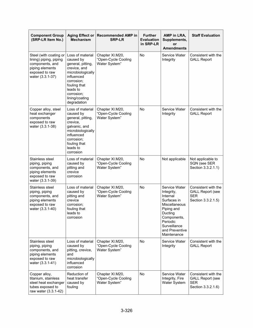
3-326
Component Group (SRP-LR Item No.)
Aging Effect or Mechanism
Recommended AMP in SRP-LR
Further Evaluation in SRP-LR
AMP in LRA, Supplements,
or Amendments
Staff Evaluation
Steel (with coating or lining) piping, piping components, and piping elements exposed to raw water (3.3.1-37)
Loss of material caused by general, pitting, crevice, and microbiologically influenced corrosion; fouling that leads to corrosion; lining/coating degradation
Chapter XI.M20, “Open-Cycle Cooling Water System”
No Service Water Integrity
Consistent with the GALL Report
Copper alloy, steel heat exchanger components exposed to raw water (3.3.1-38)
Loss of material caused by general, pitting, crevice, galvanic, and microbiologically influenced corrosion; fouling that leads to corrosion
Chapter XI.M20, “Open-Cycle Cooling Water System”
No Service Water Integrity
Consistent with the GALL Report
Stainless steel piping, piping components, and piping elements exposed to raw water (3.3.1-39)
Loss of material caused by pitting and crevice corrosion
Chapter XI.M20, “Open-Cycle Cooling Water System”
No Not applicable Not applicable to SQN (see SER Section 3.3.2.1.1)
Stainless steel piping, piping components, and piping elements exposed to raw water (3.3.1-40)
Loss of material caused by pitting and crevice corrosion; fouling that leads to corrosion
Chapter XI.M20, “Open-Cycle Cooling Water System”
No Service Water Integrity, Internal Surfaces in Miscellaneous Piping and Ducting Components, Periodic Surveillance and Preventive Maintenance
Consistent with the GALL Report (see SER Section 3.3.2.1.5)
Stainless steel piping, piping components, and piping elements exposed to raw water (3.3.1-41)
Loss of material caused by pitting, crevice, and microbiologically influenced corrosion
Chapter XI.M20, “Open-Cycle Cooling Water System”
No Service Water Integrity
Consistent with the GALL Report
Copper alloy, titanium, stainless steel heat exchanger tubes exposed to raw water (3.3.1-42)
Reduction of heat transfer caused by fouling
Chapter XI.M20, “Open-Cycle Cooling Water System”
No Service Water Integrity, Fire Water System
Consistent with the GALL Report (see SER Section 3.3.2.1.6)

3-327
Component Group (SRP-LR Item No.)
Aging Effect or Mechanism
Recommended AMP in SRP-LR
Further Evaluation in SRP-LR
AMP in LRA, Supplements,
or Amendments
Staff Evaluation
Stainless steel piping, piping components, and piping elements exposed to closed-cycle cooling water >60 °C (>140 °F) (3.3.1-43)
Cracking caused by stress corrosion cracking
Chapter XI.M21A, “Closed Treated Water Systems”
No Water Chemistry Control – Closed Treated Water Systems
Consistent with the GALL Report
Stainless steel; steel with stainless steel cladding heat exchanger components exposed to closed-cycle cooling water >60 °C (>140 °F) (3.3.1-44)
Cracking caused by stress corrosion cracking
Chapter XI.M21A, “Closed Treated Water Systems”
No Water Chemistry Control – Closed Treated Water Systems
Consistent with the GALL Report
Steel piping, piping components, and piping elements; tanks exposed to closed-cycle cooling water (3.3.1-45)
Loss of material caused by general, pitting, and crevice corrosion
Chapter XI.M21A, “Closed Treated Water Systems”
No Water Chemistry Control – Closed Treated Water Systems
Consistent with the GALL Report
Steel, copper alloy heat exchanger components, piping, piping components, and piping elements exposed to closed-cycle cooling water (3.3.1-46)
Loss of material caused by general, pitting, crevice, and galvanic corrosion
Chapter XI.M21A, “Closed Treated Water Systems”
No Water Chemistry Control – Closed Treated Water Systems
Consistent with the GALL Report
Stainless steel; steel with stainless steel cladding heat exchanger components exposed to closed-cycle cooling water (3.3.1-47)
Loss of material caused by microbiologically influenced corrosion
Chapter XI.M21A, “Closed Treated Water Systems”
No Not applicable Not applicable to SQN (see SER Section 3.3.2.1.1)
Aluminum piping, piping components, and piping elements exposed to closed-cycle cooling water (3.3.1-48)
Loss of material caused by pitting and crevice corrosion
Chapter XI.M21A, “Closed Treated Water Systems”
No Water Chemistry Control – Closed Treated Water Systems
Consistent with the GALL Report
Stainless steel piping, piping components, and piping elements exposed to closed-cycle cooling water (3.3.1-49)
Loss of material caused by pitting and crevice corrosion
Chapter XI.M21A, “Closed Treated Water Systems”
No Water Chemistry Control – Closed Treated Water Systems
Consistent with the GALL Report

3-328
Component Group (SRP-LR Item No.)
Aging Effect or Mechanism
Recommended AMP in SRP-LR
Further Evaluation in SRP-LR
AMP in LRA, Supplements,
or Amendments
Staff Evaluation
Stainless steel, copper alloy, steel heat exchanger tubes exposed to closed-cycle cooling water (3.3.1-50)
Reduction of heat transfer caused by fouling
Chapter XI.M21A, “Closed Treated Water Systems”
No Water Chemistry Control – Closed Treated Water Systems
Consistent with the GALL Report
Boraflex spent fuel storage racks: neutron-absorbing sheets (PWR); Spent fuel storage racks: neutron-absorbing sheets (BWR) exposed to treated borated water, treated water (3.3.1-51)
Reduction of neutron-absorbing capacity caused by boraflex degradation
Chapter XI.M22, “Boraflex Monitoring”
No Not applicable Not applicable to SQN (see SER Section 3.3.2.1.1)
Steel cranes: rails and structural girders exposed to air – indoor, uncontrolled (external) (3.3.1-52)
Loss of material caused by general corrosion
Chapter XI.M23, “Inspection of Overhead Heavy Load and Light Load (Related to Refueling) Handling Systems”
No Inspection of Overhead Heavy Load and Light Load (Related to Refueling) Handling Systems
Consistent with the GALL Report
Steel cranes - rails exposed to air – indoor, uncontrolled (external) (3.3.1-53)
Loss of material caused by wear
Chapter XI.M23, “Inspection of Overhead Heavy Load and Light Load (Related to Refueling) Handling Systems”
No Inspection of Overhead Heavy Load and Light Load (Related to Refueling) Handling Systems
Consistent with the GALL Report
Copper-alloy piping, piping components, and piping elements exposed to condensation (3.3.1-54)
Loss of material caused by general, pitting, and crevice corrosion
Chapter XI.M24, “Compressed Air Monitoring”
No Compressed Air Monitoring
Consistent with the GALL Report
Steel piping, piping components, and piping elements: compressed air system exposed to condensation (Internal) (3.3.1-55)
Loss of material caused by general and pitting corrosion
Chapter XI.M24, “Compressed Air Monitoring”
No Compressed Air Monitoring
Consistent with the GALL Report

3-329
Component Group (SRP-LR Item No.)
Aging Effect or Mechanism
Recommended AMP in SRP-LR
Further Evaluation in SRP-LR
AMP in LRA, Supplements,
or Amendments
Staff Evaluation
Stainless steel piping, piping components, and piping elements exposed to condensation (Internal) (3.3.1-56)
Loss of material caused by pitting and crevice corrosion
Chapter XI.M24, “Compressed Air Monitoring”
No Compressed Air Monitoring, Internal Surfaces in Miscellaneous Piping and Ducting Components
Consistent with the GALL Report (see SER Section 3.3.2.1.3)
Elastomers fire barrier penetration seals exposed to air - indoor, uncontrolled, air – outdoor (3.3.1-57)
Increased hardness; shrinkage; loss of strength caused by weathering
Chapter XI.M26, “Fire Protection”
No Fire Protection Consistent with the GALL Report
Steel halon/carbon dioxide fire suppression system piping, piping components, and piping elements exposed to air – indoor, uncontrolled (external) (3.3.1-58)
Loss of material caused by general, pitting, and crevice corrosion
Chapter XI.M26, “Fire Protection”
No Fire Protection Consistent with the GALL Report
Steel fire rated doors exposed to air - indoor, uncontrolled, air – outdoor (3.3.1-59)
Loss of material caused by wear
Chapter XI.M26, “Fire Protection”
No Fire Protection Consistent with the GALL Report
Reinforced concrete structural fire barriers: walls, ceilings and floors exposed to air - indoor, uncontrolled (3.3.1-60)
Concrete cracking and spalling caused by aggressive chemical attack, and reaction with aggregates
Chapter XI.M26, “Fire Protection,” and Chapter XI.S6, “Structures Monitoring”
No Fire Protection, Structures Monitoring, and Masonry Wall
Consistent with the GALL Report (see SER Section 3.3.2.1.7)
Reinforced concrete Structural fire barriers: walls, ceilings and floors exposed to Air – outdoor (3.3.1-61)
Cracking, loss of material caused by freeze-thaw, aggressive chemical attack, and reaction with aggregates
Chapter XI.M26, “Fire Protection,” and Chapter XI.S6, “Structures Monitoring”
No Fire Protection, Structures Monitoring, and Masonry Wall
Consistent with the GALL Report (see SER Section 3.3.2.1.7)
Reinforced concrete Structural fire barriers: walls, ceilings and floors exposed to Air - indoor, uncontrolled, Air – outdoor (3.3.1-62)
Loss of material caused by corrosion of embedded steel
Chapter XI.M26, “Fire Protection,” and Chapter XI.S6, “Structures Monitoring”
No Fire Protection, Structures Monitoring, and Masonry Wall
Consistent with the GALL Report (see SER Section 3.3.2.1.7)

3-330
Component Group (SRP-LR Item No.)
Aging Effect or Mechanism
Recommended AMP in SRP-LR
Further Evaluation in SRP-LR
AMP in LRA, Supplements,
or Amendments
Staff Evaluation
Steel Fire Hydrants exposed to Air – outdoor (3.3.1-63)
Loss of material caused by general, pitting, and crevice corrosion
Chapter XI.M27, “Fire Water System”
No External Surfaces Monitoring
Consistent with the GALL Report (see SER Section 3.3.2.1.1)
Steel, Copper-alloy Piping, piping components, and piping elements exposed to Raw water (3.3.1-64)
Loss of material caused by general, pitting, crevice, and microbiologically influenced corrosion; fouling that leads to corrosion
Chapter XI.M27, “Fire Water System”
No Fire Water System
Consistent with the GALL Report (see SER Section 3.3.2.1.4)
Aluminum Piping, piping components, and piping elements exposed to Raw water (3.3.1-65)
Loss of material caused by pitting and crevice corrosion
Chapter XI.M27, “Fire Water System”
No Not applicable Not applicable to SQN (see SER Section 3.3.2.1.1)
Stainless steel Piping, piping components, and piping elements exposed to Raw water (3.3.1-66)
Loss of material caused by pitting and crevice corrosion; fouling that leads to corrosion
Chapter XI.M27, “Fire Water System”
No Fire Water System
Consistent with the GALL Report
Steel Tanks exposed to Air – outdoor (External) (3.3.1-67)
Loss of material caused by general, pitting, and crevice corrosion
Chapter XI.M29, “Aboveground Metallic Tanks”
No Aboveground Metallic Tanks
Consistent with the GALL Report (see SER Section 3.3.2.1.1)
Steel Piping, piping components, and piping elements exposed to Fuel oil (3.3.1-68)
Loss of material caused by general, pitting, and crevice corrosion
Chapter XI.M30, “Fuel Oil Chemistry”, and Chapter XI.M32, “One-Time Inspection”
No Not applicable Not applicable to SQN (see SER Section 3.3.2.1.1)
Copper-alloy Piping, piping components, and piping elements exposed to Fuel oil (3.3.1-69)
Loss of material caused by general, pitting, crevice, and microbiologically influenced corrosion
Chapter XI.M30, “Fuel Oil Chemistry,” and Chapter XI.M32, “One-Time Inspection”
No Diesel Fuel Monitoring, One-Time Inspection
Consistent with the GALL Report

3-331
Component Group (SRP-LR Item No.)
Aging Effect or Mechanism
Recommended AMP in SRP-LR
Further Evaluation in SRP-LR
AMP in LRA, Supplements,
or Amendments
Staff Evaluation
Steel Piping, piping components, and piping elements; tanks exposed to Fuel oil (3.3.1-70)
Loss of material caused by general, pitting, crevice, and microbiologically influenced corrosion; fouling that leads to corrosion
Chapter XI.M30, “Fuel Oil Chemistry,” and Chapter XI.M32, “One-Time Inspection”
No Diesel Fuel Monitoring, One-Time Inspection, Internal Surfaces in Miscellaneous Piping and Ducting Components
Consistent with the GALL Report (see SER Section 3.3.2.1.4)
Stainless steel, Aluminum Piping, piping components, and piping elements exposed to Fuel oil (3.3.1-71)
Loss of material caused by pitting, crevice, and microbiologically influenced corrosion
Chapter XI.M30, “Fuel Oil Chemistry,” and Chapter XI.M32, “One-Time Inspection”
No Diesel Fuel Monitoring, One-Time Inspection
Consistent with the GALL Report
Gray cast iron, Copper-alloy (>15% Zn or >8% Al) Piping, piping components, and piping elements, Heat exchanger components exposed to Treated water, Closed-cycle cooling water, Soil, Raw water (3.3.1-72)
Loss of material caused by selective leaching
Chapter XI.M33, “Selective Leaching”
No Selective Leaching
Consistent with the GALL Report
Concrete; cementitious material Piping, piping components, and piping elements exposed to Air – outdoor (3.3.1-73)
Changes in material properties caused by aggressive chemical attack
Chapter XI.M36, “External Surfaces Monitoring of Mechanical Components”
No Not applicable Not applicable to SQN (see SER Section 3.3.2.1.1)
Concrete; cementitious material Piping, piping components, and piping elements exposed to Air – outdoor (3.3.1-74)
Cracking caused by settling
Chapter XI.M36, “External Surfaces Monitoring of Mechanical Components”
No Not applicable Not applicable to SQN (see SER Section 3.3.2.1.1)

3-332
Component Group (SRP-LR Item No.)
Aging Effect or Mechanism
Recommended AMP in SRP-LR
Further Evaluation in SRP-LR
AMP in LRA, Supplements,
or Amendments
Staff Evaluation
Reinforced concrete, asbestos cement Piping, piping components, and piping elements exposed to Air – outdoor (3.3.1-75)
Cracking caused by aggressive chemical attack and leaching; Changes in material properties caused by aggressive chemical attack
Chapter XI.M36, “External Surfaces Monitoring of Mechanical Components”
No Not applicable Not applicable to SQN (see SER Section 3.3.2.1.1)
Elastomers Elastomer: seals and components exposed to Air – indoor, uncontrolled (Internal/External) (3.3.1-76)
Hardening and loss of strength caused by elastomer degradation
Chapter XI.M36, “External Surfaces Monitoring of Mechanical Components”
No External Surfaces Monitoring
Consistent with GALL Report
Concrete; cementitious material Piping, piping components, and piping elements exposed to Air – outdoor (3.3.1-77)
Loss of material caused by abrasion, cavitation, aggressive chemical attack, and leaching
Chapter XI.M36, “External Surfaces Monitoring of Mechanical Components”
No Not applicable Not applicable to SQN (see SER Section 3.3.2.1.1)
Steel Piping and components (External surfaces), Ducting and components (External surfaces), Ducting; closure bolting exposed to Air – indoor, uncontrolled (External), Air – indoor, uncontrolled (External), Air – outdoor (External), Condensation (External) (3.3.1-78)
Loss of material caused by general corrosion
Chapter XI.M36, “External Surfaces Monitoring of Mechanical Components”
No External Surfaces Monitoring, Periodic Surveillance and Preventive Maintenance, Buried and Underground Piping and Tanks Inspection
Consistent with the GALL Report (see SER Section 3.3.2.1.8)
Copper-alloy Piping, piping components, and piping elements exposed to Condensation (External) (3.3.1-79)
Loss of material caused by general, pitting, and crevice corrosion
Chapter XI.M36, “External Surfaces Monitoring of Mechanical Components”
No External Surfaces Monitoring
Consistent with GALL Report

3-333
Component Group (SRP-LR Item No.)
Aging Effect or Mechanism
Recommended AMP in SRP-LR
Further Evaluation in SRP-LR
AMP in LRA, Supplements,
or Amendments
Staff Evaluation
Steel Heat exchanger components, Piping, piping components, and piping elements exposed to Air – indoor, uncontrolled (External), Air – outdoor (External) (3.3.1-80)
Loss of material caused by general, pitting, and crevice corrosion
Chapter XI.M36, “External Surfaces Monitoring of Mechanical Components”
No External Surfaces Monitoring
Consistent with the GALL Report
Copper-alloy, Aluminum Piping, piping components, and piping elements exposed to Air – outdoor (External), Air – outdoor (3.3.1-81)
Loss of material caused by pitting and crevice corrosion
Chapter XI.M36, “External Surfaces Monitoring of Mechanical Components”
No External Surfaces Monitoring
Consistent with the GALL Report
Elastomers Elastomer: seals and components exposed to Air – indoor, uncontrolled (External) (3.3.1-82)
Loss of material caused by wear
Chapter XI.M36, “External Surfaces Monitoring of Mechanical Components”
No External Surfaces Monitoring
Consistent with GALL Report
Stainless steel Diesel engine exhaust piping, piping components, and piping elements exposed to Diesel exhaust (3.3.1-83)
Cracking caused by stress corrosion cracking
Chapter XI.M38, “Inspection of Internal Surfaces in Miscellaneous Piping and Ducting Components”
No Inspection of Internal Surfaces in Miscellaneous Piping and Ducting Components
Consistent with the GALL Report (see SER Section 3.3.2.1.11)
Elastomers Elastomer seals and components exposed to Closed-cycle cooling water (3.3.1-85)
Hardening and loss of strength caused by elastomer degradation
Chapter XI.M38, “Inspection of Internal Surfaces in Miscellaneous Piping and Ducting Components”
No Internal Surfaces in Miscellaneous Piping and Ducting Components
Consistent with GALL Report
Elastomers, linings, Elastomer: seals and components exposed to Treated borated water, Treated water, Raw water (3.3.1-86)
Hardening and loss of strength caused by elastomer degradation
Chapter XI.M38, “Inspection of Internal Surfaces in Miscellaneous Piping and Ducting Components”
No Internal Surfaces in Miscellaneous Piping and Ducting Components
Consistent with GALL Report

3-334
Component Group (SRP-LR Item No.)
Aging Effect or Mechanism
Recommended AMP in SRP-LR
Further Evaluation in SRP-LR
AMP in LRA, Supplements,
or Amendments
Staff Evaluation
Steel; stainless steel Piping, piping components, and piping elements, Piping, piping components, and piping elements, diesel engine exhaust exposed to Raw water (potable), Diesel exhaust (3.3.1-88)
Loss of material caused by general (steel only), pitting, and crevice corrosion
Chapter XI.M38, “Inspection of Internal Surfaces in Miscellaneous Piping and Ducting Components”
No Internal Surfaces in Miscellaneous Piping and Ducting Components
Consistent with the GALL Report
Steel, Copper-alloy Piping, piping components, and piping elements exposed to Moist air or condensation (Internal) (3.3.1-89)
Loss of material caused by general, pitting, and crevice corrosion
Chapter XI.M38, “Inspection of Internal Surfaces in Miscellaneous Piping and Ducting Components”
No Internal Surfaces in Miscellaneous Piping and Ducting Components, Periodic Surveillance and Preventive Maintenance
Consistent with the GALL Report (see SER Section 3.3.2.1.3)
Steel Ducting and components (Internal surfaces) exposed to Condensation (Internal) (3.3.1-90)
Loss of material caused by general, pitting, crevice, and (for drip pans and drain lines) microbiologically influenced corrosion
Chapter XI.M38, “Inspection of Internal Surfaces in Miscellaneous Piping and Ducting Components”
No Internal Surfaces in Miscellaneous Piping and Ducting Components
Consistent with the GALL Report
Steel Piping, piping components, and piping elements; tanks exposed to Waste Water (3.3.1-91)
Loss of material caused by general, pitting, crevice, and microbiologically influenced corrosion
Chapter XI.M38, “Inspection of Internal Surfaces in Miscellaneous Piping and Ducting Components”
No Internal Surfaces in Miscellaneous Piping and Ducting Components, Periodic Surveillance and Preventive Maintenance
Consistent with the GALL Report (see SER Section 3.3.2.1.4)
Aluminum Piping, piping components, and piping elements exposed to Condensation (Internal) (3.3.1-92)
Loss of material caused by pitting and crevice corrosion
Chapter XI.M38, “Inspection of Internal Surfaces in Miscellaneous Piping and Ducting Components”
No Compressed Air Monitoring
Consistent with the GALL Report (see SER Section 3.3.2.1.12)
Copper-alloy Piping, piping components, and piping elements exposed to Raw water (potable) (3.3.1-93)
Loss of material caused by pitting and crevice corrosion
Chapter XI.M38, “Inspection of Internal Surfaces in Miscellaneous Piping and Ducting Components”
No Internal Surfaces in Miscellaneous Piping and Ducting Components
Consistent with the GALL Report

3-335
Component Group (SRP-LR Item No.)
Aging Effect or Mechanism
Recommended AMP in SRP-LR
Further Evaluation in SRP-LR
AMP in LRA, Supplements,
or Amendments
Staff Evaluation
Stainless steel Ducting and components exposed to Condensation (3.3.1-94)
Loss of material caused by pitting and crevice corrosion
Chapter XI.M38, “Inspection of Internal Surfaces in Miscellaneous Piping and Ducting Components”
No Not applicable Not applicable to SQN (see SER Section 3.3.2.1.1)
Copper-alloy, Stainless steel, Nickel alloy, Steel Piping, piping components, and piping elements, Heat exchanger components, Piping, piping components, and piping elements; tanks exposed to Waste water, Condensation (Internal) (3.3.1-95)
Loss of material caused by pitting, crevice, and microbiologically influenced corrosion
Chapter XI.M38, “Inspection of Internal Surfaces in Miscellaneous Piping and Ducting Components”
No Internal Surfaces in Miscellaneous Piping and Ducting Components, Periodic Surveillance and Preventive Maintenance, Compressed Air Monitoring
Consistent with the GALL Report (see SER Section 3.3.2.1.4)
Elastomers Elastomer: seals and components exposed to Air – indoor, uncontrolled (Internal) (3.3.1-96)
Loss of material caused by wear
Chapter XI.M38, “Inspection of Internal Surfaces in Miscellaneous Piping and Ducting Components”
No Internal Surfaces in Miscellaneous Piping and Ducting Components
Consistent with GALL Report
Steel Piping, piping components, and piping elements, Reactor coolant pump oil collection system: tanks, Reactor coolant pump oil collection system: piping, tubing, valve bodies exposed to Lubricating oil (3.3.1-97)
Loss of material caused by general, pitting, and crevice corrosion
Chapter XI.M39, “Lubricating Oil Analysis,” and Chapter XI.M32, “One-Time Inspection”
No Oil Analysis, One-Time Inspection, Internal Surfaces in Miscellaneous Piping and Ducting Components and Periodic Surveillance and Preventive Maintenance
Consistent with GALL Report (see SER Section 3.3.2.1.3)
Steel Heat exchanger components exposed to Lubricating oil (3.3.1-98)
Loss of material caused by general, pitting, crevice, and microbiologically influenced corrosion; fouling that leads to corrosion
Chapter XI.M39, “Lubricating Oil Analysis,” and Chapter XI.M32, “One-Time Inspection”
No Oil Analysis, One-Time Inspection
Consistent with GALL Report

3-336
Component Group (SRP-LR Item No.)
Aging Effect or Mechanism
Recommended AMP in SRP-LR
Further Evaluation in SRP-LR
AMP in LRA, Supplements,
or Amendments
Staff Evaluation
Copper-alloy, Aluminum Piping, piping components, and piping elements exposed to Lubricating oil (3.3.1-99)
Loss of material caused by pitting and crevice corrosion
Chapter XI.M39, “Lubricating Oil Analysis,” and Chapter XI.M32, “One-Time Inspection”
No Oil Analysis, One-Time Inspection
Consistent with GALL Report
Stainless steel Piping, piping components, and piping elements exposed to Lubricating oil (3.3.1-100)
Loss of material caused by pitting, crevice, and microbiologically influenced corrosion
Chapter XI.M39, “Lubricating Oil Analysis,” and Chapter XI.M32, “One-Time Inspection”
No Oil Analysis, One-Time Inspection, External Surfaces Monitoring
Consistent with GALL Report (see SER Section 3.3.2.1.12)
Aluminum Heat exchanger tubes exposed to Lubricating oil (3.3.1-101)
Reduction of heat transfer caused by fouling
Chapter XI.M39, “Lubricating Oil Analysis,” and Chapter XI.M32, “One-Time Inspection”
No Not applicable Not applicable to SQN (see SER Section 3.3.2.1.1)
Boral®; boron steel, and other materials (excluding Boraflex) Spent fuel storage racks: neutron-absorbing sheets (PWR), Spent fuel storage racks: neutron-absorbing sheets (BWR) exposed to Treated borated water, Treated water (3.3.1-102)
Reduction of neutron-absorbing capacity; change in dimensions and loss of material caused by effects of SFP environment
Chapter XI.M40, “Monitoring of Neutron-Absorbing Materials other than Boraflex”
No Neutron Absorbing Material Monitoring, Water Chemistry Control – Primary and Secondary
Consistent with the GALL Report
Reinforced concrete, asbestos cement Piping, piping components, and piping elements exposed to Soil or concrete (3.3.1-103)
Cracking caused by aggressive chemical attack and leaching; Changes in material properties caused by aggressive chemical attack
Chapter XI.M41, “Buried and Underground Piping and Tanks”
No Not applicable Not applicable to SQN (see SER Section 3.3.2.1.1)
HDPE, Fiberglass Piping, piping components, and piping elements exposed to Soil or concrete (3.3.1-104)
Cracking, blistering, change in color caused by water absorption
Chapter XI.M41, “Buried and Underground Piping and Tanks”
No Not applicable Not applicable to SQN (see SER Section 3.3.2.1.1)

3-337
Component Group (SRP-LR Item No.)
Aging Effect or Mechanism
Recommended AMP in SRP-LR
Further Evaluation in SRP-LR
AMP in LRA, Supplements,
or Amendments
Staff Evaluation
Concrete cylinder piping, Asbestos cement pipe Piping, piping components, and piping elements exposed to Soil or concrete (3.3.1-105)
Cracking, spalling, corrosion of rebar caused by exposure of rebar
Chapter XI.M41, “Buried and Underground Piping and Tanks”
No Not applicable Not applicable to SQN (see SER Section 3.3.2.1.1)
Steel (with coating or wrapping) Piping, piping components, and piping elements exposed to Soil or concrete (3.3.1-106)
Loss of material caused by general, pitting, crevice, and microbiologically influenced corrosion
Chapter XI.M41, “Buried and Underground Piping and Tanks”
No Buried and Underground Piping and Tanks
Consistent with the GALL Report
Stainless steel, nickel alloy, Piping, piping components, and piping elements exposed to Soil or concrete (3.3.1-107)
Loss of material caused by pitting and crevice corrosion
Chapter XI.M41, “Buried and Underground Piping and Tanks”
No Not applicable Not applicable to SQN (see SER Section 3.3.2.1.1)
Titanium, Super-austenitic, Aluminum, Copper-alloy, Stainless Steel, nickel alloy, Piping, piping components, and piping elements, Bolting exposed to Soil or concrete (3.3.1-108)
Loss of material caused by pitting and crevice corrosion
Chapter XI.M41, “Buried and Underground Piping and Tanks”
No Not applicable Not applicable to SQN (see SER Section 3.3.2.1.1)
Steel Bolting exposed to Soil or concrete (3.3.1-109)
Loss of material caused by general, pitting and crevice corrosion
Chapter XI.M41, “Buried and Underground Piping and Tanks”
No Buried and Underground Piping and Tanks
Consistent with the GALL Report
Underground Aluminum, Copper-alloy, Stainless Steel, nickel alloy and Steel Piping, piping components, and piping elements (3.3.1-109a)
Loss of material caused by general (steel only), pitting and crevice corrosion
Chapter XI.M41, “Buried and Underground Piping and Tanks”
No Buried and Underground Piping and Tanks
Consistent with the GALL Report
Stainless steel Piping, piping components, and piping elements exposed to Treated water >60 °C (>140 °F) (3.3.1-110)
Cracking caused by stress corrosion cracking
Chapter XI.M7, “BWR Stress Corrosion Cracking,” and Chapter XI.M2, “Water Chemistry”
No Not applicable Not applicable to PWRs (see SER Section 3.3.2.1.1)

3-338
Component Group (SRP-LR Item No.)
Aging Effect or Mechanism
Recommended AMP in SRP-LR
Further Evaluation in SRP-LR
AMP in LRA, Supplements,
or Amendments
Staff Evaluation
Steel Structural steel exposed to Air – indoor, uncontrolled (External) (3.3.1-111)
Loss of material caused by general, pitting, and crevice corrosion
Chapter XI.S6, “Structures Monitoring”
No Structures Monitoring
Consistent with the GALL Report (see SER Section 3.3.2.1.1)
Steel Piping, piping components, and piping elements exposed to concrete (3.3.1-112)
None None, provided (1) attributes of the concrete are consistent with ACI 318 or ACI 349 (low water-to-cement ratio, low permeability, and adequate air entrainment) as cited in NUREG-1557, and (2) plant OE indicates no degradation of the concrete
No, if conditions are met
None Consistent with GALL Report (see SER Sections 3.3.2.1.9, 3.3.2.1.10)
Aluminum Piping, piping components, and piping elements exposed to Air – dry (Internal/External), Air – indoor, uncontrolled (Internal/External), Air – indoor, controlled (External), Gas (3.3.1-113)
None None N/A - No AEM or AMP
Consistent with GALL report for Al components exposed to uncontrolled indoor air and gas; however, there are no Al components exposed to other environments represented by this item in systems in the scope of license renewal.
Consistent with the GALL Report
Copper-alloy Piping, piping components, and piping elements exposed to Air – indoor, uncontrolled (Internal/External), Air – dry, Gas (3.3.1-114)
None None N/A - No AEM or AMP
None Consistent with the GALL Report
Copper-alloy (≤15% Zn and ≤8% Al) Piping, piping components, and piping elements exposed to Air with borated water leakage (3.3.1-115)
None None N/A - No AEM or AMP
Not applicable Not applicable to SQN (see SER Section 3.3.2.1.1)

3-339
Component Group (SRP-LR Item No.)
Aging Effect or Mechanism
Recommended AMP in SRP-LR
Further Evaluation in SRP-LR
AMP in LRA, Supplements,
or Amendments
Staff Evaluation
Galvanized steel Piping, piping components, and piping elements exposed to Air - indoor, uncontrolled (3.3.1-116)
None None No Not applicable Not applicable to SQN (see SER Section 3.3.2.1.1)
Glass Piping elements exposed to Air – indoor, uncontrolled (External), Lubricating oil, Closed-cycle cooling water, Air – outdoor, Fuel oil, Raw water, Treated water, Treated borated water, Air with borated water leakage, Condensation (Internal/External) Gas (3.3.1-117)
None None N/A - No AEM or AMP
None Consistent with the GALL Report
Nickel alloy Piping, piping components, and piping elements exposed to Air – indoor, uncontrolled (External) (3.3.1-118)
None None N/A - No AEM or AMP
None Consistent with the GALL Report
Nickel alloy, PVC, Glass Piping, piping components, and piping elements exposed to Air with borated water leakage, Air – indoor, uncontrolled, Condensation (Internal), Waste Water (3.3.1-119)
None None N/A - No AEM or AMP
None Consistent with the GALL Report

3-340
Component Group (SRP-LR Item No.)
Aging Effect or Mechanism
Recommended AMP in SRP-LR
Further Evaluation in SRP-LR
AMP in LRA, Supplements,
or Amendments
Staff Evaluation
Stainless steel Piping, piping components, and piping elements exposed to Air – indoor, uncontrolled (Internal/External), Air – indoor, uncontrolled (External), Air with borated water leakage, Concrete, Air – dry, Gas (3.3.1-120)
None None N/A - No AEM or AMP
None Consistent with GALL Report
Steel Piping, piping components, and piping elements exposed to Air – indoor, controlled (External), Air – dry, Gas (3.3.1-121)
None None N/A - No AEM or AMP
None Consistent with the GALL Report
Titanium Heat exchanger components, Piping, piping components, and piping elements exposed to Air – indoor, uncontrolled or Air – outdoor (3.3.1-122)
None None N/A - No AEM or AMP
None Not applicable to SQN (see SER Section 3.3.2.1.1)
Titanium (ASTM Grades 1, 2, 7, 11, or 12 that contains >5% aluminum or more than 0.20% oxygen or any amount of tin) Heat exchanger components other than tubes, Piping, piping components, and piping elements exposed to Raw water (3.3.1-123)
None None N/A - No AEM or AMP
None Not applicable to SQN (see SER Section 3.3.2.1.1)

3-341
Component Group (SRP-LR Item No.)
Aging Effect or Mechanism
Recommended AMP in SRP-LR
Further Evaluation in SRP-LR
AMP in LRA, Supplements,
or Amendments
Staff Evaluation
Stainless steel, Steel (with stainless steel or nickel-alloy cladding) Spent fuel storage racks (BWR), Spent fuel storage racks (PWR), Piping, piping components, and piping elements; exposed to Treated water >60 °C (>140 °F), Treated borated water >60 °C (>140 °F) (3.3.1-124)
Cracking due to stress corrosion cracking
Chapter XI.M2, “Water Chemistry,” and Chapter XI.M32, “One-Time Inspection”
No Water Chemistry Control – Primary and Secondary, One-Time Inspection
Consistent with the GALL Report
Steel (with stainless steel cladding); stainless steel Spent fuel storage racks (BWR), Spent fuel storage racks (PWR), Piping, piping components, and piping elements; exposed to Treated water, Treated borated water (3.3.1-125)
Loss of material due to pitting and crevice corrosion
Chapter XI.M2, “Water Chemistry,” and Chapter XI.M32, “One-Time Inspection”
No Water Chemistry Control – Primary and Secondary, One-Time Inspection
Consistent with the GALL Report
The staff’s review of the auxiliary systems component groups followed several approaches. One approach, documented in SER Section 3.3.2.1, discusses the staff’s review of AMR results for components that the applicant indicated are consistent with the GALL Report and require no further evaluation. Another approach, documented in SER Section 3.3.2.2, discusses the staff’s review of AMR results for components that the applicant indicated are consistent with the GALL Report and for which further evaluation is recommended. A third approach, documented in SER Section 3.3.2.3, discusses the staff’s review of AMR results for components that the applicant indicated are not consistent with or not addressed in the GALL Report. The staff’s review of AMPs credited to manage or monitor aging effects of the auxiliary systems components is documented in SER Section 3.0.3. 3.3.2.1 AMR Results Consistent With the GALL Report LRA Section 3.3.2.1 identifies the materials, environments, AERM, and the following programs that manage aging effects for the auxiliary systems components: • Aboveground Metallic Tanks
• ASME Section XI Inservice Inspection, Subsections IWB, IWC, and IWD
• Bolting Integrity

3-342
• Boric Acid Corrosion
• Buried and Underground Piping and Tanks
• Closed Treated Water Systems
• External Surfaces Monitoring of Mechanical Components
• Fire Protection
• Fire Water System
• Fuel Oil Chemistry
• Flow-Accelerated Corrosion
• Inspection of Internal Surfaces in Miscellaneous Piping and Ducting Components
• Inspection of Overhead Heavy Load and Light Load (Related to Refueling) Handling Systems
• Lubricating Oil Analysis
• Monitoring of Neutron-Absorbing Materials other than Boraflex
• One-Time Inspection
• One-Time Inspection of ASME Code Class 1 Small-Bore Piping
• Open-Cycle Cooling Water System
• Selective Leaching
• Structures Monitoring
• Water Chemistry LRA Tables 3.3.2-1 through 3.3.2-28 summarize AMRs for the auxiliary systems components and indicate AMRs claimed to be consistent with the GALL Report. For component groups evaluated in the GALL Report, for which the applicant claimed consistency and for which the GALL Report does not recommend further evaluation, the staff performed an audit and review to determine if the plant-specific components in these GALL Report component groups were bound by the GALL Report evaluation. The applicant provided a note for each AMR item. The notes describe how the information in the tables aligns with the information in the GALL Report. The staff audited those AMRs with notes A through E, which indicate how the AMR was consistent with the GALL Report. Note A indicates that the AMR item is consistent with the GALL Report for component, material, environment, and aging effect. In addition, the AMP is consistent with the GALL Report AMP. The staff audited these AMR items to confirm consistency with the GALL Report and the validity of the AMR for the site-specific conditions. Note B indicates that the AMR item is consistent with the GALL Report for component, material, environment, and aging effect. In addition, the AMP takes some exceptions to the AMP identified in the GALL Report. The staff audited these AMR items to confirm consistency with the GALL Report and confirmed that it had reviewed and accepted the identified exceptions to the GALL Report AMPs. The staff also determined whether the AMP identified by the applicant

3-343
was consistent with the AMP identified in the GALL Report and whether the AMR was valid for the site-specific conditions. Note C indicates that the component for the AMR item, although different from, is consistent with the GALL Report for material, environment, and aging effect. In addition, the AMP is consistent with the AMP identified by the GALL Report. This note indicates that the applicant was unable to find a listing of some system components in the GALL Report; however, the applicant identified a different component in the GALL Report that had the same material, environment, aging effect, and AMP as the component under review. The staff audited these AMR items to confirm consistency with the GALL Report. The staff also determined whether the AMR item of the different component applied to the component under review and whether the AMR was valid for the site-specific conditions. Note D indicates that the component for the AMR item, although different from, is consistent with the GALL Report for material, environment, and aging effect. In addition, the AMP takes some exceptions to the AMP identified in the GALL Report. The staff audited these AMR items to confirm consistency with the GALL Report and confirmed whether the AMR item of the different component was applicable to the component under review. The staff confirmed whether it had reviewed and accepted the exceptions to the GALL Report AMPs. It also determined whether the AMP identified by the applicant was consistent with the AMP identified in the GALL Report and whether the AMR was valid for the site-specific conditions. Note E indicates that the AMR item is consistent with the GALL Report for material, environment, and aging effect, but a different AMP is credited. The staff audited these AMR items to confirm consistency with the GALL Report and determined whether the identified AMP would manage the aging effect consistent with the AMP identified in the GALL Report and whether the AMR was valid for the site-specific conditions. The staff did not repeat its review of the matters described in the GALL Report; however, it did confirm that the material presented in the LRA was applicable and that the applicant identified the appropriate GALL Report AMRs. The staff’s evaluation is discussed below. 3.3.2.1.1 AMR Results Identified as Not Applicable For LRA Table 3.3-1, items 3.3.1-16, 3.3.1-22, 3.3.1-27, and 3.3.1-110, the applicant claimed that the corresponding AMR items in the GALL Report are not applicable because the associated items are only applicable to BWRs. The staff reviewed the SRP-LR, confirmed these items only apply to BWRs, and finds that these items are not applicable to SQN, which is a PWR. For LRA Table 3.3-1, items 3.3.1-7, 3.3.1-10, 3.3.1-11, 3.3.1-12, 3.3.1-16, 3.3.1-18, 3.3.1-19, 3.3.1-26, 3.3.1-30, 3.3.1-30a, 3.3.1-31 through 3.3.1-33, 3.3.1-35, 3.3.1-39, 3.3.1-51, 3.3.1-65, 3.3.1-68, 3.3.1-73 through 3.3.1-75, 3.3.1-77, 3.3.1-94, 3.3.1-101, 3.3.1-103 through 3.3.1-105, 3.3.1-107, 3.3.1-108, 3.3.1-111, 3.3.1-115, 3.3.-1-116, 3.3.1-122, and 3.3.1-123, the applicant claimed that the corresponding items in the GALL Report are not applicable because the component, material, and environment combination described in the SRP-LR does not exist for in-scope SCs at SQN. The staff reviewed the LRA and UFSAR and confirmed that the applicant’s LRA does not have any AMR results applicable for these items. For LRA Table 3.3-1 items discussed below, the applicant claimed that the corresponding AMR items in the GALL Report are not applicable; however, the staff nonapplicability verification of

3-344
these items required the review of sources beyond the LRA and UFSAR, or the issuance of RAIs. LRA Table 3.3.1, item 3.3.1-12 addresses steel and stainless steel closure bolting exposed to condensation, air-outdoor and air-indoor, uncontrolled. The GALL Report recommends GALL Report AMP XI.M18, “Bolting Integrity,” to manage loss of material due to general (steel only), pitting, and crevice corrosion for this component group. LRA item 3.3.1-12 states, “[l]oss of material is not an aging effect for stainless steel closure bolting in indoor air unless exposed to prolonged leakage (an event driven condition). Nevertheless, the Bolting Integrity Program also applies to stainless steel bolting exposed to indoor air.” The LRA contains AMR items for stainless steel bolting exposed to indoor air in the auxiliary systems; however, the only cited aging effect is loss of preload, which is being managed with the Bolting Integrity Program. The staff notes that SRP-LR Section A.1.2.1, item 7, states that “leakage from bolted connections should not be considered abnormal events. Although bolted connections are not supposed to leak, experience shows that leaks do occur, and leakage could cause corrosion. Thus the aging effects from leakage of bolted connections should be evaluated for license renewal.” As a result, the staff considers loss of material as an applicable aging effect in indoor air. However, the staff also notes that the Bolting Integrity Program’s inspection activities for the loss of preload aging effect are also appropriate for evaluating loss of material for the subject components. The Bolting Integrity Program includes ASME Code-required volumetric and visual inspections of Code class bolting, and periodic leakage inspections (at least once per refueling cycle) of both Code class and non-ASME Code class bolted connections. The staff finds the applicant’s claim in item 3.3.1-12 acceptable because the Bolting Integrity Program includes inspections of the subject bolting that are capable of detecting loss of material prior to loss of intended function, consistent with the GALL Report recommendation. LRA Table 3.3.1, item 3.3.1-13 addresses steel closure bolting exposed to air with steam or water leakage. The GALL Report recommends GALL Report AMP XI.M18, “Bolting Integrity,” to manage loss of material due to general corrosion for this component group. The applicant stated that this item is not applicable because this component group was evaluated using LRA Table 3.3.1, item 3.3.1-12 for steel closure bolting exposed to an indoor air environment. The staff reviewed LRA Section 3.3 and confirmed that the applicant used this alternative item for the subject components. The staff evaluated the applicant’s claim and finds it acceptable because the applicant has evaluated steel closure bolting with LRA item 3.3.1-12, which manages loss of material with the Bolting Integrity Program, consistent with the GALL Report recommendation. LRA Table 3.3.1, item 3.3.1-21 addresses steel piping, piping components, and piping elements exposed to treated water. The GALL Report recommends GALL Report AMP XI.M2, “Water Chemistry,” and XI.M32, “One-Time Inspection,” to manage loss of material due to general, pitting, and crevice corrosion for this component group. The applicant stated that this item is not applicable because it is only applicable to BWRs. The staff reviewed LRA Sections 2.3.3 and 3.3 and the UFSAR and noted that steel components exposed to treated water are present in the auxiliary system; however, they are evaluated with LRA Table 3.4.1, item 3.4.1-13. The staff evaluated the applicant’s claim and finds it acceptable because the applicant has evaluated steel piping, piping components, and piping elements exposed to treated water with LRA item 3.4.1-13, which manages loss of material due to general, pitting, and crevice corrosion with the Water Chemistry Control – Primary and Secondary and One-Time Inspection Programs, consistent with the GALL Report recommendation.

3-345
LRA Table 3.3.1, item 3.3.1-24 addresses aluminum piping, piping components, and piping elements exposed to treated water. The GALL Report recommends GALL Report AMP XI.M2, “Water Chemistry,” and XI.M32, “One-Time Inspection,” to manage loss of material due to pitting and crevice corrosion for this component group. The applicant stated that this item is not applicable because it is only applicable to BWRs. The staff reviewed LRA Sections 2.3.3 and 3.3 and the UFSAR and noted that aluminum components exposed to treated water are present in the auxiliary system; however, they are evaluated with LRA Table 3.3.1, item 3.3.1-23. The staff evaluated the applicant’s claim and finds it acceptable because the applicant has evaluated aluminum piping, piping components, and piping elements exposed to treated water with LRA item 3.3.1-23, which manages loss of material due to pitting and crevice corrosion with the Water Chemistry Control – Primary and Secondary and One-Time Inspection Programs, consistent with the GALL Report recommendation. LRA Table 3.3.1, item 3.3.1-25 addresses stainless steel, steel with stainless steel cladding, and aluminum piping, piping components, piping elements, and heat exchanger components exposed to treated water and sodium pentaborate solution. The GALL Report recommends GALL Report AMP XI.M2, “Water Chemistry,” and XI.M32, “One-Time Inspection,” to manage loss of material due to pitting and crevice corrosion for this component group. The applicant stated that this item is not applicable because it is only applicable to BWRs. The staff reviewed LRA Sections 2.3.3 and 3.3 and the UFSAR and noted that the subject components exposed to a treated water environment are present in the auxiliary systems; however, they are evaluated with LRA Table 3.3.1, item 3.3.1-23 (aluminum components) and LRA Table 3.4.1, item 3.4.1-16 (stainless steel components). The staff evaluated the applicant’s claim and finds it acceptable because the applicant has evaluated the subject components with LRA items 3.3.1-23 and 3.4.1-16, which manage loss of material due to pitting and crevice corrosion with the Water Chemistry Control – Primary and Secondary and One-Time Inspection Programs, consistent with the GALL Report recommendation. LRA Table 3.3.1, item 3.3.1-26 addresses steel (with elastomer lining or stainless steel cladding) piping, piping components and piping elements exposed to treated water. The GALL Report recommends GALL Report AMPs XI.M2, “Water Chemistry,” and XI.M32, “One-Time Inspection,” to manage loss of material due to pitting and crevice corrosion (only for steel after lining/cladding degradation for this component group). The applicant stated that this item is not applicable because there are no steel piping components in the spent fuel system exposed to treated water within the scope of license renewal. The staff notes that the GALL Report items associated with SRP-LR item 3.3.1-26, VII.A3.AP-107 and VII.A4.AP-108, are associated only with the spent fuel pool cooling and cleanup system. The staff finds the applicant’s proposal acceptable because item 3.3.1-26 is associated only with SFPs, and based on a review of the UFSAR, there is no steel piping in this system. LRA Table 3.3.1, item 3.3.1-27 addresses stainless steel heat exchanger tubes exposed to treated water. The GALL Report recommends GALL Report AMP XI.M2, “Water Chemistry” and AMP XI.M32, “One-Time Inspection” to manage reduction of heat transfer due to fouling for this component group. The applicant stated that this item is not applicable because it only applies to BWRs. The staff notes that the associated GALL item, VII.E3.AP-139, shares a common precedent with VII.A4.AP-139, which is addressed in LR-ISG-2011-01 and is noted as being applicable to both BWRs and PWRs. The staff also notes that the service environment specified in LRA Table 3.0-1 as “treated water” included “treated water,” “closed-cycle cooling water,” “secondary feedwater,” and “raw water (potable).” In its review LRA Sections 2.3.3 and 3.3 and the UFSAR, the staff notes that there are stainless steel heat exchanger tubes in the auxiliary systems exposed to treated water, but that these heat exchangers are in closed treated

3-346
water systems. The staff also notes that the AMR items for these components are associated with LRA item 3.3.1-50, which addresses stainless steel heat exchanger tubes exposed to treated water in closed treated water systems, for which fouling is managed with the Water Chemistry Control – Closed Treated Water Systems Program, consistent with GALL Report guidance. The staff further noted that stainless steel heat exchanger tubes exposed to treated borated water are being managed through item 3.3.1-17, and use the Water Chemistry and One-Time Inspection Programs as recommended by the GALL Report. Therefore, the staff finds the applicant’s claim acceptable. LRA Table 3.3.1, item 3.3.1-35 addresses copper-alloy piping components exposed to raw water. The GALL Report recommends GALL Report AMP XI.M20, “Open-Cycle Cooling Water System,” to manage loss of material due to general, pitting, crevice and MIC for this component group. The applicant stated that this item is not applicable because there are no copper-alloy components exposed to raw water in the standby DG system with an intended function for license renewal. The staff notes that although the standby DG system does not have any copper-alloy piping components, copper-alloy piping components do exist in other auxiliary systems at SQN. The staff notes that the copper-alloy piping components in the other auxiliary systems are being managed through item 3.3.1-36, and that the applicant uses the Service Water Integrity Program, which is consistent with the Open-Cycle Cooling Water System AMP to manage these components. The staff evaluated the applicant’s claim that this item is not applicable and finds it acceptable because copper-alloy piping components are being managed through a different item by the GALL-recommended AMP. LRA Table 3.3.1, item 3.3.1-47 addresses stainless steel and steel with stainless steel cladding heat exchanger components exposed to closed-cycle cooling water. The GALL Report recommends GALL Report AMP XI.21A, “Closed Treated Water Systems,” to manage loss of material due to MIC for this component group. The applicant stated that this item is not applicable because it is applicable to BWR plants only. Although SRP-LR Table 3.3-1, item 47 does not state that MIC is applicable to PWR plants, the staff notes that EPRI 1007820, “Closed Cooling Water Chemistry Guideline, Revision 1,” states that microbiological organisms can be found in virtually all closed cooling water systems. As documented in the staff’s Audit Report of the Water Chemistry Control - Closed Treated Water Systems Program, the staff also notes that the applicant is monitoring microbiological activity in its closed treated water systems in accordance with the EPRI guidelines and has provisions in its procedures for performing corrective actions should levels of microbiological activity fall outside of specifications. The staff further noted that the LRA contains AMR items for stainless steel and carbon steel clad with stainless steel heat exchanger components exposed to treated water that are managed for loss of material due to pitting and crevice corrosion with the Water Chemistry Control – Closed Treated Water Systems Program, which includes visual inspections at least once every 10 years. As a result, the staff finds that the applicant is appropriately managing loss of material due to MIC for the subject components through monitoring of water chemistry and visual inspections for corrosion in the Water Chemistry Control - Closed Treated Water Systems Program, consistent with GALL Report guidance. LRA Table 3.3.1, item 3.3.1-63 addresses steel fire hydrants exposed to outdoor air. The GALL Report recommends GALL Report AMP XI.M27, “Fire Water System,” to manage loss of material due to general, pitting, and crevice corrosion for this component group. The applicant stated that item 3.3.1-78 would be used in lieu of item 3.3.1-63. LRA Table 3.3.1, item 3.3.1-78 states that loss of material due to general corrosion for steel piping components exposed to outdoor air will be managed by the External Surfaces Monitoring Program. The staff’s evaluation of the applicant’s External Surfaces Monitoring Program is documented in SER

3-347
Section 3.0.3.2.4. The staff evaluated the applicant’s claim and finds it acceptable because the External Surfaces Monitoring Program requires periodic visual inspections (not to exceed a refueling cycle) that are capable of detecting pitting, and crevice corrosion, as well as general corrosion. LRA Table 3.3.1, item 3.3.1-111 addresses structural steel exposed to air-indoor, uncontrolled (external). The GALL Report recommends GALL Report AMP XI.S6, “Structures Monitoring” to manage loss of material due to general, pitting, and crevice corrosion for this component group. The applicant stated that this item is not applicable because the AMR results for structural steel components compared to GALL Report items are presented in LRA Section 3.5. The staff evaluated the applicant’s claim and finds it acceptable because the staff reviewed LRA Table 3.5.1 and found that the applicant proposes to manage steel components: all structural steel exposed to air-indoor for loss of material due to corrosion using the Structures Monitoring Program, which is consistent with the recommendations in the GALL Report. LRA Table 3.3.1, item 3.3.1-116 addresses galvanized steel piping, piping components, and piping elements exposed to air – indoor, uncontrolled. The GALL Report states that there is no AERM and no recommended AMP for this component group. The applicant stated, “[g]alvanized (zinc) coating applied to some steel components is not credited for corrosion protection for license renewal.” The staff evaluated the applicant’s claim and finds it acceptable because the LRA Table 2s did not cite the item, not crediting the protection provided by the galvanized coating will result in steel piping aging effects being managed by an AMP, and based on a review of LRA Section 3.3, the applicant uses the External Surfaces Monitoring, Internal Surfaces in Miscellaneous Piping and Ducting Components, Periodic Surveillance and Preventive Maintenance, or Fire Protection Programs to manage aging of this component group, all of which use periodic or opportunistic visual inspections which are capable of detecting aging. 3.3.2.1.2 Hardening and Loss of Strength Due to Elastomer Degradation and Loss of Material Due to Erosion LRA Table 3.3.1, item 3.3.1-32.5 addresses elastomer seals and components exposed to raw water, which will be managed for hardening, loss of strength, and loss of material. For the AMR item that cites generic note E, the LRA credits the Internal Surfaces in Miscellaneous Piping and Ducting Components Program to manage the aging effect for elastomeric flex connections and elastomeric expansion joints. The GALL Report recommends GALL Report AMP XI.M20, “Open-Cycle Cooling Water System,” to ensure that these aging effects are adequately managed. GALL Report AMP XI.M20 states that examinations of polymeric materials should be consistent with the examinations described in AMP XI.M38, “Inspection of Internal Surfaces in Miscellaneous Piping and Ducting Components.” The staff’s evaluation of the applicant’s Internal Surfaces in Miscellaneous Piping and Ducting Components Program is documented in SER Section 3.0.3.1.8. The staff notes that the associated components are in nonsafety-related systems and therefore, are not part of the applicant’s program addressing GL 89-13, “Service Water System Problems Affecting Safety-Related Equipment,” and consequently are not within the scope of the Open-Cycle Cooling Water System AMP. The staff also notes that the AMP proposed by the applicant applies to any water system other than the open-cycle cooling water system, the closed treated water system, and the fire water system. In its review of components associated with item 3.3.1-32.5, for which the applicant cited generic note E, the staff finds the applicant’s proposal to manage these aging effects using the Internal Surfaces in Miscellaneous Piping and

3-348
Ducting Components Program acceptable because that AMP specifically addresses aging management of elastomers for cracking, loss of material, and change in material properties. The staff concludes that for LRA item 3.3.1-32.5, the applicant has demonstrated that the effects of aging for these components will be adequately managed so that the intended function(s) will be maintained consistent with the CLB during the period of extended operation as required by 10 CFR 54.21(a)(3). 3.3.2.1.3 Loss of Material Due to General, Pitting, and Crevice Corrosion LRA Table 3.3.1, item 3.3.1-34 addresses nickel alloy and copper-alloy piping components exposed to raw water, which will be managed for loss of material due to general, pitting, and crevice corrosion. For the AMR items that cite generic note E, the LRA credits the Internal Surfaces in Miscellaneous Piping and Ducting Components Program to manage the aging effect for nickel alloy rupture discs and expansion joints. The GALL Report recommends GALL Report AMP XI.M20, “Open-Cycle Cooling Water System,” to ensure that this aging effect is adequately managed. GALL Report AMP XI.M20 recommends using periodic visual inspections to manage these aging effects. The staff’s evaluation of the applicant’s Internal Surfaces in Miscellaneous Piping and Ducting Components Program is documented in SER Section 3.0.3.1.8. The staff notes that the Internal Surfaces in Miscellaneous Piping and Ducting Components Program proposes to manage the aging of the nickel alloy rupture discs and expansion joints through the use of visual inspections whenever the components are opened for any reason. The staff notes that the associated components are in nonsafety-related systems and therefore, are not part of the applicant’s GL 89-13 program, and consequently are not within the scope of the Open-Cycle Cooling Water System AMP. The staff also notes that the inspections established by GL 89-13 for corrosion and erosion did not include any specified frequency. The staff further notes that the AMP proposed by the applicant applies to any water system other than the open-cycle cooling water system, the closed treated water system, and the fire water system. In its review of components associated with item 3.3.1-34, for which the applicant cited generic note E, the staff finds the applicant’s proposal to manage these aging effects using the Internal Surfaces in Miscellaneous Piping and Ducting Components Program acceptable because it performs visual inspections of components that are capable of detecting the loss of material due to the applicable corrosion mechanisms prior to the loss of intended function(s). The staff concludes that for LRA item 3.3.1-34, the applicant has demonstrated that the effects of aging for these components will be adequately managed so that the intended function(s) will be maintained consistent with the CLB during the period of extended operation as required by 10 CFR 54.21(a)(3). By letter dated November 4, 2013, the applicant cited item 3.3.1-67 for steel tanks exposed to external outdoor air in the HPFP system, which are being managed for loss of material with the Fire Water System Program. The applicant cited generic note E for these items. LR-ISG-2012-02, "Aging Management of Internal Surfaces, Fire Water Systems, Atmospheric Storage Tanks, and Corrosion Under Insulation,” recommends that fire water storage tanks (FWSTs) be included in the scope of GALL Report AMP XI.M27, “Fire Water Systems,” instead of GALL Report AMP XI.M29, “Aboveground Metallic Tanks,” because NFPA 25, “Standard for Inspection, Testing and Maintenance of Water-Based Fire Protection Systems,” includes inspection requirements beyond those in the “detection of aging effects” program element of GALL Report AMP XI.M29. GALL Report AMP XI.M27 recommends the use of NFPA 25 for

3-349
testing and inspections of fire water system components, including FWSTs. Therefore, these items are consistent with the GALL Report and require no further staff evaluation. LRA Table 3.3.1, item 3.3.1-56 addresses stainless steel piping, piping components, and piping elements exposed to internal condensation, which will be managed for loss of material due to pitting and crevice corrosion. For the one AMR item that cites generic note E, the LRA credits the Internal Surfaces in Miscellaneous Piping and Ducting Components Program to manage the aging effect for stainless steel valve body exposed to internal condensation. The GALL Report recommends GALL Report AMP XI.M24, “Compressed Air Monitoring,” to ensure that this aging effect is adequately managed. GALL Report AMP XI.M24 recommends monitoring of air quality and inspection of the internal surfaces of critical components to manage loss of material. This includes: (a) preventive monitoring of water (moisture) and other potential contaminants to keep within the specified limits; and (b) inspection of components for indications of loss of material due to corrosion. The staff’s evaluation of the applicant’s Internal Surfaces in Miscellaneous Piping and Ducting Components Program is documented in SER Section 3.0.3.1.8. The staff notes that the Internal Surfaces in Miscellaneous Piping and Ducting Components Program proposes to manage the aging of stainless steel valve body through the use of opportunistic visual inspections of the internal surfaces of piping and components during periodic surveillances or maintenance activities when the surfaces are accessible for visual inspection. In its review of components associated with item 3.3.1-56 for which the applicant cited generic note E, the staff finds the applicant’s proposal to manage aging using the Internal Surfaces in Miscellaneous Piping and Ducting Components Program acceptable because the opportunistic visual inspections of the internal surfaces of the stainless steel valve body will ensure that, if a loss of material is occurring, it will be detected prior to a loss of intended function (e.g., PB). The staff concludes that for LRA item 3.3.1-56 the applicant has demonstrated that the effects of aging for these components will be adequately managed so that the intended function(s) will be maintained consistent with the CLB during the period of extended operation as required by 10 CFR 54.21(a)(3). LRA Table 3.3.1, item 3.3.1-89 addresses steel and copper-alloy piping, piping components, and piping elements internally exposed to moist air or condensation, which will be managed for loss of material due to general, pitting, and crevice corrosion. For the AMR item that cites generic note E, the LRA credits the Periodic Surveillance and Preventive Maintenance Program to manage the aging effect for copper-alloy heat exchanger tubes. The GALL Report recommends GALL Report AMP XI.M38, “Inspection of Internal Surfaces in Miscellaneous Piping and Ducting Components,” to ensure that this aging effect is adequately managed. GALL Report AMP XI.M38 recommends using opportunistic visual inspections of the internal surfaces of the components to manage the aging effect. The staff’s evaluation of the applicant’s Periodic Surveillance and Preventive Maintenance Program is documented in SER Section 3.0.3.3.1. The staff notes that the Periodic Surveillance and Preventive Maintenance Program proposes to manage loss of material in the miscellaneous heating, ventilation, and air conditioning (HVAC) copper-alloy heat exchanger tubes through the use of visual inspections of the tube surfaces. In its review of components associated with item 3.3.1-89 for which the applicant cited generic note E, the staff finds the applicant’s proposal to manage loss of material using the Periodic Surveillance and Preventive Maintenance Program acceptable because the program will periodically inspect the surface condition of the

3-350
tubes using visual inspection techniques that are capable of detecting a loss of material prior to the loss of intended function. The staff concludes that for LRA item 3.3.1-89 the applicant has demonstrated that the effects of aging for these components will be adequately managed so that the intended function(s) will be maintained consistent with the CLB during the period of extended operation as required by 10 CFR 54.21(a)(3). LRA Table 3.3.1, item 3.3.1-97 addresses steel piping, piping components, and piping elements; RCP oil collection system: tanks and RCP oil collection system: piping, tubing, and valve bodies exposed to lubricating oil, which will be managed for loss of material due to general, pitting, and crevice corrosion. For the AMR items that cite generic note E, the LRA credits the Internal Surface in Miscellaneous Piping and Ducting Components and Periodic Surveillance and Preventative Maintenance Programs to manage the aging effects for the following carbon steel components: piping, blower housing, and fan housing components. The GALL Report recommends GALL Report AMP XI.M39, “Lubricating Oil Analysis,” and XI.M32, “One-Time Inspection” to ensure that these aging effects are adequately managed. GALL Report AMP XI.M39 recommends performing periodic sampling and testing of lubricating oil for moisture and corrosion particles in accordance with industry standards to manage aging. GALL Report AMP XI.M32 recommends performing one-time inspection of selected components and susceptible locations using a variety of NDE methods, including visual, volumetric, and surface techniques to verify the effectiveness of the Lubricating Oil Analysis Program in managing aging. The staff’s evaluation of the applicant’s Internal Surface in Miscellaneous Piping and Ducting Components and Periodic Surveillance and Preventative Maintenance Programs is documented in SER Sections 3.0.3.1.8 and 3.0.3.3.1, respectively. The staff notes that the Internal Surface in Miscellaneous Piping and Ducting Components and Periodic Surveillance and Preventative Maintenance Programs proposes to manage the aging of some steel components through the use of periodic visual inspections. In its review of components associated with item 3.3.1-97 for which the applicant cited generic note E, the staff finds the applicant’s proposal to manage aging using the Internal Surface in Miscellaneous Piping and Ducting Components and Periodic Surveillance and Preventative Maintenance Programs acceptable because they will be able to detect aging of carbon steel components and verify the effectiveness of the Oil Analysis Program using periodic visual inspections. The staff concludes that for LRA item 3.3.1-97, the applicant has demonstrated that the effects of aging for these components will be adequately managed so that the intended function(s) will be maintained consistent with the CLB during the period of extended operation as required by 10 CFR 54.21(a)(3). 3.3.2.1.4 Loss of Material Due to General, Pitting, Crevice and Microbiologically Influenced Corrosion, and Fouling That Leads to Corrosion LRA Table 3.3.1, item 3.3.1-36 addresses copper-alloy piping components exposed to a raw water environment, which will be managed for loss of material due to general, pitting, crevice and MIC, and fouling that leads to corrosion. For the AMR items that cite generic note E, the LRA credits the Internal Surfaces in Miscellaneous Piping and Ducting Components Program to manage the aging effect for copper-alloy flex connections, orifices, piping, tubing, valve bodies, and ejectors. The GALL Report recommends GALL Report AMP XI.M20, “Open-Cycle Cooling

3-351
Water System,” to ensure that this aging effect is adequately managed. GALL Report AMP XI.M20 recommends using periodic visual inspections to manage these aging effects. The staff’s evaluation of the applicant’s Internal Surfaces in Miscellaneous Piping and Ducting Components Program is documented in SER Section 3.0.3.1.8. The staff notes that the Internal Surfaces in Miscellaneous Piping and Ducting Components Program proposes to manage the aging of copper-alloy piping components through the use of visual inspections whenever the components are opened for any reason. The staff notes that the associated components are in nonsafety-related systems and therefore, are not part of the applicant’s GL 89-13 program, and consequently are not within the scope of the Open-Cycle Cooling Water System AMP. The staff also notes that the inspections established by GL 89-13 for corrosion and erosion did not include any specified frequency. The staff further notes that the AMP proposed by the applicant applies to any water system other than the open-cycle cooling water system, the closed treated water system, and the fire water system. In its review of components associated with item 3.3.1-36 for which the applicant cited generic note E, the staff finds the applicant’s proposal to manage aging using the Internal Surfaces in Miscellaneous Piping and Ducting Components Program acceptable because it performs visual inspections of components that are capable of detecting loss of material due to the applicable corrosion mechanisms prior to the loss of intended function(s). The staff concludes that for LRA item 3.3.1-36, the applicant has demonstrated that the effects of aging for these components will be adequately managed so that the intended function(s) will be maintained consistent with the CLB during the period of extended operation as required by 10 CFR 54.21(a)(3). As amended by letter dated July 1, 2013, LRA Table 3.3.1, item 3.3.1-64 addresses steel piping and pump casings exposed to raw water, which will be managed for loss of material. For the AMR items that cite generic note E, the LRA credits the Periodic Surveillance and Preventive Maintenance Program to manage loss of material for these components. The GALL Report recommends GALL Report AMP XI.M27, “Fire Water System” to ensure that these aging effects are adequately managed. During its review of the UFSAR, the staff notes that components are used to provide makeup to the steam generators and RCS during a flooding event. The staff notes for comparable components in the same environment, which provide makeup to either the steam generators or the RCS, the GALL Report recommends AMP XI.M38, “Inspection of Internal Surfaces in Miscellaneous Piping and Ducting Components.” GALL Report AMP XI.M38 recommends using periodic opportunistic visual inspections to manage this aging effect. The staff’s evaluation of the applicant’s Periodic Surveillance and Preventive Maintenance Program is documented in SER Section 3.0.3.3.1. In addition, the applicant’s use of the Periodic Surveillance and Preventive Maintenance Program to manage loss of material for these components as a result of the response to RAI B.1.13-1 is documented in SER Section 3.0.3.2.7. In its review of components associated with item 3.3.1-64 for which the applicant cited generic note E, the staff finds the applicant’s proposal to manage aging using the Periodic Surveillance and Preventive Maintenance Program acceptable because (a) the program states that visual inspections will be conducted at least every 5 years, (b) visual inspections are capable of detecting loss of material, (c) GALL Report item SP-136 recommends that AMP XI.M38 be used to manage steel piping exposed to raw water for loss of material, and (d) the Periodic Surveillance and Preventive Maintenance Program, even though it is a plant-specific program, is consistent with AMP XI.M38 in all critical aspects for this application (e.g., inspection method, frequency, selection of inspection locations).

3-352
The staff concludes that for LRA item 3.3.1-64, the applicant has demonstrated that the effects of aging for these components will be adequately managed so that the intended function(s) will be maintained consistent with the CLB during the period of extended operation as required by 10 CFR 54.21(a)(3). LRA Table 3.3.1, item 3.3.1-70 addresses steel piping, piping components, and piping elements; and tanks exposed to fuel oil, which will be managed for loss of material due to general, pitting, crevice, and MIC, and fouling that leads to corrosion. For the AMR item that cite generic note E, the LRA credits the Internal Surfaces in Miscellaneous Piping and Ducting Components Program to manage the aging effect for gray cast iron piping. The GALL Report recommends GALL Report AMP XI.M30, “Fuel Oil Chemistry” to ensure that these aging effects are adequately managed. GALL Report AMP XI.M30 recommends using receipt testing, periodic sampling, periodic cleaning, and periodic draining of water to manage aging. Biocides or corrosion inhibitors may be added as a preventive measure or added if periodic testing indicates biological activity or evidence of corrosion. The staff’s evaluation of the applicant’s Internal Surfaces in Miscellaneous Piping and Ducting Components Program is documented in SER Section 3.0.3.1.8. The staff notes that the Internal Surfaces in Miscellaneous Piping and Ducting Components Program proposes to manage the aging of internal surfaces of piping and components through the use of opportunistic visual inspections. In its review of components associated with item 3.3.1-70 for which the applicant cited generic note E, the staff finds the applicant’s proposal to manage aging using the Internal Surfaces in Miscellaneous Piping and Ducting Components Program acceptable because visual inspections of surface conditions will allow for detection of material loss, fouling and cracking in gray cast iron piping. The applicant stated that the acceptance criterion for this material and component is that components may not have an abnormal surface condition. The staff concludes that for LRA item 3.3.1-70, the applicant has demonstrated that the effects of aging for these components will be adequately managed so that the intended function(s) will be maintained consistent with the CLB during the period of extended operation as required by 10 CFR 54.21(a)(3). LRA Table 3.3.1, item 3.3.1-91 addresses steel piping, piping components, piping elements, and tanks exposed to waste water, which will be managed for loss of material due to general, pitting, crevice, and MIC. For the AMR items that cite generic note E, the LRA credits the Periodic Surveillance and Preventive Maintenance Program to manage the aging effect for carbon steel heat exchanger bonnets and shells, piping, pump casings, sight glasses, strainer housings, tanks, traps, valve bodies, cooler housings, thermowells, flow elements, heater housing, ejectors, evaporators, condenser shells, cooler shells, demineralizers, filter housing, and orifices. The GALL Report recommends GALL Report AMP XI.M38, “Inspection of Internal Surfaces in Miscellaneous Piping and Ducting Components,” to ensure that this aging effect is adequately managed. GALL Report AMP XI.M38 recommends using visual inspections of internal surfaces to manage aging. The staff’s evaluation of the applicant’s Periodic Surveillance and Preventive Maintenance Program is documented in SER Section 3.0.3.3.1. The staff notes that the Periodic Surveillance and Preventive Maintenance Program proposes to manage the aging of the subject carbon steel components through the use of visual inspections of a representative sample of components at least once every 5 years. In its review of components associated with item 3.3.1-91 for which the applicant cited generic note E, the staff finds the applicant’s proposal to manage aging using

3-353
the Periodic Surveillance and Preventive Maintenance Program acceptable because the program uses periodic visual inspections of a representative sample of components that are capable of detecting general, pitting, crevice, and MIC. The staff concludes that, for LRA item 3.3.1-91, the applicant has demonstrated that the effects of aging for these components will be adequately managed so that the intended function(s) will be maintained consistent with the CLB during the period of extended operation as required by 10 CFR 54.21(a)(3). LRA Table 3.3.1, item 3.3.1-95 addresses steel, stainless steel, copper-alloy, and nickel alloy piping, piping components, and piping elements exposed to waste water (stainless steel and copper alloy) or condensation (steel, stainless steel, and nickel alloy), which will be managed for loss of material due to pitting, crevice, and MIC. For the nickel alloy AMR items that cite generic note E, the LRA credits the Compressed Air Monitoring Program to manage the aging effect for flex connections in the compressed air system and strainers in the standby DG system. The GALL Report recommends GALL Report AMP XI.M38, “Inspection of Internal Surfaces in Miscellaneous Piping and Ducting Components” to ensure that these aging effects are adequately managed. GALL Report AMP XI.M38 recommends using visual inspections of internal surfaces to manage aging. The staff’s evaluation of the applicant’s Compressed Air Monitoring Program is documented in SER Section 3.0.3.2.2. The staff notes that the Compressed Air Monitoring Program proposes to manage the aging of nickel alloy flex connections and strainers by periodically monitoring air samples for moisture and contaminants and by opportunistically inspecting internal surfaces within compressed air systems. In its review of components associated with item 3.3.1-95 for which the applicant cited generic note E, the staff finds the applicant’s proposal to manage aging using the Compressed Air Monitoring Program acceptable because the air moisture and contaminant controls mitigate the potential for loss of material and opportunistic visual inspections will be capable of detecting pitting, crevice, and MIC if it is occurring. For the stainless steel and copper-alloy AMR items that cite generic note E, the LRA credits the Periodic Surveillance and Preventive Maintenance Program to manage the aging effect for stainless steel and copper-alloy piping, piping components, and piping elements. The GALL Report recommends GALL Report AMP XI.M38, “Inspection of Internal Surfaces in Miscellaneous Piping and Ducting Components,” to ensure that these aging effects are adequately managed. GALL Report AMP XI.M38 recommends using visual inspections of internal surfaces to manage aging. The staff’s evaluation of the applicant’s Periodic Surveillance and Preventive Maintenance Program is documented in SER Section 3.0.3.3.1. The staff notes that the Periodic Surveillance and Preventive Maintenance Program proposes to manage the aging for copper-alloy (greater than 15 percent zinc or 8 percent aluminum) valve bodies and stainless steel piping, tubing, thermowells, flow elements, orifices, tanks, valve bodies, condenser shells, demineralizers, filter housings, rupture discs, and ejectors through the use of periodic visual inspections of internal surfaces at least once every 5 years. In its review of components associated with item 3.3.1-95 for which the applicant cited generic note E, the staff finds the applicant’s proposal to manage aging using the Periodic Surveillance and Preventive Maintenance Program acceptable because the program uses periodic visual inspections that are capable of detecting pitting, crevice, and MIC.

3-354
The staff concludes that for LRA item 3.3.1-95, the applicant has demonstrated that the effects of aging for these components will be adequately managed so that the intended function(s) will be maintained consistent with the CLB during the period of extended operation as required by 10 CFR 54.21(a)(3). 3.3.2.1.5 Loss of Material Due to Pitting and Crevice Corrosion and Fouling That Leads to Corrosion LRA Table 3.3.1, item 3.3.1-40 addresses stainless steel piping components exposed to raw water, which will be managed for pitting and crevice corrosion and fouling that leads to corrosion. For the AMR item that cite generic note E, the LRA credits the Internal Surfaces in Miscellaneous Piping and Ducting Components Program to manage the aging effect for stainless steel flex connections, flow elements, orifices, piping, sight glasses, tubing and valve bodies, and the Periodic Surveillance and Preventive Maintenance Program to manage the aging effect for stainless steel tubing. The GALL Report recommends GALL Report AMP XI.M20, “Open-Cycle Cooling Water System,” to ensure that these aging effects are adequately managed. GALL Report AMP XI.M20 recommends using periodic visual inspections to manage these aging effects. The staff’s evaluations of the applicant’s Internal Surfaces in Miscellaneous Piping and Ducting Components Program and Periodic Surveillance and Preventive Maintenance Program are documented in SER Sections 3.0.3.1.8 and 3.0.3.3.1, respectively. The staff notes that the Internal Surfaces in Miscellaneous Piping and Ducting Components Program and Periodic Surveillance and Preventive Maintenance Program propose to manage the aging of stainless steel piping components through the use of visual inspections either whenever the components are opened for any reason or through the use of visual inspections of a representative sample every 5 years. The staff notes that the associated components are in nonsafety-related systems and, therefore, are not part of the applicant’s GL 89-13 program, and consequently are not within the scope of the Open-Cycle Cooling Water System AMP. The staff also notes that the inspections established by GL 89-13 for corrosion and erosion did not include any specified frequency. In its review of components associated with item 3.3.1-40, for which the applicant cited generic note E, the staff finds the applicant’s proposal to manage aging effects using the Internal Surfaces in Miscellaneous Piping and Ducting Components Program and Periodic Surveillance and Preventive Maintenance Program acceptable because both programs perform visual inspections of components that are capable of detecting loss of material due to the applicable corrosion mechanisms prior to the loss of intended function(s). The staff concludes that for LRA item 3.3.1-40, the applicant has demonstrated that the effects of aging for these components will be adequately managed so that the intended function(s) will be maintained consistent with the CLB during the period of extended operation as required by 10 CFR 54.21(a)(3). 3.3.2.1.6 Reduction of Heat Transfer Due to Fouling LRA Table 3.3.1, item 3.3.1-42 addresses copper-alloy, stainless steel, and titanium heat exchanger tubes exposed to raw water, which will be managed for reduction of heat transfer due to fouling. For the AMR item that cites generic note E, the LRA credits the Fire Water System to manage the aging effect for copper-alloy heat exchanger tubes. The GALL Report recommends GALL Report AMP XI.M20, “Open-Cycle Cooling Water System,” to ensure that these aging effects are adequately managed. GALL Report AMP XI.M20 recommends using either periodic performance testing or visual inspections to manage the aging effect.

3-355
The staff’s evaluation of the applicant’s Fire Water System Program is documented in SER Section 3.0.3.2.7. The staff notes that the Fire Water System Program proposes to manage the aging of copper-alloy heat exchanger tubes; however, it was not clear to the staff how the applicant would accomplish this because the Fire Water System Program does not include this aging effect. By letter dated June 25, 2013, the staff issued RAI 3.3.1.42-1 requesting the applicant to describe how reduction of heat transfer due to fouling will be managed by the Fire Water System Program. In its response dated July 25, 2013, the applicant stated that the program for managing reduction of heat transfer caused by fouling of copper-alloy tubes in LRA Table 3.3.2-2 was being changed from the Fire Water System Program to the Periodic Surveillance and Preventive Maintenance (PSPM) Program. The applicant revised Table 3.3.2-2 to reflect this change and modified LRA Section A.1.31 and Section B.1.31 to include activities to visually inspect the internal surfaces of the fire pump B diesel engine copper-alloy heat exchanger tubes exposed to raw water to manage fouling. The staff finds this response acceptable because the plant-specific AMP manages specific components’ aging effects, including fouling, that are not managed by other AMPs. The staff’s concern described in RAI 3.3.1-42 is resolved. The staff’s evaluation of the applicant’s Periodic Surveillance and Preventive Maintenance Program is documented in SER Section 3.0.3.3.1. The staff notes the Periodic Surveillance and Preventive Maintenance Program, as modified in the letter dated July 25, 2013, specifies that this activity will performed through periodic inspections using NDE techniques. In its review of components associated with item 3.3.1-42, for which the applicant cited generic note E, the staff finds the applicant’s proposal to manage the aging effect using the above program acceptable because the proposed activities of the Periodic Surveillance and Preventive Maintenance Program are capable of detecting and managing reduction of heat transfer due to fouling, and these activities are performed on a frequency comparable the Open Cycle Cooling Water Program for detecting fouling in raw water systems. The staff concludes that for LRA item 3.3.1-42, the applicant has demonstrated that the effects of aging for these components will be adequately managed so that the intended function(s) will be maintained consistent with the CLB during the period of extended operation as required by 10 CFR 54.21(a)(3). 3.3.2.1.7 Concrete Cracking and Spalling Due to Aggressive Chemical Attack, and Reaction with Aggregates; Cracking and Loss of Material Due to Freeze–Thaw, Aggressive Chemical Attack, and Reaction with Aggregates; Loss of Material Due to Corrosion of Embedded Steel LRA Table 3.3.1, item 3.3.1-60 addresses reinforced concrete, structural fire barriers (i.e., walls, ceilings and floors) exposed to uncontrolled indoor air, which will be managed for cracking and spalling due to aggressive chemical attack and reaction with aggregates. LRA Table 3.3.1, item 3.3.1-61 addresses reinforced concrete, structural fire barriers exposed to outdoor air, which will be managed for cracking and loss of material due to freeze-thaw, aggressive chemical attack and reaction with aggregates. LRA Table 3.3.1, item 3.3.1-62 addresses reinforced concrete, structural fire barriers exposed to uncontrolled indoor air or outdoor air, which will be managed for loss of material due to corrosion of embedded steel. For the AMR items that cite generic note E, the LRA credits the Fire Protection and Masonry Wall Programs to manage these aging effects for masonry wall fire barriers (i.e., concrete block). The GALL Report recommends GALL Report AMPs XI.M26, “Fire Protection,” and XI.S6, “Structures Monitoring,” to ensure that this aging effect is adequately managed. The staff notes that the AMR items the applicant cites in its LRA are for concrete block, not reinforced concrete.

3-356
However, for masonry walls (e.g., concrete block), the GALL Report recommends that the Masonry Wall Program be used to manage cracking due to restraint shrinkage, creep, and aggressive environment, and loss of material (i.e., spalling and scaling) and cracking due to freeze-thaw. GALL Report AMP XI.M26 recommends that visual inspection of fire barrier walls, ceilings, and floors and other fire barrier materials be performed at a frequency in accordance with an NRC-approved Fire Protection Program to detect any sign of degradation, such as cracking, spalling, and loss of material caused by freeze-thaw, chemical attack, and reaction with aggregates that could affect their intended fire protection function. GALL Report AMP XI.S6 recommends periodic visual inspection of each structure/aging effect combination by a qualified inspector to ensure that aging degradation will be detected and quantified before there is loss of intended function. The staff’s evaluation of the applicant’s Fire Protection Program is documented in SER Section 3.0.3.2.6. The staff notes that the applicant has proposed an enhancement to its AMP to include an inspection of fire barrier walls, ceilings, and floors for any signs of degradation such as cracking, spalling, or loss of material caused by freeze-thaw, chemical attack, or reaction with aggregates under the “parameters monitored or inspected” program element. The staff’s evaluation of the applicant’s Masonry Wall Program is documented in SER Section 3.0.3.2.12. The staff notes that in LRA Section B.1.20, the applicant has stated that the Masonry Wall Program is implemented as part of the Structures Monitoring Program, and that program includes visual inspections of masonry walls including 10 CFR 50.48-required masonry walls. In its review of components associated with items 3.3.1-60, 3.3.1-61, and 3.3.1-62 for which the applicant cited generic note E, the staff finds the applicant’s proposal to manage aging using the Fire Protection and Masonry Wall Programs acceptable because the periodic visual inspections of the walls for any signs of degradation such as cracking, spalling, and loss of material will ensure that, if such degradation is occurring, it will be detected prior to a loss of intended function. The staff concludes that for LRA items 3.3.1-60, 3.3.1-61, and 3.3.1-62, the applicant has demonstrated that the effects of aging for these components will be adequately managed so that the intended function(s) will be maintained consistent with the CLB during the period of extended operation as required by 10 CFR 54.21(a)(3). 3.3.2.1.8 Loss of Material Due to General Corrosion LRA Table 3.3.1, item 3.3.1-78 addresses steel piping and components, ducting and components, and closure bolting exposed to uncontrolled indoor air, outdoor air and condensation, which will be managed for loss of material due to general corrosion. For steel components exposed to outdoor air but located in a pipe tunnel that cite generic note E, the LRA credits the Buried and Underground Piping and Tanks Inspection Program to manage the aging effect. The GALL Report recommends GALL Report AMP XI.M36, “External Surfaces Monitoring of Mechanical Components,” to ensure that these aging effects are adequately managed. GALL Report AMP XI.M36 recommends using visual inspections and walkdowns to manage aging. In August 2012, the staff issued LR-ISG-2011-03, “Changes to the Generic Aging Lessons Learned (GALL) Report Revision 2 Aging Management Program XI.M41, ‘Buried and Underground Piping and Tanks.’ ” The revised guidance recommends that GALL Report

3-357
AMP XI.M41 be used to manage the effects of aging for underground piping instead of GALL Report AMP XI.M36. By letter dated January 16, 2014, the applicant amended LRA Table 3.3-1 to include plant-specific footnote 315. Footnote 315 (cited by LRA Table 3.3.2-11) states, “[p]iping is embedded in concrete on the top deck of [t]he Condenser Cooling Water Intake Structure with the top concrete removed and covered by a Tornado Missile Shield. This essentially creates a vaulted condition.” The staff finds the applicant’s conclusion that the configuration represents a vault acceptable because the excavation of concrete and then covering of the piping by a shield results in the piping in effect being below grade, in contact with air, and located where access for inspection is restricted. This is consistent with the description of underground piping in the “scope of the program” program element of GALL Report AMP XI.M41. The staff’s evaluation of the applicant’s Buried and Underground Piping and Tanks Program is documented in SER Section 3.0.3.1.3. The staff notes that the Buried and Underground Piping and Tanks Program proposes to manage the aging of carbon steel piping and valve bodies through the use of external coatings for corrosion control and inspection of the external surface of the components. In its review of components associated with item 3.3.1-78, for which the applicant cited generic note E, the staff finds the applicant’s proposal to manage aging using the Buried and Underground Piping and Tanks acceptable because this approach is consistent with the staff’s current position as documented in LR-ISG-2011-03. The staff concludes that for LRA item 3.3.1-78, the applicant has demonstrated that the effects of aging for these components will be adequately managed so that the intended function(s) will be maintained consistent with the CLB during the period of extended operation as required by 10 CFR 54.21(a)(3). LRA Table 3.3.1, item 3.3.1-78 addresses steel piping and components, ducting and components, ducting, and closure bolting exposed to uncontrolled indoor air, outdoor air and condensation, which will be managed for loss of material due to general corrosion. For the steel spool pieces of the HPFP, essential cooling water, and CCSs that are available to support flood mode operation that cite generic note E, the LRA credits the Periodic Surveillance and Preventive Maintenance Program. The GALL Report recommends GALL Report AMP XI.M36, “External Surfaces Monitoring of Mechanical Components,” to ensure that these aging effects are adequately managed. GALL Report AMP XI.M36 recommends using visual inspections and walkdowns to manage aging. The staff’s evaluation of the applicant’s Periodic Surveillance and Preventive Maintenance Program is documented in SER Section 3.0.3.3.1. The staff notes that the Periodic Surveillance and Preventive Maintenance Program proposes to manage the aging of carbon steel piping (spool pieces) through the use of periodic visual inspections of the internal and external surfaces of the component. In its review of the component associated with item 3.3.1-78, for which the applicant cited generic note E, the staff finds the applicant’s proposal to manage aging using the Periodic Surveillance and Preventive Maintenance acceptable because the program uses periodic visual inspections at least every 5 years to manage loss of material. These visual inspections are capable of detecting loss of material. The staff concludes that for LRA item 3.3.1-78, the applicant has demonstrated that the effects of aging for these components will be adequately managed so that the intended function(s) will be maintained consistent with the CLB during the period of extended operation as required by 10 CFR 54.21(a)(3).

3-358
3.3.2.1.9 No Aging Effects Requiring Management LRA Table 3.3.1, item 3.3.1-112 addresses steel piping, piping components, and piping elements exposed to concrete, which have no AERM provided that (a) attributes of the concrete are consistent with ACI 318 or ACI 349 (low water-to-cement ratio, low permeability, and adequate air entrainment) as cited in NUREG-1557, and (b) plant OE indicates no degradation of the concrete. The applicant stated that there will be no AERM if the conditions are met. The SRP-LR recommends no AMP if the conditions are met. The AMR item for the steel 7-day fuel oil storage tanks cites item number 3.3.1-112 and generic note C. These tanks are encased in concrete underneath the DG building. The GALL Report and LR-ISG-2011-03, “Changes to the Generic Aging Lessons Learned (GALL) Report Revision 2 Aging Management Program XI.M41, ‘Buried and Underground Piping and Tanks,’ ” recommend that the aging of buried tanks be managed by GALL Report AMP XI.M41. LR-ISG-2011-03 defines “buried” as tanks in direct contact with soil or concrete. It is the staff’s intent that to be consistent with LR-ISG-2011-03, tanks buried in concrete should be managed by the Buried and Underground Piping and Tanks Program and applicants should cite item 3.4.1-47 instead of 3.3.1-112. In its response to RAI B.1.4-2, dated July 25, 2013, the applicant revised LRA Tables 3.3.2-1 and 3.4.1 to cite SRP license renewal item 3.4.1-47 and generic note I for these tanks in lieu of item 3.3.1-112. The revised item states that there is no AERM and no proposed AMP. The staff’s evaluation of the response to RAI B.1.4-2 is documented in SER Section 3.0.3.1.3. The staff finds the applicant’s proposal that there are no AERM and no AMP is needed acceptable as stated in SER Section 3.0.3.1.3. 3.3.2.1.10 Carbon Steel Exposed to Concrete with no Aging Effect LRA Table 3.3.1, item 3.3.1-112 addresses steel piping, piping components, and piping elements that have no AERM nor a recommended AMP when exposed to concrete meeting ACI 318, “Building Code Requirements for Structural Concrete and Commentary,” and where plant specific OE indicates no degradation of concrete. The applicant stated, “[e]mbedded steel components are in concrete that meets the guidelines of ACI 318 for safety-related concrete structures. OE indicates no aging related degradation of this concrete.” The staff notes several locations where in-scope piping is penetrating concrete such as: • In LRA Drawing LRA-1,2-47W850-1, “Flow Diagram Fire Protection,” in-scope fire
protection piping is shown to be penetrating what appears to be the turbine building wall at drawing locations A-3, C-1, and E-11.
• In LRA Drawings LRA-1-47W866-1 and LRA-2-47W866-1, “Flow Diagram Heating and Ventilating Air Flow,” in-scope ducting is shown penetrating the shield building wall at drawing location D-12.
• In LRA Drawings LRA-1-47W845-3 and LRA-2-47W845-3 “Flow Diagram Essential Raw Cooling Water,” in-scope piping is shown penetrating the shield wall at multiple locations. In addition, LRA Drawing LRA-1,2-47W845-5 shows in-scope piping transitioning between the auxiliary and turbine buildings.
Concrete degradation has occurred at the station as noted during staff walkdowns of the turbine building.

3-359
Although LRA Table 3.3.1, item 3.3.1-112 states that there is no age-related degradation of “this” concrete, it is not clear to the staff whether the in-scope piping and ducting components that cite this item in the LRA Table 2s penetrate through walls in locations where the concrete has degraded. By letter dated June 21, 2013, the staff issued RAI 3.3.2.1-1 requesting that the applicant state the condition of the concrete through which in-scope piping and ducting components that cite item 3.3.1-112 in LRA Tables 3.3.2-1, 3.3.2-3, 3.3.2-5, and 3.3.2-11 penetrate. If the concrete shows signs of degradation, the applicant was requested to state how the piping and ducting aging effects will be managed or state why no age-related degradation will occur. In its response dated July 29, 2013, the applicant stated that for each of the above noted drawing locations, the piping penetrating the concrete wall is installed inside of a penetration sleeve. Therefore the piping is not exposed to degraded concrete. The applicant also searched its corrective action database for each AMR item that cites LRA Table 3.3.1, item 3.3.1-112 and determined that there were no reported signs of concrete degradation in the vicinity of the embedded piping, piping components, and ducting. The applicant further stated that the areas that show concrete degradation observed during the AMP audit have occurred at the lower elevations of exterior walls in the turbine building and are not applicable to LRA table line items referring to item 3.3.1-112. The staff finds the applicant’s response acceptable because the applicant confirmed that none of the steel piping, piping components, and piping elements exposed to concrete are associated with degraded concrete. The staff’s concern described in RAI 3.3.2.1-1 is resolved. The staff concludes that for LRA item 3.3.1-112, the applicant has demonstrated that the effects of aging for these components will be adequately managed so that the intended function(s) will be maintained consistent with the CLB during the period of extended operation as required by 10 CFR 54.21(a)(3). 3.3.2.1.11 Cracking Due to Stress Corrosion Cracking LRA Table 3.3.1, item 3.3.1-83 addresses stainless steel diesel engine exhaust piping, piping components, and piping elements exposed to diesel exhaust, which will be managed for cracking due to SCC. For the AMR item that cites generic note E, the LRA credits the Periodic Surveillance and Preventive Maintenance Program to manage the aging effect for a stainless steel expansion joint. The GALL Report recommends GALL Report AMP XI.M38, “Inspection of Internal Surfaces in Miscellaneous Piping and Ducting Components,” to ensure that this aging effect is adequately managed. GALL Report AMP XI.M38 recommends using opportunistic visual inspections of the internal surfaces of the components to manage the aging effect. The staff’s evaluation of the applicant’s Periodic Surveillance and Preventive Maintenance Program is documented in SER Section 3.0.3.3.1. The staff notes that the Periodic Surveillance and Preventive Maintenance Program proposes to manage cracking in the standby DG system stainless steel expansion joint through EVT-1 visual inspections of the surface condition of the expansion joint. In its review of components associated with item 3.3.1-83 for which the applicant cited generic note E, the staff finds the applicant’s proposal to manage cracking using the Periodic Surveillance and Preventive Maintenance Program acceptable because the program will periodically inspect the surface condition of the expansion joint using visual inspection techniques that are capable of detecting cracking prior to the loss of intended function.

3-360
3.3.2.1.12 Loss of Material Due to Pitting and Crevice Corrosion LRA Table 3.3.1, item 3.3.1-92 addresses aluminum piping, piping components, and piping elements exposed to condensation (internal), which will be managed for loss of material due to pitting and crevice corrosion. The LRA credits the Compressed Air Monitoring Program to manage the aging effect for aluminum regulator and valve body. These items cite generic note E. The GALL Report recommends GALL Report AMP XI.M38, “Inspection of Internal Surfaces in Miscellaneous Piping and Ducting Components,” to ensure that this aging effect is adequately managed. GALL Report AMP XI.M38 recommends using periodic opportunistic visual inspections of the internal surfaces to manage this aging effect. The staff’s evaluation of the applicant’s Compressed Air Monitoring Program is documented in SER Section 3.0.3.2.2. The staff noted that the Compressed Air Monitoring Program proposes to manage the aging effects of aluminum valve bodies and regulator through the periodic monitoring of air samples for moisture and contaminants and the opportunistic inspection of internal surfaces within compressed air systems. Air quality is maintained in accordance to limits established by considering manufacturer recommendations as well as industry recommendations in “Instrument Air Systems: A Guide for Power Plant Maintenance Personnel” (EPRI NP-7079), “Performance Testing of Instrument Air Systems in Light-Water Reactor Power Plants” (ASME OM-S/G-1998 (Part 17)), and “Quality Standard for Instrument Air” (ISA-S7.0.1-1996). Based on its review of components associated with items 3.3.1-92 for which the applicant cited generic note E, the staff finds the applicant’s proposal to manage aging effects using the Compressed Air Monitoring Program acceptable because the applicant will minimize the moisture and contaminants in the air, which will be checked via periodic air samples, and it will perform opportunistic inspections of internal surfaces to confirm the absence of corrosion. The staff concludes that for LRA item 3.3.1-92, the applicant has demonstrated that the effects of aging for these components will be adequately managed so that the intended function(s) will be maintained consistent with the CLB during the period of extended operation as required by 10 CFR 54.21(a)(3). LRA Table 3.3.1, item 3.3.1-100 addresses stainless steel piping, piping components, and piping elements exposed to lubricating oil, which will be managed for loss of material due to pitting and crevice corrosion. For the AMR item that cites generic note E, the LRA credits the External Surfaces Monitoring Program to manage the aging effect for stainless steel strainer components. The GALL Report recommends GALL Report AMP XI.M39, “Lubricating Oil Analysis,” and XI.M32, “One-Time Inspection,” to ensure that these aging effects are adequately managed. GALL Report AMP XI.M39 recommends performing periodic sampling and testing of lubricating oil for moisture and corrosion particles in accordance with industry standards to manage aging. GALL Report AMP XI.M32 recommends performing one-time inspection of selected components and susceptible locations using a variety of NDE methods, including visual, volumetric, and surface techniques to verify the effectiveness of the Lubricating Oil Analysis Program and manage aging. The staff’s evaluation of the applicant’s External Surfaces Monitoring Program is documented in SER Section 3.0.3.2.4. The staff noted that the External Surfaces Monitoring Program proposes to manage the aging of stainless steel strainer components through the use of periodic visual inspections of external surfaces during system inspections and walkdowns for evidence of leakage, loss of material (including loss of material due to wear), cracking, and change in material properties. In its review of components associated with item 3.3.1-100 for

3-361
which the applicant cited generic note E, the staff finds the applicant’s proposal to manage aging using the External Surfaces Monitoring Program acceptable because it will be able to detect aging of stainless steel components using periodic visual inspections. The staff concludes that for LRA item 3.3.1-100, the applicant has demonstrated that the effects of aging for these components will be adequately managed so that the intended function(s) will be maintained consistent with the CLB during the period of extended operation as required by 10 CFR 54.21(a)(3). 3.3.2.2 AMR Results Consistent With the GALL Report for Which Further Evaluation Is
Recommended In LRA Section 3.3.2.2, the applicant further evaluates aging management, as recommended by the GALL Report, for the auxiliary systems components and provides information concerning how it will manage the following aging effects: • cumulative fatigue damage • cracking due to SCC and cyclic loading • cracking due to SCC • loss of material due to cladding breach • loss of material due to pitting and crevice corrosion • QA for aging management of nonsafety-related components
For component groups evaluated in the GALL Report for which the applicant claimed consistency with the GALL Report and for which the GALL Report recommends further evaluation, the staff audited and reviewed the applicant’s evaluations to determine whether it adequately addressed the issues further evaluated. In addition, the staff reviewed the applicant’s further evaluations against the criteria contained in SRP-LR Section 3.3.2.2. The staff’s review of the applicant’s further evaluation follows. 3.3.2.2.1 Cumulative Fatigue Damage LRA Section 3.3.2.2.1 states that the TLAA on Metal Fatigue Analyses for mechanical components in the auxiliary (AUX) systems are evaluated in accordance with 10 CFR 54.21(c)(1) and that the evaluation of these TLAA are addressed in Section 4.3.2. This is consistent with SRP-LR Section 3.3.2.2.1 and is, therefore, acceptable. This evaluation includes the LRA Section 3.3.2.2.1, associated with LRA Table 3.3.1, items 3.3.1-1 and 3.3.1-2. The staff’s evaluations of the TLAA for the mechanical components in the AUX systems are documented in SER Section 4.3.2. 3.3.2.2.2 Cracking Due to Stress Corrosion Cracking and Cyclic Loading LRA Section 3.3.2.2.2, associated with LRA Table 3.3.1 item 3.3.1-3, addresses stainless steel PWR nonregenerative heat exchanger components exposed to treated borated water greater than 60 °C (140 °F) which will be managed for cracking due to SCC and cyclic loading by the Water Chemistry Control – Primary and Secondary Program and augmented by the One-Time Inspection Program. The criteria in SRP-LR Section 3.3.2.2.2 states that cracking due to SCC and cyclic loading could occur for stainless steel PWR nonregenerative heat exchanger components exposed to treated borated water greater than 60 °C (140 °F) in the CVCS. The

3-362
SRP-LR states that the existing AMPs for monitoring and controlling primary water chemistry in PWRs manages cracking due to SCC; however, control of water chemistry does not preclude cracking due to SCC and cyclic loading. The SRP-LR also states that the Water Chemistry Control Program should be confirmed through a plant-specific AMP to ensure that these aging effects are adequately managed and that an acceptable verification program includes temperature and radioactivity monitoring of the shell side water and eddy current testing of the tubes. The applicant addressed the further evaluation criteria of the SRP license renewal by stating that the Water Chemistry Control – Primary and Secondary Program manages cracking of stainless steel nonregenerative heat exchanger components exposed to treated borated water and that the program is augmented by the One-Time Inspection Program which will verify the absence of cracking through the use of visual and volumetric NDE techniques. The applicant also stated that the absence of cracking of the tubes and tubesheet is also confirmed by monitoring RCS leakage and radiation levels in the CCS and that temperature monitoring is much less sensitive and is not used. The staff’s evaluation of the applicant’s Water Chemistry Control – Primary and Secondary Program and the One-Time Inspection Program are documented in SER Sections 3.0.3.1.20 and 3.0.3.1.15, respectively. In its review of components associated with item 3.3.1-3, the staff finds that the applicant has met the further evaluation criteria, and the applicant’s proposal to manage aging using the proposed AMPs is acceptable because the Water Chemistry Control – Primary and Secondary Program maintains water chemistry to minimize contaminants that contribute to SCC and the One-Time Inspection Program specifically addresses cracking due to SCC and cyclic loading through various NDE techniques, including volumetric inspections. In addition, the staff notes that the applicant monitors the leakage from the RCS and the radiation levels in the CCS, which can identify cracking in the nonregenerative heat exchanger components before there is a loss of intended function. Based on the programs identified, the staff determined that the applicant’s programs meet SRP-LR Section 3.3.2.2.2 criteria. For those items associated with LRA Section 3.3.2.2.2, the staff concludes that the LRA is consistent with the GALL Report and that the applicant has demonstrated that the effects of aging will be adequately managed so that the intended function(s) will be maintained consistent with the CLB during the period of extended operation as required by 10 CFR 54.21(a)(3). 3.3.2.2.3 Cracking Due to Stress Corrosion Cracking LRA Section 3.3.2.2.3 associated with LRA Table 3.3.1, item 3.3.1-4, addresses stainless steel piping, piping components, piping elements, and tanks exposed to outdoor air, which will be managed for cracking due to SCC by the External Surface Monitoring. The criterion in SRP-LR Section 3.3.2.2.3 item 1 state that cracking due to SCC could occur for stainless steel piping, piping components, piping element, and tanks exposed to outdoor air. The SRP-LR also states that GALL AMP XI.M36, “External Surface Monitoring,” is an acceptable method to manage cracking due to SCC. The applicant addressed the further evaluation criterion of the SRP-LR by stating that stainless steel components will be managed by the External Surfaces Monitoring Program. The staff’s evaluation of the applicant’s External Surfaces Monitoring Program is documented in SER Section 3.0.3.2.4. In its review of components associated with item 3.3.1-4, the staff finds that the applicant has met the further evaluation criterion, and the applicant’s proposal to manage aging using the External Surfaces Monitoring Program is acceptable because this

3-363
program provides for management of loss of material through periodic visual inspections of external surfaces. Based on the programs identified, the staff determined that the applicant’s programs meet SRP-LR Section 3.3.2.2.3 criterion. For those items associated with LRA Section 3.3.2.2.3, the staff concludes that the LRA is consistent with the GALL Report and that the applicant has demonstrated that the effects of aging will be adequately managed so that the intended function(s) will be maintained consistent with the CLB during the period of extended operation as required by 10 CFR 54.21(a)(3). 3.3.2.2.4 Loss of Material Due to Cladding Breach LRA Section 3.3.2.2.4, associated with LRA Table 3.3.1, item 3.3.1-5, addresses loss of material due to cladding breach in steel with stainless steel cladding charging pump casings exposed to treated borated water. The staff noted that this item is associated with NRC IN 94-63, “Boric Acid Corrosion of Charging Pump Casings Caused by Cladding Cracks.” The applicant stated that this item is not applicable because charging pump casings have been replaced with solid stainless steel casings. The staff evaluated the applicant’s claim and finds it acceptable because a review of LRA Section 3.3 and UFSAR Table 9.3.4-2 confirmed that the charging pumps are constructed of stainless steel rather than steel with stainless steel cladding; consequently, loss of material due to boric acid corrosion is not an applicable aging effect for the design of the charging pump casings at SQN. 3.3.2.2.5 Loss of Material Due to Pitting and Crevice Corrosion LRA Section 3.3.2.2.5 associated with LRA Table 3.3.1, item 3.3.1-6, addresses stainless steel piping, piping components, piping elements, and tanks exposed to outdoor air which will be managed for loss of material due to pitting and crevice corrosion by the External Surfaces Monitoring of Mechanical Components. The criterion in SRP-LR Section 3.3.2.2.5 item 1 states that loss of material due to pitting and crevice corrosion could occur for stainless steel piping, piping components, piping elements, and tanks exposed to outdoor air. The SRP-LR also states that the possibility of pitting and crevice corrosion also extends to components exposed to air which has been recently introduced into the building (i.e., components near intake vents). The applicant addressed the further evaluation criteria of the SRP-LR by stating that loss of material of stainless steel components will managed by the External Surfaces Monitoring Program. The staff’s evaluation of the applicant’s External Surfaces Monitoring is documented in SER Sections 3.0.3.2.4. In its review of components associated with item 3.3.1-6, the staff finds that the applicant has met the further evaluation criteria, and the applicant’s proposal to manage aging using the External Surfaces Monitoring is acceptable because the AMP provides for management of loss of material through periodic visual inspections of external surfaces. Based on the programs identified, the staff determined that the applicant’s programs meet SRP-LR Section 3.2.2.2.3 criterion. For those items associated with LRA Section 3.3.2.2.5, the staff concludes that the LRA is consistent with the GALL Report and that the applicant has demonstrated that the effects of aging will be adequately managed so that the intended function(s) will be maintained consistent with the CLB during the period of extended operation as required by 10 CFR 54.21(a)(3).

3-364
3.3.2.2.6 Quality Assurance for Aging Management of Nonsafety-Related Components SER Section 3.0.4 “Quality Assurance Program Attributes Integral to Aging Management Programs,” documents the staff’s evaluation of the applicant’s QA Program. 3.3.2.2.7 Operating Experience SER Section 3.0.5 “Operating Experience for Aging Management Programs” documents the staff’s evaluation of the applicant’s consideration of OE of AMPs. 3.3.2.2.8 Loss of Material Due to Recurring Internal Corrosion LR-ISG-2012-02, “Aging Management of Internal Surfaces, Fire Water Systems, Atmospheric Storage Tanks, and Corrosion under Insulation,” (ADAMS Accession No. ML13227A361) revises the SRP-LR to include a new AMR result for which further evaluation is recommended. The new Section 3.3.2.2.8, associated with LRA Table 3.3.1 item 3.3.1-127, addresses metallic piping, piping components, and tanks exposed to raw water or waste water, which will be managed for loss of material due to recurring internal corrosion by a plant-specific program. The criteria in SRP-LR Section 3.3.2.2.8 states that recurring internal corrosion is identified by both the frequency of occurrence of the same aging effect and whether the aging effect resulted in the component either not meeting plant-specific acceptance criteria or experiencing a reduction in wall thickness greater than 50 percent (regardless of the minimum wall thickness). The SRP-LR also states that if the search of plant-specific OE reveals that recurring internal corrosion has occurred, a plant-specific AMP, or a new or existing AMP, be evaluated for inclusion of augmented requirements to ensure the adequate management of the recurring aging effect(s). By letter dated August 2, 2013, the staff issued RAI 3.0.3-1, Request 1, requesting the applicant to address the recommendations related to recurring internal corrosion that are addressed by the new SRP-LR Section 3.3.2.2.8. In its response dated October 17, 2013, the applicant stated that it had identified recurring internal corrosion due to MIC for carbon steel piping components exposed to raw water in the raw cooling water, raw service water, HPFP, CCW, and ERCW systems. The applicant also stated that: • Loss of material due to MIC is monitored using ultrasonic testing (UT) examinations.
Representative inspection sites are selected based on pipe configuration, flow conditions, and operating history (known degradation or leakage). The selected grid locations are periodically reviewed to validate their relevance and usefulness. New grid locations are added as new information becomes available.
• The UT measurements are compared to the nominal pipe wall thickness for initial measurements or to previous thickness measurements to determine rates of corrosion and the estimated time to reach minimum wall thickness. Subsequent UT measurements are performed quarterly or as determined necessary based on corrosion rate and expected time to reach minimum wall thickness. If wall thickness is found to be less than required minimum wall thickness, the issue is entered into the CAP for resolution.

3-365
• In the last 5 years, approximately 70 inspections have been performed at approximately 45 identified grid locations. The number of inspections and the interval between inspections are determined based on inspection results.
• Neither pipe leaks nor pipe wall thinning has resulted in a component being unable to support system pressure and flow requirements.
• The HPFP and ERCW systems include buried piping. New technologies for inspecting buried piping to identify internal corrosion are being developed and are expected to be significantly improved before the end of the current license. As noted in Commitment No. 9.F, prior to the period of extended operation, SQN will select an inspection method (or methods) that will provide suitable indication of piping wall thickness for a representative sample of buried piping locations to supplement the existing inspection locations. The staff notes that, by letter dated January 16, 2014, the applicant has relocated Commitment No. 9F to Commitment No. 24C with no substantive changes.
• Leaks large enough to affect the function of these systems are expected to develop slowly. Leaks are detectable by changes in system performance (e.g., more frequent jockey pump operation) or by the appearance of wetted ground around the leak.
The applicant revised its Periodic Surveillance and Preventive Maintenance Program, by adding new program activities in LRA Sections A.1.31 and B.1.31 as follows: • Perform wall thickness measurements using UT at selected locations in the raw cooling
water, raw service water, high pressure fire protection, condenser circulating water and ERCW systems to identify loss of material due to MIC.
• Select inspection locations to represent a cross-section of potential MIC sites and periodically review locations to validate relevance and usefulness.
• Compare wall thickness measurements to nominal pipe wall thickness or to previous thickness measurements to determine corrosion rates, and to the minimum allowable wall thickness to determine the acceptability of the component for continued use and the timing of future inspections.
• Select a method for inspecting internal surfaces of buried piping that provides suitable indication of piping wall thickness for a representative set of buried piping locations to supplement the set of selected locations.
The staff’s evaluation of the changes to the Periodic Surveillance and Preventive Maintenance Program is documented in SER Section 3.0.3.3.1. The staff finds the applicant’s response to RAI 3.0.3-1, Request 1, partially acceptable because: • UT examinations are an industry standard method to detect internal MIC.
• Estimating a corrosion rate based on nominal wall thickness for initial inspections and previous measurements for repeat inspections provides a reasonable basis to establish the schedule for future inspections.
• Comparing the measured wall thickness to the required minimum wall thickness as an acceptance criterion and using the expected corrosion rate as the basis for scheduling future inspections is an acceptable method to ensure that the component’s CLB function(s) will be met during the period of extended operation.

3-366
• Deferring the decision on the method to use for internal inspections of buried piping provides the opportunity to select potentially more efficient means to conduct these inspections.
• The requirement to select an inspection method for internal inspections of buried piping is included in Commitment No. 24C and the UFSAR supplement, and as such, the appropriate regulatory processes will be used if the applicant elects to change this in the future.
• Detecting leaks in buried components in the HPFP system as evidenced by more frequent jockey pump operation is consistent GALL Report AMP XI.M41, “Buried and Underground Piping and Tanks.”
• The internal environments of buried and aboveground piping are essentially the same and therefore, detecting leaks cause by MIC in HPFP and ERCW system buried components by the appearance of wetted ground around the leak is acceptable because it augments the insights the applicant gains by volumetrically inspecting aboveground pipe and monitoring for changes in fire water system performance.
By letters dated December 16, 2013, and January 16, 2014, the applicant further revised the Periodic Surveillance and Preventive Maintenance Program and UFSAR supplement, and the associated Commitment No. 24 to state that (a) a minimum of 5 MIC degradation inspections would be conducted per year until the rate of MIC occurrences no longer meets the criteria for recurring internal corrosion; (b) if more than one MIC-caused leak or wall thickness less than minimum allowable wall thickness is identified in the annual inspection period, an additional 5 MIC inspections over the following 12-month period will be performed for each MIC leak or finding of wall thickness less than minimum allowable wall thickness; and (c) the total number of inspections need not exceed 25 MIC inspections per year. The applicant stated that it considers multiple MIC locations in the technical evaluation of the structural integrity of the pipe based on the results of volumetric MIC inspections, and MIC-induced leakage has not resulted in the loss of any safety-related function. The applicant revised its statement on the impact of leaks to state, “[n]either pipe leaks nor pipe wall thinning, including the consideration of structural integrity, has resulted in the loss of a component’s ability to support system pressure and flow requirements.” The staff notes that GL 90-05, “Guidance for Performing Temporary Non-Code Repair of ASME Code Class 1, 2, and 3 Piping,” states when leaks are identified in moderate energy lines, five additional volumetric inspections should be performed as augmented inspections. If during the augmented inspections a flaw is detected that does not meet code-required minimum wall thickness requirements, additional inspections of the same sample size should be conducted. The staff also notes that ASME Code Case N-513-3, “Evaluation Criteria for Temporary Acceptance of Flaws in Moderate Energy Class 2 or 3 Piping,” contains similar augmented examination criteria. The staff finds the applicant’s amended response to RAI 3.0.3-1, Request 1, acceptable because (a) the applicant has performed 70 inspections in the past 5 years and will perform a minimum of 5 inspections per year until the rate of MIC occurrences no longer meets the criteria for recurring internal corrosion; (b) an additional 5 inspections, to a maximum of 25 inspections per year, will be conducted for each MIC-caused leak or location that does not meet minimum allowable wall thickness; (c) the number of augmented inspections per MIC-caused leak or location that does not meet minimum allowable wall thickness is consistent with GL 90-05; (d) setting a limit of 25 inspections per year is consistent with sampling recommendations in other GALL Report AMPs (e.g., AMP XI.M38, “Inspection of Internal Surfaces in Miscellaneous Piping and Ducting Components,” as modified by

3-367
LR-ISG-2012-02) in that 25 inspections should provide the applicant with sufficient insights into the degree of degradation of the affected systems; (e) the applicant’s structural integrity analyses incorporate consideration of multiple flaws detected during volumetric MIC examinations; and (f) while the staff recognizes that leaks could occur anywhere in the above affected systems, to date no MIC-induced leaks have resulted in a loss of any safety-related function. Based on the program identified, the staff determined that the applicant’s program meets SRP-LR Section 3.3.2.2.8 criteria. For those items associated with the response to RAI 3.0.3-1, Request 1, the staff concludes that the LRA is consistent with the GALL Report as revised by LR-ISG-2012-02 and that the applicant has demonstrated that the effects of aging will be adequately managed so that the intended function(s) will be maintained consistent with the CLB during the period of extended operation as required by 10 CFR 54.21(a)(3). 3.3.2.3 AMR Results Not Consistent With or Not Addressed in the GALL Report In LRA Tables 3.3.2-1 through 3.3.2-16, and 3.3.2.17-1 through 3.3.2.17-32, the staff reviewed additional details of the AMR results for material, environment, AERM, and AMP combinations not consistent with or not addressed in the GALL Report. In LRA Tables 3.3.2-1 through 3.3.2-16, and 3.3.2.17-1 through 3.3.2.17-32, the applicant indicated, via notes F through J, that the combination of component type, material, environment, and AERM does not correspond to an AMR item in the GALL Report. The applicant provided further information about how it will manage the aging effects. Specifically, note F indicates that the material for the AMR item component is not evaluated in the GALL Report. Note G indicates that the environment for the AMR item component and material is not evaluated in the GALL Report. Note H indicates that the aging effect for the AMR item component, material, and environment combination is not evaluated in the GALL Report. Note I indicates that the aging effect identified in the GALL Report for the AMR item component, material, and environment combination is not applicable. Note J indicates that neither the component nor the material and environment combination for the AMR item is evaluated in the GALL Report. For component type, material, and environment combinations not evaluated in the GALL Report, the staff reviewed the applicant’s evaluation to determine whether the applicant has demonstrated that the effects of aging will be adequately managed so that the intended function(s) will be maintained consistent with the CLB during the period of extended operation. The staff’s evaluation is discussed in the following sections. 3.3.2.3.1 Fuel Oil System—Summary of Aging Management Evaluation—Auxiliary Systems—License Renewal Application Table 3.3.2-1 The staff reviewed LRA Table 3.3.2-1, which summarizes the results of AMR evaluations for the fuel oil system component groups for carbon steel tanks exposed to concrete and associated with generic note I. The staff’s review for these components is detailed in SER Section 3.3.2.1.9. Metal Piping, Tanks, and Heat Exchangers Components with Service Level III or Other Internal Coating Exposed to Fuel Oil, Raw Water, Treated Water, and Waste Water. As amended by letters dated November 4, 2013, and January 16, 2014, in LRA Tables 3.3.2-1, 3.3.2-2, 3.3.2-3, 3.3.2-5, 3.3.2-6, 3.3.2-17-6, 3.3.2-17-25, and 3.3.2-17-27 the applicant stated that metal piping, tanks, and heat exchanger channel heads with Service Level III or other internal coatings

3-368
exposed to fuel oil, raw water, treated water, and waste water will be managed for loss of coating integrity by the Periodic Surveillance and Preventive Maintenance Program, the Fire Water System Program, or the Service Water Integrity Program. The AMR items cite generic note H, indicating that the aging effect is not in the GALL Report for this component, material, and environment combination. The staff notes that the GALL Report only addresses loss of coating integrity for Service Level I coatings and is considering changes in the near future to address Service Level III and other coatings. As a result, the staff issued RAI 3.0.3-1 on August 2, 2013, requesting the applicant to address loss of coating integrity for Service Level III and other coatings, based on recent industry OE. In its response dated November 4, 2013, the applicant stated that it had identified components where coating degradation has the potential to adversely affect the passive functions of downstream components, an aging effect not addressed in the GALL Report. The applicant addressed the other aging effects identified in the GALL Report for this component, material, and environment combination with other AMR items in LRA Tables 3.3.2-1, 3.3.2-2, 3.3.2-3, 3.3.2-5, 3.3.2-6, 3.3.2-17-6, 3.3.2-17-25, and 3.3.2-17-27. The staff’s evaluations of the applicant’s Periodic Surveillance and Preventive Maintenance Program, Fire Water System Program, and Service Water Integrity Program are documented in SER Sections 3.0.3.3.1, 3.0.3.2.7, and 3.0.3.1.18, respectively. The staff notes that the applicant will make a number of enhancements to the programs to address loss of coating integrity, including a visual inspection of the applicable coatings prior to the period of extended operation. The staff finds the applicant’s proposal to manage loss of coating integrity using the Periodic Surveillance and Preventive Maintenance Program acceptable because the program will be enhanced to include periodic visual inspections by appropriately certified individuals, with specified acceptance criteria, and evaluations of inspection findings conducted by an appropriately qualified coatings specialist, which will ensure that degradation of coating integrity is detected before causing a loss of intended function. Also, the staff finds the applicant’s proposal to manage loss of coating integrity using the Fire Water System Program acceptable because enhancements to the program (as noted in response dated November 4, 2013, to RAI 3.0.3-1, Request 4), ensure that the internal tank coatings are inspected consistent with relevant guidance in NFPA 25 to prevent loss of function. In addition, the staff finds the applicant’s proposal to manage loss of coating integrity using the Service Water Integrity Program acceptable because (as noted in response dated November 4, 2013, to RAI 3.0.3-1, Request 3), the program will be enhanced to include periodic visual inspections by appropriately certified individuals, with specified acceptance criteria, and evaluations of inspection findings conducted by appropriately qualified coatings specialist, which will ensure that degradation of coating integrity will be detected before causing a loss of intended function. On the basis of its review, the staff finds that, for the items in LRA Tables 3.3.2-1 and 3.3.2-2, 3.3.2-3, 3.3.2-5, 3.3.2-6, 3.3.2-17-6, 3.3.2-17-25, and 3.3.2-17-27, the applicant has appropriately evaluated the AMR results of material, environment, AERM, and AMP combinations not evaluated in the GALL Report. The staff finds that the applicant has demonstrated that the effects of aging will be adequately managed so that the intended function(s) will be maintained consistent with the CLB for the period of extended operation, as required by 10 CFR 54.21(a)(3).

3-369
3.3.2.3.2 High Pressure Fire Protection—Water System—Summary of Aging Management Evaluation—High Pressure Fire Protection—Water System—License Renewal Application Table 3.3.2-2 The staff reviewed LRA Table 3.3.2-2, which summarizes the results of AMR evaluations for the HPFP – water system component groups. Carbon Steel, Copper Alloy, Nickel Alloy, and Stainless Steel Piping Exposed to Raw Water. In LRA Tables 3.3.2-2, 3.3.2-11, 3.3.2-17-4, 3.3.2-17-6, and 3.3.2-17-25, the applicant stated that carbon steel, copper-alloy, nickel alloy, and stainless steel piping exposed to raw water will be managed for loss of material due to erosion by the Flow-Accelerated Corrosion Program. AMR items cite generic note H. The staff notes that this material and environment combination is identified in the GALL Report, which states that carbon steel, copper-alloy, nickel alloy, and stainless steel piping exposed to raw water are susceptible to loss of material due general, pitting, crevice, galvanic, and MIC, and fouling that leads to corrosion and recommends GALL Report AMP XI.M20, AMP XI.M27, and AMP XI.M38 to manage the aging effects. However, the applicant has identified loss of material due to erosion as an additional aging effect. The applicant addressed the GALL Report identified aging effects for this component, material and environment combination in other AMR items in LRA Tables 3.3.2-2, 3.3.2-11, 3.3.2-17-4, 3.3.2-17-6, and 3.3.2-17-25. The staff’s evaluation of the applicant’s Flow-Accelerated Corrosion Program is documented in SER Section 3.0.3.2.8. The staff finds the applicant’s proposal to manage loss of material due to erosion using the above program acceptable because, as modified in response to RAI B.1.14-1a, letter dated September 20, 2013, the applicant’s Flow-Accelerated Corrosion Program procedures will implement the guidance in LR-ISG-2012-01, “Wall Thinning Due to Erosion Mechanisms,” which will adequately manage the loss of material due to erosion. Carbon Steel Tank Exposed to Condensation (internal). In LRA Table 3.3.2-2, the applicant stated that steel tanks exposed to internal condensation will be managed for loss of material by the Fire Water System Program. The AMR item cites generic note G. The staff reviewed the associated items in the LRA and considered whether the aging effects proposed by the applicant constitute all of the credible aging effects for this component, material, and environment description. Based on its review of the GALL Report, item AP-280, which states loss of material is the only applicable aging effect for steel tanks exposed to internal condensation, the staff finds that the applicant has identified all credible aging effects for this component, material, and environment combination. The staff’s evaluation of the applicant’s Fire Water System Program is documented in SER Section 3.0.3.2.7. NFPA 25 Section 9.2.6.1.2 requires that the interior of coated (internal) fire water tanks be visually inspected every 5 years and uncoated tanks every 3 years for pitting and corrosion. As discussed in SER Section 3.0.3.2.7, the staff issued RAI 3.0.3-1. This RAI requested that the applicant state whether inspections of the fire water storage tank will be conducted in accordance with NFPA 25, or state why conducting inspections in accordance with the Aboveground Metallic Tanks Program provides reasonable assurance that the intended functions of fire water storage tank will be maintained consistent with the CLB for the period of extended operation. As stated in the applicant’s response to this RAI and Enhancement No. 9 to the Fire Water System Program, the fire water storage tanks will be inspected in accordance with NFPA 25. The staff finds the applicant’s proposal to manage aging using the Fire Water

3-370
System Program acceptable because when it is implemented it will be consistent with AMP XI.M27, “Fire Water System,” (as revised by LR-ISG-2012-02) and NFPA 25 Sections 9.2.6 and 9.2.7, which ensure that tank visual inspections capable of detecting degradation are conducted on a periodic basis and signs of degradation result in followup testing to determine the condition of internal coatings. Carbon Steel Components Exposed to an Exhaust Gas Environment. In LRA Table 3.3.2-2, the applicant stated that the LRA includes a plant-specific AMR item for carbon steel piping components in the HPFP – water system that are exposed to an internal exhaust gas environment. In this AMR item, the applicant cited generic note H and credited a TLAA to manage “cracking – fatigue” in the components. The staff confirmed that there is a TLAA, as documented in LRA Section 4.3.2, for these components and this material. The staff’s evaluation of the TLAA for these carbon steel piping components is documented in SER Section 4.3.2. Carbon Steel, Copper Alloy, Nickel Alloy, and Stainless Steel Piping and Tanks Exposed to Condensation (external). As amended by letters dated November 4, 2013, and November 16, 2013, LRA Tables 3.3.2-2, 3.3.2-4, 3.3.2-6, 3.3.2-11, 3.3.2-17-4, 3.3.2-17-5, 3.3.2-17-16, and 3.3.2-17-22 state that carbon steel, copper-alloy, nickel alloy, and stainless steel piping and tanks exposed to condensation (external) will be managed for loss of material and cracking (stainless steel only) by the External Surfaces Monitoring Program. The AMR items cite generic note H. The AMR items cite plant-specific note 313, which states, “[p]rogram provisions for outdoor insulated components or for indoor insulated components that operate below the dew point apply.” The staff notes that these material and environment combinations are in part identified in LR-ISG-2012-02, “Aging Management of Internal Surfaces, Fire Water Systems, Atmospheric Storage Tanks, and Corrosion Under Insulation,” which states that insulated carbon steel, copper-alloy, and stainless steel piping and tanks exposed to condensation are susceptible to loss of material due to general (steel and copper alloy only), pitting and crevice corrosion, and cracking (stainless steel only) and recommends GALL Report AMP XI.M36, “External Surfaces Monitoring of Mechanical Components,” to manage the aging effects. The staff notes that the GALL Report does not contain an AMR item for nickel alloy exposed to condensation (external) related to managing aging effects due to CUI; however, GALL Report item AP-274, recommends that nickel alloy piping exposed to condensation (internal) should be managed for loss of material due to pitting and crevice corrosion, and MIC. The staff notes that MIC would not be an applicable aging effect for the condensation environment on the external surfaces of nickel alloy piping because insufficient condensation would be retained on the surfaces of the component to cause MIC. The staff’s evaluation of the applicant’s External Surfaces Monitoring Program is documented in SER Section 3.0.3.2.4. The staff finds the applicant’s proposal to manage loss of material and cracking using the External Surfaces Monitoring Program acceptable because the program’s frequency, number, location selection criteria, and method of inspections are consistent with LR-ISG-2012-02. The recommendations related to CUI in LR-ISG-2012-02 ensure that sufficient insulation is removed, or the jacketing inspected, in the appropriate locations during each 10-year period in order to provide reasonable assurance that the CLB intended function(s) of in-scope insulated components are met. Metal Piping, Tanks, and Heat Exchangers Components With Service Level III or Other Internal Coating Exposed to Fuel Oil, Raw Water, Treated Water, and Waste Water. The staff’s evaluation for metal piping, tanks, and heat exchanger components with Service Level III or

3-371
other internal coatings exposed to raw water, treated water, and waste water, which will be managed for loss of coating integrity by the Periodic Surveillance and Preventive Maintenance Program, Fire Water System Program, or Service Water Integrity Program and are associated with generic note H, is documented in 3.3.2.3.1 On the basis of its review, the staff finds that the applicant has appropriately evaluated the AMR results of material, environment, AERM, and AMP combinations not evaluated in the GALL Report. The staff finds that the applicant has demonstrated that the effects of aging will be adequately managed so that the intended function(s) will be maintained consistent with the CLB for the period of extended operation, as required by 10 CFR 54.21(a)(3). 3.3.2.3.3 Fire Protection CO2 and RCP Oil Collection System—Summary of Aging Management Evaluation—Auxiliary Systems—License Renewal Application Table 3.3.2-3 Metal Piping, Tanks, and Heat Exchangers Components With Service Level III or Other Internal Coating Exposed to Fuel Oil, Raw Water, Treated Water, and Waste Water. The staff’s evaluation for metal piping, tanks, and heat exchanger components with Service Level III or other internal coatings exposed to raw water, treated water, and waste water, which will be managed for loss of coating integrity by the Periodic Surveillance and Preventive Maintenance Program, Fire Water System Program, or Service Water Integrity Program and are associated with generic note H, is documented in 3.3.2.3.1 On the basis of its review, the staff finds that the applicant has appropriately evaluated the AMR results of material, environment, AERM, and AMP combinations not evaluated in the GALL Report. The staff finds that the applicant has demonstrated that the effects of aging will be adequately managed so that the intended function(s) will be maintained consistent with the CLB for the period of extended operation, as required by 10 CFR 54.21(a)(3). 3.3.2.3.4 Miscellaneous Heating, Ventilation and Air Conditioning Systems—Summary of Aging Management Evaluation—Auxiliary Systems—License Renewal Application Table 3.3.2-4 The staff reviewed LRA Table 3.3.2-4, which summarizes the results of AMR evaluations for the miscellaneous HVAC systems component groups. Stainless steel valve bodies and thermowells exposed to condensation. The staff’s evaluation for stainless steel valve bodies exposed to condensation, which will be managed for loss of material by the External Surfaces Monitoring Program and is associated with generic note G, is documented in SER Section 3.2.2.3.4. Aluminum Damper and Fan Housing Exposed to Outdoor Air. In LRA Table 3.3.2-4, the applicant stated that aluminum damper housing and fan housing exposed to outdoor air will be managed for cracking by the External Surfaces Monitoring Program. The AMR items cite generic note H. The staff notes that this material and environment combination is identified in the GALL Report, which states that aluminum damper housing and fan housing exposed to outdoor air is susceptible to loss of material due to pitting and crevice corrosion and recommends GALL Report AMP XI.M36 to manage the aging effect. However the applicant has identified cracking as an additional aging effect. The applicant addressed the GALL Report identified aging effects for this component, material and environment combination in other AMR items in LRA Table 3.3.2-4.

3-372
The staff’s evaluation of the applicant’s External Surfaces Monitoring Program is documented in SER Section 3.0.3.2.4. The staff finds the applicant’s proposal to manage cracking using the External Surfaces Monitoring Program acceptable because the AMP includes visual inspections which are capable of detecting cracking in aluminum components exposed to outdoor air. Aluminum and Copper Alloy Heat Exchanger Fins and Tubes Exposed Externally to Indoor Air. In LRA Tables 3.3.2-4 and 3.3.2-15, the applicant stated that aluminum and copper-alloy heat exchanger fins and tubes exposed externally to indoor air will be managed for fouling by the Internal Surfaces in Miscellaneous Piping and Ducting Components Program. The AMR items cite generic note H. The staff notes that this material and environment combination is identified in the GALL Report, which states that aluminum and copper-alloy components exposed externally to indoor air are not susceptible to aging and no AMP is recommended. However the applicant has identified fouling as an additional aging effect. The staff’s evaluation of the applicant’s Internal Surfaces in Miscellaneous Piping and Ducting Components Program is documented in SER Section 3.0.3.1.8. The staff finds the applicant’s proposal to manage fouling using the Internal Surfaces in Miscellaneous Piping and Ducting Components Program acceptable because the program uses visual inspections capable of detecting fouling. Aluminum and Copper Alloy Heat Exchanger Tubes and Fins Exposed Externally to Condensation. In LRA Tables 3.3.2-4 and 3.3.2-5, the applicant stated that copper-alloy heat exchanger tubes and copper-alloy and aluminum heat exchanger fins exposed externally to condensation will be managed for fouling by the Internal Surfaces in Miscellaneous Piping and Ducting Components Program. The AMR items cite generic note H. The staff notes that these material and environment combinations are identified in the GALL Report. The GALL Report states that aluminum piping, piping components, and piping elements exposed internally to condensation are susceptible to loss of material due to pitting and crevice corrosion and recommends GALL Report AMP XI.M38, “Inspection of Internal Surfaces in Miscellaneous Piping and Ducting Components,” to manage the aging effect. The GALL Report also states that copper-alloy piping, piping components, and piping elements exposed to condensation are susceptible to loss of material due to general, pitting, and crevice corrosion and recommends GALL Report AMP XI.M36, “External Surfaces Monitoring of Mechanical Components,” to manage the aging effect for external surfaces and AMP XI.M38, “Inspection of Internal Surfaces in Miscellaneous Piping and Ducting Components,” to manage the aging effect for internal surfaces. However, the applicant has identified fouling as an additional aging effect, since these components have a heat transfer intended function. The applicant addressed the GALL Report identified aging effect, loss of material, for copper-alloy heat exchanger tubes exposed to condensation in other AMR items in LRA Tables 3.3.2-4 and 3.3.2-5. However, the applicant did not address loss of material as an aging effect for the aluminum and copper-alloy heat exchanger fins. Although the LRA does not address loss of material for the fins, the staff notes that in the aging management approach discussed below, the applicant’s proposal to manage fouling using visual inspections also would be expected to identify corrosion of the fins before their heat transfer function would be challenged.

3-373
The staff’s evaluation of the applicant’s Internal Surfaces in Miscellaneous Piping and Ducting Components Program is documented in SER Section 3.0.3.1.8. The staff finds the applicant’s proposal to manage fouling using the Internal Surfaces in Miscellaneous Piping and Ducting Components acceptable because the program uses visual inspections capable of detecting fouling. Stainless Steel Body, Tubing, Tank, Heat Exchanger, Thermowell, Strainer and Sight Glass Components Exposed to Lubricating Oil. In LRA Tables 3.3.2-4, 3.3.2-10, 3.3.2-15, 3.3.2-17-12, and 3.3.2-17-18 the applicant stated that stainless steel valve body, tubing, tank, heat exchanger, thermowell, strainer and sight glass components exposed to lubricating oil will be managed for cracking by the Oil Analysis Program. The AMR items cite generic note H. The staff notes that this material and environment combination is identified in the GALL Report, which states that stainless steel valve body, tubing, tank, heat exchanger, thermowell, strainer and sight glass components exposed to lubricating oil are susceptible to loss of material and recommends the Lubricating Oil Analysis Program to manage the aging effect. However the applicant has identified an additional aging effect. The applicant addressed the GALL Report identified aging effects for these components, material and environment combination in other AMR items in LRA Tables 3.3.2-4, 3.3.2-10, 3.3.2-15, 3.3.2-17-12 and 3.3.2-17-18. The staff’s evaluation of the applicant’s Oil Analysis Program is documented in SER Section 3.0.3.2.14. Note: The aging mechanisms that cause cracking in the lubricating oil environment are SCC and IGA. A corrosive environment (i.e., water) and a susceptible material must be present for these aging mechanisms to occur. The components stated above may consist of susceptible material (austenitic stainless steel) and when subjected to a caustic environment, SSC and IGA are possible. The Oil Analysis Program described in LRA Section B.1.28 manages the oil environments through periodic sampling and analysis so that water content may be maintained at a level that precludes a corrosive environment and thereby manages cracking of stainless steel. The staff finds the applicant’s proposal to manage cracking using the Oil Analysis Program acceptable because the Oil Analysis Program requires periodic sampling and testing of lubricating oil to ensure that contaminants (primarily water and particulates) are within acceptable limits. Stainless Steel Valve Bodies and Thermowells Exposed to Condensation. The staff’s evaluation for stainless steel valve bodies exposed to condensation, which will be managed for loss of material by the External Surfaces Monitoring Program and is associated with generic note G, is documented in SER Section 3.2.2.3.4. Copper Alloy Heat Exchanger Tubes and Fins Exposed to External Condensation. In LRA Tables 3.3.2-4 and 3.3.2-7, the applicant stated that copper-alloy heat exchanger tubes and heat exchanger fins exposed to external condensation will be managed for fouling by the Periodic Surveillance and Preventive Maintenance Program. The AMR items cite generic note H. The staff noted that this material and environment combination is identified in the GALL Report, which states that copper-alloy piping, piping components, and piping elements exposed to condensation are susceptible to loss of material due to general, pitting, and crevice corrosion. The GALL Report recommends AMP XI.M36, “External Surfaces Monitoring of Mechanical Components,” to manage this aging effect for external surfaces. However, the aging effect addressed in the GALL Report is related to intended functions of either PB or leakage boundary,

3-374
but in this case the LRA identifies an intended function of heat transfer with fouling as the AERM. The applicant addressed loss of material for copper-alloy heat exchanger tubes exposed to condensation in other AMR items in LRA Tables 3.3.2-4 and 3.3.2-7. However, the applicant did not address loss of material as an aging effect for the copper-alloy heat exchanger fins. Although the LRA does not address loss of material for the fins, the staff notes that the aging management approach discussed below, in which the applicant proposed to manage fouling using visual inspections, also would be expected to identify corrosion of the fins before their heat transfer function would be challenged. The staff’s evaluation of the applicant’s Periodic Surveillance and Preventive Maintenance Program is documented in SER Section 3.0.3.3.1. The staff notes that this program will perform air-flow testing or air-side visual inspections to manage fouling of the copper-alloy tubes and fins. The staff finds the applicant’s proposal to manage fouling using the Periodic Surveillance and Preventive Maintenance Program acceptable because enhancements will be made to the program’s procedures to include air-flow testing or air-side visual inspections which can detect fouling of the heat exchanger fins before their heat transfer function is adversely affected. Aluminum Valve Bodies Exposed to Internal Condensation. In LRA Tables 3.3.2-4 and 3.3.2-15, the applicant stated that aluminum valves exposed to internal condensation will be managed for cracking by the Periodic Surveillance and Preventive Maintenance Program. The AMR items cite generic note H. The staff notes that this material and environment combination is identified in the GALL Report, which states that aluminum piping, piping components, and piping elements exposed to condensation are susceptible to loss of material due to pitting, and crevice corrosion. The GALL Report recommends AMP XI.M38, “Inspection of Internal Surfaces in Miscellaneous Piping and Ducting Components,” to manage the aging effect. However the applicant has identified cracking due to stress corrosion and IGA as an additional aging effect. The applicant addressed the loss of material for this component, material, and environment combination in other AMR items in LRA Tables 3.3.2-4, and 3.3.2-15. The staff’s evaluation of the applicant’s Periodic Surveillance and Preventive Maintenance Program is documented in SER Section 3.0.3.3.1. The staff finds the applicant’s proposal to manage cracking using the Periodic Surveillance and Preventive Maintenance Program acceptable because enhancements will be made to the program’s procedures to include enhanced visual inspections of aluminum valve surface conditions to verify the absence of cracking. Carbon Steel, Copper Alloy, Nickel Alloy, and Stainless Steel Piping and Tanks Exposed to Condensation (external). The staff’s evaluation for carbon steel, copper-alloy, nickel alloy, and stainless steel piping and tanks exposed to condensation (external) which will be managed for loss of material and cracking by the External Surfaces Monitoring Program and are associated with generic note H, is documented in SER Section 3.3.2.3.2. On the basis of its review, the staff finds that the applicant has appropriately evaluated the AMR results of material, environment, AERM, and AMP combinations not evaluated in the GALL Report. The staff finds that the applicant has demonstrated that the effects of aging will be adequately managed so that the intended function(s) will be maintained consistent with the CLB for the period of extended operation, as required by 10 CFR 54.21(a)(3).

3-375
3.3.2.3.5 Aux Building and Reactor Building Gas Treatment/Ventilation System—Summary of Aging Management Evaluation—Auxiliary Systems—License Renewal Application Table 3.3.2-5 The staff reviewed LRA Table 3.3.2-5, which summarizes the results of AMR evaluations for the Aux Building and Reactor Building Gas Treatment/Ventilation System component groups. Metal Piping, Tanks, and Heat Exchangers Components With Service Level III or Other Internal Coating Exposed to Fuel Oil, Raw Water, Treated Water, and Waste Water. The staff’s evaluation for metal piping, tanks, and heat exchanger components with Service Level III or other internal coatings exposed to raw water, treated water, and waste water, which will be managed for loss of coating integrity by the Periodic Surveillance and Preventive Maintenance Program, Fire Water System Program, or Service Water Integrity Program and are associated with generic note H, is documented in 3.3.2.3.1 Aluminum and Copper Alloy Heat Exchanger Tubes and Fins Exposed Externally to Condensation. The staff’s evaluation for aluminum and copper-alloy heat exchanger tubes and fins exposed externally to condensation, which will be managed for fouling by the Internal Surfaces in Miscellaneous Piping and Ducting Components Program and is associated with generic note H, is documented in SER Section 3.3.2.3.4. On the basis of its review, the staff finds that the applicant has appropriately evaluated the AMR results of material, environment, AERM, and AMP combinations not evaluated in the GALL Report. The staff finds that the applicant has demonstrated that the effects of aging will be adequately managed so that the intended function(s) will be maintained consistent with the CLB for the period of extended operation, as required by 10 CFR 54.21(a)(3). 3.3.2.3.6 Control Building HVAC System—Summary of Aging Management Evaluation—Auxiliary Systems—License Renewal Application Table 3.3.2-6 The staff reviewed LRA Table 3.3.2-6, which summarizes the results of AMR evaluations for the control building HVAC system component groups. Fiberglass Flexible Duct Connectors, Piping and Tanks Exposed to External and Internal Indoor Air. In LRA Tables 3.3.2-6, 3.3.2-13, and 3.3.2-17-15, the applicant stated that for fiberglass flexible duct connections, piping, and tanks exposed to internal and external indoor air, aging effects are not applicable and no AMP is proposed. The AMR items cite generic note G. The staff reviewed the associated items in the LRA to confirm that aging effects are not applicable for this component, material and environmental combination. The staff lacks sufficient details to conclude that there are no aging effects for this material and environment combination. As stated in Regulatory Issues Summary 2012-02, “Insights Into Recent LRA Consistency with the Generic Aging Lessons Learned Report,” when an applicant states that there is no AERM and no proposed AMP, the application should state the specific material type and grade of polymeric materials and greater detail on the specific environment (e.g., ultraviolet light, ozone, radiation). The staff notes that fiberglass piping can be constructed with different bonding agents (e.g., epoxy resin, reinforced vinyl ester) which can respond differently to environmental factors. In addition, flexible duct connections could be subject to wear as defined by GALL Report Table IX.F, “Selected Definitions & Use of Terms for Describing and Standardizing Aging Mechanisms,” which states, “[w]ear is defined as the removal of surface layers due to relative motion between two surfaces or under the influence of hard, abrasive

3-376
particles. Wear occurs in parts that experience intermittent relative motion, frequent manipulation, or in clamped joints where relative motion is not intended, but may occur due to a loss of the clamping force.” By letter dated June 5, 2013, the staff issued RAI 3.3.2.3.6-1 requesting that the applicant: • State the specific material type and grade for the fiberglass components including the
bonding agent; whether high enough levels of ultraviolet light, ozone, or radiation could be present which would cause the components to age; and if these environmental factors are impactful, why there is no AERM, or propose an AMP to manage the AERM.
• State whether wear could be occurring in the flexible duct connections, and if it could occur, how aging will be managing.
In its response dated July 3, 2013, the applicant stated that based on further review it would manage the aging effects for these components because it is possible that ultraviolet light and ozone could be present and cause aging. The applicant also stated that the fiberglass flexible ducts are designed to accommodate differential movement and therefore significant wear would not be expected, nevertheless, loss of material due to wear will be age managed. As a result, the applicant amended LRA Tables 3.3.2-6, 3.3.2-13, and 3.3.2-17-15 as follows: • For fiberglass flexible duct connections exposed to indoor air on the internal and
external surfaces, the external surfaces will be managed for change in material properties and loss of material due to wear by the External Surfaces Monitoring Program. The internal surfaces will be managed for loss of material due to wear by the Internal Surfaces in Miscellaneous Piping and Ducting Components Program.
• For fiberglass piping and tanks exposed to indoor air on the external surfaces, change in material properties will be managed by the External Surfaces Monitoring Program.
The staff notes that: (a) GALL Report items such as AP-75 and A-18 state that elastomeric materials are susceptible to hardening and loss of strength (change in material properties) and wear, (b) while elastomers are a subset of polymeric materials, the reverse is not necessarily the case; however, the aging effects are similar in that change in material properties occurs in both as the result of environmental factors which result in cross linking and chain scission within the polymeric material, (c) GALL Report Table IX.F, Selected Definitions & Use of Terms for Describing and Standardizing Aging Mechanisms,” states that as a result of cross linking and chain scission, hardening of materials and reduced tensile strength can occur, and (d) GALL Report Table IX.F also states that elastomer degradation may include mechanisms such as cracking, crazing, fatigue breakdown, abrasion, chemical attacks, and weathering. While fiberglass components are “hard” in their natural state, the hardening in this case refers to the bonding agents. The staff finds the applicant’s response acceptable because the applicant has identified the appropriate aging effects (i.e., change in material properties, cracking, loss of material due to wear). In addition: For fiberglass flexible duct connections exposed to indoor air on the internal and external surfaces, the periodic visual inspections conducted by the External Surfaces Monitoring and Internal Surfaces in Miscellaneous Piping and Ducting Components Programs are capable of detecting change in material properties and loss of material due to wear of fiberglass piping by observing for cracking, breakdown of the surface of the material, and discoloration. In addition, although change of material properties is only being managed by the External Surfaces Monitoring Program, this is consistent with GALL Report AMP XI.M36, “External Surfaces Monitoring of Mechanical Components,” which states, “[t]he program may also be credited with

3-377
managing loss of material from internal surfaces of metallic components and with loss of material, cracking, and change in material properties from the internal surfaces of polymers, for situations in which material and environment combinations are the same for internal and external surfaces such that external surface condition is representative of internal surface condition.” In this case the internal and external environments are the same and the effects of ultraviolet light and ozone would be expected to be more pronounced on the external surfaces. For fiberglass piping and tanks exposed to indoor air on the external surfaces, the periodic visual inspections conducted by the External Surfaces Monitoring Program are capable of detecting change in material properties and cracking. The staff’s concern described in RAI 3.3.2.3.6-1 is resolved. Carbon Steel, Copper Alloy, Nickel Alloy, and Stainless Steel Piping and Tanks Exposed to Condensation (external). The staff’s evaluation for carbon steel, copper-alloy, nickel alloy, and stainless steel piping and tanks exposed to condensation (external) which will be managed for loss of material and cracking by the External Surfaces Monitoring Program and are associated with generic note H, is documented in SER Section 3.3.2.3.2. Metal Piping, Tanks, and Heat Exchangers Components With Service Level III or Other Internal Coating Exposed to Fuel Oil, Raw Water, Treated Water, and Waste Water. The staff’s evaluation for metal piping, tanks, and heat exchanger components with Service Level III or other internal coatings exposed to raw water, treated water, and waste water, which will be managed for loss of coating integrity by the Periodic Surveillance and Preventive Maintenance Program, Fire Water System Program, or Service Water Integrity Program and are associated with generic note H, is documented in 3.3.2.3.1 On the basis of its review, the staff finds that the applicant has appropriately evaluated the AMR results of material, environment, AERM, and AMP combinations not evaluated in the GALL Report. The staff finds that the applicant has demonstrated that the effects of aging will be adequately managed so that the intended function(s) will be maintained consistent with the CLB for the period of extended operation, as required by 10 CFR 54.21(a)(3). 3.3.2.3.7 Compressed Air Systems—Summary of Aging Management Evaluation—Auxiliary Systems—License Renewal Application Table 3.3.2-7 The staff reviewed LRA Table 3.3.2-7, which summarizes the results of AMR evaluations for the Compressed Air Systems component groups. Carbon Steel Components Exposed to a Condensation Environment. In LRA Table 3.3.2-7, the applicant stated that the LRA includes a plant-specific AMR item for carbon steel piping components in the compressed air systems that are exposed to an internal condensation environment. In this AMR item, the applicant cited generic note H and credited a TLAA to manage “cracking – fatigue” in the components. The staff confirmed that there is a TLAA, as documented in LRA Section 4.3.2, for these components and this material. The staff’s evaluation of the TLAA for these carbon steel piping components is documented in SER Section 4.3.2. Copper Alloy Heat Exchanger Tubes and Fins Exposed to External Condensation. The staff’s evaluation for copper-alloy heat exchanger tubes and fins exposed to external condensation,

3-378
which will be managed for fouling by the Periodic Surveillance and Preventive Maintenance Program and are associated with generic note H, is documented in SER Section 3.3.2.3.4. On the basis of its review, the staff finds that the applicant has appropriately evaluated the AMR results of material, environment, AERM, and AMP combinations not evaluated in the GALL Report. The staff finds that the applicant has demonstrated that the effects of aging will be adequately managed so that the intended function(s) will be maintained consistent with the CLB for the period of extended operation, as required by 10 CFR 54.21(a)(3). 3.3.2.3.8 Station Drainage System—Summary of Aging Management Evaluation—Auxiliary Systems—License Renewal Application Table 3.3.2-8 The staff reviewed LRA Table 3.3.2-8, which summarizes the results of AMR evaluations for the Station Drainage System component groups. The staff’s review found that the combinations of component type, material, environment, and AERM for the compressed air system component groups in this table are consistent with the GALL Report. 3.3.2.3.9 Sampling and Water Quality System—Summary of Aging Management Evaluation—Auxiliary Systems—License Renewal Application Table 3.3.2-9 The staff reviewed LRA Table 3.3.2-9, which summarizes the results of AMR evaluations for the Sampling and Water Quality System component groups. The staff’s review found that the combinations of component type, material, environment, and AERM for the nuclear sampling system component groups in this table are consistent with the GALL Report. 3.3.2.3.10 Chemical and Volume Control System—Summary of Aging Management Evaluation—Auxiliary Systems—License Renewal Application Table 3.3.2-10 The staff reviewed LRA Table 3.3.2-10, which summarizes the results of AMR evaluations for the CVC system component groups. Stainless Steel Valve Bodies and Thermowells Exposed to Condensation. The staff’s evaluation for stainless steel valve bodies exposed to condensation, which will be managed for loss of material by the External Surfaces Monitoring Program and is associated with generic note G, is documented in SER Section 3.2.2.3.4. On the basis of its review, the staff finds that the applicant has appropriately evaluated the AMR results of material, environment, AERM, and AMP combinations not evaluated in the GALL Report. The staff finds that the applicant has demonstrated that the effects of aging will be adequately managed so that the intended function(s) will be maintained consistent with the CLB for the period of extended operation, as required by 10 CFR 54.21(a)(3). Stainless Steel Valve Body, Tubing, Tank, Heat Exchanger, Thermowell, Strainer, and Sight Glass Components Exposed to Lubricating Oil. The staff’s evaluation of stainless steel valve body, tubing, tank, heat exchanger, thermowell, strainer, and sight glass components exposed to lubricating oil, which will be managed for cracking by the Oil Analysis Program and are associated with generic note H, is documented in SER Section 3.3.2.3.4. On the basis of its review, the staff finds that the applicant has appropriately evaluated the AMR results of material, environment, AERM, and AMP combinations not evaluated in the GALL Report. The staff finds that the applicant has demonstrated that the effects of aging will be

3-379
adequately managed so that the intended function(s) will be maintained consistent with the CLB for the period of extended operation, as required by 10 CFR 54.21(a)(3). 3.3.2.3.11 Essential Raw Cooling Water Systems—Summary of Aging Management Evaluation—Auxiliary Systems—License Renewal Application Table 3.3.2-11 The staff reviewed LRA Table 3.3.2-11, which summarizes the results of AMR evaluations for the ERCW systems component groups. Carbon Steel Bolting Exposed to Raw Water. In LRA Table 3.3.2-11, the applicant stated that carbon steel bolting exposed to raw water will be managed for loss of material by the Bolting Integrity Program. The AMR item cites generic note H. The staff notes that this component, material, and environment combination is identified in the GALL Report, which states that carbon steel bolting exposed to raw water is susceptible to loss of preload due to thermal effects, gasket creep, and self-loosening and recommends GALL Report AMP XI.M18 to manage the aging effect. The applicant addressed this in another AMR item in LRA Table 3.3.2-11. The staff also notes that the GALL Report identifies loss of material as an aging effect for other (nonbolting) steel components in a raw water environment. The applicant identified this additional aging effect specifically for bolting. The staff’s evaluation of the applicant’s Bolting Integrity Program is documented in SER Section 3.0.3.3.1. The staff finds the applicant’s proposal to manage loss of material using the Bolting Integrity Program acceptable because the program’s volumetric and visual inspections of ASME Code class bolting, and periodic leakage inspections (at least once per refueling cycle) of both Code class and non-ASME Code class bolted connections, are capable of detecting loss of material prior to loss of intended function. Stainless Steel Valve Bodies and Thermowells Exposed to Condensation. The staff’s evaluation for stainless steel valve bodies exposed to condensation, which will be managed for loss of material by the External Surfaces Monitoring Program and is associated with generic note G, is documented in SER Section 3.2.2.3.4. Carbon Steel, Copper Alloy, Nickel Alloy, and Stainless Steel Piping and Tanks Exposed to Condensation (external). The staff’s evaluation for carbon steel, copper-alloy, nickel alloy, and stainless steel piping and tanks exposed to condensation (external) which will be managed for loss of material and cracking by the External Surfaces Monitoring Program and are associated with generic note H, is documented in SER Section 3.3.2.3.2. Carbon Steel Strainer Housings Externally Exposed to Raw Water. As amended by letter dated December 16, 2013, LRA Table 3.3.2-11 states that carbon steel strainer housings externally exposed to raw water will be managed for loss of material by the External Surfaces Monitoring Program. The AMR item cites generic note G and plant-specific note 314, which states, “[t]he raw water environment is strainer seal designed leak off that flows over the top of the strainer housing. The wetted strainer housing surface is an external surface accessible for direct inspection.” The staff reviewed the associated items in the LRA and considered whether the aging effects proposed by the applicant constitute all of the credible aging effects for this component, material, and environment description. Based on its review of GALL Report item VII.C1.AP-183, which states that loss of material is the only aging effect for steel in the raw service water

3-380
environment, the staff finds that the applicant has identified all credible aging effects for this component, material, and environment combination. The staff’s evaluation of the applicant’s External Surfaces Monitoring Program is documented in SER Section 3.0.3.2.4. The staff notes that the program includes periodic visual inspections, conducted at least once per refueling cycle, of external surfaces to identify loss of material by monitoring for corrosion, material wastage, and flaking, oxide-coated surfaces. The staff also notes that, as stated in plant-specific note 314, the external surfaces of the wetted strainer housings are accessible for direct inspection. The staff finds the applicant’s proposal to manage aging using the External Surfaces Monitoring Program acceptable because the program includes periodic visual inspections that are capable of identifying loss of material prior to loss of intended function. Carbon Steel, Copper Alloy, Nickel Alloy, and Stainless Steel Piping Exposed to Raw Water. The staff’s evaluation for carbon steel, copper alloy, nickel alloy, and stainless steel piping exposed to raw water, which will be managed for loss of material due to erosion by the Flow-Accelerated Corrosion Program and are associated with generic note H, is documented in SER Section 3.3.2.3.2. On the basis of its review, the staff finds that the applicant has appropriately evaluated the AMR results of material, environment, AERM, and AMP combinations not evaluated in the GALL Report. The staff finds that the applicant has demonstrated that the effects of aging will be adequately managed so that the intended function(s) will be maintained consistent with the CLB for the period of extended operation, as required by 10 CFR 54.21(a)(3). 3.3.2.3.12 Component Cooling System Auxiliary Systems—Summary of Aging Management Evaluation— Auxiliary Systems—License Renewal Application Table 3.3.2-12 The staff reviewed LRA Table 3.3.2-12, which summarizes the results of AMR evaluations for the CCS Auxiliary Systems component groups. Carbon Steel Piping Exposed to Internal Treated Water. In LRA Table 3.3.2-12, the applicant stated that carbon steel piping exposed to internal treated water (CCW) will be managed for cracking by the Periodic Surveillance and Preventive Maintenance Program. The AMR item cites generic note H. The staff notes that this material and environment combination is identified in the GALL Report, which states that carbon steel piping, piping components, and piping elements exposed to close-cycle cooling water are susceptible to loss of material due to general, pitting, and crevice corrosion. The GALL Report recommends AMP XI.M21A, “Closed Treated Water Systems,” to manage the aging effect. However, the applicant has identified cracking in stagnant treated water greater than 130 °F (54 °C) of the CCS as an additional aging effect. The staff’s evaluation of the applicant’s Periodic Surveillance and Preventive Maintenance Program is documented in SER Section 3.0.3.3.1. The staff finds the applicant’s proposal to manage cracking using the Periodic Surveillance and Preventive Maintenance Program acceptable because enhancements will be made to the program’s procedures to include ultrasonic testing of carbon steel piping in the CCS exposed to stagnant treated water greater than 130 °F (54 °C) to verify the absence of cracking.

3-381
On the basis of its review, the staff finds that the applicant has appropriately evaluated the AMR results of material, environment, AERM, and AMP combinations not evaluated in the GALL Report. The staff finds that the applicant has demonstrated that the effects of aging will be adequately managed so that the intended function(s) will be maintained consistent with the CLB for the period of extended operation, as required by 10 CFR 54.21(a)(3). 3.3.2.3.13 Waste Disposal Systems—Summary of Aging Management Evaluation—Auxiliary Systems—License Renewal Application Table 3.3.2-13 The staff reviewed LRA Table 3.3.2-13, which summarizes the results of AMR evaluations for the Waste Disposal Systems component groups. Copper Alloy Heat Exchanger Shell Internally Exposed to Treated Water. In LRA Table 3.3.2-13, the applicant stated that heat exchanger tubesheets made from copper-alloy with greater than 15 percent zinc or greater than 8 percent aluminum that are internally exposed to waste water will be managed for loss of material by the Selective Leaching Program. The AMR item cites generic note G. The staff reviewed the associated item in the LRA and considered whether the aging effect proposed by the applicant constitutes all of the credible aging effects for this component, material, and environment description. In LRA Table 3.0-1, “Service Environments for Mechanical Aging Management Reviews,” the applicant defined “waste water,” as possibly including contaminants, including oil and boric acid, as well as treated water not monitored by a chemistry program. Since some copper alloys may also be susceptible to cracking when ammonia or ammonia-like substances are present, the staff confirmed that such chemicals would not be present in the “waste water” flowing through this particular heat exchanger. The heat exchanger of interest is depicted on LRA drawings 1,2-47W830-4, “Flow Diagram Mechanical Waste Disposal System, and 1,2-47W859-1, “Mechanical Flow Diagram Component Cooling Water.” As shown on the drawing, the tubesheet is exposed to CCW. Component cooling water is water not monitored by a chemistry program; however, ammonia or other such compounds are not added to the water for chemical treatment. Since ammonia or ammonia-like compounds are not present in the CCW, the staff finds that the applicant has addressed all credible aging effects for this component, material, and environment combination. The staff’s evaluation of the applicant’s Selective Leaching Program is documented in SER Sections 3.0.3.1.17. The applicant’s Selective Leaching Program is consistent with GALL Report AMP XI.M33, which recommends a one-time visual inspection of selected components to determine whether selective leaching is occurring. The staff finds the applicant’s proposal to manage loss of material using the Selective Leaching Program acceptable because visual inspection of copper components is capable of detecting whether a loss of material due to selective leaching is occurring. Elastomeric Expansion Joints Exposed to Waste Water. In LRA Table 3.3.2-13, the applicant stated that for elastomeric expansion joints exposed internally to waste water, aging effects are not applicable and no AMP is proposed. The AMR item cites generic note G. The AMR item also cites plant-specific note 306, which states, “[t]he normal environment temperature for this component is less than the 95 °F threshold for hardening and loss of strength.” The staff notes that LRA Table 3.0-1, “Service Environments for Mechanical Aging Management Reviews,” states that waste water potentially includes contaminants including oil and boric acid as well as treated water not monitored by a water chemistry program. The staff also notes that LRA Section 2.3.3.13, “Waste Disposal,” states that the purpose of the system is to collect, process

3-382
and dispose of radioactive waste. It also states that the system includes the containment floor and equipment drain sump, and sump pumps. The staff lacks sufficient information to conclude that there are no aging effects for this material and environment combination. As stated in Regulatory Issues Summary 2012-02, “Insights Into Recent LRA Consistency with the Generic Aging Lessons Learned Report,” when an applicant states that there is no AERM and no proposed AMP, the application should state the specific material type and grade of elastomeric materials, and greater detail on the specific environment (e.g., chemicals). Although plant-specific note 306 states that environmental temperatures are below 95 °F, depending on the material type, other environmental factors may affect aging of the component. By letter dated June 21, 2013, the staff issued RAI 3.3.2.3.13-1 requesting that the applicant state the specific material type and grade for the elastomeric expansion joints, whether other environmental factors besides temperature are present, and, what chemicals could be present on the internal surfaces of the component. The staff additionally requested that the applicant address why there is no AERM or an AMP to manage the AERM if other environmental factors are present. In its response dated July 29, 2013, the applicant stated that other detrimental environmental factors besides temperature are not expected because site access training reinforces that disposing of oil, chemicals, solvents or other materials down plant drains is not permitted. However, the applicant revised LRA Table 3.3.2-13 to manage loss of material due to wear by the Internal Surfaces in Miscellaneous Piping and Ducting Components Program for these expansion joints. Given that the applicant will be managing the aging effect for these expansion joints, the specific material type is not required by the staff to evaluate the applicant’s proposal. The staff’s evaluation of the applicant’s Internal Surfaces in Miscellaneous Piping and Ducting Components Program is documented in SER Section 3.0.3.1.8. The staff finds the applicant’s proposal and RAI response to manage aging using the Internal Surfaces in Miscellaneous Piping and Ducting Components Program acceptable because the program includes visual inspections accompanied by physical manipulation which is capable of detecting loss of material due to wear. These inspections would also detect hardening and loss of strength that could occur should chemicals be introduced to the system. The staff’s concern described in RAI 3.3.2.3.13-1 is resolved. Fiberglass Piping and Tanks Exposed to External Indoor Air. The staff’s evaluation for fiberglass piping and tanks exposed to external indoor air, with generic note G, is documented in SER Section 3.3.2.3.6. Fiberglass Piping Exposed to Waste Water. In LRA Table 3.3.2-13, the applicant stated that for the internal surfaces of fiberglass piping exposed to waste water, aging effects are not applicable and no AMP is proposed. The AMR item cites generic note G. The AMR item also cites plant-specific note 307 which states, “[t]his fiberglass piping is installed in the drain line for the ice condenser and is wetted only intermittently.” As amended by letter dated July 3, 2013, the applicant revised Table 3.3.2-13 to state that the internal surfaces of fiberglass piping exposed to waste water would be managed for change in material properties and cracking by the Internal Surfaces in Miscellaneous Piping and Ducting Components Program. In addition, the applicant deleted plant-specific note 307. The staff reviewed the associated items in the LRA and considered whether the aging effects proposed by the applicant constitute all of the credible aging effects for this component,

3-383
material, and environment description. Based on its review of GALL Report item AP-238, which states that fiberglass piping exposed to raw water is susceptible to cracking, blistering and change in color due to water absorption, the staff finds that the applicant has identified all credible aging effects for this component, material, and environment combination. The staff’s evaluation of the applicant’s Internal Surfaces in Miscellaneous Piping and Ducting Components Program is documented in SER Section 3.0.3.1.8. The staff finds the applicant’s proposal to manage aging using the Internal Surfaces in Miscellaneous Piping and Ducting Components Program acceptable because the periodic visual inspections conducted by the program are capable of detecting change in material properties and loss of material due to wear of fiberglass piping by observing for cracking, breakdown of the surface of the material, and discoloration. On the basis of its review, the staff finds that the applicant has appropriately evaluated the AMR results of material, environment, AERM, and AMP combinations not evaluated in the GALL Report. The staff finds that the applicant has demonstrated that the effects of aging will be adequately managed so that the intended function(s) will be maintained consistent with the CLB for the period of extended operation, as required by 10 CFR 54.21(a)(3). 3.3.2.3.14 Spent Fuel Pit Cooling System—Summary of Aging Management Evaluation— Auxiliary Systems—License Renewal Application Table 3.3.2-14 The staff reviewed LRA Table 3.3.2-14, which summarizes the results of AMR evaluations for the SFPC system component groups. The staff’s review found that the combinations of component type, material, environment, and AERM for the fuel building HVAC system component groups in this table are consistent with the GALL Report. 3.3.2.3.15 Auxiliary Systems—Standby Diesel Generator System—Summary of Aging Management Evaluation—Auxiliary Systems—License Renewal Application Table 3.3.2-15 The staff reviewed LRA Table 3.3.2-15, which summarizes the AMR evaluations for the standby DG system component groups. Stainless Steel Heat Exchanger Tubes Exposed to Treated Water Hotter Than 60 °C (140 °F). In LRA Table 3.3.2-15, the applicant stated that stainless steel heat exchanger tubes exposed to treated water hotter than 60 °C (140 °F) will be managed for loss of material due to wear by the Service Water Integrity Program. The AMR item cites generic note H. The staff notes that this material and environment combination is identified in the GALL Report, which states that stainless steel heat exchanger tubes exposed to treated water are susceptible to loss of material, reduction of heat transfer, and cracking and recommends GALL Report AMP XI.M21A to manage these aging effects. However, the applicant has identified additional aging effect, loss of material due to wear. The applicant addressed the GALL Report identified aging effects for this component, material and environment combination in other AMR items in LRA Table 3.3.2-15. The staff’s evaluation of the applicant’s Service Water Integrity Program is documented in SER Section 3.0.3.1.18. During its reviews, the staff identified that the Service Water Integrity Program does not address loss of material due to wear and issued RAI B.1.18-3 requesting the applicant to describe the inspection method and other aspects of the “detection of aging effects” program element. See the discussion for RAI B.1.18-3, issued June 21, 2013, with associated

3-384
letter response dated August 9, 2013, in SER Section 3.0.3.1.18 for the staff’s conclusions regarding the acceptability of the applicant’s proposal to manage loss of material due to wear using the Service Water Integrity Program. Carbon Steel Heat Exchanger Tubes Exposed Externally to Indoor Air. In LRA Table 3.3.2-15, the applicant stated that carbon steel heat exchanger tubes exposed externally to indoor air will be managed for fouling by the Internal Surfaces in Miscellaneous Piping and Ducting Components Program. The AMR item cites generic note H. The staff noted that this material and environment combination is identified in the GALL Report, which states that carbon steel heat exchanger tubes exposed externally to indoor air is susceptible to loss of material and recommends GALL Report AMP XI.M38, “Inspection of Internal Surfaces in Miscellaneous Piping and Ducting Components,” to manage the aging effect. However the applicant has identified the additional aging effect of fouling. The applicant addressed the GALL Report identified aging effect for this component, material and environment combination in another AMR item in LRA Table 3.3.2-15. The staff’s evaluation of the applicant’s Internal Surfaces in Miscellaneous Piping and Ducting Components Program is documented in SER Section 3.0.3.1.8. The staff finds the applicant’s proposal to manage fouling using the Internal Surfaces in Miscellaneous Piping and Ducting Components Program acceptable because the program uses visual inspections capable of detecting fouling. Nickel Alloy Strainer Externally Exposed to Condensation. In LRA Table 3.3.2-15, the applicant stated that nickel alloy strainer externally exposed to condensation will be managed for loss of material by the Compressed Air Monitoring Program. The AMR item cites generic note F. The staff reviewed the associated item in the LRA and considered whether the aging effect proposed by the applicant constitutes all of the credible aging effects for this component, material, and environment description. According to ASM International’s “Metals Handbook,” nickel alloys are subject to SCC in high-temperature, highly caustic solutions. Because the nickel alloy strainer of interest is not exposed to such an environment, the staff finds that the applicant has identified all credible aging effects for this component, material, and environment combination. The staff’s evaluation of the applicant’s Compressed Air Monitoring Program is documented in SER Section 3.0.3.2.2. The Compressed Air Monitoring Program manages loss of material in compressed air systems by periodically monitoring air samples for moisture and contaminants and by opportunistically inspecting internal surfaces within compressed air systems. The staff finds the applicant’s proposal to manage aging using the Compressed Air Monitoring Program acceptable because the opportunistic visual inspections will be capable of detecting a loss of material if it is occurring. Carbon Steel Components Exposed to an Exhaust Gas Environment. In LRA Table 3.3.2-15, the applicant stated that the LRA includes a plant-specific AMR item for carbon steel piping components in the standby DG system that are exposed to an internal exhaust gas environment. In this AMR item, the applicant cited generic note H and credited a TLAA to manage “cracking –fatigue” in the components. The staff confirmed that there is a TLAA, as documented in LRA Section 4.3.2, for these components and this material. The staff’s evaluation of the TLAA for these carbon steel piping components is documented in SER Section 4.3.2.

3-385
Aluminum Valve Bodies Exposed to Internal Condensation. The staff’s evaluation for aluminum valve bodies exposed to internal condensation, which will be managed for cracking by the Periodic Surveillance and Preventive Maintenance Program and are associated with note H, is documented in SER Section 3.3.2.3.4. Stainless Steel Valve Body, Tubing, Tank, Heat Exchanger, Thermowell, Strainer, and Sight Glass Components Exposed to Lubricating Oil. The staff’s evaluation of stainless steel valve body, tubing, tank, heat exchanger, thermowell, strainer, and sight glass components exposed to lubricating oil, which will be managed for cracking by the Oil Analysis Program and are associated with generic note H, is documented in SER Section 3.3.2.3.4. On the basis of its review, the staff finds that the applicant has appropriately evaluated the AMR results of material, environment, AERM, and AMP combinations not evaluated in the GALL Report. The staff finds that the applicant has demonstrated that the effects of aging will be adequately managed so that the intended function(s) will be maintained consistent with the CLB for the period of extended operation, as required by 10 CFR 54.21(a)(3). 3.3.2.3.16 Flood Mode Boration Makeup System—Summary of Aging Management Evaluation—Auxiliary Systems—License Renewal Application Table 3.3.2-16 The staff reviewed LRA Table 3.3.2-16, which summarizes the results of AMR evaluations for the Flood Mode Boration Makeup System component groups. The staff’s review found that the combinations of component type, material, environment, and AERM for the DG building HVAC system component groups in this table are consistent with the GALL Report. 3.3.2.3.17 Miscellaneous Auxiliary Systems in Scope for 10 CFR 54.4(a)(2)—Summary of Aging Management Evaluation—Auxiliary Systems—License Renewal Application Table 3.3.2-17 The staff reviewed AMR evaluations for the Miscellaneous Auxiliary System component groups in scope for 10 CFR 54.4(a)(2). Stainless Steel Components Exposed to a Steam Environment—Auxiliary Systems—Auxiliary Boiler System—Nonsafety-Related Components Affecting Safety-Related Systems—License Renewal Application Table 3.3.2-17-1. In LRA Table 3.3.2-17-1, the applicant stated that the LRA includes plant-specific AMR items for nonsafety-related stainless steel flow elements, orifices, and valve bodies in the auxiliary boiler system that are exposed to an internal steam environment and have the potential to impact the intended function or functions of one or more safety-related components. In these AMR items, the applicant cited generic note H and credited a TLAA to manage “cracking – fatigue” in the components. The staff confirmed that there is a TLAA, as documented in LRA Section 4.3.2, for these components and this material. The staff’s evaluation of the TLAA for these stainless steel components is documented in SER Section 4.3.2. Aluminum Filter Housing and Sight Glass Components Exposed to Lubricating Oil—Central Lubricating Oil System—Nonsafety-Related Components Affecting Safety-Related Systems—License Renewal Application Table 3.3.2-17-3. In LRA Tables 3.3.2-17-3 and 3.3.2-17-18, the applicant stated that aluminum filter housing and sight glass components exposed to lubricating oil will be managed for cracking by the Oil Analysis Program. The AMR item cites generic note H.

3-386
The staff notes that this material and environment combination is identified in the GALL Report, which states that aluminum filter housing and sight glass components exposed to lubricating oil are susceptible to loss of material and recommends the Lubricating Oil Analysis Program to manage the aging effect. However the applicant has identified an additional aging effect. The applicant addressed the GALL Report identified aging effects for these components, material and environment combination in other AMR items in LRA Table 3.3.2-17-3. The staff’s evaluation of the applicant’s Oil Analysis Program is documented in SER Section 3.0.3.2.14. Note: The aging mechanisms that cause cracking in the lubricating oil environment are SCC and IGA. A corrosive environment (i.e., water) and a susceptible material must be present for these aging mechanisms to occur. The components stated above may consist of susceptible material (austenitic stainless steel) and when subjected to a caustic environment, SSC and IGA are possible. The Oil Analysis Program described in LRA Section B.1.28 manages the oil environments through periodic sampling and analysis so that water content may be maintained at a level that precludes a corrosive environment and thereby manages cracking of aluminum. The staff finds the applicant’s proposal to manage cracking using the Oil Analysis Program acceptable because the Oil Analysis Program requires periodic sampling and testing of lubricating oil to ensure that contaminants (primarily water and particulates) are within acceptable limits. Carbon Steel, Copper Alloy, Nickel Alloy, and Stainless Steel Piping and Tanks Exposed to Condensation (external)—Raw Cooling Water System Nonsafety-Related Components Affecting Safety-Related Systems—Table 3.3.2-17-4. The staff’s evaluation for carbon steel, copper-alloy, nickel alloy, and stainless steel piping and tanks exposed to condensation (external) which will be managed for loss of material and cracking by the External Surfaces Monitoring Program and are associated with generic note H, is documented in SER Section 3.3.2.3.2. Carbon Steel and Stainless Steel Bolting Exposed to Condensation—Raw Cooling Water System—Raw Cooling Water System Nonsafety-Related Components Affecting Safety-Related Systems—License Renewal Application Table 3.3.2-17-4. In LRA Tables 3.3.2-17-4, 3.3.2-17-22, and 3.3.2-17-25, the applicant stated that carbon steel and stainless steel bolting exposed to condensation will be managed for loss of preload by the Bolting Integrity Program. The AMR items cite generic note H. The staff notes that this component, material, and environment combination is identified in the GALL Report, which states that carbon steel and stainless steel bolting exposed to condensation is susceptible to loss of material due to general (steel only), pitting, and crevice corrosion and recommends GALL Report AMP XI.M18 to manage the aging effect. However the applicant has identified loss of preload as an additional aging effect. The applicant addressed the GALL Report identified aging effect for this component, material and environment combination in other AMR items in LRA Tables 3.3.2-17-4, 3.3.2-17-22, and 3.3.2-17-25. The staff’s evaluation of the applicant’s Bolting Integrity Program is documented in SER Section 3.0.3.3.1. The staff finds the applicant’s proposal to manage loss of preload using the Bolting Integrity Program acceptable because the program includes guidance for the application of proper torque and checking for uniform gasket compression when assembling bolted joints. Also, the program’s visual inspections of ASME Code class bolting, and periodic leakage inspections (at least once per refueling cycle) of both Code class and non-ASME Code class

3-387
bolted connections, are capable of detecting the effects of loss of preload prior to loss of intended function. Carbon Steel, Copper Alloy, Nickel Alloy, and Stainless Steel Piping Exposed to Raw Water - Auxiliary Systems—Raw Cooling Water System—Nonsafety-Related Components Affecting Safety-Related Systems—Table 3.3.2-17-4. The staff’s evaluation for carbon steel, copper-alloy, nickel alloy, and stainless steel piping exposed to raw water, which will be managed for loss of material due to erosion by the Flow-Accelerated Corrosion Program and are associated with generic note H, is documented in SER Section 3.3.2.3.2. Carbon Steel, Copper Alloy, Nickel Alloy, and Stainless Steel Piping and Tanks Exposed to Condensation (external)—Raw Service Water System Nonsafety-Related Components Affecting Safety-Related Systems—Table 3.3.2-17-5. The staff’s evaluation for carbon steel, copper-alloy, nickel alloy, and stainless steel piping and tanks exposed to condensation (external), which will be managed for loss of material and cracking (stainless steel only) by the External Surfaces Monitoring Program and are associated with generic note H, is documented in SER Section 3.3.2.3.2. Metal Piping, Tanks, and Heat Exchangers Components With Service Level III or Other Internal Coating Exposed to Fuel Oil, Raw Water, Treated Water, and Waste Water—Control Building HVAC System Nonsafety-Related Components Affecting Safety-Related Systems—License Renewal Application Tables 3.3.2-17-6. The staff’s evaluation for metal piping, tanks, and heat exchanger components with Service Level III or other internal coatings exposed to raw water, treated water, and waste water, which will be managed for loss of coating integrity by the Periodic Surveillance and Preventive Maintenance Program, Fire Water System Program, or Service Water Integrity Program and are associated with generic note H, is documented in SER Section 3.3.2.3.1. Carbon Steel, Copper Alloy, Nickel Alloy, and Stainless Steel Piping Exposed to Raw Water Auxiliary Systems—High Pressure Fire Protection System—Nonsafety-Related Affecting Safety-Related Systems—Table 3.3.2-17-6. The staff’s evaluation for carbon steel, copper-alloy, nickel alloy, and stainless steel piping exposed to raw water, which will be managed for loss of material due to erosion by the Flow-Accelerated Corrosion Program and are associated with generic note H, is documented in SER Section 3.3.2.3.2. Plastic Piping, Tubing and Valve Bodies Exposed to Indoor Air—Water Treatment System and Makeup Water Treatment Plant Nonsafety-Related Components Affecting Safety-Related Systems—License Renewal Application Tables 3.3.2-17-7. In LRA Tables 3.3.2-17-7 and 3.3.2-17-19, the applicant stated that plastic piping, tubing and valve bodies exposed to indoor air will be managed for change in material properties by the External Surfaces Monitoring Program. The AMR items cite generic note F. The staff reviewed the associated items in the LRA and considered whether the aging effects proposed by the applicant constitute all of the credible aging effects for these component, material, and environment descriptions. The staff reviewed the GALL Report and found that for plastic components exposed to indoor air in similar systems change in material properties is the only applicable aging effect evaluated. For plastic, cracking is not a potential aging effect in an indoor air environment (Chemical Resistance of Plastics and Elastomers, 3rd Edition). Therefore, the staff finds that the applicant has identified all credible aging effects for this component, material, and environment combination.

3-388
The staff’s evaluation of the applicant’s External Surfaces Monitoring Program is documented in SER Section 3.0.3.2.4. The staff finds the applicant’s proposal to manage aging using the External Surfaces Monitoring Program acceptable because the program uses periodic visual inspections that are capable of detecting changes in material properties. The staff’s evaluation for carbon steel, copper-alloy, nickel alloy, and stainless steel piping and tanks exposed to condensation (external) which will be managed for loss of material and cracking by the External Surfaces Monitoring Program and are associated with generic note H, is documented in SER Section 3.3.2.3.2. Plastic Piping, Tubing and Valve Bodies Exposed Internally to Treated Water and Waste Water—Water Treatment System and Makeup Water Treatment Plant System—License Renewal Application Tables 3.3.2-17-7. In LRA Tables 3.3.2-17-7 and 3.3.2-17-19, the applicant stated that plastic piping, tubing, and valve bodies exposed internally to treated water and waste water will be managed for changes in material properties and cracking by the Internal Surfaces in Miscellaneous Piping and Ducting Components Program. The AMR items cite generic note F. The staff reviewed the associated items in the LRA and considered whether the aging effects proposed by the applicant constitute all of the credible aging effects for this component, material, and environment description. The staff reviewed the GALL Report and found that, for high-density polyethylene and fiberglass components exposed to raw water, the applicable aging effects are cracking, blistering, and change in color. Therefore the staff finds that the applicant has identified all credible aging effects for this component, material, and environment combination. The staff’s evaluation of the applicant’s Internal Surfaces in Miscellaneous Piping and Ducting Components Program is documented in SER Section 3.0.3.1.8. The staff finds the applicant’s proposal to manage aging using the Internal Surfaces in Miscellaneous Piping and Ducting Components Program acceptable because the program uses visual inspections capable of detecting cracking and changes in surface appearance that are indicative of changes in material properties. Stainless Steel Valve Body, Tubing, Tank, Heat Exchanger, Thermowell, Strainer, and Sight Glass Components Exposed to Lubricating Oil—Auxiliary System—Generator Cooling System, Nonsafety-Related Components Affecting Safety-Related Systems—Table 3.3.2-17-12. The staff’s evaluation of stainless steel valve body, tubing, tank, heat exchanger, thermowell, strainer, and sight glass components exposed to lubricating oil, which will be managed for cracking by the Oil Analysis Program and are associated with generic note H, is documented in SER Section 3.3.2.3.4. Fiberglass Tanks Exposed Internally to Waste Water—Station Drainage System and Sewage System—Station Drainage System and Sewage System Nonsafety-Related Components Affecting Safety-Related Systems—License Renewal Application Table 3.3.2-17-15. In LRA Table 3.3.2-17-15, the applicant stated that fiberglass tanks exposed internally to waste water will be managed for change in material properties and cracking by the Internal Surfaces in Miscellaneous Piping and Ducting Components Program. The AMR items cite generic note G. The staff reviewed the associated items in the LRA and considered whether the aging effects proposed by the applicant constitute all of the credible aging effects for this component, material, and environment description. Based on its review of GALL Report, which states that

3-389
fiberglass components exposed to raw water are susceptible to cracking, blistering, and change in color, the staff finds that the applicant has identified all credible aging effects for this component, material, and environment combination. The staff’s evaluation of the applicant’s Internal Surfaces in Miscellaneous Piping and Ducting Components Program is documented in SER Section 3.0.3.1.8. The staff finds the applicant’s proposal to manage aging using the Internal Surfaces in Miscellaneous Piping and Ducting Components Program acceptable because the program uses visual inspections capable of detecting cracking and changes in surface appearance that are indicative of changes in material properties. Fiberglass Piping and Tanks Exposed to External Indoor Air—Station Drainage System and Sewage System Nonsafety-Related Components Affecting Safety-Related Systems—License Renewal Application Table 3.3.2-17-15. The staff’s evaluation for fiberglass piping and tanks exposed to external indoor air, with generic note G, is documented in SER Section 3.3.2.3.6. Carbon Steel, Copper Alloy, Nickel Alloy, and Stainless Steel Piping and Tanks Exposed to Condensation (external)—Layup Water Treatment System Nonsafety-Related Components Affecting Safety-Related Systems—Table 3.3.2.3.17-16. The staff’s evaluation for carbon steel, copper-alloy, nickel alloy, and stainless steel piping and tanks exposed to condensation (external) which will be managed for loss of material and cracking by the External Surfaces Monitoring Program and are associated with generic note H, is documented in SER Section 3.3.2.3.2. Stainless Steel Components Exposed to a Treated Water Greater Than 140 °F Environment—Auxiliary Systems—Sampling and Water Quality System—Nonsafety-Related Components Affecting Safety-Related Systems—License Renewal Application Table 3.3.2-17-17. In LRA Table 3.3.2-17-17, the applicant stated that the LRA includes plant-specific AMR items for nonsafety-related stainless steel flex connections, tubing and valve bodies in the sampling and water quality system that are exposed to a treated water greater than 140 °F environment and have the potential to impact the intended function or functions of one or more safety-related components. In these AMR items, the applicant cited generic note H and credited a TLAA to manage “cracking –fatigue” in the components. The staff confirmed that there is a TLAA, as documented in LRA Section 4.3.2, for these components and this material. The staff’s evaluation of the TLAA for these stainless steel components is documented in SER Section 4.3.2. Nickel Alloy Heat Exchanger Shell Internally Exposed to Treated Water—Sampling and Water Quality System, Nonsafety-Related Components Affecting Safety-Related Systems—License Renewal Application Table 3.3.2-17-17. In LRA Table 3.3.2-17-17, the applicant stated that nickel alloy heat exchanger shells internally exposed to treated water will be managed for loss of material by the Water Chemistry Control – Primary and Secondary Program. The AMR item cites generic note G. The heat exchangers are shown on LRA drawings 1-47W881-1 and 2-47W881-1. These drawings indicate that the shell side of the heat exchangers is internally exposed to water from the “raw cooling water system.” Based on the information in LRA Table 3.3.2-17-17 and LRA drawings 1-47W881-1 and 2-47W881-1, it appears that the AMR entry for the nickel alloy heat exchanger shell is incorrect since cooling water, which is on the shell side, is from the raw cooling water system (system 024). Therefore, by letter dated June 25, 2013, the staff issued RAI 3.3.2-17-17-1 to request that the applicant verify if the internal environment of the nickel alloy heat exchanger shell is considered to be “treated water” that is chemically treated by the Water Chemistry Control – Primary and Secondary Program.

3-390
In its response dated July 25, 2013, the applicant stated that it inadvertently listed the wrong environment for the nickel alloy heat exchanger shell in LRA Table 3.3.2-17-17, which resulted in the wrong program being credited. The applicant revised the LRA Table 3.3.2-17-17 to state that the nickel alloy heat exchanger shell is exposed to raw water, and the Internal Surfaces in Miscellaneous Piping and Ducting Components Program will be used to manage the effects of aging. The staff finds the applicant’s response, with regard to the internal environment of the nickel alloy heat exchangers, acceptable because the applicant confirmed that the internal environment was incorrect and revised LRA Table 3.3.2-17-17 to reflect the correct internal environment and a different AMP to manage the effects of aging. The staff’s concern described in RAI 3.3.2-17-17-1 is resolved. The staff reviewed the revised item in the LRA and considered whether the aging effect proposed by the applicant constitutes all of the credible aging effects for this component, material, and environment description. The staff notes that the GALL Report includes AMR items for nickel alloy piping, piping components, and piping elements exposed to raw water or treated water and the only identified aging effect is loss of material due to general, pitting, crevice or MIC. Although the AMR items in the GALL Report are for different systems than the sampling system, the environment (raw water) and operating conditions (i.e., temperature and pressure) of the shell side of the heat exchanger are similar. Therefore, based on its review of the GALL Report, the staff finds that the applicant has identified all credible aging effects for this component, material, and environment combination. The staff’s evaluation of the applicant’s Internal Surfaces in Miscellaneous Piping and Ducting Components Program is documented in SER Section 3.0.3.1.8. The Internal Surfaces in Miscellaneous Piping and Ducting Components Program employs opportunistic visual inspections of the internal surfaces of piping and components during periodic surveillances or maintenance activities when the surfaces are accessible for visual inspection. These visual inspections look for abnormal surface conditions that might be indicative of a loss of material. The staff finds the applicant’s proposal to manage aging using the Internal Surfaces in Miscellaneous Piping and Ducting Components Program acceptable because the applicant will perform opportunistic visual inspections that are capable of detecting if a loss of material is occurring. Stainless Steel Components Exposed to a Steam Environment—Turbogenerator Control System—Nonsafety-Related Components Affecting Safety-Related Systems—License Renewal Application Table 3.3.2-17-18. In LRA Table 3.3.2-17-18, the applicant stated that the LRA includes plant-specific AMR items for nonsafety-related stainless steel flow elements, orifices, and valve bodies in the turbogenerator control system that are exposed to an internal steam environment and have the potential to impact the intended function or functions of one or more safety-related components. In these AMR items, the applicant cited generic note H and credited a TLAA to manage “cracking – fatigue” in the components. The staff confirmed that there is a TLAA, as documented in LRA Section 4.3.2, for these components and this material. The staff’s evaluation of the TLAA for these stainless steel components is documented in SER Section 4.3.2. Stainless Steel Valve Body, Tubing, Tank, Heat Exchanger, Thermowell, Strainer, and Sight Glass Components Exposed to Lubricating Oil—Auxiliary System—Turbogenerator Control System, Nonsafety-Related Components Affecting Safety-Related Systems—Table 3.3.2-17-18.

3-391
The staff’s evaluation of stainless steel valve body, tubing, tank, heat exchanger, thermowell, strainer, and sight glass components exposed to lubricating oil, which will be managed for cracking by the Oil Analysis Program and are associated with generic note H, is documented in SER Section 3.3.2.3.4. Aluminum Filter Housing and Sight Glass Components Exposed to Lubricating Oil—Auxiliary System—Turbogenerator Control System, Nonsafety-Related Components Affecting Safety-Related Systems—Table 3.3.2-17-18. The staff’s evaluation of aluminum filter housing and sight glass components exposed to lubricating oil, which will be managed for cracking by the Oil Analysis Program and are associated with generic note H, is documented in SER Section 3.3.2.3.17 in Table 3.3.2-17-3. Nickel Alloy Piping and Valve Bodies Exposed to (closed) Treated Water—Hypochlorite System Nonsafety-Related Components Affecting Safety-Related Systems—License Renewal Application Table 3.3.2-17-19. In LRA Table 3.3.2-17-19, the applicant stated that nickel alloy piping and valve bodies exposed to treated water will be managed for loss of material by the Water Chemistry Control – Closed Treated Water Systems Program. The AMR items cite generic note G. The staff reviewed the associated items in the LRA and considered whether the aging effects proposed by the applicant constitute all of the credible aging effects for this component, material, and environment description. The staff notes that, while the GALL Report does not contain guidance for nickel alloys exposed to treated water in closed treated water systems, it does contain guidance for nickel alloys exposed to raw water and waste water environments. In those cases, the GALL Report cites loss of material as the only applicable aging effect (e.g., GALL Report items VII.C1.AP-206 and VII.E5.AP-279). The staff also notes that the hypochlorite system, which injects corrosion inhibitors and biocide treatments into the raw water systems, is expected to contain elevated levels of chlorides, which can cause SCC in some materials. However, nickel alloys are resistant to chloride stress corrosion cracking, particularly at the low (near ambient) temperatures of the hypochlorite system (ASM Handbook, Volume 13B, “Corrosion: Materials, Corrosion of Nickel and Nickel-Based Alloys,” 2005). As a result, the staff finds that the applicant has identified all credible aging effects for this component, material, and environment combination. The staff’s evaluation of the applicant’s Water Chemistry Control – Closed Treated Water Systems Program is documented in SER Section 3.0.3.2.22. The staff finds the applicant’s proposal to manage aging using the Water Chemistry Control – Closed Treated Water Systems Program acceptable because the program’s water chemistry controls are capable of mitigating the environmental effects on loss of material and the opportunistic and periodic visual inspections (at least once every 10 years) on a sample of components can detect loss of material prior to loss of intended function. Plastic Piping, Tubing, and Valve Bodies Exposed to Indoor Air—Auxiliary Systems—Hypochlorite System, Nonsafety-Related Components Affecting Safety-Related Systems—Table 3.3.2-17-19. The staff’s evaluation of plastic piping, tubing, and valve bodies exposed to indoor air, which are being managed for change in material properties by the External Surface Monitoring Program and are associated with generic note F, is documented in SER Section 3.3.2.3.17 in Table 3.3.2-17-7. Aluminum Piping and Valves Exposed to Internal Waste Water—Demineralized Water and Cask Decon System, and Demineralized Water Storage and Distribution System Nonsafety-Related

3-392
Components Affecting Safety-Related Systems—License Renewal Application Table 3.3.2-17-21. In LRA Table 3.3.2-17-21, the applicant stated that aluminum piping and valves exposed to internal waste water will be managed for loss of material by the Periodic Surveillance and Preventive Maintenance Program. The AMR items cite generic note G. The staff reviewed the associated items in the LRA and considered whether the aging effects proposed by the applicant constitute all of the credible aging effects for this component, material, and environment description. Based on its review of GALL Report item AP-180, which states that aluminum exposed to raw water is susceptible to loss of material due to pitting and crevice corrosion, the staff finds that the applicant has identified all credible aging effects for this component, material, and environment combination. The staff’s evaluation of the applicant’s Periodic Surveillance and Preventive Maintenance Program is documented in SER Section 3.0.3.3.1. The staff finds the applicant’s proposal to manage cracking using the Periodic Surveillance and Preventive Maintenance Program acceptable because enhancements will be made to the program’s procedures to specifically include visual inspections of aluminum piping and valves in the associated system to manage loss of material. Aluminum Piping and Valve Bodies Internally Exposed to Treated Water—Demineralized Water and Cask Decon System, and Demineralized Water Storage and Distribution System, Nonsafety-Related Components Affecting Safety-Related Systems. In LRA Table 3.3.2-17-21, the applicant stated that aluminum piping and valve bodies internally exposed to treated water will be managed for cracking by the Water Chemistry Control – Primary and Secondary Program. Also, as documented in SER Section 3.0.3.1.20, the One-Time Inspection Program will be used to verify the effectiveness of the water chemistry controls. The AMR items cite generic note H. The staff noted that this material and environment combination is identified in the GALL Report, which states that aluminum piping, piping components, and piping elements exposed to treated water are susceptible to loss of material due to pitting and crevice corrosion and recommends GALL Report AMP XI.M2, “Water Chemistry,” and XI.M32 “One-Time Inspection,” to manage the aging effect. However, the applicant has identified cracking as an additional aging effect. The applicant addressed the GALL Report identified aging effect for this component, material and environment combination in other AMR items in LRA Table 3.3.2-17-21. The staff’s evaluations of the applicant’s Water Chemistry Control – Primary and Secondary and One-Time Inspection Programs are documented in SER Sections 3.0.3.1.20 and 3.0.3.1.15, respectively. The staff noted that, according to Uhlig’s Corrosion Handbook, aluminum alloys that contain appreciable amounts of soluble alloying elements, primarily copper, magnesium, silicon, and zinc, are susceptible to cracking due to stress corrosion cracking in the presence of halides (e.g., chlorides). The staff also noted that the Water Chemistry Control – Primary and Secondary Program treats the water in the demineralized water and cask decon system to remove these halide ions. The applicant’s One-Time Inspection Program detects cracking by enhanced visual or surface examinations. The staff finds the applicant’s proposal to manage aging with the Water Chemistry Control – Primary and Secondary Program and One-Time Inspection Program acceptable because the water chemistry controls mitigate the potential for cracking and one-time inspection of a representative sample of components will verify the effectiveness of the water chemistry controls.

3-393
Carbon Steel, Copper Alloy, Nickel Alloy, and Stainless Steel Piping and Tanks Exposed to Condensation (external)—Ice Condenser System Nonsafety-Related Components Affecting Safety-Related Systems—Table 3.3.2.3.17-22. The staff’s evaluation for carbon steel, copper-alloy, nickel alloy, and stainless steel piping and tanks exposed to condensation (external) which will be managed for loss of material and cracking by the External Surfaces Monitoring Program and are associated with generic note H, is documented in SER Section 3.3.2.3.2. Stainless Steel Valve Bodies and Thermowells Exposed to Condensation—Ice Condenser System Nonsafety-Related Components Affecting Safety-Related Systems—License Renewal Application Table 3.3.2-17-22. The staff’s evaluation for stainless steel valve bodies exposed to condensation, which will be managed for loss of material by the External Surfaces Monitoring Program and is associated with generic note G, is documented in SER Section 3.2.2.3.4—LRA Table 3.3.2-17-21. Aluminum Strainer Housing Exposed to Treated Water (internal)—Ice Condenser System—Ice Condenser System Nonsafety-Related Components Affecting Safety-Related Systems—License Renewal Application Table 3.3.2-17-22. In LRA Table 3.3.2-17-22, the applicant stated that an aluminum strainer housing exposed internally to treated water will be managed for cracking by the Water Chemistry Control – Closed Treated Water Systems Program. The AMR item cites generic note H. The staff notes that this material and environment combination is identified in the GALL Report, which states that aluminum piping, piping components, and piping elements exposed to treated water in closed treated water systems are susceptible to loss of material due to pitting and crevice corrosion and recommends GALL Report AMP XI.M21A, “Closed Treated Water Systems,” to manage the aging effect. However the applicant has identified an additional aging effect. The applicant addressed the GALL Report identified aging effect for this component, material and environment combination in another AMR item in LRA Table 3.3.2-17-22. The staff’s evaluation of the applicant’s Water Chemistry Control – Closed Treated Water Systems Program is documented in SER Section 3.0.3.2.22. The staff finds the applicant’s proposal to manage aging using the Water Chemistry Control – Closed Treated Water Systems Program acceptable because the program’s water chemistry controls are capable of mitigating the environmental effects on cracking and the opportunistic and periodic visual inspections (at least once every 10 years) on a sample of components can detect cracking prior to loss of intended function. Carbon Steel and Stainless Steel Bolting Exposed to Condensation—Auxiliary System—Ice Condenser System, Nonsafety-Related Components Affecting Safety-Related Systems—Table 3.3.2-17-22. The staff’s evaluation of carbon steel and stainless steel bolting exposed to condensation, which are being managed for loss of preload by the Bolting Integrity Program and are associated with generic note H, is documented in SER Section 3.2.3.2.17 in Table 3.3.2-17-4. Metal Piping, Tanks, and Heat Exchangers Components With Service Level III or Other Internal Coating Exposed to Fuel Oil, Raw Water, Treated Water, and Waste Water—Essential Raw Cooling Water System Nonsafety-Related Components Affecting Safety-Related Systems—License Renewal Application Table 3.3.2-17-25. The staff’s evaluation for metal piping, tanks, and heat exchanger components with Service Level III or other internal coatings exposed to raw water, treated water, and waste water, which will be managed for loss of coating integrity by the

3-394
Periodic Surveillance and Preventive Maintenance Program, Fire Water System Program, or Service Water Integrity Program and are associated with generic note H, is documented in SER Section 3.3.2.3.1. Metal Piping, Tanks, and Heat Exchangers Components With Service Level III or Other Internal Coating Exposed to Fuel Oil, Raw Water, Treated Water, and Waste Water—Waste Disposal System Nonsafety-Related Components Affecting Safety-Related Systems—License Renewal Application Table 3.3.2-17-27. The staff’s evaluation for metal piping, tanks, and heat exchanger components with Service Level III or other internal coatings exposed to raw water, treated water, and waste water, which will be managed for loss of coating integrity by the Periodic Surveillance and Preventive Maintenance Program, Fire Water System Program, or Service Water Integrity Program and are associated with generic note H, is documented in SER Section 3.3.2.3.1. Carbon Steel, Copper Alloy, Nickel Alloy, and Stainless Steel Piping Exposed to Raw Water—Auxiliary Systems—Essential Raw Cooling Water System—Nonsafety-Related Components Affecting Safety-Related Systems—Table 3.3.2-17-25. The staff’s evaluation for carbon steel, copper-alloy, nickel alloy, and stainless steel piping exposed to raw water, which will be managed for loss of material due to erosion by the Flow-Accelerated Corrosion Program and are associated with generic note H, is documented in SER Section 3.3.2.3.2. Carbon Steel and Stainless Steel Bolting Exposed to Condensation—Auxiliary System—Auxiliary Systems—Essential Raw Cooling Water System—Nonsafety-Related Components Affecting Safety-Related Systems—Table 3.3.2-17-25. The staff’s evaluation of carbon steel and stainless steel bolting exposed to condensation, which are being managed for loss of preload by the Bolting Integrity Program and are associated with generic note H, is documented in SER Section 3.2.3.2.17 in Table 3.3.2-17-4. On the basis of its review, the staff finds that the applicant has appropriately evaluated the AMR results of material, environment, AERM, and AMP combinations not evaluated in the GALL Report. The staff finds that the applicant has demonstrated that the effects of aging will be adequately managed so that the intended function(s) will be maintained consistent with the CLB for the period of extended operation, as required by 10 CFR 54.21(a)(3). 3.3.3 Conclusion The staff concludes that the applicant has provided sufficient information to demonstrate that the effects of aging for the auxiliary systems components within the scope of license renewal and subject to an AMR will be adequately managed so that the intended function(s) will be maintained in a way consistent with the CLB for the period of extended operation, as required by 10 CFR 54.21(a)(3). 3.4 Aging Management of Steam and Power Conversion Systems This section of the SER documents the staff’s review of the applicant’s AMR results for the steam and power conversion (SPC) system components and component groups of the following systems: • fuel pool cooling and cleanup system • main turbine system

3-395
• MS supply system • MFW system • steam generator blowdown system • AFW system • condensate storage and transfer system
3.4.1 Summary of Technical Information in the Application LRA Section 3.4 provides AMR results for the SPC systems’ components and component groups. In LRA Table 3.4-1, “Summary of Aging Management Programs in Chapter VIII of NUREG-1801 for Steam and Power Conversion System,” the applicant provided a summary comparison of its AMRs to those evaluated in the GALL Report for SPC systems’ components and component groups. The applicant’s AMRs evaluated and incorporated applicable plant-specific and industry OE in the determination of AERM. The plant-specific evaluation included condition reports and discussions with appropriate site personnel to identify AERM. The applicant’s review of industry OE included a review of the GALL Report and OE issues identified since the issuance of the GALL Report. 3.4.2 Staff Evaluation The staff reviewed LRA Section 3.4 to determine whether the applicant provided sufficient information to demonstrate that the effects of aging for SPC system components within the scope of license renewal and subject to an AMR will be adequately managed so that the intended function(s) will remain consistent with the CLB for the period of extended operation, as required by 10 CFR 54.21(a)(3). The staff conducted an onsite audit of AMPs to confirm the applicant’s claim that certain AMPs were consistent with the GALL Report. The purpose of this audit was to examine the applicant’s AMPs and related documentation and to confirm the applicant’s claim of consistency with the corresponding GALL Report AMPs. The staff did not repeat its review of the matters described in the GALL Report. The staff’s evaluations of the AMPs are documented in SER Section 3.0.3. The staff reviewed the AMRs to confirm the applicant’s claim that certain identified AMRs were consistent with the GALL Report. The staff did not repeat its review of the matters described in the GALL Report; however, the staff did confirm that the material presented in the LRA was applicable and that the applicant identified the appropriate GALL Report AMRs. Details of the staff’s evaluation are discussed in SER Section 3.4.2.1. During its review, the staff also selected AMRs consistent with the GALL Report and for which further evaluation is recommended. The staff confirmed that the applicant’s further evaluations are consistent with the SRP-LR Section 3.4.2.2 acceptance criteria. The staff’s evaluations are documented in SER Section 3.4.2.2. The staff also reviewed the AMRs not consistent with or not addressed in the GALL Report. The review evaluated whether all plausible aging effects were identified and whether the aging effects listed were appropriate for the combination of materials and environments specified. Details of the staff’s evaluation are discussed in SER Section 3.4.2.3.

3-396
For components that the applicant claimed were not applicable or required no aging management, the staff reviewed the AMR items and the plant’s OE to confirm the applicant’s claims. Table 3.4-1 summarizes the staff’s evaluation of components, aging effects or mechanisms, and AMPs listed in LRA Section 3.4 and addressed in the GALL Report.
Table 3.4-1 Staff Evaluation for Steam and Power Conversion Systems Components in the GALL Report
Component Group (SRP-LR Item No.)
Aging Effect or Mechanism
Recommended AMP in SRP-LR
Further Evaluation in SRP-LR
AMP in LRA, Supplements,
or Amendments
Staff Evaluation
Steel Piping, piping components, and piping elements exposed to Steam or Treated water (3.4.1-1)
Cumulative fatigue damage caused by fatigue
Fatigue is a time-limited aging analysis (TLAA) to be evaluated for the period of extended operation (see SRP, Section 4.3 “Metal Fatigue,” for acceptable methods for meeting the requirements of 10 CFR 54.21(c)(1)).
Yes TLAA Consistent with the GALL Report (see SER Section 3.4.2.2.1)
Stainless steel Piping, piping components, and piping elements; tanks exposed to Air – outdoor (3.4.1-2)
Cracking caused by stress corrosion cracking (SCC)
Chapter XI.M36, “External Surfaces Monitoring of Mechanical Components”
Yes External Surfaces Monitoring
Consistent with the GALL Report
Stainless steel Piping, piping components, and piping elements; tanks exposed to Air – outdoor (3.4.1-3)
Loss of material caused by pitting and crevice corrosion
Chapter XI.M36, “External Surfaces Monitoring of Mechanical Components”
Yes External Surfaces Monitoring
Consistent with the GALL Report
Steel External surfaces, Bolting exposed to Air with borated water leakage (3.4.1-4)
Loss of material caused by boric acid corrosion
Chapter XI.M10, “Boric Acid Corrosion”
No Not applicable Not applicable to SQN (see SER Section 3.4.2.1.1)
Steel Piping, piping components, and piping elements exposed to Steam, Treated water (3.4.1-5)
Wall thinning caused by flow-accelerated corrosion
Chapter XI.M17, “Flow-Accelerated Corrosion”
No Flow-Accelerated Corrosion Program
Consistent with the GALL Report

3-397
Component Group (SRP-LR Item No.)
Aging Effect or Mechanism
Recommended AMP in SRP-LR
Further Evaluation in SRP-LR
AMP in LRA, Supplements,
or Amendments
Staff Evaluation
Steel, Stainless Steel Bolting exposed to Soil (3.4.1-6)
Loss of preload Chapter XI.M18, “Bolting Integrity “
No Not applicable Not applicable to SQN (see SER Section 3.4.2.1.1)
High-strength steel Closure bolting exposed to Air with steam or water leakage (3.4.1-7)
Cracking caused by cyclic loading, stress corrosion cracking
Chapter XI.M18, “Bolting Integrity”
No Not applicable Not applicable to SQN (see SER Section 3.4.2.1.1)
Steel; stainless steel Bolting, Closure bolting exposed to Air – outdoor (External), Air – indoor, uncontrolled (External) (3.4.1-8)
Loss of material caused by general (steel only), pitting, and crevice corrosion
Chapter XI.M18, “Bolting Integrity”
No Bolting Integrity
Consistent with the GALL Report (see SER Section 3.4.2.1.2)
Steel Closure bolting exposed to Air with steam or water leakage (3.4.1-9)
Loss of material caused by general corrosion
Chapter XI.M18, “Bolting Integrity”
No Not applicable Not applicable to SQN (see SER Section 3.4.2.1.1)
Copper alloy, Nickel alloy, Steel; stainless steel, Steel; stainless steel Bolting, Closure bolting exposed to Any environment, Air – outdoor (External), Air – indoor, uncontrolled (External) (3.4.1-10)
Loss of preload caused by thermal effects, gasket creep, and self-loosening
Chapter XI.M18, “Bolting Integrity”
No Bolting Integrity
Consistent with the GALL Report
Stainless steel Piping, piping components, and piping elements, Tanks, Heat exchanger components exposed to Steam, Treated water >60 °C (>140 °F) (3.4.1-11)
Cracking caused by stress corrosion cracking
Chapter XI.M2, “Water Chemistry,” and Chapter XI.M32, “One-Time Inspection”
No Water Chemistry Control – Primary and Secondary, One-Time Inspection
Consistent with the GALL Report
Steel; stainless steel Tanks exposed to Treated water (3.4.1-12)
Loss of material caused by general (steel only), pitting, and crevice corrosion
Chapter XI.M2, “Water Chemistry,” and Chapter XI.M32, “One-Time Inspection”
No Water Chemistry Control – Primary and Secondary, One-Time Inspection
Consistent with the GALL Report

3-398
Component Group (SRP-LR Item No.)
Aging Effect or Mechanism
Recommended AMP in SRP-LR
Further Evaluation in SRP-LR
AMP in LRA, Supplements,
or Amendments
Staff Evaluation
Steel Piping, piping components, and piping elements exposed to Treated water (3.4.1-13)
Loss of material caused by general, pitting, and crevice corrosion
Chapter XI.M2, “Water Chemistry,” and Chapter XI.M32, “One-Time Inspection”
No Water Chemistry Control – Primary and Secondary, One-Time Inspection
Consistent with the GALL Report
Steel Piping, piping components, and piping elements, pressurized-water reactor (PWR) heat exchanger components exposed to Steam, Treated water (3.4.1-14)
Loss of material caused by general, pitting, and crevice corrosion
Chapter XI.M2, “Water Chemistry,” and Chapter XI.M32, “One-Time Inspection”
No Water Chemistry Control – Primary and Secondary, One-Time Inspection
Consistent with the GALL Report
Steel Heat exchanger components exposed to Treated water (3.4.1-15)
Loss of material caused by general, pitting, crevice, and galvanic corrosion
Chapter XI.M2, “Water Chemistry,” and Chapter XI.M32, “One-Time Inspection”
No Water Chemistry Control – Primary and Secondary, One-Time Inspection
Consistent with the GALL Report
Copper-alloy, Stainless steel, Nickel alloy, Aluminum Piping, piping components, and piping elements, Heat exchanger components and tubes, PWR heat exchanger components exposed to Treated water, Steam (3.4.1-16)
Loss of material caused by pitting and crevice corrosion
Chapter XI.M2, “Water Chemistry,” and Chapter XI.M32, “One-Time Inspection”
No Water Chemistry Control – Primary and Secondary, One-Time Inspection
Consistent with the GALL Report
Copper-alloy Heat exchanger tubes exposed to Treated water (3.4.1-17)
Reduction of heat transfer caused by fouling
Chapter XI.M2, “Water Chemistry,” and Chapter XI.M32, “One-Time Inspection”
No Not applicable Not applicable to PWRs (see SER Section 3.3.2.1.1)
Copper alloy, Stainless steel Heat exchanger tubes exposed to Treated water (3.4.1-18)
Reduction of heat transfer caused by fouling
Chapter XI.M2, “Water Chemistry,” and Chapter XI.M32, “One-Time Inspection”
No Not applicable Not applicable to PWRs (see SER Section 3.3.2.1.1)

3-399
Component Group (SRP-LR Item No.)
Aging Effect or Mechanism
Recommended AMP in SRP-LR
Further Evaluation in SRP-LR
AMP in LRA, Supplements,
or Amendments
Staff Evaluation
Stainless steel, Steel Heat exchanger components exposed to Raw water (3.4.1-19)
Loss of material caused by general, pitting, crevice, galvanic, and microbiologically influenced corrosion; fouling that leads to corrosion
Chapter XI.M20, “Open-Cycle Cooling Water System”
No Not applicable Not applicable to SQN (see SER Section 3.4.2.1.1)
Copper-alloy, Stainless steel Piping, piping components, and piping elements exposed to Raw water (3.4.1-20)
Loss of material caused by pitting, crevice, and microbiologically influenced corrosion
Chapter XI.M20, “Open-Cycle Cooling Water System”
No Internal Surfaces in Miscellaneous Piping and Ducting Components
Consistent with the GALL Report (see SER Section 3.4.2.1.3)
Stainless steel Heat exchanger components exposed to Raw water (3.4.1-21)
Loss of material caused by pitting, crevice, and microbiologically influenced corrosion; fouling that leads to corrosion
Chapter XI.M20, “Open-Cycle Cooling Water System”
No Not applicable Not applicable to SQN (see SER Section 3.4.2.1.1)
Stainless steel, Copper alloy, Steel Heat exchanger tubes, Heat exchanger components exposed to Raw water (3.4.1-22)
Reduction of heat transfer caused by fouling
Chapter XI.M20, “Open-Cycle Cooling Water System”
No Not applicable Not applicable to SQN (see SER Section 3.4.2.1.1)
Stainless steel Piping, piping components, and piping elements exposed to Closed-cycle cooling water >60 °C (>140 °F) (3.4.1-23)
Cracking caused by stress corrosion cracking
Chapter XI.M21A, “Closed Treated Water Systems”
No Not applicable Not applicable to SQN (see SER Section 3.4.2.1.1)
Steel Heat exchanger components exposed to Closed-cycle cooling water (3.4.1-24)
Loss of material caused by general, pitting, crevice, and galvanic corrosion
Chapter XI.M21A, “Closed Treated Water Systems”
No Not applicable Not applicable to SQN (see SER Section 3.4.2.1.1)

3-400
Component Group (SRP-LR Item No.)
Aging Effect or Mechanism
Recommended AMP in SRP-LR
Further Evaluation in SRP-LR
AMP in LRA, Supplements,
or Amendments
Staff Evaluation
Steel Heat exchanger components exposed to Closed-cycle cooling water (3.4.1-25)
Loss of material caused by general, pitting, crevice, and galvanic corrosion
Chapter XI.M21A, “Closed Treated Water Systems”
No Not applicable Not applicable to SQN (see SER Section 3.4.2.1.1)
Stainless steel Heat exchanger components, Piping, piping components, and piping elements exposed to Closed-cycle cooling water (3.4.1-26)
Loss of material caused by pitting and crevice corrosion
Chapter XI.M21A, “Closed Treated Water Systems”
No Not applicable Not applicable to SQN (see SER Section 3.4.2.1.1)
Copper-alloy Piping, piping components, and piping elements exposed to Closed-cycle cooling water (3.4.1-27)
Loss of material caused by pitting, crevice, and galvanic corrosion
Chapter XI.M21A, “Closed Treated Water Systems”
No Not applicable Not applicable to SQN (see SER Section 3.4.2.1.1)
Steel, Stainless steel, Copper alloy Heat exchanger components and tubes, Heat exchanger tubes exposed to Closed-cycle cooling water (3.4.1-28)
Reduction of heat transfer caused by fouling
Chapter XI.M21A, “Closed Treated Water Systems”
No Not applicable Not applicable to SQN (see SER Section 3.4.2.1.1)
Steel Tanks exposed to Air – outdoor (External) (3.4.1-29)
Loss of material caused by general, pitting, and crevice corrosion
Chapter XI.M29, “Aboveground Metallic Tanks”
No Aboveground Metallic Tanks
Consistent with the GALL Report
Steel, Stainless Steel, Aluminum Tanks exposed to Soil or Concrete, Air – outdoor (External) (3.4.1-30)
Loss of material caused by general, pitting, and crevice corrosion
Chapter XI.M29, “Aboveground Metallic Tanks”
No Aboveground Metallic Tanks
Consistent with the GALL Report (see SER Section 3.4.2.1.4)
Stainless steel, Aluminum Tanks exposed to Soil or Concrete (3.4.1-31)
Loss of material caused by pitting, and crevice corrosion
Chapter XI.M29, “Aboveground Metallic Tanks”
No Aboveground Metallic Tanks
Consistent with the GALL Report (see SER Section 3.4.2.1.4)
Gray cast iron Piping, piping components, and piping elements exposed to Soil (3.4.1-32)
Loss of material caused by selective leaching
Chapter XI.M33, “Selective Leaching”
No Not applicable Not applicable to SQN (see SER Section 3.4.2.1.1)

3-401
Component Group (SRP-LR Item No.)
Aging Effect or Mechanism
Recommended AMP in SRP-LR
Further Evaluation in SRP-LR
AMP in LRA, Supplements,
or Amendments
Staff Evaluation
Gray cast iron, Copper-alloy (>15% Zn or >8% Al) Piping, piping components, and piping elements exposed to Treated water, Raw water, Closed-cycle cooling water (3.4.1-33)
Loss of material caused by selective leaching
Chapter XI.M33, “Selective Leaching”
No Selective Leaching
Not applicable to SQN (see SER Section 3.4.2.1.1)
Steel External surfaces exposed to Air – indoor, uncontrolled (External), Air – outdoor (External), Condensation (External) (3.4.1-34)
Loss of material caused by general corrosion
Chapter XI.M36, “External Surfaces Monitoring of Mechanical Components”
No External Surfaces Monitoring)
Consistent with the GALL Report
Aluminum Piping, piping components, and piping elements exposed to Air – outdoor (3.4.1-35)
Loss of material caused by pitting and crevice corrosion
Chapter XI.M36, “External Surfaces Monitoring of Mechanical Components”
No Not applicable Not applicable to SQN (see SER Section 3.4.2.1.1)
Steel Piping, piping components, and piping elements exposed to Air – outdoor (Internal) (3.4.1-36)
Loss of material caused by general, pitting, and crevice corrosion
Chapter XI.M38, “Inspection of Internal Surfaces in Miscellaneous Piping and Ducting Components”
No Internal Surfaces in Miscellaneous Piping and Ducting Components
Consistent with the GALL Report
Steel Piping, piping components, and piping elements exposed to Condensation (Internal) (3.4.1-37)
Loss of material caused by general, pitting, and crevice corrosion
Chapter XI.M38, “Inspection of Internal Surfaces in Miscellaneous Piping and Ducting Components”
No Not applicable Not applicable to SQN (see SER Section 3.4.2.1.1)
Steel Piping, piping components, and piping elements exposed to Raw water (3.4.1-38)
Loss of material caused by general, pitting, crevice, galvanic, and microbiologically influenced corrosion; fouling that leads to corrosion
Chapter XI.M38, “Inspection of Internal Surfaces in Miscellaneous Piping and Ducting Components”
No Inspection of Internal Surfaces in Miscellaneous Piping and Ducting Components
Consistent with the GALL Report
Stainless steel Piping, piping components, and piping elements exposed to Condensation (Internal) (3.4.1-39)
Loss of material caused by pitting and crevice corrosion
Chapter XI.M38, “Inspection of Internal Surfaces in Miscellaneous Piping and Ducting Components”
No Compressed Air Monitoring
Not applicable to SQN (see SER Section 3.4.2.1.1)

3-402
Component Group (SRP-LR Item No.)
Aging Effect or Mechanism
Recommended AMP in SRP-LR
Further Evaluation in SRP-LR
AMP in LRA, Supplements,
or Amendments
Staff Evaluation
Steel Piping, piping components, and piping elements exposed to Lubricating oil (3.4.1-40)
Loss of material caused by general, pitting, and crevice corrosion
Chapter XI.M39, “Lubricating Oil Analysis,” and Chapter XI.M32, “One-Time Inspection”
No Oil Analysis, One-Time Inspection
Consistent with the GALL Report
Steel Heat exchanger components exposed to Lubricating oil (3.4.1-41)
Loss of material caused by general, pitting, crevice, and microbiologically influenced corrosion
Chapter XI.M39, “Lubricating Oil Analysis,” and Chapter XI.M32, “One-Time Inspection”
No Oil Analysis, One-Time Inspection
Consistent with the GALL Report
Aluminum Piping, piping components, and piping elements exposed to Lubricating oil (3.4.1-42)
Loss of material caused by pitting and crevice corrosion
Chapter XI.M39, “Lubricating Oil Analysis,” and Chapter XI.M32, “One-Time Inspection”
No Not applicable Not applicable to SQN (see SER Section 3.4.2.1.1)
Copper-alloy Piping, piping components, and piping elements exposed to Lubricating oil (3.4.1-43)
Loss of material caused by pitting and crevice corrosion
Chapter XI.M39, “Lubricating Oil Analysis,” and Chapter XI.M32, “One-Time Inspection”
No Oil Analysis, One-Time Inspection
Consistent with the GALL Report
Stainless steel Piping, piping components, and piping elements, Heat exchanger components exposed to Lubricating oil (3.4.1-44)
Loss of material caused by pitting, crevice, and microbiologically influenced corrosion
Chapter XI.M39, “Lubricating Oil Analysis,” and Chapter XI.M32, “One-Time Inspection”
No Oil Analysis, One-Time Inspection
Consistent with the GALL Report
Aluminum Heat exchanger components and tubes exposed to Lubricating oil (3.4.1-45)
Reduction of heat transfer caused by fouling
Chapter XI.M39, “Lubricating Oil Analysis,” and Chapter XI.M32, “One-Time Inspection”
No Not applicable Not applicable to SQN (see SER Section 3.4.2.1.1)
Stainless steel, Steel, Copper alloy Heat exchanger tubes exposed to Lubricating oil (3.4.1-46)
Reduction of heat transfer caused by fouling
Chapter XI.M39, “Lubricating Oil Analysis,” and Chapter XI.M32, “One-Time Inspection”
No Not applicable Not applicable to SQN (see SER Section 3.4.2.1.1)

3-403
Component Group (SRP-LR Item No.)
Aging Effect or Mechanism
Recommended AMP in SRP-LR
Further Evaluation in SRP-LR
AMP in LRA, Supplements,
or Amendments
Staff Evaluation
Steel (with coating or wrapping), nickel alloy, Piping, piping components, and piping elements; tanks exposed to Soil or Concrete (3.4.1-47)
Loss of material caused by general, pitting, crevice, and microbiologically influenced corrosion
Chapter XI.M41, “Buried and Underground Piping and Tanks”
No Buried and Underground Piping and Tanks Inspection
Consistent with the GALL Report (see SER Section 3.4.2.1.1)
Stainless Steel, nickel alloy, Bolting exposed to Soil (3.4.1-48)
Loss of material caused by pitting and crevice corrosion
Chapter XI.M41, “Buried and Underground Piping and Tanks”
No Not applicable Not applicable to SQN (see SER Section 3.4.2.1.1)
Stainless steel, nickel alloy, Piping, piping components, and piping elements exposed to Soil or Concrete (3.4.1-49)
Loss of material caused by pitting and crevice corrosion
Chapter XI.M41, “Buried and Underground Piping and Tanks”
No Not applicable Not applicable to SQN (see SER Section 3.4.2.1.1)
Steel Bolting exposed to Soil (3.4.1-50)
Loss of material caused by general, pitting and crevice corrosion
Chapter XI.M41, “Buried and Underground Piping and Tanks”
No Not applicable Not applicable to SQN (see SER Section 3.4.2.1.1)
Underground Stainless Steel, nickel alloy and Steel Piping, piping components, and piping elements (3.4.1-50a)
Loss of material caused by general (steel only), pitting and crevice corrosion
Chapter XI.M41, “Buried and Underground Piping and Tanks”
No Not applicable Not applicable to SQN (see SER Section 3.4.2.1.1)
Steel Piping, piping components, and piping elements exposed to Concrete (3.4.1-51)
None None, provided (1) attributes of the concrete are consistent with ACI 318 or ACI 349 (low water-to-cement ratio, low permeability, and adequate air entrainment) as cited in NUREG-1557, and (2) plant operating experience (OE) indicates no degradation of the concrete
No Not applicable Not applicable to SQN (see SER Section 3.4.2.1.1)

3-404
Component Group (SRP-LR Item No.)
Aging Effect or Mechanism
Recommended AMP in SRP-LR
Further Evaluation in SRP-LR
AMP in LRA, Supplements,
or Amendments
Staff Evaluation
Aluminum Piping, piping components, and piping elements exposed to Gas, Air – indoor, uncontrolled (Internal/External) (3.4.1-52)
None None N/A - No AEM or AMP
Consistent with GALL Report for aluminum components exposed to uncontrolled indoor air; however, there are no aluminum components exposed to gas in the SPC systems in the scope of license renewal.
Consistent with the GALL Report
Copper-alloy (≤15% Zn and ≤8% Al) piping, piping components, and piping elements exposed to air with borated water leakage (3.4.1-53)
None None N/A - No AEM or AMP
Not applicable Not applicable to SQN (see SER Section 3.4.2.1.1)
Copper-alloy piping, piping components, and piping elements exposed to gas, air – indoor, uncontrolled (external) (3.4.1-54)
None None N/A - No AEM or AMP
None Consistent with the GALL Report
Glass piping elements exposed to lubricating oil, air – outdoor, condensation (internal/external), raw water, treated water, air with borated water leakage, gas, closed-cycle cooling water, air – indoor, uncontrolled (external) (3.4.1-55)
None None N/A - No AEM or AMP
None Consistent with the GALL Report
Nickel alloy Piping, piping components, and piping elements exposed to Air – indoor, uncontrolled (External) (3.4.1-56)
None None N/A - No AEM or AMP
Not applicable Consistent with the GALL Report

3-405
Component Group (SRP-LR Item No.)
Aging Effect or Mechanism
Recommended AMP in SRP-LR
Further Evaluation in SRP-LR
AMP in LRA, Supplements,
or Amendments
Staff Evaluation
Nickel alloy, PVC Piping, piping components, and piping elements exposed to Air with borated water leakage, Air – indoor, uncontrolled, Condensation (Internal) (3.4.1-57)
None None N/A - No AEM or AMP
Not applicable Not applicable to SQN (see SER Section 3.4.2.1.1)
Stainless steel piping, piping components, and piping elements exposed to air – indoor, uncontrolled (external), concrete, gas, air – indoor, uncontrolled (internal) (3.4.1-58)
None None N/A - No AEM or AMP
Not applicable Not applicable to SQN (see SER Section 3.4.2.1.1)
Steel piping, piping components, and piping elements exposed to air – indoor controlled (external), gas (3.4.1-59)
None None N/A - No AEM or AMP
None Consistent with the GALL Report
The staff’s review of the SPC system component groups followed several approaches. One approach, documented in SER Section 3.4.2.1, discusses the staff’s review of AMR results for components that the applicant indicated are consistent with the GALL Report and require no further evaluation. Another approach, documented in SER Section 3.4.2.2, discusses the staff’s review of AMR results for components that the applicant indicated are consistent with the GALL Report and for which further evaluation is recommended. A third approach, documented in SER Section 3.4.2.3, discusses the staff’s review of AMR results for components that the applicant indicated are not consistent with or not addressed in the GALL Report. The staff’s review of AMPs credited with managing or monitoring aging effects of the SPC system components is documented in SER Section 3.0.3. 3.4.2.1 AMR Results Consistent With the GALL Report LRA Section 3.4.2.1 identifies the materials, the environments, the AERM, and the following programs that manage aging effects for the SPC systems’ components: • Aboveground Metallic Tanks • Bolting Integrity • Buried and Underground Piping and Tanks • External Surfaces Monitoring of Mechanical Components • Flow-Accelerated Corrosion • Inspection of Internal Surfaces in Miscellaneous Piping and Ducting Components

3-406
• Lubricating Oil Analysis • One-Time Inspection • Water Chemistry
LRA Tables 3.4.2-1, 3.4.2-2, and 3.4.2.3-1 through 3.4.2.3-10 summarize the AMRs for the SPC systems’ components and indicate AMRs claimed to be consistent with the GALL Report. For component groups evaluated in the GALL Report for which the applicant claimed consistency and for which the GALL Report does not recommend further evaluation, the staff performed an audit and review to determine whether the plant-specific components in these GALL Report component groups were bounded by the GALL Report evaluation. The applicant provided a note for each AMR item. The notes describe how the information in the tables aligns with the information in the GALL Report. The staff audited those AMRs with notes A through E, which indicate how the AMR was consistent with the GALL Report. Note A indicates that the AMR item is consistent with the GALL Report for component, material, environment, and aging effect. In addition, the AMP is consistent with the GALL Report AMP. The staff audited these items to confirm consistency with the GALL Report and the validity of the AMR for the site-specific conditions. Note B indicates that the AMR item is consistent with the GALL Report for component, material, environment, and aging effect. In addition, the AMP takes some exceptions to the AMP identified in the GALL Report. The staff audited these items to confirm consistency with the GALL Report and confirmed that it had reviewed and accepted the identified exceptions to the GALL Report AMPs. The staff also determined whether the AMP identified by the applicant was consistent with the AMP identified in the GALL Report and whether the AMR was valid for the site-specific conditions. Note C indicates that the component for the AMR item, although different from that identified in the GALL Report, is consistent with the GALL Report for material, environment, and aging effect. In addition, the AMP is consistent with the AMP identified by the GALL Report. This note indicates that the applicant was unable to find a listing of some system components in the GALL Report; however, the applicant identified a different component in the GALL Report that had the same material, environment, aging effect, and AMP as the component under review. The staff audited these items to confirm consistency with the GALL Report and determined whether the AMR item of the different component applied to the component under review and whether the AMR was valid for the site-specific conditions. Note D indicates that the component for the AMR item, although different from that identified in the GALL Report, is consistent with the GALL Report for material, environment, and aging effect. In addition, the AMP takes some exceptions to the AMP identified in the GALL Report. The staff audited these items to confirm consistency with the GALL Report and confirmed whether the AMR item of the different component was applicable to the component under review. The staff confirmed whether it had reviewed and accepted the exceptions to the GALL Report AMPs. It also determined whether the AMP identified by the applicant was consistent with the AMP identified in the GALL Report and whether the AMR was valid for the site-specific conditions. Note E indicates that the AMR item is consistent with the GALL Report for material, environment, and aging effect, but a different AMP is credited. The staff audited these AMR

3-407
items to confirm consistency with the GALL Report and determined whether the identified AMP would manage the aging effect in a way consistent with the AMP identified in the GALL Report and whether the AMR was valid for the site-specific conditions. The staff audited and reviewed the information in the LRA. The staff did not repeat its review of the matters described in the GALL Report; however, the staff did confirm that the material presented in the LRA was applicable and that the applicant identified the appropriate GALL Report AMRs. The staff’s evaluation follows. 3.4.2.1.1 AMR Results Identified as Not Applicable For LRA Table 3.4-1, items 3.1.1-17 and 3.1.1-18, the applicant claimed that the corresponding AMR items in the GALL Report are not applicable because the associated items are only applicable to BWRs. The staff reviewed the SRP-LR, confirmed these items only apply to BWRs, and finds that these items are not applicable to SQN, which is a PWR. For LRA Table 3.4-1, items 3.4.1-4, 3.4.1-7, 3.4.1-17 through 4.1-19, 3.4.1-21 through 3.4.1-28, 3.4.1-32, 3.4.1-33, 3.4.1-35, 3.4.1-37, 3.4.1-39, 3.4.1-42, 3.4.1-45, through 3.4.1-49, 3.4.1-50a, 3.4.1-53, 3.4.1-57, and 3.4.1-58, the applicant claimed that the corresponding items in the GALL Report are not applicable because the component, material, and environment combination described in the SRP-LR does not exist for in-scope SCs at SQN. The staff reviewed the LRA and UFSAR and confirmed that the applicant’s LRA does not have any AMR results applicable for these items. For LRA Table 3.4-1 items discussed below, the applicant claimed that the corresponding AMR items in the GALL Report are not applicable, or at least that portions of the AMR are not applicable; however, the staff nonapplicability verification of these items required the review of sources beyond the LRA and UFSAR, or the issuance of RAIs. LRA Table 3.4-1, item 3.4.1-4 addresses steel external surfaces and bolting exposed to air with borated water leakage. The GALL Report recommends GALL Report AMP XI.M10, “Boric Acid Corrosion,” to manage loss of material caused by boric acid corrosion for this component group. In the LRA, the applicant stated that this item was not applicable because there are no external steel surfaces exposed to borated water in the SPC systems. The staff reviewed the LRA and UFSAR and confirmed that the applicant’s LRA does not have any AMR results applicable for this item. LRA Table 3.4-1, item 3.4.1-6 addresses steel and stainless steel bolting exposed to soil. The GALL Report recommends GALL Report AMP XI.M18, “Bolting Integrity,” to manage loss of preload for this component group. LRA Table 3.4.2-2 originally contained an AMR item for carbon steel bolting exposed to soil in the MFW and AFW system. However, in a letter dated July 25, 2013, the applicant revised the LRA to state that item 3.4.1-6 is not applicable because there is no buried steel or stainless steel bolting in the SPC systems. In a letter dated September 3, 2013, the applicant clarified that the subject bolting in LRA Table 3.4.2-2 is in a tunnel with unrestricted access. The staff evaluated the applicant’s claim and finds it acceptable because (a) based on a review of the UFSAR, the AFW system has the only in-scope SPC components that could be exposed to a buried or underground environment; (b) the applicant stated that these components are located in an accessible tunnel; and (c) the staff confirmed that the bolting in the tunnel is appropriately evaluated with other items in LRA Table 3.4.2-2 associated with indoor air and outdoor air environments.

3-408
By letter dated September 3, 2013, the applicant amended LRA Table 3.4-1, item 3.4.1-47 to state that this item is not applicable. This item addresses steel (with coating or wrapping), stainless steel and nickel alloy piping, piping components, piping elements, and tanks exposed to soil or concrete. The GALL Report recommends GALL Report AMP XI.M41, “Buried and Underground Piping and Tanks,” to manage loss of material due to general, pitting and crevice corrosion for this component group. The applicant stated that this item is not applicable because there are no in-scope steel, stainless steel, or nickel alloy components exposed to soil or concrete in the SPC systems. The applicant also stated that the in-scope AFW components are not buried, but rather are located in an accessible tunnel. The applicant further stated that External Surfaces Monitoring Program will be used to manage loss of material for these components. The staff evaluated the applicant’s claim and finds it acceptable because (a) based on a review of the UFSAR, the AFW system has the only in-scope SPC components that could be exposed to a buried or underground environment; (b) the applicant stated that these components are located in an accessible tunnel; and (c) components located within an accessible tunnel do not meet the definition of buried or underground components as described in AMP XI.M41 and are, therefore, not within its scope. By letter dated September 3, 2013, the applicant amended LRA Table 3.4-1, item 3.4.1-50 to state that this item is not applicable. This item addresses steel bolting exposed to soil. The GALL Report recommends GALL Report AMP XI.M41, “Buried and Underground Piping and Tanks,” to manage loss of material due to general, pitting and crevice corrosion for this component group. The applicant stated that this item is not applicable because there is no in-scope steel bolting exposed to soil in the SPC system. The applicant also stated that the in-scope AFW components are not buried, but rather are located in an accessible tunnel. The applicant further stated that Bolting Integrity Program will be used to manage loss of material for these components. The staff evaluated the applicant’s claim and finds it acceptable because (a) based on a review of the UFSAR, the AFW system has the only in-scope SPC components that could be exposed to a buried or underground environment; (b) the applicant stated that these components are located in an accessible tunnel; and (c) components located within an accessible tunnel do not meet the definition of buried or underground components as described in AMP XI.M41, and are, therefore, not within its scope. LRA Table 3.4-1, item 3.4.1-51 addresses steel piping, piping components, and piping elements that have neither AERM nor a recommended AMP when exposed to concrete meeting ACI 318, “Building Code Requirements for Structural Concrete and Commentary,” and for which plant-specific OE indicates no degradation of concrete. The applicant stated that this item is not applicable because, “[t]here are no steel components embedded in concrete in the steam and power conversion systems in the scope of license renewal.” The staff lacks sufficient information to complete its evaluation of this portion of the LRA because the following random sample of LRA Drawings appear to show in-scope steel piping associated with SPC systems in locations outside buildings or transitioning through building walls: • LRA-1,2-47W801-2, “Flow Diagram Steam Generator Blowdown System,” at drawing
location H-4. In this instance, although the drawing shows the in-scope boundary occurring on the inside of the auxiliary building wall, it is presumed that the piping within the wall acts as the anchor point for that portion of the line, and as such, potential aging effects should be managed.

3-409
• LRA-1,2-47W803-2, “Flow Diagram Auxiliary Feedwater,” drawing location 6-A. UFSAR page 10.4-32, “Material Compatibility, Codes, and Standards,” states that generally the system components are constructed of carbon steel.
• LRA Drawing LRA-1-47W804-1, “Flow Diagram Condensate,” drawing location F-2.
• LRA Drawing LRA-1-47W838-2, “Flow Diagram Condensate Demineralizer Unit 1 Condensate Polishers,” drawing locations A-1 and H-1. In this instance, although the drawing shows the in-scope boundary occurring on the inside of the auxiliary building wall, it is presumed that the piping within the wall acts as the anchor point for that portion of the line, and as such, potential aging effects should be managed.
Concrete degradation has occurred at the station as noted during staff walkdowns of the turbine building. By letter dated June 21, 2013, the staff issued RAI 3.4.2.1.1-1 requesting that the applicant state whether there is any SPC piping constructed of carbon steel material which penetrates buildings through concrete walls, and if this configuration exists state: (a) whether any of the penetrations are associated with degraded concrete such as noted during staff walkdowns of the turbine building and (b) if the surrounding concrete is degraded, how the piping aging effects will be managed. In its response dated July 29, 2013, the applicant stated that, although SPC systems piping constructed of carbon steel material does penetrate concrete walls, the carbon steel piping subject to an AMR is not embedded in concrete. The applicant also stated that site walkdowns and reviews of the corrective action database and Structures Monitoring Program documentation indicated no significant concrete degradation at the SPC systems’ penetrations. The applicant provided specific responses to the above examples as follows: • LRA-1,2-47W801-2, “Flow Diagram Steam Generator Blowdown System,” at drawing
location H-4: This piping has the intended function of being a PB to support the system’s intended function of maintaining integrity to prevent a physical interaction with safety-related components. The boundary for potential spatial interaction ends at the wall on the auxiliary building side. The wall provides a barrier to spatial interaction and piping in the yard does not have an intended function of maintaining integrity to prevent leakage or spray.
• LRA-1,2-47W803-2, “Flow Diagram Auxiliary Feedwater,” drawing location 6-A: These penetrations have mechanical sleeves with fluted heads, so piping at these penetrations is not exposed to concrete.
• LRA Drawing LRA-1-47W804-1, “Flow Diagram Condensate,” drawing location F-2: There is no contact with the turbine building wall where the piping enters the turbine building because the piping enters the building through an underground pipe trench.
• LRA Drawing LRA-1-47W838-2, “Flow Diagram Condensate Demineralizer Unit 1 Condensate Polishers,” drawing locations A-1 and H-1: In these locations, the piping goes through a large rectangular cut-out in the turbine building wall in such a way that the carbon steel piping penetrating the walls is not embedded in concrete or the penetration is sleeved.
The staff finds the applicant’s response acceptable because the applicant confirmed that, although SPC systems piping constructed of carbon steel material does penetrate concrete

3-410
walls, the carbon steel piping subject to an AMR is not embedded in concrete. The staff’s concern described in RAI 3.4.2.1.1-1 is resolved. 3.4.2.1.2 Loss of Material Due to General (Steel Only), Pitting, and Crevice Corrosion LRA Table 3.4-1, item 3.4.1-8 addresses steel and stainless steel closure bolting exposed to air-outdoor and air-indoor, uncontrolled. The GALL Report recommends GALL Report AMP XI.M18, “Bolting Integrity,” to manage loss of material due to general (steel only), pitting, and crevice corrosion for this component group. LRA item 3.4.1-8 states that “[l]oss of material is not an aging effect for stainless steel closure bolting in indoor air unless exposed to prolonged leakage (an event-driven condition). Nevertheless, the Bolting Integrity Program also applies to stainless steel bolting exposed to indoor air.” The LRA contains AMR items for stainless steel bolting exposed to indoor air in the SPC systems; however, the only cited aging effect is loss of preload, which is being managed with the Bolting Integrity Program. The staff notes that SRP-LR Section A.1.2.1, item 7 states that “leakage from bolted connections should not be considered abnormal events. Although bolted connections are not supposed to leak, experience shows that leaks do occur, and leakage could cause corrosion. Thus the aging effects from leakage of bolted connections should be evaluated for license renewal.” As a result, the staff considers loss of material as an applicable aging effect for stainless steel bolting in indoor air. The staff’s evaluation of the applicant’s Bolting Integrity Program is documented in SER Section 3.0.3.3.1. The staff notes that the Bolting Integrity Program’s inspection activities for the loss of preload aging effect are also appropriate for evaluating loss of material for the subject components. The Bolting Integrity Program includes ASME Code-required volumetric and visual inspections of Code class bolting, as well as periodic leakage inspections (at least once per refueling cycle) of both Code class and non-ASME Code class bolted connections. In its review of stainless steel bolting associated with item 3.4.1-8, the staff finds the applicant’s proposal to manage aging using the Bolting Integrity Program acceptable because the program includes inspections that are capable of detecting loss of material prior to loss of intended function, which is consistent with the GALL Report recommendation. The staff concludes that for LRA Item 3.4.1-8 the applicant has demonstrated that the effects of aging for these components will be adequately managed so that the intended function(s) will be maintained in ways consistent with the CLB during the period of extended operation as required by 10 CFR 54.21(a)(3). LRA Table 3.4.1, item 3.4.1-9 addresses steel closure bolting exposed to air with steam or water leakage. The GALL Report recommends GALL Report AMP XI.M18, “Bolting Integrity,” to manage loss of material due to general corrosion for this component group. The applicant stated that this item is not applicable because this component group was evaluated using LRA Table 3.4.1, item 3.4.1-8 for steel closure bolting exposed to air in the steam and power systems. The staff reviewed LRA Section 3.4 and confirmed that the applicant used this alternative item for the subject components. The staff evaluated the applicant’s claim and finds it acceptable because the applicant has evaluated steel closure bolting with LRA item 3.4.1-8, which manages loss of material with the Bolting Integrity Program, consistent with the GALL Report recommendation. 3.4.2.1.3 Loss of Material Due to Pitting, Crevice, and Microbiologically Influenced Corrosion

3-411
LRA Table 3.4-1, item 3.4.1-20 addresses copper-alloy and stainless steel piping components exposed to raw water, which will be managed for loss of material due to pitting, crevice and MIC. For the AMR items that cite generic note E, the LRA credits the Internal Surfaces in Miscellaneous Piping and Ducting Components Program with managing the aging effect for copper and stainless steel piping, sight glasses, strainer housings, tubing, and valve bodies. The GALL Report recommends GALL Report AMP XI.M20, “Open-Cycle Cooling Water System,” to ensure that this aging effect is adequately managed. GALL Report AMP XI.M20 recommends using periodic visual inspections to manage the aging effect. The staff’s evaluation of the applicant’s Internal Surfaces in Miscellaneous Piping and Ducting Components is documented in SER Section 3.0.3.1.8. The staff notes that the Internal Surfaces in Miscellaneous Piping and Ducting Components Program proposes to manage the aging of copper-alloy and stainless piping components through the use of visual inspections whenever the components are opened for any reason. The staff notes that the associated components are in nonsafety-related systems and therefore are not part of the applicant’s GL 89-13 program, and consequently are not within the scope of the Open-Cycle Cooling Water System AMP. The staff also notes that the inspections established by GL 89-13 for corrosion and erosion did not include any specified frequency. The staff further notes that the AMP proposed by the applicant applies to any water system other than the open-cycle cooling water system, the closed treated water system, and the fire water system. In its review of components associated with item 3.4.1-20 for which the applicant cited generic note E, the staff finds the applicant’s proposal to manage the aging effect using the Internal Surfaces in Miscellaneous Piping and Ducting Components Program acceptable because it performs visual inspections of components that are capable of detecting loss of material due to the applicable corrosion mechanisms prior to the loss of intended function(s). The staff concludes that for LRA item 3.4.1-20, the applicant has demonstrated that the effects of aging for these components will be adequately managed so that the intended function(s) will be maintained in ways consistent with the CLB during the period of extended operation as required by 10 CFR 54.21(a)(3). 3.4.2.1.4 Loss of Material Due to General, Pitting, and Crevice Corrosion LRA Table 3.4-1, item 3.4.1-30 addresses steel, stainless steel, and aluminum tanks exposed to soil or concrete, air outdoor (external). The GALL Report recommends GALL Report AMP XI.M29, “Aboveground Metallic Tanks,” to manage loss of material due to general, pitting, and crevice corrosion for this component group. The applicant stated that this item is not applicable for aluminum and stainless steel tanks because there are no aluminum or stainless steel tanks exposed to outdoor air in the SPC systems within the scope of license renewal. The staff evaluated the applicant’s claim and finds it acceptable because, based on a review of the UFSAR and the staff walkdown conducted during the AMP audit, there are no aluminum or stainless steel tanks exposed to outdoor air in the SPC systems in the scope of license renewal. By letter dated November 4, 2013, the applicant cited item 3.4.1-30 for steel tanks exposed to concrete and soil in the HPFP system, which are being managed for loss of material with the Fire Water System Program. The applicant cited generic note E for these items. LR-ISG-2012-02, “Aging Management of Internal Surfaces, Fire Water Systems, Atmospheric Storage Tanks, and Corrosion Under Insulation,” recommends that fire water storage tanks (FWSTs) be included in the scope of GALL Report AMP XI.M27, “Fire Water Systems,” instead of GALL Report AMP XI.M29 because NFPA 25, “Standard for Inspection, Testing and Maintenance of Water-Based Fire Protection Systems,” includes inspection requirements

3-412
beyond those in the “detection of aging effects” program element of GALL Report AMP XI.M29. GALL Report AMP XI.M27 recommends the use of NFPA 25 for testing and inspections of fire water system components, including FWSTs. Therefore, these items are consistent with the GALL Report and require no further staff evaluation. LRA Table 3.4-1, item 3.4.1-31 addresses stainless steel and aluminum tanks exposed to soil or concrete. The GALL Report recommends GALL Report AMP XI.M29, “Aboveground Metallic Tanks,” to manage loss of material due to pitting and crevice corrosion for this component group. The applicant stated that this item is not applicable for aluminum and stainless steel tanks because there are no aluminum or stainless steel tanks exposed to concrete or soil in the SPC systems in the scope of license renewal. The staff evaluated the applicant’s claim and finds it acceptable because, based on a review of the UFSAR and the staff walkdown conducted during the AMP audit, there are no aluminum or stainless steel tanks exposed to concrete or soil in the SPC systems in the scope of license renewal. By letter dated September 3, 2013, the applicant amended LRA Table 3.3.2-10 to include the CVCS holdup tanks exposed to concrete, which will be managed for loss of material by the Aboveground Metallic Tanks Program. The item cited LRA Table 3.4.1, item 3.4.1-31, and plant-specific note 312, which states, “[t]he CVCS holdup tanks are indoor tanks on a concrete foundation with an oiled sand cushion.” LRA Table 3.3.2-10 states that the outside surfaces of the tanks exposed to external indoor air have no AERM and no recommended AMP. The staff is aware of industry OE where indoor stainless steel atmospheric storage tanks have experienced cracking. By letter dated September 16, 2013, the staff issued RAI 3.4.2.1.1-2 requesting that the applicant state how it will manage cracking on the external surfaces of these tanks or state the basis for why cracking cannot occur. In its response dated October 17, 2013, as amended by letter dated December 16, 2013, the applicant stated that the tank’s external surface is exposed to an indoor air environment for which humidity control is not present. The applicant also stated that the operating temperature of the CVCS holdup tanks is 130 °F and there are no sources of chilled water or raw water that could reduce the tank temperature below the dew point and promote condensation. The staff notes that SRP-LR Section 3.3.2.2.3 states, “[c]racking is only known to occur in environments containing sufficient halides (primarily chlorides) and in which condensation or deliquescence is possible.” The staff also notes that LRA Section 3.3.2.2.5 states:
Loss of material due to pitting and crevice corrosion could occur for stainless steel piping, piping components, piping elements, and tanks exposed to outdoor air, including air which has recently been introduced into buildings, such as near intake vents. The outside air at the SQN site is not conducive to loss of material in stainless steel. The SQN site is not near a saltwater coastline, and nearby highways are treated only infrequently with salt in the wintertime. Soil in the vicinity of the site contains no more than trace quantities of chlorides. The SQN cooling tower water is not treated with chlorine or chlorine compounds. The SQN site is in an isolated location, away from agricultural or industrial sources of chloride contamination.
The staff finds that there is reasonable assurance that loss of material and cracking will not occur on the external surfaces of the CVCS holdup tanks exposed to indoor air because the operating temperature is high enough to preclude condensation and the applicant has

3-413
demonstrated that it is unlikely that there are sources of halides in the atmosphere in the vicinity of the tanks. On the basis of its review, the staff concludes for items in LRA Table 3.3.2-10 with no AERM, that the applicant has appropriately evaluated the material and environment combinations not addressed in the GALL Report, and their intended function(s) will be maintained consistent with the CLB during the period of extended operation, as required by 10 CFR 54.21(a)(3). 3.4.2.2 AMR Results Consistent With the GALL Report for Which Further Evaluation Is
Recommended In LRA Section 3.4.2.2, the applicant further evaluates aging management, as recommended by the GALL Report, for the SPC systems components and provides information concerning how it will manage the following aging effects: • cumulative fatigue damage • cracking due to SCC • loss of material due to pitting and crevice corrosion • QA for aging management of nonsafety-related components
For component groups evaluated in the GALL Report for which the applicant claimed consistency with the GALL Report and for which the GALL Report recommends further evaluation, the staff audited and reviewed the applicant’s evaluations to determine whether it adequately addressed the issues further evaluated. In addition, the staff reviewed the applicant’s further evaluations against the criteria contained in SRP-LR Section 3.4.2.2. The staff’s review of the applicant’s further evaluation follows. 3.4.2.2.1 Cumulative Fatigue Damage LRA Section 3.3.2.2.1, associated with table 3.4.1, item 3.4.1-1, states that the TLAA on Metal Fatigue Analyses for mechanical components in the SPC systems are evaluated in accordance with 10 CFR 54.21(c)(1) and that the evaluation of these TLAA are addressed in Section 4.3.2. This is consistent with SRP-LR Section 3.4.2.2.1 and is, therefore, acceptable. The staff’s evaluations of the TLAA for the mechanical components in the SPC systems are documented in SER Section 4.3.2. 3.4.2.2.2 Cracking Due to Stress Corrosion Cracking LRA Section 3.4.2.2.2, associated with LRA Table 3.4-1, item 3.4.1-2, addresses stainless steel piping, piping components, piping elements, insulation fasteners, and tanks exposed to outdoor air, which will be managed for cracking due to SCC by the External Surfaces Monitoring of Mechanical Components and Aboveground Metallic Tanks Programs. The criteria in SRP-LR Section 3.4.2.2.2 states that cracking due to SCC could occur for stainless steel piping, piping components, piping elements and tanks exposed to outdoor air. The SRP-LR also states that GALL Report AMP XI.M36, “External Surfaces Monitoring of Mechanical Components,” is an acceptable method of managing this aging effect. The applicant addressed the further evaluation criteria of the SRP-LR by stating that, with the exception of the CST, the External Surfaces Monitoring of Mechanical Components Program manages cracking due to SCC for stainless steel external surfaces exposed to an outdoor air environment. The applicant also

3-414
stated that the CST external surfaces are managed by the Aboveground Metallic Tanks Program. The staff’s evaluation of the applicant’s External Surfaces Monitoring of Mechanical Components Program is documented in SER Section 3.0.3.1.10. In its review of components associated with item 3.4.1-2 for which the applicant credited the External Surfaces Monitoring of Mechanical Components Program to manage aging, the staff finds that the applicant has met the further evaluation criteria, and the applicant’s proposal is acceptable because: (a) the program includes periodic visual inspections that will occur at least every RFO, which are capable of detecting SCC; and (b) the inspection technique and frequency are consistent with the GALL Report. The staff’s evaluation of the applicant’s Aboveground Metallic Tanks Program is documented in SER Section 3.0.3.2.8. The staff finds that the applicant has met the further evaluation criteria, and the applicant’s proposal to manage aging using the Aboveground Metallic Tanks Program is acceptable because: (a) the program uses external visual inspections of, and surface examination techniques on, the surface of the tank to manage cracking, including at least once within the 5-year period before the period of extended operation; and (b) twenty-five 1-square-foot sections of insulation will be removed to inspect the external surfaces of the tank. The staff finds that these inspections are capable of detecting cracking, and the inspection technique and frequency are consistent with those described in the GALL Report. Based on the programs identified, the staff concludes that the applicant’s programs meet SRP-LR Section 3.4.2.2.2 criteria. For those items associated with LRA Section 3.4.2.2.2, the staff determined that the LRA is consistent with the GALL Report and that the applicant has demonstrated that the effects of aging will be adequately managed so that the intended function(s) will be maintained in a way consistent with the CLB during the period of extended operation, as required by 10 CFR 54.21(a)(3). 3.4.2.2.3 Loss of Material Due to Pitting and Crevice Corrosion LRA Section 3.4.2.2.3, associated with LRA Table 3.4-1, item 3.4.1-3, addresses stainless steel piping, piping components, piping elements, insulation fasteners, and tanks exposed to air outdoor, which will be managed for loss of material due to pitting and crevice corrosion by the External Surfaces Monitoring of Mechanical Components and Aboveground Metallic Tanks Programs. The criteria in SRP-LR Section 3.4.2.2.3 states that loss of material due to pitting and crevice corrosion could occur for stainless steel piping, piping components, piping elements and tanks exposed to outdoor air. The SRP-LR also states that GALL Report AMP XI.M36, “External Surfaces Monitoring of Mechanical Components,” is an acceptable method to manage this aging effect. The applicant addressed the further evaluation criteria of the SRP-LR by stating that, with the exception of the CST, the External Surfaces Monitoring of Mechanical Components Program manages the loss of material from pitting and crevice corrosion for stainless steel external surfaces exposed to an air outdoor environment. The applicant also stated that the CST external surfaces are managed by the Aboveground Metallic Tanks Program. The staff’s evaluation of the applicant’s External Surfaces Monitoring of Mechanical Components Program is documented in SER Section 3.0.3.1.10. In its review of components associated with item 3.4.1-3, for which the applicant credited the External Surfaces Monitoring of Mechanical Components Program to manage aging, the staff finds that the applicant has met

3-415
the further evaluation criteria, and the applicant’s proposal is acceptable because: (a) the program includes periodic visual inspections that will occur at least every RFO, which are capable of detecting loss of material; and (b) the inspection technique and frequency are consistent with the GALL Report. The staff’s evaluation of the applicant’s Aboveground Metallic Tanks Program is documented in SER Section 3.0.3.2.8. The staff finds that the applicant has met the further evaluation criteria, and the applicant’s proposal to manage aging using the Aboveground Metallic Tanks Program is acceptable because: (a) the program uses external visual inspections of the surface of the tank to manage loss of material, including at least once within the 5-year period prior to the period of extended operation; (b) 25 one-square-foot sections of insulation will be removed to inspect the external surfaces of the tank; and (c) bottom thickness measurements will be performed. The staff finds that these inspections are capable of detecting loss of material, and the inspection technique and frequency are consistent with those described in the GALL Report. Based on the programs identified, the staff concludes that the applicant’s programs meet SRP-LR Section 3.4.2.2.3 criteria. For those items associated with LRA Section 3.4.2.2.3, the staff determined that the LRA is consistent with the GALL Report and that the applicant has demonstrated that the effects of aging will be adequately managed so that the intended function(s) will be maintained in a way consistent with the CLB during the period of extended operation, as required by 10 CFR 54.21(a)(3). 3.4.2.2.4 Quality Assurance for Aging Management of Nonsafety-Related Components SER Section 3.0.4 documents the staff’s evaluation of the applicant’s QA Program. 3.4.2.2.5 Operating Experience SER Section 3.0.5, “Operating Experience for Aging Management Programs,” documents the staff’s evaluation of the applicant’s consideration of OE of AMPs. 3.4.2.2.6 Loss of Material Due to Recurring Internal Corrosion LR-ISG 2012-02, “Aging Management of Internal Surfaces, Fire Water Systems, Atmospheric Storage Tanks, and Corrosion under Insulation” (ADAMS Accession No.ML13227A361), revises the SRP-LR to include a new AMR result for which further evaluation is recommended. The new Section 3.4.2.2.6, associated with LRA Table 3.4-1 item 3.4.1-61, addresses metallic piping, piping components, and tanks exposed to raw water or waste water which will be managed for loss of material due to recurring internal corrosion by a plant-specific program. The criteria in SRP-LR Section 3.4.2.2.6 states that recurring internal corrosion is identified by both the frequency of occurrence of the same aging effect and whether the aging effect resulted in the component either not meeting plant-specific acceptance criteria or experiencing a reduction in wall thickness greater than 50 percent (regardless of the minimum wall thickness). By letter dated August 2, 2013, the staff issued RAI 3.0.3 1, Request 1, requesting that the applicant address the recommendations related to recurring internal corrosion that are made in the new SRP-LR Section 3.4.2.2.6. In its response dated October 17, 2013, the applicant stated that its review of plant-specific OE for the past 10 years had identified instances of recurring internal corrosion in several systems including a system associated with the Steam and Power Conversion Systems in LRA Section 3.4. However, the staff notes that the applicant did not distinguish between the Auxiliary Systems and the Steam and Power Conversions

3-416
Systems in addressing recurring internal corrosion, and the changes made by the applicant to the Periodic Surveillance and Preventive Maintenance Program, as described in SER Section 3.3.2.2.8, are appropriate. Based on the program identified, as previously discussed in SER Section 3.3.2.2.8, the staff determined that the applicant’s program meets SRP-LR Section 3.4.2.2.6 criteria. For those items associated with the response to RAI 3.0.3-1 3.4.2.3 AMR Results Not Consistent With or Not Addressed in the GALL Report In LRA Tables 3.4.2-1, 3.4.2-2, and 3.4.2-3-1 through 3.4.2-3-6, the staff reviewed additional details of the AMR results for material, environment, AERM, and AMP combinations not consistent with or not addressed in the GALL Report. In LRA Tables 3.4.2-1, 3.4.2-2, and 3.4.2-3-1 through 3.4.2-3-6, the applicant indicated, through notes F through J, that the combination of component type, material, environment, and AERM does not correspond to an AMR item in the GALL Report. The applicant provided further information about how it will manage the aging effects. Specifically, note F indicates that the material for the AMR item component is not evaluated in the GALL Report. Note G indicates that the environment for the AMR item component and material is not evaluated in the GALL Report. Note H indicates that the aging effect for the AMR item component, material, and environment combination is not evaluated in the GALL Report. Note I indicates that the aging effect identified in the GALL Report for the AMR item component, material, and environment combination is not applicable. Note J indicates that neither the component nor the material and environment combination for the AMR item is evaluated in the GALL Report. For component type, material, and environment combinations not evaluated in the GALL Report, the staff reviewed the applicant’s evaluation to determine whether the applicant has demonstrated that the effects of aging will be adequately managed so that the intended function(s) will be maintained in a way consistent with the CLB during the period of extended operation. The staff’s evaluation is discussed in the following sections. 3.4.2.3.1 Main Steam System—Summary of Aging Management Evaluation—Steam and Power Conversion Systems—License Renewal Application Table 3.4.2-1 The staff reviewed LRA Table 3.4.2-3-1, which summarizes the results of AMR evaluations for the MS system component groups. Carbon steel bolting exposed to indoor air. In LRA Table 3.4.2-1, the applicant stated that, for carbon steel bolting exposed to indoor air, loss of material is not applicable and no AMP is proposed. The AMR item cites generic note I as well as plant-specific note 403, which states that “[h]igh component surface temperature precludes moisture accumulation that could result in corrosion.” The staff reviewed the associated item in the LRA to confirm that this aging effect is not applicable for this component, material, and environmental combination in the MS system. The staff notes that these components will be at or near ambient temperatures during normal plant events such as RFOs. By letter dated June 21, 2013, the staff issued RAI 3.1.2.1.1-1 requesting that the applicant provide the technical basis to justify why there are no AERM for the components during normal plant events. As documented in SER Section 3.1.2.3.4, the applicant provided further information in response letter dated July 29, 2013, regarding the

3-417
potential for corrosion for this and other components with normally high surface temperatures. The applicant stated that the bolting is seldom, if ever, below ambient temperatures during shutdown conditions; these conditions are comparatively brief; and OE has shown that loss of material due to corrosion has not occurred. The staff finds the applicant’s proposal acceptable because the applicant’s OE shows that moisture does not accumulate on the subject bolting to such an extent that loss of material is a concern. Also, the staff notes that the subject bolting is being managed for loss of preload with the Bolting Integrity Program in another AMR item in LRA Table 3.4.2-1, and that the periodic joint leakage inspections in the Bolting Integrity Program for managing loss of preload (at least once per refueling cycle) will also be capable of detecting unexpected loss of material before leakage should become excessive. Nickel Alloy Flexible Connection and Flow Element Internally Exposed to Steam. In LRA Tables 3.4.2-1 and 3.4.2-3-1, respectively, the applicant stated that nickel alloy flexible connections and flow elements internally exposed to steam will be managed for cracking by the Water Chemistry Control – Primary and Secondary Program. Also, as documented in SER Section 3.0.3.1.20, the One-Time Inspection Program will be used to verify the effectiveness of the water chemistry controls. The AMR items cite generic note H. As stated in LRA Table 3.0-1, steam is subject to a water chemistry program, and for determining aging effects, steam is considered as treated water. The staff notes that the applicant has addressed loss of material due to pitting and crevice corrosion for this component, material and environment combination in other AMR items in LRA Tables 3.4.2-1 and 3.4.2-3-1. However, the applicant has identified cracking as an additional aging effect. The staff notes that EPRI Non-Class 1 Mechanical Implementation Guideline and Mechanical Tools states that cracking could be an aging effect for nickel alloys if the DO concentration is greater than 100 ppb, chlorides or fluorides or sulfates are greater than 150 ppb, and if the temperature is greater than 500 °F. The staff’s evaluations of the applicant’s Water Chemistry Control – Primary and Secondary and One-Time Inspection Programs are documented in SER Sections 3.0.3.1.20 and 3.0.3.1.15, respectively. The applicant’s Water Chemistry Control – Primary and Secondary Program is consistent with GALL Report AMP XI.M2, which recommends the use of EPRI’s Pressurized Water Reactor Secondary Water Chemistry Guidelines, Revision 7. The EPRI Secondary Water Chemistry Guidelines state that DO is continuously monitored in the FW and condensate and controlled to less than 5 and 10 ppb, respectively. The EPRI guidelines also state that steam generator blowdown samples are monitored daily for chlorides and sulfates to ensure that levels stay below 10 ppb. The applicant’s One-Time Inspection Program detects cracking by enhanced visual or surface examinations. The staff finds the applicant’s proposal to manage aging using the Water Chemistry Control – Primary and Secondary Program and One-Time Inspection Program acceptable because the water chemistry controls limit oxygen concentration and contaminants to minimize cracking and one-time inspection of a representative sample of components will verify the effectiveness of the water chemistry controls. Stainless Steel Components Exposed to a Steam Environment. In LRA Table 3.4.2-1, the applicant stated that the LRA includes plant-specific AMR items for stainless steel piping, tubing and valve bodies in the MS system that are exposed to an internal steam environment. In these AMR items the applicant cited generic note H and credited a TLAA with managing “cracking – fatigue” in the components. The staff confirmed that there is a TLAA, as documented in LRA

3-418
Section 4.3.2, for these components and this material. The staff’s evaluation of the TLAA for these stainless steel components is documented in SER Section 4.3.2. Aluminum, Carbon Steel, Copper Alloy Greater Than 15 Percent Zinc or Greater Than 8 Percent Aluminum, and Stainless Steel Piping Exposed to Condensation (external). As amended by letters dated November 4, 2013, December 16, 2013, and January 16, 2014, LRA Tables 3.4.2-1, 3.4.2-2, and 3.4.2-3-9 state that aluminum, carbon steel, copper alloy greater than 15 percent zinc or greater than 8 percent aluminum, and stainless steel piping exposed to condensation (external) will be managed for loss of material and cracking (aluminum, copper alloy greater than 15 percent zinc or greater than 8 percent aluminum, and stainless steel only) by the External Surfaces Monitoring Program. The AMR items cite generic note H. The AMR items cite plant-specific note 404, which states, “[p]rogram provisions for outdoor insulated components or for indoor insulated components that operate below the dew point apply.” The staff notes that these material and environment combinations are identified in LR-ISG-2012-02, “Aging Management of Internal Surfaces, Fire Water Systems, Atmospheric Storage Tanks, and Corrosion Under Insulation which states that insulated aluminum, carbon steel, copper alloy greater than 15 percent zinc or greater than 8 percent aluminum, and stainless steel piping exposed to condensation are susceptible to loss of material due to general (steel copper alloy only), pitting and crevice corrosion, and cracking (aluminum, copper alloy greater than 15 percent zinc or greater than 8 percent aluminum, and stainless steel only) and recommends GALL Report AMP XI.M36, “External Surfaces Monitoring of Mechanical Components to manage the aging effects. The staff’s evaluation of the applicant’s External Surfaces Monitoring Program is documented in SER Section 3.0.3.2.4. The staff finds the applicant’s proposal to manage loss of material and cracking using the External Surfaces Monitoring Program acceptable because the program’s frequency, number, location selection criteria, and method of inspections are consistent with LR-ISG 2012-02. The recommendations related to CUI in LR-ISG 2012-02 ensure that sufficient insulation is removed, or jacketing inspected, in the appropriate locations during each 10-year period to provide reasonable assurance that the CLB intended function(s) of in-scope insulated components are met. Carbon Steel Piping, Valve Bodies, and Flow Elements Exposed to Indoor Air. In LRA Table 3.4.2-1, the applicant stated that, for carbon steel piping, valve bodies, and flow elements exposed to indoor air, no AERM or AMP is proposed. The AMR items cite generic note I. The AMR items cite plant-specific note 403, which states that high component surface temperature precludes moisture accumulation that could result in corrosion. The staff reviewed the associated items in the LRA to confirm that this aging effect is not applicable for this component, material and environmental combination in the MS system. As documented in SER Section 3.1.2.3.4, the applicant provided further information in letter dated July 29, 2013, regarding the potential for corrosion for these and other components with normally high surface temperatures. The applicant stated that the flow elements, piping and valves, during normal operation, are at temperatures at which condensation is not possible, and are seldom, if ever, below ambient temperatures during shutdown conditions. Further, OE is that these components do not exhibit loss of material due to corrosion. The staff finds the applicant’s proposal acceptable because the applicant’s OE shows that moisture does not accumulate on the subject components to such an extent that loss of material is a concern. The staff’s concern described in RAI 3.1.2.1.1-1 is resolved.

3-419
Carbon Steel Thermowells and Traps Exposed to Indoor Air. In LRA Table 3.4.2-1, the applicant stated that, for carbon steel thermowells and traps exposed to indoor air, no AERM or AMP is proposed. The AMR items cite generic note I. The AMR items cite plant-specific note 403, which states that high component surface temperature precludes moisture accumulation that could result in corrosion. The staff reviewed the associated items in the LRA to confirm that this aging effect is not applicable for this component, material and environmental combination. The staff notes that these components will be at or near ambient temperatures during normal plant events such as RFOs. By letter dated June 21, 2013, the staff issued RAI 3.1.2.1.1-1 requesting that the applicant provide the technical basis to justify why there are no AERM for the components during normal plant events. The staff’s review of the applicant’s response is documented in the previous few paragraphs headed “Carbon steel piping….” On the basis of its review, the staff finds that the applicant has appropriately evaluated the AMR results of material, environment, AERM, and AMP combinations not evaluated in the GALL Report. The staff finds that the applicant has demonstrated that the effects of aging will be adequately managed so that the intended function(s) will be maintained consistent with the CLB for the period of extended operation, as required by 10 CFR 54.21(a)(3). 3.4.2.3.2 Main and Auxiliary Feedwater System—Summary of Aging Management Evaluation—Steam and Power Conversion Systems—License Renewal Application Table 3.4.2-2 The staff reviewed LRA Table 3.4.2-2, which summarizes the results of AMR evaluations for the MFW and AFW system component groups. Aluminum, Carbon Steel, Copper Alloy, and Stainless Steel Piping Exposed to Treated Water and Steam. In LRA Tables 3.4.2-2, 3.4.2-3-2, 3.4.2-3-3, 3.4.2-3-4, 3.4.2-3-5, and 3.4.2-3-9, the applicant stated that aluminum, carbon steel, copper-alloy, and stainless steel piping exposed to treated water and steam will be managed for loss of material due to erosion by the Flow-Accelerated Corrosion Program. AMR items cite generic note H. The staff notes that the material and environment combinations are identified in the GALL Report, which states that aluminum, carbon steel, copper-alloy, and stainless steel piping exposed to raw water are susceptible to loss of material due to general, pitting, crevice, and galvanic corrosion; cracking due to SCC and IGSCC; and wall thinning due to FAC. It recommends GALL Report AMP XI.M2, AMP XI.M17, and AMP XI.M32 to manage these aging effects. However, the applicant has identified loss of material due to erosion as an additional aging effect. The applicant addressed the aging effects identified in the GALL Report for this component, material and environment combination in other AMR items in LRA Tables 3.4.2-2, 3.4.2-3-2, 3.4.2-3-3, 3.4.2-3-4, 3.4.2-3-5, and 3.4.2-3-9. The staff’s evaluation of the applicant’s Flow-Accelerated Corrosion Program is documented in SER Section 3.0.3.2.8. The staff finds the applicant’s proposal to manage loss of material due to erosion using the above program acceptable because, as modified in response to RAI B.1.14-1, the applicant’s Flow-Accelerated Corrosion Program procedures will implement the guidance in LR-ISG 2012-01, “Wall Thinning Due to Erosion Mechanism,” which will adequately manage the loss of material due to erosion.

3-420
Nickel Alloy Flexible Connection Internally Exposed to Treated Water. In LRA Table 3.4.2-2, the applicant stated that nickel alloy flexible connections internally exposed to treated water will be managed for loss of material by the Water Chemistry Control – Primary and Secondary Program. Also, as documented in SER Section 3.0.3.1.20, the One-Time Inspection Program will be used to verify the effectiveness of the water chemistry controls. The AMR item cites generic note G. The staff reviewed the associated item in the LRA and considered whether the aging effect proposed by the applicant constitutes all of the credible aging effects for this component, material, and environment description. While the applicant did not identify cracking as an aging effect for the subject component, it did identify cracking as an aging effect for other nickel components in the secondary loop, and cracking in those components is being managed with the Water Chemistry Control – Primary and Secondary Program. The staff’s evaluation of that activity is documented in SER Section 3.4.2.3.1. The staff notes that the water chemistry controls in that program are also applicable to managing cracking of the nickel flexible connection in the FW systems. The staff’s evaluations of the applicant’s Water Chemistry Control – Primary and Secondary and One-Time Inspection Programs are documented in SER Sections 3.0.3.1.20 and 3.0.3.1.15, respectively. The applicant’s Water Chemistry Control – Primary and Secondary Program is consistent with GALL Report AMP XI.M2, which recommends the use of EPRI’s Pressurized Water Reactor Secondary Water Chemistry Guidelines, Revision 7. The EPRI Secondary Water Chemistry Guidelines state that DO is continuously monitored in the FW and condensate and controlled to less than 5 and 10 ppb, respectively. The EPRI guidelines also state that steam generator blowdown samples are monitored daily for chlorides and sulfates to ensure that levels stay below 10 ppb. The applicant’s One-Time Inspection Program detects loss of material by visual or volumetric examinations. The staff finds the applicant’s proposal to manage aging using the Water Chemistry Control – Primary and Secondary Program and One-Time Inspection Program acceptable because the water chemistry controls limit oxygen concentration and contaminants to minimize loss of material and one-time inspection of a representative sample of components will verify the effectiveness of the water chemistry controls. Aluminum Piping and Valve Bodies Internally Exposed to Treated Water. In LRA Table 3.4.2-2, the applicant stated that aluminum piping and valve bodies internally exposed to treated water will be managed for cracking by the Water Chemistry Control – Primary and Secondary Program. Also, as documented in SER Section 3.0.3.1.20, the One-Time Inspection Program will be used to verify the effectiveness of the water chemistry controls. The AMR items cite generic note H. The staff notes that the applicant has addressed loss of material due to pitting and crevice corrosion for this component, material and environment combination in other AMR items in LRA Tables 3.4.2-2. However, the applicant has identified cracking as an additional aging effect. The staff’s evaluations of the applicant’s Water Chemistry Control – Primary and Secondary and One-Time Inspection Programs are documented in SER Sections 3.0.3.1.20 and 3.0.3.1.15, respectively. The applicant’s Water Chemistry Control – Primary and Secondary Program is consistent with GALL Report AMP XI.M2, which recommends the use of EPRI’s Pressurized Water Reactor Secondary Water Chemistry Guidelines, Revision 7. The EPRI Secondary Water Chemistry Guidelines state that DO is continuously monitored in the FW and condensate

3-421
and controlled to less than 5 and 10 ppb, respectively. The EPRI guidelines also state that steam generator blowdown samples are monitored daily for chlorides and sulfates to ensure levels stay below 10 ppb. The applicant’s One-Time Inspection Program detects cracking by enhanced visual or surface examinations. The staff finds the applicant’s proposal to manage aging using the Water Chemistry Control – Primary and Secondary Program and One-Time Inspection Program acceptable because the water chemistry controls limit oxygen concentration and contaminants to minimize cracking and one-time inspection of a representative sample of components will verify the effectiveness of the water chemistry controls. Nickel Alloy Flex Connection Exposed to Treated Water. In LRA Table 3.4.2-2, the applicant stated that the LRA includes a plant-specific AMR item for nickel alloy flex connections in the MFW and AFW system that are exposed to a treated water environment. In this AMR item the applicant cited generic note G and credited a TLAA with managing “cracking – fatigue” in the components. The staff confirmed that there is a TLAA, as documented in LRA Section 4.3.2, for these components and this material. The staff’s evaluation of the TLAA for these nickel alloy components is documented in SER Section 4.3.2. Aluminum, Carbon Steel, Copper Alloy Greater Than 15 Percent Zinc or Greater Than 8 Percent Aluminum, and Stainless Steel Piping Exposed to Condensation (external). The staff’s evaluation for aluminum, carbon steel, copper alloy greater than 15 percent zinc or greater than 8 percent aluminum, and stainless steel piping exposed to condensation (external) which will be managed for loss of material and cracking by the External Surfaces Monitoring Program and is associated with generic note H, is documented in SER Section 3.4.2.3.1. Metal Tanks With Service Level III or Other Internal Coating Exposed to Treated Water. As amended by letter dated January 16, 2014, in LRA Table 3.4.2-2, the applicant stated that metal tanks exposed to treated water will be managed for loss of coating integrity by the Periodic Surveillance and Preventive Maintenance Program. The AMR item cites generic note H, indicating that the aging effect is not in the GALL Report for this component, material, and environment combination. The staff notes that the GALL Report only addresses loss of coating integrity for Service Level I coatings and is considering changes in the near future to address Service Level III and other coatings. As a result, the staff issued RAI 3.0.3-1 on August 2, 2013, requesting the applicant to address loss of coating integrity for Service Level III and other coatings, based on recent industry OE. In its response dated November 4, 2013, the applicant stated that it had identified components where coating degradation has the potential to adversely affect the passive functions of downstream components, an aging effect not addressed in the GALL Report. The applicant subsequently added this AMR item in its letter dated January 16, 2014. The applicant addressed the other aging effects identified in the GALL Report for this component, material, and environment combination in other AMR items in LRA Table 3.4.2-2. The staff’s evaluation of the applicant’s Periodic Surveillance and Preventive Maintenance Program is documented in SER Section 3.0.3.3.1. The staff notes that the applicant will make a number of enhancements to the program to address loss of coating integrity, including a visual inspection of the applicable coated tank prior to the period of extended operation. The staff finds the applicant’s proposal to manage loss of coating integrity using the above program acceptable because the Periodic Surveillance and Preventive Maintenance Program now includes periodic visual inspections by appropriately certified individuals, with specified acceptance criteria, and evaluations of inspection findings conducted by an appropriately

3-422
qualified coatings specialist, which will ensure that degradation of coating integrity will be detected before causing a loss of intended function. On the basis of its review, the staff finds that the applicant has appropriately evaluated the AMR results of material, environment, AERM, and AMP combinations not evaluated in the GALL Report. The staff finds that the applicant has demonstrated that the effects of aging will be adequately managed so that the intended function(s) will be maintained consistent with the CLB for the period of extended operation, as required by 10 CFR 54.21(a)(3). 3.4.2.3.3 Steam and Power Conversion Systems—Nonsafety-Related Components Affecting Safety-Related—Summary of Aging Management Evaluation—License Renewal Application Table 3.4.2-3-1 The staff reviewed AMR evaluations for the MFW and AFW system component groups in scope for 10 CFR 54.4(a)(2). Stainless Steel Components Exposed to a Steam Environment – Steam and Power Conversion Systems – Main Steam System – Nonsafety-Related Components Affecting Safety-Related Systems – License Renewal Application Table 3.4.2-3-1. In LRA Table 3.4.2-3-1, the applicant stated that the LRA includes plant-specific AMR items for nonsafety-related stainless steel tubing and valve bodies in the MS system that are exposed to an internal steam environment and have the potential to impact the intended function or functions of one or more safety-related components. In these AMR items, the applicant cited generic note H and credited a TLAA with managing “cracking –fatigue” in the components. The staff confirmed that there is a TLAA, as documented in LRA Section 4.3.2, for these components and this material. The staff’s evaluation of the TLAA for these stainless steel components is documented in SER Section 4.3.2. Nickel Alloy Flexible Connection and Flow Element Internally Exposed to Steam Environment – Steam and Power Conversion Systems – Main Steam System – Nonsafety-Related Components Affecting Safety-Related Systems – License Renewal Application Table 3.4.2-3-1. The staff’s evaluation for nickel alloy flow elements internally exposed to steam, which will be managed for cracking by the Water Chemistry Control – Primary and Secondary Program and is associated with generic note H is documented in SER section 3.4.2.3.1. Stainless Steel Components Exposed to a Steam Environment—Steam and Power Conversion Systems—Condensate System—Nonsafety-Related Components Affecting Safety-Related Systems—License Renewal Application Table 3.4.2-3-2. In LRA Table 3.4.2-3-2, the applicant stated that the LRA includes a plant-specific AMR item for nonsafety-related stainless steel orifices in the condensate system that are exposed to an internal steam environment and have the potential to impact the intended function or functions of one or more safety-related components. In this AMR item, the applicant cited generic note H and credited a TLAA with managing “cracking –fatigue” in the components. The staff confirmed that there is a TLAA, as documented in LRA Section 4.3.2, for these components and this material. The staff’s evaluation of the TLAA for these stainless steel components is documented in SER Section 4.3.2. Carbon Steel, Copper Alloy, Nickel Alloy, and Stainless Steel Piping Exposed to Raw Water—Steam and Power Conversion Systems—Condensate System—Nonsafety-Related Components Affecting Safety-Related Systems—License Renewal Application Table 3.4.2-3-2. The staff’s evaluation for carbon steel, copper-alloy, nickel alloy, and stainless steel piping

3-423
exposed to raw water, which will be managed for loss of material due to erosion by the Flow-Accelerated Corrosion Program and are associated with generic note H, is documented in SER Section 3.4.2.3.2. Main and Auxiliary Feedwater System Nonsafety-Related Components Affecting Safety-Related Systems—Summary of Aging Management Evaluation—License Renewal Application Table 3.4.2-3-3. The staff reviewed LRA Table 3.4.2-3-3, which summarizes the results of AMR evaluations for the MFW and AFW system’s component groups. The staff’s review found that the combinations of component type, material, environment, and AERM for the MFW and AFW system’s component groups are consistent with those in the GALL Report. Carbon Steel, Copper Alloy, Nickel Alloy, and Stainless Steel Piping Exposed to Raw Water—Steam and Power Conversion Systems—Main and Auxiliary Feedwater System Nonsafety-Related Components Affecting Safety-Related Systems—Summary of Aging Management Evaluation—License Renewal Application Table 3.4.2-3-3. The staff’s evaluation for carbon steel, copper alloy, nickel alloy, and stainless steel piping exposed to raw water, which will be managed for loss of material due to erosion by the Flow-Accelerated Corrosion Program and are associated with generic note H, is documented in SER Section 3.4.2.3.2. Stainless Steel Components Exposed to a Steam Environment – Steam and Power Conversion Systems – Extraction Steam System – Nonsafety-Related Components Affecting Safety-Related Systems – License Renewal Application Table 3.4.2-3-4. In LRA Table 3.4.2-3-4, the applicant stated that the LRA includes plant-specific AMR items for nonsafety-related stainless steel flow elements, piping, tubing, and valve bodies in the extraction steam system that are exposed to an internal steam environment and have the potential to impact the intended function or functions of one or more safety-related components. In these AMR items, the applicant cited generic note H and credited a TLAA with managing “cracking –fatigue” in the components. The staff confirmed that there is a TLAA, as documented in LRA Section 4.3.2, for these components and this material. The staff’s evaluation of the TLAA for these stainless steel components is documented in SER Section 4.3.2. Aluminum, Carbon Steel, Copper Alloy Greater Than 15 Percent Zinc or Greater Than 8 Percent Aluminum, and Stainless Steel Piping Exposed to Condensation (external)—Extraction Steam System Nonsafety-Related Components Affecting Safety-Related Systems—License Renewal Application Table 3.4.2-3-4. The staff’s evaluation for aluminum, carbon steel, copper alloy greater than 15 percent zinc or greater than 8 percent aluminum, and stainless steel piping exposed to condensation (external) which will be managed for loss of material and cracking by the External Surfaces Monitoring Program and are associated with generic note H, is documented in SER Section 3.4.2.3.1. Carbon Steel, Copper Alloy, Nickel Alloy, and Stainless Steel Piping Exposed to Raw Water—Steam and Power Conversion Systems—Extraction Steam System—Nonsafety-Related Components Affecting Safety-Related Systems—License Renewal Application Table 3.4.2-3-4. The staff’s evaluation for carbon steel, copper alloy, nickel alloy, and stainless steel piping exposed to raw water, which will be managed for loss of material due to erosion by the Flow-Accelerated Corrosion Program and are associated with generic note H, is documented in SER Section 3.4.2.3.2. Stainless Steel Components Exposed to a Steam Environment—Steam and Power Conversion Systems—Heater Drains and Vents System—Nonsafety-Related Components Affecting

3-424
Safety-Related Systems—License Renewal Application Table 3.4.2-3-5. In LRA Table 3.4.2-3-5, the applicant stated that the LRA includes plant-specific AMR items for nonsafety-related stainless steel piping and valve bodies in the heater drains and vents system that are exposed to an internal steam environment and have the potential to impact the intended function or functions of one or more safety-related components. In these AMR items, the applicant cited generic note H and credited a TLAA with managing “cracking –fatigue” in the components. The staff confirmed that there is a TLAA, as documented in LRA Section 4.3.2, for these components and this material. The staff’s evaluation of the TLAA for these stainless steel components is documented in SER Section 4.3.2. Carbon Steel, Copper Alloy, Nickel Alloy, and Stainless Steel Piping Exposed to Raw Water—Steam and Power Conversion Systems—Heater Drains and Vents System—Nonsafety-Related Components Affecting Safety-Related Systems—License Renewal Application Table 3.4.2-3-5. The staff’s evaluation for carbon steel, copper alloy, nickel alloy, and stainless steel piping exposed to raw water, which will be managed for loss of material due to erosion by the Flow-Accelerated Corrosion Program and are associated with generic note H, is documented in SER Section 3.4.2.3.2. Stainless Steel Valve Body, Tubing, Tank and Piping Components Exposed to Lubricating Oil—Heater Drains and Vents System Nonsafety-Related Components Affecting Safety-Related Systems—License Renewal Application Tables 3.4.2-3-5. In LRA Tables 3.4.2-3-5, 3.4.2-3-9, and 3.4.2-3-10 the applicant stated that stainless steel valve body, tubing, tank and piping components exposed to lubricating oil will be managed for cracking by the Oil Analysis Program. The AMR items cite generic note H. The staff notes that this material and environment combination is identified in the GALL Report, which states that stainless steel valve body, tubing, tank and piping components exposed to lubricating oil are susceptible to loss of material and recommends the Lubricating Oil Analysis Program to manage the aging effect. However, the applicant has identified an additional aging effect. The applicant addressed the aging effects identified in the GALL Report for these combinations of components, material and environment in other AMR items in LRA Tables 3.4.2-3-5, 3.4.2-3-9, and 3.4.2-3-10. The staff’s evaluation of the applicant’s Oil Analysis Program is documented in SER Section 3.0.3.2.14. Note: The aging mechanisms that cause cracking in the lubricating oil environment are SCC and IGA. A corrosive environment (i.e., water) and a susceptible material must be present for these aging mechanisms to occur. The components stated above may consist of susceptible material (austenitic stainless steel) and, when subjected to a caustic environment, SSC and IGA are possible. The Oil Analysis Program described in LRA Section B.1.28 manages the oil environments through periodic sampling and analysis so that water content can be kept at a level that precludes a corrosive environment and cracking of stainless steel can be correspondingly managed. The staff finds the applicant’s proposal to manage cracking using the Oil Analysis Program acceptable because the Oil Analysis Program requires periodic sampling and testing of lubricating oil to ensure that contaminants (primarily water and particulates) are within acceptable limits. Stainless Steel Components Exposed to a Steam Environment—Steam and Power Conversion Systems—Turbine Extraction Traps and Drains System—Nonsafety-Related Components Affecting Safety-Related Systems—License Renewal Application Table 3.4.2-3-6. In LRA Table 3.4.2-3-6, the applicant stated that the LRA includes a plant-specific AMR item for nonsafety-related stainless steel orifices in the turbine extraction traps and drains system that

3-425
are exposed to an internal steam environment and have the potential to impact the intended function or functions of one or more safety-related components. In this AMR item, the applicant cited generic note H and credited a TLAA with managing “cracking –fatigue” in the components. The staff confirmed that there is a TLAA, as documented in LRA Section 4.3.2, for these components and this material. The staff’s evaluation of the TLAA for these stainless steel components is documented in SER Section 4.3.2. Condensate Demineralizer System Nonsafety-Related Components Affecting Safety-Related Systems—Summary of Aging Management Evaluation—License Renewal Application Table 3.4.2-3-7. The staff reviewed LRA Table 3.4.2-3-7, which summarizes the results of AMR evaluations for the Condensate Demineralizer System’s component groups. The staff’s review found that the combinations of component type, material, environment, and AERM for the Condensate Demineralizer System’s component groups are consistent with those in the GALL Report. Steam Generator Blowdown System Nonsafety-Related Components Affecting Safety-Related Systems—Summary of Aging Management Evaluation—License Renewal Application Table 3.4.2-3-8. The staff reviewed LRA Table 3.4.2-3-8, which summarizes the results of AMR evaluations for the Steam Generator Blowdown System component groups. The staff’s review found that the combinations of component type, material, environment, and AERM for the Steam Generator Blowdown System’s component groups are consistent with those in the GALL Report. Lead Flow Elements Exposed Internally to Raw Water—Condenser Circulating Water System Nonsafety-Related Components Affecting Safety-Related Systems—License Renewal Application Table 3.4.2-3-9. In LRA Table 3.4.2-3-9, the applicant stated that lead flow elements exposed internally to raw water will be managed for loss of material by the Internal Surfaces in Miscellaneous Piping and Ducting Components Program. The AMR item cites generic note F. The staff reviewed the associated items in the LRA and considered whether the aging effect proposed by the applicant constitutes all of the credible aging effects for this component, material, and environment description. Based on a review of the 2005 edition of the ASM Handbook, Volume 13B, Corrosion: Materials, “Corrosion of Lead and Lead Alloys,” pp. 195–204, which states that lead is a corrosion-resistant material in atmosphere, water and other chemical solutions, the staff finds that the applicant has identified all credible aging effects for this component, material, and environment combination. The staff’s evaluation of the applicant’s Internal Surfaces in Miscellaneous Piping and Ducting Components Program is documented in SER Section 3.0.3.1.8. The staff finds the applicant’s proposal to manage aging using the Internal Surfaces in Miscellaneous Piping and Ducting Components Program acceptable because the program uses visual inspections capable of detecting loss of material. Aluminum, Carbon Steel, Copper Alloy Greater Than 15 Percent Zinc or Greater Than 8 Percent Aluminum, and Stainless Steel Piping Exposed to Condensation (external)—Condenser Circulating Water System Nonsafety-Related Components Affecting Safety-Related Systems—License Renewal Application Table 3.4.2-3-9. The staff’s evaluation for aluminum, carbon steel, copper alloy greater than 15 percent zinc or greater than 8 percent aluminum, and stainless steel piping exposed to condensation (external) which will be managed for loss of material and cracking by the External Surfaces Monitoring Program and is associated with generic note H, is documented in SER Section 3.4.2.3.1.

3-426
Carbon Steel, Copper Alloy, Nickel Alloy, and Stainless Steel Piping Exposed to Raw Water—Steam and Power Conversion Systems—Condenser Circulating Water System Nonsafety-Related Components Affecting Safety-Related Systems—License Renewal Application Table 3.4.2-3-9. The staff’s evaluation for carbon steel, copper-alloy, nickel alloy, and stainless steel piping exposed to raw water, which will be managed for loss of material due to erosion by the Flow-Accelerated Corrosion Program and are associated with generic note H, is documented in SER Section 3.4.2.3.2. Stainless Steel Valve Bodies, Tubing, Tank, and Piping Components Exposed to Lubricating Oil—Steam and Power Conversion Systems—Condenser Circulating Water System Nonsafety-Related Components Affecting Safety-Related Systems—License Renewal Application Table 3.4.2-3-9. The staff’s evaluation for stainless steel valve bodies, tubing, tank, and piping components exposed to lubricating oil, which will be managed for cracking by the Oil Analysis Program and are associated with generic note H, is documented in SER Section 3.4.2.3.3 for Table 3.3.2-3-5. Stainless Steel Valve Bodies, Tubing, Tank, and Piping Components Exposed to Lubricating Oil—Steam and Power Conversion Systems—Feedwater Control System Nonsafety-Related Components Affecting Safety-Related Systems—License Renewal Application Table 3.4.2-3-10. The staff’s evaluation for stainless steel valve bodies, tubing, tank, and piping components exposed to lubricating oil, which will be managed for cracking by the Oil Analysis Program and are associated with generic note H, is documented in SER Section 3.4.2.3.3 for Table 3.3.2-3-5. On the basis of its review, the staff finds that the applicant has appropriately evaluated the AMR results of material, environment, AERM, and AMP combinations not evaluated in the GALL Report. The staff finds that the applicant has demonstrated that the effects of aging will be adequately managed so that the intended function(s) will be maintained consistent with the CLB for the period of extended operation, as required by 10 CFR 54.21(a)(3). 3.4.3 Conclusion The staff concludes that the applicant has provided sufficient information to demonstrate that the effects of aging for the SPC systems components within the scope of license renewal and subject to an AMR will be adequately managed so that the intended function(s) will be maintained in a way consistent with the CLB for the period of extended operation, as required by 10 CFR 54.21(a)(3). 3.5 Aging Management of Containments, Structures, and Component Supports This section of the SER documents the staff’s review of the applicant’s AMR results for the containments, structures, and component supports groups of the following SCs: • reactor building • control building • auxiliary building • turbine building • DG building • miscellaneous in-scope structures • in-scope tank foundations and structures

3-427
• electrical foundations and structures • ERCW structures • supports
3.5.1 Summary of Technical Information in the Application LRA Section 3.5 provides AMR results for the containment, structures, and component supports groups. LRA Table 3.5-1, “Summary of Aging Management Programs in Chapters II and III of NUREG-1801 for Containments, Structures, and Component Supports,” is a summary comparison of the applicant’s AMRs with those evaluated in the GALL Report for the structures and component supports groups. The applicant’s AMRs evaluated and incorporated applicable plant-specific and industry OE in the determination of AERM. The plant-specific evaluation included condition reports and discussions with appropriate site personnel to identify AERM. The applicant’s review of industry OE included a review of the GALL Report and OE issues identified since the issuance of the GALL Report. 3.5.2 Staff Evaluation The staff reviewed LRA Section 3.5 to determine whether the applicant provided sufficient information to demonstrate that the effects of aging for the structures and component supports within the scope of license renewal and subject to an AMR will be adequately managed so that the intended function(s) will remain consistent with the CLB for the period of extended operation, as required by 10 CFR 54.21(a)(3). The staff conducted an onsite audit of AMPs to ensure the applicant’s claim that certain AMPs were consistent with the GALL Report. The purpose of this audit was to examine the applicant’s AMPs and related documentation and to confirm the applicant’s claim of consistency with the corresponding GALL Report AMPs. The staff did not repeat its review of the matters described in the GALL Report. The staff’s evaluations of the AMPs are documented in SER Section 3.0.3. The staff reviewed the AMRs to confirm the applicant’s claim that certain identified AMRs were consistent with the GALL Report. The staff did not repeat its review of the matters described in the GALL Report; however, the staff did confirm that the material presented in the LRA was applicable and that the applicant identified the appropriate GALL Report AMRs. Details of the staff’s evaluation are discussed in SER Sections 3.5.2.1. During its review, the staff also selected AMRs consistent with the GALL Report and for which further evaluation is recommended. The staff confirmed that the applicant’s further evaluations are consistent with the SRP-LR Section 3.4.2.2 acceptance criteria. The staff’s evaluations are documented in SER Section 3.5.2.2. The staff also conducted a technical review of the remaining AMRs not consistent with or not addressed in the GALL Report. The technical review evaluated whether all plausible aging effects have been identified and whether the aging effects listed were appropriate for the material-environment combinations specified. The staff’s evaluations are documented in SER Section 3.5.2.3. For SSCs that the applicant claimed were not applicable or required no aging management, the staff reviewed the AMR items and the plant’s OE to confirm the applicant’s claims.

3-428
Table 3.5-1 summarizes the staff’s evaluation of components, aging effects or mechanisms, and AMPs listed in LRA Section 3.5 and addressed in the GALL Report. The staff’s review of the containments, structures, and component supports components groups followed any one of several approaches. One approach, documented in SER Section 3.5.2.1, reviewed AMR results for components that the applicant indicated are consistent with the GALL Report and require no further evaluation. Another approach, documented in SER Section 3.5.2.2, reviewed AMR results for components that the applicant indicated are consistent with the GALL Report and for which further evaluation is recommended. A third approach, documented in SER Section 3.5.2.3, reviewed AMR results for components that the applicant indicated are not consistent with, or not addressed in, the GALL Report. The staff’s review of AMPs credited to manage or monitor aging effects of the containments, structures, and component supports component groups is documented in SER Section 3.0.3.
Table 3.5-1 Staff Evaluation for Containment, Structures, and Component Supports Components in the GALL Report
Component Group (SRP-LR Item No.)
Aging Effect or Mechanism
Recommended AMP in SRP-LR
Further Evaluation in
SRP-LR
AMP in LRA, Supplements,
or Amendments
Staff Evaluation
PWR Concrete (Reinforced and Prestressed) and Steel Containments BWR Concrete and Steel (Mark I, II, and III) Containments
Concrete: dome; wall; basemat; ring girders; buttresses, concrete elements, all (3.5.1-1)
Cracking and distortion caused by increased stress levels from settlement
Chapter XI.S2, “ASME Section XI, Subsection IWL” or Chapter XI.S6, “Structure Monitoring” If a de-watering system is relied upon for control of settlement, then the licensee is to ensure proper functioning of the de-watering system through the period of extended operation.
Yes, if a de-watering system is relied upon to control settlement
ASME Section XI, Subsection IWL or Structures Monitoring
Not applicable to SQN (see SER Section 3.5.2.2.1)
Concrete: foundation; subfoundation (3.5.1-2)
Reduction of foundation strength and cracking caused by differential settlement and erosion of porous concrete subfoundation
Chapter XI.S6, “Structures Monitoring” If a de-watering system is relied upon for control of erosion, then the licensee is to ensure proper functioning of the de-watering system through the period of extended operation.
Yes, if a de-watering system is relied upon to control settlement
ASME Section XI, Subsection IWL or Structures Monitoring
Not applicable to SQN (see SER Section 3.5.2.2.1)

3-429
Component Group (SRP-LR Item No.)
Aging Effect or Mechanism
Recommended AMP in SRP-LR
Further Evaluation in
SRP-LR
AMP in LRA, Supplements,
or Amendments
Staff Evaluation
Concrete: dome; wall; basemat; ring girders; buttresses; Concrete: containment; wall; basemat; Concrete: basemat, concrete fill-in annulus (3.5.1-3)
Reduction of strength and modulus caused by elevated temperature (>150 °F general; >200 °F local)
A plant-specific aging management program is to be evaluated.
Yes, if temperature limits are exceeded
Not applicable Not applicable to SQN (see SER Section 3.5.2.2.1)
Steel elements (inaccessible areas): drywell shell; drywell head; and drywell shell (3.5.1-4)
Loss of material caused by general, pitting, and crevice corrosion
Chapter XI.S1, “ASME Section XI, Subsection IWE,” and Chapter XI.S4, “10 CFR Part 50, Appendix J”
Yes, if corrosion is indicated from the IWE examinations
Not applicable Not applicable to PWRs (see SER Section 3.5.2.2.1.1)
Steel elements (inaccessible areas): liner; liner anchors; integral attachments; Steel elements (inaccessible areas): suppression chamber; drywell; drywell head; embedded shell; region shielded by diaphragm floor (as applicable) (3.5.1-5)
Loss of material caused by general, pitting, and crevice corrosion
Chapter XI.S1, “ASME Section XI, Subsection IWE” and Chapter XI.S4, “10 CFR Part 50, Appendix J”
Yes, if corrosion is indicated from the IWE examinations
Containment Inservice Inspection – IWE, Containment Leak Rate
Consistent with GALL Report (see SER Section 3.5.2.2.1(1))
Steel elements: torus shell (3.5.1-6)
Loss of material caused by general, pitting, and crevice corrosion
Chapter XI.S1, “ASME Section XI, Subsection IWE” and Chapter XI.S4, “10 CFR Part 50, Appendix J”
No Not applicable Not applicable to PWRs (see SER Section 3.5.2.2.1(2))
Steel elements: torus ring girders; downcomers; Steel elements: suppression chamber shell (interior surface) (3.5.1-7)
Loss of material caused by general, pitting, and crevice corrosion
Chapter XI.S1, “ASME Section XI, Subsection IWE”
No Not applicable Not applicable to PWRs (see SER Section 3.5.2.2.1(3))
Pre-stressing system: tendons (3.5.1-8)
Loss of prestress caused by relaxation; shrinkage; creep; elevated temperature
Yes, TLAA Yes TLAA Not applicable to SQN (see SER Section 3.5.2.2.1)

3-430
Component Group (SRP-LR Item No.)
Aging Effect or Mechanism
Recommended AMP in SRP-LR
Further Evaluation in
SRP-LR
AMP in LRA, Supplements,
or Amendments
Staff Evaluation
Penetration sleeves; penetration bellows Steel elements: torus; vent line; vent header; vent line bellows; downcomers, Suppression pool shell; unbraced downcomers, Steel elements: vent header; downcomers (3.5.1-9)
Cumulative fatigue damage caused by fatigue (Only if CLB fatigue analysis exists)
Yes, TLAA Yes TLAA Consistent with the GALL Report (see SER Section 3.5.2.2.1.5)
Penetration sleeves; penetration bellows (3.5.1-10)
Cracking caused by stress corrosion cracking
Chapter XI.S1, “ASME Section XI, Subsection IWE,” and Chapter XI.S4, “10 CFR Part 50, Appendix J”
Yes, detection of aging effects is to be evaluated.
Containment Inservice Inspection – IWE and Containment Leak Rate
Consistent with the GALL Report SQN (see SER Section 3.5.2.2.1)
Concrete (inaccessible areas): dome; wall; basemat; ring girders; buttresses, Concrete (inaccessible areas): basemat, Concrete (inaccessible areas): dome; wall; basemat (3.5.1-11)
Loss of material (spalling, scaling) and cracking caused by freeze-thaw
Further evaluation is needed for plants that are located in moderate to severe weathering conditions (weathering index >100 day-inch/yr) (NUREG-1557).
Yes Not applicable Not applicable to SQN (see SER Section 3.5.2.2.1)
Concrete (inaccessible areas): dome; wall; basemat; ring girders; buttresses, concrete (inaccessible areas): basemat, concrete (inaccessible areas): containment; wall; basemat, concrete (inaccessible areas): basemat, concrete fill-in annulus (3.5.1-12)
Cracking caused by expansion from reaction with aggregates
Further evaluation is required to determine if a plant-specific aging management program is needed.
Yes Not applicable Not applicable to SQN (see SER Section 3.5.2.2.1)

3-431
Component Group (SRP-LR Item No.)
Aging Effect or Mechanism
Recommended AMP in SRP-LR
Further Evaluation in
SRP-LR
AMP in LRA, Supplements,
or Amendments
Staff Evaluation
Concrete (inaccessible areas): basemat, concrete (inaccessible areas): dome; wall; basemat (3.5.1-13)
Increase in porosity and permeability; loss of strength caused by leaching of calcium hydroxide and carbonation
Further evaluation is required to determine if a plant-specific aging management program is needed.
Yes Not applicable Not applicable to PWRs (see SER Section 3.5.2.2.1)
Concrete (inaccessible areas): dome; wall; basemat; ring girders; buttresses, concrete (inaccessible areas): containment; wall; basemat (3.5.1-14)
Increase in porosity and permeability; loss of strength caused by leaching of calcium hydroxide and carbonation
Further evaluation is required to determine if a plant-specific aging management program is needed.
Yes Not applicable Not applicable to PWRs (see SER Section 3.5.2.2.1)
Concrete (accessible areas): basemat (3.5.1-15)
Increase in porosity and permeability; loss of strength caused by leaching of calcium hydroxide and carbonation
Chapter XI.S2, “ASME Section XI, Subsection IWL”
No Not applicable Not applicable SQN (see SER Section 3.5.2.1.1)
Concrete (accessible areas): basemat, concrete: containment; wall; basemat (3.5.1-16)
Increase in porosity and permeability; cracking; loss of material (spalling, scaling) caused by aggressive chemical attack
Chapter XI.S2, “ASME Section XI, Subsection IWL,” or Chapter XI.S6, “Structures Monitoring”
No Not applicable Not applicable to SQN (see SER Section 3.5.2.1.1)
Concrete (accessible areas): dome; wall; basemat; ring girders; buttresses (3.5.1-17)
Increase in porosity and permeability; cracking; loss of material (spalling, scaling) caused by aggressive chemical attack
Chapter XI.S2, “ASME Section XI, Subsection IWL”
No Not applicable Not applicable to PWRs (see SER Section 3.5.2.1.1)

3-432
Component Group (SRP-LR Item No.)
Aging Effect or Mechanism
Recommended AMP in SRP-LR
Further Evaluation in
SRP-LR
AMP in LRA, Supplements,
or Amendments
Staff Evaluation
Concrete (accessible areas): dome; wall; basemat; ring girders; buttresses, concrete (accessible areas): basemat (3.5.1-18)
Loss of material (spalling, scaling) and cracking caused by freeze-thaw
Chapter XI.S2, “ASME Section XI, Subsection IWL”
No Not applicable Not applicable SQN (see SER Section 3.5.2.1.1)
Concrete (accessible areas): dome; wall; basemat; ring girders; buttresses, concrete (accessible areas): basemat, Concrete (accessible areas): containment; wall; basemat, concrete (accessible areas): basemat, concrete fill-in annulus (3.5.1-19)
Cracking caused by expansion from reaction with aggregates
Chapter XI.S2, “ASME Section XI, Subsection IWL”
Structures Monitoring
Structures Monitoring
Not applicable SQN (see SER Section 3.5.2.1.1
Concrete (accessible areas): dome; wall; basemat; ring girders; buttresses, concrete (accessible areas): containment; wall; basemat (3.5.1-20)
Increase in porosity and permeability; loss of strength caused by leaching of calcium hydroxide and carbonation
Chapter XI.S2, “ASME Section XI, Subsection IWL”
No Not applicable Not applicable SQN (see SER Section 3.5.2.1.1)
Concrete (accessible areas): dome; wall; basemat; ring girders; buttresses; reinforcing steel, concrete (accessible areas): basemat; reinforcing steel, concrete (accessible areas): dome; wall; basemat; reinforcing steel (3.5.1-21)
Cracking; loss of bond; and loss of material (spalling, scaling) caused by corrosion of embedded steel
Chapter XI.S2, “ASME Section XI, Subsection IWL”
No Not applicable Not applicable SQN (see SER Section 3.5.2.1.1)

3-433
Component Group (SRP-LR Item No.)
Aging Effect or Mechanism
Recommended AMP in SRP-LR
Further Evaluation in
SRP-LR
AMP in LRA, Supplements,
or Amendments
Staff Evaluation
Concrete (inaccessible areas): basemat; reinforcing steel (3.5.1-22)
Cracking; loss of bond; and loss of material (spalling, scaling) caused by corrosion of embedded steel
Chapter XI.S6, “Structures Monitoring”
No Not applicable Not applicable to PWRs (see SER Section 3.5.2.1.1)
Concrete (inaccessible areas): basemat; reinforcing steel, Concrete (inaccessible areas): dome; wall; basemat; reinforcing steel (3.5.1-23)
Cracking; loss of bond; and loss of material (spalling, scaling) caused by corrosion of embedded steel
Chapter XI.S2, “ASME Section XI, Subsection IWL,” or Chapter XI.S6, “Structures Monitoring”
No Not applicable Aging effect for SCV basemat addressed in Item 3.5.1-65
Not applicable SQN (see SER Section 3.5.2.1.1)
Concrete (inaccessible areas): dome; wall; basemat; ring girders; buttresses, Concrete (inaccessible areas): basemat, Concrete (accessible areas): dome; wall; basemat (3.5.1-24)
Increase in porosity and permeability; cracking; loss of material (spalling, scaling) caused by aggressive chemical attack
Chapter XI.S2, “ASME Section XI, Subsection IWL,” or Chapter XI.S6, “Structures Monitoring”
No Not applicable Aging effect for SCV basemat addressed in Item 3.5.1-67
Not applicable SQN (see SER Section 3.5.2.1.1)
Concrete (inaccessible areas): dome; wall; basemat; ring girders; buttresses; reinforcing steel (3.5.1-25)
Cracking; loss of bond; and loss of material (spalling, scaling) caused by corrosion of embedded steel
Chapter XI.S2, “ASME Section XI, Subsection IWL,” or Chapter XI.S6, “Structures Monitoring”
No Not applicable Not applicable SQN (see SER Section 3.5.2.1.1)
Moisture barriers (caulking, flashing, and other sealants) (3.5.1-26)
Loss of sealing caused by wear, damage, erosion, tear, surface cracks, or other defects
Chapter XI.S1, “ASME Section XI, Subsection IWE”
No Inservice Inspection – IWE, Containment Leak Rate, Structures Monitoring
Consistent with the GALL Report

3-434
Component Group (SRP-LR Item No.)
Aging Effect or Mechanism
Recommended AMP in SRP-LR
Further Evaluation in
SRP-LR
AMP in LRA, Supplements,
or Amendments
Staff Evaluation
Penetration sleeves; penetration bellows, steel elements: torus; vent line; vent header; vent line bellows; downcomers, suppression pool shell (3.5.1-27)
Cracking caused by cyclic loading (CLB fatigue analysis does not exist)
Chapter XI.S1, “ASME Section XI, Subsection IWE,” and Chapter XI.S4, “10 CFR Part 50, Appendix J”
No Containment Inservice Inspection – IWE, Containment Leak Rate
Consistent with the GALL Report
Personnel airlock, equipment hatch, CRD hatch (3.5.1-28)
Loss of material caused by general, pitting, and crevice corrosion
Chapter XI.S1, “ASME Section XI, Subsection IWE,” and Chapter XI.S4, “10 CFR Part 50, Appendix J”
No Containment Inservice Inspection – IWE, Containment Leak Rate
Consistent with the GALL Report
Personnel airlock, equipment hatch, CRD hatch: locks, hinges, and closure mechanisms (3.5.1-29)
Loss of leak tightness caused by mechanical wear of locks, hinges and closure mechanisms
Chapter XI.S1, “ASME Section XI, Subsection IWE,” and Chapter XI.S4, “10 CFR Part 50, Appendix J”
No Containment Inservice Inspection – IWE, Containment Leak Rate
Consistent with the GALL Report (see SER Section 3.5.2.1.1)
Pressure-retaining bolting (3.5.1-30)
Loss of preload caused by self-loosening
Chapter XI.S1, “ASME Section XI, Subsection IWE,” and Chapter XI.S4, “10 CFR Part 50, Appendix J”
No Containment Inservice Inspection – IWE, Containment Leak Rate
Consistent with the GALL Report (see SER Section 3.5.2.1.1)
Pressure-retaining bolting, steel elements: downcomer pipes (3.5.1-31)
Loss of material caused by general, pitting, and crevice corrosion
Chapter XI.S1, “ASME Section XI, Subsection IWE”
No Containment Inservice Inspection – IWE, Containment Leak Rate (a combination of Items 3.5.1-28 and -29)
Not applicable to SQN (see SER Section 3.5.2.1.1)
Prestressing system: tendons; anchorage components (3.5.1-32)
Loss of material caused by corrosion
Chapter XI.S2, “ASME Section XI, Subsection IWL”
No Not applicable Not applicable to SQN (see SER Section 3.5.2.1.1)
Seals and gaskets (3.5.1-33)
Loss of sealing caused by wear, damage, erosion, tear, surface cracks, or other defects
Chapter XI.S4, “10 CFR Part 50, Appendix J “
No Containment Leak Rate
Consistent with the GALL Report

3-435
Component Group (SRP-LR Item No.)
Aging Effect or Mechanism
Recommended AMP in SRP-LR
Further Evaluation in
SRP-LR
AMP in LRA, Supplements,
or Amendments
Staff Evaluation
Service Level I coatings (3.5.1-34)
Loss of coating integrity caused by blistering, cracking, flaking, peeling, or physical damage
Chapter XI.S8, “Protective Coating Monitoring and Maintenance”
No Protective Coating Monitoring and Maintenance
Consistent with the GALL Report
Steel elements (accessible areas): liner; liner anchors; integral attachments, penetration sleeves, steel elements (accessible areas): drywell shell; drywell head; drywell shell in sand pocket regions; steel elements (accessible areas): suppression chamber; drywell; drywell head; embedded shell; region shielded by diaphragm floor (as applicable), steel elements (accessible areas): drywell shell; drywell head (3.5.1-35)
Loss of material caused by general, pitting, and crevice corrosion
Chapter XI.S1, “ASME Section XI, Subsection IWE,” and Chapter XI.S4, “10 CFR Part 50, Appendix J”
No Containment Inservice Inspection – IWE, Containment Leak Rate
Consistent with the GALL Report (see SER Section 3.5.2.2.5)
Steel elements: drywell head; downcomers (3.5.1-36)
Fretting or lockup caused by mechanical wear
Chapter XI.S1, “ASME Section XI, Subsection IWE”
No Not applicable Not applicable to PWRs (see SER Section 3.5.2.1.1)
Steel elements: suppression chamber (torus) liner (interior surface) (3.5.1-37)
Loss of material caused by general (steel only), pitting, and crevice corrosion
Chapter XI.S1, “ASME Section XI, Subsection IWE,” and Chapter XI.S4, “10 CFR Part 50, Appendix J”
No Not applicable Not applicable to PWRs (see SER Section 3.5.2.1.1)
Steel elements: suppression chamber shell (interior surface) (3.5.1-38)
Cracking caused by stress corrosion cracking
Chapter XI.S1, “ASME Section XI, Subsection IWE,” and Chapter XI.S4, “10 CFR Part 50, Appendix J”
No Not applicable Not applicable to PWRs (see SER Section 3.5.2.1.1)

3-436
Component Group (SRP-LR Item No.)
Aging Effect or Mechanism
Recommended AMP in SRP-LR
Further Evaluation in
SRP-LR
AMP in LRA, Supplements,
or Amendments
Staff Evaluation
Steel elements: vent line bellows (3.5.1-39)
Cracking caused by stress corrosion cracking
Chapter XI.S1, “ASME Section XI, Subsection IWE,” and Chapter XI.S4, “10 CFR Part 50, Appendix J”
No Not applicable Not applicable to PWRs (see SER Section 3.5.2.1.1)
Unbraced downcomers, Steel elements: vent header; downcomers (3.5.1-40)
Cracking caused by cyclic loading (CLB fatigue analysis does not exist)
Chapter XI.S1, “ASME Section XI, Subsection IWE”
No Not applicable Not applicable to PWRs (see SER Section 3.5.2.1.1)
Steel elements: drywell support skirt, steel elements (inaccessible areas): support skirt (3.5.1-41)
None None N/A - No AEM or AMP
Not applicable Not applicable to PWRs (see SER Section 3.5.2.1.1)
Safety-Related and Other Structures; and Component Supports
Groups 1-3, 5, 7-9: concrete (inaccessible areas): foundation (3.5.1-42)
Loss of material (spalling, scaling) and cracking caused by freeze-thaw
Further evaluation is required for plants that are located in moderate to severe weathering conditions (weathering index >100 day-inch/yr) (NUREG-1557)
Yes Not applicable Not applicable to SQN (see SER Section 3.5.2.2.2.1(1))
All groups except Group 6: concrete (inaccessible areas): all (3.5.1-43)
Cracking caused by expansion from reaction with aggregates
Further evaluation is required to determine if a plant-specific aging management program is needed.
Yes Structures Monitoring
Consistent with GALL Report (see SER Section 3.5.2.2.2(2))
All Groups: concrete: all (3.5.1-44)
Cracking and distortion caused by increased stress levels from settlement
Chapter XI.S6, “Structures Monitoring,” if a de-watering system is relied upon for control of settlement, then the licensee is to ensure proper functioning of the de-watering system through the period of extended operation.
Yes Structures Monitoring or ASME Section XI, Subsection IWL
Consistent with the GALL Report (see SER Section 3.5.2.2.2(3))

3-437
Component Group (SRP-LR Item No.)
Aging Effect or Mechanism
Recommended AMP in SRP-LR
Further Evaluation in
SRP-LR
AMP in LRA, Supplements,
or Amendments
Staff Evaluation
Groups 1-3, 5-9: concrete: foundation; subfoundation (3.5.1-45)
Reduction in foundation strength, cracking caused by differential settlement, erosion of porous concrete subfoundation
Chapter XI.S6, “Structures Monitoring,” if a de-watering system is relied upon for control of settlement, then the licensee is to ensure proper functioning of the de-watering system through the period of extended operation.
Yes Not applicable Not applicable to PWRs (see SER Section 3.5.2.1.1(3))
Groups 1-3, 5-9: concrete: foundation; subfoundation (3.5.1-46)
Reduction of foundation strength and cracking caused by differential settlement and erosion of porous concrete subfoundation
Chapter XI.S6, “Structures Monitoring,” if a de-watering system is relied upon for control of settlement, then the licensee is to ensure proper functioning of the de-watering system through the period of extended operation.
Yes, if a de-watering system is relied upon to control settlement
Not applicable Not applicable to SQN (see SER Section 3.5.2.2.2(3))
Groups 1-5, 7-9: concrete (inaccessible areas): exterior above- and below-grade; foundation (3.5.1-47)
Increase in porosity and permeability; loss of strength caused by leaching of calcium hydroxide and carbonation
Further evaluation is required to determine if a plant-specific aging management program is needed.
Yes, Structures Monitoring
Consistent with GALL Report (see SER Section 3.5.2.2.2(4))
Groups 1-5: concrete: all (3.5.1-48)
Reduction of strength and modulus caused by elevated temperature (>150 °F general; >200 °F local)
A plant-specific aging management program is to be evaluated.
Yes Not applicable Not applicable to SQN (see SER Section 3.5.2.2.2.2(5))
Groups 6 - concrete (inaccessible areas): exterior above- and below-grade; foundation; interior slab (3.5.1-49)
Loss of material (spalling, scaling) and cracking caused by freeze-thaw
Further evaluation is required for plants that are located in moderate to severe weathering conditions (weathering index >100 day-inch/yr) (NUREG-1557)
Yes Not applicable Not applicable to SQN (see SER Section 3.5.2.2.2(1))

3-438
Component Group (SRP-LR Item No.)
Aging Effect or Mechanism
Recommended AMP in SRP-LR
Further Evaluation in
SRP-LR
AMP in LRA, Supplements,
or Amendments
Staff Evaluation
Groups 6: concrete (inaccessible areas): all (3.5.1-50)
Cracking caused by expansion from reaction with aggregates
Further evaluation is required to determine if a plant-specific aging management program is needed.
Yes Not applicable Not applicable to SQN (see SER Section 3.5.2.2.2.3(2))
Groups 6: concrete (inaccessible areas): exterior above- and below-grade; foundation; interior slab (3.5.1-51)
Increase in porosity and permeability; loss of strength caused by leaching of calcium hydroxide and carbonation
Further evaluation is required to determine if a plant-specific aging management program is needed.
Yes Structures Monitoring
Consistent with GALL Report (see SER Section 3.5.2.2.2(2))
Groups 7, 8 - steel components: tank liner (3.5.1-52)
Cracking caused by stress corrosion cracking; Loss of material caused by pitting and crevice corrosion
A plant-specific aging management program is to be evaluated.
Yes Structures Monitoring
Consistent with GALL Report (see SER Section 3.5.2.2.2(3))
Support members; welds; bolted connections; support anchorage to building structure (3.5.1-53)
Cumulative fatigue damage caused by fatigue (Only if CLB fatigue analysis exists)
Yes, TLAA Yes TLAA Consistent with GALL Report (see SER Section 3.5.2.2.2.5)
All groups except 6: concrete (accessible areas): all (3.5.1-54)
Cracking caused by expansion from reaction with aggregates
Chapter XI.S6, “Structures Monitoring”
No Structures Monitoring
Consistent with the GALL Report (see SER Section 3.5.2.1.2)
Building concrete at locations of expansion and grouted anchors; grout pads for support base plates (3.5.1-55)
Reduction in concrete anchor capacity caused by local concrete degradation/ service-induced cracking or other concrete aging mechanisms
Chapter XI.S6, “Structures Monitoring”
No Structures Monitoring
Consistent with the GALL Report

3-439
Component Group (SRP-LR Item No.)
Aging Effect or Mechanism
Recommended AMP in SRP-LR
Further Evaluation in
SRP-LR
AMP in LRA, Supplements,
or Amendments
Staff Evaluation
Concrete: exterior above- and below-grade; foundation; interior slab (3.5.1-56)
Loss of material caused by abrasion; cavitation
Chapter XI.S7, “Regulatory Guide 1.127, Inspection of Water-Control Structures Associated with Nuclear Power Plants” or the Federal Energy Regulatory Commission (FERC)/U.S. Army Corp of Engineers dam inspections and maintenance programs
No RG 1.127, Inspection of Water-Control Structures Associated with Nuclear Power Plants
Consistent with the GALL Report
Constant and variable load spring hangers; guides; stops (3.5.1-57)
Loss of mechanical function caused by corrosion, distortion, dirt, overload, fatigue caused by vibratory and cyclic thermal loads
Chapter XI.S3, “ASME Section XI, Subsection IWF”
No Inservice Inspection—IWF Program
Consistent with the GALL Report (see SER Section 3.5.2.1.1)
Earthen water-control structures: dams; embankments; reservoirs; channels; canals and ponds (3.5.1-58)
Loss of material; loss of form caused by erosion, settlement, sedimentation, frost action, waves, currents, surface runoff, seepage
Chapter XI.S7, “Regulatory Guide 1.127, Inspection of Water-Control Structures Associated with Nuclear Power Plants” or the FERC/U.S. Army Corp of Engineers dam inspections and maintenance programs
No RG 1.127, Inspection of Water-Control Structures Associated with Nuclear Power Plants
Consistent with the GALL Report
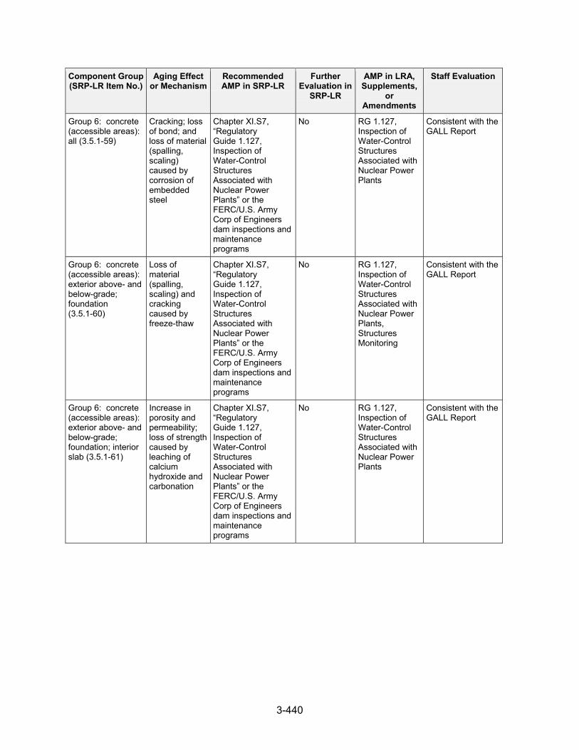
3-440
Component Group (SRP-LR Item No.)
Aging Effect or Mechanism
Recommended AMP in SRP-LR
Further Evaluation in
SRP-LR
AMP in LRA, Supplements,
or Amendments
Staff Evaluation
Group 6: concrete (accessible areas): all (3.5.1-59)
Cracking; loss of bond; and loss of material (spalling, scaling) caused by corrosion of embedded steel
Chapter XI.S7, “Regulatory Guide 1.127, Inspection of Water-Control Structures Associated with Nuclear Power Plants” or the FERC/U.S. Army Corp of Engineers dam inspections and maintenance programs
No RG 1.127, Inspection of Water-Control Structures Associated with Nuclear Power Plants
Consistent with the GALL Report
Group 6: concrete (accessible areas): exterior above- and below-grade; foundation (3.5.1-60)
Loss of material (spalling, scaling) and cracking caused by freeze-thaw
Chapter XI.S7, “Regulatory Guide 1.127, Inspection of Water-Control Structures Associated with Nuclear Power Plants” or the FERC/U.S. Army Corp of Engineers dam inspections and maintenance programs
No RG 1.127, Inspection of Water-Control Structures Associated with Nuclear Power Plants, Structures Monitoring
Consistent with the GALL Report
Group 6: concrete (accessible areas): exterior above- and below-grade; foundation; interior slab (3.5.1-61)
Increase in porosity and permeability; loss of strength caused by leaching of calcium hydroxide and carbonation
Chapter XI.S7, “Regulatory Guide 1.127, Inspection of Water-Control Structures Associated with Nuclear Power Plants” or the FERC/U.S. Army Corp of Engineers dam inspections and maintenance programs
No RG 1.127, Inspection of Water-Control Structures Associated with Nuclear Power Plants
Consistent with the GALL Report

3-441
Component Group (SRP-LR Item No.)
Aging Effect or Mechanism
Recommended AMP in SRP-LR
Further Evaluation in
SRP-LR
AMP in LRA, Supplements,
or Amendments
Staff Evaluation
Group 6: wooden piles; sheeting (3.5.1-62)
Loss of material; change in material properties caused by weathering, chemical degradation, and insect infestation repeated wetting and drying, fungal decay
Chapter XI.S7, “Regulatory Guide 1.127, Inspection of Water-Control Structures Associated with Nuclear Power Plants” or the FERC/U.S. Army Corp of Engineers dam inspections and maintenance programs
No Not applicable Not applicable to SQN (see SER Section 3.5.2.1.1)
Groups 1-3, 5, 7-9: concrete (accessible areas): exterior above- and below-grade; foundation (3.5.1-63)
Increase in porosity and permeability; loss of strength caused by leaching of calcium hydroxide and carbonation
Chapter XI.S6, “Structures Monitoring”
No Structures Monitoring
Consistent with the GALL Report
Groups 1-3, 5, 7-9: concrete (accessible areas): exterior above- and below-grade; foundation (3.5.1-64)
Loss of material (spalling, scaling) and cracking caused by freeze-thaw
Chapter XI.S6, “Structures Monitoring”
No Structures Monitoring
Consistent with the GALL Report
Groups 1-3, 5, 7-9: concrete (inaccessible areas): below-grade exterior; foundation, Groups 1-3, 5, 7-9: concrete (accessible areas): below-grade exterior; foundation, Groups 6: concrete (inaccessible areas): all (3.5.1-65)
Cracking; loss of bond; and loss of material (spalling, scaling) caused by corrosion of embedded steel
Chapter XI.S6, “Structures Monitoring”
No Structures Monitoring
Consistent with the GALL Report

3-442
Component Group (SRP-LR Item No.)
Aging Effect or Mechanism
Recommended AMP in SRP-LR
Further Evaluation in
SRP-LR
AMP in LRA, Supplements,
or Amendments
Staff Evaluation
Groups 1-5, 7, 9: concrete (accessible areas): interior and above-grade exterior (3.5.1-66)
Cracking; loss of bond; and loss of material (spalling, scaling) caused by corrosion of embedded steel
Chapter XI.S6, “Structures Monitoring”
No Structures Monitoring
Consistent with the GALL Report
Groups 1-5, 7, 9: concrete: interior; above-grade exterior, groups 1-3, 5, 7-9: concrete (inaccessible areas): below-grade exterior; foundation, group 6: concrete (inaccessible areas): all (3.5.1-67)
Increase in porosity and permeability; cracking; loss of material (spalling, scaling) caused by aggressive chemical attack
Chapter XI.S6, “Structures Monitoring”
No Structures Monitoring
Consistent with the GALL Report
High-strength structural bolting (3.5.1-68)
Cracking caused by stress corrosion cracking
Chapter XI.S3, “ASME Section XI, Subsection IWF”
No Inservice Inspection – IWF
Not applicable to SQN (see SER Section 3.5.2.1.1)
High-strength structural bolting (3.5.1-69)
Cracking caused by stress corrosion cracking
Chapter XI.S6, “Structures Monitoring” Note: ASTM A325, F1852, and ASTM A490 bolts used in civil structures have not shown to be prone to SCC. SCC potential need not be evaluated for these bolts.
No Structures Monitoring
Not applicable to SQN (see SER Section 3.5.2.1.1)
Masonry walls: all (3.5.1-70)
Cracking caused by restraint shrinkage, creep, and aggressive environment
Chapter XI.S5, “Masonry Walls”
No Masonry Wall Consistent with the GALL Report
Masonry walls: all (3.5.1-71)
Loss of material (spalling, scaling) and cracking caused by freeze-thaw
Chapter XI.S5, “Masonry Walls”
No Masonry Wall Consistent with the GALL Report

3-443
Component Group (SRP-LR Item No.)
Aging Effect or Mechanism
Recommended AMP in SRP-LR
Further Evaluation in
SRP-LR
AMP in LRA, Supplements,
or Amendments
Staff Evaluation
Seals; gasket; moisture barriers (caulking, flashing, and other sealants) (3.5.1-72)
Loss of sealing caused by deterioration of seals, gaskets, and moisture barriers (caulking, flashing, and other sealants)
Chapter XI.S6, “Structures Monitoring”
No Structures Monitoring
Consistent with the GALL Report
Service Level I coatings (3.5.1-73)
Loss of coating integrity caused by blistering, cracking, flaking, peeling, physical damage
Chapter XI.S8, “Protective Coating Monitoring and Maintenance”
No Protective Coating Monitoring and Maintenance
Consistent with the GALL Report
Sliding support bearings; sliding support surfaces (3.5.1-74)
Loss of mechanical function caused by corrosion, distortion, dirt, debris, overload, wear
Chapter XI.S6, “Structures Monitoring”
No Not applicable Not applicable to SQN (see SER Section 3.5.2.1.1)
Sliding surfaces (3.5.1-75)
Loss of mechanical function caused by corrosion, distortion, dirt, debris, overload, wear
Chapter XI.S3, “ASME Section XI, Subsection IWF”
No Not applicable Not applicable to SQN (see SER Section 3.5.2.1.1)
Sliding surfaces: radial beam seats in BWR drywell (3.5.1-76)
Loss of mechanical function caused by corrosion, distortion, dirt, overload, wear
Chapter XI.S6, “Structures Monitoring”
No Not applicable Not applicable to PWRs (see SER Section 3.5.2.1.1)
Steel components: all structural steel (3.5.1-77)
Loss of material caused by corrosion
Chapter XI.S6, “Structures Monitoring” If protective coatings are relied upon to manage the effects of aging, the structures monitoring program is to include provisions to address protective coating monitoring and maintenance.
No Structures Monitoring
Consistent with the GALL Report

3-444
Component Group (SRP-LR Item No.)
Aging Effect or Mechanism
Recommended AMP in SRP-LR
Further Evaluation in
SRP-LR
AMP in LRA, Supplements,
or Amendments
Staff Evaluation
Steel components: fuel pool liner (3.5.1-78)
Cracking caused by stress corrosion cracking; Loss of material caused by pitting and crevice corrosion
Chapter XI.M2, “Water Chemistry,” and Monitoring of the spent fuel pool water level in accordance with technical specifications and leakage from the leak chase channels.
No, unless leakages have been detected through the SFP liner that cannot be accounted for from the leak chase channels
Water Chemistry Control – Primary and Secondary
Consistent with the GALL Report (see SER Section 3.5.2.1.2)
Steel components: piles (3.5.1-79)
Loss of material caused by corrosion
Chapter XI.S6, “Structures Monitoring”
No Structures Monitoring
Consistent with the GALL Report
Structural bolting (3.5.1-80)
Loss of material caused by general, pitting and crevice corrosion
Chapter XI.S6, “Structures Monitoring”
No Structures Monitoring
Consistent with the GALL Report
Structural bolting (3.5.1-81)
Loss of material caused by general, pitting, and crevice corrosion
Chapter XI.S3, “ASME Section XI, Subsection IWF”
No Inservice Inspection – IWF
Consistent with the GALL Report
Structural bolting (3.5.1-82)
Loss of material caused by general, pitting, and crevice corrosion
Chapter XI.S6, “Structures Monitoring”
No Structures Monitoring
Consistent with the GALL Report
Structural bolting (3.5.1-83)
Loss of material caused by general, pitting, and crevice corrosion
Chapter XI.S7, “Regulatory Guide 1.127, Inspection of Water-Control Structures Associated with Nuclear Power Plants” or the FERC/U.S. Army Corp of Engineers dam inspections and maintenance programs
No RG 1.127, Inspection of Water-Control Structures Associated with Nuclear Power Plants
Consistent with the GALL Report
Structural bolting (3.5.1-84)
Loss of material caused by pitting and crevice corrosion
Chapter XI.M2, “Water Chemistry,” and Chapter XI.S3, “ASME Section XI, Subsection IWF”
No Not applicable Not applicable to SQN (see SER Section 3.5.2.1.1)

3-445
Component Group (SRP-LR Item No.)
Aging Effect or Mechanism
Recommended AMP in SRP-LR
Further Evaluation in
SRP-LR
AMP in LRA, Supplements,
or Amendments
Staff Evaluation
Structural bolting (3.5.1-85)
Loss of material caused by pitting and crevice corrosion
Chapter XI.M2, “Water Chemistry,” for BWR water, and Chapter XI.S3, “ASME Section XI, Subsection IWF”
No Not applicable Not applicable to SQN (see SER Section 3.5.2.1.1)
Structural bolting (3.5.1-86)
Loss of material caused by pitting and crevice corrosion
Chapter XI.S3, “ASME Section XI, Subsection IWF”
No Inservice Inspection – IWF
Consistent with the GALL Report
Structural bolting (3.5.1-87)
Loss of preload caused by self-loosening
Chapter XI.S3, “ASME Section XI, Subsection IWF”
No Inservice Inspection IWF Program
Consistent with the GALL Report (see SER Section 3.5.2.1.1)
Structural bolting (3.5.1-88)
Loss of preload caused by self-loosening
Chapter XI.S6, “Structures Monitoring”
No Structures Monitoring Program
Consistent with the GALL Report (see SER Section 3.5.2.1.1)
Support members; welds; bolted connections; support anchorage to building structure (3.5.1-89)
Loss of material caused by boric acid corrosion
Chapter XI.M10, “Boric Acid Corrosion”
No Boric Acid Corrosion Program
Consistent with the GALL Report
Support members; welds; bolted connections; support anchorage to building structure (3.5.1-90)
Loss of material caused by general (steel only), pitting, and crevice corrosion
Chapter XI.M2, “Water Chemistry,” for BWR water, and Chapter XI.S3, “ASME Section XI, Subsection IWF”
No Not applicable Not applicable to SQN (see SER Section 3.5.2.1.1)
Support members; welds; bolted connections; support anchorage to building structure (3.5.1-91)
Loss of material caused by general and pitting corrosion
Chapter XI.S3, “ASME Section XI, Subsection IWF”
No Inservice Inspection – IWF
Consistent with the GALL Report
Support members; welds; bolted connections; support anchorage to building structure (3.5.1-92)
Loss of material caused by general and pitting corrosion
Chapter XI.S6, “Structures Monitoring”
No Structures Monitoring
Consistent with the GALL Report (see SER Section 3.5.2.1.3)
Support members; welds; bolted connections; support anchorage to building structure (3.5.1-93)
Loss of material caused by pitting and crevice corrosion
Chapter XI.S6, “Structures Monitoring”
No Structures Monitoring
Consistent with GALL Report

3-446
Component Group (SRP-LR Item No.)
Aging Effect or Mechanism
Recommended AMP in SRP-LR
Further Evaluation in
SRP-LR
AMP in LRA, Supplements,
or Amendments
Staff Evaluation
Vibration isolation elements (3.5.1-94)
Reduction or loss of isolation function caused by radiation hardening, temperature, humidity, sustained vibratory loading
Chapter XI.S3, “ASME Section XI, Subsection IWF”
No Structures Monitoring Program, Inservice Inspection – IWF
Consistent with GALL Report (see SER Section 3.5.2.1.4)
Aluminum, galvanized steel and stainless steel support members; welds; bolted connections; support anchorage to building structure exposed to air – indoor, uncontrolled (3.5.1-95)
None None NA - No AEM or AMP
None Consistent with GALL Report (see SER Section 3.5.2.1.7)
3.5.2.1 AMR Results Consistent With the GALL Report LRA Section 3.5.2.1 identifies the materials, environments, AERM, and the following programs that manage aging effects for the containments, structures, and structural components and their commodity groups: • 10 CFR Part 50, Appendix J • ASME Section XI, Subsection IWE • ASME Section XI, Subsection IWF • ASME Section XI, Subsection IWL • Boric Acid Corrosion • Fire Protection • Masonry Walls • RG 1.127, Inspection of Water-Control Structures Associated with Nuclear Power Plants • Protective Coating Monitoring and Maintenance • Structures Monitoring • Water Chemistry
Although not identified directly in LRA Section 3.5.2.1, LRA Table 3.5-1 identifies the TLAA Program under the discussion column that manages aging effects for the structures and structural components and their commodity groups for specified conditions. LRA Tables 3.5.2-1 through 3.5.2-4 summarize AMRs for the “containments,” “structures,” and “component supports” component groups and indicate AMRs claimed to be consistent with the GALL Report.

3-447
For component groups evaluated in the GALL Report for which the applicant claimed consistency with the GALL Report and for which it does not recommend further evaluation, the staff’s audit and review determined whether the plant-specific components of these GALL Report component groups were bounded by the GALL Report evaluation. The applicant noted for each AMR item how the information in the tables aligns with the information in the GALL Report. The staff audited those AMRs with notes A through E, indicating how the AMR is consistent with the GALL Report. Note A indicates that the AMR item is consistent with the GALL Report for component, material, environment, and aging effect. In addition, the AMP is consistent with the GALL Report AMP. The staff reviewed these items to confirm consistency with the GALL Report and validity of the AMR for the site-specific conditions. Note B indicates that the AMR item is consistent with the GALL Report for component, material, environment, and aging effect. In addition, the AMP takes some exceptions to the GALL Report AMP. The staff reviewed these items to confirm consistency with the GALL Report and confirmed that the identified exceptions to the GALL Report AMPs have been reviewed and accepted. The staff also determined whether the applicant’s AMP was consistent with the GALL Report AMP and whether the AMR was valid for the site-specific conditions. Note C indicates that the component for the AMR item, although different from, is consistent with the GALL Report for material, environment, and aging effect. In addition, the AMP is consistent with the GALL Report AMP. This note indicates that the applicant was unable to find a listing of some system components in the GALL Report; however, the applicant identified in the GALL Report a different component with the same material, environment, aging effect, and AMP as the component under review. The staff reviewed these items to confirm consistency with the GALL Report. The staff also determined whether the AMR item of the different component was applicable to the component under review and whether the AMR was valid for the site-specific conditions. Note D indicates that the component for the AMR item, although different from, is consistent with the GALL Report for material, environment, and aging effect. In addition, the AMP takes some exceptions to the GALL Report AMP. The staff reviewed these items to confirm consistency with the GALL Report. The staff confirmed whether the AMR item of the different component was applicable to the component under review and whether the identified exceptions to the GALL Report AMPs have been reviewed and accepted. The staff also determined whether the applicant’s AMP was consistent with the GALL Report AMP and whether the AMR was valid for the site-specific conditions. Note E indicates that the AMR item is consistent with the GALL Report for material, environment, and aging effect but credits a different AMP. The staff reviewed these items to confirm consistency with the GALL Report. The staff also determined whether the credited AMP would manage the aging effect consistently with the GALL Report AMP and whether the AMR was valid for the site-specific conditions. The staff reviewed the information in the LRA. The staff did not repeat its review of the matters described in the GALL Report; however, the staff did confirm that the material presented in the LRA was applicable and that the applicant identified the appropriate GALL Report AMRs. The staff’s evaluation follows.

3-448
3.5.2.1.1 AMR Results Identified as Not Applicable For LRA Table 3.5-1, items 3.5.1-4, 3.5.1-6, 3.5.1-7, 3.5.1-13, 3.5.1-14, 3.5.1-17, 3.5.1-22, 3.5.1-36 through 3.5.1-41, 3.5.1-45, and 3.5.1-76, the applicant claimed that the corresponding AMR items in the GALL Report are not applicable because the associated items are only applicable to BWRs. The staff reviewed the SRP-LR, confirmed these items only apply to BWRs, and finds that these items are not applicable to SQN, which is a PWR. For LRA Table 3.5-1, items 3.5.1-1 through 3.5.1-3, 3.5.1-8, 3.5.1-1 through 3.5.1-15, 3.5.1-16, 3.5.1-18 through 3.5.1-20, 3.5.1-23 through 3.5.1-25, 3.5.1-32, 3.5.1-42, 3.5.1-48 through 3.5.1-50, 3.5.1-53, 3.5.1-62, 3.5.1-68, 3.5.1-69, 3.5.1-74, 3.5.1-75, 3.5.1-84, 3.5.1-85, 3.5.1-88, and 3.5.1-90, the applicant claimed that the corresponding items in the GALL Report are not applicable because the component, material, and environment combination described in the SRP-LR does not exist for within-scope SCs at SQN. The staff reviewed the LRA and UFSAR and confirmed that the applicant’s LRA does not have any AMR results applicable for these items. For LRA Table 3.5-1 items discussed below, the applicant claimed that the corresponding AMR items in the GALL Report are not applicable; however, the staff nonapplicability verification of these items required the review of sources beyond the LRA and UFSAR, or the issuance of RAIs. LRA Table 3.5.1, items 3.5.1-15 and -20 address accessible areas of concrete basemat exposed to water – flowing. The GALL Report recommends GALL Report AMP XI.S2, ASME Section XI, Subsection IWL to manage increase in porosity and permeability, loss of strength due to leaching of calcium hydroxide and carbonation for this component group. In LRA Table 3.5.1, the applicant stated that these items are not applicable because these aging effects do not require management at SQN. The applicant stated that the concrete at Sequoyah is designed and constructed such that this aging effect cannot occur. The staff did not agree with the applicant’s statement that the listed aging effects do not require management, and addressed the issue as part of generic concrete RAI 3.5.1-2, dated August 30, 2013. In the same RAI, the applicant was requested to provide a technical justification for why it does not need to manage “increase in porosity and permeability and loss of strength due to leaching of calcium hydroxide and carbonation” for accessible areas of the containment basemat. In its response dated September 30, 2013, the applicant addressed item 3.5.1-20 by stating that since item 3.5.1-20 applies to concrete containments, and SQN uses an SCV, item 3.5.1-20 was not referenced for SQN. The applicant revised LRA Table 3.5.1, item 3.5.1-20 to state, “NUREG-1801 items referencing this item are associated with concrete containments and SQN containment is a steel containment structure.” The staff finds this acceptable because SRP-LR Table 3.5-1, item 20 cites GALL Report items that apply to concrete containments, which are not used at SQN. The staff’s concern described in RAI 3.5.1-2, related to LRA Table 3.5.1, item 3.5.1-20, is resolved. For item 3.5.1-15, which cites this aging effect for the concrete basemat for steel containment structures, the applicant’s response to RAI 3.5.1-2 states that the SQN containment concrete basemat is integral with the shield building concrete base foundation or basemat. The applicant stated that the SCV concrete basemat is below the base liner plate of the SCV and, therefore, is not accessible. The applicant revised LRA Table 3.5.1, item 3.5.1-15, accordingly. The staff

3-449
evaluated the applicant’s claim and finds it acceptable because the line item applies to accessible areas of concrete basemat, and the SQN containment basemat is not accessible. The staff’s concern described in RAI 3.5.1-2, related to LRA Table 3.5.1, item 3.5.1-15, is resolved. LRA Table 3.5.1, item 3.5.1-16 addresses concrete (accessible areas): basemat exposed to groundwater/soil, air indoor – uncontrolled or air – outdoor. The GALL Report recommends GALL Report AMP XI.S2, “ASME Section XI, Subsection IWL,” or XI.S6, “Structures Monitoring” to manage increase in porosity and permeability, cracking, loss of material (spalling, scaling) due to aggressive chemical attack for this component group. The applicant stated that this item is not applicable because SQN concrete is designed and constructed in accordance with ACI 318 with air-entrainment. The applicant also stated that concrete SCs are constructed of a dense, well-cured concrete with an amount of cement suitable for strength development and achievement of a water-to-cement ratio that is characteristic of concrete having low permeability. The applicant stated that this prevents the effect of this aging from occurring and therefore this aging effect does not require management. The staff evaluated the applicant’s claim and does not agree that the design and construction of the concrete necessarily precludes this aging effect from occurring. The Discussion column for Table 3.5-1, item 16 states that the concrete basemat is included in the Structures Monitoring Program to confirm the absence of this aging effect; however, the associated line items do not appear in any of the LRA Table 2s for consistency with the GALL Report. By letter dated August 30, 2013, the staff issued RAI 3.5.1-2 requesting that the applicant provide a technical justification for why increase in porosity and permeability, cracking, loss of material (spalling, scaling) due to aggressive chemical attack does not require management in accessible areas or identify a program to manage this aging effect. The staff also requested that, if a program is identified to manage this aging effect, the applicant update the LRA accordingly (including Table 2 AMR line items) to reflect that accessible areas of the concrete basemat would be managed for this aging effect. In its response, dated September 30, 2013, the applicant stated that the SQN containment concrete is the circular concrete base foundation or basemat of the SCV which is integral with the shield building concrete base foundation or basemat. The SCV concrete basemat is below the base liner plate of the SCV and, therefore, is not accessible. The applicant revised LRA Table 3.5.1, item 3.5.1-16, accordingly. The staff evaluated the applicant’s claim and finds it acceptable because the line item applies to accessible areas of concrete basemat, and the SQN containment basemat is not accessible. The staff’s concern described in RAI 3.5.1-2, related to LRA Table 3.5.1, item 3.5.1-16, is resolved. LRA Table 3.5.1, item 3.5.1-18 addresses concrete (accessible areas): dome, wall, basemat, ring girders, buttresses; concrete (accessible areas) basemat exposed to air-outdoor or ground water/soil. The GALL Report recommends GALL Report AMP XI.S2, “ASME Section XI, Subsection IWL” to manage loss of material (spalling, scaling) and cracking due to freeze-thaw for this component group. The applicant stated that this item is not applicable because the containment is a freestanding steel vessel that is supported on a concrete foundation that is protected from the outer environment by the shield building’s base foundation; therefore it is not subjected to temperature variations that could cause freeze-thaw action. The staff evaluated the applicant’s claim and finds it acceptable because the containment structure is a free standing steel vessel supported on a concrete foundation that does not experience freeze-thaw action.

3-450
LRA Table 3.5.1, item 3.5.1-19 addresses accessible areas of the concrete basemat exposed to any environment. The GALL Report recommends GALL Report AMP XI.S2, “ASME Section XI, Subsection IWL” to manage cracking due to expansion from reaction with aggregates for this component group. The applicant stated that this item is not applicable because the SQN concrete was designed and constructed in accordance with the ACI Code, and that aggregates used conform to ASTM requirements and did not come from a region known to yield aggregates suspected of or known to cause aggregate reactions. The applicant also stated that water/cement ratios were within the limits provided in ACI 318. The staff notes that there is recent industry OE that has indicated that the ASTM tests used to detect aggregate reactivity may not have been effective in detecting slow-reacting aggregates. Therefore, passing the original ASTM tests for aggregate reactivity may not preclude the possibility of alkali-aggregate reaction. In its review of components associated with item 3.5.1-12, the staff does not agree that the aging effect does not require management for the justification provided in LRA Table 3.5.1. Regardless of the design and construction of the concrete, the staff determined that cracking due to expansion from reaction with aggregates for accessible and inaccessible concrete should be managed through the period of extended operation. By letter dated June 24, 2013, the staff issued RAI 3.5.1-1 related to this aging effect; however, the staff subsequently noticed that items 3.5.1-12 and 3.5.1-19 were not included in the applicant’s July 25, 2013, response. Therefore, by letter dated August 30, 2013, the staff issued followup RAI 3.5.1-1a requesting that the applicant consider revising the LRA to address this aging effect for management of the containment concrete basemat. The applicant responded by letter dated September 30, 2013, and stated that the containment concrete associated with item 3.5.1-19 is the circular concrete base foundation or basemat of the SQN SCV. The concrete basemat is below the base liner plate of the SCV and, therefore, is not accessible. The staff evaluated the applicant’s claim and finds it acceptable because the line item applies to accessible areas of concrete basemat, and the SQN containment basemat is not accessible. The staff’s concerns described in RAIs 3.5.1-1 and 3.5.1-1a are resolved. LRA Table 3.5.1, item 3.5.1-21 addresses concrete (accessible areas): basemat exposed to air indoor – uncontrolled or air – outdoor. The GALL Report recommends GALL Report AMP XI.S2, “ASME Section XI, Subsection IWL,” or XI.S6, “Structures Monitoring” to manage cracking, loss of bond, and loss of material (spalling, scaling) due to corrosion of embedded steel for this component group. The applicant stated that this item is not applicable because SQN concrete is designed and constructed in accordance with ACI 318 with air-entrainment. The applicant also stated that concrete SCs are constructed of a dense, well-cured concrete with an amount of cement suitable for strength development and achievement of a water-to-cement ratio that is characteristic of concrete having low permeability. The applicant stated that this prevents the effect of this aging from occurring and therefore this aging effect does not require management. The staff evaluated the applicant’s claim and does not agree that the design and construction of the concrete necessarily precludes this aging effect from occurring. The Discussion column for Table 3.5-1, item 21 states that the concrete basemat is included in the Structures Monitoring Program to confirm the absence of this aging effect; however, the associated line items do not appear in any of the LRA Table 2s for consistency with the GALL Report. By letter dated August 30, 2013, the staff issued RAI 3.5.1-2 requesting that the applicant provide a technical justification for why the aging effect “cracking, loss of bond, and loss of material (spalling, scaling) due to corrosion of embedded steel” does not require

3-451
management in accessible areas or identify a program to manage this aging effect. The staff also requested that, if a program is identified to manage this aging effect, the applicant update the LRA accordingly (including Table 2 AMR line items) to reflect that accessible areas of the concrete basemat would be managed for this aging effect. In its response, dated September 30, 2013, the applicant stated that the SQN containment concrete is the circular concrete base foundation or basemat of the SCV which is integral with the shield building concrete base foundation or basemat. The SCV concrete basemat is below the base liner plate of the SCV and, therefore, is not accessible. The applicant revised LRA Table 3.5.1, item 3.5.1-21, accordingly. The staff evaluated the applicant’s claim and finds it acceptable because the line item applies to accessible areas of concrete basemat, and the SQN containment basemat is not accessible. The staff’s concern described in RAI 3.5.1-2, related to LRA Table 3.5.1, item 3.5.1-21, is resolved. LRA Table 3.5.1, items 3.5.1-23 and 25 address concrete (inaccessible areas): basemat; reinforcing steel, exposed to air – indoor, uncontrolled or air – outdoor. The GALL Report recommends GALL Report AMP XI.S6, “Structures Monitoring” to manage cracking, loss of bond, and loss of material (spalling, scaling) due to corrosion of embedded steel for this component group. The applicant stated that this item is not applicable because SQN concrete is designed and constructed in accordance with ACI 318 with air-entrainment. The applicant also stated that concrete SCs are constructed of a dense, well-cured concrete with an amount of cement suitable for strength development and achievement of a water-to-cement ratio that is characteristic of concrete having low permeability. The applicant stated that this prevents the effect of this aging from occurring and therefore this aging effect does not require management. The staff evaluated the applicant’s claim and does not agree that the design and construction of the concrete necessarily precludes this aging effect from occurring. The staff notes that the applicant’s response to RAI 3.5.1-1 (see below) stated that SQN is enhancing the Structures Monitoring Program (SMP) to require inspections of inaccessible areas in environments where observed conditions in accessible areas exposed to the same environment indicate that significant degradation is occurring. LRA Table 3.5.1, item 3.5.1-24 addresses concrete (inaccessible areas) basemat exposed to air – indoor, uncontrolled or air – outdoor or groundwater/soil. The GALL Report recommends GALL Report AMP XI.S6, “Structures Monitoring Program” to manage increase in porosity and permeability, cracking, and loss of material (spalling, scaling) due to aggressive chemical attack for this component group. The applicant stated that this item is not applicable because SQN concrete is designed and constructed in accordance with ACI 318 with air-entrainment. The applicant also stated that concrete SCs are constructed of a dense, well-cured concrete with an amount of cement suitable for strength development and achievement of a water-to-cement ratio that is characteristic of concrete having low permeability. The applicant stated that this prevents the effect of this aging from occurring and therefore this aging effect does not require management. The staff evaluated the applicant’s claim and does not agree that the design and construction of the concrete necessarily precludes this aging effect from occurring. The Discussion column for Table 3.5-1, item 24 states that the concrete basemat is included in the Structures Monitoring Program to confirm the absence of this aging effect; however, the associated line items do not appear in any of the LRA Table 2s for consistency with the GALL Report. By letter dated August 30, 2013, the staff issued RAI 3.5.1-2 requesting that the applicant provide a technical justification for why increase in porosity and permeability, cracking, and loss of material (spalling, scaling) due to aggressive chemical attack does not require management in accessible areas or identify a program to manage this aging effect. The staff

3-452
also requested that, if a program is identified to manage this aging effect, the applicant update the LRA accordingly (including Table 2 AMR line items) to reflect that accessible areas of the concrete basemat would be managed for this aging effect. In its response, dated September 30, 2013, the applicant stated that the SQN containment concrete is the circular concrete base foundation or basemat of the SCV which is integral with the shield building concrete base foundation or basemat. The applicant stated that because the base foundation concrete is integral with the base foundation concrete of the shield building, the aging effect of the SCV base foundation concrete is managed along with the shield building base foundation concrete. The applicant further stated that, as such, the applicable component in LRA Table 3.5.2-1 is “Concrete (inaccessible areas): Shield building; below grade exterior; foundation,” which references LRA Table 3.5.1, item 3.5.1-67. The staff notes that LRA Table 3.5.1, item 67, applies to the aging effect of “increase in porosity and permeability; cracking; loss of material (spalling, scaling) due to aggressive chemical attack” for Groups 1-3, 5, 7-9 concrete (inaccessible areas): below-grade exterior; foundation and is managed by the SMP, which is the AMP recommended by the GALL Report. The staff evaluated the applicant’s claim and finds it acceptable because the containment concrete basemat is integral with the shield building foundation, and the shield building foundation concrete is managed by the Structures Monitoring Program, which is recommended by the GALL Report. The staff’s concern described in RAI 3.5.1-2, associated with LRA Table 3.5.1, item 3.5.1-24, is resolved. LRA Table 3.5.1, item 3.5.1-30 addresses pressure-retaining bolting of any material exposed to any environment. The GALL Report recommends GALL Report AMPs XI.S1, ASME Section XI, Subsection IWE and XI.S4, 10 CFR Part 50, Appendix J to manage loss of preload due to self-loosening for this component group. The applicant stated that this item, “SQN containment pressure-retaining bolting,” is associated with the securing of the equipment hatch and mounting hardware for the personnel airlocks. These bolts are included as part of the component “Personnel airlock, equipment hatch, CRD hatch: locks, hinges, and closure mechanisms” and addressed by LRA Table 3.5.1, item 3.5.1-29. The applicant also stated that “loss of preload due to self-loosening” would result in loss of leak tightness of the PB; therefore managing “loss of leak tightness” provides reasonable assurance that the intended function of the containment PB is maintained and “loss of preload due to self-loosening” is managed in accordance with LRA Table 3.5.1, item 3.5.1-29. The staff evaluated the applicant’s claim and finds it acceptable because the applicant proposes to use the CII-IWE and Containment Leak Rate Programs, which are consistent with the recommended programs for item 3.5.1-30. LRA Table 3.5.1, item 3.5.1-31 addresses pressure-retaining bolting of SQN containment to secure the equipment hatch and mounting hardware for the personnel airlocks. The SRP-LR and GALL Report recommend GALL Report AMP XI.S1, ASME Section XI, Subsection IWE to manage loss of material due to general, pitting, and crevice corrosion for this component group. The applicant stated that these bolts are included as part of the components “Personnel airlock, equipment hatch, CRD hatch” and “Personnel airlock, equipment hatch, CRD hatch: locks, hinges, and closure mechanisms” and are addressed by Table 3.5.1 item 3.5.1-28 and item 3.5.1-29. The applicant also stated that the aging effects “loss of material due to general, pitting and crevice corrosion” and “loss of leak tightness” will be managed by a combination of Table 3.5.1 items 3.5.1-28 and 3.5.1-29 for the equipment hatch and personnel airlocks and their mounting hardware, which includes the pressure-retaining bolting of the PB. The applicant further stated that SQN is a PWR and there are no containment downcomer pipes in need of aging management.

3-453
The staff reviewed the LRA Table 3.5.1 and noted the SQN items 3.5.1-28 and 3.5.1-29, credited for item 3.5.1-31, are consistent with the SRP-LR Table 3.5-1, items 28 and 29, and corresponding GALL Report items which recommend for aging effects, loss of material due to general, pitting, and crevice corrosion and loss of leak tightness due to mechanical wear of locks, hinges and closure mechanisms, GALL Report AMPs XI.S1 “ASME Section XI, Subsection IWE,” and XI.S4, “10 CFR Part 50, Appendix J.” The staff evaluated the applicant’s claim and finds it acceptable because the applicant proposes to use the CII-IWE, which is consistent with the recommended program for item 3.5.1-31. The staff also evaluated the applicant’s additional proposal to use its Containment Leak Rate Program to manage aging effects due to loss of preload and associated loss of leaktightness of the equipment hatch and mounting hardware for the personnel airlocks and finds acceptable because the added program will provide a reasonable assurance the containment PB intended function will be maintained during the period of extended operation. Finally, the staff concurs with the applicant that since plant is a PWR, there are no containment downcomer pipes in need of aging management. LRA Table 3.5.1, item 3.5.1-54 addresses all groups except 6: concrete (accessible areas) exposed to any environment. The GALL Report recommends GALL Report AMP XI.S6, “Structures Monitoring” to manage cracking due to expansion from reaction with aggregates for this component group. The applicant stated that this item is not applicable because SQN concrete is designed and constructed in accordance with ACI 318 with air-entrainment, and that concrete aggregates conform to the requirements of ASTM C33. The applicant also stated that the aggregate used in the concrete did not come from a region known to yield aggregates suspected of or known to cause aggregate reactions. The applicant further stated that the design and construction of these groups of structures prevents the effect of this aging from occurring; therefore, this aging effect does not require management. The staff evaluated the applicant’s claim and determined that an adequate plant-specific technical basis to support the applicant’s claim has not been provided. Therefore, by letter dated June 24, 2013, the staff issued RAI 3.5.1-1 requesting that the applicant provide technical justification for why cracking due to expansion from reaction with aggregates does not require management in accessible areas, or identify a program to manage this aging effect. In its response dated July 25, 2013, the applicant revised the LRA to indicate that cracking due to expansion from reaction with aggregates will be managed by the Structures Monitoring Program. The staff reviewed the applicant’s response and finds it acceptable because the applicant has revised the LRA to indicate that the Structures Monitoring Program will be used to manage cracking due to expansion from reaction with aggregates in all accessible concrete areas except group 6, which is consistent with the recommendations in the GALL Report. The staff’s concern described in RAI 3.5.1-1, related to LRA Table 3.5.1-1, item 3.5.1-54, is resolved. LRA Table 3.5.1, item 3.5.1-57 addresses constant and variable load spring hangers; guides; stops exposed to air indoor, uncontrolled or air outdoor environments. The GALL Report recommends GALL Report AMP XI.S3, “ASME Section XI, Subsection IWF,” to manage loss of material due to corrosion, distortion, dirt, overload, and fatigue due to vibratory and cyclic thermal loads for this component group. The applicant stated that this item is not applicable because loss of mechanical function due to distortion, dirt, overload, and fatigue due to vibratory and cyclic thermal loads is not an AERM. The applicant also stated that such failures typically result from inadequate design or events rather than the effects of aging. The staff evaluated the applicant’s claim and notes that the GALL Report identifies loss of mechanical function in Class 1 piping and components (such as constant and variable load spring hangers, guides,

3-454
stops, sliding surfaces, and vibration isolators) fabricated from steel or other materials, as an aging effect that can occur through the combined influence of a number of aging mechanisms. Such aging mechanisms are not limited to loss of material due to corrosion, but also include distortion, dirt, overload, and fatigue due to vibratory and cyclic thermal loads. The staff’s position is that the potential loss of mechanical function from distortion, dirt, overload, and fatigue due to vibratory and cyclic thermal loads is an AERM. Therefore, by letter dated September 26, 2013, the staff issued RAI 3.5.1-57 requesting that the applicant provide sufficient technical basis for concluding loss of mechanical function due distortion, dirt, overload, and fatigue due to vibratory and cyclic thermal loads is not an AERM. In its response dated October 21, 2013, the applicant stated that “TVA has reassessed and concluded that loss of mechanical function due to distortion, dirt, overload, and fatigue due to vibratory and cyclic thermal loads is an AERM.” The applicant revised LRA Table 3.5.1, “Structures and Component Supports,” item 3.5.1-57 and LRA Table 3.5.2-4, “Bulk Commodities,” to indicate that this aging effect will be managed by the Inservice Inspection—IWF Program. The staff finds the applicant’s response acceptable because the applicant has revised the LRA to indicate that the Inservice Inspection—IWF Program will be used to manage loss of mechanical function due to distortion, dirt, overload, and fatigue due to vibratory and cyclic thermal loads, which is consistent with the recommendations in the GALL Report. The staff’s concern described in RAI 3.5.1-57 is resolved. LRA Table 3.5.1, item 3.5.1-69 addresses high-strength structural bolting exposed to air indoor, uncontrolled or air outdoor. The GALL Report recommends GALL Report AMP XI.S6, “Structures Monitoring” to manage cracking due to SCC for this component group. The applicant stated that this item is not applicable because SQN does not have high strength bolts that are subject to sustained high tensile stress in a corrosive environment. The staff reviewed the Sequoyah Nuclear Plant UFSAR, evaluated the applicant’s claim, and finds it acceptable because SQN does not have high strength bolts in an environment conducive to cracking due to SCC. LRA Table 3.5.1, item 3.5.1-87 addresses structural bolting exposed to any environment. The GALL Report recommends GALL Report AMP XI.S3, “ASME Section XI, Subsection IWF,” to manage loss of preload due to self-loosening for this component group. The applicant stated that this item is not applicable because “[v]ibration, flexing of the joint, cyclic shear loads, thermal cycles and other causes can cause partial self-loosening of a fastener. These causes of loosening are minor contributors in structural steel and steel component threaded connections and are eliminated by initial preload bolt torquing.” The LRA further states, “SQN uses site procedures and manufacturer recommendations to provide guidance for proper torquing of nuts and bolts used in structural applications.” The staff evaluated the applicants claim and notes that the ASME Section XI, Subsection IWF Program described in the GALL Report program element, “parameters monitored or inspected” states “[s]tructural bolts are monitored for corrosion and loss of integrity of bolted connections due to self-loosening and material conditions that can affect structural integrity.” The staff’s position is that the potential loss of preload due to self-loosening from vibration, flexing of the joint, cyclic shear loads, thermal cycles and other causes is an AERM. Therefore, by letter dated September 26, 2013, the staff issued RAI 3.5.1-87 requesting that the applicant provide sufficient technical basis for concluding loss of preload due to self-loosening is not an AERM, or identify an AMP to manage this aging effect.

3-455
In its response dated October 21, 2013, the applicant stated that “TVA has reassessed and concluded that loss of preload due to self-loosening is an AERM.” The applicant revised LRA Table 3.5.1, “Structures and Component Supports,” item 3.5.1-87 and LRA Table 3.5.2-4, “Bulk Commodities,” to indicate that this aging effect will be managed by the Inservice Inspection—IWF Program. The staff finds the applicant’s response acceptable because the applicant has revised the LRA to indicate that the Inservice Inspection—IWF Program will be used to manage loss of preload due to self-loosening of structural bolting, which is consistent with the recommendations in the GALL Report. The staff’s concern described in RAI 3.5.1-87 is resolved. LRA Table 3.5.1, item 3.5.1-88 addresses structural bolting exposed to any environment. The GALL Report recommends GALL Report AMP XI.S6, “Structures Monitoring” to manage loss of preload due to self-loosening for this component group. The applicant stated that this item is not applicable because, although vibration, flexing of the joint, cyclic shear loads, thermal cycles and other causes can cause partial self-loosening of a fastener, they are minor contributors in structural steel and steel component threaded connections and are eliminated by initial preload bolt torquing. The applicant also stated that SQN uses site procedures and manufacturer recommendations to provide guidance for proper torquing of nuts and bolts used in structural applications and that OE has not shown self-loosening of structural bolting used in SQN. The staff evaluated the applicant’s claim and determined that an adequate technical basis to support the applicant’s claim has not been provided. The staff notes that GALL Report AMP XI.S6, “Structures Monitoring,” is an acceptable program to manage the loss of preload due to self-loosening for these components. The staff also notes that GALL Report AMP XI.S6, “Structures Monitoring,” not only considers the initial preload bolt torquing in the “preventive actions” program element, but also recommends inspection of structural bolting for loose bolts, missing or loose nuts, and other conditions indicative of loss of preload in the “parameters monitored or inspected” program element. Therefore, by letter dated August 30, 2013, the staff issued RAI 3.5.1-88 requesting that the applicant provide the staff with sufficient technical basis for concluding that loss of preload due to self-loosening is not an AERM, or identify an AMP to manage this aging effect. In its response dated September 30, 2013, the applicant stated that loss of preload due to self-loosening of structural bolting will be addressed as an AERM for structural bolting. The applicant revised LRA Table 3.5.1, “Structures and Component Support,” item 3.5.1-88 and LRA Table 3.5.2-4, “Bulk Commodities,” to indicate that this aging effect will be managed by the Structures Monitoring Program. The staff reviewed the applicant’s response and finds it acceptable because the applicant has revised the LRA to indicate that the Structures Monitoring Program will be used to manage loss of preload due to self-loosening of structural bolting, which is consistent with the recommendations in the GALL Report. The staff’s concern described in RAI 3.5.1-88 is resolved. 3.5.2.1.2 Cracking Due to Stress Corrosion Cracking and Loss of Material Due to Pitting and Crevice Corrosion LRA Table 3.5.1, item 3.5.1-52 addresses groups 7 and 8 stainless steel tank liners exposed to water - standing, which will be managed for loss of material due to pitting and crevice corrosion. For the AMR items that cite generic note E, the LRA credits the Structures Monitoring Program to manage the aging effect for stainless steel containment sump liner plates, steel liner plate,

3-456
and sump screens. The GALL Report recommends a plant-specific AMP be evaluated to ensure that these aging effects are adequately managed; however, the staff notes that the applicant does not have any tanks with stainless steel liners in the structural scope of license renewal. The applicant compared the stainless steel liners of other components, such as reactor cavity and containment sump to item 3.5.1-52 and proposes to manage loss of material using the Structures Monitoring Program. The staff also notes, in LRA Section 3.5.2.2.2.4, the applicant stated the fluid temperatures to which these components are exposed are below the threshold value of 140 °F (60 °C) for SCC. The staff’s evaluation of the applicant’s Structures Monitoring Program is documented in SER Section 3.0.3.2.21. The staff notes that the Structures Monitoring Program proposes to manage the aging of steel liner plates, sump liners (steel), and sump screens through the use of visual inspections by qualified personnel at a frequency not to exceed 5 years. In its review of components associated with item 3.5.1-52 for which the applicant cited generic note E, the staff finds the applicant’s proposal to manage aging using the Structures Monitoring Program acceptable because the program has been enhanced to include visual inspections of these components, by qualified personnel, at a frequency not to exceed 5 years. LRA Table 3.5.1, item 3.5.1-78 addresses stainless steel SFP gate and liner plates, which will be managed for loss of material with the Water Chemistry Control – Primary and Secondary Program and monitoring of the SFP water level and leakage from the leak chase channels. The LRA states that cracking due to SCC is not an applicable aging effect because there are no in-scope stainless steel spent fuel components exposed to treated water greater than 60 °C (140 °F). The GALL Report recommends GALL Report AMP XI.M2, “Water Chemistry,” and monitoring of the SFP water level and leakage from the leak chase channels to ensure that loss of material and cracking are adequately managed. The staff reviewed the associated items in the LRA to confirm that the cracking aging effect is not applicable for this component, material and environmental combination. The staff finds the applicant’s claim acceptable based on its review of UFSAR Section 9.1.3.1.1 and UFSAR Table 9.1.3-1, which indicate that the 60 °C (140 °F) threshold temperature for SCC of stainless steels is exceeded only in cases where there is either a back-to-back full discharge of the two cores (143 °F) or an unplanned full core discharge following the back-to-back scenario (147 °F), assuming two trains of pool cooling. The staff notes that, given the infrequency and short time frame of these cases, the SFP water temperature is normally below 60 °C (140 °F), and SCC would not be expected to occur. The staff further noted that the applicant’s activities that are in place to manage loss of material for the subject components are also consistent with the GALL Report guidance for managing cracking. The staff’s evaluation of the applicant’s Water Chemistry Control – Primary and Secondary Program is documented in SER Section 3.0.3.1.20. Based on its review of components associated with item 3.5.1-78, for which the applicant cited generic note A, the staff finds the applicant’s proposal to manage loss of material using the Water Chemistry Control – Primary and Secondary Program and monitoring of the SFP water level and leakage from the leak chase channels acceptable because the Water Chemistry Control – Primary and Secondary Program establishes the plant water chemistry control parameters and their limits to mitigate aging and monitoring of water level and leak chase channels is capable of detecting fuel pool leaks prior to loss of intended function. The staff concludes that for LRA item 3.5.1-78, the applicant has demonstrated that the effects of aging for these components will be adequately managed so that the intended function(s) will

3-457
be maintained consistent with the CLB during the period of extended operation as required by 10 CFR 54.21(a)(3). 3.5.2.1.3 Loss of Material Due to General, Pitting and Crevice Corrosion LRA Table 3.5.1, item 3.5.1-92 addresses carbon steel and galvanized steel support members, welds, bolted connections, and support anchorage to building structures exposed to air-indoor uncontrolled or air-outdoor, which will be managed for loss of material due to general and pitting corrosion. For the AMR item that cites generic note E, the LRA credits the Fire Water System Program to manage the aging effect for carbon steel fire hose reels. The GALL Report recommends GALL Report AMP XI.S6 Structures Monitoring Program to ensure that these aging effects are adequately managed. GALL Report AMP XI.S6 recommends using periodic visual inspections by qualified personnel, at a frequency not to exceed 5 years, to monitor steel components for loss of material to manage aging. The staff’s evaluation of the applicant’s Fire Water System Program is documented in SER Section 3.0.3.2.7. In its review of components associated with item 3.5.1-92 for which the applicant cited generic note E, the staff finds that the applicant’s proposal to manage aging of carbon steel fire hose reels using the Fire Water System Program acceptable because they will be inspected annually, which is more often than the 5-year frequency recommended by the Structures Monitoring Program. The staff concludes that for LRA item 3.5.1-92, the applicant has demonstrated that the effects of aging for these components will be adequately managed so that the intended function(s) will be maintained in a way consistent with the CLB during the period of extended operation as required by 10 CFR 54.21(a)(3). 3.5.2.1.4 Reduction or Loss of Isolation Function due to Radiation Hardening, Temperature, Humidity or Sustained Vibratory Loading LRA Table 3.5.1, item 3.5.1-94 addresses nonmetallic vibration isolation elements exposed to air indoor, uncontrolled, which will be managed for reduction or loss of isolation function due to radiation hardening, temperature, humidity or sustained vibratory loading. For the AMR item that cites generic note E, the LRA credits the Structures Monitoring Program to manage the aging effect for non-ASME elastomeric vibration isolators. The GALL Report recommends GALL Report AMP XI.S3, “ASME Section XI, Subsection IWF,” to ensure that these aging effects are adequately managed. GALL Report AMP XI.S3 recommends VT-3 examination supplemented by feel or touch to manage aging. The staff notes, however, that its evaluation of these items relates to non-ASME vibration isolation elements and that as stated in LRA Table 3.5.1, item 3.5.1-94, SQN does not have ASME vibration isolation elements. The staff’s evaluation of the applicant’s Structures Monitoring Program is documented in SER Section 3.0.3.2.21. The staff notes that the Structures Monitoring Program proposes to manage the aging of non-ASME elastomeric vibration isolators through the use of periodic visual inspections by qualified personnel at a frequency not to exceed 5 years. The staff also notes that the applicant has enhanced the “parameters monitored or inspected” and “detection of aging effects,” program elements of the Structures Monitoring Program to: (1) include the inspection of elastomeric material for cracking, loss of material, loss of sealing, and change in material properties (e.g., hardening), and (2) supplement inspection by feel or touch to detect

3-458
hardening if the intended function of the elastomeric material is suspect. In its review of components associated with item 3.5.1-94 for which the applicant cited generic note E, the staff finds the applicant’s proposal to manage aging using the Structures Monitoring Program acceptable because: (1) the AMP has been enhanced to include visual inspection of elastomeric vibration isolators, supplemented by feel or touch to detect hardening if the intended function of the elastomeric material is suspect, and (2) the enhancements are consistent with the recommendations in GALL Report AMP XI.S3, “ASME Section XI, Subsection IWF.” 3.5.2.2 AMR Results Consistent With the GALL Report for Which Further Evaluation Is
Recommended In LRA Section 3.5.2.2, the applicant further evaluates aging management, as recommended by the GALL Report, for the containments, structures, and component supports components and provides information concerning how it will manage the following aging effects: (1) PWR and BWR containments:
• cracking and distortion due to increased stress levels from settlement; reduction of foundation strength and cracking due to differential settlement and erosion of porous concrete subfoundations
• reduction of strength and modulus due to elevated temperature
• loss of material due to general, pitting, and crevice corrosion
• loss of prestress due to relaxation, shrinkage, creep, and elevated temperature
• cumulative fatigue damage
• cracking due to SCC
• cracking due to cyclic loading
• loss of material (scaling, cracking, and spalling) due to freeze-thaw
• cracking due to expansion and reaction with aggregates (2) safety-related and other structures and component supports:
• aging management of inaccessible areas
• reduction of strength and modulus due to elevated temperature
• aging management of inaccessible areas for Group 6 structures
• cracking due to SCC and loss of material due to pitting and crevice corrosion
• cumulative fatigue damage due to fatigue (3) QA for aging management of nonsafety-related components For component groups evaluated in the GALL Report for which the applicant claimed consistency with the GALL Report and for which the GALL Report recommends further evaluation, the staff audited and reviewed the applicant’s evaluations to determine whether it adequately addressed the issues further evaluated. In addition, the staff reviewed the applicant’s further evaluations against the criteria contained in SRP-LR Section 3.5.2.2. The staff’s review of the applicant’s further evaluation follows.

3-459
3.5.2.2.1 PWR and BWR Containments The staff reviewed LRA Section 3.5.2.2.1 against the criteria in SRP-LR Section 3.5.2.2.1, which address several areas: 3.5.2.2.1.1 Cracking and Distortion Due to Increased Stress Levels From Settlement; Reduction of Foundation Strength, and Cracking Due to Differential Settlement and Erosion of Porous Concrete Subfoundations LRA Section 3.5.2.2.1.1, associated with LRA Table 3.5.1 items 3.5.1 1 and 2, address cracking and distortion due to increased stress levels from settlement; reduction of foundations strength, and cracking due to differential settlement and erosion of porous concrete subfoundations in concrete: foundation; subfoundation exposed to soil or water – flowing. The criteria in SRP-LR Section 3.5.2.2.1.1 states that the ASME Section XI, Subsection IWL Program should be used to manage the aging effect of cracking and distortion of concrete and steel containments due to increased stress levels from settlement. The SRP also states that the Structures Monitoring Program should be used to manage the aging effects of reduction of foundation strength and cracking, due to differential settlement and erosion of porous concrete subfoundations. The SRP further states that the GALL Report recommends further evaluation if a plant’s CLB credits a de-watering system to control settlement to verify the continued functionality of the de-watering system during the period of extended operation. The applicant stated that this item is not applicable because the SQN steel containment vessel (SCV) base foundation (basemat) is integral with the base foundation of the shield building and is founded on bedrock that was over excavated a minimum depth of two feet below the required base elevation of the foundation. The excavated area was then covered either by grout or a fill pour of concrete. The applicant stated that this fill pour acted as a grout cap, protecting the bedrock from any tendency to erode. The applicant also stated that it does not rely on a de-watering system for control of settlement and does not use a porous concrete subfoundation. The staff evaluated the applicant’s claim and finds it acceptable because (1) the Sequoyah containment foundation slab rests on competent bedrock, (2) the primary containment base foundation slabs are not constructed of porous concrete below grade, and (3) further evaluation of a de-watering system is not necessary because the applicant’s CLB does not include a de-watering system to control settlement. 3.5.2.2.1.2 Reduction of Strength and Modulus Due to Elevated Temperature LRA Section 3.5.2.2.1.2, associated with LRA Table 3.5.1 item 3.5.1-3, addresses reduction of strength and modulus of elasticity due to high temperatures in concrete exposed to air - indoor, uncontrolled or air - outdoor. The criteria in SRP-LR Section 3.5.2.2.1.2 states that further evaluation is recommended if any portion of the containment concrete exceeds specified temperature limits of 66 °C (150 °F) general area and 93 °C (200 °F) local area. The applicant stated that this item is not applicable because the containment is a free standing steel vessel that is maintained below a general temperature of 150 °F during normal operation. The applicant further stated that any process pipes with temperatures above 200 °F are routed through penetrations in containment that are not encased in concrete. The staff evaluated the applicant’s claim and finds it acceptable because the containment structure is a free standing steel vessel with no pressure retaining concrete. Therefore, this item does not apply; the evaluation of high temperatures on other site concrete is discussed in SER section 3.5.2.2.2.2.

3-460
3.5.2.2.1.3 Loss of Material Due to General, Pitting and Crevice Corrosion Item 1. LRA Section 3.5.2.2.1.3, Item 1, associated with LRA Table 3.5.1 item 3.5.1-5, addresses steel elements (inaccessible areas): liner, liner anchors, integral attachments exposed to air-indoor, uncontrolled or treated water which will be managed for loss of material due to general, pitting and crevice corrosion by the CII-IWE and Containment Leak Rate Programs. The criteria in SRP-LR Section 3.5.2.2.1.3 item 1 state that loss of material due to general, pitting and crevice corrosion could occur for steel elements of inaccessible areas for all types of containments. The SRP-LR also states that ASME Section XI, Subsection IWE and 10 CFR Part 50, Appendix J programs should be used to manage this aging effect. The SRP further states that the GALL Report recommends further evaluation for the need for plant-specific programs to manage this aging effect if corrosion is indicated from the IWE examinations. The GALL Report states that additional plant-specific activities are warranted if loss of material due to corrosion is significant for inaccessible areas. According to the GALL Report, corrosion is not significant if the following four conditions are satisfied: (1) The concrete that is in contact with the embedded containment steel met the
requirements of ACI 318 or 349 or use the guidance of ACI 201.2R. (2) The moisture barrier at the junction where the steel becomes embedded in concrete is
subject to aging management activities in accordance with ASME Section XI, Subsection IWE requirements.
(3) The concrete is monitored to ensure that it is free of penetrating cracks that provide a path for water seepage to the surface of the containment shell.
(4) Borated water spills and water ponding are cleaned up or diverted to a sump in a timely manner.
The applicant addressed the further evaluation criteria of the SRP-LR by stating that the SCV is inspected in accordance with the requirements of Subsection IWE of the ASME Section XI, which includes a visual examination of the accessible interior and the exterior surfaces of class MC components, parts and appurtenances of the SCV and visual inspection of the moisture barrier at the concrete-to-steel interface. The LRA also states that loss of material due to general, pitting, and crevice corrosion of the steel elements of accessible areas is managed by the CII-IWE Program, the Containment Leak Rate Program, and the Boric Acid Corrosion Program. The LRA further states that the moisture barrier at the concrete to metal containment interface is covered by a stainless steel thermal barrier which is removed each inspection period to inspect the moisture barrier sealant. The applicant stated that the continued monitoring for loss of material in accessible areas will detect loss of material for inaccessible areas prior to loss of intended function. In its review of components associated with item 3.5.1-5, the staff notes that the applicant did not discuss condition 4 related to borated water spills and water ponding. The staff determined that it needed this information in order to complete its review. Therefore, by letter dated August 22, 2013, the staff issued RAI 3.5.2.2.1.3-01 requesting that the applicant discuss plant-specific OE related to water ponding on the containment concrete floor, including frequency and resulting corrective actions. The applicant responded by letter dated September 20, 2013, and stated that a review of OE was performed to identify instances of water ponding on the containment concrete floor. The search covered the last 10 years of plant operation and identified one occurrence of water ponding on the containment concrete floor which was attributed to a clogged floor drain. The applicant stated that corrective actions

3-461
included cleanup of the water and unclogging the floor drain. The applicant also reviewed the OE associated with the Boric Acid Corrosion Program, CII-IWE Program, and Structures Monitoring Program and found no documented instances of water ponding on the containment concrete floor from these programs. The applicant further stated that in addition to detecting ponding during visual inspections, it also monitors system leakage and investigates and cleans areas of leaking water promptly. Finally, the applicant stated that the containment concrete floor slopes to floor drains minimizing locations where water could accumulate on the containment floor. The staff reviewed the applicant’s response and found it acceptable because: (1) The applicant has had one instance of ponding water on the containment concrete and
enacted immediate corrective actions. (2) There have been no indications in the programs that are associated with water ponding
on containment that there are issues with water ponding. (3) The applicant monitors system parameters, including leakage that could lead to ponding
on the containment concrete. (4) The concrete floor is configured such that the floor slopes to floor drains, which
minimizes the potential for water to pond. The applicant has appropriately addressed this aging effect and the staff’s concerns documented in RAI 3.5.2.2.2.3-1 are resolved. A review of plant-specific OE has shown that there have been several instances of water intrusion into the leak chase channel areas in the containment concrete floor slab that are a pathway to the carbon steel containment below. Some of the pipes had thru wall corrosion, including a through-wall hole in tubing leading down to a leak chase channel. The applicant performed subsequent examinations, committed to installing a modification to prevent moisture intrusion, and will implement a program to inspect these areas. The discussion of the issue and the staff’s review is located in Section 3.0.3.2.10. The staff’s evaluation of the applicant’s Containment Inservice Inspection – IWE, the Containment Leak Rate Program, and the Boric Acid Corrosion Program are documented in SER Sections 3.0.3.1.4, 3.0.3.1.5; and 3.0.3.1.2, respectively. The staff noted that the programs include monitoring for water leakage that could cause corrosion, deposits that indicate borated water may have been present, and periodic visual inspections of all accessible areas of the containment steel, with provisions to evaluate inaccessible areas of containment if conditions are found in accessible areas that may indicate there could be corrosion of inaccessible areas of containment carbon steel. In addition, the applicant has committed (commitment 35) to plant-specific inspection activities that will ensure access boxes leading to the inaccessible steel containment floor are examined periodically and remain free of moisture. The staff finds that the applicant has met the further evaluation criteria, and the applicant’s proposal to manage aging using the Containment Inservice Inspection – IWE, the Containment Leak Rate, and the Boric Acid Corrosion Programs is acceptable because (1) the applicant is using a program to manage corrosion in response to plant-specific operating experience for the containment leak chase channel areas that indicated there could be degradation in inaccessible areas; (2) the applicant is following the recommendations stated in the GALL report for aging management of inaccessible areas of the steel containment in accordance with the

3-462
requirements of the ASME Code – IWE; and (3) the applicant has satisfied the four conditions identified in GALL Report item II.A2.CP-98. Based on the programs identified, the staff determined that the applicant’s programs meet SRP-LR Section 3.5.2.2.1.3 criteria. For those items associated with LRA 3.5.2.2.1.3 item 1, the staff concludes that the LRA is consistent with the GALL Report and that the applicant has demonstrated that the effects of aging will be adequately managed so that the intended function(s) will be maintained consistent with the CLB during the period of extended operation as required by 10 CFR 54.21(a)(3). Item 2. LRA Section 3.5.2.2.1.3, Item 2, associated with LRA Table 3.5.1, item 3.5.1-6, addresses loss of material due to general, pitting, and crevice corrosion in steel elements: torus shell exposed to air-indoor, uncontrolled or treated water. The criteria in SRP-LR Section 3.5.2.2.1.3 item 2 states that loss of material due to general, pitting, and crevice corrosion could occur in the steel torus shell of Mark I containments. The applicant stated that this item is not applicable because SQN is a PWR with a freestanding SCV consisting of a cylindrical wall, a hemispherical dome, and a bottom liner plate encased in concrete. The applicant further stated that the SQN PWR containment does not have a steel torus shell. The staff evaluated the applicant’s claim and finds it acceptable because this item is only applicable to Mark I BWR containments. Item 3. LRA Section 3.5.2.2.1.3, Item 3, associated with LRA Table 3.5.1, item 3.5.1-7, addresses loss of material due to general, pitting, and crevice corrosion in steel elements: torus ring girders; downcomers, steel elements: suppression chamber shell (interior surface) exposed to air – indoor, uncontrolled or treated water. The criteria in SRP-LR Section 3.5.2.2.1.3 item 3 states that loss of material due to general, pitting, and crevice corrosion could occur in steel torus ring girders and downcomers of Mark I containments, downcomers of Mark II containments, and the interior surface of suppression chamber shells in Mark III containments. The applicant stated that this item is not applicable because SQN is a PWR with a freestanding SCV consisting of a cylindrical wall, a hemispherical dome, and a bottom liner plate encased in concrete. The applicant further stated that the SQN PWR containment does not have a torus ring girder or downcomers. The staff evaluated the applicant’s claim and finds it acceptable because this item is only applicable to BWR containments. 3.5.2.2.1.4 Loss of Prestress due to Relaxation, Shrinkage, Creep, and Elevated Temperature LRA Section 3.5.2.2.1.4, associated with LRA Table 3.5.1, item 3.5.1-8, addresses loss of prestress due to relaxation; shrinkage; creep; or elevated temperature in prestressing system steel tendons exposed to uncontrolled air-indoor or air-outdoor. The criteria in SRP-LR Section 3.5.2.2.1.4 states that loss of prestress is a TLAA as defined in 10 CFR 54.3 and TLAA are required to be evaluated in accordance with 10 CFR 54.21(c). The applicant stated that this item is not applicable because there are no prestressed tendons associated with its design. The staff reviewed UFSAR section 3.8.2.1 and noted that the containment vessel at SQN is a freestanding steel structure consisting of a cylindrical wall, hemispherical dome, and bottom liner plate encased in concrete. The staff evaluated the applicant’s claim and finds it acceptable because, through a review of UFSAR section 3.8.2.1, the staff confirmed that SQN does not use a prestressing tendon system.

3-463
3.5.2.2.1.5 Cumulative Fatigue Damage LRA Section 3.5.2.2.1.5, associated with Table 3.4.1, item 3.4.1 9, states that the TLAA on fatigue of the containment penetration bellows and sleeves is evaluated in accordance with 10 CFR 54.21(c)(1) and that the evaluation of this TLAA is addressed in LRA Section 4.6. This is consistent with SRP-LR Section 3.5.2.2.1.5 and is, therefore, acceptable. The staff’s evaluation of the TLAA on fatigue of the containment bellows and sleeves is documented in SER Section 4.6. The staff’s evaluation of the TLAA for the containment bellows and sleeves includes the staff’s basis for accepting the TLAA in accordance with the acceptance criterion in 10 CFR 54.21(c)(1)(i). 3.5.2.2.1.6 Cracking Due to Stress Corrosion Cracking LRA Section 3.5.2.2.1.6 addresses steel penetration sleeves, penetration bellows, exposed to air indoor uncontrolled which will be managed for cracking by the 10 CFR Part 50 Appendix J and ASME Section XI, Subsection IWE Programs. However, the LRA states that, “Stress corrosion cracking (SCC) is not an applicable aging mechanism for the steel containment vessel (SCV) carbon steel penetration sleeves, stainless steel penetration bellows, ….” In its review of components associated with item number 3.5.1-10 in LRA Table 3.5.1, “Structures and Component Supports,” the staff noted that the LRA states stress corrosion cracking (SCC) for “penetration bellows” is an aging effect that will be managed by ISI (IWE) and 10 CFR Part 50, Appendix J programs. The staff also noted that LRA Section 3.5.2.2.1.6 addresses steel penetration sleeves, penetration bellows, exposed to air indoor uncontrolled which will be managed for cracking by the 10 CFR Part 50 Appendix J and ASME Section XI, Subsection IWE Programs. However, the LRA states that, “Stress corrosion cracking (SCC) is not an applicable aging mechanism for the steel containment vessel (SCV) carbon steel penetration sleeves, stainless steel penetration bellows, ….” The staff noted the apparent inconsistency and recognized that, based on industry operating experience, stainless steel bellows may be subject to the aging effect of SCC in some cases, specifically in the form of TG (transgranular) SCC, and therefore may require management. By letter dated June 21, 2013, the staff issued RAI 3.5.2.2.1.6-1, requesting that the applicant provide technical basis to justify that SCC is not an applicable aging effect for the stainless steel penetration bellows, or explain how the aging effect of SCC in stainless steel penetration bellows will be managed. In its response dated July 29, 2013, the applicant stated that SCC of stainless steel bellows is not an AERM based on the fact that normal operating temperature for these components is 110 °F. The applicant stated that it took a conservative approach in the LRA and credits Containment Inservice Inspection (CII-IWE) and the Containment Leak Rate programs to manage cracking due to SCC of the stainless steel penetration bellows. The staff notes that the applicant credits its Containment Inservice Inspection – IWE and the Containment Leak Rate Programs to manage the aging effect of cracking due to SCC, as stated in the LRA Table 3.5.1, consistent with the GALL Report recommendations. Therefore, the staff’s concerns described in RAI 3.5.2.2.1.6-1 are resolved. The staff’s review of the applicant’s Containment Inservice Inspection (CII-IWE) and the Containment Leak Rate Programs and its evaluations are documented in SER Sections 3.0.3.1.4 and 3.0.3.1.5, respectively. The staff finds that the credited programs are adequate to manage the aging effect because the applicant’s use of the programs to manage the aging effect is consistent with the recommendation in the GALL Report. On the basis of its review, the staff finds that the applicant’s AMR results are consistent with the GALL Report, and the applicant has met the further evaluation criteria in SRP-LR Section 3.5.2.2.1.6.

3-464
Based on the programs identified, the staff determined that the applicant’s programs meet the SRP-LR Section 3.5.2.2.1.6 criteria. For those items associated with LRA Section 3.5.2.2.1.6, the staff concludes that the LRA is consistent with the GALL Report and that the applicant has demonstrated that the effects of aging will be adequately managed so that the intended function(s) will be maintained consistent with the CLB during the period of extended operation as required by 10 CFR 54.21(a)(3). 3.5.2.2.1.7 Loss of Material and Cracking Due to Freeze–Thaw LRA Section 3.5.2.2.1.7, associated with LRA Table 3.5.1 item 3.5.1-11, addresses loss of material and cracking due to freeze-thaw in concrete exposed to air - outdoor or groundwater/soil environments. The criteria in SRP-LR Section 3.5.3.2.1.7 recommends further evaluation for plants located in areas with moderate to severe weathering conditions. The applicant stated that this item is not applicable because the containment is a free standing steel vessel that is supported on a concrete foundation that is protected from the outer environment by the shield building’s base foundation; therefore it is not subjected to temperature variations that could cause freeze-thaw action. The staff evaluated the applicant’s claim and finds it acceptable because the containment structure is a free standing steel vessel supported on a concrete foundation that does not experience freeze-thaw action. The evaluation of freeze-thaw on other site concrete is discussed in SER sections 3.5.2.2.2.2, Item 1 and 3.5.2.2.2.3, Item 1. 3.5.2.2.1.8 Cracking Due to Expansion From Reaction With Aggregates LRA Section 3.5.2.2.1.8, associated with LRA Table 3.5.1 item 3.5.1-12, addresses cracking due to expansion from reaction with aggregates in inaccessible areas of the containment concrete basemat exposed to any environment. The criteria in SRP-LR Section 3.5.2.2.1.8 states that cracking due to expansion from reaction with aggregates could occur for concrete exposed to any environment. The SRP-LR also states that further evaluation is recommended to determine if a plant-specific AMP is necessary to manage this aging effect, and references GALL Report item II.A2.CP-104 which describes the criteria. The GALL Report states that a plant-specific AMP is not required if (1) as described in NUREG-1557, investigations, tests, and petrographic examinations of aggregates performed in accordance with ASTM C295 and other ASTM reactivity tests, as required, can demonstrate that those aggregates do not adversely react within concrete; or (2) for potentially reactive aggregates, aggregate concrete reaction is not significant if it is demonstrated that the in-place concrete can perform its intended function. The applicant stated that this item is not applicable because the SQN concrete was designed and constructed in accordance with the ACI Code, and that aggregates used conform to ASTM requirements did not come from a region known to yield aggregates suspected of or known to cause aggregate reactions. The applicant also stated that water/cement ratios were within the limits provided in ACI 318. In its review of components associated with item 3.5.1-12, the staff does not agree that the aging effect does not require management for the justification provided in LRA Table 3.5.1, item 3.5.1-12. Regardless of the design and construction of the concrete, the staff determined that cracking due to expansion from reaction with aggregates for accessible and inaccessible concrete should be managed through the period of extended operation. By letter dated June 24, 2013, the staff issued RAI 3.5.1-1 related to this aging effect; however, subsequently noticed that item 3.5.1-12 was not included in the applicant’s July 25, 2013, response. Therefore, by letter dated August 30, 2013, the staff issued followup RAI 3.5.1-1a requesting

3-465
that the applicant consider revising the LRA to address this aging effect for management of the containment concrete basemat. In its response, dated September 30, 2013, the applicant stated that the inaccessible containment concrete associated with this item is the circular concrete base foundation or basemat supporting the SCV. The containment concrete foundation is integral with the concrete foundation of the shield building housing the SCV, therefore, the Structures Monitoring Program (SMP) manages the effects of aging for the inaccessible containment concrete along with the concrete foundation of the shield building. The applicant further stated that, as such, the applicable component in LRA Table 3.5.2-1 is “Concrete (inaccessible areas): Shield building; below grade exterior; foundation,” which references LRA Table 3.5.1, item 3.5.1-43. The staff notes that the applicant has revised LRA Table 3.5.1, item 3.5.1-43, in its response to RAI 3.5.1-1 by letter dated July 25, 2013, and stated that the aging effect “cracking due to expansion from reaction with aggregates” is managed by the SMP. The applicant also revised LRA Section 3.5.2.2.1.8 to state that “based on ongoing industry OE, cracking due to expansion from reaction with aggregates in below-grade inaccessible concrete areas is considered an applicable aging effect for the containment base foundation concrete. Because the SQN SCV base foundation concrete is integral with the base foundation concrete of the shield building, the SMP manages the effects of aging on the SCV base foundation concrete along with the shield building base foundation concrete.” The staff reviewed the revision to LRA Section 3.5.2.2.1.8 and determined that the applicant had appropriately considered industry OE when proposing to manage this aging effect. The staff’s evaluation of the applicant’s Structures Monitoring Program (SMP) is documented in SER Section 3.0.3.2.21. The staff notes that the SMP uses visual examinations of accessible concrete at a 5-year frequency, and is enhanced to include inspections of inaccessible areas if age-related degradation occurs in accessible areas. The staff finds that the applicant has met the further evaluation criteria, and the applicant’s proposal to manage aging using the SMP is acceptable because: (1) Visual inspections to date have not indicated that there is cracking due to expansion
from reaction with aggregates. As such, there is no current concern that aggregates react adversely with the concrete, and no plant-specific aging management is needed.
(2) The AMP will identify cracking due to expansion from reaction with aggregates for the concrete basemat for accessible areas that will indicate degradation of inaccessible areas before there is a loss of intended function for the containment concrete foundation. The staff’s concerns described in RAI 3.5.1-1 related to LRA Table 3.5.1, item 3.5.1-43, and in followup RAI 3.5.1-1a related to LRA Table 3.5.1, item 3.5.1-12, are resolved.
Based on the program identified, the staff determined that the applicant’s program meets SRP-LR Section 3.5.2.2.1.8 criteria. For those items associated with LRA Section 3.5.2.2.1.8, the staff concludes that the LRA is consistent with the GALL Report and that the applicant has demonstrated that the effects of aging will be adequately managed so that the intended function(s) will be maintained consistent with the CLB during the period of extended operation as required by 10 CFR 54.21(a)(3).

3-466
3.5.2.2.1.9 Increase in Porosity and Permeability Due to Leaching of Calcium Hydroxide and Carbonation LRA Section 3.5.2.2.1.9, associated with LRA Table 3.5.1, items 3.5.1-13 and -14, addresses the increase in porosity and permeability due to leaching of calcium hydroxide and carbonation in inaccessible areas of concrete basemat exposed to water – flowing. The criteria in SRP-LR Section 3.5.2.2.1.9 states that increase in porosity and permeability due to leaching of calcium hydroxide and carbonation could occur for inaccessible concrete exposed to water – flowing. The SRP-LR also states that further evaluation is recommended to determine if a plant-specific AMP is necessary to manage this aging effect, and references the GALL Report which describes the criteria. The GALL Report states that a plant-specific AMP is not required if (1) there is evidence in the accessible areas of adjacent structures that the flowing water has not caused leaching and carbonation, or (2) evaluation determined that the observed leaching of calcium hydroxide and carbonation in accessible areas has no impact on the intended function of the concrete structure. The applicant stated that these items are not applicable because the SQN base foundation concrete was constructed consistent with the recommendations and guidance provided by ACI 201.2R-77 and is not subject to the flowing water environment necessary for this aging effect to occur. Additionally, the SQN below-grade water environment is not aggressive. The staff did not agree with the applicant’s statement that the listed aging effects do not require management, and addressed the issue generally with this and other aging effects in RAI 3.5.1-2, dated August 30, 2012. The applicant addressed item 3.5.1-14 in its response dated September 30, 2013. The applicant stated that since item 3.5.1-14 applies to concrete containments, and SQN uses an SCV, item 3.5.1-14 was not cited for SQN. The applicant revised LRA Table 3.5.1, item 3.5.1-14 to state, “NUREG-1801 items referencing this item are associated with concrete containments and SQN containment is a steel containment.” The staff finds this acceptable because SRP-LR Table 3.5-1, item 14 cites GALL Report items that apply to concrete containments and SQN uses a SCV. The staff reviewed SRP-LR Table 3.5-1, item 13 and noted that it may be applicable to SQN because it cites GALL Item II.A2.CP-53 which applies to steel containments. The LRA states that item 3.5.1-13 is not applicable because the aging effect of “increase in porosity and permeability and loss of strength due to leaching of calcium hydroxide and carbonation” is not an AERM for the concrete basemat at SQN. In its response to RAI 3.5.1-2, the applicant stated that the SQN containment concrete is the circular concrete base foundation or basemat of the SCV which is integral with the shield building concrete base foundation or basemat. The applicant revised LRA Section 3.5.2.2.1.9 to state that, due to this configuration, the containment concrete base foundation is not exposed to an environment conducive to this aging effect. SRP Table 3.5-1, items 13 states that further evaluation is recommended if leaching is observed in accessible areas that impact intended function. As the applicant clarified in its September 30, 2013 response to RAI 3.5.1-2, the containment concrete basemat does not have any accessible areas that can be inspected to determine whether leaching of calcium hydroxide and carbonation is occurring. In addition, in its review of the Structures Monitoring Program (SMP) AMP, the staff notes that there was plant-specific OE that identified leaching of concrete in areas on site that were not necessarily exposed to a constant flowing water environment. This indicates that leaching of concrete may be an issue for inaccessible areas of concrete at SQN (see SER Section 3.0.3.2.21, “Structures Monitoring Program”), even if they are not directly exposed to a flowing water environment. However, since the configuration of the

3-467
containment basemat is such that the concrete foundation is integral to and encompassed by the shield building concrete foundation and the shield building accessible and inaccessible areas are managed by the Structures Monitoring Program (see SER Section 3.5.2.2.2.1), the staff finds it acceptable that this aging effect will not be specifically monitored for the containment basemat as an individual structure. 3.5.2.2.2 Safety-Related and Other Structures and Component Supports The staff reviewed LRA Section 3.5.2.2.2 against the criteria in SRP-LR Section 3.5.2.2.2, which address several areas: 3.5.2.2.2.1 Aging Management of Inaccessible Areas Item 1. LRA Section 3.5.2.2.2.1, Item 1, associated with LRA Table 3.5.1, item 3.5.1-42, addresses loss of material (scaling, spalling) and cracking due to freeze-thaw in Groups 1-3, 5, 7-9: Concrete (inaccessible areas): foundation exposed to air-outdoor. The criteria in SRP-LR Section 3.5.2.2.2.1, item 1, states that the GALL Report recommends further evaluation of this aging effect for inaccessible areas of these structures for plants located in moderate to severe weathering conditions (weathering index greater than 100 day-inch/yr) to determine if a plant-specific AMP is needed. The GALL Report states that a plant-specific AMP is not required if (1) there is documented evidence confirming that the existing concrete had air entrainment (per Table CC-2231-2 of the ASME Code Section III Division 2 (between 3 and 8 percent)) and (2) subsequent inspections of accessible areas did not exhibit degradation related to freeze-thaw. The applicant stated that this item is not applicable because TVA’s construction specifications require all concrete to contain air-entraining agent in sufficient quantity to maintain specified percentages; therefore, loss of material and cracking due to freeze-thaw are not aging effects that require management. The staff considered the applicant’s claim and noted that it did not specify how it met the criteria for not requiring aging management stated in the GALL Report. Therefore, by letter dated June 24, 2013, the staff issued RAI 3.5.2.2.2.1-1 requesting that the applicant (1) provide the air content values of the concrete in the Groups 1-3, 5, and 7-9 structures; and (2) explain whether or not past inspections have identified degradation that was attributed to freeze-thaw degradation. By letter dated July 25, 2013, the applicant responded to RAI 3.5.2.2.2.1-1 and stated that the air content values of the concrete in the inaccessible areas of Groups 1-3, 5, and 7-9 are between 4 percent and 8 percent. In addition, the applicant stated that past inspections have not identified degradation that was attributed to freeze-thaw degradation. The applicant further stated that SQN Structures Monitoring Program (SMP) inspections identified several areas of minor concrete spalling on the exterior concrete in these structures but the spalling was not attributed to freeze-thaw. The staff reviewed the applicant’s response against the further evaluation criteria and finds it acceptable because (1) the concrete comprising Groups 1-3, 5, and 7-9 structures has air content values between 4 and 8 percent, which is within the acceptable range; and (2) past inspections of accessible areas have not identified freeze-thaw degradation. The staff also notes that the Structures Monitoring Program is enhanced to include inspections of inaccessible areas for aging effects that are identified in accessible areas, and the applicant will manage accessible areas of Groups 1-3, 5, and 7-9 structures for this aging effect using the SMP. The staff’s concerns regarding RAI 3.5.2.2.2.1-1 are resolved.

3-468
Item 2. LRA Section 3.5.2.2.2.1, Item 2, associated with LRA Table 3.5.1, item 3.5.1-43, addresses cracking due to expansion and reaction with aggregates in inaccessible concrete for all structure Groups, except Group 6, exposed to any environment. The criteria in SRP-LR Section 3.5.2.2.2.1, item 2, states that cracking due to expansion and reaction with aggregates could occur in below-grade inaccessible areas for Groups 1-5 and 7-9 structures. The SRP also states that the GALL Report recommends further evaluation to determine if a plant-specific AMP is required to manage this aging effect. The GALL Report states that a plant-specific AMP is not required if (1) as described in NUREG-1557, investigations, tests, and petrographic examinations of aggregates performed in accordance with ASTM C295 and other ASTM reactivity tests, as required, can demonstrate that those aggregates do not adversely react within concrete, or (2) for potentially reactive aggregates, aggregate-concrete reaction is not significant if it is demonstrated that the in-place concrete can perform its intended function. The applicant stated that this item is not applicable because the SQN Groups 1-5 and 7-9 concrete structures are designed and constructed to applicable ACI and ASTM standards, all aggregates used at SQN conform to the requirements of ASTM C33 for evaluation of potential aggregate reactivity, and that the use of a low-alkali Portland cement was required and will prevent harmful expansion due to alkali-aggregate reaction. However, the staff does not agree and has not been provided adequate plant-specific technical basis to support the applicant’s claim. Regardless of the design and construction of the concrete, the staff believes the accessible areas of concrete should be monitored for these aging effects. Therefore, by letter dated June 24, 2013, the staff issued RAI 3.5.1-1 requesting the applicant provide technical justification for why cracking due to expansion from reaction with aggregates does not require management in accessible or inaccessible areas or identify a program to manage this aging effect. In its response dated July 25, 2013, the applicant stated that it will manage this aging effect for both accessible and inaccessible areas of concrete for all structure Groups. The applicant revised the Discussion column of LRA Table 3.5.1-43 to state that it is consistent with the GALL Report and that the Structures Monitoring Program will manage this aging effect. The applicant also revised its further evaluation discussion to state that based on ongoing industry operating experience, cracking due to expansion from reaction with aggregates in below-grade inaccessible concrete areas is an applicable aging effect for Groups 1-5 and 7-9 structures and is managed by the SMP. The staff’s evaluation of the Structures Monitoring Program is documented in SER Section 3.0.3.2.21. The staff noted that the applicant’s concrete was designed and constructed according to the ACI code, conforms to applicable ASTM standards, and used low-alkali cement. There is no operating experience at this site to indicate that expansion from reaction with aggregates is an issue, and has not been significant enough to affect the intended functions of any structures. Therefore, the staff concludes that the further evaluation criteria are met, and additional plant-specific aging management is not necessary. The staff finds that the applicant’s proposal to manage aging using the Structures Monitoring Program is acceptable because the periodic visual inspections for cracking due to expansion from reaction with aggregates will be able to detect concrete degradation from alkali-aggregate reaction before there is a loss of intended function. The staff’s concerns regarding RAI 3.5.1-1 are resolved. Item 3. LRA Section 3.5.2.2.2.1, Item 3, associated with LRA Table 3.5.1, item 3.5.1-44, addresses cracking and distortion due to increased stress levels from settlement in concrete (all Groups) exposed to soil and LRA Table 3.5.1, item 3.5.1-46, address reduction in foundation strength, cracking due to differential settlement, erosion of porous concrete subfoundation for

3-469
Groups 1-3, 5-9: concrete: foundation; subfoundation exposed to water – flowing under foundation. The criteria in SRP-LR Section 3.5.2.2.2.1 item 3 state that the existing program relies on structure monitoring programs to manage these aging effects. The SRP also states that some plants may rely on a de-watering system to lower the site ground water level. If the plant’s CLB credits a de-watering system, the SRP states that the GALL Report recommends verification of the continued functionality of the de-watering system during the period of extended operation. The GALL Report does not require further evaluation if this activity is included in the scope of the applicant’s Structures Monitoring Program. The applicant stated that LRA Table 3.5.1, item 3.5.1-44, which addresses cracking and distortion due to increased stress levels from settlement in concrete (all Groups) exposed to soil, is not applicable for all Category I Groups 1-3 and 5-9 structures with the exception of the DG building, additional diesel generator building (ADGB), RWST foundations, ERCW discharge box, and miscellaneous yard structures. The applicant stated that the other Category I Groups 1-3 and 5-9 structures are founded on bedrock, piles driven to bedrock, or caissons drilled into the bedrock. Due to irregularities in the bedrock surface, at the time of construction the area was over excavated a minimum depth of 2 feet below the required base elevation of the foundation. The excavated area was then covered either by grout or a fill pour of concrete. The applicant stated that this fill pour acted as a grout cap, protecting the bedrock from any tendency to erode. The staff evaluated the applicant’s claim and finds it acceptable because stresses in the foundations of these structures are transferred to bedrock; therefore the aging effect of cracking and distortion due to increased stress levels from settlement is not applicable. The DG building, ADGB, RWST foundations, ERCW discharge box, and miscellaneous yard structures are founded on either soil or compacted structural backfill. These areas of inaccessible concrete are not founded directly on bedrock and could be susceptible to the effects of settlement. Therefore, the aging effect of cracking and distortion due to increased stress levels from settlement of these structures is managed by the Structures Monitoring Program. The staff evaluated the applicant’s claim and finds it acceptable because the Structures Monitoring Program will identify cracking and distortion due to settlement for structures not founded on bedrock. LRA Section 3.5.2.2.2.1, Item 3, states that a de-watering system is not used at SQN to control settlement, and Category I Groups 1-3 and 5-9 structures were not constructed using porous concrete subfoundations. Therefore, reduction of foundation strength and cracking due to differential settlement and erosion of porous concrete subfoundations is not an applicable aging effect for these structures. The staff evaluated the applicant’s claim and finds it acceptable because the concrete subfoundations are not porous and thus subject to concern for erosion of porous concrete. Also, further evaluation is not required because the applicant does not rely on a de-watering system for control of settlement. For the structures subject to an AMR for cracking and distortion due to increased stress levels from settlement that will be managed by the SMP, the staff determined that the applicant’s program meets SRP-LR Section 3.5.2.2.2.1 item 3 criteria. For the applicable items associated with LRA Section 3.5.2.2.2.1 item 3, the staff concludes that the LRA is consistent with the GALL Report and that the applicant has demonstrated that the effects of aging will be adequately managed so that the intended function(s) will be maintained consistent with the CLB during the period of extended operation as required by 10 CFR 54.21(a)(3). Item 4. LRA Section 3.5.2.2.2.1, Item 4, associated with LRA Table 3.5.1, item 3.5.1-47, addresses increase in porosity and permeability caused by leaching of calcium hydroxide and

3-470
carbonation in Groups 1-5 and 7-9 concrete (inaccessible areas), exterior above- and below-grade; foundation exposed to water – flowing. The criteria in SRP-LR Section 3.5.2.2.2.1, item 4, state that increase in porosity and permeability, and loss of strength due to leaching of calcium hydroxide and carbonation, could occur in below-grade inaccessible concrete areas of Groups 1-5 and 7-9 structures. The GALL Report states that a plant-specific AMP is not required if (1) there is evidence in the accessible areas of adjacent structures that the flowing water has not caused leaching and carbonation, or (2) evaluation determined that the observed leaching of calcium hydroxide and carbonation in accessible areas has no impact on the intended function of the concrete structure. The applicant stated that these items are not applicable because the SQN Groups 1-5 and 7-9 concrete was constructed consistent with the recommendations and guidance provided by ACI 201.2R-77 and is not subject to the flowing water environment necessary for this aging effect to occur. Additionally, the SQN below-grade water environment is not aggressive (pH greater than 5.5, chlorides less than 500 ppm, and sulfates less than 1,500 ppm). However, the staff notes that by letter dated September 30, 2013, in response to RAI 3.5.1-2, which was issued by letter dated August 30, 2013, the applicant stated that based on ongoing plant-specific OE, increase in porosity and permeability due to leaching of calcium hydroxide and carbonation in below-grade inaccessible concrete areas is an applicable aging effect for the SQN Groups 1-5 and 7-9 concrete structures and will be managed by the Structures Monitoring Program. The applicant also revised LRA Section 3.5.2.2.2.1 to remove the statements that the aging effect is not applicable for the inaccessible concrete of SQN Groups 1-5 and 7-9 structures. The staff’s evaluation of the applicant’s Structures Monitoring Program is documented in SER Section 3.0.3.2.21. In its review of components associated with item 3.5.1-47, the staff notes that there was plant-specific OE that identified leaching of concrete. The staff reviewed the applicant’s response against the further evaluation criteria of SRP-LR Section 3.5.2.2.2.1, item 4, which states that if there is observed leaching or carbonation of concrete, an evaluation should be done to determine if this condition has had any impact on the intended function of the structure; if so, GALL Report items III.A1.TP-67, III.A2.TP-67, III.A3.TP-67, III.A4.TP-305, III.A5.TP-67, III.A7.TP-67, III.A8.TP-67, and III.A9.TP-67 recommend a plant-specific program to manage this aging effect for inaccessible areas. As discussed in SER Section 3.0.3.2.21, by letter dated October 21, 2013, the applicant added a commitment (Commitment #31.M) to revise the Structures Monitoring Program to evaluate whether water inleakage at the turbine has had any impact to concrete and implement corrective actions if needed. The staff finds that the applicant has met the further evaluation criteria, and the applicant’s proposal to manage aging using the Structures Monitoring Program is acceptable because (1) the Structures Monitoring Program is enhanced to include inspections of inaccessible areas for aging effects that are identified in accessible areas, and the applicant will manage accessible areas of Groups 1-5 and 7-9 structures for this aging effect using the Structures Monitoring Program; and (2) the applicant is implementing plant-specific actions to address observed areas of water inleakage to determine whether there is an impact on the concrete and whether further actions are needed if this aging effect is present. 3.5.2.2.2.2 Reduction of Strength and Modulus of Concrete Structures Due to Elevated Temperature LRA Section 3.5.2.2.2.2, associated with LRA Table 3.5.1, item 3.5.1-48, addresses reduction of strength and modulus of elasticity for concrete structures due to elevated temperature in concrete exposed to air – indoor, uncontrolled. The criteria in SRP-LR Section 3.5.2.2.2.2 states that for any concrete elements of Group 1-5 structures that exceed a general area

3-471
temperature of 66 °C (150 °F), or local areas that exceed 93 °C (200 °F) further evaluation is recommended. The applicant stated that this item is not applicable because during normal operation, areas within the SQN Group 1-5 structures are maintained below a general temperature of 150 °F. The LRA also states that process piping carrying hot fluid where pipe temperature exceeds 200 °F is routed through penetrations in the concrete walls, which by design does not result in temperatures exceeding 200 °F locally or in hot spots on the concrete surface. The LRA states that the penetration configuration includes guard pipes and insulation of the process piping to minimize heat transfer from the process piping to the exterior environment surrounding the process piping. The staff evaluated the applicant’s claim and finds it acceptable because the applicant maintains its general area concrete temperatures below 150 °F and no localized areas of concrete are allowed to exceed 200 °F. 3.5.2.2.2.3 Aging Management of Inaccessible Areas for Group 6 Structures Item 1. LRA Section 3.5.2.2.2.3, Item 1, associated with LRA Table 3.5.1, item 3.5.1-49, addresses loss of material (spalling, scaling) and cracking due to freeze-thaw in Group 6 concrete (inaccessible areas): exterior above- and below-grade exposed to air - outdoor. The criteria in SRP-LR Section 3.5.2.2.2.3, item 1, state that the GALL Report recommends further evaluation of this aging effect for inaccessible areas of Group 6 structures for plants located in moderate to severe weathering conditions (weathering index >100 day-inch/yr) to determine if a plant-specific AMP is needed. The GALL Report states that a plant-specific AMP is not required if (1) there is documented evidence confirming that the existing concrete had air entrainment content (as per Table CC-2231-2 of the ASME Section III Division 2 (between 3 and 8 percent)); (2) subsequent inspections of accessible areas did not exhibit degradation related to freeze-thaw. The applicant stated that this item is not applicable because TVA’s construction specifications require all concrete to contain air-entraining agent in sufficient quantity to maintain specified percentages; therefore, loss of material and cracking due to freeze-thaw are not aging effects that require management. The staff considered the applicant’s claim and noted that it did not specify how it met the criteria for not requiring aging management stated in the GALL Report. Therefore, by letter dated June 24, 2013, the staff issued RAI 3.5.2.2.2.1-1 requesting that the applicant (1) provide the air content values of the concrete in the Group 6 structures; and (2) explain whether or not past inspections have identified degradation that was attributed to freeze-thaw degradation. By letter dated July 25, 2013, the applicant responded to RAI 3.5.2.2.2.1-1 and stated that the air content values of the concrete in the inaccessible areas of Group 6 structures are between 4 percent and 8 percent. In addition, the applicant stated that past inspections have not identified degradation that was attributed to freeze-thaw degradation. The SQN SMP inspections identified several areas of minor concrete spalling on the exterior concrete in these structures but the spalling was not attributed to freeze-thaw. The staff reviewed the applicant’s response against the further evaluation criteria and finds it acceptable because (1) the concrete used for Group 6 structures has air content values between 4 and 8%, which is within the acceptable range; and (2) past inspections of accessible areas have not identified freeze-thaw degradation. The staff also noted that the Structures Monitoring Program is enhanced to include inspections of inaccessible areas for aging effects that are identified in accessible areas with the same environment, and the applicant will manage accessible areas of Group 6 structures for this aging effect using the Regulatory Guide 1.127, Inspection of Water-Control Structures Associated with Nuclear Power Plants Program and the Structures Monitoring Program.

3-472
Item 2. LRA Section 3.5.2.2.2.3, Item 2, associated with LRA Table 3.5.1, item 3.5.1-50, addresses cracking due to expansion from reaction with aggregates in Group 6 concrete (inaccessible areas) exposed to any environment. The criteria in SRP-LR Section 3.5.2.2.2.3, item 2, state that cracking due to expansion and reaction with aggregates could occur in below-grade inaccessible concrete areas of Group 6 structures. The SRP also states that the GALL Report recommends further evaluation to determine if a plant-specific AMP is required to manage this aging effect. The GALL Report states that a plant-specific AMP is not required if (1) as described in NUREG-1557, investigations, tests, and petrographic examinations of aggregates performed in accordance with ASTM C295 and other ASTM reactivity tests, as required, can demonstrate that those aggregates do not adversely react within concrete, or (2) for potentially reactive aggregates, aggregate concrete reaction is not significant if it is demonstrated that the in-place concrete can perform its intended function. The applicant stated that this item is not applicable because the SQN Group 6 concrete structures are designed and constructed to applicable ACI and ASTM standards, all aggregates used at SQN conform to the requirements of ASTM C33 for evaluation of potential aggregate reactivity, and that the use of a low-alkali Portland cement was required and will prevent harmful expansion due to alkali-aggregate reaction. However, the staff does not agree and has not been provided adequate plant-specific technical basis to support the applicant’s claim. Regardless of the design and construction of the concrete, the staff believes the accessible areas of concrete should be monitored for these aging effects. Therefore, by letter dated June 24, 2013, the staff issued RAI 3.5.1-1 requesting the applicant provide technical justification for why cracking due to expansion from reaction with aggregates does not require management in accessible or inaccessible areas or identify a program to manage this aging effect. In its response dated July 25, 2013, the applicant stated that it will manage this aging effect for both accessible and inaccessible areas of concrete for all structure Groups. The applicant revised the Discussion section of LRA Table 3.5.1-50 to state that it is consistent with the GALL Report and that the Structures Monitoring Program will manage this aging effect. The applicant also revised its further evaluation discussion to state that based on ongoing industry operating experience, cracking due to expansion from reaction with aggregate in below-grade inaccessible concrete areas is an applicable aging effect for Group 6 structures and is managed by the SMP. The staff’s evaluation of the Structures Monitoring Program is documented in SER Section 3.0.3.2.21. The staff noted that the applicant’s concrete was designed and constructed according to with the ACI code, ASTM standards, and used low alkali cement. There is no operating experience at this site to indicate that expansion from reaction with aggregates is an issue, and has not been significant enough to affect the intended functions of any structures. Therefore, the staff concludes that the further evaluation criteria are met, and additional plant-specific aging management is not necessary. The staff finds that the applicant’s proposal to manage aging using the Structures Monitoring Program is acceptable because the periodic visual inspections for cracking due to expansion from reaction with aggregates will be able to detect concrete degradation from alkali-aggregate reaction before there is a loss of intended function. Item 3. LRA Section 3.5.2.2.2.3, Item 3, associated with LRA Table 3.5.1, item 3.5.1-51, addresses increase in porosity and permeability; loss of strength due to leaching of calcium hydroxide and carbonation in Group 6 concrete (inaccessible areas): exterior above- and below-grade foundation; interior slab exposed to water – flowing. The criteria in SRP-LR

3-473
Section 3.5.2.2.2.3, item 3, states that increase in porosity and permeability, and loss of strength due to leaching of calcium hydroxide and carbonation could occur in below-grade inaccessible concrete areas of Group 6 structures. The GALL Report states that a plant-specific AMP is not required if (1) there is evidence in the accessible areas of adjacent structures that the flowing water has not caused leaching and carbonation, or (2) evaluation determined that the observed leaching of calcium hydroxide and carbonation in accessible areas has no impact on the intended function of the concrete structure. The applicant stated that these items are not applicable because the SQN Group 6 concrete was constructed consistent with the recommendations and guidance provided by ACI 201.2R-77 and is not subject to the flowing water environment necessary for this aging effect to occur. Additionally, the SQN below-grade water environment is not aggressive (pH > 5.5, chlorides < 500 ppm, and sulfates < 1,500 ppm). However, the staff notes that by letter dated September 30, 2013, in response to RAI 3.5.1-2, the applicant stated that based on ongoing plant-specific operating experience, increase in porosity and permeability due to leaching of calcium hydroxide and carbonation in below-grade inaccessible concrete areas is an applicable aging effect for the SQN Group 6 concrete structures and will be managed by the Structures Monitoring Program. The applicant revised LRA Section 3.5.2.2.2.3, item 3, to add a statement that it will manage this aging effect using the SMP and removed the statement that this aging effect is not applicable to the inaccessible concrete of SQN Group 6 structures. The staff’s evaluation of the applicant’s Structures Monitoring Program is documented in SER Section 3.0.3.2.21. In its review of components associated with item 3.5.1-51, the staff noted that there was plant-specific operating experience that identified leaching of concrete. The staff reviewed the applicant’s response against the further evaluation criteria of SRP-LR Section 3.5.2.2.2.3, item 3 which states that if there is observed leaching or carbonation of concrete, an evaluation should be done to determine if this condition has had any impact on the intended function of the structure. It cites GALL Report item III.A6.TP-109 which recommends a plant-specific program to manage this aging effect for inaccessible areas if the evaluation determined that leaching has had an impact on the intended function of the structure. As discussed in SER Section 3.0.3.2.21, by letter dated October 21, 2013, the applicant added a commitment (Commitment #31.M) to revise the Structures Monitoring Program to evaluate whether water inleakage at the turbine has had any impact to concrete and implement corrective actions if needed. The staff finds that the applicant has met the further evaluation criteria, and the applicant’s proposal to manage aging using the Structures Monitoring Program is acceptable because (1) the Structures Monitoring Program is enhanced to include inspections of inaccessible areas for aging effects that are identified in accessible areas, and the applicant will manage accessible areas of Group 6 structures for this aging effect using the Structures Monitoring Program; and (2) the applicant is implementing plant-specific actions to address observed areas of water inleakage to determine whether there is an impact on the concrete and whether further actions are needed if this aging effect is present. 3.5.2.2.2.4 Cracking due to Stress Corrosion Cracking and Loss of Material due to Pitting and Crevice Corrosion LRA Section 3.5.2.2.2.4, associated with LRA Table 3.5.1, item 3.5.1-52, addresses cracking due to stress corrosion cracking and loss of material due to pitting and crevice corrosion in Groups 7 and 8 stainless steel tank liners exposed to water – standing. The criteria in SRP-LR Section 3.5.2.2.2.4 state that further evaluation of plant-specific programs is necessary if there are stainless steel tank liners exposed to standing water in the scope of license renewal. The
3-474
applicant stated that this item is not applicable because no tanks with stainless steel liners are included in the structural scope of license renewal. The applicant also stated that the corresponding GALL Report items can be compared to the stainless steel liners of other components. The staff evaluated the applicant’s claim and finds it acceptable because (1) further evaluation of a plant-specific aging management program to manage cracking due to SCC and loss of material due to pitting and crevice corrosion is only necessary for stainless steel tank liners used in Group 7 and Group 8 structural applications; and (2) other stainless steel tank liners in containment will be age-managed using the Structures Monitoring Program. 3.5.2.2.2.5 Cumulative Fatigue Damage LRA Section 3.5.2.2.2.5 states that TLAAs are evaluated in accordance with 10 CFR 54.21(c), as documented in Section 4 of the LRA. The applicant states that, during the process of identifying TLAAs for the CLB, no fatigue analyses were identified for component support members, welds, or support anchorages to the containment building structures. SRP-LR Section 3.5.2.2.2.5 states that the CLB may include fatigue analyses of support members, anchor bolts, and welds for Group B1.1, B1.2, or B1.3 component supports that need to be identified as TLAAs, as defined in 10 CFR 54.3(a). SRP-LR Section 3.5.2.2.2.5 states that if the CLB includes these types of TLAAs, the TLAAs are required to be evaluated in accordance with 10 CFR 54.21(c). The staff’s recommendations for evaluating these types of TLAAs are given in Section 4.3 of this SRP-LR. AMR items referenced by SRP-LR Section 3.5.2.2.1.4 are given in SRP-LR Table 3.5-1, AMR Item #53, and GALL AMR item nos. II.B1.1.T-26, II.B1.2-26, and II.B1.3.T-26. The staff reviewed the applicant’s basis against the recommended guidance in SRP-LR Section 3.5.2.2.2.5 and the AMR items in SRP-LR Table 3.5-1, AMR Item No. 53, and GALL AMR item #s II.B1.1.T-26, IIB1.2-26, and II.B1.3.T-26. The staff assessed the applicant’s statement against the information in UFSAR Appendix 3.8C, which provides the applicant’s design bases for the containment anchorage systems. The staff noted that this UFSAR appendix states the containment anchorage systems involve preloaded bolted assemblies at the base of the containment structures. The staff also noted that this UFSAR appendix also identifies that the meridianal loads for the anchorage assemblies included an assessment of nonaxisymmetric loads that are induced by pressure transients on the anchorage systems. The magnitudes of these nonaxisymmetric loads are provided and shown in UFSAR Figure 3.8C-2. It was not evident to the staff whether the assessment of nonaxisymmetric pressure transient loads was a cyclical type of analysis, and if so, why the meridianal loading analysis would not need to be identified as a TLAA for the LRA. By letter dated June 25, 2013, the staff issued RAI 3.5.2.2.2.5-1, requested in Request 1 of the RAI that the applicant identify all pressure transients that were assessed as inducing the nonaxisymmetric loads that are identified in UFSAR Figure 3.8C-2. The staff also requested that the applicant clarify whether the assessment of those pressure transients was based on an assessment of the total number cycles that were assumed for those transients in the design basis. In RAI 3.5.2.2.2.5-1, Request 2, the applicant was requested to justify why the assessment of nonaxisymmetric loads for the containment anchorage systems would not need to be identified as a TLAA for the LRA, when compared to the six criteria for identifying an analysis as a TLAA in 10 CFR 54.3(a). The applicant responded to RAI 3.5.2.2.2.5-1, requests 1 and 2, in a letter dated July 25, 2013. In its response to RAI 3.5.2.2.2.5-1, Request 1, the applicant stated that the assumed pressure

3-475
transient that contributed to the nonaxisymmetric pressure transient loads was the pressure transient result from a postulated loss of coolant accident (LOCA). The applicant stated that the information in UFSAR Figure 3.8C-2 identifies the tensile and compressive loads at different azimuthal (i.e., radial) locations in the base of the containment shell during a postulated LOCA, and that these loads were used to determine the total combined load at these containment shell locations. The applicant stated that an analysis was not a fatigue or cyclical loading analysis. In its response to RAI 3.5.2.2.2.5-1, Request 2, the applicant stated that the nonaxisymmetric analysis in UFSAR Section 3.8C does not need to be identified as a TLAA for the LRA because: (a) the analysis does not consider the effects of aging, and (b) the analysis does not involve time-limited assumptions defined by the current operating term. The staff noted that the applicant response to RAI 3.5.2.2.2.5-1, requests 1 and 2, clarified that the nonaxisymmetric loading analysis discussed in UFSAR Section 3.8C was based on the applicant’s limiting postulated LOCA event that is assumed in design basis (i.e., assumed in Chapter 15 of the UFSAR). The staff also noted that, although the analysis involves an analysis of compressive and tensile stress range cycles over the during of the postulated LOCA event, the analysis of cycles is for a one-time postulated occurrence of the LOCA event and does not involve an assessment of stress cycles for the time associated with the licensed 40-year operating term. Therefore, based on this review, the staff concludes that the applicant has demonstrated that the nonaxisymmetric analysis in UFSAR Section 3.8C does not need to be identified as a TLAA because: (a) the applicant has provided adequate demonstration that the analysis does not involve time-limited assumptions defined by the current operating term, and (b) the applicant has provided adequate demonstration that the analysis does not conform to Criterion 3 in 10 CFR 54.3(a). RAI 3.5.2.2.2.5-1 is resolved. Based on this review, the staff concludes that the applicant has provided adequate demonstration that the CLB does not include any analyses that need to be identified as TLAAs for the containment bases or their anchorage systems and that the applicant has demonstrated that the LRA does not need to include any of the TLAAs cited in SRP-LR Section 3.5.2.2.2.5. 3.5.2.2.3 Quality Assurance for Aging Management of Nonsafety-Related Components SER Section 3.0.4 documents the staff’s evaluation of the applicant’s QA Program. 3.5.2.2.4 Operating Experience SER Section 3.0.5 “Operating Experience for Aging Management Programs” documents the staff’s evaluation of the applicant’s consideration of OE of AMPs. 3.5.2.3 AMR Results Not Consistent With or Not Addressed in the GALL Report In LRA Tables 3.5.2-1 through 3.5.2-4, the staff reviewed additional details of the AMR results for material, environment, AERM, and AMP combinations not consistent with or not addressed in the GALL Report. In LRA Tables 3.5.2-1 through 3.5.2-4, the applicant indicated, through notes F through J, that the combination of component type, material, environment, and AERM does not correspond to an AMR item in the GALL Report. The applicant provided further information about how it will manage the aging effects. Specifically, note F indicates that the material for the AMR item component is not evaluated in the GALL Report. Note G indicates that the environment for the AMR item component and material is not evaluated in the GALL Report. Note H indicates that

3-476
the aging effect for the AMR item component, material, and environment combination is not evaluated in the GALL Report. Note I indicates that the aging effect identified in the GALL Report for the AMR item component, material, and environment combination is not applicable. Note J indicates that neither the component nor the material and environment combination for the AMR item is evaluated in the GALL Report. For component type, material, and environment combinations not evaluated in the GALL Report, the staff reviewed the applicant’s evaluation to determine whether the applicant has demonstrated that the effects of aging will be adequately managed so that the intended function(s) will be maintained consistent with the CLB during the period of extended operation. The staff’s evaluation is discussed in the following sections. 3.5.2.3.1 Reactor Building—Summary of Aging Management Evaluation—Structures and Component Supports—License Renewal Application Table 3.5.2-1 The staff reviewed LRA Table 3.5.2-1, which summarizes the results of AMR evaluations for the reactor building component groups. Fiber-Reinforced Polyester and Urethane Foam Exposed to Air-indoor, Uncontrolled. In LRA Table 3.5.2-1, the applicant stated that for fiber reinforced polyester (FRP) lower inlet doors exposed to uncontrolled indoor air, there is no aging effect and no AMP is proposed. The AMR item cites generic note J. The AMR item also cites plant-specific note 502, which states that the material is encapsulated within a stainless steel sheet steel panel. The staff reviewed the associated items in the LRA to confirm that no credible aging effects are applicable for this component, material and environmental combination. During its review, the staff notes that UFSAR Section 6.5.9, “Lower Inlet Doors,” describes each lower inlet door as consisting of a 0.5-inch-thick FRP plate stiffened by six steel ribs, bolted to the plate. Seven inches of urethane foam are bonded to the back of the FRP plate to provide thermal insulation, and the front and back surfaces of the door are protected with 26-gauge stainless steel covers which provide a complete vapor barrier around the insulation. The staff also notes that FRP can be constructed with different bonding agents/resins which may respond differently to environmental factors. UFSAR Section 6.5.9 states that the maximum radiation at the inlet doors is 5 r/hr gamma during normal operations; however, the staff does not have sufficient information to conclude that there would be no AERM for the environments to which the FRP is exposed. The staff further noted that the urethane foam described in UFSAR Section 6.5.9, which provides an insulation function for the doors, has not been evaluated in the LRA. Therefore, by letter dated June 24, 2013, the staff issued RAI 3.5.2.3.1-1 requesting that the applicant provide the technical basis for concluding that there is no AERM, or identify the potential aging effects and propose an AMP to manage the aging effects for the FRP in the lower inlet doors. The staff also requested that the applicant identify potential aging effects associated with the urethane foam that wasn’t evaluated in the LRA, or provide the technical justification for concluding that there is no AERM. In its response dated July 25, 2013, the applicant stated that there are no identified aging effects for the FRP associated with the lower inlet doors of the ice condenser. The lower inlet doors are constructed as a composite metal door composed of a stainless steel panel that completely encloses the FRP plate material and urethane foam core. The lower inlet doors are inspected as a composite metal door; however, the applicant stated that due to the inaccessibility of the FRP plate, no visual inspection is performed. The applicant also stated that no instances of failure due to an aging effect in this environment have been identified in site

3-477
OE searches. For the same reason, the applicant stated that due to the inaccessibility, no visual inspections are performed of the urethane foam and no aging effects have been identified for urethane foam. For clarity, the applicant changed LRA Section 3.5.2.1.1 and LRA Table 3.5.2-1 to include the AMR results of the urethane foam material. The staff reviewed the applicant’s response and finds it acceptable because, considering the exposure of 5 r/hr gamma during normal operations as described in the UFSAR, no instances of failure due to an aging effect in this environment have been identified through a review of OE. The staff also finds the applicant’s response acceptable because periodic visual inspections of these composite metal doors are performed under the Structures Monitoring Program. The staff’s concern described in RAI 3.5.2.3.1-1 is resolved. On the basis of its review, the staff finds that the applicant has appropriately evaluated the AMR results of material, environment, AERM, and AMP combinations not evaluated in the GALL Report. The staff finds that the applicant has demonstrated that the effects of aging will be adequately managed so that the intended function(s) will be maintained consistent with the CLB for the period of extended operation, as required by 10 CFR 54.21(a)(3). Dacron Fabric Coated With Elastomer Exposed to Indoor Uncontrolled Air. In LRA Table 3.5.2-1, the applicant stated that the Dacron fabric seal between the upper and lower compartments exposed to indoor uncontrolled air will be managed for loss of material, cracking, and changes in material properties by the Periodic Surveillance and Preventive Maintenance Program. The AMR item cites generic note J. The staff reviewed the associated item in the LRA and considered whether the aging effects proposed by the applicant constitute all of the credible aging effects for this component, material, and environment description. Based on the comprehensive nature of the aging management activities being performed, the staff considers that the applicant has identified all credible aging effects. The staff’s evaluation of the applicant’s Periodic Surveillance and Preventive Maintenance Program is documented in SER Section 3.0.3.3.1. The staff finds the applicant’s proposal to manage aging of the seal between the upper and lower compartment using the Periodic Surveillance and Preventive Maintenance Program acceptable because enhancements will be made to the program’s procedures to include a pressure test of test coupons exposed to the same environment as the seal itself, and a visual inspection of the seal while manually flexing the seal material. Based on these activities, the program can identify loss of material, cracking, and changes in material properties. On the basis of its review, the staff finds that the applicant has appropriately evaluated the AMR results of material, environment, AERM, and AMP combinations not evaluated in the GALL Report. The staff finds that the applicant has demonstrated that the effects of aging will be adequately managed so that the intended function(s) will be maintained consistent with the CLB for the period of extended operation, as required by 10 CFR 54.21(a)(3). 3.5.2.3.2 Water Control Structures—Summary of Aging Management Evaluation—Structures and Component Supports—License Renewal Application Table 3.5.2-2 The staff reviewed LRA Table 3.5.2-2, which summarizes the results of AMR evaluations for the water control structures component groups.

3-478
Carbon Steel Structural Steel Beams and Columns Exposed to Outdoor Air. In LRA Table 3.5.2-2, the applicant stated that carbon steel beams and columns, with a fire barrier intended function, exposed to outdoor air will be managed for loss of material by the Fire Protection Program. The AMR item cites generic note H. The staff notes that this material and environment combination is identified in the GALL Report, for structures other than water-control structures, which states that all structural steel components are susceptible to loss of material due to corrosion and recommends GALL Report AMP XI.S6 to manage the aging effect. The staff reviewed the GALL Report for any additional aging effects for structural steel but did not identify any. The GALL Report does not contain any AMR items within water control structures for steel components; however, GALL Report AMP XI.S7, “RG 1.127, Inspection of Water-Control Structures Associated with Nuclear Power Plants,” includes the structural steel associated with water-control structures, and states that steel components are monitored for loss of material due to corrosion. The staff also notes that the applicant has included AMR items for carbon steel beams and columns with intended functions other than “fire barrier,” within the LRA and proposes to manage loss of material with its RG 1.127, Inspection of Water-Control Structures Associated with Nuclear Power Plants Program, which will be implemented as part of its Structures Monitoring Program. The staff’s evaluation of the applicant’s Fire Protection Program is documented in SER Section 3.0.3.2.6. The Fire Protection Program manages cracking, loss of material, delamination, separation, and change in material properties through periodic visual inspection of components and structures with a fire barrier intended function. The staff finds the applicant’s proposal to manage loss of material using the Fire Protection Program acceptable because the structural steel with a fire barrier intended function will be visually inspected at least once per refueling cycle to detect any signs of degradation Soil Earthen Embankment Exposed to Air-outdoor. In LRA Table 3.5.2-2, the applicant stated that soil earthen embankment exposed to air-outdoor will be managed for loss of form, loss of material, and change in material properties by the RG 1.127, “Inspection of Water-Control Structures Associated with Nuclear Power Plants” Program. The AMR item cites generic note G. The staff reviewed the associated items in the LRA and considered whether the aging effects proposed by the applicant constitute all of the credible aging effects for this component, material, and environment description. Based on its review of Fundamentals of Soil Behavior (Mitchell and Soga, 2005) which states that “…wind…and gravity continually erode and transport soils and rock debris away from the zone of weathering,” the staff finds that the applicant has identified all credible aging effects for this component, material, and environment combination. The staff’s evaluation of the applicant’s RG 1.127, “Inspection of Water-Control Structures Associated with Nuclear Power Plants” Program is documented in SER Section 3.0.3.2.19. The staff notes that managing loss of form, loss of material, and change in material properties is equivalent to managing for erosion, transportation, and deposition of soils. The staff finds the applicant’s proposal to manage aging using the RG 1.127, “Inspection of Water-Control Structures Associated with Nuclear Power Plants” Program acceptable because visual inspections are performed at least once every 5 years and special inspections are performed immediately following the occurrence of significant natural phenomena, such as large floods, earthquakes, hurricanes, tornadoes, and intense local rainfalls.

3-479
Rock/Stone Riprap and Rock Embankment Exposed to Air-outdoor. In LRA Table 3.5.2-2, the applicant stated that rock/stone riprap and rock embankment exposed to air-outdoor will be managed for loss of form and change in material properties by the RG 1.127, “Inspection of Water-Control Structures Associated with Nuclear Power Plants” Program. The AMR item cites generic note G. The staff reviewed the associated items in the LRA and considered whether the aging effects proposed by the applicant constitute all of the credible aging effects for this component, material, and environment description. The staff reviewed a report titled “The Aging of Embankment Dams” by the United States Society on Dams (2005), which states that “[surface e]rosion on the downstream slope and crest may be due to heavy direct rainfall or surface water runoff, brief crest overtopping, wave spray over a wave wall or wind driven wave spray,” and that “[surface e]rosion on the upstream slope may be due to wave action on too small riprap or inadequate bedding, breakdown of riprap or freeze-thaw displacement.” Based on its review of “The Aging of Embankment Dams,” which further states that “surface erosion is readily detected by routine visual inspection,” the staff finds that the applicant has identified all credible aging effects for this component, material, and environment combination. The staff’s evaluation of the applicant’s RG 1.127, “Inspection of Water-Control Structures Associated with Nuclear Power Plants” Program is documented in SER Section 3.0.3.2.19. The staff notes that managing loss of form and change in material properties is equivalent to managing surface erosion and that these aging effects that are readily detectible by visual inspections. The staff finds the applicant’s proposal to manage aging using the RG 1.127 “Inspection of Water-Control Structures Associated with Nuclear Power Plants” Program acceptable because visual inspections are performed at least once every 5 years and special inspections are performed immediately following the occurrence of significant natural phenomena, such as large floods, earthquakes, hurricanes, tornadoes, and intense local rainfalls. On the basis of its review, the staff finds that the applicant has appropriately evaluated the AMR results of material, environment, AERM, and AMP combinations not evaluated in the GALL Report. The staff finds that the applicant has demonstrated that the effects of aging will be adequately managed so that the intended function(s) will be maintained consistent with the CLB for the period of extended operation, as required by 10 CFR 54.21(a)(3). 3.5.2.3.3 Turbine Building, Aux/Control Building and Other Structures—Summary of Aging Management Evaluation—Structures and Component Supports—License Renewal Application Table 3.5.2-3 The staff reviewed LRA Table 3.5.2-3, which summarizes the results of AMR evaluations for the Turbine Building, Aux/Control Building and Other Structures component groups. The staff reviewed LRA Table 3.5.2-3, which summarizes the results of AMR evaluations for the Turbine Building, Aux/Control Building and Other Structures component groups. The staff’s review found that the combinations of component type, material, environment, and AERM for the compressed air system component groups in this table are consistent with the GALL Report.

3-480
3.5.2.3.4 Bulk Commodities—Summary of Aging Management Evaluation—Structures and Component Support—License Renewal Application Table 3.5.2-4 The staff reviewed LRA Table 3.5.2-4, which summarizes the results of AMR evaluations for the bulk commodities component groups. Carborundum Durablanket, Carborundum Fibersil Cloth, Arlon Silicone Boot, Ceraform, Kaowool, Fiberboard, and Elastomer Fire Stops Exposed to Uncontrolled Indoor Air. In LRA Table 3.5.2-4, the applicant stated that carborundum durablanket, carborundum FibersilTM cloth, Arlon silicone boot, Ceraform®, Kaowool, fiberboard, and elastomer fire stops exposed to uncontrolled indoor air will be managed for loss of material, change in material properties, cracking, delamination, and separation by the Fire Protection Program. The AMR item cites generic note J. The staff reviewed the associated items in the LRA and considered whether the aging effects proposed by the applicant constitute all of the credible aging effects for this component, material, and environment description. Although the GALL Report does not have any AMR items for nonmetallic fire barriers (e.g., fire stops), the staff notes that GALL Report AMP XI.M26, “Fire Protection,” does include aging management of fire resistant materials within the scope of the AMP. GALL Report AMP XI.M26 recommends that these materials be managed for loss of material and cracking, increased hardness, shrinkage and loss of strength. Based on its review of the GALL Report, the staff finds that the applicant has identified all credible aging effects for this component, material, and environment combination. The staff’s evaluation of the applicant’s Fire Protection Program is documented in SER Section 3.0.3.2.6. The staff finds the applicant’s proposal to manage the effects of aging using the Fire Protection Program acceptable because the program includes visual inspections of fire barriers (e.g., fire stops) of various material types that are capable of detecting degradation of the fire barrier prior to loss of intended function. Carborundum Durablanket, Carborundum Fibersil Cloth, Arlon Silicone Boot, Thermo-lag®, and Pyrocrete® Fire Wraps Exposed to Uncontrolled Indoor Air. In LRA Table 3.5.2-4, the applicant stated that carborundum durablanket, carborundum Fibersil cloth, Arlon silicone boot, Thermo-lag®, Flamemastic, and Pyrocrete® fire wraps exposed to uncontrolled indoor air will be managed for loss of material, change in material properties, cracking, delamination, and separation by the Fire Protection Program. The AMR item cites generic note J. The staff reviewed the associated items in the LRA and considered whether the aging effects proposed by the applicant constitute all of the credible aging effects for this component, material, and environment description. Although the GALL Report does not have any AMR items for nonmetallic fire barriers (e.g., fire wraps), the staff notes that GALL Report AMP XI.M26, “Fire Protection,” does include aging management of fire resistant materials, including fire wrapping and spray-on fireproofing, within the scope of the AMP. GALL Report AMP XI.M26 recommends that these materials be managed for loss of material and cracking, increased hardness, shrinkage and loss of strength. Based on its review of the GALL Report, the staff finds that the applicant has identified all credible aging effects for this component, material, and environment combination. The staff’s evaluation of the applicant’s Fire Protection Program is documented in SER Section 3.0.3.2.6. The staff finds the applicant’s proposal to manage the effects of aging using the Fire Protection Program acceptable because the program includes visual inspections of fire

3-481
barriers (e.g., fire wraps) of various material types that are capable of detecting degradation of the fire barrier prior to loss of intended function. Fiberglass and Calcium Silicate Insulation Exposed to Indoor Uncontrolled Air. In LRA Table 3.5.2-4, the applicant stated that for fiberglass and calcium silicate insulation exposed to indoor uncontrolled air, aging effects are not applicable and no AMP is proposed. The AMR item cites generic note J. The AMR item also cites plant-specific note 503, which states:
Loss of insulating characteristics due to insulation degradation is not an aging effect requiring management for insulation material. Insulation products, which are made from fiberglass fiber, calcium silicate, stainless steel, and similar materials, in an air – indoor uncontrolled environment do not experience aging effects that would significantly degrade their ability to insulate as designed. A review of site operating experience identified no aging effects for insulation used at SQN.
The staff notes that LRA Table 3.5.2-4 states that one of the intended functions of the insulation, as defined in LRA Table 2.0-1, “Component Intended Functions: Abbreviations and Definitions,” is to “provide insulating characteristics to reduce heat transfer (structural).” The staff reviewed the associated items in the LRA to confirm that aging effects are not applicable for this component, material and environmental combination. The staff notes that fiberglass and calcium silicate insulation is commonly used at nuclear power plant. The staff also notes that in a dry environment, without potential for water leakage, spray, or condensation, fiberglass and calcium silicate are expected to be inert to environmental effects. The staff further noted that both fiberglass and calcium silicate insulation have potential for prolonged retention of any moisture to which they are exposed; and prolonged exposure to moisture may increase thermal conductivity, thereby degrading the insulating characteristics. By letter dated June 5, 2013, the staff issued RAI 3.5.2.3.4-1, requesting that the applicant state whether all in-scope fiberglass or calcium silicate insulation is covered by jacketing, and what procedure requirements are in place so as to prevent water intrusion into the insulation (e.g., seams on the bottom, overlapping seams) such that aging management is not required. In its response dated July 3, 2013, the applicant stated that jacketing is not present on all in-scope fiberglass and calcium silicate insulation in LRA Table 3.5.2-4 with a function to limit heat transfer; jacketing installation is performed in accordance with “skill of the craft;” leakage and spray, if occurring, are abnormal conditions that are identified, corrected and evaluated for the potential effect on surrounding equipment, as necessary, under the CAP and work control processes; and a review of plant-specific OE identified no aging effects that resulted in a loss of intended function for insulation. The staff finds the applicant’s response unacceptable because while the staff acknowledges that leakage and spray are abnormal conditions that would be addressed by the CAP, the insulation is exposed to indoor uncontrolled air. LRA Table 3.0-2 defines uncontrolled indoor air as “[a]ir with temperature less than 150 °F, humidity up to 100% and protected from precipitation.” The definition continues by stating, “[h]umidity levels up to 100 percent are assumed and the surfaces of components in this environment may be wet.” The staff lacks sufficient information to conclude that routine sweating of pipes that could drip onto unjacketed insulation located below the pipe during humid conditions would be identified in the CAP. In addition, the applicant did not provide any evidence to demonstrate that the “skill of the craft” approach for installing jacketing has been effective. The staff’s concern described in

3-482
RAI 3.5.2.3.4-1 is not resolved. By letter dated August 2, 2013, the staff issued RAI 3.5.2.3.4-1a requesting that the applicant state whether sweating of pipes during plant operation is identified as a condition adverse to quality in the CAP and, if it is, provide evidence that either sweating does not occur or that it has routinely been identified and corrected, whether any in-scope unjacketed fiberglass or calcium silicate insulation is installed, or could be installed in the future, in locations that are susceptible to wetting by sweating of pipes during plant operation, and what evidence is available that “skill of the craft” has been sufficient to ensure that insulation jacketing has been installed in a manner that will preclude insulation moisture intrusion. Alternatively, amend the LRA to include aging management of reduction of insulation effectiveness for in-scope fiberglass and calcium silicate insulation. In its response dated September 3, 2013, the applicant amended the LRA Table 3.5.2-4 component description, “[i]nsulation (includes jacketing, wire mesh, tie wires, straps, clips), for fiberglass and calcium silicate insulation exposed to indoor uncontrolled air, to, “[i]nsulation.” The applicant also amended this component group to manage loss of material and change in material properties by the Structures Monitoring Program. The applicant amended the Structures Monitoring Program to include fiberglass and calcium silicate insulation as a commodity group which will be visually inspected for surface condition to identify exposure to moisture that can cause loss of insulation effectiveness. The “acceptance criteria” program element of the program was revised to include, “no moisture or surface irregularities which indicate exposure to moisture.” The staff’s evaluation of the applicant’s Structures Monitoring Program is documented in SER Section 3.0.3.2.21. The staff notes that the applicant selected the option to manage reduction of insulation effectiveness and, therefore, responses to the specific questions cited in the RAI were not necessary. The staff also notes that LR-ISG-2012-02, “Aging Management of Internal Surfaces, Fire Water Systems, Atmospheric Storage Tanks, and Corrosion Under Insulation,” GALL Report Item VIII.S-403 recommends that jacketed fiberglass and calcium silicate exposed to indoor uncontrolled air be managed for reduced thermal IR due to moisture intrusion by GALL Report AMP XI.M36, “External Surfaces Monitoring of Mechanical Components.” The “detection of aging effects” program element of the revised GALL Report AMP XI.M36 recommends that visual inspections be performed at a frequency not to exceed one refueling cycle. The staff finds the applicant’s response acceptable because (a) the Structures Monitoring Program conducts periodic visual examinations every 5 years that are capable of detecting evidence of loss of material and water intrusion and (b) a 5-year interval, in lieu of an RFO interval, for inspections is sufficient because a search of plant-specific OE identified no aging effects that resulted in a loss of intended function for insulation after 31 years of plant operation. The staff’s concerns described in original RAI 3.52.3.4-1 and followup RAI 3.5.2.3.4-1a are resolved. Fiberglass Seismic/Expansion Joint Exposed to Air-outdoor. In LRA Table 3.5.2-4, the applicant stated that for fiberglass seismic/expansion joint exposed to air-outdoor, there is no aging effect and no AMP is proposed. The AMR item cites generic note J. The staff reviewed the associated items in the LRA to confirm that no credible aging effects are applicable for this component, material and environmental combination. During its review, the staff notes that fiberglass can be constructed of different bonding materials which may respond differently to environmental factors; therefore, the staff does not have sufficient information to conclude that there would be no AERM for the environment to which the fiberglass seismic/expansion joint is exposed. By letter dated June 24, 2013, the staff issued RAI 3.5.2.3.4-2 requesting that the applicant provide the technical basis for concluding that
3-483
there is no AERM or identify the potential aging effects and propose an AMP to manage the aging effects for the fiberglass seismic/expansion joint. In its response dated July 25, 2013, the applicant stated that the fiberglass material of the seismic/expansion joint is a compressible filler located within a seismic/expansion joint gap between adjoining structures. An elastomeric sealant is applied over the fiberglass material to seal the joint from the outdoor environment; therefore, exposure to an adverse environment for fiberglass is not credible due to the encapsulation of the fiberglass by the surrounding concrete and elastomeric sealant material. The staff reviewed the applicant’s response and finds it acceptable because an elastomeric sealant has been applied over the fiberglass material, thereby limiting the likelihood that the fiberglass would be exposed to an adverse environment. In addition, the elastomeric sealant is also within the scope of the license renewal review and is being age-managed by the Structures Monitoring Program. The staff’s concern described in RAI 3.5.2.3.4-2 is resolved. On the basis of its review, the staff finds that the applicant has appropriately evaluated the AMR results of material, environment, AERM, and AMP combinations not evaluated in the GALL Report. The staff finds that the applicant has demonstrated that the effects of aging will be adequately managed so that the intended function(s) will be maintained consistent with the CLB for the period of extended operation, as required by 10 CFR 54.21(a)(3). 3.5.3 Conclusion The staff concludes that the applicant has provided sufficient information to demonstrate that the effects of aging for the structures and component supports within the scope of license renewal and subject to an AMR will be adequately managed so that the intended function(s) will be maintained consistent with the CLB for the period of extended operation, as required by 10 CFR 54.21(a)(3). 3.6 Aging Management of Electrical and Instrumentation and Controls The following information documents the staff’s review of the applicant’s AMR results for the electrical and I&C components and commodity groups of: • high-voltage insulators
• non-EQ insulated cables and connections: o cable connections (metallic parts) o electrical cables and connections not subject to 10 CFR 50.49 EQ
requirements o electrical cables not subject to 10 CFR 50.49 EQ requirements used in
instrumentation circuits o electrical and I&C penetration cables and connections not subject to
10 CFR 50.49 EQ requirements o fuse holders (insulation material) o non-EQ fuse holder (metallic portion)

3-484
o inaccessible power (400 V to 35 kV) cables (e.g., installed underground in conduit, duct bank or direct buried) not subject to 10 CFR 50.49 EQ requirements
o inaccessible power (161 kV) cables (e.g., installed underground in conduit, duct bank or direct buried) not subject to 10 CFR 50.49 EQ requirements
• MEB
• switchyard bus and connections
• transmission conductors and connections 3.6.1 Summary of Technical Information in the Application LRA Section 3.6 provides AMR results for the electrical and I&C components and commodity groups. LRA Table 3.6-1, “Summary of Aging Management Programs in Chapter VI of NUREG-1801 for Electrical Components,” is a summary comparison of the applicant’s AMRs with those evaluated in the GALL Report for the electrical and I&C components and commodity groups. The applicant’s AMRs evaluated and incorporated applicable plant-specific and industry OE in the determination of AERM. The plant-specific evaluation included condition reports and discussions with appropriate site personnel to identify AERM. The applicant’s review of industry OE included a review of the GALL Report and OE issues identified since the issuance of the GALL Report. 3.6.2 Staff Evaluation The staff reviewed LRA Section 3.6 to determine whether the applicant provided sufficient information to demonstrate that the effects of aging for the electrical and I&C components within the scope of license renewal and subject to an AMR will be adequately managed so that the intended function(s) will be maintained consistent with the CLB for the period of extended operation, as required by 10 CFR 54.21(a)(3). The staff reviewed AMRs to ensure the applicant’s claim that certain AMRs were consistent with the GALL Report. The staff did not repeat its review of the matters described in the GALL Report; however, the staff did verify that the material presented in the LRA was applicable and that the applicant identified the appropriate GALL Report AMPs. The staff’s evaluations of the AMPs are documented in SER Section 3.0.3. Details of the staff’s evaluation are documented in SER Section 3.6.2.1. The staff also reviewed AMRs consistent with the GALL Report and for which further evaluation is recommended. The staff confirmed that the applicant’s further evaluations are consistent with the SRP-LR Section 3.6.2.2 acceptance criteria. The staff’s evaluations are documented in SER Section 3.6.2.2. The staff also conducted a technical review of the remaining AMRs not consistent with or not addressed in the GALL Report. The technical review evaluated whether all plausible aging effects have been identified and whether the aging effects listed were appropriate for the material-environment combinations specified. The staff’s evaluations are documented in SER Section 3.6.2.3.

3-485
For SSCs that the applicant claimed were not applicable or required no aging management, the staff reviewed the AMR items and the plant’s OE to confirm the applicant’s claims. Table 3.6-1 summarizes the staff’s evaluation of components, aging effects or mechanisms, and AMPs listed in LRA Section 3.6 and addressed in the GALL Report. The staff’s review of the electrical and instrumentation and control (I&C) component groups followed any one of several approaches. One approach, documented in SER Section 3.6.2.1, reviewed AMR results for components that the applicant indicated are consistent with the GALL Report and require no further evaluation. Another approach, documented in SER Section 3.6.2.2, reviewed AMR results for components that the applicant indicated are consistent with the GALL Report and for which further evaluation is recommended. A third approach, documented in SER Section 3.6.2.3, reviewed AMR results for components that the applicant indicated are not consistent with or not addressed in the GALL Report. The staff’s review of AMPs credited to manage or monitor aging effects of the electrical and I&C components is documented in SER Section 3.0.3.
Table 3.6-1 Staff Evaluation for Electrical and I&C in the GALL Report Component Group (SRP-LR Item No.)
Aging Effect or Mechanism
AMP in SRP-LR Further Evaluation
in the GALL Report
AMP in LRA, Supplements,
or Amendments
Staff Evaluation
Electrical equipment subject to 10 CFR 50.49 EQ requirements composed of Various polymeric and metallic materials exposed to Adverse localized environment caused by heat, radiation, oxygen, moisture, or voltage (3.6.1-1)
Various aging effects caused by various mechanisms in accordance with 10 CFR 50.49
EQ is a time-limited aging analysis (TLAA) to be evaluated for the period of extended operation. See the Standard Review Plan, Section 4.4, “Environmental Qualification (EQ) of Electrical Equipment,” for acceptable methods for meeting the requirements of 10 CFR 54.21(c)(1)(i) and (ii). See Chapter X.E1, “Environmental Qualification (EQ) of Electric Components,” of this report for meeting the requirements of 10 CFR 54.21(c)(1)(iii).
Yes TLAA Environmental Qualification (EQ) of Electric Components
Further evaluation (see Section 3.6.2.2.1) Consistent with the GALL Report for component, material, environment, and aging effect

3-486
Component Group (SRP-LR Item No.)
Aging Effect or Mechanism
AMP in SRP-LR Further Evaluation
in the GALL Report
AMP in LRA, Supplements,
or Amendments
Staff Evaluation
High-voltage insulators composed of Porcelain; malleable iron; aluminum; galvanized steel; cement exposed to Air – outdoor (3.6.1-2)
Loss of material caused by mechanical wear caused by wind blowing on transmission conductors
A plant-specific aging management program is to be evaluated
Yes None - aging effect for this material and environment is not applicable
Further evaluation (see Section 3.6.2.2.2) Aging effect in the GALL Report for this component, material, and environment combination is not applicable.
High-voltage insulators composed of Porcelain; malleable iron; aluminum; galvanized steel; cement exposed to Air – outdoor (3.6.1-3)
Reduced insulation resistance caused by presence of salt deposits or surface contamination
A plant-specific aging management program is to be evaluated for plants located such that the potential exists for salt deposits or surface contamination (e.g., in the vicinity of salt water bodies or industrial pollution)
Yes None - aging effect for this material and environment is not applicable
Further evaluation (see Section 3.6.2.2.2) Aging effect in the GALL Report for this component, material, and environment combination is not applicable.
Transmission conductors composed of Aluminum; steel exposed to Air – outdoor (3.6.1-4)
Loss of conductor strength caused by corrosion
A plant-specific aging management program is to be evaluated for ACSR
Yes None - aging effect for this material and environment is not applicable
Further evaluation (see Section 3.6.2.2.3) Aging effect in the GALL Report for this component, material, and environment combination is not applicable. No aluminum-core steel-reinforced (ACSR) transmission conductors are in scope of license renewal.
Transmission connectors composed of Aluminum; steel exposed to Air – outdoor (3.6.1-5)
Increased resistance of connection caused by oxidation or loss of pre-load
A plant-specific aging management program is to be evaluated
Yes None- aging effect for this material and environment is not applicable
Further evaluation (see Section 3.6.2.2.3) Aging effect in the GALL Report for this component, material, and environment combination is not applicable. No ACSR transmission conductors are in scope of license renewal.

3-487
Component Group (SRP-LR Item No.)
Aging Effect or Mechanism
AMP in SRP-LR Further Evaluation
in the GALL Report
AMP in LRA, Supplements,
or Amendments
Staff Evaluation
Switchyard bus and connections composed of Aluminum; copper; bronze; stainless steel; galvanized steel exposed to Air – outdoor (3.6.1-6)
Loss of material caused by wind-induced abrasion; Increased resistance of connection caused by oxidation or loss of pre-load
A plant-specific aging management program is to be evaluated
Yes None - aging effect for this material and environment is not applicable
Further evaluation (see Section 3.6.2.2.3) Aging effect in the GALL Report for this component, material, and environment combination is not applicable.
Transmission conductors composed of Aluminum; Steel exposed to Air – outdoor (3.6.1-7)
Loss of material caused by wind-induced abrasion
A plant-specific aging management program is to be evaluated for ACAR and ACSR
Yes None - aging effect for this material and environment is not applicable
Further evaluation (see Section 3.6.2.2.3) Aging effect in the GALL Report for this component, material, and environment combination is not applicable.
Insulation material for electrical cables and connections (including terminal blocks, fuse holders, etc.) composed of Various organic polymers (e.g., ethylene propylene rubber (EPR), silicone rubber (SR), ethylene propylene diene monomer (EPDM), and cross-linked polyethylene (XLPE)) exposed to Adverse localized environment caused by heat, radiation, or moisture (3.6.1-8)
Reduced insulation resistance caused by thermal/ thermoxidative degradation of organics, radiolysis, and photolysis (ultraviolet (UV)-sensitive materials only) of organics; radiation-induced oxidation; moisture intrusion
Chapter XI.E1, “Insulation Material for Electrical Cables and Connections Not Subject to 10 CFR 50.49 Environmental Qualification Requirements”
No Non-EQ Insulated Cables and Connectors (B.1.27)
Consistent with the GALL Report

3-488
Component Group (SRP-LR Item No.)
Aging Effect or Mechanism
AMP in SRP-LR Further Evaluation
in the GALL Report
AMP in LRA, Supplements,
or Amendments
Staff Evaluation
Insulation material for electrical cables and connections used in instrumentation circuits that are sensitive to reduction in conductor insulation resistance (IR) composed of Various organic polymers (e.g., EPR, SR, EPDM, XLPE) exposed to Adverse localized environment caused by heat, radiation, or moisture (3.6.1-9)
Reduced insulation resistance caused by thermal/ thermoxidative degradation of organics, radiolysis, and photolysis (UV-sensitive materials only) of organics; radiation-induced oxidation; moisture intrusion
Chapter XI.E2, “Insulation Material for Electrical Cables and Connections Not Subject to 10 CFR 50.49 Environmental Qualification Requirements Used in Instrumentation Circuits”
No Non-EQ Instrumentation Circuits Test Review (B.1.26)
Consistent with the GALL Report
Conductor insulation for inaccessible power cables greater than or equal to 400 volts (e.g., installed in conduit or direct buried) composed of Various organic polymers (e.g., EPR, SR, EPDM, XLPE) exposed to Adverse localized environment caused by significant moisture (3.6.1-10)
Reduced insulation resistance caused by moisture
Chapter XI.E3, “Inaccessible Power Cables Not Subject to 10 CFR 50.49 Environmental Qualification Requirements”
No Non-EQ Inaccessible Power Cables (400 V to 35 kV) (B.1.25)
Consistent with the GALL Report
Metal enclosed bus: enclosure assemblies composed of Elastomers exposed to Air – indoor, controlled or uncontrolled or Air – outdoor (3.6.1-11)
Surface cracking, crazing, scuffing, dimensional change (e.g., ”ballooning” and “necking”), shrinkage, discoloration, hardening and loss of strength caused by elastomer degradation
Chapter XI.E4, “Metal Enclosed Bus,” or Chapter XI.M38, “Inspection of Internal Surfaces in Miscellaneous Piping and Ducting Components”
No Metal Enclosed Bus Inspection (B.1.21), or External Surfaces Monitoring (B.1.10)
Consistent with the GALL Report

3-489
Component Group (SRP-LR Item No.)
Aging Effect or Mechanism
AMP in SRP-LR Further Evaluation
in the GALL Report
AMP in LRA, Supplements,
or Amendments
Staff Evaluation
Metal enclosed bus: bus/connections composed of Various metals used for electrical bus and connections exposed to Air – indoor, controlled or uncontrolled or Air – outdoor (3.6.1-12)
Increased resistance of connection caused by the loosening of bolts caused by thermal cycling and ohmic heating
Chapter XI.E4, “Metal Enclosed Bus”
No Metal Enclosed Bus Inspections (B.1.21)
Consistent with the GALL Report
Metal enclosed bus: insulation; insulators composed of Porcelain; Xenoy; thermo-plastic organic polymers exposed to Air – indoor, controlled or uncontrolled or Air – outdoor (3.6.1-13)
Reduced insulation resistance caused by thermal/ thermoxidative degradation of organics/ thermoplastics, radiation-induced oxidation, moisture/debris intrusion, and ohmic heating
Chapter XI.E4, “Metal Enclosed Bus”
No Metal Enclosed Bus Inspections (B.1.21)
Consistent with the GALL Report
Metal enclosed bus: external surface of enclosure assemblies composed of Steel exposed to Air – indoor, uncontrolled or Air – outdoor (3.6.1-14)
Loss of material caused by general, pitting, and crevice corrosion
Chapter XI.E4, “Metal Enclosed Bus,” or Chapter XI.S6, “Structures Monitoring”
No Metal Enclosed Bus Inspection (B.1.21) or Structures Monitoring (B.1.40)
Consistent with the GALL Report
Metal enclosed bus: external surface of enclosure assemblies composed of Galvanized steel; aluminum exposed to Air – outdoor (3.6.1-15)
Loss of material caused by pitting and crevice corrosion
Chapter XI.E4, “Metal Enclosed Bus,” or Chapter XI.S6, “Structures Monitoring”
No Metal Enclosed Bus Inspection (B.1.21) or Structures Monitoring (B.1.40)
Consistent with the GALL Report

3-490
Component Group (SRP-LR Item No.)
Aging Effect or Mechanism
AMP in SRP-LR Further Evaluation
in the GALL Report
AMP in LRA, Supplements,
or Amendments
Staff Evaluation
Fuse holders (not part of active equipment): metallic clamps composed of Various metals used for electrical connections exposed to Air – indoor, uncontrolled (3.6.1-16)
Increased resistance of connection caused by chemical contamination, corrosion, and oxidation (in an air, indoor controlled environment, increased resistance of connection caused by chemical contamination, corrosion and oxidation do not apply); fatigue caused by ohmic heating, thermal cycling, electrical transients
Chapter XI.E5, “Fuse Holders”
No None Not consistent with GALL (see Section 3.6.2.1.1)
Fuse holders (not part of active equipment): metallic clamps composed of Various metals used for electrical connections exposed to Air – indoor, controlled or uncontrolled (3.6.1-17)
Increased resistance of connection caused by fatigue caused by frequent manipulation or vibration
Chapter XI.E5, “Fuse Holders”; no aging management program is required for those applicants who can demonstrate these fuse holders are located in an environment that does not subject them to environmental aging mechanisms or fatigue caused by frequent manipulation or vibration
No None Not consistent with GALL (see Section 3.6.2.1.1)
Cable connections (metallic parts) composed of Various metals used for electrical contacts exposed to Air – indoor, controlled or uncontrolled or Air – outdoor (3.6.1-18)
Increased resistance of connection caused by thermal cycling, ohmic heating, electrical transients, vibration, chemical contamination, corrosion, and oxidation
Chapter XI.E6, “Electrical Cable Connections Not Subject to 10 CFR 50.49 Environmental Qualification Requirements”
No Non-EQ Cable Connections (B.1.24)
Consistent with the GALL Report

3-491
Component Group (SRP-LR Item No.)
Aging Effect or Mechanism
AMP in SRP-LR Further Evaluation
in the GALL Report
AMP in LRA, Supplements,
or Amendments
Staff Evaluation
Connector contacts for electrical connectors exposed to borated water leakage composed of Various metals used for electrical contacts exposed to Air with borated water leakage (3.6.1-19)
Increased resistance of connection resulting from corrosion of connector contact surfaces caused by intrusion of borated water
Chapter XI.M10, “Boric Acid Corrosion”
No Boric Acid Corrosion Program
Consistent with the GALL Report
Transmission conductors composed of Aluminum exposed to Air – outdoor (3.6.1-20)
Loss of conductor strength caused by corrosion
None - for Aluminum Conductor Aluminum Alloy Reinforced (ACAR)
No None Not applicable to SQN (see SER Section 3.6.2.1.1)
Fuse holders (not part of active equipment): composed of Insulation material: Bakelite; phenolic melamine or ceramic; molded polycarbonate; other, Metal enclosed bus: external surface of enclosure assemblies composed of Galvanized steel; aluminum, Steel exposed to Air – indoor, controlled or uncontrolled (3.6.1-21)
None None No None Consistent with the GALL Report (see Section 3.6.2.1)

3-492
Component Group (SRP-LR Item No.)
Aging Effect or Mechanism
AMP in SRP-LR Further Evaluation
in the GALL Report
AMP in LRA, Supplements,
or Amendments
Staff Evaluation
Oil-Filled Cable System (3.6.2.3)
Air – outdoor (external)
None No 1 - Oil Analysis Program 2 - Periodic Surveillance and Preventive Maintenance Program (B.1.31) 3 - External Surfaces Monitoring Program (B.1.10) 4 - One-Time Inspection Program (B.1.30)
Not consistent with GALL (see Section 3.6.2.3)
3.6.2.1 AMR Results Consistent With the GALL Report LRA Section 3.6.2.1 identifies the materials, environments, and AERM, and the following programs that manage aging effects for the electrical and I&C components: • Boric Acid Corrosion • Non-EQ Cable Connections • Non-EQ Inaccessible Power Cables (400 V to 35 kV) • Non-EQ Insulated Cables and Connections • Non-EQ Instrumentation Circuits Test Review • Metal Enclosed Bus Inspection
In LRA Table 3.6.1, the applicant summarizes AMRs for the electrical and I&C components and claimed that these AMRs are consistent with the GALL Report. For component groups evaluated in the GALL Report for which the applicant claimed consistency with the report and for which the GALL Report does not recommend further evaluation, the staff’s review determined whether the plant-specific components of these GALL Report component groups were bounded by the GALL Report evaluation. The applicant noted for each AMR line item how the information in the tables aligns with the information in the GALL Report. The staff reviewed those AMRs with notes A through E indicating how the AMR is consistent with the GALL Report. The staff reviewed the information in the LRA. The staff did not repeat its review of the matters described in the GALL Report; however, the staff did verify that the material presented in the LRA was applicable and that the applicant identified the appropriate GALL Report AMP. The staff evaluated the applicant’s claim of consistency with the GALL Report. The staff also reviewed information pertaining to the applicant proposals for managing aging effects. On the

3-493
basis of its review, the staff concludes that the AMR results, which the applicant claimed to be consistent with the GALL Report, are indeed consistent. Therefore, the staff concludes that the applicant has demonstrated that the effects of aging for these components will be adequately managed so that the intended function(s) will be maintained consistent with the CLB during the period of extended operation, as required by 10 CFR 54.21(a)(3). 3.6.2.1.1 AMR Results Identified as Not Applicable For LRA Table 3.6-1, items 3.6.1-20 and 3.6.1-21, the applicant claimed that the corresponding items in the GALL Report are not applicable because the component, material, and environment combination described in the SRP-LR does not exist for in-scope SCs at SQN. The staff reviewed the LRA and UFSAR and confirmed that the applicant’s LRA does not have any AMR results applicable for these items. For LRA Table 3.6-1 items discussed below, the applicant claimed that the corresponding AMR items in the GALL Report are not applicable; however, the staff nonapplicability verification of these items required the review of sources beyond the LRA and UFSAR, or the issuance of RAIs. In LRA Table 3.6.1, items 3.6.1-16 and -17, the applicant stated that for fuse holders (not part of a larger assembly): metallic clamps exposed to air – indoor controlled and uncontrolled, increased resistance of connection due to chemical contamination, corrosion, and oxidation; fatigue due to ohmic heating, thermal cycling, electrical transients and frequent manipulation or vibration are not applicable to SQN and no AMP is proposed. LRA Table 3.6.2 includes fuse holder metallic clamps as a component type or identified fuse holder metallic clamps as generic note I and plant-specific note 601 (i.e., aging effect in the GALL Report for this component, material and environmental combination is not applicable). The applicant stated in Table 3.6.1 that a review of SQN documents indicated that fuse holders utilizing metallic clamps located in circuits that perform an intended function, and are not part of an active device, do not have aging effects that require management. However, the GALL Report (NUREG-1801, Revision 2), Item VI.A.LP-23 and -31, “Fuse Holders (Not Part of active equipment): Metallic Clamp,” identifies the aging/effect mechanism as increased resistance of connection due to chemical contamination, corrosion, oxidation; fatigue due to ohmic heating, thermal cycling, electrical transients, increased resistance of connection due to fatigue caused by frequent manipulation or vibration. The associated GALL Report AMP XI.E5, “Fuse Holders,” states that fuse holders within the scope of license renewal should be tested to provide an indication of the condition of the fuse holder metallic clamps. The GALL Report AMP states that it manages fuse holders (metallic clamps) located outside of active devices. Fuse holders inside active devices are not within the scope of GALL Report AMP XI.E5. In LRA Table 3.6.1, items 3.6.1-16 and 3.6.1-17 of the LRA, the applicant stated that there are no AMPs required for fuse holders based on a review of the environment associated with fuse holder installations and are not subject to the aging effect/mechanisms as identified in Item VI.A-8 of GALL Report, Volume 2, Revision 2. Although the applicant concludes in Table 3.6.1, items 3.6.1-16 and 3.6.1-17 that the aging effects/mechanisms identified by the GALL Report are not applicable to the fuse holders at SQN, the applicant did not provide an evaluation to substantiate the conclusion. By letter dated June 21, 2013, the staff issued RAI 3.6-2 requesting the applicant provide an evaluation that addresses the aging effect/mechanisms identified in the GALL Report, Volume 2, Revision 1, Item VI.A-8 that supports the conclusions made in LRA Table 3.6.1, items 3.6.1-16 and 3.6.1-17.

3-494
In its response dated July 29, 2013, the applicant stated that the site document for the AMR of electrical systems describes a process for the evaluation of the metallic clamps of fuse holders that are not part of active equipment. The SQN plant component database was queried to identify the population of non-EQ fuse holders located outside active components. Fuse holders included in the EQ Program were categorically eliminated because they are subject to replacement based on a qualified life, and are, therefore, not subject to an AMR. The query of the database provided a list of fuses requiring further evaluation. The applicant also stated that plant documentation, e.g., drawings, procedures, UFSAR, and DBDs, were used to identify the electrical circuits associated with these fuse holders. A determination was made as to whether each fuse holder was part of an active component. If not part of an active component, the fuse holder required further evaluation to determine whether it was in a circuit that performed an intended function. It was determined that 74 fuses out of the original list of fuses could be located outside of active components. The 74 fuses are associated with penetration protection. Upon further evaluation, the applicant determined that the 74 non-EQ fuse holders utilizing metallic clamps associated with penetration protection are either part of an active component, (i.e., inside the enclosure of an active component (e.g., breaker compartment)), or are located in circuits that perform no license renewal intended function. The applicant’s review concluded that SQN fuse holders utilizing metallic clamps are part of an active component, are located in circuits that perform no license renewal intended function, or are included in the EQ Program. The applicant made changes to LRA Table 3.6.1, items 3.6.1-16 and 3.6.1-17 to clarify the technical basis for the conclusions regarding metallic clamps of fuse holders to state the following:
NUREG-1801 aging effects are not applicable to SQN. A review of SQN documents indicated that fuse holders utilizing metallic clamps located in circuits that perform an intended function, are part of an active device, Therefore, fuse holders with metallic clamps are not subject to aging management review.
The staff finds the applicant’s response acceptable because the applicant has provided adequate justification that fuse holders (metallic clamps) at SQN are either part of an active component, (i.e., inside the enclosure of an active component, or are located in circuits that perform no license renewal intended function). Therefore, fuse holders do not require an AMR. The staff’s concern described in RAI 3.6-2 is resolved. The staff evaluated the GALL Report AMR items that the applicant claimed are not applicable. On the basis of its review, the staff concludes that the AMR results that the applicant claimed are not applicable are not applicable to SQN. As discussed in SER Section 3.3.2.1, for those AMRs that the applicant claimed consistency with the GALL Report, the staff evaluated the applicant’s claim of consistency. The staff also reviewed information pertaining to the applicant’s consideration of recent OE and proposals for managing aging effects. On the basis of its review, the staff concludes that the AMR results, which the applicant claimed to be consistent with the GALL Report, are consistent. Therefore, the staff concludes that the applicant has demonstrated that the effects of aging for these components will be adequately managed so that their intended function(s) will be maintained consistent with the CLB during the period of extended operation, as required by 10 CFR 54.21(a)(3).

3-495
3.6.2.2 AMR Results Consistent With the GALL Report for Which Further Evaluation Is
Recommended In LRA Section 3.6.2.2, the applicant further evaluated aging management, as recommended by the GALL Report, for the electrical and I&C components and provides information concerning how it will manage the following aging effects:
• electrical equipment subject to EQ
• reduced IR due to presence of any salt deposits and surface contamination, and loss of material due to mechanical wear caused by wind blowing on transmission conductors
• loss of material due to wind-induced abrasion and fatigue, loss of conductor strength due to corrosion, and increased resistance of connection due to oxidation or loss of pre-load
• QA for aging management of nonsafety-related components For component groups evaluated in the GALL Report for which the applicant claimed consistency with the GALL Report and for which the GALL Report recommends further evaluation, the staff audited and reviewed the applicant’s evaluations to determine whether it adequately addressed the issues further evaluated. In addition, the staff reviewed the applicant’s further evaluations against the criteria contained in SRP-LR Section 3.2.2.2. The staff’s review of the applicant’s further evaluation follows. 3.6.2.2.1 Electrical Equipment Subject to Environmental Qualification LRA Section 3.6.2.2.1 is associated with LRA Table 3.6.1, item 3.6.1-1. The applicant stated that EQ is a TLAA to be evaluated for the period of extended operation. TLAA are evaluated in accordance with 10 CFR 54.21(c). The applicant also stated that the EQ components are subject to replacement based on a qualified life. Section 4.4 of the staff’s SE documents the review of the applicant’s evaluation of TLAA. 3.6.2.2.2 Reduced Insulation Resistance due to Presence of Any Salt Deposits and Surface Contamination, and Loss of Material Due to Mechanical Wear Caused by Wind Blowing on Transmission Conductors LRA Section 3.6.2.2.2 is associated with LRA Table 3.6.1, items 3.6.1-2 and 3.6.1-3, and addresses reduced IR due to the presence of salt deposits and surface contamination, and loss of material due to mechanical wear. The applicant stated a large buildup of contamination enables the conductor voltage to track along the surface more easily and can lead to insulator flashover. The applicant also stated that SQN is not located near the seacoast or near other sources of airborne particles. The applicant therefore concluded that reduced IR due to surface contamination is not an applicable aging effect for high-voltage insulators at SQN. The applicant stated that industry experience has shown that transmission conductors are designed and installed not to swing significantly and cause wear due to wind-induced abrasion and fatigue. The applicant noted that SQN has no OE indicating loss of material on high-voltage connectors due to mechanical wear from wind-induced abrasion or fatigue. The

3-496
applicant further stated that, therefore, loss of material due to wind-induced abrasion and fatigue is not an applicable AERM. The staff reviewed LRA Section 3.6.2.2.2 against the criteria in SRP-LR Section 3.6.2.2.2, which states that reduced IR due to salt deposits and surface contamination may occur in high-voltage insulators. The GALL Report recommends further evaluation of plant-specific AMPs for plants at locations of potential salt deposits or surface contamination (e.g., in the vicinity of salt water bodies or industrial pollution). Loss of material due to mechanical wear caused by wind on transmission conductors may occur in high-voltage insulators. The GALL Report recommends further evaluation of a plant-specific AMP to ensure that these aging effects are adequately managed. Because SQN is not located in the vicinity of either salt water bodies or industrial pollution, surface contamination of high-voltage insulator is not a concern. In addition, rainfall and snow periodically wash away contamination; the glazed insulator surface also aids this contamination removal. The staff also notes that the EPRI electrical handbook, “Plant Support Engineering: License Renewal Electrical Handbook, EPRI Report 1003057,” states that mechanical wear in insulators is an aging effect for strain and suspension insulators in that they are subject to movement. Movement of insulators can be caused by wind blowing the supported transmission conductor, causing it to swing. If this swing is frequent enough, it could cause wear in the metal contact point of the insulator string and between an insulator and supporting hardware. Although this mechanism is possible, industry OE has shown that the transmission conductors are designed not to normally swing; if and when they do, however (e.g., due to a substantial wind), transmission conductors do not continue to swing for a long period of time once the wind has subsided. The applicant has not identified loss of material on high-voltage insulators due to mechanical wear based on plant-specific OE. Based on its review, the staff finds the mechanical wear aging effect of high-voltage insulators is not an AERM at SQN. Based on the programs identified above, the staff concludes that the applicant has met the SRP-LR Section 3.6.2.2.2 criteria. For those line items that apply to LRA Section 3.6.2.2.2, the staff finds that the LRA is consistent with the GALL Report and that the applicant has demonstrated that the effects of aging will be adequately managed so that the intended function(s) will be maintained in a way consistent with the CLB during the period of extended operation, as required by 10 CFR 54.21(a)(3). 3.6.2.2.3 Loss of Material Due to Wind-Induced Abrasion, Loss of Conductor Strength Due to Corrosion, and Increased Resistance of Connection Due to Oxidation or Loss of Pre-Load LRA Section 3.6.2.2.3 is associated with LRA Table 3.6.1, items 3.6.1.4 through 3.6.1.7, addressing loss of material due to wind-induced abrasion and fatigue, loss of conductor strength due to corrosion, and increased resistance of connections due to oxidation or loss of pre-load of transmission conductors and their connections and switchyard bus and its connections. The applicant stated that the transmission conductors from the SQN 161-kV switchyard to CSST A and from the SQN 161-kV switchyard to CSST B support recovery from a station blackout (SBO). Other transmission conductors are not subject to an AMR because they do not perform a license renewal intended function.

3-497
The applicant stated that SQN transmission conductors subject to AMR are of all-aluminum conductor (AAC) construction, so the typical degradation of aluminum-conductor steel-reinforced (ACSR) conductors is not applicable to SQN. The applicant also stated that the high-voltage sides of CSSTs A and B are connected to the 161-kV switchyard through overhead transmission lines. These 161-kV overhead transmission conductors are 636-MCM AAC (Orchid 37) conductors. The applicant stated that AAC transmission conductors are stranded aluminum conductor consisting of alloy wires in a multi-layer construction. AAC transmission conductors are similar in construction to aluminum-conductor alloy-reinforced (ACAR) transmission conductors except that the AAC transmission conductors do not have an aluminum alloy core. The aluminum-reinforced design gives ACAR transmission conductors a higher strength rating; however, this is not needed for the short span of the 161-kV AAC transmission conductors. AAC transmission conductors, like the ACAR transmission conductors, have better corrosion-resistance properties, so they are not susceptible to environmental influences. When aluminum corrodes, it forms a protective oxide layer that protects the underlying material from further corrosion, unlike the steel core of an ACSR conductor which gradually loses its galvanized coating and will continually corrode, causing a decrease in ultimate strength. The staff also concludes that AAC transmission conductors have a high degree of corrosion resistance. The applicant’s evaluation of AAC transmission conductor aging is consistent with Item VI.A LP-46 of the GALL Report which states that loss of conductor strength is not an applicable aging effect for AAC transmission conductors. Therefore, the staff finds that loss of conductor strength due to corrosion of AAC transmission conductor is not an applicable aging effect at SQN. The staff notes that switchyard buses are connected to flexible conductors that vibrate or do not swing and are supported by insulators and structural supports such as concrete footings and structural steel. Because there are no connections subject to movement or vibrating equipment, wind-induced abrasion and fatigue is not an applicable aging mechanism for switchyard bus and its connections at SQN. The staff notes that windborne particulates have not been shown to be a contributor to loss of material at SQN. Wind fatigue is addressed in LRA Section 3.6.2.2.2. Therefore, the staff finds that wind-induced abrasion and fatigue is not a significant AERM for transmission conductors and its connections at SQN. In LRA Section 3.6.2.2.3, the applicant stated that the design of switchyard bus bolted connection precludes torque relaxation as confirmed by plant-specific OE. The applicant also stated that design of switchyard bolted connections includes Belleville washers. The applicant further stated that the type of bolting plate and the use of Belleville washers is the industry standard to preclude torque relaxation. However, EPRI document TR-104213, “Bolted Joint Maintenance & Application Guide,” identifies a special problem with Belleville washers. It states that hydrogen embrittlement is a recurring problem with Belleville washers and other springs. When springs are electroplated, the plating process forces hydrogen into the metal grain boundaries. If the hydrogen is not removed, the spring may spontaneously fail at any time while in service. By letter dated June 24, 2013, the staff issued RAI 3.6-3 requesting that the applicant confirm whether electroplated Belleville washers are currently used at SQN. If they are, the applicant was requested to explain why hydrogen embrittlement is not a concern for switchyard bus bolted connections at SQN.

3-498
In its response dated July 25, 2013, the applicant stated that electroplated Belleville washers are not in use at SQN. The applicant also stated that based on SQN’s documentation, the Belleville washers used for the 161-kV in-scope transmission conductor and switchyard bus electrical connections are stainless steel. Further, that applicant stated because the stainless steel Belleville washers are not electroplated, there is no hydrogen embrittlement issue for electroplated Belleville washers for SQN. The staff notes that design of switchyard bolted connections precludes torque relaxation. SQN design incorporates the use of stainless steel Belleville washers on bolted electrical connections to compensate for temperature changes, maintain the proper torque, and prevent loss of preload. This method of assembly is consistent with the good bolting practices recommended by industry guidelines (EPRI TR-104213, “Bolted Joint Maintenance & Application Guide”). The applicant’s PM activities include periodically inspecting the connections through the use of thermography. The staff finds that increased resistance of connection due to oxidation or loss of pre-load are not significant AERM for transmission conductor and switchyard bus connections at SQN. The staff finds the applicant’s response acceptable because the applicant has confirmed that electroplated Belleville washers are not in use at SQN. The staff’s concerns outlined in RAI 3.6-3 are resolved. The staff’s concerns outlined in RAI 3.6-3 are resolved. Based on the programs identified above, the staff concludes that the applicant has met the SRP-LR Section 3.6.2.2.3 criteria. For those line items that apply to LRA Section 3.6.2.2.3, the staff finds that the LRA is consistent with the GALL Report and that the applicant has demonstrated that the effects of aging will be adequately managed so that the intended function(s) will be maintained consistent with the CLB during the period of extended operation, as required by 10 CFR 54.21(a)(3). 3.6.2.2.4 Quality Assurance for Aging Management of Nonsafety-Related Components SER Section 3.0.4 documents the staff’s evaluation of the applicant’s QA Program. 3.6.2.2.5 Operating Experience SER Section 3.0.5, “Operating Experience for Aging Management Programs,” documents the staff’s evaluation of the applicant’s consideration of OE of AMPs. 3.6.2.3 AMR Results Not Consistent With or Not Addressed in the GALL Report In LRA Table 3.6.2, the staff reviewed additional details of the AMR results for material, environment, AERM, and AMP combinations not consistent with or not addressed in the GALL Report. In LRA Table 3.6.2, the applicant indicated, using notes F through J, that the combination of component type, material, environment, and AERM does not correspond to an AMR item in the GALL Report. The applicant provided further information about how it will manage the aging effects. Specifically, note F indicates that the material for the AMR item component is not evaluated in the GALL Report. Note G indicates that the environment for the AMR item component and material is not evaluated in the GALL Report. Note H indicates that the aging effect for the AMR item component, material, and environment combination is not evaluated in the GALL Report. Note I indicates that the aging effect identified in the GALL Report for the AMR item component, material, and environment combination is not applicable. Note J

3-499
indicates that neither the component nor the material and environment combination for the AMR item is evaluated in the GALL Report. For component type, material, and environment combinations not evaluated in the GALL Report, the staff reviewed the applicant’s evaluation to determine whether the applicant has demonstrated that the effects of aging will be adequately managed so that the intended function(s) will be maintained consistent with the CLB during the period of extended operation. The staff’s evaluation is discussed in the following sections. 3.6.2.3.1 Electrical and Instrumentation and Controls—Summary of Aging Management Evaluation—Electrical and Instrumentation and Controls—License Renewal Application Table 3.6.1 The staff reviewed LRA Table 3.6.1, which summarizes the results of AMR evaluations for the electrical and I&C component groups. 161-kV Oil-Filled Cable. In LRA Table 3.6-2, under 161-kV Oil-Filled Cable, the applicant stated, under Generic Note J, that neither the component nor the material and environment combination is evaluated in the GALL Report. The applicant also stated, in Footnote 602, that the One-Time Inspection Program will verify the effectiveness of the Oil Analysis Program. The applicant further stated that 161-kV oil-filled cable (passive electrical for SBO) will use LRA AMPs: 1) Oil Analysis, 2) Periodic Surveillance and Preventive Maintenance, 3) External Surfaces Monitoring, and 4) One-Time Inspection to manage aging rather than a plant-specific AMP. The staff notes that SRP-LR Appendix A, Section A.1.2.3.4, “Detection of Aging Effects,” states that this program element should identify the aging effects that the program manages and should provide a link between the parameter or parameters that will be monitored and how the monitoring of these parameters will ensure adequate aging management. The monitoring or inspection of the 161-kV oil-filled cable should be capable of detecting the presence and extent of aging effects. In reviewing the AMPs cited above, the staff could not link the parameters monitored by each AMP to the aging mechanism and aging effects associated with the 161-kV oil-filled cables. During normal operating conditions, the mineral oil usually slowly degrades, yielding certain gases that collect in the oil. However, when there is an electrical fault, these gases are generated at a much more rapid rate. In the 161-kV oil-filled cable system, PD is a potentially severe aging mechanism that generates hydrogen. Thus, by determining whether hydrogen gas is present (and, if so, its amount), it can be concluded whether there is PD activity inside the cable. In addition to hydrogen gas, carbon monoxide (CO), ethylene (C2H4), and acetylene (C2H2) gases also are important indicators of cable degradation (Institute of Electrical and Electronics Engineers (IEEE) Std. 1406-1998, “IEEE Guide to the Use of Gas-In-Fluid Analysis for Electric Power Cable Systems”). The staff was unclear how the above AMPs would adequately manage the aging effects of oil-filled cable. For example, the proposed use of an Oil Analysis Program which detects contamination due to wear may not be an applicable parallel to parameter monitoring for oil-filled cable. By letter dated June 21, 2013, the staff issued RAI 3.6-1 requesting the applicant to provide a technical justification for why a plant-specific 161-kV oil-filled AMP is not required to manage the aging effects due to aging mechanisms such as insulation degradation, moisture intrusion, elevated operating temperature, and galvanic corrosion. In addition, the staff

3-500
also requested that the applicant explain what periodic tests are planned prior to and during the extended period of operation and how each of the AMPs ((1) Oil Analysis, (2) Periodic Surveillance and Preventive Maintenance, (3) External Surfaces Monitoring, and (4) One-Time Inspection) will be used to adequately manage aging of the 161-kV oil-filled cable system using the 10 program elements listed in the GALL Report. Thirdly, the applicant was requested to identify any surveillance procedures or tests that are currently being used and OE that may exist for this cable. In its response dated July 29, 2013, the applicant stated that:
The discussion of how the AMPs adequately manage the aging effects of 161-kV oil-filled cable follows: 1.1 Oil Analysis Program
The fluid in the oil-filled cable is an integral part of the cable electrical insulation. The fluid is pressurized from insulating oil reservoir tanks, which are pressurized with nitrogen. Each cable or phase has its own reservoir tank. Medium-pressure maintained on the system ensures that the oil impregnates the paper insulation. The basic principle of an oil-filled cable is that all the spaces inside the cable sheath are completely filled, thus preventing voids in the insulation. The impermeability of the sheath retains the fluid. The fluid purity is maintained by being sealed. Cable temperatures that vary with load changes, and cyclic thermal expansion and contraction may produce voids in the cable. High voltage initiates corona in the voids, gradually destroying cable insulation. The SQN oil-filled cable construction virtually eliminates void formation. The cable insulation deterioration by ionization is not significant, because the voids in the insulation are filled with the oil. Expansion and contraction of the cable insulating oil, due to temperature changes under load or due to ambient temperature changes, is compensated by the cable oil reservoirs. The oil inside of the cable is maintained at a positive pressure so that no moisture can intrude through the cable sheath. Routine 161-kV switchyard monitoring and oil reservoir pressure checks ensure the reliable function of this normally energized and loaded cable. Each oil reservoir is equipped with instrumentation to provide indication of a leak in the oil-filled cable system. This assures positive pressure and purity of the oil, which provides assurance that there are no voids that could eventually lead to insulation failure. LRA Table 3.6.2 includes four line items associated with the 161-kV oil-filled cable that credit the Oil Analysis Program. The material “insulation material – oil” in an “insulating oil (internal)” environment identified “reduced insulation resistance” as the aging effect for the material and environment combination. The Oil Analysis Program described in LRA Section B.1.28 includes the following enhancement:
Revise Oil Analysis Program procedures to monitor and maintain contaminants in the 161-kV oil-filled cable system within

3-501
acceptable limits through periodic sampling in accordance with industry standards, manufacturer’s recommendations, and plant-specific operating experience.
In addition to the cables, the 161-kV oil-filled cable system includes carbon steel tanks, copper alloy and stainless steel valve bodies, and stainless steel tubing with an intended function of pressure boundary exposed to an insulating oil environment. As shown in LRA Table 3.6-2, the aging effect requiring management for these materials exposed to oil is loss of material. The Oil Analysis Program described in LRA Section B.1.28, is credited to manage loss of material. The Oil Analysis Program is consistent with the program described in NUREG-1801, Section XI.M39. As indicated in LRA Table 3.6-2, the aging management review results for the carbon steel, stainless steel, and copper alloy materials exposed to the insulating oil are consistent with the aging management review results in NUREG-1801 for the same materials in an oil environment. The Oil Analysis Program performs periodic sampling and testing of the oil for moisture, corrosion particles, and reduction in insulating properties of oil in accordance with industry standards. The Oil Analysis Program provides for continued periodic sampling and testing prior to and during the PEO. The Oil Analysis Program description in LRA Section B.1.28 describes an enhancement to the program to include the insulating oil of the 161-kV oil-filled cable system.
1.2 Periodic Surveillance and Preventive Maintenance Program
LRA Table 3.6.2 includes one line item associated with the 161-kV oil-filled cable that credits the Periodic Surveillance and Preventive Maintenance (PSPM) Program for “insulation material – oil” in an “insulating oil (internal)” environment, that the 161-kV oil-filled cables are installed in a dedicated cable trench. The entire cable trench can be inspected by removing covers, so the cables are not inaccessible. Because of the cable system design, construction and installation, the SQN 161-kV oil-filled cables do not have aging effects requiring management. Nevertheless, the oil-filled cables are included in the PSPM Program to verify the absence of aging effects requiring management. LRA Section B.1.31 includes an enhancement to revise PSPM Program procedures to visually inspect the surface condition of the cable in the trench to verify there are no adverse localized equipment environments for this cable and to perform an insulation resistance test. The PSPM Program specifies a frequency for these activities of at least once every five years.

3-502
1.3 External Surfaces Monitoring Program
LRA Table 3.6.2 includes four line items associated with the 161-kV oil-filled cable that credit the External Surfaces Monitoring Program. The oil-filled cable system includes carbon steel tanks, copper alloy and stainless steel valve bodies, and stainless steel tubing with an intended function of pressure boundary for the insulating oil. These components are exposed to an “air – outdoor (external)” environment. The External Surfaces Monitoring Program described in LRA Section B.1.10 manages the effects of aging for these components in the “air – outdoor (external)” environment. As indicated by Note C in LRA Table 3.6-2, these aging management review results are consistent with the material, environment, aging effect and aging management program listed for the NUREG-1801 line item and the AMP is consistent with the NUREG-1801 AMP description. The first enhancement in LRA Section B.1.10 is to revise procedures to ensure that the External Surfaces Monitoring Program includes periodic inspections of systems in scope and subject to aging management review for license renewal in accordance with 10 CFR 54.4(a)(1) and (a)(3). This enhancement ensures that the 161-kV oil-filled cable system is included in the program.
1.4 One-Time Inspection Program
LRA Table 3.6.2 includes three line items associated with the 161-kV oil-filled cable that credit the One-Time Inspection Program. For each item, the One-time Inspection Program is credited with verifying the effectiveness of the Oil Analysis Program. As indicated in LRA Table 3.6-2, this is consistent with aging management review results in NUREG-1801. To support the SQN LRA, a review was performed to determine if there are aging effects requiring management that were not identified in industry guidance documents for implementing the license renewal rule. The basis for this approach was that if an aging effect was identified in industry guidance documents, then it would be addressed in documents such as NUREG-1801, Generic Aging Lessons Learned Report. Aging effects requiring management that were not identified in industry guidance documents could require plant-specific activities for their management. This review included an assessment of ten years of SQN operating experience, i.e., from 2001 through 2010. This review did not identify adverse plant-specific or industry operating experience associated with the 161 kV oil-filled cable system. The operating experience provided in the programs credited for the mechanical components of the 161-kV cable system is applicable. As discussed for each individual program, the applicable operating experience supports the conclusion that the aging management programs credited for the 161-kV oil-filled cable system can manage the effects of aging so that the intended function of the 161-kV oil-filled cables will be

3-503
maintained consistent with the current licensing basis for the PEO. The SQN operating experience associated with the 161-kV oil-filled cable system has demonstrated its high reliability. The review of SQN operating experience identified no issues associated with cable degradation or cable failure for the 161-kV oil-filled cables.
The staff finds the applicant’s response acceptable because the actions discussed above establish oil analysis, surveillance, PM, and external surfaces monitoring programs to manage the aging mechanisms for the oil-filled cable system. The staff’s concern described in RAI 3.6-1 is resolved. On the basis of its review, the staff finds that the applicant appropriately evaluated the AMR results involving material, environment, and AMP combinations that are not evaluated in the GALL Report. The staff finds that the applicant has demonstrated that the effects of aging will be adequately managed so that the intended function(s) will be maintained consistent with the CLB for the period of extended operation, as required by 10 CFR 54.21(a)(3). 3.6.3 Conclusion The staff concludes that the applicant has provided sufficient information to demonstrate that the effects of aging for the electrical and I&C components within the scope of license renewal and subject to an AMR will be adequately managed so that the intended function(s) will be maintained consistent with the CLB for the period of extended operation, as required by 10 CFR 54.21(a)(3). 3.7 Conclusion for Aging Management Review Results The staff reviewed the information in LRA Section 3, “Aging Management Review,” and LRA Appendix B, “Aging Management Programs.” On the basis of its review of the AMR results and AMPs, the staff concludes that the applicant has demonstrated that the aging effects will be adequately managed so that the intended function(s) will be maintained in a way consistent with the CLB for the period of extended operation, as required by 10 CFR 54.21(a)(3). The staff also reviewed the applicable UFSAR supplement program summaries and concludes that the UFSAR supplement adequately describes the AMPs credited for managing aging, as required by 10 CFR 54.21(d). With regard to these matters, the staff concludes that there is reasonable assurance that the applicant will continue to conduct the activities authorized by the renewed license in accordance with:
• the CLB, and any changes made to the CLB, in order to comply with 10 CFR 54.21(a)(3)
• the Atomic Energy Act of 1954, as amended
• NRC regulations


4-1
4SECTION 4
TIME-LIMITED AGING ANALYSES 4.1 Identification of Time-Limited Aging Analyses This section of the safety evaluation report (SER) provides the staff’s evaluation of the applicant’s basis for identifying those plant-specific or generic analyses that need to be identified as time-limited aging analyses (TLAA) for the applicant’s license renewal application (LRA) and the list of TLAA for the LRA. TLAA are certain plant-specific safety analyses that involve time-limited assumptions defined by the current operating term. This section of the SER also provides the staff’s evaluation of the applicant’s basis for identifying those exemptions that need to be identified in the LRA. In accordance with the requirements in Section 54.21(c)(1) of Title 10 of the Code of Federal Regulations (10 CFR 54.21(c)(1)), an applicant for license renewal must list all evaluations, analyses, and calculations in the current licensing basis (CLB) that conform to the definition of a TLAA as defined in 10 CFR 54.3(a). Section 54.3(a) of 10 CFR states that a plant-specific or generic evaluation, analysis, or calculation is a TLAA if it meets all six of the following criteria: (1) involves a system, structure, or component (SSC) that is within the scope of license
renewal, as described in 10 CFR 54.4(a) (2) considers the effects of aging (3) involves time-limited assumptions that are defined by the current operating term (for
example, 40 years) (4) was determined to be relevant by the applicant in making a safety determination (5) involves conclusions, or provides the basis for conclusions, related to the capability of
the SSC to perform its intended function(s), as described in 10 CFR 54.4(b) (6) is contained or incorporated by reference in the CLB For each TLAA, the applicant must demonstrate that the TLAA will be acceptable for the period of extended operation in accordance with one of the following three acceptance criteria for TLAA in 10 CFR 54.21(c)(1): (1) the analysis remains valid for the period of extended operation (2) the analysis has been projected to the end of the period of extended operation (3) the effects of aging on the intended function(s) will be adequately managed for the
period of extended operation In addition, in accordance with 10 CFR 54.21(c)(2), applicants must list all plant-specific exemptions in the CLB that were granted in accordance with the exemption approval criteria in 10 CFR 50.12, “Specific Exemptions,” and that are based on a TLAA. For any such exemptions, the applicant must evaluate and justify the continuation of the exemptions for the period of extended operation.

4-2
The U.S. Nuclear Regulatory Commission’s (NRC’s) guidance for reviewing LRA Chapter 4.1 sections is given in NUREG-1800, Revision 2, “Standard Review Plan for Review of License Renewal Applications for Nuclear Power Plants” (SRP-LR), Section 4.1, “Identification of Time Limited Aging Analyses.” SRP-LR Section 4.1.1 summarizes the areas of review. SRP-LR Section 4.1.2 provides the staff’s acceptance criteria for performing TLAA and LRA exemption identification reviews. SRP-LR Section 4.1.3 provides the staff’s review procedures for performing the TLAA and LRA exemption identification reviews. SRP-LR Table 4.1-1 provides some case-by-case examples of whether or not a given analysis category would be required to be identified as a TLAA for an LRA. SRP-LR Table 4.1-2 provides a generic list of those analyses or calculations that are normally part of an applicant’s CLB and thus are normally identified as TLAA for an LRA. SRP-LR Table 4.1-3 provides a generic list of those analyses or calculations that may be identified as plant-specific TLAA for an LRA. In accordance with 10 CFR 54.22, “Contents of Application—Technical Specifications,” applicants must identify any facility technical specification (TS) changes or additions that are necessary to manage the effects of aging during the period of extended operation, along with a justification for those TS changes or additions. 4.1.1 Summary of Technical Information in the Application 4.1.1.1 Identification of Time-Limited Aging Analyses The applicant stated that its process for identifying TLAA is consistent with the guidance provided in Nuclear Energy Institute 95-10, Revision 6. The applicant stated that the calculations and analyses that potentially meet the definition of a TLAA in 10 CFR 54.3(a) were identified by searching the following CLB documents: (a) updated final safety analysis report (UFSAR), (b) TS and TS Bases, (c) Technical Requirements Manual (TRM), (d) Facility Operating Licenses, (e) fire-protection documents, (f) Inservice Inspection Program documents, (g) NRC SERs, (h) relevant Westinghouse Commercial Atomic Power reports (WCAPs), and (i) docketed licensing correspondence. LRA Table 4.1-1 provides a summary listing of the TLAA that the applicant has identified as being applicable to the CLB. LRA Table 4.1-2 provides the applicant’s comparison of the Sequoyah Nuclear Plant (SQN) TLAA to those analyses that are listed as potential TLAAs, as identified in the SRP-LR. 4.1.1.2 Identification of Exemptions The applicant stated that the exemptions for SQN were identified through a review of the UFSAR, the operating licenses, the TSs, the NRC SERs, ASME Section XI Program documentation, fire protection documents, and docketed correspondence. The applicant stated that it did not identify any exemptions that will remain in effect for the period of extended operation and are based on a TLAA. 4.1.1.3 Identification of Technical Specification Changes or Additions Needed to Manage
Aging During the Period of Extended Operation LRA Appendix D provides the applicant’s evaluation of whether the LRA would need to include any TS changes or additions in order to manage the effects of aging during the period of extended operation. The applicant stated that it performed a review of the information in the

4-3
LRA and the SQN TSs and determined that the LRA did not need to include any TS changes or additions in the LRA to manage the effects of aging during the period of extended operation. 4.1.2 Staff Evaluation 4.1.2.1 Identification of TLAA The staff reviewed the applicant’s methodology for identifying the TLAA and the TLAA results for the LRA against the six criteria for TLAA identification in 10 CFR 54.3(a) and the generic list of TLAA in SRP-LR Section 4.1, including those in SRP-LR Tables 4.1-2 and 4.1-3, as applicable to the CLB for the SQN units. The staff used the acceptance criteria in SRP-LR Section 4.1.2 and the review procedures in SRP-LR Section 4.1.3 as the basis for its review. 4.1.2.1.1 Evaluations, Analyses, and Calculations That Conform to the Definition of a TLAA, as Defined in 10 CFR 54.3(a) The staff notes that LRA Table 4.1-1 specifies that the following analyses in the CLB met the definition of a TLAA in 10 CFR 54.3(a): • LRA Section 4.2 – “Reactor Vessel Neutron Embrittlement Analyses”
• LRA Section 4.3 – “Metal Fatigue”
• LRA Section 4.4 – “Environmental Qualification (EQ) of Electric Equipment”
• LRA Section 4.5 – “Concrete Containment Tendon Prestress”
• LRA Section 4.6 – “Containment Liner Plate, Metal Containment, and Penetrations Fatigue Analysis”
• LRA Section 4.7 – “Other Plant-Specific TLAAs” The staff determined that the applicant’s identification of these TLAA was consistent with the staff recommendations for identifying applicable TLAA in SRP-LR Sections 4.2 through 4.6. Based on this review, the staff finds that the identification of these plant-specific TLAA is acceptable because it is in accordance with 10 CFR 54.21(c)(1). The staff’s evaluation of the applicant’s basis for dispositioning these TLAA in accordance with 10 CFR 54.21(c)(1)(i), (ii), or (iii) is documented in SER Sections 4.2 through 4.7 and their subsections. The staff confirmed that the applicant has reviewed the list of potential plant-specific TLAA identified in SRP-LR Table 4.1-3. Of these potential plant-specific TLAA identified in SRP-LR Table 4.1-3, the applicant either included the TLAA in LRA Section 4.7 or justified that it is not applicable to its LRA. Those potential generic or plant-specific TLAA identified in SRP-LR Table 4.1-3 that the applicant determined were not applicable to its LRA are evaluated in SER Section 4.1.2.1.2. 4.1.2.1.2 Evaluation of Applicant’s List of Evaluations, Analyses, and Calculations That Do Not Conform to the Definition of a TLAA, as Defined in 10 CFR 54.3(a) SRP-LR Table 4.1-2, “Generic Time-Limited Aging Analyses” and Table 4.1-3, “Examples of Potential Plant-Specific TLAAs,” provide a list of analyses that may be part of the CLB for an incoming applicant and that may need to be identified as plant-specific TLAA for the LRA. The staff reviewed the information in LRA Table 4.1-2 against this list of potential plant-specific

4-4
TLAA in order to evaluate whether the applicant’s bases for not identifying specific analyses as TLAA for the LRA were valid (i.e., to evaluate the bases for the absence of TLAA determinations in the applicant’s LRA). The staff’s evaluations of these analyses are given in the subsections that follow. Absence of a TLAA – Concrete Containment Tendon Prestress Analysis. SRP-LR Table 4.1-2 and SRP-LR Section 4.5 specify that the CLB may include a concrete containment tendon prestress analysis. The SRP-LR specifies that this type of analysis may need to be identified as a potential TLAA when assessed against the six criteria for defining TLAA in 10 CFR 54.3(a). In LRA Table 4.1-2 and LRA Section 4.5, the applicant stated that the CLB does not include any concrete containment tendon prestress analysis that would need to be identified as a TLAA for the LRA. The staff review of the applicant’s conclusion is provided in Section 4.5 of this SER. Absence of a TLAA – Inservice Local Metal Containment Corrosion Analyses. SRP-LR Table 4.1-2 specifies that the CLB may include inservice local metal containment corrosion analyses. The SRP-LR specifies that these types of analyses may need to be identified as potential plant-specific TLAA when assessed against the six criteria for defining TLAA in 10 CFR 54.3(a). In LRA Table 4.1-2, the applicant stated that the CLB does not include any inservice local metal containment corrosion TLAA. UFSAR Section 3.8.2, “Steel Containment System,” provides the applicant’s design basis for the design of the containment structures at Sequoyah. UFSAR Section 3.8.3.8, “Environmental Effects,” provides the applicant’s design-basis measures that have been included in the plant design to provide protection against the environmental conditions at the units. The staff assessed the applicant’s statement against the information in UFSAR Sections 3.8.2 and 3.8.3.8 in order to assess the validity of the applicant’s basis on this TLAA identification topic. The staff notes that UFSAR Section 3.8.2 specifies that the Sequoyah containment structures are both freestanding welded steel structures that were made from vertical cylinders, hemispherical domes, and flat circular bases. The staff also notes that the applicant discusses its bases for addressing corrosion in specific containment structure components (including the ice-condenser system components that are part of the containment design) in UFSAR 3.8.3.8. The staff confirmed that UFSAR Section 3.8.3.8 indicates that the applicant uses one of the following three design options to manage corrosion of metallic containment structure components: (1) selection of a corrosion resistant material such as stainless steel, (2) inclusion of protective coating applications that eliminate exposure of the components to the air environments, or (3) galvanization of steel containment components using the galvanization practices in ASTM Standards A-123 of A-386. Thus, the staff confirmed that the UFSAR does not credit any corrosion analyses as the basis for protecting metal containment structure components against the consequences of corrosion. Based on this review, the staff concludes that the applicant has provided an acceptable basis that the inservice local metal containment corrosion analysis mentioned in SRP-LR Table 4.1-2 is not applicable to the CLB because the UFSAR demonstrates that the applicant does not rely on time-dependent corrosion analyses to manage corrosion in its metal containment components.

4-5
Absence of a TLAA – Time-Dependent Missile Generation Analyses (Flaw Analyses) for the Reactor Coolant Pump Flywheels. SRP-LR Table 4.1-3 specifies that the CLB may include a time-dependent flaw evaluation of the reactor coolant pump (RCP) flywheels at the facility. The SRP-LR specifies that this type of analysis may need to be identified as a potential plant-specific TLAA when assessed against the six criteria for defining TLAA in 10 CFR 54.3(a). In LRA Table 4.1-2, the applicant stated that the CLB includes a time-dependent flaw analysis for the RCP flywheels, but clarifies that the analysis is not a TLAA because it already covers 60 years of licensed operation. UFSAR Sections 3.5, “Missile Protection,” and 5.2.6, “Pump Flywheel,” provide the relevant information on the inspection and evaluation bases that are assumed in the design basis to comply with the requirements in 10 CFR Part 50, “Domestic Licensing of Production and Utilization Facilities,” Appendix A, “General Design Criteria for Nuclear Power Plants,” General Design Criterion 4, “Environmental and Dynamic Effects Design Bases,” and to protect the plant against the consequences of postulated missiles generated by the RCP flywheel. The staff assessed the applicant’s statement against the information in UFSAR Sections 3.5 and 5.2.6 in order to assess the validity of the applicant’s basis for this TLAA identification topic. The staff observed that the NRC has two recommended positions that may have been adopted by licensees as the basis for evaluating postulated RCP flywheel missiles. The first position is given in Section 5.4.1.1 of NUREG-0800 (Standard Review Plan or SRP), “Pump Flywheel Integrity,” which recommended the selection and use of proper flywheel disc material, preservice and inservice inspections (ISIs), RCP flywheel overspeed tests, and non-time-dependent fracture toughness evaluations of the flywheel discs as the basis for ensuring protection against postulated RCP flywheel missiles. The second position is given in Regulatory Guide (RG) 1.14, “Reactor Coolant Pump Flywheel Integrity,” which included recommendations similar to those in SRP Section 5.4.1.1 but replaced the analysis recommendations in SRP Section 5.4.1.1 with recommendations for performance of ductile failure analyses, non-ductile failure analyses, and design overspeed analyses. The staff notes that, if RG 1.14 is relied on as part of the design basis, the non-ductile failure analysis that is recommended in RG 1.14 is a time-dependent flaw growth analysis. The staff notes that it was not evident from the information in UFSAR Section 5.2.6 exactly which NRC-recommended position or positions (i.e., SRP Section 5.4.1.1 or RG 1.1.4 or both positions) were being relied on as the basis for evaluating the RCP flywheel integrity at SQN. By letter dated June 11, 2013, the staff issued request for additional information (RAI) 4.1-1, requesting clarification on the design bases that were being relied on to assess RCP flywheel integrity at the units. In RAI 4.1-1, Request a., the staff asked the applicant to clarify which NRC recommended position or positions (i.e., the position in SRP Section 5.4.1.1, the position in RG 1.14, or both positions) are being relied on in the current design basis to assess the plant against the consequences of postulated RCP flywheel missiles. In RAI 4.1-1, Request b., the staff asked the applicant to provide the following additional information if RG 1.14 or SRP Section 5.4.1.1 is being relied on as part of the design basis: (a) identify the plant-specific document, analysis, calculation, or record that is being used to conform to the time-dependent flaw growth analysis (i.e., non-ductile failure analysis) that is recommended in RG 1.14 or the recommended analysis in SRP Section 5.4.1.1; (b) identify and discuss all flaw-initiation and flaw-growth mechanisms that are conservatively assumed in the RCP flywheel flaw analysis; and (c) justify why the flaw analysis would not need to be identified as a TLAA for the LRA. The applicant responded to RAI 4.1-1 by letter dated July 11, 2013. In its response, the applicant clarified that Westinghouse Technical Report (TR) WCAP-15666, “Extension of RCP

4-6
Motor Flywheel Examination,” is currently used as the basis in the CLB for demonstrating conformance to the NRC’s regulatory position in RG 1.14 and that this TR was endorsed for use in an NRC-issued safety evaluation (SE) dated May 5, 2003 (Agencywide Documents Access and Management System (ADAMS) Accession No. ML031250595). The applicant also explained that the methodology in this TR includes a time-dependent fatigue flaw-growth analysis that is used to support extension of the ISI frequency for the RCP flywheels from a frequency of once every 10 years to a frequency of once every 20 years. In its response to RAI 4.1-1, the applicant also clarified that the fatigue flaw growth analysis in WCAP-15666 assumed a postulated flaw (with a depth of 10 percent) for the RCP flywheel and that the analysis was based on 6000 RCP start and stop cycles, which were assumed to occur at a rate of 100 cycles per year over an assumed 60-year operating period. The applicant explained that because the number of cycles is based on a 60-year assumed life, the time-dependent assumption in the fatigue flaw-growth analysis is not defined by the current term of operation, and therefore, the fatigue flaw-growth analysis in WCAP-15666 does not conform to Criterion 3 in 10 CFR 54.3(a). The applicant stated that, based on this assessment, the fatigue flaw-growth analysis for the RCP flywheels does not need to be identified as a TLAA in accordance with the TLAA identification requirement in 10 CFR 54.21(c)(1). The staff notes that Section (g) of the NRC’s Statement of Consideration (SOC) on 10 CFR Part 54, “Requirements for Renewal of Operating Licenses for Nuclear Power Plants,” specifies that analyses that constitute TLAA are those analysis “with: (i) time-related assumptions, (ii) utilized in determining the acceptability of systems, structures, and components, within the scope of license renewal…, [and] (iii) which are based on a period of plant operation equal to or greater than the current license term, but less than the cumulative period of plant operation.” The staff also notes that, under the applicant’s basis, the fatigue flaw-growth analysis was outside of the scope of those analyses that the SOC on 10 CFR 54.4, “Scope,” would classify as TLAAs. Therefore, based on this review, the staff confirmed that, although the fatigue flaw-growth analysis in WCAP-15666 is being relied on as the basis for conforming with the NRC’s regulatory position in RG 1.14, the analysis does not need to be identified as a TLAA because it does not meet Criterion 3 in 10 CFR 54.3(a). Based on this review, the staff concludes that the applicant has provided an acceptable basis that the RCP flywheel analysis mentioned in SRP-LR Table 4.1-3 is not a TLAA for SQN because the UFSAR demonstrates that the analysis does not involve time-limited assumptions defined by the current operating period. RAI 4.1-1 is resolved. Absence of a TLAA – Flow-Induced Vibration Endurance Limit for the Reactor Vessel Internals. SRP-LR Table 4.1-3 specifies that the CLB may include time-dependent flow-induced vibration analyses (high cycle fatigue analyses) for the RVI components. The SRP-LR specifies that these types of analyses may need to be identified as potential plant-specific TLAAs when assessed against the six criteria for defining TLAAs in 10 CFR 54.3(a). In LRA Table 4.1-2 and Section 4.3.1.2, the applicant specified that its review of the CLB did not identify any flow-induced vibration analyses (high cycle fatigue analyses) for the RVI components that would need to be identified as TLAAs for the LRA. The applicant stated that, although the CLB does include flow-induced vibration analyses for the RVI components, the evaluations are not based on the current operating term of 40 years (i.e., are not based on a time period defined by the life of the plant), and therefore are not analyses that need to be identified as TLAAs for the LRA. UFSAR Section 3.9.3 provides the applicant’s design basis on

4-7
the activities and evaluations that were relied on to verify that the flow-induced vibrations of the RVI components would be at acceptable levels for plant operation. The staff assessed the applicant’s statement against the information in UFSAR Section 3.9.3 in order to assess the validity of the applicant’s basis on this TLAA identification topic. The staff noted that the UFSAR confirms that the applicant relies on prior flow-induced vibrational testing that was performed on the Sequoyah RVI components as part of required preoperational testing for the units and used these test results as the basis for concluding that the flow-induced vibrational loads on the RVI components will be within acceptable levels during normal operating conditions. The staff also noted that the applicant relies on the vibrational stress analyses provided in applicable Westinghouse Technical Reports (TRs) to support the applicant’s flow-induced vibrational testing bases for the RVI components at Sequoyah. These TRs are listed in UFSAR Table 1.6.1-1 and include the following Westinghouse TRs: • Section 3.9 of WCAP-7822, “Indian Point Unit No. 2 Internals Mechanical Analysis for
Blowdown Excitation” (Dec. 1971)
• Section 3.9 of proprietary WCAP-8516, “UHI Plant Internals Vibration Measurement Program and Pre- and Post-Hot Functional Examinations” (March 1975); the nonproprietary version is WCAP-8517
• Section 3.9 of proprietary WCAP-9645, “Verification of Upper Head Injection Reactor Vessel Internals for Pre-Operational Tests on Sequoyah 1 Power Plant” (March 1981); the nonproprietary version is WCAP-9646
The staff noted that for the period of extended operation, the applicant is crediting its PWR Vessel Internals Program as the basis for managing relevant aging effects in its RVI components, including those components that may be susceptible to vibrational fatigue (i.e., high cycle fatigue) or thermal fatigue (i.e., low cycle fatigue). The staff noted that the applicant will also be performing required inservice inspections of those RVI components that are defined as core support structure components in accordance with Examination Category B-N-3 of Section XI of the ASME Boiler & Pressure Vessel Code (ASME Code). Because the vibration loads are less than the endurance limit for inducing fatigue-induced cracking, the staff noted that the flow-induced vibration analyses used by the applicant do not include a time dependency. Based on this review, the staff concludes that the applicant has provided an acceptable basis for concluding that the CLB does not include any flow-induced vibration analyses of RVI components that would need to be identified as TLAAs because the flow-induced vibrational analyses that are included in the CLB are not based on the analysis of a time-dependent vibrational fatigue parameter. Instead, the staff will rely on the applicant’s inservice inspections of those RVI components that are within the scope of the applicant’s ASME Inservice Inspection Program (LRA AMP B.1.16) and additional augmented inspections that will be performed in accordance with the applicant’s Reactor Vessel Internals Program (LRA AMP B.1.34) as the bases for determining whether flow-induced vibrational fatigue is occurring in the RVI components at the plant. The staff’s evaluation of the ASME Inservice Inspection Program is given in SER Section 3.0.3.1.7. The staff’s evaluation of the Reactor Vessel Internals Program is given in SER Section 3.0.3.2.17.

4-8
Absence of a TLAA – Ductility Reduction of Fracture Toughness for the Reactor Vessel Internals Components. SRP-LR Table 4.1-3 specifies that the CLB may include a time-dependent analysis that assesses the degree of reduction that may occur in the ductile material properties of Babcock & Wilcox Co. (B&W)-designed RVI components. The SRP-LR specifies that this type of analysis may need to be identified as a potential plant-specific reduction of ductility TLAA when assessed against the six criteria for defining TLAA in 10 CFR 54.3(a). In LRA Table 4.1-2, the applicant stated that the cited TLAA in SRP-LR Table 4.1-3 is not applicable to the CLB for the Sequoyah units. UFSAR Section 4.2.2, “Reactor Vessel Internals,” provides the relevant design-basis information for the design of the RVI components in the units. UFSAR Section 1.1, “Introduction,” specifies that the nuclear steam supply system (NSSS) components for the units (which include the RVI components) were designed and furnished by the Westinghouse Electric Company. The staff assessed the applicant’s statement against the information in UFSAR Sections 1.1 and 4.2.2 in order to assess the validity of the applicant’s basis for this TLAA identification topic. The staff notes that the cited reduction-of-ductility TLAA is the topic of the aging management review (AMR) further-evaluation recommendation in SRP-LR Section 3.1.2.2.3, Subsection 3. The applicant’s basis for responding to the further evaluation recommendation in SRP-LR Section 3.1.2.2.3, Subsection 3 is given in LRA Section 3.1.2.2.3, Subsection 3. The staff’s evaluation of the applicant’s basis for responding to this further-evaluation recommendation is given in SER Section 3.1.2.2.3, Subsection 3 in this SER, and provides the staff’s basis for determining whether the cited reduction-of-ductility TLAA is applicable to the CLB for the Sequoyah units. In summary of the evaluation in that SER section, the staff notes that the cited reduction-of-ductility TLAA is a topic that is only applicable to RVI components at B&W-designed nuclear power generation facilities. Based on this review, the staff finds that the applicant’s exclusion of a TLAA is acceptable because the RVI components at SQN were designed by the Westinghouse Electric Company, and therefore the cited reduction-of-ductility TLAA is not applicable to the design of the RVI components at SQN. Absence of a TLAA – Fatigue Analysis for the Containment Liner Plate. SRP-LR Table 4.1-3 specifies that the CLB may include a time-dependent fatigue analysis of the containment liner plate. The SRP-LR specifies that this type of analysis may need to be identified as a potential plant-specific TLAA when assessed against the six criteria for defining TLAA in 10 CFR 54.3(a). In LRA Table 4.1-2, the applicant stated that the cited TLAA in SRP-LR Table 4.1-3 is not applicable to the CLB for the Sequoyah units. UFSAR Section 3.8.2, “Steel Containment System,” provides the applicant’s design basis for the design of the containment structures at Sequoyah. UFSAR Section 3.8.3.8, “Environmental Effects,” provides the applicant’s design-basis measures that have been included in the plant design to provide protection against the environmental conditions at the units. The staff assessed the applicant’s statement against the information in UFSAR Sections 3.8.2 and 3.8.3.8 in order to assess the validity of the applicant’s basis on this TLAA identification topic. The staff notes that UFSAR Section 3.8.2 specifies that the SQN containment structures are both freestanding welded steel structures that were made from vertical cylinders, hemispherical domes, and flat circular bases. The information in UFSAR Section 3.8.2 confirms that the containment structures are not made from concrete with internal stainless steel liners. Thus, the staff confirmed that the CLB for the units do not include any containment liner fatigue analyses that, otherwise, might need to be identified as TLAA for the LRA.

4-9
Based on this review, the staff concludes that the applicant has provided an acceptable basis for concluding that the containment liner fatigue analysis mentioned in SRP-LR Table 4.1-3 is not applicable to the CLB for the units because the information in the UFSAR demonstrates that this type of analysis is not applicable to the design of the containment structures at Sequoyah or to the CLB for the Sequoyah units. Absence of a TLAA – Containment Penetration Pressurization Cycles. SRP-LR Table 4.1-3 specifies that the CLB may include a time-dependent fatigue analysis (pressurization cycle analysis) of the containment penetrations. The SRP-LR specifies that this type of analysis may need to be identified as a potential plant-specific TLAA when assessed against the six criteria for defining TLAA in 10 CFR 54.3(a). In LRA Table 4.1-2, the applicant stated that the cited TLAA in SRP-LR Table 4.1-3 is not applicable to the CLB for the Sequoyah units. UFSAR Section 3.8.2, “Steel Containment System,” provides the applicant’s design basis for the design of the containment structures at Sequoyah. The staff assessed the applicant’s statement against the information in UFSAR Section 3.8.2 in order to assess the validity of the applicant’s basis for this TLAA identification topic. The staff also assessed the applicant’s statement against information provided in LRA Section 4.6, “Containment Liner Plate, Metal Containments, and Penetrations Fatigue Analysis.” The staff notes that in LRA Section 4.6, the applicant specifies that the bellows assemblies for the containment penetrations were qualified for 7000 displacement cycles over the initial 40-year life of the plant and that this analysis is a TLAA for the LRA. The staff notes that the basis in LRA Section 4.6 for identifying cycle displacement analysis as a TLAA for the containment penetration bellows assemblies was inconsistent with the statement in LRA Table 4.1-2 that the CLB does not include any containment penetration pressurization cycle analyses that would need to be identified as TLAA for the LRA. By letter dated June 11, 2013, the staff issued RAI 4.1-2, requesting reconciliation between the “Containment penetration pressurization cycles” basis that was provided in LRA Table 4.1-2 and the applicant’s TLAA basis for containment penetration bellows assemblies in LRA Section 4.6. Specifically, the staff asked the applicant to clarify the discrepancy between LRA Table 4.1-2 and Section 4.6 regarding whether the cycle-based displacement analysis for the containment penetration bellows assemblies is a TLAA. The staff also asked the applicant to provide the basis for why LRA Table 4.1-2 indicates an absence of TLAA for containment penetration pressurization cycle analyses, when, by comparison LRA Section 4.6 identifies the cycle-based displacement analysis for the containment penetration bellows assemblies as a TLAA for the LRA. The applicant responded to RAI 4.1-2 by letter dated July 11, 2013. In its response, the applicant amended the “Containment penetration pressurization cycles” line item in Table 4.1-2 to state the following:
See Section 4.6 for the evaluation of a TLAA that includes thermal cycles and pressurization cycles.
The staff notes that the amendment of the LRA resolves the apparent discrepancy between the original version of the “Containment penetration pressurization cycles” line item in Table 4.1-2 and the information in LRA Section 4.6 that identifies the containment penetration bellows analysis as a TLAA for the LRA. The staff notes that the applicant’s amendment of the LRA

4-10
confirms that the containment penetration bellows remains an analysis that conforms to the definition of a TLAA in 10 CFR 54.3(a). The staff evaluates the applicant’s basis for dispositioning the containment penetration bellows analysis in accordance with requirements in 10 CFR 54.21(c)(1)(i) in SER Section 4.6. RAI 4.1-2 is resolved. Absence of a TLAA – Metal Corrosion Allowance Assessments. SRP-LR Table 4.1-3 specifies that the CLB may include time-dependent metal corrosion allowance analyses for metallic structures or components in the plant design. The SRP-LR specifies that these types of analyses may need to be identified as potential plant-specific TLAA when assessed against the six criteria for defining TLAA in 10 CFR 54.3(a). In LRA Table 4.1-2, the applicant stated that the cited TLAA in SRP-LR Table 4.1-3 is not applicable to the CLB for the Sequoyah units because “corrosion allowances for metallic components were reviewed and no TLAAs were identified.” The term “metal corrosion allowance” refers to and represents an additional amount of metal that was included in the original design of a metallic component beyond the amount of metal that was required to be included in the design and fabrication of the component by its design code. Licensees that opted to include a metal corrosion allowance in the original design of a particular metallic, mechanical, or structural component did so as a design measure to ensure that the component will continue to meet its design margins when considering the degradation that could be induced by potential corrosive aging effects (e.g., protection against potential loss of material caused by general, pitting, or crevice corrosion). Identification of this potential TLAA in SRP-LR Table 4.1-3 is based on the potential that the CLB for metallic components that were designed with metal corrosion allowances may have included time-dependent analyses that served as the basis for determining how much additional metal was to be included in the design and fabrication of the components. However, the amount of additional metal (i.e., corrosion allowances) may also have been based on other design factors, such as OE, simple vendor recommendations, or a design decision by the plant owner that was forwarded to the fabricator and vendor of the particular component before component fabrication. The amount of additional metal that was added as a design feature generally goes beyond the design requirements for the components, unless the corrosion allowance was specifically required to be included in the component design by the design code for the component. The staff searched the UFSAR to determine which plant components (including metallic mechanical and structure components) were subject to metal corrosion allowances. The staff notes that UFSAR Section 4.5, “Fuel Assembly,” specifies that metal corrosion allowances may have been included in the designs of specific RVI internal fuel assembly components. However, the staff also notes that the UFSAR indicates that the amount of additional metal that was to be included in the design of fuel assembly components designed to ASME Section III requirements was to be based on OE rather than on any analysis that would need to be identified as a TLAA for the LRA. Thus, the staff confirmed that the “metal corrosion allowance” TLAA referred to in SRP-LR Table 4.1-3 was not used as the basis for establishing the amount of additional metal that was to be potentially included in the design of these RVI fuel assembly components. The staff notes that, in UFSAR Section 9.5.4, “Diesel Generator Fuel Oil System,” the applicant specifies that the design of the embedded diesel fuel oil storage tanks includes an additional 0.125-inch corrosion allowance in the design of the wall thickness of the tanks. However, the staff was unable to establish what type of design-basis factor was used to include the additional 0.125-inch metal corrosion allowance in the design of the embedded diesel fuel-oil storage tanks. The staff also notes that the UFSAR indicated that metal corrosion allowances were included in the design of the emergency diesel generator (EDG) fuel-oil piping. Similar to its

4-11
review of the corrosion allowance for the embedded diesel fuel-oil storage tanks, the staff was unable to determine how much additional metal was included in the design of the emergency diesel fuel-oil piping or what type of design factor or decision basis was used to establish the amount of additional metal that was included in the original design of the fuel-oil piping. Thus, by letter dated June 11, 2013, the staff issued RAI 4.1-3, requesting additional information on the bases that were used to establish the corrosion allowances for the embedded diesel fuel-oil storage tanks and the diesel fuel-oil piping. In RAI 4.1-3, Request a., the staff asked the applicant to identify and explain the type of design factor or decision basis (i.e., analysis, vendor recommendation, or owner established decision) that was used to establish the 0.125-inch metal corrosion allowance for the tanks. If the corrosion allowance for the storage tanks was established by analysis, the staff asked the applicant to justify why the analysis would not need to be identified as a TLAA for the LRA. In RAI 4.1-3, Request b., the staff asked the applicant to identify the amount of corrosion allowance that was included in the design of the diesel fuel-oil piping and explain the type of design factor or decision basis (i.e., analysis, vendor recommendation, or owner-established decision) that was used to establish the amount of additional metal that was included in the design of the diesel fuel-oil piping. If the corrosion allowance for the piping was established by analysis, the staff asked the applicant to justify why the analysis would not need to be identified as a TLAA for the LRA. The applicant responded to RAI 4.1-3, Requests a. and b., by letter dated July 11, 2013. In its response to RAI 4.1-3, Request a., the applicant clarified that an analysis was not used as the basis for including the additional 0.125 inches of metal in the design of the wall thickness of the diesel fuel-oil tanks (i.e., as the basis for the corrosion allowance for the diesel fuel-oil tanks). Instead the applicant stated that the 0.125-inch corrosion allowance was likely considered to be a conservative design-basis decision based on the following factors: (a) the low system design pressure of the diesel oil inventory in the tanks, (b) inclusion of a concrete encasement in the diesel fuel-oil tank design, and (c) the nominal wall thickness of the diesel fuel-oil tanks, which is 0.25 inches. The staff issued RAI 4.1-3, Request 1, to confirm that the CLB did not include any plant analysis that was used to establish the basis for including a metal corrosion allowance in the design of the diesel fuel-oil tanks and that would need to be identified as a TLAA for the LRA when compared to the six criteria for TLAA in 10 CFR 54.3(a). The staff notes that the applicant’s response to RAI 4.1-3, Request 1, confirmed the metal corrosion allowance that was included in the design of the diesel fuel-oil tanks was established by engineering judgment and not by an analysis. Based on this consideration, the staff concludes that the LRA does not need to identify a metal corrosion analysis TLAA for the diesel fuel-oil tanks. In its response to RAI 4.1-3, Request 2, the applicant clarified that a metal corrosion allowance was not included in the wall-thickness design of the diesel fuel-oil piping. Based on this response, the staff notes that the CLB does not include any metal corrosion allowance analysis for the diesel fuel-oil piping. Therefore the staff concludes that the LRA does not need to identify a metal corrosion analysis TLAA for the diesel fuel-oil piping. The staff notes that the applicant credits the following aging management programs (AMPs) to manage loss of material that may be occurring in diesel fuel-oil tanks and diesel fuel-oil piping components: (a) the External Surfaces Monitoring Program to manage loss of material that may occur in the external surfaces of the tanks and piping, (b) the Diesel Fuel Monitoring Program to manage loss of material that may be occurring in the internal surfaces of the diesel fuel-oil tanks, and (c) the Diesel Fuel Monitoring Program and the Inspection of Internal Surfaces in

4-12
Miscellaneous Piping and Ducting Components Program to manage loss of material that may be occurring in the internal surfaces of the diesel fuel-oil piping components. The staff evaluates the capability of the Externals Surfaces Monitoring Program to manage loss of material in the external surfaces of the diesel fuel-oil tanks and the diesel fuel-oil piping components in SER Section 3.0.3.2.4. The staff evaluates the capability of the Diesel Fuel Monitoring Program to manage loss of material in the internal surfaces of the diesel fuel-oil tanks and the diesel fuel-oil piping components in SER Section 3.0.3.2.3. The staff evaluates the capability of the Inspection of Internal Surfaces in Miscellaneous Piping and Ducting Components Program to manage loss of material in the internal surfaces of the diesel fuel-oil piping components in SER Section 3.0.3.1.8. Therefore requests 1 and 2 of RAI 4.1-3 are resolved. The staff evaluates the capability of the Diesel Fuel Monitoring Program to manage loss of material in the internal surfaces of the diesel fuel-oil tanks and the diesel fuel-oil piping components in SER Section 3.0.3.2.3. The staff evaluates the capability of the Inspection of Internal Surfaces in Miscellaneous Piping and Ducting Components Program to manage loss of material in the internal surfaces of the diesel fuel-oil piping components in SER Section 3.0.3.1.8. Absence of a TLAA – High-Energy Line Break Analyses Based on Cumulative Usage Factors. SRP-LR Table 4.1-3 specifies that the CLB may include time-dependent fatigue analyses (i.e., cumulative usage factor [CUF] analyses) for plant piping defined as high-energy line break (HELB) locations. The SRP-LR specifies that these types of analyses may need to be identified as potential plant-specific TLAA when assessed against the six criteria for defining TLAA in 10 CFR 54.3(a). In LRA Table 4.1-2, the applicant stated that the cited TLAA in SRP-LR Table 4.1-3 is not applicable to the CLB for SQN. UFSAR Section 3.6, “Protection Against Effects Associated with Postulated Pipe Ruptures,” provides the applicant’s design basis for establishing whether the applicant was required to include fatigue analysis for HELB locations as part of its design basis. The staff assessed the applicant’s statement against the information in UFSAR Section 3.6 in order to assess the validity of the applicant’s basis for this TLAA identification topic. The staff also assessed the applicant’s basis against information in UFSAR Table 3.2.2-2, which provides the applicant’s design codes that were used for the design of Tennessee Valley Authority (TVA) Class A, B, C, and D piping in the facility (these classifications correlate to American Nuclear Society N18.2 Safety Class 1, 2a, 2b, and 3 designations, respectively). The staff determined that the UFSAR Section 3.6 indicates that the following systems were evaluated for the consequences of postulated pipe ruptures: (a) reactor coolant system (RCS), (b) main feedwater system, (c) steam generator blowdown system, (d) auxiliary feedwater (AFW) system, (e) chemical and volume control system (CVCS), (f) component cooling water system (CCS), (g) demineralized water system, (h) essential raw cooling water (ERCW) system (i.e., emergency service water system), (i) primary water system, (j) residual heat removal (RHR) system, (k) safety injection system (SIS), (l) service air system, (m) waste disposal system, (n) containment spray system, (o) spent fuel pool cooling (SFPC) and cleanup system, and (p) floor and equipment drain piping. The staff also determined that the UFSAR defines the high-energy line piping in these systems as piping that operates at both a temperature in excess of 200 °F and pressure in excess of 275 psig. The staff notes that the UFSAR specifies that these systems were designed to United States of America Standards (USAS) / American National Standards Institute (ANSI) B31.1 design code, which did not require the applicant to perform explicit CUF analyses as the basis for addressing fatigue-induced failures in these

4-13
piping systems. The one exception to this basis is that Section 4.3 of the LRA does specify that the applicant had reanalyzed the design of the pressurizer surge line using a fatigue analysis based on ASME Section III (i.e., CUF analysis). However, although the pressurizer surge line is defined as a high-energy line for the units and is the subject of an applicable CUF analysis, the staff confirmed that the applicant uses its leak-before-break (LBB) analysis TLAA (LRA Section 4.7.3) as the basis for addressing potential pipe breaks in the pressurizer surge line. Thus, the staff confirmed that the applicant does not rely on CUF analyses as a basis for identifying limiting pipe break locations for the units. Instead, the staff confirmed that the applicant has performed specific categories of loading analyses to determine the limiting pipe-break locations for these systems and (with the exceptions of the piping in the main reactor coolant loops and specific Class 1 locations in the RHR system, accumulator (ACC) lines, and the pressurizer surge lines) has taken appropriate steps to install pipe restraints on those locations that are postulated as limiting pipe-break locations. For the reactor coolant main loop piping and for the connections between the main coolant loop and the (a) RHR line, (b) ACC line, and (c) pressurizer surge line, the staff confirmed that the applicant has been approved for LBB analytical methodologies that serve as the basis for addressing the consequences of induced pipe breaks related to aging in these systems. The staff’s evaluation of the LBB TLAA is given in SER Section 4.7.3. Based on this review, the staff concludes that the applicant has provided an acceptable basis for concluding that the HELB fatigue analysis mentioned in SRP-LR Table 4.1-3 is not applicable to the CLB for the units because the information in the UFSAR demonstrates that the applicant does not rely on CUF analyses as the basis for addressing the consequences of postulated pipe breaks in high-energy piping systems. Absence of a TLAA – Inservice Inspection Flaw Growth Analyses that Demonstrate Structural Integrity for 40 Years. SRP-LR Table 4.1-3 specifies that the CLB may include inservice inspection (ISI) flaw analyses that are used to demonstrate structural stability over a 40-year licensed life. The SRP-LR specifies that these types of analyses may need to be identified as potential plant-specific TLAA when assessed against the six criteria for defining TLAA in 10 CFR 54.3(a). In LRA Table 4.1-2, the applicant specified that its review of the CLB did not identify any ISI flaw analyses that would need to be identified as TLAA for the LRA. The staff performed a review of the applicant’s CLB to determine whether the CLB included any ISI flaw analyses (safety analyses) that conformed to the six criteria for TLAA in 10 CFR 54.3(a) and would need to be identified as TLAA for the LRA in accordance 10 CFR 54.21(c)(1). The staff notes that the CLB does include a number of flaw analyses that might need to be identified as TLAA in accordance with the 10 CFR 54.21(c)(1) requirement. The following paragraphs provide the staff’s evaluation of the applicant’s bases for claiming that these flaw analyses do not need to be identified as TLAA for the LRA. The staff notes that, in a letter dated August 4, 2006, TVA submitted its ISI summary report for the ISIs that were performed during the Cycle 14 RFO for Unit 1. The staff also notes that the ISI summary report indicated that the applicant has performed a flaw-tolerance evaluation for a flaw in the RCP casings in accordance with ASME Code Case N-481 in order to support the alternative ISI visual examinations that were performed on the components during the outage. However, the staff also notes that the LRA did not address whether this flaw evaluation was time dependent or whether the analysis conformed to the six criteria for TLAA in 10 CFR 54.3(a)

4-14
and needed to be identified as a TLAA for the LRA in accordance with the TLAA identification requirement in 10 CFR 54.21(c)(1). By letter dated June 11, 2013, the staff issued RAI 4.1-4, requesting in Request 1. of the RAI that the applicant identify the type of flaw-tolerance evaluation that was performed in accordance with the ASME Code Case N-481 methodology and criteria. The staff also asked the applicant to: (a) clarify whether the flaw-tolerance evaluation for the RCP casings was based on the evaluation of a time-dependent parameter and whether the evaluation had been previously approved for use by the NRC, in a manner that is consistent with the Code Case criteria, and (b) provide its basis for why the flaw-tolerance evaluation for the RCP casing would not need to be identified as a TLAA for the LRA, when compared to the six criteria for defining an analysis as a TLAA in 10 CFR 54.3(a). The staff also asked the applicant to amend the LRA accordingly and to provide its basis for accepting the TLAA in accordance with 10 CFR 54.21(c)(1)(i), (ii), or (iii), if it is determined that the flaw-tolerance evaluation for the RCP casings does need to be identified as a TLAA for the LRA. In RAI 4.1-4, Request 2, the staff asked the applicant to clarify how the flaw-tolerance evaluation addressed potential drops in the fracture toughness property of the cast austenitic stainless steel (CASS) RCP casing material during the period of extended operation and to justify why the assessment of loss of fracture toughness in the evaluation would not need to be within the scope of a TLAA for the LRA. The applicant responded to RAI 4.1-4, Requests 1 and 2, by letter dated July 11, 2013. In its response to RAI 4.1-4, Request 1, the applicant stated that, in recent editions of the ASME Section XI, the examination requirement was changed from a volumetric examination requirement to a visual examination requirement, which eliminates the need for implementing ASME Code Case N-481 as the basis for inspecting the RCP casing welds. The applicant stated that, although the flaw-tolerance analysis for the RCP casings is based on time-dependent assumptions, the analysis will not be used during the period of extended operation and therefore does not need to be identified as a TLAA for the LRA. In its response to RAI 4.1-4, Request 2, the applicant stated that the requested clarification in Request 2 of the RAI is not needed because the flaw-tolerance evaluation will not be used during the period of extended operation. The staff observed that the regulation in 10 CFR 54.3(a) establishes six definition criteria, all of which must be met to categorize a plant analysis as a TLAA for the LRA. Criterion #6 in 10 CFR 54.3(a) states that, to be a TLAA, the analysis must be “contained or incorporated by reference in the CLB.” The staff notes that the applicant’s response to RAI 4.1-4, Requests 1 and 2 did not resolve the requests in the RAI because: (a) the response did not establish that the ASME Code Case N-481 and the supporting flaw-tolerance analysis for the RCP casings were not currently being relied on in the CLB as the basis for performing the ISI examinations of the RCP casing welds, and (b) instead, the applicant was using a future activity as the basis for concluding that the supporting flaw-tolerance analysis does not need to be identified as a TLAA.1 The staff notes that to support the conclusion that the flaw-tolerance analysis is not a TLAA, the applicant would need to either: (a) firmly establish that ASME Code Case N-481 and the supporting flaw tolerance for the RCP casings are not currently being relied on for the CLB,
1 In this case, the applicant’s basis is relying on the update of the ASME Section XI edition of record for the reactor units that will be performed for the 5th 10-year ISI interval, as will be required in accordance with the ASME Section XI update requirements in 10 CFR 50.55a and is required to be performed 12 months in advance of entering into that ISI interval.

4-15
or (b) provide adequate demonstration that the flaw-tolerance analysis does not conform to one of the other five criteria in 10 CFR 54.3(a) for defining a plant analysis as a TLAA. By letter dated August 22, 2013, the staff issued RAI 4.1-4a, Requests 1 and 2, requesting the applicant provide further demonstration that the flaw-tolerance evaluation for the RCP casings would not need to be identified as a TLAA in accordance with 10 CFR 54.21, “Contents of Application—Technical Information.” In RAI 4.1-4a, Request 1, the staff asked the applicant to clarify whether ASME Code Case N-481 and the supporting flaw-tolerance evaluation for the RCP casings is currently being relied upon in the CLB as the basis for performing alternative visual examinations of the RCP casing welds, and if so, to further justify why the flaw-tolerance analysis would not need to be identified as a TLAA for the LRA, as based on the CLB for the Sequoyah units at the time of the LRA review. In RAI 4.1-4a, Request 2, the staff asked the applicant to clarify how the flaw-tolerance evaluation addressed potential drops in the fracture toughness property of the CASS RCP casing material during the period of extended operation and to justify why the assessment of loss of fracture toughness in the evaluation would not need to be within the scope of a TLAA for the LRA. The applicant responded to RAI 4.1-4a, Requests 1 and 2, in a letter dated September 20, 2013. In its response to RAI 4.1-4a, Request 1, the applicant clarified that the Sequoyah reactor units are in the third 10-year ISI intervals for the units. The applicant stated that the CLB currently relies on the 2001 Edition of the ASME Section XI, inclusive of the 2003 Addenda, for implementation of its ISI Program. The applicant stated that, based on this edition of record, the CLB no longer relies on ASME Code Case N-481 for implementation of the ISIs that will be applied to the RCP casing welds. In its response to RAI 4.1-4a, Request 2, the applicant stated that there is not an associated TLAA for the RCP casings because the previous supporting flaw-tolerance analysis for the RPC casings, as performed in accordance with the ASME Code Case N-481, is no longer contained in the CLB and is no longer used in making a safety determination for the facility. The staff reviewed the applicant responses to RAI 4.1-4a, Requests 1 and 2, against the ISI requirements for RCP casings and casing welds in the 2001 Edition of ASME Section XI, Examination Categories B-L-1 and B-L-2, inclusive of the 2003 Addenda. The staff notes that the 2001 Edition of ASME Section XI, inclusive of the 2003 Addenda, no longer relies on ASME Code Case N-481 as the basis for performing visual examinations of the RCP casings and casing welds. Instead, the staff notes that the bases for performing these inspections are given in the VT-1 visual examination requirements for the RCP casing welds and the VT-3 visual examination requirements for the RCP casings, as performed in accordance with the requirements for ASME Section XI, Examination Categories B-L-1 and B-L-2. Thus, based on its review, the staff concludes that the LRA does not need to include a TLAA related to ASME Code Case N-481 for the RCP casings because: (a) the staff has confirmed that the applicant’s prior flaw-tolerance analysis for implementing the ASME Code Case N-481 alternative ISI requirements is no longer relied on for the CLB or used for making an ISI-related safety determination for the facility, and (b) based on this confirmation, the flaw-tolerance analysis does not meet Criterion 4 or 6 in 10 CFR 54.3(a). Therefore Requests 1 and 2 of RAI 4.1-4 and Requests 1 and 2 of RAI 4.1-4a are resolved. In LRA Section 4.3.1.3, the applicant specifies that structural weld overlays (SWOLs) were installed on the pressurizer surge, spray, and safety and relief nozzles to eliminate concerns about stress-corrosion cracking (SCC) in the Alloy 600 materials that were used to fabricate the

4-16
components. The applicant stated that the analysis of these locations now includes a postulated flaw growth analysis, but clarified that the associated flaw growth analysis is used only to justify the inspection interval and not to justify operating until the end of the current license term. Therefore, the applicant stated that this analysis is not defined as a TLAA for the LRA. The staff notes that the applicant’s basis for concluding that the flaw growth analysis for the pressurizer nozzle SWOLs is not a TLAA is based on a comparison to Criterion 3 in 10 CFR 54.3(a), which states that the analysis needs to be based on time-dependent assumptions defined by the current operating term. Thus, the staff notes that the comparison to Criterion 3 in 10 CFR 54.3(a) should be based on an assessment of the time period that is associated with the number of cycles that were assumed in the flaw analysis for the SWOLs, and not on the safety determination basis for selecting an ISI interval for the SWOL components. Instead, the staff notes that the selection of the interval for the ISI inspections is part of the applicant’s basis for augmenting the ISI requirements for these Safety Class 1 nozzles and thus has bearing on conformance to Criterion #4 in 10 CFR 54.3(a), which states that the analysis has to be relevant in making a safety determination. By letter dated June 11, 2013, the staff issued RAI 4.1-5, requesting that the applicant provide its basis (i.e., provide justification) for why the flaw growth analysis for the SWOLs would not need to be identified as a TLAA for the LRA. Specifically, the staff asked the applicant to identify the type of analysis that was used to support the previous SWOL modifications of the pressurizer surge nozzle, spray nozzle, safety nozzle, and relief nozzle designs. The staff also asked the applicant to clarify whether the analysis was based on the assessment of a time-dependent parameter, and if so, to identify and specify the time period of the time-dependent assumption that was used in the analysis. Based on this assessment, the staff asked the applicant to justify why the flaw growth analysis for the SWOLs would not need to be identified as a TLAA for the LRA, when compared to the six criteria for defining an analysis as TLAA in 10 CFR 54.3(a). The applicant responded to RAI 4.1-5 by letter dated July 11, 2013. In its response to RAI 4.1-5, the applicant stated that the flaw growth analysis for the pressurizer nozzle SWOLs did not evaluate design transient cycles over a specified time period. The applicant stated that, instead, the analysis postulated fatigue flaw growth of the nozzle flaws using an assumed constant rate of cycle occurrences for fatigue flaw growth. The applicant stated that analysis used this constant cycle occurrence rate to determine the number of additional years the plant could be operated with the flaws left in service and used the allowable time frame for service to support the ISIs for the pressurizer nozzles that would be implemented in accordance with ASME Code Case N-770-1. The staff notes that, although the fatigue flaw growth analysis for SWOLs is a time-dependent analysis, the time-parameter is not defined in terms of the current operating terms of the reactor units (i.e., is not based on an assessment of the number of design transient cycles that are postulated to occur in the 40-year design basis). Therefore, the staff concludes that the applicant has a valid basis for concluding that the fatigue flaw growth analysis for the pressurizer SWOLs does not need to be identified as a TLAA because the analysis: (a) does not involve time-dependent assumptions defined by the current operating period, and (b) does not conform to the definition of a TLAA in 10 CFR 54.3(a). Instead, the staff notes that the applicant will continue to inspect the SWOL-modified pressurizer surge nozzle, spray nozzle, safety nozzle, and relief nozzle locations during the period of

4-17
extended operation using ASME Code Case N-770-1, and will implement these inspections in accordance with the applicant’s Nickel Alloy Inspection Program and the augmented inspection requirements in 10 CFR 50.55a(g)(6)(ii)(F)(1) and (2). Therefore, RAI 4.1-5 is resolved. The staff’s evaluation of the Nickel Alloy Program is provided in SER Section 3.0.3.1.10. During the staff’s safety audit of the AMPs for the LRA (March 18-22, 2013), the staff observed that the CLB included flaw growth analyses for the following additional Safety Class 1/Safety Class A or Safety Class 2/Safety Class B components, including: • a flaw growth analysis for an existing flaw on the Unit 2 charging line boron injection tank
(BIT)
• a flaw growth analysis for an existing flaw on the Unit 1 reactor vessel closure head weld (the evaluation assumed that the total number of design cycles has been reached for all transients)
• a flaw growth analysis for the structural weld overlays (SWOLs) that were installed on the Unit 1 control rod drive mechanism (CRDM) lower canopy seal welds
The staff notes that flaw growth analyses for these Safety Class 1/Safety Class A or Safety Class 1/Safety Class B components are based on the assessment of design transient cycles, which is a time-dependent parameter input for the calculations in the analyses. However, the staff also notes that the applicant did not identify these analyses as TLAA for the LRA in accordance with 10 CFR 54.21(c)(1) nor provide a justification for why these flaw-growth analyses would not need to be identified as TLAA when compared to the six criteria for defining an analysis as a TLAA in 10 CFR 54.3(a). By letter dated June 11, 2013, the staff issued RAI 4.1-6, requesting that the applicant provide additional information on whether these flaw growth analyses would need to be identified as TLAA for the LRA. In RAI 4.1-6, Request 1, the staff asked the applicant to clarify how each of these flaw-growth analyses compares to the six criteria for defining a plant analysis as a TLAA in 10 CFR 54.3(a). In RAI 4.1-6, Request 2, the staff asked the applicant to justify whether each of these flaw-growth analyses should be identified as a TLAA in accordance with TLAA identification requirements in 10 CFR 54.21(c)(1). If a given analysis does need to be identified as a TLAA, the staff asked the applicant to amend the LRA accordingly and provide the basis for accepting the TLAA in accordance with 10 CFR 54.21(c)(1)(i), (ii), or (iii). In RAI 4.1-6, Request 3, the staff asked the applicant to identify any additional flaw-growth analyses in the CLB that should be identified as a TLAA in accordance with 10 CFR 54.21(c)(1). The applicant responded to RAI 4.1-6, Requests 1, 2, and 3, by letter dated July 11, 2013. The applicant’s response to Request 1 of RAI 4.1-6 clarified that, in 1994, a flaw was detected in the bottom-head-to-shell weld of the BIT in the Unit 2 charging system. The applicant clarified that the BIT is not operated at elevated temperatures and is not affected by the normal set of postulated design transients (e.g., plant heatups and cooldowns) for the facility. The applicant stated that, instead, the flaw analysis for the BIT was based on an assumed constant rate of plant pressurizations (i.e., 438 pressurization cycles per 10-year ISI interval). The applicant stated that, based on this constant rate of pressurization cycles, it would take at least 20 years for the flaw to reach a critical flaw depth. The applicant clarified that subsequent augmented inspections of the flaw have demonstrated that the flaw is not increasing significantly in size. The applicant stated that it will continue to perform augmented inspections of the flaw in the BIT during the period of extended operation as necessary. The applicant

4-18
stated that because the flaw analysis does not involve time-dependent assumptions defined by the current operating period, the analysis does not need to be identified as a TLAA for the LRA. The staff notes that this response, demonstrates that the flaw in the BIT would be acceptable for service only to 2014, based on the methodology in the flaw analysis. The staff notes that this demonstrates that the analysis is based on a time-dependent assumption which is not defined by the current operating term because the flaw, as analyzed, would become unacceptable for further service prior to the end of the current operating period, which is set to occur on September 15, 2021. Thus, the staff finds that the applicant’s response demonstrates that the flaw evaluation for the Unit 2 BIT does not need to be identified as a TLAA because the analysis: (a) does not involve time-dependent assumptions defined by the current operating period, and (b) does not conform to the definition of a TLAA in 10 CFR 54.3(a). However, the staff notes that the applicant did not identify cracking as an aging effect requiring management (AERM) for the boric acid tanks in LRA Table 3.3.2-10, and did not specifically credit augmented inspections under the applicant’s Inservice Inspection Program to manage cracking that was detected in the Unit 2 boric acid injection tank. By letter dated August 22, 2013, the staff issued RAI 4.1-6a, requesting further clarification on the applicant’s basis for managing crack initiation and growth in the BITs. Specifically in RAI 4.1-6a, the staff asked the applicant to identify the mechanism that initiated the flaw in the BIT bottom-head-to-shell weld and identify whether this mechanism was age-related. The staff also asked the applicant to clarify whether the flaw in the BIT bottom-head-to-shell weld could grow by an age-related growth mechanism, such as cyclic loading or one of the SCC mechanisms, regardless of the cause for initiation of the flaw in the BIT bottom-head-to-lower-shell weld. If so, the staff asked the applicant to justify why cracking (including crack growth) had not been appropriately listed in LRA Table 3.3.2-10 as an applicable AERM for welds in the BIT and why the applicant’s Inservice Inspection Program—IWF had not been credited to manage cracking in the BITs. The applicant provided its response to RAI 4.1-6a in a letter dated September 20, 2013. In its response, the applicant stated that the BIT is a carbon steel tank that is clad on its interior surface with austenitic stainless steel. The applicant stated that, although a root-cause analysis of the flaw was not performed, TVA attributed the initiation of the flaw to a manufacturing-induced mechanism and not to an age-related initiation mechanism. The applicant stated that the flaw is a subsurface flaw that is located 2.1 inches from the exterior surface of the tank. The applicant also stated that two inspections of the BIT have demonstrated that the flaw is not growing. The applicant stated that, based on this rationale, LRA Table 3.2.2-1 does not need to include an AMR item for managing fatigue-induced cracking in the BIT. The applicant stated, however, that the ISI inspections of the BIT will continue to be performed during the period of extended operation in accordance with the applicant’s ISI Program. The staff finds the applicant’s response to be acceptable because: (a) past inspections of the tank have not demonstrating any growth of the subsurface flaw by an age-related growth mechanism, and (b) the applicant will continue to perform the required ISI inspections of the BIT tank surfaces during the period of extended operation in accordance with the applicant’s implementation of the 10 CFR 50.55a and ASME Section XI ISI requirements for the tank. Therefore, RAI 4.1-6a is resolved. In regard to RAI 4.1-6, Request 1 and the flaw evaluation for the Unit 1 reactor vessel closure head weld, the applicant stated that the flaw evaluation for the reactor vessel closure head weld

4-19
does not need to be identified as a TLAA because the evaluation is no longer relied on to support acceptability of the flaw or to demonstrate the capability of the reactor vessel closure head to perform its intended reactor coolant pressure boundary (RCPB) function (i.e., the evaluation does not conform to Criterion #5 in 10 CFR 54.3(a)). Specifically, the applicant stated that ISIs of the applicable flaw were performed over the next three, consecutive intervals after detection of the flaw in 1979. The applicant stated that these inspections demonstrated that the flaw in the reactor vessel closure head welds was not growing and the augmented ISI inspections of the component need not continue (i.e., ISI inspections of the component would revert to and be performed only on the original 10-year ISI interval frequency basis). Therefore, the applicant clarified that the flaw evaluation is no longer relied on to demonstrate acceptability of the intended RCPB function of the reactor vessel closure head and acceptability of the component for further plant service. The staff also notes that, although the applicant had originally used the flaw evaluation as the basis for accepting the reactor vessel closure head weld for operability, the applicant changed this basis once the applicant had performed subsequent augmented ISI inspections of the component. The staff notes that the applicant has performed these augmented inspections during the three RFOs that commenced after the RFO in which the flaw was detected. The staff also notes that this basis for accepting the flaw for further service is acceptable in accordance with the ISI flaw disposition requirements in the ASME Section XI, Paragraph IWB-2420, “Successive Inspections.” Based on this review, the staff concludes that the applicant has provided an acceptable basis for concluding that the flaw evaluation for the reactor vessel closure head weld does not need to be identified as a TLAA because: (a) the applicant has adequately demonstrated it does not rely on the flaw evaluation as the basis for accepting the flaw in the reactor vessel closure head weld, and (b) the analysis does not conform to Criterion 5 in 10 CFR 54.3(a). In regard to RAI 4.1-6, Request 1, and the flaw evaluation for the CRDM canopy seal structural weld overlays, the applicant stated that the flaw evaluation involved an assessment of SCC in the weld. The applicant clarified that the analysis applied a constant rate of stress-corrosion crack growth instead of analyzing for SCC over a 40-year design basis. The applicant stated that the analysis demonstrates that it would take 57 years for the postulated flaws in the overlays to reach an unacceptable length and the flaws would be acceptable until at least 2052. The staff notes that, although the analysis is time-dependent, it does not involve a time-limited assumption defined by the current operating period because that analysis demonstrates acceptance of the postulated flaws beyond the period of extended operation. Therefore, based on this review, the staff concludes that the applicant has provided an acceptable basis for concluding that the flaw evaluation for the CRDM canopy seal welds does not need to be identified as a TLAA because: (a) the applicant has adequately demonstrated that the analysis is not a time-limited analysis that is defined by the current operating period, and (b) the analysis does not conform to Criterion 3 in 10 CFR 54.3(a). In its responses to RAI 4.1-6, Parts 2 and 3, the applicant stated that the assessments of the flaw evaluations for the BIT, Unit 1 RV closure head weld, and CRDM canopy seal structural weld overlays confirm that these analyses do not conform to the definition of a TLAA in 10 CFR 54.3(a) and that the CLB does not include any additional flaw evaluations for Safety Class 1/Class A or Safety Class 2/Class B components. Based on the staff’s review of the applicant’s responses to RAI 4.1-6, Part 1, the staff verified that the flaw evaluations for the BIT, Unit 1 RV closure head weld, and CRDM canopy seal structural weld overlays do not conform to

4-20
the definition of a TLAA in 10 CFR 54.3(a) and therefore do not need to be identified as TLAAs for the LRA. The staff did not identify any additional flaw evaluations for Safety Class 1/Class A or Safety Class 2/Class B components that could potentially be identified as TLAAs in accordance with the criteria in 10 CFR 54.3(a). Therefore, based on this review, the staff concludes that the applicant has adequately addressed the requests in RAI 4.1-6, Parts 1, 2, and 3. Parts 1, 2, and 3 of RAI 4.1-6 are resolved. During the staff’s safety audit of the AMPs in the LRA (performed March 18-22, 2013), the staff observed that the CLB included design cyclical assessments for the following additional non-Safety Class 1/non-Safety Class A components or RCS components: (a) the flexible connections and instrumentation flexible hoses in the RCS, (b) flexible hose and flexible joints in the CCSs, (c) expansion joints in SFPC systems, and (d) flexible hoses in the ERCW systems. However, the staff also notes that the applicant did not identify these analyses as TLAA in accordance with TLAA identification requirements in 10 CFR 54.21(c)(1) or provide appropriate justifications for why these analyses would not need to be identified as TLAA when compared to the six criteria in 10 CFR 54.3(a) for defining a plant analysis as a TLAA. By letter dated June 11, 2013, the staff issued RAI 4.1-7, requesting that the applicant provide additional information about whether these design analyses would need to be identified as TLAA for the LRA. In RAI 4.1-7, Request 1., the staff asked the applicant to provide a comparison of these cyclical analyses to the six criteria in 10 CFR 54.3(a) for defining a plant analysis as a TLAA. In RAI 4.1-7, Request 2., the staff asked the applicant to justify the position that none of these cyclical analyses would need to be identified as a TLAA for the LRA in accordance with the TLAA identification requirement in 10 CFR 54.21(c)(1). The staff asked the applicant to amend the LRA accordingly and to provide the basis for accepting the TLAA in accordance with 10 CFR 54.21(c)(1)(i), (ii), or (iii) if it is determined that the given flaw growth analysis for the components does need to be identified as a TLAA for the LRA. In RAI 4.1-7, Request 3, the staff asked the applicant to identify any additional cyclical assessments in the CLB that should be identified as TLAA in accordance with requirements in 10 CFR 54.21(c)(1). The applicant responded to RAI 4.1-7 in a letter dated August 7, 2013. In its response to RAI 4.1-7, Request 1, the applicant stated that the implicit fatigue analyses for the flexible connections and instrumentation flexible hoses in the RCS, the flexible hoses and flexible joints in the CCW systems, the expansion joints in SFPC systems, and flexible hoses in the ERCW systems do meet the definition a TLAA in 10 CFR 54.3(a). In the applicant’s response to RAI 4.1-7, Request 2, the applicant stated that, because flexible connectors or expansion joints were identified during the AMRs, TVA searched the site records to determine whether associated design analyses had been performed for the components. The applicant stated that, if the design analyses exist, the design analyses for the components should be considered TLAAs. The applicant stated that the flexible connections and instrumentation flexible hoses in the RCS, the flexible hoses and flexible joints in the CCW systems, the expansion joints in SFPC systems, and flexible hoses in the ERCW systems were determined to be qualified by the analyses for more cycles than are projected through the end of the period of extended operation. In conjunction with this response the applicant also amended LRA Section 4.3.2.2. In its response to Request 3 of RAI 4.1-7, the applicant stated that it identified additional analyses for flexible connections in the fuel oil system, the chemical and volume control system, the main steam system, and the main and auxiliary feedwater system. The applicant also amended the LRA to include additional AMR items on “cracking – fatigue” for these systems.

4-21
Based on its review, the staff finds that the applicant has addressed all of the issues in RAI 4.1-7 because the applicant has amended LRA Section 4.3.2 to include the applicable TLAA-related AMR items for these components. The staff evaluates the applicant’s basis for accepting the fatigue analyses for these flexible-connection, flexible-hose, and expansion-joint components in SER Section 4.3.2. Requests 1, 2, and 3 of RAI 4.1-7 are resolved. Absence of TLAA Bases for Miscellaneous Analyses that Exist in the CLB. Turbine Missile Analyses. UFSAR Section 3.5, “Missile Protection,” and UFSAR Section 10.2.3, “Turbine Missiles,” provide the bases in the CLB that are used for compliance with the requirements in 10 CFR Part 50, Appendix A, General Design Criterion (GDC) 4, “Environmental and Dynamic Effects Design Bases,” and for protection of the SQN Unit 1 and Unit 2 facilities against the consequences of postulated turbine-generated missiles. Specifically, in UFSAR Section 10.2.3, the applicant assesses the integrity of the plant from postulated turbine missiles in terms of assessing the probabilities of generating high-pressure turbine (HPT) and low-pressure turbine (LPT) rotor, disc, and blade failures. The design basis in UFSAR Section 10.2.3 assumes that the probability of generating HPT missiles is so low that only the LPTs need to be assessed for missile-generation consequences. However, the staff also notes that UFSAR Section 10.2.3 indicates that some Technical Reports containing fatigue and SCC analyses were used to confirm the validity of the probabilistic assessment for the HPTs and LPTs in UFSAR Section 10.2.3. Thus, the staff notes that it would need additional information to determine whether the supporting fatigue and SCC analyses for the HPTs and LPTs need to be identified as TLAA for the LRA. By letter dated June 11, 2013, the staff issued RAI 4.1-8, Request 1, requesting that the applicant identify all documents, analyses, evaluations, calculations, or records that are assumed in the design basis and contain the applicable SCC-induced and fatigue-induced flaw analyses for the HPTs and LPTs. In RAI 4.1-8, Request 2, the staff asked the applicant to clarify whether the evaluations of the applicable SCC and fatigue mechanisms involve time-dependent assumptions defined by the current operating term and to provide a basis for why the supporting time-dependent SCC-induced and fatigue-induced flaw analyses for the rotational components in the HPTs and LPTs would not need to be identified as TLAA for the LRA in accordance with 10 CFR 54.21(c)(1). The applicant responded to RAI 4.1-8, Requests 1 and 2, by letter dated July 11, 2013. In its response to RAI 4.1-8, Request 1, the applicant stated that the probabilistic missile generation analyses for the HPTs and LPTs were based on the results of the study in a report by S. H. Bush, “Probability of Damage to Nuclear Components Due to Turbine Failure,” as reported in Conference Proceedings CONF-730304, Topical Meeting on Water-Reactor Safety, Salt Lake City, Utah, March 26-28, 1973, pp. 84-104. The applicant stated that the probabilistic turbine missile analyses were based on an upper-bound failure value over 70,000 turbine-years of actual turbine OE. The applicant stated that, as such, the probabilistic analyses in the Bush report were based on actual turbine OE and did involve the assessment of crack growth. Therefore, the applicant stated that the probabilistic analysis in the Bush report was not a TLAA because it does not involve time-limited assumptions defined by the current operating term. The applicant also stated that the probabilities of a turbine missile impacting specific plant locations were determined using the methodology in WCAP-7861, “Topical Report, Methods of Determining the Probability of a Turbine Missile Hitting a Particular Plant Region,” February 1972. The applicant stated that the probabilities of impact were based on turbine

4-22
configurations, turbine rotor orientations, and the Sequoyah plant layouts. In the applicant’s response to RAI 4.1-8, Request 2, the applicant stated that a supporting analysis, Westinghouse Technical Report No. WSTG-1-NP (i.e., Reference 3 in the RAI response), was not a TLAA because it did not involve an assessment of time-limited assumptions. The applicant also stated that “no fatigue-based analysis was required or used in the turbine missile evaluation.” The staff notes that the HPT and LPT missile analysis basis that is defined in UFSAR Section 10.2.3 is based on a probabilistic methodology that assesses the HPTs and LPTs in terms of the kinetic energies that would be achieved if the turbine discs were assumed to completely fail and were to result in disc fragments that could be potential sources of missiles for the nuclear plants. The staff notes that the analysis basis then assessed the probabilities that these disc fragments would have on impacting the intended functions of safety-related structures, systems, or components, as based on the calculated kinetic energies for the disc fragment missiles. Thus, based on this review, the staff confirmed that the probabilistic analysis in UFSAR Section 10.2.3, when taken into account with the additional clarifications made in the applicant’s response to RAI 4.1-8, Request 1, did not involve time-dependent assumptions defined by the current operating period. The staff also concludes that the probabilistic analysis for the HPTs and LPTs in the UFSAR did not need to be identified as TLAA because the applicant had adequately demonstrated that: (a) the analyses did not involve time-limited assumptions defined by the current operating term, and (b) the analyses do not conform to Criterion 3 in 10 CFR 54.3(a). Therefore, Request 1 of RAI 4.1-8 is resolved. The staff notes that the applicant’s response to RAI 4.1-8, Request 2, did not sufficiently demonstrate that the Westinghouse analyses that were referenced in UFSAR Section 10.2.3 as supporting fatigue or SCC analyses for the HPTs and LPTs would not need to be identified as TLAA for the LRA. By letter dated August 22, 2013, the staff issued RAI 4.1-8a, Requests 1 and 2, requesting additional clarifications on these analyses. In RAI 4.1-8a, Requests 1 and 2, the staff asked the applicant to compare the supporting fatigue and SCC analyses that were referenced in UFSAR Section 10.2.3 to the six criteria in 10 CFR 54.3(a) for defining an analysis as a TLAA in 10 CFR 54.3(a) and to provide its bases why the analyses would not need to be identified as TLAA for the LRA. The applicant responded to RAI 4.1-8a, Requests 1 and 2, in a letter dated September 30, 2013. In this letter the applicant provided its bases for determining that the Westinghouse fatigue and SCC analyses that were referenced in UFSAR Section 10.2.3 as supporting analyses for the HPTs and LPTs would not need to be identified as TLAA for the LRA, as based on one of the following applicant-specified conclusions made in the RAI responses: • The supporting fatigue or SCC analysis does not involve time-dependent assumptions
defined by the current operating period, and therefore does not conform to Criterion 3 in 10 CFR 54.3(a).
• The supporting fatigue or SCC analysis does not involve conclusion or provide the basis for conclusions related to the capability of a structure, system, or component to perform its intended functions, and therefore does not conform to Criterion 5 in 10 CFR 54.3(a).
The staff notes that, because the HPT and LPT missile analysis methodology assumes full failures of the turbine disc components, the methodology is not based on any time-dependent

4-23
assumptions, including those time-dependent assumptions that may have been included in the supporting Westinghouse fatigue or SCC analyses that are referenced in UFSAR Section 10.2.3. Based on this review, the staff concludes that the supporting Westinghouse fatigue or SCC analyses referenced in UFSAR Section 10.2.3 do not need to be identified as TLAA because: (a) the staff has confirmed that the applicant’s missile analyses for the HPTs and LPTs do not rely on any analyses or evaluations that involve time-dependent assumptions defined by the current operating period, and (b) this demonstrates that the probabilistic HPT and LPT missile analysis and the supporting Westinghouse fatigue or SCC analyses referenced in UFSAR Section 10.2.3 do not meet Criterion 3 in 10 CFR 54.3(a). Therefore, RAI 4.1-8, Request 2, and RAI 4.1-8a, Requests 1 and 2, are resolved. Fatigue Analyses for Safety Class 1 or Class A Valves. The staff notes that the LRA did not specifically identify or discuss the specific Safety Class 1 or Class A valves that were included in the design of the facility. UFSAR Section 5.5.12 provides the applicant’s design bases for valves that are part of the RCPB (i.e., for the Group A valves in the plant design). The staff observed that UFSAR Section 5.5.12 specifies that the Safety Class 1 or Class A valves for the facility were “designed and fabricated in accordance with ANSI B16.5, MSS-SP-66 and ASME Section III, 1968 Edition.” The staff also observes that UFSAR Table 3.2.2-1 provides a slightly different design basis for the Group A valves by stating that the Group A valves are designed to the “MSS-SP-66, ANSI B16.5 and Draft ASME Code for Pumps and Valves Class 1” design codes. As a result of its UFSAR reviews, the staff notes that the LRA did not identify the specific design code of record for each of the safety valves or clarify whether the specific design code for a given Safety Class 1 or Class A valve in the plant design would have required the applicant to perform a time-dependent fatigue analysis that conforms to the definition of a TLAA in 10 CFR 54.3(a) and would need to be identified as a TLAA in accordance with 10 CFR 54.21(c)(1). Thus, the staff notes that the LRA did not provide sufficient information to demonstrate that the applicant would not need to identify any fatigue-based TLAA for the Group A valves that were included in the plant designs of the Sequoyah reactor units. By letter dated June 11, 2013, the staff issued RAI 4.1-9, Request 1, requesting that the applicant identify all Safety Class 1 or Class A valves that were included in the plant design. For each of these valves, the staff asked the applicant to identify the design code or codes (or design standard or standards) of record for the valve and to summarize how the specific design code or standard of record addressed potential cyclical loading conditions for the valve design. In RAI 4.1-9, Request 2, the staff asked the applicant to consider its response to Request 1 and to clarify whether the design code or standard of record would have required the applicant to perform a time-dependent fatigue analysis for a given Safety Class 1 or Class A valve, and if so, to clarify and justify why the given fatigue analysis would need to be identified as a TLAA consistent with the six criteria in 10 CFR 54.3(a) for defining an analysis as a TLAA and the TLAA identification requirements in 10 CFR 54.21(c)(1). The applicant provided its response to RAI 4.1-9, Requests 1 and 2, in a letter dated August 9, 2013. In its response to RAI 4.1-9, Request 1, the applicant clarified that the Safety Class 1 or Class A valves at Sequoyah are grouped into two different categories, depending on whether they are less than 4 inches in diameter or greater than or equal to 4 inches in diameter. The applicant stated that the Safety Class 1 or Class A valves with a nominal size greater than or equal to 4 inches in diameter (large-bore valves) were procured before the issuance of ASME Section III, 1971 Edition, and that these valves were designed and evaluated either in

4-24
accordance with an edition of the ASME Code Section III before the 1971 Edition of the design code or to the USAS 16.5 commercial standard. The applicant stated that the USAS 16.5 commercial standard and editions of ASME Code Section III before the 1971 Edition of the Code did not require fatigue analyses for Safety Class 1 or Class A valves that are greater than or equal to 4 inches in nominal pipe size. The applicant also stated that the design basis did not use the 1968 Edition of the draft ASME Pump and Valve Code for any large-bore Safety Class 1 or Class A valve. Therefore, the applicant stated that, the design basis does not include any large-bore Safety Class 1 or Class A valves that were required to be assessed with a fatigue analysis. The applicant also stated that the Safety Class 1 or Class A valves with a nominal size of less than 4 inches (i.e., small-bore valves) were procured, designed and analyzed to the criteria in the 1968 Edition of the draft ASME Pump and Valve Code. The applicant stated that this draft pump and valve code did not require licensees to perform any fatigue analysis of valves with a nominal size of less than 4 inches. In the applicant’s response to RAI 4.1-9, Request 2, the applicant stated that, based on the explanations provided in the response to the first part of the RAI, the design basis does not include any Safety Class 1 or Class A valves that would need to be within the scope of a fatigue TLAA. The staff reviewed the criteria in the applicable design codes to verify the accuracy of the applicant’s response bases to RAI 4.1-9, Requests 1 and 2. The staff confirmed that editions of the ASME Code Section III before the 1971 Edition of the Code and USAS 16.5 do not require fatigue analysis of valves procured, designed and analyzed to those codes or standards. The staff also confirmed that the 1968 Edition of the draft ASME Pump and Valve Code would require fatigue analyses of Safety Class 1 or Class A valves, but only if the valves had nominal sizes greater than or equal to 4 inches in diameter (i.e., only if the valves were categorized as large-bore valves). Based on this review, the staff concludes that the applicant has provided an adequate basis for concluding that the CLB does not include any fatigue TLAA for the Safety Class 1 or Class A valves because the staff has confirmed that the design codes or design standards used for fabrication and procurement of the valves did not require implementation of a fatigue analysis for the valves. Therefore, requests 1 and 2 of RAI 4.1-9 are resolved. Fatigue Analyses for Core Support Structures. In LRA Section 4.3.1.2, the applicant provides its metal-fatigue TLAA for the RVI CSS components. In this section of the LRA, the applicant provides its CUF values for the RVI CSS components in LRA Table 4.3-4 and specifies that the following RVI CSS components were analyzed in accordance with fatigue requirements in the ASME Code Section III: • control rod guide tube (CRGT) assembly support pins (split pins with a CUF equal
to 0.12)
• lower core plate (CUF equal to 0.00) The staff could not understand why the CRGT split pins and the lower core plate were listed as the only RVI CSS components that were analyzed in accordance with the ASME Code Section III fatigue-analysis requirements. Specifically, the staff notes that UFSAR Section 4.2.2 specifies that the RVI design includes both an “upper core support assembly” and a “lower core support assembly” and defines the RVI CSS components that make up these assemblies. Thus, it was not evident why all RVI components that are defined in the Sequoyah CLB as RVI CSS components in the upper internals and lower internals core support assemblies would not have been required to be analyzed in accordance with applicable fatigue calculation

4-25
requirements for RVI CSS components in the ASME Code Section III, or at least waived from the applicable calculation requirements in accordance with fatigue waiver analysis requirements in the Code. In this case, the staff notes that if a given RVI CSS component was waived from the applicable fatigue calculation requirements in the Code, the fatigue waiver analysis might still need to be identified as a TLAA, similar to the manner in which the applicant had identified the fatigue waiver analysis for the RCS hot leg and cold leg thermowells as a TLAA in LRA Section 4.3.1.7. By letter dated June 11, 2013, the staff issued RAI 4.1-10, requesting further clarification about the existing design bases for the RVI CSS components in the CLB. Specifically, the staff asked the applicant to identify all RVI components that are defined in the CLB as RVI core support components for the upper internals and lower internals core support assemblies. For each CSS component, the staff asked the applicant to identify the design code of record for the component and whether the component was subject to either an explicit fatigue calculation (i.e., a CUF calculation or It type of fatigue calculation) or a fatigue waiver analysis. If the component was required to be the subject of either a fatigue analysis or a fatigue waiver analysis, the staff asked the applicant to justify why the specific fatigue analysis or fatigue waiver analysis for the component would not need to be identified as a TLAA in conformance to the six criteria for defining TLAA in 10 CFR 54.3(a) and in compliance with the TLAA identification requirement in 10 CFR 54.21(c)(1). The applicant provided its response to RAI 4.1-10 in a letter dated August 9, 2013. In its response, the applicant clarified that UFSAR Table 3.2.2-1 specifies that the 1968 Edition of the ASME Code Section III was used for the design of the reactor vessel. The applicant also stated that the UFSAR indicates that, in some cases, the 1971 Edition of the ASME Code Section III was used to capture more recent ASME Code conditions. The applicant explained that the 1974 Edition of the ASME Code Section III was the first edition of the design code that included Subsection NG design rule requirements and fatigue analysis requirements for CSSs. The applicant stated that only those nuclear plants that were designed after the incorporation of Subsection NG in the 1974 Edition of the Code would have a complete set of fatigue analyses for the CSS components. The applicant explained that the Sequoyah RVI components were designed and constructed based on ASME Code Section III editions before the 1974 Edition of the Code and that, therefore, there was no requirement in the original design basis to perform a complete set of fatigue analyses for the CSS components in the plant design. Thus the CRGT support pins (split pins) and lower core plates in the Unit 1 and 2 designs were the only RVI CSS components that were analyzed in accordance with an ASME Code Section III fatigue analysis (i.e., CUF analysis). As described in LRA Section 4.3.1.2, the fatigue evaluations were generated to support component replacement activities or the processing of the measurement uncertainty recapture power uprate license amendment requests for the units. The staff reviewed the criteria in the applicable design codes to verify the accuracy of the applicant’s response bases to RAI 4.1-10. The staff confirmed that the 1974 Edition of the ASME Code Section III was the first edition of the design code that included Subsection NG design rule requirements for RVI CSS components, including those for performing CUF-based fatigue analyses of the RVI CSS components. The staff notes that earlier editions of ASME Code Section III did not require fatigue assessments for the RVI CSS components. Therefore, based on the applicant’s response and the staff’s verification of the Code requirements, the staff determined that the applicant had provided an acceptable explanation of why the design basis did not require a complete set of CUF calculations for the CSS components in the plant design, and why, as described in LRA Section 4.3.1.2, the CRGT support pins and lower core plate in

4-26
each unit are the only RVI CSS components that have been analyzed in accordance with an ASME Section III fatigue analysis. Therefore, RAI 4.1-10 is resolved. The staff evaluates the fatigue analyses for the CRGT supports pins and lower core plates in SER Section 4.3.1.2. 4.1.2.2 Identification of Exemptions The Commission’s regulations in 10 CFR 54.21(c)(2) require the license-renewal applicant to provide a list of all plant-specific exemptions that were granted in accordance with 10 CFR 50.12, “Specific Exemptions,” and are based on a TLAA, as defined in 10 CFR 54.3(a). For those exemptions that do need to be identified in the LRA, 10 CFR 54.21(c)(2) requires that the applicant provide an evaluation that provides the applicant’s basis for continuing these exemptions during the period of extended operation. The staff performed its review in accordance with the review procedures in SRP-LR Section 4.1.3, which state, in part, that the applicant should identify a TLAA that is also a basis for a plant-specific exemption that has been granted in accordance with the requirements in 10 CFR 50.12. This SRP-LR section also states that the reviewer should confirm that the exemption is in effect for the LRA and should verify that the applicant has specified that exemption in the LRA in accordance with the requirements of 10 CFR 54.21(c)(2). The staff notes that the applicant has stated that the exemptions for SQN were identified through a review of the UFSAR, the operating licenses, the TSs, the NRC SERs, ASME Section XI Program documentation, fire-protection documents, the NRC ADAMS database, and docketed correspondence. The staff notes that the applicant did not identify any exemptions in the CLB that will remain in effect for the period of extended operation and are based on a TLAA. The staff notes that the pressure-lift setpoints and system enable-temperature setpoints requirements for the low-temperature overpressure protection (LTOP) systems at Units 1 and 2 are predicated on the requirements in 10 CFR Part 50, Appendix G, “Fracture Toughness Requirements.” The staff notes that, on June 18, 1993 (NRC Microfiche Accession No. 9306240205), TVA was granted an exemption to use ASME Code Case N-514 as an alternative methodology for calculating LTOP system enable-temperature setpoints for the units. The staff also notes that the applicant’s current bases for establishing the pressure-lift setpoints for the power-operated relief valves (PORVs) and the enable-temperature setpoints for the LTOP systems are given in pressure-temperature limits reports (PTLRs) for the units, and specifically in TVA Report No. PTLR-1, Revision 4, for Unit 1 and TVA Report No. PTLR-2, Revision 5, for Unit 2. The staff notes that the PTLRs specify that the LTOP pressure-lift setpoint basis for the PORVs will be established in accordance with the methodology in WCAP-14040-NP-A, but the LTOP system’s enable-temperature setpoint basis will be calculated in accordance with the criteria in the ASME Code Case N-514 exemption. The staff also notes that the exemption to use ASME code Case N-514 permits the applicant to set the LTOP system’s enable-temperature setpoint to a value equal to the sum of the limiting reference temperature for nil ductility transition (RTNDT) value for the RV components plus 50 °F, or a value of 200 °F, whichever is greater. Because this exemption to use ASME Code Case N-514 is based on the limiting RTNDT values for the RVs and because the fluence-based RTNDT values are the time-dependent parameter for the calculation of the LTOP system’s enable-temperature setpoints for the units, the staff observed that it would constitute an exemption that has been granted in accordance with the provisions of 10 CFR 50.12 and is

4-27
based on a TLAA. By letter dated June 11, 2013, the staff issued RAI 4.1-11, requesting that the applicant provide its basis for why the exemption to use ASME Code Case N-514 as the basis for the LTOP system’s enable-temperature setpoints had not been identified as an exemption that has been granted in accordance with 10 CFR 50.12 and is based on a TLAA (i.e., as an exemption that meets the definition criterion in 10 CFR 54.21(c)(2)). The applicant responded to RAI 4.1-11 by letter dated July 11, 2013. In its response, the applicant stated that ASME Code Case N-514 has been incorporated in ASME Section XI, Appendix G, so this exemption will not be required when the pressure-temperature (P-T) limits are updated for the period of extended operation. The applicant stated that an LRA amendment is not needed with respect to identifying this exemption as an exemption that meets 10 CFR 54.21(c)(2). The staff did not find the applicant’s response to RAI 4.1-11 to be acceptable. The basis for this conclusion is provided in the following two paragraphs. The regulation in 10 CFR 54.21(c)(2) requires a license-renewal applicant to identify all exemptions in the CLB that were previously granted under the requirements of 10 CFR 50.12 and remain in the CLB, and whose exemption bases were based on a TLAA. The staff notes that the applicant’s response to the RAI was based on compliance with applicable 10 CFR 50.55a requirements. However, the staff notes that the granting of the exemption to use ASME Code Case N-514 was not used as an alternative basis for meeting applicable ISI requirements in either 10 CFR 50.55a or in the ASME Section XI edition of record for the facility. Instead, the staff notes that this exemption was approved as an alternative to meeting the LTOP acceptance requirements in 10 CFR Part 50, Appendix G. Specifically, the staff notes that the current PTLRs for Unit 1 and Unit 2 both list ASME Code Case N-514 as the current methodology basis for establishing the enable-temperature setpoint for the LTOP system in each unit. Because this enable temperature is relative to the limiting adjusted reference temperature (RTNDT value) for the reactor vessel beltline materials, the staff concludes that this exemption is based on a TLAA. The staff notes that, although the applicant has the option of amending its licensing basis during the period of extended operation to eliminate use of Code Case N-514 as the basis for the LTOP system’s enable-temperature setpoints, the applicant still relies on the use of the Code Case for these setpoints during the current operating period. Because the exemption to use ASME Code Case N-514 was previously granted under 10 CFR 50.12 and because the exemption is currently relied on in the CLB and is based on a TLAA, the staff concludes that the applicant’s response to RAI 4.1-11 did not provide an adequate basis for its conclusion that the exemption would not need to be identified in the LRA, as required by 10 CFR 54.21(c)(2). By letter dated August 22, 2013, the staff issued RAI 4.1-11a, requesting that the applicant provide further justification for why the exemption for use of ASME Code Case N-514 had not been identified as an exemption that meets the exemption identification criteria in 10 CFR 54.21(c)(2). Specifically, in RAI 4.1-11a, Request 1, the staff asked the applicant to clarify whether the exemption for use of ASME Code Case N-514 had been granted in accordance with the requirements in 10 CFR 50.12. In RAI 4.1-11a, Request 2, the staff asked the applicant to clarify whether the alternative bases in ASME Code Case N-514 were based on a TLAA; the staff also asked the applicant to justify its basis for concluding that the stated exemption is either based on a TLAA or not based on a TLAA. In RAI 4.1-11a, Request 3, the staff asked the applicant to take its responses to Requests 1 and 2 of the RAI into account and, based on these responses, to justify why the exemption to use ASME Code Case N-514 for Units 1 and 2 would not need to be identified as an exemption for the LRA that meets the exemption identification requirements in 10 CFR 54.21(c)(2).

4-28
The applicant responded to RAI 4.1-11a, Requests 1, 2, and 3, in a letter dated September 20, 2013. In its response to RAI 4.1-11a, Request 1, the applicant stated that it has confirmed that the exemption to use ASME Code Case N-514 was issued and granted by the NRC in accordance with the requirements in 10 CFR 50.12. In its response to RAI 4.1-11a, Request 2, the applicant stated that the exemption to apply ASME Code Case N-514 provides a method to establish LTOP system setpoints based on the P-T limits and the limiting adjusted reference temperature (i.e., RTNDT value) for the reactor vessel beltline materials, and that based on this confirmation, the exemption is based on a TLAA. In its response to RAI 4.1-11a, Request 3, the applicant stated that it is amending LRA Section 4.1.2 to include the exemption of ASME Code Case N-514 as an exemption that conforms to the exemption identification requirements in 10 CFR 54.21(c)(2). The staff notes that in the letter of September 20, 2013, the applicant amended LRA Section 4.1.2 to identify the exemption of ASME Code Case N-514 as an exemption for the LRA and to include the following statement:
4.1.2 Identification of Exemptions Exemptions for SQN were identified through a review of the UFSAR, the operating licenses, the Technical Specifications, the NRC SERs, ASME Section XI Program documentation, fire-protection documents, NRC Agencywide Documents Access and Management System (ADAMS) database, and docketed correspondence. One exemption has been specified that involves a TLAA. ASME Code Case N-514 provides a method for establishing LTOP system setpoints based on pressure-temperature limit curves and the limiting adjusted reference temperature (RTNDT value) for the reactor vessel beltline materials. For further information on how the LTOP system setpoint TLAA is evaluated, see LRA Section 4.2.5.
The staff confirmed that the current PTLRs for the units, as defined in TVA Report No. PTLR-1, Revision 4, for Unit 1 and TVA Report No. PTLR-2, Revision 5, for Unit 2, provide the basis on how the use of ASME Code Case N-514 will be applied to the applicant’s bases for establishing the LTOP system setpoints. The staff confirmed that the applicant’s basis is consistent with the Administrative Controls Section requirements in TS 6.9.1.15 and with the applicant’s PTLR process. Based on this review, the staff notes that the applicant’s basis, as amended in response to RAI 4.1-11a, resolves the issue of whether the exemption to use ASME Code Case N-514 would need to be identified for the LRA in accordance with 10 CFR 54.21(c)(2) because: (a) the applicant has confirmed that the exemption to apply ASME Code Case N-514 to the LTOP system setpoint bases was both issued in accordance with the requirements in 10 CFR 50.12 and based on a TLAA, (b) the applicant has amended the LRA to include this exemption based on compliance with the requirement in 10 CFR 54.21(c)(2), and (c) the basis is in compliance with the applicant’s TS 6.9.1.15 and PTLR process requirements. Therefore, Requests 1, 2, and 3 of RAI 4.1-11a are resolved. The staff evaluates the applicant basis for accepting the TLAA on LTOP in accordance with 10 CFR 54.21(c)(1)(iii) in SER Section 4.2.5.3.

4-29
4.1.3 Conclusion On the basis of its review, as discussed above, the staff concludes that the applicant has provided an acceptable list of TLAA as defined in 10 CFR 54.3, “Definitions,” and that, in accordance with 10 CFR 54.21(c)(2), the applicant has identified the exemption on ASME Code Case N-514 as an exemption that was granted in accordance with the requirements in 10 CFR 50.12 and is based on a TLAA. 4.2 Reactor Vessel Neutron Embrittlement The regulations governing reactor vessel integrity are in 10 CFR Part 50. The regulation in 10 CFR Part 50, Appendix G, requires owners of U.S. light-water reactors (LWRs) to comply with the fracture toughness requirements for the RCPB, including those for performing upper-shelf energy (USE) analyses and P-T limit analyses. Light-water reactors must also comply with the Reactor Vessel Surveillance Program requirements for the RCPB, as set forth in 10 CFR Part 50, Appendix H, “Reactor Vessel Material Surveillance Program Requirements.” In addition, licensees of pressurized-water reactor (PWR) plants are required to perform analyses that provide the bases for protecting the reactor vessels against the consequences of postulated pressurized thermal shock (PTS) events. The rules for performing PTS assessments are given in 10 CFR 50.61, “Fracture Toughness Requirements for Protection Against Pressurized Thermal Shock Events,” or the alternative PTS requirements of 10 CFR 50.61a, “Alternate Fracture Toughness Requirements for Protection Against Pressurized Thermal Shock Events.” The NRC’s recommended acceptance criteria and review procedure guidance related to the acceptance of TLAA on reactor vessel neutron embrittlement are given in SRP-LR Section 4.2 and its subsections. For USE analyses, the recommended acceptance criteria are given in SRP-LR Section 4.2.2.1.1, and the recommended review procedures are given in SRP-LR Section 4.2.3.1.1. For PWR PTS analyses or alternative PTS analyses, the recommended acceptance criteria are given in SRP-LR Section 4.2.2.1.2 and the recommended review procedures are given in SRP-LR Section 4.2.3.1.2. For P-T limit analyses, the recommended acceptance criteria are given in SRP-LR Section 4.2.2.1.3, and the recommended review procedures are given in SRP-LR Section 4.2.3.1.3. These SRP-LR acceptance criteria and review procedures sections are subdivided into sections that provide the staff’s guidance for dispositioning these TLAA in accordance with 10 CFR 54.21(c)(1)(i), 10 CFR 54.21(c)(1)(ii), or 10 CFR 54.21(c)(1)(iii). Recommendations for use of plant-specific or vendor-based reactor vessel neutron fluence methodologies are given in RG 1.190, “Calculational and Dosimetry Methods for Determining Pressure Vessel Neutron Fluence,” March 2001. The LRA breaks down the TLAA on reactor vessel neutron embrittlement into the following subsections: • LRA Section 4.2.1, “Reactor Vessel Fluence”
• LRA Section 4.2.2, “Upper-Shelf Energy”
• LRA Section 4.2.3, “Pressurized Thermal Shock”
• LRA Section 4.2.4, “Pressure-Temperature Limits”

4-30
• LRA Section 4.2.5, “Low-Temperature Overpressure Protection (LTOP) [Power-Operated Relief Valve] PORV Setpoints”
The staff evaluates these TLAA in the subsections that follow. 4.2.1 Reactor Vessel Fluence 4.2.1.1 Summary of Technical Information in the Application LRA Section 4.2.1 describes the applicant’s TLAA on “Reactor Vessel Fluence.” The applicant stated that reactor vessel neutron fluence is calculated based on a time-limited assumption that is defined by the current operating term. The applicant stated that the analyses for evaluating reactor vessel neutron embrittlement are based on the calculated neutron fluence values for the reactor vessel beltline and extended beltline components and that the analyses are TLAA for the LRA. The applicant stated that neutron fluence values for the Unit 1 and Unit 2 reactor vessel materials have been projected to 52 effective full-power years (EFPY) of operation and that the methods used to calculate the fluence values for the reactor vessel beltline materials satisfy the regulatory guidance set forth in RG 1.190. The applicant stated that the methods have been approved by the NRC and are described in detail in WCAP-14040-A, Revision 4, and WCAP-16083-NP-A, Revision 0. The LRA also specifies that, in addition to the reactor vessel welds and forgings that were previously analyzed for the beltline regions of the reactor vessels (e.g., the reactor vessel #05 intermediate shell forgings, the reactor vessel #04 lower shell forgings, and the reactor vessel #W05 intermediate-shell-to-lower-shell circumferential welds in the units), the beltline regions of the reactor vessels were expanded and analyzed to include the #W06 upper-shell-to-intermediate-shell circumferential welds, the #06 upper shell forgings, the #W04 lower-shell-to-bottom-head-ring circumferential welds, and the #03 bottom head rings as reactor vessel extended beltline components. The applicant stated that it added these components to the list of reactor vessel beltline components because the neutron fluence values for the components were projected to exceed a threshold of 1.0x10¹⁷ n/cm2 (E > 1.0 MeV) before the end of the period of extended operation (i.e., before 52 EFPY). The applicant stated that neutron fluence values for the components in all other reactor vessel locations (including the reactor vessel inlet and outlet nozzles) will not exceed this neutron fluence threshold before the end of the period of extended operation and do not need to be included in the expanded scope of reactor vessel beltline components. The applicant stated that, although the calculation of neutron fluence does not consider the effects of aging, it is being treated as a TLAA for the LRA. The applicant dispositioned the TLAA on reactor vessel neutron fluence in accordance with 10 CFR 54.21(c)(1)(ii) by demonstrating that the reactor vessel beltline component neutron fluence has been projected to the end of the period of extended operation. 4.2.1.2 Staff Evaluation The staff reviewed LRA Section 4.2.1, “Reactor Vessel Fluence,” to evaluate the applicant’s basis for dispositioning this TLAA in accordance with the criterion in 10 CFR 54.21(c)(1)(ii). The staff also reviewed this section for technical adequacy to ensure that the applicant was applying a reactor vessel neutron fluence methodology that was consistent with both the CLB for the Unit 1 and 2 facilities and the recommendations for neutron fluence methodologies in

4-31
RG 1.190. The staff also assessed the applicant’s information to verify that the reactor vessel neutron fluence values that were projected for the reactor vessel beltline and extended beltline components at the end of the period of extended operation were valid inputs to the USE and PTS calculations that are included in LRA Sections 4.2.2 and 4.2.3. SRP-LR Section 4.2.3.1 does not identify any specific review procedures for a TLAA related to the determination or calculation of reactor vessel neutron fluence values for the end of the period of extended operation. However, in LRA Section 4.2.1, the applicant specifies that the neutron fluence analysis for the reactor vessel beltline and extended beltline components is a TLAA for the LRA. Because the projections of neutron fluence to 52 EFPY are time-dependent, the staff finds this to be a conservative practice for the LRA. However, the staff also notes a number of administrative issues on the neutron fluence methodology that would need to be resolved as part of the staff’s review of LRA Section 4.2.1, “Reactor Vessel Fluence,” and UFSAR supplement A.2.1.1, “Reactor Vessel Fluence.” By letter dated June 11, 2013, the staff issued RAI 4.2-1, Requests 1 through 4, requesting that the applicant provide additional information to resolve these issues. These issues are discussed and evaluated in the staff’s evaluation of the UFSAR supplement summary description for this TLAA, as given in SER Section 4.2.1.3. The applicant responded to RAI 4.2-1, Requests 1 – 4, in a letter dated August 9, 2013. The staff determined that the applicant provided an acceptable basis for accepting the TLAA on reactor vessel fluence in accordance with 10 CFR 54.21(c)(1)(ii) so long as the applicant would provide an acceptable basis for resolving RAI 4.2-1, Requests 1 through 4. The staff’s evaluation of the responses to RAI 4.2-1 Requests 1 through 4 are evaluated as part of the staff’s evaluation of the UFSAR supplement for this TLAA, as given in SER Section 4.2.1.3 below. 4.2.1.3 UFSAR Supplement LRA Section A.2.1.1, “Reactor Vessel Fluence,” provides the applicant’s UFSAR supplement summary description for the TLAA on “Reactor Vessel Fluence.” The staff notes that the UFSAR supplement provided a summary description of the TLAA that was consistent with the applicant’s TLAA basis in LRA Section 4.2.1, “Reactor Vessel Fluence.” However, the staff also notes that a number of administrative issues on the neutron fluence methodology would need to be resolved as part of the staff’s review of LRA Section 4.2.1, “Reactor Vessel Fluence,” and UFSAR supplement A.2.1.1, “Reactor Vessel Fluence.” By letter dated June 11, 2013, the staff issued RAI 4.2-1, requesting that the applicant provide additional information to resolve these issues. These issues are discussed and evaluated in the subsections and paragraphs that follow. RAI 4.2-1, Request 1: The staff noted that both LRA Section 4.2.1 and LRA UFSAR supplement Section A.2.1.1 establish that two methodologies are used as the basis for estimating neutron fluence to the end of the period of extended operation (i.e., to 52 EFPY): (1) WCAP-14040-A, Revision 4 and (2) the FERRET Code’s least-squares adjustment methodology, as described in WCAP-16083-NP-A, Revision 0. These methodologies constitute the basis for the neutron irradiation embrittlement TLAA in LRA Section 4.2 and its subsections. The staff notes that, although WCAP-14040-A does include a general discussion on the topic of applying least-squares adjustment, it does not specifically refer to WCAP-16083-NP-A and the use of the FERRET methodology as the basis for performing the least-squares adjustment. The staff notes, however, that the use of WCAP-16083-NP-A is established in the CLB through reference in the Capsule Y reports for the units (i.e., WCAP-15224 for Unit 1 and WCAP-15320

4-32
for Unit 2). Yet the references in TS 6.9.1.15 do not include either the respective Capsule Y report for the unit or WCAP-16083 as an analytic method used for determining the P-T limits for either unit. Therefore, in RAI 4.2-1, Request 1, the staff asked the applicant to provide a basis for why the TS 6.9.1.15 reference list for the units would not need to be amended under the requirements of 10 CFR 54.22 to include WCAP-16083-NP-A as an additional methodology that will be used to determine future reactor vessel P-T limits. The applicant responded to RAI 4.2.1-1, Request 1, in a letter dated August 9, 2013. In its response, the applicant stated that the fluence data required for the P-T evaluation is from calculations using a Westinghouse transport code and that Westinghouse Licensing Topical Report WCAP-14040-A provides a detailed description of the Westinghouse methodology for calculating neutron fluence using the DOORS code package with the BUGLE 96 cross-section library. The applicant stated that WCAP-16083-NP-A provides further validation using the FERRET code for determination of the best estimation of dosimetry data. The applicant stated that because WCAP-14040-A contains sufficient information on the Westinghouse methodology for transport calculations, citing WCAP-14040-A alone is sufficient. The staff notes that WCAP-14040-NP-A does provide an acceptable neutron transport methodology for deriving neutron flux rates for reactor vessel beltline components and a general basis for validating the conservatisms in the neutron flux results using a least-squares-fit model for evaluating variances between calculated and measured neutron flux values. The staff also notes that UFSAR supplement Section A.2.1.1 indicates that the applicant relies on WCAP-16083-NP-A and use of the FERRET methodology to perform these least-squares-fit evaluations. Therefore, based on the review of this information, the staff concludes that, in its response to RAI 4.2-1, Request 1, the applicant adequately demonstrated that the TS 6.9.1.15 references for the units would not need to be amended to include WCAP-16083-NP-A because: (a) WCAP-14040-NP-A already includes direction for performing least-square-fit neutron dosimetry determinations and (b) UFSAR supplement A.2.1.1 indicates that WCAP-16083-NP-A will be used as the basis for performing the least-square-fit validations of the neutron dosimetry data and neutron fluence calculations. Therefore, request 1 of RAI 4.2-1 is resolved. RAI 4.2-1, Request 2: The staff observed that, in a letter dated September 26, 2012 (ADAMS Accession Nos. ML12249A388 for the package; ML12249A394 for the cover letter and non-proprietary SE; and ML12249A415 for the proprietary SE), the NRC approved a license amendment and applicable TS changes to use AREVA high-thermal-performance fuel (AREVA HTP-fuel) at Sequoyah Units 1 and 2. The staff observed that LRA Section 4.2.1 does not mention AREVA HTP-fuel. Therefore, the staff was unable to determine that the neutron fluence projections for 52 EFPY in the LRA would account for the type of AREVA HTP-fuel that was approved in the NRC letter of September 26, 2012. In RAI 4.2-1, Request 2, the staff asked the applicant to clarify whether the methodology and assumptions used to estimate the reactor vessel neutron fluence values to 52 EFPY had accounted for the use of the AREVA HTP-fuel that was approved in the NRC letter of September 26, 2012. Provided it did account for this type of fuel, the staff requested that the applicant explain how source flux associated with the AREVA HTP-fuel has been worked into the neutron transport modeling in accordance with WCAP-14040-NP-A, Revision 4. Provided the neutron fluence calculations supporting the LRA for 52 EFPY did not account for the use of the AREVA HTP-fuel, the staff requested that the applicant explain why the neutron fluence values reported in the LRA for 52 EFPY would remain as valid inputs for the remaining neutron irradiation embrittlement TLAA that are evaluated in the subsections of LRA Section 4.2.

4-33
The applicant responded to RAI 4.2-1, Request 2, in a letter dated August 9, 2013. In its response, the applicant stated that the fluence analysis supporting the LRA does not explicitly account for AREVA HTP-fuel because the LRA was submitted in early 2013, with the corresponding fluence analysis performed long before TVA was granted a license amendment for the AREVA HTP-fuel on September 26, 2012. The applicant also stated that the AREVA HTP-fuel design has essentially the same fuel pellet and fuel rod design as the previous Mark-BW fuel. The applicant stated that the AREVA HTP-fuel will be loaded in the same manner as the Mark-BW fuel. The applicant stated that, in order to assess whether the LRA fluence assumption is bounding for the AREVA HTP-fuel, it performed an examination of the core loading patterns, as described in AREVA HTP-Fuel Transition Report ANP-2986. The applicant indicated that the examination confirmed that the core peripheral power densities of transition cycles as well as representative cycles of AREVA HTP-fuel are bounded by or consistent with those assumed for the neutron fluence analysis for the LRA, and used this basis to support its conclusion that the neutron fluence values reported for 52 EFPY remain valid inputs for the TLAA on reactor vessel neutron embrittlement, even if use of AREVA HTP-fuel was implemented at the reactor units. The staff finds that the applicant’s response to Request 2 of RAI 4.2-1 resolves the issues on whether the neutron transport methodology in WCAP-14040-NP-A and neutron fluence values reported in the LRA for 52 EFPY sufficiently account for fissions of AREVA HTP-fuel because the applicant has demonstrated, through its confirmation of the core peripheral power densities and core loading patterns, that the nuclear performance of the AREVA HTP-fuel is essentially the same as that of Mark-BW fuel and that use of AREVA HTP-fuel would not impact the validity of the neutron fluence values that were reported for 52 EFPY in the LRA. Therefore, Request 2 of RAI 4.2-1 is resolved. RAI 4.2-1, Request 3: The staff also observes that the applicant has yet to pull, test, and report data from any reactor vessel surveillance capsules that would cover power operations through 52 EFPY. In many cases, the staff observed that the neutron fluence values reported in the LRA for the reactor vessel beltline components at 52 EFPY were approximately the same as or less than the limiting best-estimate 48-EFPY neutron fluence values that have been reported in the applicable Capsule Y reports for the units (refer to NRC Microfiche Addresses 9909160097 and 9909160101 for Unit 1; refer to ADAMS Accession No. ML003691809 for Unit 2). Therefore, in RAI 4.2-1, Request 3, the staff asked the applicant to provide an explanation for the differences in neutron fluence values reported in the LRA as compared to those reported in the CLB (i.e., in the Capsule Y reports). Specifically, the staff asked the applicant to explain why the LRA reports some reactor vessel neutron fluence values for 52 EFPY that are approximately the same as or lower than the limiting neutron fluence values reported for 48 EFPY in the respective Capsule Y report for the unit. The staff also asked the applicant to provide a basis (i.e., justify) why the neutron fluence values reported in the LRA for the clad-to-base-metal interface locations and ¼ thickness (¼ T) locations of the reactor vessel beltline and extended beltline components at 52 EFPY are considered to be valid, best-estimate neutron fluence values when compared to the previous 48-EFPY best-estimate values provided for those locations in the Capsule Y reports for Unit 1 and for Unit 2. The applicant responded to RAI 4.2-1, Request 3, in a letter dated August 9, 2013. In its response, the applicant provided a detailed response with its technical basis for reporting

4-34
neutron fluence values in the LRA for the units at 52 EFPY that were lower than those reported in the Capsule Y reports for the units at 48 EFPY. The applicant stated that the neutron fluence projections for the neutron embrittlement TLAA in LRA Section 4.2 were updated as described in WCAP-17539, dated March 2012. This document is the technical report (TR) that provides the basis for the TLAA in LRA Section 4.2 and its subsections. The TR also bases its neutron fluence projections for 52 EFPY on a neutron flux value equal to the average neutron flux for operating cycles 16 through 18 for Unit 1 and operating cycles 15 through 17 for Unit 2. The applicant stated that this neutron fluence projection basis is different from the neutron fluence projection basis used in the CLB, which is based on the reactor vessel Surveillance Capsule Y reports for the units (WCAP-15224 for Unit 1 and WCAP-15320 for Unit 2). These older TRs based the neutron fluence projections on an average neutron flux over cycles 5 through 9 for the units. The applicant also stated that the neutron fluence methodology in WCAP-17539, which is relied on for the 52-EFPY fluence values reported in the LRA, removed some conservatisms in the prior analyses and that these conservatisms are related to the synthesis of a three-dimensional flux from lower-dimension calculations. The applicant clarified the prior neutron fluence calculations for the CLB used an adjoint flux synthesis approach described by Equation 3 on page 13 of RG 1.190, whereas the updated calculations were performed using planar and axial models, as described by Equation 4 of RG 1.190 which removed the following conservatisms from the calculational basis: • Use of the adjoint approach does not allow cycle-to-cycle water-density variations in the
peripheral fuel assemblies, bypass region, or downcomer region. Therefore, in the analysis, water densities were chosen to conservatively envelop actual plant operation.
• The use of the adjoint approach does not account for the flattening of the axial flux distribution that naturally occurs as a function of increasing distance from the reactor core. This tends to result in an overestimate in the high fluence areas of the surveillance capsule and pressure vessel.
The staff notes that the applicant’s response to RAI 4.2-1, Request 3, indicated that the neutron fluence values for 52 EFPY in the LRA are based on the neutron fluence assessment in WCAP-17539. The applicant also stated that, by using a more exact representation that is still in accordance with RG 1.190, the updated neutron fluence methodology in WCAP-17539 removed some conservatisms from the prior neutron fluence methodologies cited in the Capsule Y reports for the units, which relied on an adjoint technique for the flux synthesis. Because either approach is in accordance with NRC RG 1.190, the staff notes that the differences in the neutron fluence values for 52 EFPY from those projected for 48 EFPY in the Capsule Y reports for the units are acceptable for application to the TLAA on USE and PTS in LRA Sections 4.2.2 and 4.2.3, and for accepting those TLAA in accordance with 10 CFR 54.21(c)(1)(ii). Based on this review, the staff concludes that the neutron fluence projection basis for 52 EFPY in WCAP-17539 is valid because it is based on the recommended position for 3-dimensional flux synthesis described by Equation 4 in RG 1.190. Therefore, request 3 of RAI 4.2-1 is resolved. RAI 4.2-1, Request 4: In RAI 4.2-1, Request 4, the staff notes that LRA Section A.2.1.1, “Reactor Vessel Fluence,” specifies that the neutron fluence calculation methods for calculating the 52-EFPY neutron fluence values in the LRA “have been approved by the NRC and are described in detail in WCAP-14040-A, Revision 4, and WCAP-16083-NP-A, Revision 0.” However, the staff notes that the UFSAR supplement summary description in LRA Section A.2.1.1 omits any reference of the applicable reactor vessel surveillance capsule reports for the units (including the Capsule Y reports for the units).

4-35
In RAI 4.2-1, Request 4, the staff asked the applicant to provide a justification as to why the UFSAR supplement summary description in LRA Section A.2.1.1 had omitted any reference of the applicable reactor vessel surveillance capsule reports for the Sequoyah reactor units (including the Capsule Y reports for the units). The applicant responded to RAI 4.2-1, Requests 1 through 4, in a letter dated August 9, 2013. In its response, the applicant amended the LRA UFSAR supplement Section A.2.1.1 to include the applicable reactor vessel capsule reports for the units. Based on this amendment of the LRA, the staff concludes that the LRA UFSAR supplement Section A.2.1.1 includes the appropriate cited documents for the TLAA on reactor vessel fluence. Therefore, Request 4 of RAI 4.2-1 is resolved. Based on its review of UFSAR supplement A.2.1.1, as amended by letter dated August 9, 2013, the staff determined that the applicant provided an adequate summary description of its actions to address the TLAA on reactor vessel fluence, as required by 10 CFR 54.21(d). 4.2.1.4 Conclusion On the basis of its review, the staff concludes that the applicant has provided an acceptable demonstration, in accordance with 10 CFR 54.21(c)(1)(ii), that the TLAA on reactor vessel fluence and the neutron fluence projection analysis basis and results for the reactor vessel beltline and extended beltline components have been projected to the end of the period of extended operation (i.e., adequately projected to 52 EFPY). The staff also concludes that the UFSAR supplement contains an appropriate summary description of the TLAA on reactor vessel fluence, as required by 10 CFR 54.21(d). 4.2.2 Upper-Shelf Energy Section IV.A.1 of 10 CFR Part 50, Appendix G, provides the Commission’s requirements for demonstrating that reactor vessels in U.S. nuclear power plants will have adequate fracture toughness throughout their service lives. The rule requires reactor vessel beltline components that are made from ferritic materials to have a Charpy upper-shelf energy (USE) value equal to or greater than 75 ft-lb initially and requires them to maintain a Charpy USE value throughout the life of the vessel of no less than 50 ft-lb. Regulatory Guide 1.99, Revision 2, “Radiation Embrittlement of Reactor Vessel Materials,” provides an expanded discussion regarding the calculations of USE values and describes two methods for determining USE values for reactor vessel beltline materials, depending on whether or not a given reactor vessel beltline material is represented in the plant’s Reactor Vessel Material Surveillance Program that is mandated by the requirements in 10 CFR Part 50, Appendix H (Reactor Vessel Surveillance Program). Licensees that cannot demonstrate compliance with these requirements are required to demonstrate to the Director of the Office of Nuclear Reactor Regulation (of the U.S. NRC) that lower values of USE will provide adequate margins of safety from fracture equivalent to those required by Appendix G of Section XI of the ASME Code. 4.2.2.1 Summary of Technical Information in the Application LRA Section 4.2.2 describes the applicant’s TLAA on upper-shelf energy (TLAA on USE). The applicant stated that the USE values were evaluated for all materials included in the original and extended beltline regions of the reactor vessels. The applicant stated that the USE values for

4-36
the reactor vessel beltline materials at 52 EFPY were determined using methods that are consistent with Regulatory Positions 1.2 or 2.2 in RG 1.99, Revision 2. The applicant stated that the values of peak neutron fluence for the reactor vessel beltline components at the ¼ T location of the reactor vessel wall were used to establish the USE values of the components at the end of the period of extended operation (i.e., at 60 years of licensed operation or 52 EFPY for the TLAA). The applicant stated that one of two methods in RG 1.99, Revision 2 is used to predict the decrease in USE values for a given reactor vessel beltline or extended beltline component as a function of cumulative irradiation. For reactor vessel beltline components with materials that are represented in the Reactor Vessel Surveillance Program and have credible reactor vessel surveillance data, the final USE values are evaluated in accordance with Regulatory Position 2.2 in RG 1.99, Revision 2. For all other reactor vessel beltline and extended beltline materials, the applicant stated that the irradiated USE values for the components at 52 EFPY are determined in accordance with Regulatory Position 1.2 in RG 1.99, Revision 2, using the ¼ T neutron fluence and the copper (Cu) alloying content (in Wt.-% Cu) of the materials for the components. LRA Tables 4.2-3 and 4.2-4 provide the 52 EFPY USE calculations for both the original set of reactor vessel beltline components and the reactor vessel extended beltline components in the units. The applicant stated that the projected USE values were calculated to determine whether the final USE values for the reactor vessel beltline components at 52 EFPY would be above the 50 ft-lb limit requirement that is specified in 10 CFR Part 50, Appendix G. The applicant stated that the limiting components for USE in the Unit 1 and 2 reactor vessels are those for the reactor vessel #03 bottom head rings in the vessels, and that the limiting 52-EFPY USE values for these components are 52.5 ft-lb and 53.1 ft-lb, respectively. The applicant stated that all of the reactor vessel components in the original and extended beltline regions of the reactor vessels will have 52-EFPY USE values that are projected to remain above the 50 ft-lb acceptance criterion for USE in 10 CFR Part 50, Appendix G. Therefore, the applicant dispositioned the TLAA on USE in accordance with 10 CFR 54.21(c)(1)(ii) to demonstrate that the analysis has been projected to the end of the period of extended operation. 4.2.2.2 Staff Evaluation The staff reviewed the applicant’s TLAA on USE and the applicant’s basis for dispositioning the TLAA in accordance with 10 CFR 54.21(c)(1)(ii), consistent with the acceptance criteria in SRP-LR Section 4.2.2.1.1.2 and the review procedures in SRP-LR Section 4.2.3.1.1.2. SRP-LR Section 4.2.3.1.1.2 states that the review of the revised USE analysis results should be based on a review of the projected ¼ T neutron fluence projections for the reactor vessel beltline components at the end of the period of extended operation and the impacts of those fluence values on the USE values for the beltline components, as projected to the end of the period of extended operation. The SRP-LR section states that the NRC reviewer should confirm whether the results of the TLAA on USE are in compliance with USE requirements or equivalent margins analysis (EMA) requirements for reactor vessel beltline components in 10 CFR Part 50, Appendix G. The staff identified that it required further demonstration that the 52-EFPY neutron fluence values reported in LRA Tables 4.2-3 and 4.2-4 for the ¼ T locations of the reactor vessel beltline and extended beltline components were conservatively bounding for the end of the

4-37
period of extended operation for the units. As described in SER Section 4.2.1.2, the staff issued RAI 4.2-1, Requests 1 – 4, which, requested a basis on why the 52-EFPY neutron fluence values for the ¼ T locations of the reactor vessel beltline and extended beltline components were considered to be valid bounding best estimate neutron fluence values for the USE calculations in LRA Tables 4.2-3 and 4.2-4. The staff evaluated the applicant’s response to RAI 4.2-1 in LRA Section 4.2.1.2 and concluded that the neutron fluence values reported in the LRA for the ¼ T location of the reactor vessel beltline and extended beltline components at 52 EFPY were acceptable for application to the TLAA on USE. The staff notes that the sources of reactor vessel surveillance data that provide data inputs for the USE assessments for the units are provided in reactor vessel surveillance capsule reports that have been docketed for the current operating period in accordance with the reporting requirements in 10 CFR Part 50, Appendix H and are given in the following technical or topical reports (TRs): • Unit 1 Capsule T – Westinghouse TR No. WCAP-10340 • Unit 1 Capsule U – Southwest Research Institute TR No. SWRI-06-8851 • Unit 1 Capsule X – Westinghouse TR No. WCAP-13333 • Unit 1 Capsule Y – Westinghouse TR No. WCAP-15224 • Unit 2 Capsule T – Westinghouse TR No. WCAP-10509 • Unit 2 Capsule U – Southwest Research Institute TR No. SWRI-17-8851 • Unit 2 Capsule X – Westinghouse TR No. WCAP-13545 • Unit 2 Capsule Y – Westinghouse TR No. WCAP-15320
The staff notes that the initial USE values (i.e., unirradiated USE [UUSE] values), and Wt.% Cu alloying content chemistry values for the original set of reactor vessel beltline forging and circumferential weld components were provided in the applicable PTLRs for the Sequoyah reactor units, which were approved in an NRC SE dated September 15, 2004 (ADAMS Accession No. ML042600465). The staff notes that the USE evaluations in LRA Table 4.2-3 (providing the 52-EFPY USE value calculations for Unit 1) and LRA Table 4.2-4 (providing the 52-EFPY USE value calculations for Unit 2) did not reference any of the reactor vessel surveillance capsule reports that were required to be docketed in accordance with the reporting requirements in 10 CFR Part 50, Appendix H, and that form part of the applicable bases for the 52-EFPY calculations in LRA Section 4.2. The staff also notes that the most recent reactor vessel surveillance capsule reports for the units (i.e., the Capsule Y reports for Units 1 and 2) reanalyzed all prior data reported in the previous Capsule T, U, and X reports for the units. Thus, it was not evident to the staff which of the previously docketed reactor vessel surveillance data capsule reports for the units were being relied on and were providing data inputs to the USE calculations that were provided in LRA Tables 4.2-3 and 4.2-4. The staff also notes a need for additional clarifications on the UUSE values and copper alloying content values (in terms of Wt.-% Cu) that had been reported for the reactor vessel extended beltline forging and weld components in the LRA. Thus, the staff sought additional clarifications on these matters. By letter dated June 21, 2013, the staff issued RAI 4.2-2, requesting in Request 1 of the RAI that the applicant identify all previously docketed reactor vessel surveillance capsule reports that are being relied upon and are providing data inputs into the 52-EFPY USE calculations in LRA Tables 4.2-3 and 4.2-4. In RAI 4.2-2, Request 2, the staff asked the applicant to identify the most current values of UUSE and Wt.% Cu alloying content that are used as reactor vessel

4-38
surveillance material data inputs for the USE calculations in the LRA (i.e., surveillance data for Unit 1 reactor vessel surveillance forging heat #980919/281587 and surveillance weld heat #25295, and for Unit 2 reactor vessel surveillance forging heat #288757/981057 and surveillance capsule weld heat #4278). For the reactor vessel surveillance material alloying content chemistries, the staff asked the applicant to clarify how the surveillance capsule chemistry data are being derived if more than one document source is providing data inputs for the derivation of the chemistry values. The staff asked the applicant to justify its bases for all responses to the requests in RAI 4.2-2. The applicant responded to RAI 4.2-2, Requests 1 and 2 in a letter dated August 9, 2013. In its response to RAI 4.2-2, Request 1, the applicant clarified that the Capsule Y reports for the units (i.e., WCAP-15224 for Unit 1 and WCAP-15320 for Unit 2) were relied upon for the USE calculations, as given in LRA Table 4.2-3 for Unit 1 and LRA Table 4.2-4 for Unit 2. The staff finds this basis to be acceptable for incorporating applicable reactor vessel surveillance data inputs into the USE calculations because the staff confirmed that: (a) these reports performed both an assessment of the Capsule Y data for the units and a reassessment of the reactor vessel surveillance capsule data that were previously reported for the units, as given in the Capsule T, U, and X reports for the units , and (b) the Capsule Y reports represent the CLB for the units. Therefore, RAI 4.2.2-2, Request 1, is resolved for those portions related to USE; those portions of the RAI that are related to the staff’s assessment of the applicant’s PTS analyses are evaluated in SER Section 4.2.3.2. In its response to RAI 4.2.2, Request 2, dated August 9, 2013, the applicant provided, in part, its reactor vessel surveillance data values and how the surveillance data have been applied as inputs for the USE assessments and the USE calculations in LRA Table 4.2-3 for Unit 1 and LRA Table 4.2-4 for Unit 2. The staff notes that the applicant’s response provided reactor vessel surveillance UUSE and copper chemistry data and bases that were based on applicable NRC positions on the use of such data, such as the staff’s recommended positions in RG 1.99, Revision 2; NRC Branch Technical Position (BTP) MTEB 5-3; or Generic Letter (GL) 92-01, Revision 1. The staff also notes that the applicant’s RAI response provided acceptable bases for applying and incorporating the reactor vessel surveillance data into the USE calculations for the units because the staff confirmed that the applicant’s basis was in conformance with Regulatory Position 2.2 of RG 1.99, Revision 2. Based on this response, the staff concludes that the surveillance data provided by the applicant and the basis for applying the applicable data to the reactor vessel USE calculations were acceptable because the values and bases were consistent with applicable NRC guidelines or branch positions on performance of reactor vessel USE calculations. Therefore, RAI 4.2-2, Request 2, is resolved for those portions related to USE; those portions of the RAI 4.2-2, Request 2, that are related to the staff’s assessment of the applicant’s PTS analyses are evaluated in SER Section 4.2.3.2. The staff also notes that the LRA did not list any weight-percent copper alloying content chemistries (and the bases for these chemistries) for any of the reactor vessel beltline and extended beltline components. The staff observed that it would need the applicant to identify these chemistry values in order to be capable of verifying the validity of those USE values that were cited by the applicant as having been calculated in accordance with the applicable guidelines in RG 1.99, Revision 2. The staff also notes that the LRA did not provide any justification for the UUSE values listed for the reactor vessel extended beltline components in LRA Tables 4.2-3 and 4.2-4. The staff also sought clarifications on the heats of material that were used to fabricate the reactor vessel extended beltline forging and ring components and the weld types and weld fluxes that were used to fabricate those welds identified as reactor vessel extended beltline circumferential welds listed in LRA Tables 4.2-3 and 4.2-4.

4-39
By letter dated June 21, 2013, the staff issued RAI 4.2-3, requesting clarification on these matters. In Request 1 of the RAI, the staff asked the applicant to: (a) provide or identify the reference documents that include the copper contents (in Wt.-% Cu) for all reactor vessel beltline and extended beltline components that are listed in LRA Tables 4.2-3 and 4.2-4, and (b) justify the applicant’s bases for the these chemistry values. In RAI 4.2-3, Request 2, the staff asked the applicant to identify the heats of material that were used to fabricate the reactor vessel extended beltline forging and ring components and the weld types and weld fluxes that were used to fabricate those welds that are identified in LRA Tables 4.2-3 and 4.2-4 as reactor vessel extended beltline circumferential welds. The applicant responded to RAI 4.2-3, Requests 1 and 2, in a letter dated August 9, 2013. In its response to RAI 4.2-3, Request 1, the applicant stated that the copper alloying values for the reactor vessel beltline and extended beltline components are given in WCAP-17539 and that the bases for these copper alloying values were derived from the PTLR requests for the units, as approved in the license amendment that was granted by the staff in approval of TS 6.9.1.15 and WCAP-15293 for Unit 1 and TS 6.9.1.15 and WCAP-15321 for Unit 2; refer to the NRC SE issued September 15, 2004 (ADAMS Accession No. ML042600465). The staff notes that applicant’s response to Request 1 of RAI 4.2-3 resolved the basis for the copper alloying values that were reported in the LRA for the reactor vessel beltline and extended beltline components because it demonstrated that the reported copper and nickel (Ni) alloying values were previously approved in an NRC-issued license amendment. Based on this review, the staff determined that the copper alloying contents that were reported in the LRA for the reactor vessel beltline and extended beltline components were acceptable because they were previously reviewed and accepted in the PTLR-related license amendment that was granted for the facility. Therefore, request 1 of RAI 4.2-3 is resolved for those portions related to the staff’s evaluation of the TLAA on USE; those portions related to the staff’s evaluation of the TLAA on PTS evaluation are evaluated in SER Section 4.2.3.2. In the applicant’s response to RAI 4.2-3, Request 2, the applicant provided the heats of materials that were used to fabricate the reactor vessel extended beltline forging, and ring components and the weld flux lots that were used to fabricate the reactor vessel extended beltline circumferential shell welds and ring welds. Thus the staff notes that reactor vessel material heat and flux information permitted the staff to verify whether the reactor vessel extended beltline forging, ring and weld components were represented in the applicant’s Reactor Vessel Surveillance Program and whether the USE values for the components should be calculated in accordance with the Regulatory Position 2.1 or Regulatory Position 2.2 of RG 1.99, Revision 2. Therefore, the staff notes that the additional information provided by the applicant permitted the staff to verify that the applicant’s calculational inputs for the TLAA on USE were being applied in conformance with the applicable recommended methods for performing USE calculations in RG 1.99, Revision 2. Therefore, request 2 of RAI 4.2-3 is resolved for those portions related to the staff’s evaluation of the TLAA on USE; those portions related to the staff’s evaluation of the TLAA on PTS evaluation are evaluated in SER Section 4.2.3.2. The staff notes that the applicant’s responses to RAI 4.2-1, Requests 1-4, specified that the bases for the TLAA on reactor vessel neutron embrittlement are provided in Westinghouse Technical Report No. WCAP-17539. The staff notes that Table 3-1 of WCAP-17539 indicates that there are no UUSE data specific to the heat of material (Heat No. 25006) used to fabricate reactor vessel circumferential weld W06 in Unit 1. The staff also notes that Table 3-1 of WCAP-17539 indicated that the UUSE value of 78 ft-lb for this weld was instead based on the

4-40
results of Charpy-impact tests that were performed on the reactor vessel surveillance weld specimen for Weld Heat No. 25295 in Capsule T of the Reactor Vessel Surveillance Program for SQN Unit 1. The staff notes that Table 3-2 of WCAP-17539 indicates that there are no UUSE data specific to the heat of material (Heat No. 721858) used to fabricate reactor vessel circumferential welds WP04 and W06 in Unit 2. The staff notes that the applicant has stated that the UUSE value for these welds is based on the limiting UUSE value for all reactor vessel beltline and extended beltline welds at Sequoyah Units 1 and 2, which corresponds to the UUSE value of 78 ft-lb reported for Unit 1 reactor vessel extended beltline circumferential weld W06 (Weld Heat No. 25006). The staff notes that the UUSE values reported in the LRA for these reactor vessel extended beltline welds did not appear to be based on conformance to any NRC-endorsed positions on the establishment of UUSE values, such as the positions in NRC GL No. 92-01, Revision 1, or in NRC BTPs MTEB-2 or MTEB-3 in the SRP. As a result, the staff determined that the applicant would need to provide supplemental information to demonstrate that the UUSE values reported for Unit 1 reactor vessel circumferential weld W06 and Unit 2 reactor vessel circumferential welds W06 and W04 were conservative, and that the USE values for these welds will be maintained above 50 ft-lb and comply with the USE requirements of 10 CFR Part 50, Appendix G, at the end of the period of extended operation for the units. By letter dated September 27, 2013, the staff issued RAI 4.2-1a, Requests 1-3, requesting additional information on the UUSE values that had been reported for Unit 1 reactor vessel circumferential weld W06 and for Unit 2 reactor vessel circumferential welds W06 and W04. In RAI 4.2-1a, Request 1, the staff asked the applicant to provide its basis for why the UUSE value reported for Unit 1 reactor vessel extended beltline circumferential weld W06 (i.e., 78 ft-lb) was considered to be a conservative basis for estimating the UUSE value of the materials. In addition, the staff asked the applicant to justify how NRC Branch Position MTEB 5-3 was used to establish a UUSE value of 78 ft-lb for this weld when the weld heat identifier (Heat No. 25006) for the weld is not represented in any of the Reactor Vessel Surveillance Programs for the Sequoyah units. Similarly, in RAI 4.2-1a, Request 2, the staff asked the applicant to identify the NRC regulatory guidance or position that was used to establish a UUSE value of 78 ft-lb for Unit 2 reactor vessel circumferential welds W06 and W04. The staff also asked the applicant to justify why the assumed UUSE value of 78 ft-lb for Unit 2 reactor vessel circumferential welds W06 and W04 was considered to be a conservative estimate of the UUSE value, particularly in consideration of the fact that the weld heat identifier (i.e., Weld Heat No. 721858) for the welds is not represented in the Reactor Vessel Surveillance Programs for the Sequoyah units. In RAI 4.2-1a, Request 3, the staff asked the applicant to justify why an EMA would not need to be performed for these welds as part of the LRA in order to demonstrate equivalency with the safety margin requirements in the ASME Section XI, Appendix G, as required by 10 CFR Part 50, Appendix G. The applicant responded to RAI 4.2-1a, Requests 1 – 3 (ADAMS ML13324A982), in a letter dated November 15, 2013. In its response to RAI 4.2-1a, Requests 1 and 2, the applicant provided a detailed response which explained how the applicant used NRC Branch Position MTEB 5-3 to establish a UUSE value of 78 ft-lb for Unit 1 reactor vessel circumferential weld W06 and for Unit 2 reactor vessel circumferential welds W06 and W04. In its response, the applicant provided the following explanations to support UUSE value of 78 ft-lb for these reactor vessel welds:

4-41
• The applicant explained that the industry does not include any available generic UUSE data for weld heats that were used to fabricate Unit 1 reactor vessel circumferential weld W06 (i.e., Weld Heat 25006) or Unit 2 reactor vessel circumferential welds W06 and W04 (i.e., Weld Heat 721858).
• The applicant explained that the certified material test reports (CMTRs) for these reactor vessel extended beltline welds included UUSE values for weld heats used to fabricate the weld components and that Charpy impact tests used to report the UUSE data for the heats were performed in triplicate at a single test temperature (i.e., at −12 °C [10 °F]). The applicant also explained that the CMTRs did not report shear data for the Charpy-impact tests of the welds.
• The applicant explained that the CMTR for Unit 1 reactor vessel circumferential weld W06 (Heat 25006) reported an average Charpy energy value of 59.7 ft-lb and a maximum Charpy energy value of 71.2 ft-lb for the component. Similarly, the applicant explained that the CMTR for Unit 2 reactor vessel circumferential welds W04 and W06 (Heat 721858) reported an average Charpy energy value of 68.3 ft-lb and a maximum Charpy energy value of 71.2 ft-lb for the components.
• The applicant stated that, since the Charpy-impact testing was performed only at a single test temperature of −12 °C (10 °F), the actual UUSE values for the heats used to fabricate these reactor vessel extended beltline welds would be higher than the maximum Charpy energy value of 71.2 ft-lb reported in the CMTRs for the components. The applicant rationalized that, in order to justify a more realistic UUSE value for these reactor vessel extended beltline weld components, Section B.1.2 of BTP No. MTEB 5-3 in the SRP was applied as the basis for identifying a conservative estimate of the UUSE value for these reactor vessel extended beltline weld components.
• The applicant indicated that, based on the NRC branch position, the USE value for the surveillance weld (Weld Heat No. 25295) in the first irradiated reactor vessel surveillance capsule (i.e., Capsule T) in the Reactor Vessel Surveillance Program for SQN Unit 1 was used to establish a UUSE value of 78 ft-lb for reactor vessel circumferential weld W06 (Heat No. 25006) in Unit 1 and for reactor vessel circumferential welds W04 and W06 (Heat No. 721858) in Unit 2. The applicant stated that this approach was an acceptable use of NRC Branch Position No. MTEB 5-3 because the branch position does not mention that the heat of material for the reactor vessel weld of concern has to be the same as the heat of material for the Reactor Vessel Surveillance Program welds for the unit.
• The applicant used a statistical assessment of surveillance weld data from the Reactor Vessel Surveillance Programs of SQN Units 1 and 2, North Anna Units 1 and 2, Catawba Unit 1, McGuire Unit 2, and Watts Bar Unit 1 to support that an UUSE value of 78 ft-lb was conservative for circumferential weld W06 in the Unit 1 reactor vessel and circumferential welds W06 and W04 in the Unit 2 reactor vessel. These plants were selected because they have Westinghouse-designed reactor vessels that were fabricated by Rotterdam Drydock Company, which is also the fabricator for the SQN reactor vessels.
The staff notes that the applicant was applying a statistical application of NRC BTP MTEB 5-3 that has not been previously approved by the staff. The staff does not endorse the applicant’s interpretation of NRC Branch Position MTEB 5-3 stated in the response to RAI 4.2-1a or the applicant’s basis for using the branch position to establish a UUSE value of 78 ft-lb for circumferential weld W06 in the Unit 1 reactor vessel and circumferential welds W06 and W04 in

4-42
the Unit 2 reactor vessel. However, the staff notes that the applicant has provided a sufficiently large set of UUSE values for reactor vessel welds made by the Rotterdam Drydock Company to support its conclusion that 78 ft-lb was a conservative, lower-bound UUSE value for these welds. Thus, the staff notes that a statistical assessment of the UUSE values for the Rotterdam Drydock welds provided in the response to RAI 4.2-1a could be used to support a UUSE value of 78 ft-lb for these welds. Specifically, the staff noted that a statistical analysis of the UUSE value from Rotterdam Drydock welds gives a median UUSE value 117.4 ft-lb and a standard deviation (σ) of 13.1 ft-lb, such that a median minus 2σ value is 91.3 ft-lb. Thus, while the staff is not endorsing the applicant’s method of applying Branch Position MTEB 5-3, the staff found 78 ft-lb to be a an acceptable conservative, lower bound UUSE value estimate for the welds because the UUSE value is less than the “mean - 2σ” bound of 91.3 ft-lb calculated by the staff for the sample set of Rotterdam Drydock welds. Therefore, RAI 4.2-1a, Parts 1 and 2, are resolved. In the applicant’s response to RAI 4.2-1a, Request 3, the applicant stated that an EMA is not needed for the assessment of reactor vessel circumferential weld W06 in Unit 1 or reactor vessel circumferential welds W04 and W06 in Unit 2 because: (a) the UUSE of 78 ft-lb is a conservative estimate of the UUSE values for the components, and (b) the USE values for the components will remain above 50 ft-lb at the end of the period of extended operation. Based on the staff’s acceptance of 78 ft-lb as a lower bound UUSE value for reactor vessel extended beltline weld W06 in Unit 1 and reactor vessel extended beltline welds W04 and W06 in Unit 2, the staff concludes that the applicant does not need to perform an EMA as part of the LRA for reactor vessel circumferential weld W06 in Unit 1 and reactor vessel circumferential welds W04 and W06 in Unit 2 because the applicant has demonstrated that the UUSE values of 78 ft-lb for these components is conservative and that the USE values for the components will remain above the 50 ft-lb acceptance criterion for the components at the expiration of the period of extended operation. Therefore, RAI 4.2-1a, Request 3, is resolved. Based on the staff’s acceptance of 78 ft-lb as a lower bound UUSE value for reactor vessel circumferential weld W06 in Unit 1 and reactor vessel circumferential welds W04 and W06 in Unit 2, the staff confirmed that the USE value for welds would be no lower than 66 ft-lb at the expiration of the period of extended operation for the units. The staff also confirmed that, based on this assessment, bottom head ring 03 in Unit 1 and bottom head ring 03 in Unit 2 are the limiting components for the USE evaluations of SQN Units 1 and 2. The staff independently calculated a USE value of 53 ft-lb for bottom head ring 03 in Unit 1 and for bottom head ring 03 in Unit 2 at the expiration of the period of extended operation (i.e., at 52 EFPY). The staff also notes that these USE values are consistent with the USE values reported by the applicant for these reactor vessel bottom head ring components at the expiration of the period of extended operation. Therefore, the staff concludes that the applicant has provided an acceptable basis for accepting the USE TLAA in accordance with 10 CFR 54.21(c)(1)(ii) because: (a) the applicant has projected the USE values for the reactor vessel beltline and extended beltline forging, ring, nozzle and weld components to the end of the period of extended operation, (b) the applicant has demonstrated that the USE values for all reactor vessel beltline and extended beltline components will remain above the 50 ft-lb acceptance criterion for irradiated, ferritic reactor vessel components at the expiration of the period of extended operation, and (c) this demonstrates compliance with 10 CFR 54.21(c)(1)(ii).

4-43
4.2.2.3 UFSAR Supplement LRA Section A.2.1.2, “Upper Shelf Energy,” provides the applicant’s UFSAR supplement summary description for the TLAA on USE. The staff reviewed LRA Section A.2.1.2 against the UFSAR acceptance criteria in SRP-LR Section 4.2.2.2, which states that the summary description for the TLAA on USE should contain appropriate information that demonstrates why the TLAA may be accepted in accordance with one of the three acceptance criteria for accepting TLAA in 10 CFR 54.21(c)(1)(i), (ii) or (iii). The staff also performed its review consistent with the review procedures in SRP-LR Section 4.2.3.2, which state that the NRC reviewer should verify that the applicant has provided sufficient information in its UFSAR supplement, including a summary description of the evaluation of the TLAA on USE and why the TLAA is acceptable in accordance with 10 CFR 54.21(c)(1)(i), (ii) or (iii). SRP-LR Table 4.2-1 provides an example of an acceptable UFSAR supplement for this TLAA and the SRP-LR states that the NRC reviewer should verify that the applicant’s UFSAR supplement provides information at least as comprehensive as the UFSAR supplement example that is provided for this type of TLAA in SRP-LR Table 4.2-1. The staff notes that the applicant’s UFSAR supplement summary description for the TLAA on USE was more comprehensive than the example for this TLAA provided in SRP-LR Table 4.2-1 and accomplished the following objectives: (a) accurately summarized how calculations for the TLAA on USE were performed in compliance with the requirements for USE assessments in 10 CFR Part 50, Appendix G, and the NRC’s regulatory position for performing USE assessments in RG 1.99, Revision 2; (b) why the 52-EFPY USE calculations were in compliance with the NRC’s 50 ft-lb USE acceptance criterion for values of reactor vessel USE at the end of licensed life (in this case at the end of the period of extended operation); and (c) why the USE calculations for the TLAA on USE are acceptable in accordance with 10 CFR 54.21(c)(1)(ii). Based on its review of the UFSAR supplement, the staff finds that LRA Section A.2.1.2 meets the acceptance criteria in SRP-LR Section 4.2.2.2 and is therefore acceptable. Additionally, the staff finds that the applicant has provided an adequate summary description of the TLAA on USE, as required by 10 CFR 54.21(d). 4.2.2.4 Conclusion On the basis of its review, the staff concludes that the applicant has provided an acceptable demonstration, in accordance with 10 CFR 54.21(c)(1)(ii), that the USE analyses for the reactor vessel beltline and extended beltline components have been projected to the end of the period of extended operation. The staff also concludes that the supplement contains an appropriate summary description of the TLAA evaluation, as required by 10 CFR 54.21(d). 4.2.3 Pressurized Thermal Shock Section 50.61 of 10 CFR, “Fracture Toughness Requirements for Protection Against Pressurized Thermal Shock Events,” provides the NRC’s regulation for protecting the reactor vessel against the consequences of postulated PTS events. The regulation in 10 CFR 50.61 is applicable to U.S. PWR facilities and requires owners of PWRs to perform a deterministic assessment of the ferritic steel (i.e., carbon steel or low-alloy steel (LAS)) components in the beltline region of the reactor vessel in order to demonstrate adequate protection against brittle failures that may be induced by PTS events. The rule establishes a prescribed calculational

4-44
methodology that must be followed for the calculation of the adjusted reference temperature (ART) values for PTS (i.e., RTPTS values), which are used as a measure of the degree of embrittlement in the reactor vessel beltline components. The regulation in 10 CFR 50.61 requires that the RTPTS values for the reactor vessel shell, nozzle, and weld components be less than or equal to a prescribed acceptance criterion value (i.e., referred to as the PTS screening criterion in the 10 CFR 50.61 rule) at the end of the licensed life of the facility. The PTS screening criteria are 270 °F for reactor vessel base metal components (i.e., forgings or plates used to fabricate the reactor vessel nozzles and shells) and for reactor vessel axial weld components, and 300 °F for reactor vessel circumferential weld components. For ferritic components that are located in the beltline region of the reactor vessel, the rule requires that the calculations of RTPTS must account for shifts in the reference temperature (i.e., ΔRTNDT values), as induced by cumulative exposure to neutron irradiation (i.e., by exposure to an integrated neutron flux or neutron fluence over time). The regulation in 10 CFR 50.61 requires that the RTPTS value for each reactor vessel beltline material be calculated in accordance with the following equation:
RTPTS = RTNDT(U) + ΔRTNDT + M In this equation, RTNDT(U) is the unirradiated ART value or unirradiated RTNDT value for the component, as established in accordance with the requirements in the ASME B&PV Code, Section III, Paragraph NB-2331. ΔRTNDT is the shift in the RTNDT value that is induced by neutron irradiation, and M is a margin term that is added to the calculation to account for uncertainties in the calculational methods. The methodology for determining ΔRTPTS values and margin term values (M values) is described in the PTS rule and includes provisions for incorporating the projected neutron fluence at the end of the license period (which would be the 52-year fluences in this case) and applicable Charpy-impact test surveillance data into the calculation method that is prescribed and implemented in accordance with the 10 CFR 50.61 rule. The Charpy-impact test data are generated through the applicant’s implementation of the Reactor Vessel Surveillance Program that is required by the regulation in 10 CFR Part 50, Appendix H (for SQN, refer to Reactor Vessel Surveillance Program in Appendix B of the LRA for the corresponding AMP). 4.2.3.1 Summary of Technical Information in the Application LRA Section 4.2.3 describes the applicant’s TLAA on “Pressurized Thermal Shock” (henceforth referred to as the TLAA on PTS). The applicant stated that, as part of the TLAA, the applicant calculated the RTPTS for the reactor vessel beltline components, as projected to the end of the period of extended operation (52 EFPY). The applicant stated that the limiting beltline forging component for the Unit 1 reactor vessel is the #04 lower reactor vessel shell forging. The applicant calculated a projected 52-EFPY RTPTS value of 227.9 °F for this reactor vessel forging component using credible surveillance data. The applicant stated that the limiting beltline weld component for the Unit 1 reactor vessel is the #W05 reactor vessel intermediate-shell-to-lower-shell circumferential weld. The applicant calculated a projected 52-EFPY RTPTS value of 163.6 °F for this reactor vessel weld component using credible surveillance data. The applicant stated that the limiting beltline forging component for the Unit 2 reactor vessel is the #04 lower shell forging. The applicant calculated a projected 52-EFPY RTPTS value of

4-45
142.3 °F for this reactor vessel forging component, using the applicable table in 10 CFR 50.61 for calculating RTPTS value shift (i.e., for calculating ΔRTPTS values in the rule) for the component. The applicant stated that the limiting beltline weld component for the Unit 2 reactor vessel is the #W05 reactor vessel intermediate-shell-to-lower-shell circumferential weld. The applicant calculated a projected 52-EFPY RTPTS value of 150.7 °F for this reactor vessel weld component using noncredible surveillance data. The applicant stated that the TLAA demonstrates that all reactor vessel forging and circumferential weld components will meet the screening criteria specified in 10 CFR 50.61 through the expiration of the period of extended operation. Therefore, the applicant dispositioned the TLAA on PTS in accordance with 10 CFR 54.21(c)(1)(ii) to demonstrate that the analysis has been projected to the end of the period of extended operation. 4.2.3.2 Staff Evaluation The staff reviewed LRA Section 4.2.3 to verify that the PTS analyses for Units 1 and 2 have been projected to the end of the period of extended operation in accordance with the requirement in 10 CFR 54.21(c)(1)(ii). The staff reviewed LRA Section 4.2.3 consistent with the acceptance criteria in SRP-LR Section 4.2.2.1.2.2 and the review procedures in SRP-LR Section 4.2.3.1.2.2, which state that the review of the projected PTS analysis results for the end of the period of extended operation should be performed consistent with the requirements in 10 CFR 50.61, and consistent with the review procedures in SRP-LR Section 4.2.3.1.2.2. The staff observed that it required further demonstration that the 52-EFPY neutron fluence values reported in LRA Tables 4.2-5 and 4.2-5 for the clad-to-base-metal locations of the reactor vessel beltline and extended beltline components were conservatively bounding for the end of the period of extended operation for the units. As described in SER Section 4.2.1.2, the staff issued RAI 4.2-1 to request a basis for why the 52-EFPY neutron fluence values for the clad-to-base-metal locations of the reactor vessel beltline and extended beltline components were considered to be valid bounding best-estimate neutron fluence values for the PTS calculations in LRA Tables 4.2-5 and 4.2-6. The staff evaluated the applicant’s response to RAI 4.2-1 in SER Section 4.2.1.2, and concluded that the neutron fluence values reported in the LRA for the RV clad-to-base-metal locations at 52 EFPY are acceptable inputs for the PTS calculations provided in LRA Table 4.2-5 for Unit 1 and LRA Table 4.2-6 for Unit 2. The staff notes that the sources of reactor vessel surveillance data that provide data inputs to the PTS assessments for the units are provided in reactor vessel surveillance capsule reports that have been docketed for the current operating period in accordance with the reporting requirements in 10 CFR Part 50, Appendix H, and are given in the following technical or topical reports (TRs): • Unit 1 Capsule T – Westinghouse TR No. WCAP-10340 • Unit 1 Capsule U – Southwest Research Institute TR No. SWRI-06-8851 • Unit 1 Capsule X – Westinghouse TR No. WCAP-13333 • Unit 1 Capsule Y – Westinghouse TR No. WCAP-15224 • Unit 2 Capsule T – Westinghouse TR No. WCAP-10509 • Unit 2 Capsule U – Southwest Research Institute TR No. SWRI-17-8851 • Unit 2 Capsule X – Westinghouse TR No. WCAP-13545 • Unit 2 Capsule Y – Westinghouse TR No. WCAP-15320

4-46
The staff notes that the PTS evaluations in LRA Section 4.2.3 and the PTS calculations for 52 EFPY in LRA Table 4.2-5 for Unit 1 and LRA Table 4.2-6 for Unit 2 did not cite any of the reactor vessel surveillance capsule reports that were required to be docketed in accordance with the reporting requirements in 10 CFR Part 50, Appendix H, and that form part of the applicable bases for the PTS calculations in that LRA Section. The staff also notes that the most recent reactor vessel surveillance capsule reports for the units (i.e., Capsule Y reports for Units 1 and 2) reanalyzed all prior data that were reported in the previous Capsule T, U, and X reports for the units. Thus, it is not evident to the staff exactly which of the previously docketed reactor vessel surveillance data capsule reports for the units were being relied on and were providing data inputs to the PTS calculations that were provided in LRA Tables 4.2-5 and 4.2-6. Thus, the staff sought additional clarifications on these matters. By letter dated June 21, 2013, the staff issued RAI 4.2-2, requesting in Request 1 of the RAI that the applicant identify all previously docketed reactor vessel surveillance capsule reports that are being relied on and are providing data inputs to the PTS calculations that were provided in LRA Tables 4.2-5 and 4.2-6. In Request 2 of RAI 4.2-2, the staff asked the applicant to identify the most current values of initial RTNDT (i.e., RTNDT(U) values) and weight-percent copper (Wt.-% Cu) and weight-percent nickel (Wt.-% Ni) alloying contents that are relied on as required reactor vessel surveillance capsule material data inputs for the PTS calculations in the LRA (i.e., for Unit 1 reactor vessel surveillance forging heat #980919/281587 and surveillance weld heat #25295 and for Unit 2 reactor vessel surveillance forging heat #288757/981057 and surveillance capsule weld heat #4278). For the explanation of the chemistries of the reactor vessel surveillance material’s alloying contents, the staff asked the applicant to clarify how the surveillance capsule chemistry data are being derived if more than one document source is providing alloying chemistry data inputs for the derivation of the chemistry values. The staff asked the applicant to justify its bases for all responses to the requests in RAI 4.2-2. The applicant responded to RAI 4.2-2 in a letter dated August 9, 2013. In the applicant’s response to Request 1 of RAI 4.2-2, the applicant clarified that it is relying on the Capsule Y report for Unit 1 (i.e., WCAP-15224) as the basis for the surveillance data inputs for to the PTS calculations in LRA Table 4.2-5 for SQN Unit 1 and WCAP-15230 as the basis for the surveillance data inputs for to the PTS calculations in LRA Table 4.2-6 for SQN Unit 2. The staff finds this basis to be acceptable for incorporating applicable reactor vessel surveillance data inputs into the PTS calculations because the staff confirmed that: (a) the capsule reports performed both an assessment of the Capsule Y data for the units and a reassessment of the reactor vessel surveillance capsule data that were previously reported for the units, as given in the Capsule U, X, and Y reports for the units, and (b) the Capsule Y reports represent the CLB for the units. Therefore, RAI 4.2-2, Request 1, is resolved for those portions related to the staff’s evaluation of the TLAA on PTS; those portions of RAI 4.2-2, Request 1, that are related to the staff’s assessment of the TLAA on USE are evaluated in SER Section 4.2.2.2. In its response to RAI 4.2-2, Request 2, the applicant, in part, provided the reactor vessel surveillance RTNDT(U) and copper and nickel alloying chemistry data inputs for the reactor vessel extended beltline forging and weld components that were evaluated in LRA Tables 4.3-5 and 4.3-6. (Note that the portions of RAI 4.2-2, Request 2, related to USE are evaluated in SER Section 4.2.2.2.) The applicant also explained how the surveillance data have been applied as inputs to the PTS assessments and calculations that were provided in LRA Table 4.2-5 for Unit 1 and in LRA Table 4.2-6 for Unit 2.

4-47
The staff notes that the applicant’s response to RAI 4.2-2, Request 2, provided reactor vessel surveillance RTNDT(U) and Cu and Ni alloying chemistry data bases that conformed to applicable NRC positions on the use of such data, such as the recommendations in RG 1.99, Revision 2, NRC BTP MTEB 5-3, or GL 92-01. The staff also notes that the applicant’s RAI response had provided an acceptable basis for applying and incorporating the reactor vessel surveillance data into the PTS calculations for the units because the staff confirmed that the applicant’s basis conforms to the requirements in 10 CFR 50.61 on how to apply reactor vessel surveillance data to plant PTS calculations. Based on this response, the staff concludes that the surveillance data provided by the applicant and the basis for applying the data to the reactor vessel PTS calculations were acceptable because the values and basis were found to be in compliance with the NRC’s requirements in 10 CFR 50.61. Therefore, request 2 of RAI 4.2-2 is resolved with respect to the reactor vessel surveillance data that are used in the TLAA on PTS; portions of RAI 4.2-2, Request 2, related to the staff’s evaluation of the TLAA on USE are evaluated in SER Section 4.2.2.2. The staff also notes that the LRA did not list any weight-percent copper or nickel alloying content chemistries (in weight percent [Wt.-%]) and the bases for these chemistries for any of the reactor vessel beltline and extended beltline components that were listed in LRA Tables 4.2-5 and 4.2-6. The staff observed that it would need the applicant to identify these chemistry values in order to be capable of verifying the validity of those RTPTS values that were cited by the applicant as having been calculated in accordance with the applicable “chemistry factor” tables in 10 CFR 50.61. The staff also notes that the LRA did not provide any justification for the RTNDT(U) values listed for the reactor vessel extended beltline components in LRA Tables 4.2-5 and 4.2-6. The staff also sought clarifications on the heats of material that were used to fabricate the reactor vessel extended beltline forging and ring components listed in LRA Tables 4.2-5 and 4.2-6 and the weld types and weld fluxes that were used to fabricate those welds identified as reactor vessel extended beltline circumferential welds in LRA Tables 4.2-5 and 4.2-6. As described in SER Section 4.2.2.2, the staff issued RAI 4.2-3, requesting clarification on these matters. In Request 1 of the RAI, the staff asked the applicant to: (a) provide or identify the reference documents that include the copper and nickel alloying content values (in Wt.-%) for all reactor vessel beltline and extended beltline components that are listed in LRA Tables 4.2-5 and 4.2-6, and (b) justify the applicant’s bases for the these chemistry values. In RAI 4.2-3, Request 2, the staff asked the applicant to identify the heats of material that were used to fabricate the reactor vessel extended beltline forging and ring components that are listed in LRA Tables 4.2-5 and 4.2-6 and the weld types and weld fluxes that were used to fabricate those welds that are identified in LRA Tables 4.2-5 and 4.2-6 as reactor vessel extended beltline circumferential welds. The applicant responded to RAI 4.2-3, Requests 1 and 2, in a letter dated August 9, 2013. In its response to RAI 4.2-3, Request 1, the applicant stated that the copper and nickel alloying content values for the reactor vessel beltline and extended beltline components are given in WCAP-17539 and that the bases for these values were derived from the PTLR requests for the units, as approved in the license amendment that was granted by the staff in approval of TS 6.9.1.15 and WCAP-15293 for Unit 1 and TS 6.9.1.15 and WCAP-15321 for Unit 2; refer to the NRC SE issued September 15, 2004 (ADAMS Accession No. ML042600465). The staff notes that applicant’s response to Request 1 of RAI 4.2-3 resolved the basis for the copper and nickel alloying values that were reported in the LRA for the reactor vessel beltline and extended beltline components because it demonstrated that the reported copper and nickel alloying values were previously approved in an NRC-issued license amendment. Based on this review,

4-48
the staff determined that the copper and nickel alloying content values that were reported in the LRA for the reactor vessel beltline and extended beltline components were acceptable because they were previously reviewed and accepted in the PTLR-related license amendment that was granted for the facility. Therefore, request 1, of RAI 4.2-3 is resolved; portions of RAI 4.2-3, Request 1, related to the staff’s evaluation of the TLAA on USE are evaluated in SER Section 4.2.2.2. In the applicant’s response to RAI 4.2-3, Request 2, the applicant provided the heats of materials that were used to fabricate the reactor vessel extended beltline forging and ring components and the weld flux lots that were used to fabricate the reactor vessel extended beltline circumferential shell welds and ring welds. The staff notes that reactor vessel material heat and flux information permitted the staff to verify whether the reactor vessel extended beltline forging, ring and weld components were represented in the applicant’s Reactor Vessel Surveillance Program and whether the RTPTS values for the components should be calculated in accordance with the applicable chemistry factor tables in 10 CFR 50.61 or in accordance with reactor vessel materials surveillance data requirements that are specified in the 10 CFR 50.61 rule. Therefore, the staff notes that the additional information provided by the applicant permitted the staff to verify that the applicant’s calculational inputs for the TLAA on PTS were being applied in compliance with the data and calculation requirements in 10 CFR 50.61. Therefore, request 2 of RAI 4.2-3 is resolved; portions of RAI 4.2-3, Request 2, related to the staff’s evaluation of the TLAA on USE are evaluated in SER Section 4.2.2.2. The staff performed an independent verification of the reactor vessel RTPTS values that were provided by the applicant for the extended period of operation by performing an independent calculation of the values using the NRC’s Reactor Vessel Integrity Database (RVID). This database is based on and consistent with the methods of analysis for PTS calculations in 10 CFR 50.61. The staff determined that, for Unit 1, the reactor vessel is limited by the 52-EFPY RTPTS value for reactor vessel lower shell forging #04 (reactor vessel material heat ID #980919/281587). The staff calculated a 52-EFPY RTPTS value of 227.9 °F for this reactor vessel forging component using available, credible reactor vessel surveillance data for the component. The staff confirmed that, for Unit 1, this is the limiting reactor vessel component for PTS because it has the smallest margin when the RTPTS value for the component is compared to the applicable PTS screening criterion in 10 CFR 50.61 for the component. The staff observed that this value is the same as the 52-EFPY RTPTS value calculated by the applicant for this forging component (i.e., 227.9 °F) and that both the applicant’s and the NRC’s RTPTS values for reactor vessel forging #04 at 52 EFPY are in compliance with PTS screening criterion of 270 °F for reactor vessel base metal components at the end the licensed operating period (in this case, at the expiration of the period of extended operation). The staff confirmed that the 52-EFPY RTPTS values for all other Unit 1 reactor vessel beltline and extended beltline components would have RTPTS margins for 52 EFPY that are greater than those calculated for reactor vessel beltline forging #04, demonstrating the compliance of these components with the requirements of 10 CFR 50.61 at the end of the period for extended operation. The staff determined that, for Unit 2, the reactor vessel is limited by the 52-EFPY RTPTS value for reactor vessel lower shell forging #04 (reactor vessel material heat ID #288757/981057). The staff calculated a 52-EFPY RTPTS value of 142.3 °F for this reactor vessel forging component using available, credible reactor vessel surveillance data for the component. The staff confirmed that, for Unit 2, this is the limiting reactor vessel component for PTS because it has the smallest margin when the RTPTS value for the component is compared to the applicable

4-49
PTS screening criterion in 10 CFR 50.61 for the component. The staff observed that this value is the same as the 52-EFPY RTPTS value calculated by the applicant for this forging component (i.e., 142.3 °F) and that both the applicant’s and NRC’s RTPTS values for reactor vessel forging #04 at 52 EFPY are in compliance with PTS screening criterion of 270 °F for reactor vessel base metal components at the end the licensed operating period (in this case, at the expiration of the period of extended operation). The staff confirmed that the 52-EFPY RTPTS values for all other Unit 2 reactor vessel beltline and extended beltline components would have RTPTS margins for 52 EFPY that are greater than those calculated for reactor vessel beltline forging #04, demonstrating the compliance of these components with the requirements of 10 CFR 50.61 at the end of the period for extended operation. Based on these assessments, the staff finds that the applicant has demonstrated in accordance with 10 CFR 54.21(c)(1)(ii) that the TLAA on PTS has been projected to the end of the period of extended operation. Additionally, the staff confirmed that the TLAA meets the acceptance criteria in SRP-LR Section 4.2.2.1.2.2 because the staff has confirmed that the reactor vessels at Sequoyah Units 1 and 2 will maintain an acceptable RTPTS level and be compliant with the PTS screening criteria requirements of 10 CFR Part 50.61 during the period of extended operation. 4.2.3.3 UFSAR Supplement LRA Section A.2.1.3, “Pressurized Thermal Shock,” provides the applicant’s UFSAR supplement summary description for the TLAA on PTS. The staff reviewed LRA Section A.2.1.3 against the UFSAR acceptance criteria in SRP-LR Section 4.2.2.2, which states that the summary description for the TLAA on PTS should contain appropriate information that demonstrates why the TLAA may be accepted in accordance with one of the three acceptance criteria for accepting TLAA in 10 CFR 54.21(c)(1)(i), (ii) or (iii). The staff also performed its review consistent with the review procedures in SRP-LR Section 4.2.3.2, which states that that NRC reviewer should verify that the applicant has provided sufficient information in its UFSAR supplement that includes a summary description of the evaluation of the TLAA on PTS and why the TLAA on PTS is acceptable in accordance with 10 CFR 54.21(c)(1)(i), (ii) or (iii). The SRP-LR also states that SRP-LR Table 4.2-1 contains an example of an acceptable UFSAR supplement for this TLAA and that the NRC reviewer should verify that the applicant’s UFSAR supplement provides information at least as comprehensive as the UFSAR supplement example that is provided for this type of TLAA in SRP-LR Table 4.2-1. The staff notes that the applicant’s UFSAR supplement summary description for the TLAA on PTS was more comprehensive than the example for this TLAA provided in SRP-LR Table 4.2-1 and accomplished the following objectives: (a) it accurately summarized how calculations of RTPTS for the TLAA on PTS were performed in compliance with the requirements for PTS assessments in 10 CFR 50.61; (b) it described why the calculations of RTPTS for the reactor vessel beltline and extended beltline components at 52 EFPY were in compliance with the applicable PTS screening criterion in 10 CFR 50.61 at the end of licensed life (in this case at the end of the period of extended operation); and (c) it explained why the calculations of reactor vessel RTPTS at 52 EFPY are acceptable in accordance with the TLAA acceptance criterion in 10 CFR 54.21(c)(1)(ii). Based on its review of the UFSAR supplement, the staff finds that LRA Section A.2.1.3 meets the acceptance criteria in SRP-LR Section 4.2.2.2 and is therefore acceptable. Additionally, the

4-50
staff finds that the applicant has provided an adequate summary description of the TLAA on PTS, as required by 10 CFR 54.21(d). 4.2.3.4 Conclusion On the basis of its review, the staff concludes that the applicant has provided an acceptable demonstration, in accordance with 10 CFR 54.21(c)(1)(ii), that the PTS analyses for the reactor vessel beltline and extended beltline components have been projected to the end of the period of extended operation (i.e., to 52 EFPY). The staff also concludes that the UFSAR supplement contains an appropriate summary description of the TLAA evaluation, as required by 10 CFR 54.21(d). 4.2.4 Pressure-Temperature Limits Part 50 of 10 CFR, Appendix G, “Fracture Toughness Requirements,” establishes, in part, the NRC’s requirements for performing calculations of the P-T limit curves that are required to be included as part of the limiting conditions of operation (LCO) in the plant TS or administratively controlled as part of an NRC-approved program (i.e., the PTLR Program) that is within the scope of the Administrative Controls Section of the TS. The requirements of 10 CFR Part 50, Appendix G, specify that the P-T limits for the facility must be at least as conservative as those that would be generated if the methods of analysis in Appendix G of the ASME Section XI were used to generate the P-T limit curves. For ferritic components in the beltline region of the reactor vessel, the rule requires the P-T limits to account for the effects of neutron irradiation. Therefore, the P-T limits are based, in part, on a function of a time-dependent neutron fluence parameter and must be updated periodically to remain valid for continued service of the facility. Part 50 of 10 CFR, Appendix G, also requires that the P-T limits take into account the relevant neutron dosimetry data and Charpy-impact data that are generated through implementation of the applicant’s Reactor Vessel Surveillance Program that is implemented in accordance with the requirements in 10 CFR Part 50, Appendix H. 4.2.4.1 Summary of Technical Information in the Application LRA Section 4.2.4 describes the applicant’s TLAA on “Pressure Temperature Limits” (henceforth TLAA on P-T Limits). The applicant stated that the P-T limit curves for Units 1 and 2 are within the scope of the requirements in two TS sections: (a) the LCO in TS Section 3.4.9.1, which require the RCS pressure, RCS temperature, and RCS heatup and cooldown rates to be kept within the limits specified in the NRC-approved PTLR; and (b) TS Section 6.9.1.15, which requires any update of P-T limits to be performed in accordance with the methodologies in several NRC-approved technical reports (TRs) issued by the Westinghouse Electric Company (i.e., WCAP reports). The applicant stated that the analyses used for calculation of the P-T limit curves, including the associated WCAP supporting documentation, are considered TLAAs. The applicant stated that the P-T limit curves for Units 1 and 2 are contained in each of the plant’s applicable PTLRs, which currently include P-T limit curves that are valid to 32 EFPY. The applicant stated that before exceeding 32 EFPY, the applicant will use the methodologies in the PTLRs to generate new P-T limits curves for the units that will cover plant operations beyond 32 EFPY.

4-51
The applicant stated that, as required by TS 6.9.1.15, the P-T limit curves will be developed using NRC-approved analytical methods, and that any generation of the P-T limit curves will incorporate applicable neutron fluence data and Charpy-impact data generated in accordance with the applicant’s Reactor Vessel Surveillance Program. The applicant stated that the analysis of the P-T curves will also consider reactor vessel locations outside of the beltline region, such as non-beltline nozzles, penetrations, and other discontinuities, to determine whether more restrictive P-T limits are required than those that would be determined solely on an evaluation of the ferritic components in the beltline region of the reactor vessel. Therefore, the applicant dispositioned the TLAA on P-T Limits in accordance with 10 CFR 54.21(c)(1)(iii) to demonstrate that the effects of aging on the intended functions of the reactor vessels will be adequately managed during the period of extended operation. 4.2.4.2 Staff Evaluation The staff reviewed the applicant’s TLAA on P-T limits and the corresponding disposition of the TLAA in accordance with 10 CFR 54.21(c)(1)(iii) in order to: (a) verify whether the impact of loss of fracture toughness caused by neutron irradiation embrittlement on the intended PB function of the reactor vessels would be adequately managed during the period of extended operation, and (b) determine whether the applicant’s application of its PTLR process would be an acceptable basis for managing this aging effect during the period of extended operation. The staff performed its review consistent with the acceptance criteria in SRP-LR Section 4.2.2.1.3.3 and the review procedures presented in SRP-LR Section 4.2.3.1.3.3, which state that, for applicants with NRC-approved PTLR Programs, the TS Administrative Controls process for generating P-T limits in accordance with an NRC-approved PTLR process can be considered adequate AMPs within the scope of 10 CFR 54.21(c)(1)(iii), such that P-T limits will be maintained through the period of extended operation. The staff notes that the basis in LRA Section 4.2.4 was acceptable and consistent with the applicant’s PTLR process in the CLB and demonstrated why the PTLR process (as implemented in accordance with the TS 6.9.1.15 requirements for the units and the applicable plant PTLR procedures) provides an acceptable basis for accepting the TLAA on P-T limits in accordance with 10 CFR 54.21(c)(1)(iii). However, the staff notes that there were also some administrative process questions that would need to be resolved on this process. The staff identifies and evaluates those administrative issues as part of its review of the UFSAR supplement summary description for this TLAA, as given in SER Section 4.2.4.3. Based on this assessment, the staff finds that the applicant has demonstrated in accordance with 10 CFR 54.21(c)(1)(iii) that the P-T limit curves for the facility will be updated in accordance with the applicant’s PTLR process, so that the effects of loss of fracture toughness caused by neutron irradiation embrittlement on the intended functions of the reactor vessel components will be adequately managed for the period of extended operation. 4.2.4.3 UFSAR Supplement LRA Section A.2.1.4, “Pressure-Temperature Limits,” provides the applicant’s UFSAR supplement summary description for the TLAA on P-T limits. The staff reviewed LRA Section A.2.1.2 against the UFSAR acceptance criteria in SRP-LR Section 4.2.2.2, which states that the summary description for the TLAA on P-T Limits should contain appropriate information that demonstrates why the TLAA may be accepted in accordance with one of the

4-52
three acceptance criteria for accepting TLAA in 10 CFR 54.21(c)(1)(i), (ii) or (iii). The staff also performed its review consistent with the review procedures in SRP-LR Section 4.2.3.2, which states that the NRC reviewer should verify that the applicant has provided sufficient information in its UFSAR supplement that includes a summary description of the evaluation of the TLAA on P-T limits and why the TLAA on P-T limits is acceptable in accordance with 10 CFR 54.21(c)(1)(i), (ii) or (iii). The SRP-LR also states that SRP-LR Table 4.2-1 contains an example of an acceptable UFSAR supplement for this TLAA and that the NRC reviewer should verify that the applicant’s UFSAR supplement provides information at least as comprehensive as the UFSAR supplement example that is provided for this type of TLAA in SRP-LR Table 4.2-1. The staff notes that the applicant’s UFSAR supplement summary description for the TLAA on P-T Limits was more comprehensive than the example for this TLAA provided in SRP-LR Table 4.2-1. The staff also notes that the UFSAR supplement also accomplished the objective of explaining how the P-T limits for the facility would be updated in accordance with the applicable TS requirements and PTLR process for the units and why the TLAA on P-T limits may be accepted in accordance with 10 CFR 54.21(c)(1)(iii). However, the staff notes that the applicant had included the same information in LRA Section 4.2.4, “Pressure Temperature Limits,” as the basis for the UFSAR supplement for the TLAA on P-T limits and the staff had a number of questions on the administrative controls that would be used to implement the applicant’s PTLR process in accordance with 10 CFR 54.21(c)(1)(iii). The staff observed that the regulation in 10 CFR 54.22 requires the applicant to identify all TS changes or additions that are needed for the LRA to manage the effects of aging during the period of extended operation. The staff notes that LRA Appendix D states that no TS additions or amendments are needed to comply with 10 CFR 54.22 and to manage the effects of aging during the period of extended operation. The staff also notes that, in relation to this TLAA, the TS 6.9.1.15 requirements for the units govern the process the applicant will implement to update the applicable P-T limit curves for the units. For Unit 1, TS 6.9.1.5 states that the analytical methodologies for the PTLR of the unit are to be based on the methodologies in WCAP-14040-NP-A, WCAP-15293, and WCAP-15984. For Unit 2, TS 6.9.1.5 states that the analytical methodologies for the PTLR of the unit are to be based on the methodologies in WCAP-14040-NP-A, WCAP-15321, and WCAP-15984. The staff also observes that the TS provisions for the applicant’s PTLR process require the applicant to submit the PTLR to the NRC for information within 30 days of issuance of any revision or supplement of the current PTLR report for the respective unit. The staff also observes that the current PTLRs for the units (inclusive of 32 EFPY of power operations) are given in the following TVA reports: • TVA Report No. PTLR-1, Revision 4, “Tennessee Valley Authority, Sequoyah Unit 1,
Pressure Temperature Limits Report” (July 2003)
• TVA Report No. PTLR-2, Revision 5, “Tennessee Valley Authority, Sequoyah Unit 2, Pressure Temperature Limits Report” (July 2003)
The staff notes that these PTLRs were approved in a license amendment and NRC SE issued September 15, 2004 (ADAMS Accession No. ML042600465). The staff also observes that the regulation in 10 CFR Part 50, Appendix G, requires that the P-T limit curves for a given unit be at least as conservative as those that would be generated if the

4-53
methods of analysis in the ASME Section XI, Appendix G, edition of record were used to generate the curves. The staff also notes that 10 CFR Part 50, Appendix G, requires the applicant to consider all reactor vessel components in the evaluation of the P-T limits and does not limit the evaluation only to an assessment of the reactor vessel components that are defined as reactor vessel beltline components. As a result of these requirements, staff notes that situations might occur in which evaluation of reactor vessel non-beltline nozzle or other components could generate P-T limits (based on their stress concentrations) that are more conservative than those that would be generated if only the reactor vessel beltline components were considered in the scope of the P-T limits analysis. The staff also notes that the method of analysis in WCAP-14040-NP-A, as invoked by TS 6.9.1.15, does not specifically address this possibility. Instead, the staff notes that the applicant has proposed to address this issue by including the following enhancement in the “scope of the program” and “monitoring and trending” program elements of the Reactor Vessel Surveillance Program, and including the enhancement in LRA Commitment No. 28, Subsection A (LRA Commitment No. 28.A):
Revise Reactor Vessel Surveillance Program procedures to consider the area outside the beltline such as nozzles, penetrations and discontinuities to determine if more restrictive pressure-temperature limits are required than would be determined by just considering the reactor vessel beltline materials.
However, it was not evident to the staff why the applicant had placed this enhancement and regulatory commitment relative to the program in the Reactor Vessel Surveillance Program, and not in the TLAA basis for the applicant’s PTLR process in LRA Section 4.2.4, “Pressure Temperature Limits.” In addition, the staff observed that this enhancement and the commitment in LRA Commitment No. 28.A are relevant to those plant procedures that would be used to generate updates to the plant P-T limits, and that these procedural controls would be contained in the procedures for implementing the TS 6.9.1.15 requirements and the PTLR process, and not the procedures for implementing the applicant’s Reactor Vessel Surveillance Program in accordance to the requirements in 10 CFR Part 50, Appendix H. The staff notes that the procedures for implementing the Reactor Vessel Surveillance Program would not be the appropriate procedures to address this P-T limit issue because the procedures only provide the bases for the design of the program and for removing reactor vessel surveillance capsules from the reactor, testing the capsule specimens for relevant dosimetry and fracture toughness data, and reporting the test data to the NRC. Thus, it was not evident to the staff why the applicant had stated that it will be updating the procedures for the Reactor Vessel Surveillance Program instead of those plant procedures that would be used to implement the applicant’s PTLR process in accordance with the TS Administrative Control requirements for the PTLRs (i.e., as given in the TS 6.9.1.15 requirements for the units). By letter dated June 21, 2013, the staff issued RAI 4.2-4, Requests 1 and 2, requesting that the applicant provide additional clarifications on these matters. In RAI 4.2-4, Request 1, the staff asked the applicant to justify why the LRA had not included any proposed changes to TS 6.9.1.15 for Unit 1 and Unit 2 in accordance with the requirements in 10 CFR 54.22. Specifically, the staff asked the applicant to justify why the TS provisions would not have to be amended to state that the generation of P-T limit curves under the PTLR process would include the consideration and evaluation of reactor vessel non-beltline areas as part of the P-T limit curve generation methodology and to identify these considerations and evaluations as part of a modification of the NRC-approved methodology in WCAP-14040-A. In RAI 4.2-4, Request 2, the staff asked the applicant to justify why the LRA did not include an enhancement to update

4-54
the applicant’s implementation procedures for PTLR processes, so that the procedures would include the consideration and evaluation of reactor vessel non-beltline components as part of the P-T limits methodology bases for the PTLRs, and why this type of enhancement had not been factored into the summary description in LRA UFSAR supplement Section A.2.1.4, “Pressure Temperature Limits.” The applicant responded to RAI 4.2-4, Requests 1 and 2, in a letter dated July 29, 2013. The applicant stated that, as identified in LRA Section 4.2.4, the P-T limits reanalysis is not being completed as part of license renewal under 10 CFR Part 54, and instead, the reanalysis is required by 10 CFR Part 50, Appendix G. The applicant stated that it would be inappropriate to provide a TS revision at this time when the reanalysis and an “NRC-approved methodology” that includes consideration of materials outside the beltline is not yet available. The applicant stated that the P-T limit curves will be generated before the expiration of the current P-T limits and, if needed, an associated TS change to identify an analysis that includes the consideration and evaluation of non-beltline areas will be completed as part of the reanalysis. The applicant stated that LRA Commitment 28.A and the UFSAR supplement Section A.2.1.4 provide assurance that the consideration and evaluation of non-beltline areas will be completed in the analysis to develop the next revision of the P-T limit curves. The staff notes that the applicant’s response to RAI 4.2-4, Request 1, did not provide an adequate basis for concluding that an update of TS 6.9.1.15 for Unit 1 and TS 6.9.1.15 for Unit 2 would not need to be included in the LRA consistent with 10 CFR 54.22. However, the staff notes that UFSAR supplement Section A.2.1.4, “Pressure-Temperature Limits,” does include the applicant’s commitment that future updates of the plant P-T limits would include considerations of reactor vessel non-beltline components. Specifically, the staff notes that UFSAR supplement Section A.2.1.4 states the following:
The SQN Unit 1 and Unit 2 P-T limit curves in each plant’s PTLR will be updated, as 10 CFR 50 Appendix G requires, through the period of extended operation in conjunction with the Reactor Vessel Surveillance Program (Section A.1.35). The analysis of the P-T curves will consider locations outside of the beltline such as nozzles, penetrations and other discontinuities to determine if more restrictive P-T limits are required than would be determined by considering only the reactor vessel beltline materials. Therefore, the P-T limit curves TLAA will be adequately managed for the period of extended operation in accordance with 10 CFR 54.21(c)(1)(iii).
The staff also notes that TS 6.9.1.15 requires the applicant to submit the PTLR for the units “to the NRC within 30 days of issuance of any revision or supplement thereto.” The staff finds that the applicant’s regulatory enhancement in LRA UFSAR Section A.2.1.4, when coupled with the applicable PTLR reporting requirements in TS 6.9.1.15 for Unit 1 and TS 6.9.1.15 for Unit 2, provide adequate assurance that the assessment of the P-T limits will include appropriate consideration of potential impacts from reactor vessel non-beltline components, as required by 10 CFR Part 50, Appendix G. Thus, the staff finds that when taken into account with information UFSAR supplement Section A.2.1.4 and the applicant’s response to RAI 4.2-4, Requests 1 and 2, the applicant has provided an acceptable basis for demonstrating that the future generation of the P-T limit curves will include adequate assessments of potential impacts from reactor vessel non-beltline components. Based on its review of the UFSAR supplement, the staff finds that the UFSAR supplement for the TLAA on P-T limits meets the acceptance criteria in SRP-LR Section 4.2.2.2, and is therefore acceptable. Additionally, the staff

4-55
determined that the applicant has provided an adequate summary description of its actions to address the impacts of the loss of fracture toughness caused by neutron irradiation embrittlement on the P-T limits and the intended PB function of the reactor vessels as required by 10 CFR 54.21(d). Therefore, RAI 4.2-4, Requests 1 and 2, are resolved. 4.2.4.4 Conclusion On the basis of its review, the staff concludes that the applicant has provided an acceptable demonstration, in accordance with 10 CFR 54.21(c)(1)(iii), that the P-T limits will be adequately managed in accordance with the applicant’s PTLR process and procedures for implementing the TS 6.9.1.15 requirements during the period of extended operation. The staff also concludes that the UFSAR supplement contains an appropriate summary description of the TLAA evaluation, as required by 10 CFR 54.21(d). 4.2.5 Low Temperature Overpressure Protection PORV Setpoints U.S. PWRs are designed with LTOP systems that form part of the plant’s design bases for protecting the RCPB against the consequences of RCS overpressurization events. These systems are required to be operable in accordance with applicable LCO or Administrative Control requirements in the plant TS. SRP-LR Table 4.1-3 identifies the analyses for establishing the plant’s LTOP system setpoints as potential plant-specific TLAAs. 4.2.5.1 Summary of Technical Information in the Application LRA Section 4.2.5 describes the applicant’s TLAA for the “Low Temperature Overpressure Protection (LTOP) PORV Setpoints.” The applicant stated that Section 3.4.12 in the Unit 1 and Unit 2 TS requires pressure-lift setpoints for the LTOP system’s PORVs to be linked to the P-T limits that are defined in the respective PTLRs for the reactor units. The applicant stated that each time the P-T limit curves are revised, the LTOP PORV setpoints must be reevaluated. Therefore, the applicant stated that the basis for establishing the LTOP pressure-lift setpoints and LTOP system enable-temperature setpoints for the PORVs are considered to be based, in part, on the calculation of P-T curves for each unit. The applicant stated that, because the P-T limit curves will need to be updated before exceeding applicable 32-EFPY limits, the evaluation of the LTOP system setpoints is considered to be a TLAA for the LRA. Therefore, the applicant dispositioned the TLAA on LTOP in accordance with 10 CFR 54.21(c)(1)(iii) to demonstrate that the impact of neutron irradiation embrittlement on the intended safety pressure-lift functions of the PORVs will be adequately managed for the period of extended operation in accordance with 10 CFR 54.21(c)(1)(iii). 4.2.5.2 Staff Evaluation The staff reviewed the applicant’s TLAA on LTOP and the corresponding disposition of the TLAA in accordance with 10 CFR 54.21(c)(1)(iii) in order to: (a) verify whether the impact of loss of fracture toughness caused by neutron irradiation embrittlement on the intended pressure-lift function of the LTOP system PORVs would be adequately managed during the period of extended operation, and (b) determine whether the applicant’s application of its PTLR process would be an acceptable basis for managing the impacts of this aging effect on the stated intended function during the period of extended operation. The staff performed its review in accordance with the review procedures in SRP-LR Section 4.7.3.1.3, which state that the reviewer reviews the applicant’s AMP to verify that it complies with 10 CFR 54.21(c)(1)(iii) and

4-56
that the effects of aging on the intended function(s) are adequately managed consistent with the CLB for the period of extended operation. The staff notes that the basis in LRA Section 4.2.5 was acceptable and consistent with the applicant’s PTLR process in the CLB and demonstrated why the PTLR process (as implemented in accordance with the TS 6.9.1.15 requirements for the units and applicable procedures for implementing the applicant’s PTLR process) provides an acceptable basis for accepting the TLAA on LTOP in accordance with the TLAA acceptance requirement in 10 CFR 54.21(c)(1)(iii). However, the staff notes that some administrative process questions would also need to be resolved about this process. The staff identifies and evaluates those administrative issues as part of its review of the UFSAR supplement summary description for this TLAA, as given in SER Section 4.2.5.3. Based on this assessment, the staff finds the applicant has demonstrated, in accordance with 10 CFR 54.21(c)(1)(iii), that the LTOP setpoint analyses for the facility will be updated in accordance with the applicant’s PTLR process, such that the effects of neutron irradiation embrittlement on the intended pressure-lift safety function of the PORVs will be adequately managed for the period of extended operation. Additionally, the staff finds that the applicant’s UFSAR supplement summary meets the acceptance criteria in SRP-LR Section 4.2.2.2 because: (a) the applicant will use its procedures for implementing the TS 6.9.1.15 requirements and the applicant’s PTLR process to update the LTOP setpoint analyses for the units at the appropriate times; and (b) this demonstrates that the effects of neutron irradiation embrittlement on the intended pressure-lift safety functions of the PORVs will be adequately managed during the period of extended operation for the units. 4.2.5.3 UFSAR Supplement LRA Section A.2.1.5, “Low Temperature Overpressure Protection (LTOP) PORV Setpoints,” provides the applicant’s UFSAR supplement summary description for the TLAA on LTOP. The staff notes that the applicant’s UFSAR supplement summary description for the TLAA on LTOP provided sufficient information consistent with the TLAA UFSAR supplement example for “Other miscellaneous TLAA on reactor vessel neutron embrittlement” provided in SRP-LR Table 4.2-1. The staff also notes that the applicant’s UFSAR supplement summary description accomplished the objective of: (a) explaining how the LTOP analyses for the facility would be updated in accordance with the TS 6.9.1.15 requirements and the procedures for implementing the applicant’s PTLR process for the units, and (b) why the TLAA on LTOP is acceptable in accordance with 10 CFR 54.21(c)(1)(iii). However, the staff notes that the applicant has included the same information in LRA Section 4.2.5, “Low Temperature Overpressure Protection (LTOP) PORV Setpoints,” as the basis for the UFSAR supplement for the TLAA on LTOP. With respect to this UFSAR supplement section, the staff is concerned about the administrative controls that would be used to implement the applicant’s PTLR process and update the LTOP setpoint analyses for the units in accordance with 10 CFR 54.21(c)(1)(iii). Specifically, as described in SER Section 4.1.2.2, the staff notes that, on June 18, 1993 (NRC Microfiche Accession No. 9306240205), TVA was granted an exemption to use ASME Code Case N-514 as an alternative methodology for calculating LTOP system enable-temperature setpoints for the units. The staff also notes that the applicant’s current bases for establishing the pressure-lift setpoints for the PORVs and the enable-temperature setpoints for the LTOP systems are given in TVA Report No. PTLR-1, Revision 4 for Unit 1 and TVA Report No. PTLR-2, Revision 5 for Unit 2. The staff notes that the PTLRs specify that the LTOP pressure-lift setpoint bases for the PORVs will be established in accordance with the

4-57
methodology in WCAP-14040-NP-A. However, the staff also notes that the PTLRs specify that the LTOP enable-temperature setpoint basis for the LTOP system will be calculated in accordance with the criteria in ASME Code Case N-514, as approved in the exemption and SE that were issued to the applicant on June 18, 1993. As described in SER Section 4.1.2.2 and following issuance of RAIs 4.1-11 and 4.1-11a, the applicant amended LRA Section 4.1.2 to identify the use of ASME Code Case N-514 as an exemption that involves a TLAA. Resolution of these RAIs is provided in SER Section 4.1.2.2. Based on its review of the UFSAR supplement and the staff’s acceptance of the applicant’s amended basis identifying the exemption related to Code Case N-514 as part of the LRA (see SER Section 4.1.2.2), the staff finds that UFSAR supplement for the TLAA on LTOP meets the acceptance criteria in SRP-LR Section 4.2.2.2, and is therefore acceptable. Additionally, the staff determined that the applicant has provided an adequate summary description of its actions to address the impacts of neutron irradiation embrittlement on the LTOP setpoint analyses and the intended pressure-lift safety functions of the PORVs, as required by 10 CFR 54.21(d). 4.2.5.4 Conclusion On the basis of its review, the staff concludes that the applicant has provided an acceptable demonstration, in accordance with 10 CFR 54.21(c)(1)(iii), that LTOP setpoint analyses will be updated in accordance with the applicant’s PTLR process such that the effects of neutron irradiation embrittlement on the intended pressure lift safety functions of the PORVs will be adequately managed in accordance with TS 6.9.1.5 requirements and the procedures for implementing the applicant’s PTLR process during the period of extended operation. The staff also concludes that the UFSAR supplement contains an appropriate summary description of the TLAA evaluation, as required by 10 CFR 54.21(d). 4.3 Metal Fatigue The design codes for Class 1 and non-Class 1 mechanical components in LWRs may have required the applicants to perform time-dependent fatigue analyses as part of the design analysis requirements for their CLB. Fatigue is an age-related degradation mechanism that is induced by mechanical or thermal cyclical stressing of a component. For those applicants that were required to perform fatigue analyses as part of the CLB, the analyses are considered TLAA for the LRA. The staff’s guidance for accepting metal fatigue TLAA in accordance with the requirements in 10 CFR 54.21 is given in Section 4.3 of SRP-LR, Revision 2 (i.e., SRP-LR Section 4.3) and its subsections. LRA Section 4.3, and its subsections, provide the applicant’s metal fatigue TLAA in the following topical areas: • LRA Section 4.3.1, “Class 1 Fatigue,” including
o LRA Section 4.3.1.1, “Reactor Vessels” o LRA Section 4.3.1.2, “Reactor Vessel Internals” o LRA Section 4.3.1.3, “Pressurizers” o LRA Section 4.3.1.4, “Steam Generators” o LRA Section 4.3.1.5, “Control Rod Drive Mechanisms”

4-58
o LRA Section 4.3.1.6, “Reactor Coolant Pumps” o LRA Section 4.3.1.7, “Reactor Coolant System Piping”
• LRA Section 4.3.2, “Non-Class 1 Systems,” including o LRA Section 4.3.2.1, “Non-Class 1 Pressure Boundary Piping Using Stress
Range Reduction Factors” o LRA Section 4.3.2.2, “Non-Class 1 Piping with Fatigue Analysis” o LRA Section 4.3.2.3, “Non-Class 1 Heat Exchangers with Fatigue Analysis”
• LRA Section 4.3.3, “Effects of Reactor Water Environment on Fatigue Life” 4.3.1 Class 1 Fatigue 4.3.1.1 Summary of Technical Information in the Application LRA Section 4.3.1 describes the applicant’s TLAA on Metal Fatigue of the Safety Class 1 RCPB and RVI CSS components, including those for components in the following Safety Class 1 subsystems: (a) reactor vessel; (b) RVI; (c) pressurizer; (d) steam generator, (e) CRDM; (f) RCPs; and (g) RCS piping, including the Class 1 portions of interfacing systems such as the safety injection, chemical and volume control, and RHR systems. The applicant stated that the CLB includes the fatigue analyses that were required for those Class 1 components that were designed to ASME Section III requirements and that the fatigue analyses are contained in the equipment stress reports and associated analyses. The applicant stated that, because these fatigue evaluations calculate a cumulative usage factor (CUF) value for each component or subassembly based on a specified number of design cycles and because the calculations involve the number of cycles assumed for design transients over a 40-year license term, these calculations are considered TLAAs. The applicant stated that the design transients, design cyclic loadings, and thermal conditions for Class 1 components are defined in the applicable design specifications and calculations for each component. The applicant stated that TS 6.8.4.I for both Unit 1 and Unit 2 identifies the need for implementation of a component cyclic and transient limit program that is used to track the design transients that are defined in UFSAR Section 5.2. In addition, the applicant stated that Technical Requirements Manual Surveillance Requirement 4.4.9.2.2 requires the recording of any occurrence of pressurizer spray system operation that results in a differential temperature greater than 320 °F for evaluation of the cyclic limits. The applicant stated that the number of design transient cycles projected for Units 1 and 2 through 60 years of licensed operations are given in LRA Tables 4.3-1 and 4.3-2 and that the tables include the design transients that are required to be tracked for fatigue, as listed in UFSAR Section 5.2.1. The applicant also stated that LRA Tables 4.3-1 and 4.3-2 include the design transients and design transient cycle projections that are applicable to the CVCS charging nozzles, safety injection nozzles, and the FW thermal sleeves. The applicant stated that the Fatigue Monitoring Program will be used to monitor the cumulative number of transient cycles that contribute to fatigue usage.

4-59
4.3.1.1.1 Reactor Vessels LRA Section 4.3.1.1 provides the applicant’s evaluation of the metal fatigue TLAA for the reactor vessel components. The applicant stated that, consistent with the information in UFSAR Section 5.4, the design and fabrication of the reactor vessels was performed in accordance with requirements for Safety Class A/Class 1 components in ASME Code Section III and that LRA Table 4.3-3 lists the CUF values for the components in the Unit 1 and Unit 2 reactor vessels. The applicant stated that the CUF values for these components are based on the cycle limits for the design transients that are listed in UFSAR Table 5.2.1-1. UFSAR Table 5.2.1.1 provides the design transients that are applicable to the components in the RCS. The applicant stated that it will monitor the number of design transient cycle occurrences using the Fatigue Monitoring Program and that that program includes measures to take appropriate corrective actions if the number of actual cycles for any given transient is approaching the design limit on analyzed cycles for the transient. The applicant stated that the Fatigue Monitoring Program will manage the effects of aging caused by fatigue on the integrity of the reactor vessel components during the period of extended operation, and that, therefore, the TLAA on metal fatigue of reactor vessel components is acceptable in accordance with the acceptance criterion in 10 CFR 54.21(c)(1)(iii). 4.3.1.1.2 Reactor Vessel Internals LRA Section 4.3.1.2 provides the applicant’s evaluation of the metal fatigue TLAA for the RVI components. The applicant stated that, consistent with the information in UFSAR Section 3.9.3, the majority of the RVI components at Unit 1 and Unit 2 were designed to codes and standards other than the design criteria in Section III of the ASME Code. Therefore, the applicant stated that the CLB for the majority of the RVI components does not include the CUF analyses required by ASME Section III. The applicant also stated that stress reports were generated and CUF values were calculated for the CRGT support pins (split pins) as part of the applicant’s replacement activities for those pins and the RVI lower core plate as part of the process of requesting and receiving NRC approval for a measurement uncertainty recapture (MUR) power uprate for the units. The applicant stated that the Fatigue Monitoring Program will manage the effects of aging caused by fatigue on the integrity of the CRGT split pins and RVI lower core plate during the period of extended operation, and that therefore the TLAA on metal fatigue of RVI components is acceptable in accordance with the acceptance criterion in 10 CFR 54.21(c)(1)(iii). 4.3.1.1.3 Pressurizers LRA Section 4.3.1.3 provides the applicant’s evaluation of the metal fatigue TLAA for the components in the pressurizers. The applicant stated that, as described in UFSAR Section 5.5.10, the pressurizers are vertical cylindrical vessels with hemispherical top and bottom heads constructed of carbon steel. The applicant stated that the design of the pressurizers includes: (a) austenitic stainless steel cladding on all inside surfaces exposed to reactor coolant and on the pressurizer surge line nozzles and (b) electric heaters installed in the bottom heads of the pressurizers.

4-60
The applicant stated that the original analysis of the pressurizers and their components assumed that design of the configuration for the surge line nozzles would cause mixing of the water in the pressurizers during insurges of the reactor coolant. The applicant stated that later studies specified that the lower-temperature water would enter the pressurizer and cause thermal stratification in the pressurizers. As a result of these studies, the applicant stated that TVA had developed an algorithm in conjunction with Duke Power Company that uses a mass balance calculation to predict the flow rates that will occur at the bottom head of the pressurizer (including at the pressurizer surge line nozzles which are welded to the bottom head). The applicant stated that the algorithm calculates the associated fatigue impact caused by these types of pressurizer insurge events. The applicant stated that LRA Table 4.3-5 provides the CUF values for the pressurizer component locations, which is the sum of the usage calculated for all the original transients defined for the RCS (refer to LRA Table 4.3-1 and 4.3-2 and UFSAR Section 5.2.1) plus the projected additional usage as a result of stratification during the number of heatups and cooldowns that are assumed for the units in the design basis (i.e., a total of 200 heatup cycles and 200 cooldown cycles). The applicant stated that structural weld overlays were installed on the pressurizer surge, spray, and safety and relief nozzles to eliminate concerns with SCC of Alloy 600 materials. The applicant stated that the analysis of these locations now includes a postulated flaw growth analysis, but clarified that the associated flaw growth analysis is used only to justify the inspection interval and not to justify operation until the end of the current license term. Therefore, the applicant stated that this analysis is not defined as a TLAA for the LRA. The applicant stated that the Fatigue Monitoring Program will manage the effects of aging caused by fatigue on the intended functions of the pressurizer components during the period of extended operation and that therefore the TLAA on metal fatigue of the pressurizers is acceptable in accordance with 10 CFR 54.21(c)(1)(iii). 4.3.1.1.4 Steam Generators LRA Section 4.3.1.4 provides the applicant’s evaluation of the metal fatigue TLAA for the steam generator components. The applicant stated that the steam generators for Unit 1 were replaced in 2003 and that the steam generators for Unit 2 were replaced in 2012. The applicant stated that all of the replacement steam generators (RSGs) were designed to ASME B&PV Code, Section III, Division 1, 1989 Edition with no Addenda and that the RSGs were designed for a 40-year life. Therefore, the 40-year design covers a time period beyond the end of the period of extended operation. However, the applicant stated that the CUF analyses for the RSGs are conservatively being treated as a TLAA for the facility even though the applicability of the CUF analyses extends beyond the expiration dates for the periods of extended operation (i.e., to 2040 for Unit 1 and 2041 for Unit 2). The applicant stated that the Fatigue Monitoring Program (with enhancements) will manage the effects of aging caused by fatigue on the steam generators in accordance with 10 CFR 54.21(c)(1)(iii). LRA Table 4.3-6 provides the CUF values for the steam generator components in the units.

4-61
4.3.1.1.5 Control Rod Drive Mechanisms LRA Section 4.3.1.5 provides the applicant’s evaluation of the metal fatigue TLAA for the CRDM components in the Unit 1 and Unit 2 designs. The applicant stated that, consistent with the information in UFSAR Section 4.2.3.2.2 and UFSAR Figure 4.2.3-7, the design of the CRDMs included CUF analyses that were based on an evaluation of design cycles for the design transients that are applicable to the RCS, as identified in UFSAR Table 5.2.1-1. The applicant stated that LRA Table 4.3-7 lists the CUF values for the CRDM components. The applicant stated that the Fatigue Monitoring Program will manage the effects of aging caused by fatigue on the intended functions of the CRDM components during the period of extended operation and that therefore the TLAA on metal fatigue of the CRDMs is acceptable in accordance with 10 CFR 54.21(c)(1)(iii). 4.3.1.1.6 Reactor Coolant Pumps LRA Section 4.3.1.6 provides the applicant’s evaluation of the metal fatigue TLAA for the RCP components in the Unit 1 and Unit 2 designs. The applicant stated that, as described in UFSAR Section 5.2 and UFSAR Figure 5.5.1-1, the RCPs are single-stage, centrifugal pumps. The applicant stated that the design of the RCPs included CUF analyses that incorporated consideration of the design cycles identified in UFSAR Table 5.2.1-1 for RCS transients. The applicant stated that LRA Table 4.3-8 identifies the CUF values for the RCPs. The applicant also stated that hydraulically tensioned nuts and studs have been installed on one RCP and may be installed in other RCPs (if the RCPs are disassembled) in place of the original main flange bolts. The applicant stated that the hydraulic tensioning analysis also included consideration of the design cycles listed in UFSAR Table 5.2.1-1 for RCS transients, as well as a component-specific evaluation of 15 tensioning cycles. The applicant stated that, based on plant operational history, the 15 cycles are adequate for the period of extended operation and do not require periodic logging because RCP disassembly is infrequent. The applicant stated that the Fatigue Monitoring Program will manage the effects of aging caused by fatigue on the intended functions of the RCP components during the period of extended operation and that therefore the TLAA on metal fatigue of the RCPs is acceptable in accordance with 10 CFR 54.21(c)(1)(iii). 4.3.1.1.7 Reactor Coolant System Piping Safety Class 1 or Class A Piping With Stress-Range-Reduction Factor Analyses. LRA Section 4.3.1.7 provides the applicant’s evaluation of the metal fatigue TLAA for Safety Class 1 or Class A piping in the RCS systems. The applicant stated that, as discussed in UFSAR Section 5.5.3, the original design analyses for the RCS piping was in accordance with the USAS B31.1 design code. The applicant stated that this piping was not analyzed for specific design transients. Instead, the applicant indicated that the USAS B31.1 design code assesses fatigue based on an implicit treatment of cyclic loading that addresses fatigue impacts through a stress-range-reduction factor applied to the stress-range allowables for the piping components. The applicant stated that, in accordance with these design-basis requirements, a reduction of the design-basis stress range allowable is required if the cumulative number of cycles for transients defined as full-thermal-range transients is projected to exceed a prescribed limit (i.e., a limit of 7,000 cycles for transients categorized as full thermal transients). For piping

4-62
whose projected cycles are projected to be fewer than or equal to this allowable limit, no reduction of the maximum allowable stress-range value is required (i.e., a reduction factor of 1.0 is applied to the maximum allowable stress range factor for the piping components if the cycle projections yield a value less than or equal to the allowable limit on cycles). Based on the time dependency of these analyses, the applicant identified the USAS B31.1 implicit fatigue analyses for RCS PB piping as TLAA for the LRA and stated that the cited implicit fatigue analyses for the RCS piping remain valid for the period of extended operation in accordance with 10 CFR 54.21(c)(1)(i). Pressurizer Surge Lines Analyzed to ASME Section III Fatigue Requirements. In regard to the design basis for the pressurizer surge lines, the applicant stated that the surge lines were reanalyzed to ASME Code Section III requirements and that the reanalyses of the components included applicable CUF calculations. The applicant stated that the inclusion of the CUF calculations in the design basis was part of the design-basis changes that the applicant implemented to resolve the generic issues in NRC Bulletin (BL) 88-11, “Pressurizer Surge Line Thermal Stratification.” The applicant stated that, due to the cyclical basis of the CUF calculations, they are considered TLAA for the LRA. The applicant stated that the impacts of metal fatigue on the intended function of the pressurizer surge lines will be managed through the Fatigue Monitoring Program during the period of extended operation, and that this AMP forms an acceptable basis for accepting the fatigue analyses for the pressurizer surge lines in accordance with 10 CFR 54.21(c)(1)(iii). RCS Thermowells with an ASME Section III Fatigue Waiver Analysis. The applicant stated that the RCS thermowells were installed as part of the plant modification activities for replacing the resistance temperature detector bypass piping in the units. The applicant clarified that, when the resistance temperature detector bypass piping was removed and direct sensing nozzles were installed on the hot and cold legs, thermowells were installed in the hot and cold legs as part of the modifications. The applicant stated that UFSAR Sections 5.5.3.2 and 5.6 provide additional details of the piping configurations and stated that the thermowells were qualified to ASME Code Section III. The applicant stated that, although the design calculations determined that the thermowells were exempt from a detailed CUF-based fatigue analysis (i.e., the conditions of Paragraph NB-3222.4(d) of Section III of the ASME Code, 1983 Edition, were satisfied with respect to the design of the thermowells), the fatigue waiver is based on the number of allowable cycles for the RCS design-basis transients, and therefore the metal fatigue waiver analysis for the RCS thermowells is considered to be a TLAA for the LRA. The applicant stated that the impacts of metal fatigue on the intended function of the RCS thermowells will be managed through the Fatigue Monitoring Program during the period of extended operation, and that this AMP forms an acceptable basis for accepting the fatigue waiver analyses for the RCS thermowells in accordance with the TLAA acceptance criterion in 10 CFR 54.21(c)(1)(iii). 4.3.1.2 Staff Evaluation The staff notes that the applicant identifies those transients that will be monitored in accordance with the Fatigue Monitoring Program in LRA Table 4.3-1 for Unit 1 and LRA Table 4.3-2 for Unit 2. In contrast, the staff notes that the applicant defines the design-basis transients for plant normal, upset, and faulted operating conditions and for test conditions in UFSAR Section 5.2, and lists the transients in UFSAR Table 5.2.1-1 along with the design-basis cycle limits on those transients. The staff also observes that the monitoring and counting of design transients is mandated by the administrative control requirements in TS Section 6.8.4.l, “Component Cyclic and Transient Limit,” which states that the “program provides controls to track the

4-63
UFSAR, Section 5.2.1, cyclic and transient occurrences to ensure that components are maintained within the design limits.” As a result, the staff reviewed LRA Section 4.3.1 to confirm that the design transients for the units are appropriately monitored in accordance with the TS requirements and the plant procedures for implementing the Fatigue Monitoring Program in order to ensure that the applicant’s fatigue evaluations will remain valid during the period of extended operation. Thus, the staff performed a comparison of information for the design transients that were listed in LRA Tables 4.3-1 and 4.3-2 with the corresponding design-transient information in UFSAR Table 5.2.1-1. The staff also reviewed the methodology used by the applicant to obtain the 60-year projections for these transients. The staff notes that the information for design basis transients in LRA Tables 4.3-1 and 4.3-2 was consistent with the design-basis information in UFSAR Table 5.2.1-1, with the following exceptions: • LRA Tables 4.3-1 and 4.3-2 list pressurizer heatups as an applicable normal operating
condition transient, but this category of transient is not defined as a design transient for normal operating conditions in UFSAR Table 5.2.1-1.
• UFSAR Table 5.2.1-1 lists the 10-percent step load increase and decrease transient, the 95-percent step load decrease transient, and the steady-state fluctuations transient as applicable design-basis transients, but these transients are not listed as transients that would need to be monitored in LRA Tables 4.3-1 and 4.3-2.
• UFSAR Table 5.2.1-1 lists 12 cycles as the design cycle limit for the pressurizer auxiliary spray actuations transient, but LRA Table 4.3-1 and LRA Table 4.3-2 specify that the cycle limit for this transient is 10 cycles.
As a result, the staff observed that the applicant would need to resolve these inconsistencies as part of the staff’s review of the LRA. By letter dated June 24, 2013, the staff issued RAI 4.3.1-1, requesting resolution of these inconsistencies. In RAI 4.3.1-1, Request 1, the staff asked the applicant to provide its basis for why UFSAR Table 5.2.1-1 does not list pressurizer heatups as an applicable normal operating condition transient category when this category of transient is listed as an applicable normal operating condition design transient for Safety Class 1 or Class A components in LRA Tables 4.3-1 and 4.3-2. The staff also asked the applicant to clarify and justify whether a 10 CFR 50.71(e) update of UFSAR Table 5.2.1-1 will need to be processed in order to add the pressurizer heatup transient as a normal operating condition transient for the Safety Class 1 or Class A components at the units. In RAI 4.3.1-1, Request 2, the staff asked the applicant to provide its basis for why the Fatigue Monitoring Program would not need to monitor the 10-percent step load increase and decrease transient that is listed in UFSAR Table 5.2.1-1, and to justify why the monitoring of these transients would not need to be performed in accordance with the applicable TS 6.8.4.l requirements for the units. In RAI 4.3.1-1, Request 3, the staff asked the applicant to provide its basis for reporting a cycle limit for the pressurizer auxiliary spray actuations transient (i.e., 10 cycles) in LRA Tables 4.3-1 and 4.3-2 that is different from the cycle limit for this transient in UFSAR Table 5.2.1-1 (i.e., 12 cycles). The staff also asked the applicant to justify its basis for reporting a new cycle limit of 10 cycles for the pressurizer auxiliary spray actuations transient. The applicant responded to RAI 4.3.1-1, Requests 1, 2, and 3, in a letter dated July 25, 2013. In its response to RAI 4.3.1-1, Request 1, the applicant stated that UFSAR Table 5.2.1-1 does not include a separate row (line item) for the pressurizer heatup transient because it is included

4-64
within the scope of the first line item in that UFSAR table, which is for plant heatup cycles at a rate of 100 °F/hr. The applicant stated that the UFSAR item reflects a limit of 200 heatup cycles for the current design basis and that, based on this reasoning, no UFSAR update is necessary. The staff notes that UFSAR Table 5.2.1-1 does list the RCS heatup transient as an applicable normal operation transient for the current design basis. The staff also notes that heatups of the RCPB would encompass applicable heatups of the pressurizers in the units because the pressurizers are part of the RCPB. Therefore, the staff notes that the number of pressurizer heatups at the facility will be automatically correlated to the number of RCS heatups that are being monitored through the Fatigue Monitoring Program in accordance with the TS 6.8.4.l requirements. The staff notes that this provides sufficient assurance that the applicant will be monitoring the number of pressurizer heatups at the units. Therefore, Request 1 of RAI 4.3.1-1 is resolved. The applicant’s response to RAI 4.3.1-1, Request 2, stated that there is no need for the Fatigue Monitoring Program to monitor the “10% Step Load Increase or Decrease” design transient because the Sequoyah units are base-loaded plants that rarely perform these changes. The applicant’s original response to RAI 4.3.1-1, Request 2, indicated that the number of transients postulated and used in the fatigue analyses (i.e., 2,000 cycles) far exceeds the numbers expected during actual plant operation and that, as a result, the “10% Step Load Increase or Decrease” transient does not require tracking to ensure that the components are kept within their design limits as specified in TS 6.8.4.l. As discussed in SER Section 4.7.3.2 the applicant submitted a response to RAI 4.7.3-3a on October 17, 2013, to resolve potential conflicts with the design transient monitoring requirements in TS 6.8.4.1 as they relate to the cycle-count monitoring bases of the “10% Step Load Increase or Decrease,” and two other design transients. The applicant response related to the “10% Step Load Increase or Decrease” transient was substantially the same as that to RAI 4.3.1-1, Request 2. The staff reviewed the applicant’s response to RAI 4.3.1-1, Request 2, against the TS 6.8.4.l requirements and the cycle limit for the “10% Step Load Increase or Decrease” design transient in UFSAR Table 5.2.1-1. The staff noted that, from a technical perspective, the applicant provided a sufficient basis that this transient does not require further monitoring because the applicant adequately demonstrates that there is a wide margin between the cycle projection for this transient and the design-basis limit listed in UFSAR Table 5.2.1-1. Therefore, RAI 4.3.1-1, Request 2, is resolved with respect to the lack of cycle-count monitoring bases for the “10% Step Load Increase or Decrease” transient in the design basis. In its response to RAI 4.3.1-1, Request 3, the applicant stated that, during its review of site documentation needed for the preparation of the LRA, it was determined that an update to the UFSAR was required to reflect the revised 10-cycle limit for the pressurizer auxiliary spray actuation transient. The applicant stated that, in order to correct the inconsistency in the design basis, a design-basis change was made to UFSAR Table 5.2.1-1 to identify 10 cycles as the applicable design-basis cycle limit for the pressurizer auxiliary spray actuation transient. The staff notes that the amendment of the design basis corrects the inconsistency between the design-basis limit identified in LRA Tables 4.3-1 and 4.3-2 for the pressurizer auxiliary spray actuation transient and the limit cited in UFSAR Table 5.2.1-1 for this transient. Therefore, Request 3 of RAI 4.3.1-1 is resolved.

4-65
The staff also observes that the applicant’s basis for projecting the number of operating cycles for a given design transient was based on: (a) the number of cycles that occurred through November 1, 2011, for Unit 1 and for Unit 2; (b) a cycle rate for each transient that was based on the average number of transient cycles that have occurred through 31 years of operations for Unit 1 and 30 years of operations for Unit 2; and (c) linear extrapolation to 60 years of operation using the cycle rate for the given transient. The staff finds that this would be an acceptable basis so long as past operations would be an appropriate basis for future operations and for projecting design-basis transient occurrences through the expiration of the period of extended operation. Thus, the staff notes that this would be a reasonable basis for all transients except for the following transients: (a) the ½ safe-shutdown earthquake transient, (b) the LTOP actuation transient, (c) the secondary-side hydrostatic test condition transient, and (d) the primary-side leak-test transient. For these transients, the applicant did not identify any occurrence of the transients to date in the “Cycles as of Nov. 1, 2011” column of LRA Tables 4.3-1 and 4.3-2, and therefore did not project any occurrences of the transients through 60 years of licensed operation. Thus, the staff notes that the applicant would need to justify its bases for not projecting any cycles of these transients out to 60 years of licensed operation. Specifically, for the “primary-side leak-test” transient, the staff was of the opinion that the applicant should have listed the total number of primary-side leak tests performed over the last 31 years for Unit 1 and over the past 30 years for Unit 2 in accordance with the ASME Section XI, Examination Category B-P system leak-test requirements. For the ½ safe-shutdown earthquake transient, the staff was of the opinion that the applicant should have listed at least one cycle of the earthquake transient in light of the recent earthquake experience at Mineral Springs, VA, which demonstrated that earthquakes of this magnitude or greater may be feasible for east coast U.S. nuclear plants. The staff was also of the opinion that the applicant should have listed at least one cycle of the LTOP actuation transient and the secondary-side hydrostatic test condition transient in the “Cycles as of Nov. 1, 2011” column of the tables. By letter dated August 30, 2013, the staff issued RAI 4.3.1-2, requesting additional information in regard to the data that been provided in LRA Tables 4.3-1 and 4.3-2 for these transients. In RAI 4.3.1-2, Request 1, the staff asked the applicant to justify why the “Cycles as of Nov. 1, 2011” columns in LRA Table 4.3-1 and 4.3-2 did not cite a cycle data value for the primary-side leak-test transient that was at least as conservative as the total number of primary-side leak tests performed over the past 31 years for Unit 1 and 30 years for Unit 2. In RAI 4.3.1-2, Request 2, the staff asked the applicant to justify why LRA Tables 4.3-1 and 4.3-2 had not provided any 60-year cycle projection values for the following design-basis transients: (a) the “½ safe-shutdown earthquake” transient, (b) the LTOP actuation, (c) the secondary-side hydrostatic test condition transient, and (d) the primary-side leak-test transient. The applicant responded to RAI 4.3.1-2, Requests 1 and 2, in a letter dated September 30, 2013. In its response to RAI 4.3.1-2, Request 1, the applicant stated that the primary-side leak-test transients are specific to the CUF analyses for the steam generator tubes. The applicant stated that the primary-side leak test is defined and accomplished by raising the primary system operating pressure to 2485 psig and keeping the differential pressure across the steam generator tube sheet below 1600 psid. However, the applicant clarified that the minimum test pressure for performing ASME Section XI primary-side leak tests is the normal operating pressure of the RCS, which is the pressure used for leak tests of the RCS at Sequoyah

4-66
(i.e., 2235 psig). The applicant stated that because the primary leak test required by ASME Section XI is performed at normal operating pressure, the primary-side leak test that pressurizes the steam generator tubes to 2485 psig is not required and is no longer performed by TVA. The applicant also stated that the Unit 1 and 2 steam generators were replaced in 2003 and 2012, respectively. The applicant stated that the design analyses for the RSGs qualified the steam generators for 50 cycles of the primary leak tests on the steam generator tubes and that the cycles were reset to zero on replacement of the steam generators for the units. The applicant stated that the leak test of the steam generator tubes has not been performed since the installation of the RSGs, so the current cycle count is zero. The applicant stated that the Fatigue Monitoring Program will be used to track any primary-side leak tests of the steam generator tubes if they are performed under the design basis. The staff notes that the applicant’s response to RAI 4.3.1-2, Request 1 adequately explains why the “Cycles as of Nov. 1, 2011” columns in LRA Table 4.3-1 and 4.3-2 did not cite a non-zero cycle data value for the primary-side leak-test transient because, based on the replacements of the steam generators, the column entries for this transient do not need to correspond to the number of past system leak tests that would have been performed on the RCS in accordance with applicable ASME Section XI Examination Category B-P requirements. Thus, the staff concludes that the applicant’s response to RAI 4.3.1-2, Request 1, provides an valid explanation of why LRA Tables 4.3-1 and 4.3-2 do not provide any past occurrences of the primary-side leak-test transient and how this transient would be monitored because: (a) the transient does not refer to past occurrences of the primary-side leak tests of the RCPB that would be performed under the ASME Section XI Examination Category B-P requirements; (b) the primary-side leak-test transient of the steam generator tubes has not been performed on the steam generator tubes since the time of the steam generator replacements (SGRs); and (c) if performed, the primary-side leak tests of the steam generator tubes will be monitored and recorded using the applicant’s Fatigue Monitoring Program. The staff’s evaluation of the Fatigue Monitoring Program is given in SER Section 3.0.3.2.5. Therefore, Request 1 of RAI 4.3.1-2 is resolved. In the applicant’s response to RAI 4.3.1-2, Request 2, dated September 30, 2013, the applicant stated that the projected 60-year cycle values in the LRA Tables 4.3-1 and 4.3-2 are information-only values used for comparison purposes. The applicant stated that the projection method uses past transient cycle occurrence to establish a cycle projection rate and then applies that rate to establish the number of projected cycles through 60 years of operation. The applicant stated that, because there have been no occurrences of the “½ safe-shutdown earthquake,” “low-temperature overpressure protection actuation,” or “secondary-side hydrostatic test condition” transients for the plants, or of the “primary-side leak test” transient for the steam generator tubes since the time of the SGRs, the rate experienced per year is zero, and the number of projected cycles is zero. The applicant also stated that the projected values do not change the allowable number of cycles for the components and are not new cycle limit values. The applicant clarified that the allowable number of cycles remains the same as the value used in the analyses, and is greater than the number of cycles expected through the period of extended operation. The applicant stated that implementation of the Fatigue Monitoring Program will track the actual cycles and ensure that the number of cycles remains below the allowable number for occurrences of the transients in the design basis. The staff notes that the applicant’s response provided an adequate explanation for why LRA Tables 4.3-1 and 4.3-2 list zero as the 60-year cycle projection for the “½ safe-shutdown

4-67
earthquakes,” “low-temperature overpressure protection actuations” and “secondary-side hydrostatic test condition” transients and for the “primary-side leak test” transient for the steam generator tubes, because the projection values are not being relied on for acceptance of the fatigue TLAA in accordance with the criteria in either 10 CFR 54.21(c)(1)(i) or (ii). Instead, the staff finds that the cycle projection bases in LRA Tables 4.3-1 and 4.3-2 are not included in the applicant’s bases for accepting metal fatigue analyses or fatigue waiver analyses of applicable RCPB components in accordance with 10 CFR 54.21(c)(1)(iii) and for using the Fatigue Monitoring Program as the basis for 10 CFR 54.21(c)(1)(iii) compliance. The staff also finds that implementation of the Fatigue Monitoring Program will provide an adequate basis for monitoring occurrences of these transients and the remaining transients listed in LRA Tables 4.3-1 and 4.3-2 because it conforms to the staff’s acceptance criteria in SRP-LR Section 4.3.2.1.13 and with the program element bases in Generic Aging Lessons Learned (GALL) Report AMP X.M1, “Fatigue Monitoring.” The staff’s evaluation of the Fatigue Monitoring Program is given in SER Section 3.0.3.2.5. Therefore, Request 2 of RAI 4.3.1-2 is resolved. 4.3.1.2.1 Reactor Vessels The staff reviewed the applicant’s TLAA on metal fatigue of the reactor vessel components, and the applicant’s basis for accepting the TLAA in accordance with 10 CFR 54.21(c)(1)(iii), by comparing the applicant’s disposition to the acceptance criteria in SRP-LR Section 4.3.2.1.1.3. This section of the SRP-LR specifies that the AMP in GALL Section X.M1, “Fatigue Monitoring,” may be used as an acceptable aging-management program basis to manage the impacts of metal fatigue on the Safety Class A/Safety Class 1 RCS components (including reactor vessel components) and to accept the CUF-based fatigue analyses for these components in accordance with 10 CFR 54.21(c)(1)(iii). The staff performed its review in accordance with the review procedures in SRP-LR Section 4.3.3.1.1.3, which states that the applicant may cite Chapter X.M1 of the GALL Report in its license-renewal application and use this GALL chapter to accept the CUF-based TLAA in accordance with 10 CFR 54.21(c)(1)(iii), as appropriate. The applicant provides its CUF values for the reactor vessel components in LRA Table 4.3-3. The staff notes that this LRA table specifies all of the reactor vessel components that were analyzed in accordance with the fatigue requirements of the ASME Code Section III. The staff notes that the applicant stated that it will use its Fatigue Monitoring Program to monitor the cumulative number of transient cycles that contribute to fatigue usage and assure that corrective actions are taken as necessary. The applicant also stated that the Fatigue Monitoring Program will manage the effects of fatigue on the reactor vessel components in accordance with 10 CFR 54.21(c)(1)(iii). The staff finds the applicant’s basis to be acceptable because it is consistent with the recommended positions in SRP-LR Section 4.3.2.1.1.3 and GALL AMP X.M1, “Fatigue Monitoring,” which establish the NRC’s position that an applicant’s Fatigue Monitoring Program may be used as the basis for managing the effects of metal fatigue during the period of extended operation and for accepting CUF-based TLAA in accordance with 10 CFR 54.21(c)(1)(iii). Therefore, based on this review, the staff concludes that the applicant has demonstrated compliance with 10 CFR 54.21(c)(1)(iii) because it has demonstrated that the effects of metal fatigue on the intended functions of the reactor vessel components will be adequately managed during the period of extended operation. The staff’s evaluation of the Fatigue Monitoring Program is given in SER Section 3.0.3.2.5.

4-68
4.3.1.2.2 Reactor Vessel Internals The staff reviewed the applicant’s TLAA on metal fatigue of the RVI components, and the applicant’s basis for accepting the TLAA in accordance with 10 CFR 54.21(c)(1)(iii), by comparing the applicant’s disposition to the acceptance criteria in SRP-LR Section 4.3.2.1.1.3. This section of the SRP-LR specifies that the AMP in GALL Section X.M1, “Fatigue Monitoring,” may be used as an acceptable aging-management program basis to manage the impacts of metal fatigue on the Safety Class A/Safety Class 1 RCS components (including RVI CSS components) and to accept the CUF-based fatigue analyses for these components in accordance with 10 CFR 54.21(c)(1)(iii). The staff performed its review in accordance with the review procedures in SRP-LR Section 4.3.3.1.1.3, which states that the applicant may cite Chapter X.M1 of the GALL Report in its license-renewal application and use this GALL chapter to accept the CUF-based TLAA in accordance with 10 CFR 54.21(c)(1)(iii), as appropriate. The applicant provides its CUF values for the RVI CSS components in LRA Table 4.3-4. The staff notes that this LRA table specifies the RVI CSS components that were analyzed in accordance with the fatigue requirements of ASME Code Section III. The staff notes that the applicant stated that it will use its Fatigue Monitoring Program to monitor the cumulative number of transient cycles that contribute to fatigue usage and assure that corrective actions are taken as necessary. The applicant also stated that the Fatigue Monitoring Program will manage the effects of fatigue on the RVI CSS components in accordance with 10 CFR 54.21(c)(1)(iii). The staff finds the applicant’s basis to be acceptable because it is consistent with the recommended positions in SRP-LR Section 4.3.2.1.1.3 and GALL AMP X.M1, “Fatigue Monitoring,” which establish the NRC’s position that an applicant’s Fatigue Monitoring Program may be used as the basis for managing the effects of metal fatigue during the period of extended operation and for accepting CUF-based TLAA in accordance with 10 CFR 54.21(c)(1)(iii). Therefore, based on this review, the staff concludes that the applicant has demonstrated compliance with 10 CFR 54.21(c)(1)(iii) because it has demonstrated that the effects of metal fatigue on the intended functions of the CRGT assembly split pins and the lower core plate in the RVI lower core support assembly will be adequately managed during the period of extended operation. The staff’s evaluation of the Fatigue Monitoring Program is given in SER Section 3.0.3.2.5. 4.3.1.2.3 Pressurizers The staff reviewed the applicant’s TLAA on metal fatigue of the pressurizer components, as well as the applicant’s basis for accepting the TLAA in accordance with 10 CFR 54.21(c)(1)(iii), by comparing the applicant’s disposition to the acceptance criteria in SRP-LR Section 4.3.2.1.1.3. This section of the SRP-LR specifies that the AMP in GALL Section X.M1, “Fatigue Monitoring,” may be used as an acceptable AMP basis to manage the impacts of metal fatigue on the Safety Class A/Safety Class 1 RCS components (including pressurizer components) and to accept the CUF-based fatigue analyses for these components in accordance with 10 CFR 54.21(c)(1)(iii). The staff performed its review in accordance with the review procedures in SRP-LR Section 4.3.3.1.1.3, which states that the applicant may cite Chapter X.M1 of the GALL Report in its license-renewal application and use this GALL chapter to accept the CUF-based TLAA in accordance with 10 CFR 54.21(c)(1)(iii), as appropriate.

4-69
The applicant provides its CUF values for the pressurizer components in LRA Table 4.3-5. The staff notes that this LRA table specifies the pressurizer components that were analyzed in accordance with the fatigue requirements of the ASME Code Section III. The staff notes that the applicant has stated that it will use its Fatigue Monitoring Program to monitor the cumulative number of transient cycles that contribute to fatigue usage and assure that corrective actions are taken as necessary. The applicant also stated that the Fatigue Monitoring Program will manage the effects of fatigue on the pressurizer components in accordance with 10 CFR 54.21(c)(1)(iii). The staff notes that, in LRA Section 4.3.3 and Table 4.3-12, the applicant had specified that the pressurizer surge lines and nozzles were among those Safety Class 1/Safety Class A components that were analyzed as part of the applicant’s environmentally assisted fatigue (EAF) assessment. The staff notes that the applicant has used the design-basis CUF value for the pressurizer spray nozzles for the EAF assessment of the pressurizer surge line components. Specifically, the staff also notes that LRA Table 4.3-12 specified that the pressurizer surge nozzles were made from LAS materials and based its EAF values for the nozzles on the methodology in NUREG/CR-6583 for Class 1 components made from LAS or carbon steel materials. However, the staff observed that the information in WCAP-14574, “License Renewal Evaluation: Aging Management for Pressurizers,” indicates that pressurizer-surge-nozzle-to-safe-end welds at SQN are made from Alloy 82/182 nickel alloy weld filler metal materials. It was not evident to the staff whether the pressurizer-surge-nozzle-to-safe-end welds were considered as part of the fatigue analysis for the pressurizer surge nozzles, which are made from alloy steel, or whether a separate CUF value was calculated for the pressurizer-surge-nozzle-to-safe-end welds. By letter dated August 30, 2013, the staff issued RAI 4.3.1-8 requesting that the applicant clarify whether the pressurizer-surge-nozzle-to-safe-end welds were included in the fatigue analysis for the pressurizer surge nozzles. If those welds were included in the fatigue analysis for the nozzles, the staff asked the applicant to justify why the EAF calculation that was performed on the pressurizer surge nozzles using the methodology in NUREG/CR-6583 for LAS components would be an acceptable basis for assessing EAF in the nickel alloy pressurizer-surge-nozzle-to-safe-end welds. If those welds were not included in the fatigue analysis for the nozzles, the staff asked the applicant to clarify whether the pressurizer-surge-nozzle-to-safe-end welds are in contact with the reactor coolant environment and how the effects of the reactor coolant environment on the component fatigue life of the pressurizer-nozzle-to-safe-end welds will be managed during the period of extended operation. The applicant responded to RAI 4.3.1-8 in a letter dated September 30, 2013. The applicant’s response to RAI 4.3.1-8, stated that the pressurizer-surge-nozzle-to-safe-end welds for the units were originally included in the CUF analyses for the pressurizer surge nozzles; however, the applicant stated that the welds have been modified to include a full structural weld overlay (SWOL). The applicant also stated that, as identified in LRA Section 4.3.1.3, the current design basis of the pressurizer surge nozzles and their nozzle-to-safe-end welds relies on a flaw evaluation that is used as the basis for establishing the ISI interval for the components. The applicant stated that the flaw evaluation replaces the CUF analysis as the basis for ensuring the integrity of the nickel alloy pressurizer-surge-nozzle-to-safe-end welds against the consequences of fatigue-induced cracking. The staff notes that, in LRA Section 4.3.1.3, the applicant has stated that the flaw evaluation for the nickel alloy pressurizer-surge-nozzle-to-safe-end welds was performed during assessment of postulated cracking that is initiated and grown by an SCC mechanism rather than by a metal

4-70
fatigue mechanism. As a result, the staff notes that the response to RAI 4.3.1-8 would only provide a valid basis for concluding that the welds would not need to be evaluated for EAF if the applicant could demonstrate that the flaw evaluation of the welds also included an evaluation of crack initiation and growth that is caused by a thermally induced metal fatigue mechanism (e.g., which might be imparted by postulated thermal stratification in the pressurizer surge nozzle). In addition, the staff notes that LRA Section 4.3.1.3 states that the flaw-growth evaluation of the SWOL-modified pressurizer surge nozzle design was used to support the ISI interval for the components based on an analysis of cracking that would be initiated and grown by SCC and not by fatigue. Thus, it was not evident whether flaw growth by a thermally-induced fatigue mechanism was included as part of the basis for establishing the ISI interval that is used to schedule the inspections of the pressurizer-spray-nozzle-to-safe-end welds under the applicant’s ISI Program or Nickel Alloy Inspection Program. By letter dated October 18, 2013, the staff issued RAI 4.3.1-8a, Requests 1 and 2. In RAI 4.3.1-8a, Request 1, the staff asked the applicant to provide clarification about whether the flaw evaluation of the SWOL-modified pressurizer surge nozzle designs included an assessment of cracking that would be caused and grown by a thermally induced metal fatigue mechanism in addition to an assessment of cracking that is initiated and grown by SCC. In RAI 4.3.1-8a, Request 2, if the flaw growth analysis did not include an assessment of cracking that could be initiated and grown by fatigue, the staff asked the applicant to identify the design-basis CUF values that are applicable to the pressurizer-surge-nozzle-to-safe-end weld locations for Units 1 and 2 and to justify why the CUF values for these nickel alloy nozzle-to-safe-end welds would not need to be adjusted for EAF, as performed in accordance with the recommended guidance for performing EAF analyses for nickel alloy components in SRP-LR Section 4.3. The staff asked the applicant to justify its bases for all of the responses to this request. The applicant responded to RAI 4.3.1-8a, Requests 1 and 2, in a letter dated November 4, 2013. In its response to RAI 4.3.1-8a, the applicant provided a detailed response that explained how the flaw analysis was performed in regard to evaluating cracking induced by a primary water stress-corrosion cracking (PWSCC) mechanism with growth by either PWSCC or fatigue crack-growth mechanisms. In its response to RAI 4.3.1-8a, Request 2, the applicant stated that the full SWOL analysis at the nickel alloy nozzle-to-safe-end weld location is a flaw growth analysis that includes consideration of PWSCC and crack growth caused by fatigue. The applicant stated that the CLB did not include the performance of a CUF analysis for the nickel alloy pressurizer-surge-nozzle-to-safe-end weld and that, based on this assessment, there is not a need to perform an environmental fatigue life correction factor (Fen-factor) adjustment of the CUF value for the pressurizer-surge-nozzle-to-safe-end weld components. The staff notes that the applicant’s response to RAI 4.3.1-8a clarified that the flaw evaluation for the pressurizer-surge-nozzle-to-safe-end weld locations involved both an assessment of flaw growth that is induced by a postulated PWSCC mechanism and by a low-cycle fatigue mechanism. The staff notes that the inclusion of PWSCC in the flaw evaluations addresses environmental conditions that could potentially increase the flaw size by a corrosive mechanism. As a result, the staff notes that the inclusion of the flaw growth analysis for the pressurizer-surge-nozzle-to-safe-end welds sufficiently addresses both PWSCC and fatigue flaw growth mechanisms in the pressurizer-surge-nozzle-to-safe-end welds.

4-71
The staff also notes that, when the applicant performed the flaw evaluation of the pressurizer-surge-nozzle-to-safe-end welds, the flaw evaluation superseded the CUF analysis for the components in the design basis because the design basis was modified to postulate the occurrence of a flaw in the pressurizer-surge-nozzle-to-safe-end weld components instead of relying on the CUF analysis of the components. The staff finds this design-basis change to be acceptable because the CUF analysis for the welds would no longer be valid if the applicant had postulated the occurrence of cracking in the pressurizer-surge-nozzle-to-safe-end welds. Because the CLB no longer relies on the performance of a CUF analysis for the pressurizer-surge-nozzle-to-safe-end welds, the staff concludes that the applicant has provided an acceptable basis for concluding that the pressurizer-surge-nozzle-to-safe-end weld locations do not need to be the subject of an EAF analysis (i.e., the subjects of a CUF-Fen analysis). Therefore, RAIs 4.3.1-8 and 4.3.1-8a are resolved. The staff finds the applicant’s basis to be acceptable because it is consistent with the recommended positions in SRP-LR Section 4.3.2.1.1.3 and GALL AMP X.M1, “Fatigue Monitoring,” which establish the NRC’s position that an applicant’s Fatigue Monitoring Program may be used as the basis for managing the effects of metal fatigue during the period of extended operation and for accepting CUF-based TLAA in accordance with 10 CFR 54.21(c)(1)(iii). Therefore, based on this review, the staff concludes that the applicant has demonstrated compliance with 10 CFR 54.21(c)(1)(iii) because it has demonstrated that the effects of metal fatigue on the intended functions of the pressurizer components will be adequately managed during the period of extended operation. The staff’s evaluation of the Fatigue Monitoring Program is given in SER Section 3.0.3.2.5. 4.3.1.2.4 Steam Generators The staff reviewed the applicant’s TLAA on metal fatigue of the RSG components, and the applicant’s basis for accepting the TLAA in accordance with 10 CFR 54.21(c)(1)(iii), by comparing the applicant’s disposition to the acceptance criteria in SRP-LR Section 4.3.2.1.1.3. This section of the SRP-LR specifies that the AMP in GALL Section X.M1, “Fatigue Monitoring,” may be used as an acceptable AMP basis to manage the impacts of metal fatigue on the Safety Class A/Safety Class 1 RCS components (including steam generator components) and to accept the CUF-based fatigue analyses for these components in accordance with 10 CFR 54.21(c)(1)(iii). The staff performed its review in accordance with the review procedures in SRP-LR Section 4.3.3.1.1.3, which states that the applicant may cite Chapter X.M1 of the GALL Report in its license-renewal application and use this GALL chapter to accept the CUF-based TLAA in accordance with 10 CFR 54.21(c)(1)(iii), as appropriate. The applicant provides its CUF values for the steam generator components in LRA Table 4.3-6. The staff notes that this LRA table specifies the steam generator components that were analyzed in accordance with the fatigue requirements of the ASME Code Section III. The staff notes that a fatigue analysis was performed for the U-bend support tree at Unit 1, but not for the same component at Unit 2. By letter dated August 30, 2013, the staff issued RAI 4.3.1-3, requesting additional clarification and justification of why the U-bend support tree for Unit 2 had not been the subject of a metal fatigue analysis in the same manner as for the Unit 1 U-bend support tree. The applicant responded to RAI 4.3.1-3 in a letter dated September 30, 2013. In its response, the applicant stated that the design of the Sequoyah Unit 1 and Unit 2 RSGs are similar, but not identical. The applicant clarified that the design of the Unit 2 RSGs included an improvement in the upper bundle tube support structure that was not included in the design of the Unit 1 RSGs.

4-72
The applicant stated that the improvement in the upper bundle support structure for the Unit 2 steam generators resulted in calculated stresses of the upper tube bundle support structure that are below the endurance limit for inducing metal fatigue in the components. The applicant stated that, based on this design improvement, a CUF value was not calculated for this location in Unit 2 RSGs. The staff notes that the applicant’s response to RAI 4.3.1-3 provides an adequate basis for why the CUF analysis for the upper bundle tube support structure was limited only to the Unit 1 RSGs because the applicant would not have been required to perform a fatigue analysis of the corresponding components at Unit 2 if the calculated stresses were below the endurance limit for initiating fatigue in the components. Therefore, RAI 4.3.1-3 is resolved. The staff notes that the applicant has stated that it will use its Fatigue Monitoring Program to monitor the cumulative number of transient cycles that contribute to fatigue usage and assure that corrective actions are taken as necessary. The applicant also stated that the Fatigue Monitoring Program will manage the effects of fatigue on the steam generator components in accordance with 10 CFR 54.21(c)(1)(iii). The staff finds the applicant’s basis to be acceptable because it is consistent with the recommended positions in SRP-LR Section 4.3.2.1.1.3 and GALL AMP X.M1, “Fatigue Monitoring,” which establish the NRC’s position that an applicant’s Fatigue Monitoring Program may be used as the basis for managing the effects of metal fatigue during the period of extended operation and for accepting CUF-based TLAA in accordance with 10 CFR 54.21(c)(1)(iii). Therefore, based on this review, the staff concludes that the applicant has demonstrated compliance with 10 CFR 54.21(c)(1)(iii) because it has demonstrated that the effects of metal fatigue on the intended functions of the steam generator components will be adequately managed during the period of extended operation. The staff’s evaluation of the Fatigue Monitoring Program is given in SER Section 3.0.3.2.5. 4.3.1.2.5 Control Rod Drive Mechanisms The staff reviewed the applicant’s TLAA on Metal Fatigue of the CRDM components, and the applicant’s basis for accepting the TLAA in accordance with 10 CFR 54.21(c)(1)(iii), by comparing the applicant’s disposition to the acceptance criteria in SRP-LR Section 4.3.2.1.1.3. This section of the SRP-LR specifies that the AMP in GALL Section X.M1, “Fatigue Monitoring,” may be used as an acceptable AMP basis to manage the impacts of metal fatigue on the Safety Class A/Safety Class 1 RCS components (including reactor vessel components) and to accept the CUF-based fatigue analyses for these components in accordance with 10 CFR 54.21(c)(1)(iii). The staff performed its review in accordance with the review procedures in SRP-LR Section 4.3.3.1.1.3, which states that the applicant may cite Chapter X.M1 of the GALL Report in its license-renewal application and use this GALL chapter to accept the CUF-based TLAA in accordance with 10 CFR 54.21(c)(1)(iii), as appropriate. The applicant provides its CUF values for the CRDM components in LRA Table 4.3-7. The staff notes that this LRA table specifies the CRDM components that were analyzed in accordance with the fatigue requirements of the ASME Code Section III. The staff notes that the applicant has stated that it will use its Fatigue Monitoring Program to monitor the cumulative number of transient cycles that contribute to fatigue usage and assure that corrective actions are taken as necessary. The applicant also stated that the Fatigue Monitoring Program will manage the effects of fatigue on the CRDM components in accordance with 10 CFR 54.21(c)(1)(iii).

4-73
The staff finds the applicant’s basis to be acceptable because it is consistent with the recommended positions in SRP-LR Section 4.3.2.1.1.3 and GALL AMP X.M1, “Fatigue Monitoring,” which establish the NRC’s position that an applicant’s Fatigue Monitoring Program may be used as the basis for managing the effects of metal fatigue during the period of extended operation and for accepting CUF-based TLAA in accordance with 10 CFR 54.21(c)(1)(iii). Therefore, based on this review, the staff concludes that the applicant has demonstrated compliance with 10 CFR 54.21(c)(1)(iii) because it has demonstrated that the effects of metal fatigue on the intended functions of the CRDM components will be adequately managed during the period of extended operation. The staff’s evaluation of the Fatigue Monitoring Program is given in SER Section 3.0.3.2.5. 4.3.1.2.6 Reactor Coolant Pumps (RCPs) The staff reviewed the applicant’s TLAA on metal fatigue of the RCP components, and the applicant’s basis for accepting the TLAA in accordance with 10 CFR 54.21(c)(1)(iii), by comparing the applicant’s disposition to the acceptance criteria in SRP-LR Section 4.3.2.1.1.3. This section of the SRP-LR specifies that the AMP in GALL Section X.M1, “Fatigue Monitoring,” may be used as an acceptable AMP basis to manage the impacts of metal fatigue on the Safety Class A/Safety Class 1 RCS components (including RCP components) and to accept the CUF-based fatigue analyses for these components in accordance with 10 CFR 54.21(c)(1)(iii). The staff performed its review in accordance with the review procedures in SRP-LR Section 4.3.3.1.1.3, which states that the applicant may cite Chapter X.M1 of the GALL Report in its license-renewal application and use this GALL chapter to accept the CUF-based TLAA in accordance with 10 CFR 54.21(c)(1)(iii), as appropriate. The applicant provides its CUF values for the RCP components in LRA Table 4.3-8. The staff notes that this LRA table specifies the RCP components that were analyzed in accordance with the fatigue requirements of the ASME Code Section III. The staff notes that one topic needed clarification with respect to the CUF values that were reported for the RCP thermowell components. Specifically, the staff notes that the applicant had stated that the CUF values for the RCP thermowells and pressure taps were negligible. However, the staff also notes that, in LRA Section 4.3.1.7, the applicant had specified that the RCS hot legs and cold legs were modified to include thermowells and that the fatigue waiver analyses for the thermowells in the RCS hot legs and cold legs were TLAA for the LRA. Thus, the staff could not determine whether the RCP thermowells referred to in LRA Section 4.3.1.6 were the same component as the thermowells that were referred to in LRA Section 4.3.1.7 for the RCS hot leg and cold leg design. The staff notes that, if the RCP thermowells referred to in LRA Section 4.3.1.6 were the same component as any of the thermowells referred to in LRA Section 4.3.1.7, the applicant would need to clarify whether the thermowells had actually been the subject of a CUF analysis, as stated in LRA Section 4.3.1.6, or a fatigue waiver analysis, as stated in LRA Section 4.3.1.7. By letter dated August 30, 2013, the staff issued RAI 4.3.1-4, requesting clarification of whether the RCP thermowells referred to in LRA Section 4.3.1.6 were the same as any of the thermowells that were cited in LRA Section 4.3.1.7 for the RCS main coolant loops. The staff also asked the applicant to justify why the CLB for the thermowells in the RCS hot legs and cold legs would not need to have included fatigue analyses when a fatigue analysis was performed as part of the CLB for the RCP thermowells.

4-74
The applicant responded to RAI 4.3.1-4 in a letter dated September 30, 2013. In its response, the applicant stated that the thermowells on the RCPs (i.e., in LRA Section 4.3.1.6) are part of the shaft seal assembly of the RCPs and are different components from the thermowells that are located in the RCS hot legs and cold legs (i.e., as referred to in LRA Section 4.3.1.7). The applicant clarified that the ASME Section III analysis of the RCP thermowells determined that more than 106 cycles were allowed by the ASME Section III requirements. The applicant stated that therefore, these CUF results are summarized in LRA Table 4.3-8 as negligible. The applicant also stated that, when the resistance temperature detector bypass piping was removed and direct sensing resistance temperature detectors were installed on the hot and cold legs, thermowells were installed as part of the design modifications. The applicant stated that a design analysis for the modification determined that the thermowells were exempt from a detailed fatigue analysis (i.e., no CUF was calculated) because the provisions of the applicable design code section (1983 ASME NB-3222.4(d)) were satisfied. The applicant stated that, because this exemption (fatigue waiver) is based on the RCS transients shown in LRA Tables 4.3-1 and 4.3-2, the fatigue waiver analysis is considered a TLAA for the LRA. The applicant stated that both of these analyses confirmed the acceptability of the associated thermowells for fatigue and that no change to LRA Appendix A is necessary. The staff notes that the applicant’s response to RAI 4.3.1-4 resolved the issue of whether LRA Sections 4.3.1.6 and 4.3.1.7 are referring to the same thermowell components because the applicant has provided sufficient demonstration that the thermowells included in the design of the RCPs are different from the thermowells that were installed in the RCS hot legs and cold legs as part of the applicant’s design modifications for installing direct sensing resistance temperature detectors in those piping systems. The staff also notes that the applicant’s response to RAI 4.3.1-4 adequately resolved the issue of whether the thermowells in the RCS hot leg and cold leg piping systems would have required a fatigue analysis in accordance with an ASME Section III CUF calculation because the applicant has provided adequate demonstration that the CLB for meeting ASME Code Section III requirements did not require a CUF analysis of those thermowells. Instead, the staff has confirmed that the applicant has appropriately included the fatigue waiver analysis of the RCS hot leg and cold leg thermowells as an applicable TLAA for the LRA. The staff evaluates the fatigue waiver TLAA for the RCS hot leg and cold leg thermowells in SER Section 4.3.1.7. Therefore, RAI 4.3.1-4 is resolved. The staff notes that the applicant has stated that it will use its Fatigue Monitoring Program to monitor the cumulative number of transient cycles that contribute to fatigue usage and assure that corrective actions are taken as necessary. The applicant also stated that the Fatigue Monitoring Program will manage the effects of fatigue on the RCP components in accordance with 10 CFR 54.21(c)(1)(iii). The staff finds the applicant’s basis to be acceptable because it is consistent with the recommended positions in SRP-LR Section 4.3.2.1.1.3 and GALL AMP X.M1, “Fatigue Monitoring,” which establish the NRC’s position that an applicant’s Fatigue Monitoring Program may be used as the basis for managing the effects of metal fatigue during the period of extended operation and for accepting CUF-based TLAA in accordance with 10 CFR 54.21(c)(1)(iii). Therefore, based on this review, the staff concludes that the applicant has demonstrated compliance with 10 CFR 54.21(c)(1)(iii) because it has demonstrated that the effects of metal fatigue on the intended functions of the RCP components will be adequately managed during the period of extended operation. The staff’s evaluation of the Fatigue Monitoring Program is given in SER Section 3.0.3.2.5.

4-75
4.3.1.2.7 Safety Class 1 or Class A Reactor Coolant System (RCS) Piping Safety Class 1 or Class A Piping with Stress-Range-Reduction Factor Analyses. The staff reviewed the implicit fatigue analyses for the Safety Class 1 or Class A RCS piping designed to USAS B31.1 Code requirements, and the applicant’s basis for accepting the TLAA in accordance with 10 CFR 54.21(c)(1)(i), by comparing the applicant’s disposition to the acceptance criteria that are defined in SRP-LR Section 4.3.2.1.2.1. This section of the SRP-LR states that, in order to demonstrate compliance with 10 CFR 54.21(c)(1)(i), the applicant should demonstrate that the fatigue analyses will remain valid for the period of extended operation and that the limit on the maximum allowable number of cycles for “full thermal range” transients (i.e., 7,000 cycles) would not be exceeded during the period of extended operation. The staff also evaluated the applicant’s basis in accordance with the review procedures in SRP-LR Section 4.3.3.1.2.1, which states that the review of the relevant information in the TLAA, operating plant transient history, design basis, and CLB (including TS cycle-counting requirements) should verify that the maximum allowable stress-range values for the existing fatigue analysis remain valid for the period of extended operation and should confirm that the allowable limit of 7,000 cycles for “full thermal range” transients will not be exceeded during the period of extended operation. The staff notes that the applicant did not identify which of the design-basis transients in LRA Table 4.3-1 or 4.3-2 constituted actual “full thermal range” transients for the implicit fatigue analysis that was performed for the Safety Class 1 or Class A piping, piping components and piping elements that were designed to USAS B31.1 Code requirements and were included within the scope of these implicit fatigue analyses. By letter dated August 30, 2013, the staff issued RAI 4.3.1-5, requesting that the applicant identify all Safety Class 1 or Class A piping systems and piping, piping components, and piping elements in the systems that are within the scope of the applicable implicit fatigue analysis for the Safety Class 1 or Class A piping systems that were designed to USAS B31.1 design code standards. For these systems, the staff asked the applicant to identify the design-basis transients that constituted “full thermal range” transients for the implicit fatigue analyses of the systems. The staff also asked the applicant to provide a justification that the total number of occurrences of those “full thermal range” transients will remain less than the limit of 7,000 cycles for “full thermal range” transients at the expiration of the period of extended operation. The applicant responded to RAI 4.3.1-5 in a letter dated September 30, 2013. In its response, the applicant stated that the original design analyses for the RCS piping was in accordance with USAS B31.1. The applicant stated that the Safety Class A or Class 1 piping, piping components, and piping elements analyzed in accordance with USAS B31.1 design code include those in the RCS main coolant loops, as well as those Safety Class 1 piping, piping components, and piping elements that are located in the SISs, RHR systems, and CVCSs and are part of the RCPB. The applicant stated that the USAS B31.1 design code states that “Piping as used in this Code includes pipe, flanges, bolting, gaskets, valves, relief devices, fittings and the pressure retaining parts of other components,” including tubing. The applicant stated that the RCPB portions of these systems are established in the following LRA drawings: (a) for RCS, in Drawing LRA-1,2-47W813-1; (b) for SIS, in Drawings LRA-1-47W811-1 and LRA-2-47W811-1; (c) for RHR, in Drawing LRA-1,2-47W810-1; and (d) for CVCS, in Drawings LRA-1-47W809-1 and LRA-2-47W809-1.

4-76
The applicant also stated that the RCPB main loop piping and any Safety Class 1 or Class A piping in the adjoining systems to the main coolant loops would be heated up when the RCS is heated up and that the plant heatups are limited to fewer than 200 cycles. However, the applicant stated that these systems are subject to additional specific design transient details, as provided in the following items: • Portions of the SIS that are normally at elevated temperatures during normal plant
operation would also be cooled if a safety injection were to occur (limited to 110 cycles).
• Piping components in the RHR loops that are not close enough to the RCS main loop piping to be at elevated temperatures during normal plant operation could be heated above the fatigue threshold when the RHR system is placed in service during a plant cooldown (limited to fewer than 200 cycles).
• Portions of the CVCS can experience thermal cycles if the CVCS flow is terminated long enough for the piping to cool. CVCS thermal cycles for plant heatup and cooldown are limited to 200 cycles. CVCS flow termination may occur during plant transients such as loss of load without trip (80 cycles), loss of AC power (40 cycles), loss of flow in one RCS loop (80 cycles), and reactor trips (400 cycles). SQN CVCS transients are tracked and would result in no more than 600 total cycles (i.e., 80 + 40 + 80 + 400). See LRA Tables 4.3-1 and 4.3-2.
• The pressurizer spray line can experience a significant temperature transient if auxiliary spray is initiated (limited to a total of 10 cycles).
The applicant stated that this demonstrates that the total number of cycles experienced by the RCS components will remain well below the 7000 cycle limit specified in the USAS B31.1 design code through the period of extended operation and that no change of LRA Appendix A is necessary. The staff notes that the applicant’s response to RAI 4.3.1-5 clarifies which systems and piping, piping components, and piping elements in these systems are within the scope of the implicit fatigue analyses required by the USAS B31.1 design code. The staff also notes that the applicant’s response to RAI 4.3.1-5 provided sufficient demonstration that the implicit fatigue analyses for the Safety Class 1 or Class A piping components in these systems would not exceed the limit of 7,000 cycles for transients defined as “full thermal range” transients. Specifically, the staff notes that, if the reactor and pressurizer heatups, reactor and pressurizer cooldowns, reactor trip, SI injection, loss of load, loss of flow, loss of alternating current (AC) power, and CVCS temperature and alternate temperature actuation transients are all conservatively assumed to involve large-scale RCS temperature changes and to be the “full thermal range” transients for the assessment of the Safety Class 1 or Class A portions of the RCS, SIS, RHR, and CVCS, the total number of “full thermal range” transients projected through 60 years of operation will be 1,000 cycles for Unit 1 and 837 cycles for Unit 2. The staff notes that this demonstrates that the number of full thermal range transients for these piping, piping components, and piping elements in these systems will be fewer than the limit of 7,000 cycles. Thus, based on these conservative assumptions, the staff finds that: (a) there is a wide margin for the number of full-thermal-range transient actuations that are projected for these Safety Class 1 or Class A systems when compared to the 7000-cycle limit that is allowed by the USAS B31.1 design code, and (b) under this basis the analyses will remain valid for the period of extend operation in such a way that the USAS B31.1 stress-range-reduction factors would not

4-77
need to be applied to maximum allowable stress ranges required for the components under the USAS B31.1 design code rules. Therefore, based on this analysis, the staff finds that the applicant has demonstrated that, in accordance with 10 CFR 54.21(c)(1)(i), the implicit fatigue analyses for Safety Class 1 piping, piping components and piping elements designed to USAS B31.1 requirements will remain valid for the period of extended operation because: (a) the applicant has demonstrated, and the staff has confirmed, that the total number of cycles projected for full thermal range transients through 60 years of licensed operations will remain below the 7000 cycle limit assumed in the analyses; and (b) this is consistent with the recommended position in SRP-LR Section 4.3.2.1.2.1 for accepting these types of implicit fatigue analyses in accordance with 10 CFR 54.21(c)(1)(i). Therefore, based on this review, the staff concludes that the applicant has demonstrated compliance with 10 CFR 54.21(c)(1)(i) because it has demonstrated that implicit fatigue analyses for Safety Class 1 or Class A piping designed to USAS B31.1 requirements will remain valid during the period of extended operation. RAI 4.3.1-5 is resolved. Pressurizer Surge Lines Analyzed to ASME Section III Fatigue Requirements. The staff also reviewed the applicant’s fatigue-based TLAA for the pressurizer surge lines and the applicant’s basis for accepting these TLAA in accordance with 10 CFR 54.21(c)(1)(iii), by comparing the applicant’s disposition to the acceptance criteria in SRP-LR Section 4.3.2.1.1.3. This section of the SRP-LR specifies that the AMP in GALL Section X.M1, “Fatigue Monitoring,” may be used as an acceptable AMP basis to manage the impacts of metal fatigue on the Safety Class A/Safety Class 1 RCS components and to accept the CUF-based fatigue analyses for these components in accordance with 10 CFR 54.21(c)(1)(iii). The staff performed its review in accordance with the review procedures in SRP-LR Section 4.3.3.1.1.3, which states that the applicant may cite Chapter X.M1 of the GALL Report in its license-renewal application and use this GALL chapter to accept the CUF-based TLAA in accordance with 10 CFR 54.21(c)(1)(iii), as appropriate. The staff notes that the applicant has stated that it will use its Fatigue Monitoring Program to monitor the cumulative number of transient cycles that contribute to fatigue usage and assure that corrective actions are taken as necessary. The applicant also stated that the Fatigue Monitoring Program will manage the effects of fatigue on the pressurizer surge lines in accordance with 10 CFR 54.21(c)(1)(iii). The staff notes that the NRC addressed the impact of thermal stratification stresses on the PB functions of pressurizer surge lines in NRC BL 88-11, “Pressurizer Surge Line Thermal Stratification” (December 20, 1988). The staff notes that the applicant has addressed the issues and requests that were identified in BL 88-11 in the following four TVA letters to the NRC: • TVA Letter of April 18, 1989 (NRC Accession No. 8905010150 and Microfiche 49554,
Fiche Pages 334–338)
• TVA Letter of May 26, 1989 (NRC Accession No. 8906020225 and Microfiche 49988, Fiche Pages 300–306)
• TVA Letter of June 22, 1989 (NRC Accession No. 8907050132 and Microfiche 50401, Fiche Pages 103–132)
• TVA Letter of Sept. 6, 1989 (NRC Accession No. 89009120190 and Microfiche 51179, Fiche Pages 71–72)

4-78
The staff notes that, collectively, TVA’s response letters to BL 88-11 indicate that the CUF analysis for the pressurizer surge line accounts for potential thermal stratification stresses on the analysis results. However, the staff notes that the “Detection of Aging Effects” program element of the applicant’s Fatigue Monitoring Program includes an enhancement to update the respective CUF analysis as needed, based on the results of the program’s cycle-counting activities for the transients that were assumed in the analysis for the pressurizer surge lines. But, it was not evident to the staff whether such potential updates of the CUF analysis for the pressurizer surge lines would continue to address the potential impact of thermal stratification stresses on the CUF results for the updated analysis. By letter dated August 30, 2013, the staff issued RAI 4.3.1-6, requesting further clarification on this matter. Specifically, the staff asked the applicant to clarify whether potential updates of the CUF analysis for the pressurizer surge line under the Fatigue Monitoring Program would continue to address potential impacts of thermal stratification stresses on the results of the CUF analysis. If not, the staff asked the applicant to justify why such potential updates of the CUF analysis for the pressurizer surge lines would not need to address potential thermal stratification stresses in the lines. The applicant responded to RAI 4.3.1-6 in a letter dated September 30, 2013. In its response, the applicant provided a detailed explanation of how the thermal stratification loads from pressurizer insurge and outsurge transients were factored into the fatigue analyses for the pressurizer surge lines, as recommended in BL 88-11. The applicant also stated that the fatigue usage value contributions from pressurizer insurge and outsurge transients assumes a total of 200 pressurizer heatups and cooldowns. The applicant stated that the resulting fatigue usage contributions from the 200 pressurizer heatup cycles and 200 pressurizer cooldown cycles is added to the CUF analysis computed by Westinghouse for the pressurizer components in the original fatigue analysis. The applicant clarified that LRA Table 4.3-5 lists the calculated design-basis CUF value for the pressurizer surge nozzles and that the CUF value is the sum of the fatigue usage calculated for all the original transients identified in Tables 4.3-1 or 4.3-2 plus the additional usage factor contributions from the occurrence of pressurizer insurge and outsurge transients. The applicant stated that, if the pressurizer surge nozzle cycle limits identified in Tables 4.3-1 and 4.3-2 are approached, additional fatigue usage caused by insurges and outsurges will again be added to calculate the total fatigue usage. The applicant stated that the Fatigue Monitoring Program will continue to track the number of heatups and cooldowns of the reactors and the pressurizers, and that under the Fatigue Monitoring Program, potential updates of the CUF analysis for the pressurizer surge line would address potential impacts of thermal stratification stresses on the results of the CUF analysis. The staff notes that the applicant’s response to RAI 4.3.1-6 confirmed that the applicant’s monitoring of the design transients that are applicable to the pressurizer surge lines will include cycle-count monitoring of any pressurizer insurge or outsurge transients that may occur during the period of extended operation in such a way that the monitoring and trending activities will continue to meet the recommendations in BL 88-11. Thus, the staff notes that the applicant has provided an acceptable basis for accepting the CUF analysis of the pressurizer surge line in accordance with 10 CFR 54.21(c)(1)(iii) because: (a) the applicant will apply the Fatigue Monitoring Program as the basis for managing thermal fatigue in the pressurizer surge lines, (b) the program’s cycle-counting activities will continue to monitor any occurrence of pressurizer insurge and outsurge transients as part of its monitoring activities for tracking the pressurizer heatup or cooldown transients, and (c) the program will evaluate these transients for their impact on the CUF value of the pressurizer surge lines if the cycle limits of the transients are exceeded.

4-79
Based on this review, the staff finds that the applicant’s basis, as supplemented in the response to RAI 4.3.1-6, is acceptable because it is consistent with the recommended positions in SRP-LR Section 4.3.2.1.1.3 and GALL AMP X.M1, “Fatigue Monitoring,” which establish the NRC’s position that an applicant’s Fatigue Monitoring Program may be used to manage the effects of metal fatigue during the period of extended operation and to accept CUF-based TLAA in accordance with 10 CFR 54.21(c)(1)(iii). Therefore, based on this review, the staff concludes that the applicant has demonstrated compliance with 10 CFR 54.21(c)(1)(iii) because it has demonstrated that the effects of metal fatigue on the intended functions of the pressurizer surge lines will be adequately managed during the period of extended operation. The staff’s evaluation of the Fatigue Monitoring Program is given in SER Section 3.0.3.2.5. RAI 4.3.1-6 is resolved. RCS Thermowells With an ASME Section III Fatigue Waiver Analysis. The staff also reviewed the applicant’s fatigue-based TLAA for the cycle-dependent fatigue waiver TLAA for RCS thermowell components, and the applicant’s basis for accepting these TLAAs, in accordance with 10 CFR 54.21(c)(1)(iii), by comparing the applicant’s disposition to the acceptance criteria in SRP-LR Section 4.3.2.1.1.3. This section of the SRP-LR specifies that the AMP in GALL Section X.M1, “Fatigue Monitoring,” may be used as an acceptable AMP basis to manage the impacts of metal fatigue on the Safety Class A/Safety Class 1 RCS components and to accept the CUF-based fatigue analyses for these components in accordance with 10 CFR 54.21(c)(1)(iii). The staff performed its review in accordance with the review procedures in SRP-LR Section 4.3.3.1.1.3, which states that the applicant may cite Chapter X.M1 of the GALL Report in its license renewal application and use this GALL chapter to accept the CUF-based TLAAs in accordance with 10 CFR 54.21(c)(1)(iii), as appropriate. The staff notes that, to extend the scope of the Fatigue Monitoring Program to the monitoring of the RCS transients in applicable ASME Section III fatigue waiver analyses, the applicant would need to enhance the “scope of the program,” “detection of aging effects,” “monitoring and trending,” and acceptance criteria program elements appropriately to clearly define that the program cycle-count monitoring activities are being applied to applicable ASME fatigue waiver analyses (i.e., in addition to applicable CUF analyses). Thus, the staff notes that the applicant would need to provide an improved basis for why the Fatigue Monitoring Program could be used to manage the fatigue waiver analysis for the RCS hot leg and cold leg thermowells in accordance with 10 CFR 54.21(c)(1)(iii). By letter dated August 30, 2013, the staff issued RAI 4.3.1-7, requesting that the applicant provide its basis for using the Fatigue Monitoring Program to accept the fatigue waiver analysis for the RCS hot-leg and cold-leg thermowells in accordance with 10 CFR 54.21(c)(1)(iii) without including any enhancements of the program elements in the AMP to account for the use of cycle-count monitoring against the design transients and the cycle limits for these transients that were assumed in the applicable fatigue waiver analyses. The applicant responded to RAI 4.3.1-7 in a letter dated September 30, 2013. In its response to RAI 4.3.1-7, the applicant stated that the thermowells in the RCS hot legs and cold legs were installed to replace the resistance temperature detector system and were qualified to ASME Section III design requirements. The applicant stated that the thermowells were determined to be exempt from a detailed fatigue analysis (i.e., no CUF was calculated) because the analysis inputs were found to meet the fatigue waiver requirements provision in the 1983 Edition of ASME Section III, Paragraph NB-3222.4(d). The applicant explained, however, that the exemption was based on the number of heatup and cooldown cycles that the thermowells would

4-80
experience during their lifetime and that the CLB currently limits the number of reactor heatups and cooldowns each to 200 cycles over the design life of the plant. The applicant stated that the Fatigue Monitoring Program manages the fatigue of the thermowells in accordance with 10 CFR 54.21(c)(1)(iii) because it tracks plant heatups and cooldowns. The applicant also stated that, as discussed in LRA Sections A.1.11 and B.1.11, the Fatigue Monitoring Program is credited for addressing applicable fatigue waiver analyses and that the Fatigue Monitoring Program procedures are updated if the number of thermowell heatups and cooldowns approaches the cycle limit assumed in the fatigue waiver analysis. However, the applicant specified that an update of LRA Section A.1.11 is necessary to specify protocols for monitoring cycle counts for design transients that are assumed in applicable fatigue waiver analyses. Thus, in the letter of September 30, 2013, the applicant amended LRA Section A.1.11 and Enhancement No. 4, “Detection of Aging Effects,” of the Fatigue Monitoring Program to state the following:
Revise Fatigue Monitoring Program procedures to provide updates of the fatigue usage calculations and cycle-based fatigue waiver evaluations on an as-needed basis if an allowable cycle limit is approached, or in a case where a transient definition has been changed, unanticipated new thermal events are discovered, or the geometry of components has been modified.
The staff notes that the applicant’s basis, as supplemented in the response to RAI 4.3.1-7 and amended in the applicant’s amendments of LRA UFSAR supplement A.1.11 and Enhancement No. 4 to the Fatigue Monitoring Program, will ensure that the cycle-count monitoring activities performed in accordance with this AMP will include applicable design transient cycle-count activities for those design transients that are assumed in applicable fatigue waiver analyses (fatigue exemption analyses) for Safety Class 1 or Class A components, including those for the thermowells in the RCS hot legs and cold legs. Based on this review, the staff finds that the applicant’s basis, as supplemented in the response in RAI 4.3.1-7 and amendments of the LRA, is acceptable because: (a) the applicant has appropriately enhanced the Fatigue Monitoring Program to include cycle-count activities for those design transients that are assumed in applicable fatigue waiver analyses; (b) the applicant has included this enhancement in UFSAR supplement Section A.1.11 and the Fatigue Monitoring Program; (c) the applicant’s basis is analogous to the staff’s recommended positions in SRP-LR Section 4.3.2.1.1.3 and GALL AMP X.M1, “Fatigue Monitoring,” which establish the NRC’s position that an applicant’s Fatigue Monitoring Program may be used to perform cycle counting of the design transients that are assumed in CUF-based fatigue analyses and to manage the effects of metal fatigue during the period of extended operation and accept CUF-based TLAA in accordance with 10 CFR 54.21(c)(1)(iii); and (d) this establishes a valid technical basis for allowing the Fatigue Monitoring Program to accept applicable fatigue waiver or fatigue exemption analyses in accordance with 10 CFR 54.21(c)(1)(iii). RAI 4.3.1-7 is resolved. Therefore, based on this review, the staff concludes that the applicant has demonstrated compliance with 10 CFR 54.21(c)(1)(iii) because it has demonstrated that the effects of metal fatigue on the intended functions of the RCS hot leg thermowells and cold leg thermowells will be adequately managed during the period of extended operation. The staff’s evaluation of the Fatigue Monitoring Program is given in SER Section 3.0.3.2.5.

4-81
4.3.1.3 UFSAR Supplement LRA Section A.2.2.1 provides the UFSAR supplement summarizing the TLAA on metal fatigue of Class 1 components, including the reactor vessel, RVI, pressurizer, steam generator, CRDM, RCP, and Safety Class 1 or Safety Class A RCS piping components. The staff reviewed LRA Section A.2.2.1 and its subsections consistent with the review procedures in SRP-LR Section 4.3.3.2, which instruct the NRC reviewer to verify that the applicant has provided information in the UFSAR supplement that includes a summary description of the evaluation of the metal fatigue TLAA. The staff’s evaluations of the metal fatigue subsections in LRA Section A.2.2.1 are given in the subsections that follow. 4.3.1.3.1 Reactor Vessels The staff notes that the applicant has provided an accurate and adequate summary description of the CUF-based metal fatigue analyses for the RVs. The staff also notes that the applicant’s UFSAR supplement provided an adequate summary of the applicant’s basis for using LRA AMP B.1.11, “Fatigue Monitoring,” to accept the metal fatigue TLAA for the reactor vessel components in accordance with 10 CFR 54.21(c)(1)(iii) and to manage the impacts of cracking by fatigue on the intended RCPB functions of the components. The staff finds this basis acceptable because the staff has confirmed that it conforms to the recommended position in SRP-LR Section 4.3.2.1.1.3 for using the Fatigue Monitoring Program to accept these types of TLAA in accordance with 10 CFR 54.21(c)(1)(iii). Therefore based on its review of the UFSAR supplement, the staff finds that the UFSAR supplement summary description for the associated CUF-based metal fatigue TLAA meets the acceptance criteria in SRP-LR Section 4.3.3.2, and is therefore acceptable. Additionally, the staff determined that the applicant provided an adequate summary description of its actions to address the basis for accepting the CUF-based metal fatigue TLAA for the reactor vessel components in accordance with 10 CFR 54.21(c)(1)(iii), as required by 10 CFR 54.21(d). 4.3.1.3.2 Reactor Vessel Internals The staff notes that the applicant has provided an accurate and adequate summary description of the CUF-based metal fatigue analyses for the CRGT split pins and the lower core plate in the lower CSS assembly. The staff also notes that the applicant’s UFSAR supplement provided an adequate summary of the applicant’s basis for using LRA AMP B.1.11, “Fatigue Monitoring,” to accept the metal fatigue TLAA for the RVI components in accordance with 10 CFR 54.21(c)(1)(iii) and to manage the impacts of cracking by fatigue on the intended RVI core support functions of the components. The staff finds this basis to be acceptable because the staff has confirmed that it conforms to the recommended position in SRP-LR Section 4.3.2.1.1.3 for using the Fatigue Monitoring Program to accept these types of TLAA in accordance with 10 CFR 54.21(c)(1)(iii). Therefore, based on its review of UFSAR supplement Section A.2.2.1, the staff finds that the UFSAR supplement summary description of the fatigue analyses for the RVI components meets the acceptance criteria in SRP-LR Section 4.3.2.1.1.3 and is therefore acceptable. The staff also concludes that the UFSAR supplement contains an appropriate summary description of the TLAA evaluation, as required by 10 CFR 54.21(d).

4-82
4.3.1.3.3 Pressurizers The staff notes that the applicant has provided an accurate and adequate summary description of the CUF-based metal fatigue analyses for the pressurizers. The staff also notes that the applicant’s UFSAR supplement provided an adequate summary of the applicant’s basis for using LRA AMP B.1.11, “Fatigue Monitoring,” to accept the metal fatigue TLAA for the pressurizer components in accordance with 10 CFR 54.21(c)(1)(iii) and to manage the impacts of cracking by fatigue on the intended RCPB functions of the components. The staff finds this basis to be acceptable because the staff has confirmed that it conforms to the recommended position in SRP-LR Section 4.3.2.1.1.3 for using the Fatigue Monitoring Program to accept these types of TLAA in accordance with 10 CFR 54.21(c)(1)(iii). Therefore, based on its review of UFSAR supplement Section A.2.2.1, the staff finds that the UFSAR supplement summary description of the fatigue analyses for the pressurizer components meets the acceptance criteria in SRP-LR Section 4.3.2.1.1.3 and is therefore acceptable. The staff also concludes that the UFSAR supplement contains an appropriate summary description of the TLAA evaluation, as required by 10 CFR 54.21(d). 4.3.1.3.4 Steam Generators The staff notes that the applicant has provided an accurate and adequate summary description of the CUF-based metal fatigue analyses for the primary-side and secondary-side components that are included in the RSGs. The staff also notes that the applicant’s UFSAR supplement provided an adequate summary of the applicant’s basis for using LRA AMP B.1.11, “Fatigue Monitoring,” to accept the metal fatigue TLAA for the RSG components in accordance with 10 CFR 54.21(c)(1)(iii) and to manage the impacts of cracking by fatigue on the intended RCPB or structural-integrity functions of these components. The staff finds this basis to be acceptable because the staff has confirmed that it conforms to the recommended position in SRP-LR Section 4.3.2.1.1.3 for using the Fatigue Monitoring Program to accept these types of TLAA in accordance with 10 CFR 54.21(c)(1)(iii). Therefore, based on its review of UFSAR supplement Section A.2.2.1, the staff finds that the UFSAR supplement summary description of the fatigue analyses for the steam generator primary-side and secondary-side components meets the acceptance criteria in SRP-LR Section 4.3.2.1.1.3 and is therefore acceptable. The staff also concludes that the UFSAR supplement contains an appropriate summary description of the TLAA evaluation, as required by 10 CFR 54.21(d). 4.3.1.3.5 Control Rod Drive Mechanisms The staff notes that the applicant has provided an accurate and adequate summary description of the CUF-based metal fatigue analyses for the CRDMs. The staff also notes that the applicant’s UFSAR supplement provided an adequate summary of the applicant’s basis for using LRA AMP B.1.11, “Fatigue Monitoring,” to accept the metal fatigue TLAA for the CRDM components in accordance with 10 CFR 54.21(c)(1)(iii) and to manage the impacts of cracking by fatigue on the intended RCPB functions of the components. The staff finds this basis to be acceptable because the staff has confirmed that it conforms to the recommended position in SRP-LR Section 4.3.2.1.1.3 for using the Fatigue Monitoring Program to accept these types of TLAA in accordance with 10 CFR 54.21(c)(1)(iii).

4-83
Therefore, based on its review of UFSAR supplement Section A.2.2.1, the staff finds that the UFSAR supplement summary description of the fatigue analyses for the CRDM PB components meets the acceptance criteria in SRP-LR Section 4.3.2.1.1.3 and is therefore acceptable. The staff also concludes that the UFSAR supplement contains an appropriate summary description of the TLAA evaluation, as required by 10 CFR 54.21(d). 4.3.1.3.6 Reactor Coolant Pumps The staff notes that the applicant has provided an accurate and adequate summary description of the CUF-based metal fatigue analyses for the RCPs. The staff also notes that the applicant’s UFSAR supplement provided an adequate summary of the applicant’s basis for using LRA AMP B.1.11, “Fatigue Monitoring,” to accept these metal fatigue TLAA for these RCP components in accordance with 10 CFR 54.21(c)(1)(iii) and to manage the impacts of cracking by fatigue on the intended RCPB functions of the RCP components. The staff finds this basis to be acceptable because the staff has confirmed that it conforms to the recommended position in SRP-LR Section 4.3.2.1.1.3 for using the Fatigue Monitoring Program to accept these types of TLAA in accordance with 10 CFR 54.21(c)(1)(iii). Therefore, based on its review of UFSAR supplement Section A.2.2.1, the staff finds that the UFSAR supplement summary description of the metal fatigue analyses for the RCP PB components meets the acceptance criteria in SRP-LR Section 4.3.2.1.1.3 and is therefore acceptable. The staff also concludes that the UFSAR supplement contains an appropriate summary description of the TLAA evaluation, as required by 10 CFR 54.21(d). 4.3.1.3.7 Safety Class 1 or Class A Piping Safety Class 1 or Class A Piping Designed to USAS B31.1 Design Code Criteria. The staff notes that the applicant has provided an accurate and adequate summary description of the implicit fatigue analyses for piping components and piping elements in the RCS and in the adjoining Class 1 or Class A portions of the SIS, RHR systems, and CVCS that were designed to the USAS B31.1 design code and the applicant’s basis for demonstrating that the implicit fatigue analysis for these components will remain bounding for the period of extended operation in accordance with the TLAA acceptance criterion in 10 CFR 54.21(c)(1)(i). The staff finds this basis to be acceptable because the staff has confirmed that it conforms to the recommended position in SRP-LR Section 4.3.2.1.2.1 for demonstrating that the implicit fatigue analyses for the USAS B31.1 piping components will remain valid for the period of extended operation and are acceptable in accordance with 10 CFR 54.21(c)(1)(i). Therefore, based on its review of UFSAR supplement Section A.2.2.1, the staff finds that the UFSAR supplement summary description of the implicit fatigue analyses for the Safety Class 1 or Class A piping systems that were designed to the USAS B31.1 design code requirements meets the acceptance criteria in SRP-LR Section 4.3.2.1.2.1 and is therefore acceptable. The staff also concludes that the UFSAR supplement contains an appropriate summary description of the TLAA evaluation, as required by 10 CFR 54.21(d). Pressurizer Surge Line Piping. The staff notes that the applicant has provided an accurate and adequate summary description of the CUF-based metal fatigue analyses for the pressurizer surge lines. The staff also notes that the applicant’s UFSAR supplement provided an adequate summary of the applicant’s basis for using LRA AMP B.1.11, “Fatigue Monitoring,” to accept these metal fatigue TLAA for pressurizer surge lines in accordance with 10 CFR 54.21(c)(1)(iii) and to manage the impacts of cracking by fatigue on the intended RCPB functions of the

4-84
components. The staff finds this basis to be acceptable because the staff has confirmed that it conforms to the recommended position in SRP-LR Section 4.3.2.1.1.3 for using the Fatigue Monitoring Program to accept these types of TLAA in accordance with 10 CFR 54.21(c)(1)(iii). Therefore, based on its review of UFSAR supplement Section A.2.2.1, the staff finds that the UFSAR supplement summary description of the metal fatigue analyses for the pressurizer surge lines meets the acceptance criteria in SRP-LR Section 4.3.2.1.1.3 and is therefore acceptable. The staff also concludes that the UFSAR supplement contains an appropriate summary description of the TLAA evaluation, as required by 10 CFR 54.21(d). Thermowells in the RCS Main Coolant Loops. The staff notes that the applicant has provided an accurate and adequate summary description of the fatigue waiver analysis that was performed for the thermowells that were included in the design of the RCS main coolant loops. The staff also notes that the applicant’s UFSAR supplement also provided an adequate summary of the applicant’s basis for using LRA AMP B1.11, “Fatigue Monitoring,” to accept the metal fatigue TLAA for the thermowells in accordance with 10 CFR 54.21(c)(1)(iii) and to manage the impacts of cracking by fatigue on the intended RCPB function of the RCS hot leg and cold leg thermowell components. The staff finds this basis to be acceptable because the staff has confirmed that it conforms to the recommended position in SRP-LR Section 4.3.2.1.1.3 for using the Fatigue Monitoring Program to accept these types of TLAA in accordance with 10 CFR 54.21(c)(1)(iii). Therefore, based on its review of UFSAR supplement Section A.2.2.1, the staff finds that the UFSAR supplement summary description of the fatigue waiver analysis for the thermowells in the RCS main coolant loops meets the acceptance criteria in SRP-LR Section 4.3.2.1.1.3 and is therefore acceptable. The staff also concludes that the UFSAR supplement contains an appropriate summary description of the TLAA evaluation, as required by 10 CFR 54.21(d). 4.3.1.4 Conclusion On the basis of its review, the staff concludes that the applicant has provided an acceptable demonstration, in accordance with 10 CFR 54.21(c)(1)(iii), that the effects of cracking caused by fatigue or cyclical loading on the intended functions of the reactor vessel components, RVI CSS components, pressurizer components, steam generator components, CRDM PB components, RCP PB components, pressurizer surge lines, and the thermowells in the RCS main loops will be adequately managed by the Fatigue Monitoring Program during the period of extended operation. On the basis of its review, the staff concludes that the applicant has provided an acceptable demonstration, in accordance with 10 CFR 54.21(c)(1)(i), that the implicit fatigue analyses for the Safety Class 1 or Class A piping, piping components, and piping elements that were designed to USAS B31.1 design code specifications will remain valid for the period of extended operation. The staff also concludes that the UFSAR supplement contains an appropriate summary description of the TLAA evaluation, as required by 10 CFR 54.21(d).

4-85
4.3.2 Non-Class 1 Systems LRA Section 4.3.2 provides the applicant’s metal fatigue TLAA for non-Safety Class 1/Class A piping systems. The applicant stated that, consistent with the information in UFSAR Table 3.2.2-2, the non-Class 1 piping systems were designed to USAS B31.1-1967, as supplemented by use of the provisions for Safety Class 2 piping in Article NC-3600 of the 1971 Edition of the ASME Code Section III, inclusive of the Winter 1972 Addenda. The applicant stated that LRA Section 4.3.2.1 provides the evaluation of the implicit fatigue analyses for the non-Safety Class 1/non-Safety Class A piping that was designed to the USAS B.31.1 design requirements or the ASME Code Section III requirements for Safety Class 2 or Class 3 systems. The applicant also stated that some of the non-Class 1 piping that is not part of the RCPB was analyzed in accordance with ASME Code Section III requirements as a result of plant modifications or analyses and that LRA Section 4.3.2.2 provides the applicant’s evaluation of the CUF-based TLAA for these piping components. The applicant also stated that certain non-Class 1 heat exchangers were analyzed to ASME Code Section III requirements and that LRA Section 4.3.2.3 addresses the CUF-based TLAA for these components. 4.3.2.1 Summary of Technical Information in the Application 4.3.2.1.1 Non-Class 1 Pressure Boundary Piping Using Stress-Range Reduction Factors LRA Section 4.3.2.1 provides the applicant’s evaluation of the implicit fatigue analyses for non-Safety Class 1 (non-Safety Class A) piping designed either to the USAS B31.1 design code requirements or to ASME Code Section III requirements for ASME Code Class 2 or 3 systems. The applicant stated that the design requirements in the ASME Code Section III for ASME Code Classes 2 and 3 systems, or in the USAS B31.1 design code for systems designed to that code, incorporate a stress-range reduction factor for determining acceptability of piping design with respect to thermal stresses. The applicant stated, in accordance with these design-basis requirements, a reduction of the allowable design-basis stress range for the components is required if the cumulative number of cycles for transients defined as “full thermal range” transients is projected to exceed a prescribed limit of 7000 cycles for those design transients categorized as full thermal transients. For piping whose cycles are projected to be fewer than or equal to this allowable limit, no reduction of the maximum allowable stress-range value is required (i.e., a reduction factor of 1.0 is applied to the maximum allowable stress-range factor for the piping components if the cycle projections are equal to or below the allowable limit of 7000 cycles). Based on the time dependency of these analyses, the applicant specified that the implicit fatigue analyses for non-Class 1 piping are TLAA for the LRA and stated that the cited implicit fatigue analyses remain valid for the period of extended operation in accordance with 10 CFR 54.21(c)(1)(i).

4-86
4.3.2.1.2 Non-Class 1 Piping With Fatigue Analysis LRA Section 4.3.2.2 provides the applicant’s evaluation of the metal fatigue analyses for non-Safety Class 1 (non-Safety Class A) piping that has been reanalyzed to ASME Code Section III and for which the updated design basis included applicable CUF analyses. The applicant stated that the following non-Safety Class 1 piping locations (i.e., piping that is not part of the RCPB) were reanalyzed with CUF evaluations in accordance with the requirements in ASME Code Section III: • pressurizer relief piping downstream of the relief valves • FW thermal sleeves and nozzle elbows
The applicant stated that a CUF analysis was generated for the pressurizer relief piping. The applicant stated that this analysis evaluated the impact that metal fatigue would have on the structural integrity of the pressurizer relief piping downstream of the pressurizer relief valves in the units. The applicant indicated that the evaluation is based on the numbers of cycles that are projected to occur for the transients that were assumed in the CUF analysis. The applicant stated that this includes the earthquake-based transients that are defined in the design basis and those upset-condition transients listed in UFSAR Table 5.2.1-1 (namely the loss-of-load and loss-of-power transients) which could result in a total of 120 safety relief valve discharge events. The applicant stated that CUF analyses were generated for the FW nozzles that are welded to the secondary side of the steam generator shells. The applicant clarified that the scope of the analyses includes the FW nozzle’s thermal sleeves and elbow welds. The applicant also clarified that the fatigue analyses were based on an assessment of the individual usage factors for the original design transients (e.g., heatup/cooldown transients and unit loading/unloading transients), as well as an assessment of location-specific transients (i.e., an assessment of the number of hours of AFW line addition with automatic flow control, which is identified as an additional transient for these components in LRA Tables 4.3-1 and 4.3-2). The applicant clarified that the impact of metal fatigue on the intended functions of pressurizer relief piping and the FW sleeve and nozzle elbow welds will be managed through the implementation of the applicant’s Fatigue Monitoring Program, and that this AMP will serve as the basis for accepting the CUF-based TLAA for these components in accordance with 10 CFR 54.21(c)(1)(iii). 4.3.2.1.3 Non-Class 1 Heat Exchangers With a Fatigue Analysis or Fatigue Waiver Analysis LRA Section 4.3.2.3 provides the applicant’s evaluation of the metal fatigue analyses for non-Safety Class 1 (non-Safety Class A) heat exchangers that have been reanalyzed to ASME Code Section III and for which the updated design basis includes applicable CUF analyses. The applicant stated that the following non-Safety Class 1 heat exchangers were reanalyzed with CUF evaluations or fatigue waiver analyses in accordance with the requirements in ASME Code Section III: • heat exchangers in the RHR system • regenerative heat exchangers in the CVCS
The applicant stated that the RHR heat exchangers were evaluated for fatigue in a calculation by the vendor and determined to be exempt from a detailed fatigue analysis in accordance with

4-87
Paragraph N-415-1 of ASME Section III (i.e., performance of a fatigue analysis waiver in accordance with the Code fatigue waiver provisions). The applicant also stated that the fatigue waiver analysis is based on an assessment of the number of heatup and cooldown cycles the RHR heat exchangers would experience during plant life. The applicant stated that, since the plant heatups and cooldowns are tracked, the Fatigue Monitoring Program will manage the effects of aging due to fatigue on the RHR heat exchangers during the period of extended operation in accordance with 10 CFR 54.21(c)(1)(iii). The applicant also stated that the CVCS regenerative heat exchangers were evaluated for fatigue in a CUF calculation by the vendor and that CUF values were calculated for the piping, tubing, shells, and tubesheets in the regenerative heat exchangers. The applicant stated that the design-basis limit assumptions for the following transients were considered bounding for projected occurrence of the transients applicable to the CVCS regenerative heat exchangers during the original licensed 40 years of plant operation, including: • 200 plant heatups and cooldowns
• 2,000 step changes in letdown stream fluid temperature from 100 °F to 560 °F
• 24,000 step changes in letdown stream temperature from 400 °F to 560 °F
• 200 step changes in letdown stream temperature from 100 °F to 560 °F occurring over a 4-hour period
The applicant specified that, of these components, the heat exchanger shells are the limiting components for fatigue with a 40-year CUF value of 0.13. The applicant stated that the low usage factors for the regenerative heat exchanger components indicate that the design-basis cycles assumed for the transients in the analyses could be increased if necessary and still have the updated analyses meet a CUF acceptance value of 1.0. The applicant also clarified that because any step changes in temperature actually occur at a very low rate, cycles for the step-change transients need not be tracked for their impact on the CUF calculations. The applicant stated that, because the numbers of plant heatups and cooldowns have a more significant impact on the results of these fatigue calculations, and because these transients are tracked, the Fatigue Monitoring Program will be used to track the number of heatups and cooldowns of the plant and to manage the impacts of aging caused by fatigue on the intended functions of the CVCS regenerative heat exchangers during the period of extended operation. Based on this assessment, the applicant stated that the Fatigue Monitoring Program will be used as the basis for accepting the CUF-based TLAA for the regenerative heat exchanger components in accordance with 10 CFR 54.21(c)(1)(iii). 4.3.2.2 Staff Evaluation 4.3.2.2.1 Non-Class 1 Piping With Fatigue Analysis The staff reviewed the implicit fatigue analyses for the non-Safety Class 1 or non-Safety Class A piping designed to USAS B31.1 design code requirements or ASME Section III requirements for ASME Code Class 2 or 3 systems, and the applicant’s basis for accepting the TLAAs, in accordance with 10 CFR 54.21(c)(1)(i), by comparing the applicant’s disposition to the acceptance criteria defined in SRP-LR Section 4.3.2.1.2.1. This section of the SRP-LR states that, in order to demonstrate compliance with 10 CFR 54.21(c)(1)(i), the applicant should demonstrate that the fatigue analyses will remain valid for the period of extended operation and

4-88
that the maximum limit of 7000 cycles for “full thermal range” transients will not be exceeded during the period of extended operation. The staff also evaluated the applicant’s basis in accordance with the review procedures in SRP-LR Section 4.3.3.1.2.1, which states that the review of the relevant information in the TLAA, operating plant transient history, design basis, and CLB (including TS cycle-counting requirements) should verify that the maximum allowable stress-range values for the existing fatigue analysis remain valid for the period of extended operation and confirm that the allowable limit of 7000 cycles for “full thermal range” transients will not be exceeded during the period of extended operation. The staff noted that the applicant amended the LRA to include additional AMR items on “cracking – fatigue” of non-Class 1 or non-Class A components, as described in the applicant’s response to RAI 4.1-7, dated August 7, 2013 (see SER Section 4.1.2.1). Specifically, the staff noted that the applicant’s responses to RAI 4.1-7, Requests 1 and 2, confirmed that the flexible connections and instrumentation flexible hoses in the RCS, the flexible hoses and flexible joints in the CCW systems, the expansion joints in SFPC systems, and flexible hoses in the ERCW systems are within the scope of the applicant’s implicit fatigue analyses for piping components and piping elements designed to the USAS B31.1 design code or to the ASME Section III requirements for Safety Class 2 or 3 components. The staff also noted that, in the applicant’s response to RAI 4.1-7, Request 3, the applicant amended the LRA to include the applicable AMR items for these items, although the cited amendment to LRA Section 4.3.2.2 should apply to SER Section 4.3.2.1. As described in the staff’s evaluation of the applicant’s response to RAI 4.1-7 in SER Section 4.1.2.1, the staff found that the applicant provided an adequate basis for identifying the AMR items on “cracking – fatigue” of these items and appropriately amended the LRA accordingly to identify the additional items that are within the scope of these implicit fatigue analysis TLAAs. The staff notes that LRA Section 4.3.2 did not identify which Non-Class 1 or Non-Class A piping systems in the engineered safety feature (ESF) systems, auxiliary (AUX) systems, or steam and power conversion (SPC) systems were the subject of these maximum allowable stress-range-reduction analyses (i.e., implicit fatigue analyses) or which type of piping components and piping elements are within the scope of the implicit fatigue analyses for these systems. The staff also notes that the applicant did not identify which design transients were characterized as “full thermal range” transients for the implicit fatigue analyses that were performed on these non-Class 1/non-Class A piping components and elements. By letter dated June 24, 2013, the staff issued RAI 4.3.2-1, requesting in Request 1 of the RAI that the applicant identify all non-Safety Class 1/non-Safety Class A ESF, AUX, and SPC systems, and the piping components and elements in these systems, that are within the scope of the implicit fatigue analysis requirements in the USAS B31.1 design code or the ASME Code Section III provisions for Class 2 or 3 components. For these systems, the staff asked the applicant to identify the design-basis transients that constitute “full thermal range” transients for the implicit fatigue analysis of these systems and to justify that the total number of cycles for the “full thermal range” transients will not exceed the limit of 7000 cycles during the period of extended operation. In RAI 4.3.2-1, Request 2, the staff asked the applicant to compare the systems and components in the response to Request 1 of the RAI to the list of components in the “Table 2” AMR tables for those ESF, AUX, and SPC systems and to amend the LRA accordingly if it is determined that additional AMR items on “cracking – fatigue” need to be identified for the LRA’s AMR tables for ESF, AUX, and SPC systems. In RAI 4.3.2-1, Request 3, the staff asked the applicant to revise LRA Appendix A as appropriate based on the responses to Requests 1 and 2 of the RAI.

4-89
The applicant responded to RAI 4.3.2-1, Requests 1, 2, and 3, in a letter dated July 25, 2013. The staff’s evaluation of the applicant’s response to RAI 4.3.2-1, Request 3 is given in the staff’s evaluation of the LRA’s UFSAR supplement summary description for this TLAA (i.e., the staff’s evaluation of LRA Section A.2.2.2), as given in SER Section 4.3.2.3. In the applicant’s response to RAI 4.3.2-1, Request 1, the applicant stated that a transient that entails a component temperature in excess of 220 °F for carbon steel components or 270 °F for stainless steel components is considered a “full range thermal” transient and that any piping and in-line components in the applicable ESF, AUX, and SPC systems that exceed these thresholds are identified as susceptible to cracking from fatigue, as identified in the individual summary of aging management review tables in the LRA. The applicant also stated that the applicable transients are the heatup and cooldown transients of the reactor, and that the following piping, piping components, and piping elements are the ones to which these types of implicit fatigue analyses apply: • specific non-Class 1 components in the RCPB, as identified in LRA Table 3.1.2-3, and
specific nonsafety-related components in the RCS that could impact the intended function of a safety-related component in the RCS, as identified in LRA Table 3.1.2-5
• specific components in the SIS and RHR system, as identified in LRA Tables 3.2.2-1 and 3.2.2-3, respectively
• specific nonsafety-related components in the RHR system whose failure could impact safety-related components, as identified in LRA Table 3.2.2-5-3
• specific components in the high-pressure fire protection (HPFP) water system, and specifically those in the fire diesel exhaust system, as identified in LRA Table 3.3.2-2
• specific components in the compressed air system, sampling and water quality system, CVCS, and standby diesel generator (DG) system, as identified in LRA Tables 3.3.2-7, 3.3.2-9, 3.3.2-10, and 3.3.2-15, respectively
• specific nonsafety-related components in the auxiliary boiler system, layup water system, sampling and water quality system, turbogenerator control system, and injection water system whose failure could impact safety-related components, as identified in LRA Tables 3.3.2-17-1, 3.3.2-17-16, 3.3.2-17-17, 3.3.2-17-18, and 3.3.2-17-20, respectively
• specific components in the MS system and main and AFW systems, as identified in LRA Tables 3.4.2-1 and 3.4.2-2, respectively
• specific nonsafety-related components in the MS system, condensate system, main and auxiliary water systems, extraction steam system, heat drains and vents system, turbine extraction traps and drain system, and steam generator blowdown system whose failure could impact safety-related components, as identified in LRA Tables 3.4.2-3-1, 3.4.2-3-2, 3.4.2-3-3, 3.4.2-3-4, 3.4.2-3-5, 3.4.2-3-6, and 3.4.2-3-8, respectively
The applicant stated that these components, which experience temperature transients associated with heatup and cooldown of the reactor, will not experience more than 7,000 cycles because the number of heatup and cooldown transients is limited to 200 cycles. The staff reviewed the information in UFSAR Table 5.2.1-1 and noted that a reactor trip (i.e., an upset-condition transient in UFSAR Table 5.2.1-1) from full power would also create a “full thermal range” transient condition. However, the staff notes that even if the 400-cycle limit

4-90
associated with the reactor trip transient was accounted for in the assessment, the non-Class 1 components subject to the implicit fatigue analyses for the systems would still be within the 7,000-cycle limit that is established by the fatigue analysis methodologies (i.e., the USAS B.31.1 design code cyclical loading analysis basis or ASME Section III cyclical loading analysis for Class 2 or 3 components). The staff notes that, based on the information in LRA Table 4.3-1, the applicant projects that the total number of heatup, cooldown, and reactor-trip transient occurrences for the Unit 1 reactor will not exceed a total of 514 cycles at the end of the period of extended operation. The staff also notes that, based on the information in LRA Table 4.3-2, the applicant projects that the total number of heatup, cooldown, and reactor-trip transient occurrences for the Unit 2 reactor will not exceed a total of 417 cycles at the end of the period of extended operation. The staff notes that this demonstrates that the total number of “full thermal range” transient occurrences for Unit 1 and Unit 2 will not exceed the 7000-cycle limit established by the implicit fatigue analysis methodologies and that the fatigue analyses for these components will remain valid during the period of extended operation and are acceptable in accordance with 10 CFR 54.21(c)(1)(i). Therefore, request 1 of RAI 4.3.2-1 is resolved. In the applicant’s response to RAI 4.3.2-1, Request 2, the applicant stated that no additional AMR items on “cracking - fatigue” were identified for the AMR tables for ESF, AUX, and SPC systems, other than those identified and added to the LRA by the amendment in the applicant’s response to RAI 4.1-7 dated August 7, 2013. The applicant stated that a review was performed of the non-Class 1 components in Units 1 and 2 that are exposed to temperatures above the fatigue thresholds of 220 °F for components made from carbon steel materials or 270 °F for components made from stainless steel materials. The applicant stated that, as part of the metal fatigue review performed in support of the LRA, a specific search was performed for flex hoses and expansion joints. The applicant stated that the implicit fatigue analyses applicable to these non-Class 1 components are further described in the response to RAI 4.1-7, and that no other specific fatigue analyses were identified for the non-Class 1 piping and in-line components. Thus, the applicant stated that no amendments to the LRA tables, beyond those already identified, are necessary because these tables are currently adequate to reflect the results of this review. Request 2 of RAI 4.3.2-1 is resolved. As a result, the staff finds the applicant’s basis, as adjusted by the staff to include the cycle-projection data for the reactor-trip transient, provided an adequate explanation of how to identify which systems and components are within the scope of the implicit fatigue analyses and for concluding that the analyses are acceptable in accordance with 10 CFR 54.21(c)(1)(i) because the staff has confirmed that: (a) the heatup, cooldown, and reactor-trip transients of the reactors are the applicable “full thermal range” transients for the applicable fatigue analyses; (b) the total number of cycles projected for “full thermal range” transients through 60 years of licensed operations will not exceed the total of 7000 cycles allowed in the analyses; (c) this is consistent with the recommended position in SRP-LR Section 4.3.2.1.2.1 for accepting these types of implicit fatigue analyses in accordance with 10 CFR 54.21(c)(1)(i); and (d) this demonstrates that implicit fatigue analyses for these components will remain valid during the period of extended operation, as accepted in accordance with 10 CFR 54.21(c)(1)(i). 4.3.2.2.2 Non-Class 1 Piping With Fatigue Analyses The staff reviewed the applicant’s CUF-based metal fatigue TLAA for the non-Class 1 pressurizer relief lines (i.e., the portions of the piping system downstream of the pressurizer relief values) and FW sleeves and nozzle elbows, and the applicant’s basis for accepting these

4-91
TLAA in accordance with 10 CFR 54.21(c)(1)(iii), by comparing the applicant’s disposition to the acceptance criteria in SRP-LR Section 4.3.2.1.1.3. This section of the SRP-LR specifies that the AMP in GALL Section X.M1, “Fatigue Monitoring,” may be used as an acceptable AMP basis to manage the impacts of metal fatigue and to accept the CUF-based fatigue analyses for these components in accordance with 10 CFR 54.21(c)(1)(iii). The staff performed its review in accordance with the review procedures in SRP-LR Section 4.3.3.1.1.3, which states that the applicant may cite Chapter X.M1 of the GALL Report in its license-renewal application and use this GALL chapter to accept the CUF-based TLAA in accordance with 10 CFR 54.21(c)(1)(iii), as appropriate. The applicant provides its CUF values for the non-Class 1/non-Class A piping components that were analyzed to ASME Section III criteria in LRA Table 4.3-10. The staff notes that this LRA table specifies that the non-Class 1 pressurizer relief piping, the FW thermal sleeve liners, and the FW nozzle elbow weld were analyzed in accordance with the requirements of the ASME Code Section III for performing CUF analyses. The staff notes that the applicant has specified that the applicable transients providing inputs to the fatigue analyses for the pressurizer relief piping at Units 1 and 2 are the reactor heatup and cooldown transients, the unit loading and unloading transients, and a location-specific transient that monitors hours of AFW addition using automatic flow control. The staff notes that the applicant has specified that the applicable transients providing inputs to the fatigue analyses for the FW thermal sleeve liners and the FW nozzle elbow welds are the reactor heatup and cooldown transients. The staff notes that the applicant has stated that it will use its Fatigue Monitoring Program to monitor the cumulative number of transient cycles that contribute to fatigue usage and assure that corrective actions are taken as necessary. The applicant also stated that the Fatigue Monitoring Program will manage the effects of fatigue on the non-Class 1 pressurizer relief piping and FW components in accordance with 10 CFR 54.21(c)(1)(iii). The staff finds the applicant’s basis to be acceptable because it is consistent with the recommended positions in SRP-LR Section 4.3.2.1.1.3 and GALL AMP X.M1, “Fatigue Monitoring,” which establish the NRC’s position that an applicant’s Fatigue Monitoring Program may be used as the basis for managing the effects of metal fatigue during the period of extended operation and for accepting CUF-based TLAA in accordance with 10 CFR 54.21(c)(1)(iii). Therefore, based on this review, the staff concludes that the applicant has demonstrated compliance with 10 CFR 54.21(c)(1)(iii) because it has demonstrated that the effects of metal fatigue on the intended functions of the pressurizer relief piping, the FW thermal sleeve liners, and the FW nozzle elbow weld components will be adequately managed during the period of extended operation. The staff’s evaluation of the Fatigue Monitoring Program is given in SER Section 3.0.3.2.5. 4.3.2.2.3 Non-Class 1 Heat Exchangers With Fatigue Analysis The staff reviewed the applicant’s CUF-based TLAA for the piping, tubing, shells, and tubesheets in the regenerative heat exchangers of the CVCS and the cycle-dependent fatigue waiver TLAA for the RHR system heat exchangers, and the applicant’s basis for accepting these TLAA in accordance with 10 CFR 54.21(c)(1)(iii), by comparing the applicant’s disposition to the acceptance criteria that are defined in SRP-LR Section 4.3.2.1.1.3. The staff performed its evaluation in accordance with the review procedures in SRP-LR Section 4.3.3.1.1.3. This section of the SRP-LR specifies that the AMP in GALL Section X.M1, “Fatigue Monitoring,” may be used as an acceptable AMP basis to manage the impacts of metal fatigue and to accept the CUF-based fatigue analyses for these components in accordance with 10 CFR 54.21(c)(1)(iii).

4-92
The staff performed its review in accordance with the review procedures in SRP-LR Section 4.3.3.1.1.3, which states that the applicant may cite Chapter X.M1 of the GALL Report in its license-renewal application and use this GALL chapter to accept the CUF-based TLAA in accordance with 10 CFR 54.21(c)(1)(iii), as appropriate. The applicant provides its CUF values for the non-Class 1/non-Class A components in the CVCS regenerative heat exchanger in LRA Table 4.3-11. The staff notes that this LRA table specifies that the CVCS regenerative heat exchanger piping, tubing, shells and tubesheets were analyzed in accordance with the requirements of the ASME Code Section III for performing CUF analyses. The staff notes that the applicant has specified that the applicable transients providing inputs to the fatigue analyses for the respective CVCS regenerative heat exchanger components are as follows: (a) the reactor heatup and cooldown transients, (b) step changes in letdown stream fluid temperature from 100 °F to 560 °F, (c) step changes in letdown stream temperature from 400 °F to 560 °F, (d) step change cycles in letdown stream temperature from 100 °F to 560 °F occurring over a 4-hour period, (e) step change cycles in letdown stream fluid temperature from 560 °F to 140 °F occurring over a 20-hour period, and (f) the number of pressurizations to respective design pressure and temperature. The staff also notes that the applicant has stated that it will use its Fatigue Monitoring Program to monitor the cumulative number of transient cycles that contribute to fatigue usage and assure that corrective actions are taken as necessary. The applicant also stated that the Fatigue Monitoring Program will manage the effects of fatigue on the non-Class 1 CVCS regenerative heat exchanger components in accordance with 10 CFR 54.21(c)(1)(iii). The staff finds the applicant’s basis to be acceptable because it is consistent with the recommended positions in SRP-LR Section 4.3.2.1.1.3 and GALL AMP X.M1, “Fatigue Monitoring,” which establish the NRC’s position that an applicant’s Fatigue Monitoring Program may be used as the basis for managing the effects of metal fatigue during the period of extended operation and for accepting CUF-based TLAA in accordance with 10 CFR 54.21(c)(1)(iii). Therefore, based on this review, the staff concludes that the applicant has demonstrated compliance with 10 CFR 54.21(c)(1)(iii) because it has demonstrated that the effects of metal fatigue on the intended functions of the CVCS regenerative heat exchanger piping, tubing, shell, and tubesheet components will be adequately managed during the period of extended operation. The staff also notes that the applicant has identified the ASME Section III fatigue waiver analysis for the RHR heat exchangers as a TLAA for the LRA and stated that it will use its cycle-counting activities of the Fatigue Monitoring Program to accept this TLAA in accordance with the acceptance criterion in 10 CFR 54.21(c)(1)(iii) and to manage cracking caused by metal fatigue in the RHR heat exchanger components during the period of extended operation. However, the staff notes that the scope of the current program description and program elements for GALL, AMP X.M1, “Fatigue Monitoring,” includes only cycle-counting and monitoring bases against those fatigue analyses that are defined as cycle-based CUF analyses. The staff also notes that the applicant has not justified or enhanced the Fatigue Monitoring Program to clearly account for the use of the program’s cycle-counting and monitoring activities against the design transients in applicable ASME fatigue waiver analyses. To extend the scope of the Fatigue Monitoring Program to monitor the design transients that have been analyzed in applicable ASME Section III fatigue waiver analyses, the staff observed that the applicant may need to enhance the “scope of the program,” “detection of aging effects”

4-93
(including a change to the fourth enhancement on this element), “monitoring and trending,” and “acceptance criteria” program elements appropriately to clearly define that the program’s cycle-count monitoring activities are being applied to applicable ASME fatigue waiver analyses in addition to applicable CUF analyses. By letter dated August 30, 2013, the staff issued RAI 4.3.2-2, requesting that the applicant provide its basis for using the Fatigue Monitoring Program to accept the fatigue waiver analysis for the RHR heat exchangers in accordance with 10 CFR 54.21(c)(1)(iii) without including any enhancements of the program elements to account for cycle-count monitoring activities against these types of analyses. The staff also asked the applicant to revise LRA Appendix A as appropriate based on the response. The applicant responded to RAI 4.3.2-2 in a letter dated September 30, 2013. In its response, the applicant stated that the RHR heat exchangers were evaluated for fatigue and determined to meet the conditions for a cycle-based fatigue waiver in accordance with ASME Section III Paragraph N-415-1. The applicant also stated that the fatigue waiver is based on cycles that the heat exchangers would experience during 200 plant heatups and cooldowns. The applicant also stated that the Fatigue Monitoring Program described in LRA Section B.1.11 performs cycle counting of the RCS heatups and cooldowns and manages the fatigue of the RHR heat exchangers in accordance with 10 CFR 54.21(c)(1)(iii) because it tracks plant heatups and cooldowns. The applicant also provided in its response to RAI 4.3.1-7 changes to LRA Section B.1.11, “Fatigue Monitoring,” and LRA UFSAR supplement Section A.1.11, “Fatigue Monitoring,” to indicate that the Fatigue Monitoring Program has been enhanced to perform cycle-counting activities for applicable fatigue exemption or waiver analyses, and based on this LRA amendment, the Fatigue Monitoring Program provides for updates of the fatigue waiver evaluation if the number of RHR heat exchanger heatups or cooldowns approaches the cycle limit assumed in the fatigue waiver evaluation, as performed in accordance with Paragraph N-415-1 of ASME Section III. In the applicant’s response to RAI 4.3.1-7, dated September 30, 2013, the staff confirmed that the applicant amended LRA Section B.1.11, “Fatigue Monitoring,” and LRA UFSAR supplement Section A.1.11, “Fatigue Monitoring Program,” to indicate that the Fatigue Monitoring Program has been enhanced to perform cycle-counting activities for applicable fatigue analyses (i.e., in addition to having the program perform cycle-count activities on design transients for CUF analyses). The staff also confirmed that the reactor heatups and reactor cooldowns are the applicable design-basis transients that are assumed in these fatigue exemption or waiver analyses. Based on this review, the staff determined that the applicant had resolved the issue of whether the Fatigue Monitoring Program could be used for accepting fatigue waiver analyses in accordance with 10 CFR 54.21(c)(1)(iii) because: (a) the staff has confirmed that the Fatigue Monitoring Program has been enhanced to perform cycle-count activities against applicable fatigue waiver analyses in the CLB; and (b) this is analogous to performing cycle-count activities of these transients, as performed relative to CUF analyses that assume these transients. Based on the resolution of RAI 4.3.1-7 in SER Section 4.3.1.2.7, RAI 4.3.2-2 is resolved with respect to the basis for monitoring design transients that have been included in applicable fatigue waiver analyses. During the staff’s safety audit of the AMPs for mechanical systems (i.e., in the NRC’s audit of March 18–22, 2013), the staff notes that the CLB includes metal fatigue analyses for the letdown heat exchangers and excessive letdown heat exchangers. However, the staff notes

4-94
that the applicant neither identified these fatigue analyses as TLAA for the LRA in accordance with 10 CFR 54.21(c)(1) nor provided appropriate justification that these analyses would not need to be identified as TLAAs, when compared to the six criteria in 10 CFR 54.3 for defining a plant analysis as a TLAA. By letter dated August 30, 2013, the staff issued RAI 4.3.2-3, requesting that the applicant provide further justification on why the fatigue analyses for the letdown heat exchangers and excessive letdown heat exchangers would not need to be identified as TLAA for the LRA. In RAI 4.3.2-3, Request 1, the staff asked the applicant to clarify how the fatigue analyses for the letdown heat exchangers and excessive letdown heat exchangers compare to the six criteria for TLAA in 10 CFR 54.3. In RAI 4.3.2-3, Request 2, the staff asked the applicant to consider the response to Request 1 of the RAI, and based on that response, to clarify and justify whether the fatigue analyses for the letdown heat exchangers and excessive letdown heat exchangers need to be identified as TLAA in accordance with requirement in 10 CFR 54.21(c)(1). If it is determined that the analyses need to be identified as a TLAA, the staff asked the applicant to amend the LRA accordingly and to provide the basis for accepting the TLAAs in accordance with 10 CFR 54.21(c)(1 )(i), (ii), or (iii). The staff also asked the applicant to revise LRA Appendix A as appropriate based on the response to the request. In RAI 4.3.2-3, Request 3, the staff asked the applicant to identify whether the CLB includes any other metal fatigue analyses or fatigue waiver analyses for non-Safety Class 1/non-Safety Class A heat exchanger components at the plant. RAI 4.3.2-3, Request 4, stated that, if it is determined that the CLB does include additional metal fatigue analyses or fatigue waiver analyses for heat exchanger components, the applicant was asked to identify each component-specific analysis that was performed as part of the CLB and justify why the applicable analysis would not need to be identified as a TLAA in accordance with 10 CFR 54.21(c)(1). The applicant responded to Requests 1 through 4 of RAI 4.3.2-3 in a letter dated September 30, 2013. In its response to RAI 4.3.2-3, Requests 1 and 2, the applicant stated that no fatigue analyses for the letdown heat exchangers and excess letdown heat exchangers were identified. The applicant stated that UFSAR Table 3.2.1-2 specifies that the letdown heat exchangers and excess letdown heat exchangers are Safety Class B components on their tube sides and Safety Class C components on their shell sides. The applicant also stated that the UFSAR indicates that the tube sides of these heat exchangers were designed to ASME Code Section III Class C requirements and that the shell sides were designed to ASME Code Section VIII design requirements. The applicant stated that neither ASME Code Section III nor ASME Code Section VIII required fatigue analyses (i.e., CUF analyses) for Class B or Class C components that were designed to these design codes. The applicant stated that no other analyses were specified that meet the definition of TLAA for the letdown heat exchangers and excess letdown heat exchangers. In its response to RAI 4.3.2-3, Requests 3 and 4, the applicant stated that LRA Section 4.3.2.3 specifies that the CLB does include metal fatigue analyses (CUF analyses) for the CVCS regenerative heat exchangers and the fatigue waiver analyses for the RHR heat exchangers. The applicant stated that the CLB does not include any other analyses identified for the non-Safety Class 1/non-Safety Class A heat exchanger components. The staff confirmed that CUF analyses or fatigue waiver analyses would not have been required for the letdown heat exchangers or excess letdown heat exchangers under the design requirements of ASME Code Section III or ASME Code Section VIII for Code Class 2 or 3 or Class B or C components. The staff also did not identify any additional plant heat exchanger components in the UFSAR that would need to be analyzed in accordance with an applicable CUF analysis or fatigue waiver analysis. Based on this review, the staff concludes that the LRA

4-95
would not need to include any CUF-based or fatigue waiver-based TLAA for the letdown heat exchangers or excess letdown heat exchangers because the staff has confirmed that the design codes for these heat exchangers did not require the applicant to perform CUF analyses or fatigue waiver analyses of these components as part of the CLB. Based on this review, the staff concludes that the fatigue waiver analysis for the RHR heat exchangers and the CUF analyses for the CVCS regenerative heat exchangers are the only plant heat exchanger components that have been analyzed with fatigue-related TLAA because the staff has confirmed that no other plant heat exchangers have been analyzed with fatigue-related TLAA. Requests 1 through 4 of RAI 4.3.2-3 are resolved. 4.3.2.3 UFSAR Supplement LRA Section A.2.2.2 provides the UFSAR supplement summarizing the TLAA on non-Class 1 metal fatigue, including applicable UFSAR supplement subsections: (a) the Subsection summarizing the TLAA on the implicit fatigue for non-Safety Class 1/non-Safety Class A piping, piping components, and piping elements that were analyzed to either the implicit fatigue analysis requirements in the USAS B31.1 design code or in the ASME Code Section III requirements for Safety Class 2 or 3 (Safety Class B or C) components; (b) the subsection summarizing the CUF-based TLAA for the pressurizer relief line piping and FW thermal sleeve and nozzle elbow components; and (c) the subsection summarizing CUF-based TLAA for the CVCS heat exchangers that were analyzed in accordance with the CUF provisions of ASME Section III design code and the fatigue waiver TLAA for the RHR heat exchangers. The staff reviewed LRA Section A.2.2.2 and its subsections consistent with the review procedures in SRP-LR Section 4.3.3.2, which instructs the NRC reviewer to verify that the applicant has provided information in the UFSAR supplement that includes a summary description of the evaluation of the metal fatigue TLAA. The staff’s evaluations of the metal fatigue subsections in LRA UFSAR supplement Section A.2.2.2 are given in the subsections that follow. 4.3.2.3.1 Non Class 1/ Pressure Boundary Piping Using Stress-Range-Reduction Factors With the exception of the topic discussed in the following paragraph, the staff notes that the applicant has provided an accurate and adequate summary description of the implicit fatigue analyses for non-Safety Class 1/non-Safety Class A piping components and elements that were analyzed in accordance with either the USAS B31.1 design code or the ASME Code Section III code rules for Class 2 and 3 components and the basis for demonstrating that the implicit fatigue analyses for these components will remain bounding for the period of extended operation in accordance with 10 CFR 54.21(c)(1)(i). SER Section 4.3.2.2.1 documents the staff’s basis for issuing RAI 4.3.2-1, Requests 1 and 2, relative to the implicit fatigue analyses for these non-Safety Class 1/non-Safety Class A piping systems. Specifically, in RAI 4.3.2-1, the staff asked the applicant to identify all non-Safety Class 1/non-Safety Class A ESF, AUX, and SPC systems, and the piping components and elements in these systems, which are within the scope of the implicit fatigue analysis requirements in the USAS B31.1 design code or the ASME Code Section III provisions for Class 2 or 3 components. For these systems, the staff asked the applicant to identify the design-basis transients that constitute “full thermal range” transients for the implicit fatigue analysis of these systems and to justify that the total number of the cycles for the “full thermal range” transients will remain less than or equal to the limit of 7000 cycles during the period of extended operation. In RAI 4.3.2-1, Request 2, the staff asked the applicant to compare the systems and components in the response to Request 1 of the RAI to the list of components in the “Table 2” AMR tables for those ESF, AUX, and SPC systems and to amend the LRA

4-96
accordingly if it is determined that additional AMR items on “cracking – fatigue” need to be identified for the LRA’s AMR tables for ESF, AUX, and SPC systems. The staff’s basis for resolving the requests in RAI 4.3.2-1, Requests 1 and 2 is presented in the staff’s evaluation of this TLAA, as given in SER Section 4.3.2.2.1. In RAI 4.3.2-1, Request 3, the staff asked the applicant to revise LRA Appendix A as appropriate based on the responses to Requests 1 and 2 of the RAI. The applicant responded to RAI 4.3.2-1, Request 3, in a letter dated July 25, 2013. In the applicant’s response to RAI 4.3.2-1, Request 3, the applicant stated that no amendment of LRA Appendix A is necessary. The staff confirmed that the applicant’s response bases to RAI 4.1-7, which were submitted to the NRC on August 7, 2013, and to RAI 4.3.2-1, Requests 1 and 2, demonstrate that the UFSAR supplement Section A.2.2.2 would not need to be amended because: (a) the staff has confirmed that the applicant has amended the LRA to include the additional AMR line items on the non-Class 1 flexible hoses and connections in response to RAI 4.1-7, and (b) the applicant has provided adequate demonstration that the implicit fatigue analyses for the non-Class 1/non-Class A components will remain valid for the period of extended operation in accordance with 10 CFR 54.21(c)(1)(i). Therefore, Request 3 of RAI 4.3.2-1 is resolved. Based on its review of the UFSAR supplement, the staff finds that it meets the acceptance criteria in SRP-LR Section 4.3.3.2 and is therefore acceptable. Additionally, the staff determined that the applicant has provided an adequate summary description of its actions to address the basis for accepting the TLAA on implicit fatigue analyses for non-Safety Class 1/non-Safety Class A piping, piping components, and piping elements in accordance with 10 CFR 54.21(c)(1)(i), as required by 10 CFR 54.21(d). 4.3.2.3.2 Non-Class 1 Piping With Fatigue Analysis The staff notes that the applicant has provided an accurate and adequate summary description the CUF-based metal fatigue analyses for the pressurizer relief lines, the FW thermal sleeve liners, and the FW nozzle elbow welds in the plant designs, and the basis for using LRA AMP B1.11, “Fatigue Monitoring,” to accept the metal fatigue TLAA for these components in accordance with 10 CFR 54.21(c)(1)(iii) and to manage the impacts of cracking by fatigue on the intended integrity functions of the components during the period of extended operation. The staff notes that the applicant has provided a summary description that was consistent with the applicant’s metal fatigue TLAA bases for the pressurizer relief lines, the FW thermal sleeve liners, and the FW nozzle elbow welds in LRA Section 4.3.2.2, which the staff has evaluated in SER Section 4.3.2.3.2 and found to be acceptable. Based on its review of the UFSAR supplement, the staff finds that the UFSAR supplement summary description for the associated CUF-based metal fatigue TLAA meets the acceptance criteria in SRP-LR Section 4.3.3.2 and is therefore acceptable. Additionally, the staff determined that the applicant has provided an adequate summary description of its actions to address the basis for accepting the CUF-based metal fatigue TLAA for the pressurizer relief lines, the FW thermal sleeve liners, and the FW nozzle elbow welds in accordance with 10 CFR 54.21(c)(1)(iii), as required by 10 CFR 54.21(d). 4.3.2.3.3 Non-Class 1 Heat Exchangers With Fatigue Analysis The staff notes that the applicant has provided an accurate and adequate summary description of the fatigue waiver analyses for the RHR heat exchangers and the applicant’s basis for using LRA AMP B.1.11, “Fatigue Monitoring,” to accept the fatigue waiver TLAA for the RHR heat

4-97
exchangers in accordance with 10 CFR 54.21(c)(1)(iii) and to manage the impacts of cracking by fatigue on the intended integrity functions of the components. The staff confirmed that in the applicant’s response to RAI 4.3.1-7, dated September 30, 2013, which is evaluated in SER Section 4.3.1.2.7, the applicant amended LRA Section B.1.11, “Fatigue Monitoring,” and LRA UFSAR supplement Section A.1.11, “Fatigue Monitoring Program,” to indicate that the Fatigue Monitoring Program has been enhanced to perform cycle-counting activities for applicable fatigue analyses (i.e., in addition to having the program perform cycle-count activities on design transients for CUF analyses). The staff also verified that the reactor heatups and reactor cooldowns are the applicable design-basis transients that are assumed in these fatigue exemption or waiver analyses. Based on this review, the staff determined that the applicant had resolved the issue of whether the Fatigue Monitoring Program could be used for accepting fatigue waiver analyses in accordance with 10 CFR 54.21(c)(1)(iii) because: (a) the staff has confirmed that the Fatigue Monitoring Program has been enhanced to perform cycle-count activities against applicable fatigue waiver analyses in the CLB and (b) this is analogous to performing cycle-count activities of these transients, as performed relative to CUF analyses that assume these transients. RAI 4.3.2-2 and RAI 4.3.1-7 are resolved with respect to the basis for monitoring design transients that have been included in applicable fatigue waiver analyses. Based on its review of the UFSAR supplement, as amended in the applicant’s letter of September 30, 2013, the staff finds that it meets the acceptance criteria in SRP-LR Section 4.3.3.2 and is therefore acceptable. Additionally, the staff determined that the applicant has provided an adequate summary description of its actions to address the basis for accepting the fatigue waiver analysis for the RHR heat exchangers in accordance with 10 CFR 54.21(c)(1)(iii), as required by 10 CFR 54.21(d). The staff notes that the applicant has provided an accurate and adequate summary description of the CUF-based metal fatigue analyses for the CVCS heat exchanger piping, tubing, shells and tubesheets and the applicant’s basis for using LRA AMP B.1.11, “Fatigue Monitoring,” to accept the metal fatigue TLAA for these components in accordance with 10 CFR 54.21(c)(1)(iii) and to manage the impacts of cracking by fatigue on the intended integrity functions of the components during the period of extended operation. The staff notes that the applicant has provided a summary description that was consistent with the applicant’s metal fatigue TLAA bases for the CVCS heat exchanger piping, tubing, shells, and tubesheets in LRA Section 4.3.2.3, which the staff has evaluated in SER Section 4.3.2.3.2 and found to be acceptable. Based on its review of the UFSAR supplement, the staff finds that the UFSAR supplement summary description for the associated CUF-based metal fatigue TLAA meets the acceptance criteria in SRP-LR Section 4.3.3.2, and is therefore acceptable. Additionally, the staff determined that the applicant has provided an adequate summary description of its actions to address the basis for accepting the CUF-based metal fatigue TLAA for the CVCS heat exchanger piping, tubing, shells, and tubesheets in accordance with 10 CFR 54.21(c)(1)(iii), as required by 10 CFR 54.21(d). 4.3.2.4 Conclusion On the basis of its review, the staff concludes that the applicant has provided an acceptable demonstration, in accordance with 10 CFR 54.21(c)(1)(i), that the implicit fatigue analysis for the non-Safety Class 1/non-Safety Class A piping, piping components, and piping elements that

4-98
were designed to the USAS B31.1 design code specifications or the ASME Code Section III requirements for Class 2 or 3 components will remain valid for the period of extended operation. On the basis of its review, the staff concludes that the applicant has provided an acceptable demonstration, in accordance with 10 CFR 54.21(c)(1)(iii), that the effects of cracking caused by fatigue or cyclical loading on the intended functions of the pressurizer relief lines, the FW thermal sleeve liners and nozzle elbow welds, the RHR heat exchangers, and the CVCS heat exchanger piping, tubing, shells and tubesheets will be adequately managed by the Fatigue Monitoring Program during the period of extended operation. The staff also concludes that the UFSAR supplement contains an appropriate summary description of the TLAA evaluation, as required by 10 CFR 54.21(d). 4.3.3 Effects of the Reactor Coolant Environment on Fatigue Life Industry test data indicate that certain environmental parameters (such as temperature and dissolved oxygen (DO) content) associated with the reactor coolants that serve as the internal environments for components in the RCPB may result in greater susceptibility to fatigue than would be predicted by those fatigue analyses that are based on ASME Section III design fatigue curves. The design fatigue curves in the ASME Code Section III were based on laboratory tests in air and at low temperatures. Although the failure curves derived from laboratory tests were adjusted to account for effects such as data scatter, size effect, and surface finish, these adjustments may not be sufficient to account for actual plant operating environments. Consistent with the regulatory position in SECY-95-245, the NRC believes that no immediate staff or licensee action is necessary to deal with the EAF issue. In SECY-95-245, the NRC concluded that it could not justify requiring a backfit of the environmental fatigue data to operating plants. However, the NRC also concluded that because metal fatigue effects increase with increasing service life, EAF should be evaluated for any period of extended operation in a license-renewal application. 4.3.3.1 Summary of Technical Information in the Application LRA Section 4.3.3 describes the applicant’s analyses to address EAF for the reactor vessel components and Safety Class 1 piping components that are included in the design of the Sequoyah units. The applicant stated that environmental fatigue calculations were performed for each component location listed in NUREG/CR-6260 for the Sequoyah-vintage PWRs. The applicant stated that environmental fatigue calculations were performed for each RPV component location that has a reported CUF value in the stress report and for each Safety Class 1 RCPB piping system in each unit. The applicant stated that these calculations include environmental fatigue calculations for additional components locations outside of those that are recommended for analysis in NUREG/CR-6260. The applicant stated that these calculations were performed for the limiting location and for each material within the component or system that is in contact with reactor coolant. LRA Table 4.3-12 shows the results from the environmental fatigue calculations for these components. The applicant dispositioned the EAF analyses for the RPV and ASME Code, Section III, Class 1 RCPB piping in accordance with 10 CFR 54.21(c)(1)(iii) to demonstrate that the effects of EAF on the intended functions of the analyzed components will be adequately managed using the Fatigue Monitoring Program during the period of extended operation.

4-99
4.3.3.2 Staff Evaluation The staff notes that the applicant has addressed the effects of EAF consistent with the guidance in the SRP-LR and the staff’s recommendations for resolving Generic Safety Issue No. 190 (GSI-190), dated December 26, 1999. The staff also notes that, consistent with Commission Order No. CLI-10-17, dated July 8, 2010, the evaluations associated with EAF do not fall within the definition of a TLAA in 10 CFR 54.3(a) because these evaluations are not in the CLB of Sequoyah Units 1 and 2. Nevertheless, the applicant has credited its Fatigue Monitoring Program with managing EAF; therefore, the staff reviewed LRA Section 4.3.3 and the evaluations for EAF to verify, in accordance with 10 CFR 54.21(c)(1)(iii), that EAF will be adequately managed for the period of extended operation. The staff reviewed the applicant’s EAF analyses for the RPV and the Safety Class 1 RCPB piping and the corresponding disposition of the TLAA in accordance with 10 CFR 54.21(c)(1)(iii) by comparing the applicant’s disposition to the acceptance criteria in SRP-LR Section 4.3.2.1.3, which defines the staff’s recommended acceptance criteria for the performance of LRA EAF assessments. The staff performed its evaluation in accordance with the review procedure guidelines in SRP-LR Section 4.3.3.1.3, which states that the reviewer should verify that the applicant has addressed EAF as AMPs are formulated in support of license renewal. In addition, the SRP-LR provides guidance for verifying that the critical components evaluated for EAF include a sample of high-fatigue usage locations and have applied environmental fatigue life correction factor (Fen) values which are calculated with certain recommended sets of formulae specified in SRP-LR Section 4.3.3.1.3. The staff notes that NUREG/CR-6260 recommends that EAF calculations should be performed on the following six PWR RCPB locations for newer vintage Westinghouse plants: (1) reactor vessel shell and lower head; (2) reactor vessel inlet and outlet nozzles; (3) pressurizer surge line (including surge-line-to-hot-leg-nozzle and pressurizer surge nozzle locations); (4) Class 1 portions of the charging system, including the charging nozzle to the main coolant loops; (5) Class 1 portions of the SIS, including the safety injection nozzles to the main coolant loops; and (6) Class 1 portions of the RHR system. The staff notes that the applicant has indicated that it will use the Fatigue Monitoring Program to enable disposition of the EAF calculations for Safety Class 1 or Class A components in accordance with 10 CFR 54.21(c)(1)(iii) and to manage the impacts of cracking caused by EAF on the intended RCPB of the components during the period of extended operation. The staff notes that the applicant’s Fatigue Monitoring Program includes an enhancement to develop fatigue usage calculations that consider the effects of the reactor water environment for a set of sample RCS components. The staff observed that the sample set will include the locations identified in NUREG/CR-6260 and additional plant-specific component locations in the RCPB if they are found to be more limiting than those considered in NUREG/CR-6260. The staff’s review of this enhancement is documented in SER Section 3.0.3.2.5. The staff finds this basis to be acceptable in accordance with the TLAA acceptance criterion in 10 CFR 54.21(c)(1)(iii) with the exception of the following topics and bases for which the staff identified a need for additional clarification. The staff notes that, based on the formulations in NUREG/CR-6583 for LAS components and in NUREG/CR-5704 for austenitic stainless steel components, the EAF correction factor (Fen)

4-100
values depend on the material sulfur content, along with the operating temperature, DO level, and strain rate at the applicant’s site. It was not evident to the staff which assumptions in NUREG/CR-6583 were used by the applicant in determining the Fen value of 2.45 for those Safety Class 1 or Class A components that were made from LAS or carbon steel materials or which assumptions in NUREG/CR-5704 were used by the applicant in determining the Fen value of 15.36 for the Safety Class 1 or Class A components that were made from austenitic stainless steel materials. By letter dated June 24, 2013, the staff issued RAI No. 4.3.3-1, requesting that the applicant clarify how the Fen values for the LAS or carbon steel components and for austenitic stainless steel components were determined and justify any assumptions about the input parameters, such as sulfur content, temperature, DO, and strain rate. The applicant responded to RAI 4.3.3-1 in a letter dated July 25, 2013. In its response to RAI 4.3.3-1, the applicant stated that the EAF correction factor (Fen) for LAS components in LRA Table 4.3-12 is calculated in accordance with NUREG/CR-6583. The applicant stated that the DO concentration in the reactor coolant during normal operations is kept below the threshold of 50 ppb that is specified in NUREG/CR-6583 for DO concentrations in the reactor coolant. The applicant stated that, because the “O*” DO level term in the NUREG/CR-6583 report is set equal to a value of zero when the RCS DO concentration is kept below 50 ppb, the combined “0.101S*T*O*ɛ*” term in the NUREG mathematical equation for calculating Fen is equal to zero. The applicant stated that, therefore, the final Fen result is not affected even if bounding (worst-case) values of sulfur content and strain rate are chosen for the calculation of the Fen factors for the components. The applicant supported this basis by including the mathematical equations to support its derivation of an Fen factor of 2.45 for RCS components made from LAS materials. In its response to RAI 4.3.3-1, the applicant also stated that the Fen factor for wrought and CASS components in LRA Table 4.3-12 is calculated in accordance with NUREG/CR-5704 using a bounding (worst-case) assumed strain rate. The applicant stated that the DO in the Unit 1 and Unit 2 RCS during normal operation is kept below the 50 ppb threshold identified for DO in the reactor coolant. The applicant stated that the RCS operating temperature is above the threshold of 200 °C specified in NUREG/CR-5704, Equation 8a. The applicant supported this basis by including the mathematical equations to support its derivation of an Fen of 15.36 for RCS components made from wrought or CASS materials. The applicant also stated that the following assumptions were used for the derivation of the Fen value of 2.45 in LRA Table 4.3-12 for components made from LAS materials and the Fen value of 15.36 in LRA Table 4.3-12 for components made from wrought or CASS materials: • The sulfur content used for LAS has no effect on the results because the sulfur term is
multiplied by zero.
• The reference temperature for the original fatigue curves is the standard 25 °C.
• The operating temperature used for stainless steel is greater than or equal to 200 °C (which results in T* being equal to 1).
• The DO in the SQN Units 1 and 2 RCS during normal operation is kept below the 50-ppb (0.05-ppm) threshold identified for DO.
• The strain rate was assumed to be worst-case (less than 0.0004 percent per second).

4-101
The staff notes that the applicant’s response to RAI 4.3.3-1 demonstrated that the applicant derived the Fen value of 2.45 for LAS materials based on actual plant operating characteristics and mathematical equations and assumptions that were consistent with the NRC’s recommended criteria in NUREG/CR-6583. The staff notes that the applicant’s response to RAI 4.3.3-1 demonstrated that the applicant derived the Fen value of 15.36 for wrought and CASS materials based on actual plant operating characteristics and mathematical equations and assumptions that were consistent with the NRC’s recommended criteria in NUREG/CR-5704. Based on this review, the staff finds that the applicant has provided acceptable Fen factors for LAS and stainless steel components in LRA Table 4.3-12 because the applicant applied appropriate methodologies in NUREG/CR-6583 and NUREG/CR-5704 for the derivation of the Fen values. Therefore, RAI 4.3.3-1 is resolved. Based on this review, the staff finds that the applicant has provided an acceptable basis for concluding that the EAF analyses are acceptable with the criterion in 10 CFR 54.21(c)(1)(iii) because the staff has confirmed that: (a) the applicant has performed its EAF analyses in accordance with the recommendations in NUREG/CR-6260, NUREG/CR-6583, and NUREG/CR-5704; (b) the Fatigue Monitoring Program has been appropriately enhanced to address the impacts of EAF on the CUF values of the RCS components; (c) the Fatigue Monitoring Program will be used to manage the impacts of cracking by EAF on the intended functions of these components; (d) the applicant’s basis is consistent with the positions in GALL AMP X.M1 and SRP-LR Sections 4.3.2.1.2.3 and 4.3.2.1.3; and (e) this demonstrates compliance with 10 CFR 54.21(c)(1)(iii). The staff’s evaluation of the Fatigue Monitoring Program is given in SER Section 3.0.3.2.5. 4.3.3.3 UFSAR Supplement LRA Section A.2.2.3 provides the UFSAR supplement summarizing the assessment of EAF for the reactor vessels and Safety Class 1 or Safety Class A piping in the RCPBs of the Sequoyah units. The staff reviewed LRA Section A.2.2.3 consistent with the review procedures in SRP-LR Section 4.3.3.2, which instructs the NRC reviewer to verify that the applicant has provided information in the UFSAR supplement that includes a summary description of the evaluation of the EAF for Safety Class 1 or Class A components. The staff also reviewed the applicant’s basis against the information in the following documents: (a) the UFSAR supplement summary description in LRA Section A.1.11, which provides the applicant’s UFSAR supplement summary description for the Fatigue Monitoring Program; (b) the recommended review procedure for accepting EAF calculations in SRP-LR Section 4.3.3.1.3; and (c) the UFSAR supplement summary description example for EAF calculations in Table 4.3-2 of SRP-LR, Revision 2 (i.e., Revision 2 of the SRP-LR). The staff notes that the applicant’s UFSAR supplement summary description for the EAF calculations included the same information and was more comprehensive than the example UFSAR supplement of EAF calculations in Table 4.3-2 of the SRP-LR. The staff also notes that UFSAR supplement Section A.2.2.3 also cited the basis for using the Fatigue Monitoring Program to accept the EAF calculations in accordance with 10 CFR 54.21(c)(1)(iii) and to manage the effects of cracking induced by EAF on the intended RCPB functions of the plant’s Safety Class 1 and Class A components (i.e., components in the RCPB) during the period of extended operation. The staff also notes that the UFSAR Section A.2.2.3 also cited the enhancement of the Fatigue Monitoring Program (refer to pages A-48 and A-49 of UFSAR supplement Section A.2.2.3) that

4-102
will be implemented during the period of extended operation as part of the basis for accepting the EAF calculations in accordance with 10 CFR 54.21(c)(1)(iii). Under this enhancement, the staff notes that the applicant had stated that it would update the fatigue usage calculations for the Safety Class 1 and Class A components using refined fatigue analyses to determine valid CUFs less than 1.0 when accounting for the effects of reactor water environment and that these calculations would apply the appropriate Fen factors to valid CUFs determined using an NRC-approved version of the ASME code or an NRC-approved alternative (e.g., NRC-approved code case). The staff also notes that, in accordance with this enhancement, the applicant stated that it will review design-basis ASME Class 1 component fatigue evaluations (CUF calculations) to ensure that the locations evaluated for the effects of the reactor coolant environment on fatigue include the most limiting components within the RCPB. The staff notes that the applicant has stated that it would perform these reviews and the updated fatigue usage calculations prior to the period of extended operation. The staff finds that when the enhancement of the Fatigue Monitoring Program is implemented and completed, the summary description in UFSAR supplement Section A.2.2.3 will be acceptable because: (a) the applicant will perform cycle-count monitoring of the design transients that apply to those Safety Class 1 and Class A components that have been assessed for EAF, including those components that correspond to those PWR locations recommended in NUREG/CR-6260 (including the limiting locations in the charging system, SIS, and RHR system lines) and additional more limiting locations than those recommended in NUREG/CR-6260, and (b) this basis conforms to the staff’s basis for performing EAF calculations in SRP-LR Section 4.3.2.1.3 and the bases in SRP-LR Section 4.3.2.1.3 and GALL AMP X.M1 for accepting these types of calculations in accordance with the acceptance criterion in 10 CFR 54.21(c)(1)(iii). Based on its review of the UFSAR supplement, the staff finds that the UFSAR supplement summary description for the associated EAF calculations meets the acceptance criteria in SRP-LR Section 4.3.2.1.3 and is therefore acceptable. Additionally, the staff determined that the applicant has provided an adequate summary description of its actions to address the basis for accepting the EAF calculations for Safety Class 1 and Class A components in accordance with 10 CFR 54.21(c)(1)(iii), as required by 10 CFR 54.21(d). 4.3.3.4 Conclusion On the basis of its review, the staff concludes that the applicant has provided an acceptable demonstration, in accordance with 10 CFR 54.21(c)(1)(iii), that the effects of EAF on the intended functions of the Safety Class 1 or Class A components that are exposed to the reactor coolant environment will be adequately managed by the Fatigue Monitoring Program during the period of extended operation. The staff also concludes that the UFSAR supplement contains an appropriate summary description of the EAF evaluation, as required by 10 CFR 54.21(d). 4.4 Environmental Qualification (EQ) of Electric Equipment 4.4.1 Summary of Technical Information in the Application LRA Section 4.4 describes the applicant’s TLAA for the evaluation of EQ of electrical equipment for the period of extended operation. The EQ Program manages applicable component thermal, radiation, and cyclic aging effects through the aging evaluations for the current operating license

4-103
using methods for qualification for aging and accident conditions established by 10 CFR 50.49(f). In addition, the applicant stated that 10 CFR 50.49, “Environmental Qualification of Electric Equipment Important to Safety for Nuclear Power Plants,” requires that EQ components not qualified for the current license term are to be refurbished, replaced, or have their qualification extended before reaching the aging limits established in the evaluation. The applicant stated that the disposition of the TLAA for electric equipment is in accordance with 10 CFR 54.21(c)(1)(iii), that the effects of thermal, radiation, and cyclical aging on the intended function(s) will be adequately managed through the EQ of Electric Equipment TLAA for the period of extended operation. 4.4.2 Staff Evaluation The staff reviewed the applicant’s TLAA for the electric equipment and the corresponding disposition of 10 CFR 54.21(c)(1)(iii) consistent with the review procedures in SRP-LR Section 4.4.2.1, which states that, in accordance with 10 CFR 54.21(c)(1)(iii), an applicant must demonstrate that the effects of aging on the intended function(s) will be adequately managed for the period of extended operation. The EQ requirements established by 10 CFR Part 50, Appendix A, Criterion 4, and 10 CFR 50.49 specifically require each applicant to establish a program to qualify electrical equipment so that such equipment, in its end-of-life condition, will meet its performance specifications during and after design-basis accidents. The 10 CFR 50.49 EQ Program is a TLAA for purposes of license renewal. Components that have a qualified life equal to or greater than the current operating term are covered by a TLAA. The TLAA of EQ of electrical components includes all long-lived passive and active electrical and instrumentation and control (I&C) components that are important to safety and are located in a harsh environment. The harsh environments of the plant are those areas subject to environmental effects by a loss-of-coolant accident (LOCA), a HELB, or post-LOCA environment. EQ equipment comprises safety-related and nonsafety-related equipment, the failure of which could prevent satisfactory accomplishment of any safety-related function, and necessary post-accident monitoring equipment. As required by 10 CFR 54.21(c)(1), the applicant must provide a list of EQ electrical equipment. The applicant shall demonstrate one of the following for each type of EQ equipment: (i) the analyses remain valid for the period of extended operation, (ii) the analyses have been projected to the end of the period of extended operation, or (iii) the effects of aging on the intended function(s) will be adequately managed for the period of extended operation. The staff reviewed LRA Sections 4.4 and B.1.9, plant basis documents, and additional information provided to the staff, and interviewed plant personnel to verify whether the applicant provided adequate information to meet the requirement of 10 CFR 54.21(c)(1). For electrical equipment, the applicant used 10 CFR 54.21(c)(1)(iii) in its TLAA evaluation to demonstrate that the aging effects of EQ equipment will be adequately managed during the period of extended operation. In accordance with the GALL Report, plant EQ Programs that implement the requirements of 10 CFR 50.49 are considered acceptable AMPs under the license renewal provisions of 10 CFR 54.21(c)(1)(iii). The GALL Report AMP X.E1, “Environmental Qualification (EQ) of Electric Components,” provides a means to meet the requirements of 10 CFR 54.21(c)(1)(iii). The staff reviewed the applicant’s EQ Program to determine whether the electrical and I&C components covered under this program will continue to perform their intended functions, consistent with the CLB, for the period of extended operation.

4-104
The staff’s evaluation of the components qualification focused on how the EQ Program manages the aging effects to meet the requirements in 10 CFR 50.49. The staff conducted an audit of the information provided in LRA Sections 4.4 and B.1.9 and the program basis documents. LRA Section B.1.9 discusses the component reanalysis attributes, including analytical models, data collection and reduction methods, underlying assumptions, acceptance criteria, and corrective actions. On the basis of its audit, the staff finds that the EQ Program, which the applicant claimed to be consistent with GALL Report AMP X.E1, “Environmental Qualification (EQ) of Electric Components,” is consistent with the GALL Report. Therefore, the staff concludes that the applicant’s EQ of Electric Equipment TLAA is implemented in accordance with the requirements of 10 CFR 54.21(c)(1)(iii). Additionally, the staff concludes that the applicant’s disposition of this TLAA meets the acceptance criteria in SRP-LR Section 4.4.2.1 because the applicant’s EQ Program is capable of managing the qualified life of components within the scope of the program for license renewal. The staff also concludes that continued implementation of the EQ Program provides assurance that the aging effects will be managed and that components within the scope of the EQ Program will continue to perform their intended functions for the period of extended operation. The staff’s evaluation of the EQ Program is given in SER Section 3.0.3.1.6. 4.4.3 UFSAR Supplement LRA Section A.2.3 provides the UFSAR supplement summarizing the EQ of Electric Equipment TLAA. The staff reviewed LRA Section A.2.3 consistent with the review procedures in SRP-LR Section 4.4.1.3, which states that the detailed information on the evaluation of TLAA is contained in the renewal application. A summary description of the evaluation of TLAA for the period of extended operation is contained in the applicant’s UFSAR supplement. Based on its review of the UFSAR supplement for the EQ of Electrical Components TLAA, the staff finds that it meets the acceptance criteria in SRP-LR Section 4.4.1.3. Additionally, the staff determined that the applicant has provided an adequate summary description of its actions to address the EQ of Electric Equipment TLAA for the period of extended operation, as required by 10 CFR 54.21(d). 4.4.4 Conclusion On the basis of its review, the staff concludes that the applicant has provided an acceptable demonstration, in accordance with 10 CFR 54.21(c)(1)(iii), that the effects of thermal, radiation, and cyclical aging on the intended functions of the electric equipment will be adequately managed by the Environmental Qualification (EQ) of Electric Equipment Program for the period of extended operation. The staff also concludes that the UFSAR supplement contains an appropriate summary description of the TLAA evaluation, as required by 10 CFR 54.21(d). 4.5 Concrete Containment Tendon Prestress 4.5.1 Summary of Technical Information in the Application The LRA states that this TLAA is not applicable because the Sequoyah Unit 1 and Unit 2 containment design does not include tendons.

4-105
4.5.2 Staff Evaluation UFSAR Section 3.8.2, “Steel Containment System,” provides the applicant’s design basis for the design of the containment structures at Sequoyah. The staff assessed the applicant’s statement against the information in UFSAR Section 3.8.2 in order to assess the validity of the applicant’s basis on this TLAA identification topic. The staff noted that UFSAR Section 3.8.2 states that the Sequoyah containment structures are both freestanding welded steel structures that were made from vertical cylinders, hemispherical domes, and flat circular bases. The information in UFSAR Section 3.8.2 confirmed that the containment structures are not made from concrete and do not include prestressed tendons as the basis for reinforcement of the containment structures against design-basis loading conditions. Thus, the staff verified that the CLBs for the units do not include any concrete containment tendon prestress analyses that, otherwise, might need to be identified as TLAAs for the LRA. Based on this review, the staff concludes that the applicant has provided an acceptable basis for concluding that the concrete containment tendon prestress analysis mentioned in SRP-LR Table 4.1-2 is not applicable to the CLB for the units because the information in the UFSAR demonstrates that this type of analysis is not applicable to the design of the containment structures at Sequoyah or to the CLB for the Sequoyah units. 4.5.3 UFSAR Supplement Based on this assessment, the staff concludes that the LRA does not need to include a UFSAR supplement for a Containment Tendon Prestress Analysis because this type of analysis is not applicable to the Sequoyah CLB. 4.5.4 Conclusion Based on this review, the staff concludes that the LRA does not need to include a Containment Tendon Prestress TLAA. 4.6 Containment Liner Plate, Metal Containment, and Penetrations Fatigue
Analysis 4.6.1 Summary of Technical Information in the Application LRA Section 4.6 describes the applicant’s fatigue evaluations for specific containment structures and components, including: (a) the freestanding steel containment structure, which consists of a cylindrical wall, a hemispherical dome, and a bottom liner plate encased in concrete (the SQN containment vessel); (b) the penetration bellows assemblies; and (c) the seal between the upper and lower compartment. The applicant stated that there is no TLAA for the SQN containment vessel because the shutdowns and startups of the units do not occur with a frequency that required the containment vessels to be designed for fatigue failure. The applicant stated that the design of the SQN containment vessel meets the requirements of the ASME Code, Section III, inclusive of the 1968 Winter Addenda, including applicable sections required for a Class B nuclear vessel and those that are within the scope of ASME Code Cases 1177-5, 1290-1, 1330-1, 1413, and 1431. The applicant dispositioned the TLAA for the penetrations bellows assemblies in accordance with the TLAA acceptance criterion in 10 CFR 54.21(c)(1)(i) by stating that the penetrations

4-106
were qualified for 7000 cycles of the design displacements, and that, in accordance with 10 CFR 54.21(c)(1)(i), the analysis remains valid for the period of extended operation. The applicant stated that UFSAR Section 3.8.3.4.5 specifies that the design life of the seal between the upper and lower compartments was initially estimated; however, the applicant stated that the qualification of the seal is now determined by results of actual specimen testing and not an analysis. The applicant also stated that testing is required by TS 3.6.5.9 and that, because the component is qualified by testing instead of analysis, there is no associated TLAA. 4.6.2 Staff Evaluation 4.6.2.1 Absence of a TLAA for the Containment Vessels The staff reviewed LRA Section 4.6 and UFSAR Section 3.8.2 to verify that there is no analysis for the freestanding steel containment vessel (SCV) that meets the definition of a TLAA, as defined in 10 CFR 54.3(a). UFSAR Section 3.8.2.5.1, “Margin of Safety,” states that local areas in the containment vessels, such as the personnel hatch and equipment hatch areas in the containments, were checked for deformations or degradations in those areas. The staff notes that the containment vessels as a whole were not designed or analyzed for deformation limits. The staff also notes that pressurizations of the containment vessels were not projected to occur at a frequency that would have required the containment vessel design to be evaluated in the CLB for postulated fatigue failures. As such, the staff notes that the number of pressurization cycles will not affect the containment vessel service life. The staff finds that, because there is no CLB fatigue analysis assessing damage incurred from cyclic loading, the containment vessel design does not meet the definition of a TLAA as stated in 10 CFR 54.3, and there is no TLAA required for compliance with 10 CFR 54.21(c)(1). 4.6.2.2 Containment Penetration Bellows Assemblies The staff reviewed the applicant’s TLAA for the penetration bellows assemblies, and the basis for accepting this TLAA in accordance with 10 CFR 54.21(c)(1)(i), consistent with the review procedures in SRP-LR Section 4.6.3.1.1.1. SRP-LR Section 4.6.3.1.1.1 states that the number of assumed transients used in the existing CUF calculations for the current operating term is compared to the number of transient cycles that are projected to occur through the expiration of the period of extended operation (i.e., through 60 years of licensed operations) to confirm that the number of transients in the existing analyses will not be exceeded during the period of extended operation. Based on the staff’s review of information in LRA Section 4.6, the staff did not have sufficient information to verify that the number of design displacements projected to occur at 60 years of operations from either thermal changes or containment pressurizations would be less than the 7,000 cycles considered in the analyses. Therefore, by letter dated August 22, 2013, the staff issued RAI 4.6-1 requesting that the applicant describe how the qualifying limit of 7,000 cycles was determined, and provide the estimated number of cycles resulting from cyclic loading conditions (e.g., thermal, pressure) for the containment penetration bellows through the end of the period of extended operation. In its response dated September 20, 2013, the applicant stated that the qualifying limit of 7,000 cycles was a conservative assumption that was used to bound the expected number of operating cycles with ample margin. The applicant stated that analyses were identified for replaced or repaired penetration bellow assemblies at penetration Nos. 13C, 24, and 30 and

4-107
that these penetrations were qualified for 7,000 cycles of the design displacements. The applicant also stated that the displacements of bellows for penetration 13C will be caused by the steam line and containment temperature increasing during plant heatups and displacements of bellows for penetrations 24 and 30 will be caused by containment temperature increasing during plant heatups. The applicant further stated that the bellows will also be displaced by loading experienced during the implementation of containment integrated leak-rate testing. Using information in the UFSAR and a safety factor of 1.5 (i.e., a safety margin of 50 percent), the applicant stated that the number of cycles that are projected for penetrations 13C, 24, and 30 through the expiration of the period of extended operation are calculated as follows:
(200 heatup cycles + 40 CILRT cycles) * 1.5 = 360 cycles Therefore, the applicant stated that the number of cycles that is projected through the expiration of the period of extended operation is well below the 7,000 cycles for which these penetration bellows are qualified. The staff finds the applicant’s response acceptable because the applicant clarified that the 7,000 cycles was a conservative assumption to bound the number of operating cycles and provided sufficient information to demonstrate that the number of expected cycles would not exceed the 7,000 cycles for which the containment penetration bellows were qualified. Therefore, the staff’s concern described in RAI 4.6-1 is resolved. Based on this review, the staff finds that the applicant has demonstrated, in accordance with 10 CFR 54.21(c)(1)(i) that the cyclical loading analysis for the penetration bellows assemblies will remain valid for the period of extended operation. Additionally, it meets the acceptance criteria in SRP-LR Section 4.6.2.1.1.1 because the number of assumed cyclic loads will not be exceeded during the period of extended operation. 4.6.2.3 Absence of a TLAA for the Upper-to-Lower Containment Compartment Seals The staff reviewed LRA Section 4.6 and UFSAR Section 3.8.3.4.5 to verify that there is no analysis for the seal between the upper and lower containment compartments. UFSAR Section 3.8.3.4.5 states that the design life of the seal materials in the expected radiation environment and at a 120 °F temperature is 8 years; however, replacement will be determined by the results of specimen testing. The staff finds that because the seal between the upper and lower compartment is qualified by testing (as required by the Surveillance Requirements in TS Section 4.6.5.9) and does not rely on a CLB fatigue analysis, it does not meet the definition of a TLAA as stated in 10 CFR 54.3. 4.6.3 UFSAR Supplement LRA Section A.2.4 provides the UFSAR supplement summarizing the analysis identified for bellows assemblies for the penetrations that stated they were qualified for 7,000 cycles of the design displacements. The staff reviewed LRA Section A.2.4 consistent with the review procedures in SRP-LR Section 4.6.3.2, which states that the reviewer should verify that the applicant provided information to be included in the UFSAR supplement that includes a summary description of the evaluation of the fatigue analyses of the containment liner plate, metal containments, and penetrations. Based on its review of the UFSAR supplement, the staff finds that it meets the acceptance criteria in SRP-LR Section 4.6.2.2 and is therefore acceptable. Additionally, the staff

4-108
determined that the applicant has provided an adequate summary description of its actions to address bellows assemblies for penetrations, as required by 10 CFR 54.21(d). 4.6.4 Conclusion On the basis of its review, the staff concludes that the applicant has provided an acceptable demonstration, in accordance with 10 CFR 54.21(c)(1)(i), that the analysis for bellows assemblies for the penetrations remains valid for the period of extended operation. The staff also concludes that the UFSAR supplement contains an appropriate summary description of the TLAA evaluation, as required by 10 CFR 54.21(d). The staff also concludes that the CLB does not include any cyclical loading analyses for the SCV structures or the upper-to-low containment compartment seals that, otherwise if included in the CLB, might need to be identified as TLAA in accordance with 10 CFR 54.21(c)(1). 4.7 Other Plant-Specific Time-Limited Aging Analyses 4.7.1 Underclad Cracking Analysis 4.7.1.1 Summary of Technical Information in the Application LRA Section 4.7.1 describes the applicant’s TLAA for underclad cracking analysis. Reactor vessel underclad cracking involves cracks in base metal forgings immediately beneath austenitic stainless steel cladding; these cracks are created as a result of the weld-deposited cladding process. The applicant specified that Westinghouse performed an analysis of flaw growth associated with underclad cracking in 1971, concluding that reactor vessel integrity could be assured for the entire 40-year original plant license term. The applicant stated that, to extend this analysis to 60 years in support of license renewal, WCAP-15338-A, “A Review of Cracking Associated with Weld Deposited Cladding in Operating PWR Plants,” provided an updated analysis of underclad cracking for Westinghouse units. The report examined the growth of underclad cracks in susceptible plants and showed that the crack growth would not threaten reactor vessel integrity through 60 years of plant operation. The LRA states that the number of transient cycles evaluated in WCAP-15338-A are equal to or greater than the number of cycles identified for the corresponding transients in LRA Tables 4.3-1 and 4.3-2. The applicant dispositioned the TLAA on reactor vessel underclad cracking in accordance with 10 CFR 54.21(c)(1)(ii) to demonstrate that the analysis has been projected to the end of the period of extended operation. 4.7.1.2 Staff Evaluation The staff reviewed LRA Section 4.7.1 and the TLAA for underclad cracking of RPV components to confirm in accordance with 10 CFR 54.21(c)(1)(ii) that the analysis has been projected to the end of the period of extended operation. The staff’s review of the applicant’s TLAA for underclad cracking of RPV components was consistent with the review procedures in SRP-LR Section 4.7.3.1.2. These procedures state that the staff is to review the documented results of the revised analysis to verify that its period of evaluation is extended, so that it is valid for the period of extended operation. The staff’s review of the fracture toughness and flaw growth analyses in WCAP-15338-A is documented in an SE to the Westinghouse Owners Group dated October 15, 2001 (ADAMS Accession

4-109
No. ML012890230). The staff’s SE indicated that a license-renewal applicant must address two action items if WCAP-15338-A is cited for use in the LRA. The first action item states that the applicant should demonstrate that the design cycles assumed in WCAP-15338-A bound the number of cycles for 60 years of operation at the plant. The second action item states that the applicant should provide a summary description of the TLAA evaluation in the UFSAR supplement. The staff notes that Westinghouse considered the entire set of design-basis transients to assess the impact on the postulated flaw sizes for the RPV cladding-to-forging welds in the WCAP-15338-A analysis. The staff further confirmed that the design-basis transients considered in WCAP-15338-A are included in LRA Tables 4.3-1 and 4.3-2 for Units 1 and 2, respectively. The staff also confirmed that the number of cycles for the design transients analyzed in WCAP-15338-A cover a projected, 60-year licensing period and bounds the number of cycles that have been projected for these transients in LRA Tables 4.3-1 and 4.3-2 through the end of the period of extended operation. Thus, the staff finds that the applicant addressed the first action item on the WCAP-15338-A methodology because the applicant has adequately demonstrated that the flaw analysis in WCAP-15338-A has been projected to cover a 60-year operating period and bounds the number of cycles that have been projected in the LRA for 60 years of operation. The staff notes that LRA Section A.2.5.1 is the UFSAR supplement for the TLAA related to underclad cracking of RPV components. Thus, the staff finds that the applicant addressed the second action item on the WCAP-15338-A methodology because the applicant has included the applicable UFSAR supplement summary description for the TLAA in Appendix A of the LRA. The staff’s review of LRA Section A.2.5.1 is documented in SER Section 4.7.1.3. The staff finds that the applicant has demonstrated, in accordance with 10 CFR 54.21(c)(1)(ii), that the generic analysis in WCAP-15338-A for underclad cracking of the RPV components has been projected to the end of the period of extended operation. Additionally, it meets the acceptance criteria in SRP-LR Section 4.7.2.1 because the flaw growth analysis for underclad cracks in RPV components has been projected to the end of the period of extended operation. 4.7.1.3 UFSAR Supplement LRA Section A.2.5.1 provides the UFSAR supplement summarizing the reactor vessel underclad cracking analysis. The staff reviewed LRA Section A.2.5.1 consistent with the review procedures in SRP-LR Section 4.7.3.2, which states that the information to be included in the UFSAR supplement should include a summary description of the evaluation of the metal fatigue TLAA. Based on its review of the UFSAR supplement, the staff finds that it meets the acceptance criteria in SRP-LR Section 4.7.2.2. Additionally, the staff determined that the applicant has provided an adequate summary description of its actions to address the TLAA for underclad cracking of the reactor vessel components, as required by 10 CFR 54.21(d). 4.7.1.4 Conclusion On the basis of its review, the staff concludes that the applicant has provided an acceptable demonstration, in accordance with 10 CFR 54.21(c)(1)(ii), that the analysis for underclad cracking of the RPV components has been projected to the end of the period of extended operation.

4-110
The staff also concludes that the UFSAR supplement contains an appropriate summary description of the TLAA evaluation, as required by 10 CFR 54.21(d). 4.7.2 Crane Load Cycle Analysis The design codes for mechanical cranes that are included in a U.S. LWR may have established limits on the dead weight loads that the cranes are designed to lift and the number of times that the cranes are designed to lift these loads. Therefore, Table 4.1-3 in SRP-LR, Revision 2 (i.e., SRP-LR Table 4.1-3), specifies that the design specifications for plant cranes may have required fatigue analyses that need to be identified as potential TLAA for an incoming LRA. 4.7.2.1 Summary of Technical Information in the Application LRA Section 4.7.2 describes the applicant’s TLAA related to the load cycle analysis for the plant’s cranes. The applicant specified that the TLAA applies to the manipulator cranes for the facility. The applicant stated that these cranes were designed to Crane Manufacturers Association of America Specification #70 (CMAA-70) and that the design specification established limits on the number of load cycles that the cranes can lift as part of their design. While there is no analysis that involves time-limited assumptions defined by the current operating term (for example, 40 years), crane cycle limits are nevertheless evaluated as a TLAA for cranes that were designed to CMAA-70. The applicant stated that the lowest number of load cycles that a manipulator crane is qualified to lift under CMAA-70 is 100,000 load cycles. The applicant stated that the number of lifts each manipulator crane would experience in 60 years, assuming that a multiplier of 1.25 is applied as an applicable safety margin, is approximately 20,500 lift cycles. Therefore, the applicant concluded that the expected number of lifts is well below the qualification in CMAA-70, and that the lift analysis for the manipulator cranes TLAA will remain valid for the period of extended operation in accordance with 10 CFR 54.21(c)(1)(i). The LRA also specifies that no other cranes at the SQN facility were designed and built to CMAA-70 requirements. The applicant stated that the reactor building’s polar crane and the auxiliary building’s crane were not designed and built to the structural fatigue requirements of CMAA-70. 4.7.2.2 Staff Evaluation SRP-LR Section 4.7.2 provides the NRC’s acceptance criteria for reviewing plant-specific TLAAs. SRP-LR Section 4.7.2 refers to the requirements in 10 CFR 54.21(c)(1)(i), (ii), or (iii) as the basis for accepting plant-specific TLAA. SRP-LR Section 4.7.3.1.1 provides the NRC’s review procedures for reviewing plant-specific TLAA that are accepted in accordance with the TLAA acceptance criterion in 10 CFR 54.21(c)(1)(i) (i.e., demonstration that the analysis remains valid for the period of extended operation). SRP-LR Section 4.7.3.1.1 states that the reviewer should review the TLAA justification provided by the applicant in order to verify that the existing analyses are valid for the period of extended operation. SRP-LR Section 4.7.3.1.1 states that the existing analyses should be shown to be bounding even during the period of extended operation. The staff reviewed the applicant’s TLAA for the manipulator cranes and the corresponding disposition of the TLAA in accordance with 10 CFR 54.21(c)(1)(i) consistent with the acceptance

4-111
criteria in SRP-LR Section 4.7.2 and review procedures in SRP-LR Section 4.7.3.1.1. The staff notes that the applicant’s estimated number of lift cycles projected through 60 years of operation is well below the 100,000 load cycle qualification in CMAA-70. However, the applicant did not provide any information on how that estimate was developed. Therefore, by letter dated June 24, 2013, the staff issued RAI 4.7.2-1, requesting in Request 1 of the RAI that the applicant explain how the manipulator cranes at SQN were determined to meet the design specifications of CMAA-70. In RAI 4.7.2-1, Request 2, the staff asked the applicant to explain and justify how the estimated number of 20,500 lifts was determined for a 60-year licensing period. By letter dated July 25, 2013, the applicant responded to RAI 4.7.2-1, Requests 1 and 2. In its response to RAI 4.7.2-1, Request 1, the applicant stated that the manipulator cranes were determined to meet the design specification of CMAA-70 through a review of the associated design specification. The applicant stated that the manipulator cranes were designed and built by Stearns Rogers in accordance with the CMAA-70 design specification requirements and supplied by the Westinghouse Electric Company. In its response to RAI 4.7.2-1, Request 2, the applicant stated that, from plant data, it was determined that there were approximately 400 lifts of the manipulator cranes per RFO (i.e., 390 fuel moves plus 10 testing moves). Therefore, the applicant explained that, assuming that a safety factor of 1.25 (i.e., a safety margin of 25 percent) is applied to the projection basis and that 41 RFOs will occur over a 60-year operating period, the number of manipulator crane lifts are projected as follows:
(41 outages * 400 lifts per outage) * 1.25 = 20,500 lifts per crane The staff reviewed the applicant’s response and found it acceptable because the applicant has: (a) clarified that the manipulator cranes were designed and built by Stearns Rogers in accordance with the CMAA-70 design specification requirements, and (b) demonstrated that the estimated number of lifts for the manipulator cranes, as projected for 60 years of licensed operations, will not exceed the 100,000 maximum allowable design limit that is placed on the number of crane lifts by the CMAA-70 design standard. Therefore, requests 1 and 2 of RAI 4.7.2-1 are resolved. The staff also notes that LRA Section 4.7.2 states that no other cranes besides the manipulator cranes were built to CMAA-70 design standard requirements; however, the staff notes that UFSAR Section 3.12.4.1 indicates that other plant cranes may have been designed in accordance with the CMAA-70 design standard. Specifically, the staff notes that UFSAR Section 3.12.4.1 states:
[t]he actual design data for the auxiliary building crane and the reactor building crane were compared with the guidelines of CMAA-70 and ANSI (ASME) B30.2. Where specific compliance was not evident by review, an evaluation was made by imposing these guidelines on the actual design…this was the approach used for evaluating the design of major structural components by using load combinations and allowable stresses given in CMAA-70. The results of this review and analysis indicate that both cranes meet or exceed the requirements of CMAA-70 and ANSI (ASME) B30.2.
The staff believes that because these analyses and comparisons to the criteria and guidelines of CMAA-70 and ANSI B30.2 for the auxiliary building’s crane and reactor building’s crane are outlined in the UFSAR, the applicant’s review of the compliance of the auxiliary and reactor buildings’ cranes with the CMAA-70 standard might meet the criteria for a TLAA. Therefore, by

4-112
letter dated June 24, 2013, the staff issued RAI 4.7.2-2 requesting that the applicant provide the basis for its conclusion that the CLB does not incorporate the applicable design specifications of CMAA-70 and ANSI B30.2, and does not consider the analyses for the auxiliary and reactor building cranes to be a TLAA. By letter dated July 25, 2013, the applicant responded and stated that its conclusion that the CLB does not incorporate the applicable design specifications of CMAA-70 and ANSI B30.2 is based on the following findings: (1) The TVA reviews that compared the reactor building and auxiliary building cranes to
CMAA-70 were not formal analyses to change the crane design to CMAA-70. Rather, these reviews provided only a comparison to limited portions of CMAA-70. The comparisons do not include a fatigue analysis or use values from CMAA-70 Table 3.3.3.1.3-1, that identifies an allowable stress range based on the number of loading cycles.
(2) UFSAR Section 3.12.4.1 provides a comparison to ANSI (ASME) B30.2 for training, inspection, testing, and maintenance, which are not structural design/fatigue related requirements. It also identifies that Chapter 2-1, “General Construction and Installation,” of 1976 ANSI (ASME) B30.2 was used in the comparison. Chapter 2-1 of ANSI (ASME) B30.2 does not require a fatigue analysis or provide an allowable stress range based on the number of loading cycles.
(3) As described in UFSAR Section 3.8.6.2.2, the electrical controls and main hoist for the auxiliary building crane were upgraded to CMAA-70 as part of an upgrade to meet “single failure proof” criteria. This did not include changing the structural design of the auxiliary building crane to CMAA-70.
The applicant further stated that TVA has estimated the number of cycles that the reactor building’s and auxiliary building’s cranes will experience, and even if the estimate is doubled for conservatism, it will remain below the 100,000 cycle value identified in CMAA-70 at the end of 60 years of operation. The staff reviewed the applicant’s response and found it acceptable because the applicant has adequately demonstrated that: (a) the analyses performed in response to NUREG-0612 were not analyses to change the design or the CLB of the cranes to conform with the requirements in the CMAA-70 design standard, and (b) the analyses performed for comparison to CMAA-70 and ANSI (ASME) B30.2 did not include any fatigue analyses or other cyclical loading analyses for the reactor building and auxiliary building cranes that were based on a time-dependent assumption defined by the current operating period. Therefore, RAI 4.7.2-2 is resolved. The staff finds that the applicant has demonstrated, in accordance with 10 CFR 54.21(c)(1)(i), that the analysis for the manipulator cranes remains valid for the period of extended operation. 4.7.2.3 UFSAR Supplement LRA Section A.2.5.2 provides the UFSAR supplement summarizing the crane load cycle limits. The staff reviewed LRA Section A.2.5.2 consistent with the review procedures in SRP-LR Section 4.7, which states that the information related to a plant-specific TLAA should be provided in a UFSAR supplement summary description of the TLAA. SRP-LR Section 4.7.3.2 also states that each summary description is reviewed to verify that it is appropriate, so that later changes can be controlled by the applicant’s 10 CFR 50.59 process, and to verify that the

4-113
description contains information that discusses how the TLAA have been dispositioned for the period of extended operation. Based on its review of the UFSAR supplement, the staff finds that it meets the acceptance criteria in SRP-LR Section 4.7.3.2 and is therefore acceptable. Additionally, the staff determined that the applicant has provided an adequate summary description of its actions to address crane load cycle limits, as required by 10 CFR 54.21(d). 4.7.2.4 Conclusion On the basis of its review, the staff concludes that the applicant has provided an acceptable demonstration, in accordance with 10 CFR 54.21(c)(1)(i), that the analysis for the manipulator crane load cycle limits remains valid for the period of extended operation. The staff also concludes that the UFSAR supplement contains an appropriate summary description of the TLAA evaluation, as required by 10 CFR 54.21(d). 4.7.3 Leak-Before-Break Analysis The CLB for some licensed U.S. PWR facilities includes NRC-approved license amendments that permitted the applicant to remove the dynamic effect analysis bases for Safety Class 1 large-bore piping systems from the scope of the accident analyses that are described and evaluated in the applicant’s UFSAR. The basis for submitting these types of license-amendment requests is given in 10 CFR Part 50, Appendix A, GDC 4, “Environmental and Dynamic Effects Design Bases.” The deterministic analysis that was required to be approved by the staff as a condition of the NRC’s approval of these types of license amendments is typically submitted as a leak-before-break (LBB) analysis for the facility. These LBB analyses may include a time dependency that would qualify the analyses as TLAA for incoming PWR LRAs. This is consistent with the listing of LBB analyses as potential TLAA in Table 4.1-3 of SRP-LR, Revision 2 (i.e., SRP-LR Table 4.1-3). 4.7.3.1 Summary of Technical Information in the Application LRA Section 4.7.3 describes the applicant’s TLAA related to the LBB analysis for the plant’s Safety Class 1 piping in the RCS. The applicant stated that the TLAA applies to the Safety Class 1 large-bore high-energy piping in the reactor coolant loops. The applicant stated that UFSAR Section 3.6 describes and addresses how the impacts of dynamic effects from postulated double-ended RCS pipe ruptures have been eliminated from the SQN design basis by the application of an LBB pipe-break methodology and assessment that was submitted by the applicant and approved by the staff. The applicant stated that the basis for eliminating the assessment of dynamic effects for these type of postulated pipe ruptures was a fracture mechanics analysis performed by the Westinghouse Electric Company. The applicant stated that the Westinghouse LBB analysis methodology considered both the impact that potential thermal aging would have on the integrity of CASS components in the RCS piping and the cumulative impacts that the design-basis transients would have on flaw growth of the limiting flaw that was postulated for the piping in the LBB analysis. The applicant stated that, because these two considerations could be defined by time-dependent parameters defined by the life of the plant, the LBB analyses were further reviewed as potential TLAA for SQN.

4-114
4.7.3.1.1 Thermal Aging of CASS With respect to the consideration regarding thermal aging of CASS components in the RCS piping, the applicant stated that the analysis assumes limiting, fully thermally aged conditions for CASS piping components that are within the scope of the LBB analysis. The applicant stated that the consideration of thermal aging in the analysis is not within the scope of a TLAA because the assumption of a fully thermally aged condition eliminates any time dependency on the “loss of fracture toughness” thermal aging parameter. Based on its review, the applicant concluded that the assessment of thermal aging embrittlement in the LBB does not conform to the six criteria for identifying TLAA in 10 CFR 54.3 and therefore does not need to be identified as a TLAA for the LRA. 4.7.3.1.2 Fatigue Crack Growth In regard to the consideration of reviewing fatigue crack growth effects in the LBB analysis, the applicant stated that the LBB analysis assumes that fatigue crack growth effects are very small when analyzing the postulated flaw in the piping for growth using the full set of design transients that is defined in the UFSAR. The applicant stated that the fatigue crack growth analysis does include a time dependency and that the basis assumes that the amount of fatigue crack growth that is projected in the LBB analysis will remain unchanged (i.e., will continue to be valid) so long as the applicant can demonstrate that the projected number of design-basis transient cycle occurrences through 60 years of operation will remain below the number of cycles assumed for the transients in the LBB’s fatigue crack growth analysis. The applicant stated that the 60-year projections for SQN provided in LRA Tables 4.3-1 and 4.3-2 demonstrate that no design-basis transients for the facility are projected to exceed the number of cycles that were analyzed in the fatigue crack growth analysis for the LBB evaluation for plant operations (including normal power operations, operations during operational transients, and plant test operations) through the end of the period of extended operation. The applicant therefore identified the LBB fatigue crack growth analysis as a TLAA for the LRA and dispositioned the analysis as one that remains valid for the period of extended operation in accordance with 10 CFR 54.21(c)(1)(i). 4.7.3.2 Staff Evaluation SRP-LR Section 4.7.2 provides the NRC’s acceptance criteria for reviewing plant-specific TLAAs. SRP-LR Section 4.7.2 refers to the requirements in 10 CFR 54.21(c)(1)(i), (ii), or (iii) as the basis for accepting plant-specific TLAAs. SRP-LR 4.7.3.1.1 provides the NRC’s review procedures for reviewing plant-specific TLAA that are accepted in accordance with the TLAA acceptance criterion in 10 CFR 54.21(c)(1)(i) (i.e., demonstration that the analysis in the TLAA remains valid for the period of extended operation). SRP-LR Section 4.7.3.1.1 instructs the NRC reviewer to review the TLAA justification provided by the applicant in order to verify that the existing analyses are valid for the period of extended operation. SRP-LR Section 4.7.3.1.1 states that the existing analyses should be shown to be bounding for the period of extended operation. The staff reviewed the applicant’s TLAA on LBB for the Safety Class 1 high-energy large-bore piping in the reactor coolant loops and the corresponding disposition of the TLAA in accordance with 10 CFR 54.21(c)(1)(i) and consistent with the acceptance criteria in SRP-LR Section 4.7.2 and the review procedures in SRP-LR Section 4.7.3.1.1. Specifically, the staff notes that the applicant has specified that the scope of the LBB analysis is applicable to the high-energy large-bore piping in the main coolant loops for the units. The staff

4-115
also notes that, consistent with the basis provided by the applicant, the LBB analysis for the main coolant loops was approved in an NRC SE dated July 19, 1989. The staff notes that the SE specifies that the LBB analysis was based on the following Westinghouse Technical Reports (TRs): • Westinghouse Proprietary Class 2 TR No. WCAP-12011, “Technical Justification for
Eliminating Large Primary Loop Pipe Rupture as the Structural Design Basis for Sequoyah Units 1 and 2” (October 1988); WCAP-12012 is the nonproprietary version of the report
• Westinghouse Proprietary Class 2 TR No. WCAP-10456, “The Effects of Thermal Aging on the Structural Integrity of Cast Austenitic Stainless Steel Piping for Westinghouse Nuclear Steam Supply Systems” (November 1983)
• Westinghouse Proprietary Class 2 TR No. WCAP-10931, “Toughness Criteria for Thermally Aged Cast Stainless Steel” (July 1986)
However, the staff also notes that LRA Section 4.7.3 omitted any reference to these WCAP reports as the appropriate Westinghouse proprietary methodologies for the LBB analysis of the Sequoyah main coolant loops. In addition, the staff notes that, in LRA Section 4.7.3, the applicant has specified that the LBB analysis was applicable to the piping in the Sequoyah primary coolant loops (i.e., reactor coolant main loops in the RCS). However, the staff notes that, in UFSAR Section 3.6 and UFSAR Table 3.6.2-1, the applicant has indicated that the piping locations for the LBB analysis also included the following interfacing branch connections to the primary coolant loops: (a) the RHR line/primary coolant loop connection, (b) the ACC line/primary coolant loop connection, and (c) the pressurizer surge line/primary coolant loop connection. Thus, the staff determined that it would need additional clarification on whether the NRC-approved LBB evaluation was limited solely to piping in the main coolant loops or whether the scope of the approved LBB analysis also included applicable large-bore high-energy Class 1 interfacing piping (e.g., interfacing Class 1 or Class A piping in the RHR, ACC, and pressurizer surge lines), and, if so, which portions of the interfacing systems were within the scope of the LBB analysis. By letter dated June 21, 2013, the staff issued RAI 4.7.3-1, requesting that the applicant provide additional clarification regarding the reference documents and the piping locations that are within the scope of the LBB analysis. In RAI 4.7.3-1, Request 1, the staff asked the applicant to identify all Safety Class A or Class 1 piping systems and locations that are within the scope of the applicant’s LBB analysis and identify the boundary conditions for the piping systems in the system diagrams that were provided in the LRA. In RAI 4.7.3-1, Request 2, the staff asked the applicant to provide a basis for why Westinghouse Class 2 Proprietary TR Nos. WCAP-12011, WCAP-10456, and WCAP-10931 were not cited in LRA Section 4.7.3 or 4.8 as the applicable methodology bases for the TLAA on LBB. The applicant responded to RAI 4.7.3-1, Requests 1 and 2, in a letter dated July 29, 2013. In its response to RAI 4.7.3-1, Request 1, the applicant provided the following additional information to clarify which components in the RCPB were within the scope of the LBB analysis for the Sequoyah units: • The applicant specified that the scope of the LBB analysis includes all of the main loop
piping in the RCPB, including Safety Class 1 or Class A branch connections to the main coolant loops.

4-116
• The applicant clarified that UFSAR Table 3.6.2-1 lists three of these previously postulated Safety Class 1 or Class A branch line breaks that were included in the scope of the design basis: (1) the RHR line and primary coolant loop connection, (2) the ACC line and primary coolant loop connection, and (3) the pressurizer surge line and primary coolant loop connection.
The applicant also stated that, with the adoption of the LBB analysis and the subsequent elimination of the primary coolant main loop breaks, these three locations previously analyzed are the “new” design-basis break locations, as reflected in the title of UFSAR Table 3.6.2-1. The applicant stated that UFSAR Figure 3.6.2-1, which is cited in UFSAR Table 3.6.2-1, uses numbered circles to show the locations of the branch lines and numbered squares to show the main coolant line break locations that were eliminated. The staff notes that design-basis information related to the applicant’s TLAA on LBB is provided in UFSAR Section 3.6.1.1, UFSAR Section 15.4.1, UFSAR Table 3.6.2-1, and UFSAR Figure 3.6.2-1. The staff also notes that the UFSAR indicates that the original design basis includes 11 postulated RCPB pipe break locations, 8 in the primary coolant loops (locations 1 through 8 in UFSAR Figure 3.6.2-1) and 3 at the junctures of the RHR, ACC, and pressurizer surge line branch connections to the primary coolant loops (locations 9, 10, and 11 in UFSAR Figure 3.6.2-1). The staff also notes that UFSAR Section 15.4.1 still assumes a full double-ended guillotine break of the primary coolant loop piping for the limiting LOCA analysis in the design basis, and that the licensee eliminated the eight original postulated pipe locations for the main coolant loop from the scope of the design basis for UFSAR Section 3.6.1.1 and not from the scope of UFSAR Section 15.4.1. The staff finds the applicant’s basis, as supplemented in the response to RAI 4.7.3-1, to be consistent with the NRC’s position on the performance of LBB analyses in Section 3.6.3 of the SRP. Therefore, based on this review, the staff finds that the basis for approval of LBB remains applicable to the LRA because: (a) the staff has confirmed that the basis is consistent with the staff’s position on the performance of LBB analyses in SRP Section 3.6.3, and (b) this basis continues to meet the NRC’s GDC 4 for evaluating “dynamic effects” as part of the design basis. Therefore, RAI 4.7.3-1, Request 1, is resolved. In the applicant’s response to RAI 4.7.3-1, Request 2, the applicant amended the LRA to include the following documents as applicable references for the TLAA on LBB: • Westinghouse Proprietary Class 2 TR No. WCAP-12011, “Technical Justification for
Eliminating Large Primary Loop Pipe Rupture as the Structural Design Basis for Sequoyah Units 1 and 2” (October 1988)
• WCAP-12012, which is the nonproprietary version of the WCAP-12011 report
• Westinghouse Proprietary Class 2 TR No. WCAP-10456, “The Effects of Thermal Aging on the Structural Integrity of Cast Austenitic Stainless Steel Piping for Westinghouse Nuclear Steam Supply Systems” (November 1983)
• Westinghouse Proprietary Class 2 TR No. WCAP-10931, “Toughness Criteria for Thermally Aged Cast Stainless Steel” (July 1986)
The staff notes that the amendment of the LRA to include these reports as appropriate references for the TLAA resolves the staff’s concern that the TLAA on LBB was not providing a

4-117
sufficient list of LBB analysis document references for the CLB. Therefore, request 2 of RAI 4.7.3-1 is resolved. 4.7.3.2.1 Thermal Aging of CASS The staff also notes that, in LRA Section 4.7.3, the applicant specified that the assessment of thermal aging embrittlement for the CASS piping components in the LBB analysis assumed fully thermally aged conditions for the CASS materials, and that based on this assumption, the assessment of thermal aging embrittlement for the CASS piping does not constitute a TLAA for the LRA because the assessment is not based on a time parameter defined by the life of the plant. The staff notes that, in the NRC’s SE that granted approval of the LBB analysis, the NRC stated that the LBB basis relies on the thermal aging embrittlement assessment bases in Westinghouse Class 2 Proprietary TR Nos. WCAP-10456 and WCAP-10931, which serve as the basis for establishing the degree of thermal aging that would occur in the CASS components over a 60-year licensed operating period. The staff confirmed that these WCAP reports assumed fully thermally aged conditions for the Safety Class 1 or Class A CASS piping components that were within the scope of the LBB analysis. The staff notes that, since the time of the NRC’s approval of the LBB analysis in 1989, considerable information has been developed that provides an improved understanding of the thermal embrittlement behaviors of CASS materials, as issued in documents that were written by O. Chopra of Argonne National Laboratory (ANL), C. Faidy of Electricité de France, and others. The following documents are examples of reports that have provided updated fracture toughness data for CASS component materials since the 1980s: • NUREG/CR-4513, Revision 1, “Estimation of Fracture Toughness of Cast Stainless
Steels During Thermal Aging in LWR Systems” (1994)
• Appendix A of Electric Power Research Institute (EPRI) report 1024966, “Probabilistic Reliability Model for Thermally Aged Cast Austenitic Stainless Steel Piping” (2012)
• ASME Code paper PVP2010-25085, “Flaw Evaluation in Elbows Through French RSEM Code [a French Nuclear Code for PWR mechanical equipment],” by C. Faidy (2010)
The staff notes that, although the LRA specifies that the LBB assumed a fully saturated thermally aged condition (i.e., assumed the minimum material fracture toughness value properties possible), the LRA does not provide justification that the basis would remain valid in light of additional information on thermal aging behavior of CASS materials published over the last 29 years. In particular, the staff notes that the LRA does not demonstrate that the amount of thermal aging occurring through 60 years of licensed operation would still be bounded by the thermal embrittlement saturation values that were assumed for fully thermally aged CASS components in the existing LBB analysis and the supporting WCAP-10456 and WCAP-10931 reports. By letter dated June 21, 2013, the staff issued RAI 4.7.3-2, requesting in Request 1 of the RAI that the applicant provide a justification that the assumed saturated fracture toughness property (i.e., lower-bound fracture toughness value) for CASS piping components in the LBB evaluation will remain bounding for the CASS components at 60 years of operation. In RAI 4.7.3-2, Request 2, the staff asked the applicant to consider its response to Request 1 of the RAI and to justify whether the thermal aging embrittlement portion of the LBB analysis would need to be identified as a TLAA for the LRA. If it is determined that the treatment of thermal aging embrittlement for the CASS piping locations does need to be identified as a TLAA for the LRA,

4-118
the staff asked the applicant to amend the application accordingly and to provide a basis for dispositioning the TLAA in accordance with 10 CFR 54.21(c)(1)(i), (ii), or (iii). The applicant responded to RAI 4.7.3-2, Requests 1 and 2, in a letter dated August 9, 2013. In its response to RAI 4.7.3-2, Request 1, the applicant explained that it is relying on bases for assessing thermally aged conditions in CASS materials, as assessed in ANL Report No. NUREG/CR-4513, Revision 1, “Estimation of Fracture Toughness of Cast Stainless Steels During Thermal Aging of LWR Systems” (May 1994). In its response to RAI 4.7.3-2, Request 2, the applicant explained that, because the treatment of thermal aging in the LBB analysis assumed bounding, conservative, fully saturated, and thermally aged conditions, the treatment of thermal aging in the LBB analysis does not involve a time-limited assumption defined by the current operating period and therefore does not meet Criterion 3 in 10 CFR 54.3 for defining a plant analysis as a TLAA. The staff notes that, in its response to RAI 4.7.3-2, the applicant has provided sufficient technical information, values, and rationales that fully demonstrated to the staff that the thermally-aged conditions assumed for CASS materials in NUREG/CR-4513, Revision 1, would be bounding for the CASS Safety Class 1 piping at Sequoyah Units 1 and 2, as assessed by comparing them to the information for the CASS thermal aging assessment in EPRI Report No. 1024966, “Probabilistic Reliability Model for Thermally Aged Cast Austenitic Stainless Steel Piping,” or in the ASME Code Paper No. PVP2010-25085, “Flaw Evaluation in Elbows Through French RSEM Code” (i.e., the C. Faidy paper on CASS piping components). In its response to RAI 4.7.3-2, the applicant clarified that it was relying on the recent studies that were performed by ANL on behalf of the NRC and were reported in NUREG/CR-4513, Revision 1. The applicant explained that ANL developed updated correlations for predicting saturated fracture toughness properties in CASS materials based on an assessment of approximately 85 compositions of CASS that were exposed to a temperature range of 290-400 °C (550-750 °F) for up to 58,000 hours. The applicant clarified that the ANL correlations for fracture toughness values produced conservative fracture toughness value estimates that were about 30-50 percent less than the actual measured values that were reported in previous journal article by ANL.2 The applicant also explained that the equations in the C. Faidy papers for predicting lower bound fracture toughness values resulted in lower-bound fracture toughness values that were about three times lower than those obtained from measured tests of CASS materials. Based on this review, the applicant concluded that the methods of analysis of the C. Faidy paper presented an overly conservative method of predicting lower-bound fracture toughness values for CASS piping components, and that instead, the analytical model developed by ANL in NUREG/CR–4513, Revision 1, provides a more realistic method of establishing lower-bound fracture toughness values for these materials. The staff finds this basis to be acceptable because the applicant is relying on an analytical method that was developed by ANL as part of its research for the NRC and because the lower-bound fracture toughness value assumed and used for CASS components in the LBB analysis bounds those established from measured tests on CASS materials. Therefore, RAI 4.7.3-2 is resolved. The staff notes that this demonstrates that the Sequoyah LBB analysis assumes conservative, lower-bound fracture toughness values for the CASS piping components that are evaluated in
2 See S. Lee, P. T. Kuo, K. Wichman (NRC) & O. Chopra (ANL), “Flaw Evaluation of Thermally Aged Cast Stainless Steel in Light-water Reactor Applications.” International Journal of Pressure Vessel and Piping, Volume 72, Issue 1, pp. 37-44, June 1997.

4-119
the LBB analysis, and therefore the fracture toughness value assumed for the CASS components in the LBB analysis would not vary based on a time dependent variable because the analysis assumes conservative fully aged conditions for the CASS piping materials. Therefore, based on the applicant response to RAI 4.7.3-2, the staff determined that the applicant has provided an acceptable basis for concluding that the assessment of thermal aging in the CASS Safety Class 1 piping components does not need to be treated as a TLAA because: (a) the staff has confirmed that the LBB analysis assumes conservative lower-bound fracture toughness values for the CASS piping components that were evaluated in the LBB analysis based on assumed fully saturated, thermally-aged conditions for the materials; (b) this demonstrates that the treatment of CASS piping components in the LBB analysis does not involve time-limited assumptions defined by the current operating period; and (c) this demonstrates that the treatment of thermal aging in the LBB analysis does not conform to Criterion 3 in 10 CFR 54.3(a) for defining a plant analysis as a TLAA for the LRA. 4.7.3.2.2 Fatigue Crack Growth The staff also notes that, in LRA Section 4.7.3, the applicant specified that the fatigue crack growth analysis in the LBB evaluation meets the definition of a TLAA in 10 CFR 54.3. The staff also notes that the applicant specified that this fatigue crack growth analysis was based on an assessment of design-basis transient cycles over an assumed 60 years of licensed operations and that the fatigue crack growth analysis is acceptable in accordance with 10 CFR 54.21(c)(1)(i) because the analysis remains valid for the period of extended operation. The staff notes that a fatigue crack growth analysis that is based on the number of design-basis transient cycles over an assumed 60 years of licensed operations would remain bounding for the period of extended operation because the scope of the analysis would cover cumulative operations for both the current period of operation and the proposed period of extended operation. However, the staff also notes that the applicant did not specifically identify which of the cited Westinghouse Class 2 Proprietary TRs included the applicable cycle-based fatigue crack growth assessment for the facilities. The staff notes that the applicant would need to provide a clarification on this matter in order for the staff to verify the validity of the applicant’s 10 CFR 54.21(c)(1)(i) disposition basis for the TLAA. The staff also notes that there appeared to be an inconsistency between the information that was provided in LRA Section 4.7.3 and the background information bases that were specified in the NRC’s SE that was issued in support of approving the applicant’s LBB analysis methodology. Specifically, the staff notes that, in the LRA, the applicant has indicated that a fatigue crack growth analysis was performed as the basis for demonstrating flaw stability in the LBB assessment; however, the staff notes that in the NRC SE of July 19, 1989, flaw stability was demonstrated though performance of an acceptable elastic-plastic fracture toughness analysis (J-integral analysis) that demonstrated a minimum safety margin factor of 2 between the flaw size that was assumed and evaluated in the LBB analysis and the critical crack size that was used as a limiting, lower-bound flaw size for the analysis. By letter dated June 21, 2013, the staff issued RAI 4.7.3-3, requesting that the applicant identify the Westinghouse Class 2 Proprietary TR in the CLB that contains the cycle-based LBB assessment. The staff also asked the applicant to clarify whether the flaw stability basis in the existing LBB analysis was performed using a fatigue crack growth analysis or a cycle-dependent fracture mechanics analysis. The staff also asked the applicant to identify all design-basis transients that were assumed in the flaw stability analysis that was used in the

4-120
LBB assessment and to identify the number of cycles for these design transients that were assumed in the LBB analysis. The applicant responded to RAI 4.7.3-3 in a letter dated July 29, 2013. In its response to RAI 4.7.3-3, the applicant stated that the application of LBB methodology is based on: (a) the technical basis in Westinghouse Proprietary Technical Report (TR) No. WCAP-12011 and (b) the NRC’s basis for approving the LBB methodology in the NRC SE of July 19, 1989. The applicant also stated that the LBB analysis in TR WCAP-12011 indicates that the applicable LBB analysis involved an elastic-plastic fracture mechanics (EPFM) methodology that involved a J-integral fracture analysis. The applicant also stated that the EPFM used fully saturated Jmax values and based the EPFM assessment on the number of cycles that were assumed in the analysis for the design-basis transients cited in the RAI response. The staff notes that the applicant’s response to RAI 4.7.3-3 clarifies that the LBB analysis involved an EPFM analysis of the primary coolant loop piping and not a fatigue crack growth analysis. The staff finds this basis to be acceptable because it is consistent with the NRC’s SE that approved the use of the LBB methodology for the Sequoyah Unit 1 and Unit 2 design bases. The staff also reviewed the applicant’s response to RAI 4.7.3-3 against the design transient cycle projections that were included in LRA Table 4.3-1 for Unit 1 and LRA Table 4.3-2 for Unit 2. The staff notes that, with the exception of the transients described below, the information in LRA Tables 4.3-1 and 4.3-2 provided adequate demonstration that the number of cycles projected at 60 years for the design transients would not exceed the number of cycles assumed for these transients in the LBB analysis. The staff notes that the applicant did not provide 60-year cycle projections in LRA Tables 4.3-1 and 4.3-2 for the LBB analysis transients identified as “load follow cycles for unit loading and unloading at a rate of 5 percent of full power per minute,” “step load increases and decreases,” and “cold hydrostatic tests.” By letter dated August 30, 2013, the staff issued RAI 4.7.3-3a, requesting that the applicant provide the 60-year projected cycle values and justify the 60-year projected cycle values for the following design transients assumed in the LBB: (a) load-follow cycles for unit loading and unloading at a rate of 5 percent of full power per minute, (b) step load increases and decreases, and (c) cold hydrostatic tests. Based on the cycle projections for these transients, the staff asked the applicant to provide its basis for concluding that the LBB analysis for the CLB would remain valid during the period of extended operation. The applicant responded to RAI 4.7.3-3a by letter dated October 17, 2013. The applicant stated that 2,000 cycles were assumed in the design-basis fatigue analysis for the “10% Step Load Increase or Decrease” transient and that over 30 cycles/year of this transient would need to occur in order to exceed the 2000 cycles that were assumed in the fatigue analysis for the transient. The applicant stated that, because the Sequoyah units are base-loaded plants, the number of occurrences of the “10% Step Load Increase or Decrease” transient are not projected to exceed the number of cycles that were assumed for the transient in the design-basis fatigue analysis. Therefore, based on this rationale, the applicant stated that the “10% Step Load Increase or Decrease” transient does not need to be monitored during the period of extended operation. This response is similar to that provided for RAI 4.3.1-1, Part 2, which is evaluated by the staff in SER Section 4.3.1.2. The applicant’s response to RAI 4.7.3-3a also stated that the number of cycles projected at 60 years for the “Unit Loading and Unloading at 5% Per Minute” transient is significantly lower

4-121
than the number of cycles allowed for these transients in UFSAR Table 5.2.1-1 (i.e., 18,300 cycles as assumed for this transient in the design-basis fatigue analysis). The applicant stated that unit loading and unloading occurs very infrequently at the plants and that over 300 cycles/year of the “Unit Loading and Unloading at 5% Per Minute” transient would need to occur in order to exceed the limit of 18,300 cycles that is placed on this transient in the design basis. The applicant indicated that, historically, only 7 cycles of this transient occurs each year. Therefore, based on this rationale, the applicant stated that the “Unit Loading and Unloading at 5% Per Minute” transient does not need to be monitored during the period of extended operation. The applicant’s response to RAI 4.7.3-3a also stated that cycle-count monitoring of the “Cold Hydrostatic Test” transient would not need to be performed because this type of test is not required in the CLB, and has not been and will not be implemented as part of the CLB for the facility. The applicant’s response to RAI 4.7.3-3a also stated that, to ensure continued compliance with the cycle-count and design transient monitoring requirements in TS 6.8.4.l, the applicant will revise the UFSAR Table 5.2.1-1 to identify those design-basis transients that do not require tracking. The staff reviewed the applicant’s response to RAI 4.7.3-3a against the TS 6.8.4.l requirements and the cycle limits for the “10% Step Load Increase or Decrease,” “Unit Loading and Unloading at 5% Per Minute” and “Cold Hydrostatic Test” design transients in UFSAR Table 5.2.1-1. The staff noted that, from a technical perspective, the applicant provided a sufficient basis that the “10% Step Load Increase or Decrease” and “Unit Loading and Unloading at 5% Per Minute” design transients do not require further monitoring because there is a wide margin between the cycle projections for these transients and the design-basis limits listed in UFSAR Table 5.2.1-1. The staff also noted that the applicant provided a sufficient basis for concluding that the “Cold Hydrostatic Test” transient would not need to be monitored because the applicant demonstrated that it does not need to implement the cold hydrostatic test as part of its CLB for complying with applicable 10 CFR 50.55a and ASME Code Section XI ISI requirements. The staff also noted that the applicant’s statement that UFSAR Table 5.2.1-1 would be updated accordingly provides an adequate basis for resolving any potential conflict between the TS 6.8.4.l cycle-counting requirements and the design bases for monitoring these transients in UFSAR Section 5.2 and UFSAR Table 5.2.1-1. Therefore, RAI 4.7.3-3a is resolved with respect to the lack of cycle-count monitoring bases for the “10% Step Load Increase or Decrease,” “Unit Loading and Unloading at 5% Per Minute” and “Cold Hydrostatic Test” design transients in the design basis. Based on this review, the staff finds that the LBB analysis meets the acceptance criteria in SRP-LR Section 4.7.3.1.1 because: (a) the applicant has adequately demonstrated that the number of cycles projected in the LRA through 60 years of operation for the design transients in the LBB analysis will remain bounded by the number of cycles assumed for these transients in the analysis, and (b) this basis provides adequate demonstration that the analysis will remain valid for the period of extended operation in accordance with 10 CFR 54.21(c)(1)(i).

4-122
4.7.3.3 UFSAR Supplement LRA Section A.2.5.3, “Leak-Before-Break Analysis,” provides the applicant’s UFSAR supplement summary description for the TLAA on LBB. The staff reviewed LRA Section A.2.5.3 against the UFSAR acceptance criteria in SRP-LR Section 4.7.2.2, which states that the summary description for plant-specific TLAA should contain appropriate information that demonstrates why the TLAA is acceptable in accordance with one of the three acceptance criteria for TLAA in 10 CFR 54.21(c)(1)(i), (ii) or (iii). The staff also performed its review consistent with the review procedures in SRP-LR Section 4.7.3.2, which states that the NRC reviewer should verify that the applicant has provided sufficient information in its UFSAR supplement, including a summary description of the evaluation of the plant-specific TLAA and an explanation of why the TLAA is acceptable in accordance with 10 CFR 54.21(c)(1)(i), (ii), or (iii). The staff notes that the applicant’s UFSAR supplement summary description for the TLAA on LBB appropriately summarized the regulatory basis for requesting and receiving NRC approval of the existing LBB analysis; explained why the LBB analysis forms the basis for compliance with the revised regulatory bases for the evaluation of dynamic effects in 10 CFR Part 50, Appendix A, GDC 4, “Environmental and Dynamic Effects Design Bases”; and explained why the TLAA on LBB was acceptable in accordance with the acceptance criterion in 10 CFR 54.21(c)(1)(i). Based on its review of the UFSAR supplement, the staff finds that LRA Section A.2.5.3 meets the acceptance criteria in SRP-LR Section 4.7.2.2 and is therefore acceptable. Additionally, the staff finds that the applicant has provided an adequate summary description of the TLAA, as required by 10 CFR 54.21(d). 4.7.3.4 Conclusion On the basis of its review, the staff concludes that the applicant has provided an acceptable demonstration, in accordance with 10 CFR 54.21(c)(1)(i), that the LBB analysis for the Safety Class 1 piping components will remain valid for the period of extended operation. The staff also concludes that UFSAR supplement Section A.2.5.3 contains an appropriate summary description of the TLAA evaluation, as required by 10 CFR 54.21(d). 4.8 Conclusion The staff reviewed the information in LRA Section 4, “Time-Limited Aging Analyses.” On the basis of its review, the staff concludes that the applicant provided a sufficient list of TLAAs, as defined in 10 CFR 54.3, and that the applicant has demonstrated the following: • The TLAAs will remain valid for the period of extended operation, as required by
10 CFR 54.21(c)(1)(i),
• The TLAAs have been projected to the end of the period of extended operation, as required by 10 CFR 54.21(c)(1)(ii), or
• The effects of aging on intended functions will be adequately managed for the period of extended operation, as required by 10 CFR 54.21(c)(1)(iii).
The staff also reviewed the UFSAR supplements for the TLAAs and finds that the supplement contains descriptions of the TLAAs sufficient to satisfy the requirements of 10 CFR 54.21(d).

4-123
In addition, the staff concludes, as required by 10 CFR 54.21(c)(2), that the applicant has identified the exemption to apply ASME Code Case N-514 as an exemption that was approved in accordance with 10 CFR 50.12 and in effect is based on a TLAA. The staff concludes that the applicant has appropriately evaluated this exemption for its impact on the basis for accepting the TLAA on LTOP in accordance with 10 CFR 54.21(c)(1)(iii) and concludes that there are not any other plant-specific, TLAA-based exemptions that would need to be identified in the LRA in accordance with the requirements in 10 CFR 54.21(c)(2). With regard to these matters, the staff concludes that there is reasonable assurance that the activities authorized by the renewed licenses will continue to be conducted in accordance with the CLB. Additionally, any changes made to the CLB to comply with 10 CFR 54.29(a) are in accordance with the Atomic Energy Act of 1954, as amended, and NRC regulations.


5-1
5SECTION 5
REVIEW BY THE ADVISORY COMMITTEE ON REACTOR SAFEGUARDS
In accordance with Title 10 of the Code of Federal Regulations (10 CFR) Part 54, “Requirements for renewal of operating licenses for nuclear power plants,” the Advisory Committee on Reactor Safeguards (ACRS) will review the license renewal application (LRA) for Sequoyah Nuclear Plant, Units 1 and 2 (SQN). The ACRS Subcommittee on Plant License Renewal will continue its detailed review of the LRA after this safety evaluation report (SER) is issued. Tennessee Valley Authority (the applicant) and the staff of the United States Nuclear Regulatory Commission (NRC) (the staff) will meet with the subcommittee and the full committee to discuss issues associated with the review of the LRA. After the ACRS completes its review of the LRA and SER, the full committee will issue a report discussing the results of the review. An update to this SER will include the ACRS report and the staff’s response to any issues and concerns reported.

5-2
UNITED STATES NUCLEAR REGULATORY COMMISSION
ADVISORY COMMITTEE ON REACTOR SAFEGUARDS WASHINGTON, DC 20555 - 0001
March 13, 2015 The Honorable Stephen G. Burns Chairman U.S. Nuclear Regulatory Commission Washington, DC 20555-0001 SUBJECT: REPORT ON THE SAFETY ASPECTS OF THE LICENSE RENEWAL
APPLICATION OF THE SEQUOYAH NUCLEAR PLANT UNITS 1 AND 2. Dear Chairman Burns: During the 622nd meeting of the Advisory Committee on Reactor Safeguards (ACRS), March 6-7, 2015, we completed our review of the license renewal application for Sequoyah Nuclear Plant Units 1 and 2 (Sequoyah) and the final Safety Evaluation Report (SER) prepared by the NRC staff. Our subcommittee on Plant License Renewal reviewed this matter during a meeting on November 5, 2014. During these reviews, we had the benefit of discussions with representatives of the NRC staff and the Tennessee Valley Authority (TVA). We also had the benefit of the documents referenced. This report fulfills the requirement of 10 CFR 54.25 that the ACRS review and report on all license renewal applications. CONCLUSION AND RECOMMENDATION
1. The programs established and committed to by TVA to manage age-related degradation provide reasonable assurance that Sequoyah can be operated in accordance with its current licensing bases for the period of extended operation without undue risk to the health and safety of the public.
2. TVA’s application for renewal of the operating licenses for Sequoyah Nuclear Plant Units
1 and 2 should be approved. BACKGROUND Sequoyah is a dual-unit site located northeast of Chattanooga, Tennessee. The NRC issued the Sequoyah Unit 1 construction permit on May 27, 1970, and operating license on September 17, 1980. The NRC issued the Sequoyah Unit 2 construction permit on May 27, 1970, and operating license on September 15, 1981.

5-3
-2-
Both units are of a pressurized water reactor design. Westinghouse Electric Corporation supplied the nuclear steam supply system. TVA designed and constructed the balance of the plant. Each unit utilizes an ice condenser containment. The licensed power output for each unit is 3,455 megawatts thermal with a gross electrical output of approximately 1,199 megawatts electric. In this application, TVA requests renewal of the operating licenses (Facility Operating License Nos. DPR-77 and DPR-79) for a period of 20 years beyond the current expiration at midnight September 17, 2020, for Unit 1, and at midnight September 15, 2021, for Unit 2. DISCUSSION In the final SER, the staff documented its review of the license renewal application and other information submitted by the applicant and obtained through staff audits and an inspection at the plant site. The staff reviewed the completeness of the identification of structures, systems, and components (SSCs) that are within the scope of license renewal; the integrated plant assessment process; the identification of plausible aging mechanisms associated with passive, long-lived components; the adequacy of the Aging Management Programs (AMPs); and identification and assessment of Time-Limited Aging Analyses (TLAAs) requiring review. TVA’s Sequoyah license renewal application identified the SSCs that fall within the scope of license renewal. The application demonstrates consistency with the Generic Aging Lessons Learned (GALL) Report (NUREG-1801, Revision 2) or documents and justifies deviations to the specified approaches in that report. TVA will implement 43 AMPs for license renewal, comprised of 31 existing programs and 12 new programs. Eighteen of the 43 AMPs are consistent with the GALL Report, without enhancements or exceptions. Twenty-three AMPs are consistent with enhancements. One AMP is consistent with enhancements and exceptions. We agree with the staff's conclusions that the GALL program exceptions are acceptable. One AMP is plant-specific. The one AMP that is plant-specific is the program titled “Periodic Surveillance and Preventative Maintenance Program (PSPM).” This AMP commits to visual examination or inspection of numerous components for aging effects that are not covered by the other AMPs, such as loss of material, fouling, cracking, and change in material properties. The staff conducted license renewal audits and performed a license renewal inspection at Sequoyah. The audits verified the appropriateness of the scoping and screening methodology for AMPs, the aging management review, and the TLAAs. The inspection verified that the license renewal requirements are implemented appropriately. Both the inspection and the report of that inspection are thorough. Based on the audits, inspection, and staff reviews related to this license renewal application, the staff concluded in the final SER that the proposed activities will manage the effects of aging of SSCs identified in the application and that the intended functions of these SSCs will be maintained during the period of extended operation. We agree with this conclusion.

5-4
-3-
The single remaining open item that was resolved between our subcommittee meeting and our final review on March 6, 2015 addressed reactor vessel internals neutron fluence. TVA communicated that the existing Reactor Vessel Internals Program, with enhancements, will be consistent with the program described in NUREG-1801, Section XI.M16A, PWR Vessels Internals Program, as revised by LR-ISG-2011-04. The staff determined that more information was required in order to demonstrate that the projected neutron fluence on the upper core plate (UCP) of the internals after 60 years will be acceptable. TVA submitted information that identified the peak projected fluence values for the UCP locations of interest, compared those values with previous fluence models, and provided qualification and adequacy of the methodology and uncertainty in those models. Recognizing that the neutron fluence values on the UCP are above applicable irradiation damage limits, TVA has committed to periodic visual inspection of the UCP. A more extensive inspection of the UCP will be initiated if cracking is observed in the lower core barrel girth weld. The staff found that the applicant has adequately addressed the staff’s concerns regarding fluence in the UCP and closed the open item. We concur with the staff’s acceptance of the resolution. We agree with the staff that there are no issues related to the matters described in 10 CFR 54.29(a)(1) and (a)(2) that preclude renewal of the operating license for Sequoyah. The programs established and committed to by TVA provide reasonable assurance that Sequoyah can be operated in accordance with its current licensing basis for the period of extended operation without undue risk to the health and safety of the public. The TVA application for renewal of the operating license for Sequoyah Nuclear Plant Units 1 and 2 should be approved. Dr. Peter Riccardella did not participate in the Committee’s deliberations regarding this matter. Sincerely, /RA/ John W. Stetkar Chairman REFERENCES
1. Safety Evaluation Report Related to the License Renewal of Sequoyah Nuclear Plant Units 1 and 2, dated January 2015 (ML15021A356).
2. Sequoyah Nuclear Plant Units 1 and 2- NRC License Renewal Inspection, Inspection
Report 05000327/2013012 AND 05000328/2013012, dated January 31, 2014 (ML14031A291).
3. Safety Evaluation Report with Open Items Related to the License Renewal of Sequoyah
Nuclear Plant Units 1 and 2, dated September 2014 (ML14266A033).

5-5
-4-
4. Sequoyah Nuclear Plant, Units 1 and 2, License Renewal Application (Package), dated January 7, 2013 (ML130240007).
5. NRC Aging Management Programs Audit Report Regarding the Sequoyah Nuclear Plant
Units 1 and 2, dated June 13, 2013 (ML13141A320).
6. Scoping and Screening Methodology Audit Report regarding the Sequoyah Nuclear Plant Units 1 and 2, dated May 16, 2013 (ML13119A135).
7. NRC NUREG 1801, Revision 2, “Generic Aging Lessons Learned (GALL) Report,” dated
December 2010 (ML103409041).
8. NRC NUREG-1800, Revision 2, “Standard Review Plan for Review of License Renewal Applications for Nuclear Power Plants” (SRP-LR), dated December 2010 (ML103409036).
9. NRC Regulatory Guide 1.188, Revision 1, “Standard Format and Content for Application
to Renew Nuclear Power Plant Operating Licenses,” dated September 2005 (ML082950585).
10. NRC License Renewal Interim Staff Guidance, "Updated Aging Management Criteria for
Reactor Vessel Internal Components for Pressurized Water Reactors," LR-ISG-2011-04, dated June 3, 2013 (ML12270A436)


6-1
6SECTION 6
CONCLUSION The staff of the United States Nuclear Regulatory Commission (NRC) (the staff) reviewed the license renewal application (LRA) for Sequoyah Nuclear Plant (SQN), Units 1 and 2, in accordance with NRC regulations and with NUREG-1800, Revision 2, “Standard Review Plan for Review of License Renewal Applications for Nuclear Power Plants,” dated December 2010. Title 10 of the Code of Federal Regulations (10 CFR) Section Section 54.29, “Standards for issuance of a renewed license,” sets the standards for issuance of a renewed license. On the basis of its review of the LRA, the staff determined that the standards of 10 CFR 54.29(a) have been met. The staff notes that any applicable requirements of Subpart A, “National Environmental Policy Act—Regulations Implementing Section 102(2),” of 10 CFR Part 51, “Environmental protection regulations for domestic licensing and related regulatory functions,” are documented in NUREG-1437, Revision 1, “Generic Environmental Impact Statement for License Renewal of Nuclear Plants,” draft supplement 53, “Generic Environmental Impact Statement for License Renewal of Nuclear Plants Regarding Sequoyah Nuclear Plant Units 1 and 2,” issued by the NRC on July 31, 2014, and issued by the Environmental Protection Agency on August 15, 2014.


A-1
APPENDIX A SEQUOYAH NUCLEAR PLANT, UNITS 1 AND 2, LICENSE RENEWAL
COMMITMENTS During the review of the Sequoyah Nuclear Plant (Sequoyah, SQN), Units 1 and 2, license renewal application (LRA) by the staff of the U.S. Nuclear Regulatory Commission (NRC) (the staff), Tennessee Valley Authority (TVA, the applicant) made commitments related to aging management programs (AMPs) to manage the aging effects of structures and components. The following table lists these commitments along with the implementation schedules and sources for each commitment.

A-2
Tabl
e A
-1:
Sequ
oyah
Lic
ense
Ren
ewal
Com
mitm
ents
Ite
m
Num
ber
Com
mitm
ent
UFS
AR
Su
pple
men
t Se
ctio
n/LR
A Se
ctio
n
Enha
ncem
ent o
r Im
plem
enta
tion
Sche
dule
Sour
ce
1 A
. Im
plem
ent t
he A
bove
grou
nd M
etal
lic T
anks
Pro
gram
as
desc
ribed
in L
RA
S
ectio
n B
.1.1
. [3
.0.3
-1, R
eque
sts
3, M
L133
12A
005.
11/
4/13
] B
. A
bove
grou
nd M
etal
lic T
anks
Pro
gram
incl
udes
out
door
tank
s on
soi
l or
conc
rete
and
indo
or la
rge
volu
me
wat
er ta
nks
(exc
ludi
ng th
e fir
e w
ater
sto
rage
ta
nks)
situ
ated
on
conc
rete
that
are
des
igne
d fo
r int
erna
l pre
ssur
es
appr
oxim
atin
g at
mos
pher
ic p
ress
ure.
Per
iodi
c ex
tern
al v
isua
l and
sur
face
ex
amin
atio
ns a
re s
uffic
ient
to m
onito
r deg
rada
tion.
Int
erna
l vis
ual a
nd s
urfa
ce
exam
inat
ions
are
con
duct
ed in
con
junc
tion
with
mea
surin
g th
e th
ickn
ess
of th
e ta
nk b
otto
ms
to e
nsur
e th
at s
igni
fican
t deg
rada
tion
does
not
occ
ur a
nd th
at th
e co
mpo
nent
’s in
tend
ed fu
nctio
n is
mai
ntai
ned
durin
g th
e pe
riod
of e
xten
ded
oper
atio
n. I
nter
nal i
nspe
ctio
ns a
re c
ondu
cted
whe
neve
r the
tank
is d
rain
ed,
with
a m
inim
um fr
eque
ncy
of a
t lea
st o
nce
ever
y 10
yea
rs, b
egin
ning
in th
e 6-
year
inte
rval
prio
r to
the
perio
d of
ext
ende
d op
erat
ion.
[3.
0.3-
1 ite
m 5
a,
ML1
3294
A46
2, E
-2 –
4 o
f 8, 1
0/17
/13]
B.1
.1
SQ
N1:
Prio
r to
03/1
7/20
20
SQ
N2:
Prio
r to
03/1
5/20
21
LRA
App
endi
x A
M
L130
2400
07 1
(1/1
4/13
)
Lette
r M
L140
58A
131
(1/1
6/20
14)
Le
tter
ML1
4239
A43
2 (8
/21/
2014
)
2 A
. R
evis
e B
oltin
g In
tegr
ity P
rogr
am p
roce
dure
s to
ens
ure
the
actu
al y
ield
st
reng
th o
f rep
lace
men
t or n
ewly
pro
cure
d bo
lts w
ill b
e le
ss th
an 1
50 k
si.
B.
Rev
ise
Bol
ting
Inte
grity
Pro
gram
pro
cedu
res
to in
clud
e th
e ad
ditio
nal
guid
ance
and
reco
mm
enda
tions
of E
PR
I NP
-576
9 fo
r rep
lace
men
t of A
SM
E
pres
sure
--re
tain
ing
bolts
and
the
guid
ance
pro
vide
d in
EP
RI T
R-1
0421
3 fo
r the
re
plac
emen
t of o
ther
pre
ssur
e-re
tain
ing
bolts
. C
. R
evis
e B
oltin
g In
tegr
ity P
rogr
am p
roce
dure
s to
spe
cify
a c
orro
sion
in
spec
tion
and
a ch
eck-
off f
or th
e tra
nsfe
r tub
e is
olat
ion
valv
e fla
nge
bolts
. D
. R
evis
e B
oltin
g In
tegr
ity P
rogr
am p
roce
dure
s to
vis
ually
insp
ect a
re
pres
enta
tive
sam
ple
of n
orm
ally
sub
mer
ged
ER
CW
sys
tem
bol
ts a
t lea
st
once
eve
ry 5
yea
rs.
(See
Set
10
(30-
day)
, Enc
losu
re 1
, B.1
.2-2
a.)
B.1
.2
SQ
N1:
Prio
r to
03/1
7/20
20
SQ
N2:
Prio
r to
03/1
5/20
21
Lette
r M
L131
90A
276
(7/1
/13)
Lette
r M
L132
52A
036
(9/3
/13)
3 A
. Im
plem
ent t
he B
urie
d an
d U
nder
grou
nd P
ipin
g an
d Ta
nks
Insp
ectio
n Pr
ogra
m a
s de
scrib
ed in
LR
A S
ectio
n B
.1.4
. B
. C
atho
dic
prot
ectio
n w
ill b
e pr
ovid
ed b
ased
on
the
guid
ance
of
NU
RE
G-1
801,
sec
tion
XI.M
41, a
s m
odifi
ed b
y LR
-ISG
-201
1-03
. [B
.1.4
-4b,
ML1
3252
A03
6. E
2 -4
of 7
, 9/3
/13]
B.1
.4
SQ
N1:
Prio
r to
03/1
7/20
20
SQ
N2:
Prio
r to
03/1
5/20
21
Lette
r M
L132
13A
026
(7/2
5/13
), Le
tter
ML1
3213
A02
7 (7
/29/
13)
1 The
11-
char
acte
r des
igna
tions
beg
inni
ng w
ith “M
L” a
re a
cces
sion
num
bers
in th
e N
RC
’s A
genc
ywid
e D
ocum
ents
Acc
ess
and
Man
agem
ent S
yste
m (A
DA
MS
).

A-3
Item
N
umbe
r C
omm
itmen
t U
FSA
R
Supp
lem
ent
Sect
ion/
LRA
Sect
ion
Enha
ncem
ent o
r Im
plem
enta
tion
Sche
dule
Sour
ce
4 A
. R
evis
e C
ompr
esse
d A
ir M
onito
ring
Prog
ram
pro
cedu
res
to in
clud
e th
e st
andb
y di
esel
gen
erat
or (D
G) s
tarti
ng a
ir su
bsys
tem
. B
. R
evis
e C
ompr
esse
d A
ir M
onito
ring
Pro
gram
pro
cedu
res
to in
clud
e m
aint
aini
ng m
oist
ure
and
othe
r con
tam
inan
ts b
elow
spe
cifie
d lim
its in
the
stan
dby
DG
sta
rting
air
subs
yste
m.
C.
Rev
ise
Com
pres
sed
Air
Mon
itorin
g P
rogr
am p
roce
dure
s to
app
ly a
co
nsid
erat
ion
of th
e gu
idan
ce o
f AS
ME
OM
-S/G
-199
8, P
art 1
7; E
PR
I NP
-707
9;
and
EP
RI T
R-1
0814
7 to
the
limits
spe
cifie
d fo
r the
air
syst
em c
onta
min
ants
. D
. R
evis
e C
ompr
esse
d A
ir M
onito
ring
Pro
gram
pro
cedu
res
to m
aint
ain
moi
stur
e, p
artic
ulat
e si
ze, a
nd p
artic
ulat
e qu
antit
y be
low
acc
epta
ble
limits
in
the
stan
dby
DG
sta
rting
air
subs
yste
m to
miti
gate
loss
of m
ater
ial.
E.
Rev
ise
Com
pres
sed
Air
Mon
itorin
g P
rogr
am p
roce
dure
s to
incl
ude
perio
dic
and
oppo
rtuni
stic
vis
ual i
nspe
ctio
ns o
f sur
face
con
ditio
ns c
onsi
sten
t w
ith fr
eque
ncie
s de
scrib
ed in
AS
ME
O/M
-SG
-199
8, P
art 1
7 of
acc
essi
ble
inte
rnal
sur
face
s su
ch a
s co
mpr
esso
rs, d
ryer
s, a
fter-
cool
ers,
and
filte
r box
es
of th
e fo
llow
ing
com
pres
sed
air s
yste
ms:
• di
esel
sta
rting
air
subs
yste
m
• au
xilia
ry c
ontro
lled
air s
ubsy
stem
•
nons
afet
y-re
late
d co
ntro
lled
air s
ubsy
stem
F.
Rev
ise
Com
pres
sed
Air
Mon
itorin
g P
rogr
am p
roce
dure
s to
mon
itor a
nd
trend
moi
stur
e co
nten
t in
the
stan
dby
DG
sta
rting
air
subs
yste
m.
G.
Rev
ise
Com
pres
sed
Air
Mon
itorin
g P
rogr
am p
roce
dure
s to
incl
ude
cons
ider
atio
n of
the
guid
ance
for a
ccep
tanc
e cr
iteria
in A
SM
E O
M-S
/G-1
998,
P
art 1
7, E
PR
I NP
-707
9; a
nd E
PR
I TR
-108
147.
B.1
.5
SQ
N1:
Prio
r to
03/1
7/20
20
SQ
N2:
Prio
r to
03/1
5/20
21
LRA
App
endi
x A
M
L130
2400
07
(1/1
4/13
)

A-4
Item
N
umbe
r C
omm
itmen
t U
FSA
R
Supp
lem
ent
Sect
ion/
LRA
Sect
ion
Enha
ncem
ent o
r Im
plem
enta
tion
Sche
dule
Sour
ce
5 A
. R
evis
e D
iese
l Fue
l Mon
itorin
g Pr
ogra
m p
roce
dure
s to
mon
itor a
nd tr
end
sedi
men
t and
par
ticul
ates
in th
e st
andb
y D
G d
ay ta
nks.
B
. R
evis
e D
iese
l Fue
l Mon
itorin
g P
rogr
am p
roce
dure
s to
mon
itor a
nd tr
end
leve
ls o
f mic
robi
olog
ical
org
anis
ms
in th
e 7-
day
stor
age
tank
s.
C.
Rev
ise
Die
sel F
uel M
onito
ring
Pro
gram
pro
cedu
res
to in
clud
e a
10-y
ear
perio
dic
clea
ning
and
inte
rnal
vis
ual i
nspe
ctio
n of
the
stan
dby
DG
die
sel f
uel o
il da
y ta
nks
and
high
pre
ssur
e fir
e pr
otec
tion
(HP
FP) d
iese
l fue
l oil
stor
age
tank
. Th
ese
clea
ning
s an
d in
tern
al in
spec
tions
will
be
perfo
rmed
at l
east
onc
e du
ring
the
10-y
ear p
erio
d pr
ior t
o th
e pe
riod
of e
xten
ded
oper
atio
n an
d at
suc
ceed
ing
10-y
ear i
nter
vals
. If
visu
al in
spec
tion
is n
ot p
ossi
ble,
a v
olum
etric
insp
ectio
n w
ill b
e pe
rform
ed.
D.
Rev
ise
Die
sel F
uel M
onito
ring
Pro
gram
pro
cedu
res
to in
clud
e a
volu
met
ric
exam
inat
ion
of a
ffect
ed a
reas
of t
he d
iese
l fue
l oil
tank
s, if
evi
denc
e of
de
grad
atio
n is
obs
erve
d du
ring
visu
al in
spec
tion.
The
sco
pe o
f thi
s en
hanc
emen
t inc
lude
s th
e st
andb
y D
G 7
-day
fuel
oil
stor
age
tank
s, s
tand
by
DG
fuel
oil
day
tank
s, a
nd H
PFP
die
sel f
uel o
il st
orag
e ta
nk a
nd is
app
licab
le to
th
e in
spec
tions
per
form
ed d
urin
g th
e 10
-yea
r per
iod
prio
r to
the
perio
d of
ex
tend
ed o
pera
tion
and
succ
eedi
ng 1
0-ye
ar in
terv
als.
B.1
.8
SQ
N1:
Prio
r to
03/1
7/20
20
SQ
N2:
Prio
r to
03/1
5/20
21
LRA
App
endi
x A
M
L130
2400
07
(1/1
4/13
)
6 A
. R
evis
e Ex
tern
al S
urfa
ces
Mon
itorin
g Pr
ogra
m p
roce
dure
s to
cla
rify
that
pe
riodi
c in
spec
tions
of s
yste
ms
in s
cope
and
sub
ject
to a
ging
man
agem
ent
revi
ew (A
MR
) for
lice
nse
rene
wal
in a
ccor
danc
e w
ith 1
0 C
FR 5
4.4(
a)(1
) and
(a
)(3)
will
be
perfo
rmed
. In
spec
tions
sha
ll in
clud
e ar
eas
surr
ound
ing
the
subj
ect s
yste
ms
to id
entif
y ha
zard
s to
thos
e sy
stem
s. I
nspe
ctio
ns o
f nea
rby
syst
ems
that
cou
ld im
pact
the
subj
ect s
yste
ms
will
incl
ude
syst
ems,
stru
ctur
es,
and
com
pone
nts
that
are
in s
cope
and
sub
ject
to a
n A
MR
for l
icen
se re
new
al in
ac
cord
ance
with
10
CFR
54.
4(a)
(2).
B.1
.10
SQ
N1:
Prio
r to
03/1
7/20
20
SQ
N2:
Prio
r to
03/1
5/20
21
Lette
r M
L133
12A
005
ML1
3294
A46
2 (1
1/4/
13)
Le
tter
ML1
4058
A13
1 (1
/16/
2014
)

A-5
Item
N
umbe
r C
omm
itmen
t U
FSA
R
Supp
lem
ent
Sect
ion/
LRA
Sect
ion
Enha
ncem
ent o
r Im
plem
enta
tion
Sche
dule
Sour
ce
6—C
ontin
ued
B.
Rev
ise
Ext
erna
l Sur
face
s M
onito
ring
Pro
gram
pro
cedu
res
to in
clud
e in
stru
ctio
ns to
look
for t
he fo
llow
ing
rela
ted
to m
etal
lic c
ompo
nent
s:
•
corr
osio
n an
d m
ater
ial w
asta
ge (l
oss
of m
ater
ial)
• le
akag
e fro
m o
r ont
o ex
tern
al s
urfa
ces
loss
of m
ater
ial)
• w
orn,
flak
ing,
or o
xide
-coa
ted
surfa
ces
(loss
of m
ater
ial)
• co
rros
ion
stai
ns o
n th
erm
al in
sula
tion
(loss
of m
ater
ial)
• pr
otec
tive
coat
ing
degr
adat
ion
(cra
ckin
g, fl
akin
g, a
nd b
liste
ring)
•
leak
age
for d
etec
tion
of c
rack
s on
the
exte
rnal
sur
face
s of
sta
inle
ss
stee
l com
pone
nts
expo
sed
to a
n ai
r env
ironm
ent c
onta
inin
g ha
lides
C
. R
evis
e E
xter
nal S
urfa
ces
Mon
itorin
g P
rogr
am p
roce
dure
s to
incl
ude
inst
ruct
ions
for m
onito
ring
agin
g ef
fect
s fo
r fle
xibl
e po
lym
eric
com
pone
nts,
in
clud
ing
man
ual o
r phy
sica
l man
ipul
atio
ns o
f the
mat
eria
l, w
ith a
sam
ple
size
fo
r man
ipul
atio
n of
at l
east
10%
of t
he a
vaila
ble
surfa
ce a
rea.
The
insp
ectio
n pa
ram
eter
s fo
r pol
ymer
s sh
all i
nclu
de th
e fo
llow
ing:
• su
rface
cra
ckin
g, c
razi
ng, s
cuffi
ng, d
imen
sion
al c
hang
es
(e.g
., ba
lloon
ing
and
neck
ing)
. •
disc
olor
atio
n.
• ex
posu
re o
f int
erna
l rei
nfor
cem
ent f
or re
info
rced
ela
stom
ers
(loss
of
mat
eria
l).
• ha
rden
ing
as e
vide
nced
by
loss
of s
uppl
enes
s du
ring
man
ipul
atio
n w
here
the
com
pone
nt a
nd m
ater
ial c
an b
e m
anip
ulat
ed.
D.
Rev
ise
Ext
erna
l Sur
face
s M
onito
ring
Pro
gram
pro
cedu
res
to s
peci
fy th
e fo
llow
ing
for i
nsul
ated
com
pone
nts.
• P
erio
dic
repr
esen
tativ
e in
spec
tions
are
con
duct
ed d
urin
g ea
ch
10-y
ear p
erio
d du
ring
the
perio
d of
ext
ende
d op
erat
ion.

A-6
Item
N
umbe
r C
omm
itmen
t U
FSA
R
Supp
lem
ent
Sect
ion/
LRA
Sect
ion
Enha
ncem
ent o
r Im
plem
enta
tion
Sche
dule
Sour
ce
6—C
ontin
ued
D.—
Con
tinue
d •
For a
repr
esen
tativ
e sa
mpl
e of
out
door
com
pone
nts,
exc
ept t
anks
, an
d in
door
com
pone
nts,
exc
ept t
anks
, ide
ntifi
ed w
ith m
ore
than
no
min
al d
egra
datio
n on
the
exte
rior o
f the
com
pone
nt, i
nsul
atio
n is
re
mov
ed fo
r vis
ual i
nspe
ctio
n of
the
com
pone
nt s
urfa
ce.
Insp
ectio
ns
incl
ude
a m
inim
um o
f 20
perc
ent o
f the
in-s
cope
pip
ing
leng
th fo
r ea
ch m
ater
ial t
ype
(e.g
., st
eel,
stai
nles
s st
eel,
copp
er a
lloy,
Al).
For
co
mpo
nent
s w
ith a
con
figur
atio
n w
hich
doe
s no
t con
form
to a
1-fo
ot
axia
l len
gth
dete
rmin
atio
n (e
.g.,
valv
e, a
ccum
ulat
or),
20 p
erce
nt o
f th
e su
rface
are
a is
insp
ecte
d. I
nspe
cted
com
pone
nts
are
20%
of
the
popu
latio
n of
eac
h m
ater
ial t
ype
with
a m
axim
um o
f 25.
A
ltern
ativ
ely,
insu
latio
n is
rem
oved
and
com
pone
nt in
spec
tions
pe
rform
ed fo
r any
com
bina
tion
of a
min
imum
of 2
5 1-
foot
axi
al
leng
th s
ectio
ns a
nd in
divi
dual
com
pone
nts
for e
ach
mat
eria
l typ
e (e
.g.,
stee
l, st
ainl
ess
stee
l, co
pper
allo
y, a
lum
inum
.) •
For a
repr
esen
tativ
e sa
mpl
e of
indo
or c
ompo
nent
s, e
xcep
t tan
ks,
oper
ated
bel
ow th
e de
w p
oint
, whi
ch h
ave
not b
een
iden
tifie
d w
ith
mor
e th
an n
omin
al d
egra
datio
n on
the
exte
rior o
f the
com
pone
nt,
the
insu
latio
n ex
terio
r sur
face
or j
acke
ting
is in
spec
ted.
The
se
visu
al in
spec
tions
ver
ify th
at th
e ja
cket
ing
and
insu
latio
n is
in g
ood
cond
ition
. Th
e nu
mbe
r of r
epre
sent
ativ
e ja
cket
ing
insp
ectio
ns w
ill
be a
t lea
st 5
0 du
ring
each
10-
year
per
iod.
If
the
insp
ectio
n de
term
ines
ther
e ar
e ga
ps in
the
insu
latio
n or
da
mag
e to
the
jack
etin
g th
at w
ould
allo
w m
oist
ure
to g
et b
ehin
d th
e in
sula
tion,
then
rem
oval
of t
he in
sula
tion
is re
quire
d to
insp
ect t
he
com
pone
nt s
urfa
ce fo
r deg
rada
tion.
•
For a
repr
esen
tativ
e sa
mpl
e of
indo
or in
sula
ted
tank
s op
erat
ed
belo
w th
e de
w p
oint
and
all
insu
late
d ou
tdoo
r tan
ks, i
nsul
atio
n is
re
mov
ed fr
om e
ither
25
1-sq
uare
-foot
sec
tions
or 2
0 pe
rcen
t of t
he
surfa
ce a
rea
for i
nspe
ctio
ns o
f the
ext
erio
r sur
face
of e
ach
tank
. Th
e sa
mpl
e in
spec
tion
poin
ts a
re d
istri
bute
d so
that
insp
ectio
ns
occu
r on
the
tank
dom
e, s
ides
, nea
r the
bot
tom
, at p
oint
s w
here
st
ruct
ural
sup
ports
or i
nstru
men
t noz
zles
pen
etra
te th
e in
sula
tion,
an
d w
here
wat
er c
olle
cts
(for e
xam
ple,
on
top
of s
tiffe
ning
ring
s).
• In
spec
tion
loca
tions
are
bas
ed o
n th
e lik
elih
ood
of C
UI.
For
ex
ampl
e, C
UI i
s m
ore
likel
y fo
r com
pone
nts
expe
rienc
ing
alte
rnat
e w
ettin
g an
d dr
ying
in e
nviro
nmen
ts w
here
trac
e co
ntam
inan
ts c
ould
be
pre
sent
and
for c
ompo
nent
s th
at o
pera
te fo
r lon
g pe
riods
of t
ime
belo
w th
e de
w p
oint
.

A-7
Item
N
umbe
r C
omm
itmen
t U
FSA
R
Supp
lem
ent
Sect
ion/
LRA
Sect
ion
Enha
ncem
ent o
r Im
plem
enta
tion
Sche
dule
Sour
ce
6—C
ontin
ued
• If
tight
ly a
dher
ing
insu
latio
n is
inst
alle
d, th
is in
sula
tion
shou
ld b
e im
perm
eabl
e to
moi
stur
e an
d th
ere
shou
ld b
e no
evi
denc
e of
da
mag
e to
the
moi
stur
e ba
rrie
r. G
iven
that
the
likel
ihoo
d of
CU
I is
low
for t
ight
ly a
dher
ing
insu
latio
n, a
min
imal
num
ber o
f ins
pect
ions
of
the
exte
rnal
moi
stur
e ba
rrie
r of t
his
type
of i
nsul
atio
n, a
lthou
gh n
ot
zero
, will
be
cred
ited
tow
ard
the
sam
ple
popu
latio
n.
• S
ubse
quen
t ins
pect
ions
will
con
sist
of a
n ex
amin
atio
n of
the
exte
rior
surfa
ce o
f the
insu
latio
n fo
r ind
icat
ions
of d
amag
e to
the
jack
etin
g or
pr
otec
tive
oute
r lay
er o
f the
insu
latio
n, if
the
follo
win
g co
nditi
ons
are
conf
irmed
in th
e in
itial
insp
ectio
n.
• N
o lo
ss o
f mat
eria
l due
to g
ener
al, p
ittin
g or
cre
vice
co
rros
ion,
bey
ond
that
whi
ch c
ould
hav
e be
en p
rese
nt
durin
g in
itial
con
stru
ctio
n.
• N
o ev
iden
ce o
f cra
ckin
g.
Nom
inal
deg
rada
tion
is d
efin
ed a
s no
loss
of m
ater
ial d
ue to
gen
eral
, pitt
ing,
or
crev
ice
corr
osio
n, b
eyon
d th
at w
hich
cou
ld h
ave
been
pre
sent
dur
ing
initi
al
cons
truct
ion,
and
no
evid
ence
of c
rack
ing.
If t
he e
xter
nal v
isua
l ins
pect
ions
of
the
insu
latio
n re
veal
dam
age
to th
e ex
terio
r sur
face
of t
he in
sula
tion
or th
ere
is
evid
ence
of w
ater
intru
sion
thro
ugh
the
insu
latio
n (e
.g.,
wat
er s
eepa
ge th
roug
h in
sula
tion
seam
s/jo
ints
), pe
riodi
c in
spec
tions
und
er th
e in
sula
tion
will
con
tinue
as
des
crib
ed a
bove
. [3
.0.3
-1 R
eque
st 6
a, M
L133
57A
722,
E-1
– 2
4 of
43,
12
/16/
13]
E.
Rev
ise
Ext
erna
l Sur
face
s M
onito
ring
Pro
gram
pro
cedu
res
to in
clud
e ac
cept
ance
crit
eria
. E
xam
ples
incl
ude
the
follo
win
g:
•
Sta
inle
ss s
teel
sho
uld
have
a c
lean
shi
ny s
urfa
ce w
ith n
o di
scol
orat
ion.
•
Oth
er m
etal
s sh
ould
not
hav
e an
y ab
norm
al s
urfa
ce in
dica
tions
. •
Flex
ible
pol
ymer
s sh
ould
hav
e a
unifo
rm s
urfa
ce te
xtur
e an
d co
lor
with
no
crac
ks a
nd n
o un
antic
ipat
ed d
imen
sion
al c
hang
e, n
o ab
norm
al s
urfa
ce w
ith th
e m
ater
ial i
n an
as-
new
con
ditio
n w
ith
resp
ect t
o ha
rdne
ss, f
lexi
bilit
y, p
hysi
cal d
imen
sion
s, a
nd c
olor
. •
Rig
id p
olym
ers
shou
ld h
ave
no e
rosi
on, c
rack
ing,
che
ckin
g or
ch
alks
.

A-8
Item
N
umbe
r C
omm
itmen
t U
FSA
R
Supp
lem
ent
Sect
ion/
LRA
Sect
ion
Enha
ncem
ent o
r Im
plem
enta
tion
Sche
dule
Sour
ce
6—C
ontin
ued
F. F
or a
repr
esen
tativ
e sa
mpl
e of
out
door
insu
late
d co
mpo
nent
s an
d in
door
in
sula
ted
com
pone
nts
oper
ated
bel
ow th
e de
w p
oint
, whi
ch h
ave
been
id
entif
ied
with
mor
e th
an n
omin
al d
egra
datio
n on
the
exte
rior o
f the
com
pone
nt,
insu
latio
n is
rem
oved
for i
nspe
ctio
n of
the
com
pone
nt s
urfa
ce.
For a
re
pres
enta
tive
sam
ple
of in
door
insu
late
d co
mpo
nent
s op
erat
ed b
elow
the
dew
po
int,
whi
ch h
ave
not b
een
iden
tifie
d w
ith m
ore
than
nom
inal
deg
rada
tion
on
the
exte
rior o
f the
com
pone
nt, t
he in
sula
tion
exte
rior s
urfa
ce is
insp
ecte
d.
Thes
e in
spec
tions
will
be
cond
ucte
d du
ring
each
10-
year
per
iod
begi
nnin
g 5
year
s be
fore
the
perio
d of
ext
ende
d op
erat
ion.
[3.
0.3-
1 R
eque
st 6
a,
ML1
3357
A72
2, E
-1 –
23
of 4
3, 1
2/16
/13]
G
. S
peci
fic, m
easu
rabl
e, a
ctio
nabl
e/at
tain
able
and
rele
vant
acc
epta
nce
crite
ria
are
esta
blis
hed
in th
e m
aint
enan
ce a
nd s
urve
illan
ce p
roce
dure
s or
are
es
tabl
ishe
d du
ring
engi
neer
ing
eval
uatio
n of
the
degr
aded
con
ditio
n.
[ML1
3357
A72
2, E
-1 –
43
of 4
3, 1
2/16
/13]
7 A
. R
evis
e Fa
tigue
Mon
itorin
g Pr
ogra
m p
roce
dure
s to
mon
itor a
nd tr
ack
criti
cal t
herm
al a
nd p
ress
ure
trans
ient
s fo
r com
pone
nts
that
hav
e be
en
iden
tifie
d to
hav
e a
fatig
ue T
LAA
. B
. Fa
tigue
usa
ge c
alcu
latio
ns th
at c
onsi
der t
he e
ffect
s of
the
reac
tor w
ater
en
viro
nmen
t will
be
deve
lope
d fo
r a s
et o
f sam
ple
RC
S c
ompo
nent
s. T
his
sam
ple
set w
ill in
clud
e th
e lo
catio
ns id
entif
ied
in N
UR
EG
/CR
-626
0 an
d ad
ditio
nal p
lant
-spe
cific
com
pone
nt lo
catio
ns in
the
RC
PB
if th
ey a
re fo
und
to
be m
ore
limiti
ng th
an th
ose
cons
ider
ed in
NU
RE
G/C
R-6
260.
In
addi
tion,
fa
tigue
usa
ge c
alcu
latio
ns fo
r RV
I (lo
wer
cor
e pl
ate
and
CR
D g
uide
tube
pin
s)
will
be
eval
uate
d fo
r the
effe
cts
of th
e re
acto
r wat
er e
nviro
nmen
t. F
en fa
ctor
s w
ill b
e de
term
ined
as
desc
ribed
in S
ectio
n 4.
3.3.
C
. Fa
tigue
usa
ge fa
ctor
s fo
r the
RC
S P
B c
ompo
nent
s w
ill b
e ad
just
ed a
s ne
cess
ary
to in
corp
orat
e th
e ef
fect
s of
the
CO
MS
eve
nt (i
.e.,
LTO
P ev
ent)
and
the
effe
cts
of s
truct
ural
wel
d ov
erla
ys.
D.
Rev
ise
Fatig
ue M
onito
ring
Pro
gram
pro
cedu
res
to p
rovi
de u
pdat
es o
f the
fa
tigue
usa
ge c
alcu
latio
ns a
nd c
ycle
-bas
ed fa
tigue
wai
ver e
valu
atio
ns o
n an
as
-nee
ded
basi
s if
an a
llow
able
cyc
le li
mit
is a
ppro
ache
d, o
r in
a ca
se w
here
a
trans
ient
def
initi
on h
as b
een
chan
ged,
una
ntic
ipat
ed n
ew th
erm
al e
vent
s ar
e di
scov
ered
, or t
he g
eom
etry
of c
ompo
nent
s ha
ve h
as b
een
mod
ified
.
B.1
.11
SQ
N1:
Prio
r to
03/1
7/20
20
SQ
N2:
Prio
r to
03/1
5/20
21
LRA
App
endi
x A
M
L130
2400
07
(1/1
4/13
)
Lette
r M
L131
90A
276
(7/1
/13)
Lette
r M
L132
67A
159
(9/2
0/13
)
Lette
r M
L132
76A
018
(9/3
0/13
)

A-9
Item
N
umbe
r C
omm
itmen
t U
FSA
R
Supp
lem
ent
Sect
ion/
LRA
Sect
ion
Enha
ncem
ent o
r Im
plem
enta
tion
Sche
dule
Sour
ce
7—C
ontin
ued
E.
Rev
ise
Fatig
ue M
onito
ring
Pro
gram
pro
cedu
res
to tr
ack
the
tens
ioni
ng
cycl
es fo
r the
RC
P h
ydra
ulic
stu
ds.
8 A
. R
evis
e Fi
re P
rote
ctio
n Pr
ogra
m p
roce
dure
s to
incl
ude
an in
spec
tion
of fi
re
barr
ier w
alls
, cei
lings
, and
floo
rs fo
r any
sig
ns o
f deg
rada
tion
such
as
crac
king
, sp
allin
g, o
r los
s of
mat
eria
l cau
sed
by fr
eeze
thaw
, che
mic
al a
ttack
, or r
eact
ion
with
agg
rega
tes.
B
. R
evis
e Fi
re P
rote
ctio
n P
rogr
am p
roce
dure
s to
pro
vide
acc
epta
nce
crite
ria o
f no
sig
nific
ant i
ndic
atio
ns o
f con
cret
e cr
acki
ng, s
palli
ng, a
nd lo
ss o
f mat
eria
l of
fire
barr
ier w
alls
, cei
lings
, and
floo
rs a
nd in
oth
er fi
re b
arrie
r mat
eria
ls.
B.1
.12
SQ
N1:
Prio
r to
03/1
7/20
20
SQ
N2:
Prio
r to
03/1
5/20
21
LRA
App
endi
x A
M
L130
2400
07
(1/1
4/13
)
9 Im
plem
ent t
he F
ire W
ater
Sys
tem
Pro
gram
as
desc
ribed
in L
RA
S
ectio
n B
.1.1
3.
A.
[Bla
nk]
B.
[Bla
nk]
C
. R
evis
e Fi
re W
ater
Sys
tem
Pro
gram
pro
cedu
res
to e
nsur
e sp
rinkl
er h
eads
ar
e te
sted
in a
ccor
danc
e w
ith N
FPA
25
(201
1 E
ditio
n), S
ectio
n 5.
3.1
[3.0
.3-1
R
eque
st 4
a]
D.
[Bla
nk]
E.
Rev
ise
Fire
Wat
er S
yste
m P
rogr
am p
roce
dure
s to
incl
ude
acce
ptan
ce
crite
ria fo
r per
iodi
c vi
sual
insp
ectio
n of
fire
wat
er s
yste
m in
tern
als
for c
orro
sion
, m
inim
um w
all t
hick
ness
, and
the
abse
nce
of b
iofo
ulin
g in
the
sprin
kler
sys
tem
th
at c
ould
cau
se c
orro
sion
in th
e sp
rinkl
ers.
F.
[B
lank
]
B.1
.13
SQ
N1:
Prio
r to
03/1
7/20
20
SQ
N2:
Prio
r to
03/1
5/20
21
Lette
r M
L131
90A
276
(7/1
/13)
Lette
r M
L132
94A
462
(10/
17/1
3)
Le
tter
ML1
3294
A46
2 M
L133
12A
005
(11/
4/13
)
Lette
r M
L140
58A
131
(1/1
6/20
14)

A-10
Item
N
umbe
r C
omm
itmen
t U
FSA
R
Supp
lem
ent
Sect
ion/
LRA
Sect
ion
Enha
ncem
ent o
r Im
plem
enta
tion
Sche
dule
Sour
ce
9—C
ontin
ued
G.
Rev
ise
Fire
Wat
er S
yste
m P
rogr
am p
roce
dure
s to
incl
ude
perio
dica
lly
rem
ove
a re
pres
enta
tive
sam
ple
of c
ompo
nent
s, s
uch
as s
prin
kler
hea
ds o
r co
uplin
gs, w
ithin
5 y
ears
prio
r to
the
perio
d of
ext
ende
d op
erat
ion,
and
eve
ry
5 ye
ars
durin
g th
e pe
riod
of e
xten
ded
oper
atio
n, to
per
form
a v
isua
l int
erna
l in
spec
tion
of th
e dr
y fir
e w
ater
sys
tem
pip
ing
for e
vide
nce
of c
orro
sion
, and
lo
ss o
f wal
l thi
ckne
ss, a
nd fo
reig
n m
ater
ial t
hat m
ay re
sult
in fl
ow b
lock
age
usin
g th
e m
etho
dolo
gy d
escr
ibed
in N
FPA
-25
Sec
tion
14.2
.1.
The
acce
ptan
ce c
riter
ia s
hall
be “n
o de
bris
” (i.e
., no
cor
rosi
on p
rodu
cts
that
co
uld
impe
de fl
ow o
r cau
se d
owns
tream
com
pone
nts
to b
ecom
e cl
ogge
d).
Any
si
gns
of a
bnor
mal
cor
rosi
on o
r blo
ckag
e w
ill b
e re
mov
ed, i
ts s
ourc
e de
term
ined
an
d co
rrec
ted,
and
ent
ered
into
the
CA
P
Due
dat
es:
S
QN
1: W
ithin
five
yea
rs p
rior t
o 03
/17/
20, a
nd e
very
five
yea
rs d
urin
g th
e pe
riod
of e
xten
ded
oper
atio
n
SQ
N2:
With
in fi
ve y
ears
prio
r to
03/1
5/21
, and
eve
ry fi
ve y
ears
dur
ing
the
perio
d of
ext
ende
d op
erat
ion
(due
dat
es fo
r U1&
2 ar
e re
vise
d in
Enc
losu
re 1
of
CN
L-14
-052
, 4/2
2/14
) [3
.0.3
-1, R
eque
st 4
a.d,
i to
vi,
ML1
3357
A72
2, E
-1 –
11
of 4
3, 1
2/16
/13]
, [9.
G is
re
vise
d in
01/
16/1
4 C
NL-
14-0
10, 3
.0.3
-1, R
eque
st 4
b, a
nd th
e du
e da
tes
in
CN
L-14
-052
] H
. R
evis
e Fi
re W
ater
Sys
tem
Pro
gram
pro
cedu
res
to p
erfo
rm a
n ob
stru
ctio
n ev
alua
tion
in a
ccor
danc
e w
ith N
FPA
25
(201
1 E
ditio
n), S
ectio
n 14
.3.1
. I.
Rev
ise
Fire
Wat
er S
yste
m P
rogr
am p
roce
dure
s to
con
duct
follo
wup
vo
lum
etric
exa
min
atio
ns if
inte
rnal
vis
ual i
nspe
ctio
ns d
etec
t sur
face
irr
egul
ariti
es th
at c
ould
be
indi
cativ
e of
wal
l los
s be
low
nom
inal
pip
e w
all
thic
knes
s.
J. R
evis
e Fi
re W
ater
Sys
tem
Pro
gram
pro
cedu
res
to a
nnua
lly in
spec
t the
fire
w
ater
sto
rage
tank
ext
erio
r pai
nted
sur
face
for s
igns
of d
egra
datio
n. I
f de
grad
atio
n is
iden
tifie
d, c
ondu
ct fo
llow
up v
olum
etric
exa
min
atio
ns to
ens
ure
wal
l thi
ckne
ss is
equ
al to
or e
xcee
ds n
omin
al w
all t
hick
ness
. Th
e fir
e w
ater
sto
rage
tank
s w
ill b
e in
spec
ted
in a
ccor
danc
e w
ith N
FPA
25
(201
1 E
ditio
n) re
quire
men
ts.
Lette
r M
L142
39A
432
(8/2
1/20
14)

A-11
Item
N
umbe
r C
omm
itmen
t U
FSA
R
Supp
lem
ent
Sect
ion/
LRA
Sect
ion
Enha
ncem
ent o
r Im
plem
enta
tion
Sche
dule
Sour
ce
9—C
ontin
ued
K.
Rev
ise
Fire
Wat
er S
yste
m P
rogr
am p
roce
dure
s to
incl
ude
a fir
e w
ater
st
orag
e ta
nk in
terio
r ins
pect
ion
ever
y 5
year
s th
at in
clud
es in
spec
tions
for s
igns
of
pitt
ing,
spa
lling
, rot
, was
te m
ater
ial a
nd d
ebris
, and
aqu
atic
gro
wth
. In
clud
e in
the
revi
sion
dire
ctio
n to
per
form
fire
wat
er s
tora
ge ta
nk in
terio
r coa
ting
test
ing,
if a
ny d
egra
datio
n is
iden
tifie
d, in
acc
orda
nce
with
AS
TM D
335
9 or
eq
uiva
lent
, inc
ludi
ng a
dry
film
thic
knes
s te
st a
t ran
dom
loca
tions
to d
eter
min
e ov
eral
l coa
ting
thic
knes
s; a
nd a
wet
spo
nge
test
to d
etec
t pin
hole
s, c
rack
s, o
r ot
her c
ompr
omis
es o
f the
coa
ting.
If t
here
is e
vide
nce
of p
ittin
g or
cor
rosi
on,
ensu
re th
e Fi
re W
ater
Sys
tem
Pro
gram
pro
cedu
res
dire
ct p
erfo
rman
ce o
f an
exam
inat
ion
to d
eter
min
e w
all a
nd b
otto
m th
ickn
ess.
L.
[B
lank
] M
. R
evis
e Fi
re W
ater
Sys
tem
Pro
gram
pro
cedu
res
to p
erfo
rm a
n an
nual
spr
ay
head
dis
char
ge p
atte
rn te
sts
from
all
open
spr
ay n
ozzl
es to
ens
ure
that
pa
ttern
s ar
e no
t im
pede
d by
plu
gged
noz
zles
, to
ensu
re th
at n
ozzl
es a
re
corr
ectly
pos
ition
ed, a
nd to
ens
ure
that
obs
truct
ions
do
not p
reve
nt d
isch
arge
pa
ttern
s fro
m w
ettin
g su
rface
s to
be
prot
ecte
d. W
here
the
natu
re o
f the
pr
otec
ted
criti
cal e
quip
men
t or p
rope
rty is
suc
h th
at w
ater
can
not b
e di
scha
rged
, the
noz
zles
sha
ll be
insp
ecte
d fo
r pro
per o
rient
atio
n an
d th
e sy
stem
test
ed w
ith a
ir, s
mok
e or
som
e ot
her m
ediu
m to
ens
ure
that
the
nozz
les
are
not o
bstru
cted
. E
nsur
e th
at th
e dr
y pi
ping
is u
nobs
truct
ed d
owns
tream
of d
elug
e va
lves
pr
otec
ting
indo
or a
reas
con
tain
ing
criti
cal e
quip
men
t by
flow
test
ing
with
air,
sm
oke
or o
ther
med
ium
from
del
uge
valv
e th
roug
h th
e sp
rinkl
er h
eads
. B
ased
on
the
trip
test
ing
of th
e de
luge
val
ves
with
out f
low
thro
ugh
the
dow
nstre
am p
ipin
g an
d sp
rinkl
er h
eads
, add
ition
al te
stin
g in
the
RC
A o
r are
as
cont
aini
ng c
ritic
al e
quip
men
t is
not w
arra
nted
due
to th
e ad
ditio
n of
ris
k-si
gnifi
cant
act
iviti
es a
nd th
e pr
oduc
tion
of a
dditi
onal
radw
aste
. [3
.0.3
-1,
Req
uest
4a,
ML1
3357
A72
2, E
-1 –
14
of 4
3, 1
2/16
/13]
N
. R
evis
e Fi
re W
ater
Sys
tem
Pro
gram
pro
cedu
res
to p
erfo
rm a
n in
tern
al
insp
ectio
n of
the
acce
ssib
le p
ipin
g as
soci
ated
with
the
stra
iner
insp
ectio
ns fo
r co
rros
ion
and
fore
ign
mat
eria
l tha
t may
cau
se b
lock
age.
Doc
umen
t any
ab
norm
al c
orro
sion
or f
orei
gn m
ater
ial i
n th
e C
AP
. [3
.0.3
-1, R
eque
st 4
a,
ML1
3357
A72
2, E
-1 –
15
of 4
3, 1
2/16
/13]

A-12
Item
N
umbe
r C
omm
itmen
t U
FSA
R
Supp
lem
ent
Sect
ion/
LRA
Sect
ion
Enha
ncem
ent o
r Im
plem
enta
tion
Sche
dule
Sour
ce
9—C
ontin
ued
O.
Rev
ise
Fire
Wat
er S
yste
m P
rogr
am p
roce
dure
s to
per
form
25
mai
n dr
ain
test
s ev
ery
18 m
onth
s w
ith a
t lea
st o
ne m
ain
drai
n te
st p
erfo
rmed
in e
ach
of
the
follo
win
g bu
ildin
gs:
(1) c
ontro
l bui
ldin
g, (2
) aux
iliar
y bu
ildin
g, (3
) tur
bine
bu
ildin
g, (4
) DG
bui
ldin
g an
d (5
) ER
CW
bui
ldin
g.
The
resu
lts o
f the
mai
n dr
ain
test
s fro
m th
e th
ree
18-m
onth
insp
ectio
n in
terv
als
will
be
eval
uate
d to
det
erm
ine
if th
e N
FPA
25
(201
4 E
ditio
n) m
ain
drai
n te
st
guid
ance
can
be
appl
ied
to th
e nu
mbe
r of m
ain
drai
n te
sts
perfo
rmed
(i.
e., S
ectio
n 13
.2.5
, “A
mai
n dr
ain
test
sha
ll be
con
duct
ed a
nnua
lly fo
r eac
h w
ater
sup
ply
lead
-in to
a b
uild
ing
wat
er-b
ased
fire
pro
tect
ion
syst
em to
de
term
ine
whe
ther
ther
e ha
s be
en a
cha
nge
in th
e co
nditi
on o
f the
wat
er
supp
ly” a
nd S
ectio
n 13
.2.5
.1 “W
here
the
lead
-in to
a b
uild
ing
supp
lies
a he
ader
or
man
ifold
ser
ving
mul
tiple
sys
tem
s, a
sin
gle
mai
n dr
ain
test
sha
ll be
pe
rform
ed.”)
A
ny fl
ow b
lock
age
or a
bnor
mal
dis
char
ge id
entif
ied
durin
g flo
w te
stin
g or
any
ch
ange
in d
elta
pre
ssur
e du
ring
the
mai
n dr
ain
test
ing
grea
ter t
han
10%
at a
sp
ecifi
c lo
catio
n is
ent
ered
into
the
CA
P.
Flow
or m
ain
drai
n te
stin
g in
crea
ses
risk
due
to th
e po
tent
ial f
or w
ater
co
ntac
ting
criti
cal e
quip
men
t in
the
area
, and
mai
n dr
ain
test
ing
in th
e R
CA
s in
crea
ses
the
amou
nt o
f liq
uid
radw
aste
. Th
eref
ore,
SQ
N w
ill n
ot p
erfo
rm m
ain
drai
n te
sts
on e
very
sta
ndpi
pe w
ith a
n au
tom
atic
wat
er s
uppl
y or
on
ever
y sy
stem
rise
r. [3
.0.3
-1, R
eque
st 4
a, M
L133
57A
722,
E-1
– 1
5 of
43,
12/
16/1
3]

A-13
Item
N
umbe
r C
omm
itmen
t U
FSA
R
Supp
lem
ent
Sect
ion/
LRA
Sect
ion
Enha
ncem
ent o
r Im
plem
enta
tion
Sche
dule
Sour
ce
9—C
ontin
ued
P.
Rev
ise
Fire
Wat
er S
yste
m P
rogr
am p
roce
dure
s to
per
form
one
of t
he
follo
win
g in
spec
tion
met
hods
for t
hose
sec
tions
of d
ry p
ipin
g de
scrib
ed in
NR
C
IN 2
013-
06, “
Cor
rosi
on in
fire
pro
tect
ion
pipi
ng d
ue to
air
and
wat
er in
tera
ctio
n,”
whe
re d
rain
age
does
not
occ
ur, t
o en
sure
ther
e is
no
flow
blo
ckag
e in
eac
h fiv
e-ye
ar in
terv
al b
egin
ning
with
the
five-
year
per
iod
befo
re th
e pe
riod
of
exte
nded
ope
ratio
n:
(a) P
erfo
rm a
flow
test
or f
lush
suf
ficie
nt to
det
ect p
oten
tial f
low
blo
ckag
e.
(b) R
emov
e sp
rinkl
er h
eads
or c
oupl
ings
in th
e ar
eas
that
do
not d
rain
and
pe
rform
a 1
00%
vis
ual i
nter
nal i
nspe
ctio
n to
ver
ify th
ere
are
no s
igns
of
abno
rmal
cor
rosi
on (w
all t
hick
ness
loss
) or b
lock
age.
(9
.P.c
is d
elet
ed in
3.0
.3-1
-1, R
eque
st 4
c, C
NL-
14-0
94)
If op
tion
(a) i
s ch
osen
, con
trols
will
be
esta
blis
hed
to e
nsur
e po
tent
ial
bloc
kage
is n
ot m
oved
to a
noth
er p
art o
f the
sys
tem
whe
re it
may
be
unde
tect
ed.
In
eac
h fiv
e-ye
ar in
terv
al d
urin
g th
e pe
riod
of e
xten
ded
oper
atio
n, 2
0% o
f the
le
ngth
of p
ipin
g se
gmen
ts th
at c
anno
t be
drai
ned
or p
ipin
g se
gmen
ts th
at a
llow
w
ater
to c
olle
ct w
ill b
e su
bjec
ted
to U
T w
all t
hick
ness
exa
min
atio
n. T
he p
ipin
g ex
amin
ed d
urin
g ea
ch in
spec
tion
inte
rval
will
be
pipi
ng th
at w
as n
ot p
revi
ousl
y ex
amin
ed.
[9.P
is a
dded
in 0
1/15
/14
CN
L-14
-010
, 3.0
.3-1
, Req
uest
4b]
If
the
resu
lts o
f a 1
00%
inte
rnal
vis
ual i
nspe
ctio
n ar
e ac
cept
able
, and
the
segm
ent i
s no
t sub
sequ
ently
wet
ted,
no
furth
er a
ugm
ente
d te
sts
or in
spec
tions
w
ill b
e pe
rform
ed.
(3.0
.3-1
-3 R
eque
st 4
c, C
NL-
14-0
94)
10
A.
Rev
ise
Flow
Acc
eler
ated
Cor
rosi
on P
rogr
am p
roce
dure
s to
impl
emen
t E
PR
I NS
AC
-202
L gu
idan
ce fo
r exa
min
atio
n of
com
pone
nts
upst
ream
of p
ipin
g su
rface
s w
here
sig
nific
ant w
ear i
s de
tect
ed.
B.
Rev
ise
Flow
-Acc
eler
ated
Cor
rosi
on P
rogr
am p
roce
dure
s to
impl
emen
t the
gu
idan
ce in
LR
-ISG
-201
2-01
, whi
ch w
ill in
clud
e a
susc
eptib
ility
revi
ew b
ased
on
inte
rnal
OE
, ext
erna
l OE
, EP
RI T
R-1
0112
31, “
Rec
omm
enda
tions
for
Con
trolli
ng C
avita
tion,
Fla
shin
g, L
iqui
d D
ropl
et Im
ping
emen
t, an
d S
olid
Par
ticle
E
rosi
on in
Nuc
lear
Pow
er P
lant
Pip
ing,
” and
NU
RE
G/C
R-6
031,
“Cav
itatio
n G
uide
for C
ontro
l Val
ves.
” [B
.1.1
4-1
and
B.1
.38-
1]
B.1
.14
SQ
N1:
Prio
r to
03/1
7/20
20
SQ
N2:
Prio
r to
03/1
5/20
21
Lette
r M
L132
25A
387
(8/9
/13)
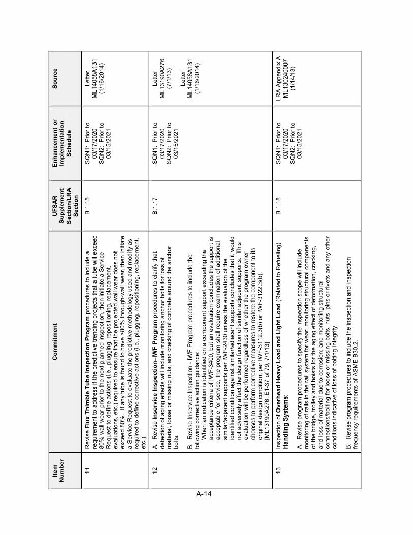
A-14
Item
N
umbe
r C
omm
itmen
t U
FSA
R
Supp
lem
ent
Sect
ion/
LRA
Sect
ion
Enha
ncem
ent o
r Im
plem
enta
tion
Sche
dule
Sour
ce
11
Rev
ise
Flux
Thi
mbl
e Tu
be In
spec
tion
Prog
ram
pro
cedu
res
to in
clud
e a
requ
irem
ent t
o ad
dres
s if
the
pred
ictiv
e tre
ndin
g pr
ojec
ts th
at a
tube
will
exc
eed
80%
wal
l wea
r prio
r to
the
next
pla
nned
insp
ectio
n, th
en in
itiat
e a
Ser
vice
R
eque
st to
def
ine
actio
ns (i
.e.,
plug
ging
, rep
ositi
onin
g, re
plac
emen
t, ev
alua
tions
, etc
.) re
quire
d to
ens
ure
that
the
proj
ecte
d w
all w
ear d
oes
not
exce
ed 8
0%.
If an
y tu
be is
foun
d to
hav
e >8
0% th
roug
h-w
all w
ear,
then
initi
ate
a S
ervi
ce R
eque
st to
eva
luat
e th
e pr
edic
tive
met
hodo
logy
use
d an
d m
odify
as
requ
ired
to d
efin
e co
rrec
tive
actio
ns (i
.e.,
plug
ging
, rep
ositi
onin
g, re
plac
emen
t, et
c.).
B.1
.15
SQ
N1:
Prio
r to
03/1
7/20
20
SQ
N2:
Prio
r to
03/1
5/20
21
Lette
r M
L140
58A
131
(1/1
6/20
14)
12
A.
Rev
ise
Inse
rvic
e In
spec
tion–
IWF
Prog
ram
pro
cedu
res
to c
larif
y th
at
dete
ctio
n of
agi
ng e
ffect
s w
ill in
clud
e m
onito
ring
anch
or b
olts
for l
oss
of
mat
eria
l, lo
ose
or m
issi
ng n
uts,
and
cra
ckin
g of
con
cret
e ar
ound
the
anch
or
bolts
. B
. R
evis
e In
serv
ice
Insp
ectio
n - I
WF
Pro
gram
pro
cedu
res
to in
clud
e th
e fo
llow
ing
corr
ectiv
e ac
tion
guid
ance
: W
hen
an in
dica
tion
is id
entif
ied
on a
com
pone
nt s
uppo
rt ex
ceed
ing
the
acce
ptan
ce c
riter
ia o
f IW
F-34
00, b
ut a
n ev
alua
tion
conc
lude
s th
e su
ppor
t is
acce
ptab
le fo
r ser
vice
, the
pro
gram
sha
ll re
quire
exa
min
atio
n of
add
ition
al
sim
ilar/a
djac
ent s
uppo
rts p
er IW
F-24
30 u
nles
s th
e ev
alua
tion
of th
e id
entif
ied
cond
ition
aga
inst
sim
ilar/a
djac
ent s
uppo
rts c
oncl
udes
that
it w
ould
no
t adv
erse
ly a
ffect
the
desi
gn fu
nctio
n of
sim
ilar a
djac
ent s
uppo
rts.
This
ev
alua
tion
will
be
perfo
rmed
rega
rdle
ss o
f whe
ther
the
prog
ram
ow
ner
choo
ses
to p
erfo
rm c
orre
ctiv
e m
easu
res
to re
stor
e th
e co
mpo
nent
to it
s or
igin
al d
esig
n co
nditi
on, p
er IW
F-31
12.3
(b) o
r IW
F-31
22.3
(b).
[M
L131
90A
276.
E1-
37 o
f 79,
7/1
/13]
B.1
.17
SQ
N1:
Prio
r to
03/1
7/20
20
SQ
N2:
Prio
r to
03/1
5/20
21
Lette
r M
L131
90A
276
(7/1
/13)
Lette
r M
L140
58A
131
(1/1
6/20
14)
13
Insp
ectio
n of
Ove
rhea
d H
eavy
Loa
d an
d Li
ght L
oad
(Rel
ated
to R
efue
ling)
H
andl
ing
Syst
ems:
A
. R
evis
e pr
ogra
m p
roce
dure
s to
spe
cify
the
insp
ectio
n sc
ope
will
incl
ude
mon
itorin
g of
rails
in th
e ra
il sy
stem
for w
ear;
mon
itorin
g st
ruct
ural
com
pone
nts
of th
e br
idge
, tro
lley
and
hois
ts fo
r the
agi
ng e
ffect
of d
efor
mat
ion,
cra
ckin
g,
and
loss
of m
ater
ial d
ue to
cor
rosi
on; a
nd m
onito
ring
stru
ctur
al
conn
ectio
ns/b
oltin
g fo
r loo
se o
r mis
sing
bol
ts, n
uts,
pin
s or
rive
ts a
nd a
ny o
ther
co
nditi
ons
indi
cativ
e of
loss
of b
oltin
g in
tegr
ity.
B.
Rev
ise
prog
ram
pro
cedu
res
to in
clud
e th
e in
spec
tion
and
insp
ectio
n fre
quen
cy re
quire
men
ts o
f AS
ME
B30
.2.
B.1
.18
SQ
N1:
Prio
r to
03/1
7/20
20
SQ
N2:
Prio
r to
03/1
5/20
21
LRA
App
endi
x A
M
L130
2400
07
(1/1
4/13
)

A-15
Item
N
umbe
r C
omm
itmen
t U
FSA
R
Supp
lem
ent
Sect
ion/
LRA
Sect
ion
Enha
ncem
ent o
r Im
plem
enta
tion
Sche
dule
Sour
ce
13—
Con
tinue
d C
. R
evis
e pr
ogra
m p
roce
dure
s to
cla
rify
that
the
acce
ptan
ce c
riter
ia w
ill
incl
ude
requ
irem
ents
for e
valu
atio
n in
acc
orda
nce
with
AS
ME
B30
.2 o
f si
gnifi
cant
loss
of m
ater
ial f
or s
truct
ural
com
pone
nts
and
stru
ctur
al b
olts
and
si
gnifi
cant
wea
r of r
ail i
n th
e ra
il sy
stem
. D
. R
evis
e pr
ogra
m p
roce
dure
s to
cla
rify
that
the
acce
ptan
ce c
riter
ia a
nd
mai
nten
ance
and
repa
ir ac
tiviti
es u
se th
e gu
idan
ce p
rovi
ded
in A
SM
E B
30.2
14
A.
Impl
emen
t the
Inte
rnal
Sur
face
s in
Mis
cella
neou
s Pi
ping
and
Duc
ting
Com
pone
nts
Prog
ram
as
desc
ribed
in L
RA
Sec
tion
B.1
.19.
B
. S
peci
fic, m
easu
rabl
e, a
ctio
nabl
e/at
tain
able
and
rele
vant
acc
epta
nce
crite
ria
are
esta
blis
hed
in th
e m
aint
enan
ce a
nd s
urve
illan
ce p
roce
dure
s or
are
es
tabl
ishe
d du
ring
engi
neer
ing
eval
uatio
n of
the
degr
aded
con
ditio
n.
[ML1
3357
A72
2, E
-1 –
43
of 4
3, 1
2/16
/13]
B.1
.19
SQ
N1:
Prio
r to
03/1
7/20
20
SQ
N2:
Prio
r to
03/1
5/20
21
LRA
App
endi
x A
M
L130
2400
07
(1/1
4/13
)
Lette
r M
L140
58A
131
(1/1
6/20
14)
15
Impl
emen
t the
Met
al E
nclo
sed
Bus
Insp
ectio
n Pr
ogra
m a
s de
scrib
ed in
LR
A
Sec
tion
B.1
.21.
B
.1.2
1 S
QN
1: P
rior t
o 03
/17/
2020
S
QN
2: P
rior t
o 03
/15/
2021
LRA
App
endi
x A
M
L130
2400
07
(1/1
4/13
)
16
A.
Rev
ise
Neu
tron
Abs
orbi
ng M
ater
ial M
onito
ring
Prog
ram
pro
cedu
res
to
perfo
rm b
lack
ness
test
ing
of th
e B
oral
cou
pons
with
in th
e 10
yea
rs p
rior t
o th
e pe
riod
of e
xten
ded
oper
atio
n an
d at
leas
t eve
ry 1
0 ye
ars
ther
eafte
r bas
ed o
n in
itial
test
ing
to d
eter
min
e po
ssib
le c
hang
es in
bor
on-1
0 ar
eal d
ensi
ty.
B.
Rev
ise
Neu
tron
Abs
orbi
ng M
ater
ial M
onito
ring
Pro
gram
pro
cedu
res
to
rela
te p
hysi
cal m
easu
rem
ents
of B
oral
cou
pons
to th
e ne
ed to
per
form
ad
ditio
nal t
estin
g.
C.
Rev
ise
Neu
tron
Abs
orbi
ng M
ater
ial M
onito
ring
Pro
gram
pro
cedu
res
to
perfo
rm tr
endi
ng o
f cou
pon
test
ing
resu
lts to
det
erm
ine
the
rate
of d
egra
datio
n an
d to
take
act
ion
as n
eede
d to
mai
ntai
n th
e in
tend
ed fu
nctio
n of
the
Bor
al.
B.1
.22
SQ
N1:
Prio
r to
03/1
7/20
20
SQ
N2:
Prio
r to
03/1
5/20
21
LRA
App
endi
x A
M
L130
2400
07
(1/1
4/13
)
17
Impl
emen
t the
Non
-EQ
Cab
le C
onne
ctio
ns P
rogr
am a
s de
scrib
ed in
LR
A
Sec
tion
B.1
.24
B.1
.24
SQ
N1:
Prio
r to
03/1
7/20
20
SQ
N2:
Prio
r to
03/1
5/20
21
LRA
App
endi
x A
M
L130
2400
07
(1/1
4/13
)

A-16
Item
N
umbe
r C
omm
itmen
t U
FSA
R
Supp
lem
ent
Sect
ion/
LRA
Sect
ion
Enha
ncem
ent o
r Im
plem
enta
tion
Sche
dule
Sour
ce
18
Impl
emen
t the
Non
-EQ
Inac
cess
ible
Pow
er C
able
s (4
00 V
to 3
5 kV
) Pr
ogra
m a
s de
scrib
ed in
LR
A S
ectio
n B
.1.2
5 A
. TV
A re
spon
se to
RA
I B.1
.25.
1a
1.
[Bla
nk]
2.
[Bla
nk]
3.
Prio
r to
the
perio
d of
ext
ende
d op
erat
ion,
the
licen
se re
new
al c
omm
itmen
t fo
r the
Non
-EQ
Inac
cess
ible
Pow
er C
able
s (4
00 V
to 3
5 kV
) Pro
gram
will
es
tabl
ish
diag
nost
ic te
stin
g ac
tiviti
es o
n al
l ina
cces
sibl
e po
wer
cab
les
in
the
400
V to
35
kV ra
nge
that
are
in th
e sc
ope
of li
cens
e re
new
al a
nd
subj
ect t
o an
AM
R.
4.
[Bla
nk]
5.
Not
e: O
nce
18.A
.1 to
4 a
re fu
lly c
ompl
eted
, Com
mitm
ents
18.
A.1
to 4
can
be
del
eted
from
this
list
or t
he U
FSA
R.
B.1
.25
SQ
N1:
Prio
r to
03/1
7/20
20
SQ
N2:
Prio
r to
03/1
5/20
21
18.A
.1 &
A.2
are
co
mpl
eted
. See
Cnl
-14-
105,
Enc
1, p
14 o
f 16.
18
.A.3
: S
QN
1: P
rior t
o 03
/17/
20
SQ
N2:
Prio
r to
03/1
5/21
18
.A4:
com
plet
ed, S
ee
CN
L-14
-221
, cov
er le
tter
LRA
App
endi
x A
M
L130
2400
07
(1/1
4/13
)
Lette
r M
L132
96A
017
(10/
21/1
3)
Le
tter
ML1
4058
A13
1 (1
/16/
2014
)
Lette
r M
L140
64A
086
(3/3
/201
4)
Le
tter
ML1
4239
A43
2 (8
/21/
2014
)
19
Impl
emen
t the
Non
-EQ
Inst
rum
enta
tion
Circ
uits
Tes
t Rev
iew
Pro
gram
as
desc
ribed
in L
RA
Sec
tion
B.1
.26.
B
.1.2
6 S
QN
1: P
rior t
o 03
/17/
2020
S
QN
2: P
rior t
o 03
/15/
2021
LRA
App
endi
x A
M
L130
2400
07
(1/1
4/13
)
20
Impl
emen
t the
Non
-EQ
Insu
late
d C
able
s an
d C
onne
ctio
ns P
rogr
am a
s de
scrib
ed in
LR
A S
ectio
n B
.1.2
7.
B.1
.27
SQ
N1:
Prio
r to
03/1
7/20
20
SQ
N2:
Prio
r to
03/1
5/20
21
LRA
App
endi
x A
M
L130
2400
07
(1/1
4/13
)
21
A.
Rev
ise
Oil
Ana
lysi
s Pr
ogra
m p
roce
dure
s to
mon
itor a
nd m
aint
ain
cont
amin
ants
in th
e 16
1-kV
oil
fille
d ca
ble
syst
em w
ithin
acc
epta
ble
limits
th
roug
h pe
riodi
c sa
mpl
ing
in a
ccor
danc
e w
ith in
dust
ry s
tand
ards
, m
anuf
actu
rer’s
reco
mm
enda
tions
and
pla
nt-s
peci
fic O
E.
B.
Rev
ise
Oil
Ana
lysi
s P
rogr
am p
roce
dure
s to
tren
d oi
l con
tam
inan
t lev
els
and
initi
ate
a P
ER
if c
onta
min
ants
exc
eed
aler
t lev
els
or li
mits
in th
e 16
1-kV
oil-
fille
d ca
ble
syst
em.
B.1
.28
SQ
N1:
Prio
r to
03/1
7/20
20
SQ
N2:
Prio
r to
03/1
5/20
21
LRA
App
endi
x A
M
L130
2400
07
(1/1
4/13
)

A-17
Item
N
umbe
r C
omm
itmen
t U
FSA
R
Supp
lem
ent
Sect
ion/
LRA
Sect
ion
Enha
ncem
ent o
r Im
plem
enta
tion
Sche
dule
Sour
ce
22
Impl
emen
t the
One
-Tim
e In
spec
tion
Prog
ram
as
desc
ribed
in L
RA
S
ectio
n B
.1.2
9.
B.1
.29
SQ
N1:
Prio
r to
03/1
7/20
20
SQ
N2:
Prio
r to
03/1
5/20
21
LRA
App
endi
x A
M
L130
2400
07
(1/1
4/13
)
23
Impl
emen
t the
One
-Tim
e In
spec
tion
– Sm
all B
ore
Pipi
ng P
rogr
am a
s de
scrib
ed in
LR
A S
ectio
n B
.1.3
0.
B.1
.30
SQ
N1:
Prio
r to
03/1
7/20
20
SQ
N2:
Prio
r to
03/1
5/20
21
LRA
App
endi
x A
M
L130
2400
07
(1/1
4/13
)
24
A.
Rev
ise
Perio
dic
Surv
eilla
nce
and
Prev
entiv
e M
aint
enan
ce P
rogr
am
proc
edur
es a
s ne
cess
ary
to in
clud
e al
l act
iviti
es d
escr
ibed
in th
e ta
ble
prov
ided
in
the
LRA
Sec
tion
B.1
.31
prog
ram
des
crip
tion.
B
. Fo
r in-
scop
e co
mpo
nent
s th
at h
ave
inte
rnal
Ser
vice
Lev
el II
I or O
ther
co
atin
gs, i
nitia
l ins
pect
ions
will
beg
in n
o la
ter t
han
the
last
sch
edul
ed R
FO p
rior
to th
e pe
riod
of e
xten
ded
oper
atio
n. S
ubse
quen
t ins
pect
ions
will
be
perfo
rmed
ba
sed
on th
e in
itial
insp
ectio
n re
sults
. [3
.0.3
-1, R
eque
st 3
, ML1
3312
A00
5,
page
s E
-1- 2
,5,7
of 5
1]
C.
Rev
ise
Per
iodi
c S
urve
illan
ce a
nd P
reve
ntiv
e M
aint
enan
ce P
rogr
am
proc
edur
es to
per
form
a m
inim
um o
f fiv
e M
IC d
egra
datio
n in
spec
tions
per
yea
r un
til th
e ra
te o
f MIC
occ
urre
nces
no
long
er m
eets
the
crite
ria fo
r rec
urrin
g in
tern
al c
orro
sion
. [c
nl-1
4-10
5, E
1p11
If
mor
e th
an o
ne M
IC-c
ause
d le
ak o
r a w
all t
hick
ness
less
than
Tm
in is
iden
tifie
d in
the
year
ly in
spec
tion
perio
d, a
n ad
ditio
nal f
ive
MIC
insp
ectio
ns o
ver t
he
follo
win
g 12
mon
th p
erio
d w
ill b
e pe
rform
ed fo
r eac
h M
IC le
ak o
r fin
ding
of w
all
thic
knes
s le
ss th
an T
min.
The
tota
l num
ber o
f ins
pect
ions
nee
d no
t exc
eed
a to
tal o
f 25
MIC
insp
ectio
ns p
er y
ear.
[01/
16/1
4 C
NL-
14-0
10, 3
.0.3
-1-3
a]
B.1
.31
24.A
&C
-G
SQ
N1:
Prio
r to
03/1
7/20
S
QN
2: P
rior t
o 03
/15/
21
24.B
S
QN
1: R
FO P
rior t
o 09
/17/
20
SQ
N2:
RFO
Prio
r to
09/1
5/21
Lette
r M
L133
12A
005
ML1
3294
A46
2 (1
1/4/
13)
Le
tter
ML1
4058
A13
1 (1
/16/
2014
)
Lette
r M
L140
64A
086
(3/3
/201
4)
Le
tter
ML1
4239
A43
2 (8
/21/
2014
)
24—
Con
tinue
d C
—C
ontin
ued
Prio
r to
the
perio
d of
ext
ende
d op
erat
ion,
sel
ect a
met
hod
(or m
etho
ds) f
rom
av
aila
ble
tech
nolo
gies
for i
nspe
ctin
g in
tern
al s
urfa
ces
of b
urie
d pi
ping
(Sys
tem
26
/HP
FP F
irew
ater
and
67/
ER
CW
) tha
t pro
vide
s su
itabl
e in
dica
tion
of p
ipin
g w
all t
hick
ness
for a
repr
esen
tativ
e se
t of b
urie
d pi
ping
loca
tions
to s
uppl
emen
t th
e se
t of s
elec
ted
insp
ectio
n lo
catio
ns.
[3.0
.3-1
, Req
uest
1a,
ML1
3357
A72
2, E
-1 –
4 o
f 43,
12/
16/1
3]
[3.0
.3-1
Req
uest
1, M
L132
94A
462,
E-1
- 6 o
f 13,
10/
17/1
3] [M
oved
from
9.F
to

A-18
Item
N
umbe
r C
omm
itmen
t U
FSA
R
Supp
lem
ent
Sect
ion/
LRA
Sect
ion
Enha
ncem
ent o
r Im
plem
enta
tion
Sche
dule
Sour
ce
24.C
in M
L140
57A
808,
E-1
p13
,29]
D
. 1.
P
rior t
o th
e pe
riod
of e
xten
ded
oper
atio
n, p
erfo
rm a
vis
ual i
nspe
ctio
n of
a
50%
sam
ple
of th
e co
ated
pip
ing
in e
ach
of th
e fo
llow
ing
coat
ed p
ipin
g sy
stem
s or
an
area
equ
ival
ent t
o th
e en
tire
insi
de s
urfa
ce o
f 73
1-fo
ot
pipi
ng s
egm
ents
for e
ach
com
bina
tion
of ty
pe o
f coa
ting,
sub
stra
te
mat
eria
l, an
d en
viro
nmen
t. In
spec
tion
loca
tion
sele
ctio
n w
ill b
e ba
sed
on
an e
valu
atio
n of
the
effe
ct o
f a c
oatin
g fa
ilure
on
com
pone
nt in
tend
ed
func
tions
, pot
entia
l pro
blem
s id
entif
ied
durin
g pr
ior i
nspe
ctio
ns, a
nd
serv
ice
life
hist
ory.
Vis
ually
insp
ect t
he s
urfa
ce c
ondi
tion
of th
e co
ated
co
mpo
nent
s to
man
age
loss
of c
oatin
g in
tegr
ity d
ue to
cra
ckin
g,
debo
ndin
g, d
elam
inat
ion,
pee
ling,
flak
ing,
and
blis
terin
g. I
n ad
ditio
n, if
co
atin
gs a
re c
redi
ted
for c
orro
sion
pre
vent
ion,
the
base
mat
eria
l (in
the
vici
nity
of d
elam
inat
ion,
pee
ling,
or b
liste
rs w
here
bas
e m
etal
has
bee
n ex
pose
d) w
ill b
e in
spec
ted
to d
eter
min
e w
heth
er c
orro
sion
has
occ
urre
d.
Pipi
ng:
i. H
PFP
(cem
ent-l
ined
pip
ing)
ii.
E
RC
W (w
here
Bel
zona
app
lied)
2.
W
ith th
e ex
cept
ion
of th
e E
DG
7-d
ay fu
el o
il ta
nks,
per
form
sub
sequ
ent
insp
ectio
ns o
f coa
tings
bas
ed o
n th
e fo
llow
ing:
i. If
no fl
akin
g, d
ebon
ding
, pee
ling,
del
amin
atio
n, b
liste
rs, o
r rus
ting
are
obse
rved
, and
any
cra
ckin
g an
d fla
king
has
bee
n fo
und
acce
ptab
le,
subs
eque
nt in
spec
tions
will
be
perfo
rmed
at l
east
onc
e ev
ery
6 ye
ars.
If
the
coat
ing
is in
spec
ted
on o
ne tr
ain
and
no in
dica
tions
are
foun
d, th
e sa
me
coat
ing
on th
e re
dund
ant t
rain
wou
ld n
ot b
e in
spec
ted
durin
g th
at
insp
ectio
n in
terv
al.

A-19
Item
N
umbe
r C
omm
itmen
t U
FSA
R
Supp
lem
ent
Sect
ion/
LRA
Sect
ion
Enha
ncem
ent o
r Im
plem
enta
tion
Sche
dule
Sour
ce
24—
Con
tinue
d D
.2.—
Con
tinue
d ii.
If
the
insp
ectio
n re
sults
do
not m
eet (
i), y
et a
coa
ting
spec
ialis
t has
de
term
ined
that
no
rem
edia
tion
is re
quire
d, th
en s
ubse
quen
t in
spec
tions
will
be
cond
ucte
d ev
ery
othe
r RFO
. iii.
If
coat
ing
degr
adat
ion
is o
bser
ved
that
requ
ires
new
ly in
stal
led
coat
ings
, sub
sequ
ent i
nspe
ctio
ns w
ill o
ccur
dur
ing
each
of t
he n
ext
two
RFO
inte
rval
s to
est
ablis
h a
perfo
rman
ce tr
end
on th
e co
atin
g.
ED
G 7
-day
fuel
oil
tank
s co
atin
g in
spec
tion:
S
ubse
quen
t coa
ting
insp
ectio
ns fo
r the
ED
G 7
-day
fuel
oil
tank
s w
ill b
e at
the
sam
e 10
-yea
r int
erva
l as
TS S
urve
illan
ce R
equi
rem
ent 4
.8.1
.1.2
.f. I
f any
ap
plie
d B
elzo
na c
oatin
g on
the
inte
rior o
f the
fuel
oil
tank
s is
pee
ling,
de
lam
inat
ing,
or b
liste
ring,
then
the
cond
ition
will
be
repa
ired
and
ente
red
into
th
e C
AP
. G
iven
the
favo
rabl
e S
QN
exp
erie
nce
with
the
curr
ent B
elzo
na
repa
irs, i
t is
just
ifiab
le to
repa
ir th
e ex
istin
g co
atin
g ap
plie
d to
loca
lized
pits
with
B
elzo
na a
nd n
ot in
spec
t the
coa
ting
for a
noth
er 1
0 ye
ars,
pro
vide
d a
deta
ched
B
elzo
na e
ngin
eerin
g tra
nspo
rtabi
lity
eval
uatio
n ha
s de
term
ined
that
the
amou
nt
of B
elzo
na a
pplie
d w
ill n
ot m
igra
te fr
om th
e E
DG
7-d
ay ta
nk to
the
day-
tank
. Th
e ev
alua
tion
will
con
side
r Bel
zona
’s 2
.5 to
3 ti
mes
hig
her s
peci
fic g
ravi
ty
than
die
sel f
uel,
pote
ntia
l siz
e of
loos
ened
Bel
zona
par
ticle
s, s
urfa
ce a
rea
and
dept
h of
the
appl
ied
Bel
zona
, die
sel f
uel f
luid
vel
ocity
in th
e im
med
iate
are
a of
th
e ap
plie
d B
elzo
na, p
roxi
mity
of t
he re
paire
d ar
ea to
the
suct
ion
line,
and
oth
er
fact
ors.
Th
e ap
plic
atio
n of
Bel
zona
to re
pair
addi
tiona
l loc
aliz
ed p
ittin
g in
the
7-da
y E
DG
fuel
oil
tank
s in
the
futu
re w
ill b
e in
stal
led
per v
endo
r spe
cific
atio
ns.
An
engi
neer
ing
eval
uatio
n w
ill b
e pe
rform
ed to
ens
ure
that
the
addi
tiona
l Bel
zona
ca
nnot
be
trans
fera
ble
out o
f the
tank
dur
ing
the
inte
rval
bet
wee
n ta
nk
insp
ectio
ns a
nd to
det
erm
ine
if th
e in
terv
al o
f ins
pect
ions
sho
uld
mee
t the
mor
e fre
quen
t ins
pect
ion
guid
elin
es o
f lic
ense
rene
wal
-IS
G-2
013-
01, o
r the
NR
C
appr
oved
TS
Sur
veill
ance
Req
uire
men
t of 1
0 ye
ars.
The
eng
inee
ring
trans
porta
bilit
y ev
alua
tion
will
con
side
r fac
tors
suc
h as
spe
cific
gra
vity
, siz
e,
dept
h, s
urfa
ce a
rea,
and
flui
d ve
loci
ty in
the
eval
uatio
n. [M
L140
57A
808,
E-1
p7
]

A-20
Item
N
umbe
r C
omm
itmen
t U
FSA
R
Supp
lem
ent
Sect
ion/
LRA
Sect
ion
Enha
ncem
ent o
r Im
plem
enta
tion
Sche
dule
Sour
ce
24—
Con
tinue
d E
. P
rior t
o th
e pe
riod
of e
xten
ded
oper
atio
n, p
erfo
rm a
vis
ual i
nspe
ctio
n of
the
follo
win
g co
ated
tank
s an
d he
at e
xcha
nger
s. V
isua
lly in
spec
t the
sur
face
co
nditi
on o
f the
coa
ted
com
pone
nts
to m
anag
e lo
ss o
f coa
ting
inte
grity
due
to
crac
king
, deb
ondi
ng, d
elam
inat
ion,
pee
ling,
flak
ing,
and
blis
terin
g.
Tank
s:
i. C
ask
deco
ntam
inat
ion
colle
ctor
(whe
re 2
coa
ts R
ed L
ead
in o
il, F
ed
SP
EC
TTP
-85
Type
II a
pplie
d)
ii.
Saf
ety
inje
ctio
n lu
be o
il re
serv
oir (
whe
re 0
.006
inch
pla
stic
coa
ting
appl
ied)
iii.
P
ress
uriz
er re
lief (
whe
re A
mbe
rcoa
t 55
appl
ied)
iv
. E
DG
7-d
ay fu
el o
il (w
here
Bel
zona
app
lied)
v.
C
ST
H
eat E
xcha
nger
s:
i. E
lect
ric b
oard
room
chi
ller p
acka
ge (w
here
Bel
zona
app
lied)
ii.
In
core
inst
rum
ent r
oom
wat
er c
hille
r pac
kage
B (w
here
Bel
zona
ap
plie
d) [
ML1
4057
A80
8, E
-1 p
6]
F.
Any
indi
catio
n or
rele
vant
con
ditio
n of
deg
rada
tion
dete
cted
is e
valu
ated
.
Incl
ude
the
follo
win
g ac
cept
ance
crit
eria
for l
oss
of c
oatin
g in
tegr
ity:
For a
ny in
dica
tion
or re
leva
nt c
ondi
tion
of c
oatin
g de
grad
atio
n, th
e in
dica
tion
or re
leva
nt c
ondi
tion
is e
valu
ated
for l
oss
of c
oatin
gs in
tegr
ity.
[CN
L-14
-021
] (1
) P
eelin
g an
d de
lam
inat
ion
are
not p
erm
itted
. (2
) C
rack
ing
is n
ot p
erm
itted
if a
ccom
pani
ed b
y de
lam
inat
ion
or lo
ss o
f ad
hesi
on.
(3)
Blis
ters
are
lim
ited
to in
tact
blis
ters
that
are
com
plet
ely
surr
ound
ed b
y so
und
coat
ing
bond
ed to
the
surfa
ce.
Cor
rect
ive
Act
ion:
If d
elam
inat
ion,
pee
ling,
or b
liste
rs a
re d
etec
ted,
follo
wup
ph
ysic
al te
stin
g w
ill b
e pe
rform
ed w
here
phy
sica
lly p
ossi
ble
(i.e.
, suf
ficie
nt ro
om to
con
duct
test
ing)
on
at le
ast t
hree
loca
tions
. Th
e te
stin
g w
ill c
onsi
st o
f des
truct
ive
or n
onde
stru
ctiv
e ad
hesi
on te
stin
g us
ing
AS
TM In
tern
atio
nal s
tand
ards
end
orse
d in
RG
1.5
4.
[ML1
4063
A54
2, E
-1 p
2]

A-21
Item
N
umbe
r C
omm
itmen
t U
FSA
R
Supp
lem
ent
Sect
ion/
LRA
Sect
ion
Enha
ncem
ent o
r Im
plem
enta
tion
Sche
dule
Sour
ce
24—
Con
tinue
d G
. 1.
Coa
ting
insp
ectio
ns a
re p
erfo
rmed
by
indi
vidu
als
certi
fied
to A
NS
I N45
.2.6
, “Q
ualif
icat
ions
of I
nspe
ctio
n, E
xam
inat
ion,
and
Tes
ting
Per
sonn
el fo
r Nuc
lear
P
ower
Pla
nts,
” and
that
sub
sequ
ent e
valu
atio
n of
insp
ectio
n fin
ding
s is
co
nduc
ted
by a
nuc
lear
coa
tings
sub
ject
mat
ter e
xper
t qua
lifie
d in
acc
orda
nce
with
AS
TM D
710
8-05
, “S
tand
ard
Gui
de fo
r Est
ablis
hing
Qua
lific
atio
ns fo
r a
Nuc
lear
Coa
tings
Spe
cial
ist.”
2.
An
indi
vidu
al k
now
ledg
eabl
e an
d ex
perie
nced
in n
ucle
ar c
oatin
gs w
ork
will
pr
epar
e a
coat
ing
repo
rt th
at in
clud
es a
list
of l
ocat
ions
iden
tifie
d w
ith c
oatin
g de
terio
ratio
n in
clud
ing,
whe
re p
ossi
ble,
pho
togr
aphs
inde
xed
to in
spec
tion
loca
tion,
and
a p
riorit
izat
ion
of th
e re
pair
area
s in
to a
reas
that
mus
t be
repa
ired
befo
re re
turn
ing
the
syst
em to
ser
vice
and
are
as w
here
coa
ting
repa
ir ca
n be
po
stpo
ned
to th
e ne
xt in
spec
tion.
[M
L140
57A
808,
E-1
p6]
25
A.
Rev
ise
Prot
ectiv
e C
oatin
g Pr
ogra
m p
roce
dure
s to
cla
rify
that
det
ectio
n of
ag
ing
effe
cts
will
incl
ude
insp
ectio
n of
coa
tings
nea
r sum
ps o
r scr
eens
as
soci
ated
with
the
EC
CS
. B
. R
evis
e P
rote
ctiv
e C
oatin
g P
rogr
am p
roce
dure
s to
cla
rify
that
inst
rum
ents
an
d eq
uipm
ent n
eede
d fo
r ins
pect
ion
may
incl
ude,
but
not
be
limite
d to
, fla
shlig
hts,
spo
tligh
ts, m
arke
r pen
, mirr
or, m
easu
ring
tape
, mag
nifie
r, bi
nocu
lars
, cam
era
with
or w
ithou
t wid
e-an
gle
lens
, and
sel
f-sea
ling
poly
ethy
lene
sam
ple
bags
. C
. R
evis
e P
rote
ctiv
e C
oatin
g P
rogr
am p
roce
dure
s to
cla
rify
that
the
last
two
perfo
rman
ce m
onito
ring
repo
rts p
erta
inin
g to
the
coat
ing
syst
ems
will
be
revi
ewed
prio
r to
the
insp
ectio
n or
mon
itorin
g pr
oces
s.
B.1
.32
SQ
N1:
Prio
r to
03/1
7/20
20
SQ
N2:
Prio
r to
03/1
5/20
21
LRA
App
endi
x A
M
L130
2400
07
(1/1
4/13
)
26
A.
Rev
ise
Rea
ctor
Hea
d C
losu
re S
tuds
Pro
gram
pro
cedu
res
to e
nsur
e th
at
repl
acem
ent s
tuds
are
fabr
icat
ed fr
om b
oltin
g m
ater
ial w
ith a
ctua
l mea
sure
d yi
eld
stre
ngth
less
than
150
ksi
. B
. R
evis
e R
eact
or H
ead
Clo
sure
Stu
ds P
rogr
am p
roce
dure
s to
exc
lude
the
use
of m
olyb
denu
m d
isul
fide
(MoS
2) o
n th
e re
acto
r ves
sel c
losu
re s
tuds
and
to
refe
r to
Reg
ulat
ory
Gui
de 1
.65,
Rev
. 1.
B.1
.33
SQ
N1:
Prio
r to
03/1
7/20
20
SQ
N2:
Prio
r to
03/1
5/20
21
LRA
App
endi
x A
M
L130
2400
07
(1/1
4/13
)

A-22
Item
N
umbe
r C
omm
itmen
t U
FSA
R
Supp
lem
ent
Sect
ion/
LRA
Sect
ion
Enha
ncem
ent o
r Im
plem
enta
tion
Sche
dule
Sour
ce
27
A.
Rev
ise
Rea
ctor
Ves
sel I
nter
nals
Pro
gram
pro
cedu
res
to p
erfo
rm d
irect
m
easu
rem
ent o
f Uni
t 1 3
04 S
S h
old
dow
n sp
ring
heig
ht w
ithin
thre
e cy
cles
of
the
begi
nnin
g of
the
perio
d of
ext
ende
d op
erat
ion.
If t
he fi
rst s
et o
f m
easu
rem
ents
is n
ot s
uffic
ient
to d
eter
min
e lif
e, s
prin
g he
ight
mea
sure
men
ts
mus
t be
take
n du
ring
the
next
two
outa
ges,
in o
rder
to e
xtra
pola
te th
e ex
pect
ed
sprin
g he
ight
to 6
0 ye
ars.
(M
L133
24A
982
11/1
5/13
, Enc
losu
re 1
, pag
es 2
4-25
) B
. R
evis
e R
eact
or V
esse
l Int
erna
ls P
rogr
am p
roce
dure
s to
incl
ude
prel
oad
acce
ptan
ce c
riter
ia fo
r the
Typ
e 30
4 st
ainl
ess
stee
l hol
d-do
wn
sprin
gs in
Uni
t 1.
C.
Con
tinue
d m
onito
ring
of in
dust
ry O
E in
the
area
of R
VI c
levi
s bo
lt w
ill b
e pe
rform
ed a
nd th
e pr
ogra
m w
ill b
e m
odifi
ed, i
f nec
essa
ry.
[[ML1
4057
A80
8, E
-1
p35,
B.1
.34-
8].
See
lette
r CN
L-14
-105
, 08-
21-1
4.
D.
[Bla
nk]
E. R
evis
e R
eact
or V
esse
l Int
erna
ls P
rogr
am p
roce
dure
s to
iden
tify
the
obse
rvat
ion
of c
rack
ing
in th
e lo
wer
cor
e ba
rrel
girt
h w
eld
as th
e pr
imar
y tri
gger
for t
he E
VT-
1 ex
pans
ion
insp
ectio
n of
the
uppe
r cor
e pl
ate.
[B.1
.34-
9d (f
ollo
w-u
p) in
CN
L-14
-221
, Enc
1.
B.1
.34
27.A
& B
S
QN
1: W
ithin
thre
e U
1 re
fuel
cyc
les
of th
e da
te
09/1
7/20
S
QN
2: N
ot A
pplic
able
27
.C S
QN
1&
2: W
ithin
th
ree
U1
refu
el c
ycle
s of
th
e da
te 0
9/17
/20
27.D
: is
com
plet
ed S
ee
B.1
.34-
9b in
Cnl
-14-
105,
E
nc 1
, pg
1 27
.E
SQ
N1:
Prio
r to
03/1
7/20
S
QN
2: P
rior t
o 03
/15/
21
Lette
r M
L133
24A
982
(11/
15/1
3)
Le
tter
ML1
4058
A13
1 (1
/16/
2014
)
Lette
r M
L140
64A
086
(3/3
/201
4)
Le
tter
ML1
4239
A43
2 (8
/21/
2014
)
Lette
r M
L143
50A
683
(12/
11/2
014)
28
A.
Rev
ise
Rea
ctor
Ves
sel S
urve
illan
ce P
rogr
am p
roce
dure
s to
con
side
r the
ar
ea o
utsi
de th
e be
ltlin
e su
ch a
s no
zzle
s, p
enet
ratio
ns a
nd d
isco
ntin
uitie
s to
de
term
ine
if m
ore
rest
rictiv
e P
-T li
mits
are
requ
ired
than
wou
ld b
e de
term
ined
by
just
con
side
ring
the
reac
tor v
esse
l bel
tline
mat
eria
ls.
B.
Rev
ise
Rea
ctor
Ves
sel S
urve
illan
ce P
rogr
am p
roce
dure
s to
inco
rpor
ate
an
NR
C-a
ppro
ved
sche
dule
for c
apsu
le w
ithdr
awal
s to
mee
t AS
TM-E
185-
82
requ
irem
ents
, inc
ludi
ng th
e po
ssib
ility
of o
pera
tion
beyo
nd 6
0 ye
ars
(ref
er to
th
e TV
A L
ette
r to
NR
C, “
Seq
uoya
h R
eact
or P
ress
ure
Ves
sel S
urve
illan
ce
Cap
sule
With
draw
al S
ched
ule
Rev
isio
n D
ue to
Lic
ense
Ren
ewal
Am
endm
ent,”
da
ted
01/1
0/13
, ML1
3032
A25
1; N
RC
fina
l saf
ety
eval
uatio
n re
port
appr
oved
on
09/2
7/13
, ML1
3240
A32
0).
C.
Rev
ise
Rea
ctor
Ves
sel S
urve
illan
ce P
rogr
am p
roce
dure
s to
with
draw
and
te
st a
sta
ndby
cap
sule
to c
over
the
peak
flue
nce
expe
cted
at t
he e
nd o
f the
pe
riod
of e
xten
ded
oper
atio
n.
B.1
.35
SQ
N1:
Prio
r to
03/1
7/20
20
SQ
N2:
Prio
r to
03/1
5/20
21
Lette
r M
L131
90A
276
(7/1
/13)

A-23
Item
N
umbe
r C
omm
itmen
t U
FSA
R
Supp
lem
ent
Sect
ion/
LRA
Sect
ion
Enha
ncem
ent o
r Im
plem
enta
tion
Sche
dule
Sour
ce
29
Impl
emen
t the
Sel
ectiv
e Le
achi
ng P
rogr
am a
s de
scrib
ed in
LR
A
Sec
tion
B.1
.37.
B
.1.3
7 S
QN
1: P
rior t
o 03
/17/
2020
S
QN
2: P
rior t
o 03
/15/
2021
LRA
App
endi
x A
M
L130
2400
07
(1/1
4/13
)
30
Rev
ise
Stea
m G
ener
ator
Inte
grity
Pro
gram
pro
cedu
res
to e
nsur
e th
at
corr
osio
n re
sist
ant m
ater
ials
are
use
d fo
r RS
G tu
be p
lugs
. B
.1.3
9 S
QN
1: P
rior t
o 03
/17/
2020
S
QN
2: P
rior t
o 03
/15/
2021
LRA
App
endi
x A
M
L130
2400
07
(1/1
4/13
)
31
A.
Rev
ise
Stru
ctur
es M
onito
ring
Prog
ram
pro
cedu
res
to in
clud
e th
e fo
llow
ing
in--
scop
e st
ruct
ures
: •
CO
2 bui
ldin
g •
CS
Ts’ f
ound
atio
ns a
nd p
ipe
trenc
h •
Eas
t ste
am v
alve
room
Uni
ts 1
& 2
•
ER
CW
pum
ping
sta
tion
• H
PFP
pum
p ho
use
and
wat
er s
tora
ge ta
nks’
foun
datio
ns
• ra
diat
ion
mon
itorin
g st
atio
n (o
r par
ticul
ate
iodi
ne a
nd n
oble
gas
st
atio
n) U
nits
1 &
2
• se
rvic
e bu
ildin
g •
skim
mer
wal
l (C
ell N
o. 1
2)
• tra
nsfo
rmer
and
sw
itchy
ard
supp
ort s
truct
ures
and
foun
datio
ns
B.
Rev
ise
Stru
ctur
es M
onito
ring
Pro
gram
pro
cedu
res
to s
peci
fy th
e fo
llow
ing
list o
f in-
scop
e st
ruct
ures
are
incl
uded
in th
e R
G 1
.127
, Ins
pect
ion
of
Wat
er-C
ontro
l Stru
ctur
es A
ssoc
iate
d w
ith N
ucle
ar P
ower
Pla
nts
Pro
gram
(S
ectio
n B
.1.3
6):
• co
nden
ser c
oolin
g w
ater
(CC
W) p
umpi
ng s
tatio
n (a
lso
know
n as
in
take
pum
ping
sta
tion)
and
reta
inin
g w
alls
•
CC
W p
umpi
ng s
tatio
n in
take
cha
nnel
•
ER
CW
dis
char
ge b
ox
• E
RC
W p
rote
ctiv
e di
ke
• E
RC
W p
umpi
ng s
tatio
n an
d ac
cess
cel
ls
• sk
imm
er w
all,
skim
mer
wal
l Dik
e A
and
und
erw
ater
dam
S
ee le
tter C
NL-
14-1
05, 0
8-21
-14.
B.1
.40
SQ
N1:
Prio
r to
03/1
7/20
20
SQ
N2:
Prio
r to
03/1
5/20
21
Lette
r M
L131
63A
442
(6/7
/201
3)
Le
tter
ML1
3178
A28
3 (6
/25/
13)
Le
tter
ML1
3190
A27
6
(7/1
/13)
Lette
r M
L132
52A
036
(9
/3/1
3)
Le
tter
ML1
3267
A15
9
(9/2
0/13
)
Lette
r M
L132
96A
017
(10/
21/1
3)
Le
tter
ML1
4058
A13
1 (1
/16/
2014
)

A-24
Item
N
umbe
r C
omm
itmen
t U
FSA
R
Supp
lem
ent
Sect
ion/
LRA
Sect
ion
Enha
ncem
ent o
r Im
plem
enta
tion
Sche
dule
Sour
ce
31—
Con
tinue
d C
. R
evis
e S
truct
ures
Mon
itorin
g P
rogr
am p
roce
dure
s to
incl
ude
the
follo
win
g in
-sco
pe s
truct
ural
com
pone
nts
and
com
mod
ities
: •
anch
or b
olts
•
anch
orag
e/em
bedm
ents
(e.g
., pl
ates
, cha
nnel
s, u
nist
rut,
angl
es,
othe
r stru
ctur
al s
hape
s)
• be
ams,
col
umns
and
bas
e pl
ates
(ste
el)
• be
ams,
col
umns
, flo
or s
labs
and
inte
rior w
alls
(con
cret
e)
• be
ams,
col
umns
, flo
or s
labs
and
inte
rior w
alls
(rea
ctor
cav
ity a
nd
prim
ary
shie
ld w
alls
; pre
ssur
izer
and
RC
P c
ompa
rtmen
ts; r
efue
ling
cana
l, st
eam
gen
erat
or c
ompa
rtmen
ts; c
rane
wal
l and
mis
sile
shi
eld
slab
s an
d ba
rrie
rs)
• bu
ildin
g co
ncre
te a
t loc
atio
ns o
f exp
ansi
on a
nd g
rout
ed a
ncho
rs; g
rout
pa
ds fo
r sup
port
base
pla
tes
• ca
ble
tray
•
cabl
e tu
nnel
•
cana
l gat
e bu
lkhe
ad
• co
mpr
essi
ble
join
ts a
nd s
eals
•
conc
rete
cov
er fo
r the
rock
wal
ls o
f app
roac
h ch
anne
l •
conc
rete
shi
eld
bloc
ks
• co
ndui
t •
cont
rol r
od d
rive
mis
sile
shi
eld
• co
ntro
l roo
m c
eilin
g su
ppor
t sys
tem
•
curb
s •
disc
harg
e bo
x an
d fo
unda
tion
• do
ors
(incl
udin
g ai
r loc
ks a
nd b
ulkh
ead
door
s)
• du
ct b
anks
•
earth
en e
mba
nkm
ent
• eq
uipm
ent p
ads/
foun
datio
ns
• ex
plos
ion
bolts
(E. G
. Sm
ith A
l bol
ts)
• ex
terio
r abo
ve a
nd b
elow
gra
de; f
ound
atio
n (c
oncr
ete)
•
exte
rior c
oncr
ete
slab
s (m
issi
le b
arrie
r) a
nd c
oncr
ete
caps
•
exte
rior w
alls
: ab
ove
and
belo
w g
rade
(con
cret
e)
• fo
unda
tions
: bu
ildin
g, e
lect
rical
com
pone
nts,
sw
itchy
ard,
tra
nsfo
rmer
s, c
ircui
t bre
aker
s, ta
nks,
etc
. •
ice
bask
ets
• ic
e ba
sket
s la
ttice
sup
port
fram
es
• ic
e co
nden
ser s
uppo
rt flo
or (c
oncr
ete)
Lette
r M
L142
39A
432
(8/2
1/20
14)

A-25
Item
N
umbe
r C
omm
itmen
t U
FSA
R
Supp
lem
ent
Sect
ion/
LRA
Sect
ion
Enha
ncem
ent o
r Im
plem
enta
tion
Sche
dule
Sour
ce
31—
Con
tinue
d C
.—C
ontin
ued
• In
sula
tion
(fibe
rgla
ss, c
alci
um s
ilicat
e)
• In
term
edia
te d
eck
and
top
deck
of i
ce c
onde
nser
•
Kic
k pl
ates
and
cur
bs (s
teel
- in
side
ste
el c
onta
inm
ent v
esse
l) •
Low
er in
let d
oors
(ins
ide
stee
l con
tain
men
t ves
sel)
• Lo
wer
sup
port
stru
ctur
e st
ruct
ural
ste
el:
beam
s, c
olum
ns, p
late
s (in
side
ste
el c
onta
inm
ent v
esse
l) •
Man
hole
s an
d ha
ndho
les
• m
anw
ays,
hat
ches
, MH
cov
ers,
and
hat
ch c
over
s (s
teel
) •
Man
way
s, h
atch
es, m
anho
le c
over
s, a
nd h
atch
cov
ers
(con
cret
e)
[CN
L-14
-105
, 08-
21-1
4]
• m
ason
ry w
alls
•
met
al s
idin
g •
mis
cella
neou
s st
eel (
deck
ing,
gra
ting,
han
drai
ls, l
adde
rs, p
latfo
rms,
en
clos
ure
plat
es, s
tairs
, ven
ts a
nd lo
uver
s, fr
amin
g st
eel,
etc.
) •
mis
sile
bar
riers
/shi
elds
(con
cret
e)
• m
issi
le b
arrie
rs/s
hiel
ds (s
teel
) •
mon
orai
ls
• pe
netra
tion
seal
s •
pene
tratio
n se
als
(ste
el e
nd c
aps)
•
pene
tratio
n sl
eeve
s (m
echa
nica
l and
ele
ctric
al n
ot p
enet
ratin
g pr
imar
y co
ntai
nmen
t bou
ndar
y)
• pe
rson
nel a
cces
s do
ors,
equ
ipm
ent a
cces
s flo
or h
atch
and
esc
ape
hatc
hes
• pi
les
• pi
pe tu
nnel
•
prec
ast b
ulkh
eads
•
pres
sure
relie
f or b
low
out p
anel
s •
rack
s, p
anel
s, c
abin
ets
and
encl
osur
es fo
r ele
ctric
al e
quip
men
t and
in
stru
men
tatio
n •
ripra
p •
rock
em
bank
men
t •
roof
or f
loor
dec
king
•
roof
mem
bran
es
• ro
of s
labs
•
RW
ST
rain
wat
er d
iver
sion
ski
rt •
RW
ST
stor
age
basi
n

A-26
Item
N
umbe
r C
omm
itmen
t U
FSA
R
Supp
lem
ent
Sect
ion/
LRA
Sect
ion
Enha
ncem
ent o
r Im
plem
enta
tion
Sche
dule
Sour
ce
• se
als
and
gask
ets
(doo
rs, m
anw
ays
and
hatc
hes)
•
seis
mic
/exp
ansi
on jo
int
31—
Con
tinue
d C
.—C
ontin
ued
• S
hiel
d bu
ildin
g co
ncre
te fo
unda
tion,
wal
l, te
nsio
n rin
g be
am a
nd
dom
e: i
nter
ior,
exte
rior a
bove
and
bel
ow g
rade
•
Ste
el li
ner p
late
•
Ste
el s
heet
pile
s •
Stru
ctur
al b
oltin
g •
sum
ps (c
oncr
ete)
•
sum
ps (s
teel
) [C
NL-
14-0
10, 1
/16/
14]
• su
mp
liner
s (s
teel
) •
sum
p sc
reen
s •
supp
ort m
embe
rs; w
elds
; bol
ted
conn
ectio
ns; s
uppo
rt an
chor
ages
to
build
ing
stru
ctur
e (e
.g.,
non-
AS
ME
pip
ing
and
com
pone
nts
supp
orts
; co
ndui
t sup
ports
; cab
le tr
ay s
uppo
rts; H
VA
C d
uct s
uppo
rts;
inst
rum
ent t
ubin
g su
ppor
ts; t
ube
track
sup
ports
; pip
e w
hip
rest
rain
ts;
jet i
mpi
ngem
ent s
hiel
ds; m
ason
ry w
alls
; rac
ks; p
anel
s; c
abin
ets
and
encl
osur
es fo
r ele
ctric
al e
quip
men
t and
inst
rum
enta
tion)
•
supp
ort p
edes
tals
(con
cret
e)
• tra
nsm
issi
on, a
ngle
and
pul
l-off
tow
ers
• tra
sh ra
cks
• tra
sh ra
cks
asso
ciat
ed s
truct
ural
sup
port
fram
ing
•
trave
ling
scre
en c
asin
g an
d as
soci
ated
stru
ctur
al s
uppo
rt fra
min
g •
trenc
hes
(con
cret
e)
• tu
be tr
ack
• tu
rnin
g va
nes
• vi
brat
ion
isol
ator
s D
. R
evis
e S
truct
ures
Mon
itorin
g P
rogr
am p
roce
dure
s to
incl
ude
perio
dic
sam
plin
g an
d ch
emic
al a
naly
sis
of g
roun
d w
ater
che
mis
try fo
r pH
, chl
orid
es,
and
sulfa
tes
on a
freq
uenc
y of
at l
east
eve
ry 5
yea
rs.

A-27
Item
N
umbe
r C
omm
itmen
t U
FSA
R
Supp
lem
ent
Sect
ion/
LRA
Sect
ion
Enha
ncem
ent o
r Im
plem
enta
tion
Sche
dule
Sour
ce
31—
Con
tinue
d E
. R
evis
e M
ason
ry W
all P
rogr
am p
roce
dure
s to
spe
cify
mas
onry
wal
ls lo
cate
d in
the
fol
low
ing
in-s
cope
stru
ctur
es a
re i
n th
e sc
ope
of t
he M
ason
ry W
all
Pro
gram
: •
auxi
liary
bui
ldin
g •
reac
tor b
uild
ing
Uni
ts 1
& 2
•
cont
rol b
ay
• E
RC
W p
umpi
ng s
tatio
n •
HP
FP p
ump
hous
e •
turb
ine
build
ing
F. R
evis
e S
truct
ures
Mon
itorin
g P
rogr
am p
roce
dure
s to
incl
ude
the
follo
win
g pa
ram
eter
s to
be
mon
itore
d or
insp
ecte
d:
• re
quire
men
ts fo
r con
cret
e st
ruct
ures
bas
ed o
n A
mer
ican
Con
cret
e In
stitu
te (A
CI)
349-
-3R
and
Am
eric
an S
ocie
ty o
f Civ
il E
ngin
eers
(A
SC
E) 1
1 an
d in
clud
e m
onito
ring
the
surfa
ce c
ondi
tion
for l
oss
of
mat
eria
l, lo
ss o
f bon
d, in
crea
se in
por
osity
and
per
mea
bilit
y, lo
ss o
f st
reng
th, a
nd re
duct
ion
in c
oncr
ete
anch
or c
apac
ity d
ue to
loca
l co
ncre
te d
egra
datio
n •
loos
e or
mis
sing
nut
s fo
r stru
ctur
al b
oltin
g •
mon
itorin
g ga
ps b
etw
een
the
stru
ctur
al s
teel
sup
ports
and
mas
onry
w
alls
that
cou
ld p
oten
tially
affe
ct w
all q
ualif
icat
ion
• m
onito
r the
sur
face
con
ditio
n of
insu
latio
n (fi
berg
lass
, cal
cium
si
licat
e) to
iden
tify
expo
sure
to m
oist
ure
that
can
cau
se lo
ss o
f in
sula
tion
effe
ctiv
enes
s G
. R
evis
e S
truct
ures
Mon
itorin
g P
rogr
am p
roce
dure
s to
incl
ude
the
follo
win
g co
mpo
nent
s to
be
mon
itore
d fo
r the
ass
ocia
ted
para
met
ers:
•
anch
ors/
fast
ener
s (n
uts
and
bolts
) will
be
mon
itore
d fo
r loo
se o
r m
issi
ng n
uts
or b
olts
, and
cra
ckin
g of
con
cret
e ar
ound
the
anch
or
bolts
. •
elas
tom
eric
vib
ratio
n is
olat
ors
and
stru
ctur
al s
eala
nts
will
be
mon
itore
d fo
r cra
ckin
g, lo
ss o
f mat
eria
l, lo
ss o
f sea
ling,
and
cha
nge
in m
ater
ial p
rope
rties
(e.g
., ha
rden
ing)
. •
[mov
ed to
the
last
bul
let o
n ‘3
1.F’
] [C
NL-
14-2
21, E
2]

A-28
Item
N
umbe
r C
omm
itmen
t U
FSA
R
Supp
lem
ent
Sect
ion/
LRA
Sect
ion
Enha
ncem
ent o
r Im
plem
enta
tion
Sche
dule
Sour
ce
31—
Con
tinue
d H
. R
evis
e S
truct
ures
Mon
itorin
g P
rogr
am p
roce
dure
s to
incl
ude
the
follo
win
g fo
r det
ectio
n of
agi
ng e
ffect
s:
• In
spec
tion
of s
truct
ural
bol
ting
for l
oose
or m
issi
ng n
uts.
•
Insp
ectio
n of
anc
hor b
olts
for l
oose
or m
issi
ng n
uts
or b
olts
, and
cr
acki
ng o
f con
cret
e ar
ound
the
anch
or b
olts
. •
Insp
ectio
n of
ela
stom
eric
mat
eria
l for
cra
ckin
g, lo
ss o
f mat
eria
l, lo
ss
of s
ealin
g, a
nd c
hang
e in
mat
eria
l pro
perti
es (e
.g.,
hard
enin
g), a
nd
supp
lem
ent i
nspe
ctio
n by
feel
or t
ouch
to d
etec
t har
deni
ng if
the
inte
nded
func
tion
of th
e el
asto
mer
ic m
ater
ial i
s su
spec
t. In
clud
e in
stru
ctio
ns to
aug
men
t the
vis
ual e
xam
inat
ion
of e
last
omer
ic
mat
eria
l with
phy
sica
l man
ipul
atio
n of
at l
east
10%
of a
vaila
ble
surfa
ce a
rea.
•
Opp
ortu
nist
ic in
spec
tions
whe
n no
rmal
ly in
acce
ssib
le a
reas
(e
.g.,
high
radi
atio
n ar
eas,
bel
ow g
rade
con
cret
e w
alls
or
foun
datio
ns, b
urie
d or
sub
mer
ged
stru
ctur
es) b
ecom
e ac
cess
ible
du
e to
requ
ired
plan
t act
iviti
es.
Add
ition
ally
, ins
pect
ions
will
be
perfo
rmed
of i
nacc
essi
ble
area
s in
env
ironm
ents
whe
re o
bser
ved
cond
ition
s in
acc
essi
ble
area
s ex
pose
d to
the
sam
e en
viro
nmen
t in
dica
te th
at s
igni
fican
t deg
rada
tion
is o
ccur
ring.
•
Insp
ectio
n of
sub
mer
ged
stru
ctur
es a
t lea
st o
nce
ever
y 5
year
s.
Insp
ectio
ns o
f wat
er c
ontro
l stru
ctur
es s
houl
d be
con
duct
ed u
nder
th
e di
rect
ion
of q
ualif
ied
pers
onne
l exp
erie
nced
in th
e in
vest
igat
ion,
de
sign
, con
stru
ctio
n, a
nd o
pera
tion
of th
ese
type
s of
faci
litie
s.
• In
spec
tions
of w
ater
con
trol s
truct
ures
sha
ll be
per
form
ed o
n an
in
terv
al n
ot to
exc
eed
5 ye
ars.
•
Per
form
spe
cial
insp
ectio
ns o
f wat
er c
ontro
l stru
ctur
es im
med
iate
ly
(with
in 3
0 da
ys) f
ollo
win
g th
e oc
curr
ence
of s
igni
fican
t nat
ural
ph
enom
ena,
suc
h as
larg
e flo
ods,
ear
thqu
akes
, hur
rican
es,
torn
adoe
s, a
nd in
tens
e lo
cal r
ainf
alls
. •
Insu
latio
n (fi
berg
lass
, cal
cium
silic
ate)
will
be
mon
itore
d fo
r los
s of
m
ater
ial a
nd c
hang
e in
mat
eria
l pro
perti
es d
ue to
pot
entia
l exp
osur
e to
moi
stur
e th
at c
an c
ause
loss
of i
nsul
atio
n ef
fect
iven
ess.
•
Rev
ise
SM
P p
roce
dure
s to
cla
rify
that
det
ectio
n of
agi
ng e
ffect
s w
ill
incl
ude
the
follo
win
g:
Qua
lific
atio
ns o
f per
sonn
el c
ondu
ctin
g th
e in
spec
tions
or t
estin
g an
d ev
alua
tion
of s
truct
ures
and
stru
ctur
al c
ompo
nent
s m
eet t
he
guid
ance
in C
hapt
er 7
of A
CI 3
49.3
R.

A-29
Item
N
umbe
r C
omm
itmen
t U
FSA
R
Supp
lem
ent
Sect
ion/
LRA
Sect
ion
Enha
ncem
ent o
r Im
plem
enta
tion
Sche
dule
Sour
ce
31—
Con
tinue
d I.
Rev
ise
Stru
ctur
es M
onito
ring
Pro
gram
pro
cedu
res
to p
resc
ribe
quan
titat
ive
acce
ptan
ce c
riter
ia b
ased
on
the
quan
titat
ive
acce
ptan
ce c
riter
ia o
f AC
I 349
.3R
an
d in
form
atio
n pr
ovid
ed in
indu
stry
cod
es, s
tand
ards
, and
gui
delin
es in
clud
ing
AC
I 318
, Am
eric
an N
atio
nal S
tand
ards
Inst
itute
(AN
SI)/
AS
CE
11
and
rele
vant
A
mer
ican
Inst
itute
of S
teel
Con
stru
ctio
n (A
ISC
) spe
cific
atio
ns.
Indu
stry
and
pl
ant-s
peci
fic O
E w
ill a
lso
be c
onsi
dere
d in
the
deve
lopm
ent o
f the
acc
epta
nce
crite
ria.
J. [B
lank
] K
. R
evis
e S
truct
ures
Mon
itorin
g P
rogr
am p
roce
dure
s to
incl
ude
the
follo
win
g ac
cept
ance
crit
eria
for i
nsul
atio
n (c
alci
um s
ilica
te a
nd fi
berg
lass
): •
no m
oist
ure
or s
urfa
ce ir
regu
larit
ies
that
indi
cate
exp
osur
e to
m
oist
ure
L. R
evis
e S
truct
ures
Mon
itorin
g P
rogr
am p
roce
dure
s to
incl
ude
the
follo
win
g pr
even
tive
actio
ns.
Spe
cify
pro
tect
ed s
tora
ge re
quire
men
ts fo
r hig
h-st
reng
th fa
sten
er c
ompo
nent
s (s
peci
fical
ly A
STM
A32
5 an
d A
490
bolti
ng).
Sto
rage
of t
hese
fast
ener
com
pone
nts
shal
l inc
lude
: (1
) m
aint
aini
ng fa
sten
er c
ompo
nent
s in
clo
sed
cont
aine
rs to
pro
tect
from
di
rt an
d co
rros
ion
(2)
stor
age
of th
e cl
osed
con
tain
ers
in a
pro
tect
ed s
helte
r (3
) re
mov
al o
f fas
tene
r com
pone
nts
from
pro
tect
ed s
tora
ge o
nly
as
nece
ssar
y (4
) pr
ompt
retu
rn o
f any
unu
sed
fast
ener
com
pone
nts
to p
rote
cted
st
orag
e

A-30
Item
N
umbe
r C
omm
itmen
t U
FSA
R
Supp
lem
ent
Sect
ion/
LRA
Sect
ion
Enha
ncem
ent o
r Im
plem
enta
tion
Sche
dule
Sour
ce
31—
Con
tinue
d
M.
RA
I B.1
.40-
4a R
espo
nse
(Tur
bine
Bui
ldin
g w
all c
rack
): (1
) S
QN
will
map
and
tren
d th
e cr
ack
in th
e co
nden
ser p
it no
rth w
all.
(2)
SQ
N w
ill te
st w
ater
inle
akag
e sa
mpl
es fr
om th
e tu
rbin
e bu
ildin
g co
nden
ser p
it w
alls
and
floo
r sla
b fo
r min
eral
s an
d iro
n co
nten
t to
asse
ss th
e ef
fect
of t
he w
ater
inle
akag
e on
the
conc
rete
and
the
rein
forc
ing
stee
l. (3
) S
QN
will
test
con
cret
e co
re s
ampl
es re
mov
ed fr
om th
e tu
rbin
e bu
ildin
g co
nden
ser p
it no
rth w
all w
ith a
min
imum
of o
ne c
ore
sam
ple
in th
e ar
ea o
f the
cra
ck.
The
core
sam
ples
will
be
test
ed fo
r co
mpr
essi
ve s
treng
th a
nd m
odul
us o
f ela
stic
ity a
nd s
ubje
cted
to
petro
grap
hic
exam
inat
ion.
(4
) Th
e re
sults
of t
he te
sts
and
SM
P in
spec
tions
will
be
used
to d
eter
min
e fu
rther
cor
rect
ive
actio
ns, i
nclu
ding
, but
not
lim
ited
to, m
ore
frequ
ent
insp
ectio
ns, s
ampl
ing
and
anal
ysis
of t
he in
leak
age
wat
er fo
r min
eral
s an
d iro
n, a
nd e
valu
atio
n of
the
affe
cted
are
a us
ing
eval
uatio
n cr
iteria
an
d ac
cept
ance
crit
eria
of A
CI 3
49.3
R. [
Out
com
e of
the
NR
C 0
1/14
/14
tele
com
] (5
) C
omm
itmen
t #31
.M w
ill b
e im
plem
ente
d be
fore
the
PE
O fo
r SQ
N
Uni
ts 1
and
2.
[ML1
3296
A01
7, E
-1-1
0 of
25,
10/
21/1
3, fo
r 31.
M.1
to
5]
32
Impl
emen
t the
The
rmal
Agi
ng E
mbr
ittle
men
t of C
ast A
uste
nitic
Sta
inle
ss
Stee
l (C
ASS
) as
desc
ribed
in L
RA
Sec
tion
B.1
.41
A.
B.1
.41-
4a:
For t
hose
CA
SS
com
pone
nts
with
del
ta fe
rrite
con
tent
>25
%,
addi
tiona
l ana
lysi
s w
ill b
e pe
rform
ed u
sing
pla
nt-s
peci
fic m
ater
ials
dat
a an
d be
st a
vaila
ble
fract
ure
toug
hnes
s cu
rves
. (B
.1.4
1-4a
, ML1
3225
A38
7, E
-1 –
19
of 2
5)
B.
B.1
.41-
4b:
For C
AS
S m
ater
ials
with
est
imat
ed d
elta
ferr
ite >
20%
that
hav
e be
en d
eter
min
ed s
usce
ptib
le to
ther
mal
agi
ng, a
flaw
tole
ranc
e an
alys
is m
ay
be n
eces
sary
. If
a fla
w to
lera
nce
anal
ysis
will
be
requ
ired
for t
he s
usce
ptib
le
CA
SS
com
pone
nts,
the
SQ
N-s
peci
fic fl
aw to
lera
nce
met
hod
will
be
subm
itted
to
the
NR
C fo
r rev
iew
and
app
rova
l at l
east
two
year
s pr
ior t
o th
e pe
riod
of
exte
nded
ope
ratio
n; u
nles
s A
SM
E h
as a
ppro
ved
the
flaw
tole
ranc
e an
alys
is
met
hodo
logy
that
SQ
N w
ill u
se.
[M
L133
57A
722,
E-1
– 1
of 4
3, 1
2/16
/13]
B.1
.41
32.A
S
QN
1: P
rior t
o 03
/17/
20
SQ
N2:
Prio
r to
03/1
5/21
32
.B
SQ
N1:
Prio
r to
09/1
7/18
S
QN
2: P
rior t
o 09
/15/
19
LRA
App
endi
x A
M
L130
2400
07
(1/1
4/13
)

A-31
Item
N
umbe
r C
omm
itmen
t U
FSA
R
Supp
lem
ent
Sect
ion/
LRA
Sect
ion
Enha
ncem
ent o
r Im
plem
enta
tion
Sche
dule
Sour
ce
33
A.
Rev
ise
Wat
er C
hem
istr
y C
ontr
ol -
Clo
sed
Trea
ted
Wat
er S
yste
ms
Prog
ram
pro
cedu
res
to p
rovi
de a
cor
rosi
on in
hibi
tor f
or th
e fo
llow
ing
chill
ed
wat
er s
ubsy
stem
s in
acc
orda
nce
with
indu
stry
gui
delin
es a
nd v
endo
r re
com
men
datio
ns:
•
auxi
liary
bui
ldin
g co
olin
g •
inco
re c
hille
rs 1
A, 1
B, 2
A, &
2B
•
6.9-
kV s
hutd
own
boar
d ro
oms
A &
B
B
. R
evis
e W
ater
Che
mis
try C
ontro
l - C
lose
d Tr
eate
d W
ater
Sys
tem
s P
rogr
am p
roce
dure
s to
con
duct
insp
ectio
ns w
hene
ver a
bou
ndar
y is
ope
ned
for t
he fo
llow
ing
syst
ems:
•
stan
dby
DG
jack
et w
ater
sub
syst
em
• co
mpo
nent
coo
ling
syst
em
• gl
ycol
coo
ling
loop
sys
tem
•
HP
FP d
iese
l jac
ket w
ater
sys
tem
•
chill
ed w
ater
por
tion
of m
isce
llane
ous
HV
AC
sys
tem
s (i.
e., a
uxili
ary
build
ing,
inco
re c
hille
rs 1
A, 1
B, 2
A, &
2B
, and
6.9
-kV
shu
tdow
n bo
ard
room
A &
B)
C
. R
evis
e W
ater
Che
mis
try C
ontro
l - C
lose
d Tr
eate
d W
ater
Sys
tem
s P
rogr
am p
roce
dure
s to
sta
te th
ese
insp
ectio
ns w
ill b
e co
nduc
ted
in
acco
rdan
ce w
ith a
pplic
able
AS
ME
Cod
e re
quire
men
ts, i
ndus
try s
tand
ards
, or
othe
r pla
nt-s
peci
fic in
spec
tion
and
pers
onne
l qua
lific
atio
n pr
oced
ures
that
are
ca
pabl
e of
det
ectin
g co
rros
ion
or c
rack
ing.
D
. R
evis
e W
ater
Che
mis
try C
ontro
l - C
lose
d Tr
eate
d W
ater
Sys
tem
s P
rogr
am p
roce
dure
s to
per
form
sam
plin
g an
d an
alys
is o
f the
gly
col c
oolin
g sy
stem
per
indu
stry
sta
ndar
ds a
nd in
no
case
gre
ater
than
qua
rterly
unl
ess
just
ified
with
an
addi
tiona
l ana
lysi
s.
B.1
.42
SQ
N1:
Prio
r to
03/1
7/20
20
SQ
N2:
Prio
r to
03/1
5/20
21
LRA
App
endi
x A
M
L130
2400
07
(1/1
4/13
)

A-32
Item
N
umbe
r C
omm
itmen
t U
FSA
R
Supp
lem
ent
Sect
ion/
LRA
Sect
ion
Enha
ncem
ent o
r Im
plem
enta
tion
Sche
dule
Sour
ce
33—
Con
tinue
d
E.
Rev
ise
Wat
er C
hem
istry
Con
trol -
Clo
sed
Trea
ted
Wat
er S
yste
ms
Pro
gram
pr
oced
ures
to in
spec
t a re
pres
enta
tive
sam
ple
of p
ipin
g an
d co
mpo
nent
s at
a
frequ
ency
of o
nce
ever
y 10
yea
rs fo
r the
follo
win
g sy
stem
s:
•
stan
dby
DG
jack
et w
ater
sub
syst
em
• C
CS
•
glyc
ol c
oolin
g lo
op s
yste
m
• H
PFP
die
sel j
acke
t wat
er s
yste
m
• ch
illed
wat
er p
ortio
n of
mis
cella
neou
s H
VA
C s
yste
ms
(i.e.
, aux
iliar
y bu
ildin
g; in
core
chi
llers
1A
, 1B
, 2A
, & 2
B; a
nd 6
.9-k
V s
hutd
own
boar
d ro
om A
& B
) F.
Com
pone
nts
insp
ecte
d w
ill b
e th
ose
with
the
high
est l
ikel
ihoo
d of
cor
rosi
on
or c
rack
ing.
A re
pres
enta
tive
sam
ple
is 2
0% o
f the
pop
ulat
ion
(def
ined
as
com
pone
nts
havi
ng th
e sa
me
mat
eria
l, en
viro
nmen
t, an
d ag
ing
effe
ct
com
bina
tion)
with
a m
axim
um o
f 25
com
pone
nts.
The
se in
spec
tions
will
be
in
acco
rdan
ce w
ith a
pplic
able
AS
ME
Cod
e re
quire
men
ts, i
ndus
try s
tand
ards
, or
othe
r pla
nt-s
peci
fic in
spec
tion
and
pers
onne
l qua
lific
atio
n pr
oced
ures
that
en
sure
the
capa
bilit
y of
det
ectin
g co
rros
ion
or c
rack
ing.
34
Rev
ise
Con
tain
men
t Lea
k R
ate
Prog
ram
pro
cedu
res
to re
quire
ven
ting
the
SC
V’s
bot
tom
line
r pla
te w
eld
leak
test
cha
nnel
s to
the
cont
ainm
ent
atm
osph
ere
prio
r to
the
cont
ainm
ent i
nteg
rate
d le
ak-r
ate
test
ing
and
rese
alin
g th
e ve
nt p
ath
afte
r the
CIL
RT
to p
reve
nt m
oist
ure
intru
sion
dur
ing
plan
t op
erat
ion.
B.1
.7
SQ
N1:
Prio
r to
03/1
7/20
20
SQ
N2:
Prio
r to
03/1
5/20
21
Lette
r M
L131
90A
276
(7/1
/13)
35
A.
From
RA
I B.1
.6-1
Res
pons
e: M
odify
the
conf
igur
atio
n of
the
SQ
N U
nit 1
te
st c
onne
ctio
n ac
cess
box
es to
pre
vent
moi
stur
e in
trusi
on to
the
leak
test
ch
anne
ls.
Prio
r to
inst
allin
g th
is m
odifi
catio
n, T
VA
will
perfo
rm re
mot
e vi
sual
ex
amin
atio
ns in
side
the
leak
test
cha
nnel
s by
inse
rting
a b
ores
cope
vid
eo
prob
e th
roug
h th
e te
st c
onne
ctio
n tu
bing
. B
. Fr
om B
.1.6
-1b
Res
pons
e: T
o m
onito
r the
con
ditio
n of
the
acce
ss b
oxes
an
d as
soci
ated
mat
eria
ls, d
evel
op a
nd im
plem
ent a
n in
stru
ctio
n/pr
oced
ure
to
perfo
rm v
isua
l exa
min
atio
ns o
f all
acce
ssib
le s
urfa
ces,
incl
udin
g th
e ac
cess
bo
x su
rface
s, c
over
pla
te, w
elds
, and
gas
ket s
ealin
g su
rface
s of
the
acce
ss
boxe
s on
eac
h un
it ev
ery
othe
r RFO
with
the
gask
eted
acc
ess
box
lid re
mov
ed.
B.1
.6
35.A
: S
QN
1: P
rior t
o 3/
17/2
020
SQ
N2:
Not
App
licab
le
35.B
&C
: S
QN
1: P
rior t
o
3/17
/202
0 S
QN
2: P
rior t
o 03
/15/
2021
Lette
r M
L131
90A
276
(7/1
/13)
Lette
r M
L133
12A
005
ML1
3294
A46
2 (1
1/4/
13)
Le
tter
ML1
4058
A13
1 (1
/16/
2014
)

A-33
Item
N
umbe
r C
omm
itmen
t U
FSA
R
Supp
lem
ent
Sect
ion/
LRA
Sect
ion
Enha
ncem
ent o
r Im
plem
enta
tion
Sche
dule
Sour
ce
35—
Con
tinue
d C
. Fr
om B
.1.6
-2b
Res
pons
e: d
evel
op a
nd im
plem
ent a
n in
stru
ctio
n/pr
oced
ure
to c
ontin
ue v
olum
etric
exa
min
atio
ns w
here
the
SC
V d
omes
wer
e cu
t at t
he
frequ
ency
of o
nce
ever
y 5
year
s un
til th
e co
atin
gs a
re re
inst
alle
d at
thes
e lo
catio
ns.
36
A.
Rev
ise
Inse
rvic
e In
spec
tion
Prog
ram
pro
cedu
res
to in
clud
e a
supp
lem
enta
l ins
pect
ion
of C
lass
1 C
AS
S p
ipin
g co
mpo
nent
s th
at d
o no
t mee
t th
e m
ater
ials
sel
ectio
n cr
iteria
of N
UR
EG
-031
3, R
evis
ion
2, w
ith re
gard
to
ferr
ite a
nd c
arbo
n co
nten
t. A
n in
spec
tion
tech
niqu
es q
ualif
ied
by A
SM
E o
r E
PR
I will
be
used
to m
onito
r cra
ckin
g.
Insp
ectio
ns w
ill b
e co
nduc
ted
on a
sam
plin
g ba
sis.
The
ext
ent o
f sam
plin
g w
ill
be b
ased
on
the
esta
blis
hed
met
hod
of in
spec
tion
and
indu
stry
OE
and
pr
actic
es w
hen
the
prog
ram
is im
plem
ente
d, a
nd w
ill in
clud
e co
mpo
nent
s de
term
ined
to b
e lim
iting
from
the
stan
dpoi
nt o
f app
lied
stre
ss, o
pera
ting
time
and
envi
ronm
enta
l con
side
ratio
ns.
(RA
I 3.1
.2.2
.6.2
-1)
B.
Rev
ise
the
Inse
rvic
e In
spec
tion
Pro
gram
pro
cedu
res
to p
erfo
rm a
n au
gmen
ted
visu
al in
spec
tion
of th
e U
nit 1
and
Uni
t 2 C
RD
M th
erm
al s
leev
es
and
a w
all t
hick
ness
mea
sure
men
t of t
he s
ix th
erm
al s
leev
es e
xhib
iting
the
grea
test
am
ount
of w
ear.
The
resu
lts o
f the
aug
men
ted
insp
ectio
n sh
ould
be
used
to p
roje
ct if
ther
e is
suf
ficie
nt w
all t
hick
ness
for t
he p
erio
d of
ext
ende
d op
erat
ion,
or u
ntil
the
next
insp
ectio
n. (
RA
I B.1
.23-
2d)
C.
Eva
luat
e in
dust
ry o
pera
ting
expe
rienc
e re
late
d to
CR
DM
hou
sing
pe
netra
tion
wea
r and
initi
ativ
es to
mea
sure
CR
DM
hou
sing
pen
etra
tion
wea
r an
d re
sulti
ng w
all t
hick
ness
. U
pon
succ
essf
ul d
emon
stra
tion
of a
wea
r dep
th
mea
sure
men
t pro
cess
, SQ
N w
ill re
vise
Inse
rvic
e In
spec
tion
Pro
gram
pr
oced
ures
to u
se th
e de
mon
stra
ted
proc
ess
at a
cces
sibl
e lo
catio
ns to
m
easu
re d
epth
of w
ear o
n th
e C
RD
M h
ousi
ng p
enet
ratio
n w
all a
ssoc
iate
d w
ith
cont
act w
ith th
e C
RD
M th
erm
al s
leev
e ce
nter
ing
pads
. (R
AI B
.1.2
3-2c
; Cnl
-14-
105,
Enc
1, A
& B
.1.1
6, In
serv
ice
Insp
ectio
n P
rogr
am, r
ev 1
7)
D.
Rev
ise
Inse
rvic
e In
spec
tion
Pro
gram
pro
cedu
re to
per
form
an
exam
inat
ion
of th
e ac
cess
ible
CR
DM
hou
sing
pen
etra
tions
to d
eter
min
e th
e am
ount
of w
ear
in th
e ar
ea o
f the
ther
mal
sle
eve
cent
erin
g pa
ds fo
r Uni
ts 1
and
2.
The
acce
ssib
le lo
catio
ns c
onsi
st o
f the
cen
term
ost C
RD
M h
ousi
ng p
enet
ratio
ns 1
th
roug
h 5.
(R
AI B
.1.2
3-2c
)
B.1
.16
SQ
N1:
Prio
r to
03/1
7/20
20
SQ
N2:
Prio
r to
03/1
5/20
21
Lette
r M
L132
13A
026
(7/2
5/13
)
Lette
r M
L132
13A
027
(7/2
9/13
)
Lette
r M
L133
24A
982
(11/
15/1
3)
Le
tter
ML1
4058
A13
1 (1
/16/
2014
)
Lette
r M
L140
64A
086
(3/3
/201
4)
Le
tter
ML1
4239
A43
2 (8
/21/
2014
)
Lette
r M
L143
50A
683
(12/
11/2
014)

A-34
Item
N
umbe
r C
omm
itmen
t U
FSA
R
Supp
lem
ent
Sect
ion/
LRA
Sect
ion
Enha
ncem
ent o
r Im
plem
enta
tion
Sche
dule
Sour
ce
36—
Con
tinue
d E
. R
evis
e In
serv
ice
Insp
ectio
n P
rogr
am p
roce
dure
to e
stim
ate
the
wal
l th
ickn
ess
of th
e ac
cess
ible
CR
DM
hou
sing
pen
etra
tion
wea
r in
the
area
of t
he
ther
mal
sle
eve
cent
erin
g ta
bs a
t th
e en
d of
the
next
RV
H in
spec
tion
inte
rval
an
d co
mpa
re th
e pr
ojec
ted
wal
l thi
ckne
ss to
the
thic
knes
s us
ed in
Seq
uoya
h de
sign
bas
is a
naly
ses
to d
emon
stra
te v
alid
ity o
f the
ana
lyse
s. (
RA
I B.1
.23-
2c;
Cnl
-14-
105,
Enc
1, A
& B
.1.1
6, In
serv
ice
Insp
ectio
n P
rogr
am, r
ev 1
7)
F. R
evis
e In
serv
ice
Insp
ectio
n P
rogr
am p
roce
dure
to m
onito
r the
wea
r of t
he
acce
ssib
le C
RD
M h
ousi
ng p
enet
ratio
ns in
wel
d ex
amin
atio
n vo
lum
e.
(RA
I B.1
.23-
2c)
G.
TVA
AS
ME
Sec
tion
XI P
rogr
am p
roce
dure
whi
ch d
efin
es th
e C
lass
1
com
pone
nts
subj
ect t
o ex
amin
atio
n w
ill b
e re
vise
d to
spe
cific
ally
requ
ire a
vi
sual
exa
min
atio
n m
etho
d V
T-3
of th
e cl
evis
bol
ts, d
owel
pin
s an
d ta
ck w
elds
as
wel
l as
the
six
core
sup
port
pads
. [M
L140
63A
542,
E-1
p4,
B.1
.34-
8a]
H.
Rev
ise
SQ
N’s
Cat
egor
y B
-N-3
insp
ectio
n pr
oced
ure
to re
fere
nce
the
Sep
tem
ber 2
2, 2
014,
NR
C R
AI B
.1.3
4-9c
and
the
SQ
N’s
resp
onse
(M
L142
54A
204
and
CN
L-14
-181
) to
iden
tify
yhat
the
insp
ectio
n of
the
acce
ssib
le re
gion
s th
e up
per c
ore
plat
e lo
wer
sur
face
(cor
e su
ppor
t stru
ctur
e co
mpo
nent
s, V
T-3
insp
ectio
n be
low
the
uppe
r cor
e pl
ate
to d
eter
min
e th
e ge
nera
l mec
hani
cal a
nd s
truct
ural
con
ditio
n of
com
pone
nts)
as
a re
quire
d Li
cens
e R
enew
al In
spec
tion
durin
g th
e P
EO
. (C
NL-
14-1
81)
37
TVA
will
impl
emen
t the
OE
for t
he A
MPs
in a
ccor
danc
e w
ith th
e TV
A re
spon
se
to th
e R
AI B
.0.4
-1 o
n 07
/29/
13, M
L132
13A
027;
and
10/
17/1
3 le
tter,
RA
Is B
.0.4
-1a
and
A.1
-1a.
A.
Rev
ise
OE
Pro
gram
Pro
cedu
re to
incl
ude
curr
ent a
nd fu
ture
re
visi
ons
to N
UR
EG
-180
1, “G
ener
ic A
ging
Les
sons
Lea
rned
(G
ALL
) Rep
ort,”
as
a so
urce
of i
ndus
try O
E, a
nd u
nant
icip
ated
ag
e-re
late
d de
grad
atio
n or
impa
cts
to a
ging
man
agem
ent
activ
ities
as
a sc
reen
ing
attri
bute
. B
. R
evis
e th
e C
AP
pro
cedu
re to
pro
vide
a s
cree
ning
pro
cess
of
corr
ectiv
e ac
tion
docu
men
ts fo
r agi
ng m
anag
emen
t ite
ms,
the
assi
gnm
ent o
f agi
ng c
orre
ctiv
e ac
tions
to a
ppro
pria
te A
MP
ow
ners
, and
con
side
ratio
n of
the
agin
g m
anag
emen
t tre
nd
code
. C
. R
evis
e A
MP
pro
cedu
res
as n
eede
d to
pro
vide
for r
evie
w a
nd
B.0
.4
37.A
, B, D
-G:
No
late
r th
an th
e sc
hedu
led
issu
e da
te o
f the
rene
wed
op
erat
ing
licen
ses
for
SQ
N U
nits
1 &
2.
(Cur
rent
ly F
ebru
ary
2015
) 37
.C:
SQ
N1:
Prio
r to
03/1
7/20
S
QN
2: P
rior t
o 03
/15/
21
[C
NL-
14-0
21]
Lette
r M
L132
13A
026
(7/2
5/13
)
Lette
r M
L132
13A
027
(7/2
9/13
)
Lette
r M
L132
25A
387
(8/9
/13)
Lette
r M
L132
94A
462
(10/
17/1
3)

A-35
Item
N
umbe
r C
omm
itmen
t U
FSA
R
Supp
lem
ent
Sect
ion/
LRA
Sect
ion
Enha
ncem
ent o
r Im
plem
enta
tion
Sche
dule
Sour
ce
eval
uatio
n by
AM
P o
wne
rs o
f dat
a fro
m in
spec
tions
, tes
ts,
anal
yses
or A
MP
OE
s. [M
L140
63A
542
CN
L-14
-105
, E-1
, p3]
D
. R
evis
e th
e O
E P
rogr
am P
roce
dure
to p
rovi
de g
uida
nce
for
repo
rting
pla
nt-s
peci
fic O
E o
n un
antic
ipat
ed a
ge-r
elat
ed
degr
adat
ion
or im
pact
to a
ging
man
agem
ent a
ctiv
ities
to th
e TV
A fle
et o
r IN
PO
.
Le
tter
ML1
4058
A13
1 (1
/16/
2014
)
Lette
r M
L140
64A
086
(3/3
/201
4)
37—
Con
tinue
d E
. R
evis
e th
e O
E, C
AP
, Ini
tial a
nd C
ontin
uing
Eng
inee
ring
Sup
port
Per
sonn
el T
rain
ing
to a
ddre
ss a
ge-r
elat
ed to
pics
, the
un
antic
ipat
ed d
egra
datio
n or
impa
cts
to th
e ag
ing
man
agem
ent
activ
ities
; inc
ludi
ng p
erio
dic
refre
sher
/upd
ate
train
ing
and
prov
isio
ns to
acc
omm
odat
e th
e tu
rnov
er o
f pla
nt p
erso
nnel
, and
re
cent
AM
P-r
elat
ed O
E fr
om IN
PO
, the
NR
C, S
cien
tech
, and
nu
clea
r ind
ustry
-initi
ated
gui
danc
e do
cum
ents
and
sta
ndar
ds.
F.
A c
ompr
ehen
sive
and
hol
istic
AM
P tr
aini
ng to
pic
list w
ill b
e de
velo
ped
befo
re th
e da
te th
e S
QN
rene
wed
ope
ratin
g lic
ense
is
sch
edul
ed to
be
issu
ed.
G.
TVA
AM
P O
E P
roce
ss, A
MP
adv
erse
tren
ding
& e
valu
atio
n in
C
AP
, AM
P In
itial
and
Ref
resh
er T
rain
ing
will
be
fully
im
plem
ente
d by
the
date
the
SQ
N re
new
ed o
pera
ting
licen
se is
sc
hedu
led
to b
e is
sued
. [C
NL-
14-2
21]
Onc
e C
omm
itmen
t 37
is fu
lly c
ompl
eted
, Com
mitm
ent 3
7 ca
n be
del
eted
from
th
is li
st o
r the
UFS
AR
.
38
A.
Impl
emen
t the
Ser
vice
Wat
er In
tegr
ity P
rogr
am (S
WIP
) as
desc
ribed
in L
RA
S
ectio
n B
.1.3
8. [
3.0.
3-1,
Req
uest
s 3,
ML1
3312
A00
5. E
-1 -
11 o
f 51,
11/
4/13
, fo
r 38.
A to
F]
B.
Par
amet
ers
Mon
itore
d an
d In
spec
ted:
Rev
ise
SW
IP p
roce
dure
s to
mon
itor
the
cond
ition
of c
oate
d su
rface
s in
the
heat
exc
hang
ers
cred
ited
in th
e N
RC
G
L 89
-13
resp
onse
. C
. D
etec
tion
of a
ging
Effe
ct:
Rev
ise
the
SW
IP p
roce
dure
s to
per
form
per
iodi
c vi
sual
insp
ectio
ns to
man
age
loss
of c
oatin
g in
tegr
ity d
ue to
cra
ckin
g,
debo
ndin
g, d
elam
inat
ion,
pee
ling,
flak
ing,
and
blis
terin
g in
hea
t exc
hang
ers
cred
ited
in th
e N
RC
GL
89-1
3 re
spon
se.
B.1
.38
SQ
N1:
Prio
r to
03/1
7/20
20
SQ
N2:
Prio
r to
03/1
5/20
21
Lette
r M
L133
12A
005
ML1
3294
A46
2 (1
1/4/
13)
Le
tter
ML1
4058
A13
1 (1
/16/
2014
)
Lette
r M
L142
39A
432
(8/2
1/20
14)

A-36
Item
N
umbe
r C
omm
itmen
t U
FSA
R
Supp
lem
ent
Sect
ion/
LRA
Sect
ion
Enha
ncem
ent o
r Im
plem
enta
tion
Sche
dule
Sour
ce
D.
Acc
epta
nce
Crit
eria
: R
evis
e th
e S
WIP
pro
cedu
res
to in
clud
e th
e fo
llow
ing
coat
ing
inte
grity
acc
epta
nce
crite
ria:
(1) P
eelin
g an
d de
lam
inat
ion
are
not p
erm
itted
. (2
) Cra
ckin
g is
not
per
mitt
ed if
acc
ompa
nied
by
dela
min
atio
n or
loss
of
adhe
sion
. (3
) Blis
ters
are
lim
ited
to in
tact
blis
ters
that
are
com
plet
ely
surr
ound
ed b
y so
und
coat
ing
bond
ed to
the
surfa
ce.
38—
Con
tinue
d E
. M
onito
ring
and
Tren
ding
: R
evis
e S
WIP
pro
cedu
res
to e
nsur
e an
indi
vidu
al
know
ledg
eabl
e an
d ex
perie
nced
in n
ucle
ar c
oatin
gs w
ork
will
prep
are
a co
atin
g re
port
that
incl
udes
a li
st o
f loc
atio
ns id
entif
ied
with
coa
ting
dete
riora
tion
incl
udin
g, w
here
pos
sibl
e, p
hoto
grap
hs in
dexe
d to
insp
ectio
n lo
catio
n, a
nd a
pr
iorit
izat
ion
of th
e re
pair
area
s in
to a
reas
that
mus
t be
repa
ired
befo
re
retu
rnin
g th
e sy
stem
to s
ervi
ce a
nd a
reas
whe
re c
oatin
g re
pair
can
be
post
pone
d to
the
next
insp
ectio
n.
F. Q
ualif
icat
ion:
Rev
ise
SW
IP p
roce
dure
s to
ens
ure
coat
ing
insp
ectio
ns a
re
perfo
rmed
by
indi
vidu
als
certi
fied
to A
NS
I N45
.2.6
, “Q
ualif
icat
ions
of
Insp
ectio
n, E
xam
inat
ion,
and
Tes
ting
Per
sonn
el fo
r Nuc
lear
Pow
er P
lant
s,” a
nd
that
sub
sequ
ent e
valu
atio
n of
insp
ectio
n fin
ding
s is
con
duct
ed b
y a
nucl
ear
coat
ings
sub
ject
mat
ter e
xper
t qua
lifie
d in
acc
orda
nce
with
AS
TM D
710
8-05
, “S
tand
ard
Gui
de fo
r Est
ablis
hing
Qua
lific
atio
ns fo
r a N
ucle
ar C
oatin
gs
Spe
cial
ist.”
G
. B
efor
e th
e P
EO
, rev
ise
Ser
vice
Wat
er In
tegr
ity P
rogr
am p
roce
dure
s to
(1
) Mon
itor t
he e
xist
ence
of f
oulin
g or
clo
ggin
g in
ER
CW
sta
gnan
t/dea
d le
g pi
ping
.
Th
is e
nhan
cem
ent i
s ap
plic
able
to E
RC
W fl
ow-p
aths
that
fulfi
ll a
safe
ty-
rela
ted
func
tion.
(2
) Per
iodi
cally
pla
ce n
orm
ally
ER
CW
sta
gnan
t/dea
d le
gs in
ser
vice
for t
he
purp
ose
of fl
ushi
ng.
Alte
rnat
ivel
y, p
erio
dica
lly fl
ush
the
norm
ally
st
agna
nt/d
ead
leg
by te
mpo
raril
y/pe
rman
ently
inst
allin
g a
flush
ing
valv
e (w
ithou
t pla
cing
the
line
in s
ervi
ce).
(3
) In
lieu
of fl
ushi
ng, p
erfo
rm p
erio
dic
radi
ogra
ph, d
emon
stra
ted
ultra
soni
c or
vi
sual
insp
ectio
ns o
f ER
CW
sta
gnan
t /de
ad le
g pi
ping
are
acc
epta
ble
to
conf
irm th
e ab
senc
e of
foul
ing/
clog
ging
, and
(4
) Whe
n E
RC
W c
logg
ing/
foul
ing
of s
tagn
ant/d
ead
leg
pipi
ng is
iden
tifie
d,
ente
r fin
ding
s in
to th
e co
rrec
tive
actio
n pr
ogra
m a
nd p
erfo
rm a
n ev
alua
tion
of th
e im
pact
of E
RC
W d
esig
n fu
nctio
ns.
(Cnl
-14-
105,
Enc
1, A
&B
.1.3
8 S
ervi
ce W
ater
Inte
grity
, rev
17)

A-37
Item
N
umbe
r C
omm
itmen
t U
FSA
R
Supp
lem
ent
Sect
ion/
LRA
Sect
ion
Enha
ncem
ent o
r Im
plem
enta
tion
Sche
dule
Sour
ce
39
Impl
emen
t the
Bor
ic A
cid
Cor
rosi
on P
rogr
am a
s de
scrib
ed in
LR
A
Sec
tion
B.1
.3.
B
.1.3
S
QN
1: P
rior t
o 03
/17/
2020
S
QN
2: P
rior t
o 03
/15/
2021
Lette
r M
L140
58A
131
(1/1
6/20
14)
40
Impl
emen
t the
Env
ironm
enta
l Qua
lific
atio
n (E
Q) O
f Ele
ctric
Com
pone
nts
Prog
ram
as
desc
ribed
in L
RA
Sec
tion
B.1
.9.
B.1
.9
SQ
N1:
Prio
r to
03/1
7/20
20
SQ
N2:
Prio
r to
03/1
5/20
21
Lette
r M
L140
58A
131
(1/1
6/20
14)
41
Impl
emen
t the
Mas
onry
Wal
l Pro
gram
as
desc
ribed
in L
RA
Sec
tion
B.1
.20.
B
.1.2
0 S
QN
1: P
rior t
o 03
/17/
2020
S
QN
2: P
rior t
o 03
/15/
2021
Lette
r M
L140
58A
131
(1/1
6/20
14)
42
Impl
emen
t the
Nic
kel A
lloy
Insp
ectio
n Pr
ogra
m a
s de
scrib
ed in
LR
A
Sec
tion
B.1
.23.
B
.1.2
3 S
QN
1: P
rior t
o 03
/17/
2020
S
QN
2: P
rior t
o 03
/15/
2021
Lette
r M
L140
58A
131
(1/1
6/20
14)
43
Impl
emen
t the
Wat
er C
hem
istr
y C
ontr
ol –
Prim
ary
And
Sec
onda
ry P
rogr
am
as d
escr
ibed
in L
RA
Sec
tion
B.1
.43.
B
.1.4
3 S
QN
1: P
rior t
o 03
/17/
2020
S
QN
2: P
rior t
o 03
/15/
2021
Lette
r M
L140
58A
131
(1/1
6/20
14)
44
Impl
emen
t the
RG
1.1
27, I
nspe
ctio
n O
f Wat
er-C
ontr
ol S
truc
ture
s A
ssoc
iate
d W
ith N
ucle
ar P
ower
Pla
nts
Prog
ram
as
desc
ribed
in L
RA
S
ectio
n B
.1.3
6.
B.1
.36
SQ
N1:
Prio
r to
03/1
7/20
20
SQ
N2:
Prio
r to
03/1
5/20
21
Lette
r M
L140
58A
131
(1/1
6/20
14)
The
abov
e ta
ble
iden
tifie
s th
e 44
SQ
N N
RC
lice
nse
rene
wal
com
mitm
ents
. Th
is C
omm
itmen
t Rev
isio
n su
pers
edes
all
prev
ious
ver
sion
s.


B-1
APPENDIX B
CHRONOLOGY
This appendix lists chronologically the routine licensing correspondence between the staff of the U.S. Nuclear Regulatory Commission (NRC) (the staff) and the Tennessee Valley Authority (TVA, the applicant) for Sequoyah Nuclear Plant (SQN), Units 1 and 2. This appendix also lists other correspondence regarding the staff’s review of the SQN license renewal application (LRA) (under Docket Nos. 50-327 and 50-328). Table B-1: Chronology
Date Accession No.1 or Federal Register No.
Subject
1/7/2013 ML130240007 Sequoyah Nuclear Plant, Units 1 and 2 License Renewal [Package from TVA to the NRC submitting a License Renewal Application for SQN]
2/22/2013 78 FR 12365 Federal Register Notice: Tennessee Valley Authority; Notice of Receipt and Availability of Application for Renewal of Sequoyah Nuclear Plant, Units 1 and 2 Facility Operating License Nos. DPR-77 and DPR-79 for an Additional 20-Year Period
2/26/2013 ML13035A214 Determination of Acceptability and Sufficiency for Docketing, Proposed Review Schedule, and Opportunity for a Hearing Regarding the Application from Tennessee Valley Authority for Renewal of the Operating Licenses Sequoyah Nuclear Plant, Units 1 and 2
3/5/2013 78 FR 14362 Federal Register Notice: Tennessee Valley Authority; Notice of Acceptance for Docketing of Application and Notice of Opportunity for Hearing Regarding Renewal of Sequoyah Nuclear Plant, Units 1 and 2 Facility Operating License Nos. DPR-77, DPR-79 for an Additional 20-Year Period
3/8/2013 ML13057A873 Plan for the Scoping and Screening Regulatory Audit Regarding the Sequoyah Nuclear Plant, Units 1 and 2 License Renewal Application Review (TAC Nos. MF0481 AND MF0482)
3/11/2013 ML13067A201 Plan for the Aging Management Program Regulatory Audit Regarding the Sequoyah Nuclear Plant, Units 1 and 2, License Renewal Application Review (TAC Nos. MF0481 AND MF0482)
3/20/2013 ML13067A331 Meeting Notice: Forthcoming Meeting to Discuss the License Renewal Process and Environmental Scoping for Sequoyah Nuclear Plant, Units 1 and 2, License Renewal Application
4/3/2013 ML13113A134 April 3, 2013, Afternoon Meeting Transcript - License Renewal Process and Environmental Scoping for Sequoyah Nuclear Plant, Units 1 and 2, License Renewal Application
4/3/2013 ML13113A137 April 3, 2013, Evening Meeting Transcript - License Renewal Process and Environmental Scoping for Sequoyah Nuclear Plant, Units 1 and 2, License Renewal Application
4/26/2013 ML13109A515 Letter to Mr. Joe W. Shea, TVA: Requests for Additional Information [RAIs] for the Review of the Sequoyah Nuclear Plant, Units 1 and 2, License Renewal Application (TAC Nos. MF0481 and MF0482) [RAIs, Set 1]
1 Accession numbers can be used to find documents in the NRC’s Agencywide Documents Access and Management System (ADAMS).

B-2
Date Accession No.1 or Federal Register No.
Subject
5/8/2013 ML13122A340 Letter to Mr. Joe W. Shea, TVA: Requests for Additional Information for the Review of the Sequoyah Nuclear Plant, Units 1 and 2, License Renewal Application (TAC Nos. MF0481 and MF0482) [RAIs, Set 2]
5/16/13 ML13119A135 Scoping and Screening Methodology Audit Report Regarding the Sequoyah Nuclear Plant, Units 1 and 2 (TAC Nos. MF0481 and MF0482)
5/21/2013 ML13119A097 Summary of Telephone Conference Call Held on April 22, 2013, Between the U.S. Nuclear Regulatory Commission and Tennessee Valley Authority, Concerning Requests for Additional Information Pertaining to the Sequoyah Nuclear Plant, License Renewal Application (TAC. Nos. MF0481, MF0482) [for RAIs, Set 1]
5/21/2013 ML13142A332 Letter to Mr. Joe W. Shea, TVA: Requests for Additional Information for the Review of the Sequoyah Nuclear Plant, Units 1 and 2, License Renewal Application (TAC Nos. MF0481 and MF0482) [RAIs, Set 4]
5/31/2013 ML13128A519 Letter to Mr. Joe W. Shea, TVA: Requests for Additional Information for the Review of the Sequoyah Nuclear Plant, Units 1 and 2, License Renewal Application (TAC Nos. MF0481 and MF0482) [RAIs, Set 3]
6/5/2013 ML13134A201 Letter to Mr. Joe W. Shea, TVA: Requests for Additional Information for the Review of the Sequoyah Nuclear Plant, Units 1 and 2, License Renewal Application (TAC Nos. MF0481 and MF0482) - Set 5
6/7/2013 ML13163A442 Letter from Mr. Joe W. Shea, TVA Responses to RAI Set 2 to the Sequoyah License Renewal Application, and Revision 4 to the Regulatory Commitment List.
6/11/2013 ML13144A712 Letter to Mr. Joe W. Shea, TVA: Requests for Additional Information for the Review of the Sequoyah Nuclear Plant, Units 1 and 2, License Renewal Application (TAC Nos. MF0481 and MF0482) - Set 6.
6/12/2013 ML13141A320 Letter to Mr. Joe W. Shea, TVA , AMP Audit Report “Letter re: Aging Management Programs Audit Report Regarding the Sequoyah Nuclear Plant, Units 1 and 2 (TAC Nos. MF0481 and MF0482).”
6/13/2013 ML13134A371 Summary of Telephone Conference Call Held on May 9, 2013, Between the U.S. Nuclear Regulatory Commission and Tennessee Valley Authority, Concerning Requests for Additional Information Pertaining to the Sequoyah Nuclear Plant, Units 1 and 2, License Renewal Application (TAC Nos. MF0481 and MF0482) [for RAIs, Set 3]
6/13/2013 ML13135A094 Summary of Telephone Conference Call Held on May 14, 2013, U.S. Nuclear Regulatory Commission and Tennessee Valley Authority Concerning Requests for Additional Information Pertaining to the Sequoyah Nuclear Plant, Units 1 and 2, License Renewal Application (TAC Nos. MF0481 and MF0482) [also for RAIs, Set 3]
6/21/2013 ML13144A734 Letter to Mr. Joe W. Shea, TVA: Requests for Additional Information for the Review of the Sequoyah Nuclear Plant, Units 1 and 2, License Renewal Application (TAC Nos. MF0481 and MF0482) - Set 7
6/24/2013 ML13150A412 Letter to Mr. Joe W. Shea, TVA: Requests for Additional Information for the Review of the Sequoyah Nuclear Plant, Units 1 and 2, License Renewal Application – Set 8 (TAC Nos. MF0481 and MF0482)
6/25/2013 ML13158A016 Letter to Mr. Joe W. Shea, TVA: Requests for Additional Information for the Review of the Sequoyah Nuclear Plant, Units 1 and 2, License Renewal Application (TAC Nos. MF0481 and MF0482) - Set 9.
6/25/2013 ML13178A283 Letter from Mr. Joe W. Shea, TVA Responses to RAI Set 1 to the Sequoyah License Renewal Application, and Revision 2 to the Regulatory Commitment List.

B-3
Date Accession No.1 or Federal Register No.
Subject
7/1/13 ML13190A276 Letter from Mr. Joe W. Shea, TVA Responses to RAI Set 3 to the Sequoyah License Renewal Application, and Revision 3 to the Regulatory Commitment List.
7/11/2013 ML13204A399 Letter from Mr. Joe W. Shea, TVA Responses to RAI Set 6 to the Sequoyah License Renewal Application.
7/25/2013 ML13213A026 Letter from Mr. Joe W. Shea, TVA Responses to RAI Set 4, 8, and 9 to the Sequoyah License Renewal Application, and Revision 4 to the Regulatory Commitment List.
7/29/2013 ML13213A027 Letter from Mr. Joe W. Shea, TVA Responses to RAI Set 7 to the Sequoyah License Renewal Application, and Revision 4 to the Regulatory Commitment List.
7/30/2013 ML13213A014 Letter from Mr. Joe W. Shea, TVA Responses to RAI Set 1 and 3 to the Sequoyah License Renewal Application.
8/1/2013 ML13171A036 Summary of Telephone Conference Call Held on June 13, 2013, Between the U.S. Nuclear Regulatory Commission and Tennessee Valley Authority, Concerning Requests for Additional Information Pertaining to the Sequoyah Nuclear Plant, Units 1 and 2, License Renewal Application (TAC Nos. MF0481 and MF0482) [for RAIs, Set 7]
8/2/2013 ML13204A257 Letter to Mr. Joe W. Shea, TVA: Requests for Additional Information for the Review of the Sequoyah Nuclear Plant, Units 1 and 2, License Renewal Application (TAC Nos. MF0481 and MF0482) - Set 10.
8/9/2013 ML13225A387 Letter from Mr. Joe W. Shea, TVA Responses to RAI Set 1, 6, and 7 to the Sequoyah License Renewal Application, and Revision 5 to the Regulatory Commitment List.
8/14/2013 ML14120A002 Email Memo from Emmanuel Sayoc to Henry Lee related to Station Blackout Transformers in Section 2.4 of the LRA.
8/22/2013 ML13224A126 Letter to Mr. Joe W. Shea, TVA: Requests for Additional Information for the Review of the Sequoyah Nuclear Plant, Units 1 and 2, License Renewal Application (TAC Nos. MF0481 and MF0482) - Set 11.
8/22/2013 ML13338A333 Summary of Telephone Conference Call Held on January 8, 2014, Between the U.S. Nuclear Regulatory Commission and Tennessee Valley Authority, Concerning Requests for Additional Information Pertaining to the Sequoyah Nuclear Plant, Units 1 and 2, LRA (TAC Nos. MF0481 and MF0482) [for RAIs, Set 12]
9/3/2013 ML13238A244 Letter to Mr. Joe W. Shea, TVA: Requests for Additional Information for the Review of the Sequoyah Nuclear Plant, Units 1 and 2, License Renewal Application (TAC Nos. MF0481 and MF0482) - Set 12.
9/3/2013 ML13252A036 Letter from Mr. Joe W. Shea, TVA Responses to RAI Set 4 and 7 to the Sequoyah License Renewal Application, and Revision 6 to the Regulatory Commitment List.
9/10/2013 ML13226A371 Summary of Telephone Conference Call Held on August 1, 2013, Between the U.S. Nuclear Regulatory Commission and Tennessee Valley Authority, Concerning Requests for Additional Information Pertaining to the Sequoyah Nuclear Plant, Units 1 and 2, License Renewal Application (TAC Nos. MF0481 and MF0482) [for RAIs, Set 10]
9/16/2013 ML13256A007 Letter to Mr. Joe W. Shea, TVA: Requests for Additional Information for the Review of the Sequoyah Nuclear Plant, Units 1 and 2, License Renewal Application (TAC Nos. MF0481 and MF0482) - Set 13.

B-4
Date Accession No.1 or Federal Register No.
Subject
9/20/2013 ML13267A159 Letter from Mr. Joe W. Shea, TVA Responses to RAI Set 11 to the Sequoyah License Renewal Application, and Revision 7 to the Regulatory Commitment List
9/23/2013 ML13247A427 Summary of Telephone Conference Call Held on August 19, 2013, Between the U.S. Nuclear Regulatory Commission and Tennessee Valley Authority, Concerning Requests for Additional Information Pertaining to the Sequoyah Nuclear Plant, Units 1 and 2, License Renewal Application (TAC Nos. MF0481 and MF0482) [for RAIs, Set 11]
9/26/2013 ML13263A338 Letter to Mr. Joe W. Shea, TVA: Requests for Additional Information for the Review of the Sequoyah Nuclear Plant, Units 1 and 2, License Renewal Application (TAC Nos. MF0481 and MF0482) - Set 14.
9/26/2013 ML13270A037 Email Memo from Richard Plasse to Henry Lee and Dennis Lundy related to the revised scope of RAI 3.0.3-1.
9/27/2013 ML13240A320 Letter to Mr. Joseph W. Shea, TVA: Sequoyah Nuclear Plant, Units 1 and 2 - Revise the Reactor Pressure Vessel Material Surveillance Capsule Withdrawal Schedule Due to License Renewal Amendment (TAC Nos. MF0631 and MF0632)
9/30/2013 ML13276A018 Letter from Mr. Joe W. Shea, TVA Responses to RAI Set 10, 11, 12 to the Sequoyah License Renewal Application, and Revision 8 to the Regulatory Commitment List.
9/30/2013 ML13268A492 Letter to Mr. Joe W. Shea, TVA: Requests for Additional Information for the Review of the Sequoyah Nuclear Plant, Units 1 and 2, License Renewal Application (TAC Nos. MF0481 and MF0482) - Set 15.
10/17/2013 ML13294A462 Letter from Mr. Joe W. Shea, TVA Responses to RAI Set 8, 10, 12, 13, 14 to the Sequoyah License Renewal Application, and Revision 9 to the Regulatory Commitment List.
10/18/2013 ML13282A330 Letter to Mr. Joe W. Shea, TVA: Requests for Additional Information for the Review of the Sequoyah Nuclear Plant, Units 1 and 2, License Renewal Application (TAC Nos. MF0481 and MF0482) - Set 16.
10/21/2013 ML13296A017 Letter from Mr. Joe W. Shea, TVA Responses to RAI Set 11, 13, 14 to the Sequoyah License Renewal Application, and Revision 10 to the Regulatory Commitment List
10/25/2013 ML13294A394 Letter to Mr. Joe W. Shea, TVA: Requests for Additional Information for the Review of the Sequoyah Nuclear Plant, Units 1 and 2, License Renewal Application (TAC Nos. MF0481 and MF0482) - Set 17
11/4/2013 ML13312A005 Letter from Mr. Joe W. Shea, TVA Responses to RAI Set 10, 12, 16 to the Sequoyah License Renewal Application, and Revision 11 to the Regulatory Commitment List.
11/15/2013 ML13324A982 Letter from Mr. Joe W. Shea, TVA Responses to RAI Set 13, 15, 16, 17 to the Sequoyah License Renewal Application, and Revision 12 to the Regulatory Commitment List
12/6/2013 ML13323A097 Letter to Mr. Joe W. Shea, TVA: Requests for Additional Information for the Review of the Sequoyah Nuclear Plant, Units 1 and 2, License Renewal Application – Set 18 (TAC Nos. MF0481 and MF0482)
12/16/2013 ML13357A722 Letter from Mr. Joe W. Shea, TVA Responses to RAI Set 7, 10, 13, and 18 to the Sequoyah License Renewal Application, and Revision 13 to the Regulatory Commitment List.
12/23/2013 ML13353A538 Letter to Mr. Joe W. Shea, TVA: Requests for Additional Information for the Review of the Sequoyah Nuclear Plant, Units 1 and 2, License Renewal Application – Set 19 (TAC Nos. MF0481 and MF0482)

B-5
Date Accession No.1 or Federal Register No.
Subject
1/16/2014 ML14058A131 Letter from Mr. Joe W. Shea, TVA Responses to RAI Set 10, 14, 18, 19 to the Sequoyah License Renewal Application, and Revision 14 to the Regulatory Commitment List
1/31/2014 ML14031A291 Letter To Mr. Joe W. Shea, TVA: Sequoyah Nuclear Plant Units 1 and 2 – NRC License Renewal Inspection, Inspection Report 05000327/2013012 and 05000328/2013012
2/3/2014 ML14027A179 Summary of Telephone Conference Call Held on January 14, 2014, Between the U.S. Nuclear Regulatory Commission and Tennessee Valley Authority, Concerning License Renewal Application Commitments Pertaining to the Sequoyah Nuclear Plant, License Renewal Application (TAC Nos. MF0481, MF0482)
2/7/2014 ML14038A346 Letter to Mr. Joe W. Shea, TVA, “Sequoyah Nuclear Plant - NRC Integrated Inspection Report 05000327/2013005 and 05000328/2013005”
2/10/2014 ML14007A470 Letter to Mr. Joe W. Shea, TVA, “Schedule Revision for the Review of the Sequoyah Nuclear Plant License Renewal Application (TAC Nos. MF0057 and MF0058)”
2/18/2014 ML13171A306 Summary of Telephone Conference Call Held on June 06, 2013, Between the U.S. Nuclear Regulatory Commission and Tennessee Valley Authority, Concerning Requests for Additional Information Pertaining to the Sequoyah Nuclear Plant, Units 1 and 2, License Renewal Application (TAC Nos. MF0481 and MF0482) [for RAIs, Set 6]
2/18/2014 ML13172A012 Summary of Telephone Conference Call Held on June 18, 2013, Between the U.S. Nuclear Regulatory Commission and Tennessee Valley Authority, Concerning Requests for Additional Information Pertaining to the Sequoyah Nuclear Plant, Units 1 and 2, License Renewal Application (TAC Nos. MF0481 and MF0482) [for RAIs, Set 8]
3/3/2014 ML14064A086 Letter from Mr. Joe W. Shea, TVA Responses to RAI Set 9, 11, 14, and 18 to the Sequoyah License Renewal Application, and Revision 15 to the Regulatory Commitment List
3/4/2014 ML14059A347 Letter to Mr. Joe T. Carlin, TVA, “Schedule Revision For the Review of the Sequoyah Nuclear Plant License. Renewal Application (TAC Nos. MF0481 and MF0482)”
3/12/14 ML14064A473 Letter to Mr. Joe W. Shea, TVA, Requests for Additional Information for the Review of the Sequoyah Nuclear Plant, Units 1 and 2, License Renewal Application – Set 20 (TAC Nos. MF0481 and MF0482)
4/11/14 ML14094A294 Letter to Mr. Joe W. Shea, TVA, Project Manager Change for the Review of the Sequoyah Nuclear Plant, Units 1 and 2, License Renewal Application (TAC Nos. MF0481 and MF0482)
4/22/2014 ML14113A208 Letter from Mr. Joe W. Shea, TVA Response to NRC Request for Additional Information Regarding the Review of the Sequoyah Nuclear Plant, Units 1 and 2, License Renewal Application: RAIs B.1.13-4 and 3.0.3-1-3c, Commitment 9.G, and 2013 LRA Annual Update (TAC Nos. MF0481 and MF0482)
5/28/2014 ML14121A179 Letter to James A. Gresham, Request for Withholding Information From Public Disclosure for the Review of the Sequoyah Nuclear Plant, Units 1 and 2, License Renewal Application (TAC Nos. MF0481 and MF0482)
6/2/2014 ML14143A213 Letter to Mr. John T. Carlin, TVA, Requests for Additional Information for the Review of the Sequoyah Nuclear Plant, Units 1 and 2, License Renewal Application – Set 21 (TAC Nos. MF0481 and MF0482)

B-6
Date Accession No.1 or Federal Register No.
Subject
6/13/2014 ML14197A267 Letter from Mr. Joe W. Shea, TVA Response to NRC Request for Additional Information Regarding the Review of the Sequoyah Nuclear Plant, Units 1 and 2, License Renewal Application: RAIs , 2.5-4, 3.0.3-1-3 Request 4c, B.1.13-4a, Revision 16 to the Regulatory Commitment List (TAC Nos. MF0481 and MF0482)
7/30/2014 ML14174A737 Summary of Telephone Conference Call Held on June 19, 2014, Between the U.S. Nuclear Regulatory Commission and Tennessee Valley Authority, Concerning Requests for Additional Information Pertaining to the Sequoyah Nuclear Plant, Units 1 and 2, License Renewal
8/21/2014 ML14239A432 Letter from Mr. Joe W. Shea, TVA Response to NRC Request for Additional Information Regarding the Review of the Sequoyah Nuclear Plant, Units 1 and 2, License Renewal Application: RAIs B.1.34-9b, Ten Commitment Updates, and 3.0.3-1 Item 5b (TAC Nos. MF0481 and MF0482)
9/22/2014 ML14254A204 Letter to Mr. Joe W. Shea, TVA, Requests for Additional Information for the Review of the Sequoyah Nuclear Plant, Units 1 and 2, License Renewal Application – Set 22 (TAC Nos. MF0481 and MF0482)
9/29/2014 ML14195A209 Letter To Mr. Joe W. Shea, TVA, Safety Evaluation Report With Open Items Related to the Sequoyah Nuclear Plant, Units 1 And 2, License Renewal Application (TAC Nos. MF0481 and MF0482)
9/30/2014 ML14258A648 Letter to Mr. Joe W. Shea, TVA, “Schedule Revision for the Review of the Sequoyah Nuclear Plant License Renewal Application (TAC Nos. MF0057 and MF0058)”
10/9/2014 ML14281A140 Memorandum to Mr. Edwin M. Hackett, Executive Director, Advisory Committee on Reactor Safeguards, Advisory Committee on Reactor Safeguards Review of the Sequoyah Nuclear Plant, Units 1 and 2, License Renewal Application - Safety Evaluation Report
10/22/2014 ML14300A016 Letter from Mr. Joe W. Shea, TVA, “Response to NRC Request for Additional Information Regarding the Review of the Sequoyah Nuclear Plant, Units 1 and 2, License Renewal Application: RAIs B.1.34-9c, Regulatory Commitment List, Revision 18 (TAC Nos. MF0481 and MF0482)”
12/4/2014 ML14323A021 Letter to Mr. Joe W. Shea, TVA, Requests for Additional Information for the Review of the Sequoyah Nuclear Plant, Units 1 and 2, License Renewal Application – Set 23 (TAC Nos. MF0481 and MF0482)
12/11/2014 ML14350A683 Letter from Mr. Joe W. Shea, TVA, “Response to NRC Request for Additional Information Regarding the Review of the Sequoyah Nuclear Plant, Units 1 and 2, License Renewal Application, Set 23, B.1.34-9.d (Follow up) (TAC Nos. MF0481 and MF0482)”
12/17/2014 ML14337A769 Letter to Mr. Joe W. Shea, TVA, “Schedule Revision for the Review of the Sequoyah Nuclear Plant License Renewal Application (TAC Nos. MF0057 and MF0058))
1/29/2015 ML14329A092 Letter to Mr. Joe W. Shea, TVA Safety Evaluation Report Related To The Sequoyah Nuclear Plant, Units 1 And 2, License Renewal Application (TAC Nos. MF0057 and MF0058)

C-1
APPENDIX C
PRINCIPAL CONTRIBUTORS This appendix lists the principal contributors for the development of this safety evaluation report (SER) and their areas of responsibility. Table C-1: Principal Contributors Name Responsibility
Armstrong, Garry Reviewer – Scoping & Screening
Basturescu, Sergiu Reviewer – Electrical
Brittner, Don Reviewer – Mechanical
Buford, Angela Reviewer – Structural
Casto, Greg Management Oversight
Davidson, Evan Reviewer – Scoping & Screening
Dennig, Robert Management Oversight
Diaz-Sanabria, Yoira Management Oversight
Doutt, Cliff Reviewer – Electrical
Erickson, Alice Reviewer – Structural
Foli, Adakou Reviewer – Electrical
Fu, Bart Reviewer – Reactor Systems
Gall, Jennifer Reviewer – Scoping & Screening
Galloway, Melanie Management Oversight
Gardner, William Reviewer – Plant Systems
Gavula, Jim Reviewer – Plant Systems
Gettys, Evelyn Project Management
Ghasemian, Shahram Management Oversight
Giitter, Joseph Management Oversight
Green, Kim Reviewer – Plant Systems
Hiland, Pat Management Oversight
Hiser, Allen Management Oversight
Hoang, Dan Reviewer – Mechanical
Holston, Bill Reviewer – Plant Systems
Homiack, Matthew Reviewer – Reactor Systems
Hunt, Christopher Reviewer – Mechanical
Iqbal, Naeem Reviewer – Fire Protection
Istar, Ata Reviewer – Structural, Fire Protection
Jackson, Christopher Management Oversight
Kalikian, Roger Reviewer – Mechanical

C-2
Name Responsibility
Karwoski, Kenneth Management Oversight, Reactor Systems
Klein, Alex Management Oversight
Kulesa, Gloria Management Oversight
Lehman, Bryce Reviewer – Structural
Li, Rui Reviewer – Electrical
Lubinski, John Management Oversight
Marshall, Michael Management Oversight
McGinty, Tim Management Oversight
McMurtray, Anthony Management Oversight
Medoff, Jim Reviewer – Reactor Systems
Min, Seung Reviewer – Reactor Systems
Morey, Dennis Management Oversight
Ng, Ching Reviewer – Reactor Systems
Nguyen, Duc Reviewer – Electrical
Nickell, Cimberly Reviewer – Plant Systems
Obodoako, Aloysius Reviewer – Mechanical
Parks, Benjamin Reviewer – Neutron Fluence
Pham, Bo Management Oversight
Plasse, Richard Project Management
Prinaris, Andrew Reviewer – Structural
Purtcher, Patrick Reviewer – Reactor Vessel Internals
Raval, Janak Reviewer – Scoping & Screening
Rogers, Bill Reviewer – Scoping & Screening Methodology
Rosenberg, Stacey Management Oversight
Sayoc, Emmanuel Project Management
Sheikh, Abdul Reviewer – Structural
Smith, Ed Reviewer – Scoping & Screening
Torres, Roberto Reviewer – Scoping & Screening
Venkataraman, Booma Project Management
Wise, John Reviewer – Plant Systems
Wong, Emma Reviewer – Mechanical
Yee, On Reviewer – Mechanical
Yoder, Matthew Reviewer – Mechanical
Yoo, Mark Project Management, Reviewer – Reactor Systems
Zimmerman, Jacob Management Oversight
Contractor Support
BLH Technologies, Inc. SER Support

D-1
APPENDIX D
REFERENCES This appendix lists the references used throughout this safety evaluation report (SER) for review of the license renewal application (LRA) for Sequoyah Nuclear Generating Station (SQN), Units 1 and 2.
U.S. Nuclear Regulatory Commission (NRC) and Tennessee Valley Authority (TVA) Documents for SQN
NRC Integrated Inspection Report - IR 05000327-12-002, 05000328-12-002, on 1/1/2012 - 3/31/2012 Sequoyah Nuclear Plant, Units 1 & 2, Adverse Weather Protection, Fire Protection, Flood Protection Measures, Evaluation of Changes, Tests, or Experiments, & Permanent Plant Modifications,” April 30, 2012
NRC letters dated May 29 and October 6, 1986, for Unit 1 License Amendment No. 227 and for Unit 2 License Amendment No. 228
NRC Letter – “Request For Publication In Biweekly FR Notice - Notice of Issuance of Amendments to Facility Operating Licenses (TAC Nos. ME6538 and ME6539),” September 26, 2012 (ADAMS Accession No. ML12249A426)
NRC Letter “Exemption to TVA to use ASME Code Case N-514,” June 18, 1993 (Microfiche 9306240205)
NRC Report - Sequoyah Nuclear Plant, Units 1 and 2, Fire Protection Report, Revision 29, December 16, 2011, (ADAMS Accession No. ML11362A057)
TVA Letter “Discusses Utility Participation In Westinghouse Owners Group Program, Per NRC Bulletin 88-011, Pressurizer Surge Line Thermal Stratification,” April 18, 1989 (ADAMS Accession No. 8905010150; Microfiche 49554, Fiche Pages 334–338)
TVA Letter “Lists Actions To Be Taken In Response To NRC Bulletin 88-011, "Pressurizer Surge Line Thermal Stratification." NDE History At Facilities Did Not Reveal Any Svc-Induced Degradation In Surge Line Piping Due To Striping,” May 26, 1989 (ADAMS Accession No. 8906020225; Microfiche 49988, Fiche Pages 300–306)
TVA Letter “Informs of Implementation Schedule For Item 1.B of NRC Bulletin 88-011, Pressurizer Surge Line Thermal Stratification," Mutually Agreed Upon Between NRC & Westinghouse Owners Group During 890411 Meeting,” June 22, 1989 (ADAMS Accession No. 8907050132; Microfiche 50401, Fiche Pages 103–132)
TVA Letter “Confirms Completion Of Action 1.B Of NRC Bulletin 88-011, "Pressurizer Surge Line Thermal Stratification," Sept. 6, 1989 (ADAMS Accession No. 89009120190; Microfiche 51179, Fiche Pages 71–72)
Report “Sequoyah Nuclear Plant (SQN) Unit 2 Reactor Vessel Surveillance Capsule Y Analysis Summary Report,” March 8, 2000, (ADAMS Accession No. ML003691809)
TVA Letter “Sequoyah Nuclear Plant (SQN) - Unit 1 Cycle 14 (U1C14) 90-Day Inservice Inspection (ISI) Summary Report,” August 4, 2006 (ADAMS Accession No. ML062280052)
TVA Letter “Sequoyah License Amendment Request,” December 15, 2011
TVA Letter - Sequoyah Nuclear Plant, Units 1 and 2 Issuance of Amendments To Revise The Technical Specification To Allow Use of AREVA Advanced W17 High Thermal Performance Fuel (TS-SQN-2011-07) (TAC Nos. ME6538 and ME6539), September 26, 2012 (ADAMS Accession No. ML12249A394)

D-2
Safety Evaluation “Safety Evaluation by the Office of Nuclear Reactor Regulation, Appendix R Deviation Requests, Sequoyah Units 1 and 2,” May 29, 1986, (ADAMS Accession No. ML091310063)
Safety Evaluation “Sequoyah Nuclear Power Plant, Units 1 and 2, Safety Evaluation Report for Deviation from Section III.L.2.d of Appendix R,” October 6, 1986, (ADAMS Accession No. ML091310111)
Safety Evaluation “Safety Evaluation by the Office of Nuclear Reactor Regulation Related to Amendment No. 227 to Facility Operating License No. DPR-77 and Amendment No. 218 to Facility Operating License No. DPR-79, Tennessee Valley Authority, Sequoyah Nuclear Plant, Units 1 and 2,” August 12, 1997, (ADAMS Accession No. ML013320009)
TVA Letter “Sequoyah Reactor Pressure Vessel Surveillance Capsule Withdrawal Schedule Revision Due to License Renewal Amendment.” January 10, 2013 (ADAMS Accession No. ML13032A251)
NRC Inspection Report “IR 05000327-12-005, 05000328-12-005; 10/1-12/31/2012; Sequoyah Nuclear Plant, Units 1 and 2; (i.e., Adverse Weather Protection, Fire Protection, Inservice Inspection Activities, Refueling and Outage Activities, and Problem Identification and Resolution.)” February 13, 2013 (ADAMS Accession No. ML13050A394)
UFSAR Update “Sequoyah, Units 1 and 2, Updated Final Safety Analysis Report Amendment 23.” December 14, 2011 (ADAMS Accession No. ML11364A031)
TVA “Preventive Maintenance (PM) Program” NPG-SPP-06.2
TVA Problem Evaluation Reports (PERs) 22693, 63662, 432510, 433761, 505259, 585074, 589672, 622595, and 690236
TVA Report “Aging Management Program Evaluation Report, Non-Class I Mechanical,” SQN-RPT-10-LRD03
TVA Report “Operating Experience Report - Aging Effects Requiring Management,” SQN-RPT-10-LRD08
TVA Nuclear Quality Assurance Plan, TVA-NQA-PLN89-A., December 5, 2013 (ADAMS Accession No. ML13344B137)
TVA Letter “Central Emergency Control Center - Emergency Plan Implementing Procedure Revision.” December 24, 2013 (ADAMS Accession No. ML13365A010)
Other NRC Documents by Type Branch Technical Position (BTP) Auxiliary Power Conversion System Branch (APCSB) 9.5-1
BTP IQMB-1, “Quality Assurance for Aging Management Programs”
BTP MTEB 5-3, “Steam generators for indirect cycle plants”
BTP RLSB-1, “Aging Management Review - Generic”
U.S. NRC Bulletin 88-09, “Thimble Tube Thinning in Westinghouse Reactors,” July 1988
U.S. NRC Bulletin 88-11, “Thimble Tube Thinning in Westinghouse Reactors” December 1988
Commission Order No. CLI-10-17, July 8, 2010
Generic Letter (GL) 82-04, “Use of INPO SEE-IN Program,” March 9, 1982
Generic Letter (GL) 88-05, “Boric Acid Corrosion of Carbon Steel Reactor Pressure Boundary Components in PWR Plants,” March 1988
GL 89-13, “Service Water System Problems Affecting Safety-Related Equipment,” July 18, 1989
GL 92-01, Rev. 1 “Reactor Vessel Structural Integrity,” May 19, 1995

D-3
GL 2007-01, “Inaccessible or Underground Power Cable Failures that Disable Accident Mitigation Systems or Cause Plant Transients,” February 2007
Generic Safety Issue No. 190 (GSI-190) “Fatigue evaluation of metal components for 60-year plant life,” December 10, 1999
Inspection and Enforcement (IE) Bulletin 80-11, “Masonry Wall Design,” May 8, 1980
Information Notice (IN) 85-08, “Industry Experience on Certain Materials Used in Safety-Related Equipment,” January 1985
IN 87-67, “Lessons Learned from Regional Inspections of Licensee Actions in Response to IE Bulletin 80-11,” December 31, 1987
IN 94-63, “Boric Acid Corrosion of Charging Pump Casings Caused by Cladding Cracks,” August 1994
IN 2004-09, “Corrosion of Steel Containment and Containment Liner,” April 2004
IN 2007-37, “Buildup of Deposits in Steam Generator,” November 2007
IN 2010-12, “Containment Liner Corrosion,” June 2010
IN 2009-02, “Biodiesel in Fuel Oil Could Adversely Impact Diesel Engine Performance,” February 23, 2009
IN 2009-26, “Degradation of Neutron-Absorbing Materials in the Spent Fuel Pool,” October 28, 2009
IN 2012-20, “Potential chloride-induced stress corrosion cracking of Austenitic Stainless-Steel and maintenance of dry cask storage system canisters,” November 14, 2012
IN 2013-06, “Corrosion in fire protection piping due to air and water interaction,” March 25, 2013
IN 2013-18, “Refueling water storage tank degradation,” September 13, 2013
LR-Interim Staff Guidance (ISG) 2012-01 “Wall Thinning Due to Erosion Mechanisms,” May 1, 2013
Letter from Mr. Douglas J. Walters, Nuclear Energy Institute, to NRC, “License renewal issue no. 98-0030, “Thermal aging Embrittlement of Cast Austenitic Stainless Steel components,” May 19, 2000 (ADAMS Accession No. ML003717179)
Letter from Mr. Nelson and Mr. Lochbaum to NRC, “Staff Guidance on Scoping of Equipment Relied on to meet the Requirements of the Station Blackout Rule (10 CFR 50.63) for License Renewal (10 CFR 54.4(a)(3)),” April 1, 2002 (ADAMS Accession No. ML020920464)
License Renewal - Interim Staff Guidance (LR-ISG-)2006-03 “Staff Guidance for Preparing Severe Accident Mitigation Alternatives Analyses,” August 14, 2007
LR-ISG-2011-01 “Aging Management of Stainless Steel Structures and Components in Treated Borated Water, Revision 1,” December 18, 2012
LR-ISG-2011-02 “Aging Management Program for Steam Generators,” December 1, 2011
LR-ISG-2011-03, “Changes to the Generic Aging Lessons Learned (GALL) Report Revision 2 Aging Management Program XI.M41, ‘Buried and Underground Piping and Tanks,’ ” August 2012
LR-ISG-2011-04, both draft and final versions “Updated Aging Management Criteria for Reactor Vessel Internal Components of Pressurized Water Reactors,” June 6, 2013
LR-ISG-2011-05, “Ongoing Review of Operating Experience,” March 16, 2012
LR-ISG-2012-01, “Wall Thinning due to Erosion Mechanisms,” May 1, 2013 (78 FR 25487), (ADAMS Accession No. ML12352A057)
LR-ISG-2012-02, “Aging Management of Internal Surfaces, Fire Water Systems, Atmospheric Storage Tanks, and Corrosion Under Insulation,” Nov. 22, 2013 (78 FR 226), (ADAMS Accession No. ML13227A361)

D-4
LR-ISG-2013-01 (Draft), “Aging Management of Loss of Coating Integrity for Internal Service Level III (Augmented) Coatings,” Jan. 10, 2014 (79 FR 10904), (ADAMS Accession No. ML13262A442)
NUREG-0011, “Safety Evaluation Report to Sequoyah Nuclear Plant, Units 1 and 2,” Supplements 1, 2, and 5
NUREG-0313, “Technical Report on Material Selection and Processing Guidelines for BWR Coolant Pressure Boundary Piping,” Revision 2, January 1988
NUREG-0588, “Interim Staff Position on Environmental Qualification of Safety-Related Electrical Equipment,” July 1981
NUREG-0612, “Control of Heavy Loads at Nuclear Plants,” July 1980
NUREG-0737, “Clarification of TMI Action Plan Requirements,” November 1980
NUREG-1339, “Resolution of Generic Safety Issue 29: Bolting Degradation or Failure in Nuclear Power Plants,” June 1990
NUREG 1412, Statement of Consideration on 10 CFR 54 “Foundation for the adequacy of the Licensing Bases,” December 1991
NUREG-1437, “Generic Environmental Impact Statement for License Renewal of Nuclear Plants (GEIS),” including draft Supplement 53, “Generic Environmental Impact Statement for License Renewal of Nuclear Plants Regarding Sequoyah Nuclear Plant Units 1 and 2,” dated July 31, 2014
NUREG-1557, “Summary of Technical Information and Agreements From Nuclear Management and Resources Council Industry Reports Addressing License Renewal,” October 1996
NUREG-1800, “Standard Review Plan for Review of License Renewal Applications for Nuclear Power Plants,” Revision 2, December 2010
NUREG-1801, “Generic Aging Lessons Learned (GALL) Report,” Revision 2, December 2010
NUREG/CR-4513, “Estimation of Fracture Toughness of Cast Stainless Steels During Thermal Aging in LWR Systems,” May 1994
NUREG/CR-5704, “Effects of LWR Coolant Environments on Fatigue Design Curves of Austenitic Stainless Steels,” April 1999
NUREG/CR-6031, “Cavitation Guide for Control Valves, ERRATA Sheet,” April 1993
NUREG/CR-6260, “Application of NUREG/CR-5999 Interim Fatigue Curves to Selected Nuclear Power Plant Components,” February 1995
NUREG/CR-6583, “Effects of [Light-Water Reactor] LWR Coolant Environments on Fatigue Curves of Carbon and Low-Alloy Steels,” February 1998
NUREG/CR-6909, “Effect of LWR Coolant Environments on the Fatigue Life of Reactor Materials,” February 2007
U.S. Nuclear Regulatory Commission (U.S. NRC) IE Bulletin 87-01, “Thinning in Pipe Walls in Nuclear Power Plants,” July 1987
U.S. NRC Bulletin 88-09, “Thimble Tube Thinning in Westinghouse Reactors,” July 1988
U.S. NRC Bulletin 88-11, “Revised Fatigue Analysis of the Pressurizer Surge Line for Thermal Cycling and Stratification,” December 1988
Order EA-03-009, Issuance of first revised NRC order (EA-03-009) establishing Interim inspection requirements for Reactor Pressure Vessel Heads at Pressurized Water Reactors, February 20, 2004
Regulatory Guide (RG) 1.14, “Reactor coolant pump flywheel integrity,” August 1975
RG 1.20, “Comprehensive Vibration Assessment Program for Reactor Internals During Preoperational and Initial Startup Testing,” May 1976

D-5
RG 1.36, “Nonmetallic Thermal Insulation for Austenitic Stainless Steel,” February 1976
RG 1.35.1, “Determining Prestressing Forces for Inspection of Prestressed Concrete Containments,” July 1990
RG 1.54, “Service Level I, II, and III Protective Coatings Applied to Nuclear Plants,” Rev. 0 and Rev. 2, October 2010
RG 1.65, “Materials and inspections for reactor vessel closure studs,” Rev. 1, April 2010
RG 1.89 “Environmental Qualification of Certain Electric Equipment Important to Safety for Nuclear Power Plants,” June 1984
RG 1.99, “Radiation Embrittlement of Reactor Vessel Materials,” Rev. 2, May 1988
RG 1.127, “Inspection of Water-Control Structures Associated with Nuclear Power Plants.” Rev. 1, March 1978
RG 1.147, “Inservice Inspection Code Case Acceptability, ASME Section XI, Division 1,” October 2010
RG 1.160, “Monitoring the Effectiveness of Maintenance at Nuclear Power Plants,” Rev. 3, May 2012
RG 1.163, “Performance-Based Containment Leak-Test Program,” March 2013
RG 1.188, “Standard Format and Content for Applications to Renew Nuclear Power Plant Operating Licenses,” Rev. 1, September 2005
RG 1.189, Fire Protection for Nuclear Power Plants,” October 2009
RG 1.190, “Calculational and Dosimetry Methods for Determining Pressure Vessel Neutron Fluence,” March 2001
U.S. NRC Regulatory Issue Summary (RIS) 2007-24, “New Staff Position on Use of the Westinghouse Crossflow Ultrasonic Flow Meter for Power Uprate or Power Recovery,” September 2007
U.S. NRC RIS 2008-30, “Fatigue Analysis Of Nuclear Power Plant Components,” December 2008
U.S. NRC RIS 2011-07, “License Renewal Submittal Information for Pressurized Water Reactor Internals Aging Management,” July 2011
U.S. NRC RIS 2011-14, “Metal Fatigue Analysis Performed by Computer Software,” December 2011
U.S. NRC RIS 2012-02, “Insights Into Recent LRA Consistency With the Generic Aging Lessons Learned Report,” January 24, 2012
Safety Evaluation (SE) “Sequoyah Main Coolant Loops,” July 19, 1989
SE “Unit 1 License Amendment No. 227 Unit 1, and License Amendment No. 228 Unit 2,” August 12, 1997
SE B&W Owners’ Group Technical Report No. BAW-2248A, “Demonstration of the Management of Aging Effects for the Reactor Vessel Internals,” March 2000
SE “Westinghouse Owners Group,” October 15, 2001, (ADAMS Accession No. ML012890230)
SE “Sequoyah Nuclear Plant, Units 1 and 2 — Issuance of amendment regarding technical specification change No. 00-14, pressure temperature limits report (TAC Nos. MB6436 and MB6437),” September 15, 2004, (ADAMS Accession No. ML042600465)
SE, “Final safety evaluation of Electric Power Research Institute (EPRI) report, materials reliability program (MRP) report 1016596 (MRP-227), revision 0, “Pressurized Water Reactor (PWR) internals inspection and evaluation guidelines” (TAC No. ME0680),” Rev. 1, December 16, 2011, (ADAMS Accession No. ML11308A770)
SECY-95-245, “Completion of the fatigue action plan,” September 25, 1995

D-6
United States Legislation National Environmental Policy Act of 1969
Regulations U.S. Code of Federal Regulations (CFR), “Agency Rules of Practice and Procedure,” Part 2, Title 10, Energy (10 CFR Part 2)
CFR, “Domestic Licensing of Production and Utilization Facilities,” Part 50, Title 10, “Energy,” (10 CFR Part 50)
CFR, “Environmental Protection Regulations for Domestic Licensing and Related Regulatory Functions,” Part 51, Title 10, “Energy” (10 CFR Part 51)
CFR, “Requirements for Renewal of Operating Licenses for Nuclear Power Plants,” Part 54, Title 10, “Energy” (10 CFR 54)
CFR, “Operators’ Licenses” Part 55, Title 10, “Energy” (10 CFR Part 55)
CFR, “Reactor Site Criteria” Part 100, Title 10, “Energy” (10 CFR Part 100)
Industry Codes, Standards, and Other Documents, By Source American Concrete Institute (ACI):
ACI 201.1R, “Guide for Making a Condition Survey of Existing Buildings,” July 2008
ACI 201.2R, “Guide to Durable Concrete,” June 2008, including ACI 201.2R-77
ACI 318-71, “Building Code Requirements for Reinforced Concrete,” August 1972
ACI 349-01, “Code Requirements for Nuclear Safety-related Concrete Structures,” February 1, 2001
ACI 349.3R-96, “Evaluation of Existing Nuclear Safety-related Concrete Structures,” 1996
American Nuclear Society (ANS):
ANS N18.2, “American National Standard Revision and Addendum to Nuclear Safety Criteria for the Design of Stationary Pressurized Water Reactor Plants,” 1973
American National Standards Institute (ANSI):
ANSI/ASME B30.2, “Overhead and Gantry Cranes—Top Running Bridge, Single or Multiple Girder, Top Running Trolley Hoist,” 2011
ANSI N45.2.6-1978, “Qualifications of Inspection, Examination, and Testing Personnel for Nuclear Power Plants”
American National Standards Institute (ANSI)/American Nuclear Society (ANS) 56.8, “Containment System Leakage Testing Requirements,” 2002
ANSI/ASME B30.2, “Overhead and Gantry Cranes—Top Running Bridge, Single or Multiple Girder, Top Running Trolley Hoist,” 2011
ANSI/ASME B31.1, “Power Piping”
ANSI B16.5, “Pipe Flanges and Flanged Fittings”
ANSI N45.2.6-1978, “Qualifications of Inspection, Examination, and Testing Personnel for Nuclear Power Plants,” 1978
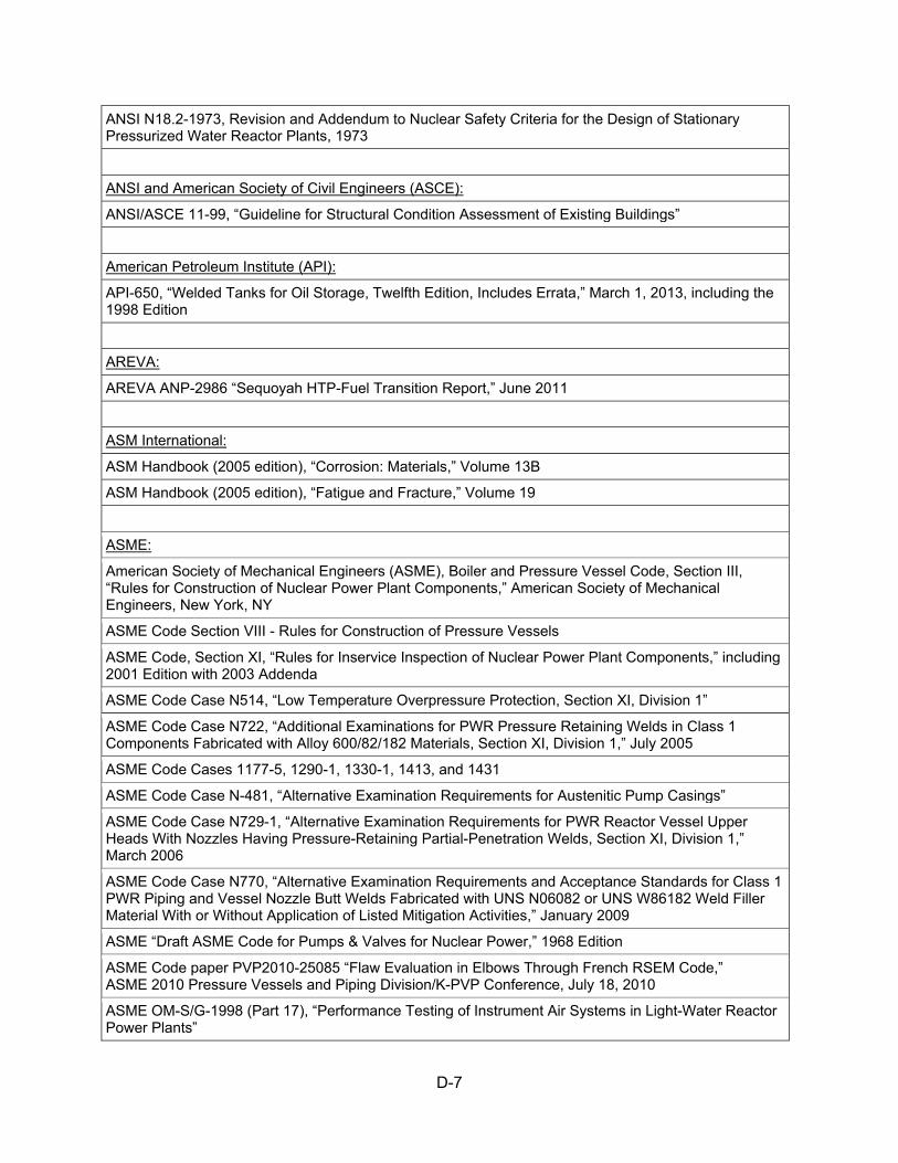
D-7
ANSI N18.2-1973, Revision and Addendum to Nuclear Safety Criteria for the Design of Stationary Pressurized Water Reactor Plants, 1973
ANSI and American Society of Civil Engineers (ASCE):
ANSI/ASCE 11-99, “Guideline for Structural Condition Assessment of Existing Buildings”
American Petroleum Institute (API):
API-650, “Welded Tanks for Oil Storage, Twelfth Edition, Includes Errata,” March 1, 2013, including the 1998 Edition
AREVA:
AREVA ANP-2986 “Sequoyah HTP-Fuel Transition Report,” June 2011
ASM International:
ASM Handbook (2005 edition), “Corrosion: Materials,” Volume 13B
ASM Handbook (2005 edition), “Fatigue and Fracture,” Volume 19
ASME:
American Society of Mechanical Engineers (ASME), Boiler and Pressure Vessel Code, Section III, “Rules for Construction of Nuclear Power Plant Components,” American Society of Mechanical Engineers, New York, NY
ASME Code Section VIII - Rules for Construction of Pressure Vessels
ASME Code, Section XI, “Rules for Inservice Inspection of Nuclear Power Plant Components,” including 2001 Edition with 2003 Addenda
ASME Code Case N514, “Low Temperature Overpressure Protection, Section XI, Division 1”
ASME Code Case N722, “Additional Examinations for PWR Pressure Retaining Welds in Class 1 Components Fabricated with Alloy 600/82/182 Materials, Section XI, Division 1,” July 2005
ASME Code Cases 1177-5, 1290-1, 1330-1, 1413, and 1431
ASME Code Case N-481, “Alternative Examination Requirements for Austenitic Pump Casings”
ASME Code Case N729-1, “Alternative Examination Requirements for PWR Reactor Vessel Upper Heads With Nozzles Having Pressure-Retaining Partial-Penetration Welds, Section XI, Division 1,” March 2006
ASME Code Case N770, “Alternative Examination Requirements and Acceptance Standards for Class 1 PWR Piping and Vessel Nozzle Butt Welds Fabricated with UNS N06082 or UNS W86182 Weld Filler Material With or Without Application of Listed Mitigation Activities,” January 2009
ASME “Draft ASME Code for Pumps & Valves for Nuclear Power,” 1968 Edition
ASME Code paper PVP2010-25085 “Flaw Evaluation in Elbows Through French RSEM Code,” ASME 2010 Pressure Vessels and Piping Division/K-PVP Conference, July 18, 2010
ASME OM-S/G-1998 (Part 17), “Performance Testing of Instrument Air Systems in Light-Water Reactor Power Plants”

D-8
American Society for Metals:
American Society for Metals (ASM) Handbook, Volume 19, “Fatigue and Fracture,” 1996
ASTM International:
ASTM A325 “Standard Specification for Structural Bolts, Steel, Heat Treated, 120/105 ksi Minimum Tensile Strength,” June 6, 2009
ASTM A490, “Standard Specification for Structural Bolts, Alloy Steel, Heat Treated, 150 ksi Minimum Tensile Strength,” 2012
ASTM C33, “Standard Specification for Concrete Aggregates”
ASTM C289, “Standard Test Method for Potential Alkali Silica Reactivity of Cement Aggregates (Chemical Method),” 2007
ASTM C295, “Standard Guide for Petrographic Examination of Aggregates for Concrete,” April 2012
ASTM C2276-78, “Standard Test Method for Particulate Contaminant in Aviation Fuel by Line Sampling,” 1978
ASTM D3359, “Standard Test Methods for Measuring Adhesion by Tape Test,” 2009
ASTM D448-08, “Standard Classification for Sizes of Aggregate for Road and Bridge Construction”
ASTM D975, “ASTM D975: Standard Specification for Diesel Fuel Oils,” 2007
ASTM D1796-83, “Standard Test Method for Water and Sediment in Fuel Oils by the Centrifuge Method,” 1983
ASTM D4057-95 (2000), “Standard Practice for Manual Sampling of Petroleum and Petroleum Products,” April 2000
ASTM D5163-08, “Standard Guide for Establishing a Program for Condition Assessment of Coating Service Level I Coating Systems in Nuclear Power Plants”
ASTM D7108, “Standard Guide for Establishing Qualifications for a Nuclear Coatings Specialist,” 2005
ASTM D7167, “Standard Guide for Establishing Procedures to Monitor the Performance of Safety-Related Coating Service Level III Lining Systems in an Operating Nuclear Power Plant”
ASTM E185-82, “Standard Practice for Conducting Surveillance Tests for Light-Water Cooled Nuclear Power Reactor Vessels”
Bush, S.H.:
Bush, S.H., “Probability of Damage to Nuclear Components Due to Turbine Failure,” Proceedings of the Topical Meeting on Water Reactor Safety, CONF-730304, American Nuclear Society, Salt Lake City, Utah, March 26–28, 1973, pp. 84–104
Crane Manufacturers Association of America (CMAA):
Crane Manufacturers Association of America (CMAA), Inc., Specification 70, “Specifications for Top Running Bridge & Gantry Type Multiple Girder Electric Overhead Traveling Cranes,” CMAA, Charlotte, NC, December 2008.

D-9
Electric Power Research Institute (EPRI):
EPRI NP-5769
EPRI NP-7079, “Instrument Air Systems: A Guide for Power Plant Maintenance Personnel”
EPRI NSAC-202L, “Recommendations for an Effective Flow-Accelerated Corrosion Program,” Revision 3
EPRI Report 1003057, “License Renewal Handbook”
EPRI Report 1007820, “Closed Cooling Water Chemistry Guideline, Revision 1: Revision 1 to TR-107396, Closed Cooling Water Chemistry Guideline” April 2004.
EPRI Report 1011231, “Recommendations for Controlling Cavitation, Flashing, Liquid Droplet Impingement, and Solid Particle Erosion in Nuclear Power Plant Piping”
EPRI Report 1012987, “Steam Generator Integrity Assessment Guidelines,” Revision 2
EPRI Report 1013234, “Materials Reliability Program: Screening, Categorization, and Ranking of Reactor Internals Components for Westinghouse and Combustion Engineering PWR Design (MRP-191)”
EPRI Report 1013475, “Plant Support Engineering: License Renewal Electrical Handbook,” Rev. 1, February 2007
EPRI 1013706, “Pressurized Water Reactor Steam Generator Examination Guidelines”
EPRI Report 1014986, “PWR Primary Water Chemistry Guidelines,” Revision 6
EPRI Report 1016555, “PWR Secondary Water Chemistry Guidelines,” Revision 7
EPRI 1016596, “PWR Internals Inspection and Evaluation Guideline (MRP-227, Revision 0)”
EPRI Report 1016609, “Materials Reliability Program: Inspection Standard for PWR Internals - 2012 Update (MRP-228)”
EPRI Report 1018292, “Materials Reliability Program: Screening, Categorization, and Ranking of B&W-Designed PWR Internals Component Items (MRP-189 Rev 1)”
EPRI 1019038, “Steam Generator Integrity Assessment Guidelines”
EPRI Report 1022863, “Materials Reliability Program: Guidelines to Implement the License Renewal Technical Requirements of 10CFR54 for Integrated Plant Assessments and Time-Limited Aging Analyses (MRP-227-A)”
EPRI draft report 1024966, “Probabilistic Reliability Model for Thermally Aged Cast Austenitic Stainless Steel Piping,” Appendix A
EPRI NP-5769, “Degradation and Failure of Bolting in Nuclear Power Plants,” Volumes 1 and 2, May 1988
EPRI Nuclear Safety Analysis Center (NSAC)-202L-R3, “Recommendations for an Effective Flow-Accelerated Corrosion Program,” non-proprietary version, August 2007
EPRI 1013706, “Pressurized Water Reactor Steam Generator Examination Guidelines”
EPRI 1016596, “PWR Internals Inspection and Evaluation Guideline (MRP-227, Revision 0)”
EPRI 1016609, “Inspection Standard for PWR Internals (MRP-228, Revision 0)”
EPRI 1019038, “Steam Generator Integrity Assessment Guidelines”
EPRI 1022863, “Materials Reliability Program: Pressurized Water Reactor Internals Inspection and Evaluation Guidelines (MRP-227-A)”

D-10
EPRI NP-5769, “Degradation and Failure of Bolting in Nuclear Power Plants,” Volumes 1 and 2, April 1988
EPRI Nuclear Safety Analysis Center (NSAC)-202L-R3, “Recommendations for an Effective Flow-Accelerated Corrosion Program.” non-proprietary version, August 2007
EPRI TR-104213, “Bolted Joint Maintenance and Applications Guide,” December 1995
EPRI TR-105090, “Guidelines to Implement the License Renewal Technical Requirements of 10CFR54 for Integrated Plant Assessments and Time-Limited Aging Analyses”
EPRI TR-108147, “Compressor and Instrument Air System Maintenance Guide”
Institute of Electrical and Electronics Engineers (IEEE):
IEEE Std. 1406-1998, “IEEE Guide to the Use of Gas-In-Fluid Analysis for Electric Power Cable Systems.”
Institute of Nuclear Power Operations (INPO):
INPO 97-011, “Guidelines for the Use of Operating Experience”
INPO 10-006, “Operating Experience (OE) Program and Construction Experience (CE) Program Descriptions,” Revision 1.
International Society of Automation (ISA):
ISA-S7.0.1-1996, “Quality Standard for Instrument Air”
National Association of Corrosion Engineers (NACE):
NACE SP0169-2007, “Control of External Corrosion on Underground or Submerged Metallic Piping Systems,” NACE International, Houston, TX, March 2007
NACE RP0285-2002, “Standard Recommended Practice Corrosion Control of Underground Storage Tank Systems by Cathodic Protection,” Revised April 2002
NACE RP0502-2002, “Standard Recommended Practice, Pipeline External Corrosion Direct Assessment Methodology,” NACE International, Houston, TX, August 2003
National Fire Protection Association (NFPA):
NFPA 25, “Standard for the Inspection, Testing, and Maintenance of Water Based Fire Protection Systems,” including the 2011 Edition
NFPA 805, “Performance-Based Standard for Fire Protection for Light Water Reactor Electric Generating Plants,” 2001 Edition
NFPA 1962, “Standard for the Inspection, Care, and Use of Fire Hose, Couplings, and Nozzles, and the Service Testing of Fire Hose”

D-11
Nuclear Energy Institute (NEI):
NEI 95-10, “Industry Guideline for Implementing the Requirements of 10 CFR Part 54—The License Renewal Rule,” Revision 6, June 2005
NEI 97-06, “Steam Generator Program Guidelines,” Revision 3
NEI 03-08, “Guideline for the Management of Materials Issues”
Nuclear Utility Management and Resources Council (NUMARC):
NUMARC 93-01, “Industry Guideline for Monitoring the Effectiveness of Maintenance at Nuclear Power Plants,” Revision 2, April 1996
Research Council on Structural Connections (RCSC):
RCSC publication “Specification for Structural Joints Using ASTM A325 or A490 Bolts,” Section 2
Revie, R.W.:
Revie, R.W. (ed.), Uhlig’s Corrosion Handbook, Third Edition, Hoboken, NJ: John Wiley & Sons, Inc., April 2011
Sandia National Laboratory:
Department of Energy (DOE) Aging Management Guide (AMG) contractor report SAND96-0344, “Aging Management Guideline for Commercial Nuclear Power Plants – Electrical Cable and Terminations”
Southwest Research Institute (SWRI):
SWRI TR No. SWRI-06-8851
SWRI TR No. SWRI-17-8851
Tennessee Valley Authority (TVA):
TVA Letter Response to Generic ltr 92-01, "Reactor Vessel Structural Integrity." NUMARC recommended response guidelines utilized to extent practical.” July 7, 1992 (ADAMS Accession No. 9207090177)
TVA response letter of Nov. 18, 1999, to Rev. 2 of the Reactor Vessel Integrity Database
TVA Report Nos. PTLR-1, Rev. 4, and PTLR-2, Rev. 5
United States of America Standards (USAS):
USAS 16.5 “Pipe Flanges and Flanged Fittings,” 1996 Edition (ANSI 16.5)
USAS B31.1, “Code of Power Piping,” 1967 Edition
United States Society on Dams (USSD):
The Aging of Embankment Dams, Denver, CO: United States Society on Dams, 2010

D-12
Westinghouse Electric Co.:
Proprietary calculation (no document number, title, or date given) of the acceptance criteria for the measurements to ensure adequate Type 304 stainless steel hold-down spring force through the period of extended operation
Westinghouse Topical Report (WCAP)-7822, “Indian Point Unit No. 2 Internals Mechanical Analysis for Blowdown Excitation.” December 1971
WCAP-7861, “Topical Report, Methods of Determining the Probability of a Turbine Missile Hitting a Particular Plant Region,” February 1972
WCAP-8516 (Proprietary) “UHI Plant Internals Vibration Measurement Program and Pre- and Post-Operational Tests on Sequoyah 1 Power Plant”
WCAP-8517 (Non- Proprietary) “UHI Plant Internals Vibration Measurement Program and Pre- and Post-Operational Tests on Sequoyah 1 Power Plant”
WCAP-9645 (Proprietary) “Verification of Upper Head Injection Reactor Vessel Internals for Pre-Operational Tests on Sequoyah 1 Power Plant”
WCAP-9646 (Non-Proprietary) “Verification of Upper Head Injection Reactor Vessel Internals for Pre-Operational Tests on Sequoyah 1 Power Plant”
WCAP-10340, Revision 1, “Analysis of Capsule T from the Tennessee Valley Authority Sequoyah Unit 1 Reactor Vessel Radiation Surveillance Program,” S.E. Yanichko, et al., February 1984
WCAP-10456, "Effects of Thermal Aging on the Structural Integrity of Cast Stainless Steel Piping for Westinghouse Nuclear Steam Supply Systems," Westinghouse Proprietary Class 2, November 1983
WCAP-10509, "Analysis of Capsule T from the Tennessee Valley Authority Sequoyah Unit 2 Reactor Vessel Radiation Surveillance Program," April 30, 1984
WCAP-10931, "Toughness Criteria for Thermally Aged Cast Stainless Steel," Revision 1, July 1986
WCAP-12011 (Proprietary) "Technical Justification for Eliminating Large Primary Loop Pipe Rupture as the Structural Design Basis for Sequoyah Units 1 and 2," and WCAP-12012 (Non-Proprietary), October 1988, including WCAP-12011 (Proprietary), Addendum 1, Revision 1.
WCAP-13333, "Analysis of Capsule X from the Tennessee Valley Authority Sequoyah Unit No. 1 Reactor Vessel Radiation Surveillance Program," June 30, 1992
WCAP-13545, "Analysis Of Capsule X From The Tennessee Valley Authority Sequoyah Unit 2 Reactor Vessel Radiation Surveillance Program," March 12, 1993
WCAP-14040-A, Rev. 4, “Methodology Used to Develop Cold Overpressure Mitigating System Setpoints and RCS Heatup and Cooldown Limit Curves,” May 2004
WCAP 14040-NP-A, “Methodology Used to Develop Cold Overpressure Mitigating System Setpoints and RCS Heatup and Cooldown Limit Curves,” May 2004
WCAP 14950, “Mitigation and Evaluation of Pressurizer Insurge-Outsurge Transients,” February 1998
WCAP-15224, “Analysis of Capsule Y from the Tennessee Valley Authority Sequoyah Unit 1 Reactor Vessel Radiation Surveillance Program,” June 1999
WCAP 15338, “A Review of Cracking Associated with Weld Deposited Cladding in Operating PWR Plants (MUHP-6110),” March 2000
WCAP-15293, Revision 1, "Sequoyah Unit 1 Heatup and Cooldown Limit Curves for Normal Operation and PTLR Support Documentation," July 2003
WCAP-15320, “Analysis of Capsule Y from the Tennessee Valley Authority Sequoyah Unit 2 Reactor Vessel Radiation Surveillance Program,” March 2000

D-13
WCAP-15321, Revision 3, “Sequoyah Unit 2 Heatup and Cooldown Limit Curves for Normal Operation and PTLR Support Documentation,” Westinghouse Electric Company, LLC, April 2001
WCAP-15666, “Extension of Reactor Coolant Pump Motor Flywheel Examination, Non-Proprietary Class 3 (MUHP-3043)," August 24, 2001
WCAP-15984, “Reactor Vessel Closure Head/Vessel Flange Requirements Evaluation for Sequoyah Units 1 and 2,” April 2003
WCAP 15988-NP, “Generic Guidance for an Effective Boric Acid Inspection Program for Pressurized Water Reactors,” February 2005
WCAP-16083-NP-A, Rev. 0, "Benchmark Testing of the Ferret Code for Least Squares Evaluation of Light Water Reactor Dosimetry" January 10, 2005
WCAP 17096-NP, “Reactor Internals Acceptance Criteria Methodology and Data Requirements,” Revision 2
WCAP-17539, “Revision 0, "Sequoyah Units 1 and 2 Time-Limited Aging Analysis on Reactor Vessel Integrity"
WCAP-17539-(Non-Proprietary), “Revision 0, "Sequoyah Units 1 and 2 Time-Limited Aging Analysis on Reactor Vessel Integrity"
Westinghouse Technical Report No. WSTG-1-NP
Woishnis, W.A.:
Woishnis, W.A. (ed.), Chemical Resistance of Plastics and Elastomers, 3rd Edition, Norwich, NY: William Andrew, Inc., 2001


NU
REG
-2181
Safety Evaluation Report R
elated to the License Renew
al of Sequoyah N
uclear Plant Units 1 and 2
July 2015
Copyright © 2022 FDOKUMEN