NUREG/CR-2189, Vol. 5, "Probability of Pipe Fracture in the ...
369
NUREG/CR-2189, Vol. 5 UClD-18967, Vol. 5 RM Probability of Pipe Fracture in the Primary Coolant Loop of a PWR Plant Volume 5: Probabilistic Fracture Mechanics Analysis Load Combination Program Project I Final Report Manuscript Completed June 1981 Date Published August 1981 Prepared by D,O.Huui,B Y UimDD .Dmihia Sefonce Applications, lnc Liairce i~vemoere labraory 7000 East Avme.. Livermore, CA 94550 Prqiared for Divison of Engineering Technology Offce of Nuclear Regulatory Research U.S. Nuclear Reuh~tor• Cemmkulon Wnsihgton, D.C. 2E•J55 NRC FIN No. A-OW3
-
Upload
khangminh22 -
Category
Documents
-
view
1 -
download
0
Transcript of NUREG/CR-2189, Vol. 5, "Probability of Pipe Fracture in the ...
NUREG/CR-2189, Vol. 5UClD-18967, Vol. 5RM
Probability of Pipe Fracturein the Primary Coolant Loopof a PWR Plant
Volume 5: Probabilistic FractureMechanics Analysis
Load Combination ProgramProject I Final Report
Manuscript Completed June 1981Date Published August 1981
Prepared by
D,O.Huui,B Y UimDD .DmihiaSefonce Applications, lnc
Liairce i~vemoere labraory7000 East Avme..Livermore, CA 94550
Prqiared forDivison of Engineering TechnologyOffce of Nuclear Regulatory ResearchU.S. Nuclear Reuh~tor• CemmkulonWnsihgton, D.C. 2E•J55NRC FIN No. A-OW3
ABSTRACT
The purpose of the portion of the. Load Combination- Program covered In thisvolume was to estimate the probability of a seismic induced loss-of-coolant
accident (LOCA) in the primary piping of a conmmercial pressurized waterreactor (PWR). Such results arre useful in rationally assessing the needto design reactor primary piping systems for the simultaneous occurrenceof these two potentially high stress events. The primary piping system atZion I was selected for analysis. Attention was focussed on the girthbutt welds in the hot leg, cold leg and cross-over leg, which are centri-fugally cast austenittic stainless steel lines with nominal outside dia-meters of 32 - 37 inches.
A fracture mechanics model of structural reliability was employed to esti-
mate the piping failure probability. This model assumes piping failureto occur as the result of the subcritical and catastrophic growth of cracksintroduced into weidments during fabrication. Part-circumferential interiorsurface cracks are considered to be present with a probability that dependson their size, and a bivariate crack size distribution is employed whichIs estimated from the literature. The size distribution is altered by pre-and in-service inspections by a crack detection probability that dependson crack size. The cracks that are present after the pro-service inspectionand proof test form the initial conditions for fracture mechanics calculatiorof how these cracks would grow due to cyclic stresses imposed in service.Seismic events of a specified magnitude at a specified time were includedin the stress history thereby providing information on the influence ofsuch events on the piping reliability.
The results generated by a specially written computer code indicated thatthe stress history was dominated by the heatup-cooldown cycle, and thatseismic envents generally did not have a strong influence. Pre-serviceinspection and the initial proof test provided a significant reduction inthe failure probabilities. The leak and LOCA probabilities were calculatedto be on the order of 10-6 and pe"• r plant lifetime (respectively) for
the complete primary system. Large variations In the input parameters (suchas Initial crack size distribution) were required before these values weresignificantly altered. Hence, it appears that the probability of a suddenand complete pipe severance in the large primary piping at Zion [ is very lcThe probability of a seismic induced LOCA is even lower.
TABLE OF CONTENTS
Section Pg
LIST OF FIGURES....................................... viii
LIST OF TABLES..................................*..... xivACNWEGMNS.................... xviEXECUTIVE SUMMARY ... .. . .. .. .. .. .. . ... .......... .. **. *. . xvli
1.0 INTRODUCTION. ................... *..*... ...... .. . ... ...... 11.1 Basic Methodology .. .. .a*. . . .. . . . .. .. . .... . ........ 21.2 Plant Description ........ , . ........... * .a*a*a.a aa*aa.... 21.3 Review of Relevant Stresses....................... 7
1.3.1 Non-Seismic Stresses .,,ma.'............. 71.3.2 Seismic Stresses .a......................* 81.3.3 Radial Gradient Thermal Stresses ............ 8
2.0 FRACTL'RE M£CANCS ACMOE... ........... 122.1 ('verview and Review of Past Work..................... 122.2 Sunmmary and Discussion of Major Assumptions ....... 16
2.3 Initial Crack Distribution...................... 202.3.1 Depth Distribution.................... 24
2.3.2 Aspect Ratio Distribution..................... 282.3.3 Resulting Area and Length Distributions * 332.3.4 Crack Existence Probabilities ............. 43
2.4 Inspection Detection Probabilities ........... 492.4.1 Review of Past Results . ....................... 492.4.2 Model for Influence of Surface Length......•54
2.4.3 Specialization to Austenitic Weidments .• 56
2.5 Material Fracture Characteristics .............. * 592.5.1 Fatigueerck rowh c....... o......h 62
2.5.2 Final Fracture........ . ... .. . .. . .. a. .aaa....... 722.6 Fatigue Crack Growth Calculation Procedures ....... 77
2.6.1 Relevant Stress Intensity Factors for Part-Through Cracks .................................... 77
2.6.2 Cycle Counting and Load Interactions ...... 802.7 Stress Intensity Factors...................... 862.8 Leak Model s . . . .. . .. . . ....................... ................. 93
2.8.1 Prediction of Flashing Water Flow-ThroughPWR Pipe-Wall Cracs...... k....... 93
2.8.2 Crack Opening Displacements ......... *.*..... 101
v
I
Table of Contents (cont'd)Section PageI
2.8.3 Leak Detection Probabilities ................. 1042.9 Failure Criteria ... *...*. *........... ......... . . .. 105 i
3.0 NUMERICAL SIMULATION PROCEDURES... .... ................... 1103.1 Monte Carlo Simulation•(...;:,;... ....... 115 mI3.2- Sample Space Definition .............................. 117i3.3 Stratified Sampling ................................. 120i
3.4 Initial Crack Size Distribution ...................... 123
3.4.1 Transformation of Variables......... .. ..... 1233 4.2 Pre-Service Inspection and Hydrostatic I
Proof Test...... . . . . ............................... 1283.5 Arrival Time for Events................................. 132i
3.6 Crack Growth Calculation.... ............................... 1343.7 Influence of Earthquakes on Crack Growth ............. 138
3.8 Statistical Variance ........ ..................... 143
4.0 APPLICATIONS TO REACTOR PIPING ............................ 148
4.1 Transient Frequencies ...................... 150 I4.2 Joint and System Reliability.. ..................... 1534.3 Results and Discussion.................... 154Is
4.3.1 Results for l ransient s ie...... t... 1554.3.2 Results for Base Case Conditionons... . 157i
4.3.3 Influence of Input Parameters on Results .,190
4.3.4 Additional Discussion of Results,... . 198i
5.0 SUMMARY AND CONCLUSIONS. ... .. . ... .. .. . .. . .,. .. . .. .. .. . . . .. 206SUMMARY OF MAJOR NOTATION ................................. 209 1REFERENCES.................................. ~214
II
Appendices
Section PageA. INTRODUCTION AND REVIEW OF STRESS INTENSITY FACTOR
A.I1 Desired Solutions. .. . .. ........ . . . .. .* .. e. .. . . .. . .... 234
A.2 Review of Previously Existing Stress IntensitySolutions ........... *.............................. 235
A,3 Review of Boundary Integral Equation Techniques ...... 249
B. STRESS INTENSITY FACTOR RESULTS FROM BOUNDARY INTEGRALEQUATION CALCULATIONS ....... . ....................................... 25113.1 Complete Circumferential Crack.................... 254
B.2 Longitudinal Semi-Elliptical Cracks ............... 257
B.3 Circumferential Semi-Elliptical Cracks ............. 269
C. INFLUENCE FUNCTIONS ...................... 277
C.1 Introductory Remarks. . .. .. .. .. .. .. .. .. . ... .. .. .. .. ... 278C.2 Underlying Theory............ ,....................... 283cCurv Fit to , ..... 2..........9...
C .4 Curve Fit to g2............*.........293....
D. APPLICATIONS TOCOMPLEEXSTRESSES..... ........... 299
D.2 Verification of the Integration Procedures........304
D .2.1 Uniform Stresses ....... . .. .. . . . . . . . . . .. *304
D.2.2 Non-Uniform Stresses... ........................... 305
D,3 Comparison With Existing Solutions.............. 309
D,3.1 U~niformi Stress. . ..* . *.,.*. .. . ........... ...... 309D.3.2 Non-Uniform Stresses.................'... 309
D,4 Applications to Radial Gradient Thermal Stresses ..... 315
GLOSSARY. . . . . ................................... . . .. . ......................... 349
mI
LIST OF FIGURESm
Figure Pg
1-1 Schematic Representation of Various Portions of Project nmto Determine Necessity of Coupling LOCA's and SeismicEvents.....* . o.o..,ma*o*o.eo . .
1-2 Olauram of Primary Piping Analyzed Showing Locations ofWel&t Considered,.,........,. 0 0 0 0 0 0 0 0 0 .. 5
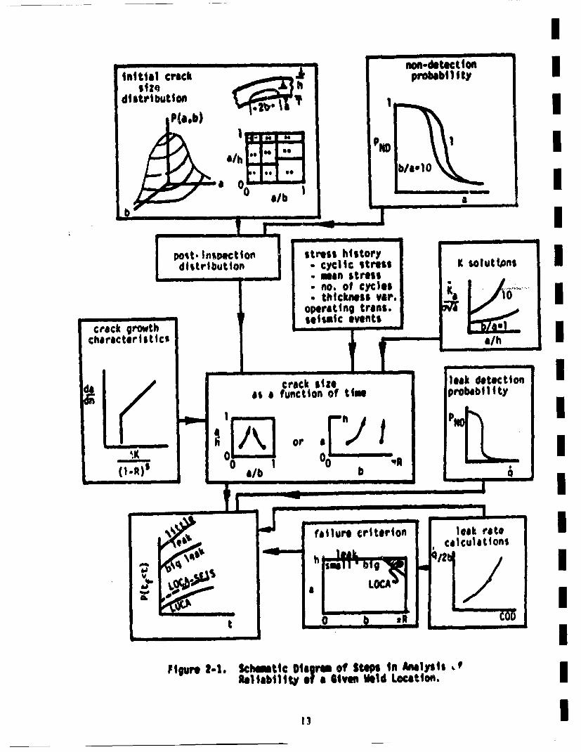
2-1 Schematic Diagram of Steps in Analysis of Reliability mof a Given Weld Location........ .. . ...*.*.. . ....... .... .*....... 13
2-2 Geometry of Part-Circumferential Internal Surface Crack mConsidered in this Inetgto.°•., .. . ...... 22
2-3 Various Complementary Cumulative Marginal Crack DepthmDistributions ....................................... 26I
2-4 Various Complementary Cumulative Marginal Distributions ofCrack Aspect Rati o .. .. ..................... ...... 32 I
2-5 Complementary Cumulative Distribution of Crack Area.Exponential Depth Distribution and Shifted Lognormal Aspectm
Ratio Distribution of Various Values of p..................... 382-6 Comparison of Feldman Data on Crack Area Distributions with
Results Using Marshall Exponential on D~pth and "Shifted" ILognormal on Aspect Ratio, with p 10" ................. 39
2-7 Complementary Cumulative Distribution of Half Surface CrackmLength for Marginal Exponential Depth Distribution and MarginalILognormal Aspect Ratio Distribution ........................... 42
2-8 Probability of Non-Detection of a Crack as a Function of itsDepth for an Ultrasonic Inspection -- Data From Literature .... 60
2-9 Crack Geometry Versus Beam Diameter for the Two DimensionalmModel of Probability of Non-Detection Based on Crack Area ..... 55I
2-10 Two Dimensional Lognormal Model of Probability of Non-Detection
of a Crack Based on Crack Area Plotted on Lognornmal Probabilitym
2-11 Two Dimensional Lognormal Model of Probability of Non-Detectionmof a Crack Based on Crack Area Plotted on Linear Scales ....... 58m
2-12 Pm Data for Wrought Materials (Same as Figure 2-8) and theMI~el for Cast Austenitic Material ................... 60I
vtii
List of Figures (cont'd)
Figure Page
2-13 Two Dimensional Lognonial Model for Probability of Non-Detection of a Crack in Cast Austenitic Materal............ 61
2-14 Fatigue Crack Growth Rate Data as a Function of EffectiveStress Intensity Shown Along with Least Square Curve-Fit ...... 65
?-15 Frequency Histogram of ln(C) for m - 4.0 .................... 69
2-16 Cumulative Distribution of C Plotted on a Lognormal Prob-ability Paper..... ............................................. 70
2-17 Schematic Representation of J-Integral R Curve .............. 74
2-18 Schematic Representation of a Stress-Time History ShowingMeans of Counting Stress Cycles and Corresponding M 1 . . .. . . . . . 82
2-19 Schematic Representation of a Time History for Stress IntensityFactor for a Transient • •at Produces Radial Gradient ThermalStresses During Steady State Plant Operation.............. 83.
2-20 X /oaa for a Part-Circumferential Crack in a Pipe WithU~iform Stress in the Pipe Wall............................... 88
2•21 . •/yai for a Part-Circumferential- Crack in a- Pipe WithUJ~iformSress nthessipe al..... p................. 89
2-22 Two-Phase Flow Through a Long, Narrow Crack (From Wallis 80). 94
2-23 Solution Method. HEM Model/Isent~halpic Flow Pin * 2250 psia,Tin - 550°F, R2 - R1 - 1.8 .......................... . .. ................. 100
2-24 Crack Flows. Pln"a 2250 psia, h - 1.8 in., Tsat - 6520F .... 103
2-25 Geometry of Part-Circumferential Interior Surface Crack Usedfor Calculation of Critical Crack Area **...........**.......... 108
3-1 Simplified PRAISE Flowchart ...... .. . .. . .. . . . ..................... 116
3-2. Sample Space for PRAISE Code...................................... 118
3-3 Schematic Representation of Typical Stratification Employedin PRAISE Calculations ...... ; .................... 122
3-4 Algorithm for Crack Growth Calculations.......................... 135
3-5 Algorithm for "Evaluation" Earthquakes.......................... 140
Ix
List of Figures (cont'd)
Figure Page
A-2 Weight Function for an Internal Circumferential SurfaceCrack In a Section of Straight Pipe (from Labbens 76) ......... 239
A-3 A Comparison of K for Internal Surface Circumferential Cracksin Pipes Subjected to Uniform Axial Stress. Results arefrom Labbens 76 and are for straight pipe runs unless other-wise noted .................... *........................................ 240
A-4 Stress Intensity Factor for Edge Crack in a Flat Plate andfor Long Longitudinal and Complete CircumferentialCrack in a Pipe with Ri/h = 10. Pipe Results are fromLabbens 76.. . . .......... .................................................... 241
A-5 Function i (€) for = 0.25 (from Heliot 79). .................... .. 243
A-6 Functions ij(.) for •= 0.50 (from Hellot 79) ................. 244
A-7 Functions ij(.) for * 0.80 (from Heliot 79).......... ,....... 245
A-8 Kn~ /aab as a Function of y for B l Iand 5 and cs *0.6.R•Ults are from Kobayashi 77 and are for uniform or pressurestress ............... *........g....................... . ... 247
A-9 Normalized Angular Variation of K Along Crack Front forSelected Cases of Uniform or Pressure Stress ........ 248
B-I Boundary Integral Equation Nodalization for CompleteCircumferential Cra c k ........................ 255
B-2 Various Comparisons of K From BIE Calculations WithCorresponding Results Obtain~able From Labbens 76 .............. 256
8-3 Stress Intensity Factor as a Function of Position on CrackFront for Pressure Loading on a Small Area of Crack Surface... 258
- ~B•4 .Nodalization for BIE Analysts.Df a Longitudinal Semi-E1lipticalCrack in a Pipe .. ............ .. .. . ... ,~* ........ ... .. . . .. ... . 259
B-S Comparison of Normalized Variation of K Along Crack Front ofSemi-Elliptical Interior Surface Longitudinal Crack in aPipe..................*............................... ...... 262
B-6 Comparison of Normalized Variation of K Along Crack Front ofSemi-Elliptical Interior Surface Longitudinal Crack inPipe ..... g.*......g.*.. ......................................... 263
xi
II
List of Figures (cont'd)I
Figure P~aqe
'B-7 Comparison of Normalized Variation of K Along Crack Frontof Semi-Elliptical Interior Surface Longitudinal Crack inaPipe. . ' **..*, 264 i
B-8 Various Comparibons of Normalized Variation of K AlongCrack Front for Semi-Elliptical Longitudinal Surface Cracksnin Pipe, Plates and Half Spaces ............................... 266
B-9 Various Comparisons of K(¢=O) for Longitudinal Semi-
Elliptical Cracks i nPpes....p............... 268•B-1O Geometry of Part-Circumferential Cracked Pipe of Interest
Showing Nodalization Scheme Employed In BIE Calculations ...... 270I
B-li Normalized Variation of K Along the Crack Front for VariousLongitudinal and Circumferential Semi -Ell1iptical Cracks inPipes as Obtained by BIECalculations.......................... 274i
8-12 Normalized Variation of K Along the Crack Front for VariousLongi tudinal and Circumferential Semi-Elliptical Cracks inmPipes as Obtained byBIE Calculations.............,..o .... 0 ..... 275I
C-i Schematic Representation of a Crack Growing Only in the "a"
Degree-of-Freedom ............................................. 281IC-2 Comparison of Curve-Fit and BIE Data Points for the Function
Gi......1............................... 295n
D-i Coordinate System for Integration Scheme for Integrating Overa Semi -Elli 1pti cal Area ... . ... .. . .. .. .. .. . ... . .. .. .. .. .... ... **303i
D-2 1_ for Uniform Stress Obtained by IF Method Compared With-2D~rect Results From BIE (Section 2.7) ......................... 310
D-3 •kfor Uniform Stress Obtained by Ir Method Compared WithD3 D1?rect Results From BIE O..O..f............ ...........*O~* ... 311
D-4 Comparison of IF Solutions for Non-Uniform Stresses WithnExisting Solutions .................. o.... ...... *b... ............. 313
D-5 Comparison of IF Solutions for Non-Uniform Stresses WithiExisting Solutions . . . . . . . . . . ....... .. ...... .* * * * * .*. *... . .. . 314I
D-6 Plant Loading and Unloading at a Rate of 5% per tMinute ....... 318i
D-7 Ten Percent Step Load Decrease From 100 Percent Power ......... 319
xli
List of Figures (cont'd)
,Figure Pg
.D•8o Ten Percent Step Load Increase'From- OPercn oer ........ 320
D-9 Large Step Decrease In Load With Steam D ump.......... 321
0-10 Loss of Load From Full Powe w.......r............... 322
D-11 Loss of Power......................... .. . ... .. . ......... 323
0-12 Loss of Flow inOne Loop .................. ........... 324
0-13 Loss of Flow in Other Loops .............................. 325
D-14 Steam Line Break From no Load....................... 326
D-15 Reactor Trip From Full Power ............................... 327
D-16 Radial Gradient Thermal Stresses at Various Times From theStart of the Transient for a 2.5 in. Thick Weld in the Hot
D-17 2.6K• as a Function of Time for Three Crack Geometries for a2AInch Thick Weld in the Hot Leg.......................... 330
0-18 Maximum 6R. During Reactor Trip as a Function of CrackGeometry for a 2.5 Inch Thick Weld in the Hot Leg............. 332
D-19 Maximum 6Xk During Reactor Trip as~a Function of CrackGeometry f~r 2.5 Inch Thick Wel d in the Hot Leg ............... 333
D-20 Maximum and Minimum 6X. During the Transient Loss of LoadFrom Full Power for a 2.5 Inch Thick Weld in the Hot Leg ...... 335
0-21 Maximum and Minimum dl• During the Transient Loss of LoadFrom Full Power for a .5 Inch Thick Weld in the Hot Leg ....... 336
xliii
LIST OF TABLES
Table Pg1-i Materials of Piping and Related Components Along With
Selected Mechanical Prope rties ......................... 61-2 Summary of Various Non-Seismic Stresses for Each of the m
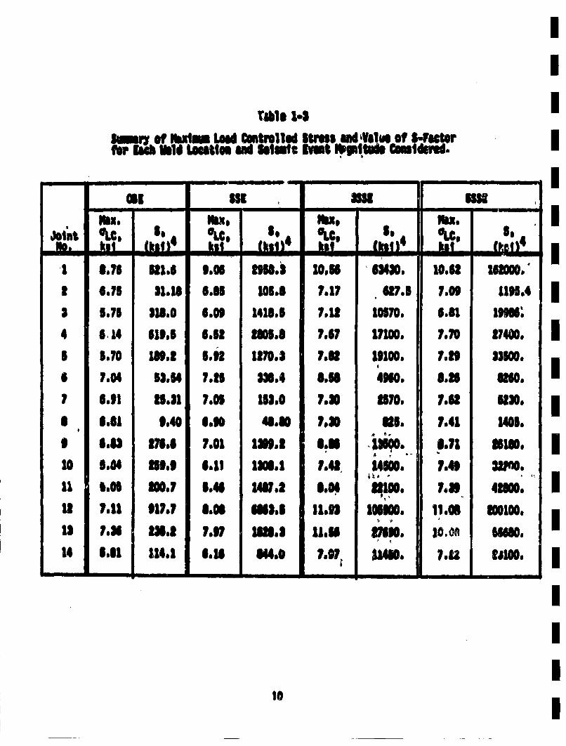
Weld Locations. Dimensional Information is Also Included ...... 91-3 Summary of Maximum Load Controlled Stress and Value ofi
S-Factor for Each Weld Location and Seismic Event Magnitude 1Considered ............ .. . ... .. .. .. . ...................... 1
2-1 Values of Complementary Cumulative Distribution of Crack iArea, P(> A), for Marshdll Exponential Depth Distributionand Various Marginal Aspect Ratio Distributions ................ 31 i
2-? Summary of Value of Crack Frequepcjes..Fr~om Cramond 74.......... 45
2-3 The Probability of Non-Detection of a Defect of Depth 'a' asia Function of 'a' For Ultrasonic Inspection ................ 52 52
2-4 The Probability of Non-Detection of a Defect of Depth 'a' asa Function of 'a' For Ultrasonic Inspection ...... ,..........5
2-5 Summary of Flow Rate Experiment Data (From Collier 80) ...... 97
2-6 Comparison of Experimental Critical Values with Predicted nLimits (From Agostinelli 58)............................ 99
2-7 Crack Flows Q' (gal/min-ft).......*.. . . . **102 mi
3-1 Illustration of Procedure Used in Monte Carlo Simulation toAccount for Influence of Pre-Service Inspection .......... ... 131i
4-1 List of Transients and Postulated Number of Occurrences in40 Years .................. ,.......................... b2i
4-2 Tabulation of Values of P~tInrA .<tlEq(g,t)] for Weld JointsConsidered-Results Conditioh•T on a Crack Being InitiallyPresent...............*........................*9 .......... 158n
4-3 Tabulation of Values of P~t1 ku <t(Eq(g,t)] for Weld JointsiConsidered-Results CondltioA•t on a Crack Being Initially [P resent ..................... ,.................,..................172 n
4-4 Estimates of Influence of In-Service Inspection for VariousTimes of First Inspection..................................4.. 201
Ixiv
I
List of Tables (cont'd)
tabl~eePg
B-i Comparisons of K(tj=O)/,aai for Unitorm Stress on aLongitudial Interior Surface Semi-Elliptical Crackin a Pipe with Ri/hulO, b/au3, Various cs=a/h ............... 261
B-2 Comparison of K(¢=O)/aa for Uniform Stress on aLongitudial Semi-Elliptical Crack in a Pipe farVarious y, ai and B. All Resluts Generated by BIE,and are not Corrected to Account for ConsistentlyLow BIE Results................................................... 267
B-3 Ce~iparison of K(4k=O)/oa• for Uniform Stress on Semi-Elliptical Cracks in Pipes with Various y ShowingDirect Comparison of Longitudinal and CircumferentialC racks...............*...........*..................................... ?72
C-i Strain Energies for Surface and Buried Cracks ............... 291
C-2 g1 for Various Sizes of Surface Cracks ................... 292
C-3 g1 for Various Crack Geometries-Results From Curve-Fit ........ 294
D-2 K= for Buiried Elliptical Defect in an Infinite Body UnderUt~iform Stress-Comparison of Results Obtained by the Inte-gration Scheme with the Existing Solutions......
D-3 • ad for Buried Circutla r Defect Under Non-UnifeodyUdrm
Stress, •n an Infinite Body--Comparison of AnalyticalResults with that Obtained by the Integration Scheme ........... 308
D-4 Description of the Transients, Including Maximum AT inHot Leg ............................. ........................... 317
0-5 Normalized RMS Stress Intensity Factors (•r-f•)forTransients in the Hot Leg of ZION 1.. .............. . .... = 338
xv
II
ACKNOWLEDGEMENTS I
We would like to take this opportunity to acknowledge the many personsI
who contributed to the efforts resulting in this report. The initialefforts of Dr. Pedro Albrecht, now at the University of Maryland, inI
initiating this project are greatly appreciated, and tie continuing supportof John O'Brien and Milt Vagins was essential to this work9 Thecontributions of C.K. Chou and his colleagues at Lawrence Livermore National ILaboratory are also gratefully acknowledged. The cooperation of T. Cruseof Pratt and Whitney Aircraft, East Hartford,,Connecticutj and P. BesunerI
of Failure Analysis Associates, Palo Alto; California inriproviding theboundary integral equation code was invaluab•h ini •ener~ation of' the numer-I
ical stress intensity factor~ results. Additionally, the assistance pro-vided by P. Besuner in the early stages of running the code, and inI
formulation of the influence functions provided essential inputs to thesekey phases of the project. Numerous co-workers at Science Applications,Inc., provided essential assistance in this work. The analysis provided byI
Dr.Verne Denny, as reported in Section 2.8.1, was especially helpful.'The key discussions with Stanley Basin at various stages of this work dre alsoI
gratefu~lly acknowledged. The assistance provided in running and developingthe PRAISE code provided by Douglas Smith of SAI and the University ofI
California at Berkeley, and the BIE nodalization and calculations performedIby Richard Northrup of SAl and the University of" Cincinnatti areespecially noteworthy. It is also a pleasure to acknowledge the helpful!
discussions held with various consultants, including D. Iglehart of Sta•-ford University, P. C. Paris of Washington University, and A.S. Kobayashi
of the University of Washington. Finally (in a departure~ from SAI traditior)we would like to acknowledge the skillful typing provided by John AnnI
ICarlle-Wbb, ormely o S~l
I
xvi I
EXECUTIVE SUIMARY
The Code of Federal Regulations requires that structures, systems, andcomponents that affect the safe operation of nuclear power plants be designed
to withstand combinations of loads that can be expected to result from nat-ural phenomena, normal operating conditions, and postulated accidents. Oneload combinations requirement -- the combination of the most severe LOCA(loss-of-coolant accident) load and SSE (safe shutdown earthquake) loads --
has beeti controversial because both events occur with very low probabilities.This issue became more controversial In recent years because postulated largeLOCA and SSE loads were each increased by a factor of 2 or more to accountfor such phenomena as asyimmetric blowdown and because better techniques fordefinlnq loadinq have been developed.
The original objective of Load Combinations Project I was to estimate thejoint probability of simultaneous occurrence of both events and to deve'lopa technical basis for the NRC (Nuclear Regulatory Commnission) to use indetermi' ing whether it could relax its requirement on the combination of SSr.and large LOCA for nuclear power plants. However, in the process ol' prob-
ability estimation we have not only estimated the probability of simultaneousoccurrence of a large LOCA and an earthquake, but also esiatdte rb
~abilit~ of..a large LOCA caused by '1'rmab-and abnormaloloading conditions with-out an earthquake. The estimates provide very useful information on thelikeliheod of asynmetric blowdown, which is a sub~et of large LOCA. Also,the probabilistic fracture mechanics model that we developed can be used toestimate the probability of pipe rupture with or without prior leak. Thatis, we can estimate the proportion of pipes that will leak detectably boforerupture under normal operation, accident, or upset conditions. We can alsoevaluate the piping reliability in general. After a sufficient parametricstudy is done, we will be able to recomumend & more rational basis for post-ulating pipe rupture locations.
If earthquakes and large LOCAs are independent events, the probability oftheir simultaneous occurrence is small. However, this probability isexpected to be greater if an earthquake can induce pipe failure that leads toa LOCA. This LOCA could result directly (i.e., ground motion causes a pipebreak in the primary cooling system) or indirectly (i.e., an earthquake causesa structural, mechanical, or electical failure that in turn causes a pipe
xvii
Ibrea Intheprimry oolng sste),Ibrea in he rimay colin sysem)
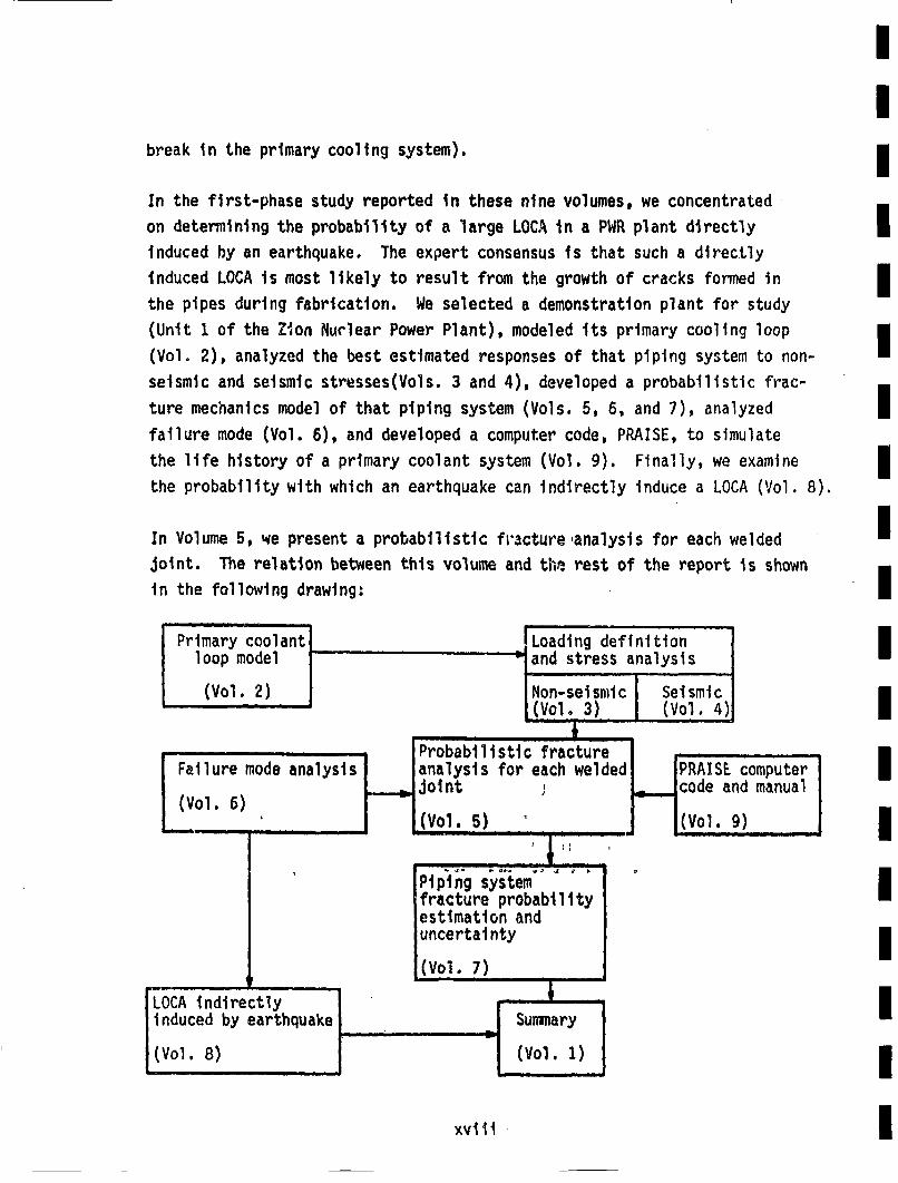
In the first-phase study reported in these nine volumes, we concentrated.on determining the probability of a large LOCA in a PWR plant directly Iinduced hy an earthquake. The expert consensus is that such a directlyinduced LOCA is most likely to result from the growth of cracks formed in Ithe pipes during fabrication. We selected a demonstration plant for studym(Unit 1. of the Zion Nuclear Power Plant), modeled its primary cooling loopm
(Vol. 2), analyzed the best estimated responses of that piping system to non-=seismic and seismic stresses(Vols. 3 and 4), developed a probabilistic frac-ture mechanics model of that piping system (Vols. 5, 6, and 7), analyzed Ifailure mode (Vol. 6), and developed a computer code, PRAISE, to simulatethe life history of a primary coolant system (Vol. 9). Finally, we examine mthe probability with which an earthquake can indirectly induce a LOCA (Vol. 8). m
In Volume 5, we present a probabilistic fr'acture ,analysis for each welded mU
joint. The relation between this volume and the rest of the report is shownin the following drawing: m
Primary oolantl[Loading definition l
oomoe and stress analysisI
Faluemoeanlsi. JIrbailsti c fracture 1Faiuremod anlyss lnalsisfor each welded fPRAISE computerI
I(Vol. 6) jolnt(Vol. 5) 'J . . _
(
I
Pipigss
fracture probestimation aruncertainty
(Vol. 7)
; ,i_..code and manualJhli(vol. 9) l
iabillIty
ndIm
,J , I,Jmmar
induced by earthquake SL
(Vol. 8)...V
xvlii
1.0 INTRODUCTION
This is the final report of work through September 1980 performed byScience Applications, Inc, (SAI) under subcontract~to Lawrence Liver-more National Laboratory (LLNL) on the Load Combinations Program Prej*ect1: Event Decoupling° Current regulations covering the design of primarypiping in commuercial power reactors require consideration of various com-binations of loads hypothesized to occur during the plant lifetime. Thetypes of loads to be considered, and the means of combining them, are oftenill-defined and not based on current best understandings of the phenomenainvolved. The LLNL Load Combinations Program was initiated to update tech-niques for a rational combination of loads in the design of reactor compo-nents. Seismic events that may occur during the life of the plant are ofspecial concern, because the frequency and magnitufe of such events areill-defined. Specifically, combining seismic loads with those resultingfrom a loss-of-coolant accident (LOCA) can result in large loads on piping,pressure vessel, component supports and reactor ves~el *1nteroals that ared~f~i'ctil to aaequately design for. Additionally, designs resulting from
requirements to combine the large loads from these rare events may be farfrom optimum for plant safety during normal operation. Significant seismicevents and LOCAs are both rare events, and if it was known that the prob-ability of both occurring simultaneously was very small, then requirementsfor combining the loads resulting from them could be relaxed.
If seismic events and LOCAs occurred independently of one another, then itis a sinple matter to show that their simultaneous occurrence is a very lowprobability event. However, it is possible that the stresses resultingfrom a seismic event could induce • LOCA. Hence, these events do notnecessarily occur independently, and means of estimating the probabilityof a seismic event leading directly and rapidly to a LOCA are of interest.If the probability of a seismic induced LOCA was very low, then perhapsrequirements for combining the loads could be e1iminated -- with resultingsimplification oF plant design, reduction of costs, and (perhaps) a favor-able influence on plant integrity during-,normal, operation. '
1
III
1.1 Basic MethodologyI
The primary purpose of the Load Combination Program covered in this reportm
is to estimate the probability of a seismic induced LOCA in the primaryIpiping of a commrercial pressurized water reactor (PWR). Best estimates,rather than upper bound results are desired. This was accomplished by use m
of a fracture mechanics model that employs a random distribution of initialcracks in the piping welds. Estimates of the probability of cracks ofI
various sizes initially existing in the welds are combined with fracturemechanics calculations of how these cracks would grow during service. ThisI
then leads to direct estimates of the probability of failure as a functionof time and location within the piping system. The influence of varyingthe stress history to which the piping is subjected is easily determined. I1
Seismic events enter into the analysis through the stresses they impose onthe pipes. Hlence, the influence of various seismic events on the pipingI
failure probability can be determined, thereby providing the desired infor-mation.I
The purpose of work presented here is to construct and exercise the fracturemechanics piping reliability model. The stress analysis of the piping wasI
supplied to SAI (Chan 81, Lu 81), and the results obtained here were com-bined with the probability of seismic events of various magnitudes (Georgel
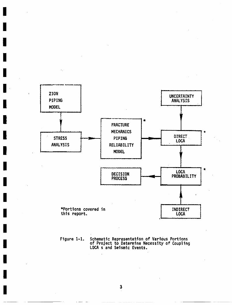
81) to provide inputs to a possible load decoupling criterion. Figure 1-1shows the various components of an overall program to assess the need toI
couple LOCA and seismic events, with identification of the portion of theIwork to be covered in this report. Details of the methodologies employed,•tf ~re~ults Obtained are included in later seci~ons of the'report,
1.2 Plant DescriptionI
A specific plant was selected for analysis so that the results obtainedIwould be applicable to a real situation. Zion I was chosen for analysis.IThis is a 1100 MWe plant of Westinghouse design. It is located on theshore of LakeMichigan some 40 miles north of Chicago. The plant is Iowned and operated by Commnonwealth Edison.
I
*
*
*Portions covered inthis report.
Figure 1-1. Schematic Representation of Various Portionsof Project to Determilne Necessity of CouplingLOCA s and Seismic Events.
3
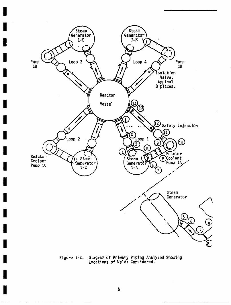
IThe large primary piping was selected for consideration because a LOCAm
in these pipes is of particular concern. Figure 1-2 presents a schematicofteppsconsidered, which consisted of the hot leg, cross-over leg, 3
an•J cQl~d l~g. Tbe nominal sizes of these~pipes'~are'as follows' (FSAR):m
Name Inside Diameter, In. Wall Thickness, in. mm
hot leg 29.0 2.50m
cross'-over leg 31.0 2.66cold leg 27.5 2.38m
Sudden and complete pipe severances are of particular concern in thisIwork. Such piping failures will be called LOCAs*. Leaks and LOCAs aremost likely to occur at welds, and attention here will be restricted towelds. Additionally, LOCAs are much more likely to occur at a circum-ferential than at a longitudinal weld. The reasons for this are two-fold'
geometrically, a longitudinal weld would result only in a slot fracturerather than directly in a complete severance, and axial piping stressestend to be higher than hoop stresses. Attention will therefore be focus--sed on circumferential girth butt welds--the locations of which are shownin Figure 1-2. As far as the primary piping is concerned, all four loopshave the same weld configuration. Stress analyses performied as anotherpart of the Load Combinations Program (Chan 81, Lu 81) revealed that
all four loops have virtually identical stresses. Attention was there-fore concentrated on a single loop, with the results being representative
of all four loops. The weld numbering system used in this report isincluded in Figure 1-2, which shows the locations of the 14 circumfer-ential girth butt pipe welds considered in this analysis.I
The materials used in fabrication of the pipes and related components(FSAR) are shown in Table 1-1, along with their selected properties(ASTM 80). These materials are basically austenitic stainless steel, pre-
dominantly of the centrifugally cast variety. The piping itself Is seam-less.•. Hence,, the only longitudinal weld•°ar•°fn t•e~e1jows.
* In this report, a LOCA is taken to be a sudden and complete pipe severance,rather than the more conventional definition of any event that can produce
aloss-of-coolant. A double ended pipe break (DEPB) would oerhaps be aI
4ete trm
Pump .lB
ReactorCool antPump 1C
Injection
SteamGenerator
J
Figure 1-2. Diagram of Primary Piping Analyzed ShowingLocations of Welds Considered.
5
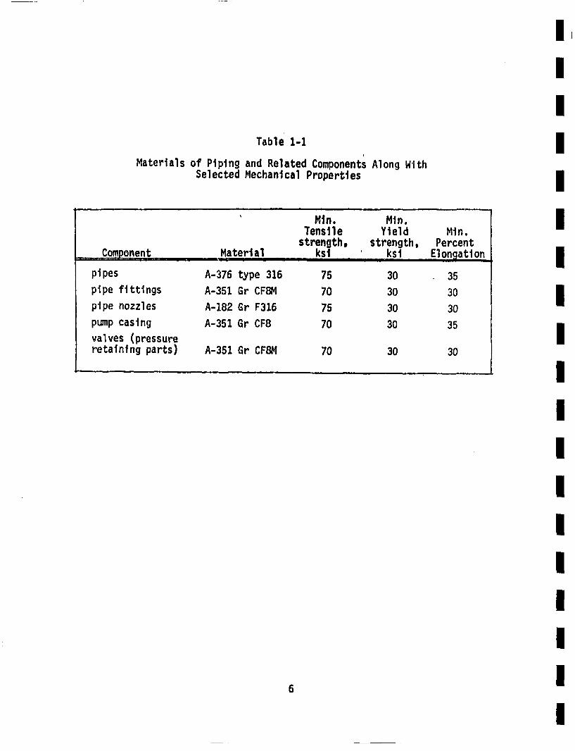
Table 1-1
Material s of Piping and Related ComponentsSelected Mechanical Properties Along With
' Mn. Min.Tensile Yield Mln.
strength, strength, PercentSComponent. Material ... ksi . ksi Elongation
pipes A-376 type 316 75 30 35pipe fittings A-351 Gr CF8M 70 30 30
pipe nozzles A-182 Gr F316 75 30 30
pump casing A-351 Gr CF8 70 30 35
valves (pressureretaining parts) A-351 Gr CF8M 70 30 30
IIIIIIIIIIIIIIIIIII
6
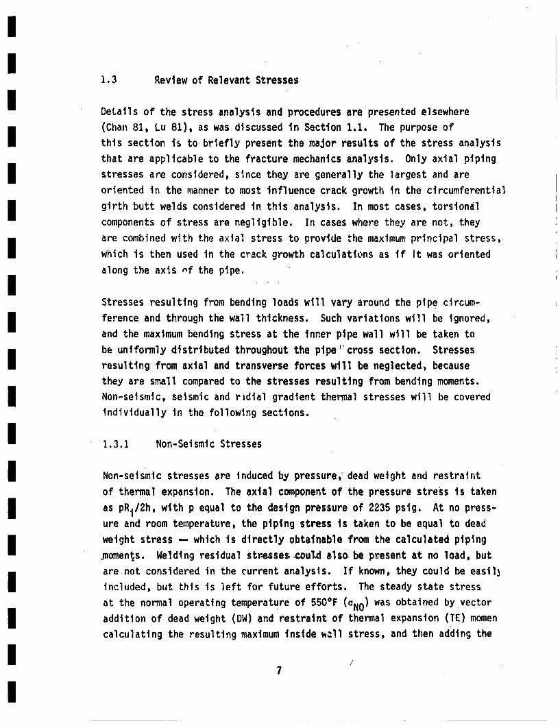
1.3 1.3 Review of Relevant Stresses
Details of the stress analysis and procedures are presented elsewhere(Chart 81, Lu 81), as was discussed in Section 1.1. The purpose ofthis section is to briefly present the major results of the stress analysisthat are applicable to the fracture mechanics analysis. Only axial pipingstresses are considered, since they are generally the largest and areoriented in the manner to most Influence crack growth in the circumferentialgirth butt welds considered in this analysis. In most cases, torsionalcomponents of stress are negligible. In cases where they are not, theyare combined with the axial stress to provide the maximum principal stress,which is then used in the crack growth calculations as if it was orientedalong the axis rnf the pipe.
Stresses resulting from bending loads will vary around the pipe circum-ference and through the wall thickness. Such variations will be ignored,and the maximum bending stress at the inner pipe wall will be taken tobe uniformly distributed throughout the pipe cross section. Stressesresulting from axial and transverse forces will be neglected, becausethey are small compared to the stresses resulting from bending moments.Non-seismic, seismic and radial gradient thermal stresses will be coveredindividually in the following sections.
1.3.1 Non-Seismic Stresses
Non-seismic stresses are induced by pressure,' dead weight and restraint
of thermal expansion. The axial component of the pressure stress is takenas PRi/2h, with p equal to the design pressure of 2235 psig. At no press-ure and room temperature, the piping stress is taken to be equal to deadweight stress -- which is directly obtainable from the calculated piping•moments. Welding residual stre•sses~.oul4 also be present at no load, butare not considered in the current analysis. If known, they could be easil3included, but this is left for future efforts. The steady state stressat the normal operating temperature of 550°F (oNO) was obtained by vectoraddition of dead weight (DW) and restraint of thermal expansion (TE) momencalculating the resulting maximum inside well stress, and then adding the
7
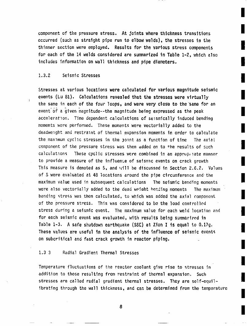
Icomponent of the pressure stress. At joints where thickness transitionsoccurred (such as straight pipe run to elbow welds), the stresses in thethinner section were employed. Results for the various stress components Ifor each of the 14 welds considered are summarized in Table 1-2, which also
inldsifrainon wall thickness and pipe diameters0
1.3.2 seismic stressesm
Stresses at various locations were calculated for various magnitude seismicevents (Lu 81). Calculations revealed that the stresses were virtuallym
the same in each of the four loops, and were very close to the same for anevent-of a iven magnitude--the magnitude being expressed as the peak m
acceleration. Time dependent calculations of seismically induced bendingmmoments were performed. These moments were vectorially added to them
deadweight and restraint of thermal expansion moments in order to calculate
the maximum cyclic stresses in the joint as a function of time The axialcomponent of the pressure stress was then ddded on to +he results of such mcalculations These cyclic stresses were combined in an apprupr late mannerto provide a measure of the influenc.e of seismic events on crack growth m
This measure is denoted as S, and ,€ill be discussed in Section 2.6.2. Valuesm
of S were evaluated at 48 locations around the pipe circumference and'them
maximum value used in subsequent calculations The seismic bending momentswere also vectorially added to the dead wpiqht her.Jing moments The maximumbending stress was then calculated, to which was added the axial component Iof the pressure stress. This was considered to be the load controlledstress dluring a seismic event. The maximum value for each weld location andm
for each seismic event was evaluated, with results being summarized inmTable 1-3. A safe shutdown earthquake (SSE) at Zion I is equal to 0.17g.m
These values are useful in the analysis of the Influence of seismic eventson subcritical and fast crack growth in reactor piping. m
1.3 3 Radial Gradient Thermal Stresses
ITemperature fluctuations of the reactor coolant give rise to stresses inaddition to those resulting from restraint of thermal expansion. Suchm
stresses are called radial gradient thermal stresses. They are self-equib.ibrating through the wall thickness, and can be determined from the temperature m
a I
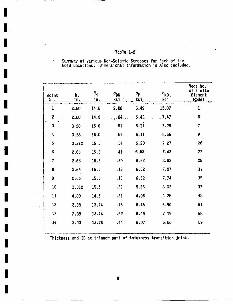
Table 1-2'
Summary of Various Non-Seismic Stresses for Each of theWeld Locations. Dimensional Informiation is Also Included.
Node No.of FiniteJoi nt h, RiaDW aP UNO, El ement
No. in. in. ksl / ksl ksi Model
1 2.50 14.5 2.08 •6.49 15.07 1'
2 2.50 14.5 .•04 /o.,,q49 , - 7.47 5
3 3.28 15.0 .51 5.11 7.28 7
4 3.28 15.0 .59 5.11 8.56 9
5 3.312 15 5 .34 5.23 7 27 26
6 2.66 15.5 .41 6.52 7.43 27
7 2.66 15.5 .30 6.52 8.63 28
8 2.66 15.5 .18 6.52 7.07 31
9 2.66 15.5 •.10 6.52 7.74 35
10 3.312 15.5 .29 5.23 8.02 37
11 4.00 14.5 .21 4.06 4.28 48
12 2.38 13.74 .15 6.46 6.90 51
13 2.38 13.74 .62 6.46 7.19 58
14 3.03 13.75 .44 5.07 5.66 59
Thickness and ID at thinner part of thickness transition joint.
9
rahl. 1.3
b'ls i leti gI L- -fe •IIu Ipl I sIsIII I •
bxII.JnJo Nt X. NIg. NIX'lC. 5.
4WJ& } kslt it4 -ks! -W - )4W -•1' (.•}
"1 1,76 511.6 9.06 3956.3 10,66 63430. 10.62 151000,.
1 6.75 31.1 6.65 25. 7.17 61.5 7.09.o 111.43 .75 316. 6.09 1418.5 7.11 0o7. 6.11 19o664 61•4 61.5 6.51 10.S 7.67 1720. .70 17400. I5 5.70 16,.1 s.I 117.3 7.61 110. 71.9 3350., 7.04 53.54 7.5 33.4 6.56 490. 6.16 6160.7 6.01 15.1 7.05 152. 7.20 3570. 7.61 53.,. 6.61 ,.40 ,.,o 46.60 ,.20 61. 7.41 140.
,. m, .o l~t*, 'a, .
no LoSo a3,., ,., iowa s , qao. i.a 4 1600o . I12 7.o, 1o.3 7.01 ama 116 376o. O.Os 5466o.14 5.61 116T.1 6160 644.0 7l.9 134100. 7I.51 MOIO.
- m
Io |
history of the coolant mnd the titens1 end elastic pespestlis of thepiping interial. -The redil gradient themml stresse were evaluatedcnsidwineg the tmertwss to be uuifom along a long strsight nm of Ipiphg.Ths strese are both time and siplc. depmidct, aind eve different ftreach of the pleat operating tranuiets. The are discussed is detailby Chin 81.• and in Appendix 0.
This concludes the Zatrodctery remarks, and attention will no be turnedto presentation of the fracture mechaics• moal of piping re1liabiit.Section 3 will provide details of the model, and Section Swtll discuss thenuwilcal procelures devised to obtain resultis. Then in Sectlon 4 ettenlca{Pwi11ll agan be turaned to actual application of the procedures to evaluation ofthe reliability of the primar pipingl at Zion.
11
II
history of the coolant and th thermal mad elastic properties of th Ipiping iotorial. The redial gradient thevnsl stresss wore evaluated con.sidering the tiperetores to be wiifowu along * long straight run of piptig. 3These stresses are both tim and space dependent, and are different forbeachhn of atthe 6nPlant o°peratingponl .transients. They are discussed in detail I
This concludes the Introductory reuarks, and attention wi1l now be turned ito presentation of the fracture mechanics moG.! of piping relabtil~ty.
n•Irical procedre dvised to ob~tan resUlts. Thenl in Section 4-sttent$I'iwill aiain be turned to actual application of the procedures to evaluation ofn
IIIIIIIIII
"I i
I1 9,,;; Ol..;eIIAm8 u| nLOU un siw jeJd PU. ine I Io
•epd~e uoJJ pwJ@ S• uW (V•1) eJAI djd 1et• PUe o~t iiJoj eq•e: Do eeSIe t•fl2IJ, 311J °I~u| •o Vo~fl@L gq te £Je2Iq
eei aA JO iPLN@U IU&Ab PoI' sSepnd en)|ump~ nte i4)N eue ej 1.Uq• q~eA juno• n• 'o•en•u 114 p Uno pjogpe ,n
-uozA~e ugepeqoeJ4s 3 £IPnLSJ eq 03 peJ•puoo eq ii Pei~ e US d 3 3i
•I•I e •o *uee s e doo ivimit mU uuotleolde h| P's u3
£IL3WPAI paoldd, eq • eo •l ij u~u oln;inep smsqi~ t-| ned~j I
11$ ~i~5~DO111d 143 1 IOlJ 31Us~ 0 peRs 0'1 Ii
Buldd ~ Buiid o ~eu. 143v~ d~quo;;~ea~u5J14 PU
4ueo~o snps eq Jouo$s~b~sd~d~IS~p 3 ~p;wdt-~&afB!
I4A~315dJO NA~ U? I~oAO 1'3I
Inittal crackdistribution
nP(a.b)
1
po~t. Inipectiondis trlbutt on iI! stress history* cyclic stress* mean stress* no. of cycles* thickness Var.
operating trans.seismic events
creck growth
I
IIIIIIIIIIII
I
Figure 2-1. Schmlitc Diapme of Steps In Anlysis ,Reliabilitt ole Siven Weld Location.
III
!1
considlered. Deipll and asseably errors are therefore omitted from consid-eretion, except as the~y would influence the existence of creck-like detects.The influence of errors during Operation of the plant that could contributeto piping failures are also not considered. Further essuwtions relayedin this analyss will be presented and discussed in Section 3.2o
Attention will new be turned to a brief discussion of past work in apply-ing fracture mechanics to the calculation of structurel reliability. Noettapt is made to provide an all.inclusive frevie.. The earliest yorkin this area appears to haew been related to aircraft applications (Shin-ozuka 69!, Heonr 71, Yang 74) although gonerell early discussions were pro.videld by Graham 74 and Cramnd 74. lecher end Pederso (lecher 74) pro-vide one of the earliest examples of the usa of such techniques in thbnuclear poweer industry, by applying the methodology to estinaticai ofthe reliability of the reactor pressure vessel. Generally speaking,meat recont applications also cgnsider nuclear reactor pressurevessels (Arnett 76, Ikrshall 74, Nilsson 77.Schlidt 77, Collier 77,Dufresne 78. Lidiard 75, Vesely 76, Lucia 79). with analyses of pipingreliability receiving somewdat less attention (iVlson 74, Harris 76,77a, 7Th, 76a, 79. 81, Burns 76, Derby 77, Schmidt 79). General discus-sions of the methodologies emloyed, without ehapsis on reactor appli-cations are also available (Seuner 77a,Harris 77c. 7Gb. 3ohnston 76a.78b1 Gallagher 79) and are of interest whenapiplying such techniques toother structural components.
The vast maority of pest applications of probabilistic wracture mochanic':employ two features that greatly simlifly the aen1lysss
Ci) Stress variations through the thickness of th. partare either ignored or taken to be linear. This isconsiteont with the spirit of the ASDU oikler andPressure Vesbel Code. Section X! (A53 1960). Theonly tnrn exceptions to this are Harris 79. 61 inwhich cases nonlinear stress gradients through thepipe well are accosmted for.
(ii) crack shapes are taken to be .simplified by consideringeither lime creeks, cmpleto ctrcumferential Cracks.or creeks with a constant length-to-depth ratio. The
14
litter case is again consistent with the ASM Code(AS[ 1910), and, when used in conjunction with theuniform or linger stress variatioans, leads to partic-Iularly straightforwaord crock growth analyses.
ratios, and these rotios can change during crock growth. The manner inwhich they change depends on the nature of the stresses--especially oniithickness gradients. Therefore, it is delsirable to ac~ount for chagein the length-to-depth ratio during crack growtdh. This is especially Itrue if it iS desired to differentite btwo e pipe Ieaks and LOCAlswhich is the case in the current investigation. In order to be able toseparately distinguish these two failure mode,, a two-ditensional dis-.tribution of crack sizes is required, and a bivaiate distribution willbe used in this investigation. This more closely models reality, butrequires stress intensity factor solutions beyond those available--especially when thickness variar!tios of the stress are consideed There-fore, an. appreciable portion of this work wee devoted to the developonet [
of suitable stress intensity factor formulations. These will be pre-sensed in deail1 in subsquent sections of this report, with the Appen-Idices containing the bulk of the informatien in this area.
Considerable work has been published on fracture mechanics analysts of crackbehavior in pressure vessels gnd piping, without regard to any statisticalIconsiderations. The results of such wor• have provided assurances that largeinittial cracks are generally required before leeks or catastrophic failure imould occur. An extensive review of such deteoministic analyses wlf1 not bemincluded here. The york of Hayfield, at al. (Hayfield SO) pvovitd• •vch acomprehensive review. Of special interest, Witt 76 and Griesbach SO provideIdeterministic analyses of the influence of seismic events a• crack growthin reactor piping.I
Each of the components of the piping reliabilitt modle depicted in Firgure 2-1lwill . dls~used in detail in the following sections of this report, PriorIto this, the meJor esesaltions empoyed herein will be samrized in thefollowing section. I
2.2 2.2 Seinty and Discussion of Maor AssIptions
The major ausptions eaployed in the curront investigation wtill besemari~ed end discussed in this section, Sm of the esseiptionsare specific to the current work, and are not inheront in e probablisticfracture machanics formulation of piping reliablity. Smn of the majorassuptions he airealdy been presnted in introductory sections, butthey will be included here for the sake of coquleteneus.
The following are the major asswqptions:
* Piping failures occur due to the growth @1 creck-likedefects introduced during fabricaltion. Therefore.design, fabricaiton and aessbly errors are emittedfrom consideration except as the my (implicitly) effectthe lsues of initial defects.
• The as-fabricated crack-like defects are confined to weldJoints. Hence, failulres due to defects in base materialare not consideredo This uss.itto is further refinedto considr only defects in clircmfemt~il girth buttwelds, because such welds are more likely to result infailures (especially LOCAs) due to gemltric consideraitons.A further asseption is usda that all defects are locatedon the Interior surface of the pipe and are oriented per-pendicular to the ais of the pipe. (Pelrt-ircuiferentillintorior surface cracks.) The uzial c•lmenit of the stressie taken to be4 applied normal to the crack In cases wheretorsioalt stresses are sill,* hien torsional stresses arenot small, the maallmi principal stres is dat','lned, andthe stres is then taken to be applied normal to the crack.This is a conservative way to treat torsional stresseswithin the fremork of current fracture machenics techniques.
I'
III
* The as-fabucated initiel derects in the weld JointsI
are iMIndapndntly and identical1 distributed In sie.in other werds, the initial crack size distribution iiakikn to be the Hs in each weld Joint, wit minor usd1.I
fications to account for varying pipe size and well thick.
* Cricks that are initilnll shorter than twce tUeir deptimare omitted tur. considertiton.
* The subcritical growth ofta creck-Ilke defect Is as afatigue crock, and the growth rteo can be Predicted fr Ilaboratory I~nelr4lantic fricture a•nchaic tests
* The cyclic stres history controls fatigue crick growthand is estiuted from plant operating history regarding IIfriquenc and types of treusients. Transient stressesof an unatitcipalted ature are therefore omitteld fromIcons ideration.I
* The Influence of seismic events asters tnrough their con-tribution to the cyclic stress history. and Influence onmmimaU sltrel4ssesI
* If usre than one creek ezists within a giv~n weld, Utenthe crek dent iotnerat wit oe anothe. nd thelcritical conditions for unstable crecb propagation areUdepn~dnt only on the size of the laei't cr•ck present.
* The unstale final grwt of a crack is detem•ieed eitheriU a set section istaiblity (eaceedanc of a criticalnet section stress) or tearin Instblity (Ta~p • Tiit)-ou I•l.ichr results in the tus11est critical craic sit, ata given stris•~. In
II
* Th •plld stress use in Ute fallre cr teronis stress tht cut so be relaxe by cra extension--otherwis km as the "1ad contvolled stress.Scstresses consist Of pressure, an~d dael4~tht, Additionally.seimic stresse viii be taket to be load controlled.
• Axial PIpe stresse Induced by bending mints are takestob unifow1l distributd ove te pipe cross-sectionate vau ei qual to thea minlim bending Stress at theinside pipe wall.
* The msximM orincipal stress, including the contributions
of torsion and transvrse stear, is asstd to act nomulto the plane of the crak. Sinc torsionaI contributionsare sill, especially in the hithly stressed jointq, thevalves Or th inaiMi principal Stress and ada)l stress areusally quite close.
* Cracks are initially elliptical In shape and remain ellipt-ical as they grow, unless the develop into through-wallcracks.
* The growth of an elliptical (er sil-elliptical surface)crack in the directions or it. s i~i s controlled by ana1eage (SIS) StresS intensity factor aSSOCiated witheachals.
* Thegr•wtretesliforeachuxs ofalcrickatait 1ven€ycli€ stress intensity factor can be determined iron cor-responding results on a planar specirmn.
* Once a crec& rw t hraiS the pipe wall, its outside sur-face length is equal tO its insidel surface leng~h,
• TIraqmll vairationor cfoolant teipretue and pressurebrng a plant transient is given by Ivales used in theoriginal platies ip. Olhe magnitude of the variations istokes ife, plant data •mr pssible.)
I1
II
* Leak grete tha 1 gall peminute• ae gi |i |- I
seismi evnt •I1C are not deece until af.' hseismic event. l w () tCrocks are found by • ~ ! lt•(IE ta probabliblty which depends only on th crruent crack stie
(not a fntion of having bee miss in earlier rinspe- Itions).
crock populatiOn. Otherwise the crock population Is not
* Defect ae not introduced uring th repar rocess,
mmIOusj scndr ass~tios are aIde in late portios of this report,•.ich will be discussed at tthe point u.ere thy ar'seo Each of the co-Iponents of the frac'ture aichanics model of piping reliability will noube presetad~c in detal,
IIIIIII
,o I
1.3 '.3 Initial Crack Distribution
The size dist~r~bution @f initial crocks pressit in a piping weld fontsa key input to the freebie imchaIcs miel of piping u'ltiablly T1eInltial creek distribution will he clnsoed iftur c ¢ests:
(I) 1w soles ditridbution gives that a crock Is present.This cmlonent ii called the conditioal crack slizdistribution,
(ii) The pro~ballity that al crack is present to begin i~th,This componest Ia called the crack exstence probablity,
md will vary with the size of the weld,
As-fabrltcae cracks in p~iping welds can be either sih-surface or awrface.for a given cro~ck size and stress level, a surface crack will be mrsevers, becuso it VdII have a larger strs intensit factor. Interiorsurface crecka ore gunerally of more concer than exterior surftee Cracks.
because thermol atresses tend to be hli~er at the inner pipe well, endInteriOr surface cricka aro subjected to the coolant ditch IS ofton asadverMe oavirmmt for Cricks. HenlCe, attention Is focused n~ interiorsurface cracks, and cracks located totally within the pipe well are omittodfrom consideraionm in the present a~lyait.
There is no inherent rosson that qedded cracks could nOt be included inthis modal, but this rofinmnlt is left for f•utro efforts. The coniderhation of only Inteiror surfac cracks will not sipificently alteP thecalculated flure probbilities, especillyl if the prubability of acrack ealatin withina we•ld is applied to inteior surfce dofec•,.Nlaslon ?? proidecs a discussion of atrel~ittfoeilrd tcniques1 f~r 1ti•t-
ing emedded crocks.
Atmtentin still be ceoestrited on circlimferntial welds. bece uswelds are generall subjcted to hli~ir stres. and their filure cam leadto we severe eonselncs ThllIs us iscussed in earlier scti~on. The
I0
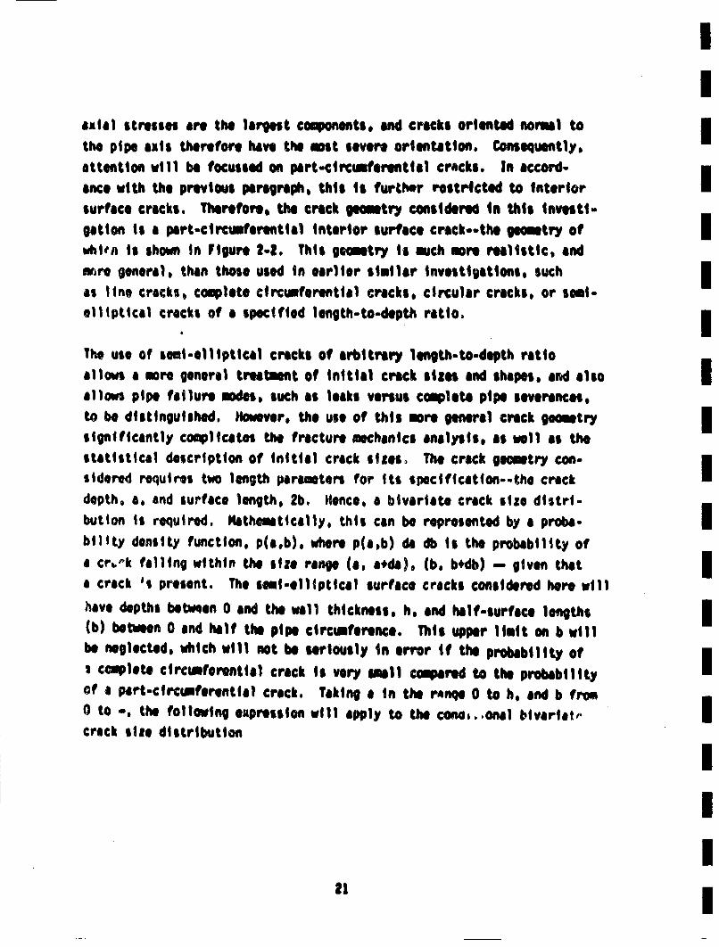
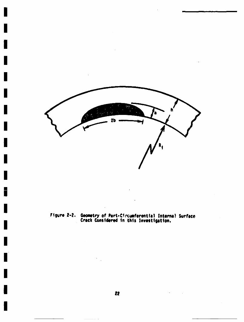
axial stresses are the largest components, and crocks oriented normal toJthe pipe axis therefore have the most severe orien~ttion. Coseq•uently,attention will be focussed on part-circumferential cracks. In accord-
acwin t h th• e previous paragraph, this is furCt'.r resticted to interiorisurface cracks. Therefore, the crack eomitry considered in this investi-getion is a part-circtiferential interior surface crack--the geometry ofIisltin is shown in Figure 2-2. This gometry is much more realistic, andwire general, than those used in earlier similar investligtions, such Ias line cracks, complete circumferential cracks, circular cracks, or soul-.Helliptical cracks of a specified length-to-depth ratio. iThe use of semi-elliptical crocks of arbitrary length-to-depth ratioallows a more general troetant of initlil crock sizes and shapes, and alsoIallows pipe failure modes, such as leaks versus campeta pipe severances,to be distinguished. However, the use of this mara general crack geintrysignificantly complicaesn the fracture mechanics analysis, as well as thestaitstical description of inittial crack sizes. The crack geometry con-i
sidered requires two length paraemters for its specificaiton--the crackIdepth, a, and surface length, 2b. IHence, a bivaiatte crack size distri-bution is required. Kathetitcally, this can be represented by a proba-Ibility density function, pia.b), where pia,b) da db is the probability ofa crb'k falling within the size rane (a. aeda), (b. b4'db) .= given thatIa crack 's present. The soual-elliptical surface cracks conlsidered here willhave depths betrmen 0 and th wall thickness, h, and half-surface lengths I(b) between 0 and half the pipe circumference. This upper limit on b willbe neglected, which will not be seriously in error if the probabilit of: complete circumferential crack is very small cmared to the probabilityof a part-circumferentile crack, Taking a in the ranqe 0 to he and b fromo to *, the following eupression will apply to the cone.,onal tivariat. Icrack size distribution
I" i
lb
RI
Figure 2-4. 0Getry of Part-CtrcmferfltlaI Interne) SurfaceCrack Ccrnldered In this Investlgatton.
RI

II
• p~obd da * 1 (2-1)I
IInformation on bivr~iate crack size distributions is very sparse, withW lson 74 providing the rest information to adequaetly define the functionI
p(a~b). A fair mount of information ii avaitlble on estietes of thedetdistribution Sf cracks (which will be rveviewd in Section 2.3.1), and itI
is desireable to use such information in estimating the size distributionof cracks considered in this analysis.
The density function of crack depths, p(a), can be obtained fron the Ibivaiat's distribution as follows:I
p(a) • (' p(a,b)db (2-2)
IThis univartite density function is called the marginal distributionof the crack depths and is directly €oeparable to information on depthI
distributions to be reviewed shortly. An expression analogous to Equa-tion 2-3 can be writteon for the marginal distribution of b. Knowledge ofI
of the marginal distributions of the two length paramaetrs is not suffi-cient to deifne the bivariate density function, because this latter
function depends on the dagee of cor'eltitoq of the two vairables (HahnI67). Addtionally, very little informtion is available on the legthdistribution of surface cracks, with Dvorak 72 providing a rare examleI
of such information. Dvorak 72 suggests that t. surfae lengths should
be loghoriualy distributed, but does not discuss any correlaiton withi
crack depth.
Sams siqplifyinO ass.uations regarding the iniltial bivariato c.rack s|ie Idistribution msit be mde in order to deitne this iqiortaat vairbleb.
reasonable, because a crack that is deep is mote likely to be lon thanone that is shallow. An alternative ass'Jation, that has soe Intuitive Iappeal, is that the crack depth and surface length-to-depth ratio a•indepnet. Takqn ip - b/a, and calling this the aispect ratio', this
assimption can be restated that the depth and aspect ratio are independent.This can be intorpreted in words as follows: take a large population ofcracks, and sort thee out into separate "stacks" according to depth. Thenmeasure the distribution of aspect ratio for each "stacke. If a and B wereindependent, then the distribution of B would be the same for all "stAcks';i.e., * is independent of a. This assumption greatly simplifies the stat-istical description of initial crack sizes, and will be used throughout thisinvestigation. This is a major aswsuption, and is in addition to thos.enmerated in Section 2.2. The information requir'sd to describe the initial
conditional distribution of crack sizes is now reduced to specifying thedistribution of crack depth, a, and aspect ratio, B - b/a. The statisticaldistribution of crack length, b, or crack area, A, can be calculated frow.
this infoaration. This will be described in succeeidng sections.
2.3.1 Depth Distribution
The available informaiton on crack size distributions ii quite limited.Many investigators cited in Section 2.1 assume the crack depth (or length)to have a particular distribution, use assaumed parameters, and then proceedwith the analysis. An exponential distribution of crack depth is comonlyassue~d, which is a particularly simple distribution. (•lo Hahn 67 for a
discussion of various standard distributions, such as exponential, normal1,lognormal, Weibu11, gauu, etc.). It is proforable to base tho size dis-tribution used on actual observations of cracks-preferably in steel weld-
ments.
Information available on crack size distributions concentrates on the crackdepth, because the depth dimension (a) has mere influence on the stressintensity factor than the length dimension (b). Wilson 74 provides infor-maioan on both depth and length, as was mentioned above. However, his
estimates are based on judgement, rather than data. The Wilson distributionhas been employed in previous analyses of reactor piping reliability (•arris76, 77b, 7k, Burns 78), but adjustments were made so that onlly cracks ex-ceeding a given surface length were included. Wlslon's marginal distributionson a and b appear to be exponential. HIrginal crack depth distributionsemployed using Wilson's data, with adjustments to include only cracks larger
24
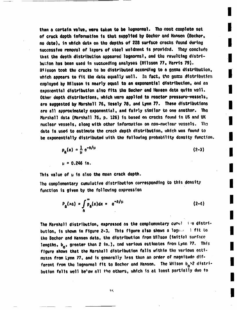
Ithan a cer~tin vaim ere• taken to be Igon1. Th mostcomlete sot iof crack depth Inforuition ii that supplied by DOckr and Hansen (Bekr,no dat). In which dati on the depths of 228 surface cracks found during Isuccessive removal of layers of steel elknnt is providetd. Thqy concludethet the depth distribution oppeated lognomal. and th• rowleing distri- .bu¶ ion has boon used In sueccoeding anlyses (Nil~son 77. Harris 79).Ni Isson took the cracks to be distribtd according to a g8mus distribution, •which appears to fit the data equally well. In fact. t•o ga• d~strib~jteniemloyed by Nilason is nearly equal to an expnonntial distribudon, and anexponential distribution also fits .he Becker end Hanson dat quito w11.aOther depth distributions, which wore applied to reactor prossure~essels,are suggested by Marhall 76, Vesely 78o and Lynn 77. Those distribu tionsIare al1 approximatly exponentilal, and fairly similar to one another. TheDMarshall data (Marshall 76. pe 126) is based on cracks found in US and UK [
nuclear vessels, along with other information on non-nuclear vessels. Th• [data is used to estimate the crack depth distribution, which was found tobeexponentially distributed with the following probaility density function.Ia
u ® 0.246 inn
This value of u is also the mean crack deptho
Th opemnaycw~lativo distribution corresponding tO this density
function is given by the following expression
po(,a) f/pa(x)dx s ~/ (2-4) U
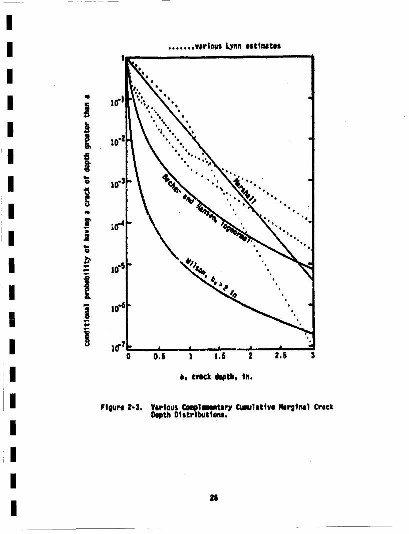
The Marshall distribution, expressed as the complemntar cu•1 1 . dtstrI-button, is sho~m in Figure 2-3o This figure also shows a lOgi,., I fit tothe Decher and Hansen data0 the distribution from ]ilson (initial aurV~eolengths. bo0 greater than 2• in. ), and various estimates froe Lynn 77° Th-is
figure shows that the Marshall distribution falls within the various ostI°mates from Lynn 177 and Is generally less than an order of magnitude dif-
foernt from the lognormal fit to 0ocher and Haonson. The Wilson be>2 dIstrI-button falls well b•ow all tti others, which is at least partially duo to I
... ,..,varlou$ Lynn estimates
iI,I.*1q
FI
II
a. crick depth, in.
Figure 2-3, Vrirous Co.le..lntarY Cwulative Marginal CrackDepth Distr butions.
26
lits exclusion of cracks with initial surface lengths less than 4 in. (2bo- I4 inl.). This modified Wilson distribution does not appear applicable tothe curret situation. The Marshall distribution will be used in succeed- iing portions of this investigation, because it appears to provide arealistic estlimte of crack depths. It falls midlway in the range of distri- Ibuttons shown in Figure 2-3, and does not differ drastically from thelecher and Hansen data. I
Iwas mentioned above, the lecher and Hansen distribution can be adequatelyifit by an exp~onetial distribution. The largest crack in the populationfound by lacher and Hansen was 0.41 in. (11.5 m), and the data is actually Ibetter fit with an exponential distribution, with parineter, u, of 0.067in. A plot of this result would drop off the scale of Figure 2-3 at 1.08•
in., which would put this distribution way below any of those shown inFigure 2-3 for crack depths exceeding about 0.6 in. In this context, acase could be made for the Marshall distribution being very conservative.INevertheless, the Marshall distribution will be used in this investigation.The mean crack depth is 0.24 in., which is considerably greater than thecorresponding values of 0.067 in. from lecher and Hansen (lecher, no date),or the value of 0.064 in. quoted on page 106 of Cranond 74.
Some modifications are required to the exponential distribution of equations2-4 and 2-6 to eliminate the physical i•possibility of having a crack depthiexceeding the pipe wall thickness. This can be accooltshed by renov'mslizngthe density function. This leads to the following marginal density of cracki
depths
%() .I ,'U) 0 , a_.h (2-6)
with •i * .246 in. i[
As sidelight, the comlementary culaltie ditritbution of crack depth.IImea value of a (5) end mediian value of a (aH)| are easily obtainedl promthe density function of equation 2-4 (Hahn S7) The results are eaisly
. I27!
sh@M tN
I.e/..O
*50o" f1z in! s * ,'i + -p in!
FOr h>>p, these ell reduce to the standard definition for expnftialdistributions.
The marginal distribution of crack depth is, now completely defined. Thenext step in the determination of the initial crack size distribution isto define the distribution of aspect ratios.
2.3.2 Aspect Ratio Distribution
The marginal distribution of the aspect ratio forms the remaining portion
of the initial conditional crack size distribution to be defined. Theaspect ratio is denoted as B, and is equal to b/a (see Figure 2.2)o Asmentioned earlier, cracks that initially have a surface length less thantwice the depth will be omittedl from consideration. Thus, the lower limittof aspect ratio corresponds to semi-circular cracks. Cracks with aspectratio less than that corresponding to smi-circular are seldom observed,and would tend to grow toward a semi-circular shape. The omission of crackswith S 1 is felt to have a negIgible influence on the results.
Information on the distribution of aspect ratio is virtually non-existent.This distribution will therefore be assured to be one of the standardform,. with slight iodificatinn to compensate for cracks with B c 1 beingomitted. From earlier discussions, the upper limit on IS will be takento be infinity--even thu this can reult in cracks longer than the
28
pipe circemference being Included. As will be seen, however, such cracks Iwill be present with a very low probability. Truncation of the B distri-bution to e~lminte cracks longer than the pipe circiiference would greatlyI
cemplicat the mathematical description of initial crack sizes withoutchanging the end result. I
Exponential and Iognormal distributions of iB will be considered. AIshifted" exponential density function of B that omits cracks with *c 1I
is given by the following
values " ~C~e'l : :1 (2-7) IThe vluJof C5 and A can be determined if the percentage of cracks with
BI ) 6S isspecified. Denoting this percentage as 0:, thel constants C0 and Acan be evaluated from the following general requirements I
,f;,(x)dx. * 1
0 (2-8 IThe resulting values Of A and C5 are the followingi
A • 4/Iln(1/o)i 29
Tho complementary c•ulat~ve distribution, mean, median and standard devi-I
aitonf Of B corresponding to this shifted expontential distr,|,,; I~ are
easily shorn to beI
Pt(4el " (( )X 2-10)
|,I*I
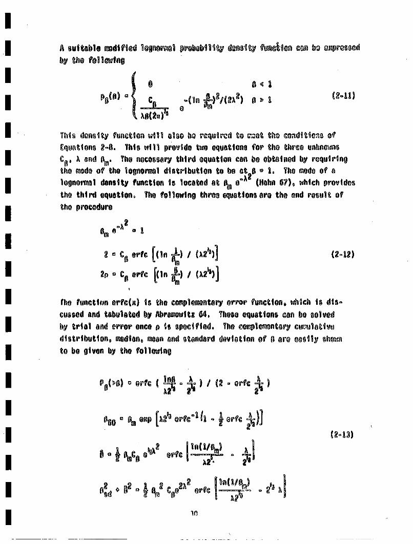
A suitbleiodi~fied 1ognor•l prob~lIt9 dees•t~ funcio an bo. oaprQBscdby the following
P•• (ln •)2 /(2A2) (241)
Cqtstionn 2-8. Thls will provide two equations for the three unkrnms•A a. nd (to' The necessary third equation con be ob~tined by requiring
tho mode of the lognoni~l distribution to bo ot• 0 1o The mode of aloonormal density function i lgocated at ieo~ (lHahn 67), which provides
the third equation. The following thre ceiations are the end result oftho procedure
2 C er,€ [(In •) / (A2~')] (24,2)
o•C re [(In •) /(A2'•)]
the functihi erfc(n) is the complemontar'y error function, which is, dis-cussed and tabultetd by Abr iwt: 64. Those equations can bo solvedby trial and error once p ii specified. The eo•le~ntary cii•'lativo
distribution, median, oan and standard deviation of II are easil shrr
to be given by the following
'rn
II
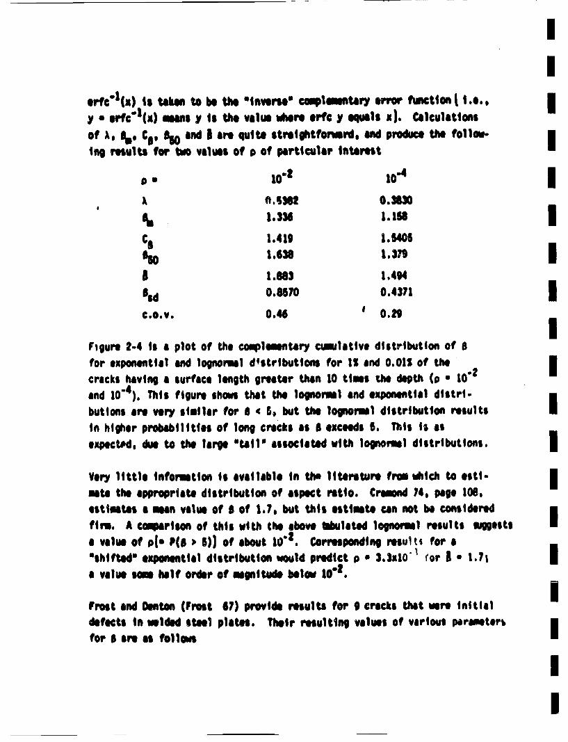
y • erfc 4 (x) oeans y ig the value vmere ,rfc y equals xl. CalIculations
1ng results for to values of p of particular Interest
A ,lISS 0,3830
C0 1.419 1.5405
5 I1.683 1.494Sld 0.857 0.4371I
c.o.v. 0.46 0 .29 IFigure 2-4 is a plot of the coe~iementiry cmalative distribution of Bfor exponential and Iognormal d'stributions for 151 and 0.021 of theIcracks havintg a surface length greater tha 10 time theI 111 depth (0 • 10"2
and 10"4). This figure shows thalt the1 lognomal and expneuntlil distil-
buttons are very similar for iS ' 5, but the lopnorml distribution resultsin hilier probabilities of long cricks as II exceeds 5. This is asexpected. due tO the large 'tail'" assOciated with lognormel distributions.I
Very i~ttle information ii available in the literoture fre •1ic to esti-mate the appropriate distribution of aspect raitO. Cremond 74, page 106.estimates a mean value of S of 17., but this estimate can not be consieredIfirm. A conprison of this with the above tbultetd lognorml results maggestsa value of p1- P(sl ) 5)) of about 10"I. Corresponding reult% for a'shifted' exponential distribution would predict p • 3.3x10" for I * 1.71 Ia value sme halt order of magnltude below 10"I.
Frost and Denton (Frost 67) provide reults for 9 cricks that were initilldefects in rilded steel plates. Their resulting values of various perameterlbI
II

1
;0" 10
,\t
10.?
10.8
it"b/al
figure 2-4. Various Cotmlontry Ciultatve INretnel0tltrtbuttoes of Crick Aspect Ratio.
1'
II
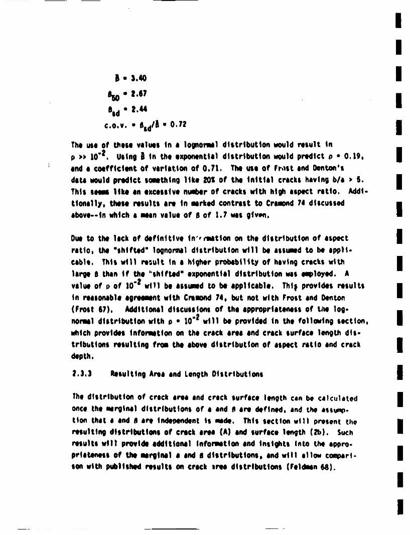
1 * 3.40 I2.,67
Bid • ,4
C.o.V. O Bsd/A * 0.72 IThe use of these values in, a1ignoreu1 distribution would result inp 1) 0"2. Using B in the exponential distribution would predict o * 0.39g, Iand a coefficient of va|iation of 0.71. The Use of Frrist and Dentonsidata would predict something like 201 of the initial cracks having b/a • 6 IThis seem lik, an excessive nieber of cricks with high aspect raito. Addi-tionally, these results are in marked contrast to Cramand 74 discussedI
above.-in which a men value of B of 1.7 was given.
Due to the lack of definitive 1n',mation on the distribution of aspect Iratio, the "shifted" lognormal distribution wIl be asstmd to be appli-cable. This will result in a higher probability of having cracks with Ilarge B than if the "shifted" exponential distribution was eployed. Avalue of p of 10"2 will be aisumed to be applicable. This provides results Iin reasonable igrernmt with Cramond 74. but not with Frost and Denton(Frost 67). Additional discussions of the appropriateness of the log-norml distribution with p * i0"2 will be provided in the following section, Iwhich provides information on the crack area and crack surface length dis-tribbtions resulting from the above distribution of aspect ratio and crackI
depth,
2.3.3 Resulting Area and Length Distributions
The distribution of crack area and crack surface length can be calculated Ionce the marginal distributions of a and B are defined, and the assump-tion that a and B are independent is rode. This section wiii prosent theI
resulting distributions of crack are (A) and surfaice length (2b). Suchreults will provide additional informtioln and insights into the appro-priateness of the marginal a and B distributions, and will allow €oear1. Ison with ptabllhed reults on crack are distributions (Fehdmn 66). I
I
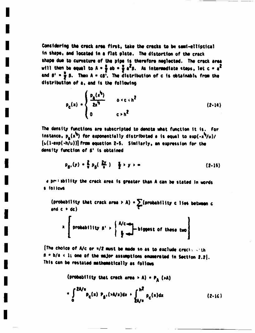
Considering! the crac~k are first, tike the cr41cks to bur sileml-l11pticalin shape. aind located ins4 flat plato. The distortion of the crackshape dlue to curvature of the pipe is therefore negllected. The crack arewill then beequel 2oA•|. Z.A nme,.,a .I€€•.and I' * j B . Then A s cs'. The dlistribution of c is obtainabl• fron the
distribution of a1, and !i the following
Ph t) "(z-34)
The delait~y functions are ssblcript4ec to denote sluet fwsction It Is. ForInstance, pa(Rli) for eaponlentillly distributed aIs! equal to eu)( -uI/u )/
(I,(-lmep(-h/u))j from equatiOn 2-4. Simlalrly, an eapression for thedensity fwnction of t1' is obtained
* Pr', a+ bility the crack area is gIrea,,4er than A can be state d In words
(probbi)|lty t,1at1 crack area ;' A) * •(1probab~lll, c lies betwaen c
and c 4 d€) €
(Tho choice Of A/c or '/1 must be eade so as to eaclude crack .. 'Uh*I b/a |I one of' the mior a~lIspPtIons ed~llIreted In Setlon 2.21.
This can be retated mUsltlcally as ollows
(probaiblity thai. cralck area + A) • A (iAi)
IA/ (1-aG)• JP *( ) %€,.•.•,,()t.
IC*, B* and A in this expression are defined implicittI in terus of pby Equations 2-12. Once again, the first expression is taken to be zeroIf it is negative, and the integral must be evaluated nuinrically. Results Ifor exponential and lognormal mrginal * distributions are preented in
Tbe2-1. which shows that the area distribtion obtained using the Itwo marginal distributions are very simlaer, with the lognormal resultsbeing only slightly higher. Results for the lognormal B are shown inIFigure 2-5, from which it ii seen that the value of a has an increasinqlylarge influence as the crack area increases. I
These results can be compared with data from Feldean 68 on crack areadistributions. Results from Feldean are presented in Figure 2-6, along I~awith corresponding results from the above analysis for P(>A). Results fora ushifteda lognorm1l distribution of aspect ratio with 0.01% of the•cracks having b/a • $ (p10"4 ) are included. This figure shows that Feld-mfnes date predicts a much lower probability of having cracks with largeareas. This suggests that the value of p of 10.4 is too large (or that Ithe ma~inal depth distribution is too high). lowever, even a value ofp • 10~ seems low--especially in light of the fairly large men aspect iirattioi reported by Frost 6), which was discussed at the end of Section 2.3.2.
In siaory, it appe•,-i tnat te "shlte~d lognormal distribution of * iwith ) u |0" irovides reasunible estrthieSt providing high results insam csess (as comared to Feldear 68) and low results in others (as icompared to Pres• 67), IAdditional ineligts can be •zainod by considering the statistical distri-
marginal distributions of a and s, along with the asstuption of inde,
pendents of thivse Lo paremeters. Th~e probability that b exceeds a valuelB ii (aiven b; the following expression.
(probablity that bSO) * (probability B lies between B and 84dB)
K (probability a • S/ll)
Table 2-1Values of Coaqlmntary Chuullative Distribution ofCrack Area, P(> A), for Marshall Exponential DepthDistribution and Vairous Marginal Aspect Ratito Dis-tributions
exoon, ntial S loanormal Sl
0. 01 7.78x 10"1 7.57x 10"1 7.79x 101 7.62x 10"1
0. 03 6.48x I0"1 6. lgx 0"1 6. 0x 10" 6.25x 1 "1
0. 10 4, r6xlO 1 4.17xlO01 4. 5axlo 1 4.25x10"1
0.30 2.56x10"n1 2,22x10"1 2,62x10"1 2.29x10⁻¹
1 8.9x 10"2 6. gx 10"2 9.07x 10"2 6.96x 10"2
3 !. 77x10"2 9. 79xlO" I. 79x10"2 1,07x 10"2
10 9.94x10.4 2.69xl0.4 9.93x10"4 3,08x10"4
30 1.96i10"s 2.06x10"6 2.02x10"5 2.27x10" 6
100 3.0SxlO"8 5.74xlO"10 4.39x10"8 5.88x1O"10
27
IIIII1IIIIIIIIII
0_
crack arm, A, Ia 2
F~gure 2-.. Co~plemnatry Cmumlatlve Olstributlor' ofCrock Area. Exponential Depth Oi stributionand Shifted Lognormul Aspect Ratio Distri-button for Various Values of p.
38
II1
*,-. 5
J•3..om
, ,
Izii •
CIUaS.U
I
(•O'<
)d/(W)a
m
m
--m
- -
m
mm
m
m
mm
m
-m
-m
m
m
-m
mm
-
This can be stated inthematically as follow•
Pb(b • B) " fI or
Pace • ) PB(8)d• (2-19)
Cars mest be taken In the limit of integration, because B < 1 and a > hare excluded from consideration. For this reason, the lower limit istaken tobe the bigger of the two nIbere or B/h. Only the case of anexponential distribution of crack depths and 'shiftedw lognonual distri-bution of aspect ratio will be considered. Using the appropriate deniltyand complementary cumulative distributions from Sections 2.3.1 and 2.3.2provides tate following result.
Pb(b~'B).U -" e' .- x./6)2/(2A 2)1wor B/h
IIIIIIIIIIIIIII
(2.20)_- B/xu . -h/ux • " dx
For conveni~ence, define Bt. as the largest of 1 or Bih. Then makinguse of the definition of the complementary error function erfc x(Abramowitt 64), and making appropriate changes of variable eventu-ally leeds to the following result
Pb(bB) e)U C.e~/ (ln 6 1/%)/ 2 '• - ~
(2.21)
.~e/ef~ m
Once again, the integral must be evaluated nimerically.som care mast be exercisled, because the upper limit ofinfinite. Pvoblem in this regard can be eliminated byterm
40
In this caseintegration isnoting that the
II
I
for x large. Nuirical integration can be used to evaluate the inte-gral from the lower limit out to where the above approximation is suffi-ciently accurate, and a closed furm expression obtained for the valueof the integlral from there to infinity. omplementary error functionswill1 resul t from such ant operaiton.
Results of such calculations for p u io0.2 are presented in Figure 2-7,
with values of b beil.g included out to a length corresponding to comp~letecircumferential cracks in the hot leg (h * 2.5 in, R1 - 14.5 in). Somerather startling results are shown in Figure 2-7, in that some very smallprobabilities are present. The marginal distributions of a and B(Figures 2-3 and 2-4) had numbers like 10.4 and above for representativecomplementary cumulaitve distributions (p - 10"2), whereas ninbers like
aOl ppear on Figure 2-7. This is undoubtedly because the very long
cracks required for nearly complete circimferentlal cracks are wayout in the tail of the aspect ratio distribution.
The Marshall e xrnetial on a and "shifted" lognormal distributions ofB with p * 10" will be used as the base case for further work in thisproject. A case could be made that this is a conservaitve initial crack siiedistribution, because the resulting crack are distribution is far abovethe corresponding eiiperinmtal results of Feldmn 68, and the Marshallmarginal distribution of crack depth ii well above the Becher and Hansen(Becher, no date) experimental results. This crack size distribution,,pears so be e reatnil. o;•iata li on current 1tiiurimloi, bUtcould be significantly altered as more information becomes availablein this area.
TO stlirtiz, th bese casel crack size distribution tI l~limn by thefollowing marginal densityl functions of a and 5, comine wlt, theessie~tion that a and a are statistically independent
41
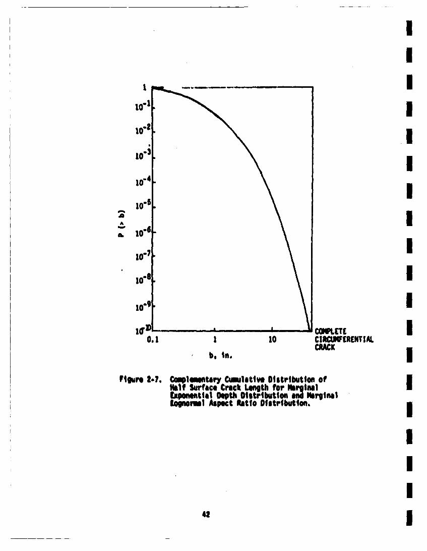
aA
0.
0.1 1 10¢IWLEfRITI AcRACK
b. rio.
Ftgu 2-.. C¢1plte'tiy Cainlatlve D~itribution ofHalf Surface Crack Length for m~glatCapore4etial Depth Ditsribtiont an NirginalIlonorml Aspect Ratio Distributina.
42
u * 0.246 In. (2-22)
BC?'
C5p * 1.419
*a 1.336
U 0.5362• P(>6 ) • iO"n2
This defines the size distribution of cracks given that a crack is present.IHene, the conditional crack size distribution Is now defined. The re-maining peice of informtiton required to coq~letoly define the initillcrack distribution is the probaiblity of a crack being initially present.This portion at the initial crack distribution will be discussed in thenext section of this report.
2.3.4 C:rack Existence Probabilities
The remaining portion of the Initial crack distribution to be definedis the probability of a crack initially existing in a weldeent. Asmentioned in earlier discussions, attention is focussed in this investi-gation on cracks located on the interior surface of the pipe. Eventhough surface crocks are ccissidered, ti'e prbaIblity of a crack beingpresent will be taken to be controlled by the weld voim. OtherPaerneters, such as length of weld nr surface area of wild and heataffected zone could be cciisidered, but will not be included lea the pre-sent work. llhch of these are taken will not have a large affect onthe results, unless large veriations in thickness are encountered. Suchis not the case here.
The wild yoell. V. will be taken to also Include the heat affected zonewhich will be taken to bie tu wall thicknesse wide.. The wild volilV is then equal to
II
V ,, uDlh (Zh) • 2. Dlh 2• (2-23) I
The rate of cricks per unit volime will be denoted as pv", and theI
nuiber of cracks in a body of voimR V will be taken to be Poissondistributed° There ar theoretical reasons for making Such an assmptionI
(see for instance page 56 of Hood 6O). The following expression forthe probabltity of having N cracks in a body of volues V is thereforeIapplicable (Iiahn 67).
P(N).*(p) L... (2.24) IIThe probability of having a1 crack in a body of voliin V is one minus the Iproabilit.y of having no cracks. which is given by the following expression
pbblt uf having a crack in V Ia •a * '. , VP ' (2-26t) I
The probability of having exactly I crack isI
P~i) " Vpv eVv (2-26a
The above approximations hold If VPv* << |. This shows that the probe-bility of having a crack is approxliatily squat to the probabililty of
having exactly I crack, and that p* vaiesllitnearly with Pv* (for V~v
<< )11 IThe rilninng part Of the probtlm is to estimate the parineter. Pv*NOt a great deal of inforlttim Is avalalble in this regard. Criond 74I
surveys results from a nmber of sources, with his results for tracksswmmriied in Table 2-.2 The frequency of cracks per unit of woid|length varies in this table frn I.1xlO"4 to g.43 1O"2 per inch. SuchIresults could be4 cast In a unit volui basis by dividing by lh2 (h * platethickneSS). Hence, the thickness would be required to estimalte Pv* f'"
the data of Table 2-2•. I
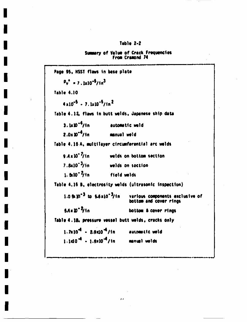
Table 2-2Snisry of Value of Crack Frequencies
From Cramnd 74
Page 95. HSST flawts in base plate
*v 7. 1z1O'/1n 3
Table 4.10
Tableo 4.1, •filaws in butt welda, Japanese ship data
3. IAKO'4in automatic weld
2.0x ]"41inmanual weld
Table 4. 15 A, iultilayer circutaaerentlat arc welds
9An10O'tln welds on bottom section
7.8JI1' 3/in welds on ieotlon
1, lkbO" 2/tn field welds
Table 4,15 8, glectrosity welds (ultrasonic Inspection)
1.OS'1ldl 3 to 5•4ab0Jll
fable 4,.18. pressure vessel I
|,lalOi . t.galO4 Iin
I l~xlO 4* .t9mbdl
various components exclusive ofbottom and cover rings
bottom 5 cover rings
iutt welds, cracks only
autmaelic weld
ianul welds
DI
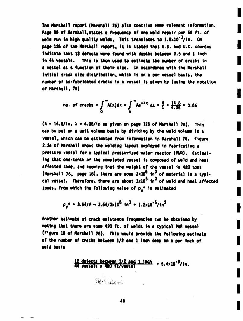
The Marshall report (Marshall 76) also contsins san relevant infomution.Pape 8 of Nsrihall~states a frequency of one weld repait per 56 ft. ofweld run in high quaity welds. This translates to 1.Sx10"3/in. Onpage 126 of the Marshall report, it is stated that U.S. and U.K. sources Iindicato that 12 defects were found with depths between 0.5 and 1 inchIn 44 vessels. This is then used to estimat the ngebr of cracks in Ja vessel as a function of their size. In accordance with the Marshallinitial crick slae distribution, vhich is on a per vessel basis, the Iniber of ss-fabricated cracks in a vessel is given by (using the noutitunof Marshall. 76)
(A a 1a.8/in. ? * 4.06/in as given on page 125 of Marshall 76). Thiscan be put on a unit voluna baiss by dividing by the weld voltin in avessel. tAich can be estlime from information in Marshall 76. Figure
2.3a of Marshall shows the welding layout employed in fabricating apressure vessel for a typical pressurized waear reactor (PWR). (stimat.ing that onee-anth of the completed vessel is composed of weld and heat Isaffected zone, and knowing that the weight of the vessel is 428 tons"(Marshall 76, pap0 18). there are amw Sx1' in3 of malterial in a typi-cal vessel. Therefore, there are about $m105 in 3 of weld and heat affectedzones, from viich the following value of Pv*' is estimated I
P* 2 .64/V -- 3.64/3x106 in 3 * 1.2u10"/in 3
Another utimaltoOf crack eixstence frequencies can be obtained bynoting that there are som 420 ft. of welds in a typical PWR vesseli(Figure 16 of Malrshall 76). This would provide the following estimateof Use neer ofcricks between1/i2and I inch deep enaiper inch of
weld basis
U!,f°,,oe 5 4 ,,0/I.,
. II
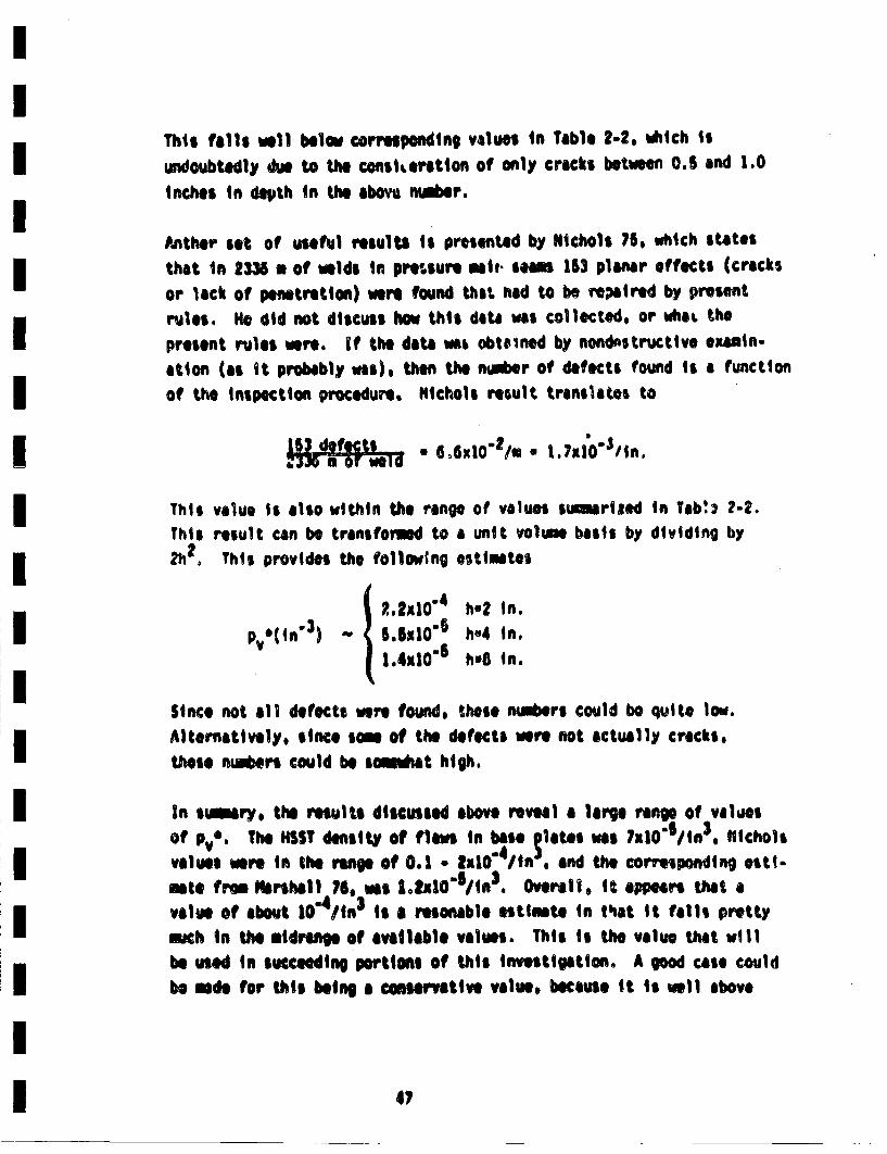
This falls weill below conrsspondinp values in Table 2-2. vhich isundoubtedly dui to the const, erotton of only cracks between 0.5 and 1.0
inches in depth in the abovti aiber.
Anther' set of usefwl results is presented by Nichols 75, which statesthat In 2336 . of welds In preHsremi~i ~,Slse 153 planar effects (cracks
or lack of penetration) were fOUnd that had to be rsailred by presefit
rules. lie did not discuss how this dta was collected, or what the
present rules were, If the date was obtetned by nondestructive ezauin-ation (as It probably was), thea the nti~er of defects found ii a functionof the inSpection procedure. Nilchols result translates to
• 6.6o' 2/m . 70•in
This value is also within the range of values sinrized in Tab'.s 2-2.This result can be transformeod to a unit voltue basis by dividing by2h12 This provides the follow~n9 ostlimtes{ 1,2•0" h.2 in.
p *(in"3) ~h~l " h4 in.1.x0s hB in.
Since not all defects were found, those niabers could be quitt low.
Alternatively, since som of the detects were not actually cracks,
these nter could be siit high.
In siry, the reults discusda bov reea a1 large range of valuesOf *V The KSST densit @ Oflawsin ba bse plates was 7xl0"SlIa 3 o Nichols
values werer in the range of 0.1 * -I |u0"/n and the corvesponding osti-rote from Ninrshall 76, was |I.Za0"S/in3. Overall, it appears that avalue of about 10"4 /in 3 is a reonable estimete in t~at it falls pretty
much in the midrange of available values. This is the value tiat willbe used in succeeding portions of this invostigation. A good case could
bemdi for this being a conservative value, because it is well above
4,
Ithe value resulting from the Marshall data. In the end, if Pv" exed I10"4/in 3 , this would not have much influence on the calculated failureprobaiblities, because the probaiblity of having a crick in a tyfpicalI
weld Joint alree~y exceeds 0.1 for this valve of Pv,*. Hence, increasesin pv• could increase the calculated fallure probabilitios by •j motan order of magnitude. For the weld volime being consilerod CV * 1139 in3
for a Joint in the hot leg), the calculated faillure probaiblities wouldvery roughly linearly with pv' as the value of this parameter decreaesd Ibelow tO0411n 3.
ICertain results obtained froem the fracture mechaincs analysis will bevirtually independent of the value of pv. This will be true of certaina
relaitve results, such as th per'centage of LOCA s thas are seisuicinduced, or the ratio of 1eaks to LOCA s.I
As another sidelight, using V * 1139 in3 and pve of 10"4 /in 3 , the pr~obi-
bilit~y Of one cr 'k end a crack are given essctly as follows:I
probaiblity of a crack • 0.1077I
probabl i ty of 1 crack * 0. 1016I
Hence, the distin•'ion of one crack versus a crack is latqely lost forI
the values of Pv" and V emloyed in this investigation.Haerris 76, 77b aumloyed a valve of Pv' o 10"6/in 3, •htch is we1l below ithe valve suggeted here. However, only cracks that were very longIrelative to their depth (s ) 6), and with an initial surface lengthIexceeding a certain value (typically 4 in) were considered in the popu.lation. Figure 1-7 shows about 11 of the cracks l avei •lo b0 4 in.I
for the crack size distribution eqployed in the investigaiton. Therefore,the twO order of mepnitude difference between Pv* eqployed he-e, andIHarris's earlier valve is felt to be consistent.
The initial crack size distribution is now cmpletely defined. This as- Ifabricated distribution meast be cambined with the probability of detect-ing a defect as a fwnction of its size in order to provide the postt-
I46 I
inspection diGLibution wsich, in turn, lors tJ'e inittal conditions forthe fracture mechanics analysis. The detection probability will be pre-sentid in the next section.
2.4 Inspection Detection Probabilities
Failures in nhclear plant piping are caused by unchecked propagationof defects until an intolerable crack size has been reached. A periodicinspection is oft• 'ased in atteqpts to detect these flaws before theyreach critical size (A~INC80). Ultrasonics is the most often usedmethod of nondestructive inspection of nuclear plant pipes. The proba-bilit~y of detecting a flaw P0 with ultrasonics, or with any other non-destructive testing method, is a function of the size of the flaw. Theprobability of detecting a very small flaw is near zero. whereas the proba-bility of detecting a very large one is nearly one. The probability ofnot detecting a flaw (P~o) is equal to (1 - P0), and will be the para-meter concentrated upon here.
2.4.1 Review of Past Results
Data on probability of non-detection for ultrasonic inspection havebeen extensively reviewed by Hlarris (Harris 76, 77b, 79) and relevantfeatures of these reviews are sumirized here. Harris 77b includesdata for fatigue cracks in a 0.66 or 0.2 inch thick 2219-TO aluelniamplate (Rtml 74) and also data for ultrasonic inspection of 3 inch00, 0.26 inch thick alueiniue tubes (Tang 73). Based on those data.a lognormal relation of the type
PND(a) * erfc (yln a/a') (2-27)
was found quite adequate to .athemetically characterise P~g' In theabOve equation, a' is th crack depth that has a SOS chance of being
detected and v is the prermtor that controls the Slope of the PO"acurvew en plotted on lognormel probability Paper. For the probabilititcrupture aMllysis (Harris 77b) of ferritic piping, a' * 0.26 in. andv * 1.33 were chosen. This model is graphically shown in Figure 2-8along with the data of Ral, Tang, aid other investigators.
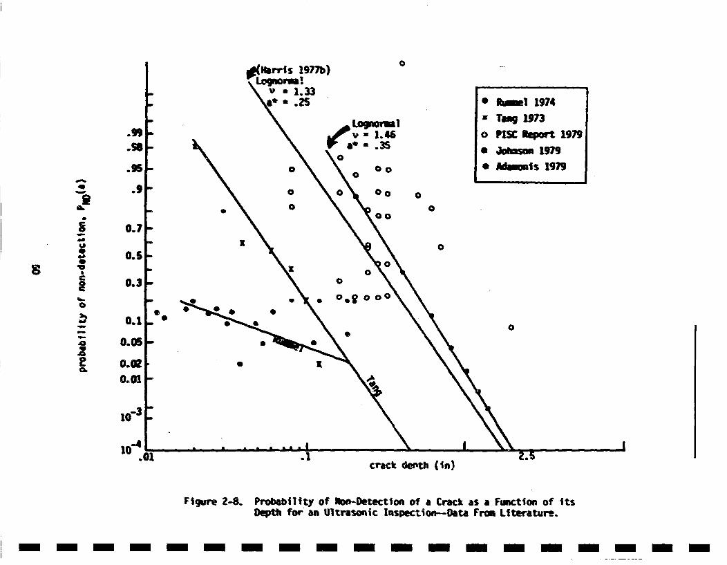
0•al Irrls 1977b)
.9, ( =. 1.46
Co
* RImil 1974- Toaq 1973o PISC •o 1979
* Ad1ms 19790
A.9 -0 o•0
• •0 0*O00
0.7
x -
~0.3
00
_ 00.01
0-3.
10"01.
crack doi'th (I n)
Figure 2-8. Probabl|ty of ion-Detectioni of a Crack as a Function of ItsDepth for an Ultrasoic Inspection--Data From Literature..
- m -m -m - -m - -m - -n - -n - -m - -n - -n
In addition to these, data ont ultrasonic Inspection of stress corrosioncracks in austnittic pipes (Kuppermann 78) were reviewed by Harris.(Harr~s 79) and again a lognormal relation between PI( and defect depthwas found appropriate. The value of v • 3 was found most reasonable andtwo values of a' (0.1 and 0.2 Inch~) were considered for the probabilisticpiping analysis.
Since the publication of the above mentioned reviews, additional Infor-mation on probalbility vf detection of flaws by ultrasonic inspection hasbecome available. The results froma PVRC Industry Cooperative Programon heavy section steels for nuclear reactor presa..re vessels were analysed(Johnson 79). These results consisted of detection probablities forultrasonic inspection of welds made on 8.25 inch thick A5338 low alloysteel plrates. Small internal imperfections were implanted in the weld-ment, and the specimen was subject to ultrasonic inspection by fivedifferent teams. Later, the specimen was metallurgically sectionedto reveal the locatlos and dimensions of these flaws. Assuming thatthe ultrasonic inspection was carried out according to ASME Section XICode (ASMESO) Johnson at. al. obtained best estimates for PNO(a)(Table 2-3) using T"Inspection uncertainty analysis.TM Their data of Table2-3 could be described by (rigure 2-8) Equation 2-27 with v * 1.46 anda'* •0.35 i n.
Taeble 2-4 shows non-detection probabilities of ultrasonic inspections madeon 8 to 12 inch thick welded plates. These data were obtained from apreliminary report by the Plate Inspection Steering Canmatte (PISC 79).This study consisted of round robin ultrasonic inspection of the platesand the detection probability for each flaw was evaluated by the fractionof the inspectors detecting that particular flaw--the existence of flawbeing verified by a later destructive exaidnation. The data listed inTable 2-4 are for only those flaws that were later verified to be crack-like defects. These data are plotted in Figure 248 wh~ch shows a largescatter but generally centered around a lognormal model with v * 1.46and a'* 0.35.S which was based on the analysis by JohnSon et al.
$1
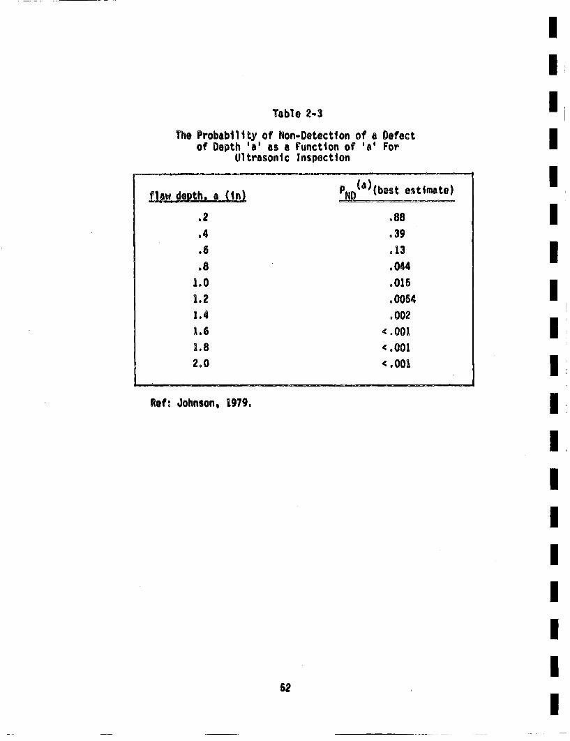
I
Table 2-3The Probability of Non-Detection of a Defect
of Depth 'a' as a Function of 'a' ForUltrasonic Inspection
q!• deth, a •nl • (a)(bsflewdo , ain ~D (estestimate)
.2 °88884 .39".6 .13
.8 0044180 8015
1.2 .00541.4 8 002
1.6 .0011,.8 ( o0012o0 <.001
I
Roft Johnson, 1979o
I
52
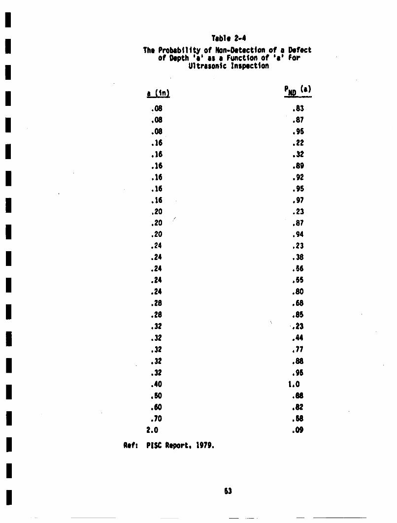
Table 2-4The Prbbliyo Non-Detection of a Defect
of Depth *e as a Function of ae ForUltrasonic Inspection
a (in) Pill (a
.08
.08
.08
. 16
.16
.16
.16
.16
.16,20.20.20.24.24.24.24.24.28.28.32.32.32
.32.32
.40
.60
.702.0
.83.87.95.22.32.89.92.95
.97.23.87.94
.23
.38
.66
.55
.80
.68
.85
1.23.44.77.88.96
1.0.88.82.58
.09
Ret: P1SK Report. 1979.
'3
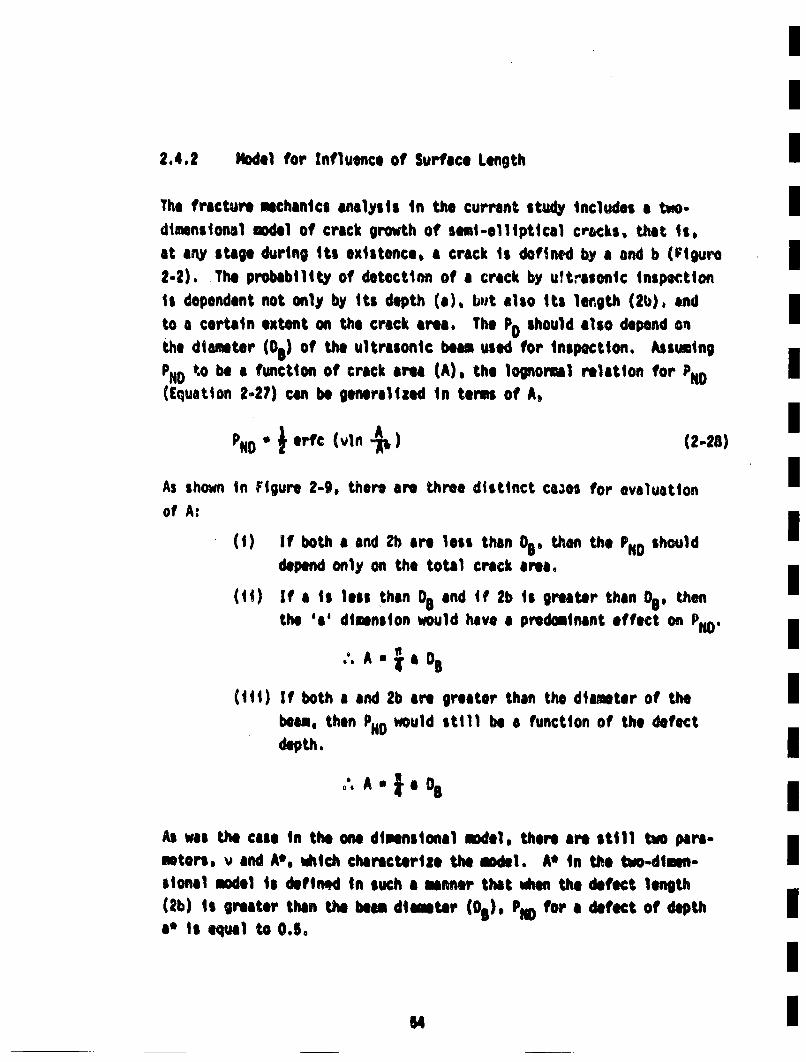
i
2.4.2 Model for Influence of Surface Length IThe fracture mechanics analysis In the currant, study Includes a two. Idimensional model of crack growth of semI-elllpt~cal cracks, that Ii.at any stage during its existence, a crack is defined~ by a and b (Figure I2-2). The probability of detection of a crack by ultrasonic Inseptiaonis dependent not only by 1it depth (a). bu•t also iti length (2b), and ito a certain extent on the crack area. The PD should also depend onthe diameter (D5) of the ultrasonic beam used for inspection. Assuming
PNDot*o be a function of crack area (A), the lognormal relation for IN(Equation 2-27) can be generalized In terms of A,
%N •~ rt (vln A (2.28)
As shown in Figure 2-9, there are three distinct cases for evaluationI
ofA: (1) If both a and Zb are less than D5, then the PDshould
depend only on the total crack area.i
(ii) If a is less than O8and if 2b is greater than 0D, thenthe 'a' d~imnsion would have a predominant effect on PO
.'. A *•.aD
(iii) if both a and 2b are greater than the diaiter of the iibeamo then PHN) would still be a function of the defect
deth.I
." A" •e O0
As was the case in the one dimensional mdedl, there are still two pare-meters,. v and A', which characterize the mdedl. A' IA the two-dimen-Isional moeal i* defined in such a sinner that vllem the defect length(2•b) is greater then the beam diinter (Di), PiE for a defect of depth Ia' is equal to 0.5o
54 I
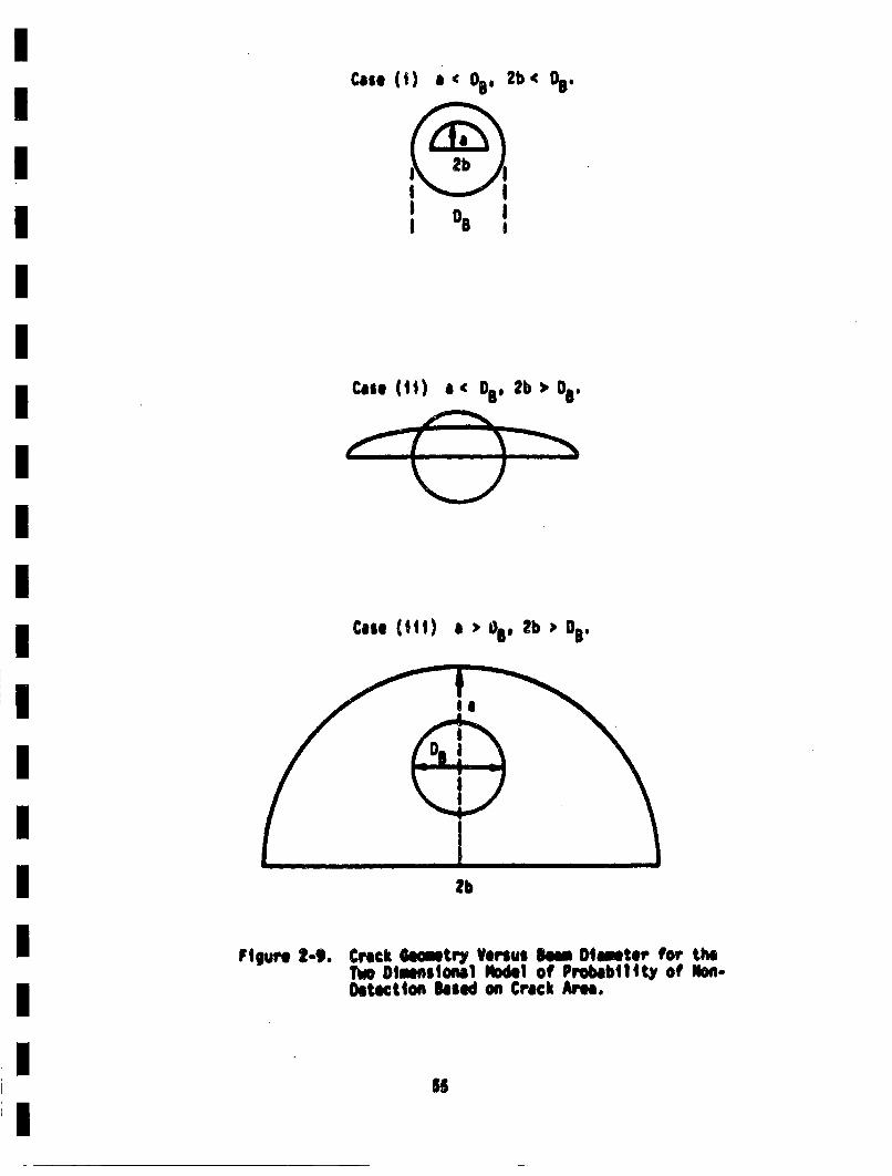
Ca.. (I) a'00 2b' D0.
III °, I
Case (It) a' D8 . 2b • OB.
Case (III) a , ZOb OO.
lb
Figuare I-9. Crock Giaittry Versus Born Diamelter for theTwo D~meeiIoell Nodal of Probability of lion.Oetsction Based on Crack Area.
55
II
For a' -0&26 in. and v • 1.33, and for a bean diameter of 1 inch, thetwo diuensional model for Pi) s shorn in Figlures 2-10 and 2-11 as afunction of detect depth for various asp~ect raties. For 2b/a * -. thetwo dimalnalmoe1ndel degenerates to One dimensional model with the sam•a' and v. The PNI) versuls a curves for any aspect ratio merge into theone-dimmasional model when tb becomes largier than the beam diamter. Fora defect of given depth, the probablity of non-detection decreases withIincreasing aspect ratio, until the length of the defect exceeds thebeam diameter.
2°4.3 Specilizaiton to Austenitic Weldets I
All the data On detection probabilities reviewed in Section 2.4.1 werebased on either wrought or welded fern tic steels or aluninnta. As•discussed in Section 1.2. the primary piping at Zion is fabricatea from
centrifugal~lycsaustenittc stainless steel. The large coliniar grlaisresulting from the casting process makhes the ultrasonic inspection verydifficult. The value of a' of 0.35 in. estlimted in Section 2.4.1 is Ifairly conservative for the data presented, but is overly optimisticfor cast austenitic stainless steel. The functional form of P10 giventn Equation P.-27 will be assured to be also applicable to cast austenitticImaterials, and th values of a" 8nM v will be altere. Beker Ssuggests that a crack woud have to be half wa throgh the wall thick-neSS to have a 505 chance of being found. Using a typical wall thicknessof 2.60 in, this results in a value of a* of 1.25 in. The value of vcan be evaluated from the assmption thata through-wall crack would bedetected with a probability of 0.MS. This results in a value of v of1.60. In s • th nond tecton probablity sed in th inaestigationis given by the following expression:
PlloA) . erfc (v In •v ) (2-9)
S4I
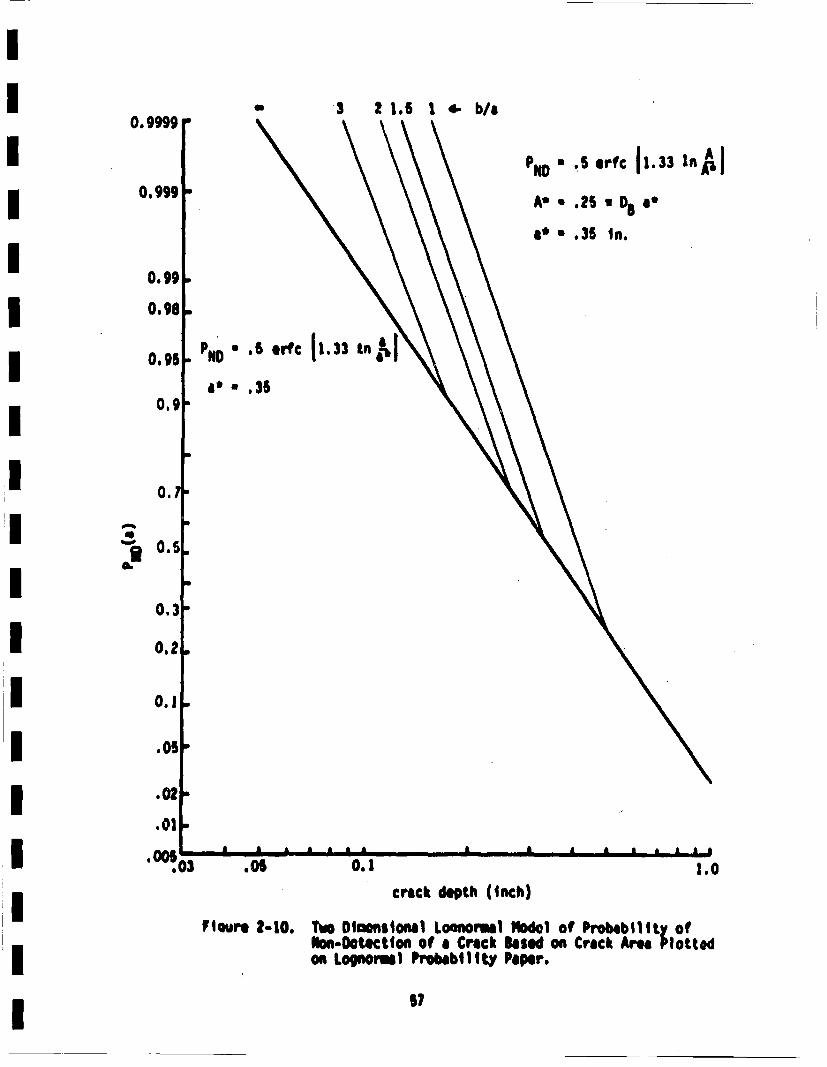
3 21. 1,!4- b/a0.9999
* .5 erIc 11.33 in~J
0. '99 * .25 '
a' * .35 In.
0.99
0.98
~ND .6 erIc 1'. 3~ In
a0 * .350.9
0.
* 0.5S.
0.3
0.2
0.1
.05
.02
.01
* 0003 .05 0.1 leocrack depth (Inch)
Flouro 2.10. Two Dinmnalonal Loonomal ~~ol of Probability ofnDotctlon of a Crack Saud on Crack Aroa Plotted
on Lognormal Probability PaMr.
I
57

10
0
S
C1
,,4
.2
-..d
CRACK DEPTH (IN)UpS
m m mFigure 2-11. Tvo Blanaslomi Loguonmi 3ode1 of Probablityr of Nom•-Otectleon
- -
V - 1.60
i* a*.6 n
The expression to be used for A is discussed in Section 2.4.2. and a
value of OBof 1 inch will be used in succeeding portions of this work.
The two-dimensional results for Pofrom Equation 2-29 is presented inFigure 2-12 along with datSa frcm the literature revtiaed In Section 2.4.1.The PND result from Equaiton 2-29 is we1l above the data from the i~ter-ature, which reflect~s the c€orrections" made to account for tho diffi-culty of detecting cracks In cast austenitic materials. The results of
Figure 2-,i12 show that the value of v is not too critical, since theslopes for ', * 1.33, 1.46 and 1,60 all appear quite similar,
Results obtained by the use of Equaiton 2.29 and the model for the influ-
ence of surface length discussed in Section 2.4.2 are sum~rized inFigure 2-13. The influence of the surfaice length is seen to not be verystrong. The nondetection probablities shown tn Figure 2-33 wll| beused in succeeding portions of this investigation, These detectionprobabili~ties are ccab|ed with the as-fabricated crack size distributic,,(discussed in Section 2.3) to provide the post-inspection crack size
a•Istribution which the serves as the initial conditions for the frac-ture mechanics calculations. Such calculations require the crack growthand ",llura characteristics of the material. These will be reviewed inthe next sections.
2.1 Malterial Fracture Characteristics
The fracture characteristics of the material are required in order toperform the fracture mechanics calculaitons of subcritical and fastcrack growth. The silcritifcal crack growth will be titlen to occur asa result of faitgu} crack growth which reY be accelerated by ew~.,•on-montal influences--such as the presence of .,ooling water in the crack.
Si
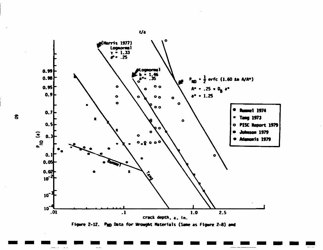
I/a0\ *(v *i 1.33)
tw .25m
0.9!0.1
0.i
0.1
S0.
0.'
0
.e.° •errc (1.60 ta A/A.)
Ae .25 1* 1
*° 1.250
0S
K
* •1 1974* Tm, 31973
o PlSK Iqiort 3979* 1~ms 1979* JId •s 1979C 0
0.20 0I
S I
to"
.1 1.0 2.5crack depth, a. is.
Fic~er 2-12. Pal Ihta for Ureght Niterlals (Same as FIgsw 2-8) -~
- m m--n-mm-m - m-m-m -m-m --m -

• 0.6 v :.1oWA8*EAM DIN4I
0.4 I F b~Te.a
0.3 I~ 2b.• , -•.u•a
0.1
0. o2 0.4 2 ' "*. IN,
FIrgure 2-13. Tuo Olminslonel Lognoruul Model for Probe-billlty of IMon-Detection of a Crack in CastAusteni tic Materiel.
61
IStress corrosion cracking will not be consideredl, because such cracking Ihas not been observed in the primary piping of a PUR. Fatigue crack
growth under noninall~y elastic condittons vill be considered. Elastic- Iplastic failure criteria will be umloyed in treatment of the onsetof fast fractur~e. The fracture characteristics of the mtetrial will beI
reviewed in the following sections.
2.5.1 Fatigue Crack Growth I
The subcritical crack growth characteristics of the piping material is
an ieportant Input to the piping reliability analysis. As mentionedin Section 1.2, the material used in the prlimry piping at Zion ! isbasically 316 type austnintic stainless steel. This material has ,evorboon observed to be susceptible to stress corrosion cracking in PWtR pri-mary piping. Attention will therefore be concentrated on faig|ue crackJ
growth, and possible environmental Influonces. Heonce, corrosion fatigueis Included In the analysis.I
The presence of water in growing fatigue cracks is widely known toaccelerate crack glrowth. it also increases the influence of loadingIrate end mean stress (related to R ratio). Additionally, mean stressIeffects s:m to be more iq~ortant as temperature is increased. Hence,i
in addition to the cyclic stress intensity factor. AK (s I~ enthe load ratio R (Kein/Kmax) may also be important, Bamford 79*, Hale78. and Jams 75 indicate that the Influence of R can be accounted for by Iconsidering the "effective' stress intensity factor "Kiff, which equalsKILM (1-R)m, and that da/d, (t.rick growth per cycle) is a function of IKetff rather than Just At. furthe', tb¶ey shot, that. a a i s a goc0 vatieto use for the steels and eutvirouents under consideration. The nOtLionI
of Kefis rat hr awliad and will Ibe replaced by
Results reviewed here will concentrate on the use of K,.
II?
hmftord 79a provides data that shows that the enviromentally enhancedfatigue crack growth (corrosion-fatigue) characteristics of 304 and 318stainless steel are virtua1Ty Idontical, and are independent of wh~ether
the material is cast, forged, or welded. Niche1 78 also Indicatesthat welding has no Influonce.-nor does irradiationl. The lack ofeffects due to fabrication history, composition, and irradiation are not
surprisi|ng, and are consistenft with observations drawn from the much
lalrger data base for ferritic pressure vessel and piping steels for
nuclear applications (such as A5338, AMOB. A517, etc.). The siml|arity
of results from 304 and 316 stainless steel suggests that information
on1 304 can be used to elimtell the subcritical crack gorwth character-
|istie of 316.
The fatigue crack growth rate of wmit materialslis1 a strong function
of cyclic stress intenit~y factor, and the creck growth rate can be
adelquately characterisedI by the folleving empirical relation (Bamford
79a, lames 76),
where *i fatigue crack growth rate (inches/cycle)
AK * Cyclic stress intensity factor * Kmag - min(ksi-dn")
R • load ratio ••n~u
Cmr • empirical constants
K' is the effective stress intensity• (actor eapressed In Equation 2-30,
that accounts for the effect of cyclic stress intensity (AK) as well asthe load ratio (a) onl fat~ige crock growth rate. | It isncessary to
ob)tain the nemerical values of the ceontants C and m to €cpute the fatig~u
crack growth as a function of stress intensity erid load ratio for the
materials and enviro.mnt under consideration.
')
Sufficient data on fatigue crack growth rates of 304 and 316 type stain-less steels in simulated LWR environment are available for a range ofstress intensity, various load ratios, test frequencies and specimenorientations, Crarck growth rate data nost relevant to this study are
available in Bamford 79a which were obtained from tests conductedin a simulated PWR environment. These data were obtained for a rangeof stress intensity and for varioui load ratios, test frequencies andspecimen orientations. These data, along with other data available inthe literature (hale 78, 79, Shahinlin 75, Ford 80, FCFNS 79) werepoolad together and the crack growth rate (da/dn) were plotted as afunction of effective stress intensity (K') on log paper. As seen inIFigure 2-14, all these data fall within a fairly narrow band. By a least-square regression analysis of these data, the values of C and m we,'eobtained as I
C * 7.19x10"12
m * 4.071
The wlduo of in obtained is very close to 4, end will be rounded off to U4 for convonierca. The value of C will be altered soewhedat by this pro-cedure, and a least-squares regression analysis usring m • 4 provides a Inew value of C of 9.I4xWO12 (da/dn is inches per cycle, K is ksi-in1 ).
Figure 2-14 sowvs the fatigue crack growth data along witn th. results
for m * 4 and 4,071. It is seen that the two curve fits are not signifi-cantly different, and a value of 4 for m will be used in this investi-•gatllon.
The 0rata points on Figure 2-14 from Ford 80 are for furnar.e sensitized 304 Istainless steel tested in water at 97C with 1.5 ppa u~ygen. Such sensi-tliation is known to be responsible for the intergrannular stress car-Ii
,'atian Cracking (IGSCC) that has been troublesome in some piping in BIE'sC(lepfer 75, ICSG 75, 79, OBiannuzzi 76). The sensitized steels may beI
uors susceptible to envtrorinntal acceleration of faitgue crack growthalthough date in Kale 76 suggests that this is not the case--at leastfor crack growth rates above I06I/y~t h fr l•pit r
for different rise-times of the loading, which consisted of variablereai loading followed by unloading in O.O~s and no load for 0.O~s.
-4 I
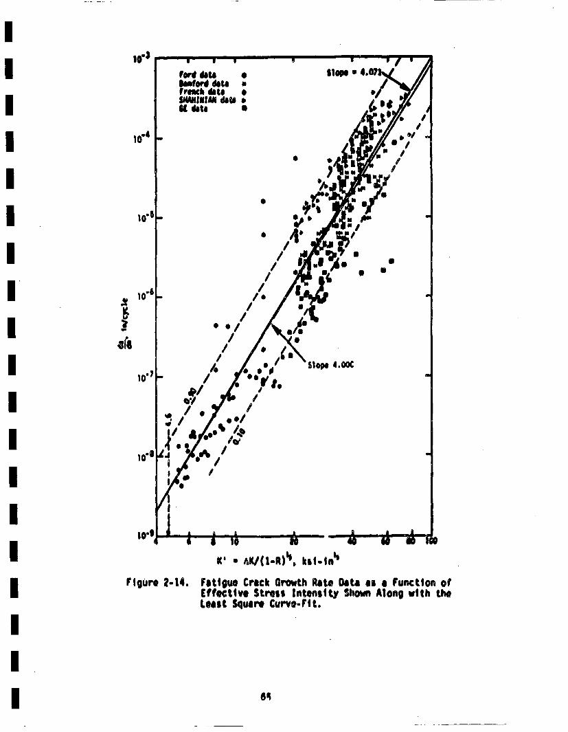
10"s
5/
/I
rigUre 2.14.K' * MC/(1-R)', hal-In1'
Fatigue Crack Growth iate Data as al Function ofEfftCtlve Stress Intensity Shown Along vith thiLeast Squart Curvo-F'gt.
iOxygen content of the water is known to influence the failure times Iand rate of growth of stress corrsion cracks in sensitied 304 stain-less steel (Klepfer 75, Clark. 73), and could also have some effect on |corrosion-fatigue crack growth rates. The data of Bamford 79a is gener-ally applicable to PUR water, which contains less than 0.1 ppm of oxygenI(Table 4.2-2 of Zion FSAR). The data of Hale 79 is for BUR operating I
conditions, which are typically 0.2 - 0.4 ppm (Hale 79, Klepfer 75). The ldata of Ford 80 is for 1.5 ppm water at 97C. A comparison of the resultsobtaied at these different oxygen levels suggest that oxygen contentis not influential within the ranges of oxygen content, loading frequen- Icies and crack growth rates considre.I
Crack Growt Threshold
Another important aspect of the fatigue crack growth relation is the Ithreshold conditions below which crack growth will not occur. rho exist-once of such a threshold has now been firmly established (Richie 77a,77b, Vandergliass 79, Shahinian 75, Paris 72, Vosikovsk~y 75, Cooke 75).The presence of this threshold may be important in the analysis of
fatigue crack growth of reactor piping, and should be considered. Thisis especially true if the small but numerous steady state fluctuationsin coolant pressure and temperature are considered. The value or the Ithreshold has bee found to be independent of the enviromunt, butdependent on ft. Additionally, Ritchie 77a, 77b has foun it to be depend- Ient on tl, e tensile properties and microstructure of the malterial.
Considering first the influence of ft. it sea reasonable to assime thatIK' would provide a useful paemeter to accout for ft. As ntionoabov, enviro~t genrally does not effect the threshod, altouh Coke75 shows a differene betwee air &n vauicn in that A does not have aneffect in a vauice. Cooke 76 found that the parimeter AK0 (I-R) 0 '63 wasIindependent of ft (6Ko is the meaured threshold AK). This suggpests the I
use of K (o AE/(1.R) ) to charecterize the threshold. This provides Ithe added convenience of kilng a single fixed value on the u-axis ofFigure 2.14, and interface nicl~l with the dad reltion for highr K'.Addtionl infovmtion on the influene of ft on th faigue threshold it Iprovideld in Pairs 72 and Ritchie ?7b, Their results show that the
- I
parameters K• for a given mtetrial, heat treatment and temperature isnot as dependent on R as the parameter AKo, and therefore provides abetter measure of the threshold than AK0o. The value of r is the expres-sion AKo/(1.R)m could be adjusted to provide results even less dependent
on R, but this seem to be an unnecessary refinement at this time
The use of the parameter AK /(l.R)• to character Ize the trsodpo
vides good agreement with experimental results for small ft. Howver.
care must be taken to adequately account for ft values as ft approaches 1(Schmidt 73). The use of this parameter becomes questionable aboveR -0.9. However, its use is conservative in that it predicts a higherAK threshold than is actually observed.
The threshold value : the effective stress intensity factor, Ko, canbe estimated from information generated by the French MetallurgicalSociety (FCFMS 79), In which the threshold conditions for fatique crack
growth in austenitic stainless steel were specifically investigated.The data points in Figure 2-14 include their results, from which it isseen that a threshold value of 4.6 ksiuin' provides a reasonable and
somownat conservative value of the effective threshold stress intensity
factor°
.Oistri~bu~tlon Of C(
The data presented in Figure 2-14 exhibits an appreciable amount ofscatter, which is typical of fatigue crack growth ra~u data. The scatteris seen to he present sn the results from each Investigator, rather thanf ro investigator-to-investigator. Vairous means of accounting for eachscatter have been suggested (Bemford 77, leiwner 77a), dad the procedureor Slurter 77a will be fallored. In this case, the value of the exspon-ont, U, in Equaiton 2-31 is taoen to be fixed, and statistical vari-ations of da/dn for a given cyclic stress intensit factor are accountedfor by considering the coefficient C to be randomly distributed. Thisis also the procedure usedI by Harris 77b.
The numerous data points In Ftgw". 2-14 each have a value of C associatedwith them, once U has been fixed at a value of 4 (C1 * (da/dn)1 /K14 whereI(da/dn)1 and K1 are the original data point). A histogram of the result-ing values of in C is shown in Figure 2-16. from which it is seen thatsome skewnels of the distribution exists, but a normal distribution of1nC would provide s resonable approximation. This would Iqply that C
is lognormully distributed.
Th cmlative distribution of C can also be obtine from this data.Iand i1 plotted on lognormal probability paper in Figure 2-16. The data
falls nearly on a straight line, with som deviations at large C. Thisfurther supprts he contetion that C is 1ognom11y distribute. Achi-squared test wi~s performed, which shoedl t+hat the obselrved data 1:1 Iinot contradict the assumption of a normal distribution of 1nC at 0.05significance level. Therfore, C will be taken to be Ionomallydistribute.
The mean value anditndr deviation of 1nC wer calculate fro thedata poits by standard procedures (i.e., (1'R•) g (li/t Z (In C1) * etc.).The following values were obtained
•I'T . 21.416 I(In C)Sd • 1,042 '
The median value and standard deviation of C can be evaluated as tol-Ilwn (kastings 74)I
¢ a e(•~ " 9"14x|O'"l ICsd.Cb€O0(eln cii "e )'2'20xlo0
Since C is loprmally distribute, it will hae the followin probbilitydensity functiont and cowlinlntary ¢iinlative distribution (14hn 67.
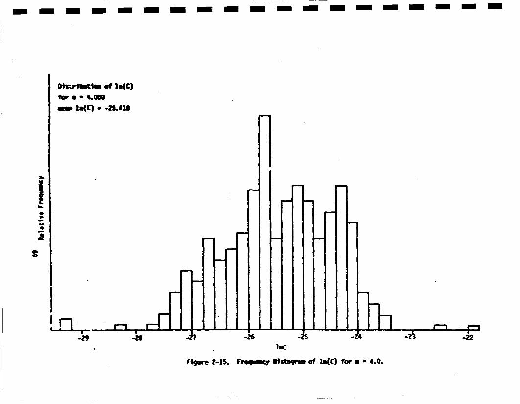
m - - - - - - -- -m-m - - - - - - -
0S-,.vmtitem of linK)form 4.0W-i ls(C) - -4543
S
2
.!-iB--
Tb]I-2Z9 U
-28 -26 -S 44i U
-22lumC
FIgmmr 2'-15. Freqemy NIstssjmat ofra(C) for - - 4.0.
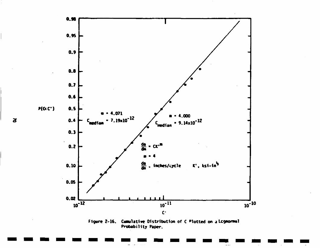
0.U8I
0.9
0.8 0
0.7- •
0.S
P(Cc C') 0.5S * 4.071 * .0
~~~0.4 Cdi -7. 19x10"12 Cetn.91x0
0.3
0.O2
10"02120 i , , t, l
C-
Figure 2-16. C~mlatlve Distribution of C Plotted on a Lcgmomsl
Prebab;l1|ty Paper.
- i-- - i-- - -- - -- i - -i - -n -
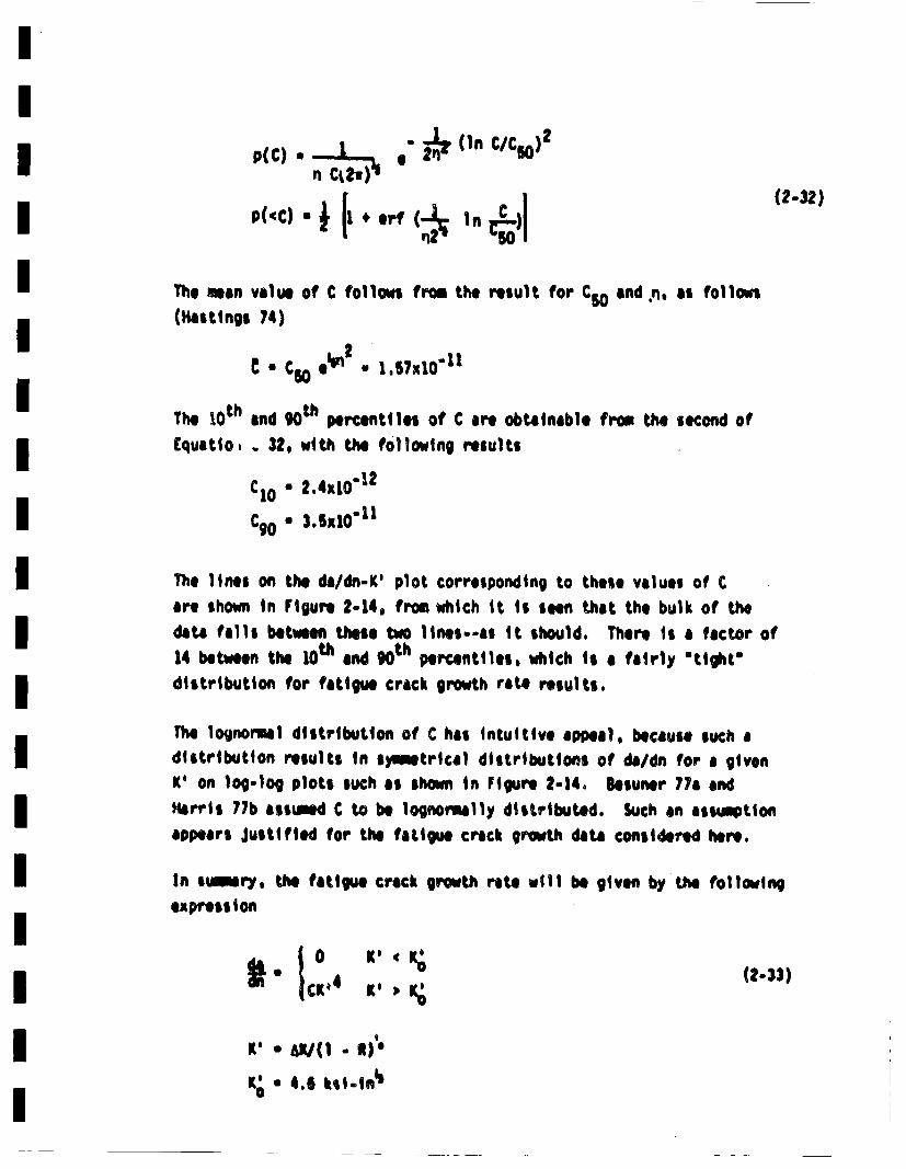
p()~ j ." & i CC)
The mean value of C follows from the result for SOand n., as follows(Hastings 74)
" m6 ec n ° 1°67x10"11
The 10th and 9Oth percentiles of C are obtainable from the second of
Equatlo,. 32, with the following results
C10 * 2,4x1O"1
Cg0 * 3.6M10"11
The lines on the da/dn.K' plot corresponding to these values of C
are shown in Figure 2-14, from which it is seen that the bulk of the
data fails betweenl these two ines.--as it should. There is a fectoer of14 between the l0th and ,0th percentiles, which is a fairly "tight"
distribution for fatigue crack growth rate reslUts.
The lognormal distribution of C has intuitive appeal, because such adistribution results in s)Ietrtcal distributions of da/dn for a givenK' on log-log plots such as shown in Figure 2-14. Besuner 77a and
Harris 77b asstwed C to be lognomally distributed. Such an assw~tionappxears Justified for the fatigue crack growth data considered here.
In sumry, th fatigue crack growth rite will be givenl by the folleving
eapressi on
i" tc: K ' (2.33)
K' • W/( - )
K' • 4.6 ksI.in'
IC lognomally distributed with
madian * 9.14x10"12 Istandard deviation * 2.20x10"11
•,: inches/cycle K: ksi-inb i
Results reviewed above indicate that this is applicable to base matorial, iiweld material and heat affected zone material for coolant water beingpresent or absent. This relation will be used in this investigation for iiall piping materials and conditions considered.
2.5.2 Final Fractre I
The subcritical crack growth characteristics of the piping material werereviewd in the previous section, and provide information required to icalculate the growth of cracks up to the point of unstable final fracture.Criteria employed in calculation of conditions for fast fracture are
reviewed in this section. Since current state-of-the-art can treat ielastic-plastic behavior, such criteria will be employed, l
There are basically two types of elastic-plastic criteria that are appli-cable tO the case under consideretion: (I) exceedance of 'JIc and Tmt
and (ii) exceedance of a critical net section stress. The governingcriterion is the one that predicts the smallest unstable crack site.I
The exceednce of JI e Td Titsa fracture criterion bas~ed on the useof Rice~s J-ntegato l (Rice 66), which provides a generaiatiton ofIearlier energy release considerations to the eas~e of nonlinear elasticity.The use of the .iintegral as a failure criterion was first suggested byIkgley and Landes (Segley 72, Leades 72). and has been subjected tOnwmrous ewperilmntal confirmations since then. The exceedance ofI
critical valve of |Cis a necessary requirmmnt for failure. Hmmver.the use of such a criteriloa s a sufficient condition is conservative,l
because it does not take credit for the increasled =driving force" requiredI
to grow a crack once Jics exceeded. hM overly conservative failurecriterion is not desired in this work, because "best estlimte" resultsare sought. Therefore. in order to take cre,,it for the increased drivingforce to grow a crack byond JIc. the tearing Instability analysis of Parisand his coworkers will be tep1oyed (Paris 79, Hutchinson 79). Figurs2-17 schmltically shows a 3-resistance curve. From this it is seen thatif the pplied valu. of J X3I exceed an amount of crack extention canoccur that will elevate the atetriel resistance to the applied J level.However, the applied value of 3 also increases with increasing crack length,and an instabilit~y will occur if (dJ/da)ati (dJ/da) 8ppl, This Is theessence of the tearing instability criterion. Paris 79 suggests the useat a dimlensionless "tearing modulus" for the material. This Ii denotedas Trat and ii given by the following expression
0 f10 is the flow stress of the material Icosmonly taken as (os*ot)and C is Young's modulus. The tearing instability criterion is stated
asfailure will occur if the applied value at T ITap * (C/ao )(dJ/da)opl
exceeds Tteet
for instability: Tappl ) Taw 3n appl l (2-35)
Values of Jcand Tet for austenitic reactor piping steals are availablefrom a rnumer of sources (Samford 79b. WilLowiki SO). Samford and hash(samford 79b) present results for 30 and 316 austenittic stainless steelsPecimens that were cast, forged and rolled plate, oriented in axialand circtaferential directions with tameratures of 70 and SOOF. Theyfound values of 'JIc ranging from t500 - 4400 in-lb/in2. The correspon•dingvalues of Tint varied from 190 - 700. It will be sham in Section 2.9that the tearing instability does not govern in the reetor piping considereqhere. Therefore no attemts will be) made to estlimte the statistical dis-tributions of aI nd Tut. The work reported in Nillsio 78 would proveuseful if it was euir to estimate such distribitions.
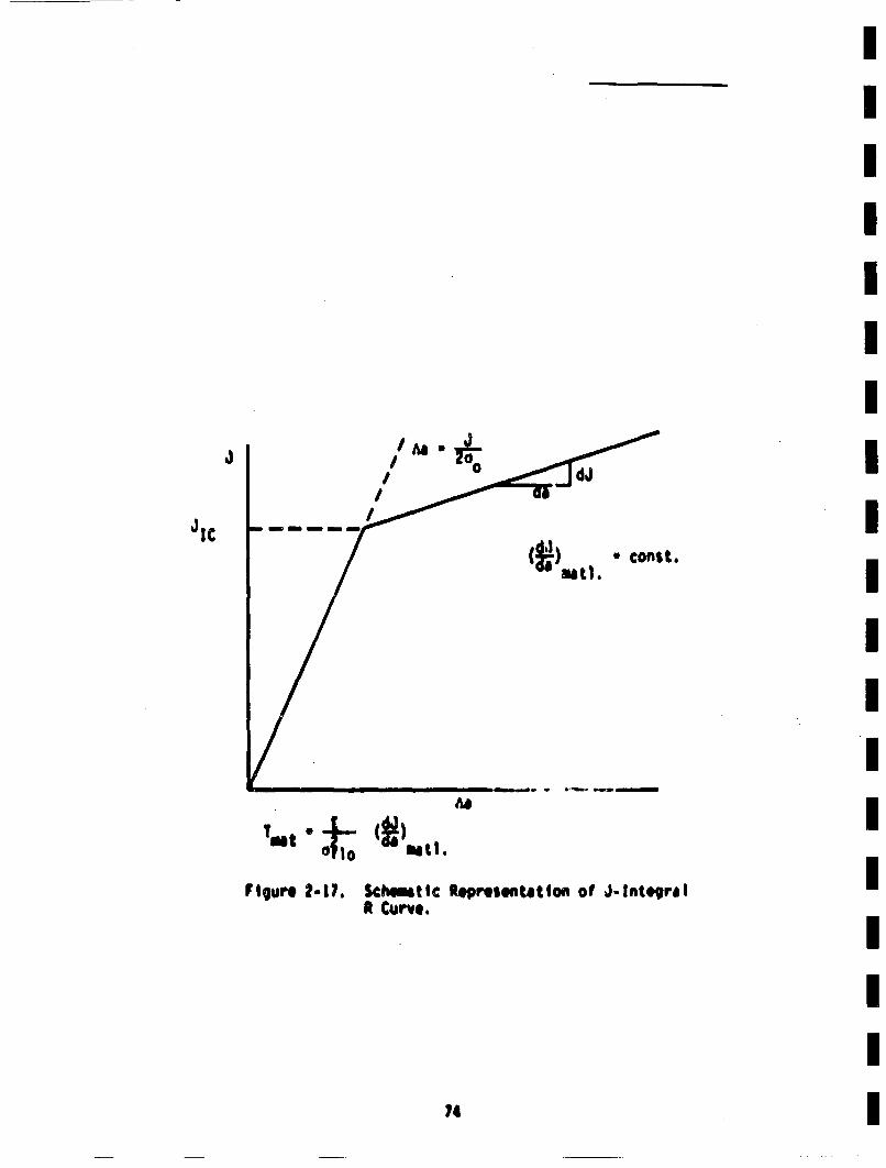
I
/
JIC
•_dJ
(•) • const.mat1.
II
Figure 2.-1?. Sch~mtlc ReprhsenUtton of J-Int41qra!iR Curve.
74 I
In the event that the tearing instability theory predicts that crackswould never go unstable. complete and sudden failures could still occurif the remaining pipe cross-section was not sufficient to support theapplied loads. This forms the baiss of the net section stress criterionsuggested by Kanninin, and subjected to experimental confirmtiton (Kanninen78. Horn 79). The load controlled stresses," 0LC' will be used as theapplied stress in thu• criterionl, such st,":seiQ can not be relaxed by
the presence of cracks or deformation of the pipe, and must be supportedby any resaining ligament. Axial ¢coponents of such stress are ofrelevance here, because attention has been focussed onI ctrcuaferentialcracks, The critical value of the net section stress is observed to beequal to the flow stress, ello, which is equal to (o• * ut)2(Kan-ninen 78). fhe failure criterion can be statred as follows: failure will"ccur if
oL.(;Ap ) tlO (Ap . Acrack) (2-36)
where 0LC is the axial cc.ponent of the loaJ control led stress, • isthe cross-sectional area of the pipe wall, and Acraek is the cross-n
sectional area Of the crack. This criterion will be applied to thecases of interest here in Section 2.9.
The value of 0flo it reuired in order to use this failure criterion.
Free above
0ft0 * ' ('ys " ult) (2-37)
Hence, 0flo is determinable from the values of the yield arid ultlm~testrength. In actuaity, these tensile properties are not deterministicvalues, but aire rsndonl valriables. * Kence, 6tl0 is also a rtendon VAi 'able,
* The following discussion of the taItistical distribution of tenslleproperties end related resrults was contributed by Dr. P.O. Straitof Law~rence tLvermore tational Laboratory.
Iand its distribution can be estimated frome informtiton in the Ilterature. IResults for tuu'peretures close to reactor operating values of abouL aY50Fiare desired.
Information on the tensile properties of 316 stainless sted in the range I400-- SOOF (200 - 430C) indicates that the t ensile strength is not influ-enced strongly by temperature, and that the yield strenlgth varies slightly Iin this range (Kadlecek 73, Lyman 74, Sinos 61, Smith 69). Since thisitemeq~rature range covers the reactor operting range, data at these temper-
atures will be considered in estimating the s~tatstical di •tribut ion ofthe relevant tensile properties,
The nature of the varlibility of tensile "properties ha' been !lscuisedby various investigators 6Kadlecek 73. Lyman 74, Swindemmn 77, Goepfert 77, II~Mainsour 73. Stliansen 79), A normal distribution of tensile properites 5s
generally assumed, although lower values often appear to have been STun. icated. The elimination of lower values is often associated with meeting
mlnlemw strength reie,.remnts of material specifications. :nclusion ofthe lower tall of tA'e distribution, as is done here, is swwewt coiner- Ivotivye.
The oistribution of the yield and ultimate strength of 316 stainles$ steel
at reactor operating temperatures was assumed to be normal, with means
and variances estimated from a vairety of sOurces (Kadlecek 73. Siuuon• 65.Smith 69). The flow stress is then also normally distributed, with mean
and stiadard deviation obtainable from the corresponding value, for the Iyield: and ultimate strength (lHahn 67). th. following ate the resultingmean and standard delviation of tPi flow stretssI
*fo 449g ksi It 'flo(sd) " 1.9 bsi
These values will be used in subsequent calc~ulat ions of pipe failure
prDobablities. As shomm in Sec•tion• 2.9. this fail.,,'e criterion will be
the One applicahle to t"• pipes udder •.onsideretlon.
A comparison of the above results with ofl1o derived from Section iII of theASME Boiler and Pressure Vessel Code (ASlE 80) is of Interest. Code mini-smu values at 60OAF for 5A376TP316 provide a of 1o of 45.3 kit. This is
close to the value determined above0 Thus, the above distribution suggestsan approximately 501 chance that of 1o does not moet code requirements. This
indicates that the above assumed distribution. is conservative°
2.6 Fatigue Crack Growth Calculation Procedures
Details of the procedures for calculating fatigue crack growth will be
provided in this section. Two aspects of the problem will be covered:
the relevant stress intensity factors for the crack growth analysis,
and the manner of treating cycles• with varying stress aiplitudes.
2.6.1 Relevant Stress Intensity Factors tor Part-Through Cracks
The crack geometry considered in this investigation is a part-circawmfer.
entinl interior surface crack, as shown schematically in Figure 2-2.
Such cracks require two length dimensions for their r~haracterizatlon.
a and b. In spite of the numerous investigations of the manner inwhich such cracks grow due to fatigue (for extensive review see refer-
ences such as Swedlow 72. Chang 79, end JW[S 77), such growth is not
well understood. In reality, cracks can change shape as they grow,
that is, as b and a increase, the value of B (; b/a) changes. The runner
in which B changes will depend onf the initrial crack shape, and the
applied stress distribution. In all cases, it appears that the aspectratio will tend towards the value that produces a constant K along the
crack periphery, Howvevr, this T"equilibriiui value of B will depend
on the nature of the applied stress. For uniform stress, the equilibrium
value is about 3.
The rate at which a and b extend will depend on the (cyclic) values
of K along the crack front, as well as the fatigue crack growth character-
Istics of the mtetrial. The growth characteristics for cases where • is
uniform along the crack front for the materials under consideration here
were reviewed in Section 2.5.IO and was suiarized in Equation 2-33.
7,
IThis growth law wtill be assiured to also be applicable to part-through Icracks but the stress intensity factor to be employed mist be care-fully defined, because K varies along the crack front. Considerabion
e" a local growth rate controlled by the local value of K would beanalytically prohibitive, and probably unrealistic. Seini.ellipticalI
crocks would not necessarily remain semi-elllptical, and stress inten-sity factor solutions for non-elliptical cracks would be resquired.•
Therefore, it will be assumed that the growth of a and b need only beconsidered, with appropriate selection of the controlling stressintanstlcy factors. Candidates are (Cruse 7Gb, Besuner 76, 77b, 78,INair 78)
(i) The growth of a ii controlled by the cyclic value ofK at the poitn of maximau crack penetration, and thegrowth of b is controlled by the cyclic K at the sur- fface. This will be called the loca1 K approach. I
(ii) The growth of a and b are controlled separately by someaveraged stress Intensity along the crack front that is
associated with growth in each of these directions, or"degrees-of- freedom," i
Suggested averaged values are the "RIS-averageu associated with eachdegree of freedom (Cruse 7Gb, Bosuner 76, 77b, 78). Thu• seems to 5o Ia mere realistic ass~qtlon than the use of simply the local values.mTherefore, these RNS-avarqged values associated with each degree of I
freedom will be assumled to govern the rate of growth of a an b. Deta1ilsa~d additional discussion are provided in Section ClI. Basically, theRMS-averaged values are denoted with a 'bar• over the K, and are definedIas fellows:
ft Ib * i ¼ JiK"°e) , I.( I
0!
,, I

These equations are discussed in detail in Section C.1. An added advan-tage of this formulation is that a~ nd Kbcan be evaluated for arbitrary
stresses on the crack plane by the use of influence functions. Thesefunctions canl be evaluated from information on the openling displacuemnts
on the crack surface for an arbitrary (non-zero) state of stress. This
is fully explained in Appendix C, which also develops and applies therelevant influence fimctions. Thus, values of Kaand Ko can be obtained
for arbitrary stresses. The use of local values of K would requireconsiderably more ninerical stress analysis for each stress system of
interest.
In accordance with the above consideration, the fatigue crack growth
rates wtill be taken to be governed by the following equations:
(2-39)
K' • aK/(1. -)
As discussed in Appendices C and 0, and Sectfon 2.7, 1ka and Kb depend on
the aspect raito (among other things) so that the growth in the depth
and length dimensions is still T"coupled". Additionally, the values of•land 1b depen:d on the magnitude and distribution of the applied stress,
and changes in the aspect ratio can be accounted for.
The suitability of usiing the IHS-averaged stress intensity factors for
calculating fatigue croek growth can be judged from experimental evi-dence. Cruse, et al. (Cruase l61b, 17) provides comparisons of theoreticaland experimental reults which suggests that such procedures areresonable. Alternative approaches are suggested in the papers
included in Chang 79 and Swedlow 72•. Oie approach that has been taken
is to use different creek grwt "lawe" for creeks growing •1ong a
7,

Isurface versus growth in the depth direction (Engle 7., Kodulak 79).Hoeethe R approach embodied in EquAtions 2.38 and 2-39 have in*.u-i
itive appeal, and are )pplicable to complex stress systems in a I
straightforward manner. ihis approach will therefore be used through-iout this Invectigation.
2.6.2 Cycle Counting and Load Interactions I
Teohraspect of fatigue crack growth analysis requiring discussioni
is the manner in which stress cycles are counted. For particularlysimple stress histories, such as constant amplitude sinusoidal loading,isuch matters are trivial. This is the type of loading counnly usedin laboratory testing to produce da/dn-•K results such as those includedin figure 2-14. in actual structural applications, including reactor Ipiping, the cyclic loads are seldom as simple as this. Two• complicat-ing factors arise: (1) the irfluence of overloads on crack retardation. IIand (ii) what constitutes a stress cycle. Occasional high stresscycles have been observed to retard crack growth during subsequenti
cycles (Hertzberg 76, Droek 78, Wet 76). However, no generally appli-cable means of treating such phenomena are available. It will there-fore be assumed that no "load interactions" occur, that is, the growthIof a crack during a given cycle is controlled Lbp the conditi~ns duringthac cycle so that a crack growth "law" such as Equaiton 2-33 isIalways applicable. This is equivalent to assuming that "history" effectsare not present. This assumption greatly simplifies the fatigue crackgrowth analysis, and is conservative (Hertzberg 76, Break 78) butrealistic within the context of the current state-of-the-art of fractLvre
mechanics.
An alternative procedure to the cycle-by-cycle computation of fatigue Icrack growth employed in this investigation, Is to consider the "MIS"time-averaged value of K. This loi value is then related to crack igrowth rater ibarson 73, 76, Rolfe 75), and good correlations are gerter-ally observed. However, such techniques are generally considered appli-
cable only to AK probaility density functions that are unimodal,gwhereas it is desired to treat multi-modal K histories. Such multiplemodes could arise fr'om different cyclic stress contributors in reactor Iipiping, such as normal heat up and cool down, versus seismic events,versus radial gradient hermal stresses.I
so I
The remaining aspect of fatigue crack growth analysis to be consideredis how a stress cycle is defined. Various techniques have been sug-gested (Wel 76, Dowling 72, Tsao 75. Nelson 75), with the range-pair
and rain-flow counting techniques being widely used. D~owling 72 pro-vtdes an especially informative discussion of the various proposed
techniques. The method that will be employed here ii closely relatedto the ralge-pi:=r procedu're. Since fatigue crack growth Ii generally
considered to occur during the rising-load portion of a cycle, atten-
tion will be focussed on such portions of the stress (or K) history.
The technique employed is shown schematically in Figure 2-18, which
shows a stress history for a transient (suc~h as a seismic event) that
produces uniform stress through the pipe wall thicknosr.
This procedure will be slightly altered in the case of transients that
produce radial gradient thermal stresses in the piping (see Sections
1.3o3 and D.4)° As an example, consider the loss of load from full
power discussed in Appendix D, Section D.4. Consider the sequence of
events that includes this transient to be heat-up from cold shut down,
steady state operation, with a loss of load and return to steady state,
followed (ovontually• by a shutdown t~o cold conditions. For a giveninitial crack size, K a as a function of time would be as shown schemi-
atically in Figure 2-19. An analogous figure could be drawn for thetim vaiaionof ,,. The procedure employed in Figure 2-19 is a
slight variation of that shown In Figure 2-18, and each of these pro-
cedures could possibly be imp~roved--such as by the use of the "rain-flow" method (DOwling 72). However, the above procedure is particularly
simple for the problem at hand, and is felt to be reasonable for the
present purposes. It also simplifies the "bookkeeping" involved inthe numerical calculation which will be discussed in Section 3. It
will be seen in Section 4 that transients producing radial gradientthermal stresses have only a small influence on the calculated proba-
bility of failure of the r1 ,•tng welds° Hence, the counting procedureemp~loyed ii not particularly influential in the present problem.
81
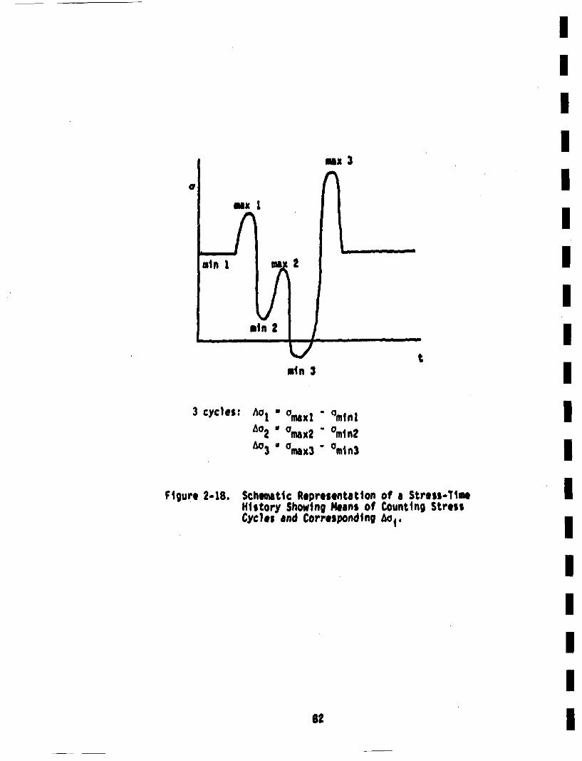
I
e
msx I
mzx 3
m• 2
mmII!mIn 3 t
3 cycles: Ao!o2
603 •
"maxi -"max2 -
Omax3-"mtn2"min3
II
Figure 2-18. Schemttc Representation of a Stress-TimeHistory' Showing Means of Counting StressCycles and Corresponding Ao1.
St I
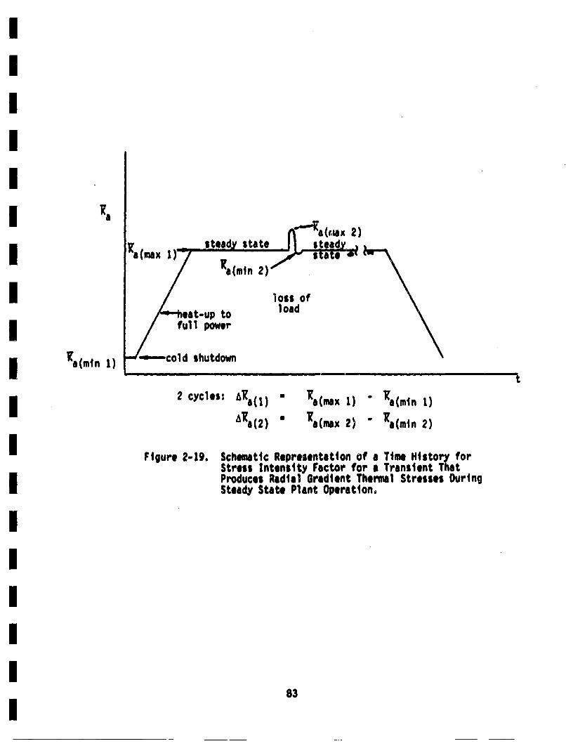
a,(riax 2)
•a(ndn 2)''
loss ofit-up to load
•a(min 1)
2 yce: ]a(1) • a(max 1) - •a(min 1)
a(2) U Xa(max 2) " '•a(min 2)
Figure 2-19. Schematic Representation of a Time History forStress Intensity Fector for a Transient ThatProduces Radial Gradient Thermal Stresses DuringSteady State Plant Operation.
83
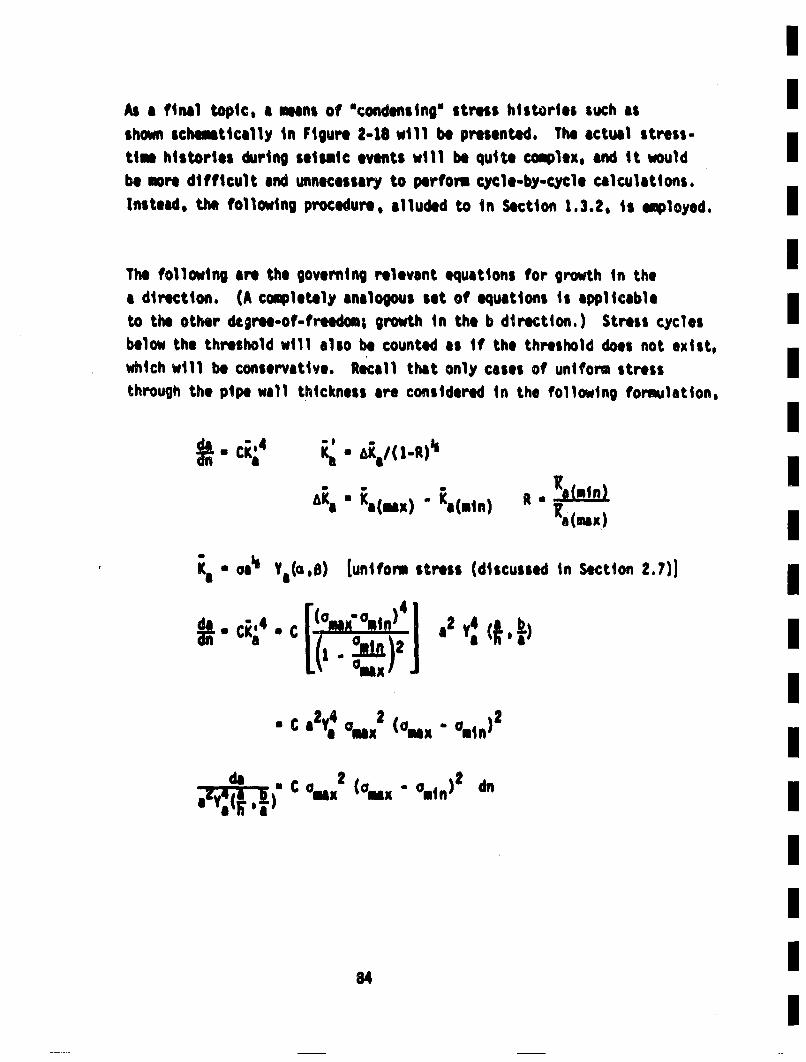
As a final topic, a means of "condensingTM stress histories such asshown scemetically in Figure 2-18 wtll be presented. The actual stress.time histories during seismic events will be quite complex, and it wouldbe more difficult and unnecessary to perform eycle-by-Cycle calculations.Instead, the following procedure, alluded to in Section 1.3.2, is employed.
The following are the governing relevant equations for growth in thea direction. (A coupletely analogous set of equations ii applicableto the other degree-of-freedom; growth in the b direction. ) Stress c~yclesbelow the threshold will also be counted as if the threshold does not exist,which will be conservative. Recall that only cases of uniform stress
through the pipe wall thickness are considered in the following formulation,
•n" CKi4m, m L.
Ka "' AKal ( [-It)'z
AKe " a(ml) " a(min) •a(max)
IIIIIIIIIIIIIII
II
Ka " °aa Ya(a'B) [uniform stress (discussed in Section 2.7)1
"2 y (ft4)
a e4maxz (aex . 0mm)z
c amx 2 (Oinx. 'min) dr
84

* CS4
This shows that all the information required for calculating the growthduring the stress history considered is the value of the parameter, S,This same parameter also enters into the analysis of growth in the bdirection. Hence, only the value of S ts required for a seismic eventrather than details of the time history of the stress. Values of Swere determined for a variet~y of seismic events for each of the weldJoints considered. Results are presented in Sectton 1.3.2.
The parameter S. defined in Equation 2-40, is employed for stressesthat are uniform through the wall thickness, have many cycles, andare generally above the fatigue limit. For transients that are rela-tively few in number and/or have stresses that vary through the wallthickness, calculations of fatigue crack growth are made on a cycle-by-cycle basis with both a and b updated each cycle, or block of few cycles.
Once a part-circimferential crack has b, oken through the pipe wall tobecome a through-wall crack, its length will be taken to be equal tothe length on the inside surface at the moment of break through. Moerdetailed fracture mechanics analys's would require the generation of
considerably mre new stress intensitt factor solutions, which isnot warranted at this time. Once the crack is through the wall,the growth rate during succeeding transients will be taken as
where now K• is the value associated with a through-wall crack. Suchvalues of Kj will be discussed in the following section, along withthe values of Ka and K used for the analysis of the growth of part-
through cracks.
85
2.7 Stress Intensity FactorsI
Considerable detail on the stress intensitty factors employed for thefatigue crack growth analysis are presented elsewhere. The motivationsIfat using RiIS-averaged values of K along the crack front CRj) wore dis-
cussed in Section 2.6.1, and in more detail in Section C.1. The use ofIInfluence functions to calculate Kj Is also discussed elsewhere (Section
2.6.1 and Appendix C), and is demonstrated for stresses with strongthickne'ss variations in Appendix D--where tabulations of Kj for the tran-sients ibi interest are included. Comparison of results generatedU as
part of ue'is investigation with previously existing solutions demon-strated ti'e accuracy of the present approach. Hence, the majority ofinformatio, on Kj is included elsewhere. The purpose of this sectionIis to present an additional result that remains to .be discussed and areof particular importance. These are the values of Kj for part-throughcracks with uniform stress on the crack plane, and the stress intensityfactor solution employed for through-wall cracks.I
The stress intensitty factor for a part-circumferential semi-ellipticalinterior surface crack with uniform applied stresses will vary alongIthe crack front, as discus~sed in Section 8.3 and shown in Figures 8-11
fatigue crack growth analysis. These parameters can be evaluated frominformation such as tha t in Figure 8-11 by the use of Equations C-2Ithrough C-4. That is, the /R/IS-avoraq,•d values of a| rc cv~lu~tc'J- iron B
knowledge of the variation of K along the crack front. Such calculations Iwere performed by numerical integration for • vdriety of crack sizesI
that were analyzed by DIE procedures. Values of a u a/h less than 0.2wore not included in the DIE calculations and are therefore not available Imheie. it was decided to curve fit the results for •j with a polynomial that
would also be applicable for very shallow cracks. Th~erefore, values of I~aIand ]•b for o * 0 obtained for an embedded defect (Besuner 77b, see Section m
D.2.1) wore also included in the i~near regression analysis at a • 0.1.I
The use of the embedded solutions for small a will result in, at most, 12Z [
86 |
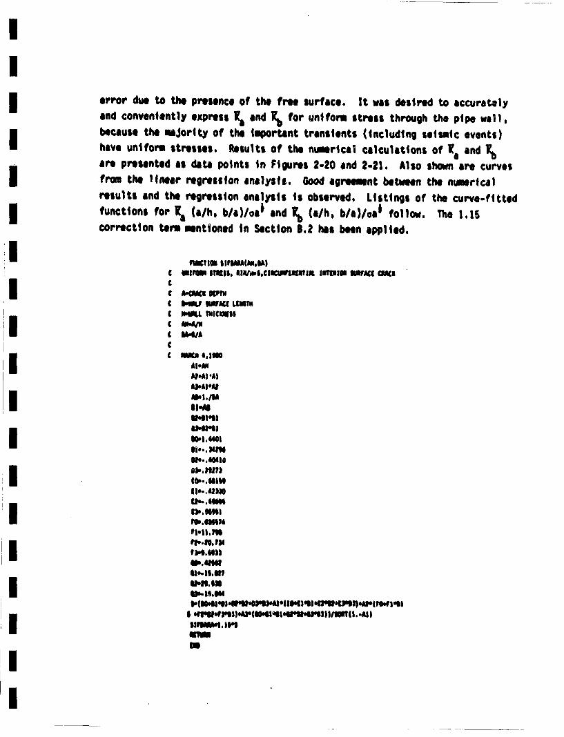
error due to the presence of the free surface. It was desired to accuratelyand conveniently express K• and Ko for uniform stress through the pipe wall,
because the maority of the important transients (including seismic events)have uniform stresses. Results of the nuesrical calculations of K•e and Kb
are presented as data points in Figures 2-20 and 2-21. Also shown are curves
'from the linear regression analysis. Good agreement between the ntmericalresults and the regression analysis is observed. Listings of the curve-fittedfunctions for K1a (a/h, b/al/oaa and K.b (a/h, b/a)/oa* follow. The 1.15
correction term mentioned in Section 8.2 hes been applied.
uwviom01 IIFI(Da.S)
C .• IlNl
C.I UI lENI
LIIMAg.IAI
IPh41|01
N.',".'
Wlb .UIW
1,.41. Vt"l. mmll
I 4NleI1.g1.wg).a~l~lql I~wgbNIII /lsl3 .M.-AI)I* IIlW.I•,iPSI)')WSIU4'2)~l
,IU 9*
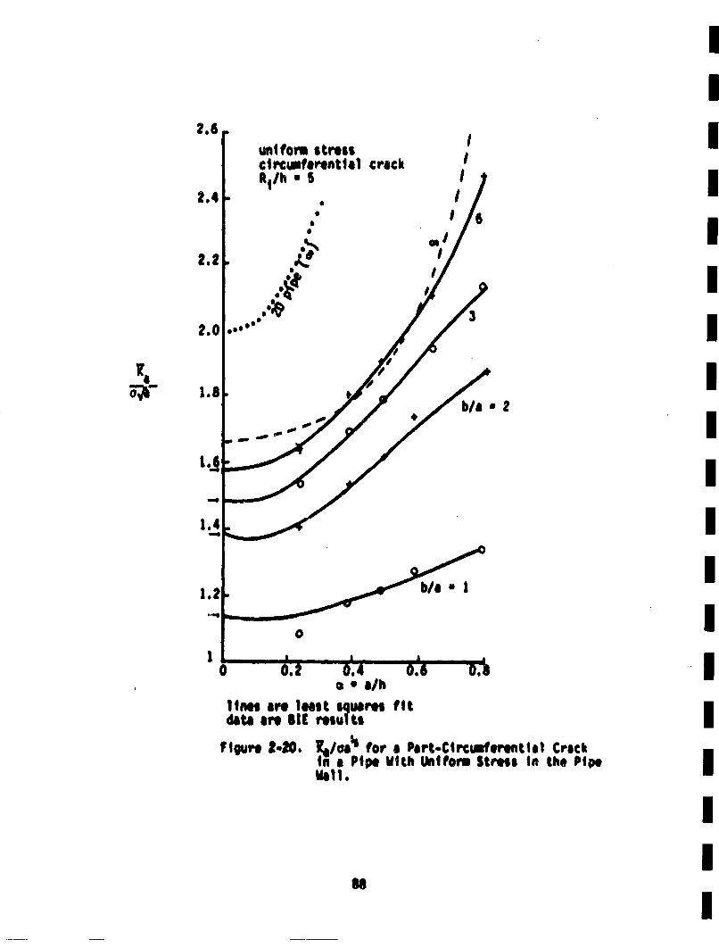
2.6
2.4
IunifCorm stresscircumferential crackR1/h * S
III
0S
0S
Sm,
2
Ka1
IIIIIIIIIIIIII
b/a *
I
!
I
1
a * a/hlines are least squares fitdata are SICI results
Figur e t-O. l./cia for a Part-Circmfermntiel Crackin Pipe With Uniform Stress in the PipeWall.
III
Me
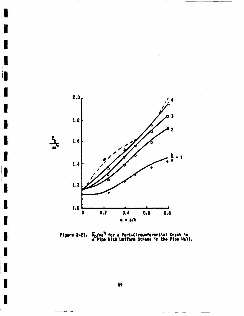
2.0 '4'A
1.8
1.6
1.4
1.2
3
/ 4
0,2 0.4 0,6 0.8
a * a/h
a-Pipe With Uwntfor Stress In the Pipe Will.
1.00
Figure 2-21.
eq
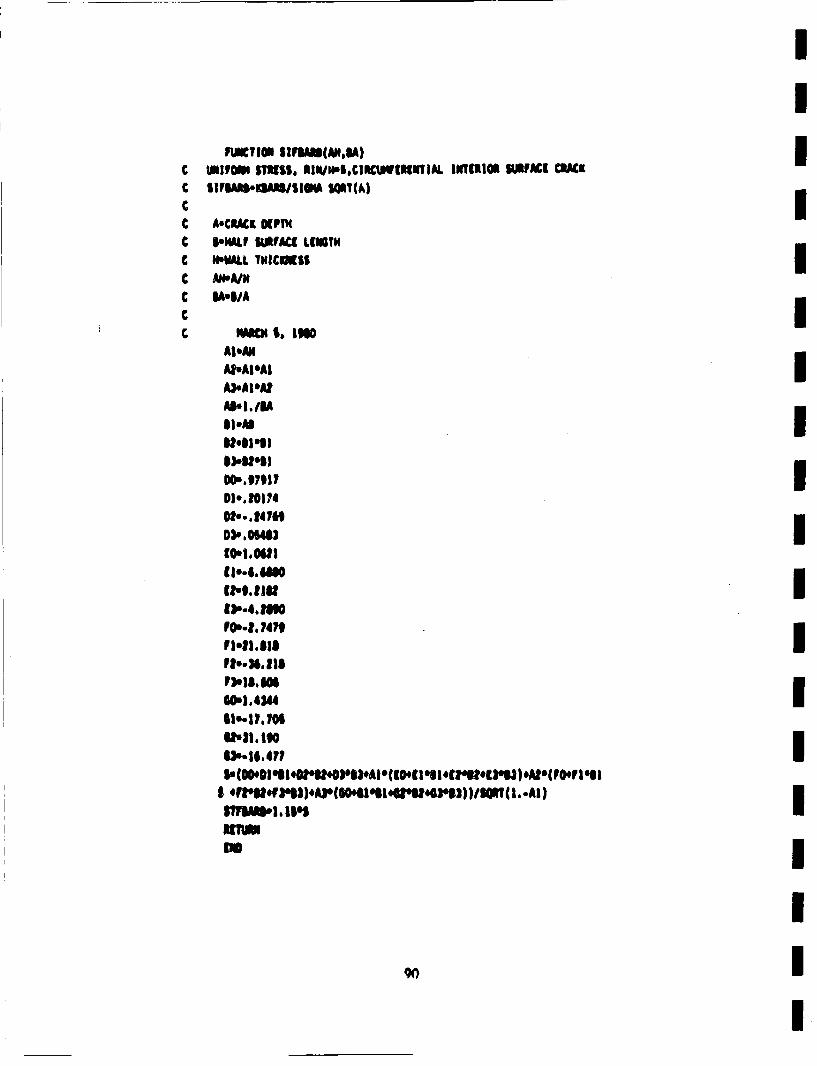
C SIYSA3S.:DfljI$1A UIT(A)
C AoCRACR KPTNC e•HALf IUAFC(. LtUNGTC NVALb•L 1WICIISS l
C I, Ma $oi I, m
A).AI'&t
lil*A I
00 .97917
020.. hiM1
101.0.6/ItI
IO.t. 747P1'-.13.12
Pto.lMilli
U',,I•. 190
£i~l 4VUI2)ANoflauzun /IC ..
-1qii .161
ni~unI
I
Figures 2-20 and 2-21 also show the value of the stress intensity factorscalculated from the curve fits for B . ,,. Geoitrically, this wouldcorrespond to a complete cirwumferential crack. Also shown in ;'lgure2-2O is the result from Labbens 76 for a complete circwtferential c.rack.It is seen that the extrapolated curve fit results are some 3O• t~lowthe complete circimferential crack. This ii somewhat discptx•Intlng,but it is perhaps too much to ask of a curve fit to data a,' the rangefrom 1-6 to be suitable for extrapolation tO -. Rice R'iG Levy (Rice 72a)show that K.mx for a surface crack in a flat plate only slowly appro-ches the edge crack results as 1B increases, and that results for B * 6are far from the edge crack results. Another contributor to the disa-greement between the Ka and 20 results has to do bith the definitionof Ks* and the behavior of B .. '. The limiting case of an eabedded
elliptical crack is a tunnel crack, in which case b -. as 2a reminsconstant, Tho stress intensity factOr for thu& configuraiton isI~ada 73)
K• ()
it would be expected that this is K a' and Kb would be zero. The appli-cable equations for ;a •nd Kb are obtained from the general solution
for an oew~edded e'lipT'cal crack subjected to uniform tension (Gren 50JoIrwin 62). Thiso equations are given in Section 0.2.1. For B * a.
they reduce to the following
• o.921
Hence, Ka is not equal to a(wa)' and K,, is not equal to zero for n - ,
Thuis i undoubtedly due to the definitions of dfM1t(*)] which are devel-oped using ellipses. The point is that K1 for 1imiting t~o-dimmnsional
93!
cases do not necessarily reduce to the 2D case. This could partiallyaccount for the 0 w result in Figure 2-20 being somewhat below thecorresponding two-dimensional result.
K~a will have a singularity as s * 1, as may also T.o' The nature of thesingularity in 1Ka can be obtained from Tada's results (Tada 73) for an [internal circular crack in a solid circular cylindical bar. The singularity B
is of the form ( - cu)|, which has been Included in the above curve fit.
This was done in order to increase the confidence in values of Ra and Rb [ca~culated from the curve fit for s , O.8. Such deep cracks may be part. ofthe population required to be considered in the fatigue crack growth iIanalysis.
The value of K for a through-weall crack will be required for the fatigue IBcrack qrowth usalysis Of cracks that hove broken through the wall, butare not long enough to result in a complete pipe severance. A reasonableimapproximation for a through-crack of length 2b is
* a (ub)•l •2-41) Im
which is the expression for a tnruugn erdck in an infinite plate (Tada 73).
This is certainly a rough approxinhation. expecially for cracks that areman appreciable fraction of the circimference in length. This estimateI
could be easily improved by the use of results that consider the cur-vature of the pipe (Folias 67). However, such refinements are not wav-ranted at this time for this problem, because, as will be seen ii' Section i2.6, the current odel for flow rates for through-wall cracks, in con-Junction with the current criterion for leak detection, results in all me
through-wall defects being Imiedlately detected and repaired.* Hence,calculations of fatigue crack growth of through-wall defects are not.i
necessary in the current pr•51Im.
* Cracks that beom through -wall during a seismic event are notIconsidered to be deteacted until after tn. seismic event is over.
II
92
I
2.8 Leak Models
A defect that grows to become a through-wall crack, but that is of I.nsuf-ficient length to result in a complete pipe severance, will be a leak.Tnis will cons,,tute a leak-before-break situation. If the leak issufffcfer.:ly large, It will produce a detectable leak, and the plant canbe shut down in an orderly marner and the leak repaired. In order toinclude st~ch considerations, the flow rate through cracks muust be esti-
mated, which, in tyr,. requires estimates of crack apening. The proba-bility of detecting the loak depends on i~s size, and estimatei of detec-
tion probaiblities must be made. These various asp~ect;s of the leak
detection problem will be covered in this section.
2.8.1 Prediction 9f Flashing Water Flow Through PU Pipe-Wall Cracks*
Leak rates for steam/water mixtures through fine cracks through the wallsof LWR piping systems are a complex function of crack geometry, crack
surface roughness, and inlet fluid thermodynamic state. Analytical pre-dictions of crack flows are hampered by phenomenological uncertaintieswhich are incurred by the wide spectrum of admitssible crack configur-ations. Appreciable meander, as well as local changes in (flow) cross-
section, are often observwd for naturally occurring cracks; adlditionally,detailed knowledge of surface roughness characteristics would likely be
unavailable.
Even for a fully specified configuration, however, the analytical taskis difficult, involving consideration of highly complex interactionsbetween (non-equilibrium) two-phase flow regimes. This is Illustrated
In Figure 2-2#2 where generally accepted features of the flow process areseen to include the formation of an initial liquid set, an interim trans-ition region wherein the Jet breaks up owing to Taylor instabilities andvapor nucleation, and a thoroughly dispersed two-phase flow mixture
thereafter.
*The following analysis of two -phase flow through cracks was contributedby Dr. V. Denny of Science Applications, Inc., Palo Alto, California.
93
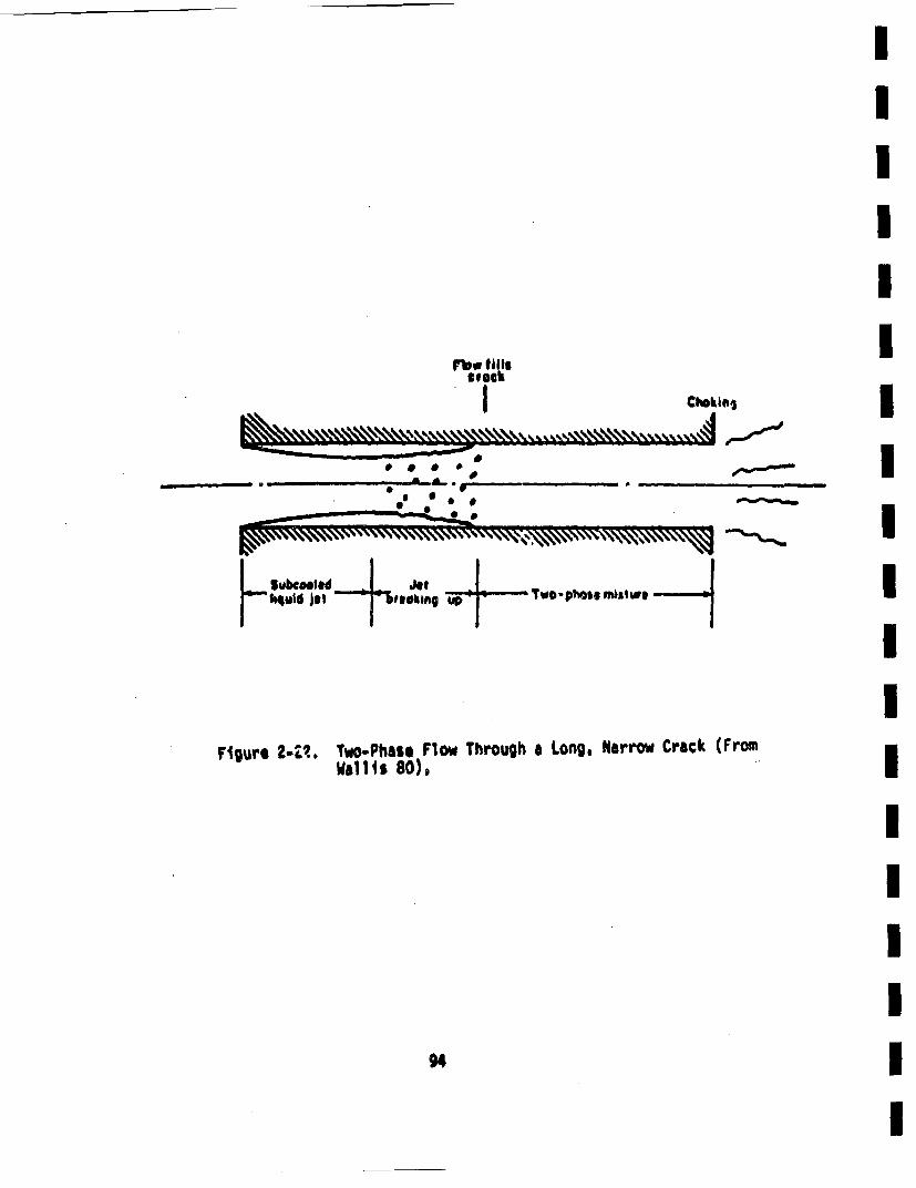
- -
-- _0 * *
Figue 2Z~.Two-Phasel Flow Through a Long, Narrow Crack (Froiu•'4gre 22•. a111t 80).
94
experimental portion of the study considered the effects of initialfluid state (stagnation pressure and teuiperature), crack geometry CL/Oh). iand crack surface roughness. The crack length (w) and depth (1) werefixed at 2.5 in. and 2.25 in., respectively. Various crack openingsiwere established to give ratios of L/Oh ranging fromi 27 to 128. RMSmsurface roughness ranged from 0.32 im to 10.16 am,, with P0 and AT sub-coolitng ranging frmn 1000 to 2250 psta and .11 to 1l10C, respectively.Critical flow measurements were compared with predictions from theirextension of the Henry model, accounting for wall friction. Measured ivalues of mass flux (6) tended to lie below predicted values, with dis-crepancies as large as 30-40% in some cases, as shown in Table 2-5, whtchImis produced from Collier 80.
As will be discussed more fully in Section 2.8.3, leaks with more than i
a few gallons per minute are expected to be detected with a high proba-bllitye Therefore, attention wi1l be focussed here on the estimation Iof leaks through crack sizes in PWR piping for which leak flow rates areless than about 6 gal/mm., Likely crack lengths (2b) are estimated to irange frt 1-50 in,, with 1-10 in. being mOst probable. Crack depths(h • RO iR) are established by the range of pipe wall thicknesses,Isay 1.4 to 2.7 in. Crack opening displacements are estimated to be onthe order of 1-10 mils as will be discussed more fully in Section 2.8.•. [
The crack opening will be taken to be rectangular, with a constant [opening, 6, and a constant length 2b. Tortuosity of typical naturallyoccurring cracks is uncertain, as is surface roughness. The peculiariconditions under study in the present work (i.e,, fatigue cracks)suggest relatively straight cracks (in-depth direction)& i.e., relativelyinsignificant wander. •I roughness of up to 10% of the crack openingnidisplacement are believed to be reasonable. initial conditions for the ileak flow are taken at typical PW operating conditions in the primary I]system piping, giving a fixed value of p0 u 2250 pita and 550 C TO < 650°FThe effects of in-depth reductions in flow cross section were not con-sidered; nor, were the effects of discharge resistance as posed by tnepossible presence of external insulation.
Owing to considerable phmnomenological uncertainty in the geometricalconfiguration of naturally occurring cracks, an elaborate model of critici gtwo-phase flow is not werrantedo Agostinelli at. .1. (Agostinelli 58) I
*6I
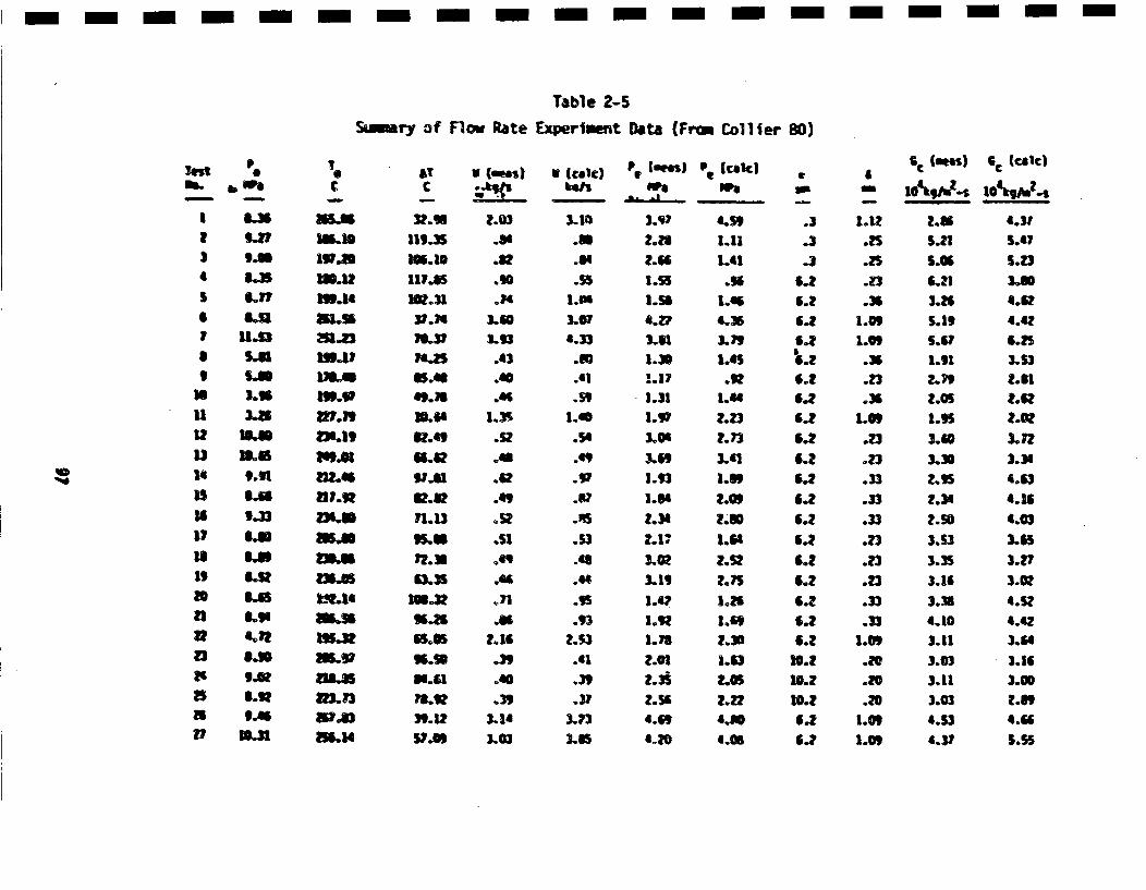
- --- m-m - m- m - m- m --- - m- n -
Table 2-5
Ssiry of flam Rate Experiment Data (fra o llier 80)
Jolt
IT
14IS
18
IS19
15
iS
8.S
8.57
811.S
6.5L.U3..
18.68
5.68
',,33
5.38,118.6
8.56
LU
T
15.13
51.5S
2511.13'"a,4
2115;.9l
mni
338.14
CTC
119.35
117.15
N.M
18.31
50.6409.33.615Y.4,
72.32
63.53o091,66.26
Bs.
66.3
V (.es)
.5Oo16
3.14
.433.93
.43
.5"1
.06£
.2ol
.439
3.51
.3,O
U (€lea)
3.10
.88
.86l
.5,l.U
4.33.80.61.59
1.40
.54
.491
.85
.53
.S
.44
.93
.61
.3,
3.73
3.97
2.23
1.55
1.504.2?3.831.31I.17.32•
3.063.69
'.93
3.56
2.34i.33.53.Ol2.42
1.92
P!ca¢k)weo
4.,5
LI1
1.56
'.3'
1.65
1.4
2.23
3.63
1.89
2.0S2.30
1.64
2.52
2.351.63LOU
I.-2
6.09
.3
.3
.36.26.?6.26.2Z
6.2
6.2
6.26.2
6.2
1.1
1.25
.23I.5
.53
.23
.23
.33
.33
.•3
.33
.33
.33
i.09
1.09
6€ luees)
2o86
S.23
3.•5
3.26
1.91
3.40
2.36
3.53
3.353.103.11
3.033.113.034.$31.37
G€ (€aic)
4.31,56.7
3.-36.624.42
3.532.31
2.16
3.123.344.63
4.164.033.653.273.004.524.42
3..S
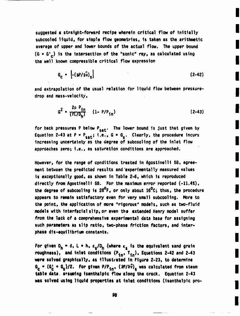
Isuggested a straight-forward recipe wherein critical flaw of initially Isubcooled liquid, for simple flow geometries, is taken as the arithmeticaverage of upper and lower bounds of the actual flow. The upper bound I(6 . G~c) is the intersection of the "sonic" ray, as calculated usingthe well known compressible critical flow expression
Gc" I(•P/v~s](2-42)
and extrapolation of the usual relation for liquid flow between pressure-drop and mass-velocity,I
62• 2p (1- P/Pin) (2-43)
for back pressures P below Psat' The lower bound Is Just that given by IaEquation 2-43 at P •Psat; i.e., 6 * Gs. Clearly, the procedure incursincreasitng uncertainty as the degree of subcooling of the inlet flow IIapproaches zero; i.e., as saturation conditions are approached.
However, for the range of conditions treated in Agostlnelli 58, agree-•
ment between the predicted results and'experimentally measured values
is exceptionally good, as shown in Table 2-6, which is reproduceddirectly from Agostinelli 58. For the maximum error reported (-11.4%),the degree of subcooling is 280°F, or only about 16°C; thus, the procedure
appears to remain satisfactory even for very small subcooling. More tothe point, the application of more "rigorous'• models, such as two-fluid
models with interfacial slip, or even the extended Henry model suffer a
from the lack of a comprehensive experimental data base for assigning•
such parameters as slip ratio, two-phase friction factors, and inter-phase dis-equilibrium constants.
For given Dh * 6, L * h, csioh (where cs is the equivalent sand grainroughness), and inlet conditions (Ptn' Ttn). Equations 2-42 and 2-43
were solved graphically, as illustrated in Figure 2-23, to determine
tabl c G * G,)/2. For given P/Pmn. (aPsI;),) was calculated from steamI•bedata. aesuming isenthalpic flow along the crack. Equation 2-43
wast solved using liquid properties at inlet conditions (isenthalpic pro.-
98m
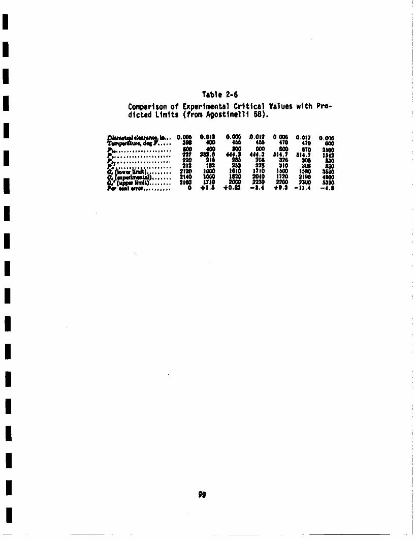
Table 2-6Comparison of Experimental Critical Values with Pro.dicted Limits (from Agostinel1i 58).
j• • ,,w• ~. 00,oo6 0.0,, 0.000 .0.o,, 0 000 0.0,, o.oow.... :SW 400 455 451 470 470 000
Pa ......... ***** .****. .. w0 40 800 8 00 I60
Pe,...... ,..........22 2 8 8 22 3 600, ~, Ud),...... 212O 233 O 283 22 0 l eaO ao
0.(oww,, mk.) ....... 2120 1000 100.70 180 1300 380
Pua~ulereoe .......... 0 +1.5 40.83 -3.4 +}.$ -1a,4 -l.8
99
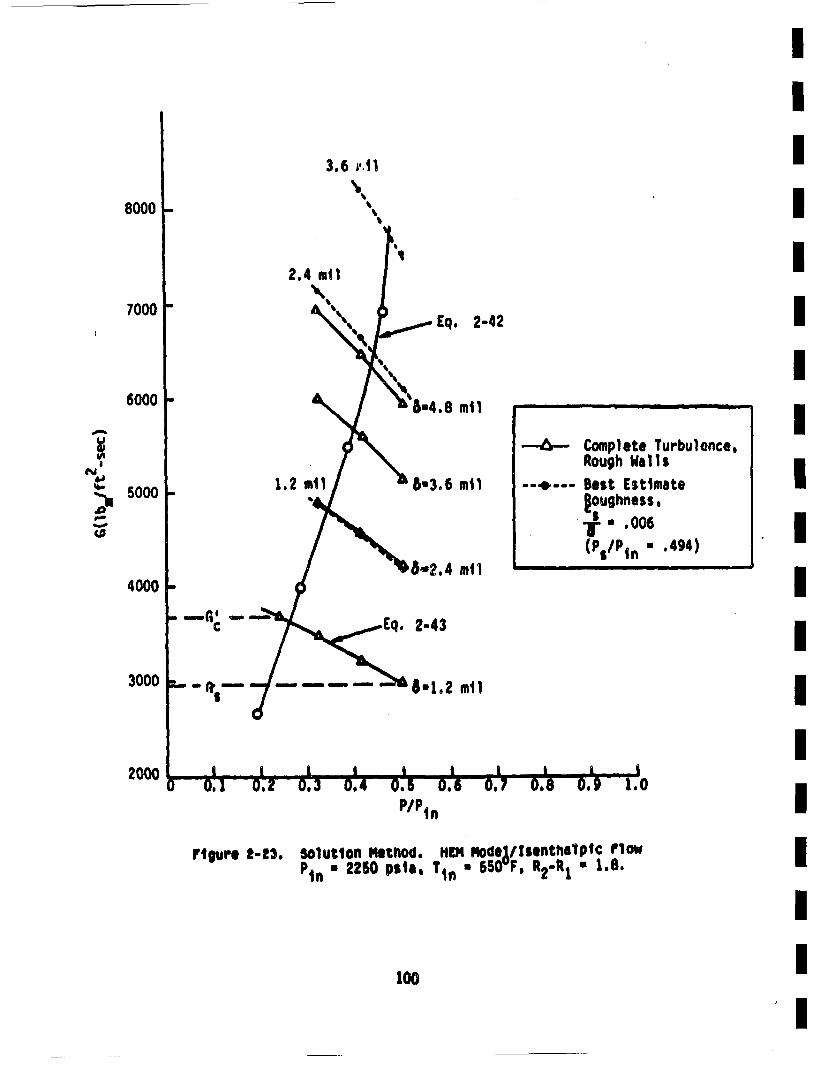
3.6 h,.ll
80001-
2.4 .11
7000
4)
' 5000
3000
2000
.. Eq. 2-42
,6"4.8 m11
1.2
m
8,.3,6 muot
8.',2.4 me1
2-43
8.1.2 m11
-6- Complete Turbulence,Rough Willi
-- *--- Best Estimate•oughness,
•. .006
(P5/P~n .494)
IIIIII
IIII1III
m"-'c --
C-- ,,,
I.
-,,. ,m.,m -
" " " a - - -- ill Ji -- I -A) 0.1 0.2 0.3 0.4 0.5 0.6 0.7
P/Ptn0.8 0.1 1.0
Ftgure 2-S3. Solution Method. flIN MlodeyllflsthilPtC FlowP*n 2250 pile, T1n • 650 F, R2-R1 . 1.B.
O00
cess is also nearly Isothermal) and employing conventional friction-fact~orversus Reynolds number plots. Results for Gcwere then converted to
.1
voiwnetric flewJ (gpm) per foot of crack length, i.e., Q.
For a typical fixed PWR operating pressure (2250 psia), the effects of theproblem parameters, areswmmarized in Table 2-7. Results for best esti-mate roughness ratios (c s/ h = .006) are litaed above those for fullyturbulent conditions (f'~0.072), the latter results being placed inparentheses. Typical trends for a wall thickness of 1.8 in. are shownin Figure 2-24. Results such as these, and in Table 2-7 will be usedin subsequent portions of the investigation.
Preliminary comparison of the results in Table 2-7 with the results ofCollier 80 (as summarized in Table 2-5), indicate some discrepanciesbetween the •.wo sets of results. A careful study is necessary before itwould be possible to find the source of anty disagreement. Such studies
are left for fUtUre efforts.
2.8.2 Cfrack Opening Displacements
The crack openinqO displacement, 6, is required to estimate the flowrate through cracks (see for instance Figure 2-24). Such opening dis-placements are influenced by plastic deformation at the crack tip.and the cylindrical nature of the pipe. Pipe bulging due to shell effectscan significantly increase opening displacements above correspondingresults for a flat plate in tension (Folias 67). Elastic-Plasticestimates of opening displacemnts could be obtained by use of relationsbetween J-Integral values and opening displacemets (Paris 79), butelastic results will be used in the present case. A lower bound on theopening displacemnent for a through-wall crack of length 2b in a pipesubjected to a uniform stress, a, can be obtained from the followingresult for an infinite plate in tension (Tada 73)
6a •4 ~ 1(2.4U)
101
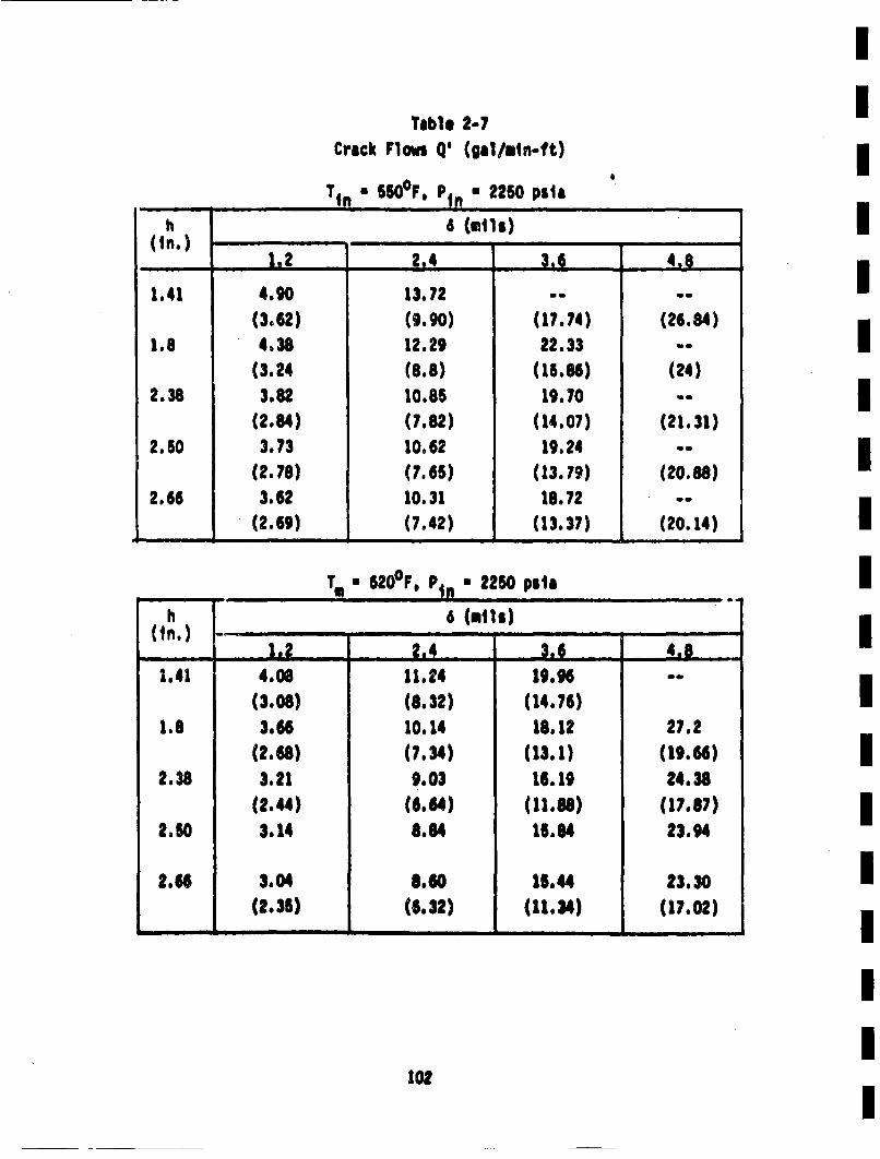
Table 2-7Crack Flows Q' (gal/.ln-ft)
Tin " 550°F. Ptn" 2250 psaleIi 6 Culls)
(.).22.4 •: 4,8
1.41 4.90 13.72 .-(3.62) (9.90) (17.74) (26.84)
1.8 4.38 12.29 22.33 -(3.24 (8.8) (15.86) (24)
2.38 3.82. 10.85 19.70 -
(2.84) (7.82) (14.07) (21.31)2.50 3.73 10.62 19.24
(2.78) (7.66) (13.79) (20.88)2.66 3.62 10.31 18.72 -.
(2.69) (7,42) (13.37) (20.14)
~~~T- T1 * 20F, P In "25 po le
h 6 (mli$)
1.41 4.06 11.24 19.96 --(3.08) (8.32) (14.76)
1.8 3.66 10.14 18.12 27.2(2.68) (7.34) (13.1) (19.66)
2.38 3.21 9.03 16.19 24.38(2.44) (6.64) (11.88) (17.67)
2.60 3.14 8.84 15.84 23.94
2.66 3.04 8.60 15.44 23.30(2.36) (6.32) (11.34) (17.02)
I
IIIIIII
III
102
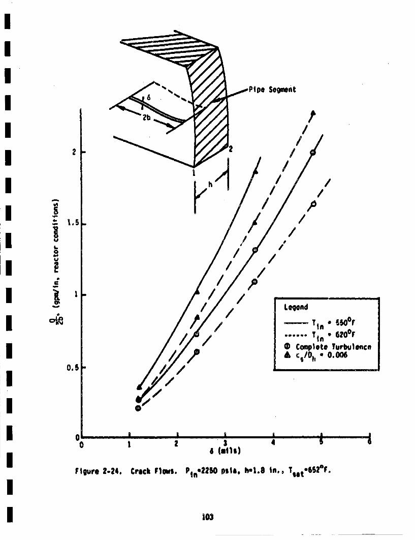
Ppe Segment
/
2
0.5
//
p/
/o/
//
//
/
Leqoad sr
...... T * 62O°F0 Complete Turbulence
£•/~ c 0.006/
'p/ • It I I l -- I
"/
0 1
Figure 2-24. Crick Flows. P1nm2250 psle, h-1.S in.. Tot-652°F.
103
ITeminimam value of b is h (the wall thickness) in accordance withI
discussions ifn Sectionl 2.2. The value of a to be used is the load con-itrolled stress. 0LC, vhich (for non-seisaic conditions is equal toI
(ou * oam). From Table 1-2. a lower value of this parameter I$ about4.3 ksu° Taking h * 2.5 in.. Equation 2-44 along with the above Ipara-•meters. predicts the following lower bound estimate of the opeonin dis- Iplacement. and corresponding lealk rate from the results in Table 2-7. I
4 • 4(43)(2.6) .1)•1.4 tils
d)~(3 gps/ft)(2x2.5/12)
Recall that this is a conservative lower bound on 4. As will be seenin the next setiton, leak rates greater than 1 gpe will be consideredIto be detected. Hence, refinements in estimates of the opening displace-Imangs are not felt to be walrranted at the present time.I
2.8.3 Leak Detection Probab+ites$
ICoamercial nuclear power reactors are required to use sensitive, sophis-ticited, and redundant, leak detection systems Currently reployedI
techlniques include the following (Frank 77, Wise 77. Harris 80b)
C am level and flow .nontoring I• ailrborne p~articulate radioactivit~y inontoringI
• airbOrne gaseOUS radiOactivitt nonitoring IIe contaiynent air cooler condensate flow rate
lhree mehodi of l eak detection autM be eq~lo~sd (RB 45), which pray i~sredundancy in the leak detection systems. Additionally, sensitivitiesof less than 1gP are generally obtainable (Frank 77, Harris S0b).The1 technical specification for Zion I (fS, no date) requires ,the plantIto be shUt down if an identified leakage of greater than 1 gpe is mes-sured. This is wall within the sensitivities of curret leak detection I
systems, which, in conjunction with the redundancies mentioned above,provides a high assurance that leaks in excess of I gpm will be detectedand remedial action taken. Therefore, the probability of detecting aleak Of rate greater than 1 gpm wll be taken as 1. Correspondin~y,
the probability of detecting (and repairing) a leek of rate less than! gpm will be taken to be zero. Maiematically this is stated as
PO~leak) (a)" * (2-45)
and this will be used for leak detection probabilities in this investi-gation. This, in conjunction with the lower bound calculation of
included in Section 2.8.2, reveals that all through-wall cracks are pre-dicted to be imeediately detected and repaired (unless they should inittiallybe large enough to produce a complete pipe severance). Hence, refinedestimates of both the crack opening displacements (Section 2.8.2) and
stress intensity factors for fatigue crack growth analysis of throughowall crocks (Section 2.7) are not warranted at the present time. Thiswas briefly mentioned in the earlier sections.
This concludes the discussion of leak rate and detection modeals, whichturns out to be particularly simple for the cases of crack openingdisplacement and leak detection probability estimates employed in thisreport.
2.9 Fai lure Criteria
Failure criteria applicable to reactor piping materials were reviewedin Section 2.5.2. which also presented results for the relevant materialfracture properties--such as OiC Talt and Oo.In this section, the
candidate criteria will be app|ld to the primary piping of Zion I, andthe molt suitable criterion for the present case selected. This selec+tion will be based on which criterion results in the smallest criticalcrock sizAS fOr given appliled stressles.
No attept will be made to provide a €omprehensive review of applications
'.1;
of al nd tearing instability criteria to reactor piping. Basically.Tada, Paris and Gauile (Tada 79) have demonstrated that circ~uferentialcracks in reactor piping will not be subject to any tearing instabilityI
for length-to-dimeter ratios representative of primary reactor pipingin LII~s. Figure 1-2 shows that the longest straight run of piping in
the large mais coolant piping at Zion ! Is the cold leg; running fromIthe isolation valve to the reactor inlet. However, it would perhaps bemore appropriate (and certainly more conservative) to include the sumI
of the length of the cross-over leg. pump casing, isolation valve andcold leg. This constitutes some 60 ft. (720 in.) of piping, with aInominal outside diameter of 32 In. This results in L/R of 45. Tada. etal. G)(Tada 79) provides the following estimate for Tepp1. (their Equation
'appi F1(e, i', P) • F2 (0, a', PS' "0fl•o R
Considering the case of no crack closure, the largest value of F1 is iabout 1.2 (Tada Figure 10). and largest value of F2 is 0.5 (Tada Figure12). Using 3 * 4000 in-lb/in2 (as in Tada 79), C * 28x106 psi, of1 I45x103 psi, R * 16 in., the following upper bound on Tappi Is obtained
T 'p 1.2 •+1.73I
IFor L/ft of 45, this results In Tep ' 66. From Section 2.5.2, the valueIof Tmat ii 190 - 700. It can therefore be concluded that a tearing insta.bility will never occur for the piping system under consideration.I
The other failure criterion that could com iate play is the criticalnet secti1.n stress criterion, which was discussed in Section 2.5.2. This Icriterion will come into play for very large cracks that reduce •.he pipecross-sectional area to the point where the loads that cannot be relaxediby extensive deformation are sufficient to break the remaining area.Such loads are considered to be the "load controlled" components of stress,iand are the dealdeight stress end axial component if the pressure stress.,Addittionally, seismic loads wrill •e assumed to be load controlled. The I
exceedance of a critical net section stress will be considered to resultIn a sudden and €omplete pipe severance (LOCA). In accordance with
Section 2.5.2 (Equation 2-36). LOCA will occur if the following condition
0LC Ap ) 0flo (Ap - Aerack)
Ap is the cross sectional iree of the pipe. of1 was discussed in Section
2.5.2, where it was found that. this parameter ii normally distributed. The
crack geometry considered for calculation of the critical crack area is
shown in Figure 2-25. This is an alteration of the semi-elliptical defect
•'lown In Figures 2-2 and A-i. This modification is necessary, because
as will be seen, very larg~e flaws are required for complete pipe sever-
ance. The standard geometrical definition of ellipses can not be used for
the large semi-welliptica1" cracks necessary for LOCA, and geometric
refinements are not felt to be worthwhile at this time. For example, ifthe crack area was taken to be •. ab, with a" * hand b * wR1, the largestpossible crack area is •i•h nR1 * Ig2hR1. The total1pipe cross-sec-
tional area Is ~2R1th. Therefore, a complete circumferential crackall the way through the thickness has an Acrack/Ap U •S 2hR1/(2ThR 1)•
:/4 * 0.79. It would be preferable to have a complete circumferentialcrack all the way through the wall thickness to have an area equal to
the pipe cross-sectional area. The crack geometry of FIgure 2-25 satis-
ifes this condition. This is the crack geometry iniployed in many of the
General Electric Studies of crack stability in BndRs, such as in Horn
79. The area of the crack shown in Figure 2.25 is given by the following
expression
A crack * ab (2, * -.) (2.46)
Any crack with an area insufficient to result in as sudden pipe severance,i.e. not big enough to satify the criterion of Equation 2-36. will be con-sidered to grow only as a fatigue crack. This includes the growth of
part-through c:racks to become through cracks. That is, as a . h, the
crack does not become unstable, but continues to grow only as a fatiguecrack. This Is aI reasonable approximation that is within the spirit of
the tearing instability approach discussed above.
1O7
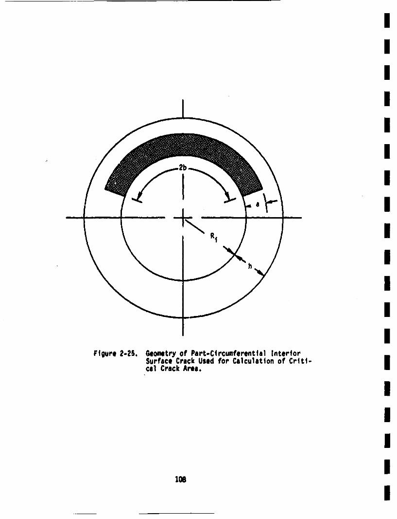
IFigure 2-25. Geometry of Part-Circumferenttal interior
Surface Crack Used for Calculation of Criti-cal Crack Area.I
1c3
This concludes the discussion of the fracture mechanics model of pipingreliability. Section 3 will present the numerical procedures developed
to obtain results from this model. The combination of a bivariate
crack size distribution with statistically distributed values of flow
stress and fatigue crack growth characteristics precludes an analytical
approach to this problun.
3.0 NUMERICAL SIMULATION PROCEDURES
The basic tools for the evaluation ofthe reliability of a circumferentialIgirth butt weld in a reactor pipe were presented and discussed in Section2.0. Basically, the probability of a leak or complete pipe severance IIoccurring is equal to the probability of cracks larger than the criticalsize for each type of failure being present. The crack size distribution I
changes in time due to fatigue crack growth resulting from cyclic stressesinduced during operation of the plant. In principle, such calculations
are quite straightforward. However, in the present case, numericaltechniques must be resorted to. This is because of the complexitiesinvolved In treating the bivariate crack size distribution, as well asthe complicated nature of the stress history. However, the need to employnumerical techniques is even more acute when various input parameters arerandom. In the present case, the flow stress and fatigue crack growthcharacteristics are random variables. Hence, some numerical scheme is
required in order to obtain actual results for the piping reliability.
IOne such numerical technique that is of general applicability is the"Hnt Carlo" technique, which will be utilized here. Extensive literature I
on Monte Carlo techniques exists, with Hahn 67, Mann 74, Schreidor 66,Hanlmersley 64 and Naylor 66 providing discussions of the procedures involved. IIn the present context, a Monte Carlo simulation can be illustrated bythe following situation. Suppose that an estimate for the failure proba-
bility of a specific weld joint in the primary coolant system is required.In theory, a simple experiment could be performed. A set of N weldjoints, each of which is representative of the joint that is actually in
the system is fabricated. Even though these welds would have the samespecifications as the joint actually in the system, they will not beI
identical to that joint or amongst themselves because of manufacturing m
tolerances, variations between batches of materials, and differences in I
welding conditions. Suppose next that each joint is subjected to a stress
t;I
history typical of the actual JOint. Normal operations, anticipaetdtransients, and earthquakes are Included. The stress histories are not
identical but are equally itkely to occur during the plant lifetime.
Two pieces of data are recorded for each of the samples:
(I) the time the Joint fatiled, and
(2) wh~ether the failure was induced by an earthquake.
The probability that a Joint has failed at or before time t can be esti-
mated by randomly selecting a crack. The probability of selecting agiven crack size is controlled by the initial crack size distribution
and detection probability (which was covered in Sections 2.3 and 2.4respectively). The crack is then grown through a stress history, which
can be either deterministic or stochastic. The fatigue crack relation
is used in these calculations. This relation can be statistical, such
as the lognormal distribution of C discussed in Section 2.5.1. A value
of C is randomly selecteo from the distribution, and used in the crackgrowth calculation. The current crack size is then compared with the
critical crack size at that time. A random value of Uf1 ios selectedfrom the normal distribution of this parameter that was discussed in
Section 2.5.2 in order to determine the critical crack size. In this way.
the time-to-failure is evaluated if failure occurs before the end of
the 40 year plant lifetime, If failure does not occur within 40 years,this fact is noted, This satmpling ts performed a large niaber of times on
a computer, with statistics being gathered on the number of simulations
that predict failure prior to time t, along with the total number of
simulations performed. Let N be the total number of simulations, andNF* (t) be the corresponding number of sImulations that predict failure
at or prior to t. Then, the probability that failure occurs at or before
t is simply given by
P(tFA< t) • "ft)-(31
il1
IThe probability of an earthquake and failure occurring simultaneously is
thnsimply the number of failures Induced directly by an earthquake divided
by the number of samples, or
P(FAILflCQ)'. N EQ'jA.1L(3)
where NEQ.FARL is the number of times the failure of the weld was induced R
by the earthquake. Although this experiment may never be performed withreal Joints and real stresses, an equivalent nwmerical experiment can ibe performed by modeling Joints and stress histories on a computer. IIn order to increase the computational efficiency, several simplifyingassumptions are empl1oyed. The basis for the first assumption can bei
seen by expanding p(tF € t) in terms of conditional probabilities on thenumber of cracks in the weld Joint, orI
p(tF • t) * , p(tF < tln)p(n) (3-3) Ii
pwhere_ in s the probability that a weld Joint with n as-p~t ~ in)fabricated defects will fail at or before time t,
and p(n) is the probabilit~y that n cracks will exist in the Iwild initially. This parameter was discussed inSection 2.3.4.I
If crack initiation can be ignored, I.e., no cracks will form duringthe plant lifetime. Equation (3.3) then becomesI
p(tF <_t) * n~ p(tF <_tIn)p(n) (3-4)I
where the suiation index begins with n-t rather' than n-0. becauseI
112
and
no seismic events. NF(t) is the number of those samples which fail at
earthquake of magnitude g at time t. Nr(g,t) is the number of those
samples which fail at or before time to
In principle, either enpirical or tabulated functions could be derivedwhich express P(tF • tIEq(g,t)) in terms of both the earthquake magni-
tude and the time, If the frequency of magnitude g earthquakes is avail-able in the formof a conditional Gig), the p(tF • tIEq(g,t)) can be
weighted by Gig) and integrated over all earthquake magnttudes to give
the probability that an earthquake at time t will induce a piping failure,
or
p(FAILAlEq at tIEq(t))
,0Pt<.tE~~) ~F-t•q)Ggd 39
0
If Equation 3-9 is multiplied by the probability of earthquake per unittime and integrated over time, the result is the probability of a simul-
taneous earthquake and piping failure over the plant lifetime under the
assumption that one earthquake occurs during the plant lifetime, or
p(FAIXfEqlEq) • .f tp(FAIl~tlqI~q(t))P(Eqlt))dt
o (3.10)
o 0
114
A computer program was specially written to imlement Monte Carlo tech-niques for evaluation of structural reliability. The progrui concen-t"ated on reactor piping weldnents, and was tailored to include thefacets of the fracture mechanics model outlined in Section 2.0. Theresulting code is called PRAISE, which stands for "Ptping ReliabilityAnalysis Including Seismic Events." Details of the code, and its use,are presented by Li. 81, and additional relevant features will be isunmmarized in the following sections.
3.t ont •ro Stulaaoni
The PRAISE computer code (Ltm 81) uses Monte Carlo simulation techniques Imto estimate the distribution of time to first failure for a girth buttweld joint in nuclear reactor piping that is subjected to normal operatingco,•dittons, anticipated transients, and seismic events of various magni-
td. PRAISE provides a numerical tool for obtaining results from the ifracture mechanics model described in Section 2.0. The code is subject m
to the limitations and assumptions enumerated for the fracture mechanicsi
model, and (as discussed above) is presently limitted to analyzing weldshaving a single as-fabricated crack. Equations 3-1 and 3-2 are the basicequations in the PRAISE simulation. Succeeding portions of Section 3 Idescribe in detail the algorithm that ii Used to obtain numerical valuesfor the piping failure probabilities (right hand side of Equations 3-I Ieand 3-2).
A simplified flowchart of the PRAISE algoithSm is shown in Figure 3-1. As ishow on the right side of the chart, the six basic steps are: I
(1) sample space definition and stratification,
(2) initial crock size selection, I(3) next event simulation,
(4) crack groth calculation, i(5) leak detection or LOCA event, and i(6) esttiate of failure probabilities and associated
confidence intervals.i
Correspoding to each of these steps are various user-supplied inputs.The calculetional steps end inputs are describe in the following sections. I
its I
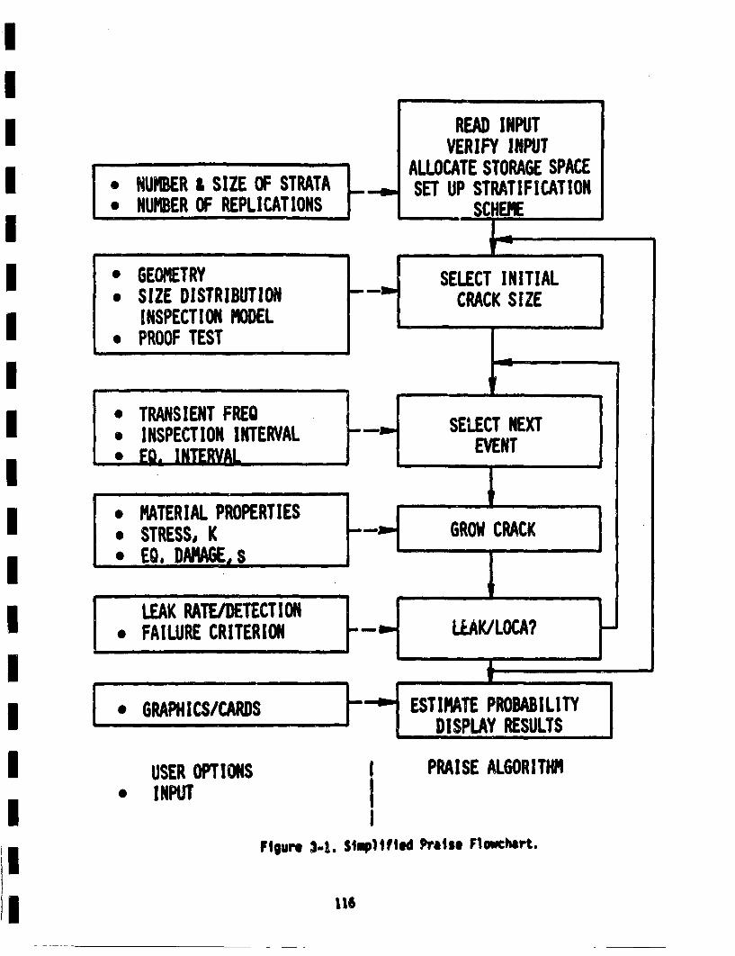
READ INPUTVERIFY INPUT
ALLOCATE STORAGE SPACESET UP STRATIFICATION
SCHEMIE
-- , mI NME FRPIAIN00
NUMBER I SIZE OF STRATA
S--HI n
* GEOMETRY* SIZE DISTRIBUTION
INSPECTION MODEL* PROOF TEST
I. TRANSIENT FREQ* INSPECTION INTERVAL• EQ. INTERVA•L.
- -H SELECT INITIALCRACK S IZE
n |1
. SELECT NEXTEVENT
II I
0
S
S
MIATERIAL PROPERTIESSTRESS, KEQ, DAMAGE, S F-.I GROW CRACK I
I • IP
a UI p
IILEAK RATE/DETECT ION
. FAILURE CRITERION -HLLAK/LOCA? FInI p
a
I * GRAPHICS/CARDS hi ESTIMATE PROBABILITYDISPLAY RESULTS 1USER OPTItONS
* INPUTIII
PRAI SE ALGOR ITHM
Figure 3-4. Simplified Praiso Flowchart.
116
I3.2 Samle Space Definition
A key ingredient in the PRASE algoriti is the samle space reresen- Imtation of the Monte Carlo simalation. Seeral possibilities eixst.Thrinal choice was motivate largely by comutatonal convenience. From ia physical standpoint, the most natural choice for the samle space isa two-diansional represen~ttion with surface crack length (2b) and crackI
depth (a) as the coordintes (see Figure 2-2 for crack geomtry). Antherpossiblity is to use crack depth and aspect ratio as the coordinates.These are aiPs the variables that define the initial crack size distrl-bution. The crack depth would 1i. between zero and the pipe wall thick-ness, while the aspect ratio is permitted to take values betveen one and Iinfinity (values less than I are omitted from consideration, see Sections2.2 and 2.3.2). Unfortunately, it tii likely that the large value of I/aspect ratio could lead tO som troublesom com tational preblim. Areasonable compromise is to use the reciprocal of the aspect ratio ori
*' a /b as one coordinate. The limits on "1become zero and one. The
crack depth coordinate can be normalized by dividing by the wall thick-
ness so that it also lies between zero and one. This representation ofthe samle space is displaye in Figure 3-2. Any crack with an (a/h)coordinate equal to one would be a through-w1ll detect and would causea leak. Cracks with (a/b) * 1 are semi-circular defects. A smal wege-shape portion adjacent to the (a/b) • 0 axis is infeasible becuse at i
crack located in this regon wold have lenths greter than the €dr-.ctinference of the pipe. The infeasible points satisfyi
(a/b) h (a/b) l31
The loci of all cracks that would cause a doble-ende guillotine breakis also shorn in Figure 3.2. The following result is obtainable from theIcritical nat section stress failure criterion discussed in Sections 2.1.2and 2.9, using the relatios "* ,.crack area in Section 2.9.I
II
117I
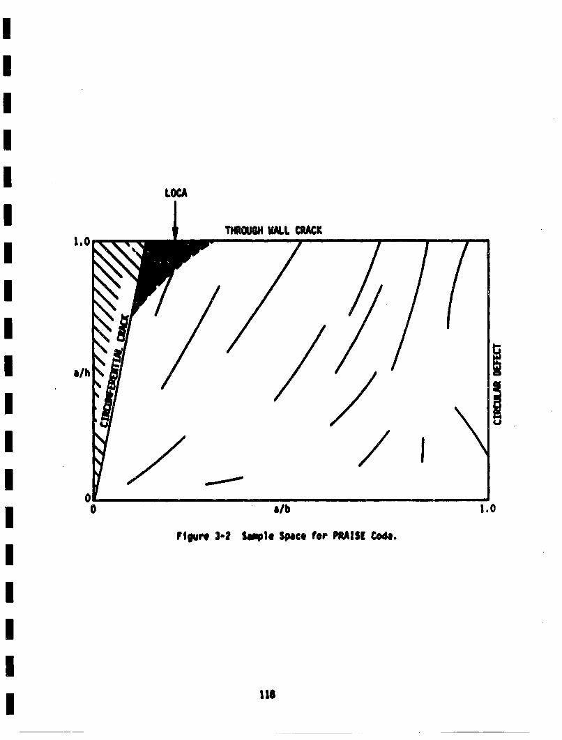
LOCA
THOGHM.L. CRAtCK
Flgure 3-2 S•1. Spco (or PRtAISE Cod..
I II
~I
As suggested by intuition, such cracks are both deep and long.
Typical crack growh trajectories are . "'• displayed on Figure 3-2. The Iitrajectories are the loci of points showing the variation of crack dimen-sions with time as the crack gr'ows under the cyclic Io~ds. The crack I
depth variable is monotonicelly increasing, while the value of (a/b)is free to either increase or decrease during the crack propgation iprocess, depeding on the current aspect ratio and nature of appliedstress. These trajectories are a vivid demnstration of the two-degree-iof-freeo moel discussed in Sections 2.6.1 and C.I, which is being Iused to reresent crack groth in PRAiSE. As discussed earlier (Section2. 1) many of the previous models either assumed a complete circumferential Imedefect (cracks whilch, satisfy the equality in Equation 3-1I•or a constantaspec ratio (vrici. lines in the (a/h) vs. (a/b) spacej
If any of the cracks in the sample space were subjected to cyclic loads
of sufficient magnitude for a long enough time, they would eventuallycause a failure, eithor as a through-wall leak or a catastropic comletepipe severance. Figure 3.2 shows that many of the failures would occur imas part-through defects that would develop into a leak. If these leaksare not detece, the length of the crack would continue to icresei
(a/b decreasing) and ultimtely reach the large LOC region. Crackswhich exhibit this sequence of leak and LOCA are said to have experienced i"leak before break.' On the other hand, it is possible to have combin-ations of initial crack tsie and stress histories that lead to a large
LOCA without first undergoing a leak. Although PRAISE routinelyIhandles both situaion~s, it is not presently equipped to differentiateand display the frection of LOCAs which experience the "leak before
brek' pheomn.
I
3.63 Stratified Sampling
A direct evaluation of Equation 3-1 and 3-2 using simple random samplingin which the initial crack dimensions are selected in accordance withtheir postulated frequencies of physically occurring is computationallyinefficient. For example, suppose that a relatively large defect mustexist before failure occurs. However. if the probability of obtaininga large initalt defect its mall, a very large nuiber of simple randomsamples may be required before a statistically significant niwber offailures is obtained. Furthermore, since the quantity of interest isthe probabili~y of failure rather than the time-dependent crack size distri-bution, simulation of cracks which do not eventually lead to failure Is,in some sense, a wasted effort. for the initial crack size distribution
discussed in Section 2.3, the overwhelming majority of the cracks that
exist would not lead to a failure within the plant lifeti'!e.
A variety of well-established techniques exist for increasing the accur-acy and computational efficiency of Montes Carlo simulations. Thesetechniques are known by a varity• of names, e.g., varianlce reduction
methods, stratified sampling, biased sampling, or importance sampling#4azidar 75, MeOrath 73, Naylor 68). For convenience in discussion,
this report shall refer to the sampling scheme incorporated In PRAISEas the stratified samling scheme. The basic idea is to partition thesample space into a set of mutually exhaustive cells or strata. Apre-determined number of samples are then selected fromeach cell. Within
each cell, the individual crack dimensions are still selected accordingto the postulated initrial crack size distribution, The distribution oftime to first failure is then obtained by use of the following equations,which are modifictitons of Equations 3-1 and 3-2 to account for the con-ditionall probablity of a crack existing in a given cell.
N Ct
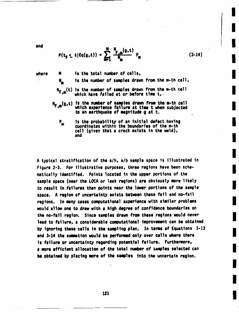
Ii
and Pt~ ~qgt) ~ N gt
where N is the total number of cells.ii t the number of staples drawn from the m-th cell, i
iFmt) s the number of samples drawii from the m-th cell•NF()which have failed at or before time t,.-
NF,*(g,t) is the number of samples drawn from the n-th cellwhich experience failure at time t when subjectedIto an earthquake of magnitude g at t.
is the probability of an initial defect havingicoordinates within the boundaries of the m-thicell (given that a crack exists in the weld),and I
A typical stratification of the a/h, a/b sample space is illustrated inFigure 3-3. For illustrative purposes, three regions have been sche-imatically identified, Points located in the upper portions of thesample space (near the LOCA or leak regions) are obviously more likelyto result in failures than points near the lower portions of the sample Ispace. A region of uncertainty exists between these fail and no-failregions. In tony cases computational experience with similar problemsImwould allow one to draw with a high degree of confidence boundaries onthe no-fail region. Since samples drawn from these regions would neverilead to failure, a considerable computtitonal improvement can be obtainedby ignoring these cells in the sampling plan. In terms of Equations 3-13
and 3-14 the suintion would be performed only over cells where there1. failure or uncertaity• regarding potential failure. Furthermore,a more efficient allocation of the total number of samples selected canbe obtained by placing more of the samples into the uncertain region.
121I
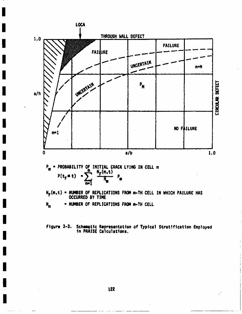
LOC1.0 THROUGH WdAL.L DEFECT __________
~FAILURE
IL L-R- ---,-
--
a/h • M"
_ _ _ _ _ _ _ _ _ _ _ _ _
/ NO F IILURE
0 a/b 1.0
P* PROBABILITY OF INITIAL CRACK LYING IN CELL m
P(tFs t) F a
NF(m~t) * NUMBER OF REPLICATIONS FROM m-TH CELL IN WHICH FAILURE HASOCCURRED BY T IME
Ne • NUMBER OF REPLICATIONS FROM m-TH CELL
Figure 3-3. Sch~mtic Representation of Typical Stratifitcation Employedin PRAISE Calculations.
122
I3.4 Initial Crack Size Distribution IThe initial crack size distribution described in Section 2.3 is definedin terms of the crack depth and the crack aspect rtiot. The coordinatesi
of the PRAISE sample space are normalized crack depth and the inverseiaspect ratio, as was discussed in Section 3.2. This section describes
the transformtion of crack size variables required to obtain the PRAISEformlation. The algoritlu used to select initial crack sizes fromtheir respective cells is also discussed. i
3.4.1 Tranlsformation of Variables
Suppose that a two-dimensional Joint probability density function isdefined as f(x1,x2 ) where Xland x2are the random, variables. If new ivariables are defined by the functions g1 and g2 such thati
y! •gz(X.x2)(3-15)
*2 g2(X1,X2 ) (3-16)I
- Glxp~x2) - 0(x) (3-17)
where x and X are vectors I
x2
and 0 is a generalized function i*_1x1x)(3-20)
*These gj functions are not to be confused with gj used in the influencel
functions of Appendix C.
123
0•
how doss one obtain the Joint probability density function p(y 1,y2) forthe transformed variables y1 and Y2? Elegant formulations and solutionsfor this problemare presented in several intermediate probability texts(Hogg 70, Walpolel2). Only the results are presented here.
Suppose that Equations 3-15 and 3-16 can be solved for theables x1 and x2, i.e., an inverse function to G(x_) exists.inverse Junction is denoted by H, or
xA H(Z)= (h2(yp')2))
original vart-If this
(3-. 1)
the transformed pdlf is given by
p(~) a f(H(~)) ~ I (3-22)
where -- is the Jacobian of the inverse transformation, or
i s the absolute value
(3-23)
and I of the determinant of that Jacobian.
For the PRAISE algorithmv, the following associations can be made:
x! • a * crack depth
*2 b/a * aspect ratio
y! a/h * normalized crack depthi
y2 * a/b * inverse aspect ratio
124
Yl x1/h a g1(x1,x 2 ) (3-24)I
*2 " lx 2 " g2(x1 'x2 ) (3-25)J
x•h~y1 • h1 (x1,X2) (3-26)
112 • l * h2(Xl,X 2) (3-27')m
Note that h is the wall thickness and is not directly related to them
Inverse functions h1 and h2 . By taking the derivatives of h1 and h2 asdefined in Equation 3-26 and 3-27, the Jacobian Is I
•e l . 1]3-28)
and
Equation 3-14 can now be written asm
P(•) * f(hy1,1/y 2)(h/y 22) (3-30)m
Recall that the original random variables were assumed to be Independent(see Section 2.3). This means that them
p(a,e) * f(x1 ,x2 ) • f1(x1 )f 2(x2) U pa(a)p8(e) (3-31)
The joint pdf Ii simply the product of the maroinal density fucntlonsm
f 1(x1 ) and f 2(x2). Under the assumption of independence. Equation 3-30becomesm
P(Z)" flh~l)f2 1/Y2(h/Y2) (-3I
"(~ P1(y1) p2 (y2) (3-33)
wherep1(y1) " hf 1 (hy 1) • hf1 jh(a/h)J (3-34)
P2Y)"f 2(1/Y2)(1/y 2 ) 2 ab'(a /b) (335
Hence, the joint pdf for the new variables (a/h) and (a/b) is the product
of the marginal density functions of these variables.
In order to be consistent with the formulation of the fracture mechanicsmodel in Section 2, the PRAISE code is designed to accept as inputsthe parameters which define the crack depth and aspect ratio probabilitydensity functions. PRAISE is capable of treating crack depth and aspectratio as being either exponential or lognormal distributions. Thesedistributions are then transformed according to the procedures outlinedabove. The formulas used by PRAISE are given below:*
(1) For crack depth exponentially distributed (see Equation 2-5)
pa u(1e)~ ea/ 0< a< h (3-36)
pila/h) * p1(e) • h Pa (hel "u (-"h/''h)
pt * 1 e-/'(3-37)
*The equations in the succeedingl sections are in the notation used inSection 2, which is not directly the same as that employed by Li. 81.Use caution in directly comparing parameters here with those in Lim 81.
126
II
whre u' * u/h (3-38)I
(2) For crack depth lognormlly distributed.
In order to make PRAISE more generally applicable, a lognormal distri-Ibution of crack depths will also be considered even thouqh such a1
distribtulon will not be em ployed in this particular investigation. Inthe following expressions, corrections for the Impossibility of havinga ' h will be omitted. Such "corrections" are small if the predicted Iprobabilit~y that a > htis very small. In this case (Hahn 67. Hasting 74)
1~ (ln a/a0)2 Ioa (2f I
p1(a/h) • p1(ca) • hf1(cxh)
e a2(ln cxi/50 )2(-0c•(2,,), "(.o
where 050 as 0/h. (3-41)I
In Equation 3-39, aS is the median of the distribution while o is the I1standard deviation of In a (not the standard deviation of a).1
For both the exponential and lognonnal distributions, the new pdf hasthe same form as the old pdf, but with slightly modified parameters.
The new rate parameter in the exponential is h times the old rate para-1meter, whtile the median In the newv lognormal Is 1/h times the oldl
inedian.
(3) ASpect ratio is exponentially distributed (see Equations 2-7 and 2-S
f2(b/a) . p6(B) . e -Bl/ B;(.2
127 I
p2(a/b),a p2(B"1) • a .i))(i~
,***j(*** *jl .)/ • I•1< (3-43)
(4) Aspect ratio is logonreully distributed (see Equations 2-11 to 2-13).
P2(a/b) • p2 (B"1) =f 2 (1/B 1l)/(l•' 1)2
• -[In 1/(Bl1Bm)j ()2 61<1 (3*45)
In the two cases of the aspect ratio considered above, the new probabi1itydensity function (for a/b) does not have the same functional form as the
old probability density function. On the other hand, the parameters which
describe the new distributions have the same numerical values as In the
old distributions.
3.4.2 Pre-Service Inspection and Mydrostatic Proof Test
Prior to Its first start-up, the primary coolant system of a nuclearreactor undergoes several pre-service Inspections designed to detectas-fabricated defects. Such detects are found with a probability depend-ing on their size. The estimated applicable detection probabilities for
an ultrasonic inspection were reviewed in Section 2.4. In accordancewith the assumptions enumerated in Section 2.2, all detected defectsarm assumed to be reaiered, with such repairs not Inducing any additionaldefects or other detrimental factors. Nence, the pre-service Inspection,
as well as any in-service inspection will have an influence on the crack
Isize distribution. Additionally, the piping is subjected to a hydro-Istatic proof test to pressures higher then will be encountered under ser-vice conditions. The fact th~at a pipe survived the proof test allowsthe crack size distribution to be truncated at the critical size cor-responding to the proof conditions. If cracks larger than that size mI
had existed prior to the proof, then the pipe would not have survivedthe proof. Hence, the initial crack size distribution empployed is altered Iby the proof test. m
The criterion for failure during the hydrostatic proof test is the sameas that employed for a complete pipe severance during normal plant operation.The latter was discussed in Section 2.9, and can be stated as follows (seeEquation 2-36)
(Ap . Acrack) of 1o > Ap al (3-46)
where the load-controlled stress consists of the deadweight and hydro-static pressure stress contributions,
For a thin-walled cylinder (hx•R 1 ), the following approximation can beImade for Ip
PH .~. ..ue) (3.47)
Two general approaches exist for incorporating the influence of pre-service inspections on the estimates of failure probability. Suppose Ithat the non-detection probability in an ultrasonic test Is given byPND(a,b) where a and b are the crack depth and crack length, respectively. IOne approach Is to simulate the test explicitly. For example, an initialcrack is selected according to the postulated crack size distribution. Amrandom numler r that is uniformly distributed between 0 and 1 is then a
selected and compared to PND(a,b). If r ' PNO(a~b), the crack is assumedto be detected and corrective action is taken. Otherwise crack growthIs sumulated. Each selection of an initial crack size is treated as oneof the samples included in the N and Nu that appear in the denominatorof Equations 3-1, 3-2, 3-13, and 3-14. Cracks that are detected do notcontribute to the samples which fail, Although this scrame Is Qtraight-
129 I
forward it may in fact be compualetionalty inefficient, bithen the proba-bility of non-detection Is smell1, the majority of the defects that leadto failure will be rejected. Hence, only a relatively small numer ofcracks is actually simulated through the lifetime of the plant. Thiswould result in large variances and large confidence intervals.
Another approach is to growe each crack that is sampled, but to correctthe swmmation in Equations 3-1, 3-2. 3-13, and 3-14 to reflect theinfluence of non-detection. Rather than adding the number of failuresthat are observed, this approach would add the P associated with thecracks that failed. This procedure can be illustrated by referring toTable 3.1. For simplicity consider first the case of simple randomsampling. Suppose that N as-fabricated defects have been selected. The
PND colwm gives the probability that the crack was not detected. TheF column presents results from hypothetical sitwlation in which ran-
dom numbers are selected and compared with PftD° A zero indicates thatthe crack was detected (failed to escape detection i.e., r > N)Otherwise r' <. N and a ane is recorded, It N[ is the number of samplesthat escape detection, the ratio •- as'uaptotically approaches PND' The
failed column gives results from a simulation In which crack growth issimulated, regardless of whether it is detected. A one1 in the Fncolumnindicates that the n-th sample would lead to failure if not detected,while a zero indicates no failure over the lifetime of the plant, N1 isthe number of failures inl N samples without crack detection. In thedirect approach, the only failures would be cracks that escaped thedetection in the pre-service inspection (En ' 1) and then grew to failurewithin the plant lifetime (F ' 1). NIF is the number of cracks In Nsamples that escape detection and also fail. The failure probability isestimated by the ratio
-F "II (3-48)
in the second approach, each failure Is weitghted by che probability of
non-detection or
Pi A E • ND,n Tn (3.49)
n,!1
130
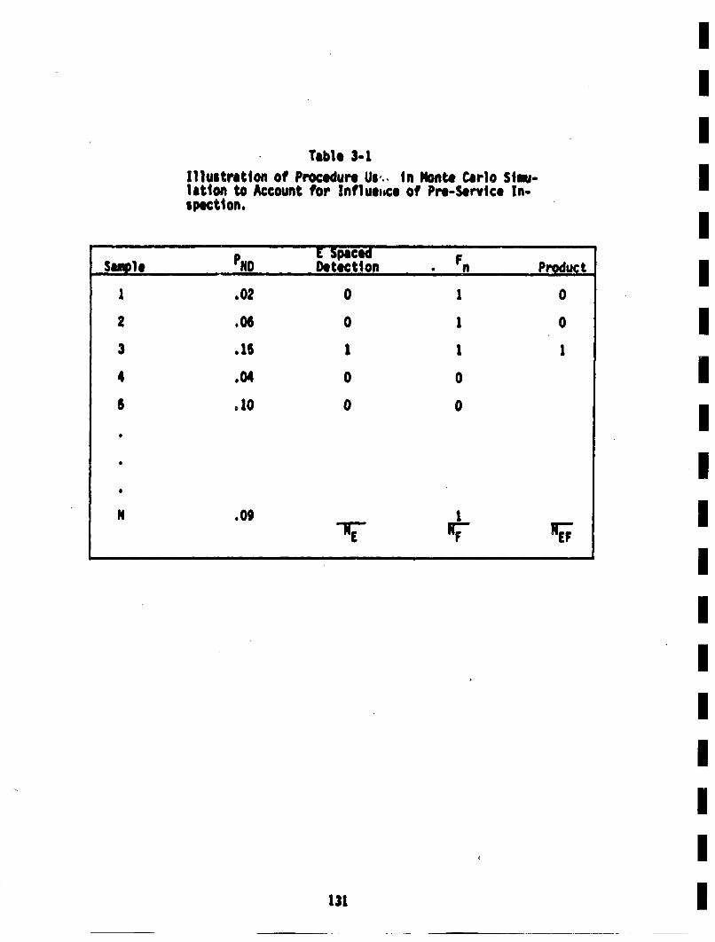
Table 3-2Illustration of Procedure Us., in Monte Carlo S1i..1ation to Account for Influ,,,ce of Pro-Service In-spection.
Sapl i ! [ Spaced FSapeDetection , • nProduct
1 .02 0 1 0
2 .06 0 1 0
3 .15 1 1 1
4 .04 0 0
5 .10 0 0
S
131
Since Fn~ * 0 when there is no failure, [quation 3.48 is equivalent toadding the PB) of the cracks that tail.
A third and mores ophisticated approach is to coabine the postulated
crack size distribution with the non-detection probability and hydrostaticproof test to create, a post-inspection Joint pdf. The initial crackstizes would then be drawn from this post-inspection joint pdf.
The second ipproach is presently being vied in PRAISE. Cio~utationally
speaking, it is more efficient than the direct approach. It requires
a minimel change in coding. On the other hand, an application of the
third approach requires either than the post-inspection pdf be input by
the user or that a specilaized procedure be developed to coline the
initial crack size distribution with the non-detection probabilities.
These requir~ments would impose unnecessary additional calculations.
The analysis of a hydrostatic proof test is slilghtly less involved than
the ultrasonic inspections. All three approaches are identical because the
hydrostatic test is assuned to give perfect results. P is exactly one
if the conditions or Equation 3-46 are satisfied. Hence, cracks in the
failure region corresponding to proof test conditions have absolutely
no chance of causing a failure under service conditions unless crack
growth occurs, or higher stresses are imposed. The present assupt ion
is that cracks in the failure region would be removed and a new initial
crack site selected.
3.6 Arrival Time for Events
The PRAISE algoritim may be broadly classified as a neat event simalatioa
in which the calculation proceeds from event to event during the reactor
lifetime. Thus, it is necessary for the simulation to model the arrival
of variousl events., from an operetional point of view, each point in
time at whic~h some calculation is performued is signaled by an event.According to this definition, events include the following:
132
bVIulmttoij SW) eflP~UI sIueA e 'uo VJ•| p 1IlY o) hlPao)V)lUeA v@ £1 Peilsui S| pewlOJjd sl vOlinl mOS 3.'q aemp
ul 1uIod q~e 15A JO luIod IV@5S~.d0 ue oJj 'e2ISAS eoOIJA Jo
IIAI.JJ9 0SW 1SP11)01 mI0U1231flin11 SW JOJ £j, ge•Iw 11 31 *111U, "n1)SlJ|joTpej .q2 hsanp IuSAS 02 2uAO• U.JJ Iph3@d uotleS~lnoIf l @4)q u|4MV
u•lIelVS1• IUA VU S 1o, pIJtJS1l= £lpeoq eq ,£ew uflI.4ots ]$1vvd e.
12UM OA] .OUI e i SA!.JV IiC
'Pe0)ele e@ s ll lPJ
LiSIIIl Au• S puS peAoJe eq pinl0• VlikJ *Ja1J .112 VI 1U~eJ• 2e1) IIuopldusss luenead 641 .Peeocl 5. IIue Se *J~a J94B54 Jo 5.afn=3o 4IAoJ$qo5J: 1s.1mm SUOI2JPUO2 e*taJee JePpfl *fnlleJ e Bulsni' jo *,ueq= ou£lelalosqe eAeq 1uO~2tpU0:) 212 j@oJd 01 Bu~pUOdIeJuo3 Uo~lJe eJafleS
*ql esnsq:• isvtumPl .,s 14eq~o.dde eeaql L¥ suo~1~.dsu! •tUo1SJjLn 042US)l PeAA|OAU| lt*llI XlqOII• s| '1to joo4ad •)!lsojpAq S1 JO 1~s~lUe 041
1U's~uoblejSl IeuoIIIPPe £J3e1Se~uun esodml pflOne 12V@Jdfnb@J *ie4j1•el211lqeqG~d UOjl2:0)P-U0U @42 IIIIN UOl2flq|J2Sp 0111 y3eJ3 Iet3lul
@42 eUlqo 01 pedoIeAep eq e~anPe~od PeSlteS~ds e 2541 JO .esaf e42£q Indul OqI jpdl UOt2dIuI-)Iod e42 u@41 Je421e 1eJInbeJ p~eoadde pIa|ql
042 JO u012?llPIdde a pue lq .em')o eqi u0 S6ulPo3 ul *Biuet) Iemil.l 'se~ln'l I "l 'Slo.dde 2~l•0p o4) Ue4) 2UelIJJS e.oW 11 21 O6a11eeds
IS~uoI9llq~0m3 3|SIVI~d ul peeaf 6u~eq &12ue1se4d 11 4oeO~dd1 pUo)e1 e41
• pd IUlOV" uoi2.1:xlug-2sod slql UoJJ UMSJp e4 V.14 PIInOA loijiIPSJ, 1112l~ elv '1J jpd iuior vopl:.dSU!-2sOd SS'2SJO 01 2502 JOdd
•I212so~pA4 pus £'2llqeq~d Uo0I1e1ep-vov 641 qtuA Uopnq~asl. olP s q~dPoe11ln2s04 @42 eu5(q03 02 1 q~eoJddS Pe2eS)|2slqd01 ejom pus PJ142 V
01 lUSISIAIfibS1 $1 8)' V0125eb3 °o~nLteJ ou 5.411 e We 4 e 0 * e~i US
(a) startup or shutdown,(b) occurrence of anticipated transients,
Cc) pre-service and in-service inspection tim. anid
Cd) earthquake evaluation times.
The frequency of arrival for these events is controlled by the user.Additional1 discussions related specifically to Zion I will be presented inSection 4.
The time at which startup/shutdown and anticipated transients occur canbe uniformly spaced throughout the plant lifetime or appear randomly inthe pleant lifetime. In the stochastic case, the events are aissted tobe part of a Poisson process. Each transient type will be governed by aseparaeo Intensity A1. The distribution of inter-arrival times is expon-ential, or for the i.tb transient type
f1(t)" A exp(' It) (3.50)
The intensity AI represents the average nimber of events In a unit tim.Tereciprocal C (= •t") s the mean time between arrivals of the it
transient.
If the user desires to model pre-service inspections, they will naturallyoccur at the beginning of each replication. In-service inspectiens and
earthquake evaluation times are determined Inputs supplied by the user.These can occur either uniformly spaced (with input time interval) orarbitrarily specified (though still deterministic) throughout thespians1lifetimae
Additionall discussion relevant specifliclly to reactor piping will be)included in Section 4.
I133
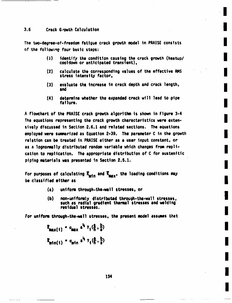
I3.6 Crack Gowth Calculation I
The two-degIree-ot-freedom fatigue crack growth moedl in PRAISE consists Iof the followis• four basic steps:
(I) identity the condition causing the crack growth (heatup/ I~lcooldown or anticipated trans lent),
(2) calculate the corresponding values of the effective RI4Sistress intensity factor,I
(3) evaluate the increase in crack depth and crack length,and I
(4) determine whether the excpanded crack will lead to pipefat lure.I
A flowchart of the PRAISE crack growth algorithm is shown in Figure 3-4The equations representing the crack growth characteristics were exten-•sively discussed in SecLion 2.6.1 and related sections. The equationsemnployed weeswusrized as Equation 2-39. The parameter C in the growth Imrelation can be treated in PRAISE either as a user input constant, oras a lognormlly distributed random variable which changes fro repli--cation to replication. The appropriate distribution of C for austenittcpiping materials was presented in Section 2.5.1, IFor purpses of calcultitng ruun and x the loading condtionsmy
beclassified either asi
(a) uniform through.the.wall stresses, or
(b) non-uniformly distributed throuh-the-wal1 stresses,Isuch as radial gradient themal stresses and weldingresidual stresses.I
For uniform thogh-the-al stresses, the present mode assumes that
-mni mna o. ,(I. I)
I
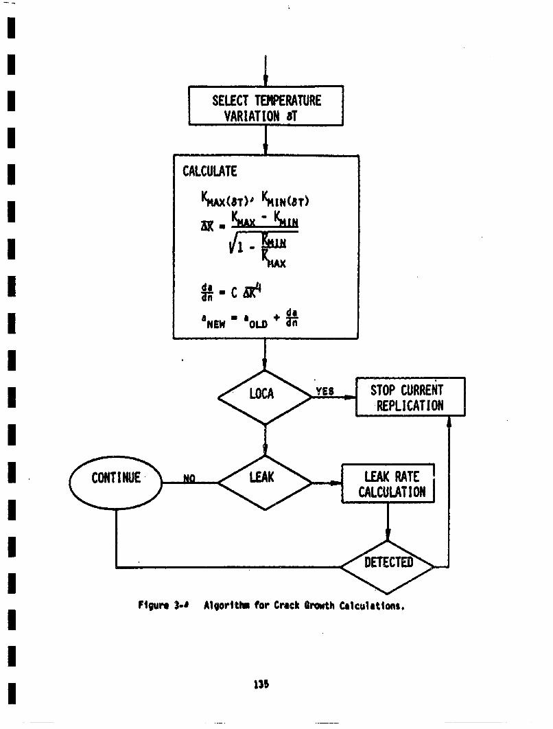
Figure 3-U Algoriti. for Crack Browth Calcultltons.
131
Iwhore m
Omnand Om are the minimum and maximum values of the uniform
through-the-wall stresses, a is the crack depth, and
is a function that relates a to •1(1 being associated with the "degree of
freedom," a o b). In the cold shutdown condition, the only contributionto the uniform stress is the deadweight. On the other hand, in the hot Ioperating condition there are contributions from the deadweight, pressure,and thermal expansion. For the specific case of a heatup/cooldown cycle, I
0min • DW
o~x o~w+ 0p + 0TE
PRAISE currently assumes that radial gradient thermal tresses are the Ionly contributors to non-uniform through wall stresses. Since thesestresses are associated with temperature transients, they will be super- Iimposed onto the normal operating stresses. Hence R,,iin(t) and ]•ax(i)consist Of contributions from both the uniform through the wel1 operating Istress and the transient-dependent non-uniform thrnugh.wall stresses,or
•.,n(,)" "op(,) + A•un (j f 'ft. AT1)I
•,ax(1) " •op(i)÷ •mx € f, ft, AT1)Iwhere J denotes the transient type, and
AT is the temperature variation during the transient. I
discussion.
I
The temperature variation is displayed explicitly in •min(i) and i~nax (I)because it might not be the same in each occurrence of a particular transienttype. PRAISE accomodates these differences in temperature variation bytreating AT as a random variable. The PRAISE formulations for •'for
transients producing radial gradient thermal stresses can be expressedas fo1llows
This is consistent with the treatment of the stress intensity factors
due to radial gradient thermal stresses presented in Section 0.4.
In general, a pdf will be supplied by the user to describe the distri-bution of AT for each transient type° The coding used by PRAISE toevaluate the above g functions is included in Chapter 5 of Lim 81.
The preceding equations arc applicable as long as the crack depth isless than the wall thickness. When a > h, the crack growth relationship
is modified in accordance with discussions in Section 2.6.2.
After each increment of crack growth, the crack is examined to determinewhether it has reached a depth equal to the pipe wall thickness, or willlead to a double-ended guillotine break. As shown in Section 2.9, thisfailure criterion for a double-ended break is based on the exceedanceof a critical net section stress, or
(Ap - Actack)Oflo >_ Ap alc (3-5!)
The user has the option of treating 0f10 either as a constant to be usedthroughout the calculation or a normally distributed random variable thatvaries frem replication to replication. In the latter case, the userspecifies the mean and standard deviation of the normal distribution.
137
The relevant distribution for austenitic piping materials was discussed
in Section 2.5.2. The load controlled stress is defined by
0L °0 *a +O (3-52) Im
If the crack is a through-wall defect (but does not produce a large LOCA), Ima leak rate calculation is performed using procedures outlined in Section2.8. PRAISE is designed to maintain statistics on the number of "sm.ll"I
leaks and the number of "big" leaks. The user is expected to providea value of leak rate which represents the threshold between small and 3mbig leaks.
The leak rate is also used in conjunction with a leak detection model to IU
determine whether a given leak can be detected. The current leak detectionmodel has a user-specified leak detection threshold. Any leak with a IIrate greater than this threshold is assumed to be detected and lead toa plant shutdown with subsequent corrective maintenance. I3.7 Influence of Earthquakes on Crack Growth I]
Seismic events occur at random timels and with random magnitudes. Itwould be inefficient to simulate earthquakes as stochastic processes in Ithe PRAISE code. The probability of a significant earthquake within a
40 year period is generally low, so that many plant life times would•
have to be sliwlated in order to generate a sufficiently large sampleto confidently estimate the influence of seismic events on piping relia-
bility. This Is somewhat enalagous to the problem discussed earlier
associated with randomly sampling the crack size distribution. Thatproblem was circumvented by using stratified sampling. In the case of Imseismic events another approach will be taken. In this case, the influ-ence of specified earthquakes of a given magnitude and times of occur-nrance wi1l be evaluated. For example, the influence of a safe shutdown
earthquake (SSE) occurring 20 years into the plant lifetime can be con-
sidered. Such results can then be used in conjunction with information I]on the probability of such an event occurring at that time to provide
esttimtes of the probability of a seismically induced l~iping failure.
138 I
Wit hin each replication, PRAISE periodically evaluates the instantaneouseffect of seismic events on the crack growth. The times at which theseevaluations take place are known as "evaluation" times, and are providedby the user. These tines may be either placed at regularly spaced intervalsor arbitrarily specified throughout the plant lifetime. Since earthquakeshave a continuum of magnitudes and stress-timle histories, the "evaluation"earthquake is actually a series of earthquakes. It is envisioned thatseveral earthquake magnitude categories, spanning the credible values ata given site will be included. Within each magnitude category, severalearthquakes will be examined. These will be treated as representative andequally likely to occur at that magnitude. At each "evaluatton" time, thecurrent crack is subjected to each of the postulated ear;hquakes. Theearthquake evaluation algorithm is shown in Figure 3-5. The case of onlyone earthquake occurring during the life at the plant will be consideredhere.
The treatment of crack growth during seismic events is somewhat differentthan crack growth under normal operation or anticipated transients.Fatigue crack growth due to non-seismic events can be characterized bya single loading cycle of known magnitude. Relationships of the form
*n aold + C1R,'4 (3)
are very convenient for predicting the crack growth under single cycleloadings. An analogous equation for b also exists. Seismic eventscharacteristically have many cycles, each of which may have a differentamplitude. A cycle-by-cycle crack growth analysis would require repeatedappli1cations of the above equation, and consequently repeated evaluation of
1t.This approach is time consuming. A reasonable compromise is the3pproach discussed in Section 2.6.2, wthich muploys the S-factor. Assumingthat a does not change much during the cycling considered, the followingrelation is obtained from the expression imedIaetely above Equation 2-40along with the definition of S given in Equation 2-40.
Cnew •old +Cs$4a4aold2 (3-54)
139
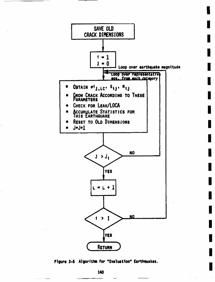
Loop over earthquake magnitude
Figure 3-4 Algor~thm for "Evaluation" Earthquakes.
140
In the case of sesmic€ events, acid and anw are the crack depths beforeand after the seismic event. An~ expression analogous to 3-54 is appli-cable to growth in the b direction (which is the other "degree-of-free-dom"). After each T"evaluation" earthquake and corresponding incrementof crack growth, the crack is examined for leak or LOCA. The appropriateload controlled stress to be used inl the failure criterion is
0LC • oW +p 0 EQ
where E is the maximu stress experienced by the joint during the earth-quake. Values of aLC applicable to seismic events are presented in Table
1-3. This Is a conservative approach because the worst load controlledstress is applied to the mximum crack stze. Within a single seismic
event, it is conceiveable that a crack can proceed from a safecondition to a leak and ultimately a LOcA. Since the temporal extent ofthe earthquake is very short, leak detection will be ineffective in
shutting down the plant if atleak should occur during the earthquake.Hence, all comparisons for leak and LOCA are performed after the earth-
quake has occurred.
The effects of the evaluation earthquake are removed, i.e.. the crackdimen sions are reset to their pre-elvaluation valueb, after each appli-
cation of the evaluation earthquake. in order to further clarify thispoint, consider the sample space shown in Figure 3-6. Tho lino a1 a2 a3
a4 is tho so-called crack trajectory in the abscnce of the earthquake.
Suppose that 'evalutiotn" earthquakes are desirnd at times correspondinoto pointes a1, a2 and a3. The resulting crack dimensions arc schematically
represented by the points a1', a2 ,• a3'. Since a1 and a2 ' have a/hhave values less than 1.0 and are not in the LOCA region, earthqakes attimes t1 and t2 would not lead to failure. On the other hand, an earth-quake at tim t$ would cause a through wall defect. PRAISE records ateach evaluation time the ntber of leeks and LOC~s that result from asingle earthquake at that time. It is important to recognize that once'
the "~evaluation" is performed, the crack size is returned to its pre-
evaluation value and the simulation proceeds. In other woins, pointson the crack trajectory are not influenced by the =evaluation" earthquakes.
t41
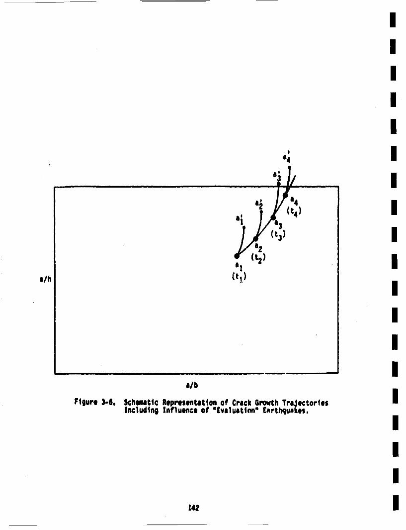
.4
a/b
Figure 3-6. Schsatl¢ Represfltatloa of Crack Growth Tra~.ctortesIncluding Influence of "Evaluattnn" EArthqu.kes.
142
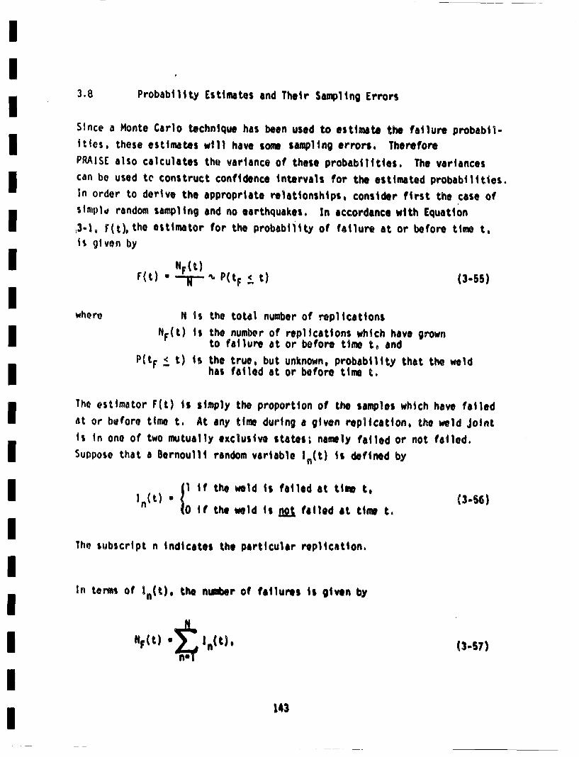
3.8 3.8 Probability Estimates and Their Sampling Errors
Since a Monte Carlo technique has been used to estimate the failure probabil-ities, these estimates will have some sampling errors. ThereforePRAIsE also calculates thet variance of these probabilities. The variancescan be used te construct confidence intervals for the estimated probabilities.In order to derive the appropriate relationships, consider first the case ofsimply random sampling and no earthquakes. In accordance with Equation
,3-1, Fit), the estimator for the probabilitty of failure at or beforo time t,
ti given by
wfh~ro N is the total number of replicationsNr(t) is the numbr of replications which have grown
to failure at or before time to andPitF • t) is the true, but unknown, probability that the weld
has failed at or before time t.
The estimator Fit) is simply the proportion of the samples which have failed
at or before time t. At any time during a given replication, the weld Jointis in one of two mutually exclusive states; naemly failed or not fatiled.Suppose that a Bernoulli random variable In(t) is defined by
p if the weld ii failed at time t.
In~t ~Oif the weld is •g failed at time t.
The subscript n indicates the particular replication.
In tern~s of In(t)* the niber of failures is given by
NF(t) "1" In(t). (3-S7)
143
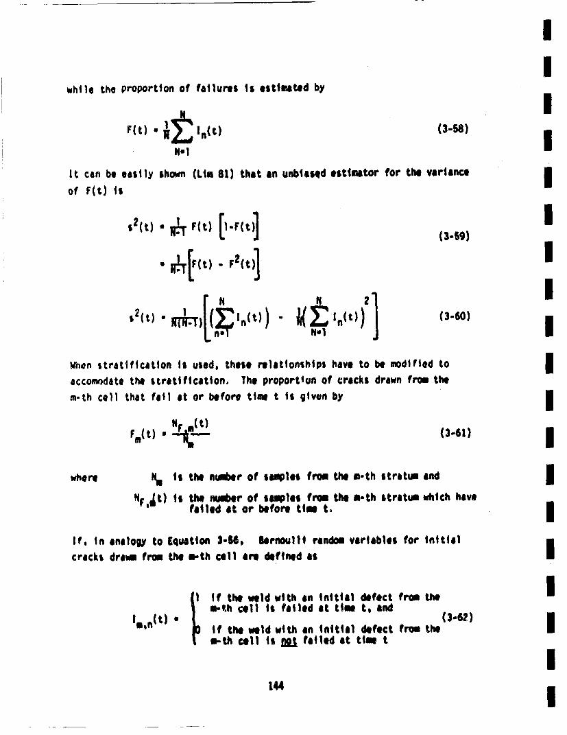
while the proportion of failures is estimated by
F(t) •. ,n ) (3.s8)IIIIt can be easily
of F(t) isshown (Lim at) that an unbiasqd estimator for the variance
*2(u). F(t) [l-F(t)](3.5,)
'4s2(t) . RtT{(~In(t)) - ~(Z'~ t)))
N. 1(3.60)
IWhen stratification is used, these relationships have to be modified toaccomodato the siratification, The proportlun of cracks drawn from thein-th cell that fail at or before time t is give~n by
F(t) • N *.(.t) (3-61)
where ia s the ni.ler of samples from the m-th stratum andNp,•t) is the number of salmples from, the m-th stratum which have
faited at or before tim to
If, in analogy to Equation 3.54. lernoulli random variables for initialcracks dra~m from the s-th cell are defined as
In'n(t) * I
if the weld with an initial defect from them-'h cell is failed at time t, and (-2
if the weld with an initial defect from theS-th cell is not failed at time t
144
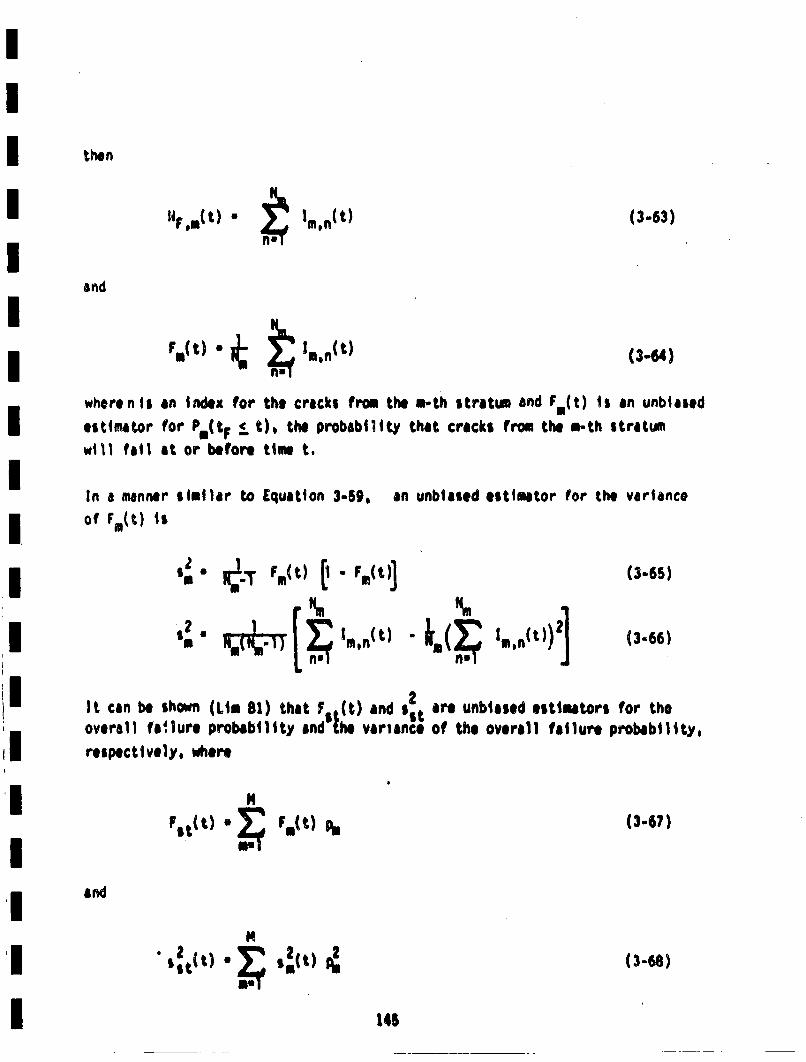
then
". U~t n.• ti~(t) (3-63)
and
rct) • • ••. 1,.,ca)(3-6,4)
wherent aI n index for the cracks from the m-th stratum and F.(t) Is an unbiasedestimator for P*(tF •_ t), the probability that cracks from the a-th stratum
will fail at or before ti.e t.
In a manner similar to Equation 3-59, an unbiased estimator for the varianceof Fm~t) ts
$:"e RT•!., Fmo(t) i.1" F,(t)]12 r~.[,I. t * ]m(3-6s)
(3-66)
It can be shown (Li. 81) that F ,(t) and s2overall1 fa; lure probabilitty and'•he variance
respectively, where
are unbiased estimators for theOf the overall failure probability,
andFst(t) .a s,(t)2
(3.67)
(3-68)
146
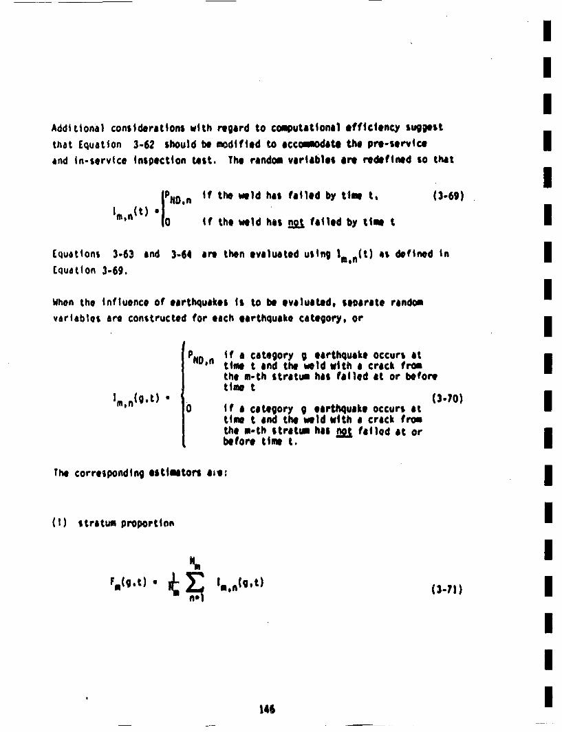
Additional considerations with regard to computational efficiency sugg)estthat Equation 3-62 should be modified to ,ccamodate the pre-serviceand tn-service Inspection test. The random variables ire redeifned so that
o iDn tf the weld has failed by time t.ire'nit) ~ °if the weld has not~ tailed by tim t (3-69)
Equations 3-63 and 3-64 are then evaluated using 1m n~t) as defined inCquatton 3-69.
When the influence of earthquakes is t~o be evaluated. seocrate randomvariables are constructed for each earthquake category, or
Im (g~t)°
P f a category g earthquake occurs atND,n time t and the weld with a crack fromthe m-th stratui has failled at or beforetimet
(3-70)0 if a category g earthquake occurs at
time t and the weld with a crack fromthe rn-tb stratin has flot failed at orbefore time t.
IIIIIIIIIIIIIIIIIII
The corresponding etitmators ate:
(I) stratum proportion
F*(g .t) " 1nI1
I*~n(g,t) (3.71)
146
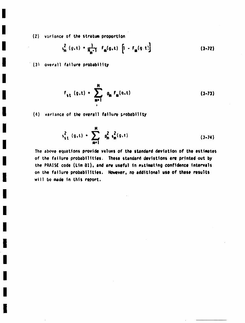
(2) var~ance of the stratum proportion
(g.t) S Fa(O.t) •" F,,(q't•1(3-72)
(.31 overdsfl failure probability
Irt (g~t)" * • mQt
(4) variance of the overall failur. v, robabillty
(3.73)
N
U. IP5 ,(g,t) (.4(3-74)
The above equations provide valams of the standard deviation of the estimatesof the failure probabilities. Those standard deviations are printed out bythe PRAISC code (Li. 81). and aer useful in eitimatlng confidence intervalson the failure probabilities. MoweVero no additional use of those resultswill bo made n this report.
4.0 APPLICATIONlS TO REACTOR PIPING
Previous sections of this report have been devoted to a description ofthe fracture mechnics model of compnent reliability (Section 2), and Iithe proeures deveope for genration of nwmerical results (Section 3).These descriptions were fairly general, and the modl and the namrircal 3scheme mployed could, with appropriate material properties, be appliedito a wide variety of structural components. This section will providei
detal|s of the specific applicaion• of the describe procedures to reactorpiping. Introductory comments that set the framework for descriptionof the model were included in Section 1. The prlimry piping at Zion I IJwas describe, and the weld joints considered are shown in Figure 1-2.Additionally, the relevant stresses to be mployed in the fracture roach-i
aincs analysis were reviewed in Section 1.3. g
Basically, it is desired to evaluate the influence of seismic events on IUl
the probability of failure of the lags primar piping at Zion I, Theprobabilit•yof failure in the absence of seismic events forms an itngral Iportion of the results. Calculations were performed for each of thegirth butt welds shown in Figure 1-2 to determine the probability of Imfailure as a function of time for no seismic events. In conjunctionwith these calculations, seimic events of specified magnitude were
Imposed at specified times, and the increase in the probabilit ofifailure at each weld Iloction was deemnedm for each of the seismicmagnitudes considre. Th difference in the failure pro~bablitybefore ,nd after the seismic event is the contribution of the seismicevent to th. failure prbbility. Rsults such as show schemtically iIn figure 4-1 were •nrae~d. This figure clearly shos the increasein the failure probability due to the specified seismic event. Failure
probabilities for times following the seismic event were not part ofithis Investigation. The failure probabilities changed with time prior•to Ihe seismic event because of the fatigue crack growth that occurs dueIto cyclic stresses impse during noesal plant opration.i
II
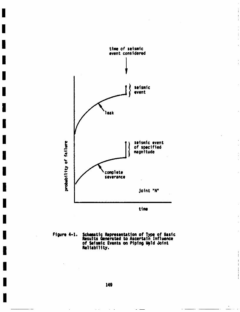
time of seismicevent considered
"leak
I seismicevent
sisemic eventIof specifiedmagnitude
Joint "N"
'II..
I.-0
atime
Figure 4-1. ReSchma..tic Representation of TypeJ of BaiescReults Generatedl to Ascertain influenceof Seismic Events on Piping M~ld JointRe1liabili ty.
149
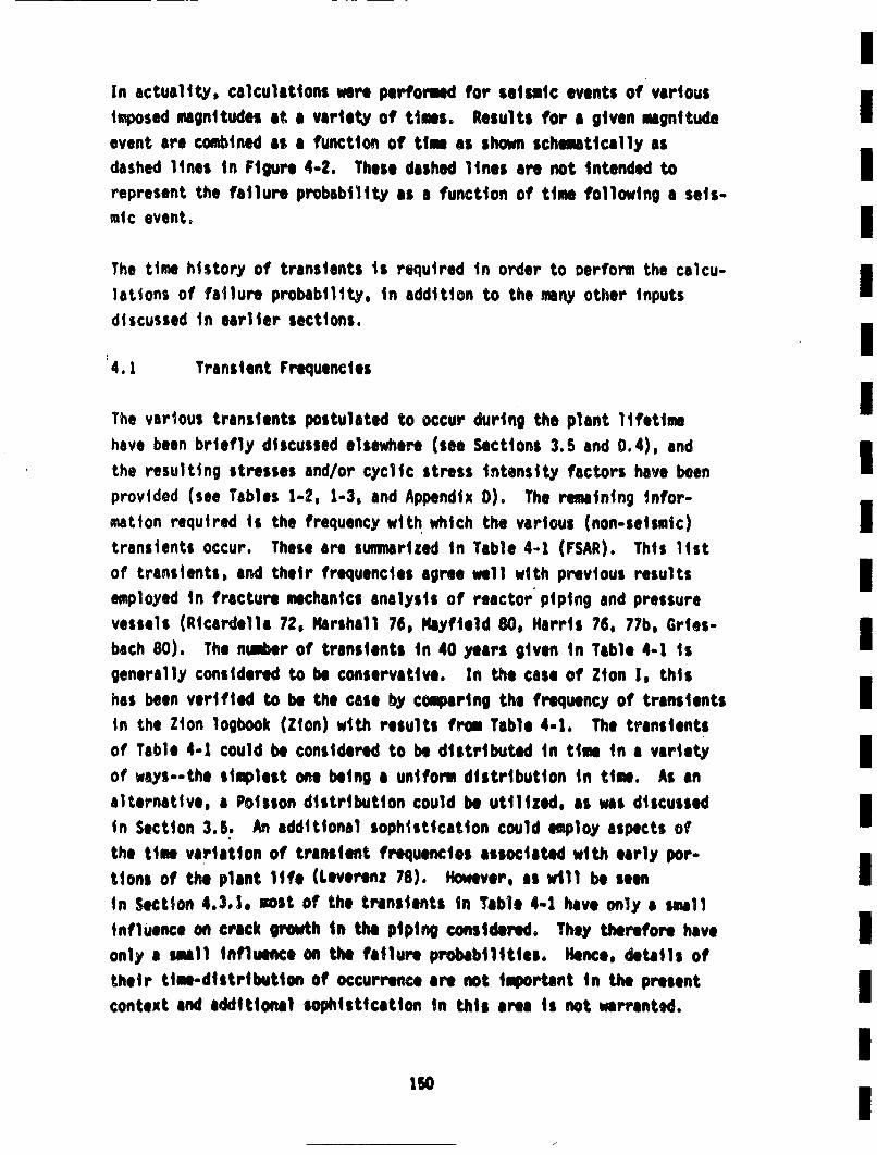
IIn actuality. calculations were performed for seismic events of various
imposed magnitudes at a variety of times. Results for a given magnitude•event are combined as a function of time as shown schematically asdashed lines in Figure 4.2. These dashed lines are not intended to Irepresent the failure probability as a function of time following a seis-mic event. IThe time history of transients is required in order to oerform the calcu-ilations of failure probability, in addition to the many other inputsdiscussed in earlier sections. I
4.1 Transient Frequencies
The various transients postulated to occur during the plant lifetime•
have been briefly discussed elsewhere (see Sections 3.5 and 0.4), and•
the resulting stresses and/or cyclic stress intensity factors have beenprovided (see Tables 1-2, 1-3, and Appendix D). The remaining infor-mation required is the frequency with which the various (non-seismic) itransients occur. These are sunnarized in Table 4-i (FSAR). This litstof transients, and their frequencies agree well with previous results Iemployed in fracture mechanics analysis of reactor' piping and pressure m
vessels (Ricardella 72, Marshall 76, Hayfield 80, Harris 76, 77b, Gries-i
bach 80). The number of transients in 40 years given in Table 4-1 isgenerally considered to be conservative. In the case of Zion I, thishas been verified to be the case by comparing the frequency of transientsIin the Zion logbook (Zion) with results from Table 4-1. The transientsof Table 4-1 could be considered to be distributed in time in a varietyof ways--the simplest one being a uniform distribution in time. As analternative, a Poisson distribution could be utilized, as was discussed
In Section 3.5. An additional sophistication could employ aspects ofthe time variation of transient frequencies associated with early por-tions of the plant Itfe (Leveren: 78). However, as will1 be seenin Section 4.3.1. .ost of the transients in Table 4-1 have only a smallinfluence on crack growth in the piping considered. They therefore haveIWonly a smell influence on the failure probabilities. Hence, details oftheir time-distribution of occurrence are not important in the present icontext and additional sophistication in this area is not warranted.
150
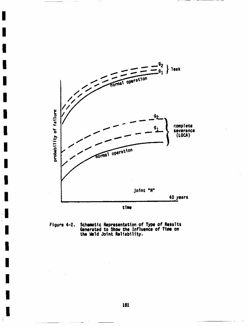
Pt'4-
'4-0
4J.9-p.'9- -.0I-
/
FIgure 4-2.
- - g2 ~- ~ leak
- g1 g~
or~~
g- -
- .oinplete(LOCA)
- - everance- -
9,
OV1t~~ 09erb~A0~
Joint "N40 years
time
Schematic Representation of Type of ResultsGenerated to Show the Influence of Time onthe •ld Joint Reliability,
15l
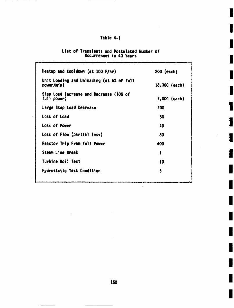
I
Table 4-1
List of Transients and Postulated Number atOccurrences In 40 Years
Heatup and Cooldown (at 100 F/hr)Unit Loading and Unloading (at 5% of fullpower/mmn)
Step Load Increase and Decrease (10% offull power)
Large Step Load Decrease
Loss at Load
Loss of Power
Loss of Flow (partial loss)
Reactor Trip From Full Power
Steam Line Break
Turbine Roll Test
Hydrostatic Test Condition
200 (each)
18,300 (each)
2,000 (each)
200
80
40
80
400
1
10
152
I
4.2 4.2 Joint and System Reliability
The various factors contributing to the reliability of a given weldjoint have been thoroughly discussed in earlier sections of this report.Basically, the weld Joints are subjected to a given set of transientswhose frequency was discussed in the previous section. Results such asshown schematically in Figure 4-2 are generaead for each joint. Hence,the probability of leak or LOCA for each joint is obtained as a functionof time, and the influence of a specified seismic event on each jointis determined. Each Joint in a given pipe section (such as hot leg,cold leg, etc.) will see the same coolant temperature history. Theywill therefore see the same radial gradient stress history, but differentseismic and normal operating stresses.
The probability of' failure in the primary piping system under consider-ation at Zion!I will be governed by the probability of failure of thevartous joints in each of the four loops. If the failure probability ofeach of the joints is independent of all the other joints, the followingrelation will hold for the probability of failure anywhere in the four loops.
The 4th power is present because there are four loops. The use of thesame failure probabilities for corresponding joints in each of the tourloops is inconsistent with the joints all being independent of one an-other. Additionally, the failure probabilities for joints in a givenloop may not be independent, because they all see th. same transienthistory. Therefore, Equation 4-1 is only approximate. Howvere, it canserve as anaiur. l•.. ontr~o the loop failure probability. Time, t, endseismic event magnit~ude, g, are carried along inl the calculaion€.
A lowr •on the system (or loop) failure probabiliW would be theprobability of failure of the joint with the highest failure probability.
'B)
Thi s can be expressed asI
*i k f( 1.n4 k"l (4-2) I
If all of the Joints were perfectly correltetd this would provide theexact system failure probability.
The seismic hazard curve must be known before it is possible to directlycalculate the probaiblity of a seismic.induced LOCA (or leak). Resultsigenerated in this investigation are concerned with t~he probaiblity of aLOCA (or leak) given that a seismic event of a given magnitud occurredat a given time during the life of the plant. Section 3.0 briefly dis-Icussed a proc~edure for combining the seismic hazard curve with theresults generated herein.I
The Inputs necessary for the numerical generation of the probability offailure at each of the weld Joints have now been presented. and actualresults can be obtained. Such results are presented in the next section.
4.3 Results and Discussion
Numerical results for pipe Joint failure probabilities will now be pre.
san~ed and discussed. Unless otherwise stated, the following conditionsIwill be applicable to all results
- pre-service t~ydrostatic proof test Is performed. i- pre-service inspection is performed, but no in-
service inspection, I- C and flo0 are random variables,- the Marshall distribution on crack depth is used
(Equation 2-6).- the medified lognonml distributiog on aspect ratio
is used (Equaiton 2-11) with g~1O.', and I- occurrences of non-seismic trensients are uniform overI
plant lifetime (see Table 4-1). I
4.3.1 4.3.1 Results for All Transients
Calculations were performed for the hot leg-to-pressure vessel joint(anumer) 1 n Figure 1-2) for the case of a transient history based onTable 4-1. The maixsmu teperature and pressure excursion for each tran-sient were taken to be deterministic with values as specified in Appe n-'lix D. The results are presented in Figure 4-3. Also shown in thisfigure are correspontding results generated by considering the heatup.cooldown transient to be the only nonseismic transient, and the event istaken to occur S times per year (200 times in the life of the plant).|t is seen1 that the two sets of reSUltS are quite close to one another.This ii. not too surprising. The heatup-cooldown transient results in
a stress that is uniform through the wall thickness, and the cyclicstress is relatively large. Therefore, the cylic stress intensity factorwill also be relatively large. The majority of transients other thanheatup-cooldown (HU-CO) produce primarily radial gradient thermal stresses.As shown in Appendix 0, these stress contributions produce relativelysmall cyclic stress intensity factoers. In fact, K1 ofte n actuallypasses through a peak at intermediate crack depths, and decreases asthe depths get larger. Therefore, the cyclic stress intensities arenot large, and these transients have only a saall influence on the largecracks that can produce coeplete pipe severances.
The inclusion of the radial gradient thermal itresses could be Inopatint--especially to LOCAs, because these stresses are highest at the inner
wall, and would therefore tend to grow cracks in the circuaferentialdirection (whore they could gow• to cause LOCAs) rather than through thethickness (where they could grow to cause leaks). it was not known apriori what the influence of radial gradient stresses would be. In thepresent case, they are seen to not be influential. it will be seenshortly that the influence on leak probabilities is even less than theinfluence on LOCA probabilities.
The cost of running the4 PRIAISE code increases almost linearly with thenuobr of transients considered. Since the reults of Figure 4-3 shoythat the hea tup-cooldesm cycle dininates the stress history, sv~ubsqet
If,
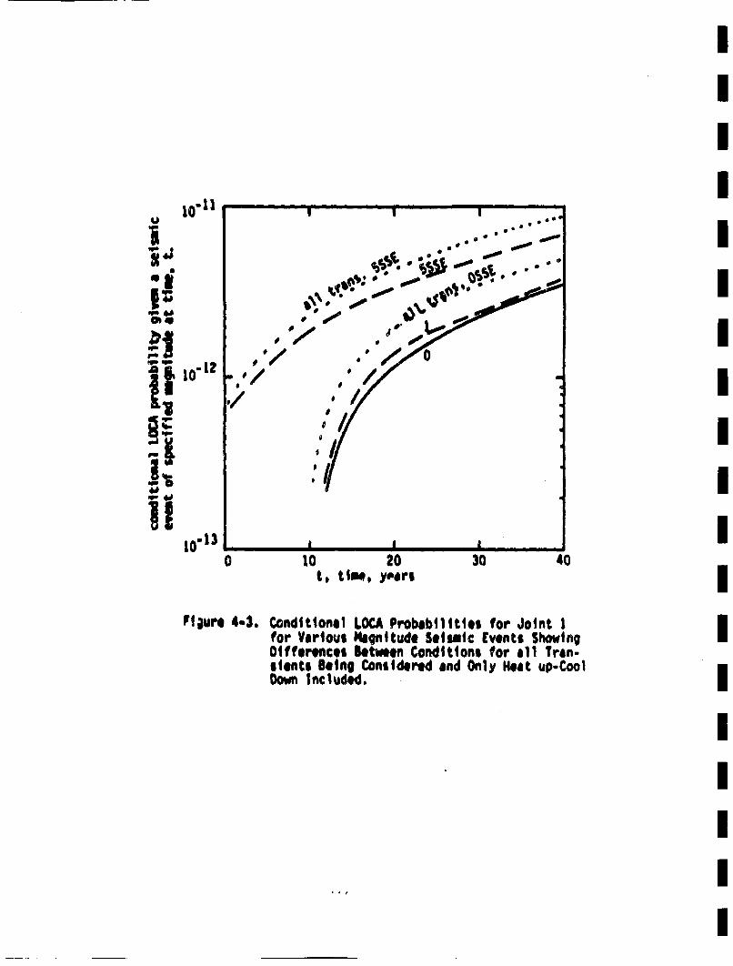
III
bll101
0 10 20 30t. time, yper$ 40
Plaure 4-3. Conditional LOCi, Probabilities for Joint 1(or Vairous Magnitude Seisaic Events ShowingDifferences Setteeen Conditions for all Tran-sients Being Considered and Only Heat up-CoolDown Included.
III
calculations were performed with this being the only nonseismic tranl-slant occuirring during the plant life. This results in considerablesavings in coutr costs, and (as indicated in Figure 4-3) will not
significantly alter the results obtained. Hene, unless otherwisespecified, all raining results to be presented here are for the heatup-cooldown transients only, along with the other conditions specfied atthe beginning of this section (4.3). Thesewill be taken to be the base
case condi tions.
4,3.2 Results for Base Case Conditions
Calculations for the base case conditions were performed for eachof the fourtee wild joints. The results for LOCAs and leaks areincluded in Tables 4-2 and 4-3. The results in these tables formthe bulk of the results obtained in the course of this investigation.Selected results extracted fro these tables wrill now be discussed.
The probabilitty of failure is a strong function of weld location, asshown in Tables 4-2 and 4-3. This is because of the strong variation In
applied stresses with wld location, •iich are shown in Tables 1-2 and1-3. Selected results for joints I and 13 are presented in Figure 4-4.As mentioned above, these results are for the base case conditions. Allof the LOCA probabilities are very low. This is because of the largetolerable cracks in the tough piping material, and the fairly benignstress history these pipes are subjected to. The observance of verylow LOC probbilities means that cracks that can produce LOCs areInitially very larg.
It is seen in Figures 4-3 and 4-4 that seismic events have only a smallInfluence on the LOCA probabilittes for Joint 1. In contrast to this.Figure 4-4 shows that seismic events have a large influence at joint 13.The relative influene of seismic events is governed by the relativemagntudes of the seismic ad nomal oprating stresses. In Tables 1-2and 1-3 joint 13 is seen to have a large seismic stress and relativelymall normal operating stress. This accounts for the relatively large
15?
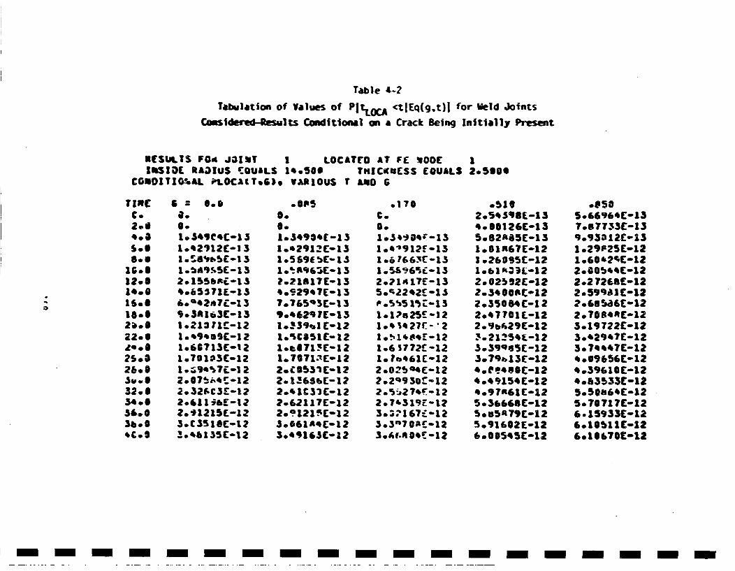
Table 1-2Tabulation of Values of PIt~oC ctlEq(g~t)! for Meld Joints
Consldwe-Rsuts Couidltlonal on a Crack Being Initially Present
RESULTS F0i JO~tT 1 LOCATCo AT FE •00CIRSIOLa RADIUS 'QUaLS 1eeSOS THICiuIESS EQUALS
COSDhITOGSAL iLtOCACT.65. VARIOUS 1 AqO G
12.5600
=)
Ti REC.2.S
S..
UG.S12.6
16.6
22.6
2609
34.005'.,Sb .6'C.5
I.0.I1* 49C4C-1.51.42')12E-l3
1. •'.-,5i(- 132. 155bRL- 13b.65571L--1 3i0'm t2a,7T.-1 3903Rl63E-131.213 ?IC-12
106B?13C-I?
1.T0173-012
2.611 i&bE-122. 31215E-123.C3Sl1CC-1?5.' ,6135C.12
.OUSS.S.1.349@',(1 31.,,2'12C-13
?021617C'-13
7.o765',T-1 3
'J.4,62q 7(01)3l0• 3 9b1 [-12
10,b871'E's- 2
2.cSS7.•l,,122.1.!653"E-12
2.',1 CSI Ca12?•.621 I7E-122.Q121f[-13
.0•61l**C12304e'16S(12
.176€.0.
10."'912' -131.6 7£663(-13
2 .2 14 lYE-13$0';22,)2£ 1.5
1 .,1 ,,27r.- •2
1.6 3772fo1210 * b,61E-122.025Q4C12?202930-.-12
2.7',319E.- 130.•. 167.-'123..3"?70E-12
05192.54 S98L-1 34.SS126C-135.S2ABSE-131001R67E-12Io.2695£°C12
2. 61• 92-12
?03400RC-s122.350O4C-122.47701 C-1220'Ib(29C012
3.39Q1 3 5 C-1 23.79a,15(12*.CF'S00-124.45154C-12
5.sSA79C-125.916S2C-12*0005tSC-12
5."y'6,C-137.877'33(-139.Y33 12E-151.?9P25(01210.60'2•E-122000b44E-122.2 7268Co122.599a1C-12?06s8a6C-122.7084AC-.123019722C-123.'2'347C-12307',47C01Z* .69E56t-12so3%I10C-12*o83533C-012505@Im'4C-125. 7071 7C-126. 15933C-12£016511C-126010e70C-12
- m------n-m- --------- m -
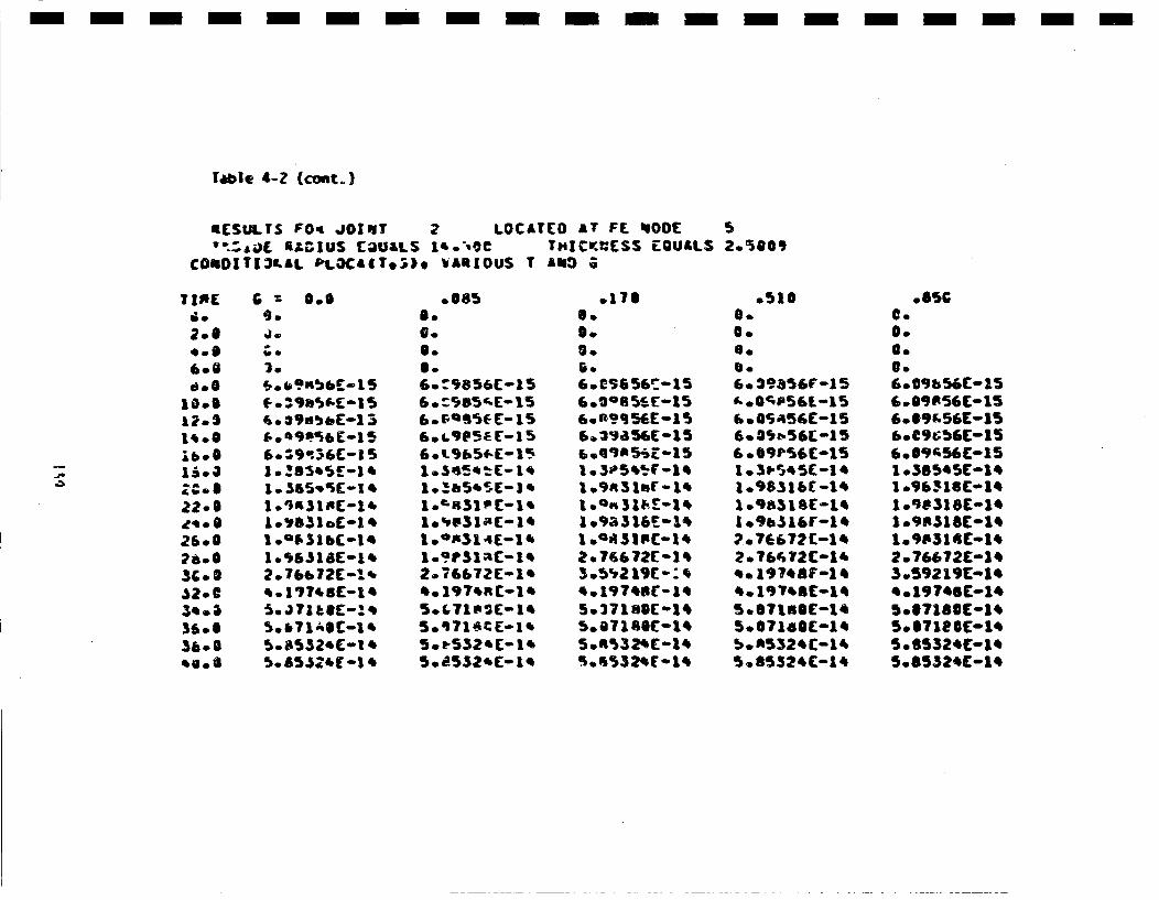
- m- m - - - - -m m- m -m m -m - m- m m - -
rabte 4-Z (costo,)
RESULTS FOq JOJIUT 2 LOCATLO *T FL qOOC 5'•:aJ ILG1US CaU&LS l'o'OC THJCW•[S$ CQU&LS 2.5800
COSOITI3LAL PLOCAITo.), VARIOUS T &AOG
TIME
2.0
6.6
O- -
l S-
22o0
26 *0
* C0
36.0* 00
& : Oo5
J.
6.$9'6C-1 5
I .i8SINC-14
1oi631bE-1.
l177'sE-le
S.£S.$524 -1'
00850.S.S.
6. 95S6[-15
1.•h5'5-i'
10oR314E-1e
2. 76672E-1A*.oJ97•RE-1A
5oESSZ.E.. i
.176S.S.S.0.
6.CS656[015
6.PY9S6EmlI6.q'3a56E-15
1.93155'E11
1 .9a316ro.1,
2.76;672E-1
S. •19756-"S
5027180[01S
5o0R1305C01S
Os100.
0.
6.39,85'r-l5
6.05a56C-15
6 .S9t56E-15
1.9631bE-1S
2o.73E62(-15
*. 19758F-1S5. 197'SE-1S
5.067140C-15
boA5325C-1'.5.85325C-15
.8sGC.0.O.S.6.09 bS6C"-156.09R56C'-156.S9k.56C-1S*.egt56C-156.S9•56E-15
I09SSS18E-15
l.9P316C-l'
2.?66?ZC-1S3.59219C-1'S *19?A8C-1SS007180C-1S5.871? SC-iSS *8532 SC-i'5.85S2SC-iS
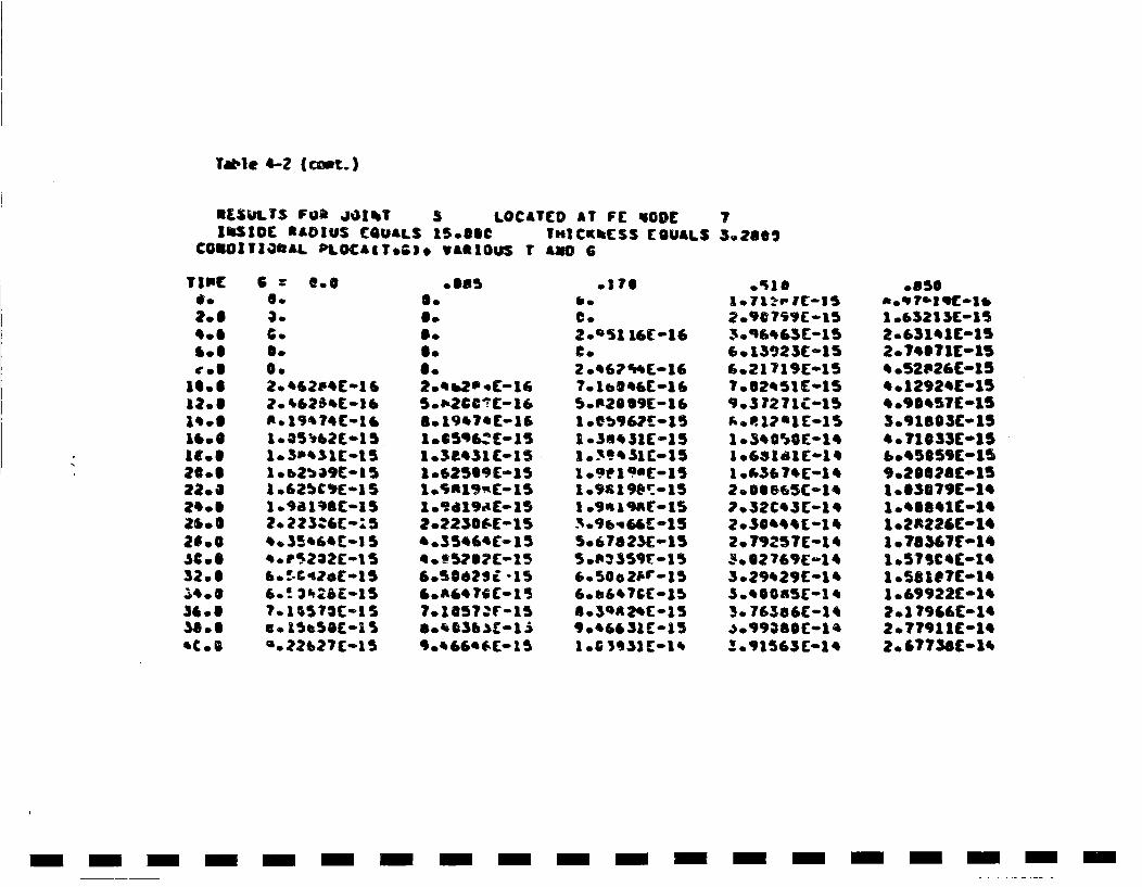
Tale 4-2 (coet.)
RSISLTS Faa JGIkT 3 LOCATED AT FE qODE 7lIbSIO S&DIUS EQUALS l5SSOC THICKhCSS EOUAL$ 3.2605
COUORTZOSAL PLOCAtT.G)e vASlOUS T AMO G
T IPC
S.O
oeg
12.01•°O
22.6a'o.
26.Sas0,.sco.
S.
O.O.2.0&e*2C-[1
2.1 •46?5*1
l.5a'31ColS
2. ?Z3•SC-.5,.35'*C[-1 S
6.!322?EolS
7.1 S5?2C-I SU * eSOSS-;5*.o?267(-1S
S.6.B.O.6.2o' b2J 'C-1S5.u266'C-1SS. 19*7*E-16
i .3ee3£ C01S1 .i2509C-151 .$R1•w- 151.9d19aE-15
*.35*S'C-015
&.5S42S•'-15S.A64 76C-I15
9.0SSeC- [15
S.l
C.
2 o*62F...-l67.1 ItS6[-1S(50•2B09E[-16
1 .Sb,61C-15
109.3 I SiC-151 og Sigt-iS1 o 9*C-iqSt'
I .961966[-15
S 0676 ?SE-155.Plt•3591•-,.S
9 * 6631 C015
6. 15923C-1S6.21 719E01ST.52*SlC-159.5 7271C-15
?.32C*SC-1*
2. 79257C-1*
3.*29*29 C014S.'SOnSS-1'
!.9i565E-1*
.656
1.63213(C-152.632*1-152.7*S?11015* .52•2SC-1S
3.I,18,3c-1S* *710S3C(015'.'SOSS9C-15
9.0SS2OC-1S
10.OSs*1£-1*1 .26226C.*1
1 .579C*C-1*1 .56117C-1*10.69922C-1S
2T7?911C01*2.0S?73fl-1'.
m- m m- - -m m -m - - - - - - - - - - - -m
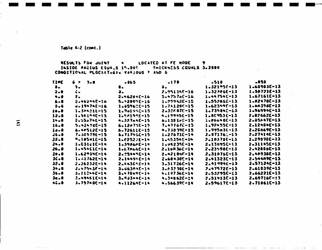
- m--m-m-m m-m-m-m----
Tabe 4-Z (coat.)
qf.Su..T• rO.i .Jbi•T LOCATED AT It( •00CIlbSIO(, *A•1U$ (C•UA.S l1,.o20(• TFIICKtm.SS L:GU&LS
C€OhIQ||',LL P;tCCZIT.).I va.•1OUS • Albl G3.ZSSO
0.0
1•.00
160
Z*lS
22 *z•olt
*1,S20 * SS•C *32.5
3,.5e3...
2.
C'.
6-'D51?C-15
l..'S1cl-Is
I .,+50C1E.-11 .G.2,3iC-t
2•. 202 3*-I 4
3.1 .!b4E..m1
S.8a.
3.~2~li
1.° G~6ZE-.15
1.E5o1'E-,1'I
102. ,1,",C£1'
3. 70.9I(-. 1'&. 20?(-1'
,.1II2EqC-1,
.175
1 .7'l2sf:-152.3!F•-07t-1S
.. 7a3 35[-1510.27671C-I4
1 0.7S23%C-1•2 *1lin 36C -1'
4. 197 36C -1S*.3'S62E-1S* .56439[-.11
.5101.3?1'5r-1310.32'C6C-1S
1 .5578S(-13
1 .8995s51.-
2.67176.-13
2.0130E5-13
2.23•98C-13S2.31 17SC-1320•1323C-15
2.55217(a13
.8501Io60905Co13I .96 ?2i-131.6?161l-13
1 .AAS3C-13
2.O2E62C-132005f4?£-132.12*0'C*13
?.27414C-1S2.2090C0-132.311 '5£-1S2.* 2 oC•- 13204A938C-l32. b•4RC-1 32.57124(0132 .61059C01S
2.6,?•1£-1 3
2.71061C-13
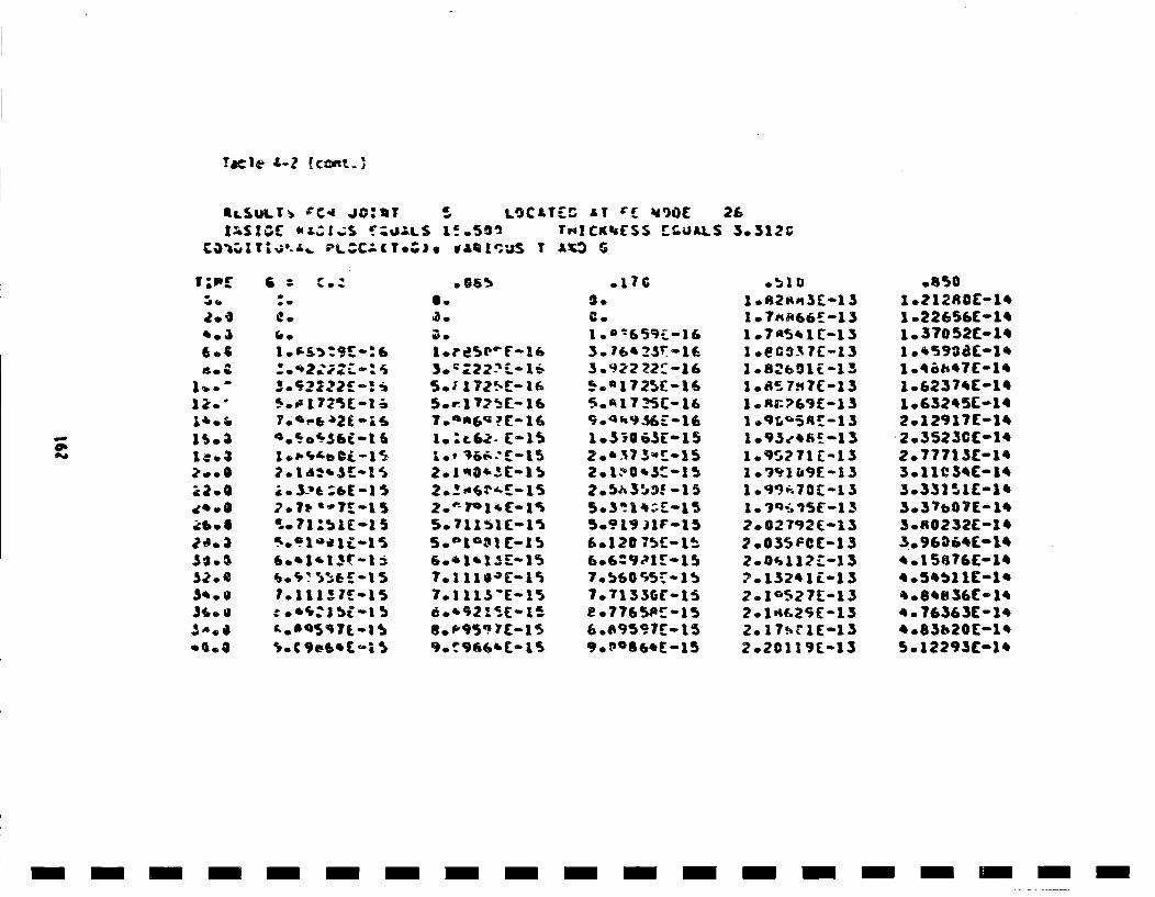
Yac:le z-? ((onL]
LgC&T[g AT r• •gO( 2£ILSULTa ~C4 jo:~r 5 LOCLT~ LY 6~ 26l~S1~C 4~LZI~.,.S '~l1LS L~.5Oi TnICkUI(SS t~.UALS 3.512C
c1T~.5~ PLZC.(T.). wA~I'~uS T A~ S
@1
3a.
6.6
tQ..Ib ti
L'Jo
I:.3
.5,. *
.6'.4
2.1r•'•"7r 1$
2.o1le7l.-15
'L.7Z,,;15-1 5•
* ". a 71.-I
B S C.:6.
5.. 1 7r•- 165.@A6Q?([16
1.' 62-['1S
2.1 u0'3E-Ib
6.'II[1
7.1 113"E-15
80, 9 5 q 7(-15
.ic0.C.I .e=5£1
3. lb"25-11
*. 17 '•5 - 16
6.20 373S-15
7.t130,,F-15e.77358!-aS6 .E"155 7C- i
1 .82a,3t-1 510*7*a66£-l3
I .eao' 7(-131.82691E-131.85 7H7(-13
I .R17S9E-13
1..V'1b0E-13
2.002 792E-1S2 .035F0C-13
2. 10 527E-132.1.If25E-132.o17!tlE-132.20 11'9t-13
.8501 .?128OE-1*1 .22656(-161.37052C-16
1 .ioht7C-141 .6237.E-1,
-2.3525CC-1•2.77713C-163.11 V3SI- 14303321C1-1'3.3?b07E0113.R0232£-1•3. 960 •01
*08'836E-1*40.76363C- 104083620C-1'S. 12293C-1*
- -- ----------------
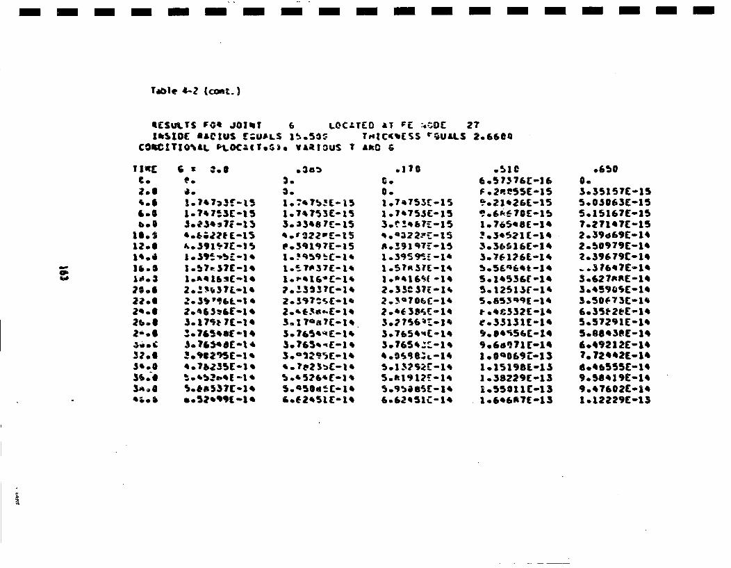
- - m-m- --- - - - - - - -m --- -
4CSULT5 POt 401~T 6 L.OCzrED AT PC .4.O0[ 272.6600IkSIOC RACIUS C;UALS 1%o5O• THtC<(CS %gUALS
COSCI(TIOjaL PltOC-gT.•). VAftIOUS T AftO G
I-
I.,2.6
46.6b.S
12.0
220621 o$26 * l2' .6
.1mol
3a .0'I.'J
L-?4713C'15
1 .57e37C01S
toe 3I '9£-le
2.'656E•II,-1
.S.7&5E1'-I 4
*.?e6235C-1 .
.3533.3.
1.T'.?53C-l530.33• 7(-15
1..PST•C- i1.P'16 7(- 1,
Z.397=SC01'
2'3sEo•?- 1,•
S.'5t26 $'C-I '
46.E2451E-1S
.170
0.1 .7'.755(-151 .7'753C-15
'o.322.•-l5
1 *395 9' . -1 k1 .S?•SIC-1*,
,2.33C 07E-14
3.7654qP..- 13.7654ZZ:-1 s* .O++ 9 SL--l4
50.1 312t-'.- k
S.920S51C-14
46.5 7376C-16F ° 2P.•55C-159o.21*26C-15Uo669470E-1S
1.765'8(-14
3o36,616C-14
3.7£6 126-14
S. 1,53Sr-l,5. 12531r-145 0853qC-1'a .4c3321-1ee.331S1C-149. eSs%56r-1*9.6s971E-14
1 .05198t-13
1 .38229C-131.550l11-1310.6*6R7E-13
.6500.3o 3515 7E-155.0S063C-155.151467E-1S?.271*?C-15?o39d69C01,2.50979C-1'2.39679C-1S
3o.E27AAE0145°45909$C01'.3050673C01'.
5.57291E-145088*38E-1446.4921 2E-147. 72",2E014tS046555C-1,9.5041 9E-1'.9.47602Colt10.12229C-13

Table 4-2 {(•t.)
ILSuL.TS F0O JO1t b 7 LOCATED AT FE ECOO 26z.66eeIb$1OC RAgiuS C&UALS I5.$@o TMICKmESS EQUALSCOSOITI•AL PlIOCACTeC,). VARlOUS T MaC 6
TI NC
2.e
'.8
13.612.oS
16.623 *aaoe
* tS
.32.0
35o13, S.
'elo
* : l-Ig.eo1.o',753C015
3.+31'7C-1 S'..eOtlCg-15
1.,e1'2(01'ao'. 54£01,
3°O5gSC7-lt
A. 12751C5-1,A. ?2s'e£-1A
u"0 i5$C-1'
Co
3.773qE-(15
3.j3,d7E-15
1.2 iqi -I'1.' 0163C- 1'
*.12575C-|4
0.70I.
3.C5AP7(-15
• .I3951t.15
10.As13F•t-l':P1 ".s'3Oe.E-1'
2 .3, 8 q2,- 1 '
'.125 7SF-l'
5o564iS4-1+
.0 10
0.1o?,'753E-151.o7*753(-153.oS3A87E-353.03tu7!-3566°2,57E-151o.21'21 C-I'1 .S623(-141o.S'35,E-1,2.33223E-142°3oI92(-1S
3.52c61 C01,3.76519C-1A3o5900S(ol,3.89338E01++o53962Eo14S.35579C-14
* 1e598£-1A
.850S.1 067972E-151 .7,753E-1l52.35049C-153.03'is7E-154080991(C1510.596,4(-14
1.58 C? 3C-141 .91033E-142.3q8'2E-le2oA0572C-14
3.8352?C-1tA. 03A50E-143o62071Cm014*.64SASC014S.57?5TT814S. 74530Cm-1q5.S2983C-14
- - -m - m- m - -m - -m - -m - -m - m- m - -
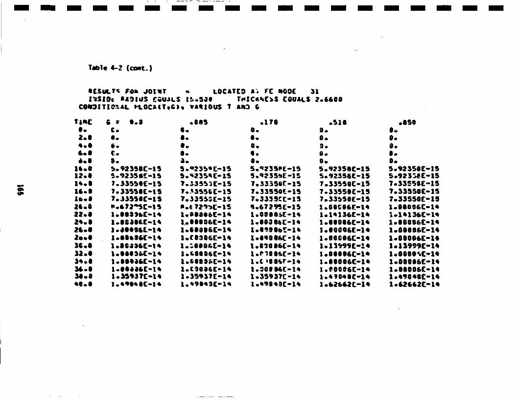
Table 4-Z (comt..)
SCSUIATr FO~a JO1qT ft LOCATCO LA FC NGOD 31Zl*SIOc 5AgIUS (GUJLS 150501 TI4IC•8BCS EGUALScOSII3TIO~m4L I-1.OCAIl'.G). VANROUS T AI53 G
0.2oi
.01.01
li.l1S *1? °I,*01U.01
2600
36.032.03* .0
C.S.
SoS
7-52355CC-I5?.33550£-iS
1.IG8ICC-I+1.SlS30E-L+
1.e953 SC-i
10S.S.a.
5.023 mE[-155..23SSm[-a5
7. S355S C-15
*.t 72i•C-1Soa..Oeeo-a
1.6SelbC-1+a.c~os'c-l'a o35937c-1'
.176O.S.S.6.
5*q235•(- 1 55.Q235•E-1!57o33350r.157.33550•-157.333 5CC-15m06729'5C-15
l.O7SS6C-l•
l.+oSl4C-1e
l.35937C-1'.
o510S.
S.5.9?358C-155.o92558E-157 .33550 C-i57.S33551-151.0S3cg0-15
.1.ee0eC-l'
l .O0@@6C-1'
1 .62,62Co1q
0.
S.
S.5o9235SE-155o923T•C-157.033556C-157o33550So157o33550[°151.S100'C01.
i000006[-a.
1013,99,01'a.S@S0rC01,1o0001'C-1,
1l.S2662£° 11

Table 4-? (o•at.)
&ESULT$ F• JCI•Tr LGCAT(D AT F[. •OD( 35ZmSI•( ILAQJUS tUALS l5.503 Th1C•?XSS (QUALS 2.660•
CO•ITI1=.L PLGC.I(rG), vaq1OuS T & •
3.2.e
13.012.61'0S1• .118 *2G08622.92dt0O28 *0S
2ao ;.50 *Sa. 0Se. *
Sq 0"5o.0
S: 9-€€.
6.1.7"Th3f-151.Tq, ?3C-15;.3"23E9-I 5
3.'?air-015
5.473 7[--1 S
b.61825£-15
1.72•&£C-1e
1.86 13&E-1.
g.37,11l-I1
2.55 189E-t'
0.
0.
l.•s75Sr-15
2*39 32e71(-15239O#690-15
1I°6E535(- 1*
1 ."2653(-34
2.*551 6;£-1 ,2. 551 ;C-1•
5.•65?C(-1'
0.0.
:.7,753f-151 .7E.753C- 152.3g,qr-15
1 0.'1731-151 .7266([-15
1 7o?%fIE-1'
1 .7%694[-1t1.9?, 15(-14
2.2?.3 3Oc-l,
2 .$519E•- 143.267 73£-1*
.510
°S .1135-,7.338L6C-1,1'.8C711E-1,1.*07090E-1 31o.25271(o131l.50963L-13107T9ROC-131l.8o376C-151o93153E-13
2.23?S2t:-15
2o5e035C-13?o5A,5?(-1 3?.53642E01 32.61132C-132.61R06C-1320.73593 (-13
2.9,21 66-13
3.05371E-13
.850
qo 70P71£-14, .57565C-1,5 .56335C-1,
1o.0137BE-131.103,0C-131 .128E5C-131 .29956E-13
1052633C-131o.64910£0-131 .56062C-151.61 761E-131. 71892C-15108398CC-iS2.021688(13200633CC0iS2.18696C013
- - -m - -m - - - - -m- -n- -m- -m- -m -
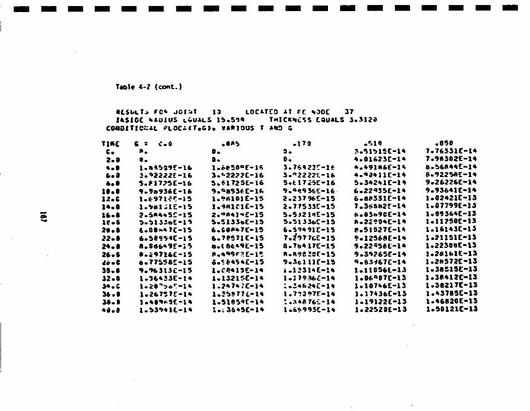
- m- n - -m - - - - - - - - - -m - -m -m -
Table 4-2 (ccnt.)
IL[,SbILT. FCm Jioi[.T 13 LOC&TEO ,IT FE ee3OCZmSlGC bLUJUS Lt.UAtLS 15o5'J0 T"ICK'uiA.S EQUALS 3.o3120
C005DT1C.,L-L PLOC-'(T.G), VARItOUS r' ak: ,G
TiRE
2.S
e06
1.0€1.60
12. C1eoS1106
it.0.208*2.680
2.6~o26.SO
6.
30•2222E -115o. 17•'5E-1 6
,*9a,,35-01&
?.°O*'"5?-1 5
*.5S•.54C-.. 5a. $S66•'9 g£S
,.o?7?5B~r-a S9.%h3 13•-I5I .•6'3S(--t4
I °,6q•5(--t'
3•.L22722-165.61725E-16
109al101 -15
'.'Sa7C£-152.7@13?'.C-ISs.I5Se3fl-15
Go(¶7 (°*E15
°1 .215':-I*
.170900.
3.n2222•-16Set 172•E-1l6
2.237%r_0152.715533C155.5-J2 Iqr-1550513 56,r-15
8.?b* 111-15
R.9e !cr-115
a .1231,£-:4
11.7?.397-1*
* . .• 48 6* ~ 1*
1 .6,993Ca.14
.510•.1515-1*
,.01123(01,
5.3*2*11[-14
6.224351-1*608p331-1I'7.36a12r-14b003b9C[-1*Is02290(1e°51 0271-14
90220 58L-1t9.392651-14
1011056L-1S
lo.191221-131o22520(-13
* 8507.763311-1H7.965021-1H
8.9225AC-1*9.262261-1*9.936*11-lH1°02*21E-151. 077991:-li1.093641-131.11750(-131.161,31-13
1o211051[13
10281b1F.-131.21.572o1431o38515[o131 .3S12C-131.5821 71"01310,*3785C013I o*1820Co131.50 1211-15
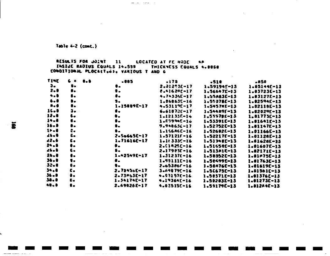
Trme 6-2 (cost.)
ISiuatS F0B J0)•T 11 LOCAYCO AT F( aa03r *PIhS$.0C EA0IUS EQUALS 14.553 TNICK'CSS EQUALS 'SOS..
CO•OIt1OmaL PL.0CA(r..,. vASIOUS 7 £JJO G
3.
.608..
1Cl.S3,..1'0811.6l.~o.
I"..
2'.S26,0Sas .e3,..
38 *'O..
6.S.
35S.
C.C.
Io
6.
go
C.6.
SoS S.OS.S.
S.S.
20Se5C-6517
1o.'2545C-17
.05 4.5( 1
2. 73NS3(01~7
2o69026El17
.1782.,12 2)£-17*.'3162Rt-1 7*.7-33iE-1 7r1.O6S63[*16
40531@1q-17
Y. 9 *863f.-171.Ii6A6C-16l.571218r011.1* 333r016
2.13g3[11o3123?(01610.•111C016
3.o6 76t8-16
' .6'; 57C-16* .1q364[01
.S1S1.59194£-131 .5664?C-13I .b5AS$£o1 31.05?S78-13I.5t573E-1)
1.512?12C13
1 .5221?E0131.52 )SC-131.51'j56C-1310.513R1C-131080SS2C01310.58•99C0131 .50A?6(0131 .SC675C*11 .SO571C[131 .SS2SSC0131 .5a11•C-13
.850
1 083723C0131 .63127E-1310025qC°131o02118C-13I 03202qE-131.S1773C-15
I .S1l~rC-131.S1114C-131.S1128[-131001628([email protected]
1.0619[IS-iS1006I19C1-1S
1.01 3731Cii1.612 7C-151
I- I - -I - -I - -I - -I - -I - -I - -I - -I -
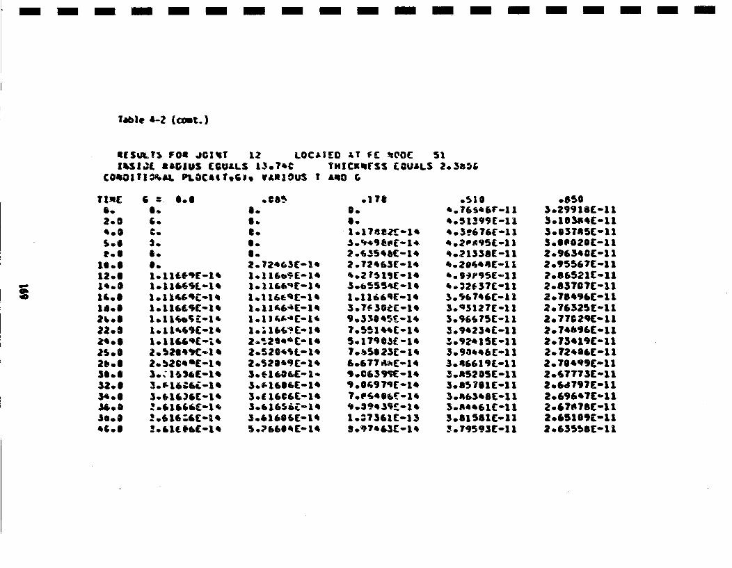
tble 4-2 (c•t.)
IISUSlt$ FOml JG|IT 12 LOCa;rlo AT FIC 'uOO(t 51IlSIJ( rAIGUS (GULLS L3.7•C THICKmtrSS EGUALS ?.35&.r
€@O•Ofrl.Al. PLOCA(Tr.G3, VAnlguS I LO G
S.2.S
SIe
12°01'.SI6.S
22.5
2S, O3* *O
"C.0
E - O.6
a.a.
e.
1.11"5IC-I,
IOI1614.-I'
1.1 1"665-1,
3.. I l&Cq-i •
0.S.O.6I.2. ?2.63C-lt.
1.11A64C-1a
2..2166IC 1Z.11204fl i
l.S.16S6E-1,34 16C6C(-15
3.61606( i..1
30616566 C-,
.I7S0.0.1 o 17482 •Z -15
2 .7256(1;51£5.2 T? 1SC-1,S.6.55sC-1,10.1166q5.-1 e
9.330S5$T-l,?.S51lss(01s5.17903(-15
To t.5S O23'- 15
9).395.5;r-1s
g.9?.&31t-i,
o51O*.76~ssV-1 15.5 1399E-i1
5.2PA95£~-1I5.21338Ci11s.?e',.C-011'.9*P95E-1 15.32*37C-113.i67'6t-1 1
3.92515(oll5.9Oss6 C-i1
5.RS6S1C0115.n505 1C11
3.R635 C-I11
3o81561(oll3o.S93S1-lR
.850
3.16355C-113003785C0113.0S020C-'1l2.9654CC-i I2o9556?C-ol1?086521C-112o83707C-11z.7.s•bC-112.76325C-1 I2.77029C-0112.74b96C-112.73519E-lI
2.714q9C-11
2.677735-l12.6dT97E-112.69&'7(-1 12.67B?8C-112o651SSColl2.63SS8(011
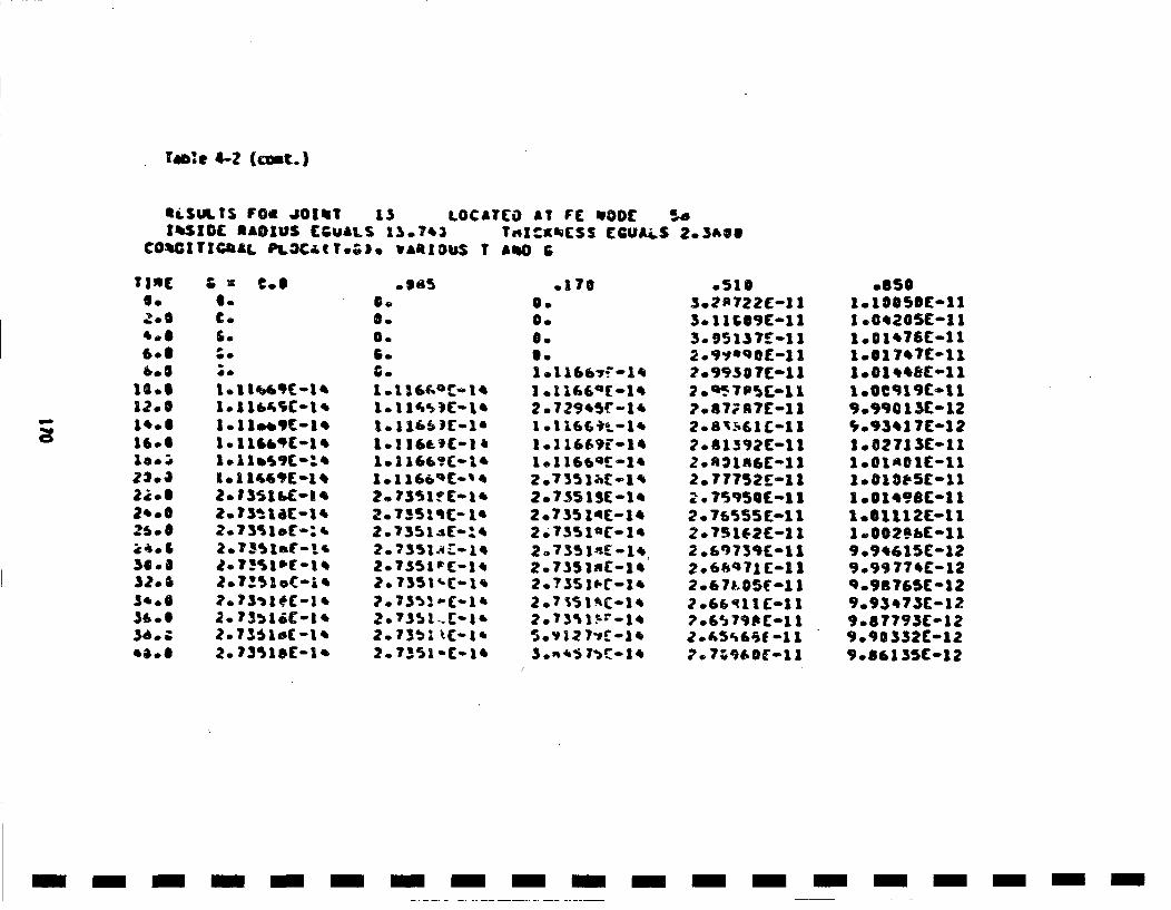
Table 4-Z (cont.)
SLSUIN. I FOB JO|•! 13 LOCA1CO LT F( MO00[ .Z4SIOC rAIOUS (CUALS 13.?.3 Tn|:gi(ScS CCUJi.S 2.3406
C0O•IT1GOALI PI.CaT;.;). vaRlOU$ T AmlO &
TinEOo2.6
6-0eOs
12.0
1.60
12 *6
1.*0
23 .0
32.o&
34o0., o8
Co
;0
1.11".$c-m.1
2. 13514(-1
2. 73516C-1 4
0.
Soso
1o11"@c)m-1,
207351qC014
2.07351I'(m1,2.o7$51 C-I'
2.73'aa EC-1
o1700.0.
3.1 .1166~-'o14
1 ol16Eat-l'
2.•729,ISC-1',2.?o14C.).-1'
2.735 1;•-l'
2.7.35 InC-l.2.o735 1I.C-1'
5o'D12 7'C-14s.73i51-.•;1
.510
3.9g5137£oll1
2.99eq07-11
2.87iR7C011
2.6 1S96C-11
2o77752E-11
2.076555C-1 12.75 1E•2-1 12o.8973fl-112o6s'71C-11
,.6~790 C-11
7.o?;'u!e-i11
.650
1 .0e205C-1 11o01t76E-11
1.017e(1
9og9C13C-12',.93417E-12I .02713E-111.Sla01C-11
1 0 01,.8C-11a
1.01112C-111 .002'bC-119 .94615C-129.99 774C-12q09876 5(-129093e73C-129.67793C-129.90 332C'12
- m- - - - - - - - - - --m m-m- -m- m - -
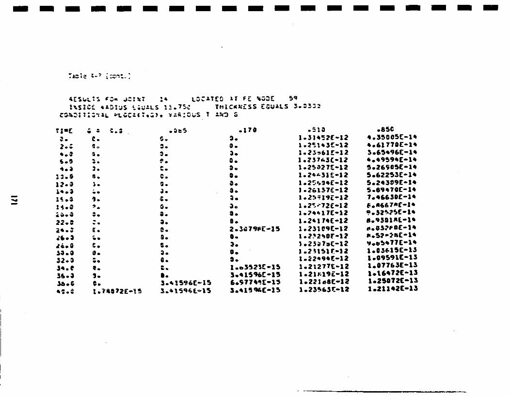
- - n- m - m- m m- n - m- m - m -m n -n- -
1•S1C•. qwL•3U$ € .•LS I_!.75• Tui1C.KESS EC•jALS 3.
'.3
a'.:"@e3
.33.e
32.3G
$o
S.
C. 0
:0
S.
'C
S.1.A0o E1
d.
3.3.
C.
2.
C.
0.
3.
3.0.
3.0.
.1703.
3.0.0.0.0.0.
0,.
2. 3C 7q•-a50.
0.
1 .o3•23E-153.q iqC-15
1 .31'12?-121 .?s1*5t-12
1 .?3763£121 .2¶027E012
3 .26137(0121 .2•1,E01210.2•72C012
1.2'1 7(0121 .231O'9C0121 .?'Zq0r-l2
I .25151sC012
1 .22'9.t-121.2 12 77[12
1.2?1e8(-121 .23•s5[0.)2
.85€
*o61 770[-1'3.65'96C01•
5.12253E01'
7.8qq70(-1'
70.9301R-1'
1.05591(-13l.07763(o131lot~72C0131.25S72C-1S10.21142C013
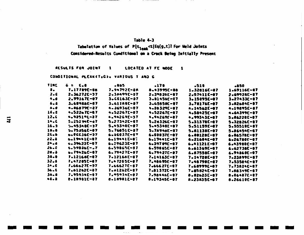
Table 4..-3Tabinlatoam of Values of PltekctIEq(g.t)l For Meld Jotmts
Csade'ej-lts Cnd~ttlom1 o- a Crack 1,e1mg Inittally Present
EtL[SULTS roe JiO[iIT I LOCATCD AT FC tlOOC I,
CO•OI1IrGmaL PLCAK(T.ItG. VAStROU, T AqlO p
2.6
6•.4
I2•&
161.SI8..21.0
32.6I
3* °€
380S
7. 17 r89C-0
2.991617-S7
*.•522e7C.'O 7
•. ?5aS61C-O7
6. 3q•2?3oS 7
b. 71 t2C6r-O
•1.7215 C -07
1.661612C7-S7*°513•(-0T
* m557.9,7T92C-.O
3.CO61SC-87
a. J4936E-07.. 52261T@.•O7
5.? 73'2C-ST
5.7E451C-8?
E.59E,23C-86o5•62fl-S 7
7.012161S(-677.' 726 S(-S 7
To.'5D3'[email protected]
*0170
2.5'8 ?61C-07
3.6155K-S(T4 oSe32fl 08T
4.5Z267C-ST* .94269E-S 75.2s32EC@-0
50789agE 087
6•800037C 07
6.7~eP27C087
7.G4627C-07
7.°61372(oeS7
S.193*5C-@T
.5101.32616C-6T;2.57a11C-t73. 15095E-S73.?S17'(o07
*05b'25C-4T* .q34S[C07
5•51159('4?5.51138(-076•.OS12SC-076•2164[°0-761.41121C-4T61.613&9[°iT&.57558(C4i7. • '721iC0S7
80 02862$C[-S7B 023835C00?
•8551.6191 16C-IQT2*.69928C-@?3o2?.33C-073 .8Zb84C-S7
* 044399C0875.S&22S(uSI5032S26C0S7
61.SL4STSCST
61.26780S00?04 .39S0S CS7
61.62738(-ST6.94860C-S77.23899C-S77.$35S4(08?
707324610C-S
- m- m - -m -m m -m - -m- n- m m- m m- m m- -
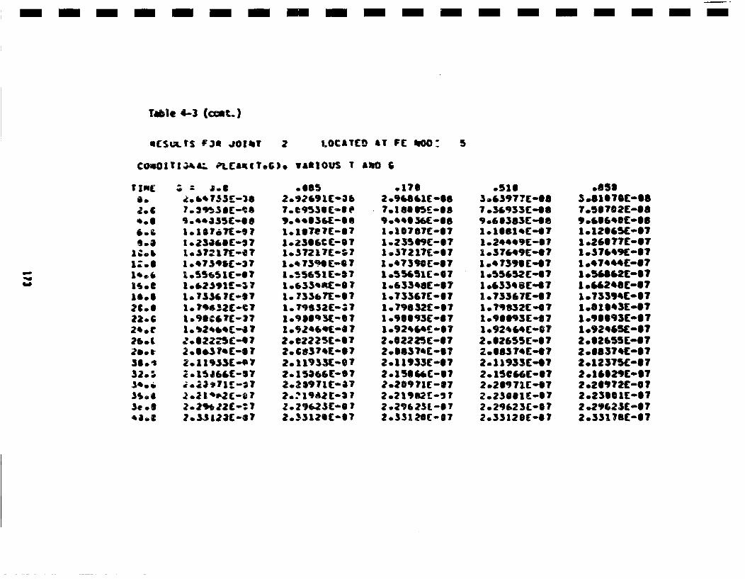
m- - - - - m- m -m - -m - -m - -m - m- n - -
6 (5wIS F3@e jOKn, 2 LOCATCO AT FC toO0: S
COamOITI3.A•. Pl.C&RIT.G). VARIOUS I £•JO 6
TIoC
4206'Z.5
15oe
22.°c26e£
32.0•.1g0 li.3,,,3e0@4'a.,
1-42301'SC-7103721 T-oeT
1 .*?391C-37
1. 7354 i-si1-?90632C-$
2.0l$7'(017
*-ISIE6(-57
2.2l9*22C-:7Z.0L3Cm672-:
* S85
,o..S36(-SS
1.Z3SSCC-ST
1055651 (-5710633'A-0710 733e1't-S71. 7952C-;7
2.CB37.(-072.11933t-O?2.15266C-S72.25971 c0aT2.?196210-Si2.29623(-8?2033125C-57
.ITS
7.1S11lC0089).0.'.6(-S8
1.23509C-671 .37217(01S71.'73WC[-071 55651C0071.633*8[-17I.733E7C-I?l.79832C-57
2.063 TAC°0S2.1933C-07201. I •1C-1Sii?.20€9 ?1I-172.21912C'5 720 29•231-S1T2.5531 20(007
.5163.43971C-S87.36933(ot6
1.o6038C-S8
1 .S7649C-OT1.67395(4t?
1.43368(-071.73367C-ST
1.00832(4[7
2.11933C-4)?
2.230011-572.29623C-072.3312 SE-S7
7.5S?02C-,'09 .ll656lSCo08
1 .24SlgC-IT
I .674C-I67I.-
I .G4A2611C-17
1.90093[-171.92,0(51-72 .e2655CoO7
2.I123T5C6-I
2.16S2SC(-Ii2 .26O9P721C- 72.231101i- S?2 .2962)C-672.33178(-07
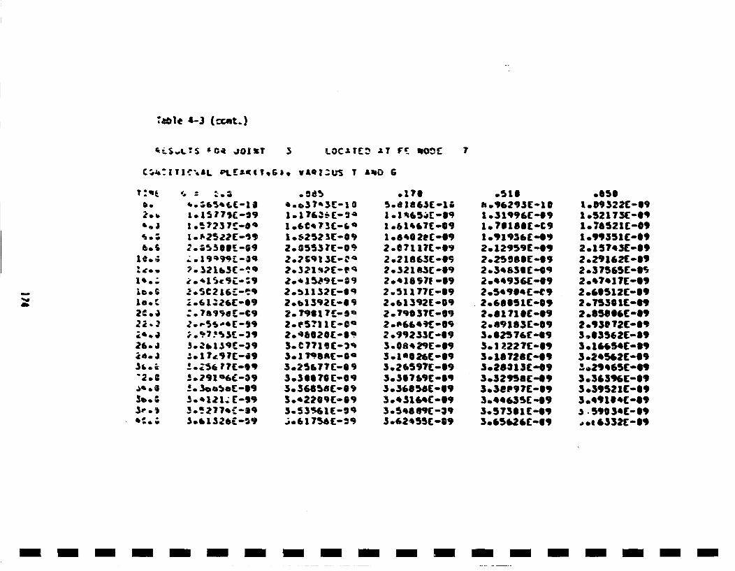
7m~1e 4-3 (rcnt.)
~LS.,LS ~O4 J012? 5 LOC.:Tt• .T F'. mIOOc 7
C•,J&:K[TR•'-.L PlLr~*((TgG~8 VAQI.U'S T £tjD 6
be
6.3
6S
1e.'•2C..)
"2.S
Sb.
3,.);
1.15 ?,E7' (- 2 9
1.92Sfl7'C-:19
:?. l5SqOeC-c9
3.•b159C-39
-:. 1 ?e9?Ce[-
5.•277sr-s9q
2o055) ?C-0'.
,2o.15.•9L-092.•1132C-692.b1392L.-i 9
2.79S~l17-9a
3oC77Ie(-2"3.1 ?9S AC-Oa3.25177C-6 9
3.S3.%iE-Sq,•0 7$6'r26-
.176
1 .61i&7[,..S9
2.071 1?C-692.2 1S63C-05?.•321B3[ -69
2.51 177C-1192.61392(-09?.79SO3TC-09
2 .99233C-693.0S82'P-69
3.?6597C-69
30337 S9C-Sq
305S8 S9(-393.62455C-89
SI .'96293(- 101 .31996(0091. ?S180(olC91.'91"J36(-092. 12959C "O692.025 SSSC-69
2 .3*636 (-09
2.81 ?111"09208q183C009
3.6]22276(°9
3.26313C-093.329568C 493.36P97(0119
3.57361 (-693.,Gke16C-609
.0531o.9322(-691 .52175(-Si1.7S521C-@91 .99351E-692.157*3C-692.2,3162( -6,2 .37565C-S5
2 .&0512C-692.755601C009
2.93e T2C-693 .!13562C-1193. l6S4C-(6O93.2e5sC-O9"-02965C-69
3 .39521C:°19
:s - 590 3*C-S9.,,, 6332E-69
- i-i - - - - -n-m i -m i -m n-i- -i- -m-
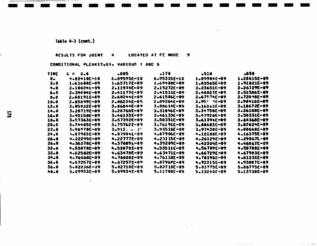
- - - - - - - - - - - - - -m m - - - -m -
Table 4-3 (cont.)
RESULTS FOR JOIWT * LOCATED AT FE ROD[
COWOITIO•uAL PL(AK(T.G). VARIOUS I ARC 6
0.2.6
6.06.6
10.6
16.S18.620*0022.0
26 *
30 *32.6
36.656.640.6
10616SSE-09
2.59104E-092.60 191E*'092o85•99E0093.0S59S2E-053.028719E-S93.04515BE0003057363E-S9
3.7a'SSE-09
'007903E-09422295E009
*. 36376E-S9*.53078E-09*.62582E-094. 76088E-'094. 67257E-095.0022S6E-39
.065£•. 09595[:-1 0I *63717 C:0092. 11934C-0 92.411?77-09
2.86234[C-0 9
3o28768C-S93.461 32 C-S 93.5 7392 C- 893.*75762r-s 095.912; -*.14.079041-0940.22777 C-094037S89i009*.53078[:°09* .63470C-S 94. 76688[:0S9
5.002710C:--09500993,E-6,
.1706.95315E-101 .6c400E-S92015272E-692041511E-S92.61S06E-1•2 .89284E-S93.000614"[-093o31046E-093.46133C-093 .58351C-693.761 91E-093.955 1aCo09400790661-694.231 15[E-S94.392069C-094.53511ZE-S94o6 3471£--094.761 18E:o09* .8796PE-S95.027 10C-095.1 i7S0[-09)
.5161.,998'C-o,1 .83565E-092.23651£0092.48827E-.9
3.16802 (-093.5475SE-093047926E009
3.97430E-09
4026129[:°09*.42384[:°09*.567S9E-S9*.66729[:009* *78196C-S9*092315E-095003775E-095.01324 0(-09
,.85610.20615C.S910.91821C:°092 .267291[-S92.51586(-092072S4ESP12 .96416C-093.16672[°09
3 .50331C-@9
3 .82624[019*.0066SE-S,*.16375C-S94.290671-694 .4(867C009
* .67983(49* .6123CE609* .93867E-0095006775[:°695o13750[:009
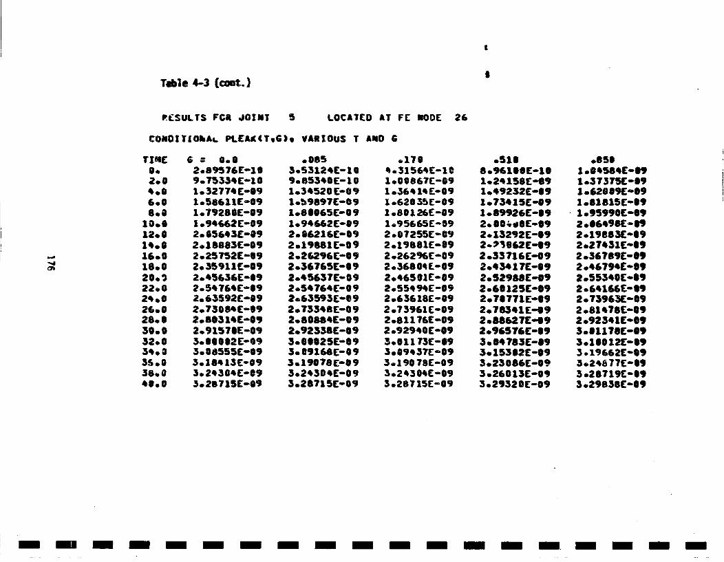
I
Tble 403 (coxt.)
RL•SULTS FCR JOINT S LOCATED AT FE NODE 26
CONDITLOhA... PLEAK(T.G). VARIOUS T AND 6
"-4
TINE
2.04..6.008.0
10.012.01*.S
20. g22.024 *0
28. S30.032.0034.0035S*038.046o0
6 = 0.02.89576E-109.75334 E-1 0lo32774E-091.58611E-091.79280E-091o.94662ES092.005643E"-092.1S883E-092.25T52C-S92. 35911C0092.45636E-092.54764E-S92. 63592C-092.73084E-S92.80314E-092.9157SE-093.SSSS2E-093.008555C-S93 *184~13 E°0,3. 243 04E-095028715C-09
.0853.5312 4E-109.85340(- 101.34520Eo091.59897E0091.80065C-091.94642E-S92.86216E-S92.19S81C-092o21;296C-S09
2.4563 7C-092.54?64C-092.63593['692.7334E:-.0 92o80884E-092.92338E-093.°S0025E-693. 69166C-093.19078E"093.243S4E-093.28?15E-09
.1704o31564-1011.00867C-091 .36414(-001o£2635E-091 .80126E-091 .95665E-692 .S7255E-092019S81E-092o.262%6[-092036804L-092.46501E-092o55494E-092.63618£-0n92.73961 C00920811?6E-092o92940E-093.011 73E-S93.•094 37E-093.190 78E-093.24304E-093.287 15[-09
o51O8.,'100£-1S1.24158E-691 .49232E-09l.73415£-091 .69926E-09
2 *13292E-092-•3962E,-492.33 716E-092043 1 7E-!92o52988C-092.66 125E-S92.760771E0092.7834 1E-69
2.96576E-093. 04?83E--893.153S2E--093.23086£--093.26013C-093.29320(-09
.05S1 .S4S84£E091.3 737510891o.62009£009
1 o95990[0092 .0649SE-0,2 .19883£0092 .27431E-S92 .367B9E-092 .46794£00S92.55340E.S920.64166E0S92o.73963E-S9
2 .92341C@093001178C-*,3.1S012£0893 .19662ESO93.248 77£0S93 .2S719E'093 .29838£009
- mm -m m -m m -m n -m m -m m- m m- m -m - -m -
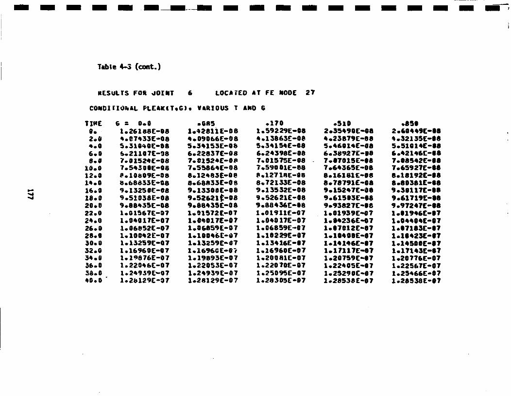
- - - - - -m m -_ -_n m - - - - - - - - - -,m n m
Table 4-3 (coot.)
RLSULrS FOR ~JOINT 6 LOCAIED AT FE NODE 27
COMO|II]OkAL PLEAK(T.G). VARIOUS T AND 6
*.1
0.2.04.06.0
10.0
12.0
16 *018.020.022.024.0260828.050.032.034.036*00360040.0
& -- 0.0l.26188C-06
.0•74331C-085.31S'0C0[00(•021107C-987.001524 (-087.o543 001E-0S
8068833E-089.13250S[-S89.51038E-089) .88435E-OS1.001567E-071. 0401T160071. 06852E -071. 10042E-071. 13259E-071 e 16960[-071.19876E-0710 22046E-0T1l• 249.39 (-0 71.2b129C-07
.0*51.,42811 C-OS4,,090'66(-0 8
6.2283 7C-087. 01524£-0ft7.55864C-0 88.124831--088.68833C-0 89.,13300C-089.52621 •0089.8S,35C-081~0 1572 c-071.040171[-071.06859 (-07
1. 13259E-071.1696GE-S71.•1989 3E-O71.22 053E-071024939C-071028129E-07
.1701.592 29E-084 .1 38636-085.34154E--S86.243 981E-S87.01575E-087,.590 [email protected] 21E-S89.88464E[-S11 ,019;11C-071.040 17E-071 .06859E-071,,16229E-071.13416E-0 7I .16960E-071.200 81E"071.220 70E-07I .25095E-071 .28305E-07
.5102.35490('484 .23879E-S850460 HE'08603892 7E-SS7.17S15E-@87 .64365(°088.16181E-S88.78 791E-089. 15247E-SS9.615S3E-S89.93827C'081.01939E'071.S4236E-071.S7012C-S7101SS0SE-S71.141466"871o17117EaS?1.20759E-471.22405E-071.2S290E-0?1.28538['07
oSSS2 .E0449C-S84.32135C0S85.510141£-S86°42146C°|87008542E-087.65927C-SSS°18192E-S8S°80381E-S89.31117C0089 .E1719C0S89 .9?247E-S81 .S1946C0S7
1 .S7183E-S71.10423E-071014500E"671027143C0871.20776E-071.22567C-0710.25466E-071.28538E°0?
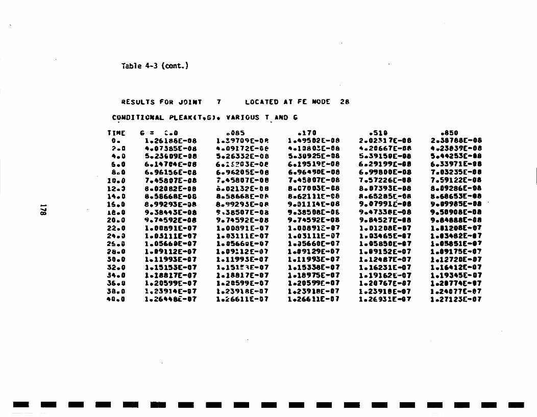
Table 4-3 (ca0nt.)
RESULTS FOR JOINT 7 LOCATED AT FE NODE 28
COUDITICNAL PLEAK(TG). VARIOUS T AND G
TINE0.
4.006.08.B
10.012.314.00
16.0
22.0024 *0
2800
32*00
366038.0040.0
1.26186E-084.07385[E-085.zs'09C-086.1'7@'C-0S6. 96 i56E-087. 45807E-088.02082E-0S8.5866BE-088.99293E-089. 38443E-089o78592E0081.00891C-071.0S111E00710.05&60B-071009112E-071.o11993E0071.15153C-071°18817E-071 .20599E-071.23914C-071 .26448iS07
* 0851.•9709E-004.09172E-005.26332E-086.:£?03E-006.'96.05-0087.45807E-0 8o.02132E-08
8.'9923C-0R9 38507E-089. 74592E-081000891E-071-03111E-071.0566OE-07
1.11995E-07
1. 1881 7E-071.20599E0071.2391 RE-f01.26611C-07
.1701.49582 C-OS4.1080"..-085030925E-08601 95 19E-086.964 90E-087.45807E-088.070 03E-088.62111[E-C8
9.385081E-oOE90745 92 C-081 .00891-071.03111C-071 .a5660E-071.o09129E-071.11993E-071.15338E-071 .18975[:-071.20599C'071.23918E-071026611E-07
.5102.02317(E-0S4.20667E-085.39150 C-OS6.29199C-OS6.99800E-087 .57226E-088.07393 C-O8S .65285C-S89.0799 IC-O89.4733SC"089.8452 C-08S1. 01208SC-ST1.003465C-S71005850C-071.S9152C-S7le 1248 7[071. 16231Co071.19162E-571020767C-071 .2391SE.071.26931C-07
.8502.58 788 C-OS*.23S39C-085044253C-S86.33971C-SS7.03235E-SS7.59122C-008.09286C-088.65653E-1S9 0 099SSC0089050908C-08,o84S88C'0810|S1208E'071 .63482C-S 71.0SS51E0071009175C-071 .12720-0871 .16412C-071.19345C-071 .2S77SC-S71 .24077C-S71.271 23C-0 7
- m- - -m - m- - - -n - -m - -m - -m - -m - -
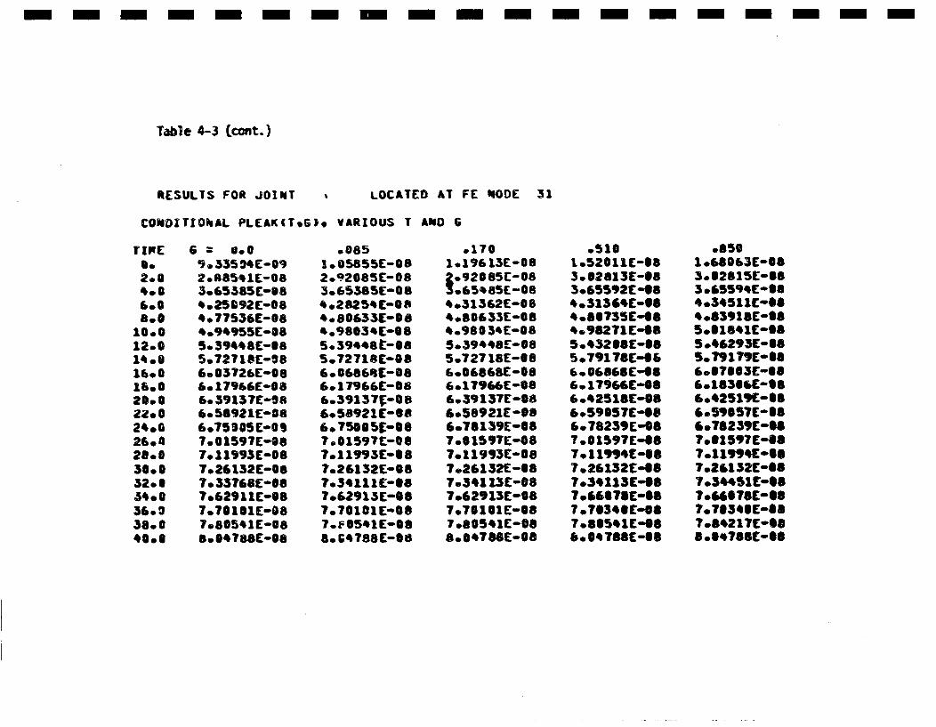
- m-m-n- n-m- m -m n-m- -m- ----- m
Table 4--3 (cont.)
RESULTS FOR JOINT • LOCATED AT FE NODE 31
COMDXTIOhAL PLEAKITeG). VARIOUS T AkO 6
rzP[2.04.06.0a.,
10 *012 *0
16.018.020.02Z. 024o*026.028.030.0320g54*0036.238.040.0
9.33594C-092.R85I1E-O83.6538551-IS4.25092 C-0S4.775361:-OS4.949551:--05. 394481:-US5.727181:-O86.037261:-0S6.o179&651-O86.591371:-Os6.569211E-OS6.75,051:oOS7.0 15971:-OS7.119931:-087.261321:-OS7. 33768(008S7.629111[00S7.701S1E-087.505411E00SS. 047581:00S
.0851. 058551:-OS
3.658555E-84.2S2541:-OS4.806SSC-S8* .9803' C0085.3944St-S85.727181:-OS6.06568C-086.17966(0086.3913 7•- S6.58921(0086.750055-0S7.015971:-OS7.1199 31:0S87.261321:-OS7.34111 C-OS7.629131:-S87070101 1:-S87.40541E-S8S.0C47881:-SS
.1701:196 131:-0S
S905C-0080654S5E-08
4.313621:-0S4.806331:008O4o980 341:0OS5.39448[:-0S5.727181:-O86.008681:-086.17986610-86.391371-086.569211-SS6.7813910087 .615971:-O87.119931:-0S7.26132E-S87.341 13C0087.629131:-OS7.701011:-@S7 .805411£°088.04788 1-.00
.5101.520111:-US3.S2613E-S83.655921:454 .313641:-OS4 .567351:-SB4.982711:4850432S8C-SS5.79178E£.066006868(°466. 179641:-S60.425181:-OS6.59057£1:486.782391:-f87.015971:-OS7.1199•41:US7.261321:467034113E-o07.66S78£-SS7 .70340£:oS87.835411£-OSS.• 04 7881:-OS
.8501 .680631:-IS3.328151:-SB3.655941:-US4.34511018-O4.839181:485.s1S41c0085 .462931:0SB5.79179C-SS6.17603£-08
60.425191:-OS6.5,057C0O86.76239C0067.31 597 C-O87.11994C-SS7026132C00870344511[0OS7.66S78£'08?0703401:-OS7 .842171:-OSS8.S478SS-0S
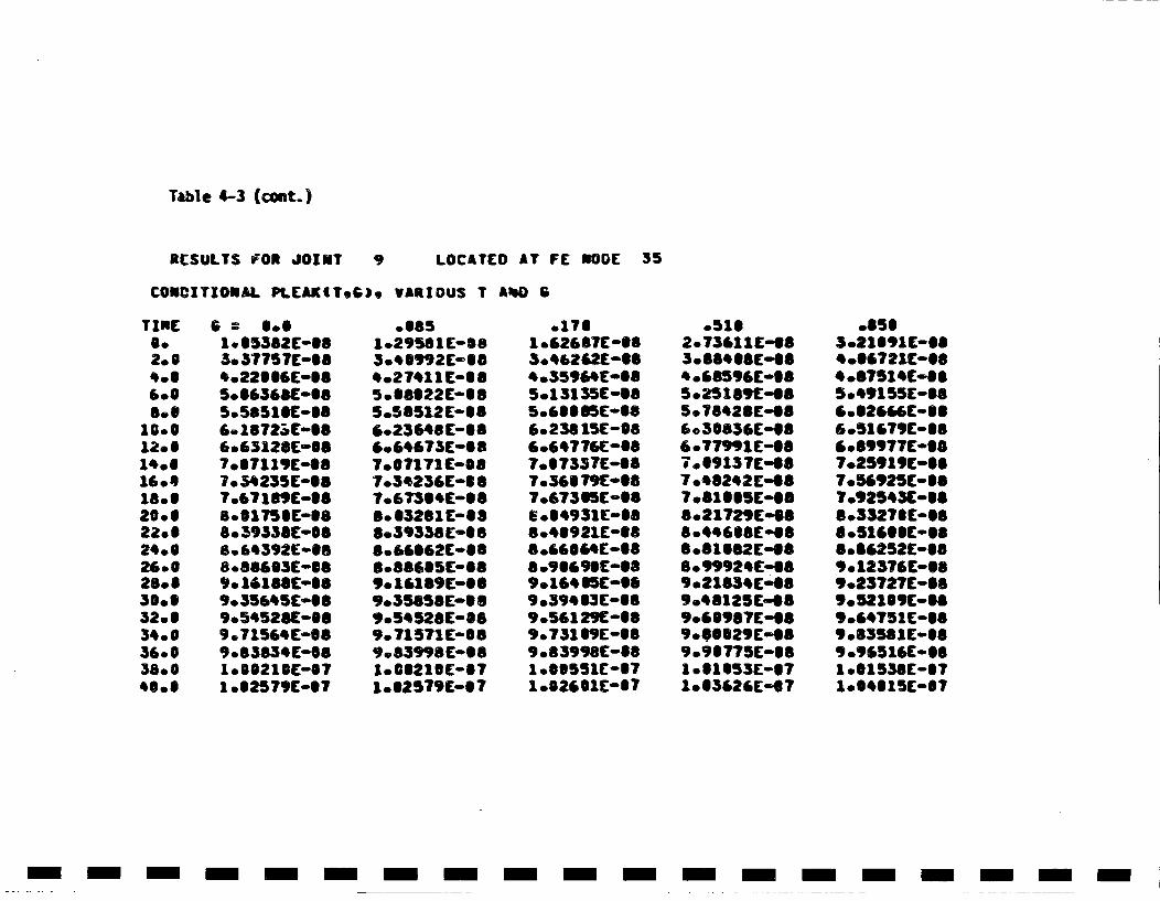
Table 4-3 (ccut.)
RESULTS FOR JOjmT 9 LOCATED AT FE NODE 35
CONDxTIONAL. PLCAKITG). VARIOUS T Aid) B
TINE
2.0
600
10.0
14.6160918.620.6
24 *26 *S28.630.632.534*0036.038.040.6
1.05382E-SS3. 37757C-S84022006C-S85.056368C-S85.5851 SC-086.01872.iC-086.63128E-SS7 *0711 9E-887.o34235C-087.67188£-08
S8*39338C-S868*64392C-6S
9. 161688C009.035645C-SS9.54528110089 *71564C-SS9.83834C-SS1.00210SC-ST1 .62579C-S7
.5851.29581£C-SB8304S992C-SS40274111C-S85.S8822C--08S505512C-..86023648C-886.64673C'S S7.67171E-S87.3 423 6C-S 8
8.63281 C-88S.39338C-88S8066082C-88
9.0161891C-SS9.358561C-SS9054528C-S89. 71571 C-889083998C"081.0021SC'871 .62579£-8 7
.17610&62687E -883.46262E-SS*035964C[-S85013135E-S8
60236 15E-O86.64776[°087.57357C-887.365e79C-SS7.67355C-SS* 0S4931C-S88o48921C-888 .66064C-S8
9.394 53C-889.56129C0589.7310flE-889.83998C-S8
1002601E'47
.5162.73611C-683.88468C'88
5.25189C"485.78428C'486o 3S836Ew4S6 * 77991E-68V . 9137C-fl7 008242C-88
8021729E-68880.4468C8[00
8.099924 CO8S,.2183'C-oS9.48125 C-0S
9*00829C-OS
1003626['07
.856S.21591E-S8*088721E-SS4.8751 4E-65.491 SIC-Se6002666(-886051E?9C-8860899?77(°07.25919E-S870.J6925E-8S70925431[0888033278£-88
S.S6252C-689o12376C-S89.23727C-68,.5215,E-SS9084751C-S89083551E-8890.96516E-0810851538C-071004015E-07
- - - m- m - -m - -m -m m - -m -m - -m - -m-
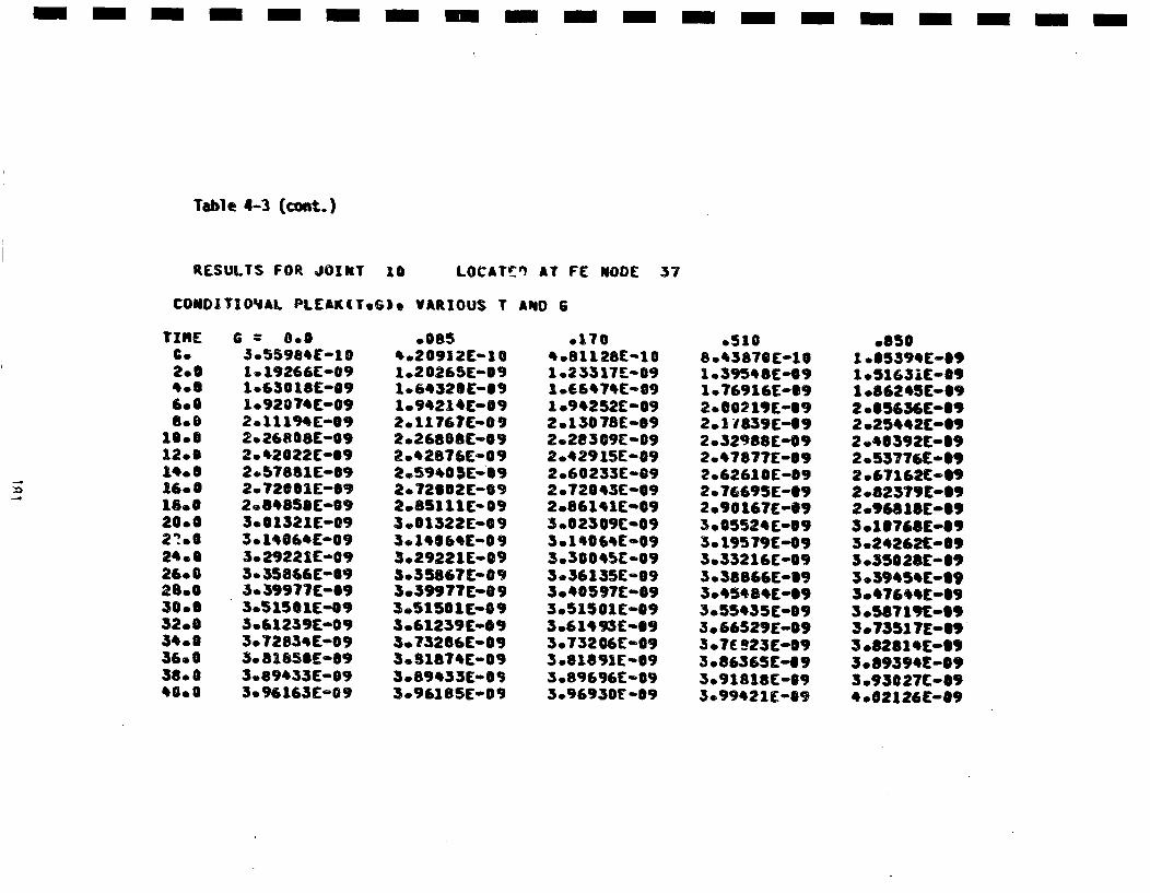
m m-m m ----- m- m -m mm m -m m -mmm- m
Table 4-3 (cost.)
RESULTS FOR JOINT 10 LOCAT[• AT FE NODE 37
CONDITIO•AL PLEAKITG), VARIOUS T AND 6
TINeC.2. S
8.0
12.014.S16.018.020*002%0024 *26.028.0300032.0340036.038.040.0
6 0.0
1. 19266E-091.6 30 ISC-693.92014C-092011194ES92.2680 8E-092.42022C-S92 .578S1E009
2.S4850C-093.S1321E-093. H064C-093.29221E-093. 358G66-S93. 39971C-S9
3.6125,C-.0,3.7283qE-093.0SXS5SE-093.89433E-093.96163[009
.0854.20912E-101.20265E-091o6432SE-S91.94214(-092011767C-09
20q2876E-092.5940 IES920T2SU2E-092.851 11E-093.01322E0093.014S 64C'093029221Eu093035867C-0 93.39977E-0 93.515O1E-O93061239Em093°?3206C-093o81874(o093.89433E-083.96185('09
.1704.81128E-101023317[-09I .E6474C-091o.94252E-S92.°130 78E-09202e3o9E-092042915E-092060233[-092072S43C-092°86141E-093.02309C-09
3036 045E-093.36135E-8930.40597[--093.S1S01E-093o61493E-093.732 06C-093 .81891E-693 .89696E-093.96930E .09
.5108.43870C-101o39548E-091 .76916C-S9
2.1 1839E-692 .329688-092.47877E-S92.62610E-S92.76695E-S92.90 167E-S93.05524E-S93.195 ?9C-093.33216C-S93.o38866E-S93.45484E-S93055435C-093.66529E-09307£ e23c0mp308636SE°|93.9 1818[-093.99421E-S9
.8501.S5394E-69
1 .S6245C-6920.S5636C-S92 .25*42C-S920.4S392C0S920.53776C-S92.67162(-S92 .82379(e-92 .96SISC-S93 .1176SC-S93 .24262C-S93 .5502SC-S93°.39454C-S93 .47644C0S930.58719C-S93.73517E0093.8281 4E-S93.89394C-093°93027(°094 .02126(-09
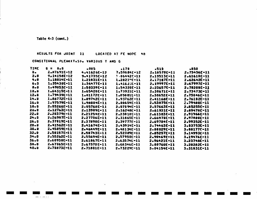
Table 4-3 (cont.)
RESULTS FOR JUOflT 11 LOCATED AT FE NOPE q8
CONCITIOUIAL PLEAKITeS). VARIOUS T AND G
TIME2002.0
6.0800
10.012.0
16.018.S20.02200240026*0028s030.032.034003600380040.0
6 = 0.02.87691E-129. 14158Eo121o1881,Coll1.35430C0111049055C-111.64 S15(!111 .79e39C-111 .88772E-111.97579E-112.05266E-112. 12763E-112.20379E-112. 26~9 [-I112. 370 19C-112.41562E-112. 45859C-112.50157E-112.552b2E-1 12.60930E-112.67T065E01 12.70873C-11
.0854.41626E-129.o 1735C-1 21.21S31C-1 11.36477E-111050339E-1 11.65420(0i111.81172E-111.89742C-111.'98004E-1 12065748E-112.139@9[--1 I2.21254E01 12.2 7706E1 I2.3 7890E-1 12.41674E-1 12.46449 CI112.50 743C01 12.55694C-112.61867E-1 12.6737TO-i112.71801C-11
.1707.59684[-12!-06442Y2-111 .2821c(0111 .416LE0111.54320E-111.73921E-111 .8508tL-1l1 .93762E-112.000654E-112.07094E-112.16248E-1 12.23010E-112.31865C-112.39777E-112o43914 ColI2.48134E-112.52309E-112o.5795C0-ol12 .65574E-112.68346E-112o7322Y-oll
.5102. 16570E-112.10513C-112.o17187E-112.o1999 7C-112 .23157C-1 I2.36671E-112 .58652 C-l12.41166E-112o53075E-1120 51663C-11I2.61051E-112.61383E-112.66970C-112.69784C-112. 74463E-112o80029Coll2.85257C10112.90469E0112o96421C1ol3. 00-60E-113004154C-11
.8502.75454C-112o.61610C-112o.62642Coll2o.67997C-ol1
2o73473E-112o.75046Coll2.76102E-11:o07VW8V[-1
2 .85255C-1Z2 .89478C-112 .91966E-112 .97800C-112 .99352E-1 13. 03753C01 13.68177(-113.14993E-113 .19476C-113 .23748C-1 13o.28282E- 113031831C-11
- m -m m -m m -m m - -m-n m - -n -m m-m m-
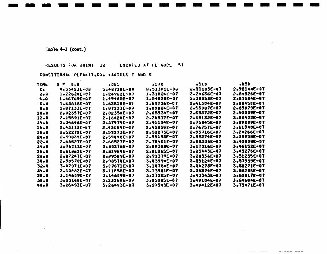
- m- m -m- m- m -n m m- m- m - -n -m m-m-
Table 4-3 (cont,,)
RESULTS FO• JOINtT 12 LOCATED AT FE 'dOIE: 51
COkr•ITIO~dAL PLr-&K(T.6). VARIOUS T LikD G
C.2.04.06088.0
10.012.014.0
200022.0240026.026.030.032.034.0350038.040.0
G 0.04. 33423C-G81e022624E-071 .46709E-07I .63818E-071 .871S33-072.02357E-0 72. 15591E-07Zo 34646E-O072.43113E-072.52272E-072.59039[-072.68527E-072.7SC11[-072.81861E-072.87247C°072.9s570E-073.07071E-073. 10882E-073.14609E-C73.23166[E-073. 26493E-07
*00855048718 C- 01 .24962E-0 71.49465(-071.6381RE-071.67133E-072.02358E-072016420E-072037974E-B72043164E-072052273E-072.59040E-072.68527C-072.60276E-072.81'964E'02.89589E-0 72.98570E-0730 C7071C- 073011858C- 073.14609E-G073023168E-073.26493E-0 7
.1708.51381E-081.31024E-071054628E-071 .69736E-071 .89824E-072.05534E-072.20517£.-072.41194E-072 .45850('-072 .52273E:-07r2.59193E'-072.70401E-072 .80380E-072.81965E-072 .9 1379C-0 73.03994r-073q10 784E 073.1 3501[-Si3. 27265E-073.250 05 (-073.27543E-07
.5102.33183E-072.24636C-072030558C-S72.41304E-072.53987(-072.65372E-072.65132E-072.75045E-072.76757C-072.93716E-072o99274E-173.o08306E-673.17016E-S73.02544 3C-073o28336E-073.35124E-073.34273E-673.36574E0673o43343('073049104C-073.49412E-07
08502.92144C-S72 .84526C-O72 .67584C-S72.80450C-S72.65679[-|72.93039[-073.06422C-073.69209(-673.11940E-673 .24206E-073.39958[-073.42SSC-0730.46152C-075045276C-003.51255C-073057959C-073.58271C-ST3. 56758 (-@73.(6.217C-S73 .64684C-073.75471E-07
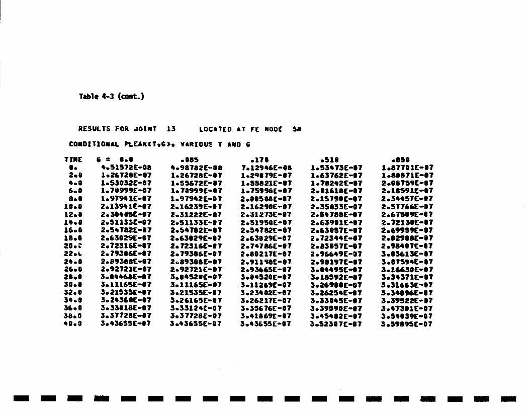
Table 4-3 (coat.)
RESULTS FOR JOINT 13 LOCATED AT FE MODE 58
CONDITIONAL PLEAK~ITG). vARIOUS T AND C
TINE
2.04,.06.0
16.012 *0
1800
20. 222. L
28.030.632.0
360038.0C0.0
4.515T2E-08
1.*53032E-S7
1. 97% 1C-072.13% iC0ST
2.51133E007
2 .63029E-072. 72316(00ST2. 79386E0072. 893868C-ST2.92721C-S7
3. 21535E-073. 2q36SC-S73°[email protected]£0073. 43655E-07
60854098782C-S81 .26728C-071.55672C-S71.70999E-ST
2°16239C-0T2.3 1222E-072.5 1133£°0 72.5C782oeIT2 .63S29ES072. 72316E-6?2. 79386E-0T2.89388C-072092721£-07
3.11165E-073.21535E-S73.26165W-ST3.33124E-0 73.3 7728E-073 .C3655C-S07
SITS70129e46£-0
1.55821(-07
2.16290E-072.31273E-072 .51950E-07
2.630 29E-S07
2.S021TE-072.Y1198£0072 .93665E-073.04520E-073.1 1269E-073o23402C0073.262 17E-003*356?6E-073.18 69E -673.0 365.5E-0T
.5101o.53473E-071.63762£..471 .782C2C-07
201579SE-6T2 .35833E-'0T
2063901E-ST2.63S57[-572o 7234~41072.83057£E-S72 .96649E-0T2.98197E-S73.04495E-073.18592 E073.26988£-0730 26254C-e 73.33045C-873.39590£°07
3.52307E-07
.8501 .87701iC-0T1.88871E0072 .SB759C0072.i8591C-072 .3*457C-S72.577681['072 .E7509C-60723.7213SC-572 .69959[°S72 .829688-S72 .9SQOT£-073.03613£C-Si3 .S7594C-07
3.3C371E-S73 .31663£00S73.34896C0073.39522E-0?3.47301C-S73.5C039C-003 .59895E-07
- i-m--i-----i --i --i --m i-m-
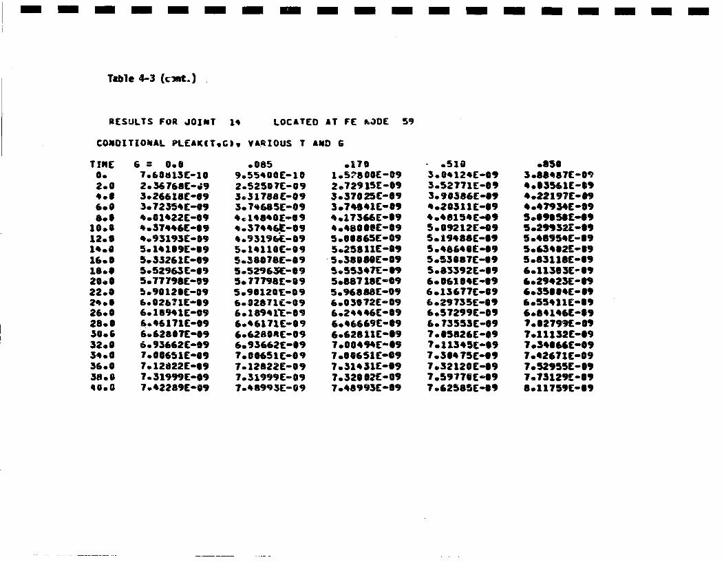
-- --- --- --- m --- m -m -- m m-
Table 4-3 (c•xmt.)
RE:SULTS FOR JOINT 14 LOCATED AT FE vk3DE 59
COMOITIONAL PL.EAK(T.G~, VARIOUS T AND B
TIRE0.2.9
6.08.S
10.012.6
16.6
20.02200
26002800
32.053 0036.05800*0.0
6 =0.67o60813E-102.3676810G93.26618E-19
4.001•22E-09,.37446C(009*.9 3193E-S9
5.3526 1CwS95052'963E-695.77798E-S9b.9012SE-09
[email protected] E-0970 •2289C-09
.0859o55400[0102.52507E-09S.31788Cm093. 71685E-09* 1 4840£E009
,.37446E-S9*093 1964E- 095.1'110ca0095580 678(0095.52963•o095.0777/98[-095.9S1201[-096.02871t°096.189'1T-S9604~6171 Eo096.S280RC-og6.9S662C-S97.00@651 --097. 12822E-097.31999(0097o4R993E-,9
01701 .57800O-092.72915[0-093.37025C-693.07q8*1E-09*.17366EmS9
5.00865E-095.258 11C-095.38080[009S5.55347E0095.887 1SE'095096888[0096.03072E*09
6.'6669E-,96.6282I1C-09
7.31451E-S97.320012E-097.48993E009
*.5163.04124[E093.52771E-S93.09*386E-S9*.20511E-S94.48154(0095.09212E-095. 194S8E-695.4864S £49S.53087C-095.S3392[0096.061064E0S,6013 677C-0960.29735E-096.57299E-S96.073553E-097.065826C-097.11345C-S97.30475(.g97.32120(-097.59770[-097 .62585E"49
.8505 .8S587[-09
*.22197C-09* .4T93E[-O9
50.29932E-09S .4S95*C--0950.653S2£- 095.831 1SC-096.113 3£- 596029S23C-S9'.356004c006.55,11C-096o0'1'6c-59700279,C-089?.11132C-S970.34066C-0970426?1(0097.5r2,55E-0,7.73129C-S9801175,c.-.,
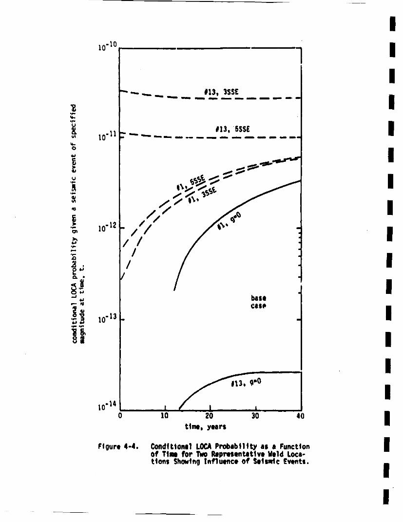
I10"I0
.4-.9..
.4-C
4.D
4,
Im
9.-.9-.0
2.0. *
9-.*Ii99-
*ii
10"11
1I0"12
IIIIIIIIIIIIIII
tlme, years
F~gure 4-4. Conditionall LOCA Probability as a Function Iof Tim for Two Representative Weld Loca-tions Showtng Influence of Seismic Events.
sensitivity of joint 13 to seismic events. Additionally, the stressesin joint 13 are seen to be more largely Influence by a 3SSE seismic eventthan a SSSE event. This is because of the stress values in Table 1-3,which, in turn, has to do with variances in the stresses due to seismicevents.
Overall, the results of Table 4-2 and Figurex• 4-3 and 4-4 show that theprobabi1lty of a sudden and complete pipe severat~ce (LOCA) is very low(10"t per weld Joint per plant lifetime given that a crack is initially
present), and that the influence of seismic events is not large. (Joint13 is somewhat of an exception to this as far as seismic events areconcerned.) System failure probabilities will be dominated by the highfailure probability locations, which generally show a relatively smallinfluence of seismic events.
Leak probability results were siummarized in Table 4-3. rigure 4-5 showsresults for Joints 1 and 13. From this ittis seen that the probabilityof developing a leak is much higher than the corresponding LOCA proba-bility. This is because very large cracks are required to produce aLOCA, whereas shorter cracks (which occur with a much higher probability)can produce a leak. Figure 4-5 shows that seismic events have a very
small influence on the probability of developing a leak. Additionally,calculations were performed for joint 1 that considered all the tran-sients in Table 4.1. The leak probabilities were virtually identicalto the cor'responding results that included heatup-cooldown only. Hlence,the lesier expected influence of radial gradient stresses on leak protie-bilittes that was mentioned above is borne out.
The results of Tables 4-2 and 4-3 can be coubined to provide systemfailure probabilities, and the probailityl of a seismic induced LOCA.Equations such as 3-9, 3-10, 4-1 and 4.2 would bee used. It is impor-tant to recall that all results in Tables 4-2 and 4.3 are conditional ona crack being initially present (in each of the weld Joints). Hence,the probaiblity of a crack being initilaly present must be included (seeEquation 2-25). As motioned in Section 2.3.4, the probability of a
187
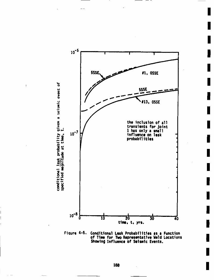
III
10" 6
~eo
p.. .j
'p 4,h
'Ii'•
IIIIIIIIIIIII10"8
time, t. ynr$,
Fiqure 4-5, Conditional Leek Probabilities as a Functionof Time for Two Representative Weld LocationsShowinO Influence of Seismic Events. I
II1e6
crack being Initially present in a weld i$ about 0.1 for the weld vol-umes consideredl. Hence, the absolute failure probabilities will beabout an order of magnitude less than the values included in Tables4-2 and 4-3.
In the case of no seismic events, calculation of the systembilities are particularly simple. The use of Equations 4-1provide the following results (which include the correctionbeing initially present).
fai lure proba-and 4-2for cracks
c umulative probability of a suddenand comp~lete pipe severance inlarge primary piping (no seismicevents) IUt
3.7x10:13 (lower bound)*1. 7x10 12 (upper bound")
tcumulative probability of a leak
in large Primary piping (no seis-mic events))
8.8x10"8
9. 4x10"7(lower bound)*(uppar bound06)
Corresponding results that include the influence of seismic events requireinformation on the seismic hazard curve 0(g), as shown in Equations 3-9and 3-10. The consideration of such results is btyond the scope of' thecurrent work, and will be generated as pert of the Load Cosbinatione Pro-
gram (George 81). However, results presented here on the influence ofspecified seismic events indicate that the problNibty1 of a simultaneousLOCA and seismic event is very low; even when compared to the alreadysmell number presented above. Results in Figure 4-5 indicate that theinfluence of seismic events on leak probablitites ts also very small.
The estimates on leak and LOCA probabilities in the primary piping atZion!I that are provided tImediately above are quite small. The leakprobability In the smell subset of piping of .10.'6 per plant liet'e.|•
is somewhat low--but is felt to not be unreasonable. The 6 order ofmagnitude difference betwesen the leak and LOCA results is ,ome ,D.:,,L
*Result for Joint 1 - highest probability Joint.
189
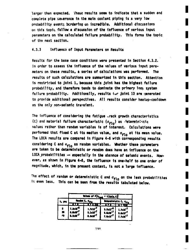
larger' than expected. These results seam to indicate that a sudden and Ucomplete pipe severance in tihe main coolant piping is a very lowprobabilltty event; bcrdering ui• incredible. Additional discussions Ior, this topic follow a d'scusslon of the influence of various inputparameters on the calculated failure probability. This forms the topic Imof the next section.
4.3,3 1nfluenc,• of Input Parameters on Results IiN
Results f'or the base case conditions were presented in Section 4.3.2.I
)n order to assess the influence of the values of vartious Input para-meters on these results, a series of calculations was performed. The mIresults of such calculations are sununrized in this section. Attention B
is restrticted to Joint 1, because this Joint has the highest failure Iprobability, and therefore tends to dominate the primary 1loo, systemfailure probability. A•dditionally, results tvr Joint 13 are jleneratedto provide additional perspectives. All results consider heatup-cooldownn
as the only non-seismic trurnsient.
Tho influence of considering the fatigue .rack growth characteristics(C) and material failure characteristic (oflo) as ,4eteninitic
values rather than random variables is of interest. Calculations wereperformed that fixed C at its median value, and 0f 1o at its mean value.The LOCA results are compared in Figure 4-6 with corresponding results Iconsidering C and 0fl1o as random variables. Whether these paramters
are taken to be deterministic or random does have an influence on theILOCA probablitties -- especially in the abstnce of seismic events. How-ever, as shown in Figure 4-6, the influence is one-half to one order ofImagnitude, which, in the present context, is not a large influence.
The effect of random or deterministic C and 0f~o on the leak probabilities Ik, even less. This can be seen frog, the results tabulated below.
i_ _ _ __ _
Ia ~if S, Iuh-1 selw-' s.s~ir'
-- -- LI1. I n --'rqH
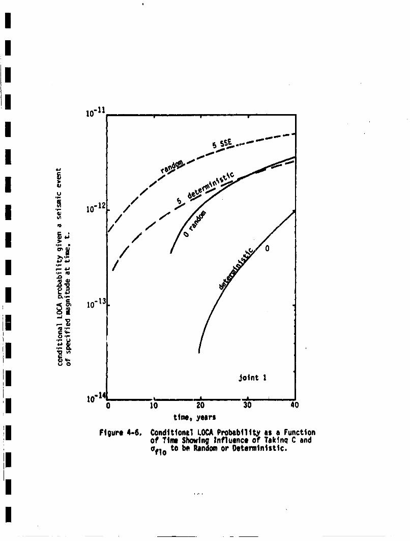
10" 1. ...
/
J~i/
-13
10 . A A " -0 10 20 30 40
time, years
figure 4-6, Cond~ttonal LOCA Probability as a Functionof Thuu Showing Influence of Tak~nq C and0flo to be Random or Deterministic.
The fairly small influence of considering C and 0f 1o to be random
variables is most likely due to the fairly small variances of these para-Imeters (i.e., small scatter).
The Irnfluences of the pre-service Inspection and proof test are shownItn Figures 4-7 and 4-8. It is seen that both of these procedures have•
a noticeable influence . The omission of either one raises the failureprobability by an order of magnitude. An exception to this is the influ-ence of a proof test on the leak probability. As shown in I Igure 4-8,Ithe omission of the proof test has no influence on the leaks. This isbecause the proof test will not "weed out" the internediate size cracksthat can grow to produce a leak. The proof test does "weed outu a signifi-cant portion of the cracks that could grow to produce a LOCA. The differ-
ence between an inspection and no inspection on the 10CR probabilities(Figure 4-7) is approximately a factor of 20. This is approximatelythe value of (PD)for large cracks that could grow to produce a LOCA I(see Figurt 2-1). The influence of 'Rnspcction on the leak probabilitiesis somewhat smaller, because PND for cracks that would grow to produceIa leak is somewhat larger (because the relevant cracks are somewhat e
smaller). These results show that the valL,•s of the failure probabilities Iare influenced by the pre-service inspections and proof test, but thatonly roughly an order of mangitude is involved. q4ence, the calculated
failure probabilities remain very low.
In order to gain additional insight into the Influence of other fac-tors on the calculated failure probabilities, numerous additionalcomputer runs were made. A comparison cf the results was based on theIvalues calculated for a 40 year period (I.e., values at t * 40 yrs.).The input parameters were varied from the base case conditions as mdi-1
cated on Figures 4-9 and 4-10 which show bar graphs of the various results.Conditions were altered from the base case one at a time. The alteredconditions are indicated at the bottom of the figures, with the cortes-ponding leak and LOCA probabilities shown In the bar graph. The follow-ing ob:arvations can be drawn frcm these figures:
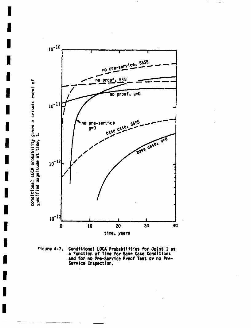
i0"I0
4-C
*1
U
4,4n
'U
.~ .
~ .1-.f- 4.h
2
'-I
.~ .~
0 10 20 30tinie, years
40
Figure 4-.7. Conditional LOCA Probabilities for Joint 1 asa Function of Time for Base Case Conditionsand for no Pru-Service Proof Test or no Pre-Service Inspection.
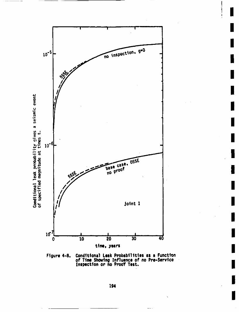
II
, II
I/I
ii IU
'I.- I• I
.o-,
CO '4" I
jolnt 1!
I I'0i 10 2•0 130• 4(
tIme, years IFigure 4-8. Conditional Leak Probabilities as a Function
of Time Showing Influence of no Pro-ServiceInspection or no Proof Test. l
194
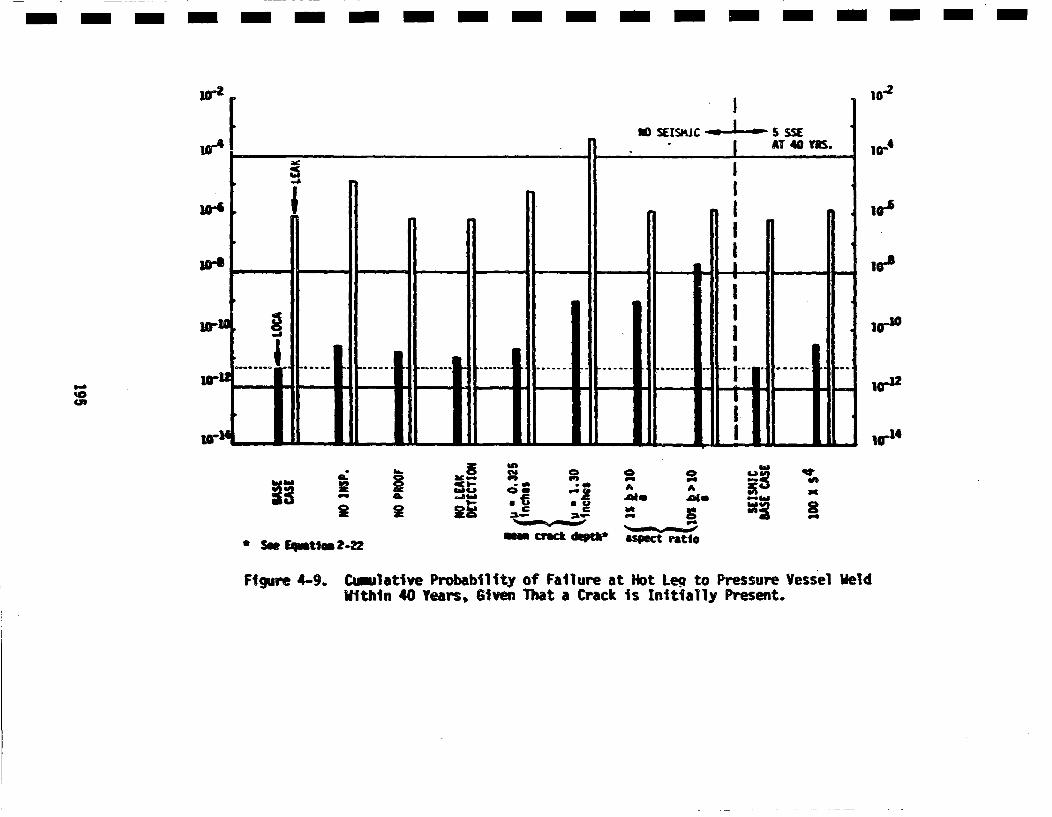
m m m m-m-m m - - - -n- - -m -m- - -
10-i
ir~
'0as~5.32
1.-i.
CF, PS
C.Eu U
C C
- mck d'Kh
CPS tWo
* Se E~mmtiem~
Figure 4-9.
~-22
Caalative Probability of Failure at Hot Leg to PressureWithin 40 Years, Given That a Crack is Initially Present. Vessel Weld
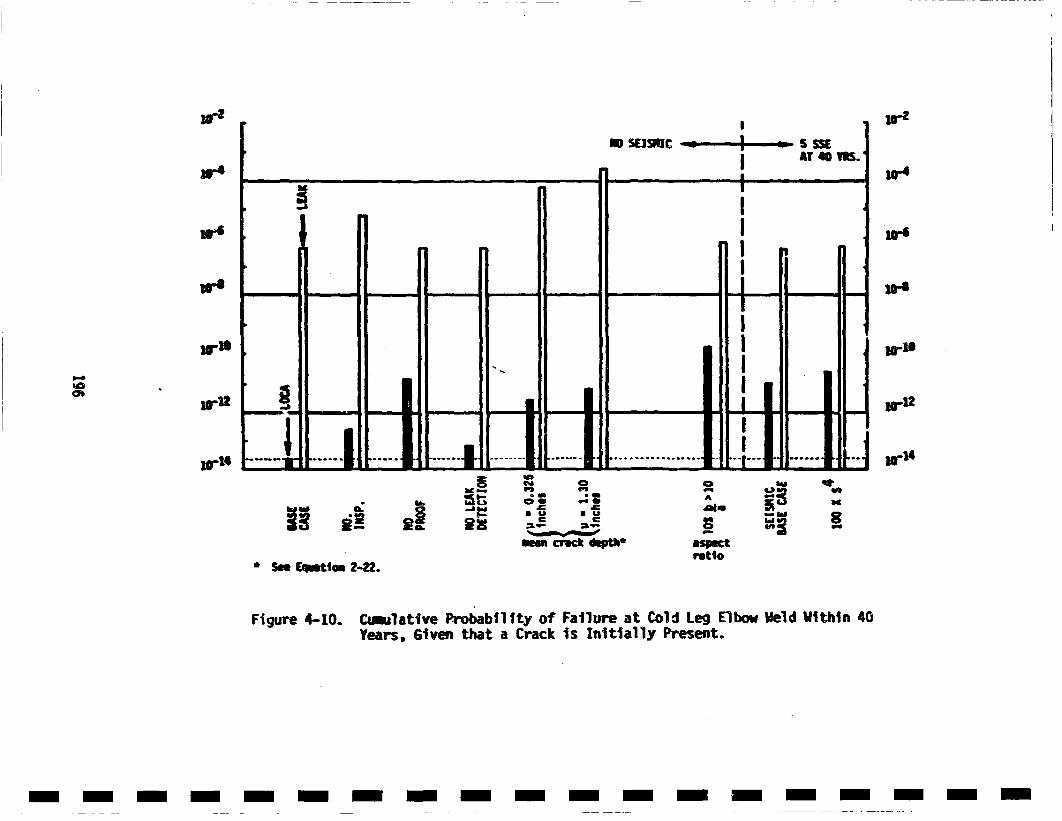
Wa
'.4
34
we
3.4
3-'
34
~0
ag-I
344
iltIs.
aiC~ 01 us 0
0@ Me
meest crack dinptls aspectratio* S... fElmtto 2-22.
Figure 4-10. C~mllative Probability of Failure at Cold Leg ElbowYears, Given that a Crack is Initially Present. Weld liithin 40
m-m -m- m -m- -m- -m- - - --m -m -m-
* The proof test can have a large influence on LOCA proba-bilities, but has littl@ influence on leak probabilities.
This is in accordance with earlier observations.
* Inspection has some Influence on LOCA probabilTItes, and
leak probabilities.
* The influence of lelk detection is small. This is becausethe majority of cracks that grow to leaks are fairly
small, and would have to grow substantially as through-
wall crac' before they could result in a LOCA. The
stress intensity factor used for through-will cracks(Equation 2-41) would tend to understimate the growth of
such cracks, but this is not a significant factor:
* Changes In the marginal distribution of crack depth(changes in ,j) have more of an influence on leaks thanLOCAso Crack depth distributions bordering on ridiculous
are required to raise the LOCA probabilities more than
a couple of orders of magnitude.
* Changes in the distribution of aspect ratio have only
a small influence on leak probablities. However, such
changes have a large influence on LOCA probabilities.
This is an expected result. In fact, changing the aspect
ratio distribution so that 15 of the cracks have b/a > 10(rather than 1% wlth b/a > 5) has the sam effect as
going to the "ridiculous" crack depth distribution.Taking 10S of the cracks to have b/a > 10 represents an
extreme case that is seen to further increase the calcu-
lated failure probability.
* Increasing the S for seismic events by a factor of 100
produces only a minimal increase in the failure proba-
bility due to seismic events.
197
'II
Overall 1 it is seen that the distribution of aspect rastios is the mostinfluential factor affecting the LCICA probabilities. However, evenI
going to extremes (such as 10% of cracks with b/a > 10) produces LOCAprobabilities of only 10° at the location most likoly to fall (givenI
that a crack is initially present). These results therefore indicatethat a sudden and complete pipe severance in the primary piping atZion! I s an extremely unlikely event. The probability of developing Ia leak is much higher, but'still not likely. An additional parameter tobe considered in sensitivity studies is p•. However, as discussed inI
Section 2.3.4, the calculated failure probabilities vary nearly linearlywith Pv* as the parameter decreases below 10"4/in 3 , and if this para-I
meter is increased the calculated failure probabilities would increaseby .at most an order of magnitude. The relative Influence of seismicIevents, if expressed as a ratio of failure probabilities with and with-Iout seismic events, would be independent of PJv*' because this parameterappears is the same form in both factors. I
Additional discussions of some of these results will be included in theI
fol lowing section.I
4.3.4 Additional Discussion of Results I
The results presented in earlier portions of Section 4 can now be used Ito assess the suitability of some of the assumptions made in this investi-gation. The low L0CA and leak probabilities obtained reveal that suchIfailures result from cracks that are large at the beginning of the plantlife. Hence, within the context of the present work, crack initiationi
will not contribute to the calculated failure probabilties, and theomission of such initiation from the current model appears Justified.However, this may not be true of all piping systems. Additionally, the Iomission of longitudinal welds will not appreciably alter the estimatedsystem failure probabilities in the present case. This is, especiallyItrue of the LOCA probabilities. There are relatively fewer longitudinalwelds, and their failure is much less likely to lead to a double endedI
1 On i
I
pipe break than •hc failure of a circumferential girth butt weld. Stresscorrosion cracking hai been observed to be a large con tributor to failurein piping in boiling water reactors (Klepfer 75, PCSG 75), but hasnot been observed In the primary side of prc~ssurized water reactors(PCSG 79). Hence, omission of this crack growt•hmechanism is justified
in the present case.
Cyclic stresses due to steady state coolant temperature and pressurefluctuations (FSAR) have not been included in the present analysis.Although such stresses will have many cycles associated with them, theirinfluence will be small, because (except for very large cracks) they areof insufficient magnitude to produce cyclic stress intensity factors abovethe threshold used for these piping materials. If such a threshold wasnot present, then these numerous small cyclic stresses coul? he veryimportant. The same is true for vibratory stresses, which wore estimatedby Chan, et al., (Chan 81). The inclusion of the welding residual stresses(Chan 81) would not significantly alter the results of this investigation,because they would enter only through their influence on the load ratio,and would not affect the cyclic stresses or critical crack sizes.
Primary piping in a commiercial power reactor is required to be inspectedduring the life of the plant (ASME 80). Such in-service inspections(ISI) will reduce the probability of failure of the piping, and areeasily Included in the moedl (see Section 3.5). However, such inspectionshave not been considered in the results reported here, The influence ofin-service inspections is dependent on many factors, including the timesof inspection, the time of the first inspection, and the detection proba-bility. An upper bound on the influence of 1S1 would be the case of allcracks that could result in a subsequent failure being tound and removed
at the first in-service inspection. This would result in the cumulativefailure probability not varying after the first inspection, as shownschematically in Figure 4-11. For simplification, only the case of noseismic events is shown. For base case conditions at location 1 (hotleg to pressure vessel weld), the results shown in Table 4-4 can beobtained from Tables 4-2 and 4-3. It Is seen from Table 4-4 that' thecumulative failure probabilitt within the plant lifetiree is not strongly
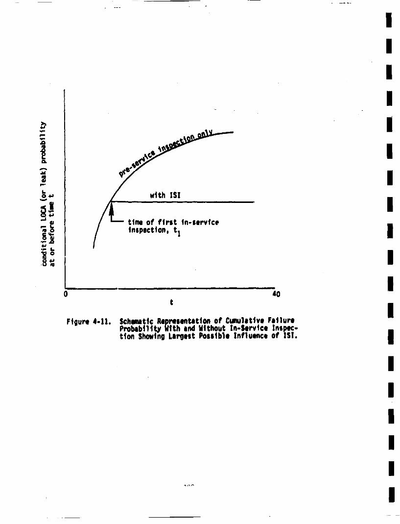
41.4-4-..9-
.0~1I9-.
I.041
-J
"0
4.,.9- 1.
time of first tn-serviceinspection, t1
IIIIIIIIIIIIIIIIIII
II II I II lib | I II
0 40t
FtlgUra 4-11. Schematic Representation of Cunultitve FailureProbabili• tblWth and Widthout In-Service Inspec-tion Showing Largest Possible Influence of I SI.
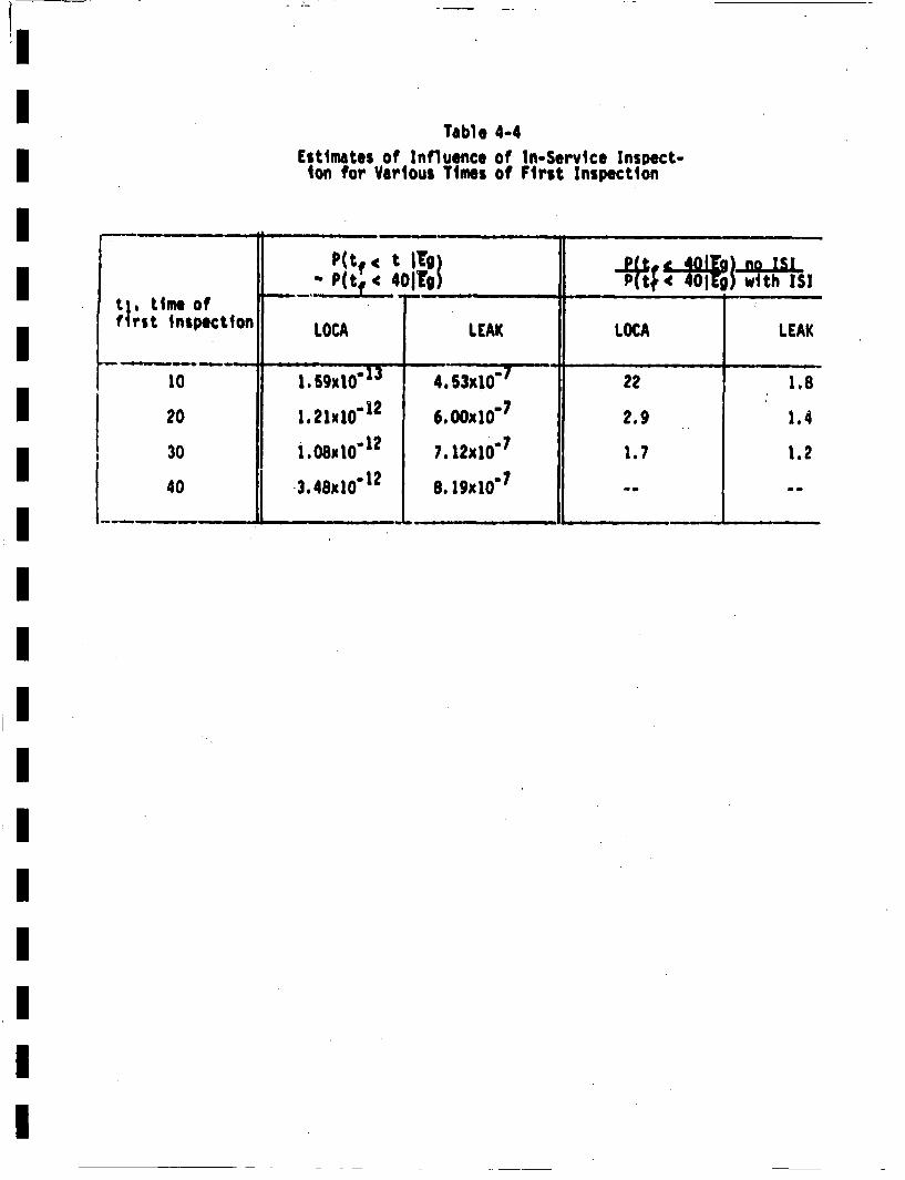
Table 4-4Estimates of Influence of tn-Service Inspect-ion for Various Times of First Inspection
t;. of ~,"P(tf: ____4____ ___)
first Inspection LOCA LEAK LOCA LEAK
10 I.5g9 '1 45x10"7 22 1.8
20 1.21x10"12 5.00x10"7 2.9 1.4
30 1,08x10"t 2 7.12x10"7 1.7 1.2
40 3.48x10"12 8.1igxi0"7-
II
influenced by 15I. Thus, it appears that IS! will generally not havea large influence on the results preswnted here. The ratio of failure Irate_.s with and without 151 is independent of the initial crack sizedistribution for univariate crack depth distributions (Harris 79). Also,Ithe parameter p• cancels out in ratios such as Included in the comparison.IThus, this estimate of the influence of 1S| is not strongly dependent onthe inttial crack size and frequencies. It appears that IS! can result Iin appreciable increases in piping reliability, but in many instancesit will not. This is in agreement with earlier results obtained by Harris I(Harris ?8a, 79).
The leak and LOCA probabilities reported in earlier portions of Section 4 Iare generally lower than estimates suggested in the literature. Theresults were approximately 10"6 for leaks and i0"12 for LOCAs--cumulative Iwithin the plant lifetime in large primary piping consideeld. Beforeproceeding with a comparison of the above results with estimates fromI
other sources, a reminder is provided that only circumferential welds inthe large piping were considered here. Hence, the following iterns were Ispecifically omitted
e longitudinal welds in elbows (4 per 1eoo• Ie disimilar metal girth butt weld (4 per loop), only
the austenlttc-to-austenittc portions of these weldsIwere consi dered
a nozzles and nozzle-to-run pipe welds. IThe inclusion of these welds in the analysis could have a significant in-fluence on ti~e failure probability results. I
The reactor safety study CR55 75) contains estimates of pipe failure pro- Ibabilities based largely on past industrial experience. A summ~ary of value•in the reactor safety study is provided in Table lI! 2-1 of that reference.IThe values are quoted for a pipe section. which ts defined to be a lengthIof 10-100 ft between major discontinuities such as valves and pumps. Thefollowing values are given for the rupture of high quality pipe of diem- Ieter greater than 3 inches. I
20? I
pf * 8..8x10' 7/sectlon-year ('assesslmnt meidan")2.6x10°8/section-year (lower bound)
2.6x10 '/•ectlo,..year (upper bound)
As shown tIn Figure 1-2, the primary piping at Zion contains 12 sect~ons.Considering the 40 •ear plant life, the cumulative failure probabilitywithin the lifetime would approximately be
40 x 12 x 8.8 x *07 4.2x10"4
for the assessed median. This estimate of the rupture probability issome two orders •f magnitude above the result obtained here for theteak probability. One source of this discrepancy arises from using datafor pipes 3 in. and larger for th, 30 in. lines analyzed here.
The reactor safety study estimates the probability of rupture for pipes
of diamwter less than 3 in. to be an order of magnitude higher. Hence,it. is recognized that the probability of failure decreases with Increas-Irig Pipe size. Wilson 74 also shows that pipe rupture probabilitiesdecrease with increasing pipe diameter.
The reactor safety study (RSS 7S) contains another estimate of pipe fail-ure rates in Table 111-6-9. where the following LOCA Initiating ruptu~erates are given for pipes with diameter greater than 6 in.
pf- * U'4/plant-year (median)
;05to 1O03/plant year (90%l range)
it is interesting to note that the imnediately above estimates cover arange of 100 (upper bound/lower bound * 100), whereas the values givenearlier cover a range of 1000. The differences in these estimates couldbe due to differences in pipe diameters, mixing of infant an' mature data,and data from different class codes.
Phillips and Waerwick (Phillips 69) provide a swanary of 106 pressure
vessel years of British experience with fossil fired plants 'rom whichthey deduce the probability of catastrophic failure in nuclear primarycircuits to be 2x1O0S/plant-year (p. 8, Ph~llitps 69). Comparisons
between countries are difficult because of differences in code require-
2O~

Imerits, but this estimate provides a useful additional piece of infor-Imation. This value for catastrophic failure is orders of magnitude abovethe LOCA probabilities obtained here. However, Phillips end Warwickinclude the entire primary circuit, whereas this analysis considers only
a small subset.
Additional discussions of pipe rupture probabilities are provided byI
6~ush 75a, 75b, 76, WASH-1285 (1974), Burns 78, and Basin 77. The esti-mates contained in these references varx widely, but are invariably con--siderably larger than even the leak probabilities obtained in tiiis investi-gation. As mentioned above, one factor that could accouit for the disa-Igreemient is that the estimates from the literature are generally appli-
cable to much smaller pipes than considered here, and the failure proba-bility is generally considered to decrease with increasing pipe size. ImAn additional factor is that the estimates cited above are averaged outover lorge populations of pipes, which will generally include pipes thatIore subjected to considerably less quality control, and higher stressesand number of cycles than the primary piping considered here. Thesefactors would tend to result in pipe failure rates well above those appli- Icable to the special small subset of pipes considered In this Investi-gation. Nevertheless, the results obtained here are very small, andthe LOCA probabilites are well below any estimate that could be basedon observations of actual piping systems. The fact that no leeks haveIbeen observod in the large primary piping of PWRs is of some comfort,
however.,
The very low LOCA probabilities obtained here, along with the observationthat alterations bordering on ridiculous are necessary to brtne thefailure probabilities up to the values based on past observations (seeSection 4.3.•), suggest that some factors that could produce a LOCA inIactual sttutationft have not been considered in the current model. Suchfactors would inclifde design *rrors, fabrication errors, errot in operationof the plant, and mechanisms of accelerated crack growth that are ofIfairly low probability but could result in mch faster growth than th
?OI
fatigue mechanism considered here. An example of operator error wouldbe some error that would produce pressure excursions to higlher pressurethan considered here. Quite high pressure, with resulting high stressesand increased failure probabilities, could be present with a probabilitymuch higher than i0".2 per plant lifetime.
The quantification of the influence of these various "human factor errors"is quite difficult, and wel1 beyond the scope of this investigation.Sabri 80, Rasmussen 78, and Swain 78, 80, contain discussions of suchconsiderations. Rzevski 78 provides a discussion of design errors.Although the results presented here indicate that human errors are Impoer-tant, results generated by the techniques employed herein for other pip-ing sizes, systems and materials would be very informative in providingadditional perspectives on the relative importance of various factors on
the reliability of reactor piping systems.
5.0 SUI4MARY AND CONCLUSIONS
A fracture mechanics model of structural reliability has been appliedto obtain estimates of the influence of seismic ewonts on the probabilityof failure in the large pri'uary piping of a counercial pressurizedIwater power reactor.* This work forms a portion of the Lawrence LivermoreLoad Combination Program, and Is atbed at assessing the need to designconunercial power reactors for simultaneous seismic events and loss- of-coolant-accidents (IOCAs). Zion 1 was analyzed in this project, so thatm
results obtained are representative of realistic situations. However, B
the appl cability of the results obtained here to plants cther than Zion•
remains to be seen. Best estimates of the failure probabilities weredesired, rather than upper hound estimates.
Basically, the fracture mechanics model assumes that failures in theprimary piping can occur only as the result of the subcritical growth ofma pre-existing defect introduced during fabrication of the plant. The m
growth of such defects is assumed to be predictable using fracturem
mechanics techniques based on laboratory investigations. Numerous add-itional assumptions are made which are detailed throughout the report.The as-fabricated defects are considered to be randomly distributed Iin size, and to be concentrated in piping wcldments. The calculated
steshistory at each circumferential girth butt weld is used in con- -mmjunction with the subcritical crack growth characteristics of thematerial to predict the time variation of the crack size distribution. iThe crack geometry considered is a semi-elliptical interior surface part-circumferential crack. Therefore, a bivariate crack size distribution•is employed. Seismic stresses are considered as part of the stress Ihistory, and the influence of such stresses on piping reliability can
basetie. Cyclic stresses induced during normal plant-operationmform an important part of the stress history. The probability of fail-ure (leak or LOCA) at a givkai location and time is simply the probabilitymof having a crack larger than the corresponding critical size. Elastic-plastic failure criteria were employed to estimate crititcal crack sizes,
whereas subcritical crack growth was calculated based on elastic analysis.
' Specifically, 56 girth butt welds were considered.- 14 welds ineach of the four loops, such as shown in Figure 1.2.
Considerable new information on stress intensity factors for part-circwnferential interior surface cracks was generated as a portion ofthis project in order to adequately treat the desired coplex factorsinvolved.
A special computer program was written for generation of nwnerical resultsfrom the fracture mechanics model. This program is called PRAISE (PipingReliability Analysis Including Seismic Events), and its development wasrequired in order to handle the initial bivariate crack size distributionin conjunction with the complex stress hi story and statistical distributionof material properties.
The results for LOCA and leak probabilities generated by PRAISE indicatedthat the stress history for the piping system considered was dominatedby the heatup-cooldown cycle. Radial gradient thermal stresses due totemperature excursions of the coolant during various plant operating tran-sients provided only a minimal influence on the calculated failure pro-babilities. Pre-service Inspection and proof test had an appreciableinfluence on the calculated failure probabilities, but in-serviceinspection generally would not have a large influence. Results for variousweld locations showed differing results depending on the level of appliedstresses. The leak and LOCA probabilities were calculated to be quitesmall, being on the order of 10-n6 and 10"12 per plant lifetime (respect-
ively). Large variations in the input parameters (such as initial cracksize distribution) were required before these values were stgiificantlyaltered. The LOCA probabliti/es were more strongly influenced by thestatistical distribution of initial aspect ratio (ratio of crack surfacelength to crack depth) than by other input parameters. The results alsoshowed that the influence of seismic events on calculated failure pro-babilittes was not large. Hence, it appears that the probability of a
sudden and complete pipe severance in the large primary piping at Zion 1is very low - borderingl on Incredible. The probability of a simultaneousLOCA and seismic event (seismic induced LOCA) is even lower. Thus, it appearsthat ths requirement to design conunrcial power reactors for simultaneous LOCAand seismic events should be reviewed.
The very low LOCA probabilities obtained In thi$ work, along with theobservation that extreme alterations of inputs are required before theIcalculated values are Increased to be comparable to current estimatesof piping reliability, suggest that same factors that could contributeto a LOCA have been omitted from the model. Such factors could includefailures in portions of the primary coolant loop not evaluated herein,
design errors, fabrication errors, errors tn plant operation, and thepresence of crack growth mechanisms that could produce higher crack growth
rates (but be present with low probability)o Although the results pre-sented here itidicate that'dominant failure contributors 'may have been omittedfrom conside-'atton, it is important to remember that only a very specialIsubset of the piping at Zion 1 was included in this analysis. Additional
rslsgenerated by the techniques employed herein for other pipingmmsizes, systems and materials would be very informative in gaining addi-tional perspectives on the relative importance of various factors on them
reliability of reactor piping systems. [
I
SUWIAiRY OF M4AJOR NOTATION
A area of crackh* crack area having a 50% chance of being found during
inspection.Ap cross-sectional area of pipe
AA1 increment of crack area for a crack extending in the "1"direction.
a maximum depth of a semi-elliptical surface cracka* crack depth h~vitng a 50% chance of being found
during Inspectio..da/dn fatigue crack growth rateb half surface length of a semi-elliptical surface crackC parameter in fatigue crack growth relationC0 constant i~n distribution of initial crack depth
C• constant in distribution of initial crack aspect ratio (8)c equals a2
DB diameter of beam of ultrasonic probe used in inspectionO• tnside pipe diameter
E modulus of elasticityer'fc(x) complementary error function of argument xF ~ equals :•/2 (sin2 x +• cos2 x~)I dx
f| correction factor for hi for surface crack
G shear modulus (or a function of a/b)g peak acceleration (relative to gravity) during a seismic
event,91 a function in influence function (see Eq. C-13)
92 a function in influence function (see Eq. C-14).H equals E/(1-v' 2)
h pipe wall thicknesshi influence function associated with Rj (see Eq. C-I)
h]* known Influence function for a buried elliptical crack
209
II
K'
K0'
Kmax
AK
k
m
m(u ,c)
n
P(tF<t)
P(tF<t!Fq)
PftF< t[Eq(g,t)]
P~leak) (Q)
Po (a)
PND(a)
Pf( sys )(t~g)
P
PB
nonsingular portion of Influence function (see Eq. D-3).value of J-integralcritical value of 3 for onset of crack extensionstress intensity factorequals Knmax/(1-R)½
threshold value of K'RMS averaged stress intensity factor associated withcrack extension in the "I" degree of freedom direction.maximum K during a stress cycleminimum K during a stress cyclecyclic stress intensity factor (equals Kmax-Kmin)stress intensity factor (R1) due only to radial gradientthermal stress.equals [1-(a/b)2]•
exponent in fatigue crack growth relationinfluence function for complete circumferential cracknumber of stress cyclesprobability of failure at or before time t given thatalcrack is initially presentprobability of failure at or before time t in the absenceof seismic events (given that a crack is initially present).probability of failure at or before time t given an earth-quake of peak acceleration g at time t (given that acrack is initially present).
0
probability of detecting a leak of rate Q.probability of detecting a crack of depth a duringinspect ion,probability of nondetection of a crack of depth a duringinspection.probability of failure in primary system considered at orbefore time t given an earthquake of magnitude g occurringat t (given that a crack ii initially present).
pressuremarginal density function of initial crack depthmarginal density function of initial aspect ratio
IIIIIIIIIIIIII
III210
p* frequency of cracks in a weld of volume VPv* frequency of cracks in a unit volume of weld
p(n) probability that n cracks exist initially in a weld of volume V.9Q leak rate through a crack
|Q' leak rate through a crack per unit length of crack.R load ratio (equals K•in/Klax) (or radial distance in a polar
coordinate system)Rt inside radius of pipe
S parameter a•;ociated with Influence of stress cycles onfatigue crack growth (see Eq. 2-40).
T temperature [or tearing modulus E(dJ/da)/oflo 2jTappl applied, value of tearing modulusTreat value of material tearing modulus
T average temperature through pipe wall thicknessTC temperature in cold leg
TH temperature in hot legTsteam temperature of steam
t timeU strain energy
U* exact value of U for a reference problemUa•,proximate U for a general problem
•) approximate U for a reference problem
u equals x/hV wel d volumev opening displacement of a crack surfaceWcrack opening displacement (as a function of crack siz, and
position on crack surface).IP exact value of WI for a reference problem
Wl approximate W for a general problem,%•l approximate W for a reference problem
x distance into ptpe wallV1 function in expression for Xi for uniform stressy a C~artesian coordinate
211
II
Qequals a/hI
cs coefficient of thermal expansionB aspect ratio (equals b/a)I
13' equals .B/2•L ~ largest of I or b/hI
•nparameter in marginal distribution of initial crack aspectI
y equals Rj/hI
6 maximum total crack opening displacementn parameter in distribution of C Io a polar coordinate
~parameter in marginal distribution of initial crack aspect ratio4tparameter related to frequency of occurreance of transient i
type "I" (see Eq. 3-50).ii parameter in marginal distribution of initial crack uepthm
p' equals u/hU parameter in expression for PNDm
v* Poisson's ratioecuals ri-iE/a) 2 - (y/b) 23 I
p fraction of initial cracks with $)5ejaxial stress (or occasionally standard deviation)I
oDW stress due to dead weight loads0EQ maximum stress due to an earthquake0flo flow stress [equals (oys + OuIt)12J I0LC load controlled portion of applied stresscOmax maximum stress during a stress cyclemom~n minimum stress during a stress cycle0NO normal operating stressm
op axidl stress due to pressureOTE stress due to restraint of thermal expansion
I
?II I
ays 0.2% of oft~at yield strength* elliptical angle
General Coiwents
1. A bar over a variable• denotes the man value of the variable.
2o Ab~.|us p "sd denotes the standard deviation of the var~i-
3. A numerical subscript (such as "50") denotes the value ofthe variable at that percentile of its distribution (there-fore, a50 would be theamdian value of a).
4. An upper case P generally denot~s a cumulative distributionfunction.
5. A lower case p generally denotes a density function.
I
REFERENCES*
Abraniowitz 64
Adamonis 79
Agostinelli 58
Ardron 76
Arnett 76
ASME 80
N. Abramowitz and A. Stegun, Handbogk of Hath eMtic~lFunctions, National Bureau of'Standards, Appliel Ha the-nmatcsS-eries 55, Washington, D.C., 1964.
D.C. Adanionis and E.T. Hughes, "Ultrasonic Evaluationand Sectioning of PVRC Plate Weld and Specimen 201."Welding Research Council Bulletin No. 252, New York,September 1979.
A. Agostinelli and V. salemann, "Prediction of FlashingWater Flow Through Fine Annular Clearances," Trans-actions of the ASNE, Vol. 80, 1958, pp. 1138.TT•7T
K.H. Ardron and R.A. Furness, "Study, of the CriticalFlow Models Used in Reactor Slowd~own Analysis," N ceaEn..ngeertna and Desjg, Vol. 39, 1976, pp. 257-26K.
L.M. Arnett, "Optimization of In-Service Inspection ofPressure Vessels,' Report DP-1428, E.1. duPont de Nemoursand Company, Savannah River Laboratory, Aikon, SouthCarolina, August 1976.
Bo 11cr and Pressure Vessel Code, Section Xl, Rules forIn-Service inspectiton or Nuclear Power Plant Components,
American Socity• of Mechanical Engineers, New York, 1980.
AnulBo fAT tnadAeia society forTestngad~atrlas, hilaelpiaPennsylvania,
1980.
S.N. Atluri, K. Kithiresan, A.S. Kobayashi, and N. Naka-akl, "nnr Surface Cracks In an Internally Pressur-
zed Cylinder Analyzed by a Three Dimensional Displace-ment-Hybrid Finite Element Method," Third International
al an Fabrication, l~r can Sle• of Mechanical Engi.neers, New York, 1977.
S.N. Atluri and K. Kathiresan, "Outer and Inner Sur-face Flaws In Thick.Walled Pressure Vessels," •r ~-
T~ii~'iTiial1I ofeerncs markhed wt nith an al t eris e)i ndc a n t-
IIIIIIIIIIII
II
II
ASTM 80
Atluri 77a
Atluri 77b
on page 232.
214
AtlurI 79
Bamford 77
Baniford 79a
S.N. Atluri and K. Kathiresan, "Influence of FlawShapes on Stress Intensitty Factors for Pressure VesselSurface Flaws and Nozzle Corner Cracks", AmericanSocity• of Mechanical Engineers Paper 79-PVP-65, NewYork, 1979.
W.H. Bamford, D.H. Schaffer and G.M. Jouris, "Startis-tical Methods for Interpreting Fatigue Crack GrowthData with Applications to Reactor Pressure VesselSteel," Third In ternational Conference on PressureVessel Technol~gyZ,'Part II:'Mtetrials and Fabrication,pp'1•'T•'7•,Tnertcan Society of Mechanical Engineers,New York, 1977,
W.H. Bamford, "Fatigue Crack Growth of Stainless SteelPiping in a Pressurized Water Reactor Environment."Journal of Pressure Vessel Technology, Vol. 101, No. 1(February 1997), pp. 73-79.
W.H. Bamford and A.J. Bush, "Fracture Behavior of Stain-less Steel," Elastic-Plastic Fracture, pp. 553-577, Ameri-can Society ror Testtng and Materials, Special TechnicalPublication No. 668, Philadelphia, Pennsylvania, 1979.
S.L. Basin and [.T. Burns, "Characteristics of PipeSystem Failures in Light Water Reactors," Report EPRiNP-438, Electric Power Research Institute, Palo Alto,California, August 1977.
J.M. Barsom, "*Fati ue-Crack Growth Under VariableAmplitude Loading n ASTN A514-8 Steel," Progress inFlaw Grwh nd Fratre Touhness Tstin. 'pP. 14-167,
nrtcan 5cie for Tesing and Herlal Special .Technical Publication No. 536, Philadelphia, Pennsyl-vanta 1973.
Bamford 79b
Basin 77
Blarsom 73
Barsofn 76 tude Loading
Publicationf
,"Fatigue Crack Growth Under Variable Ampli-i n Various Bridge Steels,"Ftm gu Crack
Testhing andaterials Special TechnicalNO. 595, Philadelphia, Pennsylvania, 1976.
Bother P.E. 8echer and B. Hansen, "Statistical evaluationof Defects in Welds and Design Implications," DanishWelding Institute, Danish Atomic Energy Connission,Research Establistuent, RISO, •v date).
215
Becher 74
Becket 80
Begley 72
Besuner 76
Besuner 77a
Besuner 77b
Besuner 78
Blauel 75
Broek 78
Buchalot 76
P.E, Becher and A. Pederson, "Application of Statisti-cal Linear Elastic Fracture Mechanics to PressureVessel Reliability Analysis," Nuclear Engineering andDesig, Vol. 27, No. 3, pp. 413-425, 1974.
F.L. Becker, Sr., Battelle Pacific Northwest Laboratory,Richiand, Washington, private comniunication, 1980.
J.A. Begley and 3.0. Landes, "The 3-Integral as aFailure Criterion," FrcueTuhes pp. 1-23, Ameri-can Socity• for TeBstrfig d1Ratertal$Special TechnicalPublication No. 514, Philadelphia, Pennsylvania, 1972.
P.M. Besuner, "Residual Life Estimate for Structureswith Partial Thickness Cracks," Me chanics of Crackrot, pp. 403-419, American Societ~y for Teiting andRi1als Special Technical Publication No. 590, Phila-delphia. Pennsylvania 1976,
P.M. Besuner and A.S. Tetelman, "Probabilistic FractureMechanics," Nuclear Engineering and Desjgn, Vol. 43,No. 1, (August 1977), pp. 99-114.
P.M. Besuner, "The Influence Function M4ethod for Frac-ture Mechanics and Residual Life Analysis of CrackedComponents Under Complex Stress Fields," En -
nen and Design, Vol. 43, No. 1, (AugusVi9),~
P.M. Besuner, et al., "BIGIF: Fracture Mechanics Codefor Structures," Report EPR! NP-838, Electric PowerResearch Institute, Palo Alto, California, July 1978.
J.G. Blauel, D. Stahn, and J.F. Kalthoff, "Investiga-tions into Brittle Fracture Behavior of Thick-WalledHollow Cylinders Subjected to Thermal Shock," U.S.Nuclear Regulatory Comisslon Translation Series I4UREGITR-O022, R3, NRC publication date January 1978 oforigtnsl German report BN4FT RS 61 dated September
D. Broek, E1ementary Engineering Fracture MechanicsSlithoff and Noordhoff, The Netherlands, 1978. "
C.B. Buchalet and IE.H. Bainford, "Stress IntensityFactor Solutions for Continuous Surface Flaws inReactor Pressure Vessels," Hej~hantcs of Crack Growth,pp. 385-402. Amrican Societ for Tes ng and I'•'tenllsSpecial Technical Publication No. SQO, 1hiadelphia,Pemnnylvania, 1976.
IIIIIIIIIIIII
IIII
216
Burns 78
Bush 75a
Bush 75b
E.T. Burns, D.O. Harris and R.C. Erdmann, "Reliabilityof Nuclear Piping Systems with Consideration of CasesWhere Design Points Have Been Exceeded." Science Appli-cations, Inc., Report SAI-091-79-PA, Palo Alto, Califor-nia, presented at ASME/CSME Pressure Vessels and Pip-ing Conference, Montreal, June 1978.
S.H. Bush, 'Pressure Vessel Reliability," Journal ofPressure Vessel Technology, Vol. 97, SeriesT7R, 1T.7WF'biruIy 975J, p7.54-70.
S.H. Bush, "The Impact of Inservice Inspection on theReliability of Pressure Vessels and Piping," 41iyEngineering in Pressure Vessels and Piping, pp.1-3~,~American Society ofr echanical Engineers-, New York,1975.
Bush 76
Chan 81
Chang 79
Clarke 73
Collier 77
Collier 80
S.H. Bush,Reactors,"1976), pp.
"Reliability of Piping in Light-WaterNucearSaftyVol. 17, No. 5, (Sept-Oct
A.L. Chan, E.F. Rybicki and D.J. Curtis, "Non-SeismicStress Analysis", Vol. 3 of "Probability of Pipe Fracturein the Primary Coolant Loop of a PWlR, U.S. NuclearRegulatory Comnission Report NUREG/CP,-2189, Wlashington,D.C., August 1981.*
Part-Through Crack Fatigue Life Prediction, edited by;TT•hang, Ameerican Society for Testt ng and MaterialsSpecial Technical Publication No. 687, Philadelphia,Pennsylvania, 1979.
W.L. Clarke and G.M. Gordon, "Investigation of StressCorrosion Cracking Susceptibility of Fe-Ni-Cr Alloysin Nuclear Reactor Water Environments," Corrosion-MACE,Vol. 29, No. 1, (January 1973), ppo 1-12.
J.G. Collier and W. Marshall, 'How UK Experts Assessedthe Integrity of PWR Pressure Vessels," NularEg-neerina International, Vol. 22, No. 260, July 1977,pp. 41-40.
R.P. Collier et. al., "Study of Critical Two-PhaseFlow Through Simulated Cracks," Interim Report,BCL-EPRI-8(-1, Battelle Columbus Laboratories, C•lunbus,Ohio, 1980.
217
Cooke 75
Cramond 74
Cruse 69
Cruse 73
Cruse 75a
Cruse 75b
Cruse 77
Derby 77
Dowllng 72
Dufr, sne 78
R.J. Cooke, P.E. Irving, GaS.. Booth and C.O. Beevers,"The Slow Fitigue (track Growth and Threshold Behaviorof a Medium Carbon Alloy Steel in Air and Vacuum,"Journal of Engineering Frectu'e Mechanics, Vol. 7,(1975), pp. 69-77.
R. Cramond, Jr., A Probabil.istic Analysis of StructurslRefblt~ats atu and.allure, PhD. Thesis,-
•nt'ers• o n1no s,iV•Ur~btniChimlpatgn, 1974
T.A. Cruse, "Nunmerical Solutions In Three DimensionalElastostatics," I[ternational Journel of Solids andStructures, Vol. 5, (1969), pp. 1259-1Z74.
T.A. Cruse, "An Improved Boundary - Integral EquationMethod for Three Dimensional Elastic Stress Analysis,"Report SM-73-19, Department of Mechanical Engineering.Carnegie-Mellon University, Pittsburgh, Pennsylvania,August 1973.
Boundary Intego EqainMethod: CornputationalApta tns fn Aple lan cs,e edte by To.Cruse
and ., zno, knr can octet of Mechanical Engi-neers, New York, 1975.
T.A. Cruse and P.M. Besuner, "Residual Life Predictionfor Surface Cracks in Complex Structural Details,
Junlof Air raft, Vol. 12, No. 4, (April 19755,pp. 36-7.
T.A. Cruse, 0.3. Meyers and R.B. Wilson "Fatigue Growthof Surface Cracks," Flaw G ro.th, and Fracture, pp. 174-189, American Socity for Testing and Materials SpectldTechnical Publication No. 631, e'hiladelphia, Pennsyl-vania, 1977.
S.L. D~erby and N.E, Hackford, "Probabilistic LeakAnalysis for LMFBR Primary Coolant Piping," GeneralElectric Fast Breeder Reactor Department ReportGE FR-O0041, UC-79p, Sunnyvale, California, July 1977.
N.E. Dowling, "Fatigue Failure. Predictions for Compli-cated Stress-Strain Hitstories," Jora f trasVol° 7, No. 1, (March 1972), ppJ 71-87."
3. Dufresne, et al., "The CE.A.Sponsored Research pro-aram on PWlR Reactor Vessel Failure Probability Calcu-1ation," Prob biistic 1n lsis of Nuclear Reactor
V!b ol. , aper x[. , Proceengso OTopicaI sponsored by the American Nuclear Society,
Los Angeles, California, May 1978.
IIIIIIIIIIIIIIIII
I218
Dvorak 72
Engle' 79
Crdol 78
FCFMS 79
Fnldman 68
Flugge 62
Follas 67
Ford 80
Frank 77
Frost 67
H.R. Dvorak and E.C. Schwegler, Jr., "StatisticalDistribution of Flaw Sizes," International Journal ofFracture Mechanics, Vol. 8, (1972), pp. 110-111.
R.M. Engle, Jr., "Aspect Ratio Variability in Part-Trhrough Crock Life Analysis," r'art-Throug h Crack FatigueLife Prediction, pp, 74-88, edited by' 3.8. Chang,°Aibierican'Society for Testing and Materials Special Tech-nical Publication NO0 687, Philadelphia, Pennsylvania,19790
R. Erdol and F. Erdogan, "A Thick-Walled Cylinder withan Axisynumetric Internal or Edge Crack," Journal of
AliejdMechanics, Vol. 45, No. 2, (June 1g7'"p•7 pp. 281-
"Influence of Various Parameters on the Determinationof the Fatigue Crack Arrest Threshold," Fatigue Con,-mission of the French Metallurgical Society, presentedat ASThMMeeting, Pittsburgh, Pennsylvania, October 1979..
L.So Feldman, "Statistical Analysis of the Results ofUltrasonic Monitoring of Large Forged Pieces and Stampingsof Aluminum Alloys," Deetskp• 1968, pp. 26-32,English translation a albe--ram -. O. Harris, ScienceApplications, Inc., San Jose, California.
W. Flugge, Handbook of Engineering Mechanics, McGraw-Hill Book Company, New York, 1962.
E.S. Folias, "A Circumferential Crack in a PressurizedCylindrical Shell," International Journal of FractureMechanics, Vol. 3, No. 1, "(March 1967), pp.''-li.
P. Ford, to appear in Second Semi-Annual Progress Reporton Electric Power Research Institute Research ProjectRP-1332, EPRI, Palo Alto, California,
F.J. Frank and M.J. Asztalos, "Primary Coolant LeakDetection System Evaluation and Development Program:Capability Study of Existing Reactor Coolant PressureBoundary Leakage Detection Systems," Report WCAP-9173,-
-Westinghouse Electric Company, Pittsburgh, Pennsylvania,Septembr 1977.
N.E. Frost and K. D~enton, "The Fatigue Strength ofButt Welded Joints in Low Alloy Structural Steel,"British.Weldina Journal, Vol. 14, No. 4, (April 1967),pp. 156-161,
21g
FSAR
Gallagher 79
George 80
G~orge 81
Glarinuzzi 78
Goepfert 77
Graham 74
Green 50
Griesbach 80
Fin ~aet ii Zi•)~t !on Station. Unit 1.omeowa son any (no date).
StutrlItg~yehooy edited by J.P. Galla-herand.. Crooker, knrln Society of Mechanical
Engineers, New York, 1979.
Letter from L. George. Lawrence Livermore NationalLaboratory, to D. Harris, Science Applications. Inc.,San Jose, California, dated May 9, 1980.
1. George and R. Mansing, "Piping Syst.. FractureProbability Estimation", Vol. 7 of Probabiblity ofPipe Fracture in the Primary Coolant Loop of a PWR",U.S. Nuclear Regulatory Commission Report NUREB/CR.2189, Waslhington, D.C. (to be published SepLteuer 1YB1).
"Studies on AISI Type-304 Stainless Steel Piping Weld-ments for Use in SWR Applications," Report ErRI NP-944,RP449-2, Liectric Power Research Institute, Palo AltoCalifornia, December 1978.
W.P. Goepfert, "tStatistical Aspects of MechanicalProperty Assurance," Reprodluctblllty and Accuracy~of Mechanical Tests, pp. 136-144, Amnerlcan Soc ietyftr resting and Materials Special Technical PublicationNo. 626, Philadelphia, Pennsylvania, 1977.
T.W. Grahami and A.S. Tetelman, "The Use of Crack SizeDistribution and Crack Detection for Determining theProbability of Fatigue Failure," AIAA Paper No. 74-394,presented at AIAA/ASME/ SAE 15th Structure, StructuralDynamics and Materials Conference, Las Vegas, Nevada,April 1974.
A.E. Green and I.N. Sneddon, "The Distribution of Stressin Neighborhood of a Flat Elliptical Crack in an ElasticSolid,n Proceedings of the CaS ridoe PhilosoohicalSoit, Vol. 46, 1950, pp. 159-164.
T.J. Griesbach, "Dynamic Elastic-Plastic Behavlo, ofCircumferential Cracks in a Pipe Subject to SeismicLoading Conditions," AMrican Socity• of Mechanical Engi-neers Paper No. 80-C2/PVP-151, New Yo.'k, 1980.
G.J. Hahn and S.S. Shapiro, Statistical Models ingrjjgJohn Wiley and sonsI-•nc., New York, 1967.
D.A. Hale, 3. Yuen and T. Gerber, "Fatigue Crack Growthin Pi~tnq and RPV Steels in Simulate' BWR Water Environ-ment, Report GEAP-24098, fiRe-5, Re•.ort Prepared byGeneral Electric Company, San Jose, California for theU.S. Nuclear Regulatory Commission, January, 1978.
220
IIIIIIIIIII!IIIIII
Hahn 67
Hale 78
I
Hale 79
Hamburg 70
Hammersley 64
Harris 76
Harris 77a
Harris 77b
D.A. Hale, C.W. Jewett and J.N. Kass, "Fatigue CrackGrowth Behavior of Four Structural Alloys in HighTemperature High Purlt~y Oxygenated Idater," Aneri canSociety of Mechanical Engineers Paper 79-PVP-104, NewYork, 1979.
No Hamburg, Statistical Analysts for Decision Making.Hartcourt, Brace and World, Inc., New York, 1970.
J.M. Hanumersle~y and D.C. Handscomb, Monte Carlo Method~s,Fletcher a Son Ltd;, Norwich, Great Britain.
0.0. Harris and R.R. Fullwood, "An Analysis of theRelative Probability of Pipe Rupture at Various Loca-tions in the Primary Cooling Loop of a PressurizedWater Reactor Including the Effects of a PeriodicInspection," Report SAI-OO1-PA, Science Applications,Inco, Palo Alto, California, June 1976.
0.0. Harris, "Relative Rupture Probabilities at VariousLocations in Reactor Coolant Piping," Transactions ofthe American Nuclear Society, Vol. 26, po 404,J~i
0.0. Harris, "An Analysis of the Probability of PipeRupture at Various Locations in the Primary CoolingLoop of a Babcock and Wilcox 177 Fuel Assembly Pres-surized Water Reactor - Including the Effects of aPeriodic Inspection," Science Applications, Inc.,Report SAI-OSO-77-PA, Palo Alto, California, September1977.
Har'ris 77c 0.0. Harris, "A Meanson the Reliability ofMaterials EValuation,1977.
of Assessing the Effects of NDECyclically Loaded Structures,"Vol. 35, No. 7, pp. 57-65, July
Harris 78a
Harris 78b
Harris 79
D.0. Harris, "Probabilistic Analysis of Rupture inReactor Coolant Piping," Probabilistic Analysts ofNucea Ractor Sfe ~, Vol. 2, Paper II.?, Proceedings
of opial ntlg sponsored by the American NuclearSociety, Los Angeles, California, May 1978.
0.0. Harris, "A Meants of Assessing the Effects of Peri-odic Proof Testing and HOE on the Reliability of Cyc-lically Loaded Structures," Journal of Pressure VesselTechnology, Vol. 100, No. 7,3pp.150:TT-R157,T 78.
0.O. Harris, "The Influence of Crack Growth Kineticsend Inspection on the Integrity of Sensitized BWRPiping Welds," Report EPRI NP-1163, Electric PowerResearch Institute, Palo Alto, California, 1979.
221
Harris 80a
Harris 80b
Harris 81
Hartranft 72
Hastings 77
D.0. Harris and E.Y. LIm, "Stress Intensity Factorsfor Complete Circumferential Interior Surface Cracksin Hollow Cylinders," Report SAI-181-80-PA, ScienceApplications, Inc., Palo Alto, California, presentedat Thirtheenth National Symposium on Fracture Mechanics,Philadelphia, Pennsylvania, June 1980, to be publishedIn symposium proceedings.
0.0. Harris, R.G. Brown, D. Dedhia and 9.E, Leaver,"Acoustic Emission Leak Detection and Location SystemsTechnology. Review." Electric Power Research InstituteReport NP-80-7-LD, Palo Alto, California, D~cember1980.
0.0. Harris and 0. Dedhia, "Further Studies of theinfluence of Residual Stresses and Crack Growth Kineticson the Integrity of Sensitized BWR Piping Welds,"Science Applications, Inc., Report SAI-OO2-81-SJ,San Jose, California, January 1981, report on ElectriCPower Research Instituts Research Project Tl18-6, PaloAlto, Cali1fornia.
R.J. Havrtanft and B.C. Sih, "Alternating Method Appliedto Edge and Surface Crack Problems," Mechanics ofFracture 1: Methods of Analysis and Solutions' of CrackProblems, edited by G.C. Slh, Ch. 4, pp. 179-'23•,Noo1rdof International Publishing, Leyden, The Nether-lands, 1972.
N.A.J. Hastings and J.B. Peacock. Sta~ttsttca.L0tstt-buin, Butterworths, London, 1974.
E. Heear and J.N. Yang, "Structural Optimization Basedon Fracture Mechanics and Reliability Criteria," AIAAJournal, Vol. 9, April 1971, pp. 621-628.
J. Heliot, R.C. Labbens and A. Pe11isier-Tanon, "Semi-Elliptical Cracks In a Cylinder Subjected to StressGradients," FrqueMch~anics, pp. 341-364, AmericanSociety for Test~ing and Haertals Special TechnicalPublication No. 677, Philadelphia, Pennsylvania, 1979.
R.E. Henry, "The Two-Phase Critical Discharge of mnit-lally Saturated or Sub-cooled Ltquid," Nuclear Scienceand Engineering, Vol. 41, 1970, pp. 336°32.
R.E. Henry and H.K. Fauske, "The Two-Phase CriticalFlow of One-Component Mixtures in Nozzles, Orificesand Short Tubes," Journal of Heat Transfer, Vol. 93,1971. pp. 179-187.
222
IIIIIIIIIIIIIIIIIII
Hoer 71
Heliot 79
Henry 70
Henry 71
Hertzberg 76
Hodulak 79
Hogg 70
Horn 79
Hutchinson 79
irwtn 62
James 75
Johnson 79
R.W. Hertzberg, Defrmation ,and Fr~actur~e Mechanicso Engineering Ptter1als, John Wiley and So'ns, NewYork, 96
L. Hodulak, H. Kordisch, S. Kunzelmann, and E. Sonuer,"Growth of Part.Through Cracks," Fracture Me chanics,pp. 399-410, American Society for Testing andliaerlialsSpecial Technical Publication No. 677, Philadelphia,Pennsylvania, 1979.
R.V. Hogg and A.T. Craig, Introduction to Mathematical.Statistics, 3rd Ed., The Macmillan Company, Collier-Macmillan'Limited, London, 1970.
R.M. Horn, "The Growth and Stability'of Stress Car-rossion Cracks in Large Diameter BUR Piping," ReporttIEDC-24750-1, General Electric Company, San Jose, Cali-fornia, November 1979.
J.W. Hutchinson and P.C. Paris, "Stability Analysisof J-Controlled Crack Growth," Elastic-Plastic Fracture,pp. 37-64, American Society for Testing and MaterialsSpecial Technical Publication No. 668, Philadelphia,Pennsylvania, 1979.
G.R. Irwin, "Crack-Extension Force for a Part-ThroughCrack in a Plate," Journal of.Ap.plied echanics, Decem-ber 1962, pp. 641-654 -"
L.A. James, "Some Questions Regarding the I nteracttonof Creep and Fatigue," Journal of Engineering Materialsand Technology, (ASME paper 75-WAiMat'6).
D.P. Johnson, T.L. Toomay and C.S. Davic, "Estimationof the Defect Detection Probability for Ultrasonic T~'stson Thick Section Steel Weldment," E~lectric Power ResearchRteport EPRI NP-991, Palo Alto, California, February
Q.0. Johnston, "What Are the Chances of Failure? Part 1,Material Properties and Design Factors," Welding Insti-tute Research Buliettnl, Vol. 19, pp. 36-40, February1978.
Gi.O. Johnston, "What Are the Chances of Failure? Part 2,NDT, Pressure Vessel Applications and Fatigue," Weldtng.Institute R~ese~arch Bull1etin, Vol. 19, pp. 78-e2,Hiich1978.
Johnston 78a
Johnston 78b
2? 3
Leyerenz 78
Lldiard 78
Lim 81
F.L. Loyerenz, 3re, I.M. Koren, R.C. Erdann andG.S. Lellouche, "ATW1S: A Reappraisal, Part III:Frequencyf oAnticipated Transients," Report EPRINP-BO1, Electric Power Research Institute, PaloAlto, California, July 1978.
A.B. Lidiard and N. Wil1liams, "The Sensitivity ofPressure Vessel Reliabilit to Material and OtherFactors," Reliabilit PrObla of Reactor Pressure
opnents, oe. 1,pp. *3 24, nternational AtIcEnero Aency, Vienna, 1978.
E.Y. Lrn, "PRAISE Computer Code User's Manual",Vol. 9 of "Probability of Ptpe Fracture in thePrimary Coolant Loop of a PWR", U.S. NuclearRegulatory Conuission, Report NUREG/CR-2189,Washington, D.C., August 1981.*
A.E.H. Love, A rts nte etclTerof [ls~iy oe ulctos e ok 94
A.C. Lucia, R. Brunnhuber and 3. Elbat, "A New ComputerCode for the Estimation of the Probability of Failureof PWR Pressure Vessels," American Society of MechanicalEngineers Paper 79-PVP-Ua8, New York, 1979.
Metals Hand book, Vol. 1, Properties and Selection ofMlaterials', edited by T. Lyman, 8th ed~tion, AmericanSociety for Metals, Novelty, Ohio, 1974.
Love 44
Lucia 79
Lyman 74
Lynn 77
Lu 81
Mann 74
E.K. Lynn, "The OCTAVIAPerformance and Failurethe Fifth Water ReactorMaryland, November 1977,
Code for Predicting VesselProbabilities," presented atSafety Meeting, Gaithersburg,
IIIIIIIIIIIIIIII
Mansour 73
Marshall 76
Hayfield 80
S.* Lu, M. Ma and R. Larder, "Seismic ResponseAnalysis", Vol. 3 of "Probability of PipeFracture in the Primary Coolant Loop Of a PWR",U.S. Nuclear Regulatory Conmission, ReportNUREG/CR.2189, Washington, D.C., August 1981.*
N.R •n, R[. chaer nd .D.S~npurwalla,M1eth s
A.E. Mansour and D. Faulkner, "On Applying the Statisti-,cal Approach to Extreme Sea Loads and Ship Hull strength,"Tr nnacti~ O he Roy1 Intitution of Na al Archi-
"An Assessment of the Intogrity of PWR Pressure Vessels,"Report by a Study Group Chaired by U. Marshall, avail-able from H.M. Stationary Office, London, October 1976.
N.E. Hayfield, T.P. Forte, EoC. Rodabaugh. B.N. Leisand R.3. Elber, "COld Leg Integrity Evaluation," BattelleColiubus Laboratories Report to U.S. Nuclear RegulatoryComission NUREB/CR.-1319, February 1980. *
JWES 77
Kadlecek 73
Kannlnen 78
Kltagawa 77
Klepfer 75
Kobayashl 77
Kupperman 78
Labbens 76
"Study on the Safety Assessment of Fatigue Strengthof Pressure Vessels and Piping Systems in NuclearPlants," Japan Welding Engineering Society ReportJWES-AE-7707, December 1977, (NCR Translation No. 351).
P. Kadiccek, "Mechanical Property Data on Hot-Extruded304N and 316N Staei,;uas Z:i1 Pipe." Eleve~t edT__•-a tture Properties as. Influenced by Nitrooe-n•d~1~
Technical Publication No. 52Philadelphia, Pennsyl-vania, 1973.
M.F. Kanninen, et al., "Towards an Elastic - PlasticFracture Mechanics Capability for Reactor Piping,"Nuclear Enaineerina and Design, Vol. 45, (1978), pp.117-134.
H. Kitagawa and T. Hisada, "Reliability Analysis ofStructures Under Periodic Inspection," Third Inter-national Conference on Pressure Vessel TechnOlogy,Part I, Analysis and Design, pp.475-48Z, AmericanSociety of Mechanical Engineers, New York, 1977.
H.H. Klepfer, et al., "Investigation of Cause ofCracking in.Austentic Stainless Steel Weidments ,Report NEDO-21000, General Electric Company, NuclearEnergy Division, San Jose, California, July 1975.
A.S. Kobayashi, N. Polvnicha, A.F. Emery and W.J. Love,"Inner and Outer Cracks in Internelly PressurizedCylinder," Journal of Pressure W.ssel. Technology, Febru-ary 1977, pp. 83-89.
0.5. Kupperman, K.J. Reimann and U.A. Ellingson, "Evalu-ation of Ultrasonic Technique for Detection of StressCorrosion Cracks In Stainless Steel Piping," ElectricPower Research Institute Report EPRI NP -761. PaloAlto, California, June 1978.
R. Labbens, A. Pellisier-Tanon and J. Heliot, "Practt-cal Method for Calculaitng Stress-Intensity FactorsThrough Weight Functions," ok~anc f Crack Growth,pp. 368-384, meritcan otey or Testn an aeralalSpecial Technical Publication No, 590, Philadelphia,Pennsylvania, 1976.
Landes 72 J.D. LandesGeometry oncan SocietyPublication
and .3.A. Bagley, "The Effect of SpecimenJIc." FL.rs..uI2 Touohess, pp. 24-39, Pineri-for Tea ting and Materialsa Special TechnicalNo. 614, Philadelphia, Pennsylvania, 1972.

Mazumdar 75
McGowan 79
McGrath 73
Michel 7B
Mood 50
Natr 78
Naylor 66
Nelson 75
Noenn 79
N. Niazumdar, "Ilmportance Sampling in Reliability Esti-mation," in Reliability and Fault Anal sias Theo-retical and Appli1TiUAspects of Syst Rem l"ibflTty andSafety Assessment SIAM, Philadelphia, 1975, pp. 153-163.
3.J. McGowan and 14. Rayrnund, HStress Intensity FactorSolutions for Internal Longitudinal Semi-EllipticalSurface Flaws in a Cylinder Under Arbitrary Loading,"Fracture Mechanics, pp. 365-380, American Society forThting and Materials Special Technical PublicationNo. 677, Philadelphia, Pennsylvania, 1979.
E.J. McGrath, et al., "Techniques for Efficient Monte-Carlo Simulation," Science Applications, Inc., ReportSM- 72-59o-LJ. for Office of Naval Rese~rch, March1973.
D.3. Michel, L.E. Steele and J.R. Hawthorne, "Influ-ence of Irradiation and Other Factors on Fatigue Crack
Austria, 1978.
A,M. Mood, In~t.rgd~ugtion..•j thleeeeee~.• 1•.McGraw-Hi 1 1, ew York, T950.
P.1. Nair, "Fatigue Crack Growth Model for Part-ThroughFlaws in Plates and Ptpes," American Society of Mech-anical Engineers .Paper No, 78-Mat-9, New York, 1978.also published in Journal.e.I.....of (nternPtras.. nTehnoloo.
T.H. Nalylor, 3.1, Balinty, 0.S. Surdick and K. Chu,Comute Smultl~~nTechniques, John Wiley & Sons, Inc.,
D.V. Nelson and H.O. Fuchs, uPredictions of CumiulativeDamage Using Condensed Load Histories," Paper 750045,p resented at SA[ Automotive Engineering Congress andExposition, February 1975.
3.C, Neian, Jr., "A Review and Assessment of the Stress-Intensity Factors fo"- Surface Cracks," Part-ThrouSgh•r~a k F tiato!•~e _ Ljf..red4jtion, pp. 16.4•"FGi•-ica•n •od eyIo'r Tes in nd Mater~ials Specal Technical Publication
No. 687, Philadelphia, Pennsylvania, 1979.
IIIIIIIIIIIIIIIIIII
Nichols 75
Nilsson 77
N lsson 78
Parts 85
Paris 72
Parts 79
PCSG 75
R.W. Nichols, "The Uses of Welded Materials in NuclearPower Engineering." Vfelin• Oournal, Vol. 54, No. 12.(December 1975), pp, 47.3s .
F. Nilsson, "A M odel for Fracture Mechanical Estima-tion of the Failure Pr&~tlitt of Reactor PressureVessels,' Third Internes .',al Conference on PressureVessel TechnoloQgY.,.Par9. r•,. Materials and Fabrication,
• -6'01 M~ercan "•ciety of Mechanical' Engineers,New York, 1977.
F. Nilsion and 8. Ostqnsson, "3 c-1esting of A-S33BStatistical Evaluation of Some Different Testing Tech-niques," Eanetn rcue *hnc, Vol. 10.
P.C. Paris and O.C. 5th, "Stress Analysis of Cracks,"Fracture Toughness Testing and itt ApDl.tcattons,pp. 30-81, PAmerican Society for Testing a'Maerialsspecial Technical Publication No. 381, Philadelphia,Pennsylvania, 1965.
P.C. Paris, R.3. Bucti, E.T. Wesse1, W.G. Clark andT.R. Mager, "Extensive Study of Low Fatigue CrackGrowth Rates in A533 and A50S Steels," Stress Analystsand Growth of Cracks, American Society TFo• hsting andIaterials special Technitcal Publication No. 513, pp. 141-.176, Philadelphia, Pennsylvania, 1972.
P.C. Paris, H. Tada, A. Zahoor and H. Ernst, "'rheTheory of Instability of the Tearing Mode of Elastic-Plastic Crack Growth," Elastic-Plastic Fracture.pp. 5-36, American Society vor Testing and EiteralsSpecial Technical Publication No. 668, Philadelphia,Pennsylvania, 1979.
"Investigation and Evaluation of Cracking in AustenittcStainless Steel Ppting of Boiling Water Reactor Plants,"Report NUREG-75/O6• (NTIS No. P8-246 645) Pipe Crack-ing Study Group, Nuclear Regulatory Coiutsston, Wash-ington, I).C., October 1975.
"Investigation and Evaluation of Stress-CorrosionCracking in Piping of Light Water Reactor Plants,"Report NUREG-0531, Pipe Crack Study Group, NuclearReguiatory Conuission, Washington, D.C., February
PCSG 79
Ph~llips 69 C.A.G. Phillips and R.G. Warwick, "A Survey ofin Pressure Vessels Built to High Standards ofstruction and its Relevance to Nuclear PrimaryEnvelopes," AHSS(S)R162, AKACA, 1969.
DefectsCon-Circuit
PJSC 79 "Evaluation of PlSC Trials Results," Preprint of ReportNo. 5, Plate Inspection Steering Coiittee, May 1979.
Rasmussen 78
Reynen 77
RG45S
Rtcardella 72
Rtce 68
Rice 72a
Rice 72b
Ritchie 77a
Attch' )7
Rizzo 67
Rolfe 75
3. Rasmussen, "Notes on Human Error Analysis anL'Predictions," Synthesis and Analysis 14ethods fora• ,~ pp. 3s7-38Y, edited by 6. Apostolakls, S.Garribba and S. Volta, Plenum Press, New York. 1978.
3. Reynen, "Surface Cracks in Cylinders During ThermalSho,,k," American Society of Mechanical EngineersPaper 77-PWP-5, New York, 1977.
Regulatory Guide 1.45. "Reactor Coolant P.-c~ure Bound-ary Leakage Detection System," Nuclear Regulatory Com-mission, Washington, D.C.
P.C. Ricardella and T.R. )eager, "Fati jue Crack Growthin Pressurized Hater Reactor Vessels, Yeesur Vselsand Piping: Design and Analysis, Vol. T, AnalysiSipp. 32•-340, Maerlcan Society of MechanicaT'iibGe-ers,New York, 1972.
J.R. Rice, "A Path Independent Integral and the Approxi-mate Analysis of Strain Concentration by Notches andCracks," Journal of ADpl led Mlechanics, Vol, 35, (1968),pp. 379.385. ..
J.R. Rich and N. Levy,* "The Part-Through Surface Crackin an Elastic Plate," Journal of Applied M).echanics, Vol.39, (1972), pp. 185-194. ' -- '
J.R. Rice, "Som Remrks on Elastic Crack-Tip StressFields," 1!nternton!lJourelI of Solids and St~ructures.Vol. 8, (IgTz), p.7Jl-58.sa
R.O. Ritchie, "Near-Threshold Fatigue Crack Propagationin Ultra-High Strength Steel: Influence of Load Ratioand Cyclic Strength," Journl 1• fnginern ~etland Technologot, (July 1 j77),rpp lg.20eia.
R Ritchie, 'influence of Microstructure on Near-Threshold Ftitgue-Crach Propagation in Ultra-HighStrength Steel," Metal Science, August/Septuuier 1977,
pp 6-381.
V.3. Riuzo, "An Integral Equation Approach to BoundaryValue Problms In Classical Elas tqstatics,"Qarelof AD!ied Mathetics, Vol. 2. (1967), pp. •
S.T. Rolfe and 3.K. Blarsom, Fra •re and F ti ue Con-
ran ce l], nct., ngl C1ff, N~ erSey,
iIIIIIIIIIIIIII
I
I228
RSS75
Runumel 74
Rzevski 78
Sobra 80
Schmtdt 73
Reactor Safety Study, _AnAelment of.Atcident Risks.tnU.S.ouiomercial NucTea-r P Yo.P.anit•,-Ai-T0(HO[Q-5114 ApXpendices HZ and IV,. Failure Data
and Caumon Mode Failures Bounding.Techniques and SpecialTechniques," Nuclear Regulatory Comunission, Washington,D.C., O&tober, 1975.
W.O. Rummel, P.H. Todd. Jr., R.A. Rathke and W.L.Castner, "The Detection of Fatigue Cracks by Non-Destructive Test Methods," M~tetal [vlujttgn,Vol. 32, No. 10, (October 1974), pp. 205-212.
F. Rzevski, "Improving System Reliability by the Elim-ination of a Class of Design Errors,"anAnalysis Methods for Safe~ty and Rotb •pp. 391.399, edited by u. A O~ak S, *. aerr andG. Volta, Plenum Press, New York, 1978.
Z.A. Sabri and A.A. Husseiny, "Human Factors in NuclearPower Plant Operation," Proceeding of the AmericanNuclear Society/European Nuclear Society Toptcal*
Heelin or Thm1 Sac ter *aey Knoxville, Tennessee.Apt1 980. CONIF-003, V0l1, pp. 1056-1063.
R.A. Schmidt and P.C. Paris, "Threshold for FatigueCrack Propagation and the Effects of Load Ratio andFrequency,' Progress in Flaw Growth and Fracture Tough-fl1•ili9 pp. 7g-94, PAmerican !Society fo'r Testingand Materlil s Special Technical Publication No. 536,Philadelphia, Pennsylvania, 1973.
W. Schmi~t, £. Rohrich and R. Wellein, "ApplicationofProbabilistic Fracture M4echanics to the Reliability
Analysis of Pressure Beairng Reactor Comlponents,"Paper G 612, Transaction of the 4th International Con-ferenee on Struc turl p•echaincs In Re~ctOr Techrnology,San Francisco, Au gust 1977.
Id. Sclhnidt and R. Wellein, "Leakage Probability of Circum-ferential Defeicts in Pipes', Nuclear Energy Agency, SteeringCoimittee for Nuclear Energy, Paris, August 30, 1979.
P. Shahinian, "Creep-Fatigue Crack Propagation in Auste-nitfCSic t•~ Stait ess Ste f rssr Vsel T"hnagna•, (.•~E Paper -W v-Z.- "
M. Shinozuka and J.N. Yin , "Optimam Structural DesignBae~d on Reliability and Pro od Test," Annalsof Asr ne Science Proceedings of the RelT5T•
Y.A. Shreider, The Monte Carlo Met - The Method ofS I I rmn rs
Schmidt 77
Schmidt 79
Shhihnian 75
Shinozuka 69
Shrelder 66
229
S inmKns 65
Simonoau 74
Sm It h 72
SmitLh 69
Site~nsn 79
Swsai~n 78
S$wai n 8')
S~ied I • 72
Sw •nd'Inm,, 77
Tadac1 73
W.F. Simmnons and J.A. Van Echo, E_1evated emperaturePrpriso tils tes ASTh D'ata Series Pub]li-catio 1S•-STT *jnerlan socli-'y for Testing and Mater-lals, Philadelphia, Pennsylvania, 1965.
R.J. Sirnoneau, "Two-Phase Choked Flow of Sub-CooledNitrogen Through a Slit," NASA Technical Memorandum,NASA TM X-71516, NASA Lewis Research Ce~nter, 1914.
F.W. Smith, "The Elastic Analysis of the Part-CircularSurface Flaw Problem by the Alternating Method," TheSurface Crack: PhI~sical Problems. and Copu~tation•-Solu'ttons, pp. 1Z5-15•, me'rican Society of MechanicalniiFiineeIsi New York, 1972.
G.V. Smith, An Evaluation of the Yield. reD andRupture Stegh fwog •_••
•liness Steels at Eleva ted"Temperature s,' AST1W OatSeiFes 0S 552, American Society for Testing and Mater-lals, Philadelphia, Pennsylvania, 1969.
S.G. Stiansen, A. Mansour, H.Y. Jan and A. Thayamnballt,"Reliability Methods in Ship Structures," Paper No. 5,Spring 1979, Meeting of the Royal Institution of NavalArchitSects, London,
A.D. Swain and H.E. Guttmann, "Human Reliability Analysisof Dependent £vents," PobltlcAnal sis o~f NuclearReoactoor Safety, Vol. 3, p. x'2-Tti'oplc meeting spon-sated by Ameiiican Nuclear Society at Los Angeles, May1978.
A.D. Swain and H.E. Guttman, "Handbook of Human Relia-bility Analysis with Em phasis on NuJclear Power PlantApplication•," U.S. Nuclear Regulatory ConmmissionReport NUREG/CR-1278, Washington, D.C., April 1980.**
The Surface Crack: Physical Problems and Coiputational
•c•hI•i r~nv/lnoers. New York, 1972.
RW. Swindoman, W.J. McAfeo and V.,K. Sikka, "ProductForm Variability in the Mechanical Behavior of Type304 Stainless Steel at Room Temperature and 593C(1100F)," btt ndAccuracy of Mechanical_Tosts, pp. 464Rican ociet for T*stng and-M'Ef1orhIa Special 'treatment Publictiton No, 626, Phila-delphia, Pennsylvania, 1977.
Ht. Tada, P.C. Paris and G.R. Irwin, The Stress Anal vsisof Cracks Hlandbook, Del Research Corporation,1Xeliertotn,
H. Tada, P. Paris and R. Gamble, "Stability Analysisof Circumferential Cracks in Reactor Piping Systems,"NUREG;/CR-0838, U.S. Nuclear Regulatory Conumission,Wo~hingt.on D.C., June 1979.*
IIIIIIiIIIIII
IIII
230
Tang 73
Timoshenko 51
rS
Tsao 75
Vandergiass 79
Ves~1y 78
Voslkovsky 75
Wall1s 80
Walpole 72
WASH 74
W.H. Tang, "Probabilistic Updating of Flaw Information,"Journal of Testing and Evaluation, Vol. 1, !to. 6,tNovember 1973), pp. 459-467.
S. Timoshenko and J.N. Boodier, Theory of Elasticity.McGraw-Hill Book Company, Inc., New York, 1951.
Zion Station Technical Specifications, CommnonwealthEdison Company, Docket No. 50-304.
N.S. Tsao and S.D. Werner, "Determination of Equiva-lent Response Cycles for Use in Earthquake - InducedFatigue Analyses," Agbabian Associates, El1Segundo,California, Report SAJN/1011-106, to Energy Research
.and Development Administration, May 1975.
M.L. Vanderglass and B. Mukherjee, "Fatigue ThresholdStress Intensity and Life Estimation of ASTM A-i106Piping Steel', American Society of Mechanical EngineersPaper 79-PVP-86, New York, 1979.
W.E. Vesely, E.K. Lynn and F.F. Gdbeg, "OCTAVIA:A Cornputer Code to Calculate the Probability of Pres-sure Vessel Failure From Pressure-Transient Occurances,"Reliability Problmas of Reactor pressure Components,vol. 1, pp. 105-12Z, International Atomic EnergyAgency, Vienna, 1978.
A. Vosikovaky, "Fatigue Crack Growth in an X-65 Line-.Pipe Steel at Low Cyclic Frequencies in Aqueous Environ-ments," Journal of Engineerina Materials and Technoloay,(October 1975), pp. Z98-304.
G.Bo Wallis, "Critical Two-Phase Flow," InternationalJournal of Mul~tihase Flow, Vol. 6, 1980-, p. 7-112.
R.E. Walpole and R.H. Myers, Probability and StatisticsfQr.Engtrnieri.p tnttsts, Macmillan Publishing Co.
lnc, Nw ork 9.
Reprt n te Iteattyof Reactor Vessels for LiahtWe~rPowr Ractrs, he dvioryComi ttee on
Rea¢)r~legard, U..A..C.Reprt ASH-1285, Wash-ington, D.C., January 1974, also published in NuclearEnaineerina and Design, Vol. 28, (1974), pp. 1 •7g3
231
Wel 76
Wilkowski 80
Wilson 74
Wise 77
Wltt 78
FtueCack Growth Under Spectrum Loads, editedbyRP Me nd R.I. Stephens, American Society forTesting and Mtaterials Special Technical PublicationNo. 595, Philadelphia, Pennsy'vania, 1976.
G.M. Wilkowski, A. Zahoor and M.F. Kanninen, "A PlasticFracture Mechanics Prediction of Fracture Instabilityin a Circumf'erentially Cracked Pipe in Bending - PartII: Experimental Verification on a Type 304 Stain-less Steel Pipe," @Ameircan Society of MechanicalEngineers Paper 80-WA/PVP-4, New York, 1980.
S.A. Wilson, "Estimating the Relative Probability ofPipe Severance by Fault Cause,' General ElectricCompany Report GEAP-20615, Boiling Water Reactor Sys-tems Department, San Jose, California, September 1974.
N.J. Wise and E.R. Reinhart, "Survey of Recent OperatingExperience Using Leak Detection Systems to ImprovePlant Operation," Transaction of the AmJerican NuclearSociety, Vol. 27, Novemb'er 1977, p. 936.
F.J. Witt, W.H. Bamford and T.C. Esselman, "Integrityof the Primary Systems of Westinghouse Nuclear PowerPlants During Postulated Seismic.Events," WestinghouseElectric Corporation Report WCAP-9283, Pittsburgh,Pennsylvania, March 1978.
G. Yagawa, N. Ichiyama and Y. Ando, "Theoretical andExperimental Analysis of Semi-Elliptical Surface CracksSubject to Thermal Shack," Fracture Mechanics, pp. 381-398, American Society for Testing and Maerials SpecialTechnical Publication No. 677, Philadelphia, Pennsyl-vania, 1979.
J.N. Yang and W.J. Trapp, "Reliability Analysis ofAircraft Structures Under Random Loading and PeriodicInspection," AIAA Journal, Vol. 12, pp. 1623-1630,December 1974.
"Zion Station Thermal cycle Records," logbook ofobserved transienlts maintained by Comonwealth Edison,Zion Generating Station, Zion, llitnois.
IIIIIIIIIIIIII
Yagawa 79
Yang 74
Zion
'Available for purchase from the NRC/GPO Sales Program, U.S. NuclearRegulatory Comuissionm Washington, DC 20555 and/or the National TechnicalInformation Service, Spr ingfield, VA 22161.
**Sing le copies are avail able free upon written request to the Division ofTechnical Information and Document Control, U.S. Nuclear Regulatory ConunssliWashington, D)C 20555.
232
III
APPENDIX A
INTRODUCTION AND REVIEW OFSTRESS INTENSITY FACTOR ANALYSIS
233
II
APPENDIX A
INTRODUCTION AND REVIEW OF ISTRESS INTENSITY FACTOR ANALYSIS
IPreviously existing information on ,stress Intensity factors for semi-elliptical surface cracks In bodies of finite thickness was insufficient ito perform an analysis for seml-elliptical cracks of arbitrary sizesbetdto stresses that vary strongly through the thickness. SuchI
information is necessary in order to adequately treat the bivariatemdistribution of initial cracks (discussed in Section 2.3). and to allowI
consideration of stresses that vary strongly through the thickness.Radial gradient thermal stresses have strong thickness variations, asdiscussed in Section 1.3 and Appendix D. In order to circumvent theseJshortcomings of previously existing solutions, new information was gener-ated as a part of this research project that will allow inclusion of Ithe above factors In the piping reliability analysis. A considerable m
amount of new fracture mechanics information was obtainedi. Detailsm
of these results will be presented In the following appendices, with onlymajor highpoirpts being included In the ,aain body of the report.
A. 1 Desired Solutions
The crack geometry considered inl the analysis of piping reliability tsa part-circumferential interinr surface semi.olliptiea1 'erack, which is
shown in Figure 2-2. The reasons for considering this crack geometryand orientation were discussed in Section 2.2. The stress Intensityfactors for cracks of arbitrary aspect ratio, B * b/a (B > 1), and a/h Iare required. Additionally, it is desired to account for growth in boththe depth and length directions, and to allow the aspect ratio to change Ias the crack grows. Changes in the aspect ratio will depend on the m
nature of the applied stresses. It is desired to account for stressesm
with steep thickness gradients, such as radial gradient and residualstresses. Thieref'ore, fairly general results are required, rather than
just uniform or linearly varying stesses. Thus, it is seen that a fairlyi
I234 I
general stress intensity factor solution for part-circwuiferential cracksis required. Previously existing stress intensity solutions will Lereviewed in the next section, from which ittwill be seen that these solu-tions are insufficient for the current purposes. Therefore, new solu-tions were generated by boundary integral equation (BIE) techniques.Such techniques will be briefly reviewed, and the results obtained pre-sented. Since the results of the fracture mechanics analysis was intendedfor use in the piping reliability efforts, no efforts were made to attainextreme accuracy in the K solutions. Uncertainties In various input para-meters, such as the initial crack size distribution, are large enough thatthe expense and effort of obtaining highly accurate stress Intensityresults was not warranted. Hence, the results generated are not of highaccuracy, but are felt to be sufficient to adequately treat the desiredphenomena. The accuracies attained will be discussed in the following,and were estimated by comparisons with selected previous solutions.
t .2 Review ot Previously Existing Stress Intensity Solutions
Previously existing stress intensity factor solutions for crack geometriesrelated to part-circumferential interior surface cracks in pipes will bebriefly reviewed in this section. No attempt will be made to providea complete review of work i.: this area. Semi-elliptical cracks in flatplates and in longitudinal and circumferential orientations in pipes will
be considered. Figure A-.4 shows the geouiwtric parameters of Interebt.
Three limiting cases of elliptical cracks in pipes are of interest: (i)an elliptical crack in an infinite b'~dy, (ii) a complete circumferentialinterior crack, and (iii) a very long interior longitudinal crack. ZaseI is approachable by clapsical elasticitt, and waz solved in 1g50 (Green60). This solution was cast in a stress Intmnsity factor form by Irwin62, who obtained the following approximate expressions for K for a seul-elliptical surface defect in a flat plate subjected to uniform stress, o
235
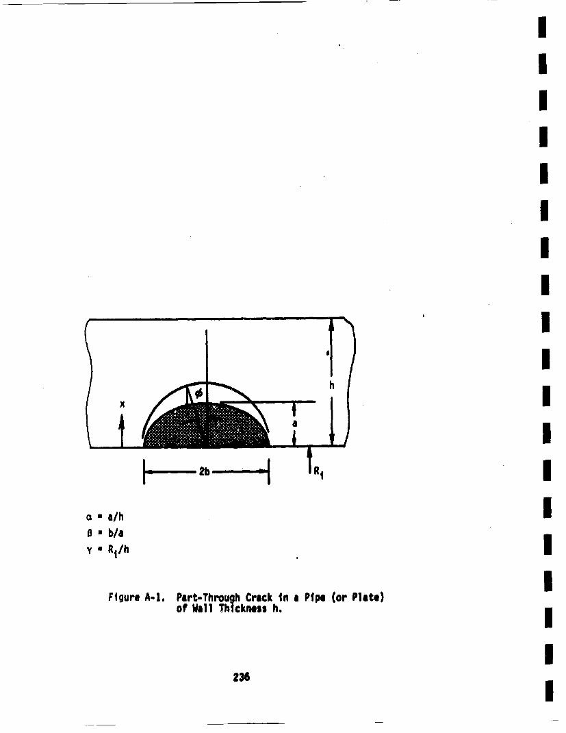
HIn bi, H
* a/h8 " b/ay• R1/h
Figure A-i. Part-Through Crack In a Ptpe (or Plate)of Wall Th ickness h.
236
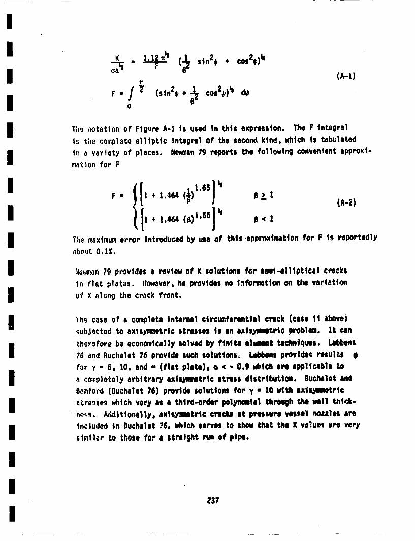
K.. T (1" sin2* + cos2*)kaa B (A-i)
The notation of" Figure A-i is used in this expression. The F integralIs the complete elliptic integral of the second kind, which Ii tabulatedin a variety of places. Newm~an 79 reports the following convenient approxi-
mnation for F
{• : 6 (j J ±_ ( A-2)[1•1464 (B)165J • B '
The maximum error introduced by use of this approximation for F is reportedly
about 0. 1%.
Neonn 79 provides a review of K solutions for semi-elliptical cracksIn flat plates. However, he provides noig nformation on the variationof K along the crack front.
The case of a complete internal circumferential crack (case ii above)subjected to axisnmetric stresses is an axismymtric probim. it cantherefore be economically solved by finite el~ent techniques. Labbens76 and IBuchalet 76 provide such solutions° Labbens provides results *)for y - 5, 10, and - (flat plate), a 0.9 which are applicable toa coeipletoly arbitrary axisyumtric stress distribution. Buchalet andDa•mford (IBuchalet 76) provide solutions for y * 10 with exisymtricstresses which vary as a third-order polyoial through the wall thick-ness. Additionally, axisymetric cracks at pressure vessel nozzles areIncluded in Buchalet 76, which serves to show that the K values are verysimilar to those for a straight run of pipe.
237
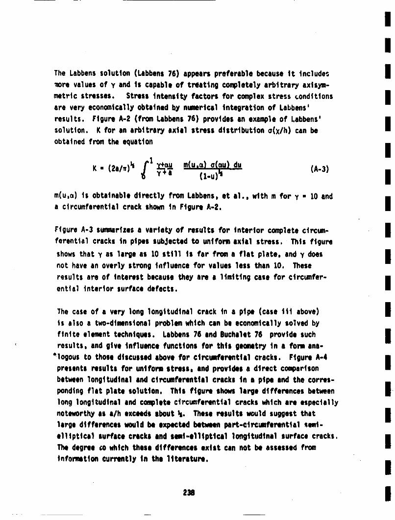
The Labbens solution (Labbens 76) appears preferable because it includes Inore values of y and is capable of treating completely arbitrary axisym,-metric stresses. Stress intensity factors for complex stress •ondittons
are very economically obtained by numerical integration of Labbens 6 m
results. Figure A-2 (from Labbens 76) provides an example of Labbens'
solution. K for an arbitrary axial stress distribution o(xlh) can beobtained from the equation•
K 2/w3 + ±I (A-3)
m(u,ci) is obtainable directly from Labbens, et al., with m for y • 10 anda circumferential crack shown in Figure A-2. IFigure A-3 summarizes a variety of results for interior complete circum-I
ferential cracks in pipes subjected to uniform axial stress. This figure l
shows that y as large as 10 still is far from a flat plate, and y doesInot have an overly strong influence for values less than 10. These i
results are of interest because they are a limiting case for circumnfer- I
ential interior surface defects.
The case of a very long longitudinal crack in a pipe (case iii above) Iis also a two-dimensional problem which can be economically solved byfinite element techniques. Labbens 76 and Buchalet 76 provide suchiresults, and give influence functions for this geometry in a form ana-
• logous to those discussed above for circ~aerential cracks. Figure A-4 Ipresents results for uniform stress, and provides a direct comparisonbetween longitudinal and circumferential cracks in a pipe and the corres-ponding flant plate solution. This figure shows large differences between IElong longitudinal and complete circumferential cracks which are especiallynoteworthy as a/h exceeds about s., These results would suggest that
large differences would be expected between part-circumferential semi- B
elliptical surface crecks and semi-elliptical longitudinal surface cracks. I
The degree wo which these differences exist can not be assessed frominformetion currently in the literature.
238|
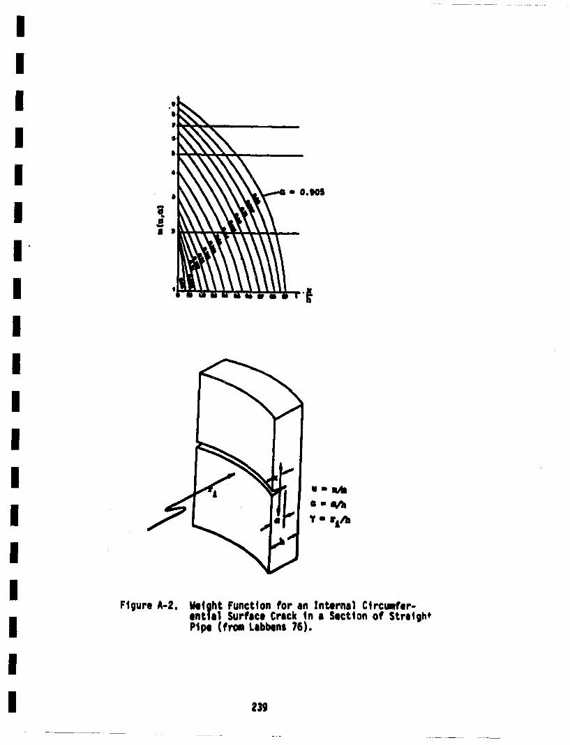
- o.eo5
a
W4etght Functton for an Internal Circimfer-enti al Surface C;rack in a Section of Straigh*Pipe (fros Labbens 76).
Figure A-2.
239
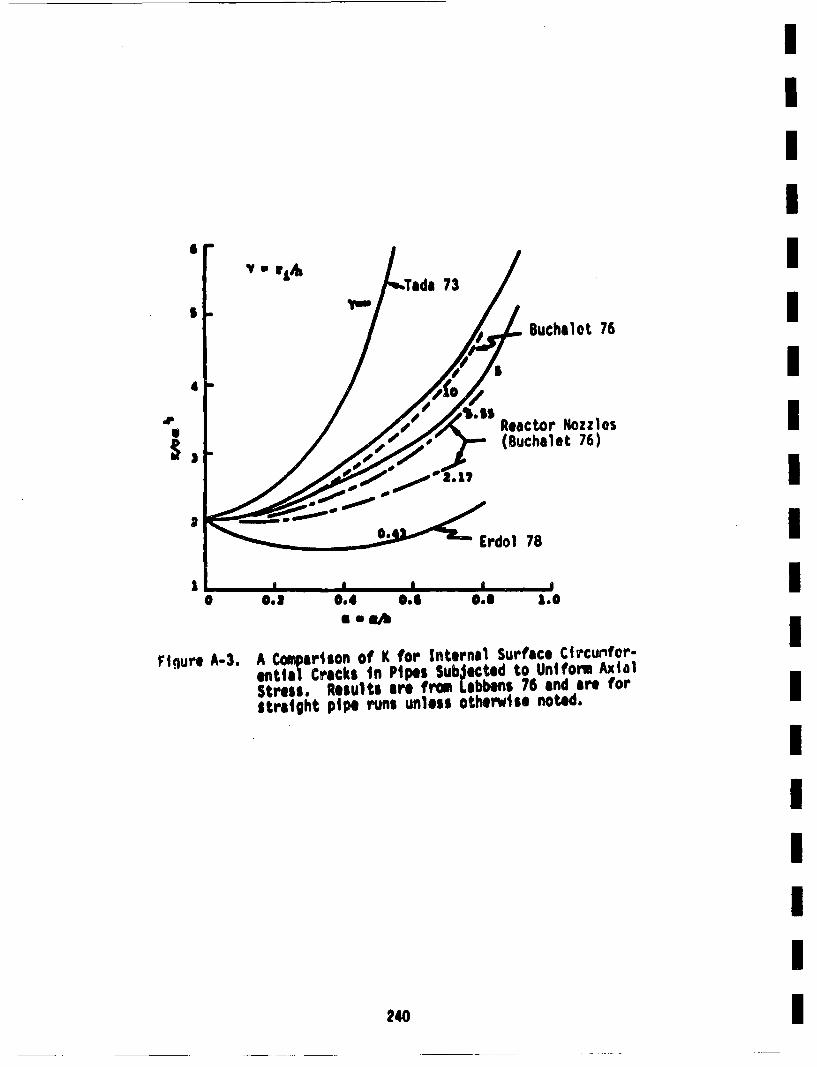
S
4l
7 Buchalot 76I
Reactor Nozzles(Buchalet 76)dp
2
2
I
IIIIIIIIIIIIIIIIIII
a -a l
Ftigure A-3. A Cuaparlion of K for Internal Surface Circurnfor-ential Creeks In Pipes Subjecoted to Uniform AxialStress, Results are from Labbens 76 anda re forstraight pipe runs unless otherwise, noted.
240
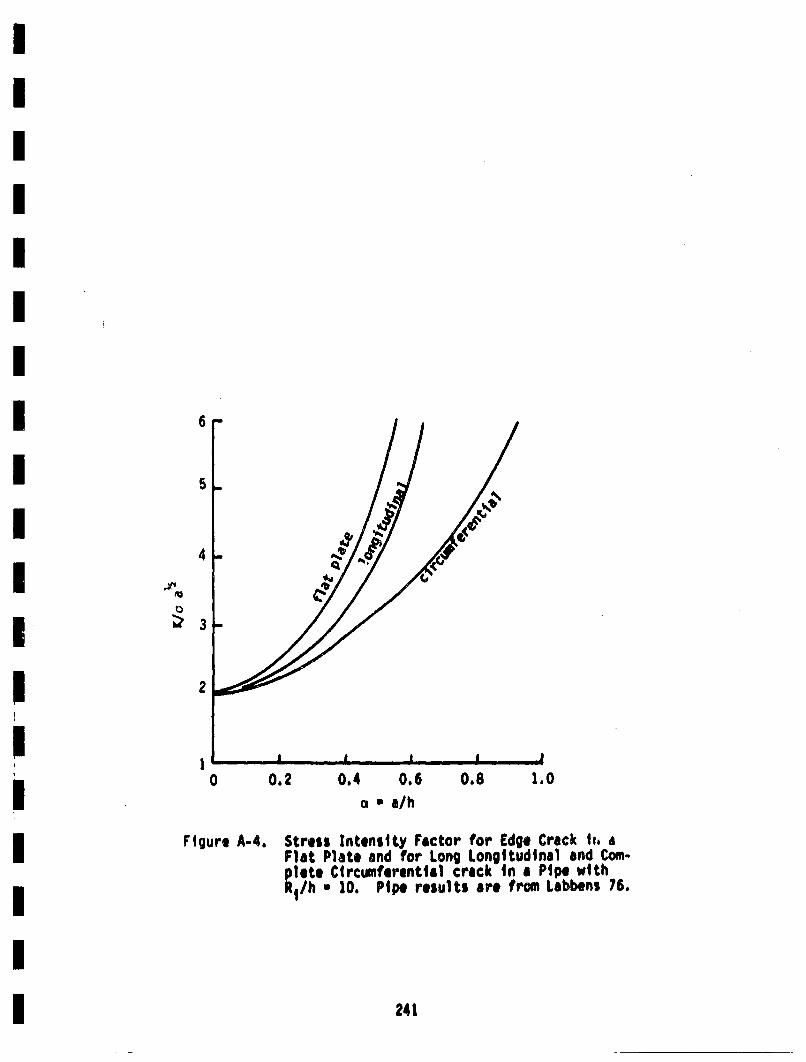
6
5
4
.e.
3
2
10 0.2 0.4 0.6 0.8
a * a/h1.0
Figure A-4. Stress Intenslty Factor for Edge Crack h,. aFlat Plate and for Long Longitudinal and Cor-p late Circumferential crack in a Ptpe withRih• 10. Pipe results are from Labbens 76.
241
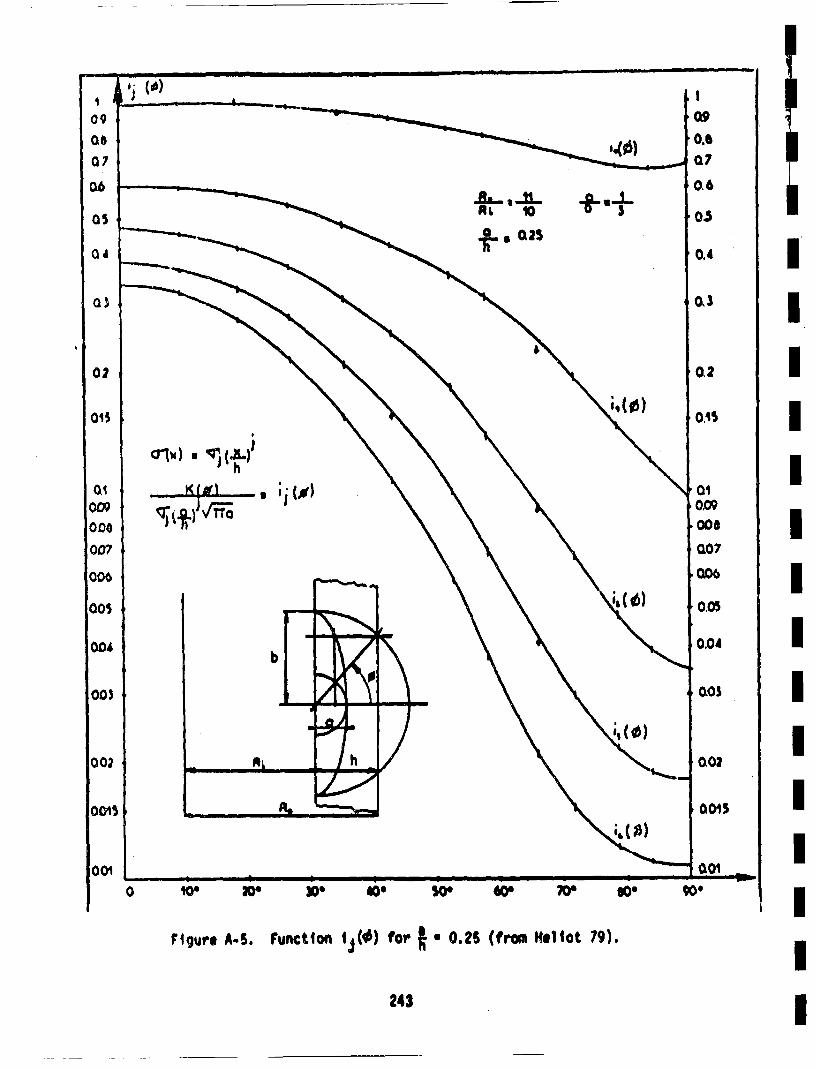
A• I0
,]a,.., 0.25÷-t
,,,) at i x
0 '0. 6O
Figure A.S. Function ij(•) for ft 0 .25 (frown Reliot 79).
243
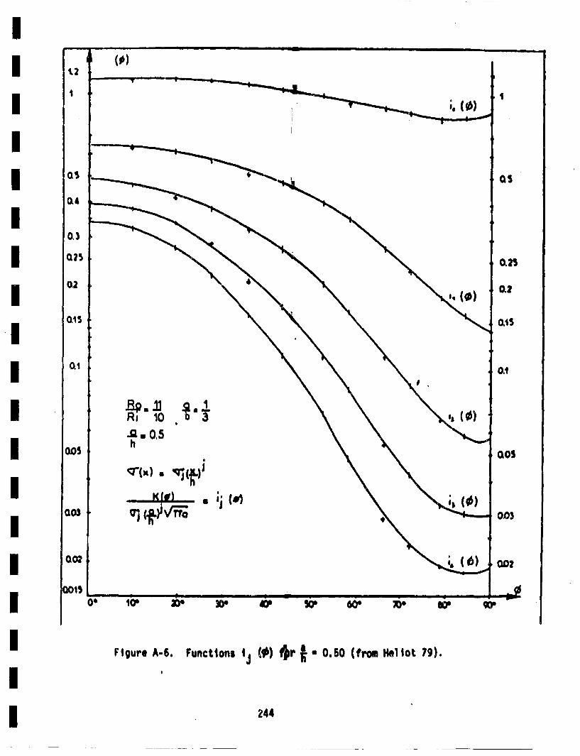
rigure A-6. Functions ij (*) #~r ft • 0.50 (from He4o 79).
244
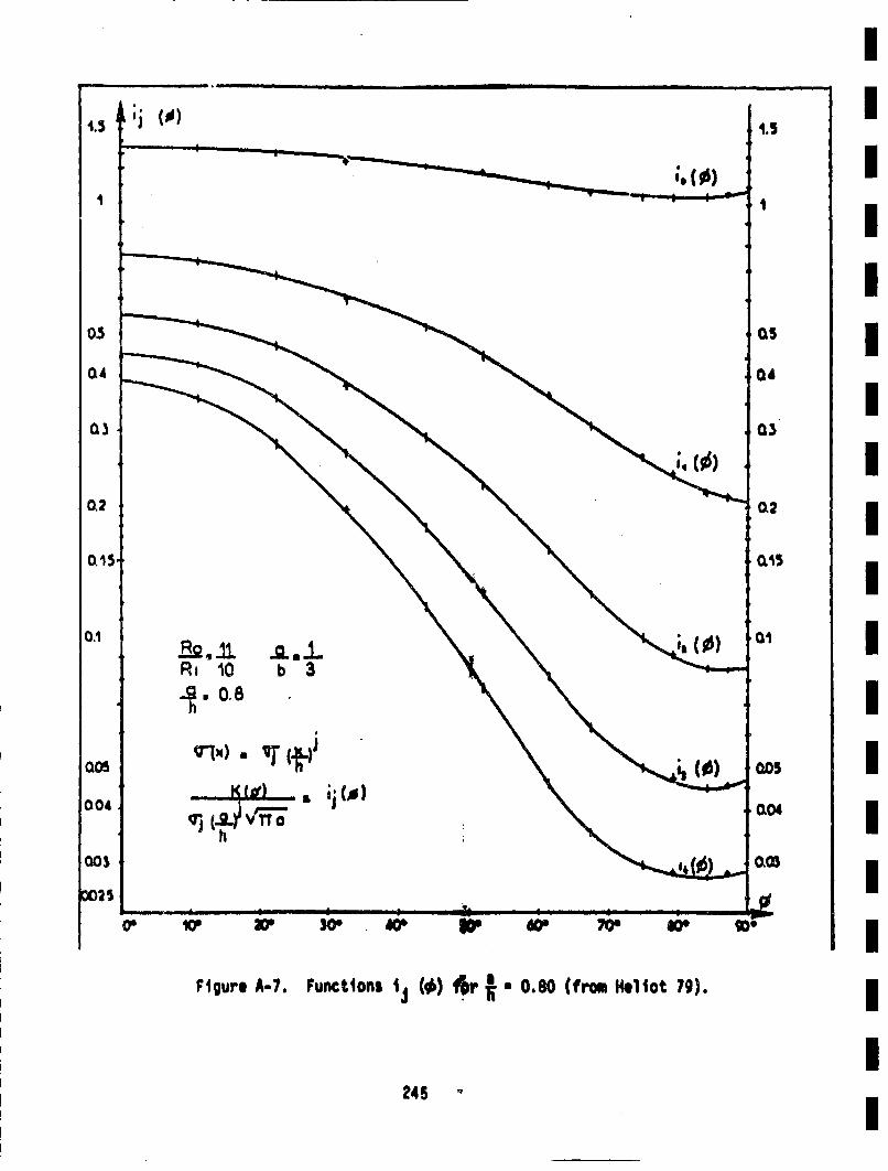
Dj ('
• - ill I I I I - i I
1.5
Os
04
0,2
0. iS,
0.1
004
003
LXO2
IIIIIIIIIIIIIIIIIII
Figure A-i. Functions 1~t (,p) f~~l ft • 0.80 (from Hliot 7g).
245
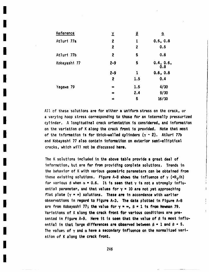
Reference y xaAtluri 77a 2 1 0.5. 0.8
2 2 0.5
Atluri 77b 2 5 0.8
Kobayashi 77 2-9 5 0.4, 0.6,0.8
2-9 1 0.6, 0.82 1.5 0.4
Yagawa 79 1 . 5 4/30-2.4 9/30o•5 1613O
All of these solutions are for either a uniform stress on the crack, ora varying hoop stress corresponding to those for an internally pressurizedcylinder. A longitudinal crack orientation Is considered, and informationon the variation of K along the crack front is provided, Note that mostof the information is for thick-walled cylinders (y ~2). Atluri 77b
and Kobayashi 77 also contain information on exterior semi-elliptical
cracks, which will not be discussed here.
The K solutions included in the above table provide a great deal ofinformation, but are far from providing complete solutions. Trends inthe behavior of K with various geometric parameters can be obtained fromthose existing solutions. Figure A-8 shows the influence of y (-R1 /h)for various B when • * 0.6. It is seen that y Is not a strongly influ-ential parameter, and that values for y - 10 are not yet approachingflat plate (y * w) solutions. These are in accordance with earlierobservations in regard to Figure A-3. The data plotted In Figure A-8are from Kobayashi 77; the value for y * -, 0• - 1 is from Newman 79.Variations of K along the crack front for various conditions are pre-sented in Figure A-9° Here it is seen that the value of 8 Is most influ-ential in that large differences are observed between 0 * 1 and B * 5.The values of y and G have a secondary influence on the normalized vari-atlon of K along the crack front.
245
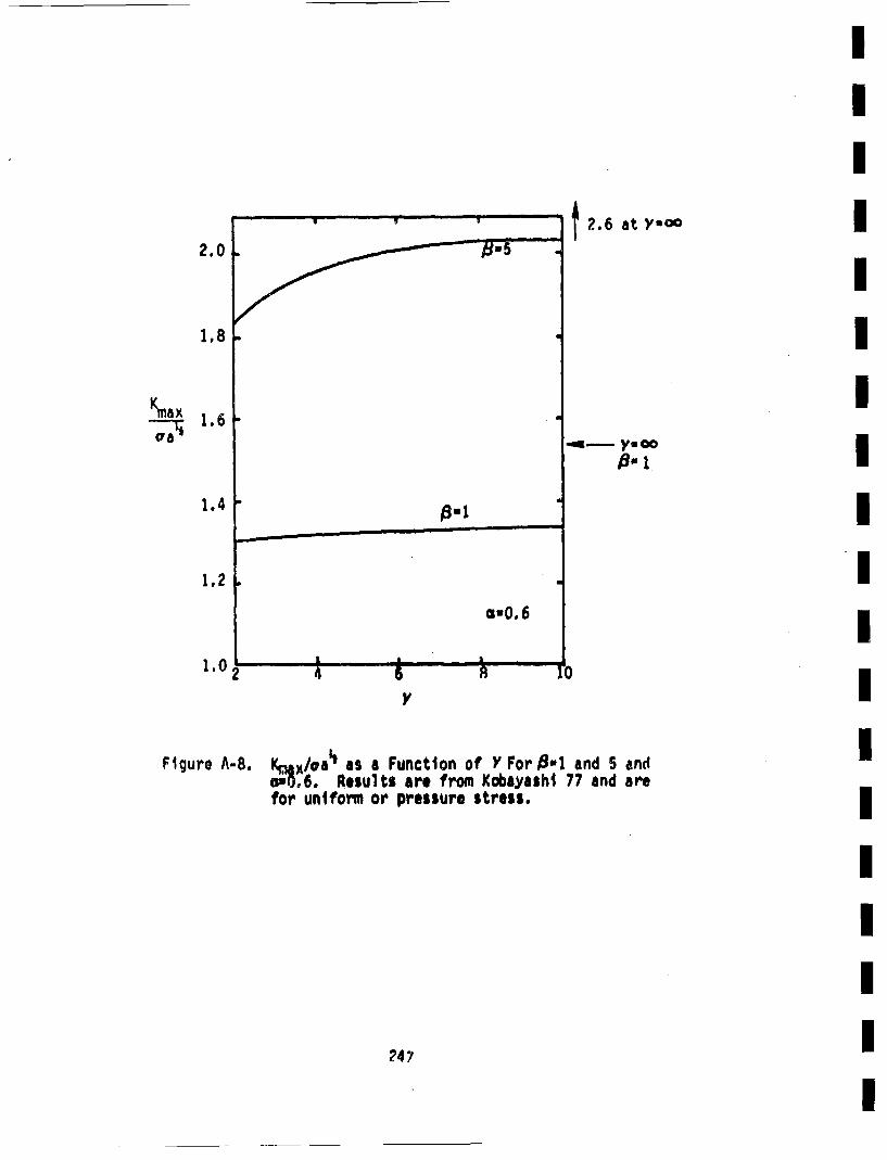
2.0
1,8
Km ax-I;aa
1.6
a-O. 6
It a It
t2.6 at Y-ca
*• ymca8-1,
1.4
1.2
1.02!2 4 6 B 1U
Figure A-8. Km.ax~/oa' as a Function of Y For •-1 and 5 and.- O,6. Results are from Kabsyasht 77 and arefor uniform or pressure stress.
247
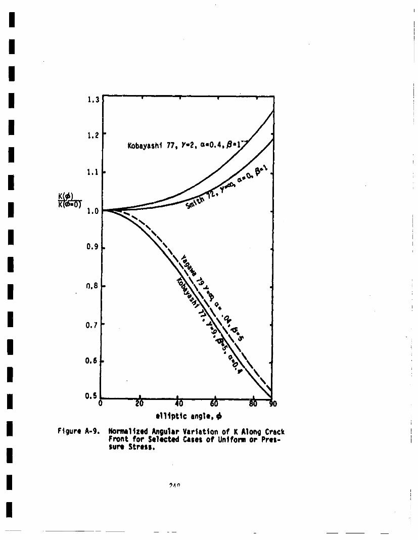
1.3
Kobayashl 77, Y-2, ca-O.4, ,~a
1.1-
0.7" •
0.60
0.5 p '
e111ptic angle, 6
Figure A-g. Normal lied Angular Variation of K Along CrackFront for Selected Cases of Uniform or Pres-sure Stress.
0,4
IOver'all, the above review indicates that existing stress intensity factorsfur cracks In pipes are available for only a spottY selection of valuesmof, the many geometric parameters involved. Such information Is especially B
lacking for cases where thickness gradients of the stress exist, andsolutions for part-circumferential cracks are virtually nonexistent.ITherefore, in order to be able to adequately treat the bivariate distri-bution of part-circumferential cracks considered in this investigation, Isome new stress itnensity factor results needed to be generated. Theelasticity problem is fully three-dimensional, and numerical technqiuesI
must be resorted to. The boundary integral equation (BIE) techniquemwas solecr~od for use. This technique will be briefly reviewed, followedby presentation of results obtained byr its use.
A.3 Review of Boundary Integral Equation TechniquesI
The problem of a part-circumferential crack in a pipe composed of Ielastic material is a fully three-dimensional problem. Analytic m
solutions of such problems are usually unobtainable, and numerical tech-
niques must be resorted to. The most coeuonly known aind applied tech-nique for elasticity problems is finite elements. In such cases thecomplete body, including its interior, must be broken uJp into small Ielements. For three-dimensional problem, very large computers and longexecution times are generally the rule. Another means of obtaining
num•erical solutions to three-dimensional elasticity problems is themboundary integral equation technique (SIC[). In this technique, only the Isurface of the body need be broken up into elements, and the numericalsolution then directly, provides displacements and surface tractions atthe surface nodal points. If information in the interior of the body Iis desired, additional calculations are required. However, crack prob-lems can generally be formulated such that the crack surface and crackImplane form a part of the surface of the body to be analyzed. Stressintensity factors are obtainable from crack surface displacements closeito the crack tip (see Appendix B). Therefore, numerical infonmation oncrack surface displacements is sufficient for the preent case, andBIE techniques appear to be especially well suited to provide economical Isolutions to the three-dimensional creek problem of interest.•
The BIE technique Is based on some integral results originally obtainedby Somigliana •hich relate displacements to surface integrals of coudbin-ations of surface tractions and surface displacements. Such Integralsare covered in Section 169 of Love 44. Rizzo, and Cruse and his Co.workers pioneered the application of DIE to elasticity porbiems, andtheoretical bases of the procedures employed are covered in Rizzo 67,Cruse 69, 73, 75a. Basically, the surface of the body Is broken up Intosegmnts, and the variation of stresses and displacements within anarea segient are assumed. The surface integrals are then evaluated interms of the unknown surface displacements and tractions. This resultsin a set of simultaneous linear equations that can be solved for the un-known nodal displacements or tractions. Since only the surface of thebody has to be modelled, the size of the problem is much less than ifthe entire volume of the body had to be broken up into elements. Hence,BIE techniques can be advantageous over finite element techniques. How-ever, the "matrix of coefficients" of the unknowns is "banded" in finiteelements which comperiates sonmewat for this. Additionally, finite ele-ment techniques are more accurate. Nevertheless, BIE techniques wereselected for use In this investigation, because high accuracy was notdesired, and computer expenses were to be minimizedo The computerprogram described by Cruse 73 was obtained' and applied to the problemsof interest. The results obtained are presented in Appendix B.
*The generous assistance of T. Cruse, Pratt and lhitn~ey Aircraft, EastHartford, Connecticutt, and P.M. Besuner, Failure Analysis Associates,Palo Alto. California. provided in obtaining and exercising the tilE pro-gram is gratefully acknowledged.
25O

APPENDIX B ISTRESS INTE.NSITY FACTOR RESULTS FROM BOUNDARY
INTEGRAL. EQUATION CALCULATIONS I
IIII
• II
251
Appendix B
STRESS iNTENSITY FACTOR RESULTS FROM BOUNDARYINTEGRAL EQUATION CALCULATIONS
Existing stress intensity factor solutions are not adequate for treatingthe bivariate distribution of part-circumferential cracks consideredin this investigation--as was extensively discussed In Appendix A. There-
fore, boundary integral equation techniques were applied to obtain thedesired results. In order to gain familiarit~y with the code (Cruse 73)
and to estimate its accuracy, problems with previously existing solutions
were first analyzed. New problem were solved after reproducing pre-
vious results with sufficient accuracy. Comparisons with previous solu-
tions and newly generated results will be presented in this Appendix.
The stress intensity factor for a crack problem can be estimated fromthe results of numeriSal pv'oceduros that. do not employ singular elements
In a variety of ways - including the following:
e Evaluation of results for two nearly equal crack sizes,
then calculating the strain energy release rates and
obtaining the stress Intensit~y factor (K) from theenergy release rate. This requires roughly twice asmany computer runs, and therefore approximately doublesthe computer cost (see for instance, Cruse 75a).
C Performing contour integrals around the crack tip andrelating values of the integrals to singular conditions
at the crack tip. This is anlalogous to Rice's J -
Integral formulation (Rice 68).
C Comparison of stresses near the crack tip with theknown singular solution in terms of K.
0 Comparison of crack surface opening displacement nearthe crack front with known soiutions in terms of K.
Z22
I
IIThis last procedure will be used here, because only one BIE calculationis required per crack size considerei, numerical elasticity solutionsIgenerally provide displacements with higher accuracy than stresses.and the crack surface displacements are obtained directly from the OlEI
calculations. As was mentioned above, extreme accuracy was not required.
The relevant equation relating the stress intensity factor, K, to theI
crack surface displacement close to the crack tip is derived fromclassical elasticity (Paris 65, Tada 73). For the standard polar coordin-Iate system with origin at the crack tip, the vertical displacement, v,is given byI
IThis equation is for plane strain. On the crack surface, o •180°,Iand the variation of v with distance from the crack tip isI
v(r, 1800)• * (•)J' (B-2)I
In this project, K will be evaluated from the opening displacment atthe node closest to the crack front. D~enoting this as V(ro), the equa- Ition for K Is
K1- -Veto) (.-j (8-3)I
As before rotis the distance between the crack front and the closest node. IThis equation will be used to obtain values of K from the results of8IC calculations. IComparison with previously existing results will be presented in the
fol lowing section.
II
B.1 B.1 Complete Circumferential Crack
The axisynunetric geometry of a complete circumferential crack in apipe was selected as an Initial probiem to analyze in order to becomefamiliar with running the BIE code. For axisynumetric loading, K resultscould be compared with corresponding results from Labbens 76. Thefirst loading case considered was axisynuietric, and Is shown in FigureB-i, along with the nodalizatlon scheme employed. 'C due to the ringof pressure loading was evaluated by numerical integration of Labbens76 weight functions. The loading geometry, and K from the DIE displace-me,•ts and Integration of Labbens results are shown in Figure B-2. Thisfigure also presents results obtained when the pipe length is halved, orwhen the portion of the crack over which the pressure is applied isaltered. K is independent of angular position for this loading andbody geometry. This is seen to be borne out by the DIE results, whichprovides a good check on the program and its inputs. When the pipelength is taken to be half the base case (which was 6 in. from the crackplane to the end of the pipe) K increases, as would be expected. Theagreement between the BIE results and Labbens 76 is good, with the DIEresults being 9.2% low for ro/a • 0,1 and 6.75 low for ro/a 0 .05. Avalu, of ro/a of 1/10 thus appears to provide satisfactory results.Additional results were generated in which the row of nodes on thecyclindrical surfaces closest to the crack plane were moved only halfas far from the crack plane. This was found to have a negligibleinfluence on the stress intensity factor.
Those results demonstrated that the code was capable of providing accurateresults, that boundary conditions were being properly treated, and thatK could be evaluated by use of Equation S-3.
The next problem to be considered retained the axisymetric geometry ofthe body, but considered a pressure loading only over a small angularsegmnt. This wes intended to check on the accurecy of results •-'steep gradients of K existed along crack front. Some renodalizaticn was
254
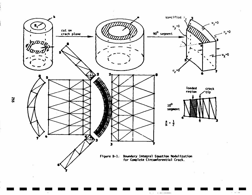
hb
Uz=Uv
,,crack plane 90o segneft
- , I-
(m' " I
'r
lodd rp
, 100o ff
_ 4,::;a . I -t
Figure B-I.. Bounwdary Integral Equation !aodalizationfor Complete Circisferential Crack.
n m- - - -m -m m -m m -m - m-m m-m u -n- -
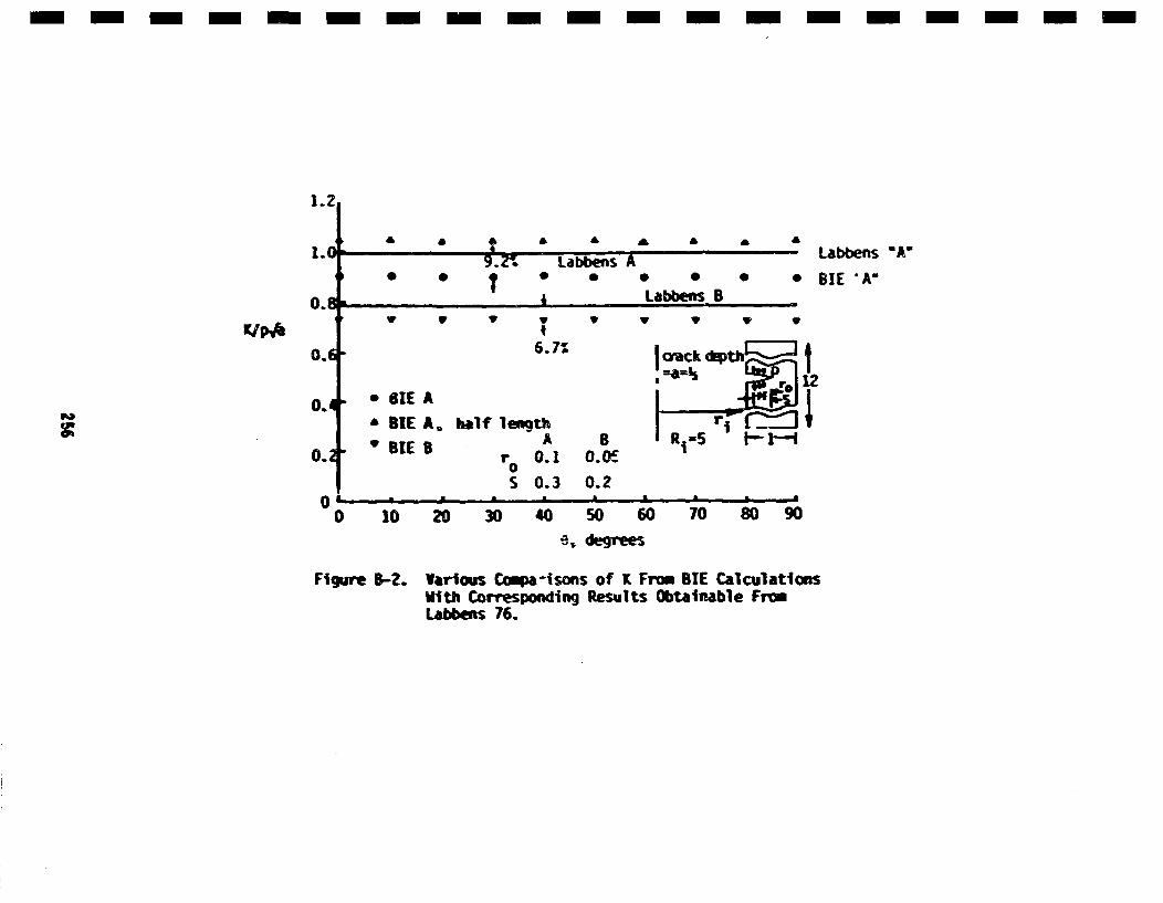
- - m-m--n--m-----m --m --m --m
1.2,
|i(
A £ * lb £ £ £ £ £ &I. Labbens "A
no
•9. Zi •Labbenos AS
k
Labben B E'AI * C.
K/pb r , VP V yV V I' V
o.6- 6. 7Z
£
SIEBIE
AA,
5 BIE B0.2
n
half lengthAr° 0.1
S 0.3
B0. O
0.2
V 0 10 20 30 40 50 60 70 80 90
Figure B-2. Various Coma-isons of K Fron BIE CalculationsVith Corresponding Results Obtainable FrnmLabbens 76.
II
done, with more nodes being concentrated in regions of steep gradients. IThe loading geometry considered is shown in Figure 8-3, along with vari-Ious sets of results. The "analyticalt m solution refers to an estimatedK for a point load included In Harris 79 and Harrti S8f. The value B
of 0 at which boundary conditions were specified was varied, with a treesurface at 300 and a "roller" surface at 900 being considered, Results
for those two cases are shown in Figure 5-3, front which it is observedthat the boundary condition did not have an appreciable influence.•
This is an expected result, due to St. Vinant's principle. Figure 8-3shows good agreement between the SIC resuits and an approxio;ia.; analyti-cal solution. This demonstrates the suitability of the BIE code to•crack problems when steep K gradients exist along thre crack front. Once
agin :he DIE results appear to be somewhat low. I
The next step wa• to employ the BIE code for a semi-elliptical longi-•tudinal crack. This would exercise the code on a fully three-dimensionalproblom for wh•ich previouslyaxisting results are available (Heliot 79,
McGowan 79). The results obtained will be presented in the next section.
8).2 Longi tudinal Semi-Elliptical Cracks IThe DIE code was used to calculate K for semi-elliptical longitudinal•cracks in pipes. The results obtained can thin be conmpered to infor-matrion In the literature in order to assess the accura'y of the SIC
resulSts.g
The geometry considered Is shown in Figure 8-4 which also presents theI
nodalization employed. General expressions for the nodal coordinateswore written in terms of the crack depth, crack length, wall thickness•
and inner pipe radius. This allowedmenSy different crack and pipe sizesto be treated without extensive changes to the SI[ input. Results wereobtained only for uniform stress; techniques for treating nonuniform Istresses will be covered in Appendix C. Results were first genieratedror y * R1/h * 10. since this value yes considered by Helite 79 andI
Mcywan 79, which are the references with the most complete set of results
II
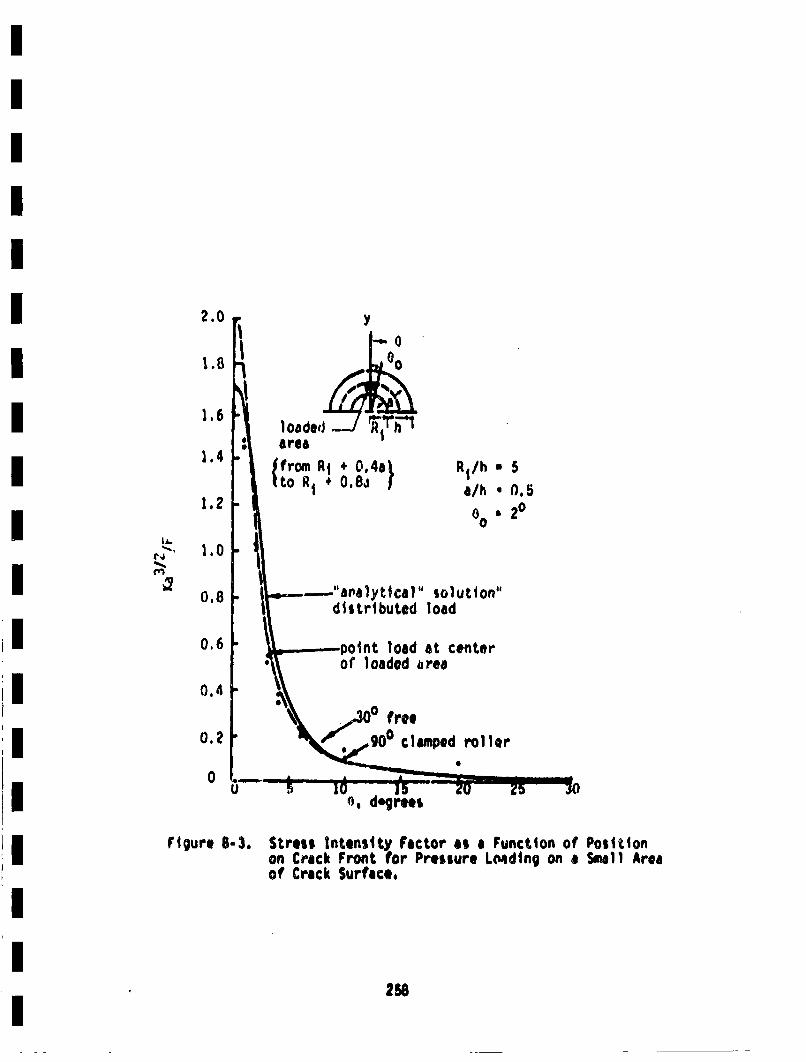
2.0
1,8
1.6
1.4
1.2
1.0
0.8
0.6
0.4
0.?
Y0o
1oa deJ,
area
tor + 0.8~I R1/h U 5a/h 0 .5
00 •20
IA.
solution"load
-polnt load at centerof loaded •aree
f ree
0
0
Figure 8-3. Stress Intensity Factor as a Function of Positionon Crack Front for Pressure Lo~mding on a Small Areaof Crack Surface.
258
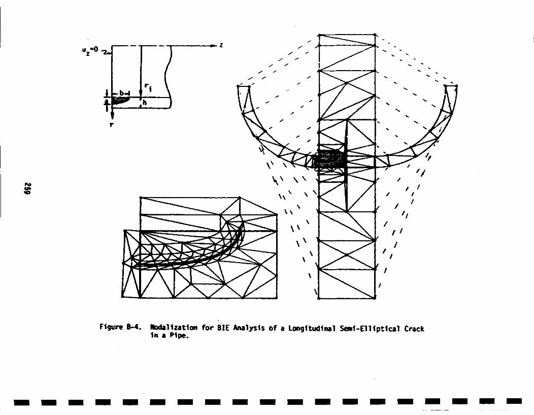
zSzO - -
- -
F,P
I,/
I,
\ /"IU, 'I
II
/II
/'I
\I I/
/
Figur B-4 fodllzaion or BE Anaysisof aLongtudial si-ElItiaCrc
I
in a Pipe.
- -- H -- D ---------- i i - i--
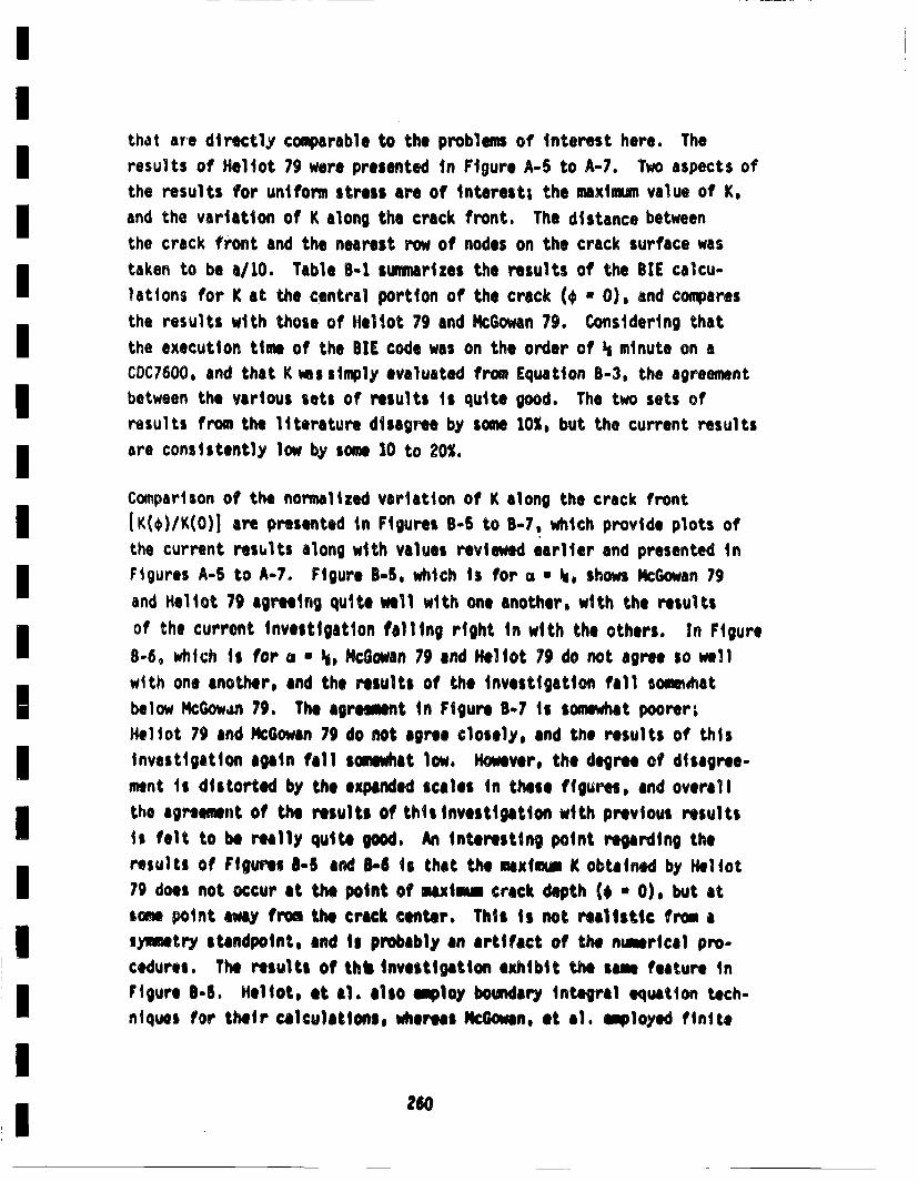
that are directlyv comparable to the problems of Interest here. Theresults of Heliot 79 were presented in Figure A-5 to A-7. Two aspects ofthe results for uniform stress are of interest; the maximum value of K,and the variation of K along the crack front. The distance betweenthe crack front and the nearest row of nodes on the crack surface wastaken to be a/10. Table 8-1 suninarizes the results of the BIE calcu-lations for K at the central portion of the crack (* u 0), and compares
the results with those of Heliot 79 and Mcoan 79. Considering thatthe execution time of the BIE code was on the order of I• minute on aCDC(7600, and that K ms simply evaluated from Equation 8-3, the agreementbetween the various sets of results is quite good. The two sets ofresults from the literature disagree by some 10%, but the current resultsare consistently low by some 10 to 20%.
Comparison of the normalized variation of K along the crack frontIK(,)/K(O)1 are presented in Figures B-B to B-7, which provide plots ofthe current restlts along with values reviewed earlier and presented inFigures A-B to A°7. Figure B-B, which is for o u I•, shows McGowan 79and Heloto 79 agreeng quite well with one another, with the resultsof the current investigation falling right in with the others. In Figure
8-6, which is for a * 3i, Mc:(owan 79 and Neliot 79 do not agree so wellwith one another, and the results of the investigation fall some~atbelow McGow~an 79. The agreement in Figure 8-7 is somewat poorer;HeliSot 79 and Mc:Oowan 79 do not agree closely, and the results of thisinvestigation again fall somewhat low. However, the degree of disagree-ment is distorted by the expanded scales in these figures, and overallthe agreement of the results of this Investigaiton with previous resultsii felt to be really quite good. An Interesting point regarding theresults of Figures 8-5 and 81-6 Is that the maximum K obtained by Mel lot79 does not occur at the point of maxlm. crack depth (€ • 0). but atsome point away from the crack center. This Is not realistic from alywuetry standpoint, and is probably an artifact of the numerical pro-cedures. The results of thb investigation exhibit the sans feature inFigure 8-5. Heliot, et al. also •ploy boindary integral equation tech-niques for their calculaitons, wheres IkMc~n, et al. illoyedl finite
260
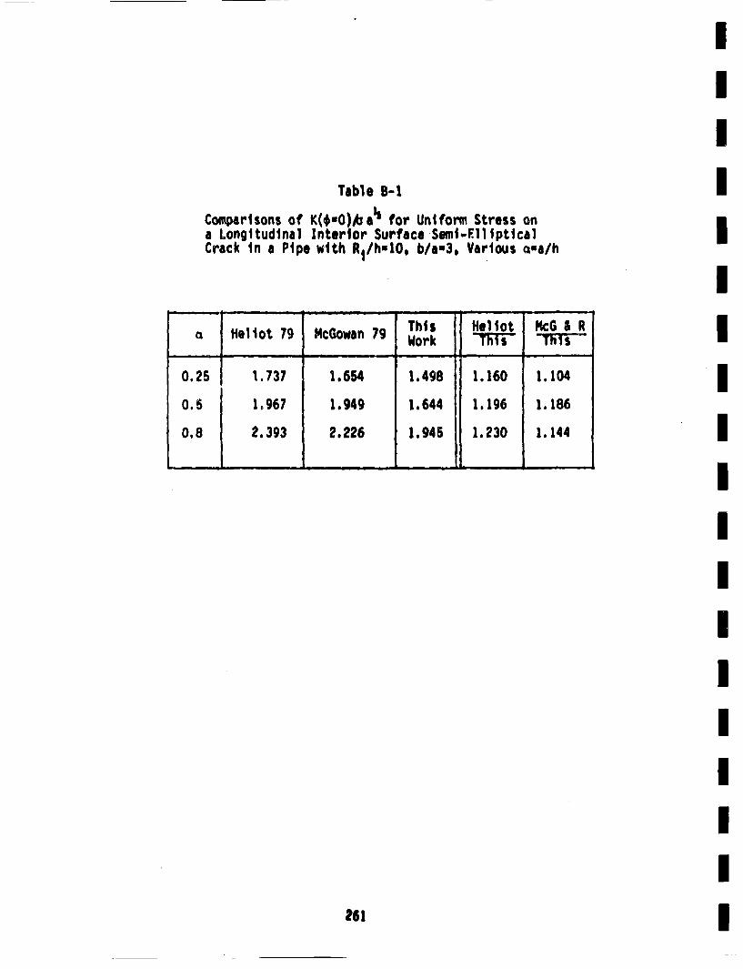
II
Table B-IComparisons of K(*,O)Aba" for Uniform Stress ona Longitudinal Interior Surface Semb.E11ipticalCrack in a Pipe with R1/h-1O. b/a,3, Various eisa/h I
IThis 14.1lot McG&I R
cz teliot 79 McGowan 79 Work 1'iV TT
0.25 1.737 1.654 1.498 1.160 1.104
0.5 1.967 1.949 1.644 1.196 1.186
0.8 2.393 2.226 1.945 1.230 1.144
I
261
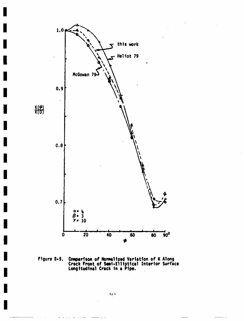
1.
0o9
0.8 \
0.7
'-33)'" 10
8 A 8 a a 8 a
020 40 608 900
Flrguro 0-S. Comperison of Noretlized Varlitton of K AlongCrack Front of Ssmi-Clli ptical Interior SurfaceLongitudinal Crack in a Pipe.
1~
1.0:
0. cGowan I
this work•
N, I0.8 - I
II~I
'I\ Iyo 10 I .a
0.7 a a a a a a ,, a,)0 20 40 60 60 900 I
€IFigure 8-6. Cocpartion of Normalized Vriatiton or K Alone)
Crack Front of Sim-Elllptical Interior SurffceLongitudinal Crack in a Pipe,
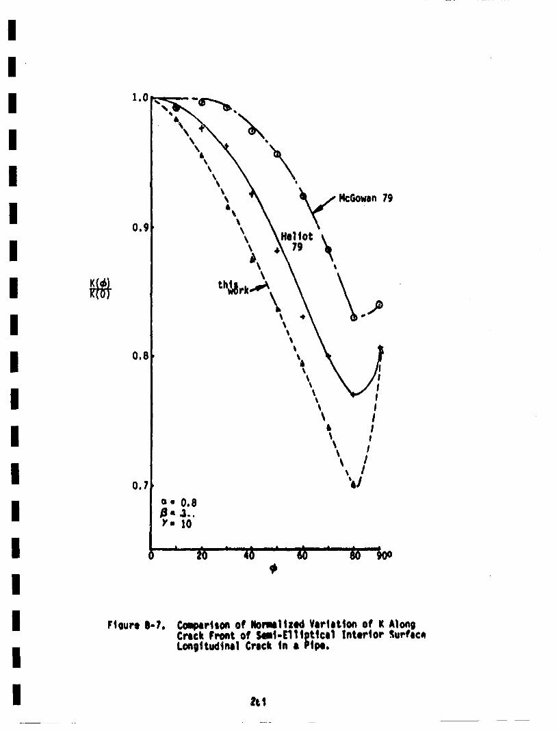
McGowan 79
0.9
0.8
0.7
\\
'4
\
&
'4'4
I
IeI/
'4,
ri. 0.)'" J0
Fioure I-?. Comparison of Mlormlied Variation of K AlongCrack Front of 5.1-Elli ptfca1 anterior Surtac*Longitudinal Crack in a ie
tt t
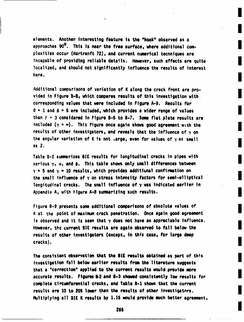
elements. Another interesting feature is the uhooku observed as *approaches 900. This is near the free surface, where additional corn- Iplexittes occur (Hartranft 72), and current numerical tecnniques areincapable of providing reliable details. However, such effects are quite Ilocalized, and should not significantly influence the results of interesthere. IAddSitinal comparisons of variation of K along the crack front are pro-
vided in Figure 8-8, which compares results of this investigation withcorresponding values that were included in Figure A-9. Results for0 * 1 and S * S are included, which provides a wider range of values 1lthan e• ' 3 considered in Figure 8-5 to 8-7. Some flat plate results areincluded (y • ,,). This figure once again shows good agreement with theIresults of other investigators, and reveals that the influence of v onthe angular variation of K is not ,arge, even for values of y as smallas 2. ITable 8-2 stumarizes SIC results for longitudinal cracks in pipes withIvarious y, ca, and B. This table shows only small differences betweenIy a 5 and y * 10 results, which provides additi..nal confirmation onthe small Influence of y on stress itenstyml factors for semi-ellipticalIlongitudinal cracks. The small influence of y was indicated earlier inAppendix A, with Figure A-S sunmarizing such results.
Figure 0-9 presents some additional comparisons of absolute values ofIK at the point of maxmLmu crack penetration. Once again good agreementIIs observed and ittis seen that y does not have an appreciable influence.However, the current SIC results are again observed to fall below theIresults of other investigators (except, in this case, for large deep
cracks).
The consistent observation that the SIC reults obtained as part of thisIinvestigation fall below earlier results from the literature suggeststhat a "correction" applied to the current results would provide moreaccurate results. Figures 5.2 and S-3 sheed consistently low results for Icomplete circuiferential cracks, and Table S-i shows that the currentresults are 10 to 201 lower than the results of other investigatnrs.1e
P•ltiplying all SIC K results by 1.15 would provide much better agreement,
285 I
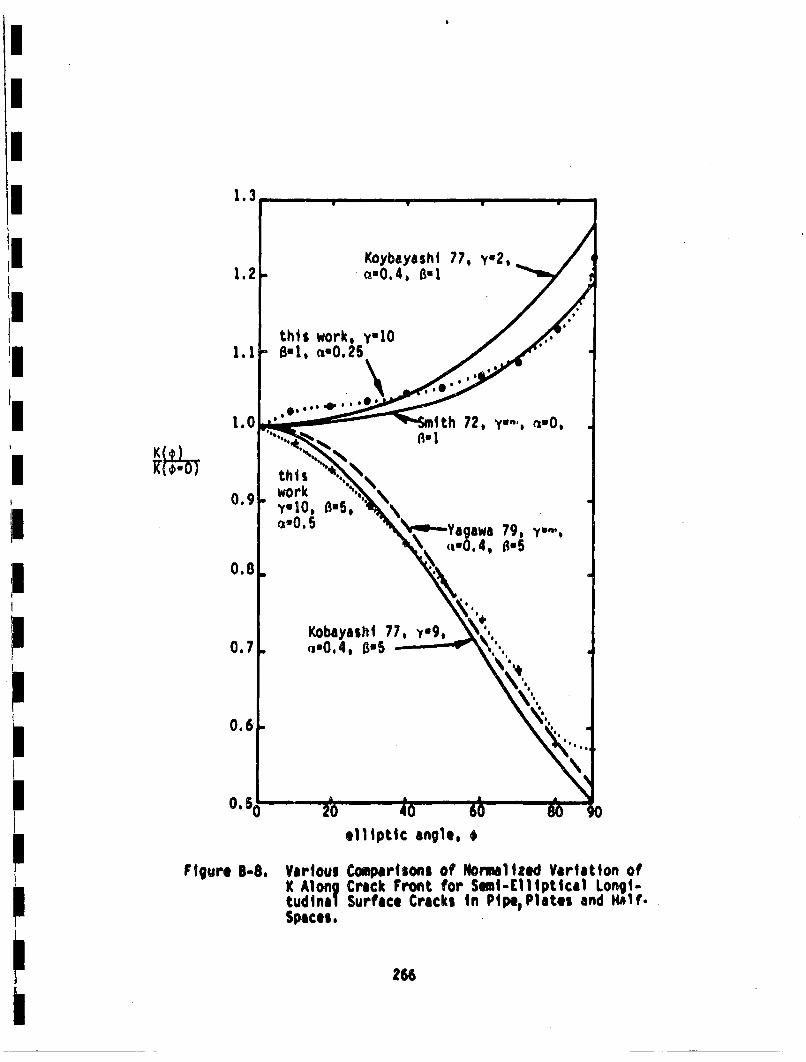
1.3
0.9-
0.8.
0.7.
0.6
Figure Bum.
elliptic angle, 4
YariouiK Aiong
Spaces.
CoutpartsOns of Normalized Variation ofCrack Front for SemI-Elliptical Longi-Surface Cracks In Pipe, Plates and HIlf.
266

Table 8-2Comparison of K(taO)/oaa for Uniform Stress ona Longitudinal Semi-El~lpt|cal Crack In a Pipefor Varlo**ey v. and B. All Results Generatedby SIC, and are not Corrected to Account forConsistently Low BIE Results
, i :" 0.25 ci *O.5
- , - I I-~I ~ I - V
y•-5 10 10 lO
10 Y* S yuS 10.-------.-. I - I.~ I I - I .. 11 - A -
I
3
5
0.99
£ .45
1.59
1.01
1.60
1.65
1.*03
1.61
1.83
1.05
1.64
1.86
1.15
1.*97
2,36
1.12
1.*95
2.33
9.84Ii
-- eb
9 hA 4.081
II
IIIIII
II
* from Labbons 1976
26?
IIIIIIIIIIII
IIIIII
2.0
o Cfa
.
I
i=e/hF~gre -9.Varloui Couipartsons of K(*'O) for Ln:ngltudlnal
S~.[111UpttCa1 Cracks tn Pipos.
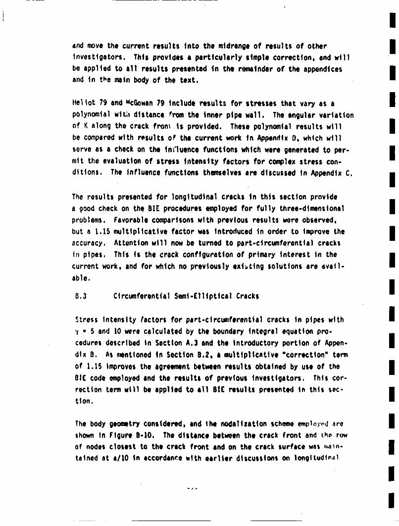
and move the current results into the midrange of results of otherm
investigators. This provides a particularly simple correction, and will m
be applied to all results presented in the remainder of the appendicesmand in th'e rain body of the text.
Hel lot 79 and McGowan 79 Include results for stresses that vary as a Ipolynomial wit;, distance •rom the inner pipe wall. The angular varititonof K along the crack from is provided. These polynomial results will Imbe compared with results oP the current work in Appendix 0, which willserve as a check on the lnl'luence functions which were generated to per- Imit the evaluation of stress intensity factors for complex stress con-ditions. The influence functions themselves are discussed in Appendix C.m
The results presented for longitudinal cracks in this section providea 9ood check on the BIE procedures employed for fully three-dimensional Improblems. Favorable compairsons with previous results were observed,but a 1.15 multiplicative factor was introduced in order to improve the Iaccuracy. Attention will now be turned to part-circumferential cracks B
in pipes, This is the crick configuration of primary interest in thej
curront work, and for which no previously exit•ing solutions are avail-able.
8.3 Ci rcumferential Semi-Ell !iptical Cracksm
Stress intensity factors for part-circumferential cracks in pipes with Imy * 5 end 10 were calculated by the boundary integral equation pro-cedures described in Section A.3 and the introductory portion of Appen-
dix 0. As mentioned in Section 8.2, a multiplicative "~correction" termiof 1.15 improves the agreement between results obtained by use of the IOlE code mployed and the relsults of previous investigators. This cor-mrection tenm will be applied to all BIC results presented in this sec-m
t ion.
The body geometry considered, and the nodalization scheme emp1•o',d ,ire Ishown in Figure 8-10. The distance between the crack front and itho ro~wof nodes closest to the crack front and on the crack surface was •.ain- mtameod at a1/0 in accordaine with earlier discussions on longltudtn,•l m
II
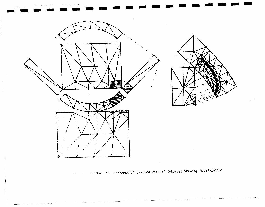
- - - - - - - - - mm - - - - - -m -
= •.~-. r-,fcr-ci, tl :r~ck'd Pi;c Of Interest $I~ewi •dd31izatione
Iand coniplete circumferential cracks. General expressions of the nodalcoordinates were written in terms of the crack depth, crack length,.I
wall thickness and inside pipe rsdius. In this manner, the differentgeometries considered could be ree;oalized by the coaputer rm~ce the
relevant geometric parameters were defined. This greatly facilitatesconsideration of a wide variety of crack and pipe sizes. Long semi-
elliptical circumferential cracks become distorted due to the curvatureof the pipe surface, it was therefore required to generalize the equationfor an ellipse, which was accomplished by use of the following expressionIi
(r'R1)2 (R0)2 I
where r and 0 form a polar coordinate system centered at the center of Ithe pipe.I
Calculations for uniform applied stress of K as a function of positionon the crack front were performed, with the results for K at the point
of maximum crack depth (•-O) summnarized in rable B-3. Correspondingresults obtained for longitudinal cracks are also included in this table.
All values in Table B-3 have been subjected to the 1.15 multiplicative mm
"~correction" factor. Hence, the numbers rable 8-3 are 15% higher thanthe correspond~no value in Table B-?. V•. s of K for a flat plate (y--)
are from Newman 79, values for finite y b)• infinite 0 are from Labbens B
76, and values for y=u". are from the siiiglo-edge-cracked strip in tension•
results provided by Tada, Paris and Irwin (Tada 73).
The results presented in Table B-3 reveal only very small differences Ibetween longitudinal and circumferential cracks as long as 03 does notapproach •o. That is, for semi-elliptical cracks, the K results are virt- -Iually Independent of whether the crack is longitudinal or circumferential. •f
The only time that the orientation has an effect Ii when the aspect ratio•
becomes very large, and the corresponding two-dimensional problem is approa-ched. As shown in Figure A-4, the limiting two-dimensional cases oflongitudinal andl •onplete circumferential cracks have quite different I
271I
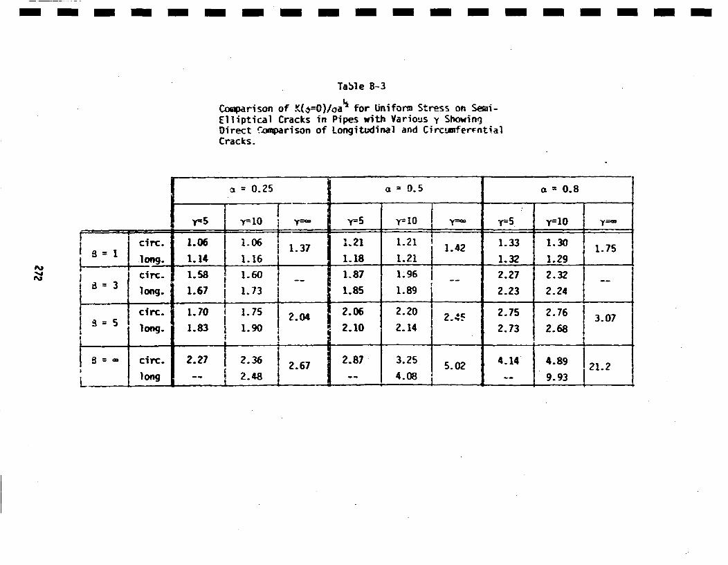
- m- m-m-m- m-m - -n - -m- m- m-m- m-
Table B-3
Coiaparison of KG•-O)/oaa for U~nifonn Stress on Smi-Elliptical Cracks in Pipes wit Various y ShowinrDirect .oq•rison of Longitudinal and Circ!u~erntialCracks.
S= 0.25 ac = 0.5 = 0.8
y= 10 y=~5 'r~ 1 y=5 y~lO
*.1
~ 1 circ. l.06 1.06 11.37 1.21 1.21 ' .2 1.33 j1.30 17_______ lo1g. 1.14 1.16 j____ 1.18 1.21 1.2 1.32 1.29 ____
clrc. 1.58 1.60 __ 1.87 1.96 J- 2.27 2.32
•= 3 long. 1.67 1.73 1.85 3.9 .253a 4.894 1
SCirC. 1.70 1.75 12.04 i 2.06 2.20 2.45 2.75 2.76 3.07
__=__jlong. 1.83 1.90 *2.10 2.14 2.73 2.68
8ciI I 1S 'cr. 2.27 2.36 2.67 2.871 .2 5.02 4.1 1.9 21.2
I L__ __2.8 __0 __ __I__9
mvalues of K once a/h exceeds about 0.2. Table B-3 reveals that the longi-
tudinal and eircumferentlal cracks have virtually the sane K if a three-dimensional configuration with finite 8 Is considered. Thus, the differ-ences expe~cted from consideration of the two-dimensional results (Figure 1IA-4) are not observed in the corresponding three-dimensional values (TableB-3). This is most likely due to the differing effects on global stiff-lnesses of pipes and plates produced by semi-elliptical versus infinitely m
tong cracks. IThe results of Table 8-3 again show that y does not have an appreciable I]influence on the K values, except in the extreme case of 0 m* It isalso seen that results fQ• 0 '•, are not representative of infinitely
The other aspect of the results for part-circumferential cracks that islof interest is the variation of K along the~ crack front. Figures B-lIand B-12 present selected results normalized to the value at the pointof maximum crack penetration. These figures show that there are not Isignificant differences between longitudinal and circumferential cracksas regards variation of K along the crack front. Results presented inImSection B.2 showed that K variations along the crack front were nearlythe same for longitudinal cracks in pipes and corresponding cracks inl
flat plates. Thus, it can be concluded that to a satisfactory degree [of approximation, stress intensity factors for semi-elliptical cracksare virtually independent of whether they are in a flat plate or oriented Icircumferentially or longitudinally in a pipe. However, limiting two-dimensional cases, such as plane strain longitudinal cracks or comlete Imcircumferential cracks, do exhibit appreciable differences that are notobserved for the range of aspect ratio considered here. Such differences Iwere shown in Figure A-4,.
Results for uniform applied stresses have been detailed here in Appendix ImB. As was stated earlier, It is desired to account for stresses wh•ichhave complex and steep gradients through the thickness of the pipe wall. m
The use of the B|E code for every thickness distribution of interest would
I
273
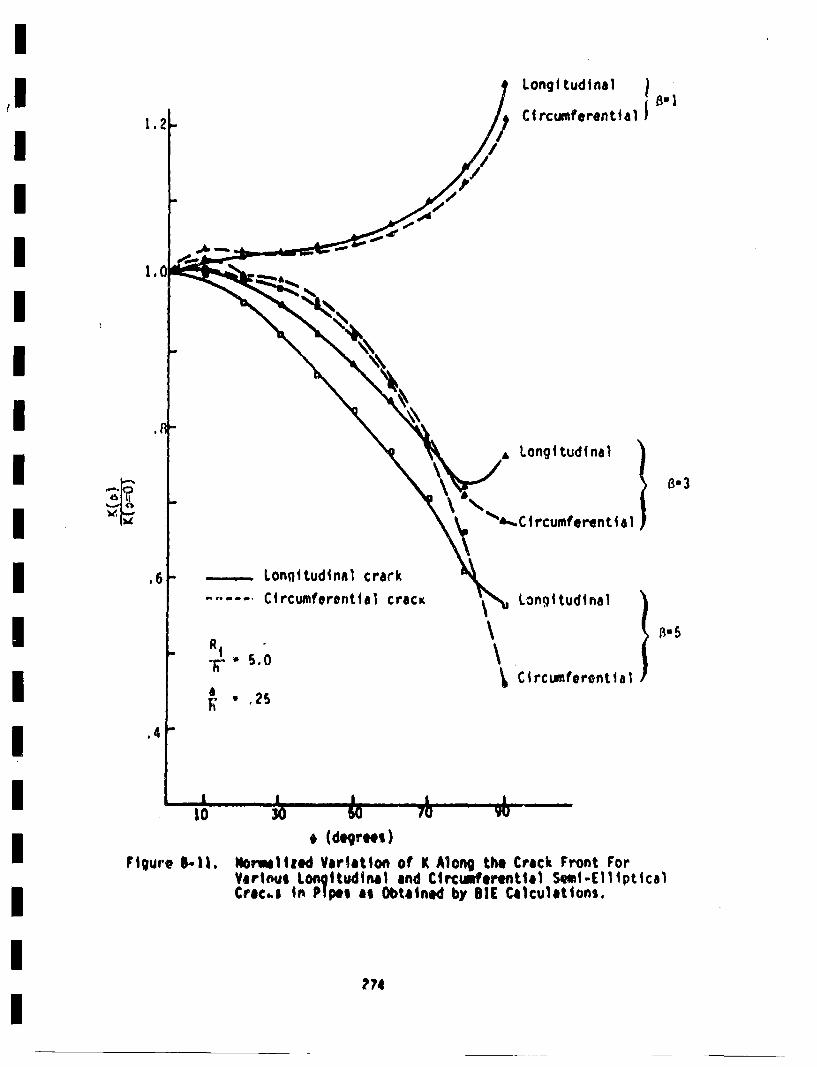
Longi tudtnal ICi rcumtferential B1
1,
1.i
~Jf'
SLongi tudinal
/ L.Ctrufrn } -~3
,6 -..- Lonqi~tudinal crark.... Circumferential cracK Longitudinal
CircumferentalaRAI- S,
'• 5.02
,4
* (degre~i)Figure 1-11. IWorwilied Variation of K Along the Crack Front For
Varinvi Longitudinatl and Circumferential Sumi-Cllipt~calCraCba In P1 pn ai Obtain(I by BIE Calculations,
274
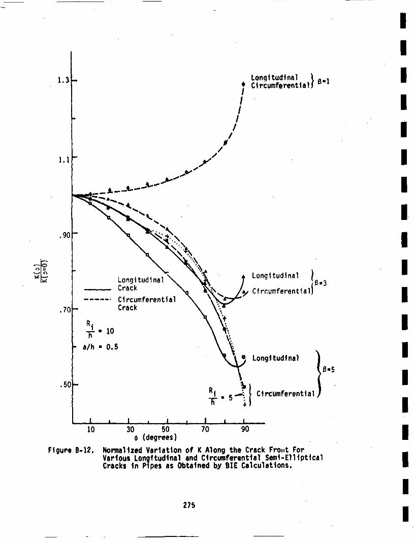
1.3
I.I
.go
I/
,/N
//
--V.
- j. ~ -
Longitudinal i .Circumferential) •' "
Longitudinal I
CircumferentiallS
IIIIIIIIIIII
'~ lie'-I 4~
Longi tudinalCrack
CircumferentialCrack
*- 10
a/h * 0.5
Longitudinal l.
Circumferential)
III-5--5' I
'!I i, 70 goI I
10 30 50€ (degrees) IFigure B-12. Normalized Variation of K Along the Crack Fro,,t ForVarious Longitudinal and Circumferential Semi-Elliptical
Cracks in Pipes as Obtained by BIE Calculations. III275
be prohibitively expensive, and would produce more detail than couldbe effectively used in the fatigue crack growth analysis. Influencefunction techniques are capable of generating the desired informtionusing only results already obtained as part of' the BIE calculations foruniform applied stresses. These techniques will be reviewed in Appendix C.and applied to radial gradient, thermal stresses of interest in Appendix ().
276
APPENOI X CSINFLUCNCE FUIJCTlOftS
2??
APPENDIX C
INFLUENCE FUNCTIONS
The desire to account in the fatigue crack growth analysis for transientstresses which have steep and complex variations through the wall thick-ness necessitates the generation of stress intensity factor solutionsin addition to those provided for uniformstress in Appendtx 8. Theuse of boundary Integral equation techniques for all stresses consideredwould be prohibitively expensive, and would produce more information thanrequired for a fatigue crack growth analysis. Influence function tech-ntques based on some results by Rice 72b wore therefore resorted to,which was originally suggested by Cruse and Besuner (Cruse 75b, Bosuner76). Some introductory remarks will be provided, followed by a briefreview of the underlying theory and a presentation of the results gener-ated for a part-circumferential crack in a pipe.
Cl Introductory Remarks
A semi-elliptical surface crack such as shown in Figure 2-2 or A-I, isa two-dimensional crack that requires two length dimensions for itsspecification; a and b. The local value of the stress intensity factorvaries along the crack front--even for uniform applied stress. Resultspresonte• In Appendices A and B vividly show this. When considering thegrowth of a semi-elliptical fatigue crack due to cyclic loading, it wouldbe tempting to consider the local value of the crack growth rate to dependon the local value of K. l~owever, this results in considerable complexit3in the crack growth analy~is, and would quickly lead to cracks that werenot semi-elliptical in shape. This, in turn, would lead to the necessityOf generating new stress intensity factor results to account for themnon-elllpticity" of the crack. In order to circumvent such problems,it is generally assumed that the crack remains elliptical as it grows sothat only a and b need to be considered (Cruse 7Sb, Besuner 76, 77b, 78,Nair 78). This is discussed more fully in Section 2.6. Basically, two
278
I
options are generally considered: (I) the growth rates of a and t areIcontrolled by the local values of K at *u0 and 900 respectivwly #&seeIFigure A-I); or (ii) the growth of a and b are controlled by "RMS-averaged"stress Intensity factors associated with the growth of cracks in theI
a and b directions. The second option will be used in this work, forreasons discussed in Section 2!.6. One prim advantage to this option isI
that the "RHS-averaged" stress intensity factors are obtainable fromInfluence functions that can be derived from crack surface displacementI
results obtained by BIE calculations. Hence, a "two-.degree of freedom"model is employed, with "RNS averaged"M stress intensity factors control1-I
ing the growth rates in each of the directions associated with eachIdegre-t of freedom. The "PRiS-averaged" stress intensities will be denotedby a bar over the symbol, such as Ka'* This is the RI4S-K value for growth Iin the depth, or a, direction. The other MP5-K is Kb, which is associatedwith growth in the surface length direction.I
The valhes of K a and Kb can be determined by the use of influence functionsI
ha and hb from the foll,wing general expressions (Rice 72b, Cruse 75b,IBesuner 76, 77b, 78).I
KaM f ha(xay'a'b) a(x,y) dA
~I
The integration is carried out over the crack surface A. o(x,y) is
the stress on the crack plane that would be present before the crack isintruduced, and ha and hb are the influence functions associated withm
growth in the a and b directions (the two degrees of freedom considered).The influence functions will be discussed in the following section.
The relationship between the Ks and the angular variation of K (K(4)1is obtainable. The basic relations are the followingI
279
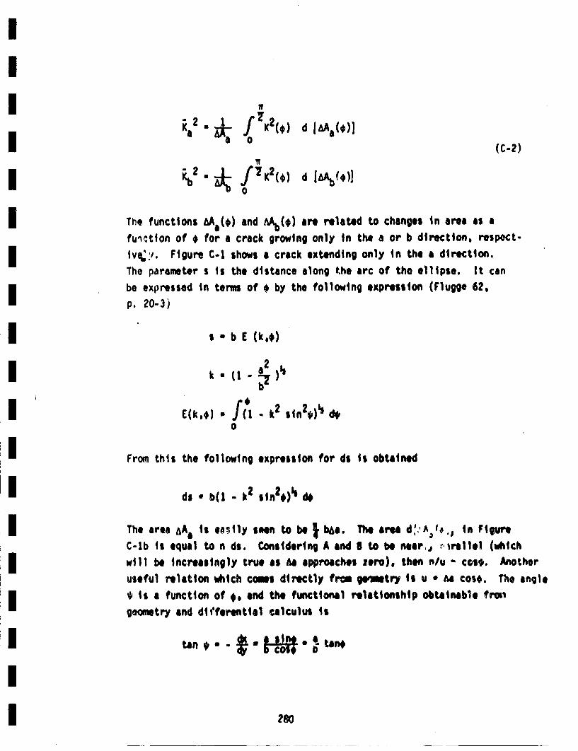
a 0 (C-2)
*2,j f=K 2 (,) d [ ()
0
The functions MA C,) and AU~b(*) are related to changes in area as afu'•ction of * for a crack growing only in the a or b directionl, resp~ect-1tv:'. Figure C-I shows a crack extending only in the a direction.The parameter s is the distance along the arc of tho ellipse. It canbe exp)ressed in terms of * by the following expression (Flugge 62,
p. 20-3)
a b E (k.,)
k • t - ½--).E(k,*) •/ - k2 sin2*)" d4
From this the following expression for ds is obtained
di • b(1 - k2 sin2*)1 d4
The area &Aa is enstly+ seen to be • bha. The are d"Ao I,, .jin FigureC-lb is equal to n ds. Considering A and S to be nier,, rirellel (vdiichwill be increasingly true as Aa approaches zero), then n/u os*. Another
useful relatiton ihich comes directly from ge'qtry is u * Aa co$,. The angle* is a function of *, and the functional relationship obtainable frm'geometry and dittferential calculus is
280
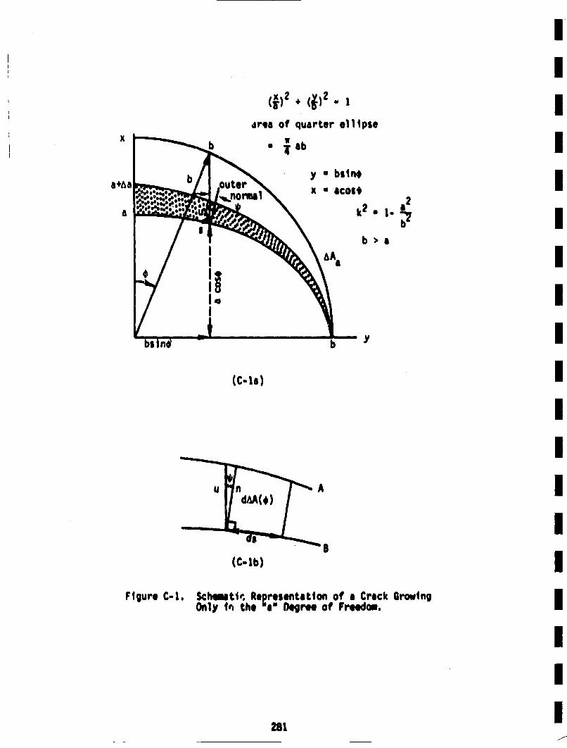
I
jrta of quarter ellipse
*a•b
K • bcst * •
X • 8COb
b•a
(C-la)
I
A
S(C-lb)
Figure C-i. Schemtlw, Represenltatiofl of a Crack GrowingOnly 4vq the a" IDegre. of Freedom,
281
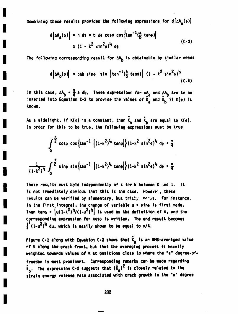
Combining these results provides the following expressions for diM C($))
x (1 - k2 •in 2*)' d* C-3
The following corresponding reselts for M~b Is obtainable by similar means
(C.4)
thwarted into Equation C-2 to provide the values of Ka and Kb if K(•) |skrnown.
Asa sidelight, if K(e) is a constant, then K1 and Kb are equal toK()
In order for this to be true, the following expressions must be true.
-1~- f sin, so.{.a"l (1,k2)• .an.j)(,-k2 ,i.2*)• 4j. *
These results must hold independently of k for k between 0 ".nd 1. It
Is not iniwdiately obvious that this ii the case. Hewevrs . these
results can be verified by elementary, buc tric:*. me",,s. For Instance,in the first integral, the chqage of variable u * sin$ ii first made.Then tanO* •"~-',ik 2)'u/( lu 2)"j i, used, aste definition of 0. and thecorresponding expression for coso is written. The end result becomes-t'il-u2 )"t du, which is easily shown to be equal to u/4.
FiueC-I along with Erquation C-2 shows that K i s an UIS-averaged! value
v^f K along the crack front, but that the averaging process is heavilyweighted towards values of K at positions close to where the am degree-of-
freedom is most prominent.. Corresponding remarks can be male regarding,.The expression C-2 suggests that (Ks) 2- Is closely related to the
strain eniergy rel~eae rate associaed with crack growth in the ae degree
2A2
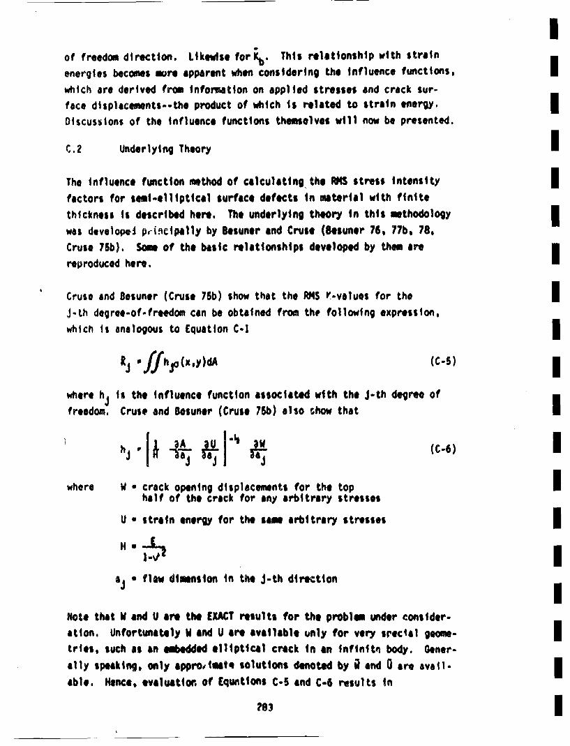
Iof freedom direction. Likewilse for Kb•. This relationship with strain
energies becomes more apparent when considering the influence functions,lwhich are derived from information on applied stresses and crack sur-face displacements--the product of which is related to strain energy,.mDiscussions of the influence functions themselves will now be presented.
C.?2 Underlying Theory mm
The influence function method of calculating the UI stress intensity Ifactors for seim-elliptical surface defects in malterial with finitethickness ii described here. The underlying theory in this methodologymwas developei p,-I.•etpally by Besuner and Cruse (Besuner 76, 77b, 78, m
Cruse 75b). Scm of the baic! relationships developed by them arem
reproduced here.
Cruse and Besuner (Cruse 76b) show that the RMS V-values for the IJ-th degree-of-fredo can be obtained fro the, following expression,which Is analogous to Equation C-I m3
where hjtis the influence function associated with the j-th degree ofmfreedom. Cruse and Bosuner (Cruse 75b) also show thatI
where WV • crack opening displacements for the top mmhalf of the crack for any arbitrary stresses
U • strain energy for the sam arbitrary stresses m
*j flaw dimension in the J-th direction
Note that W and U are the EXACT results for the problem under consider-ation. Unfortuna1tely U and U are available unly for very srec'al geese- mmtries, such as an e lxdded elliptical crack in ane infinitt• body. Gener-ally speaking, only eppro, imate solutions denoted by t• and 0 are avail-mable. Hence, evailuation of Equotions C-5 and C-6 results inm
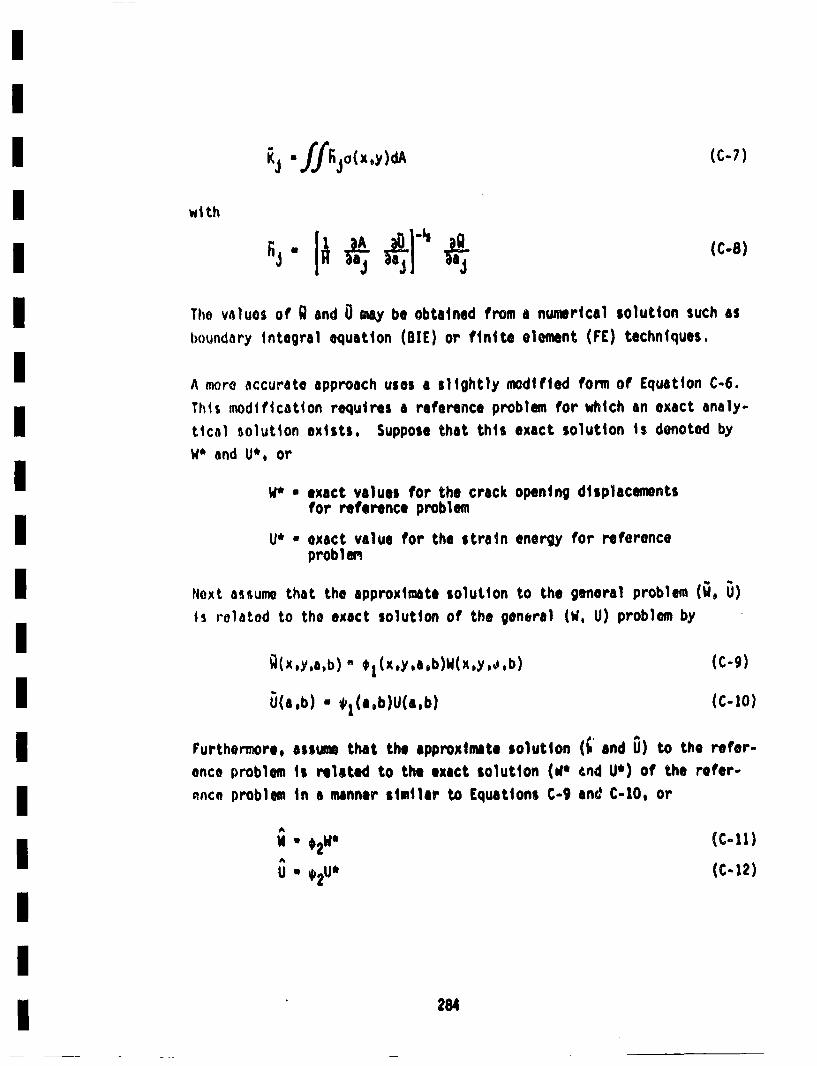
j -ffFGja(x.y)UA (c-7)
wi th
Tho values of • and 0 ma be obtained from a numerical solution such asboundary Integral equation (BIE) or finite element (FE:) techniques.
A more accurate approach uses a slightly modified forn of Equation C-6.Thi$ modification requires a reference problem for which an exact analy-tical solution exists. Suppose that this exact solution is denoted byW* and U*, or
W* •exact values for the crack opening displacementsfor reference problem
U* exact value for the strain energy for referenceprobl1m
Next assume that the approximate solution to the general problem (U, U)is related to the exact solution of the gendtral (W4, U) problem by
U(a,b) - *1(a,b)U(a~b) (C-%0)
Furthermore, assum that the approximate solution (•' and 0) to the refer-once problem is related to the exact solution (.1 t•nd U*) of the refer-enco problem in a manner similar to Equations C-9 and% C-l0, or
AW • *2W* (C-li)
AU • •,2U (C-12)
284
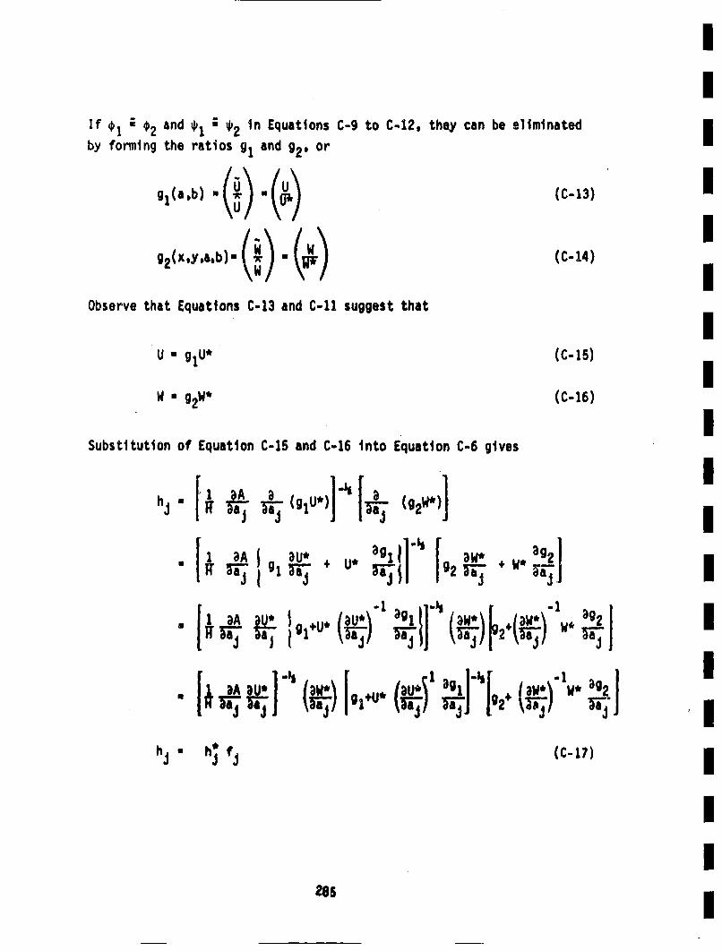
If @1; €2and 1 2in Equations C-9 to C-12, they can be eliminatedby forming the ratios gland g2. or
g2(xy.ab)u (~) U (a.)(c-13)
(c-14)
Observe that Equations C-13 and C-li suggest that
U " g1U*
mgW *
(c-15
(C- 16)
IIIIIIIIIIIIII
Substitution of Equation C-iS and C-16 Into Equation C-6 gives
h~m
au~ .,ag I]- 1* a g2
-U1 3A ~ ~3g1 ~1"' I aw* j aw*\1~ 3g2~aa ~I )g1\~~j-/ ~IT (I ~i2~ 3aa 1 i i Ji i'i ~ ii
" 3)A 31*1 )WIlU i•..•' ,,,l-•( /aw.\'t.. !•I •J P2+ •2J 'I
h U h f,, (C-i?)
II
285
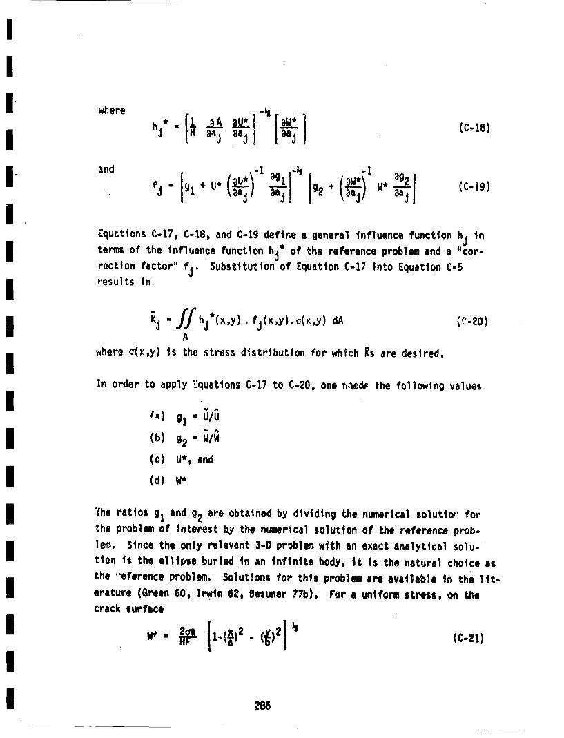
where r•
h" ii . aA 1 BU ( (c-18)
Equctions C-17, C-18, and C-19 define a general influence function hj interms of the influence function hj* of the reference problem and a "cor-
rection factor" fj. Substitution of Equation C-i7 into Equation C-5
results in
A
where a(•,y) is the stress distribution for which Rs are desired.
In order to apply Lquations C-17 to C-20, one rn~ecd. the following values
fA) g1 . U/U
(b) g2 " *
(c) U*, and
(d) W*
(he ratios g1 and g2 are obtained by dividing the numerical solutio~, for
the problem of interest by the numerical solution of the reference prob-
lem. Since the only relevant 3-0 problew with an exact analytical solu-tion ii the ellipse burled in an infinite body, it ii the natural choice asthe "eference problem. Solutions for this problem are available in the lIt-
erature (Green 50, Irwin 62, Besuner 77b). For a unlforu stress, on the
crack surface
g•(4* - (*)1I C.21)
286
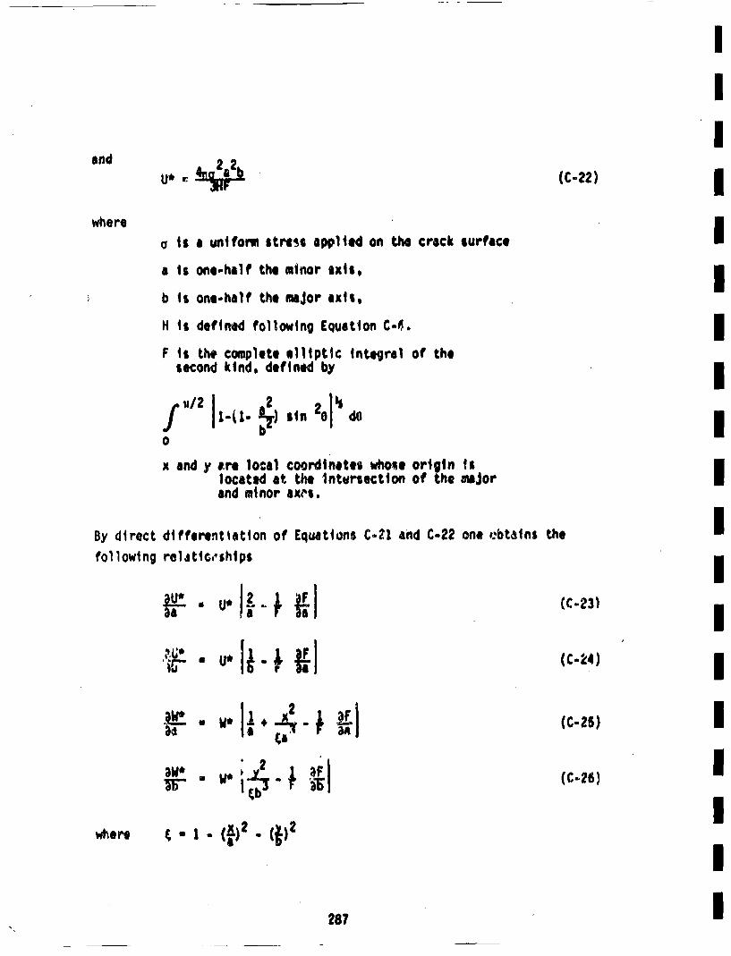
and (~?
wherea is a uniform stress apli1ed on the crack surfaiceI
a is oneehalf the mi~nor axis,
b is one-half the maJor aixs,
H is defined following Equation C-'#.I
F is the complete elliptic integral at the
second kind, defined by If~'2 I sin ' I0
x and y ere local coordinates whose origin fs
located at the Inteirsection of the major [
By direct different tatlon of' Equations C-21 and C.22 one #:btains the IIfollowtng relstto,.shtpt I
• ,.I~.ipi (C-2 I
' I
287 I
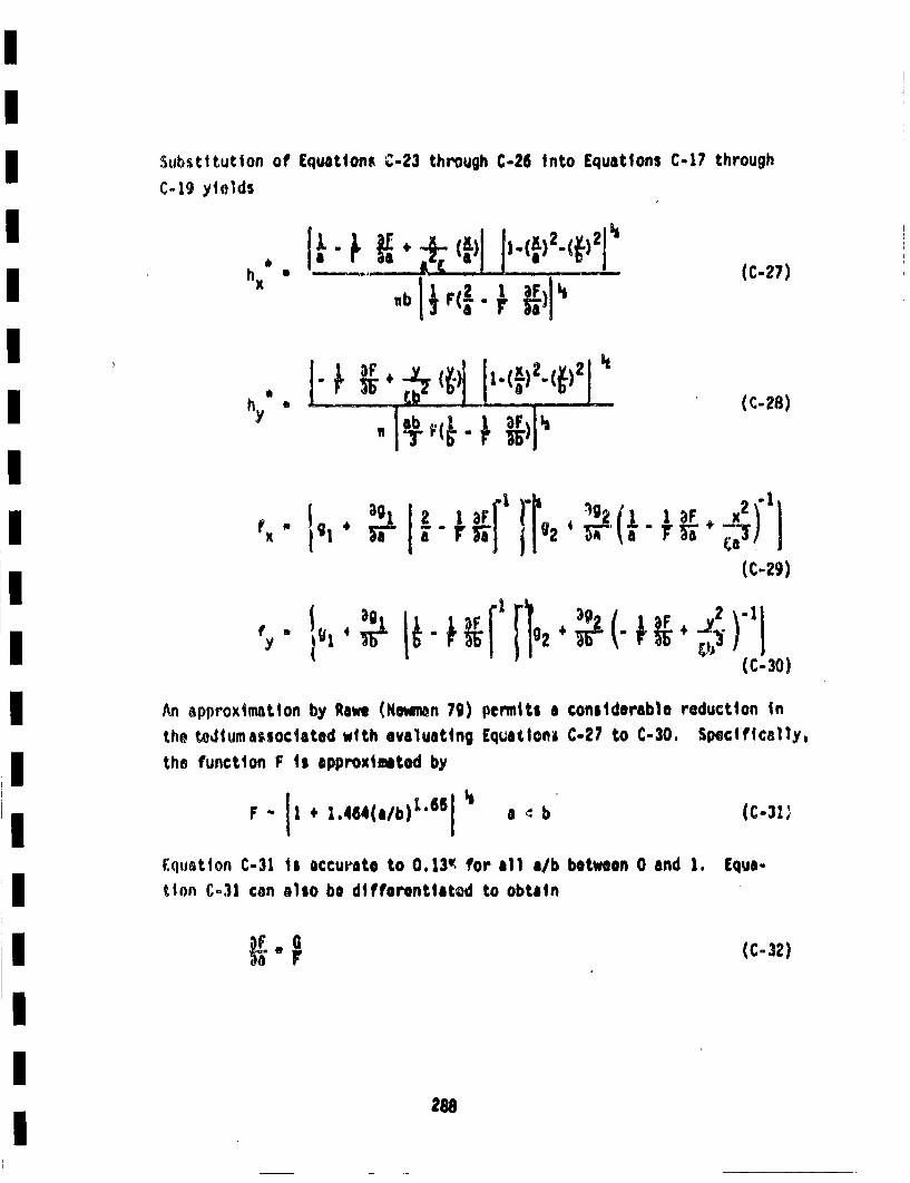
Suhstitutlon ofC-19 yields
Equations C-23 through C-26 Into Equations C-17 through
L'-- I' (:'1nx -
h
I- ~' ~ ~ ji .(~)2~(~)2j II
(C-f7)
(C- 28)B ~ . ~P 3F)j1~
(C- 29)
(C -30)
An approximation by Rawe (Nawnan 79) penntt$ athe tedium associated with evaluating Equationsthe function F is approximtod by
F. ji 4 i.4 64(a/b)L'GSj •
constderable reduction inC-27 to C-30. Specifically,
(C-31;
between 0 and 1. Equa-
a •b
Equation C-31 Is accurate to 0.13• for all a/btion C-31 can a1so be difforentfitod to obtain
(C -32)
208
an €*a*(-3) Iwhere G - 1.46x 65 (C-34) IOnce g1 and g2are defined, such as by the expressions followingEquation C-20, then fj are defined by Equations c-2g and C-30. Thesecan be combined with h• in Equations C-27 and C-28 to obtain hj (Equa-tion C-I?), which is then integrated by use of Equation C-5 to obtainKj for arbitrary stresses on the crack plane, a(x,y). The principal
diffiulty n th eautoofKj arises from the necessity to integratean integral with a •' singularily--which comes from the h•'. The inte-
gration procedure developed to efficiently handle this will be coveredin Appendix D. The procedure for obtaining suitable mathematical expres-sions for gland g2will be discussed in the next section.
C.3 Curve Fit to gl
The function glis required as a part of the desired influence functions,mas can be seen in Equation C-19. The following definition of g1 wasIprovided in Section C.2. (-5
Uis the strain Uenergy determined froni numerical procedures for the mmA
crack 9eonmtry of interest, and U is the strain energy determined numer-ically for the reference problem (which in this case Is the buried ellip- Itical crack subjected to uniform stress). The strain energy in the halfof the body on one side of the crack plane 4s desired, and can be calcu-m
lated from the work of the surface tractions during the application of m
loads to the body. Mathematically, this can be expressed as
u sAoxy (x,y mmm
289
The influence functions themselves are independent of the applied stressused to determine g1 and g'Uniform stress on the crack face was con-sidered, hence the expression for U becomes a simple rotter of Integra-ting the nodal values of crack surface displacement, w, over the crackarea. In accordance vith the assumption In the BIE code that displace-ments vary linearly within an area segment, the value of U is easilyobtained from the nodal coordinates and corresponding displacements.Table C-i summnarizes such results for a surface crack and an estedded
crack. These values correspond to a stress on the crack surface of100 ksi, however, since ratios are taken, the value cancels out and theunits of Uare irrelevant. Values of U for a buried elliptical crackwere calculated for a/h * 0.26. This is felt to provide results thatare representative of an elliptical crack in an infinite body. g1 fora/h • 0.25 was scaled according to the following procedure.
The strain energy for an embedded crack in an infinite body is givenanalytically by the following expression (Irwin 62)
. . 4l•c 2a2b * ioab
This shows that for a given 83 * b/a, Urn a3. there'ore
^U(a/h) (a)3
U(:, 1h-O. 25) v,
Therefore, for any a/h, the following expression for g1 holds
g1(aih) . ^U(a/h,) (.*2i513U(a/h-0.25) f ~hs h 1
The values of g1 obtained by use of thi expression and th r esultsincluded In Table C-i are presented in Table C-2 as a function of a/hand b/a.
The values of gl in Table C-2 were curve fitted by a least squaresregression to a polynomial in cx(-a/h) and B(-b/a). The following result
was obtained.
290
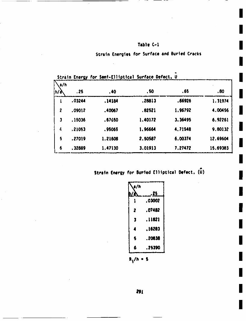
Table C-i1
Strain Energies for Surface and Buried Cracks
Strain Energy fro SemI-E11iptical Surface Defect, u
.25 .40 . S0 .65 .80
1 .03244 . 14184 .28813 .66926 1.31974
2 .09012 .40067 .82621 1.96792 4.004l56
3 .15S036 .67650 1.40172 3.36495 6.92261
4 .21053 .95065 1.96664 4,71548 9.8013)2
5 .27019 1.21608 2.50587 6.00374 12.69604
6 ,.32889 1.47130 3.01913 7.27472 16.69383 I
Strain Energyfor Burled Elliptical Defect, (U)
_-.21 .03002
2 .07482
3 ,11621
4 .16282
6 .20626
6 .25390
R1/h * $
I
rn
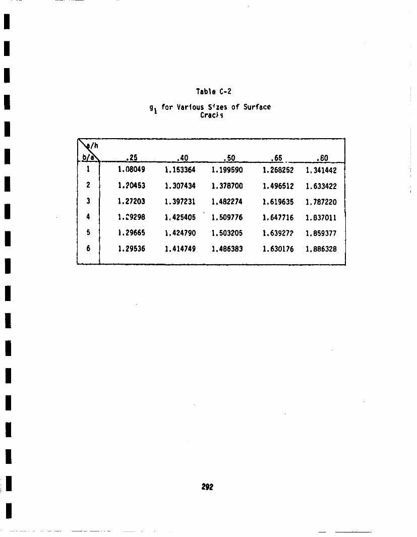
Table C-2
gt fr Various S~zes of SurfaceCrac• '
b/ .25 .40 .50 65 .6011.08049 1.153364 1.199590 1.268252 1.341442
21.20453 1.307434 1.378700 1.496512 1.633422
31.27203 1.397231 1.482274 1.619635 1.787220
41.Z9298 1.425405 1.509776 1,647716 1.837011
51.29665 1.424790 1.503205 1.639272 1.859377
61.29536 1.414749 1.486383 1.630176 1.886328
29?
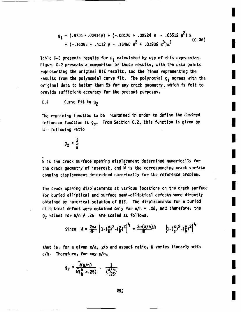
I
91i (.9701+.034148) + (-,00176 + .39924 B - .05512 82)cI+ (-.16095 + .4112 8 - .15460 82 + .01936 83)cx2 (C-36)I
Table C-3 presents results for glcalculated by use of this expression.I
Figure C-2 presents a comparison of these results, with the data pointsrepresenting the original OIE results, and the lines representing theI
results from the polynomial curve fit. The polynomial g1 agrees with theoriginal data to better than 5% for any crack geometry, which is felt toprovide sufficient accuracy for the present purposes. IC.A CL~wve Fit to 92 I
The remaining function to be ,cerntned in order to define the desiredInfluence function is g2. From Section C.2, this function is given byI
the following ratio
UI
~I
W is the crack surface opening displa~cement determined numerically forthe crack geometry of interest, and W is the corresponding crack surface 3opening displacement deternined numerically for the reference problem.
The crack opening displacements at various locations on the crack surface Ifor buried elliptical and surface semi-elliptical defects were directlyobotined by numerical solution of BIE. The displacements for a buriedI
elliptical defect were obtained only for a/h - .25, and therefore, theg2values for a/h ji .25 are scaled as follows4
that is. for a given x/a, y/b and aspect ratio, W varies linearly withIa/h. Therefore, for •fny a/h,
Wa/h) 1I
293 I
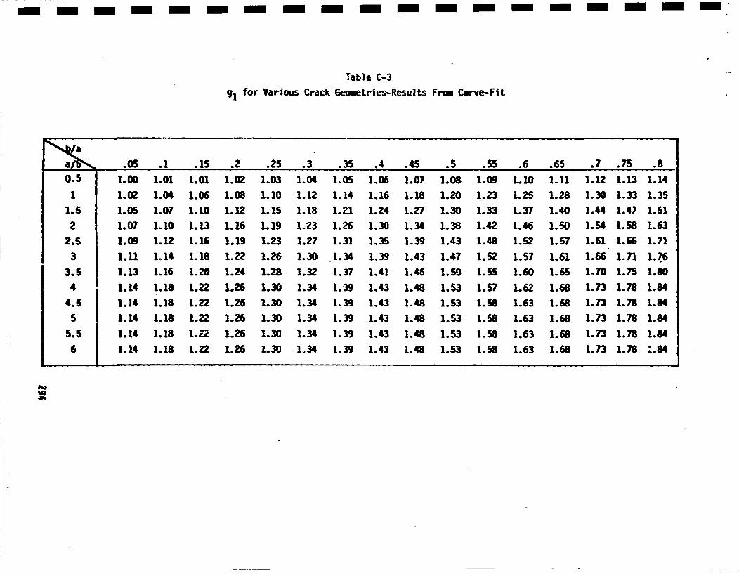
- -- --m -i -n- -i-n- i -n- -n -n -
Table C-391for Various C;rack Geometries-Results Frau Curve-Fit
a.05 .1 .15 .2 .25 .3 .3.5 .4 .45 .5 .55 .6 .65 .7 .75 .8
0.5 11.00 1.01 1.01 1.02 1.03 1.04 1.05 1.06 1.07 1.06 1.09 1.10 1.11 1.12 1.13 1.14
1 1.02 1.04 1.06 1.08 1.10 1.12 1.14 1.16 1.18 1.20 1.23 1.25 1.28 1.30 1.33 1.35
1.5 1.05 1.07 1.10 1.12 1.15 1.18 1.21 1.24 1.27 1.30 1.33 1.37 1.40 1.44 1.47 1.51
2 1.07 1.10 1.13 1.16 1.19 1.23 1.26 1.30 1.34 1.38 1.42 1.46 1.50 1.54 1.58 1.63
2.5 1.09 1.12 1.16 1.19 1.23 1.27 1.31 1.35 1.39 1.43 1.48 1.52 1.57 1.61 1.66 1.71
3 1.11 1.14 1.18 1.22 1.26 1.30 1.34 1.39 1.43 1.47 1.52 1.57 1.61 1.66 1.71 1.7.6
3.5 1.13 1.16 1.20 1.24 1.28 1.32 1.37 1.41 1.46 1.50 1.55 1.60 1.65 1.70 1.75 1.80
4 1.14 1.18 1.22 1.26 1.30 1.34 1.39 1.43 1.48 1.53 1.57 1.62 1.68 1.73 1.78 1.844.5 1:14 1.18 1.22 1.26 1.30 1.34 1.39 1.43 1.48 1.53 1.58 1.63 1.68 1.73 1.78 1.84
51 1.14 1.18 1.22 1.26 1.30 1.34 1.39 1.43 1.48 1.53 1.58 1.63 1.68 1.73 1.78 1.84
5.5 1:14 1.18 1.22 1.26 1.30 1.34 1.39 1.43 1.48 1.53 1.58 1.63 1.68 1.73 1.78 1.8k
6 1.4 1.18 1.22 1.26 1.30 1.34 1.39 1.43 1.48 1.53 1.58 1.63 1.68 1.73 1.78 :.84
p.•'I0
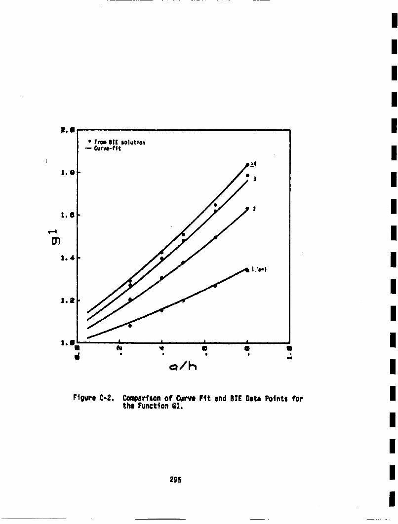
El., . .
* Fim SI[ solution-- Curve-fit
Ld
1. 1 0 3
1.62I
1.4 ta
a..''
Qth I
Figure C-2, Coprison of Curve Fit and STE Data Points forthe Function 61.
295
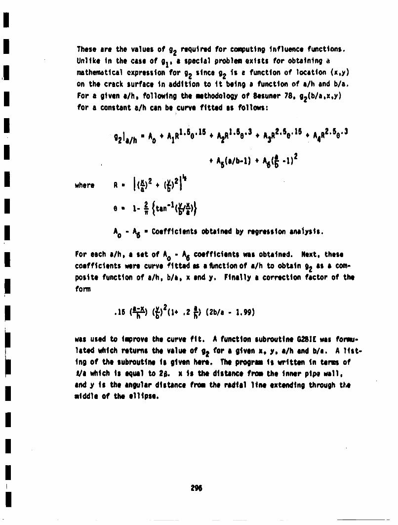
These are the values of g2 required for coqputing influence functions.Unlike in the case of g1, a special problem exists for obtainingmathematical expression for g2 since i2 s a function of location (x.y)
on the crack surface in addition to it being a function of a/h and b/a.For a given a/h, following the methodology of Sesuner 78, g2(b/a,x,y)
for a constant a/h can be curve fitted as followsl:
g2t a/h • A0 + A)R1 .50'I 5 , A2RI.B6. 3 + A)R2 .50.16 4.O'
+A5(,/b-1) * A6( -1)2
A0 - A6 * C;oefficients obtained by regression analysis.
For each a/h, a set of A0 - A6 coefficients was obtained. Next, thesecoefficients were curve fitted as ajbnctionof a/h to obtain *2 as a corn-posit. function of a/h, b/a, x and y. Finally a €orrection factor of theform
.15(; ) s21 .2 ' (2b/a. - .99)
was used to Improve the curve fit. A function iubroutine G2I[ was formlU-laetd which returns the vallue of g2 for aI given x, y, a/h end b/a. A list-ing of the subroutine is given here. The progrm is writtenm in tems ofa/c which is equal to 29, x is the distance from the inner pipe well,and y is the angular distance from the radial line extending through t,.e
middle of the ellipse.
296
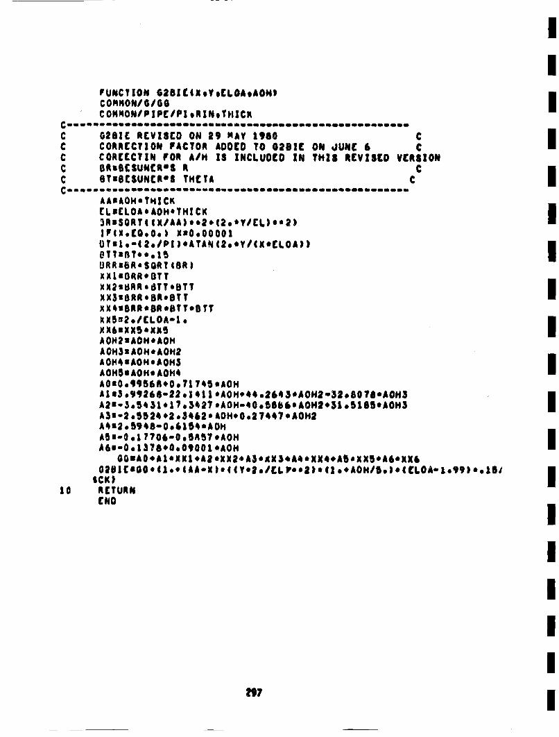
PUANCTIO~c~HN/O G2BZIC(oVoELOAAON,
COHISONIPIPE/PI ,RINoTI, ICKI
CO2BC RVID ON 9 MY 160NC COREECTIt OR A/H IS INCLUDED IN THiS REVISEDVRIO
C RuBCSUNCR'S ¢€cC TuSCSUN4CR*S THCTA CI
AAuAOH*THICKCL nC[LOA * AOI1' THI CKnrl3)RuSGRTt t K/AA)*e2. |2**Y/EL)** ?)IXtN.CQ.O.O) E'0.oO000IOThl.o'(2,/PI IeATAN (2**Y/CX*[LOA))
UR~suR* SQAT •BR)IME1'ORR*BTT)(M2uSRR* 8TT*BTT iKXSUBRR*SBR*OTTXK~uBRR*BReBTT.BTTXXS'2./CLOA2.o
AO0H2 *AOH *AOHAO0H3 EAOHeAO012AOI4suAOt~eAOH5n
AOH~uALOH* AOH4AOIO, 99~BAB*O, l 745 *AOHA| l3, 99268122, | 4| |eAOH*44 o264 5A0N02.fl,80 ?/eAOHl3A2'- 3,54 .1.* 7? 3•)27 *AOH-Q 0od6b k* OH2.'51 •1B5eAON3 iA4u2,5948-0,. 154*AOisABE"Ge • ??06"0O• AB7 *AOH lA~u-O,| 37Se0,090O0 *AOH
GDBIC'|GOO* (| ** 4AA*N 1S44 (Y0e*/CL P**2104 .* ( AOH/5o )*.( LOA* 1o99 )*1e.1SICK I I
ia RETURN
[NO I
I
Oncetd g1 and g2 are kn.own,C2 the correction drvtvfactors fx and fy, can •1 evalu-atdusing Equations C-9and C-30. The deiaieterm like ia n
the expressions for fxand fy are evaluated by numerical differentiablon
as fol lows:
)g2 g2(a+Ma) -g2 (a-Aa)
All the components for obtaining the RMS stress Intensity factors using
Equation C-20
A
are now complece. hj*(x~y) is the known influence function for a buriedelliptical defect and fj(x,y) is the correction factor for hj*(x.y) toobtain the influence functions for semi-elliptical circumferential sur-face defects in pipeB, a(xoy) is the arbitrary stress on the cracksurface. The Kjfor burled elliptical defects for an arbitrary stresso(x,y) is obtained by integrating the above equation with fj(x.y) •1.0.Siruilarly, I for sein-elli ptical surface defects with unfostrfess
on thtl crack surface are obtained by Initeration of the above equationwith o(x,y) equal to a constant. The •jfor burled ellipse with uniform
stress are obtained by making fj(x~y) * 1 as well as o(x,y) • a constant.The actual Intogration procedures and some of the above cases will b
discussed in Appendix D. Such special cases provide checks on tie accur-acy of the approximate influence functions developed In this appendix.
2 9$•
APPENDIX CAPPLICATIONS TO COMPLEX STRESSES
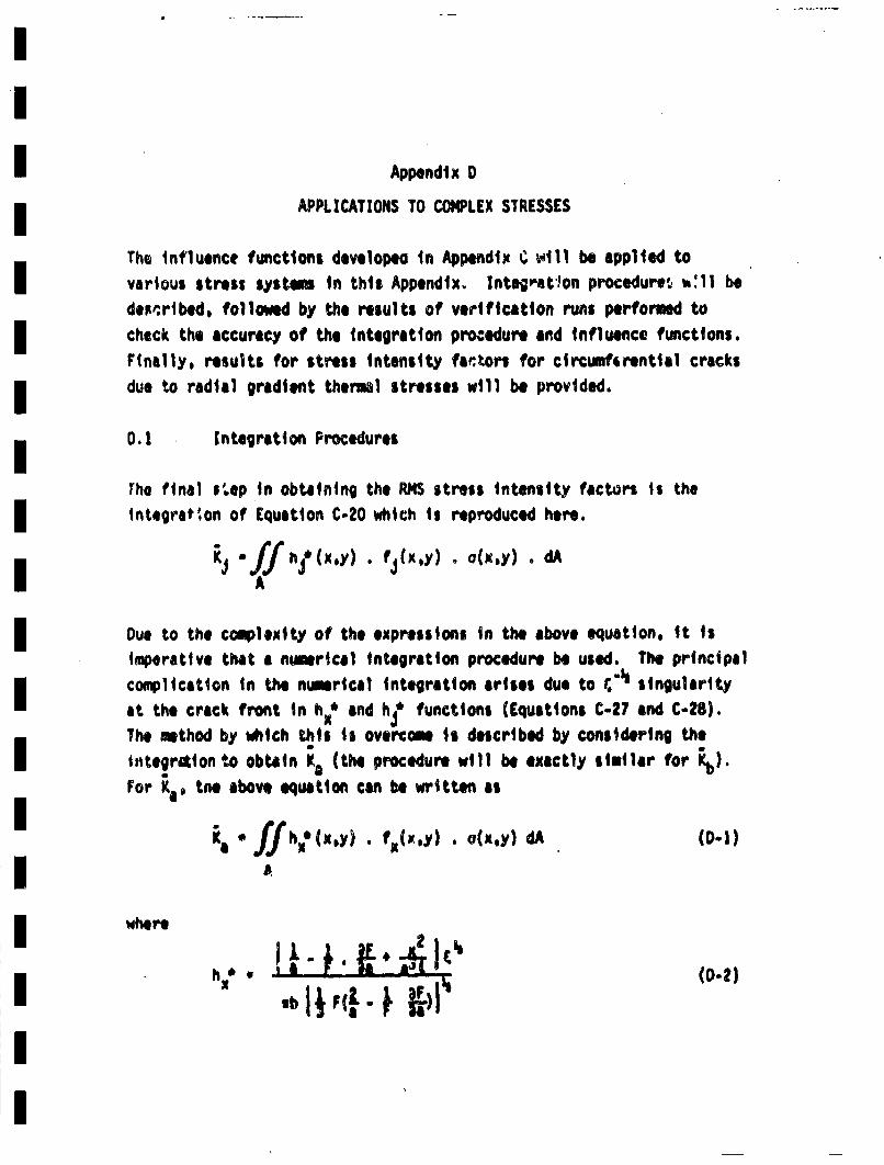
Appendix D
APPLICATIONS TO COI•LEX STRESSES
The Influence functions developen in Appendix C •tull be applied tovarious stress systems in this Appendix.. Integ"'at'!on procedure• •:11 bedeR'cribed, followed by the results of verification runs performed tocheck the accuracy of the integration procedure aind influence functions.Finally, results for stress intensity far,•ors for circumfsrential cracksdue to radial gradient thermsl stresses will be provided.
0.1! Integration Procedures
rho final step in obtaining the RH stress intensity factors is the
integrat~on of Equation C-20 which is reproduced here.
A. f ,'xy lxy l.,
Due to the complexity of the expressions in the above equation, it isimperative that a nwuerical integration procedure be used. The principalcoaiplication in the nueerical integration arises du. to r.•singularity
at the crack front in hx' and h? functions (Equations C.?? and C.28).The method by which this is overcome is described by considering the
Intgrloto obtain ka (the procedure will be exactly similar for •)For Y''tne above equation can be written a
w~here
and •-* 1. (•)2. ()
rearranging the equation forhx
• ,;, •(0.3)
These expressions follow directly from results included in Appndix •:.Tho function hx* has no singularities within the crack area.
Substituting this in the expreSSion for Ka*
h, • xy)y ~xy (0.4)
Changing to pular coordinete•,
xu•r coOSOy * sinO, dAs=rdr d6
leads to the following expression
In turn, this leads to the following expression:
.~o1
Specifically, for int~egration over a semi-elliptical area (Figure D-1,.
the first-integration can be considered •s the integration in the rdirection at the segment; shown by the cress-hatched area, the 1lrotts ofintegration being from r • 0 to r * R(O), wtere R(6) is the edge of the
ellipse, defined b~y
The second part of the integration would then be to integrate thesesegments in the 0 direction, the limits of integration being 0 • 0 to0 • n/2, that. is, over the semi-elliptical area.
The following expression is obtained from results presented above.
1 - r2(4. LI-t • 1 . r/(0)2
The Equation 0-6 can now be rewritten as
• /2 R9) n2"(r,0)K''o~ f- - ,~z•~)- , (r.o),o (r,0) rdr dO (D-6)
The integration along r involves a singularity at r • Re A ntmricalmethod for integrating this type of singularity is given on p.889, Equa-tion 26S.4.36 in browitta 64. This method ws used to integrate theright hand side of Equation O-6 over r . 0 to r * R(0). The integrationof the resulting function in the angular direction (from 0 • 0 to 0 * ,/2)wet then carried out using the standard Brauss Quadrature method, suchas given by Equtietn 25.4.30 of Abremowt: 64. Two computer subroutines
302
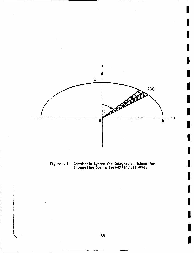
x
a
R( 8)
0 b
IIIIIII
Figre ... Cordnae Sstm fr Itoraton chme orI
Iy
IIIIIIIIII
Integrating Over a Semi-El1Iptica1 Area.
303\
BARA and KBARB were written to numerically evaluate RN stress Intensityfactors for arbitrary stress on the crack surface for semi-elliptical
surface cracks In pipes.
D.2 Verification of the Integration Procedures
The accuracy of the numerical integration scheme was verified by obtain-ing RMS stress Intensity factor results usring this method for thoseproblems for which the solutions already exist. One such problem is theburled elliptical crack in an infinite body under uniform stress, andanother one Is a burled circular defect under a non-uniform stress (Tada73). For both of these cases, stress intensity factors are obtained
by the integration schemes and the results are compared with the corre-sponding analytical solutions.
D.2.1 Uniform Stresses
For a buried elliptical defect in an infinite body under uniform stress,Besuner 77b gives solutions for PRMS stress Intensity factors as
and
where F. u + 1.464 (a/b) 1~66j•
expsstns or a ad Kb by simple algebraic menipulation,can be simplified to
and
304
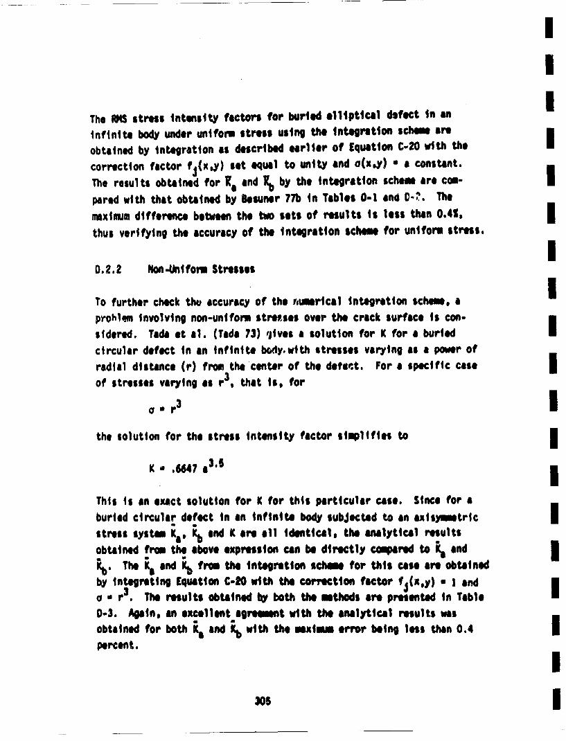
II
The •t stres intensity fictrs for bule elliptical defect in anInfinite bod under uniform stress using th interetion schimn are
obtained by interation as describe earlier of Equation C-20 it thecorrection factor fj(x.•) set equa to uit and oCE,)) • a costant.m
The results obtaind for Kl and Kb by the itegration schem are com-pared with tht obtained by Besner 7Th In Tables 0-1 and C-?.Tenaxinmu difference between the two sets of results is less than 0.4%, 3thus verifying the accuracy of the integlration scheme for uniform stress.
I0.2.2 Non.Aniform Stresses
To further check th4, accuracy of the rmerical interation scheme, ap~ohlem inIvolin non-uniform isteses over the crack surface is con-Isidered. Tada et el. (Tada 73) 'jives a solution for K for a buriedcircular defect in an infinite boy.with stresses varyng as a power ofradial ditatnce (r) from the center of the defee.t. For a specific caseIof stresses varying as r3, that is, for
a. r3 Ithe solution for the stress intensity factor simplifies t
K *.64, a3., IThis is an sexat solution for K¢ for this particular case. Since for aburied circular defect in an infinite bod subjected to an axismetric mstress system Ka* Kb and K¢ are all identical, the anlytical resultsobtained from the above expression can be directly compae to and 3Rb. The Kj and Kb from the integ1retion scem for this case are obtainedbyintegrating Equaiton C-20 with the correction factor f•(x~y) • I andiao •r. The results obtained by both the methods are presented in Table
0-3. Aginil, an excellent agreement with the analytical results was
percent.
I~I
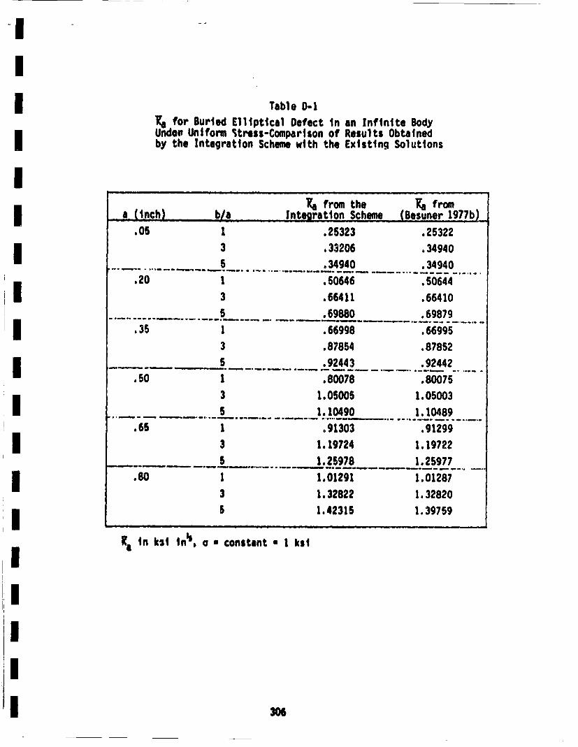
Table D-IUI, for Burled Elliptical Defect in an I~nfinite BodyUnder uniform Sress-Comparison of Results Obtainedby the Integration Scheme with the Existing Solutions
.05 1 .25323 .25322
3 .33206 .34940
... ........ .. ....-. 34940 . 34940
.20 1 •.50646 .50644
3 .66411 .66410
5 .69880 .9879.35 1 •.66998 .66995
3 .87854 .87852
5-........* _.92443 .92442
3 1•05005 1.050035 ...... . 1.10490 1.104. .. 89"...
1 5 o91303 .91299
3 1. 19724 1. 19722
5 ... 1_.._2.59 78 1.25977. . ... 1.0129 1.01287
3 1.32822 1.3282051.42315 1. 39759
Ra in kil inq, o * constant * 1 ksi
306
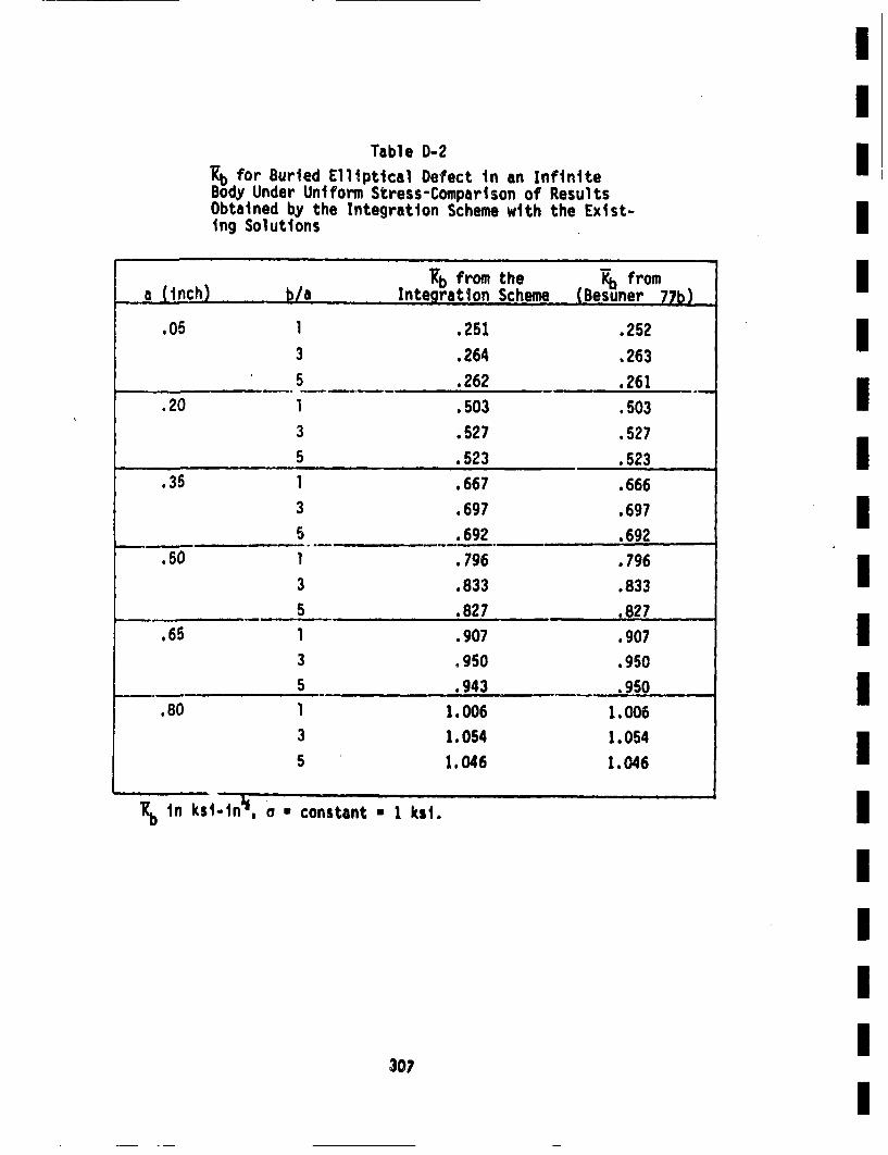
II
Table 0-2IKb for Burled Elliptical Defect in an InfiniteBody Under Uniform Stress-Comparison of ResultsObtained by the Integration Scheme with the Exist-Iing Solutions
Rb from the R.b fromI•a Cinch) b/a Integration Scheme (Besuner 77b)
.05 1 .251 .252 I3 .264 .263
________ 5 .262 .261I
.20 1 .503 .5033 .527 .527
5.523 .523 I.35 1 .667 .666
3 .697 .697 I-5 .692 .692
.50 1 .796 .796I
3 .833 .833______ 5 .827 .827
.65 I .907 .907 I3 .950 .9505 .943 .5
.80 1 1. 006 1. 0063 1.054 1.054I
5 1.046 1.046
1Kbtn ksi-tn•~, a * constant * 1 ks1,
IIII
30?
I
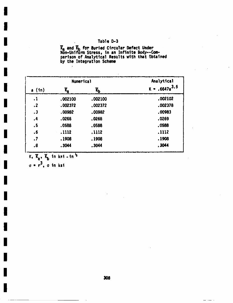
Table D-3~aand Rab for Buried Circular Defect UnderNon-Uniform Stress, in an Infinite Body--Com-parison of Analytical Results with that Obtainedby the Integration Scheme
Numerical Analyticala (In) 1R b K-* .6647a 3'6
.1 .002100 .002100 .002102
.2 .002372 .002372 .002378
.3 ° 00982 .00982 .00983
.4 .0268 .0268 .0269
.5 • 0588 .0588 .0588
.6 .1112 .1112 .1112
.7 .1908 .1908 .1908
.8 .3044 .3044 . 3044
K, Ra n kla - r3, a in kil
-in"
308
II
0.3 C~omparisons With Existing Solutions IZn this section the RMS stress itentsit factors for semi-ellipticalsurface cracks In material with finite thickness obtaned by the inte-igraitton of Equaitton C-20 will be compard with the existing'solutions forthe same or siudre~ problems. The Kt results obtained fro the Inte-gration schem, hereatfter referred to ats influence function (IF) results,will be first compared with results for uniform stresses. Next theIF results will be obtaned for p~wer law stresses for i•tch solutions iiexist in the open iteoratture (Heliot 79, NcB•an 79).
I0. 3.1! Uni fore Stress
The RS stress intensity fatctors for smit-elliptical surface cracksin material with finite thicknass curt be obtained from IF method by IIntegrating Equaiotn C-20 for a given crack geometry deinted by at/hand b/at. The K for uniform stress are obtained by setting a(x~y) * 1.0,that i,,.a costant These result (Ka. and ,ar obtaine for a/hvarying from .06 to .8 and b/a rearying from I to 6. The normalizedKj(Kj/oa") are then plotted ats a function of a/h (Figures 0-2 and Do3)Ifor various b/a. The IF results are show ats dashed lines. The solidltines atre the results obtaitned dirctly from the BIE calculaittons, atsldescribed in Section 2.7. For at/h latrger than .26, the errors in tisestress intensity fatctors obtait. 4 by IF metod atre generally lessthan 105. Larger errors, both in Kg and- K. for at/h less than .25 atre Inot very significant. Plotting the normaized vatlues of Kj •mds toverowthaitsze the inaccuracies for sall1 a, becatuse of therea• term. IThe values of Kj for siall a are themselves small, so inaccuracies Insuch values atre not of great concern in this investigation. I
As was mentioned earlier (Appendix A), the curret IF solutions foro9 tres itenmsit factors wre developed for semi.e11iptica1 cir- i
cumferential cracks in PW primary pipes (Re/hmS).• For non-uniformstresse on the crack surface, the closest aevailable solutions are for l
09I
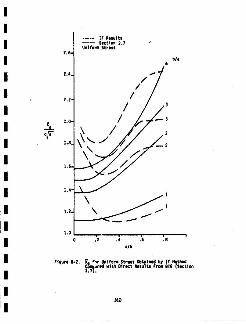
.....- IF Results---- Section 2.7U~nlfovm Stress
b/a6
///
/ / 3
/ 3
1.- /
1.1
.0 .2 4.6.
a/h
Flgu 0.. K,"brUnifrm tres Obaine byIF MethodFtgu O-•. ~alred with Direct Results From SIC (Section
310
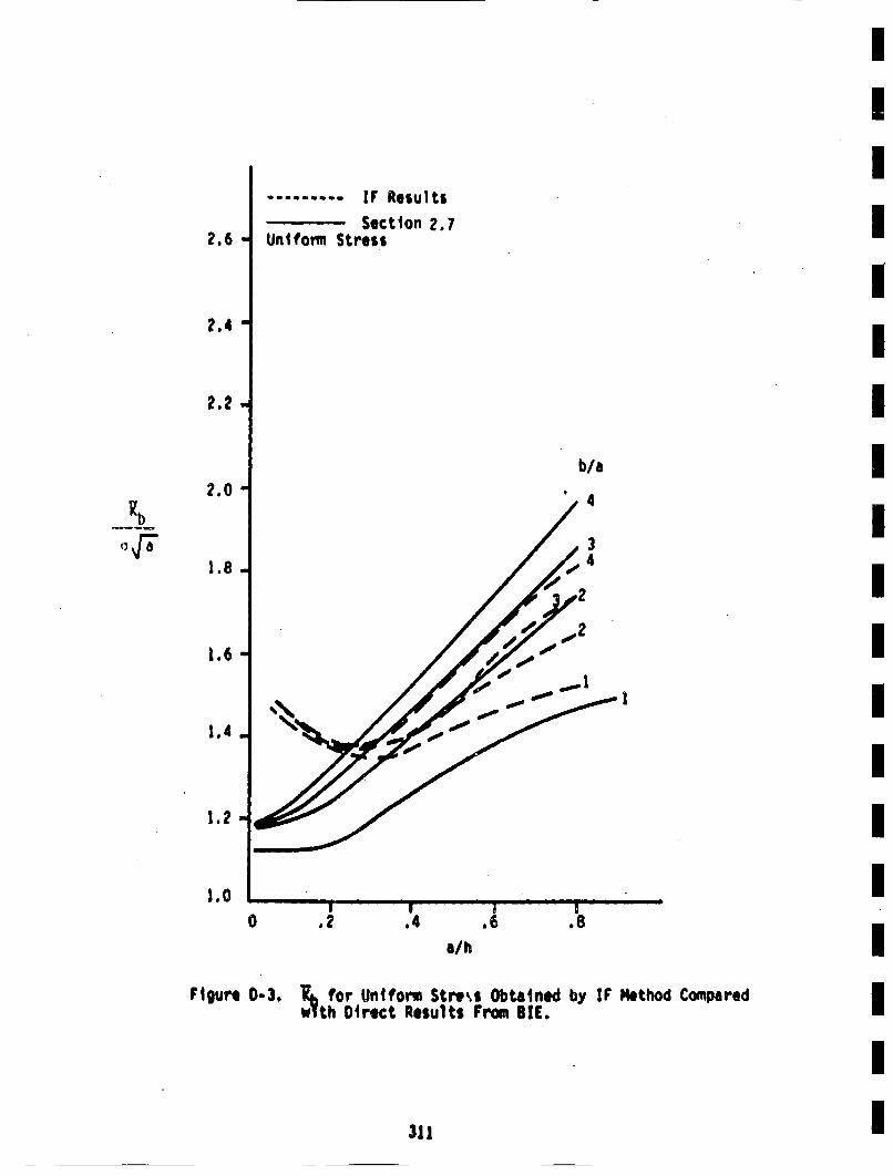
........ IF Results:: Section 2.7
Uniform Stress2.6 a
2.4"-
2.2
b/a
J/4
'Rb
2.0
1.8
•2
1.6
1.4
1.2 -
1.0
1
0 .2 U,4 .6 .8
a/h
Figure 0-3. for Uniform Stress Obtained by IF Method Comparedwth Direct Results From SIC.
311
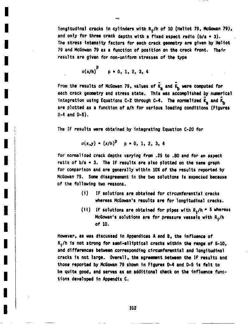
'eo
longitudinal cracks in cylinders with R1/h of 10 (Heliot 79, McGowan 79).and only for three crack depths with a fixed aspect radio (b/a , 3).The stress intensity factors for each crack geometry are given by Heliot79 and McGowan 79 as a function of position on the crack front. Their
results are given for non-uniform stresses of the type
o(x/h)p p0 , 1, 2,3, 4
From the results of McGowan 79. values of K a and Kh, were computed for
each crack geometry and stress state. This was accomplished by nimericalintegration using Equations C-2 through C-4. The normalized Ka andK
are plotted as a function of a/h for various loading conditions (Figures
0-4 and D-S).
The IF results were obtained by integrating Equation C-20 for
o(x~y) • (x/h)p p- * , 1, 2, 3, 4
for normalized crack depths varying from .25 to .80 and for an aspectratio of b/a - 3. The IF results are also plotted on the same graphfor comparison and are generally within 10%; of the results reported byMcGowan 79. Some disagreement in the two solutions is expected becauseof the following two reasons.
(1) IF solutions are obtained for circumferential crackswhereas McGowan's results are for longitudinal cracks.
(ii) IF solutions are obtained f'or pipes with R1/h "5 whereasMcGowan's solutions are for pressure vessels with R1/h
of 10.
However, as was discussed in Appendices A and 8, the influence ofRt/h is not strong for semi-elliptical cracks within the range of 5-10.and differences between corresponding circumferential and longitudinalcracks is not large. Overall, the agreement between the IF results andthose reported by M4cGowan 79 shown in Figures D-4 and D-5 is felt tobe quite good, and serves as an additional check on the influence func-
tions developed in Appendix C.
312
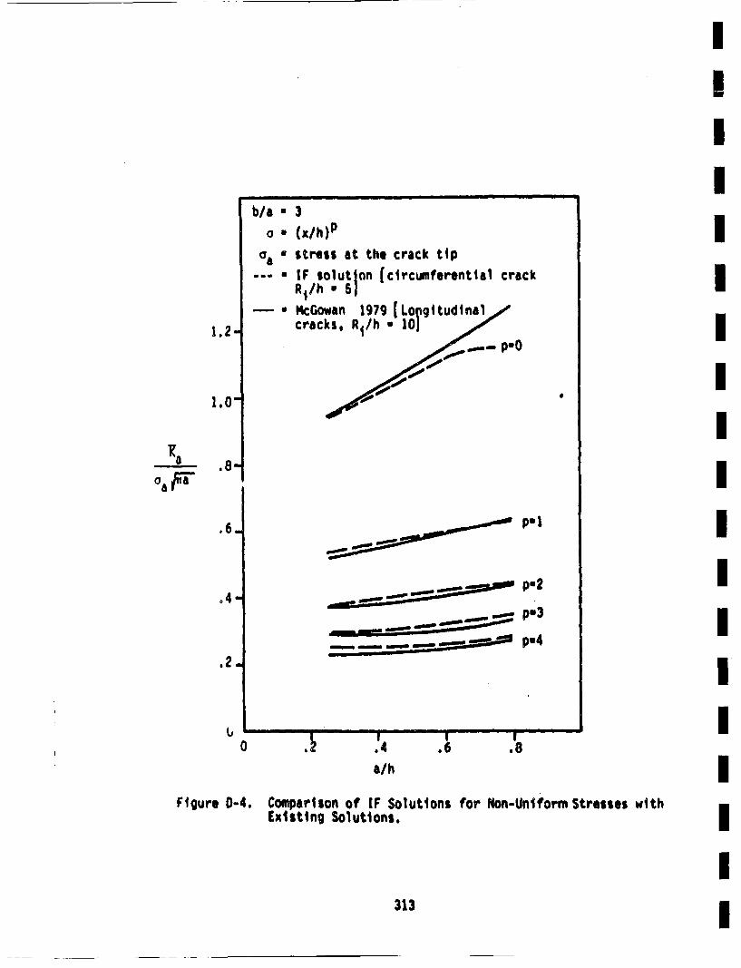
I I I II I I
b/a " 30 • (x/h)p
0a * Stre•SS at the crack tip-- • r solution [circumferential crack
R1/h • 51- a MGowan 1979 [Lo~igttudlnal..#"
cracks, R1/h * 10J1.21
1.0
p-0
a ..
.6..
o4"
•,•p.1
• •.•p.2 -
-L - p 4
0 .4a/h
.6 .8
Figure 0-4. Comparison Of iF Solutions for Non-Uniform Stresses withExisting Solutions.
313
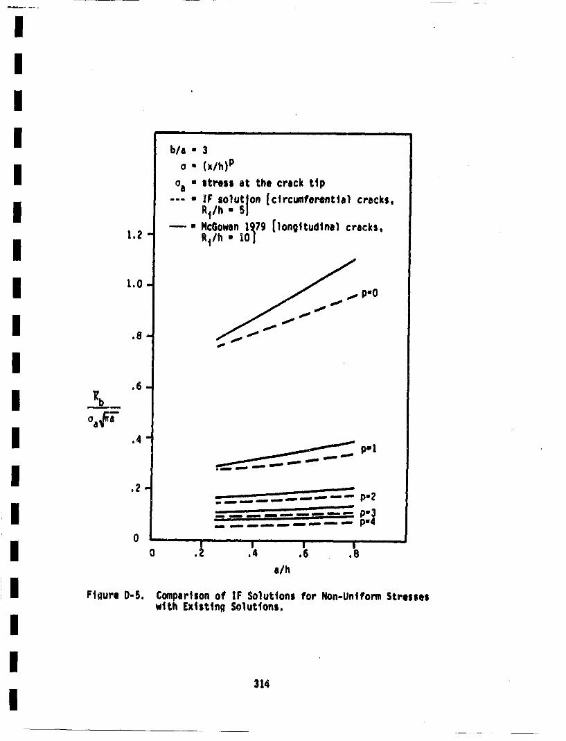
-II!III
I 1.2
I 1.0-
1 .8
[]
| I
b/a • 3a • (x/h)p
"a * st~ess at the crack tip--•IF solution [circumferentital cracks,
R1/h- * 5-- * cGowan I•7 (longitudinal cracks,
~p,,1
--- __ __. - :
.6 -
aab
.4"-
0I II I III I -- -- I
0I.4 I
.6I.8
a/h
Figure 0-5. Comparison of IF Solutions for Non-Uniform Stresseswith Existing Solutions.
314
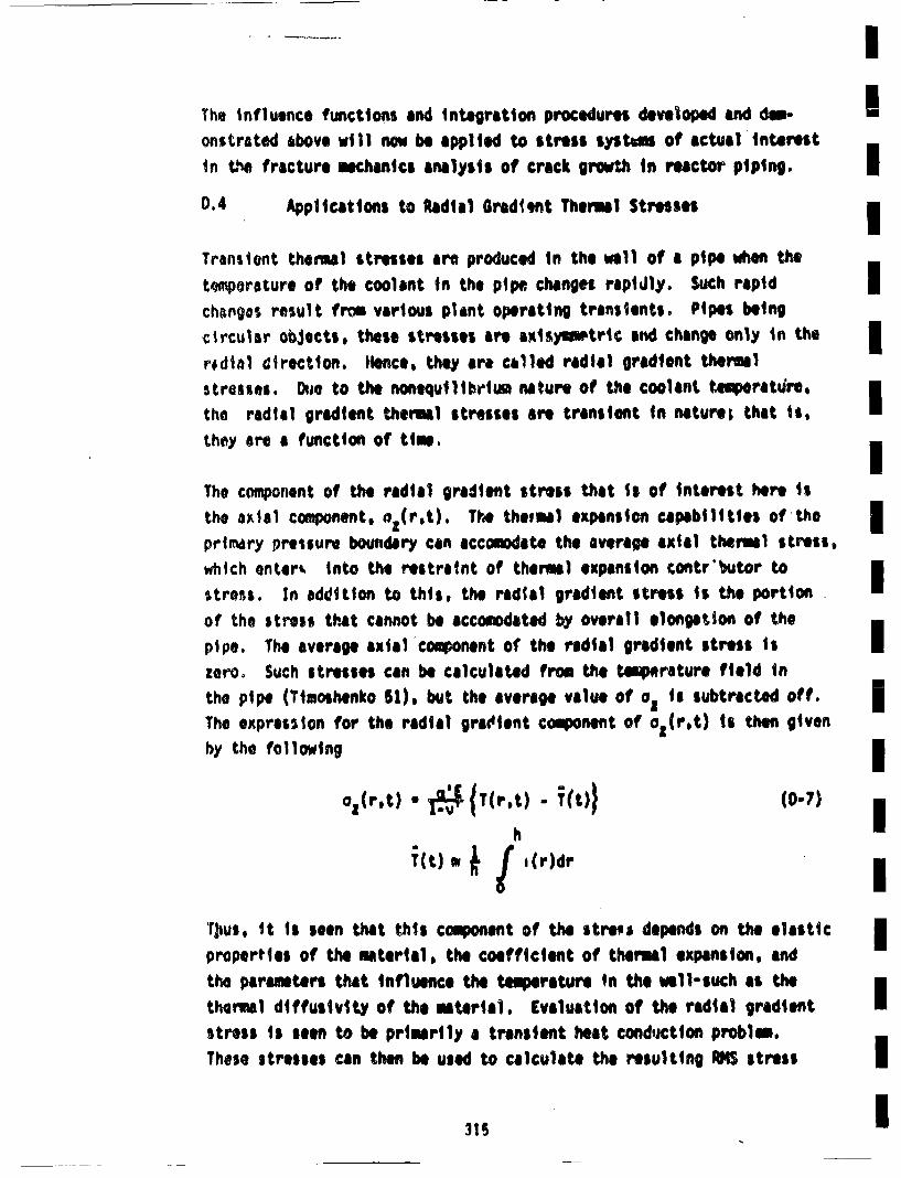
* - IThe influence functions and integration procedures dleveloped and dma- Ionstrated above will now be applied to stress systems of actual interestIn t.• fracture mechanics analysis of crack growth in reactor piping. IID.4 Applications to Radial Gradiet Thermal StressesI
Transient thermal stresses are produced in the wall of a pipe when thetomporature or the coolunt in the pipe changes rapidly. Such rapidchengos result from various plant operating transients. Pipes beingcircular objects, these stresses are axlsyinetric, and change only in the Ire dial direction. Hence, they are called radial gradient thermalstre)sses. Due to the nonequilibriwa nature of the coolant timperatilrs,the radial gradient thermal stresses are transient in natures that is, [they are a function of tim,
The component of the radial gradient stress that Is of interest here isth~e a l component. o1(r,t). The the, ma expansion capabilities of the I
primary pressure boundary can accosodate the average axial thermal stress, ~which onter• into the restraint of thermal expansion contr'butor to•stress. In addition to this, the raials gradient stress is the portion [of the stress that cannot be accomnodated by overall elongation of thepipe. The average axial component of the radial gradient stress isIzero. Such stresses can be calculated from the tu•rature field inthe pipe (Timoshenko 51), but the averagle value of oIts subtractedI off. iThe expression for the radial gratdient component of a (r,t) is then givenby the followingI
az(r,t)= * {IT(r~t) -T(t,) (D-,) I
TjiUs, it is leen that this component of the stree depends on the elasticproperties of the material, the coefficient of thermal expansion, and B
the parameters that influence the temperature in the well-such as thelthermal diffusivity of the material. Evaluation of the radial graidentstress is seen to be prtimrily a transient heat conduction probim.These stresses can then be used to calculate the resulting •5I stress 1
intensity factters by use of the influence functions developed inAppendix C. These Cyclic stress intensities in turn are used to calcu-late fatigue crack growth due to transients.
The computation of the radial gradient theral1 stress was performedusing a numerical computer code PIPET (Chan SI). The temp~erature fieldca'ulations were performed bY treating the pipe of wall thickness has a flat slab of this same thickness. The slab was considered to beinsulated on the out,' ide surface, and subjected to flowing water ofvaryinlg specified temperature on the inside surface. Convection heattransfer at the inner wall was accounted for.
For a given transient, the primary input to the code was the time-temper-ature profile of the coolant. Eleven transients (George 80) that produceradial gradient thermal stresses were considered and a short descriptionof these transients is given in Table 0-4. The maximum change in thecoolant temperstureitn the hot leg (AT) for each transient is also listedin the table. The time-tumpe'ature profiles of the coolant in the hotleg (TH), cold leg (TC) and steam lines CT steam for each transient aregiven In Figures 0-6 through 0-15. Smelt differences between the maximumAT values in Table 0-4 and Figures 0-6 through D-15 exist, but are incon-sequential.
For each transient, the radial gradient thermal stresses ware calculatedat various positions through the pipe wall thickness for about every0.2 seconds, starting from the beginning of the transient and until afterthe coolant temperature has reached an equilibrium value. Calculationsware performed for the various thickness joints in the hot leg, cold legand cross-over leg. ReJsults to be presented in the remainder of thisappendix are limited to the hot leg with a wall thickness of 2.5 In.The hot leg generally sees the largest temperature excursionl, and there-fore is subjected to the largest .. dial gradient thermal stresses.
316

Table 0-4mDescription of the Transients, Including Maximum
AT in Hot Legm
Transient Description AT(•F)
1 Plnt oadig, % pr mtute39.1 Plant uloading, 5% per minute 39.5m
2 Planste uloadig d ere minue 139.53 10% step load decrease 13.4m
5 large step decrease in load 84.0
6loss of load from full power 89.0m
7 loss of power 44.0 I8 loss of flow in one loop 120.0
9 loss of flow in other loops 69.0 I10 steam line break from no load 339.511 reactor trip from full power 73.0 I
I
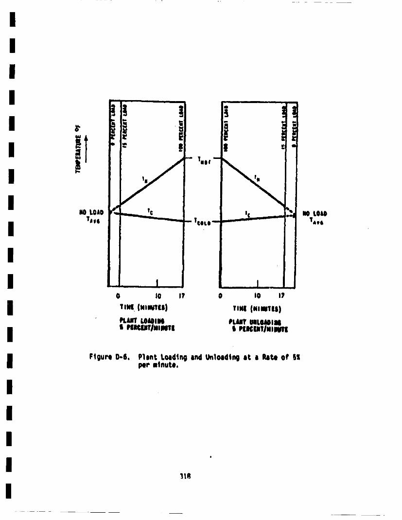
ii
NO LOAOTa,.
Wl LO&14a9t
T0t |WtO)
PLANT LOtI eI PUJIm P61l1tm
I? 0
TIMI (mmv Niii
I IPlICITININUIIqI
Flgure D)-6. Plant Loading and Unloading at a Rate of SIper minuto,
its
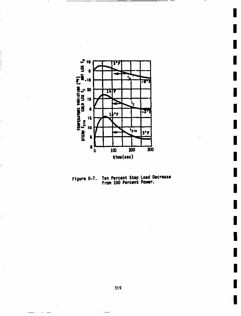
i., o
0
pp
•m mm
-I'1
,.,
_ 1 +'V -•!'i;I'\o.,-... •M 30+
0 tlme(sec)
Figure 0-7. Ten Percent Step Load DecreaseFrom 100 Percent Power.
319
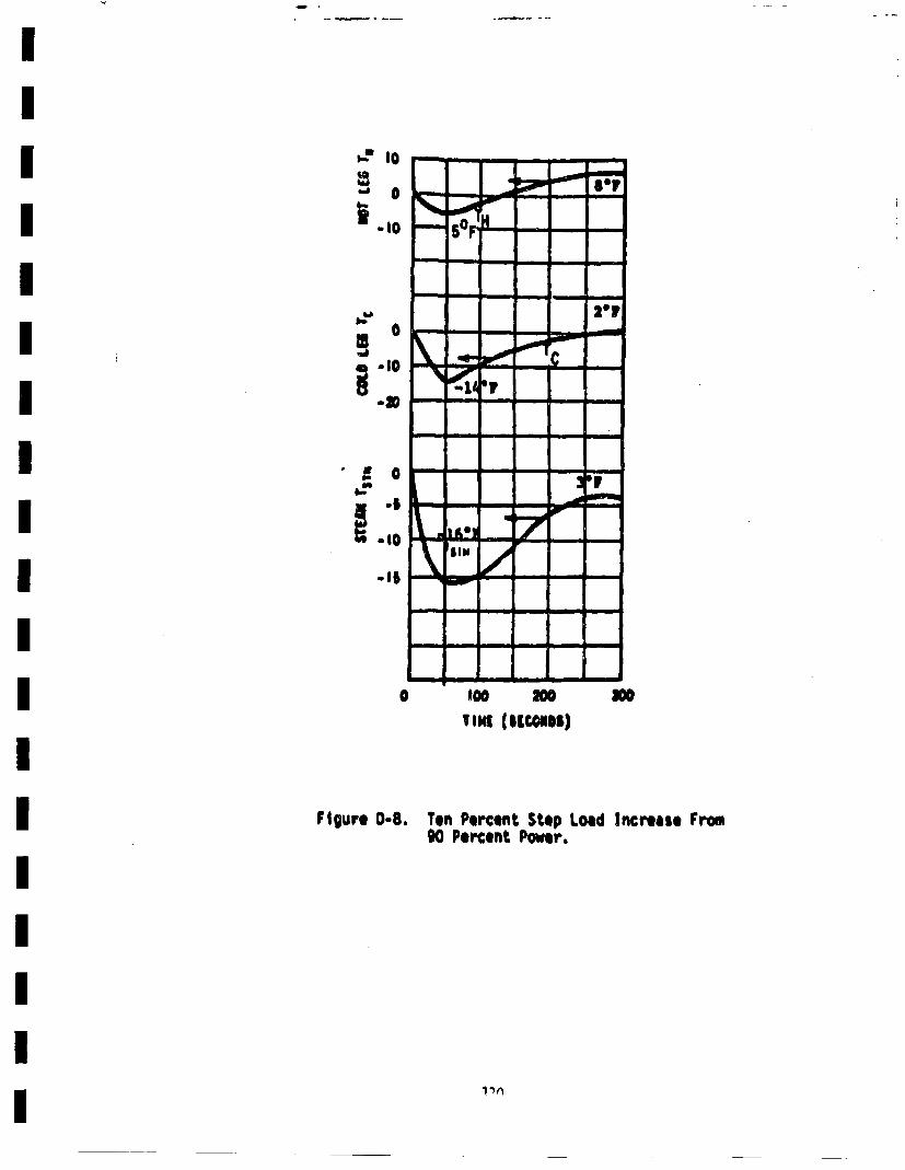
*- I0
9,Jr 0 Pecet ow r.
1 V~
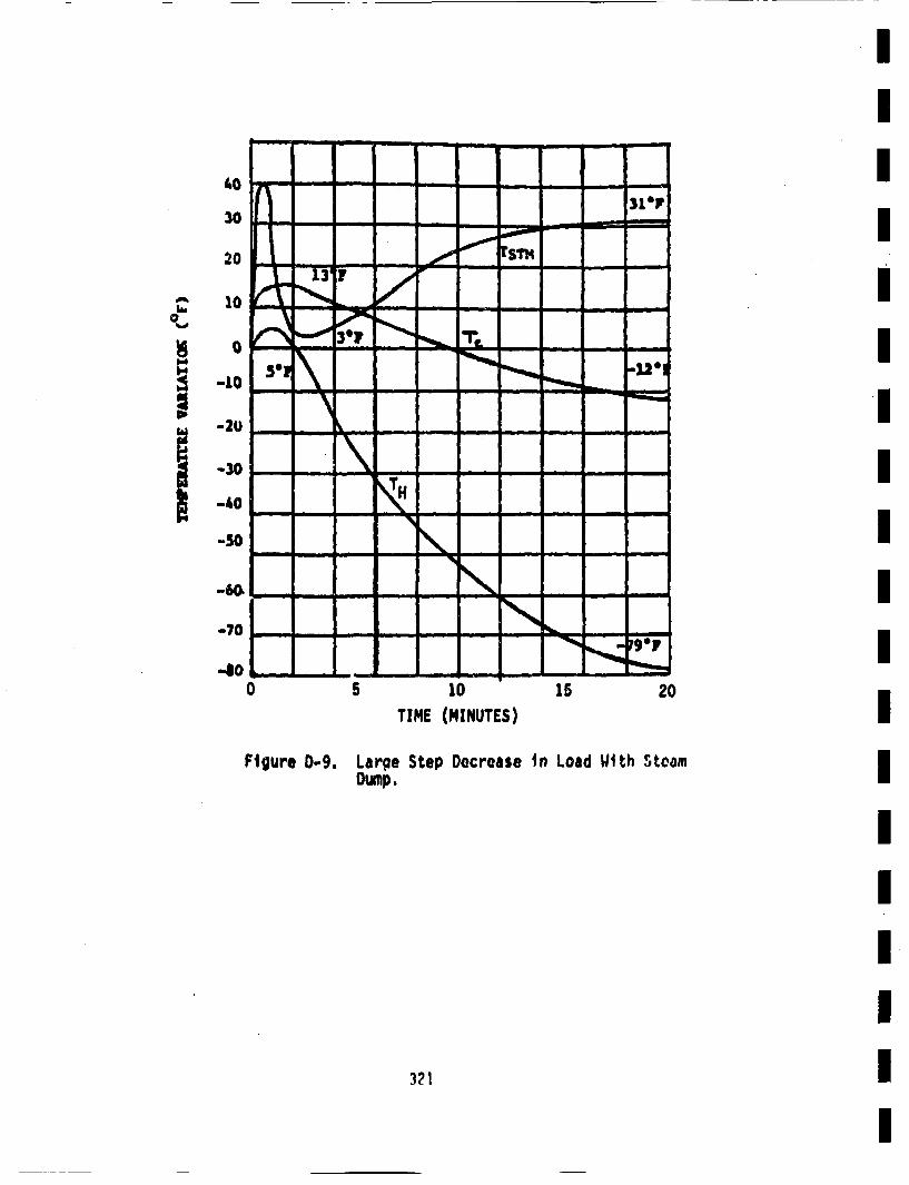
40 - -zv I
30 .I
' I5 10 -_
-20 ___"Uo
-50 I\ I
-70
-0 20.••
TIME (MINUTES) IFigure D-9. Large Step Docrease in Load With Steam I
Dump.
321
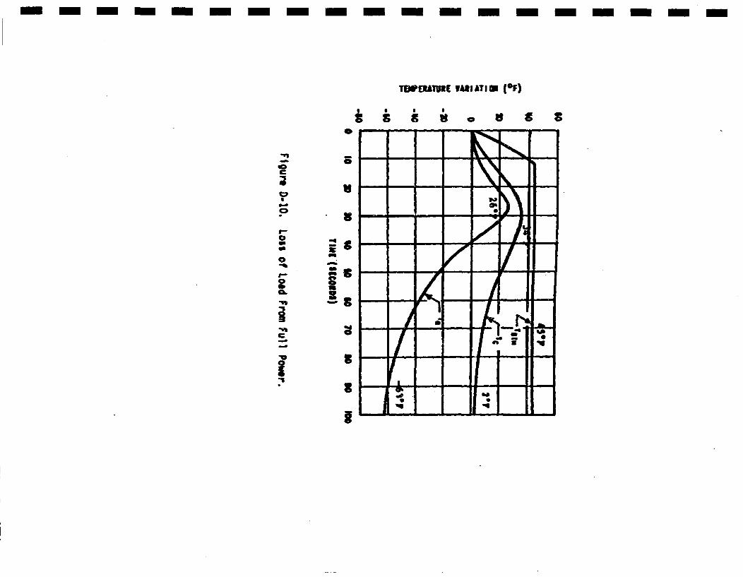
- --- -- - ------- -----
TDEUhVlE YARIATIW (SF)
30 W S S
-I'
I
C
9-a
a
II-nC
I
5
Vs
I
S
I
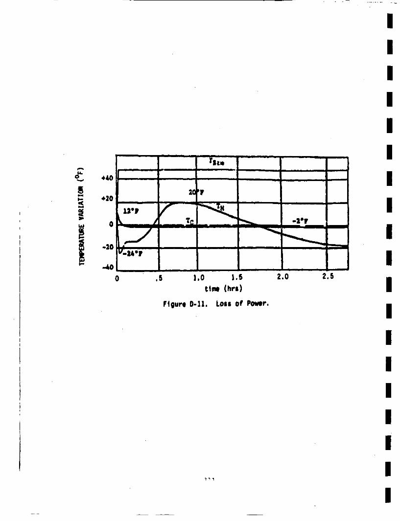
K440
420
0
-20
-40
II
0 .5 1,0 1.5 2.0 2.5tIm (hr's)
Figure D-11. Loss of Power.
II
I
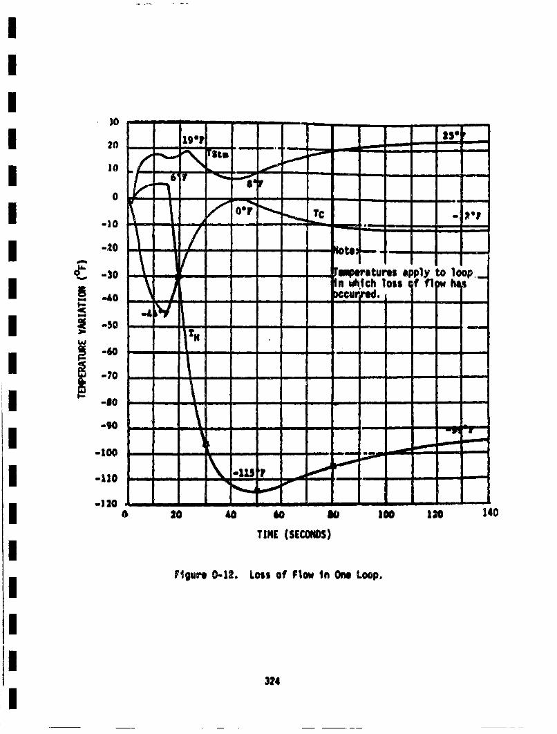
0 .- ,. - --. - ---
• - ---
• -SO
-10
-. 20
C *o - - - 60 -I JO0tr appl to40o
Ftur D12 os o Fo 1t One~ Loosp.
324
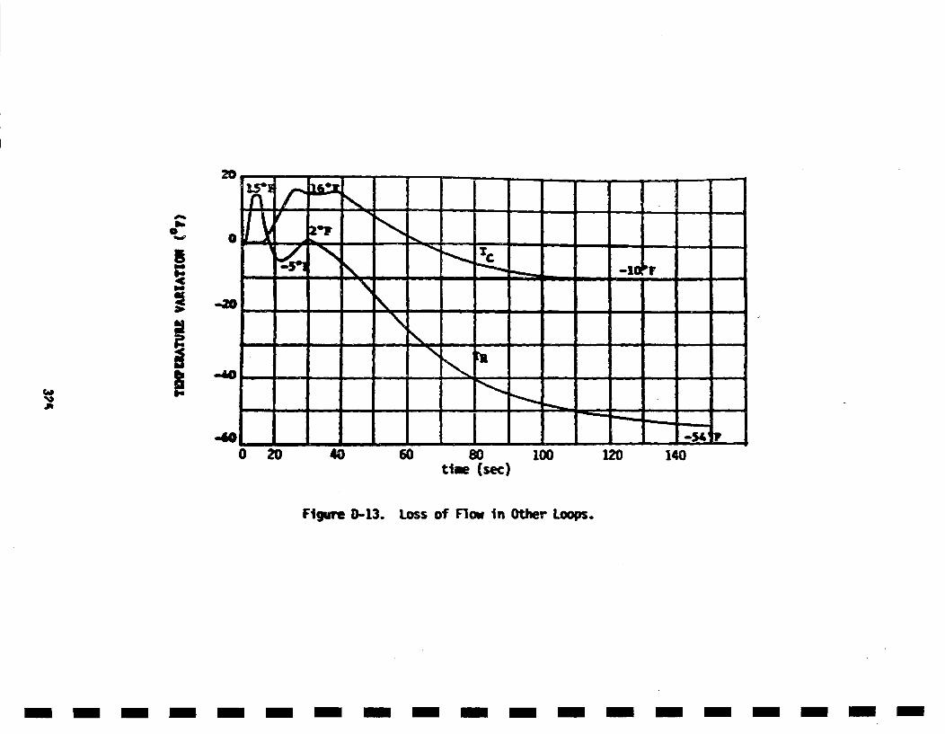
S - - - - - - - - -
40 O06O8 O
time (see)
Figure D-13. Loss of Flow in Other Loops.
- m- m m-m - -m - -m -m m -m m-m- -m- -m
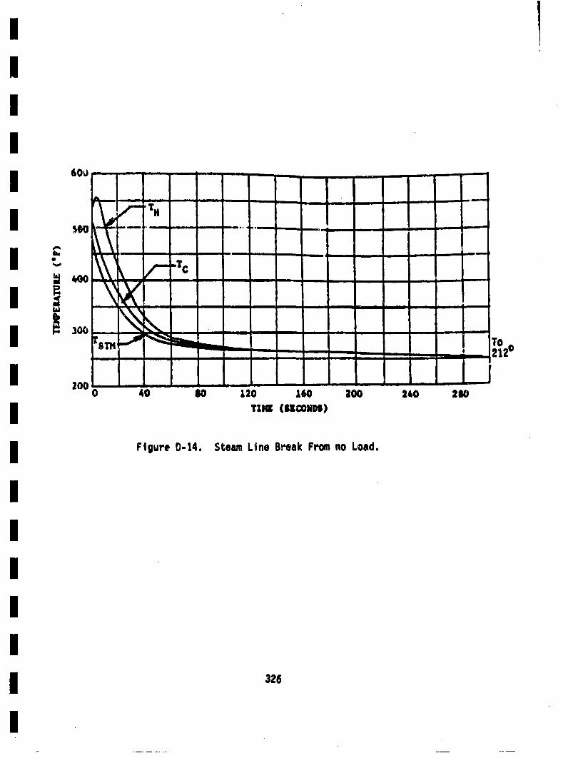
I
b
~'oo
300
120 160Tug (UOODs)
Figure 0-14. Steam Line Break From no Load.
326
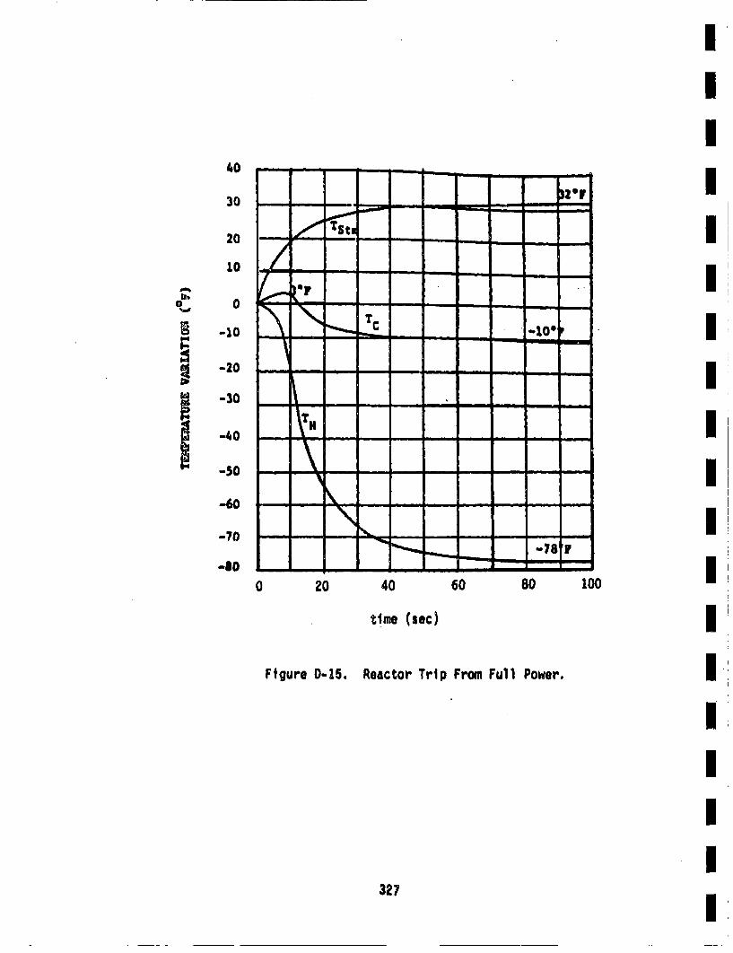
40
30
20
10
lb0
U.0
-10
-20
-:30
-40
-30
-60
-70
-80
0 20 40 60 80 100
ttme (sec)
Figure 0-15. Reactor Trip From Full Power.
327
The procedure for computing the fatigue crack growth due to the transientradial gradient thermal stresses will now be illustrated by consideringthe example of reactor trip from full power (transient 11 In Table D-4).This is one of the most important transients as far as its influence onfatigue crack growth is concerned, because it occurs about 400 timesduring the lifetime of a plant (see Section 4.1) and the stresses pro-duced during this transient are fairly highe
The time-temperature profiles of the coolant during the reactor tripare given in Figure 0-15. For this illustration, the cyclic stressintensity factor occurring at the hot leg-to-pressure vessel Joint willbe considered. The weld junction is 2.5 rinch thick and is a part of thehot leg (joint 1 in Figure 1-2). The time variation of the coolanttemperature of the hot leg will be considered for computing the stresses.The radial gradient thermal stresses were computed using the PJPET code(Chin 81) at 51 locations equally spaced from the inner surface of thepipe to the outer surface, for every 0.2 second time interval from thestart of the transient. These stresses are shown as a function of timefor a few time Intervals in Figure D-16. (The stresses shown here arethe axial stresses which are relevant for circumferential cracks. Radialand circumferential stresses were also computed In a similar fashion,which could be used if longitudinal cracks are considered.)
For each time interval, the RMS stress intdnsl~y factors (Ka and Io) werecalculated by using the influence function (IF) method. For each timeinterval the radial gradient stresses were read into the computer programas a table and a linear interpolation scheme was used to obtain stressesas a function of position in the pipe wall. Because of the very fine grid(51 points), this linear interpolation scheme was found to be very accul-.ate. Then for each time interval, values of K andbercoptdf,range of crack geometries. For Illustration, Ka for selected crack geoin-triostis plotted as 6 function of time in Figure 0-17. These PJ4S stressintensity factors are referred to as, 5K because these stress int~esityfactors are those due only to the radial gradient thermal stresses, 'end
328

1.0u/b (h.- 2.5 I~cs)
FI 9 .r'e 0-16. Rtadial Gradient Tberml Stresses at Various Ttls Frothe Start of the Transient for a 2.5 in. Thick Uuied inthe Hot Leg.
m--- - - - - -m-m m - -m- -m m m-m- -
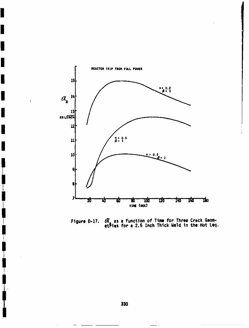
13
NI I v '1 J
12 .€
11ueD1.6.a ucin fTm o he rc em
10 ~sfra25Ic h~kWl nteHtLg
330
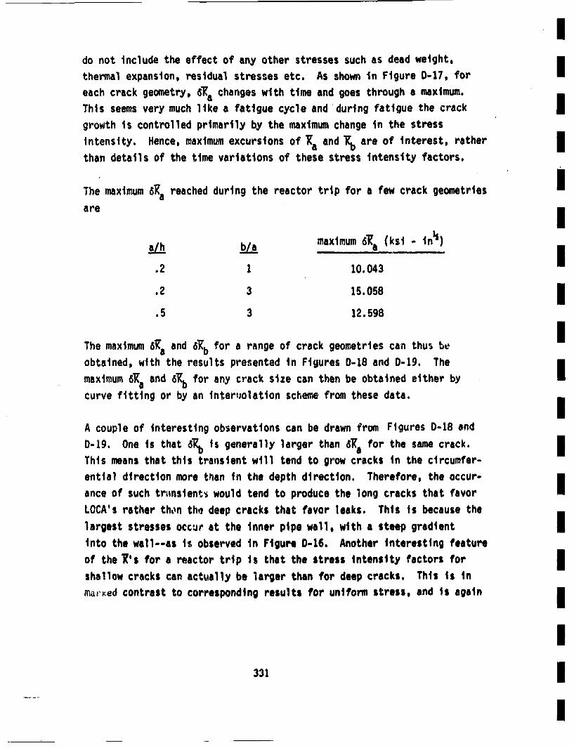
Ido not include the effect of any other stresses such as dead weight, [thermal expansion, residual stresses etc. As shown In Figure D-17, for I]each crack geometry, 6a changes with time and goes through a maximum. [
This seems very much like a fatigue cycle and during fatigue the crackgrowth is controlled primarily by the maximum change in the stressIntensity. Hence, maximum excursions of Xa and are of interest, ratherm
than details of the time variations of these stress intensity factors. m
The maximum a6K reached during the reactor trip for a few crack geometries Im
ahb/a maximum 'a (ksi - t•
.2 1 10.043
.2 3 15.058I
.5 3 12.598
The maximum 6Ka and 6Kb for a range of crack geometries can thus be
obtained, with the results presented in Figures D-18 and 0-19. The [maximum 6Ka and 6XL for any crack size can then be obtained either byI
curve fitting or by an tntertiolation scheme from these data.I
A couple of interesting observations can be drawn from Figures 0-18 and0-19. One is that 6Kb is generally larger than 5K8 for the same crack.
This means that this transient will tend to grow cracks In the circumfer- m
ential direction more than in the depth direction. Therefore, the occur-
ance of such trlinsient'• would tend to produce the long cracks that favor [LOCA's rather then tho deep cracks that favor leaks. This is because thelargest stresses occur at the inner pipe wall, with a steep gradient Iinto the wall--as is observed in Ftgure 0-16. Another interesting featureof the K's for a reactor trip is that the stress intensity factors forI
shallow cracks can actually be larger than for deep cracks. This is inmarKed contrast to corresponding results for uniform stress, and is againI
I331I
I
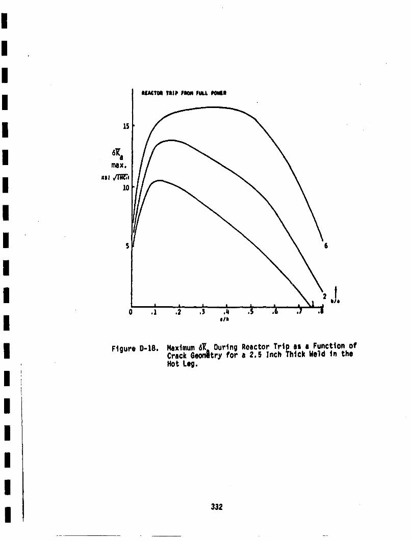
15
max.
0 .1 .2 ,3 ,•i .S
Figure D-18. Maximum 6•K During Reactor Trip is a Function ofCrack Geomltry for a 2.5 Inch Thick Weld in theHot Leg.
332
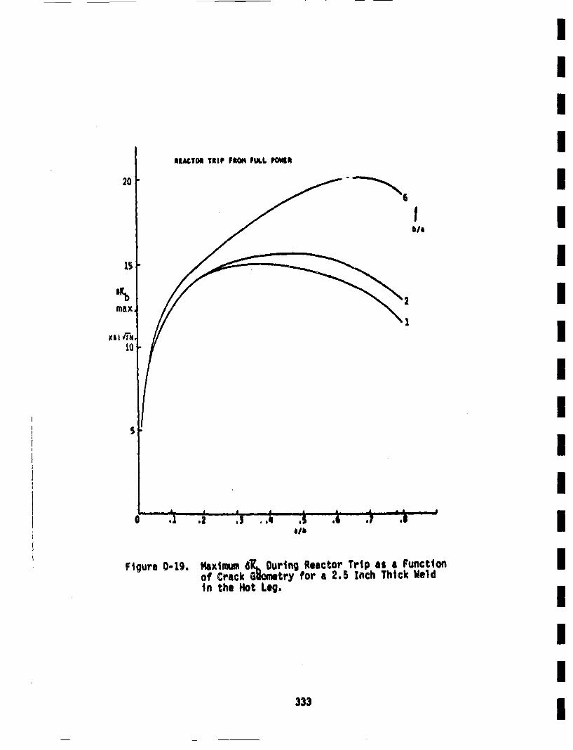
REAMCTORI TRIP PEION PULL, POWElR
20 1"6
Ib/a
15
max.
110 f~
IIIIIIUIIIIIIIIIIII
5j
p A A *A
a .1 ,2 .3 .. , .5,a/ll .6 .7 .1
Figure 0-19. t•xitmumGR., During Reactor Trip as a Functionof Crack Gl~ome try for a 2.5 Inch Thick Weldin the Hot Leg.
333
duo to the steep stress gradients through the pipe wall. This means thatcrock growth in the depth direction due to reactor trips will decelleratewith increasing depth, which again points to such transients tending toload to complete pipe severances more than uniform stress transients.The degree to which this is actually observed in the leak and LOCA proba-
bilities wi1l be addressed in Section 4.3.
Th@ transient considered for the above illustration (reactor trip fromfull power), has such a time-temperature profile that no negative RHSstress intensity factors are produced. In this case the minimum 61R!
are considered all zeroes. On the other hand, during the transientloss of load from full power, the temperature profile goes positive andthen negative with respect to the initial coolant temperature. Thisproduces negative radial gradient thermal stresses and therefore theminimum 6 are negative rather than zero as seen in Figures D-20 andD-21. Even though negative stress intensity factors are physically
meaningless, they are still of interest because they represent the influ-once of radial gradient stresses on cracks in pipes subjected to tensileloads, such as those due to dead weight, pressure, etc. Details onhow to comlbine these radial Gradient stress intensity factor results with
] duo to other stresses, a.ld then to calculate fatigue crack grovth are
discussed in Section 2.6.
The RMS stress intensity factors described here were calculated for
radial gradient theme', stresses in 2.5 inch thick pipes with Youngsmodulus E = 2°87 x 10 psi and coefficient of thermal expansion &a'9.1 x i0"6 0F1! for a given time-temperature profile of the coolant. Themaximum and minismimd• data thus obtained are normalized to make them
dimensionless as
33:4
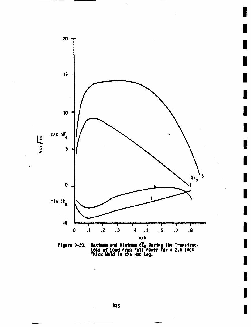
II
20 I
I15 II
I10" I
I
Ia I
0.! 2 .3 4 .5 .6 .7 .8Ia/h
Loss of Load Froo= FullPo r o , ihThick Wkld in the Hot Leg.I
I
335 1

20
15l
10
max 'b
L 5 -
mm
•~6-5
0 .1 .2 .3 .4 .5 .6 .7 .8
Figure D-21. Malximum and Minimum 6K.b Durinq the Transient Lossof Load From Full Power for a 2.5 Inch Thick Weldin the Hot Leg.
where AT • maximum change in the coolant temerature duringa transientI
C * Youngs moulus
*' coefficient of thermal expansioni
a • crack depthi
Thenomalze maimm nd inmum 6 V an 6. 0 dat fr echtrasinti
are listed in Table 0-5. This normalization mekes it possible to usethese tabulate data for the transient whe it has the same temeratureIn
time variatin but with a different ATm . It is also possible• o use the same table for •aterials with differet thermal coefficienti
of expansion (but the same thermal diffusivity).
This cocludes the characterization of the radial gradier't termal sates- Iisea, which will be used in the fatigue crack growth analysis,
33I
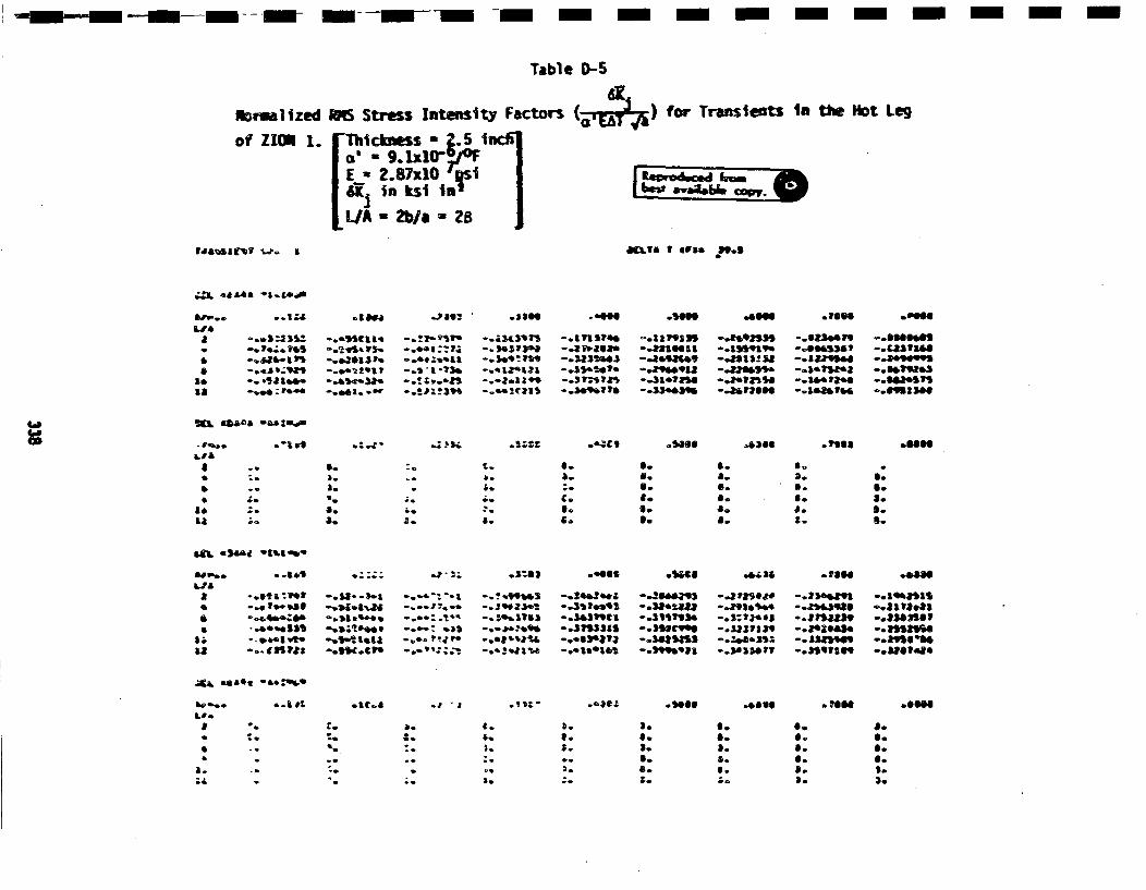
,,m--m--m--m --- m m--m- -- - m-m m-n m-m- -
Table 0)-5
10rulizedof ZIONI 1.
i Stress Intenity Factor's (,)for TraileltS3 111 U• Nt Leg[Thickness - Z.5 IncIlI ' - 9.1,1~ 0"F / ______
IE - .87x10"ls I tewdu •Io.
[LA- m1 -b~ ZB Jal~I,.1 Ua 39.1• •~
Ir4 .*|•a *..&.
adub
ae.1a
-. 88.-a 1=
-... h |b9r,--QO .i 10n0.
-.. u2*131. P,
-. &5•.2.e D-. eel. ..85P
.380e
-. eIL)SW1•-.- 1i9
-. 181129.Pe~-. 8I ?01039l-. 123100)
-. 381 •,1*
-.. 109.I•720
-. II2P1011
-. 8900912 I
--.31.1*56
-. 809391 . ~-. 8*00SS55
-. 8.,18O06
-. l68l)0 19
-. 1.1514
-.1085164b
-. OOOni'-. 8000099ll
-. 6198)II-osea.,,,o.t0,9 1340
-1~LI A
a -.0
**
18
.~ 'a~ .6@€ • •,.140I •.430O6 -'gsaII .06O0
a.
a.
a.1.
a.'0
a,
2.
a.
O-6.UI.
I6.
B.a.6.
aI.
aD.O.6.ID.
Ia.
a.
ala-.. ~tl
-,.5. ak• -- ,
-. 15- .e 16~-.- : .aa I~ -. 2t.8 e
-. 316515l I
-. 11315)1-.. l638?3
-. 38.112*
-. 31513).0o.3531tl3
-. 891.5,4e
-o$: ?r1.ei
-. 38) I1139r
-. *38J986O
-. 81588t)9
0.19.851l1S-. 1ll8.81
-. 15593l6lo.a5 &1' s,1o
bl•,e... ll oo
LU.,,.1Y - .,4t,11t11 .1656 .0,Ot06
r.
-o
a.
a.
2.1.
a.
a.S.3.
3o6.a.
S.$o
O.
a.
6.
6.9.a.6.a.a.
Oo0.og.6.,8o
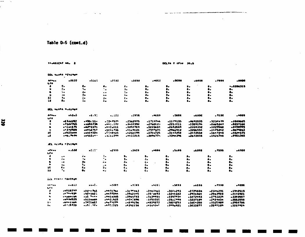
Table 0-S (cmt~d)
ew',.•saca ms. a ID•fI I 6918 ).M,,,S
I,,
al
C mt&,& 9 4J14• .13"06
.--
I.41.
*-e
Z.
".oI.
6.
g.
6.,1..O.a.,
6.IS.II.
IS.a-,
a.8I.
8.a.
0.
6I.41.lB.II.
S.fl
II.S.
O.41.
GIL .aOe *~45~.
IC[
.6 ,a41, fl42
o.4l,,8I II
.- 8g.3
l.
-a -. "
.a.,ml41 il.oa 52 .).,C.:tl) .C 49 '11.
,,,, r, I.C , .'541
.1 IlIata. .I I Tcaa..3a)fa! .- ,53a09I
o.!Q%P&'r, ,,,.944, 9
.6saae -SeO.
.e.93525• ,.2*3.31,3 ; .ae0ea1as
.a l'ep*Jl . l4i•3.111 .SdiS•aT6
.J.11a,Ii .1. 72l.T,6 ec'tl1ell
AL e~s'%L6,.1213 .. 4Sl6l~l .4,.II o 3I'1
a
II
be
6L.
48.
I0.
"C
1I.
I[.4;.
6.
a.
O.'C
g.S..a.0.II.S..
31.6.
6I.
a.Ia.
a.,0I.
0.o0.Iio0oS.0.
04 9
I.
.s:ea C)', 8 o.130
-a 'C."3S * .'I* .,,I*- .0.17 2.r . 1+.'n .S .* zts ba .|S6I+tO) ,.2 1*50*5 .5 3-,*91*s.ai'e"~ ] .ss.qz•l .$a.1•a .fla11Ps4] . I 2)4),30.3%a+IIs -.lsS'13. .35j,?'34 .1113S)I .*t"i5*9
.1*)•II s2, .b14,'I." .2•I.9.08 .20)3I?? .)S*139
9ocOS
.aIIIuaI
.aauIazal
.3.9",.I
.3PSSe'rI
- -- ------- --- -- - ---
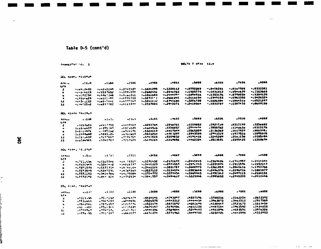
- i--- -- i ---- -- i -i i-n i- -
Table 0-5 (cont'd)
~.a~1*"' *.~- 3 gg.ta t *Vrpo as..
U81 -
aJ0
1e
UJ
•k28I *Ylsa .8000
-..-.. j.31 -.-. i!J' -.- *!1 -. aO•Im -. 1ZD61U -.67035 -. i.*b.1O -. 01.1,21 -.S1S)3361
o._•.'b -. "e2 . , -o.4•1?? -. 3~3?S,s -. *5.43?- -. 3.106*4 -. 195317q? - .0 ZU#JlS -. 6*80:8.
~L .~aha *a.E~
a,-..LJ&
J
S0
U
'GIg .1666 -alas
l.1-.:-4l1 . -.. .. •* .$3,zcz1 .41e1TmA9 .3I~S4Sq4 .la+eJ* .3(4153? - .8.&31L~
;..&"4.4ll .'aat*.2- -.sal!•ki .5+ll *!7t 311? .3,~SS~]l .*0151 ".. I9 *ThI& .&S951613
I.,a.." -. • • -t.l-1 *'l o7:" 'li' .+~~l .1*.'05i .'*alhlI' .ssissoll .2l)114 55 .1*$6*0e4aI
*I .I'•i*
kLii. ... *USI .i4*.• ,S 140 .aill . visa .4$81
* .ll ,l i -. 3..:.-j -.. lzlal" -.. ~lll23 -. a.1.ll5' -*•Sle?4 -.33*ggli -. Il5115qI -. 11021.?
S .~).2t3 i~~ -. 1Jll_*1 ?::- .•i .'... -. 34.11l1 -. 34311,0, -. 3ll84?) -. 23*35 5t -. lll -. 1?S111*i -. ,1tllil -&lI., 't -,.' l•..*3 -*+.3*7112 -05l3e5?* -. 3063*40 -. 3 49.Se0 -. 319*11*i I -. 144161?
L.im a
0.J
.~I3 .$€00 .1660 . ill
.*I a&3ll . t..'55•+••., :.'I. *3_ . 3 C
4J5i64-5
o*54)4t4l -*434334? *433•1 .316l334 .31*3334 .3*33302.. •!l .satal1, *eq.fill .444.,34 .*39*313 .34.2313 .29l7349
*.:.#*-. *5546Ill .75099*4 *S.•le*. .e91309* *.-1l359 *39?*330.,1'ii *.al!c3P .lll .•1)89753 *.3U?3' *...159 .03)3413
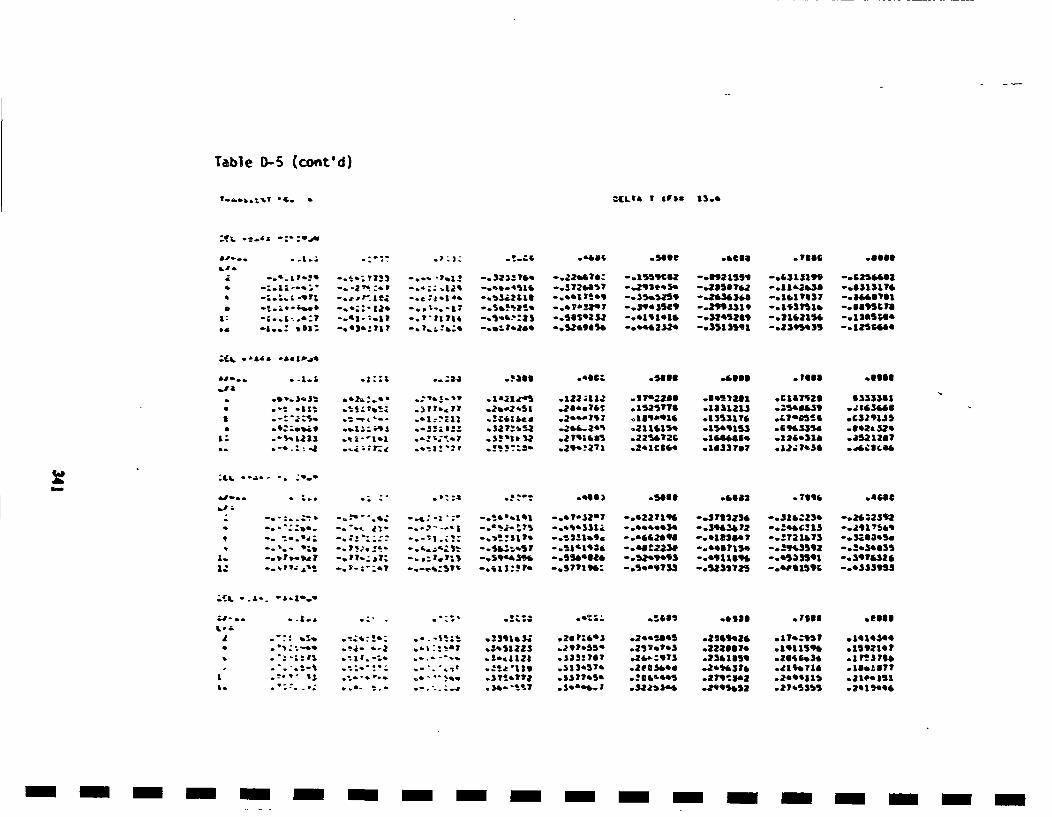
Tab~le 0)-S (cont'd)
~. * •Cta& I £FbS 1ISie
LA,-
aL
- sage o'as' .7S15 -... l
-- L. I l'?l -. •.-; ?T3• -.- • "rll." -. 323; T6t -. 22iITi: -. I•9{IZ -. l•a l• -o&][31• -. {ZSI•li
tlb.21.•i .. i'_'. I•i .. ll...[.• .. •i.l•il+l .. i•l•7 --. •l•l• -- • .•.•J l. 9 --. l!.•lr• It, -. 11•11
"1..: 'ill: --. 4•Jil " Ii F o ill •. •, .'•' It. ; 4i o. I•t. iiQ4•lt 0.e44•69154k -- o !•4b'lb l .•6•ll ".•l •ql ".ll4'ea4i $5 --o 12•S664
:(A. *L~a -aagb.U
a,.. -*i a
IS
a:
.~ ::a o.•:34 -"'sl .5... -'000 • Ioll .6111
-Ia- ~3:?.~ .~t1..,7 *2..2Sa .iaa.?.~ .152,716 .aa)a~u .25043, *~a~~a
.- :~:s. ~ ..'I:!~11 ..3C9Iae~ *2*~.797 189.010 *1353176 47DS30 *C329135
.- '.: a ~ ~ ~ *29"271 .a.acaO. .u1~vu7 *a2..?o36 .d4.~g4e0
:L. *l .-" -o.
a.~
Q • • .'.: . -. .5.11 50612 .7$10 .408e
-0" o ;; + • ".; -...- "- : -. *e.1'-l| -.. T-'S*7 -0t2271% *-51t123t -. J16.ZS0 *.202392
-- ;¶.'I: - **';;:; - -! •. -. 3!.SI1' -. 5.2±1.9.S -.5602990 -.0182O0T -.3721*73 -.3•SO05.
-.aI,'5-5,a7 -,. I7 .. • 7? -.. I-*, *r59 -•.S4r 590 -. 5541iO20 -. 52.5'93llJ~ - .,09110 %q# * -05•1 -.il "3076320
-o .--I ,. . ;," .
S.: .*.:-,
.o'0: .760l ,.3066
.*.-1•a5 .3391.3t .21P|6*+ *2055805 .216920 .1T7.21'5 .1410304.1t:•+l .z+s1aZ5 .29?*.55 .237.1+3 .1222117 .191119l0 .I5,2l0?
* - . ...- .!-.1121 .+333116 .20-973 .2301159 .2l90.30 .1•.713
.. '+ *37!'ill .317.5T. .210',.54I .279i3'2 .0992I151 .2l..IIi+*-"+. ..d T*ilT7 *.0$4..1 .3225.34 .2995052 *27a5il5 .2.1*1.0
- - - -rm -rm i --- i- -m -m - --m m
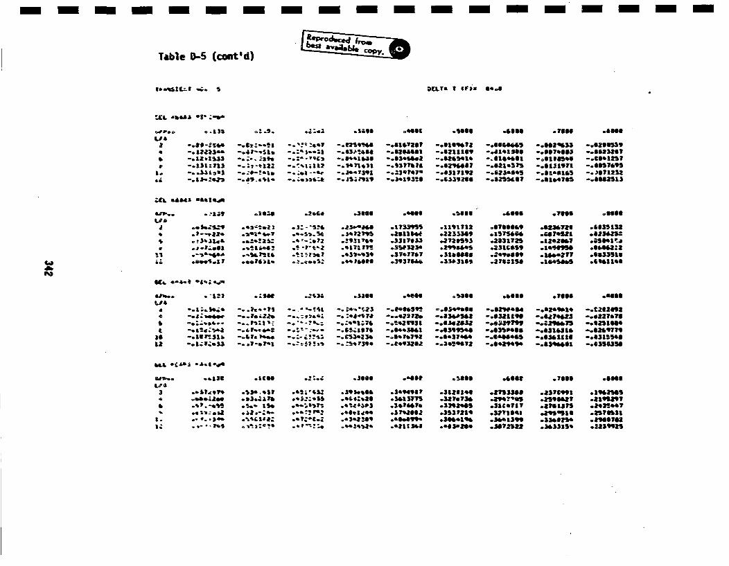
Table I)-5 (cont'd)
(4 ZC.i1 o. I S 3"0TB 4.i s••( ei4I( .A 7 (Fl •6.8 D .g•e
-'. -. 1)'e~b .°..€--1 o.••:ll - .5606M .0081G~O -. 950l66 -. OOO66 *.7O660 o.8061
a -. e*-*;i~.. -. 4 t'-.'-al -o':" .-i• -. n83o%.0 -. oOis'asi -. ga. lL.?1 -.eseI inoa -. 602%))5 -.020$53T* -. u2z1s.. -. aa.o, •t -. :~-- :a{ -.osI*isosa - .szosox -. 621:10• -. J1i4100 -.667I464 -.1655*17* -. aalzsss -. °. ;T-:. -. :.-"ll -.o'.asae -.63T16.7 -.658S414 -. o1001.61 -o.eis, o -. 30.125?
Lio -.131.IIl 2t4 3113 - .x .. za -. 7): -.03757 -.624ll -. 62111 -.ui,,l -.6 I759
.*- .j -.. s':2e2 -. 1 -. , " -e i . yal -. I3.19355 -. 1131706 -. 8255537 -.81.4705 -.80025
6Il. °*--a2 .36l•L ,0 .2•-"64 .56012 •P .00i66i .22133 .1.666 .7660ii .6666
J ° .. ea .5Z "JSf"2 .23iT4- *17339 .1191112i .878601$9 .0231.729l .l563515*
&• ~.llSb.g * °34ii5 o. '*o•2 o91?4 .35l°•3716) .2726593 .2151l2 .120244 *asi'l:.
.,*,oo ° 1.4 . -51i.4 .•$15Z .e$T101 .350323 .79584 .2315 *10995 .608022
.t o,'.•.i..- -... 10a !- . •.e .. 4b?08t67 .o3937060 -. 5303160 -. 2753159 -. 1045805 -. 60011
lO -. 1.14. -°.7..7 - .•' •-•'.* -. •'.-¶23 -. l0 60505 -. 6504.66 -. 6256.141 -. oO0611 -. CZC*6.,5
* .. ii'-- .. 11.3'I -•.-'% -.$ .Z~lZ?0 .. i4093 $ -•.1328S2 .l.59?99l o.l447 -.lT 051604i
I . 124.4 2 .i.-'• .. , :-". -I.&5e•16?6 -.6.i561.1 -. 0599n46 -.035046 -.83021 - .07097
*.. 18.1l .1C84t- .2~~'.• .5i06 .. 02 ll .5000 .*00i02 .7660 .0606ll
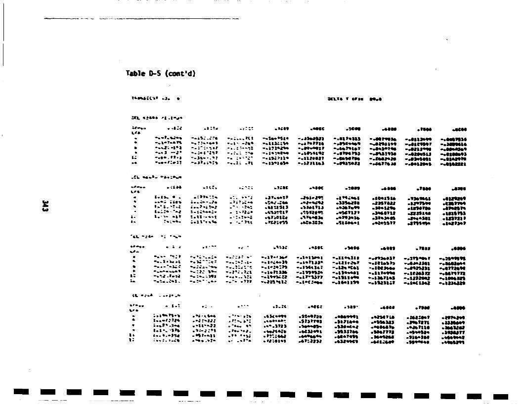
Table 0-S (cont'd)
lll.Li4•; {.'• S .]• • •Li,.a I LII. I59.0
s1.6
. 4"¢ .: :~.
.,.?.*•6 l% -. ?,, •I
-'--a * Cl~
- - -:1 -. u'3*i.l
- -2 a• -. 3W33I'1i
*. "2-;-; .,tII4a3*;4
-. ele4lla -.. st..' --519159 -.8110091 -. 14mli
-. u: -4*5 1 -.. '95141 *.-.*Mt~ -. SlsSS•a -. 03lea4,91
-. 11113,3 -*.895• * *1, .Ei'I -. , I185' .010MtiII~
-less -a-al
I' 0.
0o
1.1).. S * :l; -it*91 I.8 .i01~e4l *l5'lSla .. 351i4 .5139l5i.•.a4as .. 3eW.9s -*satul *l.s5le .aieaS15.*1•1Te9 o.1T?1, .34t45111 alIiaell .asiIa
*SIe.1)e .4.9)14b .31.3401 .s1.'SSS .1851851
4J-.. * I .1'~~ o. Icc • Ill01.5.5.
C
4.
Ca
a::*: ~
--.... -i- -.a9Y5-Z*-- :.1 -.*2i%12i
- 5~i~t - .llt13l -. 9251'~ -. 2110 le1 -. 21.0i00
-. 1e1t83' -. 1*ltle! -. ll.5P, -. 51.81lt -. 5458.94
-. a?33?P -.- i1 l• -. 135 'as -. i~lia.' -. assmll-. 1.C2,o., --. l35. laJS -0511J3;1 -. 15t41,48 a83o111
44 *:.5 -
a:£.0. .,24 .9314J5l
*... a'0
*S~ *4 ..*.3113
10 *a~j .1'~;*e2 .4,9914~
• 1" .4500 .101 .5055
.o59991 *ea•T'Is .351Z59 891s150J~
.5i1l15. .e11)ll3 .891l1311 .5385599
.SSSS-P.' .0541118 .s9..tte .35351111
-4401915 q * M93 .91511O .•5'9.5.43*9965 .84lt~k5l .19~44S *955195
- -I -I -- -I -I - - - - - -
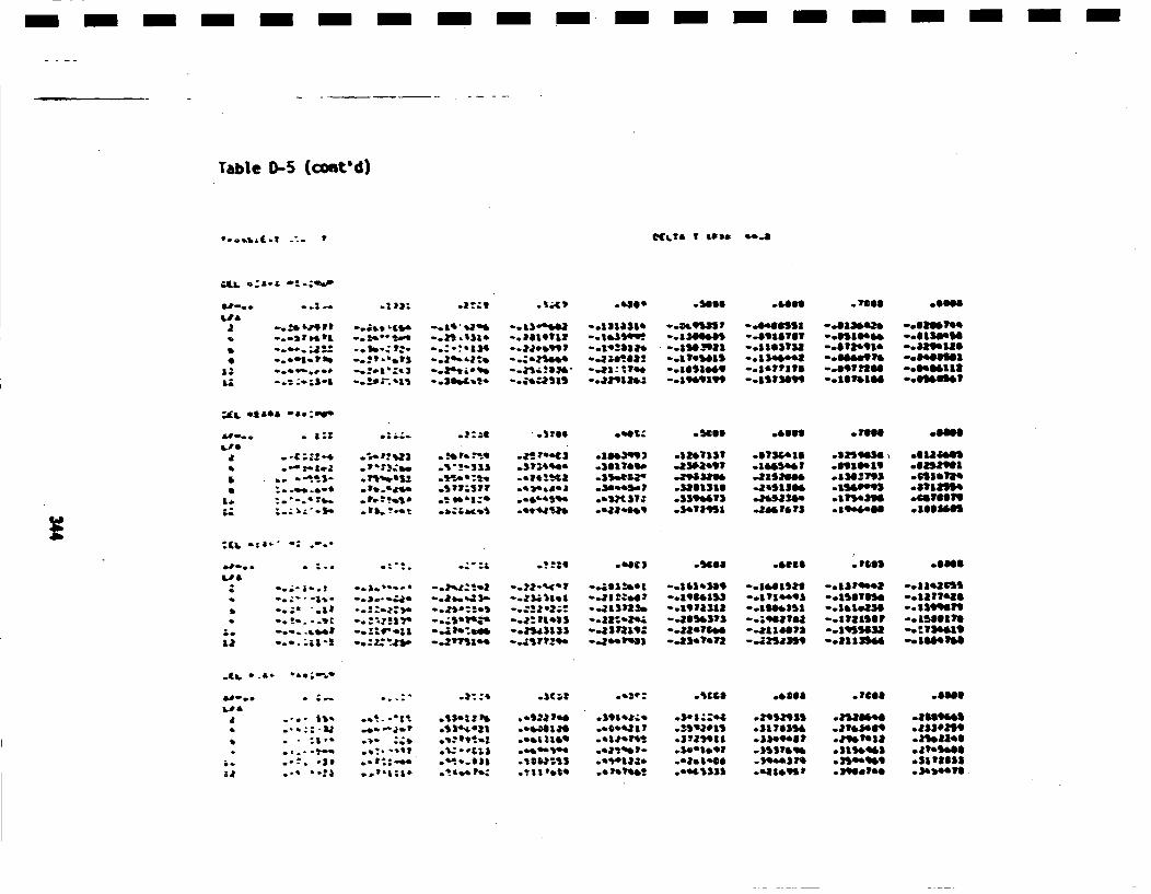
Table C-5 (comtmd)
Q. &oI
g•IqT• I SIglb a4b.a
a,-.."a/
a
0
U:
.. 1- . 'a .5€.. o640€ -.1m1
.. • •II -oL++ +It4 -oi+ •T• -. 13• -. fill•l+ +°•q•klST -el4mll•Sl -. ll• -. ll161•ll-.. mr•tl .. •-+ •,,t -. • ,131- -. II14711 -. I&3•41•. -ol•14k• -+111711 -+ISII4M -. IISIeM-0,+.•+.•" -0k-•7.% -.-- ;+IJ•l -. l+++q•l -. l++.lllt + -. Itl•ll -°IIIiTM --elll•ll+ -olhl•llllo.+Ol- 7hD --.. ll-+llJ "DIk+I:I -. ;++ "-3+e•-ll-+ -. ll+Mll -. l•4ke• -. + IPQ -el•lllll-. ++,+-+ -. ;+l''m3 "o•P•': "• -... "•+ 20 •Ni,- -,•,11 : '€7e4. -. II+IMI -. liTIll -. IqI•IM -oltMIII-. :+-+i'l -o'.e:" +I+ -. 31•+•.+ ".tt•T51$ -. +J•lll• -. I•IIH -. I+IMVI -. III•IM -ol•l•l
zi[I. ,.tsell .a.awg
LIj
aa•
• ::+ .1266 .5.63 .1000 .0060
- -:z+-. . '•TI . !abI,~ *?!?S .C) e .aa•399 .13.11ST .gS.ll .325505. * eU 8001°* •-¶l- *ij.t~e~ °5"-.S:3 .. 1e 5+e .35.O*@k .3931*9 .311250 o.55.2193 *flI1l?
a.'-..
I a
S. -eel, .1•Sa *.661 . 2063
.. + .l .|++ie -. +•++ -. •e+ --*J511**1 -@901531 -. 1,1e93 -. 15616elH -. l1311a19
-.+ -+ -0' .*j..J• *..5a:2. -01:3J131 -- 31313) -.391331$ -. 1010151 -. 1711511 -.1I9II19
-0-. ;I1 - -. :Z•'n. -. VT1s.. -. ,ZI1?29 -. 315031q -..33.?13 --.321350 -. 3113950 -. 150.1064
.•1•, • .L- e6e'-.e"•
a,-..~ a
a
a
U
.+€11 .1606 o0i06
*.-1: I .e*" -a .+I1#.f .eeI31l9 .. 1al~t .37*591l5 .$1tl101 .3t101018 .3503*06
. "31" *.t+ ;.. •.+l..*a .5103153~ .el5133' .e~s11ll .34.031 .350.109 .5111635
.- * -*e o. ~l;+-. °t *.Il .1*++ .. 1.l10! .0445l3l .101.11 .350.110q~ .3h5.l1

Tablle i)-S (€onatd)
31'.A+1gCjt .. 1 -4%
~CLC a guam 1*5..
a,-. -qL1
&
o08
a)
- I i'eJ .4 ~S2 .-'sDea -'SIe. . Ieeel .5l81
-. " l; +,,,;$ -... %•I •'Z -. s" II, I I• -. •+I•+17 -. ll.5q• -- lit: 18q'o - .+DOll •3•17 -. ll1•Ol -e•lhllM TI-. :+,'tS -. ;6• 14b4.1 -. &2$e.lq• -. ;l 31db111 --. ,11141•34bi --. 1 =41.,1•i II -. ilJ•141,1 -,IIIIKI --elll1464•1t-. 1 *.-•$2 - .+•..J32 7 -. ll r,• -. 31•,•I -. 01|e..'I•. -. LI•ITIb$ -. lklS.le V -•&1,-•8 -,,lll4lqk4-. k-+,. o++.4 -. l•. I •II -. Me .'1•t -. II ,•13 -. II ".,TI!l - .Ik15• I -. l14•l II -. Hlllkl7 -e81111•i-.-. o+. I'• -0•+'III -. I•IQ•.+ -- +•+=ll- -ollMlll -. II+411H ,..H llhlM -. gO+ I•T - ,, II Ill41100,,+•+... I• -.. I•--) -. •k•lhll -. +le+lS• -. llqm6• -. ll ;•lll -. IHIIIII -. l:e I•H -. llltlll
ta~ agUl 0as1e~
LI*;J
.:1a4 .|=61 .$3)1 -'egg -i8ee
.... 3.1 I.=$I;:I .3$$6TI -t*l .le+s79l .434444
.4 636I191 **e)314q .61163564
.2+413403*I .J31*812 e Z3*19flI
.*a* I9) *r+l d.59'a+e9 o.3U.9)l5
°,q.. 1?e* .*915.996 * .IM455I
U. ,•1. el&o+ o" +%•,
6l'**
LIS
i0
0;
.010S o.mle..
-. .. I+ -. .- -", -. ;aZ!!iI -. 4'.'-)I -..L14)59 -. II193II -. I331I25 -. ll1e78k -c.il6111"--I'I+I" -..- '.53 -.. l•lI1 -- +-+• -..42..5, -. 3I35?3 -. l33.leI -. )3a1711 -. 15941,5
"-•• "*.;+.SLs -. i3)393: -. ;+,':* -..43)099 -. :a17617 -. 5251345, -.S1291• -. 136452'
a, -. - .2 I S .SL a . mc ej -... 11 .4h500 .166l o.l~l
1....-.3 3,• .. Jl.1c'¶ .l~+.l .l . •6m11 .- 1.t *131723. .I•*•5$ .$7341591 .. 52'I9 53•l .,3I991g0
1.72- t.-- I-.$S 121 .41-OO• .•.",33 .Tl.•lb .5177e900 .e*63?2 .ll45)576 0a541*S~.. t-q.-01 +o.*¶...$ &.+-i a:1s. .. ,7.o39. .*1l9*slle .7310*15 .s.eaue1 .s*..41esa$ .. e,0eIaa
- - ----------- ------
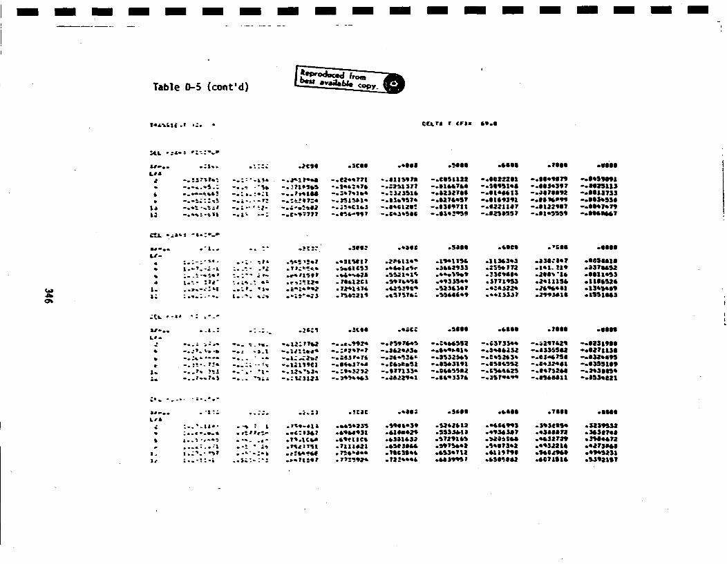
Table 03-5 (cont'd) ~c~~
*.. :.+ . : .7i1t o.iCI .eilt .o66O .466 .Ti06 .060l
a -. !3?,I .' -- ; i" .! - .jr~a "a -. i2.9771l -..aa1 '7a -.835i122 -.6622201l -. llel?9 -ett~o -o.'-•-.- -.. ,-.'H -.. l71$e3 -o.t.&e7& -o.25137 -. Ui&1160 -. 26911.6 o.66S439? -.6.25113
* "-.-:!,- • -L.- . -.; .:' . Ti:.l -. )St"*iS6 -o63.9179 -.i121695? -.61i93lZ -.6696399 "-.665536
id -. +'.• :-'I -. l' --. i~ 0 -. ~ 3C~ -. .69,6T l•12S -.m369711 -. guzze? -. 812*96? -. SS~IT.
mE,-.. ." - .. .. - - .. , . .3.g: .. ;e* hit .5e6e . T66 .06sUJ-
l..- - . -.-; -il' .i.4'!.7l _ o111517 .236119' .a9.154• . 1346i93 .6341 i.? .iSSS4ol
i l-' 7j1 -.. l *i .r,Zl!!e .TSiZCIl .S•lbeiSl .*9.335* .3771953 .2.11154 .1166526
a. :..... a. ; l.-'*.i *?&•lS~ *e.t'll6 .255i$41 .'.zS3 .2963a01 o.154160
Oh
* . .: -: -. .•€6VI ~ .310 .*; .5ill .6lll .76 *001 .lil
." --.. " ;:-- -- *. . -. a2" vT.• -.. a.9929 -.7597695S -. :9665S52 -. G$?S•el -. a~lua~ -.6I31i06* -. :'.'.- .-• -. *l. *..-.a..ed' -. :8297-? -- 362'•3. --. t69*..1• --.906132 . -8335562 oo6271130* -. '-. "- +-.-o.. -. a..a;2•. -.- '63 7, * - , .,•, ". - .13236 --.2952639 -. e3,,• So -.aszla9
-. . i. - . -*°1xs931 -.66.176 -.Cis9.51 -. 543191 -.0561512 -.8935601 -.635516
- . .. ?' 1• -- ". • i *.:9-.12•3 -- :9.6 -- 291 .6336 -2799 .6-81 -. 5,2
*+.. .. + .. .. l .. i ll ll kl Tl tl
9.. ,. 1. ii..•- ;: .il.Ill .!CaCll ..11i .1883l .6663I~ .1666l .6666
• * * :. .I if - + a .a?' -dka ..i59235 .5l 6103 .s$'al I .0466993 .4sliias .313953
I &..-.-,- * - . .- .?s lC66l .tittles .i301632 .5?29166 .12i*066 .0432i189 .1989i7- *..:.:.:a .- .,i .pill:sl .71z1121 .65110i4 .59Tlhi9 .5967392 .9933116 .9273838l
I. .:+ 5 . .L-. .:. 9•9* .t-ibeee .1663l96 .6539112 .6119196l .560296. *996523
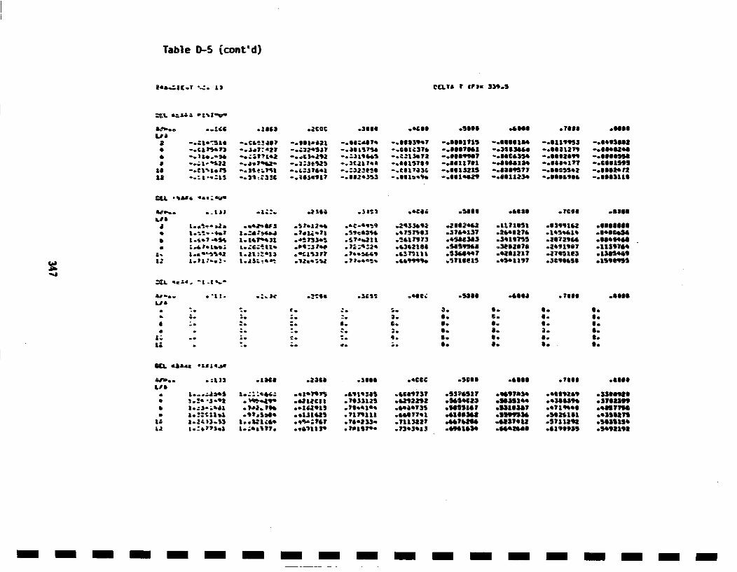
Table ID-5 {cont'd)
ecL?8A V aI:~ 339.5
L/a
&L
-. caI¶73 .. I.?:*2?
-. ;i-'saa -. d.1%2-
- aL t1
--. 1t s1ata
- OS.1 I&?
.3660
-. 3117•5ei
-. .0 1904
03eA
-. 1613997--. 00 IC 37-. CI 3sT?
-. 00 & 318
.0666
-. Oal?141
-. Ot8aili
-. 61215
.2112.'
.li'013
.530697i
.i3luelS
-. tlllll. ".6001279-ogaa035. -.6662S99-. es..aa. -.. sataTT-.. 3a,5ll -.mm03S.Z-.8011*So -. lllu0,l
.7988 e.ill
-. cauaml
-..61111
.1115749
.1859164
ASP..Lie
aA
C0
U
a"
L.~D.Lba~ L..0~i1ZA1.z'3342 Ia1~e13
-3 7.12.9.?* 1. * 13
*1573)e3
L132V1
.2.35.92
.,15tI*3l
-'gsa
.•117161.1043270
07€oe
.83991i2
t l.Se&1e
a'-..
a;
- "Il. .93106 o'sea - 7i.6 -sea.
•o;..'o
r.
a.
'Ce
3.
I-.
0.6.U.6.
a.
6.6.a-a-
S.S.S.a-S.
U-
O.,.,
toOo
£13.. .-12 l.1968~f . 436 .3160l .CCCCl .oOSlll .5306ll .7ll3li o.9668
*• I..i.JAS i.;il09. .. ill97 • &9l9391 .0109737 .5324417 .099703l e6•tl .ssnlle
i * i.! iz. i i5121 / 312 /0929 i1102 i nI3 i04 / i i l
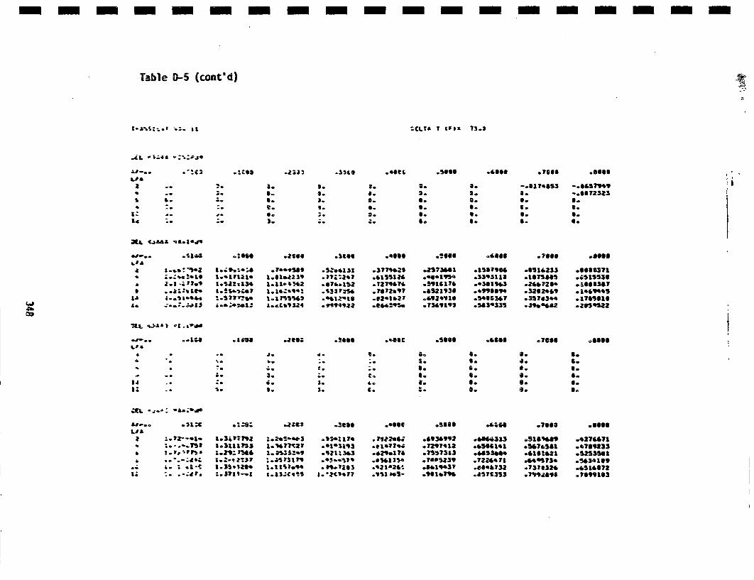
Table D-5 (cont'd)
II GcLra T (P)2 73.2
L 18
a
4L
~Cg3 .2 ~ 22 .3310 *0tC( .'eil
2.
;o
d*.o
a.a.6.
1.
S.0.°2.
3.I.a.S.3.
2.
S.S.S.
a.
0.S.S.S.
.7611
-. 8174053
I-
0.S.
.a~ll
-. gI5T,,9-0.172323
S.
0.
6.ll
.1e+69445olTI5SI1*Z05532
JEt (446Z ~S.1*J~
a,-..LID
LAb£4
.o$1A4
I. -.tb 1.t
-". i.,e 4 *
o2S•o .2560
Io1.171A1 l.01.a231
1.131:134 1.11e+!43
I°b•4LJ+ll L.ZC.0913
.11-.66t
*1.$131*77•,2o7
.65il
.0155124
.7l2714?
.7173b9T0 3241027
.5666l+
*6521,31
. 7349192
*151?+16 .051*233.33,iiala .1710511
o.49I339T .35703449.546•335 .35763.4
(.1
1Ig~ -JO.: .3.5. .5111 .4666 .7601 .l6lloP
4d .I.
2.4.
S.
3.
8.
2.€0
C.
1.S.
S.
10
6.S.
S.8.
I.S.6.
S.
S.
I.6.
LI£
I,
4I0-.+.S * ot l.35.328. 1.7115.9
-. + . -,:41*r :.3?1l -+1 i1.I$;Ci-
.3086 .slll .•+O1 .301;
.9341174 .l~lfla1 .1038992 .6564431 .5168489
.911193• *eIeT' .1217412 .00I6141 *0•7o581
.$21134 .629.1749 .7557313 .405356. .410141•.43.i? .83154 7613•+ 7m39 .722•441 .444573..79.7313 *'2la240 .8&lq937 .8044732 .75732*•H
.II000
.4716913
.4514619* T09913
GLOSKARY I
Artificial eccelogrami
A nuu~ri~.aly snwulsted aceleration time-history plot of an earthquake'sground motion,
Aspect ratio
Half-length-to-depth ratio of a semi-elliptical surface crack, b/a-I
The half length is wmesured along the surface of the pipe.Availability
The percent of time that the reactor plant is actually in operationi
during its 40-yr life. For Zion. the estimated availability ii 702.Boundary integral equation (Bii) technique i
A mathematical solution of three-dismensional elasticity problems whichdivides a body's surface into elements and provides displacements andi
tractions at surface nodal points. Results are a set oi samultaneouslinear equations that are solved for the unknown nodal displacements or|
tractions.I
BR oiling water reactor.
CoLd legPortion of the primary coolant loop piping which connects reactor coolanti
pump to reactor pressure vessel.Conditional probability
If A and S rar any two events, the conditional probability of A relativei
to B is the probability that A rill occur given that B has occurred iirwill occur. I
Confidence interval (estimator)An interval estimator with a given probability (tits confidence
coefficient) that it will contain the parameter it is intended toest imate.
Containment IA concrete shell designe,! to house the 16855, the polar crane, and otherinternal systemu and components of a nuclear paoer plant.
Corr@IationiThe relation between two or more variables.I
i
I
CoupleTo comsbne, to connect for consideration together.
Covariance
The expected value of the product of the deviations of twoa random
variables from their respective means. The covafiance of two ir~dependent
random variable. s zo ero, but a zero covariance does not impiy
independence.
Crossover log
Portioan of t:he primary coolant Loop piping which connects the steam
genierator teo the reactor coolant: pump.
Cumulative dist~ribution, function (cdf)
A funct~ion t:hat gives th.e probability that: a random variable. X, is less
than or equlal teo a real value, x,
Dec oupl e
The opposite of couple; disconnect~ing tawo events•.
Kestimat~e
A number or an intervaL, based on a sample, thatis ie ntended to
approximate a paraetaler of a mathematical model.
F.st imator
A reel-valued functiLon of a sample used to estiLm * a paramet~er.
Fatigue crock growth
Growth of cracks due t~o cyclic stressee.
Floy st:ress
The average of t:he yield st~rengt~h and ultimate t~ensile ltrenagth of a
material. Approximat~e st~ress a w htch gross plastic flow occurs.
F rac Culre
See pipe fracture.
Girt~h butt: weld
Circumferential weld connecting adjacent pipe ends. The girth butt welds
referred to in t:his reportc are in the primary coolant: loop piping.
lazasrd curve (seismic)
The probability that one earthquake will generate a specified value of
the peak ground acceleration in a tcime interval of specifiled longte,
usually one year.
360
IHot leg
Portion of the primary coolant loop piping which connect. the reactor
prissureesll.to steal enerator.IIndependent events
'No events are independent if, end only if, the probability that theywill both occur equale the product of the probabiitites that each one,
individually, will occur. If two events are not indepen~dnt, they are
dependamnt. IIndependent random variables
Two or more random variables are independent if, and only if, the valuesI
of their joint distribution functionl are given by the products of thecorresponding values of their individual (marginal) distributionfunction.. If random variables are not independent, they are dependent.I
l~arge LOCALargn loss-of-coo lant accident. For the purpose of this report the larges
LOCA is equivalent to n pip. fracture in th~e primary coolant loop pipe.(Bee pipe fracture).
Leak-before-break situationA pip. defect that grows to become a through-wall crack but in orfinsufficient Length to result luomdiately in a complate pipe severance.I
L~oad-controlled stressStress upon a pipe that cannot be relaxed by displacement. As such, theI
load is not relieved by crack extension. In this analysis pressure, deadKinweight, and seismic stresses are assumed to be load controlled. L
(1). A measure of the center of a set of data. The sample mean of nnumbers is their sum divided by n. (2). A population mean is a measurei
of the center of the probability dsnsity function. This is also calledthe mathematical expectation., iNuclear steam supply system. i
OssOperating basis earthquake.
Operating streass
Stres- in the piping due to normal operating loads, e. g., dead weight,pressure, start ups, etc.i
I351 1
Pipe fractureA double-ended guillotine pipe break; also referred to in this report as
a LOCA and a large LOCA. Refers to a circumferential pipe fracture in
which pipe uectioers on either side of the fracture are completely severed
from each other.
Pipe severance
See pipe fracture°
Poisson process
A random process, continuous in time, for which the probability of the
occu~rrence of a certain kiutd of event during a small time interval t is
nppro~iWI•tely t, the probability of occurrence of more than one such
e'ent during the same time interval is negligible,, and the probability of
what happened duringsouch a small time interval does not depend on wnat
happened before.
PRA ISEK
A computer code, Piping Reliability Analysis Including /Selmic Events,
developed to estimate the tim,. to first failure for individual joints in
a piping system. It is used to analyze the Zion I primary coolant loop.
PRAIBSE is written in FORTRAN.
Primary cooling loop
Cold leg, hot 1Mg, and crossover leg.
Probability density function (pdf)
A non-negativw, real-valued function whose integral Vrom a to b (a less
than or equal to b) gives the probability thet a Lor'eapondin5 random
variable assumes a value on the interval free a to b.
Pwlt
Pressurized water reactor.
Radial gradient thermal stressAximymmetric stress in the pipe arising free temperature variations
through the pipe wail thickness. in this report, the radial gradient
thermal stress isea result of temperature transients in the reactor
coolant.
Random variableA real-valued function defined over a sample spaes.
362
IResponse spectrum anialysis
A response analysis that estimantes rhe nma&num response from response ispedtra.
Reactor coolant Loop.
RC Pi
Reactor coolant pump.I
£Kpeeted lose.
Reactor pressure vessesl,.
Sample space a
A set of points that represent all possible outcomes of an experiment. iS factor
Stress factor used for fatigue analaysis to A~count for multilpe stresscyc lee.
Seismic haaard curve8.. hasard curve.
S~imulation
Numerical technique employed to simulate e random event, artificial*eneration of a random process. The PRLAtlE computer cuds uses Monte ICrlro Simtulationl to estimat~e tihe probability of failure in nuclearreactor piping.I
Boil impedance functions
Porces required to oscillate the foundation throulh sandt displacemente
4ltferent directions.
Safe ehu~dovn earthquake. iStandard deviation
(I). A measure of the variation of a set of data. The sample standerali
deviation of a sample of st.iio is gaiven by the square room of the euwsi
the deviatilons from the mean divided by (n-I)) (2). A meseure of zh,
variability of a random variable. The population standard deviationthe square root of the variance; the wan of the square of the randomvariable minus ite mean. i
I3•I3 I
Respnse sopectrum analysisA respos•e analysis that estinmates rho na•tmum response from response
• pec t ra.
Reactor coolant loop.
RCP
Reactor coolant puep.
Risla
Expected loss.
'PV•
Reactor pressure vessel.
Sample s pece
A eel of po~ints that represent all posaible outcomes of an euperiemnt.
B factor
Stress factor usead for fat~igue analysis to account (or multiple stress
cyc los.
Seismic hasard curve
See hasard curve.
SC
Steam genorator.
Simulat ion
Numierical technique. employed to simulat, a randomn event. artificial
generation of a random process. The PRtAISS computer €wie uses lHonte
Carlo Simulation to estimate thle probabil|ty of failure in nuclear
reactor piping.
Boil imp~edance functions
Porces required to oscilliate the foundation through unit displacenmnts
tlfelorent directilons.
555
Safe ehu~down earthquake.
Standard deviation
(I). A maciut. of the variation of a set of data. Theo sample stanldf
deviat ion of a sample of eshe n is given by the square root of the sue
the deviations from th. mean divided by (n-I). (2). A m,0esure of ih,
variab~iity of a random v, riable. The population standard d.,via~t on
the squaare root of the varience; the wan of the square of the random
variable minus its mean.
3~3
Statistically dependentTNo events are statistically dependent if they do not fit the criterioni
for statistical independence.
Stadati~cally independenti
See independent eve nts.
Stratified random samplingA method of sampling in which portions of th. total sample are allocatedI
to individual aubpopulationi and randomly selected from those strata.The principal purpose of this kind of samplingisL to guarantee that Ipopulation subdivisions of interest are represented in the sample. and to
improve the precision of whatever .etimates are to be made from the
sample data,
Stress corrosion crackin8Cracking due to the combined effects of struss and corrosioi..
Stress intensity factor
A fracture mechanics parameter that describes the state of stress at the
tip of a crack.Surge linei
Piping that connects pressurisers to th. reactor coolant loop. In the
Zion 1 PUR the surge line is a branch from the hot Leg in Loop 4.Time-history response analysis i
A response analysie that estimate. th. maidmum response froee responsespec tra. n
Transient
An event in the operation of the PVRt hat gives rise to a load in thei
piping over a specified length of liew.
Unc..rtaltnry
Absence of certainty due to randomness of a random 'ar~nlab or lack of Iknov'odgs of thhaodf of a ranege variable.
Uniform hasard method (ta.) iA procedure for ootimatirg8 fresuency of occurrenco distributions fori
various ground motion parameoters.
UTUltrasonic teetin..I
Var lne eIThe mean of the squerees -1 he deviationa from the mean of a random
Lror period grsued acceLeration; defines the else of , t earthquake,
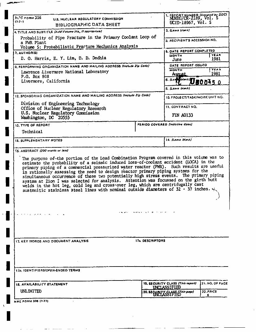
1•,•C FOAM 33 U.S. NUCLEAR REGULATORY COMMISSI1ON I' ?IR•/cR-2189, Vol, SB•BLbOGRAPHIC DATA SHEET IUI-86,Vl
4. TITLE AND SUBTITLE (A dd Volume ]•• If ,aO~PpF,i•h j 2. IL".'e bla',k)
Probability of Pipe Fracture in the Primary Coolant Loop of ______________
a PWR Plant R3 fECIPIENT'S ACCESSION NO.Voltume 5: Probabilistic Fracture Mechanics Analysis ._____________
7. AUTHOR IS) S. DATE REPORT COMPLETEDOMONTH JIvAA
D. 0. Harris, E. Y. Lram, D. D. IDedhia June 19819). PE.RPORMING ORGANIZATION NAME; AND MAILING ADDRESS; .Include Zip• Coda) DATE REPORT ISSUED o
Lawrence .Livermere National Laboratory MONTH ,.••P.O. Box 808 A-ut _. 1981Livermore, California ... IL00•
8. ILe..'. bl,'k,h
12. SPONSORING ORGANIZATION NAME AND MAILING ADDRESS (lnclud, Z/p cod,) ORETTS/OKUI O
Division of Engineering Technology 1.CNRC OOffice of Nuclear Regulatory Research .CTRCN.U.S. Nuaclear Regulatory CcmuissionFIA13Washington, DC 20555FNA13
13. TYPE OP REPORT PERIOO COVERLID (twnculu$, daft,)
Technical I
15. SUPPLEMENTARY NOTES 1 14. (LB,w blavA)
•6. ABSTRACT (200 words or l=ss)
The purpose of/-the portion of the Load Contination Program covered in this volume was toestimate the probability of a seismic induced loss-of-coolant accident (LOCA) in theprimary piping of a coninercial pressurized water reactor (PWR). Such results are usefulin rationally assessing .the need t:o design reactor primary piping systems for thesimultaneous occurrence of these two potentially high stress events. The p1rimary pipingsystem at Zion I was selected for analysis. Attention was focussed on the girth buttwelds in the hot leg, cold leg and cross-over leg, which are centrifugally castaustenitic stainless steel lines with nominal outside diameters of 32 - 37 inches. '•
i7. KEY WORDS AND DOCUMENT ANALYSIS 17.. DESCRIPTORS
7Th. ID!NTIFIERS/OPEN-ENDED TERMS
is. AVAILABIL, rY STATEMENT 190. SECURITY CILASS (Thu 'Dp,•=rTJ 2 . NO. OF PAGE
INIvIE 20 .SEC SSI22. R1.
NRC PORM 325 (7./77)