NUREG-1861, "Peer Review of GSI-191 Chemical Effects ...
231
NUREG-1861 Peer Review of GSI-191 Chemical Effects Research Program U.S. Nuclear Regulatory Commission Office of Nuclear Regulatory Research Washington, DC 20555-0001
-
Upload
khangminh22 -
Category
Documents
-
view
1 -
download
0
Transcript of NUREG-1861, "Peer Review of GSI-191 Chemical Effects ...
NUREG-1861
Peer Review ofGSI-191 Chemical EffectsResearch Program
U.S. Nuclear Regulatory CommissionOffice of Nuclear Regulatory ResearchWashington, DC 20555-0001
AVAILABILITY OF REFERENCE MATERIALSIN NRC PUBLICATIONS
NRC Reference Material
As of November 1999, you may electronically accessNUREG-series publications and other NRC records atNRC's Public Electronic Reading Room athftt://www.nrc.cgov/reading-rm html.Publicly released records include, to name a few,NUREG-series publications; Federal Register notices;applicant, licensee, and vendor documents andcorrespondence; NRC correspondence and internalmemoranda; bulletins and information notices;inspection and investigative reports; licensee eventreports; and Commission papers and theirattachments.
NRC publications in the NUREG series, NRCregulations, and Title 10, Energy, in the Code ofFederal Regulations may also be purchased from oneof these two sources.1 . The Superintendent of Documents
U.S. Government Printing OfficeMail Stop SSOPWashington, DC 20402-0001Internet: bookstore.gpo.govTelephone: 202-512-1800Fax: 202-512-2250
2. The National Technical Information ServiceSpringfield, VA 22161-0002.www.ntis.gov1-800-553-6847 or, locally, 703-605-6000
A single copy of each NRC draft report for comment isavailable free, to the extent of supply, upon writtenrequest as follows:Address: U.S. Nuclear Regulatory Commission
Office of AdministrationMail, Distribution and Messenger TeamWashington, DC 20555-0001
E-mail: DISTRIBUTION(8)nrc.govFacsimile: 301-415-2289
Some publications in the NUREG series that areposted at NRC's Web site addresshftp://www.nrc.gov/readinq-rm/ldoc-collections/nuregsare updated periodically and may differ from the lastprinted version. Although references to material foundon a Web site bear the date the material wasaccessed, the material available on the date cited maysubsequently be removed from the site.
Non-NRC Reference Material
Documents available from public and special technicallibraries include all open literature items, such asbooks, journal articles, and transactions, FederalRegister notices, Federal and State legislation, andcongressional reports. Such documents as theses,dissertations, foreign reports and translations, andnon-NRC conference proceedings may be purchasedfrom their sponsoring organization.
Copies of industry codes and standards used in asubstantive manner in the NRC regulatory process aremaintained at-
The NRC Technical LibraryTwo White Flint North11545 Rockville PikeRockville, MD 20852-2738
These standards are available in the library forreference use by the public. Codes and standards areusually copyrighted and may be purchased from theoriginating organization or, if they are AmericanNational Standards, from-
American National Standards Institute11 West 42"d StreetNew York, NY 10036-8002www.a nsi. org212-642-4900
Legally binding regulatory requirements are statedonly in laws; NRC regulations; licenses, includingtechnical specifications; or orders, not inNUREG-senies publications. The views expressedin contractor-prepared publications in this seriesare not necessarily those of the NRC.
The NUREG series comprises (1) technical andadministrative reports and books prepared by thestaff (NUREG-XXXX) or agency contractors(NUREG/CR-XXXX), (2) proceedings ofconferences (NUREGICP-XXXX), (3) reportsresulting from international agreements(NUREG/IA-XXXX), (4) brochures(NUREG/BR-XXXX), and (5) compilations of legaldecisions and orders of the Commission andAtomic and Safety Licensing Boards and ofDirectors' decisions under Section 2.206 of NRC'sregulations (NUREG,-0750).

NUIREG-1861
Peer Review ofGSI-191 Chemical Effe ctsResearch Program
Manuscript Completed: July 2006Date Published: December 2006
Prepared byP.A. Torres
P.A. Torres, NRC Project Manager
Prepared forDivision of Fuel, Engineering and Radiological ResearchOffice of Nuclear Regulatory ResearchU.S. Nuclear Regulatory CommissionWashington, DC 20555-0001

ABSTRACT
The U.S. Nuclear Regulatory Commission (NRC), Office of Nuclear Regulatory Research (RES),has a policy of initiating formal peer reviews for research programs that are on the cutting-edgeof technology and will influence important regulatory decisions. Such is the case for the seriesof research projects that RES has sponsored to (1) resolve Generic Safety Issue 191,"Assessment of Debris Accumulation on PWR Sump Performance," and (2) inform the NRC'sregulatory decisions regarding the potential for chemical byproducts to clog sump screensin the post-loss-of-coolant accident environment in pressurized-water reactors (PWRs).
This NUREG-series report describes the chemical effects peer review assessment processand summarizes its significant findings. It is important to mention that this peer review is nota consensus review. Each reviewer was asked to provide an individual evaluation based onhis or her particular area of expertise. The research projects addressed by the peer reviewincluded integrated chemical effects testing (ICET) and ICET followup testing and analysisconducted at Los Alamos National Laboratory, chemical speciation prediction conductedthrough the Center for Nucle 'ar Waste Regulatory Analyses at Southwest Research Institute,and accelerated chemical effects head loss testing conducted at Argonne National Laboratory.The chemical effects peer review evaluated the technical adequacy and uncertainty associatedwith the RES-sponsored research results, and identified outstanding chemical effects issues.The results of this peer review will support NRC staff audits and evaluations of industry responsesto Generic Letter 2004-02, "Potential Impact of Blockage on Emergency RecirculationDuring Design-Basis Accidents at Pressurized-Water Reactors." The final assessment reportsfrom the peer reviewers are included as appendices to this NUREG-series report.
iii

FOREWORD
The U.S. Nuclear Regulatory Commission (NRC), Office of Nuclear Regulatory Research (RES),has a policy of initiating formal peer reviews for research programs that are on the cutting-edgeof technology and will influence important regulatory decisions. Such is the case for the seriesof research projects that RES has sponsored to (1) resolve Generic Safety Issue 191 (GSI-1 91),"Assessment of Debris Accumulation on PWR Sump Performance," and (2) inform the NRC'sregulatory decisions regarding the potential for chemical byproducts to clog sump screensin the post-loss-of-coolant accident (LOCA) environment in pressurized-water reactors (PWRs).Chemical effects in the sump pool of a PWR represent a relatively new research area that hasproven to be quite complex. Recognizing this complexity, RES decided that an independentpeer review was necessary to assess the technical adequacy of the chemical effectsresearch program and to help the staff identify outstanding chemical effects issues.
The chemical effects peer review group consisted of five members selected from industry andacademia for their diversity in their affiliations and technical expertise. The technical areasreviewed were (1) the integrated chemical effects testing (ICET) and ICET followup analysis andtesting conducted at Los Alamos National Laboratory, (2) chemical speciation predictionconducted at the Center for Nuclear Waste.Regulatory Analyses, and (3) accelerated chemicaleffects head loss testing conducted at Argonne National Laboratory. The review groupparticipated in kickoff and final meetings, which promoted discussion and enabled the membersto exchange information and address questions. The members then developed individualpreliminary 'reports addressing various questions that arose during the kickoff meeting, as wellas individual final reports (provided as appendices to this NUREG-series report) that providedformal assessments of both prior and ongoing research activities.
Significant general findings from the peer review included (1) the ICET was representativeand identified some important contributing materials and interactions; (2) the chemical speciationprediction study identified required capabilities and limitations of commercially available codes,and revealed that more rigorous code development is needed to develop an adequateassessment tool; and (3) the chemical effects head loss testing project revealed thatsmaller-scale testing should be conducted to allow more rapid evaluation, in parallel, so thatmore parameters can be identified and evaluated in several smaller loops, rather than one loop.
The peer review panel did an excellent job of engaging the NRC staff and contractorsin discussing the research projects and sharing their insights. Their feedback has beenespecially valuable in improving our understanding of the mechanisms underlying developmentof chemical byproducts. This NUREG-series report captures those insights, and is expectedto be helpful to the nuclear power industry as it considers changes to plant designs and operationtoward the resolution of GSI-1 91. The information developed by the peer review groupwill also assist the staff of the NRC's Office of Nuclear Reactor Regulation (NRR) in evaluatinglicensees' responses to Generic Letter (GL) 2004-02.
Brian W. Sheron, DirectorOffice of Nuclear Regulatory ResearchU.S. Nuclear Regulatory Commission
v

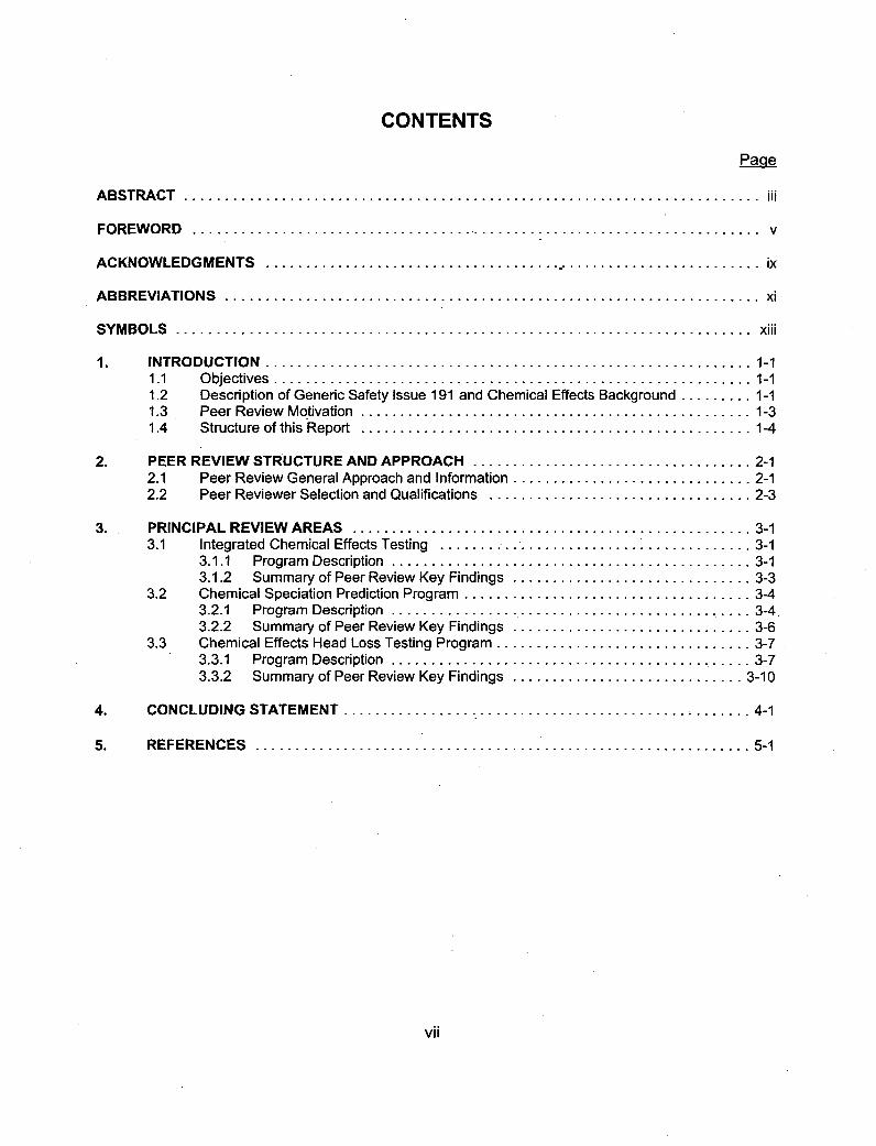
CONTENTS
Pagqe
ABSTRACT.................................................................... i
FOREWORD.................................................................... v
ACKNOWLEDGMENTS .................................. ......................... ix
ABBREVIATIONS................................................................ xi
SYMBOLS..................................................................... xiii
1. INTRODUCTION.......................................................... 1-11.1 Objectives.............................................. '*'******* 1-11.2 Description of Generic Safety Issue 191 and Chemical Effects Background ......... 1-11.3 Peer Review Mo tivation............................................... 1-31.4 Structure of this Report............................................... 1-4
2. PEER REVIEW STRUCTURE AND APPROACH.................................. 2-12.1 Peer Review General Approach and Information............................. 2-12.2 Peer Reviewer Selection and Qualifications................................ 2-3
3. PRINCIPAL REVIEW AREAS................................................ 3-13.1 Integrated Chemical Effects Testing ...... I................................ 3-1
3.1.1 Program Description........................................... 3-13.1.2 Summary of Peer Review Key Findings............................. 3-3
3.2 Chemical Speciation Prediction Program .................................. 3-43.2.1. Program Description............................................ 3-4.3.2.2 Summary of Peer Review Key Findings ............................. 3-6
3.3 Chemical Effects Head Loss Testing Program .............................. 3-73.3.1 Program Description........................................... 3-73.3.2 Summary of Peer Review Key Findings............................ 3-10
4. CONCLUDING STATEMENT ........................................... 4-1
5. REFERENCES ........................................................... 5-1
vii
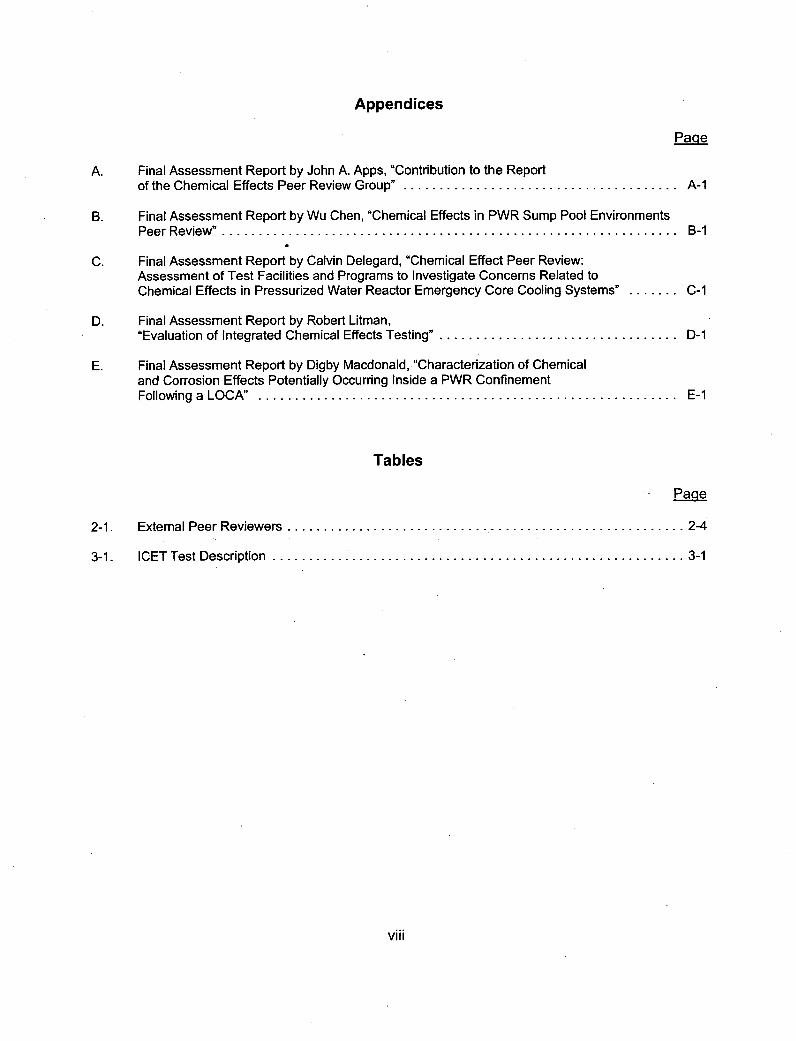
Appendices
Page
A. Final Assessment Report by John A. Apps, "Contribution to the Reportof the Chemical Effects Peer Review Group". .................................... A-i
B. Final Assessment Report by Wu Chen, "Chemical Effects in PWR Sump Pool EnvironmentsPeer Review"............................................................ B-i
C. Final Assessment Report by Calvin Delegard, "Chemical Effect Peer Review:Assessment of Test Facilities and Programs to Investigate Concerns Related toChemical Effects in Pressurized Water Reactor Emergency Core Cooling Systems"....C-i
0. Final Assessment Report by Robert Litman,"Evaluation of Integrated Chemical Effects Testing"................................. D-i
E. Final Assessment Report by Digby Macdonald, "Characterization of Chemicaland Corrosion Effects Potentially Occurring Inside a PWR ConfinementFollowing a LOCA" ........................................................ E-i
Tables
- Paoe
2-i. External Peer Reviewers .................................................... 2-4
3-i. ICET Test Description....................................................... 3-1
viii
ACKNOWLEDGMENTS
The author wishes to thank Argonne National Laboratory for providing the contractual support,hosting the chemical effects peer review kickoff meeting, and presenting and making availablethe technical information that the peer reviewers needed to complete their mission. The authoralso wishes to thank the Southwest Research Institute (SWRI) and the Center for Nuclear WasteRegulatory Analyses (CNWRA) for hosting the second chemical effects peer review meeting.In addition, the author wishes to thank SWRI, CNWRA, and Los Alamos National Laboratoryfor presenting and, making available the technical information that the peer reviewers neededto complete their mission.
The author would also like to acknowledge Robert Tregoning for his technical guidanceand leadership in discussions during the peer review meetings. Finally, the author would liketo thank Ann Ramey-Smith, Robert Tregoning, and Bhagwat Jain for their advice and review ofthis report.
ix


ABBREVIATIONS
ACRS Advisory Committee on Reactor SafeguardsANL Argonne National Laboratory
Cal-Sil Calcium SilicateCNWRA Center for Nuclear Waste Regulatory Analyses
ECCS Emergency Core Cooling SystemECP Electrochemical Corrosion Potential
[also known as Reduction-Oxidation (Redox) Potential]EDO Executive Director for Operations (NRC)EDS Energy Dispersive SpectroscopyEPRI Electric Power Research InstituteESEM Environmental Scanning Electron Microscopy
ETI R Fourier Transform Infrared Spectroscopy
GL Generic LetterGSI Generic Safety Issue
HPSI High-Pressure Safety Injection
ICET Integrated Chemical Effects TestingICP Inductively Coupled Plasma
LANL Los Alamos National LaboratoryLOCA Loss-of-Coolant Accident
NPSH Net Positive Suction HeadNRC U.S. Nuclear Regulatory Commission
PZC Point of Zero ChargePSD Particle Size DistributionPWR Pressurized Water Reactor
QLR Quick Look Report
RCS Reactor Coolant SystemRES Office of Nuclear Regulatory Research (NRC)RHR Residual Heat Removal
Ai

SEM Scanning Electron MicroscopySTB Sodium TetraborateSWRI Southwest Research Institute
TEM Transmission Electron MicroscopyTSP Trisodium PhosphateTSS Total Suspended Solids
UNM University of New Mexico
XRD X-Ray Diffraction
xii
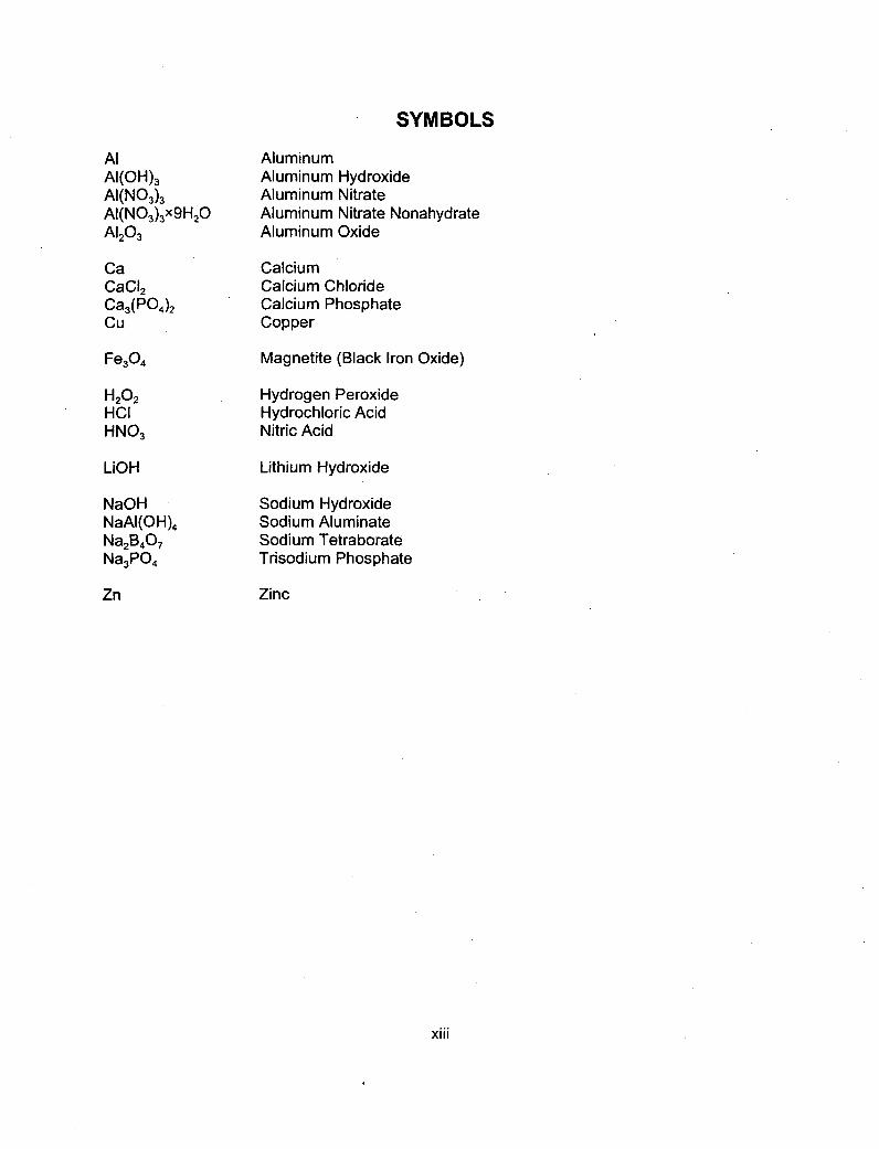
SYMBOLS
AlAI(OH) 3AI(N0 3)3AI(NO3)3X9H 2OA1203
CaCaCI 2Ca3(P04)2Cu
Fe3O4
H202HCIHN0 3
LiGH
NaOHNaAI(OH)4Na2B4O7Na3PO4
Zn
AluminumAluminum HydroxideAluminum NitrateAluminum Nitrate NonahydrateAluminum Oxide
CalciumCalcium ChlorideCalcium PhosphateCopper
Magnetite (Black Iron Oxide)
Hydrogen PeroxideHydrochloric AcidNitric Acid
Lithium Hydroxide
Sodium HydroxideSodium AluminateSodium TetraborateTrisodium Phosphate
Zinc
xiii


1. INTRODUCTION
1.1 O1bjectives
The principal objective of the chemical effects peer review group was to assess the technicaladequacy of research activities, sponsored by the U.S. Nuclear Regulatory Commission (NRC),Office of Nuclear Regulatory Research (RES), related to chemical effects in pressurized-waterreactor (PWR) sump pool environments. Toward that end, the peer review members focusedonly on those programs in which RES is specifically evaluating chemical effects. A secondprincipal objective was to have the peer reviewers recommend improvements to RES programsin the area of chemical effects, and to identify additional important technical issues that RESis not currently addressing. A third objective was to attempt to gain a theoretical understandingof the relevancy of these chemical effects in the post-loss-of-coolant accident (LOCA) environment.The final objective was to address specific questions from NRC staff, as described in Section 3of this report. In so doing, RES hoped that the peer reviewers' comments and suggestions,together with their expertise in the various technical areas, would help the NRC staffto better understand these questions. In addition, it is important to mention that this peer reviewwas not a consensus review. Rather, each reviewer was asked to provide an individual evaluationbased on his or her particular area of expertise.
1.2 Description of Generic Safety Issue 191 and Chemical Effects Background
Generic Safety Issue (GSI) 191, "Assessment of Debris Accumulation on PWR Sump Performance,"was established to assess the potential for transportation and accumulation of debris that isgenerated during a LOCA to impede or degrade emergency core cooling system (ECCS)performance in operating commercial PWRs. The ECOS is required to meet the criteriaof Title 10, Section 50.46, of the Code of Federal Regulations (10 CFR 50.46), "AcceptanceCriteria for Emergency Core Cooling Systems for Light-Water Nuclear Power Reactors."In particular, 10 CFR 50.46(b)(5) requires licensees to design their ECCS systems with capabilityfor long-term cooling. That is, after successful initiation, the ECCS must be able to providecooling to maintain the core at an acceptably low temperature for a sufficient duration.
In this report, "chemical effects" include corrosion products, gelatinous material, or otherchemical reaction products that form as a result of the interaction between the PWR containmentenvironment and containment materials following a LOCA. Reaction products or precipitatesmay be generated as a result of chemical reactions between ECCS recirculation sump fluidor containment spray fluid and exposed materials in containment, such as zinc in coating materialsor galvanized steel, aluminum in scaffolding, thermal insulation and electrical or electronicmaterials, exposed carbon steel, concrete, fiberglass debris, and so forth.
In a meeting in February 2003, the NRC's Advisory Committee on Reactor Safeguards (ACRS)raised a concern based on its review of staff activities related to the resolution of GSI-191(Reference 1). Specifically, the ACRS was concerned that chemical effects could significantlyincrease the pressure drop (or "head loss") across ECCS recirculation sump screen debris bedsat a PWR. The ACRS stated that previous work related to GSI-1 91 did not consider the potentialfor chemical interactions between the cooling water and exposed materials within containmentto generate new forms of debris with unique screen blockage characteristics, or to affectthe head loss behavior of previously investigated debris types. To support this concern,
1-1
the ACRS cited evidence including the gelatinous material discovered in the post-LOCAsump pooi of the containment following the 1979 accident at Three Mile Island, Unit 2(References 2 and 3).
In response to the ACRS concern that gelatinous substances or agglomerates could formand have the potential to affect head loss, especially in concert with other debris transportedto the sump screen, a small-scale study of head-loss flow and quiescent immersion corrosionwas performed at the University of New Mexico (UNM), under the direction of Los AlamosNational Laboratory (LANL). The purpose of this study was to determine whether debrisgeneration and sump screen head loss can be affected by chemical interactions betweenthe ECCS recirculation water and exposed metal surfaces, inorganic zinc-based paint chips,and fiberglass insulation debris. This study is described in NUREG/CR-6868, "Small-ScaleExperiment: Effects of Chemical Reactions on Debris-Bed Head Loss" (Reference 3),which assesses the potential for chemically induced corrosion products and chemical degradationeffects to impede the performance of ECCS recirculation following a LOCA. In addition,NUREG/CR-6868 presents observations gleaned from scoping tests that were conductedto experimentally assess the degree of influence and the mechanisms by which water chemistryand temperature may influence the head loss characteristics of an ECCS sump screen followinga LOCA in a PWR nuclear power plant. An independent expert review panel reviewedthe NUREG/CR-6868 study, and recommended conducting a follow-on study involvingintegrated chemical effects testing of representative amounts of multiple containment materialsin a simulated post-LOCA environment.
As part of the resolution of GSI-1 91, the NRC and the nuclear industry jointly developedan integrated chemical effects testing (ICET) program to determine whether chemical reactionproducts can form in representative PWR post-LOCA containment sump environments.The ICET series, conducted at UNM under the direction of LANL, involved five tests, each of whichrepresented a different subset of expected post-LOCA environments within existing PWR plants(References 4-9). Results showed that chemical byproducts were present in the test solutions,fibrous insulation samples, and sediment of all five ICET environments, and some of these productswere amorphous in nature. Inductively coupled plasma (ICP) results, for example, indicated thatfor Test #1, aluminum and sodium were present in the greatest concentrations in the test solution,while for Test #5, the highest concentrations were sodium, aluminum, calcium, and silica.
A follow-on study was conducted at LANL to provide a better understanding of the aluminumchemistry in post-LOCA PWR containment environments (Reference 10). More specifically,that study addressed the conditions for generating aluminum-based precipitates, characterizingproperties and particle size distributions of those precipitates, developing surrogate precipitatesand solutions, and determinating the adequacy of the surrogates by comparison to ICET-generated precipitates and solutions.
1-2

A second area of investigation involved chemical effects head loss testing conducted byArgonne National Laboratory (ANL). The objective of this research was to measure the head lossassociated with simulated ICET environments, to improve our understanding of the effectsof key environmental variables on chemical product formation and head loss (Reference 11).A third area of investigation involved a -chemical speciation analysis performed by the Centerfor Nuclear Waste Regulatory Analyses (CNWRA) at the Southwest Research Institute (SWRI).This research involved analytical, thermodynamic simulation of the ICET series to predictthe chemical species formed in those environments (Reference 12).
Given the significance of this issue, the NRC has requested all PWR licensees perform anevaluation of the potential for excessive head loss attributable to the accumulation of debris onthe containment sump screen. Toward that end, Generic Letter (GL) 2004-02, "Potential Impactof Blockage on Emergency Recirculation During Design-Basis Accidents at Pressurized-WaterReactors," requests that licensees evaluate the maximum head loss postulated from debrisaccumulation (including chemical effects) on the submerged sump screen (Reference 13).
Chemical effects in the sump pool of a PWR plant represent a relatively new research areathat has proven to be quite complex. Recognizing this complexity, RES decided thatan independent peer review was necessary to review the technical adequacy of RES-sponsoredresearch activities related to chemical effects in PWR sump pool environments. In addition toreviewing and commenting on the research that was underway, this external peer review grouphelped the staff identify and prioritize issues in the chemical. effects arena.
The NRC has an aggressive resolution schedule associated with GSI-191. Toward that end,the staff will use information developed through the, peer review effort in evaluating licensees'responses to GL 2004-02 and conducting audits to ensure appropriate resolution.
1.3 Peer Review MotivationFollowing RES Office Instruction PRM- 010 (Reference 14), "Peer Review of RES Projects,"all RES programs and products are candidates for peer review. This includes programsconducted under contract, as well as research performed within NRC by RES staff members.A peer review is defined as a form of deliberation involving an exchange of judgmentsabout the appropriateness of methods and the strength of the author's conclusion. Peer reviewoccurs when a draft product is reviewed for quality by specialists who were not involvedin producing the draft. Acceptable peer review can involve either NRC staff or specialistswho are external to, and do not work for, the NRC. Peer review involves either one independentreviewer or a team of reviewers in which each member provides a final independent assessment,and the results of peer reviews are made publicly available.
The RES policy with regard to peer review groups is to encourage a formal and independentpeer review of research products consistent with the nature, importance, and timelinessof the information to be disseminated. Peer review fosters confidence in the research productsand helps maintain high standards of competence in research programs. It is expected thatpeer reviews will provide critical assessments regarding those research products, will help injudging the technical adequacy of the results for the proposed solutions, and can aid in bringingthe widest and best available knowledge to bear on the quality of the research products.However, RES does not rely on peers to achieve resolution of technical issues. To the contrary,the NRC staffs technical expertise, leadership, and effective communications are vital aspectsof the process of achieving resolution of technical issues.
1-3
External peer review is a recommended strategy for promoting broader understandingand context for issues that are technically complex, have potentially significant implications,span many technical disciplines, and are emerging within the agency. On the basis of thosecriteria, the RES staff identified the research on sump pool chemical effects as a logicalpeer review topic. There is little information on chemical product formation in representativeplant sump environments. This is a new technical area of investigation, and it is sufficientlycomplex to warrant independent assessment and consultation. Moreover, the researchconducted in the chemical effects arena could significantly affect the resolution of GSI-1 91.In addition, there is no clear idea of the appropriate approach and how applicable the results arein comparison with the three areas of investigation. Thus, RES believed that the peer reviewgroup members would help to improve our understanding of this issue by providing reviewcomments, suggestions, and possible contributions for issue resolution. RES decided that anindependent peer review was necessary to assess the technical adequacy of the chemicaleffects research program and to help the staff identify outstanding chemical effects issues.
1.4 Structure of this Report
The body of this NUREG-series report is divided into five sections:
* Section 1 defines the objectives of the chemical effects peer review group assessment,and provides related background information concerning GSI-191 and chemical effects,as well as the peer review and motivation.
* Section 2 describes the structure and approach of the peer review group(e.g., how the members of the group were selected).
* Section 3 describes each of three research areas, and summarizes the key findingsof the peer review in each area.
* Section 4 presents a concluding statement, which su mmarizes the insights that emergedfrom the peer review, and discusses how those insights will be used.
* Section 5 lists the references cited in this report.
Finally, the five appendices that accompany this report present the final independentassessment reports from each of the five chemical effects peer review group members,as well as a more in-depth description of the motivation for this peer review.
1-4

2. PEER REVIEW STRUCTURE AND APPROACH
2.1 Peer Review General Approach and Information
The NRC established the chemical effects peer review group to evaluate the technical adequacyof RES-sponsored activities related to chemical effects in PWR sump pool environments.Toward that end, the review encompassed the integrated chemical effects testing conductedat LANL, chemical speciation prediction activities conducted at CNWRA, and chemical effects-accelerated head loss testing conducted at ANL. Because of the complexity of these programs,RES aimed to ensure diversity in both the members' affiliations and their technical expertise.Approximately 3-4 months were spent gathering recommendations for peer review candidatesand assembling a group that spanned a broad range of affiliations and also had diversetechnical expertise and experience.
To decide upon the final peer review group, RES considered recommendations from multiplesources, such as the NRC staff, the ACRS, the nuclear power industry, and NRC contractorswho were conducting research in the chemical effects area. The selected chemical effectspeer review group consisted of five members drawn from national laboratories, academia,and industry. These peer review group members possessed diverse backgrounds and expertisein areas such as gel formation, filtration, analytical and experimental chemistry, corrosionand metallic corrosion, experimental testing, nuclear waste, and electrochemistry. The intentwas that the individual members would interact as a group and look at the chemical effects issuesusing a holistic approach. Each peer reviewer was asked to address a set of defined questionsin the three program areas. The questions and responses are defined and anwered in Section 3of this report. The NRC also provided the peer review group members with initial documentationrelevant to the ongoing technical program areas. The formality of that documentation variedas a function of the program. This initial documentation included the following references:
* ICET Data Reports 1, 2, and 3 and the accompanying appendices (References 15-17)* ICET Test Plan (Reference 18)* ANL Quick Look Report: Tests 1 and 2 (Reference 19)* CNWRA 2004-07 Report (Reference 20)* NUREG/CR-6873 (Reference 21)
After providing the peer review members with the initial documentation, the NRC conducteda chemical effects peer review group kickoff meeting at ANL in October 2005. The purposeof that meeting was to summarize the initial technical documentation and identify the importanttechnical issues and questions that the NRC wanted the peer review group to assess in its review.In addition, representatives of the various program areas from the national laboratoriesand nuclear power industry gave a number of oral presentations, which provided the latesttechnical information and research findings since the initial documentation was prepared.The meeting participants also discussed the plans and philosophy behind the ongoingNRC-sponsored research, identified additional information that the peer reviewers neededto complete their preliminary assessment, and planned the peer review group activitiesfor the next several months.
2-1
The peer reviewers submitted their preliminary individual assessment reports in December 2005.The purpose of those reports was to provide an informal assessment of both prior and futureresearch activities. The NRC intended that these preliminary assessment reports would identifyany major deficiencies or course changes that the research programs should make at that time.The peer reviewers' preliminary assessment reports also included lists of follow-on questionsto be discussed in the second chemical effects peer review group meeting. The NRC staffespecially wanted the peer reviewers to raise technical questions regarding the need foradditional information, so that the NRC staff could provide the needed information duringthe second peer review group meeting so the peer reviewers would have the informationavailable to them as they prepared their final assessment reports.
The NRC staff subsequently summarized the results and recommendations of the reviewers'preliminary assessment reports, and organized the key points of each program area. The staffdisseminated this summary of results and recommendations to LANL, CNWRA, and ANILfor consideration, review, and action. Each research organization took the lead in addressingthe issues and questions identified by the preliminary assessment reports corresponding totheir technical area. This helped the NRC staff and the national laboratories to properly addressthe issues and questions from the peer reviewers.
After a thorough review of the preliminary assessments reports, the staff then distributedthe preliminary assessment reports to the peer review group members. In so doing, the staffexpected the peer reviewers to continue their detailed review of NRC activities to raise issuesor concerns that arose subsequent to the preliminary assessments. Toward that end, the staffalso provided the peer reviewers with new information regarding ongoing research activities.That information included the following followup technical documents:
* ICET Data Reports 4-5 and the accompanying appendices (References 11 and 12)* ANL Quick Look Report: ICET-3 Tests 4-11 (Reference 22)* CNWRA speciation draft NUREG/CR, "GSI-191 PWR Sump Screen Blockage
Chemical Effects Tests: Thermodynamic Simulations" (Reference 1)
In March 2006, the NRC staff held a second chemical effects peer review group meeting at SWRI.The purpose of this second meeting was to provide the group members with new informationregarding research activities conducted between October 2005 and March 2006. Toward that end,representatives from LANL, ANL, and CNWRA presented information relevant to their respectiveresearch areas and, along with NRC staff, addressed the peer reviewers' questions and clarifiedremaining issues that they raised in their preliminary assessment reports. Most importantly,this second meeting fostered interaction among the reviewers to support their final assessments.In addition, the NRC asked the reviewers to submit any additional requests for informationbefore providing their final individual assessment reports.,
In May 2006, the peer reviewers submitted their final individual reports, which provided formalassessments of both prior and ongoing research activities. All five of these final assessmentsare included as appendices to this NUREG-series report.
2-2
2.2 Peer Reviewer Selection and Qualifications
The NRC staff selected the peer review group members on the basis of their technical expertise,experience, skills, and affiliations. Characteristics such as discipline, point of view, diversityof experience, and type of institution played an important role in the selection process.As a result, the selected group of peer reviewers is sufficiently diverse to fairly representthe relevant scientific and technical perspectives and fields of knowledge needed to addressthe program areas of interest. Specifically, the staff initially identified the following technicalspecialties for the selection of the peer review group:
* gel/amorphous product formation and characterization* analytical chemistry* metallic corrosion processes* experimental testing and analysis* theoretical chemistry/speciation prediction* industrial filtration processes* fluid (e.g., water and wastewater) treatment processes* manufacturing gels, chemicals, and insulation materials
In addition, to be selected, each reviewer had to be recognized as an expert in one or moreof these technical specialties. Each reviewer also had to demonstrate active participationin numerous reviews in his or her respective area(s) of expertise, and had to have made numerouspresentations at technical conferences, and written numerous papers for publication in conferenceproceedings and journals. Finally, the staff selected the peer review group members to covera broad range of technical expertise. Table 2-1 identifies the five selected peer reviewers,along with their respective affiliations and areas of technical expertise.
2-3

____________Table 2-1. External Peer ReviewersName Position/Affiliation Areas of Technical Expertise
John Apps Senior scientist Geochemical modeling and gel formationEarth Sciences Division (gel/amorphous product formationLawrence Berkeley National and characterization)LaboratoryEarth Sciences Division Chemical speciation modelingBerkeley, CA 94720 (theoretical chemistry/speciation prediction)
Nuclear waste isolation
Wu Chen Senior specialist Fluid/particle separationThe Dow Chemical Co.B-1402, 2301 N. Brazosport Blvd. Industrial filtration processesFreeport, TX 77541
Calvin Delegard Staff scientist Experimental testing and analysisPacific Northwest NationalLaboratory Analytical chemistryPO Box 999, MS P7-25 (applied/process chemistry)Richland, WA 99352
Nuclear materials safeguards
Robert Litman Independent consultant Analytical chemistryRadiochemistry LaboratoryBasics Metallic/corrosion processes28 Hutchinson DriveHampton, NH 03842 Nuclear plant systems and chemistry
Digby Macdonald Professor of Materials Science Electrochemistry and thermodynamicsand Engineering, and Director scienceof the Center for ElectrochemicalScience and Technology Metallic/corrosion processesPennsylvania State University0201 Steidle Bldg. Experimental testing and analysisUniversity Park, PA 16802
2-4

3. PRINCIPAL REVIEW AREAS
3.1 Integrated Chemical Effects Testing
3.1.1 Program Description
The primary objectives of the ICET research program were to (1) determine, characterize,and quantify chemical reaction products that may develop in a PWR containment poolin a representative post-LOCA environment, and (2) determine and quantify any gelatinousmaterial(s) that could be produced during the post-LOCA recirculation phase. Toward that end,the ICET series simulated the chemical environment present in a containment water poolfollowing a LOCA, and monitored the chemical system for an extended period of time to identifythe presence, composition, and physical characteristics of chemical products that formedduring the test. By contrast, the ICET series was not designed to evaluate debris or sedimenttransport, bound the chemical environment present in a containment water pool, or measurehead loss associated with any chemical byproducts. Within those constraints, the ICET serieswas conducted at UNM under the direction of LANL, in accordance with the test plan shownin Table 3-1.
_________ ~~~Table 3-1. ICET Test Plan__________Test Buffering Agent Initial Boron (ppm) Insulation Mixture
____ ____ ____ ____ Target pH _ _ _ _ _ _ _ _ _ _ _ _ _ _ _ _ _
1Sodium Hydroxide 10 2800 100% fiberglass(NaOH)__ _ _ _ _ _ _ _ _ _ _ _ _ _ _
2 Trisodium Phosphate 7 2800 100% fiberglass(TSP) (NaPO,)_____________ ______
80% cal-sil3 TSP (NaPO,) 71 2800
__________________20% fiberglass
4 Sodium Hydroxide 10 280080 asi(NaOH)
______20%
fiberglass5 Sodium Tetraborate 8- 8.5 2400 100% fiberg~las~s
____ ____ (STB3) (Na,BAO,)__ _ _ _ _ _ _ _ _ _ __ _ _ _ _ _ _ _ _ _ _
The ICET research program consisted of five distinct 30-day tests, each of which was intendedto simulate a subset of current operating PWR plants. The ICET apparatus consisted of a largestainless steel tank with heating elements, spray nozzles, and associated recirculation pumpand piping to simulate the post-LOCA chemical environment. Submerged samples of structuralmetals, concrete, and insulation debris were scaled in proportion to their relative surface areasfound in containment, and in proportion to a maximum test dilution volume of 250 gallons(946 liters) of circulating fluid.
3-1

The primary differences among the ICET tests were the buffering agent and insulation material.The three types of buffering agents were sodium hydroxide (NaOH), trisodiumn phosphate (TSP),and sodium tetraborate (STB, used in ice condenser plants). The materials tested in this.environment included representative amounts of submerged and unsubmerged aluminum (Al),copper (Cu), zinc (Zn), concrete, carbon steel, and insulation samples. Representative amountsof concrete dust and latent debris were also added to the test solution.
All of the ICET tests were conducted in an environment that simulated expected containmentpool conditions during recirculation. The initial chemical environment contained 2,800 mg/Lof boron (2,400 ppm for STB plants), 100 mg/L of hydrochloric acid (HCI), and 0.7 mg/Lof lithium hydroxide (LiOH). Each test was conducted for 30 days at a constant temperatureof 60 'Cc (140 OF) and consisted of an initial 4-hour spray phase to simulate containment sprayinteraction with the unsubmerged samples. Water was circulated through the bottom portionof the test chamber throughout each test to achieve representative flow rates over the submergedspecimens. The system was then monitored while corrosion and mixing occured for 30 days(a time frame comparable to the ECCS recirculation mission time).
The test solution pH also differed in each test, varying from approximately 7.3 in ICET Test #2to approximately 9.8 in Test #4. Precipitates at test temperature were visible for only Test #3.However, test sample solutions for Tests #1 and #5 produced precipitates upon cooling to roomtemperature, although Tests #2, #3, and #4 did not. In each test, turbidity measurements weretaken at 60 0C (140 0F),and 23 OC (73 OF), and measurements at both temperatures yieldedsimilar results in Tests #2, #3, and #4. However, in Tests #1 and #5, the turbidity at 23 0C(73 OF) deviated from those at 60 0C (140 OF). Total suspended solids (TSS) were alsomeasured in each test and, with the exception of Test #5, all tests reached a maximum TSSvalue by the first day and decreased to a value relatively close to the baseline measurementfor the duration of the test.
Throughout the ICET series, daily water samples were taken to determine the compositionof the solution by inductively coupled plasma (lOP) analysis with a standard list of elements.Boron was present in high concentrations in all tests. In Test #1, aluminum and sodiumwere present in the greatest concentrations of all tested elements. In Test #2, silica and sodiumwere the dominant elements in solution. Silica, sodium, and calcium elements were presentin the greatest concentrations in Test #3. In Test #4, silica, sodium, calcium, and potassiumwere present in the greatest concentrations. Sodium, aluminum, calcium, and silica werethe dominant elements in the Test #5 solution.
The amounts and types of deposits seen on the fiberglass insulation varied from test to testbecause of differences in solution chemistry. Comparison revealed that the greatest degree ofdeposition occurred in Test #3, followed in order by Tests #1, #4, and #2, while Test #5 sampleshad the fewest deposits. Analyses of the cal-sil samples revealed large amounts of phosphorouson the exterior of samples obtained from Test #3, but not those obtained from Test #4.Moreover, the interior of the cal-sil samples from Tests #3 and #4 showed that the phosphorusdid not penetrate the solid.
3-2
The system effect on the coupons also differed for each test, as did the sediment produced.Tests #1 and #5 showed the largest amount of coupon corrosion (e.g. 25% and 5% loss of pre-test mass in submerged aluminum coupons respectively), while the conditions in Tests #2through #4 did not appear to cause significant coupon corrosion. By contrast, Tests #3 and #4produced the most sediment, which consisted of a large amount of chemical precipitateand sediment attributable to the large amount of cal-sil added to the tank. Tests #1, #2, and #5produced the smallest amount of sediment, which was largely composed of materials fromthe insulation (fiberglass) and debris added to the tank. Overall, the ICET results demonstratedthat changes to one important environmental variable (e.g., pH adjusting agent, insulationmaterial) can significantly affect the chemical products that form.
3.1.2 Summary of Peer Review Key Findings
The review focused on a predetermined set of ICET-related technical questions. Those questionsand the related responses from the peer reviewers are summarized as follows:
Question 1:
Response:
Question 2:
Response:
Question 3:
Response:
Have the principal sump pool variables, which affect chemical byproductformation environment, been adequately simulated?
The majority of the reviewers agree that the types of materials that are presentin PWR containments have been appropriately selected. They also statedthat the concentrations of chemicals used during the operation of a PWRare approximately in the range of anticipated chemical concentrations.The reviewers also noted that other chemical constituents have not been simulated,the analysis lacks consideration of redox effects and radiolysis, and the testsdid not adequately model the steep cyclic temperature transients of recirculatingcoolant or the hot fuel cladding and pressure vessel surfaces.
Many ICET variables were held constant during the experiments. How wouldchanges in the most important constant variables affect chemical productformation?
In general, the reviewers suggest comprehensive evaluation of the physical,chemical, and mineralogical properties of the observed precipitates duringthe experiments, along with detailed evaluation of all of the data to betterunderstand the effects of chemical product formation. Some of the reviewerssuggest that temperature has a significant effect on solubility and the typesof compounds that will form. They recognize temperature as a difficult aspectto model and recommend further work.
What variables or materials not simulated by the ICET testing may havethe most impact on chemical product formation (e.g., coatings, free insulation,flow through sediment and other materials on sump screen, galvanic effects),and how should their effect be characterized by testing or analysis?
In general, the reviewers think that field visits to operating PWR facilitiescould unearth limitations or omissions not otherwise anticipated. Considerationsfrom the reviewers are diverse and are summarized as follows:
3-3
(a) failure to control or monitor CO2 uptake, which could deviate significantlyfrom the actual post-LOCA environment of a PWR
(b) presence of suspended solids from the reactor coolant system (RCS)and how they could change their chemical form
(c) effects of organic coatings to estimate the quantities of coatings involved,their properties, and the secondary effects of radiation and hydrothermalreactions (reactions with hot water) on the organic materials
(d) effects of high- and low-temperature heat transfer surfaces on collectionand dissolution of solid phases to determine the importance of surfacedeposition
(e) effect of liquid coming into contact with fuel in the reactor vesselto understand heat and radiolytic effects
(f) effects of silica in the water storage systems and RCS on the total massof material precipitating
(g) simulation of the production of hydrogen peroxide (1-20 2, to determineredox potential) and nitric acid (HNO 3, lowers the pH of the solution)
Question 4: Were the methods used within the ICET program to characterize and analyzechemical byproducts sufficient?
Response: The reviewers agree that the methods used within the ICET program were notsufficient to characterize and analyze chemical byproducts. Much more seriouswork needs to be done to characterize the physical, chemical, and mineralogicalproperties of the precipitates and coatings as a basis for subsequent conceptualand computer modeling. Some X-ray diffraction (XRD) and transmission electronmicroscopy (TEM) work was performed during the course of ICET or duringfollow-up work, but in general, the tests should have incorporatedthe following analytical techniques as part of their standard analysis:
(a) Particle size distribution (PSD)(b) Fourier transform infrared spectroscopy (FTIR)(c) X-ray diffraction (XRD)(d) Transmission electron microscopy (TEM)
3.2 Chemical Speciation Prediction Program
3.2.1 Program Description
The objective of the chemical speciation prediction program (performed at CNWRA)was to evaluate the accuracy of thermodynamic predictions on the quantities and speciesof chemical products formed. Toward that end, four chemical modeling software programsEQ3/6, PHREEQC, Geochemist's Workbench REACT, and OLI Systems StreamAnalyzer -
were evaluated to assess their ability to perform aqueous speciation and mass transfer calculationsrelevant to post-LOCA conditions. The code comparison exercise considered several examplesimulations, each of which was representative of post-LOCA conditions in alkaline, boratedcontainment water at temperatures between 60 'C (140 'F) and 110 'C (230 'F).
3-4
The reactor system components included galvanized steel (a source of dissolved zinc),carbon steel (a source of dissolved iron), aluminum scaffolding, copper fans and instrument lines,glass fiber insulation material, and concrete. The modeling software was used to identifythe over-saturated secondary solids that would precipitate, and calculate the final solutioncomposition. The most important differences in results were traceable to different setsof solid phases in the thermodynamic database files accompanying each modeling code,rather than to different capabilities of the codes themselves.
The benchmarked simulations considered a set of blind predictions using the EQ3/6 code,and the predicted results were compared to data from the corresponding ICET experiment.In some cases, observed final concentrations in the sampled water were higher than the initialsource-term estimates, indicating that the input value source-term contribution for that elementhad been underestimated. In other cases, the identity and quantity of precipitate did not conformto observations from the ICET experiment, indicating kinetic restrictions on precipitationunder the modeled conditions.
Another set of simulations, called "informed predictions," used the OLI StreamAnalyzer codeand its accompanying thermodynamic database. The general modeling approach was similarto the approach used for the blind predictions with EQ316. In this case, each ICET experimentwas represented by a set of source-term water compositions at different times of exposure,estimated from the initial composition of the containment water and experimentally determinedcorrosion rates of sample materials. The results of the informed predictions corresponded tothe ICET experiment results more closely than the blind predictions, largely because ofthe revised element release rates for aluminum and insulation materials, for exposure timesof up to148hours. Beyond that timeframe, final- concentrations of calcium, silica, and aluminumwere typically over-predicted, indicating a possible inert stage of the metal surface or formationof an inhibitive surface coating on the insulation material *during the experiment. These changesin release rate were not included in the source-term water concentrations for informed predictions.
The differences in results for the blind and informed predictions were attributed to differencesin the lists of potential precipitates provided in the thermodynamic database files that accompanythe modeling software. For the informed simulations in which precipitation affected the so ilutionchemistry, good agreement was obtained between predicted and observed results for calciumconcentration under the conditions in ICET Test #1 (alkaline water buffered to pH valuesnear 10 by NaOH) because of the precipitation of monohydrocalcite, for silica concentrationunder the conditions in ICET Tests #2 and #3 (solution buffered to near-neutral pH by TSP)because of the precipitation of amorphous silicon dioxide, and for phosphorous concentrationunder the conditions in ICET Test #3 because of the precipitation of calcium phosphate.
This study concluded that chemical modeling software is a broadly useful tool for assessingthe potential effects of post-LOCA interaction on sump screen blockage. However, its predictivecapability was hindered by insufficient thermodynamic data for relevant phases and aqueousspecies in the code database, and by limitations in the kinetic data for the dissolutionof reactive materials in the presence of co-dissolving materials.
3-5

3.2.2 Summary of Peer Review Key Findings
The review focused on a predetermined set of technical questions related to predictionof chemical speciation. Those questions and the related responses from the peer reviewersare summarized as follows:
Question 1:
Response:
Question 2:
Response:
Question 3:
Response:
Is the speciation analysis expected to provide reasonable predictionsof chemical product formation over a range of possible sump environments?
The reviewers agree that even though this chemical speciation analysisrepresents a significant improvement over earlier work, it does not exploitexisting capabilities of the selected codes to their fullest advantage.Specifically, two physical effects not modeled were the radiation field from the fuel,and the layer of corrosion products on the interior surface of the RCS.The reviewers note that concessions had to be made for the seeming lack ofCO 2 to form low-solubility carbonates. Reaction rates (kinetics) also are nothandled well by the modeling software; therefore, the models may not reflect theevolving concentration profiles. As the models are refined, they should providecloser matching of the observed ICET concentrations, the concentrationsobserved in the supplemental CNWRA testing, and the concentrations insystems not replicated in the ICET experiments. In addition, non-equilibriumconcentration of radiolysis products (and even species in the absence of radiolysis)cannot be addressed by the selected codes.
Is the plan for benchmarking these codes using small-scale testingand the ICET results appropriate?
The reviewers agree that the plan for benchmarking codes is satisfactory,provided that the actual processes are accurately simulated. Some reviewersthink that the capabilities of the codes currently being used are not being usedto full advantage and, as a result, the value of the associated experimental studiesis diminished. In addition, the reviewers note that small-scale testing is a validapproach to gain more information, especially on the kinetic and equilibriumbehaviors of the key solutes and solid phases.
What is the most appropriate way to measure the uncertainty associated withthese codes?
The reviewers suggest various ways to measure the uncertainty associatedwith the codes, noting that it is difficult to measure the overall uncertaintyof the output of any multi-component chemical simulation, because a large numberof parameters are involved with widely varying levels of accura cy. First,a sensitivity analysis of empirical or deterministic models is suggested. Second,comparison of the code predictions against the results of targeted small-scale testsis a feasible way to strengthen the codes and identify and measure theiruncertainties. Third, the most realistic values should be utilized, and runsshould be replicated using Monte Carlo methods to determine variationsin parameters deemed to have the greatest uncertainties and considered to bemost critical to model output. The cumulative variation in outputs can then beadopted as a measure of uncertainty.
3-6

3.3 Chemical Effects Head Loss Testing Program
3.3.1 Program Description
The objective of the chemical effects head loss testing program (performed at ANL) was toevaluate the head loss associated with chemical byproducts observed during the integratedchemical effects testing by LANLJUNM, and to understand how relevant changes withinthe environment affect chemical byproduct formation, physical characteristics, and anyassociated head loss. The head loss testing was done in a piping loop containing a simulatedsump pool environment intended to be representative of post-LOCA buffering environments.The test screen had an effective diameter of = 16.5 cm (=6.5 inches), and the fluid volumein the loop was 0. 12 m' (4.2 ift). At 3.05 cm/s (0. 1 ftls), the transit time around the loopwas =4 minutes.
Two types of perforated plates were used in the testing. One had a 51 -percent flow areaand staggered holes with a diameter of 0.48 cm ('/i1inch), while the other had a 40-percentflow area and staggered holes with a diameter of 0.32 cm (1/8 inch). In scaling resultsfrom the ANL test facility, the mass of chemical product per unit area of screen must be considered.Thus, the amount of chemicalFproduct produced scales with fluid volume, while the screen areaper fluid volume determines the product mass per unit screen area. The ANL initial tests resultsare described in detail in ANL's 1st and 2 nd Chemical Effects/Head Loss Testing QLRs(References 19 and 22), dated September 16, 2005, and January 20, 2006, respectively.
The initial head loss testing focused on the environment corresponding to ICET Test #3,which contained cal-sil insulation and used TSP buffering. In that test, calcium phosphate[nominally Ca3(P0 4)2] became apparent within 30 minutes after initiating TSP injectioninto the recirculation loop. The first ANL head loss test (ICET #3-1) was intended to simulatethe Ca3(P04)2 precipitate concentration created by the initial burst of dissolved calcium (Ca)that formed within the first 30 minutes of ICET Test #3, prior to metering TSP into the chamber.Dissolution testing of the ICET Test #3 cal-sil loading [19 g/L (0.190 lb/gal) submerged cal-sillshowed that during the 30 minutes between the introduction of the cal-sil and the initiationof TSP injection, head loss would increase significantly as a result of Ca3(P0 4)2 precipitatecorresponding to 200 ppmn of dissolved Ca.
The second ANL head loss test (ICET #3-2) was parametric and tested several dissolved Caconcentrations to determine the effect of a range of cal-sil loadings on head loss. In both tests,a physical debris bed was formed, approximately 1.59 cm (% inch) thick, consisting of equalamounts [15 g (0.53 oz.)] of NUKON'~ fiber and cal-sil insulation. Dissolved Ca was thenadded to the test loop, which contained TSP-buffered borated water, to form Ca3(P0 4)2precipitates. In this configuration, ICET #3-2 resulted in head loss increases for precipitateloadings that were one-twentieth of those used in ICET #3-1 (10 ppmn of dissolved Ca),and loadings corresponding to 25 ppm of dissolved Ca increased the head loss to more than4.2 m (13.8 ft).
3-7
ANL also performed additional head loss tests, tests of settling rates of Ca3(P0 4)2 precipitates,and cal-sil dissolution tests in TSP solutions. The objective of the head loss tests was to assessthe pressure drop across debris beds created by various mixtures of cal-sil, fibrous insulation,and Ca 3(P0 4)2 precipitates. In addition, ANL evaluated the effects of the degree of cal-sildissolution that will occur before the debris bed forms, as well as the relative arrival timeof the precipitates and insulation debris at the screen. Toward that end, ANL selecteddebris loadings and test temperatures that were reasonably representative of those expectedin limiting design-basis analyses for plants with updated sump screen configurations. The testconditions used in this series of tests are summarized in Reference 22.
The results of the ANL head loss tests in environments similar to those in ICET Test #3demonstrate that chemical products [Ca3(P0 4)2 precipitates] associated with TSP-bufferedcontainment environments can significantly contribute to head loss. Moreover, the head lossesassociated with fiberglass insulation and cal-sil debris beds can be much smaller than thosethat occur across debris beds in which some of the cal-sil has been dissolved and the resulting Careacts with phosphate to form Ca3(P0 4)2 precipitates. Notably, the rate of cal-sil dissolutiondepends somewhat on the initial pH in the sump pool, as well as the rate of TSP dissolution.However, even with instantaneous TSP dissolution and cal-sil concentrations as low as 0.5 gIL(5.01 E-3 lb/gal), the equivalent dissolved Ca could be high enough within a few hoursto produce significant increases in head loss compared to that attributable to the equivalentparticulate loading. The Ca3(P0 4)2 precipitate settling rate is also important in determiningthe transportability of the precipitate. The rate varies with concentration. For example,at a concentration of 75 ppm Ca with no bulk directional flow, the estimated settling rateis 8 mm/mmn (0.31 inch/min).
In an environment similar to that used for ICET Test #3, the chemical products in the ANLhead loss tests formed either by actual dissolution of cal-sil (an integral test) or by the additionof dissolved Ca as calcium chloride (CaCI 2). Moreover, the chemical products formedby either manner are calcium phosphates, and the surrogate product is very similar to thatformed in the integral test. By contrast, in the environment used for ICET Test #1, the mainchemical product is aluminum hydroxide [AI(OH) 3]. However, aluminum hydroxide may existin either amorphous or crystalline forms, and these forms can have very different properties.For example, the solubility of amorphous AI(OH)3 can be 500 times as great as the solubilityof some crystalline forms of aluminum hydroxide. Thus, itis important to note that in ICETTest #1, dissolved Al formed slowly by corrosion of the Al plates.
The precipitation process is complex, and the Al can be present as dissolved Al, colloidal product,and solid precipitates. The existing amounts of the various forms, even for the same total Alcontent can be highly time-dependent, and may depend on the timing of the addition of material.to the coolant, the change in temperature or pH over time, and the degree and order of mixing.The solid products in ICET Test #1 have been shown to be primarily amorphous AI(OH) 3.There is a very high degree of hydration, and product exists as agglomerations of nano-sizedparticles, but the degree and strength of agglomeration and the actual effective hydrodynamicsize of the product is difficult to characterize.
3-8

The ANL head loss tests for the ICET Test #1 environment were based on the use of surrogatechemical products. The test fluid had boric acid and lithium hydroxide levels consistent withthe ICET test, but aluminum nitrate nonahydrate [AI(N0 3)3X9H 2OI was added to generateAI(OH) 3 products (rather than actual dissolution of Al metal). Nonetheless, bench scale testsshowed that the products were amorphous, and their physical appearance and behaviorwere qualitatively similar to the products observed in the ICET #1 integral test. Particle sizemeasurements showed that products were agglomerated, and the measured particle sizecould vary depending on whether the solution was quiescent or deflocculated by ultrasound.
The initial ANL head loss tests in the ICET Test #1 environment attempted to simulate the ICETtest where the dissolved Al level was =375 ppm. For these tests, ANL prepared a solutioncontaining boric acid, LiOH, and NaOH. A NUKON' debris bed was formed, and the systemwas heated to 60 'C (140 OF). AI(N0 3)3x9H2O was then added to obtain a dissolved Al levelof 375 ppm, and the pH was adjusted to match the conditions in ICET Test #1.
In the first ANL test in this environment, the flow velocity in the loop was kept at 30 mm/s(0.1 ftls), and a heavy "snowfall" was observed as the Al solution was added. [The additionof AI(N0 3)3 appeared to result in a local decrease in pH and concomitant increase in Alconcentration that exceeded the solubility limit; however, the "snow" dissolved in a few minutes.]High head losses were observed almost immediately upon introduction of the Al solution,even though the temperature remained at 60 0C (140 OF) and there was no visible buildupof precipitate on the debris bed or anywhere else in the loop. As the temperature decreased,the pressure drop across the bed continued to increase, although no precipitate was observedon the bed. At 32 00 (90 OF) the pressure drop was so high [4.2 mn and 6 psi] that flow velocitycould not be maintained. In a repeat test with 375 ppmn dissolved Al, a new distribution headerwas used for the Al solution, and much less snow formed when the solution was addedto the loop. In addition, in the repeat test at 375 ppm, no increase in pressure drop was observedat temperature or as the loop cooled to 38 0C (100 OF) until about 120 minutes after additionof Al. Once the pressure drop began to increase, it rapidly climbed from 0.015 m and 0.3 psito 2.6 m and 5 psi in approximately 30 minutes. Again, the pressure drop occurredwith no visible precipitate.
ANL also performed additional tests with lower levels of dissolved Al. In initial tests with 100 ppmand 200 ppm of Al, no pressure drop increases were observed over a 6-hour test periodas the temperatures decreased from 60 00 (140 OF) to 27 00 (80 OF). A second test was runwith 100 ppm dissolved Al at 27 0C (80 OF) for 8 days, also with no significant increasein pressure drop. Nitric acid was then added to decrease the pH by 0.2 units, and the pressure dropimmediately began to increase, although there was again no visible precipitate. The processwas at least somewhat reversible in terms of temperature. That is, when the temperatureincreased, the pressure drop decreased, and when the temperature decreased, the pressure dropincreased. However, the temperature holds were not long enough to fully assess the degreeof reversibility.
In a third test with 100 ppm dissolved Al, 15 nmn aluminum oxide (A1203) particles were addedafter = 1 day in an attempt to accelerate the precipitation process. The pressure drop beganto increase =4 days after the particle addition, so any connection seems remote. In this case,the pressure drop increased to =2.6 m (5 psi), and loop velocity could no longer be maintained.Again, no product was visible during the test, but a colloidal suspension did become visiblein samples of fluid removed from the loop at the end of the test and aged for 3-4 days.
3-9

ICET Test #5 involved an STB buffer, and the dissolved Al level (= 50 ppm) was lower thanin ICET Test #1, but the pH was also lower (=8.5). Only a limited amount of precipitates wereobserved during the test, but somewhat more became visible during longer-term storage of fluidfrom the test. The corresponding ANL head loss tests again used AI(N0 3)3x9H2Oas a surrogate for Al from actual dissolution. For these tests, ANL prepared a solutioncontaining boric acid, LiCH, and STB. A NUKON' debris bed was formed, and the systemwas heated to 60 'C (140 'F). AI(N0 3)3X9H 2O was then added to obtain a dissolved Al levelof 50 ppm. Because the aluminum nitrate addition lowered the pH, ANL also added NaOHto match the pH in ICET Test #5. The test was run for 6 days with no indication of increasedpressure drop. The pH was then decreased 0.2 units, nanoparticles were added, and the testwas continued for another =5 days with no indication of increased pressure drop. The dissolvedAl level was then increased to 100 ppm, which corresponds to a very conservative estimateof submerged area of Al for most plants. With this amount of dissolved Al, the pressure droprapidly increased until the pump could no longer maintain the fluid velocity.
ANL also performed a second test with the STB3 buffer, in which the physical debris bed contained15 g (0.53 ounce) each of NUKON® and cal-sil. The initial head loss when this debriswas added to the loop was somewhat greater than that observed in tests with similarNUKON/cal-sil loadings, but this may be attributable to test-to-test variability. The pressure dropdecreased over time during the test to levels typical of pure NUKONO loading, suggesting thatthe cal-sil was dissolving, the particulate loading on the bed was decreasing, and no chemicalproducts were forming that could lead to high pressure drops.
3.3.2 Summary of Peer Review Key Findings
The review focused on a predetermined set of technical questions related to chemical effectshead loss testing. Those questions and the related responses from the peer reviewersare summarized as follows:
Question 1:
Response:
Is the accelerated head loss testing approach viable for evaluating the effectsof multiple chemical environments quickly?
The majority of the reviewers agree that the current head loss testing facilityis insufficiently flexible for evaluation of multiple chemical environmentsor replication of tests to establish reproducibility, and the test loop does notprovide the same type of stagnant environment that would be encounteredin the submerged portion of the containment building. Some recommendationsare as follows:(a) Use multiple small bench-scale facilities that could be run simultaneously, with
stepped variations in critical parameters, so that the sensitivityand magnitude of potentially adverse conditions could be rapidly mappedas a function of these parameters.
(b) A smaller test loop might be designed to model the operation of a verticalscreen, rather than the tested perpendicular dead-end screen.
(c) A smaller test loop would also allow easier testing at temperaturesthat vary with time, and might allow exposed high and low temperaturesurfaces.
3-10

Question 2: What is the best method for incorporating time-dependent effects(e.g., material aging, evolving chemical environments) in simulation testing?
Response: The reviewers suggest various methods to incorporate time-dependent effectsin simulation testing:
(a) With the variability in individual PWR designs and differing operatinghistories, there is a need to concentrate on the most critical parametersand efficiently study their effects through small-scale bench tests.Once the degree of variability and its importance has been established,small-scale loop and head-loss tests could be conducted on a suitablerange of variably aged samples.
(b) Study the effect of temperature through small bench-scale tests,followed by limited small-scale loop and head-loss tests.Confirmatory tests using the present facilities should be conductedonly after assessing the impact of all relevant parameters.
(c) Kinetic models, coupled with thermodynamic codes, should be considered,making sure that the codes accurately simulate radiolysis and redox effects.
Question 3: What metrics; are most appropriate for evaluating the results of simulatedchemical products with those that formed during the ICET program?
Response: The reviewers identified various metrics for evaluating the results of simulatedchemical products:
(a) In the filtration/head-loss testing, the aluminum corrosion productwas introduced by neutralizing aluminum nitrate [AI(N0 3)3]with sodium hydroxide (NaOH). This method is not representativeof the way aluminum solids arise in the post-LOCA cooling water system.It is proposed that the aluminum be introduced in another manner,either by corroding a coupon of aluminum in NaOH or by addingsodium aluminate solution [NaAI(OH) 4].
(b) The testing performed for the ICET program showed the importanceof pH, Cal-Sil dissolution, borate, aluminum corrosion, phosphate,NUKONO fiberglass, and concrete on solids formation. The head losstesting could focus on varying these components, plus study the effectsof temperature differentials and hot and cold surfaces, to createthe solids present in the post-LOCA environment.
3-11

Question 4:
Response:
Are correlations available, or can they be developed, which can predictthe associated head loss if important physical characteristicsof a chemical byproduct are known?
The reviewers think that methods to predict head loss or filtration behaviorbased on physical properties may or may not exist, noting that a reason for thisis the secondary effect of coprecipitated or agglomerated materials. Anotherreviewer opined that models that predict head loss cannot account for the effectsof gelatinous or amorphous materials. However, even if such parameterscould be identified and measured, the coolant solutes and suspended solidscontinue to react as shown by ICET and other testing. Another reviewersuggested treating this problem with a kinetic model for hydrolysis, polymerization,coagulation, and precipitation in a highly non-equilibrium environment,recognizing that none of the present codes has this capability.
3-12

4. CONCLUDING STATEMENT
The principal objectives of the chemical effects peer review were met. Overall, the peer reviewersassessed and independently confirmed the technical adequacy of the three research programsrelated to chemical effects in PWR sump pool environments, including the integrated chemicaleffects testing at LANL, chemical speciation prediction activities at CNWRA, and chemical effectsaccelerated head loss tests at ANL.
The peer review members provided their final assessments of these three RES-sponsoredresearch programs areas, and independently offered recommendations for improvement.Even though the peer reviewers sometimes expressed different opinions in addressingthe specific questions provided by the NRC staff regarding the various research programs,their input based on their technical expertise is very valuable and will help the NRC to identifyimportant technical issues for further consideration. As a result, this peer review yieldedthe following benefits for the NRC:
* The reviewers' comments and suggestions provided significant feedbackon how one might possibly refine the testing programs to ensure that theyare more representative of the actual PWR environment.
* The reviewers' comments and suggestions will provide the NRC's Office of NuclearReactor Regulation (NRR) with a measure for use in assessing the reliabilityand strength of industry-sponsored testing in the chemical effects arena. NRR willconsider outstanding technical issues identified by the chemical effects peer reviewpanel.
4-1


5. REFERENCES
(1) Bonaca, M. (ACRS), Memo to W.D. Travers (EDO), "Proposed Resolution of GSI-191,Assessment of Debris Accumulation on PWR Sump Pump Performance,"U.S. Nuclear Regulatory Commission, Washington, DC, February 20, 2003,ADAMS Accession #ML030520101.
(2) Shults, W.D., Oak Ridge National Laboratory, Analytical Chemistry Report to J.A. Daniel,GPUI Service Corporation, September 14, 1979.
(3) Letellier, B.C., "Small-Scale Experiment: Effects of Chemical Reactions on Debris-BedHead Loss," NUREG/CR-6868, U.S. Nuclear Regulatory Commission, Washington, DC,March 2005, ADAMS Accession #ML050900260.
(4) Dallman, J., B.C. Letellier, J. Garcia, J. Madrid, W. Roesch, D. Chen, K. Howe,L. Archuleta, and F. Sciacca, "Integrated Chemical Effects Test Project:Consolidated Data Report," NUREG/CR-6914, Volume 1, U.S. Nuclear RegulatoryCommission, Washington, DC, September 2006, ADAMS Accession #ML062560105.
(5) Dallman, J., B.C. Letellier, J. Garcia, J. Madrid, W. Roesch, D. Chen, K. Howe,L. Archuleta, and F. Sciacca, "Integrated Chemical Effects Test Project:Test #1 Data Report," NUREG/CR-6914, Volume 2, U.S. Nuclear RegulatoryCommission, Washington, DC, September 2006, ADAMS Accession #ML0625601 11.
(6) Dallman, J., B.C. Letellier, J. Garcia, J. Madrid, W. Roesch, D. Chen, K. Howe,L. Archuleta, and F. Sciacca, "Integrated Chemical Effects Test Project:Test #2 Data Report," NUREG/CR-6914, Volume 3, U.S. Nuclear RegulatoryCommission, Washington, DC, September 2006, ADAMS Accession #ML0625601 19.
(7) Dallman, J., B.C. Letellier, J. Garcia, J. Madrid, W. Roesch, D. Chen, K. Howe,L. Archuleta, and F. Sciacca, "Integrated Chemical Effects Test Project:Test #3 Data Report," NUREG/CR-6914, Volume 4, U.S. Nuclear RegulatoryCommission, Washington, DC, September 2006, ADAMS Accession #ML0625601 12.
(8) Dallman, J., B.C. Letellier, J. Garcia, J. Madrid, W. Roesch, D. Chen, K. Howe,L. Archuleta, and F. Sciacca, "Integrated Chemical Effects Test Project:Test #4 Data Report," NUREG/CR-6914, Volume 5, U.S. Nuclear RegulatoryCommission, Washington, DC, September 2006, ADAMS Accession #ML062560129.
(9) Dallman, J., B.C. Letellier, J. Garcia, J. Madrid, W. Roesch, D. Chen, K. Howe,L. Archuleta, and F. Sciacca, "Integrated Chemical Effects Test Project:Test #5 Data Report," NUREG/CR-6914, Volume 6, U.S. Nuclear RegulatoryCommission, Washington, DC, September 2006, ADAMS Accession #ML0625601 33.
(10) Klasky, M., J. Zhang, M. Ding, B.C. Letellier, D. Chen, and K. Howe, "Aluminum*Chemistry in Prototypical Post-LOCA PWR Containment Environment," NUREG/CR-6915,U.S. Nuclear Regulatory Commission, Washington, DC, October 2006,ADAMS Accession #ML062400465.
5-1

(111) K. Kasza, J.H. Park, B. Fisher, J. Oras, K. Natesan, and W.J. Shack, "Chemical EffectsHead-Loss Research in Support of Generic Safety Issue 191," NUREG/CR-6913,U.S. Nuclear Regulatory Commission, Washington, DC, September 2006,ADAMS Accession #ML06228041 5.
(12) J. McMurry, V. Jain, X. He, D. Pickett, R. Pabalan, and Y.M. Pan, "GSI-191,PWR Sump Screen Blockage Chemical Effects Tests-Thermodynamic Simulations,"NUREG/CR-69 12, U.S. Nuclear Regulatory Commission, Washington, DC,September 2006, ADAMS Accession #ML060230442.
(13) Generic Letter (GL) 2004-02, "Potential Impact of Debris Blockage on EmergencyRecirculation During Design-Basis Accidents at Pressurized-Water Reactors,"U.S. Nuclear Regulatory Commission, Washington, DC, September 13, 2004,available through the NRC's public Web site at hftp://www.nrc.Clov/readin-g-rm/doc-collections/aen-comm/aen-letters/2004/o1200402. odf.
(14) RES Office Instruction PRM-010, "Peer Review of RES Projects," Revision 0,U.S. Nuclear Regulatory Commission, Washington, DC, November 14, 2005,ADAMS Accession #ML052690063.
(15) Los Alamos National Laboratory, "Integrated Chemical Effects Test Project:Test #1 Data Report," Los Alamos, NM, June 2005, ADAMS Accession #ML051800488.
(16) Los Alamos National Laboratory, "Integrated Chemical Effects Test Project:Test #2 Data Report," Los Alamos, NM, September 2005, ADAMS Accession#ML052770402.
(17) Los Alamos National Laboratory, "Integrated Chemical Effects Test Project:Test #3 Data Report," Los Alamos, NM, October 2005, ADAMS Accession#ML053040479.
(18) Andreychek, T.S., "Test Plan: Characterization of Chemical and Corrosion EffectsPotentially Occurring Inside a PWR Containment Following a LOCA," WestinghouseElectric Company, Revision 13, Monroeville, PA, July 2005, ADAMS ML052100426.
(19) Oras, J., J.H. Park, K. Kasza, K. Natesan, and W.J. Shack, "ANL Quick Look Report:Tests 1 and 2," Argonne National Laboratory, Argonne, IL, September 16, 2005,ADAMS Accession #ML052590238.
(20) Jain, V., L. Yang, and K. Chiang, "Chemical Speciation, Using Thermodynamic Modeling,During a Representative Loss-of-Coolant Accident Event," Center for Nuclear WasteRegulatory Analyses (CWNRA) Report 2004-07 (Revision 1), Southwest ResearchInstitute, San Antonio, TX, 2004. Published as Appendix C to NUREG/CR-6873,ADAMS Accession #ML051610123.
(21) Jain, V., X. He, and Y.M. Pan, "Corrosion Rate Measurements and Chemical Speciationof Corrosion Products Using Thermodynamic Modeling of Debris ComponentsTo Support GSI-1 91," NUREG/CR-6873, U.S. Nuclear Regulatory Commission,Washington, DC, April 2005, ADAMS Accession #ML051610123.
(22) Oras, J., J.H. Park, K. Kasza, K. Natesan, and W.J. Shack, "ANL Quick Look Report:ICET-3 Tests 4-11," Argonne National Laboratory, Argonne, IL, January 20, 2006,ADAMS Accession #ML060190709.
5-2
The following additional references are not cited in this report, but are integrally relatedto the chemical effects peer review group assessment:
(23) Dale, C.B., and B.C. Letellier, "Screen Penetration Test Report," NUREG/CR-6885,U.S. Nuclear Regulatory Commission, Washington, DC, October 2005,available through the NRC's Agencywide Documents Access and Management System(ADAMS), under Accession #ML053000064.
(24) Los Alamos National Laboratory, "Integrated Chemical Effects Test Project:Test #4 Data Report," Los Alamos, NM, November 2005, ADAMS Accession#ML0533501 63.
(25) Los Alamos National Laboratory, "Integrated Chemical Effects Test Project:Test #5 Data Report," Los Alamos, NM, January 2006, ADAMS Accession#ML053550355.
(26) NRC Information Notice 2005-26, "Results of Chemical Effects Head Loss Testsin a Simulated PWR Sump Pool Environment," U.S. Nuclear Regulatory Commission,Washington, DC, September 16, 2005, ADAMS Accession #ML052570220.
(27) NRC Information Notice 2005-26, Supplement 1, "Additional Results of Chemical EffectsTests in a Simulated PWR Sump Pool Environment," U.S. Nuclear Regulatory Commission,Washington, DC, January 20, 2006, ADAMS Accession #ML060170102.
For more information on the I CET program, see hftp://www. nrc.gov/reactors/operating/ops-exoerience/Dwr-suMD-pDerformance/tech-references.html.
5-3


Appendix A
CONTRIBUTION TO THE REPORT
OF THE
CHEMICAL EFFECTS PEER REVIEW GROUP
John A. Apps
Ernest Orlando Lawrence Berkeley National LaboratoryEarth Sciences Division
1 Cyclotron RoadBerkeley, California 94720, U.S.A.
May 2006
FINAL REPORT
This work was supported by the Division of Engineering Technology, Office of NuclearRegulatory Research, U.S. Nuclear Regulatory Commission, through MPO (5T-00308 from theUniversity of Chicago, as Operator of Argonne National Laboratory, with the U.S. Department ofEnergy, under Contract (DE-ACO2-O5CHl 1231 with the University of California.
A-I.

ABSTRACT
A joint U.S. Nuclear Regulatory Commission (NRC) and industry sponsored program wasconducted to evaluate the chemical processes following a Loss of Coolant Accident (LOCA) in apressurized water reactor (PWR), to address problems associated with the clogging of pumprecirculation screens by secondary precipitates and gels. The program consists of three tasks:(1) Chemical modeling at the Center for Nuclear Waste Regulatory Analysis (CNWRA) at theSouthwest Research Institute, (2) Performance of an Integrated Chemical Effects Test (ICET)series at the University of New Mexico under the direction of Los Alamos National Laboratory(LANL), and (3) Accelerated head loss testing at Argonne National Laboratory (ANL). TheChemical Effects Peer Review Group was asked to review the technical adequacy of the treetasks. In response, the reviewer studied three reports by CNWRA, five ICET reports by LANL,and three reports by ANL. A number of documents supporting oral presentations at twomeetings held at ANL on October 18-19, 2005, and at Southwest Research Institute on March27-29, 2006, respectively, were also reviewed together with material supplied by NRC.Additional documents, scientific papers and reports were also consulted to aid in thesubsequent evaluation and provide corroborating arguments in support of the reviewer'sfindings. This report constitutes the response by one of the members of the Peer Review Group,who was chosen for his expertise in chemical modeling.
The reviewer concludes that the ICET program has made substantial progress towardsunderstanding and quantifying the chemical processes that could lead to sump screen blockageduring the emergency cooling phase following a LOCA at an operating PWR. However, thechemical modeling conducted as part of this program falls far short of what is needed, either tointerpret the completed or ongoing experimental studies supporting the program, or ultimately,to construct a simulator for evaluating PWR plant response following a LOCA; this, despite thesignificant improvement in technical understanding and competence reflected in the third reportof the series generated by CNWRA. The reviewer recommends substantive refinements andimprovements to any future modeling, by taking better advantage of the kinetic data acquired inthe course of the program, developing a dedicated thermodynamic database, whichincorporates those aqueous species and product phases of relevance to the test conditions, andmore fully utilizing the reaction progress features available in state-of-the-art codes. Only afterthese recommendations are implemented will it be possible to fully interpret the experimentalresults of the ICET and head loss test series, refine the thermodynamic and kinetic parametersin the chemical simulators, and provide ongoing support and guidance to future experimentalresearch.
A-2
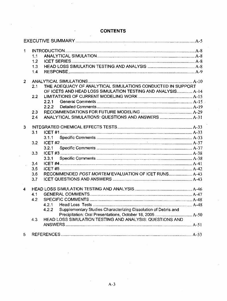
CONTENTS
EXECUTIVE SUMMARY........................................................................... A-5
1 INTRODUCTION.................................................................................. A-81.1 ANALYTICAL SIMULATION ............................................................. A-81.2 ICET SERIES.............................................................................. A-81.3 HEAD LOSS SIMULATION TESTING AND ANALYSIS.............................. A-81.4 RESPONSE ............................................................................... A-9
2 ANALYTICAL SIMULATIONS.................................................................. A-102.1 THE ADEQUACY OF ANALYTICAL SIMULATIONS CONDUCTED IN SUPPORT
OF ICETS AND HEAD LOSS SIMULATION TESTING AND ANALYSIS.......... A-142.2 LIMITATIONS OF CURRENT MODELING WORK .................................. A-15
2.2.1 General Comments ............................................. I............... A-152.2.2 Detailed Comments ............................................................ A-19
2.3 RECOMMENDATIONS FOR FUTURE MODELING................................. A-292.4 ANALYTICAL SIMULATIONS: QUESTIONS AND ANSWERS..................... A-3 1
3 INTEGRATED CHEMICAL EFFECTS TESTS ............................................... A-333.1 ICET #1................................................................................... A-33
3.1.1 Specific Comments................................................ ............ A-333.2 ICET #2.................................................................................... A-37
3.2.1 Specific Comments ............................................................ A-373.3 ICET #3................................................................................... A-38
3.3.1 Specific Comments ............................................................ A-383.4 ICET #4................................................................................... A-413.5. ICET #5.................................................................................... A-423.6 RECOMMENDED POSTMORTEM EVALUATION OF ICET RUNS............... A-433.7 ICET QUESTIONS AND ANSWERS................................................... A-43
4 HEAD LOSS SIMULATION TESTING AND ANALYSIS .................................... A-464.1 GENERAL COMMENTS ................................................................ A-474.2 SPECIFIC COMMENTS ................................................................ A-48
4.2.1 Head Loss Tests .............................................................. A-484.2.2 Supplementary Studies Characterizing Dissolution of Debris and
Precipitation: Oral Presentations, October 18, 2005 ....................... A-504.3 HEAD LOSS SIMULATION TESTING AND ANALYSIS: QUESTIONS AND
ANSWERS................................................................................ A-51
5 REFERENCES .................................................................................. A-53
A-3

TABLES
Table 1: Simulations conducted by Jain et al. (2004).............................................. A-l ITable 2: Simulations conducted by Jain et al. (2005).............................................. A-12Table 3. ICET Matrix ................................................................................. A-33Table 4. Chemical Effects Head Loss Tests ........................................................... A-46
A-4
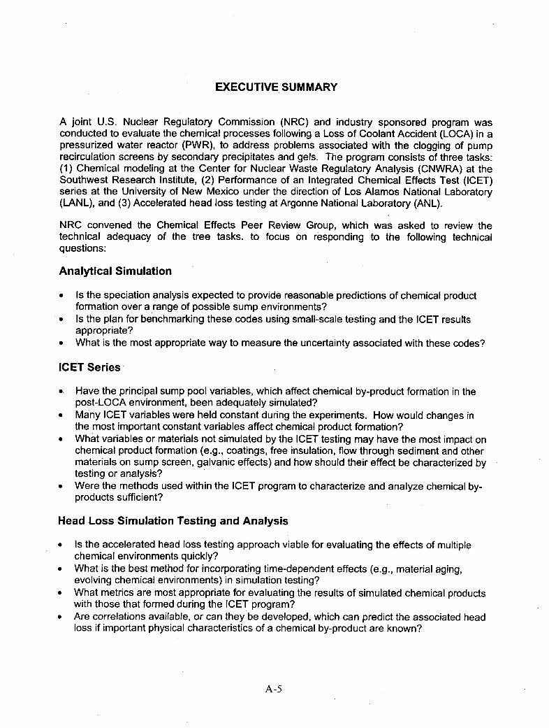
EXECUTIVE SUMMARY
A joint U.S. Nuclear Regulatory Commission (NRC) and industry sponsored program wasconducted to evaluate the chemical processes following a Loss of Coolant Accident (LOCA) in apressurized water reactor (PWR), to address problems associated with the clogging of pumprecirculation screens by secondary precipitates and gels. The program consists of three tasks:(1) Chemical modeling at the Center for Nuclear Waste Regulatory Analysis (CNWRA) at theSouthwest Research Institute, (2) Performance of an Integrated Chemical Effects Test (ICET)series at the University of New Mexico under the direction of Los Alamos National Laboratory(LANL), and (3) Accelerated head loss testing at Argonne National Laboratory (ANL).
NRC convened the Chemical Effects Peer Review Group, which was asked to review thetechnical adequacy of the tree tasks. to focus on responding to the following technicalquestions:
Analytical Simulation
* Is the speciation analysis expected to provide reasonable predictions of chemical productformation over a range of possible sump environments?
" Is the plan for benchmarking these codes using small-scale testing and the ICET resultsappropriate?
* What is the most appropriate way to measure the uncertainty associated with these codes?
ICET Series
*Have the principal sump pool variables, which affect chemical by-product formation in thepost-LOCA environment, been adequately simulated?
*Many ICET variables were held constant during the experiments. How would changes inthe most important constant variables affect chemical product formation?
*What variables or materials not simulated by the ICET testing may have the most impact onchemical product formation (e.g., coatings, free insulation, flow through sediment and othermaterials on sump screen, galvanic effects) and how should their effect be characterized bytesting or analysis?
*Were the methods used within the ICET program to characterize and analyze chemical by-products sufficient?
Head Loss Simulation Testing and Analysis
" Is the accelerated head loss testing approach viable for evaluating the effects of multiplechemical environments quickly?
* What is the best method for incorporating time-dependent effects (e.g., material aging,evolving chemical environments) in simulation testing?
* What metrics are most appropriate for evaluating the results of simulated chemical productswith those that formed during the ICET program?
* Are correlations available, or can they be developed, which can predict the associated headloss if important physical characteristics of a chemical by-product are known?
A-5

In order to respond to the technical questions posed, the reviewer studied three reports byCNWRA, five ICET reports by LANL, and three reports by ANL. A number of documentssupporting oral presentations at two meetings held at ANL on October 18-19, 2005, and atSouthwest Research Institute on March 27-29, 2006, respectively, were also reviewed togetherwith material supplied by NRC. Additional documents, scientific papers and reports were alsoconsulted to aid in the subsequent evaluation and provide corroborating arguments in support ofthe. reviewer's findings.
The following report constitutes the response by one of the members of the Peer Review Group,.who was chosen for his expertise in chemical modeling. The report is sub-divided into five parts.The first is an introduction defining the background, scope and objectives of the review, thesecond addresses the analytical computer simulations to evaluate the requirements for theICETs, the third contains a review of the adequacy of the ICET series, and the fourth part is areview of the head loss tests and supporting research. The report concludes with a list of citedreferences. Findings, conclusions and recommendations are not allocated separate parts, asthese topic are adequately covered within parts 2, 3 and 4 of the report that address themodeling and experimental parts of the program, and are briefly summarized below.
Part 2 contains an in-depth review of three reports produced by the CNWRA. The simulations inall three reports are summarized in tabular form, and the reviewer gives the conclusionsreached by the authors together with his comments and observations. The adequacy of themodeling work in relation to support for the experimental studies is then reviewed. Thelimitations of the work described in the three reports are then discussed, with both generalcomments, and detailed comments relating to specific sections of each text.Recommendations for future modeling are then made, based on the limitations of the reportedwork, and required improvements. The section concludes with responses to the questionsposed by NRC for the Analytical Simulations, as listed above.
Part 3 lists the specifications for the ICET series. Both general and detailed comments by thereviewer follow for each of the five reports describing the procedures and results of each test.After reviewing all five reports, the reviewer concluded that a post mortem evaluation of theICET runs should be conducted in order to resolve issues of data interpretation and increaseconfidence in subsequent modeling analyses. A section is therefore included with specificrecommendations. The section concludes with responses to the questions posed by NRC forthe ICET Series, as listed above.
Part 4 addresses the head loss testing and supplementary bench-scale testing and analysis toaid in the interpretation of both head loss and the ICET series. Three preliminary reportsspecifically addressing the head loss tests done to date and supplementary oral presentationsgiven at the December 18-19, 2005 meeting at ANL were reviewed. Specific head loss testscompleted to date are listed. Both general and detailed comments by the reviewer follow for thereports and oral presentations. The section concludes with responses to the questions posed byNRC for the head loss simulation testing and analysis, as listed above.
The reviewer concludes that. the ICET program has made substantial progress towardsunderstanding and quantifying the chemical processes that could lead to sump screen blockageduring the emergency cooling phase following a LOCA at an operating PWR. However, thechemical modeling conducted as part of this program falls far short of what is needed, either tointerpret the completed or ongoing experimental studies supporting the program, or ultimately,to construct a simulator for evaluating PWR plant response following a LOCA; this, despite thesignificant improvement in technical understanding and competence reflected in the third report
A-6

of the series generated by CNWRA. The reviewer recommends substantive refinements andimprovements to any future modeling, by taking better advantage of the kinetic data acquired inthe course of the program, developing a dedicated thermodynamic database, whichincorporates those aqueous species and product phases of relevance to the test conditions, andmore fully utilizing the reaction progress features available in state-of-the-art codes. Only afterthese recommendations are implemented will it be possible to fully interpret the experimentalresults of the ICET and head loss test series, refine the thermodynamic and kinetic parametersin the chemical simulators, and provide ongoing support and guidance to future experimentalresearch.
A-7
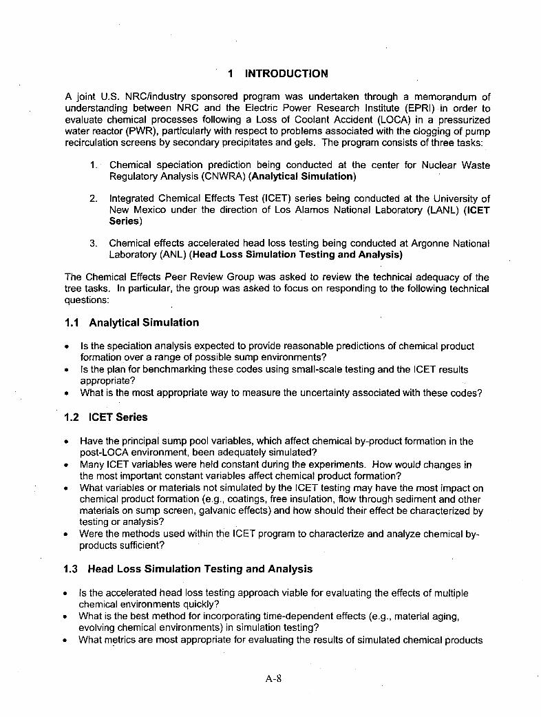
I INTRODUCTION
A joint U.S. NRC/industry sponsored program was undertaken through a memorandum ofunderstanding between NRC and the Electric Power Research Institute (EPRI) in order toevaluate chemical processes following a Loss of Coolant Accident (LOCA) in a pressurizedwater reactor (PWR), particularly with respect to problems associated with the clogging of pumprecirculation screens by secondary precipitates and gels. The program consists of three tasks:
1 . Chemical speciation prediction being conducted at the center for Nuclear WasteRegulatory Analysis (CNWRA) (Analytical Simulation)
2. Integrated Chemical Effects Test (ICET) series being conducted at the University ofNew Mexico under the direction of Los Alamos National Laboratory (LANL) (ICETSeries)
3. Chemical effects accelerated head loss testing being conducted at Argonne NationalLaboratory (ANL) (Head Loss Simulation Testing and Analysis)
The Chemical Effects Peer Review Group was asked to review the technical adequacy of thetree tasks. In particular, the group was asked to focus on responding to the following technicalquestions:
1.1 Analytical Simulation
* Is the speciation analysis expected to provide reasonable predictions of chemical productformation over a range of possible sump environments?
" Is the plan for benchmarking these codes using small-scale testing and the ICET resultsappropriate?
* What is the most appropriate way to measure the uncertainty associated with these codes?
1.2 ICET Series
* Have the principal sump pool variables, which affect chemical by-product formation in thepost-LOCA environment, been adequately simulated?
* Many ICET variables were held constant during the experiments. How would changes inthe most important constant variables affect chemical product formation?
* What variables or materials not simulated by the ICET testing may have the most impact onchemical product formation (e.g., coatings, free insulation, flow through sediment and othermaterials on sump screen, galvanic effects) and how should their effect be characterized bytesting or analysis?
" Were the methods used within the ICET program to characterize and analyze chemical by-products sufficient?
1.3 Head Loss Simulation Testing and Analysis
" Is the accelerated head loss testing approach viable for evaluating the effects of multiplechemical environments quickly?
" What is the best method for incorporating time-dependent effects (e.g., material aging,evolving chemical environments) in simulation testing?
* What metrics are most appropriate for evaluating the results of simulated chemical products
A-8

with those that formed during the ICET program?*Are correlations available, or can they be developed, which can predict the associated head
loss if important physical characteristics of a chemical by-product are known?
1.4 Response
The program is here reviewed in three parts. The first addresses the analytical computersimulations to evaluate the requirements for the ICETs, the second contains a review of theadequacy of the ICET series, and the third part is a review of the head loss tests and supportingresearch.
A-9
2 ANALYTICAL SIMULATIONS
The Center for Nuclear Waste Regulatory Analysis (CNWRA) was asked to perform computer-based modeling with the following objectives:
1. To determine the need for a pressurized test ioop for the ICETs
2. To assess whether gelatinous products could form following a LOCA
3. To gain insights into important parameters
4. To attempt to predict ICET results.
The reason for conducting such computer based modeling was that it would "...allow rapid andrelatively inexpensive identification of the critical chemistry, time, temperature, pressure and pHvariables that affect chemical product formation" (Jain et al., 2005).
To meet the above-cited objectives, a literature survey was conducted to determine thecorrosion rates of materials exposed to cooling water following a LOCA. These materialsincluded aluminum, copper, carbon steel, and galvanized steel-(zinc), fiberglass insulation andconcrete. Estimated conservative values for corrosion rates of these materials were made onthe basis that corrosion rates at 9000 would be representative, and that the concentrations ofthe corrosion products would be dependent on time (up to 15 days), and the estimated totalsurface areas of the exposed materials. Two alternative aqueous solutions were assumed, oneconsisting of a solution of 0.259 mol/L B(OH)3 Plus 0.15 mol/L NaOH, buffered at a pH = 10, andthe other consisting of 0.259 mol/L B(OH)3 plus Na3PO 4, buffered at a pH = 7.
Preliminary modeling was conducted using OLI system Inc.'s Stream Analyzer Version 1.2 andEnvironmental Simulation Program (ESP) Version 6.6 (OLI Systems inc., 2002a,b) by assumingthe equilibrium partitioning of the total concentration of corrosion products between the aqueousphase, and solid phases at given times following a LOCA, and at temperatures rangingdownwards from 15000 to 6000. Sensitivity studies were also conducted by varying theconcentrations of the individual corrosion products -by +/- 1-2 orders of magnitude at anunspecified time at 60 and 130 00.
The results and findings of the preliminary modeling are described in a report by Jain et al.(2004), which was subsequently attached as Appendix C to a later report by Jain et al. (2005).A listing of the simulations conducted by Jain et al. (2004) is given in Table 1
Jain et al. (2005) conducted electrochemical corrosion rate studies on aluminum, carbon steel,copper and zinc in 0.259 mol/L B(OH)3 plus 0.15 mol/L NaOH, solutions buffered at a pH = 10.Studies were also conducted to measure the chemical corrosion of glass used to fabricateNUKON fiberglass insulation, and the chemical corrosion of concrete in the same solution.These measurements allowed for refinement of the postulated corrosion rates andthermodynamic simulations were repeated using revised conservative estimates of thecorrosion rates of the tested materials. The follow-on simulations used the same software as inthe preceding report. A listing of the simulations conducted by Jain et al. (2005) is summarizedin Table 2.
A-10

Table 1: Simulations conducted by Jain et al. (2004)
B(OH)3/NaOH Solution Buffered at pH = 10 _ _____________
No. T, 'C P, kPa Time, hr SpecifiedConditions Output Reported1 60 101 - 0.26 mau/L B(OH)3 PH, Eh (VSi4E)
90 101 0.23 moliL NaOH
130 304PH=1
150 5072 60 110.5 As above, plus predicted concentrations of Solid phases precipitated in mot/L or
90 01dissolved components at 0.5 hr from Zn. Al, percent as f(T). Elemental distribution in130 304carbon steel, Cu. NukonT"S concrete solid phases as f(T, P).150 507particles and concrete. Amounts estimated
______ _______ ~~~~~~~based on corrosion rate at 90_C for_0.5_hr. ___________________3 60 101 360 As above, but for an additional 0.24 molIL Solid phases precipitated in mol/L
B(OH)3 to maintain pH at 10.
4 60 101 0.5? As for 3, above, but pH varied between 7 Solid phases precipitated in molIL, plotted130 304 and 11 as a function of pH
5 60 101 0.5? Sensitivity Study: As for 3, above, but Zn Variation in quantity of precipitated Zn-130 304 aqueous concentration varied containing phases as a function of
__________ _____________________________ concentration at 60 and 130 *C.
6 60 101 0.5? Sensitivity Study: As for 3, above, but Al Variation in quantity of precipitated Al-130 304 . aqueous concentration varied containing phases as a function of
__________ _____________________________ concentration at 60 and 130 *C.
7 60 101 0.5? Sensitivity Study: As for 3, above, but Fe Variation in quantity of precipitated Fe-130 304 concentration varied containing phases as a function of
______concentration at 60 and 130 *C.8 60 101 0.5? Sensitivity Study: As for 3, above, but Variation in quantity of precipitated phases
aqueous concentration of concrete as a function of dissolved Ca2SiO410 304 components varied concentration at 60 and
___ ___ _____ ______ ___________1_____ 130 *C.
9 60 101 0.5? Sensitivity Study: As for 3, above, but Variation in quantity of precipitated phases__________aqueous concentration of NukonTý as a function of dissolved NukonTM
130 304 components varied components at 60 and 130 *C.
___ _____B(OH)3/Na3PO4 Solution Buffered at pH =71 60 101 - 0.26 mol/L B(OH)3 pH, Eh (VSHE)
90 101 0.0084 mol/L Na3PO4pH = 7130 304150 507
2 60 101 0.5 As above, plus predicted concentrations of Solid phases precipitated in mol/L or90 101 dissolved components at 0.5 hr from Zn, Al, percent as f(T). ). Elemental distribution in
130 304 carbon steel, Cu, Nukon'", concrete solid phases as f(T, P).10 507 particles and concrete. Amounts estimated
FIN ____ based on corrosion rate at 90 *C for 0.5 hr.3 60 101 360 As above, but for an additional 1.5 molIL Solid phases precipitated in mol/L
B(OH) 3 to maintain pH at 7. compared with results above at 130 *C.
5 60 101 0.5? Sensitivity Study: As for 3, above, but Zn Variation in quantity of precipitated Zn-aqueous concentration varied containing phases as a function of
130 304 concentration at 60 and 130 'C.6 60 101 0.5? Sensitivity Study: As for 3, above, but Al Variation in quantity of precipitated Al-
130 304 aqueous concentration varied containing phases as a function of______ _________concentration at 60 and 130 *C.
7 60 101 0.5? Sensitivity Study: As for 3, above, but Fe Variation in quantity of precipitated Fe-concentration varied containing phases as a function of
130 34concentration at 60 and 130 'C.
8 60 101 0.5? Sensitivity Study: As for 3, above, but Variation in quantity of precipitated phases______ _________aqueous concentration of concrete as a function of dissolved Ca2Si0 4
____ 130 304 ______ components varied concentration at 60 and 130 *C.9 60 101 0.5? Sensitivity Study: As for 3. above, but Variation in quantity of precipitated phases
130 304 aqueous concentration of NukonTM as a function of dissolved NukonTM__________ ________ _________ components varied components atf60 and 130 *C.
A-l I
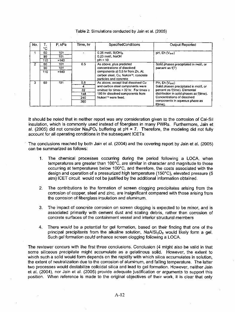
Table 2: Simulations conducted by Jain et al. (2005)
No. T, P, kPa Time, hr SpecifiedConditions Output Reported_ _ oc__ _ _ _
1 60 101 - 0.26 mol/L B(OH)3 pH, Eh (VSHE)
90 101 0.23 mol/L NaOH___110 =140 pH =10
2 60 101 0.5 As above, plus predicted Solid phases precipitated in mol/L or90 101 concentrations of dissolved percent as f(T)110 f -10410 components at 0.5 hr from Zn, Al,
carbon steel, Cu, NukonTm, concrete_________ __________ particles and concrete
3 60 101 0.5 As above, except that dissolved Cu PH, Eh (VSHE)4 and carbon steel components were Solid phases precipitated in mol/L or32 omitted for times > 32 hr. For times Ž percent as f(time). Elemental148 180 hr dissolved components from distribution in solid phases as f(time).240 NukonTM were fixed. Concentrations of dissolved360 components in aqueous phase as
I __ I _ _ ______ ______ ________________ f(time).
It should be noted that in neither report was any consideration given to the corrosion of Cal-Silinsulation, which is commonly used instead of fiberglass in many PWRs. Furthermore, Jain etal. (2005) did not consider Na 3PO4 buffering at pH = 7. Therefore, the modeling did not fullyaccount for all operating conditions in the subsequent ICETs
The conclusions reached by both Jain et al. (2004) and the covering report by Jain et al. (2005)can be summarized as follows:
1 . The chemical processes occurring during the period following a LOCA, whentemperatures are greater than 10000C, are similar in character and magnitude to thoseoccurring at temperatures below 10000, and therefore, the costs associated with thedesign and operation of a pressurized high temperature (150 0C), elevated pressure (5atm) ICET circuit would not be justified by the additional information obtained.
2. The contributions to the formation of screen clogging precipitates arising from thecorrosion of copper, steel and zinc, are insignificant compared with those arising fromthe corrosion of fiberglass insulation and aluminum.
3. The impact of concrete corrosion on screen clogging is expected to be minor, and isassociated primarily with cement dust and scaling debris, rather than corrosion ofconcrete surfaces of the containment vessel and interior structural members
4. There would be a potential for gel formation, based on their finding that one of theprincipal precipitants from the alkaline solution, NaAISi 3O83 would likely form a gel.Such gel formation could enhance screen clogging following a LOCA.
The reviewer concurs with the first three conclusions. Conclusion (4 might also be valid in thatsome siliceous precipitate might accumulate as a gelatinous solid. However, the extent towhich such a solid would form depends on the rapidity with which silica accumulates in solution,the extent of neutralization due to the corrosion of aluminum, and falling temperature. The lattertwo processes would destabilize colloidal silica and lead to gel formation. However, neither Jainet al. (2004), nor Jain et al. (2005) provide adequate justification or arguments to support thisposition. When reference is made to the original objectives of their work, it is clear that only
A-12
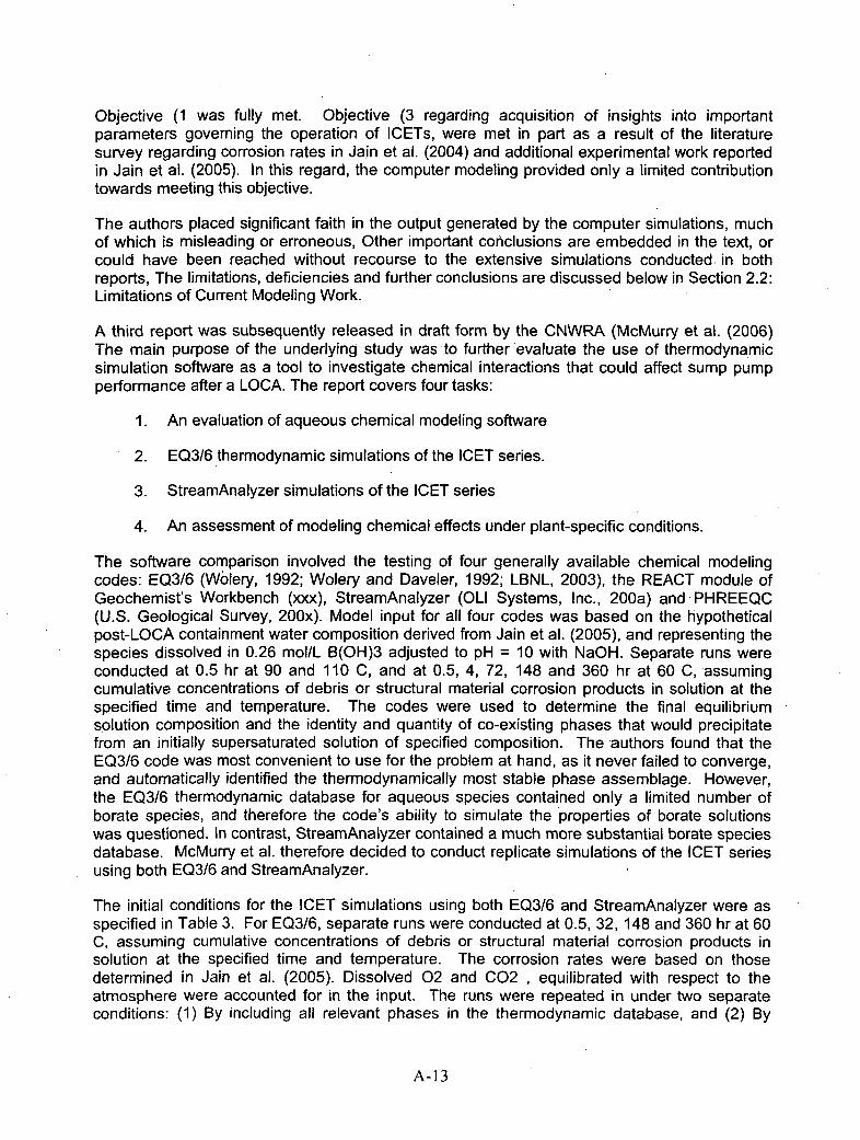
Objective (1 was fully met. Objective (3 regarding acquisition of insights into importantparameters governing the operation of ICETs, were met in part as a result of the literaturesurvey regarding corrosion rates in Jamn et al. (2004) and additional experimental work reportedin Jain et al. (2005). In this regard, the computer modeling provided only a limited contributiontowards meeting this objective.
The authors placed significant faith in the output generated by the computer si mulations, muchof which is misleading or erroneous, Other important conclusions are embedded in the text, orcould have been reached without recourse to the extensive simulations conducted in bothreports, The limitations, deficiencies and further conclusions are discussed below in Section 2.2:Limitations of Current Modeling Work.
A third report was subsequently released in draft form by the CNWRA (McMurry et al. (2006)The main purpose of the underlying study was-to further evaluate the use of thermodynamicsimulation software as a tool to investigate chemical interactions that could affect sump pumpperformance after a LOCA. The report covers four tasks:
1 . An evaluation of aqueous chemical modeling software
2. EQ3/6 thermodynamic simulations of the ICET series.
3. StreamAnalyzer simulations of the ICET series
4. An assessment of modeling chemical effects under plant-specific conditions.
The software comparison involved the testing of four generally available chemical modelingcodes: EQ3/6 (Wolery, 1992; Wolery and Daveler, 1992; LBNL, 2003), the REACT module ofGeochemist's Workbench (xxx), StreamAnalyzer (OLI Systems, Inc., 200a) and PHREEQC(U.S. Geological Survey, 200x). Model input for all four codes was based on the hypotheticalpost-LOCA containment water composition derived from Jain et al. (2005), and representing thespecies dissolved in 0.26 mol/L B(OH)3 adjusted to pH = 10 with NaOH. Separate runs wereconducted at 0.5 hr at 90 and 110 C, and at 0.5, 4, 72, 148 and 360 hr at 60 C, assumingcumulative concentrations of debris or structural material corrosion products in solution at thespecified time and temperature. The codes were used to determine the final equilibriumsolution composition and the identity and quantity of co-existing phases that would precipitatefrom an initially supersaturated solution of specified composition. The authors found that theEQ316 code was most convenient to use for the problem at hand, as it never failed to converge,and automatically identified the thermodynamically most stable phase assemblage. However,the EQ3/6 thermodynamic database for aqueous species contained only a limited number ofborate species, and therefore the code's ability to simulate the properties of borate solutionswas questioned. In contrast, StreamAnalyzer contained a much more substantial borate speciesdatabase. McMurry et al. therefore decided to conduct replicate simulations of the ICET seriesusing both EQ3/6 and StreamAnalyzer.
The initial conditions for the ICET simulations using both EQ316 and StreamAnalyzer were asspecified in Table 3. For EQ3/6, separate runs were conducted at 0.5, 32, 148 and 360 hr at 60C, assuming cumulative concentrations of debris or structural material corrosion products insolution at the specified time and temperature. The corrosion rates were based on thosedetermined in Jain et al. (2005). Dissolved 02 and C02 , equilibrated with respect to theatmosphere were accounted for in the input. The runs were repeated in under two separateconditions: (1) By including all relevant phases in the thermodynamic database, and (2) By
A-13
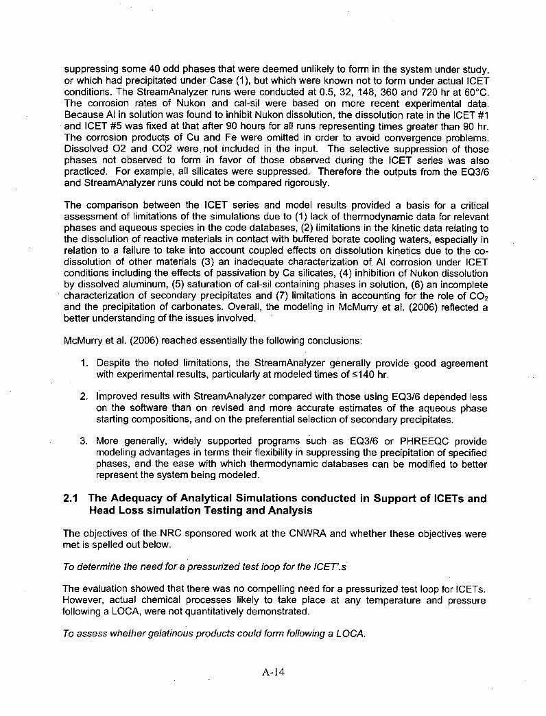
suppressing some 40 odd phases that were deemed unlikely to form in the system under study,or which had precipitated under Case (1), but which were known not to form under actual ICETconditions. The StreamAnalyzer runs were conducted at 0.5, 32, 148, 360 and 720 hr at 60*C.The corrosion rates of Nukon and cal-sil were based on more recent experimental data.Because Al in solution was found to inhibit Nukon dissolution, the dissolution rate in the ICET #1and ICET #5 was fixed at that after 90 hours for all runs representing times greater than 90 hr.The corrosion products of Cu and Fe were omitted in order to avoid convergence problems.Dissolved 02 and 002 were. not included in the input. The selective suppression of thosephases not observed to form in favor of those observed during the ICET series was alsopracticed. For example, all silicates were suppressed. Therefore the outputs from the EQ3/6and StreamAnalyzer runs could not be compared rigorously.
The comparison between the ICET series and model results provided a basis for a criticalassessment of limitations of the simulations due to (1) lack of thermodynamic data for relevantphases and aqueous species in the code databases, (2) limitations in the kinetic data relating tothe dissolution of reactive materials in contact with buffered borate cooling waters, especially inrelation to a failure to take into account coupled effects on dissolution kinetics due to the co-dissolution of other materials (3) an inadequate characterization of, Al corrosion under ICETconditions including the effects of passivation by Ca silicates, (4) inhibition of Nukon dissolutionby dissolved aluminum, (5) saturation of cal-sil containing phases in solution, (6) an incompletecharacterization of secondary precipitates and (7) limitations in accounting for the role Of CO 2
and the precipitation of carbonates. Overall, the modeling in McMurry et al. (2006) reflected abetter understanding of the issues involved.
McMurry et al. (2006) reached essentially the following conclusions:
1 . Despite the noted limitations, the StreamAnalyzer generally provide good agreementwith experimental results, particularly at modeled times of •5140 hr.
2. I mproved results with StreamAnalyzer compared with those using EQ316 depended lesson the software than on revised and more accurate estimates of the aqueous phasestarting compositions, and on the preferential selection of secondary precipitates.
3. More generally, widely supported programs such as EQ316 or PHREEQC providemodeling advantages in terms their flexibility in suppressing the precipitation of specifiedphases, and the ease with which thermodynamic databases can be modified to betterrepresent the system being modeled.
2.1 The Adequacy of Analytical Simulations conducted in Support of ICETs andHead Loss simulation Testing and Analysis
The objectives of the NRC sponsored work at the CNWRA and whether these objectives weremet is spelled out below.
To determine the need for a pressurized test loop for the ICET'. s
The evaluation showed that there was no compelling need for a pressurized test loop for ICETs.However, actual chemical processes likely to take place at any temperature and pressurefollowing a LOCA, were not quantitatively demonstrated.
To assess whether gelatinous products could form following a L OCA.
A-14
No information was provided that would demonstrate that gelatinous products would formfollowing a LOCA.
To gain insights into important parameters.
The experimental studies to quantify metal and other debris corrosion rates by Jain et a[. (2005)ands subsequent refinement of Nukon and cal-sil leaching kinetics by McMurry et al. (2006) area valuable contribution towards model development, and helped show which debris componentswere important, and which were less so. However, the data developed were not used to theirfullest advantage in subsequent modeling.
To attempt to predict ICET results.
ICET results were predicted only in a rudimentary sense.
In the following discussion, the reviewer is responsive to pertinent technical questions posed byNRC for the Chemical Effects Peer Review Group. However, because the current modelingwork falls short of what is needed, the reviewer also provides and expanded critique of thelimitations of the work done so far, and recommends an amended approach that would be bothscientifically defensible, and provide a more meaningful basis for model calibration andverification using the results of the ICETs; and the Head Loss Simulation Testing. Such anapproach might permit the resulting model to be customized for predictive simulations of theconsequences of hypothetical LOCAs with respect to specific PWR designs. The work done sofar has only begun to address the requirements for model calibration or validation with theICETs and the Head Loss Simulation Testing.
2.2 Limitations of Current Modeling Work
2.2.1 General Comments
The modeling work described by Jain et al. (2004), Jain et al. (2005) and McMurry et al. (2006)suffers from several limitations and deficiencies. The limitations and deficiencies apply primarilyto the first two reports, as some have been partially addressed, or at least identified, in the lastreport. Full advantage has not been taken of available software capabilities to provide anadequate framework for follow-on experiments and analysis. Specific issues are as follows:
1 . The thermodynamic database for OLI Systems Inc. codes lists phases solely by theirchemical composition, e.g., NaAlSi 3O8. Specific polymorphs are not identified by theirmineral names, properties, or Greek alphabet prefix, as is customary in thegeochemical or materials science literature, respectively. Thus there are 5polymorphs of albite (NaA[Si 3O8) listed in the output provided in Appendix B to Jain etal. (2004), i.e., Appendix C of Jain et al. (2005). The source of the data containedwithin the database is not given, so there is no way of finding out whether the data iscorrect or when it was last updated or revised. Inspection of the listing of participatingphases suggests that they might be rock-forming minerals that would form underhydrothermal, metamorphic or magmatic conditions. Such a database is largelyunsuitable or useless for the simulations being conducted, and would yieldmeaningless results.
2. The OLI Systems codes are designed to explore the operation of. systems in whichreaction rates are sufficiently fast that equilibrium is assumed, and that complex flow
A- 15

streams between multiple reactors can be modeled. A particular feature of the OLISystems codes is that they are capable of modeling very high ionic strength solutions(up to 30 Md) using Pitzer (1991) or Bromley (1972) electrolyte models. Thecapabilities of these codes are either insufficient, or not critical for the system beingmodeled. The absence of provisions that would allow for the evolution of a systemunder specified kinetic controls is particularly critical.
3. For reasons that are discussed further below, phases that would nucleate andprecipitate following a LOCA, would probably be amorphous or poorly crystalline, andcolloidal or microcrystalline in size. Such phases would be far more soluble than thethermodynamically most stable phases for the specified conditions. A more suitablethermodynamic database than that used with the OLI Systems codes for phases thatwould form under such conditions is that used with the MINTEQ code (Felmy et al.,1984), which is designed for relatively low temperature (0 - 100'C) aqueous chemicalprocesses. However, it is up to the modeler to ensure that the thermodynamicdatabase contains those phases most likely to nucleate and precipitate under theconditions to be modeled. It is not sufficient to take an off-the-shelf code andassociated database without first establishing its suitability, or revising the databasethrough addition of more appropriate phases and their properties. Jain et al. (2005)may have been aware of the limitations of the OLI Systems database, as they refer tothe phases as "potentially amorphous", but took no action to correct for the problem.McMurry et al, in contrast, were fully aware of the limitations, and attempted to correctthe problem,, at least in part, by suppressing certain phases from participating in theequilibrium calculation while using both EQ316 and the OLI Systems StreamAnalyzer.
3. All of the calculations performed using OLI Systems Inc. codes assume a given initialconcentration of components in solution, which are then distributed between theaqueous phase, and thermodynamically most stable solid phases. However, in Jainet al. (2004) and Jain et al. (2005), the initial conditions are incompletely specified,i.e., whether a vapor phase is assumed to be present, and if so, how much? Howwas the oxidation state specified? Was the pH fixed, as suggested in the text, or wasit a dependent variable? The "Typical OLI Simulation Output", given in Appendix B ofJain et al. (2004) indicates that Zn, Al, Cu and Fe were specified as being in theirmetallic state in the "Stream Inflows", and as cited in Table 3-3 of Jain et al. (2005).Furthermore, the output indicates that hydrogen was generated, but remained entirelyin the aqueous phase, instead of partitioning into a vapor phase. No mention is madeof the input pH, so it must be presumed to be a dependent variable, i.e. pH = 6.977 1as cited for the output. The code option "Redox selected" was also invoked, whichallowed calculation of the Eh = -0.339 V.
4. The purpose of the studies by Jain et al. (2004) and Jain et al. (2005) was to provideguidance in the design and operation of the ICET and head loss experiments.Because the ICETs and Head Loss Simulation tests are both conducted With limitedheadspace, the absence of a coexisting vapor or vapor phase should be of limitedconcern if the computer calculations are used for the purpose of predicting, orsimulating these tests. However, this presumes that the limited headspaces have notbeen exposed to atmospheric exchange for a significant period of time. Suchexchange, particularly with respect to 002, could have a significant impact on thechemical evolution of the system over time, and should require that such uptake betaken into account, if necessary. Jain et al. (2004) and Jain et al. (2005) did notconsider the effect of scavenging 002 from the air as possibly impacting the evolving
A-16
chemistry and nature of the precipitates. Calculations by the reviewer suggest thatthe potential quantity of calcium precipitated, as calcite through uptake of atmospheric002 in a containment building would be less than 1 % of the total calcium brought intosolution by the dissolution of fiberglass. However, calcite might nucleate andprecipitate early in the post-LOCA cooling cycle, and facilitate subsequentheterogeneous nucleation and precipitation of calcium phosphates and silicates.Furthermore, the amount of C02 taken up during operation of any of the ICETs mayhave proportionately exceeded that which could have been scavenged from theatmosphere in the containment building. Thus, although the omission might bejustified, because atmospheric 002 would be a minor component, its effect onprecipitation kinetics could be significant. McMurry et al. have drawn attention to thelimitations in accounting for the role Of CO2 and the precipitation of carbonates. Theultimate goal of all simulations undertaken in the program should be to predictadverse conditions following a LOCA in an operating PWR. Due consideration shouldtherefore be given to eventually simulating actual post-LOCA cooling operations byincluding a coexisting gas phase equivalent in volume to that of the containmentbuilding.
5. The calculated Eh values presented in Tables 3-2 and 4-1 of Jain et al. (2004) and inTables xx of MoMurry et al (2006) are probably meaningless under the conditions ofthe ICETs, as it is highly unlikely that the circulating aqueous phase would achieveinternal equilibrium with respect to participating redox pairs. Therefore, Eh should notbe emphasized. This same caveat applies with even greater force to actualconditions following a LOCA. Hydrogen from the corrosion of aluminum would degasinto the air of the containment building, and oxygen would continue to saturate thecirculating coolant water. However, as other members of the Chemical Effects PeerReview Group have pointed out, e.g. McDonald (2006), significant radiolysis of thecirculating coolant could occur with formation of H202, depletion of oxygen, andproduction of additional hydrogen. Attainment of a meaningful calculated solution Ehwould be unlikely, as the circulating coolant would not be able to achievehomogeneous equilibrium during the frame it would be recirculated. Furthermore,radiolytic effects could be adequately simulated only through modification of theexisting a geochemnical modeling code to account for an imposed radiation flux.
6. As noted above, the thermodynamic calculations presented by Jai et al. (2004) andJain et. (2005) assume a certain quantity of Zn, Al, Cu or Fe is available for corrosionafter a given time, and is supplied as input to the model in the metallic state.Thermodynamic equilibrium is then assumed through reaction of the constituentmetals with the aqueous phase, and precipitation of corrosion products. This causesthe calculated Eh to fall sharply to approximately -0.4 V at pH = 7, (e.g., seeAppendix B of Jain et al., 2004), and even lower at higher pH. Under such conditions,Cu is stable in its native state, rather than as an oxide, as is confirmed by thereported results of the simulations in both Jain et al. (2004) and Jain et al. (2005).Dissolved copper in the recirculating coolant would plate out on exposed aluminumand steel surfaces, and be quantitatively removed from solution, in conformity with themodeling results. The presence of native copper in contact with exposed steel oraluminum could enhance the corrosion rate of either through galvanic coupling. Incontrast, the dissolution of metallic Fe, i.e., steel, would lead to immediate oxidationwith precipitation of Fe oxides under oxidizing alkaline conditions, as oxidation of Fe 2 +
is catalyzed by 01-1 (Singer and Stumm, 1968, 1970). Passivation of the Fe couldresult if Fe 3O4 precipitates on exposed steel surfaces, as is suggested by Jain et al.
A-17
(2005, p. 2-2). At lower pH, i.e., at a pH =7, Fe 2+ is likely to accumulate in theaqueous phase, but the presence of oxygen will ensure that precipitation in the Illstate will occur during circulation of the coolant. It is quite unlikely that iron would atany time precipitate in the Fe(ll) state as reported in the simulations, i.e., see p. 3-4 ofJain et al. (2004). It would have been more appropriate, therefore, to assume anexcess of oxygen to have been present during the computation of the speciesdistribution between the aqueous and solid phases, rather than ignoring it as wasdone by the authors.
7. The chemical composition of the concrete and concrete dust is presumed to consistof Ca 2SiO4 (belite), a phase known to occur in five polymorphic forms (Taylor, 1997).However, Ca2SiO4 is one of the principal ingredients of cement before it is mixed withwater to produce a cement paste, and *does not persist in concrete or concrete dust.Ordinary Portland cement (OPC) reacts with water to form principally C-S-H (CaO-SiO2-H 20) "gel' and portlandite (Ca(OH)2). It is these phases that should beconsidered if fresh concrete were to be leached by the recirculating coolant.However, neither the exposed concrete faces nor concrete dust in the containmentbuilding are likely to be fresh. After 30 years exposure to the atmosphere, asubstantial fraction of both the exposed C-S-H gel and the portlandite would havebeen carbonated (Parrot and Killoh, 1989), i.e. they would have converted to amixture of amorphous silica and either vaterite or calcite (Slegers and Rouxhet,1976). Therefore, exposed cementitious materials would most likely be carbonated,and the modeling should reflect this state of affairs.
8. There are inherent limitations to all modeling work done to date, because thedissolution rates of debris and construction materials are represented by computing afictive accumulated concentration of dissolved species in solution after fixed timeperiods, and then distributing the dissolved species among precipitated phases. Whileit is understandable that the initial stage of modeling should involve such scopingcalculations, this approach seriously limits realistic simulations of the ICETs or headloss tests. Several codes are available in either the academic or commercial sectorthat allow simulations in which dissolution and precipitation rates are kineticallycontrolled, e.g. EQ6 (Wolery and Daveler, 1992), TOUGHREACT (Xu et al., 2004),the Geochemist's Workbench (Bethke, 2005) and PHREEQ-C (Parkhurst and Appelo,2005). While some effort would be required to incorporate appropriate kinetics forheterogeneous reactions in these codes, this is not insuperable, and would greatlyenhance the value of the modeling. The major difficulty with the study of the evolutionof a chemical system with time is largely overcome in this program, because Jain etal. (2004) and Jain et al. (2005) have already undertaken an extensive literaturesearch and conducted experimental studies to measure the corrosion rates ofaffected materials, and this work is supplemented by further studies of the dissolutionrates of Nukon and cal-sil reported by McMurry et al. (2006). Furthermore, theTOUGHREACT code also permits non-isothermal simulations to be conducted.Therefore, a simulation of both variable dissolution and precipitation rates duringcooling could be accomplished. Such modeling would also possess the addedadvantage that the kinetic parameters could be refined using output data from theICET and head loss tests.
9. McMurry et al. (2006) correctly identify additional limitations hindering an improvedpredictive capability for current modeling activities. They include (1) a lack ofthermodynamic data for relevant phases and aqueous species in the code databases,
A-18

(2) limitations in the kinetic data relating to the dissolution of reactive materials incontact with buffered borate cooling waters, and (3) an incomplete characterization ofsecondary precipitates. However, these problems are not insuperable, and muchprogress can be made by a further review of the literature, particularly in relation towork conducted with respect to metastable calcium phosphate precipitates (VanKemenade and de Bruyn, 1987) and metastable aluminum oxy-hydroxides (VanStraten and De Bruyn, 1984). The extensive data on borate species in solutionundoubtedly has a source (ref), and suitable analysis could permit its consolidation inthe databases f the code of choice. The limitation in current kinetic data, e.g.,inhibition of Nukon dissolution by dissolved aluminum, and the potential passivation ofaluminum by dissolved silica (+ calcium?), clearly mandate additional experimentalstudies to characterize the interactive kinetic behavior of concurrently corrodingmaterials. Finally, the inadequate characterization of precipitates during the ICETsmay necessitate dedicated experiments to collect sufficient material for more detailedcharacterization.
10. In Jain et al. (2005), sensitivity studies were conducted by arbitrarily varying thecorrosion rates of the various materials, one at time, over very large, and possiblyunrealistic ranges. Apart from the fact that the kinetic rate parameters are only a fewof the total number of parameters in the models that contribute to uncertainty, theselection of the magnitudes of these parameters tended to be made on the basis ofconservatism rather than accuracy. Ideally, the uncertainties in all parameters shouldbe embedded in the chemical modeling simulator, and the uncertainties in allcalculated results carried through to the output. Attempts to do this have so far beenexceedingly limited, e.g. see Najm et al. (2003) and Reagan et al. (2004). Add-onmodules to address this problem have been developed for the PHREEQC code(Ekberg and Emren, 1996; Ekberg et al., 2000). Given the current limitations of codedevelopment, it would seem that the most pragmatic approach would be to conductmultiple realizations, each time varying the critical input parameters using a MonteCarlo approach, and evaluating the overall uncertainty in output parameters.
11. It has been noted that all simulations conducted to date ignore the presence of aradiation flux, which would induce radiolysis in the water and some of the dissolvedspecies, e.g. bicarbonate. Preliminary simulations show that a variety of radiolysisproducts are formed, including H202, H2, with corresponding reduction in dissolvedoxygen. Radiolysis could cause the oxidation state of the aqueous phase to rise, asH2 would partition into the atmosphere of the containment building. It is not certainwhat the overall effect would be on precipitate formation and sump-screen clogging.However, the issue should be reviewed in the event that it may have a significantimpact on real world behavior.
2.2.2 Detailed Comments
2.2.2.1 Jain et al. (2005)
2-2. Reference is made to the variability in Fe corrosion with temperature due to lowerdissolved oxygen at elevated temperatures. However, rates of reaction are likely toincrease and 02 diffusion rates also. A more likely reason is the more rapid andcoherent build-up of a passivating oxide layer on the steel surface.
A-19
2-4. Reference is made to "stones" in concrete. The correct terminology is "coarseaggregate".
Dicalcium silicate is referred to as the reactant in concrete. This is incorrect. It shouldbe C-S-H gel or Ca(OH) 2.
4-1 The simulation is limited to pH = 10 with a B(OH) 3INaOH mixture. However, that is notwhat is meant. The pH would vary with time depending on the amount of debrisdissolved and the initial contribution Of 002 that would be stripped from the air in thecontainment building. The latter process would not be relevant to ICET or head losstests, where the air headspace is small.
It is stated that corrosion rates at pH = 7 are expected to be similar to those at pH =10,
but the corrosion of Nukon is reported as being three times slower at the lower pH.
It is not clear whether the cited pH values are measured or calculated at the operatingtemperature, or are referenced to 250C. As noted elsewhere, pH should be considereda dependent parameter, as treated in the modeling.
4-2 The text is confusing. No reference is made to whether corrosion products of metal areincorporated or the metals themselves. Only reference to the incorporation of a metalsis the reference that ".. .most of the copper added as copper metal in the simulationremained as copper metal", and in Table 3-3.
Repeated reference is made to "...potentially amorphous solid phases..." Either theyare or they are not amorphous in the simulation. Did the authors check to find outwhether the product phases in the simulation were specified as amorphous orcrystalline?
Repeated reference is made to "...soluble phases of silica [such as] H3SiO4 _1 andNaHSiO3 .. ." or "...the calcium-bearing soluble phase was CaH 2SiO3". This is incorrect.What the authors are referring to as aqueous species in a homogeneous aqueousphase.
Reference is made to the "...speciation of solid phases.." Presumably, the authorsmean distribution of solid phases?
A statement is made that "Copper was thermodynamically stable and showed nocorrosion." Yet published Eh-pH diagrams show that under the Eh-pH conditionsreported in Table 3-2 of Appendix C, CuO, i.e. a Cu(ll) containing phase would be morestable than copper. Only by reference to Appendix B of Jain et al. (2004) can it bediscerned that the redox potential is determined by the corrosion principally of aluminum,and that the Eh and pH are in the region of -0.4 V and 7.0 respectively.
4-5 Reference is made to the formation of CaSiO 3 and Si0 2. These formulas correspond tothe minerals wollastonite and quartz, which are unlikely to coexist at the temperaturesand pressures of post LOCA coolant circulation. A more likely assemblage would betobermorite + gyrolite or the Z-phase, or gyrolite or the Z phase + amorphous silica.CaSiO3 and Si0 2 is a fictive model assemblage generated by the simulator, andhighlights the problem associated with the use of off-the-shelf databases and uncriticalacceptance of the model results.
A-20

4-10 It is inappropriate to discuss the stability field of albite (NaAlSi3O8) in relation to gibbsiteAI(OH) 3 using an Eh-pH diagram. No redox reactions are involved. If the stabilityrelations of these two phases require graphical examination, then an activity diagramusing chemical potentials Na2O, A1203 and SiO2 should be generated. The authorswould then discover that other phases should also be taken into consideration such asbeidellite, kaolinite, halloysite or allophane.
4-11 The solubility boundaries in this Eh-pH diagram should be defined by a Total Aluminumconcentration. Without such data, the figure is inadequately defined.
Appendix B
B-2 The authors note that the rates of Nukon dissolution clearly vary as a function of time,as. Yet, for reasons of conservatism, they adopted a maximum initial rate of corrosionas being representative. The cause of the non-linearity in rates over time was notevaluated, although it was assumed that it was due to the formation of secondary layers[leached layers?] on the surface (Appendix C, p. 2-10). However, it could also be due tothe dissolution of a more highly reactive disturbed layer, the precipitation of secondaryphases, or an approach to metastable equilibrium of the glass with the aqueous solution.For meaningful modeling, the mechanisms should be identified, and a suitable algorithmdescribing the temperature dependent process incorporated in a simulator. See noteselsewhere concerning the use of "conservative" versus realistic values in modeling.
2.2.2.2 Jain et al. (2004) [Appendix C of Jain et al. (2005)]
xii Throughout Appendix C, reference is made to the precipitation of Ca5(OH)(P0 4)3, orapatite as the phase that would precipitate through the reaction of dissolved Ca 2+ withNa3PO 4. In actual fact, this phase is slow to crystallize, and it is far more likely thatmetastable poorly crystallized phosphates will form, especially at high degrees ofsupersaturation (Van Kemenade and De Bruyn,1987; Van Cappellen, 1991). Therefore,permitting this phase to control the solubility of Ca 2 + and P0 4 3 in solution is unrealistic.
1-3 Table 1-2. The analysis of the "gel" in this table is essentially meaningless, as thereported constituents add up to only 0.0131 % of the total mass. What accounted for theremaining 99.99%?
2-8 Concrete is not a mixture of tricalcium silicate, dicalcium silicate, etc. The first two arethe principal phases present in cement before it is mixed with water and aggregate toproduce concrete. Corrosion rates cited in Jantzen (1984) are with respect to freshconcrete. The assumption is that none of the cementitious materials exposed in theinterior of a containment building would have undergone carbonation, which is highlyunlikely given the duration of exposure of exposed concrete faces to the atmosphere.Concrete dust would be especially subject to very rapid carbonation, converting thecement reaction products into CaCO 3 (calcite, vaterite) + Si0 2 (amorphous silica).
3-1 It is stated that "Simulations were conducted at pH 10..." and that a pH of 10 wasobtained by adding 0.23 [mol/LJ. ... NaOH." and that "Additional 0.24 [mol/L] 1- 3130 3 wasneeded to maintain pH at 10." The statements are confusing. As far as the reviewer canascertain, the input to the OLI Systems codes did not permit the specification of pH, andfurthermore, pH could not be maintained in the simulation through the addition ofB(OH) 3. Throughout Section 3, figures contain captions referring to "simulated
A-21
containment water at pH 10" or similar phraseology. It is not stated whether "pH 10"'refers to the initial pH before reaction or after, and whether the pH is referenced to 25 'Cor the temperature of the simulation. Inspection of Table 3-2 and reference to AppendixB suggests that "pH 10" refers to the pH of the simulated containment water alone at6000, and therefore does not reflect the final pH of the aqueous phase in equilibriumwith secondary precipitates.
The authors refer to the "hourly corrosion amount of each component", when in fact, theyare referring to the half-hourly corrosion amount.
3-2 It is not clear what reaction determines the redox state for borated water in Table 3-2.Note that reference is made elsewhere that oxygen and 002 was not included in theinitial chemical composition of the aqueous phase.
3-5 Note the argument that "...similar solid phases are formed in the first half hour of theLOCA event at 150'C as those from a 15-day or longer simulation test at 600C."Presumably, this is one of the reasons justifying the exclusion of elevated pressureICETs. However, these results are primarily an artifact of the database, and might not bevalid if more realistic secondary precipitates were incorporated in the model.
3-7 It is noted that the formation of iron phases depends on pH. Thus, with increasing pH,iron is found in F'e3Si2O5(OH)4, then Fe304, then Ca3Fe2Si301 2 and finally CaFe2O4. Thissequence shows that the oxidation state for iron goes from 11 to Il/Ill to Ill to Ill, indicatinghigher oxidation states with increasing pH. This finding is the result of allowing nativemetals to dissolve in a system where the only oxidant is the water itself. This isinconsistent with the role of oxygen in oxidizing Fe to the 11 state in neutral to alkalinesolutions. See the reviewer's comment regarding OH- catalysis under item 6 on p. 9.Therefore, 02 should have been specified as an input species.
3-16 The final statement: "This fiber insulation..." is ambiguously worded. The reviewerpresumes that the authors are referring to the lack of variation in the makeup of theprecipitated phases with varying fiberglass concentrations, rather than the mass ofsecondary precipitates, which does vary. Also, it should be noted that in the simulationsthe concentration of fiberglass reaction products is roughly equivalent to that of concrete,e.g., see Table 3-1. Therefore, it would not be expected that variation of fiberglassreactant composition would have much impact on the results.
4-1 It is stated that "An additional amount of 1.5 [mol/L] 1- 3B303 was needed to maintain a pH7." Yet subsequent tables refer only to simulated containment water containing 0.26mol/L Boron. What does the quoted statement mean? Was this additional quantity ofB(OH) 3 added to the input composition in order to maintain an output pH of 7?
It is not clear what reaction determines the redox state for borated water in Table 4-1.What causes the Eh to be lower than that of the alkaline borated water given in Table 3-2?
4-12 It is stated that "The fiber insulation sensitivity analysis at pH 7 indicated no significantimpact on the formation of solid phases..." See comment for pp. 3-16. The real reasonfor the lack of variation is primarily because its reaction products are roughly equivalentto those that form from concrete.
A-22

5-2 Item (v). There is a real danger in placing too much faith in the finding that theretrograde solubility of secondary calcium silicate phases could assist in the uncloggingof pump strainers. In reality, secondary colloidal/gelatinous hydrated calcium aluminumsilicates, once formed, would be unlikely to redissolve within the time frame of interest.The ICET and Head Loss tests would help answer this question.
6-1 This section on gel formation is devoid of meaningful content. Better descriptions ofgelation phenomena, and their causes, especially with respect to the formation of silicagel, can be found in the literature (Scherer, 1999; Lasaga, 1998; Lyklema, 1991; Wereset al., 1980).
7-1 It is claimed that the report validates OLI Systems, Inc software for speciation in boratedwaters.. However, the relevant validation study is reported only in Appendix A, Section 2.If the findings of the validation study are of sufficient importance to be included in theConclusions, then this work should have been incorporated in the main body of the text.
7-2 7.1 Conclusions For convenience, the eight bulleted conclusions relating to thecirculated alkaline borate water are numbered in order to facilitate comment.
NaAISi3O8, Ca3Fe2Si3O12 and Fe3Si4O1O(OH) 2 were dominant solid phases that contributedto over 90 percent of the solid phases formed between 1500C [3020F]. 507 kPa [5 atm] and600C [1400FJ.
Phases cited are unlikely to form under LOCA conditions
The CaaFe2Si3Oi2 solid phase was formed at 150*C [302 0F]. 507 kPa [5 atm]l. whileFe3Si2O5(QH)4 was formed at 60'C [140 0F]. This transformation was attributed to theretrograde solubility of calcium in iron bearing minerals. Despite these phase changes, allthe iron was present in the solid phase.
Cited phases are unlikely to form under LOCA conditions. Stabilization of Ca3Fe(llI) 2 Si301 2and Fe(Il) 3Si205(OH)4 with iron in different oxidation states is an artifact of the specifiedinitial conditions for the distribution of species. As noted above, the distribution of Fe is afunction of (OH)- dependent oxidation kinetics
Copper had no influence on the precipitation of solid phases, and no corrosion of copper isexpected.
This conclusion is correct.
The contribution from zinc was insignificant compared to other solid phases and was limitedto 5 percent to the total quantity of solid phases.
This conclusion is justified by the presented literature data on zinc corrosion, and themagnitude of exposed galvanized steel.
Sensitivity analyses for aluminum indicated formation of A I(OH) 3 for aluminumconcentrations exceeding 2 x 10⁻⁴ mo/IL at 600C [1400F]. The formation of AI(OH)3 was notobserved at 130 0C [266 0F]. 304 kPa [3 atm].
A-23

The precipitation of AI(OH) 3, or AIO(OH) at temperatures higher than 600C, depends on theirbeing an insufficiency of silica to form phases such as beidellite, kaolinite, halloysite,allophane, etc. Their failure to precipitate as stable phases in the simulations suggestseither an insufficiently comprehensive thermodynamic database, or erroneous data.
Sensitivity analyses for concrete indicated, irrespective of the temperature and pressure, forCa2SiO4 exceeding I x 10-3 mo/IL, the concentration of CaSiO3 increased with an increaseof concrete concentration.
Wollastonite (CaSiOA) is a high temperature phase, and is unlikely to precipitate under postLOCA conditions. The fact that fresh concrete contains C-S-H gel and portlandite, ratherthan Ca2SiO 4, and that aged concrete most likely to be exposed to the atmosphere would becarbonated to a significant depth, essentially invalidates this conclusion.
In a 15-day simulation at 600C [1400F], all solid phases (except copper) present in thesimulated containment water were solid silicates.
This conclusion is generally valid except for the precipitation of minor calcite and magnetiteor hydroxy-magnetite on exposed steel surfaces. Both phases would probably be present ifmore accurate simulations had been performed.
As silicon concentration was reduced, the concentration of silicate phases reduced also. Inan alkaline environment, the solubility of silica increased with an increase in pH andtemperature. Since silicates were major corrosion products, a strong influence of pH andtemperature was observed on the formation of the dominant solid phases in the simulatedcontainment water. However, at pH 10, irrespective of the temperature, pressure, andconcentration, silicates of aluminum and iron contribute 90 percent of the solid phases.
The conclusions of this item are generally correct.
7-3 For convenience, the eight bulleted conclusions relating to circulated Na3PO4 bufferedborate water are numbered in order to facilitate comment.
There were significant differences in the solid phase formation in Na3PO4 containingsimulated containment water at pH .7 from that in alkaline simulated containment water at pH10.
This conclusion is valid
At pH 7, Ca5(OH)(P0 4)3 was the dominant solid phase containing almost 100 percent ofcalcium, while at pH 10, calcium was approximately 1 percent insoluble at 600C
[140 0FJ.Precipitation of apatite (Ca 5(P04)3(OH)) as a dominant phase is unlikely. Amorphous topoorly crystalline precursors such as Ca4(P0 4)3H (Van Kemenade and De Bruyn, 1987;Van Cappellen, 1991) are more likely .
A significantly larger quantity of solid phases was formed in a solution containing Na3PO4compared to alkaline containment water. Ca5(OH)(P04)3 and NaAISi3O8 contributed to over90 percent of the solid phases.
A-24
This conclusion is, likely valid.
Sensitivity analyses for concrete indicated increase in the Ca5(OH)(P0 4)3 concentration witha increase in the concrete concentration. For concentrations of concrete exceeding 3 x 10⁻⁴moliL, Ca5(OH)(P04)3 coexisted with solid SiO2 phase. The concentrations of these twophases far exceeded contributions from other soid phases.
This conclusion is generally valid. However the precipitating phases are unlikely to beapatite and quartz.
Copper had no influence on the precipitation of solid phases.This conclusion is correct.
The sensitivity analyses for aluminum indicated an increase in the concentrations ofNaAISi3O8 with an increase in aluminum concentration. Formation of AI(OH) 3 and AIO(OH)was observed for aluminum concentrations exceeding 3 x 10⁻⁴ moliL at 600C [140*F] and130 0C [266 *F1, 304 kPa [3 atm], respectively. In a 15-day simulation, aluminum was presentexclusively as NaAISi3O8."
The precipitation of AI(OH)3, or AIO(OH) at temperatures higher than 600C, depends on theirbeing an insufficiency of silica to form phases such as beidellite, kaolinite, halloysite,allophane, etc. Their failure to precipitate as stable phases in the simulations suggestseither an incomplete thermodynamic database, or erroneous data.
Both iron and zinc showed a decrease in solid phase concentration with decreaseintemperature and pressure. The contribution of zinc was below 2 percent and that of iron isbelow 9 percent compared to the, total solid phases. Other than a reorganization of ironphases, no significant changes were observed.
This conclusion is likely valid.
The dominant solid phases formed after 15 days were Ca5(OH)(P04)3 and NaAiSi3Oa withminor quantities of Ca 2Mg5SiBO22(OH]2, Fe3Si4O 10(OH)2, SiO2, and Zn2SiO4 in the simulatedcontainment water.
For reasons stated elsewhere, the phases identified are unlikely to form under post LOCAcooling operation.
Appendix A.
A-16 The test results for the dissociation constant of boric acid in 3 mol/L NaCI are only fair.Although the discrepancies between experimental and modeled values are significant, itis difficult to ascertain whether such would adversely affect the findings of the report.
A-18 The differences *between the calculated concentrations of Zn 2 ' and Ca 2" and therespective measured concentrations, illustrated in Tables A-8 - A-il1 are substantial, andsuggest defects in the either the thermodynamic data or the electrolyte model beingused in the code.
A-25

2.2.2.3 McMurry et al. (2006)
1-1 It would be helpful if specific references could be given regarding the previous at theBarsback plant in Sweden, and strainer clogging events in U.S. boiling water reactors.Otherwise the assertions appear to be merely anecdotal.
2-5 It is not clear why StreamAnalyzer generated an output Eh of -0.600 V at pH = 10, asspecification of dissolved iron as Fe 31 (Table 2-2) should have poised the Eh at a muchhigher value. The actual conditions that result in such a low initial Eh should beexplained. In any event, it is not clear why Eh had to be specified as input in any of theruns, unless the objective was to ensure final equilibrium with respect to some reducedphase, such as copper or magnetite. The outputs of subsequent runs to model the ICETseries did not report Eh.
2-6 With reference to Table 2-4, note that B(OH)4-and B02- are essentially equivalent. Also,the extensive list of borate species listed in the StreamAnalyzer database may bebecause this code is capable of modeling high ionic strength solutions, i.e. up to 30molal where such species may be present in significant concentrations. It is quitepossible that under the conditions of the present simulations, most, if not all of thoseadditional species would be present at concentrations too low to significantly affect theresults. Because the dissociation constants for these species are not listed in the report,it is not possible to check this postulate. However, the authors should check howsignificant these species are in affecting the results.
2-7 Charge balancing is a necessary requirement if total mass is to be redistributed amongseveral phases, and should not be considered an artificial constraint. Much dependshow it is accomplished. It appears that charge balancing was performed throughadjustment of pH, which is satisfactory in strongly buffered systems, but may not alwaysbe an appropriate strategy.
2-8 Perhaps it should be emphasized that the inter-code comparison presented in section 2is really an evaluation of the consequences of using different databases. The databasesof all four codes are unsuitable for the problem at hand. Therefore the main purpose ofthe study is defeated, unless the databases are modified through incorporation of thethermodynamic properties of phases known to be relevant to the ICETs.
Tbl 3.2 The corrosion rates of metals, Nukon, and concrete and cal-sil insulation are given indifferent units (g/m2/hr, mg/h, moIIL). An explanation is called for in the accompanyingtext.
3-2 It is stated that cal-sil insulation was assumed to dissolve such that Ca and Si0 2 ionswere contributed to the containment water in "equal molecular proportions". Yet theanalysis in Table 3-3 indicates that the molar ratio is 2.4:1. Some explanation for the,ratio chosen is called for. In view of the fact that a significant quantity of Na + seems tobe released from cal-sil during leaching experiments, e.g. see ref, this should have beenincluded in those simulations where cal-sil was involved.
3-2 Mention is made that the water supplied tO the tank was in equilibrium with dissolvedcarbon dioxide. Is this in reference to solution buffered with NaOH to pH = 10? If so, fartoo much CO 2 would have been taken up to realistically represent the amount of C02likely absorbed during the ICET series.
A-26

Tbl 3.3 The sources of the analyses for both Nukon and cal-sil are not given.
3-3 The most serious discrepancy between the EQ3/6 modeled results and the ICET #1listhe almost quantitative removal of Al from solution in the modeled results. Thesuppression of diaspore is appropriate, but the resulting induced precipitation ofdawsonite and near quantitative removal of Al raises questions regarding the validity ofthe thermodynamic data for the participating phases and aqueous species. The causeof the discrepancy should be identified.
3-4 Note that the chemical analysis of the precipitate from ICET #1, which containedcarbonate as well as aluminum, boron and sodium, could have taken up carbon dioxidefrom the atmosphere after sampling.
3-5 Inspection of the EQ316 simulation 2 nd trial results for ICET #2 suggest that thedepressed silica concentration is due to the precipitation of kaolinite rather than a lessstable form such as allophane. The depressed Ca concentration is probably due toprecipitation of apatite rather than a metastable form of Ca3PO4 , e.g. see van Kemenadeand De Bruyn (1987).
3-6 Inspection of the EQ316 simulation 2 nd trial results for ICET #3 suggest that thedepressed pH is due at least in part to the precipitation of apatite rather than ametastable form of Ca3PO 4. The elevated Ca concentration is a cons .equence of thelowered pH. The elevated phosphorus concentration may also be due to the equilibriumof the system with respect to apatite at lowered pH, as raising [OH]- by 102-4 woulddepress phosphate accordingly. This assertion appears to be supported by the ICET #3results of the StreamAnalyzer simulation, (see note to pp. 4-7).
3-7, Although EQ316 simulation 2 nd trial results for ICET #4 corresponds well with theexperimental results for Ca, Si and Al, these results may be fortuitous. It is unlikely thatkaolinite would be a precipitant at the prevailing pH of the system, and within the shorttime frame of the test. In nature, smectitic phases would be replaced by zeolites at pH=10. Bench-scale testing to determine the nature of any precipitates that would formunder the spec 'ified conditions might help identify the composition and nature ofprecipitants that control the aqueous phase composition.
3-8 The EQ3/6 simulation 2 nd trial results for ICET #5 predict the precipitation of gibbsite,which is less stable than boehmite at 600C. In actual fact, it is more likely thatpseudoboehmite would precipitate under the conditions of the test (Van Straten and DeBruyn, 1984), as is suggested by a prediction of a lower Al concentration in solution thanactually observed.
3-10 Note that the rationale for using StreamAnalyzer in subsequent simulations was becauseof the expanded database of borate species in the database for this code. However, thesignificance of these species under the conditions of the ICET series was not evaluatedin the report. Appendix C to this report is a summary of a StreamAnalyzer run for ICET#1 after 148 hr at 6000. The output of this run allows an example calculation of thedistribution of borate species for the specified conditions, where B = 0.259 mol/L and pH= 10. It shows that B(OH) 4-= 69.2%, B(OH) 3 = 8.O%and B40 5(OH)4
2 - = 6.7%. All otherspecies contribute less than 6% each to the total boron concentration.Thermodynamically, the only other borate species of potential importance is CaH 2BO 3 +,
which, although of insignificant concentration (0.00017 mol/L), is actually responsible for
A-27
complexing 76% of the dissolved Ca 21, and could therefore have a profound impact inlowering the chemical potential of CaO in solution.
4-2 If X-ray diffraction analysis indicated that aluminum oxyhydroxide formed during ICET#1, it would be interesting to know whether the pattern reflected truly crystallineboehmite, or pseudoboehmite, which is a poorly crystalline precursor, and commonlyconfused with the former. See note to pp. 3-8, above. As noted elsewhere, merelyspecifying the formula of the precipitate INS not sufficient, and a serious disadvantage tousing the OLI Inc. codes.
Tbl 4-3 Note that borate species but not their concentrations are listed in this table and others inthe StreamAnalyzer simulations. Therefore their significance in affecting the resultscannot be compared to model results using EQ3/6.
4-4ff The simulation results for ICET #2 using StreamAnalyzer indicate several problems. TheCa concentration is still too low; suggesting that the Ca3(P04)2 phase in theStreamAnalyzer databases is not appropriate for the case under study. Furthermore, itis unlikely that berlinite would precipitate, as very acid conditions are required to preventAl hydrolysis. The literature should be searched for more suitable AI-hydroxy-phosphatephases to substitute for berlinite.
4-5 The assumption. that cal-sil can be represented by CaSiO3 is inconsistent with thechemical analysis for this material in Table 3-3.
4-6 The dissolution tests for cal-sil suggest that saturation with respect to some Ca bearingphase was attained within 200 hr of the start of leaching. Failure to take this intoaccount may explain the excessive Ca concentrations in solution in the ICET #3simulations. The authors allude to this possibility on pp. 4-7. If this phenomenon wasobserved during the cal-sil dissolution experiments, why was this not taken into accountin the simulations?
4-7 The precipitation of Ca3(P0 4)2 in the StreamAnalyzer simulation of ICET #3 avoids thepH shift due to apatite precipitation in the EQ316 ICET #2 simulation. This indirectlyconfirms that apatite could not be the phosphate phase precipitating in this experiment.
4-8ff The very large difference in Al concentration between ICET #1 and ICET #4 maysuggest that reaction is taking place between the dissolved Al and the cal-sil to producesome hydrated Ca-Al silicate. However, other explanations include the inhibition of Alcorrosion by hydrated Ca silicate coating, or secondary precipitation of a hydrated Ca-Alsilicate, as suggested by the authors. Resolution of this issue should be particularlyamenable to bench-scale testing.
5-3 The authors point out that precipitation and subsequent dissolution of Ca-phosphateprecipitate after 9 days in ICET #3 is not explained by the modeling. The Na and P04analyses of the aqueous phase reveal sharp discontinuities at about 15 days, the formerfalling in concentration by 500 mg/L and the latter rising by 0.2 mg/L. If thesediscontinuities are real and not artifacts of sampling and/or analysis, then some cluemight be provided regarding the chemical reactions that could have taken place. BothCNWRA and LANL should coordinate their efforts in attempting to resolve this questionregarding the purported disappearance of the initial calcium phosphate precipitate.stable.
A-28

5-5 Note that the occurrence of borax and tincalconite may have been due to the effects ofsample drying in the presence of the coexisting aqueous phase from which theprecipitate was taken, resulting in concentration of borate and precipitation of theobserved phases. Note, however, that neither the EQ316 nor the StreamAnalyzerdatabases appear to contain data pertaining to a range of naturally occurring Ca- andNa- borosilicates, amorphous or poorly crystalline forms of which might precipitate in thesystems under investigation.
2.3 Recommendations for Future Modeling
Before serious modeling is undertaken, a conceptual understanding of the chemical processesinvolved is essential. The nature of the problem then determines what algorith ms would mostsatisfactorily represent the processes involved, and whether computer codes exist that would dojustice in realistically simulating those processes. Chemical reactions between water containingB(OH) 3 and suitable pH adjusters, such as NaOH or Na3PO4, and insulating and structuralmaterials results in supersaturation with respect to various silicates, aluminosilicates,phosphates and minor oxides and borates. Because of the presence of pre-existing particulatematerial, much of it in active suspension, heterogeneous nucleation of solid phases would beinduced upon reaching a critical nucleation threshold (Lasaga, 1998; Stumm, 1992). Empiricalcalculations indicate that this would probably be at a concentration about 10 times that requiredto achieve saturation, but could be significantly less.
The nucleating phase is commonly that which possesses the minimum interfacial free energy ofall candidate phases. Usually such a phase is also the least stable phase when present as amacroscopic particle. Once nucleation has occurred, the degree of supersaturation fallsrapidly, and the crystal growth rate slows, the interfacial free energy contribution also falls, andthe crystallites become increasingly stable. At some point, the nucleating phase becomessupersaturated with respect to a more stable phase with higher interfacial energy, and thatphase can initiate growth on a suitable substrate, as illustrated by Parks et al. (1990) for thesystem SiO 2.
Solutions containing silica commonly nucleate and grow as small colloidal particles of uniformsize that can be stabilized in solution by the enveloping electrical double layer (e.g., see Iler,1979). Because saturation has been reached, the colloidal particles can persist indefinitely in ametastable state. Destabilizing factors such as a change in ionic strength or pH can, however,overcome the repulsive effects of the electrical double layer (EDL) and lead to the aggregationof the colloidal particles to form a viscoelastic gel, a form of polymerization. Such gels cancontract and fracture through syneresis (Scherer, 1999), and will eventually redissolve andrecrystallize to thermodynamically more stable phases, but over time frames far longer than thatrequired for coolant circulation following a LOCA.
During a LOCA, su persatu ration, heterogeneous nucleation, colloid stabilization, and gelformation are likely to be the important processes. Recrystallization to form more stable phaseswould generally take place over timescales longer than the period of coolant recirculation.Therefore, the most suitable model for simulating a post LOCA system is one that takes suchmechanisms into account. Unfortunately, although the theory for such chemical processes isquite well understood (Lyklema, 1991), only rarely have attempts been made to model suchsystems (Steefel and Van Cappellen, 1990; Ozkan and Ortoleva, 2000), and no off-the-shelfsimulator is presently available to simulate these processes. Given the nature of the problemand time and financial constraints, it would probably be difficult to justify formulation of theneeded algorithms and generation of appropriate code for this project. Therefore, an alternative
A-29
simpler, but less rigorous approach should be taken, which ignores nucleation phenomena andcoagulation, and gelatinous products are allowed to precipitate directly from solution. Severalcodes, noted above can be readily adapted for such a purpose, provided that thethermodynamic properties of the least stable phases are incorporated in the thermodynamicdatabase and the more stable phases are suppressed. It should be borne in mind that very fastkinetic reactions that would achieve essential equilibrium in a matter of minutes should beignored and equilibrium assumed, whereas reactions taking a year or more to achieve 90%equilibration can also be ignored as being too slow to be relevant.
In summary, the following steps should be taken for meaningful simulation of ICET and looptests in addition to the debris and metal dissolution studies already accomplished:
1. Review the literature to identify candidate metastable colloidal and micro particulatephases that form or nucleate from solutions with similar chemical compositions to thosepostulated.
2. Analyze data to determine phase solubilities as a function of composition and pH, andtemperature, if possible.
3. Calculate the solubility products of the phases as a function of temperature, usingsuitable approximation techniques, where appropriate thermodynamic data isunavailable.
4. Derive kinetic data for dissolution and precipitation reactions, where available, andcalculate their temperature dependence, i.e., the apparent activation energies. Iftemperature dependent data is unavailable, estimates should be taken from closelyanalogous reactions. Although such estimates could be very inaccurate, this is notcritical, as the rates of reaction and specific characteristics of the precipitates can berefined from the experimental results of the ICET and loop tests, and supplementarylaboratory experiments as needed.
5. Insert the resulting data in the thermodynamic and kinetic databases of an appropriatecode, e.g., EQ316 or TOUGHREACT, and run simple simulations to duplicate nucleationand precipitation data from which the thermodynamic and kinetic data were derived.
6. Depending on the selection of code and its features, conduct non-isothermal simulationsof the kinetics of dissolution of debris and precipitation of reaction products, assumingoxygen saturation and CO 2 uptake. Depending on the features available in thesimulator, hydrogen might be beneficially treated as an "inert' product species, i.e., onethat cannot react chemically with an oxidant to produce water, whereas oxygen can bemade reactive. Such conditions would lead to more realistic simulations of the systembeing modeled.
7. As Jamn et al. (2005) have determined, the omission of zinc and copper components fromthe simulations is unlikely to have a significant impact on results. If the simulations areconducted with an initial elevated pH, i.e., pH = 10, then the impact of Fe corrosionproducts might be omitted. However, if Na3PO4 buffers the pH at =7, then the effect ofiron corrosion might be included to accommodate the early nucleation of amorphousferric hydroxides in suspension. This matter'should be evaluated further before a finaldetermination is made.
8. If possible, simulations should be set up to duplicate precisely, the actual sequence ofsteps undertaken during the course of ICET and lop tests.
9. Results of the ICET and loop tests can be used to refine the kinetics of reactions underoperating conditions, which, in turn could be used for simulations of postulated LOCAevents at actual PWR plants.
A-30
Even with perfect algorithms simulating the chemical processes that could take place, there willundoubtedly be aspects of the chemistry that are not fully understood or may be omitted fromthe model. Some possible limitations and how they might be addressed are given below.
1. The Nukon fiberglass insulation is coated with a phenyl formaldehyde resin basedinsoluble polymer (Jain et al. (2004, p 2-8). Yet experiments to measure corrosion of thefiberglass were conducted on uncoated glass coupons. The extent to which this coatingwould impede corrosion of the underlying glass appears to be minor. However, if theresin dissolves into an alkaline aqueous phase, the dissolved species could inhibitnucleation and growth of solid phases. Small-scale testing should be conducted toascertain the importance or otherwise of dissolved organics on nucleation andprecipitation kinetics of solid phases.
2. As noted by Jain et al. (2005) and McMurry et al. (2006), all kinetic parameters weredetermined either from experimental studies in the literature, or on additionalexperimental studies, where the complex interaction between dissolution processes ofseparate materials was not addressed. Examples already noted include inhibition ofNukon fiber dissolution by dissolved Al, and possible inhibition of Al corrosion bydissolved Ca and Si02. Another example is the suppression of copper dissolution in thepresence of less noble metals, thus: Cu>Fe (steel) ,>Zn> Al. Such second orderinteractions are difficult to identify, but could adversely affect the value of any simulatoras a predictive tool for potential real events. Should circumstantial evidence from theICET or head loss tests suggest second order interactions, experimental factorial designstudies might be necessary to identify the second-order effects even though they maynot be adequately defined.
3. Corrosion data for various participating metals, was extracted from the publishedliterature and tabulated in Jain et al. (2004). The data showed wide variability dependingon the specific corrosion conditions, and the nature of the alloy being subject tocorrosion. Numerous different aluminum alloys are commercially available, but thevariability in alloy dependent corrosion rates was not addressed. Given the corrosiveenvironment of alkali borate solutions, the nature of the alloy in setting corrosion ratesmay not be important, but this issue does not appear to have been addressed.
2.4 Analytical Simulations : Questions and Answers
NRC posed the following questions relating to analytical simulations for consideration by thePeer Review Group. Answers are provided in response.
Q Is the speciation analysis expected to provide reasonable predictions of chemicalproduct formation over a range of possible sump environments?
R (The speciation analysis conducted by McMurry et al. (2006) represents a significantimprovement over earlier work, but does not exploit existing capabilities of the selectedcodes to fullest advantage. Nor is the present analysis adequate, because of over-reliance on existing and irrelevant thermochemnical data for solid phases that wereprovided with the selected codes.
Q Is the plan for benchmarking these codes using small-scale testing and the ICET resultsappropriate?
R Yes. The plan is generally satisfactory, but, as noted above, the capabilities of thecodes currently being used are not being used to full advantage, and therefore, the valueof the associated experimental studies are diminished. Furthermore, modeling studies
A-31
supporting ongoing small-scale testing are currently not being done. With fullexploitation of codes currently being used, and ongoing modeling support for small-scaletesting, the program could be much more effective.
Q What is the most appropriate way to measure the uncertainty associated with thesecodes?
R Measurement of overall uncertainty of the output of any multi-component chemicalsimulation is difficult, because a large number of parameters are involved with widelyvarying levels of accuracy. In general, methods to address uncertainty in suchsimulations are in their infancy and have not been developed to a satisfactory level. Thebest approach in the present circumstances is to avoid the temptation to adoptunrealistically conservative values for the base case, but to utilize those values deemedto be most realistic. Then replicate runs can be made using Monte Carlo methods todetermine variations in those parameters deemed to have the greatest uncertainties andmost critical to model output. The cumulative variation in outputs can then be adoptedas a measure of uncertainty. Further discussion of this issue is given in section 2.2Limitations of Current Modeling Work.
A-32

3 INTEGRATED CHEMICAL EFFECTS TESTS
The NRC Office of Nuclear Regulatory Research (RES) sponsored the- Integrated ChemicalEffects Test (ICET) program at the University of New Mexico under the direction of the LosAlamos National laboratory (LANL). The primary objectives for the ICET series were to:
1. Determine, characterize, and quantify chemical reaction products that may develop inthe containment sump under a representative post-LOCA environment
2. Determine and quantify any gelatinous material that could be produced during the post-LOCA recirculation phase.
There were five tests in the series. The test matrix is given in Table 3.
Table 3. ICET Matrix
Test PH Control System Insulation MaterialNo.
I Sodium Hydroxide: pH -10 100% Fibrous (NUKON)
2 Tni-sodiumn phosphate: pH =7 100% Fibrous (NUKON)
3 Tni-sodiumn phosphate: pH -7 80% Particulate (Cal-Sil)20% Fibrous (NUKON)
4 Sodium Hydroxide: pH =10 80% Particulate (Cal-Sil)20% Fibrous (NUKON)
5 Sodium Tetraborate: pH =8 100% Fibrous (NUKON)
Extended reports have been written for all five tests, (Dallman et al., 2005a,; Dallman et al.,2005b; Dailman et al., 2005c,d Dallman et al., 2006) and brief summary reports have beenwritten for the first two and last two (Anonymous, 2005c, Anonymous, 2005a,b). In addition, anoral presentation regarding all tests was given at Argonne National Laboratory on October 18-19, 2005 (Letellier, 2005).
Reviews follow of the work summarized in the above-cited references.
3.1 ICET #1
The ICET #1 used a circulating fluid consisting of 2,800 mg/L boron, 100 mg/L HCI (about 12 N,as cited in a subsequent ICET report) and 0.7 mg/L LiOH. According to Letellier (2005) thesolution was made up using 15.14 kg B(OH)3, 5.87 kg NaOH, 0.66 g LiOH and 214 mL HCI in250 gallons. Within 30 minutes of the start of the test, an additional 2.27 kg NaOH wasintroduced during an initial 4-hr spray stage., the quantity of NaOH added being that necessaryto attain an initial pH = 10. The primary insulation debris consisted of NUKON fibers.
3.1.1 Specific Comments
p. 1 Section 2.0. In view of what follows from the tests, what are the concerns that the decayheat removal (DHR) heat exchangers might be fouled with. precipitates of the typeobserved to form during ICET test #1? Letellier (2005, Slide 21) believes there is
A-33
justification for concern that calcium silicate will coat heat exchanger pipe internals, butother precipitates do not appear to be considered..
p. 2 It is noted that "...the test tank is capable of maintaining both a liquid and vaporenvironment...". However, a realistic air/liquid volume ratio that would replicate thattypical of a post-LOCA environment was not attempted. The post-LOCA air volume in acontainment building would be effectively isolated from the atmosphere outside.Therefore, the mass Of C02 available that would be stripped from the air inside thecontainment building is limited, However, during initiation of the ICET #1, the systemwas exposed to atmospheric 002 for some period of time, and an unknown quantity of002 was absorbed, possibly proportionately in excess of that which would be absorbedin a real LOCA. Chemical analyses for dissolved 002 during the test have not beenreported, so it is not possible to say whether the observed decline in pH could beattributed to 002 uptake.
p. 19 The discussion of the XRD technique does not indicate what the composition was of thetarget anode. Presumably, it is copper. This information, is needed to interpret the XRDpatterns of Figs 55 and 56.
With respect to wet chemical analyses, no mention is made of sample handling, otherthan the sample size, and whether or not the sample was filtered. In the handling of allalkaline solutions, it is essential to avoid atmospheric exposure to prevent 002 uptake.There is no mention that stabilizing agents were added to the solutions to preventprecipitation. Nor is any information given as to how the samples were conditioned priorto lOP analysis. If precipitates formed, as is noted subsequently, are the lOP analysesof the supernatant or the total supernatant plus precipitate? See also comments to p. 28of the ICET #3 report.
p. 20 Apparently the pH meter was calibrated with certified buffers at pH = 4, 7 and 10. andautomatic temperature compensation was used. But at what temperature was the pHmeasured? At 25 or 6000? Was provision taken to ensure that 002 uptake did notoccur during measurement? Elsewhere, it is noted that the pH electrode for continuousmonitoring of pH was calibrated initially, but not at the end of the experiment. After 30days of continuous operation, the pH could have drifted substantially, and it would havebeen essential to recalibrate to quantify the extent of drift during the course of theexperiment.
p. 24 Under hydrogen generation, it is stated that nearly constant levels of hydrogen wereobserved for the first 17 or 18 days ... but that they subsequently declined and hydrogen"...was undetectable for the last 5 days of the test...". This raises the question, why?One would have expected that the aluminum coupons would have corroded relativelyuniformly throughout the test. pH did not fall sufficiently for passivation to have occurred.What about the role of dissolved Cu(ll) as a catalyst? Was there a build-up of silica orother passivating material on the aluminum coupons? A suitable explanation found orthis matter should be investigated further. It would be helpful in the post mortemnanalysis of ICET experiments to have some redundancy built into the analyticalprocedures, so that appropriate mass balance calculations could have been conductedwith confidence. Thus, it would have been useful to have made quantitativedeterminations of hydrogen concentration in the vapor and the aqueous phase, as wellas monitoring d~issolved oxygen concentration.
A-34
p. 28 Mg(ll) in the NUKON glass fiber could, if it were to go into solution, adversely affect thekinetics of calcium carbonate precipitation, and possibly other calcium containingphases. This consideration might have to be addressed, or at least recognized, insubsequent computer modeling and calibration studies.
p. 28 Reference is made to the NUKON glass fiber containing 3% of a phenolic resin binder.Elsewhere (p. 33) it is noted that the resin was responsible for causing a yellowcoloration of the water. Furthermore, it is noted that precipitation did not seem to affectthe intensity of this color. This raises the question as to what the solubilized constituentsare, and whether they affect the kinetics of nucleation and precipitation. Letellier (2005)noted that the circulating ICET solutions were analyzed for Total Organic Carbon (TOC),and that a search was made for organic compounds causing the yellow, amber or teacolored solution. However, these analyses have not been incorporated in any reports sofar. Such analyses might help identify potential sorbents. A small bench-scale testcould be conducted to determine whether nucleation and precipitation kinetics areaffected.
pp. 28f Regarding the SEM images of the fiberglass 'after exposure to the circulating water for30 days,, i.e., see Fig. 22 and 23, the reviewer is concerned about the mechanism offormation of the membrane-like material stretching between the exposed glass fibers.So far, the identity of this material remains unclear although Letellier (2005) and Klasky(2005) believe it to consist primarily of Na, B and 0. Elsewhere, Letellier noted that themembrane like material is "an artifact of draining", and Klasky (2005) noted that rinsingof the film with Dl water resulted in its disappearance. This suggests that it is most likelya solution residue.
p. 35 4.5.2 Turbidity. The turbidity analyses at 25 0C, reproduced graphically in Fig. 29 (p. 37)raise some interesting questions. It appears that the turbidity at 23 00 remained low untilafter Day 7, when a sharp rise is observed, gradually flattening off and stabilizing after,Day 20. the break in continuity is also observed in other data sets for Total SuspendedSolids (Fig. 30), kinematic viscosity (Fig. 36, p. 42), Ca concentration (Fig. 44, p. 47),Cu concentration (Fig. 45, p. 48), Zn concentration (fig. 47, p. 49, Na concentration (Fig.48, p. 49). Although the discontinuities may in some cases be the product of a vividimagination, the data do suggest that critical (heterogeneous) nucleation threshold mayhave been reached in the aqueous solution after 7 days at operating temperature(60'C). Thereafter, the system might have achieved saturation with respect to one ormore phases at 6000, as is evidenced by the fact that samples held at 600C did not formprecipitates (p. 36). Furthermore, only a small depression in temperature of 5 *C issufficient to induce precipitation (Fig. 31). The linear relationship between TSS andtemperature in Fig.31 also intersects at T = 6000 at approximately 0 mg/L TSS, againsuggesting that the solution is just saturated with respect to some phase. It appears thatany precipitates, even if formed in suspension, became entrained or grew within thedebris accumulations in the test loop. Tiny particles also appear to have grown on theNUKON fibers, perhaps having nucleated and grown in situ, rather than having beenentrained from suspension. Unfortunately, current information on the nature and identityof the precipitates provides only a limited basis for developing a working hypothesis.Further characterization work, already underway, i.e., Klasky (2005) and modeling isneeded to help resolve the unanswered questions.
p. 35 4.5.3 Total Susgended Solids. The study conducted to measure the quantity ofsuspended solids as a function of temperature (Fig. 31), and the follow-on test in which
A-3 5
cooled samples were reheated to 600C provides tantalizing evidence that the saturatingphase at 600C in the circulating loop was metastable with respect to a less solublephase, at least above 40*C. Whether this was due to Ostwald ripening, or thenucleation and growth of another phase, or to precipitation of a carbonate due to 002absorption from the atmosphere, can only be guessed at without more detailed analysis.
p. 40 4.5.4 PH. The decline in DAS pH over the course of the experiment could be due toinstrument drift. Discrepancies between the DAS and grab sample pHs could be due tothe former being measured at a different temperature than 600C, and that temperaturecompensation was insufficient. Fluctuations in the grab sample readings appear to berandom, when compared with the DAS measurements.
p. 42 4.5.6 Shear-dependent Viscosity This technique can provide valuable supplementaryinformation concerning colloid formation and subsequent gelation in the aqueous phase.The results, indicating non-Newtonian behavior in quenched 25 00 samples during thelater stages of the test, are suggestive. But does the technique allow one to discriminatebetween colloid formation, flocculation, or gelation? The filter clogging behavior of theobserved precipitates could differ substantially, depending on their aggregationcharacteristics.
p. 47 4.5.7 Metal Ion Concentrations Note the reviewer's caveats concerning samplehandling under the comments to p. 19. The Al concentration stabilizes after 15 - 20days, but Ca, Cu and Si stabilize after about 7 days,. and decline slowly thereafter. Zndeclines to 8 days, then shows a "hop". Na shows a discontinuity at about 7 days, and amaximum after 15 days, followed by a decline to 20 days after which the concentrationstabilizes. This suggests that the precipitate in the circulating loop may have been a Ca(+ Na) silicate, with minor Al substitution for tetrahedral Si. and possibly minor calciumcarbonate (either calcite, or a les stable polymorph such as aragonite or vaterite).However, the system is somewhat undersaturated with respect to C-S-H "gel" (Chen etal., 2004), and is the precipitate is therefore unlikely to be a disordered tobermorite(Merlino et al., 2000). Because B and Na are major components in the aqueous phase, itis not surprising that the mineralogical analysis of the precipitates that form in thesample containers following cooling to room temperature, and after separation anddrying, may contain proto-tincalconite and borax. However, the precipitate observedupon cooling might well also be present at saturation in the loop at 6000. A distributionof species analysis and calculation of the saturation indices of potential precipitates mayshed further light on this matter.
p. 50 Precipitated Solids The 15-day filtered test sample at 50,000-x magnification suggeststhat primary particulates, approximately 5 nm in diameter, formed initially. The 30-dayunfiltered sample (Fig. 52) indicates a somewhat coarser primary particle about 10 nmn insize. Both Fig 49 and 52 show that the initial particles tend to coagulate into largerparticles containing between 5 and 20 of the initial particles, and that these, in turn,tended to agglomerate in still larger particles. However, apart from the initialaggregation into 6-20 membered nanoparticles, subsequent aggregations cannot bedescribed as gelation, but rather as flocculation. Neither the degree of adhesion, nor theconcentration of aggregated particles is sufficient to induce the formation of a true gel.The authors of the report note this. The initial particles, by virtue of their small size,would have a very large surface area, and, even if well crystallized, would contain only afew unit cells. Therefore, the solubility of such material is probably one to two orders ofmagnitude greater than the equivalent macroscopic solid. The observations substantiate
A-36

the contention that the precipitating phases are metastable with respect to more stablephases in the same multi-component chemical system, and that computer modelingstudies must take this condition into account.
3.2 ICIET #2
The solution was made up using 15.14 kg B(OH)3 and 0.66 g LiOH in 250 gallons. A mix of1.893 kg trisodium phosphate (TSP) and 0.300 kg B(OH)3 was metered into the system duringthe first two hours of the test, an a similar mix of TSP plus B(OH) 3 plus 214 mL concentratedHCI was added during the next two hours. The primary insulation debris consisted of NUKONfibers.
3.2.1 Specific Comments
p. 27 The presence of secondary Cu2(C0 3)(OH) 2 on the copper coupons, and the signal forC appearing in many of the EDS scans raises the question as to whether the collectedsamples were exposed to atmospheric contamination following sampling, or whethercarbonates precipitated because the circulating fluid had been exposed to atmosphericCO 2. The carbon observed in the EDS traces might also be due to the adsorption ofdissolved organic components of the phenolic resin. Also, it is noted in section 3.3 (p.12) that confusion may have occurred identifying carbon for boron. The absence ofanalytical data for dissolved carbonate species (or alkalinity) in the circulating water,makes it difficult to establish whether carbonates are contributing to the precipitate loadin addition to phosphate, and indeed, whether mixed carbonate-phosphates might beprecipitating. Letellier (2005) noted that carbonate analyses were performed. However,it is not clear whether these analyses were of the circulating solution.
p. 42 In this report, no results are presented of high magnification TEM of secondaryprecipitates or coatings. Therefore, it is not possible in this case to determine whetherthe precipitates represent an aggregation of nanoparticles, or are fine crystals withdistinct morphology. We do not know whether the particles have a narrow or broad sizedistribution, or whether the distribution might be bi-m~odal. Also, TEM studies would helpdetermine whether more than one phase had precipitated during the run. It is not clearwhether XRD analyses revealed a crystalline or substantially amorphous solid. This kindof information is critical in formulating conceptual models for computer simulations ofboth laboratory tests and real scenarios.
p. 42 Some effort should have been made to characterize the chemistry and mineralogy of theadhering coating on the metal coupons. In particular, the deposits on the submerged Alcoupons appeared to be discrete "rosettes" (Figs 4-3 and 4-5 on p. 22). It would beinteresting to know why this aggregation of material occurred, and whether it is reallyaluminum hydroxide as claimed.
p. -46 The adhering material on the fiberglass, imaged by ESEM, and illustrated in Figs 4-50and 4-52 display shrinkage cracks. If they were caused by dehydration during samplepreparation, then the material could be a flocculent. However, if they are due tosyneresis, then the adhering material could legitimately be considered a gel.
p. 50 Examination of the 30-day fiberglass sample from within the birdcage, revealed thepresence of lath-like crystals, which were analyzed by EDS. It would have beendesirable to have characterized this crystalline material further using TEM.
A-37
p. 58 The inadvertent generation of enhanced turbidity in the sample taken on Day 3, due toexcessive cooling before measurement, indicated that the solution may have beensaturated or near saturation with respect to some phase at operating temperature, andthat prolonged cooling might have induced precipitation. It is unfortunate that the studiesconducted in ICET #1, were not repeated to determine the degree of under-coolingneeded to generate a precipitate, and the stability of the precipitate upon reheating.Note that such a study provides helpful information regarding the thermodynamic andkinetic properties of precipitates, especially in relation to the fouling of heat exchangersin the system.
p. 65 As with ICET #1, a yellow coloration of the circulated water occurred, which is probablydue to the leaching of the phenolic resin. As noted in the comments to ICET #1, thepresence of organics may affect the rate of precipitation of phases from asupersaturated solution.
3.3 ICIET #3
The solution was made up using 15.14 kg B(OH) 3 and 0.66 g LiGH in 250 gallons. A mix of1.893 kg TSP and 0.300 kg B(OH)3 was metered into the system during the first two hours ofthe test, an a similar mix of TSP plus B(OH) 3 plus 214 mL concentrated HCI was added duringthe next two hours. The primary insulation debris consisted of 80% particulate cal-sil and 20%NUKON fibers.
3.3.1 Specific Comments
p. i The abstract notes that "...the bottom of the tank was filled with a sediment that had apinkish white deposit on top." Elsewhere, on p. 78 it was noted that the sediments wereboth yellowish and pink, but the order was not stated.. On p. 68 it is also noted that thecal-sil that was heated, had a pinkish hue, and that the untreated cal-sil was yellowish,the color change being potentially due to the transformation of ferric hydroxide tohematite. This suggests that the last layer to sediment out was the heat-treated.material, suggesting a smaller particle size. The report does not discuss the likelyparticle distribution of cal-sil debris. A size distribution analysis of heat-treated anduntreated samples would be useful in quantifying the behavior of this material following aLOCA.
p. I It is not clear whether 3.786 kg of STP was added as the hydrate (Na3PO4 .12H 20) or inthe anhydrous form. This ambiguity extends to citations elsewhere in the text.
p. 20 It is noted that an apparent "...dissolution of white particulate was observed occurringfrom Day 7 through Day 9." This phenomenon appears to be correlated with ameasurable perturbation in the Al concentration, which persisted from Day 8 throughDay 15, a slight fluctuation in Si0 2(aq) commencing on Day 7, and a progressive rise inNa concentration, starting about Day 9 and returning to a normal trend after Day 15.The authors are silent on these matters, so it is not clear whether the observed analyticalfluctuations in solution chemistry are artifacts or are real. See also comments to p. 58 ofICET #2. Although this issue may not be important in the overall scheme of things,computer modeling that does not account for such fluctuations would be consideredsuspect in predictive modeling. Therefore it is important that these observations beexplained. Kieser and Park (2005?) noted that if the dissolved concentration of TSPexceeds 1000 ppm, the initially precipitated Ca phosphate begins to dissolve, while the
A-38

solution pH rises to 8-8.75. These conditions were not evident in the current test, but apossible relationship between these disparate observations should be investigated.
p. 20 The fact that the flow meter fouled with precipitate after Day 8 is an indication that suchprecipitates are also likely to coat the interior of the heat exchangers that cool thecirculating coolant. Whether they would also coat the reactor core is uncertain, becauseit depends on the degree of supersaturation of the precipitating solid, and whether thetemperature dependence on solubility is pro- or retrograde. (indications are that it isprograde. See comments to p. 20). Kieser and Park also note that a rise in pH permitsthe bonding of calcium phosphate particulates to steel piping. This issue would furthercomplicate cooling following a LOCA. Letellier (2005) has already noted that there isconcern regarding the precipitation of calcium silicate on the internal surfaces of pipes.
p. 20 The differential variation in pH between the bench-top measurements and the in linemeasurements over the course of the test is -0. 18 units. This again raises the questionof post test calibration of the in-line pH probe, and whether bench-top measurementswere taken at room temperature or at 600C, The automatic temperature compensationmay not have been adequate.
p. 28 The Al concentration in Fig. 3-8 shows an inexplicable jump in concentration betweenDay 8 and Day 16. No explanation is given. However, Letellier (2005) notes that it isnot significant. Strange and inexplicable variations in chemistry are noted elsewhere.One cannot help speculate that these fluctuations may have been the result of sampleaging. It looks suspiciously like aqueous samples were collected and Submitted foranalysis in batches, and that the fluctuations observed are the consequence of faultysample preservation. See also comments to p. 19 of ICET #1.
p.. 30 In Fig. 3-13, the Si0 2(aq) concentration reaches a maximum on Day 2, suggesting thatnucleation occurred around that time.
p. 32 Fig. 3-16 shows an inexplicable jump in P0 4 concentration between Day 13 and Day 16.No explanation is given. See p. 20 comments regarding dissolution/precipitation.
p. 33 It is stated that deposits formed in the interior of the fiberglass insulation are likely tohave been "chemically originated". However, elsewhere it is also noted that. "depositsare pervasive throughout the fiber", and further, "... [tlhe drying process caused theformation of flocculence through chemical precipitation" (whatever that means). Thereviewer is concerned that the sample preparation procedures for SEM examination maybe introducing artifacts that could be confounded with chemical processes that occurredduring the test run. Note that the EDS spectra of the flocculent precipitates displayed inFigs 3-24,3-30, 3-33, 3-36, 3-41, 3-43 and 3-47 are all somewhat similar and consistprimarily of 0, Na, Si and Ca, those principal components in aqueous solution, which aremeasurable by EDS. The presence of C may be due to carbonate species in solution,analyses of which, unfortunately, have not been reported. Thus it is important that eitherthe sample preparation procedure needs to be changed, or some way of discriminatingbetween the artifact and the real thing needs to be devised.
p. 34 Note that the adhering flocculent material appears to be physically entrained, rather thanhaving nucleated on the fibers, and that the fibers do not appear to have been corroded.This suggests that the fibers may have been protected from corrosion by saturation withrespect to Si0 2(aq) by the cal-sil and with respect to Al and B by the corroding Al
A-3 9

coupons and by the presence of B(OH) 3 component in solution. Thus, the measuredcorrosion rates of NUKON, reported in Appendix B of Jain et al. (2005), might not beapplicable to systems in which. cal-sil debris are present.
p. 55 With refe rence to the particles shown in Fig. 3-55, and the EDS spectrum of the same inFig. 3-56, it should be noted that fine particles of cal-sil could be chemically altered in thepresence of TSP solution to form mixed Ca-phosphate/silicate phase. The authorsallude to this possibility on p. 68. They note further that phosphate diffusion into theinteriors of the particles is limited, but unfortunately provide no quantitative evidence tosupport this contention. The phosphate uptake should be examined through separatebench-scale tests and instrumental analysis. Note also, on pp. 58-60, white and darkparticles are separately analyzed, one showing elevated P (dark particles), incomparison with the other light particles. This again suggests more than one generationof particulate formation, which is not readily explained by the simple precipitation of acalcium phosphate compound. (The reviewer recognizes that EDS analyses of smallparticles may result in overlap with adjacent particles with differing chemicalcomposition.
p. 63 Care should be taken not to assume that an EDS spectrum of a particle is representativeof the bulk composition. The particle illustrated in Fig. 3-70 looks like some coarseparticulate material that has been coated with a secondary amorphous ormicrocrystalline material. Thus the EDS spectrum is that of the coating, and it cannot beassumed that the interior is of the same composition, i.e., some calcium phosphate.
p. 68 The source and provenance of the cal-sil is not disclosed. Therefore the reader cannotascertain whether the cal-sil is of recent manufacture, is old stock, or was removed froman operating PWR after having been in service for a protracted period of time. The factthat some of the material was heat treated., suggests that the cal-sil was not previouslyexposed to operating conditions. Like concrete, the cal-sil could have undergone.carbonation during storage, and the chemical composition of the sample includedsecondary calcite and amorphous silica, decomposition products of C-S-H gel ortobermorite. The fact that the XRD spectra on p. 82 includes that due to calcite, a largediffuse peak at 120 20 in addition to tobermorite spectra (9A-tobermorite and 14A(?)-tobermorite) is suggestive of an old-stock sample that has significantly carbonated, andthat subsequent thermal treatment led to the formation of 9A-tobermorite. The chemicalanalysis of the 30-Day sediment on p. 82 (which is presumably dominantly cal-sil)suggests there is a slight excess Of SiO2 over that required to form tobermorite alone.However, a significant portion of the tobermorite may have been carbonated. It isessential the analyses for contained CO 2 be conducted.
Note that the cal-sil insulation in an operating PWR, and exposed to temperatures ashigh as 2600C, might not have undergone carbonation to the same extent, as calciumsilicate tends to be more stable than calcite in the presence of reactive silica atatmospheric pressure at 2600C. Furthermore, containment with SS or aluminumcladding could limit access by atmospheric CO 2. Thus the cal-sil used in ICET #3 and inICET #4 may not be representative of a real world condition.
p. 69 Very little information is given anywhere in the report on the chemistry and structure ofthe adhering coatings on the metal coupons. Clearly, the corrosion of Al is non-uniformas evidenced by the illustrations on p. 69. It would be useful to know why. Also, thecoatings should be fully characterized with supporting TEM and XRD studies. Finally,
A-40

we do not know whether the Al coupons are pure aluminum sheet or some Al alloy,which might corrode differently from the pure substance.
p. 84 XRD analyses confirm that the initial gel like Ca phosphate contains Ca4H(P0 4)3.H20 asanticipated in the reviewer's comments regarding the CNWRA report on computermodeling. However, it is interesting to note that a double salt incorporatingNaHCO3.H20 actually formed. The XRD pattern in Fig. 3-122 also contains a diffusering at about 120 2 0, which is not explained. Does it relate to the sample or to samplepreparation? The gel-like calcium phosphate should be more fully characterized, withadditional high magnification TEM, surface area measurements, anid chemical analyses.This again indicates the importance of monitoring the alkalinity or 002 content of thecirculating water in order to permit calculation of the solubility characteristics of thismaterial.
3.4 ICET #4
Before the start of the test, 15.14 kg of B(OH) 3, 8.47 kg of NaOH, 212 mL of 12.24 N HCI and0.663 g LiOH were dissolved in the circulating fluid. Within 30 minutes of the start of the test,additional NaOH solution of unspecified strength was introduced during an initial. 4-hr sprayphase, the quantity of NaOH added being that necessary to attain an initial pH = 10. Thesolution formulation appears to be essentially similar, if not identical to that for ICET #1.However, instead of exposure to insulation composed entirely (100%) of NUKON fiberglass, theinsulation consisted of 80% cal-sil and 20% NUKON. This is assumed, based on the test seriesparameters given in Table 2 of the test report for ICET #1. However, the ICET #4 deviated fromthe initial plan in using NaOH to buffer the pH at 10 rather than TSP to buffer the pH at 7.
Results can be compared with those of ICET #1, which utilized circulating water of the samecomposition. The major difference between the two tests is the presence of cal-sil, whichsignificantly impacted the solution chemistry.
Noteworthy differences are:
" The turbidity measurements at 6000 and 250C were essentially identical. Therefore,unlike ICET #1, there was no tendency for precipitation to occur during sample cooling.
" Instead of a progressive buildup of Al in solution to about 350 mg/L apparently reflectingthe solubility of AI(OH)3, Al quickly fell to undetectable concentrations in solution aftertwo days
* Ca 2 + concentration was about 3 times higher.
" SiO2(aq) rose progressively to about 180 mg/L compared with 13 - 18 mg/L in ICET #1.Na showed an upward trend in concentration from 6,000 mg/L to about 11,000 mg/Lafter 30 days. This is in contrast to the trend in ICET #1, which remained essentiallyconstant at about 5,000 mg/L between 3 and 30 days.
The upward trend in Na concentration over the course of the test needs to be explained. Itcould be due to the leaching of Na from the cal-sil, as suggested by the bench-scale dissolutiontests of Park et al. (2005) (See comments under Park et al., 2005). However, the associatedNukon fiberglass contains about 17% Na20, and the relatively slow release rate might beattributed to Na leaching from the fibers.
A-41I
There appears to be no evidence for the formation of secondary precipitates, which suggest thatprecipitation, if it occurred, was minor in quantity. Only minor corrosion products were observedon the submerged metal coupons. Corrosion products on submerged Al coupons appear to belimited to minor oxidation products, and perhaps minor adsorbed SiO2.
The most striking feature of this test is the lack of corrosion of the submerged Al coupons. ASEM/EDS study of the uncontaminated surface indicates that only an al hydroxide layer ispresent on the surface, with minor adsorbed(?) silica. It is tempting to speculate that theadsorbed silica passivates the aluminum and inhibits corrosion at pH = 10. Letellier (2005),however, attributes the lack of corrosion to the formation of a "calcium-carbonate passivationlayer'. Further electrochemical studies to investigate the potential role of silica in passivating Alare merited.
One other interesting set of results pertains to the XRD and XRF analyses of the Day 30sediment, which is believed to consist primarily of fine cal-sil debris. It appears that cal-sil iscomposed primarily of three phases: tobermorite, 9-A tobermorite and calcite (Fig. 3-129).From Table 3-6, the Si:Ca molar ratio is calculated to be 1:0.89, which is consistent with amaterial originally containing tobermorite-like phases with excess portlandite, the latterconverting to calcite upon exposure to air. However, the Si:Ca molal ratio is inconsistent withthat reported by McMurry et al. (2006) in their Table 3-3, which shows a molar ratio of 1:2.4. Anexplanation for this discrepancy is called for.
3.5 I1CET #5
Before the start of the test, 6.48 kg of B(OH) 3, 10.0 kg of borax, and 0.284 g LiOH weredissolved in the circulating fluid. Apparently, HCI was also added, leading to a bench top pH of8.34 at 6.00C. The primary insulation debris consisted of 10% NUKON fibers.
The ICET #5 results can be compared with those of ICET #11, which utilized circulating water ofsomewhat similar composition, and insulation debris was similarly restricted to 100% Nukon. Amajor difference between ICET #1 and #5 is the lower pH of the latter, which varied between 8.1and 8.5, compared with about 9.4 for the former. This directly affected the Al concentration insolution, i.e., a concentration between 30 and 50 mg/L in ICET #5 compared with about 350mg/L in ICET #1. Ca concentrations are somewhat higher (about 20-30 mg/L versus 12 mgIL),whereas the Si0 2(aq) concentration is about 10 mg/L versus 13 - 18 mgIL. Another similaritybetween ICET #5 and ICET #1 is the tendency for precipitates to form from solution samplesafter cooling to room temperature as determined by turbidity analysis., see Fig. 4. Precipitateswere also observed to have formed in the test loop, although the quantities were minor, andwere not explicitly characterized.
It is difficult to speculate what went on during this test without more information. Some of thefluctuations in turbidity, and in Al, Ca, Si and Na concentrations, suggest erratic behavior underconditions that should have been relatively stable once saturation and precipitation hadoccurred. It is not clear whether these effects are real or are artifacts. If they are real, then aninterpretation is called for. Such an interpretation could. be aided by supplementarythermodynamic and kinetic modeling of the test.
Most, if not all of the corrosion product SEM/EDS analyses show significant concentrations ofcarbon. When compared with the associated oxygen concentrations, there is too much carbonpresent to represent the carbon as being exclusively due to the presence of carbonate. Itseems more likely that the carbon may be due to adsorption or co-precipitation of the phenolic
A-42
resins originally coating the Nukon insulation. It is, of course, recognized that the sensitivity ofEDS to carbon is poor, and therefore, the computed atomic percentages of carbon are subjectto large uncertainties.
The presence of quartz in the particulate deposits at the bottom of the tank, as reported insection 3.5, is unlikely to have originated with a crystalline form of fiberglass debris, but ratherwas associated with the concrete particulate material deliberately added at the beginning of thetest.
3.6 Recommended Post Mortem Evaluation of ICET Runs
If aqueous solution samples are still available, analyze for alkalinity or 002 content. Re-measure pH at ambient, i.e., room temperature.
Perform a distribution of species analysis using a standard distribution of species code, e.g.EQ316 or PHREEQ-C using the initially measured pH at 60'C to determine the degree ofimbalance between cations and anions. Explore the option that calcite, vaterite or aragonitemight be saturated, through charge balancing on HCO&-. If carbonate saturation cannot bedemonstrated, proceed with an evaluation of saturation solubilities of the precipitates.
Conduct in-depth evaluations of the morphology, crystallinity, specific surface area, andchemistry of precipitates and coatings using available instrumentation.
Review the literature on microcrystal line and amorphous phases that form in the multi-component system under study.
Derive solubility data of the participating solid phase precipitates, taking into account possible.contributions by the interfacial free energy.
Attempt to establish rates of precipitation at 600C., based on an interpretation of available data,supplemented with any available literature data.
Formulate and conduct additional lab tests to quantify poorly known parameters of criticalimportance.
The thermodynamic and kinetic parameters can be used as input to a non-isothermal chemicalreaction simulator, e.g. TOUGHREACT.
Implementation of the above guidance is seriously complicated by the omission of alkalinity orcarbonate analyses. It is not certain a priori how much useful information can be obtained fromsuch an analysis, but the resulting information is absolutely necessary if a satisfactory computersimulator is to be developed.
3.7 ICET Questions and Answers
Answers are provided below to the questions posed to the Peer Review Group by NRC.
Q. Have the principal sump pool variables, which affect chemical by-product formation inthe post-LOCA environment, been adequately simulated?
A-43

A. Given the complexity of the problem, and the need to get started on some kind ofsimulation, the reviewer believes that the approach to simulating a post-LOCAenvironment (Andreychek, 2005) was satisfactory, and the ICET series yielded usefulinformation.
Q. Many ICET variables were held constant during the experiments. How would changesin the most important constant variables affect chemical product formation?
A. This question can only be answered through a comprehensive evaluation of thephysical, chemical and mineralogical properties of the observed precipitates, a detailedevaluation of all of the data, especially that which relates the aqueous phasecomposition, with the thermodynamic properties (i.e. solubilities) and kinetic properties(i.e. nucleation and growth) of the precipitates. Quantitative information concerning thekinetics of corrosion of the debris and metal coupons under the full range of operatingconditions is also required. Additional bench-scale testing to evaluate the temperaturedependence of key kinetic processes, such as that currently under way at ANL (Seecomments regarding Park et aL., 2005). Electrochemical corrosion studies also shouldbe made of aluminum alloys in solutions with varying chemical compositions, includingthose resulting from cal-sil dissolution. Further work needs to be accomplished beforea satisfactory computer simulator could be calibrated using the experimental dataobtained from the ICET series, this simulator being necessary for more realistic non-isothermal runs replicating realistic post-LOCA conditions.
0. What variables or materials not simulated by the ICET testing may have the mostimpact on chemical product formation (e.g., coatings, free insulation, flow throughsediment and other materials on sump screen, galvanic effects) and how should theireffect be characterized by testing or analysis?
A. The most glaring omission is the testing was failure either to control or to monitor C0 2uptake. This has resulted in conditions that could deviate significantly from the actualpost-LOCA environment in the containment building of a PWR. The second is anadequate a priori characterization of the cal-sil used in some of the tests. The history ofthe material may differ from that in an operating PWR, especially with respect to thedegree of carbonation. This same problem also applies to the cementitious materialsused in the test. Under real conditions, these materials could be substantiallycarbonated at the time of a hypothetical LOCA. As noted in the preceding question, thetemperature dependent variation of a number of key parameters have not been studiedin the presence of cal-sil disintegration and dissolution products. This appliesespecially with respect to aluminum corrosion. Regarding other materials omitted fromconsideration, such as coatings, free insulation, etc., the reviewer can only express hisopinion that no significant adverse consequences would be expected from thesematerials, as already noted by Andreychek (2005). Some protective paint coatingscould peel off en masse, and accumulate as flakes on the screens.
Some variables and materials were included in the ICET runs, but could well have beenomitted, based on the earlier computer simulations conducted at CNWRA (Jain et al.,2005) and in hindsight. For example, copper, galvanized steel, lOZ coated steel, anduncoated steel coupons were incorporated, but appeared to have had little impact onprecipitate formation or ultimately on screen clogging. These materials could beomitted from further consideration, unless the impact of post-LOCA cooling on corrosionand the integrity of structural materials is of interest, i.e. see Andreychek, 2005, p. 13).
A-44
The reviewer is similarly of the opinion that the release of small quantities of HCI fromPVC insulation may have only a minor effect on precipitate production.
The reviewer believes that field visits to operating PWR facilities could unearth otherlimitations or omissions not otherwise anticipated. Out-of-scope issues relating to thefouling of heat exchangers and possibly the reactor core with precipitating phosphatesor other compounds have not been addressed, and could also adversely affect reactorcooling.
Q. Were the methods used within. the ICET program to characterize and analyze chemicalby-products sufficient?
A. In terms of the diversi ty of instrumental methods used, the ICET program wassatisfactory. For the purposes of detailed modeling, it would have been useful to havemeasured the specific surface areas of the precipitates, using either the BET method orpossibly a dye adsorption technique. However, the real criticism that might be leveledat the test reports is not so much the diversity of facilities used, but rather the lopsidedemphasis on the ESEM, SEM and EDS characterization of precipitates and coatings.Much more serious work needs to be done characterizing the physical, chemical andmineralogical properties of the precipitates and~ coatings as a basis for subsequentconceptual and computer modeling. As noted in answers to preceding questions, thischaracterization work needs to be done in conjunction with additional laboratory testingand computer modeling. Fortunately, this deficiency is being rectified throughsupplementary bench-scale studies at ANL and LANL.
A-45
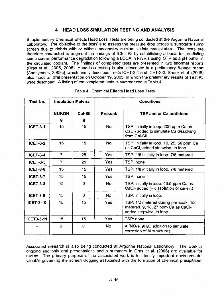
4 HEAD LOSS SIMULATION TESTING AND ANALYSIS
Supplementary Chemical Effects Head Loss Tests are being conducted at the Argonne NationalLaboratory. The objective of the tests is to assess the pressure drop across a surrogate sumpscreen due to debris with or without secondary calcium sulfate precipitates. The tests aretherefore conducted to augment the findings of ICET #3 by establishing a basis for predictingsump screen performance degradation following a LOCA in PWR s using STP as a pH buffer inthe circulated coolant. The findings of completed tests are presented in two informal reports(Oras et al., 2005, 2006). Head-loss testing is also described in a preliminary 8-page report(Anonymous, 2005c), which briefly describes Tests ICET-3-1 and ICET-3-2. Shack et al. (2005)also made an oral presentation on October 19, 2005, in which the preliminary results of Test #3were described. A listing of the completed tests is summarized in Table 4.
Table 4. Chemical Effects Head Loss Tests
Test No. Insulation Material Conditions
NUKON Cal-Sil Presoak TSP and or Ca additions
g g _ _ _ _ _ _ _ _ _ _
ICET-3-1 15 15 No TSP: initially in loop. 200 ppm Ca asCaCI 2 added to simulate Ca dissolvingfrom Cal-Sil.
JICET-3-2 15 15 No TSP: initially in loop. 10, 25, 50 ppm Caas CaCI 2 added stepwise, in loop.
ICET-3-4 7 25 Yes TSP: 118 initially in loop, 7/8 metered
ICET-3-5 7 25 Yes TSP: none
ICET-3-6 15 15 Yes TS.P: 1/8 initially in loop, 7/8 metered
ICET-3-7 15 15 Yes TSP: none
ICET-3-8 15 0 No TSP: initially in loop. 43.5 ppmn Ca asCaC12 added (= dissolution of cal-sil.)
ICET-3-9 15 0 No TSP: initially in loop.
ICET-3-10 15 15 Yes TSP: 1/2 metered during pre-soak; 1/2metered. 9, 18, 27 ppmn Ca as CaCI 2added stepwise, in loop.
ICET3-3-11 15 15 Yes TSP: none
-0 0 No Al(N03)3-9H2O addition to simulatecorrosion of Al structures.
Associated research is also being conducted at Argonne National Laboratory. The work isongoing and only oral presentations and a summary in Oras et al. (2006) are available forreview. The primary purpose of the associated work is to identify important environmentalvariable governing the screen clogging associated with the formation of chemical precipitates.
A-46

In particular, the investigators are concerned with the dissolution of cal-sil and formation ofcalcium phosphates over a range of simulated sump pool conditions.:
* To examine a broader range of conditions than examined in ICET
" To simulate chemical precipitate formation rather than conduct integrated tests
" Answer critical questions relating to the appropriateness of the produced precipitatesand the right amounts. Especially critical is the mass of chemical precipitate that canaccumulate per unit area of sump screen.
4.1 General Comments
The overall scope of the research under way at ANL is appropriate and reasonable. Ofparticular interest were slides # 6 and 8 supporting the oral presentation (Shack et al., 2005), inwhich were tabulated the parameters of relevance to post-LOCA cooling (See also, Andreychek,2005, Table 7). It is clear that the large variability in parameters between different plantspresents a challenge in designing a test program that adequately addresses this variability.Noteworthy is the observation that the ICET #1 achieved a circulating aluminum concentrationof 375 mg/L, which is for the most part well over an order of magnitude greater than expected inall plants but one containing a large quantity of structural aluminum. Addressing such variabilitycould tax the resources of the research team at ANL unless a suitable strategy is adopted for anefficient set of experiments. This strategy might be best implemented through a series ofbench-scale tests to evaluate critical processes and their controlling parameters, with suitabledata developed for incorporation in a computer simulator. Factorial design studies might alsobe conducted using appropriate test designs, particularly where parameter interactions are notunderstood.
Of the test work done so far, most has concentrated on the use of a TSP to buffer pH followinga LOCA in a PWR containing cal-sil insulation. The head loss test series ICET-3-1 - ICET-3-1 1have effectively demonstrated the potentially serious consequences associated with the use ofSTP as a pH buffer. The various conditions studied in this series represents the very worst-casescenario with the predictable formation of abundant flocculent calcium phosphate precipitates.The series appears to be conducted with a definite plan in mind. However, the large potentialrange and variability in parameters under study, and the limited number of tests possibleprevents formal study of the sensitivity of the various parameters to screen blockage underactual field conditions. This is especially relevant to the reported non-linear behavior of headloss in response to stepwise additions of CaC12, and to the fact that head losses becameexcessive before the full range of TSP additions could be metered in to the test loop.Furthermore, the discrepant results between tests that were essential duplicates, e.g., ICET-3-7and ICET-3-1 1, raises the question of reproducibility. Clearly, it would be both time consumingand costly to run the tests a sufficient number of times to obtain a quantitative measure ofreproducibility. It is not clear how the investigators plan to overcome these limitations. Althoughwork is progressing well, the reported results give the impression of an 'ad hoc rather thans ystematic approach at tacking the problems involved.
An independent test used added AI(NO 3)3 .9H20 to simulate the corrosion of Al structures atpost-LOCA elevated pH conditions (pH =10) where precipitates are relatively minor and aremost likely to form during progressive cooling. The test was conducted at a series of decliningtemperature steps, and therefore approximated the non-isothermal conditions prevailing duringpost-LOCA cooling. Unfortunately, the test was compromised by the "instantaneous" addition ofAl, which would not reflect the progressive corrosion of aluminum components following an
A-47

actual LOCA. It is not certain that precipitates, as observed in the course of ICET #1 and #5,would in combination with NUKON cause screen blockage. However, the test is suggestive thatan adverse condition could arise. Emphasis should therefore be placed on the defining therange of conditions where screen blockage is probable under ICET #1 and ICET #5 conditions.
Many of the tests could be simulated using chemical modeling software. Coordination of workby CNWRA and ANL would greatly assist in the interpretation of results, and facilitate modelrefinement.
4.2 Specific Comments
4.2.1 Head Loss Tests
4.2.1.1 Anonymous, 2005c
p. 1 Reference is made to the precipitate being Ca 3(P04)2, which "...was confirmed by lateranalysis." Since there are a variety of known Ca-phosphates, the identity should havebeen better characterized.
4.2.1.2 Oras et al. (2005)
p. 2 Reference is made to the hydrolysis of potassium and sodium released from the cal-sil.Potassium is a minor component of cal-sil, and sodium constitutes a smaller molarconcentration than Ca. It is not clear what the state of the sodium is in the cal-sil, i.e.,whether present as NaOH or NaHCQ3, or combined with Ca as a silicate. However,leaching tests by Park et al. (oral presentation, October 18-19, 2005) suggest that asignificant quantity of Na is released upon leaching of cal-sil. This appears to becorroborated by the ICET #4 test results, which show a progressive increase in Naconcentration with time during exposure to cal-sil. In any case, the Ca probablycontributes as much to raising the pH as the Na.
It is also stated that cal-sil is "...mostly CaSiO 3..." In fact, it appears to consist primarilyof tobermorite and minor calcite. See comments .to p. 82 of the ICET #3 report.
4.2.1.3 Oras et al. (2006).
.Figures Some of the figures are difficult to follow. Labels describing the test conditions can beconfused with the legend, e.g., see Figure 4, or appear to be labels describing someaspect of a graph, e.g., Figure 2. In one case, a label has no explanation in theassociated text, e.g., the label "Add 1/2 NUKON/CalSil slurry" in Figure 2. The onsetof physical screen clogging by debris is claimed on p. 8 to occur "within the first 6minutes (or after approximately one test loop recirculation)", but elsewhere, it isclaimed that one pass round the loop is =4 minutes (p. 13). However, clogging isshown to occur within 2 minutes in Figure 18. It would help if test conditions wereboxed on the graphs to avoid confusion with labels. Also, it would help if additionalinformation were added to the graphs, where appropriate, such as the timing of STPadditions.
p. 3 Reference is made to cal-sil dissolution being limited by the solubility of calciumsilicate (CaSiO3). See comment regarding p. 2 of Oras et al. (2005). Any sodiumsilicate that might have been used in the manufacture of cal-sil has probably been
A-48
converted to calcium carbonate and amorphous silica by the time it was used for thehead loss loop tests.
p. 5 in Table 1 it is stated that any remaining fraction of TSP was metered in during a 30-60minute period after the debris was added to the -loop, but it is not clear when thatperiod started. Thus, for ICET-3-6, it looks as if the balance of the TSP was meteredin between 30 and 60 minutes after the start of the test. But for the ICET-3-10procedure, it merely states that the remaining TSP was metered in "...after introductionof the debris".
p. 18 1st par. It seems that a direct graphical comparison between ICET-3-6 and ICET-3-10would be better than those with ICET-3-11 in Figures 17a and 17b.
p.18 2 nd par. The strongly non-linear relationship observed due to stepwise additions ofCaC12 in ICET-3-9 suggests a relatively high degree of sensitivity to screen cloggingdue to small increases in Ca once a critical calcium phosphate concentration isreached. Several factors may be involved; the degree of supersaturation with respectto calcium phosphate before nucleation is induced, the relative growth rate of calciumphosphate particles, the Ca2+ and P043-saturation concentration with respect tocalcium phosphate, the extent of Ca borate complexing, and the conditions needed toinduce coagulation. These factors suggest that the test may not be reproducible,unless great care is taken to control all parameters. Because ICET-3-9 has unearthedthis issue, which could be very important in predicting the behavior of screen cloggingin a PWR, further testing and characterization work may be needed.
p. 19 It is pointed out that the effect of cal-sil loading, even without the effect of calciumphosphate precipitates is to cause head loss to increase "...very rapidly to a highlevel". Yet this head loss is only 40% of that due to calcium phosphate precipitation.
p. 23 Hydroxyapatite is highly unlikely to form, as noted elsewhere, when discussing thework of McMurry et al. (2006). Indeed, these authors indirectly demonstrate thathydroxy apatite could not form without seriously depressing the pH of the solution, aphenomenon that is not observed in ICET #3.
Table 2 The experiments conducted respectively at 1.5 gIL and 0.5 gIL cal-sil are not identified.
p. 24 The rate of cal-sil dissolution is discussed, and the conclusion is made that theexperimental work being reported supports an earlier assumption that the cal-sildissolution rate is not too strongly dependent on the [Ca] concentration [in solution].How do these findings compare with the cal-sil dissolution studies reported byMcmurry et al. (2006) in their Appendix A?
p. 25 The observation that some of the tests could not be completed as planned, because ofexcessive head losses, raises the questions as to what should be done next. It istempting to fiddle with the test parameters so that quantifiable results can be obtainedwithin the range where head losses are less than 100 %, i.e. when substantiallycomplete blockage of the screen has occurred under conditions comparable to thatwould exist in a PWR. However, how would such results be used to modify existingplant design, or how does the resulting information bear on modified sump screenchanges that have already been implemented at operating PWRs?. Will any additional
A-49
changes be required? How will this be demonstrated using the results of current andongoing testing?
4.2.2 Supplementary Studies Characterizing Dissolution of Debris and Precipitation:Oral Presentations, October 18, 2005
4.2.2.1 Park et al. (2005)
This presentation includes some experimental results regarding the dissolution of cal-sil inborated water at pH = 4, in borated water adjusted with NaOH to pH = 7.14, and in watercontaining dissolved STP. Information was also provided on a simulated short-term test of theICET #1 aluminum chemistry, designed to mimic the conditions involving precipitation oncooling. This work is interesting and should be pursued with the. goal of generatingtemperature dependent kinetic data on cal-sil dissolution, and aluminum hydroxide nucleationand precipitation from pH = 10 borate solutions.
4.2.2.2 Klasky (2005)
In this presentation, the major observations of ICET #1 were summarized, and a number ofissues identified for more detailed exploration. In general, the reviewer concurs with theobjectives, the issues raised, the approach and the methodology. A commentary followsregarding specific issues.
Particulate Nature of Precipitates. Slides 6 and 7, representing TEM images of 15-day a nd 30-day high volume filtrates indicate that the material is made up of clusters of sub-equant particles(See comments to p. 50 of ICET #1). It seems likely that the particles, once nucleated from asupersaturated solution, were inhibited from further growth by the adsorption of boron (asB(OH)3 or B(OH)4-) on the surface. Sorption of B on amorphous aluminum oxides approachesa maximum at pH = 8.5 - 9.0, but falls off steeply above pH = 9, so that the amount adsorbedat pH = 10, is less than 50% of that at maximum adsorption at pH -8.5. (Goldberg et al., 2001).In another paper, Goldberg et al. (2004) have successfully modeled B adsorption on soils usinga constant capacitance model:
SOH + B(OH) 3(aq) = SH3B30 4 + H
Thus, B(OH)3 adsorption would be favored with increasing p H until B(OH) 3(aq) itself dissociatesin solution at pH =8.6. At still higher pH values, the B(OH)4 would tend to be repelled from thehydroxylated surface, thus causing borate adsorption to decline. The solid state 1183 NMRspectrum of the ICET #1 precipitate (Slide 20) indicates that B is present in both tetragonal andtrigonal coordination, raising the question whether B is adsorbed in more than one way on theprecipitate.
B(OH) 3(aq) adsorption could not only stabilize the AI(OH) 3 particles, but also inhibit Ostwaldripening. In other words, a suspension of borate-coated particles is thermodynamicallymetastable. However, it is possible that certain cluster configurations, consisting of 6 - 20particles, may be slightly more stable than the individual particles, and that particle adhesioncan overcome the repulsive effects of the adsorbed B(OH)3. Thus, the multi-modal particle sizedistribution shown in slides 25 and 26, may reflect the stable formation of such multi-particleassemblages or clusters. An extensive literature exists on the thermodynamic stability ofclusters, e.g., Sciortino et al (2004), which might be relevant to the problem at hand It is
A-50

suspected, however, that adhesion between the particles is generally weak in the system underconsideration, and that turbulence would limit aggregation to form a gel.
The small size of the discrete particles (- 2-5 nm) approaches in size some of the largerpolynuclear Al complexes, which have been identified in solution, and have been reviewed byCasey et al. (2001),. The fact that most of the Al present in the precipitates is octahedrallycoordinated, with only a small proportion in tetrahedral coordination (see 27Al NMR, Slide 19) isconsistent with the coordination state of Al in the Keggin molecule, which has 12 Al inoctahedral coordination and one in tetrahedral coordination (Casey et al., loc. cit.)
The reviewer endorses additional bench-top solubility studies on the observed precipitates(Slides 35 and 36), and concurs in the use of the MINTEQ codes for evaluation of, andcomparison with the solubility products of known precipitates. However, the thermodynamicdata used in MINTEQ may be neither up to date, nor sufficiently comprehensive for the problemunder study. Therefore a literature study should complement the ongoing experimental studies,and the results of both be used to augment the thermodynamic database.
4.3 Head Loss Simulation Testing and Analysis: Questions and Answers
Answers are provided below to the questions posed to the Peer Review Group by NRC.
0. Is the accelerated head loss testing approach viable for evaluating the effects of multiplechemical environments quickly?
A. The general impression gained is that the current head loss testing facility isinsufficiently flexible for evaluation of multiple chemical' environments or replication oftests to establish reproducibility. A better approach would be to use replicate smallbench-scale facilities that could be run simultaneously, with stepped variations in criticalparameters, so that the sensitivity and magnitude of potentially adverse conditions couldbe rapidly mapped out as a function of these parameters. The rapid acquisition of'results would also facilitate focusing the experimental program on important issues asthey are recognized. Factorial design experiments might be considered if parameterinteractions are poorly understood and unpredictable. The current test loop should bereserved for confirmatory 'demonstration" tests, based on the results of small-scalescoping studies.
Q. What is the best method for incorporating time-dependent effects (e.g., material aging,evolving chemical environments) in simulation testing?
A. This is a very broad and non-specific question, without a simple answer. Clearly, withthe variability in individual PWR designs and differing operating histories, there is a needto concentrate on the most critical parameters and efficiently study their effects throughsmall-scale bench tests. Thus, for example, the impact of cal-sil carbonation duringaging could be investigated through field sampling from operating PWRs followed bymineralogical and bench-scale leaching studies. Once the degree of variability and itsimportance has been established, then small-scale loop and head-loss tests could beconducted on a suitable range of variably aged samples. Similarly, the effect oftemperature could also be studied through small bench-scale tests followed by limitedsmall-scale loop and head-loss tests. Only after the impact of all relevant parametershas been assessed, should confirmatory tests be conducted using the present facilities.Even confirmatory tests are limited in what they can accomplish. For example, it would
A-51
be difficult to conduct, or analyze the results of a non-isothermal test simulating post-LOCA cooling history.
A second approach is to develop a sufficiently powerful chemical modeling simulator thatthe consequences of material aging and evolving chemical environments can be studiedin simulation mode. Simulations would allow multiple complex non-isothermal cases tobe run that would be difficult, expensive, or impractical using current facilities For thisapproach to be successful requires active ongoing coordination between the modelinggroup at SW Research Institute and the experimental investigators at ANL and LANL onan experiment by experiment basis This is not happening at present.
Q. What metrics are most appropriate for evaluating the results of simulated chemicalproducts with those that formed during the ICET program?
A. By "metrics" the reviewer presumes that this is to mean measurement methods. By"simulated chemical products", it is assumed that the investigator is attempting tosimulate conditions in the laboratory that would permit the formation of similar oridentical products that formed during the ICETs, and that are also likely to form underactual conditions in a PWR. The purpose of such studies is to identify the processestaking place, quantify certain parameters under controlled conditions, and characterizethe chemical and physical properties of any precipitates that form. Such investigationsshould take advantage of all instrumental techniques that are currently available. Itappears that the scientific staff is already well versed as to what should be done. Thereviewer's primary concern is that there appears to be little if any attempt to coordinateexperimental studies with model developers. At present this is a serious limitation, as itleaves the investigator conducting bench-scale. tests without the needed focus, orincentive to tailor his work to the requirements of a model that encompasses the diverserange, of conditions expected in current operating plants.
Q. Are correlations available, or can they be developed, which can predict the associatedhead loss if important physical characteristics of a chemical by-product are known?
A. The reviewer has limited experience in this particular area, but is confident, that even ifcorrelations are currently unavailable, they could be developed, and could predict theassociated head loss if the physical properties of a given precipitate are known. Theremust be a huge literature concerning filtration technology that could be readily adaptedto the problem at hand. This should be initiated promptly. One could conceive of thedevelopment of a post-LOCA coolant circulator simulator, which would utilize as input,the precipitation conditions generated by a chemical simulator module alluded to in thereviewer's response to the preceding question. With such. an integrated simulator,critical screen blockage scenarios could be defined, and system modifications tested foreffectiveness.
A-52

5 REFERENCES
'Andreychek, T.S. "Test Plan: Characterization of Chemical and Corrosion Effects PotentiallyOccurring Inside A PWR Containment Following A LOCA." (Revision 13). Joint DocumentPrepared by Westinghouse Electric Company, Electric Power Research Institute and U.S.Nuclear Regulatory Commission, 48 pp. 2005.
Anonymous. "Integrated Chemical Effects Test Project Test #4 Day 30." Quick Look Report LosAlamos National Laboratory Report TR-T04-QLR, Revision 0. Los Alamos National Laboratory,Los Alamos, New Mexico. 12 pp., 2005a.
Anonymous. "Integrated Chemical Effects Test Project Test #5 Day 30." Quick Look Report LosAlamos National Laboratory Report TR-T04-QLR, Revision 0. Los Alamos National Laboratory,Los Alamos, New Mexico. 12 pp., 2005b.
Anonymous. "Chemical Effects/Head-Loss Testing." Quick Look Report, Scoping Tests 1 & 2,September 12, 2005. Informal Report, Argonne National Laboratory, 8 pp., 2005c.
Bethke, C. The Geochemist's Workbench&.http://www.cgeology.uiuc.edu/-bethke/hydro cjwb.htm 2005.
Bromley, L.A. "Approximate Individual Ion Values of ... in Extended Debye-Huckel Theory forUnivalent Aqueous Solutions at 298.15 K." Journal of Chemical Thermodynamics, Vol. 4, pp.669., 1972.
C asey, W.H., Phillips, B.L. and Furrer, G. "Aqueous Aluminum Polynuclear Complexes andNanoclusters: A Review." Chapter 5 in Nanoparticles and. The Environment, (J.F. Banfield andA. Navrotsky, Eds.) Reviews in Mineralogy and Geochemistry, Vol. 44, pp. 167-190.Mineralogical. Society of America, 2002.
Chen, J.J., Thomas, J.J., Taylor, H.F.W. and Jennings, H.M. "Solubility and Structure ofCalcium Silicate Hydrate." Cement and Concrete Research, Vol. 34, pp. 1499-1519, 2004.
Dallman, J., Garcia, J., Klasky, M., Letellier, B. and Howe, K. "Integrated Chemical Effects TestProject Test #1 Data Report." Los Alamos National Laboratory Report LA-UR-05-0124. LosAlamos National Laboratory, Los Alamos, New Mexico. 61 pp. plus Appendices., 2005a.
Dallman, J., Letellier, B., Garcia, J., Klasky, M., Roesch, W., Madrid, J., Howe, K. and Chen, D."Integrated Chemical Effects Test Project Test #2 Data Report." Los Alamos NationalLaboratory Report LA-UR-05-6146. Los Alamos National Laboratory, Los Alamos, New Mexico.71 pp. plus Appendices, 2005b.
Dallman, J., Letellier, B., Garcia, J., Madrid, J., Roesch, W., Chen, D., Howe, K., Archuleta, L.and Sciacca, F. "Integrated Chemical Effects Test Project: Test #3 Data Report." Los AlamosNational Laboratory Report LA-UR-05-6996. Los Alamos National Laboratory, Los Alamos,New Mexico. 93 pp. plus Appendices, 2005c.
Dallman, J., Letellier, B., Garcia, J., Madrid, J., Roesch, W., Chen, D., Howe, K., Archuleta, L.and Sciacca, F. "Integrated Chemical Effects Test Project: Test #4 Data Report." Los AlamosNational Laboratory Report LA-UR-05-8735. Los Alamos National Laboratory, Los Alamos,New Mexico. 103 pp. plus Appendices, 2005d.
A-53

Daliman, J., Letellier, B., Garcia, J., Madrid, J., Roesch, W., Chen, D., Howe, K., Archuleta, L.and Sciacca, F. "Integrated Chemical Effects Test Project: Test #5 Data Report." Los AlamosNational Laboratory Report LA-UR-05-9177. Los Alamos National Laboratory, Los Alamos,New Mexico. 88 pp. plus Appendices, 2006.
Ekberg, C. and Emren, A.T. "SENVAR: A Code for Handling Chemical Uncertainties InSolubility Calculations." Computers & Geosciences, Vol. 22, No. 8, pp. 867-875, 1996.
Ekberg, C., Borjesson, S., Emren, A.T. and Samuelsson, A. "MINVAR and UNCCON:Computer Programs for Uncertainty Analysis of Solubility Calculations in Geological Systems."Computers & Geosciences, Vol. 26, pp. 219-226, 2000.
Felmy, A.R., Girvin, D. and Jenne, E.A. "MINTEQ: A Computer Program for CalculatingAqueous Geochemical Equilibria." U.S. Environmental Protection Agency Report EPA-600/3-84-032, 1984.
Goldberg, S., Lebron, I., Suarez, D.L. and Hinedi, Z.R. "Surface Characterization of AmorphousAluminum Oxides." Soil Science Society of America Journal, Vol. 65, pp. 78-86, 2001.
Goldberg, S., Suarez, D.L., Basta, N.T. and Lesch, S.M. "Predicting Boron AdsorptionIsotherms by Midwestern Soils Using The Constant Capacitance Model." Soil Science Societyof America Journal, Vol. 68, pp. 795-801, 2004.
Helgeson, H. C., Delany, J. M., Nesbitt, H. W. and Bird, D. K. "Summary and Critique of TheThermodynamic Properties of Rock Forming Minerals." American Journal of Science, Vol. 278-A, 229 pp.' 1978
ler, R.K. The Chemistry of Silica. Wiley-lInterscience, John Wiley and Sons, New York, 461pp., 1979.
Jain, V., Yang, L. and Chiang, K. "Chemical Speciation, Using Thermodynamic Modeling,During A Representative Loss-of-Coolant Accident Event." Center for Nuclear Waste RegulatoryAnalyses Report (CWNRA 2004-07 (Revision 1). Center for Nuclear Waste RegulatoryAnalyses, San Antonio, Texas. 56 pp. plus Appendices, 2004.
Jain, V., He, X. and Pan, Y.-M. "Corrosion Rate Measurements and Chemical Speciation ofCorrosion Products Using Thermodynamic Modeling of Debris Components To Support GSI-191." U.S. Nuclear Regulatory Commission Report (NUREG/CR-6873. U.S. NuclearRegulatory Commission, Office of Nuclear Regulatory Research, Division of EngineeringTechnology, Washington, DC 20555-001. 30 pp. plus Appendices, 2005.
Jantzen, C.M. "Radioactive Waste-Portland Cement Systems 11: Leaching Characteristics."Journal of the American Ceramic Society, Vol. 67, No. 10, pp. 674-678, 1984.
Kieser, J. and Park, J.H. "Chemical Analysis of Sump Water in Pressurized Water Reactors."Abstract in Student Abstracts: Materials Sciences at ANL, 2005.
Klasky, M. "Chemical Effects: Status of Supplemental Testing and Analysis of ICET Results."Oral Presentation at Argonne National Laboratory, October 18-19, 2005.
A-54

Lawrence Livermore National Laboratory. "EQ316, Version 7.2b." Lawrence Livermore NationalLaboratory, Livermore, California, 1995.
Lasaga, A.C. Kinetic Theory in The Earth Sciences, Princeton University Press, Princeton, NewJersey, 811 pp., 1998.
Letellier, B. "Integrated, Chemical Effects Tests Design and Operations." Oral Presentation atArgonne National Laboratory, October 18-19, 2005.
Lyklema, J. Fundamentals of Interface and Colloid Science, Vol. 1: Fundamentals. AcademicPress, London, 1991.
Mcmurry, J., Jain, V., He, X., Pickett, D. and Pabalan, R. UGSI..191 PWR Sump ScreenBlockage Chemical Effects Tests-Thermodynamic Simulations." Final Report. Prepared by TheCenter for Nuclear Waste Regulatory Analyses, San Antonio, Texas. U.S. Nuclear RegulatoryCommission Report (NUREG/CR-6912), 104 pp. plus Appendices. U.S. Nuclear RegulatoryCommission, Office of Nuclear Regulatory Research, Washington, DC 20555-001, 2006.
Merlino, S., Bonaccorsi, E. and Kampf, A.R. "Tobermorite 14 A: Crystal Structure and 00Character." In Applied Mineralogy (Rammlmair Et Al., Eds), Balkema, Rotterdam, pp. 859-861,2000.
Najm, H.N., Reagan, M.T., Knio, O.M., Ghanem, R.G. and Le Maitre, O.P. "UncertaintyQuantification in Reacting Flow Modeling." Sandia Report SAND2003-8598, 42 pp. SandiaNational Laboratories, Albuquerque, New Mexico, 87185, 2003.
OLI Systems Inc. "Stream Analyzer"'© Version 1.2." OLI Systems Inc., Morris Plains, NewJersey, 2002a.
OLI Systems Inc. "Environmental Simulation Program`ý@ Version 6.6." OLI Systems Inc., MorrisPlains, New Jersey, 2002b.
Oras, J., Park, J.H., Kasza, K., Natesan, K. and Shack, W.J. "Chemical Effects/Head-LossTesting." Quick Look Report, Scoping Tests 1 & 2, September 16, 2005. Informal Report,Argonne National Laboratory, 10 pp., 2005.
Oras, J., Park, J.H., Kasza, K., Natesan, K. and Shack, W.J. Chemical Effects/Head-LossTesting. Quick Look Report, Tests ICET-3-4 To 11. Informal Report, Argonne NationalLaboratory, 27 pp., January 20, 2006.
Park, J.-H., Natesan, K., and Shack, W. Chemical Effects On The Sump Water. OralPresentation at Argonne National Laboratory, October 18-19, 2005.
Parks, G.A. "Surface Energy and Adsorption at Mineral-Water Interfaces: An Introduction."Chapter 4 in Mineral-Water Interface Geochemistry (M.F. Hochella, Jr. and A.F. White, Eds),Reviews in Mineralogy, Vol. 23, pp. 133-175, Mineralogical Society of America, 1990.
Parkhurst, D.L. and Appelo, C.A.J "User's Guide To PHREEQC (Version 2)--A ComputerProgram for Speciation, Batch-Reaction, One-Dimensional Transport, and Inverse GeochemnicalCalculations." 2005.Hftp://Wwwbrr.Cr.Usgs.Gov/Projects/GWC_Coupled/Phreeqc/Html/Final. Html
A-55
Parrot, L.J. and Killoh, D.C. "Carbonation in 36 Year Old, In-Situ Concrete." Cement andConcrete Research, Vol. 19, pp. 649-655, 1989.
Pitzer, K.S. Activity Coefficients in Electrolyte Solutions, (K.S. Pitzer, Ed.) 2 nd Edition, CRCPress, Chemical Rubber Company, Boston, Massachusetts pp. 75-153, 1991.
Reagan, M.T., Najm, H.N., Debusschere, B.J., Le Maitre, O.P., Knio, O.M. and Ghanem, R.G."Spectral Stochastic Uncertainty Quantification in Chemical Systems." Combustion Theory andModelling, Vol. 8, pp. 607-632, 2004.
Rockware, Inc. "Geochemist's Workbench, Version 5.0." Rockware, Inc., Golden, Colorado,2004.
Scherer, G.W. "Structure and Properties of Gels." Cement and Concrete Research, Vol. 29, pp.1149-1157, 1999.
Sciortino, F., Mossa, S., Zaccarelli, E. and Tartaglia, P. "Equilibrium Cluster Phases and Low-Density Arrested Disordered States: The Role of Short-Range Attraction and Long-RangeRepulsion." Physical Review Letters, Vol. 93, No. 5, #1 055701, pp. 1-4, 2004.
Shack, W.J., Oras. J., Park, J.H., Kasza, K. and Natesan, K. "Chemical Effects Head LossTests." Oral Presentation at Argonne National Laboratory, October 18-19, 2005.
Singer, P.C. and Stumm, W. "Oxygenation of Ferrous Iron: The Rate Determining Step In TheFormation of Acid Mine Drainage." Federal Water Pollution Control Administration ResearchSeries Report. NTIS Report No. PB-189-233, 1968.
Singer, P.C. and Stumm, W. "Acid Mine Drainage: The Rate Determining Step." Science, Vol.167, pp. 1121-1123, 1970.
Slegers, P.A. and Rouxhet, P.G. "Carbonation of The Hydration Products of TricalciumSilicate." Cement and Concrete Research, Vol. 6, pp.381-388, 1976.
Steefel, C.l. and Van Cappellen, P. A New Kinetic Approach To Modeling Water-RockInteraction: The Role of Nucleation, Precursors, and Ostwald Ripening. Geochimica etCosmochimica, Acta, 54, 2657-2677, 1990.
Stumm W. Chemistry of The Solid-Water Interface. 1992.
Taylor, H.F.W. Cement Chemistry, 2 nd Edition. Thomas Telford Publishing, Thomas TeifordServices Ltd., London, England, 1997.
U.S. Geological Survey. "PHREEQC, Version 2.8." U.S. Geological Survey, Reston, Virginia,2003.
Van Cappellen, P. "The Formation of Marine Apatite: A Kinetic Study." Ph.D. Dissertation, YaleUniversity, 240 pp., 1991.
Van Kemenade, M.J.M. and De Bruyn, P.L. A Kinetic Study of Precipitation FromSupersaturated Calcium Phosphate Solutions. Journal of Colloid and Interface Science, Vol.118 No. 2, pp. 564-585., 1987.
A-56
Van Straten, H.A. and De Bruyn, P.L. "Precipitation From Supersaturated Aluminate Solutions.11. Role of Temperature." Journal of Colloid and Interface Science, Vol. 102 No. 1, pp. 260-277,1984.
Weres. 0., Yee, A. and Tsao, L. "Kinetics of Silica Polymerization." Lawrence BerkeleyNational Laboratory Report (LBL-7033. Lawrence Berkeley National Laboratory, Berkeley,California, 256 pp., 1980.
Wolery, T. J. "EQ3NR, A Computer Program for Geochemical Aqueous Speciation-SolubilityCalculations: Theoretical Manual, User's Guide, and Related Documentation." URCL-MA-110662 Pt 111, 246 pp.' 1992.
Wolery, T. J. and Daveler, S.A. "EQ6, A Computer Program for Reaction Path Modeling ofAqueous Geochemnical Systems:: Theoretical Manual, User's Guide, and RelatedDocumentation (Version 7)." URCL-MA-1 10662 Pt IV, 338 pp., 1992.
Xu, T., Sonnenthal, E., Spycher, N. and Pruess, K. "TOUGHREACT User's Guide: A SimulationProgram for Non-isothermal Multiphase Reactive Transport in Variably Saturated PorousMedia." Lawrence Berkeley National Laboratory Report (LBL-55460. Lawrence BerkeleyNational Laboratory, Berkeley, California, 192 pp., 2004.
A-5 7

Appendix B
Final Assessment Report
Chemical Effects in PWR Sump Pool EnvironmentsPeer Review
Wu Chen
Abstract
This report evaluated the results of the project work for investigating the chemical effecton the sump screen head loss at the post LOCA sump environment. The evaluation wasdone from the view point of filtration. Once particles are formed in the post LOCA sumpenvironment, the key information to look at are if these particles can reach the sumpscreen and how many (represented by the total suspended solid value) and what kind ofparticle (characterized by particle size and morphology). Based on the ICET runs byLANL and loop tests by ANL, there is a high possibility that the sump screen willencounter head loss problems during the post LOCA recirculation.
Executive Summary
This report is the results of the Chemical Effect Peer Review. The project was toinvestigate the possible scenarios of chemical effect in the sump during a post LOCAsituation. It was a concern that the particles generated in the post LOCA sumpenvironment might cause the increase of head loss at the sump screen and reduce or stopthe flow of the recirculating cooling water.
The investigation was conducted by Los Alamos National Laboratory (LANL) andArgonne National Laboratory (ANL) and the results were discussed in two peer reviewmeetings and team communications.
In this report, the assessment of the results from the project work was evaluated from thefiltration perspective as the head loss in the sump screen is a filtration process.
Once particles are formed in the post LOCA sump environment, the key information tolook at is(1) Will these particles reach the pump. screen?(2) How many (represented by the total suspended solid value)?(3) What kind of particle (characterized by particle size and morphology)?
Based on the ICET runs by LANL and loop tests by ANL, it is a highly possible that thesump screen will encounter head loss during the post LOCA recirculation.
Final Report-WCB- B-1
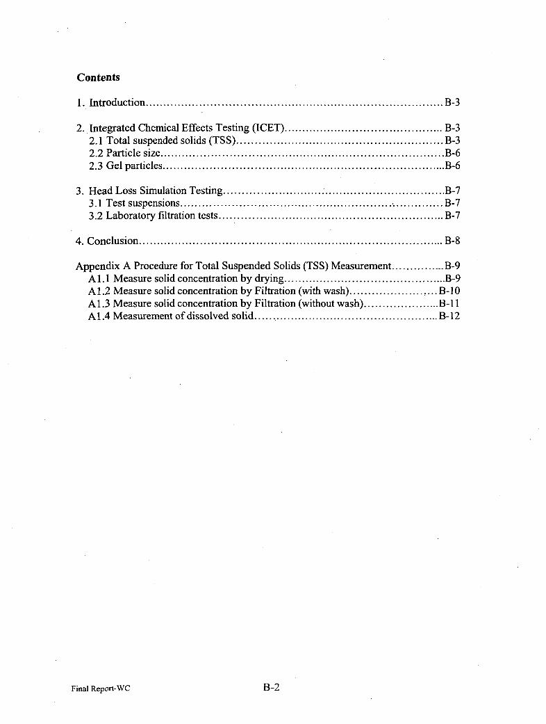
Contents
1. Introduction ................................................................. B-3
2. Integrated Chemical Effects Testing (ICET) ................................... B-32.1 Total suspended solids (TSS) ............................................. B-32.2 Particle size.............................................................. B-62.3 Gel particles .............................................................. B-6
3. Head Loss Simulation Testing ................................................. B-73.1 Test suspensions .......................................................... B-73.2 Laboratory filtration tests ................................................. B-7
4. Conclusion .................................................................. B-8
Appendix A Procedure for Total Suspended Solids (TSS) Measurement............ B-9Al.1I Measure solid concentration by drying ................................... B-9A 1.2 Measure solid concentration by Filtration (with wash) ................... B-10Al. 3 Measure solid concentration by Filtration (without wash) ................. B-1IlA 1.4 Measurement of dissolved solid......................................... B-12
Final Report-WC -B-2

1. Introduction
This report is the results of the Chemical Effect Peer Review. The project was toinvestigate the possible scenarios of chemical effect in the sump pool during a postLOCA situation. There was a concern that the particles generated in the post LOCA sumpenvironment might cause the increase of head loss at the sump screen and reduce or stopthe flow of the circulating cooling water.
The investigation was conducted by LANL (Los Alamos National Laboratory) and ANL(Argonne National Laboratory) and the results were discussed in two peer reviewmeetings and team communications.
In this report, the assessment of the results from the project work was focused o n the
filtration aspect as the head loss in the sump screen is a filtration process.
2. Integrated Chemical Effects Testing (ICET)
This work was conducted by LANL. Excellent work has been done to investigate thepotential chemical effects in the sump pool under the post-LOCA environment. Theexperimental parameters were derived from surveys of operation nuclear power plantsand should be representative. The type and quantity of coupon material, degree ofsubmergence were thoroughly considered. Advanced tools and analytical methods wereused to analyze the chemical species generated under each condition.
The Phenomenon Identification and Ranking Table (PIRT) process conducted at the endof the 2nd review meeting and the teleconference afterward were very useful inidentifying additional potential post-LOCA scenarios which can be investigated in futurework. Perhaps PIRT process can be conducted at the beginning or the early phase of theproject to guide the research plan.
The head loss process in the sump screen during post-LOCA is the same as the pressuredrop development across the filter medium in any filtration process. The pressure drop ina filtration process can be caused by either a cake build up or the clogging of the filtermedium. In either case, the rate of pressure drop increase can be affected by particleconcentration, particle size, particle shape, particle charge, particle-particle interactions(such as coagulation- and flocculation), liquid viscosity, and chemical reaction around thefilter medium. Among these factors, particle concentration and particle size have themost profound impact on the head loss of the post-LOCA sump screen.
2.1 Total suspended solids (TSS)
Total suspended solid (TSS) is the key parameter to quantify the amount of particlesgenerated in different sump environments. It is also important to monitor TSS as afunction of time to determine if the rates of chemical effects change.
Final Report-WCB3 B-3
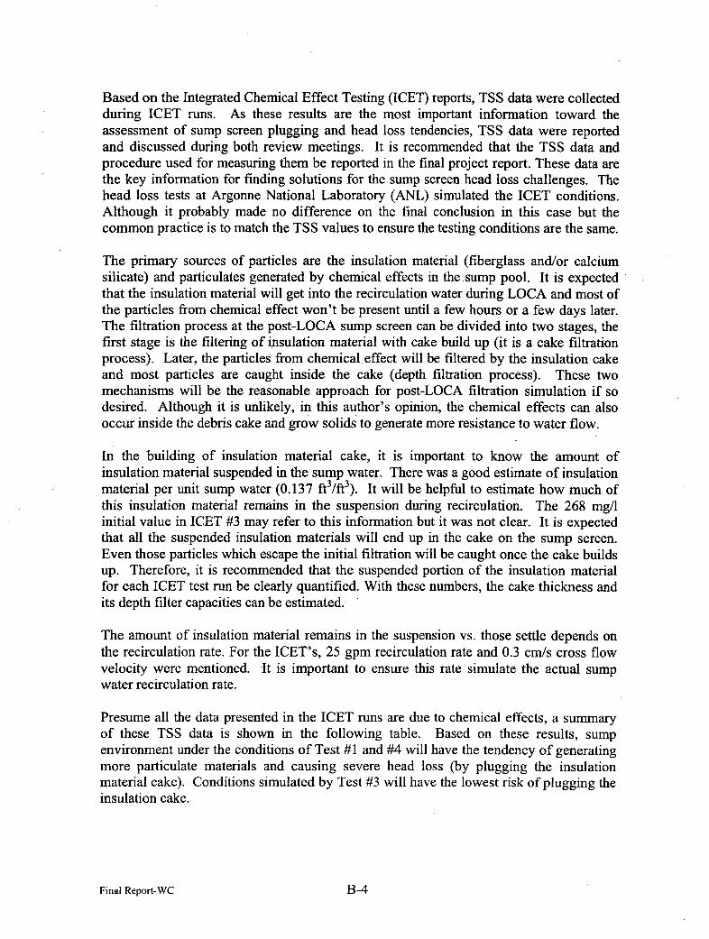
Based on the Integrated Chemical Effect Testing (ICET) reports, TSS data were collectedduring ICET runs. As these results are the most important information toward theassessment of sump screen plugging and head loss tendencies, TSS data were reportedand discussed during both review meetings. It is recommended that the TSS data andprocedure used for measuring them be reported in the final project report. These data arethe key information for finding solutions for the sump screen head loss challenges. Thehead loss tests at Argonne National Laboratory (ANL) simulated the ICET conditions.Although it probably made no difference on the final conclusion in this case but thecommon practice is to match the TSS values to ensure the testing conditions are the same.
The primary sources of particles are the insulation material (fiberglass and/or calciumsilicate) and particulates generated by chemical effects in the sump pool. It is expectedthat the insulation material will get into the recirculation water during LOCA and most ofthe particles from chemical effect won't be present until a few hours or a few days later.The filtration process at the post-LOCA sump screen can be divided into two stages, thefirst stage is the filtering of insulation material with cake build up (it is a cake filtrationprocess). Later, the particles from chemical, effect will be filtered by the insulation cakeand most particles are caught inside the cake (depth filtration process). These twomechanisms will be the reasonable approach for post-LOCA filtration simulation if sodesired. Although it is unlikely, in this author's opinion, the chemical effects can alsooccur inside the debris cake and grow solids to generate more resistance to water flow.
In the building of insulation material cake, it is important to know the amount ofinsulation material suspended in the sump water. There was a good estimate of insulationmaterial per unit sump water (0.137 ftl/ft3). It will be helpful to estimate how much ofthis insulation material remains in the suspension during recirculation. The 268 mg/linitial value in ICET #3 may refer to this information but it was not clear. It is expectedthat all the suspended insulation materials will end up in the cake on the sump screen.Even those particles which escape the initial filtration will be caught once the cake buildsup. Therefore, it is recommended that the suspended portion of the insulation materialfor each ICET test run be clearly quantified. With these numbers, the cake thickness andits depth filter capacities can be estimated.
The amount of insulation material remains in the suspension vs. those settle depends onthe recirculation rate. For the ICET's, 25 gpm recirculation rate and 0.3 cm/s cross flowvelocity were mentioned. It is important to ensure this rate simulate the actual sumpwater recirculation rate.
Presume all the data presented in the ICET runs are due to chemical effects, a summaryof these TSS data is shown in the following table. Based on these results, sumpenvironment under the conditions of Test #1 and #4 will have the tendency of generatingmore particulate materials and causing severe head loss (by plugging the insulationmaterial cake). Conditions simulated by Test #3 will have the lowest risk of plugging theinsulation cake.
Final Report-WCB- B-4
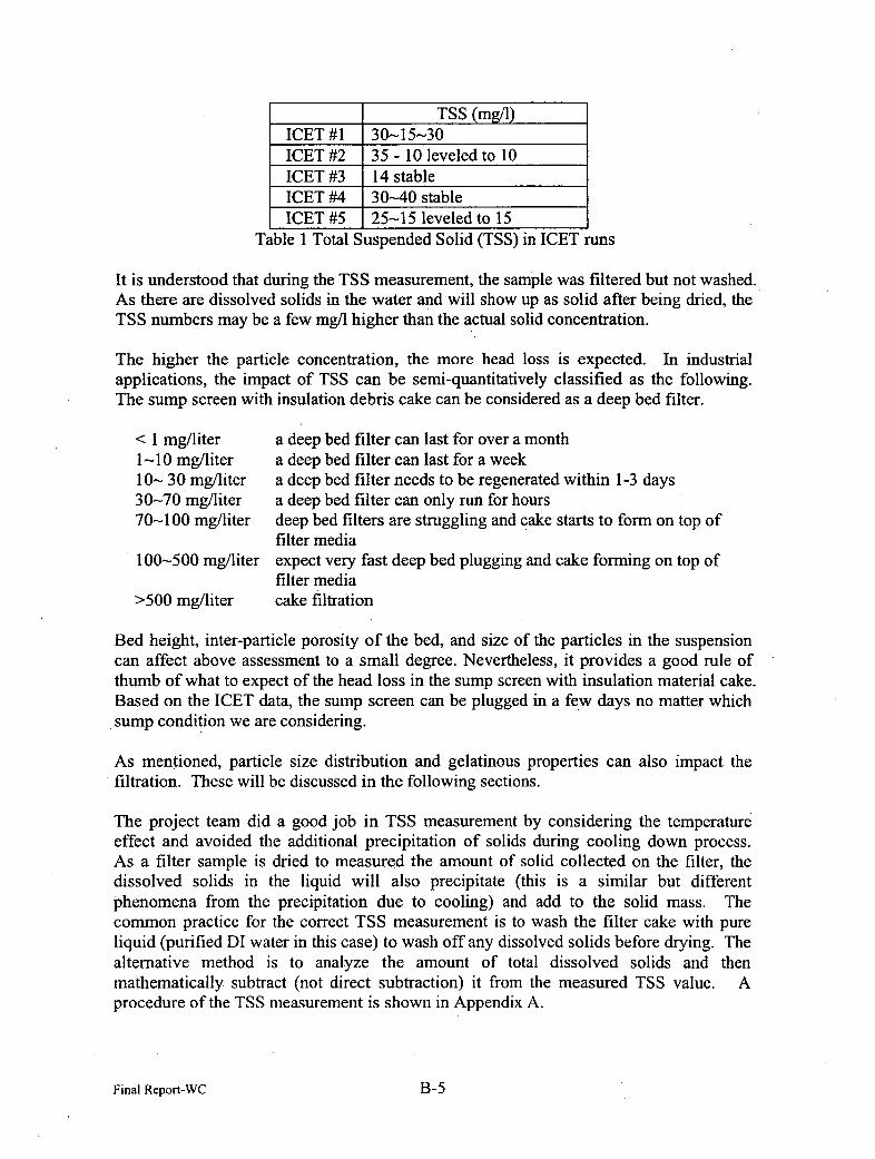
TSS (mg/i)ICET #1 30-15--30ICET #2 35 - 10 leveled to 10ICET #3 14 stableICET #4 30~-40 stableICET #5 25-15 leveled to 15
Table 1 Total Suspended Solid (TSS) in ICET runs
It is understood that during the TSS measurement, the sample was filtered but not was hed.As there are dissolved solids in the water and will show up as solid after being dried, theTSS numbers may be a few mg/i higher than the actual solid concentration.
The higher the particle concentration, the more head loss is expected. In industrialapplications, the impact of TSS can be semi-quantitatively classified as the following.The sump screen with insulation debris cake can be considered as a deep bed filter.
<1I mg/liter a deep bed filter can last for over a month1-10 mg/liter a deep bed filter can last for a week10~- 30 mg/liter a deep bed filter needs to be regenerated within 1-3 days30-70 mg/liter a deep bed filter can only run for hours70-100 mg/liter deep bed filters are struggling and cake starts to form on top of
filter media100-500 mg/liter expect very fast deep bed plugging and cake forming on top of
filter media>500 mg/liter cake filtration
Bed height, inter-particle porosity of the bed, and size of the particles in the suspensioncan affect above assessment to a small degree. Nevertheless, it provides a good rule ofthumb of what to expect of the head loss in the sump screen with insulation material cake.Based on the ICET data, the sump screen can be plugged in a few days no matter whichsump condition we are considering.
As mentioned, particle size distribution and gelatinous properties can also impact thefiltration. These will be discussed in the following sections.
The project team did a good job in TSS measurement by considering the temperatureeffect and avoided the additional precipitation of solids during cooling down process.As a filter sample is dried to measured the amount of solid collected on the filter, thedissolved solids in the liquid will also precipitate (this is a similar but differentphenomena from the precipitation due to cooling) and add to the solid mass. Thecommon practice for the correct TSS measurement is to wash the filter cake with pureliquid (purified DI water in this case) to wash off any dissolved solids before drying. Thealternative method is to analyze the amount of total dissolved solids and thenmathematically subtract (not direct subtraction) it from the measured TSS value. Aprocedure of the TSS measurement is shown in Appendix A.
Final Report-WCB- B-5
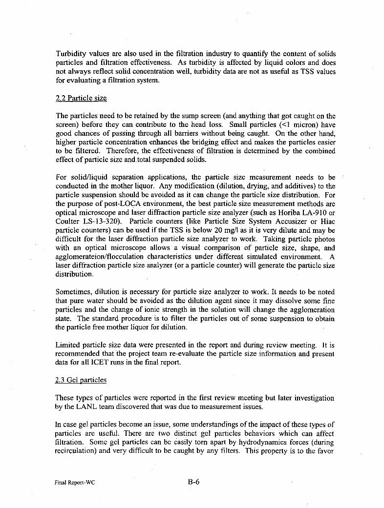
Turbidity values are also used in the filtration industry to quantify the content of solidsparticles and filtration effectiveness. As turbidity is affected by liquid colors and doesnot always reflect solid concentration well, turbidity data are not as useful as TSS valuesfor evaluating a filtration system.
2.2 Particle size
The particles need to be retained by the sump screen (and anything that got caught on thescreen) before they can contribute to the head loss. Small particles (<I micron) havegood chances of passing through all barriers without being caught. On-the other hand,higher particle concentration enhances the bridging effect and makes the particles easierto be filtered. Therefore, the effectiveness of filtration is determined by the combinedeffect of particle size and.total suspended solids.
For solid/liquid separation applications, the particle size measurement needs to beconducted in the mother liquor. Any modification (dilution, drying, and additives) to theparticle suspension should be avoided as it can change the particle size distribution. Forthe purpose of post-LOCA environment, the best particle size measurement methods areoptical microscope and laser diffraction particle size analyzer (such as Horiba LA-91 10 orCoulter LS-13-320). Particle counters (like Particle Size System Accusizer or Hiacparticle counters) can be used if the TSS is below 20 mg/l as it is very dilute and may bedifficult for the laser diffraction particle size analyzer to work. Taking particle photoswith an optical microscope allows a visual comparison of particle size, shape, andagglomerateionlflocculation characteristics under different simulated environment. Alaser diffraction particle size analyzer (or a particle counter) will generate the particle sizedistribution.
Sometimes, dilution is necessary for particle size analyzer to work. It needs to be notedthat pure water should be avoided as the dilution agent smice it may dissolve some fineparticles and the change of ionic strength in the solution will change the agglomerationstate. The standard procedure is to filter the particles out of some suspension to obtainthe particle free mother liquor for dilution.
Limited particle size data were presented in the report and during review meeting. It isrecommended that the project team re-evaluate the particle size information and presentdata for all ICET runs in the final report.
2.3 Gel particles
These types of particles were reported in the first review meeting but later investigationby the LANL team discovered that was due to measurement issues.
In case gel particles become an issue, some understandings of the impact of these types ofparticles are useful. There are two distinct gel particles behaviors which can affectfiltration. Some gel particles can be easily torn apart by hydrodynamics forces (duringrecirculation) and very difficult to be caught by any filters. This property is to the favor
Final Report-WCB- B-6

of the sump screen and will not cause head loss problems. Another type of gel particlescan be sticky and easily plug up filter media even at very low TSS. If this type of gel ispresent in the post-LOCA sump pool, fast head loss can be encountered in the sumpscreen.
The only method to understand the impact of these gelatinous coating materials to thesump screen filter is by experiments. A cake of insulation material can be formed basedon the estimated amount (as discussed earlier) and a sample suspension containing the gelmaterial be poured through this cake. By measuring the presence of gel in the filtrate andthe head loss of the filter, a qualitative to semi-quantitative measurement of the effect ofthis kind of gel to the sump screen can be evaluated.
3. Head Loss Simulation Testing
This work was conducted by ANL. A very good test ioop was constructed at ANL andsuitable for the intended head loss test. The challenges seemed to be on the confirmationof the representative type and amount of material used for testing. The test suspensionshould match the environment in the ICET runs and the actual post-LOCA sump pool.
3.1 Test suspensions
It is important to match the particle size and concentration from the ICET findings. It isdifficult to generate exactly the same materials given the time and scale of tests. As longas the particle size and concentration are matched, the head loss experiment will generateuseful information about the screen plugging tendencies.
Head loss test #1 mimics the condition of ICET #3. ICET#3 reported a stable TSS of 14mg/l. The "cloud" and the fast pressure drop increase encountered in head loss test #1right after CaCl2 was added indicted the TSS must be higher than 14 mg/l and could be in200 mg/i range. It would be useful if the TSS data were collected during the head losstest to document the test conditions.
There are more opportunities for solids to settle in the ICET tank as the cross flow rate isnot uniform throughout the whole system and some stagnant portion cannot be avoided.The flow ioop in ANL is easier for maintaining a uniform cross flow velocity so fewerparticles can settle and most of them will be caught by the filter.
3.2 Laboratory filtration tests
It is time and efforts consuming to run the big test flow loop. Valuable information canbe obtained by running simple laboratory filtration test or a smaller flow loop. Oneexample is shown in Figure 1.
As the first step in a post LOCA sump recirculation is the build up of a cake by theinsulation material, it is important to understand the filtration behavior of the insulationmaterial. Tests can be conducted with different amount of insulation material to build a
Final Report-WC 1-B-7
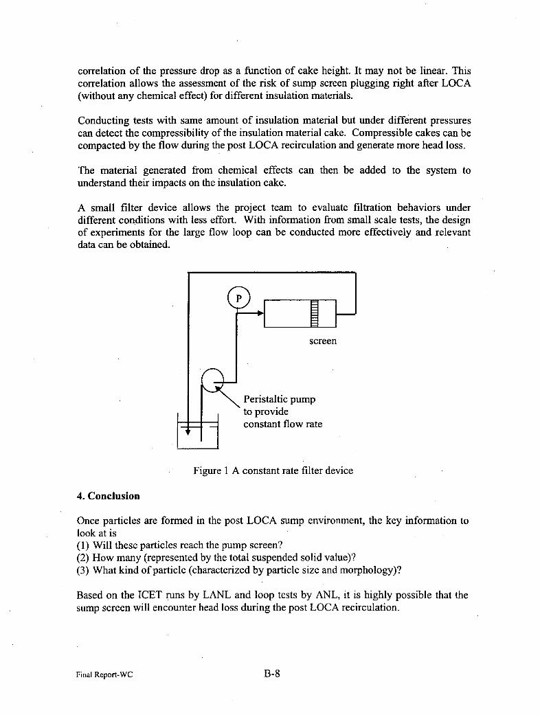
correlation of the pressure drop as a function of cake height. It may not be linear. Thiscorrelation allows the assessment of the risk of sump screen plugging right after LOCA(without any chemical effect) for different insulation materials.
Conducting tests with same amount of insulation material but under diffierent pressurescan detect the compressibility of the insulation material cake. Compressible cakes can becompacted by the flow during the post LOCA recirculation and generate more head loss.
The material generated from chemical effects can then be added to the system tounderstand their impacts on the insulation cake.
A small filter device allows the project team to evaluate filtration behaviors underdifferent conditions with less effort. With information from small scale tests, the designof experiments for the large flow loop can be conducted more effectively and relevantdata can be obtained.
P
screen
Peristaltic pumpto provideconstant flow rate
Figure I A constant rate filter device
4. Conclusion
Once particles are formed in the post LOCA sump environment, the key information tolook at is(1) Will these particles reach the pump screen?(2) How many (represented by the total suspended solid value)?(3) What kind of particle (characterized by particle size and morphology)?
Based on the ICET runs by LANL and loop tests by ANL, it is highly possible that thesump screen will encounter head loss during the post LOCA recirculation.
Final Report-WCB8 B-8
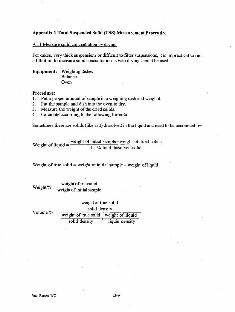
Appendix 1 Total Suspended Solid (TSS) Measurement Proceudre
Al 1. Measure solid concentration by drying
For cakes, very thick suspensions or difficult to filter suspensions, it is impractical to runa filtration to measure solid concentration. Oven drying should be used.
Equipment: Weighing dishesBalanceOven
Procedure:1. Put a proper amount of sample in a weighing dish and weigh it.2. Put the sample and dish into the oven to dry.3. Measure the weight of the dried solids.4. Calculate according to the following formula.
.Sometimes there are solids (like salt) dissolved in the liquid and need to be accounted for.
Weight of liquid =weight of initial sample-weight of dried solids
1 - % total dissolved solid
Weight of true solid = weight of initial sample - weight of liquid
Weight% weight of true solidweight of initial sample
Volume %
weight of true solidsolid density
weight of true solid weight of liquidsolid density- liquid density
Final Report-WCB- B-9
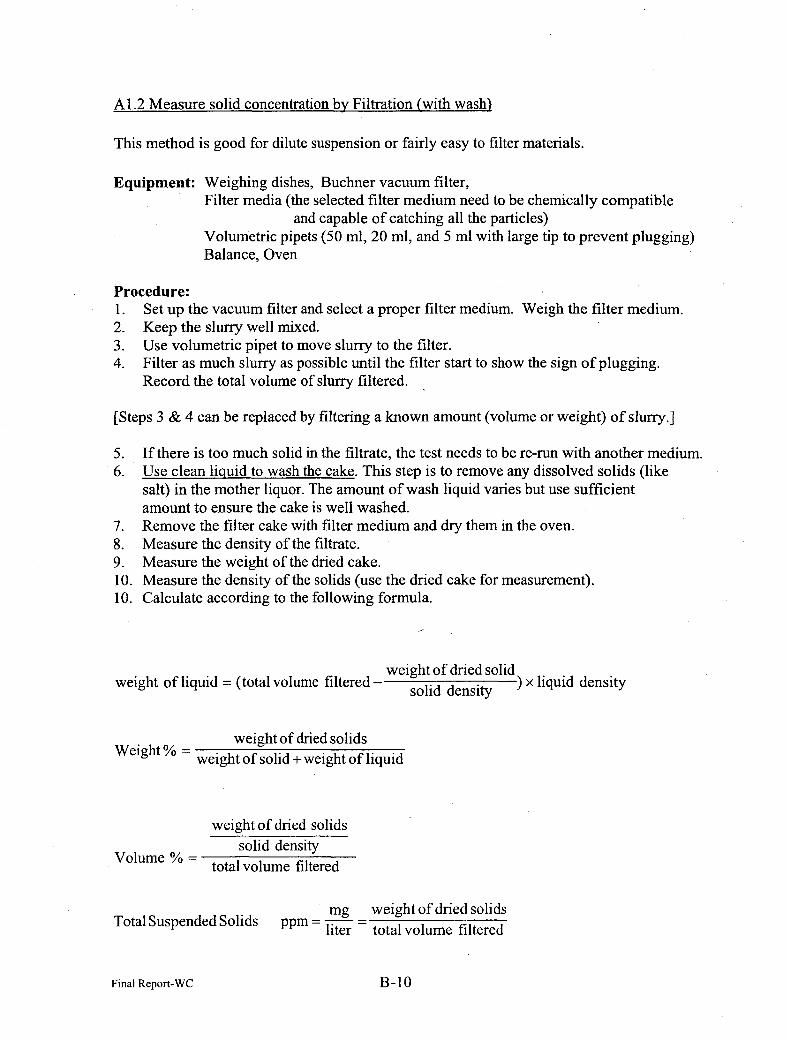
A 1.2 Measure solid concentration by Filtration (with wash)
This method is good for dilute suspension or fairly easy to filter materials.
Equipment: Weighing dishes, Buchner vacuum filter,Filter media (the selected filter medium need to be chemically compatible
and capable of catching all the particles)Volumetric pipets (50 ml, 20 ml, and 5 ml with large tip to prevent plugging)Balance, Oven
Procedure:1. Set up the vacuum filter and select a proper filter medium. Weigh the filter medium.2. Keep the slurry well mixed.3. Use volumetric pipet to move slurry to the filter.4. Filter as much slurry as possible until the filter start to show the sign of plugging.
Record the total volume of slurry filtered.
[Steps 3 & 4 can be replaced by filtering a known amount (volume or weight) of slurry.]
5. If there is too much solid in the filtrate, the test needs to be re-run with another medium.6. Use clean liquid to wash the cake. This step is to remove any dissolved solids (like
salt) in the mother liquor. The amount of wash liquid varies but use sufficientamount to ensure the cake is well washed.
7. Remove the filter cake with filter medium and dry them in the oven.8. Measure the density of the filtrate.9. Measure the weight of the dried cake.10. Measure the density of the solids (use the dried cake for measurement).10. Calculate according to the following formula.
weight of liquid =(total volume filtered - segtoli dren soityd liquid density
Weightweight of dried solidsWeight/oweight of solid + weight of liquid
weight of dried solids
Volume %solid densityVolum ~ =total volume filtered
Tota Supened olis pm -mg -weight of dried solidsTota Supened olis pm =liter -total volume filtered
Final Report-WCB- B-10

Al .3 Measure solid concentration by Filtration (without wash)This method is used cake washing is difficult due to cake cracking or low filtration rate.
Equipment: Weighing dishes , Buchner vacuum filter,Filter media (the selected filter medium need to be chemically compatible
and capable of catching all the particles)Volumetric pipets (50 ml, 20 ml, and 5 ml with large tip to prevent plugging)Balance, Oven
Procedure:1. Set up the vacuum filter and select a proper filter medium. Weigh the filter medium.2. Keep the slurry well mixed.3. Use volumnetric pipet to move slurry to the filter.4. Filter as much slurry as possible until the filter start to show the sign of plugging.
Record the total volume of slurry filtered.
[Steps 3 & 4 can be replaced by filtering a known amount (volume or weight) of slurry.]
5. If there is too much solid in the filtrate, the test needs to be re-run with another medium.6. Remove the filter cake with filter medium and measure the wet weight of the cake7. Dry the cake in the oven.8. Measure the density and the total dissolved solids in the filtrate.9. Measure the weight of the dried cake.10. Measure the density of the solids (by measuring the dried cake). If there is dissolved
solids in the liquid, this measurement should be done with a washed cake.11. Calculate according to the following formula.
Weiht f lqui inthecak =weight of wet cake-weight of dried cakeWeigt ofliqud inthe ake(l-% total dissolved solid)
Weight of solid in the cake =weight of wet cake - weight of liquid in the cake
Weigt% =weight of solidWeight %weight of solid + weight of liquid
weight of dried solids
Volume %solid densityVolum % =total volume filtered
Totl Sspnde Soid pp =mg weight of solidsTota Supened olis pm =liter -total volume filtered
Final Report-WC BlB-I I

A 1.4 Measurement of dissolved solid
Equipment: Weighing dish, Balance, and Oven
Procedure:1 . Remove all the suspended solid from the liquid by a Buchner vacuum filter or a
laboratory centrifuge.2. Measure the weight of an empty dish (Wdihb).
3. Put some liquid in the dish and measure the weight (Wdish+Iiquid).
4. Dry the sample in the oven.5. After drying, measure the weight of dish plus the remaining non-volatile.
(Wdish~nonvolatiles).
6. Calculate according to the following formula.
Wdish+ non volatile -WdishTotal dissolved solids= Wdish+liquid -Wdish
Final Report-WC B1B-12
Appendix C
CHEMICAL EFFECT PEER REVIEW:ASSESSMENT OF TEST FACILITIES AND PROGRAMS
TO INVESTIGATE CONCERNS RELATED TO CHEMICAL EFFECTSIN PRESSURIZED WATER REACTOR
EMERGENCY CORE COOLING SYSTEMS
Calvin H. DelegardPacific Northwest National Laboratory
C-1
SUMMARY
The Generic Safety Issue 191 was formulated by the Nuclear Regulatory Commission (NRC) toevaluate the potential for and phenomena associated with debris accumulation on sumpscreens located upstream of pressurized water reactor pumps used in the emergency corecooling system following a loss-of-coolant accident (LOCA). To help understand thephenomena and the magnitudes of debris generation and accumulation, the NRCcommissioned the performance of three technical studies - "Integrated Chemical EffectsTesting," "Chemical Speciation Prediction," and the "Accelerated Chemical Effects Head LossTesting."
The "Integrated Chemical Effects Testing" experiments endeavored to re-create the post-LOCAenvironment in five engineering scale tests. The test conditions, following both chemical andtemporal evolution of the post-LOCA, included reactor building containment spray-down,corrosion of both spray-wetted and immersed reactor containment test coupons, insulationmaterials, and recirculating solution. The "Integrated Chemical Effects Testing" apparatus andexperimental design thus were devised to provide an approximate scale model of the post-LOCA reactor and containment environment and endeavored to encompass the primarymaterial and environmental conditions present in the post-LOCA PWRs.
In doing these extensive and complicated tests, the ICET matrix provided much valuableinformation on material phase behavior and interaction. On one hand it was learned that manyof the materials in the test matrix, including many of the metals, had little, if any, effect on solidsformation either by direct contribution or by secondary interactions. On the other hand, thefollowing materials had larger effects on solids formation:
o Hydrogen and hydroxide ion concentration (pH)o Dissolved boron from borate buffers and burnable poisonso Dissolved phosphate from trisodium phosphate pH buffero Aluminum metal (largely present as temporary structural material)o Fiberglass thermal insulation materialo Cal-Sil, a calcium silicate thermal insulation material" Concrete.
The "Chemical Speciation Prediction" work was. accomplished by assessing the ability ofgeochemnical and process chemical thermodynamic modeling software to replicate the soluteconcentrations and reaction sequence in the post-LOCA coolant system. The task ensured thateach candidate model contained a sufficient thermochemnical database. For this, the presenceof boron aqueous solutes and compounds was a key discriminator. The models also needed tobe valid for temperatures up to about 11 00C and ionic strength up to 0.5 molal. Four chemical /geochemnical models met these and other criteria:
o OLI "StreamAnalyzer", version 2.0o Lawrence Livermore National Laboratory "EQ3/6", version 7.2bo RockWare, Geochemist's Workbench7, REACT, version 5.0o US Geological Survey "PHREEQC", version 2.8.
Each model then was tested for seven different starting solution conditions representative of thepost-LOCA environment. It was found that EQ3/6 was the most robust, avoiding theconvergence problems that the other codes suffered. The EQ3/6 code was selected, with the
C-2
OLI StreamAnalyzer, to predict the outcomes of the five ICET experiments and the resultscompared with the results actually found by ICET. Small scale experiments to determine thedissolution rates of insulation materials and the corrosion rates of aluminum in post-LOCAsolution environments also were performed under the "Chemical Speciation Prediction" task andthe results provided support to improving the accuracy of the chemical models. The small scaletests gave valuable insights into chemical behaviors of the complex post-LOCA solid/solutionmixtures. The modeling refinements might be nearing the point that compositions in non-testedsolid/solution conditions can be predicted.
The "Accelerated Chemical Effects Head Loss Testing" simulated the loading of the sumpscreen with debris materials and solids produced by chemical precipitation under recirculatingcoolant conditions. The test apparatus created seemingly the most severe pump screengeometry, perpendicular to stream flow, to provide the most definitive (conservative) testconditions. The testing focused on the chemical conditions studied in the one (of the five)"Integrated Chemical Effects Testing" experiments that produced finely divided calciumphosphate precipitates. The testing showed the severity of sump screen blockage that couldoccur even with relatively low debris loads and small amounts of calcium phosphate precipitate.
Some small scale tests also were performed under the "Accelerated Chemical Effects HeadLoss Testing" to determine the dissolution of Cal-Sil and the subsequent precipitation of calciumphosphate under simulated sump pool conditions. It was found that the Cal-Sil dissolution issufficiently rapid, even in the presence of trisodium phosphate (which inhibits Cal-Sildissolution), to precipitate significant amounts of calcium phosphate within a few hours andengender prohibitive pressure drops in the debris bed.
The results of these three studies were presented to a group of five peer reviewers in technicalreports, and in workshop meetings in October 2005 and March 2006, by the NRC and thestudies' researchers. The reviewers, with reactor, nuclear, industrial, and academic credentials,were charged by the NRC to review test approaches and results, recommend improvements tothe testing and analysis, and to identify any important but overlooked technical issues foradditional consideration or, perhaps, experiments. The evaluations of the author, one of the fivepeer reviewers, are presented in this report.
As seen, the three technical studies provided substantial information to understanding to theeffects of various~factors in the post-LOCA environment germane to Generic Safety Issue 191.The scope of the post-LOCA conditions in the many PWR configurations, however, forcedcertain simplifications in the experimental design. The results of the studies also suggestedpotential avenues of further investigation. The following additional investigations are suggestedbased on the evaluations made during review of the three technical studies:
o Further parametric studies could be performed both to understand theobservations from the completed rounds of experiments and to investigate theroles of temperature variation, temperature gradient (heated and cooledsurfaces), boron concentration variation, radiolysis, and organic materials.Because of the large size of the "Integrated Chemical Effects Testing" apparatusand resulting large quantity of required materials, the execution of more largescale tests under more widely varying conditions may be inefficient. Instead, thetesting should be done on a smaller scale to gain, at lower cost, most of thepertinent information.
C-3

" The influence of organic materials to act as glues to accrete solid particles couldbe great. Therefore, determination of the behavior of electrical insulations,plastic coatings, and paints when treated to steam and hot liquid water should bedone to investigate their coalescence and ability to collect inorganic solids asthey cool.
" Kilorad (10~3 Rad) per hour fields may exist away from the reactor core in thepost-LOCA coolant system while megarad (106 ) Rad per hour fields may existaround the core. Tests of the effects of radiolysis, particularly for organicmaterials, should be performed. The organic materials, besides providingradiolysis products that contribute additional chemical effects to the solution, canact as radiolytic radical scavengers and impose reducing conditions to thesystem.
o The effects of high temperature and low temperature heat transfer surfaces andheat cycling should be studied. The test approach perhaps could use arecirculation loop in which simulated post-LOCA coolant slurries, containing thedissolved and undissolved solids, would be exposed to surfaces at temperaturesrepresentative of the hotter fuel and cooler heat exchangers.
o Aluminum metal surface analysis by x-ray diffractometry may be useful todetermine the competing or complementary effects of calIcium ion, silicate, orboth on inhibiting aluminum corrosion. The effects of phosphate and boratespecies on aluminum corrosion also might be monitored in this fashion. In a likemanner, surface analyses could be done to assess the effects of the varioussolutes, particularly aluminum, on fiberglass or other silicates corrosion.
" The accelerated head loss test apparatus appears to be too large to encouragemultiple tests. A smaller test loop perhaps would allow more of the needed teststo be performed with the same resources. The test conditions could includetemperatures that ramped down with time, exposed high temperature surfaces(as provided in the post-LOCA system by the exposed fuel rods), and exposedlower temperature surfaces.
o The redox conditions and concentrations of water radiolysis products, such ashydrogen peroxide, in the post-LOCA waters should be estimated taking intoaccount the particularly high radiation fields imposed by the core.
" The potential presence of hypochlorite from radiolysis of chloride ion in theaqueous post-LOCA coolant should be investigated. If hypochlorite is present,its effect on metal corrosion under post-LOCA conditions should be investigated.
o The potential for hot sodium tetraborate or boric oxide to act as a flux to attackand perhaps dissolve the magnetite oxide layer from the reactor vessel wall orthe cladding from fuel should be examined.
o The relative impact of the quantity of the solids formed by reaction of the mineraltobermorite (from Cal-Sil) with carbonic acid from absorption of atmosphericcarbon dioxide to form calcite and amorphous silica, though likely to be small,should be assessed.
C-4

oThe potential for algae and other biological growth in the post-LOCA waterrecirculation system should be investigated either through examination of thetechnical literature or through testing. The boron concentration in the post-LOCAwater (-0.2 molar) may prove to be sufficiently high to preclude biological activity.
C-5
CONTENTS
Summary ............................................................................................... C-2
Abbreviations........................................... ............................................... C-7
1 Introduction.................................................................................... C-8
2 Principal Technical Questions .............................................................. C-12.1 Integrated Chemical Effects Testing................................................. C-1 1
2.1.1 Principal Sump Pool Variables and Constant Variables................. C-1 22.1.2 Variables or Materials for Most Importance But Not Considered ICET C-132.1.3 Sufficiency of ICET Analysis Methods .................................... C-14
2.2 Chemical Speciation Prediction ...................................................... C-i52.2.1 Credibility of Product Predictions.......................................... C-162.2.2 Code Benchmarking by Tests ............................................. C-1 72.2.3 Measuring the Code Uncertainties ........................................ C-17
2.3 Accelerated Chemical Effects Head Loss Testing.................................. C-1 72.3.1 Adequacy of the Head Loss Testing Approach .......................... C-182.3.2 Methods for Observing Time-Dependent Effects ........................ C-192.3.3 Evaluation of Simulated Chemical Products.............................. C-1 92.3.4 Identifying Key Physical Parameters to Predict Head Loss
Performance................................................................. C-20
3 Unexamined and Little Examined Conditions............................................. C-213.1 Radiolysis and Its Effect on Metal Corrosion........................................ C-213.2 Solution Composition Effects on Metal Corrosion .................................. C-223.3 Spallation of Deposits from the Hot Fuel Cladding and Reactor Vessel.......... C-233.4 Atmospheric Contributions ............................................................ C-253.5 Biological Activity...................................................................... C-26
4 References................................................................................... C-27
Appendices
1 Curriculum Vitae - CH Delegard........................................................... C-292 Preliminary Assessment Report............................................................ C-313 Informal Comments to ICET Reports - May 7, 2006 and Responses -
May 10, 2006 ................................................................................ C-36
Tables
1 ICET Matrix................................................................................... C-il12 Dissolution and Corrosion Rate Measurement Results.................................. C-1 6
C-6

ABBREVIATIONS
ANL Argonne National Laboratory
CNWRA Center for Nuclear Waste Regulatory Analyses
ECCS emergency core cooling system
GSI-191 Generic Safety Issue 191
ICET Integrated Chemical Effects Testing
LANL Los Alamos National LaboratoryLOCA loss-of-coolant accident
NRC Nuclear Regulatory Commission
PSID particle size distributionPWR pressurized water reactor
SwRl Southwest Research Institute
TSP Trisodium phosphate
UNM University of New Mexico
XRD x-ray diffractometry
C-7

I INTRODUCTION
During a loss-of-coolant accident (LOCA) in a pressurized water reactor (PWR) operating at fullload power, the primary coolant will be lost rapidly from the reactor pressure vessel and heatexchangers. The superheated water, at nominally 250-3300C temperature, will escape from thepressurized coolant system, flash off as steam as it attains normal atmospheric pressure, andscour the region surrounding the break, removing thermal insulation, paint, and even concrete.Immediately after the LOCA event, alkaline water jets near the top of the reactor containmentdome will spray down within the containment building with the purpose of scrubbingradionuclides from the air space. Within about 30 minutes after the LOCA, emergency coolingwater will be injected into the cooling system.
The condensed primary cooling water, the spray water, and the emergency cooling water willflow downward in the containment building, through sump screens, and into a pump located atthe physical low point in the containment building. There, the water will be collected and, oncethe emergency cooling water is exhausted, pumped to the reactor pressure vessel, over thecore, and through the cooling circuit breach where it will again flow down to the sump. Thisrecirculating water system, which serves to cool the reactor core and reactor vessel in the post-LOCA period, is called the emergency core cooling system (ECCS).
The Generic Safety Issue 191 (GSI-1 91) was formulated to evaluate the phenomena associatedwith debris creation and bed accumulation on the sump screens located upstream of the PWRsump pump for the ECCS following a LOCA. The GSI-11 91 was engendered by the observationof gelatinous material in the containment building of the reactor, Three Mile lsland-2, some timeafter its accident. The Nuclear Regulatory Commission (NRC) has defined the impacts of thepump blockage in Bulletin 2003-0 1 and in Generic Letter 2004-02 (NRC 2003 and NRC 2004).
As part of the resolution of GSI-1 91, three areas of technical investigation were undertaken atthe behest of the NRC to define the nature and magnitude of the debris formation which wouldserve to block the sump screens.
The first area of investigation, the "Integrated Chemical Effects Testing" (ICET), was conductedby researchers at the Los Alamos National Laboratory (LANL) and the University of New Mexico(UNM). The ICET experiments endeavored to re-create the post-LOCA environment, includingspray-down conditions, corrosion of reactor containment test coupons under both spray-wettedand immersed conditions, degradation of thermal insulation materials, and recirculating ofcoolant solution at a selected nominal temperature (60*C) in 30-day tests. The test scale was250 gallons (-946 liters). Five different combinations of insulation materials and reactor solutioncompositions, thought to be broadly representative of the conditions in United States PWRs,were investigated. The results of the five tests were reported both formally (Dallman et al.2005a-2005e) and during review meetings held October 18-19, 2005, at the Argonne NationalLaboratory (ANL) and March 27-29, 2006 at the Southwest Research Institute (SwRl). Follow-up testing and analysis by this same group is underway.
The second area of investigation was "Chemical Speciation Prediction". This work wasperformed by the Center for Nuclear Waste Regulatory Analyses (CNWRA) of the SwRI.Geochemnical and process chemical thermodynamic modeling software was. used to attempt toreplicate the solute concentrations and reaction sequence in the post-LOCA coolant system.Initial evaluations used starting conditions postulated for post-LOCA environments. The studieswere informed by the results from metal corrosion rate laboratory studies and insulation material
C-8

dissolution rate experiments performed by SwRl staff and by the results of the LANL/UNM ICETexperimental series as they became available. The results of the experiments and the modeltesting and development are provided by formal reports (Jain et a[. 2004, Jain et al. 2005, andMcMurry et al. - draft) and by presentations during the October 2005 and March 2006 reviewmeetings.
The third area of investigation, "Accelerated Chemical Effects Head Loss Testing," is beingperformed by ANL researchers. The objective of the head loss testing is to create a simulationof the loading of the sump screen. The tests are conducted with debris solids (primarily arisingfrom insulation materials) and precipitating solids in a recirculating loop containing flowingsimulated coolant. The differential pressure across the 6-inch (-15-cm) diameter model sumpscreen, consisting of a plate perforated with holes of 3/1 6-inch (-0.4-cm) diameter, wasmeasured as the flow continued to circulate. The test conditions to date have been based onvariations of the third ICET experiment. Results of the experiments have been presented in twoinformal "quick look" reports (Oras et al. 2005 and Oras et al. 2006) and by presentations duringthe October 2005 and March 2006 review meetings.
A technical peer group, comprised of five members with reactor, nuclear, industrial, andacademic credentials, was convened by the NRC to review the three sponsored activitiesrelated to understanding the post-LOCA PWR sump pool environments and the GSI-191. Thepeer review group also was charged to recommend improvements to the testing and analysisapproaches in the three activities and identify any important but overlooked technical issues foradditional consideration or, perhaps, experiments.
The NRC requested judgments from the peer reviewers on the technical soundness andpotential shortcomings of the "ICET," the "Chemical Speciation Prediction," and the "AcceleratedChemical Effects Head Loss Testing." The evaluations of the present report author (CalDelegard), one of the five peer reviewers, are presented in this report. The specific questionsposed by the NRC guidance to the peer reviewers and the author's responses are given inSection 2 of this report. Some areas for new or expanded work to help understand effects notyet investigated by the existing program are proposed and discussed in Section 3. Technicalreferences are given in Section 4.
The author's credentials (curriculum vitae) are summarized in Appendix A. Brief comments andquestions on the research results provided to the NRC by the author in a preliminaryassessment report dated November 30, 2005 are found in Appendix B. Some further questions.on ICET experiments, and the answers obtained from the researchers, are given in Appendix C.These questions were raised in an e-mail message on May 7, 2006.
C-9

2 PRINCIPAL TECHNICAL QUESTIONS
Three areas of investigation were pursued in the studies conducted to help resolve the impact ofGSI-1 91, concerned with the potential for debris to accumulate on the sump screens locatedupstream of the PWR sump pump for the ECCS following a LOCA. The three investigationareas are called "Integrated Chemical Effects Testing" (dubbed ICET), "Chemical SpeciationPrediction", and "Accelerated Chemical Effects Head Loss Testing". A technical peer group wasconvened by the NRC to review the three sponsored activities. As part of the review, a set ofPrincipal Technical Questions was posed to the review panel by the NRC.
The questions posed to the review panel are:
Integrated Chemical Effects Testing
" Have the principal sump pool variables which affect chemical by-productformation in the post-LOCA environment been adequately simulated?
o Many ICET variables were held constant during the experiments. How wouldchanges in the most important constant variables affect chemical productformation?
o What variables or materials not simulated by the ICET testing may have the mostimpact on chemical product formation (e.g., coatings, free insulation, flow throughsediment and other materials on sump screen, galvanic effects) and how shouldtheir effect be characterized by testing or analysis?
0 Were the methods used within the ICET program to characterize and analyzechemical by-products sufficient?
Chemical Speciation Prediction
" Is the speciation analysis expected to provide reasonable predictions of chemicalproduct formation over a range of possible sump environments?
" Is the plan for benchmarking these codes using small-scale testing and the ICETresults appropriate?
o What is the most appropriate way to measure the uncertainty associated withthese codes?
Accelerated Chemical Effects Head Loss Testing
o Is the accelerated head loss testing approach viable for evaluating the effects ofmultiple chemical environments quickly?
o What is the best method for incorporating for time-dependent effects (e.g.,material aging, evolving chemical environments) in simulation testing?
o What metrics are most appropriate for evaluating the results of simulatedchemical products with those that formed during the ICET program?
o Are correlations available, or can they be developed, which can predict theassociated head loss if important physical characteristics of a chemical by-product are known?
The responses to the principal technical questions are addressed, in the order given above, inthis section of the report.
C-10
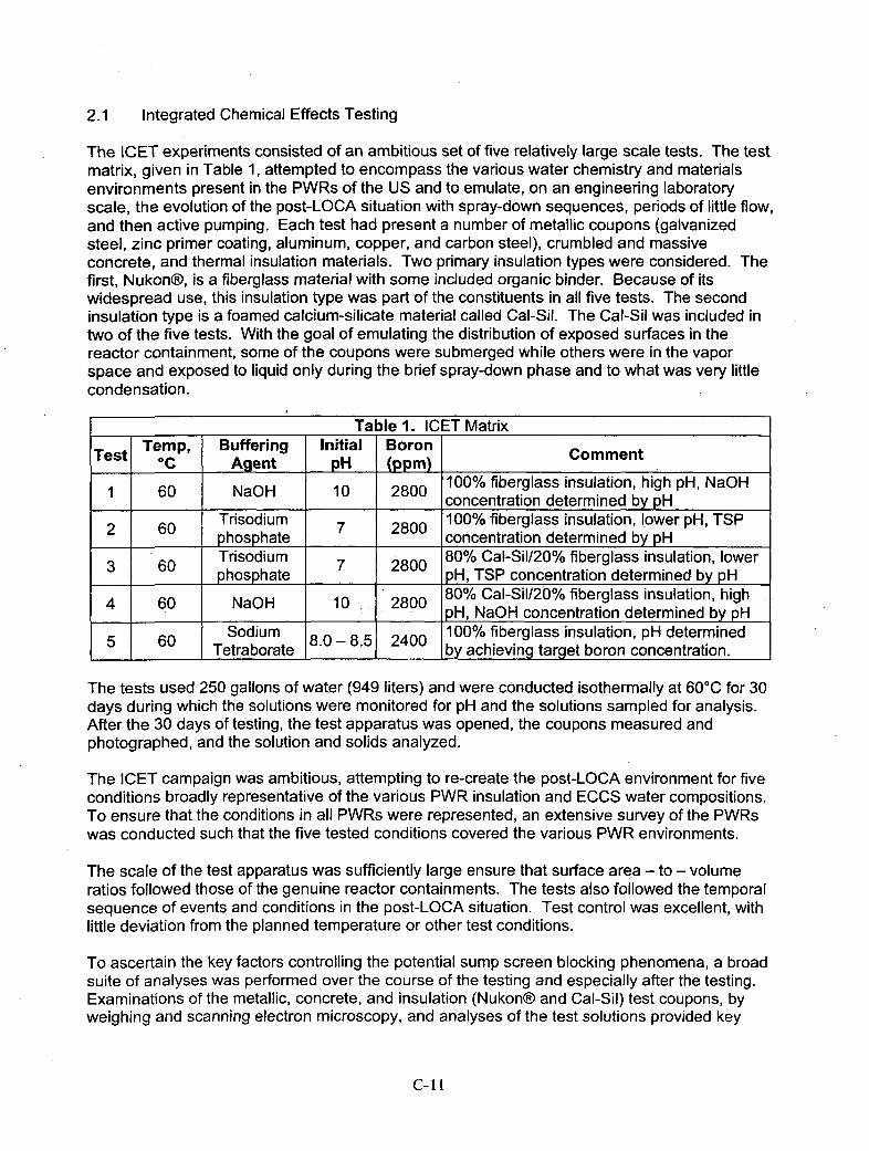
2.1 integrated Chemical Effects Testing
The ICET experiments consisted of an ambitious set of five relatively large scale tests. The testmatrix, given in Table 1, attempted to encompass the various water chemistry and materialsenvironments present in the PWRs of the US and to emulate, on an engineering laboratoryscale, the evolution of the post-LOCA situation with spray-down sequences, periods of little flow,and then active pumping. Each test had present a number of metallic coupons (galvanizedsteel, zinc primer coating, aluminum, copper, and carbon steel), crumbled and massiveconcrete, and thermal insulation materials. Two primary insulation types were considered. Thefirst, Nukon®, is a fiberglass material with some included organic binder. Because of itswidespread use, this insulation type was part of the constituents in all five tests. The secondinsulation type is a foamed calcium-silicate material called Cal-Sil. The Cal-Sil was included intwo of the five tests. With the goal of emulating the distribution of exposed surfaces in thereactor containment, some of the coupons were submerged while others were in the vaporspace and exposed to liquid only during the brief spray-down phase and to what was very littlecondensation.
Table 1. ICET MatrixTetTemp, Buffering Initial BoronComn
Tes_ c Agent pH (PPM) omen
1 60 NaO 10 800100% fiberglass insulation, high pH, NaOH1 60 NaO 10 800concentration determined by pH
2 0 Trisodium 7 80100% fiberglass insulation, lower pH, TSP_______________fn concentration determined by pH
Trisodium 80% Cal-Sil/20% fiberglass insulation, lower3 60 phophat 7 800pH, TSP concentration determined by pH4 60 NaO 10 80080% Cal-Sil/20% fiberglass insulation, high
4 ~~ 60-O1 80PH, NaOH concentration determined by pH
5 0 Sodium 8.-. 40100% fiberglass insulation, pH determined5~ 60 8 - 8.r240 by achieving target boron concentration.
The tests used 250 gallons of water (949 liters) and were conducted isothermally at 600C for 30days during which the solutions were monitored for pH and the solutions sampled for analysis.After the 30 days of testing, the test apparatus was opened, the coupons measured andphotographed, and the solution and solids analyzed.
The ICET campaign was ambitious, attempting to re-create the post-LOCA environment for fiveconditions broadly representative of the various PWR insulation and ECCS water compositions.To ensure that the conditions in all PWRs were represented, an extensive survey of the PWRswas conducted such that the five tested conditions covered the various PWR environments.
The scale of the test apparatus was sufficiently large ensure that surface area - to - volumeratios followed those of the genuine reactor containments. The tests also followed the temporalsequence of events and conditions in the post-LOCA situation. Test control was excellent, withlittle deviation from the planned temperature or other test conditions.
To ascertain the key factors controlling the potential sump screen blocking phenomena, a broadsuite of analyses was performed over the course of the testing and especially after the testing.Examinations of the metallic, concrete, and insulation (Nukon® and Cal-Sil) test coupons, byweighing and scanning electron microscopy, and analyses of the test solutions provided key
C-11
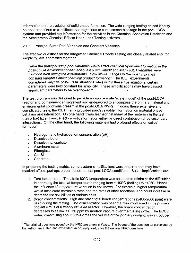
information on the evolution of solid phase formation. The wide-ranging testing helped identifypotential reactions or conditions that might lead to sump screen blockage in the post-LOCAsystem and provided key information for the activities in the Chemical Speciation Prediction andthe Accelerated Chemical Effects Head Loss Testing activities.
2.1.1 Principal Sump Pool Variables and Constant Variables
The first two questions for the Integrated Chemical Effects Testing are closely related and, forsimplicity, are addressed together. .
Have the principal sump pool variables which affect chemical by-product formation in thepost-LOCA environment been adequately simulated? and Many ICET variables wereheld constant during the experiments. How would changes in the most importantconstant variables affect chemical product formation? The ICET experimentsconsidered only five post-LOCA situations while within these five situations, certainparameters were held constant for simplicity. These simplifications may have causedsignificant parameters to be overlooked.a
The test program was designed to provide an approximate "scale model" of the post-LOCAreactor and containment environment and endeavored to encompass the primary material andenvironmental conditions present in the post-LOCA PWRs. In doing these extensive andcomplicated tests, the ICET matrix provided much valuable information on material phasebehavior and interaction. On one hand it was learned that many of the materials in the testmatrix had little, if any, effect on solids formation either by direct contribution or by secondaryinteractions. On the other hand, the following materials had profound effects on solidsformation:
*Hydrogen and hydroxide ion concentration (pH)*Dissolved boron*Dissolved phosphate*Aluminum metal*Fiberglass*Cal-Sil*Concrete.
In preparing the testing matrix, some system simplifications were required that may havemasked effects perhaps present under actual post-LOCA conditions. Such simplifications are:
1. Test temperature. The static 600C temperature was selected to minimize the difficultiesin operating the tests at temperatures ranging from -1 000C (boiling) to -40'C. Hence,the influence of temperature variation is not known. For example, higher temperaturewould accelerate corrosion rates and the rates of other reactions, and could increase ordecrease the solubilities of various salts.
2. Boron concentrations. High and static total boron concentrations (2400-2800 ppm) wereused during the testing. The concentration was near the maximum used in the primarycoolant circuit of a freshly refueled reactor. However, the boron concentrationdecreases to as low as -50 ppm by neutron capture over the fueling cycle. The ECCSwater, constituting about 3 to 4-times the volume of the primary coolant, was introduced
a The original questions posed by the NRC are given in italics. The bases of the question as perceived bythe author are stated and expanded, in ordinary font, after the original NRC questions.
C-I12
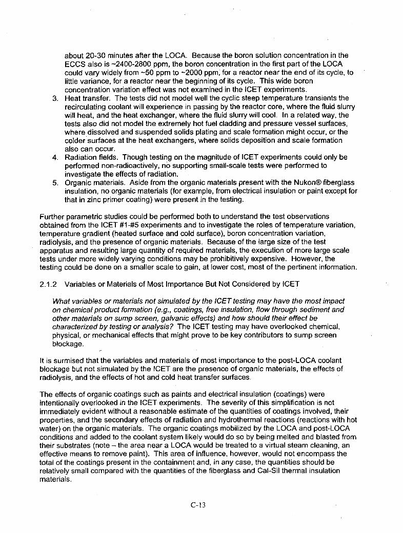
about 20-30 minutes after the LOCA. Because the boron solution concentration in theECCS also is -2400-2800 ppm, the boron concentration in the first part of the LOCAcould vary widely from -50 ppmn to -2000 ppm, for a reactor near the end of its cycle, tolittle variance, for a reactor near the beginning of its cycle. This wide boronconcentration variation effect was not examined in the ICET experiments.
3. Heat transfer. The tests did not model well the cyclic steep temperature transients therecirculating coolant will experience in passing by the reactor core, where the fluid slurrywill heat, and the heat exchanger, where the fluid slurry will cool. In a related way, thetests also did not model the extremely hot fuel cladding and pressure vessel surfaces,where dissolved and suspended solids plating and scale formation might occur, or thecolder surfaces at the heat exchangers, where solids deposition and scale formationalso can occur.
4. Radiation fields. Though testing on the magnitude of ICET experiments could only beperformed non-radioactively, no supporting small-scale tests were performed toinvestigate the effects of radiation.
5. Organic materials. Aside from the organic materials present with the Nukon®) fiberglassinsulation, no organic materials (for example, from electrical insulation or paint except forthat in zinc primer coating) were present in the testing.
Further parametric studies could be performed both to understand the test observationsobtained from the ICET #1-45 experiments and to investigate the roles of temperature variation,temperature gradient (heated surface and cold surface), boron concentration variation,radiolysis, and the presence of organic materials. Because of the large size of the testapparatus and resulting large quantity of required materials, the execution of more large scaletests under more widely varying conditions may be prohibitively expensive. However, thetesting could be done on a smaller scale to gain, at lower cost, most of the pertinent information.
2.1.2 Variables or Materials of Most Importance But Not Considered by ICET
What variables or materials not simulated by the ICET testing may have the most impacton chemical product formation (e.g., coatings, free insulation, flow through sediment andother materials on sump screen, galvanic effects) and how should their effect becharacterized by testing or analysis? The ICET testing may have overlooked chemical,physical, or mechanical effects that might prove to be key contributors to sump screenblockage.
It is surmised that the variables and materials of most importance to the post-LOCA coolantblockage but not simulated by the ICET are the presence of organic materials, the effects ofradiolysis, and the effects of hot and cold heat transfer surfaces.
The effects of organic coatings such as paints and electrical insulation (coatings) wereintentionally overlooked in the ICET experiments. The severity of this simplification is notimmediately evident without a reasonable estimate of the quantities of coatings involved, theirproperties, and the secondary effects of radiation and hydrothermal reactions (reactions with hotwater) on the organic materials. The organic coatings mobilized by the LOCA and post-LOCAconditions and added to the coolant system likely would do so by being melted and blasted fromtheir substrates (note - the area near a LOCA would be treated to a virtual steam cleaning, aneffective means to remove paint). This area of influence, however, would not encompass thetotal of the coatings present in the containment and, in any case, the quantities should berelatively small compared with the quantities of the fiberglass and Cal-Sil thermal insulationmaterials.
C-13
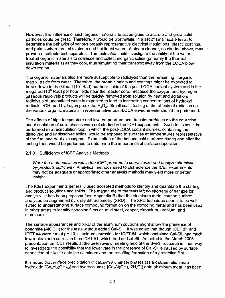
However, the influence of such organic materials to act as glues to accrete and grow. solidparticles could be great. Therefore, it would be worthwhile, in a set of small scale tests, todetermine the behavior of various broadly representative electrical insulations, plastic coatings,and paints when treated to steam and hot liquid water. A steam cleaner, as alluded above, mayprovide a suitable test apparatus. The tests also could investigate the ability of the water-treated organic materials to coalesce and collect inorganic solids (primarily the thermalinsulation materials) as they cool, thus simulating their transport away from the LOCA blow-down region.
The organic materials also are more susceptible to radiolysis than the remaining inorganicmatrix, aside from water. Therefore, the organic paints and coatings might be expected tobreak down in the kilorad (103~ Rad) per hour fields of the post-LOCA coolant system and in themegarad (10~6 Rad) per hour fields near the reactor core. -Because the oxygen and hydrogengaseous radiolysis products will be quickly removed from solution by heat and agitation;radiolysis of unconfined water is expected to lead to increasing concentrations of hydroxylradicals, -OH, and hydrogen peroxide, H202 - Small scale testing of the effects of radiation onthe various organic materials in representative post-LOCA environments should be performed.
The effects of high temperature and low temperature heat transfer surfaces on the collectionand dissolution of solid phases were not studied in the ICET experiments. Such tests could beperformed in a recirculation loop in which the post-LOCA coolant slurries, containing thedissolved and undissolved solids, would be exposed to surfaces at temperatures representativeof the fuel and heat exchangers. Examination of the hot and cold surfaces during and after thetesting then would be performed to determine the importance of surface deposition.
2.1.3 Sufficiency of ICET Analysis Methods
Were the methods used within the ICET program to characterize and analyze chemicalby-products sufficient? Analytical methods used to characterize the ICET experimentsmay not be adequate or appropriate; other analysis methods may yield more or betterinsight.
The ICET experiments generally used accepted methods to identify and quantitate the startingand product solutions and solids. The magnitude of the tests left no shortage of sample foranalysis. It has been proposed (see Appendix B) that the aluminum metal coupon surfaceanalyses be augmented by x-ray diffractometry (XRD). The XRD technique seems to be wellsuited to understanding surface compound formation on the corroding metal and has been usedin other areas to identify corrosion films on mild steel, copper, zirconium, uranium, andaluminum.
The surface appearances and XRD of the aluminum coupons might show the presence ofboehmite (AIOOH) for the tests without added Cal-Sil. It was noted that though ICET #1 andICET #4 were run at pH 10, aluminum corrosion for ICET #4, which contained Cal-Sil, had muchlower aluminum corrosion than ICET #1, which had no Cal-Sil. As noted in the March 2006presentation on ICET results at the peer review meeting held at the SwRl, research is underwayto investigate the possibility that the lower rate in the presence of Cal-Sil is caused by surfacedeposition of silicate onto the aluminum and the resulting formation of a protective film.
It is noted that surface precipitation of calcium aluminate phases (as tricalciumn aluminumhydroxide [Ca3A12(OH)12] and hydrocalumite [Ca2AI(OH) 7-2H2OJ) onto aluminum metal has been
C-14

found from tests of grouting of aluminum with portland cement and from reaction with calciumhydroxide [Ca(OH)2] slurries.b Such coatings also can suppress aluminum corrosion and shouldbe investigated. Surface examination of the aluminum metal coupons after ICET #1 and #4 byXRD and other methods would help determine the relative roles of calcium and silicate tosuppress aluminum corrosion. Surface analyses also might be done for fiberglass and for othersilicates including concrete and Cal-Sil.
Analyses of p article size distribution (PSD) during the evolution of the ICET experiments wouldhave been useful. However, measurement of the PSID without performing new experimentswould not be valid because of alterations, with time, of the particles. If other smaller scaleexperiments were to be performed, an on-line assay of PSID would be a useful complement tothe other analytical approaches as used in the original ICET experiments.
2.2 Chemical Speciation Prediction
The Chemical Speciation Prediction task was performed at the Center for Nuclear WasteRegulatory Analyses (CNWRA) of the Southwest Research Institute. Chemical speciation,algorithms were run to attempt to model the post-LOCA coolant conditions, as observed in theICET experiments, and to use the developed model or models to predict the post-LOCAconditions (particularly, types and quantities of precipitates) based on input values germane toreactors operating under conditions not exactly represented by the five ICET conditions. To dothis, geochemnical and process chemical modeling software was tested for robustness andaccuracy in predicting ICET observations. Some laboratory testing also was performed tomeasure dissolution and corrosion rates to provide input data to test the models.
The Chemical Speciation Prediction task screened the available modeling software, first takingcare that each model had present a sufficient thermochemnical database. For this, the presenceof boron aqueous solutes and compounds was a key discriminator. The models also needed tobe valid for temperatures up to about.1 I100C and ionic strength up to 0.5 molal. The CNWRAselected four che micalI/geoch emical models that met these and other criteria:
o OLI "StreamAnalyzer"', version 2.0o Lawrence Livermore National Laboratory "EQ3/6", version 7.2bo RockWare, Geochemist's Workbench7, REACT, version 5.0o US Geological Survey "PHREEQC", version 2.8.
and then compared their performances in modeling post-LOCA solutions and solids.
Each code was tested for seven different starting solution conditions representative of the post-LOCA environment. It was found that the code EQ3/6 was the most robust, avoiding theconvergence problems that the other codes suffered. The EQ3/6 code was selected, with theOLI StreamAnalyzer, to predict the outcomes of the five ICET experiments. The predictedexperimental results of both EQ316 and StreamAnalyzer for ICET then were compared with theresults actually found by ICET. Modeling simulations were also run for post-LOCA conditionsinvolving metal corrosion and for interactions of the post-LOCA fluids with the fiberglassinsulation, Cal-Sil, and concrete.
b See Short and Parker (2005) for a description of the results of reacting aluminum metal with Ca(OH)2aqueous slurry and with portland cement grout.
C-I15
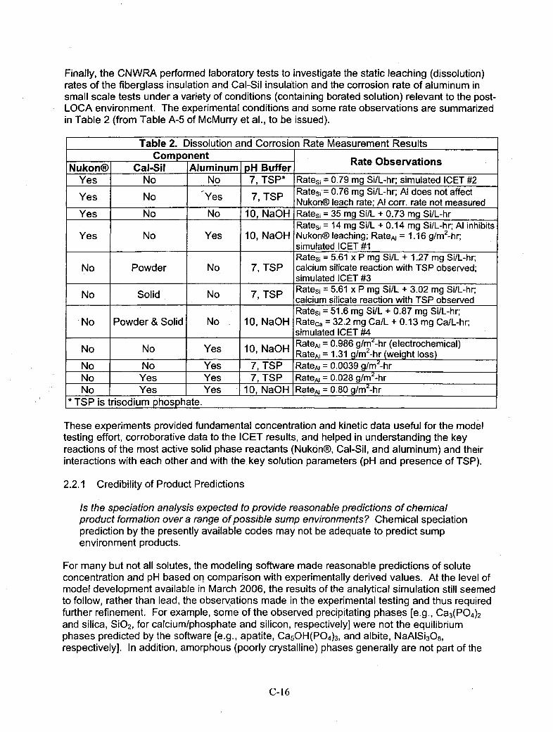
Finally, the CNWRA performed laboratory tests to investigate the static leaching (dissolution)rates of the fiberglass insulation and Cal-Sil insulation and the corrosion rate of aluminum insmall scale tests under a variety of conditions (containing borated solution) relevant to the post-LOCA environment. The experimental conditions and some rate observations are summarizedin Table 2 (from Table A-5 of McMurry et al., to be issued).
Table 2. Dissolution and Corrosion Rate Measurement ResultsCorn pnent RateObsrvaion
Nukon®) Cal-Sill Aluminum pH Buffer aeOsrainYes No No 7, TSP* Rates, = 0.79 mg Si/L-hr; simulated ICET #2
Yes o Ys 7,TSP Ratesi = 0.76 mg Si/L-hr; Al does not affectYes o Ys 7,TSP Nukon® leach rate; Al corr. rate not measured
Yes No No 10, NaOH Ratesi = 35 mg SilL + 0.73 mg SilL-hrRates, = 14 mg SilL + 0.14 mg Si/L-hr; Al inhibits
Yes No Yes 10, NaOH Nukon® leaching; RateA, = 1. 16 glm2 -hr;________simulated ICET #1
Ratesi = 5.61 x P mg SiUL + 1.27 mg SiIL-hr;No Powder No 7, TSP calcium silicate reaction with TSP observed;
simulated ICET #3NoSolid No 7, TSP Ratesi = 5.61 x P mg Si/L + 3.02 mg Si/L-hr;
calcium silicate reaction with TSP observedRatesi 51.6 mg Si/L + 0.87 mg Si/L-hr;
No Powder & Solid No 10, NaOH Rateca =32.2 mg Ca/ll + 0.13 mg Ca/L-hr;Isimulated ICET #4RateAl = 0.986 g/m~-hr (electrochemical)
No No Yes 10, NaOH RateAl = 1.31 g/M2 -hr (weight loss)No No Yes 7, TSP RateAl = 0.0039 g/M2 -hrNo Yes Yes 7, TSP RateAl = 0.028 g/m2-hrNo Yes Yes 10, NaOH RateAl = 0.80 glm2-hr
*TSP is trisodiumn phosphate.
These experiments provided fundamental concentration and kinetic data useful for the modeltesting effort, corroborative data to the ICET results, and helped in understanding the keyreactions of the most active solid phase reactants (Nukon®, Cal-Sil, and aluminum) and theirinteractions with each other and with the. key solution parameters (pH and presence of TSP).
2.2.1 Credibility of Product Predictions
Is th e speciation analysis expected to provide reasonable predictions of chemicalproduct formation over a range of possible sump environments? Chemical speciationprediction by the presently available codes may not be adequate to predict sumpenvironment products.
For many but not all solutes, the modeling software made reasonable predictions of soluteconcentration and pH based on comparison with experimentally derived values. At the level ofmodel development available in March 2006, the results of the analytical simulation still seemedto follow, rather than lead, the observations made in the experimental testing and thus requiredfurther refinement. For example, some of the observed precipitating phases [e.g., Ca3(P0 4)2and silica, Si0 2, for calcium/phosphate and silicon, respectively] were not the equilibriumphases predicted by the software [e.g., apatite, Ca5OH(P04)3, and albite, NaAlSi 3O8,respectively]. In addition, amorphous (poorly crystalline) phases generally are not part of the
C-i16
model databases but may be the compounds controlling the concentrations of many of thesolutes in the relatively short 30-day time frames of the post-LOCA systems.
It was observed that concessions to the seeming lack of the role Of 002 to form low solubilitycarbonates had to be made. Reaction rates (kinetics) also are not handled well by the modelingsoftware; the models thus may not reflect the evolving concentration profiles. As the models arerefined, they should provide closer matching of the observed ICET concentrations, theconcentrations observed in the supplemental CNWRA testing described in Table 2, andultimately the concentrations in systems not exactly mimicked in the ICET experiments.
Of the software modeling codes tested, the StreamAnalyzer® by OLI seemed best, likelybecause of its industrial pedigree and ability to handle the higher solute concentrations. It wouldbe useful for the purposes of GSI-l 91 if the modeling could predict, with more certainty, thechemical precipitation behaviors at the higher and lower post-LOCA temperatures in addition tothe conditions not yet investigated by ICET or other testing. It is not evident from the results to-date that the predictions would be successful.
2.2.2 Code Benchmarking by Tests
Is the plan for benchmarking these codes using small-scale testing and the ICET resultsappropriate? Other methods may exist that are better in calibrating and determining theadequacy of the thermodynamic modeling codes.
The small-scale testing is a valid approach to gain more information on the kinetic andequilibrium behaviors of the key solutes and solid phases. From the present results, it seemsthat benchmarking these codes is constructive because it reveals where gaps exist in the data.Further small-scale testing, as is being done under this activity to validate the code predictions,likely will be useful.
2.2.3 Measuring the Code Uncertainties
What is the most appropriate way to measure the uncertainty associated with thesecodes? The ability of the codes to predict behaviors accurately for chemical regimeshaving no experimental results may not be adequate.
Comparison of the code predictions against the results of targeted small-scale tests is a feasibleway to strengthen the codes and to identify and measure their uncertainties. Again, however,the codes seem to be following, rather than leading, the chemical testing. Predicting thebehaviors and evolutions of the complicated and rapidly changing post-LOCA coolant systemsmay be beyond the sophistication of present geochemnical and industrial chemical modelingcodes. However, the models are approaching the ability to predict compositions at non-testedconditions.
2.3 Accelerated Chemical Effects Head Loss Testing
The objective of Accelerated Chemical Effects Head Loss Testing is to simulate the loading ofthe sump screen by recirculating dissolved and suspended solids generated in the post-LOCAsystem. This is done by directing the simulated coolant flow containing suspended debrissolids, primarily arising from insulation materials and precipitating solids, through a screen in arecirculating loop. The quantity of cake that ultimately forms on the screen is measured; therate of cake formation and the cake's flow properties also are measured.
C-i17
The Head Loss Testing focused on the environments for which trisodium phosphate (TSP)buffering is used to control pH and Cal-Sil insulation is present. These conditions, found inICET #3, lead to the precipitation of finely particulate calcium phosphate with the calcium arisingfrom dissolution of the Cal-Sil. The effects of the degree of Cal-Sil dissolution, amount offiberglass and Cal-Sil debris (which is adjusted to match the areal mass loading on the screen),and the relative arrival times of the debris and the calcium phosphate precipitates were studied.The effects of the Nukon® fiberglass and Cal-Sil insulation debris beds alone and the debrisbeds with the calcium phosphate precipitate were compared.
Some small scale tests also were performed to determine the dissolution of Cal-Sil and thesubsequent precipitation of calcium phosphate under simulated sump pool conditions. It wasfound that the Cal-Sil dissolution is sufficiently rapid, even in the presence of TSP (which inhibitsCal-Sil dissolution), to precipitate significant amounts of calcium phosphate within a few hoursand engender flow-prohibitive pressure drops in the debris bed.
2.3.1 Adequacy of the Head Loss Testing Approach
Is the accelerated head loss testing approach viable for evaluating the effects of multiplechemical environments quickly? Perhaps other, more efficient, or more definitivemethods are available to test head loss effects.
The accelerated head loss test apparatus and associated reagent requirements as practiced inthe testing to-date (Oras et al. 2005 and 2006) has produced a large foundation of datagermane to the those reactors having both TSP buffering and Cal-Sil insulation and thus havingthe prospect of calcium phosphate solids generation in the post-LOCA coolant. Such conditionsare exemplified by ICET #3. The calcium phosphate, in concert with the debris from remainingundissolved Cal-Sil and fiberglass insulation, produce significant pressure drops across the.prototypical screen bed. Note that it would be valuable to determine if the calcium leached or'rinsed from concrete alone and without the Cal-Sil (i.e., ICET #2 conditions) would be sufficientto produce enough calcium phosphate to create a significant pressure drop in the prototypicalscreen bed.
The testing approach demonstrably provides valuable information on the behavior of the mixeddebris and precipitate bed formed in a dead-end screen loop. Nonetheless, the test apparatusseems overly large. The apparatus also forces 'all solution to go, in a parallel flow, through thescreen. This design would seem to be the most prone to blockage and may have been chosenin the test design for this reason. In some of the sump screen designs being created for reactorapplication, the screens are vertical and the solution would pass through the debris bed onlynear the screen bottom. The debris bed depth would decrease with screen height with the moreeasily suspended precipitates flowing over the top without encountering significant fiberglass orremaining solid Cal-Sil debris.
Because of the large scale of the tests, fewer tests can be performed than would be performedif tests were at smaller scale. This limitation decreases the information that could otherwise beobtained to characterize the multiple chemical environments of the post-LOCA coolant. Asmaller apparatus might accomplish the needed testing and generate much less waste per testthus encouraging more and more varied testing. A smaller apparatus might also be designed tomodel the operation of a vertical screen rather than the tested perpendicular dead-end screen.
A smaller test loop also would make possible, or make easier, testing at temperatures that vary(ramp down) with time and might allow exposed high temperature surfaces (as provided in the
c-I18

post-LOCA system by the cooling fuel rods) and exposed lower temperature surfaces (at theheat exchangers) to be examined more economically.
2.3.2 Methods for Observing Time-Dependent Effects
What is the best method for incorporating for time-dependent effects (e.g., materialaging, evolving chemical environments) in simulation testing? The simulation of headloss effects in laboratory testing can involve shortcuts in creation of the cake on thescreen to overcome slowly evolving reactions and environments. The adequacy of thisapproach is questioned.
The evolution over time of TSP and Cal-Sil dissolution and the accumulation of a solids deb risbed in an actual post-LOCA event are unknown. Therefore, various modes of creating thedebris and calcium phosphate precipitate bed were emulated in the testing program. The testresults indicated the approximate quantities of solids necessary to provoke bed blockage.Because the only way to incorporate time-dependent effects is to run the experiments over time,the testing program endeavored to recreate the evolution of the debris bed. As shown in thefollowing section, the solids created in some post-LOCA environments, were unlikely to havebeen adequately recreated by certain chemical shortcuts.
2.3.3 Evaluation of Simulated Chemical Products
What metrics are most appropriate for evaluating the results of simulated chemicalproducts with those that formed during the ICET program? Chemical products createdto simulate those created during the ICET experiments are used in some of the headloss testing. The adequacy of the simulated products to perform like the genuineproducts must be measured to determine their legitimacy.
The ICET experiments generated aluminum corrosion products from the actual corrosion ofaluminum. However, in the filtration / head-loss testing, the aluminum corrosion product wasintroduced by neutralization of AI(N03)3 with NaOH. This method is not representative of theway aluminum solids arise in the post-LOCA cooling water system. This introduction methodalso may have caused the non-prototypical so-called "snowfall" behavior. At a minimum, thealuminum nitrate method introduces nitrate, an anion not otherwise present in the real post-LOCA system. It is proposed that the aluminum be introduced in another manner, either bycorroding a coupon of aluminum in NaOH (simulating the actual conditions, but potentiallydifficult to achieve under experimental conditions) or by adding sodium aluminate solution,NaAI(OH) 4. Sodium aluminate is what is initially dissolved from the corroding aluminum metalby the NaOH and is available as a solid material through chemical supply houses or can bemade by dissolving AI(OH)3 in hot excess NaOH.
Similarly, several of the head loss tests used calcium chloride (CaCI 2) solution addition tosimulate the dissolution of Cal-Sil. Use of CaCI 2 provides chloride at concentrationsoverwhelming the small chloride concentrations normally present in the post-LOCAenvironment. Besides giving an unrealistically high chloride concentration, the addition of CaCI2in place of Cal-Sil fails to provide other solutes (e.g., sodium, silicate, some carbonate) and solidphases (e.g., amorphous silica) gained by dissolving the Cal-Sil. It is proposed that dissolvedCal-Sil (as used in many of the tests), rather than CaC12, provide the desired dissolved Cal-Siladdition.
C-19
To be consistent with the ICET experiments, the head loss testing emulated the ICET solidsgeneration sequence. However, it is more important that the simulated chemical productscreated in the head loss testing emulate the products arising in the containment building duringthe 30-day post-LOCA interval. The testing performed for the ICET program has shown theimportance of pH, Cal-Sil dissolution, borate, aluminum corrosion, phosphate, the Nukonfiberglass, and perhaps concrete on solids formation. The head loss testing could focus onvarying these components, plus study the effects of temperature differentials and hot and coldsurfaces, to create the solids present in the post-LOCA environment.
2.3.4 Identifying Key Physical Parameters to Predict Head Loss Performance
Are correlations available, or can they be developed, which can predict the associatedhead loss if important physical characteristics of a chemical by-product are known?Certain key physical parameters, such as particle size and shape, might be useful topredict the filtration/screening behavior of fluids bearing such suspended solids.
Methods to predict head loss or filtration behavior based on physical properties may or may notexist. Therefore, in such, an effort, it likely would be useful to consult experts, including expertsin the review panel, with backgrounds in water treatment, wastewater treatment, mineral miningand milling, or similar process industries for correlation methods.
However, even if such parameters could be identified and measured, the coolant solutes andthe suspended solids continue to react as shown by ICET and other testing. Thus, chemicalinteractions of the various particles and the coolant solutes themselves (e.g., borate, phosphate)can influence head loss due to material corrosion, surface precipitation, self-cementation, orother chemical and even radiolytic effects.
C-20
3 UNEXAMINED AND LITTLE EXAMINED CONDITIONS
In Section 3, certain post-LOCA conditions are identified that require more examination.Discussions of these important post-LOCA conditions and some possible avenues of researchare presented in this section. The phenomena being examined are radiolysis, solutioncomposition effects on metal (particularly aluminum) corrosion, material deposition andspallation, atmospheric contributions, and biological activity. Recommendations for additionaltesting and analysis are presented for each topic.
3.1 Radiolysis and Its Effect on Metal Corrosion
The effects of radiolysis on water and its subsequent effects on the corrosion of vulnerablemetals such as aluminum (Al; present in scaffolding and ladders) and zinc (Zn; present ongalvanized metal), were not examined in any of the testing. The current studies show thataluminum can be one of the primary contributors to solids loading in the post-LOCA recirculatingcoolant waters. The behavior of aluminum and other metals as influenced by water radiolysisremains to be studied.
The review panel, in the meetings held March 27-29, 2006, at the SwRI, discussed the radiolyticconditions of the cooling water as the LOCA event evolves. Under operating reactor conditions,water radiolysis produces primarily hydrogen (H-2), diatomic oxygen (02), and hydrogen peroxide(1-20 2). These components recombine, however, under the pressurized conditions in the PWR.The concentrations of these three species at full reactor power, where the dose rate is taken tobe 10 gray/second (-3.6x 10⁹ rad/hour) at 280*C, are _1i0 5 moles per liter in H2 and H20 2 and_10-6 moles per liter in 02 (Ishigure et al. 2006). At the same time, corrosion of the reactor steelpressure vessel exposed to the water imposes reducing conditions by being oxidized tomagnetite (Fe304) and related spinel phases. These reactions chemically reduce water toproduce H2. A H2 overpressure is also actively maintained by injection of H2 gas within theprimary coolant system to preserve reducing conditions and impede metal corrosion. Thisoverpressure gives much higher H2 concentrations than those produced by radiolysis.
During a LOCA, however, the confining overpressure is released and the gaseous H2 and 02constituents are flashed from the liquid water and lost to the air. And though nuclear fissionceases during the LOCA, water radiolysis continues by fission and activation product decay toproduce the estimated mega rad-per-hou r fields in the core. Though the gaseous H2 and 02constituents continue to be created but escape readily from the hot irradiated solution, thehydroxyl radical, 0OH, continues to be formed but is retained by the solution. Two 0OH radicalscombine to form H20 2 which likewise stays dissolved in solution.
The H202 can build in the solution to give conditions more oxidizing than deaerated or evenoxygenated water. This effect may be augmented by the radiolysis of chloride ion, Cr-,dissolved in water to produce hypochlorite (OC[-) or hypochlorous acid (1-1Cd), both strongoxidants. The ICET experiments #14#5 contained 100 ppmn HCI (~-2.7x 10⁻³ moles Cl- per liter).On the other hand, organic compounds present in the recirculating water from post-LOCAcooling water, from paint, plastic, the organic coating on the fiberglass insulation, or othersources, can act as scavengers of the radiolytically generated oxidants. This scavenging can,in itself, engender reducing conditions. As a result of these conflicting effects, thereduction/oxidation, or redox, conditions extant in the post-LOCA recirculating water are notimmediately evident.
C-2 1
Recommendation: It is suggested that the redox conditions and concentrations of radiolysisproducts, such as hydrogen peroxide, in the post-LOCA waters be defined taking into accountthe radiation fields imposed by the core.
It was recognized early in the design of nuclear reactors that the effects of radiolytically-generated H202 on engineering materials must be considered. The role of aluminum in metallicuranium fuel cladding and in reactor fuel tubes led to much early work on the durability ofaluminum in radiolytic conditions. For expediency, instead of studying aluminum performanceunder radiolysis, initial studies simply tested aluminum in the presence of H20 2. In these tests,the H202 was added to water in concentrations expected during reactor operations. These earlytests showed that H20 2 had very little effect on aluminum corrosion. Subsequent tests ofaluminum performance in water by direct irradiation under reactor conditions showed enhancedaluminum corrosion rates. Because of the higher corrosion observed under direct exposure, itwas thought that the primary but transitory oxidizing radiolytic products - free hydroxyl or atomicoxygen - rather than the subsequent H202 or dissolved diatomic oxygen, 02, were responsible(Goldsmith 1953). These findings were confirmed in subsequent studies (Richman 1958).
Such direct irradiation of aluminum should not occur under the postulated post-LOCA situationin which the fuel is defined to remain intact and radiolysis only to occur on the recirculatingcoolant. Hence, the effects of radiolysis should be confined to the secondary reactions of theirradiated water, and its contained solutes and entrained solids, on the corroding metals.
3.2 Solution Composition Effects on Metal Corrosion
Continued parametric testing of the susceptibility of aluminum to corrosion caused by typicalwater constituents was conducted (Troutner 1957). The results of these studies are verygermane to the present considerations of aluminum durability in the post-LOCA environment.The constituents whose effects were studied included chloride, nitrate (NO3-), sulfate (SQ4 2-)bicarbonate (HC0 3), hydrogen peroxide, acetate (CH 3CO2j), oxalate (C2042-), citrate[C3H4 OH(COO)3
3-], arsenate (AsO42}) phosphate (P04 -), silicate (HSi423) , dichromate(C-2O7
2 -), molybdate (Mo70 246) , and mixtures of these ions. Individual tests, run at 920C(-1 980F) with 100 ppm of the respective constituents, showed that only citrate increasedcorrosion, and phosphate decreased corrosion.
Significantly, again hydrogen peroxide had no effect on aluminum corrosion rate. Though theeffects of hypochlorite were not studied, chloride even up to 10,000 ppmn concentration (-0.28moles of chloride per liter) also had no effect on uniform corrosion rate. In addition, testscontaining both chloride and hydrogen peroxide, even up to 100 ppm CI- and 100 ppmn H202(-3x 0-3 moles per liter) showed no enhanced corrosion.
Recommendation: It is suggested that the potential presence of hypochiorite in the post-LOCAcoolant be investigated. If present, its effect on metal corrosion under post-LOCA conditionsshould be investigated.
As noted in the ICET testing, pH had a significant effect on aluminum corrosion rates with muchhigher rates observed at pH -10 than at pH -7. In the tests by Troutner (1957), minimumcorrosion rates were exhibited at pH -6 with rates increasing steeply above and below this pH.
Further study of the corrosion of aluminum (Troutner 1957) showed that measurable inhibitionoccurred with as little as 5 ppm (-0.0005 M) phosphate. It was postulated that the inhibitionoccurred because of the surface deposition of a protective layer of aluminum phosphate.
C-22

Subsequent X-ray diffraction studies of the surface of aluminum exposed to 5 ppm phosphate at195*C (383'F) for 24 days showed the formation of the aluminum phosphate compoundaugelite, A12P04(OH) 3, on the metal surface and is even formed on aluminum at 0.5 ppmnphosphate (Groot 1957). Such deposits might be postulated to form on the aluminum couponsin the ICET experiments 2 and 3 having the phosphate buffer at pH 7.
Recommendation: It is suggested that further post-test XRD examination of the corroded metalcoupon surfaces be conducted, especially for aluminum, and to examine the role of phosphatein coupons prepared during the ICET and other testing.
Some salts including chromates, dichromates, silicates, and borates are reported to inhibitaluminum corrosion (Shreir et al. 1994). Borates are common additives to automotiveantifreeze formulations and can encounter aluminum parts. The formation of perborates, B0 3 ,from the reaction of sodium metaborate, sodium hydroxide, and hydrogen peroxide, also shouldbe considered to be possible under radiolytic conditions (p. 980, Wiberg 2001). Perborates areused as bleaches and thus indicate that they are oxidizing.
Recommendation: Compare the effects of sodium tetraborate and perborate on aluminumcorrosion.
3.3 Spallation of Deposits from the Hot Fuel Cladding and Reactor Vessel
The LOCA event produces a rapid alteration in the pressure, temperature, and local chemicalconditions on the fuel cladding and reactor vessel walls. In the initial moments of the LOCA, thepressure within the vessel drops to atmospheric, the vessel itself undergoes mechanicalshuddering attendant to the loss of coolant, and the temperature of the fuel fluctuates as thecoolant supply and condition varies. Under such thermal and mechanical transients, the.magnetite corrosion layer in the reactor vessel, though nominally adherent, may vibrate looseand report to the recirculating coolant. The fuel itself, generally clad in zirconium alloy, mayspall its metal oxide outer layer (in this case, zirconium oxide, ZrO2) though this is much lesslikely than magnetite spallation from the reactor vessel. Note, however, that thick -50-pm filmsof ZrO2 have been observed under certain conditions (Johnson 1989).
Deposits of "crud" from stainless steel and nickel hardware in the primary coolant circuit alsooccur on fuel cladding. In one study, the crud deposits from operating PWRs were less thanone mil (-0.025 mm) thick, were composed of a nickel-substituted magnetite (formula NiFe3-,O4with 0.45<x<0.75) spinel, and were more highly concentrated on fuel having lower power(Solomon and Roesmer 1976; Sandler 1979). Chromium also was found in some cruds,substituting for iron in the spinel structure to give the composition CryNi,,Fe3-),-O 4. Othercontaminants found in the crud included aluminum and silicon, which were not incorporated inthe spinel but apparently formed amorphous aluminosilicates, and carbonaceous material,postulated to arise from ion exchange resin (Sandler 1979). In both reactor vessel and fuelcladding cases, the spalled solids would report to the recirculating coolant and then travel to thesump and sump screens where they would contribute to the solids loading and may impedecoolant flow.
Recommendation: Tests should be conducted to examine the possibility and extent of corrosionproduct spallation from reactor vessel walls and from fuel cladding surfaces under conditionsthat would occur under LOCA thermal and mechanical shock conditions.
C-23

It is more likely that solids spallation from reactor vessel and fuel cladding surfaces will occurfrom cyclic deposition onto and spallation from hot surfaces during the subsequent recirculatingcoolant flow. The deposition would occur by the transport of the dissolved and suspended boricacid (H3BO03), sodium tetraborate (Na 2B4 O4), trisodiumn phosphate (TSP; Na3PO 4), Cal-Silinsulation, aluminum corrosion products [e.g., Al(OH) 3, AIOOH, aluminum phosphate phases],calcium phosphate, fiberglass fibers, concrete particles, and other suspended debris to the hotfuel cladding and reactor vessel surfaces. The characterization of crud found on PWR fuelcladding from operating reactors (Sandler 1979) informs this hypothesized post-LOCA scenarioin that organic and aluminosilicate deposits were found in addition to nickel ferrites.
Note that most of the suspended solids, by virtue of being transported into the reactor vesseland past the sump screen, would be in the form of fine particulates. The coolant water, bearingthe dissolved and suspended solids, would flash away as it encountered the hot fuel claddingand reactor vessel surfaces and leave its solids load behind. There, the deposited solids couldundergo higher temperature hydrothermal reactions and likely undergo self-cementation. Withtime, as the deposits thickened, thermal shock and mechanical vibration caused by therecirculating water would loosen the deposits and transport the caked, dried, and matted solidsto the sumps and sump screens. Overall, the fine particulates and dissolved salts couldagglomerate and become cemented to create much larger particles that would present greaterbarriers to fluid flow.
The solid deposits likely would be shaped by the depositional surfaces and take the form ofcurved flakes. As such, they could be both easily transported by the flowing coolant and bereadily caught upon, and thus clog, the sump screens. Much of the deposit would arise from.drying of dissolved salts. The dried salts (e.g., sodium tetraborate, sodium phosphate) mayeasily re-dissolve in hot water and with agitation once they were re-introduced to the water flowafter spallation. However, the phosphate and borate salts themselves also undergopolymerization upon heating to produce polyphosphates and polyborates that resist re-dissolution.
In addition, sodium tetraborate dehydrates on heating to 350-4000C (662-7520F) to formNa2B34O7 and, if heated to the 878*C melting point of Na2B34O7, can act as a fluxing agent todissolve zirconium oxide, ZrO2, from the cladding and transition metal oxides (such as themagnetite coating on the reactor pressure vessel; Bock 1979). Boric acid (1-3B303) and itsdehydrate, B20 3, also can act as fluxes. The sodium tetraborate and boric acid thus might actas an additional vector to displace iron and nickel from the reactor vessel and zirconium fromthe fuel cladding and direct the 'm to the cooling water where they would precipitate as finehydroxides. More importantly, attack by the hot boron compounds might compromise thezirconium and, more so, any stainless steel fuel cladding to expose the irradiated fuel to theflowing coolant.
The solids might also cling tenaciously to the fuel cladding and compromise the heat transfermeant to occur during the post-LOCA period. If such deposition occurs, it might sufficientlyimpede the desired heat transfer as to lead to fuel cladding failure due to thermal stresses.
Recommendation: The behavior of recirculating coolant, bearing dissolved and suspendedsolids, upon encountering reactor fuel and vessel surfaces heated to the immediate post-LOCAtemperatures should be investigated. Of particular interest are examination of solids deposition,spallation, shape, re-dissolution or re-suspension, and the resistance of the solids to transport.The formation of tenaciously held deposits on the fuel surfaces is of high impact because of itseffect on heat transfer. The potential effect of hot sodium tetraborate or boric oxide to act as
C-24
fluxes to dissolve the magnetite oxide layer from the reactor vessel wall or the clad fuel shouldbe examined in separate tests.
3.4 Atmospheric Contributions
The alkaline post-LOCA spray-down of the reactor containment building will scrub carbondioxide (C0 2) from the air to contribute from -25 to 170 kg of CO 2 to the coolant solution.c
Accounting of the solids budget due to CO 2 absorption shows that the effect may be minor. ForCO 2 to have an effect, it must first be absorbed by water to form carbonic acid, H2C0 3. Theformation of H2C0 3 would move the pH towards -5.5, either up or down depending on thestarting pH imposed by the other solution components. The carbonic acid would react withcalcium with the calcium source most likely being from the dissolution of Cal-Sil insulation.Water attack of concrete, another potential source of calcium, would provide little solublecalcium; the calcium would already be in stable solid phases including CaCO 3.
The Cal-Sil insulation contains both CaCO3 and tobermorite, Ca 2.25(Si3O7.5(OH)1.5)-H20 (Dallmanet aL. 2005c). The reaction of solid tobermorite with CO 2 dissolved in water produces solidCaCO3, solid amorphous silica, SiO 2, and releases some water:
4 Ca2.25(Si 3O7.5(OH)l.5)-H20 (S) + 9 C02~ (9-+ 9 CaCO 3 (S) + 12 SiO2 (am) + 4 H20 (1)
The parent tobermorite, without reacting with carbonic acid, forms amorphous silica andhydrated lime, Ca(OH) 2, by reaction with water:
4 Ca2.25(Si3O7.5(OH)1. 5)-H20 (,) + 2 H20 (1) -~9 Ca(OH)2 (.) + 12 SiO2 (am)
It is seen that the difference between the two reactions of tobermorite is the replacement of theCa(OH)2 product from reaction with water with the CaCO 3 from the reaction with CO 2. The neteffect is that the hydrated lime from tobermorite reacts with CO 2 to produce calcite and water:
Ca(OH)2 (s) + CO 2 (g) --. CaCO 3 (s) .+ H20 (1
The 107 ft3 (-280,000 in) volume of the largest containme nt building holds about 171 kg Of CO 2.Therefore, the net increase in solids weight, caused by the reaction of Ca(OH)2 with C0 2, wouldbe -100 kg. The weight increase for other containment buildings would be lower by about afactor of 4. These quantities likely are negligible contributors to the total suspended solidsbudget in the coolant system. For both reactions, finely divided solids, consisting of amorphoussilica and either hydrated lime or calcite, would form. The solids in either case are physicallysimilar'and are unlikely to be significantly different in affecting sump screen flow.
cAccording to the presentation, "Principal Attributes of the LOCA Accident Sequence", made on March27, 2006, during the second peer review meeting, the air volumes in one of the PWR containmentbuildings is about 10 million cubic feet. The remaining 29 PWR containment buildings have volumesaround 1.5-3 million ft3 . Because the concentration Of CO 2 in air is about 330 parts per million on a molebasis, the quantity Of C0 2 present in 107 ft3 of air is
10f3arx28.3 liters X0.00033 liters CO 2 X mole X-0.044 kg =11k 0ft liter air 24 liters gas mole C0 2
C-25
Recommendation: The relative impact of the quantity of the solids formed by reactingtobermorite from Cal-Sil with carbonic acid from CO 2 absorbed from the air to form calcite andamorphous silica, though likely to be small, should be assessed.
3.5 Biological Activity
Temperatures during the immediate post-LOCA period will not be sufficiently high to sterilize theinterior of the reactor containment building. As a result, as the reactor and surroundings cool,warm moist conditions, augmented in many cases by phosphate buffer, will be conducive togrowth of algae and perhaps other life forms. With time, the algae and other growths maydevelop mats and help block flow through the sump screens.
However, it is noted that boron is an effective algaecide and may be a sufficient biocide tothwart growth of biota in the coolant water system. Therefore, the presence of boric acid(H3B0 3) in all tests and sodium tetraborate in Test #5 may be adequate to block growth in anysituation.
The total boron concentrations in Tests #14#4 was 2800 ppm, or about 0.26 moles of boron perliter, and 2400 ppm in Test #5, about 0.22 moles boron per liter. These high boronconcentrations may be toxic and preclude biologic growth. Though boron is consumed byneutron capture during irradiation and its concentration decreases to -50 ppm towards the endof the fueling cycle, its concentration is quickly restored to near starting levels within about 30minutes after LOCA by the injection of 3- to 4-fold volumes of emergency cooling watercontaining -2800 ppm boron.
Recommendation: The potential for algae and other biological growth in the post-LOCA waterrecirculation system should be investigated either through testing or through examination of thetechnical literature. The -2000 ppm boron concentration in the post-LOCA. coolant may besufficiently high to preclude biological activity.
C-26
4 REFERENCES
Bock, R. 1979. A Handbook of Decomposition Methods in Analytical Chemistry, InternationalTextbook Company, Edinburgh, UK.
Dailman, J., J. Garcia, M. Kiasky, B. Letellier, and K. Howe. 2005a. Integrated Chemical EffectsTest Project: Test #1 Data Report, LA-UR-05-1024, Los Alamos National Laboratory, LosAlamos, NMV.
Dailman, J., B. Letellier, J. Garcia, M. Kiasky, W. Roesch, J. Madrid, K. Howe, and D. Chen.2005b. Integrated Chemical Effects Test Project:, Test #2 Data Report, LA-UR-05-6146, LosAlamos National Laboratory, Los Alamos, NM.
Dailman, J., B. Letellier, J. Garcia, J. Madrid, W. Roesch, D. Chen, K. Howe, L. Archuleta and F.Sciacca. 2005c. Integrated Chemical Effects Test Project: Test #3 Data Report, LA-U R-05-6996, Los Alamos National Laboratory, Los Alamos, NM.
Daliman, J., B. Letellier, J. Garcia, J. Madrid, W. Roesch, D. Chen, K. Howe, L. Archuleta and F.Sciacca. 2005d. Integrated Chemical Effects Test Project: Test #4 Data Report, LA-U R-05-8735, Los Alamos National Laboratory, Los Alamos, NM.
Daliman, J., B. Letellier, J. Garcia, J. Madrid, W. Roesch, D. Chen, K. Howe, L. Archuleta and F.Sciacca. 2005e. Integrated Chemical Effects Test Project: Test #5 Data Report, LA-UR-05-9177, Los Alamos National Laboratory, Los Alamos, NM.
Goldsmith, S. 1953. Interim Report - Production Test Number 105-510-E Determination of PileIrradiation Effects on Corrosion of 2-S Aluminum, HW-27531, Hanford Atomic ProductsOperation, Richland, WA (http://www2.hanford.gov/ddrs/search/RecordDetails.cfm?AKey=Dl198147099).
Groot, C. 1957. Phosphoric Acid Corrosion Inhibition in Present Reactors, HW-5021 9, HanfordAtomic Products Operation, Richland, WA(hftp://www2.hanford.gov/ddrs/common/findpage.cfm?AKey=D8370590)-
Ishigure, K., T. Nukii, and S. Ono. 2006. "Analysis of Water Radiolysis in Relation to StressCorrosion Cracking of Stainless Steel at High Temperatures - Effect of Water Radiolysis onLimiting Current Densities of Anodic and Cathodic Reactions Under Irradiation," Journal ofNuclear Materials 350:56-65.
Jain, V., L. Yang, and K. Chiang. 2004. Chemical Speciation, Using Thermodynamic Modeling,During a Representative Loss-of-Coolant Accident Event, CNWRA 2004-07, Rev. 1, Center forNuclear Waste Regulatory Analysis, San Antonio, TX (Appendix C in NUREG/CR-6873, Jain etal. 2005).
Jain, V., X. He, and Y.-M. Pan. 2005. Corrosion Rate Measurements and Chemical Speciationof Corrosion Products Using Thermodynamic Modeling of Debris Components to Support GSI-191, NUREG/CR-6873, US Nuclear Regulatory Commission, Washington, DC(http://www.nrc.gov/reading-rm/doc-collections/nuregs/contract/cr6873/cr6873.pdf).
Johnson, A. B. Jr. 1989. Thick-Film Effects in the Oxidation and Hydriding of Zirconium Alloys,PNL-SA-17065, Pacific Northwest Laboratory, Richland, WA.
C-27
McMurry, J., V. Jain, X. He, 0. Pickett, and R. Pabalan. To be issued. GSI-191 PWR SumpScreen Blockage Chemical Effects Tests - Thermodynamic Simulations, NUREG/CR-xxxx(draft), US Nuclear Regulatory Commission, Washington, DC.
NRC. 2003. Potential Impact of Debris Blockage on Emergency Sump Recirculation atPressurized- Water Reactors, NRC Bulletin 2003-01, US Nuclear Regulatory Commission,Washington, DC (http://www.nrc.gov/reading-rm/doc-collections/gen-comm/bulletins/2003/bIO3001 .pdf).
NRC. 2004. Potential Impact of Debris Blockage on Emergency Recirculation During DesignBasis Accidents at Pressurized- Water Reactors, NRC Generic Letter 2004-02, US NuclearRegulatory Commission, Washington, DC(http://www. nrc.gov/reading-rm/doc-collections/gen-comm/-aen-lefters/2004ý/a1200402.pdf)
Oras, J., J. H. Park, K. Kasza, K. Natesan, and W. J. Shack. 2005. Chemical Effects/ Head-Loss Testing Quick Look Report, Tests I & 2, Argonne National Laboratory, Argonne, IL.
Oras, J., J.. H. Park, K. Kasza, K. Natesan, and W. J. Shack. 2006. Chemical Effects /Head-Loss Testing Quick Look Report, Tests ICET-3-4 to 11, Argonne National Laboratory, Argonne,IL.
Richman, R. B. 1958. Radiation Effects on Aluminum Corrosion in Process Water -Analysis ofData from Supplement A, PT-105-550-E, HW-57854, Hanford Atomic Products Operation',Richland, WA (http://www2.hanford.gov/ddrs/search/Recordoetails.cfm?AKey=D8431 132).
Sandier, Y. L. 1979. "Structure of PWR Primary Corrosion Products," Corrosion 35(5):205-208.
Short, S. M. and B. M. Parker. 2005. Potential for Generation of Flammable Mixtures ofHydrogen from Aluminum-Grout Interaction in the K Basins During Basin Grouting.,PNNL-15156, Pacific Northwest National Laboratory, Richland, WA(http://www.pnl.gov/main/publications/externaI/technical-reports/PNNL-1 51 56.pdf).
Shreir, L. L., R. A. Jarman, and G. T. Burstein. 1994. Corrosion, Volume 1, "Metal/EnvironmentReactions," Butterworth-Heinemann, Oxford, UK.
Solomon, Y. and J. Roesmer. 1976. "Measurement of Fuel Element Crud Deposits inPressurized Water Reactors," Nuclear Technology 29:166-173.
Troutner, V. H. 1957. Uniform Aqueous Corrosion of Aluminum - Effects of Various Ions, HW-50133, Hanford Atomic Products Operation, Richland, WA(http://www2.hanford.gov/ddrs/search/RecordDetails.cfm?AKey=D850681 1).
Wiberg, N. 2001. Inorganic Chemistry, Academic Press, San Diego, CA.
C-28
APPENDIX 1
Curriculum Vitae - Calvin H. Delegard
Professional Activities
Twenty-six years (1970; 1972-1976; 1979-1987; 1992-present) in applied/process chemistryand nuclear materials safeguards at the Hanford Site.
" Plutonium process and waste chemistry (speciation, separation, purification, processing)" PUREX and Plutonium Finishing Plant process chemistry" Environmental chemistry of radionuclides (Co, Sr, Tc, Cs, U, Np, Pu, Amn)" Technical liaison with the Institute of Physical Chemistry, Russian Academy of Sciences, on
chemistry of the actinides and technetium in alkaline media, on K Basin sludgetreatment/disposal, chromium phase dissolution, and uranium metal corrosion
" Hanford tank waste chemistry (bulk and radionuclide components)" Tank farm evaporator chemistry (concentration and crystallization)" Organic decomposition reactions in tank waste (e.g., gas generation in 101l-SY)* Tank waste treatment chemistry (ozonation, electrolysis, calcination/dissolution,
leaching/sludge washing)" Material corrosion; Zr and other metals in nitric acid; copper and mild steel in basalt
groundwater" Chemical characterization, processing, and U metal corrosion of K Fuel Storage Basins
sludge* Domestic (234-5) and design of int'l. (Hanford, RFES, SRS) nuclear materials safeguards" Development and qualification of plant calorimeters for international safeguards" Development of prompt gamma analysis for Pu materials characterization
*Plutonium materials stabilization for storage.
Eight years (1976-79; 1987-92), nuclear materials safeguards at the International AtomicEnergy Agency, Vienna, Austria.
* International nuclear material safeguards inspection execution" Subsidiary arrangements, design information, and facility attachments preparation" Destructive and non-destructive nuclear materials verification methods development.
Technical Publications
Contractor and National Laboratory Documents* Atlantic Richfield Hanford Company e Los Alamos National Laboratory" Rockwell Hanford Operations e Brookhaven National Laboratory" Westinghouse Hanford Company 9 Pacific Northwest National Laboratory* B&W Hanford, Duke ESH, B&W Protec, Numatec Hanford
Symposium Proceedings*Institute of Nuclear Science, *Institute of Nuclear Materials
Boris Kidri6, Vin~a, Yugoslavia Managemente American Nuclear Society @ American Chemical Society* American Society Metallurgical e European Safeguards Research andEngineers Development Association
C-29
" Minerals, Metals & Materials Society * Waste Management" Russian Conference on Radiochemistry e Materials Research Society" NATO Advanced Research Workshop e International Atomic Energy Agency
Scientific Journals" Radiochimica Acta * Journal of Alloys and Compounds" Radiochemistry * Journal of Nuclear Material Management" Nuclear and Chemical Waste Management
Selected Recent Publications
- Peretroukhine, V. F., and C. H. Delegard, 1998, "Some Comparisons of Plutonium-Bearing RadwasteManagement in the USA and Russia," The Environmental Challenges of Nuclear Disarmament,NATO Advanced Research Workshop, Cracow, Poland.
- Barney, G. S. and C. H. Delegard, 1999, "Chemical Species of Plutonium in Hanford Site RadioactiveTank Wastes," in Actinide Speciation in High Ionic Strenogth Media, D. T. Reed, S. B. Clark, and L.Rao (editors), Kluwer Academic/Plenum Publishers, New York.
- Bredt, P. R., C. D. Carlson, C. H. Delegard, K. H. Pool, A. J. Schmidt, D. B. Bechtold, J. Bourges, 0.A. Dodd, T. A. Flament, N. N. Krot, and A. B. Yusov, 2000, "Studies of Chemical Processing of KBasin Sludge," Waste Management 2000, Tucson, AZ.
- Delegard, C., 2001, "K Fuel Basin Sludge - Characterization, Reactions, Retrieval, and Storage,"presentation to Washington Group Intemnational, Warrington, UK, October 9, 2001, PNWD-SA-5513,Pacific Northwest Division, Battelle, Richland, WA.
- Fedoseev, A. M., V. P. Shilov, N. A. Budantseva, A. B. Yusov, 1. A. Charushnikova, and C. H.Delegard, 2002, "Selective Recovery of Chromium from Precipitates Containing d Elements andActinides: I-Ill. Effect of 02, H202 , S2O8 2, " Radiochemistry 44(4):347-365 (three articles).
- Clark, S. B. and C. Delegard, 2002, "Plutonium in Concentrated Solutions," Chapter 7 in Advances inPlutonium Chemistry 1967-2000, D. C. Hoffmann, Editor, American Nuclear Society, La GrangePark, IL (hftp://www.ans.org/store/Vi-300029).
- Boak, J., E. A. Conrad, C. H. Delegard, A. M. Murray, G. D. Roberson, and T. J. Venetz, 2003,"Recommendations on Stabilization of Plutonium Material Shipped to Hanford from Rocky Flats," LA-UR-03-3789, Los Alamos National Laboratory, Los Alamos, NM (http://lib-www.lanl.gov/cgi-bin/getfile?00937076.pdf).
- Schmidt, A. J., C. H. Delegard, S. A. Bryan, M. R. Elmore, R. L. Sell, K. L. Silvers, S. R. Gano, and B.M. Thornton, 2003, "Gas Generation from K East Basin Sludges and Irradiated Metallic UraniumFuel Particles - Series III Testing," PNNL-14346, Pacific Northwest National Laboratory, Richland,WA (http://www.pnl.gov/main/publications/external/technical-reports/PNNL-1 4346.pdf).
- Delegard C. H., A. J. Schmidt, R. L. Sell, S. 1. Sinkov, S. A. Bryan, S. R. Gano, and B. M. Thornton,2004, "Final Report - Gas Generation Testing of Uranium Metal in Simulated K Basin Sludge and inGrouted Sludge Waste Forms," PNNL-1481 1, Pacific Northwest National Laboratory, Richland, WA(http://www.pnl.gov/main/publications/external/technical-reports/PNN L- 1481 1.pdf)
- Yusov, A. B., A. M. Fedosseev, and C. H. Delegard, 2004, "Hydrolysis of Np(IV) and Pu(IV) and TheirComplexation by Aqueous Si(OH)4," Radiochimica Acta 92(12):869-881.
- Shilov, V. P., A. M. Fedoseev, A. B. Yusov, and C. H. Delegard, 2004, "Behavior of Np(VII, VI, V) inSilicate Solutions," Radiochemistry 46(6):574-577.
Education
BS, Chemistry, with distinction, Phi Beta Kappa, Washington State University, 1970;Graduate course work at the University of Colorado (1970-72) and Washington StateUniversity (1973-2001).
[email protected], (509) 376-0548Pacific Northwest National Laboratory
PO Box 999, MS P7-25Richland, WA 99352 USA
C-30
APPENDIX 2
Preliminary Assessment Report
To: Robert Tregoning, US Nuclear Regulatory Commission
From: Cal Delegard, ChemistPacific Northwest National LaboratoryPO Box 999, MS P7-25Richland, WA 99352(509) 376-0548calvin.delegard~pnl.gov
Date: November 30, 2005
Subject: Peer Review Preliminary Assessment Report
Thank you for the opportunity-to participate in the Chemical Effect Peer Review of the PWRsump pool chemistry. The following comments are based on the peer review meeting atArgonne National Laboratory, October 18-19, 2005, the associated view graph materials, andlisted reports.
The comments are provided in fulfillment of the obligation to provide a 'Preliminary AssessmentReport" of the Chemical Effects studies by November 30, 2005. The comments are grouped infive sections according to general remarks and the major areas of investigation:
1. General Questions and Comments2. Integrated Chemical Effects Testing (ICET)3. Modeling4. Chemical Effects Head Loss Testing5. Chemical Effect on the Sump Water.
I look forward to the follow-on review meeting in January 2006.
1. General Questions and Comments
" The overall testing approach is comprehensive, ambitious, and sound. Many of thequestions, comments, and suggestions given below arise from the fact that much of thework still is in progress. However, some areas of investigation may still need to be done.The suggested additional work is noted within the following questions and comments.
" Was chemical and physical characterization done of the sump materials from the TMI-2 andBarseback-2 LOCAs? d If so, what were the findings? How do they compare. with the ICETand other experimental results?
* Flashing of the cooling water bearing dissolved and entrained mineral solids and theretrograde solubility of calcite (CaCOA) calcium phosphate [Ca3(P0 4)2], and perhaps otherminerals may leave solids deposited on the hot fuel and vessel surfaces. What is theinfluence of this caking on the fuel rods and the heat transfer that the post-LOCA
dI was not able to find the reference by Hermannson and Erixon (SKI Report 98:12) cited in NUREG/OR-6873 and in LA-UR-03-641 5 Small-Scale Experiments: Effects of Chemical Reactions on Debris-BedHead Loss, by R.C. Johns et al., nor a description of the TMVI-2 solids (reference 7 in LA-UR-03-6415).
C-31I

recirculation is designed to achieve? For the purposes of the present task, spallation of thedeposits from the fuel cladding surfaces also would be expected. These spalled crustswould contribute to the solids loading in the cooling cycle and likely would adopt curledshapes imparted by the fuel pin surface. Therefore, tests might be proposed to test for thispotential effect and, if operant, project the type and characteristics of the spalled materials.
* Some interesting discussion arose during the first day's meeting regarding the spallation ofthe protective magnetite (Fe 3O4) corrosion layer from within the stainless steel pressurevessel due to the abrupt thermal and pressure shocks in a LOCA. I do not know thethickness of the protective film nor to what degree this spallation might occur but per ,hapssome industry experts could be consulted.e The magnetite spallation, if it should happen,would contribute to the solids load that must be considered in the post-LOCA cooling cycle.
* The same discussion also provoked speculation on the rapid corrosion of the internalsurface of the pressure vessel under high temperature oxic water to produce dissolved Fe 2 +
that would air oxidize to give fine Fe(OH) 3 particles. Again, some industry experts mighthave insight on the amount of corrosion that would occur.
2. Integrated Chemical Effects Testing (ICET)
The Integrated Chemical Effects Testing (ICET) results were presented in five separate reports,one for each of the five tests in the series. The first three tests were described in full reports(the third one in draft version), and the fourth and fifth in -10-page "quick look" reports. ICETresults also were summarized in presentations by Bruce Letellier ("Integrated Chemical EffectsTests - Design and Operations" and - "Survey of Results") and Marc Klasky ("Chemical ProductAnalysis and Simulation") of LANIL at the "Chemical Effects Peer Review Kick-off Meeting,"October 18-19, 2005. Observations, suggestions, and critiques on the ICET laboratoryinvestigations are provided.
* The ICET experiments must cover the range of anticipated chemical and physical (primarilytemperature) conditions, and combinations of conditions, which might occur for the USPWRs. It would be useful in the presentation of the ICET results to assign the variousPWRs to the conditions encompassed by the 2x2 test matrix (i.e., high/low pH,presence/absence of Cal-Sil) plus the fifth test for the sodium tetraborate ice melt (i.e., Tests#1 through #5). Such assignment would ensure that all of the US PWRs were representedby at least one of the five test conditions.
* The close proximities of the metallic test coupons may have influenced their respectivebehaviors as noted in the surmised plating of copper on the aluminum (ICET #2, LA-UR-OS-6146, page 21; ICET #3, Bruce Letellier presentation, page 56). Could the close metalcoupon proximities also have affected their corrosion rates? It is evident from theexperimental results (and also what would be expected) that the biggest metallic corrosioncontributor is aluminum followed distantly by zinc. Therefore, the influence of copper onpotentially decreasing or increasing the corrosion rate of aluminum is of concern and maybe profound.
*Related to the above question, what was the arrangement of coupons in the test racks (e.g.,AI-Cu-GS-US etc.)? According to the photos of the test racks (e.g., Figures 11 and 18 ofLA-UR-05-0124), it seems that the metals were placed in groups. Were the aluminum and
e I did not find mention of this phenomenon in the report Development of a Phenomena Identification andRanking Table (PIRT) for Thermal-Hydraulic Phenomena During a PWR Large-Break LOCA, R. A. Shaw,S. Z. Rouhani, T. K. Larson, and R. A. Dimenna, NUREG/CR-5047, Idaho National EngineeringLaboratory, Idaho Falls, ID (1988). However, I am not conversant in the literature. Is magnetite spallationfrom the inside of the reactor vessel a credible outcome from a large break LOCA?
C-32
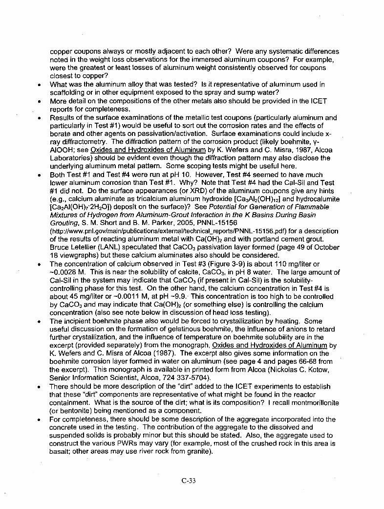
copper coupons always or mostly adjacent to each other? Were any systematic differencesnoted in the weight loss observations for the immersed aluminum coupons? For example,were the greatest or least losses of aluminum weight consistently observed for couponsclosest to copper?
*What was the aluminum alloy that was tested? Is it representative of aluminum used inscaffolding or in other equipment exposed to the spray and sump water?
*More detail on the compositions of the other metals also should be provided in the ICETreports for completeness.
*Results of the surface examinations of the metallic test coupons (particularly aluminum andparticularly in Test #11) would be useful to sort out the corrosion rates and the effects ofborate and other agents on passivation/activation. Surface examinations could include x-ray diffractometry. The diffraction pattern of the corrosion product (likely boehmite, v-AIOOH; see Oxides and Hydroxides of Aluminum by K. Wefers and C. Misra, 1987, AlcoaLaboratories) should be evident even though the diffraction pattern may also disclose theunderlying aluminum metal pattern. Some scoping tests might be useful here.
*Both Test #1 and Test #4 were run at pH 10. However, Test #4 seemed to have muchlower aluminum corrosion than Test #11. Why? Note that Test #4 had the Cal-Sil and Test#1 did not. Do the surface appearances (or XRD) of the aluminum coupons give any hints(e.g., calcium aluminate as tricalcium aluminum hydroxide [Ca3AI2(OH) 121 and hydrocalumiteECa 2AI(OH)7*2H20D) deposit on the surface)? See Potential for Generation of FlammableMixtures of Hydrogen from Aluminum-Grout Interaction in the K Basins During BasinGrouting, S. M. Short and B. M. Parker, 2005, PNNL-1 5156(http://www.pnl.gov/main/publications/external/technical_reports/PNN L-1 51 56.pdf) for a descriptionof the results of reacting aluminum metal with Ca(OH)2 and with portland cement grout.Bruce Letellier (LANL) speculated that CaCO 3 passivation layer formed (page 49 of October18 viewgraphs) but these calcium aluminates also should be considered.
" The concentration of calcium observed in Test #3 (Figure 3-9) is about 110 mg/liter or-0.0028 M. This is near the solubility of calcite, CaCO 3, in pH 8 water. The large amount~ofCal-Sil in the system may indicate that CaCO 3 (if present in Cal-Sil) is the solubility-controlling phase for this test. On the other hand, the calcium concentration in Test #4 isabout 45 mg/liter or -0.0011 M, at pH -9.9. This concentration is too high to be controlledby CaCO 3 and may indicate that Ca(OH) 2 (or something else) is controlling the calciumconcentration (also see note below in discussion of head loss testing).
* The incipient boehmite phase also would be forced to crystallization by heating. Someuseful discussion on the formation of gelatinous boehmite, the influence of anions to retardfurther crystallization, and the influence of temperature on boehmite solubility are in theexcerpt (provided separately) from the monograph, Oxides and Hydroxides of Aluminum byK. Wefers and C. Misra of Alcoa (1987). The excerpt also gives some information on theboehmite corrosion layer formed in water on aluminum (see page 4 and pages 66-68 fromthe excerpt). This monograph is available in printed form from Alcoa (Nickolas C. Kotow,Senior Information Scientist, Alcoa, 724 337-5704).
* There should be more description of the "dirt" added to the ICET experiments to establishthat these "dirt" components'are representative of what might be found in the reactorcontainment. What is the source of the dirt; what is its composition? I recall montmorillonite(or bentonite) being mentioned as a component.
" For completeness, there should be some description of the aggregate incorporated into theconcrete used in the testing. The contribution of the aggregate to the dissolved andsuspended solids is probably minor but this should be stated. Also, the aggregate used toconstruct the various PWRs may vary (for example, most of the crushed rock in this area isbasalt; other areas may use river rock from granite).
C-33
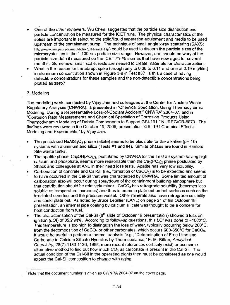
" One of the other reviewers, Wu Chen, suggested that the particle size distribution andparticle concentration be measured for the ICET runs. The -physical characteristics of thesolids are important in selecting the solid/liquid separation equipment and media to be usedupstream of the containment sump. The technique of small angle x-ray scattering (SA)(S;hftp://www.mri.psu.edu/mcl/techniaues/saxs.asr)) could be used to discern the particle sizes of themicrocrystallites in the 1-100 nmn particle size range. However, one should be wary of theparticle size data if measured on the ICET #14#5 slurries that have now aged for severalmonths. Some new, small scale, tests are needed to create materials for characterization.
" What is the reason for the abrupt spike (though only to 0.06 to 0.11 and one at 0.19 mg/liter)in aluminum concentration shown in Figure 3-8 in Test #3? Is this a case of havingdetectible concentrations for these samples and the non-detectible concentrations beingplotted as zero?
3. Modelinq
The modeling work, conducted by Vijay Jain and colleagues at the Center for Nuclear WasteRegulatory Analyses (CNWRA), is presented in "Chemical Speciation, Using ThermodynamicModeling, During a Representative Loss-of-Coolant Accident," CNWRAf 2004-07, and in"Corrosion Rate Measurements and Chemical Speciation of Corrosion Products UsingThermodynamic Modeling of Debris Components to Support GSI-1 91," NUREG/CR-6873. Thefindings were reviewed in the October 19, 2005, presentation "GSI-191 Chemical Effects:Modeling and Experiments," by Vijay Jamn.
* The postulated NaAlSi3O8 phase (albite) seems to be plausible for the alkaline (pH 10)systems with aluminum and silica (Tests #1 and #4). Similar phases are found in HanfordSite waste tanks.
* The apatite phase, Ca5OH(P0 4)3, postulated by CNWRA for the Test #3 system having highcalcium and phosphate, seems more reasonable than the Ca3(P0 4)2 phase postulated byShack and colleagues at ANL in their head loss tests. Apatite has very low solubility.
" Carbonation of concrete and Cal-Sil (i.e., formation of CaCO 3) is to be expected and seemsto have occurred in the Cal-Sil that was characterized by CNWRA. Some limited amount ofcarbonation also will occur during spraydown of the containment building atmosphere butthat contribution should be relatively minor. CaCO 3 has retrograde solubility (becomes lesssoluble as temperature increases) and thus is prone to plate out on hot surfaces such as theirradiated core fuel and the pressure vessel. Other minerals also have retrograde solubilityand could plate out. As noted by Bruce Letellier (LANL) on page 21 of his October 18presentation, an internal pipe coating by calcium silicate was thought to be a concern forheat conduction from fuel.
*The characterization of the Cal-Sil (8 th slide of October 19 presentation) showed a loss onignition (LOI) of 35.2 wt%. According to follow-up questions, this LOI was done to '-10000C.This temperature is too high to distinguish the loss of water, typically occurring below 200'C,from the decomposition of CaCO3 or other carbonates, which occurs 600-850*C for CaCO3.It would be useful to perform a thermal analysis [e.g., "Determination of Free Lime andCarbonate in Calcium Silicate Hydrates by Thermobalance," F. M. Biffen, AnalyticalChemistry, 28(7):1133-1136, 1956; more recent references certainly exist] or use somealternative method to find out how much CO 2 as carbonate is present in the Cal-Sil. Theactual condition of the Cal-Sil in the operating plants then must be considered as one wouldexpect the Cal-Sil composition to change with aging.
fNote that the document number is given as CWNRA 2004-07 on the cover page.
C-34

4. Chemical Effects Head Loss Testina
The chemical effects head loss testing was conducted by Bill Shack, J. Oras, and colleagues atANL. Their results were given in "Chemical Effects / Head-Loss Testing Quick Look Report,Tests 1 & 2" and in the October 19 viewgraphs, "Chemical Effects Head Loss Tests".
* The introduction of the aluminum phase to the filtration / head-loss testing, accomplished byneutralization of AI(N0 3)3 with NaOH, is not representative of the way aluminum isintroduced to the post-LOCA system (and may have caused the so-called non-prototypicalsnowfall behavior). For one thing, it introduces nitrate, an anion otherwise not present. It isproposed that the aluminum be introduced in another manner, either by corroding a couponof aluminum in NaOH (simulating the actual conditions, but potentially difficult underexperimental conditions) or by adding sodium aluminate solution, NaAI(OH) 4. Sodiumaluminate is what is initially dissolved off the corroding aluminum metal by the NaOH.Sodium aluminate is available as a solid material through chemical supply houses(https://wwwl .fishersci.com/Coupon?catnum=NC9365903) or can be made by dissolving AI(OH)3 inhot excess NaOH.
" The calcium concentration dependence on pH given by Cal-Sil dissolution tests (Figure 1 of"Quick Look" report) is interesting in that it is practically flat - i.e., the calcium concentrationdecreases only about a factor of 10 for a pH increase of 6. Most minerals would becomeless soluble by about a factor of 100 per increase of one pH unit. Has the solid phase(s)been identified?
5. Chemical Effect on the Sump Water
The "Chemical Effect on the Sump Water" presentation describes work by J. H. Park andcolleagues of ANL. Perhaps some of their findings also were given in the "Small ScaleDissolution Test" section in the "quick look" report by J. Oras and colleagues of ANL.
*The Cal-Sil dissolution information (below) shows increasing dissolution with time. Doesthis increase continue with time? What do the solids look like?
(a) __ _ _ _ _ _ _ _ (b)
T = 600C TWCN250% pH = 7.14 (NaOH) Na sc 50 pH- = 7.14 (N~aOH)
252-0 CaISiIIL P Ca V E 25-.g CaISiIIL
C,,a
-I ~kC&predict0 0 53 50 0 80 Iu0
0.1 I 10 100t (h) S! (ppm)
Elements in the solution as a function of time (a) and Ca and Na vs. Si (b)
*The experiments using AI(N0 3)3 to introduce the aluminum (slides 8-10 of the presentation)again are not representative of the system being studied (which contains no nitrate).Suggest repeating the tests using sodium aluminate.
C-35

APPENDIX 3
Informal Comments on ICET Reports to B. Letellier - May 7, 2006And Responses - May 10, 2006 (in italics)
* Will an ICET comparison report be prepared? It would be usefut to see, in one report, a side-by-sidecomparison of the various tests and their outcomes. A comparison report is being prepared.
* It would be useful to provide a more detailed description of the inorganic zinc / coated steel coupons.For example, they are called (I think) cold galvanizing spray paints and they contain high, -93%, zincconcentrations. Is this what is meant? Yes, paint containing high metallic zinc content is what ismeant.
* Please describe if more or different deposits were observed on the heat exchanger surfaces. Thismight give some information on what may be expected for the potential for deposits on hot fuel in thepost-LOCA reactor. The deposits on the heat exchanger surfaces did not appear to be materiallydifferent from the recirculating solids and were not present in noticeably higher concentrations.
* Was any biological activity noticed in any ICET bath? This might be the presence of green slines orsome checking with a microscope. The presence or lack of biological activity should be noted,whatever the case. No particular microscopic study looking for algae or other biota was done;however, no apparent "green slines" were observed.
* When RO water was added on Day 8 of Test #3 (p. 21), and cloudiness observed, was it because oftemperature drop? If so, how much did the temperature drop? The cloudiness is thought to be due toturbulence that moved previously deposited solids when the water was added.
* In Figure 3-5 of the Test #3 report, (p. 26), what is the label on the y-axis? What was the averageNTU, excluding the potential~ly spurious day #1 and day #15 results? The label will be remedied infuture reports.
" Also check y-axis label on Figure 3-7 of Test #3 report. The label will be remedied in future reports." How was chloride analyzed? Was it by ICP or instead by ion chromatography? Ion chromatography
was used to analyze chloride concentration." In the proposed overview report, it would be useful to compare Ca concentrations with respect to
phosphate concentrations (for example, in the Test #3 report, compare Figures 3-16 (phosphate) withFigure 3-9 (Ca). The direct comparison could be done, as suggested, or another means used tocorrelate the data.
" In Figure 3-8 of Test #3, the Al concentrations look anomalous around days 8-15 inclusive. Is this aminimum detection limit phenomenon in which "real" values were found on days 8-15 and the otherdays had "less-than' values? As suspected, this is an artifact of the minimum detection limit.
* In Figure 3-39 of the Test #3 report, was EDS (energy dispersive spectroscopy) done on the large flatfibers to identify the elements present? What is their origin? Were the large flat fibers observed inthe original fiberglass insulation? The large flat fibers were postulated to come from the cal-silmaterials, as noted on page 47 of the report.
* On p. 56 of the ICET #3 report, is there further substantiation of the identification of the Ca3(P04)2phase? This identification is based on EDS data, not on XRD. Therefore, the speculation that thephase is Ca3(P04)2 is not supported.
* Suggest X-ray diffraction be done to identify phases on metal coupons though your XPS and surfaceinfrared analyses might give other complementary information. This suggestion is acknowledged.
* In the Summary of the test #3 report, at the bottom of p. 97, identify the "crystalline substances". Thecrystalline substances were identified earlier in the report (e.g., p. 81 and Figure 3-117) astobermorite, Ca2 .25('Si 3O7.5(OH) 1.5) (H20).
" In test #4, p. 20, did the RO water addition and cooling cause precipitation? As in the Test #3 result,this is probably from loosening of solids deposits caused by turbulence.
*On p. 99 of the test #4 report, and as you indicated in one of the presentations at the SwR1,aluminosilicate surface precipitation may be occurring. This is also suggested by comparison of theTest #1 and Test #4 conditions, which differ in that Test #4 has Cal-sil and Test #1 does not; both atpH 10. However, on slide #22 of Jude McMurry's presentation of March 27 (excerpted below), littlechange in corrosion rate found between the pH 10 tests with and without Cal-sil. The tests done at
C-36
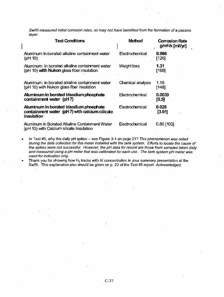
SwRI measured initial corrosion rates, so may not have benefited from the formation of a passivelayer.
Test Conditions Method
Aluminum in borated alkaline contairnment water(pH 10)
Aluminum in borated alkaline contairment water(pH 10) with Nukan glass fiber insulation
Aluminum in borated alkaline containment water(pH 10) with Nukon glass fiber insulation
Aluminum in borated trisodium phosphatecontainment water (pH 7)
Alurninum in borated trisodium phosphatecontainment water (pH 7) with calcium ciliczteinsulation
Aluminum in Borated.Alkaline Containment Water(pH 10) with Calcium silicate Insulation
Electrochemical
Weight loss
Chemical analysis
Electrochemical
Electrochemical
Electrochemical
Corrosion Rateglrr?-h [nil/yr]
0.986(126]
1.31(168]
1.16[148]
0.0039[0.510.028[3.61]
0.80 [103]
*In Test #5, why the daily pH spikes -- see Figure 3-1 on page 21 ? This phenomenon was notedduring the data collection for this meter installed with the tank system. Efforts to locate the cause ofthe spikes were not successful. However, the pH data for record are those from samples taken dailyand measured using a pH meter that was calibrated for each use. The tank system pH meter wasused for indication only.
*Thank you for showing how H2 tracks with Al concentration in y our summary presentation at theSwRI. This explanation also should be given on p. 22 of the Test #5 report. Acknowledged.
C-37

Appendix D
EVALUATION OFINTEGRATED CHEMICAL EFFECTS TESTING
Robert Litman, PhD
RADIOCHEMISTRYLABORATORY BASICS
28 Hutchinson DriveHampton, NH 03842
drbob2064,comcast.net(603)926-4863
Prepared forArgonne National Laboratory Sub-Contract No. 5F-00556
andUnited States Nuclear Regulatory Commission
May 2006
D-1
Abstract
The potential formation of gels, as a result of containment materials interacting withreactor coolant fluid following a large break loss of coolant accident (LOCA), wasstudied under various conditions. The principal concern is that formation of gels, or otherinsoluble materials, could block the screens on the containment recirculation sumps ofpressurized water reactors (PWR). A series of experimental chemical simulations wereperformed by Argonne National Laboratory (ANL), Los Alamos National Laboratory(LANL) and Southwest Research Institute (SwRI) to determine if the chemicals resultingfrom reactor coolant system post-LOCA containment spray reacting with ReactorCoolant System (RCS) insulation and other materials in containment (metals andconcrete) could be identified, and if the containment recirculation sump screens would, infact, become blocked due to formation of these chemicals.This report reviews the fidelity of these simulations, and addresses how the simulationscan be further refined to address more closely all significant, potential factors in thecomplex mixture of materials that are exposed to RCS liquid during a large break LOCA.
D-2
CONTENTS
Abstract D-2Abbreviations D-4Executive Summary D-5Summary of Key Points D-6Introduction D-7Discussion D-7Part I D-8Part 11 D-1 5Conclusions D-20Recommendations D-21
Attachment I D-23
D-3
.ABBREVIATIONS
CBS Containment Building Spray
CRUD A term used to identify insoluble corrosion products present in theReactor coolant system and located on the piping
ICET Integrated Chemical Effects Test
ICP Inductively Coupled Plasma Spectrometry
LOCA Loss of Coolant Accident
pH The negative logarithm (base 10) of the H' concentration
PWR Pressurized Water Reactor
RHR Residual Heat Removal
RCS Reactor Coolant System
SAT Spray Additive Tank
SEM Scanning Electron Microscopy
SG Steam Generator
TSP Trisodium Phosphate
TSS Total Suspended Solids
XRD X-ray Diffraction
D-4
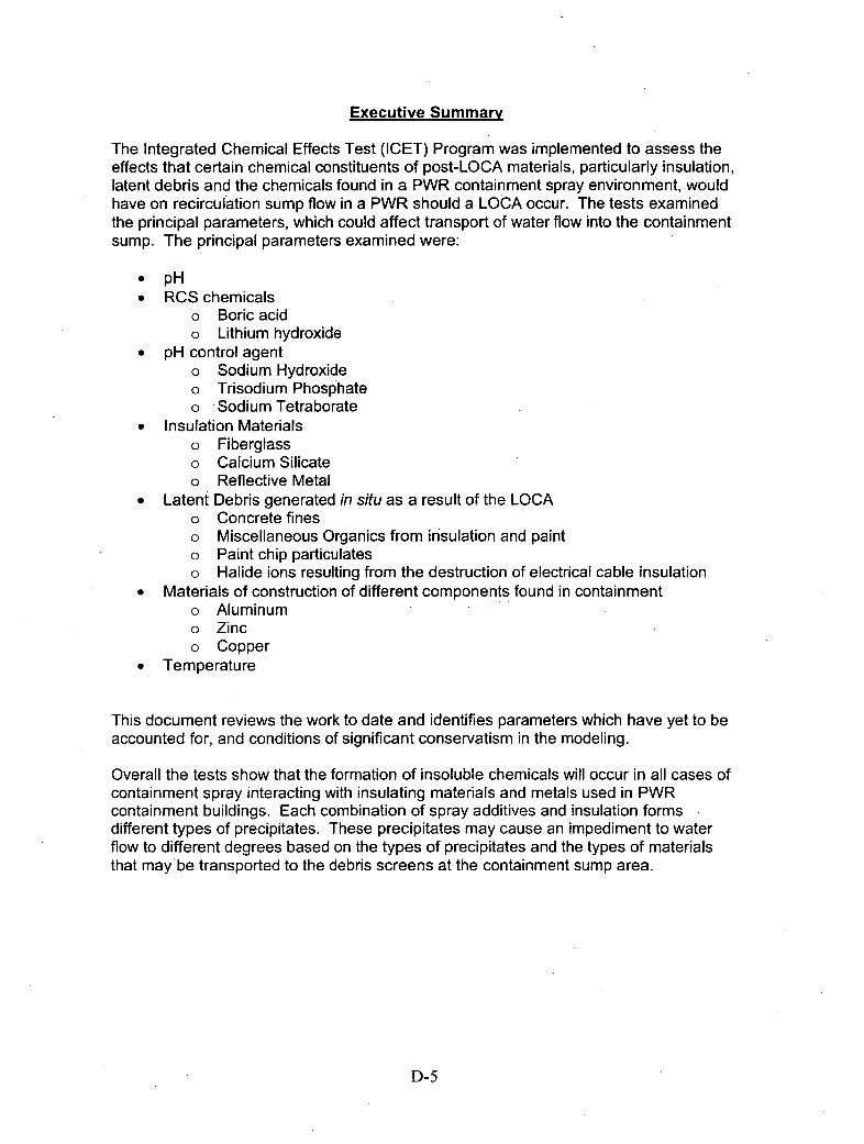
Executive Summary
The Integrated Chemical Effects Test (ICET) Program was implemented to assess theeffects that certain chemical constituents of post-LOCA materials, particularly insulation,latent debris and the chemicals found in a PWR containment spray environment, wouldhave on recirculation sump flow in a PWR should a LOCA occur. The tests examinedthe principal parameters, which could affect transport of water flow into the containmentsump. The principal parameters examined were:
" pH* RCS chemicals
o Boric acido Lithium hydroxide
* pH control agent" Sodium Hydroxide" Trisodium Phosphateo Sodium Tetraborate
" Insulation Materialso Fiberglass" Calcium Silicateo Reflective Metal
" Latent Debris generated in situ as a result of the LOCAo Concrete fineso Miscellaneous Organics from insulation and painto Paint chip particulateso Halide ions resulting from the destruction of electrical cable insulation
* Materials of construction of different components found in containmento Aluminumo Zinco Copper
" Temperature
This document reviews the work to date and identifies parameters which have yet to beaccounted for, and conditions of significant conservatism in the modeling.
Overall the tests show that the formation of insoluble chemicals will occur in all cases ofcontainment spray interacting with insulating materials and metals used in PWRcontainment buildings. Each combination of spray additives and insulation formsdifferent types of precipitates. These precipitates may cause an impediment to waterflow to different degrees based on the types of precipitates and the types of materialsthat may be transported to the debris screens at the containment sump area.
D-5
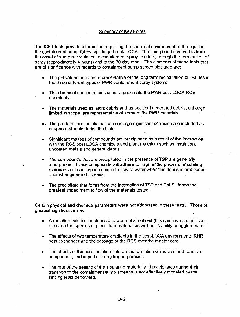
Summary of Key Points
The ICET tests provide information regarding the chemical environment of the liquid inthe containment sump following a large break LOCA. The time period involved is fromthe onset of sump recirculation to containment spray headers, through the termination ofspray (approximately 4 hours) and to the 30-day mark. The elements of these tests thatare of significance with regards to containment sump screen blockage are:
* The pH values used are representative of the long term recirculation pH values inthe three different types of PWR containment spray systems
* The chemical concentrations used approximate the PWR post LOCA RCSchemicals.
* The materials used as latent debris and as accident generated debris, althoughlimited in scope, are representative of some of the PWR materials
" The predominant metals that can undergo significant corrosion are included ascoupon materials during the tests
" Significant masses of compounds are precipitated as a result of the interactionwith the RCS post LOCA chemicals and plant materials such as insulation,uncoated metals and general debris
* The compounds that are precipitated in the presence of TSP are generallyamorphous. These compounds will adhere to fragmented pieces of insulatingmaterials and can impede complete flow of water when this debris is embeddedagainst engineered screens.
* The precipitate that forms from the interaction of TSP and Cal-Sil forms thegreatest impediment to flow of the materials tested.
Certain physical and chemical parameters were not addressed in these tests. Those ofgreatest significance are:
* A radiation field for the debris bed was not simulated (this can have a significanteffect on the species of precipitate material as well as its ability to agglomerate
* The effects of two temperature gradients in the post-LOCA environment: RHRheat exchanger and the passage of the RCS over the reactor core
* The effects of the core radiation field on the formation of radicals and reactivecompounds, and in particular hydrogen peroxide.
* The rate of the settling of the insulating material and precipitates during theirtransport to the containment sump screens is not effectively modeled by thesettling tests performed.
D-6

IntroductionThe objective of the Integrated Chemical Effects Test is determine if during a Loss ofCoolant Accident (LOCA) in a PWR chemical reactions may occur with materials alreadyin containment, which may form insoluble compounds that can block containmentrecirculation sump screens. This review will examine the key parameters used toestablish the test conditions, the implementation of those conditions and the analyticaltechniques used to measure the chemical effects.
DiscussionThe discussion section of this final assessment is divided into three parts. Part Iaddresses the tests conducted using tni-sodium phosphate, sodium hydroxide andsodium tetraborate on containment materials and if all major parameters that could affectthe results have been considered. The specific materials examined were fiberglassinsulation, Cal-Sil insulation, concrete debris, non-metallic jacketed insulation andcombinations of these materials. Specific questions were posed to the peer reviewgroup that serves as the structure for Part 1.
Part 11 discusses individual test results and their potential impact on the blockage ofcontainment sump screens
Part Ill identifies plant specific configurations that will have an impact (either mitigation orexacerbation) on the applicability of these test results, and need to be considered on aplant-by-plant basis.
D-7
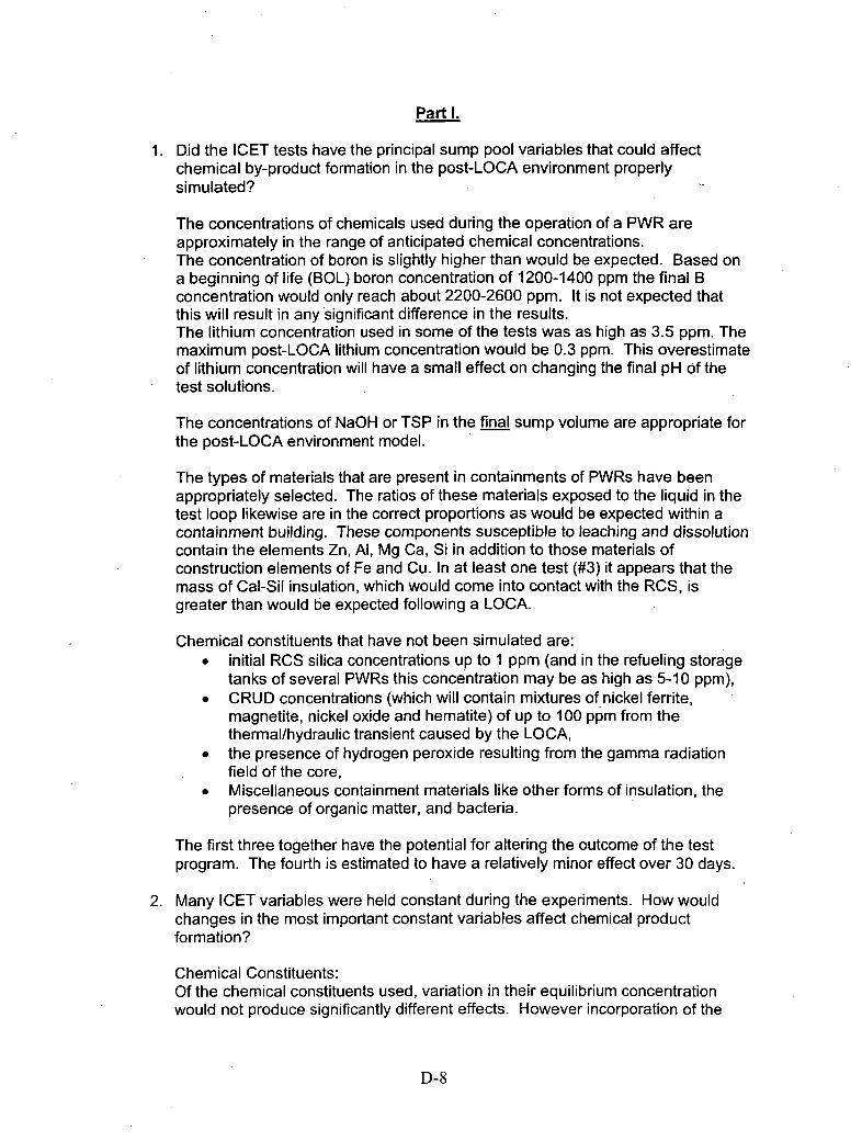
Part I.
1 . Did the ICET tests have the principal sump pool variables that could affectchemical by-product formation in the post-LOCA environment properlysimulated?
The concentrations of chemicals used during the operation of a PWR areapproximately in the range of anticipated chemical concentrations.The concentration of boron is slightly higher than would be expected. Based ona beginning of life (BOL) boron concentration of 1200-1400 ppm the final Bconcentration would only reach about 2200-2600 ppm. It is not expected thatthis will result in any significant difference in the results.The lithium concentration used in some of the tests was as high as 3.5 ppm. Themaximum post-LOCA lithium concentration would be 0.3 ppm. This overestimateof lithium concentration will have a small effect on changing the final pH of thetest solutions.
The concentrations of NaOH or TSP in the final sump volume are appropriate forthe post-LOCA environment model.
The types of materials that are present in containments of PWRs have beenappropriately selected. The ratios of these materials exposed to the liquid in thetest loop likewise are in the correct proportions as would be expected within acontainment building. These components susceptible to leaching and dissolutioncontain the elements Zn, Al, Mg Ca, Si in addition to those materials ofconstruction elements of Fe and Cu. In at least one test (#3) it appears that themass of Cal-Sil insulation, which would come into contact with the RCS, isgreater than would be expected following a LOCA.
Chemical constituents that have not been simulated are:* initial RCS silica concentrations up to 1 ppmn (and in the refueling storage
tanks of several PWRs this concentration may be as high as 5-10 ppm),* CRUD concentrations (which will contain mixtures of nickel ferrite,
magnetite, nickel oxide and hematite) of up to 100 ppm from thethermal/hydraulic transient caused by the LOCA,
" the presence of hydrogen peroxide resulting from the gamma radiationfield of the core,
* Miscellaneous containment materials like other forms of insulation, thepresence of organic matter, and bacteria.
The first three together have the potential for altering the outcome of the testprogram. The fourth is estimated to have a relatively minor effect over 30 days.
2. Many ICET variables were held constant during the experiments. How wouldchanges in the most important constant variables affect chemical productformation?
Chemical Constituents:Of the chemical constituents used, variation in their equilibrium concentrationwould not produce significantly different effects. However incorporation of the
D-8
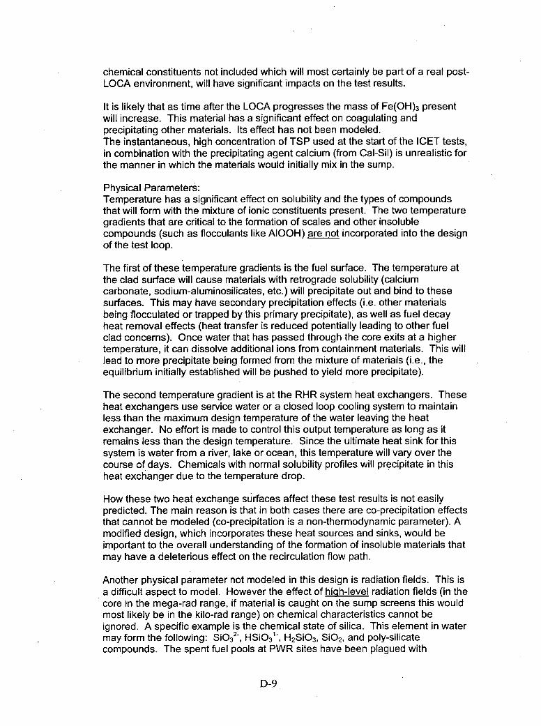
chemical constituents not included which will most certainly be part of a real post-LOCA environment, will have significant impacts on the test results.
It is likely that as time after the LOCA progresses the mass of Fe(OH) 3 presentwill increase. This material has a significant effect on coagulating andprecipitating other materials. Its effect has not been modeled.The instantaneous, high concentration of TSP used at the start of the ICET tests,in combination with the precipitating agent calcium (from Cal-Sil) is unrealistic forthe manner in which the materials would initially mix in the sump.
Physical Parameters:Temperature has a significant effect on solubility and the types of compoundsthat will form with the mixture of ionic constituents present. The two temperaturegradients that are critical to the formation of scales and other insolublecompounds (such as flocculants like AIOOH) are not incorporated into the designof the test loop.
The first of these temperature gradients is the fuel surface. The temperature atthe clad surface will cause materials with retrograde solubility (calciumcarbonate, sodium-aluminosilicates, etc.) will precipitate out and bind to thesesurfaces. This may have secondary precipitation effects (i.e. other materialsbeing flocculated or trapped by this primary precipitate), as well as fuel decayheat removal effects (heat transfer is reduced potentially leading to other fuelclad concerns). Once water that has passed through the core exits at a highertemperature, it can dissolve additional ions from containment materials. This willlead to more precipitate being formed from the mixture of materials (i.e., theequilibrium initially established will be pushed to yield more precipitate).
The second temperature gradient is at the RHR system heat exchangers. Theseheat exchangers use service water or a closed loop cooling system to maintainless than the maximum design temperature of the water leaving the heatexchanger. No effort is made to control this output temperature as long as itremains less than the design temperature. Since the ultimate heat sink for thissystem is water from a river, lake or ocean, this temperature will vary over thecourse of days. Chemicals with normal solubility profiles will precipitate in thisheat exchanger due to the temperature drop.
How these two heat exchange surfaces affect these test results is not easilypredicted. The main reason is that in both cases there are co-precipitation effectsthat cannot be modeled (co-precipitation is a non-thermodynamic parameter). Amodified design, which incorporates these heat sources and sinks, would beimportant to the overall understanding of the formation of insoluble materials thatmay have a deleterious effect on the recirculation flow path.
Another physical parameter not modeled in this design is radiation fields. This isa difficult aspect to model. However the effect of high-level radiation fields (in thecore in the mega-rad range, if material is caught on the sump screens this wouldmost likely be in the kilo-rad range) on chemical characteristics cannot beignored. A specific example is the chemical state of silica. This element in watermay form the following: SiO3
2-, HSiO3'-, H2SiO3, SiO 2, and poly-silicatecompounds. The spent fuel pools at PWR sites have been plagued with
D-9

decomposition of their Boraflexaby the radiation fields from the spent fuel. T hisdecomposition has led to concentrations of reactive silica (usually as HSiO3, orreactive silica) as high as 100 ppm. Contrary to this phenomenon, reactive silicain solutions from pH 3-9 has been known to form poly-silicates (in the absence ofradiation) that are highly insoluble. One possible resolution to this issue may beto take the solids formed from the lOFT Test Runs and expose them to highradiation doses for several days, then re-examine their morphology. This wouldhelp to assess if there is any effect by the high intensity radiation fields within thecoolant system.
3. What variables or materials not simulated by the ICET testing may have the mostimpact on chemical product formation (e.g.., coatings, free insulation, flow throughsediment and other materials on sump screen, galvanic effects) and how shouldtheir effect be characterized by testing or analysis?
The effect of the liquid coming into contact with fuel in the reactor vessel willhave considerable impact. There are two missing variables here: heat andradiolytic effects. Heat at the fuel surface will be several hundred degreesFahrenheit. This will have an affect as the materials with retrograde solubility,the scale formers, will concentrate on this surface and not be available to formother precipitates. [See additional notes on this effect above].
The presence of suspended solids from the reactor coolant system, which willhave a very high iron and nickel content were not considered as one of thesolution constituents. Specifically, magnetite, nickel ferrite, bonaccordite, nickeloxide and nickel metal are materials that would be produced in large amounts(10-500 ppm) following a LOCA. Over the course of a thirty-day test thesematerials will change their chemical form, including the formation of ferrichydroxide (a strong flocculating material).
Another variable not simulated is the presence of silica in the water storagesystems and the RCS. The concentration of silica in the storage tanks may beas high as 1 ppm and in the RCS the silica concentration will be in the range of0.3 ppm to 3.0 ppm. Since silica in combination with magnesium, calcium andaluminum can form materials with retrograde solubility; silica can have an effecton the total mass of material precipitating.
4. Were the methods used within the ICET program to characterize and analyzechemical by-products sufficient?
The analytical techniques. used for characterizing the chemical by-products were:
A. Inductively -Coupled Plasma-Atomic Emission Spectrometry (ICP -AES):Method for determining the elemental content qualitatively andquantitatively present in the solutions produced by the tests. Although itdoes not identify oxidation state or molecular environment it will identifyall elemental components in the percent to the ppb range. Theconcentration ranges used for analysis were appropriate for theconcentrations expected in the simulated post-LOCA environment.
B. Scanning Electron Microscopy (SEM):
D-10
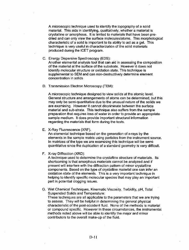
A microscopic technique used to identify the topography of a solidmaterial. This aids in identifying, qualitatively, whether a material iscrystalline or amorphous. It is limited to materials that have, been pre-dried and can only view the surface molecules/atoms. This morphologicalcharacteristic of a solid is important to its ability to act as a gel. Thistechnique is very useful in characterization of the solid materialsproduced during the ICET program.
C. Energy Dispersive Spectroscopy (EDS):Another elemental analysis tool that can aid in assessing the compositionof the material at the surface of the substrate. However it does notidentify molecular structure or oxidation state. This technique issupplemental to SEM and can non-destructively determine elementconcentration in solids
D. Transmission Electron Microscopy (TEM):
A microscopic technique designed to view solids at the atomic level.General structure and arrangements of atoms can be determined, but thismay only be semi-quantitative due to the unusual nature of the solids weare examining. However it cannot discriminate between the surfacematerial and sub-strata. This technique also suffers from the samplepreparation that requires loss of water in order to provide an appropriatesample medium. It does provide important structural informationregarding the materials that form during the tests.
E. X-Ray Fluorescence (XRF).An elemental technique based on the generation of x-rays by theelements in the sample matrix using particles from the instrument source.In matrices of the type we are examining this technique will be semi-quantitative since the duplication of a standard geometry is very difficult.
F. X-ray Diffraction (XRD):A technique used to determine the crystalline structure of materials. Itsshortcoming is that amorphous materials cannot be analyzed and ifpresent will interfere with the diffraction pattern of minor crystallinecomponents. Based on the type of crystalline material one can infer anoxidation state of the elements. This is a very important technique inhelping to identify specific molecular species that may play an importantpart in potential clogging issues.
G. Wet Chemical Techniques, Kinematic Viscosity, Turbidity, pH, TotalSuspended Solids and Temperature:These techniques are all applicable. to the parameters that we are tryingto assess. They will be helpful in determining the general physicalcharacteristic of the post-accident fluid. None of the methods is materialor compound specific. However in these circumstances, the instrumentalmethods noted above will be able to identify the major and minorcontributors to the overall make-up of the fluid.
D-11I
The analytical techniques used to characterize the chemical compounds thatwere formed are complementary. Taken as a whole they are the most extensiveanalytical tools that could be used for this assessment and are adequate toaddress changes that would be observed during the ICET program.The only additional test that might be of value would be FTIR of the coloredmaterials/solution to identify the chemical identity of those colored materials. Itshould be noted that in a strong radiolytic field that most color-bearing organicmaterials would be transformed to carbon dioxide and water.
The one analytical test that yields very little useful information is the massdetermination of the coupons before and after the tests. These co upons shouldbe used for qualitative observation of the mechanism of corrosion and depositionof other insoluble compounds.. XRD may be useful in assessing the types ofcompounds not related to the coupon material that may be formed on its surface,and TEM may provide qualitative insight as to the materials present. Unless atotal mass balance is attempted using the interior system surfaces as well as thecoupons, the actual mass of the coupons will not provide any significantinformation.
5. Analytical Simulation. Is the speciation analysis expected to provide reasonablepredictions of chemical product formation over a range of possible sumpenvironments?
The average temperature and concentration ranges used for the ICET programdo simulate the bulk water, average temperature and concentrations ofconstituents (with the exceptions noted in Al (above).
However, two important temperature profiles and two physical effects are not partof the ICET simulation. The increase in temperature as the water passes overthe hot fuel surface will cause scale to form at that surface, potentiallyscavenging the gel formers from the solution. The decrease in temperature asthe water passes from the containment sump to the residual heat removalsystem can also cause precipitation of materials on the inlet tubesheet and tubesurfaces of the heat exchanger (this particular effect was seen in Test#1 withturbidity see Figure 29 of test report).
The two physical effects not modeled are the radiation field from the fuel, and thelayer of corrosion products on the interior surface of the reactor coolant system.The radiation field will promote the formation of radicals that can expand thepotential number of mineral products that can be formed. The presence ofcorrosion products on the interior surface of the system can provide amechanism for removal of some contaminants. The corrosion products releasedduring he LOCA can contribute to the settling rate of other insoluble compoundsof lower density prior to reaching the containment sump. The exact location ofthis settled material would need to be modeled in a future experiment.
6. Is the plan for benchmarking these codes using small-scale testing and the ICETresults appropriate?
It would be appropriate to use the codes to help bound the characteristics that weexpect to observe. However, it is important to note that not all of the important
D-12
physical and chemical parameters present in the post-LOCA environment havebeen appropriately modeled in the ICET tests. Thus using the models with theexisting data can give us limited information.
7. What is the most appropriate way to measure the uncertainty associated withthese codes?Not within the reviewer's area of expertise.
8. Was the Head Loss Simulation Testing & Analysis for the accelerated head losstesting approach viable for evaluating the effects of multiple chemicalenvironments quickly?
One of the difficulties in this testing mechanism is that the- concentrations ofseveral of the potential fouling species will increase over time. The effects ofaging of the insoluble materials are that they generally will increase in size andcrystalline character, increasing density. The test loop does not provide the sametype of stagnant environment that would be encountered in the submergedportion of the containment building. The relatively lower flow rate would promotebetter agglomeration of particulate material due to the effect of relatively highconcentration of the precipitants at the surface of the insulation. This will promotesettling that will not be modeled in these tests.
The test loop as designed does not allow for insoluble materials to drop out, aswould occur during transit along the containment floor following a LOCA. Therelatively long flow paths and impediments to flow caused by structuralcomponents are not simulated. These provide 'drop out' areas forinsoluble/suspended materials before they can approach the screens. Thusthere is a bias towards a rapidly increasing pressure across the filtering media,which does not depict the actual mechanism of transport in the containment.
Furthermore the test loop design has forced impingement, vertically down on thefilter screen. In containment sump the flow of water is horizontal, and the water isnot confined to a pipe. If the surface area of the screen at, and below the waterlevel is clogged, the water will rise to a higher level where the screen is notclogged. This type of 'overflow effect' cannot be realized in the current design. Aproposed modification where the effect of long term clogging could be morerealistically evaluated is shown in Attachment I.
9. What is the best method for incorporating for time-dependent effects (e.g.,material aging, evolving chemical environments) in simulation testing?
The techniques that have been used by the test groups thus far seem to be themost appropriate.The only exception is the preparation of the stainless steel surface of the testloop. In a PWR the interior surfaces of all the metals will be covered withrelatively thick oxide coatings (100-250 microns, compared to the test loop whichis most likely only about 10 microns). The stainless steel will visibly be black,
D-13

and several hundred microns thick. Although this is an initial material condition, itgoes to the heart of developing the right conditions of materials to supplyaccurate data for simulations.
10. What metrics are most appropriate for evaluating the results of simulatedchemical products with those that formed during the ICET program?Not within the reviewer's area of expertise.
11. Are correlations available, or can they be developed, which can predict theassociated head loss if important physical characteristics of a chemical by-product are known?
Models that predict head-loss cannot account for the effects of gelatinous oramorphous materials. At least one reason is the secondary effect ofcoprecipitated or agglomerated materials. Flow rate-AP curves for specificfiltration media have been developed by filter manufacturers. These relationshipsare almost all made for closed systems, where flow is impacted on a constantfiltration area, and a specific well-characterized material is used for the tests. Inthe early stages of the event this type of curve would not be representative ofwhat would occur in containment. Additionally should the entire screen becomecovered with debris and the level of water should rise above the screen level,buoyant effects for the solid debris may come into play and change the effectedarea of blockage.Although the preliminary data provides some information regarding head lossdue to a certain type of compound, there is insufficient information to make validpredictions of head-loss based on physical or chemical characteristics of thecontainment mixture of materials.
D-14

Part 11.In this portion of the report, the individual tests and their results are evaluated.Three parameters not included in the test conditions that will have a significant effect onthe conclusions reached are:
*Radiation Field (a flux of approximately 1012 e/cm2 -sec in the fuel vicinity) inaddition to the gamma flux from the fuel (mega rad level)
*Presence of magnetite as an insoluble material which would be present inconcentrations of upwards of 50 ppmn in the post LOCA environment
*Presence of several ppm of hydrogen peroxide due to air-saturated-waterradiolysis in the fuel area
These conditions would favor the formation of an agglomerated precipitate that wouldhave a large density compared to the precipitates measured in these tests, and wouldsettle or be filtered more easily. The only way to determine whether the test representsthe post-LOCA condition is to add these additional items as test parameters.
The above comments apply to all five ICET programs.
Test# 1.
The introduction of chemicals into the loop simulates the containment spray initiationprocess when NaOH would be used. The pH attained in the bulk fluid is representativeof what would be expected in this situation. In this test, 100% of the insulation wasfiberglass.
In section 4.3 SEM examined the effects of the test solution -on the fiberglass insulation.However it does not appear that a control was run for this experiment, i.e., demnineralizedwater soaking of the fiberglass that would assess whether the same type deposits wouldform. This is relatively important since in containment the, humidity is about 100%saturation during operation. This means that fiberglass will be moisture saturated whilein service. It would be important to distinguish what is caused post-LOCA and normaloperations.
Section 4.4 describes the grinding of concrete into dust prior to introducing it into the testloop. This technique appears to be overly conservative. Although it is possible forconcrete to be ground up by a water jet during the LOCA, it would be rather limited dueto the short duration of the blowdown period and the relatively small surface area thatwould be scoured. Once the material settled (and it most certainly would during the firstfour hours) the concrete would begin to "heal" over, forming a protective coating ofCaCO3 over the open scar and over any deposited material. This would take place inaerated waters in particular due to the enhanced solubility Of CO 2 in the post-LOCAbasic pH.
In Figure 43 the solubility of aluminum is plotted as a function of time. It is noted thatfiltration through a 0.7 micron filter did not affect the filtered vs. non-filtered results sothat all samples after day 25 were not filtered. The solubility of AI(OH) 3 at pH 7.0 is 0.14ppb, but increases substantially above pH 9.0 due to the formation of the complexAI(OH) 4-1. These compounds when heated will have waters of hydration removed andcondense to AIO(OH) [boehmite] or A1203 [alumina] depending upon the temperature.
D-15
The conditions to promote the formation of these materials will exist at the fuel surface,which is at a much higher temperature than the titanium immersion heaters. ICET#1 hasthe highest concentration of aluminum in solution as a direct result of the high pHyielding a soluble aluminate complex.
One conclusion of the test was, "Most of the aluminum remained in solution and passedthrough the 0.45 pm filter at 60 00, e.g., the aluminum did not settle." This conclusion isconsistent with the results of Test #1 conditions. It is important to note that once thesolution cooled, that a significant solubility effect was observed. The reheating of theprecipitated material during this test did not completely rea-dissolve the precipitate. Thisis an important effect for this combination of materials, since the post-LOCA sump wateris passed through a heat exchanger that will significantly lower the temperature of thesolution. This will cause precipitation to occur in both the heat exchanger and otherportions of the RCS, that precipitate will then not completely redissolve. Thisprecipitated material may then act to trap or coprecipitate other species.
Qualitatively, the SEM photographs show that the precipitated material forms bridgesbetween the fiberglass fibers. These precipitates are somewhat structured, but this is avery qualitative observation. The amount of material seen in these photographs mayhave an effect on flow, but this would need to be specifically measured versus a cleanfilter bed to determine any quantitative effects.
Test#2.
The test condition s were targeted for a pH of 7.3 using Na3PO4 (TSP).The TSP is immediately injected into the test line, which flows over the test coupons inthe tank. This condition does not simulate the containment environment during the initial4 hours. Immediately following the break, water to the spray header and the RCS will besupplied by the RWST. This is borated water at a pH of approximately 4.2. TSP iscontained in baskets in the sump or surrounding the sump and slowly dissolves as thevolume of water from the break depletes the RCS and RWST inventory. Once theinventory is depleted, containment recirculation phase begins. At this point (-30 minuteslater, depending upon the size of the LOCA) the pH 7.3 solution will come into contactwith the bulk of the materials in containment.During the initial phase of containment spray for TSP based plants the pH of the spraywill be closer to 4.5 (due to the presence of some Li+ in the RCS). This will mean thatmore dissolution of metals contacted will occur during that 30-minute period when theTSP is not buffering the containment spray.
The non-detectable concentration of aluminum in the solution for Test #2 is consistentwith the presence of a mixture of very insoluble aluminum hydroxide and calciumphosphate precipitates. As noted in the Test#1 discussion, the solubility at pH 7.0 isapproximately 0.14 ppb for aluminum hydroxide. This is much less than the detectionlevel for the ICP-AES analysis of 50 ppb. The limiting reagent in this test was thephosphate as calcium and magnesium were found in solution as a soluble species.
The deposits on the aluminum metal coupons were found to be predominantly AI(OH)3,with insoluble calcium, magnesium, sodium and silica materials. These additionalcompounds were most likely coprecipitated with the aluminum hydroxide. Although theappearance of the coupons indicates significant weight gain due to precipitate
D-16

deposition, generally speaking, the weight loss/gain by the coupons is going to be of littleanalytical value. The real value is in identifying the qualitative nature of the deposits(see pages 45-50 in the ICET #2 Report). The amorphous, precipitated materialattached well to the fiberglass fibers and appears that it would provide significantimpedance to water flow through a debris bed comprised of these fibers.
A significant quantity of white precipitate consisting of calcium phosphate and aluminumhydroxide were found in the bottom of the test tank. Although this material precipitatedwithin the first day, its amorphous nature, density and attachment to fiberglass materialsmake it a concern for flow through sump screens.
Test#3.
Test#3 had an initial pH of -4.2 and used a mixture of 80% Cal.-Sil and 20% fibrousinsulation, as well as "latent debris". Based on the amount of concrete dust added (21.3g) and the surface are of exposed concrete (solid) it is surprising that the pH did notinitially rise to close to 9.0. The concrete dust and soil that were added as "latent debris"are may no be representative of what is present in the reactor containment building.Those materials from concrete would provide a significant alkaline environment for waterin contact with them even over short period of time.
This starting condition is out of synchronization with the LOCA starting sequence. At theonset the high velocity jet that would impinge the insulation would be closer to a pH of 5-6.0 rather than 4.2. This is because the boric acid concentration during the blowdownphase will be dominated by the ambient RCS boron concentration (1-1600 ppm) and notthe much higher (2300+ ppm) in the storage tanks.
As the leak progresses and the water collects in the sump the water washing over theinsulation is maintained at that pH. Until the containment recirculation spray initiates. Atthat time a swing in pH from about 5.0 to about 8.0 then back to about 7.1 will occur overthe next 30.minutes to 4 hours as the water in the containment begins to mix toequilibrium concentrations. During the time period prior to recirculation the insulationwould be lying in a stagnant pool of water on the containment floor or caught on anothercomponent.
Table 2-1 shows the ratio of mass or ft3 of contaminant per ft3 of sump water. The ratioof Cal-Sil to water mass (0. 137 ft3/ ft3), in particular, seems very high. If this is scaled upto the PWR case, the mass of insulation that would be getting soaked is about 7,400 ft3.This particular parameter should be revisited to determine if the long-term recirculationsolution would contact this significant a mass of Cal-Sil.
The introduction of the TSP as a concentrate directly into the wetted insulation matrixdoes not simulate what would happen in the containment situation. The concentration ofTSP would be far more dilute before it initially contacted the insulation due to dilutionwith the remaining volume in the RCS and containment floor. Additional tests within theICETTest#3 matrix was performed which varied the concentrations of insulation usedwith the matrix. The purpose was to ascertain if there would be significant differences inthe measured head loss when the solution is pumped through the in situ debris bed.The results show that even though with lower concentrations of Cal-Sil insulation that
D-17
less head loss was initially experienced, the head loss continued to increases for theduration of the test (approximately one hour). One variation of this test used the testsolution without the introduction of TSP. The purpose was to ascertain what the directeffect of the TSP-Calcium precipitate had on head loss. Although an initial pressureincrease of -2.8 pounds was measured, it stabilized at that value and did not change forthe remainder of that test.
The concentration of boron in the test ioop increased by -18% during the 30 day trial.The reason for this is most likely leaching from the fiberglass insulation. It is possiblethat this would occur in the post-LOCA environment since the much of the containmentinsulation would eventually become wetted. It would be important to determine if this isthe case (note this also happened in Test #4; a boron concentration increase of about21%).
The results from Test #3 show that significant mass of precipitate can form in thepresence of TSP and the Cal-Sil insulation. The data presented indicate that this is amixture of Ca3(P0 4)2 and some other amorphous materials that either co-precipitate withthe calcium phosphate or are innately insoluble. The SEM/EDS results provide evidencethat at least part of the precipitated material is a carbonate. This is also significant inthat it adds to the mass of precipitate that will be formed from the carbon dioxide that is'scrubbed' from the containment air. The TEM results were not able to provideconclusive evidence for a specific type of crystalline material being formed.
Test#4.
The solution for Test #4 was made up to pH 10 using NaOH with a mixture of Cal-Sil(80%) and Fiberglass (20%) insulation.The high pH and presence of Cal-Sil yielded solution samples that had high TSS valuesand turbidity, but low aluminum. A significant mass of precipitate was collected from thescreen at the tank bottom at the test conclusion. Although analysis of this precipitate didnot detect aluminum, a small quantity must be present form the initial solutionmeasurements. The precipitates of (calcite) CaCO 3, Lime (Ca(OH) 2)and tobermorite(CaSiOA) most likely coprecipitated any aluminum from the fiberglass insulation. It isalso likely that the aluminum coupon was coated with a thin film of the tobermorite thatinhibited the further dissolution of the aluminum metal. The significant decrease inturbidity over the first day identifies the flocculent nature of this mixed precipitate.
Additionally, the precipitate would 'stick' to surfaces like fibers of insulating material, butit could not be found on materials like the nylon bag used to hold the unfracturedinsulation pieces. This is most likely due to the 'common ion' effect (decreasinglocalized solubility) that exists at the surface of the insulating materials (containing oneof the precipitate ions) while in other materials this cannot occur. This is also seen in themetal test coupon photographs taken at the end of the 30-day period. The amount ofdeposited material is minimal because of this lack of 'common ion' effect.
As compared toTest#3 the precipitated material in Test#4 was more crystalline.Crystalline precipitates are less likely to cause attract significant amounts of othermaterials and block flow, than are amorphous, hydrated gels.
D-18
Test#5.
This test used sodium tetraborate as the chemical additive for the spray system. Onlyfiberglass insulation was used for the test. In general, very little mass of precipitatedmaterial was observed over the 30-day test. These materials were composed of sodiumaluminum and silicates.
Borax was added before the spray phase began. Borax is a constituent in "ice-condensers", and would only be added into the mix after the spray phase had initiated.Thus the initial interaction of the 'blowdown" liquid with containment materials would bewith acidic borated solution. The addition of boric acid with the components in theinitiation of the test is out of sequence with actual LOCA conditions. It would take atleast 2 hours for the pH to approach 8.0 in the containment sump. Thus the interactionof the RCS with the containment metallic components would yield additional metal ionsin solution (lower pH generally will favor more significant dissolution of the metalliccomponents).
The step decreases in aluminum on days 14 and 21, and the step increase in calcium onday. 25, appear to be unrelated. This type of behavior is not expected in a system, whichhas solid material in excess with a soluble counterpart (i.e., a saturated solution). Thesechanges do not appear to correspond to system changes during those time periods thathave been noted in the report thus far.
The significant change in appearance of the coupon materials and the general weightloss is evidence for corrosion occurring in this chemical environment. The qualitativeanalysis of the aluminum coupons shows deposition of some iron and zinc corrosionproducts. The exception to this was for the concrete 'coupon' which showed a largeweight gain. This is presumably from the deposition of sodium-alumino-silicates.
The rise in aluminum concentration over the first 14 days is consistent with the smallamount of hydrogen gas generation during that same period. The continued presence ofaluminum in solution, and the lack of additional hydrogen generation after day 18,suggests that the corrosion film that was observed on its surface has mitigated thealuminum corrosion.
Copper and iron corrosion played a part in the inhibition of the aluminum corrosion. Thecopper concentration in solution was constant after about 8 days at 0.7 ppm. The ironconcentration either in the filtered or unfiltered solution was undetectable.
The qualitative effect of the precipitated material was that it formed a more structuredsolid on the fiberglass surfaces than was observed in previous tests (especially ICET#3).The mass of material observed was significantly smaller. Both of these observationsgenerally support the notion that flow through the debris bed on a screen would be lessimpeded with this chemical combination in the post-LOCA environment.
D-19
Conclusions
The ICET test clearly shows that there are a variety of different chemical environmentsformed when containment spray is initiated and interacts with materials within thecontainment building. The effects observed which are of note are:
" In all cases insoluble precipitates are formed as a result of the containment spraychemicals reacting with insulation and metallic components in the containmentbuilding
" The precipitated materials are different depending upon the type of spraychemical and the type of insulation.
* Aluminum metal corrosion contributes most significantly to the dissolved metalconcentration of the post-LOCA environment
" Significant concentrations of magnesium, silica and calcium may be leached fromthe two insulating materials used in these tests
" The corrosion of metal coupons (with the exception of aluminum) used in thesetests show that in the 30-day trial that their contribution to the metal loading insolution is small, but that they can provide a surface for the adherence ofprecipitated materials
Plant specific characteristics will impact how the results of these tests can be used toassess the acceptability of current sump and screen designs.
It is important to note that although the different classes of post-LOCA spray have beenidentified, not all containment materials have been tested in these programs. Each PWRwill need to carefully examine all materials that could potentially come into contact withpost-LOCA spray, and assess the effects of leaching, precipitation of leached ions andcoprecipitation of ionic substances on these plant specific materials.
The most significant impacts on post-LOCA sump chemistry occur with systems thathave both TSP and Cal-Sil type insulation. The formation of amorphous calciumphosphate and the apparent coprecipitation of other materials create a significantimpediment to forced water flow in the system used in the ICET programs.
The information in the ICET programs provides plant personnel with a direction forfocusing any testing that they may need to perform if modifications to their sump screensare going to be made. Each plant should use their plant specific information as part oftest program for assessing feasibility of design. The methods of analysis used in theICET programs that should be considered as part of the design testing are:
*SEM*XRD*TSS*Turbidity*Metal concentration (by an lOP or related spectroscopic technique)*EDS
These analyses will help to characterize the precipitated materials and establish specificbases for flow testing.
D-20
Recommendations
1. Chemical constituents that have not been simulated are:a. Initial RCS silica concentrations up to 1 ppm (and in the refueling storage
tanks of several PWRs this concentration may be as high as 5-10 ppm),b. CRUID concentrations (which will contain mixtures of nickel ferrite,
magnetite, nickel oxide and hematite) of up to 100 ppm from thethermal/hydraulic transient caused by the LOCA, and
c. The presence of hydrogen peroxide resulting from the gamma radiationfield of the core.
Consideration should be given to include these parameters in the experimentalsimulations.
2. The relatively high concentration of TSP used at the start of the ICET tests, isvery conservative compared to the manner in which the materials would finallymix in the sump. Consideration should be given to inject the TSP into the loop ata lower concentration over a longer period of time to simulate more closely actualpost-LOCA condition.
3. Temperature profiles of the reactor coolant system have not been modeled. Thetemperature profiles will have a significant effect on the rate and type ofprecipitate that is formed, and also where the precipitates will be formed. Thismay have a significant effect on the head loss modeling. These temperatureprofiles should be included in the test loop.
4. Radiation fields from the nuclear fuel also have not been modeled. Free radicalformation will have a significant effect on the type of compounds that can beformed and where they will precipitate. One possible resolution to this issue maybe to take the solids formed from the ICET Test Runs and expose them to highradiation doses for several hours, then re-examine their morphology. This wouldhelp to assess if there is any effect by the high intensity radiation fields within thecoolant system.
5. The analytical techniques used to characterize the chemical compounds thatwere formed are complementary. Taken as a whole they are the most extensiveanalytical tools that could be used for this assessment and are adequate toaddress changes that would be observed during the ICET program.The only additional test I could recommend would be ETIR of the coloredmaterials/solution to identify the chemical identity of those colored materials. Itshould be noted that in a strong radiolytic field, most color-bearing organicmaterials would be transformed to carbon dioxide and water.
6. The mass determination of the coupons yields little quantitative information (ifany). I would recommend deleting this part of the coupon analysis unless a totalmass balance approach is performed. Coupons should be used strictly forqualitative assessment of what transformations of the coupon materials occurand what insoluble products are formed or precipitate on these surfaces.
7. The test loop as designed does not allow for insoluble materials to drop out, aswould occur during transit along the containment floor following a LOCA. The
D-21
relatively long flow paths and impediments to flow caused by structuralcomponents are not simulated. Recommend using the modification as shown inAttachment 1.
8. The interior surface of the test ioop does not simulate the conditions of theinterior surfaces of a PWR. Recommend that the test loop internal surfaces thatare designed to mimic the internal PWR surfaces be treated with the initial testsolution at 550OF and 2200 psig before additional testing is performed.
9. The concentration of boron in the test loop, in Tests 3 and 4 increased by -18%and 21 % respectively, during the 30 day trial. The reason for this may beleaching from the fiberglass insulation. It is important to determine if this is thesource of the increase, or if not where the increase is coming from.
10. In Test 5, Borax was added before the spray phase began. Borax is aconstituent in "ice-condensers", and would only be added into the mix after thespray phase had initiated. This is out of sequence with actual LOCA conditions.This should be corrected in a subsequent run of this test.
11. The ICET tests did not include all combinations of materials (i.e., insulation) inthe reactor containment buildings. If additional tests are performed, othermaterials should be put into the mix to help assess the extent of materials thatmay be precipitated.
12. The submerged mass/volume of Cal-Sil insulation involved in the long-termtesting is greater than expected during a post-LOCA recovery. Although this is aconservatism in the ICET programs, it would be beneficial to identify morerealistic submerged materials and th~eir effect compared the existing information.
D-22
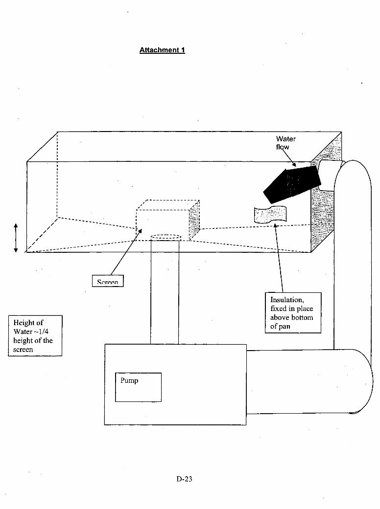
Attachment I
Height ofWater - 1/4height of thescreen
D-23

Appendix E
Final Report
Characterization of Chemical and Corrosion Effects PotentiallyOccurring Inside a PWR Confinement Following a LOCA
By
Digby D. Macdonald3222 Shellers Bend Rd.State College, PA 16801
Submitted to
Paulette TorresRobert L. Tregoning
Division of Engineering TechnologyOffice of Nuclear Regulatory ResearchUS Nuclear Regulatory Commission
Washington, DC 20555-0001
June 28, 2006
E- 1

Abstract
A review is presented of the fundamental physico-electrochemistry of those processesthat are reckoned to contribute to the evolution of the chemical properties of the containmentpool after a LOCA (Loss of Coolant Accident) in a Pressurized Water Reactor (PWR). Theprocesses and issues considered include the establishment of the redox and corrosion propertiesof the environment, due to the radiolysis of water and the presence of hydrogen from the PWRprimary coolant and the oxygen contained within containment; the impact of the redox potentialon the chemistry of the pool 'in a post-LOCA environment; co-precipitation of other species withFeOOH, AlOGH, etc; Ostwald ripening; the Schikorr reaction and the generation of hydrogen insitu; the pH of zero charge (PZC) and coagulation; y-AIOOH formation; precipitation on fibers;thermal hydrolysis of organic material; the maximum particle size that can be tolerated; thereason(s) why a bimodal distribution exist might exist in particle size; and the corrosion ofaluminum. These are all issues that figure prominently in the generation of solid products thathave the potential for clogging the sump pump screens that are designed to enable recirculationof the coolant ejected from the primary circuit upon a LOCA, the injection of emergency corecoolant into the core, and the functioning of the building spray system that is designed to removethe fission product, iodine. The purpose of this report is not to provide a time-line for the eventsthat occur during a LOCA, but rather to identify and articulate some of the fundamentalprocesses involved. This process does, however involve an assessment of how well theIntegrated Chemical Effects Tests (ICETs) and the analytical simulations were able to reasonablyreproduce the effects that might occur in an actual LOCA. It is concluded that the ICETs andanalytical simulations have serious shortcomings, because redox potential effects and the impactof radiolysis were not taken into account. For example, the redox potential, which arises fromnon-equilibrium processes, cannot be simulated analytically using current chemical modelingcodes, because they lack an effective mixed potential model. The redox potential determines thedriving force for the transition between different oxidation states. Possibly, of much greaterimportance, is the radiolytic conversion of nitrogen from the ambient containment air into nitricacid, because preliminary modeling work indicates that, if the dose rate is sufficiently high in thepool, the production of nitric acid may overwhelm the buffering capacity of the boricacid/lithium hydroxide in the pool. If this were the case, the pH would drop precipitously andthe conditions would lie well outside those simulated in the ICETs and in the analytical modelingperformed to date. Indeed, if the pH drops by the amount predicted for a high (but realistic)gamma-photon dose rate (16 Oradlh), massive corrosion of structural materials might be expected,which, in turn, might have unforeseen consequences for the operation of vital systems thatmaintain effective cooling of the core. Therefore, it is recommended that radiolytic acidificationof the pool and changes in the redox properties be explored to determine the exact impact thatthey might have on pool chemistry.
E-2
Executive Summary
A review is presented of the fundamental physico-electrochemistry of those processesthat are reckoned to contribute to the evolution of the chemical properties of the containmentpool after a LOCA (Loss of Coolant Accident) in a Pressurized Water Reactor (PWR). Elevencritical issues were identified: (1) The evolution of the electrochemical properties of thecontainment pool, and scoping calculations were performed using the radiolysis/corrosionpotential code, FOCUS, and variants thereof, that was developed to model electrochemicalphenomena in the primary coolant circuits of Boiling Water Reactors (BWRs) and PWRs; (2)Co-Precipitation of Other Species with FeOOH, AlOOH, etc.; (3) Ostwald Ripening, whichtransforms newly precipitated* phases into thermodynamically more stable phases; (4) theSchikorr reaction and the in situ generation of hydrogen; (5) the pH of zero charge (PZC) and itsrole in coagulation; (6) y-AIOOH formation; (7) precipitation of solid particles and corrosionproducts on fibers; (8) degradation of organic materials; (9) whether there is a particle size thatcan be tolerated; (10) possible reasons why a bimodal distribution exists in the particle size; and(11) the corrosion of aluminum. Additionally, an assessment was made of the effectiveness ofthe experimental programs that were supported at various national laboratories (ANL, LANL)and at the Center for Nuclear Waste Regulatory Analysis (CNWRA) at the Southwest ResearchInstitute in San Antonio, Texas, in addressing vexing issues and in simulating the chemicalprocesses that might 'occur in a containment pool after a PWR LOCA.
The processes. and issues considered include the establishment of the redox and corrosionproperties of the environment, due to the radiolysis of water and the presence of hydrogen fromthe PWR primary coolant and the oxygen contained within containment, and the impact of theredox potential on the chemistry of the pool in a post-LOCA environment. This issue is judgedto be particularly important, because the redox potential controls the oxidation states of allcomponents in the pool and the valency of dissolved species. The production of hydrogenperoxide via the radiolysis of water is expected to raise the redox potential substantially, therebypromoting precipitation of oxides, oxyhydroxides, and hydroxides through the formation of morehighly charged cations (Fe 3+ versus Fe2+) . The second overriding issue arises from thetendencies of surfaces to acquire electrical charge through the protonation (at low pH) orionization (at high pH) of surface hydroxyl groups to yields positive and negative chargesrespectively. The pH at which the net charge is zero is known as the "pH of zero charge" (PZC).If a multi-component system contains particles of opposite charge, the particles will coagulate toform macroscopic precipitates. Even if the particles are not oppositely charges, increasing theionic strength of the medium will cause the electrical double layers to shrink to the extent thatthe attractive van der Waal forces will overcome electrostatic repulsion and coagulation willoccur, as in the Alum water clarification technology. The third, principal issue that is addressedis corrosion, particularly the corrosion of aluminum. This phenomenon is expected to be asignificant source term for solid materials in the containment pooi after a LOCA. It is noted thatthe theory of corrosion is highly developed and that meaningfuil predictions of corrosion rate canbe made if the corrosion evolutionary path can be defined (i.e., the path in terms of variousparameters that the system travels after the LOCA). The important point is that these are allissues that figure prominently in the generation of solid products that have the potential forclogging the sump pump screens and pumps that are designed to recirculate the coolant ejectedfrom the primary circuit upon a LOCA, the emergency core coolant, and the building spray thatis designed to remove the fission product, iodine, through the core to remove decay heat. The
E-3
purpose of this report is not to provide a time-line for the events that occur during a LOCA, butrather to identify and articulate some of the fundamental processes that require attention andanalysis, if a reasonably accurate picture of the post-LOCA environment in a PWR is to bedeveloped.
A number of recommendations were formulated that might advance the technology ofpredicting the evolution of the containment pool environment after a. LOCA. The principalrecommendations are as follows:
Equilibrium models must be used with great caution, because the environment producedby a LOCA is unlikely to be at equilibrium, at least during the initial stages. Furthermore, theprocesses that occur during corrosion, precipitation, and ripening are generally slow, as has beenshown in some of the work carried out by ANL. The kinetics of many of these processes aresuch that the system may still be far from equilibrium as it enters the recirculation system.Accordingly, equilibrium calculations need to be bench-marked to the greatest extent possibleagainst experiment to assess the reliability of the thermodynamic equilibrium codes.
Given the likelihood that equilibrium models may not be appropriate, emphasis should beplaced on developing kinetic models for the precipitation and ripening (coagulation) processes.These models must recognize the most important driving force for coagulation; the charge (signand magnitude) that develops on the surfaces of particles, as characterized by the zeta potentialand the PZC (pH of zero charge). None of the commercial codes employed by SwRI appear tohave the necessary sophistication to effectively model non-equilibrium precipitation phenomena.
The possible generation of hydrogen from the Schikorr reaction
3Fe(OH)2 -4 Fe3O4 + H2 +.2H 2 0
and related chemical transformations should be explored, as they might contribute significantlyto the inventory of hydrogen in containment immediately after a LOCA and to the inventory ofmagnetite (Fe3O4) in the system.
.Realistic and viable models for the corrosion of aluminum, iron, and zinc, and of thedissolution of concrete and polymeric materials in contact with hot coolant under high masstransfer rate conditions (e~g., due to impinging jets) need to be developed that are capable ofpredicting corrosion rates under LOCA environmental conditions.
The hydrothermal hydrolysis of various organic/inorganic coating and insulationmaterials needs to be explored under conditions that realistically simulate a LOCA. It isexpected that hydrothermal hydrolysis will partially de-polymerize polymeric materials,producing materials ranging from particles. to gels. These materials need to be screened for theirphysical and chemical properties and, in particular, for their tendencies to "set" into moreresilient forms.
The models that are produced to predict corrosion rates and phase properties must be, tothe greatest extent possible, deterministic in nature. Thus, a deterministic model is one whoseoutput (prediction) is constrained by the natural laws to that which is physically. viable. Theseconstraints are generally the conservation laws, such as the conservation of mass, charge, energy,and momentum.
Development of a radiolysis code specifically for a containment pool is absolutelyessential, since the redox potential controls the speciation within the pool. This model shouldincorporate boric acid/LiGH + TSP (tni-sodium phosphate) models for estimating the pH. Themodel should be calibrated and evaluated against laboratory experiments to establish efficacy.A thorough analysis should be carried out to estimate the likely y-dose rates in the containmentpool as a function of time after a LOCA in a PWR. The contribution of a-dose rate from fission
E-4

products also needs to be evaluated. The latter is completely ignored in the present analysis andthe former (y-dose rate) is little more than a guess. No information of guidance on this subjectcould be found in the open literature.
A better database for the kinetics of the hydrogen electrode reaction, the oxygen electrodereaction, and the hydrogen peroxide electrode reaction needs to be established. Some of the"raw" data are already in the literature, but the information is incomplete and the data aregenerally not in a form that is readily interfaced with radiolysis/redox potential models. In somecases, however, the required data must be experimentally measured.
It is concluded that the ICETs and analytical simulations have serious shortcomings,because redox potential effects and the impact of radiolysis were not taken into account. Forexample, the redox potential, which arises from non-equilibrium processes, cannot be simulatedanalytically using current chemical modeling codes, because they lack an effective mixedpotential model. The redox potential determines the driving force for the transition betweendifferent oxidation states. Possibly of much greater importance is the radiolytic conversion ofnitrogen from the ambient containment air into nitric acid, because preliminary fniodeling workby the author indicates that, if the dose rate is sufficiently high in the pool, the production ofnitric acid may overwhelm the buffering capacity of the chemicals in the pool. If this were thecase, the pH would drop precipitously and the conditions would lie well outside those simulatedin the ICETs and in the analytical modeling performed to date. Furthermore, if the pH drops tothe extent predicted by preliminary scoping calculations, massive corrosion of structuralmaterials might be expected with unforeseen consequences for the operation of vital systems thatmaintain effective cooling of the core.
E-5
Contents
Abstract................................................................................................ E-2
Executive Summary.................................................................................. E-3
List of Figures ........................................................................................ E-7
List of Tables......................................................................................... E-8
1 . Introduction .................................................................................. E-9
2. Charge to Reviewers ........................................................................ E-9
2.1. Peer Review Objectives ............................................................ E-92.2. Principal Technical Questions .................................................... E-102.3. Motivation........................................................................... E-10
3. Reviewer's Expertise ....................................................................... E-1 1
4. Review of Simulations...................................................................... E-I1I
4.1 Integrated Chemical Effects Testing (LANL) ................................... E- 124.2 ICET Follow-up Testing and Analysis (LANL)................................. E-144.3 Chemical Speciation Prediction (CNWRA) ..................................... E- 144.4 Accelerated Chemical Effects Head Loss Testing (ANL) ...................... E- 154.5 Limitations of the Current Tests .................................................. E-15
5. Issues
5.1.
5.2.5.3.5.4.5.5.5.6.5.7.5.8.5.9.5.10.5.11.
.............................................................................. E-17
Electrochemical Properties of the Containment Pool ........................... E- 17Radiolytic Yield................................................................ E-19Chemical Reactions............................................................ E-2 1Convection................................... .... E-24General Solution of the Equations............................................ E-24Mixed Potential Model and the Redox and
Electrochemical Corrosion Potential ..................................... E-26Impact of Radiolysis in the Containment Pool .............................. E-3 1
Co-Precipitation of Other Species with FeOOH, AlOOH, etc ................. E-39Ostwald Ripening................................. I.................................. E-39Schikorr Reaction Generates Hydrogen In Situ.................................. E-40PZC and Coagulation .............................................................. E-40y-AlOOH Formation ................................................................ E-43Precipitation on Fibers ............................................................. E-44Thermal Hydrolysis of Organic Materials ....................................... E-44Is There a Particle Size that Can be Tolerated9 .............. . . . . . . . . . . . . . . . . . . . . E-45Why Does a Bimodal Distribution Exist in Particle Size?9 ........ . . . . . . . . . . . . . E-45Corrosion of Aluminum............................................................ E-45
6. Recommendations........................................................................... E-49
Appendix 1 ........................................................................................... E-52
E-6
Figures
Figure 1. Summary of the defect generation and annihilation reactions envisioned at theinterfaces of the barrier oxide layer on a metal, according to the Point DefectModel (PDM). V,ý- cation vacancy in the film; v. = vacancy in the metalsubstrate; M(X+ cation interstitial;, VO'* = oxygen (anion) vacancy; MI-+ (aq)cation in solution; MM cation in cation site on the metal sublattice; 00 oxideion in anion site on the oxygen sublattice; and MO., 2 stoichiometric barrierlayer oxide. Note that Reactions 1, 2, 4, 5 and 6 are lattice conservative processes(they do not result in the movement of the interface) whereas Reaction 3 and 7are non-conservative [D. D. Macdonald, Pure Appl. Chem., 71, 951 (1999)] .... E-27
Figure 2. Comparison of calculated and measured ECP for the Leibstadt BWR.The "measured" data were acquired in a test cell attached to therecirculation piping ..................................................................... E-29
Figure 3. Calculated ECP vs. [02] or [H 202] for a simulated PWR coolant system.T = 320 0C, [H12] = 25cc(STP)/kg(H 20), [B] = 1000 mg/kg, [Li] = 2 mg/kg,pH =7.36, flow velocity = 100 cmls, channel hydrodynamicdiameter = 100 cm...................................................................... E-30
Figure 4: Schematic plot of surface charge density versus pH for two surfaces incontact with the same aqueous solution .............................................. E-37
Figure 5: Schematic representation of the electrical double layer in the solutionside of an oxide/solution interface..................................................... E-3 8
Figure 6: Point defect model for the anodic oxidation of aluminum in aqueous solution.The species Al, A13~, vA, AlA!, Vý*, Al13+, and 00 represent aluminum metal,an aluminum cation interstitial, a vacancy in the metal substrate, an aluminumcation on the cation sublattice of the barrier layer., an oxygen vacancy on theanion sub lattice of the barrier layer, an aluminum cation in solution, and anoxygen anion on a normal anion site on the anion sublattice, respectively. Thesubscripts "oP' and "b" designate outer layer and bulk solution locations......... E-38
Figure 7: Schematic plot of surface charge density versus pH for two surfaces incontact with the same aqueous solution .............................................. E-41
Figure 8: Schematic representation of the electrical double layer in the solution sideof an oxide/solution interface.......................................................... E-42
Figure 9: Point defect model for the anodic oxidation of aluminum in aqueous solution.The species Al, A VA3, v AlA, Vý*, A131 , and 00 represent aluminum metal,an aluminum cation interstitial, a vacancy in the metal substrate, an aluminumcation on the cation sublattice of the barrier layer, an oxygen vacancy on theanion sublattice of the barrier layer, an aluminum cation in solution, and anoxygen anion on a normal anion site on the anion sublattice, respectively. Thesubscripts "or' and "b" designate outer layer and bulk solution locations......... E-47
E-7

Tables
Table 1. Radiolytic Yields (G Values) for Primary Radiolytic Species....................... E-20
Table 2. Reaction set used in the PWR radiolysis model ...................................... E-21
Table 3. Preliminary calculation of the generation of hydrogen peroxide, oxygen,and hydrogen in water at 30'C as a fuinction of ambient oxygen concentration(concentration in the absence of radiolysis), pH, and y-dose rate ................... E-3 1
E-8

1. Introduction
By any metric, a loss of coolant accident (LOCA) in a Pressurized Water Reactor wouldbe a catastrophic event, potentially resulting in the over-heating of the core to the extent that a"'melt-down" might occur. Such a possibility has been anticipated, of course, and the coolantsystem has been designed to provide for emergency core cooling via a gravity-fed supply ofwater that can be used to flood the core and remove the heat from the continuing fission anddecay processes. However, the supply of emergency coolant is limited and it is insufficient toremove the decay heat from the core that continues to be generated well after the fission processhas been shut down. Accordingly, the system relies upon the recirculation of the coolant that hasbeen injected from the LOCA onto the containment floor, together with the emergency corecoolant from the same location, to remove the decay heat. The free flow of the coolant from thecontainment floor through the pumps, screens, and filters is vital for the success of this strategy.
The occurrence of a LOCA, with water from the pipe break being directed onto a varietyof surfaces, including concrete, steel, plastic (polymer, including coatings and paints), andaluminum, will result in a complex mixture of compounds that could further react to produce averitable "soup"~. The high temperature of the water is assumed to result in significantdissolution and corrosion, resulting in the formation of precipitates and gelatinous material that,potentially, might block filters and screens and hence impede flow in the recirculating system.Thus, the goal of this program is to provide critical analysis and review of experiments that arebeing carried out at various national laboratories or affiliated units to identify the reactionproducts that may form by hydrothermal hydrolysis and other processes, resulting from theimpingement of high temperature coolant [boric acid + lithium hydroxide solution] on thestructural materials. The exact conditions (temperature and chemical composition) of theimpinging coolant are somewhat uncertain, because of adiabatic expansion and flashing of thecoolant from the break lowers the temperature and because much of the resulting chemistryremains unknown or not understood.
2. Charge to the Reviewers
The charge to the reviewers was presented by the Nuclear Regulatory Commission (NRC)(Paulette Torres and Robert L. Tregoning) in the kick-off meeting that was convened at theArgonne National Laboratory on August 18-19, 2005. The charge comprises specific tasks andissues that are best summarized by adopting, verbatim, the material presented by the NRC, asfollows:
2.1. Peer Review Objectives
Review technical adequacy of RES-sponsored activities related to chemical effects in PWRsump pool environments. The Technical Review Areas (TRAs) are listed as follows:
* Integrated Chemical Effects Testing (ICET): LANL* ICET Follow-up Testing and Analysis: LANL.* Chemical Speciation Prediction: CNWRA.* Accelerated Chemical Effects Head Loss Testing: ANL.
E-9
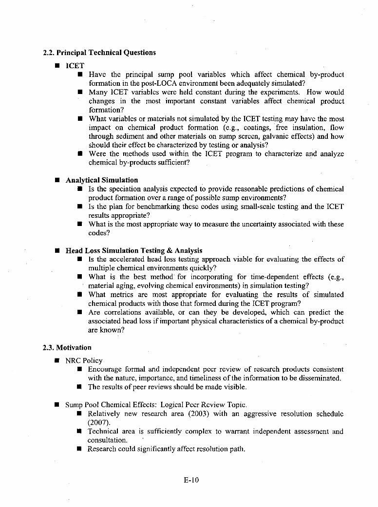
2.2. Principal Technical Questions
" ICET* Have the principal sump pool variables which affect chemical by-product
formation in the post-LOCA environment been adequately simulated?* Many ICET variables were held constant during the experiments. How would
changes in the most important constant variables affect chemical productformation?
" What variables or materials not simulated by the ICET testing may have the mostimpact on chemical product formation (e.g., coatings, free insulation, flowthrough sediment and other materials on sump screen, galvanic effects) and howshould their effect be characterized by testing or analysis?
" Were the methods used within the ICET program to characterize and analyzechemical by-products sufficient?
" Analytical Simulation" Is the speciation analysis expected to provide reasonable predictions of chemical
product formation over a range of possible sump environments?* Is the plan for benchmarking these codes using small-scale testing and the ICET
results appropriate?" What is the most appropriate way to measure the uncertainty associated with these
codes?
* Head Loss Simulation Testing & Analysis" Is the accelerated head loss testing approach viable for evaluating the effects of
Imultiple chemical environments quickly?" What is the best method' for incorporating for time-dependent effects (e.g.,
.material aging, evolving chemical environments) in simulation testing?* What metrics are most appropriate for evaluating the results of simulated
chemical products with those that formed during the ICET program?" Are correlations available, or can they be developed, which can predict the
associated head loss if important physical characteristics of a chemical by-productare known?
2.3. Motivation
" NRC Policy" Encourage formal and independent peer review of research products consistent
with the nature, importance, and timeliness of the information to be disseminated." The results of peer reviews should be made visible.
" Sump Pool Chemical Effects: Logical Peer Review Topic." Relatively new research area (2003) with an aggressive resolution schedule
(2007)." Technical area is sufficiently complex to warrant independent assessment and
consultation." Research could significantly affect resolution path.
E- 10

3. Reviewer's Expertise
The author of this report is an electrochemist/corrosion scientist who has 30± years oftechnical experience in the nuclear industry. In particular, the author has been extensivelyinvolved in the modeling of the chemistry and electrochemistry of heat transfer circuits in BWR,PWR, and CANDU reactors. This modeling work has resulted in the prediction of theaccumulated damage due to pitting corrosion, stress corrosion cracking, and corrosion fatigueusing deterministic models whose outputs (p~redictions) are constrained by the natural laws(conservation of mass, charge, etc). The author has also developed the Point Defect Model andDamage Function Analysis, which provide the most current view of the phenomena of passivityand passivity breakdown and the accumulation of localized corrosion damage, which are criticalissues in the present study. Finally, the author has spent three decades studying the properties ofhigh temperature aqueous solutions and has been instrumental in developing methods formeasuring pH (at a maximum temperature of 5280C), [H 2], [02], and redox and corrosionpotential at temperatures exceeding the critical value (374.1 50C). A resume for the author isappended to this report.
4. Review of Simulations
An important function of the review was to assess the effectiveness of work carried out atthe Argonne National Laboratory (ANL), Los Alamos National Laboratory (LANL), the Centerfor Nuclear Waste Regulatory Analysis (CNWRA) at the Southwest Research Institute (SwRI),San Antonio, Texas, and at the University of New Mexico to address some of the issues relatedto chemical effects in the containment pool post LOCA. This work was performed to supportresolution of Generic Safety Issue (GSI)- 191, which addresses the potential for post LOCAdebris accumulation on PWR pump screens to interfere with the emergency-core-cooling-system(ECCS). The specific task was to address the role that might be played by chemical processes("chemical effects") in the interference.
Both experimental work and thermodynamic simulations have been performed to providea broad basis for predicting chemical processes in the pool as a function of time after a LOCA.While these data provide a basis for predicting what might develop in the pool they are, bythemselves, insufficient to develop a thorough understanding of the chemical processes thatmight occur, because: (1) The processes that are expected to occur in the pooi are much morecomplex than can be reasonably simulated in "ideal" laboratory experiments; (2) Assumptionsmade in the simulations (e.g., equilibrium in the case of thermodynamic calculations) may nothold in practice, or: (3) Certain phenomena [e.g., radiolysis due to fission products ('y- and ax-emitters)] may be difficult or even impossible to accurately reproduce in the laboratory and maynot be incorporated in current, commercially-available codes. Nevertheless, selectedexperiments provide the means of checking expected behavior and hence of building confidencein the predictions of pool behavior as the containment environment evolves after a LOCA.
ICETs (Integrated Chemical, Effects Tests) were designed to address certain aspects ofthe evolution of the chemistry of the containment pool after a LOCA. These tests sought toreasonably simulate the chemical properties of the pool, so that the responses of certain materials(e.g., fiberglass insulation, concrete, electrical insulation, and various metals and alloys) could beassessed. These tests were carried out with an initial chemical environment containing 2800mg/L of boron as boric acid, 100 mg/L of HCl, and 0. 7 mg/L of lithium as LiOH. The tests weregenerally carried out over 30 days at a temperature of 600C, and pH control was affected by the
E-1 1
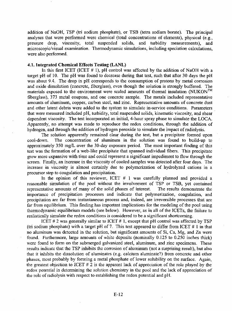
addition of NaGH, TSP (tri sodium phosphate), or TSB (tetra sodium borate). The principalanalyses that were performed were chemical (total concentrations of elements), physical (e.g.,pressure drop, viscosity, total suspended solids, and turbidity measurements), andmicroscopic/visual examination. Thermodynamic simulations, including speciation calculations,were also performed.
4.1. Integrated Chemical Effects Testing (LANL)In this first ICET (ICET # 1), pH control was affected by the addition of NaOH with a
target pH of 10. The pH was found to decrease during that test, such that after 30 days the pHwas about 9.4. The drop in pH corresponds to the consumption of protons by metal corrosionand oxide dissolution (concrete, fiberglass), even though the solution is strongly buffered. Thematerials exposed to the environment were scaled amounts of thermal insulation (NUKON T M
fiberglass), 373 metal coupons, and one concrete sample. The metals included representativeamounts of aluminum, copper, carbon steel, and zinc. Representative amounts of concrete dustand other latent debris were added to the system to simulate in-service conditions. Parametersthat were measured included pH, turbidity, total suspended solids, kinematic viscosity, and sheardependent viscosity. The test incorporated an initial, 4-hour spray phase to simulate the LOCA.Apparently, no attempt was made to reproduce the redox conditions, through the addition ofhydrogen, and through the addition of hydrogen peroxide to simulate the impact of radiolysis.
The solution apparently remained clear during the test, but a precipitate formed uponcool-down. The concentration of aluminum in the solution was found to build-up toapproximately 350 mg/L over the 30-day exposure period. The most important finding of thistest was the formation of a web-like precipitate that spanned individual fibers. This precipitategrew more expansive with time and could represent a significant impediment to flow through thescreen. Finally, an increase in the viscosity of cooled samples was detected after four days. Theincrease in viscosity is almost certainly due to polymerization of hydrolyzed cations in aprecursor step to coagulation and precipitation.
In the opinion of this reviewer, ICET # 1 was carefully planned and provided areasonable simulation of the pool without the involvement of TSP or TSB, yet containedrepresentative amounts of many of the solid phases of interest. The results demonstrate theimportance of precipitation processes and indicate that polymerization, coagulation, andprecipitation are far from instantaneous process and, indeed, are irreversible processes that arefar from equilibrium. This finding has important implications for the modeling of the pool usingthermodynamic equilibrium models (see below). However, as in all of the ICETs, the failure torealistically simulate the redox conditions is considered to be a significant shortcoming.
ICET #• 2 was generally similar to ICET #t 1, except that pH control was affected by TSP(tri sodium phosphate) with a target pH of 7. This test appeared to differ from ICET #t 1 in thatno aluminum was detected in the solution, but significant amounts of Si, Ca, Mg, and Zn werefound. Furthermore, large amounts of white deposits (nominally 0.125 to 0.250 inches thick)were found to form on the submerged galvanized steel, aluminum, and zinc specimens. Theseresults indicate that the TSP inhibits the corrosion of aluminum (not a surprising result), but alsothat it inhibits the dissolution of aluminates (e.g. calcium aluminate?) from concrete and otherphases, most probably by forming a metal phosphate of lower solubility on the surface. Again,the greatest objection to ICET #t 2 is the apparent lack of appreciation of the role played by theredox potential in determining the solution chemistry in the pool and the lack of appreciation ofthe role of radiolysis with respect to establishing the redox potential and pH.
E- 12
The third ICET (ICET # 3) was similar to ICET #f 2, except that the target pH (establishedwith TSP) was 7.0. Process control comprised monitoring on-line recirculation flow rate,solution temperature, and pH. The flow rate and temperature were controlled at 25gpm and140'F (600C), respectively. The pH of the solution initially rose to 7.32 four hours after theaddition of the TSP and the experiment ran uninterrupted for 30 days. No corrosion productswere visible in the solution at either the test temperature or at room temperature. However,chemical analysis of the solution revealed the presence of Al, but of only trace amounts of Ca, Si,and Na. Examination of the fiberglass specimens revealed chemical, products and the web-likematerial spanning the fibers. Shear-rate dependent viscosity measurements showed that thesolution behaved as a Newtonian fluid, indicating the lack of significant amounts of hydrolyticpolymers that are precursors to precipitation. Again, no attempt was made to control the redoxpotential or to simulate the impact of radiolysis.
ICET #f 4 was generally similar to ICET if 1, in that NaOH was used to control the pH.The sodium hydroxide (6.65N) was added during the spray cycle, causing the pH to rise to 9.92(in-line pH probe) at the end of the 4-hour cycle. Thereafter, the pH declined to 9.79 after 30days of operation. The turbidity declined over the 4-hour spray period from about 1 3ONTU to alittle less than 4ONTU, indicating the agglomeration of colloidal particles into larger species andeventually into precipitates. Thereafter, the turbidity remained constant at a very low value, forthe remainder of the test. This finding is consistent with a similar variation observed in the totalsuspended solids (TSS), indicating that the formation and settling of solids occurs primarilyduring the spray period. No significant changes were detected in the viscosity of the solution inthis test at either the test temperature (60 0C) or at 25 0C. Finally, the concentration of dissolvedaluminum remained low (< lmg/L), but those of Ca (40 - 55mgIL), silica (0 - 200mg/L), andsodium (6,000 - 12,0O0mgIL) were high (note that the initial concentration of Na+ was due to theadded NaOH, but, nevertheless, the sodium concentration doubled over the term . of theexperiment). The concentrations of zinc and copper were found to remain low (< 1 mg/L)throughout the entire ICET if 4. These results all indicate that, because of the high pH, theprincipal source of dissolved species is the concrete (sample and dust) with a possiblecontribution from the fiberglass. However, and again, no attempt was made to simulate theredox, properties or the impact that radiolysis might have on this important parameter or on thepH.
in ICET # 5, the pH of the initial solution (6.48kg of boric acid + 10kg of borax + 0.284gof LiOH) was modified by the addition of HCl to achieve a value of 8.2 - 8.4. The in-line pHprobe gave a value of 8.5±0.1 while the bench-top probe gave values that are slightly lower at8.25±1-0.15 over the same period, possibly because of solution of carbon dioxide from ambient airduring the sampling procedure. In this case, the turbidity during the initial spray perioddecreased slightly from 14NTU to about 12.5NTU; a much smaller decrease than in ICET if 4 ata higher pH. This is a consistent finding and indicates that cation hydrolysis, polymerization,agglomeration, and precipitation become more prevalent as the pH increases. At longer times,the turbidity measured at 25'C was found to be consistently higher than that measured at the testtemperature of 60'C with the difference increasing with time. These data are indicative ofcontinued formation of colloids over the entire period of the test, particularly upon cool-down.This finding is also consistent with the measured TSS (total suspended solids), which remainedconstant at 15 - 30mg/L over the entire test. The viscosity at 25'C and at 60'C remainedconstant during this test. The concentration of aluminum was found to build-up to about S0mg/Lover the term of the experiment, while the concentrations of Ca and SiO2 ranged over a few tens
E- 13
of mg/L. The concentrations of Cu, Zn, and Mg remained low (< lmg/L), while that of sodiumremained constant at 1150 - l400mg/L. These data are consistent with enhanced corrosion ofthe aluminum metal coupons, probably because of the lower pH than employed in some otherexperiments. Finally, the initiation of this test resulted in significant turbidity and precipitation,resulting in the fouling of an in-line flow meter. Precipitates continued to form throughout theentire test, particularly from solution samples removed from the system. Also, the submergedmetal samples appeared to be coated with a white precipitate. In this test, the rate of hydrogengeneration was monitored, but no attempt was made to relate th e hydrogen concentration to theredox conditions.
4.2. ICET Follow-up Testing and Analysis (LANL)The issues raised in this follow-up analysis have been largely dealt with in the material
presented above.
4.3. Chemical Speciation Prediction (CNWRA).Extensive thermodynamic simulations of chemical effects associated with PWR sump
screen blockage have been carried out by the Center for Nuclear Waste Regulatory Analyses atthe Southwest Research Institute in San Antonio, TX. [J. McMurray, et.al., "GSI-191 PWRSump Screen Blockage Chemical Effects Tests '- Thermodynamic Simulations", ReportNUREG/CR-XXXX (Working Draft)], These studies were performed using four widely-available chemical modeling programs, including the OLI System's StreamAnalyzer, EQ3/6(LLNL), Geochemist's Workbench REACT (distributed by Rockware, Inc.), and PHREEQC(USGeological Survey). All four programs are largely equilibrium in nature and hence aresignificantly restricted in their ability to simulate the dynamic conditions that exist in the pool asthe conditions evolve with time after a LOCA. However, the latter two (Geochemist'sWorkbench REACT and PHREEQC) also have the capability of simulating kineticallycontrolled (including irreversible) and mass transfer processes. None have the ability to simulateradiolysis phenomena, nor do the have the capability of calculating the redox potential via amixed potential model, and these limitations are judged by the author to be severe. In this regard,it is also important to note that, in the geochemical literature, the Eh that is commonly referred to.as the "redox potential" is, in fact, an equilibrium potential that is calculated for a specific chargetransfer reaction. The term, redox potential, as used in electrochemistry (from which itoriginates), is. a mixed potential that reflects the occurrence of two or more charge transferreactions occurring simultaneously at a metal surface. The mixed potential not only reflects theequilibrium properties of the individual reactions (through their equilibrium potentials), but isalso determined by their kinetics (through the exchange current densities or rate constant andthrough the transfer constants) and by mass transfer processes. Because the exchange currentdensities, rate constants, and the transfer coefficients for the individual redox reactions dependupon the substrate, the redox potential is substrate specific. Thus, the value obtained forplatinum will differ from that calculated for carbon, for example. If one or more of the redoxreactions that occur at the surface involves oxidation of the substrate itself (e.g., dissolutionand/or oxide formation), the potential is termed the "electrochemical corrosion potential" (ECP),which is a quantity of great importance in corrosion science. Thus, it is evident that the trueredox potential that characterizes the oxidizing/reducing power of an environment is not thesame as that commonly defined in geochemistry as Eh and that it cannot be calculated byequilibrium thermodynamics. This issue is discussed at greater length later in this report.
E-14

The predictions of the four codes were compared by simulating identical containmentwater after 30 minutes of exposure at temperatures of 1 I100C, 90'C, and 60TC. The four codesgenerally produced identical results for the major component elements that exhibit a singleoxidation state and hence that are not susceptible to changes in the redox conditions. For thoseelements that have multiple, accessible oxidation states the comparison is quite poor. Theauthors of the report attribute the discrepancies to the listing of different sets of solid phases inthe data bases and, presumably, inconsistent thermodynamic data among these phases. However,the general lack of recognition of the importance of redox effects may also be an important,contributing factor. Furthermore, the lack of the ability of these codes to simulate radiolyticeffects must, however, be judged a serious shortcoming in simulating actual pooi conditions, inlight of simulations discussed elsewhere in this report that predict significant acidification of thepooi water due-to the radiolytic generation of nitric acid from nitrogen in the ambient air..
Nevertheless, comparison with ICET data from the University of New Mexico (obtainedin the absence of radiolysis) show generally fair (qualitative to semi-quantitative) agreementbetween theory (thermodynamic calculation) and experiment, as might be expected whenmodeling complex, kinetically-controlled chemical systems using equilibrium models.Combining this limitation with the lack of radiolysis modeling and the lack of viable modeling ofredox effects raises serious doubts in the reviewer's mind of the viability of employing "off theshelf' codes to model a unique system such as the containment pool after a LOCA.
4.4. Accelerated Chemical Effects Head Loss Testing (ANL)Head loss testing, which provides a measure of the likelihood of clogging of the screens
during a LOCA, was performed during the ICETs by monitoring the pressure drop across, andthe volume flow rate through, the screen. Precipitation was found to clog the screen, particularlyin the presence of a debris bed of fiber glass and other material. In particular, the injection ofCa2+ in the presence of TSP (e.g., in ICET #3) led to the precipitation of Ca3(P0 4)2, whicheffectively blocked the screen. Accordingly, the ICETs have effectively confirmed that theclogging of pump screens is a practical reality and they have defined the general conditionsunder which it may occur.
4.5. Limitations of the Current TestsIn Section 2.2, "Principal Technical Questions", the reviewers were asked to comment on
the appropriateness and the effectiveness of the ICETs, analytical simulation, and head-losstesting work in accurately resolving various "chemical" issues related to clogging of the sumpscreens after a LOCA. These issues are addressed below in the order that they are presented inSection 2.2.
0 ICET* Ha~ve the principal sump pooi variables *which affect chemical by-product
formation in the post-LOCA environment been adequately simulated? No. Thelack of consideration of redox effects and radiolysis, particularly upon the pH, dueto the production of nitric acid, and upon the redox potential are seriousshortcomings that need to be addressed. During the course of this study, theauthor and his colleagues modified radiolysis/corrosion models to predict theproduction of highly oxidizing H20 2 and highly acidic HNO3. These simulationsare important, because both the redox. potential and pH are of great importance
E- 15

with regard to corrosion processes and chemical speciation in the pool. It ispredicted that, if the LOCA results in the release of copious amounts of fissionproducts from damaged fuel, with dose rates exceeding 1 05 _ 106 radlhr, theproblem may be severe, because radiolysis may overwhelm the buffering capacityof the pool. In that case, the pH could easily drop to values (I - 3) at which thecorrosion of metals and the leaching of inorganic ions from concrete (for example)-would bec~me severe.
.M Many ICET variables were held constant during the experiments. How wouldchanges in the most important constant variables affect chemical productformation? As an initial approach, I would use the radiolysis/ECP (redoxpotential) models to bound the values of the redox potential and pH that might beexperienced in the pool, post LOCA, and then simulate these effects by injectinghydrogen peroxide and HN0 3 into the solution at formation rates that arepredicted by the radiolysis codes.
* What variables or materials not simulated by the ICET testing may have the mostimpact on chemical product formation (e.g., coatings, free insulation, flowthrough sediment and other materials on sump screen, galvanic effects) and howshould their effect be characterized by testing or analysis? The most importantomission from the current tests is simulation of the production of H20 2 (which,along with hydrogen, essentially determines the redox potential) and productionof HNO 3, which lowers the pH, by radiolysis.
" Were the methods used within the ICET program to characterize and analyzechemical by-products sufficient? No. Probes (Pt electrodes) should have beenincorporated in the tests to measure the ECP (redox potential) and (in retrospect,because the effects apparently had not been predicted when the experiments wereplanned) injections of hydrogen peroxide and nitric acid should have been madeto simulate radiolysis effects. The measurements that have been made effectivelycharacterize the physico-chemical, not the electrochemical, properties of thesystem.
U Analytical Simulation" Is the speciation analysis expected to provide reasonable predictions of chemical
product formation over a range of possible sump environments? No. Again,none of these codes (to my knowledge) accurately predict redox effects, becausethe redox potential is a non-equilibriium phenomenon that can only be predictedusing a mixed potential model. Thus, in a post LOCA environment, non-equilibrium concentrations of radiolysis products (and even species in the absenceof radiolysis) render the system far from equilibrium, which cannot be addressedby the four codes chosen [OLI System's StreamiAnalyzer, 'EQ3/6 (LLNL),Geochemist's Workbench REACT (distributed by Rockware, Inc.), andPHREEQC (US Geological Survey)].
* Is the plan for benchmarking these codes using small-scale testing and the ICETresults appropriate? Yes, provided that the actual processes are accuratelysimulated (see above).
" What is the most appropriate way to measure the uncertainty associated withthese codes? Sensitivity analysis on empirical or deterministic models.
E- 16
0 Head Loss Simulation Testing & Analysis" is the accelerated head loss testing approach viable for evaluating the effects of
multiple chemical environments quickly? Yes, again, only provided that therelevant processes are simulated (see above).
" What is the best method for incorporating for time-dependent effects. (e.g.,material aging, evolving chemical environments) in simulation testing? Kineticmodels, coupled with thermodynamic codes. However, the codes MUSTaccurately simulate radiolysis and redox effects.
" What metrics are most appropriate for evaluating the results of simulatedchemical products with those that formed during the ICET program? Speciationand concentration. However, if equilibrium models are to be used, they mustinvolve a global Gibbs energy minimization algorithm to predict the existence of-stable and meta-stable phases (and their relative stabilities). Because I do nothave access to the source codes for OLI System's StreamAnalyzer, EQ3/6(LLNL), Geochemist's Workbench REACT (distributed by Rockware, Inc.), andPHREEQC (US Geological Survey, it is not possible'for me to ascertain theircapabilities with regard to this issue. Furthermore, the codes would only beeffective if they incorporate effective means of handling redox effects in highlynon-equilibrium systems.
*Are correlations available, or can they be developed, which can predict theassociated head loss if important physical characteristics of a chemical by-product are known? This is a difficult problem that could only be treated by akinetic model for hydrolysis, polymerization, coagulation, and precipitation in ahighly non-equilibrium environment, coupled with codes for. To my knowledge,none of the present codes [OLI System's StreamAnalyzer, EQ3/6 (LLNL),Geochemist's Workbench REACT (distributed by Rockware, Inc.), andPHREEQC (US Geological Survey)] have this capability.
5. Issues
Review of the documents supplied to the review team and review of the presentations thatwere made by NRC, ANL, LANL, SwRL, and EPRI personnel raised a number of issues thatshould be addressed in developing an understanding of the chemical processes that might occurin containment during a LOCA and for developing predictive models.. In the opinion of thisreviewer, certain aspects of the chemistry and the electrochemistry of the system are notadequately covered or understood. Accordingly, it is recommended that the NRC request thecontractors involved in the program to address the issues raised in this report through analyticalassessment or by experiment. The issues are summarized below:
5.1. Electrochemical Properties of the Containment Pool
Upon the occurrence of a LOCA, it is likely that a significant amount of radioactivematerial will be released into containmnent. This material will arise from two principal sources;(1) Fission products from failed fuel, and (2) Neutron activated corrosion products and deposits.that form on the fuel and coolant circuit surfaces. More than a, hundred fission product isotopesexist, with some of the more prominent that are expected to be released from the fuel being I31,
E- 17
134Cs, 137CS , and 90Sr, among others. The isotopes of iodine ("31, 134, etc) are particularlydangerous, because they are gaseous and are readily absorbed by the human thyroid gland,resulting in carcinomas. Iodine is removed by the building spray system within containment.Neutron activated corrosion products contain 60 ,Co"5, Zn 65 , Fe5", Fe"5 , and Ni613, together withmany other radio nuclides, all of which are y-photon emitters, and hence all of which, dependingupon their activity and photon energies, will contribute to greater or lesser extents to theradiolysis of water in the containment pool. Many of the fission products are a-particle emitters,which also cause the radiolysis of water and should be taken into any account in any analysis ofthe radiolysis issue.
The radiolysis of water in Water Cooled Nuclear Reactor (WCNR) heat transport circuitshas long been recognized as a potential source of corrosive, oxidizing species, such as 02, H202,OH, etc., and for this reason hydrogen is added to PWR primary coolant circuits, and, in morerecent years, to BWR coolant circuits, to suppress their radiolytic generation of oxidizing speciesand/or to displace the corrosion potentials of structural components in the coolant circuits in thenegative direction. This has been accomplished in the case of PWR primary coolant by addinglarge amounts of hydrogen to the coolant [20 - 7Occ(STP)/kg, 8.93xl0A4 - 3.13x 0-3M,respectively], seemingly with the philosophy that "if a little is good, a lot more must be better.In the case of BWRs, the Intergrannular Stress Corrosion Cracking (IGSCC) of sensitized Type304SS primary coolant components (particularly the recirculation piping system, but morerecently in-vessel components) has been linked to excessively high corrosion potentials, resultingfrom the generation of oxidizing species (02, H20 2 due to the radiolysis of water), and to asensitized microstructure, due to either thermal sensitization or neutron irradiation above acertain fluence (accumulated dose > 1 021n/cm2,ý energy > I MeV). That the ElectrochemicalCorrosion Potential (ECP) is the prime parameter in determining the accumulation of corrosiondamage has been slowly accepted in the power reactor community, possibly becauseelectrochemistry is seldom, if ever, included in Mechanical and Nuclear Engineering curricula atuniversities. The impact that ECP has on crack growth rate is roughly exponential [D. D.Macdonald and M. Urquidi-Macdonald, Corr. Sci., 32, 51 (1991). D. D. Macdonald and M.Urquidi-Macdonald, "An Advanced Coupled Environment Fracture Model for Predicting CrackGrowth Rates", Proc. TMS Parkins Symp. Fund. Aspects Stress Corros. Crack., pp. 443-455,Oct. 20-24, 1991, Cincinnati, OH, (TMS, Warrendale, PA, 1992). D. D. Macdonald, P.C. Lu,M. Urquidi-Macdonald, and T. K. Yeh, Corrosion, 52, 768 (1996). D. D. Macdonald, Corr. Sci.,38, 1033 (1996). X. Zhou, 1. Balachov, and D. D. Macdonald, "The Effect of DielectricCoatings on Sensitized Type 30455S in High Temperature Dilute Sodium Sulfate Solution",Corr. Sci., 40, 1349 (1998). D. D. Macdonald and L. Kriksunov, "Flow Rate Dependence ofLocalized Corrosion Processes in Thermal Power Plants" Adv. Electrochem. Sci. Eng.,5, 125,(1997) [John Wiley & Sons, New York, N.Y.]. M. P. Manahan, Sr., D. D. Macdonald, and A. J.Peterson, Jr., Corr. Sci., 37, 189 (1995)], if the ECP is above a critical potential for IGSCC(EIGSCc), although the rate also depends upon the stress intensity, the extent of cold-working ofthe substrate, the conductivity of the environment, and the flow velocity of the coolant across thesurface [D. D. Macdonald, and G. Cragnolino. "The Critical Potential for the IGSCC ofSensitized Type 304 SS in High Temperature Aqueous Systems". Proc. 2nd Int'l. Symp. Env.Deg. Mat. Nuci. Power Syst. - Water Reactors. (September 9-12, 1985). Monterey, CA., ANS].Note that in much of the discussion that follows, the focus is on the primary'coolant circuits ofoperating reactors, but the author emphasizes that the same principles apply to the containmentpool post-LOCA.
E- 18
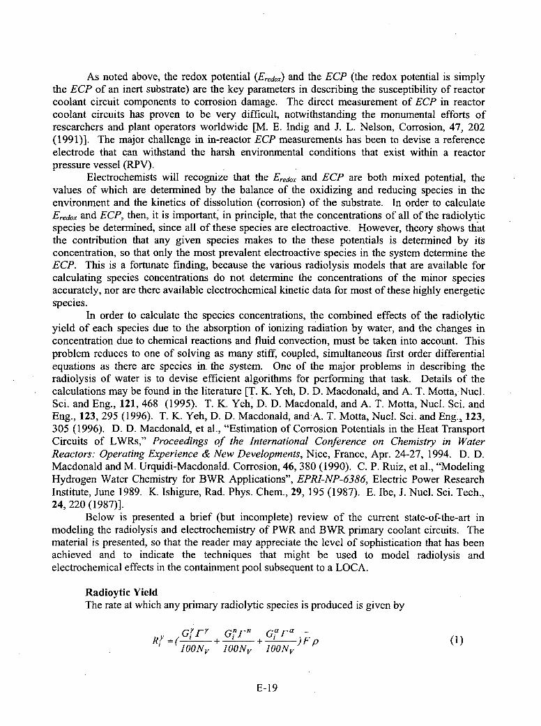
As noted above, the redox potential (Eredox) and the ECP (the redox potential is simplythe ECP of an inert substrate) are the key parameters in describing the susceptibility of reactorcoolant circuit components to corrosion damage. The direct measurement of ECP in reactorcoolant circuits has proven to be very difficult, notwithstanding the monumental efforts ofresearchers and plant operators worldwide [M. E. Indig and J. L. Nelson, Corrosion, 47, 202(1991)]. The major challenge in in-reactor ECP measurements has been to devise a referenceelectrode that can withstand the harsh environmental conditions that exist within a reactorpressure vessel (RPV).
Electrochemists will recognize that the Eredox. and ECP are both mixed potential, thevalues of which are determined by the balance of the oxidizing and reducing species in theenvironment and the kinetics of dissolution (corrosion) of the substrate. In order to calculateEredox and ECP, then, it is important, in principle, that the concentrations of all of the radiolyticspecies be determined, since all of these species are electroactive. However, theory shows thatthe contribution that any given species makes to the these potentials is determined by itsconcentration, so that only the most prevalent electroactive species in the system determine theECP. This is a fortunate finding, because the various radiolysis models that are available forcalculating species concentrations do not determine the concentrations of the minor speciesaccurately, nor are there available electrochemical kinetic data for most of these highly energeticspecies.
In order to calculate the species concentrations, the combined effects of the radiolyticyield of each species due to the absorption of ionizing radiation by water, and the changes inconcentration due to chemical reactions and fluid convection, must be taken into account. Thisproblem reduces to one of solving as many stiff, coupled, simultaneous first order differentialequations as there are species in. the system. One of the major problems in describing theradiolysis of water is to devise efficient algorithms for performing that task. Details of thecalculations may be found in the literature [T. K.. Yeh, D. D. Macdonald, and A. T. Moffa, Nucl.Sci. and Eng., 121, 4.68 (1995). T. K. Yeh, D. D. Macdonald, and A. T. Motta, NucI. Sci. andEng., 123, 295 (1996). T. K. Yeh, D. D. Macdonald, and A. T. Motta, NucI. Sci. and Eng.., 123,305 (1996). D. D. Macdonald, et al., "Estimation of Corrosion Potentials in the Heat TransportCircuits of LWRs," Proceedings of the International Conference on Chemistry in WaterReactors: Operating Experience & New Developments, Nice, France, Apr. 24-27, 1994. D. D.Macdonald and M. Urquidi-Macdonald. Corrosion, 46, 380 (1990). C. P. Ruiz, et al., "ModelingHydrogen Water Chemistry for BWR Applications", EPRI-NP-6386, Electric Power ResearchInstitute, June 1989. K. Ishigure, Rad. Phys. Chem., 29, 195 (1987). E. Ibe, J. Nucl. Sci. Tech.,24, 220 (1987)].
Below is presented a brief (but incomplete) review of the current state-of-the-art inmodeling the radiolysis and electrochemistry of PWR and BWR primary coolant circuits. Thematerial is presented, so that the reader may appreciate the level of sophistication that has beenachieved and to indicate the techniques that might be used to model radiolysis andelectrochemical effects in the containment pool subsequent to a LOCA.
Radioytic YieldThe rate at which any primary radiolytic species is produced is given by
GiyrT- Gi-F- Gap-aRl ( + + ' )Fp()
lOONv lOONv JOONv
E- 19

where the rate of production of species "i", R-', has units of mollcm3 .s, G , G9, and G'are the
radiolytic yields for neutrons, gamma photons, and alpha particles, respectively, in number of
particles per 100eV of energy absorbed, Nv is Avogadro's number, F equals 6.25x101 3 (the
conversion factor from Radls to eV/gram.s), and p is the water density in g/cm3 . r', T", and I'are the gamma photon, neutron, and a-particle energy dose rates, respectively, in units of radls.
Table 1. Radiolytic Yields (G Values) for Primary Radiolytic Species
Species Species Gy GUn0 ONo. (No./IOOeV) (No./ IOOeV) (No./lOOe'I)
1 e 2.66 0.61 0.062 H 0.55 0.34 0.213 OH 2.67 2.02 0.244 H2 02 0.72 0.65 0.9855 HO2 0.00 0.05 0.226 HO2 - 0.00 0.00 0.007 02 0.00 0.00 0.008 O2f 0.00 0.00 0.009 H2 0.45 1.26. 1.310 0- 0.00 0.00 0.00I11 0 0.00 0.00 0.0012 02 0.00 0.00 0.0013 OH- 0.01 0.00 0.0014 H+ 2.76 10.00 10.06 1
Values for the radiolytic yields for various species considered in the author's radiolysismodel for PWR coolants are listed in Table 1. A review of the literature reveals a wide variancein the U-values, even from the same author. The current G-values should be regarded as beinglittle more than rough estimates.
.The third term in Equation (1) accounts for the radiolysis of water by a-particles (4 He2nucleus), which are produced by the 10B 5('no,4 He2)7 Li3 reaction in PWR primary coolantenvironments, but this nuclear reaction does not occur on BWR environments, because of theabsence of boron (specifically 10 B5). The importance of a-particle radiolysis in PWR cores hasbeen recently assessed and it was concluded that the contributions from a-radiolysis to theconcentrations of the radiolytic species are small, when compared with those from neutrons andy-photons at the prevailing dose rates. Nevertheless, in a PWR primary coolant circuit, there areregions where a-particle radiolysis contributes significantly to the formation of the radiolyticspecies (> 10 %), and hence the third term in Equation (2) is necessary. In the case of BWRcores, the radiolysis models have tended to be based on that originally proposed by Burns andMoore, with modification being made in light of the later studies by Elliot. The models used bythe author and his colleagues for modeling BWR primary coolant circuits contains 34 reactions,as discussed further below.
E-20
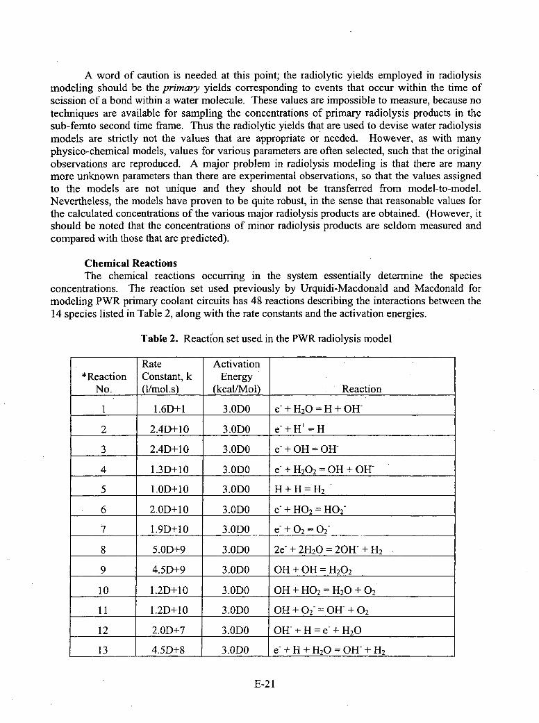
A word of caution is needed at this point; the radiolytic yields employed in radiolysismodeling should be the primary yields corresponding to events that occur within the time ofscission of a bond within a water molecule. These values are impossible to measure, because notechniques are available for sampling the concentrations of primary radiolysis products in thesub-femnto second time frame. Thus the radiolytic yields that are used to devise water radiolysismodels are strictly not the values that are appropriate or needed. However, as with manyphysico-chemical models, values for various parameters are often selected, such that the originalobservations are reproduced. A major problem in radiolysis modeling is that there are manymore unknown parameters than there are experimental observations, so that the values assignedto the models are not unique and they should not be transferred from model-to-model.Nevertheless, the models have proven to be quite robust, in the sense that reasonable values forthe calculated concentrations of the various majo .r radiolysis products are obtained. (However, itshould be noted that the concentrations of minor radiolysis products are seldom measured andcompared with those that are predicted).
Chemical ReactionsThe chemical reactions occurring in the system essentially determine the species
concentrations. The reaction set used previously by Urquidi-Macdonald and Macdonald formodeling PWR primary coolant circuits has 48 reactions describing the interactions between the14 species listed in Table 2, along with the rate constants and the activation energies.
Table 2. Reacti'on set used in the PWR radiolysis model
Rate Activation*Reaction Constant, k Energy
No. (1mls jkca/My l) Reaction
1 1.6D+l 3.ODO e-+ H 2 0=H±+0H-
2 2.4D+10 3.013D e &+H + = H
3 2.4D+ 10 3.013D e &+OH = OH-
4 1.3D+10 3.ODO e-+ H 2 0 2 0= H±+OH
5 1.OD+1O 3.0130 H+H=H2
6 2.OD+1O 3.ODO e-+ H0 2 =H02
7 1.9D±10 3.013D e &+02 =02-
8 5.OD+9 3.0130 2e- + 2H20 = 20H- + H2
9 4.5D+9 3.0130 OH + OH = H 20 2
10 1.2D'+10 3.ODO OH±+H0 2 =H 20 +0 2
11 I .2D+10 3.0130 OH +02f= OH-+ 0 2
12 2.OD+7 3.ODO OHW+H=e-±H 20
13 4.5D+8 3.013D e &+H +H 20 =OH + H 2
E-2 1
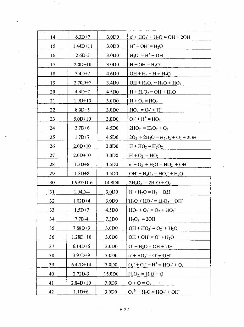
14 6.3D+7 3.ODO e- + H02- + H20 = OH + 20H-
15 1.44D+1 I 3.ODO H+±+OH-= H2 0
16 2.6D-5 3.ODO H20 = H+ +OH
17 2.OD+10 3.ODO H +OH = H 20
18 3.4D+7 4.6D0 OH+H 2 =H+H 2 0
19 2.70D+7 3.4D0 OH + H1202 = H20 + HO2
20 4.4D+7 4.5D0 H + H20 2 = OH +1H20
21 1.9D±10 3.ODO H +0 2 =H02
22 8.OD±5 3.ODO HO 2 = 02- +H
23 5.OD±10 3.ODO 0 2-+ H = H0 2
24 2.7D+6 4.5D0 21102 = H20 2 + 02
25 1 .7D+7 4.5D0 202- ± 2H20 = H 2 0 2 +0 2 +20H-
26 2.OD+1O 3.ODO H +H0 2 =H 2 0 2
27 2.OD+10 3.ODO H__+ __02___=__H02__
28 1 .3D+8 4.5D0 e- + O2f +1120 = H02- + OH-
29 1.8D+8 4.5D0 OWf +1H202 = H02- + H20
30 1 .9973D-6 14. 8D0 211202 = 2H 20 + 02
31 1.04D-4 3.ODO H +H 20 =H 2 +OH
32 1 .02D+4 3.ODO 1120 -I H02 = H20 2 + OW-
33 1 .5D+7 4.5D0 HO2 + 02- =02 + H02-
34 7.7D-4 7.3D0 11202 = 20H1
35 7.88D+9 3.ODO 0H1+1H02- = O2f +1120
36 1.28D+10 3.ODO OH+OHW=&+H 2 0
37 6.14D+6 3.ODO 0O+ H 2 0 =OH + OH
38 3.97D+9 3.ODO e-+ H02= 0-+Off
39 6.42D+14 3.ODO O2f + O2f + H+ = 1102 + 02
40 2.72D-3 15.ODO H20 2 H 120 + 0
41 2.84D+ 10 3.ODO 0+ 0=02
42 1.I1D+6 I 3.ODO 0 2 2-+H20 =1H02- +01H
E-22
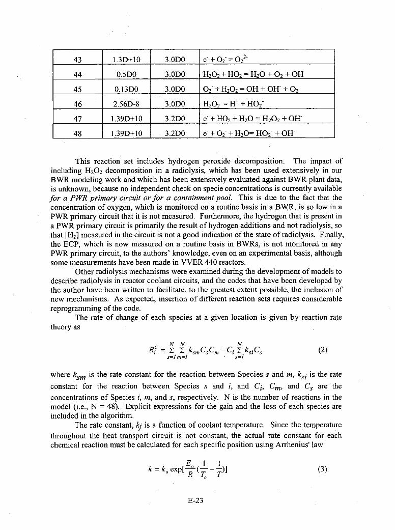
43 1.3D+10 3.0130 e-___+_02___=__02__2-
44 0.5D0 3.ODO H20 2 + HO 2 = H20 + 02 + OH
45 0.13D0 3.ODO 02- + H20 2 = OH + OH- + 02
46 2.56D-8 3.ODO H20 2 = H+ + H02-
47 1.39D+10 3.2D0 e- + HO2 + H20 = H20 2 + OH-
48 1.39D+10 3.2D0 e- + O2f ± H20= H0 2 - + OH-
This reaction set includes hydrogen peroxide decomposition. The impact ofincluding H20 2 decomposition in a radiolysis, which has been used extensively in ourBWR modeling work and which has been extensively evaluated against BWR plant data,is unknown, because no independent check on specie concentrations is currently availablefor a P WR primary circuit or for a containment pool. This is due to the fact that theconcentration of oxygen, which is monitored on a routine basis in a BW~R, is so low in aPWR primary circuit that it is not measured. Furthermore, the hydrogen that is present ina PWR primary circuit is primarily the result of hydrogen additions and not radiolysis, sothat [H21 measured in the circuit is not a good indication of the state of radiolysis. Finally,the ECP, which is now measured on a routine basis in BWRs, is not monitored in anyPWR primary circuit, to the authors' knowledge, even on an experimental basis, althoughsome measurements have been made in VVER 440 reactors.
Other radiolysis mechanisms were examined during the development of models todescribe radiolysis in reactor coolant circuits, and the codes that have been developed bythe author have been written to facilitate, to the greatest extent possible, the inclusion ofnew mechanisms. As expected, insertion of different reaction sets requires considerablereprogramming of the code.
The rate of change of each species at a given location is given by reaction ratetheory as
N N NXc=zY ksmCsCm C- X i~ (2)
where ksm is the rate constant for the reaction between Species s and m, ks is the rate
constant for the reaction between Species s and i, and Ci, Cm, and Cs are the
concentrations of Species i, m, and s, respectively. N is the number of reactions in themodel (i.e., N = 48). Explicit expressions for the gain and the loss of each species areincluded in the algorithm.
The rate constant, Ic1 is a function of coolant temperature. Since the~temperaturethroughout the heat transport circuit is not constant, the actual rate constant for eachchemical reaction must be calculated for each specific position using Arrhenius' law
kc = k,, exp[ E.( --- ) (3)R T, T
E-23
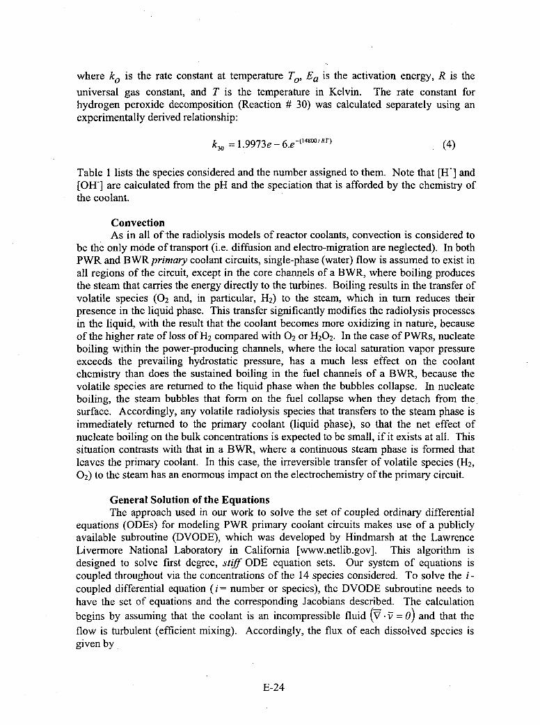
where Ic0 is the rate constant at temperature To, Ea is the activation energy, R is the
universal gas constant, and T is the temperature in Kelvin. The rate constant forhydrogen peroxide decomposition (Reaction ft 30) was calculated separately using anexperimentally derived relationship:
kc30 =1.9973e - 6.e' 4800 /RT) (4)
Table 1 lists the species considered and the number assigned to them. Note that [H+] and[OH] are calculated from the pH and the speciation that is afforded by the chemistry ofthe coolant.
ConvectionAs in all of the radiolysis models of reactor coolants, convection is considered to
be the only mode of transport (i.e. diffusion and electro-migration are neglected). In bothPWR and BWR primary coolant circuits, single-phase (water) flow is assumed to exist inall regions of the circuit, except in the core channels of a BWR, where boiling producesthe steam that carries the energy directly to the turbines. Boiling results in the transfer ofvolatile species (02 and, in particular, H2 ) to the steam, which in turn reduces theirpresence in the liquid phase. This transfer significantly modifies the radiolysis processesin the liquid, with the result that the coolant becomes more oxidizing in nature, becauseof the higher rate of loss of H2 compared with 02 or H20 2. In the case of PWRs, nucleateboiling within the power-producing channels, where the local saturation vapor pressureexceeds the prevailing hydrostatic pressure, has a much less effect on the coolantchemistry than does the sustained boiling in the fuiel channels of a BWR, because thevolatile species are returned to the liquid phase when the bubbles collapse. In nucleateboiling, the steam bubbles that form on the fuel collapse when they detach from thesurface. Accordingly, any volatile radiolysis species that transfers to the steam phase isimmediately returned to the primary coolant (liquid phase), so that the net effect ofnucleate boiling on the bulk concentrations is expected to be small, if it exists at all. Thissituation contrasts with that in a BWR, where a continuous steam phase is formed thatleaves the primary coolant. In this case, the irreversible transfer of volatile species (H2 ,
02) to the steam has an enormous impact on the electrochemistry of the primary circuit.
General Solution of the EquationsThe approach used in our work to solve the set of coupled ordinary differential
equations (ODEs) for modeling PWR primary coolant circuits makes use of a publiclyavailable subroutine (DVODE), which was developed by Hindmarsh at the LawrenceLivermore National Laboratory in California [www.netlib.gov]. This algorithm isdesigned to solve first degree, stiff ODE equation sets. Our system of equations iscoupled throughout via the concentrations of the 14 species considered. To solve the i -coupled differential equation (i =number or species), the DVODE subroutine needs tohave the set of equations and the corresponding Jacobians described. The calculationbegins by assuming that the coolant is an incompressible fluid (V -: = 0) and that theflow is turbulent (efficient mixing). Accordingly, the flux of each dissolved species isgiven by
E-24
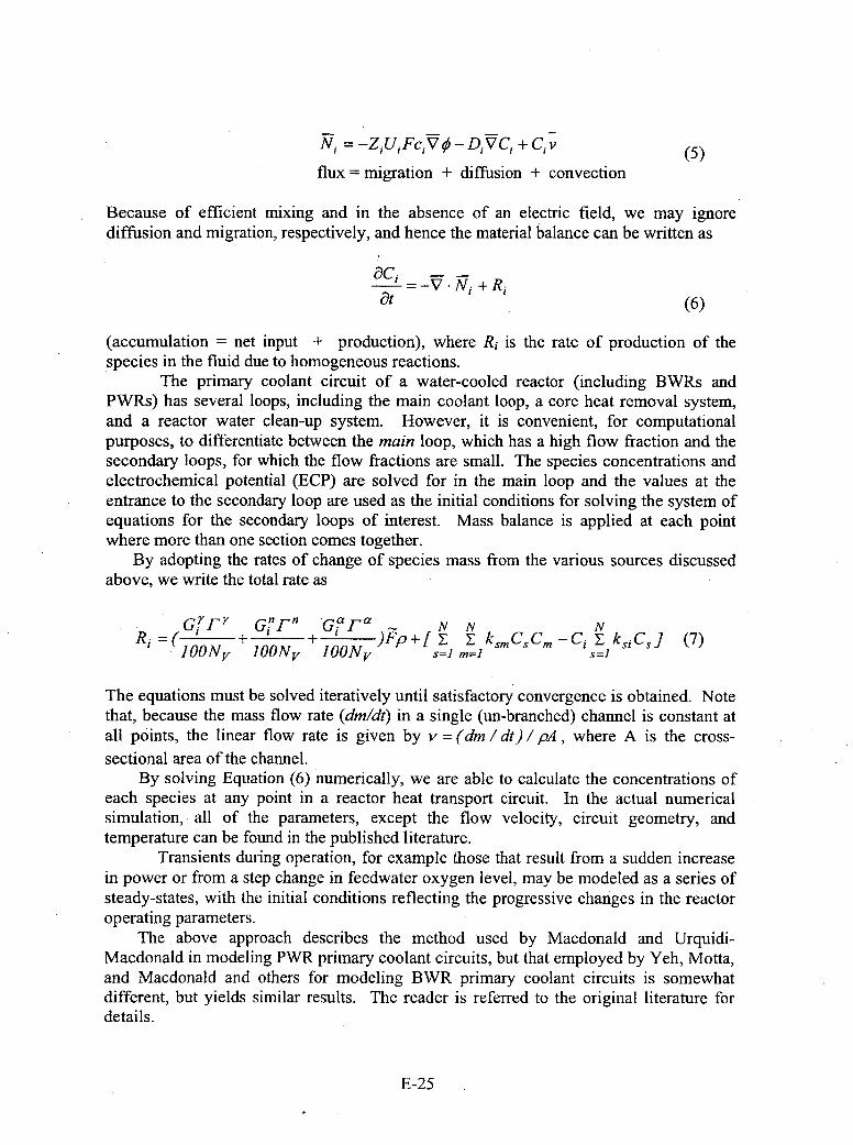
N. = -Z 1 UFciV 0- DVC1 ±+Cv (5)flux = migration + diffusion + convection
Because of efficient mixing and in the absence of an electric field, we may ignorediffusion and migration, respectively, and hence the material balance can be written as
ac, !V +--
at -VN+,(6)
(accumulation = net input + production), where R1 is the rate of production of the*species in the fluid due to homogeneous reactions.
The primary coolant circuit of a water-cooled reactor (including BWRs andPWRs) has several loops, including the main coolant loop, a core heat removal system,and a reactor water clean-up system. However, it is convenient, for computationalpurposes, to differentiate between the main loop, which has a high flow fraction and thesecondary loops, for which the flow fractions are small. The species concentrations andelectrochemical potential (ECP) are solved for in the main loop and the values at theentrance to the secondary loop are used as the initial conditions for solving the system ofequations for the secondary loops of interest. Mass balance is applied' at each pointwhere more than one section comes together.
By adopting the rates of change of species mass from the various sources discussedabove, we write the total rate as
GGF n 1-n' Gi'Fa N N NRi+ + )Fp +[z Y ~ksm CS CM -Ci Yksi Cs ] (7)
lOONy JOONV JOONV s=J m=J s=I
The equations must be solved iteratively until satisfactory convergence is obtained. Notethat, because the mass flow rate (dm/dt) in a single (un-branched) channel is constant atall points, the linear flow rate is given by v = (din / dt) / pA , where A is the cross-sectional area of the channel.
By solving Equation (6) numerically, we are able to calculate the concentrations ofeach species at any point in a reactor heat transport circuit. In the actual numericalsimulation, all of the parameters, except the flow velocity, circuit geometry, andtemperature can be found in the published literature.
Transients during operation, for example those that result from a sudden increasein power or from a step change in feedwater oxygen level, may be modeled as a series ofsteady-states, with the initial conditions reflecting the progressive changes in the reactoroperating parameters.
The above approach describes the method used by Macdonald and Urquidi-Macdonald in modeling PWR primary coolant circuits, but that employed by Yeh, Motta,and Macdonald and others for modeling BWR primary coolant circuits is somewhatdifferent, but yields similar results. The reader is referred to the original literature fordetails.
E-25

Mixed Potential Model and the Redox and Electrochemical CorrosionPotentialsAfter the concentration of each radiolysis species is calculated, the corrosion
potential of the component can be estimated using a mixed potential model (MPM) [D.D. Macdonald, Corrosion, 48, 194 (1992)].. The MPM is based on the physico-electrochemical condition that charge conservation must be obeyed at the corrodinginterface. Because electrochemical reactions transfer charge across a metal/solutioninterface at rates measured by the partial currents, the following equation expresses thecharge conservation constraint
ZiR,oj(E)+ i.., E) = 0 (8)j=1
where ipIjQ is the partial current density due to the j-th redox couple in the system and
icorr is the metal oxidation (corrosion) current density. These partial currents depend onthe potential drop across the metal/solution interface.
In the current version of the MPM, which was developed for modeling the ECP ofType 304 SS in BWR primary circuits, the steel oxidation current density, icrr wasmodeled as an empirical function of voltage,
e(E-Eo)lbf e-(E-E0 ) /b,
384.62e 446 /T + X(9
wheree(E -E0 ) / b
2.6 lxl 03 e -44 16 /T+O.523(E-E 0 )U5 (0
andE0 =0. 122 -1.5286A10-'T (t1)
In these expressions, bj and br are the forward and reverse Tafel constants, respectively,for the metal dissolution reaction, with values of 0.06 V being assumed for both. Inactual fact, they are empirical constants that were assumed a priori in fitting Equation (9)to the current/voltage data. It is important to note that Equation (9) applies strictly toType 304 SS in near neutral solutions and hence that this expression may not be a goodempirical model for stainless steels in PWR primary circuits or for metals and alloys in acontainment pool. More recently, the Point Defect Model [D. D. Macdonald, Pure Appl.Chem., 71, 951 (1999)] has been used as the basis for calculating the corrosion currentdensity of the metal substrate.
E-26

Metal IBarrier Layer Solution/Outer Layer
()M +V M k m~m±%e ()M ', a)+V" F-X
k2 k >MX + V +X - ()M k
(2 M + M e (5 Mix k6 I '+(q F Xe
(3) m k3 +MM+iVo'+Xe (6 +~H O k6 0 0 +2H+
(7) MOZ 1 2 +zH+ M-+k(q) 2H2+(F-Xe
Figure 1. Summary of the defect generation and annihilation reactionsenvisioned at the interfaces of the barrier oxide layer on a metal, according
to the Point Defect Model (PDM). VM'= cation vacancy in the film;
Vm vacancy in the metal substrate; MX+ cation interstitial;V'
oxygen (anion) vacancy; MF (aq) =cation in solution; MM cation in
cation site on the metal sublattice; 00 oxide ion in anion site on the
oxygen sublattice; and MO./2 stoichiometric barrier layer oxide. Note
that Reactions 1, 2, 4, 5 and 6 arc lattice conservative processes (they donot result in the movement of the interface) whereas Reaction 3 and 7 arenon-conservative [D. D. Macdonald, Pure AppI. Chem., 71, 951 (1999)].
The PDM yields the, passive current density in the form
'ss = F[k 0e aayveae~s +k~ea yeafw ±ko .C+ (12)
where the film thickness is given by
1S -a 1+ I 2.303n pH 'l(3 (13)C a3% a ~ k7 )
[D. D. Mac donald, Pure Appl. Chem., 71, 951 (1999)]. The parameters in theseequations are as follows: X~, a, 86, and n are the oxidation state of the cation in thebarrier layer;, the polarizability of the film/solution interface (i.e., the dependence of thepotential drop across the film/solution interface on the applied voltage); the dependenceof the potential drop across the film/solution interface on the pH; and the kinetic order ofthe film dissolution reaction with respect to hydrogen ion concentration; respectively.Note that, in deriving Equations (12) and (13), the oxidation state of the cation in thebarrier layer (xý) is set equal to the oxidation state of the same cation in the solution/outer
E-27
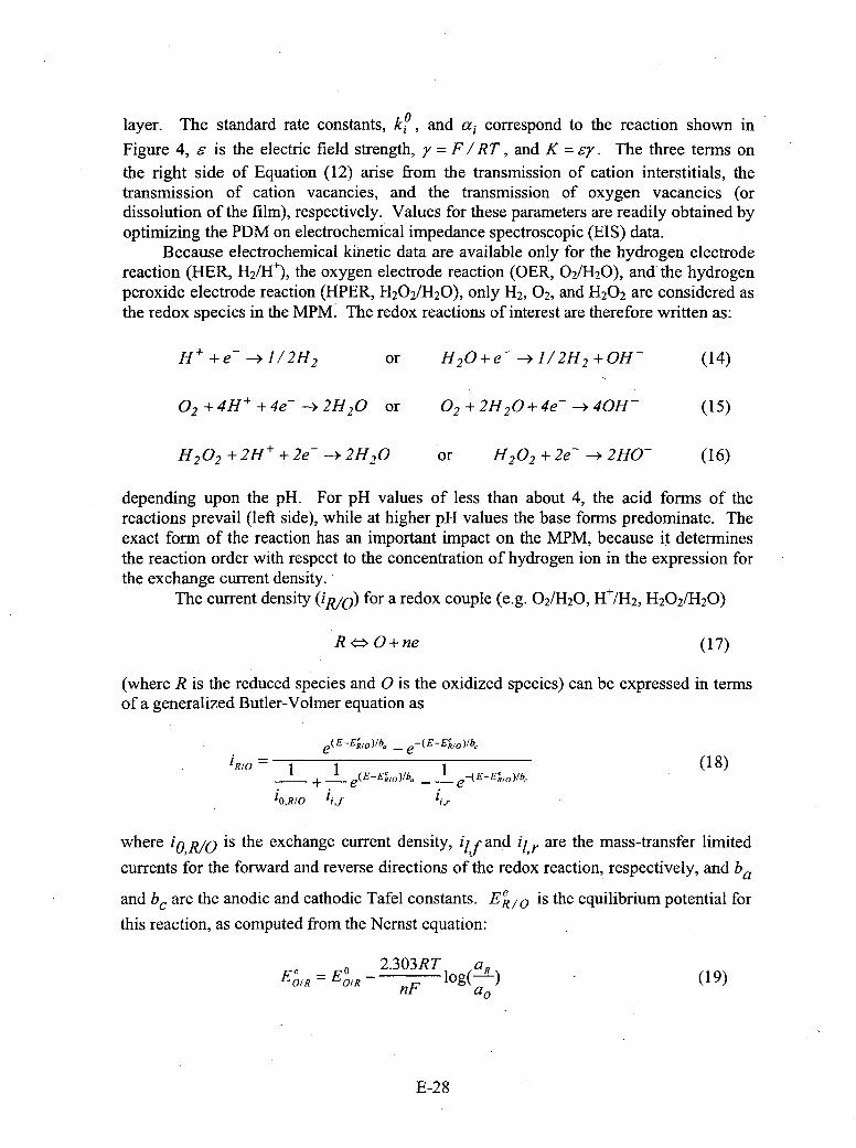
layer. The standard rate constants, ko, and a1 correspond to the reaction shown in
Figure 4, e is the electric field strength, y =F / RT , and K = ey. The three terms onthe right side of Equation (12) arise from the transmission of cation interstitials, thetransmission of cation vacancies, and the transmission of oxygen vacancies (ordissolution of the film), respectively. Values for these parameters are readily obtained byoptimizing the PDM on electrochemical impedance spectroscopic (EIS) data.
Because electrochemical kinetic data are available only for the hydrogen electrodereaction (HER, H2/H~), the oxygen electrode reaction (GER, 02/1120), and the hydrogenperoxide electrode reaction (HPER, 11202/1120), only H2, 02, and 11202 are considered asthe redox species in the MPM. The redox reactions of interest are therefore written as:
H+ +e->112H2 or H 2 0+e- -J/12H 2 +0OH- (14)
02+ 4H+ +4e--> 2H2 O or 0 2 ±+2H2 0 +4e- -*40H- (15)
H 2 0 2 + 2H+ + 2e_ --* 2H2 0 or H 2 0 2 + 2e- --> 2H0- (16)
depending upon the pH. For pH values of less than about 4, the acid forms of thereactions prevail (left side), while at higher p11 values the base forms predominate. Theexact form of the reaction has an important impact on the MPM, because it determinesthe reaction order with respect to the concentration of hydrogen ion in the expression forthe exchange current density.
The current density (ipJo) for a redox couple (e.g. 02/H120, H+/H2, 11202/1120)
R <* O+ne (17)
(where R is the reduced species and 0 is the oxidized species) can be expressed in termsof a generalized Butler-Volmer equation as
e-EE'1)b e-(E-E~O)Ib,1RI0 = (18)
1 0,R/O 1iif ii
where iop~lo is the exchange current density, izf and j' r are the mass-transfer limited
currents for the forward and reverse directions of the redox reaction, respectively, and baand b~ are the anodic and cathodic Tafel constants. E' 1 steeulbru oeta o
this reaction, as computed from the Nernst equation:
EI= E0 -2.303RT~o~R
O/ OIR nF log-) (19)
E-28

where aR and a0 are the thermodynamic activities of R and 0, respectively, and EO,,R is
the standard potential. Limiting currents are calculated using the equation:
'l,O/R =±O.0165nFDC-bRRe 0 -6SCO.33 Id (20)
where the sign depends on whether the reaction is in the forward (+) or reverse(-direction, F is Faraday's number, D is the diffusivity of the redox species, COIR is thebulk concentration of 0 or R, as appropriate, Re is the Reynolds number (Re= Vd/q7), Sc isthe Schmidt number (Se / 7 D), d is the channel diameter, V is the flow velocity, and q7 isthe kinematic viscosity.
An important point that needs to be emphasized again is that the maximumcontribution that any given radiolytic species can make to the ECP is roughlyproportional to its concentration. Thus, in BWR simulations the concentrations of H2 , 02,
and 11202 are calculated to be orders of magnitude greater than any other radiolyticspecies and hence only these three need be considered. In the case of PWR primaryHTCs, our previous modeling work suggests that aquated electrons, H atoms, and OHradicals may be significant species in regions of very high-energy dose rate (e.g. near thefuel). However, no electrochemical kinetic data exist for these reactions and hence theycannot be incorporated at this time.
0.3
0.2-*CIVCI Figure 2. Comparison of cacltdand0.1 measured ECP for the Leibstadt BWR.
*0.0 T The "measured" data were acquired in a-0.1 test cell attached to the recirculation
-0 .2 piping.
-0.50 .0 0.5 1.0 1.0 2.0 2.5
Feedwater [H2] (mg/kg)
The accuracy of the Mixed Potential Model has been evaluated by comparingcalculated ECP values for Type 304 SS against measured BWR plant data [D. D.Macdonald, Corrosion, 48, 194 (1992)]. While modeling of the ECP in BWR primarycoolant circuits will be discussed at length later in this section, a brief discussion of someof the data is appropriate at this point. Thus, the most comprehensive comparison isprobably that which employed data obtained during a Hydrogen Water Chemistry (HWC)mini-test at the Leibstadt BWR in Switzerland (Figure 2). The reactor water chemistrymodeling and the prediction of the ECP was carried out in a "double blind" manner (i.e.,we did not have access to the plant [02], [H12, or ECP data prior to submission of ourcalculations and the contractor did not have access to our calculations while performingthe mini-test). We were, of course, provided with the flow velocity, hydrodynamicdiameter, and temperature data for the test system. The calculated and measured (plant)
E-29

ECP data for this case are summarized in Figure 2. Excellent agreement is obtained insystems to which hydrogen -had been added, with the measured and calculated ECPvalues agreeing within the combined uncertainty levels. .In the normal water chemistrycase ([H2] = 0), the measured ECP is significantly higher than the calculated value. Thisis almost certainly due to the presence of hydrogen peroxide in the coolant, which wasnot measured by the personnel conducting the HWC mini-test. Accordingly, we wereunable to input a value for [H 20 2] into the MPM. However, if we use the calculatedvalues for [H 2], [02], and [H 20 2] obtained from RADIOCHEM, excellent agreement isobtained.
At this point, it is of interest to explore the impact that oxygen and hydrogenperoxide are predicted to have on the ECP under typical PWR primary circuit conditions.This is done in Figure 9 for the system parameter values as summarized in the caption. Inthe case *of both oxygen and hydrogen peroxide, the ECP is predicted to be displaced inthe positive direction for [02] or [H 20 2] greater than 0.001 mg/kg (1 pp~b). Below thisconcentration, the ECP is dominated by the hydrogen electrode reaction. At high oxidantconcentrations (> 0. 1 mg/kg), the stronger oxidizing power of H20 2 becomes evident, inthat the ECP is progressively displaced to more positive values compared with that foroxygen as the oxidant concentration is increased. The critical. oxidant concentration oflI pg/kg (lppb) at which the ECP is displaced from the hydrogen electrode behavior is ingood semi-quantitative agreement with experimental data obtained from laboratorystudies by Bertuch, et.al. [A. Bertuch, J. Pang, and D. D. Macdonald, "The Argument ForLow Hydrogen and Lithium Operation in PWR Primary Circuits ", Proc. 7rh Int'l. Symp*Env. Deg. Mat. Nuc. Pwr. Sys. - Water Reactors, 2, 687-697 (August 1995)].
0.0
6a0 Figure 3. Calculated ECP vs. [02] or-0 ,O, [H 20 2] for a simulated PWR coolant
system. T = 320 TC, [H2]1;!7 -. 4 -25cc(STP)/kg(H 20), [B] = 1000 mg/kg,
[Li] = 2mg/kg, pH = 7.36, flow velocity-06
-100 cmls, channel hydrodynamic-08 . diameter= 100 cm.
le-6 le.5 1le-4 1e-3 le-2 1-i le-. le-l
1021 or [1H2021 (mglkg)
Finally, we note that, at least for BWR, coolant conditions, and possibly for PWRprimary conditions, also, when the ECP is not "clamped" by the hydrogen electrodereaction, the corrosion potential is a sensitive function of the hydrodynamic conditions inthe channel. This sensitivity to flow arises because the hydrodynamic conditions controlthe rate of mass transport of the redox species to the metal surface. This is an extremelyimportant issue when comparing the calculated ECP with laboratory and plant data,because the measurements are seldom carried out in a channel that is well characterizedhydrodynamically. Indeed, a well-characterized channel should be a prerequisite forperforming measurements of this type.
E-30

Impact of Radiolysis in the Containment PoolThe computer code FOCUS, which was developed to describe the radiolysis of.
water and the accumulation of damrage due to stress corrosion cracking in Boiling WaterReactors (BWRs) and which is outlined above, was modified to calculate theconcentrations of oxygen, hydrogen peroxide, and hydrogen in the containment pool as afunction of y-dose rate, pH, and temperature. While this is a "stop gap" measure, given,the lack of resources available to develop a code designed to specifically model the pool,it does yield useful information that provides a qualitative indication of the likely impactof radiolysis on the chemistry of the containment po 'ol after a LOCA. Scopingcalculations are summarized in Table 3, in which the concentrations of hydrogenperoxide, oxygen, and hydrogen are calculated for a temperature of 30'C as a function ofthe ambient oxygen concentration (that concentration that would exist due to equilibriumwith the ambient atmosphere in the absence of radiolysis), pH, and 'y-dose rate.Calculations were also carried out at temperatures of 60'C and 900C with broadly sim ilarresults. In the interest of brevity, they will not be presented at this time.
Table 3. Preliminary calculation of the generation of hydrogen peroxide,oxygen, and hydrogen in water at 30'C as a function of ambient oxygenconcentration (concentration in the absence of radiolysis), pH, and y-doserate.
02 Conc y-Dose tH20 21 [021 11121pH Rate
(ppm) (radls) (ppb) (ppb) (ppb)0.1 10 44.00518, 73.38579 1.91507
100 58.57714 85.27291 4.34055
8 1000 83.31808 116.1293 9.83723
10000 129.3054 168.6386 21.76393100000 756.4755 862.5814 151.4454
10 43.90286 73.38271 1.91325100 58.43296 85.26128 4.33657
9 1000 83.13144 116.0977 9.8304310000 137.4481 181.3297 22.55719
100000 756.297 863.5652 151.58210 43.89336 73.38182 1.91308
100 58.41952 85.25942 4.336210 1000 83.11398 116.0935 9.82978
10000 129.0472 168.6263 21.75823
100000 756.278 863.6576 151.59511 10 43.89242 73.38173 1.91306
100 j 58.41819 85.25923 4.33616
E-3 1

1000 83.11225 116.0931 9.82972 1
10000l 137.4217 181.3244 22.55634100000 756.276 863.6668 15 1.5963
10 214.5571 720.4191 3.60908
8
1001 401.6951 677.9821 9.53419
10001 483.10181 722.1711 20.17785
10000 j 576.0389 j834.3471 43.23481100000 1171. 148 1504.855 205.1361
1
10 214.5038 720.2722 3.60841
100 401.4674 677.7833 9.5308
9 1000 482.7655 721.9559 20.16937
10000 575.5655 834.1186 43.2132
100000 1170.635 1505.187 205.1646
10 214.4986 720.256 3.60835
100 401.4446 677.7611 -9.53047
10 1000 482.7322 721.9315 20.16856
10000 575.515 834.0901 43.21096
100000 1170.584 1505.218 205.1673
10 214.498 720.2544 3.60834
I1I
100 401.4424 677.7588 9.53044
1000 482.7288 721.9291 J 20.16848
10000 575.5104 834.0874 43.21076
100000 1170.579 1505.22 1 205.1676+ i i
8 10 390.266 6020.668 4.60369
8
100 1884.806 5619.741 20.20714
1000 3166.904 5229.377 47.54566
10000 3579.936 5380.753 91.93316
100000 4627.551 6649.682 398.6037
10 390.2369 6020.403 4.60325
100 1884.622 5619.026 20.20429
9 1000 3166.315 5228.681 47.53422
10000 3579.17 5380.175 91.89964
100000 4626.253 6648.662 398.4206
10 390.2337 6020.374 4.60321
10
100 1884.603 5618.949 20.20402
1000 3166.254 j5228.605 47.53312
10000 3579.093 5380.112 91.89642
100000 4626. 123 6648.559 398.4024
E-32

10 390.2334 6020.371 4.6032
I1I100 1884.601 5618.941 20.20399
10001 3166.2481 5228.598 47.53301
100001 3579.0851 5380.106 91.8961
I ______1 ____ 11000001 4626.111 6648.549 j 398.4006
Of particular interest is the hydrogen peroxide concentration, because this speciesis a strong oxidizing agent. The calculations indicate that the H202 concentration is avery strong function of the y-dose rate and ambient oxygen concentration, as expected,but is predicted to be insensitive to pH. At high ambient oxygen concentration (8ppm)and high y-dose rate (100,OO0rad/s), the hydrogen peroxide concentration is predicted toexceed 4ppm. Likewise, the concentrations of oxygen and hydrogen are also predicted tobe sensitive functions of the y-dose rate (in particular) and oxygen concentration, but notof pH. One interesting prediction is that as the ambient oxygen concentration isincreased, the concentration of hydrogen is also found to increase, which is counter-intuitive. We currently do not know whether this latter prediction is "real", in that itarises from the radiolysis mechanism, or whether it is an artifact that is produced byattempting to apply a model to describe a scenario for which it was never intended.
Assuming that. the predictions are qualitatively correct, it is evident that radiolysiscan have a major impact on the chemistry of the containment pool, if y-dose rate can riseto the 104 to 105 rad/s level through entrapment of neutron-activated corrosion productsand fission products from failed fuel in the debris bed of the pool. The concentration ofH20 2 is sufficiently high that the redox potential is expected to be correspondingly high.Unfortunately, the code FOCUS does not yield the redox potential of the solution, onlythe corrosion potential of stainless steel in contact with the environment is calculated.While both the redox. potential and the corrosion potential (ECP) are mixed potentials,their values in the same environment can be greatly different, depending upon thekinetics of the charge transfer reactions that occur at the surfaces of platinum (thesubstrate that is normally used for defining the redox potential) and the steel, respectively.Thus, an unequivocal resolution of this issue will require the following:
* Development of a radiolysis code specifically for a containment pool. This modelshould incorporate boric acidlLiOH + TSP (tni-sodium phosphate) +TSB (tetra-sodium borate) modules for estimating the pH. The model should becalibrated/evaluated against laboratory experiments to establish efficacy.
" A thorough analysis should be carried out to estimate the likely y-dose rates in thecontainment pool as a fuinction of time after a LOCA in a PWR. The contributionof at-dose rate from fission products also needs to be evaluated. The latter iscompletely ignored in the present analysis and the former (y-dose rate) is littlemore than a guess. No information of guidance on this subject could be found inthe open literature.
" A better database for the kinetics of the hydrogen electrode reaction, the oxygenelectrode reaction, and the hydrogen peroxide electrode reaction needs to beestablished. Some of the "raw"~ data are already in the literature, but theinformation is incomplete and the data are generally not in a form that is readily
E-33

interfaced with radiolysis/redox potential models. In some cases, however, therequired data must be experimentally measured.
Given the above, it is useful at this point to speculate on the likely chemicaleffects that radiolysis might have on the containment pool chemistry. Thus, the solubilityof species that are electroactive themselves (e.g., FeOOH) or yield species that areelectroactive (Fe 2 +, Fe 3 +) generally depend upon the redox conditions of the environment.Thus, we may write as the solubility reactions for FeOOH as
FeOOH + 3Hf'- = Fe'+ + 2H20 (21)
which clearly is not an electrochemical reaction and hence does not depend upon theredox conditions, but if the environment is sufficiently reducing, such that Fe 2 + is Stable,the reaction becomes
FeOOH + 112H2 +2HJ' = Fe2+ + 2H20 (22)
The equilibrium concentration of Fe 2 + may be written as
[Fe2+] P1/2[H]2 e AG0/ RT (3
wher PHis the partial pressure of hydrogen and AGO is the change in standard Gibbs
energy for Reaction (22). Clearly, as written, the solubility of FeOOH depends upon thehydrogen partial pressure and pH and, since the coolant in a LOCA contains hydrogen[approx. 25 cc/kg (H 2 0) in the virgin coolant], the partial pressure of hydrogen after theLOCA becomes important (as does the pH), if the solubility is to be accurately calculated.However, when the hydrogen is released in a LOCA, the gas space presumably contains amixture of H2 and 02, with [H2] being below the explosive limit, such that the solubilitycannot be defined by Equation (3), because the system is not at equilibrium. Instead, thesystem is non-equilibrium in nature and a different approach must be used to estimate thesolubility.
The dissolution Reaction (22) may be written in slightly different form as:
Fe00H + 3HP+ e-=Fe2 + 2H2 0 (24)
for which the concentration of Fe 2 + can be written as:
[Fe 2+ = [H+ 12 2eF(E2,E,)/RT (25)
In this expression, E24 = -AGO /IF is the standard potential for Reaction (24), AGO4 is
as previously defined, F is Faraday's constant, R is the universal gas constant, and T isthe Kelvin temperature. The parameter Eh is the redox potential. This potential cannotbe calculated from equilibrium thermodynamics, because the system is not at equilibrium,as noted above, due to the simultaneous generation of H2 , 02, and H2 0 2 , among other
E-34
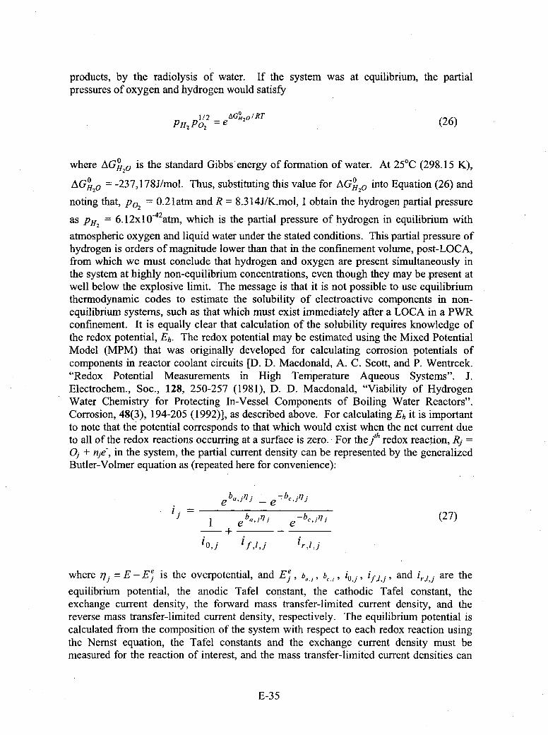
products, by the radiolysis of water. If the system was at equilibrium, the partialpressures of oxygen and hydrogen would satisfy
PHP 12 = AGH01 10 RT (26)
where AGHO2Q is the standard Gibbs energy of formation of water. At 25'C (298.15 K),
AGOJ = -237,178J/mol. Thus, substituting this value for AO into Equation (26) and
noting that, po, 0.2 1latin and R = 8.3 14J/K..mol, I obtain the hydrogen partial pressure
as PH2 = 6.12x 0-4 atm, which is the partial pressure of hydrogen in equilibrium with
atmospheric oxygen and liquid water under the stated conditions. This partial pressure ofhydrogen is orders of magnitude lower than that in the confinement volume, post-LOCA,from which we must conclude that hydrogen and oxygen are present simultaneously inthe system at highly non-equilibrium concentrations, even though they may be present atwell below the explosive limit. The message is that it is not possible to use equilibriumthermodynamic codes to estimate the solubility of electroactive components in non-equilibrium systems, such as that which must exist immediately after a LOCA in a PWRconfinement. It is equally clear that calculation of the solubility requires knowledge ofthe redox potential, Eh. The redox potential may be estimated using the Mixed PotentialModel (MPM) that was originally developed for calculating corrosion potentials ofcomponents in reactor coolant circuits [D. D. Macdonald, A. C. Scott, and P. Wentrcek."Redox Potential Measurements in High Temperature Aqueous Systems". J.Electrochem., Soc., 128, 250-257 (1981), D. D. Macdonald, "Viability of HydrogenWater Chemistry for Protecting In-Vessel Components of Boiling Water Reactors".Corrosion, 48(3), 194-205 (1992)], as described above. For calculating Eh it is importantto note that the potential corresponds to that which would exist when the net current dueto all of the redox reactions occurrng at a surface is zero. -For the] t redox reaction, Rj =9, + nje-, in the system, the partial current density can be represented by the generalizedButler-Volmer equation as (repeated here for convenience):
ebij- e ebj7
e b,,l - e -b,,jl' (27)
io~j 1f I] r,l1j
where 77 E - E'is the overpotential, and E'> bý 1,j b, 1, 0 , and 'r~lj are the
equilibrium potential, the anodic Tafel constant, the cathodic Tafel constant, theexchange current density, the forward mass transfer-limited current density, and thereverse mass transfer-limited current density, respectively. The equilibrium potential iscalculated from the composition of the system with respect to each redox reaction usingthe Nernst equation, the Tafel constants and the exchange current density must bemeasured for the reaction of interest, and the mass transfer-limited current densities can
E-35

be calculated from the mass transfer correlations for the system. Thus, for the net currentat the surface of an inert electrode-being zero, the following equation results
e b.,j(Eh-Ej) _-e -b,,(Eh-E.ý) 0(8
L0j if~lij i"
Equation (28) must be solved for the redox potential, Eh. This normally is done by directsubstitution or by using the Newton-Raphson iterative technique. It is important to notethat, in applying Equation (28), the summation must be made over all redox reactions inthe system. Thus, in the present case,, the summation should be carried out overFe +/Fe2 +in addition to 0 21H20, and H2/H20, and possible even over reactions involving
various radiolytic species, such as H2 0 2 /H20, if their concentrations are significant. Animportant conclusion from many years of modeling the redox potential and corrosionpotential properties of a wide range of physico-electrochemical systems is that thecontribution that any given species makes to the redox or corrosion potential is roughlyproportional to its concentration. That is why, in modeling nuclear reactor coolantcircuits, all radiolysis species except 02, H2, and H 2 0 2 can be ignored. The sameprinciple holds for a LOCA environment. 2
It may be argued that, if there is sufficient hydrogen in the water that Fe2 is thepredominant dissolved species and that the stable phase is not FeOOH, but is Fe3 0 4 oreven Fe (OH) 2 (see Issue 4 below), then the reaction of interest should be
Fe (OH) 2 + 2H+ Fe~+2 2 0 (29)
This argument would be valid, if the system was at equilibrium but, as shown above, weare dealing with a system that is far from equilibrium. Thus, in my opinion, the onlyrational way of modeling the chemistry of the system is in tenns of the non-equilibriumredox potential and not in terms of equilibrium concepts.
There are a number of points that need to be made at this point:
" Precipitation, particularly if it occurs by rapid cooling and/or flashing, rarelyresults in an equilibrium product. Instead, the precipitate that forms is that whichis least hindered kinetically in its formation and not that which isthermodynamically the most stable.
* For any given set of conditions, the most unstable solid exhibits the highestsolubility. Thus, from the Second Law of Thermodynamics, the least stable formwill dissolve to form a super saturated solution with respect to the more stableform, resulting in the precipitation of the latter. On the other hand, the least stableform may convert to the more stable form via a solid state reaction, although theseare generally very slow at the temperatures of interest in this analysis.
* To ensure that a system is at equilibrium, the solubility should be approached.from both sides of an independent variable (e.g., redox potential, pH, temperature).Furthermore, before any equilibrium model calculations can be believed or
E-36
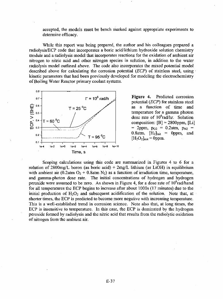
accepted, the models must be bench marked against appropriate experiments todetermine efficacy.
While this report was being prepared, the author and his colleagues prepared aradiolysis/ECP code that incorporates a boric acid/lithium hydroxide solution chemistrymodule and a radiolysis model that incorporates reactions for the oxidation of ambient airnitrogen to nitric acid and other nitrogen species in solution, in addition to the waterradiolysis model outlined above. The code also incorporates the mixed potential modeldescribed above for calculating the corrosion potential (ECP) of stainless steel, usingkinetic parameters that had been previously developed for modeling the electrochemistryof Boiling Water Reactor primary coolant systems.
0.8-
0.7- r = 106 rad/h Figure 4. Predicted corrosionpotential (ECP) for stainless steel
w0.6- T 0 2 as a function of time and:rT2U) .5- temperature for a gamma photon
>V.1 dose rate of 1 O6radlhr. Solution0.4 60 0 Ccomposition: [B] =2800ppm, [Li]
oL .- ... ... ............ 2ppm, P02 = O.2atm, pN2
0.2 0.8atm, [H 2]1i~it Oppm, and------ ' T =95 0C [H202]i~it = Oppm.
0.1t I I I I I
le-4 1le-2 1le+0 1le+2 le+4 Ile+6 le+8 le+10
Time, s;
Scoping calculations using this code are summarized in Figures 4 to 6 for asolution of 2800mg/L boron (as boric acid) + 2mg/L lithium (as LiOH) in equilibriumwith ambient air (O.2atm 02 + O.8atm N2) as a fuinction of irradiation time, temperature,and gamma-photon dose rate. The initial concentrations of hydrogen and hydrogenperoxide were assumed to be zero. As shown in Figure 4, for a dose rate of 106 radlhandfor all temperatures the ECP begins to increase after about 1 OO0s (17 minutes) due to theinitial production of H20 2 and subsequent acidification of the solution. Note that, atshorter times, the ECP is predicted to become more negative with increasing temperature.This is a well-established trend in corrosion science. Note also that, at long times, theECP is insensitive to temperature. In this case, the ECP is dominated by the hydrogenperoxide formed by radiolysis and the nitric acid, that results from the radiolytic oxidationof nitrogen from the ambient air.
E-37
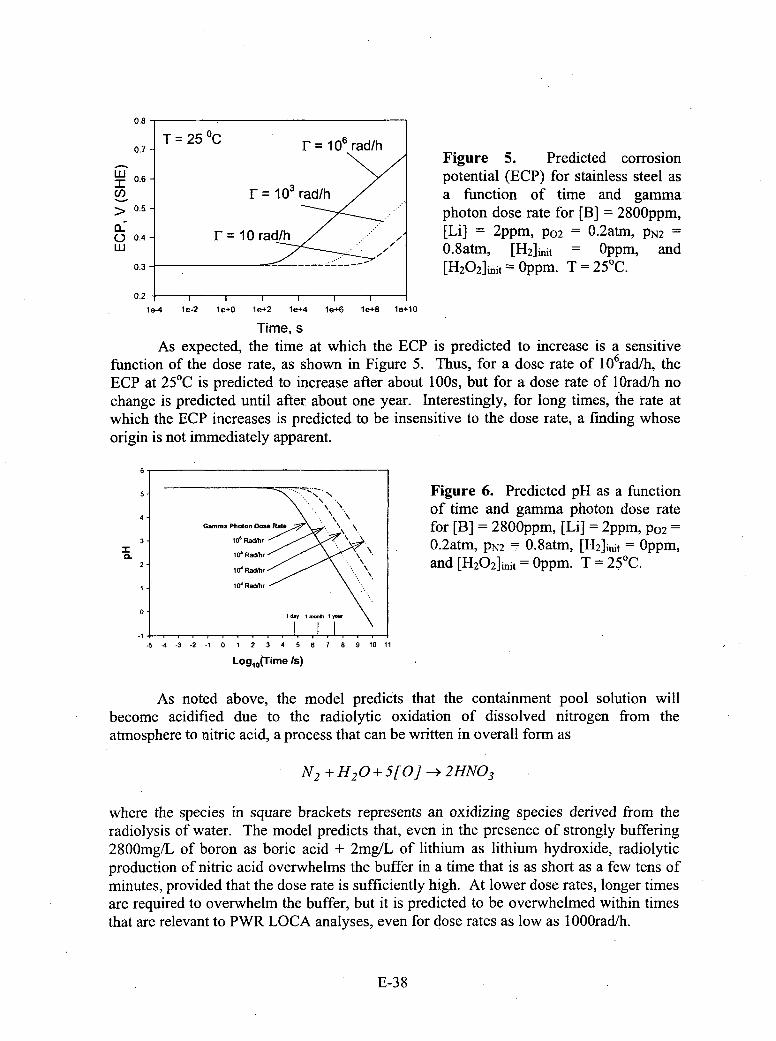
0.8
0.7 -1 - Iu IdUIlIFigure 5. Predicted corrosion
W0.6 -potential (ECP) for stainless steel as__F 1 rad/h a function of time and gamma
>0.5 photon dose rate for [B] = 2800ppm,
O0.4 -FIF 10 rad/h .. [Li] = 2ppm, P02 = O.2atm, PN2W .* .8atm, [H2]init = Oppm, and
0.3---- [H2O2]i~it =Oppm. T =250C.
0.2- 1 1 1 I
1le-4 1le-2 I e+0 1le+2 1le+4 Ie+6 le+8 le+10
Time, sAs expected, the time at which the ECP is predicted to increase is a sensitive
function of the dose rate, as shown in Figure 5. Thus, for a dose rate of 106 rad/h, theECP at 25'C is predicted to increase after about 100~s, but for a dose rate of 1 Oradlh nochange is predicted until after about one year. Interestingly, for long times, the rate atwhich the ECP increases is predicted to be insensitive to the dose rate, a finding whoseorigin is not immediately apparent.
6-
5- ~Figure 6. Predicted pHas a function4 of time and gamma photon dose rate
Gama Poto D~se atefor [B] = 2800ppm, [Li] = 2ppm, P02=
:r 0.2atm, PN2 0 .8atm, [H-2]1init Oppm,2 - rand [H 2O2]1init Oppm. T 250C.
-1 I-5 -4 -3 2 -1 0 1 2 3 4 5 6 7 8 9 10 11
Logj,(Time /s)
As noted above, the model predicts that the containment pool solution willbecome acidified due to the radiolytic oxidation of dissolved nitrogen from theatmosphere to nitric acid, a process that can be written in overall form as
N 2 +H 2 0+S5[0]--> 2HN0 3
where the species in square brackets represents an oxidizing species derived from theradiolysis of water. The model predicts that, even in the presence of strongly buffering2800mg/L of boron as boric acid + 2mg/L of lithium as lithium hydroxide, radiolyticproduction of nitric acid overwhelms the buffer in a time that is as short as a few tens ofminutes, provided that the dose rate is sufficiently high. At lower dose rates, longer timesarc required to overwhelm the buffer, but it is predicted to be overwhelmed within timesthat are relevant to PWR LOCA analyses, even for dose rates as low as I OO0rad/h.
E-38
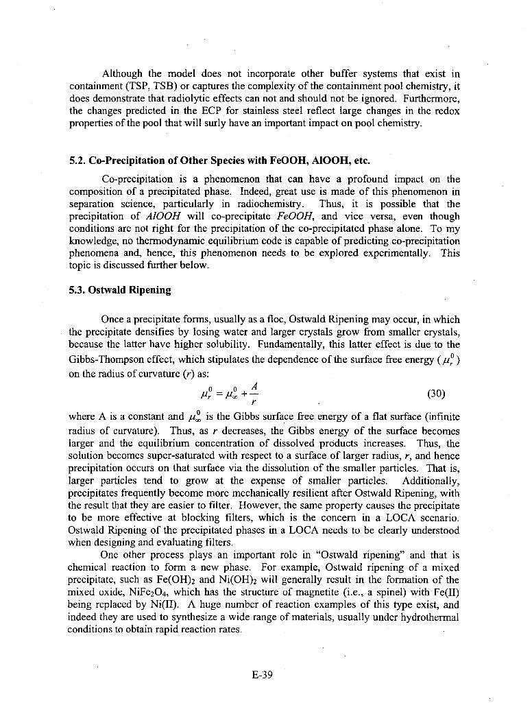
Although the model does not incorporate other buffer systems that exist incontainment (TSP, TSB) or captures the complexity of the containment pool chemistry, itdoes demonstrate that radiolytic effects can not and should not be ignored. Furthermore,the changes predicted in the ECP for stainless steel reflect large changes in the redoxproperties of the pooi that will surly have an important impact on pool chemistry.
5.2. Co-Precipitation of Other Species with FeOOH, A100H, etc.
Co-precipitation is a phenomenon that can have a profound impact on thecomposition of a precipitated phase. Indeed, great use is made of this phenomenon inseparation science, particularly in radiochemistry. Thus, it is possible that theprecipitation of A100H will co-precipitate FeOOH, and vice versa, even thoughconditions are not right for the precipitation of the co-precipitated phase alone. To myknowledge, no thermodynamic equilibrium code is capable of predicting co-precipitationphenomena and, hence, this phenomenon needs to be explored experimentally. Thistopic is discussed further below.
5.3. Ostwald Ripening
Once a precipitate forms, usually as a floc, Ostwald Ripening may occur, in whichthe precipitate densifies by losing water and larger crystals grow from smaller crystals,because the latter have higher solubility. Fundamentally, this latter effect is due to the
Gibbs-Thompson effect, which stipulates the dependence of the surface free energy (Pr~on the radius of curvature (r) as:
Pr = .+ (30)r
where A is a constant and po is the Gibbs surface free energy of a flat surface (infiniteradius of curvature). Thus, as r decreases, the Gibbs energy of the surface becomeslarger and the equilibrium concentration of dissolved products increases. Thus, thesolution becomes super-saturated with respect to a surface of larger radius, r, and henceprecipitation occurs on that surface via the dissolution of the smaller particles. That is,larger particles tend to grow at the expense of smaller particles. Additionally,precipitates frequently become more mechanically resilient after Ostwald Ripening, withthe result that they are easier to filter. However, the same property causes the precipitateto be more effective at blocking filters, which is the concern in a LOCA scenario.Ostwald Ripening of the precipitated phases in a LOCA needs to be clearly understoodwhen designing and evaluating filters.
One other process plays an important role in "Ostwald ripening" and that ischemical reaction to form a new phase. For example, Ostwald ripening of a mixedprecipitate, such as Fe(OH) 2 and Ni(OH)2 Will generally result in the formation of themixed oxide, NiFe2 O4 , which has the structure of magnetite (i.e., a spinel) with Fe(II)being replaced by Ni(II). A huge number of reaction examples of this type exist, andindeed they are used to synthesize a wide range of materials, usually under hydrothermalconditions to obtain rapid reaction rates.
E-39
5.4. Schikorr Reaction Generates Hydrogen In Situ.
The Schikorr reaction describes the conversion of ferrous hydroxide, which is theimmediate precipitated product of Fe 2+ hydrolysis, results in the conversion of Fe (OH) 2into magnetite (Fe3 04):
3Fe (OH)2 --4 Fe3O4 + H2 + 2H20 (31)
This reaction not only forms a hard, crystalline deposit of black magnetite, but itproduces one mole of hydrogen for every mole of magnetite formed. The hydrogen canhave a profound impact on the redox potential of the system, and hence upon thesolubility of those phases that are electroactive (i.e., dissolve with a change in oxidationstate) - see Issue 1, above. This reaction has been recognized for many decades as beingof great importance in boiler water chemistry and corrosion phenomena and, indeed,evidence suggests that the hydrogen that is produced is responsible for the hydrogenembrittlement of steels. Calculations need to be made as to how much hydrogen may begenerated and what the consequences of that hydrogen may be for the redox potentialassuming realistic values for Fe 2+ [and hydrolyzed Fe(II) ions] in the coolant at the pointof a LOCA, The author wishes to stress that there are many reactions that exist in theFe/H20 system (and .indeed in the Ni/H20 and Cr/H20 systems) that are "Schikorr-like"and that may result in the conversion of hydroxides into oxides with the concomitantgeneration of hydrogen. These reactions need to be defined within the LOCA contextand included in any discussion of chemical effects.
5.5. PZC and Coagulation
Certain aspects of the precipitation and coagulation of particles in aqueousenvironments are well understood, including the role played by the zeta potential and thePZC (pH of zero charge). Thus, all oxide/oxyhydroxide/hydroxide surfaces areamphorteric; that is, they undergo acid/base reactions to produce a surface charge. Thus,at sufficiently low pH (sufficiently high H+ activity), surface hydroxide groups areprotonated, S-OH- + H+ 4 S-OH2+, whereas at a sufficiently high pH, deprotonationoccurs,' S-OH- + O1- -* S-0- + H2 0, where S designates the surface. Thus, at somepH value, there will be equal populations of protonated and deprotonated hydroxylgroups on the surface or all groups will be the charge neutral, S-OH-. In either case, thesurface will have a net zero charge. This pH is known as the PZC (pH of zero charge).Thus, for pH < PZC, the surface will be positively charged, but for pH > PZC, the surfaceis negatively charged. The variation of the surface charge with pH for two differentsurfaces (A and B) is shown schematically in Figure 1. The true variation is sigmoid inshape (without the sudden changes in slope as shown) and the PZC is indicated by the pHat which the curve crosses the horizontal axis ((Y = 0). The charge saturates at high andlow pH, because there is a fixed density of adsorption sites on the surface, correspondingto the density of S-OH groups. A rough estimate of the density of sites is lnmollcm 2,giving a charge density at saturation of 97[tC/cm 2.
E-40
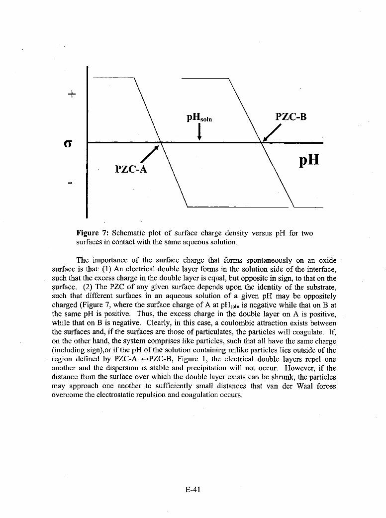
+
Figure 7: Schematic plot of surface charge density versus pH for twosurfaces in contact with the same aqueous solution.
The importance of the surface charge that forms spontaneously on an oxidesurface is that: (1) An electrical double layer forms in the solution side of the interface,such that the excess charge in the double layer is equal, but opposite in sign, to that on thesurface. (2) The PZC of any given surface depends upon the identity of the substrate,such that different surfaces in an aqueous solution of a given pH may be oppositelycharged (Figure 7, where the surface charge of A at pH,,,,, is negative while that on B atthe same pH is positive. Thus, the excess charge in the double layer on A is positive,while that on B is negative. Clearly, in this case, a coulombic attraction exists betweenthe surfaces and, if the surfaces are those of particulates, the particles will coagulate. If,on the other hand, the system comprises like particles, such that all have the same charge(including sign),or if the pH of the solution containing unlike particles lies outside of theregion defined by PZC-A *-*PZC-B, Figure 1, the electrical double layers repel oneanother and the dispersion is stable and precipitation will not occur. However, if thedistance from the surface over which the double layer exists can be shrunk, the particlesmay approach one another to sufficiently small distances that van der Waal forcesovercome the electrostatic repulsion and coagulation occurs.
E-41
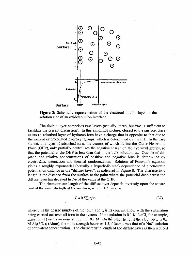
CD 0
Surface o (
(D 0
L I.. TH.Lmnce krmi Eileclrode
Poteuntia
Surface 011P' Diffuse oyeI*
Figure 8: Schematic representation of the electrical double layer in thesolution side of an oxide/solution interface.
The double layer comprises two layers (actually, three, but two is sufficient tofacilitate the present discussion). In this simplified picture, closest to the surface, thereexists an adsorbed layer of hydrated ions have a charge that is opposite to that due tothe ionized or protonated hydroxyl groups, which is determined by the pH. In the caseshown, this layer. of adsorbed ions, the centers of Which define the Outer HelmholtzPlane (OHP), only partially neutralizes the negative charge on the hydroxyl groups, sothat the potential at the OHP is less than that in the bulk solution, 9,* Outside of thisplane, the relative concentrations of positive and negative ions is determined byelectrostatic interaction and thermal randomization. Solution of Poisson's equationyields a roughly exponential (actually a hyperbolic sine) dependence of electrostaticpotential on distance in the "diffuse layer", as indicated in Figure 8. The characteristiclength is the distance from the surface to the point where the potential drop across thediffuse layer has decayed to I/e of the value at the OHP.
The characteristic length of the diffuse layer depends inversely upon the squareroot of the ionic strength of the medium, which is defined as
I1= 0.5yz'Ci (32)
where zi is the charge number of the ion i, and ci is its concentration, with the summationbeing carried out over all ions in the system. If the solution is 0. 1 M NaCI, for example,Equation (1) yields an ionic strength of 0. 1 M. On the other hand, if the electrolyte is 0. 1M A12 (S0 4 )3 (Alum), the ionic strength becomes 1.5, fifteen times that of a NaCI solutionof equivalent concentration. The characteristic length of the diffuse layer is then reduced
E-42
by a factor of nearly 4 and this reduction is sufficient to cause coagulation andprecipitation of colloidal particles (e.g., clay, organic matter, and polymeric hydrolyzedions), due to van der Waal attraction, followed by Ostwald ripening. Additionally, thehydrolysis and polymerization of Al(III) produces a gelatinous precipitate that co-precipitates other matter (ions,. colloids, or even particles), as discussed in Issues 2 and 3above and further discussed below. The above is nothing more or less than the Alumprocess for clarifying domestic and industrial water su'plies and has been practiced formore than 140 years.
An important consequence of coagulation via surface charge effects is thephenomenon of co-precipitation and/or co-coagulation, in which the hydroxides and oroxyhydroxides and oxides of different metals may coagulate together to form, afterripening, mixed oxides, hydroxides and oxyhydroxides. Indeed, this is a well-establishedroute for the synthesis of such materials. If the starting system is a colloidal mixture,then the charges (sign and magnitude) on the different material particles play key roles indetermining the form and extent of the co-precipitates. Because the charge (again, thesign and magnitude) are determined by the activity of hydrogen ion in the solution, thepH is a key variable in determining the nature of the product. After a LOCA, it isenvisioned that various oxides, oxyhydroxides, and hydroxides of elements, such as Al,Zn, Fe, Si, and Ca, will be present in the system. These oxides, oxyhydroxides, andhydroxides have widely differing PZC values, so that the relative charges on the differentparticles may change drastically as the pH of the medium is changes. Clearly anunderstanding of the dynamics of co-precipitation and co-coagulation requires a thoroughcharacterization of the surface charge characteristics of all components in the system.
These concepts must be used to develop an understanding and, eventually, apredictive model for precipitation and coagulation post LOCA. This model should thenbe combined with a model for Ostwald ripening to provide a quantitative tool forpredicting the identities and yield of solid precipitates in a LOCA. The combined modelshould be capable of predicting the temperature and pH at which precipitation occurs (seeIssue 6, below) and the rate of particle growth. The process should begin by firstcollecting the extensive data that exist in the literature for the PZCs of the materials thatare expected to come into contact with water and with one another; if the data are notavailable, they should be measured using standard techniques. The critical ionicstrengths for coagulation should then be measured for the various colloidal systems, fromwhich the van der Waal parameters may be estimated. From there, the rate ofprecipitation can be modeled as a Brownian motion problem (see collisional theory forgases) by assuming a sticking probability of one. Little attention seems to have been paidto these important factors in the analysis to date, but they provide guidance as to the rateof precipitate formation and may allow formulation of strategies to control theprecipitation, so as to avoid clogging of the filters.
5.6. y-A100H formation
The hydrothermnal formation of boehmite, y-AlOOH, from A13+ solutions has beenstudied [see D. D. Macdonald, P. Butler, and D. Owen. "Hydrothermal Hydrolysis ofA13 + and Precipitation of Boehmite from Aqueous Solution". J. Phys. Chem., 77(20),2474-2479 (1973)], and this work provides useful data on the buffering capacity of thatreaction as the precipitate forms. The reader will note that, as the temperature increases,
E-43
the pH of the solution becomes independent of the initial concentration of A13 + in thesystem. This may have important implications in modeling the precipitation process.The paper also provides a model for the speciation of the principal polymeric ionicspecies in the system as hydrothermal precipitation of boehmite (y-AlOOH) occurs. Forexample, starting with a solution of 0.038m A13 + in 1.0 mn KCl at an initial pH of 2.59, theprincipal hydrolysis product is predicted to be the dimer, A12 (OH)2 , over the entiretemperature range (25TC - 1 500C). However, at temperatures above about 1 25'C, thehighly polymerized species, Al14(OH)34
8+, is predicted to become significant, coincidentwith the precipitation of boehmite. Thus, this study shows that the hydrothermalprecipitation of boehmite, for example, proceeds by the progressive formation of morehighly hydrolyzed cationic species with the ratio of 0 to Al converging onto the ratio thatexists in the precipitate (ratio = 2), with some species being preferred for structuralreasons. Finally, this paper contains a model, which after updating with later data for thehydrolysis of A13 +' should allow accurate simulation of the formation of theoxyhydroxides of aluminum in a LOCA environment.
Similar models have been developed for the precipitation of the oxyhydroxides ofiron, but the author is not aware of similar treatments for the thermal hydrolysis of Zn 2 +
and Ca2 ~ for example.
5.7. Precipitation on Fibers
I believe that an explanation for the initial precipitation of y-AIOOH onto glassfibers might be found in an analysis of the PZCs of the fiber and the precipitatingmaterial, with respect to the pH of the solution, and in the impact of ionic strength on thecritical lengths of the diffuse layers and their impact, in turn, on the rate of particleagglomeration, as discussed in Issue 5. The viability of this mechanism might be testedby studying the rate of growth on different surfaces (and hence of different surface charge)and from solutions of different ionic strength using a quartz crystal microbalance. Thistechnique is capably of detecting mass changes of nano-grams per square centimeter, isreadily applied in situ, and can be used over a range of temperatures. The principalchallenge will be in obtaining low mass fiber glass samples mounted on the siliconoscillator. Nevertheless, QCM would allow a high throughput in the experiments andwould permit the determination of quantitative data for deposit growth rate.
5.8. Thermal Hydrolysis of Organic Material
Considerable organic material exists in confinement in a PWR, ranging from paintto plastic insulation. Some of this material would be partially pulverized and renderedinto a colloidal form by hydrothermal hydrolysis. The reader should note that the PZCconcept also applies to organic particles, so that PZC values for the organic colloids thatare produced by the thermo-hydrolysis of the organic materials need to be determined.Thus, organic colloids need to be included in the list of particles that should be exploredunder Issue 6. It is most important to note that the hydrothermal hydrolysis of organicmaterials results not only in depolymerization, and hence in the production of particles ofmicro- to nano-meter dimension, but also in surfaces that are partially oxidized toproduce alcoholic (-OH), ketonic (C=0), and acidic (-COGH) moeties, which contributeto defining the acid/base properties of the surfaces and hence the PZC.
E-44
Organic species also have an important effect of modifying surfaces by adsorption.In doing so, they may change the surface charge characteristics completely, causingprecipitation or inhibiting coagulation. Many of these effects are currently very poorlydefined and understood and, hence, are very difficult, if not impossible, to predict fromfirst principle calculation. Those systems that have been studied at any depth tend to be"4simple systems", that are of only marginal value to the problem of interest in this work.
5.9. Is There a Particle Size That Can Be Tolerated?
Accepting that clogging of the filters most likely would result from the initialformation of colloidal particles followed by coagulation and Ostwald ripening, thequestion arises: Is there a particle size that can be tolerated? A closely related questionconcerns the impact of flow velocity and fluid shear rate on the particle size distribution.This issue needs to be explored under realistically simulated LOCA conditions, becausepresumably there exists a particle size below which the particles will pass through thefilter and hence will not impede flow. The formation of larger particles would bediscouraged by the high shear rate that tends to inhibit coagulation. However, the currentinformation on this process is very qualitative in nature, whereas quantitative informationis required in order to synthesize predictive models. The models would then be used toassess the risk of clogging of the filters (and the pump) for different pump speeds.However, it is doubtful that such a model would yield a definitive answer withoutcalibration using a full mock-up of the pump and filter system.
5.10. Why Does a Bimodal Distribution Exist in Particle Size?
A bimodal distribution in particle size commonly indicates parallel growth processesfrom a common population of nuclei, with the two growth processes occurring atdifferent rates. The different growth rates may reflect different Ostwald ripening rates ora bimodal distribution in the nuclei with regard to surface charge (and hence with respectto agglomeration rate). The latter should be detectable by measuring the particle mobilityelectrophoretically, in which case a bimodal distribution in mobility should be found.Another method that might be tried is to fractionate the sample using centrifugation atdifferent rotation speeds and then use each fraction as seeds for further growth. If thereare two preferred sizes for growth, they might be detected in the final particle sizedistribution.
5.11. Corrosion of Aluminum
The corrosion and passivity of aluminum has been studied extensively and space doesnot exist here for me to summarize all that is known. Aluminum is a very active metal,particularly at elevated temperature, as indicated by the potential-pH diagram [D. D.Macdonald and P. Butler. "The Thermnodynamics of the Aluminum-Water System atElevated Temperatures". Corros. Sci., 13, 259-274 (1973)]. The potential-pH diagramdisplays a large predominance region for the oxyanion aluminate, Al(OH)4i that becomeslarger with respect to that for AP3 + as the temperature increases (reflecting a lower surfacecharge density for the former than for the latter). At intermediate pH values, there existsa stability region for the oxide, A1 2 03 , which passivates the surface.
E-45
The formation of passivating oxide films on metal surfaces is well understood interms of the Point Defect Model (PDM) [D. D. Macdonald, Pure Appi. Chem., 71, 951(1999)]. Briefly, the film forms as a bi-layer structure, comprising a defective oxidebarrier layer adjacent to the metal and an outer, precipitated layer of Al(OH) 3 adjacent tothe solution. A point defect model for the passive layer in acidic solutions, where Al3 + isthe predominant species, is presented below, assuming that the mobile cation in thebarrier layer is the metal interstitial. A similar model is easily formulated for the passivefilm on any metal under the conditions of interest.
The validity of the PDM for describing passivity and the corrosion of passivemetals has now been demonstrated by the author and other researchers. The model iscapable of accounting for not only the properties of the passive state, but also thetransition to the transpassive state, passivity breakdown, and depassivation phenomena.When combined with the generalized Butler-Volmer equation for the cathodic reductionof oxygen and hydrogen evolution, and after imposing the conservation of charge, theresulting mixed potential model (MPM) is capable of calculating the corrosion potentialand corrosion rate quantitatively, as has been demonstrated by the author's extensivemodeling of corrosion processes in the heat transport circuits of water-cooled nuclearpower reactors.
By using a two-component brick wall analogy (red bricks for cations and cationvacancies and blue bricks for oxygen ions and oxygen vacancies), and noting that theminimum unit of the barrier layer is one red brick and one blue brick in adjacentpos itions, it is apparent that Reactions (1), (3), and (4), Figure 3, are lattice conservativeprocesses (i.e., the barrier layer boundaries do not move with their occurrence), whereasReactions (2) and (5) are lattice non-conservative processes. Note that the entity
A/Al + 3 - Il (I~) seuiaett A12 03 , because vacancies can be regarded2 V ~ 12 V)iseuvlnto2
as being real species. Experimentally, we know that the barrier layer on a metal achievesa steady-state thickness and, hence, there must exist two non-conservative reactions at thebarrier layer interfaces; specifically, the other must be at the barrier layer/outer layerinterface. That reaction is Reaction (5), which describes the dissolution of the barrierlayer. Thus, in the steady-state, the rates of Reactions (2) and (5) must be equal. Theformation of the outer layer is due to precipitation of Al(OH) 3 from a super-saturatedsolution of Al+ that forms via dissolution from thermodynamically less stable sources;namely, aluminum metal via interstitials in the barrier layer and the defective barrierlayer, itself, Al1+,O1-y. In any event, the outer later forms by precipitation and maycontain substantial quantities of other species, such as borate, that are present in thesolution.
E-46
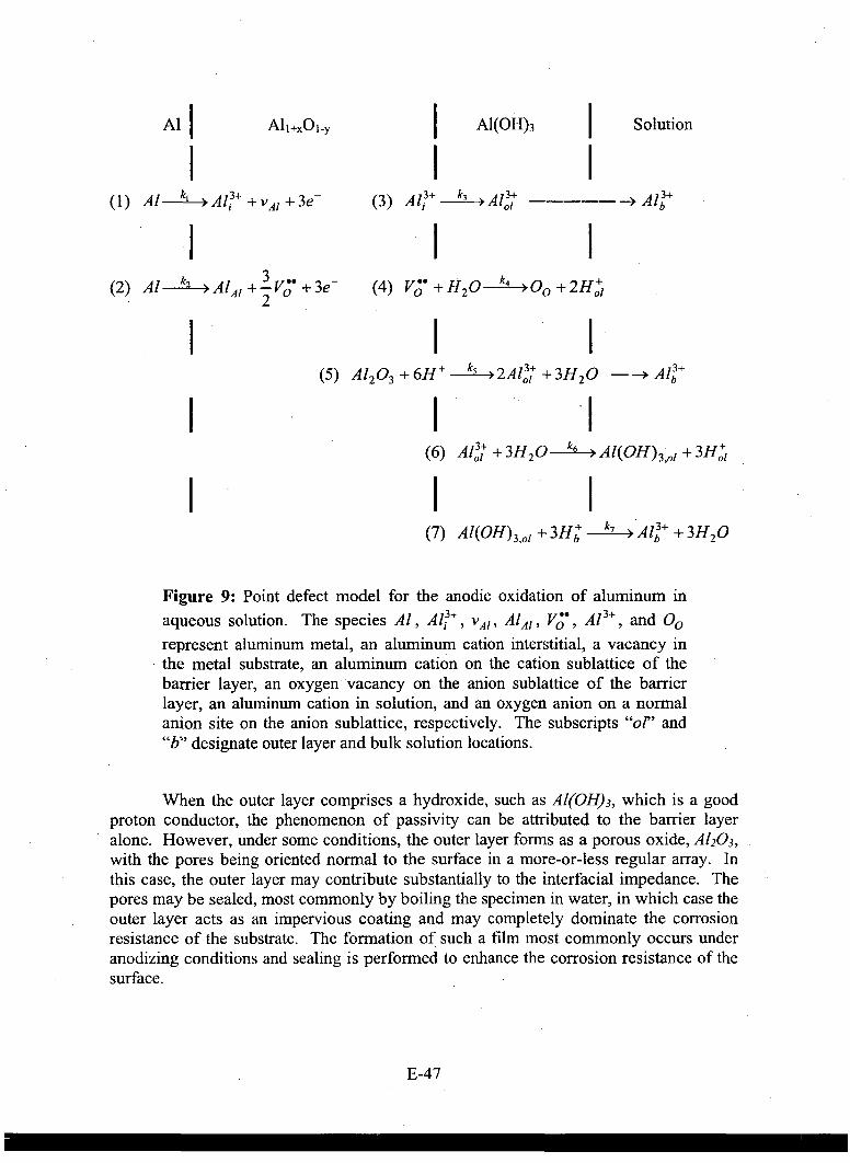
Al All±,Ol-y A1(OH) 3 Solution
I k, 13I3 3 3(1) Al-- -A? + VAl +3e- (3) A ~ A3 01 - - - - - - - ->A
(2) Al k2 >AlAl +-3V'* + 3e (4) Vc7 +H2 0 k4 -->0+2H+~2 0
(5) A1203 +6H+--k 5 -2Al3+ +3H 2 0 --- >Al3+
(6) A 131 + 3 H 20 k6 4Al(OH)3 ,1 + 3H+01
(7) Al(OH)3 ,o1 + 3H+ k7 Alb~ + 3H0
Figure 9: Point defect model for the anodic oxidation of aluminum inaqueous solution. The species Al, A i3 VAI I A/Al I Vý, A13+' andO00represent aluminum metal, an aluminum cation interstitial, a vacancy inthe metal substrate, an aluminum cation on the cation sublattice of thebarrier layer, an oxygen vacancy on the anion sublattice of the barrierlayer, an aluminum cation in solution, and an oxygen anion on a normalanion site on the anion sublattice, respectively. The subscripts "of' and"b" designate outer layer and bulk solution locations.
When the outer layer comprises a hydroxide, such as Al(OH) 3 , which is a goodproton conductor, the phenomenon of passivity can be attributed to the barrier layeralone. However, under some conditions, the outer layer forms as a porous oxide, A1 2 03 ,with the pores being oriented normal to the surface in a more-or-less regular array. Inthis case, the outer layer may contribute substantially to the interfacial impedance. Thepores may be sealed, most commonly by boiling the specimen in water, in which case theouter layer acts as an impervious coating and may completely dominate the corrosionresistance of the substrate. The formation of such a film most commonly occurs underanodizing conditions and sealing is performed to enhance the corrosion resistance of thesurface.
E-47
The corrosion rate of aluminum is due to Reactions (1) and (2), Figure 3, and maybe written as
CR =f2,41(k, +k 2 ) (cm/s) (33)
where k, and k2 are the rate constants (mollcm2.s), as indicated in Figure 3, and nA1 is
the molar volume of aluminum metal. The corrosion rate may also be expressed in termsof mass per unit area per unit time as:
CR =MAI (k, + k2 ) (g/cm .s) (34).
where MAI is the atomic weight of aluminum. Regardless of which expression is used, itis necessary to determine the rate constants k, and k2. Partial charge transfer theory andactivated complex theory show that the rate constants may be written in morefundamental form as
ki ki0e ajV e-~Le cjpH (35)
and
2 2kooea2V e b2L eC2PH (36)
where the coefficients a, b, and c are functions of still more fundamental parameters,including the electric field strength, the polarizability of the barrier layer/outer layerinterface, and the transfer coefficients for the interfacial reactions, among others, V is thevoltage (the corrosion potential, in this case), and L is the thickness of the barrier layer.Values for these parameters are readily determined by using electrochemical impedancespectroscopy (EIS) [D. D. Macdonald, A. Sun, Priyantha, N., P. Jayaweera, "AnElectrochemical Impedance Study of Alloy 22 in NaCl Brine at Elevated TemperaturefII.Reaction Mechanism Analysis", J. Electroanal. Chem., 572, 421-431 (2004)], and hencethe corrosion rate may be calculated.
In highly alkaline solutions, corrosion is believed to occur in the transpassivestate, in which the metal has been depassivated by the loss of the barrier layer. In thiscase, the corrosion rate is controlled by the dissolution of the metal in the presence of theprecipitated outer layer, which offers only moderate resistance to corrosio n. This casehas been studied extensively under the DOE program in the 1980s that aimed atdeveloping fuiels for aluminum-air batteries for automotive appli cation [D. D.Macdonald, K. H. Lee, A Moccari, and D. Harrington, "Evaluation of Alloy Anodes forAluminum/Air Batteries I. Corrosion Studies". Corrosion, 44, 652-657 (1988); S. Real,M. Urquidi-Macdonald, and D. D. Macdonald, "Evaluation of Alloy Anodes for
E-48

Aluminum/Air Batteries II. Delineation of Anodic and Cathodic Partial Reactions". J.Electrochem. Soc., 135(7), 1633-1636 (1988); D. D. Macdonald, S. Real, and M.Urquidi-Macdonald. "Evaluation of Alloy Anodes for Aluminum-Air Batteries 111.Mechanisms of Activation, Passivation, and Hydrogen Evolution", J. Electrochem. Soc.,135(10), 2397-2409 (1988); D. D. Macdonald, S. Real, S. 1. Smedley, and M. Urquidi-Macdonald, "Evaluation of Alloy Anodes for Aluminum-Air Batteries IV.Electrochemical Impedance Analysis of Pure Aluminum in 4M KOH at 25'C", J.Electrochem. Soc., 135(10), 2410-2414 (1988)]. That work produces a model foraluminum dissolution in highly alkaline solutions that involves the stepwiseelectrochemical discharge of OH onto the metal surface followed by the chemicaldissolution of Al(OH)4 from the surface. The key question concerns which model toadopt (with or without a barrier layer) for the conditions that prevail in a LOCA.
In my opinion, a quantitative model for calculating, the corrosion rate ofaluminum, or of any other metal or alloy, could be developed and used to estimate theinventory of aluminum corrosion products in confinement as a function of time during aLOCA. This would require an EIS study of aluminum in various enviromnments as afunction of voltage, pH, and temperature, followed by optimization of the Point DefectModel (Figure 3) on the experimental data, in order to extract values for various modelparameters. Work on developing a PDM for the corrosion of aluminum has beeninitiated in the author's laboratory with a visiting student from Spain. The results of thiswork will be made available to NRC/ANL as they become available.
Similar models may (and in some cases, have been) formulated for the othermetals of interest, including iron and zinc. The models are readily available in theliterature published over the past twenty years.
6. Recommendations
In the light of the issues identified above, a number of recommendations havebeen formulated that, in the author's opinion, will significantly aid in developing aquantitative understanding of, and a predictive capability for, the chemical processes thatmight occur during and after a LOCA in confinement of a PWR. The recommendationsare supported by a number of publications that are cited in this report, but it is to beunderstood that the literature review was not exhaustive.
Equilibrium models must be used with great caution, because the environmentproduced by a LOCA is unlikely to be at equilibrium, at least during the initialstages. Furthermore, the processes that occur during corrosion, precipitation, andripening are generally slow, as has been shown in some of the work reviewedduring the Kickoff Meeting at ANL. The kinetics of many of these processes aresuch that the system may still be far from equilibrium as it enters the recirculationsystem. Accordingly, equilibrium calculations need to be bench-marked to thegreatest extent possible against experiment to assess the reliability of thethermodynamic equilibrium codes. This has been done to a significant extent inthe present program, but the results are hampered by the lack of consideration ofradiolysis and redox effects.
E-49
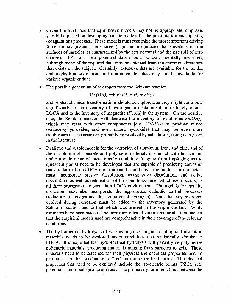
*Given the likelihood that equilibrium models may not be appropriate, emphasisshould be placed on developing kinetic models for the precipitation and ripening(coagulation) processes. These models must recognize the most important drivingforce for coagulation; the charge (sign and magnitude) that develops on thesurfaces of particles, as characterized by the zeta potential and the pzc (PH of zerocharge). PZC and zeta potential data should be experimentally measured,although many of the required data may be obtained from the enormous literaturethat exists on the subject. Certainly, extensive data are available for the oxidesand oxyhydroxides of iron and aluminum, but data may not be available forvarious organic entities.
*The possible generation of hydrogen from the Schikorr reaction
3Fe(OH)2 -4 Fe3O4 + H2 + 2H120
and related chemical transformations should be explored, as they might contributesignificantly to the inventory of hydrogen in containment immediately after aLOCA and to the inventory of magnetite (Fe304) in the system. On the positiveside, the Schikorr reaction will decrease the inventory of gelatinous Fe (OH) 2,which may react with other components [e.g., Si(OH)4] to produce mixedoxides/oxyhydroxides, and even mixed hydroxides that may be even moretroublesome. This issue can probably be resolved by calculation, using data givenin the literature.
*Realistic and viable models for the corrosion of aluminum, iron, and zinc, and ofthe dissolution of concrete and polymeric materials in contact with hot coolantunder a wide range of mass transfer conditions (ranging from impinging jets toquiescent pools) need to be developed that are capable of predicting corrosionrates under realistic LOCA environmental conditions. The models for the metalsmust incorporate passive dissolution, transpassive dissolution, and activedissolution, as well as delineation of the conditions under which each occurs, asall three processes may occur in a LOCA environment. The models for metalliccorrosion must also incorporate the appropriate cathodic partial processes(reduction of oxygen and the evolution of hydrogen). Note that any hydrogenevolved during corrosion must be added to the inventory generated by theSchikorr reaction and to that which was present in the virgin coolant. Whileestimates have been made of the corrosion rates of various materials, it is unclearthat the empirical models used are comprehensive in their coverage of the relevantconditions.
*The hydrothermal hydrolysis of various organic/inorganic coating and insulationmaterials needs to be explored under conditions that realistically simulate aLOCA. It is expected that hydrothermal hydrolysis will partially de-polymerizepolymeric materials, producing materials ranging from particles to gels. Thesematerials need to be screened for their physical and chemical properties and, inparticular, for their tendencies to "set" into more resilient forms. The physicalproperties that need to be explored include the iso-electric points (PZC), zetapotentials, and rheological properties. The propensity for interactions between the
E-50
various components produced by hydrothermal hydrolysis among themselves andwith. other materials in the system must be clearly defined.
*The models that are produced to predict corrosion rates and phase properties mustbe, to the greatest extent possible, deterministic in nature. Thus, a deterministicmodel is one whose output (prediction) is constrained by the natural laws to thatwhich is physically viable. These constraints are generally the conservation laws,such as the conservation of mass, charge, energy, and momentum. Theequivalence laws, such as Faraday's law of the equivalence of mass and charge,or Joule's law of the equivalence of heat and work, are generally part of theconstitutive equations of a model. Importantly, in the art of prediction, it is notsufficient for a model to be "mechanism based"; it must be implicitly constrainedby the conservation laws, which are a summation of scientific experience. Thus,the researchers working on this program, and who are involved in the process ofmodel building, are urged to ensure that their models are deterministic within thecontext stated above.
" Development of a radiolysis code specifically for a containment pooi is absolutelyessential, since the redox potential controls the speciation within the pool. Thismodel should incorporate boric acidlLiOH + TSP (tni-sodium phosphate) + TSB(tetra-sodium borate) modules for estimating the pH. The model should becalibrated/evaluated against laboratory experiments to establish efficacy.
* A thorough analysis should be carried out to estimate the likely y-dose rates in thecontainment pool as a function of time after a LOCA in a PAIR. The contributionof a-dose rate from fission products also needs to be evaluated. The latter iscompletely ignored in the present analysis and the former ('y-dose rate) is littlemore than a guess. No information of guidance on this subject could be found inthe open literature.
* A better database for the kinetics of the hydrogen electrode reaction, the oxygenelectrode reaction, and the hydrogen peroxide electrode reaction needs to beestablished. Some of the "raw"~ data are already in the literature, but theinformation is incomplete and the data are generally not in a form that is readilyinterfaced with radiolysis/redox potential models. In some cases, howeve~r, therequired data must be experimentally measured.
* Possible acidification of the pool by radiolysis is a matter of essential importanceand must be explored to ascertain whether unacceptable conditions may developdue to the radiolytic generation of nitric acid from nitrogen in the ambient air. Ofall of the recommendations given above, this recommendation and that onincluding redox effects is by far the most important.
E-5 1

Appendix 1.
Resume of Digby D. Macdonald
Distinguished Professor of Materials Science and EngineeringDirector, Center for Electrochemical Science and Technology
The Pennsylvania State University201 Steidle Bldg.
University Park, PA 16802(814) 863-7772, (814.) 863-4718 (fax), [email protected]
EDUCATIONAL IBACKGROUNDB.Sc. (1965) and M.Sc. (1966) in Chemistry, University of Auckland (New Zealand);Ph.D. in Chemistry (1969), University of Calgary (Canada).
PROFESSIONAL EXPERIENCE (past 35 years)Distinguished Professor of Materials Science and Engineering, 6/2003 - present.Chair, Metals Program, Penn. State Univ., 6/200 1 - 6/2003Director, Center for Electrochemical Sci. & Tech., Penn. State Univ., 7/99 - present.Vice President, Physical Sciences Division, SRI International, Menlo Park, CA, 1/98 -
7/99Director, Center for Advanced Materials, Penn. State Univ., 7/91-3/2000
Professor, Materials Science and Engineering, Penn. State Univ., 7/91 - 6/03.
Deputy Director, Physical Sciences Division, SRI International, Menlo Park, CA, 4/87 -
7/91Laboratory Director, Mat. Research Lab., SRI International, Menlo Park, CA, 4/87 - 7/91Laboratory Director, Chemistry Laboratory, SRI International, Menlo Park, CA, 3/84 -
4/87Director and Professor, Fontana Corrosion Center, Ohio State University, 3/79 - 3/84Sr. Metallurgist, SRI International, Menlo Park, CA, 3/77 - 3/79.Sr. Research Associate, University of Calgary, Canada, 3/75 - 3/77.Lecturer in Chemistry, Victoria University of Wellington, New Zealand, 4/72 - 3/75.Assist. Research Officer, Whiteshell. Nuclear Research Establishment, Atomic Energy of
Canada Ltd., Pinawa, Manitoba, Canada, 9/69 - 4/72.
CONSULTING ACTIVITIES (Partial list for the last five years))Integrated Design TechnologiesOLI SystemsElectric Power Research InstituteSRI InternationalStone & Webster Engineering Co.Science Applications International Corp.FramatomeMetallic Power Inc.
E-52

Los Alamos National Laboratory
PA TENTS
1 . D. D. Macdonald and A. C. Scott, "Pressure Balanced External Reference ElectrodeAssembly and Method", US Patent 4,273,63 7 (198 1).
2. D. D. Macdonald, "Apparatus for Measuring the pH of a Liquid", US Patent4,406,766 (1983).
3. S. C. Narang and D..D. Macdonald, Novel. Solid Polymer Electrolytes", US Patent5,061,581 (1991).
4. S. Hettiarachchi, S. C. Narang, and D. D. Macdonald, "Synergistic CorrosionInhibitors Based on Substituted Pyridmnium Compounds", US Patent 5,132,093(1992).
5. S. Hettiarachchi, S. C. Narang, and D. D. Macdonald, "Reference ElectrodeAssembly and Process for Constructing", US Patent, 5,238,553 (1993).
6. D. D. Macdonald, et al, "Conducting Polymer for Lithium/Aqueous Syst.", US Prov.Pat. 60/119,360 (1998).
7. D. D. Macdonald, et al, "Polyphosphazenes as Proton Conducting Membranes", USPat. Appl. 09/590,985 (1999).
8. D. D. Macdonald, et al, "Impedance/Artificial Neural Network Method...", US Prov.Pat. 60/241,871 (1999)
9. D. D. Macdonald, "Electrochemical Conditioning of Wine", US Prov. Pat.60/295,080 (2001).
PUBLICATIONS (from 180 published over the past five years and from a total of650+).I1. Engelhardt, G.R., M. Urquidi-Macdonald, and D. D. Macdonald. "A Simplified
Method for Estimating Corrosion Cavity Growth Rates". Corros. Sci., 39(3), 419-441(1997).
2. Gao, L. and D. D. Macdonald. "Characterization of Irreversible Processes at theLi/Poly[bis(2,3-di-(2-methoxyethoxy)propoxy)phosphazene] Interface on ChargeCycling". J. Electrochem. Soc., 144(4), 1174-1179 (1997).
3. Sikora, E. and D. D. Macdonald. "Defining the Passive State". Solid State Ionics, 94,141-150 (1997).
4. Engelhardt, G. R. and D. D. Macdonald, "Deterministic Prediction of Pit DepthDistribution", Corrosion, 54, 469-479 (1998).
5. Macdonald, D. D., E. Sikora, and J. Sikora, "The Kinetics of Growth of the PassiveFilm on Tungsten in Acidic Phosphate Solutions", Electrochim. Acta, 43, 2851-61(1998).
6. Pensado-Rodriguez, 0., J. Flores, M. Urquidi-Macdonald, and D. D. Macdonald,"The Electrochemistry of Lithium in Alkaline Aqueous Electrolytes. Part 11: PointDefect Model". J. Electrochem. Soc., 146, 1326-1335 (1999).
7. Macdonald, D. D, I. Balachov, and G. Engelhardt, "Deterministic Prediction ofLocalized Corrosion Damage in Power Plant Coolant Circuits", Power PlantChemistry, 1, 9 (1999).
8. Engelhardt, G. R., D. D. Macdonald, and P. Millett, "Transport Processes in SteamGenerator Crevices. 1. General Corrosion Model", Corros. Sci., 41, 2165-2 1 90 (1999).
E-53
9. Macdonald, D. D., "Passivity: The Key to Our Metals-Based Civilization", Pure Appi.Chem., 71, 95 1-986 (1999).
10. Quiroga. Becerra, H., D. D. Macdonald, and C. Retamosa, "The Corrosion of CarbonSteel in Oil-in-Water Emulsions Under Controlled Hydrodynamic Conditions",Corros. Sci., 42, 561-575 (2000).
11. Sikora, E. and D. D. Macdonald, "The Passivity of Iron in the Presence of EDTA.Part 1. General Electrochemical Behavior". J. Electrochem. Soc., 147(11), 4087-4092(2000).
12. Macdonald, D. D., M. AI-Rafaie and G. R. Engelhardt, "New Rate Laws for theGrowth and Reduction of Passive Films", J. Electrochem. Soc., 148(9), B343 - B347(2001).
13. Macdonald, D. D., "Probing the Chemical And Electrochemical Properties of SCWOSystems", Electrochim. Acta, 47, 775-790 (2001).
14. Zhou, X.Y., S. N. Lvov, X. J. Wei, L. G. Benning, and D. D. Macdonald,"Quantitative Evaluation of General Corrosion of Type 304 Stainless Steel inSubcritical and Supercritical Aqueous Solutions via Electrochemical Noise Analysis".Corros. Sci., 44(2), 84 1-860 (2002).
PROFESSIONAL ASSOCIATIONS AND HONORS" Selector of the Kuwait Prize for Applied Sciences, 1985.* Research Award, College of Engineering, Ohio State University, 1983.* The 1991 Carl Wagner Memorial Award from The Electrochemical Society.* The 1992 Willis Rodney Whitney Award from NACE International." Chair, Gordon Research Conference on Corrosion, New Hampshire, 1992.* Member, Board of Visitors, Office of Naval Research." W.B. Lewis Memorial Lecture by Atomic Energy of Canada, Ltd., 1993, "in
recognition of [his] contributions to the development of nuclear power in theservice of mankind".
* Elected Fellow, NACE-International, 1994.* Member, USAF Scientific Advisory Board, Protocol Rank: DE-4 (Lieutenant
General equivalent), 1993-1997" Elected Fellow, The Electrochemical Society, 1995." Elected Fellow, Royal Society of Canada, 1996. ("National Academy" of
Canada)." Wilson Research Award, College of Earth and Minerals Sciences,
Pennsylvania State University, 1996." Elected Fellow, Royal Society of New Zealand, 1997. ("National Academy" of
New Zealand).* H. H. Uhlig Award, The Electrochemical Society, 2001." U. R. Evans Award, The British Corrosion Institute, 2003.
*Appointed Adjunct Professor, Massey University, New Zealand, 2003.*Appointed Adjunct Professor, University of Nevada at Reno, 2003.*Elected Fellow, World Innovation Foundation, 2004..Elected Fellow, ASM International, 2005.
E-54
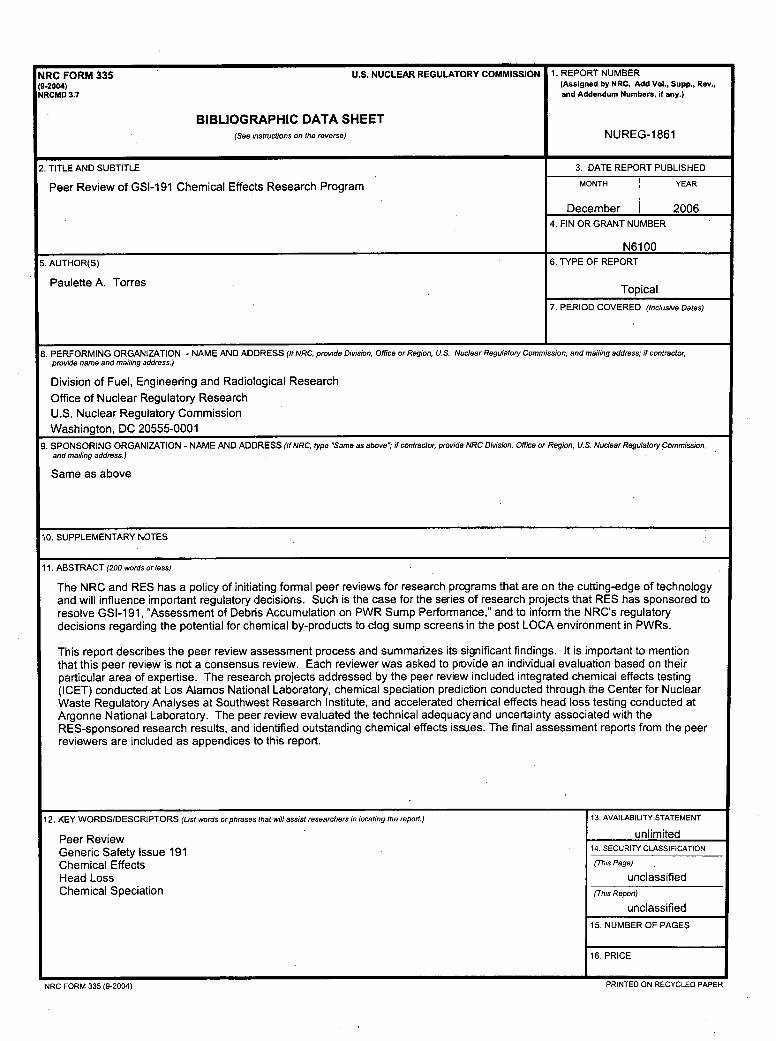
NRC FORM 335 U.S. NUCLEAR REGULATORY COMMISSION 1. REPORT NUMBER(9.2004) (Assigned by NRC, Add Vol.. Supp.. Rev..NRCMD 3.7 and Addendum Numbers, if any.)
BIBLIOGRAPHIC DATA SHEET(See instructions on the reverse) NUREG-1861
2. TITLE AND SUBTITLE 3. DATE REPORT PUBLISHED
Peer Review of GSI-191 Chemical Effects Research Program MONTH YEAR
December 20064. FIN OR GRANT NUMBER
__________________________________________________________N6100
5. AUTHOR(S) 6. TYPE OF REPORT
Paulette A. TorresToia
7. PERIOD COVERED (inclusive Dates)
8. PERFORMING ORGANIZATION -NAME AND ADDRESS (if NRC, provide Division. Office or Region, U.S. Nuclear Regulatory Commission, and mailing address; if contractor.provide name and mailing address.)
Division of Fuel, Engineering and Radiological ResearchOffice of Nuclear Regulatory ResearchU.S. Nuclear Regulatory CommissionWashington, DC 20555-0001
9. SPONSORING ORGANIZATION - NAME AND ADDRESS (If NRC, type "Same as above'; if contractor, provide NRC Divsion, Office or Region. U.S. Nuclear Regulatory Commission,and mailing address.)
Same as above
10. SUPPLEMENTARY NOTES
11. ABSTRACT (200 words or less)
The NRC and RES has a policy of initiating formal peer reviews for research programs that are on the cutting-edge of technologyand will influence important regulatory decisions. Such is the case for the series of research projects that RES has sponsored toresolve GSI-1 91, "Assessment of Debris Accumulation on PWR Sump Performance,' and to inform the NRC's regulatorydecisions regarding the potential for chemical by-products to clog sump screens in the post LOCA environment in PWRs.
This report describes the peer review assessment process and summarizes its significant findings. It is important to mentionthat this peer review is not a consensus review. Each reviewer was asked to provide an individual evaluation based on theirparticular area of expertise. The research projects addressed by the peer review included integrated chemical effects testing(ICET) conducted at Los Alamos National Laboratory, chemical speciation prediction conducted through the Center for Nuclear-Waste Regulatory Analyses at Southwest Research Institute, and accelerated chernical effects head loss testing conducted atArgonne National Laboratory. The peer review evaluated the technical adequacy and uncertainty associated with theRES-sponsored research results, and identified outstanding chemical effects issues. The final assessment reports from the peerreviewers are included as appendices to this report.
12. KEY WORDS/DESCRIPTORS (List words or phrases that will assist researchers in locating the report.) 13. AVAILABILITY STATEMENT
Peer Review unlimitedGeneric Safety Issue 191 14. SECURITY CLASSIFICATION
Chemical Effects (This Page)
Head Loss unclassifiedChemical Speciation (This Report)
unclassified15. NUMBER OF PAGES
16. PRICE
NRC FORM 335 (9-2004) PRINTED ON RECYCLED PAPER

Federal Recycling Program

UNITED STATESNUCLEAR REGULATORY COMMISSION
WASHINGTON, DC 20555-0001
OFFICIAL BUSINESS


![NUREG-75/087, [2:4] Chpt 4 - 7, "Standard Review Plan for ...](https://static.fdokumen.com/doc/165x107/631f39ec4573ad0c3e02f61b/nureg-75087-24-chpt-4-7-standard-review-plan-for-.jpg)