Thermal instability in a rotating nanofluid layer: A revised model

This article was downloaded by: [b-on: Biblioteca do conhecimento online UBI]On: 06 July 2012, At: 02:01Publisher: Taylor & FrancisInforma Ltd Registered in England and Wales Registered Number: 1072954 Registeredoffice: Mortimer House, 37-41 Mortimer Street, London W1T 3JH, UK
Numerical Heat Transfer, Part A:Applications: An International Journal ofComputation and MethodologyPublication details, including instructions for authors andsubscription information:http://www.tandfonline.com/loi/unht20
Numerical Study of the Turbulent ForcedConvection Jet Flow of Nanofluid in aConverging DuctM. Rahimi-Esbo a , A. A. Ranjbar a , A. Ramiar a , M. Rahgoshay a &A. Arya aa School of Mechanical Engineering, Babol University of Technology,Babol, I. R. Iran
Version of record first published: 02 Jul 2012
To cite this article: M. Rahimi-Esbo, A. A. Ranjbar, A. Ramiar, M. Rahgoshay & A. Arya (2012):Numerical Study of the Turbulent Forced Convection Jet Flow of Nanofluid in a Converging Duct,Numerical Heat Transfer, Part A: Applications: An International Journal of Computation andMethodology, 62:1, 60-79
To link to this article: http://dx.doi.org/10.1080/10407782.2012.677368
PLEASE SCROLL DOWN FOR ARTICLE
Full terms and conditions of use: http://www.tandfonline.com/page/terms-and-conditions
This article may be used for research, teaching, and private study purposes. Anysubstantial or systematic reproduction, redistribution, reselling, loan, sub-licensing,systematic supply, or distribution in any form to anyone is expressly forbidden.
The publisher does not give any warranty express or implied or make any representationthat the contents will be complete or accurate or up to date. The accuracy of anyinstructions, formulae, and drug doses should be independently verified with primarysources. The publisher shall not be liable for any loss, actions, claims, proceedings,demand, or costs or damages whatsoever or howsoever caused arising directly orindirectly in connection with or arising out of the use of this material.

NUMERICAL STUDY OF THE TURBULENT FORCEDCONVECTION JET FLOW OF NANOFLUID IN ACONVERGING DUCT
M. Rahimi-Esbo, A. A. Ranjbar, A. Ramiar, M. Rahgoshay,and A. AryaSchool of Mechanical Engineering, Babol University of Technology, Babol,I. R. Iran
In this article, two-dimensional incompressible turbulent nanofluid flow in a confined
converging jet is numerically investigated. The finite volume method and the Rhie and Chow
interpolation with a collocated mesh is used for solving the governing equations. Thermal
conductivity and viscosity of nanofluid are temperature-dependant properties. Results have
been obtained for the flow structure at different Reynolds numbers for steady and unsteady
asymmetric jet development at various values of the duct-to-jet width ratio (aspect ratio)
and different volume fractions of nanoparticles. Headbox is an example of flow in a con-
verging channel. The headbox is a critical component in the papermaking system. The
present computations are in very good agreement with experimental and numerical results
in the open literature. The results show that by increasing the Reynolds number, aspect
ratio, and volume fraction the average Nusselt number will increase.
INTRODUCTION
Convective heat transfer can be enhanced passively by changing the flowgeometry, the boundary conditions, or by enhancing the thermal conductivity ofthe fluid. Various techniques have been proposed to enhance the heat transferproperties of fluids. Researchers have also tried to increase the thermal conductivityof base fluids by suspending micro- or larger-sized solid particles in fluids, since thethermal conductivity of solid is typically higher than that of liquids. However, due tothe large size and high density of the particles, there is no adequate way to preventthe solid particles from settling out of suspension. The lack of stability of such sus-pensions induces additional flow resistance and possible erosion. Hence, fluids withdispersed coarse-grained particles have not yet been commercialized. Modern nano-technology provides new opportunities to process and produce materials with aver-age crystallite sizes below 50 nm. Fluids with suspended nanoparticles are callednanofluid, a term proposed in 1995 by Choi [1] of the Argonne National Laboratory,USA. Nanofluids can be considered to be the next generation of heat transfer fluidsbecause they offer exciting new possibilities to enhance heat transfer performances
Received 30 June 2011; accepted 2 March 2012.
Address correspondence to A. A. Ranjbar, School of Mechanical Engineering, Babol University of
Technology, P. O. Box 484, Shariati Av., Babol, I. R. Iran. E-mail: [email protected]
Numerical Heat Transfer, Part A, 62: 60–79, 2012
Copyright # Taylor & Francis Group, LLC
ISSN: 1040-7782 print=1521-0634 online
DOI: 10.1080/10407782.2012.677368
60
Dow
nloa
ded
by [
b-on
: Bib
liote
ca d
o co
nhec
imen
to o
nlin
e U
BI]
at 0
2:01
06
July
201
2
compared to pure liquids. They are expected to have superior properties comparedto conventional heat transfer fluids, as well as fluids containing micro-sized metallicparticles. The much larger relative surface area of nanoparticles, compared to thoseof conventional particles, should not only significantly improve heat transfer capa-bilities but should also increase the stability of the suspensions. Also, nanofluidcan improve abrasion-related properties as compared to conventional solid=fluidmixtures. To explain the reasons for the anomalous increase of the thermal conduc-tivity in nanofluid, Keblinski et al. [2] and Eastman et al. [3] proposed four possiblemechanisms. Brownian motion of the nanoparticles, molecular-level layering of theliquid at the liquid=particle interface, the nature of heat transport in the nanoparti-cles, and the effects of nanoparticles clustering.
Many researchers applied nanofluid in different applications. Zhang et al. [4]numerically investigated heat transfer enhancement of Al2O3-water nanofluids innatural convection in heated wavy cavities. They studied the effects of Rayleighnumber, amplitude of wavy wall, and volume fraction of nanofluids on the flow fieldand temperature distribution. They reported that the effect of this parameter ismore effective on flow field than that of temperature distribution. Rostamiani et al.[5] analyzed numerically the turbulent flow of nanofluids with different volume
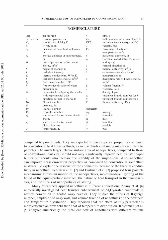
NOMENCLATURE
AR aspect ratio
c1, c2, c3, c4 constant parameters
Cp specific heat, kJ=kg K
d jet width, m
df diameter of base fluid molecules,
m
dp average diameter of nanoparticles,
m
G rate of generation of turbulent
energy, m2=s4
h height of channel, m
I turbulent intensity
K thermal conductivity, W=m K
k turbulent kinetic energy, m2=s2
kb Boltzmann number, J=K
lf free average distance of water
molecules, m
N parameter for adapting the results
with experimental data
n direction normal to the walls
Nu Nusselt number
P pressure, Pa
Pr Prandtl number
Re Reynolds number
sk source term for turbulent kinetic
energy
se source term for turbulent
dissipation rate
T temperature, K
t time, s
TB bulk temperature of nanofluid, K
TKE turbulent kinetic energy, m2=s2
u velocity, m=s
Vb Brownian velocity of
nanoparticles, m=s
x horizontal direction, m
xi Cartesian coordinates, m, x1¼x
and x2¼ y)
y vertical direction, m
a thermal diffusivity, m2=s
d center-to-center distance of
nanoparticles, m
e dissipation rate of kinetic energy,
m2=s3
/ volume fraction, %
m viscosity, Pa � sq density, kg=m3
rk turbulent Prandtl number for k
re turbulent Prandtl number for eC thermal diffusivity, Pa s
Subscripts
avg average
f base fluid
in inlet
nf nanofluid
p particle
w wall
NUMERICAL STUDY OF NANOFLUID IN A CONVERGING DUCT 61
Dow
nloa
ded
by [
b-on
: Bib
liote
ca d
o co
nhec
imen
to o
nlin
e U
BI]
at 0
2:01
06
July
201
2
concentrations of nanoparticles flowing through a two-dimensional duct under aconstant heat flux condition. They found that by increasing the particle volume con-centration, the wall shear stress and heat transfer rates increase. Also, they reportedfor a constant volume concentration and Reynolds number that the effect of CuOnanoparticles to enhance the Nusselt number is better than Al2O3 and TiO2 nano-particles. Taofik et al. [6] experimentally compared the heat transfer characteristicsof Al2O3-water and CuO-water nanofluids through a square cross-section cupricduct in laminar flow under uniform heat flux. Their results indicate that a consider-able heat transfer enhancement has been achieved by both nanofluids compared withthe base fluid. However, CuO-water nanofluid showed better heat transfer augmen-tation compared with Al2O3-water nanofluid through a square cross-section duct.Bianco et al. [7] numerically analyzed turbulent forced convection flow of awater-Al2O3 nanofluid in a circular tube subjected to a constant temperature atthe wall. The two-phase mixture model employed to simulate the nanofluid con-vection, taking into account appropriate thermophysical properties. They foundheat transfer enhancement increases with the particles’ volume concentration andReynolds number. Behzadmehr et al. [8] numerically investigated turbulent mixedconvection heat transfer of a nanofluid consisting of water and Al2O3 through ahorizontal curved tube. They implemented a two-phase mixture model to study sucha flow field. They reported that the nanoparticle volume fraction does not have adirect effect on the secondary flow and the skin friction coefficient, however, itseffects on the thermal parameters and flow turbulent intensity are significant. Biancoet al. [9] numerically investigated laminar forced convection flow of a water–Al2O3
nanofluid in a circular tube, submitted to a constant and uniform heat flux at thewall. They applied a single- and two-phase discrete particles model for simulation.They reported a maximum 11% difference in the average heat transfer coefficientbetween single- and two-phase models. They presented that heat transfer enhance-ment increases with the particle volume concentration and the Reynolds number,but it is accompanied by increasing wall shear stress values.
Also, Bianco et al. [10] numerically studied the hydrodynamic and thermal beha-viors of water-Al2O3 nanofluids flowing inside uniformly heated tubes with a squaresection at average steady state-conditions in turbulent flow. Also, they performedentropy generation analysis in order to determine the optimal working condition forthe given geometry under the considered boundary conditions. They used a mixturemodel with constant temperature to simulate the nanofluid. Their results clearlyshowed that the inclusion of nanoparticles produced a considerable increase in theheat transfer with respect to that of the base liquid. They analytically determinedthe optimal Reynolds number in terms of minimum entropy generation value, andit was in very good agreement with the numerical results. Their entropy generationanalysis has shown that at low Re value, the entropy generation, due to the irreversi-bility of heat transfer, dominates; whereas, with increasing Re value and particles’ con-centration, the entropy generation due to friction losses becomes more important.
Many works are recorded at the field of converging channel, backward facingstep, and headbox. Yang et al. [11] presented a numerical study of homogeneousturbulent shear flow and turbulent flow past a backward-facing step using differentlinear and nonlinear turbulence models. Driver et al. [12] experimentally investigatedturbulent flow past a backward-facing step. In their experiment, the ratio of step
62 M. RAHIMI-ESBO ET AL.
Dow
nloa
ded
by [
b-on
: Bib
liote
ca d
o co
nhec
imen
to o
nlin
e U
BI]
at 0
2:01
06
July
201
2

height to the tunnel exit was 9. Shariati et al. [13] investigated the flow through theconverging zone of a headbox, both numerically and experimentally. The experi-mental headbox that they used was a laboratory scale model of a typical headbox withthe size reduced by a factor of 5. The main focus of their study was on the turbulencequantities and secondary flows in the outlet jet. They reported that the turbulence kin-etic energy computed numerically is much higher than that measured experimentally.Zhang [14] measured the fiber orientations along the centerline of an asymmetricheadbox. He also predicted the fiber orientation in both symmetric and asymmetricheadboxes using a fiber model, but only using the mean flow field obtained fromthe k–e model. His comparison between the measured and predicted results showedthat the simulated orientations tend to align more with the flow than the experimen-tally observed results because the turbulence was not taken into consideration for hiscalculation. Feng et al. [15] carried out a large eddy simulation (LES) to model theflow field in the converging section. They used a Lagrangian tracking scheme to simu-lae the motion of flexible or rigid individual fibers. Olson et al. [16] derived theone-dimensional headbox model to predict the orientation distribution of fibers ina turbulent suspension passing through a planar contraction. They reported thatthe fiber orientation distribution is a function of two nondimensional parameters:the dimensionless dispersion coefficient and the headbox contraction ratio. Further-more, they showed that fiber orientation distribution was approximately dependenton the headbox Peclet number, defined as the ratio of contraction ratio to dimension-less dispersion coefficient. Nazemi et al. [17] analyzed a two-dimensional model of theorientation distribution of fibers in a paper machine headbox. They investigated theorientation of fibers at the outlet by shape variations. They applied an embeddingmethod and replaced the class of admissible shapes by a class of positive Radonmeasures. The optimization problem in measured space was approximated by a lin-ear programming problem. The optimal measure represented optimal shape isapproximated by the solution of this linear programming problem. They reportedthe embedding method (embedding the admissible set into a subset of measures),can successfully be applied to shape variation design to a one-dimensional headbox.
Furthermore, there are articles in the literature in the field of jet flow. DeLemos and Dorea [18] numerically investigated turbulent jet impinging against a flatplane covered with a layer of permeable and thermally conducting material. Theystudied the effects of the Reynolds number, porosity, permeability, thickness, andthermal conductivity of the porous layer on the local Nusselt number. They reportedthat inclusion of a porous layer eliminates the peak in Nu at the stagnation region.Furthermore, for highly porous and highly permeable material integral heat fluxfrom the wall is enhanced when a thermally conducting porous material is attachedto the surface. Pathak et al. [19] employed commercial code FLUENT 6.2.16 to pre-dict the mean flow field of heated turbulent rectangular jets in a cross flow. The jet isdischarged with a slightly higher temperature than the cross flow. The computationswere done for two values of jet-to-cross flow velocity ratio. They discussed the influ-ence of the velocity field on the temperature distributions. Fischer et al. [20] numeri-cally studied turbulent jet impinging against a flat plane covered with a layer ofpermeable material, which is kept at a higher temperature than that of the incomingfluid. They investigated the various parameters such as porosity, permeability, thick-ness, and thermal conductivity of the porous layer to analyze their effects on the
NUMERICAL STUDY OF NANOFLUID IN A CONVERGING DUCT 63
Dow
nloa
ded
by [
b-on
: Bib
liote
ca d
o co
nhec
imen
to o
nlin
e U
BI]
at 0
2:01
06
July
201
2

local distribution of Nusselt number. They applied the control volume method witha boundary-fitted nonorthogonal coordinate system for discretizing the governingequations. The SIMPLE algorithm was used to handle the pressure–velocity coup-ling. Their results indicated that inclusion of a porous layer decreases the peak inNusselt, avoiding excessive heating or cooling at the stagnation point. Also, theyfounded the integral heat flux from the wall is enhanced for certain ranges of valuesof porosity, layer thickness, and thermal conductivity ratio. Uddin et al. [21] ana-lyzed turbulent jets that impinge orthogonally on a target surface. Their focus wason the case of a jet which issues from a circular pipe into a stagnant surroundingat a relatively high value of Reynolds number of 23,000, for which experimental dataare available. They applied large-eddy simulations to obtain details of the meanflows and the turbulence fields including distributions of all components of the tur-bulent heat fluxes. According to the results, they assed three alternative models forthe turbulent heat fluxes, which differ from the conventional Fourier’s Law, by notbeing based on the assumption of proportionality between the eddy and thermal dif-fusivities via a constant Prandtl number. They discussed that only one of the modelsconsidered succeeds in representing the effects on the heat fluxes of the complexstrain field associated with the stagnation region and the subsequent developmentinto the wall-jet region.
Some researchers investigated nanofluid turbulent flow, but none of theminvestigated the turbulent nanofluid jet flow. In this article, contemporaneous effectof adding Al2O3 nanoparticles and jet flow on improvement of heat transfer proper-ties in a headbox is investigated. The headbox is a critical component in the paper-making system. The rapidly converging section of a paper machine headbox carries adilute concentration of pulp fibers to the wire mesh where the fibers are dried tobecome paper. Also, the effect of aspect ratios (duct width=jet width) on flow fea-tures and heat transfer properties is investigated. Jet flows are encountered in a widevariety of applications, such as gas turbine combustors, industrial burners, ejectorsystems, rocket nozzles, etc. The aim of this study is to obtain an understandingof the velocity and temperature distribution, the Nusselt number along both topand bottom walls downstream from the jet, and the velocity profile at different sec-tions. Moreover, the performance of the jet flow at various Reynolds numbers isinvestigated. Also, the effect of nanoparticles on thermal and flow characteristicsand the effect of aspect ratios on flow features and heat transfer properties are inves-tigated. The thermal conductivity of Al2O3, which is used in this research, is approxi-mately one-tenth of Cu; however, the unique property of Al2O3 is its low thermaldiffusivity. The reduced value of thermal diffusivity leads to higher temperaturegradients and, therefore, more heat transfer enhancement.
MODEL DESCRIPTION AND MATHEMATICAL FORMULATION
The 2-D incompressible turbulent jet flow is considered. For simplicity, the jetis taken as isothermal, and the velocity profile at the jet inlet is taken as uniform. Thegeometry considered and the flow configurations used in this work are shown inFigure 1. The nanoparticles and the base fluid (i.e., water) are assumed to be in ther-mal equilibrium and no slip condition occurs between them. The other boundaryconditions are mentioned in Figure 1.
64 M. RAHIMI-ESBO ET AL.
Dow
nloa
ded
by [
b-on
: Bib
liote
ca d
o co
nhec
imen
to o
nlin
e U
BI]
at 0
2:01
06
July
201
2

The aspect ratio is taken as follows.
AR ¼ d=h ð1Þ
The continuity, momentum, and energy equations [22] for the 2-D flowproblem are given by the following.
Continuity
qqxi
ðqnf uiÞ ¼ 0 ð2Þ
Momentum
qnfquiqt
þ qqxj
ðqnf uiujÞ ¼ �qp qxi þqqxj
mðqui=qxj þ quj=qxiÞ� �
þ qqxj
ð�qnf u0i u
0jÞ ð3Þ
Energy
qnfqTqt
þ qqxi
ðqnf uiTÞ ¼ qqxj
ðCþ CtÞqTqxj
� �ð4Þ
where C and Ct are the molecular thermal diffusivity and turbulent thermal diffusiv-ity, respectively, and are given by the following.
C ¼ mnf =Prnf Ct ¼ mt=Prt ð5Þ
The Reynolds-averaged approach to turbulence modeling requires that the
Reynolds stresses, i.e., qnf u0i u
0j, be modeled. For this purpose the k–e model is cho-
sen. A common method employs the Boussinesq hypothesis to relate the Reynoldsstresses to the mean velocity gradients.
qnf u0i u
0j ¼ mtðqui=qxj þ quj=qxiÞ ð6Þ
Figure 1. Geometry and boundry condition of the problem.
NUMERICAL STUDY OF NANOFLUID IN A CONVERGING DUCT 65
Dow
nloa
ded
by [
b-on
: Bib
liote
ca d
o co
nhec
imen
to o
nlin
e U
BI]
at 0
2:01
06
July
201
2

The turbulent viscosity term is needed to be computed, which is defined asfollows.
mt ¼ qnf cm k2=e ð7Þ
Following, are transport equations for k and e.
qnfqkqt
þ qqxi
ðqnf kuiÞ ¼qqxj
mnf þmtrk
� �qkqxj
� �þ Gk � qnf eþ Sk ð8Þ
and
qnfqeqt
þ qqxi
ðqnf euiÞ ¼qqxj
mnf þmtre
� �qeqxj
� �þ C1e
ekGk þ C2eqnf
e2
kþ Se ð9Þ
where Gk is the rate of generation of the TKE, and qe is its destruction rate, and iswritten as follows.
Gk ¼ �qnf u0i u
0j
q ujqxi
ð10Þ
sk, se are source terms for k and e and in this research are taken as zero. The bound-ary values for the turbulent quantities near the wall are specified with the standardwall-treatment method. The values of Cm¼ 0.009, C1e¼ 1.44, C2e¼ 1.92, rk¼ 1,re¼ 1.3, and Prt¼ 0.9 are chosen to be the empirical constants in the turbulent trans-port equations [22]. The following equations are used to calculate the turbulentintensity (I), turbulent kinetic energy (k), and turbulent dissipation rate (e) at theinlet section of the headbox [5].
I ¼ 0:16 Re�1=8
k ¼ ð3=2ÞðI � uinÞ2
e ¼ c0:75m � ðk1:5=0:1 hÞ ð11Þ
The nondimentional flow and heat transfer parameters are defined by thefollowing.
Re ¼ 2qf Uin d=mf ð12Þ
Nu ¼ 1� ðKnf qT=qnÞ=ðKf ðTw � TBÞÞ ð13Þ
Nuavg ¼RNuðxÞ dx
L
66 M. RAHIMI-ESBO ET AL.
Dow
nloa
ded
by [
b-on
: Bib
liote
ca d
o co
nhec
imen
to o
nlin
e U
BI]
at 0
2:01
06
July
201
2

THERMOPHYSICAL PROPERTIES OF NANOFLUID
Thermal Conductivity
The thermal conductivity of the nanofluid is calculated from Chon et al. [23],which is expressed in the following form:
Knf
Kf¼ 1þ 64:7/0:746ðdf =dpÞ0:369 � ðKp=Kf Þ0:7476 Pr0:9955f Re1:2321p ð14Þ
Prf ¼ mf =qf af ð15Þ
Rep ¼ qf kb T=3 p m2lf ð16Þ
dp ¼ 36� 10�9 m ð17Þ
kb is the Boltzmann constant, 1.3807� 10�23 and lf is the free average distance ofwater molecules that according to suggestion of Chon et al. is taken as 17 nm.Minister et al. [24] approved the accuracy of this model.
Viscosity
The viscosity of the nanofluid is approximated as viscosity of the base fluidmf containing dilute suspension of fine spherical particles, as given by Masoumiet al. [25].
mnfmf
¼ 1þ qp Vb d2p=72N d ð18Þ
N ¼ ðc1/þ c2Þ dp þ ðc3/þ c4Þ
d ¼ffiffiffiffiffiffiffiffiffiffiffiffip=6/3
p� dp
Vb ¼ ð1=dpÞffiffiffiffiffiffiffiffiffiffiffiffiffiffiffiffiffiffiffiffiffiffiffiffiffiffiffiffiffiffi18 kbT=p qp dp
q
N is a parameter for adapting the results with experimental data, wherec1¼� 1.133� 10�6, c2¼� 2.771� 10�6, c3¼ 9.0� 10�8, and c4¼� 3.93� 10�7.
Density and Specific Heat
The density and specific heat of the nanofluid are calculated by using the Pakand Cho [26] correlations, which are defined as follows.
ðqnf ¼ /qp þ 1� /ð Þqf ð19Þ
ðCpÞnf¼ ðð1�/Þ � ðqCpÞf þ /� ðq� CpÞpÞ=qnf ð20Þ
Prnf ¼ mnf � Cpnf =Knf ð21Þ
NUMERICAL STUDY OF NANOFLUID IN A CONVERGING DUCT 67
Dow
nloa
ded
by [
b-on
: Bib
liote
ca d
o co
nhec
imen
to o
nlin
e U
BI]
at 0
2:01
06
July
201
2
NUMERICAL PROCEDURE AND CODE VALIDATION
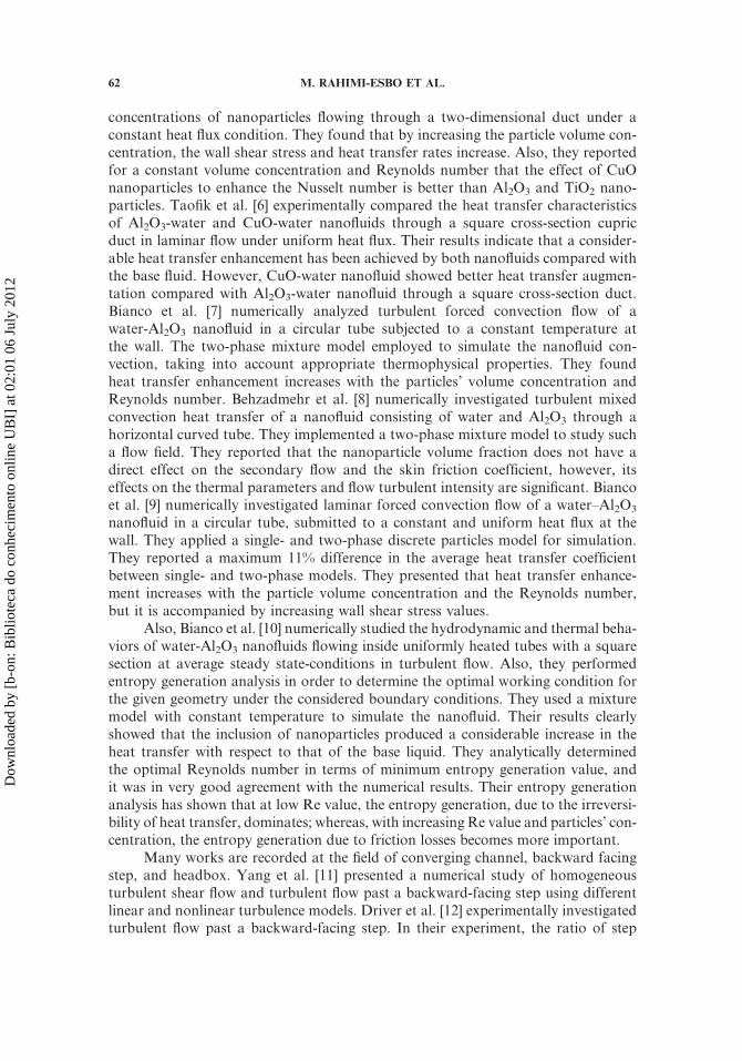
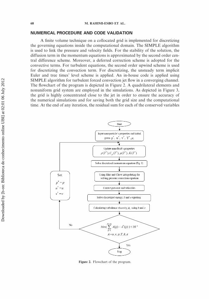
A finite volume technique on a collocated grid is implemented for discretizingthe governing equations inside the computational domain. The SIMPLE algorithmis used to link the pressure and velocity fields. For the stability of the solution, thediffusion term in the momentum equations is approximated by the second order cen-tral difference scheme. Moreover, a deferred correction scheme is adopted for theconvective terms. For turbulent equations, the second order upwind scheme is usedfor discretizing the convection term. For discretizing, the unsteady term implicitEuler and tree times’ level scheme is applied. An in-house code is applied usingSIMPLE algorithm for turbulent forced convection jet flow in a converging channel.The flowchart of the program is depicted in Figure 2. A quadrilateral elements andnonuniform grid system are employed in the simulations. As depicted in Figure 3,the grid is highly concentrated close to the jet in order to ensure the accuracy ofthe numerical simulations and for saving both the grid size and the computationaltime. At the end of any iteration, the residual sum for each of the conserved variables
Figure 2. Flowchart of the program.
68 M. RAHIMI-ESBO ET AL.
Dow
nloa
ded
by [
b-on
: Bib
liote
ca d
o co
nhec
imen
to o
nlin
e U
BI]
at 0
2:01
06
July
201
2
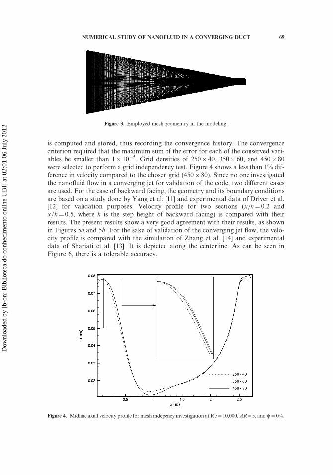
is computed and stored, thus recording the convergence history. The convergencecriterion required that the maximum sum of the error for each of the conserved vari-ables be smaller than 1� 10�5. Grid densities of 250� 40, 350� 60, and 450� 80were selected to perform a grid independency test. Figure 4 shows a less than 1% dif-ference in velocity compared to the chosen grid (450� 80). Since no one investigatedthe nanofluid flow in a converging jet for validation of the code, two different casesare used. For the case of backward facing, the geometry and its boundary conditionsare based on a study done by Yang et al. [11] and experimental data of Driver et al.[12] for validation purposes. Velocity profile for two sections (x=h¼ 0.2 andx=h¼ 0.5, where h is the step height of backward facing) is compared with theirresults. The present results show a very good agreement with their results, as shownin Figures 5a and 5b. For the sake of validation of the converging jet flow, the velo-city profile is compared with the simulation of Zhang et al. [14] and experimentaldata of Shariati et al. [13]. It is depicted along the centerline. As can be seen inFigure 6, there is a tolerable accuracy.
Figure 3. Employed mesh geomentry in the modeling.
Figure 4. Midline axial velocity profile for mesh indepency investigation at Re¼ 10,000,AR¼ 5, and/¼ 0%.
NUMERICAL STUDY OF NANOFLUID IN A CONVERGING DUCT 69
Dow
nloa
ded
by [
b-on
: Bib
liote
ca d
o co
nhec
imen
to o
nlin
e U
BI]
at 0
2:01
06
July
201
2

RESULTS AND DISCUSSION
Simulations are performed for different Reynolds numbers of 4,000, 8,000,12,000, 16,000, 20,000, 25,000, 30,000, 35,000 and 40,000 and various volume frac-tion of nanofluid 1%, 2%, 3%, 4%, and 5% compared to its pure base fluid (water).Furthermore, the simulations are carried out for different aspect ratios of 1, 2, 5, 10,and 20. The flow expands from the uniform profile from the jet and separates to form
Figure 5. (a) Velocity distributions for a backward facing at Re¼ 37,423 and X=h¼ 0.2; and (b) velocity
distributions for a backward facing at Re¼ 37,423 and X=h¼ 0.5.
Figure 6. Velocity distributions at midline for a converging channel at uin¼ 1.22.
70 M. RAHIMI-ESBO ET AL.
Dow
nloa
ded
by [
b-on
: Bib
liote
ca d
o co
nhec
imen
to o
nlin
e U
BI]
at 0
2:01
06
July
201
2

a primary recirculation region at the upper and lower plates. After that, the velocityprofile reattaches and redevelops approaching a fully developed flow as fluid flowstowards the channel exit.
At high Reynolds number and aspect ratio, an asymmetric flow was observedat jet flow in a converging sinusoidal channel in a steady solution; so, an unsteadysolution was seemed to be necessary. For the case of AR¼ 20, Re¼ 15,000 anunsteady solution is obtained and the streamline and temperature contours are sim-ultaneously depicted in Figure 7. It is observed that after 480 s the streamlineremains fixed. According to Figure 7, asymmetric flow occurs for both steady andunsteady cases. It should be noted that the asymmetry in the flow pattern corre-sponds to a bimodal steady configuration with the jet turning upwards or down-wards in a random manner, during any computational run. Sarma et al. [27]presented this behavior. According to the above proof, the steady solution can begeneralized to the unsteady problem. From now on, results are reported on thesteady state condition.
In Figures 8 and 9, the steady state streamline patterns at different Reynoldsnumbers and aspect ratios are depicted. In Figure 8, the effect of Reynolds numberon flow structure at AR¼ 10 and /¼ 0% is shown. It is observed that for a low Rey-nolds number such as Re¼ 4,000, the jet development is almost symmetric andcounter-rotating velocities are seen immediately after the sudden expansion. Thejet decay is rapid and the transition from jet-to-duct flow occurs in a short distance.At a higher Reynolds number of Re¼ 10,000, it is observed that the steady state jetflow development is asymmetric. Also, the transition from jet-to-duct flow occursover a longer distance. For a still higher Reynolds number of 40,000, it is seen thatasymmetric flow exhibits a wavy pattern with a larger wavelength and the flow devel-opment inside the duct occurs over a larger axial distance. It should be noted that theasymmetry in the flow pattern corresponds to a bimodal steady configuration withthe jet turning upwards or downwards in a random manner, during any computa-tional run. In Figure 9, the influence of aspect ratio on flow structure atRe¼ 15,000 and /¼ 0% is shown. It is observed that for a low aspect ratio suchas AR¼ 2, the jet develops almost symmetric and back flow are seen immediatelyafter the sudden expansion. The jet decay is rapid and the transition from jet-to-ductflow occurs in a short distance. At a higher aspect ratio of AR¼ 20, it is observedthat the steady state jet flow development is asymmetric. The transition from jet-to-duct flow occurs over a longer distance as well.
Figure 10 shows the distribution of the Nusselt number at the top wallfor Re¼ 10,000 using different nanoparticles volume fractions. The figure revealsan enhancement in Nusselt number by increasing the volume fraction of nanoparti-cles. This behavior is explained by looking at Eq. (21). The effect of nanoparticleson the temperature difference term is negligible. The effect of volume fraction ofnanoparticles on the temperature gradient term and on the thermal conductivityratio term is more pronounced. Before the point of reattachment, as the volume frac-tion percentage of nanoparticles intensifies, the temperature gradient at the top wallincreases. This is related to the addition inertia forces, as depicted by Eq. (3). Theequations show that any increase in volume fraction increases inertia forces becauseqnf will be increased and accordingly, increases the temperature gradient. Besides,the nanoparticles increase the thermal conductivity ratio term, as can be seen from
NUMERICAL STUDY OF NANOFLUID IN A CONVERGING DUCT 71
Dow
nloa
ded
by [
b-on
: Bib
liote
ca d
o co
nhec
imen
to o
nlin
e U
BI]
at 0
2:01
06
July
201
2

Figure 7. Streamlines and temperature contours for unsteady solution at AR¼ 20, Re¼ 15,000, and
/¼ 0% (color figure available online).
72 M. RAHIMI-ESBO ET AL.
Dow
nloa
ded
by [
b-on
: Bib
liote
ca d
o co
nhec
imen
to o
nlin
e U
BI]
at 0
2:01
06
July
201
2

Eq. (12). Therefore, both the temperature gradient and thermal conductivity ratioterms increase by increasing the volume fraction of nanoparticles. Accordingly, itcan be seen that with increasing the volume fraction, the Nusselt number will beincreased because the heat transfer properties is improved. Two sudden growths thatcan be seen in this figure are related to the position of vortex zone.
The effect of the Reynolds number on the average Nusselt number at bothbounds is represented in Table 1. With increasing the Reynolds number the influenceof jet, chaotic behavior of the flow, length of recirculation zones, and irregularity ofthe fluid flow will be increased. These facts cause the average Nusselt number toincrease.
Figure 8. Streamline contours for different Reynolds number at AR¼ 10 and /¼ 0%. (a) Re¼ 4000, (b)
Re¼ 10000, (c) Re¼ 30000, (d) Re¼ 40000.
NUMERICAL STUDY OF NANOFLUID IN A CONVERGING DUCT 73
Dow
nloa
ded
by [
b-on
: Bib
liote
ca d
o co
nhec
imen
to o
nlin
e U
BI]
at 0
2:01
06
July
201
2

In Table 2, the effect of nanoparticles on the average Nusselt number at bothtop and bottom walls is deduced. As it is mentioned above, nanoparticles improvethrermophisycal properties of the fluid; it directly affects increasing the Nusseltnumber.
The effect of the aspect ratio on the Nusselt number is depicted in Figure 11.The average Nusselt number can be seen in Table 3. As the aspect ratio increases,the influence of jet and recirculation zones is increased. Besides, chaotic behaviorof the fluid flow will be increased and will have more impact between molecules of
Figure 9. Streamline contours for different aspect ratio at Re¼ 15,000 and /¼ 0%. (a) AR¼ 2, (b)
AR¼ 5, (c) AR¼ 10, (d) AR¼ 20.
74 M. RAHIMI-ESBO ET AL.
Dow
nloa
ded
by [
b-on
: Bib
liote
ca d
o co
nhec
imen
to o
nlin
e U
BI]
at 0
2:01
06
July
201
2

Figure 10. Effect of volume fraction of nanoparticles (/) on Nusselt number at Re¼ 10,000 and AR¼ 5
(color figure available online).
Table 1. Average Nusselt number at AR¼ 10 and /¼ 0% (h¼ 1m,
L¼ 2.75m)
Nuavg
Re Up wall Down wall
4,000 195.999 196.725
10,000 305.927 319.684
15,000 355.746 371.711
20,000 388.266 404.651
30,000 427.324 442.826
40,000 449.350 463.518
Table 2. Average Nusselt number at Re¼ 10,000 and AR¼ 5 (h¼ 1m,
L¼ 2.75m)
Nuavg
phi %ð Þ Up wall Down wall
0 280.204 281.151
1 291.051 292.010
2 296.22 297.166
3 299.417 300.337
4 301.517 302.406
5 303.029 303.884
NUMERICAL STUDY OF NANOFLUID IN A CONVERGING DUCT 75
Dow
nloa
ded
by [
b-on
: Bib
liote
ca d
o co
nhec
imen
to o
nlin
e U
BI]
at 0
2:01
06
July
201
2
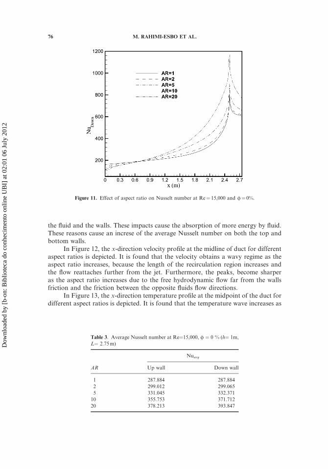
the fluid and the walls. These impacts cause the absorption of more energy by fluid.These reasons cause an increse of the average Nusselt number on both the top andbottom walls.
In Figure 12, the x-direction velocity profile at the midline of duct for differentaspect ratios is depicted. It is found that the velocity obtains a wavy regime as theaspect ratio increases, because the length of the recirculation region increases andthe flow reattaches further from the jet. Furthermore, the peaks, become sharperas the aspect ratio increases due to the free hydrodynamic flow far from the wallsfriction and the friction between the opposite fluids flow directions.
In Figure 13, the x-direction temperature profile at the midpoint of the duct fordifferent aspect ratios is depicted. It is found that the temperature wave increases as
Figure 11. Effect of aspect ratio on Nusselt number at Re¼ 15,000 and /¼ 0%.
Table 3. Average Nusselt number at Re¼15,000, / ¼ 0 % (h¼ 1m,
L¼ 2.75m)
Nuavg
AR Up wall Down wall
1 287.884 287.884
2 299.012 299.065
5 331.045 332.371
10 355.753 371.712
20 378.213 393.847
76 M. RAHIMI-ESBO ET AL.
Dow
nloa
ded
by [
b-on
: Bib
liote
ca d
o co
nhec
imen
to o
nlin
e U
BI]
at 0
2:01
06
July
201
2

the aspect ratios increases. The length of the recirculation region increases and theflow reattaches further from the jet, so heat transfer enhancement between the wallsand main flow is done.
Figure 13. Midpoint temperature profile at different aspect ratio at Re¼ 15,000 and /¼ 0%.
Figure 12. Midpoint velocity profile at different aspect ratio at Re¼ 15,000 and /¼ 0%.
NUMERICAL STUDY OF NANOFLUID IN A CONVERGING DUCT 77
Dow
nloa
ded
by [
b-on
: Bib
liote
ca d
o co
nhec
imen
to o
nlin
e U
BI]
at 0
2:01
06
July
201
2

CONCLUSIONS
Force convection of turbulent nanofluid flow in a converging duct has beennumerically studied. The results show that by increasing the Reynolds number,aspect ratio, and volume fraction the average Nusselt number will increase. Byincreasing the aspect ratio from 1 to 20, as the result of a simultaneous increase inthe developing length, penetration of the jet flow in to the duct, and length of therecirculation zones more than 36% enhancement in the average Nusselt numberon the down wall is detected. This effect can also be seen by increasing the Reynoldsnumber. Furthermore, it was demonstrated in the investigations that increasing theReynolds number and aspect ratio, the length of the recirculation zones rise. This hasa direct impact on the local Nusselt number which, consequently, increases the aver-age Nusselt number. Also, more than 8% enhancement in the average Nusselt num-ber on the down wall is seen by increasing the volume fraction from 0% to 5%. Itshould be noted that the intensification of turbulence eddy, suppression of theboundary layer, dispersion of the suspended particles, besides the augmentation ofthermal conductivity and the heat capacity of the fluid, were suggested to be thepossible reasons for heat transfer enhancement.
REFERENCES
1. S. U. S. Choi Enhancing Thermal Conductivity of Fluids with Nanoparticles, Develop-ments, and Applications of Non-Newtonian Flows, ASME FED 231=MD, vol. 66, pp.99–103, 1995.
2. P. P. Keblinski, S. U. S. Choi, and J. A. Eastman Mechanisms of Heat Flow in Suspen-sions of Nano-Sized Particles (Nanofluid), Int. J. of Heat and Mass Transfer, vol. 45, pp.855–863, 2002.
3. J. A. Eastman, S. R. Phillpot, S. U. S. Choi, and P. Keblinski Thermal Transport inNanofluids, Ann. Rev. Mater. Res., vol. 34, pp. 219–246, 2004.
4. Y. Zhang, L. Li, H. B. Ma, and M. Yang, Effect of Brownian and Thermophoretic Diffu-sions of Nanoparticles on Nonequilibrium Heat Conduction in a Nanofluid Layer withPeriodic Heat Flux, Numer. Heat Transfer, A, vol. 56, pp. 325–341, 2009.
5. M. Rostamani, S. F. Hosseinizadeh, M. Gorji, and J. M. Khodadadi, Numerical Study ofTurbulent Forced Convection Flow of Nanofluids in a Long Horizontal Duct ConsideringVariable Properties, Int. Comm. in Heat and Mass Transfer, vol. 37, pp. 1426–1431, 2010.
6. H. T. Nassan, S. Z. Heris, and S. H. Noie, A Comparison of Experimental Heat TransferCharacteristics for Al2O3-Water, and CuO-Water Nanofluids in Square Cross-SectionDuct, Int. Comm. in Heat and Mass Transfer, vol. 37, pp. 924–928, 2010.
7. V. Bianco, O. Manca, and S. Nardini, Numerical Simulation of Water=Al2O3 NanofluidTurbulent Convection, Adv. in Mech. Eng., pp. 1–10, 2010.
8. O. Ghaffari, A. Behzadmehr, and H. Ajam, Turbulent Mixed Convection of a Nanofluidin a Horizontal Curved Tube using a Two-Phase Approach, Int. Comm. in Heat and MassTransfer, vol. 37, pp. 1555–1558, 2010.
9. V. Bianco, F. Chiacchio, O. Manca, and S. Nardini, Numerical Investigation of Nano-fluids Forced Convection in Circular Tubes, Appl. Therm. Engineering, vol. 29, pp.
3632–3642, 2009.10. V. Bianco, S. Nardini, and O. Manca Enhancement of Heat Transfer, and Entropy Gen-
eration Analysis of Nanofluids Turbulent Convection Flow in Square Section Tubes,Nanoscale Res. Lett., vol. 6, pp. 252–264, 2011.
78 M. RAHIMI-ESBO ET AL.
Dow
nloa
ded
by [
b-on
: Bib
liote
ca d
o co
nhec
imen
to o
nlin
e U
BI]
at 0
2:01
06
July
201
2

11. X. D. Yang, H. Y. Ma, and Y. N. Huang, Prediction of Homogeneous Shear Flow, and aBackward-Facing Step Flow with Some Linear, and Nonlinear k–e Turbulence Models,Comm. in Nonlinear Science and Numer. Simulation, vol. 10, pp. 315–328, 2005.
12. D. Driver and H. Seegmiller, Features of Reattaching Turbulent Shear Layer in DivergentChannel Flow, AIAA J., vol. 23, pp. 163–171, 1985.
13. M. R. Shariati, Experimental and Mathematical Modeling of Flow in Headbox, Ph.D.thesis, University of British Columbia, Canada, 2002.
14. X. Zhang, Fiber Orientation in Headbox, M.Sc. thesis, University of British Columbia,
Canada, 2001.15. X. Feng, S. Dong, I. Gartshore, and M. Salcudean, Numerical Model of Fiber Orien-
tation in the Converging Section of a Paper-Machine Headbox using Large Eddy Simula-tion, Fourth International Conference on CFD in the Oil and Gas, Metallurgical &Process Industries, SINTEF=NTNU Trondheim, Norway, 2005.
16. J. A. Olson, I. Frigaard, C. Chan, and J. P. Hamalainen, Modeling a Turbulent FibreSuspension Flowing in a Planar Contraction: The One-Dimensional Headbox, Int. J. ofMultiphase Flow, vol. 30, pp. 51–66, 2004.
17. A. R. Nazemi and M. H. Farahi, Control the Fibre Orientation Distribution at the Outletof Contraction, Acta Appl. Math, vol. 106, pp. 279–292, 2009.
18. M. J. S. De Lemos and F. T. Dorea, Simulation of a Turbulent Impinging Jet into a layerof Porous Material using a Two–Energy Equation Model, Numer. Heat Transfer A, vol.59, no. 10, pp. 769–798, 2011.
19. M. Pathak, A. Dewan, and A. K. Dass, Distribution of Temperature as a Passive Scalar inthe Flow Field of a Heated Turbulent Jet in a Crossflow, Numer. Heat Transfer A, vol. 54,no. 1, pp. 67–92, 2008.
20. C. Fischer and M. J. S. De Lemos, A Turbulent Impinging Jet on a Plate Covered with aPorous Layer, Numer. Heat Transfer A, vol. 58, no. 6, pp. 429–456, 2010.
21. N. Uddin, S. O. Neumann, B. Weigand, and B. A. Younis, Large-Eddy Simulations, andHeat-Flux Modeling in a Turbulent Impinging Jet, Numer. Heat Transfer A, vol. 55,no. 10, pp. 906–930, 2009.
22. B. E. Launder and D. B. Spalding, Lectures in Mathematical Models of Turbulence,Academic Press, London, 1972.
23. C. H. Chon, K. D. Kihm, S. P. Lee, and S. U. S. Choi, Empirical Correlation Finding theRole of Temperature, and Particle Size for Nanofluid (Al2O3) Thermal ConductivityEnhancement, Appl. Phys. Lett., vol. 87, no. 15, pp. 153107–153110, 2005.
24. H. A. Mintsa, G. Roy, C. T. Nguyen, and D. Doucet, New Temperature Dependent Ther-mal Conductivity Data for Water-Based Nanofluids, Int. J. of Therm. Sci., vol. 48, pp.363–371, 2009.
25. N. Masoumi, N. Sohrabi, and A. A. Behzadmehr, New Model for Calculating the Effec-tive Viscosity of Nanofluids, J. of Phy. D: Appl. Physics, vol. 42, pp. 55501–55506, 2009.
26. B. C. Pak, and Y. I. Cho, Hydrodynamic and Heat Transfer Study of Dispersed Fluidswith Submicron Metallic Oxide Particles, Exper. Heat Transfer, vol. 11, pp. 151–170,1998.
27. A. S. R. Sarma, T. Sundararajan, and V. Ramjee, Numerical Simulation of ConfinedLaminar Jet Flows, Int. J. Numer. Meth. in Fluids, vol. 33, pp. 609–626, 2000.
NUMERICAL STUDY OF NANOFLUID IN A CONVERGING DUCT 79
Dow
nloa
ded
by [
b-on
: Bib
liote
ca d
o co
nhec
imen
to o
nlin
e U
BI]
at 0
2:01
06
July
201
2
Copyright © 2022 FDOKUMEN