
Numerical Analysis of the Bottom Thickness of Closed ... - MDPI
13
applied sciences Article Numerical Analysis of the Bottom Thickness of Closed Rectangular Tanks Used as Pontoons Anna Szymczak-Graczyk Department of Construction and Geoengineering, Faculty of Environmental and Mechanical Engineering, Poznan University of Life Sciences, Piatkowska Street 94, 60-649 Poznan, Poland; [email protected]; Tel.: +48-602-516-345 Received: 13 October 2020; Accepted: 11 November 2020; Published: 15 November 2020 Abstract: This paper concerns the numerical analysis of closed rectangular tanks made in one stage, used as pontoons. Such structures can be successfully used as floating platforms, although they primarily serve as floats for ‘houses on water’. Amphibious construction has fascinated designers for many years and is becoming, in addition to a great and prestigious location for many purposes, a practical global necessity. Severe weather phenomena that no country is safe from, i.e., heavy rains or floods, combined with the scarcity of space intended for the construction of residential buildings, encourage development at the contact of water and land or on water only. This paper contains an analysis of the static work of tanks with different bottom thickness subjected to hydrostatic load acting on tank walls and the bottom plate and evenly distributed load acting on the upper plate, i.e., major impacts that occur when tanks are used as pontoons. Calculations were made using the finite difference method in terms of energy, assuming the Poisson’s ratio ν = 0. Based on the solutions obtained, charts were made that illustrated the change in bending moments at the characteristic points of the analysed tanks depending on acting loads. The article also includes calculations of buoyancy, stability and the metacentric height for tanks with different bottom thicknesses, with the main purpose being to improve and share knowledge on their safe use as pontoons. Keywords: floating platforms; pontoon; finite difference method; rectangular tanks; hydrostatic load; bending moments 1. Introduction Tanks as civil engineering structures have been used in numerous branches of industry and the economy for many years. Applications of tanks as civil engineering structures include swimming pools, fire tanks, clean water tanks, waste tanks and tanks for fuel rectification products. As there are many applications of these types of structures, the analysis of their static work is important [1]. The most frequently designed and produced tanks have a constant wall thickness, regardless of whether their cross-sections are rectangular or circular. If they are closed tanks, the cover is usually a plate based freely on the walls, whereas the bottom is a bottom plate that is usually thicker than the tank walls. The contact between the bottom plate and tank walls is assumed to be rigid in static analysis. Tanks with walls of variable thickness (i.e., of trapezoidal cross-section) are very rarely designed despite their optimal adjustment to stress distribution (from the point of view of calculation schemes). For tanks hydrostatically loaded, the load acting on walls increases with the depth (of foundations), and triangular load distribution means that the highest values of bending moments in the vertical cross-section occur at the point where the wall connects to the bottom, while the upper free edge of the tank has a zero value. Thus, structural and economic considerations should determine the selection of walls with a thickness that increases accordingly with the immersion of the tank [2,3]. Changes in Appl. Sci. 2020, 10, 8082; doi:10.3390/app10228082 www.mdpi.com/journal/applsci
-
Upload
khangminh22 -
Category
Documents
-
view
1 -
download
0
Transcript of Numerical Analysis of the Bottom Thickness of Closed ... - MDPI
applied sciences
Article
Numerical Analysis of the Bottom Thickness ofClosed Rectangular Tanks Used as Pontoons
Anna Szymczak-Graczyk
Department of Construction and Geoengineering, Faculty of Environmental and Mechanical Engineering,Poznan University of Life Sciences, Piatkowska Street 94, 60-649 Poznan, Poland;[email protected]; Tel.: +48-602-516-345
Received: 13 October 2020; Accepted: 11 November 2020; Published: 15 November 2020 �����������������
Abstract: This paper concerns the numerical analysis of closed rectangular tanks made in one stage,used as pontoons. Such structures can be successfully used as floating platforms, although theyprimarily serve as floats for ‘houses on water’. Amphibious construction has fascinated designers formany years and is becoming, in addition to a great and prestigious location for many purposes, apractical global necessity. Severe weather phenomena that no country is safe from, i.e., heavy rains orfloods, combined with the scarcity of space intended for the construction of residential buildings,encourage development at the contact of water and land or on water only. This paper contains ananalysis of the static work of tanks with different bottom thickness subjected to hydrostatic loadacting on tank walls and the bottom plate and evenly distributed load acting on the upper plate, i.e.,major impacts that occur when tanks are used as pontoons. Calculations were made using the finitedifference method in terms of energy, assuming the Poisson’s ratio ν = 0. Based on the solutionsobtained, charts were made that illustrated the change in bending moments at the characteristicpoints of the analysed tanks depending on acting loads. The article also includes calculations ofbuoyancy, stability and the metacentric height for tanks with different bottom thicknesses, with themain purpose being to improve and share knowledge on their safe use as pontoons.
Keywords: floating platforms; pontoon; finite difference method; rectangular tanks; hydrostatic load;bending moments
1. Introduction
Tanks as civil engineering structures have been used in numerous branches of industry and theeconomy for many years. Applications of tanks as civil engineering structures include swimmingpools, fire tanks, clean water tanks, waste tanks and tanks for fuel rectification products. As there aremany applications of these types of structures, the analysis of their static work is important [1]. Themost frequently designed and produced tanks have a constant wall thickness, regardless of whethertheir cross-sections are rectangular or circular. If they are closed tanks, the cover is usually a platebased freely on the walls, whereas the bottom is a bottom plate that is usually thicker than the tankwalls. The contact between the bottom plate and tank walls is assumed to be rigid in static analysis.Tanks with walls of variable thickness (i.e., of trapezoidal cross-section) are very rarely designeddespite their optimal adjustment to stress distribution (from the point of view of calculation schemes).For tanks hydrostatically loaded, the load acting on walls increases with the depth (of foundations),and triangular load distribution means that the highest values of bending moments in the verticalcross-section occur at the point where the wall connects to the bottom, while the upper free edge of thetank has a zero value. Thus, structural and economic considerations should determine the selectionof walls with a thickness that increases accordingly with the immersion of the tank [2,3]. Changes in
Appl. Sci. 2020, 10, 8082; doi:10.3390/app10228082 www.mdpi.com/journal/applsci

Appl. Sci. 2020, 10, 8082 2 of 13
internal forces occurring along the longer wall of the tank also apply to bridge structures, where theinteraction between incoherent backfill (similar to a fluid) and spandrel walls is studied [4,5].
Floats used for constructing floating platforms can be made of plastic, steel or aluminium sheets,as well as reinforced concrete. These structures often consist of two elements: a box and a cover plate.As a result, they can be treated computationally as rectangular open tanks with the upper plate restingfreely on walls. The solution carries either the risk of inaccuracy in assembly or possible leaks and fasterwear in use [6]. A better proposal, although it is more difficult in terms of calculation and performance,is to design and construct a monolithic reinforced concrete tank concreted entirely in one stage [7].The structure is then computationally treated as a closed rectangular tank. Reinforced concrete pontoonsintended for the construction of floating platforms should have adequate buoyancy and be stable; i.e.,they should not show excessive tilt at partial load [6,8].
Stationary floating structures are becoming increasingly popular around the world, stimulatedby various reasons [9]. It is estimated that there are 40,000 to 50,000 such structures [10]. They areconsidered to be architecturally attractive with pleasing locations. On the other hand, their constructionis associated with changes in water levels [11] or with high population density, and they are seenas a way of ensuring enough living space for people. Severe and rapid meteorological phenomenasuch as typhoons, hurricanes and floods affect many areas of the world. Climatologists predict thatwater levels will have risen by a meter by the end of the century. Amphibious construction is one ofthe building solutions oriented towards the urbanisation of floodplains. However, it is necessary torecognise the statics of their construction so that ‘houses on water’ can become a viable alternative totraditional construction [12].
The purpose of this article is to analyse the statics of closed rectangular tanks, the distributionof internal forces and the impact of bottom thickness on the values of occurring bending moments,the buoyancy and the stability of the pontoon. The subject matter of plate structures is well knownin engineering literature. As for the design of tanks, scientific publications most often refer to opentanks, in which calculations are made using the finite element method. There are few works on closedrectangular tanks, and additionally, this paper includes calculations with the finite difference method,which is used even less frequently than the finite element method. The work is of an applied natureand contributes to the considerations on the construction of closed rectangular tanks and their use aspontoons. It also shows the possibility of applying the finite difference method to calculate a structureas an alternative to or verification of the finite element method.
2. Materials and Methods
2.1. Calculation Method
Monolithic rectangular tanks are complex plate structures characterised by spatial static work, sothe load acting on one fragment of the structure causes displacement and creates cross-sectional forcesthroughout the system. Failure to consider it in the static calculations leads to incorrect determinationof internal forces (bending moments and cutting forces), which in turn affects the value and distributionpattern of the adopted reinforcement and the correct design of the structure.
One of the numerical methods that can be successfully used in calculating these structures is thefinite difference method in a variational approach. It takes into account the spatial work of structures,the real geometric dimensions (E and ν) corresponding to the material from which the tank will be madeand any type of acting load, including temperature load. Apart from the finite element method, the finitedifference method is one of the most popular numerical methods used for static calculations of buildingstructures. The subject matter has been taken up in numerous outstanding and fundamental scientificworks [13–26]. The method has been used in calculations regarding plate structures [3,27,28], tanks [2,7]or surface girders. The finite difference method (FDM) is one of the methods used to solve differentialequations that are difficult or impossible to solve analytically. It is based on the energy functionalaccumulated in the deformed system. The finite difference method adopted for the numerical analysis

Appl. Sci. 2020, 10, 8082 3 of 13
was validated in [2]. The verification process of this method consisted in calculating the deflections of thetank using the traditional approach, i.e., the solution of the matrix of the displacement equation systemusing the finite difference method and the calculation of the tank with a specialised computer programbased on the finite element method and on measurements of actual deflections using a coordinatemeasuring arm with a contact head [2]. The results found the finite difference method was suitable forsolving the given analytical problems.
The solutions presented in the paper were obtained using the energy functional presented in theformula below (1) [23].
V = D2
s
A
{(∂2w∂x2
)2+ 2
(∂2w∂x∂y
)2+
(∂2w∂y2
)2+ 2v
[∂2w∂x2∂2w∂y2 −
(∂2w∂x∂y
)2]
+2(1 + v)αt∆Th
(∂2w∂x2 + ∂2w
∂y2 + ∂2∆Th
)}dA+ 1
2
s
AKw2dA −
s
AqwdA
(1)
where D = Eh3
12(1−v2)is plate flexural rigidity, E is elasticity modulus of material, v is Poisson’s ratio, h is
plate thickness, w is plate deflection, q is load perpendicular to the central surface of the plate, A isplate area, ∆T is difference in temperature between lower plate Td and upper plate Tg determined bycorrelation: ∆T = Td − Tg, αt is coefficient of thermal expansion of the plate material and K is subgradestiffness reaction.
Further analysis was based on the adopted denominations (2):
w2xx =
(∂2w∂x2
)2
w2xy =
(∂2w∂x∂y2
)2
w2yy =
(∂2w∂y2
)2
wxx =∂2w∂x2 wyy =
∂2w∂y2 (2)
On the assumption that the Poisson’s ratio was v = 0, and excluding the parameter of temperature,the energy functional changed its form into Formula (3) [23].
V =D2
x
A
(w2
xx + 2 w2xy + w2
yy)+
12
x
A
Kw2dA−x
A
qwdA (3)
2.2. Verification of Pontoon Buoyancy and Stability
Rectangular tanks used as pontoons in the construction of floating platforms, besides theappropriate strength of their walls, must meet the requirements of buoyancy and stability. Pontoonbuoyancy is determined by calculating its immersion depth and by controlling its freeboard, i.e., thevertical distance from the top edge of the pontoon (deck) to the surface of the water. Pontoon stabilityis determined by the location of the metacentric point and the tilt angle of the pontoon. The metacentreis the theoretical intersection point of the buoyant vector of the tilted floating vessel and its plane ofsymmetry. The distance from the centre of gravity of the floating vessel (e.g., pontoon), the metacentricheight, is a measure of its stability [6]. In floating vessels, gravity and buoyancy forces are applied todifferent points. When the floating vessel is not tilted, both forces are in one straight line, perpendicularto the level of water. When the floating vessel tilts due to acting loads, the point at which the buoyancyforce is applied is shifted in the direction to which the tilt occurs. A vertical line that is perpendicularto the water level and passes through the buoyancy force application point at the point of intersectionwith the axis of symmetry of the floating vessel marks the point known as the metacentre.
If the metacentre is above the centre of gravity, i.e., the metacentric height is positive, then thebalance of the floating vessel is stable. If the metacentric distance is negative, it indicates unstableequilibrium.
According to recommendations adopted in Poland, in compliance with [29] when designingplatforms to be loaded with a crowd, it should be assumed that the load is 3.0 kPa, and the tilt should beverified by acting on half the platform width with a load of 1.0 kPa. The freeboard of floating elementsshould be at least 0.05 m, with the tilt angle not exceeding 6◦ (according to [8]) and 10◦ (accordingto [29]). Simplified calculations can be performed in compliance with [30] for the tilt angle not exceeding
Appl. Sci. 2020, 10, 8082 4 of 13
15◦. When verifying stability, buoyancy and metacentric height, characteristic loads should be includedin calculations (i.e., load factor γF = 1) by analogy with the verification of serviceability limit statesprovided in, for instance, Eurocode 2 [31]. PN-EN 14504 [8] states that when verifying the stabilityof floating platforms, the partial safety factor should be taken as equal to 1.0. The results of stabilityand metacentric height calculations presented later in this paper were obtained on the basis of theprocedures provided for in the Australian Standard AS 3962-2001 [30]. Figure 1a shows the schematicdrawing of the pontoon (cross-section) used to verify buoyancy, and Figure 1b shown the schematicused to verify stability.
Appl. Sci. 2020, 10, x 4 of 15
serviceability limit states provided in, for instance, Eurocode 2 [31]. PN-EN 14504 [8] states that when verifying the stability of floating platforms, the partial safety factor should be taken as equal to 1.0. The results of stability and metacentric height calculations presented later in this paper were obtained on the basis of the procedures provided for in the Australian Standard AS 3962-2001 [30]. Figure 1a shows the schematic drawing of the pontoon (cross-section) used to verify buoyancy, and Figure 1b shown the schematic used to verify stability.
(a) (b)
Figure 1. The schematic drawing of the pontoon under constant load (a) and the schematic drawing of the pontoon under constant and variable load (b). G, gravity centre of the pontoon; B, buoyancy centre of the pontoon at rest; K, keel; hd, immersion due to dead weight load; hg, location of gravity centre; C, centre of the visible area of the water surface; M, metacentre; W1, total weight of constant and variable loads; B’, buoyancy centre of the loaded pontoon; F, floating forces in water; hmc, metacentric height above gravity centre; hmb, metacentric height above buoyancy centre; h1d, height of buoyancy centre.
3. Results
3.1. Static Analysis of the Tanks
By using the finite difference method in a variational approach, static calculations were made for five closed monolithic rectangular tanks with axial dimensions lx:ly:lz = 4:1:0.5, assuming in each case thicker bottom plates compared to the thickness of tank walls. The bottom thickness of the pontoon was determined as h, and the calculated bottom thickness values for individual tanks were 1 h, 1.25 h, 1.5 h, 1.75 h and 2.0 h. The division grid was adopted with square cell shape, with the mesh size equal to ly/12. With this division grid, by taking into account the plane of symmetry, a system of equations with 823 unknowns was obtained for each half of the tank. The following loads were assumed: hydrostatic load acting on tank walls, uniform load acting on the bottom (Figure 2a) and uniform load acting on the upper plate of the tank (Figure 2b).
Figure 2. Schematic drawing of the hydrostatic load acting on tank walls and the bottom (a) and uniform load acting on the upper plate (b) for which static calculations were made.
Figure 1. The schematic drawing of the pontoon under constant load (a) and the schematic drawing ofthe pontoon under constant and variable load (b). G, gravity centre of the pontoon; B, buoyancy centreof the pontoon at rest; K, keel; hd, immersion due to dead weight load; hg, location of gravity centre; C,centre of the visible area of the water surface; M, metacentre; W1, total weight of constant and variableloads; B’, buoyancy centre of the loaded pontoon; F, floating forces in water; hmc, metacentric heightabove gravity centre; hmb, metacentric height above buoyancy centre; h1d, height of buoyancy centre.
3. Results
3.1. Static Analysis of the Tanks
By using the finite difference method in a variational approach, static calculations were made forfive closed monolithic rectangular tanks with axial dimensions lx:ly:lz = 4:1:0.5, assuming in each casethicker bottom plates compared to the thickness of tank walls. The bottom thickness of the pontoon wasdetermined as h, and the calculated bottom thickness values for individual tanks were 1 h, 1.25 h, 1.5 h,1.75 h and 2.0 h. The division grid was adopted with square cell shape, with the mesh size equal toly/12. With this division grid, by taking into account the plane of symmetry, a system of equations with823 unknowns was obtained for each half of the tank. The following loads were assumed: hydrostaticload acting on tank walls, uniform load acting on the bottom (Figure 2a) and uniform load acting onthe upper plate of the tank (Figure 2b).
Appl. Sci. 2020, 10, x 4 of 15
serviceability limit states provided in, for instance, Eurocode 2 [31]. PN-EN 14504 [8] states that when verifying the stability of floating platforms, the partial safety factor should be taken as equal to 1.0. The results of stability and metacentric height calculations presented later in this paper were obtained on the basis of the procedures provided for in the Australian Standard AS 3962-2001 [30]. Figure 1a shows the schematic drawing of the pontoon (cross-section) used to verify buoyancy, and Figure 1b shown the schematic used to verify stability.
(a) (b)
Figure 1. The schematic drawing of the pontoon under constant load (a) and the schematic drawing of the pontoon under constant and variable load (b). G, gravity centre of the pontoon; B, buoyancy centre of the pontoon at rest; K, keel; hd, immersion due to dead weight load; hg, location of gravity centre; C, centre of the visible area of the water surface; M, metacentre; W1, total weight of constant and variable loads; B’, buoyancy centre of the loaded pontoon; F, floating forces in water; hmc, metacentric height above gravity centre; hmb, metacentric height above buoyancy centre; h1d, height of buoyancy centre.
3. Results
3.1. Static Analysis of the Tanks
By using the finite difference method in a variational approach, static calculations were made for five closed monolithic rectangular tanks with axial dimensions lx:ly:lz = 4:1:0.5, assuming in each case thicker bottom plates compared to the thickness of tank walls. The bottom thickness of the pontoon was determined as h, and the calculated bottom thickness values for individual tanks were 1 h, 1.25 h, 1.5 h, 1.75 h and 2.0 h. The division grid was adopted with square cell shape, with the mesh size equal to ly/12. With this division grid, by taking into account the plane of symmetry, a system of equations with 823 unknowns was obtained for each half of the tank. The following loads were assumed: hydrostatic load acting on tank walls, uniform load acting on the bottom (Figure 2a) and uniform load acting on the upper plate of the tank (Figure 2b).
Figure 2. Schematic drawing of the hydrostatic load acting on tank walls and the bottom (a) and uniform load acting on the upper plate (b) for which static calculations were made.
Figure 2. Schematic drawing of the hydrostatic load acting on tank walls and the bottom (a) anduniform load acting on the upper plate (b) for which static calculations were made.

Appl. Sci. 2020, 10, 8082 5 of 13
Tables 1 and 2 summarise coefficients proportional to deflections and coefficients proportionalto bending moments for selected characteristic points of the tanks shown in Figure 3. To calculatedefinite values of bending moments and deflections, the β and β1 coefficients provided in Tables 1and 2 should be multiplied by 10−2qi ly2 for bending moments and 10−4qi ly4/D for deflections, whereD = Eh3/12 [32,33].
Table 1. The β coefficients proportional to bending moments and deflections for closed monolithictanks with proportional dimensions lx:ly:lz = 4:1:0.5, at hydrostatic load (Figure 2a).
Compared Value Bottom Thickness in Relation to the Thickness of Tank Walls and the Upper Plate h1 h 1.25 h 1.5 h 1.75 h 2 h
w1 5.52276 4.05760 2.67487 1.53470 0.64370w2 47.92313 30.63693 21.04255 15.00900 10.94071
Mx1 0.013431 0.01201 0.01015 0.00835 0.00642
My1 0.43861 0.32156 0.21129 0.12044 0.04967
Mx2 0.01189 0.02881 0.04903 0.07703 0.01040
My2 5.85994 6.80889 7.69847 8.44210 9.00978
Mx3 −0.00469 −0.00501 −0.00475 −0.00488 −0.00333
Mz3 −1.52590 −1.09941 −0.69717 −0.36497 −0.10378
My4 −0.22551 −0.16301 −0.10056 −0.05156 −0.01411
Mz4 −0.04943 0.05892 0.18169 0.28149 0.36022
MA1 0.45367 0.33603 0.22483 0.13288 0.05928MA2 −6.64609 −5.68503 −4.76554 −4.01176 −3.40429MB1 −0.03675 −0.05803 −0.09301 −0.12098 −0.14385MB2 −4.47676 −3.90449 −3.32288 −2.86228 −2.50630
Table 2. The β1 coefficients proportional to bending moments and deflections for closed monolithictanks with proportional dimensions lx:ly:lz = 4:1:0.5, at uniform load on the upper plate (Figure 2b).
Compared Value Bottom Thickness in Relation to the Thickness of Tank Walls and the Upper Plate h1 h 1.25 h 1.5 h 1.75 h 2 h
w1 52.45820 51.77994 51.14352 50.61946 50.21080w2 9.41934 7.62396 5.93182 4.53880 3.44650
Mx1 0.01328 0.01206 0.01068 0.00943 0.00825
My1 6.22265 6.16866 6.11809 6.07649 6.04413
Mx2 0.01493 0.02697 0.03994 0.05515 0.00761
My2 0.75018 1.18460 1.59133 1.93058 2.18944
Mx3 −0.00531 −0.00506 −0.00451 −0.00418 −0.00325
Mz3 −2.75005 −2.34321 −2.36535 −2.21184 −2.09146
My4 −0.43140 −0.40992 −0.38776 −0.36965 −0.35549
Mz4 −0.90169 −0.86478 −0.82122 −0.78400 −0.75396
MA1 −6.28306 −6.33845 −6.39055 −6.43357 −6.46783MA2 0.76584 1.21608 1.64339 1.99491 2.27454MB1 −4.09582 −4.09701 −4.10487 −4.11243 −4.11926MB2 0.27686 0.46413 0.66433 0.83138 0.96283
Appl. Sci. 2020, 10, x 5 of 15
Tables 1 and 2 summarise coefficients proportional to deflections and coefficients proportional to bending moments for selected characteristic points of the tanks shown in Figure 3. To calculate definite values of bending moments and deflections, the β and β1 coefficients provided in Tables 1 and 2 should be multiplied by 10−2qi ly2 for bending moments and 10−4qi ly4/D for deflections, where D = Eh3/12 [32,33].
Figure 3. Numbering and designation of characteristic points of the calculated tanks, for which Tables 1 and 2 summarise coefficients proportional to bending moments and deflections.
Table 1. The β coefficients proportional to bending moments and deflections for closed monolithic tanks with proportional dimensions lx:ly:lz = 4:1:0.5, at hydrostatic load (Figure 2a).
Compared Value Bottom Thickness in Relation to the Thickness of Tank Walls and the Upper Plate h
1 h 1.25 h 1.5 h 1.75 h 2 h w1 5.52276 4.05760 2.67487 1.53470 0.64370 w2 47.92313 30.63693 21.04255 15.00900 10.94071 Mx1 0.013431 0.01201 0.01015 0.00835 0.00642 My1 0.43861 0.32156 0.21129 0.12044 0.04967 Mx2 0.01189 0.02881 0.04903 0.07703 0.01040 My2 5.85994 6.80889 7.69847 8.44210 9.00978 Mx3 −0.00469 −0.00501 −0.00475 −0.00488 −0.00333 Mz3 −1.52590 −1.09941 −0.69717 −0.36497 −0.10378 My4 −0.22551 −0.16301 −0.10056 −0.05156 −0.01411 Mz4 −0.04943 0.05892 0.18169 0.28149 0.36022 MA1 0.45367 0.33603 0.22483 0.13288 0.05928 MA2 −6.64609 −5.68503 −4.76554 −4.01176 −3.40429 MB1 −0.03675 −0.05803 −0.09301 −0.12098 −0.14385 MB2 −4.47676 −3.90449 −3.32288 −2.86228 −2.50630
Table 2. The β1 coefficients proportional to bending moments and deflections for closed monolithic tanks with proportional dimensions lx:ly:lz = 4:1:0.5, at uniform load on the upper plate (Figure 2b).
Compared Value Bottom Thickness in Relation to the Thickness of Tank Walls and the Upper Plate h
1 h 1.25 h 1.5 h 1.75 h 2 h w1 52.45820 51.77994 51.14352 50.61946 50.21080 w2 9.41934 7.62396 5.93182 4.53880 3.44650 Mx1 0.01328 0.01206 0.01068 0.00943 0.00825 My1 6.22265 6.16866 6.11809 6.07649 6.04413 Mx2 0.01493 0.02697 0.03994 0.05515 0.00761 My2 0.75018 1.18460 1.59133 1.93058 2.18944 Mx3 −0.00531 −0.00506 −0.00451 −0.00418 −0.00325 Mz3 −2.75005 −2.34321 −2.36535 −2.21184 −2.09146 My4 −0.43140 −0.40992 −0.38776 −0.36965 −0.35549
Figure 3. Numbering and designation of characteristic points of the calculated tanks, for which Tables 1and 2 summarise coefficients proportional to bending moments and deflections.

Appl. Sci. 2020, 10, 8082 6 of 13
Figures 4 and 5 graphically show the changes in bending moments for the calculated tanksdepending on bottom thickness values.
Appl. Sci. 2020, 10, x 6 of 15
Mz4 −0.90169 −0.86478 −0.82122 −0.78400 −0.75396 MA1 −6.28306 −6.33845 −6.39055 −6.43357 −6.46783 MA2 0.76584 1.21608 1.64339 1.99491 2.27454 MB1 −4.09582 −4.09701 −4.10487 −4.11243 −4.11926 MB2 0.27686 0.46413 0.66433 0.83138 0.96283
Figures 4 and 5 graphically show the changes in bending moments for the calculated tanks depending on bottom thickness values.
Figure 4. Variability pattern of selected bending moments depending on the thickness of the bottom at hydrostatic load acting on tank walls and uniform load acting on the bottom.
Figure 4. Variability pattern of selected bending moments depending on the thickness of the bottom athydrostatic load acting on tank walls and uniform load acting on the bottom.Appl. Sci. 2020, 10, x 7 of 15
Figure 5. Variability pattern of selected bending moments depending on the thickness of the bottom at uniform load acting on the upper plate.
In order to analyse the effect of the bottom thickness on the change in deflections and bending moments, charts were produced that show the distribution of these values in the cross-sections running in the middle of the analysed tanks. The charts are shown in Figures 6–9.
Figure 5. Variability pattern of selected bending moments depending on the thickness of the bottom atuniform load acting on the upper plate.

Appl. Sci. 2020, 10, 8082 7 of 13
In order to analyse the effect of the bottom thickness on the change in deflections and bendingmoments, charts were produced that show the distribution of these values in the cross-sections runningin the middle of the analysed tanks. The charts are shown in Figures 6–9.
Figure 6 shows the distribution of deflections in the cross-section of the tank at half of its lengthfrom the acting hydrostatic load. This load causes the greatest deflections in the bottom plate. As thethickness of the bottom plate increases, the deflection in the bottom decreases, and deflections in theupper plate and tank walls also decrease.Appl. Sci. 2020, 10, x 8 of 15
Figure 6. Distribution of deflections in the cross-section in the middle of the tank length.
Figure 6 shows the distribution of deflections in the cross-section of the tank at half of its length from the acting hydrostatic load. This load causes the greatest deflections in the bottom plate. As the thickness of the bottom plate increases, the deflection in the bottom decreases, and deflections in the upper plate and tank walls also decrease.
Figure 6. Distribution of deflections in the cross-section in the middle of the tank length.
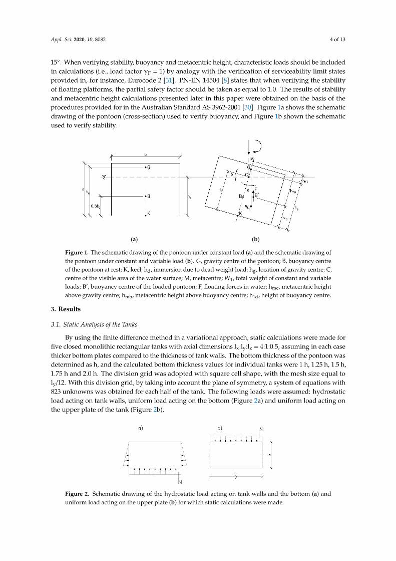
Figure 7 shows the distribution of bending moments in the cross-section of the tank at half of itslength from the acting hydrostatic load. This load causes the greatest bending moments in the bottomplate. As the thickness of the bottom plate increases, the value of the bending moment in the bottom inthe middle of the tank width increases, while clamping moments decrease. The values of bendingmoments in the upper plate and tank walls also decrease.
Figure 8 shows the distribution of deflections in the cross-section of the tank at half its lengthfrom the evenly distributed load acting on the upper plate. This load causes the greatest values ofdeflections in the upper plate. As the thickness of the bottom plate increases, the deflection in thebottom decreases, and the deflections in the upper plate and tank walls also decrease.
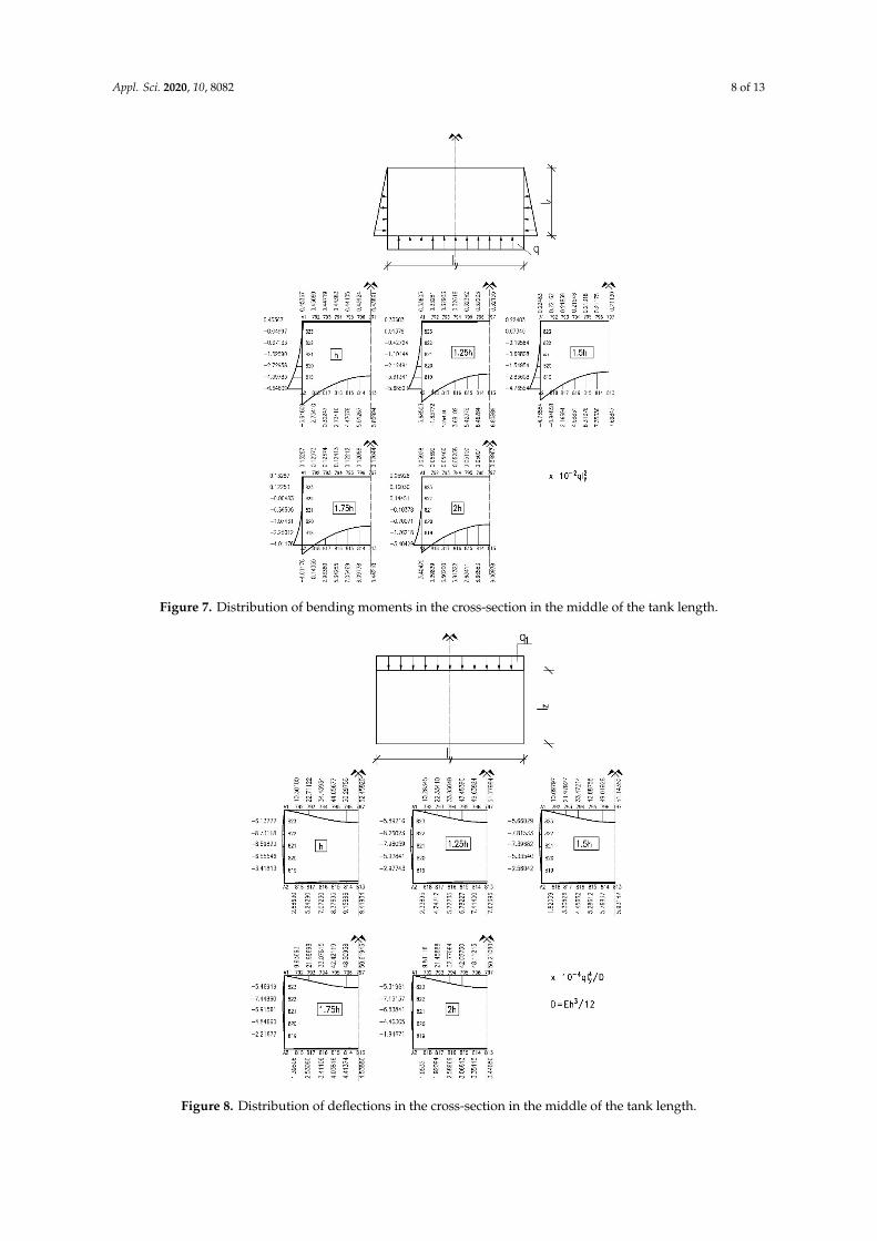
Figure 9 shows the distribution of bending moments in the cross-section at half of its length fromthe evenly distributed load acting on the upper plate. This load causes the greatest bending momentsin the upper plate. As the thickness of the bottom plate increases, the value of bending moment in thebottom, both in the middle of its width and the clamping moment, increases. On the other hand, thevalues of clamping moments in the upper plate and tank walls increase, and the values of bendingmoments in the middle of the width of the tank decrease.
Appl. Sci. 2020, 10, 8082 8 of 13Appl. Sci. 2020, 10, x 9 of 15
Figure 7. Distribution of bending moments in the cross-section in the middle of the tank length.
Figure 7 shows the distribution of bending moments in the cross-section of the tank at half of its length from the acting hydrostatic load. This load causes the greatest bending moments in the bottom plate. As the thickness of the bottom plate increases, the value of the bending moment in the bottom in the middle of the tank width increases, while clamping moments decrease. The values of bending moments in the upper plate and tank walls also decrease.
Figure 7. Distribution of bending moments in the cross-section in the middle of the tank length.Appl. Sci. 2020, 10, x 10 of 15
Figure 8. Distribution of deflections in the cross-section in the middle of the tank length.
Figure 8 shows the distribution of deflections in the cross-section of the tank at half its length from the evenly distributed load acting on the upper plate. This load causes the greatest values of deflections in the upper plate. As the thickness of the bottom plate increases, the deflection in the bottom decreases, and the deflections in the upper plate and tank walls also decrease.
Figure 8. Distribution of deflections in the cross-section in the middle of the tank length.
Appl. Sci. 2020, 10, 8082 9 of 13Appl. Sci. 2020, 10, x 11 of 15
Figure 9. Distribution of bending moments in the cross-section in the middle of the tank length.
Figure 9 shows the distribution of bending moments in the cross-section at half of its length from the evenly distributed load acting on the upper plate. This load causes the greatest bending moments in the upper plate. As the thickness of the bottom plate increases, the value of bending moment in the bottom, both in the middle of its width and the clamping moment, increases. On the other hand, the values of clamping moments in the upper plate and tank walls increase, and the values of bending moments in the middle of the width of the tank decrease.
3.2. Calculation Results of Buoyancy and Stability
Following the recommendations of Australian standard AS 3962-2001 [31] and using the dependencies detailed and described in the paper [32–34], buoyancy at self-load and at service load evenly distributed on the upper plate, amounting to 3.0 kN/m2, was calculated for the analysed tanks differing in bottom thickness. Moreover, the metacentric height and tilt angle were calculated with half of the upper plate loaded 1.0 kN/m2.
The following data was used for detailed calculations: length lx = 10 m, width ly = 2.5 m, height lz = 1.25 m, thickness of tank walls and the upper plate h = 0.08 m, reinforced concrete class C35/45, Styrofoam filling with a volumetric weight 0.45 kN/m3.
The results of the calculations are summarised in Table 3.
Figure 9. Distribution of bending moments in the cross-section in the middle of the tank length.
3.2. Calculation Results of Buoyancy and Stability
Following the recommendations of Australian standard AS 3962-2001 [31] and using thedependencies detailed and described in the paper [32–34], buoyancy at self-load and at serviceload evenly distributed on the upper plate, amounting to 3.0 kN/m2, was calculated for the analysedtanks differing in bottom thickness. Moreover, the metacentric height and tilt angle were calculatedwith half of the upper plate loaded 1.0 kN/m2.
The following data was used for detailed calculations: length lx = 10 m, width ly = 2.5 m, heightlz = 1.25 m, thickness of tank walls and the upper plate h = 0.08 m, reinforced concrete class C35/45,Styrofoam filling with a volumetric weight 0.45 kN/m3.
The results of the calculations are summarised in Table 3.

Appl. Sci. 2020, 10, 8082 10 of 13
Table 3. Results of buoyancy and stability calculations of the analysed tanks.
Bottom Thickness of theAnalysed Tanks
(m)
Pontoon BuoyancyPontoon Stability with Half of the Upper Plate Loaded 1.0 kN/m2
At Self-Weight Load At Uniform Load3.0 kN/m2
Immersion Depthhd (m)
Freeboardhf (m)
Immersion Depthhd (m)
Freeboardhf (m)
Metacentric Heighthmc (m)
Tilt Angleϕ (◦)
Freeboardhf (m)
0.08 0.66 0.59 0.96 0.29 0.35 7.16 0.380.10 0.71 0.54 1.01 0.24 0.37 6.38 0.350.12 0.75 0.50 1.05 0.20 0.38 5.86 0.320.14 0.80 0.45 1.10 0.15 0.41 5.15 0.290.16 0.84 0.41 1.14 0.11 0.42 4.77 0.26
Appl. Sci. 2020, 10, 8082 11 of 13
4. Discussion
This paper presents calculation results for closed monolithic rectangular tanks performed in onestage and analyses the impact of bottom plate thickness on the distribution and values of deflectionsand bending moments in the considered system. No relevant results have been found in the literaturefor this type of structure.
Since there are still problems related to the analysis, design and execution of concrete floatingstructures, the matter is considered to be challenging [35]. Most of the available and constructedreinforced concrete floats consist of a box and a covering plate. However, this approach is uncertain,since each contact can be a potential spot through which water gets inside [36]. The closed rectangulartank analysed in the paper is an effective solution that eliminates the possibility of water getting insidethe structure [7,34]. Tight filling of the box with polystyrene means water that could possibly get insidehas no place to accumulate.
By taking into account in static calculation the interaction of the tank structures with Styrofoamfilling treated as an elastic foundation, all points of the structure see the reduction in the values ofbending moments, sometimes even by approximately 30–40%. Including the Poisson’s ratio ν , 0in calculations results in obtaining, for the central parts of plates (beyond the edges of the tank), thevalues of bending moments higher than calculated for ν = 0. Including the Poisson’s ratio in staticcalculation in closed monolithic tanks does not affect the values of bending moments occurring on theedges. Parameters such as ν and K do not affect the calculation related to the so-called freeboard [33].
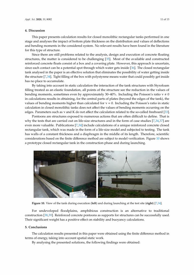
Pontoons are structures exposed to numerous actions that are often difficult to define. That iswhy the tests that are carried out on life-size structures and in the form of case studies [7,34,37] areeven more valuable. Publications [7,34] include calculations of a unique reinforced concrete closedrectangular tank, which was made in the form of a life-size model and subjected to testing. The tankhas walls of a constant thickness and a diaphragm in the middle of its length. Therefore, scientificconsiderations based on the finite difference method are subject to model verification. Figure 10 showsa prototype closed rectangular tank in the construction phase and during launching.
Appl. Sci. 2020, 10, x 12 of 15
Table 3. Results of buoyancy and stability calculations of the analysed tanks.
Bottom Thickness
of the Analysed
Tanks (m)
Pontoon Buoyancy Pontoon Stability with Half of the
Upper Plate Loaded 1.0 kN/m2 At Self-Weight Load At Uniform Load 3.0 kN/m2
Immersion Depth hd
(m)
Freeboard hf (m)
Immersion Depth hd
(m)
Freeboard hf (m)
Metacentric Height hmc (m)
Tilt Angle φ (°)
Freeboard hf (m)
0.08 0.66 0.59 0.96 0.29 0.35 7.16 0.38 0.10 0.71 0.54 1.01 0.24 0.37 6.38 0.35 0.12 0.75 0.50 1.05 0.20 0.38 5.86 0.32 0.14 0.80 0.45 1.10 0.15 0.41 5.15 0.29 0.16 0.84 0.41 1.14 0.11 0.42 4.77 0.26
4. Discussion
This paper presents calculation results for closed monolithic rectangular tanks performed in one stage and analyses the impact of bottom plate thickness on the distribution and values of deflections and bending moments in the considered system. No relevant results have been found in the literature for this type of structure.
Since there are still problems related to the analysis, design and execution of concrete floating structures, the matter is considered to be challenging [35]. Most of the available and constructed reinforced concrete floats consist of a box and a covering plate. However, this approach is uncertain, since each contact can be a potential spot through which water gets inside [36]. The closed rectangular tank analysed in the paper is an effective solution that eliminates the possibility of water getting inside the structure [7,34]. Tight filling of the box with polystyrene means water that could possibly get inside has no place to accumulate.
By taking into account in static calculation the interaction of the tank structures with Styrofoam filling treated as an elastic foundation, all points of the structure see the reduction in the values of bending moments, sometimes even by approximately 30–40%. Including the Poisson’s ratio ν ≠ 0 in calculations results in obtaining, for the central parts of plates (beyond the edges of the tank), the values of bending moments higher than calculated for ν = 0. Including the Poisson’s ratio in static calculation in closed monolithic tanks does not affect the values of bending moments occurring on the edges. Parameters such as ν and K do not affect the calculation related to the so-called freeboard [33].
Pontoons are structures exposed to numerous actions that are often difficult to define. That is why the tests that are carried out on life-size structures and in the form of case studies [7,34,37] are even more valuable. Publications [7,34] include calculations of a unique reinforced concrete closed rectangular tank, which was made in the form of a life-size model and subjected to testing. The tank has walls of a constant thickness and a diaphragm in the middle of its length. Therefore, scientific considerations based on the finite difference method are subject to model verification. Figure 10 shows a prototype closed rectangular tank in the construction phase and during launching.
Figure 10. View of the tank during execution (left) and during launching at the test site (right) [7,34]. Figure 10. View of the tank during execution (left) and during launching at the test site (right) [7,34].
For undeveloped floodplains, amphibious construction is an alternative to traditionalconstruction [38,39]. Reinforced concrete pontoons as supports for structures can be successfully used.Their significant weight has a positive effect on stability and buoyancy calculations.
5. Conclusions
The calculation results presented in this paper were obtained using the finite difference method interms of energy, taking into account spatial static work.
By analysing the presented solutions, the following findings were obtained:

Appl. Sci. 2020, 10, 8082 12 of 13
• Thickening of the bottom plate in relation to the constant and identical wall and upper platethickness, at all points of the calculated tanks, led to a reduction in deflections as the bottomthickness increased.
• Hydrostatic load on tank walls and uniform load on the bottom combined with an increase in thebottom thickness led to an increase in bending moments acting in the middle of the bottom platespan towards a shorter span (My
2, Figure 3), while reducing bending moments at other points ofthe tank.
• Uniform load on the upper plate in tanks with a thicker bottom led to an increase in bendingmoments, but only in the bottom, both in fastening moments (MA2 and MB2, Figure 3) and inthe moment acting in the centre of the plate towards a shorter span (My
2, Figure 3). Bendingmoments at other points of the tank practically did not change.
• An increase in the thickness of the bottom plate leads to a change in the size of the pontoon’s tiltangle, which enables it to change easily, to smaller than required by applicable regulations (in thiscase ϕ ≤ 6◦).
Funding: This research received no external funding.
Acknowledgments: The publication was co-financed within the framework of Ministry of Science and HigherEducation programme as “Regional Initiative Excellence” in years 2019–2022, Project No. 005/RID/2018/19.
Conflicts of Interest: The author declares no conflict of interest.
References
1. Halicka, A.; Franczak, D. Design of Reinforced Concrete Tanks. Volume 2. Tanks for Liquids; WydawnictwoNaukowe PWN: Warsaw, Poland, 2014.
2. Buczkowski, W.; Szymczak-Graczyk, A.; Walczak, Z. Experimental validation of numerical static calculationsfor a monolithic rectangular tank with walls of trapezoidal cross-section. Bull. Pol. Acad. Sci. Tech. Sci. 2017,65, 799–804. [CrossRef]
3. Szymczak-Graczyk, A. Rectangular plates of a trapezoidal cross-section subjected to thermal load. IOP Conf.Ser. Mater. Sci. Eng. 2019, 603, 032095. [CrossRef]
4. D’Amato, M.; Laterza, M.; Casamassima, V.M. Seismic Performance Evaluation of Multi-Span ExistingMasonry Arch Bridge. Open Civ. Eng. J. 2017, 11 (Suppl. 5), 1191–1207. [CrossRef]
5. Pelà, L.; Aprile, A.; Benedetti, A. Seismic Assessment of masonry arch bridges. Eng. Struct. 2009, 31, 1777–1788.[CrossRef]
6. Mazurkiewicz, B. Yacht Ports and Marinas. Design; Fundacja Promocji Przemysłu Okretowego i GospodarkiMorskiej: Gdansk, Poland, 2010.
7. Szymczak-Graczyk, A. Floating platforms made of monolithic closed rectangular tanks. Bull. Pol. Acad. Sci.Tech. Sci. 2018, 66, 209–219. [CrossRef]
8. PN–EN 14504:2010: Inland Waterway Vessels. Floating Harbors. Requirements, Tests; Polish StandardizationCommittee: Warsaw, Poland, 2010.
9. Wang, C.M. Great, Ideas Float on the Top. In Large Floating Structures: Technological Advances; Wang, C.M.,Wang, B.T., Eds.; Springer: Berlin/Heidelberg, Germany, 2015; pp. 1–36.
10. Holcombe, S. Applications and Huge Potential Demand for Amphibious Structures. In Proceedings of theFirst International Conference on Amphibious Architecture, Design & Engineering, Waterloo, ON, Canada,25–28 June 2017; Volume 138.
11. Nakajima, T.; Umeyama, M. A New Concept for the Safety of Low-lying Land Areas from Natural Disasters.J. Ocean Eng. Mar. Energy 2015, 1, 19–29. [CrossRef]
12. Ostrowska-Wawryniuk, K.; Piatek, Ł. Lightweight Prefabricated Floating Buildings for Shallow InlandWaters. Design and Construction of The Floating Hotel Apartment in Poland. J. Water Land Dev. 2020, 44,118–125. [CrossRef]
13. Gołas, J. Introduction to the Theory of Plates; Opole University of Technology Publishing House: Opole, Poland, 1972.14. Donnell, L.H. Beams, Plates and Shells; McGraw-Hill: New York, NY, USA, 1976.15. Naghdi, P.M. The Theory of Shells and Plates; Handbuch der Physick: Berlin, Germany, 1972.

Appl. Sci. 2020, 10, 8082 13 of 13
16. Panc, V. Theries of Elastic Plates; Academia: Prague, Czech Republic, 1975.17. Timoshenko, S.; Woinowsky-Krieger, S. Theory of Plates and Coatings; Arkady: Warszawa, Poland, 1962.18. Szlilard, R. Theory and Analysis of Plates. Classical and Numerical Methods; Prentice Hall, Englewood Cliffs:
Bergen, NJ, USA; Prentice-Hall: Upper Saddle River, NJ, USA, 1974.19. Ugural, A.C. Stresses in Plates and Shells; McGraw-Hill: New York, NY, USA, 1981.20. Wilde, P. Variational approach of finite differences in the theory of plate. In Proceedings of the Materials
of XII Scientific Conference of the Committee of Science PZiTB and the Committee of Civil Engineering ofPolish Academy of Sciences, Krynica, Poland, 12–17 September 1966.
21. Tribiłło, R. Application of the generalized finite difference method for plate calculations. Arch. InzynieriiLadowej 1975, 2, 579–586.
22. Son, M.; Sang Jung, H.; Hee Yoon, H.; Sung, D.; Suck Kim, J. Numerical Study on Scale Effect of RepetitivePlate-Loading Test. Appl. Sci. 2019, 9, 4442. [CrossRef]
23. Kaczkowski, Z. Plates. Static Calculations; Arkady: Warszawa, Poland, 2000.24. Rapp, B.E. Chapter 30—Finite Difference Method. In Microfluidics: Modelling, Mechanics and Mathematics, Micro
and Nano Technologies; Rapp, B.E., Ed.; Elsevier: Amsterdam, The Netherlands, 2017; pp. 623–631. [CrossRef]25. Blazek, J. Chapter 3—Principles of Solution of the Governing Equations. In Computational Fluid Dynamics:
Principles and Applications; Blazek, J., Ed.; Elsevier: Amsterdam, The Netherlands, 2015; pp. 29–72. [CrossRef]26. Sadd, M.H. Chapter 5—Formulation and Solution Strategies. In Elasticity, Theory, Applications, and Numerics;
Sadd, M.H., Ed.; Academic Press, Elsevier: Cambridge, MA, USA, 2005; pp. 83–102. [CrossRef]27. Szymczak-Graczyk, A. Numerical analysis of the impact of thermal spray insulation solutions on floor
loading. Appl. Sci. 2020, 10, 1016. [CrossRef]28. Numayr, K.S.; Haddad, R.H.; Haddad, M.A. Free vibration of composite plates using the finite difference
method. Thin-Walled Struct. 2004, 42, 399–414. [CrossRef]29. Z44, Recommendations for the Design of Offshore Hydrotechnical Structures, Z1–Z46; No. 21; Gdansk University
of Technology, Department of Maritime Construction. Studies and Materials: Gdansk, Poland, 1997.30. AS 3962-2001: The Australian Standard: Guidelines for Design of Marinas; Standards Australia International
Ltd.: Sydney, Australian, 2001.31. PN-EN 1992-1-1:2008 Eurocode 2. Design of Concrete Structures. Part 1-1. General Rules and Rules for Buildings;
Polish Standardization Committee: Warsaw, Poland, 2008.32. Buczkowski, W.; Szymczak-Graczyk, A. The influence of the thickness of the bottom of the work and static
stability of the pontoon made as a monolithic closed, reinforced concrete tank. In Modelling of structures andEngineering Structures; SGGW: Warsaw, Poland, 2014.
33. Buczkowski, W.; Szymczak-Graczyk, A.; Walczak, Z. The analysis of static works of closed monolithicrectangular tanks. In Proceedings of the IV International Scientific Conference, Durability of ConstructionWork—Science and Research, Poznan, Poland, 19–21 November 2014.
34. Szymczak-Graczyk, A. Floating Platforms Made from Monolithic, Closed Rectangular Tanks. Ph.D. Thesis,SGGW, Warsaw, Poland, 2014.
35. Jiang, D.; Tan, K.H.; Wang, C.M.; Ong, K.C.G.; Bra, H.; Jin, J.; Kim, M.O. Analysis and design of floatingprestressed concrete structures in shallow waters. Mar. Struct. 2018, 59, 301–320. [CrossRef]
36. Spychalski, K.; Szymczak-Graczyk, A. Multi-criteria analysis of the selection of structural types of floatingplatforms. Mater. Bud. 2020, 2, 2–4. [CrossRef]
37. Seifa, M.S.; Inoue, Y. Dynamic analysis of floating bridges. Mar. Struct. 1998, 11, 29–46. [CrossRef]38. Laks, I.; Walczak, Z. Modelling of the impact of the retention reservoir on the flood protection of the city—A
case study for the city of Kalisz (Central Poland). IOP Conf. Ser. Mater. Sci. Eng. 2019, 603, 022066. [CrossRef]39. Laks, I.; Walczak, Z.; Szymczak-Graczyk, A.; Ksit, B.; Madrawski, J. Hydraulic and legal conditions for
buildings in floodplains—A case study for the city of Kalisz (Poland). IOP Conf. Ser. Mater. Sci. Eng. 2019,471, 102050. [CrossRef]
Publisher’s Note: MDPI stays neutral with regard to jurisdictional claims in published maps and institutionalaffiliations.
© 2020 by the author. Licensee MDPI, Basel, Switzerland. This article is an open accessarticle distributed under the terms and conditions of the Creative Commons Attribution(CC BY) license (http://creativecommons.org/licenses/by/4.0/).