Practical mastery of closed loops I
39
05.08.2008 Folie 1 Jürgen Helmich Practical mastery of closed loops I Module 2: Commissioning a basic closed-loop control system MPS® PA Compact Workstation
-
Upload
khangminh22 -
Category
Documents
-
view
5 -
download
0
Transcript of Practical mastery of closed loops I

05.08.2008 Folie 1Jürgen Helmich
Practical mastery of closed loops I
Module 2: Commissioning a basic closed-loop control system
MPS® PA Compact Workstation

05.08.2008 Folie 2Jürgen Helmich
Outcome of Module 2 – Commissioning a closed-loop control system
The participant
can commission a basic closed-loop control system
— ensure supply
— install controller
— setup wiring
Detailed competencies needed:
able to identify components
able to read a circuit diagram or wiring schematic
able to connect components according to a circuit diagram or wiring schematic
Reason why:
In order to maintain a closed-loop control system in their production line the participant must understand the components and circuit of a closed-loop.
set up training system for following exercises/modules.

05.08.2008 Folie 3Jürgen Helmich
Module 2 - Contents
Overview components of MPS® PA Compact Workstation
sensors
actuators
I/O-board
control possibilities
Commissioning and testing with Simulation box, digital/analogue
Commissioning and testing with Easyport, digital/analogue and FluidLab-PA

05.08.2008 Folie 4Jürgen Helmich
Training system for process automation – MPS® PA Compact Workstation
Process technology is not only simple like basic
principles of a water treatment process or
production of food. It can be as highly complex as
a technical processes.
No matter the complexity of process technology –
to learn about the fundamentals of open and
closed-loop control technology is always the first
step.
This is why MPS® PA Compact Workstation
is great to learn about closed-loop control.

05.08.2008 Folie 5Jürgen Helmich
What´s new ?
The MPS® PA Compact Workstation has new technical features:
tanks with scaling 0-10 L, new form drains completely, without adhesive joint
screw-on tank cover with filling flap and fixed section, → parts as pipes and sensors are firmly mounted, → connecting cables or pipes are not moved, → no re-connection at commissioning necessarynew clearly laid out piping system
new proportional valve with larger diameter DN7 (higher flow rate)
pluggable pressure sensor for flexible usage in piping system, e.g. before or after the proportional valve
19“-frame with integrated ground fault circuit interrupter for heating element
2-row ER-frame
pressure tank connected to upper tank, therefore better visibility of inspection pipe
5 cm less head room
design MPS-PA conform

05.08.2008 Folie 6Jürgen Helmich
Components
tank
pump
flow rate sensor
controller
trolley
profile plate
proportional valve
ultrasonic sensor
I/O-board
2-wayball valve
pressure sensor heating
temperature sensor

05.08.2008 Folie 7Jürgen Helmich
• Two capacitive sensors at the rear of the lower
tank are monitoring the level of the water. The
sensors can be mechanically adjusted on an
aluminum profile.
• sensors detect the water level through the tank
wall.
• The binary 24 V signal output of the sensors is
wired to the I/O terminal in the form of an input.
Capacitive level sensors „see“ through the container wall
Datasheet → 690588

05.08.2008 Folie 8Jürgen Helmich
Float switch housing for lateral installation
• Depending on assembly position, the float
switch can be used either to switch at
increasing or decreasing water level.
• The binary 24 V signal is wired to the I/O
terminal as an input.
• connecting cables with plug/socket for easy
wiring or maintenance.
Datasheet → 691282

05.08.2008 Folie 9Jürgen Helmich
Float switch housing for heating safety
• The float switch is monitoring the decreasing
filling level in the tank. The heating is switched
off if the filling level sinks below the heating.
The heating must be surrounded completely by
the fluid. It is connected in line to the digital
output for activating the heating.
• connecting cables with plug/socket for easy
wiring or maintenance.
Datasheet → BE.EL.0162

05.08.2008 Folie 10Jürgen Helmich
• The binary 24 V signal is wired to the I/O
terminal (input at SysLink interface)
• also can be used as a safety limit switch to
switch off the pump by means of a safety relay.
• The switching solenoid is located in a
transparent float housing for easy visibility.
Float switch in tank cover
Datasheet → 691383

05.08.2008 Folie 11Jürgen Helmich
• Ultrasonic sensor, 50-300 mm / standard current signal 4-20 mA
• sensor detects distance to a surface, signal characteristic is modified to “falling”
• dead range < 50 mm, no defined measure value• Current to voltage transducer
4-20 mA → 0-10 V DC
Level detection with ultrasonic sensor
Datasheet → BE.SI.0193

05.08.2008 Folie 12Jürgen Helmich
Level detection with ultrasonic sensor
Ultrasonic sensor with “falling” signal characteristic

05.08.2008 Folie 13Jürgen Helmich
Level detection with ultrasonic sensor
L = E - D
D = • vst 2
t = sonic duration timevs = sonic speedBD = block distanceE = empty distanceD = measured distance to level surfaceL = level
E
D
BD
L
ultra sonicsensor measuring
transformer
Sour
ce: E
ndre
ss+H
ause
r

05.08.2008 Folie 14Jürgen Helmich
Actual value of flow rate is detected by
an opto-electronic vane sensor.
Frequency signal
0,3-9,0 l/min / 40-1200Hz
signal amplitude ~24 V DC
for PLC fast counter inputs
Impulse height 8-24 V DC
Frequency to voltage transducer
0-1000 Hz → 0-10 V DC
Flow rate measuring
Datasheet → 170711170711

05.08.2008 Folie 15Jürgen Helmich
Flow rate measuring
liquid product strikes the front edge of the rotor blades
low-pressure area is produced between the upstream cone and the rotor hub
Fluid flowing through the meter impacts an angular velocity to the turbine rotor blades
degree of the angular velocity or number of revolutions per minute of the turbine rotor is proportional to the flowing stream of the liquid
turbine rotor is hydraulically balanced on its axis
minimum flow rate of a turbine flow meter becomes a factor of viscosity versus the degree of accuracy
cavitation in a turbine flow meter will take place when the local pressures fall close to or below the vapor pressure of the liquid product

05.08.2008 Folie 16Jürgen Helmich
Pressure sensor
Pressure sensor, ceramic measurement cell
measure range 0…400 mbar
signal output 0-10 V DC
pluggable connector for flexible usage
in piping system
Datasheet → BE.EL.0600

05.08.2008 Folie 17Jürgen Helmich
Ceramic pressure cell
Suitable for:
compressed air, oxygen
water, sea water
fuel oil, diesel oil, fuel
hydraulic oil, brake fluid
aggressive media
pasty mediaSo
urce
: BD
Sen
sors

05.08.2008 Folie 18Jürgen Helmich
Temperature measuring
PT100 sensor
platinum resistance thermometer with
interchangeable measuring element.
Measuring range -50 °C ... +150 °C
Datasheet → 170709

05.08.2008 Folie 19Jürgen Helmich
Platinum resistance thermometer
1
2
3
1 Screw
2 Shield tube
3 Thermo element

05.08.2008 Folie 20Jürgen Helmich
• centrifugal pump with delivery rate of approx.
5 l/min ensures continuous flow of water.
• continuous control of the pump, pump motor
speed can be varied by means of a motor
controller with a voltage signal:
input 0-10 VDC, output 0-24 VDC.
• ON/OFF control of the pump motor with a
digital output/relay circuit.
Centrifugal pump
Datasheet → 170712

05.08.2008 Folie 21Jürgen Helmich
Centrifugal pump
1 rotor
2 rotor axis

05.08.2008 Folie 22Jürgen Helmich
• Flow control of fluids with directly actuated
proportional 2/2-way valve.
A solenoid coil current lifts the valve piston
continuously from its seat.
• An external standard signal is converted into a
pulse width modulated (PWM) signal. The
orifice of the valve is infinitely adjustable. The
frequency of the PWM signal can be modified.
• Standard signal 0-10VDC
(also: 0-20mA and 4-20mA)
Proportional valve
Datasheet → 170714
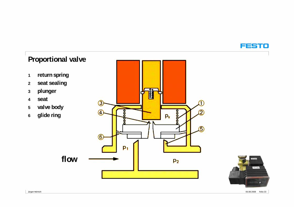
05.08.2008 Folie 23Jürgen Helmich
Proportional valve
1 return spring
2 seat sealing
3 plunger
4 seat
5 valve body
6 glide ring
flow

05.08.2008 Folie 24Jürgen Helmich
2-way ball valve for water process with:
• rotary pneumatic quarter turn actuator SYPAR,
scotch yoke principle
• 5/2 way pneumatic valve
with port pattern to NAMUR
direct mounted onto rotary drive
• electrical signal box
with two micro-switches for position feedback
CLOSED/OPEN
2-way ball valve with pneumatic rotary drive
ball valve → 534304
actuator → 533417
valve → 535987
signal box → 534469

05.08.2008 Folie 25Jürgen Helmich
Quarter turn actuator SYPAR – Double acting function
Process valve opensPistons move towards the end caps
Process valve closesPistons move toward the shaft

05.08.2008 Folie 26Jürgen Helmich
I/O-board wiring with measuring transducers and motor controller
Syslink I/O module, 20 pin Centronix
analogue 15pin Sub-D terminal block
top-hat rail relays
motor controller for the pump motor0-10V DC → 0-24 V DC, max. 3,5 A
measuring transducersC→ V, f → V, PT100 → V
current limiter, max. 2A
mechanical adaptation with ER-frame clips

05.08.2008 Folie 27Jürgen Helmich
19“- and ER-frame
ground fault circuit interrupter for heating element
2 ER-rows for I/O-board, EduTrainers, touch panels or control panel
optional: with power supply 24 V DC/4,5 A

05.08.2008 Folie 28Jürgen Helmich
PLC control
Siemens S7-300
CPU 313C
PC control
Festo EasyPort,
digital/analog
Closed-loop control
Industrial controller
Siemens Sipart DR19
Control possibilities
Commissioning/testing
Festo simulation box
digital/analog PLC control
Festo CPX-FEC
Closed-loop control
Industrial controller
Jumo Imago 500
PLC control
Siemens Logo
PLC control
Allen-Bradley
Micrologix 1500

05.08.2008 Folie 29Jürgen Helmich
Commissioning and testing with Simulation box, digital/analog
Station training:
Commissioning the station and check the digital and analog I/O signals.
Display of analog values
Connect Simulation box, digital/analog with crossover digital and analog Syslink cable to station I/Os

05.08.2008 Folie 30Jürgen Helmich
Connecting Simbox, digital/analogue
Connect Simulation box, digital/analog with crossover digital and analog Syslink cable to station I/Os

05.08.2008 Folie 31Jürgen Helmich
Compact Workstation
PC control with FluidLab-PA
PCstudy 1
Station training:
Basic training for measuring, control
and closed-loop control.
Connect a PC with RS232 cable to EasyPortDA (station I/O) using FluidLab-PA
PTP RS232

05.08.2008 Folie 32Jürgen Helmich
Connecting Easyport digital, analogue
PC

05.08.2008 Folie 33Jürgen Helmich
Compact Workstation
PLC control with Simatic S7-300 – CPU313C/CPU314C-2DP
PCstudy 1
PLC training:
Basic and advanced training for open and
closed-loop control.
Advanced training for
network communication
and visualization.
Programming with PC and Step7. Connect a PLC with digital and analogue Syslink cable to station I/Os
COM1 MPI
RS232

05.08.2008 Folie 34Jürgen Helmich
PLC control with Simatic S7-300 – CPU313C/CPU314C-2DP
19“- and ER-frame for multiple use
19“ control panel
19“ground fault circuit interrupter
EduTrainer for ER-frame

05.08.2008 Folie 35Jürgen Helmich
Compact Workstation
PLC control with Festo CPX-FEC
PCstudy 1
PLC training:
Basic and advanced training for open and
closed-loop control.
Advanced training for
network communication
and visualization.
Programming with PC and FSTV4.1 or higher. Connect a PLC with digital and analogue Syslink cable to station I/Os.
Visualization with FED120 and making projectwith FED Designer.
Ethernet

05.08.2008 Folie 36Jürgen Helmich
PLC control with Festo CPX-FEC
19“- and ER-frame for multiple use
19“ control panel
19“ground fault circuit interrupter
EduTrainer for ER-frame

05.08.2008 Folie 37Jürgen Helmich
Compact Workstation
Closed-loop control with industrial controller – Sipart DR19
PCstudy 1
Industrial controller training:
Basic operation training for industrial controller.
Advanced training
for closed-loop control.
Configuration and setup of parameters with PC and Simatic PDM V5.2 or higher. PC card CP5611 for Profibus-DP recommended. Connect a PLC with digital and analogue Syslink cable to station I/Os.
Profibus-DP

05.08.2008 Folie 38Jürgen Helmich
• Station size
w x d x h = 700 x 700 x 935 mm
d + approx. 100 mm for PLC or controller
towards the rear
• Station weight approx. 45 kg
• Voltage supply 24 VDC, 4,5 A
• Compressed air supply approx. 6 bar
General technical data

05.08.2008 Folie 39Jürgen Helmich
Getting started – commissioning a basic closed-loop control system
Which tasks have to be maintained ?
1. Prepare components following equipment list.
2. Visual check.
3. Make cable and pneumatic connections.
4. Arrange supply for voltage and pressurized air.
5. Fill the water tank if empty.
6. Deairate pipe system.
7. Start controller.
8. Operate controller.
Prepare work station
Visual check
Cable connections
Pneumatic connection
Commissioning Closed-loop control system
Operate controller
Runing closed-loop
Voltage supply
Filling tank
Deaeration pipe system
Start controller