Novel Vine-like Continuum Robot for Environmental ...
80
Clemson University TigerPrints All eses eses 5-2016 Novel Vine-like Continuum Robot for Environmental Exploration Applications Michael Benjamin Wooten Clemson University, [email protected] Follow this and additional works at: hps://tigerprints.clemson.edu/all_theses is esis is brought to you for free and open access by the eses at TigerPrints. It has been accepted for inclusion in All eses by an authorized administrator of TigerPrints. For more information, please contact [email protected]. Recommended Citation Wooten, Michael Benjamin, "Novel Vine-like Continuum Robot for Environmental Exploration Applications" (2016). All eses. 2406. hps://tigerprints.clemson.edu/all_theses/2406
-
Upload
khangminh22 -
Category
Documents
-
view
2 -
download
0
Transcript of Novel Vine-like Continuum Robot for Environmental ...

Clemson UniversityTigerPrints
All Theses Theses
5-2016
Novel Vine-like Continuum Robot forEnvironmental Exploration ApplicationsMichael Benjamin WootenClemson University, [email protected]
Follow this and additional works at: https://tigerprints.clemson.edu/all_theses
This Thesis is brought to you for free and open access by the Theses at TigerPrints. It has been accepted for inclusion in All Theses by an authorizedadministrator of TigerPrints. For more information, please contact [email protected].
Recommended CitationWooten, Michael Benjamin, "Novel Vine-like Continuum Robot for Environmental Exploration Applications" (2016). All Theses.2406.https://tigerprints.clemson.edu/all_theses/2406
NOVEL VINE-LIKE CONTINUUM ROBOT FOR ENVIRONMENTAL EXPLORATION APPLICATIONS
A Thesis Presented to
the Graduate School of Clemson University
In Partial Fulfillment of the Requirements for the Degree
Master of Science Electrical Engineering
by Michael Benjamin Wooten
May 2016
Accepted by: Dr. Ian D. Walker, Committee Chair
Dr. Richard E. Groff Dr. Adam Hoover
ii
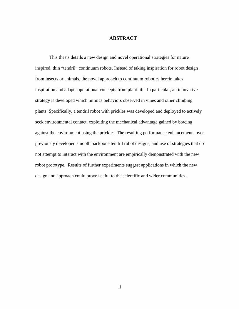
ABSTRACT
This thesis details a new design and novel operational strategies for nature
inspired, thin “tendril” continuum robots. Instead of taking inspiration for robot design
from insects or animals, the novel approach to continuum robotics herein takes
inspiration and adapts operational concepts from plant life. In particular, an innovative
strategy is developed which mimics behaviors observed in vines and other climbing
plants. Specifically, a tendril robot with prickles was developed and deployed to actively
seek environmental contact, exploiting the mechanical advantage gained by bracing
against the environment using the prickles. The resulting performance enhancements over
previously developed smooth backbone tendril robot designs, and use of strategies that do
not attempt to interact with the environment are empirically demonstrated with the new
robot prototype. Results of further experiments suggest applications in which the new
design and approach could prove useful to the scientific and wider communities.

iii
DEDICATION
To my wife and family for the putting up with me.
To my colleagues, for all the aid and support throughout the process.
iv
ACKNOWLEDGMENTS
I would like to first acknowledge all of the support, guidance, and patience shown
to me by my advisor, Professor Dr. Ian D. Walker. He gave me the opportunity to work
on this project and in so doing the ability to become part of the graduate student
community here at Clemson. Dr. Walker always gave his time and expertise gladly, and I
truly think that this would not have been possible without him.
I would like to thank Professors Dr. Richard E. Groff, and Dr. Adam W. Hoover
for accepting to be my other committee members.
I would also like to acknowledge the guidance and support of Dr. Apoorva
Kapadia during our weekly meetings during the course of my research.
Furthermore, I would like to thank everyone at Clemson that helped me achieve
this milestone: everyone in the lab for providing helping hands and advice when it was
needed, Ms. Lillian Burns and her administrative assistance in procuring everything that I
needed, and Mr. Tim Pruett for his help with rapid prototyping.
This work is supported in part by the U.S. National Science Foundation under
grant IIS-1527165, and in part by NASA under contract NNX12AM01G.
v
TABLE OF CONTENTS Page
ABSTRACT ......................................................................................................................... i
DEDICATION ................................................................................................................... iii
ACKNOWLEDGMENTS ................................................................................................. iv
CHAPTER ONE: INTRODUCTION ................................................................................. 1
1.1 Continuum Robots ............................................................................................... 1
1.2 Continuum Tendril Robots and Inspiration from Plants ...................................... 3
1.3 Overview of Thesis .............................................................................................. 5
CHAPTER TWO: HARDWARE AND SOFTWARE DEVELOPMENT ........................ 7
2.1 Goals for Further Hardware Development ........................................................... 7
2.2 Hardware Design, Characteristics, and Improvements ........................................ 9
2.3 Actuator and Sensing Package ........................................................................... 13
2.4 User and Hardware Interface Design ................................................................. 16
2.5 Testing Space Development ............................................................................... 18
CHAPTER THREE: PLANT-LIKE CONTINUUM ROBOT DESIGNS AND
BEHAVIORS .................................................................................................................... 20
3.1 Prickles and Environmental Attachment ............................................................ 21
3.2 Circumnutation ................................................................................................... 24
vi
Table of Contents (Continued)
Page
CHAPTER FOUR: EXPERIMENTS AND APPLICATIONS ........................................ 28
4.1 Preliminary experiments .................................................................................... 28
4.2 Towards Applications ........................................................................................ 37
CHAPTER FIVE: CONCLUSIONS AND FUTURE WORK ......................................... 42
5.1 Conclusions ........................................................................................................ 42
5.2 Suggestions for future work ............................................................................... 44
APPENDICES .................................................................................................................. 47
Appendix A: Calibration Data and Curves for Each Compression Sensor .................. 48
Appendix B: Arduino Code for Controlling Tendril Using GUIno Library ................. 52
vii
LIST OF TABLES
Table Page 2.1 Section lengths for current and previous designs ........................................ 11 2.2 Spring stiffness by section and total compressibility of the new design ................................................................................... 12 4.1 Experiment 1 displacement measurements .................................................. 30 A-1 Compression load cell calibration data by accompanying motors (0 – 4) ................................................................ 48 A-2 : Compression load cell calibration data by accompanying motors (4 – 8) ................................................................ 49
viii
LIST OF FIGURES
Figure Page 1.1 Tentacle robot developed at Clemson ............................................................ 2 1.2 Climbing plants that serve as inspiration in robotics ..................................... 4 1.3 NASA/JSC’s Tendril [16] .............................................................................. 5 2.1 Concentric tube, spring loaded robot ............................................................. 8 2.2 Prototype vine-like robot section descriptions. .............................................. 9 2.3 (a) (Left) Previous version of tendril robot and (b) current version .................................................................................... 9 2.4 Nitinol tube buckling failure ........................................................................ 10 2.5 Plastic spacer and end cap design for routing tendons ................................ 12 2.6 Compression sensor and motor setup and assembled actuator package..................................................................................... 14 2.7 Images explaining how the motors interact with the compression sensors............................................................................... 15 2.8 Sensor reading as a function of tension ....................................................... 15 2.9 Arduino Mega 2560 board with wires connected to actuator package..................................................................................... 16 2.10 Screenshot of GUI interface for Arduino ..................................................... 17 2.11 Actuator package guiding system and robot environment cavity................................................................................. 19 3.1 Tendril Robot in Undesirable Configuration Due to Lack of Structural Support .............................................................................. 20 3.2 Set of early prickles implemented on tendril robot spacer .......................... 22
ix
List of Figures (Continued) Figure Page 3.3 3D Rendering of Prickle Hardware Cover Design ...................................... 23 3.4 Installed Set of prickles on the Tendril Robot ............................................. 24 3.5 Circumnuation. Top to bottom: increasing time. Left: hop vine. Right: tendril robot ..................................................................... 26 3.6 Underling algorithm for robot tendril circumnutation ................................. 27 4.1 Visual results of experiment 1 where (a) (left) has no attachment, while (b) was attached at the yellow point ......................... 29 4.2 Exploration with non-prickled tendril prototype ......................................... 31 4.3 Additional example of a non-constant curvature “S-bend” configuration .......................................................................... 32 4.4 Exploration with prickled tendril prototype ................................................. 33 4.5 Prickle set stuck in grid ................................................................................ 35 4.6 Grasping mechanism forming a connection to bamboo branch ....................................................................................... 36 4.7 Tendril imitating a growing vine. Yellow circles: points of attachment. Top to bottom: increasing time, Left: Tendril, Right: up close point of attachment ......................................... 37 4.8 “Gremlin” used in computer exploration trials ............................................ 39 4.9 Exploration of a computer system using the prickled augmented tendril robot ......................................................................... 40 A-1 Calibration curves for compression load cells corresponding to motors 0 to 2 .............................................................. 50 A-2 Calibration curves for compression load cells corresponding to motors 3 to 5 .............................................................. 50 A-3 Calibration curves for compression load cells corresponding to motors 6 to 8 .............................................................. 51
CHAPTER ONE: INTRODUCTION
The field of robotics has been growing rapidly since its inception a few decades
ago. Research investigations into robotics have been responsible for many important
changes to manufacturing, exploration, and hazardous environment investigation. In most
of these cases, deployed robots are built from rigid links connected by finite number of
joints where any changes in body shape occur, with the geometry predesigned in order to
perform a predefined task. Large scale manufacturing robots are perhaps some of the
most recognizable examples of modern day robots in action. These robots are popular
because of their precision and ability to consistently perform mundane and repetitious
tasks. However, their ability to adapt to unanticipated situations remains limited, and
their successful operation is dependent on the having predefined tasks and workspaces.
1.1 Continuum Robots
This thesis presents a new design and innovative implementation of a novel
continuous backbone, or “continuum,” robot. Continuum robots have no rigid links of
predefined joints. Instead, like snakes or elephant trunks, they have a long, continuous
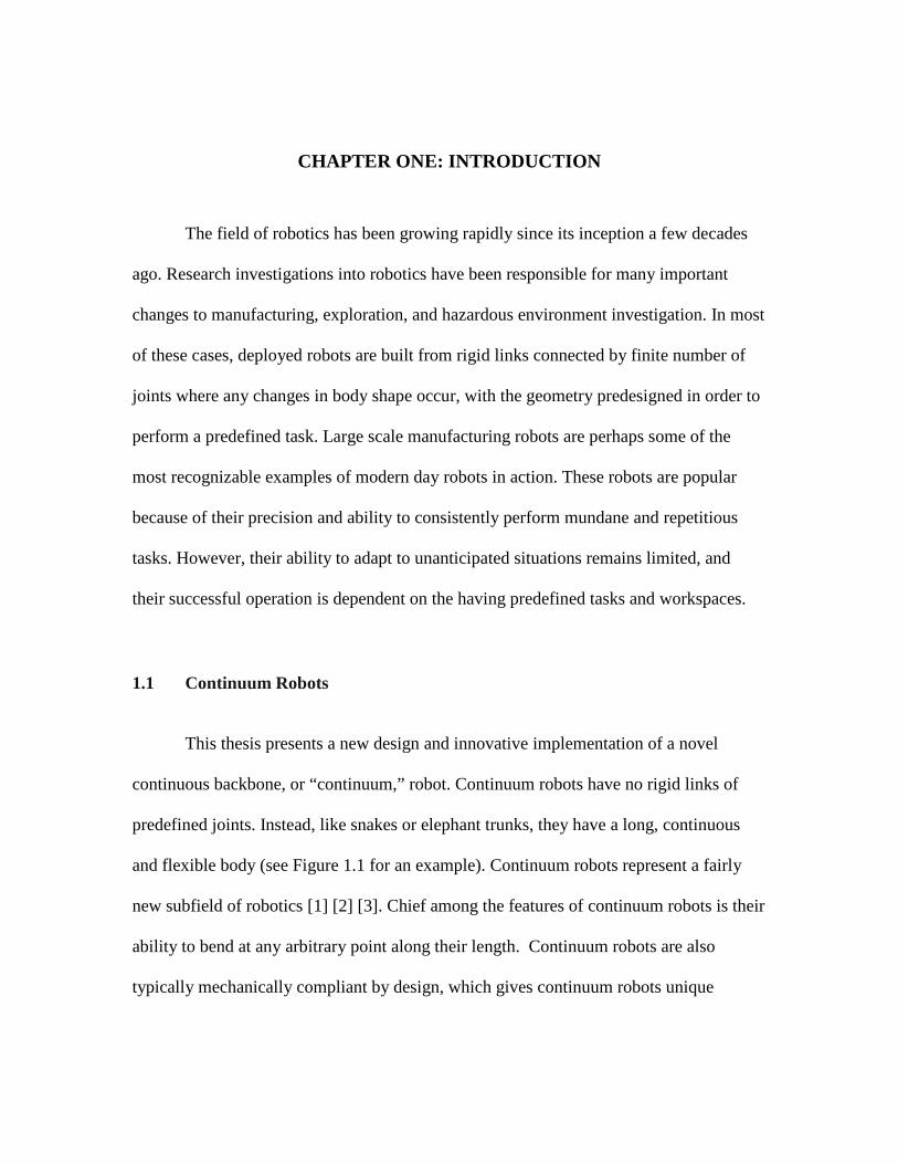
and flexible body (see Figure 1.1 for an example). Continuum robots represent a fairly
new subfield of robotics [1] [2] [3]. Chief among the features of continuum robots is their
ability to bend at any arbitrary point along their length. Continuum robots are also
typically mechanically compliant by design, which gives continuum robots unique
2
advantages over rigid link robots. In particular, the ability to perform compliant adaptive
shaping along their length allows them to conform to a priori unknown environments, and
allow for grasping of environmental objects of a wide range of shapes and sizes [1] [2]
[3]. Combined with their small form factor, these robots are capable of entering and
investigating extremely congested areas. This feature of their structure has made them
ideal for medical applications such as minimally invasive surgery [4].
Many types of robots, whether made of rigid links or otherwise, have been
inspired by nature. Examples of this include robots made to show human emotions, or
exhibit legged locomotion. Continuum robotic designs are often inspired by nature,
mimicking or resembling features observed in biology [1]. Perhaps the most memorable,
or at least widespread, examples have been inspired by elephant trunks [5], octopus arms
[6], and snakes [7].
Figure 1.1 Tentacle continuum robot developed at Clemson [8]
3
However, animals and humans are not the only source of inspiration for the field of
robotics. Plants, in particular, offer a vast array of variations in structure and movement.
Though slow in relation to most robots, the movements demonstrated by plants boast a
significant range of environmental adaptability. This thesis focuses on continuum robots
inspired by plants.
1.2 Continuum Tendril Robots and Inspiration from Plants
As previously noted, design of continuum robots has been strongly influenced by
similar structures in biology, notably elephant trunks and octopus arms [1]. Although
relatively rare compared to inspiration from animals, plants have been used as inspiration
for robots previously [9] [10] [11]. Only in the last several years however have robotics
researchers begun to use plants as inspiration for robotic designs [9]. Recently, research
has led to a new group of robots designed with both plant and animal characteristics in
mind [12]. These new robots lead to comparisons between plant stems and roots as well
as with invertebrate animals [10] [13]. However, there has been little research done to
date into adopting methods of movement and environmental exploitation in plants as a
means of improving robotic exploration.
It can be observed that the structure of many plants is very similar to that of some
continuum robots. As an example, vine stems have long, thin continuous backbones, and
are capable of adaptively penetrating congested areas [14] - note that this is one of the
specific intended uses of continuum robots. In the case of many vines and climbing
plants, successful exploration is possible due to their ability to actively engage the
4
environment for support [15]. They have at their disposal a variety of specialized
appendages for this task, including thorns, tendrils, and prickles, as well as specialized
root structures. Instead of using valuable resources to gain structural support, such as
bark in trees, these climbing plants use their specialized appendage tools to procure
support from the environment so their resources can instead be largely spent on growth.
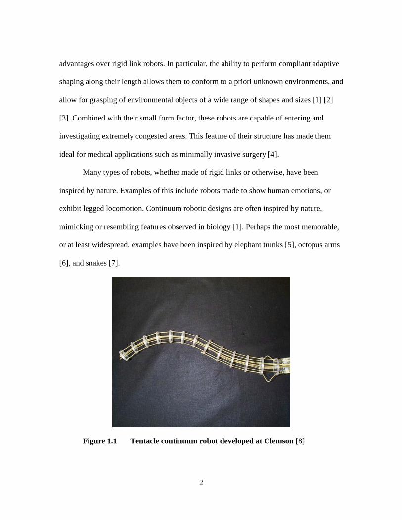
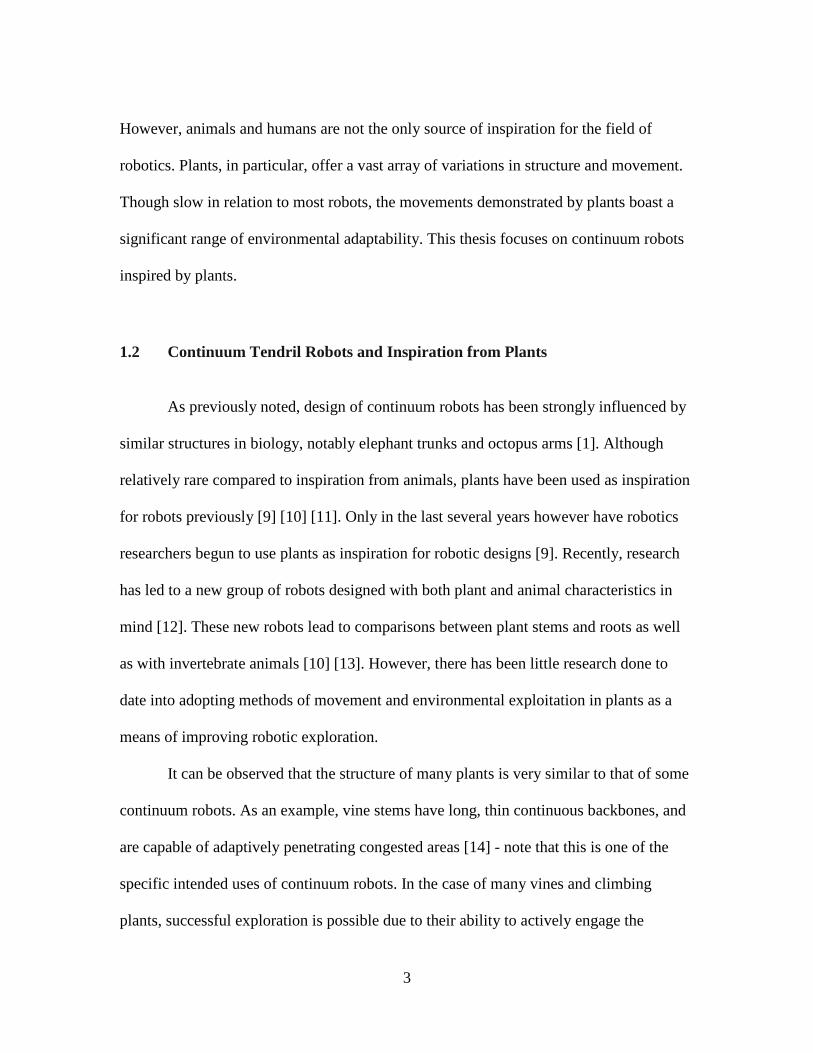
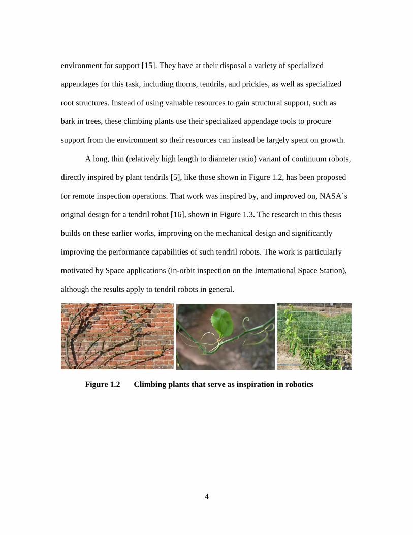
A long, thin (relatively high length to diameter ratio) variant of continuum robots,
directly inspired by plant tendrils [5], like those shown in Figure 1.2, has been proposed
for remote inspection operations. That work was inspired by, and improved on, NASA’s
original design for a tendril robot [16], shown in Figure 1.3. The research in this thesis
builds on these earlier works, improving on the mechanical design and significantly
improving the performance capabilities of such tendril robots. The work is particularly
motivated by Space applications (in-orbit inspection on the International Space Station),
although the results apply to tendril robots in general.
Figure 1.2 Climbing plants that serve as inspiration in robotics
5
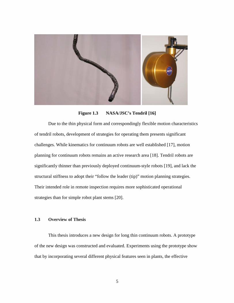
Figure 1.3 NASA/JSC’s Tendril [16]
Due to the thin physical form and correspondingly flexible motion characteristics
of tendril robots, development of strategies for operating them presents significant
challenges. While kinematics for continuum robots are well established [17], motion
planning for continuum robots remains an active research area [18]. Tendril robots are
significantly thinner than previously deployed continuum-style robots [19], and lack the
structural stiffness to adopt their “follow the leader (tip)” motion planning strategies.
Their intended role in remote inspection requires more sophisticated operational
strategies than for simple robot plant stems [20].
1.3 Overview of Thesis
This thesis introduces a new design for long thin continuum robots. A prototype
of the new design was constructed and evaluated. Experiments using the prototype show
that by incorporating several different physical features seen in plants, the effective

6
workspace of long, thin continuum robots can be significantly improved.
Correspondingly, by adapting some specific plant-like behaviors, a tendril continuum
robot’s ability to interact with a variety of environments, and the range of applications
that are feasible, can be further enhanced.
The following Chapter introduces the new design for long thin continuum robots.
The changes in the underlying design from previously proposed designs [21] [22], as well
as several novel supporting features, are discussed. The further enhancement of the
developed prototype vine-like continuum robot with prickles to enable environmental
support and bracing is detailed in Chapter 3, using plant physical features and movement
strategies as inspiration. Chapter 4 describes and discusses experiments and resultant
findings pertaining to the advantages of the addition of plant-like features into the overall
design, as well as the possibilities for future work involving vine-like robots. Chapter 5
summarizes and discusses the findings of this research and offers conclusions and
suggestions for future research drawn from it.
7
CHAPTER TWO: HARDWARE AND SOFTWARE DEVELOPMENT
2.1 Goals for Further Hardware Development
A new prototype continuum robot was developed and tested in our laboratory.
The backbone design is based on earlier prototypes of long, thin continuum robots [5]
produced by our group based on spring-loaded concentric tubes [21] [22]. This design is
itself an evolution of NASA’s original thin continuum “Tendril” robot [16]. The design
discussed in the following sections is further modified from [21] [22], but it retains the
core three section concentric tube backbone design. The backbone is composed of three
flexible tubes, each more distal tube of a slightly smaller diameter, and partially
contained within its predecessor, to create a long thin telescopic structure, which can both
extend/contract and bend.
The backbone structure is tendon actuated, each tube actuated by three tendons,
spaced at 120 degrees apart radially about the tube, and fixed at the tube end. Differential
tensions on the tendons allows for control of bending of that tube, or section, in two
dimensions. The telescopic backbone is additionally spring loaded, providing for local
compression and extension, allowing the tubes to retract and extend from their
predecessors by pulling simultaneously on all three tendons. The springs are adhered to
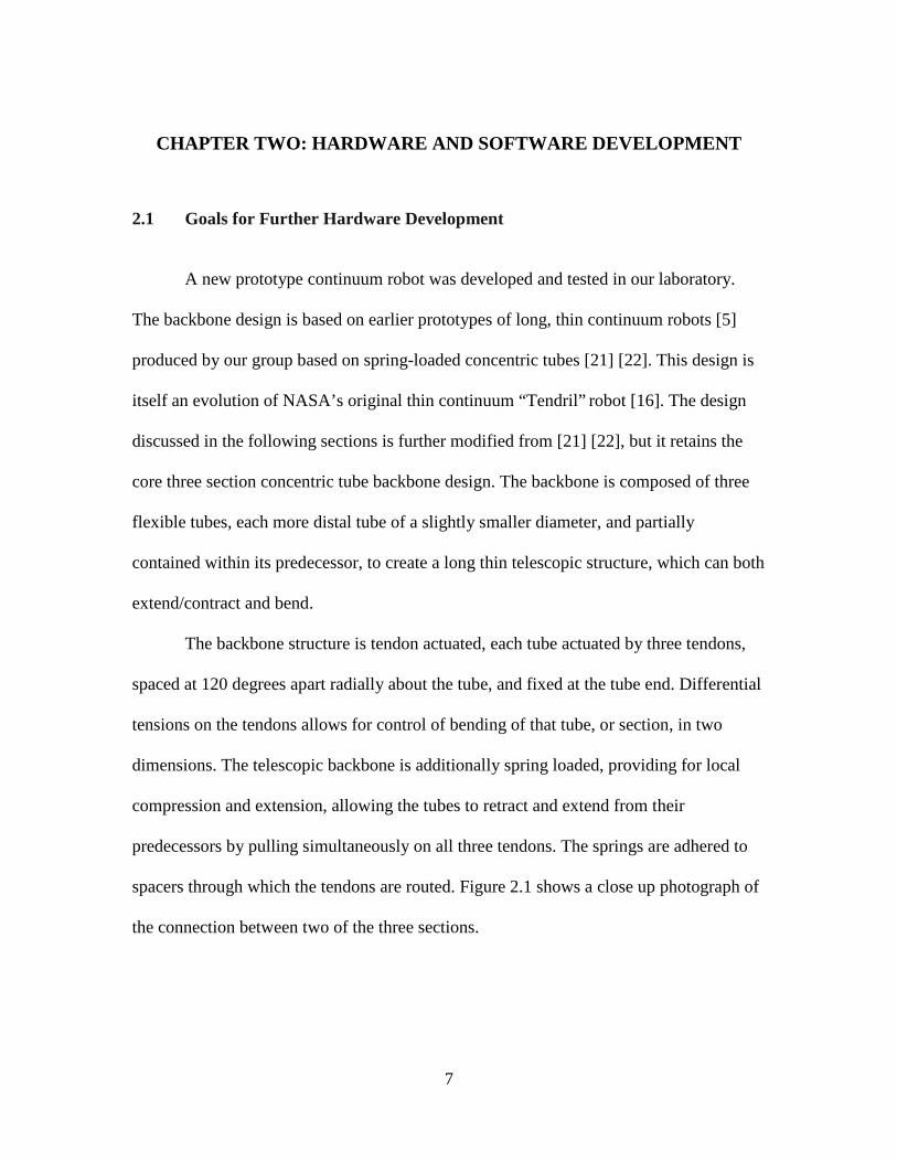
spacers through which the tendons are routed. Figure 2.1 shows a close up photograph of
the connection between two of the three sections.
8
Figure 2.1 Concentric tube spring loaded robot
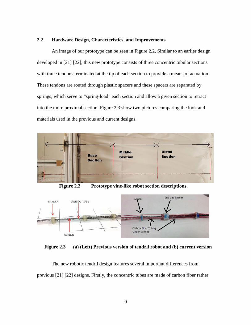
Sensing of shape [23] and inferring the effects of environmental contact [24] for
continuum robots are challenging problems [25]. A key goal for the new robot was to
refine the earlier design concept in order to better address these issues. The following
sections of this Chapter detail how the design was improved over previous iterations [21]
[22] and introduce new features that were introduced during the process. All of these
changes were made with the following goals in mind:
1. Maintain low overall system weight (the research was funded by NASA and motivated
by space applications, in which low mass is a high priority)
2. Increase overall length, while maintaining slim profile (NASA goal for space deployment
of tendril robots 3m length, 1cm maximum diameter)
3. Develop supporting hardware and software to aid in operation (previous prototypes had
minimal supporting hardware/software environment)
4. Add sensing capabilities (previous prototypes had no sensing)
5. Maintain ability to compress and decompress the sections (key novel functionality of
design)
9
2.2 Hardware Design, Characteristics, and Improvements
An image of our prototype can be seen in Figure 2.2. Similar to an earlier design
developed in [21] [22], this new prototype consists of three concentric tubular sections
with three tendons terminated at the tip of each section to provide a means of actuation.
These tendons are routed through plastic spacers and these spacers are separated by
springs, which serve to “spring-load” each section and allow a given section to retract
into the more proximal section. Figure 2.3 show two pictures comparing the look and
materials used in the previous and current designs.
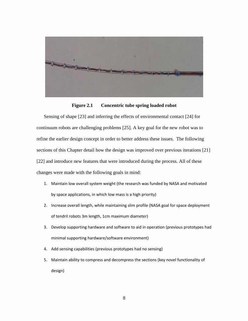
Figure 2.2 Prototype vine-like robot section descriptions.
Figure 2.3 (a) (Left) Previous version of tendril robot and (b) current version
The new robotic tendril design features several important differences from
previous [21] [22] designs. Firstly, the concentric tubes are made of carbon fiber rather

10
than nitinol (NiTi), a nickel titanium alloy. Nitinol was used in earlier work due to its
high bendability without fear of permanent deformation, and particularly for its low
friction surface. However, it was found that these tubes were prone to buckling, due to
the thin walls required in order to obtain feasible bendability, especially in the proximal
sections. An example of the damage caused by this issue can be seen in Figure 2.4, which
shows the result of a failure in the most proximal section of a nitinol tube. This became
fiscally prohibitive, as a costly new tube and numerous hours or rebuilding were needed
every time this occurred. Consequently, a new material was sought. Carbon fiber tubing
was found to possess similar stiffness, frictional properties, and breaking strengths, all
while costing less than Nitinol by an approximate factor of 100.
Figure 2.4 Nitinol tube buckling failure
The total length of the three sections was also increased in the process of
improving the hardware and replacing the nitinol tubing. The decision to increase the
length was made in order to further approach the tendril’s original design goals, which as

11
noted earlier were to create a long, thin robot approximately three meters in length, while
still maintaining a thickness of around 1 centimeter. The new design was constructed to
be two meters in total diameter. A more precise breakdown of the section lengths is given
in Table 2.1. Also given in Table 2.1 are the measurements for the previous iteration of
the robot [21] [22], which was used for conducting the preliminary experiments presented
in Chapter 4.
Table 2.1. Section lengths for current and previous designs
Current Design Most Recent, Previous Design
Length, cm Length, cm Base Section 61.9 42
Middle Section 50.8 43 Distal Section 70.3 34
Total Length to Width Ratio 130:1 85:1
In addition to increasing the length, it was determined that a decrease in the spring
stiffness in the middle section would be beneficial to overall prototype performance. Due
to this decrease in local spring stiffness, the added length, and consequently the increased
number of springs in series, the overall linear stiffness of the most distal two sections
decreased significantly. This change allowed for a significant increase in total
“compressibility” of the prototype as a whole. Previous iterations of the design were able
to compress up to around 30% of their total length. These new design choices allow the
prototype to compress over 40% of its total length. When compared to the previous
designs using total length contracted, the new design’s two most distal sections can
contract up to 2 or 3 times farther into the proximal sections. Table 2.2 details the spring
stiffnesses and overall compression percentage.

12
Table 2.2 Spring stiffness by section and total compressibility of the new design
Current Design Stiffness, kg/cm
Middle Section Springs 0.41 Distal Section Springs 1.15
Total compression (%) 42%
The new tendril robot also features new and smaller spacers for each section. The
choice to reduce the overall size of the spacer was based on the necessity to limit total
mass, particularly in response to each section being more compliant. Part (a) of Figure
2.5 shows one such spacer 3D printed out using DurusWhiteTM plastic. In previous
designs, there were no end caps on the sections and the final spacers were merely secured
to the ends of a given section with adhesive. This was found to be problematic when the
tension in the tendons grew too large and the spacers tended to either break free of their
intended positioning or become warped, requiring frequent repair. We therefore designed
a specialized end cap, shown in part (b) of Figure 2.5, to counteract this problem. This
specialized spacer fits on the end of each section and features a “lip” that keeps the larger
section from sliding through the central hole, while allowing the lower diameter tube to
slide through easily. Therefore, this design offers a previously nonexistent mechanical
(a) Simple Spacer for Routing Tendons (b) Cross Section of End Cap Spacer Figure 2.5 Plastic spacer and end cap design for routing tendons.
13
advantage supported with use of adhesives to better protect the entire system from
breakage. This design and adhesive was found to withstand tendon tensions of up to
forty-five pounds before failure, where the previous design would fail at around thirty
pounds of tension. In order to exploit this new robustness in the spacers, the new design
also has new high tensile strength tendons. An additional problem present in the previous
design was that of tendons breaking when tension increased past 30 lbs. The new
design’s tendons have a tensile strength of 80 lbs.
2.3 Actuator and Sensing Package
During development of the new prototype hardware we invested a significant
amount of effort on the design of the actuator package hardware and operational
software. The overall structure was cut from 3 mm acrylic sheets in order to produce as
little overall weight as possible. The actuator package was designed to form three tiers of
actuators, each of which is rotated 40 degrees about the center axis so that the tendons
line up with the actuators (servomotors) that pull them. Each tier holds three SM-S8166R
high torque continuous rotation servos. These servos are rated to have thirty-three
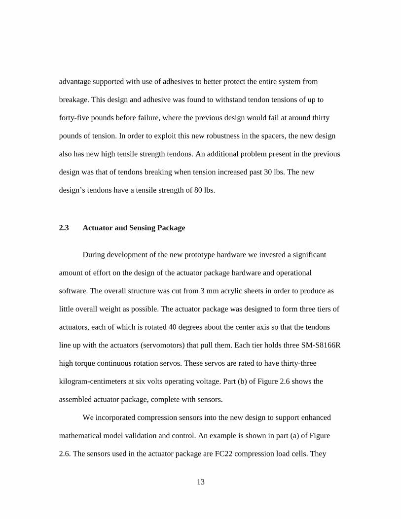
kilogram-centimeters at six volts operating voltage. Part (b) of Figure 2.6 shows the
assembled actuator package, complete with sensors.
We incorporated compression sensors into the new design to support enhanced
mathematical model validation and control. An example is shown in part (a) of Figure
2.6. The sensors used in the actuator package are FC22 compression load cells. They
14
output a voltage signal from zero to five volts, which directly correlates to how much
force is applied to the load cell. As can be seen, the sensor was mounted under the motor,
in the direction of the tendons. However, due to the physical dimensions of the motors,
the tension in each tendon could not be directly measured, because the tendons pull the
motors at a small non-zero angle as they tighten.
(a) Compression Sensor Placement (b) Nine Motor Actuator Package Figure 2.6 Compression sensor and motor setup and assembled actuator package.
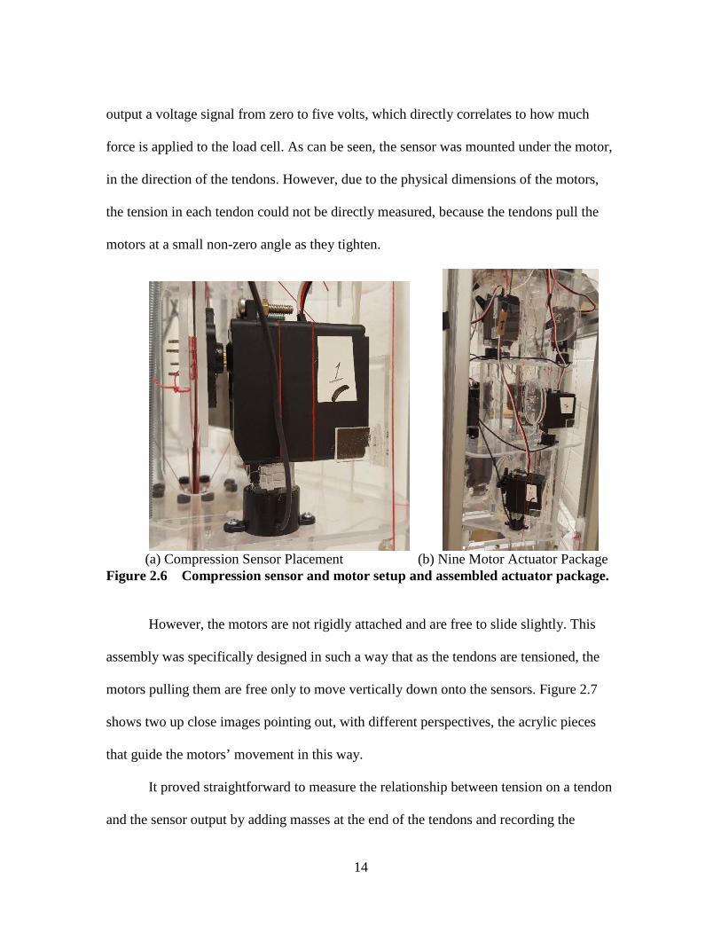
However, the motors are not rigidly attached and are free to slide slightly. This
assembly was specifically designed in such a way that as the tendons are tensioned, the
motors pulling them are free only to move vertically down onto the sensors. Figure 2.7
shows two up close images pointing out, with different perspectives, the acrylic pieces
that guide the motors’ movement in this way.
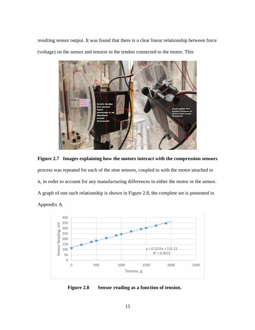
It proved straightforward to measure the relationship between tension on a tendon
and the sensor output by adding masses at the end of the tendons and recording the
15
resulting sensor output. It was found that there is a clear linear relationship between force
(voltage) on the sensor and tension in the tendon connected to the motor. This
Figure 2.7 Images explaining how the motors interact with the compression sensors
process was repeated for each of the nine sensors, coupled to with the motor attached to
it, in order to account for any manufacturing differences in either the motor or the sensor.
A graph of one such relationship is shown in Figure 2.8, the complete set is presented in
Appendix A.
Figure 2.8 Sensor reading as a function of tension.
y = 0.1215x + 121.22R² = 0.9975
050
100150200250300350400
0 500 1000 1500 2000 2500
Sens
or R
eadi
ng, m
V
Tension, g
16
2.4 User and Hardware Interface Design
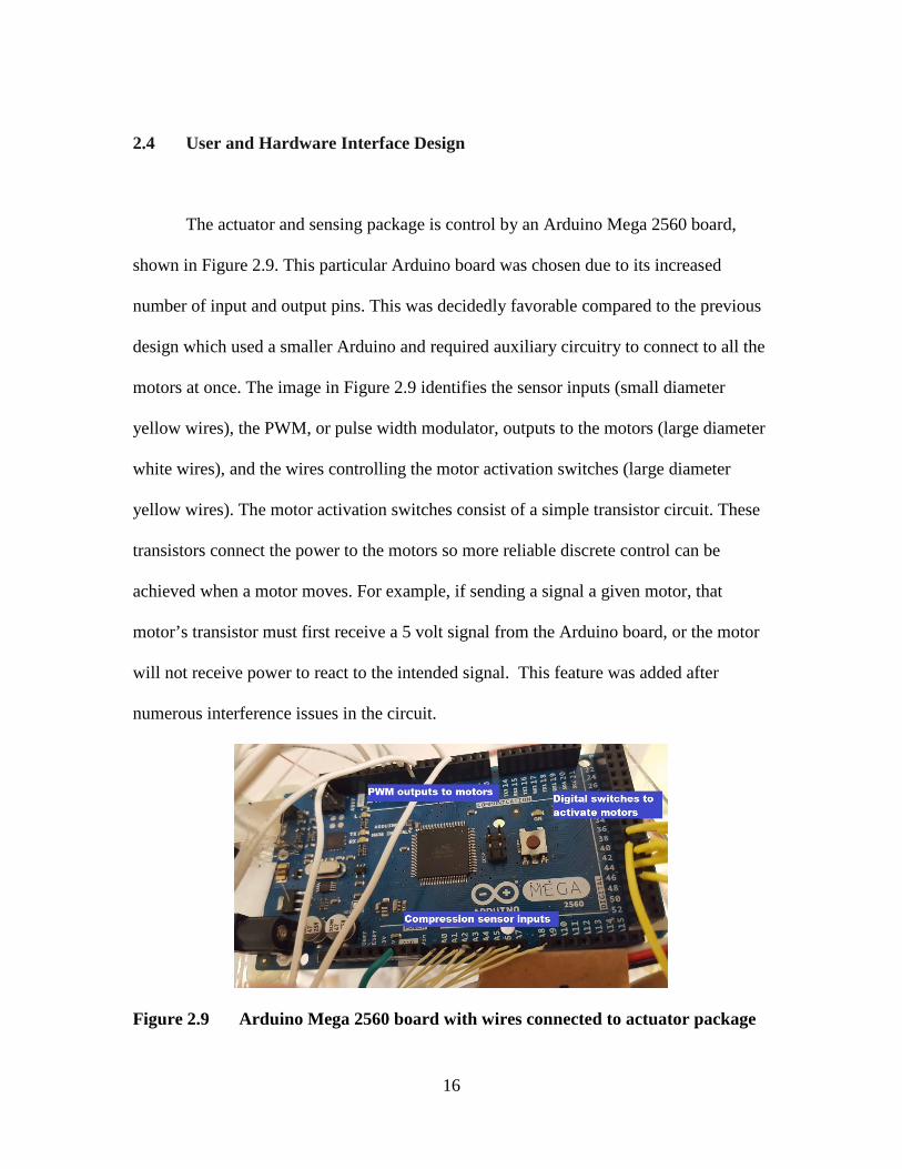
The actuator and sensing package is control by an Arduino Mega 2560 board,
shown in Figure 2.9. This particular Arduino board was chosen due to its increased
number of input and output pins. This was decidedly favorable compared to the previous
design which used a smaller Arduino and required auxiliary circuitry to connect to all the
motors at once. The image in Figure 2.9 identifies the sensor inputs (small diameter
yellow wires), the PWM, or pulse width modulator, outputs to the motors (large diameter
white wires), and the wires controlling the motor activation switches (large diameter
yellow wires). The motor activation switches consist of a simple transistor circuit. These
transistors connect the power to the motors so more reliable discrete control can be
achieved when a motor moves. For example, if sending a signal a given motor, that
motor’s transistor must first receive a 5 volt signal from the Arduino board, or the motor
will not receive power to react to the intended signal. This feature was added after
numerous interference issues in the circuit.
Figure 2.9 Arduino Mega 2560 board with wires connected to actuator package
17
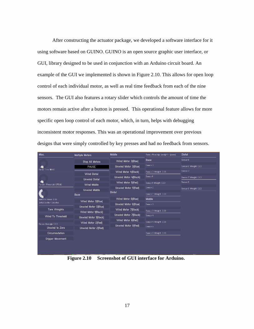
After constructing the actuator package, we developed a software interface for it
using software based on GUINO. GUINO is an open source graphic user interface, or
GUI, library designed to be used in conjunction with an Arduino circuit board. An
example of the GUI we implemented is shown in Figure 2.10. This allows for open loop
control of each individual motor, as well as real time feedback from each of the nine
sensors. The GUI also features a rotary slider which controls the amount of time the
motors remain active after a button is pressed. This operational feature allows for more
specific open loop control of each motor, which, in turn, helps with debugging
inconsistent motor responses. This was an operational improvement over previous
designs that were simply controlled by key presses and had no feedback from sensors.
Figure 2.10 Screenshot of GUI interface for Arduino.
18
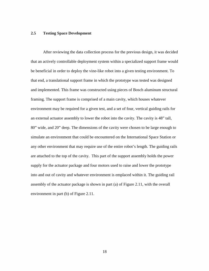
2.5 Testing Space Development
After reviewing the data collection process for the previous design, it was decided
that an actively controllable deployment system within a specialized support frame would
be beneficial in order to deploy the vine-like robot into a given testing environment. To
that end, a translational support frame in which the prototype was tested was designed
and implemented. This frame was constructed using pieces of Bosch aluminum structural
framing. The support frame is comprised of a main cavity, which houses whatever
environment may be required for a given test, and a set of four, vertical guiding rails for
an external actuator assembly to lower the robot into the cavity. The cavity is 48” tall,
80” wide, and 20” deep. The dimensions of the cavity were chosen to be large enough to
simulate an environment that could be encountered on the International Space Station or
any other environment that may require use of the entire robot’s length. The guiding rails
are attached to the top of the cavity. This part of the support assembly holds the power
supply for the actuator package and four motors used to raise and lower the prototype
into and out of cavity and whatever environment is emplaced within it. The guiding rail
assembly of the actuator package is shown in part (a) of Figure 2.11, with the overall
environment in part (b) of Figure 2.11.
19
(a) (b) Figure 2.11 Actuator package guiding system and robot environment cavity.
20
CHAPTER THREE: PLANT-LIKE CONTINUUM ROBOT DESIGNS AND
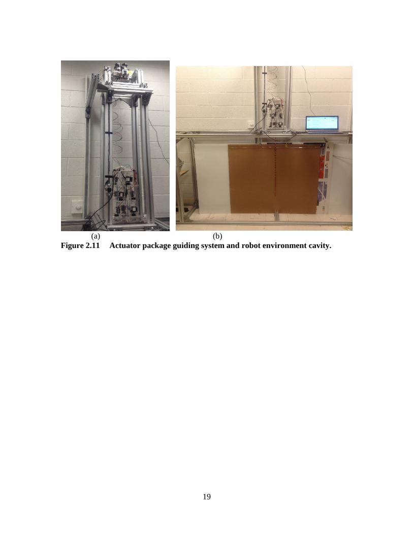
BEHAVIORS As mentioned in previous chapters, the long thin structure of Tendril robots is
significantly lacking in structural support. Due to this, as well as internal constraints
caused by assembly imperfections and external constraints notably gravity, controlling
the new tendril robot prototype was challenging. In particular, there were several
instances in which unpredictable behavior in the distal section was caused by tension in
one of its tendons. One such case is shown in figure 3.1. In this particular case, only one
tendon was pulled without any tension applied in the other two. The spring and spacers
were free to rotate about the backbone, which resulted in the configuration seen below.
The distal section tended to twist as necessary in order for it to maintain its center of
gravity.
Figure 3.1 Tendril Robot in Undesirable Configuration Due to Lack of Structural Support
In addition, coupling between the sections was found to be a problematic issue
with the hardware. When the distal section would bend or contract, the movement would
often also strongly affect the sections proximal to it. This coupling resulted in
unanticipated shapes for the tendril, and an inability to attain the position and orientation

21
desired for the distal section and tendril tip. Consequently, a means to mitigate these
issues was necessary.
In order to address these issues, we gained insight from nature, and in particular
climbing plants, noting their thin structures and lack of structural support, much like the
Tendril robot. Using as inspiration plants in general, and vines in particular, novel vine-
like physical features and behaviors were designed and included in our new prototype. In
particular, a major contribution of the research reported in this thesis is in attaching
“prickles” (fixed hooks) to selected spacers of the middle and base sections of the
prototype, and their use in improving the operational performance of the robot. A
secondary contribution is in the adaptation of a distinctive novel exploratory motion, that
of circumnutation, used by plants, to tendril robots. These novel approaches are
introduced and discussed in the following sections.
3.1 Prickles and Environmental Attachment
Environmental attachment is an intimate part of some plant life, and that of vines
and other climbing plants in particular. The types of climbing plants vary widely and are
often categorized by their method used for environmental interaction including hookers,
rooters, leaners, weavers, twiners, tendril bearers, and several more. In total there are at
least 30 different means by which climbing plants engage the environment for support
[15]. The simplest of these methods, mechanically, to reproduce is that of the prickles
used by “hooker” climbing plants.
22
The plants that evolved these biological mechanisms need them in order to
survive. They do not possess the internal support present in other types of plant life. The
methods in which a given plant actively or passively engages the environment serves as a
means to conserve growth energy. Plants that interact and adhere to external structures
have no need of expending energy on developing structural support, and can instead use
that energy strictly for upwards growth. Charles Darwin stated that “Plants become
climbers, in order, it may be presumed, to reach the light, and to expose a large surface of
leaves to its action and to that of the free air. This is effected by climbers with
wonderfully little expenditure of organized matter, in comparison with trees, which have
to support a load of heavy branches by a massive trunk” [26].
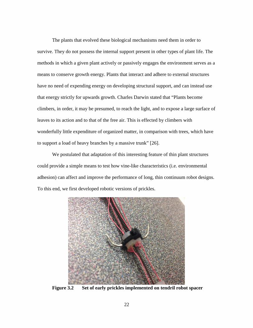
We postulated that adaptation of this interesting feature of thin plant structures
could provide a simple means to test how vine-like characteristics (i.e. environmental
adhesion) can affect and improve the performance of long, thin continuum robot designs.
To this end, we first developed robotic versions of prickles.
Figure 3.2 Set of early prickles implemented on tendril robot spacer
23
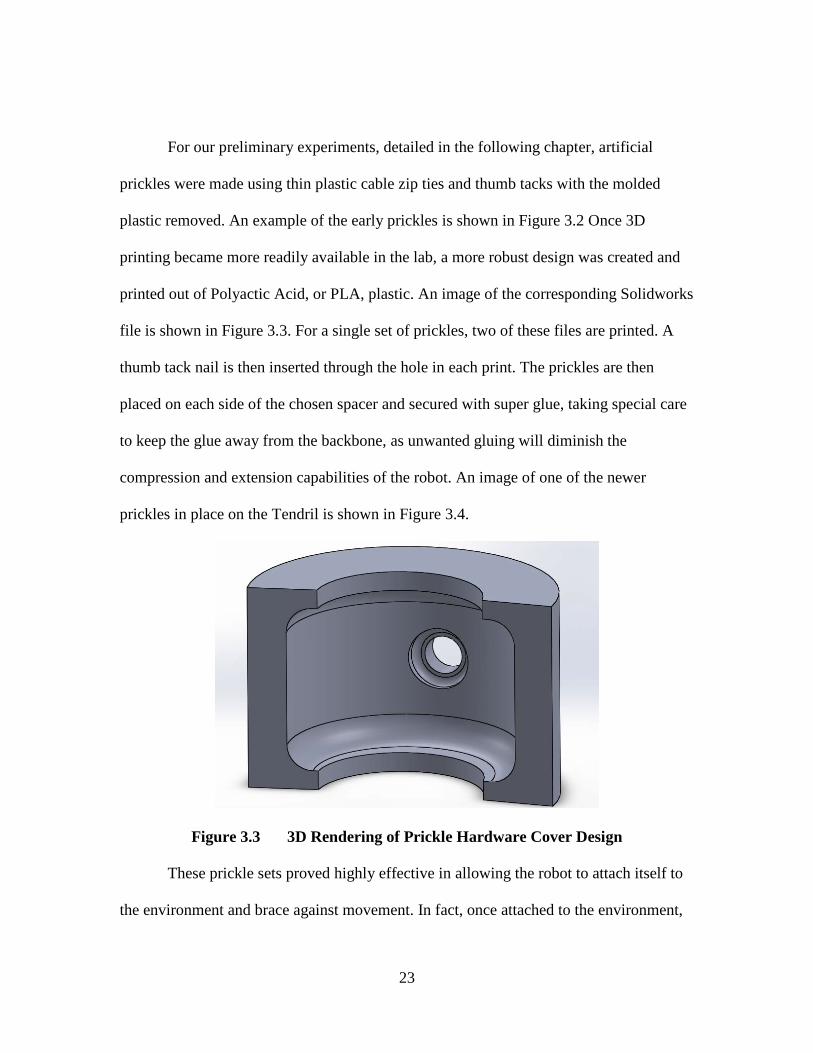
For our preliminary experiments, detailed in the following chapter, artificial
prickles were made using thin plastic cable zip ties and thumb tacks with the molded
plastic removed. An example of the early prickles is shown in Figure 3.2 Once 3D
printing became more readily available in the lab, a more robust design was created and
printed out of Polyactic Acid, or PLA, plastic. An image of the corresponding Solidworks
file is shown in Figure 3.3. For a single set of prickles, two of these files are printed. A
thumb tack nail is then inserted through the hole in each print. The prickles are then
placed on each side of the chosen spacer and secured with super glue, taking special care
to keep the glue away from the backbone, as unwanted gluing will diminish the
compression and extension capabilities of the robot. An image of one of the newer
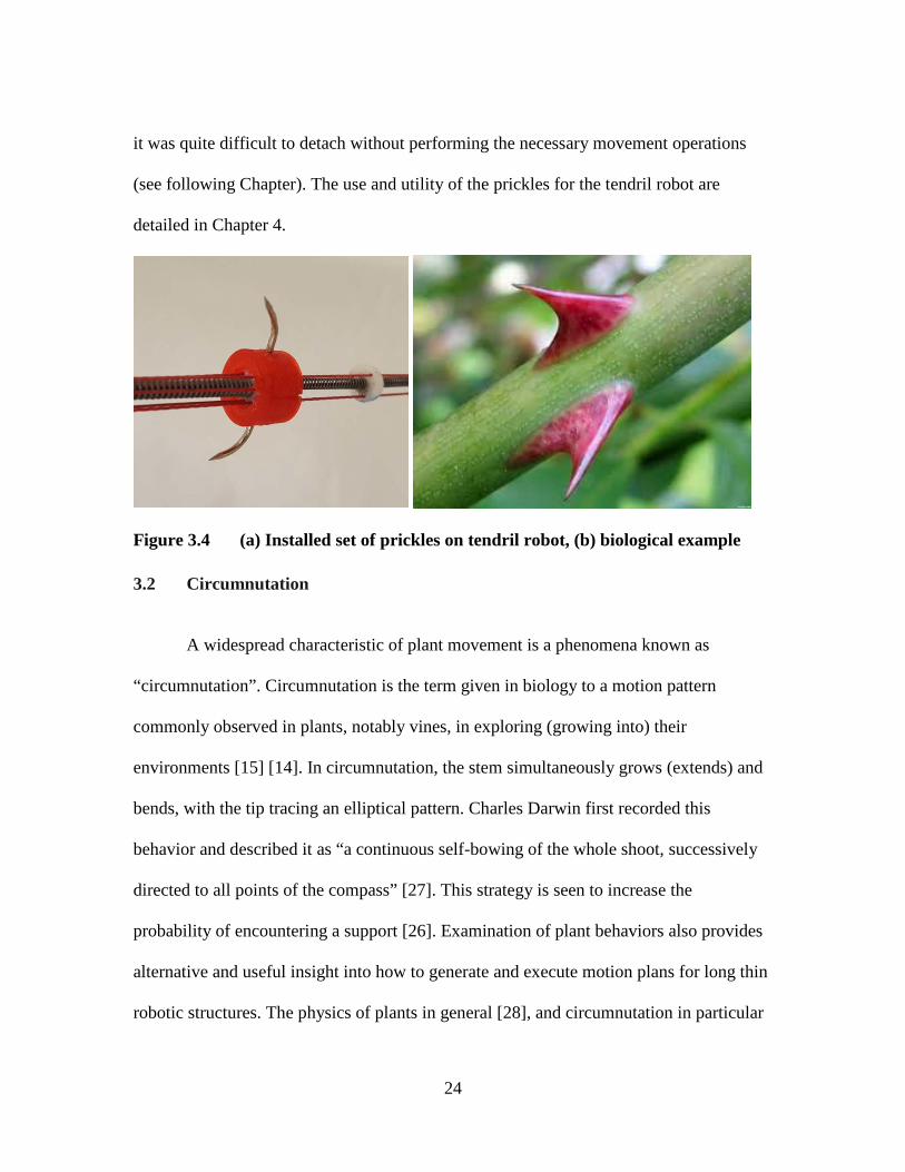
prickles in place on the Tendril is shown in Figure 3.4.
Figure 3.3 3D Rendering of Prickle Hardware Cover Design
These prickle sets proved highly effective in allowing the robot to attach itself to
the environment and brace against movement. In fact, once attached to the environment,
24
it was quite difficult to detach without performing the necessary movement operations
(see following Chapter). The use and utility of the prickles for the tendril robot are
detailed in Chapter 4.
Figure 3.4 (a) Installed set of prickles on tendril robot, (b) biological example
3.2 Circumnutation
A widespread characteristic of plant movement is a phenomena known as
“circumnutation”. Circumnutation is the term given in biology to a motion pattern
commonly observed in plants, notably vines, in exploring (growing into) their
environments [15] [14]. In circumnutation, the stem simultaneously grows (extends) and
bends, with the tip tracing an elliptical pattern. Charles Darwin first recorded this
behavior and described it as “a continuous self-bowing of the whole shoot, successively
directed to all points of the compass” [27]. This strategy is seen to increase the
probability of encountering a support [26]. Examination of plant behaviors also provides
alternative and useful insight into how to generate and execute motion plans for long thin
robotic structures. The physics of plants in general [28], and circumnutation in particular
25
[29], have been extensively studied. The details of the kinematics of circumnutation
varies between plants [29], but the pattern of generally elliptical tip motion is consistent,
providing a model of how to efficiently move a thin backbone.
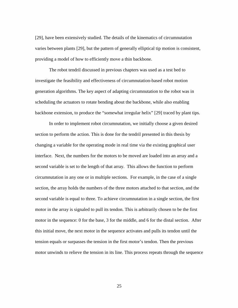
The robot tendril discussed in previous chapters was used as a test bed to
investigate the feasibility and effectiveness of circumnutation-based robot motion
generation algorithms. The key aspect of adapting circumnutation to the robot was in
scheduling the actuators to rotate bending about the backbone, while also enabling
backbone extension, to produce the “somewhat irregular helix” [29] traced by plant tips.
In order to implement robot circumnutation, we initially choose a given desired
section to perform the action. This is done for the tendril presented in this thesis by
changing a variable for the operating mode in real time via the existing graphical user
interface. Next, the numbers for the motors to be moved are loaded into an array and a
second variable is set to the length of that array. This allows the function to perform
circumnutation in any one or in multiple sections. For example, in the case of a single
section, the array holds the numbers of the three motors attached to that section, and the
second variable is equal to three. To achieve circumnutation in a single section, the first
motor in the array is signaled to pull its tendon. This is arbitrarily chosen to be the first
motor in the sequence: 0 for the base, 3 for the middle, and 6 for the distal section. After
this initial move, the next motor in the sequence activates and pulls its tendon until the
tension equals or surpasses the tension in the first motor’s tendon. Then the previous
motor unwinds to relieve the tension in its line. This process repeats through the sequence

26
until one full revolution occurs. The number of these full revolutions is predefined in the
program and arbitrarily selected.
Circumnutation in multiple sections is performed in a similar way to that of a
single section. The key difference is that, for multiple sections, the number of array
entries increases. In the case of all three sections the array is formed as 0, 3, 6, 1, 4, 7, 2,
5, and 8. The total number of motors to move in this case is nine. The most important
change is that instead of winding or unwinding one tendon at a time, the action is
performed in sets of three. In the case of circumnutation in all three sections at once,
motors 0, 3, and 6 pull on their tendons at the same time, since these tendons are down
the same side of the device. Otherwise, the algorithm repeats as though for a single
section but in sets of two or three depending on the operating mode.
Figure 3.5 Circumnutation. Top to bottom: increasing time. Left: hop vine. Right:
tendril robot.
27
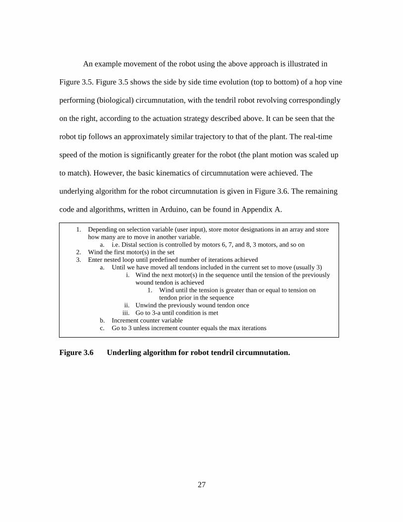
An example movement of the robot using the above approach is illustrated in
Figure 3.5. Figure 3.5 shows the side by side time evolution (top to bottom) of a hop vine
performing (biological) circumnutation, with the tendril robot revolving correspondingly
on the right, according to the actuation strategy described above. It can be seen that the
robot tip follows an approximately similar trajectory to that of the plant. The real-time
speed of the motion is significantly greater for the robot (the plant motion was scaled up
to match). However, the basic kinematics of circumnutation were achieved. The
underlying algorithm for the robot circumnutation is given in Figure 3.6. The remaining
code and algorithms, written in Arduino, can be found in Appendix A.
Figure 3.6 Underling algorithm for robot tendril circumnutation.
1. Depending on selection variable (user input), store motor designations in an array and store how many are to move in another variable.
a. i.e. Distal section is controlled by motors 6, 7, and 8, 3 motors, and so on 2. Wind the first motor(s) in the set 3. Enter nested loop until predefined number of iterations achieved
a. Until we have moved all tendons included in the current set to move (usually 3) i. Wind the next motor(s) in the sequence until the tension of the previously
wound tendon is achieved 1. Wind until the tension is greater than or equal to tension on
tendon prior in the sequence ii. Unwind the previously wound tendon once
iii. Go to 3-a until condition is met b. Increment counter variable c. Go to 3 unless increment counter equals the max iterations

28
CHAPTER FOUR: EXPERIMENTS AND APPLICATIONS
Numerous tests were conducted in order to determine how active use of the
prickles affected the performance of our prototype, as compared with operation without
their use. Experiments 1 through 3 were conducted using the earlier Nitinol tube based
iteration of the prototype as a proof of concept. The performance attributes improved
most by the ability to engage the environment were found to be stability, accessible
workspace, load capacity, and reduction in coupling between the sections. Each of these
attributes was found to be significantly affected by the implementation of prickles.
Following these initial experiments we constructed the prototype described in Chapter 2,
which employs carbon fiber tubes, and further evaluated the effects of environmental
interaction on the tendril prototype’s performance.
4.1 Preliminary experiments
Experiment 1
The first set of experiments was designed to test the extent of the vine-like robot’s
reach, or accessible workspace. This “reachability” test actuated tendons that provided
planar motion with respect to an externally mounted camera (for ease of data collection).
The starting locations for each section’s end cap were recorded and the tendons were
actuated in order, starting from the base section and proceeding distally. During this
process, the new position for each tip of a given section was recorded at each significant

29
movement, meaning a movement resulting in an increase in Euclidean distance from the
distal tip to its starting point within the two dimensional plane of the background.
Initially, these tests were conducted with the robot in open space, i.e. without the robot
actively or accidentally attaching to the environment. The final position of a
representative example of the middle (yellow) and distal (red) sections when the robot is
in “unbraced mode” can be seen in part a) of Figure 4.1.
Figure 4.1. Visual results of experiment 1 where (a) (left) has no attachment, while (b) was attached at the yellow point
Next, we braced the tip of the middle section at its maximum attainable Euclidian
distance from its starting position. This was done by attaching a hook mounted at the end
of the middle section (yellow rectangle in images in figure 4.1) to the surface behind the
robot. We then actuated the distal section in order to observe the differences in its
attainable tip positions. The final positions (maximum achievable bending) of this second
test for the example in Figure 8 (a) are shown in part (b) of Figure 4.1. The measurements
for each recorded position are given in Table 4.1. In Table 4.1, points 1 through 4
correspond to the robot’s sections while the robot is unbraced, and points 5 through 7
30
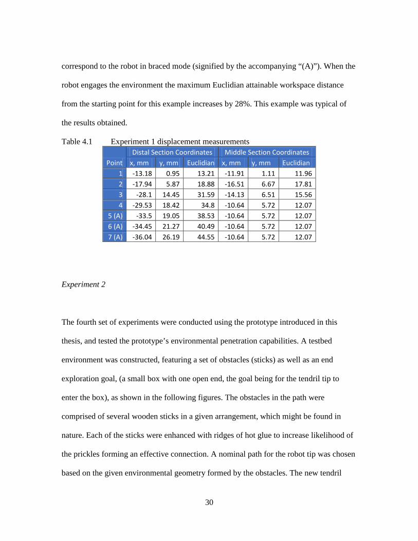
correspond to the robot in braced mode (signified by the accompanying “(A)”). When the
robot engages the environment the maximum Euclidian attainable workspace distance
from the starting point for this example increases by 28%. This example was typical of
the results obtained.
Table 4.1 Experiment 1 displacement measurements
Point Distal Section Coordinates Middle Section Coordinates
x, mm y, mm Euclidian x, mm y, mm Euclidian 1 -13.18 0.95 13.21 -11.91 1.11 11.96 2 -17.94 5.87 18.88 -16.51 6.67 17.81 3 -28.1 14.45 31.59 -14.13 6.51 15.56 4 -29.53 18.42 34.8 -10.64 5.72 12.07
5 (A) -33.5 19.05 38.53 -10.64 5.72 12.07 6 (A) -34.45 21.27 40.49 -10.64 5.72 12.07 7 (A) -36.04 26.19 44.55 -10.64 5.72 12.07
Experiment 2
The fourth set of experiments were conducted using the prototype introduced in this
thesis, and tested the prototype’s environmental penetration capabilities. A testbed
environment was constructed, featuring a set of obstacles (sticks) as well as an end
exploration goal, (a small box with one open end, the goal being for the tendril tip to
enter the box), as shown in the following figures. The obstacles in the path were
comprised of several wooden sticks in a given arrangement, which might be found in
nature. Each of the sticks were enhanced with ridges of hot glue to increase likelihood of
the prickles forming an effective connection. A nominal path for the robot tip was chosen
based on the given environmental geometry formed by the obstacles. The new tendril

31
robot prototype was initially deployed to enter and explore the environment by this path
using without the aid of the prickles. Snapshots of the results are shown in Figure 4.3.
The image in part (a) of Figure 4.3 shows the prototype entering the environment, and
navigating between the obstacles, which was achieved with relative ease. However, once
past the obstacles, turning to approach the goal (the box opening is on its bottom left as
viewed in Figure 4.3), the robot was not able to achieve its task. Part (b) of Figure 4.3
shows the prototype’s response when attempting to move toward the observation goal
(box). As highlighted by the arrow, the robot buckled to form an “S-bend” shape when it
was attempted to move the tip towards the goal. This undesired S-bend (instability due to
the buckling) prevented the tendril robot from accurately approaching or even pointing
towards the goal point. The orange arrow in part (b) of Figure 4.3 highlights the
“twisting” (torsional backbone movement) that occurs in the robot as one tendon is
tensioned at a time.
(a) Entering into the environment (b) S-bend as tendon tension increases Figure 4.2 Exploration with non-prickled tendril prototype.
This feature of undesired buckling resulting in unpredictable S-bend shapes is one
of the most significant problems with long, thin, concentric tube designs. When operating

32
in open space, S-bend buckling occurred frequently with our prototype, particularly when
attempting significant bending towards the tip. A typical example is shown in Figure 4.4.
It was this behavior that initially motivated us to consider how thin plants avoid similar
problems, thus leading to the active environmental contact strategy.
Figure 4.3 Additional example of a non-constant curvature “S-bend” configuration
The tendril robot was subsequently used to explore the same environment via the
same path, but with the robot augmented with several sets of prickles. These prickles
were placed at the tip of the middle section and two places along the distal section. Parts
(a) through (d) of Figure 4.4 show the prototype’s exploration of the same environment
with the aid of prickles. In contrast to the earlier experiments, the prickle/environment
contacts were actively made, i.e. by robot movements directed remotely by the remote
human operator, as opposed to a human (hand) entering the workspace to make the
contacts. Entering the environment again proved relatively straightforward, however only
after making the attachments seen in parts (b) and (c) (on the lower two obstacles), did
the orientation shown in part (d) of Figure 4.4 become feasible. However, after making

33
these contacts the task proved simple to conduct, due to the improved stability and
enhanced local workspace gained by the environmental support.
(a)Entering environment (b) Attachment 1 (c) Attachment 2 (d) Successfully reaches goal Figure 4.4. Exploration with prickled tendril prototype
Observations on Internal Coupling During Testing
While conducting the aforementioned experiments, it was observed that engaging
the environment positively affects several other critical performance characteristics in
both prototype designs. During the first set of experiments involving non-prickled goal
searching, any increase in tension in the distal section led to a corresponding increase in
tension in the base section, due to internal coupling. Though this increase in tension
typically did not hinder the functioning of the system, the effect introduces unintended
potential energy in the system and is undesirable, and our observations show that the
effects could be avoided by bracing. Adopting the bracing strategy will be particularly
advantageous when the motors are close to their load limits.
34
Additionally, throughout the experiments, it was observed that when the robot
actively engages the environment, the amount of twisting that occurs in the sections distal
to the environmental contact significantly decreases. This feature is evident upon close
inspection of Figures 4.2 and 4.4. This reduced torsion is due to reduced backbone
coupling, with the sections proximal to the point of attachment being constrained by the
environment.
Additional Prickle Utilization
The experiments presented in the previous section outline the basic functionality
of the vine-like features presented in this thesis. However, after the initial course of
experimentation and observations, further experiments were conducted in order to
explore alternative ways in which the prickles could be utilized. Through this process
new local movement algorithms were developed as a way to better utilize both the
prickles and tendril robot alike.
One such algorithm, though simple, proved highly beneficial for the utilization of
the prickles. Experiment 2 above was the initial experiment in which the prickles were
actively used. In order to actively attach to the environment using the prickles, the
operator had to wind one or several tendons until a contact point was made. This implies
that local compression and extension is critical to the active use of prickles for
environmental interaction. However, this process could potentially be complicated by the
tendril’s tendency to succumb to torsional instability, in which case a point of contact
35
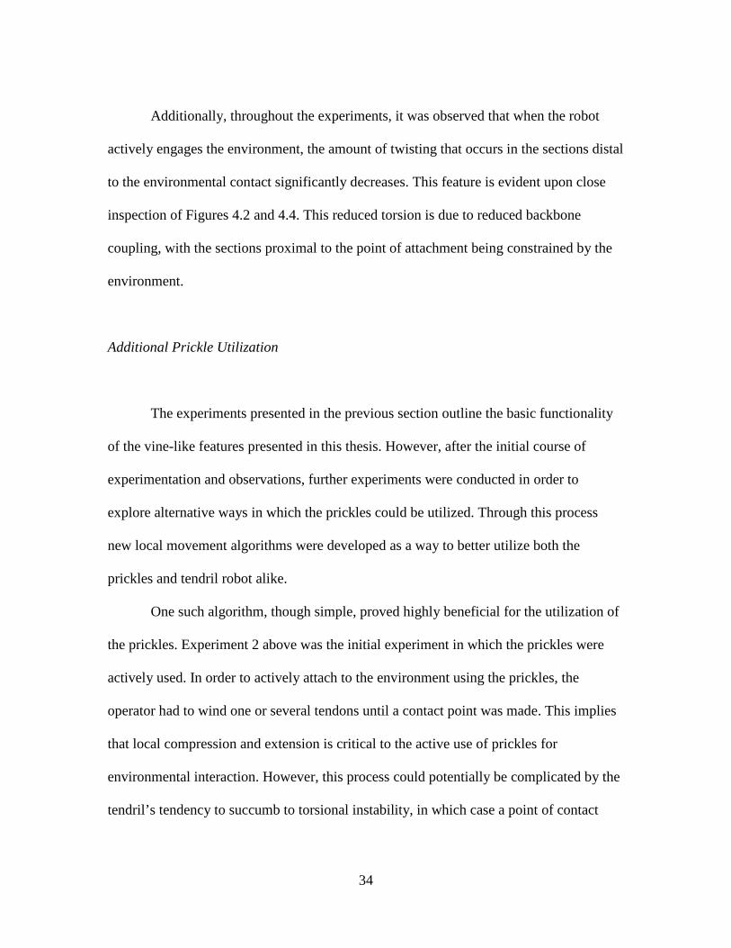
could be difficult to secure. The operator also had to be careful when abandoning the
point of attachment, i.e. in unhooking. If other contact points were present as the tendon
responsible for the initial attachment was released, the prickles occasionally adhered to
the points below. One such case can be seen in Figure 4.5. Here the prickles were initially
used to form a connection, and upon release from the connection the force of the springs
act on the bottom of the prickle structure which is then pushed against the wire below it.
In this case, another tendon could often “twist” the prickles clear of the undesirable
connection point, which was required in the case of the situation shown in Figure 4.5.
Figure 4.5 Prickle set stuck in grid
Based on these observations, improved hook hardware and related algorithms
were developed. The most successful algorithm was based on our creation of a “double
hook” grasping device on the backbone of the robot. This mechanism was formed by
placing a set of prickles on the endcap of the middle section, as well as, and in the
36
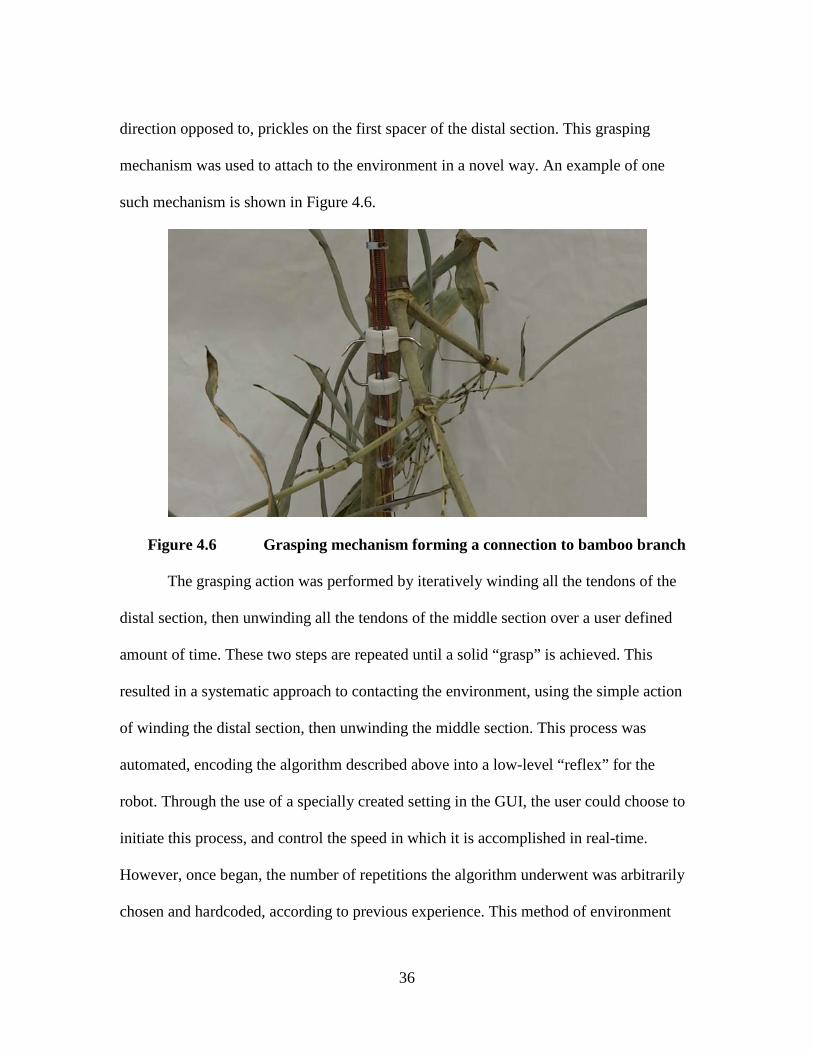
direction opposed to, prickles on the first spacer of the distal section. This grasping
mechanism was used to attach to the environment in a novel way. An example of one
such mechanism is shown in Figure 4.6.
Figure 4.6 Grasping mechanism forming a connection to bamboo branch
The grasping action was performed by iteratively winding all the tendons of the
distal section, then unwinding all the tendons of the middle section over a user defined
amount of time. These two steps are repeated until a solid “grasp” is achieved. This
resulted in a systematic approach to contacting the environment, using the simple action
of winding the distal section, then unwinding the middle section. This process was
automated, encoding the algorithm described above into a low-level “reflex” for the
robot. Through the use of a specially created setting in the GUI, the user could choose to
initiate this process, and control the speed in which it is accomplished in real-time.
However, once began, the number of repetitions the algorithm underwent was arbitrarily
chosen and hardcoded, according to previous experience. This method of environment
37
adherence was found to be superior to that using single prickles, as single prickle
attachments are more likely to come undone due to excessive movement.
4.2 Towards Applications
Environmental Exploration and Plant Motion Strategies
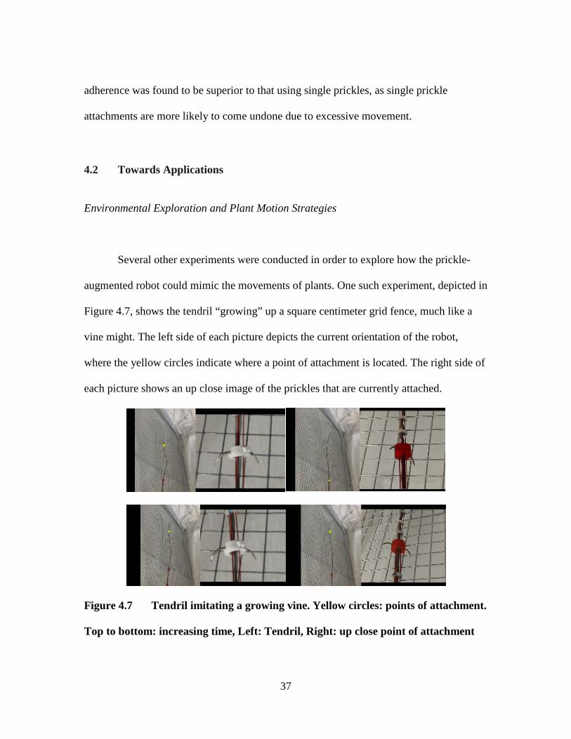
Several other experiments were conducted in order to explore how the prickle-
augmented robot could mimic the movements of plants. One such experiment, depicted in
Figure 4.7, shows the tendril “growing” up a square centimeter grid fence, much like a
vine might. The left side of each picture depicts the current orientation of the robot,
where the yellow circles indicate where a point of attachment is located. The right side of
each picture shows an up close image of the prickles that are currently attached.
Figure 4.7 Tendril imitating a growing vine. Yellow circles: points of attachment.
Top to bottom: increasing time, Left: Tendril, Right: up close point of attachment
38
This experiment was executed by first forming an attachment in the distal section.
Then the next attachment was formed in the middle section, while maintaining the
attachment in the distal section. The distal section attachment was then released, and the
section itself was extended. After extension the distal section found a new point of
attachment, and the process was repeated for the middle section.
These experiments complement the circumnutation movements described in the
previous chapter, in demonstrating plant-like behavior of the robot. Exploring plant-like
of behaviors with robots is of interest to botanists that study the corresponding
phenomena in plants. Subsequent to the beginning of the research reported herein, we
have begun collaborative NSF-funded research with a leading botanist (Professor Karl
Niklas at Cornell University). The goal of that project is to expand on the work in this
thesis to better understand how biologically inspired motion planning using tendril robots
could give insight into strategies underlying the movements in plants, and vice versa.
Space Inspection
The previously mentioned space station application, in which a tendril robot is
intended to reach behind equipment racks in order to ascertain the status of the equipment
therein, has formed much of the driving force of this research. To that end, several
iterations of the experiment depicted in Figure 4.9 were performed in our lab. This
experiment involved the insertion of the robot into a piece of electronic equipment to find
a target item, shown in Figure 4.8. This target was chosen for its ability to be easily

39
placed anywhere in the environment using nothing more than tape, and for the fact that it
is not something one would typically find in a computer system. In Figure 4.9, the left
side of each of the double images shows the external perspective of the robot’s
movements. The right side of each of the double images shows the view from the
perspective of the tip of the robot where a modified 5mm borescope camera was
mounted. The borescope’s modifications included the removal of waterproofing
insulation and aluminum shielding to mitigate the affect its introduction would have on
the robot’s bending, contraction, and extension properties.
Figure 4.8 “Gremlin” used in computer exploration trials
40
(a) (b)
(c) (d)
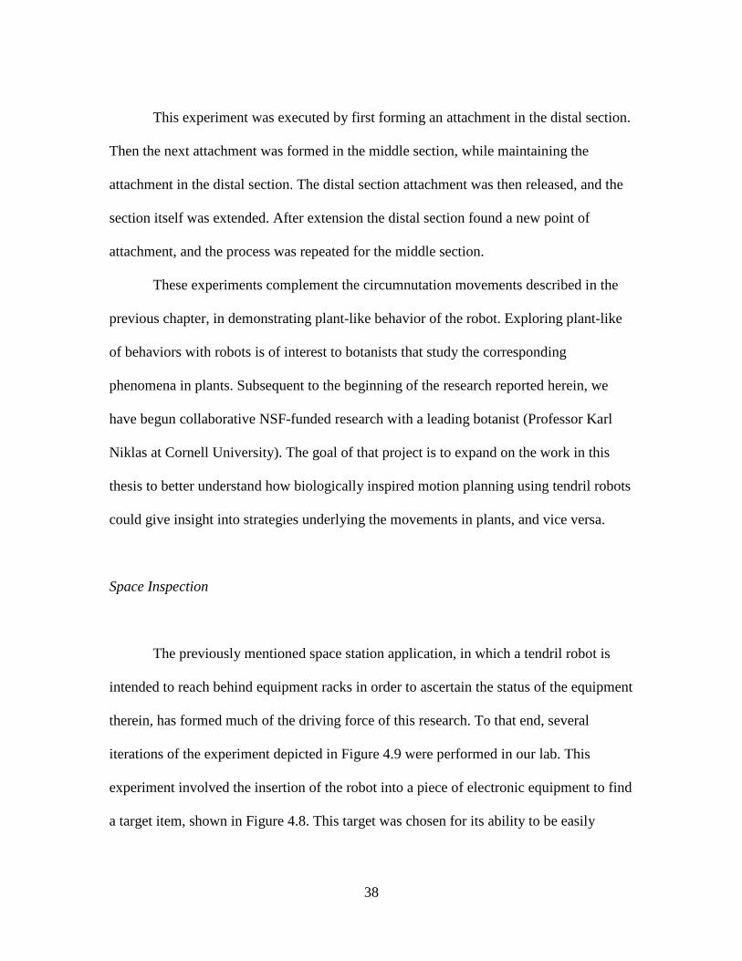
Figure 4.9 Exploration of a computer system using the prickled augmented
tendril robot.
In an initial experiment no attachments were sought by the operator. The task
proved impossible in this case. Subsequently, active environmental support was sought
and achieve using the prickles. Parts (a) and (b) of Figure 4.9 show the robot before
engaging the environment. The movements were erratic and at times, hard to watch due
to camera vibration, particularly emphasized with the borescope camera. Part (b) shows
the S-bend caused by the lack of structural support in the robot. Parts (c) and (d) of
Figure 4.9 show the robot after using prickles to engage the environment. Part (c) shows
the robot searching for the “Gremlin” and achieving around 130 degrees of bending,
which is impossible to achieve with this tendril prototype without engaging the
environment. Part (d) shows the tendril finding the gremlin in the end.
This experiment further supports the observation that the use of prickles with thin
tendril continuum robots, the key innovation of this thesis, drastically improves

41
exploration performance in a congested environment. In some case this improvement
goes well beyond what the robot is capable of without environmental attachment. In the
above experiment, the prickles were only used once it was determined that the gremlin
could not be found without using environmental support.
42
CHAPTER FIVE: CONCLUSIONS AND FUTURE WORK 5.1 Conclusions
This thesis introduces novel approaches to the design and operation of thin
continuum robots, also known as robot tendrils, using features inspired by biological
vines. The work is specifically aimed at space applications, although most of the results
also apply directly to terrestrial applications.
The main contribution of the research is in demonstrating the efficacy of vine-
inspired strategies for creating and exploiting environmental contact for thin continuum
robots. In the process of conducting the research, we generated new insight into the
design of tendril robots, and made incremental (but operationally important)
enhancements to previously established tendril robot actuator and sensor packages aimed
at space applications.
The most significant results in the thesis center on the novel use of active
environmental contact to provide structural support. Specifically, we chose to incorporate
“prickles,” commonly encountered in nature as thorns, in a new long, thin continuum
robot prototype. Adding these prickles at key points along the spine of the robot, we
conducted numerous experiments which identify and examine beneficial changes in the
robot’s performance characteristics when the prickles are used to contact the environment
to provide structural support. The work in this thesis is the first time continuum robots
have been augmented with prickles, or used to actively seek environmental support.

43
We found that the addition of the simple vine-like prickle features enhance the
performance of the robot in numerous ways. In particular, we observed that the coupling
in sections proximal to a given point of attachment was significantly reduced. This
created an increase in reach, stability, and load capacity when actuating the section(s)
distal to a given point of attachment along the backbone. Overall, our results show that
the vine-inspired strategy of actively seeking periodic environmental contact and support,
when judiciously used, can indeed improve the performance for thin continuum robot
tendrils.
In this thesis, we also show how circumnutation, a movement strategy commonly
observed in plants, can be adapted to synthesize a novel and potentially useful algorithm
for continuum robot motion planning. Circumnutation involves elliptical motion of the tip
of a plant stem, and is used by plants to increase the likelihood of finding environmental
support. We show that, and detail how, circumnutation can be used as the basis for
algorithms for motion planning in thin continuum robots, which similarly benefit from
environmental contact and support. The discussion is supported by experimental results
with our tendril prototype performing a robotic version of circumnutation to more
efficiently achieve environmental contact.
In conducting the research we developed significant experience in the
development and operation of spring-loaded, tendon driven concentric tube robots, a
relatively recent continuum robot design. In particular, we gained insight into the effect
that section length has on robot performance. Throughout the hardware development and
experiments presented in this thesis, the length of each section was changed several

44
times. These multiple iterations of the same underlying tendril robot design resulted in a
deeper understanding in the significant role relative section length has in the kinematic
behavior of such long, thin continuum robots. They key conclusion is that with such
compliant robots, section performance is hampered by excessive length, particularly
towards the distal end of the tendril.
The target application for the research is for inspection within and behind the
equipment racks on the International Space Station. There is a strong need for a
technology which can access and image the areas between and behind the equipment and
experiment racks on Station, to avoid the time-consuming process of disassembly
currently required of astronauts. The spaces are tight, and the depths significant enough
to preclude the use of conventional borescopes, making this an ideal application for vine-
like robots. However, to be feasible for space operations, the actuator package needs to
be relatively light and compact. The actuator package developed for the tendril prototype
in this thesis refines and improves a previously developed version by our group. The
tendril robot prototype developed as part of this research is also the first spring-loaded
concentric tube robot instrumented with tendon tension sensing.
5.2 Suggestions for future work
The results in this thesis suggest numerous direction for developing improved
ways of operation of tendril robots, particularly involving strong environmental
interaction. Results and lessons learned from the research suggest further research in
hardware development, modeling, and operational strategies.
45
Experience gained in conducting the experiments herein suggest a deeper analysis
of the hardware design tradeoffs between section lengths, tube stiffness, and spring
stiffness. We plan to develop several new sets of hardware and to quantify the effect the
relative length of a section, particularly the distal section, has on performance.
Furthermore we plan to add additional sensing capabilities, including tendon length, to
the tendril robot in order to better sense its shape and support controller development.
Additionally, it may be worthwhile to explore tactile sensing combined with the
circumnutation algorithm to better imitate the senses of plant stems. These new methods
of sensing will then eventually be used to implement kinematic models of the tendril, in
order to best utilize it in the future.
In terms of modeling, the highly compliant sections of the tendril typically take
shapes which deviate from the constant curvature which is the basis for almost all
continuum robot kinematic models in the literature. It would be beneficial to synthesize
and validate new non-constant curvature kinematics for thin continuum robots, something
which is currently absent from the literature. The continuum robot literature also has
produced very few models thus far incorporating environmental contact. New work in
this area would be of obvious benefit in developing simulations, planners, and controllers
for the plant-inspired active environmental contact strategies introduced herein.
Operationally, the experiments highlight a need for more intuitive user interfaces
and improved control of tendril robots. The tendon tension sensing in the prototype could
support haptic feedback, if a suitable input device could be developed. Integrating sensors
to support feedback for controllers and user visualization of the robot and its environment
46
remains a significant operational challenge for continuum robots in general. This
challenge is particularly acute for thin tendril robots which have highly limited real estate
and load capacity for addition of sensor hardware.
We will continue to take inspiration from other features of biological vines, such
as their strategies for motion planning and environmental contacts when exploring new
spaces, in order to further improve tendril robot performance. However, new directions
for research are likely to open up. This thesis details how plants can provide inspiration
and improved means of robot operation. An intriguing possible dual consequence of
further research is that the exploration of tendril robot technology and related algorithms
may provide botanists with new insight into plant biology.

47
APPENDICES
48
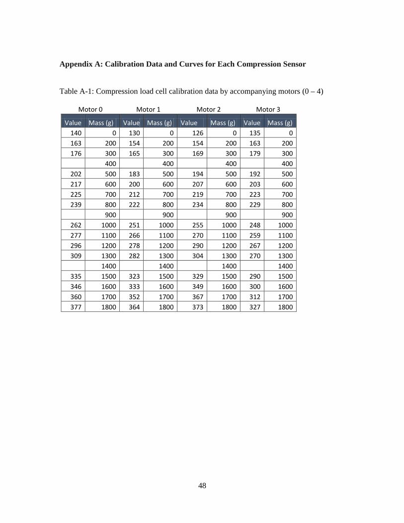
Appendix A: Calibration Data and Curves for Each Compression Sensor
Table A-1: Compression load cell calibration data by accompanying motors (0 – 4)
Motor 0 Motor 1 Motor 2 Motor 3
Value Mass (g) Value Mass (g) Value Mass (g) Value Mass (g) 140 0 130 0 126 0 135 0 163 200 154 200 154 200 163 200 176 300 165 300 169 300 179 300
400 400 400 400 202 500 183 500 194 500 192 500 217 600 200 600 207 600 203 600 225 700 212 700 219 700 223 700 239 800 222 800 234 800 229 800
900 900 900 900 262 1000 251 1000 255 1000 248 1000 277 1100 266 1100 270 1100 259 1100 296 1200 278 1200 290 1200 267 1200 309 1300 282 1300 304 1300 270 1300
1400 1400 1400 1400 335 1500 323 1500 329 1500 290 1500 346 1600 333 1600 349 1600 300 1600 360 1700 352 1700 367 1700 312 1700 377 1800 364 1800 373 1800 327 1800
49
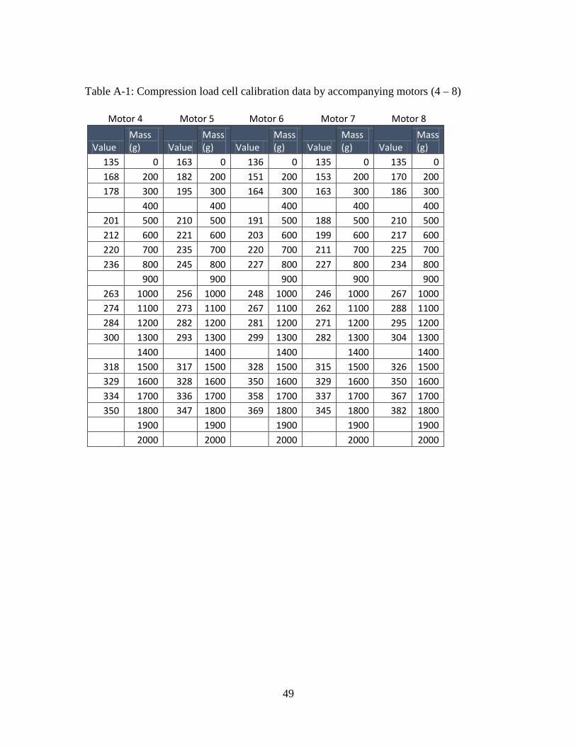
Table A-1: Compression load cell calibration data by accompanying motors (4 – 8)
Motor 4 Motor 5 Motor 6 Motor 7 Motor 8
Value Mass (g) Value
Mass (g) Value
Mass (g) Value
Mass (g) Value
Mass (g)
135 0 163 0 136 0 135 0 135 0 168 200 182 200 151 200 153 200 170 200 178 300 195 300 164 300 163 300 186 300
400 400 400 400 400 201 500 210 500 191 500 188 500 210 500 212 600 221 600 203 600 199 600 217 600 220 700 235 700 220 700 211 700 225 700 236 800 245 800 227 800 227 800 234 800
900 900 900 900 900 263 1000 256 1000 248 1000 246 1000 267 1000 274 1100 273 1100 267 1100 262 1100 288 1100 284 1200 282 1200 281 1200 271 1200 295 1200 300 1300 293 1300 299 1300 282 1300 304 1300
1400 1400 1400 1400 1400 318 1500 317 1500 328 1500 315 1500 326 1500 329 1600 328 1600 350 1600 329 1600 350 1600 334 1700 336 1700 358 1700 337 1700 367 1700 350 1800 347 1800 369 1800 345 1800 382 1800
1900 1900 1900 1900 1900 2000 2000 2000 2000 2000

50
Figure A-1: Calibration curves for compression load cells corresponding to motors 0 to 2
Figure A-2: Calibration curves for compression load cells corresponding to motors 3 to 5
y = 7.6084x - 931.02R² = 0.9952
y = 7.5852x - 1030.9R² = 0.9986
y = 7.2134x - 893.31R² = 0.9977
0
200
400
600
800
1000
1200
1400
1600
1800
2000
0 50 100 150 200 250 300 350 400
Compression Load Cell Calibration For Motors 0-2
1
2
3
Linear (1)
Linear (2)
Linear (3)
Linear (3)
y = 9.9106x - 1423.2R² = 0.9929
y = 8.5079x - 1203.1R² = 0.9969
y = 9.736x - 1567R² = 0.9977
-500
0
500
1000
1500
2000
2500
0 50 100 150 200 250 300 350 400
Compression Load Cell Calibration For Motors 3-5
Motor 3
Motor 4
Motor 5
Linear (Motor 3)
Linear (Motor 4)
Linear (Motor 5)
51
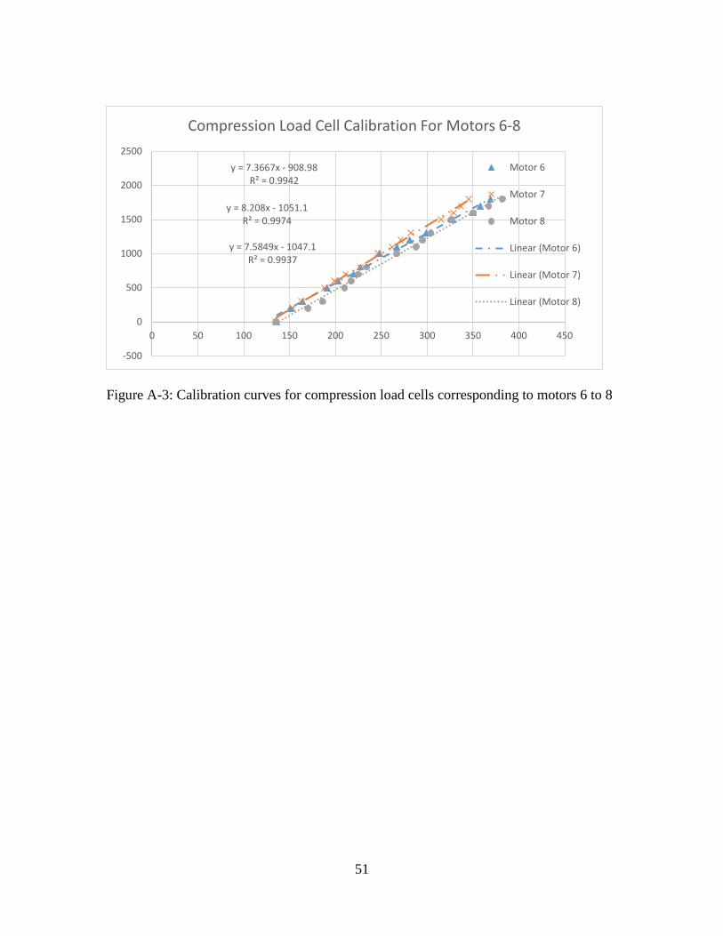
Figure A-3: Calibration curves for compression load cells corresponding to motors 6 to 8
y = 7.3667x - 908.98R² = 0.9942
y = 8.208x - 1051.1R² = 0.9974
y = 7.5849x - 1047.1R² = 0.9937
-500
0
500
1000
1500
2000
2500
0 50 100 150 200 250 300 350 400 450
Compression Load Cell Calibration For Motors 6-8
Motor 6
Motor 7
Motor 8
Linear (Motor 6)
Linear (Motor 7)
Linear (Motor 8)

52
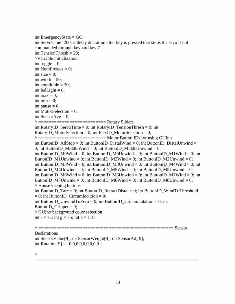
Appendix B: Arduino Code for Controlling Tendril Using GUIno Library
/* GUINO DASHBOARD TEMPLATE FOR THE ARDUINO. Done by Mads Hobye as a part of Instructables (AIR Program) & Medea (PhD Student). Licens: Creative Commons — Attribution-ShareAlike It should be used with the GUINO Dashboard app. More info can be found here: www.hobye.dk # This is your main template to edit. */ #include <Servo.h> // Allows for the use of servos void sensor_update(); void move_motors(int *motor_num, int motor_count, int message); void wind_to_threshold(int selection, int theshold); // Servo structures Servo servo[9]; // create servo object to control a servo // =================================== Variable Declarations ================================================== // // Servo speeds for SM-S4315R #define SERVO_STOP 93 #define SERVO_WIND 110 #define SERVO_UNWIND 76 #define DELAY_TIME 0 #define MAX_DIFF 30 #define GO 0 #define STOP 1 #define CIRCUMNUTATION_DURATION 12 #define GRIPPER_DURATION 6 // =============== Digital pins to motor switches (transistors) const int switches[9] = {40,41,42,43,44,45,46,47,48}; // =============== Misc. Variable declarations
53
int EmergencyState = GO; int ServoTime=200; // delay duaration after key is pressed that stops the sevo if not commanded through keybard key 7 int TensionThresh = 20; //Variable initialization: int toggle = 0; int NumPresses = 0; int size = 0; int width = 50; int amplitude = 20; int ledLight = 0; int max = 0; int min = 0; int pause = 0; int MotorSelection = 0; int SensorAvg = 0; // ========================== Rotary Sliders int RotaryID_ServoTime = 0; int RotaryID_TensionThresh = 0; int RotaryID_MotorSelection = 0; int FlexID_MotorSelection = 0; // ========================== Motor Button IDs for using GUIno int ButtonID_AllStop = 0; int ButtonID_DistalWind = 0; int ButtonID_DistalUnwind = 0; int ButtonID_MiddleWind = 0; int ButtonID_MiddleUnwind = 0; int ButtonID_M0Wind = 0; int ButtonID_M0Unwind = 0; int ButtonID_M1Wind = 0; int ButtonID_M1Unwind = 0; int ButtonID_M2Wind = 0; int ButtonID_M2Unwind = 0; int ButtonID_M3Wind = 0; int ButtonID_M3Unwind = 0; int ButtonID_M4Wind = 0; int ButtonID_M4Unwind = 0; int ButtonID_M5Wind = 0; int ButtonID_M5Unwind = 0; int ButtonID_M6Wind = 0; int ButtonID_M6Unwind = 0; int ButtonID_M7Wind = 0; int ButtonID_M7Unwind = 0; int ButtonID_M8Wind = 0; int ButtonID_M8Unwind = 0; // House keeping buttons int ButtonID_Tare = 0; int ButtonID_RetractDistal = 0; int ButtonID_WindToThreshold = 0; int ButtonID_Circumlocution = 0; int ButtonID_UnwindToZero = 0; int ButtonID_Circumnutation = 0; int ButtonID_Gripper = 0; // GUIno background color selection int r = 75; int g = 75; int b = 110; // ==================================================== Sensor Declarations int SensorValue[9]; int SensorWeight[9]; int SensorAdj[9]; int Rotation[9] = {0,0,0,0,0,0,0,0,0}; // ===============================================================

54
========= Arduino Setup ================================================= // void setup(){ servo[0].attach(13); // attaches the servo on pin 9 to the servo object servo[1].attach(5); servo[2].attach(7); servo[3].attach(4); servo[4].attach(10); servo[5].attach(12); servo[6].attach(11); servo[7].attach(8); servo[8].attach(9); pinMode(switches[0], OUTPUT); pinMode(switches[1], OUTPUT); pinMode(switches[2], OUTPUT); pinMode(switches[3], OUTPUT); pinMode(switches[4], OUTPUT); pinMode(switches[5], OUTPUT); pinMode(switches[6], OUTPUT); pinMode(switches[7], OUTPUT); pinMode(switches[8], OUTPUT); // prevents motor for running/flying off without command // servo[0].write(SERVO_STOP); servo[1].write(SERVO_STOP); servo[2].write(SERVO_STOP); servo[3].write(SERVO_STOP); servo[4].write(SERVO_STOP); servo[5].write(SERVO_STOP); servo[6].write(SERVO_STOP); servo[7].write(SERVO_STOP); servo[8].write(SERVO_STOP); digitalWrite(switches[0], LOW); digitalWrite(switches[1], LOW); digitalWrite(switches[2], LOW); digitalWrite(switches[3], LOW); digitalWrite(switches[4], LOW); digitalWrite(switches[5], LOW); digitalWrite(switches[6], LOW); digitalWrite(switches[7], LOW); digitalWrite(switches[8], LOW); // Serial.begin(9600); // baud rate // Start the guino dashboard interface. // The number is your personal key for saving data. This should be unique for each sketch // This key should also be changed if you change the gui structure. Hence the saved data vill not match. gBegin(373536); }
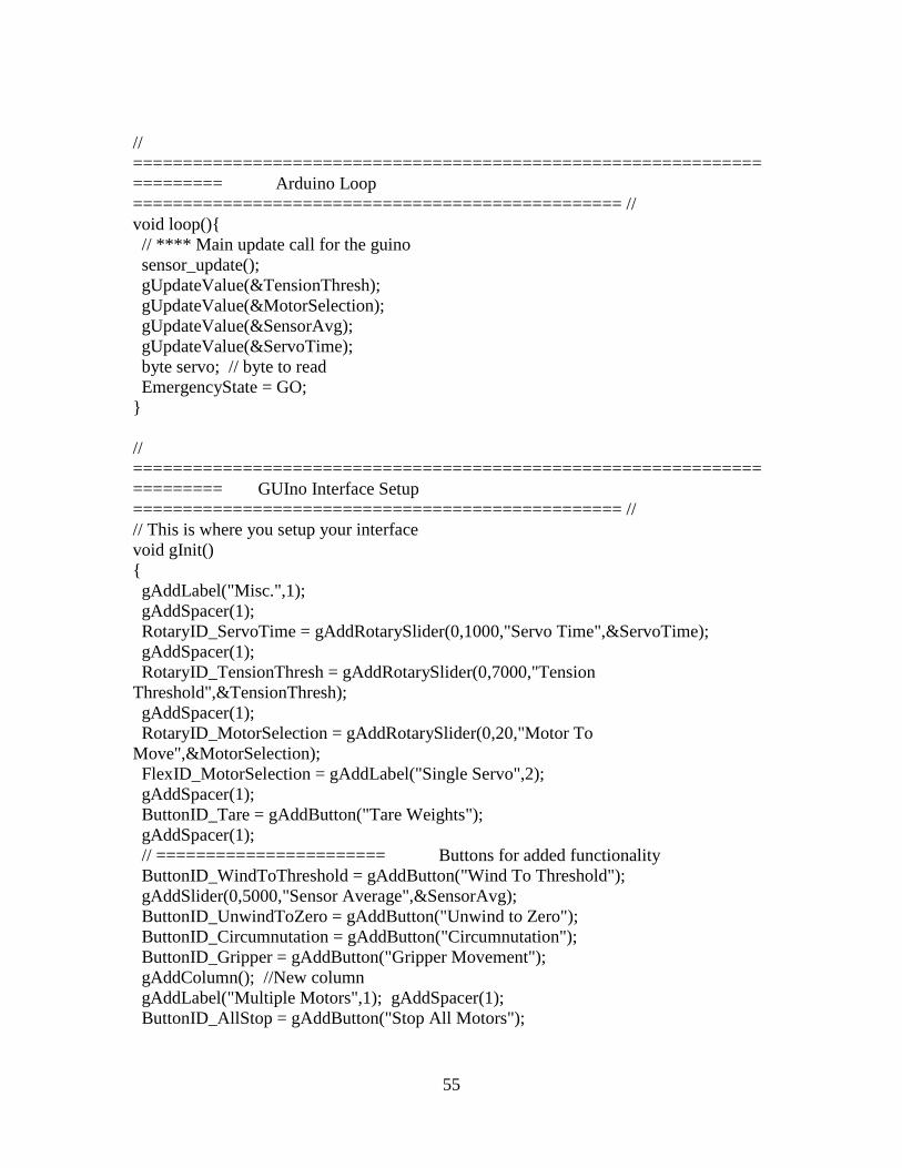
55
// ======================================================================== Arduino Loop ================================================= // void loop(){ // **** Main update call for the guino sensor_update(); gUpdateValue(&TensionThresh); gUpdateValue(&MotorSelection); gUpdateValue(&SensorAvg); gUpdateValue(&ServoTime); byte servo; // byte to read EmergencyState = GO; } // ======================================================================== GUIno Interface Setup ================================================= // // This is where you setup your interface void gInit() { gAddLabel("Misc.",1); gAddSpacer(1); RotaryID_ServoTime = gAddRotarySlider(0,1000,"Servo Time",&ServoTime); gAddSpacer(1); RotaryID_TensionThresh = gAddRotarySlider(0,7000,"Tension Threshold",&TensionThresh); gAddSpacer(1); RotaryID_MotorSelection = gAddRotarySlider(0,20,"Motor To Move",&MotorSelection); FlexID_MotorSelection = gAddLabel("Single Servo",2); gAddSpacer(1); ButtonID_Tare = gAddButton("Tare Weights"); gAddSpacer(1); // ======================= Buttons for added functionality ButtonID_WindToThreshold = gAddButton("Wind To Threshold"); gAddSlider(0,5000,"Sensor Average",&SensorAvg); ButtonID_UnwindToZero = gAddButton("Unwind to Zero"); ButtonID_Circumnutation = gAddButton("Circumnutation"); ButtonID_Gripper = gAddButton("Gripper Movement"); gAddColumn(); //New column gAddLabel("Multiple Motors",1); gAddSpacer(1); ButtonID_AllStop = gAddButton("Stop All Motors");
56
gAddToggle("PAUSE",&pause); gAddSpacer(1); // Buttons for winding all three Distal Tendons ButtonID_DistalWind = gAddButton("Wind Distal"); ButtonID_DistalUnwind = gAddButton("Unwind Distal"); // gAddSpacer(1); //Buttons for winding all three Middle Tendons ButtonID_MiddleWind = gAddButton("Wind Middle"); ButtonID_MiddleUnwind = gAddButton("Unwind Middle"); // gAddSpacer(1); // ============================================ Buttons for individual motors by section //gAddColumn(); //New column gAddLabel("Base",1); gAddSpacer(1); ButtonID_M0Wind = gAddButton("Wind Motor 0(Blue)"); ButtonID_M0Unwind = gAddButton("Unwind Motor 0(Blue)"); // gAddSpacer(1); ButtonID_M1Wind = gAddButton("Wind Motor 1(Black)"); ButtonID_M1Unwind = gAddButton("Unwind Motor 1(Black)"); // gAddSpacer(1); ButtonID_M2Wind = gAddButton("Wind Motor 2(Red)"); ButtonID_M2Unwind = gAddButton("Unwind Motor 2(Red)"); // gAddSpacer(1); gAddColumn(); //New column gAddLabel("Middle",1); gAddSpacer(1); ButtonID_M3Wind = gAddButton("Wind Motor 3(Blue)"); ButtonID_M3Unwind = gAddButton("Unwind Motor 3(Blue)"); // gAddSpacer(1); ButtonID_M4Wind = gAddButton("Wind Motor 4(Black)"); ButtonID_M4Unwind = gAddButton("Unwind Motor 4(Black)");// gAddSpacer(1); ButtonID_M5Wind = gAddButton("Wind Motor 5(Red)"); ButtonID_M5Unwind = gAddButton("Unwind Motor 5(Red)"); // gAddSpacer(1); // gAddColumn(); //New column gAddLabel("Distal",1); gAddSpacer(1); ButtonID_M6Wind = gAddButton("Wind Motor 6(Blue)"); ButtonID_M6Unwind = gAddButton("Unwind Motor 6(Blue)"); // gAddSpacer(1); ButtonID_M7Wind = gAddButton("Wind Motor 7(Black)"); ButtonID_M7Unwind = gAddButton("Unwind Motor 7(Black)"); // gAddSpacer(1); ButtonID_M8Wind = gAddButton("Wind Motor 8(Red)"); ButtonID_M8Unwind = gAddButton("Unwind Motor 8(Red)"); // gAddSpacer(1); gAddColumn(); // ============================================ 'Sliders' indicating sensor values and other system feedback gAddLabel("Sensor Readings (weight in grams)",2); gAddSpacer(1); gAddLabel("Base",1); gAddSpacer(1);
57
gAddLabel("Sensor 0",2); /* gAddSlider(-500,10023,"Motor 0 Rotation",&Rotation[0]);*/ gAddSlider(0,5000,"Sensor 0 Weight",&SensorWeight[0]); gAddSpacer(1); gAddLabel("Sensor 1",2); /* gAddSlider(-500,10023,"Motor 1 Rotation",&Rotation[1]);*/ gAddSlider(0,5000,"Sensor 1 Weight",&SensorWeight[1]); gAddSpacer(1); gAddLabel("Sensor 2",2); /* gAddSlider(-500,10023,"Motor 2 Rotation",&Rotation[2]);*/ gAddSlider(0,5000,"Sensor 2 Weight",&SensorWeight[2]); gAddSpacer(1); //gAddColumn(); gAddLabel("Middle",1); gAddSpacer(1); gAddLabel("Sensor 3",2); /* gAddSlider(-500,10023,"Motor 3 Rotation",&Rotation[3]);*/ gAddSlider(0,5000,"Sensor 3 Weight",&SensorWeight[3]); gAddSpacer(1); gAddLabel("Sensor 4",2); /* gAddSlider(-500,10023,"Motor 4 Rotation",&Rotation[4]);*/ gAddSlider(0,5000,"Sensor 4 Weight",&SensorWeight[4]);gAddSpacer(1); gAddLabel("Sensor 5",2); /* gAddSlider(-500,10023,"Motor 5 Rotation",&Rotation[5]);*/ gAddSlider(0,5000,"Sensor 5 Weight",&SensorWeight[5]); gAddSpacer(1); gAddColumn(); gAddLabel("Distal",1); gAddSpacer(1); gAddLabel("Sensor 6",2); /* gAddSlider(-500,20023,"Motor 6 Rotation",&Rotation[6]);*/ gAddSlider(0,5000,"Sensor 6 Weight",&SensorWeight[6]); gAddSpacer(1); gAddLabel("Sensor 7",2); /* gAddSlider(-500,20023,"Motor 7 Rotation",&Rotation[7]);*/ gAddSlider(0,5000,"Sensor 7 Weight",&SensorWeight[7]); gAddSpacer(1); gAddLabel("Sensor 8",2); /* gAddSlider(-500,20023,"Motor 8 Rotation",&Rotation[8]);*/ gAddSlider(0,5000,"Sensor 8 Weight",&SensorWeight[8]); gAddSpacer(1); gSetColor(r,g,b); // Set the color of the gui interface. } // ===================================== Method called everytime a button has been pressed in the interface ==================================== // void gButtonPressed(int id) { int numbertomove; int motorstomove[9]; int ndx, i, j, k;

58
if (toggle == 0) // This if-statement toggles whether or not the button just pressed will work or not. This is to fight button boucing that occurs in the GUI { NumPresses++; gUpdateValue(&NumPresses); id = 0; toggle = 1; gUpdateValue(&toggle); } else { toggle = 0; } if(id == ButtonID_Tare) { sensor_update(); SensorAdj[0] += SensorWeight[0]; SensorAdj[1] += SensorWeight[1]; SensorAdj[2] += SensorWeight[2]; SensorAdj[3] += SensorWeight[3]; SensorAdj[4] += SensorWeight[4]; SensorAdj[5] += SensorWeight[5]; SensorAdj[6] += SensorWeight[6]; SensorAdj[7] += SensorWeight[7]; SensorAdj[8] += SensorWeight[8]; gUpdateValue(&SensorAdj[0]); gUpdateValue(&SensorAdj[1]); gUpdateValue(&SensorAdj[2]); gUpdateValue(&SensorAdj[3]); gUpdateValue(&SensorAdj[4]); gUpdateValue(&SensorAdj[5]); gUpdateValue(&SensorAdj[6]); gUpdateValue(&SensorAdj[7]); gUpdateValue(&SensorAdj[8]); } if(id == ButtonID_AllStop) { EmergencyState = STOP; } // ============================================================= Section Contraction if(id == ButtonID_DistalWind) { motorstomove[0] = 6; motorstomove[1] = 7; motorstomove[2] = 8; numbertomove = 3; move_motors(motorstomove, numbertomove, SERVO_WIND); }
59
if(id == ButtonID_DistalUnwind) { motorstomove[0] = 6; motorstomove[1] = 7; motorstomove[2] = 8; numbertomove = 3; move_motors(motorstomove, numbertomove, SERVO_UNWIND); } if(id == ButtonID_MiddleWind) { motorstomove[0] = 3; motorstomove[1] = 4; motorstomove[2] = 5; numbertomove = 3; move_motors(motorstomove, numbertomove, SERVO_WIND); } if(id == ButtonID_MiddleUnwind) { motorstomove[0] = 3; motorstomove[1] = 4; motorstomove[2] = 5; numbertomove = 3; move_motors(motorstomove, numbertomove, SERVO_UNWIND); } //=============================================================== Motor 0 if(id == ButtonID_M0Wind) { motorstomove[0] = 0; numbertomove = 1; move_motors(motorstomove, numbertomove, SERVO_WIND); } if(id == ButtonID_M0Unwind) { motorstomove[0] = 0; numbertomove = 1; move_motors(motorstomove, numbertomove, SERVO_UNWIND); } //=============================================================== Motor 1 if(id == ButtonID_M1Wind) { motorstomove[0] = 1; numbertomove = 1; move_motors(motorstomove, numbertomove, SERVO_WIND); } if(id == ButtonID_M1Unwind) { motorstomove[0] = 1; numbertomove = 1; move_motors(motorstomove, numbertomove, SERVO_UNWIND); }

60
//================================================================ Motor 2 if(id == ButtonID_M2Wind) { motorstomove[0] = 2; numbertomove = 1; move_motors(motorstomove, numbertomove, SERVO_WIND); } if(id == ButtonID_M2Unwind) { motorstomove[0] = 2; numbertomove = 1; move_motors(motorstomove, numbertomove, SERVO_UNWIND); } //================================================================ Motor 3 if(id == ButtonID_M3Wind) { motorstomove[0] = 3; numbertomove = 1; move_motors(motorstomove, numbertomove, SERVO_WIND); } if(id == ButtonID_M3Unwind) { motorstomove[0] = 3; numbertomove = 1; move_motors(motorstomove, numbertomove, SERVO_UNWIND); } //================================================================ Motor 4 if(id == ButtonID_M4Wind) { motorstomove[0] = 4; numbertomove = 1; move_motors(motorstomove, numbertomove, SERVO_WIND); } if(id == ButtonID_M4Unwind) { motorstomove[0] = 4; numbertomove = 1; move_motors(motorstomove, numbertomove, SERVO_UNWIND); } //================================================================ Motor 5 if(id == ButtonID_M5Wind) {
61
motorstomove[0] = 5; numbertomove = 1; move_motors(motorstomove, numbertomove, SERVO_WIND); } if(id == ButtonID_M5Unwind) { motorstomove[0] = 5; numbertomove = 1; move_motors(motorstomove, numbertomove, SERVO_UNWIND); } //================================================================ Motor 6 if(id == ButtonID_M6Wind) { motorstomove[0] = 6; numbertomove = 1; move_motors(motorstomove, numbertomove, SERVO_WIND); } if(id == ButtonID_M6Unwind) { motorstomove[0] = 6; numbertomove = 1; move_motors(motorstomove, numbertomove, SERVO_UNWIND); } //=============================================================== Motor 7 if(id == ButtonID_M7Wind) { motorstomove[0] = 7; numbertomove = 1; move_motors(motorstomove, numbertomove, SERVO_WIND); } if(id == ButtonID_M7Unwind) { motorstomove[0] = 7; numbertomove = 1; move_motors(motorstomove, numbertomove, SERVO_UNWIND); } //============================================================== Motor 8 if(id == ButtonID_M8Wind) { motorstomove[0] = 8; numbertomove = 1; move_motors(motorstomove, numbertomove, SERVO_WIND); } if(id == ButtonID_M8Unwind) {

62
motorstomove[0] = 8; numbertomove = 1; move_motors(motorstomove, numbertomove, SERVO_UNWIND); } // ============================================================ Wind to threshold subroutine if(id == ButtonID_WindToThreshold) { sensor_update(); wind_to_threshold(MotorSelection, TensionThresh); } // ============================================================ Unwind to zero subroutine if(id == ButtonID_UnwindToZero) { sensor_update(); while (SensorWeight[MotorSelection] > 0) // Only if the MotorSelection is for a single servo { if (EmergencyState) break; motorstomove[0] = MotorSelection; numbertomove = 1; move_motors(motorstomove,numbertomove,SERVO_UNWIND); delay(DELAY_TIME); sensor_update(); } } // ============================================================ Circumnutation subroutine if(id == ButtonID_Circumnutation) { if (MotorSelection == 9) // Distal section { // Counter-Clockwise // ======================= Wind 6 -> 7 -> 8 -> 6 motorstomove[0] = 6; motorstomove[1] = 7; motorstomove[2] = 8; numbertomove = 3; }else if (MotorSelection == 10) // Middle Section { // Counter-Clockwise // ======================= Wind 3 -> 4 -> 5 -> 3 motorstomove[0] = 3; motorstomove[1] = 4; motorstomove[2] = 5; numbertomove = 3; }else if (MotorSelection == 11) // Base Section { // Counter-Clockwise // ======================= Wind 0 -> 1 -> 2 -> 0 motorstomove[0] = 0; motorstomove[1] = 1; motorstomove[2] = 2;
63
numbertomove = 3; }else if (MotorSelection == 12) // Multi - Section Circumnutation { // Counter-Clockwise // ======================= Wind 0,3,6 -> 1,4,7 -> 2,5,8 -> 0,3,6 motorstomove[0] = 0; motorstomove[1] = 3; motorstomove[2] = 6; motorstomove[3] = 1; motorstomove[4] = 4; motorstomove[5] = 7; motorstomove[6] = 2; motorstomove[7] = 5; motorstomove[8] = 8; numbertomove = 9; }else if (MotorSelection == 13) // Multi - Section Circumnutation { // Counter-Clockwise // ======================= Wind 0,3,6 -> 1,4,7 -> 2,5,8 -> 0,3,6 motorstomove[0] = 0; motorstomove[1] = 3; motorstomove[2] = 6; motorstomove[3] = 1; motorstomove[4] = 4; motorstomove[5] = 7; motorstomove[6] = 2; motorstomove[7] = 5; motorstomove[8] = 8; numbertomove = 9; } move_motors(motorstomove,numbertomove/3,SERVO_WIND); delay(DELAY_TIME); sensor_update(); for (ndx = 0; ndx < CIRCUMNUTATION_DURATION && !EmergencyState; ndx++) { for (i = 1; i <= 3; i++) { for (j = (numbertomove/3)*(i%3), k = (numbertomove/3)*((i-1)%3); j < (numbertomove/3)*(i%3)+(numbertomove/3); j++, k++) wind_to_threshold(motorstomove[j],SensorWeight[motorstomove[k]]); delay(DELAY_TIME); sensor_update(); move_motors(&motorstomove[(numbertomove/3)*((i-1)%3)],(numbertomove/3),SERVO_UNWIND); delay(DELAY_TIME); sensor_update(); } } } // ========================================================================================================== Gripper subroutine if(id == ButtonID_Gripper) { for (ndx = 0; ndx < GRIPPER_DURATION && !EmergencyState; ndx++) { motorstomove[0] = 3; motorstomove[1] = 4; motorstomove[2] = 5;

64
motorstomove[3] = 6; motorstomove[4] = 7; motorstomove[5] = 8; numbertomove = 3; move_motors(motorstomove,numbertomove, SERVO_UNWIND); for (i = 0; i < GRIPPER_DURATION/2; i++) move_motors(&motorstomove[3],numbertomove, SERVO_WIND); } } } // void gItemUpdated(int id) { if(RotaryID_MotorSelection == id) { if (MotorSelection < 9) gUpdateLabel(FlexID_MotorSelection, "Single Servo"); else if (MotorSelection == 9) gUpdateLabel(FlexID_MotorSelection, "Distal Section Selected"); else if (MotorSelection == 10) gUpdateLabel(FlexID_MotorSelection, "Middle Section Selected"); else if (MotorSelection == 11) gUpdateLabel(FlexID_MotorSelection, "Base Section Selected"); else if (MotorSelection == 12) gUpdateLabel(FlexID_MotorSelection, "All 3 (Circ only)"); else if (MotorSelection == 13) gUpdateLabel(FlexID_MotorSelection, "Middle and Distal"); else if (MotorSelection == 14) gUpdateLabel(FlexID_MotorSelection, "Gripper"); } } // ======================================================================== Sensor Read Function ================================================= // void sensor_update() { SensorValue[0] = analogRead(A0); SensorValue[1] = analogRead(A1); SensorValue[2] = analogRead(A2); SensorValue[3] = analogRead(A3); SensorValue[4] = analogRead(A4); SensorValue[5] = analogRead(A5); SensorValue[6] = analogRead(A6); SensorValue[7] = analogRead(A7); SensorValue[8] = analogRead(A8); SensorWeight[0] = (SensorValue[0]) * 7.6084 - 931.02 - SensorAdj[0]; SensorWeight[1] = (SensorValue[1]) * 7.5852 - 1030.9 - SensorAdj[1]; SensorWeight[2] = (SensorValue[2]) * 7.2134 - 893.31 - SensorAdj[2]; SensorWeight[3] = (SensorValue[3]) * 9.9106 - 1423.2 - SensorAdj[3];
65
SensorWeight[4] = (SensorValue[4]) * 8.5079 - 1203.1 - SensorAdj[4]; SensorWeight[5] = (SensorValue[5]) * 9.736 - 1567 - SensorAdj[5]; SensorWeight[6] = (SensorValue[6]) * 7.3667 - 908.98 - SensorAdj[6]; SensorWeight[7] = (SensorValue[7]) * 8.208 - 1051.1 - SensorAdj[7]; SensorWeight[8] = (SensorValue[8]) * 7.849 - 1047.1 - SensorAdj[8]; gUpdateValue(&SensorWeight[0]); gUpdateValue(&SensorValue[0]); gUpdateValue(&Rotation[0]); gUpdateValue(&SensorWeight[1]); gUpdateValue(&SensorValue[1]); gUpdateValue(&Rotation[1]); gUpdateValue(&SensorWeight[2]); gUpdateValue(&SensorValue[2]); gUpdateValue(&Rotation[2]); gUpdateValue(&SensorWeight[3]); gUpdateValue(&SensorValue[3]); gUpdateValue(&Rotation[3]); gUpdateValue(&SensorWeight[4]); gUpdateValue(&SensorValue[4]); gUpdateValue(&Rotation[4]); gUpdateValue(&SensorWeight[5]); gUpdateValue(&SensorValue[5]); gUpdateValue(&Rotation[5]); gUpdateValue(&SensorWeight[6]); gUpdateValue(&SensorValue[6]); gUpdateValue(&Rotation[6]); gUpdateValue(&SensorWeight[7]); gUpdateValue(&SensorValue[7]); gUpdateValue(&Rotation[7]); gUpdateValue(&SensorWeight[8]); gUpdateValue(&SensorValue[8]); gUpdateValue(&Rotation[8]); guino_update(); } // ===================================================== Function that governing signals to motors =============================================== // void move_motors(int *motor_num, int motor_count, int message) { int ndx; if (motor_count == 1) { digitalWrite(switches[motor_num[0]], HIGH); delay(DELAY_TIME); servo[motor_num[0]].write(message); delay((ServoTime)); Rotation[motor_num[0]] = Rotation[motor_num[0]] + (ServoTime); servo[motor_num[0]].write(SERVO_STOP); digitalWrite(switches[motor_num[0]], LOW);

66
} else { for(ndx = 0; ndx < motor_count; ndx++) digitalWrite(switches[motor_num[ndx]], HIGH); delay(DELAY_TIME); for(ndx = 0; ndx < motor_count; ndx++) servo[motor_num[ndx]].write(message); delay((ServoTime)); for(ndx = 0; ndx < motor_count; ndx++) Rotation[motor_num[ndx]] = Rotation[motor_num[ndx]] + (ServoTime); for(ndx = 0; ndx < motor_count; ndx++) servo[motor_num[ndx]].write(SERVO_STOP); for(ndx = 0; ndx < motor_count; ndx++) digitalWrite(switches[motor_num[ndx]], LOW); } } // ===================================================== Threshold Winding and Compression =============================================== // void wind_to_threshold(int selection, int threshold) { int motorstomove[9]; int numbertomove = 0; int highestdiff = 0; int ndx; int weightdiff0_1, weightdiff1_2, weightdiff0_2; if (selection < 9) // For a single motor referenced from 0 - 8 { motorstomove[0] = selection; numbertomove = 1; } else if (selection == 9) // For the Distal Section { motorstomove[0] = 6; motorstomove[1] = 7; motorstomove[2] = 8; numbertomove = 3; } else if (selection == 10) // For the Middle Section { motorstomove[0] = 3; motorstomove[1] = 4; motorstomove[2] = 5; numbertomove = 3; } else if (selection == 11) // For Base Section {

67
} else if (selection == 12) // Under Development { } SensorAvg = 0; for (ndx = 0; ndx < numbertomove; ndx++) SensorAvg = SensorAvg + SensorWeight[motorstomove[ndx]]; SensorAvg = SensorAvg / numbertomove; gUpdateValue(&SensorAvg); while (SensorAvg < threshold) { if (EmergencyState) break; if (numbertomove == 3) { weightdiff0_1 = abs(SensorWeight[motorstomove[0]] - SensorWeight[motorstomove[1]]); weightdiff1_2 = abs(SensorWeight[motorstomove[1]] - SensorWeight[motorstomove[2]]); weightdiff0_2 = abs(SensorWeight[motorstomove[0]] - SensorWeight[motorstomove[2]]); highestdiff = max(weightdiff0_1, weightdiff1_2); highestdiff = max(highestdiff, weightdiff0_2); } else { highestdiff = 0; } if (highestdiff > MAX_DIFF) { if (weightdiff0_1 == highestdiff) { if (SensorWeight[motorstomove[0]] < SensorWeight[motorstomove[1]]) { move_motors(&motorstomove[0],1,SERVO_WIND); delay(DELAY_TIME); sensor_update(); }else { move_motors(&motorstomove[1],1,SERVO_WIND); delay(DELAY_TIME); sensor_update(); } }else if (weightdiff1_2 == highestdiff) {
68
if (SensorWeight[motorstomove[1]] < SensorWeight[motorstomove[2]]) { move_motors(&motorstomove[1],1,SERVO_WIND); delay(DELAY_TIME); sensor_update(); }else { move_motors(&motorstomove[2],1,SERVO_WIND); delay(DELAY_TIME); sensor_update(); } }else if (weightdiff0_2 == highestdiff) { if (SensorWeight[motorstomove[0]] < SensorWeight[motorstomove[2]]) { move_motors(&motorstomove[0],1,SERVO_WIND); delay(DELAY_TIME); sensor_update(); }else { move_motors(&motorstomove[2],1,SERVO_WIND); delay(DELAY_TIME); sensor_update(); } } } else { move_motors(motorstomove, numbertomove, SERVO_WIND); delay(DELAY_TIME); sensor_update(); } SensorAvg = 0; for (ndx = 0; ndx < numbertomove; ndx++) SensorAvg += SensorWeight[motorstomove[ndx]]; SensorAvg = SensorAvg / numbertomove; gUpdateValue(&SensorAvg); } }
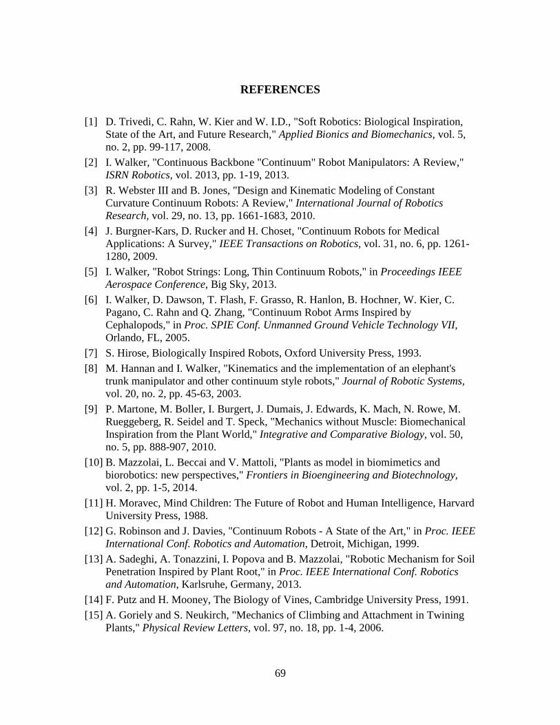
69
REFERENCES [1] D. Trivedi, C. Rahn, W. Kier and W. I.D., "Soft Robotics: Biological Inspiration,
State of the Art, and Future Research," Applied Bionics and Biomechanics, vol. 5, no. 2, pp. 99-117, 2008.
[2] I. Walker, "Continuous Backbone "Continuum" Robot Manipulators: A Review," ISRN Robotics, vol. 2013, pp. 1-19, 2013.
[3] R. Webster III and B. Jones, "Design and Kinematic Modeling of Constant Curvature Continuum Robots: A Review," International Journal of Robotics Research, vol. 29, no. 13, pp. 1661-1683, 2010.
[4] J. Burgner-Kars, D. Rucker and H. Choset, "Continuum Robots for Medical Applications: A Survey," IEEE Transactions on Robotics, vol. 31, no. 6, pp. 1261-1280, 2009.
[5] I. Walker, "Robot Strings: Long, Thin Continuum Robots," in Proceedings IEEE Aerospace Conference, Big Sky, 2013.
[6] I. Walker, D. Dawson, T. Flash, F. Grasso, R. Hanlon, B. Hochner, W. Kier, C. Pagano, C. Rahn and Q. Zhang, "Continuum Robot Arms Inspired by Cephalopods," in Proc. SPIE Conf. Unmanned Ground Vehicle Technology VII, Orlando, FL, 2005.
[7] S. Hirose, Biologically Inspired Robots, Oxford University Press, 1993. [8] M. Hannan and I. Walker, "Kinematics and the implementation of an elephant's
trunk manipulator and other continuum style robots," Journal of Robotic Systems, vol. 20, no. 2, pp. 45-63, 2003.
[9] P. Martone, M. Boller, I. Burgert, J. Dumais, J. Edwards, K. Mach, N. Rowe, M. Rueggeberg, R. Seidel and T. Speck, "Mechanics without Muscle: Biomechanical Inspiration from the Plant World," Integrative and Comparative Biology, vol. 50, no. 5, pp. 888-907, 2010.
[10] B. Mazzolai, L. Beccai and V. Mattoli, "Plants as model in biomimetics and biorobotics: new perspectives," Frontiers in Bioengineering and Biotechnology, vol. 2, pp. 1-5, 2014.
[11] H. Moravec, Mind Children: The Future of Robot and Human Intelligence, Harvard University Press, 1988.
[12] G. Robinson and J. Davies, "Continuum Robots - A State of the Art," in Proc. IEEE International Conf. Robotics and Automation, Detroit, Michigan, 1999.
[13] A. Sadeghi, A. Tonazzini, I. Popova and B. Mazzolai, "Robotic Mechanism for Soil Penetration Inspired by Plant Root," in Proc. IEEE International Conf. Robotics and Automation, Karlsruhe, Germany, 2013.
[14] F. Putz and H. Mooney, The Biology of Vines, Cambridge University Press, 1991. [15] A. Goriely and S. Neukirch, "Mechanics of Climbing and Attachment in Twining
Plants," Physical Review Letters, vol. 97, no. 18, pp. 1-4, 2006.
70
[16] J. Mehling, M. Diftler, M. Chu and M. Valvo, "A Minimally Invasive Tendril Robot for In-Space Inspection," in Proc. BioRobotics 2006 Conf., 2006.
[17] B. Jones and I. Walker, "Kinematics for Multisection Continuum Robots," IEEE Transactions on Robotics, vol. 22, no. 1, pp. 43-55, 2006.
[18] J. Li, Z. Teng, J. Xiao, A. Kapadia, A. Bartow and W. I.D., "Autonomous Continuum Grasping," in Proc. IEEE/RSJ Int. Conf. Intelligent Robots and Systems, Tokyo, Japan, 2013.
[19] R. Buckingham, "Snake Arm Robots," Industrial Robot: An International Journal, vol. 29, no. 3, pp. 242-245, 2002.
[20] N. Truong-Thinh and N. Ngoc-Phuong, "Design and Development of a Continuum Structure for Robotic Flower," in Proc. IEEE Conf. Robotics and Biomimetics, Phuket, Thailand, 2011.
[21] M. Tonapi, I. Godage and I. Walker, "Next Generation Rope-Like Robot for In-Space Inspection," in Proc. IEEE Aerospace Conf., Big Sky, MT, 2014.
[22] M. Tonapi, I. Godage and I. Walker, "Design, Modeling and Performance Evaluation of a Long and Slim Continuum Robotic Cable," in Proc. IEEE/RSJ Int. Conf. Intelligent Robots and Systems (IROS), Chicago, IL, 2014.
[23] B. Kim, J. Ha, F. Park and P. Dupont, "Optimizing Curvature Sensor Placement for Fast, Accurate Shape Sensing of Continuum Robots," in Proc. IEEE Int. Conf. Robotics and Automation, Hong Kong, 2014.
[24] J. Lock, G. Laing, M. Mahvash and P. Dupont, "Quasistatic Modeling of Concentric Tube Robots with External Loads," in Proc. IEEE/RSJ Int. Conf. Intelligent Robots and Systems (IROS), Taipei, 2010.
[25] L. Lyons, R. Webster III and R. Alterovitz, "Planning Active Cannula Configurations Through Tubular Anatomy," in Proc. IEEE Int. Conf. Robotics and Automation, Anchorage, 2010.
[26] S. Isnard and W. Silk, "Moving with Climbing Plants from Charles Darwin’s Time into the 21st Century," American Journal of Botany, vol. 96, no. 7, pp. 1205-1221, 2009.
[27] C. Darwin, The Movements and Habits of Climbing Plants, London: John Murray, 1875.
[28] A. Brown, ""Circumnutations” From Darwin to Space Flights," Plant Physiology, vol. 101, pp. 345-348, 1993.
[29] K. Niklas and H.-C. Spatz, Plant Physics, University of Chicago Press, 2012.