Novel Magnetic Circuit Design and Acceleration Calculation of ...
10
Citation: Jiang, Z.; Park, K.; Hwang, S. Novel Magnetic Circuit Design and Acceleration Calculation of Horizontal Linear Vibration Motor. Actuators 2022, 11, 149. https:// doi.org/10.3390/act11060149 Academic Editor: Kenji Uchino Received: 27 April 2022 Accepted: 30 May 2022 Published: 2 June 2022 Publisher’s Note: MDPI stays neutral with regard to jurisdictional claims in published maps and institutional affil- iations. Copyright: © 2022 by the authors. Licensee MDPI, Basel, Switzerland. This article is an open access article distributed under the terms and conditions of the Creative Commons Attribution (CC BY) license (https:// creativecommons.org/licenses/by/ 4.0/). actuators Article Novel Magnetic Circuit Design and Acceleration Calculation of Horizontal Linear Vibration Motor Zhixiong Jiang 1 , Kihong Park 2 and Sangmoon Hwang 1, * 1 School of Mechanical Engineering, Pusan National University, Busan 46241, Korea; [email protected] 2 Motor Group, Hyundai Motor Company, Hwaseong-si 18280, Korea; [email protected] * Correspondence: [email protected]; Tel.: +82-051-510-3204 Abstract: This study proposes a novel magnetic circuit design to reduce the size of horizontal linear vi- bration motors (HLVMs) used in vehicle touchscreens. The HLVM prototype uses two thick permanent magnets to create a magnetic circuit below the voice coil; however, the novel design places four thin permanent magnets above and below the voice coil. Moreover, the coil position has been changed to a yoke center to create an effective magnetic circuit with short magnets. Compared with the vertical linear vibration motor, the force calculation method of the HLVM is significantly different. In this study, a new force calculation method is used to analyze the electromagnetic–mechanical coupling of the HLVM. As a prototype, the novel design is small in size (-28.85%) but possesses similar acceleration. The experimental results verify the analysis results of the HLVM in the displacement and acceleration on a dummy jig. Keywords: linear vibration motor; acceleration; electromagnetic–mechanical coupling; electromag- netic force; magnetic circuit design 1. Introduction Rotational motors with an eccentric mass were previously widely used to provide continuous vibration in mobile devices. Chung et al. introduced a new brushless and sensor-less vibration motor to increase the lifetime of motor and manufacturing cost [1]. Won et al. developed a new method to analyze a flat-type vibration motor to obtain the load torque and rising time [2]. However, most of those motors showed slow response time (more than 100 ms) and short lifetime due to the inertia, making it difficult to provide fast haptic feedback. Hwang et al. introduced a novel design of a solenoid type with a shaker vibration algorithm to increase the lifetime and reliability [3]. Fukumoto et al. used a small actuator attached to the backside of a touch panel to generate fast haptic feedback; the actuator is similar to a magnetic speaker that provides a linear motion of voice coil to reduce the response time and extend the lifetime [4]. Choi et al. introduced a linear vibration motor, equipping a voice coil and permanent-magnet springs to increase the lifetime [5]. At that time, people were focusing on improving the response time and lifetime of rotational motors by using linear vibration motors, but not performance. In recent years, linear vibration motors have become increasingly popular and are used to improve the haptic performance of some devices, which are included in smartwatches, handheld game players and in-vehicle touchscreens that require haptic feedback or vibration alert. With the rapid development of electric cars, the number of in-vehicle touchscreens has drastically increased to enhance multimedia entertainment, which replaces traditional instrument clusters. It is extremely dangerous for drivers to operate some functions on the touchscreen while driving. Bernard et al. figured out that gradient haptic feedback can guide the user to adjust settings on the touchscreen without vision [6]. In addition, he conducted many studies on gradual surface haptic feedback and proposed a new haptic touchpad to control the setting value [7]. The demand of linear vibration motor used for the touchscreen in electric cars is also increasing. Linear vibration motors can be classified into Actuators 2022, 11, 149. https://doi.org/10.3390/act11060149 https://www.mdpi.com/journal/actuators
-
Upload
khangminh22 -
Category
Documents
-
view
1 -
download
0
Transcript of Novel Magnetic Circuit Design and Acceleration Calculation of ...

Citation: Jiang, Z.; Park, K.; Hwang, S.
Novel Magnetic Circuit Design and
Acceleration Calculation of
Horizontal Linear Vibration Motor.
Actuators 2022, 11, 149. https://
doi.org/10.3390/act11060149
Academic Editor: Kenji Uchino
Received: 27 April 2022
Accepted: 30 May 2022
Published: 2 June 2022
Publisher’s Note: MDPI stays neutral
with regard to jurisdictional claims in
published maps and institutional affil-
iations.
Copyright: © 2022 by the authors.
Licensee MDPI, Basel, Switzerland.
This article is an open access article
distributed under the terms and
conditions of the Creative Commons
Attribution (CC BY) license (https://
creativecommons.org/licenses/by/
4.0/).
actuators
Article
Novel Magnetic Circuit Design and Acceleration Calculation ofHorizontal Linear Vibration MotorZhixiong Jiang 1 , Kihong Park 2 and Sangmoon Hwang 1,*
1 School of Mechanical Engineering, Pusan National University, Busan 46241, Korea; [email protected] Motor Group, Hyundai Motor Company, Hwaseong-si 18280, Korea; [email protected]* Correspondence: [email protected]; Tel.: +82-051-510-3204
Abstract: This study proposes a novel magnetic circuit design to reduce the size of horizontal linear vi-bration motors (HLVMs) used in vehicle touchscreens. The HLVM prototype uses two thick permanentmagnets to create a magnetic circuit below the voice coil; however, the novel design places four thinpermanent magnets above and below the voice coil. Moreover, the coil position has been changed toa yoke center to create an effective magnetic circuit with short magnets. Compared with the verticallinear vibration motor, the force calculation method of the HLVM is significantly different. In thisstudy, a new force calculation method is used to analyze the electromagnetic–mechanical couplingof the HLVM. As a prototype, the novel design is small in size (−28.85%) but possesses similaracceleration. The experimental results verify the analysis results of the HLVM in the displacementand acceleration on a dummy jig.
Keywords: linear vibration motor; acceleration; electromagnetic–mechanical coupling; electromag-netic force; magnetic circuit design
1. Introduction
Rotational motors with an eccentric mass were previously widely used to providecontinuous vibration in mobile devices. Chung et al. introduced a new brushless andsensor-less vibration motor to increase the lifetime of motor and manufacturing cost [1].Won et al. developed a new method to analyze a flat-type vibration motor to obtain theload torque and rising time [2]. However, most of those motors showed slow responsetime (more than 100 ms) and short lifetime due to the inertia, making it difficult to providefast haptic feedback. Hwang et al. introduced a novel design of a solenoid type with ashaker vibration algorithm to increase the lifetime and reliability [3]. Fukumoto et al. useda small actuator attached to the backside of a touch panel to generate fast haptic feedback;the actuator is similar to a magnetic speaker that provides a linear motion of voice coilto reduce the response time and extend the lifetime [4]. Choi et al. introduced a linearvibration motor, equipping a voice coil and permanent-magnet springs to increase thelifetime [5]. At that time, people were focusing on improving the response time and lifetimeof rotational motors by using linear vibration motors, but not performance. In recent years,linear vibration motors have become increasingly popular and are used to improve thehaptic performance of some devices, which are included in smartwatches, handheld gameplayers and in-vehicle touchscreens that require haptic feedback or vibration alert.
With the rapid development of electric cars, the number of in-vehicle touchscreenshas drastically increased to enhance multimedia entertainment, which replaces traditionalinstrument clusters. It is extremely dangerous for drivers to operate some functions onthe touchscreen while driving. Bernard et al. figured out that gradient haptic feedbackcan guide the user to adjust settings on the touchscreen without vision [6]. In addition, heconducted many studies on gradual surface haptic feedback and proposed a new haptictouchpad to control the setting value [7]. The demand of linear vibration motor used for thetouchscreen in electric cars is also increasing. Linear vibration motors can be classified into
Actuators 2022, 11, 149. https://doi.org/10.3390/act11060149 https://www.mdpi.com/journal/actuators

Actuators 2022, 11, 149 2 of 10
two types based on the direction of vibration: VLVM (vertical linear vibration motor) andHLVM (horizontal linear vibration motor), as shown in Figure 1. The reason to distinguishthe VLVM and HLVM is to establish the main differences between HLVM and VLVM, whichcan help people to decide what kind of motor type (VLVM or HLVM) is more suitable to beused in specific application conditions.
Actuators 2022, 11, x FOR PEER REVIEW 2 of 11
touchpad to control the setting value [7]. The demand of linear vibration motor used for the touchscreen in electric cars is also increasing. Linear vibration motors can be classified into two types based on the direction of vibration: VLVM (vertical linear vibration motor) and HLVM (horizontal linear vibration motor), as shown in Figure 1. The reason to dis-tinguish the VLVM and HLVM is to establish the main differences between HLVM and VLVM, which can help people to decide what kind of motor type (VLVM or HLVM) is more suitable to be used in specific application conditions.
Figure 1. Comparison between VLVM and HLVM.
VLVM vibrates along the height of the device (z-direction), which is the smallest di-mension, while the HLVM vibrates along the length and width dimensions (x- or y-direc-tion). There are many linear vibration motors that have been developed to obtain the best haptic feedback. However, due to the physical constraints of devices or touchscreens, the motor should be lightweight and small.
In most cases, the height is limited owing to design targets, e.g., smartphones and smartwatches. Thus, it is difficult to reduce the height of the device and maintain the same performance using the VLVM. HLVM has a spatial advantage over VLVM in the era of thinner touchscreens, which can be used in some applications instead of VLVM.
Lee et al. proposed a horizontal vibration motor to improve motor performance con-sidering smaller thickness; the finite element method and mathematical vibration model-ing were used to calculate the magnetic force [8]. A new electromagnetic actuator using permanent magnet and solenoid coil was proposed to generate higher magnetic force in order to provide a higher vibration acceleration. The experimental results showed that the proposed actuator can generate more than 2.5 G vibration over a wide frequency range from 0 Hz to 100 Hz [9]. Pyo et al. proposed a novel linear impact-resonant actuator for mobile devices to improve acceleration by using stronger magnetic force. Based on the experiment, a sufficient vibration intensity (above 2.0 G) is generated over a broad fre-quency range of 1 Hz to 210 Hz [10]. These papers only discuss force analysis results and experimental acceleration, as there is no results comparison between analysis and experi-ment.
In previous studies, the electromagnetic–mechanical coupling model was used to ob-tain the displacement of tubular linear stepping motors by using the finite element method and Newton–Raphson algorithm [11]. Kim et al. introduced the electromagnetic–mechanical coupling method and numerical iteration method to obtain the current, dis-placement and impedance value of vertical linear actuator, considering nonlinear param-eters [12]. The above papers conducted research on linear motors to obtain the magnetic force and displacement by using the electromagnetic–mechanical coupling method. How-ever, they did not include the analysis of motor acceleration on a dummy jig. A dummy jig is used to simulate a test environment for smartphones or other electronic devices.
Nowadays, the HLVM has been mainly used to replace the VLVM in several appli-cations to provide better haptic feedback. The prototype of the HLVM used for in-vehicle infotainment is shown in Figure 2. Haptic feedback provides touch sense and allows
Figure 1. Comparison between VLVM and HLVM.
VLVM vibrates along the height of the device (z-direction), which is the smallestdimension, while the HLVM vibrates along the length and width dimensions (x- or y-direction). There are many linear vibration motors that have been developed to obtain thebest haptic feedback. However, due to the physical constraints of devices or touchscreens,the motor should be lightweight and small.
In most cases, the height is limited owing to design targets, e.g., smartphones andsmartwatches. Thus, it is difficult to reduce the height of the device and maintain the sameperformance using the VLVM. HLVM has a spatial advantage over VLVM in the era ofthinner touchscreens, which can be used in some applications instead of VLVM.
Lee et al. proposed a horizontal vibration motor to improve motor performanceconsidering smaller thickness; the finite element method and mathematical vibrationmodeling were used to calculate the magnetic force [8]. A new electromagnetic actuatorusing permanent magnet and solenoid coil was proposed to generate higher magnetic forcein order to provide a higher vibration acceleration. The experimental results showed that theproposed actuator can generate more than 2.5 G vibration over a wide frequency range from0 Hz to 100 Hz [9]. Pyo et al. proposed a novel linear impact-resonant actuator for mobiledevices to improve acceleration by using stronger magnetic force. Based on the experiment,a sufficient vibration intensity (above 2.0 G) is generated over a broad frequency rangeof 1 Hz to 210 Hz [10]. These papers only discuss force analysis results and experimentalacceleration, as there is no results comparison between analysis and experiment.
In previous studies, the electromagnetic–mechanical coupling model was used toobtain the displacement of tubular linear stepping motors by using the finite elementmethod and Newton–Raphson algorithm [11]. Kim et al. introduced the electromagnetic–mechanical coupling method and numerical iteration method to obtain the current, displace-ment and impedance value of vertical linear actuator, considering nonlinear parameters [12].The above papers conducted research on linear motors to obtain the magnetic force anddisplacement by using the electromagnetic–mechanical coupling method. However, theydid not include the analysis of motor acceleration on a dummy jig. A dummy jig is used tosimulate a test environment for smartphones or other electronic devices.
Nowadays, the HLVM has been mainly used to replace the VLVM in several applica-tions to provide better haptic feedback. The prototype of the HLVM used for in-vehicleinfotainment is shown in Figure 2. Haptic feedback provides touch sense and allows driversto know that the input has been registered by the infotainment system without glancing atthe touchscreen.

Actuators 2022, 11, 149 3 of 10
Actuators 2022, 11, x FOR PEER REVIEW 3 of 11
drivers to know that the input has been registered by the infotainment system without glancing at the touchscreen.
Figure 2. HLVM prototype.
Usually, the mechanical volume of a linear vibration motor is proportional to the motor performance. Thus, it is always a significate issue to maintain a similar performance with size reduction. This study proposes a new design of a small-volume HLVM with a novel and optimized magnetic circuit using a 3D (three-dimensional) FEM (finite element method). Moreover, the E-M (electromagnetic–mechanical) coupling method is employed to obtain the displacement and acceleration of the HLVM on a 100 g dummy jig with a new spring design. The sample of the novel HLVM is developed, and the experimental results agree well with the analysis results.
2. Analysis Method The HLVM includes an electromagnetic domain and a mechanical domain. The Lo-
rentz force calculation of the HLVM is different from that of the VLVM due to different magnetic circuits and coil positions. In previous research, the magnetic flux passed through the entire coil, thereby generating the Lorentz force on every section of the coil [13]. The magnetic circuit of the prototype and magnetic flux direction are shown in Fig-ure 3a. However, the force calculation method of the HLVM is not the same, as shown in Figure 3b. The coil is divided into eight parts based on the directions of the current and magnetic flux, and only six parts of the coil can generate the Lorentz force along the x–y plane, as shown in Figure 3c.
(a) (b)
Figure 2. HLVM prototype.
Usually, the mechanical volume of a linear vibration motor is proportional to themotor performance. Thus, it is always a significate issue to maintain a similar performancewith size reduction. This study proposes a new design of a small-volume HLVM with anovel and optimized magnetic circuit using a 3D (three-dimensional) FEM (finite elementmethod). Moreover, the E-M (electromagnetic–mechanical) coupling method is employedto obtain the displacement and acceleration of the HLVM on a 100 g dummy jig with a newspring design. The sample of the novel HLVM is developed, and the experimental resultsagree well with the analysis results.
2. Analysis Method
The HLVM includes an electromagnetic domain and a mechanical domain. TheLorentz force calculation of the HLVM is different from that of the VLVM due to differentmagnetic circuits and coil positions. In previous research, the magnetic flux passed throughthe entire coil, thereby generating the Lorentz force on every section of the coil [13]. Themagnetic circuit of the prototype and magnetic flux direction are shown in Figure 3a.However, the force calculation method of the HLVM is not the same, as shown in Figure 3b.The coil is divided into eight parts based on the directions of the current and magnetic flux,and only six parts of the coil can generate the Lorentz force along the x–y plane, as shownin Figure 3c.
Actuators 2022, 11, x FOR PEER REVIEW 3 of 11
drivers to know that the input has been registered by the infotainment system without glancing at the touchscreen.
Figure 2. HLVM prototype.
Usually, the mechanical volume of a linear vibration motor is proportional to the motor performance. Thus, it is always a significate issue to maintain a similar performance with size reduction. This study proposes a new design of a small-volume HLVM with a novel and optimized magnetic circuit using a 3D (three-dimensional) FEM (finite element method). Moreover, the E-M (electromagnetic–mechanical) coupling method is employed to obtain the displacement and acceleration of the HLVM on a 100 g dummy jig with a new spring design. The sample of the novel HLVM is developed, and the experimental results agree well with the analysis results.
2. Analysis Method The HLVM includes an electromagnetic domain and a mechanical domain. The Lo-
rentz force calculation of the HLVM is different from that of the VLVM due to different magnetic circuits and coil positions. In previous research, the magnetic flux passed through the entire coil, thereby generating the Lorentz force on every section of the coil [13]. The magnetic circuit of the prototype and magnetic flux direction are shown in Fig-ure 3a. However, the force calculation method of the HLVM is not the same, as shown in Figure 3b. The coil is divided into eight parts based on the directions of the current and magnetic flux, and only six parts of the coil can generate the Lorentz force along the x–y plane, as shown in Figure 3c.
(a) (b)
Figure 3. Cont.

Actuators 2022, 11, 149 4 of 10Actuators 2022, 11, x FOR PEER REVIEW 4 of 11
(c)
Figure 3. Force calculation of the HLVM: (a) magnetic circuit and magnetic flux direction; (b) parts of coil; (c) force direction on different parts of coil.
The force calculation method is expressed by the equations mentioned below. The HLVM only vibrates along the y-direction. 𝐹 = 𝐵 𝐿 𝑖, 𝐿 = 𝑉 𝐿𝑉 , 𝑘 = 1 to 6, (1)
𝐹 = ∑ 𝐹 , and (2)
𝐵𝑙 = . (3)𝐹 (N) is the Lorentz force on each coil part, of which calculation along the y-direc-tion depends on the flux density, where 𝐵 (T), 𝐿 (m), 𝑖 (A), 𝑉 (m3), 𝑉 (m3), 𝐿 (m) and 𝑘 represent z-direction magnetic flux density passing through the coil, length of each coil part, current applied to the coil, total coil volume, coil volume of each part, total coil length and the coil part number, which ranges from 1 to 6, respectively.
Equation (2) expresses the total force calculation of the coil, which is the summation of the Lorentz force on each coil part. Furthermore, the total force factor is defined using Equation (3), where 𝐹 (N) and 𝐵𝑙 (N/A) are total force of coil and total force factor, respectively.
The voltage equation of the motor is defined by Equation (4), where 𝑅 (ohm), {𝑖}, 𝐿 (mH), 𝑉 (V), 𝑉 (V), 𝑒, 𝜔 (rad/s) and 𝑡 (s) are coil DCR (direct current resistance), current vector, inductance, back electromotive force (back emf) vector, input voltage vector, Euler’s number, angular frequency and time, respectively.
Equation (5) expresses the relationship between the back emf, force factor and me-chanical velocity. The vibration of the motor under Lorentz force is defined by Equation (6). The moving mass of the motor includes the yoke, top plate and magnets, where [𝑀 ] (kg), [𝐶 ] (Ns/m), [𝐾 ] (N/m), (m/s ) and {𝑦} (m) are the mass matrix, damping matrix, stiffness matrix, acceleration vector and displacement vector, re-spectively. The E–M coupling method is shown in Figure 4a. The total force 𝐵𝑙{𝑖} is ap-plied to the moving mass. Figure 4b describes the acceleration calculation on the dummy jig and the accelerometer is on the side of the dummy jig. 𝑅{𝑖} + 𝐿 { } + {𝑉 } = {𝑉 }𝑒 , (4)
Figure 3. Force calculation of the HLVM: (a) magnetic circuit and magnetic flux direction; (b) parts ofcoil; (c) force direction on different parts of coil.
The force calculation method is expressed by the equations mentioned below. TheHLVM only vibrates along the y-direction.
Fky = BkzLki, Lk =VkLtotal
Vtotal, k = 1 to 6, (1)
Ftotal = ∑6k=1 Fky, and (2)
Bl =Ftotal
i. (3)
Fky (N) is the Lorentz force on each coil part, of which calculation along the y-directiondepends on the flux density, where Bkz (T), Lk (m), i (A), Vtotal (m3), Vk (m3), Ltotal (m) andk represent z-direction magnetic flux density passing through the coil, length of each coilpart, current applied to the coil, total coil volume, coil volume of each part, total coil lengthand the coil part number, which ranges from 1 to 6, respectively.
Equation (2) expresses the total force calculation of the coil, which is the summa-tion of the Lorentz force on each coil part. Furthermore, the total force factor is definedusing Equation (3), where Ftotal (N) and Bl (N/A) are total force of coil and total forcefactor, respectively.
The voltage equation of the motor is defined by Equation (4), where R (ohm), {i},Le (mH),
{Vbackem f
}(V),
{Vinput
}(V), e, ω (rad/s) and t (s) are coil DCR (direct current
resistance), current vector, inductance, back electromotive force (back emf) vector, inputvoltage vector, Euler’s number, angular frequency and time, respectively.
Equation (5) expresses the relationship between the back emf, force factor and mechan-ical velocity. The vibration of the motor under Lorentz force is defined by Equation (6). Themoving mass of the motor includes the yoke, top plate and magnets, where [Mmotor] (kg),
[Cmotor] (Ns/m), [Kmotor] (N/m),{
d2ydt2
} (m/s2) and {y} (m) are the mass matrix, damp-
ing matrix, stiffness matrix, acceleration vector and displacement vector, respectively.The E–M coupling method is shown in Figure 4a. The total force Bl{i} is applied to the
Actuators 2022, 11, 149 5 of 10
moving mass. Figure 4b describes the acceleration calculation on the dummy jig and theaccelerometer is on the side of the dummy jig.
R{i}+ Le
{didt
}+{
Vbackem f
}={
Vinput}
ejωt, (4)
{Vbackem f
}= Bl
{dydt
}, and (5)
[Mmotor]
{d2ydt2
}+ [Cmotor]
{dydt
}+ [Kmotor]{y} = Bl{i}. (6)
Actuators 2022, 11, x FOR PEER REVIEW 5 of 11
{𝑉 } = 𝐵𝑙{ }, and (5)
[𝑀 ] + [𝐶 ] + [𝐾 ]{𝑦} = 𝐵𝑙{𝑖}. (6)
(a)
(b)
Figure 4. Analysis method: (a) E–M coupling method; (b) acceleration calculation of the HLVM.
The material properties of the mechanical domain are the density, Young’s modulus and Poisson’s ratio, as shown in Table 1. The coil is made of a DHT wire (Daikoku high tension). The top plate and yoke are made of the same magnetic material, named SPCC (commercial quality cold-rolled steel), which exhibits high nonlinear magnetic permeabil-ity. SPCC is defined in JIS G 3141 (Japanese material standard for cold rolled steel). The magnetic material possesses neodymium iron boron with an N42H magnetic grade. The motor spring and dummy jig spring possess the same material as the cases. POM is the short name for polyoxymethylene, which is an engineering thermoplastic.
Table 1. Mechanical material properties.
Parts Material Density [kg/m3] Young’s Modulus
[GPa] Poison’s Ratio
Cases Stainless steel 7859 166 0.25 Coil DHT 6101 126 0.34 Yoke SPCC 7821 207 0.29
Magnet N42H 7551 160 0.30 Dummy jig POM 1417 3.15 0.30
3. Novel Magnetic Circuit Design The prototype places two thick magnets below the coil. Type 1 is designed consider-
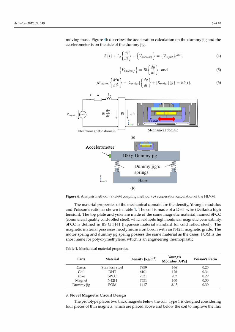
ing four pieces of thin magnets, which are placed above and below the coil to improve the flux density passing through the coil; the coil can generate high Lorentz force. From types 1 to 2, the outer dimension has been changed to consider a smaller volume from 9867 mm3 to 7020 mm3, as shown in Figure 5a.
Figure 4. Analysis method: (a) E–M coupling method; (b) acceleration calculation of the HLVM.
The material properties of the mechanical domain are the density, Young’s modulusand Poisson’s ratio, as shown in Table 1. The coil is made of a DHT wire (Daikoku hightension). The top plate and yoke are made of the same magnetic material, named SPCC(commercial quality cold-rolled steel), which exhibits high nonlinear magnetic permeability.SPCC is defined in JIS G 3141 (Japanese material standard for cold rolled steel). Themagnetic material possesses neodymium iron boron with an N42H magnetic grade. Themotor spring and dummy jig spring possess the same material as the cases. POM is theshort name for polyoxymethylene, which is an engineering thermoplastic.
Table 1. Mechanical material properties.
Parts Material Density [kg/m3]Young’s
Modulus [GPa] Poison’s Ratio
Cases Stainless steel 7859 166 0.25Coil DHT 6101 126 0.34Yoke SPCC 7821 207 0.29
Magnet N42H 7551 160 0.30Dummy jig POM 1417 3.15 0.30
3. Novel Magnetic Circuit Design
The prototype places two thick magnets below the coil. Type 1 is designed consideringfour pieces of thin magnets, which are placed above and below the coil to improve the flux
Actuators 2022, 11, 149 6 of 10
density passing through the coil; the coil can generate high Lorentz force. From types 1 to2, the outer dimension has been changed to consider a smaller volume from 9867 mm3 to7020 mm3, as shown in Figure 5a.
Actuators 2022, 11, x FOR PEER REVIEW 6 of 11
To improve the Lorentz force as much as possible, the coil is positioned at the center of the magnets. The yoke shape is designed as an x-axial symmetry. The prototype coil plate is connected to the upper case using the welding process, whereas the type 2 design uses a newly structured coil plate fixed on the lower case with a silicon supporter to im-prove the stability of the coil. Owing to the coil plate, the coil comes closer to the upper magnet, which implies that the upper air gap is smaller than the lower air gap in the type 2 design.
Furthermore, coil DCR, FPCB (flexible printed circuit board) and spring dimensions are redesigned to produce a resonance frequency similar to that of the prototype. The po-sition of the type 2 coil is shown in Figure 5b.
(a)
(b)
Figure 5. Prototype and new designs: (a) dimension and structure comparison and (b) the position of the type 2 coil.
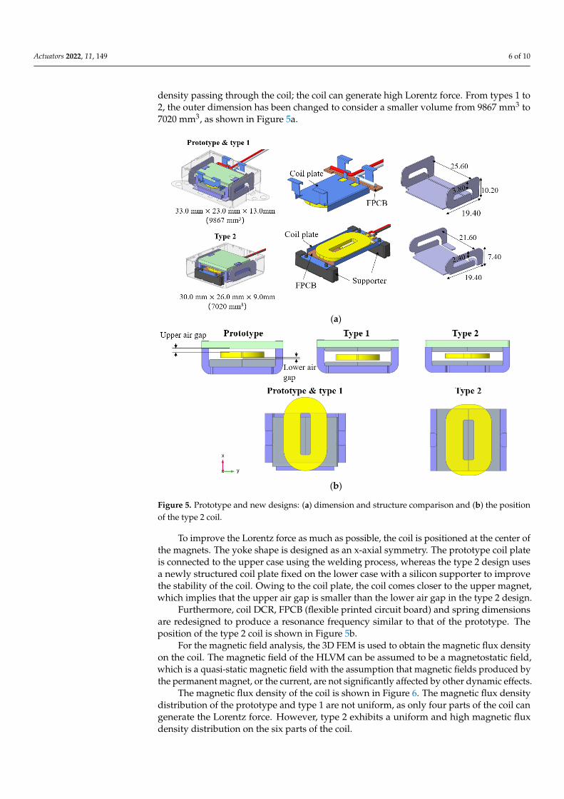
For the magnetic field analysis, the 3D FEM is used to obtain the magnetic flux den-sity on the coil. The magnetic field of the HLVM can be assumed to be a magnetostatic field, which is a quasi-static magnetic field with the assumption that magnetic fields pro-duced by the permanent magnet, or the current, are not significantly affected by other dynamic effects.
The magnetic flux density of the coil is shown in Figure 6. The magnetic flux density distribution of the prototype and type 1 are not uniform, as only four parts of the coil can generate the Lorentz force. However, type 2 exhibits a uniform and high magnetic flux density distribution on the six parts of the coil.
Figure 5. Prototype and new designs: (a) dimension and structure comparison and (b) the positionof the type 2 coil.
To improve the Lorentz force as much as possible, the coil is positioned at the center ofthe magnets. The yoke shape is designed as an x-axial symmetry. The prototype coil plateis connected to the upper case using the welding process, whereas the type 2 design usesa newly structured coil plate fixed on the lower case with a silicon supporter to improvethe stability of the coil. Owing to the coil plate, the coil comes closer to the upper magnet,which implies that the upper air gap is smaller than the lower air gap in the type 2 design.
Furthermore, coil DCR, FPCB (flexible printed circuit board) and spring dimensionsare redesigned to produce a resonance frequency similar to that of the prototype. Theposition of the type 2 coil is shown in Figure 5b.
For the magnetic field analysis, the 3D FEM is used to obtain the magnetic flux densityon the coil. The magnetic field of the HLVM can be assumed to be a magnetostatic field,which is a quasi-static magnetic field with the assumption that magnetic fields produced bythe permanent magnet, or the current, are not significantly affected by other dynamic effects.
The magnetic flux density of the coil is shown in Figure 6. The magnetic flux densitydistribution of the prototype and type 1 are not uniform, as only four parts of the coil cangenerate the Lorentz force. However, type 2 exhibits a uniform and high magnetic fluxdensity distribution on the six parts of the coil.
Actuators 2022, 11, 149 7 of 10Actuators 2022, 11, x FOR PEER REVIEW 7 of 11
Figure 6. Model and flux density distribution comparison.
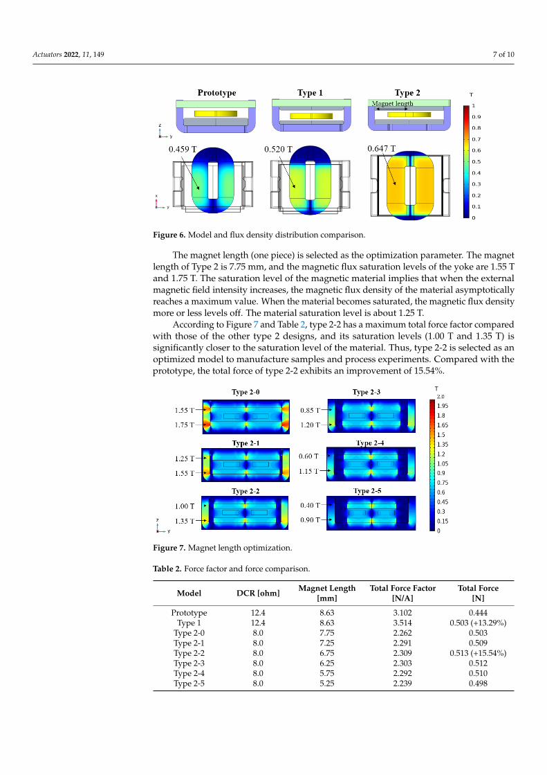
The magnet length (one piece) is selected as the optimization parameter. The magnet length of Type 2 is 7.75 mm, and the magnetic flux saturation levels of the yoke are 1.55 T and 1.75 T. The saturation level of the magnetic material implies that when the external magnetic field intensity increases, the magnetic flux density of the material asymptotically reaches a maximum value. When the material becomes saturated, the magnetic flux den-sity more or less levels off. The material saturation level is about 1.25 T.
According to Figure 7 and Table 2, type 2-2 has a maximum total force factor com-pared with those of the other type 2 designs, and its saturation levels (1.00 T and 1.35 T) is significantly closer to the saturation level of the material. Thus, type 2-2 is selected as an optimized model to manufacture samples and process experiments. Compared with the prototype, the total force of type 2-2 exhibits an improvement of 15.54%.
Figure 7. Magnet length optimization.
Table 2. Force factor and force comparison.
Model DCR [ohm] Magnet Length
[mm] Total Force Factor
[N/A] Total Force
[N] Prototype 12.4 8.63 3.102 0.444
Type 1 12.4 8.63 3.514 0.503 (+13.29%) Type 2-0 8.0 7.75 2.262 0.503 Type 2-1 8.0 7.25 2.291 0.509 Type 2-2 8.0 6.75 2.309 0.513 (+15.54%) Type 2-3 8.0 6.25 2.303 0.512 Type 2-4 8.0 5.75 2.292 0.510 Type 2-5 8.0 5.25 2.239 0.498
Figure 6. Model and flux density distribution comparison.
The magnet length (one piece) is selected as the optimization parameter. The magnetlength of Type 2 is 7.75 mm, and the magnetic flux saturation levels of the yoke are 1.55 Tand 1.75 T. The saturation level of the magnetic material implies that when the externalmagnetic field intensity increases, the magnetic flux density of the material asymptoticallyreaches a maximum value. When the material becomes saturated, the magnetic flux densitymore or less levels off. The material saturation level is about 1.25 T.
According to Figure 7 and Table 2, type 2-2 has a maximum total force factor comparedwith those of the other type 2 designs, and its saturation levels (1.00 T and 1.35 T) issignificantly closer to the saturation level of the material. Thus, type 2-2 is selected as anoptimized model to manufacture samples and process experiments. Compared with theprototype, the total force of type 2-2 exhibits an improvement of 15.54%.
Actuators 2022, 11, x FOR PEER REVIEW 7 of 11
Figure 6. Model and flux density distribution comparison.
The magnet length (one piece) is selected as the optimization parameter. The magnet length of Type 2 is 7.75 mm, and the magnetic flux saturation levels of the yoke are 1.55 T and 1.75 T. The saturation level of the magnetic material implies that when the external magnetic field intensity increases, the magnetic flux density of the material asymptotically reaches a maximum value. When the material becomes saturated, the magnetic flux den-sity more or less levels off. The material saturation level is about 1.25 T.
According to Figure 7 and Table 2, type 2-2 has a maximum total force factor com-pared with those of the other type 2 designs, and its saturation levels (1.00 T and 1.35 T) is significantly closer to the saturation level of the material. Thus, type 2-2 is selected as an optimized model to manufacture samples and process experiments. Compared with the prototype, the total force of type 2-2 exhibits an improvement of 15.54%.
Figure 7. Magnet length optimization.
Table 2. Force factor and force comparison.
Model DCR [ohm] Magnet Length
[mm] Total Force Factor
[N/A] Total Force
[N] Prototype 12.4 8.63 3.102 0.444
Type 1 12.4 8.63 3.514 0.503 (+13.29%) Type 2-0 8.0 7.75 2.262 0.503 Type 2-1 8.0 7.25 2.291 0.509 Type 2-2 8.0 6.75 2.309 0.513 (+15.54%) Type 2-3 8.0 6.25 2.303 0.512 Type 2-4 8.0 5.75 2.292 0.510 Type 2-5 8.0 5.25 2.239 0.498
Figure 7. Magnet length optimization.
Table 2. Force factor and force comparison.
Model DCR [ohm] Magnet Length[mm]
Total Force Factor[N/A]
Total Force[N]
Prototype 12.4 8.63 3.102 0.444Type 1 12.4 8.63 3.514 0.503 (+13.29%)
Type 2-0 8.0 7.75 2.262 0.503Type 2-1 8.0 7.25 2.291 0.509Type 2-2 8.0 6.75 2.309 0.513 (+15.54%)Type 2-3 8.0 6.25 2.303 0.512Type 2-4 8.0 5.75 2.292 0.510Type 2-5 8.0 5.25 2.239 0.498

Actuators 2022, 11, 149 8 of 10
4. Experiments and Results4.1. Samples and Experimental Setups
Type 2-2 is defined as the final type. The voice coil specification comparison betweenprototype and final type are shown in Table 3. The sample comparison between theprototype and final type is shown in Figure 8a. The parts of type 2-2 are shown in Figure 8b.The input voltage is 1.78 V with a sinusoidal signal of 50–500 Hz. The Klippel measurementsystem includes a monitor for Klippel motor control, power amplifier, Klippel motor andlaser head, shown in Figure 8c. The displacement on the spring from the vibration motorcan be obtained by using laser of Klippel setup. The acceleration measurement setupsinclude the monitor, vibration analyzer, dummy jig and accelerometer. The vibration motoris set on the center of the dummy jig and acceleration is attached on the side to obtain theacceleration, shown in Figure 8d.
Table 3. Voice coil specification comparison.
Model Prototype Final Type
Coil diameter [mm] 0.141 0.117DCR [ohm] 12.4 8.0
Coil inductance [mH] 0.560 0.153Coil total length [m] 10.31 4.58
Coil turn 269 125
Actuators 2022, 11, x FOR PEER REVIEW 8 of 11
4. Experiments and Results 4.1. Samples and Experimental Setups
Type 2-2 is defined as the final type. The voice coil specification comparison between prototype and final type are shown in Table 3. The sample comparison between the pro-totype and final type is shown in Figure 8a. The parts of type 2-2 are shown in Figure 8b. The input voltage is 1.78 V with a sinusoidal signal of 50–500 Hz. The Klippel measure-ment system includes a monitor for Klippel motor control, power amplifier, Klippel motor and laser head, shown in Figure 8c. The displacement on the spring from the vibration motor can be obtained by using laser of Klippel setup. The acceleration measurement set-ups include the monitor, vibration analyzer, dummy jig and accelerometer. The vibration motor is set on the center of the dummy jig and acceleration is attached on the side to obtain the acceleration, shown in Figure 8d.
Table 3. Voice coil specification comparison.
Model Prototype Final Type Coil diameter [mm] 0.141 0.117
DCR [ohm] 12.4 8.0 Coil inductance [mH] 0.560 0.153 Coil total length [m] 10.31 4.58
Coil turn 269 125
(a)
(b)
Figure 8. Cont.

Actuators 2022, 11, 149 9 of 10Actuators 2022, 11, x FOR PEER REVIEW 9 of 11
(c)
(d)
Figure 8. Sample comparison and experimental setups: (a) prototype sample and final type sample; (b) parts of sample; (c) displacement measurement setup; and (d) acceleration measurement setup.
4.2. Experimental Results and Analysis Results The displacement and acceleration comparisons between the prototype and final
type are illustrated in Figure 9. Due to the size reduction, the moving mass of the final type is less than that of the prototype. Compared to the prototype, the final type has a higher force factor, which causes a higher displacement in the motor around the resonance frequency. The higher displacement of the motor offsets the moving mass reduction in the final type and provides a similar acceleration on the dummy jig as that of the prototype. The analysis results match well with the experimental results.
Figure 8. Sample comparison and experimental setups: (a) prototype sample and final type sample;(b) parts of sample; (c) displacement measurement setup; and (d) acceleration measurement setup.
4.2. Experimental Results and Analysis Results
The displacement and acceleration comparisons between the prototype and final typeare illustrated in Figure 9. Due to the size reduction, the moving mass of the final type isless than that of the prototype. Compared to the prototype, the final type has a higher forcefactor, which causes a higher displacement in the motor around the resonance frequency.The higher displacement of the motor offsets the moving mass reduction in the final typeand provides a similar acceleration on the dummy jig as that of the prototype. The analysisresults match well with the experimental results.
Actuators 2022, 11, x FOR PEER REVIEW 10 of 11
(a) (b)
Figure 9. Displacement and acceleration comparison: (a) displacement results and (b) acceleration results.
5. Conclusions In this paper, a small-volume horizontal linear vibration motor that used a novel
magnetic circuit, new coil position magnet, length optimization, new coil plate and new spring size was proposed to obtain a similar performance as the prototype. Moreover, this study clearly described the magnetic circuit of HLVM and developed a force calculation method based on the coil position to obtain the Lorentz force on the coil. To overcome the space limitation of the display, the height of the prototype was reduced from 13.0 mm to 9.0 mm. The novel magnetic circuit with four pieces of permanent magnets has been pro-posed to generate more magnetic flux density passing through the voice coil. The new coil supporters were used to simplify the mechanical structure and improve the stability of the coil plate. The E–M coupled analysis method was used on the HLVM to calculate dis-placement and acceleration on a 100 g dummy jig. The final type exhibited a similar dis-placement and acceleration as those of the prototype, verified by the experimental results.
Author Contributions: Conceptualization, Z.J., K.P. and S.H.; methodology, Z.J.; software, Z.J. and K.P.; validation, Z.J., K.P. and S.H.; formal analysis, Z.J.; investigation, Z.J. and K.P.; resources, Z.J.; data curation, Z.J.; writing—original draft preparation, Z.J.; writing—review and editing, Z.J. and S.H.; visualization, Z.J.; supervision, S.H.; project administration, S.H. All authors have read and agreed to the published version of the manuscript.
Funding: This research received no external funding.
Institutional Review Board Statement: Not applicable.
Informed Consent Statement: Not applicable.
Data Availability Statement: Not applicable.
Conflicts of Interest: The authors declare no conflict of interest.
References 1. Chung, S.U.; Hwang, G.Y.; Hwang, S.M.; Kang, B.S; Kim, H.G. Development of brushless and sensorless vibration motor used
for mobile phone. IEEE Trans. Magn. 2002, 38, 3000–3002. 2. Won, S.H.; Lee, J. Analysis of flat-type vibration motor for mobile phone. IEEE Trans. Magn. 2005, 41, 4018–4020. 3. Hwang, S.M.; Lee, H.J.; Chung, S.U.; Hwang, G.Y.; Kang, B.S. Development of solenoid-type vibrators used for mobile phones.
IEEE Trans. Magn. 2003, 39, 3262–3264. 4. Fukumoto, M.; Sugimura, T. Active click: Tactile feedback for touch panels. In CHI'01 Extended Abstracts on Human Factors in
Computing Systems; Association for Computing Machinery: New York, NY, USA, 2001; pp. 121–122. 5. Choi, J.K.; Yoo, S.Y.; Noh, M. Design and analysis of linear vibration motor equipped with permanent-magnet springs and
voice-coil actuators. Trans. Korean Soc. Mech. Eng. A 2013, 37, 359–364.
Figure 9. Displacement and acceleration comparison: (a) displacement results and (b) accelerationresults.

Actuators 2022, 11, 149 10 of 10
5. Conclusions
In this paper, a small-volume horizontal linear vibration motor that used a novel mag-netic circuit, new coil position magnet, length optimization, new coil plate and new springsize was proposed to obtain a similar performance as the prototype. Moreover, this studyclearly described the magnetic circuit of HLVM and developed a force calculation methodbased on the coil position to obtain the Lorentz force on the coil. To overcome the spacelimitation of the display, the height of the prototype was reduced from 13.0 mm to 9.0 mm.The novel magnetic circuit with four pieces of permanent magnets has been proposed togenerate more magnetic flux density passing through the voice coil. The new coil support-ers were used to simplify the mechanical structure and improve the stability of the coilplate. The E–M coupled analysis method was used on the HLVM to calculate displacementand acceleration on a 100 g dummy jig. The final type exhibited a similar displacement andacceleration as those of the prototype, verified by the experimental results.
Author Contributions: Conceptualization, Z.J., K.P. and S.H.; methodology, Z.J.; software, Z.J. andK.P.; validation, Z.J., K.P. and S.H.; formal analysis, Z.J.; investigation, Z.J. and K.P.; resources, Z.J.;data curation, Z.J.; writing—original draft preparation, Z.J.; writing—review and editing, Z.J. andS.H.; visualization, Z.J.; supervision, S.H.; project administration, S.H. All authors have read andagreed to the published version of the manuscript.
Funding: This research received no external funding.
Institutional Review Board Statement: Not applicable.
Informed Consent Statement: Not applicable.
Data Availability Statement: Not applicable.
Conflicts of Interest: The authors declare no conflict of interest.
References1. Chung, S.U.; Hwang, G.Y.; Hwang, S.M.; Kang, B.S.; Kim, H.G. Development of brushless and sensorless vibration motor used
for mobile phone. IEEE Trans. Magn. 2002, 38, 3000–3002. [CrossRef]2. Won, S.H.; Lee, J. Analysis of flat-type vibration motor for mobile phone. IEEE Trans. Magn. 2005, 41, 4018–4020.3. Hwang, S.M.; Lee, H.J.; Chung, S.U.; Hwang, G.Y.; Kang, B.S. Development of solenoid-type vibrators used for mobile phones.
IEEE Trans. Magn. 2003, 39, 3262–3264. [CrossRef]4. Fukumoto, M.; Sugimura, T. Active click: Tactile feedback for touch panels. In CHI’01 Extended Abstracts on Human Factors in
Computing Systems; Association for Computing Machinery: New York, NY, USA, 2001; pp. 121–122.5. Choi, J.K.; Yoo, S.Y.; Noh, M. Design and analysis of linear vibration motor equipped with permanent-magnet springs and
voice-coil actuators. Trans. Korean Soc. Mech. Eng. A 2013, 37, 359–364. [CrossRef]6. Bernard, C. Perception of Audio-Haptic Textures for New Touchscreen Interactions. Ph.D. Thesis, Aix-Marseile Université,
Marseille, France, 2022.7. Bernard, C.; Monnoyer, J.; Ystad, S.; Wiertlewski, M. Eyes-off your fingers: Gradual surface haptic feedback improves eyes-free
touchscreen interaction. In Proceedings of the CHI Conference on Human Factors in Computing Systems, New Orleans, LA, USA,30 April–3 May 2022; pp. 1–10.
8. Lee, K.B.; Kim, J.H.; Kim, J.H. Horizontal linear vibrating actuator to reduce smart phone thickness. J. Vibroeng. 2013, 15, 2003–2011.9. Yang, T.H.; Pyo, D.; Kim, S.Y.; Cho, Y.J.; Bae, Y.D.; Lee, Y.M.; Lee, J.S.; Lee, E.H.; Kwon, D.S. A new subminiature impact actuator
for mobile devices. In Proceedings of the IEEE World Haptics Conference, Istanbul, Turkey, 21–24 June 2011; pp. 95–100.10. Pyo, D.; Yang, T.H.; Ryu, S.; Kwon, D.S. Novel linear impact-resonant actuator for mobile applications. Sens. Actuators A Phys.
2015, 233, 460–471. [CrossRef]11. Zaouia, M.; Benamrouche, N.; Rachek, M. Electromagnetic-mechanical coupled model of tubular linear stepping motors.
Electromotion 2011, 18, 8–14.12. Kim, J.H.; Jiang, Y.W.; Hwang, S.M. Analysis of a vibrating motor considering electrical, magnetic, and mechanical coupling
effect. Appl. Sci. 2019, 9, 1434. [CrossRef]13. Jiang, Z.X.; Park, K.H.; Hwang, S.M. Design of a Width Slim Linear Vibration Motor Used for Automotive LCD Display Panel.
IEEE Trans. Magn. 2022, 58, 1–5.