Notification of a Proposal to issue a Certification Memorandum ...
25
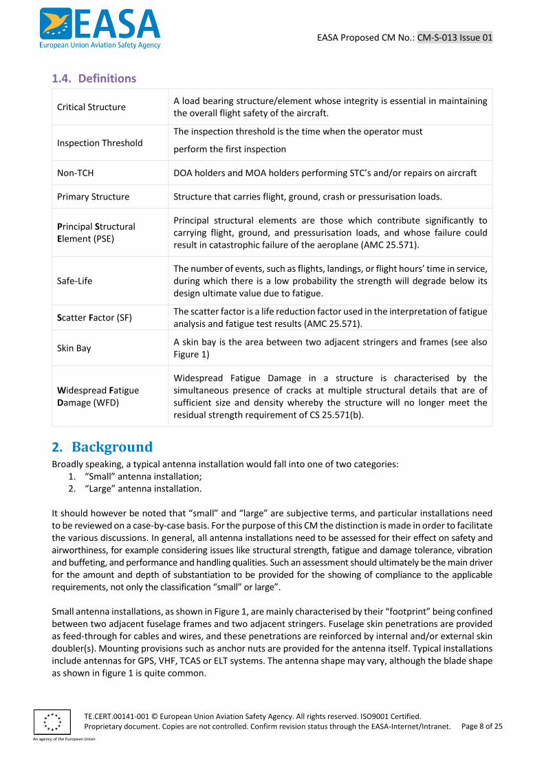
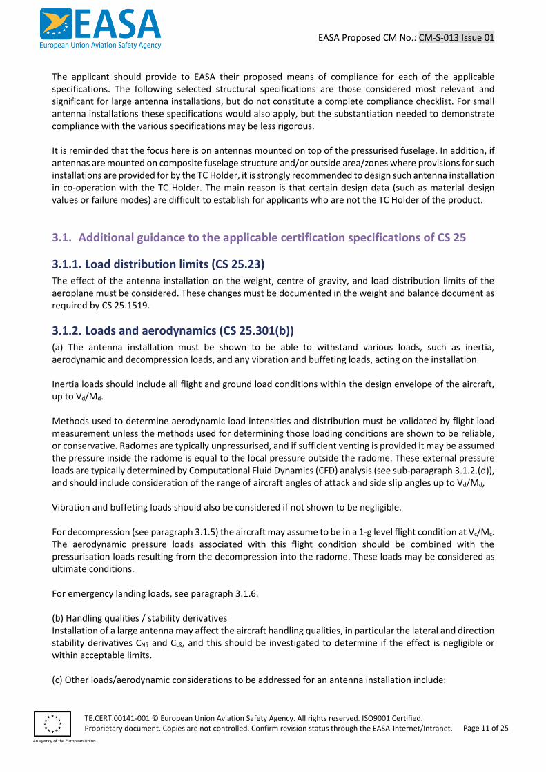
EASA Proposed CM No.: CM-S-013 Issue 01 TE.CERT.00141-001 © European Union Aviation Safety Agency. All rights reserved. ISO9001 Certified. Proprietary document. Copies are not controlled. Confirm revision status through the EASA-Internet/Intranet. An agency of the European Union Page 1 of 25 Notification of a Proposal to issue a Certification Memorandum Installation of Antennas on Large Aeroplanes (CS-25) EASA CM No.: Proposed CM–S–013 Issue 01 issued 15 November 2019 Regulatory requirement(s): CS 25.23, CS 25.301, CS 25.305, CS 25.365, CS 25.561, CS 25.571, CS 25.581, CS 25.603, CS 25.605, CS 25.609, CS 25.613, CS 25.629, CS 25.631, CS 25.841, CS 25.901, CS 25.1419, CS 25.1529 and Appendix H EASA Certification Memoranda (CM) clarify the European Union Aviation Safety Agency’s general course of action on specific certification items. They are intended to provide guidance on a particular subject and, as non-binding material, may provide complementary information and guidance for compliance demonstration with current standards. Certification Memoranda are provided for information purposes only and must not be misconstrued as formally adopted Acceptable Means of Compliance (AMC) or as Guidance Material (GM). Certification Memoranda are not intended to introduce new certification requirements or to modify existing certification requirements and do not constitute any legal obligation. EASA Certification Memoranda are living documents into which either additional criteria or additional issues can be incorporated as soon as a need is identified by EASA.
-
Upload
khangminh22 -
Category
Documents
-
view
0 -
download
0
Transcript of Notification of a Proposal to issue a Certification Memorandum ...
EASA Proposed CM No.: CM-S-013 Issue 01
TE.CERT.00141-001 © European Union Aviation Safety Agency. All rights reserved. ISO9001 Certified.
Proprietary document. Copies are not controlled. Confirm revision status through the EASA-Internet/Intranet. An agency of the European Union
Page 1 of 25
Notification of a Proposal to issue a Certification Memorandum
Installation of Antennas on Large Aeroplanes (CS-25)
EASA CM No.: Proposed CM–S–013 Issue 01 issued 15 November 2019
Regulatory requirement(s): CS 25.23, CS 25.301, CS 25.305, CS 25.365, CS 25.561, CS 25.571, CS 25.581, CS 25.603, CS 25.605, CS 25.609, CS 25.613, CS 25.629, CS 25.631, CS 25.841, CS 25.901, CS 25.1419, CS 25.1529 and Appendix H
EASA Certification Memoranda (CM) clarify the European Union Aviation Safety Agency’s general course of action on specific certification items. They are intended to provide guidance on a particular subject and, as non-binding material, may provide complementary information and guidance for compliance demonstration with current standards. Certification Memoranda are provided for information purposes only and must not be misconstrued as formally adopted Acceptable Means of Compliance (AMC) or as Guidance Material (GM). Certification Memoranda are not intended to introduce new certification requirements or to modify existing certification requirements and do not constitute any legal obligation. EASA Certification Memoranda are living documents into which either additional criteria or additional issues can be incorporated as soon as a need is identified by EASA.
EASA Proposed CM No.: CM-S-013 Issue 01
TE.CERT.00141-001 © European Union Aviation Safety Agency. All rights reserved. ISO9001 Certified.
Proprietary document. Copies are not controlled. Confirm revision status through the EASA-Internet/Intranet. An agency of the European Union
Page 2 of 25
Log of issues
Issue Issue date Change description
01 15/11/2019 First issue
Table of Content Log of issues ....................................................................................................................................................... 2
Table of Content ................................................................................................................................................ 2
1. Introduction ............................................................................................................................................... 4
1.1. Purpose and scope ............................................................................................................................ 4
1.2. References ......................................................................................................................................... 4
1.3. Abbreviations ..................................................................................................................................... 6
1.4. Definitions ......................................................................................................................................... 8
2. Background ................................................................................................................................................ 8
3. EASA Certification Policy ......................................................................................................................... 10
3.1. Additional guidance to the applicable certification specifications of CS 25 ................................... 11
3.1.1. Load distribution limits (CS 25.23) ........................................................................................... 11
3.1.2. Loads and aerodynamics (CS 25.301(b)) ................................................................................. 11
3.1.3. Strength and deformation (CS 25.303, 25.305, 25.307 and 25.625) ....................................... 12
3.1.4. Vibration and Buffeting (CS 25.251, 25.305(e)) ....................................................................... 12
3.1.5. Pressurised compartment loads (CS 25.365(e)) ...................................................................... 12
3.1.6. Emergency landing conditions (CS 25.561) ............................................................................. 13
3.1.7. Damage-tolerance and fatigue evaluation of structure (CS 25.571) ....................................... 13
3.1.8. Lightning protection (CS 25.581) ............................................................................................. 15
3.1.9. Materials (CS 25.603), Material Strength Properties and Material Design Values (CS 25.613) 15
3.1.10. Fabrication methods (CS 25.605) ............................................................................................ 16
3.1.11. Protection of structure (CS 25.609) ......................................................................................... 16
3.1.12. Aeroelastic stability requirements (CS 25.629) ....................................................................... 16
3.1.13. Bird strike damage (CS 25.631) ............................................................................................... 16
3.1.14. Pressurised cabins (CS 25.841) ................................................................................................ 17
3.1.15. Sustained engine imbalance (CS 25.901(c)) ............................................................................ 17
3.1.16. Ice Protection (CS 25.1419) and Super cooled Large Droplets (CS-25.1420) .......................... 18
3.1.17. Instructions for Continued Airworthiness (CS 25.1529 and Appendix H) ............................... 18
3.1.18. Airworthiness Directives .......................................................................................................... 18
3.2. Who this Certification Memorandum affects.................................................................................. 18
4. Remarks ................................................................................................................................................... 18
5. Appendix .................................................................................................................................................. 19

EASA Proposed CM No.: CM-S-013 Issue 01
TE.CERT.00141-001 © European Union Aviation Safety Agency. All rights reserved. ISO9001 Certified. Proprietary document. Copies are not controlled. Confirm revision status through the EASA-Internet/Intranet.
An agency of the European Union
Page 3 of 25
5.1. Appendix A: Damage Tolerance and Fatigue Evaluation ................................................................. 19
5.1.1. Applicable certification specifications ..................................................................................... 19
5.1.2. Selection of new or modified structural details for evaluation ............................................... 19
5.1.3. Development of the fatigue spectrum .................................................................................... 20
5.1.4. Initial, detectable and critical crack lengths ............................................................................ 20
5.1.5. Crack growth analysis .............................................................................................................. 22
5.1.6. Determination of thresholds and repeat intervals .................................................................. 23
5.2. Appendix B: Bird Strike Damage – Numerical Analysis ................................................................... 24
EASA Proposed CM No.: CM-S-013 Issue 01
TE.CERT.00141-001 © European Union Aviation Safety Agency. All rights reserved. ISO9001 Certified.
Proprietary document. Copies are not controlled. Confirm revision status through the EASA-Internet/Intranet. An agency of the European Union
Page 4 of 25
1. Introduction
1.1. Purpose and scope The purpose of this Certification Memorandum is to provide guidance regarding the installation of (small or large) antennas mounted on top of the pressurised fuselage1 of large aeroplanes (CS-25). Antenna installations on aircraft are becoming more and more common due to operational and commercial needs and demands. Based on experience acquired on many certification programmes, EASA is of the opinion that further guidance is needed in relation to antenna installations, to clarify the most relevant and most significant certification and means of compliance issues. This applies to all applicants and is especially important for supplemental type certificate (STC) applicants who are non-type certificate holders (non-TCH), as they may not have access to all type certificate holder (TCH) data required for such installations. The safety issues associated with antenna installations are mainly related to their size, shape, location and their attachment means. These aspects of antenna installations may determine the effect on, for example the stability& control, aeroelastic behaviour or damage tolerance characteristics of the aircraft. Compliance with the applicable certification specifications is also aimed at avoiding antenna separation or (partial) break-up, which may result in impact of debris on other structural elements or systems of the aircraft and could also jeopardize persons on the ground. This CM therefore provides guidance, making a distinction between “large” and “small” antenna installations, which may help applicants to define the extent to which compliance with the various applicable specifications has to be shown. The focus of this CM is on structural (related) certification specifications associated with antenna installations, and/or the effect(s) such antenna installations may have on aircraft structure or on persons on the ground [35]. Other airworthiness (e.g. systems related) or environmental requirements, that are not part of this CM, however may also apply and would have to be considered.
1.2. References It is intended that the following reference materials be used in conjunction with this Certification Memorandum:
Reference Title Code Issue Date
[1]
Annex I (PART-21) to Regulation (EU) No 748/2012 + AMC and GM and Certification specifications and acceptable means of compliance for large aeroplanes
PART-21
CS-25
latest
latest
-
-
[2]
Repairs to Damage Tolerant Aircraft, FAA-AIR-90-01 and
- - -
1 Some of the considerations contained in this CM are also relevant for antenna installations on other aircraft locations, or for other external modifications such as camera installations or external stores, but for these installations additional/different considerations may apply
EASA Proposed CM No.: CM-S-013 Issue 01
TE.CERT.00141-001 © European Union Aviation Safety Agency. All rights reserved. ISO9001 Certified. Proprietary document. Copies are not controlled. Confirm revision status through the EASA-Internet/Intranet.
An agency of the European Union
Page 5 of 25
Reference Title Code Issue Date
Engineering Approach to Damage Tolerance Analysis of Fuselage Skin Repairs, DOT/FAA/AR-95/75,
[3] Effects of Repair on Structural Integrity, DOT-FAA-CT-93-79
- - -
[4] Generation of Spectra and Stress histories for F&DT analysis of fuselage repairs, DOT-VNTSC-FAA-91-16,
- - -
[5] Structural Certification for Antennas, Radomes and other External Modifications, FAA PS-ANM-25-17
- latest -
[6] USAF Structures Bulletin No. EN-SB-08-002 - latest -
[7]
Chicago Aircraft Certification Office (ACO) paper “Damage Tolerance Analysis for antenna Installations on Pressurized Transport Airplanes” R. Eastin (presentation) or J. McGarvey (paper)
- - -
[8] “DTA guidelines for antenna installations”, P. Safarian - - -
[9] NASGRO Reference Manual - latest -
[10] “Airframe Structural Design”, M. Niu - - -
[11] AFGROW DTD Handbook online - latest -
[12] HSB Handbuch Struktur Berechnung ch. 60000 - latest -
[13] FAA DT Handbook, DOT/FAA/CT-93/69 - latest -
[14] ESDU Series - - -
[15] Current Nondestructive Inspection Methods for Aging Aircraft, DOT/FAA/CT-91/5
- - -
[16], [17] Detectable crack: NAVAIR technical manual NDT Resource Center
- - -
[18], [19], [20], [21]
Stress Intensity Factor: Handbuch Struktur Berechnung Ch. 60000 ESDU Intensity Factors NASGRO Manual Swift papers/courses
- latest -
[22], [23], [24], [25], [26], [27]
Material F&DT Properties: MMPDS Walker Coefficients from Chicago Paper ESDU Handbuch Struktur Berechnung Ch. 60000 ASM handbook NASGRO/AFGROW database
- latest -
[28] Stress Concentration Factors, R.E. Peterson - - -
EASA Proposed CM No.: CM-S-013 Issue 01
TE.CERT.00141-001 © European Union Aviation Safety Agency. All rights reserved. ISO9001 Certified. Proprietary document. Copies are not controlled. Confirm revision status through the EASA-Internet/Intranet.
An agency of the European Union
Page 6 of 25
Reference Title Code Issue Date
[29] Environmental Conditions and Test Procedures for Airborne Equipment, DO160
- latest -
[30] Composite Aircraft Structure, AMC 20-29 - latest -
[31] Aircraft Electrical and Electronic System Lightning Protection, AC 20-136
- latest -
[32] Composite Materials Handbook, CMH-17 - latest -
[33] Bird Strike Damage, CM S-001 - latest -
[34] Sustained Engine Imbalance, AMC 25-24 - latest -
[35] Basic Regulation, Article 4 - latest -
1.3. Abbreviations
AC Advisory Circular
ACO Aircraft Certification Office
ALS Airworthiness Limitation Section
AMC Acceptable Means of Compliance
AMoC Alternative Means of Compliance
ASNA AIRBUS Internal Parts Standard
BAC Boeing Aircraft Company internal Standard
CFD Computational Fluid Dynamics
CFR Code of Federal Regulations
CM Certification Memorandum
CMH Composite Materials Handbook
CS Certification Specification
DDP Declaration of Design and Performance
DOA Design Organisation Approval
DT Damage Tolerance
EASA European Union Aviation Safety Agency
ELT Emergency Locator Transmitter
EASA Proposed CM No.: CM-S-013 Issue 01
TE.CERT.00141-001 © European Union Aviation Safety Agency. All rights reserved. ISO9001 Certified. Proprietary document. Copies are not controlled. Confirm revision status through the EASA-Internet/Intranet.
An agency of the European Union
Page 7 of 25
ESF Equivalent Safety Finding
FAA Federal Aviation Administration
FAR Federal Aviation Regulations
FCBS Fatigue Critical Baseline Structure
FEA Finite Element Analysis
F&DT Fatigue & Damage Tolerance
GM Guidance Material
GPS Global Positioning System
HSB Handbuch Strukturberechnung
ICA Instructions for continued Airworthiness
JAR Joint Aviation Requirements
MMPDS Metallic Materials Properties Development and Standardization
MOA Maintenance Organisation Approval Holder
NAS National Aerospace Standard
NDI Non Destructive Inspection
Non-TCH Non-Type Certificate Holder
OEM Original Equipment Manufacturer
PSE Principal Structural Element
SF Scatter Factor
SRM Structures Repair Manual
STC Supplemental Type Certificate
TCAS Traffic Collision Avoidance System
TCH Type Certificate Holder
VHF Very High Frequency
WFD Widespread Fatigue Damage
EASA Proposed CM No.: CM-S-013 Issue 01
TE.CERT.00141-001 © European Union Aviation Safety Agency. All rights reserved. ISO9001 Certified. Proprietary document. Copies are not controlled. Confirm revision status through the EASA-Internet/Intranet.
An agency of the European Union
Page 8 of 25
1.4. Definitions
Critical Structure A load bearing structure/element whose integrity is essential in maintaining the overall flight safety of the aircraft.
Inspection Threshold The inspection threshold is the time when the operator must
perform the first inspection
Non-TCH DOA holders and MOA holders performing STC’s and/or repairs on aircraft
Primary Structure Structure that carries flight, ground, crash or pressurisation loads.
Principal Structural Element (PSE)
Principal structural elements are those which contribute significantly to carrying flight, ground, and pressurisation loads, and whose failure could result in catastrophic failure of the aeroplane (AMC 25.571).
Safe-Life The number of events, such as flights, landings, or flight hours’ time in service, during which there is a low probability the strength will degrade below its design ultimate value due to fatigue.
Scatter Factor (SF) The scatter factor is a life reduction factor used in the interpretation of fatigue analysis and fatigue test results (AMC 25.571).
Skin Bay A skin bay is the area between two adjacent stringers and frames (see also Figure 1)
Widespread Fatigue Damage (WFD)
Widespread Fatigue Damage in a structure is characterised by the simultaneous presence of cracks at multiple structural details that are of sufficient size and density whereby the structure will no longer meet the residual strength requirement of CS 25.571(b).
2. Background Broadly speaking, a typical antenna installation would fall into one of two categories:
1. “Small” antenna installation; 2. “Large” antenna installation.
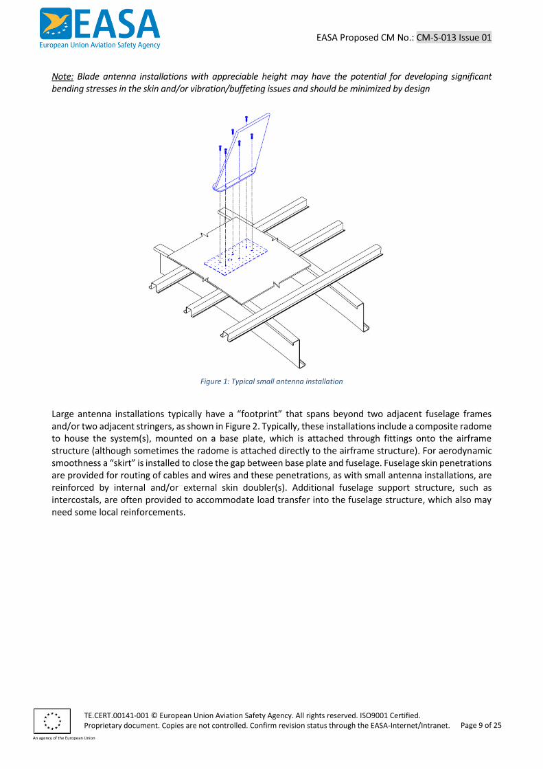
It should however be noted that “small” and “large” are subjective terms, and particular installations need to be reviewed on a case-by-case basis. For the purpose of this CM the distinction is made in order to facilitate the various discussions. In general, all antenna installations need to be assessed for their effect on safety and airworthiness, for example considering issues like structural strength, fatigue and damage tolerance, vibration and buffeting, and performance and handling qualities. Such an assessment should ultimately be the main driver for the amount and depth of substantiation to be provided for the showing of compliance to the applicable requirements, not only the classification “small” or large”. Small antenna installations, as shown in Figure 1, are mainly characterised by their “footprint” being confined between two adjacent fuselage frames and two adjacent stringers. Fuselage skin penetrations are provided as feed-through for cables and wires, and these penetrations are reinforced by internal and/or external skin doubler(s). Mounting provisions such as anchor nuts are provided for the antenna itself. Typical installations include antennas for GPS, VHF, TCAS or ELT systems. The antenna shape may vary, although the blade shape as shown in figure 1 is quite common.
EASA Proposed CM No.: CM-S-013 Issue 01
TE.CERT.00141-001 © European Union Aviation Safety Agency. All rights reserved. ISO9001 Certified. Proprietary document. Copies are not controlled. Confirm revision status through the EASA-Internet/Intranet.
An agency of the European Union
Page 9 of 25
Note: Blade antenna installations with appreciable height may have the potential for developing significant bending stresses in the skin and/or vibration/buffeting issues and should be minimized by design
Figure 1: Typical small antenna installation
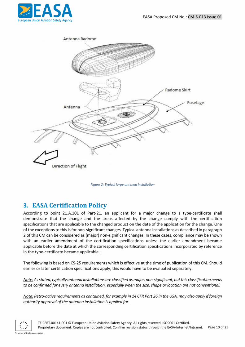
Large antenna installations typically have a “footprint” that spans beyond two adjacent fuselage frames and/or two adjacent stringers, as shown in Figure 2. Typically, these installations include a composite radome to house the system(s), mounted on a base plate, which is attached through fittings onto the airframe structure (although sometimes the radome is attached directly to the airframe structure). For aerodynamic smoothness a “skirt” is installed to close the gap between base plate and fuselage. Fuselage skin penetrations are provided for routing of cables and wires and these penetrations, as with small antenna installations, are reinforced by internal and/or external skin doubler(s). Additional fuselage support structure, such as intercostals, are often provided to accommodate load transfer into the fuselage structure, which also may need some local reinforcements.
EASA Proposed CM No.: CM-S-013 Issue 01
TE.CERT.00141-001 © European Union Aviation Safety Agency. All rights reserved. ISO9001 Certified. Proprietary document. Copies are not controlled. Confirm revision status through the EASA-Internet/Intranet.
An agency of the European Union
Page 10 of 25
Figure 2: Typical large antenna installation
3. EASA Certification Policy According to point 21.A.101 of Part-21, an applicant for a major change to a type-certificate shall demonstrate that the change and the areas affected by the change comply with the certification specifications that are applicable to the changed product on the date of the application for the change. One of the exceptions to this is for non-significant changes. Typical antenna installations as described in paragraph 2 of this CM can be considered as (major) non-significant changes. In these cases, compliance may be shown with an earlier amendment of the certification specifications unless the earlier amendment became applicable before the date at which the corresponding certification specifications incorporated by reference in the type-certificate became applicable. The following is based on CS-25 requirements which is effective at the time of publication of this CM. Should earlier or later certification specifications apply, this would have to be evaluated separately. Note: As stated, typically antenna installations are classified as major, non-significant, but this classification needs to be confirmed for every antenna installation, especially when the size, shape or location are not conventional. Note: Retro-active requirements as contained, for example in 14 CFR Part 26 in the USA, may also apply if foreign authority approval of the antenna installation is applied for.
EASA Proposed CM No.: CM-S-013 Issue 01
TE.CERT.00141-001 © European Union Aviation Safety Agency. All rights reserved. ISO9001 Certified. Proprietary document. Copies are not controlled. Confirm revision status through the EASA-Internet/Intranet.
An agency of the European Union
Page 11 of 25
The applicant should provide to EASA their proposed means of compliance for each of the applicable specifications. The following selected structural specifications are those considered most relevant and significant for large antenna installations, but do not constitute a complete compliance checklist. For small antenna installations these specifications would also apply, but the substantiation needed to demonstrate compliance with the various specifications may be less rigorous. It is reminded that the focus here is on antennas mounted on top of the pressurised fuselage. In addition, if antennas are mounted on composite fuselage structure and/or outside area/zones where provisions for such installations are provided for by the TC Holder, it is strongly recommended to design such antenna installation in co-operation with the TC Holder. The main reason is that certain design data (such as material design values or failure modes) are difficult to establish for applicants who are not the TC Holder of the product.
3.1. Additional guidance to the applicable certification specifications of CS 25
3.1.1. Load distribution limits (CS 25.23) The effect of the antenna installation on the weight, centre of gravity, and load distribution limits of the aeroplane must be considered. These changes must be documented in the weight and balance document as required by CS 25.1519.
3.1.2. Loads and aerodynamics (CS 25.301(b)) (a) The antenna installation must be shown to be able to withstand various loads, such as inertia, aerodynamic and decompression loads, and any vibration and buffeting loads, acting on the installation. Inertia loads should include all flight and ground load conditions within the design envelope of the aircraft, up to Vd/Md. Methods used to determine aerodynamic load intensities and distribution must be validated by flight load measurement unless the methods used for determining those loading conditions are shown to be reliable, or conservative. Radomes are typically unpressurised, and if sufficient venting is provided it may be assumed the pressure inside the radome is equal to the local pressure outside the radome. These external pressure loads are typically determined by Computational Fluid Dynamics (CFD) analysis (see sub-paragraph 3.1.2.(d)), and should include consideration of the range of aircraft angles of attack and side slip angles up to Vd/Md, Vibration and buffeting loads should also be considered if not shown to be negligible. For decompression (see paragraph 3.1.5) the aircraft may assume to be in a 1-g level flight condition at Vc/Mc. The aerodynamic pressure loads associated with this flight condition should be combined with the pressurisation loads resulting from the decompression into the radome. These loads may be considered as ultimate conditions. For emergency landing loads, see paragraph 3.1.6. (b) Handling qualities / stability derivatives Installation of a large antenna may affect the aircraft handling qualities, in particular the lateral and direction stability derivatives CNß and CLß, and this should be investigated to determine if the effect is negligible or within acceptable limits. (c) Other loads/aerodynamic considerations to be addressed for an antenna installation include:
EASA Proposed CM No.: CM-S-013 Issue 01
TE.CERT.00141-001 © European Union Aviation Safety Agency. All rights reserved. ISO9001 Certified. Proprietary document. Copies are not controlled. Confirm revision status through the EASA-Internet/Intranet.
An agency of the European Union
Page 12 of 25
- the downstream effect of the disturbed airflow caused by the radome, for example on tail structure, engines or other (existing or optional) antenna installations;
- the effect on air load distributions, for example on the wings when the radome is installed close to the wings;
- increase in drag, which may result in performance penalties.
(d) Computational Fluid Dynamics (CFD) CFD analysis is often used to determine the pressure loads (distribution) on the antenna installation and/or to investigate the effect of the installation on the vibration and buffet characteristics of the aircraft. See paragraph 3.1.4. for further guidance on this subject.
3.1.3. Strength and deformation (CS 25.303, 25.305, 25.307 and 25.625) Compliance to the static strength requirements has to be shown for all of the structural elements of the antenna installation, including the radome, base plate, airframe attachments/reinforcements and equipment/systems installations. It means that limit load deformation criteria have to be met, as well as demonstration of sufficient strength for the critical ultimate load cases, considering cut-outs and stress concentrations areas. Structural analysis may be used only if the structure conforms to that for which experience has shown this method to be reliable. Some items that may require specific attention for antenna installations:
(a) As most radomes are made from composite material, and the base plate to which they are attached to is typically metallic, thermal stresses would have to be considered in the static strength substantiation;
(b) The effect of additional loads due to the antenna installation being introduced in the airframe structure (e.g. fuselage frames) needs to be evaluated, and if the pre-modified loads/stresses are unknown, conservative assumptions may have to made to substantiate sufficient strength capability;
(c) Although composite radomes may be considered as “secondary” (non-PSE) structure, the effect of Category 1 damage (as per AMC 20-29) on the ultimate strength capability should be considered, as well as the effect of environmental conditions;
(d) If discrete fittings are used to attach the base plate to the airframe structure, it is highly recommended to design this as fail-safe structure (i.e. one of the most critical fittings can be lost and residual limit load capability can be shown). It is also reminded that for intact conditions the fitting factor requirements of CS 25.625 apply.
3.1.4. Vibration and Buffeting (CS 25.251, 25.305(e)) The effects of vibration and buffeting on the aeroplane resulting from the antenna installation must be considered, as well as the effect on the antenna installation itself. In addition to CS 25.305(e), CS 25.251 also applies, and needs to be complied with. For more details (including guidance on the use of CFD analysis and the need for additional flight testing) on this subject applicants may refer to the EASA Generic Certification Review Item (ESF) on Vibration & Buffeting, available at EASA. Particular attention should be paid to the aerodynamic interference effect between multiple antenna installations. Service experience has shown that this effect can be significant with different combinations of small and large antennas installed.
3.1.5. Pressurised compartment loads (CS 25.365(e)) Rapid pressurisation of the antenna compartment (radome) must be considered as outlined in CS 25.365(e)(3) if loss of the antenna could interfere with continued safe flight and landing. CS 25.365(e)(3)
EASA Proposed CM No.: CM-S-013 Issue 01
TE.CERT.00141-001 © European Union Aviation Safety Agency. All rights reserved. ISO9001 Certified. Proprietary document. Copies are not controlled. Confirm revision status through the EASA-Internet/Intranet.
An agency of the European Union
Page 13 of 25
requires the consideration of “the maximum opening caused by aeroplane or equipment failures not shown to be extremely improbable.”
EASA’s interpretation of CS 25.365(e)(3) is that to address structural failures, the opening size resulting from a skin bay failure (bounded by two adjacent frames and two adjacent stringers) should generally be considered (i.e. is not extremely improbable), unless a smaller opening can be justified based upon the maximum level of cracking that can be conservatively expected when a directed inspection for the structure under the radome exists in the ALS. The assumed crack size and resulting opening should account for bulging affects and the possibility of missed opportunities for detection. Failures to equipment and items such as sealed skirt should also be considered separately and in combination with structural failures as appropriate.
Consideration of CS 25.365(e)(1) is not required as the engine disintegration is assumed to adequately “vent” any remaining section of radome if the compartment beneath is penetrated. Application of the formula hole size requirement of CS 25.365(e)(2) is also not required, since, for the size of radome being considered, the majority of hole sizes up to the maximum stated in the formula will exceed the boundary of the antenna/radome. Furthermore, the potential for such large openings to create debris problems equivalent to or worse than the loss of the antenna alone supports the position that application of CS 25.365(e)(2) to such antenna would be beyond the accepted intent of the rule. Rather, the focus for compliance to the decompression requirement should be consideration of any airframe or equipment failures not shown to be extremely improbable, as explained above.
3.1.6. Emergency landing conditions (CS 25.561) Compliance to CS 25.561 (c) and (d) needs to be considered for installation of equipment/system items inside of the fuselage that are related to the antenna installation, for example, when such items are installed in the passenger cabin, as these items of mass could cause direct injury to occupants in case of release. This requirement also addresses impact on critical systems. Compliance to this paragraph is generally not requested for the external antenna installation itself, but this depends on the installation details.
3.1.7. Damage-tolerance and fatigue evaluation of structure (CS 25.571) A damage tolerance evaluation2 must be performed on any structural element of the antenna installation whose failure due to fatigue, manufacturing defects, environmental deterioration or accidental damage could result in loss of the antenna and subsequent strike on other parts of the aircraft, such as the empennage, or other hazards such as rapid decompression of the aeroplane. Any inspection that is determined necessary as a result of this evaluation must be addressed as per CS 25.1529 and Appendix H (see paragraph 3.18). For small antenna installation, [7] and [8] provide acceptable methods for the damage tolerance evaluation. This method, sometimes referred to as the Chicago ACO method due to its origin, is based on a conservative definition of the “far-field” 1-g longitudinal stress level, σ1g, acting on the outer perimeters of the antenna installation. This longitudinal stress is due to the combined action of pressure and bending loads. A constant amplitude fatigue spectrum is derived from this loading condition, with a factor of 1.3 applied to obtain the peak stress. Using for example the compatibility equations from [2] one can derive the stresses in the critical fastener locations, which form the basis for the subsequent crack growth analysis, from initial crack length to critical crack length, to determine the necessary inspection threshold and repeat interval. Similarly, but
2 In most cases a damage tolerance evaluation is required, or is considered as the most practical way to show compliance. See Appendix A under chapter 5.1.1 for a more detailed discussion on this issue.
EASA Proposed CM No.: CM-S-013 Issue 01
TE.CERT.00141-001 © European Union Aviation Safety Agency. All rights reserved. ISO9001 Certified. Proprietary document. Copies are not controlled. Confirm revision status through the EASA-Internet/Intranet.
An agency of the European Union
Page 14 of 25
without consideration of bending loads, the damage tolerance analysis is performed in the circumferential direction. In the past, this method has been incorporated in a computer program called RAPID-T3 that was made available by the Federal Aviation Administration (FAA) (USA). Although it contains some slight variations from [7] and [8], it is also considered as an acceptable method which can be used for demonstration of compliance. It should be noted that this method was developed for antenna installations on top of the (pressurised) fuselage. Some of the assumptions may not necessarily be valid for installations on other locations of the fuselage, such as closer to the empennage, where other (bending, shear, torsion) load conditions may prevail. Also, the factor of 1.3 mentioned above would only be applicable in combination with a conservatively defined σ1g, and a higher factor may be required in combination with a more rationally derived 1-g stress level. For large antenna installations, [7] and [8] alone are not sufficient due to the more complex loading conditions and installation details. In such cases, a more rigorous assessment is needed, to address:
- applicable certification specifications, such as CS 25.571 Amdt. 19 or subsequent and in the USA 14 CFR Part 26 §29.21 for Widespread Fatigue Damage (WFD);
- selection of new or modified structural details for evaluation; - development of the fatigue spectrum; - initial, detectable and critical crack lengths; - crack growth analysis; - determination of thresholds and repeat intervals.
In Appendix A chapter 5.1 of this CM these items are addressed in more detail. Some of these considerations would also apply to small antenna installations should the applicant chose to apply a method different from the Chicago ACO method. Whatever means of compliance is chosen, good design practices would include attachment redundancy where practicable, would provide opportunity (accessibility) for damage detectability, would reduce stress concentrations, and would avoid unnecessary introduction of stiffness changes. In addition, installation and maintenance instructions should ensure prevention of fatigue, corrosion and accidental damages.
Sealant application can influence drainage and ventilation and therefore corrosion. The doubler(s), protective coatings, sealing etc. should be based on TC Holder design principles relevant to the fuselage skin or justified separately. For fatigue critical quality details, the following installation instruction may be relevant:
- Deburring to remove stress concentrations; - Paint/protection removal instructions to avoid scratches, and re-application instructions to
ensure right material and process; - Re-use of holes: if oversized and adequately inspected, initial damage can be considered as “nil”
for fatigue life calculations It is also necessary to anticipate and prevent contact with adjacent structures after structure deformation.
3 T for Transport – note that RAPID-C (for FAR 23/ CS-23 Commuters) was also made available.
EASA Proposed CM No.: CM-S-013 Issue 01
TE.CERT.00141-001 © European Union Aviation Safety Agency. All rights reserved. ISO9001 Certified. Proprietary document. Copies are not controlled. Confirm revision status through the EASA-Internet/Intranet.
An agency of the European Union
Page 15 of 25
3.1.8. Lightning protection (CS 25.581) The antenna external parts (metallic and composite) must be protected against the effect of lightning (CS 25.581 and related AMC 25.581 for structures). Lightning protection design features (e.g., proper bonding, diverting strips ...) are always needed for the antenna composite radome to minimise the risk of structural failure, large damage, and system damage (including electrical systems that are requested to comply with CS 25.1316 and AC 20-136) which would preclude continued safe flight and landing. The lightning protection effectiveness on composite structures should be demonstrated by tests or analysis supported by tests (if not already tested in the course of the equipment Declaration of Design and Performance (DDP) under the DO160). Any structural damage observed in standard lightning tests should be limited to Category 1, 2 or 3, depending on the level of detection. This damage is characterised and integrated into the composite structure damage tolerance evaluation (AMC 20-29). Repairs should be designed to maintain lightning protection level as per the initial certification.
3.1.9. Materials (CS 25.603), Material Strength Properties and Material Design Values (CS 25.613)
CS 25.603 states that the suitability and durability of materials used for parts, the failure of which could adversely affect safety, must conform to approved specifications and must take into account the effects of environmental conditions. The complete or partial failure of a large antenna installation may result in debris impacting on other parts of the aircraft such as the empennage structure, which could adversely affect safety, and therefore CS 25.603 is considered applicable to such installations. In addition, CS 25.613 requires material strength properties to be based on enough tests of material meeting approved specifications to establish design values on a statistical basis. Large antenna installations are typically composed of a mix of metallic parts (such as the adapter plate, the attachment fittings, and the fuselage doublers) and composite parts (such as the radome). In relation to the application of CS 25.603 and CS 25.613 to large antenna installations, the following items are highlighted:
- Material design values should be statistically derived. Data may come from dedicated testing performed by the applicant, or if available, from recognized sources like the Metallic Materials Properties Development and Standardization (MMPDS) handbook or the Composite Materials Handbook (CMH) 17);
- The effect of environmental conditions, such as temperature and humidity, on material design values should be considered, particularly for composite parts, where the effect should be investigated in accordance with CMH-17 recommendations;
- Material specifications, for both the metallic and composite parts, should be established. These specifications may be defined by the applicant or, if shown to be applicable, by reference to recognized industry standards and specifications (such as ASTM, AMS, …);
- Fasteners should conform to recognized industry standards and specifications (such as NAS, BAC, ASNA, …);
- The strength substantiation for composite parts should consider the effect of manufacturing defects and in-service damages (Cat. 1 / BVID, see AMC 20-29). The radome is often classified as secondary structure, but Cat. 1 Damage (BVID) needs to be considered for secondary structure as well;
- Due to the mix of metallic and composite parts, thermal effects should be considered in the strength substantiation.
EASA Proposed CM No.: CM-S-013 Issue 01
TE.CERT.00141-001 © European Union Aviation Safety Agency. All rights reserved. ISO9001 Certified. Proprietary document. Copies are not controlled. Confirm revision status through the EASA-Internet/Intranet.
An agency of the European Union
Page 16 of 25
3.1.10. Fabrication methods (CS 25.605) The methods of fabrication used for antenna part must produce a consistently sound structure. There are generally no new fabrication methods involved in antenna installation, but should new fabrication method be identified, they must be substantiated by a test programme according to CS 25.605.
3.1.11. Protection of structure (CS 25.609) Each part of the structure must be suitably protected against deterioration or loss of strength in service and must have provisions for ventilation and drainage where necessary for protection.
3.1.12. Aeroelastic stability requirements (CS 25.629) The applicant must demonstrate by analysis and/or test that the aeroplane is free from aeroelastic instability with the antenna installed. Typically, this would be accomplished by one of the following means:
1. The applicant obtains confirmation from the TC Holder that the mass, stiffness and aerodynamic changes are acceptable, or within the range of parameter variations already substantiated;
2. The applicant provides a representative comparison between the installation and another installation of his own design that has been properly substantiated and approved, and shows that the mass, stiffness and aerodynamic changes are within the range already substantiated;
3. The applicant provides a comparison of the mass, stiffness and aerodynamic characteristics before and after installation of the antenna, showing that the aeroelastic stability of the aeroplane will be unaffected by the change;
4. The applicant submits a comprehensive flutter analysis validated by ground vibration testing and flight flutter testing in accordance with CS 25.629
Although beyond the scope of this CM, particular attention should be paid to antenna installation that are not conformal to the fuselage, such as mounted on a vertical tail.
3.1.13. Bird strike damage (CS 25.631) The applicant must show that a bird strike on the antenna/radome, including attachments, will not prevent continued safe flight and landing. This must be shown by test, or analysis supported by test. Particularly the failure modes of composites in a dynamic non-linear event such as bird strike are not easily predicted by analysis. Therefore, if analysis is used, it must be validated by sufficient testing. See Appendix B for more guidance on this subject. If it cannot be shown that the antenna installation can withstand the bird impact without failure, a careful assessment of the failures and its consequences (e.g. pressure build-up in radome) should be performed to ensure continued safe flight and landing. This includes consideration of parts or debris that may separate from the aeroplane. This requirement need not be considered if it can be demonstrated that a bird cannot strike the antenna installation, including attachments, within the normal flight envelope. For this demonstration the applicant should consider the attitude of the aircraft during all phases of flight (climb, cruise, descent and approach - including high lift devices extended or retracted) from sea level to the maximum operating altitude, at the full range of certified design weights, centre of gravity range, and at the airspeeds defined in CS 25.631. Reasonable sideslip angles should also be considered. Note: For more information on this subject also see CM S-001 “Bird Strike Damage”
EASA Proposed CM No.: CM-S-013 Issue 01
TE.CERT.00141-001 © European Union Aviation Safety Agency. All rights reserved. ISO9001 Certified. Proprietary document. Copies are not controlled. Confirm revision status through the EASA-Internet/Intranet.
An agency of the European Union
Page 17 of 25
3.1.14. Pressurised cabins (CS 25.841) For aeroplanes approved for operation at high altitude (above 41.000 ft) Special Conditions are used by EASA to protect occupants against decompression effects. For these aeroplanes, the requirements defined in the Special Conditions apply to any change, including antenna installations, of the pressure vessel. Two structural aspects of these Special Conditions in particular are relevant for this CM:
1. For the damage tolerance evaluation, in addition to the damage sizes critical for residual strength, the damage sizes critical for pressurisation decay must be considered, taking also into account the (normal) unflawed pressurised cabin leakage rate. The resulting leakage rate must not result in the cabin pressure altitude exceeding the cabin pressure altitude time history defined in the Special Conditions;
2. The cabin pressure altitude time history may not exceed the one defined in the Special Conditions, after loss of an antenna.
In practical terms this means that fatigue, accidental or environmental damage should not result in larger pressure vessel openings/leakage rates than what has been shown to result in an acceptable cabin pressure altitude time history. Also, the pressure vessel openings associated with an antenna installation (for example, cable feed-throughs) should be smaller than what has been shown to result in an acceptable cabin pressure altitude time history. Acceptable pressure vessel opening sizes/leakage rates can sometimes be found in the Type Certificate Data Sheet of the aircraft. If not, the TC Holder should be contacted to obtain this information, or the data should be developed using the applicant’s own resources. It should be noted that the FAA has issued Special Conditions for high altitude operations as well, and from a structural substantiation point of view these differ from the EASA Special Conditions in two aspects:
1. Federal Aviation Regulation (FAR) 25.365(d) requires a 1.67 factor instead of a 1.33 factor contained in CS 25.365(d);
2. The FAA Special Condition requires a scatter factor of 4 to be applied to the inspection interval calculation, which is not required by EASA
3.1.15. Sustained engine imbalance (CS 25.901(c)) The capability to perform safe flight and landing under sustained engine imbalance (windmilling) conditions is required to be demonstrated by a combination of tests and analyses. This windmilling condition may occur after complete loss of an engine fan blade, or after a shaft support failure, including ensuing damage to other parts of the engine. The evaluation must show, that during continued operation at windmilling engine rotational speeds, the engine induced vibrations will not cause damage to either the primary structure of the aeroplane, or to critical equipment that would jeopardise continued safe flight and landing. Applicants for antenna installation may need to consider the effects of sustained engine imbalance (windmilling) if the antenna/radome design is such that it would be susceptible to structural failure due to such vibrations. It must be shown that the resulting vibration will not cause a structural failure of the antenna/radome installation that would result in a foreseeable hazard, either at the point of failure, to the primary structure of the aeroplane, or to critical equipment that would jeopardise continued safe flight and landing. AMC 25-24 provides further guidance on this subject. When evaluating the antenna installation for the windmilling condition, engine induced vibration loads may need to be obtained from the TCH. Alternatively, compliance may be shown by performing a vibration test,
EASA Proposed CM No.: CM-S-013 Issue 01
TE.CERT.00141-001 © European Union Aviation Safety Agency. All rights reserved. ISO9001 Certified. Proprietary document. Copies are not controlled. Confirm revision status through the EASA-Internet/Intranet.
An agency of the European Union
Page 18 of 25
or vibration analysis supported by test, showing that the natural frequency of the installation is sufficiently separated from the airframe response.
3.1.16. Ice Protection (CS 25.1419) and Super cooled Large Droplets (CS-25.1420)
For aircraft certified for flight in icing condition, compliance with CS 25.1419 has to be shown. Ice shedding from the antenna/radome installation should be considered. It must be shown that such shedding and the resulting damage to other parts of the aeroplane does not interfere with continued safe flight and landing (CS25.571). Static strength shall be substantiated for the maximum ice accretion possible according to CS 25. 303, 305, 307.
3.1.17. Instructions for Continued Airworthiness (CS 25.1529 and Appendix H) The applicant must demonstrate compliance by developing an appropriate maintenance and inspection program. See also Appendix 5.1.6.
3.1.18. Airworthiness Directives The applicant has to address any Airworthiness Directive(s) applicable to the area of the antenna installation. The applicant may have to request an Alternative Means of Compliance (AMoC) from EASA if the installation affects the operator’s ability to comply with the requirements of an Airworthiness Directive.
3.2. Who this Certification Memorandum affects Any person, company or organisation involved in the design and/or certification process of small or large antenna installations on Large Aeroplanes (CS-25).
4. Remarks 1. This EASA Proposed Certification Memorandum will be closed for public consultation on the 6th of
December 2019. Comments received after the indicated closing date for consultation might not be taken into account.
2. Suggestions for amendment(s) to this EASA Certification Memorandum should be referred to the Certification Policy and Planning Department, Certification Directorate, EASA. E-mail [email protected].
3. For any question concerning the technical content of this EASA Certification Memorandum, please contact:
Name: Willem, DOELAND Function: Senior Structures Expert, Large Aeroplanes Phone: +49 (0)221 89990 4041 E-mail: [email protected] [email protected] [email protected] [email protected]
EASA Proposed CM No.: CM-S-013 Issue 01
TE.CERT.00141-001 © European Union Aviation Safety Agency. All rights reserved. ISO9001 Certified. Proprietary document. Copies are not controlled. Confirm revision status through the EASA-Internet/Intranet.
An agency of the European Union
Page 19 of 25
5. Appendix
5.1. Appendix A: Damage Tolerance and Fatigue Evaluation This Appendix discusses in more detail the following items related to the damage tolerance and fatigue evaluation:
1. Applicable certification specifications; 2. Selection of new or modified structural details for evaluation; 3. Development of the fatigue spectrum; 4. Initial, detectable and critical crack lengths; 5. Crack growth analysis; 6. Determination of thresholds and repeat intervals
Further guidance on these and other related subjects can be found under chapter 1.2 References.
5.1.1. Applicable certification specifications The damage tolerance evaluation as currently required by CS 25.571 was first introduced in Joint Aviation requirements (JAR) 25 Change 7 and 14 CFR Part 25 Amendment 45. JAR-25 Change 10 and 14 CFR Part 25 Amendment 54 subsequently introduced the requirement to include the resulting inspections in the Airworthiness Limitations Section (ALS) of the Instructions for Continued Airworthiness (ICA). Therefore, antenna installations on aircraft that include these and subsequent damage tolerance requirements in their TC Basis should comply with these requirements. 14 CFR Part 25 Amdt. 96 and CS 25 Amdt. 19 introduced the requirements for evaluation of WFD Note: For example, 14 CFR Part 26 requires damage tolerance requirements to be applied retroactively
5.1.2. Selection of new or modified structural details for evaluation An overview of Primary Structural Elements (PSE’s) and Fatigue Critical Baseline Structure (FCBS) is normally documented in the Structural Repair Manual (SRM) of the TC Holder. Fuselage skin (particularly if pressurized), stringers and frames are typically identified as PSE’s and/or FCBS. This means that failure of these elements could contribute to catastrophic failure of the aircraft, so this baseline structure should be evaluated under the damage tolerance and fatigue requirement. Although normally large antenna installations, including the radome, are not designed to carry flight, ground or pressurisation loads, the effects of radome detachment should be considered. Where detachment could be catastrophic, for example through hitting and damaging other airframe structure, the attachment of the radome to the airframe should be classified as PSE’s as well. Redundancy of attachments is a practical way to make a critical part of the load path fail-safe by design. Some design aspects which may warrant further assessment are highlighted below:
- When attaching the doubler to stiffeners: this reduces disturbance to skin; however, the stiffeners or frames need checking. Increased stiffness (e.g. use of intercostals) attracts loads which can introduce a fatigue problem at the attachments.
Important design aspects:
- Doubler placed internally or externally: the crack detectability has an impact on inspection programme;
- A higher doubler/skin thickness ratio increases static strength but also the fastener load; i.e. higher transfer of load from skin into doubler;
EASA Proposed CM No.: CM-S-013 Issue 01
TE.CERT.00141-001 © European Union Aviation Safety Agency. All rights reserved. ISO9001 Certified. Proprietary document. Copies are not controlled. Confirm revision status through the EASA-Internet/Intranet.
An agency of the European Union
Page 20 of 25
- Good design practice is to minimise stress concentrations which should be consistent with the SRM, such as fastener pitch, edge distance, distance to radius.
Analysis of fatigue critical modified details:
- Antenna or doubler attachments (fasteners); - Filled loaded holes induce plate bearing and bending; - Cable penetrations are open holes. A large hole could induce high stress concentrations on an
adjacent small hole. All elements, including all doublers, need to be evaluated.
5.1.3. Development of the fatigue spectrum For antenna installations located on the pressurized fuselage skin, bounded by frames and stiffeners, away from discontinuities like doors and windows, the stress state is mainly biaxial loading (circumferential and longitudinal) due to pressure plus vertical inertia fuselage bending (longitudinal) only. Other loading could be reasonably neglected. The longitudinal bending stress needs to be considered for non-pressurized areas. For other locations on the fuselage where primary loading has other components, stress values may be obtained for the TC Holder, or by rational or by simplified/conservative analysis. Sometimes the fatigue spectrum is post-processed (truncation) to simplify the crack growth analysis. For further guidance on fatigue spectrum development see [7] and [4]. This includes stress derivation from fuselage bending as a beam, with some simplifications and supported by flight test or ground test measurements, if necessary. Stresses due to 1g load should be attributed to the constant part of the spectrum. If an equivalent constant amplitude stress is calculated, the following needs to be taken into account:
- Rainflow count, if cycles aren’t complete; - Miner’s rule or fracture mechanics for equivalent constant amplitude stress; - Sequencing strategies (random and semi-random) for realistic truncation and retardation effects
(often conservatively omitted). Note: Referring to SRM repairs where the doubler doesn’t have a hole may not be fully representative, as stress concentrations at the skin hole would be different.
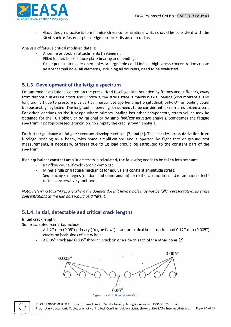
5.1.4. Initial, detectable and critical crack lengths Initial crack length Some accepted scenarios include:
- A 1.27 mm (0.05”) primary (“rogue flaw”) crack on critical hole location and 0.127 mm (0.005”) cracks on both sides of every hole
- A 0.05” crack and 0.005” through crack on one side of each of the other holes [7]
Figure 3: Initial flaw assumption
EASA Proposed CM No.: CM-S-013 Issue 01
TE.CERT.00141-001 © European Union Aviation Safety Agency. All rights reserved. ISO9001 Certified. Proprietary document. Copies are not controlled. Confirm revision status through the EASA-Internet/Intranet.
An agency of the European Union
Page 21 of 25
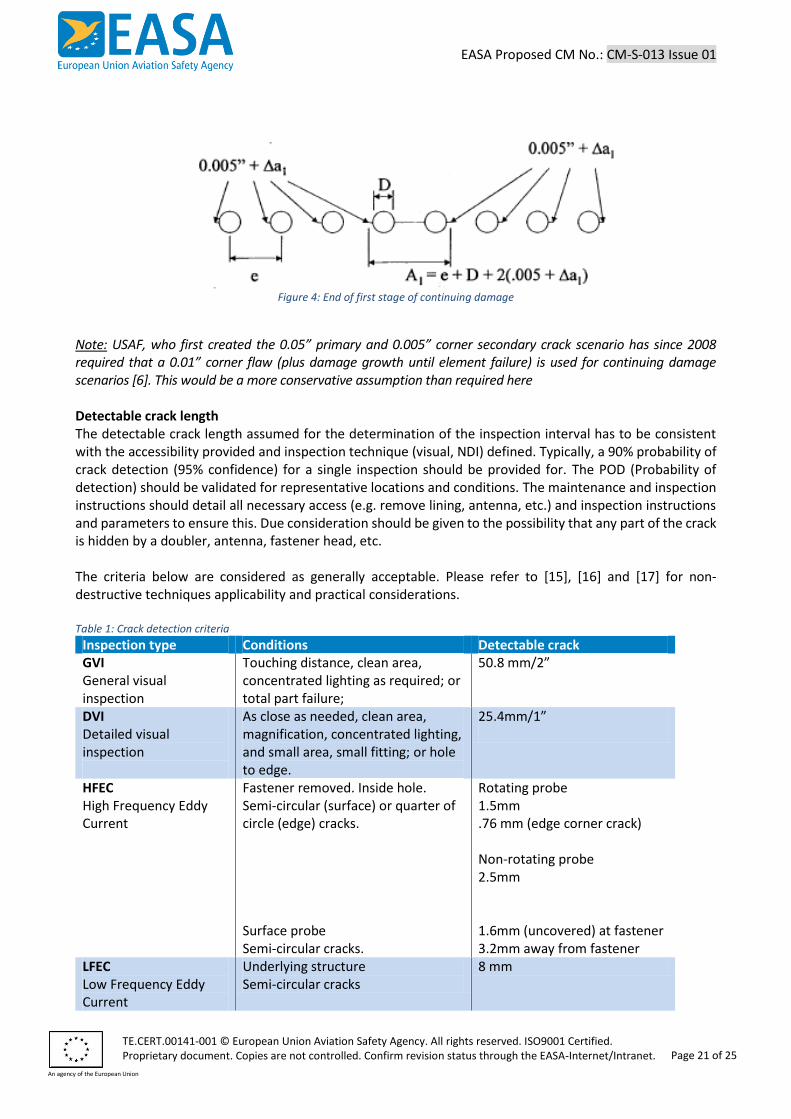
Figure 4: End of first stage of continuing damage
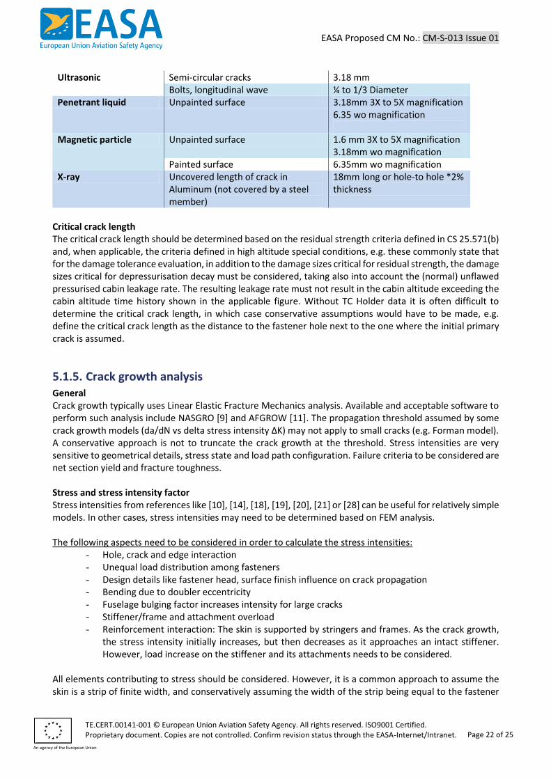
Note: USAF, who first created the 0.05” primary and 0.005” corner secondary crack scenario has since 2008 required that a 0.01” corner flaw (plus damage growth until element failure) is used for continuing damage scenarios [6]. This would be a more conservative assumption than required here Detectable crack length The detectable crack length assumed for the determination of the inspection interval has to be consistent with the accessibility provided and inspection technique (visual, NDI) defined. Typically, a 90% probability of crack detection (95% confidence) for a single inspection should be provided for. The POD (Probability of detection) should be validated for representative locations and conditions. The maintenance and inspection instructions should detail all necessary access (e.g. remove lining, antenna, etc.) and inspection instructions and parameters to ensure this. Due consideration should be given to the possibility that any part of the crack is hidden by a doubler, antenna, fastener head, etc. The criteria below are considered as generally acceptable. Please refer to [15], [16] and [17] for non-destructive techniques applicability and practical considerations. Table 1: Crack detection criteria
Inspection type Conditions Detectable crack GVI General visual inspection
Touching distance, clean area, concentrated lighting as required; or total part failure;
50.8 mm/2”
DVI Detailed visual inspection
As close as needed, clean area, magnification, concentrated lighting, and small area, small fitting; or hole to edge.
25.4mm/1”
HFEC High Frequency Eddy Current
Fastener removed. Inside hole. Semi-circular (surface) or quarter of circle (edge) cracks. Surface probe Semi-circular cracks.
Rotating probe 1.5mm .76 mm (edge corner crack) Non-rotating probe 2.5mm 1.6mm (uncovered) at fastener 3.2mm away from fastener
LFEC Low Frequency Eddy Current
Underlying structure Semi-circular cracks
8 mm
EASA Proposed CM No.: CM-S-013 Issue 01
TE.CERT.00141-001 © European Union Aviation Safety Agency. All rights reserved. ISO9001 Certified. Proprietary document. Copies are not controlled. Confirm revision status through the EASA-Internet/Intranet.
An agency of the European Union
Page 22 of 25
Ultrasonic Semi-circular cracks 3.18 mm Bolts, longitudinal wave ¼ to 1/3 Diameter
Penetrant liquid Unpainted surface 3.18mm 3X to 5X magnification 6.35 wo magnification
Magnetic particle Unpainted surface 1.6 mm 3X to 5X magnification 3.18mm wo magnification
Painted surface 6.35mm wo magnification X-ray Uncovered length of crack in
Aluminum (not covered by a steel member)
18mm long or hole-to hole *2% thickness
Critical crack length The critical crack length should be determined based on the residual strength criteria defined in CS 25.571(b) and, when applicable, the criteria defined in high altitude special conditions, e.g. these commonly state that for the damage tolerance evaluation, in addition to the damage sizes critical for residual strength, the damage sizes critical for depressurisation decay must be considered, taking also into account the (normal) unflawed pressurised cabin leakage rate. The resulting leakage rate must not result in the cabin altitude exceeding the cabin altitude time history shown in the applicable figure. Without TC Holder data it is often difficult to determine the critical crack length, in which case conservative assumptions would have to be made, e.g. define the critical crack length as the distance to the fastener hole next to the one where the initial primary crack is assumed.
5.1.5. Crack growth analysis General Crack growth typically uses Linear Elastic Fracture Mechanics analysis. Available and acceptable software to perform such analysis include NASGRO [9] and AFGROW [11]. The propagation threshold assumed by some crack growth models (da/dN vs delta stress intensity ΔK) may not apply to small cracks (e.g. Forman model). A conservative approach is not to truncate the crack growth at the threshold. Stress intensities are very sensitive to geometrical details, stress state and load path configuration. Failure criteria to be considered are net section yield and fracture toughness. Stress and stress intensity factor Stress intensities from references like [10], [14], [18], [19], [20], [21] or [28] can be useful for relatively simple models. In other cases, stress intensities may need to be determined based on FEM analysis. The following aspects need to be considered in order to calculate the stress intensities:
- Hole, crack and edge interaction - Unequal load distribution among fasteners - Design details like fastener head, surface finish influence on crack propagation - Bending due to doubler eccentricity - Fuselage bulging factor increases intensity for large cracks - Stiffener/frame and attachment overload - Reinforcement interaction: The skin is supported by stringers and frames. As the crack growth,
the stress intensity initially increases, but then decreases as it approaches an intact stiffener. However, load increase on the stiffener and its attachments needs to be considered.
All elements contributing to stress should be considered. However, it is a common approach to assume the skin is a strip of finite width, and conservatively assuming the width of the strip being equal to the fastener
EASA Proposed CM No.: CM-S-013 Issue 01
TE.CERT.00141-001 © European Union Aviation Safety Agency. All rights reserved. ISO9001 Certified. Proprietary document. Copies are not controlled. Confirm revision status through the EASA-Internet/Intranet.
An agency of the European Union
Page 23 of 25
pitch. Analysis refinements can be complex but often don’t bring much benefit in terms of extended inspections, compared with the conservative simple approach above. The stress state across the thickness affects the plastic deformation pattern and consequently the critical stress intensity:
- Thin plates will have a plane stress, while thick ones will have plane strain. - While there is a constant K1c for plane strain, for thin sheet and ductile materials there is stable
crack growth beyond K1c. The plane stress critical Kc (unstable crack growth) depends on thickness, initial crack size and geometry. It is internally calculated by AFGROW [11]. It is possible to use the R-curves approach for a refined failure criterion
5.1.6. Determination of thresholds and repeat intervals Ultimately, the crack growth and fatigue analyses help to determine the resulting threshold and repeat inspection, with the application of a scatter factor (SF). Considerations relevant for high altitude operation (see section on CS 25.841) may also have to be taken into account. Compliance with subparagraph (b) of CS 25.571 (damage tolerance evaluation) is either required by the certification basis or is the most practical solution. According to CS 25.571 and AMC to CS 25.571 2.1.1 (b), besides fatigue, corrosion, manufacturing errors and accidental damage in service are potential damage sources, this evaluation can result in inspections to be included in the ICA, as part of the mandatory ALS (CS 25.1529 and appendix H). For fatigue analysis, the same as for crack growth analysis, the effect of loaded fasteners should be considered. The data contained in [2] is considered as conservative for this effect. The inspection tasks established to manage crack growth typically consist of a threshold inspection (first inspection), and a repeat inspection to be performed at regular intervals starting from the threshold. See also [7] as an acceptable means of compliance:
- Threshold: Calculate crack growth from initial to critical (residual strength or high altitude opening) crack scenario applying a SF. Alternatively, time to fatigue initiation with a SF (if easily inspectable and fail-safe).
- Interval: Crack growth from detectable to critical crack, applying a safety or scatter factor Acceptable scatter factors for application to mean crack growth and fatigue data:
- SF= 2 is usually accepted for threshold and interval determination and interval of multiple load path structures
- SF= 3 or more is recommended for interval inspection for single load path or equivalent, such as large antenna
- For fatigue-based demonstration for the inspection threshold, a factor of 8 is recommended unless the applicant has extensive test and service experience to support a lower factor
Antennas affecting one fuselage skin bay of semi-monocoque fuselage, the reinforced fuselage skin frame combination can be considered as Multiple Load Path. For large antennas or cracks longer than one skin bay, however, the capability of the structure to redistribute the loads after possible failure of the full length of skin under the antenna needs to be assessed before concluding that the installation remains multiple load path.
EASA Proposed CM No.: CM-S-013 Issue 01
TE.CERT.00141-001 © European Union Aviation Safety Agency. All rights reserved. ISO9001 Certified. Proprietary document. Copies are not controlled. Confirm revision status through the EASA-Internet/Intranet.
An agency of the European Union
Page 24 of 25
5.2. Appendix B: Bird Strike Damage – Numerical Analysis Some applicants may want to use non-linear Finite Element Analysis (FEA) as the proposed means of compliance for bird impact on antenna installations (including radomes). Although this technique has improved significantly over the last decade in terms of capability and accuracy, analysis may be used only if the structure conforms to those for which experience has shown this method to be reliable. Therefore, all the following items should be successfully met before EASA can accept such proposed means of compliance:
1. Demonstration that the analysis tool used (in this particular case, to conduct dynamic impact simulations) is valid. This includes the following considerations:
(a) The analysis tool has been designed for these types of investigations; (b) Any limitations the analysis tool has are understood, defined and respected; (c) A series of (code & calculation) verification and validation test problems, example problems
and benchmark problems are performed to ensure the analysis tool is functioning properly 2. Demonstration that the personnel involved is sufficiently experienced, trained and qualified to
use the analysis tool 3. Demonstration that the combination of analysis tool and personnel involved was able to
accurately4 or conservatively predict (upfront) the outcome of the bird strike tests on other similar, previously approved antenna installation(s). This would include comparison of (analysis versus test data):
(a) Deformations, penetrations, or damage induced; (b) Stresses and strains; (c) Impact pressure loads; (d) Accelerations; (e) Reaction/interface loads
Evidence of the previously issued approval(s) should be presented, plus any necessary additional information to better understand the subject test data.
4. Demonstration that the antenna installation and substantiation method is sufficiently similar to the other previously approved antenna installation(s) (identified under (3) above), considering the following aspects:
(a) Personnel involved; (b) Analysis software tool(s) used (pre- and post-processing, solver, release version); (c) Installation details:
(i) Overall weight, shape, geometry and dimensions (including thicknesses, stiffnesses, …);
(ii) Location on the aircraft; (iii) Aircraft type (business, transport a/c); (iv) Materials for all major components of the installation; (v) Manufacturing techniques; (vi) Means of attachment to airframe; (vii) Joints, splices and other design details/discontinuities; (viii) Underlying/supporting airframe structure;
4 Normally the analysis results should correlate within 5 – 10% of the test data. Both magnitude and shape errors should be investigated using an acceptable methodology.
EASA Proposed CM No.: CM-S-013 Issue 01
TE.CERT.00141-001 © European Union Aviation Safety Agency. All rights reserved. ISO9001 Certified. Proprietary document. Copies are not controlled. Confirm revision status through the EASA-Internet/Intranet.
An agency of the European Union
Page 25 of 25
(d) Impact conditions (bird weight, speed, impact angle) and critical locations; (e) All relevant parameters/values/modelling details which the software allows the user to
choose, related to the (i) Bird model; (ii) Fluid domain, and (iii) Airframe model (antenna installation and supporting airframe structure).
Parameters/values/modelling details to be addressed include: (i) Analysis technique (implicit/explicit FE, Lagrangian, Eulerian, ALE, CEL, SPH, …); (ii) Meshing (fixed, translating, contracting, expanding) and spatial convergence; (iii) Formulation of elements / particles (number, type, kernel function /
smoothing length / spacing / distribution); (iv) Boundary conditions and constraints; (v) Material models (e.g. elasto-plastic), Equations of State, properties &
allowables (quasi-static or strain rate dependent, A/B basis); (vi) Failure criteria and damage propagation models/assumptions; (vii) Damping values/factors; (viii) Static and dynamic friction coefficients; (ix) Application of impact loads and contact algorithm; (x) Analysis time step (temporal convergence) and mass scaling; (xi) Sensitivity analysis (variation of key parameters) and (pre/post analysis)
quality / consistency checks, for example on energy balance, on hourglass effects and on negative volumes.
5. Should the investigation reveal that penetration of the radome occurs, special attention should be given to the validation of the amount of damage, and the remaining energy and bird mass residue after penetration. Also, the size, shape and weight of the radome debris released should not pose a hazard to the aircraft.
Note: For more background information on the verification and validation process, see ASME V&V 10-2006 and Advisory Circular (AC) 20-146A.