Note 3 Performance Metrics of RFID Systems - COECIS Sites
52
Note 3 Performance Metrics of RFID Systems Edwin C. Kan School of Electrical and Computer Engineering Cornell University Fall 2014
-
Upload
khangminh22 -
Category
Documents
-
view
2 -
download
0
Transcript of Note 3 Performance Metrics of RFID Systems - COECIS Sites

Note 3Performance Metrics of RFID Systems
Edwin C. Kan
School of Electrical and Computer Engineering
Cornell University
Fall 2014

Outline
• Share of the free space– Radiated and backscattered power regulation
– Air regulation in various regions
• Range by tag and reader sensitivity– RF Link Budget
• System throughput– Bandwidth
– Signal-to-noise ratio
– Bit error rate and interference
• Ambient consideration

Quotable Quotes
“It ain't ignorance that causes all the trouble in this world. It's the things people know that ain'tso.”
― Edwin H. Armstrong (1890 – 1954)

Key Operational Parameters
dBoutdBin
out
in SNRSNRSNR
SNRFNF ,,log10log10

A Word on dB and dBm
dB is used to translate multiplication in the transfer functions to addition by applying a logarithmic function (remember that any number in exponential or logarithmic function HAS TO be unitless).
For power related items (such as SNR, path loss, etc.), it is RdB = 10 log10(R)
For magnitude related items (such as voltage, current, etc.), it is AdB = 20 log10(A)
For power in reference with mW, it is PdBm = 10
log10(P/1mW). The “m” stands for mW.

Federal Communication Committee (FCC)

FCC News (May 2014)
The FCC approved rules for next year's incentive auction of 600 MHz broadcast TV spectrum that will open up bandwidth for unlicensed wireless use. Depending upon how much spectrum is voluntarily relinquished by broadcasters in a reverse auction and repacked for the forward auction, a total of 14 to 28 MHz of guard band spectrum should be available for unlicensed use in a given area.

Radiated Power: EIRP and ERP
Dipole antenna easier to measure
A standard in EU EN302-208
Intuitive in radar cross section
True isotropic antennas are not physically possible
A standard in US FCC.
Use linearly polarized element for capturing
Circularly polarized antenna gain can be 3dB higher
EIRP: Effective isotropic radiated power
ERP: Effective radiated power

Antenna Polarization The polarization of an antenna is the orientation of the electric field (E-plane)
of the radio wave with respect to the Earth's surface and is determined by the physical structure of the antenna and by its orientation.
Polarization is the sum of the E-plane orientations over time projected onto an imaginary plane perpendicular to the direction of motion of the radio wave. In the most general case, polarization is elliptical, meaning that the polarization of the radio waves varies over time
Linear polarization or plane polarization is a confinement of the electric field vector and/or the magnetic field vector to a given plane along the direction of propagation
Circular polarization has the electric field of the passing wave not changing strength but only changing direction in a rotary manner.
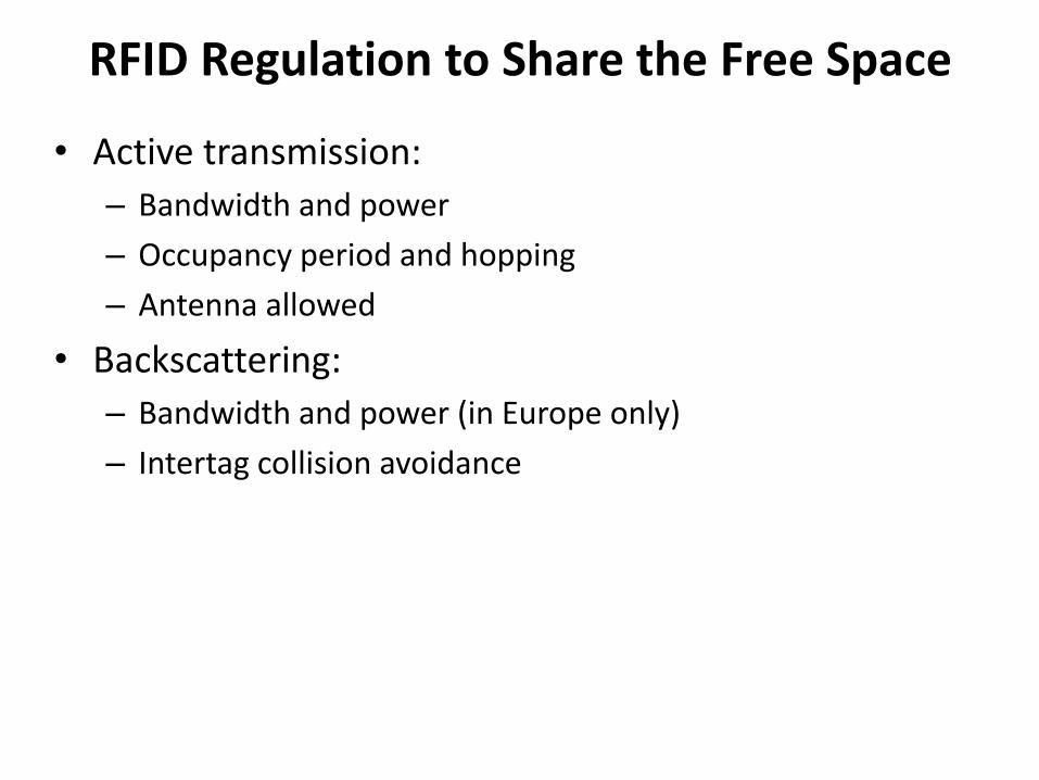
RFID Regulation to Share the Free Space
• Active transmission:
– Bandwidth and power
– Occupancy period and hopping
– Antenna allowed
• Backscattering:
– Bandwidth and power (in Europe only)
– Intertag collision avoidance

RFID Regulations in UHF
FHSS: Frequency hopping spread spectrumLBT: Listen before talkLic: Licensed

RFID PSD Regulations Around 900MHz(Reader Emission)

RFID PSD Regulations Around 900MHz(Tag Backscattering)
No passive backscattering regulation in USA FCC!!!
EU EN 302-208 backscattering PSD mask to limit spectral spreading

How Should RFID Manufacturers Deal With Different Air Regulations?
1. Coordinate with IEEE 802.xx and ISO (International Organization of Standards) to from a consortium to unify air regulations.
2. Make the circuits broadband to cover all regulations, and put a GPS-like device on readers for automatic switching among different regulations.
3. Supply different readers and tags to places with different air regulations.

Outline
• Share of the free space– Radiated and backscattered power regulation
– Air regulation in various regions
• Range by tag and reader sensitivity– RF Link Budget
• System throughput– Bandwidth
– Signal-to-noise ratio
– Bit error rate and interference
• Ambient consideration

Frii’s Far-Field Transmission
Ptag: Signal power the tag receives
PS: Power supplied by the interrogator
: Wavelength of the carrier wave
r: distance between interrogator and tag antennas
T: Interrogator antenna gain
ri: Tag antenna subsystem gain when receiving
Ptag_sen: Minimally required tag sensitivity
Unobstructed narrow-band propagation approximation
riTStagr
PP
2
4
sentag
riTS
P
Pr
_
max4
or
r
T
ri

Performance Metrics
• Tag sensitivity: Minimal power the tag has to receive for circuit activation, signal decoding and return signal encoding.– Passive tag sensitivity: often limited by the RF-to-DC converter
– Active tag sensitivity: often limited by received signal decoding
• Reader sensitivity: Minimal backscattered signal power required to produce a meaningful signal with acceptable BER and tag differentiation.
• Signal-to-noise ratio (SNR): signal power over input noise power at any stage.
• Bit error rate (BER): error bit probability in total number of bits transmitted in digital form.
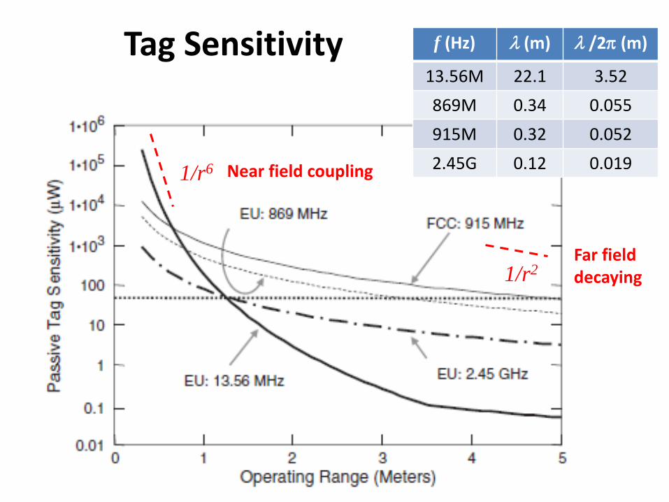
Tag Sensitivity
1/r2
1/r6 Near field coupling
Far field decaying
f (Hz) (m) /2 (m)
13.56M 22.1 3.52
869M 0.34 0.055
915M 0.32 0.052
2.45G 0.12 0.019

Interrogator/Reader Signal Power
ri: Tag antenna subsystem gain when receiving
ro: Tag antenna subsystem gain when reflecting
The signal power the interrogator/reader receives from tag backscattering
roTSBr
PP
2
4
4
The reader decoder needs to give sufficient RF and baseband gains to be able to decode and demodulate this backscattered signal above the noise level (ambient and interference).

Antenna Effective ApertureAnother point of view to consider antenna gain is to use the antenna effective aperture Aeff in dB, normalized to the intended wavelength.
For a physical RFID dipole antenna of 10cm1cm tag, the antenna gain is related to the largest dimension 10cm. If it has an aperture efficiency of = Aeff/Aphy = 0.8 (Aphy = 100cm2), the antenna gain is about 0.4 dBi.
4
4
2
2 eff
effAor
A
0 dBi antenna is a quasi-isotropic antenna with
4
2
effA
At 900MHz, = 33 cm; Aeff of 0dBi antenna = 88 cm2;Aeff of 8dBi antenna = 558 cm2;Aeff of 3dBi antenna = 44 cm2;

Free-Space Path Loss
PB = PS + 2T + 2PL + ro
We can now use antenna gain and free space path loss PL for RF link calculation (cascaded multiplication becomes addition in dB)
Free Space Path Loss at 1m at 10m at 100m at 1km
1.2GHz -34dB -54dB -74dB -94dB
2.4GHz -40dB -60dB -80dB -100dB
5.0GHz -46dB -66dB -86dB -106dB
1
4 2r
AP
eff
L
r

Noises at the Reader/Interrogator
Ambient noises
- Thermal noise: proportional to bandwidth
- Black body noise: Nearby hot body
- Atmospheric noise: Nearby thunderstorms
- Cosmic noise: sun, center of milky way, meteorite, cosmic microwave background radiation from big bang, etc.
Interference from surrounding RF components
- Self interference
- Multipath interference
- Other readers
- Other tags

Thermal Noise Floor
fdBm
mW
fTkP
R
fTkifTkP
BdBmtherm
BthermBtherm
10
10_
log10174
1log10
Bandwidth (f) Thermal noise floor at 300K Notes
1 Hz -174 dBm
10 kHz -134 dBm FM channel
200 kHz -121 dBm GSM channel
500 kHz -117 dBm FCC UHF RFID channel
1 MHz -114 dBm Bluetooth channel
2 MHz -111 dBm GPS channel
6 MHz -106 dBm Analog TV channel
20 MHz -100 dBm WLAN 802.11 channel
1 GHz -84 dBm UWB channel
For conjugate matching, the noise power fed into a receiver is:

Interrogator/Reader Sensitivity
For passive tags, most often the tag sensitivity (enough power can be scavenged to wake up and execute) is most stringent to set the operating range. If the maximum operating distance rmax is set by the tag sensitivity, the corresponding reader sensitivity at rmax (the signal power the reader can decode correctly)
2
2
_
_
ri
ro
S
senstag
sensIP
PP
No T dependence: RF reciprocity principle when output gain is balanced with input gain.
Inversely proportional to PSri2: rmax will be larger
RF link margin (in dB) is defined as the ratio between the actual power radiated by the reader and the reader sensitivity.

RF Link Margin in dB
For example, an EU compliant reader transmitting at 2 W ERP (33 dBm), assuming the reader sensitivity is at 90 dBm. The link margin is: 123 dB.
For 2.4GHz passive tags, the free space loss is at 40 dB for 1m and 60 dB for 10m. If the antenna gains of T ,ri and ro are all 0dB, then we have range of roughly 10m at 2.4GHz in the 123dB link budget.
For active radios or RFID reader-reader interference, the link budget of 120dB is however sufficient to support 10km range for free-space path loss!!!
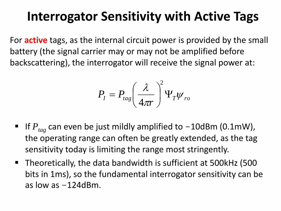
Interrogator Sensitivity with Active Tags
For active tags, as the internal circuit power is provided by the small battery (the signal carrier may or may not be amplified before backscattering), the interrogator will receive the signal power at:
roTtagIr
PP
2
4
If Ptag can even be just mildly amplified to -10dBm (0.1mW), the operating range can often be greatly extended, as the tag sensitivity today is limiting the range most stringently.
Theoretically, the data bandwidth is sufficient at 500kHz (500 bits in 1ms), so the fundamental interrogator sensitivity can be as low as -124dBm.

A Few Thoughts on EM Waves
Assuming a mobile unit can have 4W transmitting power and a receiver of -90dBm sensitivity:
Free space vs. guided wave (like cables and fibers): loss views:
– Free space loss (1/r2) vs. line loss (exp(r) vs. both
Focus radiation beams vs. isotropic radiation: scaling‒ Same free space loss in dBm!!! Just antenna gain.
Active radio vs. backscattering radar by dBm and distance‒ At 2.4GHz, backscatter can go 20m, while radio can go 40km!
‒ For radar to achieve 1,000 km, what is needed?
‒ Lower frequency
‒ Large antenna and focused beams
‒ Large transmitting power
‒ Quiet bands
‒ Brain tease: Do raindrops matter? How does cloud influence radar?
Outline
• Share of the free space– Radiated and backscattered power regulation
– Air regulation in various regions
• Range by tag and reader sensitivity– RF Link Budget
• System throughput– Bandwidth
– Signal-to-noise ratio
– Bit error rate and interference
• Ambient consideration

Digital Decoder
Modulation, Bandwidth and Bit Rate
Once the reader and the tag determines a “channel”, the command/data are modulated onto a designated carrier.
Carrier modulation generates a power spectral density (PSD) that is regulated by FCC and EU EN.
PSD can be thought as a electromagnetic energy footprint.
Higher data rate spreads the data energy away from carrier: Rbit
BW, where Rbit is the data bit rate.
RF Amplifier, filter and attenuator
Multiplier/ Demodulator
A/D converterPB SNROUT
OUT
IN
SNR
SNRF
therm
BIN
P
PSNR ASK, BPSK
Rbit
BER
01011…
ASK Modulation in RFID
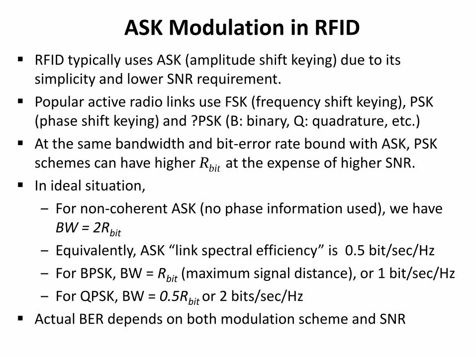
RFID typically uses ASK (amplitude shift keying) due to its simplicity and lower SNR requirement.
Popular active radio links use FSK (frequency shift keying), PSK (phase shift keying) and ?PSK (B: binary, Q: quadrature, etc.)
At the same bandwidth and bit-error rate bound with ASK, PSK schemes can have higher Rbit at the expense of higher SNR.
In ideal situation,
‒ For non-coherent ASK (no phase information used), we have BW = 2Rbit
‒ Equivalently, ASK “link spectral efficiency” is 0.5 bit/sec/Hz
‒ For BPSK, BW = Rbit (maximum signal distance), or 1 bit/sec/Hz
‒ For QPSK, BW = 0.5Rbit or 2 bits/sec/Hz
Actual BER depends on both modulation scheme and SNR

ASK, FSK and PSK

Protocol Throughput
The data rate of the forward link (downlink): interrogator to the tag: commands + verify + security
The data rate of the return link (uplink): tag backscattering to the interrogator: ID code + verify + security
The media access control (MAC) protocol: sequence control for multiplexing of tags: time division (most often) and code division?

Signal-to-Noise Ratio (SNR)
which is integrated over the given bandwidth. Noise includes thermal, shot, ambient noises, and all other interferences.
Before an ideal digital decoder, the SNR of the digital signal is by definition:
noise
sig
P
PSNR
The signal-to-noise ratio at any circuit node between two modules is defined as:
ASK
bbitbOUT
N
E
BW
R
N
ESNRSNR
00 2
Eb : the energy per bit in Joules
N0 : the single-sided noise power spectral density in Watts/Hz

Bit Error Rate of Digital ASK Decoder
pe : bit error probability or bit error rate
Non-coherent ASK:SNRb
e eN
Ep
2
1
2exp
2
1
0

Noise Factor and Noise Figure
The performance of the amplifier and signal conditioning between the receiving antenna and the decoder (the signal is still embedded in the RF carrier) depends on the circuit technology used, and is measured by “noise factor” F (in real unitless number) or noise figure NF (in dB)
dBOUTdBINdB
OUT
IN
SNRSNRNF
SNR
SNRF
__
That is, F or NF is a measurement of the SNR degradation in the RF receiving unit. Typical NF for CMOS is around 3 – 20 dB. 3dB corresponds to expensive units with special techniques, as well as often large power consumption.

RFID Interrogator Design by ASKPutting the RF and digital decoder together:
22
0
1
1,,
,,
BNBo
Bo
therm
BIN
R
rNRrM
NRrMP
PSNR
Correction for non-line-of-sight reflection
M : Non-line-of-sight reflection correction in indoors
Ro : Free-space equivalent breakpoint distance
NB : Environment attenuation factor (NB = 2 for free space)
Signal-to-noise ratio at the interrogator antenna limited by thermal noise

RFID Bit Rate LimitsHighest achievable bit rate for a ASK RFID receiver, given pe, F and PB
e
B
BoroTS
bB
BoBbit
p
FTkNRrM
rP
E
N
FTkNRrMPR
2
1ln2
11,,
4
1,,
4
2
0
Digital Decoder
RF Amplifier, filter and attenuator
Multiplier/ Demodulator
A/D converterPB SNROUT
OUT
IN
SNR
SNRF
therm
BIN
P
PSNR ASK, BPSK
Rbit
BER
01011…

The Real-World Interrogator
• RF amplifier needs to provide a high and variable gain, adequate filtering, and low noise figure simultaneously.
• Multiplier or demodulator needs an accurate carrier reference from local oscillator.
• PB can have a large range of 80 dBmwith tags that are close and at rmax.
• Circuits are not exact, and have problems of saturation, biasing stability, line noise, etc.
• Digital baseband can apply error correction (ECC)

Channel Sharing• Common channel sharing techniques like CDMA (code division
multiple access) use DSSS (direct-sequence spread spectrum) modulation: a pseudo-noise (PN) code (or “chips”) of -1 and +1 with higher bit rates than the data bits is modulated on.
• This PN code is known for both the transmitter and the reader. The reader can use this known sequence to reconstruct the intended data signal, with a “process gain”.
• Different transmitters can share the SAME channel and use different PN codes, and the reader will selectively read the one with the matching PN code.

PN Codes and CDMA
PN code spectrum
Data code spectrum
As the pulse periods get shorter, the bandwidth gets larger (spread): T >> Tc
T : data pulse period
Tc: PN code period

DSSS with PN Code Modulation

Channel Hopping in RFID• RFID has NOT adopted such sophistication yet for reader-tag
multiplexing, but uses only simple time division methods such as frequency hopping (FH) or listen before talk (LBT).
• FCC in USA requires FH for transmission above 125mW (22 dBm) in all FCC regulated domains. This is meant to spread the power across the band over a given duration.
• For UHF RFID bands, FCC requires FH for 50 of 52 channels between 902MHz and 928MHz (0.5MHz channel). The average time transmitting in any channel is less than 0.4 second over any 20-second period.
• EU EN has much less UHF RFID channels, and FH or LBT needs to be further evolved.
• Reader-Reader communication can potentially use CDMA, but that will be similar as implementing an additional WiFi channel.

Rank Factors for Career Success
• Degree/GPA
• Effort
• Motivation/passion
• Knowledge
• Opportunity
• Integrity
• Personality
• (Any thing else: add here)
For discussion purposes:
Give answers that are true to your heart NOW. Do not give “nominally correct” answers!

Heddy Lamarr(1914 – 2000)
Patent: Markey, Antheil and Lamarr. Markey is Hedy Lamarr's second of six husbands.
Inventor of Spread Frequency Spectrum for secure communication US PATENT 2,292,387

Achievements Success Happiness
Make sure to pursue what you really want!
Lemmas:
• What factors are controllable?
• Opportunity does not have a random impinging function.
• Some factors do not change over night.

Outline
• Share of the free space– Radiated and backscattered power regulation
– Air regulation in various regions
• Range by tag and reader sensitivity– RF Link Budget
• System throughput– Bandwidth
– Signal-to-noise ratio
– Bit error rate and interference
• Ambient consideration

Impact of Surrounding Materials• In addition to multi-path reflections, metals and water solution,
when present close to the reader or the tag, will cause additional antenna detuning and signal absorption issues.
• Actually any material with a permittivity (in the given frequency range) much different from air will change the radiation pattern and impedance match
Near Field(NFC tags)
Far Field(Backscattering tags)
MetalsDetuning
Reduced performance
Reflection, diffraction an detuning
Reduced performance
Water
Some detuningNear full performance
(magnetic coupling as the permeability is often similar)
Absorption(Penetration around 1mm –
10cm)

Water Absorption of EM Waves
Visible light spectrum
Common RF bands
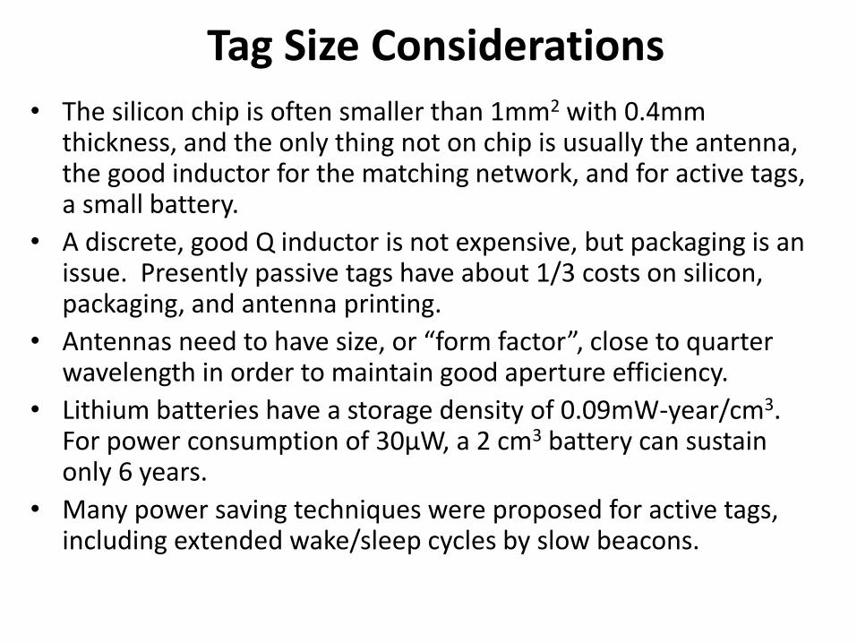
Tag Size Considerations
• The silicon chip is often smaller than 1mm2 with 0.4mm thickness, and the only thing not on chip is usually the antenna, the good inductor for the matching network, and for active tags, a small battery.
• A discrete, good Q inductor is not expensive, but packaging is an issue. Presently passive tags have about 1/3 costs on silicon, packaging, and antenna printing.
• Antennas need to have size, or “form factor”, close to quarter wavelength in order to maintain good aperture efficiency.
• Lithium batteries have a storage density of 0.09mW-year/cm3. For power consumption of 30µW, a 2 cm3 battery can sustain only 6 years.
• Many power saving techniques were proposed for active tags, including extended wake/sleep cycles by slow beacons.

Health and Safety• FCC regulates radio wave health standard by International
Standard Office (ISO) Specific Absorption Rate (SAR).
• EU regulation is by European Committee for Electro Technical Standardization ENV50166-2. RF emission should not exceed 10W per m2 over a six-minute average within 20 cm of the emitting antenna.
• Exposure limit should be more stringent for frequency > 1 GHz due to microwave heating.

Total Cost of Ownership• Total cost of ownership is a better marketing model.
• The RFID market today has a distinctive cost structure with high fixed cost and low variable cost, just like most chip-based applications.
• The table below assumes a volume production has been achieved.
Reader Cost Tag CostDeployment
costMaintenance
cost
Passive NFC system
~ $60 - $200Ready integration with
cell phone
~ $0.20 - $1Large volume
Low Zero
Passive UHF system
~ $200 - $2,000Dedicated
~ $0.05 - $0.30Large volume
Very Low Zero
Active UHF system
~ $200 - $2,000Possible integration to computer/cell phone
~ $2 - $10Large volume
HighBattery
replacement

What Did You Learn
• FCC and EU regulations
• Estimation of RF link budget in dB
• Tag sensitivity and reader sensitivity
• Relation among bandwidth, bit rate, bit error rate and SNR
• Practical considerations of RFID