Nonlinear Passive Control of a Wave Energy Converter Subject to Constraints in Irregular Waves
15
Energies 2015, 8, 6528-6542; doi:10.3390/en8076528 energies ISSN 1996-1073 www.mdpi.com/journal/energies Article Nonlinear Passive Control of a Wave Energy Converter Subject to Constraints in Irregular Waves Liguo Wang * and Jan Isberg Department of Engineering Sciences, Swedish Centre for Renewable Electric Energy Conversion, Division of Electricity, the Ångström Laboratory, Uppsala University, P.O. Box 534, 75121 Uppsala, Sweden; E-Mail: [email protected] * Author to whom correspondence should be addressed; E-Mail: [email protected]; Tel.: +46-18-471-5908. Academic Editor: Jens Peter Kofoed Received: 17 April 2015 / Accepted: 18 June 2015 / Published: 29 June 2015 Abstract: This paper investigates a passive control method of a point absorbing wave energy converter by considering the displacement and velocity constraints under irregular waves in the time domain. A linear generator is used as a power take-off unit, and the equivalent damping force is optimized to improve the power production of the wave energy converter. The results from nonlinear and linear passive control methods are compared, and indicate that the nonlinear passive control method leads to the excitation force in phase with the velocity of the converter that can significantly improve the energy production of the converter. Keywords: wave energy converter; power take off; passive control; load control; irregular waves; time domain 1. Introduction Wave energy is the transport of power by ocean surface waves, and it has high availability, density and good predictability compared to other renewable sources. A variety of technologies for converting wave energy to electricity have been developed in the past decades [1–5]. This paper focus on a wave energy converter (WEC) concept developed at the Swedish Centre for Renewable Electric Energy Conversion at Uppsala University [6–8]. As shown in Figure 1 [9], the WEC contains two main parts, a floating buoy and a submerged linear generator. The buoy captures the energy from the ocean waves. OPEN ACCESS
Transcript of Nonlinear Passive Control of a Wave Energy Converter Subject to Constraints in Irregular Waves
Energies 2015, 8, 6528-6542; doi:10.3390/en8076528
energies ISSN 1996-1073
www.mdpi.com/journal/energies
Article
Nonlinear Passive Control of a Wave Energy Converter Subject to Constraints in Irregular Waves
Liguo Wang * and Jan Isberg
Department of Engineering Sciences, Swedish Centre for Renewable Electric Energy Conversion,
Division of Electricity, the Ångström Laboratory, Uppsala University, P.O. Box 534,
75121 Uppsala, Sweden; E-Mail: [email protected]
* Author to whom correspondence should be addressed; E-Mail: [email protected];
Tel.: +46-18-471-5908.
Academic Editor: Jens Peter Kofoed
Received: 17 April 2015 / Accepted: 18 June 2015 / Published: 29 June 2015
Abstract: This paper investigates a passive control method of a point absorbing wave energy
converter by considering the displacement and velocity constraints under irregular waves in
the time domain. A linear generator is used as a power take-off unit, and the equivalent
damping force is optimized to improve the power production of the wave energy converter.
The results from nonlinear and linear passive control methods are compared, and indicate
that the nonlinear passive control method leads to the excitation force in phase with the velocity
of the converter that can significantly improve the energy production of the converter.
Keywords: wave energy converter; power take off; passive control; load control;
irregular waves; time domain
1. Introduction
Wave energy is the transport of power by ocean surface waves, and it has high availability, density
and good predictability compared to other renewable sources. A variety of technologies for converting
wave energy to electricity have been developed in the past decades [1–5]. This paper focus on a wave
energy converter (WEC) concept developed at the Swedish Centre for Renewable Electric Energy
Conversion at Uppsala University [6–8]. As shown in Figure 1 [9], the WEC contains two main parts,
a floating buoy and a submerged linear generator. The buoy captures the energy from the ocean waves.
OPEN ACCESS
Energies 2015, 8 6529
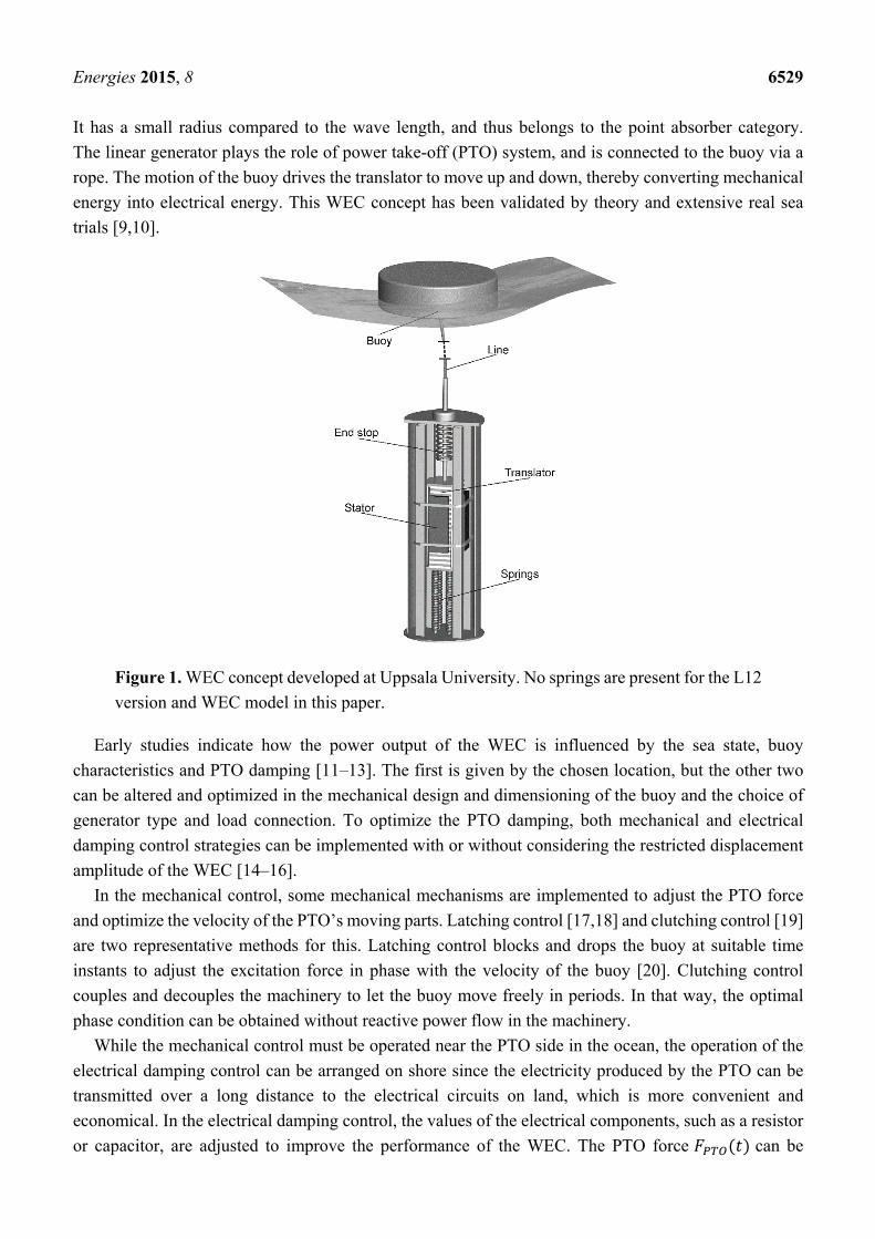
It has a small radius compared to the wave length, and thus belongs to the point absorber category.
The linear generator plays the role of power take-off (PTO) system, and is connected to the buoy via a
rope. The motion of the buoy drives the translator to move up and down, thereby converting mechanical
energy into electrical energy. This WEC concept has been validated by theory and extensive real sea
trials [9,10].
Figure 1. WEC concept developed at Uppsala University. No springs are present for the L12
version and WEC model in this paper.
Early studies indicate how the power output of the WEC is influenced by the sea state, buoy
characteristics and PTO damping [11–13]. The first is given by the chosen location, but the other two
can be altered and optimized in the mechanical design and dimensioning of the buoy and the choice of
generator type and load connection. To optimize the PTO damping, both mechanical and electrical
damping control strategies can be implemented with or without considering the restricted displacement
amplitude of the WEC [14–16].
In the mechanical control, some mechanical mechanisms are implemented to adjust the PTO force
and optimize the velocity of the PTO’s moving parts. Latching control [17,18] and clutching control [19]
are two representative methods for this. Latching control blocks and drops the buoy at suitable time
instants to adjust the excitation force in phase with the velocity of the buoy [20]. Clutching control
couples and decouples the machinery to let the buoy move freely in periods. In that way, the optimal
phase condition can be obtained without reactive power flow in the machinery.
While the mechanical control must be operated near the PTO side in the ocean, the operation of the
electrical damping control can be arranged on shore since the electricity produced by the PTO can be
transmitted over a long distance to the electrical circuits on land, which is more convenient and
economical. In the electrical damping control, the values of the electrical components, such as a resistor
or capacitor, are adjusted to improve the performance of the WEC. The PTO force can be
Energies 2015, 8 6530
decomposed into two components, one is about the velocity and another is about the displacement
, viz. , where and are coefficients that should be nonnegative.
Two main strategies for the electrical control are passive control [21,22] and active control [23–25].
For passive control, the reactive component of the PTO is set to zero, and only is controlled. The active
control necessitates tuning of both and , which requires bidirectional power flow between the PTO
and device. This leads to a large energy exchange [26]. Furthermore, the reactive control involves high
oscillating excursion, which is unacceptable for a linear generator. There are two main advantages for
passive control. One is that it can be implemented in a simple way, and another is that the passive control
can significantly decrease the ratio of peak power to mean power produced by the WEC [27]. This paper
focuses on the passive control method for the WEC.
For the passive control, different time scales can be applied for the damping tuning. The simplest case
is that the damping coefficient is constant and will never be tuned, which corresponds to linear passive
control (LPC). Then the PTO force will be proportional to the velocity. However, the sea state is not
regular and varies with time. Therefore, it is necessary to tune with time to maximize the power
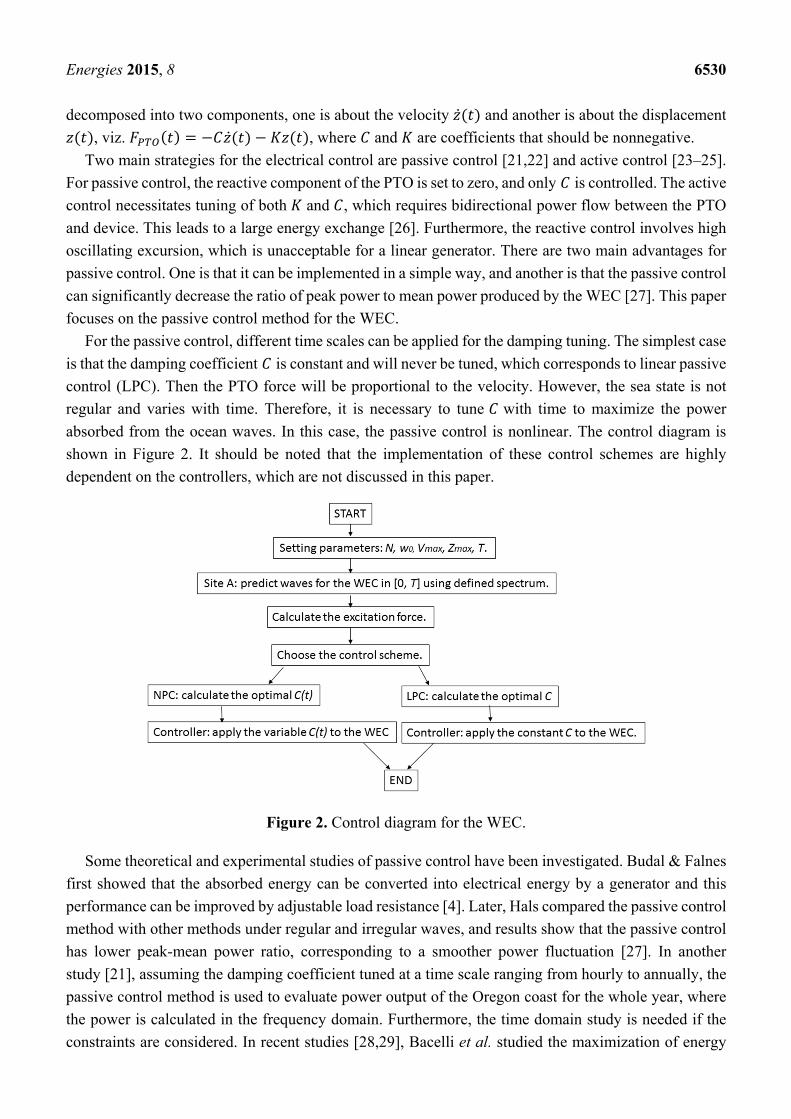
absorbed from the ocean waves. In this case, the passive control is nonlinear. The control diagram is
shown in Figure 2. It should be noted that the implementation of these control schemes are highly
dependent on the controllers, which are not discussed in this paper.
Figure 2. Control diagram for the WEC.
Some theoretical and experimental studies of passive control have been investigated. Budal & Falnes
first showed that the absorbed energy can be converted into electrical energy by a generator and this
performance can be improved by adjustable load resistance [4]. Later, Hals compared the passive control
method with other methods under regular and irregular waves, and results show that the passive control
has lower peak-mean power ratio, corresponding to a smoother power fluctuation [27]. In another
study [21], assuming the damping coefficient tuned at a time scale ranging from hourly to annually, the
passive control method is used to evaluate power output of the Oregon coast for the whole year, where
the power is calculated in the frequency domain. Furthermore, the time domain study is needed if the
constraints are considered. In recent studies [28,29], Bacelli et al. studied the maximization of energy
Energies 2015, 8 6531
production of WECs under displacement constraint based on the approximation of the motion of the
WEC and of the PTO force by means of a combination of basis functions.
In this paper, using the same basis functions, the motion of the WEC and the PTO force are expanded
in terms of truncated Fourier series. The motion constraints and the sign of the damping coefficient are
considered in the solution. The damping coefficients are tuned with time under the irregular waves to
maximize the mean power within a fixed time horizon. Therefore our approach belongs to the category
of nonlinear passive control (NPC). It should be noted that the damping coefficients are required to be
nonnegative here, something that is usually ignored by other investigators. This corresponds to the
physical characteristics of a resistor in electrical circuits, which means its value must be nonnegative,
and the resistor will always consume power no matter whether the voltage is positive or negative.
A displacement constraint is necessary for the linear generator, since it plays a role in protecting the hull
of the generator from being struck by the translator. Reference [30] indicates that the induced peak
voltage of the generator and velocity amplitude have a correlation, and even coincide, so that the peak
voltage can be limited by introducing a constraint on the velocity amplitude. The influence of the
displacement constraint and the velocity constraint to the performance of the WEC under regular waves
has been investigated in our previous work [31].
The structure of this paper is as follows. In Section 2, the dynamic model of the point absorber WEC
is established, and the resulting optimization problem is presented in a standard format with the cost
function and constraints. In Section 3, simulation results are demonstrated and discussed. Finally,
the paper is concluded in Section 4.
2. Methodology
2.1. Wave Model
In order to evaluate the performance of the WEC in real seas, the analysis of the WEC under irregular
waves is necessary. For ocean waves driven by wind, the superposition theory can be used to describe
the irregular waves under the assumption that the wave heights are small compared to the wave length.
Then the irregular wave elevation can be created by summing regular wave components of small height,
random phase, and different frequencies [32], as follows:
ξ cos Ɵ (1)
where , Ɵ , α are the angular frequency, phase, amplitude of the ith harmonic wave
respectively, and is the fundamental angular frequency from:
/ (2)
where is the maximum frequency component present in the spectrum and N is the number of
wave components.
The wave amplitude can be derived from the wave spectrum as:
2 (3)
where 0 is the wave frequency interval.
Energies 2015, 8 6532
Ocean waves are produced by the wind. The faster the wind, the longer the wind blows, and the bigger
the fetch over which the wind blows, the bigger the waves. To describe the ocean wave spectrum, various
idealized spectra have been used. The Pierson-Moskowitz spectrum, a relatively simple spectrum, is
used to describe the case where the wind blew steadily for a long time over a long fetch. If the wave
spectrum is not fully developed, the JONSWAP spectrum can be used instead. Assuming a fully
developed sea, a modified Pierson-Moskowitz Spectrum defined by the significant wave height and the
peak wave period can be described as [33]:
5πexp
20π (4)
where w is wave angular frequency, Tp the peak wave period, Hs the significant wave height.
The nth spectral moment can be expressed in terms of the moments of the spectral function as:
(5)
and the energy period is defined as / .
2.2. WEC Model
For simplicity, only heave motion is considered here. Assuming that the fluid flow is inviscid,
incompressible, and irrotational, the motion of the WEC can be expressed according to Newton’s
law as:
(6)
where m is the total mass of the buoy and translator and is the vertical acceleration of the WEC.
is the PTO force. is the total wave force, which is the sum of the excitation force ,
the radiation force and the hydrostatic restoring force i.e.:
(7)
The excitation force is produced by an incident wave acting on the fixed body. For regular waves, the
excitation force is a harmonic function of time. For irregular waves, the excitation force can be
represented as the summation of the individual force components as [32]:
σ cos φ (8)
where σ and φ are the coefficient and phase of the excitation force under the ith harmonic wave,
and can be calculated using, e.g., the commercial boundary element method solver WAMIT [34].
The radiation force is the part of the hydrodynamic force produced by oscillation of the buoy in calm
water. It can be approximated by the state-space method or presented by:
τ τ (9)
where is the infinite-frequency limit of added mass, the impulse response function.
Energies 2015, 8 6533
The hydrostatic restoring force is proportional to the buoy displacement, and can be expressed as:
(10)
where gπ is the hydrostatic stiffness coefficient with being the radius of buoy, the water
density, and g the gravitational acceleration.
2.3. Modelling of Power Absorption under Constraints
In this paper, trigonometric functions are chosen as the basis functions, and the basis vector can be
expressed as:
cos , sin , cos 2 , sin 2 , … , cos , sin (11)
The velocity of the WEC can be approximated by the Fourier series, and then expressed in terms of the
basis vectors as:
≅ cos sin (12)
where 1, 1, 2, 2,…… . , , , and the “T” superscript indicates the transpose of a vector.
For linear passive control, the PTO force can be expressed as , where the damping
coefficient is a constant scalar. For nonlinear passive control, the damping coefficient varies with time,
and the optimal values can be derived if the optimal velocity and PTO force are known. The PTO force
in the nonlinear case can be expressed as:
≅ cos sin (13)
where , , , , …… . , , . The excitation force can be expressed as
, where , , , , …… . , , , and σ cos φ ,
σ sin φ .
Then the approximate solution to the motion equation can be found as follows (the derivation can be
found in reference [28]):
(14)
The matrix is block diagonal and its lth block elements can be expressed as follows
with = 1, 2… N:
δ (15)
where δ / , is the added mass, is the damping coefficient.
Then the energy produced by the WEC in the time range [0 T] can be expressed as:
(16)
Taking a long time average, the mean power can be expressed as:
12
(17)
Energies 2015, 8 6534
For the passive control, no directional power flow will occur between the device and the PTO, which
is one of the differences from the reactive control. Therefore the power produced by the WEC is always
nonnegative, i.e., the opposite sign of the power consumed by the PTO. This is the reason for the negative
sign in Equations (16) and (17).
Two motion constraints are considered here, viz. the displacement constraint and the velocity
constraint. The displacement constraint implies that the displacement of the buoy at time must not
exceed a limiting value, which can be expressed as:
| | (18)
where is the limiting value of the displacement.
The velocity constraint can similarly be expressed as:
| | (19)
where is the limiting value of the velocity.
For a given time horizon, i.e., for a constant , the maximum energy can be found if and only if the
mean power is found. Then the objective of the paper can be converted into an optimization problem:
find the optimal velocity or passive damping coefficients to maximize the mean power. This can be
expressed in the standard form: minimize
subject to
| || |
0 (20)
where is the cost function.
2.4. Numerical Solution and Benchmark
The damping coefficients, which are required to be nonnegative, can be considered as independent
variables. This constraint can be converted into the requirement that the power produced by the
WEC is always nonnegative, viz. 0 , Equation (20) can be rewritten as follows,
minimize
subject to
11
11
11
11
0
(21)
where , , , , …… . , , , and sin / , cos / .
Equation (21) is an optimization problem for the dependent variable , and is solved using MATLAB
by the active-set method. The constraints are imposed only at specified time instants in the
range [0, T], are integers starting from zero and the time step is 0.1 s. Hydrodynamic
parameters, added mass and damping, are frequency dependent and calculated using the boundary
potential flow solver WAMIT. Main parameters of the WEC used in the following calculation are shown
in Table 1.
Energies 2015, 8 6535
The ability of the WEC for extracting power from the ocean waves can be evaluated by the capture
width ratio (CWR), defined as:
100 (22)
where is the diameter of the buoy. The available power is the total time averaged power in the
incident wave train per unit crest length and can be expressed as:
(23)
where is given in the deep water approximation as ρg /64π.
3. Results and Discussion
3.1. Performance of the WEC in One Sea State
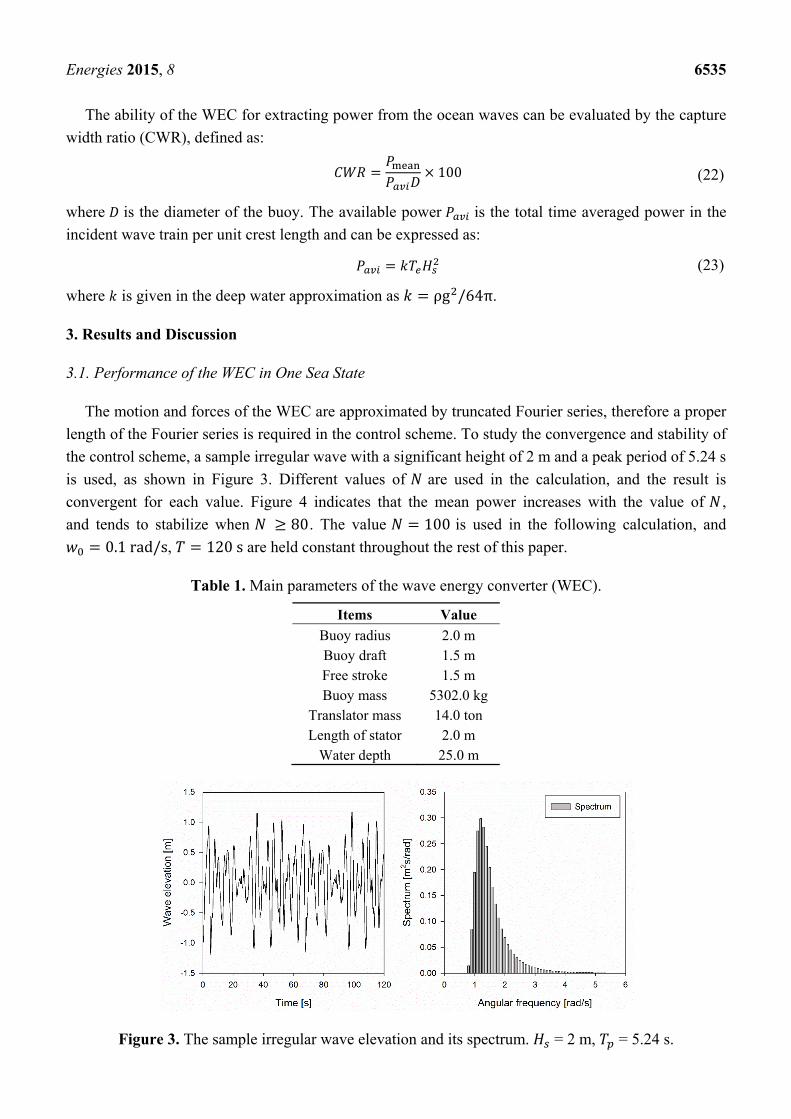
The motion and forces of the WEC are approximated by truncated Fourier series, therefore a proper
length of the Fourier series is required in the control scheme. To study the convergence and stability of
the control scheme, a sample irregular wave with a significant height of 2 m and a peak period of 5.24 s
is used, as shown in Figure 3. Different values of are used in the calculation, and the result is
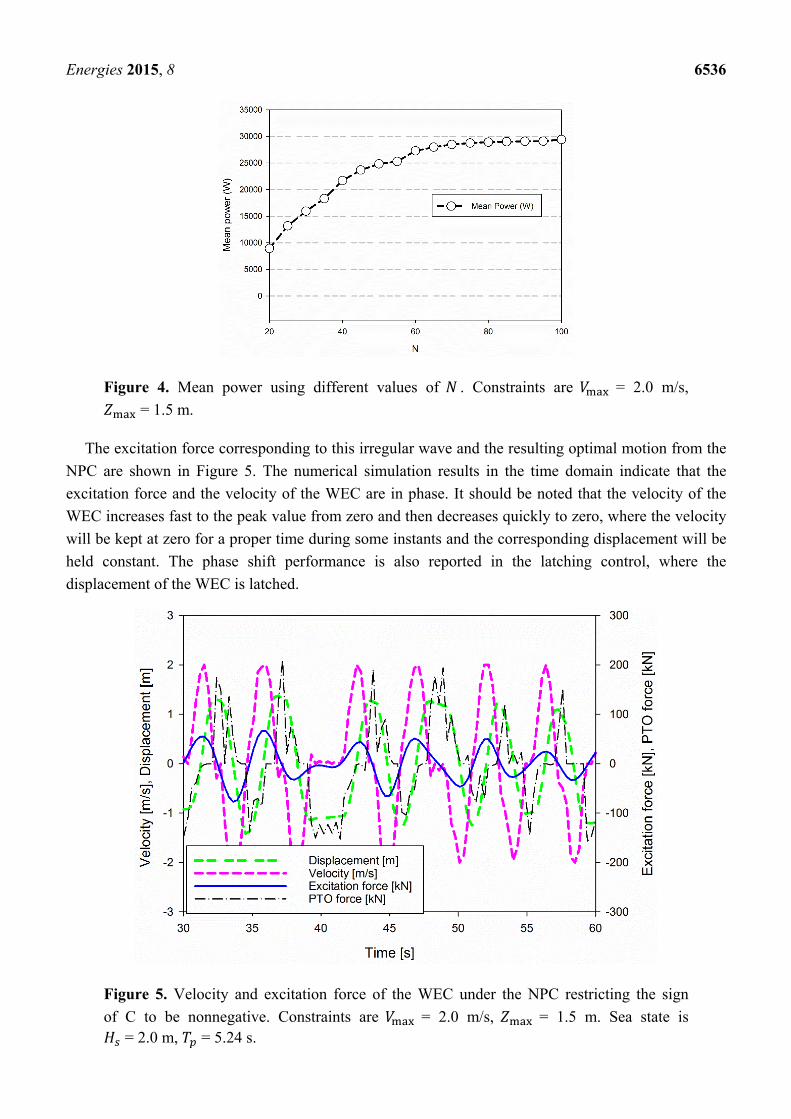
convergent for each value. Figure 4 indicates that the mean power increases with the value of ,
and tends to stabilize when 80. The value 100 is used in the following calculation, and
0.1rad/s, 120s are held constant throughout the rest of this paper.
Table 1. Main parameters of the wave energy converter (WEC).
Items Value
Buoy radius 2.0 m Buoy draft 1.5 m Free stroke 1.5 m Buoy mass 5302.0 kg
Translator mass 14.0 ton Length of stator 2.0 m
Water depth 25.0 m
Figure 3. The sample irregular wave elevation and its spectrum. = 2 m, = 5.24 s.
Energies 2015, 8 6536
Figure 4. Mean power using different values of . Constraints are = 2.0 m/s, = 1.5 m.
The excitation force corresponding to this irregular wave and the resulting optimal motion from the
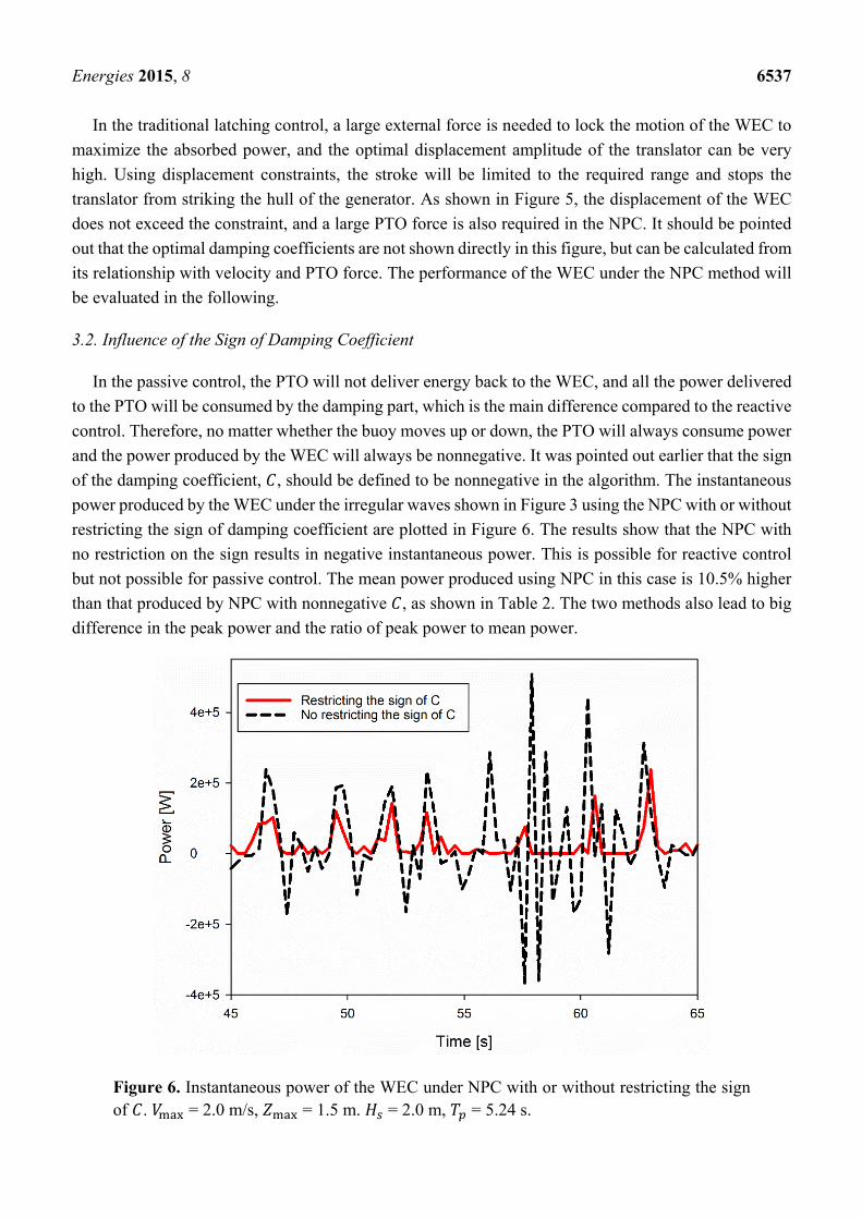
NPC are shown in Figure 5. The numerical simulation results in the time domain indicate that the
excitation force and the velocity of the WEC are in phase. It should be noted that the velocity of the
WEC increases fast to the peak value from zero and then decreases quickly to zero, where the velocity
will be kept at zero for a proper time during some instants and the corresponding displacement will be
held constant. The phase shift performance is also reported in the latching control, where the
displacement of the WEC is latched.
Figure 5. Velocity and excitation force of the WEC under the NPC restricting the sign
of C to be nonnegative. Constraints are = 2.0 m/s, = 1.5 m. Sea state is = 2.0 m, = 5.24 s.
Energies 2015, 8 6537
In the traditional latching control, a large external force is needed to lock the motion of the WEC to
maximize the absorbed power, and the optimal displacement amplitude of the translator can be very
high. Using displacement constraints, the stroke will be limited to the required range and stops the
translator from striking the hull of the generator. As shown in Figure 5, the displacement of the WEC
does not exceed the constraint, and a large PTO force is also required in the NPC. It should be pointed
out that the optimal damping coefficients are not shown directly in this figure, but can be calculated from
its relationship with velocity and PTO force. The performance of the WEC under the NPC method will
be evaluated in the following.
3.2. Influence of the Sign of Damping Coefficient
In the passive control, the PTO will not deliver energy back to the WEC, and all the power delivered
to the PTO will be consumed by the damping part, which is the main difference compared to the reactive
control. Therefore, no matter whether the buoy moves up or down, the PTO will always consume power
and the power produced by the WEC will always be nonnegative. It was pointed out earlier that the sign
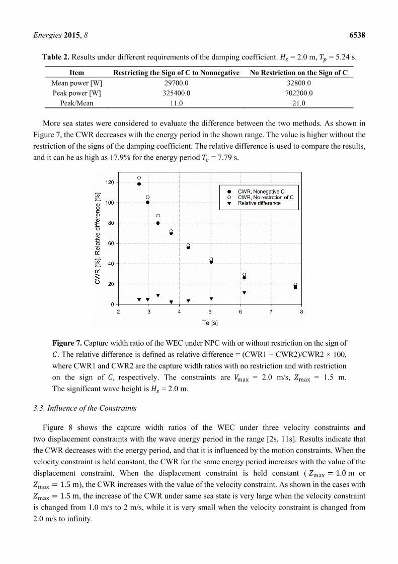
of the damping coefficient, , should be defined to be nonnegative in the algorithm. The instantaneous
power produced by the WEC under the irregular waves shown in Figure 3 using the NPC with or without
restricting the sign of damping coefficient are plotted in Figure 6. The results show that the NPC with
no restriction on the sign results in negative instantaneous power. This is possible for reactive control
but not possible for passive control. The mean power produced using NPC in this case is 10.5% higher
than that produced by NPC with nonnegative , as shown in Table 2. The two methods also lead to big
difference in the peak power and the ratio of peak power to mean power.
Figure 6. Instantaneous power of the WEC under NPC with or without restricting the sign of . = 2.0 m/s, = 1.5 m. = 2.0 m, = 5.24 s.
Energies 2015, 8 6538
Table 2. Results under different requirements of the damping coefficient. = 2.0 m, = 5.24 s.
Item Restricting the Sign of C to Nonnegative No Restriction on the Sign of C
Mean power [W] 29700.0 32800.0 Peak power [W] 325400.0 702200.0
Peak/Mean 11.0 21.0
More sea states were considered to evaluate the difference between the two methods. As shown in
Figure 7, the CWR decreases with the energy period in the shown range. The value is higher without the
restriction of the signs of the damping coefficient. The relative difference is used to compare the results,
and it can be as high as 17.9% for the energy period = 7.79 s.
Figure 7. Capture width ratio of the WEC under NPC with or without restriction on the sign of
. The relative difference is defined as relative difference = (CWR1 − CWR2)/CWR2 × 100,
where CWR1 and CWR2 are the capture width ratios with no restriction and with restriction
on the sign of , respectively. The constraints are = 2.0 m/s, = 1.5 m.
The significant wave height is = 2.0 m.
3.3. Influence of the Constraints
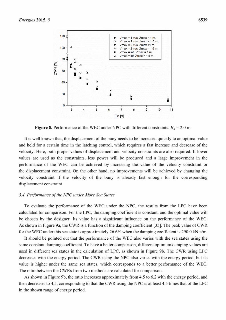
Figure 8 shows the capture width ratios of the WEC under three velocity constraints and
two displacement constraints with the wave energy period in the range [2s, 11s]. Results indicate that
the CWR decreases with the energy period, and that it is influenced by the motion constraints. When the
velocity constraint is held constant, the CWR for the same energy period increases with the value of the
displacement constraint. When the displacement constraint is held constant ( 1.0m or
1.5m), the CWR increases with the value of the velocity constraint. As shown in the cases with
1.5m, the increase of the CWR under same sea state is very large when the velocity constraint
is changed from 1.0 m/s to 2 m/s, while it is very small when the velocity constraint is changed from
2.0 m/s to infinity.
Energies 2015, 8 6539
Figure 8. Performance of the WEC under NPC with different constraints. = 2.0 m.
It is well known that, the displacement of the buoy needs to be increased quickly to an optimal value
and held for a certain time in the latching control, which requires a fast increase and decrease of the
velocity. Here, both proper values of displacement and velocity constraints are also required. If lower
values are used as the constraints, less power will be produced and a large improvement in the
performance of the WEC can be achieved by increasing the value of the velocity constraint or
the displacement constraint. On the other hand, no improvements will be achieved by changing the
velocity constraint if the velocity of the buoy is already fast enough for the corresponding
displacement constraint.
3.4. Performance of the NPC under More Sea States
To evaluate the performance of the WEC under the NPC, the results from the LPC have been
calculated for comparison. For the LPC, the damping coefficient is constant, and the optimal value will
be chosen by the designer. Its value has a significant influence on the performance of the WEC.
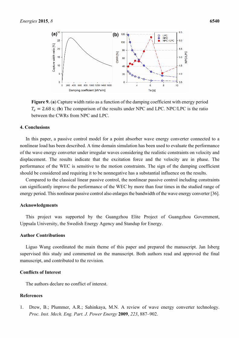
As shown in Figure 9a, the CWR is a function of the damping coefficient [35]. The peak value of CWR
for the WEC under this sea state is approximately 26.6% when the damping coefficient is 290.0 kN·s/m.
It should be pointed out that the performance of the WEC also varies with the sea states using the
same constant damping coefficient. To have a better comparison, different optimum damping values are
used in different sea states in the calculation of LPC, as shown in Figure 9b. The CWR using LPC
decreases with the energy period. The CWR using the NPC also varies with the energy period, but its
value is higher under the same sea states, which corresponds to a better performance of the WEC.
The ratio between the CWRs from two methods are calculated for comparison.
As shown in Figure 9b, the ratio increases approximately from 4.5 to 6.2 with the energy period, and
then decreases to 4.5, corresponding to that the CWR using the NPC is at least 4.5 times that of the LPC
in the shown range of energy period.
Energies 2015, 8 6540
Figure 9. (a) Capture width ratio as a function of the damping coefficient with energy period
2.68s; (b) The comparison of the results under NPC and LPC. NPC/LPC is the ratio
between the CWRs from NPC and LPC.
4. Conclusions
In this paper, a passive control model for a point absorber wave energy converter connected to a
nonlinear load has been described. A time domain simulation has been used to evaluate the performance
of the wave energy converter under irregular waves considering the realistic constraints on velocity and
displacement. The results indicate that the excitation force and the velocity are in phase. The
performance of the WEC is sensitive to the motion constraints. The sign of the damping coefficient
should be considered and requiring it to be nonnegative has a substantial influence on the results.
Compared to the classical linear passive control, the nonlinear passive control including constraints
can significantly improve the performance of the WEC by more than four times in the studied range of
energy period. This nonlinear passive control also enlarges the bandwidth of the wave energy converter [36].
Acknowledgments
This project was supported by the Guangzhou Elite Project of Guangzhou Government,
Uppsala University, the Swedish Energy Agency and Standup for Energy.
Author Contributions
Liguo Wang coordinated the main theme of this paper and prepared the manuscript. Jan Isberg
supervised this study and commented on the manuscript. Both authors read and approved the final
manuscript, and contributed to the revision.
Conflicts of Interest
The authors declare no conflict of interest.
References
1. Drew, B.; Plummer, A.R.; Sahinkaya, M.N. A review of wave energy converter technology.
Proc. Inst. Mech. Eng. Part. J. Power Energy 2009, 223, 887–902.
Energies 2015, 8 6541
2. Falnes, J. A review of wave-energy extraction. Mar. Struct. 2007, 20, 185–201.
3. Falcão, A.F. Wave energy utilization: A review of the technologies. Renew. Sustain. Energy Rev.
2010, 14, 899–918.
4. Budal, K.; Falnes, J. A resonant point absorber of ocean-wave power. Nature 1975, 256, 478–479.
5. Clément, A.; McCullen, P.; Falcão, A.; Fiorentino, A.; Gardner, F.; Hammarlund, K.; Lemonis, G.;
Lewis, T.; Nielsen, K.; Petroncini, S.; et al. Wave energy in Europe: Current status and perspectives.
Renew. Sustain. Energy Rev. 2002, 6, 405–431.
6. Leijon, M.; Danielsson, O.; Eriksson, M.; Thorburn, K.; Bernhoff, H.; Isberg, J.; Sundberg, J.;
Ivanova, I.; Sjöstedt, E.; Ågren, O.; et al. An electrical approach to wave energy conversion. Renew.
Energy 2006, 31, 1309–1319.
7. Thorburn, K.; Bernhoff, H.; Leijon, M. Wave energy transmission system concepts for linear
generator arrays. Ocean. Eng. 2004, 31, 1339–1349.
8. Leijon, M.; Bernhoff, H.; Agren, O.; Isberg, J.; Sundberg, J.; Berg, M.; Karlsson, K.E.;
Wolfbrandt, A. Multiphysics simulation of wave energy to electric energy conversion by permanent
magnet linear generator. IEEE Trans. Energy Convers. 2005, 20, 219–224.
9. Eriksson, M.; Waters, R.; Svensson, O.; Isberg, J.; Leijon, M. Wave power absorption: Experiments
in open sea and simulation. J. Appl. Phys. 2007, 102, doi:10.1063/1.2801002.
10. Waters, R.; Stålberg, M.; Danielsson, O.; Svensson, O.; Gustafsson, S.; Strömstedt, E.;
Eriksson, M.; Sundberg, J.; Leijon, M. Experimental results from sea trials of an offshore wave
energy system. Appl. Phys. Lett. 2007, 90, doi:10.1063/1.2432168.
11. Lejerskog, E.; Boström, C.; Hai, L.; Waters, R.; Leijon, M. Experimental results on power absorption
from a wave energy converter at the Lysekil wave energy research site. Renew. Energy 2015, 77, 9–14.
12. Stålberg, M.; Waters, R.; Danielsson, O.; Leijon, M. Influence of Generator Damping on Peak
Power and Variance of Power for a Direct Drive Wave Energy Converter. J. Offshore Mech.
Arct. Eng. 2008, 130, doi:10.1115/1.2905032.
13. Engström, J.; Kurupath, V.; Isberg, J.; Leijon, M. A resonant two body system for a point absorbing
wave energy converter with direct-driven linear generator. J. Appl. Phys. 2011, 110,
doi:10.1063/1.3664855.
14. Kurupath, V.; Ekström, R.; Leijon, M. Optimal Constant DC Link Voltage Operation of a Wave
Energy Converter. Energies 2013, 6, 1993–2006.
15. Ekström, R.; Ekergård, B.; Leijon, M. Electrical damping of linear generators for wave energy
converters—A review. Renew. Sustain. Energy Rev. 2015, 42, 116–128.
16. Eidsmoen, H. Optimum Control of a Floating Wave-Energy Converter with Restricted Amplitude.
J. Offshore Mech. Arct. Eng. 1996, 118, 96–102.
17. Babarit, A.; Duclos, G.; Clément, A.H. Comparison of latching control strategies for a heaving wave
energy device in random sea. Appl. Ocean. Res. 2004, 26, 227–238.
18. Babarit, A.; Clément, A.H. Optimal latching control of a wave energy device in regular and irregular
waves. Appl. Ocean. Res. 2006, 28, 77–91.
19. Babarit, A.; Guglielmi, M.; Clément, A.H. Declutching control of a wave energy converter.
Ocean. Eng. 2009, 36, 1015–1024.
20. Sheng, W.; Alcorn, R.; Lewis, A. On improving wave energy conversion, part II: Development of
latching control technologies. Renew. Energy 2015, 75, 935–944.
Energies 2015, 8 6542
21. Oskamp, J.A.; Özkan-Haller, H.T. Power calculations for a passively tuned point absorber wave
energy converter on the Oregon coast. Renew. Energy 2012, 45, 72–77.
22. Jaén, A.D.L.V.; Andrade, D.E.M.; Santana, A.G. Increasing the efficiency of the passive loading
strategy for wave energy conversion. J. Renew. Sustain. Energy 2013, 5, doi:10.1063/1.4824416.
23. Abraham, E.; Kerrigan, E.C. Optimal Active Control and Optimization of a Wave Energy
Converter. IEEE Trans. Sustain. Energy 2013, 4, 324–332.
24. Shek, J.K.H.; Macpherson, D.E.; Mueller, M.A.; Xiang, J. Reaction force control of a linear electrical
generator for direct drive wave energy conversion. IET Renew. Power Gener. 2007, 1, 17–24.
25. Molinas, M.; Skjervheim, O.; Andreasen, P.; Undeland, T.; Hals, J.; Moan, T.; SØrby, B. Power
Electronics as Grid Interface for Actively Controlled Wave Energy Converters. In Proceedings of
the International Conference Clean Electric Power 2007 ICCEP 07, Capri, Italy, 21–23 May 2007;
pp. 188–195.
26. Korde, U. Control System Applications in Wave Energy Conversion. In Proceedings of the
OCEANS 2000 MTSIEEE Conference Exhibition, Providence, RI, USA, 11–14 September 2000;
Volume 3, pp. 1817–1824.
27. Hals, J.; Falnes, J.; Moan, T. A Comparison of Selected Strategies for Adaptive Control of Wave
Energy Converters. J. Offshore Mech. Arct. Eng. 2011, 133, doi:10.1115/1.4002735.
28. Bacelli, G.; Ringwood, J.; Gilloteaux, J.C. A Control System for a Self-Reacting Point Absorber
Wave Energy Converter Subject to Constraints. In Proceedings of the 18th IFAC World Congress.
Milano, Italy, 28 August–2 September 2011; pp. 11387–11392.
29. Bacelli, G.; Ringwood, J. Constrained control of arrays of wave energy devices. Int. J. Mar. Energy
2013, 3–4, e53–e69.
30. Ekström, R.; Kurupath, V.; Boström, C.; Waters, R.; Leijon, M. Evaluating Constant DC-Link
Operation of Wave Energy Converter. J. Dyn. Syst. Meas. Control. 2013, 136,
doi:10.1115/OMAE2012-83339.
31. Wang L.; Engström, J.; Göteman, M.; Isberg, J. Constrained optimal control of a point absorber
wave energy converter with linear generator. J. Renew. Sustain. Energy. 2015, submitted.
32. Cargo, C.J.; Hillis, A.J.; Plummer, A.R. Optimisation and control of a hydraulic power take-off unit
for a wave energy converter in irregular waves. Proc. Inst. Mech. Eng. Part J. Power Energy 2014,
228, 462–479.
33. Pierson, W.J.; Moskowitz, L. A proposed spectral form for fully developed wind seas based on the
similarity theory of S.A. Kitaigorodskii. J. Geophys. Res. 1964, 69, 5181–5190.
34. WAMIT. WAMIT User Manual version 7.0 n.d; WAMIT: Boston, MA, USA, 2013.
35. Engström, J.; Eriksson, M.; Isberg, J.; Leijon, M. Wave energy converter with enhanced amplitude
response at frequencies coinciding with Swedish west coast sea states by use of a supplementary
submerged body. J. Appl. Phys. 2009, 106, doi:10.1063/1.3233656.
36. Kara, F. Time domain prediction of power absorption from ocean waves with latching control.
Renew. Energy 2010, 35, 423–434.
© 2015 by the authors; licensee MDPI, Basel, Switzerland. This article is an open access article
distributed under the terms and conditions of the Creative Commons Attribution license
(http://creativecommons.org/licenses/by/4.0/).


![Passive design[1]](https://static.fdokumen.com/doc/165x107/63215c9580403fa2920cb59b/passive-design1.jpg)