Nonlinear dynamics of current-modulated vertical-cavity surface-emitting lasers
10
Nonlinear dynamics of current-modulated vertical-cavity surface-emitting lasers A. Valle a, * , L. Pesquera a , S.I. Turovets b , J.M. L opez a a Instituto de F ısica de Cantabria, Consejo Superior de Investigaciones Cient ıficas, Universidad de Cantabria, Facultad de Ciencias, Avda. Los Castros s/n, E-39005, Santander, Spain b Siros Technologies, Inc. 101 Daggett Drive, San Jose CA 95134, USA Received 6 February 2002; received in revised form 7 May 2002; accepted 22 May 2002 Abstract A numerical analysis of the nonlinear dynamics of weakly index-guided vertical-cavity surface-emitting lasers (VCSELs) subject to high-frequency current modulation is performed. Chaotic behavior appears in the multi-mode regime due to transverse-mode competition. Chaotic operation is such that multi-stability of the chaos–chaos type is observed. Injection of appropriate optical pulses can switch between different chaotic solutions. The analysis of the nonlinear dynamics of high-frequency current-modulated single-mode VCSELs indicates that the chaotic behavior is not present for the considered range of current modulation amplitudes and frequencies. Only periodic behaviors are observed in such a way that multi-stability of different periodic solutions is also observed. Switching between different stable periodic solutions can be obtained by injecting external optical pulses. Finally, we show that spontaneous emission noise increases the number of available channels in chaotic optical communication systems in which frequency division multiplexing with multi-transverse-mode VCSELs is used. Ó 2002 Elsevier Science B.V. All rights reserved. PACS: 42.55.Px; 42.60.Mi; 42.60.Jf; 42.65.Sf 1. Introduction Vertical-cavity surface-emitting lasers (VCSELs) are highly attractive light sources for applications in interconnections and optical communications, because of their useful characteristics such as sin- gle longitudinal-mode operation, low-threshold current, circular output beam, wafer scale inte- gration and high-speed-modulation capabilities [1,2]. An important consideration for applications of VCSELs in optical communications is the understanding of their large-signal modulation behavior. It is well known that edge-emitting sin- gle-mode diode lasers exhibit a variety of nonlin- ear behaviors under pulsed operation, i.e., harmonic distortion, multi-pulse response on the time scale of the modulation period, period dou- bling, amplitude and/or pulse position bistability, and chaos [3–8]. Similar studies for VCSELs are scarce [9–11]. VCSELs usually operate in several transverse modes due to spatial-hole burning 1 July 2002 Optics Communications 208 (2002) 173–182 www.elsevier.com/locate/optcom * Corresponding author. Tel.: +34-942-201465; fax: +34-942- 200935. E-mail address: [email protected] (A. Valle). 0030-4018/02/$ - see front matter Ó 2002 Elsevier Science B.V. All rights reserved. PII:S0030-4018(02)01579-1
Transcript of Nonlinear dynamics of current-modulated vertical-cavity surface-emitting lasers

Nonlinear dynamics of current-modulatedvertical-cavity surface-emitting lasers
A. Vallea,*, L. Pesqueraa, S.I. Turovetsb, J.M. L�oopeza
a Instituto de F�ıısica de Cantabria, Consejo Superior de Investigaciones Cient�ııficas, Universidad de Cantabria, Facultad de Ciencias,
Avda. Los Castros s/n, E-39005, Santander, Spainb Siros Technologies, Inc. 101 Daggett Drive, San Jose CA 95134, USA
Received 6 February 2002; received in revised form 7 May 2002; accepted 22 May 2002
Abstract
A numerical analysis of the nonlinear dynamics of weakly index-guided vertical-cavity surface-emitting lasers
(VCSELs) subject to high-frequency current modulation is performed. Chaotic behavior appears in the multi-mode
regime due to transverse-mode competition. Chaotic operation is such that multi-stability of the chaos–chaos type is
observed. Injection of appropriate optical pulses can switch between different chaotic solutions. The analysis of the
nonlinear dynamics of high-frequency current-modulated single-mode VCSELs indicates that the chaotic behavior is
not present for the considered range of current modulation amplitudes and frequencies. Only periodic behaviors are
observed in such a way that multi-stability of different periodic solutions is also observed. Switching between different
stable periodic solutions can be obtained by injecting external optical pulses. Finally, we show that spontaneous
emission noise increases the number of available channels in chaotic optical communication systems in which frequency
division multiplexing with multi-transverse-mode VCSELs is used. � 2002 Elsevier Science B.V. All rights reserved.
PACS: 42.55.Px; 42.60.Mi; 42.60.Jf; 42.65.Sf
1. Introduction
Vertical-cavity surface-emitting lasers (VCSELs)are highly attractive light sources for applicationsin interconnections and optical communications,because of their useful characteristics such as sin-gle longitudinal-mode operation, low-thresholdcurrent, circular output beam, wafer scale inte-
gration and high-speed-modulation capabilities[1,2]. An important consideration for applicationsof VCSELs in optical communications is theunderstanding of their large-signal modulationbehavior. It is well known that edge-emitting sin-gle-mode diode lasers exhibit a variety of nonlin-ear behaviors under pulsed operation, i.e.,harmonic distortion, multi-pulse response on thetime scale of the modulation period, period dou-bling, amplitude and/or pulse position bistability,and chaos [3–8]. Similar studies for VCSELs arescarce [9–11]. VCSELs usually operate in severaltransverse modes due to spatial-hole burning
1 July 2002
Optics Communications 208 (2002) 173–182
www.elsevier.com/locate/optcom
*Corresponding author. Tel.: +34-942-201465; fax: +34-942-
200935.
E-mail address: [email protected] (A. Valle).
0030-4018/02/$ - see front matter � 2002 Elsevier Science B.V. All rights reserved.
PII: S0030-4018 (02 )01579-1
[12,13]. It has been shown experimentally thatVCSELs undergo strong transverse-mode compe-tition under excitation by fast electrical pulses[14,15]. VCSELs are then likely to exhibit richernonlinear dynamics because of that modal com-petition. Another characteristic of VCSELs is thepossibility of obtaining several lasers in the samewafer with identical performance. This is one ofthe reasons why VCSELs are appropriate sourcesin optical chaotic communication systems [16].Another reason is that the transmission capacity ofthese systems can be increased when using fre-quency division multiplexing [17] with multi-transverse mode VCSELs.
In this paper we study the nonlinear dynamicsof a current-modulated multi-transverse-modeVCSEL. We consider the dynamical evolution ofall the azimuthally dependent transverse modesthat are supported by the waveguide of an index-guided VCSEL. Bifurcation diagrams show a pe-riod-doubling route to chaos. Stable multiplechaotic solutions are obtained in such a way thatmulti-stability of the chaos–chaos type appears.Injection of appropriate optical pulses can switchbetween different stable chaotic solutions. The caseof a VCSEL in which the fundamental mode isselected is also analysed due to the numerous ap-plications of these devices. This selection can beobtained by using several control strategies [18–22]. Nonlinear dynamics of the single-modeVCSEL is such that the chaotic behavior is notpresent for the considered range of current mod-ulation amplitudes and frequencies. Only periodicbehaviors are observed in such a way that multi-stability of different periodic solutions also ap-pears. Switching between different stable periodicsolutions by applying external optical pulses is alsoanalysed. Finally, the effect of spontaneous emis-sion noise is studied. Multi-mode solutions in thepresence of noise are such that deterministic cha-otic attractors cannot be distinguished. The solu-tion with noise has a greater number of modeswith considerable power than the deterministicmulti-mode solution. This can increase the numberof available channels in a chaotic optical commu-nication systems where frequency division multi-plexing [17] of multi-transverse mode VCSELs isused. Chaotic communication systems based on
VCSELs with optical feedback have been recentlyproposed [16,23,24]. Chaotic transmitter and re-ceiver studied in this paper have several advanta-ges like its compactness and robustness.
The paper is organised as follows. In Section 2the numerical model is summarised. Nonlineardynamics of a multi-transverse mode VCSEL isstudied in Section 3. In Section 4 the nonlineardynamics of single-mode VCSELs is analysed.Section 5 is devoted to the study of the effect ofspontaneous emission noise on the dynamics ofmulti-mode VCSELs. Finally, in Section 6 wesummarise the obtained results.
2. Model
The model utilised in the present work incor-porates the spatial dependence of both carrier andoptical field profiles [25,26]. The cylindrical weaklyindex guided VCSEL structure considered in thefollowing analysis is illustrated schematically inFig. 1 of [25]. The refraction index at the core re-gion, ncore, is slightly greater than the one at thecladding region, ncladd, in such a way that thecarrier induced change in the refractive index issmaller than the built-in refractive index difference.Then, waveguiding properties of the laser are notsignificantly affected by temporal changes in thecarrier density. It is appropriate to utilize a cylin-drical coordinate system, ðr;/Þ to describe thespatial distributions of charge carriers and opticalfields in the structure. The waveguide is taken to beof radius a. The active region consists of threeGaAs–Al0:2Ga0:8As quantum wells with a wellwidth of 100 �AA and barrier thickness of 150 �AA. Thelaser cavity is defined by two highly reflectingmirrors separated by a distance, L, along thelongitudinal axis. We consider a current density, j,that is injected in a uniform way over a disk ofradius a. The modes supported by the assumedwaveguide are conventionally denoted as the LPmnmodes. Several modes (LP01, LP02, LP11, LP12, LP21,and LP31) are supported by the waveguide struc-ture. We take into account the azimuthal degree offreedom by considering for each LPmn mode thecorresponding modes with cosinus (LPc
mn) and si-nus (LPs
mn) azimuthal dependence. Then, electric
174 A. Valle et al. / Optics Communications 208 (2002) 173–182

field spatial distributions of LPcmn and LPs
mn modesare, respectively, wc
mnðr;/Þ ¼ wmnðrÞ cosðm/Þ andws
mnðr;/Þ ¼ wmnðrÞ sinðm/Þ. The radial variation ofthe electric field is given by
wmnðrÞ ¼Jmðumnr=aÞJmðumnÞ
if r6 a;
wmnðrÞ ¼Kmðwmnr=aÞKmðwmnÞ
otherwise:
ð1Þ
Here umn ¼ aððncorejmnÞ2 � �bb2Þ1=2, wmn ¼ að�bb2 �ðncladdjmnÞ2Þ1=2; and Jm and Km are Bessel functionsof the first and second kind. A cavity resonancecondition is imposed in the form �bbL ¼ qp, to ob-tain a 850 nm lasing wavelength (here q ¼ 8,therefore a 4� k cavity is considered). The wave-vector jmn is obtained from eigenvalue equations[27]. The two-dimensional dependence of the in-tensity of some of the modes LP01, LP02, LPc
11 andLPc
21 is shown in the insets of Fig. 1. The model canbe used to describe dynamics in VCSELs providedthat the modal profiles are determined by an ef-fective waveguide structure. This waveguide can be
due to the lower refractive index of oxide currentapertures in oxide confined VCSELs or by thethermal lensing effect in proton implantedVCSELs [28–31]. In this work we have chosen aparticular structure and hence a particular familyof modes (LPmn) to work with, but we note that themodel can also be applied to some other familiesof modes [29–31] more appropriated to describedifferent structures.
Assuming that the VCSEL can operate simul-taneously in several transverse modes, the electricfield is expressed as
Eðr;/; tÞ ¼ 1
2
Xm;n;i
wimnðr;/ÞEi
mnðtÞe�jxmnt þ cc; ð2Þ
where EimnðtÞ (i ¼ c; s) and xmn are, respectively, the
field amplitudes and frequencies of LP imn modes.
We have assumed the same polarization directionfor all transverse modes. This situation can beachieved by using some external mechanism ofpolarization control [32–34].
Rate equations for the complex amplitudes ofthe previous modes are
dEimn
dt¼ 1� ja
2vgCgimn
"� 1
sip;mn
#EimnðtÞ; ð3Þ
where gimn is the modal gain of LP imn mode. Similar
modal losses (sip;mn ¼ sp) and material gain for allmodes have been assumed. Therefore the modeldescribes VCSELs in which the modal gain is thedominant mechanism for the selection of high-or-der transverse modes [25]. Modal gain of LP i
mnmode is given by
gimn ¼R10
R 2p0
jwimnðr;/Þj
2AðNðr;/; tÞ � N0Þrdrd/R10
R 2p0
jwimnðr;/Þj
2rdrd/;
ð4Þ
where A is the differential gain, Nðr;/; tÞ is thecarrier density, and wi
mnðr;/Þ is the electric fieldprofile of LP i
mn mode. Modal gain then representsthe two-dimensional degree of overlapping be-tween the mode intensity profile and the carrierdistribution. The numerical value and meaning ofthe other parameters can be found in Table 1.
In order to determine the temporal evolution ofthe modal gain and power it is necessary to cal-
Fig. 1. Intensity profiles for some low-order modes of the
weakly index guided VCSEL are shown in the upper part.
Dynamical evolution of the optical output power of the fol-
lowing modes is shown in the lower part: LP01 (solid line), LP02
(dashed–dotted line), LPc11 (dotted line), LPs
11 (dashed line).
A. Valle et al. / Optics Communications 208 (2002) 173–182 175

culate the time development of the spatial distri-bution of the carrier density in the laser activeregion:
oNðr;/; tÞot
¼ D1
ro
orroNor
� �� �þDr2
o2N
o/2� N
sn
þ jðr;/; tÞed
�Xn
a0njw0nðrÞj2g0njE0nj2
þXm¼1;3
Xi¼c;s
2amnjwimnðr;/Þj
2gimnjEimnj
2
!;
ð5Þ
where amn ¼ vgCð2pdR10
jwmnðrÞj2rdrÞ�1
. We havesplit the stimulated recombination term in twosums: one for azimuthally independent modes(m ¼ 0) and another one for modes with m 6¼ 0.Superindices i are dropped for m ¼ 0 since they areno longer needed for azimuthally independentmodes. Current modulation of the VCSEL isconsidered by taking
jðr;/; tÞ ¼jb þ jm sinð2pfmtÞ
if 0 < r < a and jðr;/; tÞ > 0;0 otherwise;
8<:
ð6Þ
where jb is the bias current density, jm is themodulation current density, and fm is the modu-lation frequency. We have considered a high-fre-quency current modulation (fm ¼ 10 GHz) and abias current slightly below threshold, jb ¼ 0:95 jth,where jth is the threshold current density(jth ¼ 1:76 kA=cm2
).This equation can be solved by a two-dimen-
sional discretization of the space with its corre-sponding long computational time. When theinjected current has a simple azimuthal symmetrythe problem of solving the two-dimensional carriercontinuity equation can be reduced to solve fourone-dimensional equations with the consequentdiminution of demands upon computational re-sources [26]. Numerical solutions of the previousequations subject to the condition that Nðr ¼1;/; tÞ ¼ 0 are obtained via a discretization ofspace and time. Time and space integration stepsof 0.1 ps and 0:075 lm have been used throughoutthis work.
3. Nonlinear dynamics of multi-tranverse mode
VCSELs
In this section we study the nonlinear dynamicsof the multi-transverse mode VCSEL. We considerthe dynamical evolution of ten modes: LP01, LP02,LPc
11, LPs11, LPc
12, LPs12, LPc
21, LPs21, LPc
31 and LPs31.
These are all the modes that are supported by theassumed waveguide. An example of the obtainedmulti-mode dynamics can be found in Fig. 1,where the temporal evolution of the power of somemodes has been plotted when jm=jth ¼ 11:4. Theoptical output power of each mode becomes cha-otic. In this case the modes with appreciable cha-otic power are LP01, LP02, LPc
11, LPs11, LP
c21, and LPs
21.It is also shown that chaotic behaviour appears forindividual azimuthally dependent modes (see LPc
11
and LPs11 power). Bifurcation diagrams including
period-doubling and optical chaos were obtainedin the simpler case of a VCSEL operating in twoazimuthally independent transverse modes [10].This nonlinear dynamics is due to the transversemode competition induced by spatial-hole burning[10]. Then, it is expected that by increasing thenumber of modes and by considering the azimu-
Table 1
Device and material parameters
Symbol Value Meaning of the symbol
a 3 lm Radius of the core
L 0:972 lm Length of the cavity
D 5 cm2 s�1 Diffusion constant
ncore 3.5 Effective refraction index
of the core region
ncladd 3.49 Effective refraction index
of the cladding region
d 0:03 lm Active region thickness
vg 0:86 1010 cm s�1 Group velocity
C 0.06 Longitudinal confine-
ment factor
sp;i 1:5 ps Photon lifetime of i-mode
sn 2 ns Carrier lifetime
a 3 Linewidth enhancement
factor
b 2 10�5 Spontaneous emission
factor
A 3 10�16 cm2 Gain coefficient
N0 1:33 1018 cm�3 Carrier density at
transparency
176 A. Valle et al. / Optics Communications 208 (2002) 173–182

thals degrees of freedom, more complicated bi-furcation diagrams would be obtained. This isshown in Fig. 2 where the sampled output peakpowers for each mode are plotted as a function ofjm=jth. The bifurcation parameter, jm, is increasedstep by step up to 200 steps. At each step jm isconstant during 30 ns. The initial conditions forthe evolution at each value of jm are the finalconditions that are obtained for the previous valueof jm. In this way bifurcation diagrams with asweeping of the bifurcation parameter are ob-tained. In these bifurcation diagrams only themaxima of modal powers that occur from 20 to 30ns, for each value of jm, have been plotted.Therefore the steady-state pulse characteristics arerepresented. Period-doubling route to chaos isobtained as in [10]. Bifurcation diagrams are morecomplicated when the number of modes increasesbecause current ranges over which chaotic behav-iour is obtained are much wider. This is illustratedin Fig. 2 where chaotic behavior appears over wideranges (9 < jm=jth < 17:8 and 20:7 < jm=jth < 28).This contrasts with the two azimuthally indepen-dent case where chaotic behavior is only obtained
when 7 < jm=jth < 8 and 21:2 < jm=jth < 24 [10].The origin of chaotic behavior is the transverse-mode competition. We have confirmed it by re-peating the calculations for a VCSEL lasing onlyin LP01, LPc
11 and in LPs11 modes. This VCSEL has
been simulated by considering that the losses ofthose three modes are small. Now, chaotic be-havior is obtained from 9 < jm=jth < 15 and bi-furcation diagrams have much wider periodicregions. The VCSEL behaves in a periodic waywhen jm=jth > 15, with the exception of very nar-row chaotic windows. In fact, if a single-modeVCSEL is considered, no chaos is observed as itwill be shown in the following section.
Chaotic operation on a longer time scale isrepresented in Fig. 3. Stable multi-mode chaoticoperation is obtained as it can be seen in Fig. 3 fortimes smaller than 80 ns. Chaotic operation is suchthat LP02, LPc
11 and LPs11 are the lasing modes.
However, if a different set of initial conditions,Eimnð0Þ, had been used, a different chaotic evolu-
tion, composed mainly by LP01, LPc21 and LPs
21,would have been obtained. In fact, the obtainedattractor is very sensitive to the initial conditions:
0 5 10 15 20 25 jm/jth
0
20
40
60
800
10
20
30
Pow
er (
mW
) 0
10
20
30
0 5 10 15 20 25
LP01LP21
c
LP11
c LP11
s
LP02TOTAL
Fig. 2. Bifurcation diagrams as a function of modulation current. Bifurcation diagrams are plotted for the total power and for all the
lasing transverse modes, with the exception of LPs21 (very similar to the one of LPc
21).
A. Valle et al. / Optics Communications 208 (2002) 173–182 177

just a very small change of the initial electric fieldcan completely change the modal composition ofthe attractor. Then, different stable chaotic at-tractors can be obtained by changing the initialconditions and therefore multi-stability of thechaos–chaos type is observed. Switching betweenboth previous chaotic evolutions is illustrated alsoin Fig. 3 for times larger than 80 ns. This switchingcan be produced by the injection of appropriateoptical pulses. We consider the injection, at timet ¼ 80 ns, of a lasing pulse with central frequencyequal to the LP01 mode frequency. This pulse canbe produced by another similar VCSEL in which aselection mechanism of the LP01 mode is imple-mented. The spatial distribution of the injectedlight can be similar to the LP01 modal distributionof the chaotic laser, providing that the distancebetween both lasers is small. Because the frequencydifference between LP01 and the other modes islarger than 100 GHz, the injection rate for the LP01
mode is much larger than for the other modes.Light injection is then simulated by adding theterm, jEinjðtÞ, in the RHS of the rate Eq. (3)corresponding to the LP01 mode [35], wherej ¼ 4:4 1011 s�1 is the injection rate and EinjðtÞ is
the injected electrical field. The temporal shape ofthe injected intensity, jEinjðtÞj2, is Gaussian, with a200 ps full width at half maximum (FWHM), andmaximum optical power of 11 mW. As it is shownin Fig. 3, injection of that pulse at t ¼ 80 ns can setthe system in the chaotic evolution composed bythe LP01, LPc
21 and LPs21 modes. Subsequent injec-
tion of a second pulse at t ¼ 160 ns can reset thesystem again to the initial evolution, composed bythe LP02, LPc
11 and LPs11 modes. We have considered
a second pulse with a temporal shape similar tothat of the first one but with a central frequencyequal to the LP02 mode frequency. The spatialdistribution of this second pulse can be similar tothe LP02 mode distribution if the pulse is producedby another similar VCSEL in which a selectionmechanism of the LP02 mode is implemented. In-jection of this pulse has been simulated by addinga similar injection term in the Eq. (3) corre-sponding to the LP02 mode.
4. Nonlinear dynamics of single mode VCSELs
In this section the analysis of the nonlineardynamics of single mode VCSELs is performed.Single mode VCSELs have been simulated byconsidering that the loss of the LP01 mode is muchsmaller than the losses of all the other modes.Then, fundamental mode operation is obtained forthe considered current range. High-frequencymodulation is performed in the same way as in theprevious section. Bifurcation diagrams for the LP01
mode are shown in Fig. 4. In Fig. 4(a), we showthe bifurcation diagram that is obtained when in-creasing the modulation amplitude, as it was donein the previous section. In Fig. 4(b), we also showthe bifurcation diagram obtained when decreasingjm from the conditions at the highest value of jm.Chaotic behavior disappears as it can be seen inboth bifurcation diagrams. Indeed, only periodicsolutions are observed. T -periodic solution is ob-served at low values of jm, where T ¼ 1=fm. It canbe seen in Fig. 4 (a) that changes to 2T , 4T , 2T andT-periodic solutions are observed at jm=jth ¼ 5, 9,14 and 28, respectively. Single-mode VCSELs,which current are modulated at frequency fm, re-spond at the frequencies of their subharmonics,
40 60 80 100 120 140 160 180 200Time (ns)
0
10
0
10
20
0
10
Pow
er (
mW
)
010203040
01020304050
LP01
LP21
c
LP02
LP11
c
TOTAL
Fig. 3. Dynamical evolution of the total power and the power
of several transverse modes when jm=jth ¼ 17. Pulses at LP01
and LP02 optical frequencies are injected at t ¼ 80 and
t ¼ 160 ns, respectively. LPs11 and LPs
21 dynamics are not shown
because their behaviors are very similar to the dynamics of
LPc11 and LPc
21, respectively.
178 A. Valle et al. / Optics Communications 208 (2002) 173–182

fm=n. Different solutions are obtained when de-creasing jm. For instance, the T-periodic solutionobtained at the highest value of jm does not changeto 2T solution at jm=jth ¼ 28. In fact, the systemremains in the T-periodic solution for a muchwider range of the amplitude modulation. Hys-teresis is then observed because different periodicsolutions are obtained when increasing anddecreasing the bifurcation parameter. Hysteresisindicates that this system displays generalizedmulti-stability. This is confirmed in Fig. 5 wheredifferent temporal evolutions are obtained by
changing the initial conditions, E01ð0Þ. T , 3T , 4Tand 5T -periodic stable solutions are found whenjm=jth ¼ 4. We have been able to observe a narrowcurrent range (3:6 < jm=jth < 4:2) where there iscoexistence of T , 3T , 4T and 5T -periodic stablesolutions. This kind of behaviour has also beenobserved in CO2 lasers with modulated losses [36–39].
Switching between different stable periodic so-lutions by applying external optical pulses is alsoanalysed. We focus on the case where two 2T -pe-riodic solutions coexist. These periodic solutionsare distinguished by a period temporal shift be-tween their temporal positions. The effect of in-jecting a pulse at the optical frequency of LP01
mode is shown in Fig. 6. The injected pulse has thesame power than those considered in the previoussection and has also a Gaussian temporal shapewith mean 20:15 ns and 50 ps FWHM. Before thepulse is injected the VCSEL is in one of the 2T -periodic solutions (see t < 20 ns in Fig. 6). After atransient time of around 2 ns the system changesto the other 2T -periodic solution. Two zooms ofFig. 6(a) and the sinusoidal current signal of pe-riod 2T are shown in Fig. 6(b) and Fig. 6(c) to
0 5 10 15 20 25jm/jth
01020304050607080
Pow
er (
mW
)
01020304050607080
Pow
er (
mW
) (a)
(b)
Fig. 4. Bifurcation diagram for the single-mode VCSEL when
(a) increasing and (b) decreasing the modulation current.
18 19 20Time (ns)
0.01.02.03.04.00.01.02.03.04.0
F
unda
men
tal M
ode
Pow
er (
mW
)
0.0
0.5
1.0
1.50.0
0.5
1.0
1.5T
3T
4T
5T
Fig. 5. Dynamical evolution of the fundamental mode power
for four different initial conditions. The amplitude modulation
is jm=jth ¼ 4.
24.0 24.2 24.4 24.6 24.8 25.0Time (ns)
0.01.02.03.04.05.0
19.0 19.2 19.4 19.6 19.8 20.00.01.02.03.04.05.0
Pow
er (
mW
) 19.0 20.0 21.0 22.0 23.0 24.0 25.00.0
1.0
2.0
3.0
4.0
5.0
(a)
(b)
(c)
Fig. 6. (a) Dynamical evolution of the optical output power of
the fundamental mode when a pulse at LP01 optical frequency is
injected at t ¼ 20:15 ns. The amplitude modulation is
jm=jth ¼ 6:8. A zoom of the part (a) before and after injecting
the pulse is shown in parts (b) and (c), respectively. A sinusoidal
current signal of period 2T is also shown in (b)–(c) parts to il-
lustrate the temporal phase change.
A. Valle et al. / Optics Communications 208 (2002) 173–182 179

illustrate the change of 2T solution. The depen-dence of this switching on the injected opticalpower and on the injection time will be the subjectof future work. This kind of switching could findapplications for all-optical time multiplexing.Some other applications of this switching werereported in previous experimental work with edge-emitting semiconductor lasers [40]. It was shownthat the combination of resonance period-dou-bling regime and pulse position bistability could beused for realising high-speed optical logic elements[40]. Switching between periodic solutions withdifferent periodicity can also be effected by inject-ing optical pulses. For instance, injection of anappropriate pulse can change from a nT solutionto a T -periodic solution.
5. Effect of the spontaneous emission noise
We now consider the effect of spontaneousemission noise on the nonlinear dynamics of cur-rent-modulated VCSELs. This effect is taken intoaccount by including in Eq. (3) Gaussian whitenoise terms, ni
mnðtÞ,
dEimn
dt¼ 1� ja
2vgCgimn
"� 1
sip;mn
#EimnðtÞ
þ
ffiffiffiffiffiffiffiffiffiffiffiffiffiffiffiffiffiffiffiffiffiffiffiffiffiffiffiffiffiffiffiffiffiffiffiffiffiffiffiffiffiffiffiffiffiffiffiffiffiffiffiffibdR a0
R 2p0
Nðr;/; tÞrdrd/
2sn
snimnðtÞ ð7Þ
of zero mean and a temporal correlation given by
hnimnðtÞn
jH
m0n0 ðt0Þi ¼ 2dmm0dnn0dijdðt � t0Þ: ð8ÞIn Fig. 7 we show the dynamical evolution of thesystem in the presence of noise for the same con-ditions of Fig. 3. Several conclusions can be drawnfrom this figure. First, injection of similar pulses tothose considered in Fig. 3 do not change appre-ciably the state of the system. Indeed, no appre-ciable qualitative changes can be seen at timest ¼ 80 ns and t ¼ 160 ns. Then, previous switch-ings, obtained in a deterministic framework, dis-appear when the effect of spontaneous emissionnoise is taken into account. It can also be seen thatprevious deterministic multi-mode solutions,composed only by LP02, LPc
11 and LPs11 modes, are
not reached when the spontaneous emission noiseis considered (compare Fig. 3 and Fig. 7 fort < 80 ns. Instead of that attractor, a solution inwhich also, LP01, LPc
21 and LPs21 have considerable
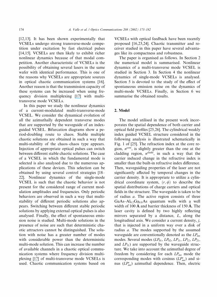
power, is reached. Chaos–chaos multi-stabilitythen disappears in the presence of spontaneousemission noise. The current modulation amplitudeis large and then the laser power switches off to thespontaneous emission noise levels. The effect ofthis noise is to change the modal initial conditions.As we showed in the previous section, the attractorthat is obtained is very sensitive to the initialconditions of the evolution. Then, noise is makingthe system to change from one attractor to an-other, in such a way that those changes are sofrequent that different attractors cannot be dis-tinguished. The multi-mode solution with noisehas a greater number of modes with nonnegligiblepower than the deterministic multi-mode solution.This is illustrated in Fig. 8 where the modal aver-aged power is plotted as a function of the currentmodulation amplitude. It can be seen that there isa wide amplitude range over which LP01, LP02, LPc
11,LPs
11, LPc21, and LPs
21 modes have appreciable power.
40 60 80 100 120 140 160 180 200Time (ns)
0
10
0
10
0
10
Pow
er (
mW
)
0
10
20
0
10
20
30TOTAL
LP01
LP21
c
LP02
LP11
c
Fig. 7. Dynamical evolution of the optical output power of
several transverse modes in the presence of spontaneous emis-
sion noise. The modulation amplitude is jm=jth ¼ 17. Pulses at
LP01 and LP02 optical frequencies are injected at t ¼ 80 and
t ¼ 160 ns, respectively. LPs11 and LPs
21 dynamics are not shown
because their behavior are very similar to the dynamics of
LPc11 and LPc
21, respectively.
180 A. Valle et al. / Optics Communications 208 (2002) 173–182
For instance, at jm=jth ¼ 17, all those six modeshave appreciable lasing power while in the deter-ministic case only three modes are lasing (see Fig.3). A lasing mode can then be used as a chaoticcarrier in a chaotic optical communication system.The number of chaotic carriers, and hence thenumber of channels, increases then in the presenceof spontaneous emission noise. Therefore, there isan increase of the number of channels that can beused in a chaotic optical communication systemswhere frequency division multiplexing with multi-transverse mode VCSELs is used. Frequency di-vision multiplexing can be used with transversemodes in VCSELs because frequency differencesbetween them are typically higher than 100 GHz.With these frequency differences identification ofdifferent channels is feasible [16].
6. Summary
Nonlinear dynamical behavior of VCSELs hasbeen studied when applying current modulation ofhigh-frequency and large modulation depth. Cha-otic behavior has been obtained in the multi-transverse mode regime due to transverse modecompetition. Multi-mode chaotic operation is suchthat different stable chaotic attractors can be ob-
tained by changing the initial conditions andtherefore multi-stability of the chaos–chaos type isobserved. Injection of appropriate optical pulsescan switch between different stable chaotic solu-tions. The case of a VCSEL in which the funda-mental mode is selected has also been analysed.Nonlinear dynamics of the single mode VCSEL issuch that the chaotic behavior is no longer presentfor the considered values of frequency and currentmodulation amplitudes. Only periodic behaviorsare observed. We have shown that generalizedmulti-stability and subharmonic resonances arepresent in the system. Switching between differentstable periodic solutions by applying external op-tical pulses has also been obtained. The effect ofspontaneous emission noise on the dynamics ofmulti-mode VCSELs has been studied. The ob-tained solution has a greater number of modeswith considerable power than the deterministicsolution. Then, there is an increase in the numberof available channels in a chaotic optical commu-nication systems where frequency division multi-plexing of multi-mode VCSELs is used. Finally,the effect of spontaneous emission noise on thedynamics of single-mode VCSELs will be thesubject of future work.
Acknowledgements
Financial support has been provided by CICYT(Spain) Project TIC99-0645-C05-01 and by theEuropean Comission under Project OCCULT(IST-2000-29683) and under Human Potential-Research Training Network VISTA (HPRN-CT-2000-00034).
References
[1] C.J. Chang-Hasnain, in: G.P. Agrawal (Ed.), Semiconduc-
tor Lasers: Past, Present and Future, American Institute of
Physics, Woodbury, NY, 1995.
[2] C.W. Wilmsen, H. Temkin, L. Coldren, in: Vertical-cavity
Surface-emitting Lasers, Cambridge University Press,
Cambridge, UK, 1999.
[3] H. Kawaguchi, in: Bistabilities and Nonlinearities in Laser
Diodes, Artech House, Boston, London, 1994.
[4] W.F. Ngai, H.F. Liu, Appl. Phys. Lett. 62 (1993) 2611.
5 10 15 20 25jm/jth
0.0
0.5
1.0
1.5
2.0
2.5
3.0
Ave
rage
d P
ower
(m
W)
LP01
LP02
LP11
c and LP11
s
LP21
c and LP21
s
Total
Fig. 8. Modal averaged power as a function of the current
modulation amplitude in the presence of spontaneous emission
noise. Time averages have been performed over a 300 ns period.
A. Valle et al. / Optics Communications 208 (2002) 173–182 181

[5] H.F. Liu, W.F. Ngai, IEEE J. Quantum Electron. 29
(1993) 1668.
[6] Y. Matsui, S. Kutsuzawa, S. Arahira, Y. Ogawa, A.
Suzuki, IEEE J. Quantum Electron. 34 (1998) 1213.
[7] S. Bennett, C.M. Snowden, S. Iezekiel, IEEE J. Quantum
Electron. 33 (11) (1997) 2076.
[8] H. Lamela, G. Carpintero, F.J. Mancebo, IEEE J. Quan-
tum Electron. 34 (10) (1998) 1797.
[9] S.F. Yu, IEEE J. Quantum Electron. 35 (1999) 332.
[10] J.Y. Law, G.P. Agrawal, Opt. Commun. 1–3 (13) (1997)
95.
[11] D.A. Richie, T. Zhang, K.D. Choquette, R.E. Leibenguth,
J.C. Zachman, N. Tabatabaie, IEEE J. Quantum Electron.
30 (1994) 2500.
[12] C.J. Chang-Hasnain, J.P. Harbison, G. Hasnain, A.C. von
Lehmen, L.T. Florez, N.G. Stoffel, IEEE J. Quantum
Electron. 27 (1991) 1402.
[13] D. Vakhshoori, J.D. Wynn, G.J. Zydzik, R.E. Leibenguth,
M.T. Asom, K. Kojima, R.A. Morgan, Appl. Phys. Lett.
62 (13) (1993) 1448.
[14] O. Buccafusca, J.L.A. Chilla, J.J. Rocca, S. Feld, C.
Wilmsen, V. Morozov, R. Leibenguth, Appl. Phys. Lett. 68
(5) (1996) 590.
[15] M. Giudici, J.R. Tredicce, G. Vaschenko, J. Rocca, C.S.
Menoni, Opt. Commun. 158 (1998) 313.
[16] S.F. Yu, P. Shum, N.Q. Ngo, Opt. Commun. 200 (2001)
143.
[17] J.K. White, J.V. Moloney, Phys. Rev. A 59 (1999) 2422.
[18] R.A. Morgan, G.D. Guth, M.W. Focht, M.T. Asom, K.
Kojima, L.E. Rogers, S.E. Callis, IEEE Photon. Technol.
Lett. 4 (1993) 374.
[19] Y.A. Wu, G.S. Li, R.F. Nabiev, K.D. Choquette, C.
Caneau, C.J. Chang Hasnain, IEEE J. Sel. Top. Quantum
Electron. 1 (2) (1995) 629.
[20] J. Heinrich, E. Zeeb, K.J. Ebeling, IEEE Photon. Technol.
Lett. 10 (10) (1998) 1365.
[21] K.D. Choquette, G.R. Hadley, H.Q. Hou, K.M. Geib,
B.E. Hammons, Electron. Lett. 34 (10) (1998) 991.
[22] H. Martinsson, J.A. Vukusik, M. Grabherr, R. Michalzik,
R. Jager, K.J. Ebeling, A. Larsson, IEEE Photon. Technol.
Lett. 11 (12) (1999) 1536.
[23] C.R. Mirasso, P.S. Spencer, K.A. Shore, IEEE J. Quantum
Electron. 34 (1998) 1673.
[24] P.S. Spencer, C.R. Mirasso, IEEE J. Quantum Electron. 35
(1999) 803.
[25] A. Valle, J. Sarma, K.A. Shore, IEEE J. Quantum
Electron. 31 (1995) 1423.
[26] A. Valle, IEEE J. Quantum Electron. 34 (10) (1998) 1924.
[27] A.W. Snyder, J.D. Love, Optical Waveguide Theory,
Chapman & Hall, London, 1983.
[28] K.J. Ebeling, in: Semiconductor Quantum Optoelectronics.
From Quantum Physics to Smart Devices, 312, Institute of
Physics, London, 1999.
[29] W. Nakwaski, R.P. Sarzala, Opt. Commun. 148 (63)
(1998).
[30] S.F. Pereira, M.B. Willemsen, M.P. van Exter, J.P.
Woerdman, Opt. Commun. 179 (2000) 485.
[31] G.R. Hadley, K.L. Lear, M.E. Warren, K.D. Choquette,
J.W. Scott, S.W. Corzine, IEEE J. Quantum Electron. 32
(1996) 607.
[32] T. Mukaihara, N. Ohnoki, Y. Hayashi, N. Hatori, F.
Koyama, K. Iga, IEEE J. Sel. Top. Quantum Electron. 1
(2) (1995) 667.
[33] P. Dowd, P.J. Heard, J.A. Nicholson, L. Raddatz, I.H.
White, R.V. Penty, J.C.C. Day, G.C. Allen, S.W. Corzine,
M.R.T. Tan, Electron. Lett. 33 (15) (1997) 1315.
[34] G. Verschaffelt, W. van de Vieuten, M. Creusen, E.
Smalbrugge, T.G. van de Roer, F. Karouta, R.C. Strijbos,
J. Danckaert, I. Veretennicoff, B. Ryvkin, H. Thienpont,
G.A. Acket, IEEE Photon. Technol. Lett. 12 (8) (2000) 945.
[35] J.Y. Law, G.H.M. VanTartwijk, G.P. Agrawal, Quantum
Semiclassical Opt. 9 (5) (1997) 737.
[36] F.T. Arecchi, R. Meucci, G. Puccioni, J.R. Tredicce, Phys.
Rev. Lett. 49 (1982) 1217.
[37] D. Dangoisse, P. Glorieux, D. Hennequin, Phys. Rev. A 36
(10) (1987) 4775.
[38] V.N. Chizhevsky, S.I. Turovets, Phys. Rev. A 50 (2) (1994)
1840.
[39] V.N. Chizhevsky, J. Opt. B: Quantum Semiclassical Opt. 2
(6) (2000) 711.
[40] D.F.G. Gallagher, I.H. White, J.E. Carroll, R.G. Plumb, J.
Lightwave Technol. 5 (10) (1987) 1391.
182 A. Valle et al. / Optics Communications 208 (2002) 173–182


![[- 200 [ PROVIDING MODULATED COMMUNICATION SIGNALS ]](https://static.fdokumen.com/doc/165x107/6328adc85c2c3bbfa804c60f/-200-providing-modulated-communication-signals-.jpg)