non- destructive testing nuclear I technology - International ...
Upload
khangminh22Category
view
4download
0
applied sciences
Review
Non-Destructive Testing Applications for Steel Bridges
Seyed Saman Khedmatgozar Dolati 1,* , Nerma Caluk 1,* , Armin Mehrabi 1
and Seyed Sasan Khedmatgozar Dolati 2
�����������������
Citation: Khedmatgozar Dolati, S.S.;
Caluk, N.; Mehrabi, A.;
Khedmatgozar Dolati, S.S.
Non-Destructive Testing Applications
for Steel Bridges. Appl. Sci. 2021, 11,
9757. https://doi.org/10.3390/
app11209757
Academic Editor: Evangelos
Z. Kordatos
Received: 28 September 2021
Accepted: 15 October 2021
Published: 19 October 2021
Publisher’s Note: MDPI stays neutral
with regard to jurisdictional claims in
published maps and institutional affil-
iations.
Copyright: © 2021 by the authors.
Licensee MDPI, Basel, Switzerland.
This article is an open access article
distributed under the terms and
conditions of the Creative Commons
Attribution (CC BY) license (https://
creativecommons.org/licenses/by/
4.0/).
1 Department of Civil and Environmental Engineering, Florida International University, Miami, FL 33174, USA;[email protected]
2 Department of Civil and Environmental Engineering, University of Texas at San Antonio,San Antonio, TX 78249, USA; [email protected]
* Correspondence: [email protected] (S.S.K.D.); [email protected] (N.C.)
Abstract: The growing population and increasing demand for surface transportation have highlightedthe importance of maintaining safe and reliable civil infrastructures for daily use. Among all civilinfrastructures, bridges are one of the most important elements in the transportation system. Assuch, to prevent any failures caused by aging and environmental impacts, bridges require periodicinspections. This becomes even more critical due to climate change and its effect on bridges, especiallyin the coastal regions. Most of the inspections conducted incorporate the visual type of evaluationdue to its simplicity. However, with the current developments in new technologies, there is a need formore advanced techniques of structural health monitoring (SHM) methods to be incorporated in themaintenance programs for more accurate and efficient surveys. In this paper, non-destructive testing(NDT) methods applicable to steel bridges are reviewed, with a focus on methods applicable tolocal damage detection. Moreover, the methodology, advantages and disadvantages, and up-to-dateresearch on NDT methods are presented. Furthermore, the application of novel NDT techniquesusing innovative sensors, drones, and robots for the rapid and efficient assessment of damages onsmall and large scales is emphasized. This study is deemed necessary as it compiles in one place theavailable information regarding NDT methods for in-service steel bridges. Access to such informationis critical for researchers who intend to work on new or improved NDT techniques.
Keywords: non-destructive testing (NDT); non-destructive evaluation (NDE); steel; bridges; inspec-tion; damage detection; vibration method; vision-based method; robotics
1. Introduction
Because of an increased reliance of communities and businesses on surface transporta-tion, and with the presence of ever-increasing environmental impacts caused by aging,maintaining the safety and reliability of civil infrastructures has become a critical issue.Among all civil infrastructures, bridges can be deemed as the most affected type. Fromover 617,000 accounted bridges in the United States, about 42% of those bridges are atleast 50 years old, and 7.5% of them are considered structurally deficient. Although thenumber of structurally deficient bridges has been declining over the past 50 years, the rateof their improvement is still considered slow [1]. Out of the total number of bridges in theUnited States, around 33% are steel bridges [2]. A similar condition also exists for bridgesin other parts of the world. Throughout the years, steel bridges have been evolved andadapted by their designers, eliminating issues that were consistently reoccurring in thedesigns. However, there are still many issues that can decrease the structural integrity ofa steel bridge, with corrosion being the most prevalent, followed by fatigue and fracturein sensitive connections, some exacerbated by welding issues. Accordingly, bridges mustbe inspected periodically for the on-time detection of possible structural damage andapply the needed repairs before the damage becomes significant and costly. The NationalBridge Inspection Standards (NBIS) mandates that all bridges with a span of longer than
Appl. Sci. 2021, 11, 9757. https://doi.org/10.3390/app11209757 https://www.mdpi.com/journal/applsci

Appl. Sci. 2021, 11, 9757 2 of 34
20 ft and located on public roads need to be inspected every 24 months by a qualifiedbridge inspector [1,3].
Over the years, various techniques have been implemented for the structural healthmonitoring of the bridge systems. Among various methods, non-destructive testing (NDT)methods incorporate the non-invasive testing of structural components and structuralsystems without causing any damage, changing their material composition or shape of theinspected components. The Federal Highway Administration (FHWA) also defines NDTas a “means of analyzing and assessing the condition of various structural componentsof in-service highway infrastructure assets—pavement, bridges, and tunnels—withoutimpairing their future usefulness” [4]. These methods bring an innovative and rapidmode of inspection with which to analyze and diagnose structural deficiencies such ascracks, fatigues, delamination, voids, and corrosion. Various non-destructive testing (NDT)methods have been implemented for the inspection of bridge elements. The required typeof NDT method differs from one bridge to the next, depending on the structural type, theenvironment, and the preference of the owner.
This paper compiles in one place all the information regarding the application of NDTmethods for steel bridges. Although both global and local damage detection methods arediscussed, the focus of this paper is on the methods applicable to local NDT methods. Assuch, the methodology, advantages, and disadvantages of each technique are thoroughlyinvestigated. Furthermore, recent innovations in this regard, including the application ofdrones, sensors, or robots for rapid and efficient assessment of damages on small and largescales, are presented. This is an attempt to compile in one place all the NDT techniques,including state-of-the-art and advanced techniques, for the inspection of steel bridges. Itaims to keep researchers up-to-date with existing methods and pave the way for furtherinnovations in this regard. Importantly, this study can help engineers and inspectors selectthe most proper NDT methods at the site, potentially saving considerable cost and time.
2. Need for Inspection of Steel Bridges
Steel bridges constitute a substantial portion of national wealth. Unchecked dam-ages and the potential failure of these critical infrastructure links could not only have asignificant economic impact, but also threatens public safety. As such, they should beinspected between short intervals to prevent the exacerbation of potential damages andfailure. Typical damages of in-service steel bridges include corrosion and the loss of cross-section, delamination, cracks, wear, and surface blemishes (Figure 1). These damages, afterdetection, should be repaired or appropriately rehabilitated to prevent future catastrophicfailures. It goes without saying that detecting the damages is the first step in this process.
Figure 1. Most common deficiencies in steel bridges: (a) Corrosion [5–7]; (b) Delamination [8];(c) Cracks [9]; (d) Top chord plate wearing groove into a top chord pin [10]; (e) Surface blemishes(welding arc strike on surface of steel plate) [10].
Appl. Sci. 2021, 11, 9757 3 of 34
Most of these damages in their advanced stage can be detected easily with a visualinspection. However, the detection of small and subsurface cracks and damages in deficientwelded connections require inspection and testing techniques with capabilities above andbeyond visual inspection. To address this, various NDT methods have been practiced overrecent decades. The type of NDT method required for the inspection should incorporatethe most practical and cost-effective technique to successfully assess the condition of thestructural components and to determine the need for maintenance and repair action. Inaddition to a familiarity with, and skill in, the use of these various available methods, theinspector needs to be aware of the environment in which the inspection takes place, as wellas the bridge section that is under survey, to determine the proper procedure.
3. NDT Methods with Potential Application to Steel Bridges
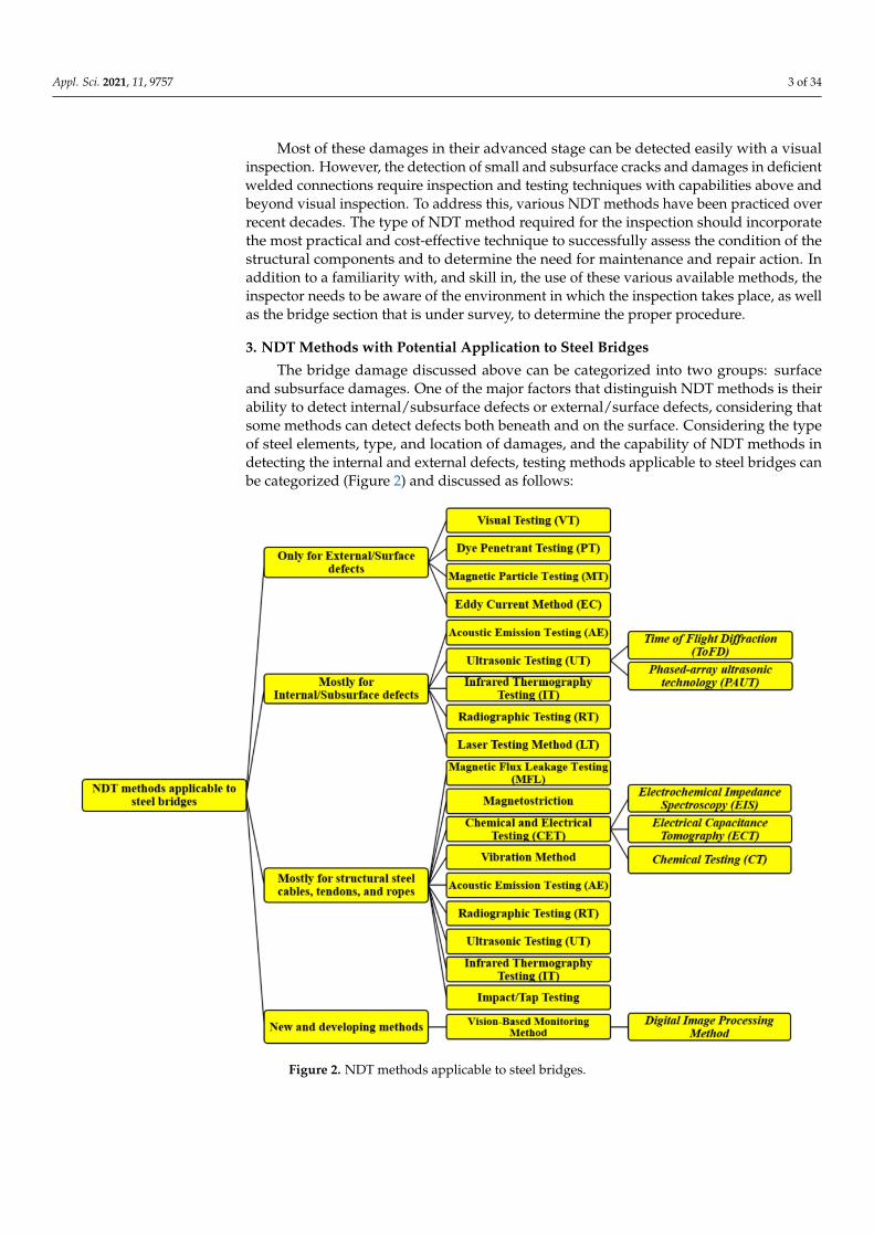
The bridge damage discussed above can be categorized into two groups: surfaceand subsurface damages. One of the major factors that distinguish NDT methods is theirability to detect internal/subsurface defects or external/surface defects, considering thatsome methods can detect defects both beneath and on the surface. Considering the typeof steel elements, type, and location of damages, and the capability of NDT methods indetecting the internal and external defects, testing methods applicable to steel bridges canbe categorized (Figure 2) and discussed as follows:
Figure 2. NDT methods applicable to steel bridges.

Appl. Sci. 2021, 11, 9757 4 of 34
3.1. Test Methods Applicable Only to External/Surface Defects
NDT methods discussed in this section can be implemented to detect defects anddamages occurring on the surface of steel bridges. These methods can be considered assimple to apply and easy to interpret when compared to methods for internal defects.Despite the relative simplicity of these methods, the inspectors should be experienced andwell trained. These testing methods are described as follows:
3.1.1. Visual Testing (VT)
This technique is the most common form among all NDT methods due to its simplicity.Although most of a visual inspection is performed with the naked eye, some cases mayrequire visual aids such as magnifiers, binoculars, scopes, and borescopes. The inspector inthis case needs to be experienced and familiar with the types and levels of damage in thesteel. This is the most economical and fastest method of inspection [11]. However, becauseof the subjectivity of the visual inspection method, different results could be reportedby different inspectors. Visual inspection limits the inspector to the surface defects thatare sufficiently noticeable [12]. Different conditions can affect the inspector’s judgmentand focus, including traffic, working at a height, limited visual angle, lighting conditions,and multitasking with other tasks for bridge element rating [10]. These factors can beproblematic for the inspectors to decide whether a flaw should be considered a defect andif it requires follow-up action. An example of challenging visual inspection is shown inFigure 3, where the lack of lighting and height can be of concern.
Figure 3. Challenges of visual inspection method: (a) Lack of lighting [10]; (b) Visual inspection at heights can be dangerousand challenging [11].
3.1.2. Dye Penetrant Testing (PT)
The Dye Penetrant Testing (PT) is an NDT method and is used to detect and monitorsurface cracks, welded details, and gusset plate connections in steel bridge members. Thismethod is inexpensive and simple, and can be implemented for the confirmation of thevisual inspection. However, its process is time-consuming and, as a result, may not becost-effective where multiple locations need to be inspected. The PT method relies on dyeliquid that is applied onto the surface with the ability to penetrate a crack, void, and othersurface defects in the element [10,13–15]. The penetrant dye is usually packed in a kitthat contains the required chemicals in three aerosol spray cans, i.e., a cleaner, a penetrant,and a developer. Each of the cans is related to a specific step of the process [4]. Figure 4indicates the steps needed for the application of PT to provide the inspectors with accurateand valid results [13,16,17]

Appl. Sci. 2021, 11, 9757 5 of 34
Figure 4. Steps for implementation of PT tests [13].
The dye penetrant method is highly sensitive, portable, and can detect even thesmallest surface discontinuities. It can be applied to a variety of base material and issuitable for complex shapes. However, there are some disadvantages for this method: Itis not suitable for inspecting the elements with a porous surface; it requires caution inpre-cleaning, chemical handling, and removal of the excess penetrant; and the inspectorneeds to access the tested components to safely conduct the whole inspection [17].
3.1.3. Magnetic Particle Testing (MT)
This method can be implemented to detect surface and near-surface internal flawsin steel bridge elements (Figure 5). Compared to the PT method, its application is fasterand less costly, and requires less surface preparation. In this method, after cleaning thesurface of the test component from oil, grease, or any other contaminations, a magneticyoke is placed on, producing magnetic fields between the yoke probes (Figure 6). Thiscreates magnetic flux lines which flow between the legs of the yoke. As such, any defectinterrupting the magnetic flux lines produces a localized area of flux leakage, consequentlychanging the formation of iron particles that is spread on the suspect area. There are twomethods for applying this technique: implementation with dry iron particles or wet ironparticles. For dry MT, iron powder is applied to the surface of the test area while themagnetic force is applied by the yoke. Then, the surface is lightly blown using a bulbapplicator, removing additional iron particles. In response, the particles are absorbed andclustered at flawed sites (magnetic leakage areas), creating a clear indication (Figure 7). Forthe wet MT application, the iron particles in a combination of water or oils are sprayed tothe test areas. Other steps for the application of wet MT are the same as dry MT. Otherworks can be referred for more detailed procedures and practices [18,19].
Figure 5. Application of magnetic particle testing for steel bridges [10,20].

Appl. Sci. 2021, 11, 9757 6 of 34
Figure 6. Producing a magnetic field using the yoke in the test piece [21].
Figure 7. Application of dry MT (Alta Vista Solutions).
MT is a practical option for exterior/surface flaws for steel bridges. This method issimple and requires minimum training for inspectors. However, this technique has somedisadvantages, including issues for irregular surface finishes, the need for lane closurefor performing the test, and its being not applicable to non-ferromagnetic material. Thecoating thicker than 2 mils should be removed before applying the tests [10].
3.1.4. Eddy Current Method (EC)
Eddy current (EC) method represents a non-destructive electromagnetic test that usesenergized probes. This technology uses eddy coils placed side by side on the probe. Whenthe probe is placed on the test piece, a dynamic magnetic field is created around the probe.This magnetic field produces eddy currents in the test piece centered on the probe. Thecurrents induced on the test piece oscillate in a circular pattern and flow in a directionopposite to the current in the coil. Because a specific magnitude and phase are generated bythe eddy current, any cracks or discontinuities affect the magnitude and phase, thereforepointing to a defect. Figure 8 shows an example of EC practiced for the purpose of detectinga flaw on a steel element.
The EC method has initially been used in the aerospace and petrochemical industry forthe non-destructive testing of non-ferromagnetic cylinders, metallic pipes, rods, bars, etc., todetect cracks, corrosion, and other material defects. The EC method has been expanded tocivil engineering, specifically in the non-destructive testing of steel bridge components [25].
Compared to MT and PT, the eddy current method is faster and requires less surfacepreparation. Accordingly, it is a time-efficient process and can be implemented wheremultiple inspection sites are present on a bridge. This method is practical for the detectionof flaws through both non-conductive and conductive coatings.

Appl. Sci. 2021, 11, 9757 7 of 34
Figure 8. Example of the eddy current method for detection of flaws on a steel pipe [22]. Thesignals from the eddy current method can be affected and distorted by factors such as lift-off(distance between the test coil and the specimen), electrical conductivity, magnetic permeability,inhomogeneity of the material, or the thickness of the test piece [23]. Lift-off is one of the mostcommon problems for EC tests, slowing down and limiting the growth of its applications. Furtherfactors that can affect the received signals are the noise and low-level signals [24,25]. To providefor the desired parameters and accurate readings, signal processing, signal analysis, and featureextraction and classification of the model must be performed.
3.2. Test Methods Applicable to Internal/Subsurface Defects
The methods discussed in this section are normally implemented to detect inter-nal/subsurface defects in steel elements; however, these methods are also applicable inthe detection of external/surface defects. Their application is mostly used for the sizingand characterizing of the defects previously indicated by external/surface NDT methods;the inspection of test sites in which potential for internal damage exists, including pins,questionable welds, weld repairs, or impact damage; and the monitoring of the size of thesubsurface to assess progressive fracture and determine the follow-up action. These tech-niques are slow and require experienced operators, special training, and costly equipment.
3.2.1. Ultrasonic Testing (UT)
The application of Ultrasonic Testing (UT) to damage detection in steel bridges iswidespread. It can be used to detect subsurface volumetric flaws, including slag inclusionsand cluster porosity, surface-breaking flaws (e.g., cracks), and material thickness, to mea-sure corrosion and construction errors. It is the most practical NDT method for detectingplanar defects, including cracks, a lack of fusion, and a lack of penetration. It has also beenimplemented for wire break detection at anchorage zones for stay cables and tendons [10].The UT method uses tools that include a pulser–receiver, electronic signal controls, displayscreen, transducers, lead wires, reference gages, and a couplant. Sometimes, surface prepa-ration is required, which requires wire brushes, grinding disks, scrapers, and hammers.In this method, the structural component is tested using ultrasound waves at frequenciesmore than the audible ranges [26,27]. The reflection of waves on the UT monitor indicatesthe exact distance of any subsurface/internal flaws from the surface [28] (Figure 9).
Figure 9. UT Methodology [28,29].

Appl. Sci. 2021, 11, 9757 8 of 34
Specific amplitudes and frequencies of the electronic pulses are generated throughthe lead wires that are connected to piezoelectric crystal probes. For steel elements, thefrequency is typically between 2 and 5 Hz. Two types of transducers exist depending onthe kind of waves that are generated: straight beam and angle beam transducers. Straightbeam transducers generate compression waves consisting of alternating layers of steelatoms that expand and compress due to the of the elastic motion. Angle beam transducersgenerate shear waves that oscillate at right angles to the direction of the wave motion [10].The presence of air gaps between the contact of UT transducers and the surface of a testedpiece may cause wave scattering. Accordingly, a gel couplant is applied to the surfaceto strengthen the in-situ bonding and to prevent wave scattering [30]. Figure 10 showsthe application of UT for the steel bridges. UT is considered a fast NDT method, and itscost is moderate. Its accuracy in detecting defects, portability, and high safety are otheradvantages of this technique. However, this method is less effective for inspecting verythin components, fragile materials, and elements with a complex geometry [31]. In orderto enhance the capabilities of the ultrasonic tests, several methods have been developed;the following are more details of these techniques.
Figure 10. Applications of UT for steel bridges [10].
Phased-array ultrasonic technology (PAUT)— Phased-array ultrasonic technology(PAUT) is one of the advanced UT methods developed to detect cracks located at differentdepths, with random orientation probes at fixed conditions (Figure 11). The main propertyof PAUT is its computer-controlled excitation of individual elements with a multi-elementprobe, which can generate an ultrasound focused beam with the capabilities of modifyingthe beam parameters [32] (Figure 12). These parameters include the beam angle, focaldistance, and focal spot size, allowing this technique to detect cracks in various orientationslocated away from the beam axis [33].

Appl. Sci. 2021, 11, 9757 9 of 34
Figure 11. Phased-array ultrasonic technology (PAUT).
Figure 12. Comparison between conventional UT and phased-array UT, where PAUT allows for the shaping and steering ofthe ultrasonic beam angles, better depth focus, and enhanced coverage [34].
PAUT is known for its simplicity in implementing multiple transducers. This typeof ultrasonic method is not only faster and more convenient than conventional mono-lithic technology, but it also possesses better accuracy. Further capabilities include easieraccessibility to out-of-reach components, shorter inspection time, and the detection andmeasurement of small stress corrosion cracks. Sometimes, the limitation in orientationfor the path of the ultrasonic pulse makes it difficult for PAUT to fully obtain an image ofcracks and defects. It also requires costlier equipment compared to conventional UT.
Time of Flight Diffraction (ToFD)— To address the issues with orientation when usingPAUT, ToFD was invented, which uses diffraction instead of reflection. A ToFD transducergenerates pulsed ultrasonic waves [32,35–37], which are diffracted at a certain degree dueto the irregularities in the inspected component. After the diffraction, waves are thencollected by the receiver on the other side of the component. The image is then generated,containing the size and location of the cracks and defects, using the difference in the flighttime of the ultrasonic waves that traveled from the transducer to the receiver (Figure 13).This type of ultrasonic technology is preferred over PAUT when the objective is to finddefects and flaws, regardless of their orientation. ToFD can also be used to inspect weldedoverlays and heat-affected zones. Furthermore, it is considered to be one of the fastestnon-destructive testing methods as it only requires one scan for detection. An example ofthe reading of weld cracks with ToFD can be seen in Figure 14 [36–38].
However, the ToFD method has shortcomings, including the possibility of presentinglateral wave dead zones, timing errors, off-axis errors, or resolution errors on the imageif only a single scan has been performed on the component. This issue can be solved byimplementing the PAUT to vary the wave angle, width, and entry point. Combining ToFDwith PAUT gives the inspectors a more reliable and efficient scanner [39].

Appl. Sci. 2021, 11, 9757 10 of 34
Figure 13. Principle of Time-of-Flight Diffraction Ultrasonic Method with a transmitter (transducer)on the left side of the figure and receiver on the opposite side [38].
Figure 14. Cracks in a drum weld detected using ToFD technology [38].
3.2.2. Acoustic Emission Testing (AE)
Another method that can be used for the NDT of steel bridges is Acoustic EmissionTesting (AE). AE is implemented to monitor materials experiencing dynamic processes,including structural loading, corrosion, and weld heating and cooling.
The methodology of this technique works according to acoustic emissions generatedas elastic waves (Figure 15) by the onset or progression of cracks and other discontinuitiesin steel elements. These waves are radiated outward from the vicinity of crack tips in acircular pattern and are sensed by the sensors (transducers) attached to the surface of thetest piece seen by the AE monitor. Before the installation of the transducers, the coatingshould be removed at the attachment sites. In some cases, magnetic hold-downs areemployed to couple the transducers to a test piece. For monitoring bridge componentswith the AE method, multiple transducers are typically used. To locate cracks and removeinterference signals from noise sources, the transducers are to be placed on a test piece ingeometric arrays. Figure 16 indicates the application of AE testing for the inspection ofsteel bridges [10].
Figure 15. Schematic of AE technique (NDT Resource Center at Iowa State University).

Appl. Sci. 2021, 11, 9757 11 of 34
Figure 16. Application of AE for steel bridges [10,40,41].
The AE has various applications for steel bridge elements including for rolled shapes,plates, welded connections, pins, and cable fittings. This method can only be used to detectthe onset of a defect or the progression of existing anomalies; it cannot be used to detectexisting defects without major activity. The AE method has been used successfully fordetecting wire breaks in cable-stayed bridges and fatigue cracking in orthotropic bridgedecks [42]. It should be stated that this method requires special equipment and training forthe inspectors.
3.2.3. Infrared Thermography Testing (IT)
The IT method is based on the relationship between thermal radiation and temperature,where the heteromorphic structure of an object is described by the difference of the surfacetemperature distribution. In this technique, an infrared camera is implemented to measurethe emitted infrared radiation from the test elements (Figure 17). Thus, by using differentforms of active thermal excitation, the defect can be effectively detected. Figure 18 presentsthe principle of IT technology, where a heating source is applied to both a non-defectedand defected object. If the material is uniform, i.e., without any defects, the thermal signalpropagates smoothly through the object, while, for the defected object, the thermal signalresults in sudden changes in the surface temperature distribution [43].
Figure 17. Infrared camera used for IT method [44].
Figure 18. Principle of infrared thermography for uniform and nonuniform elements and theirthermal wave propagation [43].
Appl. Sci. 2021, 11, 9757 12 of 34
Much research has been carried out on the application of IT for steel elements [45–47].Sakagami et al. [46] conducted an IT test on the steel deck of a steel bridge, with two typesof cracks: Crack A (weld-bead-penetrant-type) and Crack B (through-deck-type), as shownin Figure 19 [46]. They found this technique practical for identifying the cracks. Mehrabi(2006) employed IT for the non-destructive evaluation of cables in cable-stayed bridgeswith an ambient heat source [44].
Figure 19. Schematic representation of fatigue cracks and IT inspection at rib-to-deck joint [46].
There are two types of IT technology, which include a traditional approach knownas pulse thermography (PT) and the more advanced lock-in thermography (LT) [48]. Thetraditional PT uses a short-duration energy pulse and records the thermal response. Incontrast, the LT uses mono-frequency sinusoidal thermal excitation to find the phase andmagnitude of the reflected thermal wave from the recorded thermal images. The LT methodprovides better accuracy and efficiency for noise rejection, but it takes a considerably longertime to measure frequencies [48,49]. The PT method is known for its fast detection speed,large detection area, and ease of data access. This method can be implemented to detectcracks, rust, fatigue damage, and debonding in steel bridges [48–50].
According to the Non-destructive Evaluation Center of the Federal Highway Ad-ministration, compared to other NDT techniques, IT covers more areas for inspection,therefore it is a cost-effective method for inspection of steel bridges with large areas. More-over, this method can indicate the percentage of deteriorated areas. However, there aresome disadvantages to this technique, including the high cost of test equipment, beingdependent on the proper temperature of the ambient, and the need for special training forthe operators [51].
3.2.4. Radiographic Testing (RT)
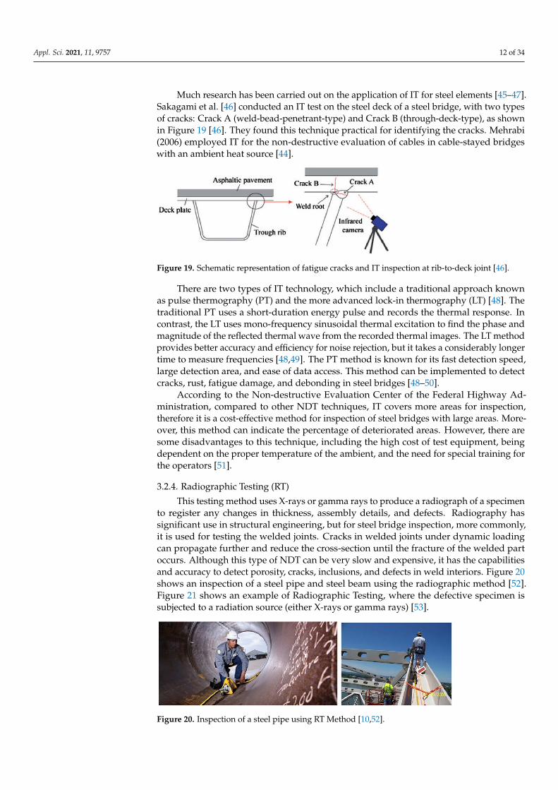
This testing method uses X-rays or gamma rays to produce a radiograph of a specimento register any changes in thickness, assembly details, and defects. Radiography hassignificant use in structural engineering, but for steel bridge inspection, more commonly,it is used for testing the welded joints. Cracks in welded joints under dynamic loadingcan propagate further and reduce the cross-section until the fracture of the welded partoccurs. Although this type of NDT can be very slow and expensive, it has the capabilitiesand accuracy to detect porosity, cracks, inclusions, and defects in weld interiors. Figure 20shows an inspection of a steel pipe and steel beam using the radiographic method [52].Figure 21 shows an example of Radiographic Testing, where the defective specimen issubjected to a radiation source (either X-rays or gamma rays) [53].
Figure 20. Inspection of a steel pipe using RT Method [10,52].

Appl. Sci. 2021, 11, 9757 13 of 34
Figure 21. Example of radiographic testing of a defective component and its results gathered throughthe X-ray film [53].
The radiographic testing equipment consists of a radiation source, film cassette ordigital flat panel detector, penetrometer, and filmmakers. Little or no surface preparation isneeded for the application of RT. The most effective application for RT is for the detection ofsubsurface defects hidden from the naked eye. In this method, the test piece is subjected tothe radiation source. Based on the material density, the radiation is transmitted at differentrates and variations are captured on photographic film or fluorescent screen. Radiographictesting functions with an X-ray sensitivity of 2%, meaning that if the smallest dimension ofa component is 20 mm, the smallest void that can be detected is 0.4 mm [15,54]. RT hasalso been used at an experimental level for detection of wire breaks in stay cables [55]. Thedisadvantages of the RT method for steel bridges include its slow operation and high cost,its serious safety issues and health hazards, its improper use for thick sections, and its needfor expensive equipment and special training for the inspectors [56].
3.2.5. Laser Testing Method (LT)
Another NDT method that can be used for the detection of defects in steel bridgesis the laser testing method. This method is in the experimental stage and information onits applicability is very limited. This method employs Lamb wave initiation by pulsedlaser generating a laser impact on the component (Figure 22) [57]. The flaw is detectedby a standing Lamb wave produced by the impact and recorded by the photorefractiveinterferometer. Guldur et al., in 2015, inspected and determined the condition ratings of abridge component by employing quantified surface damage from a 3D laser image (pointcloud image). They used two techniques for the inspection: Graph-based Surface DamageDetection and Surface Normal-based Surface Damage Detection. Graph-based SurfaceDamage Detection was implemented to detect the surface defect, including bent members,ruptures, and points of discontinuity; Surface Normal-based Surface Damage Detectionwas used to detect corrosion and cracks. It was concluded that the laser scanners coulddetect defects and flaws and can thus be employed to aid visual inspection [58,59].
Figure 22. LT method (Schematic layout) [28].

Appl. Sci. 2021, 11, 9757 14 of 34
3.3. Test Methods Applicable to Structural Steel Cables, Tendons, and Ropes
Structural tension elements normally pose additional challenges for their inspectionand evaluation. For most of these elements, such as stay cables and post-tensioningtendons, the main steel tension elements are encased in protective sheathing and arefilled by some type of corrosion inhibiting material. As such, they require methods withcapabilities to penetrate beyond the protective elements. The methods discussed in thissection are typically used for the inspection and damage detection of structural steel cables,tendons, and ropes in the bridges, but could be applicable to other components of steelbridges as well. Additionally, some of the above-mentioned methods, as stated in theirdescription, can and have been used in the case of steel cables, tendons, and ropes, arenot described in this section. These include Radiographic and Acoustic Emission Testingfor detection of wire breaks along the cables, and Ultrasonic Testing for anchorage zones.Additionally, Infrared Thermography and Tap/Impact testing can be used to detect flawsin corrosion barriers [44].
3.3.1. Magnetic Flux Leakage Testing (MFL)
In this method, to detect defects including corrosion, breaks, loss of cross-section, andpitting of steel components, the element is magnetized through the use of a strong externalmagnet [60]. The magnet source can be either a permanent or electrically activated magnet.In this method, the magnetic field is present between the probes of the magnet, so that adefect in the steel element leads to the leakage of the magnetic field in the material from itsflux path [61]. The magnetic leakage is detected by magnetic sensors (e.g., a Hall sensor)placed between the magnet poles (Figure 23) [28]. The first reported use of this methodfor stay cables was the work by Bergamini in 2001 [62]. Figure 24 shows its applicationfor I-310 Hale Boggs Bridge in Louisiana [10]. This technique has also been modified andimplemented to inspect the stay cables of a bridge in Thailand (RAMA IX Bridge) [62].
Figure 23. The methodology of MFL non-destructive testing method [28].
Figure 24. MFL application for a cable steel bridge [10].

Appl. Sci. 2021, 11, 9757 15 of 34
MFL can also be implemented to detect flaws in bridge hanger cables and cables ofcable cars with smaller diameters than stay cables. The equipment implemented for theMFL test for the stay cables includes a modular magnetizing and sensing unit mounted onthe cable, and travels along the cable to detect flaws. The time for application of this testingmethod is 10–20 min per cable. However, the time typically is extended to 1 day per cabledue to cable surface preparation and logistical matters. There are some limitations to thismethod, including safety considerations, because of the intense electromagnetic field, theneed for heavy preparation of surface cable, and the heavy and expensive equipment [44].
3.3.2. Magnetostriction
The magnetostrictive sensor (MsS) technology was introduced at the Southwest Re-search Institute (SwRI) in the 1990s [63]. The concept for this technology is that the magneticfields create small changes in the physical dimension of steel material, and material strainscreate changes in magnetization. Accordingly, when the magnetic field around the steelelement is changed, an elastic wave is produced, traveling in both directions along thelength of the wire. The stress wave modifies the magnetic induction of the material, so thatit produces voltage in the receiving coil. This can be monitored and used for the detectionof flaws. This method was used to inspect the hanger cables of the George WashingtonBridge in New York City (Figure 25) [42].
Figure 25. Application of MsS for George Washington Bridge, New York City [42].
This method was also implemented for the inspection of the anchorage area of mainsuspension cables. Their applications for stay cables are under investigation. The re-searchers concluded that this method is not practical for small defects and in the anchor-age zones [42].
3.3.3. Chemical and Electrical Testing (CET)
CET is typically used for the detection of corrosion, voids, and inclusions of consider-able sizes in the structural element. This NDT method can be categorized into:
Electrochemical Impedance Spectroscopy (EIS)—This is an impedance method inwhich a low-amplitude voltage (alternating current) is implemented to the steel under in-spection over a wide range of frequencies. The changes in signal amplitude and phase shiftcan be measured to calculate the impedance of the concrete–steel interface. This methodrequires physical access to the element being inspected. The application of this methodhas been mostly for the external tendons. Special training and sophisticated approachesare needed for the interpretation of the data and extracting meaningful results [60]. Thismethod is generally slow, as low frequencies are required to determine the corrosion rate.Its application has been mainly in laboratory conditions.

Appl. Sci. 2021, 11, 9757 16 of 34
Electrical Capacitance Tomography (ECT)—This method was introduced in the late1980s. ECT obtains capacitance data with the use of multi-electrode sensors and generatespermittivity images of sections by several iterations (Figure 26). It is considered a fast, safe,and inexpensive NDT method. However, it has not been used widely, except in specialinvestigations on small parts of structural elements. Its inherent problems with the imageresolution are the major drawback for its application.
Figure 26. A cross-section model of ECT [31].
Chemical Testing (CT)—This method is mostly used to detect corrosion in the rein-forced concrete elements but can be implemented for other structural elements. In themarine environment, the measurement of chloride in the element can be a means fordetecting corrosion. This method for measuring chloride employs chemical testing or theuse of sensors/indicators [64].
Another method of chemical testing has been investigated in the research conductedby Fujita and Masuda in 2014. The compositions of structural members were analyzedby wavelength through an optical emission spectrometer (Figure 27). In their work, thecontent of the chemical composition was analyzed by the strength on-site. Accordingly,weld crack sensitivity (Pcm) and carbon equivalent (Ceq) composition were evaluatedby this method. These two components can be used for the detection of corrosion in thesteel element [65]. The literature cited can be referenced for more details on proceduresand applications.
Figure 27. Optical emission spectrometer [65].
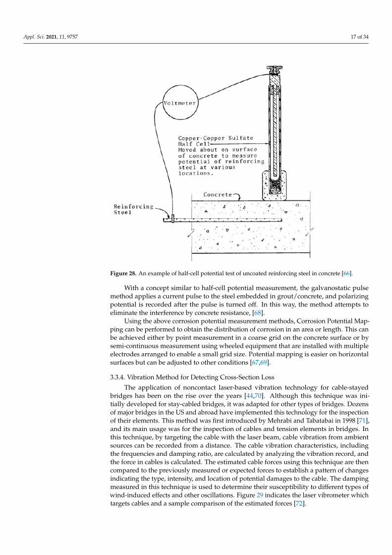
Half-cell Potential Measurement, Galvanostatic Pulse Technique, and Potential Mapping—These methods are electrochemical techniques and have been used widely for corrosion detec-tion in reinforced concrete elements, and, with some modifications, they can be used for staycables and external post-tensioning tendons. The method requires a direct electrical connectionto the steel element embedded in the grout/concrete and access to the face of the grout/concrete.The difference in potential between electrodes and electrolyte is utilized in a half-cell potentialmeasurement technique. A schematic example is shown in Figure 28 [66]. Application of thehalf-cell potential method is inexpensive and simple to perform. Limitations exist when thegrout/concrete is contaminated, leading to difficulties when obtaining quantitative measurefor corrosion [67].
Appl. Sci. 2021, 11, 9757 17 of 34
Figure 28. An example of half-cell potential test of uncoated reinforcing steel in concrete [66].
With a concept similar to half-cell potential measurement, the galvanostatic pulsemethod applies a current pulse to the steel embedded in grout/concrete, and polarizingpotential is recorded after the pulse is turned off. In this way, the method attempts toeliminate the interference by concrete resistance, [68].
Using the above corrosion potential measurement methods, Corrosion Potential Map-ping can be performed to obtain the distribution of corrosion in an area or length. This canbe achieved either by point measurement in a coarse grid on the concrete surface or bysemi-continuous measurement using wheeled equipment that are installed with multipleelectrodes arranged to enable a small grid size. Potential mapping is easier on horizontalsurfaces but can be adjusted to other conditions [67,69].
3.3.4. Vibration Method for Detecting Cross-Section Loss
The application of noncontact laser-based vibration technology for cable-stayedbridges has been on the rise over the years [44,70]. Although this technique was ini-tially developed for stay-cabled bridges, it was adapted for other types of bridges. Dozensof major bridges in the US and abroad have implemented this technology for the inspectionof their elements. This method was first introduced by Mehrabi and Tabatabai in 1998 [71],and its main usage was for the inspection of cables and tension elements in bridges. Inthis technique, by targeting the cable with the laser beam, cable vibration from ambientsources can be recorded from a distance. The cable vibration characteristics, includingthe frequencies and damping ratio, are calculated by analyzing the vibration record, andthe force in cables is calculated. The estimated cable forces using this technique are thencompared to the previously measured or expected forces to establish a pattern of changesindicating the type, intensity, and location of potential damages to the cable. The dampingmeasured in this technique is used to determine their susceptibility to different types ofwind-induced effects and other oscillations. Figure 29 indicates the laser vibrometer whichtargets cables and a sample comparison of the estimated forces [72].

Appl. Sci. 2021, 11, 9757 18 of 34
Figure 29. Laser vibrometer targeting cables (a); sample force comparison (b) [72].
The laser-based measurement technique provides a noncontact remote sensing ability.Accordingly, for a periodic inspection of the elements with a more difficult accessibility, thelaser-based noncontact vibration technique can save a lot of on cost and time.
Other non-contact sensors have been used for vibration measurement. Non-contactmicrowave interferometric radars have also been used for the non-contact assessment ofstay cables. This method can simultaneously measure the dynamic response of an array ofstay-cables [73,74].
Vibration measurement can also be performed using contacting sensors. Accelerome-ters can be attached to the cables with proper clamps [42].
4. New and Developing Methods
This section reviews the new and developing NDT methods that can be implementedfor the inspection of steel bridges.
4.1. Vision-Based Inspection Methods
The application of vision-based methods for structural monitoring goes back decades.Some of the early uses of this technique was employed for the static and dynamic monitor-ing of bridges [75–77]. Many vision-based monitoring methods have been introduced tomeasure structural displacement, monitor vibration response and the stress/strain, and de-tect cracks and other anomalies with further processing [78–80]. Xu et al. (2018) performeda comprehensive review of vision-based structural health monitoring systems [81]. Theirreview has pointed out the growing use of vision-based methods for structural health moni-toring for buildings and bridges [82–85]. They also proposed a simple vision-based methodbased on two major abilities: non-contacting and multi-point simultaneous sensing.
A vision-based measurement system typically includes an image acquisition device(digital camera, image grabber, and lens), image processing software, and a computer. Inthis technique, the image processing software plays an important role that is later integratedwith the specific computational algorithm for obtaining the mechanical parameters instructural monitoring. Figure 30 indicates the methodology for this technique, in which theimages consist of some predefined targets captured by the digital camera. By employing thedigital image processing and pattern-matching algorithm, the targets are tracked, so that thedisplacement at the target positions on the structure is obtained. Accordingly, this methodhas great potential in detecting cracks and flaws in steel elements [86]. Vision-basedmethods are appropriate for measuring structural displacement, monitoring vibrationresponse and stress/strain, and detecting cracks and other anomalies. These methods arenot applicable to internal defects.

Appl. Sci. 2021, 11, 9757 19 of 34
Figure 30. The methodology for the vision-based displacement measurement technique [86].
4.2. Digital Image Processing Method
The American Society for Testing and Materials (ASTM) [87] presents a guidelinebased on which an inspector shall be able to rate the corrosion for the inspected element.The key term for the measurement of the corrosion is the percentage of rusted surface,where a scale from 1 to 10 is incorporated (Table 1).
Table 1. Corrosion performance rating based on ASTM [87].
Corrosion Rating Description Area to Be Painted
10 No rust, less than 0.01% rust 09 Minute rust, less than 0.03% rust 08 Few isolated rust spots, less than 0.1% rust 07 Less than 0.3% rust 06 Extensive rust spots, less than 1% rust 85 Less than 3% rust 184 Less than 10% rust 403 Approximately 1/6 of surface rusted 602 Approximately 1/3 of surface rusted 1001 Approximately 1/2 of surface rusted 1000 Approximately 100% of surface rusted 100
The digital image processing method entails an intelligent system that can automati-cally detect areas with rust through the processing of the captured photos. Digital imageprocessing is not only limited to steel bridges, but can also be incorporated in other areas,including underground pipelines, construction material, and pavement, due to its accuracy,consistency, and objectivity. Lee and Chang [88,89] presented two different rust defectrecognition methods. Both methods start with the same step of converting the originalimage to a grayscale image. After the conversion to grayscale, where the grayscale isexpressed using light intensities from 0 to 255 (0 is black, and 255 is white), one of tworecognition methods are applied: (1) Neuro-Fuzzy Recognition Approach (NFRA) [88,90];(2) Simplified K-Means Approach (SKMA).
The ability to process digitized images can be obstructed due to different environ-mental conditions, low-contrast digital images, non-uniform illumination, and noises onpainting surfaces. Unfavorable environmental and lighting conditions can lead to falseindications since the lack of distinction exists between the rust pixels and the background.The unsatisfactory results are mainly due to the grayscale image processing. Lee andChang [88] demonstrated that the implementation of color images for identifying the rustis feasible and more effective. The color space can be expressed as a 3D cube (Figure 31),representing the most fundamental color space with three primary colors, red, green, andblue (RGB).

Appl. Sci. 2021, 11, 9757 20 of 34
Figure 31. Three-dimensional RGB color space.
Lee et al. [89] utilized color space for statistical data acquisition and multivariatestatistical analysis to detect rust on steel bridges. Medeiros et al. [91] further developedcolor image processing by including image texture and color descriptions to fully describethe roughness and common color changes on metal surfaces. Shen et al. [92] used Fouriertransform and texture features to model a Fourier Transform-based Defect DetectionApproach (FT-DEDA) that is applicable to various environmental conditions. This methodcan process images of steel bridge coatings with various background colors, includingbrown and red colors that were not applicable for other similar methods. Another rustdetection method known as RUDERM has been developed to address the limitation of theFT-DEDA method to distinguish rust from other types of defects. RUDERM incorporatesthe collected rust color spectrum in the RGB color space to develop a rust color range usedto differentiate various types of defects. Figure 32 presents a comparison between theK-means method and RUDERM incorporated with K-means [92]. The comparison clearlyshows that combining K-means and RUDERM methods results in a significantly higheraccuracy than the use of K-means method alone in a shorter time.
Figure 32. (a) Original image with added artificial light; (b) processed results using K-means, rustpercentage of 43.67% with the processing time of 1.75 s; (c) processed results using RUDERM andK-means combined system, with 8.63% rust percentage and processing time of 1.18 s [92].
5. Complementary to NDT Methods
Several techniques are implemented as complementary to NDT methods to improvemonitoring efficiency and accuracy, to ease the inspection operations, and to reduce thecost associated with the inspection. These methods are described below.
5.1. Implementation of Robotic Technology
Due to the growing number of defective bridges affected by natural aging, corrosion,deterioration, loading conditions, etc., the need for inspections is rising, leading to asignificant amount of cost and efforts [93,94]. The inspection of hard-to-reach locationsalso poses safety concerns for both the inspectors and the public (Figure 33). Other factorsinclude traffic interruptions through lane closures and the need for specialized training for

Appl. Sci. 2021, 11, 9757 21 of 34
inspectors. Accordingly, the application of robotic technology is growing rapidly, for whichonly a limited amount of time is required to collect necessary data with a variety of sensors.The increased focus on robotics equipment, semi-autonomous or fully autonomous, for theNDE of bridge infrastructure, has led to the providing of previously inaccessible bridgeareas with faster and more accurate inspections [95–107].
Figure 33. Dangerous bridge inspections [108–110].
The automated robotic equipment must be a certain weight and size, implementingspecific modes of operation, power supply, types of data collection, and accuracy [111], and,currently, not all NDT methods can be accommodated by robotic delivery. Depending onthe area or component that needs to be inspected, there are three main types of inspectionrobots that are described below.
5.1.1. Aerial Robots
In the past decade, the use of aerial robotics, specifically Unmanned Aerial Vehicles(UAVs), or drones, have been emphasized in various fields, including mapping, surveil-lance, traffic control, inspections, and the health monitoring of bridges. They can reachareas inaccessible to humans or other ground vehicles and take off vertically, eliminating aneed for a predetermined path of flight [112]. However, the inspection and health monitor-ing with the implementation of UAVs is still in the development stage, with more NDTmethods being added gradually [113–117]. An example of aerial drone inspection can beseen in Figure 34.
Figure 34. (a) Implementing aerial robot (drone) for bridge inspection [118,119]; (b) detected crackon a steel bridge component by the implementation of the visual inspection via aerial robot [115].

Appl. Sci. 2021, 11, 9757 22 of 34
There are also some limitations to this method, including the inability to removeany path obstructions, difficulty to fly during sustained gusts of winds and precipitation,battery life, network instability due to lack of GPS signal under the bridge, line of sightconstraints, and the need for being close for crack detection [115,120]. The development oftechniques such as image processing and machine learning can improve the limitationsmentioned above [121]. Its advantages include a lower cost due to a lower number ofpersonnel, not requiring lane closures, reduced inspection time, increased safety, and theability to reach wider areas of the bridge [116,122].
5.1.2. Ground Robots
Ground-based inspection robots represent the majority of the current advancedequipment used for the NDE and SHM of bridges. They can be further classified basedon the type of locomotion they are implementing into a wheel-based robotic platform,climbing robotic platform, and bipedal as well as quadrupedal legged robotic plat-form [101,104–106,110,123–127]. Different types of ground and climbing robots can beadapted to handle different surfaces while still providing accurate navigation. Their mo-bility consisting of moving speed and traversing abilities should be taken into account forimplementation. The pace of a ground inspection robot depends on the dimensions andareas of the structural element to be inspected. The traversing ability implies its steeringand the capability to avoid any obstacles along its path, including internal and externalcorners, steps, welds, walls, or bolts. Furthermore, the battery life of the robotic platformshould be considered when designing the path and required inspection areas due to thecomplexity of retrieving the robot after losing its power. Figure 35 presents several typesof ground and climbing robots that can efficiently be used with NDT methods.
Figure 35. (a) robot capable of adhesion with steel bridge components [123]; (b) steel climbingrobotic system, equipped with a camera and eddy current sensors for the NDE of the steel bridgestructure [123]; (c) A robotic system collaborating with operator for bridge inspection [31].

Appl. Sci. 2021, 11, 9757 23 of 34
According to a review of robotic platforms in the NDE of civil engineering infras-tructures [128], different sensors can be implemented with robotic systems. These sensorscan be classified as radars (GPR sensors with EM waves of different wavelengths andfrequencies), vision (visual representation with different types and quality of cameras),acoustic (sensors for sound with microphones, ultrasonic sensors, or different IE methods),and electric (sensors for variations in voltage and current, such as eddy current sensors).An example of a robotic system for the inspection of a steel bridge is shown in Figure 36.This climbing robot can move freely on a steel surface while carrying the sensors, collectingthe data, and sending it to a ground station for processing [110].
Figure 36. Automated robot prototype carrying the sensors for the inspection [110].
Another example of the implementation of robotics with NDT methods is AutomatedUltrasonic Testing (AUT). The effectiveness and accuracy of AUT systems have been inves-tigated by several researchers for the detection of defects on steel components [129–133].Figure 37 shows a prototype AUT system used for a steel plate and for the in-service bridge.
Figure 37. Testing of the prototype AUT system in the lab on steel plate (a) and on the in-servicebridge (b) [132].
5.1.3. Hybrid Robots
Several research projects have studied hybrid inspection robotic equipment, inves-tigating their ability to fly and walk for inspection purposes [99,107,134]. These specialtypes of robots with advanced capabilities have been implemented to access differentsteel bridge components rapidly. Figure 38 shows the hybrid robot prototype, whichwas designed for efficient maneuvering in 3D dimensions. Myeong and Myung [134]presented a wall-climbing robot based on a drone platform called the Climbing AerialRobot System (CAROS). This robotic system generates friction force using normal force tothe wall, which enables its movement on different wall conditions with the use of novel

Appl. Sci. 2021, 11, 9757 24 of 34
tiltrotors, as shown in Figure 39. Figure 40 shows a new hybrid robotic system to inspectsteel bridges developed by Bui et al. This system has capabilities that entail mobile andinch-worm transformation, implementing autonomous real-time navigation for minimizinghuman involvement [107].
Figure 38. Hybrid robot prototype capable of walking and flying for steel bridge inspections [128].
Figure 39. Wall-climbing robot with drone platform [134].
Figure 40. Inch-worm transformation of ARA robot on a steel bridge inspection test [107].
To sum up, innovative robotic systems provide various functions and maneuveringcapabilities, but they still require extensive research on their stability when moving in 3Dspace. Future research is needed to improve their performance to avoid sudden failure anddamage, to ease their application in the field and testing, and to increase their accuracy.
5.2. Global Structural Response Testing (GSR)
The global structural response testing can also be considered a complementary NDTmethod for monitoring steel bridges. For example, vibration and modal techniques areimplemented for evaluating the condition of elements through the mechanical propertiesreflected in their dynamic behavior. Defects in the structures affect the structural responses,including modal frequencies and modal shapes. As such, any change in the structuralresponse can be a symptom of a defect. It should be noted that global techniques areapplicable where the structural damage is significant, as the modal parameters are notsufficiently sensitive to identify minor structural damage and their locations [28,135]. Thefollowing discusses the application of the vibration method for the detection of fractures insteel bridges.

Appl. Sci. 2021, 11, 9757 25 of 34
Damage detection through the determination of changes in the dynamic characteristicsis one of the most widely used global response methods [136,137]. The source of excitationfor vibration testing can be ambient (traffic or wind) or manual (loading and shakers).Abedin and Mehrabi [138,139] have developed a laser-based noncontact vibration techniquefor continuous or periodic bridge monitoring and damage detection through the changesin the natural frequencies of a bridge to address cost, traffic interruption, and safetyissues associated with conventional bridge vibration monitoring. In this technique, alaser vibrometer is used to capture the bridge vibration under normal operation withoutinterruption to traffic and without the need for direct access to the bridge. The results can becompared to measurements in previous period or finite element analysis for the indicationof damage if a certain threshold is surpassed. The feasibility of using self-powered wirelesssensors for monitoring steel bridges has also been investigated [140]. Abedin and Mehrabi(2021) studied the modal analysis method and demonstrated its applicability for damagedetection in steel girder bridges. Their results showed that modal sensitivities are indicativeenough for detecting certain expected damages in simple and continuous span bridges,where the frequency change method may not be adequately sensitive [141].
Based on the above review, Tables 2 and 3 are developed, summarizing the appli-cations, advantages, and disadvantages of various NDT methods for the inspection ofsteel bridges.
Table 2. The applications of NDT methods discussed in this study for steel bridges.
NDT Technology Applications and Defects/Anomalies Detected by Relevant Method
Visual Inspection • Corrosion, cracks, and geometrical defects
Dye-Penetrant Testing • Defects opened to the surface of homogenous material• Surface cracks, breaks, and weld defects
Vision-based method/DigitalImage Processing • Surface rust, cracks, and defective welds
Eddy Current Testing • Subsurface and surface flaws• Cracks in welds with and without coating
Radiographic Testing• Welding cracks, separations, and inclusions• Corrosion• Defects in cables and tendons
Ultra-Sonic Testing• Presence and size of welds defects, cracks, and loss of cross-section• Thickness measurements with access from one side• Wire break and cross-section loss in cables and tendons
Infrared Thermography• Fatigue cracks• Internal damage and determining the material strength• Checking integrity of corrosion protection in cables and tendons
Laser Technology • Defects including bent members, ruptures, and points of discontinuity in steel members• Detection of corrosion and other types of defects in cables and tension elements
Magnetic flux leakage • Surface or shallow cracks• Corrosion, section loss, and break of wires in cables and tendons
Chemical and ElectricalTesting (CET)
• Corrosion, breaks, and cross-section loss• It can be used for inspection of external tendons
Vibration Method • Section loss in cables and tendons• Detection of damages through modal test
Magnetostriction • Flaws and damages in ropes, cables, and other tension elements
Acoustic Emission • Active and incipient cracks• Wire break detection in cables, tendons and prestressing strands

Appl. Sci. 2021, 11, 9757 26 of 34
Table 3. Advantages and disadvantages of NDT methods discussed in this paper.
NDT Technology Advantages Disadvantages
Visual Inspection
• Lowest cost of all NDE methods• Immediate data for viewing and analysis• No need for equipment and special training• Minimum part preparation
• Dependent on the inspector’s experienceand knowledge
• Limited only to surface defects• Only able to detect significant flaws• Subjectivity in the identification of
the flaws
Dye-Penetrant Testing
• Simple, less expensive, and rapid NDEmethod
• Proper method for detection ofsurface-breaking cracks in metals
• Limited only to surface defects, unable todetermine the depth of cracks
• Safety hazard in chemical handlingand disposal
• Impractical for inspection of theporous surfaces
Vision-basedmethod/Digital Image
Processing
• Provide better visual appearance of thedetected flaws
• The precise method for rust detection
• The cost is dependent on the system usedfor the inspection
• Can be a time-consuming process• Need for special training
Eddy CurrentTesting
• Rapid NDE method• No need for surface preparation• Detection of hidden defects and estimation
of their size• Low cost and robust sensors, while also
being suitable for automation
• Its accuracy is dependent on probe size• The probe must be close to the surface of
the test piece• Not suitable for complex geometries, edges;
surface conditions affect the test• The results are comparative and
not quantitative
RadiographicTesting
• Ability to inspect assembled components• Minimum surface preparation• Sensitive to changes in thickness, corrosion,
and material density• A permanent record of the inspection• A large area can be inspected at one time
• Slow and expensive method; requiringaccess to the opposite side of a test piece
• Requires handling of radioactivesubstances and can pose a health hazard
• Not convenient for surface defects andautomation unless the system containsspecific electronic aid
• It does not work well with thick sectionsand is unable to indicate the depth of theflaw below the surface
Ultra-Sonic Testing
• Portable and lightweight equipment; testsare performed quickly
• Inspection data is recorded and can beaccessed easily
• Applicable for thick sections• It can be very sensitive (when needed) and
can be fully automated• Tests can be performed only from one side
of the component
• Expensive compared to other methods• Special training is needed for the
interpretation of test results• It requires surface preparation for coupling
the transducers to the surface of theelement
• Difficult for inspection of thin sections• Less effective for brittle materials and
irregular geometries
Infrared Thermography
• Fast NDE method with the largedetection area
• The test results are intuitive• No radiation source; therefore, no
health hazard
• Intensive mathematical calculationmodeling is required for finding the depthof the defects with complex parts
• Not applicable for thick components andcannot detect deep flaws
• Expensive equipment and operationalknowledge are required
• Moderate accuracy of the results due tovarying emissivity and reflections
Laser Technology • Accurate detection of defects • Require special training

Appl. Sci. 2021, 11, 9757 27 of 34
Table 3. Cont.
NDT Technology Advantages Disadvantages
Magnetic Flux Leakage
• Rapid NDT method• Simply used for automation• Requiring little or no surface preparation
(cleaning of the surface from oil or greaseis enough)
• Inexpensive NDT technique
• Require access to the element• Cannot detect the diagonal defects properly• Each component needs to be tested twice,
ensuring that the flux travels intwo directions
• Its accuracy depends on the size ofthe probes
Chemical and ElectricalTesting (CET)
• Fast NDT method• Determine regions susceptible to chloride
penetration• It can be implemented to map
corrosion activity
• Requires access to the test piece• Require special training
Magnetostriction • Fast and simple NDT method • Not practical for small defects• Requires special training
Vibration Method• It is implemented remotely• Simple NDT method• No need for surface preparation
• Time-consuming NDT method• Dependent on the ambient condition
Acoustic Emission
• Long-term and remote monitoring• Portable NDT method• Ability to detect very small cracks• Ability to locate the source of failure
• Require surface preparation (removal ofthick coatings)
• Results depend on the arrangementof transducers
• Require special training and skilled labor totest and interpret
• Requiring noise filtering waveguides inhigh noises areasinability to repeatthe measurement
6. Summary and Conclusions
This study investigated non-destructive testing (NDT) methods used for the inspec-tion of steel bridges with a focus on methods applicable to local damage detection. Theirapplications, advantages, and disadvantages were discussed and tabulated. This studyalso reviewed ongoing research studies regarding the implementing of the robotic tech-nologies for the structural health monitoring and inspection of steel bridges. The followingconclusions can be made from this study:
• NDT methods are used to detect and characterize any flaws in the steel componentswith no or minimal damage to the member.
• Among all NDT techniques, visual inspection is the least costly and easiest method.However, because visual inspection depends strongly on the level of experienceand expertise of the inspector, the results are subjective, and different results mightbe obtained when different inspectors are involved. Accordingly, when potentialfor critical damage exists, other techniques should be used in conjunction with thismethod to assure valuable results. Use of visual aids as well as vision-based techniqueswith digital processing can increase the accuracy and reliability of inspection results.
• NDT methods are normally categorized based on their ability to detect internal defectsor external defects, having in mind that some methods can detect defects both on andbeneath the surface. Considering the type of steel elements, the type and location ofdamages, and the capability of NDT methods in detecting the internal and externaldefects, testing methods applicable to steel bridges were categorized and discussed inthis paper.
• Visual inspection, dye penetrant, magnetic particle, and eddy current are NDT meth-ods applicable to only surface defects. Visual inspection is the most common andappropriate NDT method for detecting noticeable flaws, which is used for the majorityof steel bridges. The dye penetrant method is a practical way for the detection of

Appl. Sci. 2021, 11, 9757 28 of 34
flaws in non-porous surfaces. Magnetic particle testing is a fast and inexpensiveNDT method suitable for ferromagnetic materials that requires minimum trainingfor inspectors. The eddy current method is a rapid inspection technique that can beimplemented with automation. This method can also be used for the detection offlaws for surfaces with conductive and non-conductive coatings requiring little or nosurface preparation.
• Acoustic Emission Testing, Infrared Thermography Testing, Ultrasonic Testing, ra-diographic testing, and laser testing methods are normally used for the detection ofsubsurface or internal defects in steel bridges, but they can be implemented for thedetection of surface damages as well. Care should be taken with radiographic testingmethods, as the radiation can pose a health hazard. Despite its slow and costly process,it can detect porosity, cracks, and inclusions in weld interiors with a high accuracy. TheUltrasonic Testing method is practical for the detection of subsurface volumetric flaws.It is very sensitive and accurate but requires relatively expensive equipment. Theinfrared thermography is cost-effective for the inspection of steel bridges with largeareas. However, it cannot be implemented to accurately inspect thick components.Acoustic Emission Testing is a suitable method for the detection of active and incipientcracks, but it cannot be implemented to detect existing inactive defects.
• For structural tension elements such as cables, tendons, and ropes, certain NDTmethods are more common. These include Magnetic Flux Leakage Testing, Chemicaland Electrical Testing, Chemical and Electrical Testing, Radiographic Testing (RT),and Acoustic Emission Testing. Ultrasonic Testing can be used for the detection ofwire cross-section losses in the anchorage zones, and infrared thermography andTap/Impact testing can be employed to detect defects in corrosion barriers. Thenon-contact and contact vibration method is another NDT method that can indirectlyindicate flaws in cables and tension elements. The advantage of this method is itsability to detect flaws without being in a close vicinity of the component, and normallydoes not cause any interruption to traffic.
• The implementation of robotics technology for NDT of steel bridges has improved thereliability and accuracy of testing, reduced the cost and time of inspection, and easedthe process significantly.
This paper has also reviewed novel approaches for the non-destructive evaluationof steel bridges, including a vision-based monitoring method, along with a digital imageprocessing and non-contact sensor method. It is expected that this compilation will helppractitioners determine the selection and application of the most appropriate NDT methods,and will assist researchers in their path for developing new and improved methods.
Author Contributions: Conceptualization, S.S.K.D. (Seyed Saman Khedmatgozar Dolati), N.C., A.M.and S.S.K.D. (Seyed Sasan Khedmatgozar Dolati); methodology, S.S.K.D. (Seyed Saman Khedmat-gozar Dolati), N.C., S.S.K.D. (Seyed Sasan Khedmatgozar Dolati), and A.M.; software, S.S.K.D. (SeyedSaman Khedmatgozar Dolati); formal analysis, S.S.K.D. (Seyed Saman Khedmatgozar Dolati), N.C.,A.M. and S.S.K.D. (Seyed Sasan Khedmatgozar Dolati); investigation, S.S.K.D. (Seyed Saman Khed-matgozar Dolati), N.C., A.M. and S.S.K.D. (Seyed Sasan Khedmatgozar Dolati); resources, S.S.K.D.(Seyed Saman Khedmatgozar Dolati), N.C. and A.M.; data curation, S.S.K.D. (Seyed Saman Khedmat-gozar Dolati) and A.M.; writing—original draft preparation, S.S.K.D. (Seyed Saman KhedmatgozarDolati), N.C., A.M. and S.S.K.D. (Seyed Sasan Khedmatgozar Dolati); writing—review and editing,S.S.K.D. (Seyed Saman Khedmatgozar Dolati) and A.M.; visualization, S.S.K.D. (Seyed Saman Khed-matgozar Dolati), N.C., S.S.K.D. (Seyed Sasan Khedmatgozar Dolati), and A.M.; supervision, A.M.All authors have read and agreed to the published version of the manuscript.
Funding: This research received no external funding.
Data Availability Statement: The data presented in this study are available on request from thecorresponding author.
Acknowledgments: The authors greatly acknowledge the internal support by the Department ofCivil and Environmental Engineering at Florida International University. The contents of this paper

Appl. Sci. 2021, 11, 9757 29 of 34
reflect the views of the authors, who are responsible for the facts and the accuracy of the informationpresented herein.
Conflicts of Interest: The authors declare that they have no known competing financial interest orpersonal relationships that could have appeared to influence the work reported in this paper.
References1. Structurally Deficient Bridges|Bridge Infrastructure|ASCE’s 2021 Infrastructure Report Card. Available online: https://
infrastructurereportcard.org/cat-item/bridges/ (accessed on 23 May 2021).2. Highways and Bridges—NACE. Available online: https://www.nace.org/resources/industries-nace-serves/highways-bridges
(accessed on 23 May 2021).3. FHWA—FAPG 23 CFR 650C, National Bridge Inspection Standards. 2004. Available online: https://www.fhwa.dot.gov/
legsregs/directives/fapg/cfr0650c.htm (accessed on 23 May 2021).4. Rus, G. Nondestructive Evaluation Laboratory 2010. U.S. Department of Transportation, Federal Highway Administration.
2010. Available online: https://highways.dot.gov/research/laboratories/nondestructive-evaluation-laboratory/nondestructive-evaluation-laboratory-overview (accessed on 23 May 2021).
5. Dolati, S.S.K.; Mehrabi, A. Review of available systems and materials for splicing prestressed-precast concrete piles. Structures2021, 30, 850–865. [CrossRef]
6. Mehrabi, A.B.; Khedmatgozar Dolati, S.S. Alternative Materials and Configurations for Prestressed-Precast Concrete Pile Splice Connection;ABC-UTC Rep.; Accelerated Bridge Construction University Transportation Center (ABC-UTC): Miami, FL, USA, 2020.
7. Corrosion of Steel—Reliant Institute of Technology. 2018. Available online: http://www.relianttechnologyinstitute.com/blog/tekla/corrosion-of-steel/ (accessed on 23 May 2021).
8. Dogan, M. Delamination failure of steel single angle sections. Eng. Fail. Anal. 2011, 18, 1800–1807. [CrossRef]9. Haghani, R.; Al-Emrani, M.; Heshmati, M. Fatigue-prone details in steel bridges. Buildings 2012, 2, 456–476. [CrossRef]10. Hopwood, T.; Gof, C.; Fairchild, J.; Palle, S. Nondestructive Evaluation of Steel Bridges: Methods and Applications; Kentucky
Transportation Center, University of Kentucky: Lexington, KY, USA, 2016.11. Phares, B.M.; Rolander, D.D.; Graybeal, B.A.; Washer, G.A. Reliability of visual bridge inspection. Public Roads 2001, 64, 22–29.12. Campbell, L.E.; Connor, R.J.; Whitehead, J.M.; Washer, G.A. Benchmark for Evaluating Performance in Visual Inspection of
Fatigue Cracking in Steel Bridges. J. Bridg. Eng. 2020, 25, 04019128. [CrossRef]13. Dye Penetrant Testing (PT)—Nondestructive Evaluation (NDE) Web Manual. Federal Highway of Administration Research and
Technology. 2015. Available online: https://cms7.fhwa.dot.gov/research/projects/nondestructive-evaluation-nde-web-manual(accessed on 28 September 2021).
14. Achille Peiris, B.S. Capillary Action—Chemistry LibreTexts; LibreTexts: Davis, CA, USA, 2017.15. Dwivedi, S.K.; Vishwakarma, M.; Soni, A. Advances and researches on non destructive testing: A review. Mater. Today Proc. 2018,
5, 3690–3698. [CrossRef]16. FMB Oxford Non Destructive Testing—Dye Penetrant Inspection. Ionisation Chambers. Available online: http://www.wermac.
org/others/ndt_dyepenetrant.html (accessed on 28 May 2021).17. Worman, J. Liquid Penetrant Examination. 2011. Available online: http://www.nationalboard.org/index.aspx?pageID=164&ID=374
(accessed on 29 May 2021).18. Willcox, M.; Downes, G. A Brief Description of NDT Techniques; Toronto NDT Equip. Ltd.: Bedford, VA, USA, 2003.19. Magnetic Particle Inspection, Inspection Services. Available online: http://ccindt.com/magnetic-particle-inspection.php
(accessed on 28 September 2021).20. Globetrace Magnetic Particle Inspection (MPI). Available online: http://www.globetrace.co.uk/?page_id=96 (accessed on 30
May 2021).21. Simionescu, D.; Mitelea, I.; Karancsi, O.; Utu, I.-D. Research on the nondestructive examination of narrow gap MAG welding of
API 5L X65M thermomechanical treated steel. Mater. Today Proc. 2021, 45, 4105–4111. [CrossRef]22. Eddy Current Testing|Institut Dr; Foerster GmbH und Co., KG. Available online: http://www.foerstergroup.com/en/usa/
technology/eddy-current-testing/ (accessed on 29 May 2021).23. Sophian, A.; Tian, G.; Fan, M. Pulsed Eddy Current Non-destructive Testing and Evaluation: A Review. Chinese J. Mech. Eng.
2017, 30, 500–514. [CrossRef]24. García-Martín, J.; Gómez-Gil, J.; Vázquez-Sánchez, E. Non-destructive techniques based on eddy current testing. Sensors 2011,
11, 2525–2565. [CrossRef]25. Lamtenzan, D.; Washer, G.; Lozev, M. Detection and Sizing of Cracks in Structural Steel Using the Eddy Current Method; FHWA-RD-00;
Turner-Fairbank Highway Research Center: McLean, VA, USA, 2000.26. Hellier, C.J. Handbook of Nondestructive Evaluation; McGraw-Hill Education: New York, NY, USA, 2013; ISBN 0071777148.27. Shokouhi, P.; Wolf, J.; Wiggenhauser, H. Detection of delamination in concrete bridge decks by joint amplitude and phase analysis
of ultrasonic array measurements. J. Bridge Eng. 2014, 19, 4013005. [CrossRef]28. Farhangdoust, S.; Mehrabi, A. Health monitoring of closure joints in accelerated bridge construction: A review of non-destructive
testing application. J. Adv. Concr. Technol. 2019, 17, 381–404. [CrossRef]29. Mohamed, O.A.; Rens, K.L. Ultrasonic testing of properties of 50 year old concrete. Mater. Eval. 2001, 59, 1426–1430.

Appl. Sci. 2021, 11, 9757 30 of 34
30. Ongpeng, J.M.C.; Oreta, A.W.C.; Hirose, S. Contact and noncontact ultrasonic nondestructive test in reinforced concrete beam.Adv. Civ. Eng. 2018, 2018, 1–10. [CrossRef]
31. Mehrabi, A.; Farhangdoust, S. NDT Methods Applicable to Health Monitoring of ABC Closure Joints; Accelerated Bridge ConstructionUniversity Transportation Center (ABC-UTC): Miami FL, USA, 2019.
32. Dube, N. Introduction to Phased Array Ultrasonic Technology Applications, 4th ed.; Olympus Technical Communications Service, Ed.;Olymous: Waltham, MA, USA, 2004.
33. Lin, Z.B.; Azarmi, F.; Al-Kaseasbeh, Q.; Azimi, M.; Yan, F. Advanced Ultrasonic Testing Technologies with Applications toEvaluation of Steel Bridge Welding—An Overview. Appl. Mech. Mater. 2015, 727–728, 785–789. [CrossRef]
34. Phased Array Services—Acuren. Available online: https://www.acuren.com/inspection/advanced-nde-ndt/phased-array/(accessed on 29 May 2021).
35. Sinclair, A.N.; Fortin, J.; Shakibi, B.; Honarvar, F.; Jastrzebski, M.; Moles, M.D.C. Enhancement of ultrasonic images for sizing ofdefects by time-of-flight diffraction. NDT E Int. 2010, 43, 258–264. [CrossRef]
36. Time-of-Flight Diffraction (TOFD) vs Phased Array Methods: What’s the Difference?|Zetec. Available online: https://www.zetec.com/blog/time-of-flight-diffraction-tofd-vs-phased-array-methods-whats-the-difference/ (accessed on 29 May 2021).
37. Baskaran, G.; Balasubramaniam, K.; Lakshmana Rao, C. Shear-wave time of flight diffraction (S-TOFD) technique. NDT E Int.2006, 39, 458–467. [CrossRef]
38. TOFD—AUT Solutions. Available online: https://autsolutions.net/ndt-resources/tofd/ (accessed on 29 May 2021).39. Laprise, F.; Berlanger, J.; Maes, G. Sectorial Scan PAUT Combined with TOFD, a Robust Weld Inspection Technique in Lieu of RT.
In Proceedings of the 18th Conference on Nondestructive Testing, Durban, South Africa, 16–20 April 2012.40. Hay, D.R.; Cavaco, J.A.; Mustafa, V. Monitoring the civil infrastructure with acoustic emission: Bridge case studies. J. Acoust.
Emiss. 2009, 27.41. Kosnik, D.E.; Marron, D.R. Acoustic Emission Evaluation of Retrofits on the I-80 Bryte Bend Bridge, Sacramento, California. In
Proceedings of the AEWG-50/ICAE-6. Acoustic Emission Working Group, CO, USA, and Acoustic Emission Group, Encino, CA,USA, Lake Tahoe, NV, USA, 29 October–2 November 2007.
42. Tabatabai, H. Inspection and Maintenance of Bridge Stay Cable Systems: A Synthesis of Highway Practice; Transportation ResearchBoard: Washington, DC, USA, 2005; Volume 353, ISBN 0309097606.
43. Qu, Z.; Jiang, P.; Zhang, W. Development and application of infrared thermography non-destructive testing techniques. Sensors2020, 20, 3851. [CrossRef]
44. Mehrabi, A.B. In-service evaluation of cable-stayed bridges, overview of available methods and findings. J. Bridge Eng. 2006,11, 716–724. [CrossRef]
45. Díaz, F.A.; Patterson, E.A.; Tomlinson, R.A.; Yates, J.R. Measuring stress intensity factors during fatigue crack growth usingthermoelasticity. Fatigue Fract. Eng. Mater. Struct. 2004, 27, 571–583. [CrossRef]
46. Sakagami, T.; Izumi, Y.; Kubo, S. Application of infrared thermography to structural integrity evaluation of steel bridges. InProceedings of the Journal of Modern Optics; Taylor & Francis Group: London, UK, 2010; Volume 57, pp. 1738–1746.
47. Izumi, Y.; Sakagami, T.; Kubo, S. Stress Intensity Factor Measurements for Fatigue Cracks in Steel Bridges Based on ThermoelasticStress Analysis. In Proceedings of the 12th International Conference on Fracture 2009 (ICF-12), Ottawa, ON, Canada, 12–17 July 2009.
48. Tuli, S.; Mulaveesala, R. Defect detection by pulse compression in frequency modulated thermal wave imaging. Quant. InfraredThermogr. J. 2005, 2, 41–54. [CrossRef]
49. Maldague, X.; Galmiche, F.; Ziadi, A. Advances in pulsed phase thermography. Infrared Phys. Technol. 2002, 43, 175–181.[CrossRef]
50. Rodríguez-Martín, M.; Lagüela, S.; González-Aguilera, D.; Martinez, J. Prediction of depth model for cracks in steel using infraredthermography. Infrared Phys. Technol. 2015, 71, 492–500. [CrossRef]
51. Wimsatt, A.J.; Scullion, T.; Fernando, E.G.; Hurlebaus, S.; Lytton, R.L.; Zollinger, D.G.; Walker, R.S. A Plan for Developing High-Speed,Nondestructive Testing Procedures for Both Design Evaluation and Construction Inspection; TRB: Washington, DC, USA, 2009.
52. Gamma Radiography (RT). Available online: https://www.shawcor.com/integrity-management-solutions/ndt-and-inspection-services/onshore-inspection-services/gamma-radiography-(rt) (accessed on 28 May 2021).
53. Sukesh, O.P. Radiographic Testing (RT)-NDT. Available online: https://www.slideshare.net/SukeshOP/ndt-module-5 (accessedon 28 May 2021).
54. Kumar, S.; Mahto, D. Recent Trends in Industrial and Other Engineering Applications of Non Destructive Testing: A ReviewNoTitle. Int. J. Sci. Eng. Res. 2013, 4, 13.
55. De Pinna, M.A. Focus: Applications of high energy X-ray inspection of post-tensioned concrete structures and cable stay bridges.PTI J. 2003, 1, 43–48.
56. Wilkinson, S.; Duke, S.M. Comparative Testing of Radiographic Testing, Ultrasonic Testing and Phased Array Advanced Ultrasonic TestingNon Destructive Testing Techniques in Accordance with the AWS D1.5 Bridge Welding Code; Florida Department of Transportation:Tallahassee, FL, USA, 2014; p. 38.
57. Lee, S.; Kalos, N. Non-destructive testing methods in the US for bridge inspection and maintenance. KSCE J. Civ. Eng. 2014,18, 1322–1331. [CrossRef]

Appl. Sci. 2021, 11, 9757 31 of 34
58. Elbeheri, A.; Zayed, T. Non-destructive Evaluation Techniques for Steel Bridges Inspection. In Proceedings of the TAC 2016:Efficient Transportation-Managing the Demand-2016 Conference and Exhibition of the Transportation Association of Canada,Vancouver, BC, Canada, 25–28 September 2016.
59. Guldur, B.; Yan, Y.; Hajjar, J.F. Condition assessment of bridges using terrestrial laser scanners. In Proceedings of the StructuresCongress 2015, Portland, OR, USA, 23–25 April 2015; pp. 355–366.
60. Hurlebaus, S.; Hueste, M.B.D.; Karthik, M.M.; Terzioglu, T. Condition Assessment of Bridge Post-tensioning and Stay Cable SystemsUsing NDE Methods; Transportation Research Board of the National Academies, Texas A&M Transportation Institute: CollegeStation, TX, USA, 2016.
61. Shi, Y.; Zhang, C.; Li, R.; Cai, M.; Jia, G. Theory and application of magnetic flux leakage pipeline detection. Sensors 2015,15, 31036–31055. [CrossRef]
62. Bergamini, A. Nondestructive Testing of Stay Cables; International Association for Bridge and Structural Engineering: Zürich,Switzerland, 2001; Volume 84, pp. 16–23.
63. Bartels, K.A.; Kwun, H.; Hanley, J.J. Magnetostrictive sensors for the characterization of corrosion in rebars and prestressingstrands. In Proceedings of the Nondestructive Evaluation of Bridges and Highways, Scottsdale, AZ, USA, 4 December 1996;International Society for Optics and Photonics: Bellingham, WA, USA, 1996; Volume 2946, pp. 40–50. [CrossRef]
64. Kalogeropoulos, A. Non-Destructive Determination of Chloride and Water Content in Concrete Using Ground Penetrating Radar; EPFL:Lausanne, Switzerland, 2012. [CrossRef]
65. Fujita, M.; Masuda, T. Application of various NDT methods for the evaluation of building steel structures for reuse. Materials2014, 7, 7130–7144. [CrossRef]
66. American Society for Testing and Materials. ASTM C876-99 Standard, Test Method for Half-Cell Potentials of Uncoated ReinforcingSteel in Concrete; American Society for Testing and Materials: West Conshohocken, PA, USA, 1999.
67. Ahmed, S. Corrosion Potential Mapping. Available online: https://faculty.kfupm.edu.sa/CE/sud/Teaching/CE%20401-112/03%20-%20Half-Cell%20Potential.pdf (accessed on 28 May 2021).
68. Sathiyanarayanan, S.; Natarajan, P.; Saravanan, K.; Srinivasan, S.; Venkatachari, G. Corrosion monitoring of steel in concrete bygalvanostatic pulse technique. Cem. Concr. Compos. 2006, 28, 630–637. [CrossRef]
69. Elsener, B.; Andrade, C.; Gulikers, J.; Polder, R.; Raupach, M. Half-cell potential measurements—Potential mapping on reinforcedconcrete structures. Mater. Struct. 2003, 36, 461–471. [CrossRef]
70. Mehrabi, A.B. Performance of cable-stayed bridges: Evaluation methods, observations, and a rehabilitation case. J. Perform.Constr. Facil. 2016, 30, C4014007. [CrossRef]
71. Mehrabi, A.B.; Tabatabai, H. Unified finite difference formulation for free vibration of cables. J. Struct. Eng. 1998, 124, 1313–1322.[CrossRef]
72. Mehrabi, A.B.; Farhangdoust, S. A laser-based noncontact vibration technique for health monitoring of structural cables:Background, success, and new developments. Adv. Acoust. Vib. 2018, 2018, 1–13. [CrossRef]
73. Gentile, C. Deflection measurement on vibrating stay cables by non-contact microwave interferometer. NDT E Int. 2010,43, 231–240. [CrossRef]
74. Gentile, C.; Cabboi, A. Vibration-based structural health monitoring of stay cables by microwave remote sensing. Smart Struct.Syst 2015, 16, 263–280. [CrossRef]
75. Marécos, J.; Castanheta, M.; Trigo, J.T. Field observation of Tagus river suspension bridge. J. Struct. Div. 1969, 95, 555–583.[CrossRef]
76. Stephen, G.A.; Brownjohn, J.M.W.; Taylor, C.A. Measurements of static and dynamic displacement from visual monitoring of theHumber Bridge. Eng. Struct. 1993, 15, 197–208. [CrossRef]
77. Macdonald, J.H.G.; Dagless, E.L.; Thomas, B.T.; Taylor, C.A. Dynamic measurements of the second severn crossing. In Proceedingsof the Institution of Civil Engineers-Transport; Thomas Telford-ICE Virtual Library: London, UK, 1997; Volume 123, pp. 241–248.
78. Lee, J.J.; Fukuda, Y.; Shinozuka, M.; Cho, S.; Yun, C.-B. Development and application of a vision-based displacement measurementsystem for structural health monitoring of civil structures. Smart Struct. Syst. 2007, 3, 373–384. [CrossRef]
79. Feng, D.; Feng, M.Q. Vision-based multipoint displacement measurement for structural health monitoring. Struct. Control HealthMonit. 2016, 23, 876–890. [CrossRef]
80. Choi, I.; Kim, J.; Kim, D. A target-less vision-based displacement sensor based on image convex hull optimization for measuringthe dynamic response of building structures. Sensors 2016, 16, 2085. [CrossRef] [PubMed]
81. Xu, Y.; Brownjohn, J.; Kong, D. A non-contact vision-based system for multipoint displacement monitoring in a cable-stayedfootbridge. Struct. Control Health Monit. 2018, 25, e2155. [CrossRef]
82. Liao, W.Y.; Chen, W.H.; Ni, Y.; Xia, Y. Development of a vision-based real-time displacement measurement system for GuangzhouNew TV Tower. In Proceedings of the 5th European Workshop on Structural Health Monitoring 2010, Naples, Italy, 29 June–4July 2010; pp. 450–455.
83. Ribeiro, D.; Calçada, R.; Ferreira, J.; Martins, T. Non-contact measurement of the dynamic displacement of railway bridges usingan advanced video-based system. Eng. Struct. 2014, 75, 164–180. [CrossRef]
84. Wahbeh, A.M.; Caffrey, J.P.; Masri, S.F. A vision-based approach for the direct measurement of displacements in vibrating systems.Smart Mater. Struct. 2003, 12, 785. [CrossRef]

Appl. Sci. 2021, 11, 9757 32 of 34
85. Caetano, E.; Silva, S.; Bateira, J. Application of a vision system to the monitoring of cable structures. In Proceedings of the SeventhInternational Symposium on Cable Dynamics; Citeseer: Princeton, NJ, USA, 2007; pp. 225–236.
86. Ye, X.-W.; Dong, C.-Z.; Liu, T. A review of machine vision-based structural health monitoring: Methodologies and applications. J.Sensors 2016, 2016, 7103039. [CrossRef]
87. Liao, K.W.; Lee, Y.T. Detection of rust defects on steel bridge coatings via digital image recognition. Autom. Constr. 2016,71, 294–306. [CrossRef]
88. Lee, S.; Chang, L.M. Digital image processing methods for assessing bridge painting rust defects and their limitations. InProceedings of the 2005 ASCE International Conference on Computing in Civil Engineering; American Society of Civil Engineer: Cancun,Mexico, 2005; pp. 841–852.
89. Lee, S.; Chang, L.M.; Skibniewski, M. Automated recognition of surface defects using digital color image processing. Autom.Constr. 2006, 15, 540–549. [CrossRef]
90. Chen, P.H.; Chang, L.M. Intelligent steel bridge coating assessment using neuro-fuzzy recognition approach. Comput. Civ.Infrastruct. Eng. 2002, 17, 307–319. [CrossRef]
91. Medeiros, F.N.S.; Ramalho, G.L.B.; Bento, M.P.; Medeiros, L.C.L. On the evaluation of texture and color features for nondestructivecorrosion detection. EURASIP J. Adv. Signal Process. 2010, 2010, 1–7. [CrossRef]
92. Shen, H.K.; Chen, P.H.; Chang, L.M. Automated steel bridge coating rust defect recognition method based on color and texturefeature. Autom. Constr. 2013, 31, 338–356. [CrossRef]
93. Riccitelli, F. Performance of Existing Abc Projects: Inspection Case Studies; Accelerated Bridge Construction University TransportationCenter (ABC-UTC): Miami, FL, USA, 2020.
94. Taeby, M.; Mehrabi, A.B. Decision Support Framework for Inspection and Maintenance: A Focus on Bridges using Post-TensioningTendons. Curr. Trends Civil. Struct. Eng. 2019, 3. [CrossRef]
95. Murphy, R.R.; Steimle, E.; Hall, M.; Lindemuth, M.; Trejo, D.; Hurlebaus, S.; Medina-Cetina, Z.; Slocum, D. Robot-assisted bridgeinspection. In Proceedings of the Journal of Intelligent and Robotic Systems: Theory and Applications; Springer: Berlin/Heidelberg,Germany, 2011; Volume 64, pp. 77–95.
96. Liu, Q.; Liu, Y. An approach for auto bridge inspection based on climbing robot. In Proceedings of the 2013 IEEE InternationalConference on Robotics and Biomimetics, ROBIO 2013, Shenzhen, China, 12–14 December 2013; IEEE Computer Society:Washington, DC, USA, 2013; pp. 2581–2586.
97. Jimenez-Cano, A.E.; Braga, J.; Heredia, G.; Ollero, A. Aerial manipulator for structure inspection by contact from the underside.In Proceedings of the IEEE International Conference on Intelligent Robots and Systems, Hamburg, Germany, 28 September–3October 2015; Institute of Electrical and Electronics Engineers Inc.: Piscataway, NJ, USA, 2015; Volume 2015, pp. 1879–1884.
98. Pham, N.H.; La, H.M. Design and implementation of an autonomous robot for steel bridge inspection. In Proceedings of the 54thAnnual Allerton Conference on Communication, Control, and Computing, Allerton, IL, USA, 27–30 September 2016; Institute ofElectrical and Electronics Engineers Inc.: Piscataway, NJ, USA, 2017; pp. 556–562.
99. Ratsamee, P.; Kriengkomol, P.; Arai, T.; Kamiyama, K.; Mae, Y.; Kiyokawa, K.; Mashita, T.; Uranishi, Y.; Takemura, H. A hybridflying and walking robot for steel bridge inspection. In Proceedings of the SSRR 2016—International Symposium on Safety,Security and Rescue Robotics, Lausanne, Switzerland, 23–27 October 2016; Institute of Electrical and Electronics Engineers Inc.:Piscataway, NJ, USA, 2016; pp. 62–67.
100. Ellenberg, A.; Kontsos, A.; Moon, F.; Bartoli, I. Bridge deck delamination identification from unmanned aerial vehicle infraredimagery. Autom. Constr. 2016, 72, 155–165. [CrossRef]
101. Sirken, A.; Knizhnik, G.; McWilliams, J.; Bergbreiter, S. Bridge risk investigation diagnostic grouped exploratory (BRIDGE) bot.In Proceedings of the IEEE International Conference on Intelligent Robots and Systems, Vancouver, BC, Canada, 24–28 September2017; Institute of Electrical and Electronics Engineers Inc.: Piscataway, NJ, USA, 2017; Volume 2017, pp. 6526–6532.
102. Ikeda, T.; Yasui, S.; Fujihara, M.; Ohara, K.; Ashizawa, S.; Ichikawa, A.; Okino, A.; Oomichi, T.; Fukuda, T. Wall contact by octo-rotor UAV with one DoF manipulator for bridge inspection. In Proceedings of the IEEE International Conference on Intelligent Robotsand Systems; Vancouver, BC, Canada, 24–28 September 2017, Institute of Electrical and Electronics Engineers Inc.: Piscataway, NJ,USA, 2017; Volume 2017, pp. 5122–5127.
103. Zheng, Z.; Yuan, X.; Huang, H.; Yu, X.; Ding, N. Mechanical Design of a Cable Climbing Robot for Inspection on a Cable-StayedBridge. In Proceedings of the World Congress on Intelligent Control and Automation (WCICA), Changsha, China, 4–8 July 2018;Institute of Electrical and Electronics Engineers Inc.: Piscataway, NJ, USA, 2019; Volume 2018, pp. 1680–1684.
104. Zheng, Z.; Hu, S.; Ding, N. A Biologically Inspired Cable Climbing Robot: CCRobot—Design and Implementation. In Proceedingsof the 2018 IEEE International Conference on Robotics and Biomimetics, ROBIO 2018, Kuala Lumpur, Malaysia, 12–15 December2018; Institute of Electrical and Electronics Engineers Inc.: Piscataway, NJ, USA, 2018; pp. 2354–2359.
105. Zheng, M.; Yang, M.; Yuan, X.; Ding, N. A Light-Weight Wheel-Based Cable Inspection Climbing Robot: From Simulation toReality. In Proceedings of the 2018 IEEE International Conference on Robotics and Biomimetics, ROBIO 2018, Kuala Lumpur,Malaysia, 12–15 December 2018; Institute of Electrical and Electronics Engineers Inc.: Piscataway, NJ, USA, 2018; pp. 1365–1370.
106. Li, X.; Gao, C.; Guo, Y.; He, F.; Shao, Y. Cable surface damage detection in cable-stayed bridges using optical techniques andimage mosaicking. Opt. Laser Technol. 2019, 110, 36–43. [CrossRef]

Appl. Sci. 2021, 11, 9757 33 of 34
107. Bui, H.D.; Nguyen, S.; Billah, U.H.; Le, C.; Tavakkoli, A.; La, H.M. Control Framework for a Hybrid-steel Bridge Inspection Robot.In Proceedings of the 2020 IEEE/RSJ International Conference on Intelligent Robots and Systems (IROS), Las Vegas, NV, USA,24–30 October 2020.
108. Bridge Inspection|UAV America. Available online: https://uavamerica.com/bridge-inspection/ (accessed on 21 May 2021).109. Mike O’Callaghan-Pat Tillman Memorial Bridge Inspection. Available online: https://www.stantec.com/en/projects/united-
states-projects/m/dm-ocallaghan-tillman-bridge-project (accessed on 21 May 2021).110. La, H.M.; Dinh, T.H.; Pham, N.H.; Ha, Q.P.; Pham, A.Q. Automated robotic monitoring and inspection of steel structures and
bridges. Robotica 2019, 37, 947–967. [CrossRef]111. Wang, R.; Kawamura, Y. An Automated Sensing System for Steel Bridge Inspection Using GMR Sensor Array and Magnetic
Wheels of Climbing Robot. J. Sensors 2016, 2016, 8121678. [CrossRef]112. Kocer, B.B.; Tjahjowidodo, T.; Pratama, M.; Seet, G.G.L. Inspection-while-flying: An autonomous contact-based nondestructive
test using UAV-tools. Autom. Constr. 2019, 106, 102895. [CrossRef]113. Lei, B.; Wang, N.; Xu, P.; Song, G. New Crack Detection Method for Bridge Inspection Using UAV Incorporating Image Processing.
J. Aerosp. Eng. 2018, 31, 04018058. [CrossRef]114. Dorafshan, S.; Maguire, M.; Hoffer, N.V.; Coopmans, C. Challenges in bridge inspection using small unmanned aerial systems:
Results and lessons learned. In Proceedings of the 2017 International Conference on Unmanned Aircraft Systems, ICUAS 2017,Miami, FL, USA, 13–16 June 2017; Institute of Electrical and Electronics Engineers Inc.: Piscataway, NJ, USA, 2017; pp. 1722–1730.
115. Dorafshan, S.; Thomas, R.J.; Maguire, M. Fatigue Crack Detection Using Unmanned Aerial Systems in Fracture Critical Inspectionof Steel Bridges. J. Bridg. Eng. 2018, 23, 04018078. [CrossRef]
116. Seo, J.; Duque, L.; Wacker, J. Drone-enabled bridge inspection methodology and application. Autom. Constr. 2018, 94, 112–126.[CrossRef]
117. Tognon, M.; Chavez, H.A.T.; Gasparin, E.; Sable, Q.; Bicego, D.; Mallet, A.; Lany, M.; Santi, G.; Revaz, B.; Cortes, J.; et al. ATruly-Redundant Aerial Manipulator System with Application to Push-and-Slide Inspection in Industrial Plants. IEEE Robot.Autom. Lett. 2019, 4, 1846–1851. [CrossRef]
118. Minnesota Department of Transportation. Unmanned Aerial Vehicle Bridge Inspection Demonstration Project; Report MN/RC 2015-40;Minnesota Department of Transportation: St. Paul, MN, USA, 2015.
119. Zink, J.; Lovelace, B. Unmanned Aerial Vehicle Bridge Inspection Demonstration Project; TRB: Washington, DC, USA, 2015.120. Feroz, S.; Abu Dabous, S. UAV-Based Remote Sensing Applications for Bridge Condition Assessment. Remote Sens. 2021, 13, 1809.
[CrossRef]121. Abedin, M.; Mokhtari, S.; Mehrabi, A.B. Bridge damage detection using machine learning algorithms. In Proceedings of the Health
Monitoring of Structural and Biological Systems XV; International Society for Optics and Photonics: Bellingham, WA, USA, 2021;Volume 11593, p. 115932P.
122. Aerial Inspections | Best Crane Inspections|Bridge Inspections. Available online: https://www.infrastructurepc.com/aerial-inspections/ (accessed on 30 May 2021).
123. Nguyen, S.T.; La, H.M. Development of a Steel Bridge Climbing Robot. In Proceedings of the IEEE International Conference onIntelligent Robots and Systems, Macau, China, 3–8 November 2019; pp. 1912–1917.
124. Pham, N.H.; La, H.M.; Ha, Q.P.; Dang, S.N.; Vo, A.H.; Dinh, Q.H. Visual and 3D mapping for steel bridge inspection using aclimbing robot. In Proceedings of the ISARC 2016—33rd International Symposium on Automation and Robotics in Construction,Auburn, AL, USA, 18–21 July 2016; pp. 141–149.
125. Cho, K.H.; Jin, Y.H.; Kim, H.M.; Moon, H.; Koo, J.C.; Choi, H.R. Caterpillar-based cable climbing robot for inspection of suspensionbridge hanger rope. In Proceedings of the IEEE International Conference on Automation Science and Engineering, Lyon, France,23–27 August 2013; pp. 1059–1062.
126. Zheng, Z.; Ding, N. Design and implementation of CCRobot-II: A palm-based cable climbing robot for cable-stayed bridgeinspection. In Proceedings of the IEEE International Conference on Robotics and Automation, Montreal, QC, Canada, 20–24 May2019; Institute of Electrical and Electronics Engineers Inc.: Piscataway, NJ, USA, 2019; Volume 2019, pp. 9747–9753.
127. Nguyen, S.T.; Pham, A.Q.; Motley, C.; La, H.M. A Practical Climbing Robot for Steel Bridge Inspection. In Proceedings of theIEEE International Conference on Robotics and Automation, Paris, France, 31 May–31 August 2020; pp. 9322–9328.
128. Ahmed, H.; La, H.M.; Gucunski, N. Review of non-destructive civil infrastructure evaluation for bridges: State-of-the-art roboticplatforms, sensors and algorithms. Sensors 2020, 20, 3954. [CrossRef] [PubMed]
129. Zhang, D.; Watson, R.; Dobie, G.; MacLeod, C.; Pierce, G. Autonomous Ultrasonic Inspection Using Unmanned Aerial Vehicle. InProceedings of the IEEE International Ultrasonics Symposium, IUS, Kobe, Japan, 22–25 October 2018; IEEE Computer Society:Washington, DC, USA, 2018; Volume 2018.
130. Meksen, T.M.; Boudraa, B.; Drai, R.; Boudraa, M. Automatic crack detection and characterization during ultrasonic inspection. J.Nondestruct. Eval. 2010, 29, 169–174. [CrossRef]
131. Petersen, D.; Link, R.; Miki, C.; Kazuhiro, N.; Hiromi, S.; Minoru, T. Performance Evaluation Test of Automatic Ultrasonic TestingSystems for Welded Joints of Steel Bridges. J. Test. Eval. 2005, 33, 12443. [CrossRef]
132. Boone, S.D.; Sauser, P.; Cohen, J.A. Nchrp idea Program Testing of in-Service Bridges Using Automated Ultrasonic Testing Methods FinalReport for Nchrp Idea Project 191; TRB: Washington, DC, USA, 2019.

Appl. Sci. 2021, 11, 9757 34 of 34
133. Deleye, X.; Horchens, L.; Chougrani, K. Experimental comparison of wave-field based ultrasonic imaging with other advancedultrasonic weld inspection techniques. In Proceedings of the 18th World Conference on Nondestructive Testing, Durban, SouthAfrica, 16–20 April 2012.
134. Myeong, W.; Myung, H. Development of a Wall-Climbing Drone Capable of Vertical Soft Landing Using a Tilt-Rotor Mechanism.IEEE Access 2019, 7, 4868–4879. [CrossRef]
135. Liang, Z.; Lee, G.C.; Kong, F. On detection of damage location of bridges. In Proceedings of the 15th International Modal AnalysisConference, Orlando, FL, USA, 3–6 February 1997; Volume 3089, p. 308.
136. Mashayekhi, M.; Santini-Bell, E. Detection of Damage-induced Fatigue Response Based on Structural Health Monitoring Data ofIn-service Steel Bridges Using Artificial Neural Network. Struct. Health Monit 2019. [CrossRef]
137. Adams, T.; Mashayekhizadeh, M.; Santini-Bell, E.; Wosnik, M.; Baldwin, K.; Fu, T. Structural Response Monitoring of a Vertical LiftTruss Bridge; TRB: Washington, DC, USA, 2017.
138. Abedin, M.; Mehrabi, A.B. Novel approaches for fracture detection in steel girder bridges. Infrastructures 2019, 4, 42. [CrossRef]139. Abedin, M.; Mehrabi, A.B. Bridge damage identification through frequency changes. In Proceedings of the Sensors and Smart
Structures Technologies for Civil, Mechanical, and Aerospace Systems; Online, 22–26 March 2021, International Society for Optics andPhotonics: Bellingham, WA, USA, 2021; Volume 11591, p. 1159109.
140. Abedin, M.; Farhangdoust, S.; Mehrabi, A. Fracture detection in steel girder bridges using self-powered wireless sensors. InRisk-based Bridge Engineering; CRC Press: Boca Raton, FL, USA, 2019; pp. 216–228. ISBN 0367815648.
141. Abedin, M.; Mehrabi, A.B. Health Monitoring of Steel Box Girder Bridges Using Non-Contact Sensors. Structures 2021, 34, 4012–4024.[CrossRef]
Copyright © 2022 FDOKUMEN