
New Laser Applications in Geodetic and Engineering Surveys
8
New Laser Applications in Geodetic and Engineering Surveys Adam Chrzanowski, Fouad Ahmed, and Bernd Kurz Large engineering constructions and first-order geodetic control nets often require a relative accuracy of 10- or better in positioning of survey points. A team from the University of New Brunswick has developed new instruments for precision alignment surveys and for engineering and geodetic leveling which satisfy the demands for accuracy. Prototypes of integrating centering detectors have been de- signed and constructed which allow alignment of laser beams with an accuracy of 0.2 see of arc in a turbulent atmosphere over distances of a few kilometers. Two types of laser plummets have been de- veloped to set a laser beam in a vertical direction with an accuracy of 0.5 see of arc or better. A He-Ne laser has been adapted to a conventional self-aligning level giving a standard error of 0.7 mm/km in determination of a difference in elevation. A new type of laser level has been constructed which gives new possibilities for precision leveling. 1. Introduction The rapid growth and automation of modern in- dustry, expansion of densely populated urban areas, and need for precision control of environmental changes have put new demands on engineering and geodetic surveys. Accuracies in the order of 10-6 or even higher are often required in the determination of relative positions of physical points in alignment and deforma- tion measurements of large engineering constructions, in geodetic research, and in first-order geodetic control nets. Research on the development of new instruments and surveying techniques which would satisfy the new standards for accuracy and speed up time-consuming surveying procedures started a few years ago in the Department of Surveying Engineering at the University of New Brunswick with financial support from the National Research Council of Canada, Surveys and Mapping Branch of the Department of Energy, Mines and Resources, and from the Defence Research Board (grant 9510-103). Use of the laser in surveying has been a part of the research program, and this paper summarizes results obtained to date by the authors and their associates in developing new surveying instruments using in- expensive, low power He-Ne lasers. The authors are with the Department of Surveying Engineer- ing, University of New Brunswick, Fredericton, New Brunswick. Received 2 June 1971. CLEA paper 11.6. 11. Use of the Laser in Alignment Surveys over Long Distances Low power (1-25 mW) He-Ne lasers with a con- tinuous radiation of energy and with a single mode (TEMoo) of operation are the most common types being used in engineering and geodetic surveys.' A colli- mated laser beam gives a natural visible reference line for any type of alignment survey. Due to thermal air turbulence, which always takes place in the atmosphere close to the ground, and the unavoidable divergence of laser beams in a far field, the direct use of lasers for an alignment survey does not improve the accuracy ob- tainable with classical optical instuments, which give relative standard errors in the order of 10-5. In- terferometric methods' or the use of centering zeroing detectors, for example, the Perkin-Elmer model CD-1, can give accuracies of 10-6 or even better, but they are ineffective in the open air at distances greater than 100 m. The scintillation and wandering of the laser beam in a turbulent atmosphere make it very difficult to determine with satisfactory accuracy the average position of its centroid of energy. To develop a method for a precision alignment over long distances, investigations were performed at the University of New Brunswick on the behavior of a laser beam in a turbulent atmosphere in different atmo- spheric and topographic conditions over distances up to 5.4 km. A 2-mW He-Ne laser collimated with a 6-cm-diam telescope was used in the research. The investigations and their results have been de- scribed by Chrzanowski and Ahmed 2 and by Eg- berongbe.3 Main findingsof the investigations are: (a) the distribution curve of the laser light intensity at a distant target is symmetrical if averaged (inte- grated) over a long enough time interval; February 1972 / Vol. 11, No. 2 / APPLIED OPTICS 319
-
Upload
independent -
Category
Documents
-
view
0 -
download
0
Transcript of New Laser Applications in Geodetic and Engineering Surveys
New Laser Applications in Geodetic and Engineering Surveys
Adam Chrzanowski, Fouad Ahmed, and Bernd Kurz
Large engineering constructions and first-order geodetic control nets often require a relative accuracy of10- or better in positioning of survey points. A team from the University of New Brunswick hasdeveloped new instruments for precision alignment surveys and for engineering and geodetic levelingwhich satisfy the demands for accuracy. Prototypes of integrating centering detectors have been de-signed and constructed which allow alignment of laser beams with an accuracy of 0.2 see of arc in aturbulent atmosphere over distances of a few kilometers. Two types of laser plummets have been de-veloped to set a laser beam in a vertical direction with an accuracy of 0.5 see of arc or better. A He-Nelaser has been adapted to a conventional self-aligning level giving a standard error of 0.7 mm/km indetermination of a difference in elevation. A new type of laser level has been constructed which givesnew possibilities for precision leveling.
1. Introduction
The rapid growth and automation of modern in-dustry, expansion of densely populated urban areas,and need for precision control of environmental changeshave put new demands on engineering and geodeticsurveys. Accuracies in the order of 10-6 or even higherare often required in the determination of relativepositions of physical points in alignment and deforma-tion measurements of large engineering constructions,in geodetic research, and in first-order geodetic controlnets.
Research on the development of new instrumentsand surveying techniques which would satisfy the newstandards for accuracy and speed up time-consumingsurveying procedures started a few years ago in theDepartment of Surveying Engineering at the Universityof New Brunswick with financial support from theNational Research Council of Canada, Surveys andMapping Branch of the Department of Energy, Minesand Resources, and from the Defence Research Board(grant 9510-103).
Use of the laser in surveying has been a part of theresearch program, and this paper summarizes resultsobtained to date by the authors and their associatesin developing new surveying instruments using in-expensive, low power He-Ne lasers.
The authors are with the Department of Surveying Engineer-ing, University of New Brunswick, Fredericton, New Brunswick.
Received 2 June 1971.CLEA paper 11.6.
11. Use of the Laser in Alignment Surveysover Long Distances
Low power (1-25 mW) He-Ne lasers with a con-tinuous radiation of energy and with a single mode(TEMoo) of operation are the most common types beingused in engineering and geodetic surveys.' A colli-mated laser beam gives a natural visible reference linefor any type of alignment survey. Due to thermal airturbulence, which always takes place in the atmosphereclose to the ground, and the unavoidable divergenceof laser beams in a far field, the direct use of lasers foran alignment survey does not improve the accuracy ob-tainable with classical optical instuments, which giverelative standard errors in the order of 10-5. In-terferometric methods' or the use of centering zeroingdetectors, for example, the Perkin-Elmer model CD-1,can give accuracies of 10-6 or even better, but they areineffective in the open air at distances greater than 100m. The scintillation and wandering of the laser beamin a turbulent atmosphere make it very difficult todetermine with satisfactory accuracy the averageposition of its centroid of energy.
To develop a method for a precision alignment overlong distances, investigations were performed at theUniversity of New Brunswick on the behavior of alaser beam in a turbulent atmosphere in different atmo-spheric and topographic conditions over distances upto 5.4 km. A 2-mW He-Ne laser collimated witha 6-cm-diam telescope was used in the research.The investigations and their results have been de-scribed by Chrzanowski and Ahmed2 and by Eg-berongbe.3 Main findings of the investigations are:
(a) the distribution curve of the laser light intensityat a distant target is symmetrical if averaged (inte-grated) over a long enough time interval;
February 1972 / Vol. 11, No. 2 / APPLIED OPTICS 319

Loser spot withcontours of lightintensity.
Fig. 1. Integration of laser energy with an array of photovoltaiccells.
D R
Photocell Vn L E
(i)FET-Meter
Fig. 2. Circuit diagram of a single integrating sensor. DOP,
differential operational amplifier; FET, voltmeter with fieldeffect transistor input.
The above findings have led the authors to a develop-ment of new centering detectors with a linear time in-tegration of the laser energy. Prototypes of an inte-grating scanning detector and an integrating centeringtarget have been constructed and field-tested. Alsoa self-aligning centering detector 4 has been designed anda prototype was being constructed at the time that thispaper was being written. Basic principles of operationand some field results with the prototypes are givenbelow.
A. Integrating Scanning Detector
The principle of centering a laser spot with the in-tegrating detector is explained in Fig. 1. The cen-troid of energy of a laser spot is determined byan array of photovoltaic cells of equal size and equallight sensitivity. If the area of each sensor is smallenough in comparison with the size of the laser spot,one can assume with a good approximation that eachcell with a coordinate Xi of its center is homogeneouslylighted with an intensity Ei at the instant of measure-ment. The output signal from each photocell islinearly amplified and time-integrated via a simple RCcircuit (Fig. 2). The position of the centroid of energyof a laser beam on the array of the photocells is de-termined in a coordinate system of the array
n I n I nX= E Xi Eidt/ E J Eidt = E
i=1 JLT = JT i=1 i=u
Fig. 3. Prototype of the integrating scanning detector.
(b) five seconds of time is the minimum intervalover which the energy of the laser light should be in-tegrated at the distant target to obtain the center ofthe laser spot of light with a relative standard errornot larger than 10-6.
where AT is the time interval of the integration of thelaser intensity, and a, is the readout of the integrated
signal linearly proportional to f Eidt.
Instead of using an array of n photoelectric sensors,one can scan the laser spot with a single photovoltaiccell, integrating the laser energy step by step in in-tervals equal to the width of the sensor.
One can expect, of course, a certain drop in thecentering accuracy using the scanning method insteadof the array type because of the introduction of atiming error in the time integration. (The scanningsensor should be exposed to the laser light over exactlythe same time interval at each Xi point.)
Figure 3 shows a prototype of the integrating scanningdetector. A silicon photocell with dimensions of 10mm X 18 mm is mounted on a carriage which can beslid in two perpendicular directions on two calibratedarms which provide the X,Y coordinate system. Afocusing lens with a changeable rectangular apertureis placed in front of the photocell so that the collectingarea of the laser light can be of any desired dimensionsregardless of the dimensions of the photocell. It iseasier to change the aperture on the lens than to changethe photocell if another width or height of the scanningsensor is preferable in different centering conditions.
Investigations of the different sensors in different
320 APPLIED OPTICS / Vol. 11, No. 2 / February 1972
rl~g~t,;}C~rt 6_-><>tr+N>7rtt~iS~krS< "_, >3.
"�� �m�4�:�' ly��N��-'-.'��W��2RM,
'2�'
6- 14

conditions have shown that the ratio 1:4 of the widthof the sensor to the diameter of the laser spot is thelargest that is acceptable from the point of view ofaccuracy.
Field tests of the scanning detector were performedat different distances ranging from 100 m to 1500 m,using a He-Ne laser with a 1-mW output. Differentcollimating telescopes were used, so that the size ofthe laser spot for short distances was sometimes largerthan for the longer ones. An artificial defocusing ofthe laser spot was also introduced in some measure-ments to simulate conditions over long distances. Thesize of the aperture on the focusing lens of the photocellwas kept at 10 mm X 60 mm throughout the experi-ments. Five determinations along the horizontalaxis for the position of the centroid of the laser energywere made at each distance. The integration timeinterval was 5 see in all the measurements and wascontrolled by a stopwatch.
Table I shows linear and angular standard devia-tions calculated from discrepancies between the five re-sults. The result at the 1500-m distance was obtainedin extremely difficult field conditions on a windy nightat a temperature of - 18'C. The laser was projectedthrough a glass window from a room at 240 C. Theobtained standard deviation of 0.2 see of arc is muchbetter than expected in -these conditions and provesthat the scanning detector, though in its prototypeform, can give accuracies much better than those ofany other available method over distances up to 1.5km. There is a strong indication that the same ac-curacy can be obtained over distances of severalkilometers as long as the diameter and range of wan-dering of the laser spot are kept within the area coveredby the centering system.
One of the drawbacks of the scanning system is thenonsimultaneous integration of the laser energy acrossthe whole diameter of the laser spot. To scan a 10-cm-diam spot with a 1-cm photovoltaic cell takesabout 2 min. Because of possible systematic changesin the refractive index of air in this time interval, oneshould expect better results from centering the laserbeam with a simultaneous integration of the wholelaser spot.
Table . Standard Errors of Centering with theIntegrating Scanning Detector
Diameter Linear Angularof standard standard
Distance laser spot deviation deviation(m) (mm) (mm) (see of arc)
100 110 0.14 0.28120 125 0.15 0.25300 68 0.43 0.29400 90 0.40 0.20500 140 0.40 0.16600 140 0.64 0.21800 150 0.38 0.09
1000 170 0.80 0.161500 70 1.50 0.20
Fig. 4. Prototype of the integrating centering target.
B. Integrating Centering TargetTo provide the simultaneous integration of the whole
laser spot, a prototype of an integrating centeringtarget has been constructed (Fig. 4) using the sameelectronic system as in the scanning centering detec-tor. It consists of a string of sixteen photocells 10mm X 20 mm. The integrated output from eachphotocell is measured with a FET-meter and then thesixteen readouts are used for the computations of X0using Eq. (1).
Laboratory tests with the prototype have shown adifficulty in adjusting the sixteen integrating circuitsto obtain the same output signal e* (Fig. 2) when ex-posed to the same light intensity. Readout from eachof sixteen circuits must be corrected separately on thebasis of the laboratory calibration data. Despite thesedifficulties, the prototype has shown possibilities of cen-tering the laser beam with a standard error of 1 mm upto 1.5-km distances. This means better than 10-6 ifprecautions are taken during the measurements.
An improved version of the integrating centeringtarget which overcomes the difficulties of adjustment ofthe integrating circuits and a possible saturation of theamplifiers is now under construction.
The new design is also based on Eq. (1) but in theform
(2)Xo= , 2Xi~idt/T 2Eidt = N/D.J T /JAT
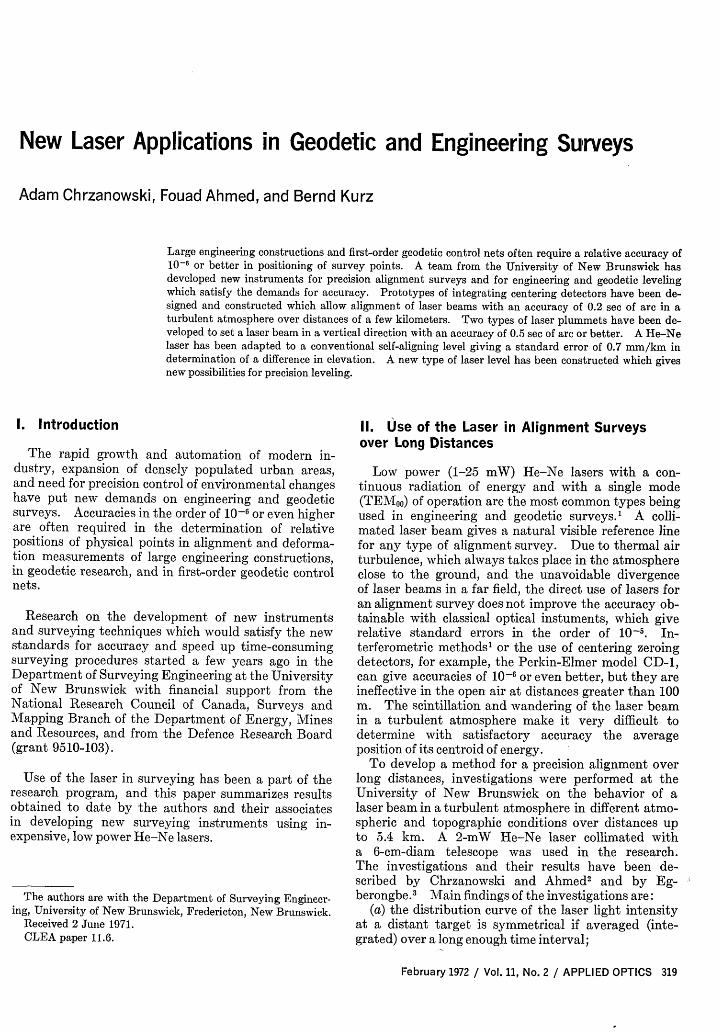
The implementation of Eq. (2) requires two steps.First, an analog computation for the weighted sum ofall sensor signals is required separately for the nu-merator N and denominator D. Second, the two sum-mation signals are time-integrated over the periodAT, yielding signals for N and D. These steps areshown in the block diagram in Fig. 5. One can see that
February 1972 / Vol. 11, No. 2 / APPLIED OPTICS 321
SUM FORDENOMINATOR
INTEGRATE RESET
Fig. 5. Block diagram of the integrating centering target.
INTEGiTIM
DIGITAL DISPLAY____ ________ _ x_ AX (U IMAL
DEVIATION FROMLASER BEAM CENTRE
Fig. 6. Block diagram of the self-aligning centering detector.
322 APPLIED OPTICS / Vol. 11, No. 2 / February 1972
WEIGHTS XiFOR
NOMINATORN
+10 xA
+ I d
- I x
-10 )
"A,

only two integrators are needed regardless of thenumber of photosensors in the target. Each photo-sensor has a current-to-voltage converting amplifierassociated with it, to operate the sensor in a short-circuit condition and to allow for a precise adjustmentof the amplifier gain in order to achieve a commonlight sensitivity.
To obtain the absolute value of the coordinate Xo,only two readings will be necessary after the integrationperiod, namely, for N and D followed by a simpledividing operation.
Another feature of the new centering detector willbe the automatic timing mode. Started manually,the detector will stay in the integration mode untilthe integrated output voltage corresponding to Dreaches a prespecified threshold. Both integratorsthen will be switched into the hold mode by the logiccontrol unit. Therefore, an integration time suitableto the existing laser light conditions will be obtainedautomatically. Since the voltage corresponding to Dis always greater than that corresponding to N, satura-tion of the integrators will be avoided. Anotheranalog/digital control circuit will indicate saturationof any sensor amplifier if the laser light should be toobright and will stop the operation.
C. Self-aligning Centering DetectorFigure 6 shows a block diagram of the newly designed
self-aligning detector. Instead of a fixed target with astring of photosensors, as in the above-describedcentering target, the self-aligning detector uses onlytwo large area sensors and employs basically the sameprinciple of centering the laser beam as the well-knowndifferential zeroing detectors. An electric steppingmotor connected by means of a precision gear with thedetector is used to move it automatically toward thecenter of the laser beam. If the sensors are not ex-actly centered, an output signal from the operationalamplifier OP1, which corresponds to the difference ofthe two sensor signals, is produced and time-integrated.When a certain threshold level is reached, a logicsignal is transmitted to the motor logic and the steppingmotor moves the whole detector one step toward thelaser beam center. When the center of the laser beamis reached, no difference in signal from the sensors isdetected by the operational amplifier and no step move-ments of the motor are produced.
The self-aligning detector exhibits an interestingproperty; the integration time is inversely proportionalto the distance of the centering detector from the centerof the laser beam. The detector moves quickly whenthe center of the laser beam is far away and slows downin its vicinity, increasing the integration time.
The self-aligning detector is designed to have adigital display of the absolute value of the deviationAX (Fig. 6). One step of the stepping motor causes adefinite movement of the sensors. Starting at areference mark a binary up-down counter will count thesteps until the the detector reaches the center of thelaser beam. The display will be designed to give the
reading directly in linear decimal units with a resolutionof 0.01 mm.
A pinhole source of light will be used as the referencemark to measure the value of AX. Another pair ofphotosensors with an operational amplifier OP2 willbe used to center the detectors automatically on thecalibration reference mark. The display will be reset tozero when the detector reaches the center of. the ref-erence mark.
A prototype of the self-aligning detector is now underconstruction at the University of New Brunswick.
111. Use of the Laser in Vertical AlignmentPrecise vertical alignment and deformation measure-
ment of high constructions or deep mining shafts isanother problem of engineering surveys.
Prototypes of the instruments for setting the laserbeam in a vertical direction with the goal of achievinga standard error of 0.5 see of arc were designed andconstructed at the University of New Brunswick.Both instruments use basically the same principle ofsetting the vertical line. A laser beam is projectedonto, and reflected from, a mercury pool and direc-tionally adjusted until the outgoing and reflected laserbeams coincide. Different techniques for making thelaser beams coincident are used in the two instruments.
The first instrument, the laser optical plummet, whichwas developed by Chrzanowski and Masry, 6 uses anautocollimation technique schematically shown in Fig.7. A first surface mirror is adjusted by means of anautocollimating telescope to be perpendicular to theaxis of sight of the telescope. Then the laser tube andthe whole instrument are adjusted by means of pre-cision gears until the two laser beams, the reflectionsfrom the mirror and from the mercury, coincide withthe center of the reticle of the telescope.
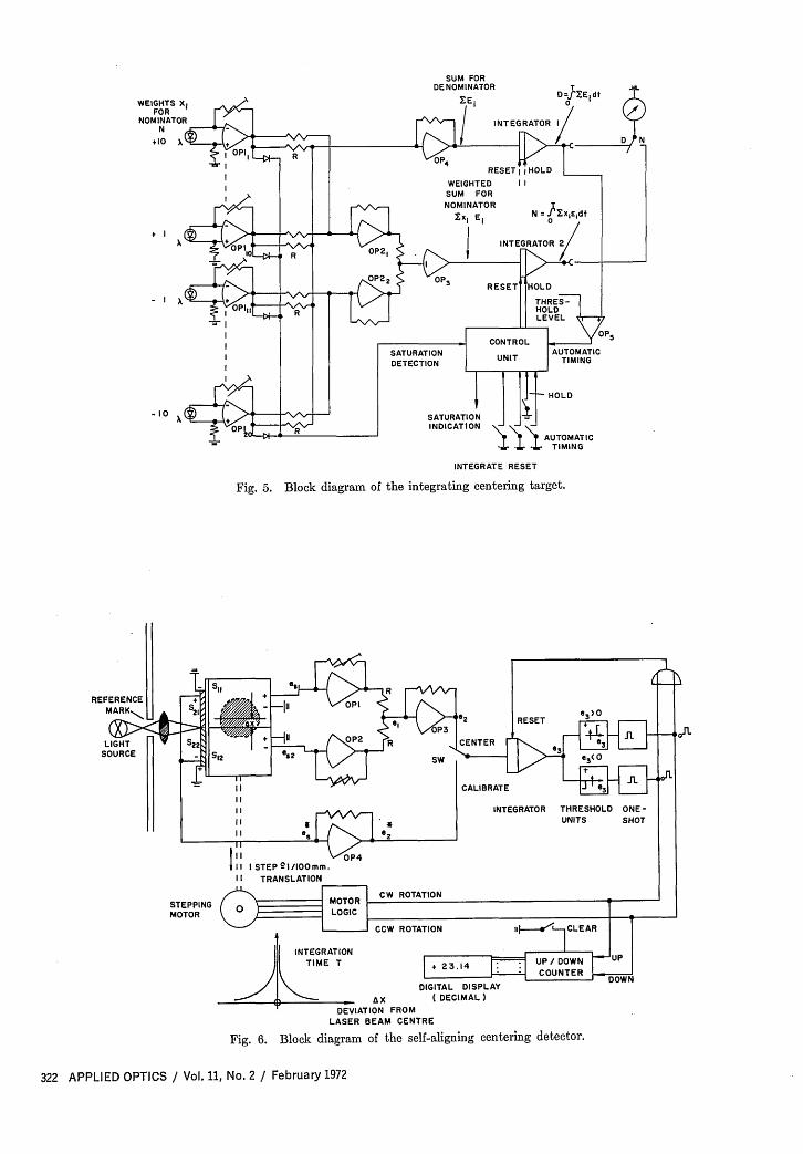
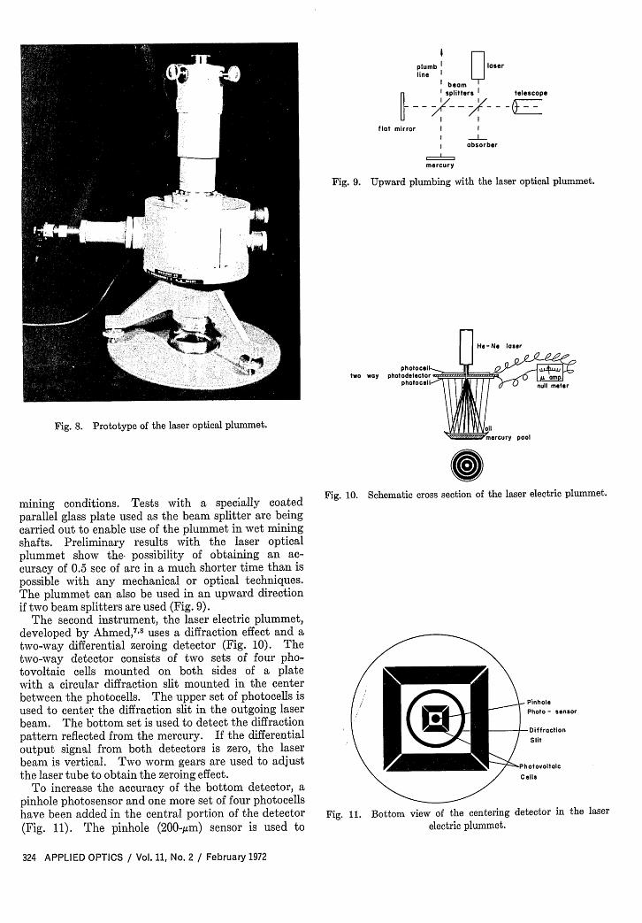
The prototype of the laser optical plummet (Fig. 8)uses a 40X magnifying autocollimating telescope witha 6-cm-diam objective. An 8-pm thin film (apellicle) was used as the beam splitter in the firstpractical tests. The pellicle proved to give a betteraccuracy and less internal reflections than any othertype of beam splitter but failed to work in humid
j He-Ne laserfirst
surfacemirror
I
I
beam splitterX - -- ~
_ =telescope CV
oilMercury pool
'to centering detector
Fig. 7. Schematic cross section of the laser optical plummet.
February 1972 / Vol. 11, No. 2 / APPLIED OPTICS 323
*1 As _ 1 --- n
40,1 -
I
II
plumb laserline l
beam1 splitters | telescope
flat mirror I
absorber
mercury
Fig. 9. Upward plumbing with the laser optical plummet.
He-Ne laser
photocelltwo way photodetector aa
Fig. 8. Prototype of the laser optical plummet.pool
mining conditions. Tests with a specially coatedparallel glass plate used as the beam splitter are beingcarried out to enable use of the plummet in wet miningshafts. Preliminary results with the laser opticalplummet show the possibility of obtaining an ac-curacy of 0.5 sec of arc in a much shorter time than ispossible with any mechanical or optical techniques.The plummet can also be used in an upward directionif two beam splitters are used (Fig. 9).
The second instrument, the laser electric plummet,developed by Ahmed, 8 uses a diffraction effect and atwo-way differential zeroing detector (Fig. 10). Thetwo-way detector consists of two sets of four pho-tovoltaic cells mounted on both sides of a platewith a circular diffraction slit mounted in the centerbetween the photocells. The upper set of photocells isused to center the diffraction slit in the outgoing laserbeam. The bottom set is used to detect the diffractionpattern reflected from the mercury. If the differentialoutput signal from both detectors is zero, the laserbeam is vertical. Two worm gears are used to adjustthe laser tube to obtain the zeroing effect.
To increase the accuracy of the bottom detector, apinhole photosensor and one more set of four photocellshave been added in the central portion of the detector(Fig. 11). The pinhole (200-,4m) sensor is used to
iFig. 10. Schematic cross section of the laser electric plumnmet.
Fig. 11. Bottom view of the centeringelectric plummet.
_ _ nholePhoto- sensor
DiffractionSlit
X-PhotovoltoicCells
detector in the laser
324 APPLIED OPTICS / Vol. 11, No. 2 / February 1972

cury to a photoelectric centering detector. The posi-tion of the laser tube is adjusted by means of a wormgear and gimbal suspension until the reflected laserbeam is centered on the photodetector. After the
-worm gear
Gimbal suspension
: __ 1 Collimator
Loser beam -k 3_ Photo centering
Beam_--' detectorSplitter
1l~ocsiInLocking X LensCollaredi Reference mirror
Centering pin Mercury
Fig. 13. Schematic crosssection of the prototype of
the laser level.
Fig. 12. Prototype of the photoelectric laser level.
detect the peak intensity of the diffraction pattern inaddition to the zeroing effect of the four photocelldetectors.
A laboratory test with the laser electric plummet wasperformed over a distance of 130 m with a mercurypool located 1 m below the laser output. The test gave0.3 see of arc standard deviation in resetting the laserbeam in the vertical direction.
IV. Use of the Laser in Precision LevelingFirst-order geodetic leveling and precision deforma-
tion measurements in engineering surveys call for astandard deviation smaller than 1 mm per 1 km betweenthe points to be determined.
A new instrument, the photoelectric laser level (Fig.12) has been developed by the authors, which satisfiesthe accuracy requirements.
Basic components and the working principle of thelaser level are shown schematically in Fig. 13. Afterpassing through a beam splitter, the laser beam pro-duced by a vertically mounted laser tube is re-flected from the surface of a mirror floating on mer-
/
Fig. 14. Jena Ni-007 level with adapted He-Ne laser.
February 1972 / Vol. 11, No. 2 / APPLIED OPTICS 325
/
¢
. . -- x R�_' g � g' q - '_ 0, 01.9 II x! 11BMW 1" 11100W V� q M -IrH �m '0 M
I

4t~
Fig. 15. Schematic cross section of the self-aligning level Ni-007.
above procedure is accomplished, the output laserbeam from the instrument is horizontal or is slightlyinclined at a constant angle to the horizontal plane.The eventual inclination of the laser output is constantin all directions on rotation of the instrument, as longas the laser beam is kept centered on the photodetectorand as long as the floating mirror (reference surface)rotates together with the whole instrument. Tosatisfy the latter condition, the mercury pool with thefloating mirror is connected by means of a tube withthe beam splitter and with the photodetector. Toavoid drift of the floating mirror when rotating theinstrument, three sliding pins are provided which lockthe mirror in a fixed central position in the mercurypool. The pins are released when a measurement to aleveling target is being performed. The constant in-clination of the laser output has no influence on theaccuracy of a differential leveling if the instrument isset up exactly at the midposition between the twoleveling targets.
A preliminary prototype of the laser level used thesurface of mercury as the reference surface for settingthe laser beam in a horizontal direction. Practicaltests have shown, however, that the direct use ofmercury as a gravitational mirror was impractical dueto difficulties in damping vibrations. The floatingmirror has therefore been introduced as a referencesurface. The heavy mirror dampens the vibrationsof mercury in a few seconds, providing a very stablereference surface. The eventual small inclination ofthe surface of the mirror in respect to the surface ofmercury has no significant influence on the measure-ments, as already mentioned.
Accuracy of differential leveling with the laser leveldepends on the sensitivity of the centering photode-tector and its distance from the reference mirror.Laboratory tests with the centering detector (fourphotocell, zeroing output) used in the prototype havegiven a standard deviation of 2 pjm (2 mm X 10-' mm)of centering the laser beam. The distance of the
mercury pool from the photodetector is changeablefrom 40 cm to 1.5 m.
One can expect, therefore, the following standarddeviation in setting the laser beam at a constant in-clination: (2 X 10-' X 206265)/(2 X 1500) = 0.13sec. This corresponds to a leveling error of 0.02 mmbetween two targets 50 m apart. The accuracy iscomparable with that of hydrostatic leveling and isbetter than one can achieve with geodetic spirit levelsequipped with parallel glass plate micrometers.
Another application of lasers in precision levelinghas been introduced by Chrzanowski 9 with a He-Nelaser adapted to a conventional self-aligning levelJena Ni-007 as shown in Figs. 14 and 15. Fieldmeasurements' 0 on a 1200-m test line gave a standarderror of 0.7 mm/km when 200-m distances between theleveling rods were used. A differential zeroing photo-detector (two photovoltaic cells) sliding on a rod witha millimeter scale was used as a leveling rod in the fieldtests. Even better accuracy than 0.7 mm/km is ex-pected in the future when the previously described (seeSec. II.C) self-aligning centering detector combinedwith an Invar rod is used. The laser/Ni-007 level isexpected to solve the present geodetic problem of de-termining a precise difference in elevation when longlines of sight are necessary, as for instance in levelingacross rivers.
The authors are indebted to A. Ali and K. Fila,graduate students of the University of New Bruns-wick, for their help and cooperation in the research.Special thanks should go to R. Carruthers and hisstaff of the Engineering Workshop for the constructionof the prototype instruments.
References1. A. Chrzanowski, "New Laser Instruments for Engineering
Surveys," presented at the VIth International Conferenceon Precision Engineering Surveys, Graz, Austria, 1970.
2. A. Chrzanowski and F. Ahmed, "Alignment Surveys inTurbulent Atmosphere Using Laser," Proceedings of the31st Annual Meeting of the ACSM, Washington, 1971.
3. A. Egberongbe, "Evaluation of a He-Ne Laser for Use InAlignment Surveys," M.Sc. Thesis, University of NewBrunswick (1971).
4. A. Chrzanowski and B. Kurz, "Automatic Centering De-tector," Patent pending in Canada, 1971.
5. A. Chrzanowski, The Canadian Surveyor 24, 23 (1970).6. A. Chrzanowski and S. Masry, Canadian Patent 811923,
6 May 1969.7. F. Ahmed, "New Laser Instruments and New Methods for
Mine Orientation Surveys," Ph.D. Thesis, University ofNew Brunswick (1970).
8. F. Ahmed, "Laser Electric Plummet," unpublished Tech-nical Report, University of New Brunswick (1970).
9. A. Chrzanowski, "Development of New Laser Instrumentsfor Precision Surveys," prepared for presentation at the13th International Congress of Surveyors (F.I.G.), Wies-
, baden, September 1971.10. K. Fila, "Use of Laser in Leveling," M.Sc. Thesis, University
of New Brunswick (1971).
326 APPLIED OPTICS / Vol. 11, No. 2 / February 1972